MitraStar Technology HES209M1H WiMAX Indoor VoIP IAD User Manual User s guide
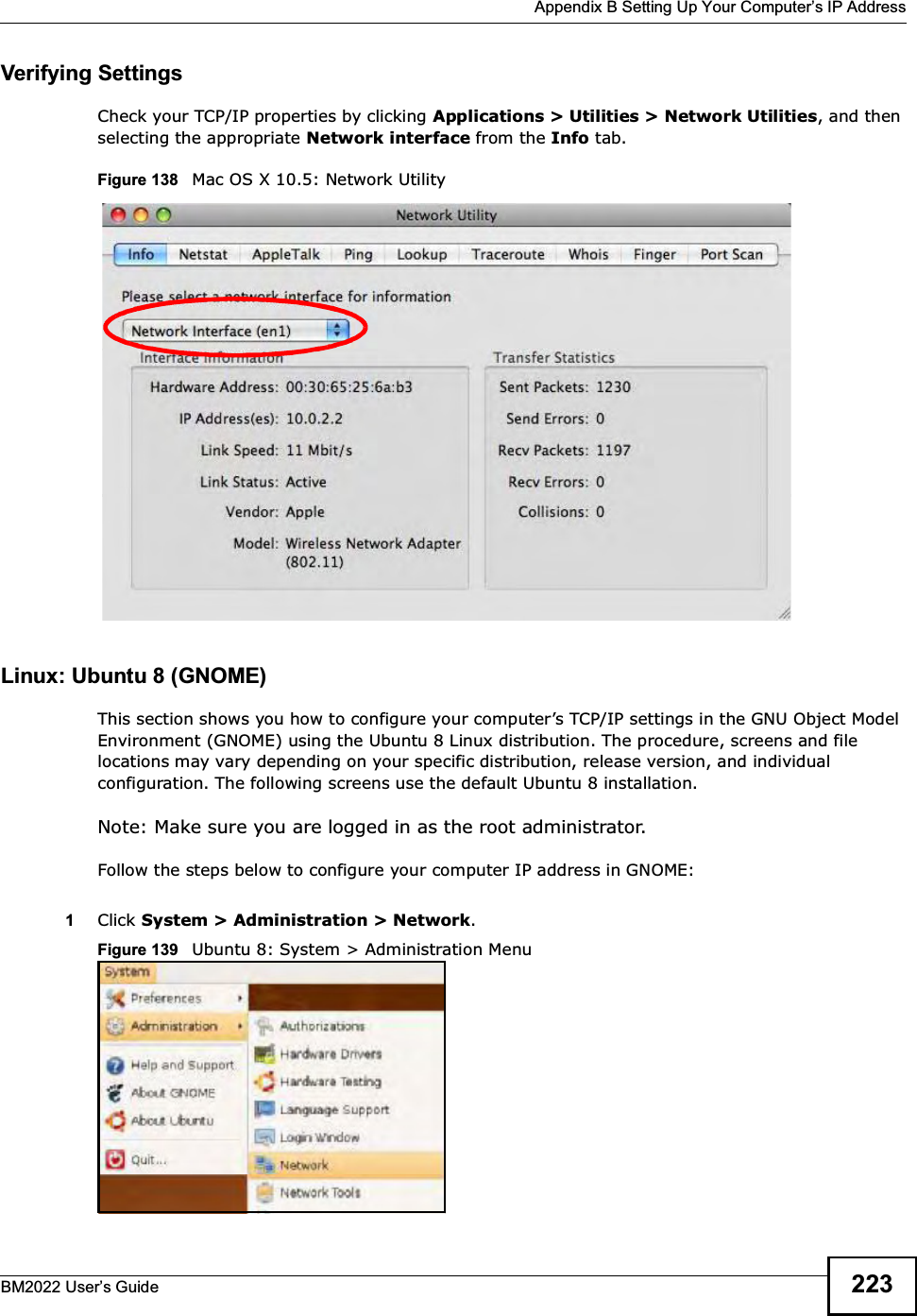
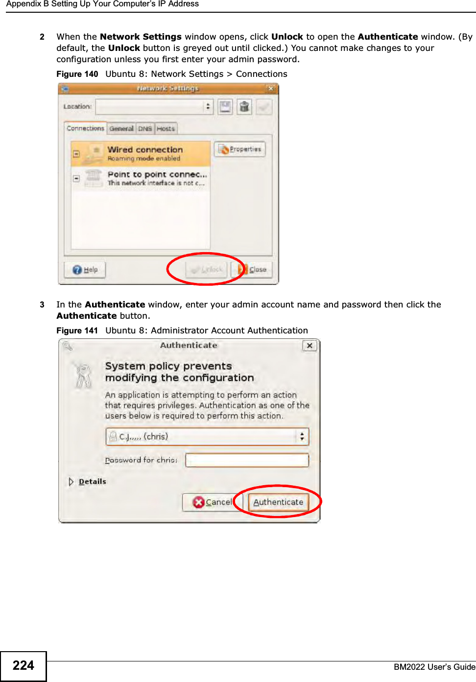
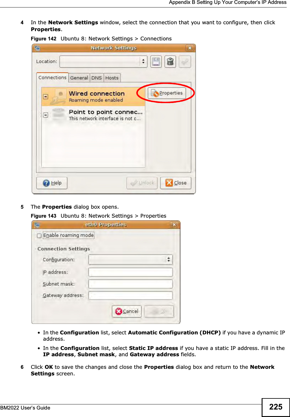
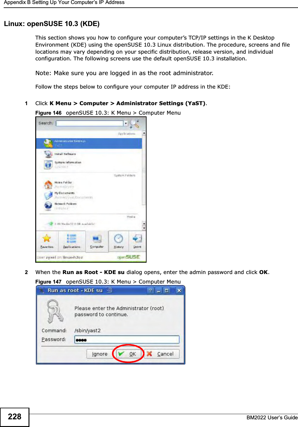
MitraStar Technology Corporation WiMAX Indoor VoIP IAD User s guide
UserManual.wiki
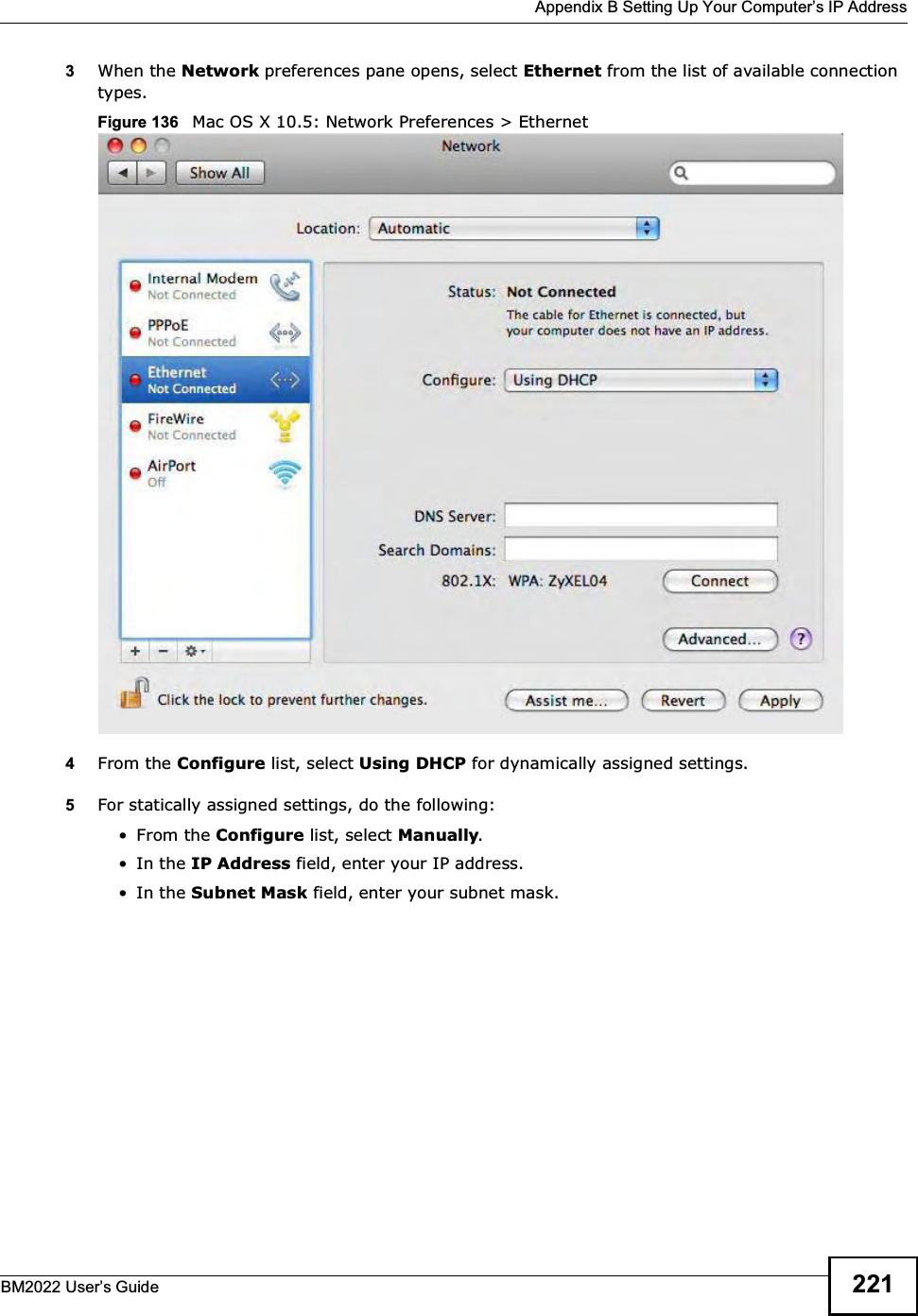
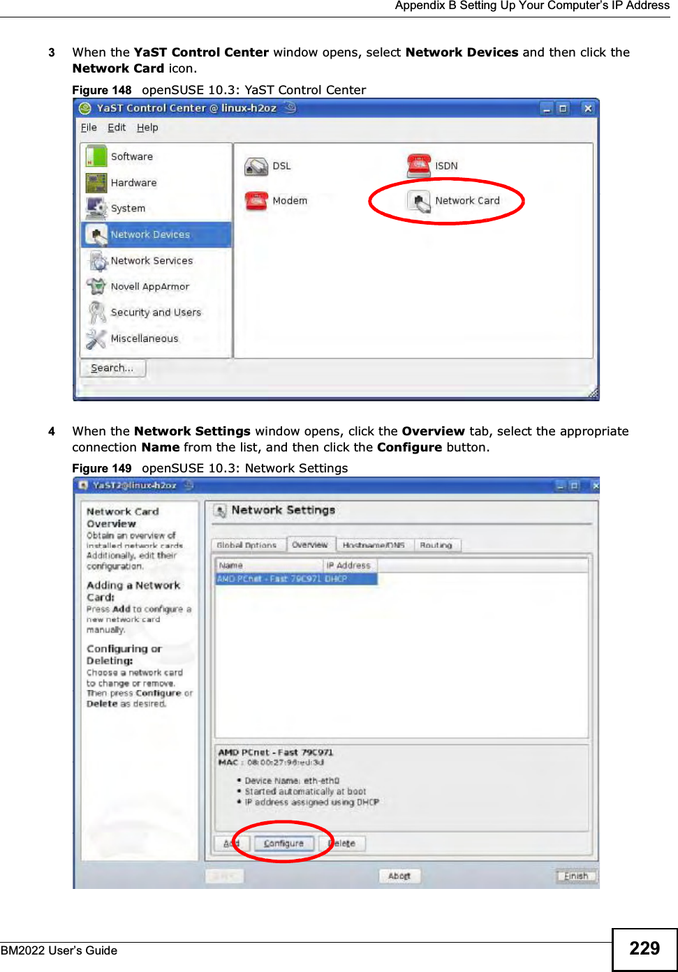
>
MitraStar Technology
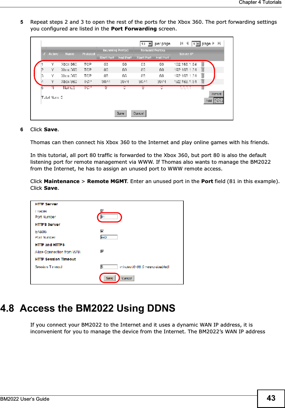
>
HES209M1H User Manual
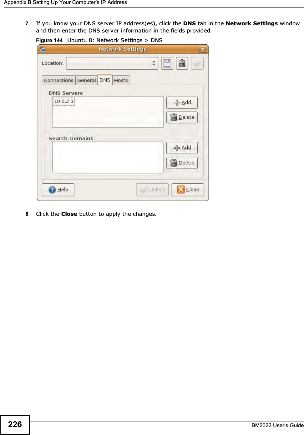
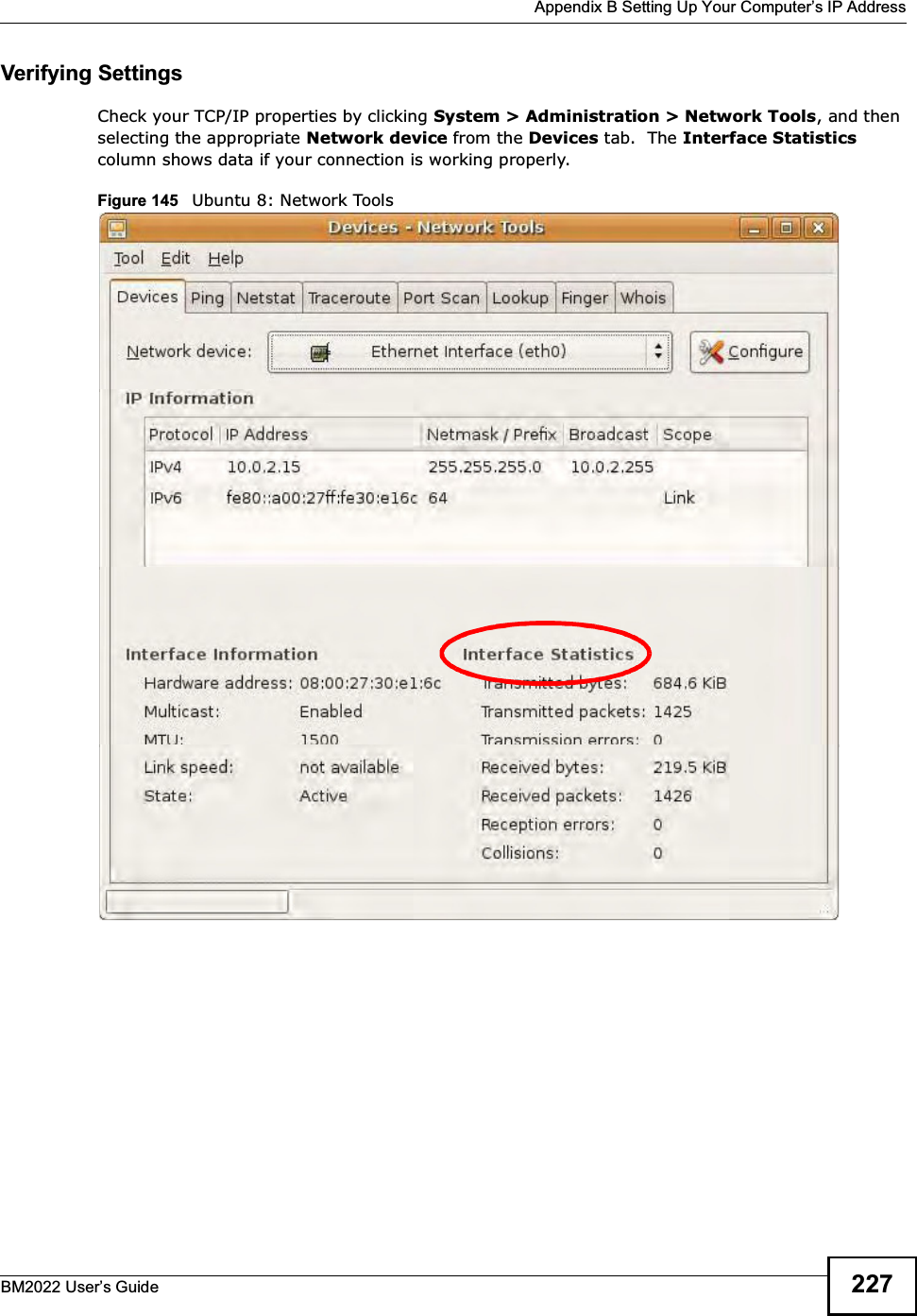
User Manual
Navigation menu
Upload a User Manual
Namespaces
Wiki Guide
HTML
PDF
Info
Views
User Manual
Discussion / Help
Navigation
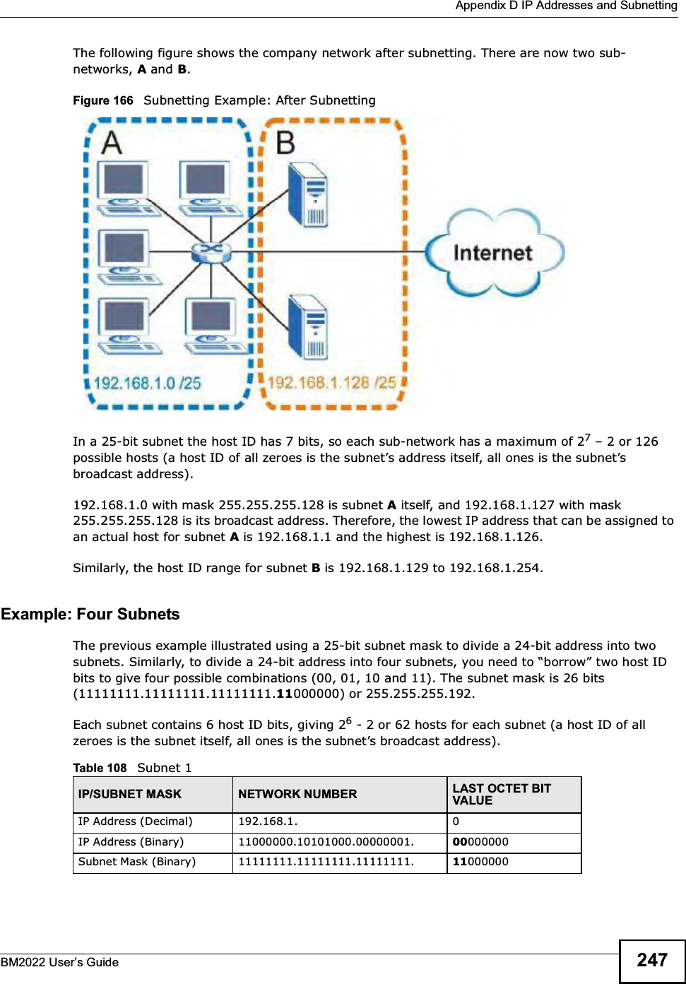
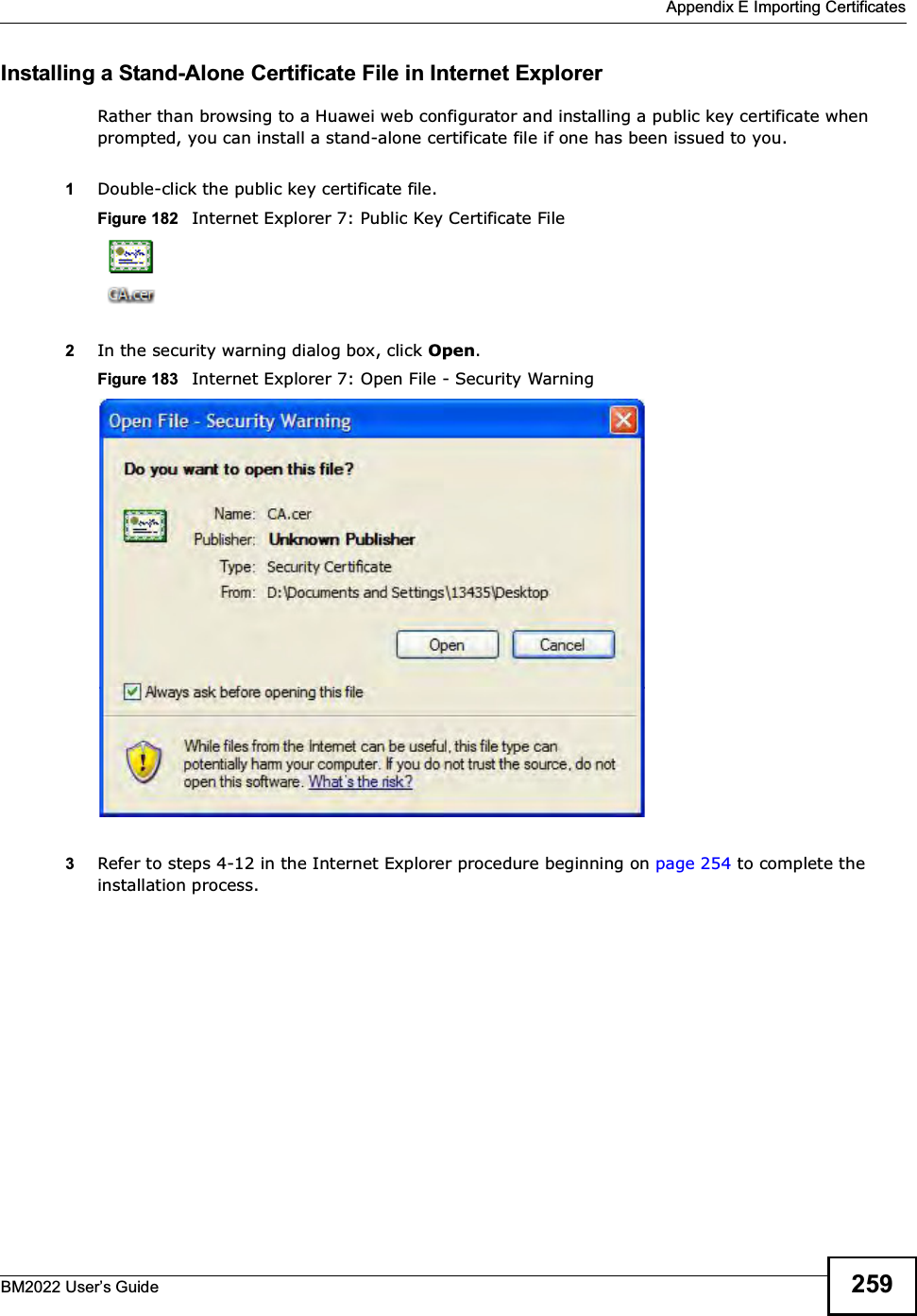
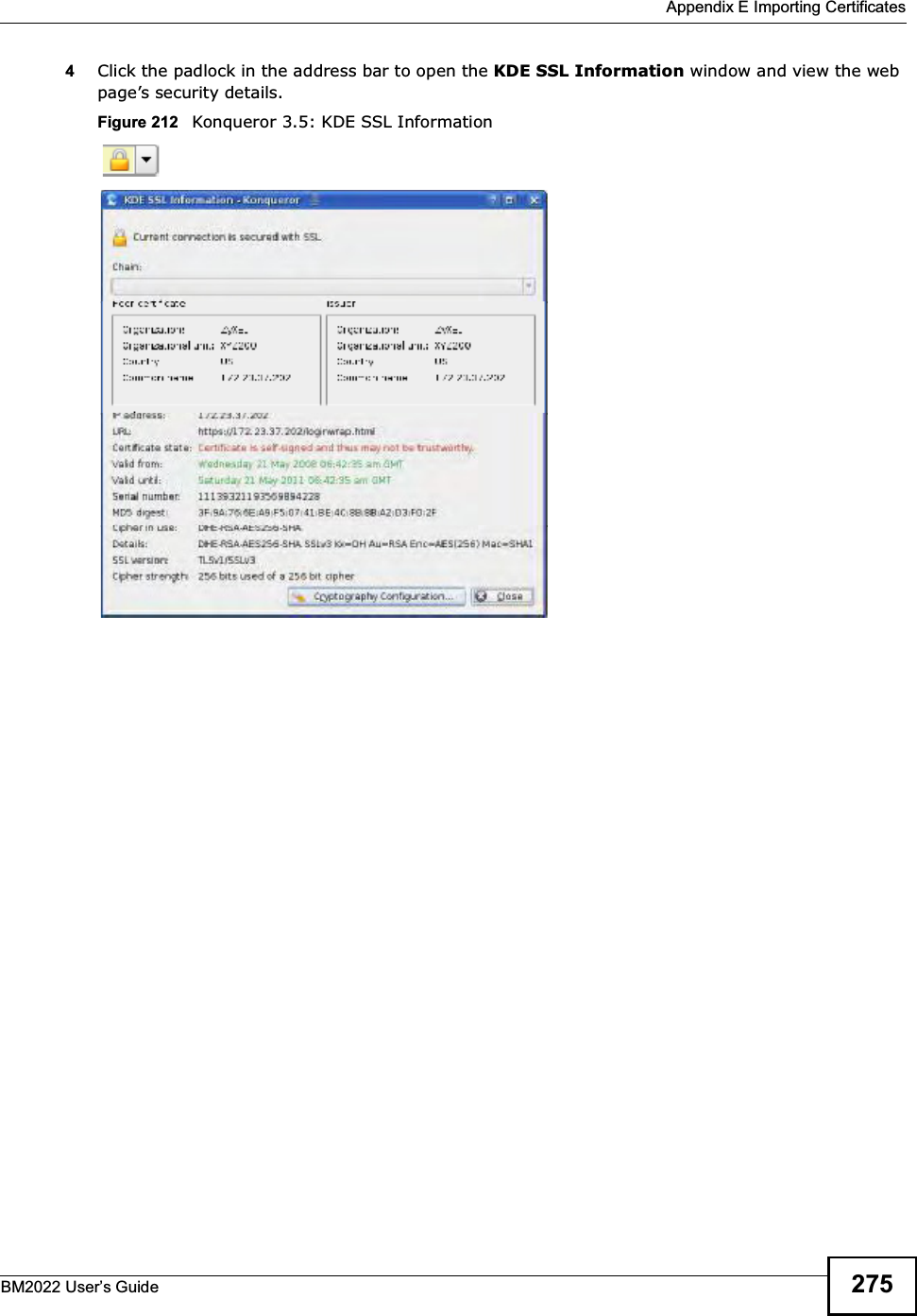
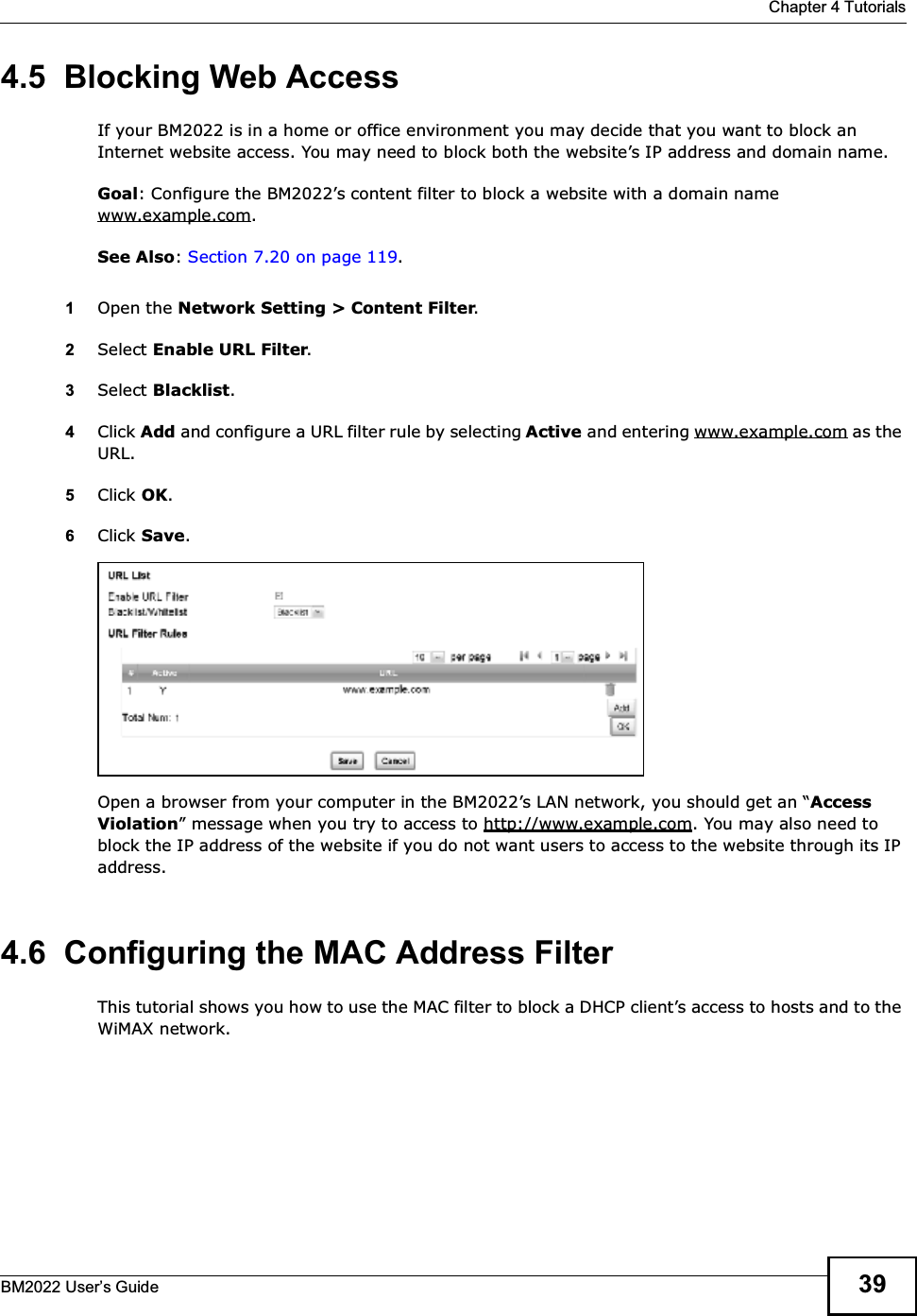
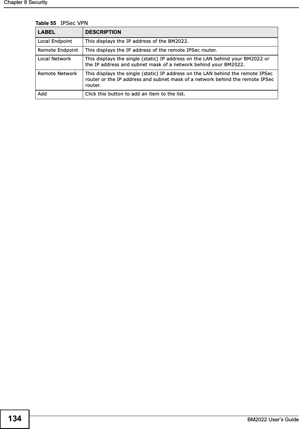
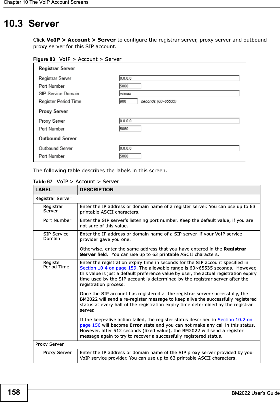
![About This User's GuideBM2022 Users Guide 3About This User's GuideIntended AudienceThis manual is intended for people who want to configure the Huawei BM2022 using the Huawei Web Configurator. You should have at least a basic knowledge of TCP/IP networking concepts and topology.Related Documentation Quick Start Guide The Quick Start Guide is designed to help you get up and running right away. It contains information on setting up your network and configuring for Internet access.Support DiscRefer to the included CD for support documents. Huawei Web SitePlease refer to www.huawei.com for additional support documentation and product certifications. Document ConventionsWarnings and NotesThese are how warnings and notes are shown in this Users Guide. Warnings tell you about things that could harm you or your BM2022.Note: Notes tell you other important information (for example, other things you may need to configure or helpful tips) or recommendations.Syntax Conventions The product(s) described in this book may be referred to as the BM2022, the device, the system or the product in this Users Guide. Product labels, screen names, field labels and field choices are all in bold font. A key stroke is denoted by square brackets and uppercase text, for example, [ENTER] means the enter or return key on your keyboard. Enter means for you to type one or more characters and then press the [ENTER] key. Select or choose means for you to use one of the predefined choices. A right angle bracket ( > ) within a screen name denotes a mouse click. For example, TOOLS > Logs > Log Settings means you first click Tools in the navigation panel, then the Logs sub menu and finally the Log Settings tab to get to that screen. Units of measurement may denote the metric value or the scientific value. For example, k for kilo may denote 1000 or 1024, M for mega may denote 1000000 or 1048576 and so on. e.g., is a shorthand for for instance, and i.e., means that is or in other words.](https://usermanual.wiki/MitraStar-Technology/HES209M1H/User-Guide-1574324-Page-2.png)
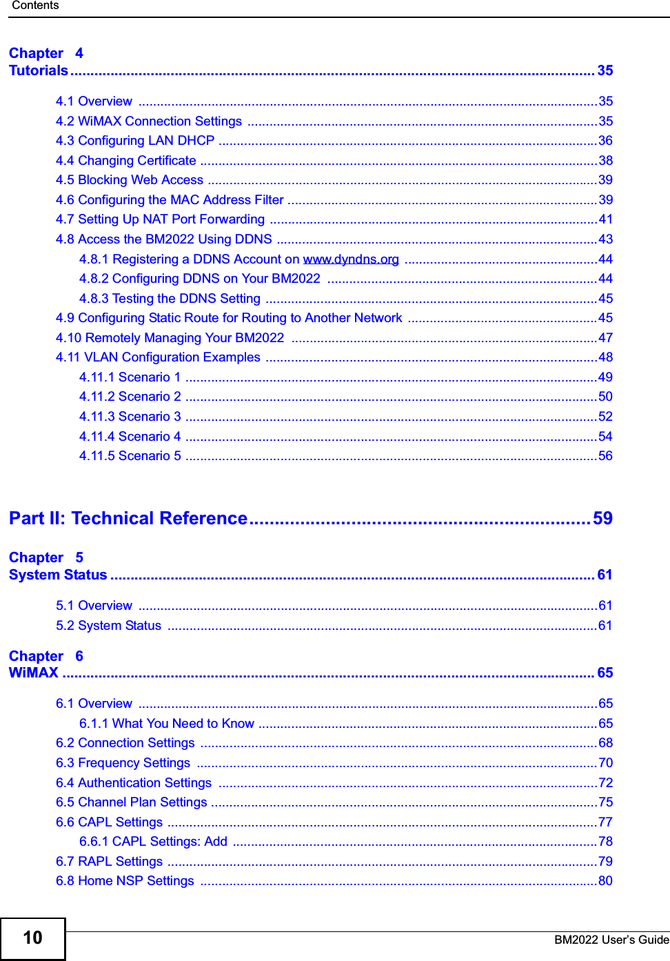
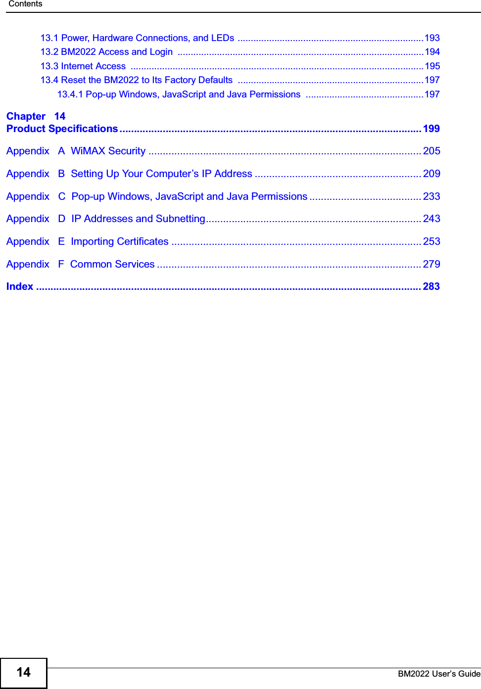

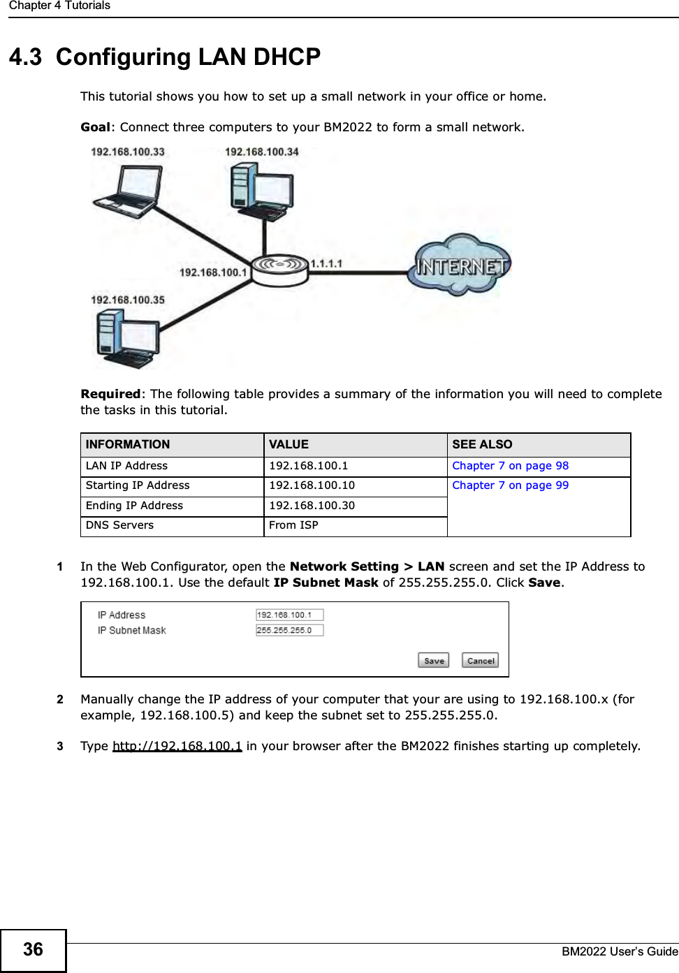
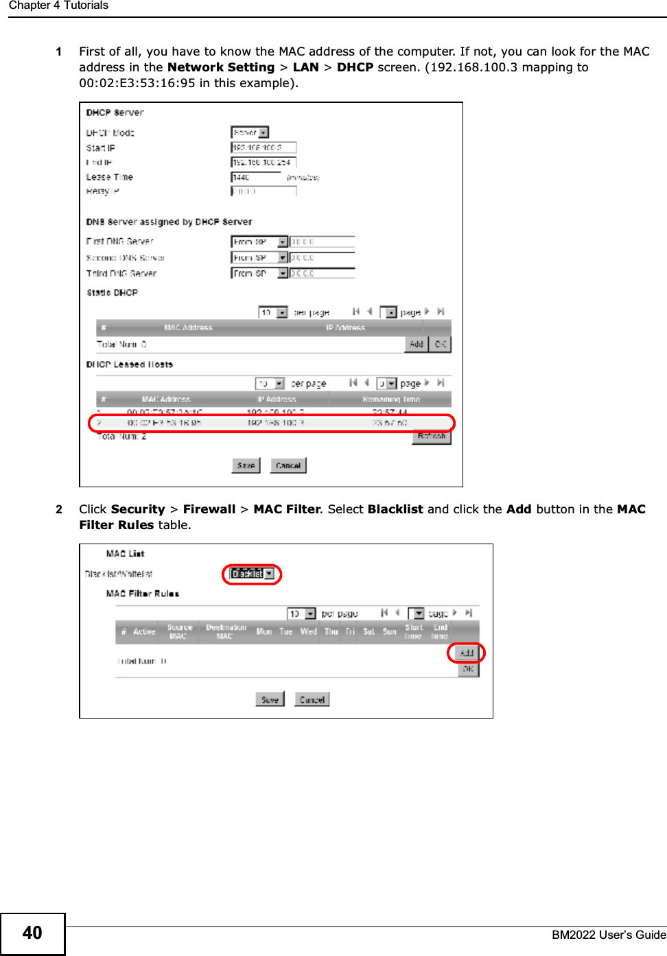
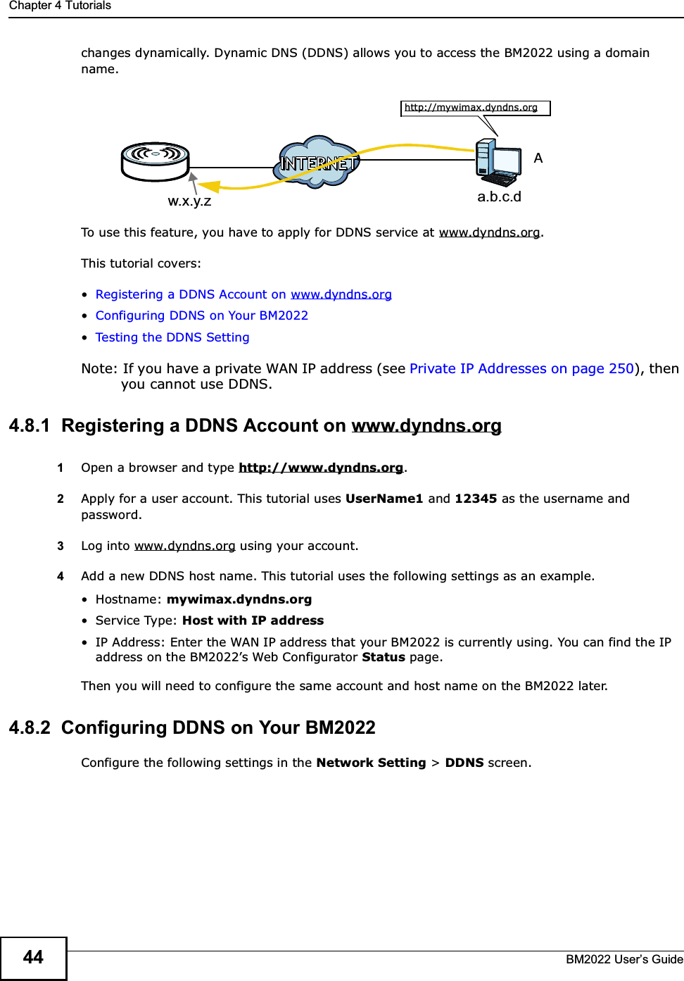
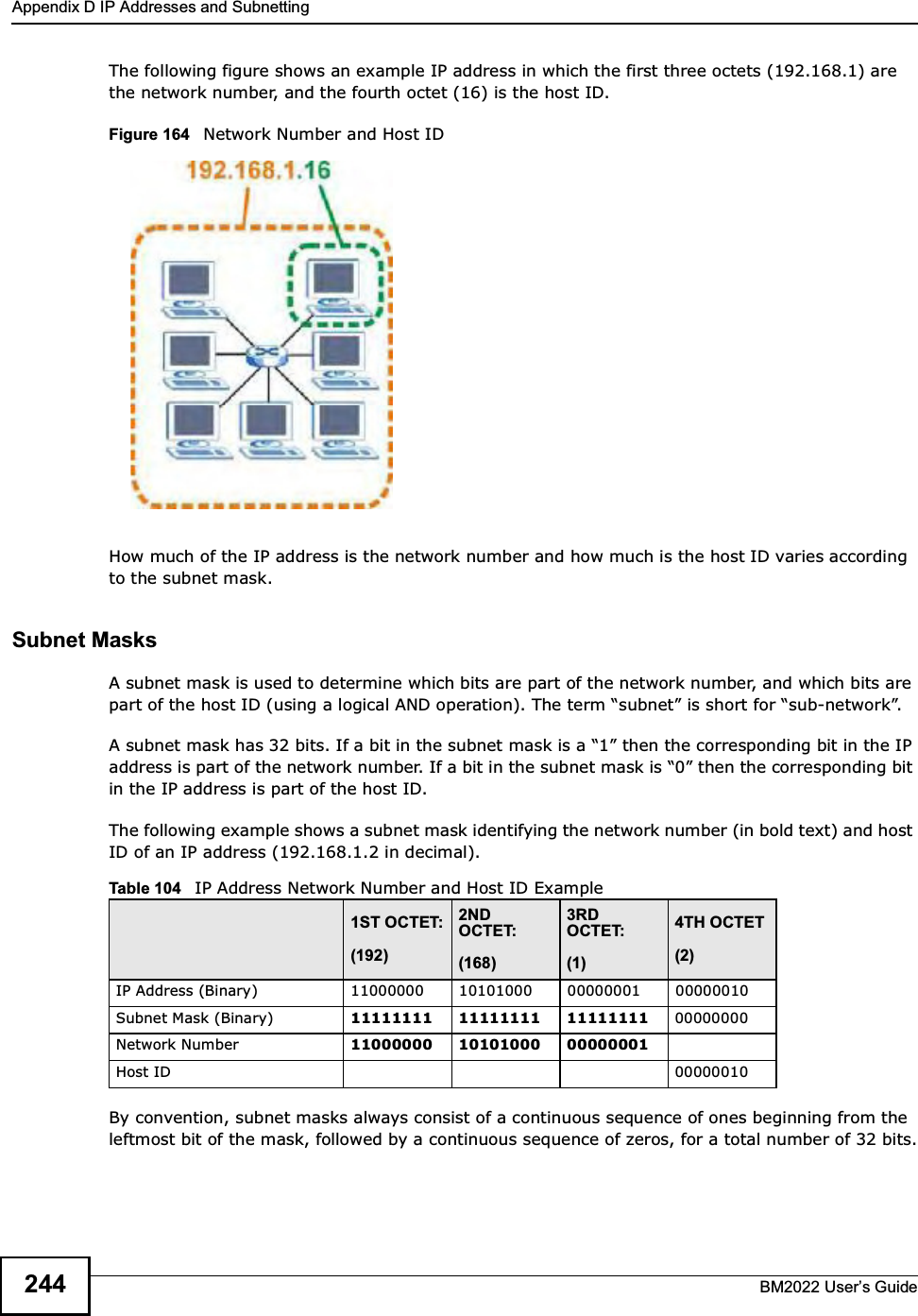
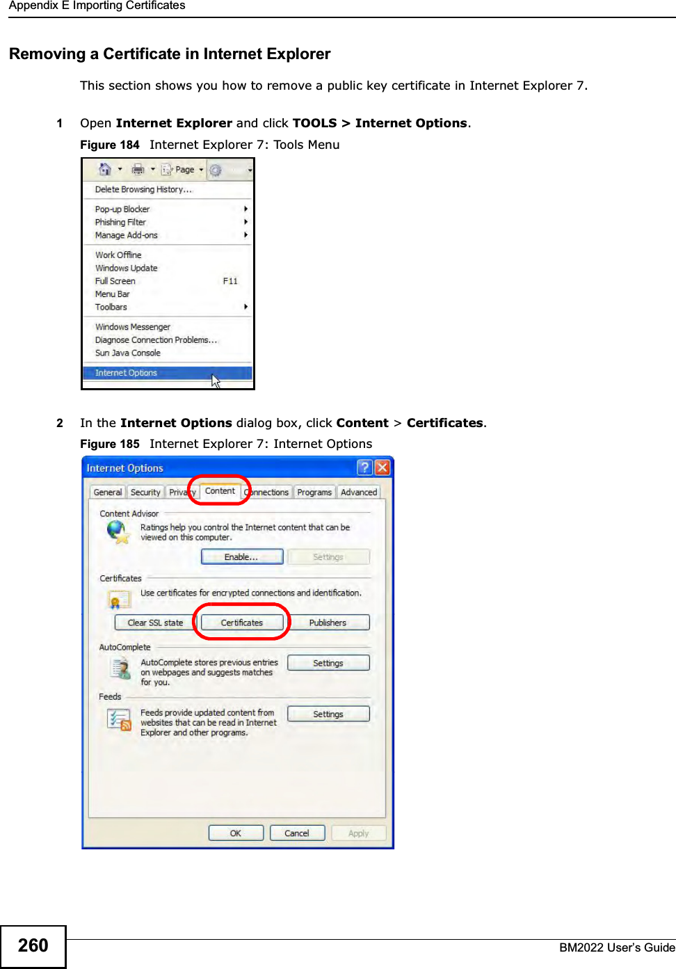
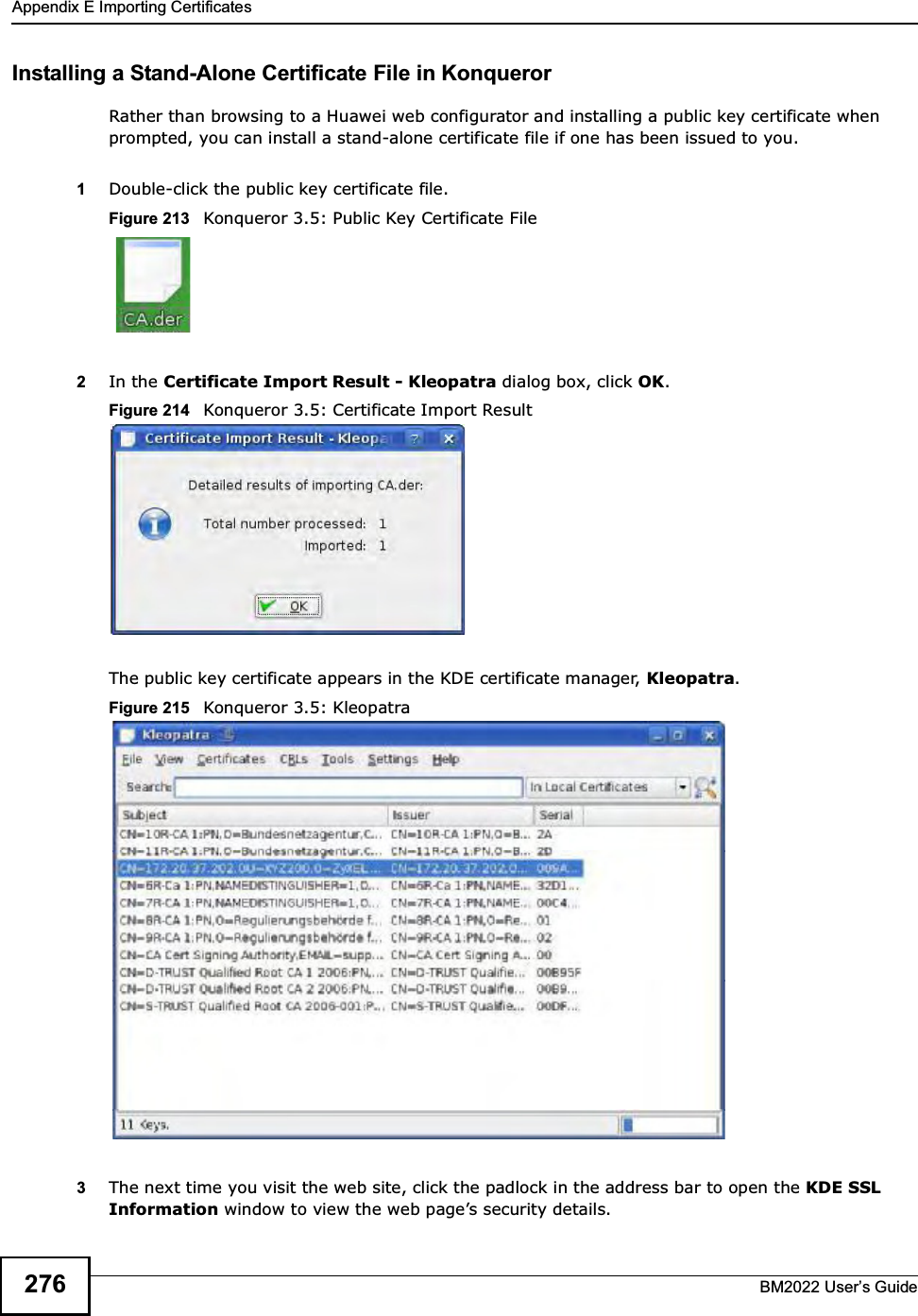
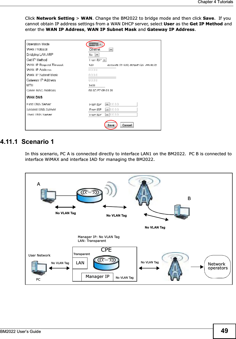
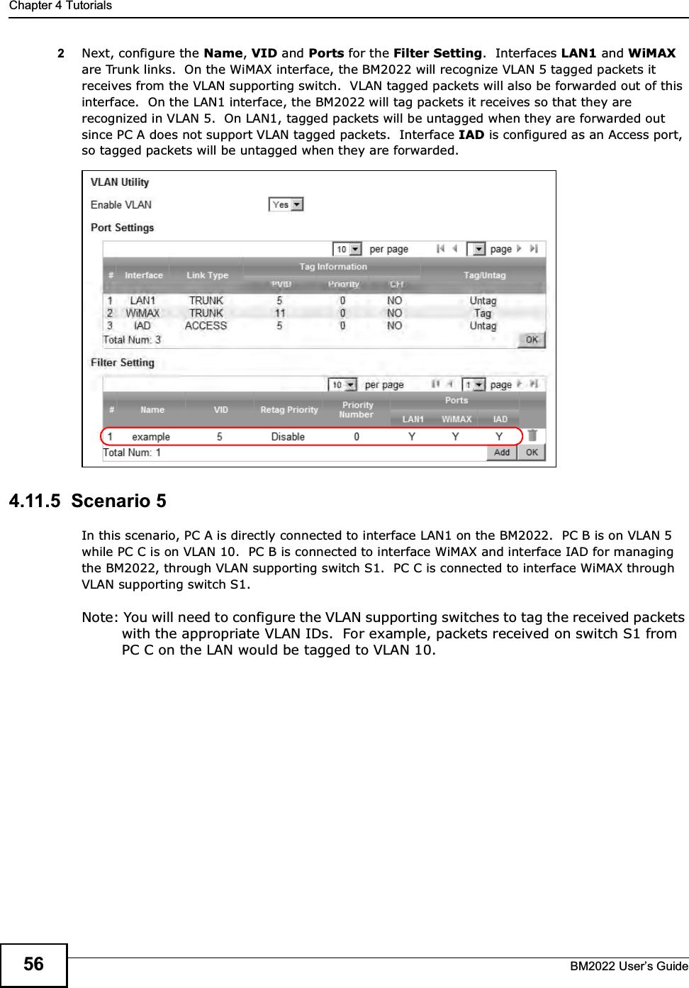
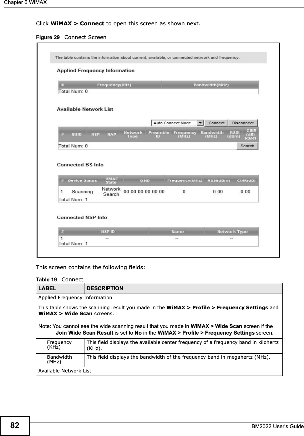
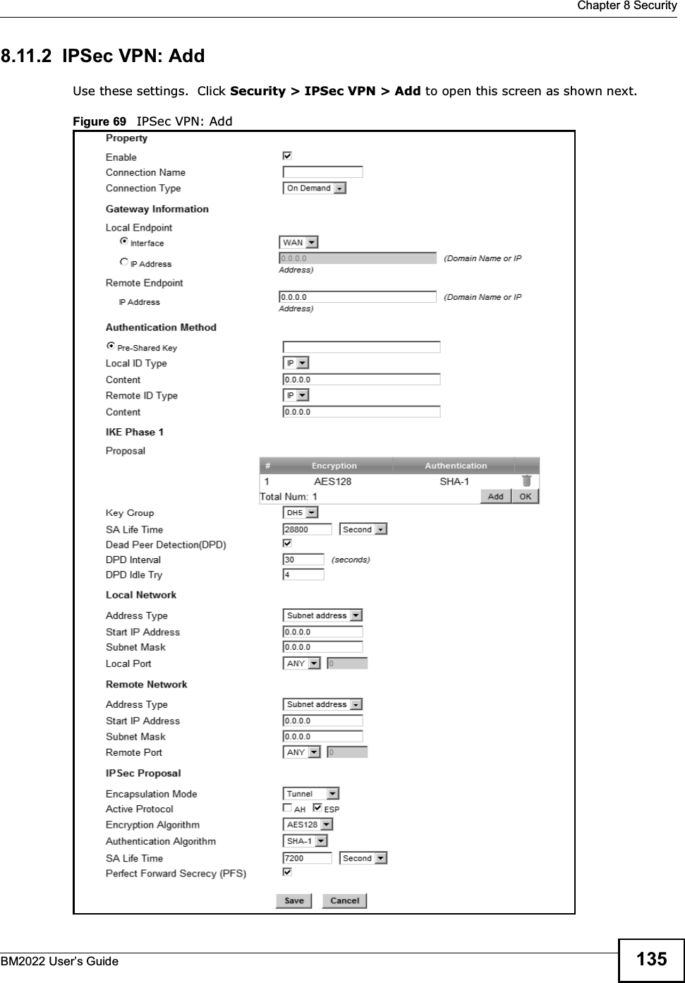
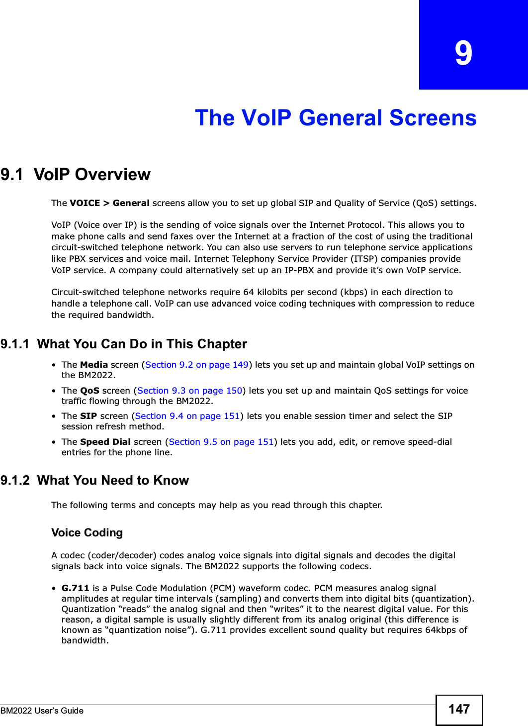
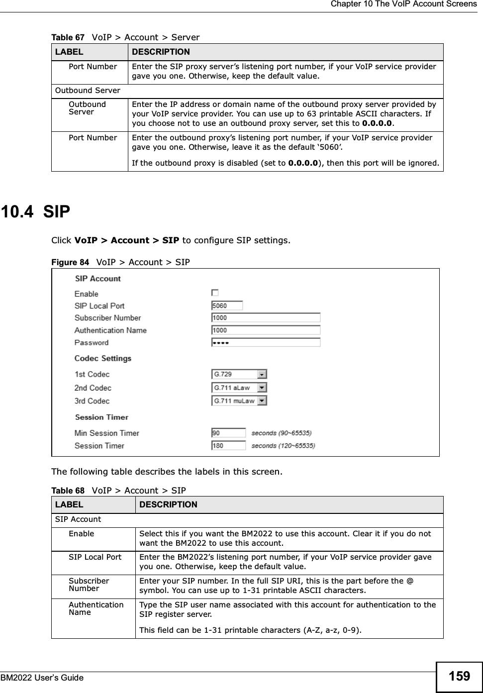
![Chapter 4 TutorialsBM2022 Users Guide 451Select Enable Dynamic DNS.2Select dyndns.org for the service provider.3Select Dynamic for the service type.4Type mywimax.dyndns.org in the Domain Name field.5Enter the user name (UserName1) and password (12345).6Select WAN IP for the IP update policy.7Click Save.4.8.3 Testing the DDNS SettingNow you should be able to access the BM2022 from the Internet. To test this:1Open a web browser on the computer (using the IP address a.b.c.d) that is connected to the Internet.2Type http://mywimax.dyndns.org and press [Enter].3The BM2022s login page should appear. You can then log into the BM2022 and manage it.4.9 Configuring Static Route for Routing to Another NetworkIn order to extend your Intranet and control traffic flowing directions, you may connect a router to the BM2022s LAN. The router may be used to separate two department networks. This tutorial shows how to configure a static routing rule for two network routings.In the following figure, router R is connected to the BM2022s LAN. R connects to two networks, N1 (192.168.1.x/24) and N2 (192.168.10.x/24). If you want to send traffic from computer A (in N1](https://usermanual.wiki/MitraStar-Technology/HES209M1H/User-Guide-1574324-Page-41.png)


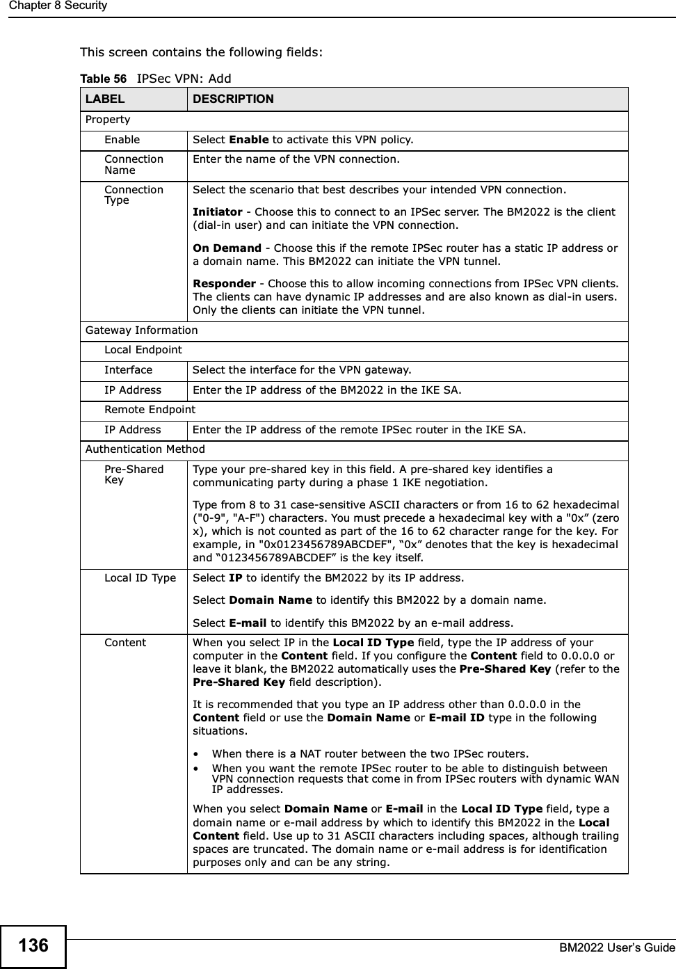
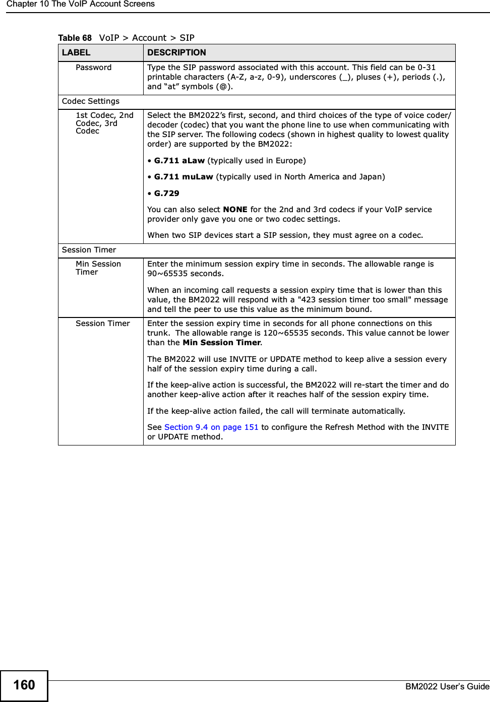
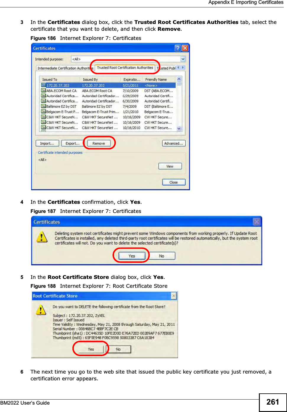
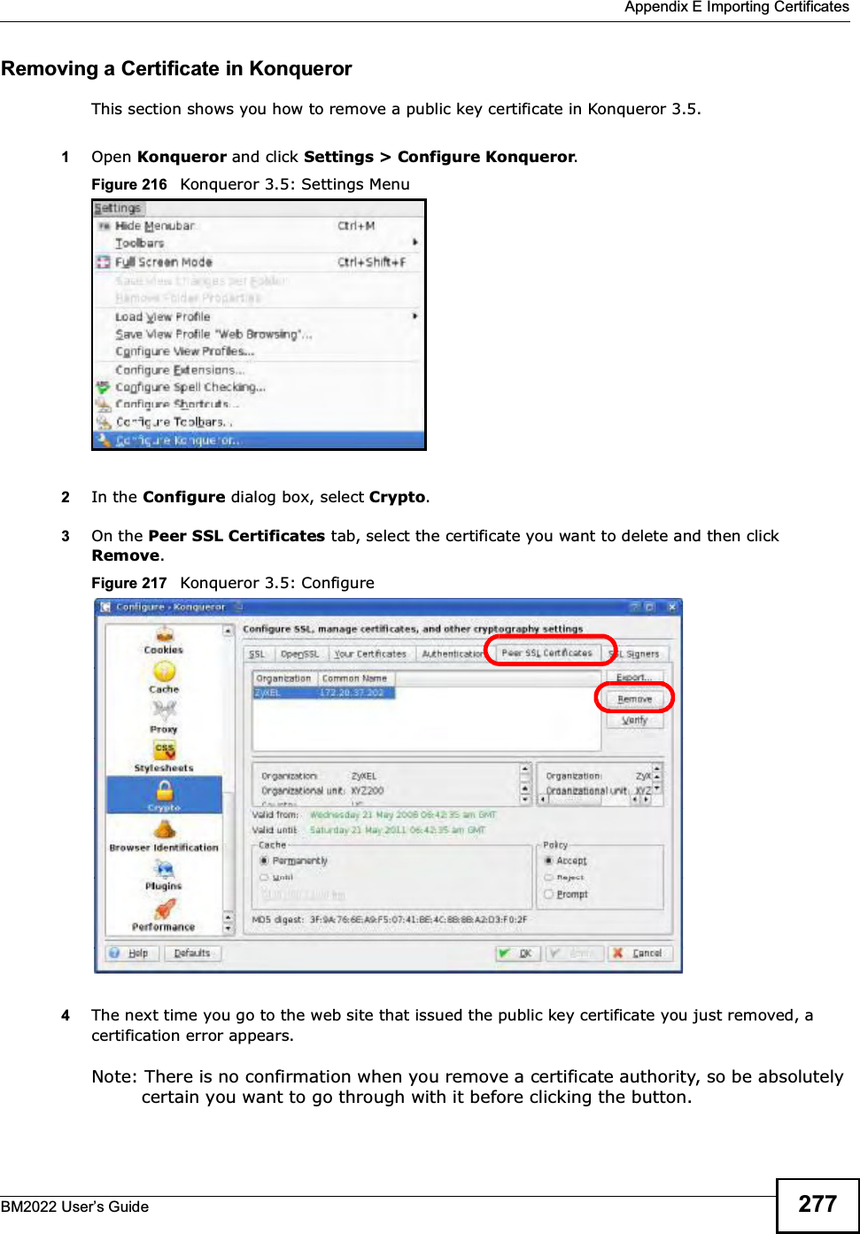
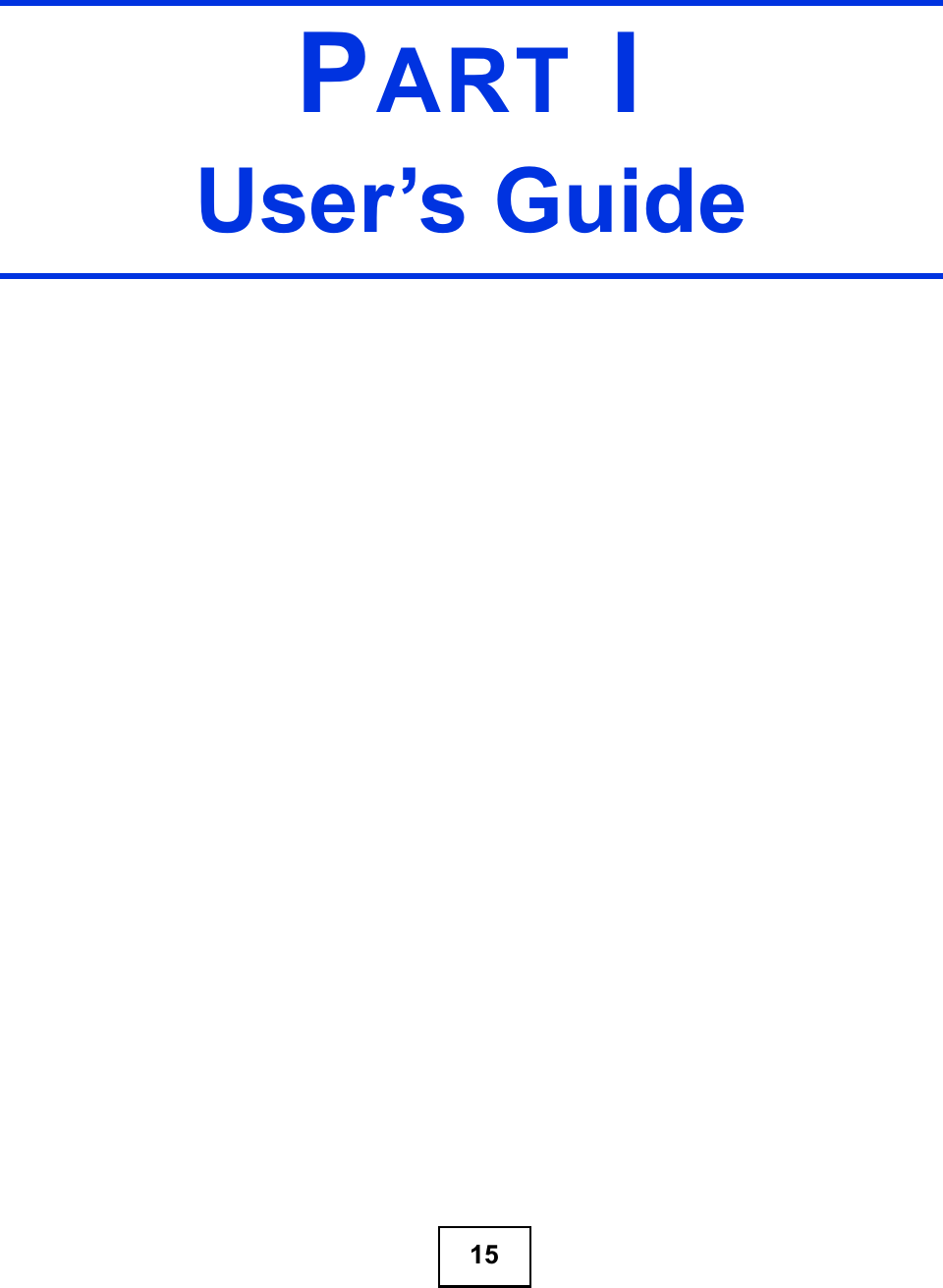
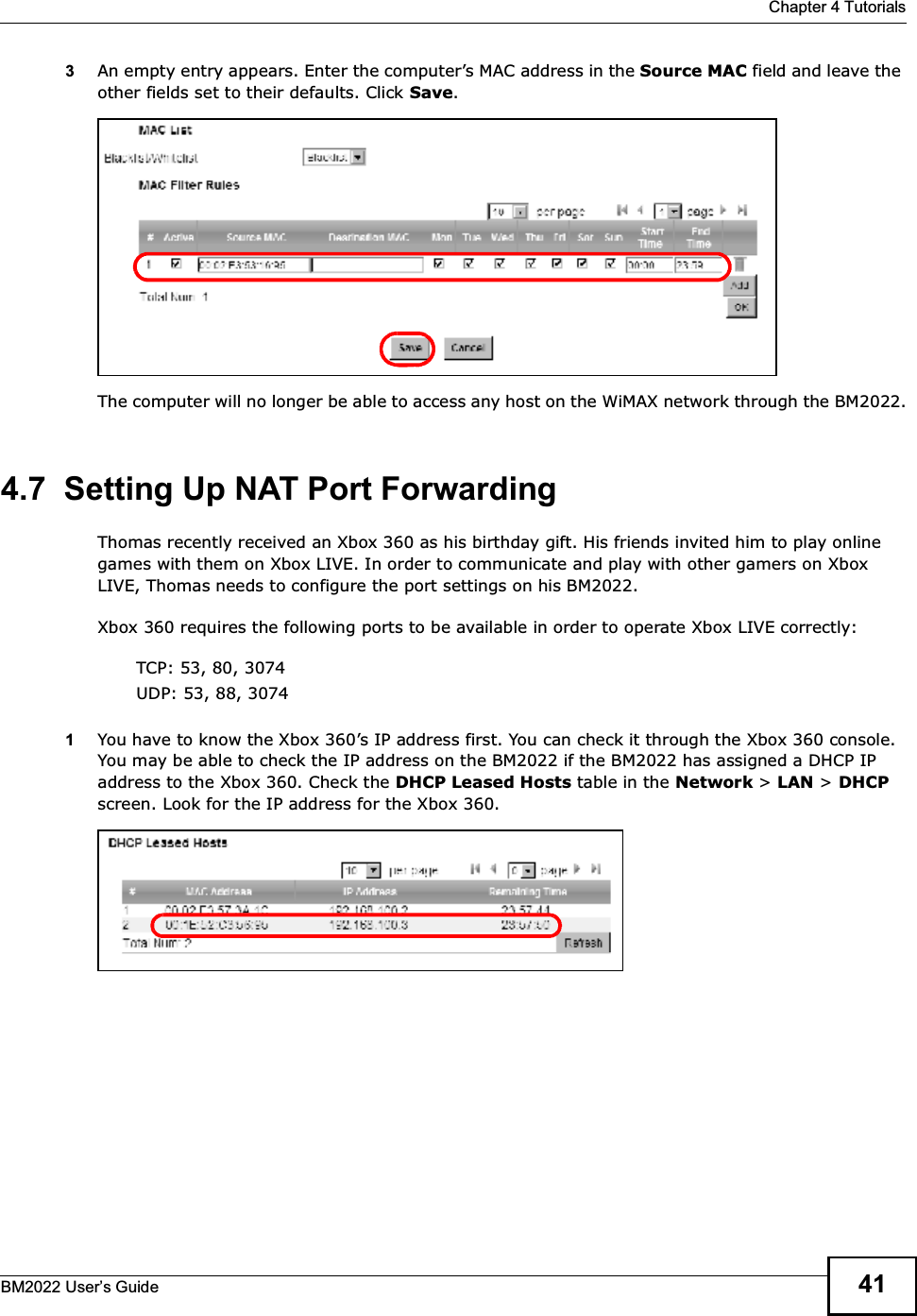
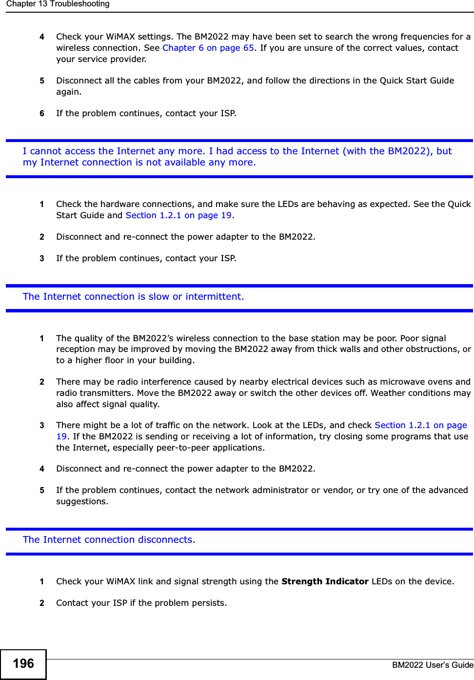
![Chapter 13 TroubleshootingBM2022 Users Guide 1956If the problem continues, contact the network administrator or vendor, or try one of the advanced suggestions.Advanced Suggestions Try to access the BM2022 using another service, such as Telnet. If you can access the BM2022, check the remote management settings and firewall rules to find out why the BM2022 does not respond to HTTP. If your computer is connected wirelessly, use a computer that is connected to a LAN/ETHERNET port.I can see the Login screen, but I cannot log in to the BM2022.1Make sure you have entered the user name and password correctly. The default user name is admin, and the default password is 1234. These fields are case-sensitive, so make sure [Caps Lock] is not on.2You cannot log in to the web configurator while someone is using Telnet to access the BM2022. Log out of the BM2022 in the other session, or ask the person who is logged in to log out.3Disconnect and re-connect the power adapter or cord to the BM2022.4If this does not work, you have to reset the BM2022 to its factory defaults. See Section 12.16 on page 187.I cannot Telnet to the BM2022.See the troubleshooting suggestions for I cannot see or access the Login screen in the web configurator. Ignore the suggestions about your browser.13.3 Internet AccessI cannot access the Internet.1Check the hardware connections, and make sure the LEDs are behaving as expected. See the Quick Start Guide and Section 1.2.1 on page 19.2Make sure you entered your ISP account information correctly in the wizard. These fields are case-sensitive, so make sure [Caps Lock] is not on.3Check your security settings. See Chapter 8 on page 121.](https://usermanual.wiki/MitraStar-Technology/HES209M1H/User-Guide-1574324-Page-190.png)


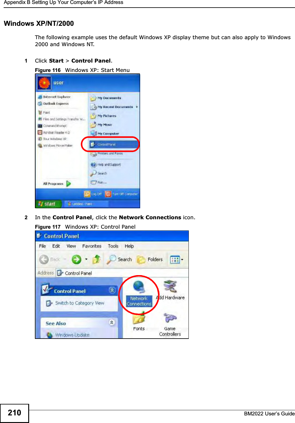
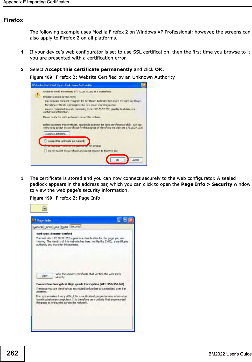
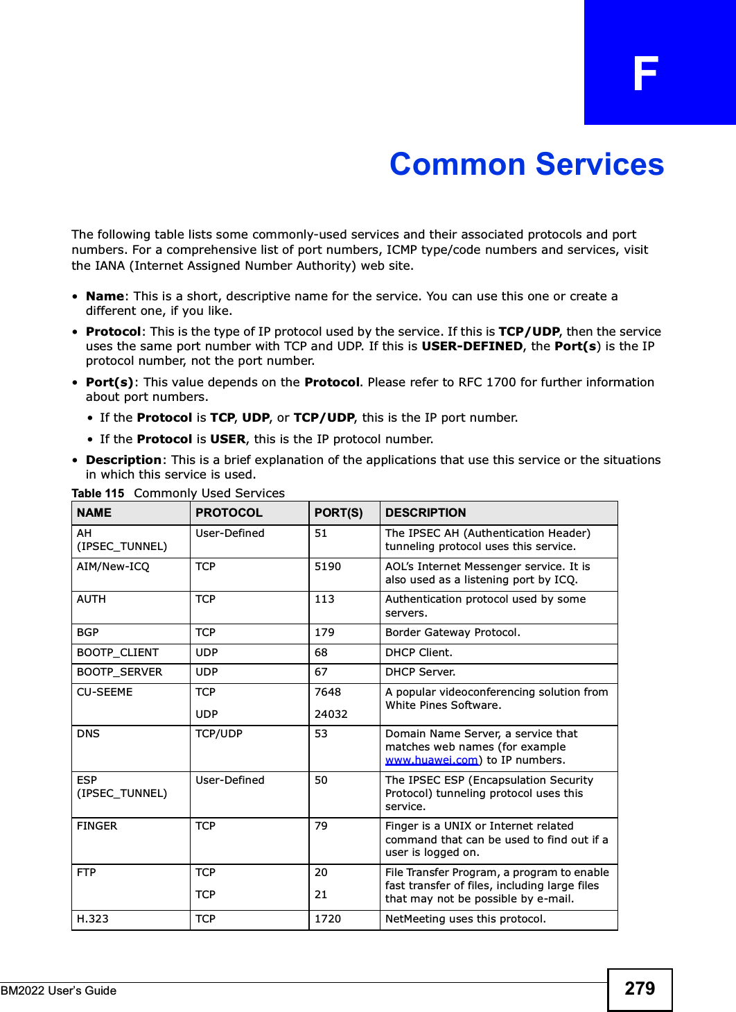
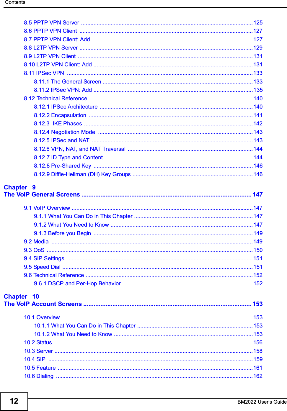
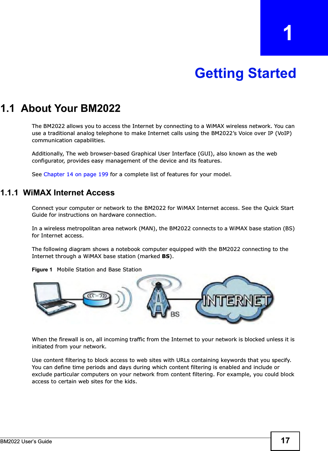
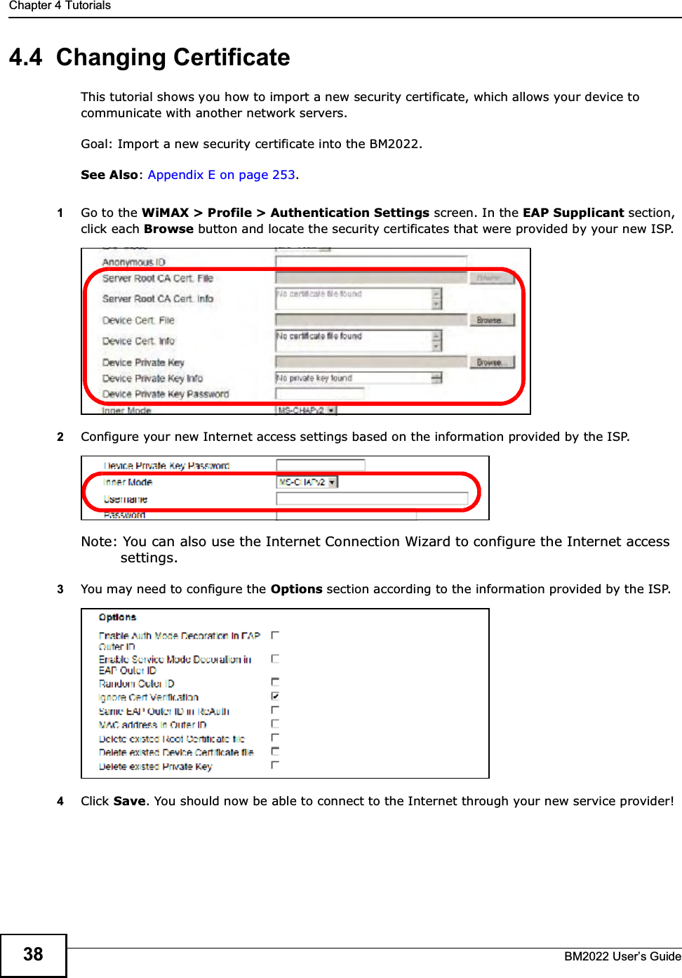
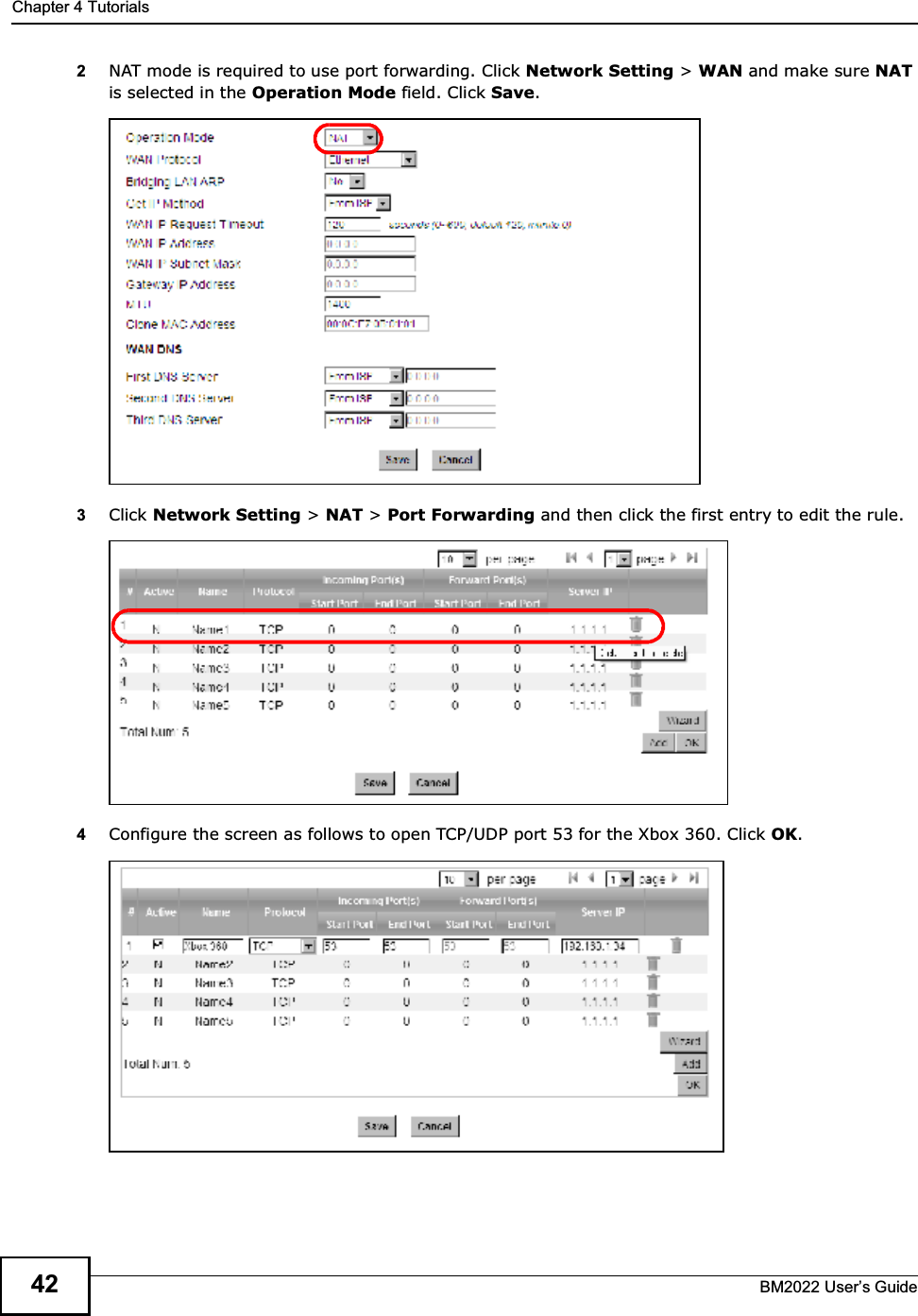
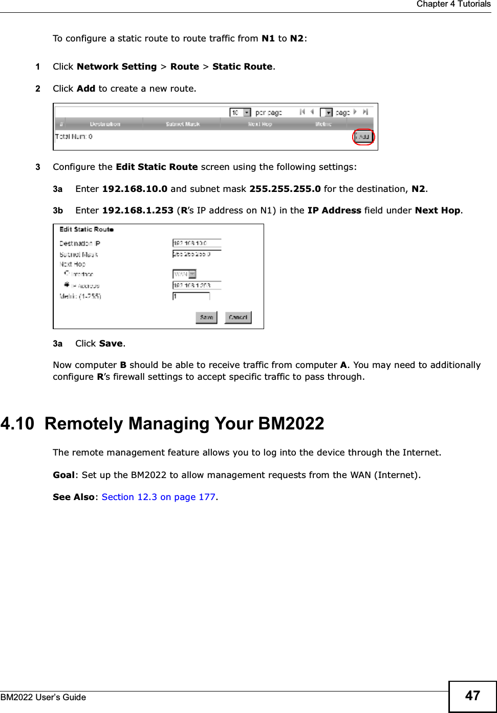
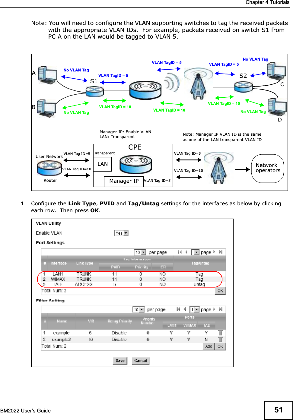
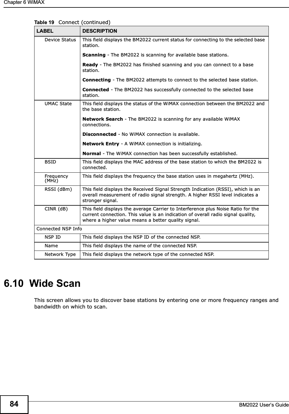
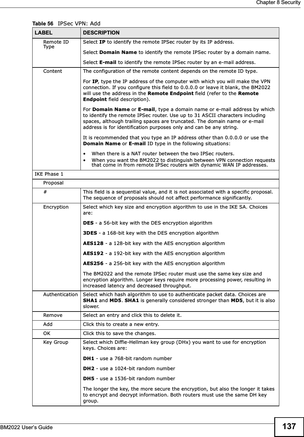
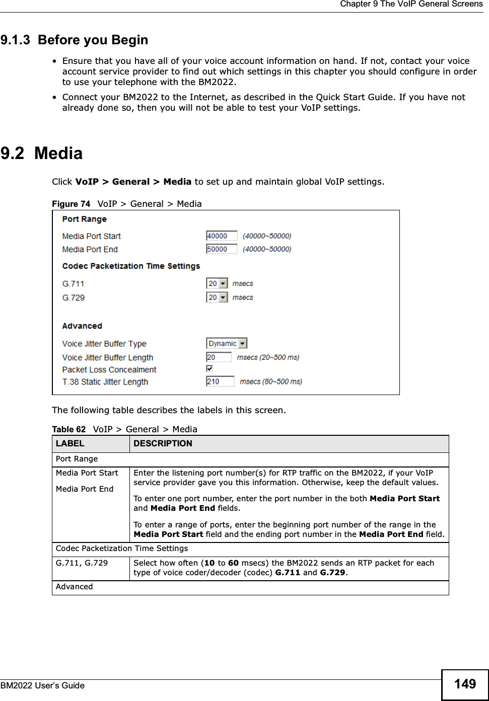
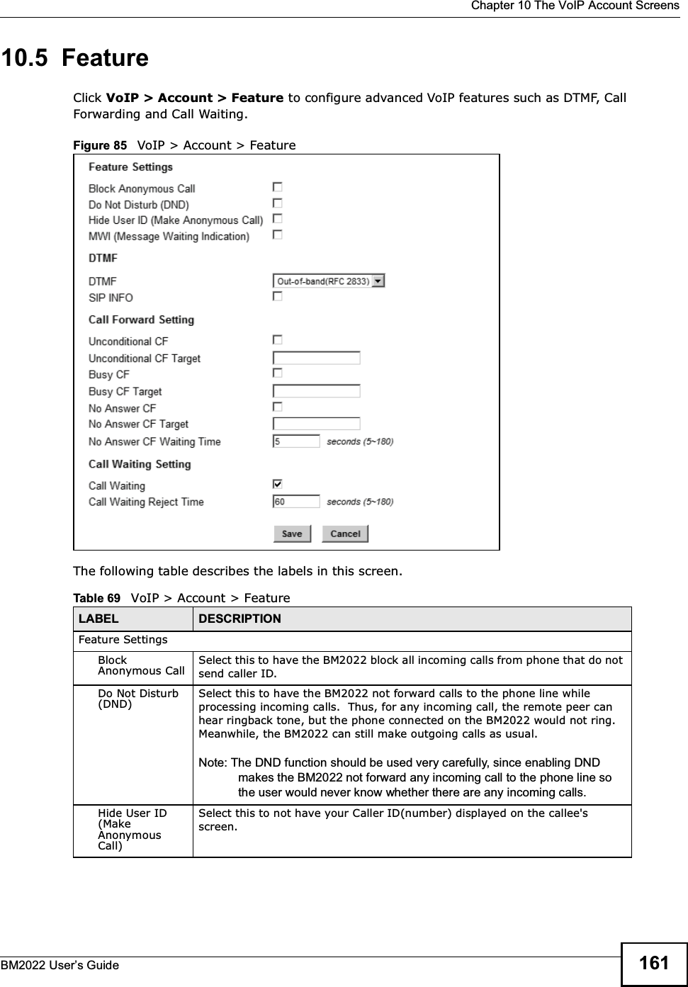
![Appendix B Setting Up Your Computers IP AddressBM2022 Users Guide2125The Internet Protocol TCP/IP Properties window opens.Figure 120 Windows XP: Internet Protocol (TCP/IP) Properties6Select Obtain an IP address automatically if your network administrator or ISP assigns your IP address dynamically.Select Use the following IP Address and fill in the IP address, Subnet mask, and Default gateway fields if you have a static IP address that was assigned to you by your network administrator or ISP. You may also have to enter a Preferred DNS server and an Alternate DNS server, if that information was provided.7Click OK to close the Internet Protocol (TCP/IP) Properties window.Click OK to close the Local Area Connection Properties window.Verifying Settings1Click Start > All Programs > Accessories > Command Prompt.2In the Command Prompt window, type "ipconfig" and then press [ENTER]. You can also go to Start > Control Panel > Network Connections, right-click a network connection, click Status and then click the Support tab to view your IP address and connection information.](https://usermanual.wiki/MitraStar-Technology/HES209M1H/User-Guide-1574324-Page-207.png)
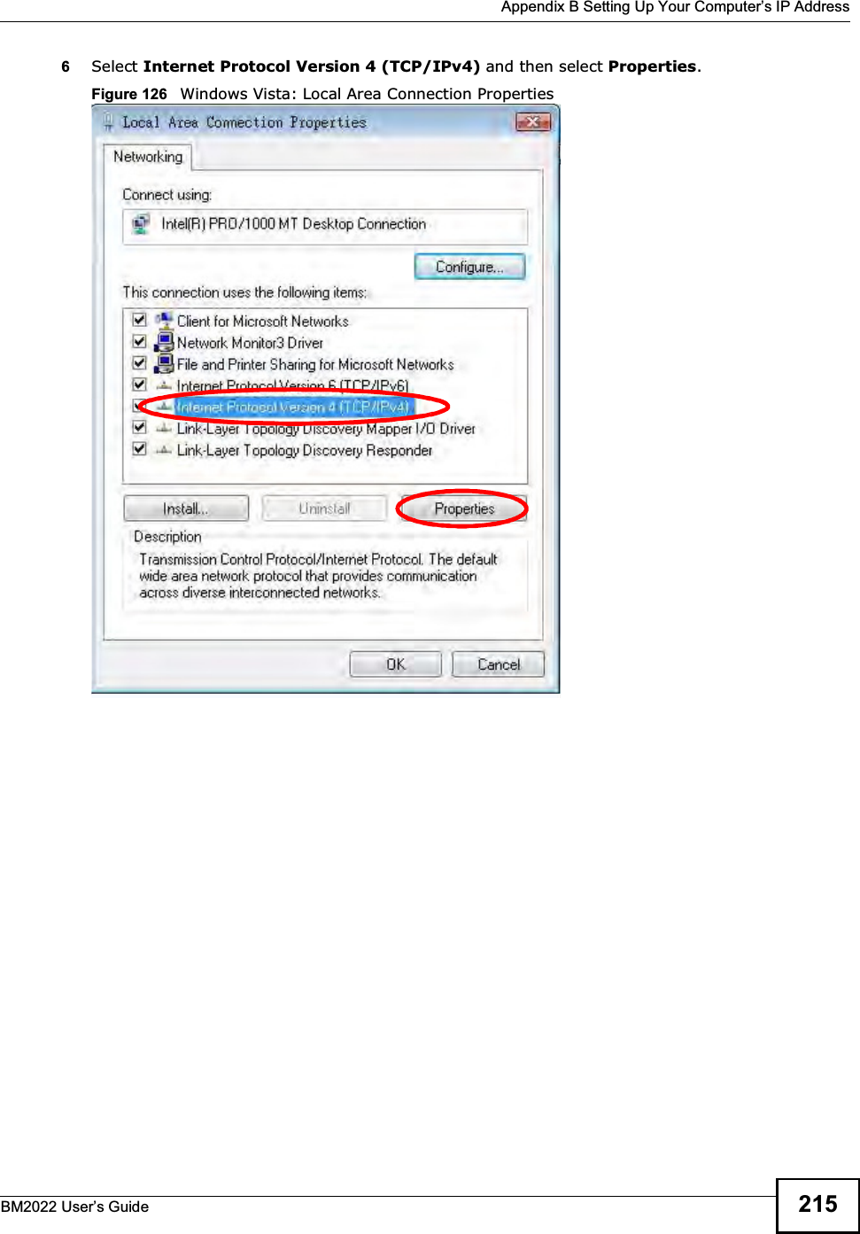
![Appendix B Setting Up Your Computers IP AddressBM2022 Users Guide2167The Internet Protocol Version 4 (TCP/IPv4) Properties window opens.Figure 127 Windows Vista: Internet Protocol Version 4 (TCP/IPv4) Properties8Select Obtain an IP address automatically if your network administrator or ISP assigns your IP address dynamically.Select Use the following IP Address and fill in the IP address, Subnet mask, and Default gateway fields if you have a static IP address that was assigned to you by your network administrator or ISP. You may also have to enter a Preferred DNS server and an Alternate DNS server, if that information was provided.Click Advanced.9Click OK to close the Internet Protocol (TCP/IP) Properties window.Click OK to close the Local Area Connection Properties window.Verifying Settings1Click Start > All Programs > Accessories > Command Prompt.2In the Command Prompt window, type "ipconfig" and then press [ENTER]. You can also go to Start > Control Panel > Network Connections, right-click a network connection, click Status and then click the Support tab to view your IP address and connection information.](https://usermanual.wiki/MitraStar-Technology/HES209M1H/User-Guide-1574324-Page-211.png)