MitraStar Technology HES209M1H WiMAX Indoor VoIP IAD User Manual User s guide
MitraStar Technology Corporation WiMAX Indoor VoIP IAD User s guide
User Manual
www.huawei.com
BM2022
WiMAX IEEE 802.16 Indoor CPE
Copyright 2011
Huawei Technologies Co., LTD.
Firmware Version V2.00
Edition 1, 4/2011
Default Login Details
IP Address: http://192.168.1.1
Username admin
Password 1234
HES-209M1H

About This User's Guide
BM2022 Users Guide 3
About This User's Guide
Intended Audience
This manual is intended for people who want to configure the Huawei BM2022 using the Huawei
Web Configurator. You should have at least a basic knowledge of TCP/IP networking concepts and
topology.
Related Documentation
Quick Start Guide
The Quick Start Guide is designed to help you get up and running right away. It contains
information on setting up your network and configuring for Internet access.
Support Disc
Refer to the included CD for support documents.
Huawei Web Site
Please refer to www.huawei.com for additional support documentation and product certifications.
Document Conventions
Warnings and Notes
These are how warnings and notes are shown in this Users Guide.
Warnings tell you about things that could harm you or your BM2022.
Note: Notes tell you other important information (for example, other things you may
need to configure or helpful tips) or recommendations.
Syntax Conventions
The product(s) described in this book may be referred to as the BM2022, the device, the
system or the product in this Users Guide.
Product labels, screen names, field labels and field choices are all in bold font.
A key stroke is denoted by square brackets and uppercase text, for example, [ENTER] means the
enter or return key on your keyboard.
Enter means for you to type one or more characters and then press the [ENTER] key. Select
or choose means for you to use one of the predefined choices.
A right angle bracket ( > ) within a screen name denotes a mouse click. For example, TOOLS >
Logs > Log Settings means you first click Tools in the navigation panel, then the Logs sub
menu and finally the Log Settings tab to get to that screen.
Units of measurement may denote the metric value or the scientific value. For example, k
for kilo may denote 1000 or 1024, M for mega may denote 1000000 or 1048576 and so
on.
e.g., is a shorthand for for instance, and i.e., means that is or in other words.
About This User's Guide
BM2022 Users Guide
4
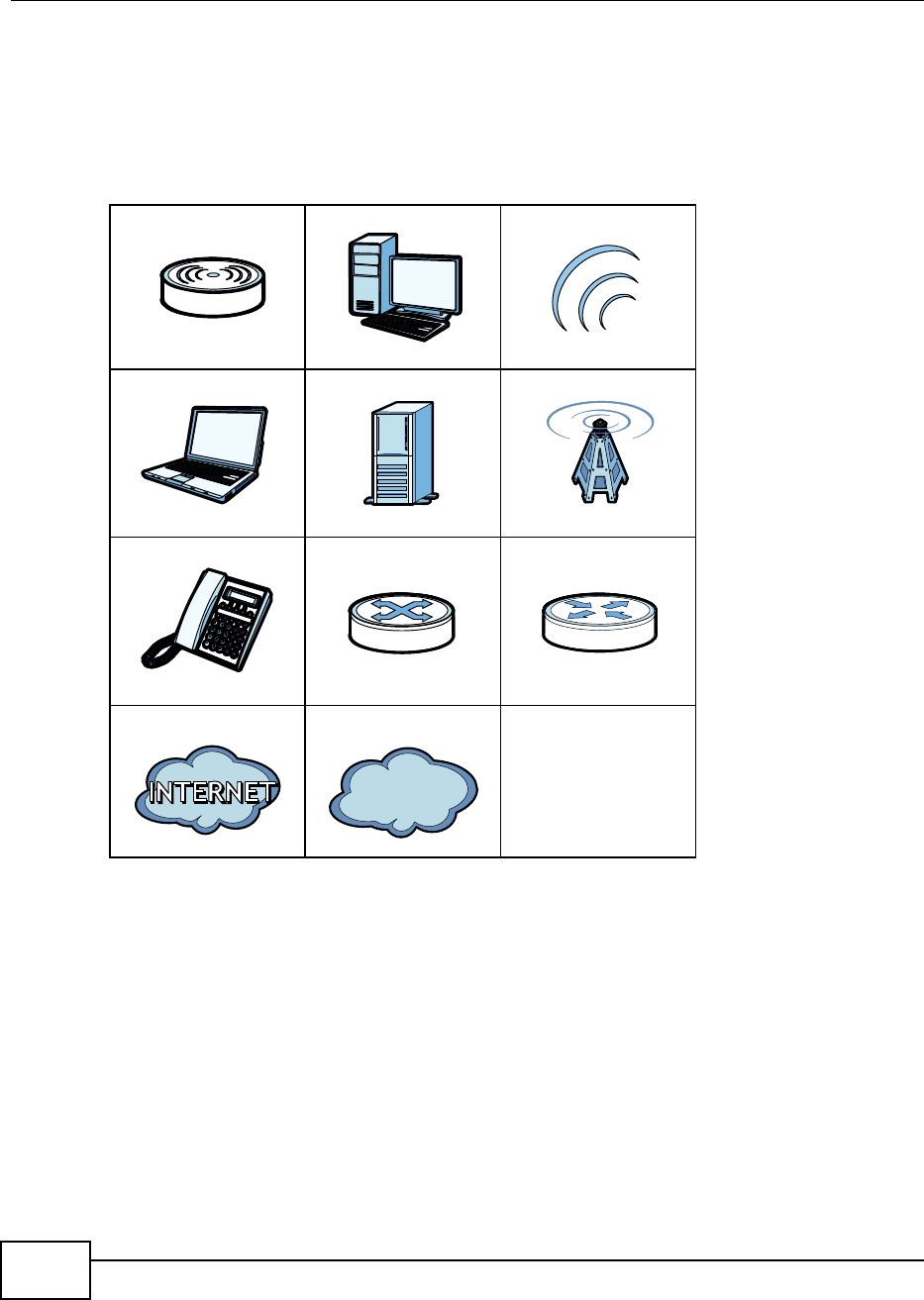
Icons Used in Figures
Figures in this Users Guide may use the following generic icons. The BM2022 icon is not an exact
representation of your product.
Table 1 Common Icons
BM2022 Computer Wireless Signal
Notebook Server Base Station
Telephone Switch Router
Internet Cloud Network Cloud

Safety Warnings
BM2022 Users Guide 5
Safety Warnings
For your safety, be sure to read and follow all warning notices and
instructions.
Do NOT use this product near water, for example, in a wet basement or near a swimming pool.
Do NOT expose your device to dampness, dust or corrosive liquids.
Do NOT store things on the device.
Do NOT install, use, or service this device during a thunderstorm. There is a remote risk of
electric shock from lightning.
Connect ONLY suitable accessories to the device.
Do NOT open the device or unit. Opening or removing covers can expose you to dangerous high
voltage points or other risks. ONLY qualified service personnel should service or disassemble this
device. Please contact your vendor for further information.
Make sure to connect the cables to the correct ports.
Place connecting cables carefully so that no one will step on them or stumble over them.
Always disconnect all cables from this device before servicing or disassembling.
Use ONLY an appropriate power adaptor or cord for your device. Connect it to the right supply
voltage (for example, 110V AC in North America or 230V AC in Europe).
Do NOT remove the plug and connect it to a power outlet by itself; always attach the plug to the
power adaptor first before connecting it to a power outlet.
Do NOT allow anything to rest on the power adaptor or cord and do NOT place the product where
anyone can walk on the power adaptor or cord.
Do NOT use the device if the power adaptor or cord is damaged as it might cause electrocution.
If the power adaptor or cord is damaged, remove it from the device and the power source.
Do NOT attempt to repair the power adaptor or cord. Contact your local vendor to order a new
one.Do not use the device outside, and make sure all the connections are indoors. There is a
remote risk of electric shock from lightning.
Do NOT obstruct the device ventilation slots, as insufficient airflow may harm your device.Use
only No. 26 AWG (American Wire Gauge) or larger telecommunication line cord.
Antenna Warning! This device meets ETSI and FCC certification requirements when using the
included antenna(s). Only use the included antenna(s).
If you wall mount your device, make sure that no electrical lines, gas or water pipes will be
damaged.
Make sure that the cable system is grounded so as to provide some protection against voltage
surges.
Your product is marked with this symbol, which is known as the WEEE mark.
WEEE stands for Waste Electronics and Electrical Equipment. It means that used electrical
and electronic products should not be mixed with general waste. Used electrical and
electronic equipment should be treated separately.

Contents Overview
BM2022 Users Guide 7
Contents Overview
Users Guide ........................................................................................................................... 15
Getting Started ...........................................................................................................................17
Introducing the Web Configurator ..............................................................................................21
Setup Wizard.............................................................................................................................. 27
Tutorials .....................................................................................................................................35
Technical Reference .............................................................................................................. 59
System Status ............................................................................................................................61
WiMAX .......................................................................................................................................65
Network Setting ..........................................................................................................................91
Security ....................................................................................................................................121
The VoIP General Screens ......................................................................................................147
The VoIP Account Screens ......................................................................................................153
The VoIP Line Screens ............................................................................................................167
Maintenance .............................................................................................................................171
Troubleshooting .......................................................................................................................193
Product Specifications ..............................................................................................................199

Contents
BM2022 Users Guide 9
Contents
About This User's Guide.......................................................................................................... 3
Safety Warnings........................................................................................................................ 5
Contents Overview .................................................................................................................. 7
Contents .................................................................................................................................... 9
Part I: Users Guide ................................................................................15
Chapter 1
Getting Started ........................................................................................................................ 17
1.1 About Your BM2022 .............................................................................................................17
1.1.1 WiMAX Internet Access ..............................................................................................17
1.1.2 Make Calls via Internet Telephony Service Provider ..................................................18
1.2 BM2022 Hardware ...............................................................................................................18
1.2.1 LEDs ...........................................................................................................................19
1.3 Good Habits for Managing the BM2022 ...............................................................................20
Chapter 2
Introducing the Web Configurator ........................................................................................ 21
2.1 Overview ..............................................................................................................................21
2.1.1 Accessing the Web Configurator ................................................................................21
2.1.2 The Reset Button ........................................................................................................22
2.1.3 Saving and Canceling Changes .................................................................................22
2.1.4 Working with Tables ....................................................................................................23
2.2 The Main Screen ..................................................................................................................23
Chapter 3
Setup Wizard ........................................................................................................................... 27
3.1 Overview ..............................................................................................................................27
3.1.1 Welcome to the Setup Wizard ....................................................................................27
3.1.2 LAN Settings ...............................................................................................................28
3.1.3 WiMAX Frequency Settings ........................................................................................29
3.1.4 WiMAX Authentication Settings ..................................................................................30
3.1.5 VoIP Settings ..............................................................................................................32
3.1.6 Setup Complete ..........................................................................................................34

Contents
BM2022 Users Guide
10
Chapter 4
Tutorials................................................................................................................................... 35
4.1 Overview ..............................................................................................................................35
4.2 WiMAX Connection Settings ................................................................................................35
4.3 Configuring LAN DHCP ........................................................................................................36
4.4 Changing Certificate .............................................................................................................38
4.5 Blocking Web Access ...........................................................................................................39
4.6 Configuring the MAC Address Filter .....................................................................................39
4.7 Setting Up NAT Port Forwarding ..........................................................................................41
4.8 Access the BM2022 Using DDNS ........................................................................................43
4.8.1 Registering a DDNS Account on www.dyndns.org .....................................................44
4.8.2 Configuring DDNS on Your BM2022 ..........................................................................44
4.8.3 Testing the DDNS Setting ...........................................................................................45
4.9 Configuring Static Route for Routing to Another Network ....................................................45
4.10 Remotely Managing Your BM2022 ....................................................................................47
4.11 VLAN Configuration Examples ...........................................................................................48
4.11.1 Scenario 1 .................................................................................................................49
4.11.2 Scenario 2 .................................................................................................................50
4.11.3 Scenario 3 .................................................................................................................52
4.11.4 Scenario 4 .................................................................................................................54
4.11.5 Scenario 5 .................................................................................................................56
Part II: Technical Reference...................................................................59
Chapter 5
System Status ......................................................................................................................... 61
5.1 Overview ..............................................................................................................................61
5.2 System Status ......................................................................................................................61
Chapter 6
WiMAX ..................................................................................................................................... 65
6.1 Overview ..............................................................................................................................65
6.1.1 What You Need to Know .............................................................................................65
6.2 Connection Settings .............................................................................................................68
6.3 Frequency Settings ..............................................................................................................70
6.4 Authentication Settings ........................................................................................................72
6.5 Channel Plan Settings ..........................................................................................................75
6.6 CAPL Settings ......................................................................................................................77
6.6.1 CAPL Settings: Add ....................................................................................................78
6.7 RAPL Settings ......................................................................................................................79
6.8 Home NSP Settings .............................................................................................................80

Contents
BM2022 Users Guide 11
6.9 Connect ................................................................................................................................81
6.10 Wide Scan ..........................................................................................................................84
6.11 Link Status ..........................................................................................................................86
6.12 Link Statistics .....................................................................................................................87
6.13 Connection Info ..................................................................................................................88
6.14 Service Flow .......................................................................................................................89
Chapter 7
Network Setting ...................................................................................................................... 91
7.1 Overview ..............................................................................................................................91
7.1.1 What You Need to Know .............................................................................................91
7.2 WAN .....................................................................................................................................94
7.3 PPPoE ..................................................................................................................................96
7.4 GRE .....................................................................................................................................97
7.5 EtherIP .................................................................................................................................98
7.6 IP ..........................................................................................................................................98
7.7 DHCP ...................................................................................................................................99
7.8 Static Route ........................................................................................................................100
7.9 Static Route Add ................................................................................................................101
7.10 RIP ...................................................................................................................................101
7.11 Port Forwarding ................................................................................................................103
7.11.1 Port Forwarding Wizard ..........................................................................................104
7.12 Port Trigger ......................................................................................................................105
7.12.1 Port Trigger Wizard .................................................................................................106
7.12.2 Trigger Port Forwarding Example ...........................................................................107
7.13 DMZ .................................................................................................................................107
7.14 ALG ..................................................................................................................................108
7.15 QoS ..................................................................................................................................109
7.16 UPnP ................................................................................................................................109
7.16.1 Installing UPnP in Windows XP ..............................................................................110
7.16.2 Web Configurator Easy Access .............................................................................. 114
7.17 VLAN ................................................................................................................................ 115
7.18 DDNS ............................................................................................................................... 117
7.19 IGMP Proxy ...................................................................................................................... 118
7.20 Content Filter .................................................................................................................... 119
Chapter 8
Security.................................................................................................................................. 121
8.1 Overview ............................................................................................................................121
8.1.1 What You Need to Know ...........................................................................................121
8.2 IP Filter ...............................................................................................................................121
8.3 MAC Filter ..........................................................................................................................122
8.4 DDOS .................................................................................................................................123

Contents
BM2022 Users Guide
12
8.5 PPTP VPN Server ..............................................................................................................125
8.6 PPTP VPN Client ...............................................................................................................127
8.7 PPTP VPN Client: Add .......................................................................................................127
8.8 L2TP VPN Server ...............................................................................................................129
8.9 L2TP VPN Client ................................................................................................................131
8.10 L2TP VPN Client: Add ......................................................................................................131
8.11 IPSec VPN .......................................................................................................................133
8.11.1 The General Screen ................................................................................................133
8.11.2 IPSec VPN: Add ......................................................................................................135
8.12 Technical Reference .........................................................................................................140
8.12.1 IPSec Architecture ..................................................................................................140
8.12.2 Encapsulation .........................................................................................................141
8.12.3 IKE Phases ............................................................................................................142
8.12.4 Negotiation Mode ...................................................................................................143
8.12.5 IPSec and NAT .......................................................................................................143
8.12.6 VPN, NAT, and NAT Traversal ................................................................................144
8.12.7 ID Type and Content ...............................................................................................144
8.12.8 Pre-Shared Key ......................................................................................................146
8.12.9 Diffie-Hellman (DH) Key Groups .............................................................................146
Chapter 9
The VoIP General Screens ................................................................................................... 147
9.1 VoIP Overview ....................................................................................................................147
9.1.1 What You Can Do in This Chapter ............................................................................147
9.1.2 What You Need to Know ...........................................................................................147
9.1.3 Before you Begin ......................................................................................................149
9.2 Media .................................................................................................................................149
9.3 QoS ....................................................................................................................................150
9.4 SIP Settings .......................................................................................................................151
9.5 Speed Dial ..........................................................................................................................151
9.6 Technical Reference ...........................................................................................................152
9.6.1 DSCP and Per-Hop Behavior ...................................................................................152
Chapter 10
The VoIP Account Screens .................................................................................................. 153
10.1 Overview ..........................................................................................................................153
10.1.1 What You Can Do in This Chapter ..........................................................................153
10.1.2 What You Need to Know .........................................................................................153
10.2 Status ...............................................................................................................................156
10.3 Server ...............................................................................................................................158
10.4 SIP ...................................................................................................................................159
10.5 Feature .............................................................................................................................161
10.6 Dialing ..............................................................................................................................162

Contents
BM2022 Users Guide 13
10.7 FAX ..................................................................................................................................163
10.8 Technical Reference .........................................................................................................163
10.8.1 SIP Call Progression with Session Timer ...............................................................163
10.8.2 SIP Client Server ....................................................................................................166
Chapter 11
The VoIP Line Screens ......................................................................................................... 167
11.1 Overview ..........................................................................................................................167
11.1.1 What You Can Do in This Chapter ..........................................................................167
11.1.2 What You Need to Know .........................................................................................167
11.2 Phone ...............................................................................................................................168
11.3 Voice .................................................................................................................................168
11.4 Region ..............................................................................................................................169
Chapter 12
Maintenance .......................................................................................................................... 171
12.1 Overview ..........................................................................................................................171
12.1.1 What You Need to Know .........................................................................................171
12.2 Password .........................................................................................................................176
12.3 HTTP ................................................................................................................................177
12.4 Telnet ................................................................................................................................177
12.5 SSH ..................................................................................................................................178
12.6 SNMP ...............................................................................................................................179
12.7 CWMP ..............................................................................................................................179
12.8 OMA-DM ..........................................................................................................................181
12.9 Date ..................................................................................................................................183
12.10 Time Zone ......................................................................................................................183
12.11 Upgrade File ...................................................................................................................184
12.11.1 The Firmware Upload Process .............................................................................184
12.12 Upgrade Link ..................................................................................................................185
12.13 CWMP Upgrade .............................................................................................................185
12.14 Backup ...........................................................................................................................186
12.15 Restore ...........................................................................................................................186
12.15.1 The Restore Configuration Process .....................................................................187
12.16 Factory Defaults .............................................................................................................187
12.17 Log Setting .....................................................................................................................188
12.18 Log Display ....................................................................................................................188
12.19 Ping Test ........................................................................................................................189
12.20 Traceroute Test ..............................................................................................................190
12.21 About ..............................................................................................................................190
12.22 Reboot ............................................................................................................................191
Chapter 13
Troubleshooting.................................................................................................................... 193

Contents
BM2022 Users Guide
14
13.1 Power, Hardware Connections, and LEDs .......................................................................193
13.2 BM2022 Access and Login ..............................................................................................194
13.3 Internet Access ................................................................................................................195
13.4 Reset the BM2022 to Its Factory Defaults .......................................................................197
13.4.1 Pop-up Windows, JavaScript and Java Permissions .............................................197
Chapter 14
Product Specifications.........................................................................................................199
Appendix A WiMAX Security ............................................................................................... 205
Appendix B Setting Up Your Computers IP Address .......................................................... 209
Appendix C Pop-up Windows, JavaScript and Java Permissions ....................................... 233
Appendix D IP Addresses and Subnetting........................................................................... 243
Appendix E Importing Certificates ....................................................................................... 253
Appendix F Common Services ............................................................................................ 279
Index ...................................................................................................................................... 283

15
PART I
Users Guide
BM2022 Users Guide 17
CHAPTER 1
Getting Started
1.1 About Your BM2022
The BM2022 allows you to access the Internet by connecting to a WiMAX wireless network. You can
use a traditional analog telephone to make Internet calls using the BM2022s Voice over IP (VoIP)
communication capabilities.
Additionally, The web browser-based Graphical User Interface (GUI), also known as the web
configurator, provides easy management of the device and its features.
See Chapter 14 on page 199 for a complete list of features for your model.
1.1.1 WiMAX Internet Access
Connect your computer or network to the BM2022 for WiMAX Internet access. See the Quick Start
Guide for instructions on hardware connection.
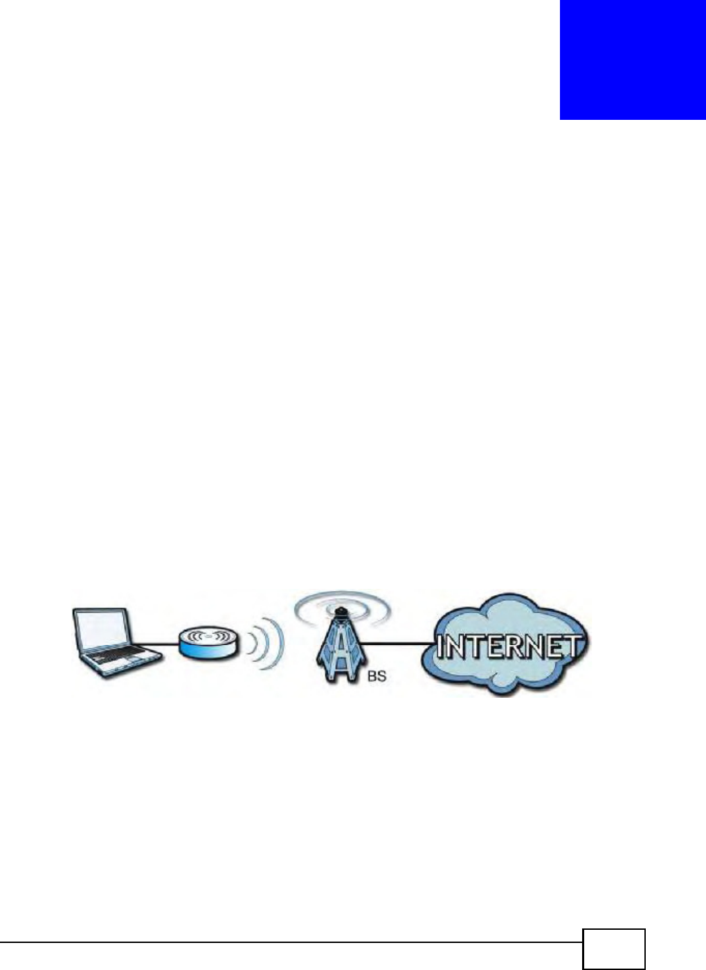
In a wireless metropolitan area network (MAN), the BM2022 connects to a WiMAX base station (BS)
for Internet access.
The following diagram shows a notebook computer equipped with the BM2022 connecting to the
Internet through a WiMAX base station (marked BS).
Figure 1 Mobile Station and Base Station
When the firewall is on, all incoming traffic from the Internet to your network is blocked unless it is
initiated from your network.
Use content filtering to block access to web sites with URLs containing keywords that you specify.
You can define time periods and days during which content filtering is enabled and include or
exclude particular computers on your network from content filtering. For example, you could block
access to certain web sites for the kids.
Chapter 1 Getting Started
BM2022 Users Guide
18
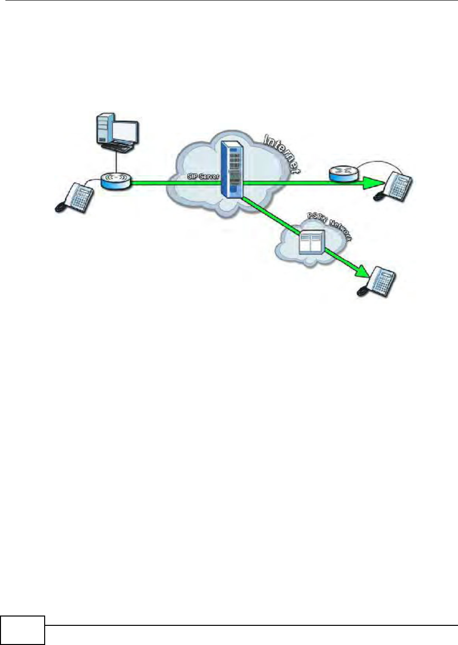
1.1.2 Make Calls via Internet Telephony Service Provider
In a home or small office environment, you can use the BM2022 to make and receive the following
type of VoIP telephone calls:
Calls via a VoIP service provider - The BM2022 sends your call to a VoIP service providers SIP
server which forwards your calls to either VoIP or PSTN phones.
Figure 2 Calls via VoIP Service Provider
1.2 BM2022 Hardware
Follow the instructions in the Quick Start Guide to make hardware connections.
Chapter 1 Getting Started
BM2022 Users Guide 19
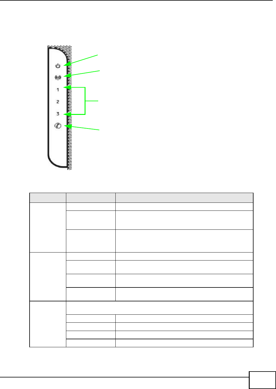
1.2.1 LEDs
The following figure shows the LEDs (lights) on the BM2022.
Figure 3 The BM2022s LEDs
The following table describes your BM2022s LEDs (from top to bottom).
Table 2 The BM2022 LEDs behavior
LED STATE DESCRIPTION
Power Off The BM2022 is not receiving power.
Red The BM2022 is receiving power but has been unable to start
up correctly or is not receiving enough power. See the
Troubleshooting section for more information.
Green Solid: The BM2022 is receiving power and functioning
correctly.
Flashing: the device is self-testing (startup)
WiMAX Link Off The BM2022 is not connected to a wireless (WiMAX) network.
Green The BM2022 is successfully connected to a wireless (WiMAX)
network.
Green (Blinking
Slowly)
The BM2022 is searching for a wireless (WiMAX) network.
Green (Blinking
Quickly)
The BM2022 has found a wireless (WiMAX) network and is
connecting.
Signal
Strength
Indicator
The Strength Indicator LEDs display the Interference-plus-Noise Ratio (CINR) of the
wireless (WiMAX) connection.
No Signal LEDs On Ths signal strength is less than -90dBm
Signal 1 On The signal strength is between -89dBm and -80dBm.
Signal 1 and 2 On The signal strength is between -79dBm and -70dBm.
Signal 1, 2 and 3 On The signal strength is greater than or equal to -69dBm.
STRENGTH
INDICATORS
VOICE
LED
POWER
LED
SIGNAL
WIMAX
LINK

Chapter 1 Getting Started
BM2022 Users Guide
20
1.3 Good Habits for Managing the BM2022
Do the following things regularly to make the BM2022 more secure and to manage the BM2022
more effectively.
Change the password. Use a password thats not easy to guess and that consists of different
types of characters, such as numbers and letters.
Write down the password and put it in a safe place.
Back up the configuration (and make sure you know how to restore it). Restoring an earlier
working configuration may be useful if the BM2022 becomes unstable or even crashes. If you
forget your password, you will have to reset the BM2022 to its factory default settings. If you
backed up an earlier configuration file, you would not have to totally re-configure the BM2022.
You could simply restore your last configuration.
Voice Off No SIP account is registered, or the BM2022 is not receiving
power.
Green A SIP account is registered.
Green (Blinking) A SIP account is registered, and the phone attached to the
VoIP port is in use (off the hook).
Yellow A SIP account is registered and has a voice message on the
SIP server.
Yellow (Blinking) A SIP account is registered and has a voice message on the
SIP server, and the phone attached to the VoIP port is in use
(off the hook).
Table 2 The BM2022 LEDs behavior
LED STATE DESCRIPTION
BM2022 Users Guide 21
CHAPTER 2
Introducing the Web Configurator
2.1 Overview
The Web Configurator is an HTML-based management interface that allows easy device set up and
management via any web browser that supports: HTML 4.0, CSS 2.0, and JavaScript 1.5, and
higher. The recommended screen resolution for using the web configurator is 1024 by 768 pixels
and 16-bit color, or higher.
In order to use the Web Configurator you need to allow:
Web browser pop-up windows from your device. Web pop-up blocking is enabled by default in
many operating systems and web browsers.
JavaScript (enabled by default in most web browsers).
Java permissions (enabled by default in most web browsers).
See the Appendix C on page 233 for more information on configuring your web browser.
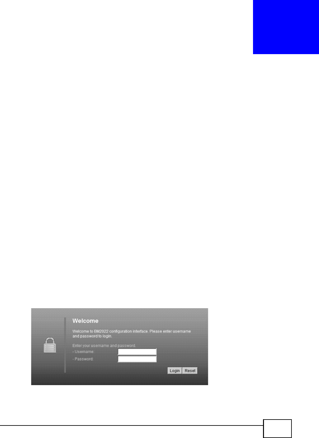
2.1.1 Accessing the Web Configurator
1Make sure your BM2022 hardware is properly connected (refer to the Quick Start Guide for more
information).
2Launch your web browser.
3Enter 192.168.1.1" as the URL.
4A login screen displays. Enter the default Username (admin) and Password (1234), then click
Login.
Figure 4 Login screen
Note: For security reasons, the BM2022 automatically logs you out if you do not use the
Web Configurator for five minutes. If this happens, log in again.
Chapter 2 Introducing the Web Configurator
BM2022 Users Guide
22
2.1.2 The Reset Button
If you forget your password or cannot access the Web Configurator, you will need to use the Reset
button to reload the factory-default configuration file. This means that you will lose all
configurations that you had previously and the password will be reset to 1234.
2.1.2.1 Using The Reset Button
1Make sure the Power light is on (not blinking).
2To set the device back to the factory default settings, press the Reset button for five seconds or
until all LED lights blink one time, then release it. The device restarts when the defaults have been
restored.
3Reconfigure the BM2022 following the steps in your Quick Start Guide.
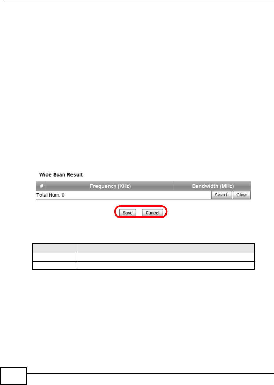
2.1.3 Saving and Canceling Changes
All screens to which you can make configuration changes must be saved before those changes can
go into effect. If you make a mistake while configuring the BM2022, you can cancel those changes
and start over.
Figure 5 Saving and Canceling Changes
This screen contains the following fields:
Note: If you make changes to a page but do not save before switching to another page or
exiting the Web Configurator, those changes are discarded.
Table 3 Saving and Canceling Changes
LABEL DESCRIPTION
Save Click this to save your changes.
Cancel Click this to restore the settings on this page to their last saved values.
Chapter 2 Introducing the Web Configurator
BM2022 Users Guide 23
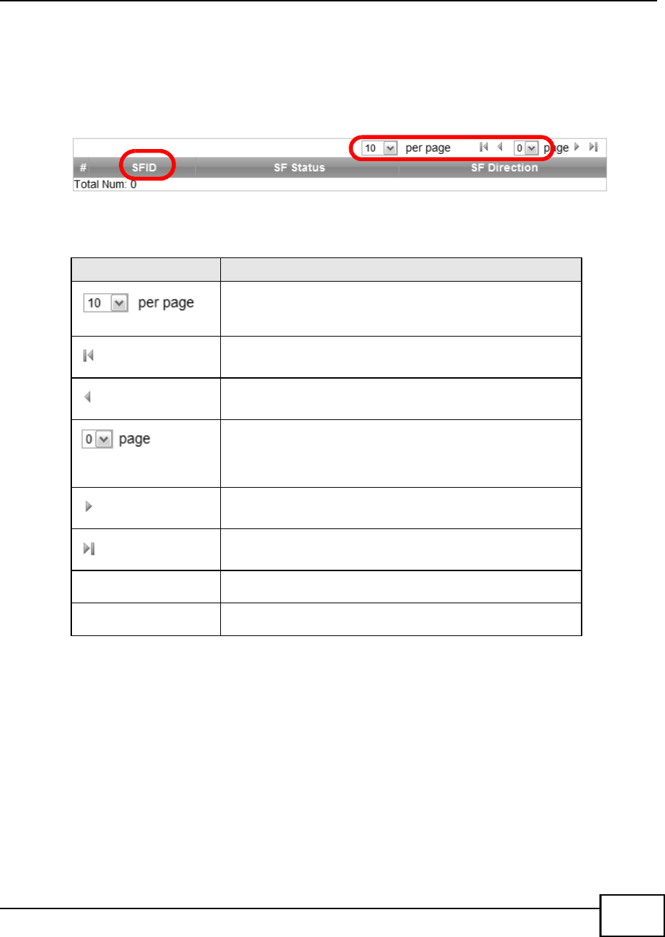
2.1.4 Working with Tables
Many screens in the BM2022 contain tables to provide information or additional configuration
options.
Figure 6 Tables Example
This screen contains the following fields:
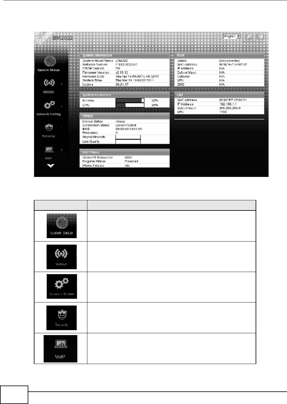
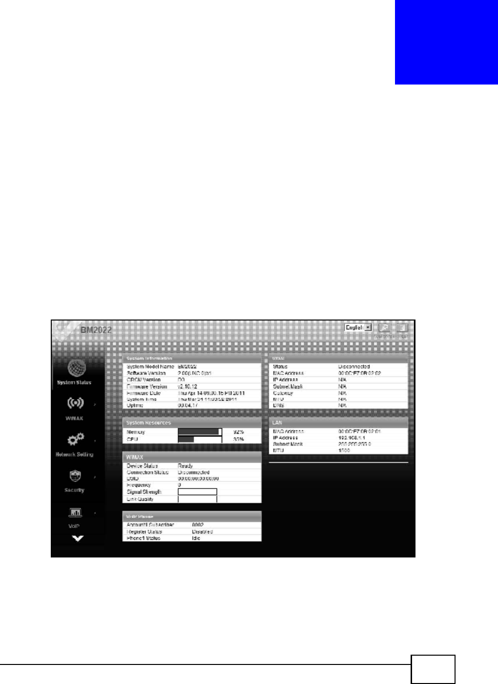
2.2 The Main Screen
When you first log into the Web Configurator, the Main screen appears. Here you can view a
summary of your BM2022s connection status. This is also the default home page for the Web
Configurator and it contains conveniently-placed shortcuts to all of the other screens.
Note: Some features in the Web Configurator may not be available depending on your
firmware version and/or configuration.
Note: The available menus and screens vary depending on the user account you use for
login.
Table 4 Saving and Canceling Changes
LABEL DESCRIPTION
Items per Page
This displays the number of items displayed per table page. Use
the menu to change this value.
First Page
Click this to go to the first page in the table.
Previous Page
Click this to go to the previous page in the table.
Page Indicator / Jump to Page
This indicates which page is currently displayed in the table. Use
the menu to jump to another page. You can only jump to other
pages if those pages exist.
Next Page
Click this to go to the previous page in the table.
Last Page
Click this to go to the last page in the table.
# This indicates an items position in the table. It has no bearing on
that items importance or lack there of.
Total Num This indicates the total number of items in the table, including
items on pages that are not visible.
Chapter 2 Introducing the Web Configurator
BM2022 Users Guide
24
Figure 7 Main Screen
The following table describes the icons in this screen.
Table 5 Main > Icons
ICON DESCRIPTION
System Status
Click this to open the Main screen, which shows your BM2022 status and
other information.
WiMAX
Click this to open the WiMAX menu, which gives you options for
configuring your WiMAX settings.
Network Setting
Click this to open the Network menu, which gives you options for
configuring your network settings.
Security
Click this to open the Security menu, which gives you options for
configuring your firewall and security settings.
VoIP
Click this icon to open the VoIP menu, which gives you options on how
to use the device to make phone calls.
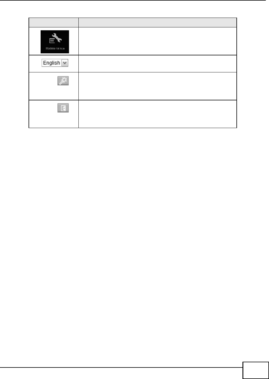
Chapter 2 Introducing the Web Configurator
BM2022 Users Guide 25
Maintenance
Click this to open the Maintenance menu, which gives you options for
maintaining your BM2022 and performing basic network connectivity
tests.
Language
Use this menu to select the Web Configurators language.
Setup Wizard
Click this to open the Setup Wizard, where you can configure the most
essential settings for your BM2022 to work.
Logout
Click this to log out of the Web Configurator.
Table 5 Main > Icons (continued)
ICON DESCRIPTION

Chapter 2 Introducing the Web Configurator
BM2022 Users Guide
26
BM2022 Users Guide 27
CHAPTER 3
Setup Wizard
3.1 Overview
This chapter provides information on the Huawei Setup Wizard. The wizard guides you through
several steps for configuring your network settings.
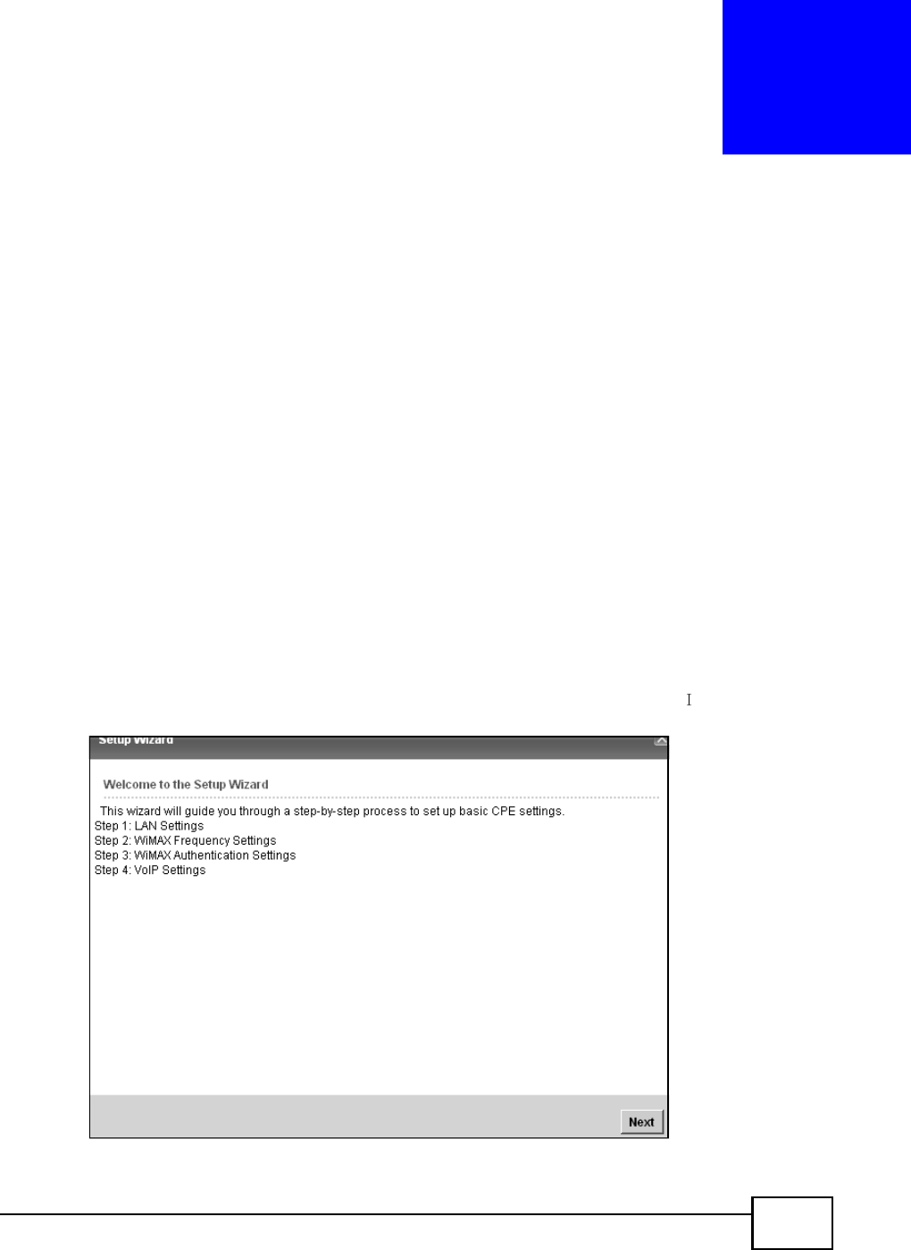
3.1.1 Welcome to the Setup Wizard
This screen provides a quick summary of the configuration tasks the wizard helps you to perform.
They are:
1Set up your Local Area Network (LAN) options, which determine how the devices in your home or
office connect to the BM2022.
2Set up your BM2022s broadcast frequency, which is the radio channel it uses to communicate with
the ISPs base station.
3Set up your BM2022s login options, which are used to connect your LAN to the ISPs network and
verify your account.
4Set up your BM2022s VoIP Settings, which will allow you to make calls over the nternet.
Figure 8 Setup Wizard > Welcome
Chapter 3 Setup Wizard
BM2022 Users Guide
28
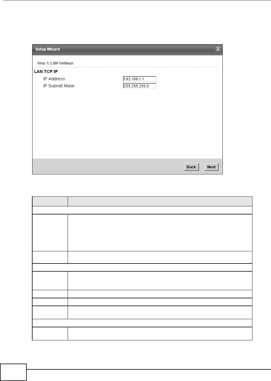
3.1.2 LAN Settings
The LAN Settings screen allows you to configure your local network options.
Figure 9 Setup Wizard > LAN Settings
The following table describes the labels in this screen.
Table 6 Setup Wizard > LAN Settings
LABEL DESCRIPTION
LAN TCP/IP
IP Address Enter the IP address of the BM2022 on the LAN.
Note: This field is the IP address you use to access the BM2022 on the LAN. If the
web configurator is running on a computer on the LAN, you lose access to it as
soon as you change this field. You can access the web configurator again by
typing the new IP address in the browser.
IP Subnet
Mask
Enter the subnet mask of the LAN.
DHCP Server
Enable Select this if you want the BM2022 to be the DHCP server on the LAN. As a DHCP
server, the BM2022 assigns IP addresses to DHCP clients on the LAN and provides
the subnet mask and DNS server information.
Start IP Enter the IP address from which the BM2022 begins allocating IP addresses.
End IP Enter the IP address at which the BM2022 stops allocating IP addresses.
Lease
Time
Enter the duration in minutes before the device requests a new IP address from the
DHCP server.
DNS Server assigned by DHCP Server
First DNS
Server
Specify the first IP address of three DNS servers that the network can use. The
BM2022 provides these IP addresses to DHCP clients.
Chapter 3 Setup Wizard
BM2022 Users Guide 29
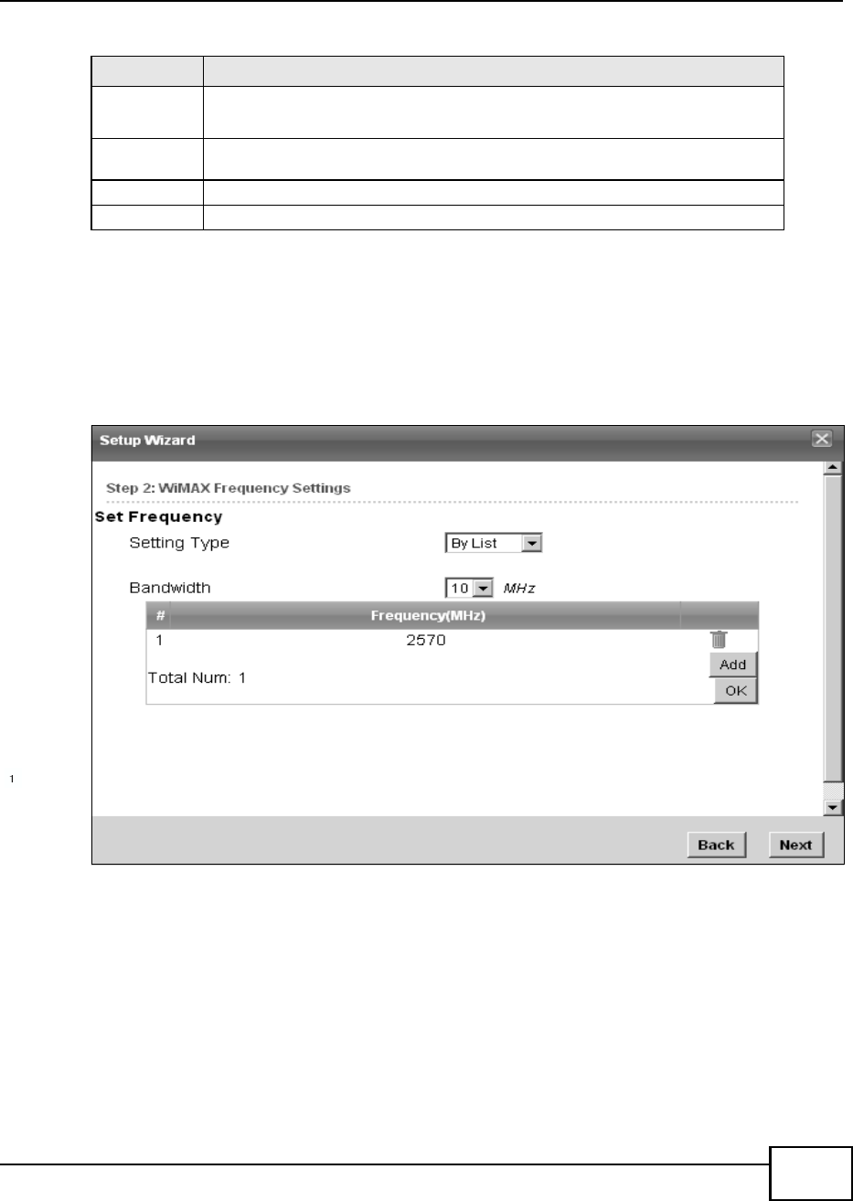
3.1.3 WiMAX Frequency Settings
The WiMAX Frequency Settings screen allows you to configure the broadcast radio frequency used
by the BM2022.
Note: These settings should be provided by your ISP.
Figure 10 Setup Wizard > WiMAX Frequency Settings
Second
DNS
Server
Specify the second IP address of three DNS servers that the network can use. The
BM2022 provides these IP addresses to DHCP clients.
Third DNS
Server
Specify the third IP address of three DNS servers that the network can use. The
BM2022 provides these IP addresses to DHCP clients.
Back Click to display the previous screen.
Next Click to proceed to the next screen.
Table 6 Setup Wizard > LAN Settings (continued)
LABEL DESCRIPTION

Chapter 3 Setup Wizard
BM2022 Users Guide
30
The following table describes the labels in this screen.
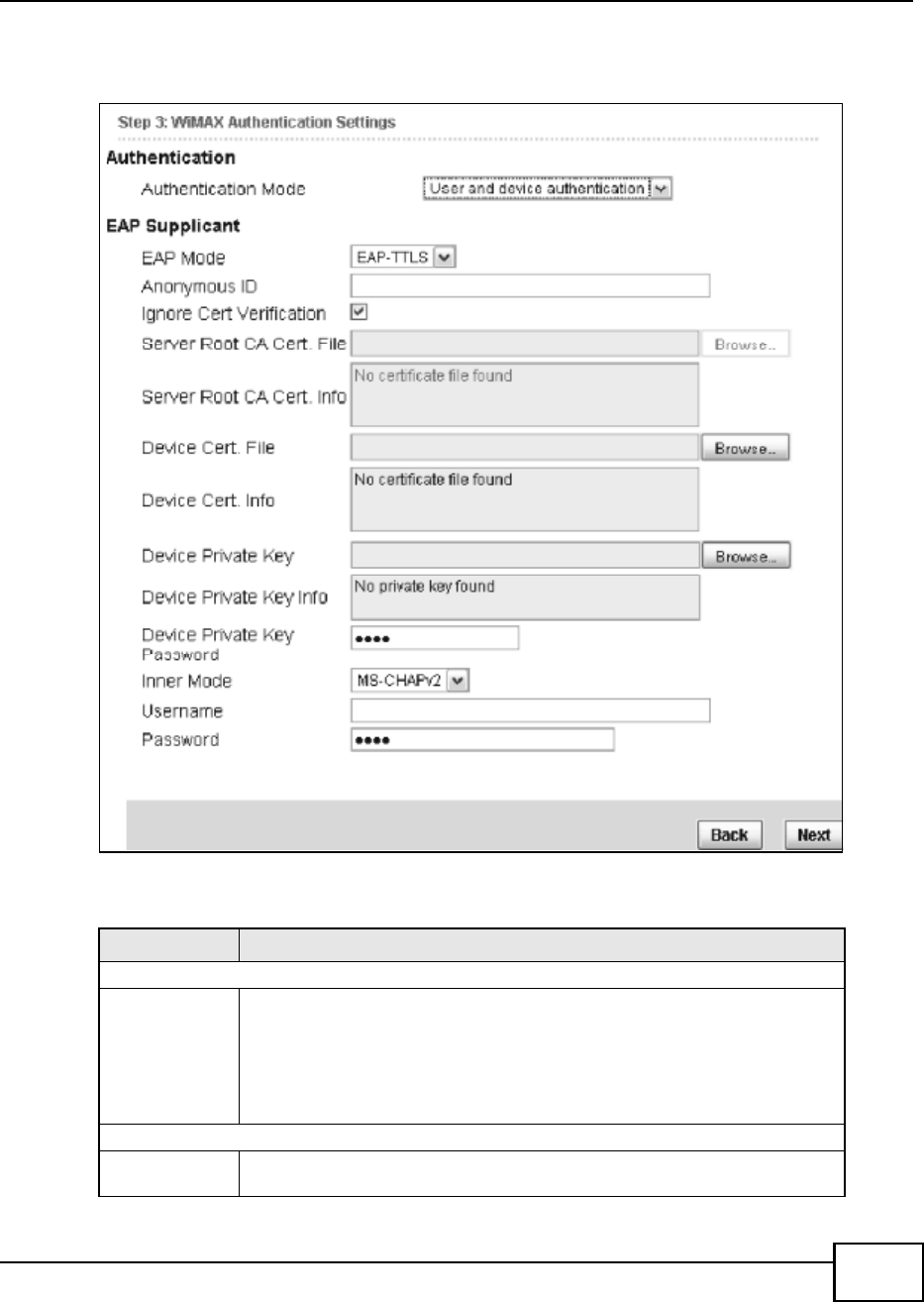
3.1.4 WiMAX Authentication Settings
The WiMAX Authentication Settings screen allows you to configure how your BM2022 logs into the
service providers network.
Note: These settings should be provided by your ISP.
Note: The EAP supplicant settings on this screen vary depending on the authentication
mode your select.
Table 7 Setup Wizard > WiMAX Frequency Settings
LABEL DESCRIPTION
Setting Type Select the WiMAX frequency setting type from the list.
By Range - Select this to set up the frequency based on a range of
MHz.
By List - Select this to set up the frequency on an individual MHz basis.
You can add multiple MHz values to the list.
Step Enter the increments in MHz by which to increase the frequency range.
Note: This field only appears when you select By Range under Setting Type.
Start Frequency Enter the frequency value at the beginning of the frequency range to use.
The frequency is increased in increments equal to the Step value until the
End Frequency is reached, at which time the cycle starts over with the
Start Frequency.
Note: This field only appears when you select By Range under Setting Type.
End Frequency Enter the frequency value at the end of the frequency range to use.
Note: This field only appears when you select By Range under Setting Type.
Bandwidth Set the frequency bandwidth in MHz that this BM2022 uses.
# This is an index number for enumeration purposes only.
Frequency (MHz) Displays the frequency MHz for the item in the list.
Total Num Displays the total number of items in the list.
Delete Click this to remove an item from the list.
Add Click this to add an item to the list.
OK Click this to save an newly added item to the list.
# This is an index number for enumeration purposes only.
Band Start (KHz) Indicates the beginning of the frequency band in KHz.
Band End (KHz) Indicates the end of the frequency band in KHz.
Total Num Displays the total number of items in the list.
Back Click to display the previous screen.
Next Click to proceed to the next screen.
Chapter 3 Setup Wizard
BM2022 Users Guide 31
Figure 11 Setup Wizard > WiMAX Authentication Settings
The following table describes the labels in this screen.
Table 8 Setup Wizard > WiMAX Authentication Settings
LABEL DESCRIPTION
Authentication
Authenticatio
n Mode
Select a WiMAX authentication mode for authentication network sessions with the
ISP. Options are:
No authentication
User authentication
Device authentication
User and Device authentication
EAP Supplication
EAP Mode Select an EAP authentication mode. See Table 13 on page 74 if you need more
information.

Chapter 3 Setup Wizard
BM2022 Users Guide
32
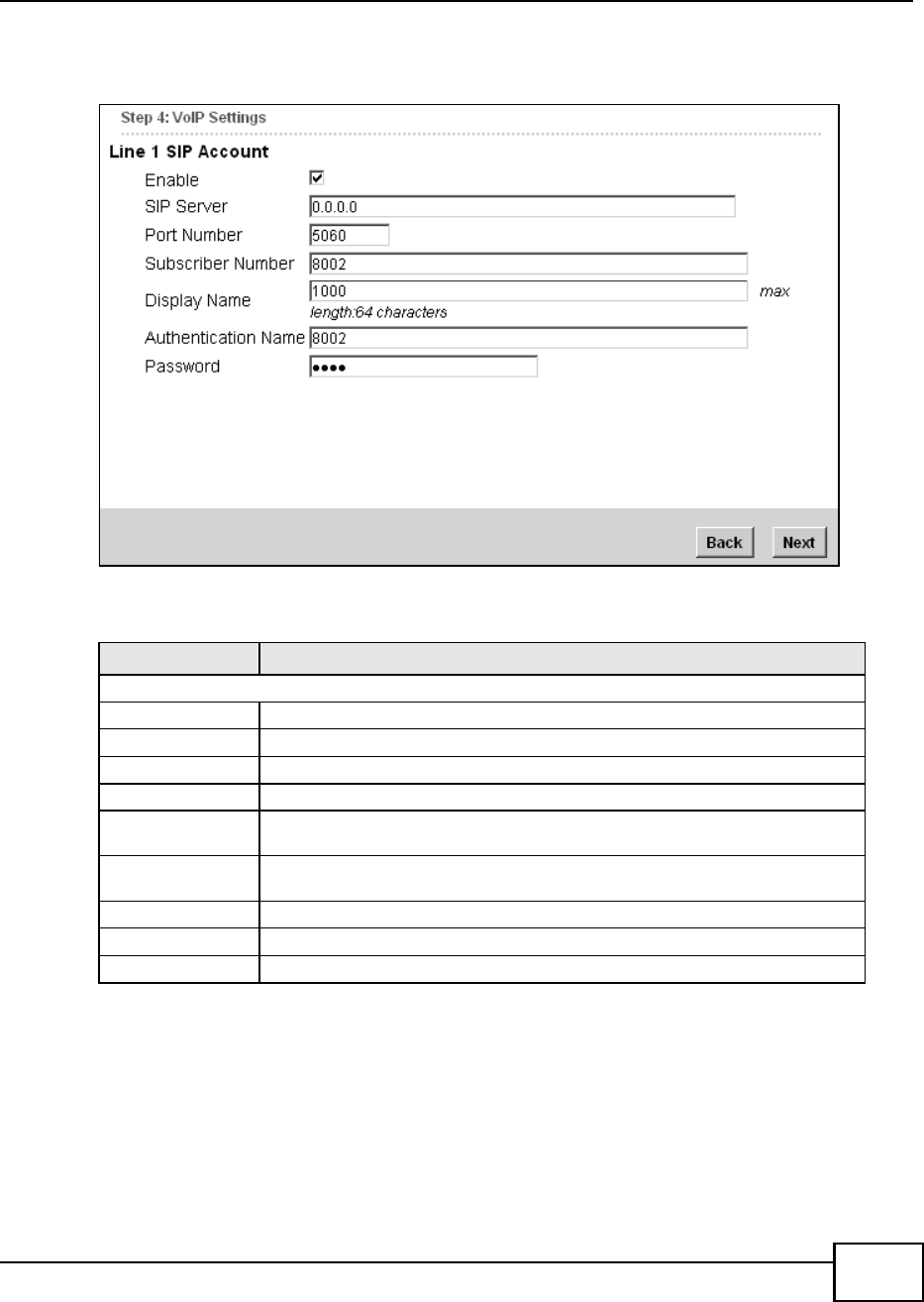
3.1.5 VoIP Settings
The VoIP Settings screen allows you to configure how your BM2022 connects to the VoIP service
providers network and makes calls over the Internet.
Anonymous
Id
Enter your anonymous ID.
Note: Some modes may not require this.
Ignore Cert
Verification
Select this to ignore base station certification verification when a certificate is
received during EAP-TLS or EAP-TTLS.
Server Root
CA Cert. File
Browse for and choose a server root certificate file, if required.
Server Root
CA Cert. Info
This field displays information about the assigned server root certificate.
Device Cert.
File
Browse for and choose a device certificate file, if required.
Before you import certificate from WebGUI, the certificate file must be signed by
chipset vendor due to security reason.
Device Cert.
Info.
This field displays information about the assigned device certificate.
Device
Private Key
Browse for and choose a device private key, if required.
Device
Private Key
Info
This field displays information about the assigned device private key.
Device
Private Key
Password
Enter the device private key, if required.
Inner Mode Select an inner authentication mode (MS-CHAP, MS-CHAPV2, CHAP, MD5, PAP.
See Table 13 on page 74 if you need more information.
Username Enter your authentication username.
Password Enter your authentication password.
Back Click to display the previous screen.
Next Click to proceed to the next screen.
Table 8 Setup Wizard > WiMAX Authentication Settings (continued)
LABEL DESCRIPTION
Chapter 3 Setup Wizard
BM2022 Users Guide 33
Note: This settings should be provided by your VoIP service provider.
Figure 12 Setup Wizard > VoIP Settings
The following table describes the labels in this screen.
Table 9 Setup Wizard > VoIP Settings
LABEL DESCRIPTION
Line 1 SIP Account - Configure this section to use the PHONE 1 port.
Enable Select this to activate the SIP account.
SIP Server Enter the IP address or domain name of the SIP server.
Port Number Enter the SIP servers listening port number.
Subscriber Number Enter your SIP number. In the full SIP URI, this is the part before the @ symbol.
Display Name Enter the name that appears on the other partys device if they have Caller ID
enabled.
Authentication
Name
Type the SIP user name associated with this account for authentication to the SIP
server.
Password Type the SIP password associated with this account.
Back Click to display the previous screen.
Next Click to proceed to the next screen.
Chapter 3 Setup Wizard
BM2022 Users Guide
34
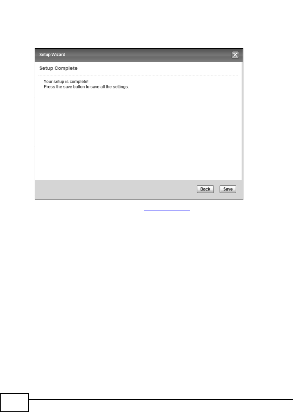
3.1.6 Setup Complete
Click Save to save the Setup Wizard settings and close it.
Figure 13 Setup Wizard > Setup Complete
Launch your web browser and navigate to www.huawei.com. If everything was configured properly,
the web page should display. You can now surf the Internet!
Refer to the rest of this guide for more detailed information on the complete range of BM2022
features available in the more advanced web configurator.
Note: If you cannot access the Internet, open the web configurator again to confirm that
the Internet settings you configured in the wizard setup are correct.

BM2022 Users Guide 35
CHAPTER 4
Tutorials
4.1 Overview
This chapter shows you how to configure some of the BM2022s features.
Note: Be sure to read Introducing the Web Configurator on page 21 before working
through the tutorials presented here. For field descriptions for individual screens,
see the related technical reference in this User's Guide.
This chapter includes the following configuration examples:
WiMAX Connection Settings on page 35
Configuring LAN DHCP on page 36
Changing Certificate on page 38
Blocking Web Access on page 39
Configuring the MAC Address Filter, see page 39
Setting Up NAT Port Forwarding, see page 41
Access the BM2022 Using DDNS, see page 43
Configuring Static Route for Routing to Another Network, see page 45
Remotely Managing Your BM2022 on page 47
VLAN Configuration Examples on page 48
4.2 WiMAX Connection Settings
This tutorial provides you with pointers for configuring the BM2022 to connect to an ISP.
1Connect the BM2022 to the ISPs nearest base station. See Section 6.2 on page 68.
2Configure the BM2022s broadcast frequency. Section 6.3 on page 70.
3Configure the BM2022 to connect securely to the ISPs authentication servers. See Section 6.4 on
page 72.
4Check the BM2022s connection status to ensure everything is working properly. See Section 6.11
on page 86.
Chapter 4 Tutorials
BM2022 Users Guide
36
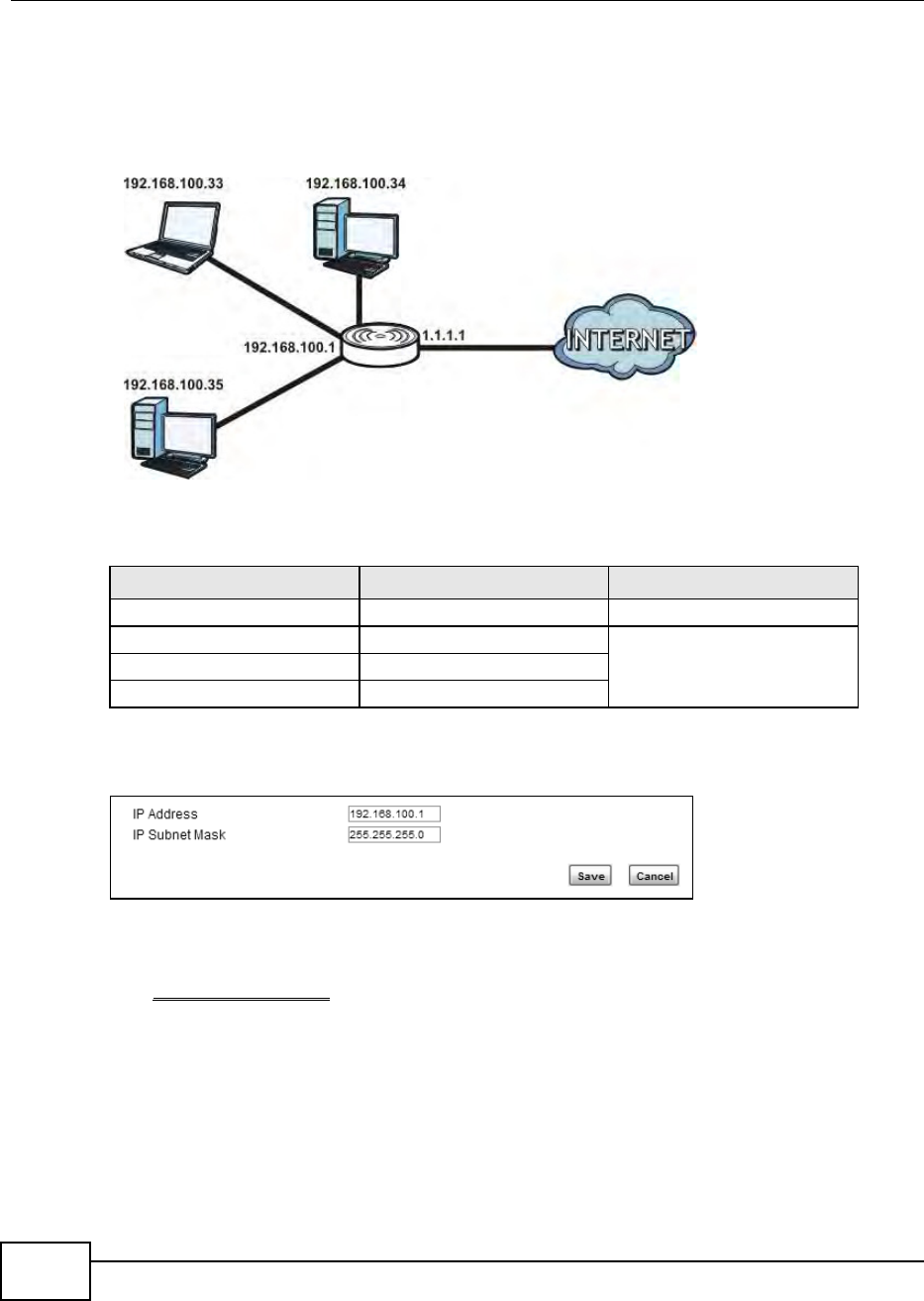
4.3 Configuring LAN DHCP
This tutorial shows you how to set up a small network in your office or home.
Goal: Connect three computers to your BM2022 to form a small network.
Required: The following table provides a summary of the information you will need to complete
the tasks in this tutorial.
1In the Web Configurator, open the Network Setting > LAN screen and set the IP Address to
192.168.100.1. Use the default IP Subnet Mask of 255.255.255.0. Click Save.
2Manually change the IP address of your computer that your are using to 192.168.100.x (for
example, 192.168.100.5) and keep the subnet set to 255.255.255.0.
3Type http://192.168.100.1 in your browser after the BM2022 finishes starting up completely.
INFORMATION VALUE SEE ALSO
LAN IP Address 192.168.100.1 Chapter 7 on page 98
Starting IP Address 192.168.100.10 Chapter 7 on page 99
Ending IP Address 192.168.100.30
DNS Servers From ISP
Chapter 4 Tutorials
BM2022 Users Guide 37
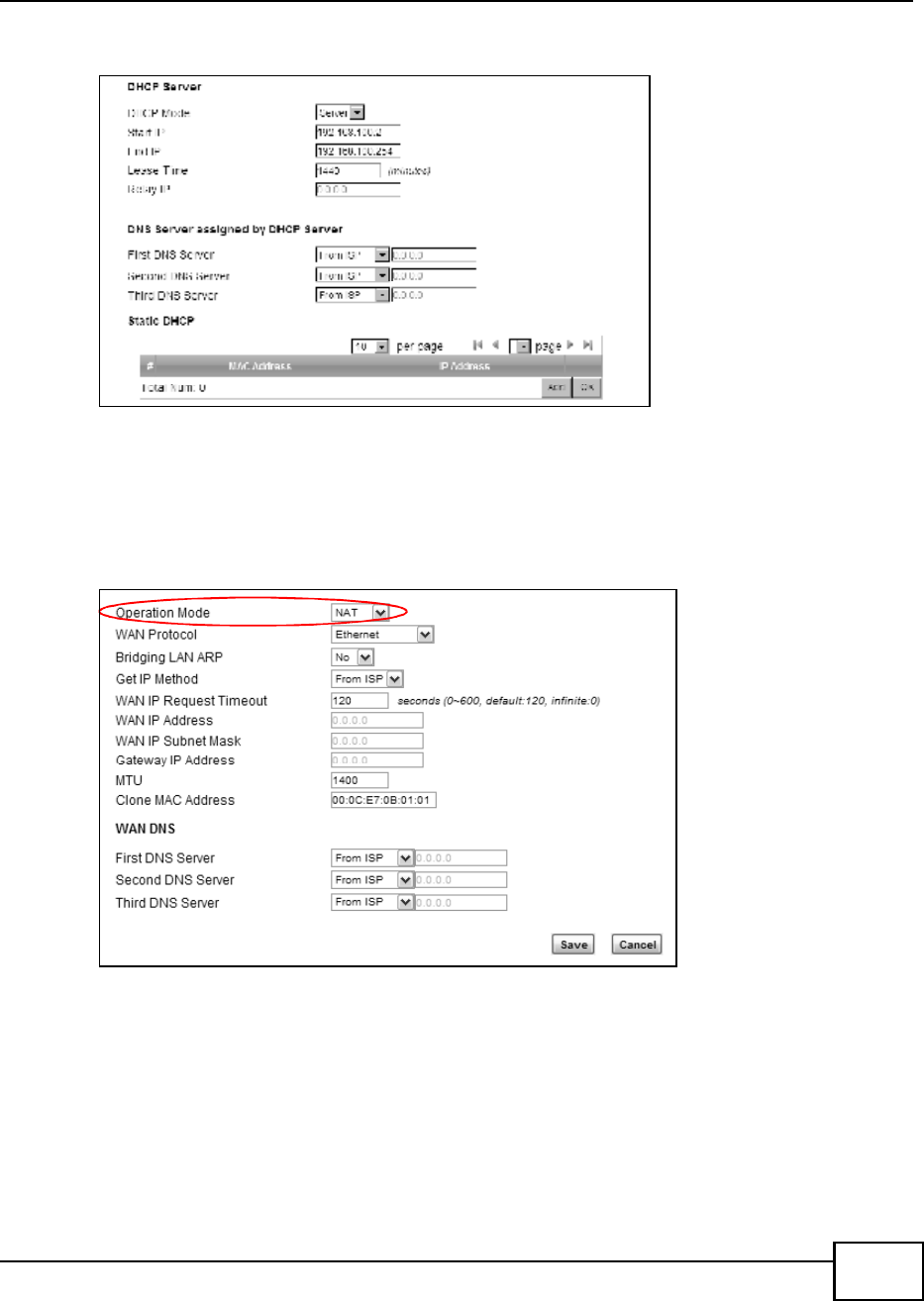
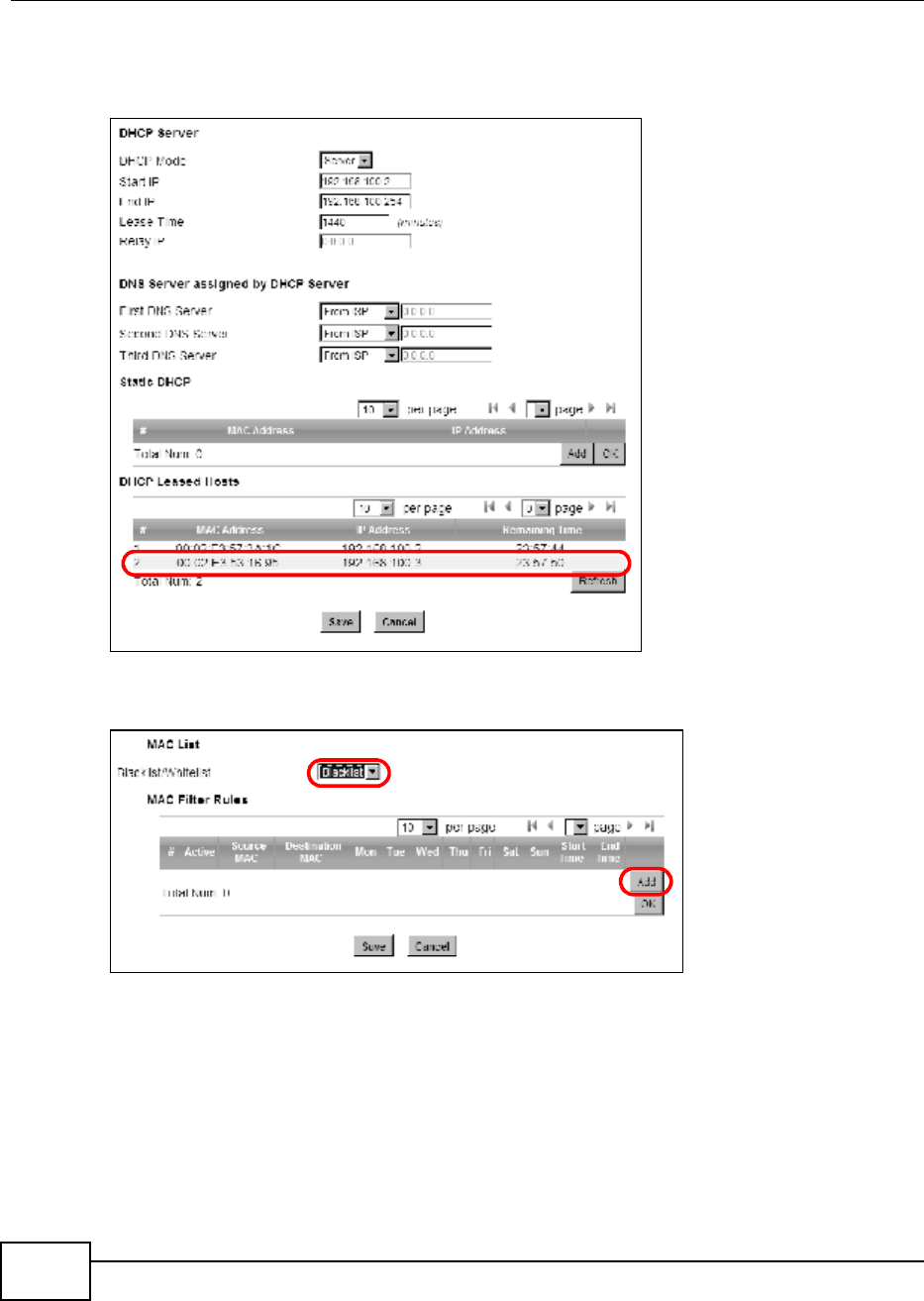
4Log into the Web Configurator and open the Network Setting > LAN > DHCP screen.
5Select Server for the DHCP mode, then enter 192.168.100.10 and 192.168.100.30 as your DHCP
starting and ending IP addresses.
6Leave the other settings as their defaults and click Save.
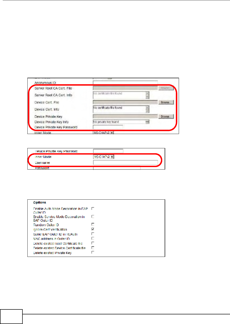
7Next, go to the Network Setting > WAN screen and select NAT in the Operation Mode field.
Click Save.
8Connect your computers to the BM2022s Ethernet ports and youre all set!
Note: You may need to configure the computers on your LAN to automatically obtain IP
addresses. For information on how to do this, see Appendix B on page 209.
Once your network is configured and hooked up, you will want to connect it to the Internet next. To
do this, just run the Internet Connection Wizard (Chapter 3 on page 27), which walks you
through the process.
Chapter 4 Tutorials
BM2022 Users Guide
38
4.4 Changing Certificate
This tutorial shows you how to import a new security certificate, which allows your device to
communicate with another network servers.
Goal: Import a new security certificate into the BM2022.
See Also: Appendix E on page 253.
1Go to the WiMAX > Profile > Authentication Settings screen. In the EAP Supplicant section,
click each Browse button and locate the security certificates that were provided by your new ISP.
s
2Configure your new Internet access settings based on the information provided by the ISP.
Note: You can also use the Internet Connection Wizard to configure the Internet access
settings.
3You may need to configure the Options section according to the information provided by the ISP.
4Click Save. You should now be able to connect to the Internet through your new service provider!
Chapter 4 Tutorials
BM2022 Users Guide 39
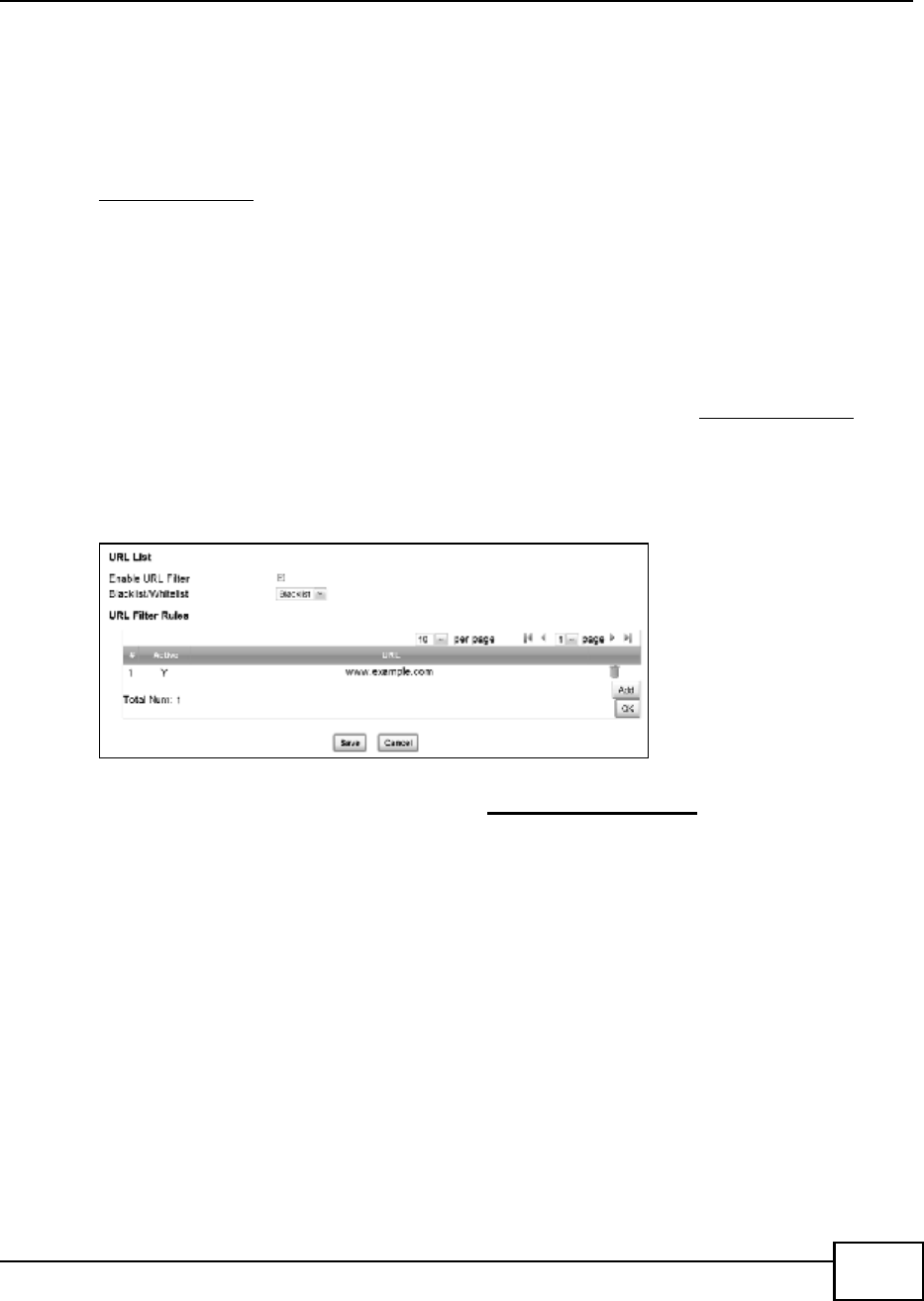
4.5 Blocking Web Access
If your BM2022 is in a home or office environment you may decide that you want to block an
Internet website access. You may need to block both the websites IP address and domain name.
Goal: Configure the BM2022s content filter to block a website with a domain name
www.example.com.
See Also: Section 7.20 on page 119.
1Open the Network Setting > Content Filter.
2Select Enable URL Filter.
3Select Blacklist.
4Click Add and configure a URL filter rule by selecting Active and entering www.example.com as the
URL.
5Click OK.
6Click Save.
Open a browser from your computer in the BM2022s LAN network, you should get an Access
Violation message when you try to access to http://www.example.com. You may also need to
block the IP address of the website if you do not want users to access to the website through its IP
address.
4.6 Configuring the MAC Address Filter
This tutorial shows you how to use the MAC filter to block a DHCP clients access to hosts and to the
WiMAX network.
Chapter 4 Tutorials
BM2022 Users Guide
40
1First of all, you have to know the MAC address of the computer. If not, you can look for the MAC
address in the Network Setting > LAN > DHCP screen. (192.168.100.3 mapping to
00:02:E3:53:16:95 in this example).
2Click Security > Firewall > MAC Filter. Select Blacklist and click the Add button in the MAC
Filter Rules table.
Chapter 4 Tutorials
BM2022 Users Guide 41
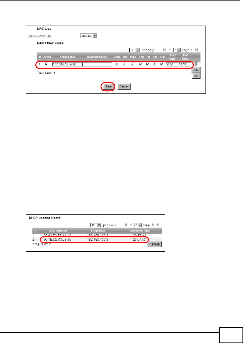
3An empty entry appears. Enter the computers MAC address in the Source MAC field and leave the
other fields set to their defaults. Click Save.
The computer will no longer be able to access any host on the WiMAX network through the BM2022.
4.7 Setting Up NAT Port Forwarding
Thomas recently received an Xbox 360 as his birthday gift. His friends invited him to play online
games with them on Xbox LIVE. In order to communicate and play with other gamers on Xbox
LIVE, Thomas needs to configure the port settings on his BM2022.
Xbox 360 requires the following ports to be available in order to operate Xbox LIVE correctly:
TCP: 53, 80, 3074
UDP: 53, 88, 3074
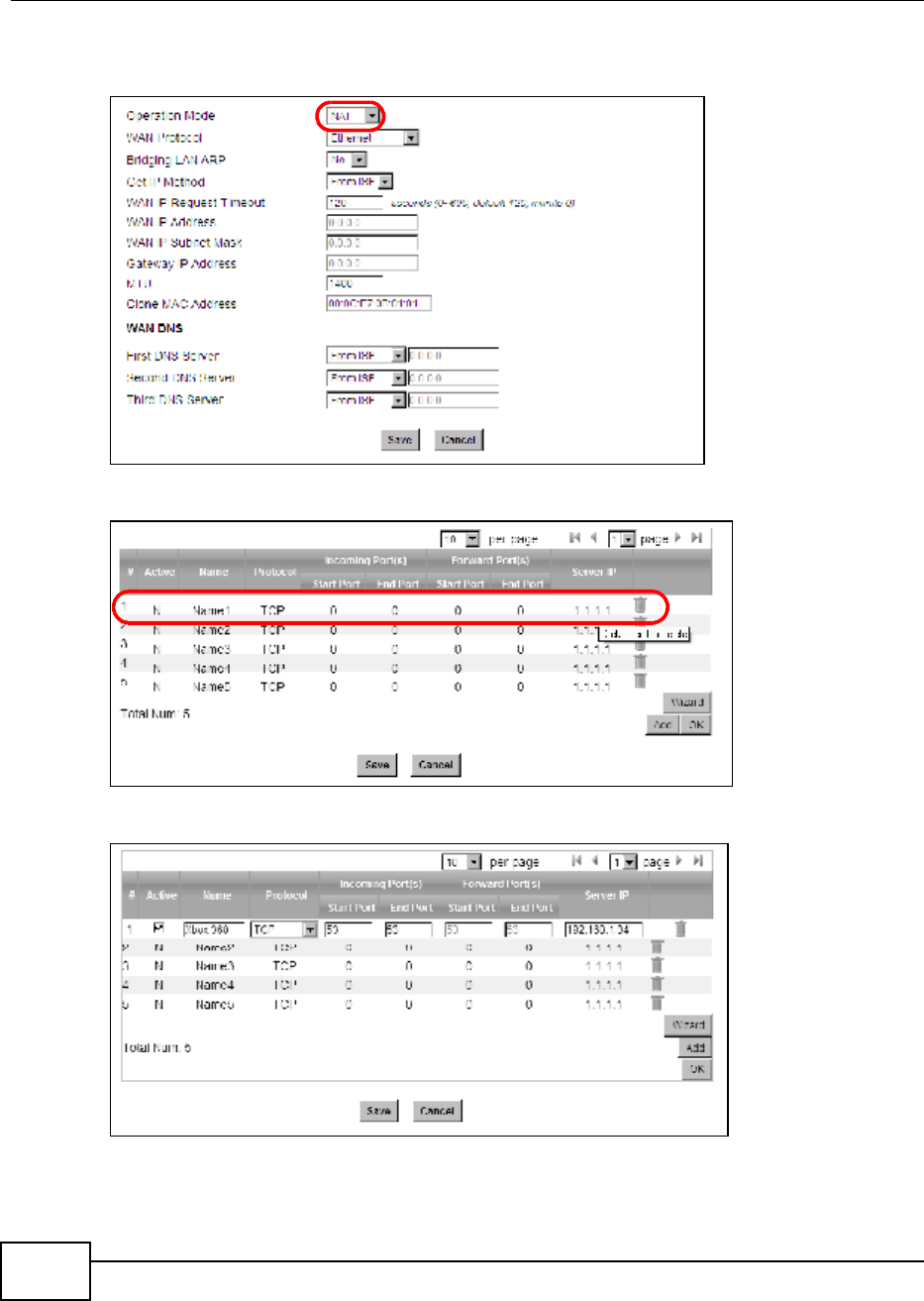
1You have to know the Xbox 360s IP address first. You can check it through the Xbox 360 console.
You may be able to check the IP address on the BM2022 if the BM2022 has assigned a DHCP IP
address to the Xbox 360. Check the DHCP Leased Hosts table in the Network > LAN > DHCP
screen. Look for the IP address for the Xbox 360.
Chapter 4 Tutorials
BM2022 Users Guide
42
2NAT mode is required to use port forwarding. Click Network Setting > WAN and make sure NAT
is selected in the Operation Mode field. Click Save.
3Click Network Setting > NAT > Port Forwarding and then click the first entry to edit the rule.
4Configure the screen as follows to open TCP/UDP port 53 for the Xbox 360. Click OK.
Chapter 4 Tutorials
BM2022 Users Guide 43
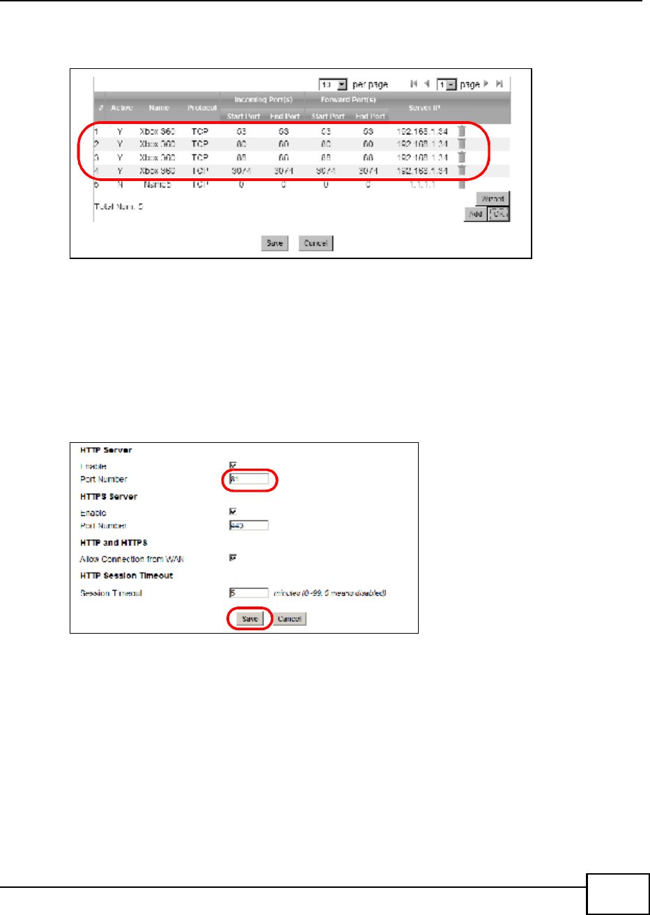
5Repeat steps 2 and 3 to open the rest of the ports for the Xbox 360. The port forwarding settings
you configured are listed in the Port Forwarding screen.
6Click Save.
Thomas can then connect his Xbox 360 to the Internet and play online games with his friends.
In this tutorial, all port 80 traffic is forwarded to the Xbox 360, but port 80 is also the default
listening port for remote management via WWW. If Thomas also wants to manage the BM2022
from the Internet, he has to assign an unused port to WWW remote access.
Click Maintenance > Remote MGMT. Enter an unused port in the Port field (81 in this example).
Click Save.
4.8 Access the BM2022 Using DDNS
If you connect your BM2022 to the Internet and it uses a dynamic WAN IP address, it is
inconvenient for you to manage the device from the Internet. The BM2022s WAN IP address
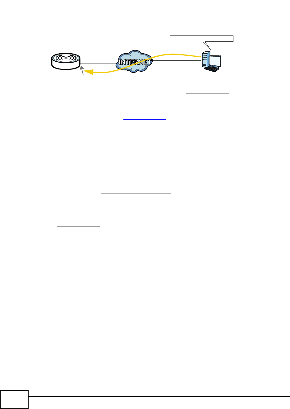
Chapter 4 Tutorials
BM2022 Users Guide
44
changes dynamically. Dynamic DNS (DDNS) allows you to access the BM2022 using a domain
name.
To use this feature, you have to apply for DDNS service at www.dyndns.org.
This tutorial covers:
Registering a DDNS Account on www.dyndns.org
Configuring DDNS on Your BM2022
Testing the DDNS Setting
Note: If you have a private WAN IP address (see Private IP Addresses on page 250), then
you cannot use DDNS.
4.8.1 Registering a DDNS Account on www.dyndns.org
1Open a browser and type http://www.dyndns.org.
2Apply for a user account. This tutorial uses UserName1 and 12345 as the username and
password.
3Log into www.dyndns.org using your account.
4Add a new DDNS host name. This tutorial uses the following settings as an example.
Hostname: mywimax.dyndns.org
Service Type: Host with IP address
IP Address: Enter the WAN IP address that your BM2022 is currently using. You can find the IP
address on the BM2022s Web Configurator Status page.
Then you will need to configure the same account and host name on the BM2022 later.
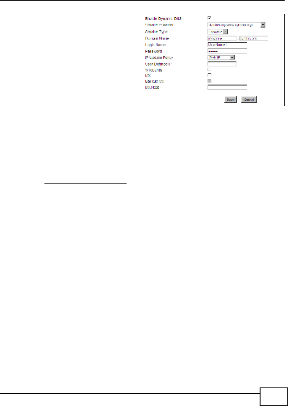
4.8.2 Configuring DDNS on Your BM2022
Configure the following settings in the Network Setting > DDNS screen.
w.x.y.z a.b.c.d
http://mywimax.dyndns.org
A
Chapter 4 Tutorials
BM2022 Users Guide 45
1Select Enable Dynamic DNS.
2Select dyndns.org for the service
provider.
3Select Dynamic for the service type.
4Type mywimax.dyndns.org in the
Domain Name field.
5Enter the user name (UserName1) and
password (12345).
6Select WAN IP for the IP update policy.
7Click Save.
4.8.3 Testing the DDNS Setting
Now you should be able to access the BM2022 from the Internet. To test this:
1Open a web browser on the computer (using the IP address a.b.c.d) that is connected to the
Internet.
2Type http://mywimax.dyndns.org and press [Enter].
3The BM2022s login page should appear. You can then log into the BM2022 and manage it.
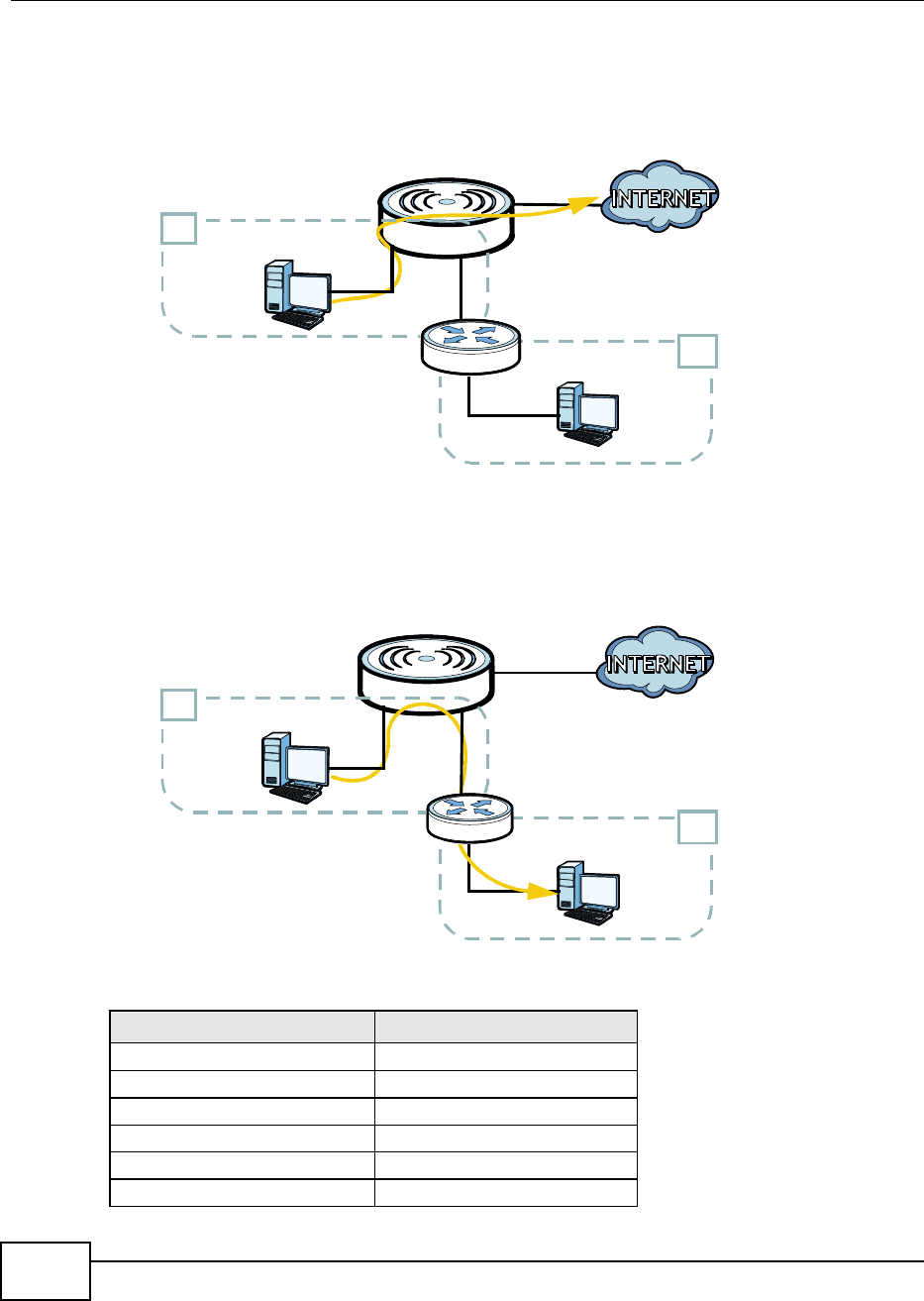
4.9 Configuring Static Route for Routing to Another
Network
In order to extend your Intranet and control traffic flowing directions, you may connect a router to
the BM2022s LAN. The router may be used to separate two department networks. This tutorial
shows how to configure a static routing rule for two network routings.
In the following figure, router R is connected to the BM2022s LAN. R connects to two networks, N1
(192.168.1.x/24) and N2 (192.168.10.x/24). If you want to send traffic from computer A (in N1
Chapter 4 Tutorials
BM2022 Users Guide
46
network) to computer B (in N2 network), the traffic is sent to the BM2022s WAN default gateway
by default. In this case, computer B will never receive the traffic.
You need to specify a static routing rule on the BM2022 to specify R as the router in charge of
forwarding traffic to N2. In this case, the BM2022 routes traffic from computer A to R and then R
routes the traffic to computer B.
This tutorial uses the following example IP settings:
DEVICE / COMPUTER IP ADDRESS
The BM2022s WAN 172.16.1.1
The BM2022s LAN 192.168.1.1
A192.168.1.34
Rs IP address on N1 192.168.1.253
Rs IP address on N2 192.168.10.2
B192.168.10.33
N2
B
A
R
N1
N2
B
N1
A
R
Chapter 4 Tutorials
BM2022 Users Guide 47
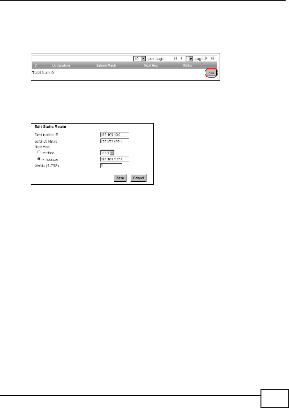
To configure a static route to route traffic from N1 to N2:
1Click Network Setting > Route > Static Route.
2Click Add to create a new route.
3Configure the Edit Static Route screen using the following settings:
3a Enter 192.168.10.0 and subnet mask 255.255.255.0 for the destination, N2.
3b Enter 192.168.1.253 (Rs IP address on N1) in the IP Address field under Next Hop.
3a Click Save.
Now computer B should be able to receive traffic from computer A. You may need to additionally
configure Rs firewall settings to accept specific traffic to pass through.
4.10 Remotely Managing Your BM2022
The remote management feature allows you to log into the device through the Internet.
Goal: Set up the BM2022 to allow management requests from the WAN (Internet).
See Also: Section 12.3 on page 177.
Chapter 4 Tutorials
BM2022 Users Guide
48
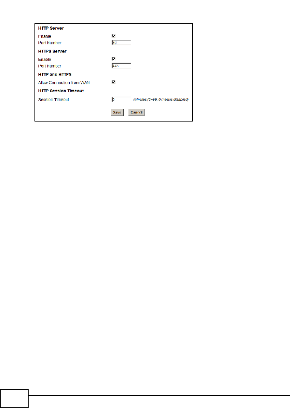
1Open the Maintenance > Remote MGMT > HTTP screen.
2Select Enable in both HTTP Server and HTTPS Server sections and leave the Port Number
settings as 80 and 443.
3Select Allow Connection from WAN. This allows remote management connections not only from
the local network but also the WAN network (Internet).
4Click Save.
4.11 VLAN Configuration Examples
This section shows VLAN configuration scenarios.
See Section 7.17 on page 115 if you need more information about VLAN.
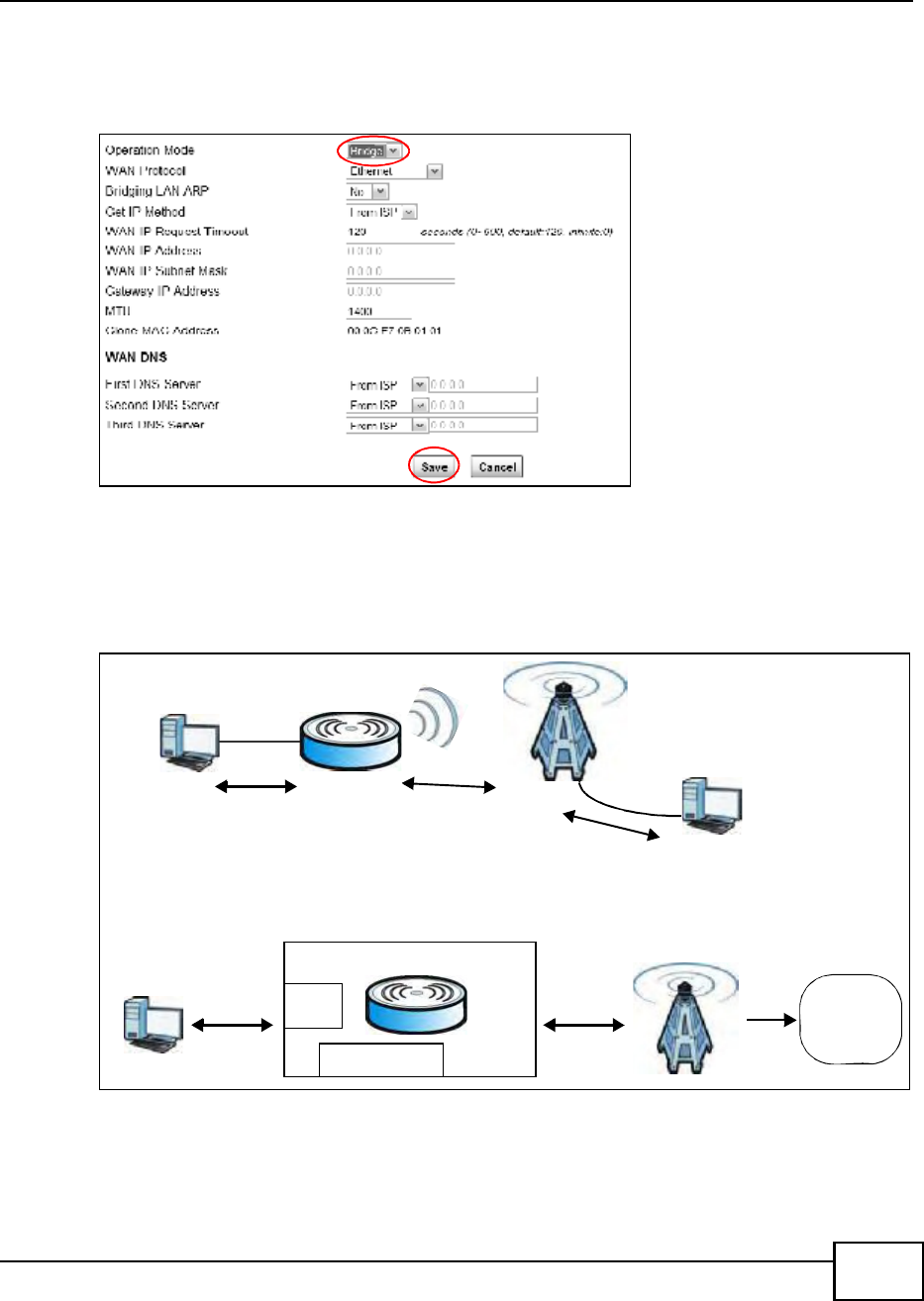
Before enabling VLANs you will need to change the BM2022 to bridge mode.
Chapter 4 Tutorials
BM2022 Users Guide 49
Click Network Setting > WAN. Change the BM2022 to bridge mode and then click Save. If you
cannot obtain IP address settings from a WAN DHCP server, select User as the Get IP Method and
enter the WAN IP Address, WAN IP Subnet Mask and Gateway IP Address.
4.11.1 Scenario 1
In this scenario, PC A is connected directly to interface LAN1 on the BM2022. PC B is connected to
interface WiMAX and interface IAD for managing the BM2022.
A
B
No VLAN Tag
No VLAN Tag
No VLAN Tag
CPE
LAN
Manager IP No VLAN Tag
No VLAN Tag
No VLAN Tag
User Network
PC
Manager IP: No VLAN Tag
LAN: Transparent
Network
operators
Transparent
Chapter 4 Tutorials
BM2022 Users Guide
50
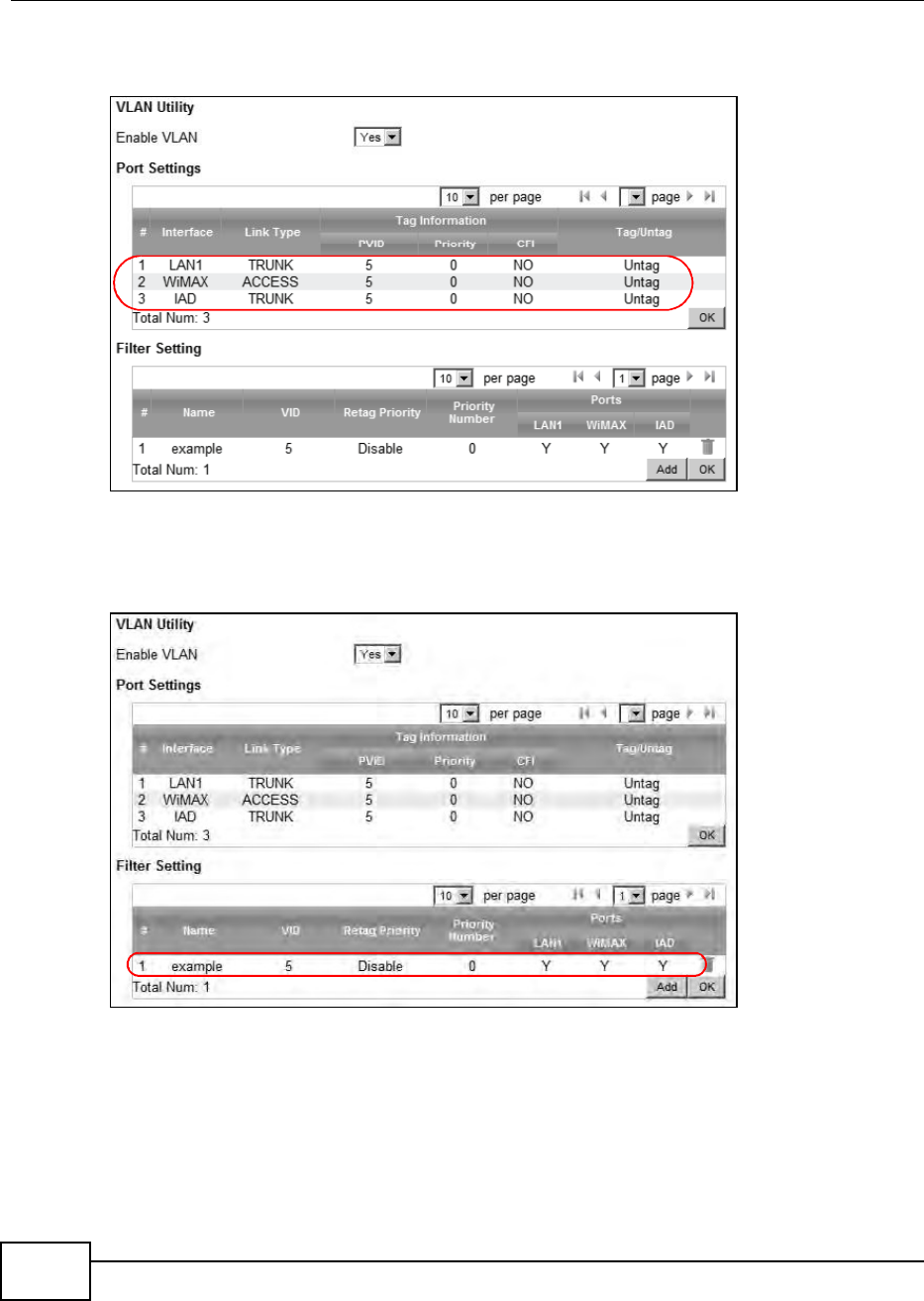
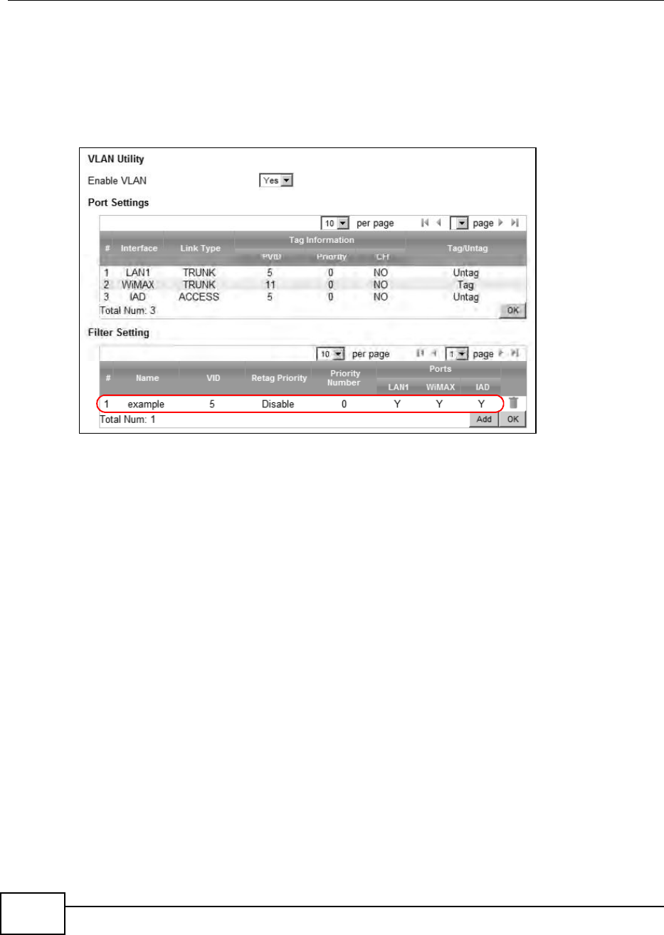
1Configure the Link Type, PVID and Tag/Untag settings for the interfaces as below by clicking
each row. Then press OK.
2Next, configure the Name, VID and Ports for the Filter Setting. The BM2022 will tag packets it
receives on each interface so that they are recognized in VLAN 5. Tagged packets will be untagged
when they are forwarded out of each interface since the devices attached to these interfaces do not
support VLAN tagged packets.
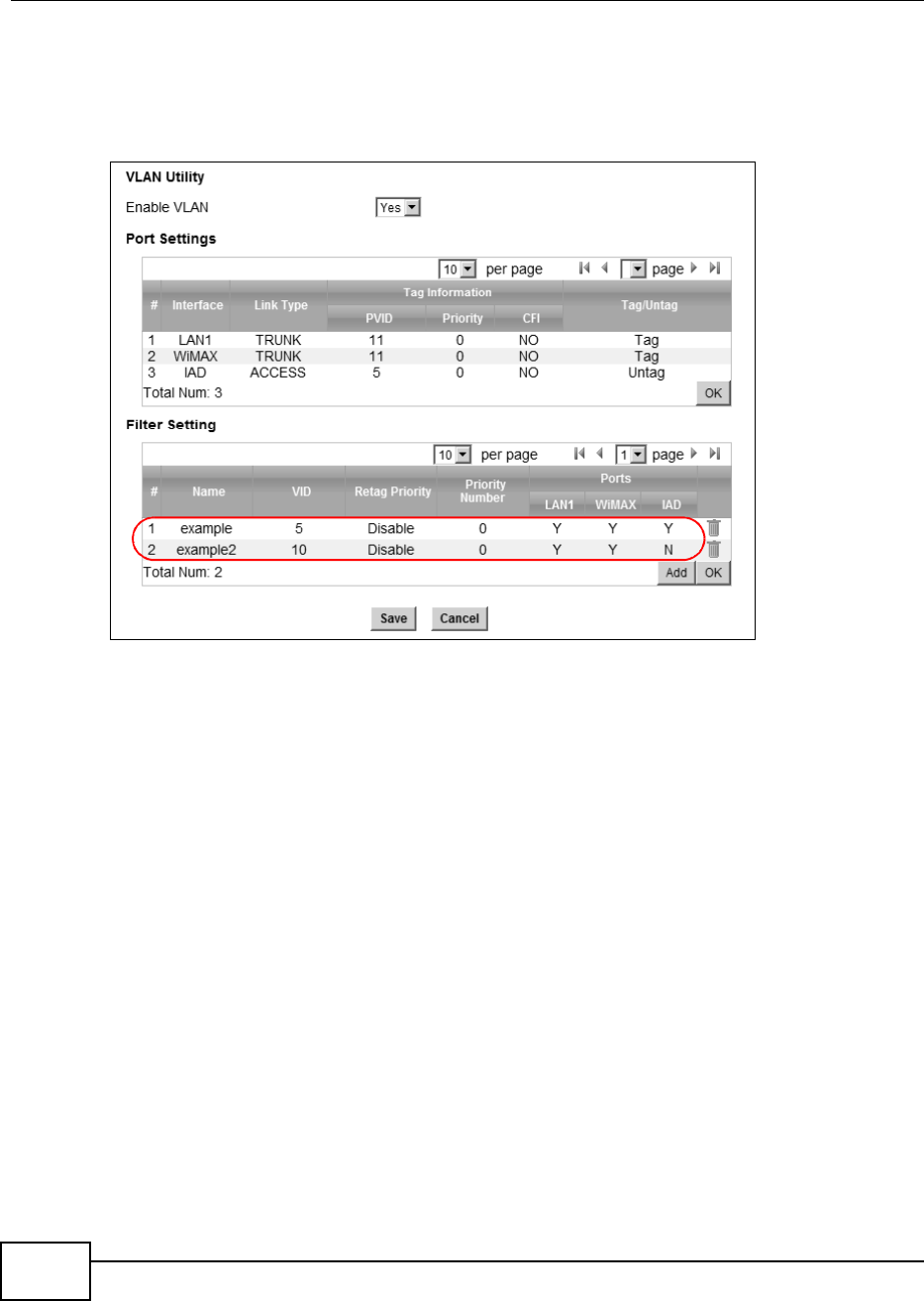
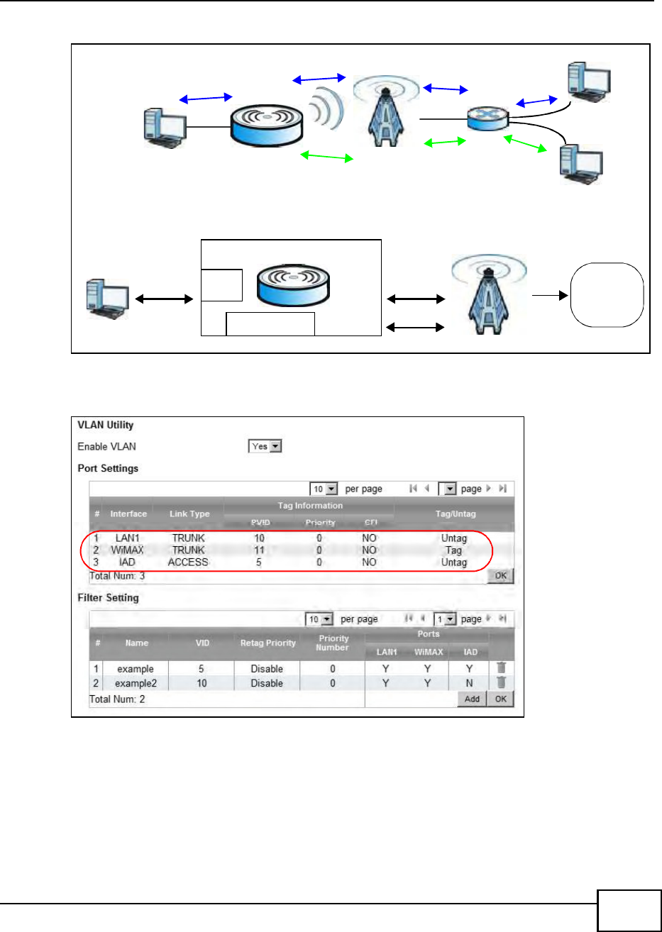
4.11.2 Scenario 2
In this scenario, PC A and PC C are on VLAN 5, while PC B and PC D are on VLAN 10. PC A and PC
B are connected to interface LAN1 through VLAN supporting switch S1. PC C is connected to
interface WiMAX and interface IAD for managing the BM2022, through VLAN supporting switch S2.
PC D is connected to interface WiMAX through VLAN supporting switch S2.
Chapter 4 Tutorials
BM2022 Users Guide 51
Note: You will need to configure the VLAN supporting switches to tag the received packets
with the appropriate VLAN IDs. For example, packets received on switch S1 from
PC A on the LAN would be tagged to VLAN 5.
1Configure the Link Type, PVID and Tag/Untag settings for the interfaces as below by clicking
each row. Then press OK.
VLAN TagID = 5
VLAN TagID = 10
A
B
No VLAN Tag
No VLAN Tag
VLAN TagID = 5
VLAN TagID = 5
VLAN TagID = 10
VLAN TagID = 10 No VLAN Tag
No VLAN Tag
C
D
S1 S2
CPE
LAN
Manager IP
User Network
Router
Manager IP: Enable VLAN
LAN: Transparent
Network
operators
Transparent
Note: Manager IP VLAN ID is the same
as one of the LAN transparent VLAN ID
VLAN Tag ID=5
VLAN Tag ID=5
VLAN Tag ID=10 VLAN Tag ID=10
VLAN Tag ID=5
Chapter 4 Tutorials
BM2022 Users Guide
52
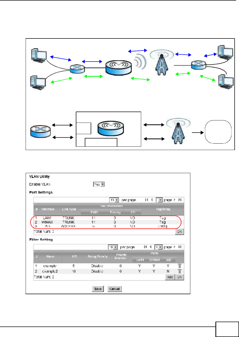
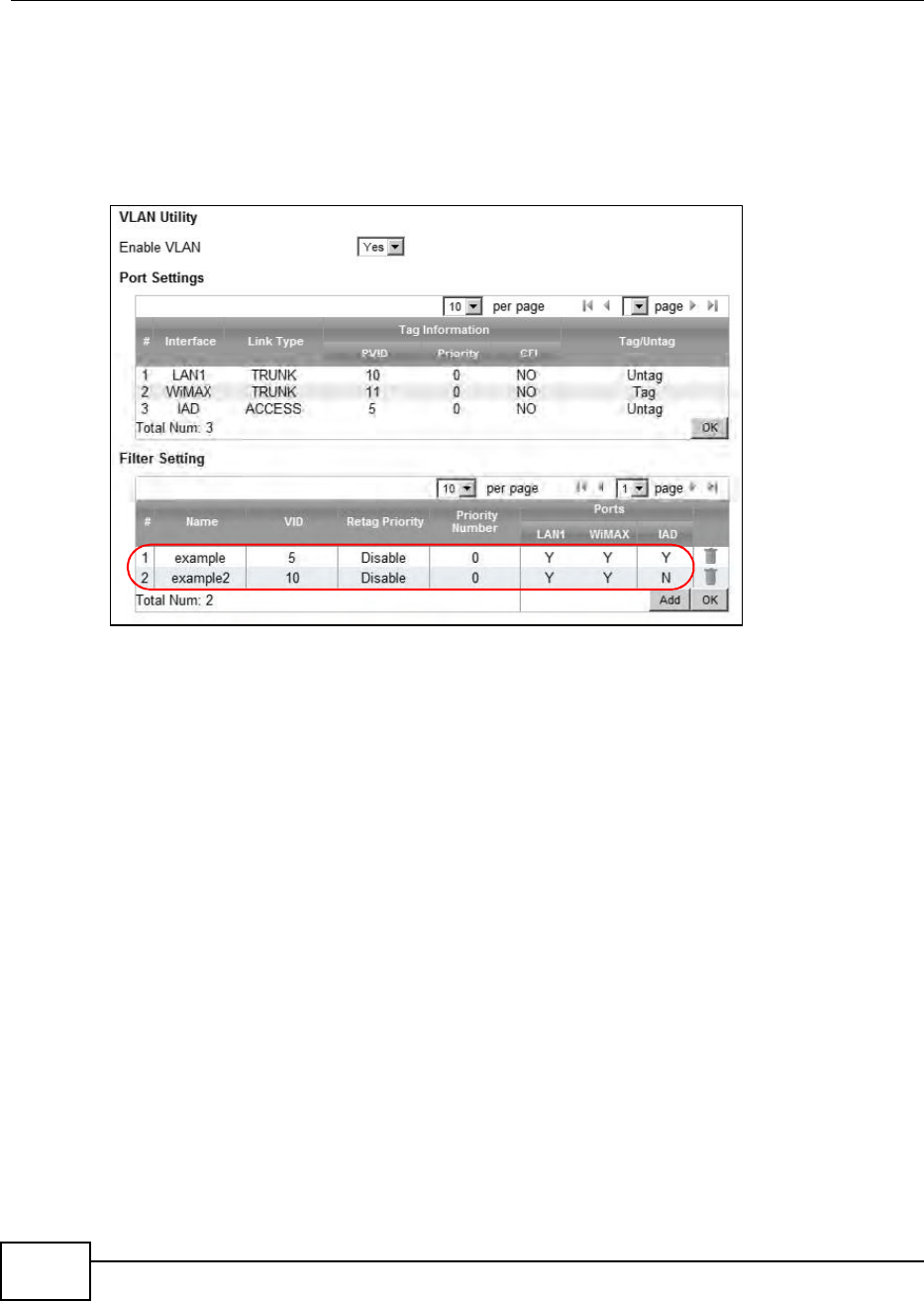
2Next, configure the Name, VID and Ports for the Filter Setting. Interfaces LAN1 and WiMAX
are Trunk links, so the BM2022 will recognize VLAN 5 and VLAN 10 tagged packets it receives on
these interfaces from the VLAN supporting switches. VLAN tagged packets will also be forwarded
out of these interfaces. Interface IAD is configured as an Access port, so tagged packets will be
untagged when they are forwarded.
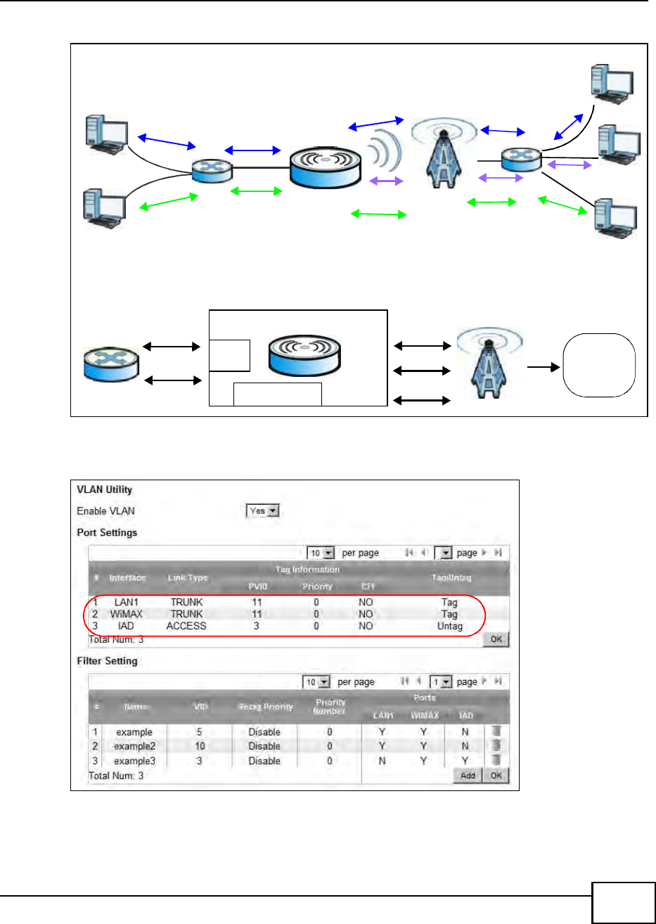
4.11.3 Scenario 3
In this scenario, PC A and PC C are on VLAN 5, PC B and PC D are on VLAN 10, and PC E is on VLAN
3. PC A and PC B are connected to interface LAN1 through VLAN supporting switch S1. PC C and
PC D are connected to interface WiMAX through VLAN supporting switch S2. PC E is connected to
interface IAD through VLAN supporting switch S2 for managing the BM2022.
Note: You will need to configure the VLAN supporting switches to tag the received packets
with the appropriate VLAN IDs. For example, packets received on switch S1 from
PC A on the LAN would be tagged to VLAN 5.
Chapter 4 Tutorials
BM2022 Users Guide 53
1Configure the Link Type, PVID and Tag/Untag settings for the interfaces as below by clicking
each row. Then press OK.
VLAN TagID = 5
VLAN TagID = 10
A
B
No VLAN Tag
No VLAN Tag
VLAN TagID = 5
VLAN TagID = 5
VLAN TagID = 10
VLAN TagID = 10 No VLAN Tag
No VLAN Tag
C
D
No VLAN Tag E
VLAN TagID = 3
VLAN TagID = 3
S1 S2
CPE
LAN
Manager IP
User Network
Router
Manager IP: Enable VLAN
LAN: Transparent
Network
operators
Transparent
Note: Manager IP VLAN ID is different from
VLAN Tag ID=5
VLAN Tag ID=5
VLAN Tag ID=10
VLAN Tag ID=10
VLAN Tag ID=3 VLAN Tag ID=3
the LAN transparent VLAN ID
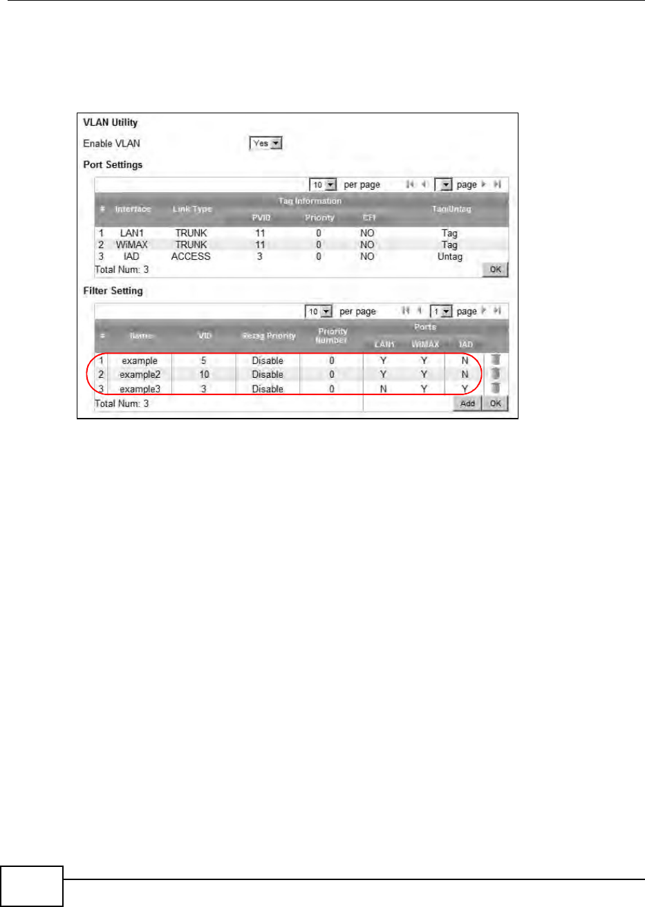
Chapter 4 Tutorials
BM2022 Users Guide
54
2Next, configure the Name, VID and Ports for the Filter Setting. Interfaces LAN1 and WiMAX
are Trunk links, so the BM2022 will recognize VLAN 5 and VLAN 10 tagged packets it receives on
these interfaces from the VLAN supporting switches. VLAN tagged packets will also be forwarded
out of these interfaces. Interface IAD is configured as an Access port, so tagged packets will be
untagged when they are forwarded.
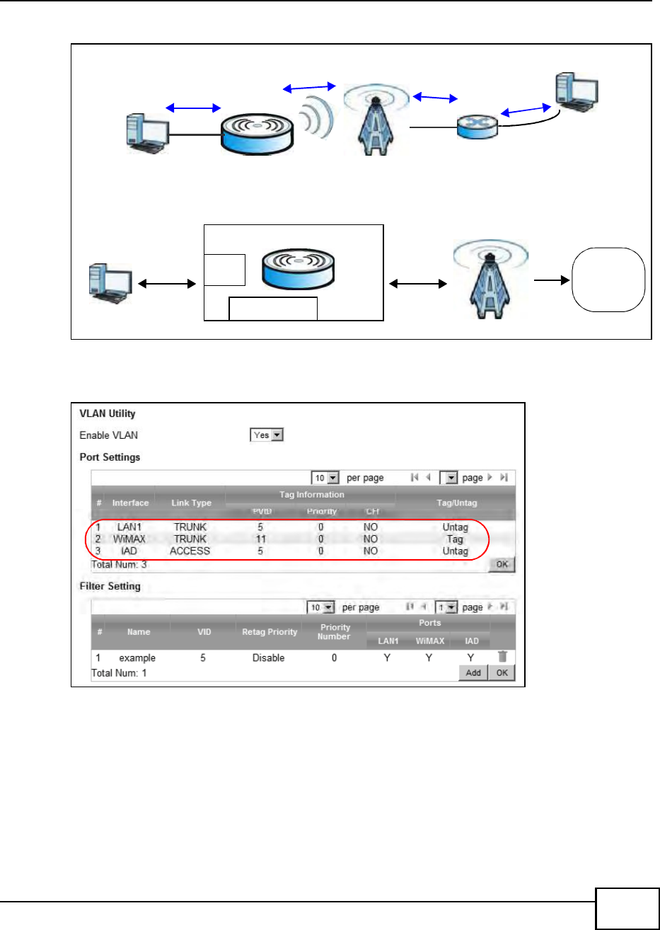
4.11.4 Scenario 4
In this scenario, PC A is connected directly to interface LAN1 on the BM2022, while PC B is on VLAN
5. PC B is connected to interface WiMAX and interface IAD for managing the BM2022, through
VLAN supporting switch S1.
Note: You will need to configure the VLAN supporting switches to tag the received packets
with the appropriate VLAN IDs. For example, packets received on switch S1 from
PC B on the LAN would be tagged to VLAN 5.
Chapter 4 Tutorials
BM2022 Users Guide 55
1Configure the Link Type, PVID and Tag/Untag settings for the interfaces as below by clicking
each row. Then press OK.
A
VLAN TagID = 5
VLAN TagID = 5
B
S1
No VLAN Tag No VLAN Tag
CPE
LAN
Manager IP
No VLAN Tag
User Network
PC
Network
operators
Manager IP: Enable VLAN
LAN: Transparent Note: Manager IP VLAN ID is the same
as the LAN transparent VLAN ID
VLAN Tag ID=5
VLAN Tag ID=5
VLAN Tag ID=5
Chapter 4 Tutorials
BM2022 Users Guide
56
2Next, configure the Name, VID and Ports for the Filter Setting. Interfaces LAN1 and WiMAX
are Trunk links. On the WiMAX interface, the BM2022 will recognize VLAN 5 tagged packets it
receives from the VLAN supporting switch. VLAN tagged packets will also be forwarded out of this
interface. On the LAN1 interface, the BM2022 will tag packets it receives so that they are
recognized in VLAN 5. On LAN1, tagged packets will be untagged when they are forwarded out
since PC A does not support VLAN tagged packets. Interface IAD is configured as an Access port,
so tagged packets will be untagged when they are forwarded.
4.11.5 Scenario 5
In this scenario, PC A is directly connected to interface LAN1 on the BM2022. PC B is on VLAN 5
while PC C is on VLAN 10. PC B is connected to interface WiMAX and interface IAD for managing
the BM2022, through VLAN supporting switch S1. PC C is connected to interface WiMAX through
VLAN supporting switch S1.
Note: You will need to configure the VLAN supporting switches to tag the received packets
with the appropriate VLAN IDs. For example, packets received on switch S1 from
PC C on the LAN would be tagged to VLAN 10.
Chapter 4 Tutorials
BM2022 Users Guide 57
1Configure the Link Type, PVID and Tag/Untag settings for the interfaces as below by clicking
each row. Then press OK.
A
VLAN TagID = 5
VLAN TagID = 5
VLAN TagID = 10
VLAN TagID = 10
No VLAN Tag
B
C
S1
No VLAN Tag
No VLAN Tag
CPE
LAN
Manager IP
No VLAN Tag
User Network
PC
Network
operators
Manager IP: Enable VLAN
LAN: Transparent
VLAN Tag ID=5
VLAN Tag ID=5
VLAN Tag ID=10
VLAN Tag ID=10
Note: Manager IP VLAN ID is different from
the LAN transparent VLAN ID
Chapter 4 Tutorials
BM2022 Users Guide
58
2Next, configure the Name, VID and Ports for the Filter Setting. Interfaces LAN1 and WiMAX
are Trunk links. On the WiMAX interface the BM2022 will recognize VLAN 5 and VLAN 10 tagged
packets it receives from the VLAN supporting switch. VLAN tagged packets will also be forwarded
out of these interfaces. On the LAN1 interface, the BM2022 will tag packets it receives so that they
are recognized in VLAN 10. On LAN1, tagged packets will be untagged when they are forwarded
out, since PC A does not support VLAN tagged packets. Interface IAD is configured as an Access
port, so tagged packets will be untagged when they are forwarded.

59
PART II
Technical Reference

60
BM2022 Users Guide 61
CHAPTER 5
System Status
5.1 Overview
Use this screen to view a summary of your BM2022 connection status.
5.2 System Status
This screen allows you to view the current status of the device, system resources, and interfaces
(LAN and WAN).
Click System Status to open this screen as shown next.
Figure 14 System Status

Chapter 5 System Status
BM2022 Users Guide
62
The following tables describe the labels in this screen.
Table 10 Status
LABEL DESCRIPTION
System Information
System Model
Name
This field displays the BM2022 system model name. It is used for identification.
Software
Version
This field displays the Web Configurator version number.
CROM Version This field displays the CROM version number.
Firmware
Version
This field displays the current version of the firmware inside the device.
Firmware Date This field shows the date the firmware version was created.
System Time This field displays the current system time.
Uptime This field displays how long the BM2022 has been running since it last started
up.
System Resources
Memory This field displays what percentage of the BM2022s memory is currently used.
The higher the memory usage, the more likely the BM2022 is to slow down.
Some memory is required just to start the BM2022 and to run the web
configurator. You can reduce the memory usage by disabling some services; by
reducing the amount of memory allocated to NAT and firewall rules (you may
have to reduce the number of NAT rules or firewall rules to do so); or by
deleting rules in functions such as incoming call policies, speed dial entries, and
static routes.
CPU This field displays what percentage of the BM2022s CPU is currently used. The
higher the CPU usage, the more likely the BM2022 is to slow down.
WiMAX
Device Status This field displays the BM2022 current status for connecting to the selected
base station.
Scanning - The BM2022 is scanning for available base stations.
Ready - The BM2022 has finished a scanning and you can connect to a base
station.
Connecting - The BM2022 attempts to connect to the selected base station.
Connected - The BM2022 has successfully connected to the selected base
station.
Connection
Status
This field displays the status of the WiMAX connection between the BM2022 and
the base station.
Network Search - The BM2022 is scanning for any available WiMAX
connections.
Disconnected - No WiMAX connection is available.
Network Entry - A WiMAX connection is initializing.
Normal - The WiMAX connection has successfully established.
BSID This field displays the MAC address of the base station to which the device is
connected.
Frequency This field indicates the frequency the BM2022 is using.
Signal Strength This field indicates the strength of the connection that the BM2022 has with the
base station.
Link Quality This field indicates the relative quality of the link the BM2022 has with the base
station.

Chapter 5 System Status
BM2022 Users Guide 63
WAN
Status This field indicates the status of the WAN connection to the BM2022.
MAC Address This field indicates the MAC address of the port making the WAN connection on
the BM2022.
IP Address This field indicates the current IP address of the BM2022 in the WAN.
Subnet Mask This field indicates the current subnet mask on the WAN.
Gateway This field indicates the IP address of the gateway to which the BM2022 is
connected.
MTU This field indicates the Maximum Transmission Unit (MTU) between the BM2022
and the ISP servers to which it is connected.
DNS This field indicates the Domain Name Server (DNS) to which your BM2022 is
connected.
LAN
MAC Address This field indicates the MAC address of the port making the LAN connection on
the BM2022.
IP Address This field displays the current IP address of the BM2022 in the LAN.
Subnet Mask This field displays the current subnet mask in the LAN.
MTU This field indicates the Maximum Transmission Unit (MTU) between the BM2022
and the client devices to which it is connected.
VOIP Phone
Account1
Subscriber
This field displays the SIP number for the SIP account.
Registered
Status
This field displays whether the SIP account is already registered with a SIP
server (Up or Disabled).
Phone1 Status This field displays whether the phone line (mapping to the VoIP port) is in use
or not (idle).
Table 10 Status (continued)
LABEL DESCRIPTION

Chapter 5 System Status
BM2022 Users Guide
64
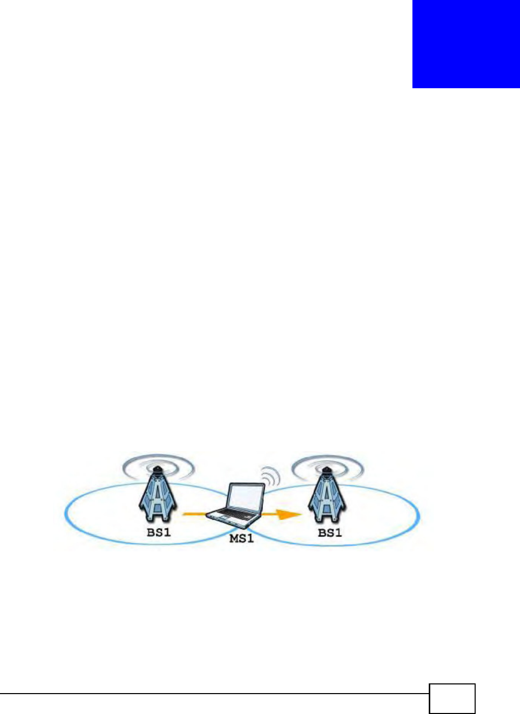
BM2022 Users Guide 65
CHAPTER 6
WiMAX
6.1 Overview
This chapter shows you how to set up and manage the connection between the BM2022 and your
ISPs base stations.
6.1.1 What You Need to Know
The following terms and concepts may help as you read through this chapter.
WiMAX
WiMAX (Worldwide Interoperability for Microwave Access) is the IEEE 802.16 wireless networking
standard, which provides high-bandwidth, wide-range wireless service across wireless Metropolitan
Area Networks (MANs). Huawei is a member of the WiMAX Forum, the industry group dedicated to
promoting and certifying interoperability of wireless broadband products.
In a wireless MAN, a wireless-equipped computer is known either as a mobile station (MS) or a
subscriber station (SS). Mobile stations use the IEEE 802.16e standard and are able to maintain
connectivity while switching their connection from one base station to another base station
(handover) while subscriber stations use other standards that do not have this capability (IEEE
802.16-2004, for example). The following figure shows an MS-equipped notebook computer MS1
moving from base station BS1s coverage area and connecting to BS2.
Figure 15 WiMax: Mobile Station
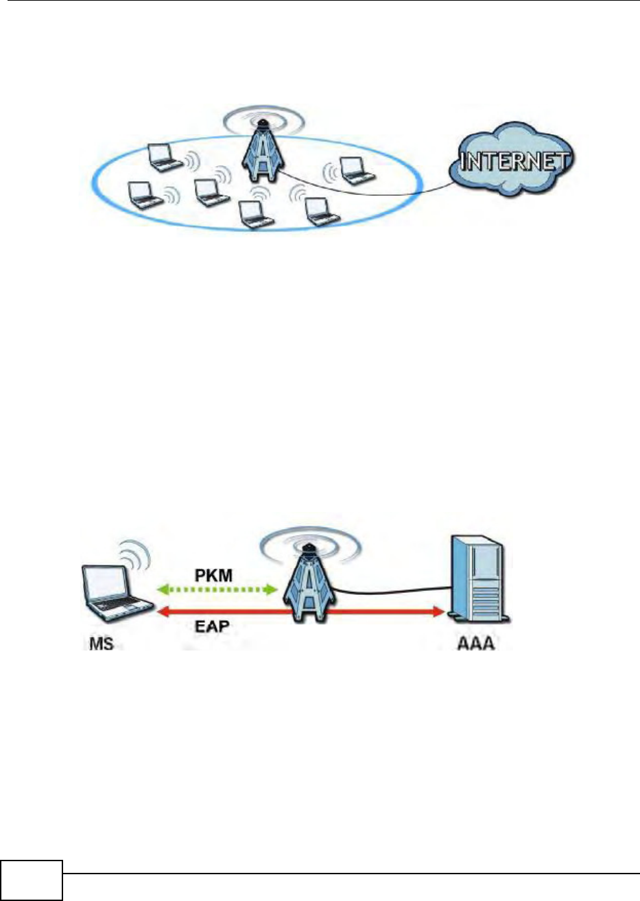
Chapter 6 WiMAX
BM2022 Users Guide
66
WiMAX technology uses radio signals (around 2 to 10 GHz) to connect subscriber stations and
mobile stations to local base stations. Numerous subscriber stations and mobile stations connect to
the network through a single base station (BS), as in the following figure.
Figure 16 WiMAX: Multiple Mobile Stations
A base stations coverage area can extend over many hundreds of meters, even under poor
conditions. A base station provides network access to subscriber stations and mobile stations, and
communicates with other base stations.
The radio frequency and bandwidth of the link between the BM2022 and the base station are
controlled by the base station. The BM2022 follows the base stations configuration.
Authentication
When authenticating a user, the base station uses a third-party RADIUS or Diameter server known
as an AAA (Authentication, Authorization and Accounting) server to authenticate the mobile or
subscriber stations.
The following figure shows a base station using an AAA server to authenticate mobile station MS,
allowing it to access the Internet.
Figure 17 Using an AAA Server
In this figure, the dashed arrow shows the PKM (Privacy Key Management) secured connection
between the mobile station and the base station, and the solid arrow shows the EAP secured
connection between the mobile station, the base station and the AAA server. See the WiMAX
security appendix for more details.
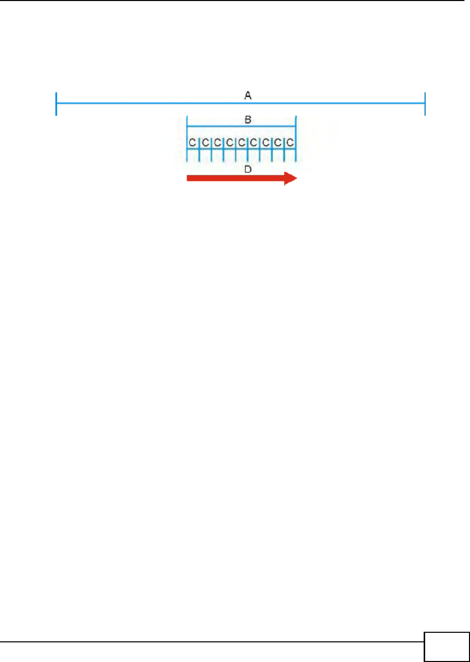
Chapter 6 WiMAX
BM2022 Users Guide 67
Frequency Ranges
The following figure shows the BM2022 searching a range of frequencies to find a connection to a
base station.
Figure 18 Frequency Ranges
In this figure, A is the WiMAX frequency range. WiMAX frequency range refers to the entire range
of frequencies the BM2022 is capable of using to transmit and receive (see the Product
Specifications appendix for details).
In the figure, B shows the operator frequency range. This is the range of frequencies within the
WiMAX frequency range supported by your operator (service provider).
The operator range is subdivided into bandwidth steps. In the figure, each C is a bandwidth step.
The arrow D shows the BM2022 searching for a connection.
Have the BM2022 search only certain frequencies by configuring the downlink frequencies. Your
operator can give you information on the supported frequencies.
The downlink frequencies are points of the frequency range your BM2022 searches for an available
connection. Use the Site Survey screen to set these bands. You can set the downlink frequencies
anywhere within the WiMAX frequency range. In this example, the downlink frequencies have been
set to search all of the operator range for a connection.
Certification Authority
A Certification Authority (CA) issues certificates and guarantees the identity of each certificate
owner. There are commercial certification authorities like CyberTrust or VeriSign and government
certification authorities. You can use the BM2022 to generate certification requests that contain
identifying information and public keys and then send the certification requests to a certification
authority.
Certificate File Formats
The certification authority certificate that you want to import has to be in one of these file formats:
Binary X.509: This is an ITU-T recommendation that defines the formats for X.509 certificates.
PEM (Base-64) encoded X.509: This Privacy Enhanced Mail format uses lowercase letters,
uppercase letters and numerals to convert a binary X.509 certificate into a printable form.
Binary PKCS#7: This is a standard that defines the general syntax for data (including digital
signatures) that may be encrypted. The BM2022 currently allows the importation of a PKS#7 file
that contains a single certificate.

Chapter 6 WiMAX
BM2022 Users Guide
68
PEM (Base-64) encoded PKCS#7: This Privacy Enhanced Mail (PEM) format uses 64 ASCII
characters to convert a binary PKCS#7 certificate into a printable form.
CINR
Carrier to Interference-plus-Noise Ratio (CINR) measures the effectiveness of a wireless signal and
plays an important role in allowing the BM2022 to decode signal burst. If a burst has a high signal
strength and a high interference-plus-noise ratio, it can use Digital Signal Processing (DSP) to
decode it; if the signal strength is lower, it can switch to an alternate burst profile.
RSSI
Received Signal Strength Indicator (RSSI) measures the relative strength of a given wireless signal.
This is important in determining if a signal is below the Clear-To-Send (CTS) threshold. If it is below
the arbitrarily specified threshold, then BM2022 is free to transmit any data packets.
EAP Authentication
EAP (Extensible Authentication Protocol) is an authentication protocol that runs on top of the IEEE
802.1x transport mechanism in order to support multiple types of user authentication. By using EAP
to interact with an EAP-compatible RADIUS server, an access point helps a wireless station and a
RADIUS server perform authentication.
The BM2022 supports EAP-TLS and EAP-TTLS (at the time of writing, TTLS is not available in
Windows Vista). For EAP-TLS authentication type, you must first have a wired connection to the
network and obtain the certificate(s) from a certificate authority (CA). Certificates (also called
digital IDs) can be used to authenticate users and a CA issues certificates and guarantees the
identity of each certificate owner.
6.2 Connection Settings
This screen allows you to configure how the BM2022 connects to the base stations on the WiMAX
network.
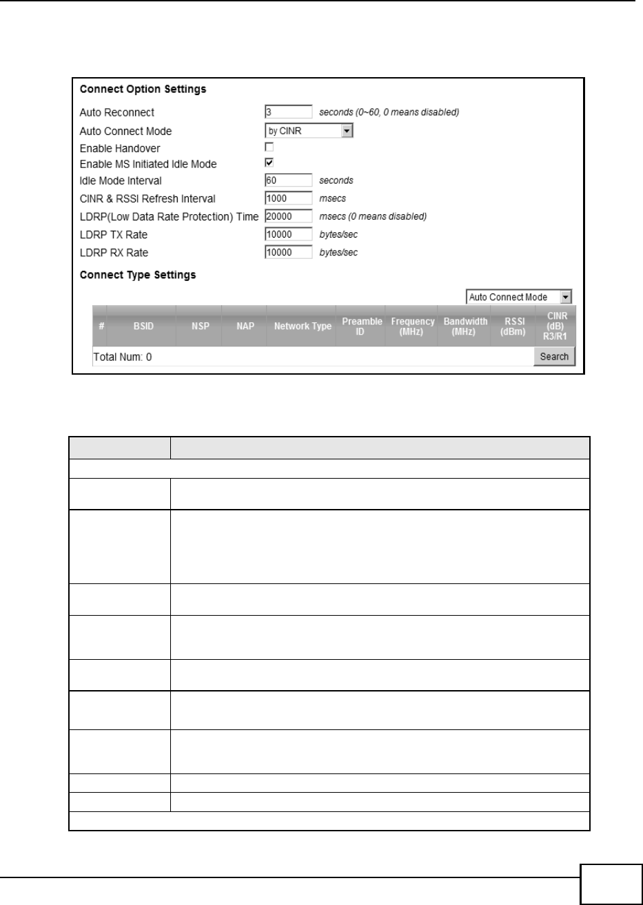
Chapter 6 WiMAX
BM2022 Users Guide 69
Click WiMAX > Profile > Connection Settings to open this screen as shown next.
Figure 19 Connection Settings Screen
This screen contains the following fields:
Table 11 Connection Settings
LABEL DESCRIPTION
Connection Option Settings
Auto
Reconnect
Select the interval in seconds that the BM2022 waits after getting disconnected
from the base station before attempting to reconnect.
Auto Connect
Mode
Select the auto connect mode.
By channel power - Auto connects to the base station if the signal strength
of the channel is sufficient for the BM2022.
By CINR - Auto connects to the base station if the signal-to-noise ratio is
sufficient for the BM2022.
Enable
Handover
Select this to maintain connectivity while the BM2022 switches its connection
from one base station to another base station.
Enable MS
Initiated Idle
Mode
Select this to have the BM2022 enter the idle mode after it has no traffic passing
through for a pre-defined period. Make sure your base station also supports this
before selecting this.
Idle Mode
Interval
Set the idle duration in minutes. This is how long the BM2022 waits during
periods of no activity before going into idle mode.
CINR & RSSI
Refresh
Interval
Set the refresh interval in milliseconds for calculating the signal-to-noise
measurement (CINR) and signal strength measurement (RSSI) of the BM2022.
LDRP (Low
Data Rate
Protection)
Enter the Low Data Rate Protection (LDRP) time in milliseconds. If the uplink/
downlink data rate is smaller than the LDRP time, the BM2022 sends a
disconnect request to the base station.
LDRP TX Rate Enter the outgoing data rates for LDRP in bytes per second.
LDRP RX Rate Enter the incoming data rates for LDRP in bytes per second.
Connection Type Settings

Chapter 6 WiMAX
BM2022 Users Guide
70
6.3 Frequency Settings
Use this screen to have the WiMAX Device to scan one or more specific radio frequencies (given by
your WiMAX service provider) to find available connections to base stations.
Mode Select Select how the BM2022 connects to the base station.
Auto Connect Mode - The device connects automatically to the first base
station in range.
Network Search Mode - The device scans for available base stations then
connects to the best one it can.
BSID This displays the MAC address of a base station within range of the BM2022.
Preamble ID The preamble ID is the index identifier in the header of the base stations
broadcast messages. In the beginning of a mobile stationss network entry
process, it searches for the preamble and uses it to additional channel
information.
The preamble ID is used to synchronize the upstream and downstream
transmission timing with the base station.
Frequency
(MHz)
This field displays the radio frequency of the BM2022s connection to the base
station.
Bandwidth
(MHz)
This field displays the bandwidth of the base station in megahertz (MHz).
RSSI (dBm) This field displays the Received Signal Strength Indication (RSSI), which is an
overall measurement of radio signal strength. A higher RSSI level indicates a
stronger signal.
CINR (dB) R3/
R1
This field displays the average Carrier to Interference plus Noise Ratio for the
current connection. This value is an indication of overall radio signal quality,
where a higher value means a better quality signal.
Search Click this to have the BM2022 scan for base stations.
Table 11 Connection Settings (continued)
LABEL DESCRIPTION
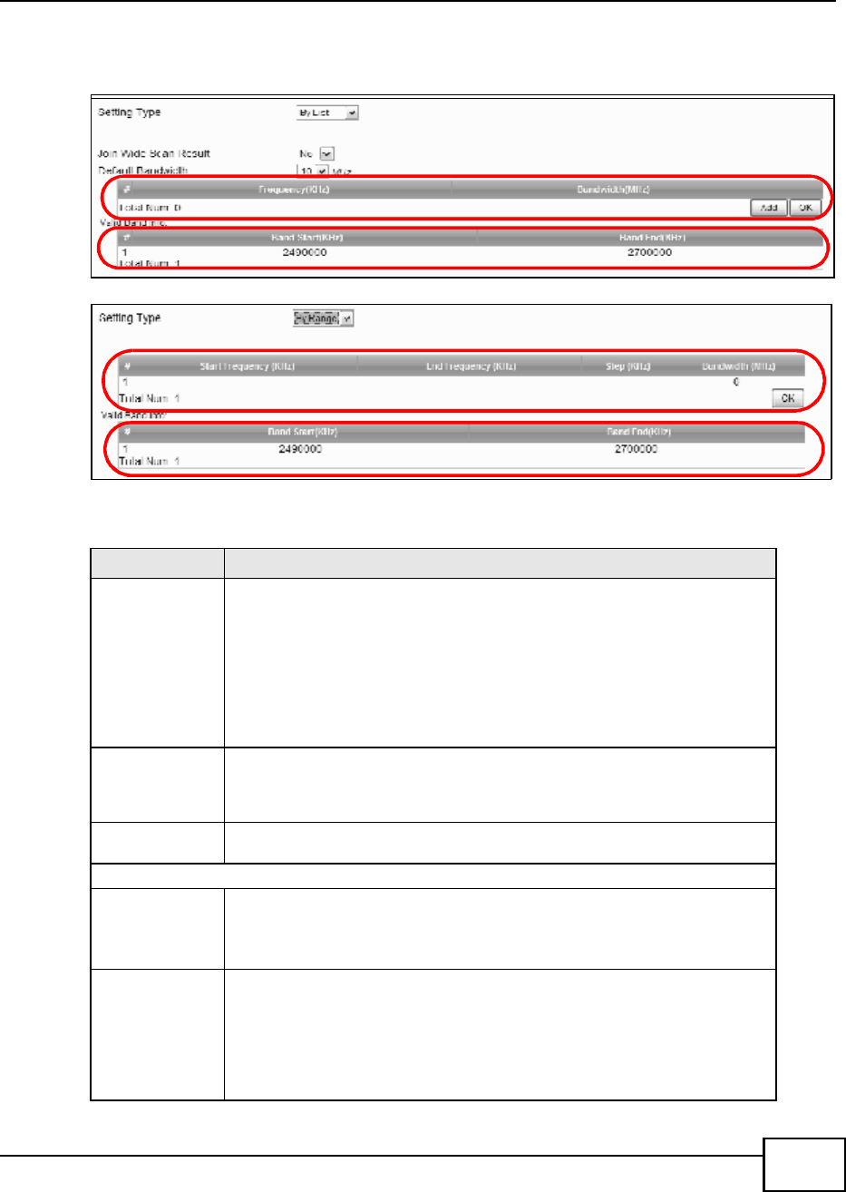
Chapter 6 WiMAX
BM2022 Users Guide 71
Click WiMAX > Profile > Frequency Settings to open this screen as shown next.
Figure 20 Frequency Settings Screen (By List)
Figure 21 Frequency Settings Screen (By Range)
This screen contains the following fields:
Table 12 Frequency Settings
LABEL DESCRIPTION
Setting Type Select whether to scan base stations by entering specific frequency(-ies) (By
List) or a range of frequencies (By Range).
Note: When you select By Range, you can only configure one range of
frequencies in this screen. To configure multiple frequency ranges, use the
WiMAX > Wide Scan screen.
Note: Some settings in this screen are only available depending on the Setting
Type selected.
Join Wide Scan
Result
The scanning result of the frequency to scan you configured in this screen will
be shown in the WiMAX > Connect screen. Select this option to determine
whether to also append the wide scanning result (configured in the WiMAX >
Wide Scan screen) to the same table.
Default
Bandwidth
Select the default bandwidth (size) per frequency band you specify in table A.
A (When By List is selected in the Setting Type field)
Frequency
(KHz)
This displays the center frequency of an frequency band in kilohertz (KHz).
Click the number to modify it.
Enter the center frequency in this field when you are adding an entry.
Bandwidth
(MHz)
This displays the bandwidth of the frequency band in megahertz (MHz). If you
set a center frequency to 2600000 KHz with the bandwidth of 10 MHz, then the
frequency band is from 2595000 to 2605000 KHz.
Click the number to modify it.
Enter the bandwidth of the frequency band in this field when you are adding an
entry.
A
B
A
B

Chapter 6 WiMAX
BM2022 Users Guide
72
6.4 Authentication Settings
These settings allow the WiMAX Device to establish a secure (authenticated) connection with the
service provider.
Delete Click this button to remove an item from the list.
Add Click this button to add an item to the list.
OK Click this button to save any changes made to the list.
A (When By Range is selected in the Setting Type field)
Start
Frequency
(KHz)
This indicates the beginning of a frequency band in kilohertz (KHz).
Click this field to modify it.
Enter the beginning frequency when you are adding an entry.
End
Frequency
(KHz)
This indicates the end of the frequency band in kilohertz (KHz).
Click this field to modify it.
Step (KHz) This indicates the frequency step within each band in kilohertz (KHz).
Click this field to modify it.
Bandwidth
(MHz)
This indicates the bandwidth in megahertz (MHz).
Click this field to modify it.
OK Click this button to save any changes made to the list.
Valid Band Info (B)
This table displays the entire frequency band the BM2022 supports. The frequenc(ies) to scan that
you configured in table A must be within this range.
Band Start
(KHz)
This indicates the beginning of the frequency band in kilohertz (KHz).
Band End
(KHz)
This indicates the end of the frequency band in kilohertz (KHz).
Table 12 Frequency Settings (continued)
LABEL DESCRIPTION
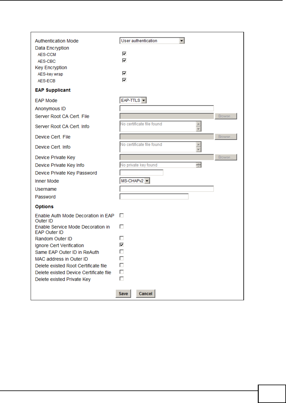
Chapter 6 WiMAX
BM2022 Users Guide 73
Click WiMAX > Profile > Authentication Settings to open this screen as shown next.
Figure 22 Authentication Settings Screen

Chapter 6 WiMAX
BM2022 Users Guide
74
This screen contains the following fields:
Table 13 Authentication Settings
LABEL DESCRIPTION
Authentication
Mode
Select the authentication mode from the list.
The BM2022 supports the following authentication modes:
No authentication
User authentication
Device authentication
User and device authentication
Data Encryption
AES-CCM Select this to enable AES-CCM encryption. CCM combines counter-mode
encryption with CBC-MAC authentication.
AES-CBC Select this to enable AES-CBC encryption. CBC creates message authentication
code from a block cipher.
Key Encryption
AES-key wrap Select this encapsulate cryptographic keys in a symmetric encryption algorithm.
AES-ECB Select this to divide cryptographic keys into blocks and encrypt them separately.
EAP Supplicant
EAP Mode Select an Extensible Authentication Protocol (EAP) mode.
The BM2022 supports the following:
EAP-TLS - In this protocol, digital certifications are needed by both the
server and the wireless clients for mutual authentication. The server presents
a certificate to the client. After validating the identity of the server, the client
sends a different certificate to the server. The exchange of certificates is done
in the open before a secured tunnel is created. This makes user identity
vulnerable to passive attacks. A digital certificate is an electronic ID card that
authenticates the senders identity. However, to implement EAP-TLS, you
need a Certificate Authority (CA) to handle certificates, which imposes a
management overhead.
EAP-TTLS - This protocol is an extension of the EAP-TLS authentication that
uses certificates for only the server-side authentications to establish a secure
connection. Client authentication is then done by sending username and
password through the secure connection, thus client identity is protected. For
client authentication, EAP-TTLS supports EAP methods and legacy
authentication methods such as PAP, CHAP, MS-CHAP and MS-CHAP v2.
Anonymous
ID
Enter the anonymous ID used for EAP supplicant authentication.
Server Root
CA Cert File
Browse for and choose a server root certificate file, if required.
Server Root
CA Info
This field displays information about the assigned server root certificate.
Device Cert
File
Browse for and choose a device certificate file, if required.
Before you import certificate from WebGUI, the certificate file must be signed by
chipset vendor due to security reason.
Device Cert
Info
This field displays information about the assigned device certificate.
Device Private
Key
Browse for and choose a device private key, if required.
Device Private
Key Info
This field displays information about the assigned device private key.
Device Private
Key Password
Enter the device private key, if required.

Chapter 6 WiMAX
BM2022 Users Guide 75
6.5 Channel Plan Settings
This screen allows you to specify channel plan settings for Network Discovery and Selection
(ND&S). The BM2022 uses ND&S to establish connections when it is roaming. To do this, the
BM2022 will scan for base stations that are operated by Network Access Providers (NAP) that have
service agreements with the subscribers service provider (Home-Network Service Provider or
Inner Mode Sets the EAP-TTLS inner mode.
The BM2022 supports the following:
MS-CHAP v2 - This is version 2 of Microsofts variant of Challenge
Handshake Authentication Protocol (CHAP). It allows for mutual
authentication between devices.
MS-CHAP - This is Microsofts variant of Challenge Handshake
Authentication Protocol (CHAP). It allows for mutual authentication between
devices.
CHAP - The Challenge Handshake Authentication Protocol (CHAP) uses PPP
to authenticate remote devices using a three-way handshake and shared
secret verification.
MD5 - Message-Digest, algorithm 5, (MD5) encryption is typically used for
checking file integrity. Because this encryption protocol contains a number of
serious security flaws it is generally not recommended that you use it for
authentication security.
PAP - Password Authentication Protocol uses unencrypted plaintext to send a
passwords for authentication over the network. Its probably not a good idea
to rely on this for security.
Username Enter the username required for the EAP-TTLS inner method.
Password Enter the password required for the EAP-TTLS inner method.
Options
Enable Auth
Mode
Decoration in
EAP Outer ID
Select this to enable authentication mode.
Enable
Service Mode
Decoration in
EAP Outer ID
Select this to enable service mode.
Random Outer
ID
Select this to allow the BM2022 to generate a 16-byte random number as a
username for the EAP Identity Response message.
Ignore Cert
Verification
Select this to ignore base station certification verification when a certificate is
received during EAP-TLS or EAP-TTLS.
Same EAP
OuterID in
ReAuth
Select this to use the same EAP to the outer ID when reauthenticating.
MAC address
in EAP-TLS
outer Id
Adds the MAC address of the BM2022 to the outer ID while the EAP mode is set
to EAP-TLS.
Delete existed
Root
Certificate file
Select this to delete an existing root certificate file from the BM2022.
Delete existed
Device
Certificate file
Select this to delete an existing device certificate file from the BM2022.
Delete existed
Private Key
Select this to delete an existing private key from the BM2022.
Table 13 Authentication Settings (continued)
LABEL DESCRIPTION
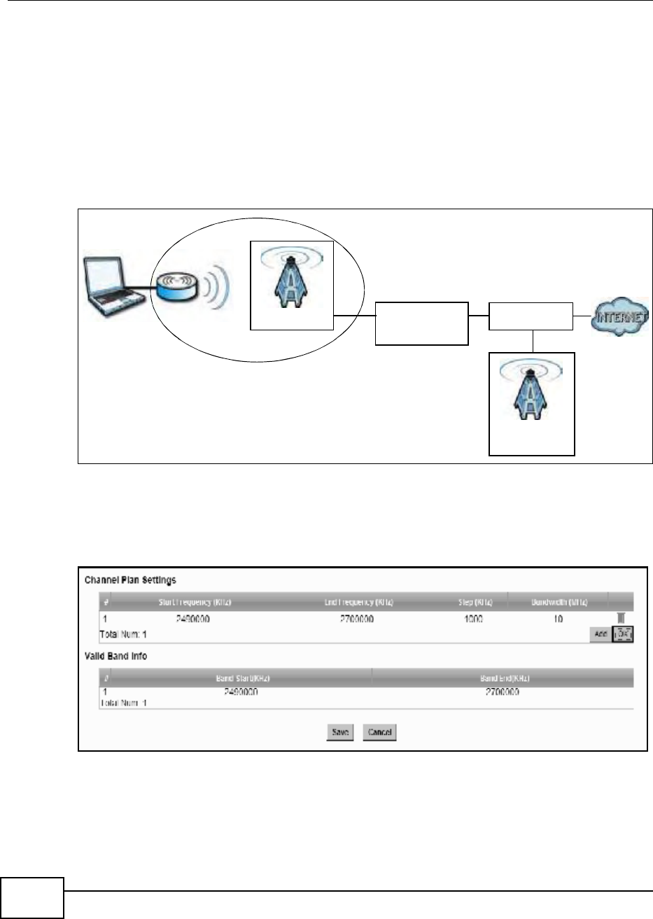
Chapter 6 WiMAX
BM2022 Users Guide
76
Home NSP). Through the NAPs base station, which is identified by a NAP-ID, the subscribers
BM2022 can access the Internet through a network service provider (NSP). Access can be through
another network service provider (Visited-Network Service Provider or V-NSP) or his own network
service provider (Home NSP), depending on his service agreement.
In the following scenario, the subscribers BM2022 cannot reach a base station owned by his Home
NSP (base station with NAP-ID = 1). The BM2022 uses ND&S and is able to access another base
station with NAP-ID = 2. This base station is associated with another service provider (V-NSP with
NSP-ID = 20). The subscribers service agreement specifies to route traffic from the other service
provider to the Home NSP, so the Home NSP authenticates and authorizes the connection.
Figure 23 ND&S Scenario
The channel plan settings specify the allowed frequency range to search for a NAP. The channel
plan is necessary to speed up the network discovery process.
Click WiMAX > ND&S > Channel Plan Settings to open this screen as shown next.
Figure 24 Channel Plan Settings
NAP-ID = 2
NAP-ID = 1
Home NSP
V-NSP
NSP-ID = 20

Chapter 6 WiMAX
BM2022 Users Guide 77
This screen contains the following fields:
6.6 CAPL Settings
This screen allows you to view the Contractual Agreement Preference List (CAPL) of NAPs for base
stations that are preferred for establishing connections. The CAPL is a list of NAPs that are affiliated
with the Home NSP through contractual agreements.
Table 14 Channel Plan Settings
LABEL DESCRIPTION
Channel Plan Settings - You can configure multiple ranges of frequencies to scan for different NAPs.
The configured frequency ranges to scan must be within the Valid Band. Specify the Channel Plan to
scan for each NAP on the CAPL Settings: Add screen (Section 6.6.1 on page 78).
Start
Frequency
(KHz)
This indicates the beginning of a frequency band in kilohertz (KHz).
Click this field to modify it.
Enter the beginning frequency when you are adding an entry.
End
Frequency
(KHz)
This indicates the end of the frequency band in kilohertz (KHz).
Click this field to modify it.
Step (KHz) This indicates the frequency step within each band in kilohertz (KHz).
Click this field to modify it.
The minimum step is 250KHz and the maximum step is the difference between
the start frequency and end frequency.
Bandwidth
(MHz)
This indicates the bandwidth in megahertz (MHz).
Click this field to modify it.
Delete Click this button to remove an item from the list.
Add Click this button to add an item to the list.
OK Click this button to save any changes made to the list.
Valid Band Info - This table displays the entire frequency band the BM2022 supports. The frequency
ranges to scan that you configured in Channel Plan Settings must be within this range.
Band Start
(KHz)
This indicates the beginning of the frequency band in kilohertz (KHz).
Band End
(KHz)
This indicates the end of the frequency band in kilohertz (KHz).
Save Click this to save the changes made.
Cancel Click this avoid any changes made from being saved to your configuration.
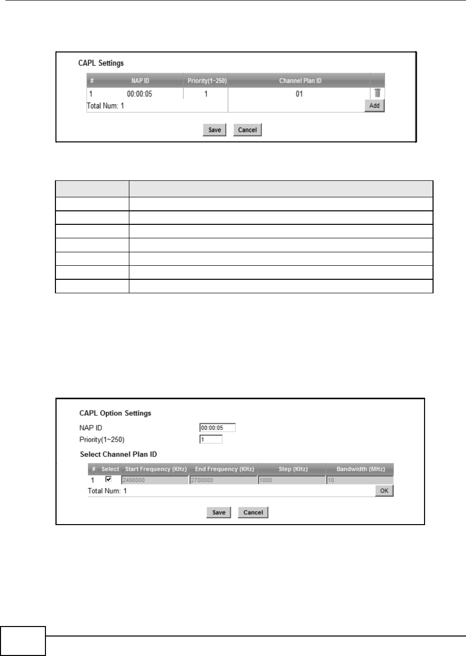
Chapter 6 WiMAX
BM2022 Users Guide
78
Click WiMAX > ND&S > CAPL Settings to open this screen as shown next.
Figure 25 CAPL Settings
This screen contains the following fields:
6.6.1 CAPL Settings: Add
This screen allows you to specify the Contractual Agreement Preference List (CAPL) of NAPs, and
the corresponding channel plan to search for the NAP.
Click WiMAX > ND&S > CAPL Settings: Add to open this screen as shown next.
Figure 26 CAPL Settings: Add
Table 15 CAPL Settings
LABEL DESCRIPTION
NAP ID This displays the NAP ID.
Priority This displays the priority for the NAP ID.
Channel Plan ID This displays the Channel Plan ID.
Delete Click this button to remove an item from the list.
Add Click this button to add an item to the list.
Save Click this to save the changes made.
Cancel Click this avoid any changes made from being saved to your configuration.
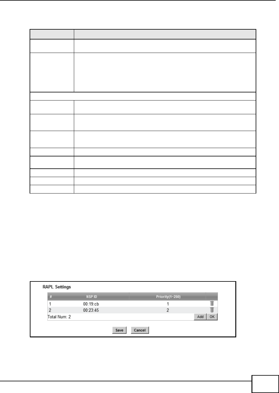
Chapter 6 WiMAX
BM2022 Users Guide 79
This screen contains the following fields:
6.7 RAPL Settings
This screen allows you to specify the Roaming Agreement Preference List (RAPL) of preferred NSPs
for establishing connections to the Home NSP. The RAPL is a list of NSPs that are affiliated with the
Home NSP through roaming agreements. A NSP specified in the RAPL is a V-NSP and can route
data to the Home NSP.
Click WiMAX > ND&S > RAPL Settings to open this screen as shown next.
Figure 27 RAPL Settings
Table 16 CAPL Settings: Add
LABEL DESCRIPTION
NAP ID Specify the NAP ID in the format XX:XX:XX where X is a hexadecimal character.
The NAP ID is typically the first three blocks of the BSID of the base station.
Priority Specify the priority for the NAP ID. Enter 1-250 where 1 is the highest priority.
The BM2022 will search for NAPs according to the priority specified.
Priority may be determined by the number of base stations an NAP has, with a
NAP having more base stations being assigned a higher priority. If the same
priority is assigned to a NAP ID, the BM2022 will consider them as having equal
priority.
Select Channel Plan ID
Select After clicking a Channel Plan ID entry in the list, you can click this check box to
select it.
Start
Frequency
(KHz)
This indicates the beginning of a frequency band in kilohertz (KHz).
End
Frequency
(KHz)
This indicates the end of the frequency band in kilohertz (KHz).
Step (KHz) This indicates the frequency step within each band in kilohertz (KHz).
Bandwidth
(MHz)
This indicates the bandwidth in megahertz (MHz).
OK Click this button to save any changes made to the list.
Save Click this to save the changes made.
Cancel Click this avoid any changes made from being saved to your configuration.
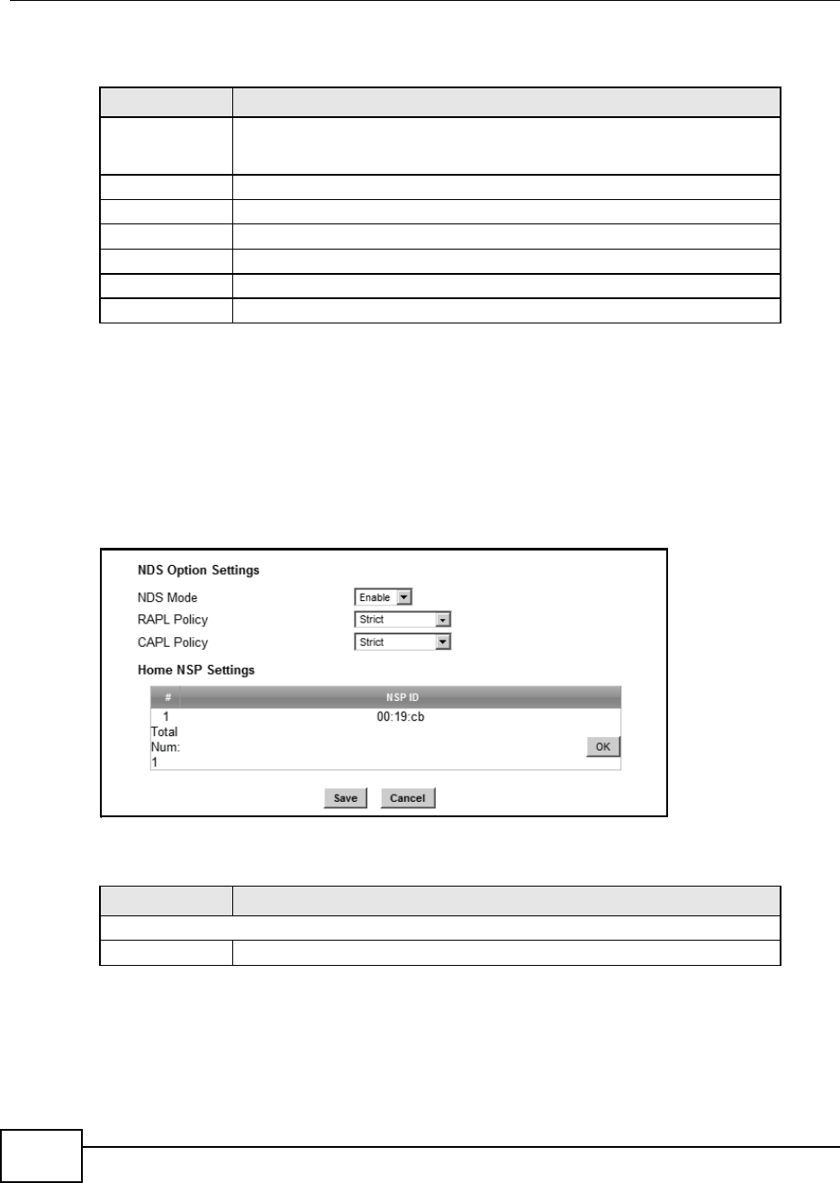
Chapter 6 WiMAX
BM2022 Users Guide
80
This screen contains the following fields:
6.8 Home NSP Settings
On this screen, you can configure settings for the Home NSP. The Home NSP can authenticate and
authorize connections and may support roaming through relationships with other NSPs.
Click WiMAX > ND&S > Home NSP Settings to open this screen as shown next.
Figure 28 Home NSP Settings
This screen contains the following fields:
Table 17 RAPL Settings
LABEL DESCRIPTION
NSP ID Specify the Network Service Provider (NSP) ID in the format XX:XX:XX where X
is a hexadecimal character. If the Home NSP ID is entered in this list, the
BM2022 will try to use it to establish a connection.
Priority Specify the priority for the NSP. Enter 1-250 where 1 is the highest priority.
Delete Click this button to remove an item from the list.
Add Click this button to add an item to the list.
OK Click this button to save any changes made to the list.
Save Click this to save the changes made.
Cancel Click this avoid any changes made from being saved to your configuration.
Table 18 Home NSP Settings
LABEL DESCRIPTION
NDS Option Settings
NDS Mode Select Enable to use NDS to establish connections to the Home NSP.

Chapter 6 WiMAX
BM2022 Users Guide 81
6.9 Connect
This screen allows you to view the available WiMAX frequency band(s) and base station(s) the
BM2022 found through scanning and choose a base station to which to connect.
RAPL Policy Select Strict to only allow V-NSPs specified in the RAPL to be used for
establishing connections to the H-NSP.
Select Partially Flexible to allow the BM2022 to use V-NSPs not specified in the
RAPL to connect to the H-NSP. Before attempting V-NSPs not specified in the
RAPL the BM2022 will first try the V-NSPs specified in the RAPL to connect to the
H-NSP.
Select Flexible to allow the BM2022 to use any V-NSPs for establishing
connections to the H-NSP. V-NSPs specified in the RAPL will have the same
priority as V-NSPs not specified in the RAPL.
CAPL Policy Select Strict to only allow NAPs specified in the CAPL to be used for establishing
connections to the H-NSP.
Select Partially Flexible to allow the BM2022 to use NAPs not specified in the
CAPL to connect to the H-NSP. Before attempting NAPs not specified in the CAPL
the BM2022 will first try the NAPs specified in the CAPL to connect to the H-NSP.
Select Flexible to allow the BM2022 to use any NAPs for establishing
connections to the H-NSP. NAPs specified in the CAPL will have the same priority
as NAPs not specified in the CAPL.
Home NSP Settings
NSP ID After clicking the entry in the NSP ID list, you can enter the NSP ID for the Home
NSP here in the format XX:XX:XX where X is a hexadecimal character. Only one
Home NSP can be entered.
OK Click this button to save any changes made to the list.
Save Click this button to save any changes made to the list.
Note: If you change the NDS Mode, the BM2022 will reboot when you click save.
Cancel Click this avoid any changes made from being saved to your configuration.
Table 18 Home NSP Settings (continued)
LABEL DESCRIPTION
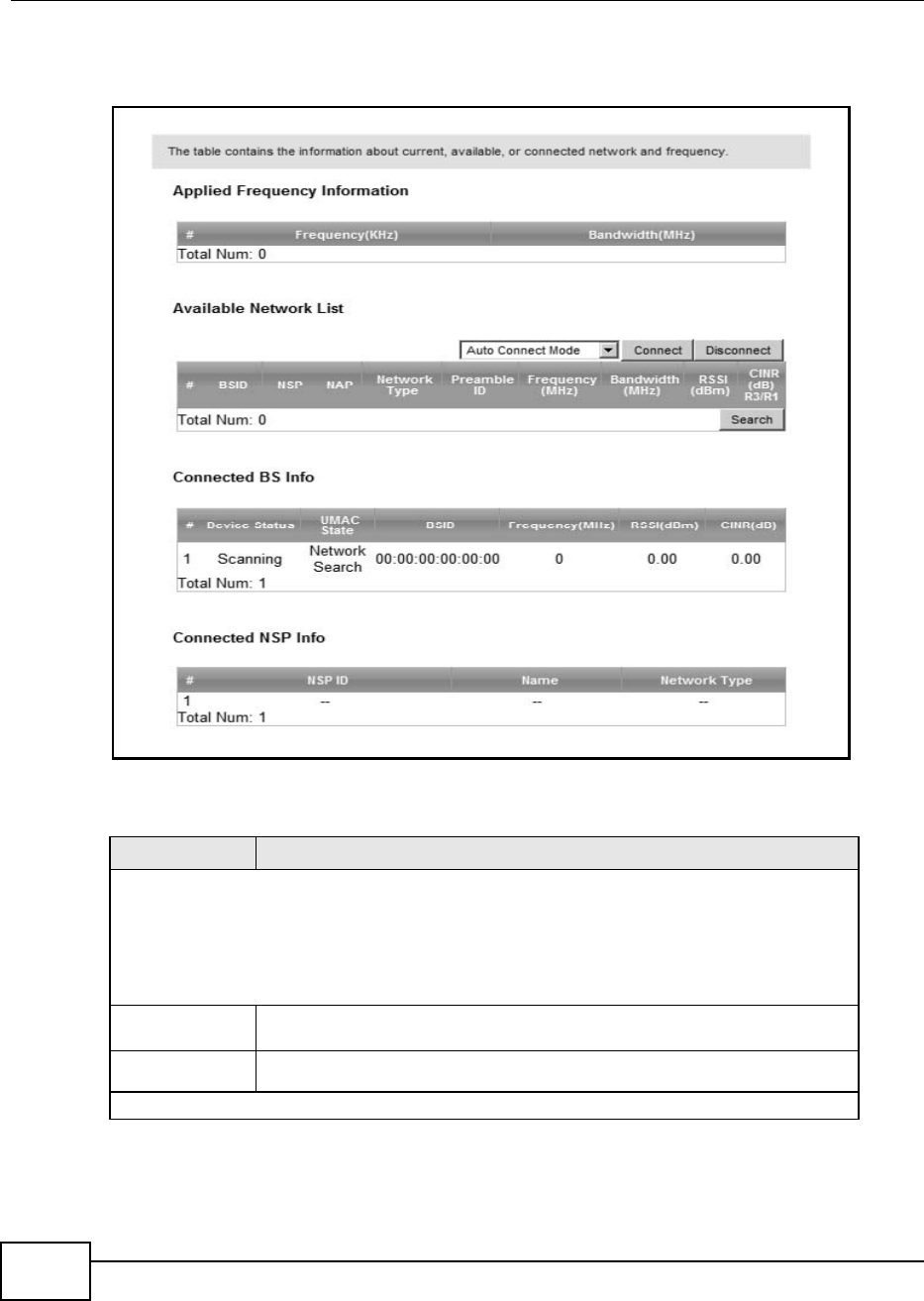
Chapter 6 WiMAX
BM2022 Users Guide
82
Click WiMAX > Connect to open this screen as shown next.
Figure 29 Connect Screen
This screen contains the following fields:
Table 19 Connect
LABEL DESCRIPTION
Applied Frequency Information
This table shows the scanning result you made in the WiMAX > Profile > Frequency Settings and
WiMAX > Wide Scan screens.
Note: You cannot see the wide scanning result that you made in WiMAX > Wide Scan screen if the
Join Wide Scan Result is set to No in the WiMAX > Profile > Frequency Settings screen.
Frequency
(KHz)
This field displays the available center frequency of a frequency band in kilohertz
(KHz).
Bandwidth
(MHz)
This field displays the bandwidth of the frequency band in megahertz (MHz).
Available Network List

Chapter 6 WiMAX
BM2022 Users Guide 83
Connected
Mode
Select a connect mode:
Auto Connect Mode - This allows the BM2022 to connect to any of the base
stations on the list automatically.
Network Search Mode - This allows the BM2022 to connect to a user-
specified base station. Select this option, choose a base station, click
Connect.
NSP Mode - This allows the BM2022 to connect to a base station with a
user-specified NSP ID. To specify the NSP ID, select a result in the list and
click Connect. The BM2022 will automatically connect to a base station with
the same NSP ID, and the best CINR or RSSI.
NSP/NAP Mode - This allows the BM2022 to connect to a base station with
a user-specified NSP ID and NAP ID. To specify the NSP ID and NAP ID,
select a result in the list and click Connect. The BM2022 will automatically
connect to a base station with the same NSP ID and NAP ID, and the best
CINR or RSSI.
NSP/NAP/BSID Mode - This allows the BM2022 to connect to a base
station with a user-specified NSP ID, NAP ID and BSID. To specify the NSP
ID, NAP ID and BSID, select a result in the list and click Connect. The
BM2022 will automatically connect to a base station with the same NSP ID,
NAP ID and BSID, and the best CINR or RSSI.
Connect Click this to connect to the selected base station.
Disconnect Click this to disconnect from the selected base station.
BSID This field displays the base station MAC address.
NSP This field displays the NSP ID.
NAP This field displays the NAP ID.
Network Type This field displays the network type.
Preamble ID This field displays the preamble ID.
The preamble ID is the index identifier in the header of the base stations
broadcast messages. In the beginning of a mobile stationss network entry
process, it searches for the preamble and uses it to additional channel
information.
The preamble ID is used to synchronize the upstream and downstream
transmission timing with the base station.
Frequency
(MHz)
This field displays the center frequency the base station uses in kilohertz (KHz).
Bandwidth
(MHz)
This field displays the frequency band bandwidth the base station uses in
megahertz (MHz).
RSSI (dBm) This field displays the Received Signal Strength Indication (RSSI), which is an
overall measurement of radio signal strength. A higher RSSI level indicates a
stronger signal.
CINR (dB) R3/
R1
This field displays the average Carrier to Interference plus Noise Ratio for the
current connection. This value is an indication of overall radio signal quality,
where a higher value means a better quality signal.
Search Click this to have the BM2022 scan for base stations in the frequency band(s)
listed in the Applied Frequency Information table.
Connected BS Info
Table 19 Connect (continued)
LABEL DESCRIPTION

Chapter 6 WiMAX
BM2022 Users Guide
84
6.10 Wide Scan
This screen allows you to discover base stations by entering one or more frequency ranges and
bandwidth on which to scan.
Device Status This field displays the BM2022 current status for connecting to the selected base
station.
Scanning - The BM2022 is scanning for available base stations.
Ready - The BM2022 has finished scanning and you can connect to a base
station.
Connecting - The BM2022 attempts to connect to the selected base station.
Connected - The BM2022 has successfully connected to the selected base
station.
UMAC State This field displays the status of the WiMAX connection between the BM2022 and
the base station.
Network Search - The BM2022 is scanning for any available WiMAX
connections.
Disconnected - No WiMAX connection is available.
Network Entry - A WiMAX connection is initializing.
Normal - The WiMAX connection has been successfully established.
BSID This field displays the MAC address of the base station to which the BM2022 is
connected.
Frequency
(MHz)
This field displays the frequency the base station uses in megahertz (MHz).
RSSI (dBm) This field displays the Received Signal Strength Indication (RSSI), which is an
overall measurement of radio signal strength. A higher RSSI level indicates a
stronger signal.
CINR (dB) This field displays the average Carrier to Interference plus Noise Ratio for the
current connection. This value is an indication of overall radio signal quality,
where a higher value means a better quality signal.
Connected NSP Info
NSP ID This field displays the NSP ID of the connected NSP.
Name This field displays the name of the connected NSP.
Network Type This field displays the network type of the connected NSP.
Table 19 Connect (continued)
LABEL DESCRIPTION
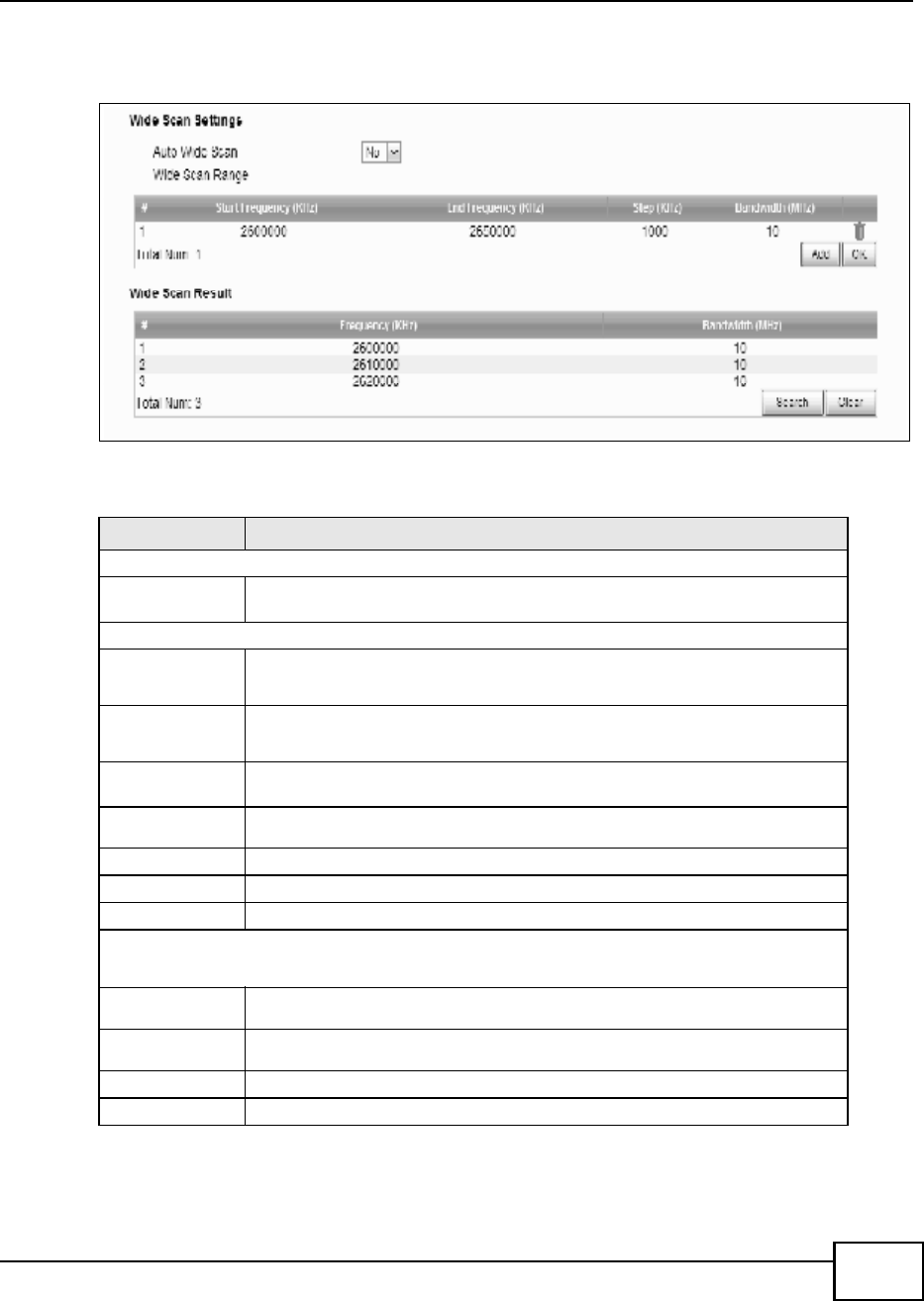
Chapter 6 WiMAX
BM2022 Users Guide 85
Click WiMAX > Wide Scan to open this screen as shown next.
Figure 30 Wide Scan Screen
This screen contains the following fields:
Table 20 Wide Scan
LABEL DESCRIPTION
Wide Scan Settings
Auto Wide
Scan
Use this to enable (Yes) or disable (No) automatically scanning for base
stations.
Wide Scan Range
Start
Frequency
(KHz)
Enter the start frequency in kilohertz (KHz) for a wide scan range.
End
Frequency
(KHz)
Enter the end frequency in kilohertz (KHz) for a wide scan range.
Step (KHz) Enter the step increment in kilohertz (KHz) that the wide scan jumps each time it
scans between the start and end frequencies.
Bandwidth
(MHz)
Enter the frequency bandwidth to be scanned.
Delete Click this to remove a range of frequencies from the wide scan range list.
Add Click this to add a range of frequencies to the wide scan range list.
OK Click this so save any changes to the wide scan range list.
Wide Scan Result
This table displays the available frequency band(s) found through the wide scan.
Frequency
(KHz)
This field displays the frequency in kilohertz (KHz).
Bandwidth
(MHz)
This field displays the bandwidth in megahertz (MHz).
Search Click this to initiate a wide scan.
Clear Click this to clear the wide scan results.
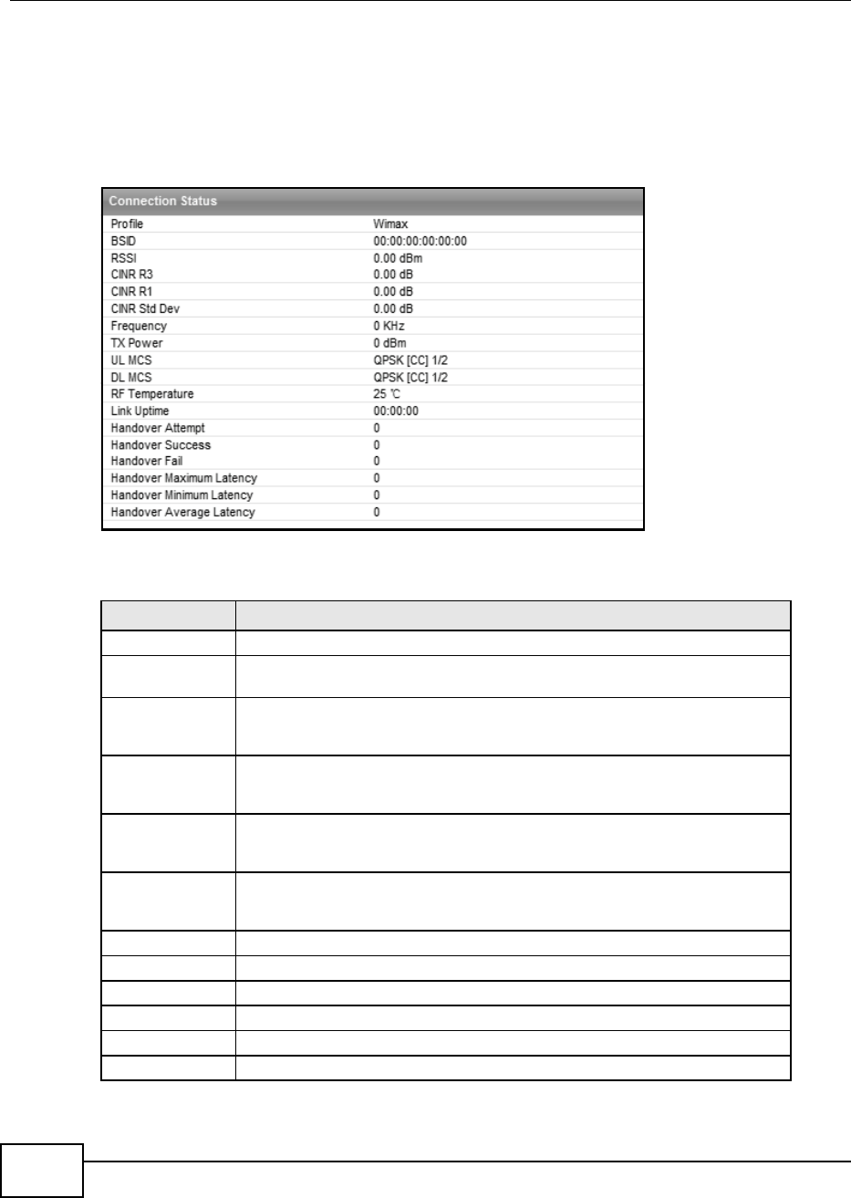
Chapter 6 WiMAX
BM2022 Users Guide
86
6.11 Link Status
This screen provides a general overview of the current WiMAX connection with the service provider.
Click WiMAX > Link Status to open this screen as shown next.
Figure 31 Link Status Screen
This screen contains the following fields:
Table 21 Link Status
LABEL DESCRIPTION
Profile This field displays the profile name.
BSID This field displays the MAC address of the base station to which the BM2022 is
currently connected.
RSSI This field displays the Received Signal Strength Indication (RSSI), which is an
overall measurement of radio signal strength. A higher RSSI level indicates a
stronger signal.
CINR R3 This field displays the average Carrier to Interference plus Noise Ratio (R3) for
the current connection. This value is an indication of overall radio signal quality,
where a higher value means a better quality signal.
CINR R1 This field displays the average Carrier to Interference plus Noise Ratio (R1) for
the current connection. This value is an indication of overall radio signal quality,
where a higher value means a better quality signal.
CINR Std Dev This field displays the average Carrier to Interference plus Noise Ratio (Std Dev)
for the current connection. This value is an indication of overall radio signal
quality, where a higher value means a better quality signal.
Frequency This field displays the frequency in kilohertz (KHz).
TX Power This field displays the transmission power of the BM2022 in dBm.
UL MCS This field displays the Uplink Modulation and Coding Sequence (UL MCS).
DL MCS This field displays the Downlink Modulation and Coding Sequence (DL MCS).
RF Temperature This field displays the temperature in centigrade of the BM2022s RF circuit.
Link Uptime This field displays the length of time the current connection has been up.

Chapter 6 WiMAX
BM2022 Users Guide 87
6.12 Link Statistics
This screen provides a detailed overview of the current WiMAX connection with the service provider.
Handover Success This field displays how many times the BM2022 had ever successfully switched
its connection from one base station to another base station, since the BM2022
last restarted.
Handover Fail This field displays how many times the BM2022 had been failed to switch its
connection from one base station to another base station, since the BM2022 last
restarted.
Handover
Maximum Latency
This field displays the maximum latency for switching connections from one base
station to another base station, since the BM2022 last restarted.
Handover
Minimum Latency
This field displays the minimum latency for switching connections from one base
station to another base station, since the BM2022 last restarted.
Handover
Average Latency
This field displays the average latency for switching connections from one base
station to another base station, since the BM2022 last restarted.
Table 21 Link Status (continued)
LABEL DESCRIPTION
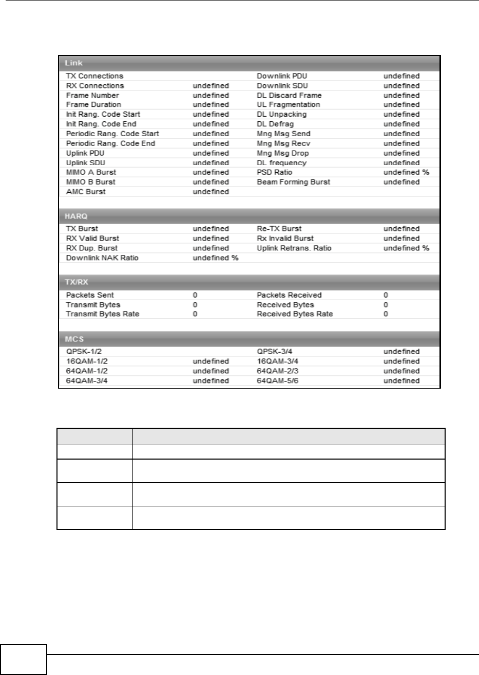
Chapter 6 WiMAX
BM2022 Users Guide
88
Click WiMAX > Link Statistics to open this screen as shown next.
Figure 32 Link Statistics Screen
This screen contains the following sections:
6.13 Connection Info
This screen displays all of the connections made through the WiMAX device since its last reboot.
Table 22 Link Statistics
LABEL DESCRIPTION
Link This section provides a detailed overview of link statistics.
HARQ This section provides a detailed overview of Hybrid Automatic Repeat Request
link statistics.
TX/RX This section provides a detailed overview of transmission and receiving link
statistics.
MCS This section provides a detailed overview of Modulation and Coding Sequence
(MCS) link statistics
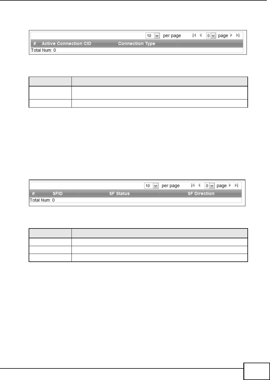
Chapter 6 WiMAX
BM2022 Users Guide 89
Click WiMAX > Connection Info to open this screen as shown next.
Figure 33 Connection Info Screen
This screen contains the following fields:
6.14 Service Flow
This screen displays data priority information for all of the connections made through the WiMAX
device since its last reboot.
Click WiMAX > Service Flow to open this screen as shown next.
Figure 34 Service Flow Screen
This screen contains the following fields:
Table 23 Connection Info
LABEL DESCRIPTION
Active Connection
CID
This displays the unique, unidirectional 16-bit Connection Identifier (CID) for an
active connection.
Connection Type This displays the type of connection.
Table 24 Service Flow
LABEL DESCRIPTION
SFID This displays a 32-bit service flow identifier.
SF Status This display the service flow status.
SF Direction This displays the service flow direction.

Chapter 6 WiMAX
BM2022 Users Guide
90

BM2022 Users Guide 91
CHAPTER 7
Network Setting
7.1 Overview
This chapter shows you how to configure the BM2022s network setting.
7.1.1 What You Need to Know
The following terms and concepts may help as you read through this chapter.
IP Address
IP addresses identify individual devices on a network. Every networking device (including
computers, servers, routers, printers, etc.) needs an IP address to communicate across the
network. These networking devices are also known as hosts.
Subnet Masks
Subnet masks determine the maximum number of possible hosts on a network. You can also use
subnet masks to divide one network into multiple sub-networks.
DHCP
A DHCP (Dynamic Host Configuration Protocol) server can assign your BM2022 an IP address,
subnet mask, DNS and other routing information when its turned on.
DNS Server Address
DNS (Domain Name System) is for mapping a domain name to its corresponding IP address and
vice versa. The DNS server is extremely important because without it, you must know the IP
address of a machine before you can access it. The DNS server addresses that you enter in the
DHCP setup are passed to the client machines along with the assigned IP address and subnet mask.
There are two ways that an ISP disseminates the DNS server addresses. The first is for an ISP to
tell a customer the DNS server addresses, usually in the form of an information sheet, when s/he
signs up. If your ISP gives you the DNS server addresses, enter them in the DNS Server fields;
otherwise, leave them blank.
Some ISPs choose to pass the DNS servers using the DNS server extensions of PPP IPCP (IP Control
Protocol) after the connection is up. If your ISP did not give you explicit DNS servers, chances are
the DNS servers are conveyed through IPCP negotiation. The BM2022 supports the IPCP DNS
server extensions through the DNS proxy feature.

Chapter 7 Network Setting
BM2022 Users Guide
92
If the Primary and Secondary DNS Server fields are not specified, for instance, left as 0.0.0.0,
the BM2022 tells the DHCP clients that it itself is the DNS server. When a computer sends a DNS
query to the BM2022, the BM2022 forwards the query to the real DNS server learned through IPCP
and relays the response back to the computer.
Please note that DNS proxy works only when the ISP uses the IPCP DNS server extensions. It does
not mean you can leave the DNS servers out of the DHCP setup under all circumstances. If your ISP
gives you explicit DNS servers, make sure that you enter their IP addresses. This way, the BM2022
can pass the DNS servers to the computers and the computers can query the DNS server directly
without the BM2022s intervention.
RIP Setup
RIP (Routing Information Protocol) allows a router to exchange routing information with other
routers. The RIP Direction field controls the sending and receiving of RIP packets. When set to:
RX/TX - the BM2022 will broadcast its routing table periodically and incorporate the RIP
information that it receives.
RX Only - the BM2022 will not send any RIP packets but will accept all RIP packets received.
TX Only - the BM2022 will send out RIP packets but will not accept any RIP packets received.
None - the BM2022 will not send any RIP packets and will ignore any RIP packets received.
The Version field controls the format and the broadcasting method of the RIP packets that the
BM2022 sends (it recognizes both formats when receiving). RIP-1 is universally supported; but RIP-
2 carries more information. RIP-1 is probably adequate for most networks, unless you have an
unusual network topology.
Both RIP-2B and RIP-2M sends the routing data in RIP-2 format; the difference being that RIP-2B
uses subnet broadcasting while RIP-2M uses multicasting.
Port Forwarding
A NAT server set is a list of inside (behind NAT on the LAN) servers, for example, web or FTP, that
you can make accessible to the outside world even though NAT makes your whole inside network
appear as a single machine to the outside world.
With port forwarding, you can forward incoming service requests to the server(s) on your local
network. You may enter a single port number or a range of port numbers to be forwarded, and the
local IP address of the desired server. The port number identifies a service; for example, web
service is on port 80 and FTP on port 21. In some cases, such as for unknown services or where one
server can support more than one service (for example both FTP and web service), it might be
better to specify a range of port numbers.
In addition to the servers for specified services, NAT supports a default server. A service request
that does not have a server explicitly designated for it is forwarded to the default server. If the
default is not defined, the service request is simply discarded.
For example, let's say you want to assign ports 21-25 to one FTP, Telnet and SMTP server (A in the
example), port 80 to another (B in the example) and assign a default server IP address of
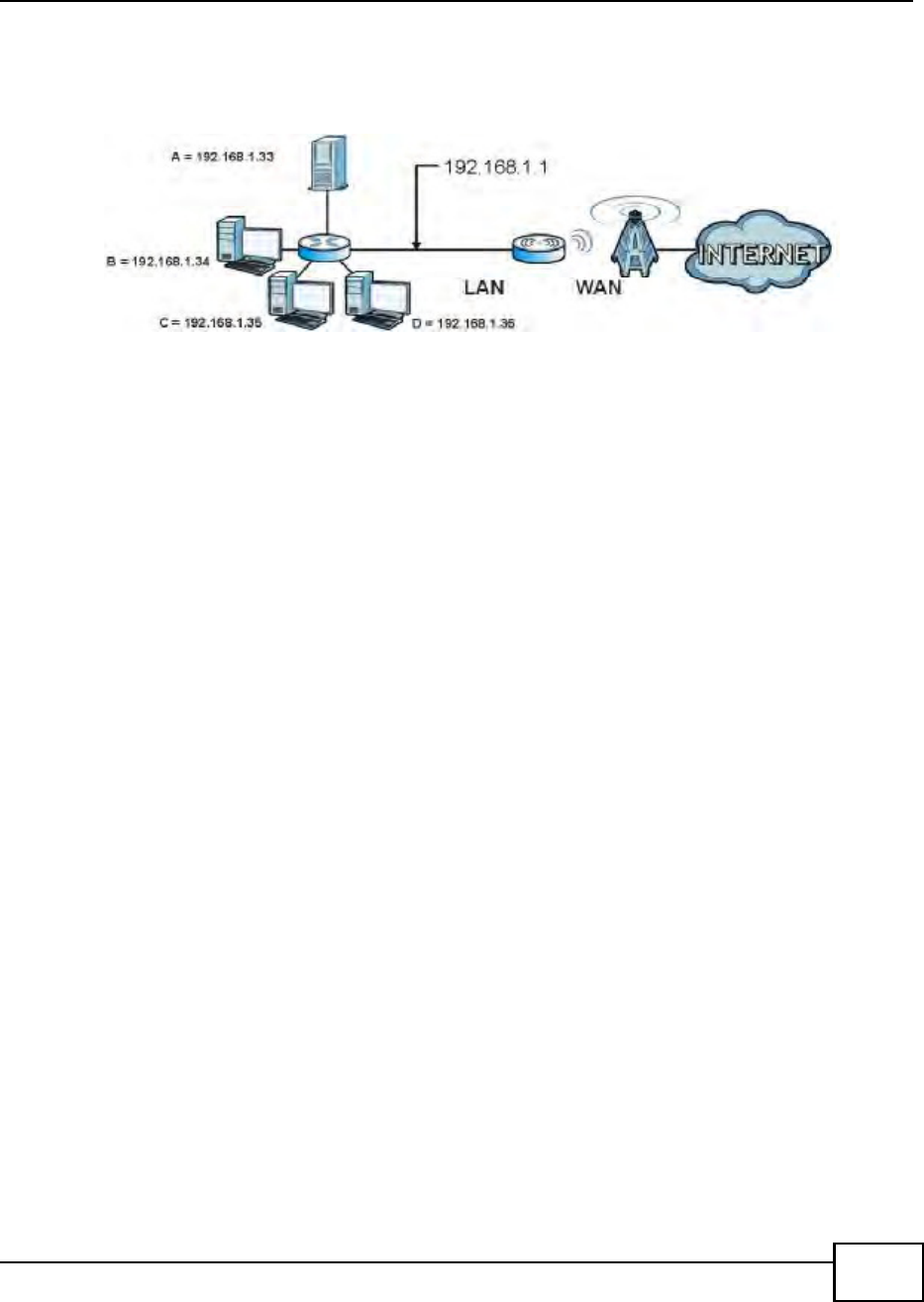
Chapter 7 Network Setting
BM2022 Users Guide 93
192.168.1.35 to a third (C in the example). You assign the LAN IP addresses and the ISP assigns
the WAN IP address. The NAT network appears as a single host on the Internet.
Figure 35 Multiple Servers Behind NAT Example
Trigger Ports
Some services use a dedicated range of ports on the client side and a dedicated range of ports on
the server side. With regular port forwarding you set a forwarding port in NAT to forward a service
(coming in from the server on the WAN) to the IP address of a computer on the client side (LAN).
The problem is that port forwarding only forwards a service to a single LAN IP address. In order to
use the same service on a different LAN computer, you have to manually replace the LAN
computer's IP address in the forwarding port with another LAN computer's IP address,
Trigger port forwarding solves this problem by allowing computers on the LAN to dynamically take
turns using the service. The BM2022 records the IP address of a LAN computer that sends traffic to
the WAN to request a service with a specific port number and protocol (a "trigger" port). When the
BM2022's WAN port receives a response with a specific port number and protocol ("incoming" port),
the BM2022 forwards the traffic to the LAN IP address of the computer that sent the request. After
that computers connection for that service closes, another computer on the LAN can use the
service in the same manner. This way you do not need to configure a new IP address each time you
want a different LAN computer to use the application.
ALG
Some applications, such as SIP, cannot operate through NAT (are NAT un-friendly) because they
embed IP addresses and port numbers in their packets data payload. Some NAT routers may
include a SIP Application Layer Gateway (ALG). An Application Layer Gateway (ALG) manages a
specific protocol (such as SIP, H.323 or FTP) at the application layer.
A SIP ALG allows SIP calls to pass through NAT by examining and translating IP addresses
embedded in the data stream.
UPnP
Universal Plug and Play (UPnP) is a distributed, open networking standard that uses TCP/IP for
simple peer-to-peer network connectivity between devices. A UPnP device can dynamically join a
network, obtain an IP address, convey its capabilities and learn about other devices on the network.
In turn, a device can leave a network smoothly and automatically when it is no longer in use.
How do I know if I'm using UPnP?

Chapter 7 Network Setting
BM2022 Users Guide
94
UPnP hardware is identified as an icon in the Network Connections folder (Windows XP). Each UPnP
compatible device installed on your network will appear as a separate icon. Selecting the icon of a
UPnP device will allow you to access the information and properties of that device.
NAT Traversal
UPnP NAT traversal automates the process of allowing an application to operate through NAT. UPnP
network devices can automatically configure network addressing, announce their presence in the
network to other UPnP devices and enable exchange of simple product and service descriptions.
NAT traversal allows the following:
Dynamic port mapping
Learning public IP addresses
Assigning lease times to mappings
Windows Messenger is an example of an application that supports NAT traversal and UPnP.
Cautions with UPnP
The automated nature of NAT traversal applications in establishing their own services and opening
firewall ports may present network security issues. Network information and configuration may also
be obtained and modified by users in some network environments.
All UPnP-enabled devices may communicate freely with each other without additional configuration.
Disable UPnP if this is not your intention.
UPnP and Huawei
Huawei has received UPnP certification from the official UPnP Forum (http://www.upnp.org).
Huawei's UPnP implementation supports IGD 1.0 (Internet Gateway Device).
The BM2022 only sends UPnP multicasts to the LAN.
Content Filter
Internet content filtering allows you to create and enforce Internet access policies tailored to their
needs. Content filtering is the ability to block certain specific URL keywords.
7.2 WAN
Use these settings to configure the WAN connection between the WiMAX Device and the service
provider.
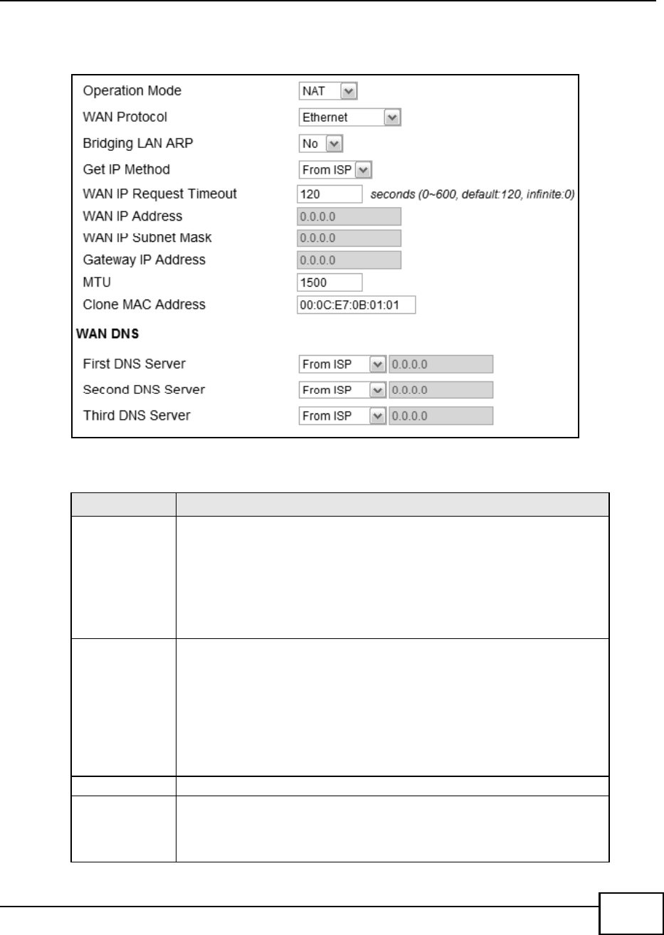
Chapter 7 Network Setting
BM2022 Users Guide 95
Click Network Setting > WAN to open this screen as shown next.
Figure 36 WAN Screen
This screen contains the following fields:
Table 25 WAN
LABEL DESCRIPTION
Operation Mode Select the BM2022s operational mode.
Bridge - This puts the BM2022 in bridge mode, acting as a transparent
middle man between devices on the LAN and the devices on the WAN.
Router - Select Router from the drop-down list box if your ISP gives you one
IP address only and you want multiple computers to share an Internet
account.
NAT - This allows the BM2022 to tag frames for NAT, allowing devices on the
LAN to use their own internal IP addresses while communicating with devices
on the WAN.
WAN Protocol Select the protocol the BM2022 uses to connect to the WAN.
The options are:
Ethernet - Select this if you have a persistent connection to the network.
PPPoE - Select this if must log into the network before initiating a persistent
connection.
GRE Tunnel - Select this if you connect to the network using Point-to-Point
Protocol to create VPNs.
EtherIP - Select this if you need to tunnel Ethernet and IEEE 802.3 MAC
frames across an IP Internet.
Bridging LAN ARP This option enables or disables allow ARP requests to cross the BM2022.
Get IP Method Select how the BM2022 receives its IP address.
User - Select this to manually enter the IP address the BM2022 uses.
From ISP - Select to automatically get the IP address the BM2022 uses from
the ISP.
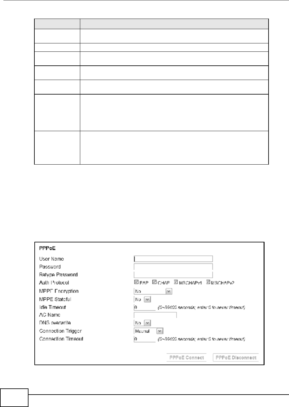
Chapter 7 Network Setting
BM2022 Users Guide
96
7.3 PPPoE
Use these settings to configure the PPPoE connection between the WiMAX Device and the service
provider.
Click Network Setting > WAN > PPPoE.
Figure 37 PPPoE Screen
WAN IP Request
Timeout
Enter the number of seconds the BM2022 waits for an IP from the ISP before it
times out.
WAN IP Address If the BM2022 gets its IP from the user, enter the IP address it is to use.
WAN IP Subnet
Mask
If the BM2022 gets its IP from the ISP, enter the IP address it is to use.
Gateway IP
Address
If the BM2022 gets its gateway IP address from the user, enter the IP address it
is to use.
MTU Enter the Maximum Transmission Unit (MTU) for the BM2022. This is the largest
protocol unit that the BM2022 allows to pass through it.
Clone MAC
Address
Enter a MAC address here for registering bridged devices on the network if their
current MAC addresses are causing problems. For example, this can happen
when a desktop computer swaps network interface cards; the original NIC may
have used its MAC address to register itself on the network and now the new NIC
is unrecognized. Using a MAC address that you know is valid, i.e. a clone,
allows that device to stay registered.
First~Third DNS
Server
Select how the BM2022 acquires its DNS server address.
From ISP - Select this to have the BM2022 acquire its DNS server address
from the ISP.
User Define - Select this to manually enter the DNS server used by the
BM2022.
Table 25 WAN (continued)
LABEL DESCRIPTION

Chapter 7 Network Setting
BM2022 Users Guide 97
This screen contains the following fields:
7.4 GRE
Use these settings to configure the peer setting of the Generic Routing Encapsulation (GRE) tunnel
between the WiMAX Device and another GRE peer.
Click Network Setting > WAN > GRE to open this screen as shown next.
Figure 38 GRE Screen
Table 26 PPPoE
LABEL DESCRIPTION
User Name Enter the username for PPPoE login into the WAN network.
Password Enter the password for PPPoE login into the WAN network.
Retype Password Retype the password to confirm it.
Auth Protocol Select a PPPoE authentication protocol. The BM2022 supports the following:
CHAP - The Challenge Handshake Authentication Protocol (CHAP) uses PPP
to authenticate remote devices using a three-way handshake and shared
secret verification.
PAP - Password Authentication Protocol uses unencrypted plaintext to send a
passwords for authentication over the network. Its probably not a good idea
to rely on this for security.
MS-CHAP v1/2 -This is Microsofts variant of Challenge Handshake
Authentication Protocol (CHAP). It allows for mutual authentication between
devices.
MPPE Encryption Use this option to enable or disable authentication through Microsoft Point-To-
Point Encryption (MPPE) protocol.
MPPE Stateful Use this option to allow or disallow the BM2022 to use the Microsoft Point-To-
Point Encryption (MPPE) protocol for stateful peer negotiation.
Idle Timeout Enter the number of second the BM2022 waits during authentication before
timing out.
AC Name Enter the access concentrator name for the PPPoE interface if your ISP uses an
AC PPPoE service.
DNS Overwrite Use this option to allow or disallow the BM2022 to overwrite DNS static DNS
entries on client devices.
Connection
Trigger
Set whether the BM2022 is persistently connected to the WAN (AlwaysOn) or
you must click the PPPoE Connect button each time you want to get on the WAN
(Manual).
Connection
Timeout
Enter in seconds the duration the BM2022 waits for idle activity before
disconnecting from the WAN.
PPPoE Connect Click this to connect to the WAN using PPPoE.
PPPoE Disconnect Click this to disconnect from the WAN.
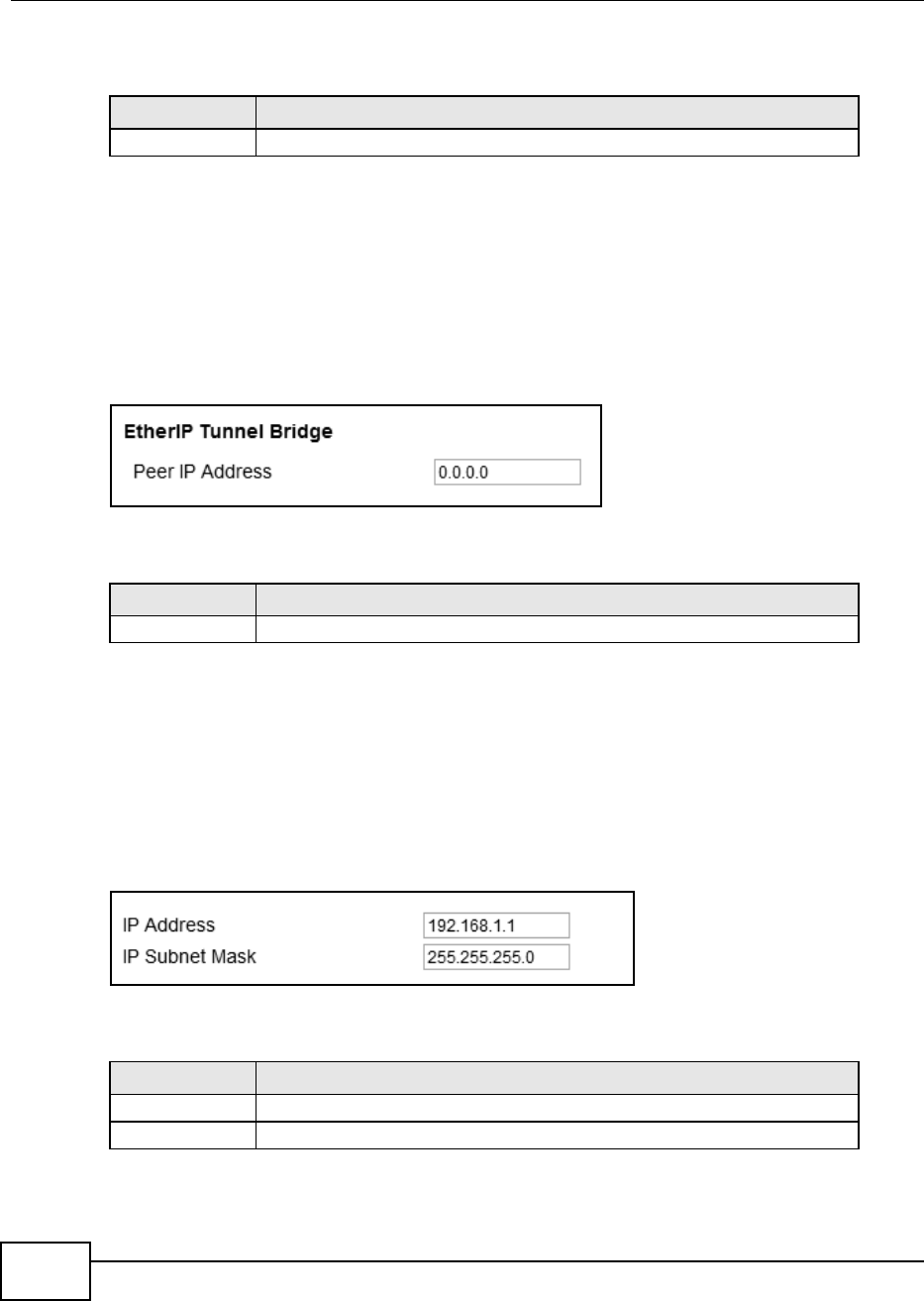
Chapter 7 Network Setting
BM2022 Users Guide
98
This screen contains the following fields:
7.5 EtherIP
Use these settings to configure the peer setting of the EtherIP tunnel between the WiMAX Device
and another EtherIP peer.
Click Network Setting > WAN > EtherIP to open this screen as shown next.
Figure 39 EtherIP Screen
This screen contains the following fields:
7.6 IP
Use these settings to configure the LAN connection between the WiMAX Device and your local
network.
Click Network Setting > LAN > IP to open this screen as shown next.
Figure 40 IP Screen
This screen contains the following fields:
Table 27 GRE
LABEL DESCRIPTION
Peer IP Address Enter the IP address of the GRE peer.
Table 28 EtherIP
LABEL DESCRIPTION
Peer IP Address Enter the IP address of the EtherIP peer.
Table 29 IP
LABEL DESCRIPTION
IP address Enter the IP address of the LAN interface for the BM2022.
IP Subnet Mask Enter the IP subnet mask of the LAN interface for the BM2022.
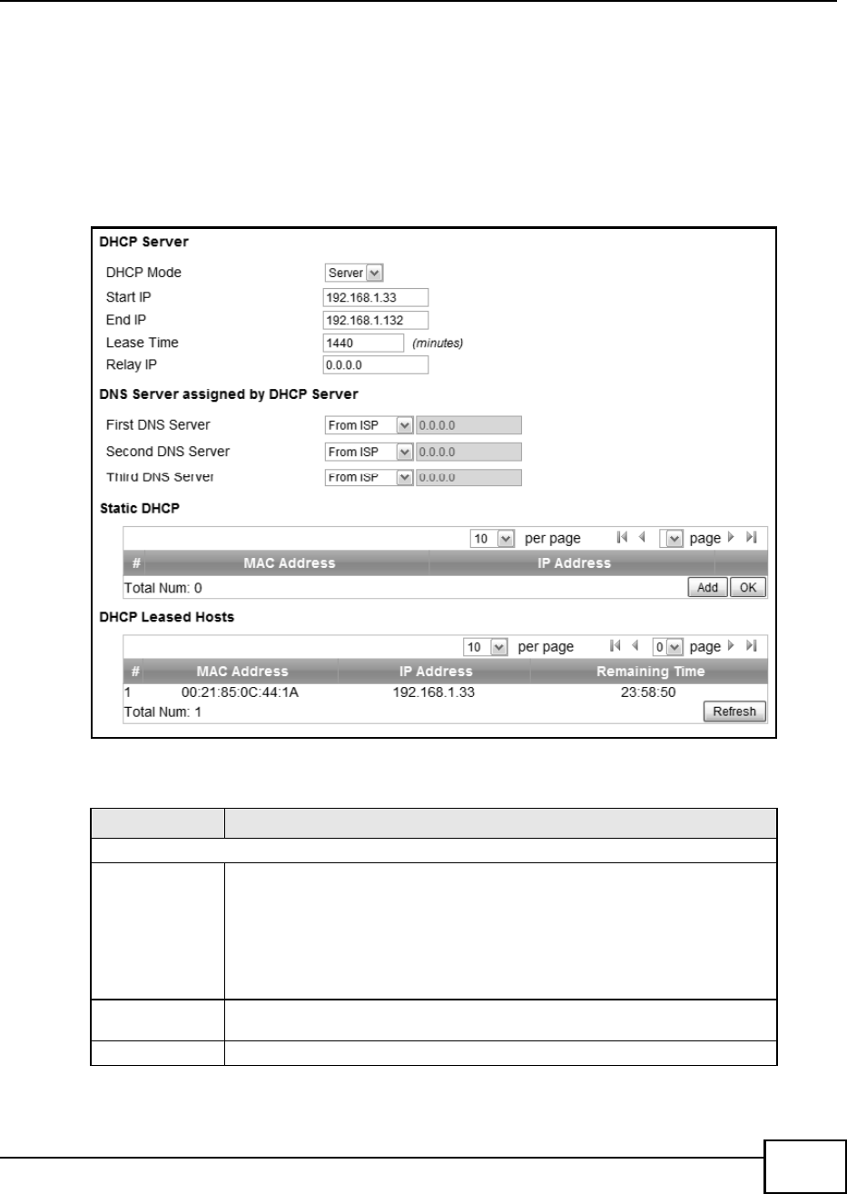
Chapter 7 Network Setting
BM2022 Users Guide 99
7.7 DHCP
Use these settings to configure whether the WiMAX Device functions as a DHCP server for your local
network, or a DHCP relay between the local network and the service provider. You can also disable
the DHCP functions.
Click Network Setting > LAN > DHCP to open this screen as shown next.
Figure 41 DHCP Screen
This screen contains the following fields:
Table 30 DHCP
LABEL DESCRIPTION
DHCP Server
DHCP Mode Select this if you want the BM2022 to be the DHCP server on the LAN. As a DHCP
server, the BM2022 assigns IP addresses to DHCP clients on the LAN and
provides the subnet mask and DNS server information.
None - This disables DHCP mode for the BM2022.
Server - This sets the BM2022 as a DHCP server for the LAN.
Relay - This sets the BM2022 as a DHCP relay for the LAN, allowing it to
pass-through IP addresses assigned to LAN devices from the ISP servers.
Start IP Enter the start IP address from which the BM2022 begins allocating IP
addresses.
End IP Enter the end IP address at which the BM2022 ceases allocating IP addresses.
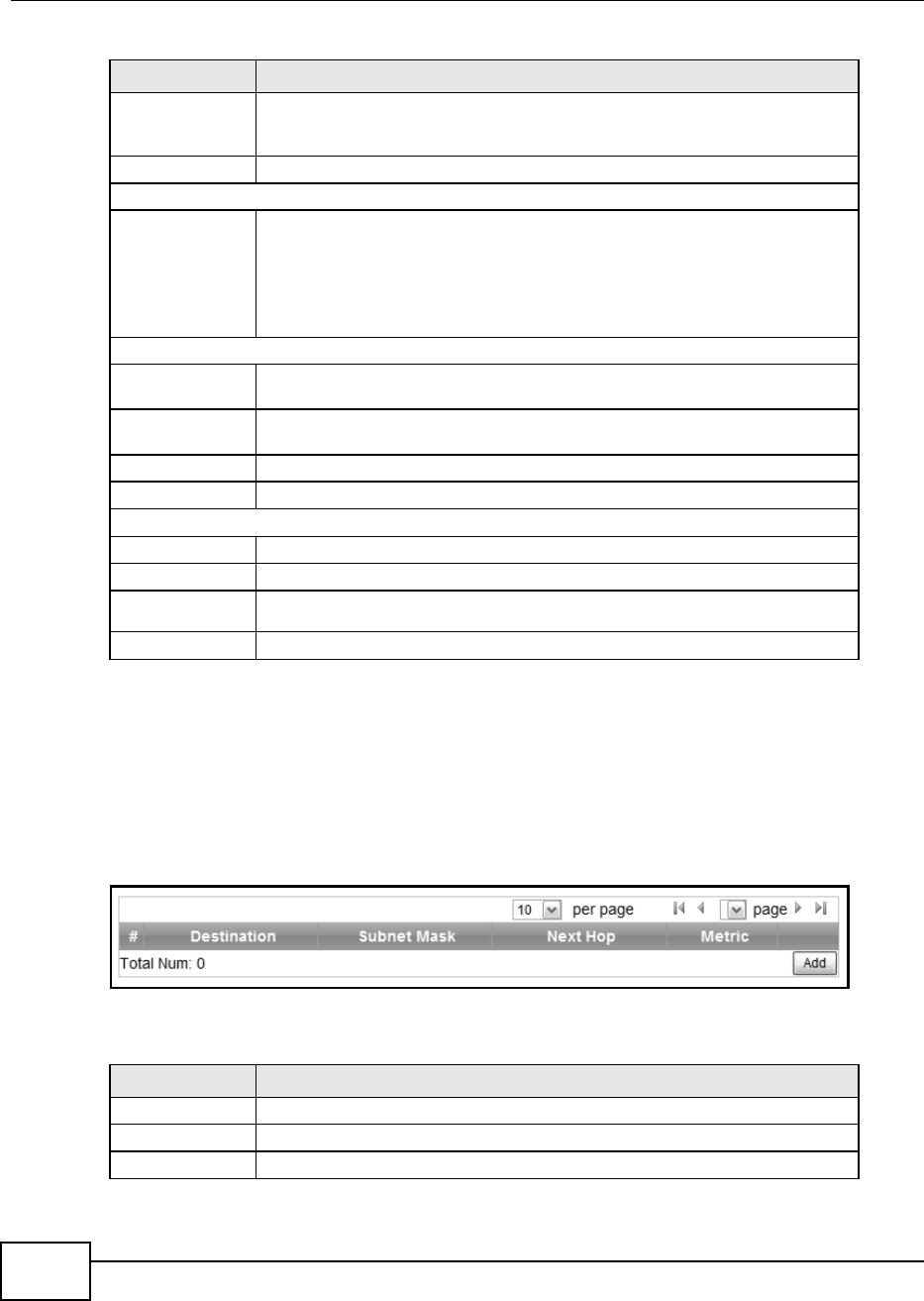
Chapter 7 Network Setting
BM2022 Users Guide
100
7.8 Static Route
Use these settings to create fixed paths through the network.
Click Network Setting > Route > Static Route to open this screen as shown next.
Figure 42 Static Route Screen
This screen contains the following fields:
Lease Time Enter the duration in minutes that devices on the LAN retain their DHCP-issued
IP addresses. At the end of the lease time, they poll the BM2022 for a renewed
or replacement IP.
Relay IP Enter the name of the IP address to be used.
DNS Server Assigned by the DHCP Server
First~Third
DNS Server
Select how the BM2022 acquires its DNS server address.
None - Select this to not use a DNS server.
From ISP - Select this to have the BM2022 acquire its DNS server address
from the ISP.
User Define - Select this to manually enter the DNS server used by the
BM2022.
Static DHCP
MAC Address This field displays the MAC address of the static DHCP client connected to the
BM2022.
IP Address This field displays the IP address of the static DHCP client connected to the
BM2022.
Add Click this to add a new static DHCP entry.
OK Click this to save any changes made to this list.
DHCP Leased Hosts
MAC Address This displays the MAC address of the DHCP leased host.
IP Address This displays the IP address of the DHCP leased host.
Remaining
Time
This displays the how much time is left on the hosts lease.
Refresh Click this to refresh the list.
Table 30 DHCP (continued)
LABEL DESCRIPTION
Table 31 Static Route
LABEL DESCRIPTION
Destination This field displays the destination IP address of the static route.
Subnet Mask This field displays the subnet mask of the static route.
Next Hop This field displays next hop information of the static route.
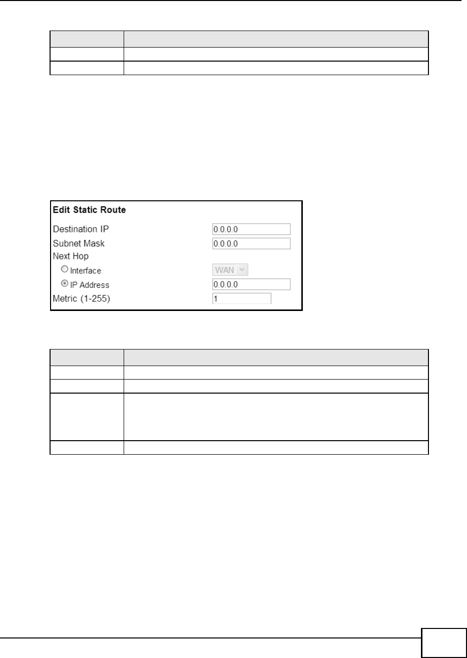
Chapter 7 Network Setting
BM2022 Users Guide 101
7.9 Static Route Add
Use these settings to configure a static route.
Click Add in the Network Setting > Route > Static Route screen to open this screen as shown
next.
Figure 43 Static Route Screen
This screen contains the following fields:
7.10 RIP
Use these settings to configure how the WiMAX Device exchanges information with other routers.
Metric This field displays the static route metric.
Add Click this to add a new static route to the list.
Table 31 Static Route (continued)
LABEL DESCRIPTION
Table 32 Static Route
LABEL DESCRIPTION
Destination IP Enter the destination IP address of the static route.
Subnet Mask Enter the subnet mask of the static route.
Next Hop Select Interface and then select WAN or LAN for the next hop of the static
route.
If the next hop is an IP address rather than an interface on the BM2022, select
IP Address and enter the IP address.
Metric Enter the static route metric.
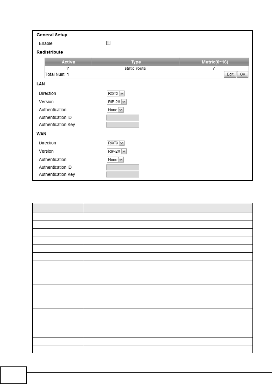
Chapter 7 Network Setting
BM2022 Users Guide
102
Click Network Setting > Route > RIP to open this screen as shown next.
Figure 44 RIP Screen
This screen contains the following fields:
Table 33 RIP
LABEL DESCRIPTION
General Setup
Enable Select this to enable RIP on the BM2022.
Redistribute
Active This indicates whether a route is being redistributed.
Type This indicates what type of route is being redistributed.
Metric This indicates the metric that is being used for redistribution.
Edit Click this to edit a selected route.
OK Click this to save any changes to the redistribution table.
LAN
Direction Set the LAN network direction to use with RIP.
Version Set the RIP version to use.
Authentication Use this option to enable or disable RIP authentication.
Authentication ID Enter the authentication ID to use for RIP authentication.
Authentication
Key
Enter the authentication key to use for RIP authentication.
WAN
Direction Set the WAN network direction to use with RIP.
Version Set the RIP version to use.
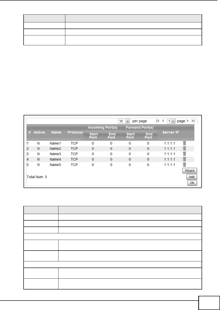
Chapter 7 Network Setting
BM2022 Users Guide 103
7.11 Port Forwarding
Use these settings to forward incoming service requests to the ports on your local network.
Note: Make sure you did not configure a DMZ host in the Network Setting > NAT >
DMZ screen if you want to make the settings of this screen work.
Click Network Setting > NAT > Port Forwarding to open this screen as shown next.
Figure 45 Port Forwarding Screen
This screen contains the following fields:
Authentication Use this option to enable or disable RIP authentication.
Authentication ID Enter the authentication ID to use for RIP authentication.
Authentication
Key
Enter the authentication key to use for RIP authentication.
Table 33 RIP (continued)
LABEL DESCRIPTION
Table 34 Port Forwarding
LABEL DESCRIPTION
Active This indicates whether the port forwarding rule is active or not.
Name The displays the name of the port forwarding rule.
Protocol This displays the protocol to which the port forwarding rule applies.
Incoming Port(s)
Start Port This displays the starting port number for incoming traffic for the port forwarding
rule.
End Port This displays the ending port number for incoming traffic for the port forwarding
rule.
Forward Port(s)
Start Port This field displays the beginning of the range of port numbers forwarded by this
rule.
End Port This field displays the end of the range of port numbers forwarded by this rule. If
it is the same as the Start Port, only one port number is forwarded.
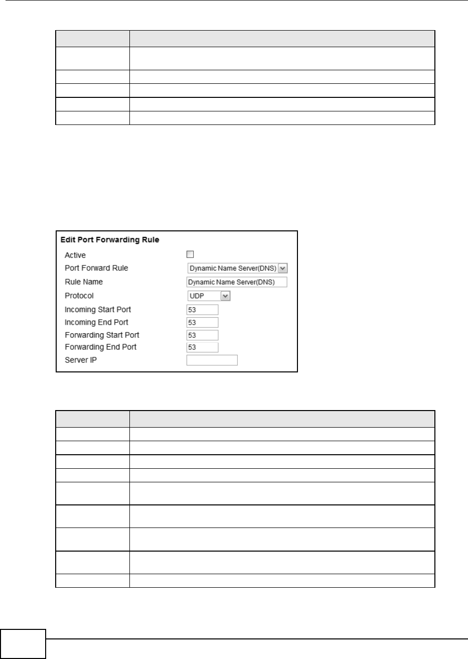
Chapter 7 Network Setting
BM2022 Users Guide
104
7.11.1 Port Forwarding Wizard
Use this wizard to set up a port forwarding rule for incoming service requests to the ports on your
local network.
Click Network Setting > NAT > Port Forwarding > Wizard to open this screen as shown next.
Figure 46 Port Forwarding Wizard Screen
This screen contains the following fields:
Server IP This displays the IP address of the server to which packet for the selected port(s)
are forwarded.
Delete Click this to delete a specified rule.
Wizard Click this to open the port forwarding wizard.
Add Click this to add a new port forwarding rule.
OK Click this to save any changes made to the port forwarding list.
Table 34 Port Forwarding (continued)
LABEL DESCRIPTION
Table 35 Port Forwarding Wizard
LABEL DESCRIPTION
Active Select this to make this port forwarding rule active.
Port Forward Rule Select the type of port forwarding rule.
Rule Name Enter a name for the port forwarding rule.
Protocol Select the port forwarding protocol.
Incoming Start
Port
Enter the starting port number for incoming traffic for the port forwarding rule.
Incoming End
Port
Enter the ending port number for incoming traffic for the port forwarding rule.
Forwarding Start
Port
Enter the starting port number for forwarded traffic for the port forwarding rule.
Forwarding End
Port
Enter the ending port number for forwarded traffic for the port forwarding rule.
Server IP Enter the port forwarding server IP address.
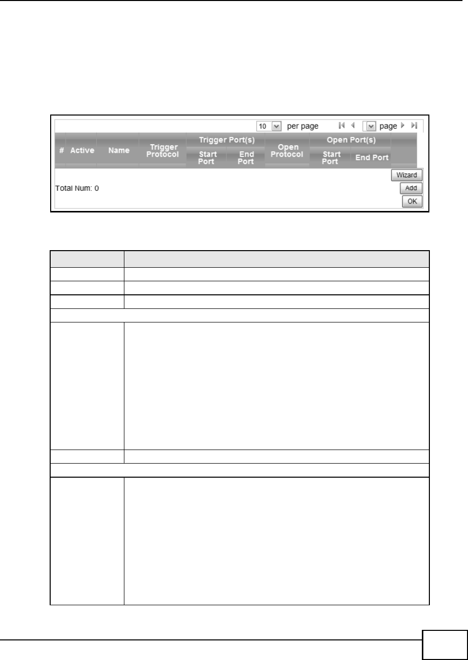
Chapter 7 Network Setting
BM2022 Users Guide 105
7.12 Port Trigger
Use these settings to automate port forwarding and allow computers on local network to provide
services that would normally require a fixed address on the local network.
Click Network Setting > NAT > Port Trigger to open this screen as shown next.
Figure 47 Port Trigger Screen
This screen contains the following fields:
Table 36 Port Trigger
LABEL DESCRIPTION
Active This indicates whether the port trigger rule is active or not.
Name The displays the name of the port trigger rule.
Trigger Protocol This displays the protocol to which the port trigger rule applies.
Trigger Port(s)
Start / End
Port
This displays the start / end trigger port for the port trigger rule.
Click Add to create a new, empty rule, then enter the incoming port number or
range of port numbers you want to forward to the IP address the BM2022
records.
To forward one port number, enter the port number in the Start Port and End
Port fields.
To forward a range of ports,
enter the port number at the beginning of the range in the Start Port field
enter the port number at the end of the range in the End Port field.
If you want to delete this rule, click the Delete icon.
Open Protocol This indicates which protocol is used to open the port trigger ports.
Open Port(s)
Start / End
Port
This displays the start / end open port for the port trigger rule.
Click Add to create a new, empty rule, then enter the outgoing port number or
range of port numbers that makes the BM2022 record the source IP address and
assign it to the selected incoming port number(s).
To select one port number, enter the port number in the Start Port and End
Port fields.
To select a range of ports,
enter the port number at the beginning of the range in the Start Port field
enter the port number at the end of the range in the End Port field.
If you want to delete this rule, click the Delete icon.
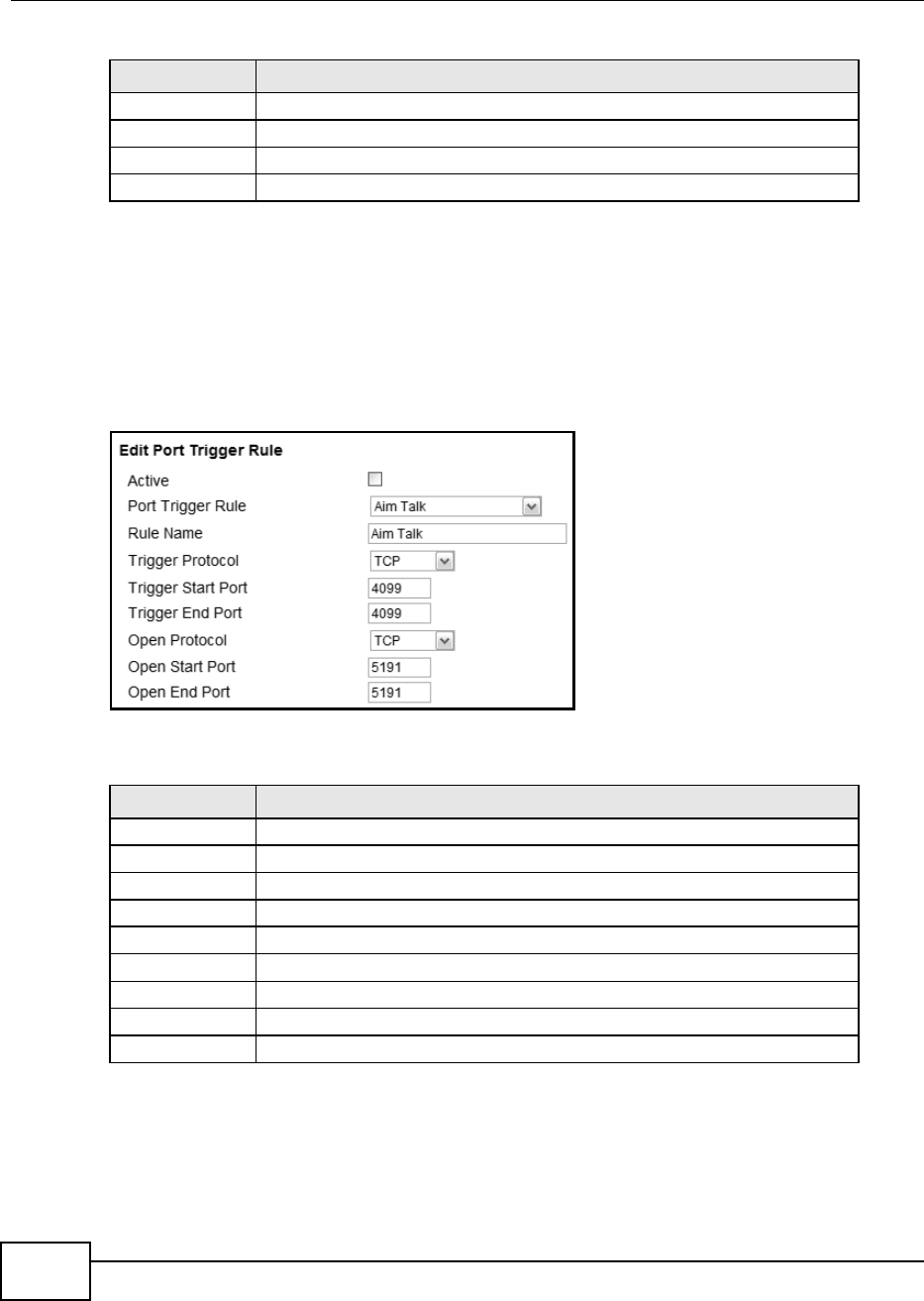
Chapter 7 Network Setting
BM2022 Users Guide
106
7.12.1 Port Trigger Wizard
Use the wizard to create a port trigger rules that will allow the BM2022 to automate port forwarding
and allow computers on local network to provide services that would normally require a fixed
address on the local network.
Click Network Setting > NAT > Port Trigger > Wizard
Figure 48 Port Trigger Wizard Screen
This screen contains the following fields:
Delete Click this to delete a specified rule.
Wizard Click this to open the port trigger wizard.
Add Click this to add a new port trigger rule.
OK Click this to save any changes made to the port trigger list.
Table 36 Port Trigger (continued)
LABEL DESCRIPTION
Table 37 Port Trigger Wizard
LABEL DESCRIPTION
Active Select this to make this port trigger rule active.
Port Trigger Rule Select the type of port trigger rule.
Rule Name Enter a name for the port trigger rule.
Trigger Protocol Select the type of port trigger protocol.
Trigger Start Port Enter the port trigger start port.
Trigger End Port Enter the port trigger end port.
Open Protocol Select the type of open protocol for the port trigger rule.
Open Start Port Select the starting open port for the port trigger rule.
Open End Port Select the ending open port number for the port trigger rule.
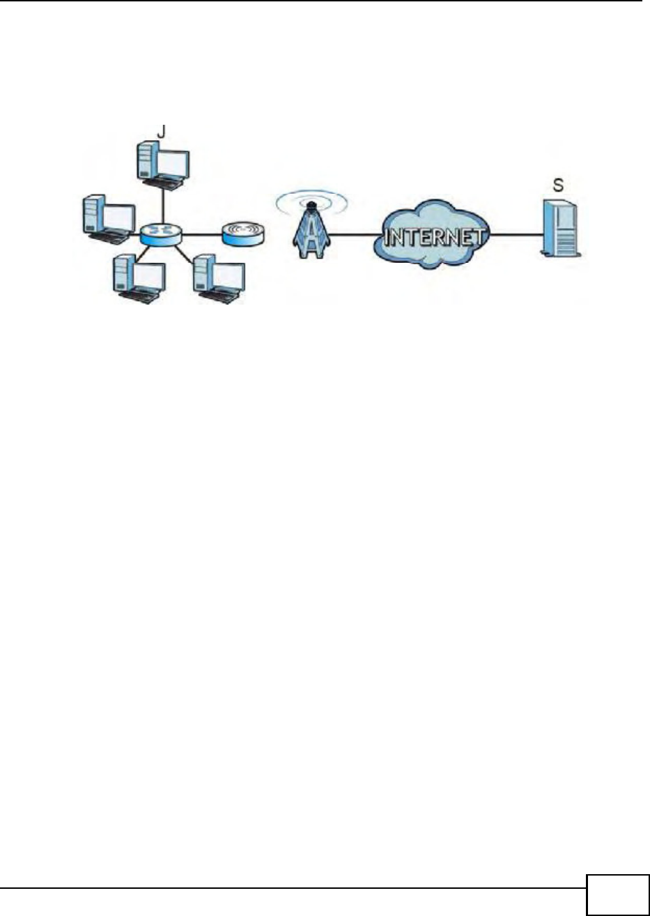
Chapter 7 Network Setting
BM2022 Users Guide 107
7.12.2 Trigger Port Forwarding Example
The following is an example of trigger port forwarding. In this example, J is Janes computer and S
is the Real Audio server.
Figure 49 Trigger Port Forwarding Example
1Jane requests a file from the Real Audio server (port 7070).
2Port 7070 is a trigger port and causes the BM2022 to record Janes computer IP address. The
BM2022 associates Jane's computer IP address with the "incoming" port range of 6970-7170.
3The Real Audio server responds using a port number ranging between 6970-7170.
4The BM2022 forwards the traffic to Janes computer IP address.
5Only Jane can connect to the Real Audio server until the connection is closed or times out. The
BM2022 times out in three minutes with UDP (User Datagram Protocol), or two hours with TCP/IP
(Transfer Control Protocol/Internet Protocol).
Two points to remember about trigger ports:
1Trigger events only happen on data that is coming from inside the BM2022 and going to the
outside.
2If an application needs a continuous data stream, that port (range) will be tied up so that another
computer on the LAN cant trigger it.
7.13 DMZ
Use this page to set the IP address of your network DMZ (if you have one) for the WiMAX Device.
All incoming packets received by this BM2022s WAN interface will be forwarded to the DMZ host
you set.
Click Network Setting > NAT > DMZ to open this screen as shown next.
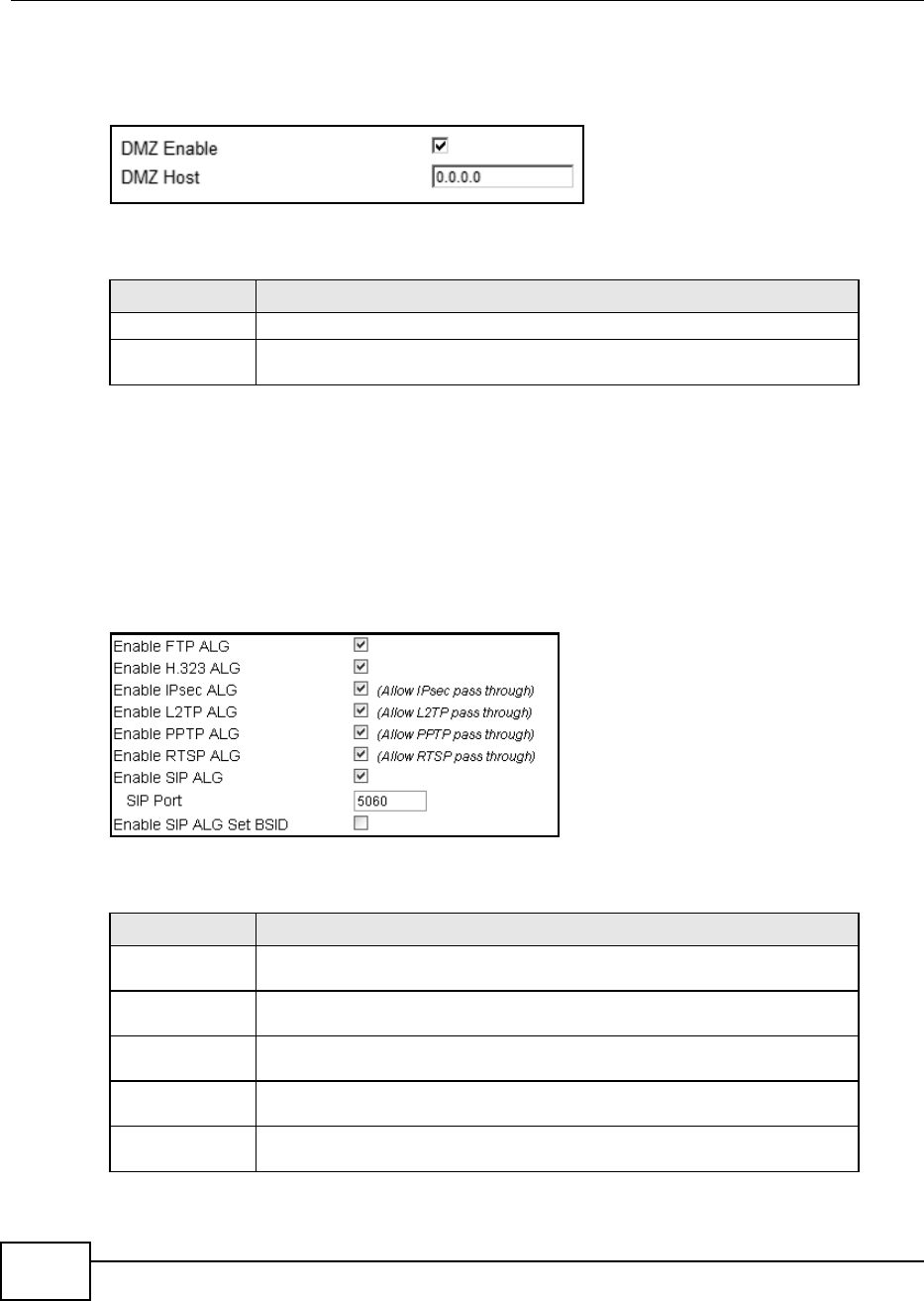
Chapter 7 Network Setting
BM2022 Users Guide
108
Note: The configuration you set in this screen takes priority than the Network Setting >
NAT > Port Forwarding screen.
Figure 50 DMZ Screen
This screen contains the following fields:
7.14 ALG
Use these settings to bypass NAT on your WiMAX Device for those applications that are "NAT un-
friendly".
Click Network Setting > NAT > ALG to open this screen as shown next.
Figure 51 ALG Screen
This screen contains the following fields:
Table 38 DMZ
LABEL DESCRIPTION
DMZ Enable Click this check box to enable DMZ.
DMZ Host Enter the IP address of your network DMZ host, if you have one. 0.0.0.0 means
this feature is disabled.
Table 39 Network Setting > NAT > ALG
LABEL DESCRIPTION
Enable FTP ALG Turns on the FTP ALG to detect FTP (File Transfer Program) traffic and helps build
FTP sessions through the BM2022s NAT.
Enable H.323 ALG Turns on the H.323 ALG to detect H.323 traffic (used for audio communications)
and helps build H.323 sessions through the BM2022s NAT.
Enable IPsec ALG Turns on the IPsec ALG to detect IPsec traffic and helps build IPsec sessions
through the BM2022s NAT.
Enable L2TP ALG Turns on the L2TP ALG to detect L2TP traffic and helps build L2TP sessions
through the BM2022s NAT.
Enable PPTP ALG Turns on the PPTP ALG to detect PPTP traffic and helps build PPTP sessions
through the BM2022s NAT.
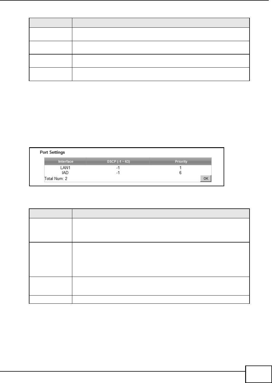
Chapter 7 Network Setting
BM2022 Users Guide 109
7.15 QoS
Use this page to configure QoS settings on the WiMAX Device.
Click Network Setting > QoS to open this screen as shown next.
Figure 52 QoS Screen
This screen contains the following fields:
7.16 UPnP
Use this page to enable the UPnP networking protocol on your WiMAX Device and allow easy
network connectivity with other UPnP-compatible devices.
Enable RTSP ALG Turns on the RTSP ALG to detect RTSP traffic and helps build RTSP sessions
through the BM2022s NAT.
Enable SIP ALG Turns on the SIP ALG to detect SIP traffic and helps build SIP sessions through
the BM2022s NAT.
SIP Port If you are using a custom UDP port number (not 5060) for SIP traffic, enter it
here.
Enable SIP ALG
Set BSID
Check this box to add the base station ID to the outgoing SIP messages. Select
this option only if the media server forwarding calls requires this information.
Table 39 Network Setting > NAT > ALG (continued)
LABEL DESCRIPTION
Table 40 QoS
LABEL DESCRIPTION
Interface This displays the interface for the QoS rule. The IAD interface is for device
management. Configure DiffServ Code Point (DSCP) and/or Priority marking
based on which method is supported within your network. With DSCP you can
use 64 (0-63) different markings, compared to 6 (1-6) with Priority marking.
DSCP Specify a DiffServ Code Point (DSCP) classification identification number (-1-63)
to mark traffic that passes through this interface. Setting the DSCP to -1
indicates marking is not enabled. A higher number indicates higher priority. The
DSCP allows marked packets to receive specific per-hop treatment at DiffServ-
compliant network devices along the route based on the application types and
traffic flow.
Priority Select a priority level (1 to 6) to assign a priority to traffic that passes through
this interface. A higher number indicates higher priority. Like DSCP, this
marking is used to identify traffic for specific treatment.
OK Click this to save any changes made to the QoS rules.
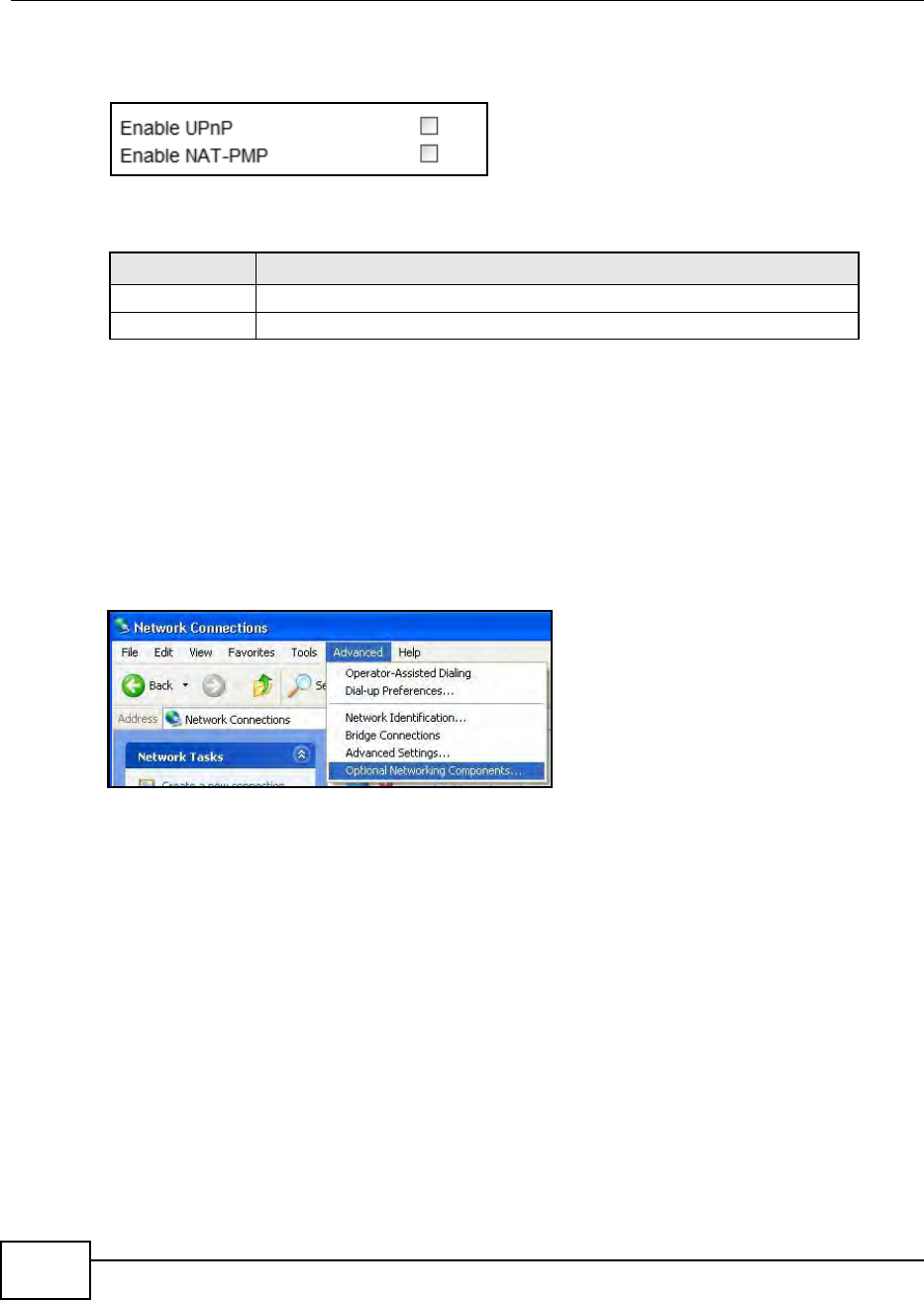
Chapter 7 Network Setting
BM2022 Users Guide
110
Click Network Setting > UPnP to open this screen as shown next.
Figure 53 UPnP Screen
This screen contains the following fields:
7.16.1 Installing UPnP in Windows XP
Follow the steps below to install the UPnP in Windows XP.
1Click Start > Control Panel.
2Double-click Network Connections.
3In the Network Connections window, click Advanced in the main menu and select Optional
Networking Components .
Table 41 UPnP
LABEL DESCRIPTION
Enable UPnP Select this to enable UPnP on the BM2022.
Enable NAT-PMP Select this to enable NAT Port Mapping Protocol on the BM2022.
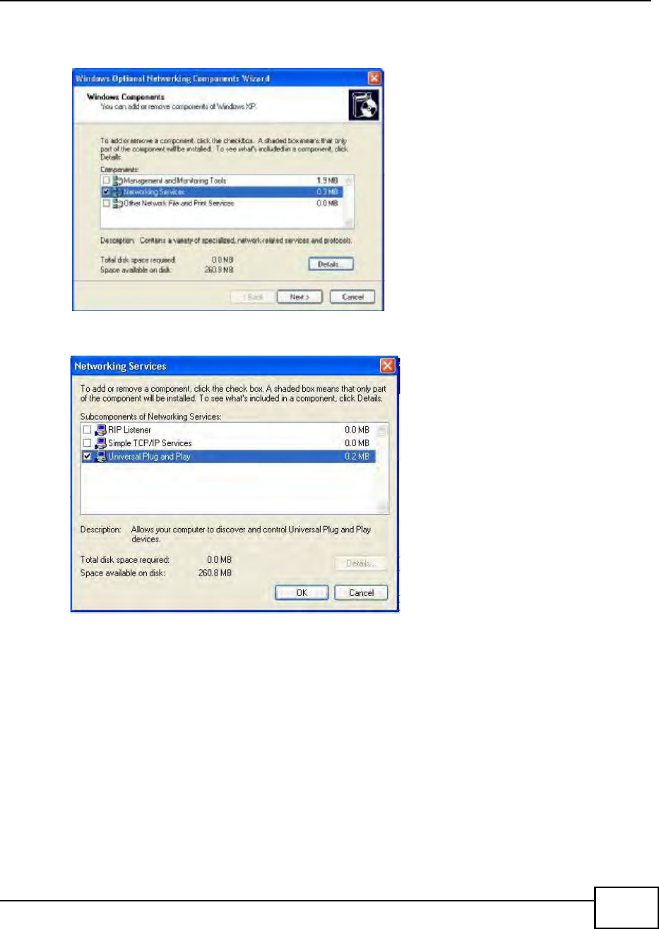
Chapter 7 Network Setting
BM2022 Users Guide 111
4The Windows Optional Networking Components Wizard window displays. Select Networking
Service in the Components selection box and click Details.
5In the Networking Services window, select the Universal Plug and Play check box.
6Click OK to go back to the Windows Optional Networking Component Wizard window and
click Next.
7.16.1.1 Auto-discover Your UPnP-enabled Network Device in Windows XP
This section shows you how to use the UPnP feature in Windows XP. You must already have UPnP
installed in Windows XP and UPnP activated on the BM2022.
Make sure the computer is connected to a LAN port of the BM2022. Turn on your computer and the
BM2022.
1Click Start and Control Panel. Double-click Network Connections. An icon displays under
Internet Gateway.
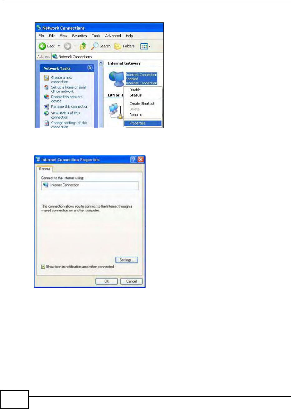
Chapter 7 Network Setting
BM2022 Users Guide
112
2Right-click the icon and select Properties.
3In the Internet Connection Properties window, click Settings to see the port mappings there
were automatically created.
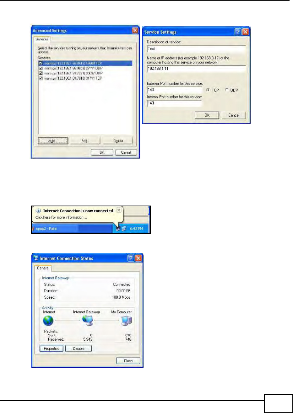
Chapter 7 Network Setting
BM2022 Users Guide 113
4You may edit or delete the port mappings or click Add to manually add port mappings.
5When the UPnP-enabled device is disconnected from your computer, all port mappings will be
deleted automatically.
6Select Show icon in notification area when connected option and click OK. An icon displays in
the system tray.
7Double-click on the icon to display your current Internet connection status.
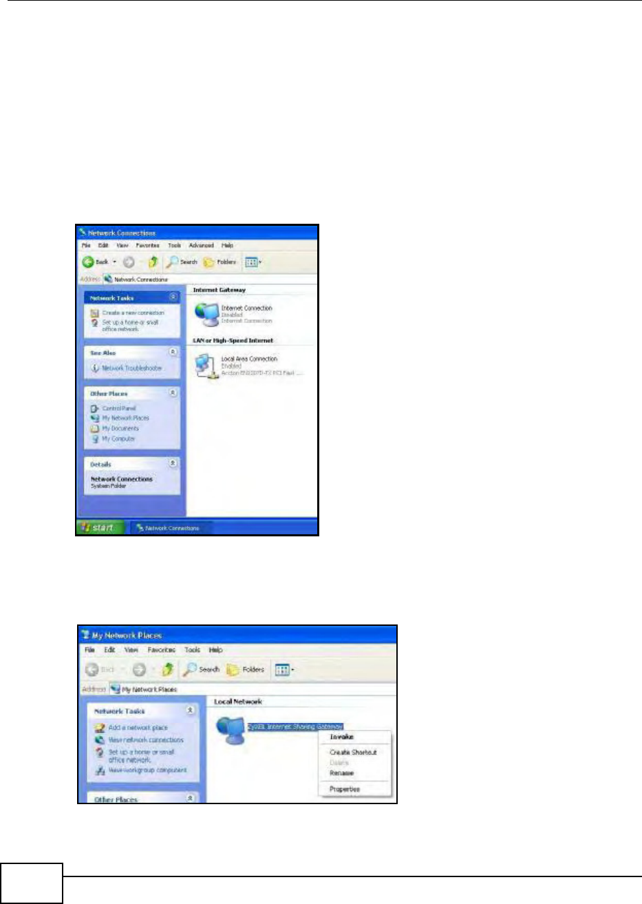
Chapter 7 Network Setting
BM2022 Users Guide
114
7.16.2 Web Configurator Easy Access
With UPnP, you can access the web-based configurator on the BM2022 without finding out the IP
address of the BM2022 first. This becomes helpful if you do not know the IP address of the BM2022.
Follow the steps below to access the web configurator:
1Click Start and then Control Panel.
2Double-click Network Connections.
3Select My Network Places under Other Places.
4An icon with the description for each UPnP-enabled device displays under Local Network.
5Right-click on the icon for your BM2022 and select Invoke. The web configurator login screen
displays.
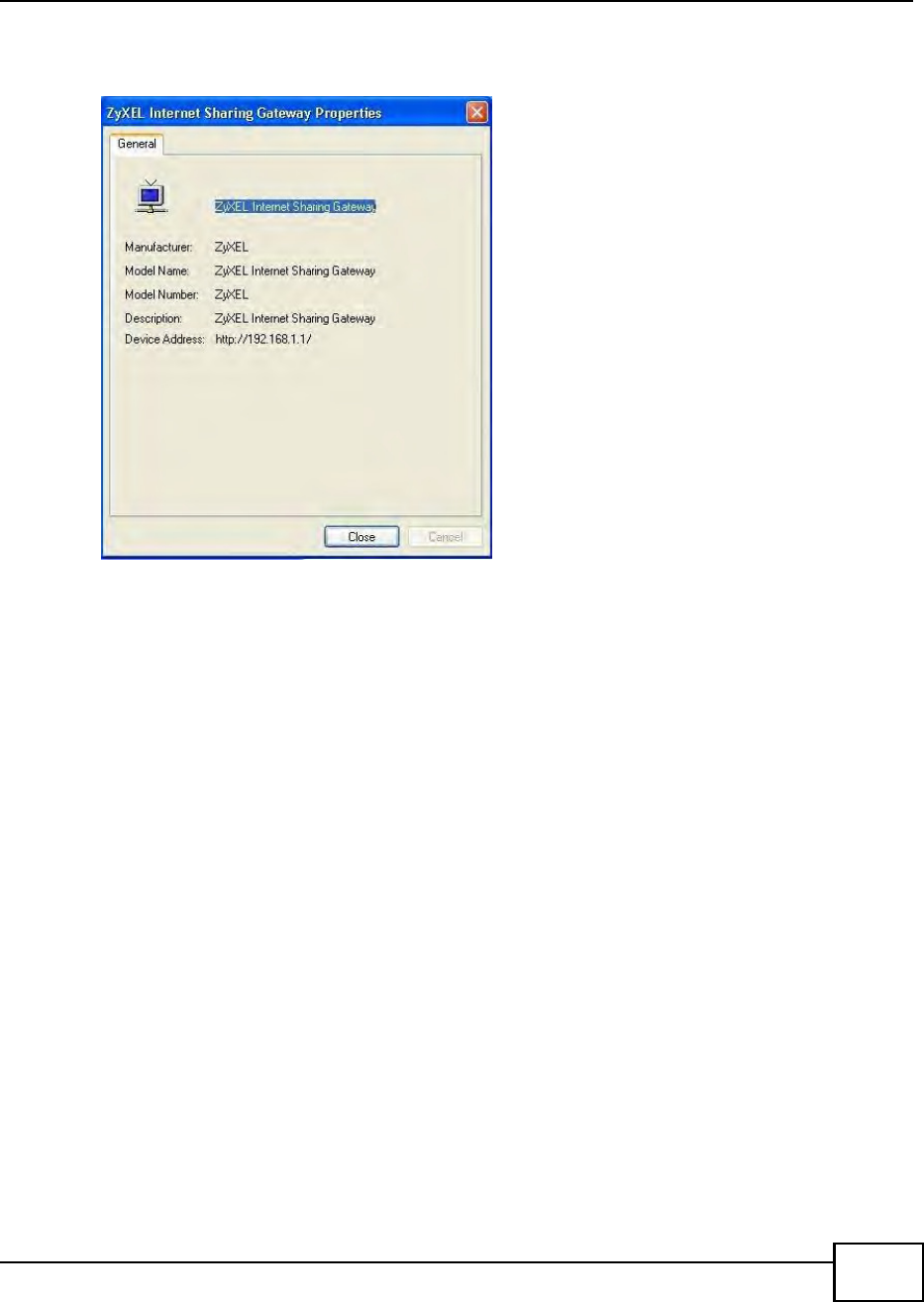
Chapter 7 Network Setting
BM2022 Users Guide 115
6Right-click on the icon for your BM2022 and select Properties. A properties window displays with
basic information about the BM2022.
7.17 VLAN
Use this screen to configure port-based VLAN settings on the BM2022. This screen allows you to
assign port(s) to specific virtual LAN(s) in order to isolate traffic from different VLAN groups. See
Section 4.11 on page 48 for example configurations for VLANs.
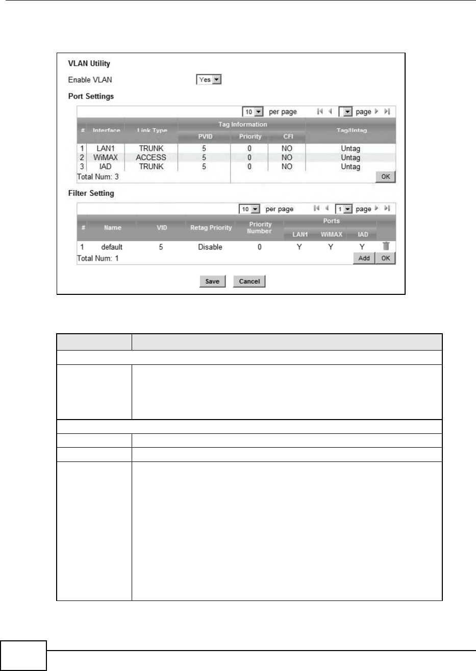
Chapter 7 Network Setting
BM2022 Users Guide
116
Click Network Setting > VLAN to open the screen as shown next.
Figure 54 VLAN Screen
This screen contains the following fields:
Table 42 VLAN
LABEL DESCRIPTION
VLAN Utility
Enable VLAN Select Yes to enable the VLAN function on the BM2022.
Note: To use VLAN on the BM2022, you must switch the operation mode to
bridge on the Network Setting > WAN screen. It will then require system
restart to take effect.
Port Settings
# This is the index number of the port setting.
Interface This displays the interface that the port setting applies to.
Link Type Select Access if this port forwards traffic for only one VLAN. The device
connected to an access port does not support VLAN tagged packets, so the
BM2022 will remove packets forwarded out of this port. Packets received on
access ports will be tagged with the specified PVID.
Select Trunk to allow packets belonging to different VLAN groups to pass
through the port. The device connected to this port should support VLAN tagged
packets. You must configure Filter Settings for the port and VLAN ID for
tagged packets to be forwarded. If received packets are already tagged, the
PVID set for this port should not be the same as the VLAN IDs configured in
Filter Settings. This will allow the tagged packets to be forwarded to the
specified VLANs. If received packets are not tagged, the BM2022 will tag them
with the PVID.
Select Hybrid to allow the port to function as an access port and trunk port.

Chapter 7 Network Setting
BM2022 Users Guide 117
7.18 DDNS
Use this page to configure the WiMAX Device as a dynamic DNS client.
PVID A PVID (Port VLAN ID) is a tag that adds to incoming untagged packets received
on a port so that the packets are forwarded to the VLAN group that the tag
defines. Enter a number between 1and 4094 as the port VLAN ID.
Priority Enter a priority level (1~7) that the BM2022 assigns to packets belonging to this
VLAN. Enter 0 for no priority assigned.
CFI Select Yes if the CFI (Canonical Format Indicator) field in a received packet is
set to 1, indicating non-Canonical Format. In this case, the packet should not be
forwarded as it is to an untagged port.
Tag/Untag You can only select Tag if the port is configured as a Trunk or Hybrid port. The
BM2022 will receive and forward VLAN tagged packets. Untagged packets will
be tagged with the PVID.
If you select Untag the BM2022 will remove tags from tagged packets it
forwards out of the port. Untagged packets received will be forwarded. If the
port is an Access port, the BM2022 will add tags to untagged packets it receives
and drop tagged packets it receives. If the port is a Trunk port, the BM2022 will
add tags to untagged packets it receives and retag tagged packets.
OK Click this to save the changes in the Port Setting section.
Filter Setting
# This is the index number of a filter.
Name This is the name of a filter rule.
VID This field displays the VLAN ID for the filter. Click this field to change the VLAN
ID.
Retag Priority Select Yes to retag the priority of a packet received on a Trunk or Hybrid port.
Priority
Number
If Retag Priority is enabled, specify the new priority level (1~7) to tag. Enter 0
for no priority assigned.
Ports This field displays the ports included in the filter. Click this field to select which
ports to include.
Delete Click this button to remove an item from the list.
Add Click this button to add an item to the list.
OK Click this button to save any changes made to the list.
Save Click this to save the changes made.
Cancel Click this avoid any changes made from being saved to your configuration.
Table 42 VLAN
LABEL DESCRIPTION
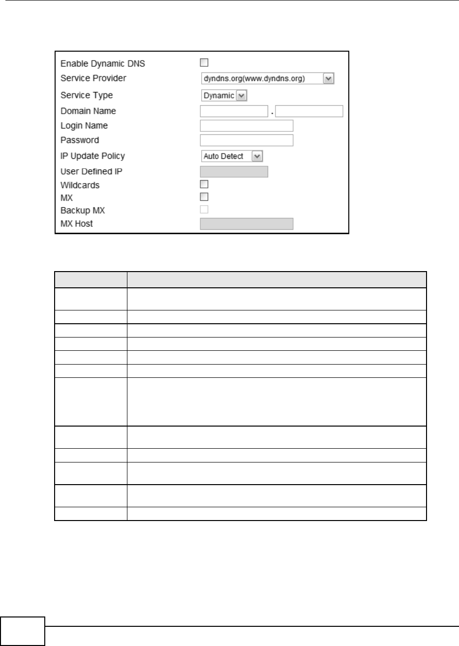
Chapter 7 Network Setting
BM2022 Users Guide
118
Click Network Setting > DDNS
Figure 55 DDNS Screen
This screen contains the following fields:
7.19 IGMP Proxy
Use this page to enable IGMP Proxy on the WiMAX Device.
Table 43 DDNS
LABEL DESCRIPTION
Enable Dynamic
DNS
Select this to enable dynamic DNS on the BM2022.
Service Provider Select the dynamic DNS service provider for the BM2022.
Service Type Select the dynamic DNS service type.
Domain Name Enter the domain name.
Login Name Enter the user name.
Password Enter the password.
IP Update Policy Select the policy used by the BM2022. Options are:
Auto Detect
WAN
User Defined
User Defined IP If chose User Defined for the IP Update Policy, enter the user defined IP
address.
Wildcards Select this to allow a hostname to use wildcards such as *.
MX Select this to enable mail routing, if supported by the specified DYNDNS service
provider.
Backup MX Select this to enable a secondary mail routing, if supported by the specified
DYNDNS service provider.
MX Host Enter the host to which mail is routed when the MX option is selected.
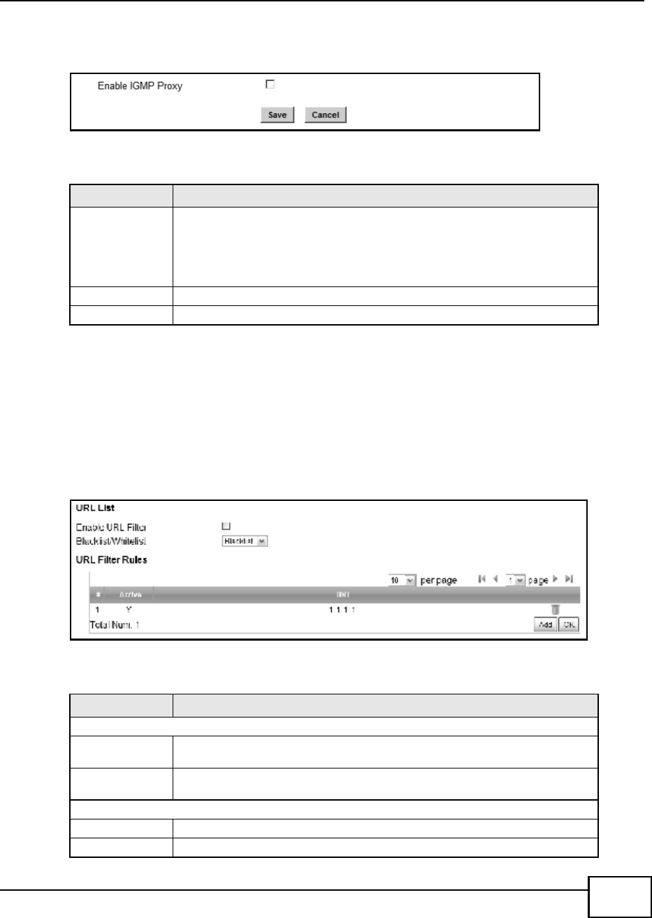
Chapter 7 Network Setting
BM2022 Users Guide 119
Click Network Setting > IGMP Proxy to open this screen as shown next.
Figure 56 IGMP Proxy
This screen contains the following fields:
7.20 Content Filter
Use these settings to allow ("whitelist") or block ("blacklist") connections to and from specific web
sites through the WiMAX Device.
Click Network Setting > Content Filter to open this screen as shown next.
Figure 57 Content Filter Screen
This screen contains the following fields:
Table 44 IGMP Proxy
LABEL DESCRIPTION
Enable IGMP
Proxy
Internet Group Multicast Protocol (IGMP) is a network-layer protocol used to
establish membership in a Multicast group - it is not used to carry user data.
Select this option to have the BM2022 act as an IGMP proxy. This allows the
BM2022 to get subscribing information and maintain a joined member list for
each multicast group. It can reduce multicast traffic significantly.
Save Click this to save the changes made.
Cancel Click this avoid any changes made from being saved to your configuration.
Table 45 Content Filter
LABEL DESCRIPTION
URL List
Enable URL
Filter
Select this employ the content filter to allow (whitelist) or block (blacklist)
specific URL connections made through the BM2022.
Blacklist/
Whitelist
Select whether the current filtering applies to the blacklist (sites that are
blocked) or the whitelist (sites that are allowed).
URL Filter Rule
Active Indicates whether the current URL filter is active or not.
URL Indicates the URL to be filtered according to blacklist or whitelist rules.

Chapter 7 Network Setting
BM2022 Users Guide
120
Delete Click this to delete a specified rule.
Add Click this to add a new filter rule.
OK Click this to save any changes made to the list.
Table 45 Content Filter (continued)
LABEL DESCRIPTION

BM2022 Users Guide 121
CHAPTER 8
Security
8.1 Overview
This chapter shows you how to configure the BM2022s network settings.
8.1.1 What You Need to Know
The following terms and concepts may help as you read through this chapter.
About the BM2022s Security Features
The BM2022 security features are designed to protect against Denial of Service attacks when
activated as well as block access to and from specific URLs and MAC addresses. Its purpose is to
allow a private Local Area Network (LAN) to be securely connected to the Internet. The BM2022 can
be used to prevent theft, destruction and modification of data.
The BM2022 is installed between the LAN and a WiMAX base station connecting to the Internet.
This allows it to act as a secure gateway for all data passing between the Internet and the LAN.
The BM2022 has one Ethernet (LAN) port. The LAN (Local Area Network) port attaches to a network
of computers, which needs security from the outside world. These computers will have access to
Internet services such as e-mail, FTP and the World Wide Web. However, inbound access is not
allowed (by default) unless the remote host is authorized to use a specific service.
8.2 IP Filter
Use this screen to block incoming connections from specific IP addresses.
Click Security > Firewall > IP Filter to open this screen as shown next.
Figure 58 IP Filter Screen

Chapter 8 Security
BM2022 Users Guide
122
This screen contains the following fields:
8.3 MAC Filter
Use this screen to allow ("whitelist") or block ("blacklist") connections to and from specific devices
on the network based on their unique MAC addresses.
Note: This feature only works when the BM2022 is in bridge mode.
Table 46 IP Filter
LABEL DESCRIPTION
Active Indicates whether the current IP filter is active or not.
Source IP This displays the source IP address for the IP filter rule.
Click Add to create a new, empty rule, then enter the incoming IP address for
the BM2022 to block.
If you want to delete this rule, click the Delete icon.
Source Port This displays the source port number for the IP filter rule.
Click Add to create a new, empty rule, then enter the incoming port number for
the BM2022 to block.
If you want to delete this rule, click the Delete icon.
Destination IP This displays the destination IP address for the IP filter rule.
Click Add to create a new, empty rule, then enter the outgoing IP address for
the BM2022 to block.
If you want to delete this rule, click the Delete icon.
Destination Port This displays the destination port number for the IP filter rule.
Click Add to create a new, empty rule, then enter the outgoing port number for
the BM2022 to block.
If you want to delete this rule, click the Delete icon.
Protocol This displays the protocol blocked by the IP filter rule.
Click Add to create a new, empty rule, then select the protocol type for the
BM2022 to block.
If you want to delete this rule, click the Delete icon.
Delete Click this to delete a specified rule.
Add Click this to add a new filter rule.
OK Click this to save any changes made to the list.
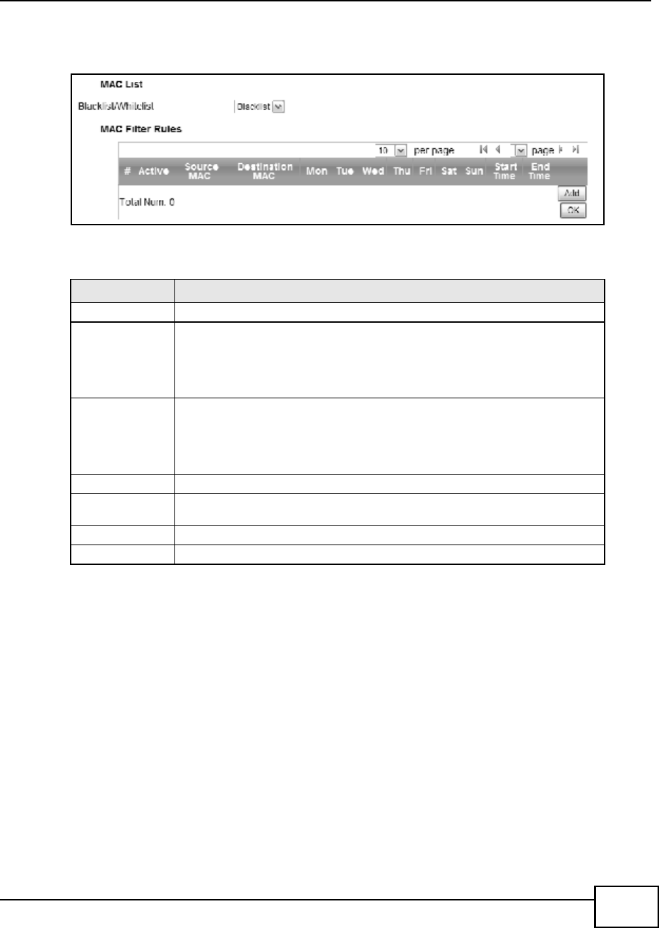
Chapter 8 Security
BM2022 Users Guide 123
Click Security > Firewall > MAC Filter to open this screen as shown next.
Figure 59 MAC Filter Screen
This screen contains the following fields:
8.4 DDOS
Use these settings to potentially block specific types of Denial of Service attacks directed at your
WiMAX Device.
Table 47 MAC Filter
LABEL DESCRIPTION
Blacklist/Whitelist Select either whitelist or blacklist for viewing and editing.
Source MAC This displays the source MAC for the MAC filter rule.
Click Add to create a new, empty rule, then enter the incoming MAC address for
the BM2022 to block.
If you want to delete this rule, click the Delete icon.
Destination MAC This displays the destination MAC for the MAC filter rule.
Click Add to create a new, empty rule, then enter the outgoing MAC address for
the BM2022 to block.
If you want to delete this rule, click the Delete icon.
Mon ~ Sun Select which days of the week you want the filter rule to be effective.
Start / End Time Select what time each day you want the filter rule to be effective. Enter times in
24-hour format; for example, 3:00pm should be entered as 15:00.
Add Click this to add a new filter rule.
OK Click this to save any changes made to the list.

Chapter 8 Security
BM2022 Users Guide
124
Click Security > Firewall > DDOS to open this screen as shown next.
Figure 60 DDOS Screen
This screen contains the following fields:
Table 48 DDOS
LABEL DESCRIPTION
Prevent from TCP
SYN Flood
Select this to monitor for and block TCP SYN flood attacks.
A SYN flood is one type of denial of service attack where an overwhelming
number of SYN requests assault a client device.
Prevent from UDP
Flood
Select this to monitor for and block UDP flood attacks.
An UDP flood is a type of denial of service attack where an overwhelming
number of UDP packets assault random ports on a client device. Because the
device is forced to analyze and respond to each packet, it quickly becomes
unreachable to other devices.
Prevent from
ICMP Flood
Select this to monitor for and block ICMP flood attacks.
An ICMP flood is a type of denial of service attack where an overwhelming
number of ICMP ping assault a client device, locking it down and preventing it
from responding to requests from other servers.
Prevent from Port
Scan
Select this to monitor for and block port scan attacks.
A port scan attack is typically the precursor to a full-blown denial of service
attack wherein each port on a device is probed for security holes that can be
exploited. Once a security flaw is discovered, an attacker can initiate the
appropriate denial of service attack or intrusion attack against the client device.
Prevent from
LAND Attack
Select this to monitor for and block LAND attacks.
A Local Area Network Denial (LAND) attack is a type of denial of service attack
where a spoofed TCP SYN packet targets a client devices IP address and forces it
into an infinite recursive loop of querying itself and then replying, effectively
locking it down.
Prevent from IP
Spoof
Select this to monitor for and block IP address spoof attacks.
An IP address spoof is an attack whereby the source IP address in the incoming
IP packets allows a malicious party to masquerade as a legitimate user and gain
access to the client device.
Prevent from
ICMP redirect
Select this to monitor for and block ICMP redirect attacks.
An ICMP redirect attack is one where forged ICMP redirect messages can force
the client device to route packets for certain connections through an attackers
host.
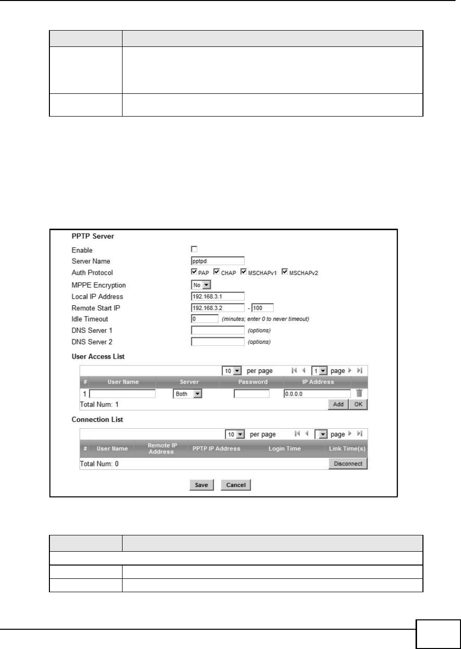
Chapter 8 Security
BM2022 Users Guide 125
8.5 PPTP VPN Server
Use this screen to configure settings for a Point to Point Tunneling Protocol (PPTP) server.
Click Security > PPTP VPN > PPTP Server to open this screen as shown next.
Figure 61 PPTP Server
This screen contains the following fields:
Prevent from
PING of Death
Select this to monitor for and block ping of death attacks.
A Ping of Death (POD) attack is one where larger-than-allowed ping packets are
fragmented then sent against a client device. This results in the client device
suffering from a buffer overflow and subsequent system crash.
Prevent from
PING from WAN
Select this to ignore ping requests from the WAN.
Table 48 DDOS (continued)
LABEL DESCRIPTION
Table 49 PPTP Server
LABEL DESCRIPTION
PPTP Server
Enable Use this field to turn the BM2022S PPTP VPN function on or off.
Server Name Enter the server name for the PPTP VPN connection.

Chapter 8 Security
BM2022 Users Guide
126
Auth Protocol Select the Authentication Protocol allowed for the connection. Options are:
PAP - Password Authentication Protocol (PAP) authentication occurs in clear text
and does not use encryption. Its probably not a good idea to rely on this for
security.
CHAP - Challenge Handshake Authentication Protocol (CHAP) provides
authentication through a shared secret key and uses a three way handshake.
MSCHAPv1 - Microsoft CHAP v1 (MSCHAPv1) provides authentication through a
shared secret key and uses a three way handshake. It provides improved
usability with Microsoft products.
MSCHAPv2 - Microsoft CHAP v2 (MSCHAPv2) provides encryption through a
shared secret key and uses a three way handshake. It provides additional
security over MSCHAPv1, including two-way authentication.
MPPE
Encryption
If MSCHAPv1 or MSCHAPv2 is selected as an Auth Protocol, use the drop-
down list box to select the type of Microsoft Point-to-Point Encryption (MPPE).
Options are:
MPPE 40 - MPPE with 40 bit session key length
MPPE 128 - MPPE with 128 bit session key length
Auto - Automatically select either MPPE 40 or MPPE 128
Local IP
Address
Enter the local endpoint for the PPTP connection.
Remote Start
IP
Enter the local IP address range the BM2022 assigns to remote users if the
remote client device is set to obtain an IP address automatically.
Idle Timeout Enter the time in minutes to timeout PPTP connections.
DNS Server 1
DNS Server 2
Specify the IP addresses of DNS servers to assign to the remote users.
User Access List
User Name Enter the user name for the remote user.
Server Select the server that the remote user has access to: PPTPD, L2TPD or Both.
Password Enter the password for the remote user.
IP Address Enter the local IP address the BM2022 assigns to the remote user.
Entering 0.0.0.0 indicates the local IP address will be dynamically assigned.
Delete Select an entry and click this to delete it.
Add Click this to create a new entry.
OK Click this to save the changes.
Connection List
User Name This displays the user name for the remote user.
Remote IP
Address
This displays the remote endpoint IP address of the remote user.
PPTP IP
Address
This displays the local IP address of the PPTP server.
Login Time This displays the time the PPTP connection started.
Link Time(s) This displays the duration of the PPTP connection.
Table 49 PPTP Server
LABEL DESCRIPTION
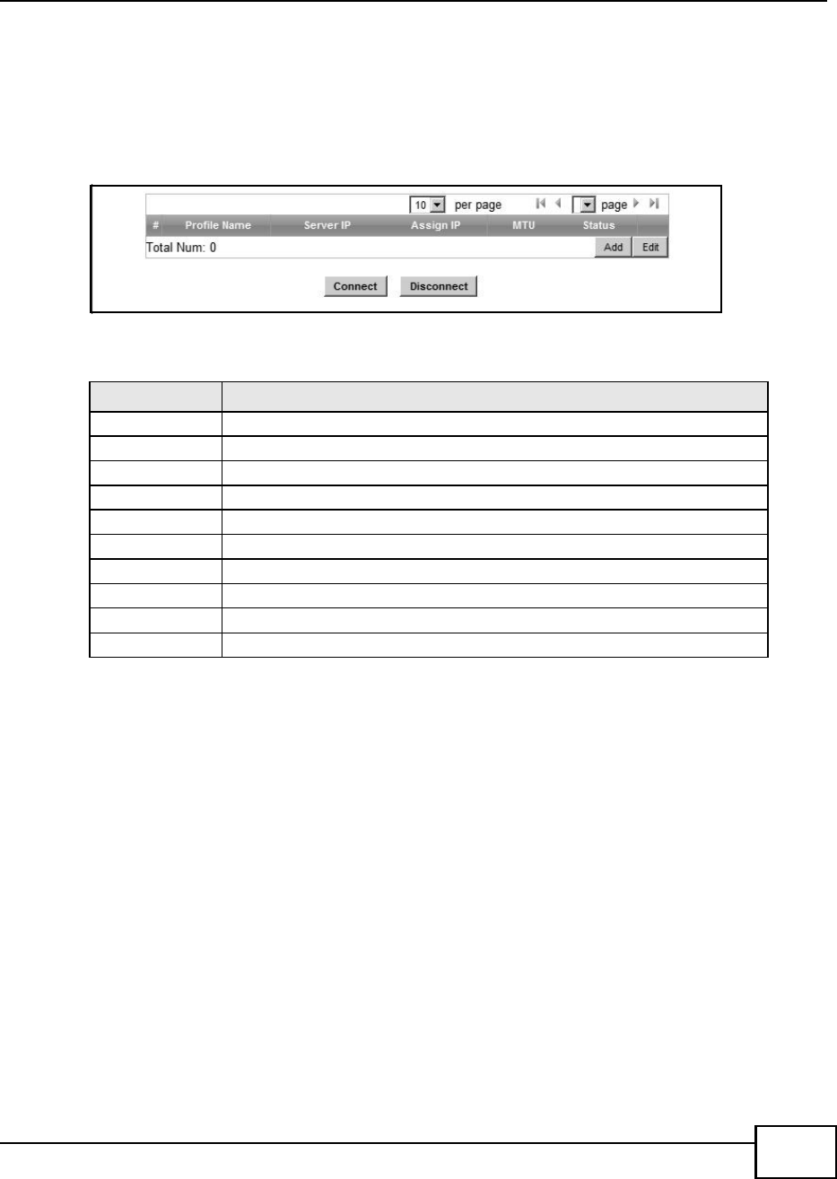
Chapter 8 Security
BM2022 Users Guide 127
8.6 PPTP VPN Client
Use this screen to view settings for Point to Point Tunneling Protocol (PPTP) clients.
Click Security > PPTP VPN > PPTP Client to open this screen as shown next.
Figure 62 PPTP Client
This screen contains the following fields:
8.7 PPTP VPN Client: Add
Use this screen to configure settings for Point to Point Tunneling Protocol (PPTP) clients.
Table 50 PPTP Client
LABEL DESCRIPTION
# This is the index number of the connection.
Profile Name This is the name of this client connection.
Server IP This is the IP address of the PPTP VPN server.
Assign IP This is the local IP address the client assigns to itself or is assigned by the server.
MTU This field indicates the Maximum Transmission Unit (MTU) for the connection.
Status This is the connection status.
Add Click this to add a VPN client profile.
Edit Click this to edit an existing VPN client profile.
Connect Select a VPN client connection and click this to connect.
Disconnect Select a VPN client connection and click this to disconnect.
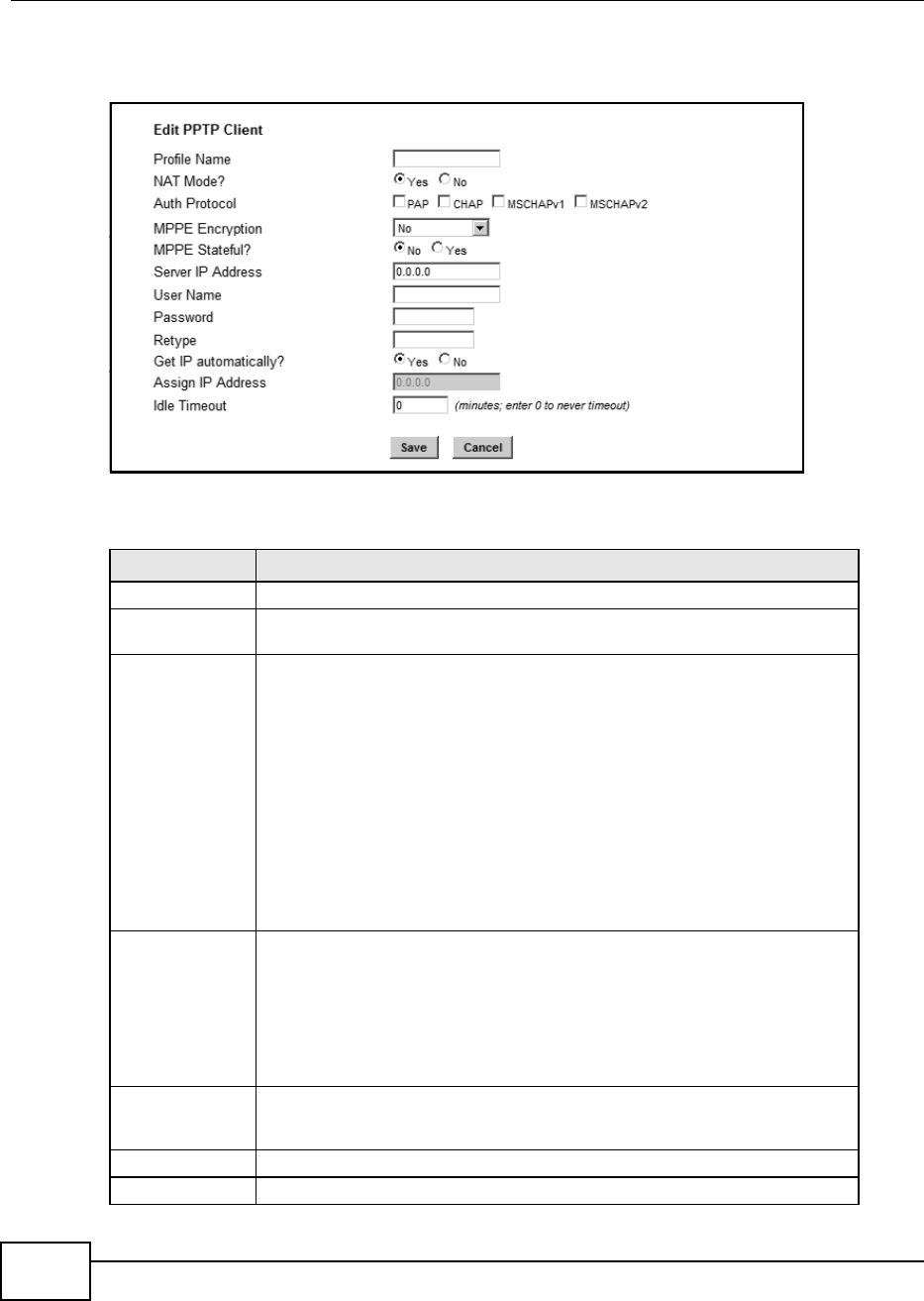
Chapter 8 Security
BM2022 Users Guide
128
Click Security > PPTP VPN > PPTP Client > Add to open this screen as shown next.
Figure 63 PPTP Client: Add
This screen contains the following fields:
Table 51 PPTP Client: Add
LABEL DESCRIPTION
Profile Name Enter the name for this client connection.
NAT Mode? Select Yes if the client will be located behind a NAT enabled router. This will
allow multiple clients using NAT to connect with PPTP at the same time.
Auth Protocol Select the Authentication Protocol allowed for the connection. Options are:
PAP - Password Authentication Protocol (PAP) authentication occurs in clear text
and does not use encryption. Its probably not a good idea to rely on this for
security.
CHAP - Challenge Handshake Authentication Protocol (CHAP) provides
authentication through a shared secret key and uses a three way handshake.
MSCHAPv1 - Microsoft CHAP v1 (MSCHAPv1) provides authentication through a
shared secret key and uses a three way handshake. It provides improved
usability with Microsoft products.
MSCHAPv2 - Microsoft CHAP v2 (MSCHAPv2) provides encryption through a
shared secret key and uses a three way handshake. It provides additional
security over MSCHAPv1, including two-way authentication.
MPPE Encryption If MSCHAPv1 or MSCHAPv2 is selected as an Auth Protocol, use the drop-
down list box to select the type of Microsoft Point-to-Point Encryption (MPPE).
Options are:
MPPE 40 - MPPE with 40 bit session key length.
MPPE 128 - MPPE with 128 bit session key length.
Auto - Automatically select either MPPE 40 or MPPE 128.
MPPE Stateful? Select Yes to enable stateful MPPE encryption. This can increase performance
over stateless MPPE, but should not be used in lossy network environments like
layer two tunnels over the Internet.
Server IP Address Enter the IP address of the PPTP server.
User Name Enter the user name for connecting to the PPTP server.
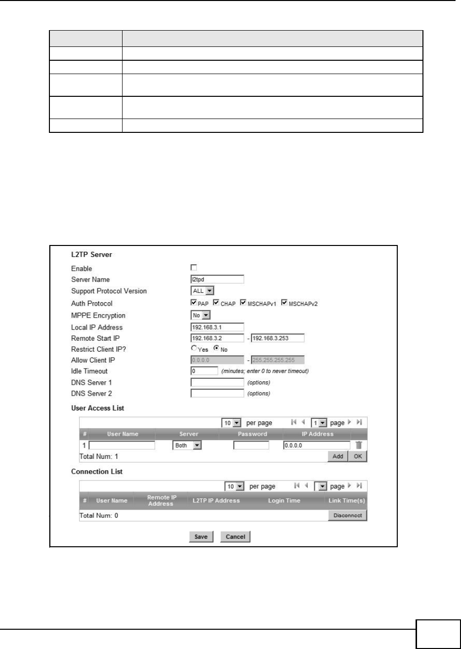
Chapter 8 Security
BM2022 Users Guide 129
8.8 L2TP VPN Server
Use this screen to configure settings for Layer 2 Tunneling Protocol (L2TP) server.
Click Security > L2TP VPN > L2TP Server to open this screen as shown next.
Figure 64 L2TP Server
Password Enter the password for connecting to the PPTP server.
Retype Retype the password for connecting to the PPTP server.
Get IP
automatically
Select Yes to have the PPTP server assign a local IP address to the client.
Assign IP Address Enter the IP address for the client. Ensure that the IP address is configured to
be allowed on the PPTP server.
Idle Timeout Enter the time in minutes to timeout PPTP connections.
Table 51 PPTP Client: Add
LABEL DESCRIPTION

Chapter 8 Security
BM2022 Users Guide
130
This screen contains the following fields:
Table 52 L2TP Server
LABEL DESCRIPTION
L2TP Server
Enable Use this field to turn the BM2022S L2TP VPN function on or off.
Server Name Enter the server name for the L2TP VPN connection.
Support
Protocol
Version
Select the L2TP Protocol Version 2 or 3. L2TPv2 is a standard method for
tunneling Point-to-Point Protocol (PPP) while L2TPv3 provides improved support
for other types of networks including frame relay and ATM.
Auth Protocol Select the Authentication Protocol allowed for the connection. Options are:
PAP - Password Authentication Protocol (PAP) authentication occurs in clear text
and does not use encryption. Its probably not a good idea to rely on this for
security.
CHAP - Challenge Handshake Authentication Protocol (CHAP) provides
authentication through a shared secret key and uses a three way handshake.
MSCHAPv1 - Microsoft CHAP v1 (MSCHAPv1) provides authentication through a
shared secret key and uses a three way handshake. It provides improved
usability with Microsoft products.
MSCHAPv2 - Microsoft CHAP v2 (MSCHAPv2) provides encryption through a
shared secret key and uses a three way handshake. It provides additional
security over MSCHAPv1, including two-way authentication.
MPPE
Encryption
If MSCHAPv1 or MSCHAPv2 is selected as an Auth Protocol, use the drop-
down list box to select the type of Microsoft Point-to-Point Encryption (MPPE).
Options are:
MPPE 40 - MPPE with 40 bit session key length
MPPE 128 - MPPE with 128 bit session key length
Auto - Automatically select either MPPE 40 or MPPE 128
Local IP
Address
Enter the local endpoint for the L2TP connection.
Remote Start
IP
Enter the local IP address range the BM2022 assigns to remote users if the
remote client device is set to obtain an IP address automatically.
Restrict Client
IP?
Select Yes to restrict the remote client device local IP address.
Allow Client IP Enter the local IP address range the remote client device is restricted to. If the
client device is configured with a static IP address, it should be in this range.
Idle Timeout Enter the time in minutes to timeout L2TP connections.
DNS Server 1
DNS Server 2
Specify the IP addresses of DNS servers to assign to the remote users.
User Access List
User Name Enter the user name for the remote user.
Server Select the server that the remote user has access to: PPTPD, L2TPD or Both.
Password Enter the password for the remote user.
IP Address Enter the local IP address the BM2022 assigns to the remote user.
Entering 0.0.0.0 indicates the local IP address will be dynamically assigned.
Delete Select an entry and click this to delete it.
Add Click this to create a new entry.
OK Click this to save the changes.
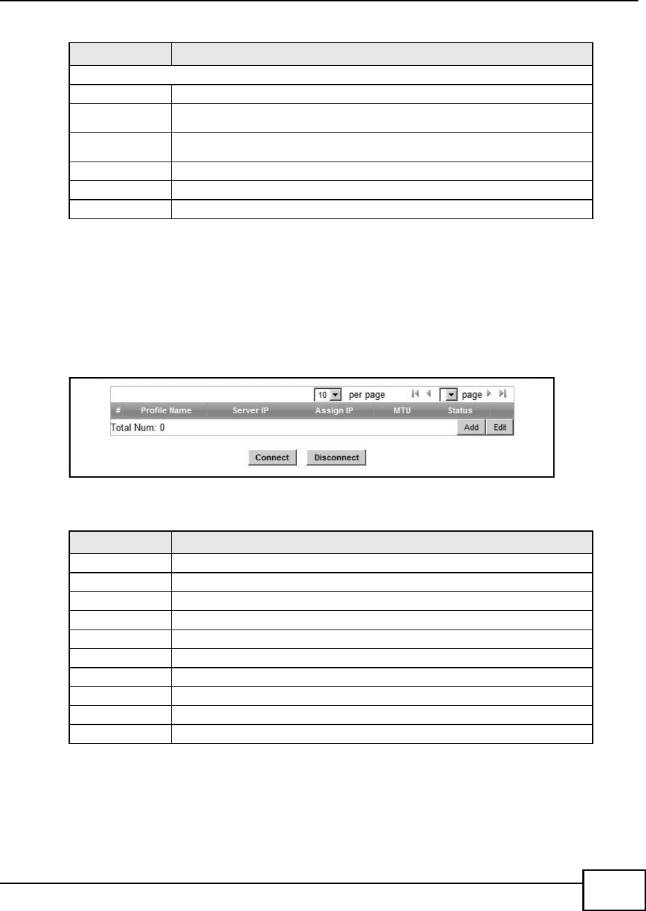
Chapter 8 Security
BM2022 Users Guide 131
8.9 L2TP VPN Client
Use this screen to view settings for Layer 2 Tunneling Protocol (L2TP) clients.
Click Security > L2TP VPN > L2TP Client to open this screen as shown next.
Figure 65 L2TP Client
This screen contains the following fields:
8.10 L2TP VPN Client: Add
Use this screen to configure settings for Layer 2 Tunneling Protocol (L2TP) clients.
Connection List
User Name This displays the user name for the remote user.
Remote IP
Address
This displays the remote endpoint IP address of the remote user.
L2TP IP
Address
This displays the local IP address of the L2TP server.
Login Time This displays the time the L2TP connection started.
Link Time(s) This displays the duration of the L2TP connection.
Disconnect Select a client and click this button to disconnect the selected client.
Table 52 L2TP Server
LABEL DESCRIPTION
Table 53 L2TP Client
LABEL DESCRIPTION
# This is the index number of the connection.
Profile Name This is the name of this client connection.
Server IP This is the IP address of the L2TP VPN server.
Assign IP This is the local IP address the client assigns to itself or is assigned by the server.
MTU This field indicates the Maximum Transmission Unit (MTU) for the connection.
Status This is the connection status.
Add Click this to add a VPN client profile.
Edit Click this to edit an existing VPN client profile.
Connect Select a VPN client connection and click this to connect.
Disconnect Select a VPN client connection and click this to disconnect.
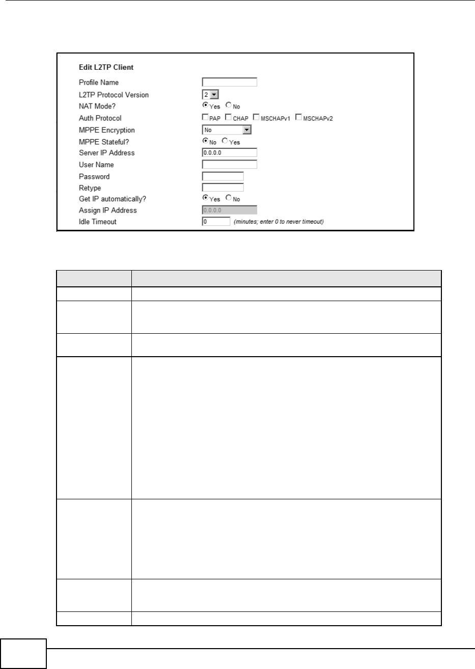
Chapter 8 Security
BM2022 Users Guide
132
Click Security > L2TP VPN > L2TP Client > Add to open this screen as shown next.
Figure 66 L2TP Client: Add
This screen contains the following fields:
Table 54 L2TP Client: Add
LABEL DESCRIPTION
Profile Name Enter the name for this client connection.
L2TP Protocol
Version
Select the L2TP Protocol Version 2 or 3. L2TPv2 is a standard method for
tunneling Point-to-Point Protocol (PPP) while L2TPv3 provides improved support
for other types of networks including frame relay and ATM.
NAT Mode? Select Yes if the client will be located behind a NAT enabled router. This will
allow multiple clients using NAT to connect with L2TP at the same time.
Auth Protocol Select the Authentication Protocol allowed for the connection. Options are:
PAP - Password Authentication Protocol (PAP) authentication occurs in clear text
and does not use encryption. Its probably not a good idea to rely on this for
security.
CHAP - Challenge Handshake Authentication Protocol (CHAP) provides
authentication through a shared secret key and uses a three way handshake.
MSCHAPv1 - Microsoft CHAP v1 (MSCHAPv1) provides authentication through a
shared secret key and uses a three way handshake. It provides improved
usability with Microsoft products.
MSCHAPv2 - Microsoft CHAP v2 (MSCHAPv2) provides encryption through a
shared secret key and uses a three way handshake. It provides additional
security over MSCHAPv1, including two-way authentication.
MPPE Encryption If MSCHAPv1 or MSCHAPv2 is selected as an Auth Protocol, use the drop-
down list box to select the type of Microsoft Point-to-Point Encryption (MPPE).
Options are:
MPPE 40 - MPPE with 40 bit session key length
MPPE 128 - MPPE with 128 bit session key length
Auto - Automatically select either MPPE 40 or MPPE 128
MPPE Stateful? Select Yes to enable stateful MPPE encryption. This can increase performance
over stateless MPPE, but should not be used in lossy network environments like
layer two tunnels over the Internet.
Server IP Address Enter the IP address of the L2TP server.
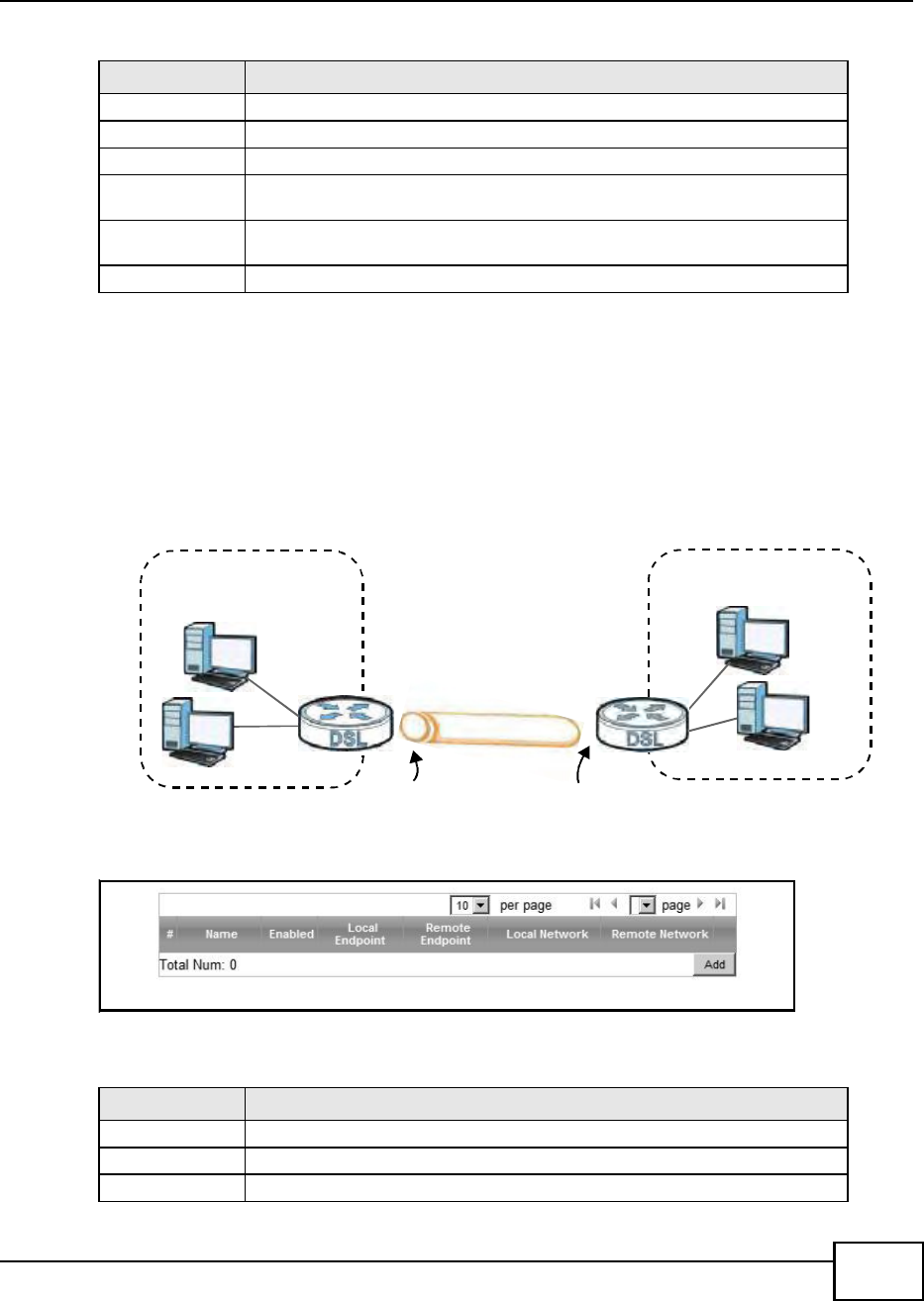
Chapter 8 Security
BM2022 Users Guide 133
8.11 IPSec VPN
8.11.1 The General Screen
The following figure helps explain the main fields in the web configurator.
Figure 67 IPSec Fields Summary
Click Security > IPSec VPN to open this screen as shown next.
Figure 68 IPSec VPN
This screen contains the following fields:
User Name Enter the user name for connecting to the L2TP server.
Password Enter the password for connecting to the L2TP server.
Retype Retype the password for connecting to the L2TP server.
Get IP
automatically
Select Yes to have the L2TP server assign a local IP address to the client.
Assign IP Address Enter the IP address for the client. Ensure that the IP address is configured to
be allowed on the L2TP server.
Idle Timeout Enter the time in minutes to timeout L2TP connections.
Table 54 L2TP Client: Add
LABEL DESCRIPTION
Table 55 IPSec VPN
LABEL DESCRIPTION
# This is the VPN policy index number.
Name Enter the name of the VPN connection.
Enabled This displays if the VPN policy is enabled.
Local Network
Local IP Address
Remote Network
Remote IP Address
Remote
IPSec Router
VPN Tunnel

Chapter 8 Security
BM2022 Users Guide
134
Local Endpoint This displays the IP address of the BM2022.
Remote Endpoint This displays the IP address of the remote IPSec router.
Local Network This displays the single (static) IP address on the LAN behind your BM2022 or
the IP address and subnet mask of a network behind your BM2022.
Remote Network This displays the single (static) IP address on the LAN behind the remote IPSec
router or the IP address and subnet mask of a network behind the remote IPSec
router.
Add Click this button to add an item to the list.
Table 55 IPSec VPN
LABEL DESCRIPTION
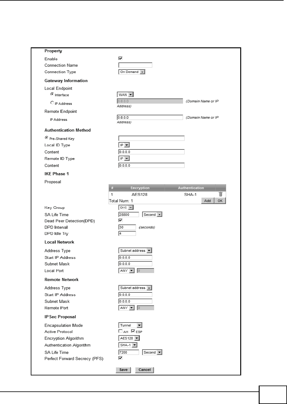
Chapter 8 Security
BM2022 Users Guide 135
8.11.2 IPSec VPN: Add
Use these settings. Click Security > IPSec VPN > Add to open this screen as shown next.
Figure 69 IPSec VPN: Add

Chapter 8 Security
BM2022 Users Guide
136
This screen contains the following fields:
Table 56 IPSec VPN: Add
LABEL DESCRIPTION
Property
Enable Select Enable to activate this VPN policy.
Connection
Name
Enter the name of the VPN connection.
Connection
Type
Select the scenario that best describes your intended VPN connection.
Initiator - Choose this to connect to an IPSec server. The BM2022 is the client
(dial-in user) and can initiate the VPN connection.
On Demand - Choose this if the remote IPSec router has a static IP address or
a domain name. This BM2022 can initiate the VPN tunnel.
Responder - Choose this to allow incoming connections from IPSec VPN clients.
The clients can have dynamic IP addresses and are also known as dial-in users.
Only the clients can initiate the VPN tunnel.
Gateway Information
Local Endpoint
Interface Select the interface for the VPN gateway.
IP Address Enter the IP address of the BM2022 in the IKE SA.
Remote Endpoint
IP Address Enter the IP address of the remote IPSec router in the IKE SA.
Authentication Method
Pre-Shared
Key
Type your pre-shared key in this field. A pre-shared key identifies a
communicating party during a phase 1 IKE negotiation.
Type from 8 to 31 case-sensitive ASCII characters or from 16 to 62 hexadecimal
("0-9", "A-F") characters. You must precede a hexadecimal key with a "0x (zero
x), which is not counted as part of the 16 to 62 character range for the key. For
example, in "0x0123456789ABCDEF", 0x denotes that the key is hexadecimal
and 0123456789ABCDEF is the key itself.
Local ID Type Select IP to identify the BM2022 by its IP address.
Select Domain Name to identify this BM2022 by a domain name.
Select E-mail to identify this BM2022 by an e-mail address.
Content When you select IP in the Local ID Type field, type the IP address of your
computer in the Content field. If you configure the Content field to 0.0.0.0 or
leave it blank, the BM2022 automatically uses the Pre-Shared Key (refer to the
Pre-Shared Key field description).
It is recommended that you type an IP address other than 0.0.0.0 in the
Content field or use the Domain Name or E-mail ID type in the following
situations.
When there is a NAT router between the two IPSec routers.
When you want the remote IPSec router to be able to distinguish between
VPN connection requests that come in from IPSec routers with dynamic WAN
IP addresses.
When you select Domain Name or E-mail in the Local ID Type field, type a
domain name or e-mail address by which to identify this BM2022 in the Local
Content field. Use up to 31 ASCII characters including spaces, although trailing
spaces are truncated. The domain name or e-mail address is for identification
purposes only and can be any string.

Chapter 8 Security
BM2022 Users Guide 137
Remote ID
Type
Select IP to identify the remote IPSec router by its IP address.
Select Domain Name to identify the remote IPSec router by a domain name.
Select E-mail to identify the remote IPSec router by an e-mail address.
Content The configuration of the remote content depends on the remote ID type.
For IP, type the IP address of the computer with which you will make the VPN
connection. If you configure this field to 0.0.0.0 or leave it blank, the BM2022
will use the address in the Remote Endpoint field (refer to the Remote
Endpoint field description).
For Domain Name or E-mail, type a domain name or e-mail address by which
to identify the remote IPSec router. Use up to 31 ASCII characters including
spaces, although trailing spaces are truncated. The domain name or e-mail
address is for identification purposes only and can be any string.
It is recommended that you type an IP address other than 0.0.0.0 or use the
Domain Name or E-mail ID type in the following situations:
When there is a NAT router between the two IPSec routers.
When you want the BM2022 to distinguish between VPN connection requests
that come in from remote IPSec routers with dynamic WAN IP addresses.
IKE Phase 1
Proposal
# This field is a sequential value, and it is not associated with a specific proposal.
The sequence of proposals should not affect performance significantly.
Encryption Select which key size and encryption algorithm to use in the IKE SA. Choices
are:
DES - a 56-bit key with the DES encryption algorithm
3DES - a 168-bit key with the DES encryption algorithm
AES128 - a 128-bit key with the AES encryption algorithm
AES192 - a 192-bit key with the AES encryption algorithm
AES256 - a 256-bit key with the AES encryption algorithm
The BM2022 and the remote IPSec router must use the same key size and
encryption algorithm. Longer keys require more processing power, resulting in
increased latency and decreased throughput.
Authentication Select which hash algorithm to use to authenticate packet data. Choices are
SHA1 and MD5. SHA1 is generally considered stronger than MD5, but it is also
slower.
Remove Select an entry and click this to delete it.
Add Click this to create a new entry.
OK Click this to save the changes.
Key Group Select which Diffie-Hellman key group (DHx) you want to use for encryption
keys. Choices are:
DH1 - use a 768-bit random number
DH2 - use a 1024-bit random number
DH5 - use a 1536-bit random number
The longer the key, the more secure the encryption, but also the longer it takes
to encrypt and decrypt information. Both routers must use the same DH key
group.
Table 56 IPSec VPN: Add
LABEL DESCRIPTION

Chapter 8 Security
BM2022 Users Guide
138
SA Life Time Type the maximum number of seconds the IKE SA can last. When this time has
passed, the BM2022 and remote IPSec router have to update the encryption and
authentication keys and re-negotiate the IKE SA. This does not affect any
existing IPSec SAs, however.
Dead Peer
Detection
(DPD)
Select this check box if you want the BM2022 to make sure the remote IPSec
router is there before it transmits data through the IKE SA. The remote IPSec
router must support DPD. If the remote IPSec router does not respond, the
BM2022 shuts down the IKE SA.
If the remote IPSec router does not support DPD, see if you can use the VPN
connection connectivity check.
DPD Interval Specify the time interval for the BM2022 to send a DPD message to the remote
IPSec router.
DPD Idle Try Specify the maximum number of times the BM2022 sends the DPD message.
Local Network Local IP addresses must be static and correspond to the remote IPSec router's
configured remote IP addresses.
Two active SAs can have the same configured local or remote IP address, but not
both. You can configure multiple SAs between the same local and remote IP
addresses, as long as only one is active at any time.
In order to have more than one active rule with the Remote Endpoint field set
to 0.0.0.0, the ranges of the local IP addresses cannot overlap between rules.
If you configure an active rule with 0.0.0.0 in the Remote Endpoint field and
the LANs full IP address range as the local IP address, then you cannot configure
any other active rules with the Remote Endpoint field set to 0.0.0.0.
Address Type Select Single address or Subnet address to specify if the VPN connection
begins at an IP address or subnet.
Start IP
Address
If Single address is selected, enter a (static) IP address on the LAN behind your
BM2022.
If Subnet address is selected, specify IP addresses on a network by their
subnet mask by entering a (static) IP address on the LAN behind your BM2022.
Then enter the subnet mask to identify the network address.
Subnet Mask If Subnet address is selected, enter the subnet mask to identify the network
address.
Local Port Select how the BM2022 checks the connection. The peer must be configured to
respond to the method you select.
Select icmp to have the BM2022 regularly ping the address you specify to make
sure traffic can still go through the connection. You may need to configure the
peer to respond to pings.
Select tcp or udp to have the BM2022 regularly perform a TCP or UDP
handshake with the address you specify to make sure traffic can still go through
the connection. You may need to configure the peer to accept the TCP or UDP
connection. If you select tcp or udp, specify the port number to use for the
connectivity check.
Remote Network Remote IP addresses must be static and correspond to the remote IPSec router's
configured local IP addresses. The remote fields do not apply when the Remote
Endpoint field is configured to 0.0.0.0. In this case only the remote IPSec
router can initiate the VPN.
Two active SAs cannot both have the same local and remote IP address(es). Two
active SAs can have the same local or remote IP address, but not both. You can
configure multiple SAs between the same local and remote IP addresses, as long
as only one is active at any time.
Table 56 IPSec VPN: Add
LABEL DESCRIPTION

Chapter 8 Security
BM2022 Users Guide 139
Address Type Select Single address or Subnet address to specify if the VPN connection
terminates at an IP address or subnet.
Start IP
Address
If Single address is selected, enter a (static) IP address on the LAN behind the
remote IPSecs router.
If Subnet address is selected, specify IP addresses on a network by their
subnet mask by entering a (static) IP address on the LAN behind the remote
IPSecs router. Then enter the subnet mask to identify the network address.
Subnet Mask If Subnet address is selected, enter the subnet mask to identify the network
address.
Remote Port Select how the BM2022 checks the connection. The peer must be configured to
respond to the method you select.
Select icmp to have the BM2022 regularly ping the address you specify to make
sure traffic can still go through the connection. You may need to configure the
peer to respond to pings.
Select tcp or udp to have the BM2022 regularly perform a TCP or UDP
handshake with the address you specify to make sure traffic can still go through
the connection. You may need to configure the peer to accept the TCP or UDP
connection. If you select tcp or udp, specify the port number to use for the
connectivity check.
IPSec Proposal
Encapsulation
Mode
Select Tunnel mode or Transport mode from the drop-down list box.
Active
Protocol
Select the security protocols used for an SA.
Both AH and ESP increase processing requirements and communications latency
(delay).
If you select ESP here, you must select options from the Encryption Algorithm
and Authentication Algorithm fields (described below).
Encryption
Algorithm
Select which key size and encryption algorithm to use in the IPSec SA. Choices
are:
DES - a 56-bit key with the DES encryption algorithm
3DES - a 168-bit key with the DES encryption algorithm
AES128 - a 128-bit key with the AES encryption algorithm
AES192 - a 192-bit key with the AES encryption algorithm
AES256 - a 256-bit key with the AES encryption algorithm
The BM2022 and the remote IPSec router must use the same key size and
encryption algorithm. Longer keys require more processing power, resulting in
increased latency and decreased throughput.
Authentication
Algorithm
Select which hash algorithm to use to authenticate packet data. Choices are
SHA1 and MD5. SHA1 is generally considered stronger than MD5, but it is also
slower.
SA Life Time Define the length of time before an IPSec SA automatically renegotiates in this
field.
A short SA Life Time increases security by forcing the two VPN gateways to
update the encryption and authentication keys. However, every time the VPN
tunnel renegotiates, all users accessing remote resources are temporarily
disconnected.
Table 56 IPSec VPN: Add
LABEL DESCRIPTION
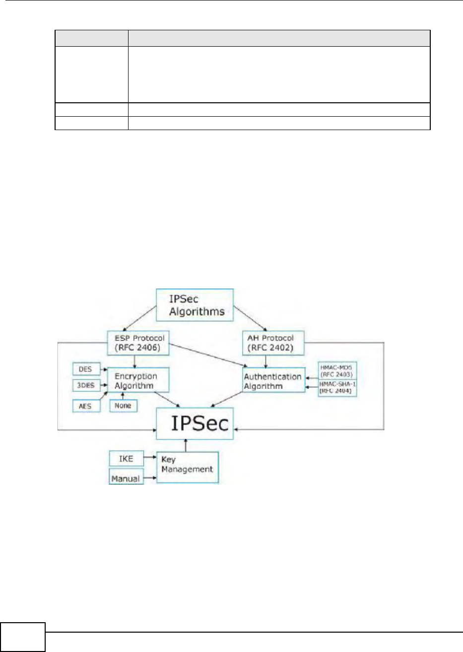
Chapter 8 Security
BM2022 Users Guide
140
8.12 Technical Reference
This section provides some technical background information about the topics covered in this
section.
8.12.1 IPSec Architecture
The overall IPSec architecture is shown as follows.
Figure 70 IPSec Architecture
IPSec Algorithms
The ESP (Encapsulating Security Payload) Protocol (RFC 2406) and AH (Authentication Header)
protocol (RFC 2402) describe the packet formats and the default standards for packet structure
(including implementation algorithms).
The Encryption Algorithm describes the use of encryption techniques such as DES (Data Encryption
Standard) and Triple DES algorithms.
Perfect
Forward
Secrecy (PFS)
Select whether or not you want to enable Perfect Forward Secrecy (PFS)
PFS changes the root key that is used to generate encryption keys for each IPSec
SA. The longer the key, the more secure the encryption, but also the longer it
takes to encrypt and decrypt information. Both routers must use the same DH
key group.
Save Click Apply to save your changes back to the BM2022.
Cancel Click Cancel to restore your previous settings.
Table 56 IPSec VPN: Add
LABEL DESCRIPTION
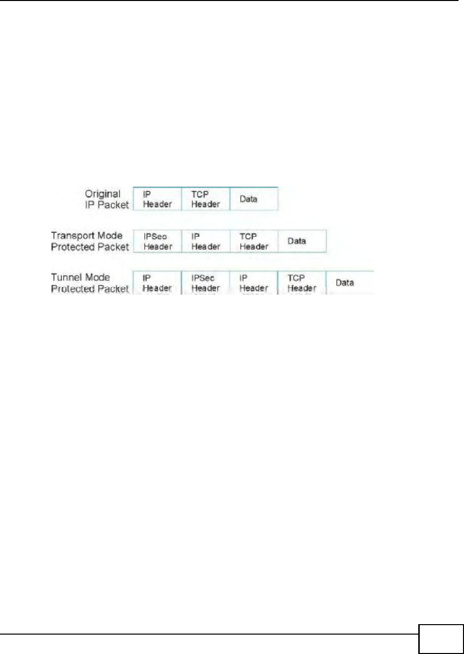
Chapter 8 Security
BM2022 Users Guide 141
The Authentication Algorithms, HMAC-MD5 (RFC 2403) and HMAC-SHA-1 (RFC 2404, provide an
authentication mechanism for the AH and ESP protocols.
Key Management
Key management allows you to determine whether to use IKE (ISAKMP) or manual key
configuration in order to set up a VPN.
8.12.2 Encapsulation
The two modes of operation for IPSec VPNs are Transport mode and Tunnel mode. At the time of
writing, the BM2022 supports Tunnel mode only.
Figure 71 Transport and Tunnel Mode IPSec Encapsulation
Transport Mode
Transport mode is used to protect upper layer protocols and only affects the data in the IP packet.
In Transport mode, the IP packet contains the security protocol (AH or ESP) located after the
original IP header and options, but before any upper layer protocols contained in the packet (such
as TCP and UDP).
With ESP, protection is applied only to the upper layer protocols contained in the packet. The IP
header information and options are not used in the authentication process. Therefore, the
originating IP address cannot be verified for integrity against the data.
With the use of AH as the security protocol, protection is extended forward into the IP header to
verify the integrity of the entire packet by use of portions of the original IP header in the hashing
process.
Tunnel Mode
Tunnel mode encapsulates the entire IP packet to transmit it securely. A Tunnel mode is required
for gateway services to provide access to internal systems. Tunnel mode is fundamentally an IP
tunnel with authentication and encryption. This is the most common mode of operation. Tunnel
mode is required for gateway to gateway and host to gateway communications. Tunnel mode
communications have two sets of IP headers:
Outside header: The outside IP header contains the destination IP address of the VPN gateway.
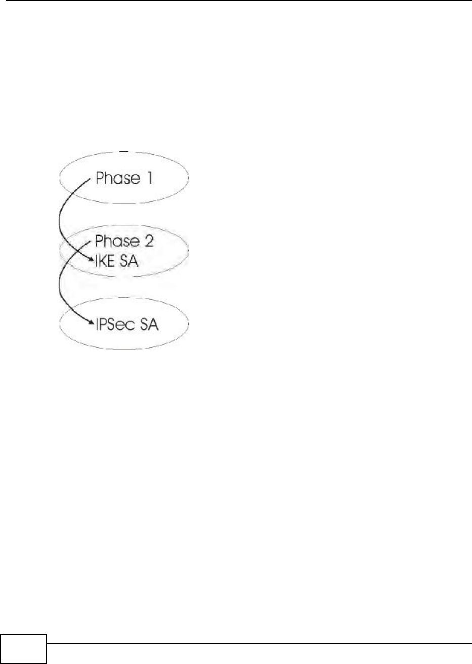
Chapter 8 Security
BM2022 Users Guide
142
Inside header: The inside IP header contains the destination IP address of the final system
behind the VPN gateway. The security protocol appears after the outer IP header and before the
inside IP header.
8.12.3 IKE Phases
There are two phases to every IKE (Internet Key Exchange) negotiation phase 1 (Authentication)
and phase 2 (Key Exchange). A phase 1 exchange establishes an IKE SA and the second one uses
that SA to negotiate SAs for IPSec.
Figure 72 Two Phases to Set Up the IPSec SA
In phase 1 you must:
Choose a negotiation mode.
Authenticate the connection by entering a pre-shared key.
Choose an encryption algorithm.
Choose an authentication algorithm.
Choose a Diffie-Hellman public-key cryptography key group (DH1 or DH2).
Set the IKE SA lifetime. This field allows you to determine how long an IKE SA should stay up
before it times out. An IKE SA times out when the IKE SA lifetime period expires. If an IKE SA
times out when an IPSec SA is already established, the IPSec SA stays connected.
In phase 2 you must:
Choose an encryption algorithm.
Choose an authentication algorithm
Choose a Diffie-Hellman public-key cryptography key group.
Set the IPSec SA lifetime. This field allows you to determine how long the IPSec SA should stay
up before it times out. The BM2022 automatically renegotiates the IPSec SA if there is traffic
when the IPSec SA lifetime period expires. If an IPSec SA times out, then the IPSec router must
renegotiate the SA the next time someone attempts to send traffic.

Chapter 8 Security
BM2022 Users Guide 143
8.12.4 Negotiation Mode
The phase 1 Negotiation Mode you select determines how the Security Association (SA) will be
established for each connection through IKE negotiations.
Main Mode ensures the highest level of security when the communicating parties are
negotiating authentication (phase 1). It uses 6 messages in three round trips: SA negotiation,
Diffie-Hellman exchange and an exchange of nonces (a nonce is a random number). This mode
features identity protection (your identity is not revealed in the negotiation).
Aggressive Mode is quicker than Main Mode because it eliminates several steps when the
communicating parties are negotiating authentication (phase 1). However the trade-off is that
faster speed limits its negotiating power and it also does not provide identity protection. It is
useful in remote access situations where the address of the initiator is not know by the responder
and both parties want to use pre-shared key authentication.
8.12.5 IPSec and NAT
Read this section if you are running IPSec on a host computer behind the BM2022.
NAT is incompatible with the AH protocol in both Transport and Tunnel mode. An IPSec VPN using
the AH protocol digitally signs the outbound packet, both data payload and headers, with a hash
value appended to the packet. When using AH protocol, packet contents (the data payload) are not
encrypted.
A NAT device in between the IPSec endpoints will rewrite either the source or destination address
with one of its own choosing. The VPN device at the receiving end will verify the integrity of the
incoming packet by computing its own hash value, and complain that the hash value appended to
the received packet doesn't match. The VPN device at the receiving end doesn't know about the
NAT in the middle, so it assumes that the data has been maliciously altered.
IPSec using ESP in Tunnel mode encapsulates the entire original packet (including headers) in a
new IP packet. The new IP packet's source address is the outbound address of the sending VPN
gateway, and its destination address is the inbound address of the VPN device at the receiving end.
When using ESP protocol with authentication, the packet contents (in this case, the entire original
packet) are encrypted. The encrypted contents, but not the new headers, are signed with a hash
value appended to the packet.
Tunnel mode ESP with authentication is compatible with NAT because integrity checks are
performed over the combination of the "original header plus original payload," which is unchanged
by a NAT device.
Transport mode ESP with authentication is not compatible with NAT.
Table 57 VPN and NAT
SECURITY PROTOCOL MODE NAT
AH Transport N
AH Tunnel N
ESP Transport N
ESP Tunnel Y
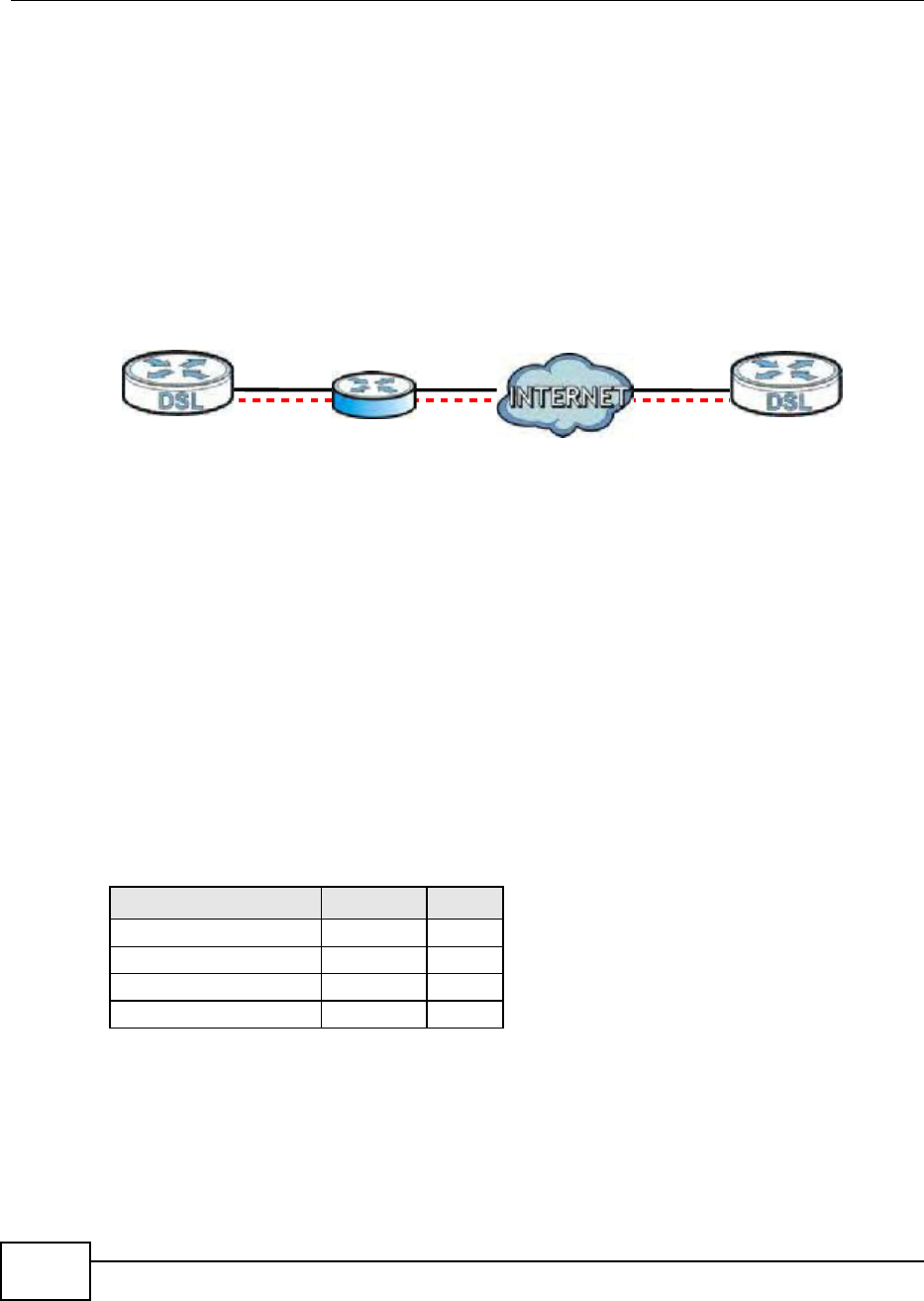
Chapter 8 Security
BM2022 Users Guide
144
8.12.6 VPN, NAT, and NAT Traversal
NAT is incompatible with the AH protocol in both transport and tunnel mode. An IPSec VPN using
the AH protocol digitally signs the outbound packet, both data payload and headers, with a hash
value appended to the packet, but a NAT device between the IPSec endpoints rewrites the source or
destination address. As a result, the VPN device at the receiving end finds a mismatch between the
hash value and the data and assumes that the data has been maliciously altered.
NAT is not normally compatible with ESP in transport mode either, but the BM2022s NAT
Traversal feature provides a way to handle this. NAT traversal allows you to set up an IKE SA when
there are NAT routers between the two IPSec routers.
Figure 73 NAT Router Between IPSec Routers
Normally you cannot set up an IKE SA with a NAT router between the two IPSec routers because
the NAT router changes the header of the IPSec packet. NAT traversal solves the problem by adding
a UDP port 500 header to the IPSec packet. The NAT router forwards the IPSec packet with the UDP
port 500 header unchanged. In the above figure, when IPSec router A tries to establish an IKE SA,
IPSec router B checks the UDP port 500 header, and IPSec routers A and B build the IKE SA.
For NAT traversal to work, you must:
Use ESP security protocol (in either transport or tunnel mode).
Use IKE keying mode.
Enable NAT traversal on both IPSec endpoints.
Set the NAT router to forward UDP port 500 to IPSec router A.
Finally, NAT is compatible with ESP in tunnel mode because integrity checks are performed over the
combination of the "original header plus original payload," which is unchanged by a NAT device. The
compatibility of AH and ESP with NAT in tunnel and transport modes is summarized in the following
table.
Y* - This is supported in the BM2022 if you enable NAT traversal.
8.12.7 ID Type and Content
With aggressive negotiation mode (see Section 8.12.4 on page 143), the BM2022 identifies
incoming SAs by ID type and content since this identifying information is not encrypted. This
Table 58 VPN and NAT
SECURITY PROTOCOL MODE NAT
AH Transport N
AH Tunnel N
ESP Transport Y*
ESP Tunnel Y
AB

Chapter 8 Security
BM2022 Users Guide 145
enables the BM2022 to distinguish between multiple rules for SAs that connect from remote IPSec
routers that have dynamic WAN IP addresses.
Regardless of the ID type and content configuration, the BM2022 does not allow you to save
multiple active rules with overlapping local and remote IP addresses.
With main mode (see Section 8.12.4 on page 143), the ID type and content are encrypted to
provide identity protection. In this case the BM2022 can only distinguish between up to 12 different
incoming SAs that connect from remote IPSec routers that have dynamic WAN IP addresses. The
BM2022 can distinguish up to 48 incoming SAs because you can select between three encryption
algorithms (DES, 3DES and AES), two authentication algorithms (MD5 and SHA1) and eight key
groups when you configure a VPN rule (see Section 8.11.1 on page 133). The ID type and content
act as an extra level of identification for incoming SAs.
The type of ID can be a domain name, an IP address or an e-mail address. The content is the IP
address, domain name, or e-mail address.
8.12.7.1 ID Type and Content Examples
Two IPSec routers must have matching ID type and content configuration in order to set up a VPN
tunnel.
The two BM2022s in this example can complete negotiation and establish a VPN tunnel.
The two BM2022s in this example cannot complete their negotiation because BM2022 Bs Local ID
type is IP, but BM2022 As Remote ID type is set to E-mail. An ID mismatched message
displays in the IPSEC LOG.
Table 59 Local ID Type and Content Fields
LOCAL ID TYPE= CONTENT=
IP Type the IP address of your computer.
DNS Type a domain name (up to 31 characters) by which to identify this BM2022.
E-mail Type an e-mail address (up to 31 characters) by which to identify this BM2022.
The domain name or e-mail address that you use in the Local ID Content field
is used for identification purposes only and does not need to be a real domain
name or e-mail address.
Table 60 Matching ID Type and Content Configuration Example
BM2022 A BM2022 B
Local ID type: E-mail Local ID type: IP
Local ID content: tom@yourcompany.com Local ID content: 1.1.1.2
Remote ID type: IP Remote ID type: E-mail
Remote ID content: 1.1.1.2 Remote ID content: tom@yourcompany.com
Table 61 Mismatching ID Type and Content Configuration Example
BM2022 A BM2022 B
Local ID type: IP Local ID type: IP
Local ID content: 1.1.1.10 Local ID content: 1.1.1.2
Remote ID type: E-mail Remote ID type: IP
Remote ID content: aa@yahoo.com Remote ID content: 1.1.1.0

Chapter 8 Security
BM2022 Users Guide
146
8.12.8 Pre-Shared Key
A pre-shared key identifies a communicating party during a phase 1 IKE negotiation (see Section
8.12.3 on page 142 for more on IKE phases). It is called pre-shared because you have to share it
with another party before you can communicate with them over a secure connection.
8.12.9 Diffie-Hellman (DH) Key Groups
Diffie-Hellman (DH) is a public-key cryptography protocol that allows two parties to establish a
shared secret over an unsecured communications channel. Diffie-Hellman is used within IKE SA
setup to establish session keys. 768-bit, 1024-bit 1536-bit, 2048-bit, and 3072-bit Diffie-Hellman
groups are supported. Upon completion of the Diffie-Hellman exchange, the two peers have a
shared secret, but the IKE SA is not authenticated. For authentication, use pre-shared keys.

BM2022 Users Guide 147
CHAPTER 9
The VoIP General Screens
9.1 VoIP Overview
The VOICE > General screens allow you to set up global SIP and Quality of Service (QoS) settings.
VoIP (Voice over IP) is the sending of voice signals over the Internet Protocol. This allows you to
make phone calls and send faxes over the Internet at a fraction of the cost of using the traditional
circuit-switched telephone network. You can also use servers to run telephone service applications
like PBX services and voice mail. Internet Telephony Service Provider (ITSP) companies provide
VoIP service. A company could alternatively set up an IP-PBX and provide its own VoIP service.
Circuit-switched telephone networks require 64 kilobits per second (kbps) in each direction to
handle a telephone call. VoIP can use advanced voice coding techniques with compression to reduce
the required bandwidth.
9.1.1 What You Can Do in This Chapter
The Media screen (Section 9.2 on page 149) lets you set up and maintain global VoIP settings on
the BM2022.
The QoS screen (Section 9.3 on page 150) lets you set up and maintain QoS settings for voice
traffic flowing through the BM2022.
The SIP screen (Section 9.4 on page 151) lets you enable session timer and select the SIP
session refresh method.
The Speed Dial screen (Section 9.5 on page 151) lets you add, edit, or remove speed-dial
entries for the phone line.
9.1.2 What You Need to Know
The following terms and concepts may help as you read through this chapter.
Voice Coding
A codec (coder/decoder) codes analog voice signals into digital signals and decodes the digital
signals back into voice signals. The BM2022 supports the following codecs.
G.711 is a Pulse Code Modulation (PCM) waveform codec. PCM measures analog signal
amplitudes at regular time intervals (sampling) and converts them into digital bits (quantization).
Quantization reads the analog signal and then writes it to the nearest digital value. For this
reason, a digital sample is usually slightly different from its analog original (this difference is
known as quantization noise). G.711 provides excellent sound quality but requires 64kbps of
bandwidth.

Chapter 9 The VoIP General Screens
BM2022 Users Guide
148
G.729 is an Analysis-by-Synthesis (AbS) hybrid waveform codec. It uses a filter based on
information about how the human vocal tract produces sounds. The codec analyzes the incoming
voice signal and attempts to synthesize it using its list of voice elements. It tests the synthesized
signal against the original and, if it is acceptable, transmits details of the voice elements it used
to make the synthesis. Because the codec at the receiving end has the same list, it can exactly
recreate the synthesized audio signal.G.729 provides good sound quality and reduces the
required bandwidth to 8kbps.
Quality of Service (QoS)
Quality of Service (QoS) refers to both a network's ability to deliver data with minimum delay and
the networking methods used to provide bandwidth for real-time multimedia applications.
Type Of Service (ToS)
Network traffic can be classified by setting the ToS (Type Of Service) values at the data source (for
example, at the BM2022) so a server can decide the best method of delivery, that is the least cost,
fastest route and so on. The ToS field is consist of 8 bits. The first 3 bits indicate the priority of the
packet.
DiffServ
DiffServ is a class of service (CoS) model that marks packets so that they receive specific per-hop
treatment at DiffServ-compliant network devices along the route based on the application types
and traffic flow. Packets are marked with DiffServ Code Points (DSCPs) indicating the level of
service desired. This allows the intermediary DiffServ-compliant network devices to handle the
packets differently depending on the code points without the need to negotiate paths or remember
state information for every flow. In addition, applications do not have to request a particular service
or give advanced notice of where the traffic is going.
DiffServ uses the first 6 bits of the 8-bit ToS value so that it can be backward compatible with non-
DiffServ compliant but ToS-enabled network device. See Section 9.6.1 on page 152 for more
information.
SIP
The Session Initiation Protocol (SIP) is an application-layer control (signaling) protocol that handles
the setting up, altering and tearing down of voice and multimedia sessions over the Internet. SIP
signaling is separate from the media for which it handles sessions. The media that is exchanged
during the session can use a different path from that of the signaling. SIP handles telephone calls
and can interface with traditional circuit-switched telephone networks.
RTP
When you make a VoIP call using SIP, the RTP (Real time Transport Protocol) is used to handle voice
data transfer. See RFC 1889 for details on RTP.
Speed Dial
Speed dial provides shortcuts for dialing frequently used phone numbers. You can map a phone
number to a self-defined key(s) and then use that key(s) to call the phone number. For example,
you can map 123456 to #01. When you press #01 it means that you press 123456.
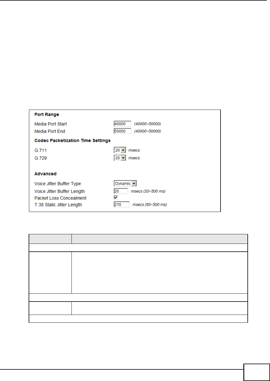
Chapter 9 The VoIP General Screens
BM2022 Users Guide 149
9.1.3 Before you Begin
Ensure that you have all of your voice account information on hand. If not, contact your voice
account service provider to find out which settings in this chapter you should configure in order
to use your telephone with the BM2022.
Connect your BM2022 to the Internet, as described in the Quick Start Guide. If you have not
already done so, then you will not be able to test your VoIP settings.
9.2 Media
Click VoIP > General > Media to set up and maintain global VoIP settings.
Figure 74 VoIP > General > Media
The following table describes the labels in this screen.
Table 62 VoIP > General > Media
LABEL DESCRIPTION
Port Range
Media Port Start
Media Port End
Enter the listening port number(s) for RTP traffic on the BM2022, if your VoIP
service provider gave you this information. Otherwise, keep the default values.
To enter one port number, enter the port number in the both Media Port Start
and Media Port End fields.
To enter a range of ports, enter the beginning port number of the range in the
Media Port Start field and the ending port number in the Media Port End field.
Codec Packetization Time Settings
G.711, G.729 Select how often (10 to 60 msecs) the BM2022 sends an RTP packet for each
type of voice coder/decoder (codec) G.711 and G.729.
Advanced
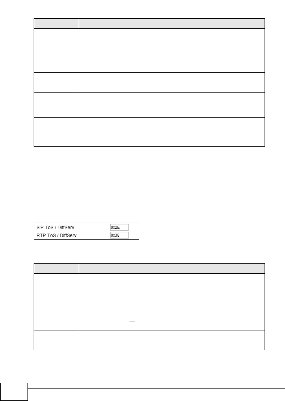
Chapter 9 The VoIP General Screens
BM2022 Users Guide
150
9.3 QoS
This section describes the features of the Quality of Service (QoS) screen.
Click VoIP > General > QoS to set up Type of Service (ToS) and Differentiated Services (Diffserv)
settings for voice traffic transmission through the BM2022.
Figure 75 VoIP > General > QoS
The following table describes the labels in this screen.
Voice Jitter Buffer
Type
Voice jitter is a variation in delay of RTP packets delivery. This could cause
strange sound effects. The BM2022 can utilize the following types of jitter buffer
to minimize the effects of jitter.
Dynamic - Jitter buffer size is dynamically changed by RTP packets delivery
status.
Static - Jitter buffer size is fixed.
Voice Jitter Buffer
Length
Select the maximum number of milliseconds of voice traffic the BM2022 can help
to smooth out the jitter in order to ensure good voice quality for your
conversations.
Packet Loss
Concealment
Packets may be dropped due to an overwhelming amount of traffic on the
network. Some degree of packet loss will not be noticeable to the end user, but
as packet loss increases the quality of sound degrades. Select this to have the
BM2022 to improve the voice quality when packet loss occurs.
T.38 Static Jitter
Length
T.38 is an ITU-T standard that VoIP devices use to send fax messages over the
Internet.
Select the number of milliseconds for the jitter buffer size used for transmitting
T.38 fax messages.
Table 62 VoIP > General > Media (continued)
LABEL DESCRIPTION
Table 63 VoIP > General > QoS
LABEL DESCRIPTION
SIP ToS/DiffServ Enter the DSCP value you want to mark on all outgoing SIP packets generated by
the BM2022 for DiffServ-enabled networks. Since DiffServ uses the first 6 bits of
the 8-bit IP ToS field to represent the DSCP value, enter here the 6-bit DSCP
value you want to mark in hexadecimal (in a format of 0x00), and the BM2022
will then automatically append 2 bits '0' to make a whole 8-bit ToS field value for
all outgoing SIP packets.
For example, if you enter 0x2E, it is 101110 in binary for DSCP. The BM2022
converts it to 10111000 in binary and marks on the IP ToS field of all the
outgoing SIP packets.
RTP ToS/DiffServ Enter the DSCP value you want to mark on all outgoing VoIP data packets
(including both RTP and T.38 UDPTL packets) generated by the BM2022 for
DiffServ-enabled networks.
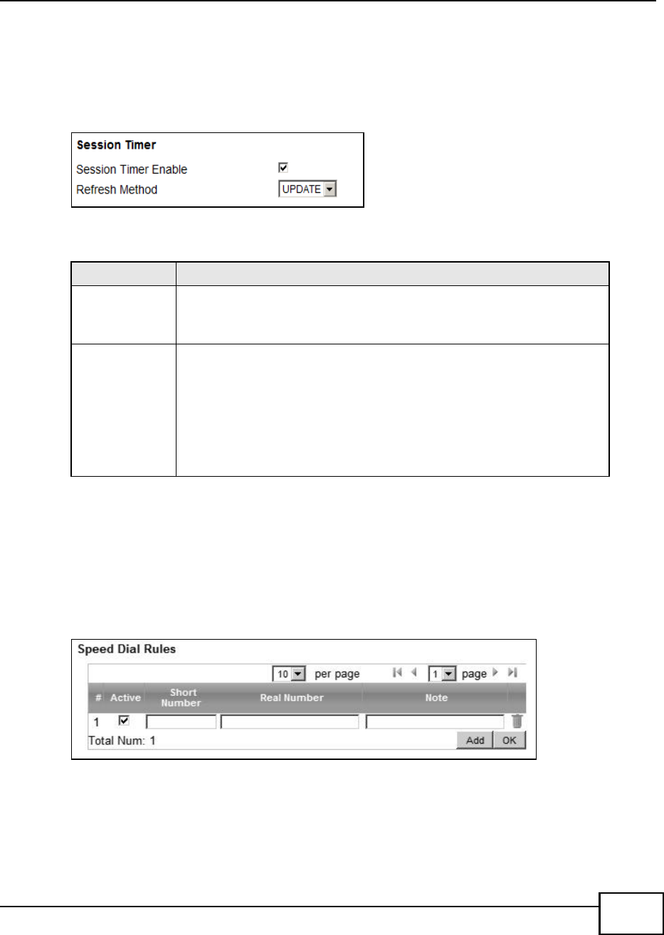
Chapter 9 The VoIP General Screens
BM2022 Users Guide 151
9.4 SIP Settings
Click VoIP > General > SIP to set up session timer on the BM2022. See Section 10.8 on page
163 for more information on SIP.
Figure 76 VoIP > General > SIP
The following table describes the labels in this screen.
9.5 Speed Dial
Speed dial allows you to use a shorter number for dialing frequently used phone numbers.
Click VoIP > General > Speed Dial to add, edit, or remove speed-dial rules.
Figure 77 VoIP > General > Speed Dial
Table 64 VoIP > General > SIP
LABEL DESCRIPTION
Session Timer
Enable
Select this to activate the BM2022s SIP Session Timer. SIP Session Timer is a
function used by both of the communication peers to determine if the call
session is still active (alive) or not. It uses the method specified in the following
Refresh Method field to periodically refresh the SIP sessions.
Refresh Method Select the method to be used for periodically refreshing SIP sessions, to
determine if the session is still active. Select UPDATE to use Update requests to
refresh the session and select INVITE to use Re-Invite requests. You should
use the same method as the peer device.
The Update method uses less overhead than Re-Invite, but is not as widely
supported as Re-Invite. By default the BM2022 is set to use the UPDATE
method. When set to UPDATE, the BM2022 can also revert to using the
INVITE method for SIP session refresh, depending on the method supported
and allowed by the peer device.

Chapter 9 The VoIP General Screens
BM2022 Users Guide
152
The following table describes the labels in this screen.
9.6 Technical Reference
The following section contains additional technical information about the BM2022 features
described in this chapter.
9.6.1 DSCP and Per-Hop Behavior
DiffServ defines a new DS (Differentiated Services) field to replace the Type of Service (TOS) field
in the IP header. The DS field contains a 2-bit unused field and a 6-bit DSCP field which can define
up to 64 service levels. The following figure illustrates the DS field.
Figure 78 DiffServ: Differentiated Service Field
DSCP is backward compatible with the three precedence bits in the ToS octet so that non-DiffServ
compliant, ToS-enabled network device will not conflict with the DSCP mapping.
The DSCP value determines the forwarding behavior, the PHB (Per-Hop Behavior), that each packet
gets across the DiffServ network. Based on the marking rule, different kinds of traffic can be
marked for different priorities of forwarding. Resources can then be allocated according to the DSCP
values and the configured policies.
Table 65 VoIP > General > Speed Dial
LABEL DESCRIPTION
Speed Dial Rules - This is a list of speed dial numbers. To edit an existing speed dial rule, you can
click the row for the rule and editable fields will appear.
Active This field displays whether the rule is activated or not.
Short Number This field displays the abbreviated number you want to use to substitute for the
real (actual) phone number in the following Real Number field.
When the rule is activated, you can press the assigned Short Number to dial the
Real Number.
Real Number This field displays the actual phone number you want the BM2022 to call when you
use the specified Short Number.
Enter the actual phone number you want the BM2022 to call when you use the
specified Short Number if you are editing the entry.
Notes This field displays additional information for this speed-dial rule.
Enter additional information or any remark for this speed-dial rule if your are
editing the entry.
Remove Click this to remove the rule.
Add Click this to add a new speed-dial rule.
OK Click this to save the changes you made in this table.
DSCP
(6-bit)
Unused
(2-bit)

BM2022 Users Guide 153
CHAPTER 10
The VoIP Account Screens
10.1 Overview
Use the VoIP > Account screens to configure SIP servers, authentication, additional VoIP
features, dialing timeout values and how to handle fax messages for the account on the BM2022.
10.1.1 What You Can Do in This Chapter
The Status screen (Section 10.2 on page 156) lets you view the current status of the SIP server,
and selected phone line and call history. You can also manually disconnect the VoIP connection or
request the SIP server for a new connection.
The Server screen (Section 10.3 on page 158) lets you configure the SIP server, proxy server
and outbound server settings for the phone line.
The SIP screen (Section 10.4 on page 159) lets you configure the SIP account, codec and SIP
settings for the phone line.
The Feature screen (Section 10.5 on page 161) lets you configure the SIP additional functions
such as DTMF, call forward and call waiting for the phone line.
The Dialing screen (Section 10.6 on page 162) lets you configure some timeout setting for the
phone line.
The FAX screen (Section 10.7 on page 163) lets you configure which standard the phone line
uses for sending faxes.
10.1.2 What You Need to Know
The following terms and concepts may help as you read through this chapter.
SIP Identities
A SIP account uses an identity (sometimes referred to as a SIP address). A complete SIP identity is
called a SIP URI (Uniform Resource Identifier). A SIP account's URI identifies the SIP account in a
way similar to the way an e-mail address identifies an e-mail account. The format of a SIP identity
is SIP-Number@SIP-Service-Domain.
SIP Number
The SIP number is the part of the SIP URI that comes before the @ symbol. A SIP number can
use letters like in an e-mail address (johndoe@your-ITSP.com for example) or numbers like a
telephone number (1122334455@VoIP-provider.com for example).
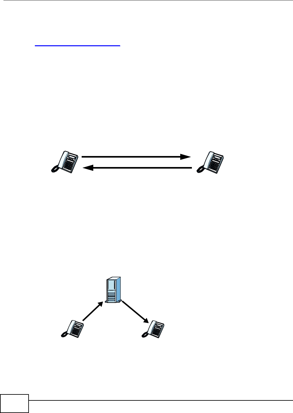
Chapter 10 The VoIP Account Screens
BM2022 Users Guide
154
SIP Service Domain
The SIP service domain of the VoIP service provider (the company that lets you make phone calls
over the Internet) is the domain name in a SIP URI. For example, if the SIP address is
1122334455@VoIP-provider.com, then VoIP-provider.com is the SIP service domain.
SIP Register Server
A SIP register server maintains a database of SIP identity-to-IP address (or domain name)
mapping. The register server checks your user name and password when you register.
SIP User Agent
A SIP user agent can make and receive VoIP telephone calls. This means that SIP can be used for
peer-to-peer communications even though it is a client-server protocol. In the following figure,
either A or B can act as a SIP user agent client to initiate a call. A and B can also both act as a SIP
user agent to receive the call.
Figure 79 SIP User Agent
SIP Proxy Server
A SIP proxy server receives requests from clients and forwards them to another server.
In the following example, you want to use client device A to call someone who is using client device
C.
1The client device (A in the figure) sends a call invitation to the SIP proxy server (B).
2The SIP proxy server forwards the call invitation to C.
Figure 80 SIP Proxy Server
AB
AC
B
12
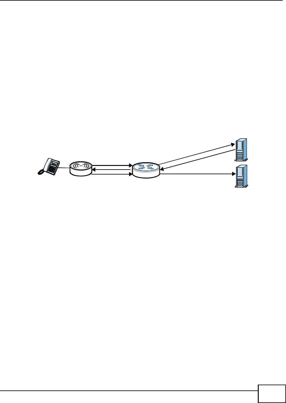
Chapter 10 The VoIP Account Screens
BM2022 Users Guide 155
STUN
STUN (Simple Traversal of User Datagram Protocol (UDP) through Network Address Translators)
allows the BM2022 to find the presence and types of NAT routers and/or firewalls between it and
the public Internet. STUN also allows the BM2022 to find the public IP address that NAT assigned,
so the BM2022 can embed it in the SIP data stream. STUN does not work with symmetric NAT
routers or firewalls. See RFC 3489 for details on STUN.
The following figure shows how STUN works.
1The BM2022 (A) sends SIP packets to the STUN server (B).
2The STUN server (B) finds the public IP address and port number that the NAT router used on the
BM2022s SIP packets and sends them to the BM2022.
3The BM2022 uses the public IP address and port number in the SIP packets that it sends to the SIP
server (C).
Figure 81 STUN
Outbound Proxy
Your VoIP service provider may host a SIP outbound proxy server to handle all of the BM2022s
VoIP traffic. This allows the BM2022 to work with any type of NAT router and eliminates the need
for STUN or a SIP ALG. Turn off a SIP ALG on a NAT router in front of the BM2022 to keep it from
retranslating the IP address (since this is already handled by the outbound proxy server).
NAT and SIP
The BM2022 must register its public IP address with a SIP register server. If there is a NAT router
between the BM2022 and the SIP register server, the BM2022 probably has a private IP address.
The BM2022 lists its IP address in the SIP message that it sends to the SIP register server. NAT
does not translate this IP address in the SIP message. The SIP register server gets the BM2022s IP
address from inside the SIP message and maps it to your SIP identity. If the BM2022 has a private
IP address listed in the SIP message, the SIP server cannot map it to your SIP identity.
Use a SIP ALG (Application Layer Gateway), STUN, or outbound proxy to allow the BM2022 to list
its public IP address in the SIP messages.
DTMF
Dual-Tone Multi-Frequency (DTMF) telephone call signaling uses pairs of frequencies (one lower
frequency and one higher frequency) to set up calls. It is also known as Touch Tone. Each of the
keys on a DTMF telephone corresponds to a different pair of frequencies.
A
12
3
NAT
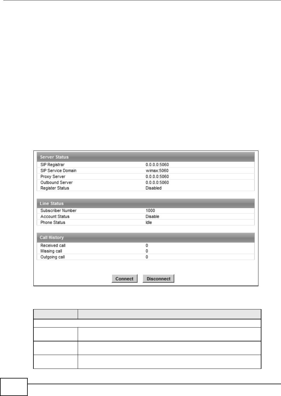
Chapter 10 The VoIP Account Screens
BM2022 Users Guide
156
Supplementary Phone Services Overview
Supplementary services such as call hold, call waiting, call transfer, etc. are generally available from
your VoIP service provider. The BM2022 supports the following services:
Call Waiting
Call Forwarding
Caller ID
Note: To take full advantage of the supplementary phone services available though the
BM2022's phone port, you may need to subscribe to the services from your VoIP
service provider.
10.2 Status
Click VoIP > Account > Status to view VoIP settings and current status.
Figure 82 VoIP > Account > Status
The following table describes the labels in this screen.
Table 66 VoIP > Account > Status
LABEL DESCRIPTION
Server Status
SIP Register This field displays the IP address (or domain name) and service port number of
the register server, if you have configured one.
SIP Service
Domain
This field displays the SIP service domain and port number of the SIP server, if
you have configured one.
Proxy Server This field displays the IP address (or domain name) and service port number of
the SIP proxy server, if you have configured one.

Chapter 10 The VoIP Account Screens
BM2022 Users Guide 157
Outbound
Server
This field displays the IP address (or domain name) and service port number of
the outbound proxy server, if you have configured one.
Register
Status
This field displays Disabled if the SIP account (set up in Section 10.4 on page
159) is disabled or de-registered from the registrar server. It displays
Registering (or Unregistering) after sending out the SIP register (or
unregister) message to make registration (or de-registration) at (or from) the
SIP registrar server.
If the registration fails, for example, rejected by SIP registrar server (due to
wrong authentication data) or timeout to get response from the server, Error
would be displayed. It displays Up if the SIP account is registered at the
registrar server successfully.
Line Status
Subscriber
Number
This field displays the SIP phone number for the phone line.
Account
Status
This indicates whether the SIP account is activated or not. Enable means
activated and Disable means deactivated.
Phone Status This field displays the phone status, such as Idle, Calling, Ringing,
Connecting, InCall, Hold, and Disconnecting.
Call History
Received call This field displays the number of calls you have received through the connected
phone since the BM2022 last restarted or was turned on.
Missing call This field displays the number of calls you have missed since the BM2022 last
restarted or was turned on.
Outgoing call This field displays the number of calls you have made through the connected
phone since the BM2022 last restarted or was turned on.
Connect Click this to register the BM2022 to the specified register server.
Disconnect Click this to de-register the BM2022 with the register server.
Table 66 VoIP > Account > Status
LABEL DESCRIPTION
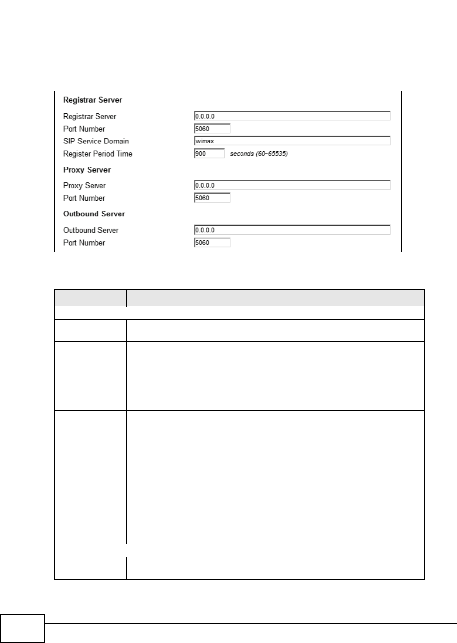
Chapter 10 The VoIP Account Screens
BM2022 Users Guide
158
10.3 Server
Click VoIP > Account > Server to configure the registrar server, proxy server and outbound
proxy server for this SIP account.
Figure 83 VoIP > Account > Server
The following table describes the labels in this screen.
Table 67 VoIP > Account > Server
LABEL DESCRIPTION
Registrar Server
Registrar
Server
Enter the IP address or domain name of a register server. You can use up to 63
printable ASCII characters.
Port Number Enter the SIP servers listening port number. Keep the default value, if you are
not sure of this value.
SIP Service
Domain
Enter the IP address or domain name of a SIP server, if your VoIP service
provider gave you one.
Otherwise, enter the same address that you have entered in the Registrar
Server field. You can use up to 63 printable ASCII characters.
Register
Period Time
Enter the registration expiry time in seconds for the SIP account specified in
Section 10.4 on page 159. The allowable range is 60~65535 seconds. However,
this value is just a default preference value by user, the actual registration expiry
time used by the SIP account is determined by the registrar server after the
registration process.
Once the SIP account has registered at the registrar server successfully, the
BM2022 will send a re-register message to keep alive the successfully registered
status at every half of the registration expiry time determined by the registrar
server.
If the keep-alive action failed, the register status described in Section 10.2 on
page 156 will become Error state and you can not make any call in this status.
However, after 512 seconds (fixed value), the BM2022 will send a register
message again to try to recover a successfully registered status.
Proxy Server
Proxy Server Enter the IP address or domain name of the SIP proxy server provided by your
VoIP service provider. You can use up to 63 printable ASCII characters.
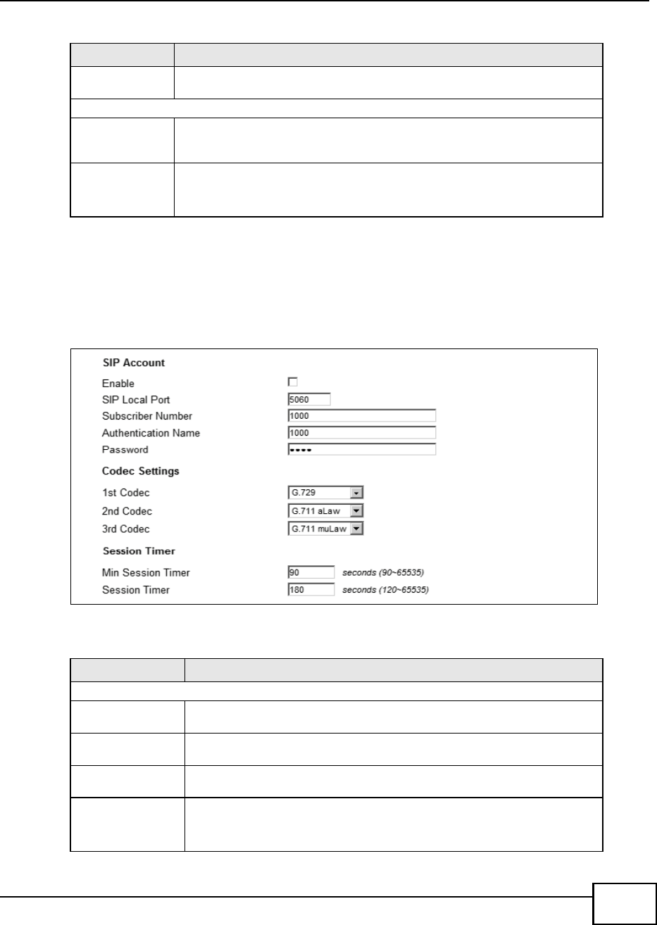
Chapter 10 The VoIP Account Screens
BM2022 Users Guide 159
10.4 SIP
Click VoIP > Account > SIP to configure SIP settings.
Figure 84 VoIP > Account > SIP
The following table describes the labels in this screen.
Port Number Enter the SIP proxy servers listening port number, if your VoIP service provider
gave you one. Otherwise, keep the default value.
Outbound Server
Outbound
Server
Enter the IP address or domain name of the outbound proxy server provided by
your VoIP service provider. You can use up to 63 printable ASCII characters. If
you choose not to use an outbound proxy server, set this to 0.0.0.0.
Port Number Enter the outbound proxys listening port number, if your VoIP service provider
gave you one. Otherwise, leave it as the default 5060.
If the outbound proxy is disabled (set to 0.0.0.0), then this port will be ignored.
Table 67 VoIP > Account > Server
LABEL DESCRIPTION
Table 68 VoIP > Account > SIP
LABEL DESCRIPTION
SIP Account
Enable Select this if you want the BM2022 to use this account. Clear it if you do not
want the BM2022 to use this account.
SIP Local Port Enter the BM2022s listening port number, if your VoIP service provider gave
you one. Otherwise, keep the default value.
Subscriber
Number
Enter your SIP number. In the full SIP URI, this is the part before the @
symbol. You can use up to 1-31 printable ASCII characters.
Authentication
Name
Type the SIP user name associated with this account for authentication to the
SIP register server.
This field can be 1-31 printable characters (A-Z, a-z, 0-9).

Chapter 10 The VoIP Account Screens
BM2022 Users Guide
160
Password Type the SIP password associated with this account. This field can be 0-31
printable characters (A-Z, a-z, 0-9), underscores (_), pluses (+), periods (.),
and at symbols (@).
Codec Settings
1st Codec, 2nd
Codec, 3rd
Codec
Select the BM2022s first, second, and third choices of the type of voice coder/
decoder (codec) that you want the phone line to use when communicating with
the SIP server. The following codecs (shown in highest quality to lowest quality
order) are supported by the BM2022:
G.711 aLaw (typically used in Europe)
G.711 muLaw (typically used in North America and Japan)
G.729
You can also select NONE for the 2nd and 3rd codecs if your VoIP service
provider only gave you one or two codec settings.
When two SIP devices start a SIP session, they must agree on a codec.
Session Timer
Min Session
Timer
Enter the minimum session expiry time in seconds. The allowable range is
90~65535 seconds.
When an incoming call requests a session expiry time that is lower than this
value, the BM2022 will respond with a "423 session timer too small" message
and tell the peer to use this value as the minimum bound.
Session Timer Enter the session expiry time in seconds for all phone connections on this
trunk. The allowable range is 120~65535 seconds. This value cannot be lower
than the Min Session Timer.
The BM2022 will use INVITE or UPDATE method to keep alive a session every
half of the session expiry time during a call.
If the keep-alive action is successful, the BM2022 will re-start the timer and do
another keep-alive action after it reaches half of the session expiry time.
If the keep-alive action failed, the call will terminate automatically.
See Section 9.4 on page 151 to configure the Refresh Method with the INVITE
or UPDATE method.
Table 68 VoIP > Account > SIP
LABEL DESCRIPTION
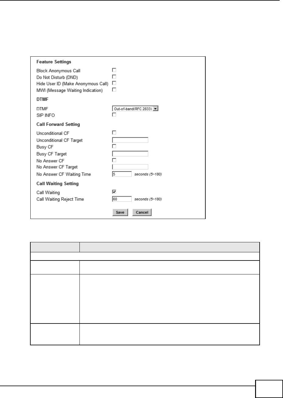
Chapter 10 The VoIP Account Screens
BM2022 Users Guide 161
10.5 Feature
Click VoIP > Account > Feature to configure advanced VoIP features such as DTMF, Call
Forwarding and Call Waiting.
Figure 85 VoIP > Account > Feature
The following table describes the labels in this screen.
Table 69 VoIP > Account > Feature
LABEL DESCRIPTION
Feature Settings
Block
Anonymous Call
Select this to have the BM2022 block all incoming calls from phone that do not
send caller ID.
Do Not Disturb
(DND)
Select this to have the BM2022 not forward calls to the phone line while
processing incoming calls. Thus, for any incoming call, the remote peer can
hear ringback tone, but the phone connected on the BM2022 would not ring.
Meanwhile, the BM2022 can still make outgoing calls as usual.
Note: The DND function should be used very carefully, since enabling DND
makes the BM2022 not forward any incoming call to the phone line so
the user would never know whether there are any incoming calls.
Hide User ID
(Make
Anonymous
Call)
Select this to not have your Caller ID(number) displayed on the callee's
screen.

Chapter 10 The VoIP Account Screens
BM2022 Users Guide
162
10.6 Dialing
Click VoIP > Account > Dialing to configure dialing timeout values.
Figure 86 VoIP > Account > Dialing
MWI (Message
Waiting
Indication)
Select this to enable Message Waiting Indicator (MWI) function for this SIP
account specified in Section 10.4 on page 159. When there is at least one new
voicemail for the SIP account, the voice LED (described in Section 1.2.1 on
page 19) turns yellow and the BM2022 sends a beeping tone to the phone
while user picks-up the phone to make calls.
DTMF
DTMF Control how the BM2022 handles the DTMF tone relay to the communication
peer. The DTMF tone is generated by the phone when you push its digit
buttons during a call. One application is to send numbers when trying to do
IVR (Interactive Voice Response) service with server.
You should use the same mode as your VoIP service provider. The choices are:
Out-of-band(RFC 2833) - Follow the RFC 2833 standard and send the
DTMF tones in RTP packets.
In Band - Send the DTMF tones in the voice data stream. This works best
when you are using a codec that does not use compression (like G.711).
Codecs that use compression (like G.729) can distort the tones.
SIP INFO Select this to have the BM2022 send the DTMF tones in SIP messages.
Call Forward Setting
Unconditional
CF,
Unconditional
CF Target
Select this if you want the BM2022 to forward all incoming calls to the specified
phone number, regardless of other rules in this Call Forward Setting section.
Specify the phone number in the Unconditional CF Target field.
Note: The Unconditional CF function should be used very carefully, since
enabling this function makes the BM2022 forward all incoming calls to
another phone number, so the user would never know if there are any
incoming calls.
Busy CF,
Busy CF Target
Select this if you want the BM2022 to forward incoming calls to the specified
phone number if the phone port is busy. Specify the phone number in the
Busy CF Target field. If you have call waiting, the incoming call is forwarded
to the specified phone number if you reject or ignore the second incoming call.
No Answer CF,
No Answer CF
Targ e t , N o
Answer CF
Waiting Time
Select this if you want the BM2022 to forward incoming calls to the specified
phone number if the call is unanswered. Specify the phone number in the No
Answer CF Target field on the right. Specify the time to wait before
forwarding incoming calls in the No Answer CF Waiting Time field.
Call Waiting Setting
Call Waiting Select this to enable call waiting for this SIP account on the BM2022.
Call Waiting
Reject Time
Enter time to wait before rejecting a call when call waiting is enabled.
Table 69 VoIP > Account > Feature
LABEL DESCRIPTION
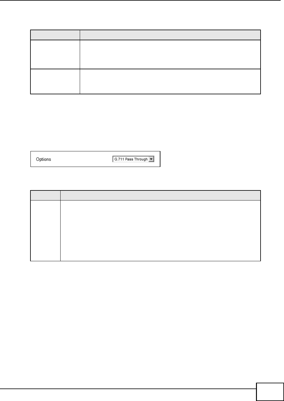
Chapter 10 The VoIP Account Screens
BM2022 Users Guide 163
The following table describes the labels in this screen.
10.7 FAX
Click VoIP > Account > FAX to configure which standard the account uses for fax services.
Figure 87 VoIP > Account > FAX
The following table describes the labels in this screen.
10.8 Technical Reference
The following section contains additional technical information about the BM2022 features
described in this chapter.
10.8.1 SIP Call Progression with Session Timer
The following figure displays the basic steps in the setup and tear down of a SIP call with session
timer supported by both peers. The UPDATE method is used to refresh the session. A calls B and
uses proxy server P. Messages include Session Expiry (SE) and Minimum Session Expiry (MSE)
Table 70 VoIP > Account > Dialing
LABEL DESCRIPTION
Inter-digit
Timeout
Set the time in seconds (1~5) the BM2022 waits for each digit input of a
complete callee number after you press the first key on the phone.
If the BM2022 cannot receive the next digit entered within this time period,
the BM2022 processes digits you have dialed.
First-digit
Timeout
Set the number of seconds (5~30) for the BM2022 to wait for you to start
dialing a number after you pick up the telephone receiver. If you do not dial
any number within that time period, the dial tone becomes a busy signal. Put
back the receiver and pick it up again if you want to make a new call.
Table 71 VoIP > Account > FAX
LABEL DESCRIPTION
Options Select which standard the BM2022 uses to handle faxes. The peer devices must also
use standard.
G.711A Pass Through - Select this option to send and receive fax messages over the
network or Internet using VoIP (G.711a). By encoding fax data as audio data, faxes
may be susceptible to packet loss and other errors. However, as this standard is
considerably older than T.38, it is more compatible with older obsolete systems.
T.38 FAX Relay - BM2022 encodes fax messages to T.38 packets and sends as UDP
packets through IP networks. This provides better quality, but it may have
interoperability problems.

Chapter 10 The VoIP Account Screens
BM2022 Users Guide
164
time values. When the duration of the call reaches half of the SE time period, the session is
refreshed.
Table 72 SIP Call Progression
A P B
1. INVITE
SE: 60
------------------>
2. 422
MSE: 3600
<-----------------------
3. ACK
------------------>
4. INVITE
SE: 3600
MSE: 3600
------------------>
5. INVITE
SE: 3600
MSE: 3600
------------------------>
6. INVITE
SE: 3600
MSE: 3600
-------------------->
7. OK
SE: 3600
<-------------------
8. OK
SE: 3600
<------------------------
9. OK
SE: 3600
<------------------
10. ACK
------------------>
11. ACK
------------------------> -------------------->
12. Dialogue (voice traffic)

Chapter 10 The VoIP Account Screens
BM2022 Users Guide 165
1A sends a SIP INVITE request. This message is an invitation for B to participate in a SIP telephone
call. As INVITE specifies a SE of 60 seconds.
2As request arrives at P but is below the minimum allowed value of 3600, so it is rejected with a 422
message, which contains the MSE of 3600.
3A sends an ACK to acknowledge the message was received.
4A retries the INVITE request with SE of 3600 and MSE of 3600.
5The SE in the new INVITE is acceptable so P forwards it to B.
6B receives the INVITE.
7B responds with an OK message which includes the SE of 3600.
8P forwards the OK message to A.
9A receives the OK.
10 A then sends an ACK message to acknowledge that the call is established completely.
11 The proxy server forwards the ACK message to B.
12 Now A and B exchange voice media (talk).
13 After around half of the SE time period is reached, or 1800 seconds in this case, A sends an UPDATE
request to refresh the session.
13. UPDATE
SE: 3600
------------------>
14. UPDATE
SE:3600
-----------------------> -------------------->
<----------------------
15. OK
SE: 3600
<-------------------
16. OK
SE: 3600
<------------------
17. BYE
------------------>
18. OK
<-------------------
Table 72 SIP Call Progression (continued)
A P B

Chapter 10 The VoIP Account Screens
BM2022 Users Guide
166
14 The UPDATE request is forwarded by P to B.
15 B receives the UPDATE request and responds with an OK message.
16 The OK message is received by A.
17 After talking, A hangs up and sends a BYE request.
18 B replies with an OK response confirming receipt of the BYE request and the call is terminated.
10.8.2 SIP Client Server
SIP is a client-server protocol. A SIP client is an application program or device that sends SIP
requests. A SIP server responds to the SIP requests.
When you use SIP to make a VoIP call, it originates at a client and terminates at a server. A SIP
client could be a computer or a SIP phone. One device can act as both a SIP client and a SIP server.
For more information on the SIP protocol, please refer to RFC 3261.

BM2022 Users Guide 167
CHAPTER 11
The VoIP Line Screens
11.1 Overview
The VoIP > Line screens allow you to configure the volume, echo cancellation, VAD settings and
custom tones for the phone port which maps to the SIP account (see Chapter 10 on page 153).
11.1.1 What You Can Do in This Chapter
The Phone screen (Section 11.2 on page 168) lets you configure phone settings.
The Voice screen (Section 11.3 on page 168) lets you configure voice settings.
The Region screen (Section 11.4 on page 169) lets you configure which country of the world the
BM2022 is in.
11.1.2 What You Need to Know
The following terms and concepts may help as you read through this chapter.
Voice Activity Detection/Silence Suppression/Comfort Noise
Voice Activity Detection (VAD) detects whether or not speech is present. This lets the BM2022
reduce the bandwidth that a call uses by not transmitting silent packets when you are not
speaking.
When using VAD, the BM2022 generates comfort noise when the other party is not speaking. The
comfort noise lets you know that the line is still connected as total silence could easily be mistaken
for a lost connection.
Echo Cancellation
G.168 is an ITU-T standard for eliminating the echo caused by the sound of your voice
reverberating in the telephone receiver while you talk.
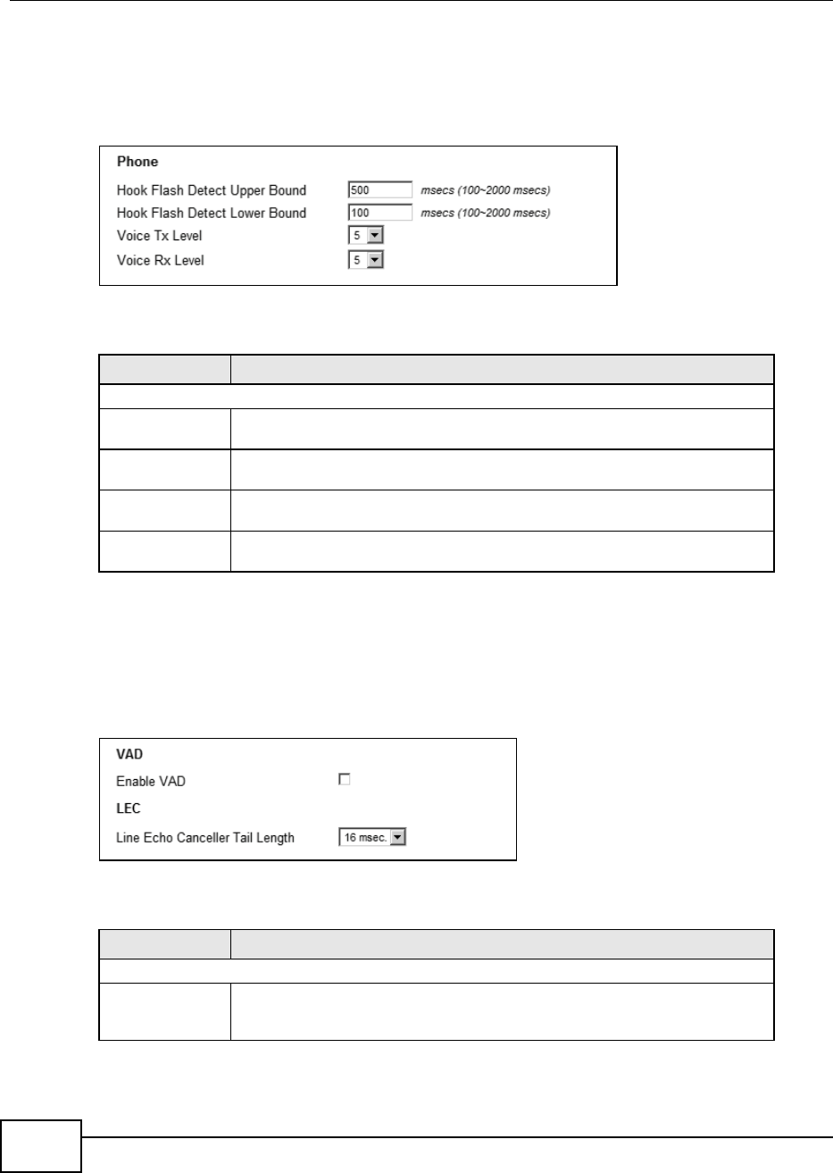
Chapter 11 The VoIP Line Screens
BM2022 Users Guide
168
11.2 Phone
Click VoIP > Line > Phone to configure phone related settings.
Figure 88 VoIP > Line > Phone
The following table describes the labels in this screen.
11.3 Voice
Click VoIP > Line > Voice to configure voice settings.
Figure 89 VoIP > Line > Voice
The following table describes the labels in this screen.
Table 73 VoIP > Line > Phone
LABEL DESCRIPTION
Phone
Hook Flash Detect
Upper Bound
Enter the number of milliseconds for the upper bound of a quick on-hook and off-
hook cycle in order to recognize a hook flash event.
Hook Flash Detect
Lower Bound
Enter the number of milliseconds for the lower bound of a quick on-hook and off-
hook cycle in order to recognize a hook flash event.
Voice Tx Level Select the volume level transmitted by the BM2022. -9 is the quietest, and 9 is
the loudest.
Voice Rx Level Select the volume level transmitted to the BM2022. -9 is the quietest, and 9 is
the loudest.
Table 74 VoIP > Line > Voice
LABEL DESCRIPTION
VAD - Voice Activity Detection
Enable VAD Enable Voice Active Detector (VAD) to have the BM2022 stop transmitting voice
traffic when you are not speaking using the detection method. This reduces the
bandwidth the BM2022 uses.

Chapter 11 The VoIP Line Screens
BM2022 Users Guide 169
11.4 Region
Click VoIP > Line > Region to maintain settings that depend on which region of the world the
BM2022 is in.
Figure 90 VoIP > Line > Region
The following table describes the labels in this screen.
LEC - Line Echo Cancellation
Line Echo
Canceller Tail
Length
Select the maximum number of milliseconds of an echo length (16 ms, 32 ms or
48 ms) the BM2022 can handle and eliminate the effect. An echo is normally
caused by the sound of your voice reverberating in the telephone receiver while
you talk. Select Disable to turn this feature off.
Table 74 VoIP > Line > Voice
LABEL DESCRIPTION
Table 75 VoIP > Line > Region
LABEL DESCRIPTION
Country Profile Select the place in which the BM2022 is located, USA (Default) or any other
country.

BM2022 Users Guide 171
CHAPTER 12
Maintenance
12.1 Overview
Use these screens to manage and maintain your BM2022.
12.1.1 What You Need to Know
The following terms and concepts may help as you read through this chapter.
Remote Management Limitations
Remote management over LAN or WAN will not work when:
1You have disabled that service in one of the remote management screens.
2The IP address in the Secured Client IP field does not match the client IP address. If it does not
match, the BM2022 will disconnect the session immediately.
3There is already another remote management session with an equal or higher priority running. You
may only have one remote management session running at one time.
Remote Management and NAT
When NAT is enabled:
Use the BM2022s WAN IP address when configuring from the WAN.
Use the BM2022s LAN IP address when configuring from the LAN.
System Timeout
There is a default system management idle timeout of five minutes. The BM2022 automatically logs
you out if the management session remains idle for longer than this timeout period. The
management session does not time out when a statistics screen is polling.
SNMP
Simple Network Management Protocol (SNMP) is a protocol used for exchanging management
information between network devices. SNMP is a member of the TCP/IP protocol suite. Your
BM2022 supports SNMP agent functionality, which allows a manager station to manage and monitor
the BM2022 through the network. The BM2022 supports SNMP version one (SNMPv1) and version
two (SNMPv2). The next figure illustrates an SNMP management operation.
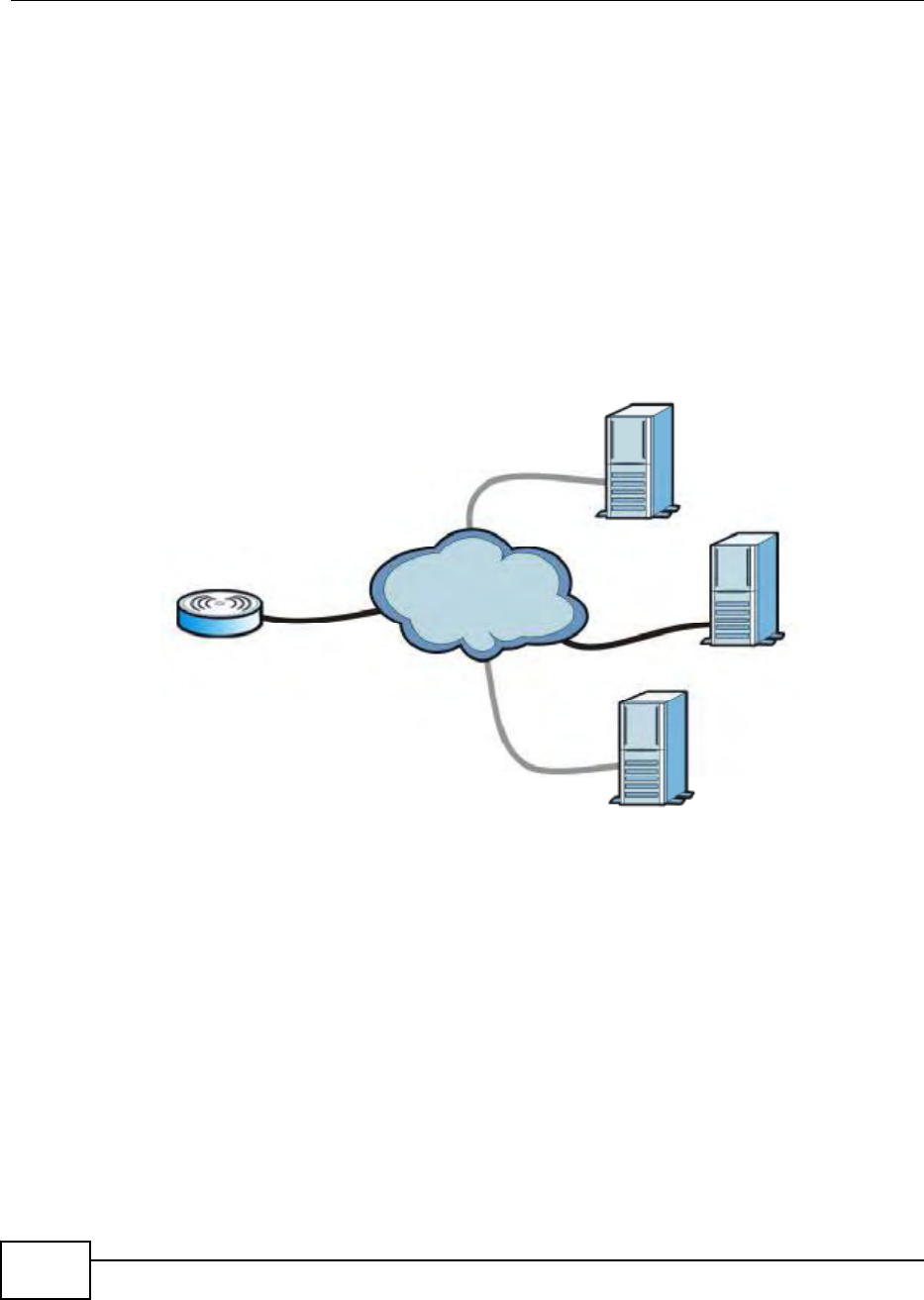
Chapter 12 Maintenance
BM2022 Users Guide
172
Note: SNMP is only available if TCP/IP is configured.
TR-069
TR-069 is an abbreviation of Technical Reference 069, a protocol designed to facilitate the remote
management of Customer Premise Equipement (CPE), such as the BM2022. It can be managed
over a WAN by means of an Auto Configuration Server (ACS). TR-069 is based on sending Remote
Procedure Calls (RPCs) between the ACS and the client device. RPCs are sent in Extensible Markup
Language (XML) format over HTTP or HTTPS.
An administrator can use an ACS to remotely set up the BM2022, modify its settings, perform
firmware upgrades, and monitor and diagnose it. In order to do so, you must enable the TR-069
feature on your BM2022 and then configure it appropriately. (The ACS server which it will use must
also be configured by its administrator.)
Figure 91 TR-069 Example
In this example, the BM2022 (A) receives data from at least 3 sources: A SIP server for handling
voice calls, an HTTP server for handling web services, and an ACS, for configuring the BM2022
remotely. All three servers are owned and operated by the clients Internet Service Provider.
However, without the configuration settings from the ACS, the BM2022 cannot access the other two
servers. Once the BM2022 receives its configuration settings and implements them, it can connect
to the other servers. If the settings change, it will once again be unable to connect until it receives
its updates from the ACS.
The BM2022 can be configured to periodically check for updates from the auto-configuration server
so that the end user need not be worried about it.
SIP
ACS
HTTP
A
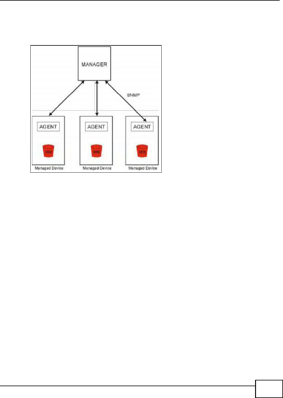
Chapter 12 Maintenance
BM2022 Users Guide 173
SNMP
An SNMP managed network consists of two main types of component: agents and a manager.
Figure 92 SNMP Management Model
An agent is a management software module that resides in a managed device (the BM2022). An
agent translates the local management information from the managed device into a form
compatible with SNMP. The manager is the console through which network administrators perform
network management functions. It executes applications that control and monitor managed
devices.
The managed devices contain object variables/managed objects that define each piece of
information to be collected about a device. Examples of variables include such as number of
packets received, node port status etc. A Management Information Base (MIB) is a collection of
managed objects. SNMP allows a manager and agents to communicate for the purpose of accessing
these objects. The BM2022 supports MIB II that is defined in RFC-1213 and RFC-1215. The focus of
the MIBs is to let administrators collect statistical data and monitor status and performance.
SNMP itself is a simple request/response protocol based on the manager/agent model. The
manager issues a request and the agent returns responses using the following protocol operations:
Get - Allows the manager to retrieve an object variable from the agent.
GetNext - Allows the manager to retrieve the next object variable from a table or list within an
agent. In SNMPv1, when a manager wants to retrieve all elements of a table from an agent, it
initiates a Get operation, followed by a series of GetNext operations.
Set - Allows the manager to set values for object variables within an agent.
Trap - Used by the agent to inform the manager of some events.
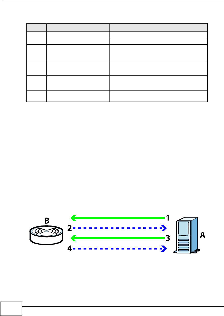
Chapter 12 Maintenance
BM2022 Users Guide
174
The BM2022 sends traps to the SNMP manager when any of the following events occurs:
OMA-DM
When the BM2022 initiates communication with the server (often times at start up or after the first
time you turn it on), the server uploads commands, new files (if any), and other information used
by a service provider to customize the BM2022s features.
Device management works as follows:
1The server (A) sends out the query (1) to the BM2022 (B).
2The BM2022 responds by sending back its credentials (2), to which the server responds with its
credentials along with a string of management operations (3).
3The client responds to the management operations (4), perhaps confirming file alterations or
confirming receipt of file uploads and so on.
4The server disconnects from the BM2022 once all of its management operations have been carried
out.
Figure 93 OMA-DM Data Management
OMA-DM Authentication
In order to ensure the integrity of the connection between an OMA-DM server and the BM2022,
communication between the two is encoded using one of three common algorithms. They are not
intended to be used in lieu of proper digital security, but instead as a means of transmitting multiple
Table 76 SNMP Traps
TRAP # TRAP NAME DESCRIPTION
0coldStart (defined in RFC-1215)A trap is sent after booting (power on).
1warmStart (defined in RFC-1215)A trap is sent after booting (software reboot).
4authenticationFailure (defined in
RFC-1215)
A trap is sent to the manager when receiving any
SNMP get or set requirements with the wrong
community (password).
6whyReboot A trap is sent with the reason of restart before
rebooting when the system is going to restart (warm
start).
6a For intentional reboot: A trap is sent with the message "System reboot by
user!" if reboot is done intentionally, (for example,
download new files, CI command "sys reboot", etc.).
6b For fatal error: A trap is sent with the message of the fatal code if
the system reboots because of fatal errors.
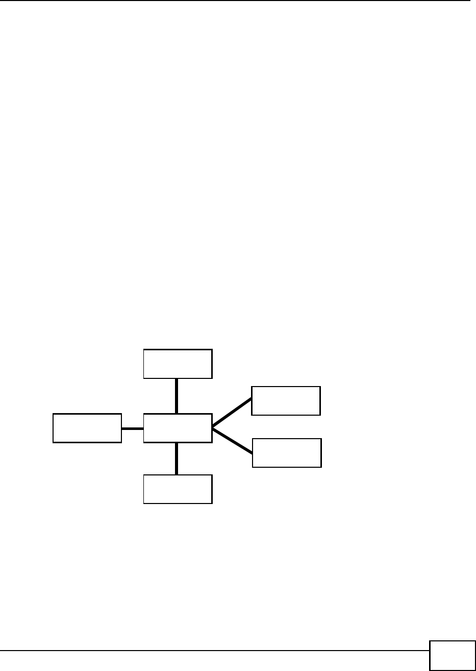
Chapter 12 Maintenance
BM2022 Users Guide 175
disparate types of data over HTTP. Security encryption for communication is handled by different
processes configured elsewhere in the BM2022s web configurator
Basic Access Authentication Sends a persons user name and password in Base64. This
authentication protocol is supported by all browsers that are HTTP 1.0/1.1 compliant. Although
converted to Base64 for the sake of cross-compatibility, credentials are nonetheless passed
between the web browser and the server in plaintext, making it extremely easy to intercept and
read. As such, it is rarely used anymore.
Digest Access Authentication This protocol was designed to replace basic access
authentication. Instead of encoding a user name and password in plaintext, this protocol uses what
is known as an MD5 message authentication code. It allows the server to issue a single-use,
randomly generated number (known as a nonce) to the client (in this case, the web browser),
which then uses the number as the public key for encrypting its data. When the server receives
the encrypted data, it unlocks it using the key that was just provided. While stronger than basic
access authentication, this protocol is not as strong as, say, HMAC, or as secure as the client using
a client-side private key encryption scheme.
Hash Message Authentication Code Also known as HMAC, this code relies on cryptographic
hash functions to bolster an existing protocol, such as MD5. It is a method for generating a
stronger, significantly higher encryption key.
OMA-DM Data Model
Each device that conforms to the current OMA-DM standard has an identical data structure
embedded in its controlling firmware. This allows a similarly conforming OMA-DM server to navigate
the folder structure and to make file alterations where appropriate or required.
Figure 94 OMA-DM Data Model
In the example data model shown here, the parent folders must conform to the OMA-DM standard.
The child folders, on the other hand, can be customized on an individual basis. This allows the
parent folders to all maintain a consistent URI (Uniform Resource Identifier) across all devices that
meet the OMA-DM standards requirements.
For example, in the preceding figure the URI for the Games folder is ./Vendor/Games/. The ./
Vendor/ portion of the URI exists on all devices that conform to the OMA-DM standard. The
Games folder, however, may or may not exist depending on the services provided by the company
managing the device.
Root Folder
./
DMAcc
Vendor
Operator
MP3s
Games
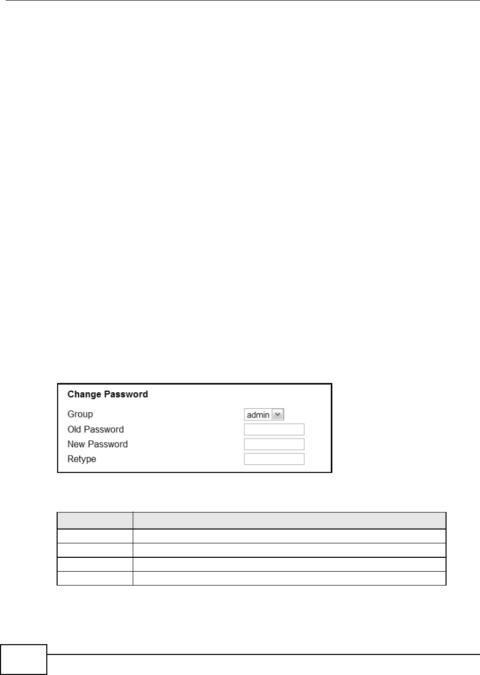
Chapter 12 Maintenance
BM2022 Users Guide
176
Daytime
A network protocol used by devices for debugging and time measurement. A computer can use this
protocol to set its internal clock but only if it knows in which order the year, month, and day are
returned by the server. Not all servers use the same format.
Time
A network protocol for retrieving the current time from a server. The computer issuing the
command compares the time on its clock to the information returned by the server, adjusts itself
automatically for time zone differences, then calculates the difference and corrects itself if there
has been any temporal drift.
NTP
NTP stands for Network Time Protocol. It is employed by devices connected to the Internet in order
to obtain a precise time setting from an official time server. These time servers are accurate to
within 200 microseconds.
12.2 Password
Use this screen to set up admin and guest accounts for logging into and managing the WiMAX
Device. The admin user can access and configure all screens. The guest user can only perform
some basic settings such as viewing the system status information, configuring LAN, NAT, DDNS,
and Firewall settings and reset the BM2022 to factory defaults and restart the BM2022.
Click Maintenance > Password to open this screen as shown next.
Figure 95 Password Screen
This screen contains the following fields:
Table 77 Password
LABEL DESCRIPTION
Group Select the group for which you want to change the login password.
Old Password Enter the old password for the login group.
New Password Enter the new password for the login group.
Retype Retype the new password for the login group.
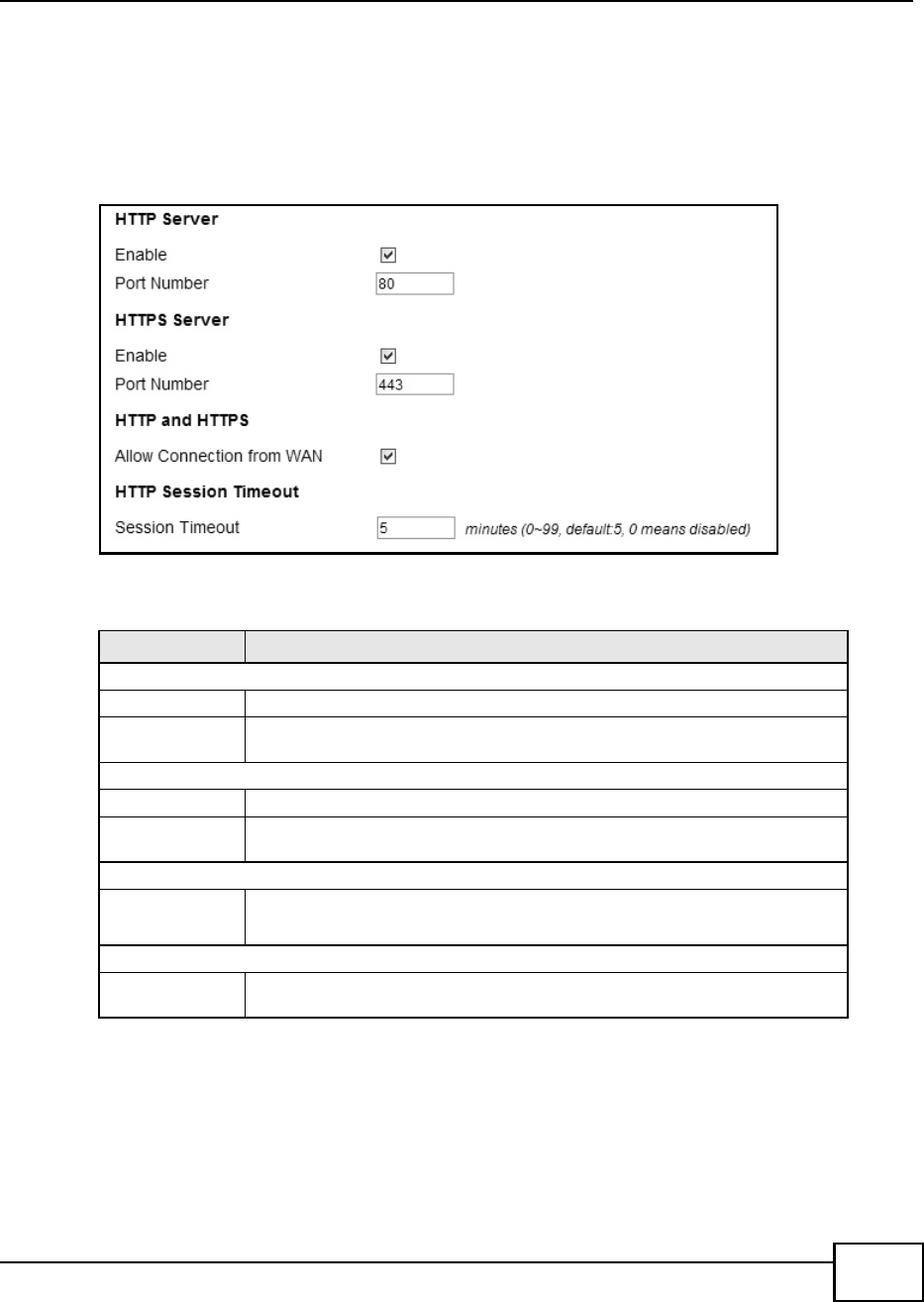
Chapter 12 Maintenance
BM2022 Users Guide 177
12.3 HTTP
Use this screen to allow remote access to the WiMAX Device from a network connection over HTTP.
Click Maintenance > Remote MGMT > HTTP to open this screen as shown next.
Figure 96 HTTP Screen
This screen contains the following fields:
12.4 Telnet
Use this screen to allow remote access to the WiMAX Device from a network connection over Telnet.
Table 78 HTTP
LABEL DESCRIPTION
HTTP Server
Enable Select this to enable remote management using this service.
Port Number Enter the port number this service can use to access the BM2022. The computer
must use the same port number.
HTTPS Server
Enable Select this to enable remote management using this service.
Port Number Enter the port number this service can use to access the BM2022. The computer
must use the same port number.
HTTP and HTTPS
Allow
Connection
from WAN
Select this to allow incoming connections from the WAN over either HTTP or
HTTPS.
HTTP Session Timeout
Session
Timeout
Enter the number of minutes (0-99) the BM2022 waits to delete an inactive web
connection (HTTP or HTTPS).
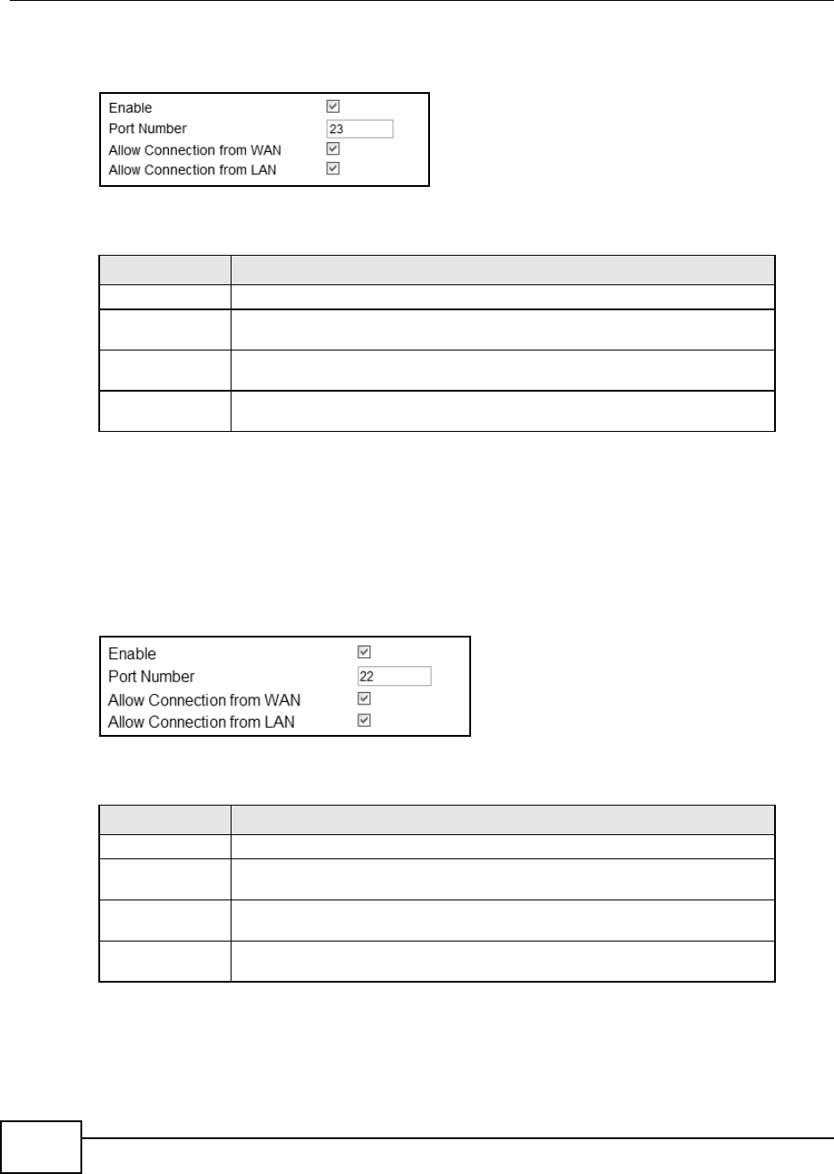
Chapter 12 Maintenance
BM2022 Users Guide
178
Click Maintenance > Remote MGMT > Telnet to open this screen as shown next.
Figure 97 Telnet Screen
This screen contains the following fields:
12.5 SSH
Use this screen to allow remote access to the WiMAX Device from a network connection over SSH.
Click Maintenance > Remote MGMT > SSH to open this screen as shown next.
Figure 98 SSH Screen
This screen contains the following fields:
Table 79 Telnet
LABEL DESCRIPTION
Enable Select this to enable remote management using this service.
Port Number Enter the port number this service can use to access the BM2022. The computer
must use the same port number.
Allow Connection
from WAN
Select this to allow connections using this service that originate on the WAN.
Allow Connection
from LAN
Select this to allow connection using this service that originate on the LAN.
Table 80 SSH
LABEL DESCRIPTION
Enable Select this to enable remote management using this service.
Port Number Enter the port number this service can use to access the BM2022. The computer
must use the same port number.
Allow Connection
from WAN
Select this to allow connections using this service that originate on the WAN.
Allow Connection
from LAN
Select this to allow connection using this service that originate on the LAN.
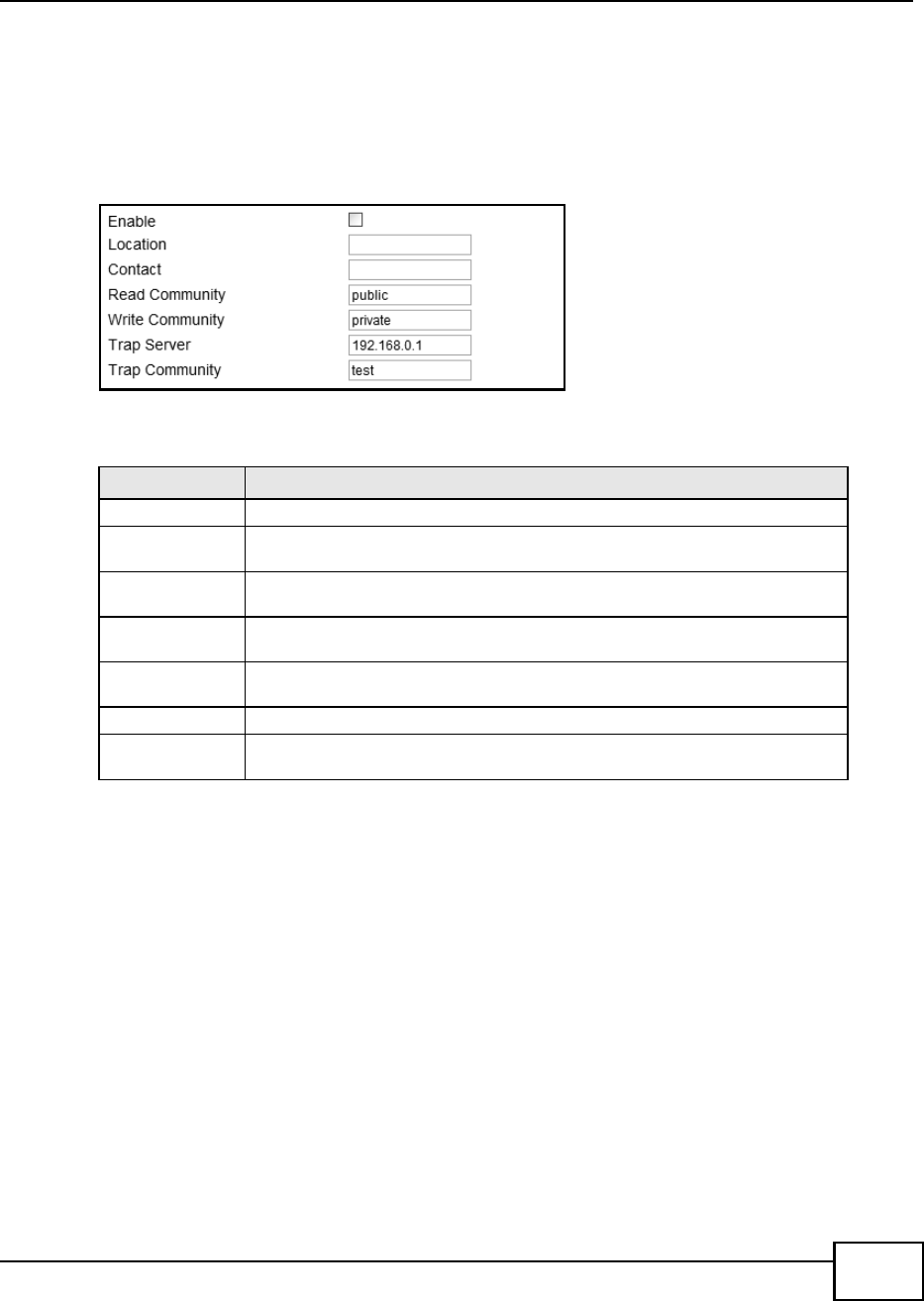
Chapter 12 Maintenance
BM2022 Users Guide 179
12.6 SNMP
Use this screen to allow remote access to the WiMAX Device from a network connection over SNMP.
Click Maintenance > Remote MGMT > SNMP to open this screen as shown next.
Figure 99 SNMP Screen
This screen contains the following fields:
12.7 CWMP
Use this screen to allow CWMP connections for remote management, firmware upgrades and
troubleshooting.
Table 81 SNMP
LABEL DESCRIPTION
Enable Select this to enable remote management using this service.
Location Enter the location of the SNMP server (for example, Engineering Dept., Floor 6,
Building A, New York City).
Contact Enter contact information for the administrator managing the SNMP server (for
example, Bill Smith, IT Dept., (555) 555-5454).
Read Community Enter the password for the incoming Get and GetNext requests from the
management station. The default is public and allows all requests.
Write Community Enter the password for incoming Set requests from the management station.
The default is public and allows all requests.
Tra p S er ver Enter the IP address of the station to send your SNMP traps to.
Tra p C ommu nity Enter the trap community, which is the password sent with each trap to the
SNMP manager. The default is public and allows all requests.
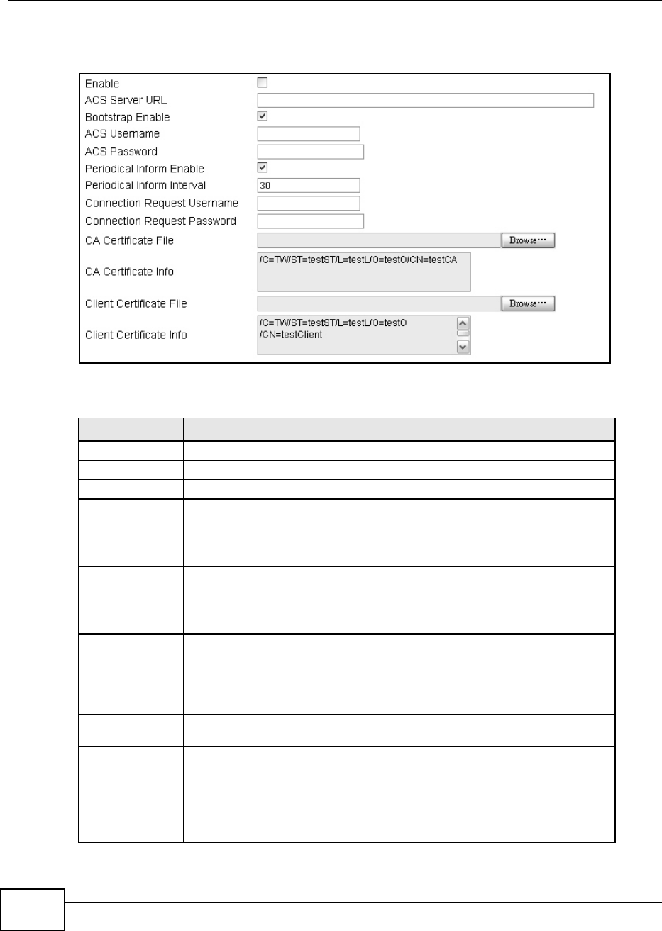
Chapter 12 Maintenance
BM2022 Users Guide
180
Click Maintenance > Remote MGMT > CWMP to open this screen as shown next.
Figure 100 CWMP Screen
This screen contains the following fields:
Table 82 CWMP
LABEL DESCRIPTION
Enable Select this to enable remote management using this service.
ACS Server URL Enter the URL or IP address of the auto-configuration server.
Bootstrap Enable Select this to enable bootstrap events.
ACS Username Enter the user name sent when the BM2022 connects to the ACS and which is
used for authentication.
You can enter up to 31 alphanumeric characters (a-z, A-Z, 0-9) and underscores
but spaces are not allowed.
ACS Password Enter the password sent when the BM2022 connects to an ACS and which is used
for authentication.
You can enter up to 31 alphanumeric characters (a-z, A-Z, 0-9) and underscores
but spaces are not allowed.
Periodical Inform
Enable
Select this to allow the BM2022 to periodically connect to the ACS and check for
configuration updates.
If you do not enable this feature then the BM2022 can only be updated
automatically when the ACS initiates contact with it and if you selected the
checkbox on this screen.
Periodical Inform
Interval
Enter the time interval (in seconds) at which the BM2022 connects to the auto-
configuration server.
Connection
Request
Username
Enter the connection request user name that the ACS must send to the BM2022
when it requests a connection.
You can enter up to 31 alphanumeric characters (a-z, A-Z, 0-9) and underscores
but spaces are not allowed.
Note: This must be provided by the ACS administrator.
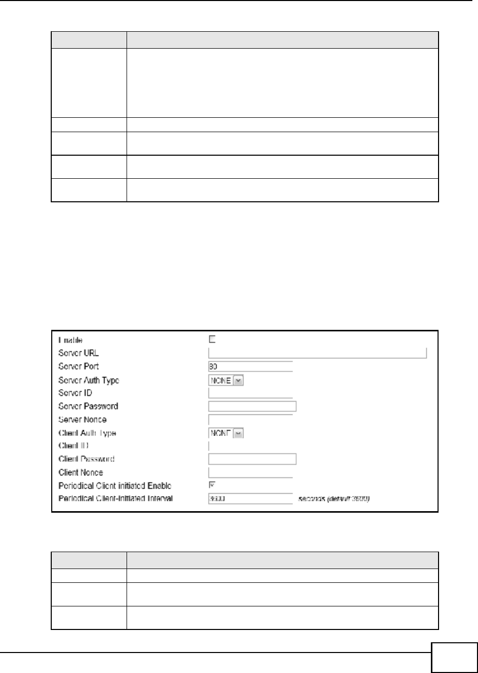
Chapter 12 Maintenance
BM2022 Users Guide 181
12.8 OMA-DM
Use this screen to allow remote access to the WiMAX Device from a network connection over OMA-
DM.
Click Maintenance > Remote MGMT > OMA-DM to open this screen as shown next.
Figure 101 OMA-DM Screen
This screen contains the following fields:
Connection
Request Password
Enter the connection request password that the ACS must send to the BM2022
when it requests a connection.
You can enter up to 31 alphanumeric characters (a-z, A-Z, 0-9) and underscores
but spaces are not allowed.
Note: This must be provided by the ACS administrator.
CA Certificate File Click Browse to upload a Certificate Authority (CA) certificate to the BM2022.
CA Certificate
Info
This displays information about the currently active CA certificate.
Client Certificate
File
Click Browse to upload a client certificate to the BM2022.
Client Certificate
Info
This displays information about the currently active client certificate.
Table 82 CWMP (continued)
LABEL DESCRIPTION
Table 83 OMA-DM
LABEL DESCRIPTION
Enable Select this to enable remote management using this service.
Server URL Enter the IP address or URL of the OMA-DM server that you intend to use to
manage this device.
Server Port Enter the port number for the IP address of the OMA-DM server set up in the
preceding field.

Chapter 12 Maintenance
BM2022 Users Guide
182
Server Auth Type Select the encryption algorithm scheme used by the OMA-DM server to
communicate with client devices. If the scheme selected here does not match
the actual scheme used by the server, then server will challenge the BM2022 to
automatically update its settings.
None - No authentication.
Basic - Server ID and Password are encoded using a Basic Access
Authentication Code.
Digest (MD5) - Server ID and Password are encoded using a Digest Access
Authentication Code.
HMAC - Server ID and Password are encoded using a keyed Hash Message
Authentication Code.
Server ID Enter the identification code for the server. This is used by the BM2022 during
the communication handshake process to identify the server.
Server Password Enter the password for the servers identification code. This shared public key is
used by the BM2022 during the communication handshake process to identify
the server.
Server Nonce The BM2022 and the OMA-DM server use nonces to authenticate each other if
you select MD5 as the authentication algorithm in the Server Auth Type field.
Nonce is an abbreviation of 'number used once'. It is normally a random or
pseudo-random number applied in an authentication protocol to protect existing
communications from being reused in replay attacks.
Type up to 20 digits for the OMA-DM server nonce.
Client Auth Type Select the encryption algorithm scheme used by the OMA-DM server to
communicate with client devices. If the scheme selected here does not match
the actual scheme used by the server, then server will challenge the BM2022 to
automatically update its settings.
None - No authentication.
Basic - Server ID and Password are encoded using a Basic Access
Authentication Code.
Digest (MD5) - Server ID and Password are encoded using a Digest Access
Authentication Code.
HMAC - Server ID and Password are encoded using a keyed Hash Message
Authentication Code.
Note: Make sure that the scheme selected here matches the the Server Auth
Type.
Client ID Enter the client name for the BM2022.
Client Password Enter the password for the BM2022s client name.
Client Nonce The BM2022 and the OMA-DM server use nonces to authenticate each other if
you select MD5 as the authentication algorithm in the Client Auth Type field.
Type up to 20 digits for the OMA-DM client nonce.
Periodical Client-
Initiated Enable
Select this to allow the BM2022 to periodically connect to the OMA-DM server
and check for configuration updates.
If you do not enable this feature then the BM2022 can only be updated
automatically when the OM-DM server initiates contact with it and if you selected
the checkbox on this screen.
Periodical Client-
Initiated Interval
Enter the time interval (in seconds) at which the BM2022 connects to the OMA-
DM server.
Table 83 OMA-DM (continued)
LABEL DESCRIPTION
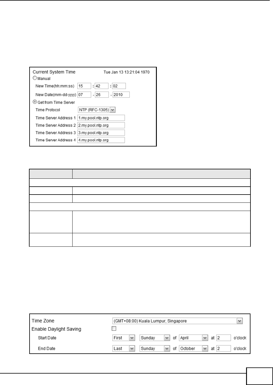
Chapter 12 Maintenance
BM2022 Users Guide 183
12.9 Date
Use these settings to set the system time or configure an NTP server for automatic time
synchronization.
Click Maintenance > Date/Time > Date to open this screen as shown next.
Figure 102 Date Screen
This screen contains the following fields:
12.10 Time Zone
Use this screen to set the time zone in which the WiMAX device is physically located.
Click Maintenance > Date/Time > Time Zone to open this screen as shown next.
Figure 103 Time Zone Screen
Table 84 Date
LABEL DESCRIPTION
Manual
New Time Enter the new time in this field.
New Date Enter the new date in this field.
Get from Time Server
Time Protocol Select the time service protocol that your time server uses.Check with your ISP
or network administrator, or use trial-and-error to find a protocol that works.
NTP (RFC 1305) - This format is similar to Time (RFC 868).
Time Server
Address 1~4
Enter the IP address or URL of your time server. Check with your ISP or network
administrator if you are unsure of this information.
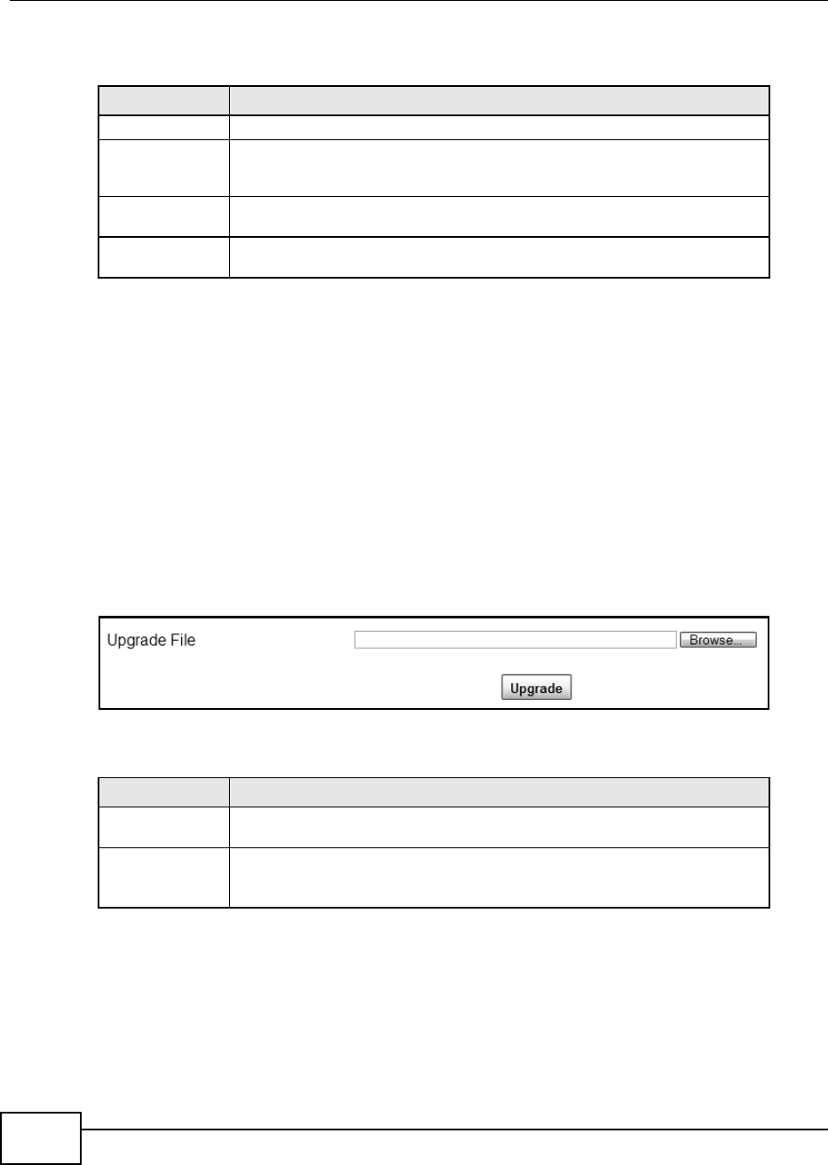
Chapter 12 Maintenance
BM2022 Users Guide
184
This screen contains the following fields:
12.11 Upgrade File
Use this screen to browse to a firmware file on a local computer and upload it to the WiMAX Device.
Firmware files usually use the system model name with a "*.bin" extension, such as "BM2022.bin".
The upload process uses HTTP (Hypertext Transfer Protocol) and may take up to two minutes. After
a successful upload, the system restarts.
Contact your service provider for information on available firmware upgrades.
Note: Only use firmware for your BM2022s specific model.
Click Maintenance > Firmware Upgrade > Upgrade File to open this screen as shown next.
Figure 104 Upgrade File Screen
This screen contains the following fields:
12.11.1 The Firmware Upload Process
When the BM2022 uploads new firmware, the process usually takes about two minutes. The device
also automatically restarts in this time. This causes a temporary network disconnect.
Note: Do not turn off the device while firmware upload is in progress!
Table 85 Time Zone
LABEL DESCRIPTION
Time Zone Select the time zone at your location.
Enable Daylight
Savings Time
Select this if your location uses daylight savings time. Daylight savings is a
period from late spring to early fall when many places set their clocks ahead of
normal local time by one hour to give more daytime light in the evening.
Start Date Enter which hour on which day of which week of which month daylight-savings
time starts.
End Date Enter which hour on the which day of which week of which month daylight-
savings time ends.
Table 86 Upgrade File
LABEL DESCRIPTION
Upgrade File Click Browse then browse to the location of a firmware upgrade file and select
it.
Upgrade Click this to begin uploading the selected file. This may take up to two minutes.
Note: Do not turn off the device while firmware upload is in progress!
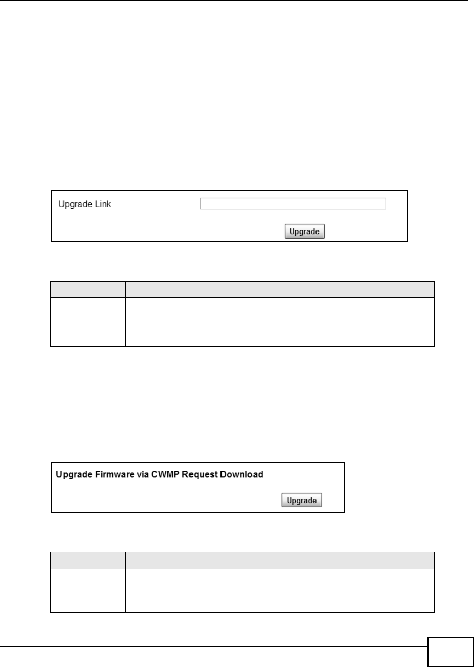
Chapter 12 Maintenance
BM2022 Users Guide 185
After two minutes, log in again, and check your new firmware version in the Status screen. You
might have to open a new browser window to log in.
If the upload is not successful, you will be notified by error message.
12.12 Upgrade Link
Use this screen to set the URL of a firmware file on a remote computer and upload it to the WiMAX
Device.
Click Maintenance > Firmware Upgrade > Upgrade Link to open this screen as shown next.
Figure 105 Upgrade Link Screen
This screen contains the following fields:
12.13 CWMP Upgrade
Use this screen to upgrade the firmware on the WiMAX Device using CWMP Request Download.
Click Maintenance > Firmware Upgrade > CWMP Upgrade to open this screen as shown next.
Figure 106 CWMP Upgrade Screen
This screen contains the following fields:
Table 87 Upgrade Link
LABEL DESCRIPTION
Upgrade Link Enter the URL or IP address of the firmwares upgrade location on the network.
Upgrade Click this to begin uploading the selected file. This may take up to two minutes.
Note: Do not turn off the device while firmware upload is in progress!
Table 88 CWMP Upgrade
LABEL DESCRIPTION
Upgrade Click this to begin upgrading firmware using CWMP Request. This may take up to
two minutes.
Note: Do not turn off the device while firmware upload is in progress!
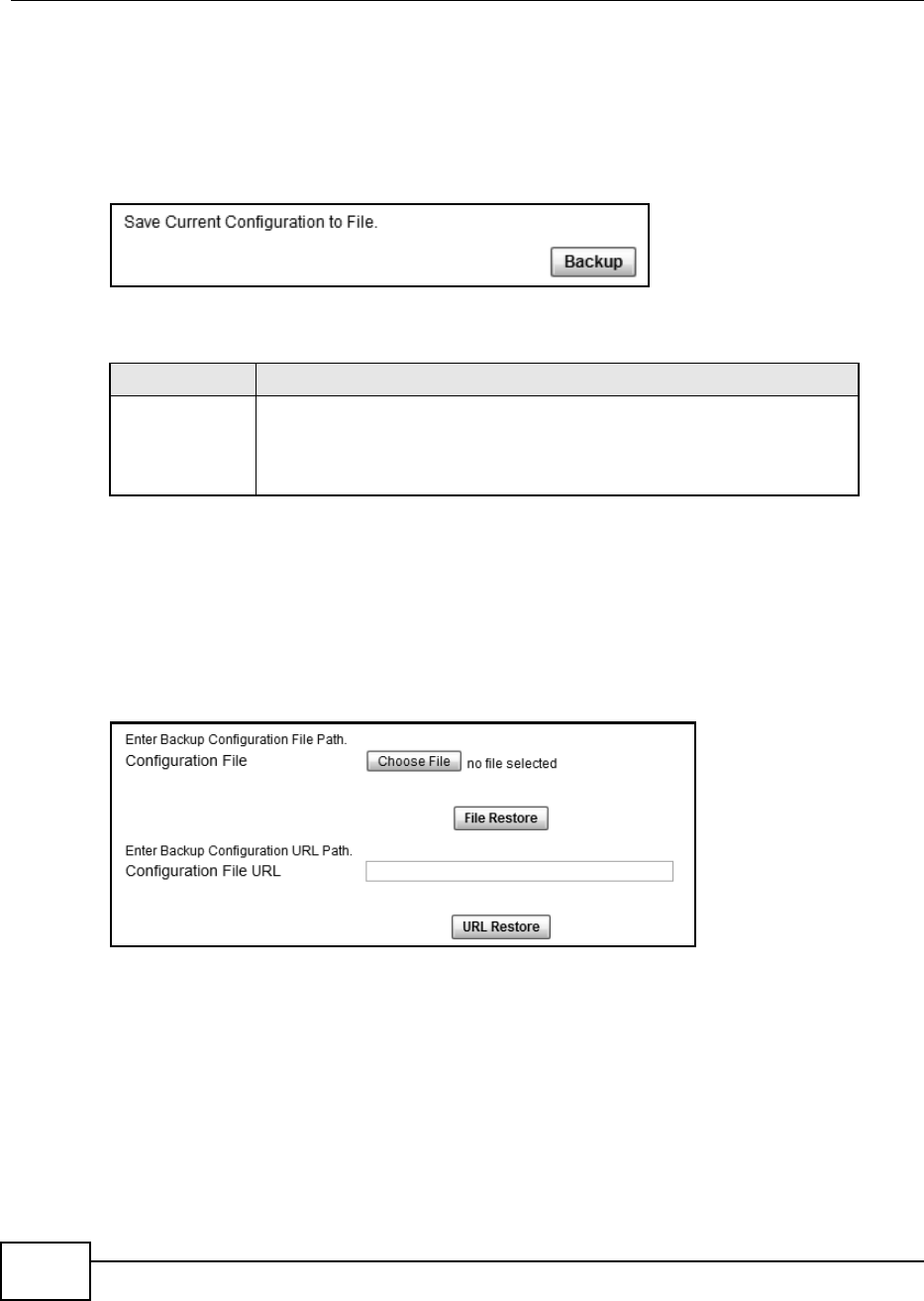
Chapter 12 Maintenance
BM2022 Users Guide
186
12.14 Backup
Use this screen to backup your current WiMAX Device settings to a local computer.
Click Maintenance > Backup/Restore > Backup to open this screen as shown next.
Figure 107 Backup/Restore Screen
This screen contains the following fields:
12.15 Restore
Use this screen to restore your WiMAX Device settings from a backup file on a local computer.
Click Maintenance > Backup/Restore > Restore to open this screen as shown next.
Figure 108 Restore Screen
Table 89 Backup/Restore
LABEL DESCRIPTION
Backup Click this to save the BM2022s current configuration to a file on your computer.
Once your device is configured and functioning properly, it is highly
recommended that you back up your configuration file before making
configuration changes. The backup configuration file is useful if you need to
return to your previous settings.
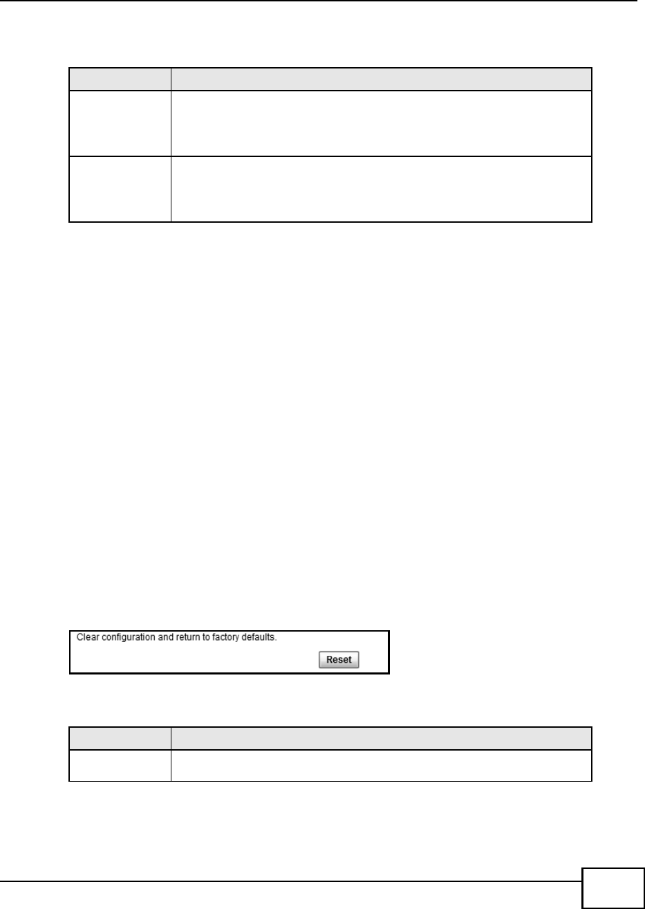
Chapter 12 Maintenance
BM2022 Users Guide 187
This screen contains the following fields:
12.15.1 The Restore Configuration Process
When the BM2022 restores a configuration file, the device automatically restarts. This causes a
temporary network disconnect.
Note: Do not turn off the device while configuration file upload is in progress.
If the BM2022s IP address is different in the configuration file you selected, you may need to
change the IP address of your computer to be in the same subnet as that of the default
management IP address (192.168.5.1). See the Quick Start Guide or the appendices for details on
how to set up your computers IP address.
You might have to open a new browser to log in again.
If the upload was not successful, you are notified with an error message.
12.16 Factory Defaults
Use this screen to restore the WiMAX Device to its factory default settings.
Click Maintenance > Backup/Restore > Factory Defaults to open this screen as shown next.
Figure 109 Factory Defaults Screen
This screen contains the following fields:
Table 90 Restore
LABEL DESCRIPTION
Configuration File Click Choose File then browse to the location of a firmware upgrade file and
select it.
Click File Restore to upload the specified configuration to the BM2022 and
replace the current settings.
Backup
Configuration File
URL
Enter the URL or IP address of the backup configuration files location on the
network.
Click URL Restore to upload the specified configuration to the BM2022 and
replace the current settings.
Table 91 Factory Defaults
LABEL DESCRIPTION
Reset Click this to clear all user-entered configuration information and return the
BM2022 to its factory defaults. There is no warning screen.
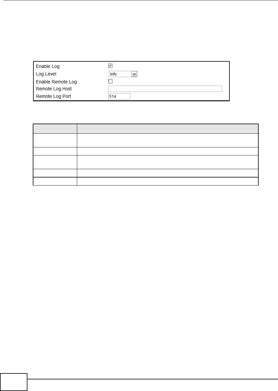
Chapter 12 Maintenance
BM2022 Users Guide
188
12.17 Log Setting
Use this screen to configure which type of events on the WiMAX Device are logged.
Click Maintenance > LOG > Log Setting to open this screen as shown next.
Figure 110 Log Setting Screen
This screen contains the following fields:
12.18 Log Display
Use this screen to view the log messages of the WiMAX Device.
Table 92 Log Setting
LABEL DESCRIPTION
Enable Log Select this to have the BM2022 log network activity according to the selected
Log Level.
Log Level Select the type of logs to record.
Enable Remote
Log
Select this to allow logs to be recorded and stored on a remote logs server.
Remote Log Host Enter the remote log host IP address if Enable Remote Log is selected.
Remote Log Port Enter the remote log host port if Enable Remote Log is selected.
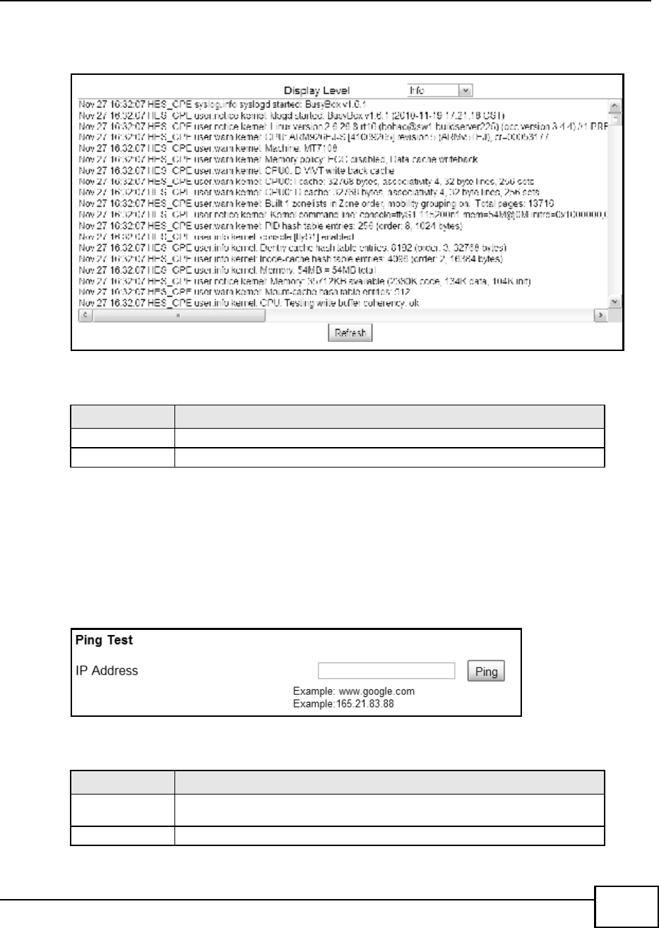
Chapter 12 Maintenance
BM2022 Users Guide 189
Click Maintenance > LOG > Log Display to open this screen as shown next.
Figure 111 Log Display Screen
This screen contains the following fields:
12.19 Ping Test
Use this screen to test network connectivity using ping.
Click Maintenance > Network Test > Ping to open this screen as shown next.
Figure 112 Ping Screen
This screen contains the following fields:
Table 93 Log Display
LABEL DESCRIPTION
Display Level Select the type of logs to display from this menu.
Refresh Click this to refresh the logs in the display window.
Table 94 Ping
LABEL DESCRIPTION
IP Address Enter the IP address or domain name of a target device to which this test will
send.
Ping Click this to start the test. The result will show at the bottom of the screen.
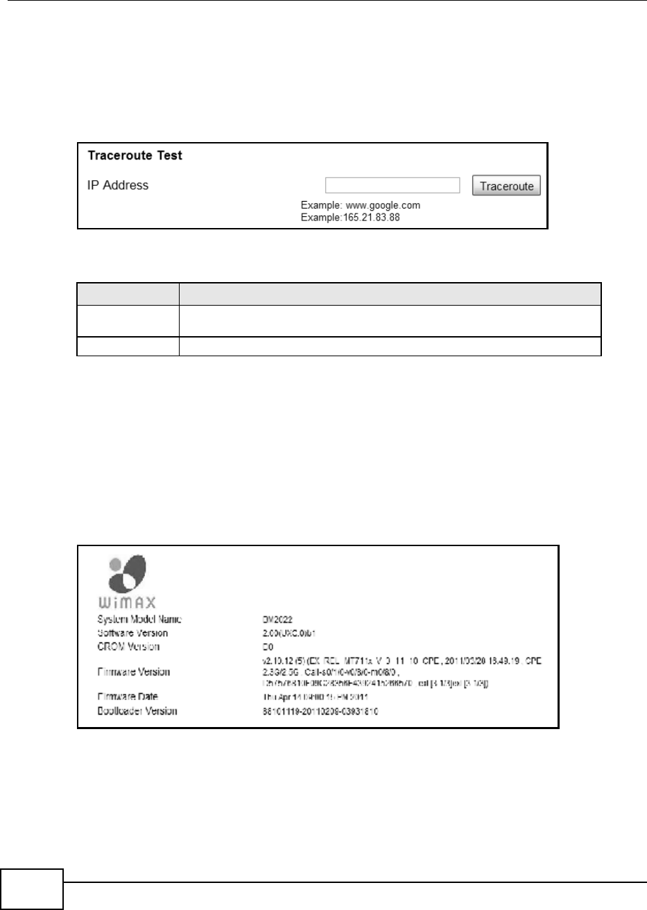
Chapter 12 Maintenance
BM2022 Users Guide
190
12.20 Traceroute Test
Use this screen to test network connectivity using traceroute.
Click Maintenance > Network Test > Traceroute to open this screen as shown next.
Figure 113 Traceroute Screen
This screen contains the following fields:
12.21 About
This screen displays information about the BM2022 that can be useful when upgrading firmware,
considering deployment options, and working with technical support if the device encounters
difficulties.
Click Maintenance > About to open this screen as shown next.
Figure 114 About Screen
Table 95 Traceroute
LABEL DESCRIPTION
IP Address Enter the IP address or domain name of a target device to which this test will
send.
Traceroute Click this to start the test. The result will show at the bottom of the screen.
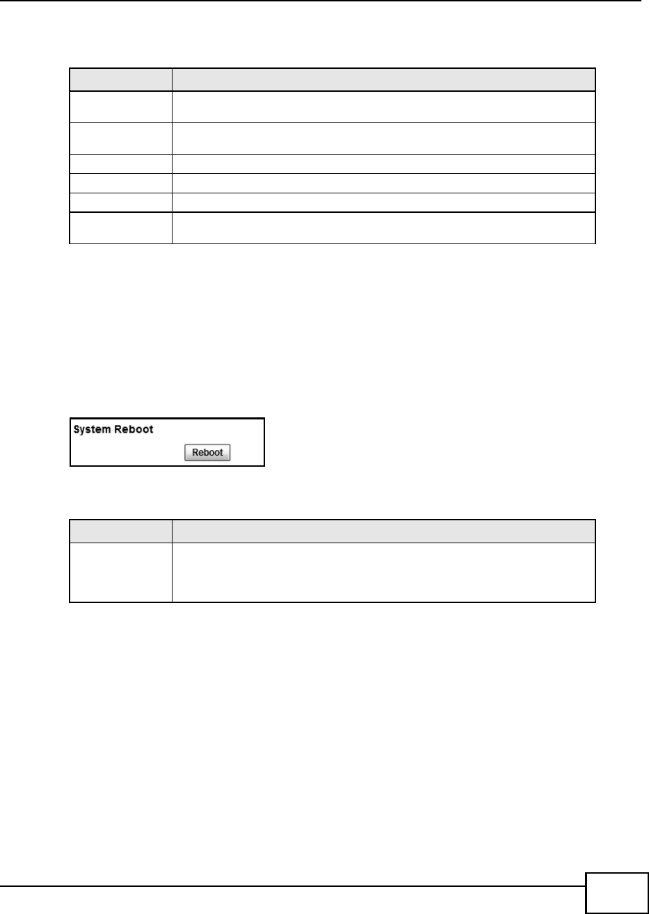
Chapter 12 Maintenance
BM2022 Users Guide 191
This screen contains the following fields:
12.22 Reboot
Use this screen to perform a software restart of the WiMAX Device. You may log in again within a
few minutes of using the reboot button.
Click Maintenance > Reboot to open this screen as shown next.
Figure 115 Reboot Screen
This screen contains the following fields:
Table 96 About
LABEL DESCRIPTION
System Model
Name
This field displays the BM2022 system name. It is used for identification.
Software Version This field displays the Web Configurator software version that the BM2022 is
currently running.
CROM Version This field displays the CROM version number.
Firmware Version This field displays the current version of the firmware inside the device.
Firmware Date This field displays the date the firmware version was created.
Bootloader
Version
This field displays the bootloader version.
Table 97 Reboot
LABEL DESCRIPTION
Reboot Click this button to have the device perform a software restart. The Power LED
blinks as it restarts and the shines steadily if the restart is successful.
Note: Wait one minute before logging back into the BM2022 after a restart.

Chapter 12 Maintenance
BM2022 Users Guide
192

BM2022 Users Guide 193
CHAPTER 13
Troubleshooting
This chapter offers some suggestions to solve problems you might encounter. The potential
problems are divided into the following categories:
Power, Hardware Connections, and LEDs
BM2022 Access and Login
Internet Access
Reset the BM2022 to Its Factory Defaults
13.1 Power, Hardware Connections, and LEDs
The BM2022 does not turn on. None of the LEDs turn on.
1Make sure you are using the power adapter or cord included with the BM2022.
2Make sure the power adapter or cord is connected to the BM2022 and plugged in to an appropriate
power source. Make sure the power source is turned on.
3Disconnect and re-connect the power adapter or cord to the BM2022.
4If the problem continues, contact the vendor.
One of the LEDs does not behave as expected.
1Make sure you understand the normal behavior of the LED. See Section 1.2.1 on page 19 for more
information.
2Check the hardware connections. See the Quick Start Guide.
3Inspect your cables for damage. Contact the vendor to replace any damaged cables.
4Disconnect and re-connect the power adapter to the BM2022.
5If the problem continues, contact the vendor.

Chapter 13 Troubleshooting
BM2022 Users Guide
194
13.2 BM2022 Access and Login
I forgot the IP address for the BM2022.
1The default IP address is 192.168.1.1.
2If you changed the IP address and have forgotten it, you might get the IP address of the BM2022
by looking up the IP address of the default gateway for your computer. To do this in most Windows
computers, click Start > Run, enter cmd, and then enter ipconfig. The IP address of the Default
Gateway might be the IP address of the BM2022 (it depends on the network), so enter this IP
address in your Internet browser.
3If this does not work, you have to reset the BM2022 to its factory defaults. See Section 12.16 on
page 187.
I forgot the password.
1The default password is 1234.
2If this does not work, you have to reset the BM2022 to its factory defaults. See Section 12.16 on
page 187.
I cannot see or access the Login screen in the web configurator.
1Make sure you are using the correct IP address.
The default IP address is 192.168.1.1.
If you changed the IP address (Section 7.6 on page 98), use the new IP address.
If you changed the IP address and have forgotten it, see the troubleshooting suggestions for I
forgot the IP address for the BM2022.
2Check the hardware connections, and make sure the LEDs are behaving as expected. See the Quick
Start Guide and Section 1.2.1 on page 19.
3Make sure your Internet browser does not block pop-up windows and has JavaScript and Java
enabled. See Appendix C on page 233.
4If there is a DHCP server on your network, make sure your computer is using a dynamic IP address.
Your BM2022 is a DHCP server by default.
If there is no DHCP server on your network, make sure your computers IP address is in the same
subnet as the BM2022. See Appendix D on page 243.
5Reset the BM2022 to its factory defaults, and try to access the BM2022 with the default IP address.
See Chapter 2 on page 21.

Chapter 13 Troubleshooting
BM2022 Users Guide 195
6If the problem continues, contact the network administrator or vendor, or try one of the advanced
suggestions.
Advanced Suggestions
Try to access the BM2022 using another service, such as Telnet. If you can access the BM2022,
check the remote management settings and firewall rules to find out why the BM2022 does not
respond to HTTP.
If your computer is connected wirelessly, use a computer that is connected to a LAN/ETHERNET
port.
I can see the Login screen, but I cannot log in to the BM2022.
1Make sure you have entered the user name and password correctly. The default user name is
admin, and the default password is 1234. These fields are case-sensitive, so make sure [Caps
Lock] is not on.
2You cannot log in to the web configurator while someone is using Telnet to access the BM2022. Log
out of the BM2022 in the other session, or ask the person who is logged in to log out.
3Disconnect and re-connect the power adapter or cord to the BM2022.
4If this does not work, you have to reset the BM2022 to its factory defaults. See Section 12.16 on
page 187.
I cannot Telnet to the BM2022.
See the troubleshooting suggestions for I cannot see or access the Login screen in the web
configurator. Ignore the suggestions about your browser.
13.3 Internet Access
I cannot access the Internet.
1Check the hardware connections, and make sure the LEDs are behaving as expected. See the Quick
Start Guide and Section 1.2.1 on page 19.
2Make sure you entered your ISP account information correctly in the wizard. These fields are case-
sensitive, so make sure [Caps Lock] is not on.
3Check your security settings. See Chapter 8 on page 121.

Chapter 13 Troubleshooting
BM2022 Users Guide
196
4Check your WiMAX settings. The BM2022 may have been set to search the wrong frequencies for a
wireless connection. See Chapter 6 on page 65. If you are unsure of the correct values, contact
your service provider.
5Disconnect all the cables from your BM2022, and follow the directions in the Quick Start Guide
again.
6If the problem continues, contact your ISP.
I cannot access the Internet any more. I had access to the Internet (with the BM2022), but
my Internet connection is not available any more.
1Check the hardware connections, and make sure the LEDs are behaving as expected. See the Quick
Start Guide and Section 1.2.1 on page 19.
2Disconnect and re-connect the power adapter to the BM2022.
3If the problem continues, contact your ISP.
The Internet connection is slow or intermittent.
1The quality of the BM2022s wireless connection to the base station may be poor. Poor signal
reception may be improved by moving the BM2022 away from thick walls and other obstructions, or
to a higher floor in your building.
2There may be radio interference caused by nearby electrical devices such as microwave ovens and
radio transmitters. Move the BM2022 away or switch the other devices off. Weather conditions may
also affect signal quality.
3There might be a lot of traffic on the network. Look at the LEDs, and check Section 1.2.1 on page
19. If the BM2022 is sending or receiving a lot of information, try closing some programs that use
the Internet, especially peer-to-peer applications.
4Disconnect and re-connect the power adapter to the BM2022.
5If the problem continues, contact the network administrator or vendor, or try one of the advanced
suggestions.
The Internet connection disconnects.
1Check your WiMAX link and signal strength using the Strength Indicator LEDs on the device.
2Contact your ISP if the problem persists.

Chapter 13 Troubleshooting
BM2022 Users Guide 197
13.4 Reset the BM2022 to Its Factory Defaults
If you reset the BM2022, you lose all of the changes you have made. The BM2022 re-loads its
default settings, and the password resets to 1234. You have to make all of your changes again.
You will lose all of your changes when you push the Reset button.
To reset the BM2022,
1Make sure the Power LED is on and not blinking.
2Press and hold the Reset button for five to ten seconds. Release the Reset button when the
Power LED begins to blink. The default settings have been restored.
If the BM2022 restarts automatically, wait for the BM2022 to finish restarting, and log in to the web
configurator. The password is 1234.
If the BM2022 does not restart automatically, disconnect and reconnect the BM2022s power. Then,
follow the directions above again.
13.4.1 Pop-up Windows, JavaScript and Java Permissions
Please see Appendix C on page 233.

Chapter 13 Troubleshooting
BM2022 Users Guide
198

BM2022 Users Guide 199
CHAPTER 14
Product Specifications
This chapter gives details about your BM2022s hardware and firmware features.
Table 98 Environmental and Hardware Specifications
FEATURE DESCRIPTION
Operating Temperature 0C to 45C
Storage Temperature -25C to 55C
Operating Humidity 10% to 95% (non-condensing)
Storage Humidity 10% to 95% (non-condensing)
Power Supply 12V DC, 1A
Power consumption Less than 12W
Ethernet Interface One auto-negotiating, auto-MDI/MDI-X NWay 10/100 Mbps RJ-45
Ethernet port
Telephony Interface One analog ATA interface for standard telephones through RJ-11
FXS (Foreign Exchange Subscriber) analog connector
Antenna 6 +/- 0.5dBi internal antenna
Weight 600 g
Dimensions 165 mm (W) x 25 mm (D) x 260 mm (H)
Certification FCC
CNC
Comply with WiMAX Forum Wave II standard.
EEE (Proposal for Directive on Environmental Impacts of
Electrical and Electronic Equipment).
EMC
o EN 301 489-1 and EN 301 489-17. Emission class B.
Transportation Shock and Vibration
o EN 300 019-2-2, Public transportation
2002/95/EC (RoHS) Restriction of Hazardous Substances
Directive
2002/96/EC (WEEE) (WEEE) Waste Electrical and Electronic
Equipment Directive
European Parliament and Council Directive 94/62/EC of 20
December 1994 on packaging and packaging waste
Table 99 Radio Specifications
FEATURE DESCRIPTION
Media Access Protocol IEEE 802.16e-2005
WiMAX Bandwidth 2.5 GHz
Data Rate Aggregate throughput: up to 20 mbps
Upload: 5 mbps

Chapter 14 Product Specifications
BM2022 Users Guide
200
Modulation QPSK (uplink and downlink)
16-QAM (uplink and downlink)
64-QAM (downlink only)
Output Power Typically 26.5 dBm with internal antennas
Duplex mode Time Division Duplex (TDD)
Security PKMv2
EAP TLS based device authentication
EAP-TTLS/CHAP/PAP/MSCHAP/MSCHAPv2
CMAC message autentication
CCM mode 128-bit AES data ciphering
Device authentication
WiMAX Forum X.509 certificates
Table 100 Firmware Specifications
FEATURE DESCRIPTION
Web-based Configuration and
Management Tool
Also known as the web configurator, this is a firmware-based
management solution for the BM2022. You must connect using a
compatible web browser in order to use it.
High Speed Wireless Internet
Access
The BM2022 is ideal for high-speed wireless Internet browsing.
WiMAX (Worldwide Interoperability for Microwave Access) is a
wireless networking standard providing high-bandwidth, wide-range
secured wireless service. The BM2022 is a WiMAX mobile station
(MS) compatible with the IEEE 802.16e standard.
Firewall The BM2022 is a stateful inspection firewall with DoS (Denial of
Service) protection. By default, when the firewall is activated, all
incoming traffic from the WAN to the LAN is blocked unless it is
initiated from the LAN. The BM2022s firewall supports TCP/UDP
inspection, DoS detection and prevention, real time alerts, reports
and logs.
Content Filtering The BM2022 can block access to web sites containing specified
keywords. You can define time periods and days during which
content filtering is enabled and include or exclude a range of users on
the LAN from content filtering.
Network Address Translation
(NAT)
Network Address Translation (NAT) allows the translation of an
Internet protocol address used within one network (for example a
private IP address used in a local network) to a different IP address
known within another network (for example a public IP address used
on the Internet).
Universal Plug and Play
(UPnP)
Your device and other UPnP enabled devices can use the standard
TCP/IP protocol to dynamically join a network, obtain an IP address
and convey their capabilities to each other.
Dynamic DNS Support With Dynamic DNS support, you can have a static hostname alias for
a dynamic IP address, allowing the host to be more easily accessible
from various locations on the Internet. You must register for this
service with a Dynamic DNS service provider.
Table 99 Radio Specifications (continued)

Chapter 14 Product Specifications
BM2022 Users Guide 201
DHCP DHCP (Dynamic Host Configuration Protocol) allows the individual
clients (computers) to obtain the TCP/IP configuration at start-up
from a centralized DHCP server. Your device has built-in DHCP server
capability enabled by default. It can assign IP addresses, an IP
default gateway and DNS servers to DHCP clients. Your device can
also act as a surrogate DHCP server (DHCP Relay) where it relays IP
address assignment from the actual real DHCP server to the clients.
IP Alias IP alias allows you to partition a physical network into logical
networks over the same Ethernet interface. Your device supports
three logical LAN interfaces via its single physical Ethernet interface
with the your device itself as the gateway for each LAN network.
Multiple SIP Accounts You can configure multiple voice (SIP) accounts.
SIP ALG Your device is a SIP Application Layer Gateway (ALG). It allows VoIP
calls to pass through NAT for devices behind it (such as a SIP-based
VoIP software application on a computer).
Dynamic Jitter Buffer The built-in adaptive buffer helps to smooth out the variations in
delay (jitter) for voice traffic (up to 60 ms). This helps ensure good
voice quality for your conversations.
Voice Activity Detection/
Silence Suppression
Voice Activity Detection (VAD) reduces the bandwidth that a call uses
by not transmitting when you are not speaking.
Comfort Noise Generation Your device generates background noise to fill moments of silence
when the other device in a call stops transmitting because the other
party is not speaking (as total silence could easily be mistaken for a
lost connection).
Echo Cancellation You device supports G.168 of at least 24 ms.
This an ITU-T standard for eliminating the echo caused by the sound
of your voice reverberating in the telephone receiver while you talk.
Time and Date Get the current time and date from an external server when you turn
on your BM2022. You can also set the time manually.
Logging Use the BM2022s logging feature to view connection history,
surveillance logs, and error messages.
Codecs G.711 (PCM -law and a-law), G729, G.729a
Fax Support T.38 FAX relay (FAX over UDP).
G.711 fax relay for fax calls and be able to renegotiate codec to
G.711 if a fax call is detected.
Ring Tones Supports different distinctive ring tones on each line.
Call Prioritization Prioritize VoIP traffic originating from the RJ-11 ports over any other
traffic.
Table 101 Standards Supported
STANDARD DESCRIPTION
RFC 768 User Datagram Protocol
RFC 791 Internet Protocol v4
RFC 792 Internet Control Message Protocol
RFC 792 Transmission Control Protocol
RFC 826 Address Resolution Protocol
RFC 854 Telnet Protocol
RFC 1112 IGMPv2
RFC 1349 Type of Service Protocol
Table 100 Firmware Specifications (continued)
FEATURE DESCRIPTION

Chapter 14 Product Specifications
BM2022 Users Guide
202
RFC 1706 DNS NSAP Resource Records
RFC 1889 Real-time Transport Protocol (RTP)
RFC 1890 Real-time Transport Control Protocol (RTCP)
RFC 2030 Simple Network Time Protocol
RFC 2104 HMAC: Keyed-Hashing for Message Authentication
RFC 2236 IGMPv2
RFC 2131 Dynamic Host Configuration Protocol
RFC 2401 Security Architecture for the Internet Protocol
RFC 2409 Internet Key Exchange
RFC 2475 Architecture for Differentiated Services (Diffserv)
RFC 2543 SIP Protocol
RFC 2617 Hypertext Transfer Protocol (HTTP) Authentication: Basic and Digest
Access Authentication
RFC 2782 A DNS RR for specifying the location of services (DNS SRV)
RFC 2833 Real-time Transport Protocol Payload for DTMF Digits, Telephony Tones
and Telephony Signals
RFC 2976 The SIP INFO Method
RFC 3261 Session Initiation Protocol (SIP version 2)
RFC 3262 Reliability of Provisional Responses in the Session Initiation Protocol
(SIP).
RFC 3263 Session Initiation Protocol (SIP): Locating SIP Servers
RFC 3264 An Offer/Answer Model with the Session Description Protocol (SDP)
RFC 3265 Session Initiation Protocol (SIP)-Specific Event Notification
RFC 3323 A Privacy Mechanism for SIP
RFC 3325 Private Extensions to the Session Initiation Protocol (SIP) for Asserted
Identity within Trusted Networks
RFC 3489 NAT Traversal - STUN
RFC 3550 RTP - A Real Time Protocol for Real-Time Applications
RFC 3581 An Extension to the Session Initiation Protocol (SIP) for Symmetric
Response Routing
RFC 3611 RTP Control Protocol Extended Reports (RTCP XR)-XR
RFC 3715 IP Sec/NAT Compatibility
RFC 3842 A Message Summary and Message Waiting Indication Event Package for
the Session Initiation Protocol (SIP)
IEEE 802.3 10BASE5 10 Mbit/s (1.25 MB/s)
IEEE 802.3u 100BASE-TX, 100BASE-T4, 100BASE-FX Fast Ethernet at 100 Mbit/s
(12.5 MB/s) with auto-negotiation
Table 101 Standards Supported (continued)
STANDARD DESCRIPTION

Chapter 14 Product Specifications
BM2022 Users Guide 203
Table 102 Voice Features
Call Park and Pickup Call park and pickup lets you put a call on hold (park) and then continue the
call (pickup). The caller must still pay while the call is parked.
When you park the call, you enter a number of your choice (up to eight digits),
which you must enter again when you pick up the call. If you do not enter the
correct number, you cannot pickup the call. This means that only someone
who knows the number you have chosen can pick up the call.
You can have more than one call on hold at the same time, but you must give
each call a different number.
Call Return With call return, you can place a call to the last number that called you (either
answered or missed). The last incoming call can be through either SIP or
PSTN.
Country Code Phone standards and settings differ from one country to another, so the
settings on your BM2022 must be configured to match those of the country
you are in. The country code feature allows you to do this by selecting the
country from a list rather than changing each setting manually. Configure the
country code feature when you move the BM2022 from one country to
another.
Do not Disturb
(DnD)
This feature allows you to set your phone not to ring when someone calls you.
You can set each phone independently using its keypad, or configure global
settings for all phones using the command line interpreter.
Auto Dial You can set the BM2022 to automatically dial a specified number immediately
whenever you lift a phone off the hook. Use the Web Configurator to set the
specified number. Use the command line interpreter to have the BM2022 wait
a specified length of time before dialing the number.
Phone config The phone configuration table allows you to customize the phone keypad
combinations you use to access certain features on the BM2022, such as call
waiting, call return, call forward, etc. The phone configuration table is
configurable in command interpreter mode.
Firmware update
enable / disable
If your service provider uses this feature, you hear a recorded message when
you pick up the phone when new firmware is available for your BM2022. Enter
*99# in your phones keypad to have the BM2022 upgrade the firmware, or
enter #99# to not upgrade. If your service provider gave you different
numbers to use, enter them instead. If you enter the code to not upgrade, you
can make a call as normal. You will hear the recording again each time you
pick up the phone, until you upgrade.
Call waiting This feature allows you to hear an alert when you are already using the phone
and another person calls you. You can then either reject the new incoming
call, put your current call on hold and receive the new incoming call, or end
the current call and receive the new incoming call.
Call forwarding With this feature, you can set the BM2022 to forward calls to a specified
number, either unconditionally (always), when your number is busy, or when
you do not answer. You can also forward incoming calls from one specified
number to another.
Caller ID The BM2022 supports caller ID, which allows you to see the originating
number of an incoming call (on a phone with a suitable display).
REN A Ringer Equivalence Number (REN) is used to determine the number of
devices (like telephones or fax machines) that may be connected to the
telephone line. Your device has a REN of three, so it can support three devices
per telephone port.
QoS (Quality of
Service)
Quality of Service (QoS) mechanisms help to provide better service on a per-
flow basis. Your device supports Type of Service (ToS) tagging and
Differentiated Services (DiffServ) tagging. This allows the device to tag voice
frames so they can be prioritized over the network.

Chapter 14 Product Specifications
BM2022 Users Guide
204
Note: To take full advantage of the supplementary phone services available through the
BM2022's phone port, you may need to subscribe to the services from your voice
account service provider.
Not all features are supported by all service providers. Consult your service
provider for more information.
SIP ALG Your device is a SIP Application Layer Gateway (ALG). It allows VoIP calls to
pass through NAT for devices behind it (such as a SIP-based VoIP software
application on a computer).
Other Voice
Features
SIP version 2 (Session Initiating Protocol RFC 3261)
SDP (Session Description Protocol RFC 2327)
RTP (RFC 1889)
RTCP (RFC 1890)
Voice codecs (coder/decoders) G.711, G.726, G.729
Fax and data modem discrimination
DTMF Detection and Generation
DTMF: In-band and Out-band traffic (RFC 2833),(PCM), (SIP INFO)
Point-to-point call establishment between two IADs
Quick dialing through predefined phone book, which maps the phone dialing
number and destination URL.
Flexible Dial Plan (RFC3525 section 7.1.14)
Table 103 Star (*) and Pound (#) Code Support
*0 Wireless Operator Services
*2 Customer Care Access
*66 Repeat Dialing
*67 Plus the 10 digit phone number to block Caller ID on a single call basis
*69 Return last call received
*70 Followed by the 10 digit phone number to cancel Call Waiting on a single call
basis
*72 Activate Call Forwarding (*72 followed by the 10 digit phone number that is
requesting call forwarding service)
*720 Activate Call Forwarding (*720 followed by the 10 digit phone number that is
requesting deactivation of call forwarding service)
*73 Plus the forward to phone number to activate Call Forwarding No Answer (no
VM service plan)
*730 Deactivate Call Forwarding No Answer
*740 Plus the forward to phone number to activate Call Forwarding Busy (no VM
service plan)
*911/911 Emergency phone number (same as dialing 911)
*411/411 Wireless Information Services
Table 102 Voice Features

BM2022 Users Guide 205
APPENDIX A
WiMAX Security
Wireless security is vital to protect your wireless communications. Without it, information
transmitted over the wireless network would be accessible to any networking device within range.
User Authentication and Data Encryption
The WiMAX (IEEE 802.16) standard employs user authentication and encryption to ensure secured
communication at all times.
User authentication is the process of confirming a users identity and level of authorization. Data
encryption is the process of encoding information so that it cannot be read by anyone who does not
know the code.
WiMAX uses PKMv2 (Privacy Key Management version 2) for authentication, and CCMP (Counter
Mode with Cipher Block Chaining Message Authentication Protocol) for data encryption.
WiMAX supports EAP (Extensible Authentication Protocol, RFC 2486) which allows additional
authentication methods to be deployed with no changes to the base station or the mobile or
subscriber stations.
PKMv2
PKMv2 is a procedure that allows authentication of a mobile or subscriber station and negotiation of
a public key to encrypt traffic between the MS/SS and the base station. PKMv2 uses standard EAP
methods such as Transport Layer Security (EAP-TLS) or Tunneled TLS (EAP-TTLS) for secure
communication.
In cryptography, a key is a piece of information, typically a string of random numbers and letters,
that can be used to lock (encrypt) or unlock (decrypt) a message. Public key encryption uses key
pairs, which consist of a public (freely available) key and a private (secret) key. The public key is
used for encryption and the private key is used for decryption. You can decrypt a message only if
you have the private key. Public key certificates (or digital IDs) allow users to verify each others
identity.
RADIUS
RADIUS is based on a client-server model that supports authentication, authorization and
accounting. The base station is the client and the server is the RADIUS server. The RADIUS server
handles the following tasks:
Authentication
Determines the identity of the users.

Appendix A WiMAX Security
BM2022 Users Guide
206
Authorization
Determines the network services available to authenticated users once they are connected to the
network.
Accounting
Keeps track of the clients network activity.
RADIUS is a simple package exchange in which your base station acts as a message relay between
the MS/SS and the network RADIUS server.
Types of RADIUS Messages
The following types of RADIUS messages are exchanged between the base station and the RADIUS
server for user authentication:
Access-Request
Sent by an base station requesting authentication.
Access-Reject
Sent by a RADIUS server rejecting access.
Access-Accept
Sent by a RADIUS server allowing access.
Access-Challenge
Sent by a RADIUS server requesting more information in order to allow access. The base station
sends a proper response from the user and then sends another Access-Request message.
The following types of RADIUS messages are exchanged between the base station and the RADIUS
server for user accounting:
Accounting-Request
Sent by the base station requesting accounting.
Accounting-Response
Sent by the RADIUS server to indicate that it has started or stopped accounting.
In order to ensure network security, the access point and the RADIUS server use a shared secret
key, which is a password they both know. The key is not sent over the network. In addition to the
shared key, password information exchanged is also encrypted to protect the network from
unauthorized access.
Diameter
Diameter (RFC 3588) is a type of AAA server that provides several improvements over RADIUS in
efficiency, security, and support for roaming.
Security Association
The set of information about user authentication and data encryption between two computers is
known as a security association (SA). In a WiMAX network, the process of security association has
three stages.

Appendix A WiMAX Security
BM2022 Users Guide 207
Authorization request and reply
The MS/SS presents its public certificate to the base station. The base station verifies the
certificate and sends an authentication key (AK) to the MS/SS.
Key request and reply
The MS/SS requests a transport encryption key (TEK) which the base station generates and
encrypts using the authentication key.
Encrypted traffic
The MS/SS decrypts the TEK (using the authentication key). Both stations can now securely
encrypt and decrypt the data flow.
CCMP
All traffic in a WiMAX network is encrypted using CCMP (Counter Mode with Cipher Block Chaining
Message Authentication Protocol). CCMP is based on the 128-bit Advanced Encryption Standard
(AES) algorithm.
Counter mode refers to the encryption of each block of plain text with an arbitrary number, known
as the counter. This number changes each time a block of plain text is encrypted. Counter mode
avoids the security weakness of repeated identical blocks of encrypted text that makes encrypted
data vulnerable to pattern-spotting.
Cipher Block Chaining Message Authentication (also known as CBC-MAC) ensures message
integrity by encrypting each block of plain text in such a way that its encryption is dependent on the
block before it. This series of chained blocks creates a message authentication code (MAC or
CMAC) that ensures the encrypted data has not been tampered with.
Authentication
The BM2022 supports EAP-TTLS authentication.
EAP-TTLS (Tunneled Transport Layer Service)
EAP-TTLS is an extension of the EAP-TLS authentication that uses certificates for only the server-
side authentications to establish a secure connection (with EAP-TLS digital certifications are needed
by both the server and the wireless clients for mutual authentication). Client authentication is then
done by sending username and password through the secure connection, thus client identity is
protected. For client authentication, EAP-TTLS supports EAP methods and legacy authentication
methods such as PAP, CHAP, MS-CHAP and MS-CHAP v2.

Appendix A WiMAX Security
BM2022 Users Guide
208

BM2022 Users Guide 209
APPENDIX B
Setting Up Your Computers IP Address
Note: Your specific Huawei device may not support all of the operating systems described
in this appendix. See the product specifications for more information about which
operating systems are supported.
This appendix shows you how to configure the IP settings on your computer in order for it to be
able to communicate with the other devices on your network. Windows Vista/XP/2000, Mac OS 9/
OS X, and all versions of UNIX/LINUX include the software components you need to use TCP/IP on
your computer.
If you manually assign IP information instead of using a dynamic IP, make sure that your networks
computers have IP addresses that place them in the same subnet.
In this appendix, you can set up an IP address for:
Windows XP/NT/2000 on page 210
Windows Vista on page 213
Mac OS X: 10.3 and 10.4 on page 217
Mac OS X: 10.5 on page 220
Linux: Ubuntu 8 (GNOME) on page 223
Linux: openSUSE 10.3 (KDE) on page 228
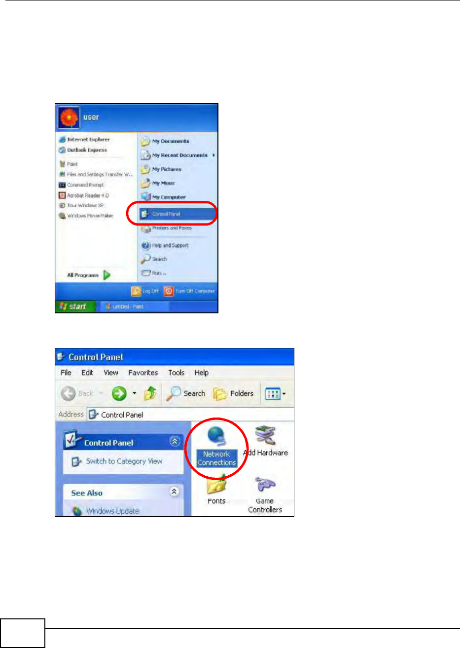
Appendix B Setting Up Your Computers IP Address
BM2022 Users Guide
210
Windows XP/NT/2000
The following example uses the default Windows XP display theme but can also apply to Windows
2000 and Windows NT.
1Click Start > Control Panel.
Figure 116 Windows XP: Start Menu
2In the Control Panel, click the Network Connections icon.
Figure 117 Windows XP: Control Panel
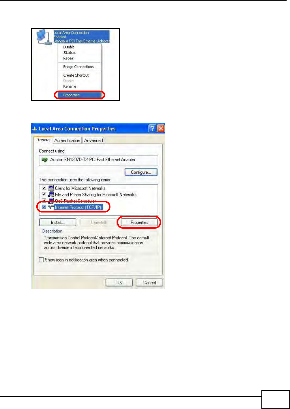
Appendix B Setting Up Your Computers IP Address
BM2022 Users Guide 211
3Right-click Local Area Connection and then select Properties.
Figure 118 Windows XP: Control Panel > Network Connections > Properties
4On the General tab, select Internet Protocol (TCP/IP) and then click Properties.
Figure 119 Windows XP: Local Area Connection Properties
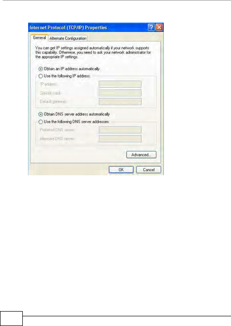
Appendix B Setting Up Your Computers IP Address
BM2022 Users Guide
212
5The Internet Protocol TCP/IP Properties window opens.
Figure 120 Windows XP: Internet Protocol (TCP/IP) Properties
6Select Obtain an IP address automatically if your network administrator or ISP assigns your IP
address dynamically.
Select Use the following IP Address and fill in the IP address, Subnet mask, and Default
gateway fields if you have a static IP address that was assigned to you by your network
administrator or ISP. You may also have to enter a Preferred DNS server and an Alternate DNS
server, if that information was provided.
7Click OK to close the Internet Protocol (TCP/IP) Properties window.
Click OK to close the Local Area Connection Properties window.Verifying Settings
1Click Start > All Programs > Accessories > Command Prompt.
2In the Command Prompt window, type "ipconfig" and then press [ENTER].
You can also go to Start > Control Panel > Network Connections, right-click a network
connection, click Status and then click the Support tab to view your IP address and connection
information.
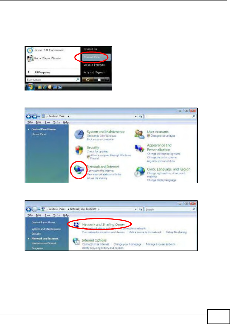
Appendix B Setting Up Your Computers IP Address
BM2022 Users Guide 213
Windows Vista
This section shows screens from Windows Vista Professional.
1Click Start > Control Panel.
Figure 121 Windows Vista: Start Menu
2In the Control Panel, click the Network and Internet icon.
Figure 122 Windows Vista: Control Panel
3Click the Network and Sharing Center icon.
Figure 123 Windows Vista: Network And Internet
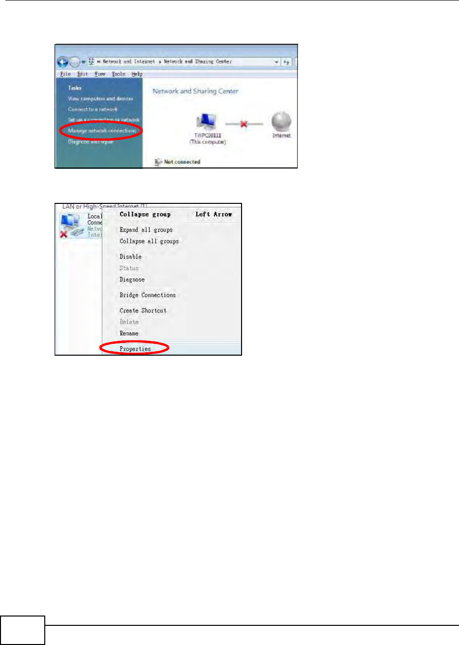
Appendix B Setting Up Your Computers IP Address
BM2022 Users Guide
214
4Click Manage network connections.
Figure 124 Windows Vista: Network and Sharing Center
5Right-click Local Area Connection and then select Properties.
Figure 125 Windows Vista: Network and Sharing Center
Note: During this procedure, click Continue whenever Windows displays a screen saying
that it needs your permission to continue.
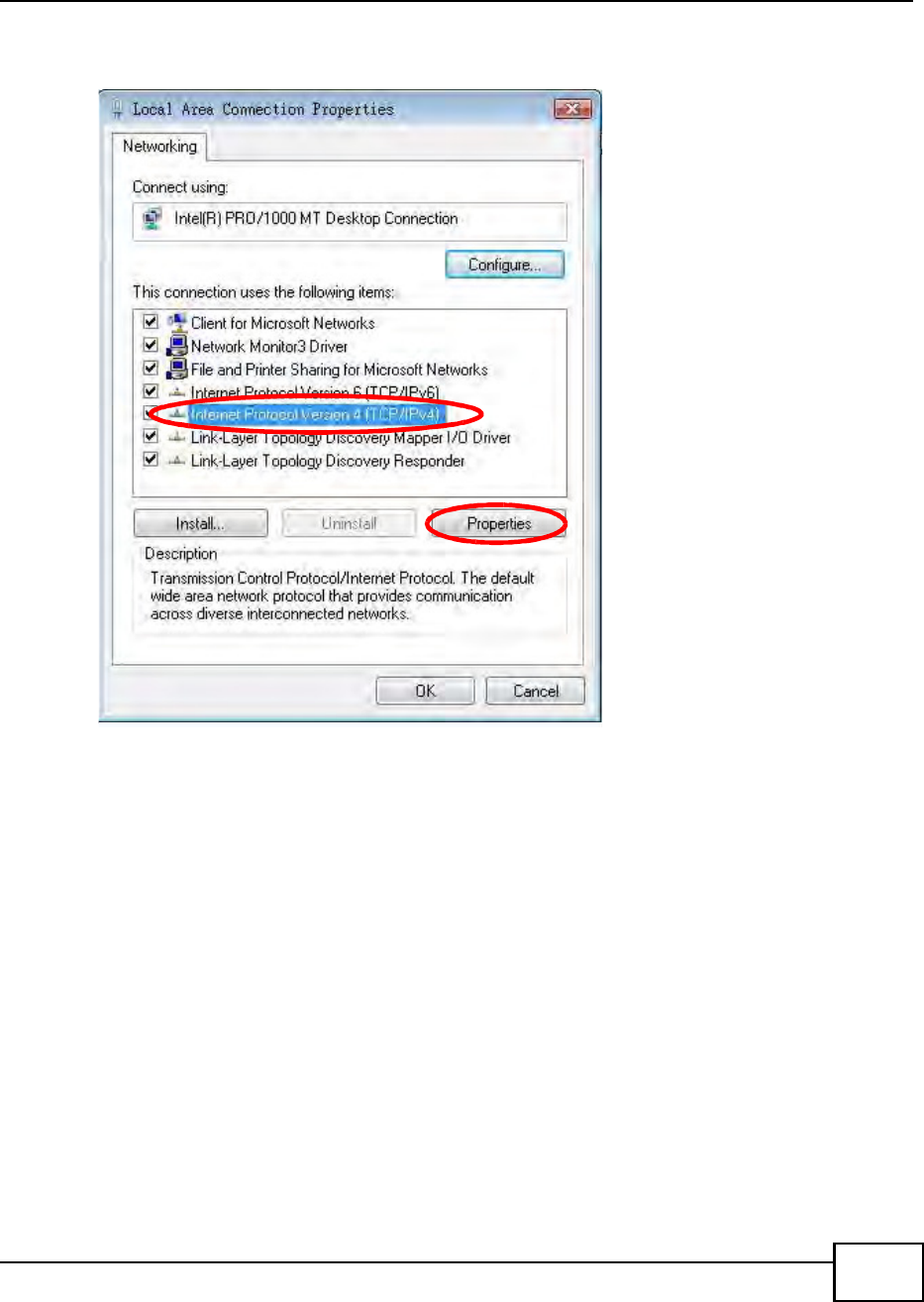
Appendix B Setting Up Your Computers IP Address
BM2022 Users Guide 215
6Select Internet Protocol Version 4 (TCP/IPv4) and then select Properties.
Figure 126 Windows Vista: Local Area Connection Properties
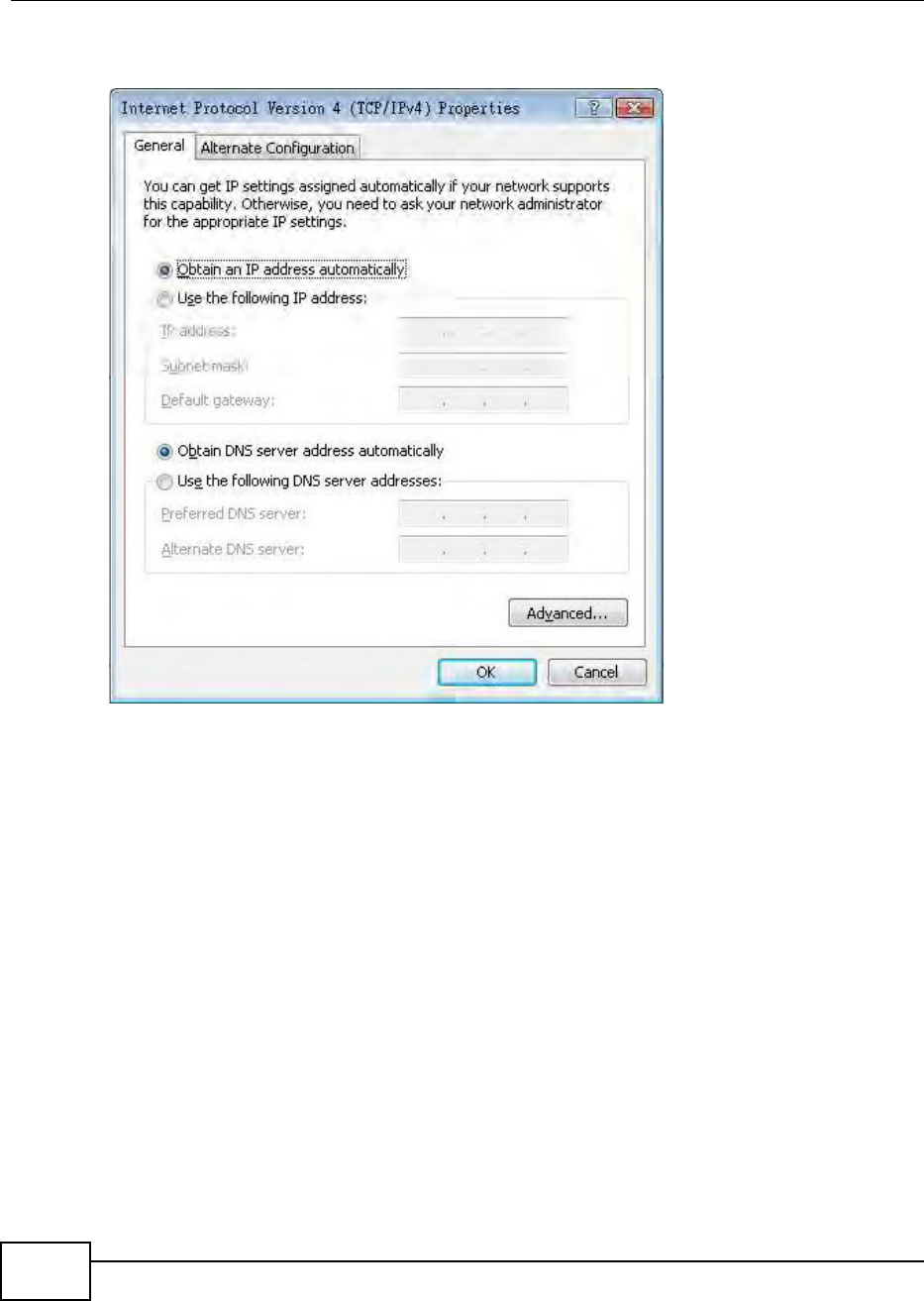
Appendix B Setting Up Your Computers IP Address
BM2022 Users Guide
216
7The Internet Protocol Version 4 (TCP/IPv4) Properties window opens.
Figure 127 Windows Vista: Internet Protocol Version 4 (TCP/IPv4) Properties
8Select Obtain an IP address automatically if your network administrator or ISP assigns your IP
address dynamically.
Select Use the following IP Address and fill in the IP address, Subnet mask, and Default
gateway fields if you have a static IP address that was assigned to you by your network
administrator or ISP. You may also have to enter a Preferred DNS server and an Alternate DNS
server, if that information was provided.Click Advanced.
9Click OK to close the Internet Protocol (TCP/IP) Properties window.
Click OK to close the Local Area Connection Properties window.Verifying Settings
1Click Start > All Programs > Accessories > Command Prompt.
2In the Command Prompt window, type "ipconfig" and then press [ENTER].
You can also go to Start > Control Panel > Network Connections, right-click a network
connection, click Status and then click the Support tab to view your IP address and connection
information.
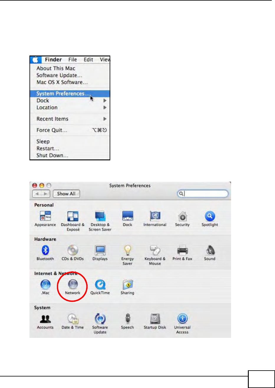
Appendix B Setting Up Your Computers IP Address
BM2022 Users Guide 217
Mac OS X: 10.3 and 10.4
The screens in this section are from Mac OS X 10.4 but can also apply to 10.3.
1Click Apple > System Preferences.
Figure 128 Mac OS X 10.4: Apple Menu
2In the System Preferences window, click the Network icon.
Figure 129 Mac OS X 10.4: System Preferences
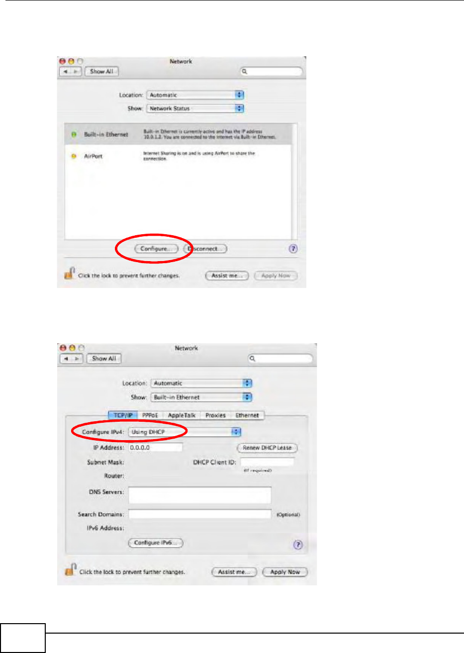
Appendix B Setting Up Your Computers IP Address
BM2022 Users Guide
218
3When the Network preferences pane opens, select Built-in Ethernet from the network
connection type list, and then click Configure.
Figure 130 Mac OS X 10.4: Network Preferences
4For dynamically assigned settings, select Using DHCP from the Configure IPv4 list in the TCP/IP
tab.
Figure 131 Mac OS X 10.4: Network Preferences > TCP/IP Tab.
5For statically assigned settings, do the following:
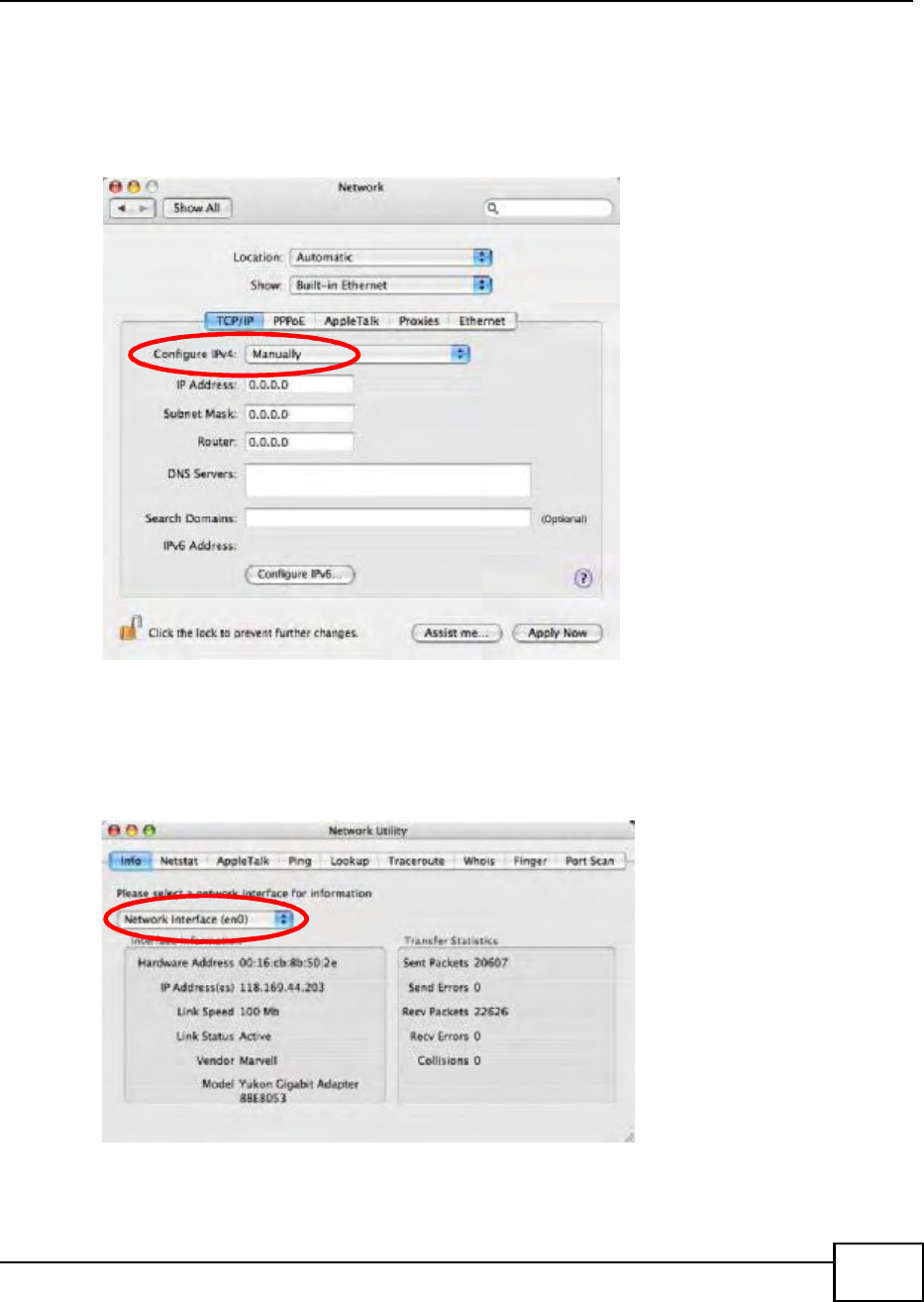
Appendix B Setting Up Your Computers IP Address
BM2022 Users Guide 219
From the Configure IPv4 list, select Manually.
In the IP Address field, type your IP address.
In the Subnet Mask field, type your subnet mask.
In the Router field, type the IP address of your device.
Figure 132 Mac OS X 10.4: Network Preferences > Ethernet
Click Apply Now and close the window.Verifying Settings
Check your TCP/IP properties by clicking Applications > Utilities > Network Utilities, and then
selecting the appropriate Network Interface from the Info tab.
Figure 133 Mac OS X 10.4: Network Utility
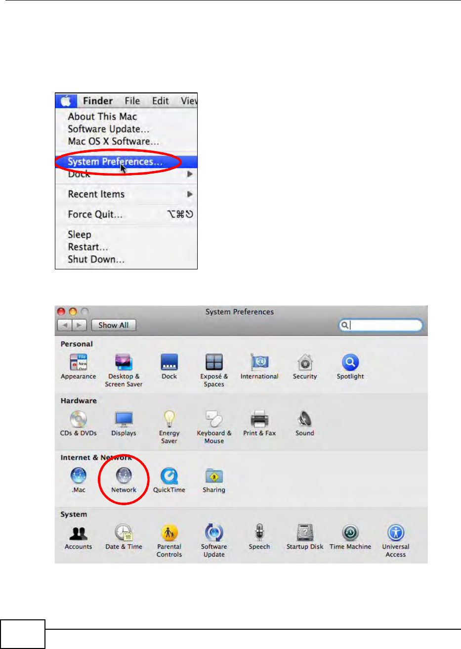
Appendix B Setting Up Your Computers IP Address
BM2022 Users Guide
220
Mac OS X: 10.5
The screens in this section are from Mac OS X 10.5.
1Click Apple > System Preferences.
Figure 134 Mac OS X 10.5: Apple Menu
2In System Preferences, click the Network icon.
Figure 135 Mac OS X 10.5: Systems Preferences
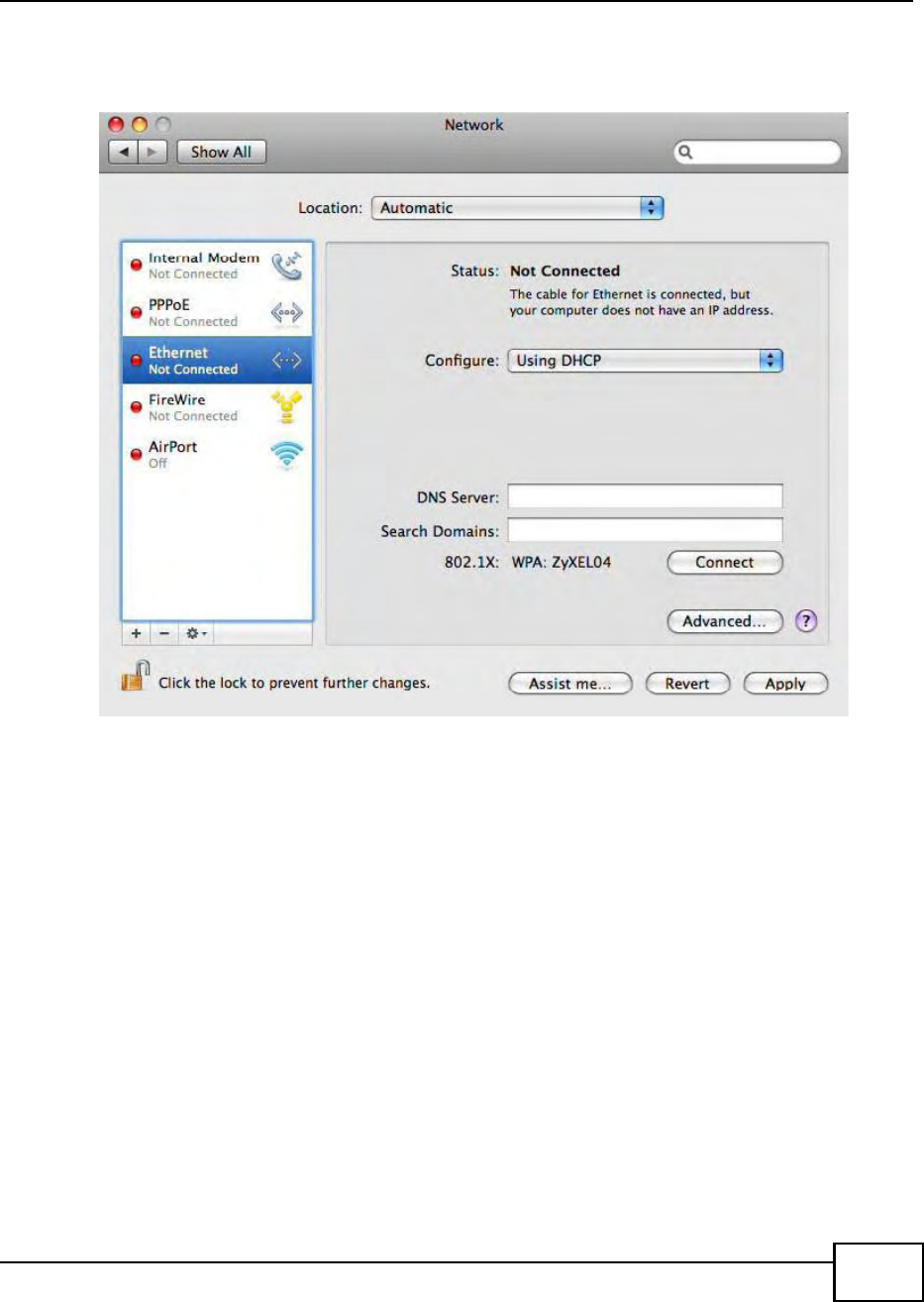
Appendix B Setting Up Your Computers IP Address
BM2022 Users Guide 221
3When the Network preferences pane opens, select Ethernet from the list of available connection
types.
Figure 136 Mac OS X 10.5: Network Preferences > Ethernet
4From the Configure list, select Using DHCP for dynamically assigned settings.
5For statically assigned settings, do the following:
From the Configure list, select Manually.
In the IP Address field, enter your IP address.
In the Subnet Mask field, enter your subnet mask.
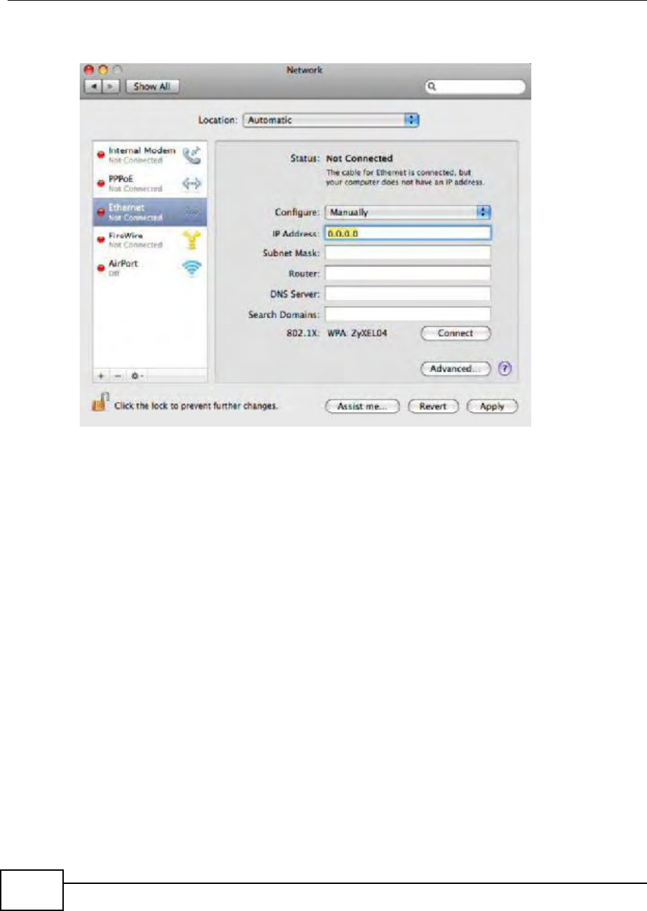
Appendix B Setting Up Your Computers IP Address
BM2022 Users Guide
222
In the Router field, enter the IP address of your BM2022.
Figure 137 Mac OS X 10.5: Network Preferences > Ethernet
6Click Apply and close the window.
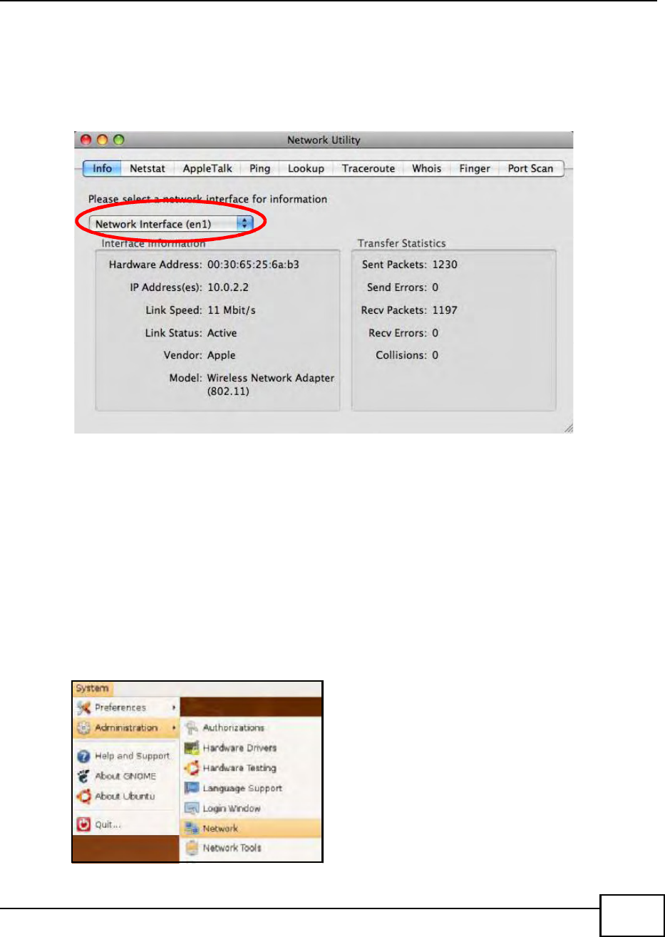
Appendix B Setting Up Your Computers IP Address
BM2022 Users Guide 223
Verifying Settings
Check your TCP/IP properties by clicking Applications > Utilities > Network Utilities, and then
selecting the appropriate Network interface from the Info tab.
Figure 138 Mac OS X 10.5: Network Utility
Linux: Ubuntu 8 (GNOME)
This section shows you how to configure your computers TCP/IP settings in the GNU Object Model
Environment (GNOME) using the Ubuntu 8 Linux distribution. The procedure, screens and file
locations may vary depending on your specific distribution, release version, and individual
configuration. The following screens use the default Ubuntu 8 installation.
Note: Make sure you are logged in as the root administrator.
Follow the steps below to configure your computer IP address in GNOME:
1Click System > Administration > Network.
Figure 139 Ubuntu 8: System > Administration Menu
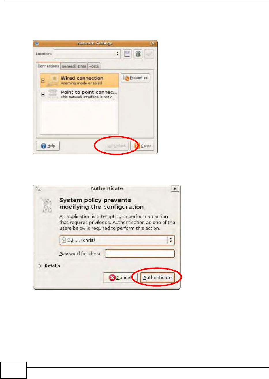
Appendix B Setting Up Your Computers IP Address
BM2022 Users Guide
224
2When the Network Settings window opens, click Unlock to open the Authenticate window. (By
default, the Unlock button is greyed out until clicked.) You cannot make changes to your
configuration unless you first enter your admin password.
Figure 140 Ubuntu 8: Network Settings > Connections
3In the Authenticate window, enter your admin account name and password then click the
Authenticate button.
Figure 141 Ubuntu 8: Administrator Account Authentication
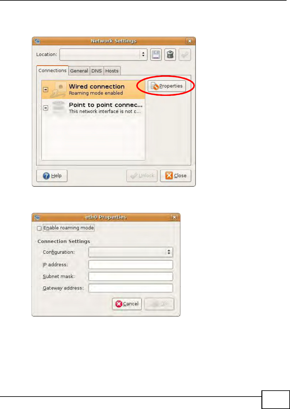
Appendix B Setting Up Your Computers IP Address
BM2022 Users Guide 225
4In the Network Settings window, select the connection that you want to configure, then click
Properties.
Figure 142 Ubuntu 8: Network Settings > Connections
5The Properties dialog box opens.
Figure 143 Ubuntu 8: Network Settings > Properties
In the Configuration list, select Automatic Configuration (DHCP) if you have a dynamic IP
address.
In the Configuration list, select Static IP address if you have a static IP address. Fill in the
IP address, Subnet mask, and Gateway address fields.
6Click OK to save the changes and close the Properties dialog box and return to the Network
Settings screen.
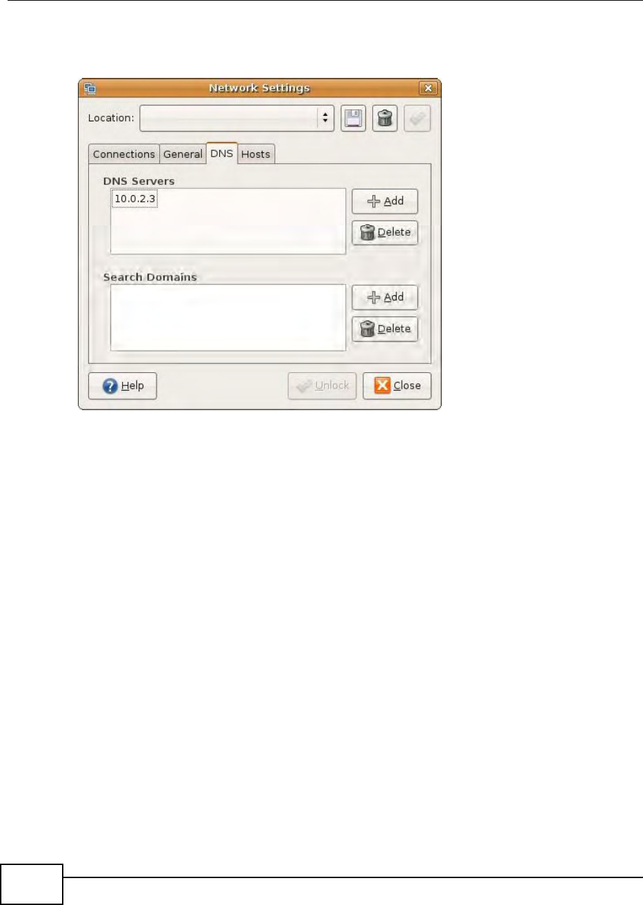
Appendix B Setting Up Your Computers IP Address
BM2022 Users Guide
226
7If you know your DNS server IP address(es), click the DNS tab in the Network Settings window
and then enter the DNS server information in the fields provided.
Figure 144 Ubuntu 8: Network Settings > DNS
8Click the Close button to apply the changes.
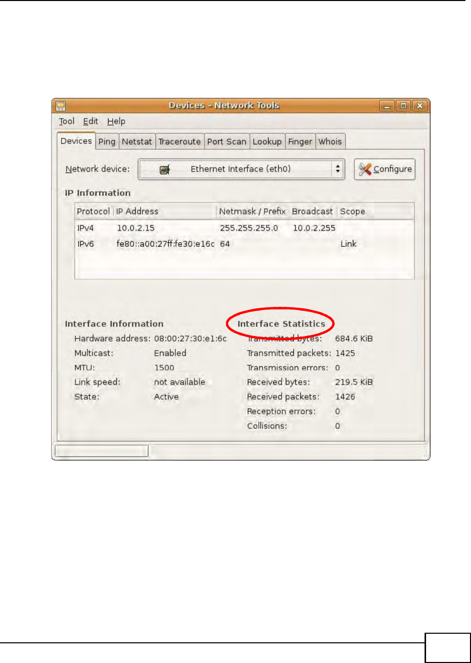
Appendix B Setting Up Your Computers IP Address
BM2022 Users Guide 227
Verifying Settings
Check your TCP/IP properties by clicking System > Administration > Network Tools, and then
selecting the appropriate Network device from the Devices tab. The Interface Statistics
column shows data if your connection is working properly.
Figure 145 Ubuntu 8: Network Tools
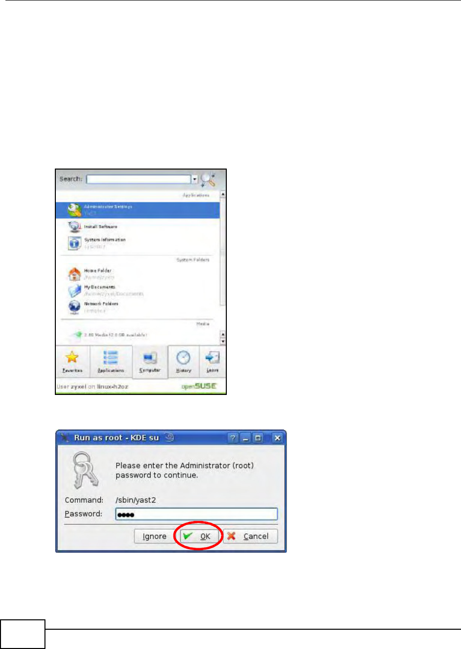
Appendix B Setting Up Your Computers IP Address
BM2022 Users Guide
228
Linux: openSUSE 10.3 (KDE)
This section shows you how to configure your computers TCP/IP settings in the K Desktop
Environment (KDE) using the openSUSE 10.3 Linux distribution. The procedure, screens and file
locations may vary depending on your specific distribution, release version, and individual
configuration. The following screens use the default openSUSE 10.3 installation.
Note: Make sure you are logged in as the root administrator.
Follow the steps below to configure your computer IP address in the KDE:
1Click K Menu > Computer > Administrator Settings (YaST).
Figure 146 openSUSE 10.3: K Menu > Computer Menu
2When the Run as Root - KDE su dialog opens, enter the admin password and click OK.
Figure 147 openSUSE 10.3: K Menu > Computer Menu
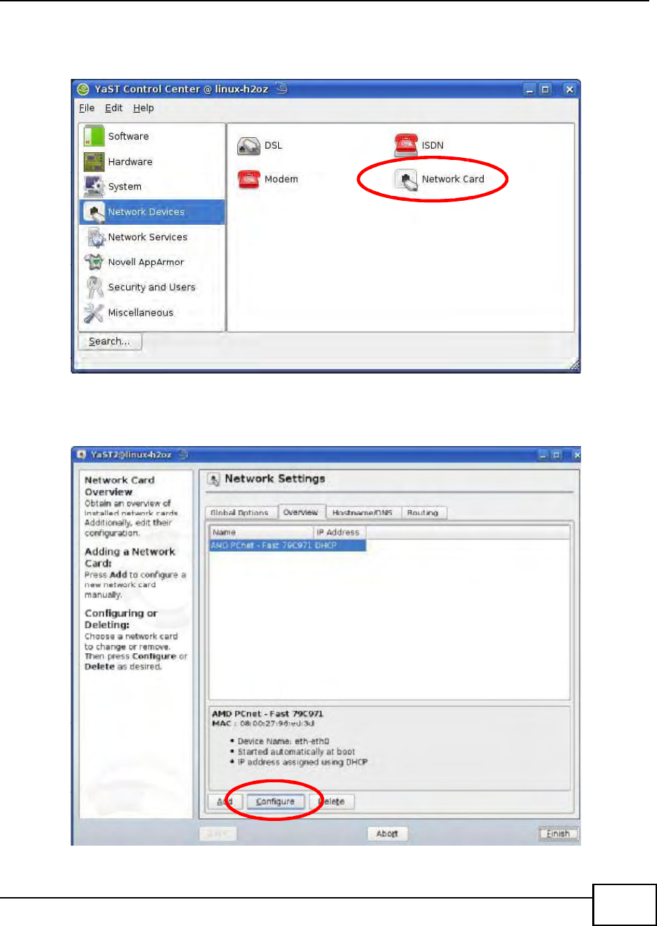
Appendix B Setting Up Your Computers IP Address
BM2022 Users Guide 229
3When the YaST Control Center window opens, select Network Devices and then click the
Network Card icon.
Figure 148 openSUSE 10.3: YaST Control Center
4When the Network Settings window opens, click the Overview tab, select the appropriate
connection Name from the list, and then click the Configure button.
Figure 149 openSUSE 10.3: Network Settings
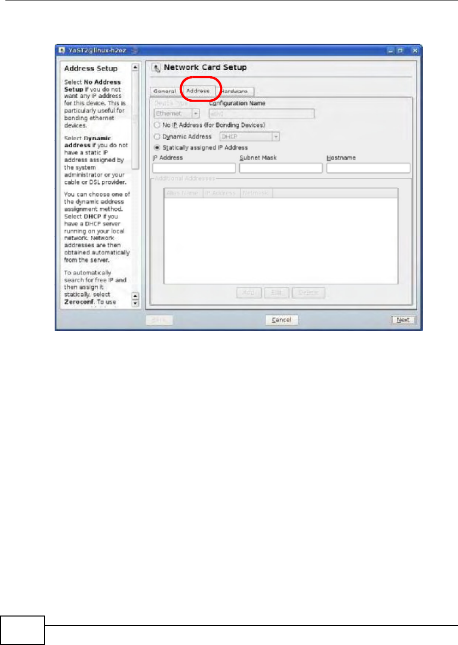
Appendix B Setting Up Your Computers IP Address
BM2022 Users Guide
230
5When the Network Card Setup window opens, click the Address tab
Figure 150 openSUSE 10.3: Network Card Setup
6Select Dynamic Address (DHCP) if you have a dynamic IP address.
Select Statically assigned IP Address if you have a static IP address. Fill in the IP address,
Subnet mask, and Hostname fields.
7Click Next to save the changes and close the Network Card Setup window.
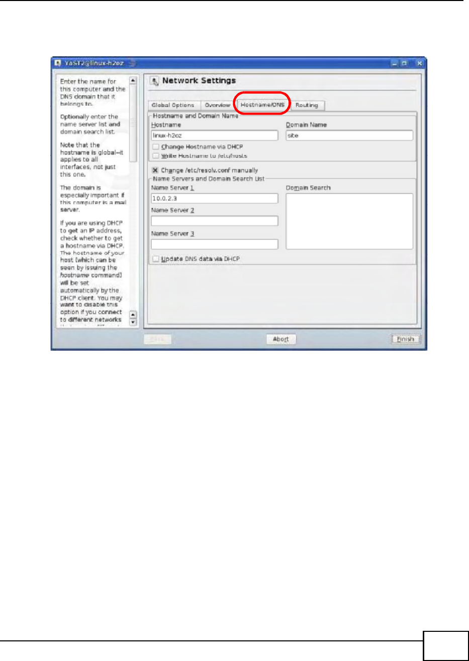
Appendix B Setting Up Your Computers IP Address
BM2022 Users Guide 231
8If you know your DNS server IP address(es), click the Hostname/DNS tab in Network Settings
and then enter the DNS server information in the fields provided.
Figure 151 openSUSE 10.3: Network Settings
9Click Finish to save your settings and close the window.
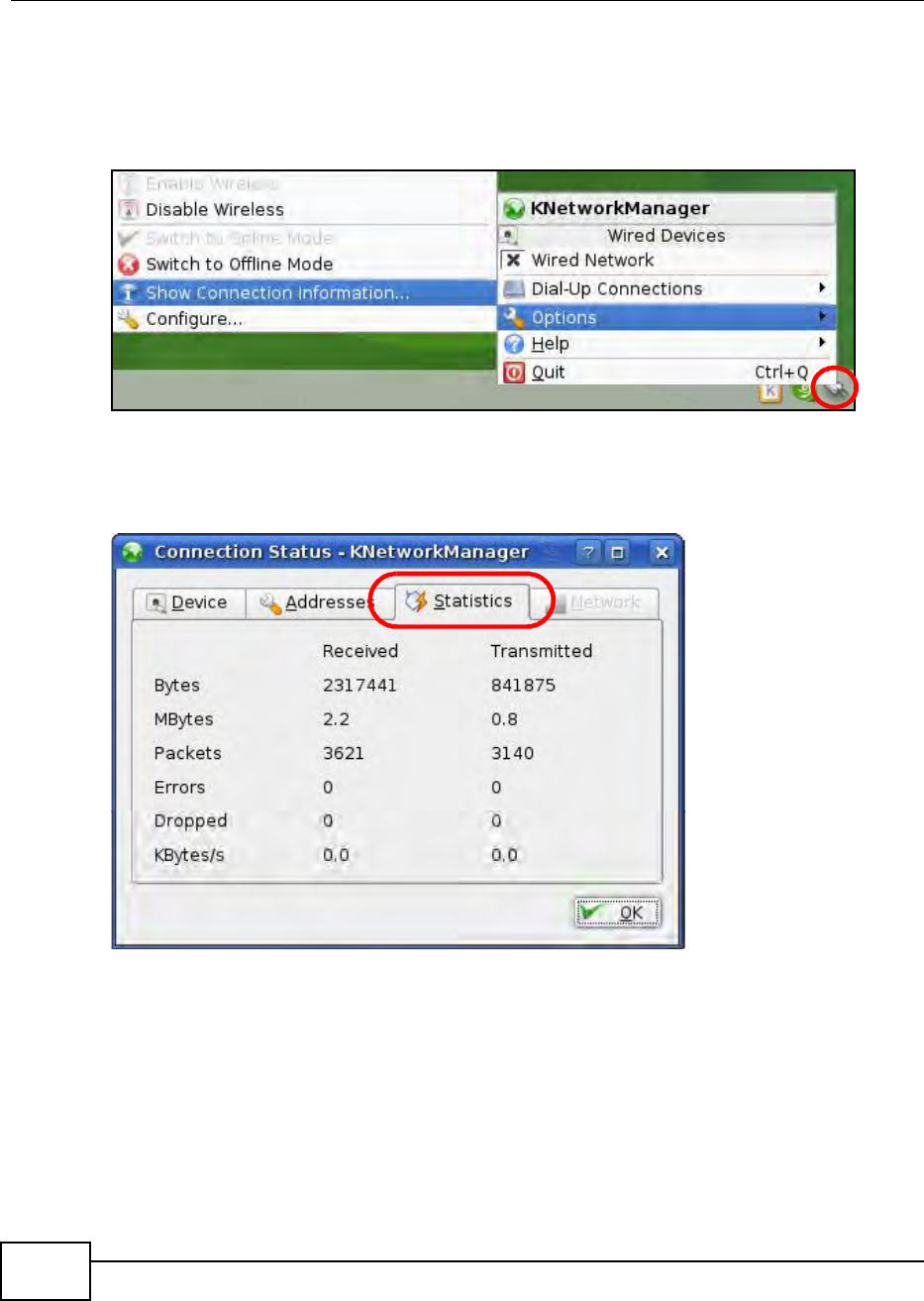
Appendix B Setting Up Your Computers IP Address
BM2022 Users Guide
232
Verifying Settings
Click the KNetwork Manager icon on the Task bar to check your TCP/IP properties. From the
Options sub-menu, select Show Connection Information.
Figure 152 openSUSE 10.3: KNetwork Manager
When the Connection Status - KNetwork Manager window opens, click the Statistics tab to
see if your connection is working properly.
Figure 153 openSUSE: Connection Status - KNetwork Manager
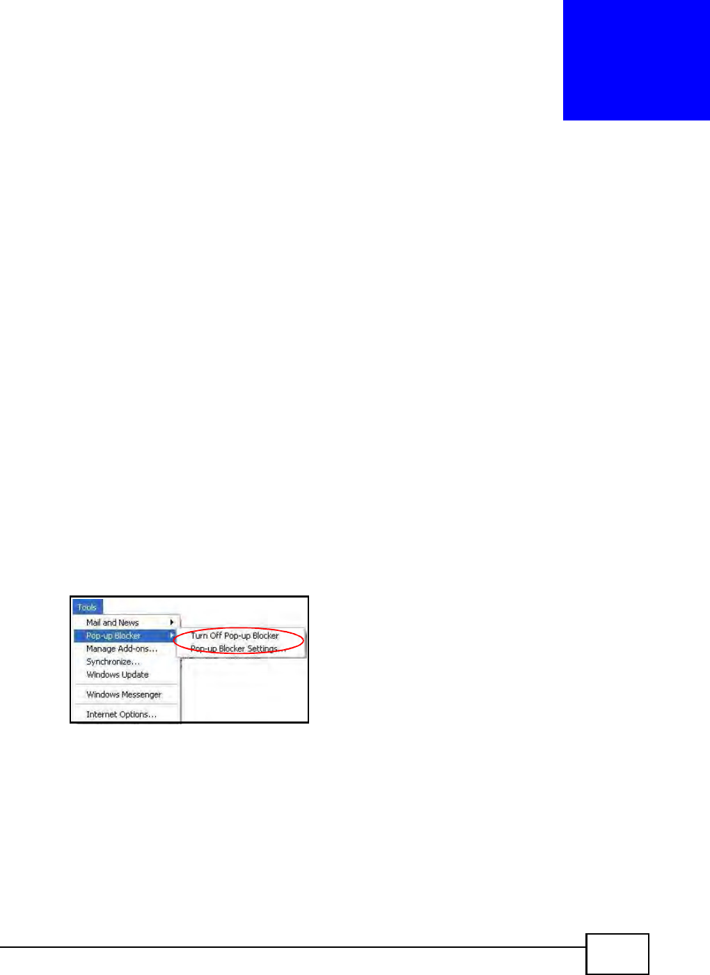
BM2022 Users Guide 233
APPENDIX C
Pop-up Windows, JavaScript and Java
Permissions
In order to use the web configurator you need to allow:
Web browser pop-up windows from your device.
JavaScript (enabled by default).
Java permissions (enabled by default).
Note: Internet Explorer 6 screens are used here. Screens for other Internet Explorer
versions may vary.
Internet Explorer Pop-up Blockers
You may have to disable pop-up blocking to log into your device.
Either disable pop-up blocking (enabled by default in Windows XP SP (Service Pack) 2) or allow
pop-up blocking and create an exception for your devices IP address.
Disable Pop-up Blockers
1In Internet Explorer, select Tools, Pop-up Blocker and then select Turn Off Pop-up Blocker.
Figure 154 Pop-up Blocker
You can also check if pop-up blocking is disabled in the Pop-up Blocker section in the Privacy tab.
1In Internet Explorer, select Tools, Internet Options, Privacy.
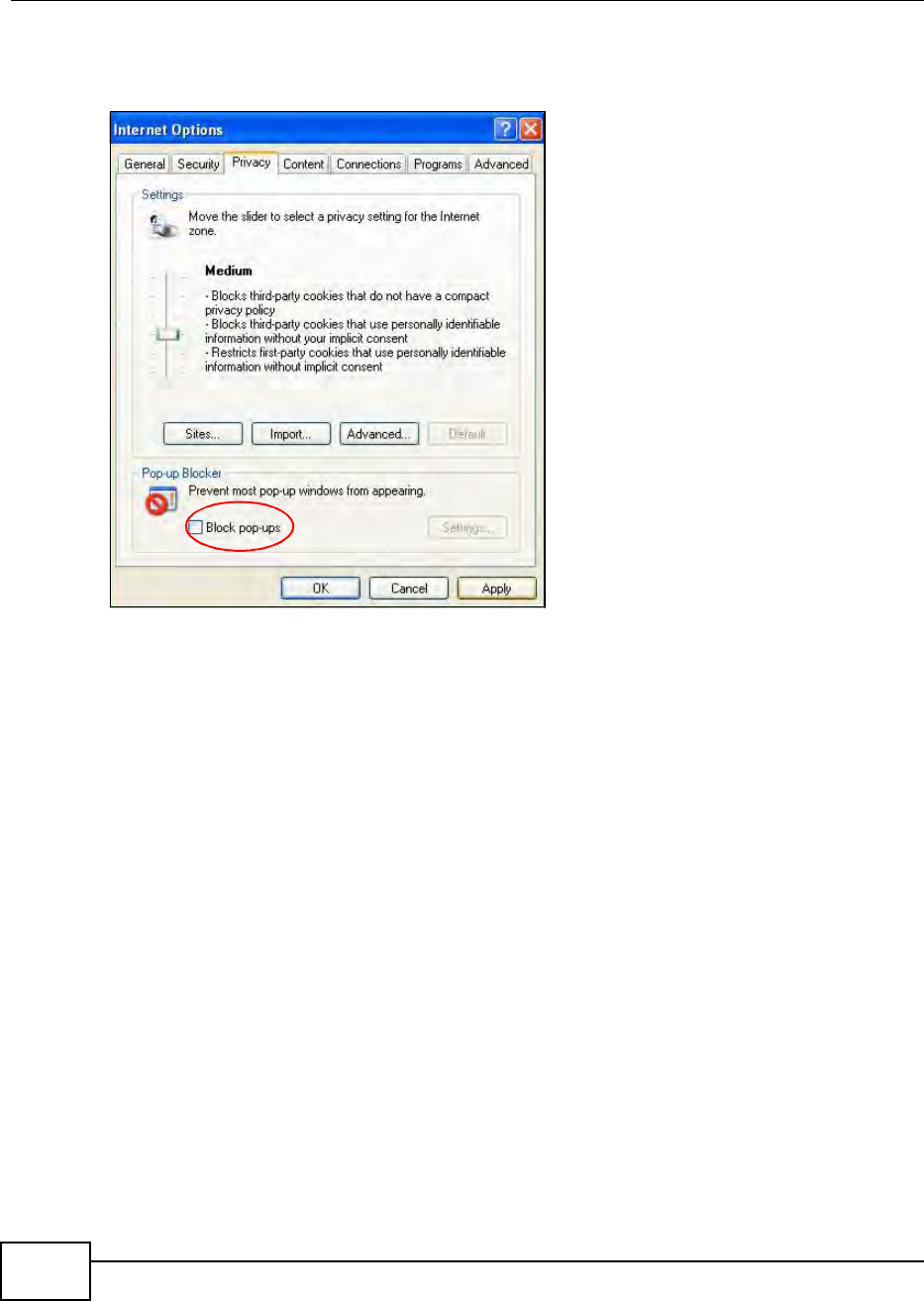
Appendix C Pop-up Windows, JavaScript and Java Permissions
BM2022 Users Guide
234
2Clear the Block pop-ups check box in the Pop-up Blocker section of the screen. This disables any
web pop-up blockers you may have enabled.
Figure 155 Internet Options: Privacy
3Click Apply to save this setting.
Enable Pop-up Blockers with Exceptions
Alternatively, if you only want to allow pop-up windows from your device, see the following steps.
1In Internet Explorer, select Tools, Internet Options and then the Privacy tab.
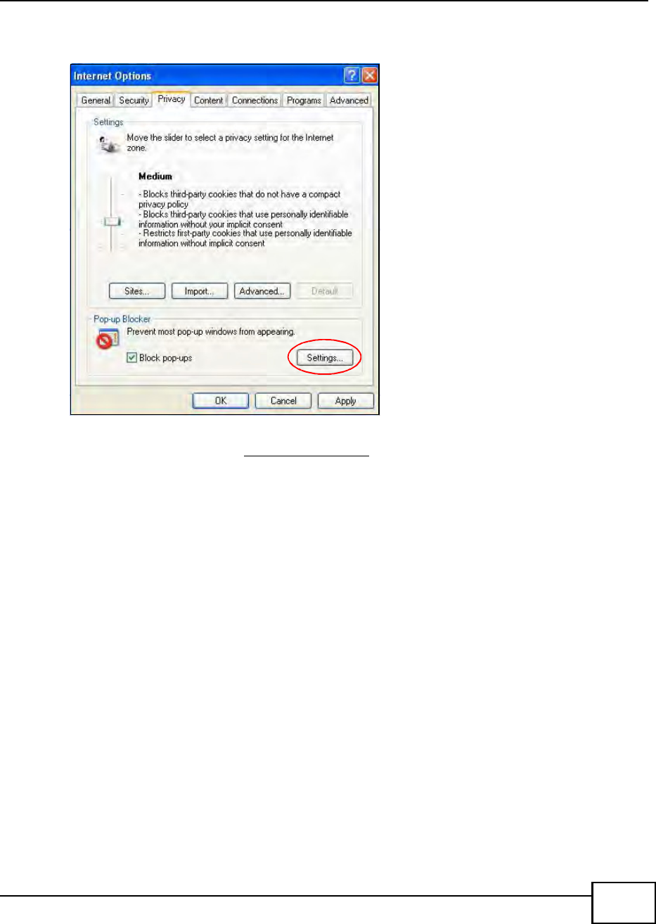
Appendix C Pop-up Windows, JavaScript and Java Permissions
BM2022 Users Guide 235
2Select Settingsto open the Pop-up Blocker Settings screen.
Figure 156 Internet Options: Privacy
3Type the IP address of your device (the web page that you do not want to have blocked) with the
prefix http://. For example, http://192.168.167.1.
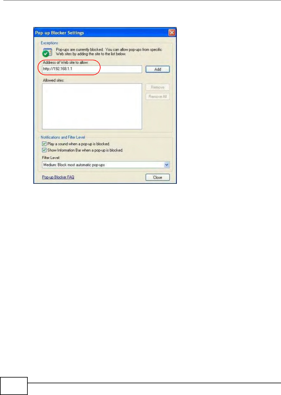
Appendix C Pop-up Windows, JavaScript and Java Permissions
BM2022 Users Guide
236
4Click Add to move the IP address to the list of Allowed sites.
Figure 157 Pop-up Blocker Settings
5Click Close to return to the Privacy screen.
6Click Apply to save this setting.
JavaScript
If pages of the web configurator do not display properly in Internet Explorer, check that JavaScript
is allowed.
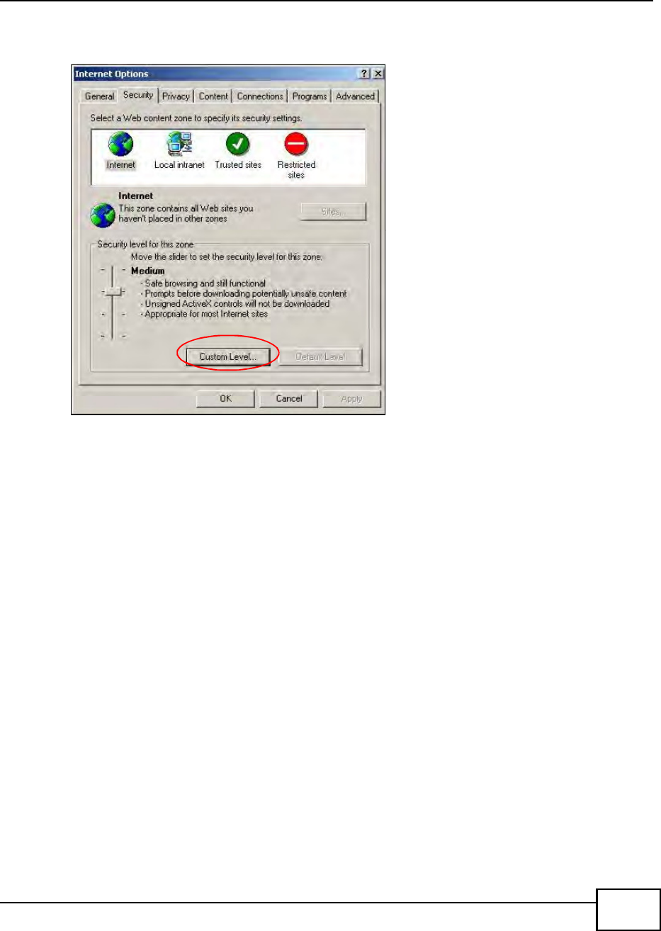
Appendix C Pop-up Windows, JavaScript and Java Permissions
BM2022 Users Guide 237
1In Internet Explorer, click Tools, Internet Options and then the Security tab.
Figure 158 Internet Options: Security
2Click the Custom Level... button.
3Scroll down to Scripting.
4Under Active scripting make sure that Enable is selected (the default).
5Under Scripting of Java applets make sure that Enable is selected (the default).
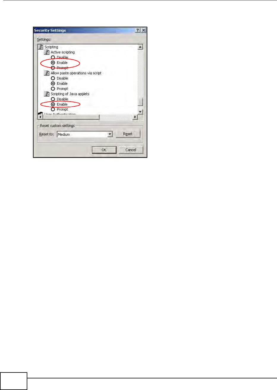
Appendix C Pop-up Windows, JavaScript and Java Permissions
BM2022 Users Guide
238
6Click OK to close the window.
Figure 159 Security Settings - Java Scripting
Java Permissions
1From Internet Explorer, click Tools, Internet Options and then the Security tab.
2Click the Custom Level... button.
3Scroll down to Microsoft VM.
4Under Java permissions make sure that a safety level is selected.
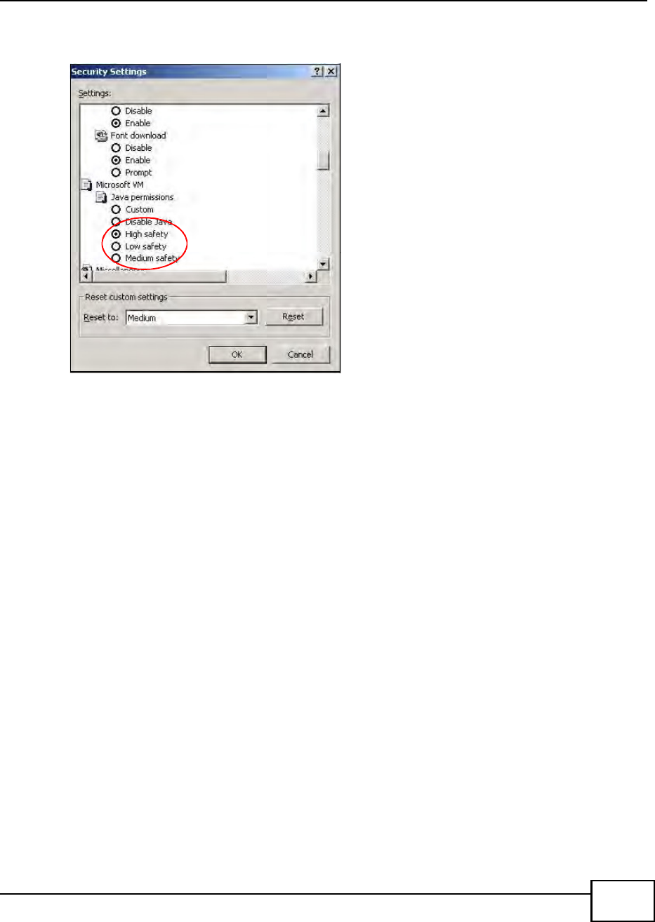
Appendix C Pop-up Windows, JavaScript and Java Permissions
BM2022 Users Guide 239
5Click OK to close the window.
Figure 160 Security Settings - Java
JAVA (Sun)
1From Internet Explorer, click Tools, Internet Options and then the Advanced tab.
2Make sure that Use Java 2 for <applet> under Java (Sun) is selected.
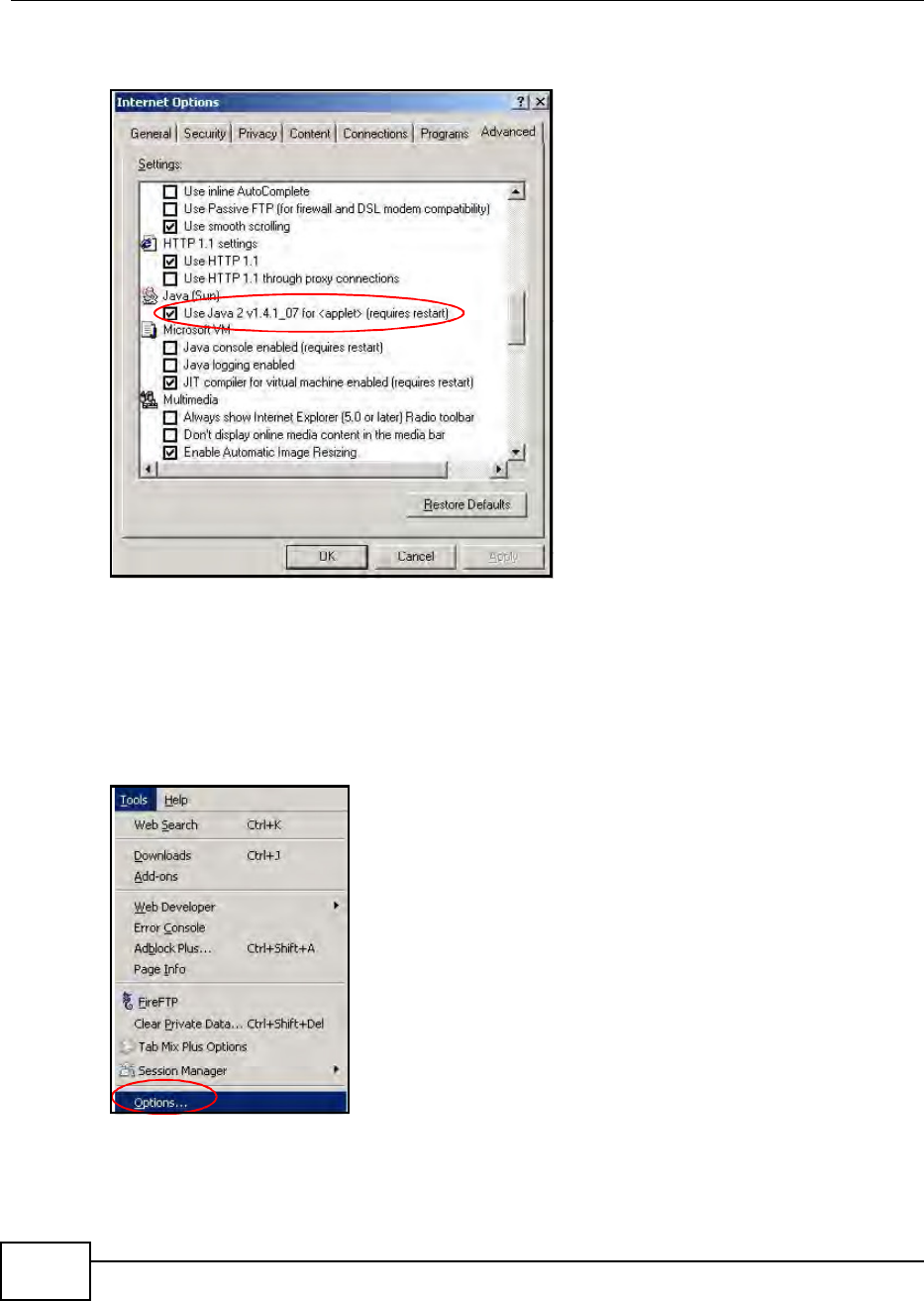
Appendix C Pop-up Windows, JavaScript and Java Permissions
BM2022 Users Guide
240
3Click OK to close the window.
Figure 161 Java (Sun)
Mozilla Firefox
Mozilla Firefox 2.0 screens are used here. Screens for other versions may vary.
You can enable Java, Javascript and pop-ups in one screen. Click Tools, then click Options in the
screen that appears.
Figure 162 Mozilla Firefox: TOOLS > Options
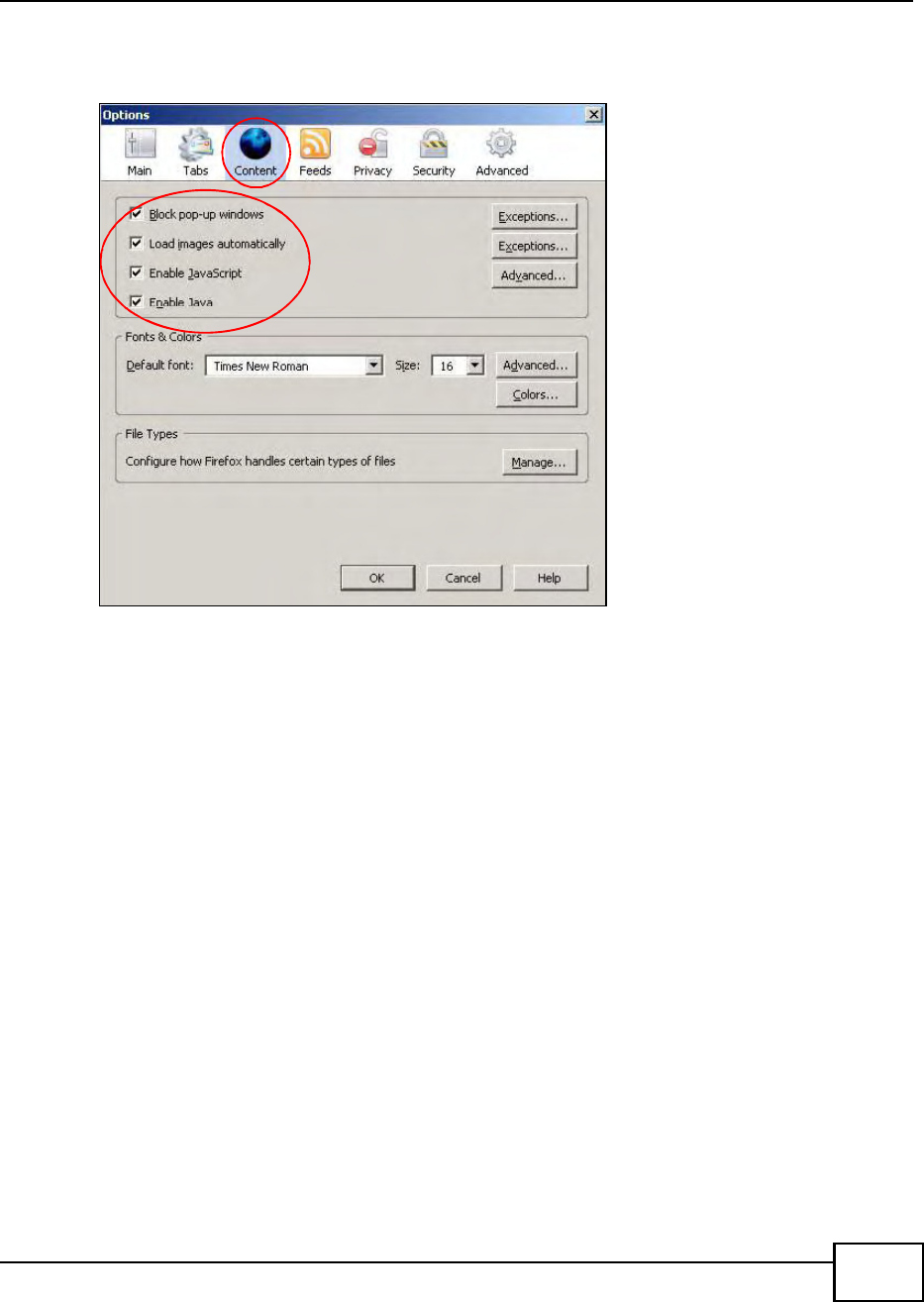
Appendix C Pop-up Windows, JavaScript and Java Permissions
BM2022 Users Guide 241
Click Content.to show the screen below. Select the check boxes as shown in the following screen.
Figure 163 Mozilla Firefox Content Security

Appendix C Pop-up Windows, JavaScript and Java Permissions
BM2022 Users Guide
242

BM2022 Users Guide 243
APPENDIX D
IP Addresses and Subnetting
This appendix introduces IP addresses and subnet masks.
IP addresses identify individual devices on a network. Every networking device (including
computers, servers, routers, printers, etc.) needs an IP address to communicate across the
network. These networking devices are also known as hosts.
Subnet masks determine the maximum number of possible hosts on a network. You can also use
subnet masks to divide one network into multiple sub-networks.
Introduction to IP Addresses
One part of the IP address is the network number, and the other part is the host ID. In the same
way that houses on a street share a common street name, the hosts on a network share a common
network number. Similarly, as each house has its own house number, each host on the network has
its own unique identifying number - the host ID. Routers use the network number to send packets
to the correct network, while the host ID determines to which host on the network the packets are
delivered.
Structure
An IP address is made up of four parts, written in dotted decimal notation. Each of these four parts
is known as an octet. An octet is an eight-digit binary number (for example 11000000, which is 192
in decimal notation).
Therefore, each octet has a possible range of 00000000 to 11111111 in binary, or 0 to 255 in
decimal.
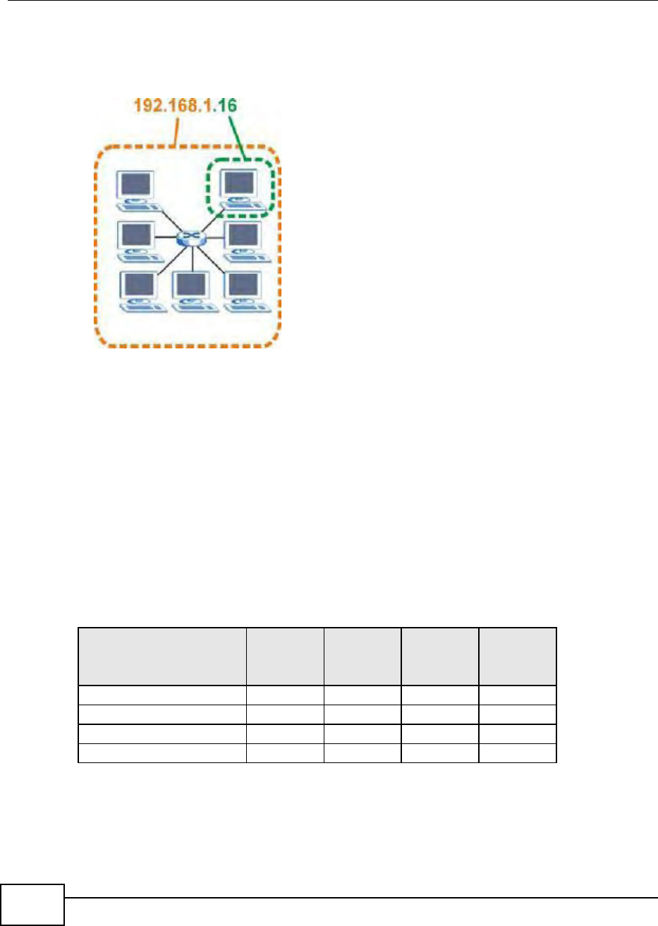
Appendix D IP Addresses and Subnetting
BM2022 Users Guide
244
The following figure shows an example IP address in which the first three octets (192.168.1) are
the network number, and the fourth octet (16) is the host ID.
Figure 164 Network Number and Host ID
How much of the IP address is the network number and how much is the host ID varies according
to the subnet mask.
Subnet Masks
A subnet mask is used to determine which bits are part of the network number, and which bits are
part of the host ID (using a logical AND operation). The term subnet is short for sub-network.
A subnet mask has 32 bits. If a bit in the subnet mask is a 1 then the corresponding bit in the IP
address is part of the network number. If a bit in the subnet mask is 0 then the corresponding bit
in the IP address is part of the host ID.
The following example shows a subnet mask identifying the network number (in bold text) and host
ID of an IP address (192.168.1.2 in decimal).
By convention, subnet masks always consist of a continuous sequence of ones beginning from the
leftmost bit of the mask, followed by a continuous sequence of zeros, for a total number of 32 bits.
Table 104 IP Address Network Number and Host ID Example
1ST OCTET:
(192)
2ND
OCTET:
(168)
3RD
OCTET:
(1)
4TH OCTET
(2)
IP Address (Binary) 11000000 10101000 00000001 00000010
Subnet Mask (Binary) 11111111 11111111 11111111 00000000
Network Number 11000000 10101000 00000001
Host ID 00000010

Appendix D IP Addresses and Subnetting
BM2022 Users Guide 245
Subnet masks can be referred to by the size of the network number part (the bits with a 1 value).
For example, an 8-bit mask means that the first 8 bits of the mask are ones and the remaining 24
bits are zeroes.
Subnet masks are expressed in dotted decimal notation just like IP addresses. The following
examples show the binary and decimal notation for 8-bit, 16-bit, 24-bit and 29-bit subnet masks.
Network Size
The size of the network number determines the maximum number of possible hosts you can have
on your network. The larger the number of network number bits, the smaller the number of
remaining host ID bits.
An IP address with host IDs of all zeros is the IP address of the network (192.168.1.0 with a 24-bit
subnet mask, for example). An IP address with host IDs of all ones is the broadcast address for that
network (192.168.1.255 with a 24-bit subnet mask, for example).
As these two IP addresses cannot be used for individual hosts, calculate the maximum number of
possible hosts in a network as follows:
Notation
Since the mask is always a continuous number of ones beginning from the left, followed by a
continuous number of zeros for the remainder of the 32 bit mask, you can simply specify the
number of ones instead of writing the value of each octet. This is usually specified by writing a /
followed by the number of bits in the mask after the address.
For example, 192.1.1.0 /25 is equivalent to saying 192.1.1.0 with subnet mask 255.255.255.128.
Table 105 Subnet Masks
BINARY
DECIMAL
1ST
OCTET
2ND
OCTET
3RD
OCTET 4TH OCTET
8-bit mask 11111111 00000000 00000000 00000000 255.0.0.0
16-bit mask 11111111 11111111 00000000 00000000 255.255.0.0
24-bit mask 11111111 11111111 11111111 00000000 255.255.255.0
29-bit mask 11111111 11111111 11111111 11111000 255.255.255.248
Table 106 Maximum Host Numbers
SUBNET MASK HOST ID SIZE MAXIMUM NUMBER OF HOSTS
8 bits 255.0.0.0 24 bits 224 2 16777214
16 bits 255.255.0.0 16 bits 216 2 65534
24 bits 255.255.255.0 8 bits 28 2 254
29 bits 255.255.255.24
8
3 bits 23 2 6
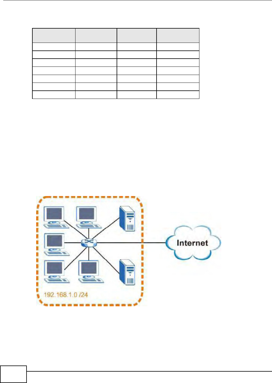
Appendix D IP Addresses and Subnetting
BM2022 Users Guide
246
The following table shows some possible subnet masks using both notations.
Subnetting
You can use subnetting to divide one network into multiple sub-networks. In the following example
a network administrator creates two sub-networks to isolate a group of servers from the rest of the
company network for security reasons.
In this example, the company network address is 192.168.1.0. The first three octets of the address
(192.168.1) are the network number, and the remaining octet is the host ID, allowing a maximum
of 28 2 or 254 possible hosts.
The following figure shows the company network before subnetting.
Figure 165 Subnetting Example: Before Subnetting
You can borrow one of the host ID bits to divide the network 192.168.1.0 into two separate sub-
networks. The subnet mask is now 25 bits (255.255.255.128 or /25).
The borrowed host ID bit can have a value of either 0 or 1, allowing two subnets; 192.168.1.0 /25
and 192.168.1.128 /25.
Table 107 Alternative Subnet Mask Notation
SUBNET MASK ALTERNATIVE
NOTATION
LAST OCTET
(BINARY)
LAST OCTET
(DECIMAL)
255.255.255.0 /24 0000 0000 0
255.255.255.128 /25 1000 0000 128
255.255.255.192 /26 1100 0000 192
255.255.255.224 /27 1110 0000 224
255.255.255.240 /28 1111 0000 240
255.255.255.248 /29 1111 1000 248
255.255.255.252 /30 1111 1100 252
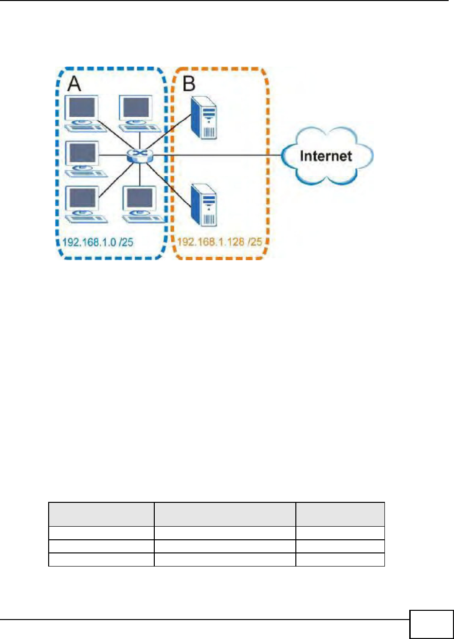
Appendix D IP Addresses and Subnetting
BM2022 Users Guide 247
The following figure shows the company network after subnetting. There are now two sub-
networks, A and B.
Figure 166 Subnetting Example: After Subnetting
In a 25-bit subnet the host ID has 7 bits, so each sub-network has a maximum of 27 2 or 126
possible hosts (a host ID of all zeroes is the subnets address itself, all ones is the subnets
broadcast address).
192.168.1.0 with mask 255.255.255.128 is subnet A itself, and 192.168.1.127 with mask
255.255.255.128 is its broadcast address. Therefore, the lowest IP address that can be assigned to
an actual host for subnet A is 192.168.1.1 and the highest is 192.168.1.126.
Similarly, the host ID range for subnet B is 192.168.1.129 to 192.168.1.254.
Example: Four Subnets
The previous example illustrated using a 25-bit subnet mask to divide a 24-bit address into two
subnets. Similarly, to divide a 24-bit address into four subnets, you need to borrow two host ID
bits to give four possible combinations (00, 01, 10 and 11). The subnet mask is 26 bits
(11111111.11111111.11111111.11000000) or 255.255.255.192.
Each subnet contains 6 host ID bits, giving 26 - 2 or 62 hosts for each subnet (a host ID of all
zeroes is the subnet itself, all ones is the subnets broadcast address).
Table 108 Subnet 1
IP/SUBNET MASK NETWORK NUMBER LAST OCTET BIT
VALUE
IP Address (Decimal) 192.168.1. 0
IP Address (Binary) 11000000.10101000.00000001. 00000000
Subnet Mask (Binary) 11111111.11111111.11111111. 11000000

Appendix D IP Addresses and Subnetting
BM2022 Users Guide
248
Example: Eight Subnets
Similarly, use a 27-bit mask to create eight subnets (000, 001, 010, 011, 100, 101, 110 and 111).
Subnet Address:
192.168.1.0
Lowest Host ID: 192.168.1.1
Broadcast Address:
192.168.1.63
Highest Host ID: 192.168.1.62
Table 109 Subnet 2
IP/SUBNET MASK NETWORK NUMBER LAST OCTET BIT
VALUE
IP Address 192.168.1. 64
IP Address (Binary) 11000000.10101000.00000001. 01000000
Subnet Mask (Binary) 11111111.11111111.11111111. 11000000
Subnet Address:
192.168.1.64
Lowest Host ID: 192.168.1.65
Broadcast Address:
192.168.1.127
Highest Host ID: 192.168.1.126
Table 110 Subnet 3
IP/SUBNET MASK NETWORK NUMBER LAST OCTET BIT
VALUE
IP Address 192.168.1. 128
IP Address (Binary) 11000000.10101000.00000001. 10000000
Subnet Mask (Binary) 11111111.11111111.11111111. 11000000
Subnet Address:
192.168.1.128
Lowest Host ID: 192.168.1.129
Broadcast Address:
192.168.1.191
Highest Host ID: 192.168.1.190
Table 111 Subnet 4
IP/SUBNET MASK NETWORK NUMBER LAST OCTET BIT
VALUE
IP Address 192.168.1. 192
IP Address (Binary) 11000000.10101000.00000001. 11000000
Subnet Mask (Binary) 11111111.11111111.11111111. 11000000
Subnet Address:
192.168.1.192
Lowest Host ID: 192.168.1.193
Broadcast Address:
192.168.1.255
Highest Host ID: 192.168.1.254
Table 108 Subnet 1 (continued)
IP/SUBNET MASK NETWORK NUMBER LAST OCTET BIT
VALUE

Appendix D IP Addresses and Subnetting
BM2022 Users Guide 249
The following table shows IP address last octet values for each subnet.
Subnet Planning
The following table is a summary for subnet planning on a network with a 24-bit network number.
The following table is a summary for subnet planning on a network with a 16-bit network number.
Table 112 Eight Subnets
SUBNET SUBNET
ADDRESS FIRST ADDRESS LAST
ADDRESS
BROADCAST
ADDRESS
1 0 1 30 31
2 32 33 62 63
3 64 65 94 95
4 96 97 126 127
5 128 129 158 159
6 160 161 190 191
7 192 193 222 223
8 224 225 254 255
Table 113 24-bit Network Number Subnet Planning
NO. BORROWED
HOST BITS SUBNET MASK NO. SUBNETS NO. HOSTS PER
SUBNET
1255.255.255.128 (/25) 2 126
2255.255.255.192 (/26) 4 62
3255.255.255.224 (/27) 8 30
4255.255.255.240 (/28) 16 14
5255.255.255.248 (/29) 32 6
6255.255.255.252 (/30) 64 2
7255.255.255.254 (/31) 128 1
Table 114 16-bit Network Number Subnet Planning
NO. BORROWED
HOST BITS SUBNET MASK NO. SUBNETS NO. HOSTS PER
SUBNET
1255.255.128.0 (/17) 2 32766
2255.255.192.0 (/18) 4 16382
3255.255.224.0 (/19) 8 8190
4255.255.240.0 (/20) 16 4094
5255.255.248.0 (/21) 32 2046
6255.255.252.0 (/22) 64 1022
7255.255.254.0 (/23) 128 510
8255.255.255.0 (/24) 256 254
9255.255.255.128 (/25) 512 126
10 255.255.255.192 (/26) 1024 62
11 255.255.255.224 (/27) 2048 30
12 255.255.255.240 (/28) 4096 14

Appendix D IP Addresses and Subnetting
BM2022 Users Guide
250
Configuring IP Addresses
Where you obtain your network number depends on your particular situation. If the ISP or your
network administrator assigns you a block of registered IP addresses, follow their instructions in
selecting the IP addresses and the subnet mask.
If the ISP did not explicitly give you an IP network number, then most likely you have a single user
account and the ISP will assign you a dynamic IP address when the connection is established. If this
is the case, it is recommended that you select a network number from 192.168.0.0 to
192.168.255.0. The Internet Assigned Number Authority (IANA) reserved this block of addresses
specifically for private use; please do not use any other number unless you are told otherwise. You
must also enable Network Address Translation (NAT) on the BM2022.
Once you have decided on the network number, pick an IP address for your BM2022 that is easy to
remember (for instance, 192.168.1.1) but make sure that no other device on your network is using
that IP address.
The subnet mask specifies the network number portion of an IP address. Your BM2022 will compute
the subnet mask automatically based on the IP address that you entered. You don't need to change
the subnet mask computed by the BM2022 unless you are instructed to do otherwise.
Private IP Addresses
Every machine on the Internet must have a unique address. If your networks are isolated from the
Internet (running only between two branch offices, for example) you can assign any IP addresses to
the hosts without problems. However, the Internet Assigned Numbers Authority (IANA) has
reserved the following three blocks of IP addresses specifically for private networks:
10.0.0.0 10.255.255.255
172.16.0.0 172.31.255.255
192.168.0.0 192.168.255.255
You can obtain your IP address from the IANA, from an ISP, or it can be assigned from a private
network. If you belong to a small organization and your Internet access is through an ISP, the ISP
can provide you with the Internet addresses for your local networks. On the other hand, if you are
part of a much larger organization, you should consult your network administrator for the
appropriate IP addresses.
Regardless of your particular situation, do not create an arbitrary IP address; always follow the
guidelines above. For more information on address assignment, please refer to RFC 1597, Address
Allocation for Private Internets and RFC 1466, Guidelines for Management of IP Address Space.
13 255.255.255.248 (/29) 8192 6
14 255.255.255.252 (/30) 16384 2
15 255.255.255.254 (/31) 32768 1
Table 114 16-bit Network Number Subnet Planning (continued)
NO. BORROWED
HOST BITS SUBNET MASK NO. SUBNETS NO. HOSTS PER
SUBNET
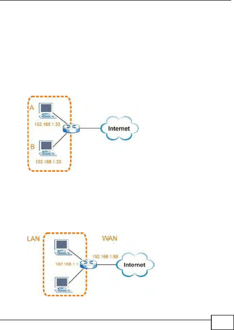
Appendix D IP Addresses and Subnetting
BM2022 Users Guide 251
IP Address Conflicts
Each device on a network must have a unique IP address. Devices with duplicate IP addresses on
the same network will not be able to access the Internet or other resources. The devices may also
be unreachable through the network.
Conflicting Computer IP Addresses Example
More than one device can not use the same IP address. In the following example computer A has a
static (or fixed) IP address that is the same as the IP address that a DHCP server assigns to
computer B which is a DHCP client. Neither can access the Internet. This problem can be solved by
assigning a different static IP address to computer A or setting computer A to obtain an IP address
automatically.
Figure 167 Conflicting Computer IP Addresses Example
Conflicting Router IP Addresses Example
Since a router connects different networks, it must have interfaces using different network
numbers. For example, if a router is set between a LAN and the Internet (WAN), the routers LAN
and WAN addresses must be on different subnets. In the following example, the LAN and WAN are
on the same subnet. The LAN computers cannot access the Internet because the router cannot
route between networks.
Figure 168 Conflicting Computer IP Addresses Example
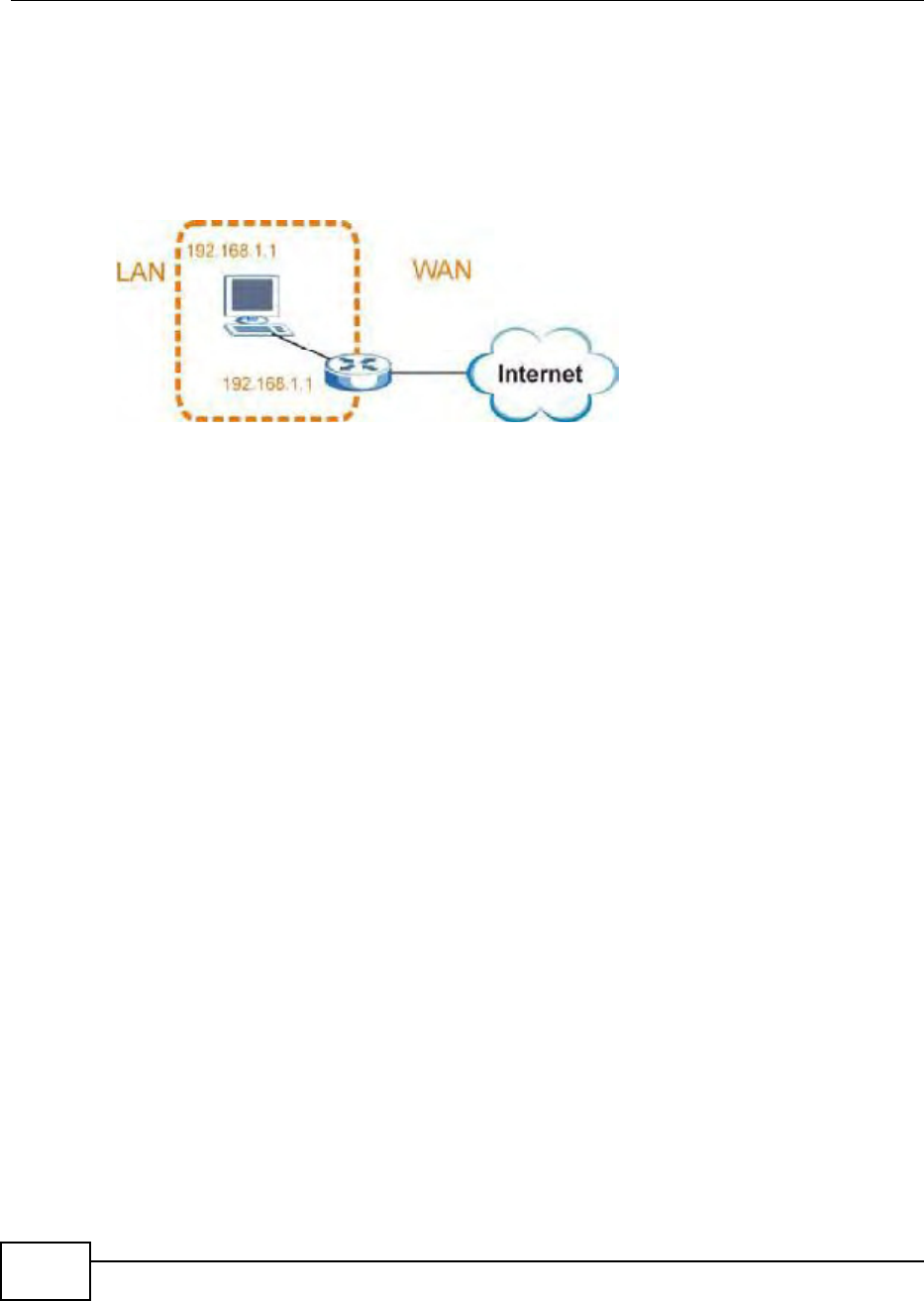
Appendix D IP Addresses and Subnetting
BM2022 Users Guide
252
Conflicting Computer and Router IP Addresses Example
More than one device can not use the same IP address. In the following example, the computer and
the routers LAN port both use 192.168.1.1 as the IP address. The computer cannot access the
Internet. This problem can be solved by assigning a different IP address to the computer or the
routers LAN port.
Figure 169 Conflicting Computer and Router IP Addresses Example

BM2022 Users Guide 253
APPENDIX E
Importing Certificates
This appendix shows you how to import public key certificates into your web browser.
Public key certificates are used by web browsers to ensure that a secure web site is legitimate.
When a certificate authority such as VeriSign, Comodo, or Network Solutions, to name a few,
receives a certificate request from a website operator, they confirm that the web domain and
contact information in the request match those on public record with a domain name registrar. If
they match, then the certificate is issued to the website operator, who then places it on the site to
be issued to all visiting web browsers to let them know that the site is legitimate.
Many Huawei products issue their own public key certificates. These can be used by web browsers
on a LAN or WAN to verify that they are in fact connecting to the legitimate device and not one
masquerading as it. However, because the certificates were not issued by one of the several
organizations officially recognized by the most common web browsers, you will need to import the
Huawei-created certificate into your web browser and flag that certificate as a trusted authority.
Note: You can see if you are browsing on a secure website if the URL in your web
browsers address bar begins with https:// or there is a sealed padlock icon
( ) somewhere in the main browser window (not all browsers show the padlock
in the same location.)
In this appendix, you can import a public key certificate for:
Internet Explorer on page 254
Firefox on page 262
Opera on page 267
Konqueror on page 274
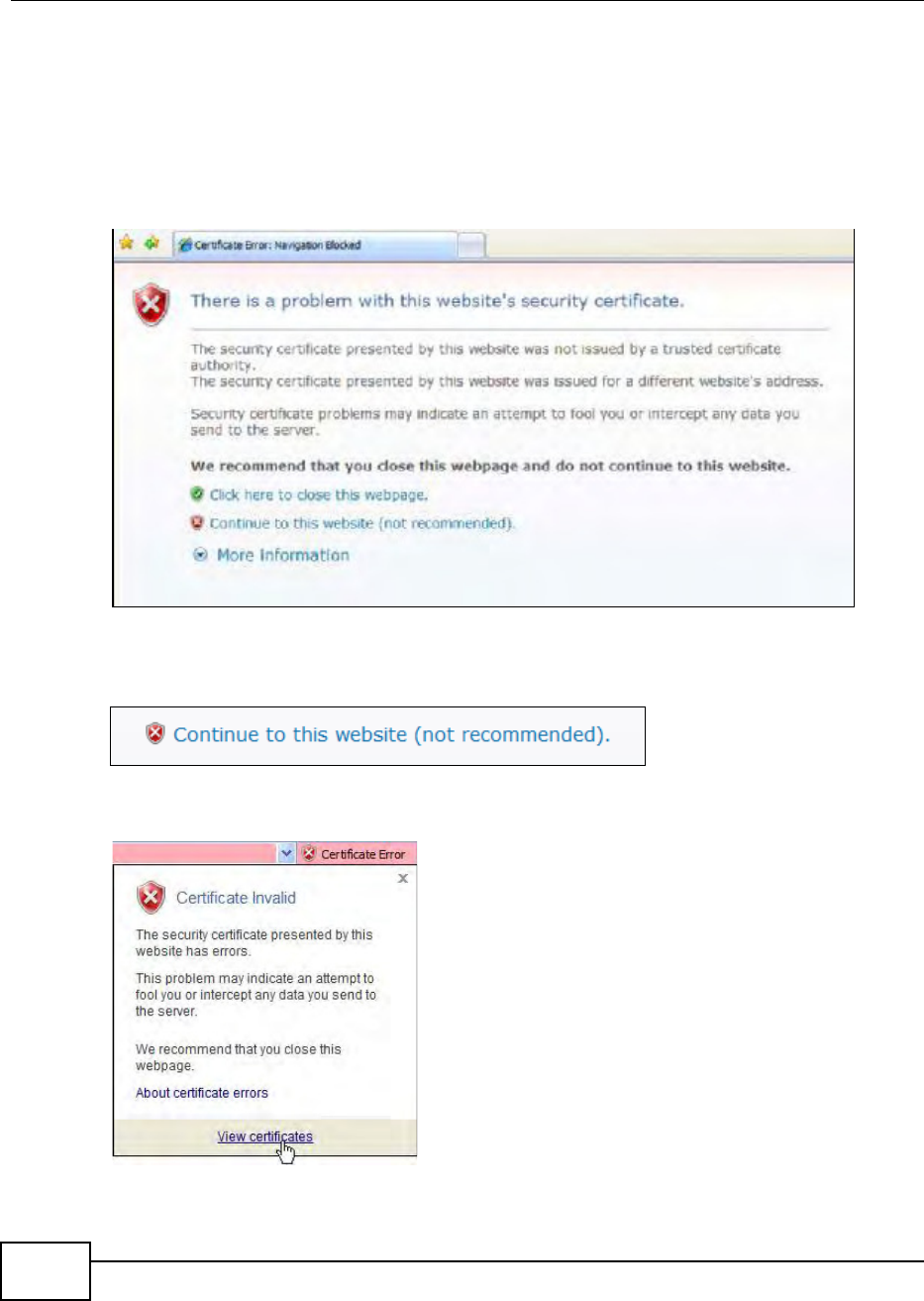
Appendix E Importing Certificates
BM2022 Users Guide
254
Internet Explorer
The following example uses Microsoft Internet Explorer 7 on Windows XP Professional; however,
they can also apply to Internet Explorer on Windows Vista.
1If your devices web configurator is set to use SSL certification, then the first time you browse to it
you are presented with a certification error.
Figure 170 Internet Explorer 7: Certification Error
2Click Continue to this website (not recommended).
Figure 171 Internet Explorer 7: Certification Error
3In the Address Bar, click Certificate Error > View certificates.
Figure 172 Internet Explorer 7: Certificate Error
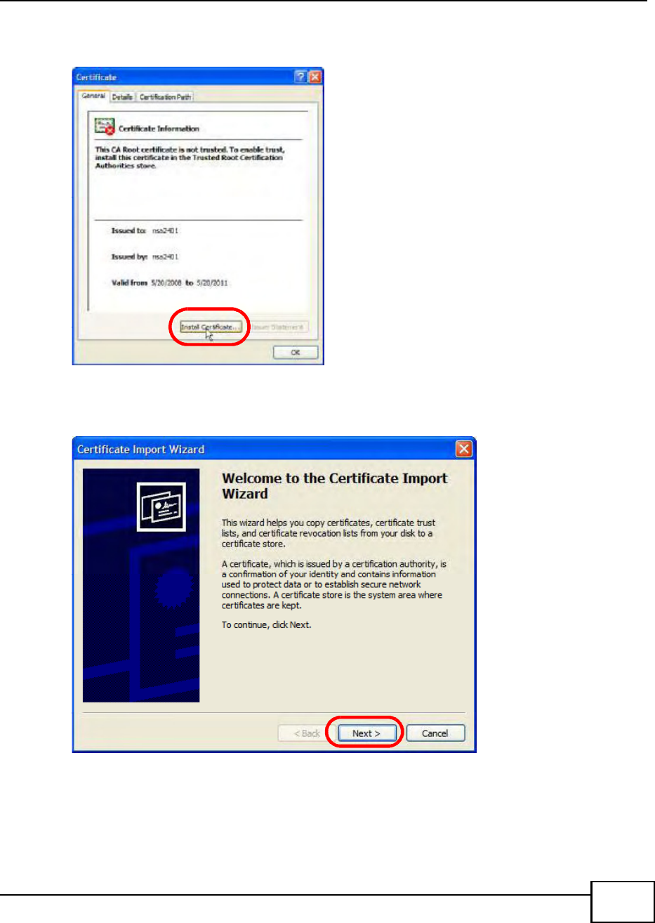
Appendix E Importing Certificates
BM2022 Users Guide 255
4In the Certificate dialog box, click Install Certificate.
Figure 173 Internet Explorer 7: Certificate
5In the Certificate Import Wizard, click Next.
Figure 174 Internet Explorer 7: Certificate Import Wizard
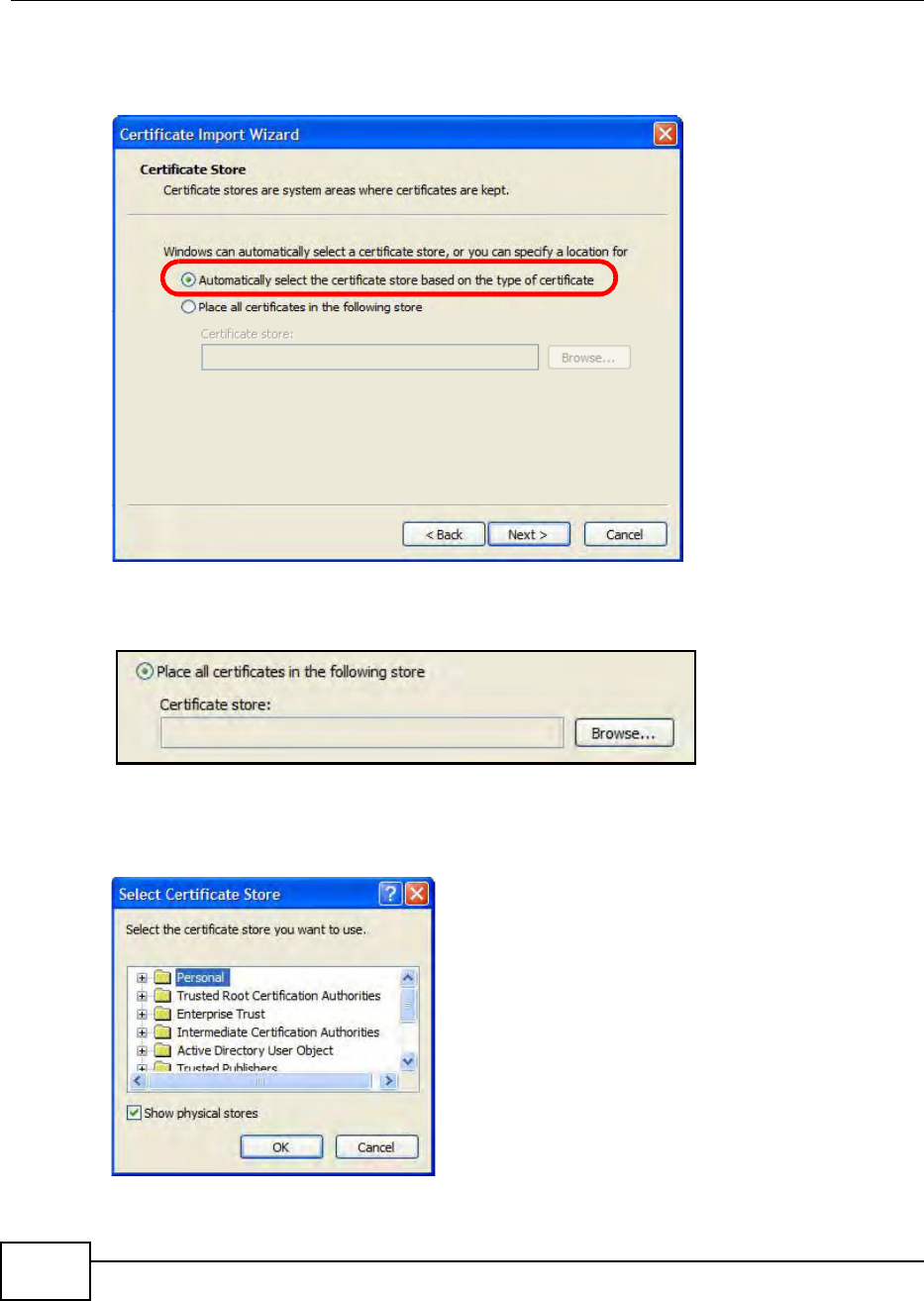
Appendix E Importing Certificates
BM2022 Users Guide
256
6If you want Internet Explorer to Automatically select certificate store based on the type of
certificate, click Next again and then go to step 9.
Figure 175 Internet Explorer 7: Certificate Import Wizard
7Otherwise, select Place all certificates in the following store and then click Browse.
Figure 176 Internet Explorer 7: Certificate Import Wizard
8In the Select Certificate Store dialog box, choose a location in which to save the certificate and
then click OK.
Figure 177 Internet Explorer 7: Select Certificate Store
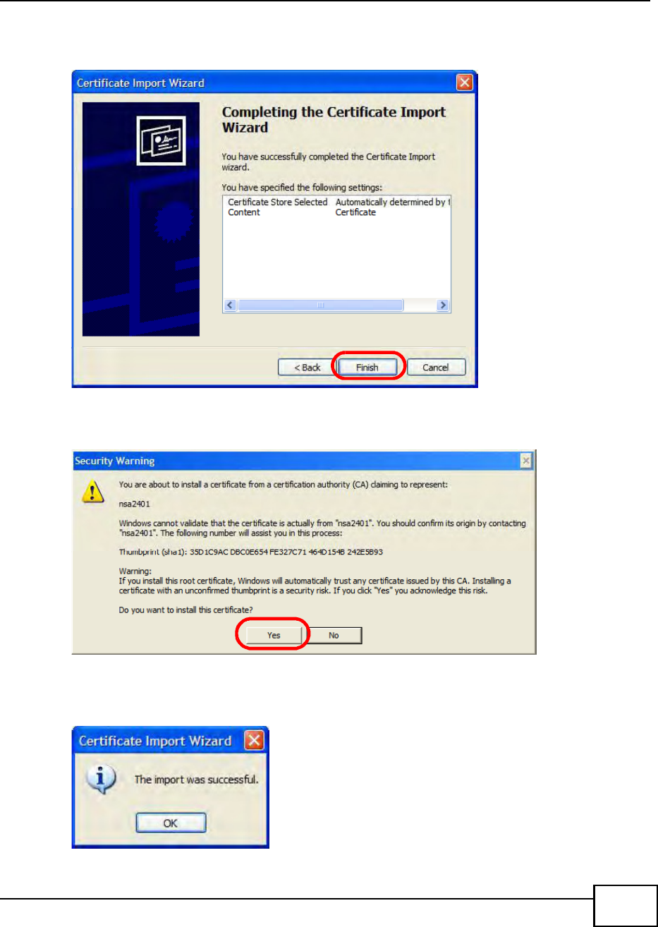
Appendix E Importing Certificates
BM2022 Users Guide 257
9In the Completing the Certificate Import Wizard screen, click Finish.
Figure 178 Internet Explorer 7: Certificate Import Wizard
10 If you are presented with another Security Warning, click Yes.
Figure 179 Internet Explorer 7: Security Warning
11 Finally, click OK when presented with the successful certificate installation message.
Figure 180 Internet Explorer 7: Certificate Import Wizard
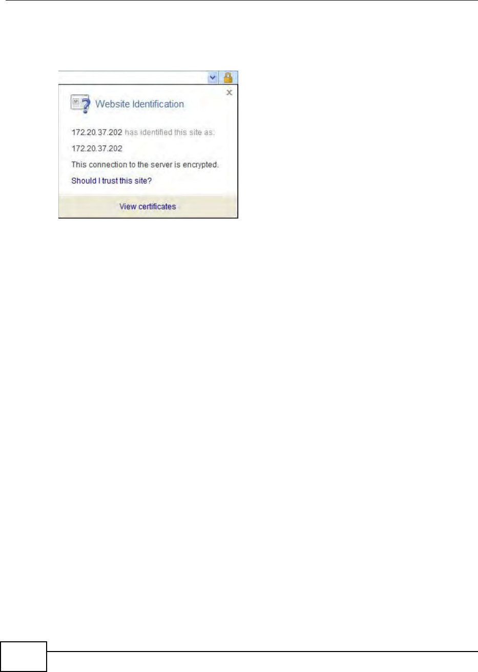
Appendix E Importing Certificates
BM2022 Users Guide
258
12 The next time you start Internet Explorer and go to a Huawei web configurator page, a sealed
padlock icon appears in the address bar. Click it to view the pages Website Identification
information.
Figure 181 Internet Explorer 7: Website Identification
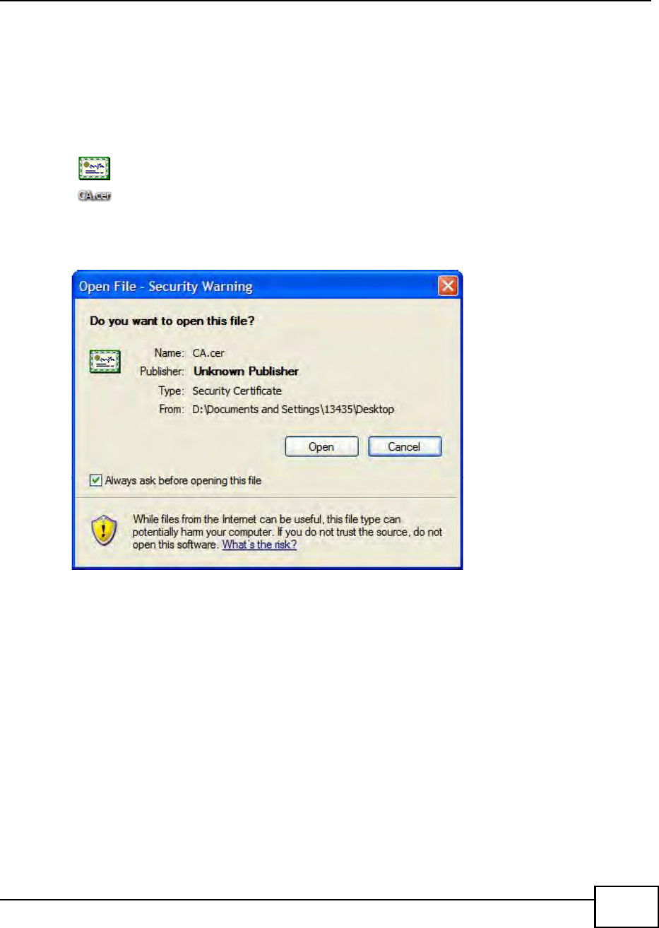
Appendix E Importing Certificates
BM2022 Users Guide 259
Installing a Stand-Alone Certificate File in Internet Explorer
Rather than browsing to a Huawei web configurator and installing a public key certificate when
prompted, you can install a stand-alone certificate file if one has been issued to you.
1Double-click the public key certificate file.
Figure 182 Internet Explorer 7: Public Key Certificate File
2In the security warning dialog box, click Open.
Figure 183 Internet Explorer 7: Open File - Security Warning
3Refer to steps 4-12 in the Internet Explorer procedure beginning on page 254 to complete the
installation process.
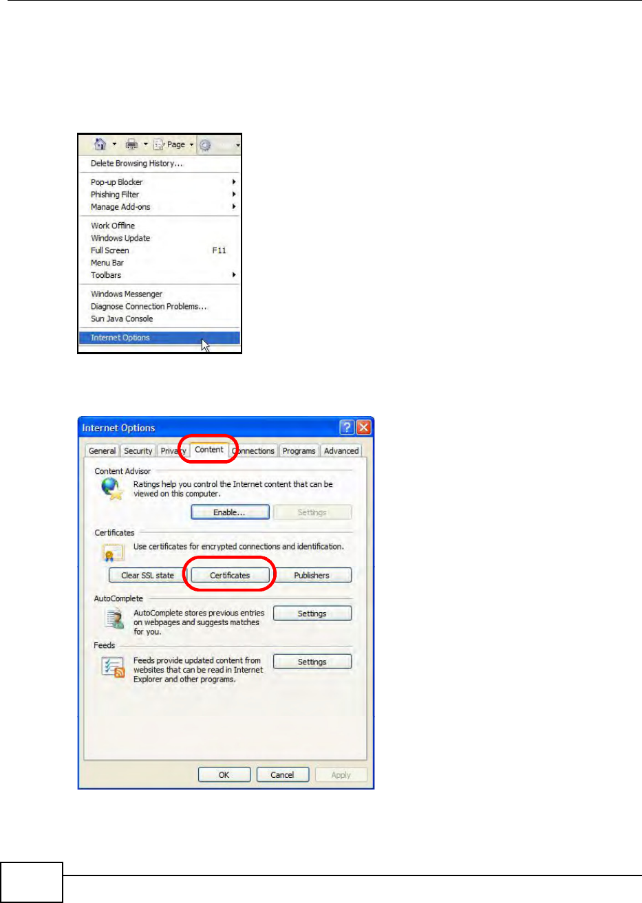
Appendix E Importing Certificates
BM2022 Users Guide
260
Removing a Certificate in Internet Explorer
This section shows you how to remove a public key certificate in Internet Explorer 7.
1Open Internet Explorer and click TOOLS > Internet Options.
Figure 184 Internet Explorer 7: Tools Menu
2In the Internet Options dialog box, click Content > Certificates.
Figure 185 Internet Explorer 7: Internet Options
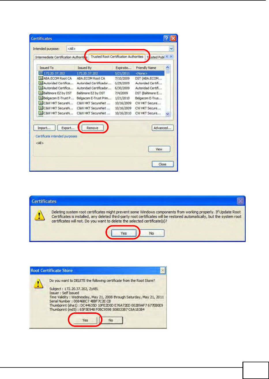
Appendix E Importing Certificates
BM2022 Users Guide 261
3In the Certificates dialog box, click the Trusted Root Certificates Authorities tab, select the
certificate that you want to delete, and then click Remove.
Figure 186 Internet Explorer 7: Certificates
4In the Certificates confirmation, click Yes.
Figure 187 Internet Explorer 7: Certificates
5In the Root Certificate Store dialog box, click Yes.
Figure 188 Internet Explorer 7: Root Certificate Store
6The next time you go to the web site that issued the public key certificate you just removed, a
certification error appears.
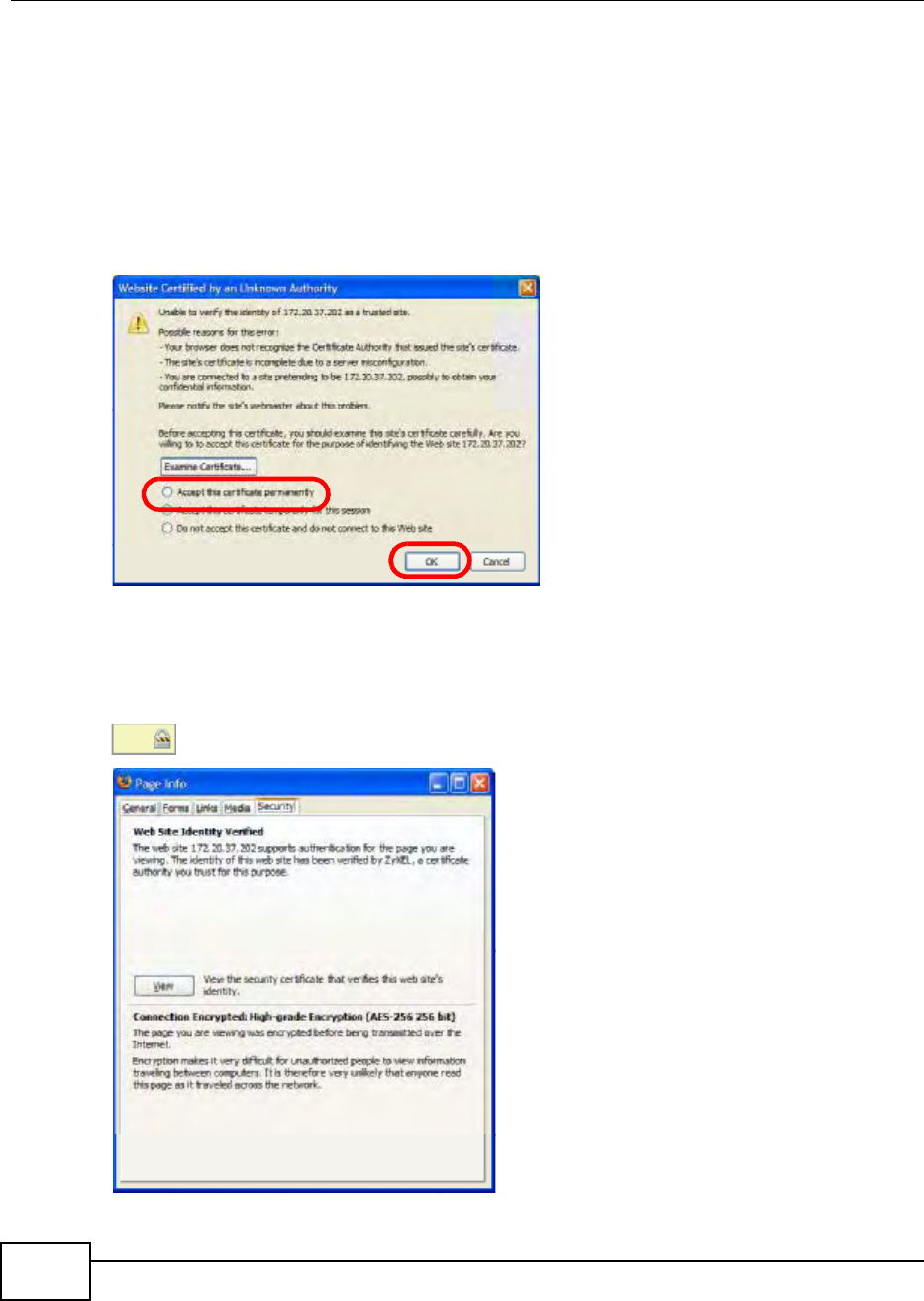
Appendix E Importing Certificates
BM2022 Users Guide
262
Firefox
The following example uses Mozilla Firefox 2 on Windows XP Professional; however, the screens can
also apply to Firefox 2 on all platforms.
1If your devices web configurator is set to use SSL certification, then the first time you browse to it
you are presented with a certification error.
2Select Accept this certificate permanently and click OK.
Figure 189 Firefox 2: Website Certified by an Unknown Authority
3The certificate is stored and you can now connect securely to the web configurator. A sealed
padlock appears in the address bar, which you can click to open the Page Info > Security window
to view the web pages security information.
Figure 190 Firefox 2: Page Info
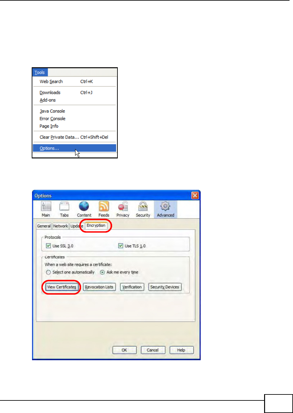
Appendix E Importing Certificates
BM2022 Users Guide 263
Installing a Stand-Alone Certificate File in Firefox
Rather than browsing to a Huawei web configurator and installing a public key certificate when
prompted, you can install a stand-alone certificate file if one has been issued to you.
1Open Firefox and click TOOLS > Options.
Figure 191 Firefox 2: Tools Menu
2In the Options dialog box, click ADVANCED > Encryption > View Certificates.
Figure 192 Firefox 2: Options
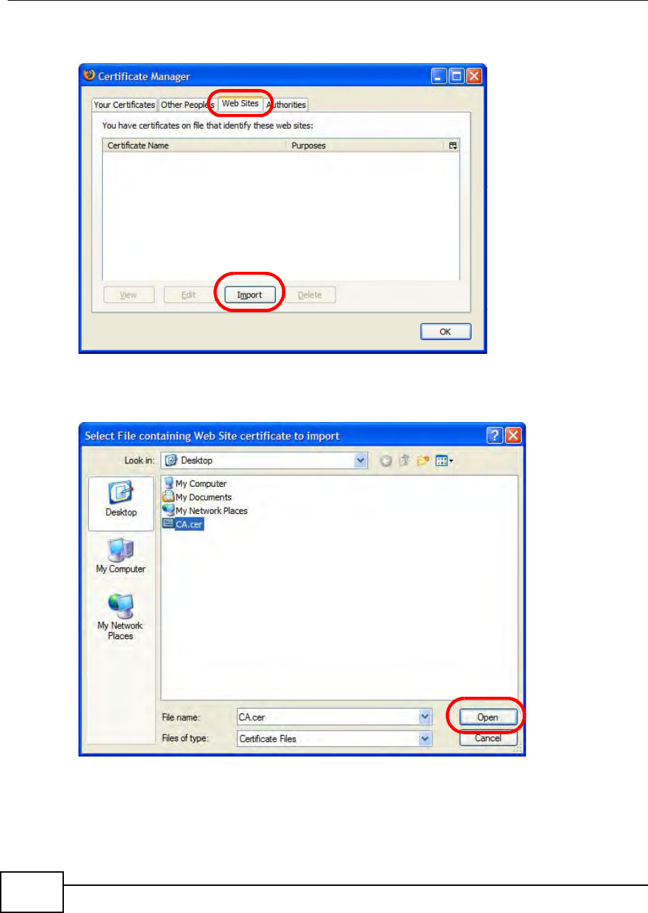
Appendix E Importing Certificates
BM2022 Users Guide
264
3In the Certificate Manager dialog box, click Web Sites > Import.
Figure 193 Firefox 2: Certificate Manager
4Use the Select File dialog box to locate the certificate and then click Open.
Figure 194 Firefox 2: Select File
5The next time you visit the web site, click the padlock in the address bar to open the Page Info >
Security window to see the web pages security information.
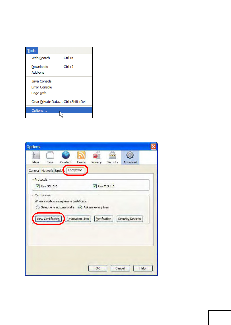
Appendix E Importing Certificates
BM2022 Users Guide 265
Removing a Certificate in Firefox
This section shows you how to remove a public key certificate in Firefox 2.
1Open Firefox and click TOOLS > Options.
Figure 195 Firefox 2: Tools Menu
2In the Options dialog box, click ADVANCED > Encryption > View Certificates.
Figure 196 Firefox 2: Options
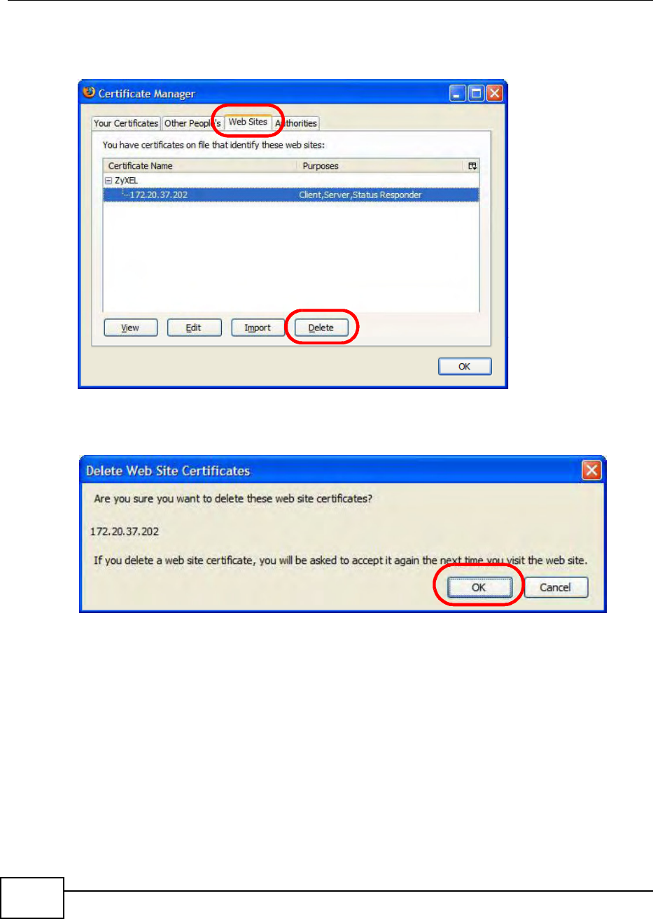
Appendix E Importing Certificates
BM2022 Users Guide
266
3In the Certificate Manager dialog box, select the Web Sites tab, select the certificate that you
want to remove, and then click Delete.
Figure 197 Firefox 2: Certificate Manager
4In the Delete Web Site Certificates dialog box, click OK.
Figure 198 Firefox 2: Delete Web Site Certificates
5The next time you go to the web site that issued the public key certificate you just removed, a
certification error appears.
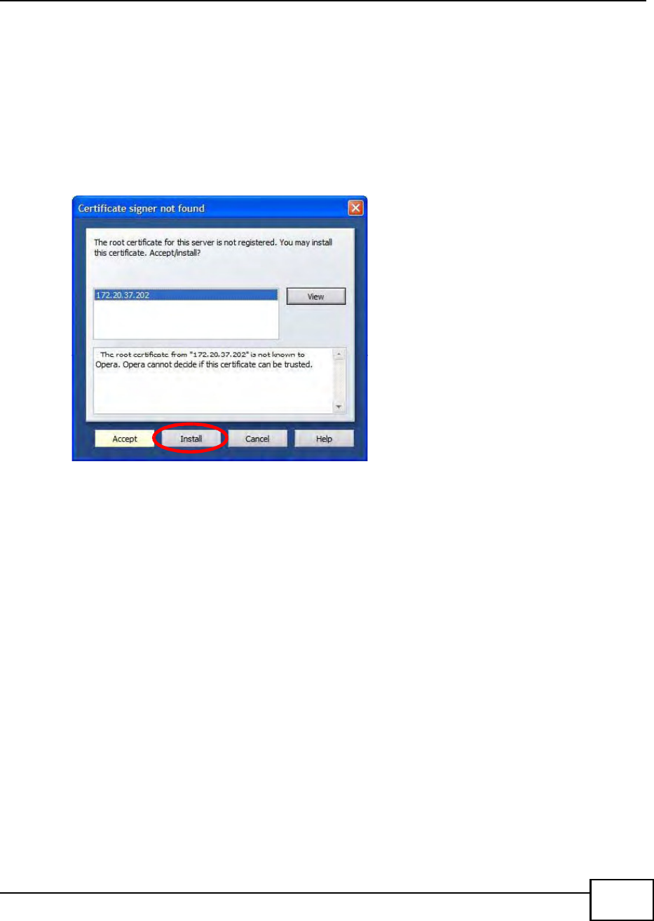
Appendix E Importing Certificates
BM2022 Users Guide 267
Opera
The following example uses Opera 9 on Windows XP Professional; however, the screens can apply
to Opera 9 on all platforms.
1If your devices web configurator is set to use SSL certification, then the first time you browse to it
you are presented with a certification error.
2Click Install to accept the certificate.
Figure 199 Opera 9: Certificate signer not found
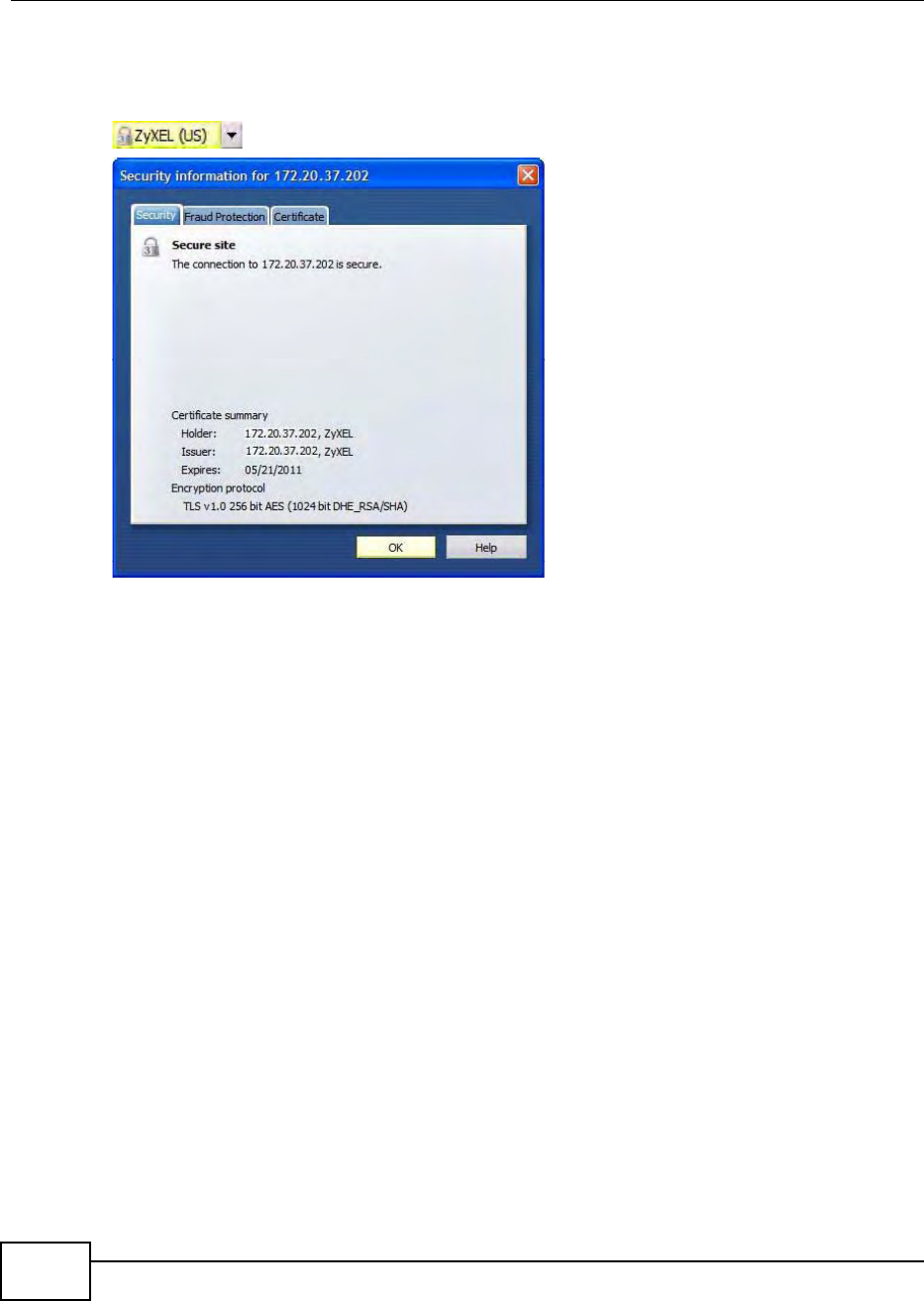
Appendix E Importing Certificates
BM2022 Users Guide
268
3The next time you visit the web site, click the padlock in the address bar to open the Security
information window to view the web pages security details.
Figure 200 Opera 9: Security information
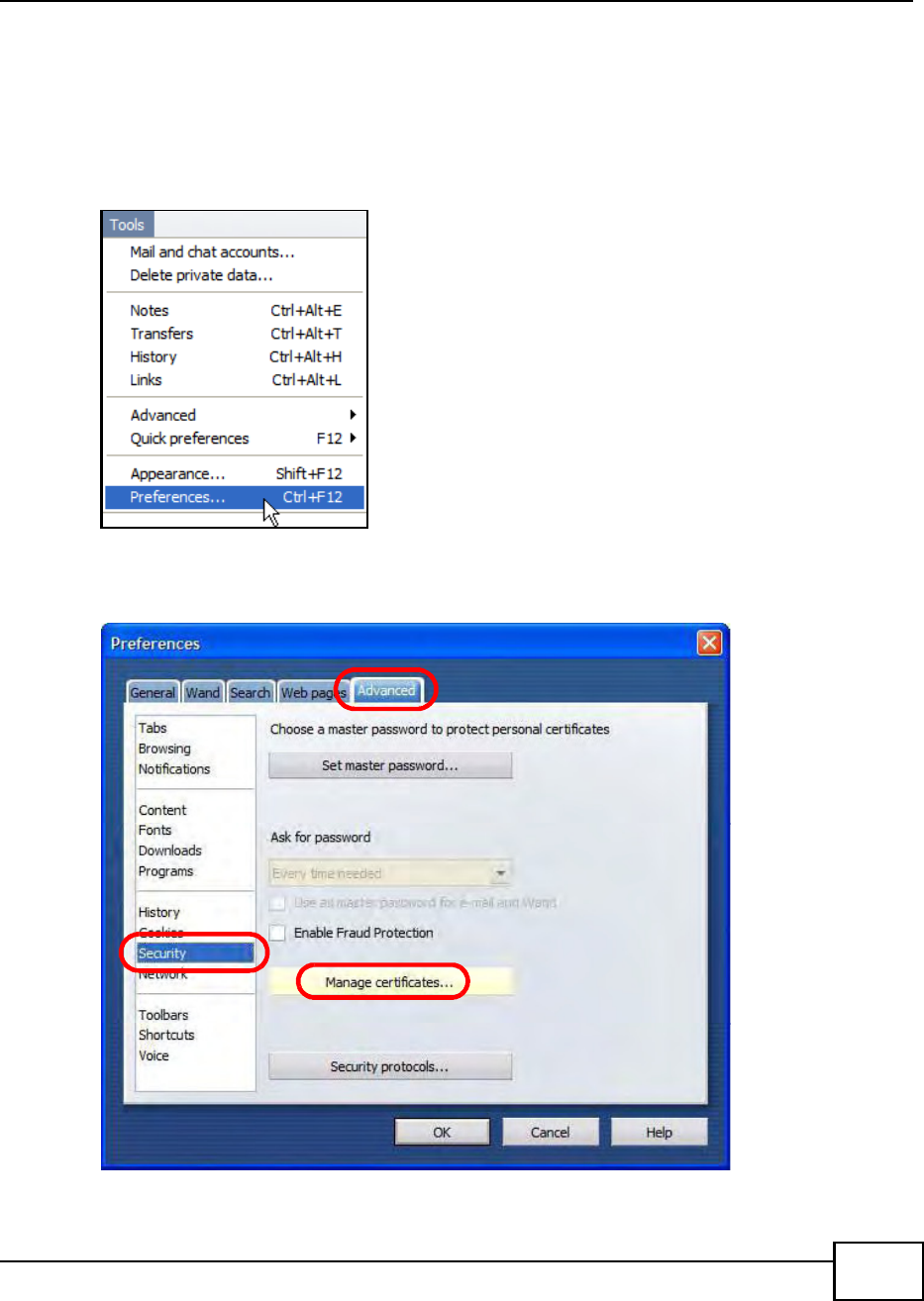
Appendix E Importing Certificates
BM2022 Users Guide 269
Installing a Stand-Alone Certificate File in Opera
Rather than browsing to a Huawei web configurator and installing a public key certificate when
prompted, you can install a stand-alone certificate file if one has been issued to you.
1Open Opera and click TOOLS > Preferences.
Figure 201 Opera 9: Tools Menu
2In Preferences, click ADVANCED > Security > Manage certificates.
Figure 202 Opera 9: Preferences
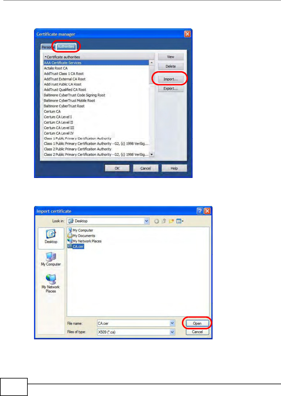
Appendix E Importing Certificates
BM2022 Users Guide
270
3In the Certificates Manager, click Authorities > Import.
Figure 203 Opera 9: Certificate manager
4Use the Import certificate dialog box to locate the certificate and then click Open.
Figure 204 Opera 9: Import certificate
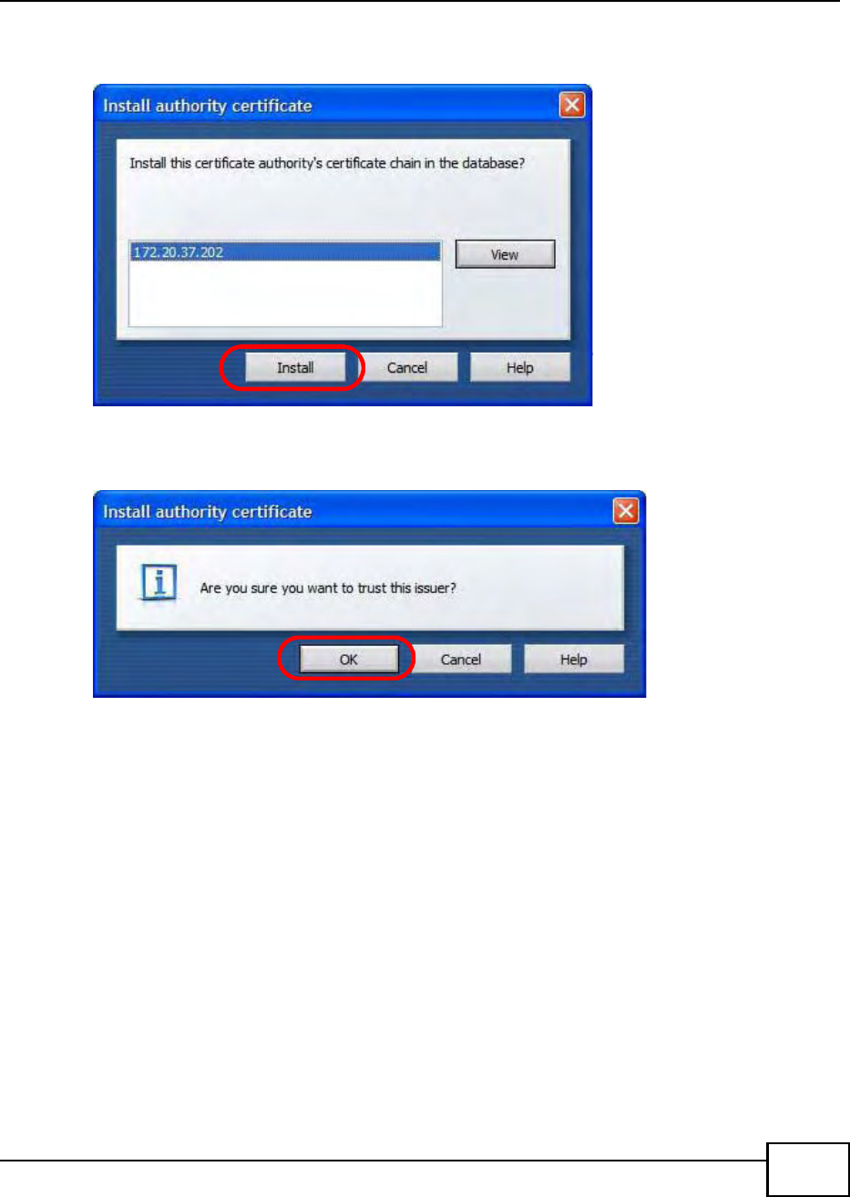
Appendix E Importing Certificates
BM2022 Users Guide 271
5In the Install authority certificate dialog box, click Install.
Figure 205 Opera 9: Install authority certificate
6Next, click OK.
Figure 206 Opera 9: Install authority certificate
7The next time you visit the web site, click the padlock in the address bar to open the Security
information window to view the web pages security details.
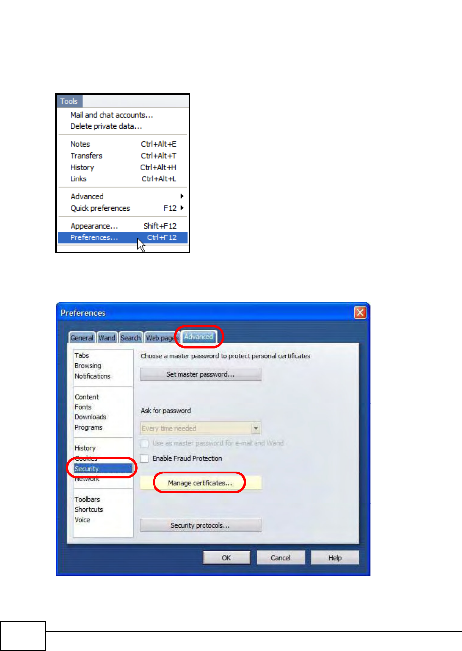
Appendix E Importing Certificates
BM2022 Users Guide
272
Removing a Certificate in Opera
This section shows you how to remove a public key certificate in Opera 9.
1Open Opera and click TOOLS > Preferences.
Figure 207 Opera 9: Tools Menu
2In Preferences, ADVANCED > Security > Manage certificates.
Figure 208 Opera 9: Preferences
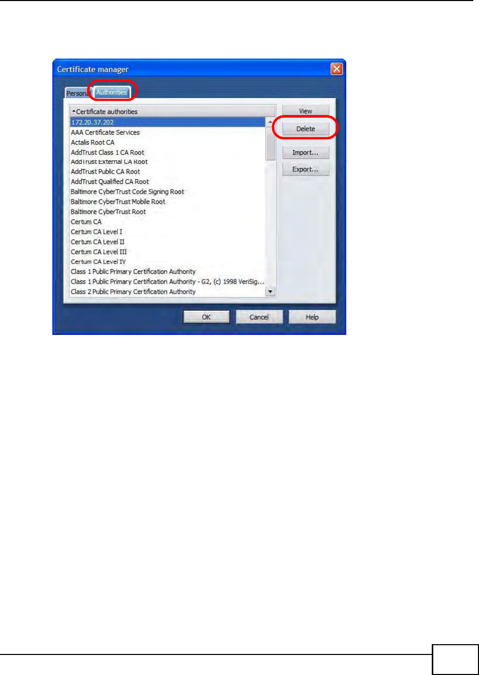
Appendix E Importing Certificates
BM2022 Users Guide 273
3In the Certificates manager, select the Authorities tab, select the certificate that you want to
remove, and then click Delete.
Figure 209 Opera 9: Certificate manager
4The next time you go to the web site that issued the public key certificate you just removed, a
certification error appears.
Note: There is no confirmation when you delete a certificate authority, so be absolutely
certain that you want to go through with it before clicking the button.
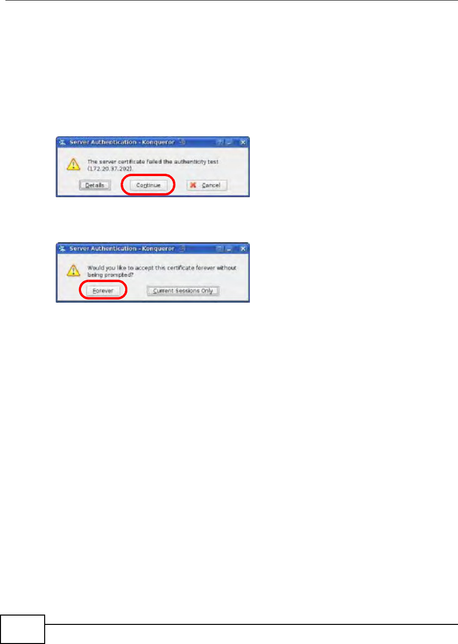
Appendix E Importing Certificates
BM2022 Users Guide
274
Konqueror
The following example uses Konqueror 3.5 on openSUSE 10.3, however the screens apply to
Konqueror 3.5 on all Linux KDE distributions.
1If your devices web configurator is set to use SSL certification, then the first time you browse to it
you are presented with a certification error.
2Click Continue.
Figure 210 Konqueror 3.5: Server Authentication
3Click Forever when prompted to accept the certificate.
Figure 211 Konqueror 3.5: Server Authentication
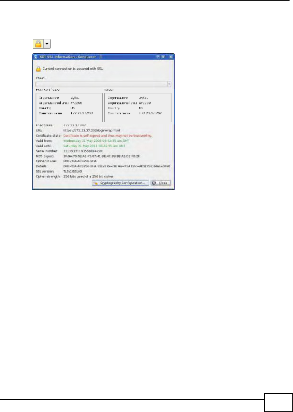
Appendix E Importing Certificates
BM2022 Users Guide 275
4Click the padlock in the address bar to open the KDE SSL Information window and view the web
pages security details.
Figure 212 Konqueror 3.5: KDE SSL Information
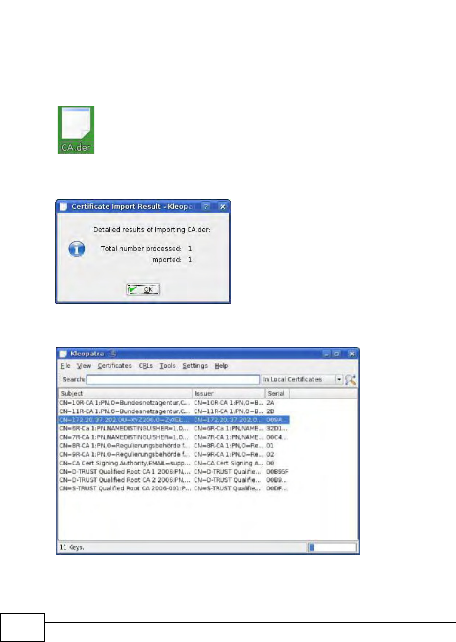
Appendix E Importing Certificates
BM2022 Users Guide
276
Installing a Stand-Alone Certificate File in Konqueror
Rather than browsing to a Huawei web configurator and installing a public key certificate when
prompted, you can install a stand-alone certificate file if one has been issued to you.
1Double-click the public key certificate file.
Figure 213 Konqueror 3.5: Public Key Certificate File
2In the Certificate Import Result - Kleopatra dialog box, click OK.
Figure 214 Konqueror 3.5: Certificate Import Result
The public key certificate appears in the KDE certificate manager, Kleopatra.
Figure 215 Konqueror 3.5: Kleopatra
3The next time you visit the web site, click the padlock in the address bar to open the KDE SSL
Information window to view the web pages security details.
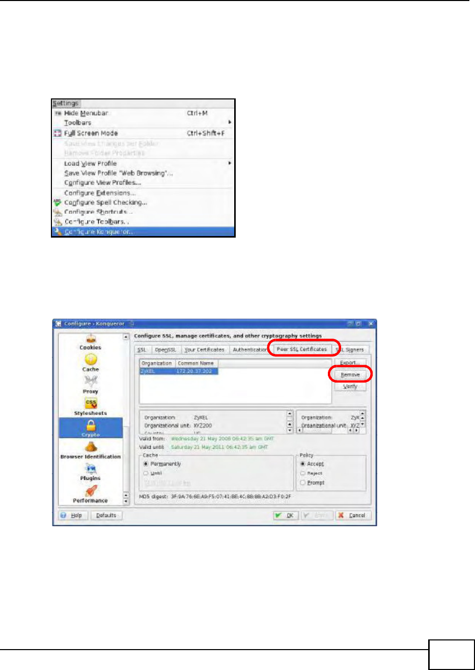
Appendix E Importing Certificates
BM2022 Users Guide 277
Removing a Certificate in Konqueror
This section shows you how to remove a public key certificate in Konqueror 3.5.
1Open Konqueror and click Settings > Configure Konqueror.
Figure 216 Konqueror 3.5: Settings Menu
2In the Configure dialog box, select Crypto.
3On the Peer SSL Certificates tab, select the certificate you want to delete and then click
Remove.
Figure 217 Konqueror 3.5: Configure
4The next time you go to the web site that issued the public key certificate you just removed, a
certification error appears.
Note: There is no confirmation when you remove a certificate authority, so be absolutely
certain you want to go through with it before clicking the button.

Appendix E Importing Certificates
BM2022 Users Guide
278

BM2022 Users Guide 279
APPENDIX F
Common Services
The following table lists some commonly-used services and their associated protocols and port
numbers. For a comprehensive list of port numbers, ICMP type/code numbers and services, visit
the IANA (Internet Assigned Number Authority) web site.
Name: This is a short, descriptive name for the service. You can use this one or create a
different one, if you like.
Protocol: This is the type of IP protocol used by the service. If this is TCP/UDP, then the service
uses the same port number with TCP and UDP. If this is USER-DEFINED, the Port(s) is the IP
protocol number, not the port number.
Port(s): This value depends on the Protocol. Please refer to RFC 1700 for further information
about port numbers.
If the Protocol is TCP, UDP, or TCP/UDP, this is the IP port number.
If the Protocol is USER, this is the IP protocol number.
Description: This is a brief explanation of the applications that use this service or the situations
in which this service is used.
Table 115 Commonly Used Services
NAME PROTOCOL PORT(S) DESCRIPTION
AH
(IPSEC_TUNNEL)
User-Defined 51 The IPSEC AH (Authentication Header)
tunneling protocol uses this service.
AIM/New-ICQ TCP 5190 AOLs Internet Messenger service. It is
also used as a listening port by ICQ.
AUTH TCP 113 Authentication protocol used by some
servers.
BGP TCP 179 Border Gateway Protocol.
BOOTP_CLIENT UDP 68 DHCP Client.
BOOTP_SERVER UDP 67 DHCP Server.
CU-SEEME TCP
UDP
7648
24032
A popular videoconferencing solution from
White Pines Software.
DNS TCP/UDP 53 Domain Name Server, a service that
matches web names (for example
www.huawei.com) to IP numbers.
ESP
(IPSEC_TUNNEL)
User-Defined 50 The IPSEC ESP (Encapsulation Security
Protocol) tunneling protocol uses this
service.
FINGER TCP 79 Finger is a UNIX or Internet related
command that can be used to find out if a
user is logged on.
FTP TCP
TCP
20
21
File Transfer Program, a program to enable
fast transfer of files, including large files
that may not be possible by e-mail.
H.323 TCP 1720 NetMeeting uses this protocol.

Appendix F Common Services
BM2022 Users Guide
280
HTTP TCP 80 Hyper Text Transfer Protocol - a client/
server protocol for the world wide web.
HTTPS TCP 443 HTTPS is a secured http session often used
in e-commerce.
ICMP User-Defined 1Internet Control Message Protocol is often
used for diagnostic or routing purposes.
ICQ UDP 4000 This is a popular Internet chat program.
IGMP (MULTICAST) User-Defined 2Internet Group Management Protocol is
used when sending packets to a specific
group of hosts.
IKE UDP 500 The Internet Key Exchange algorithm is
used for key distribution and
management.
IRC TCP/UDP 6667 This is another popular Internet chat
program.
MSN Messenger TCP 1863 Microsoft Networks messenger service
uses this protocol.
NEW-ICQ TCP 5190 An Internet chat program.
NEWS TCP 144 A protocol for news groups.
NFS UDP 2049 Network File System - NFS is a client/
server distributed file service that provides
transparent file sharing for network
environments.
NNTP TCP 119 Network News Transport Protocol is the
delivery mechanism for the USENET
newsgroup service.
PING User-Defined 1Packet INternet Groper is a protocol that
sends out ICMP echo requests to test
whether or not a remote host is reachable.
POP3 TCP 110 Post Office Protocol version 3 lets a client
computer get e-mail from a POP3 server
through a temporary connection (TCP/IP
or other).
PPTP TCP 1723 Point-to-Point Tunneling Protocol enables
secure transfer of data over public
networks. This is the control channel.
PPTP_TUNNEL
(GRE)
User-Defined 47 PPTP (Point-to-Point Tunneling Protocol)
enables secure transfer of data over public
networks. This is the data channel.
RCMD TCP 512 Remote Command Service.
REAL_AUDIO TCP 7070 A streaming audio service that enables
real time sound over the web.
REXEC TCP 514 Remote Execution Daemon.
RLOGIN TCP 513 Remote Login.
RTELNET TCP 107 Remote Telnet.
RTSP TCP/UDP 554 The Real Time Streaming (media control)
Protocol (RTSP) is a remote control for
multimedia on the Internet.
SFTP TCP 115 Simple File Transfer Protocol.
Table 115 Commonly Used Services (continued)
NAME PROTOCOL PORT(S) DESCRIPTION

Appendix F Common Services
BM2022 Users Guide 281
SMTP TCP 25 Simple Mail Transfer Protocol is the
message-exchange standard for the
Internet. SMTP enables you to move
messages from one e-mail server to
another.
SNMP TCP/UDP 161 Simple Network Management Program.
SNMP-TRAPS TCP/UDP 162 Traps for use with the SNMP (RFC:1215).
SQL-NET TCP 1521 Structured Query Language is an interface
to access data on many different types of
database systems, including mainframes,
midrange systems, UNIX systems and
network servers.
SSH TCP/UDP 22 Secure Shell Remote Login Program.
STRM WORKS UDP 1558 Stream Works Protocol.
SYSLOG UDP 514 Syslog allows you to send system logs to a
UNIX server.
TACACS UDP 49 Login Host Protocol used for (Terminal
Access Controller Access Control System).
TELNET TCP 23 Telnet is the login and terminal emulation
protocol common on the Internet and in
UNIX environments. It operates over TCP/
IP networks. Its primary function is to
allow users to log into remote host
systems.
TFTP UDP 69 Trivial File Transfer Protocol is an Internet
file transfer protocol similar to FTP, but
uses the UDP (User Datagram Protocol)
rather than TCP (Transmission Control
Protocol).
VDOLIVE TCP 7000 Another videoconferencing solution.
Table 115 Commonly Used Services (continued)
NAME PROTOCOL PORT(S) DESCRIPTION

Index
BM2022 Users Guide 283
Index
A
AAA 66
AbS 148
accounting server
see AAA
ACK message 165
activity 66
Advanced Encryption Standard
see AES
AES 207
AH 140
ALG 93
algorithms 140
alternative subnet mask notation 246
analysis-by-synthesis 148
Application Layer Gateway
see ALG
authentication 66, 205
inner 207
key
server 66
types 207
authorization 205
request and reply 207
server 66
auto-discovery
UPnP 111
B
base station
see BS
BS 6566
links 66
BYE request 166
C
CA 67, 68
CBC-MAC 207
CCMP 205, 207
cell 65
certificates 205
CA 67
formats 67
verification 207
Certification Authority, see CA
chaining 207
chaining message authentication
see CCMP
circuit-switched telephone networks 147
Class of Service (CoS) 148
client-server
protocol 166
SIP 166
CMAC
see MAC
codec 147
comfort noise 167
CoS 148
counter mode
see CCMP
coverage area 65
cryptography 205
D
data 205206
decryption 205
encryption 205
flow 207
DH 146
DHCP 91
server 91
diameter 66

Index
BM2022 Users Guide284
Differentiated Services
see DiffServ
Diffie-Hellman key groups 146
DiffServ 148
DiffServ Code Point (DSCP) 148
marking rule 152
digital ID 68, 205
DS field 152
DSCP
see DiffServ
DTMF 155
dual-tone multi-frequency
see DTMF
Dynamic Host Configuration Protocol
see DHCP
E
EAP 66
EAP (Extensible Authentication Protocol) 68
EAP-TLS 68
EAP-TTLS 68
echo cancellation 167
encapsulation 141
encryption 205206, 207
traffic 207
ESP 140
Ethernet
encapsulation 92
Extensible Authorization Protocol
see EAP
F
firewall 121
FTP 171
restrictions 171
G
G.168 167
G.711 147
G.729 148
H
hybrid waveform codec 148
I
IANA 250
ID type and content 144
identity 66, 205
idle timeout 171
IEEE 802.16 65, 205
IEEE 802.16e 65
IGD 1.0 94
IKE phases 142
inner authentication 207
inside header 142
Internet
access 66
gateway device 94
Internet Assigned Numbers Authority
see IANA 250
Internet Key Exchange 142
Internet Telephony Service Provider
see ITSP
interoperability 65
IP-PBX 147
IPSec
algorithms 140
architecture 140
NAT 143
IPSec VPN 133
ITSP 147
ITU-T 167
K
key 205
request and reply 207

Index
BM2022 Users Guide 285
L
L2TP VPN 129
Layer 2 Tunneling Protocol VPN
see L2TP VPN
M
MAC 207
MAN 65
Management Information Base (MIB) 173
Message Authentication Code
see MAC
message integrity 207
Metropolitan Area Network
see MAN
microwave 65, 66
mobile station
see MS
MS 66
multimedia 148
N
NAT 250
and remote management 171
IPSec 143
server sets 92
traversal 94, 144
NAT routers 155
ND&S 75
negotiation mode 143
network
activity 66
services 66
network address translators 155
Network Discovery and Selection
see ND&S
O
outbound proxy 155
SIP 155
outbound proxy server 155
outside header 141
P
pattern-spotting 207
PBX services 147
PCM 147
per-hop behavior 152
PHB (per-hop behavior) 152
phone
services 156
PKMv2 66, 205, 207
plain text encryption 207
Point to Point Tunneling Protocol VPN
see PPTP VPN
PPTP VPN 125
pre-shared key 146
Privacy Key Management
see PKM
private key 205
proxy server
SIP 154
public certificate 207
public key 205
pulse code modulation 147
Q
QoS 148
quality of service
R
RADIUS 66, 68, 205
Message Types 206
Messages 206

Index
BM2022 Users Guide286
Shared Secret Key 206
Real-time Transport Protocol
see RTP
register server
SIP 154
related documentation 3
remote management and NAT 171
remote management limitations 171
required bandwidth 148
RFC 1889 148
RFC 3489 155
RTP 148
S
safety warnings 5
secure communication 205
secure connection 66
security 205
security association 206
see SA
see QoS
server, outbound proxy 155
services 66
Session Initiation Protocol
see SIP
silence suppression 167
silent packets 167
SIP 148
account 153
ACK message 165
ALG 93, 155
Application Layer Gateway, see ALG
BYE request 166
call progression 163
client 166
client server 166
identities 153
INVITE request 165
number 153
proxy server 154
register server 154
servers 166
service domain 154
URI 153
user agent 154
SIP outbound proxy 155
SNMP 171
manager 173
sound quality 147
SS 65, 66
STUN 155
subnet 243
mask 244
subnetting 246
subscriber station
see SS
supplementary phone services 156
syntax conventions 3
system timeout 171
T
tampering
TCP/IP configuration 91
TEK 207
TFTP restrictions 171
TLS 205
To S 148
Touch Tone 155
transport encryption key
see TEK
transport layer security
see TLS
transport mode 141
trigger port forwarding
process 107
TTLS 205, 207
tunnel mode 141
tunneled TLS
see TTLS
Type of Service 148
U
unauthorized device 205
uniform resource identifier 153

Index
BM2022 Users Guide 287
Universal Plug and Play
see UPnP
UPnP 93
application 94
auto-discovery 111
security issues 94
Windows XP 110
use NAT 155
user authentication 205
V
VAD 167
verification 207
virtual LAN
see VLAN
VLAN 115
examples 48
voice
activity detection 167
coding 147
mail 147
Voice over IP
see VoIP
VoIP 147
W
waveform codec 147
WiMAX 6566
security 206
WiMAX Forum 65
Wireless Interoperability for Microwave Access
see WiMAX
Wireless Metropolitan Area Network
see MAN
wireless network
access 65
standard 65
wireless security 205
wizard setup 27

Index
BM2022 Users Guide288
Federal Communication Commission Interference Statement
This equipment has been tested and found to comply with the limits for a Class B digital device, pursuant to
Part 15 of the FCC Rules. These limits are designed to provide reasonable protection against harmful
interference in a residential installation. This equipment generates, uses and can radiate radio frequency
energy and, if not installed and used in accordance with the instructions, may cause harmful interference to
radio communications. However, there is no guarantee that interference will not occur in a particula
r
installation. If this equipment does cause harmful interference to radio or television reception, which can
be determined by turning the equipment off and on, the user is encouraged to try to correct the interference
by one of the following measures:
- Reorient or relocate the receiving antenna.
- Increase the separation between the equipment and receiver.
- Connect the equipment into an outlet on a circuit different from that
to which the receiver is connected.
- Consult the dealer or an experienced radio/TV technician for help.
FCC Caution: Any changes or modifications not expressly approved by the party responsible fo
r
compliance could void the user's authority to operate this equipment.
This device complies with Part 15 of the FCC Rules. Operation is subject to the following two conditions:
(1) This device may not cause harmful interference, and (2) this device must accept any interference
received, including interference that may cause undesired operation.
IMPORTANT NOTE:
Radiation Exposure Statement:
This equipment complies with FCC radiation exposure limits set forth for an uncontrolled environment. This
equipment should be installed and operated with minimum distance 20cm between the radiator & you
r
body.
This transmitter must not be co-located or operating in conjunction with any other antenna or transmitter.