MitraStar Technology HES209M2W WiMAX Indoor VoIP Wi-Fi IAD User Manual User s guide Update
MitraStar Technology Corporation WiMAX Indoor VoIP Wi-Fi IAD User s guide Update
UserManual.wiki
>
MitraStar Technology
>
HES209M2W User Manual
>
User Manual Part 1
Contents
1.
User Manual Part 1
2.
User Manual Part 2
User Manual Part 1
Navigation menu
Upload a User Manual
Namespaces
Wiki Guide
HTML
PDF
Info
Views
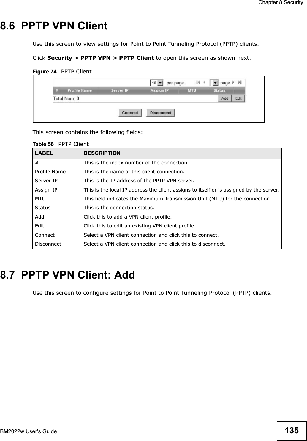
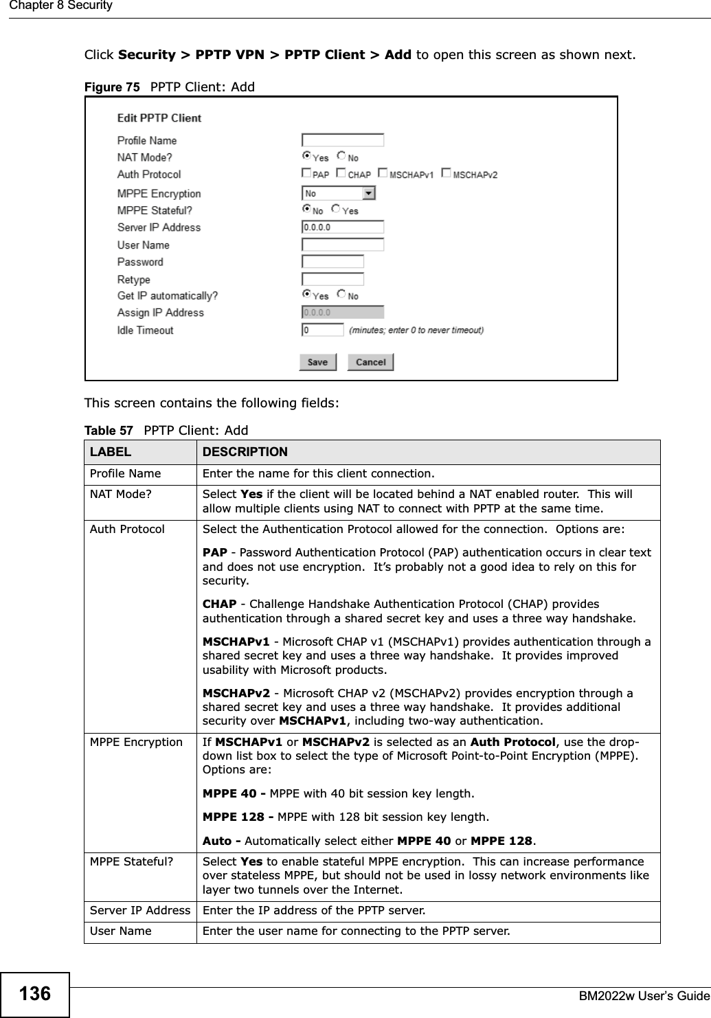
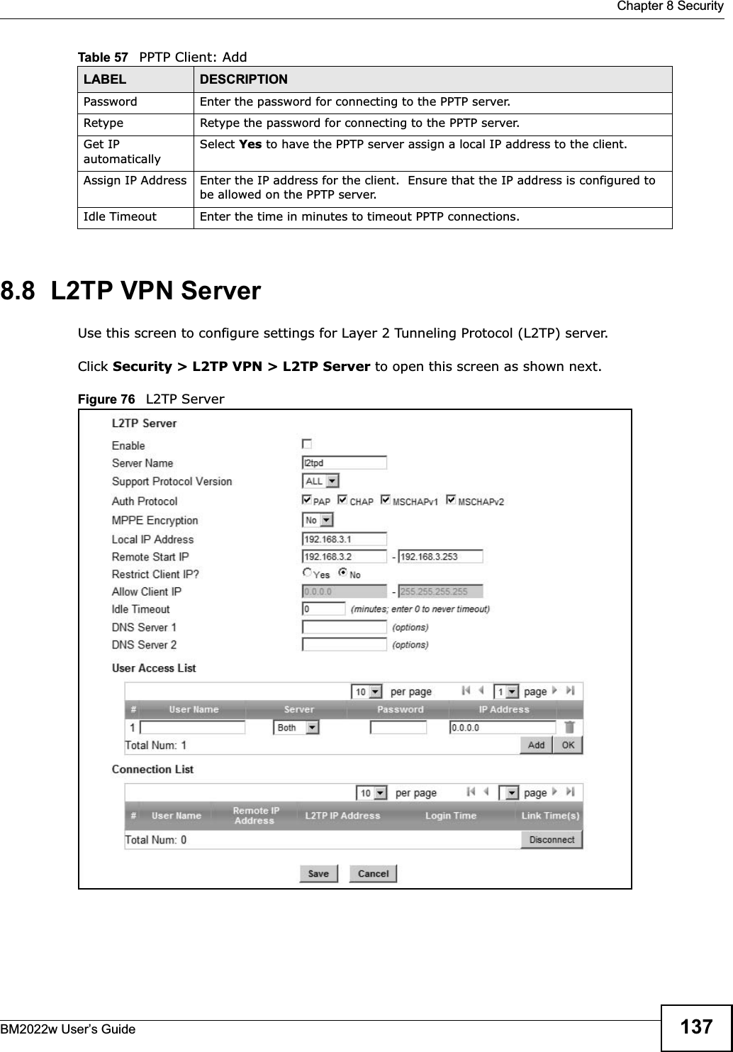
User Manual
Discussion / Help
Navigation
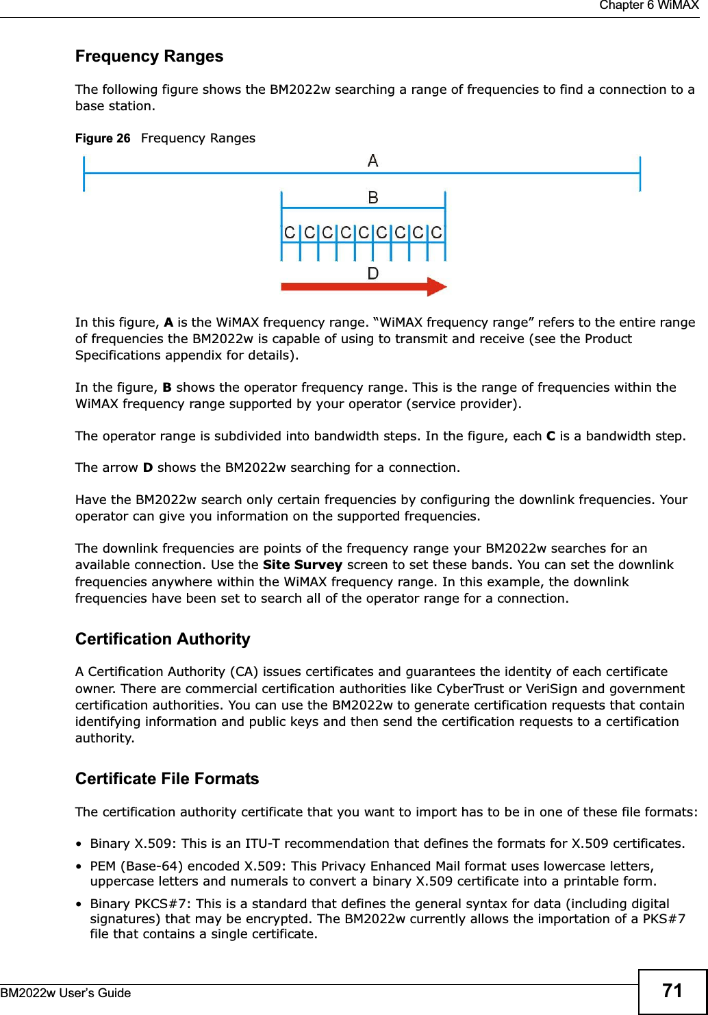
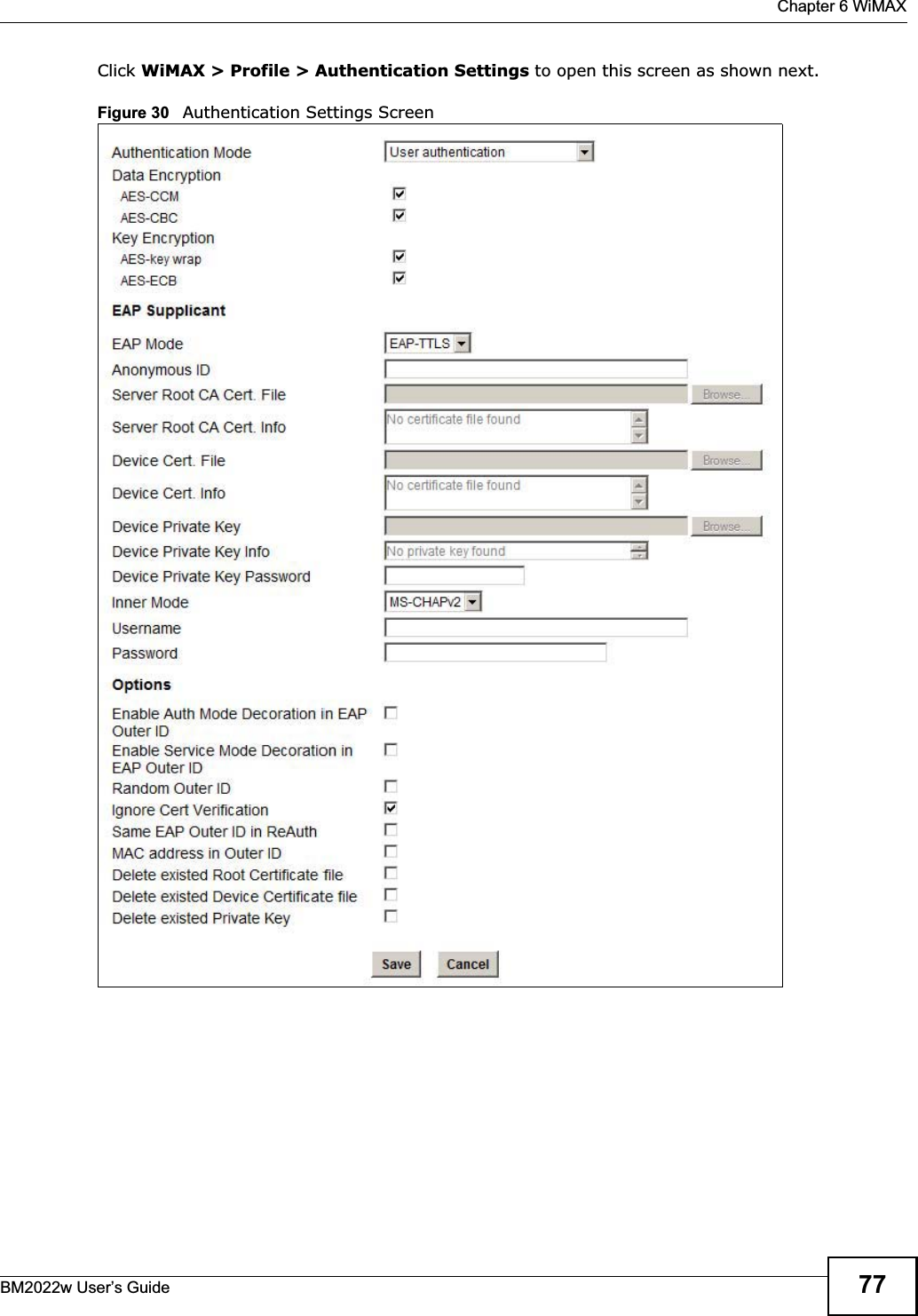
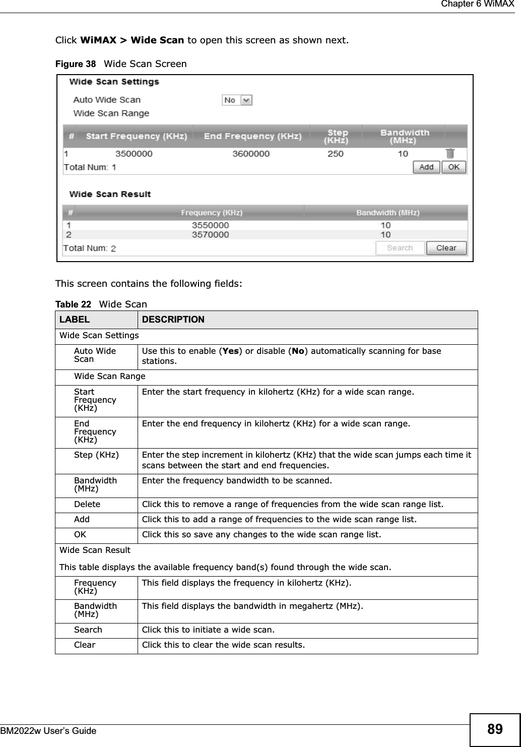
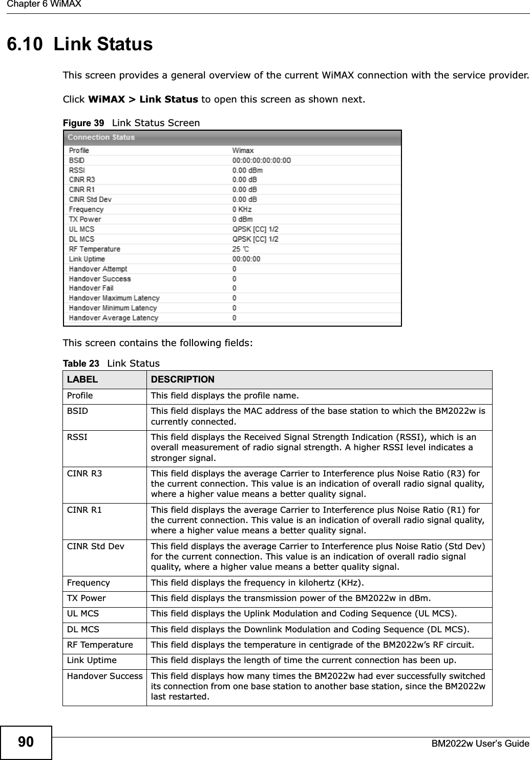
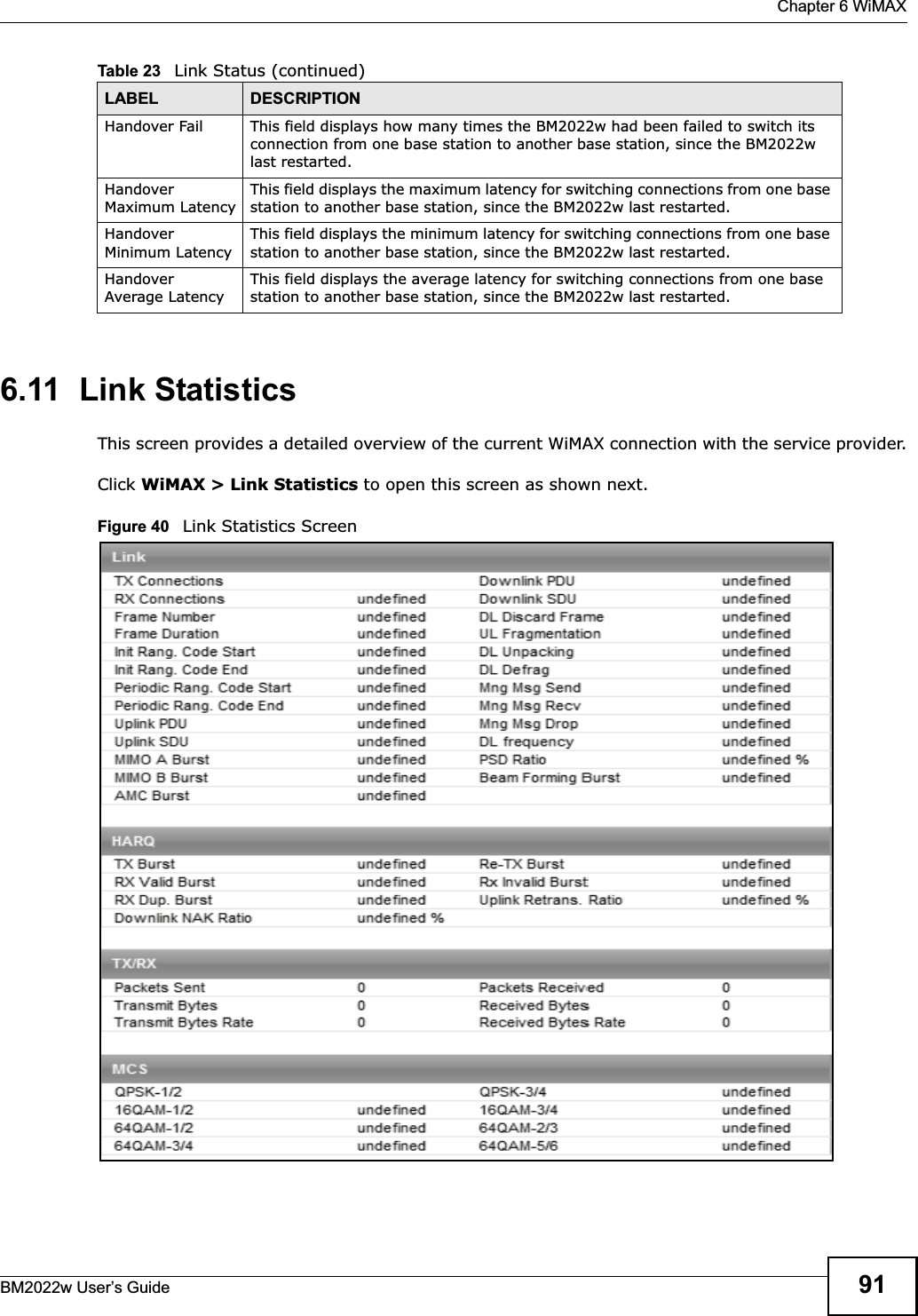
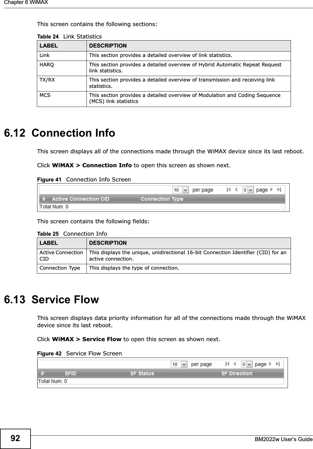
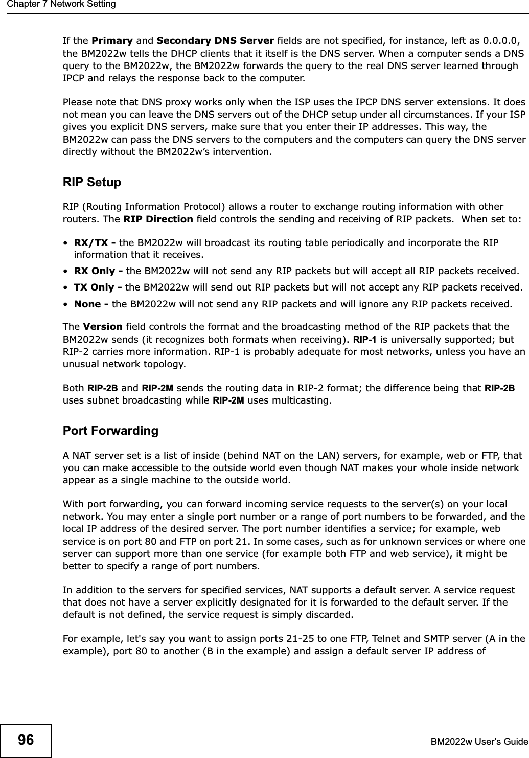
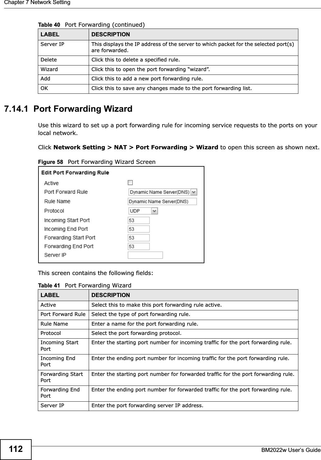
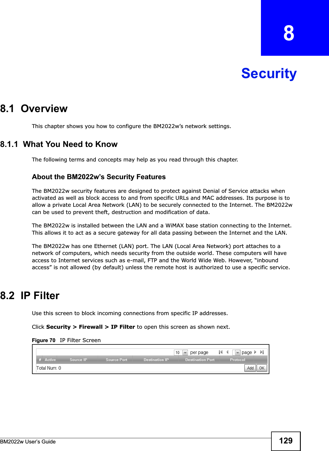
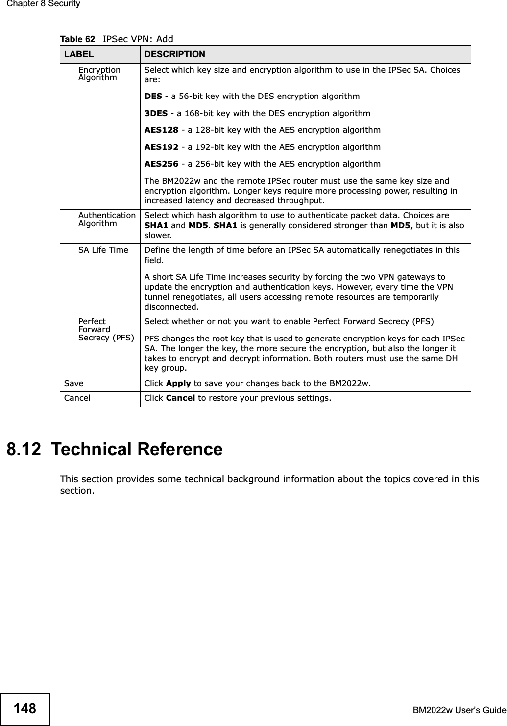
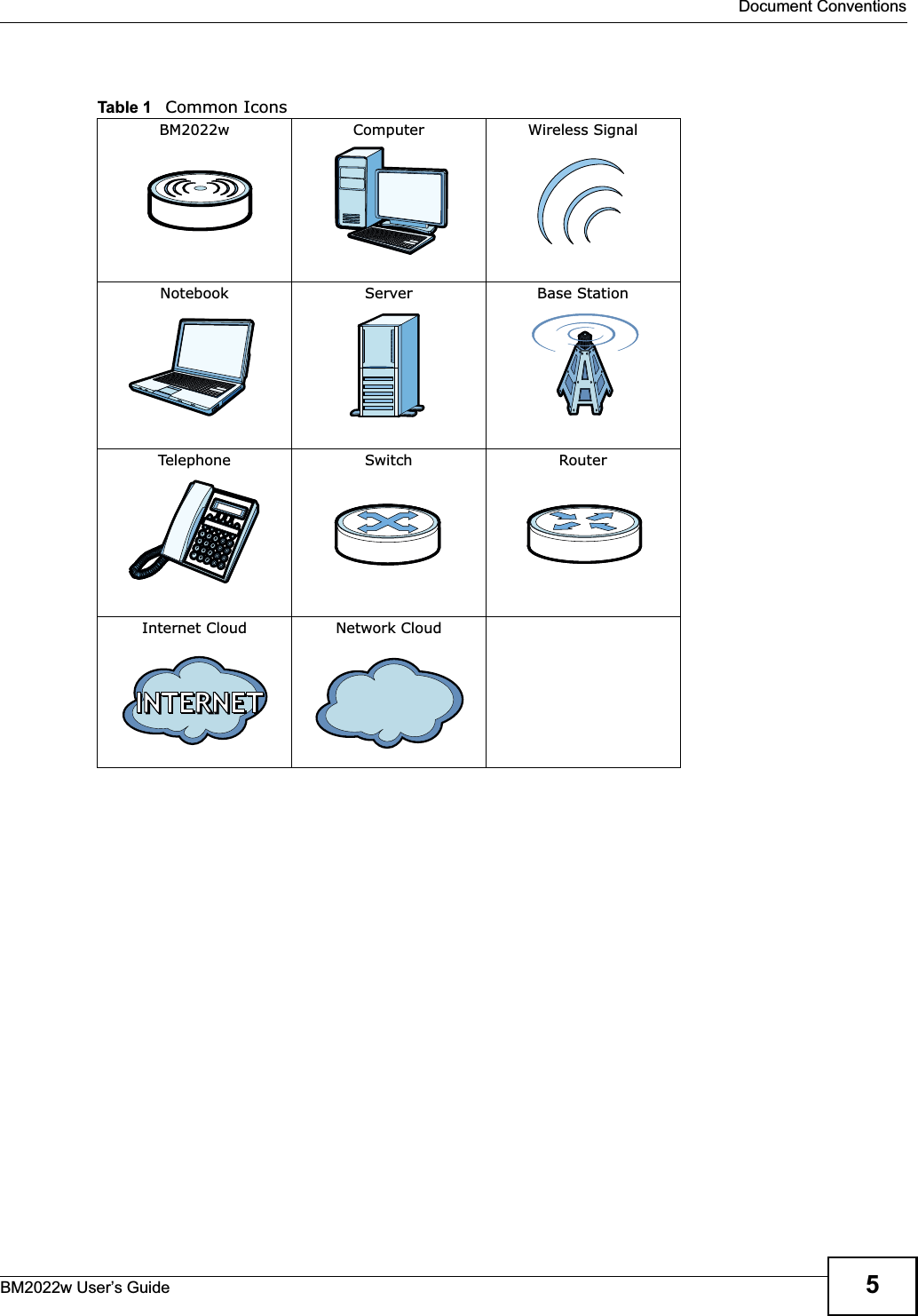
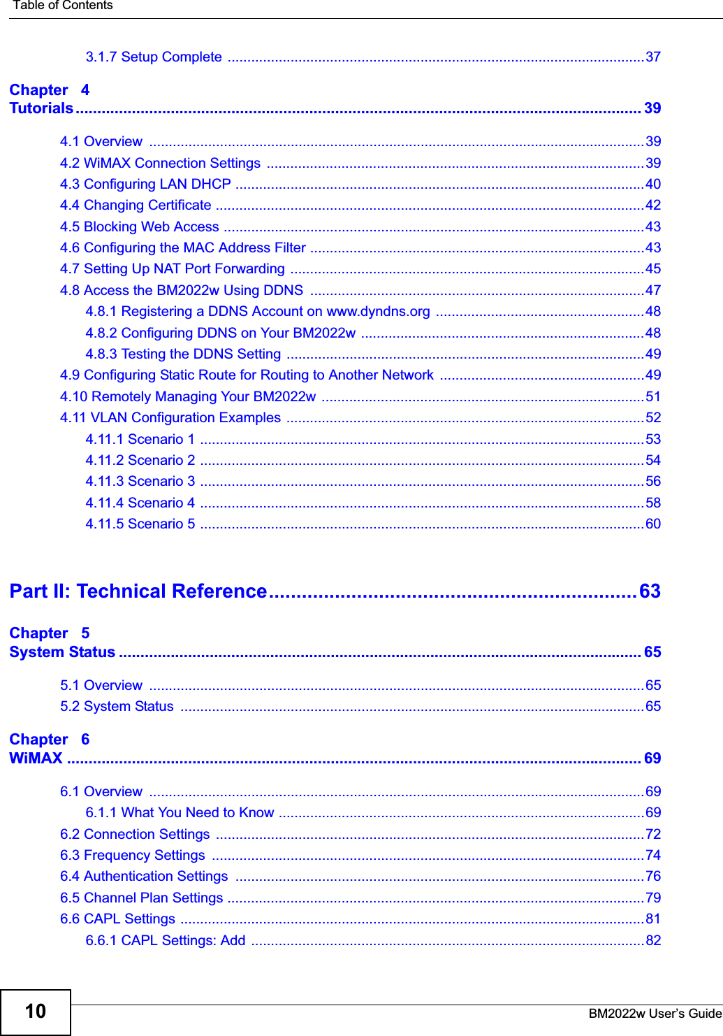
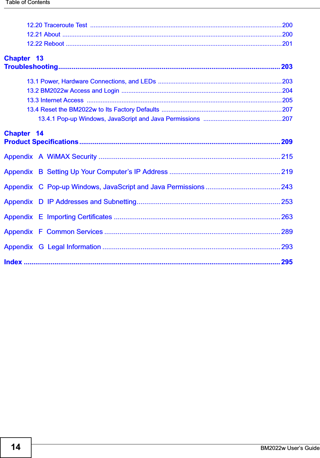
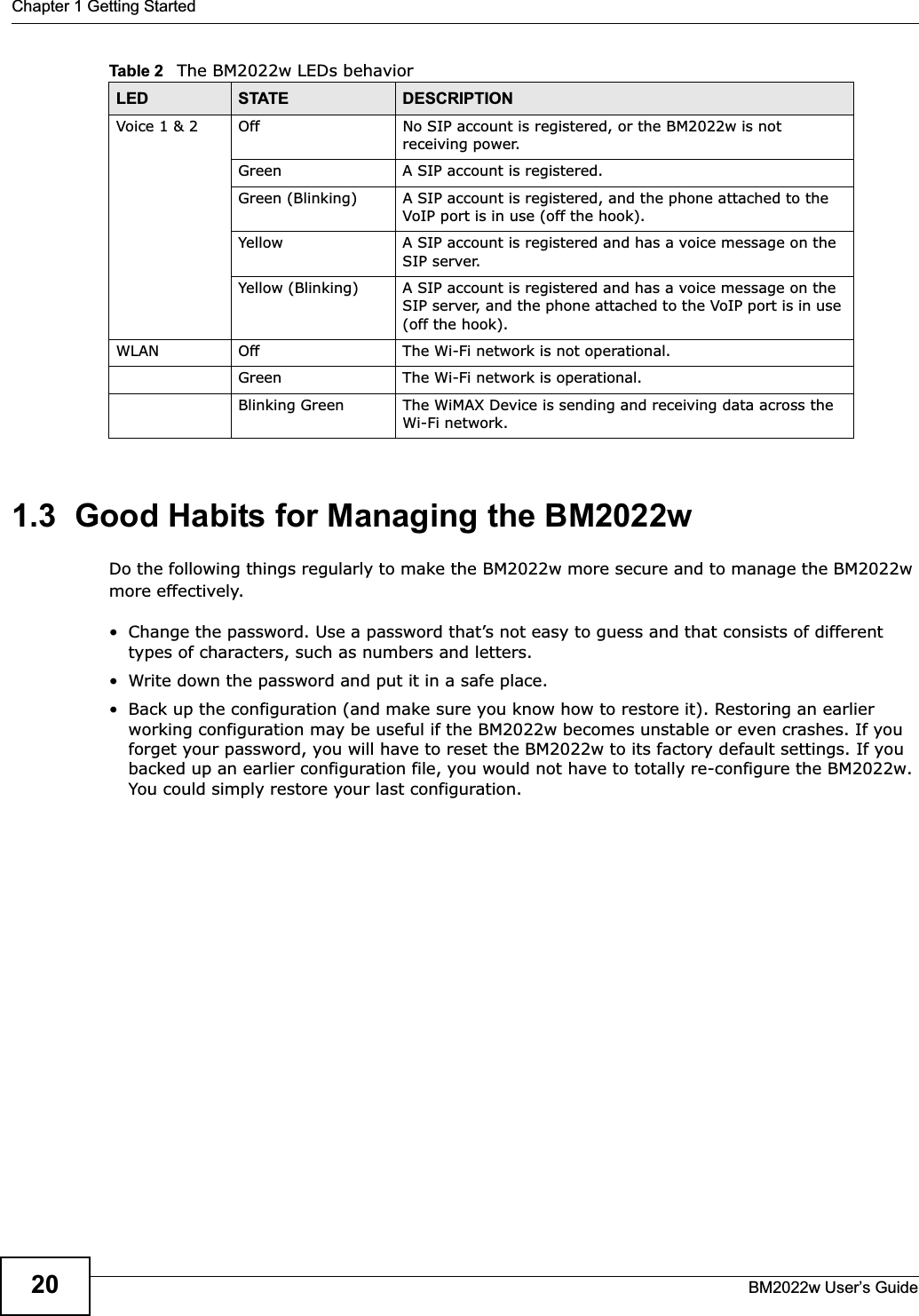
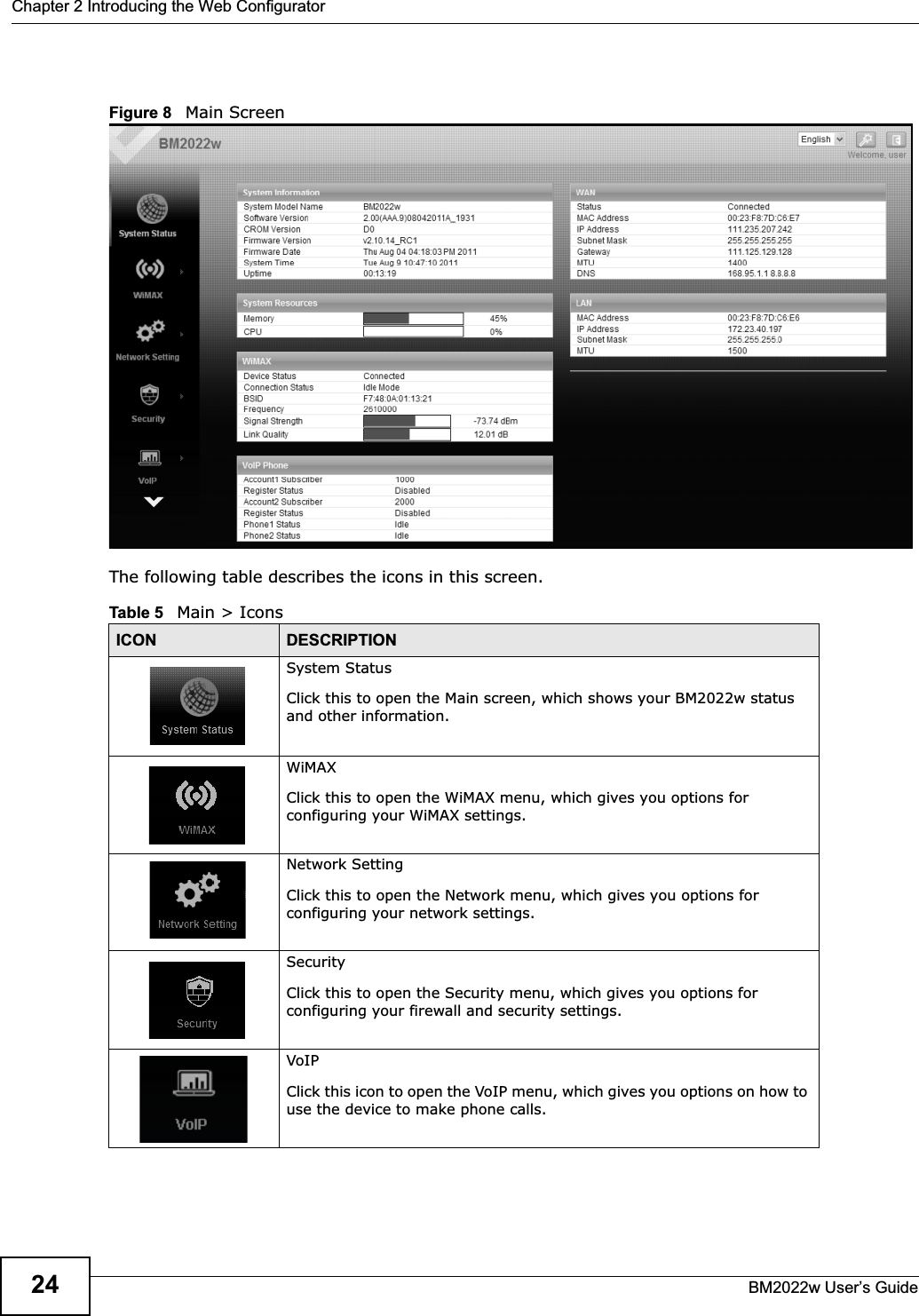
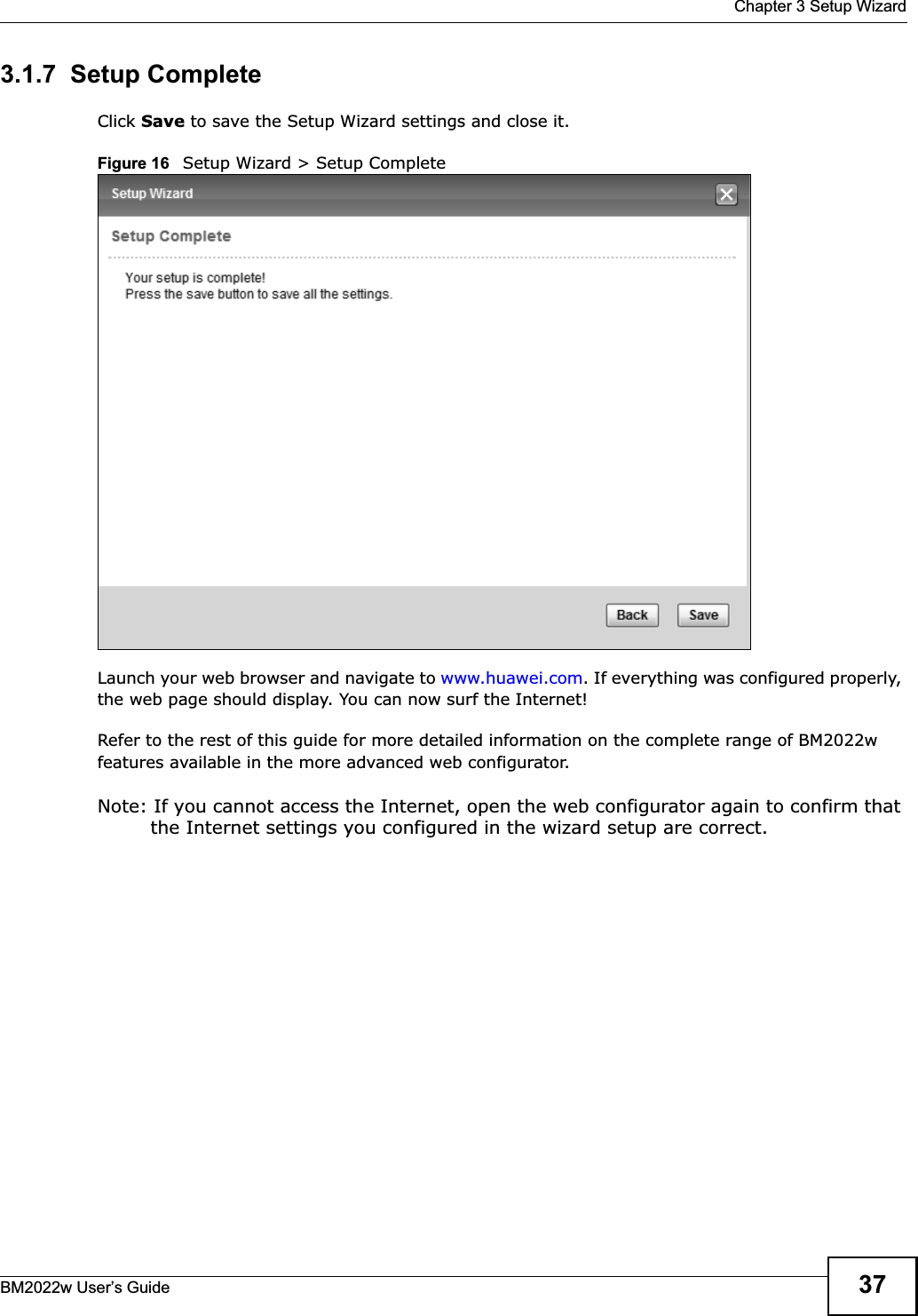
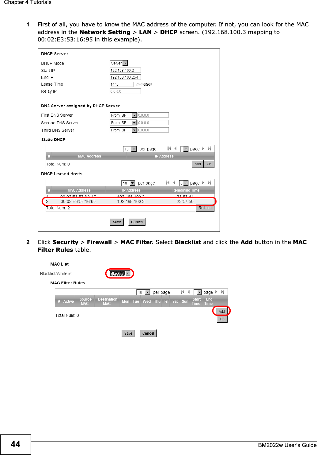
![Document ConventionsBM2022w User’s Guide4Document ConventionsWarnings and NotesThese are how warnings and notes are shown in this User’s Guide. Warnings tell you about things that could harm you or your BM2022w.Note: Notes tell you other important information (for example, other things you may need to configure or helpful tips) or recommendations.Syntax Conventions• The product(s) described in this book may be referred to as the “BM2022w”, the “device”, the “system” or the “product” in this User’s Guide.• Product labels, screen names, field labels and field choices are all in bold font.• A key stroke is denoted by square brackets and uppercase text, for example, [ENTER] means the “enter” or “return” key on your keyboard.• “Enter” means for you to type one or more characters and then press the [ENTER] key. “Select” or “choose” means for you to use one of the predefined choices.• A right angle bracket ( > ) within a screen name denotes a mouse click. For example, TOOLS > Logs > Log Settings means you first click Tools in the navigation panel, then the Logs sub menu and finally the Log Settings tab to get to that screen.• Units of measurement may denote the “metric” value or the “scientific” value. For example, “k” for kilo may denote “1000” or “1024”, “M” for mega may denote “1000000” or “1048576” and so on.• “e.g.,” is a shorthand for “for instance”, and “i.e.,” means “that is” or “in other words”.Icons Used in FiguresFigures in this User’s Guide may use the following generic icons. The BM2022w icon is not an exact representation of your product.](https://usermanual.wiki/MitraStar-Technology/HES209M2W.User-Manual-Part-1/User-Guide-1603517-Page-3.png)


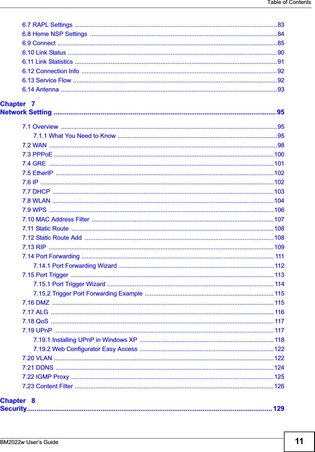


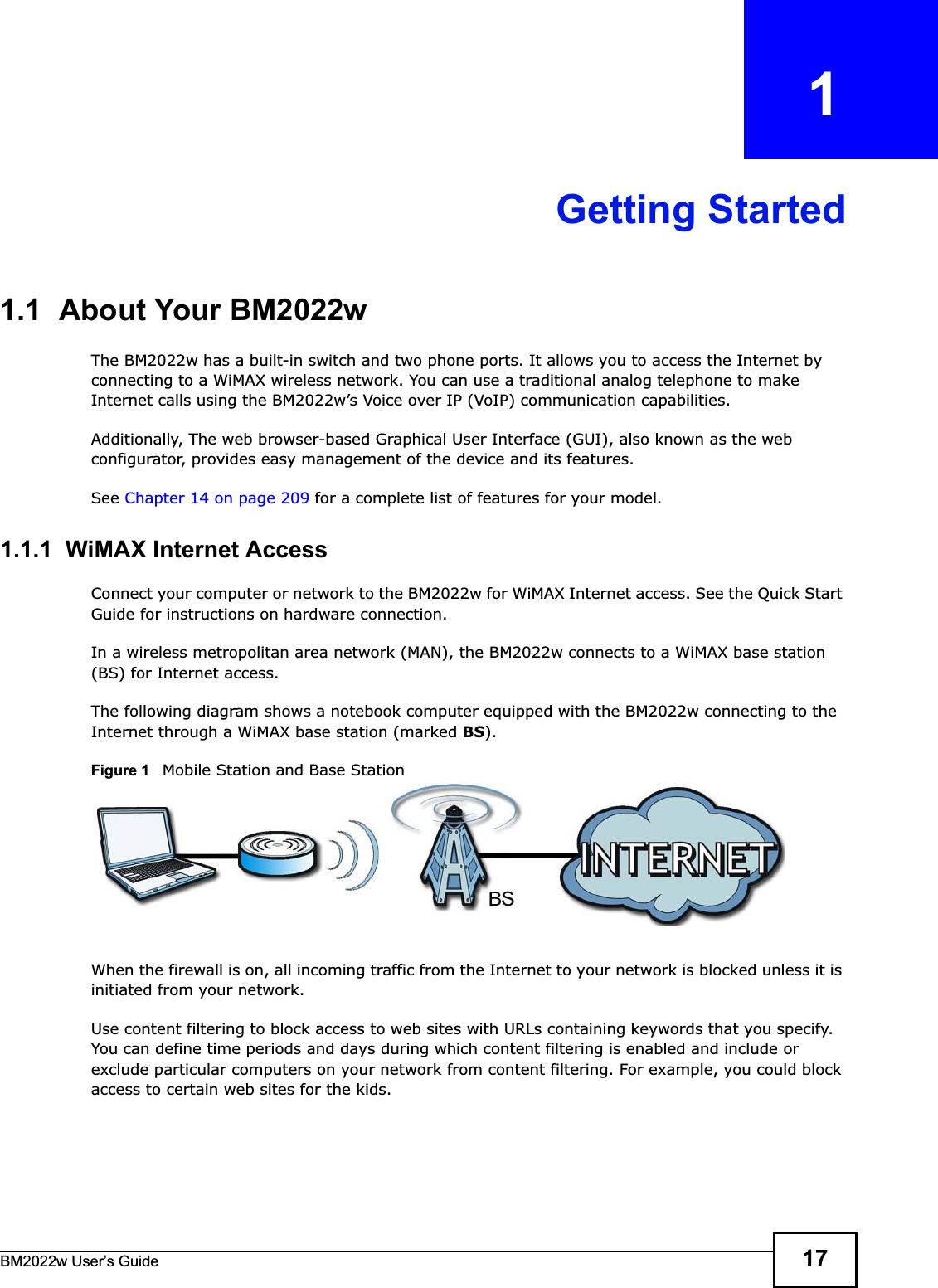
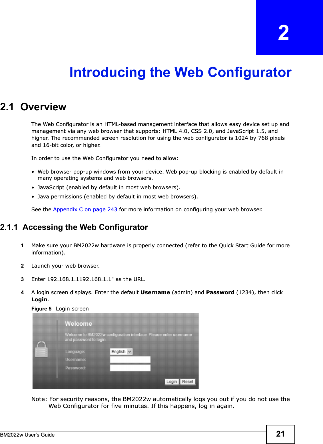
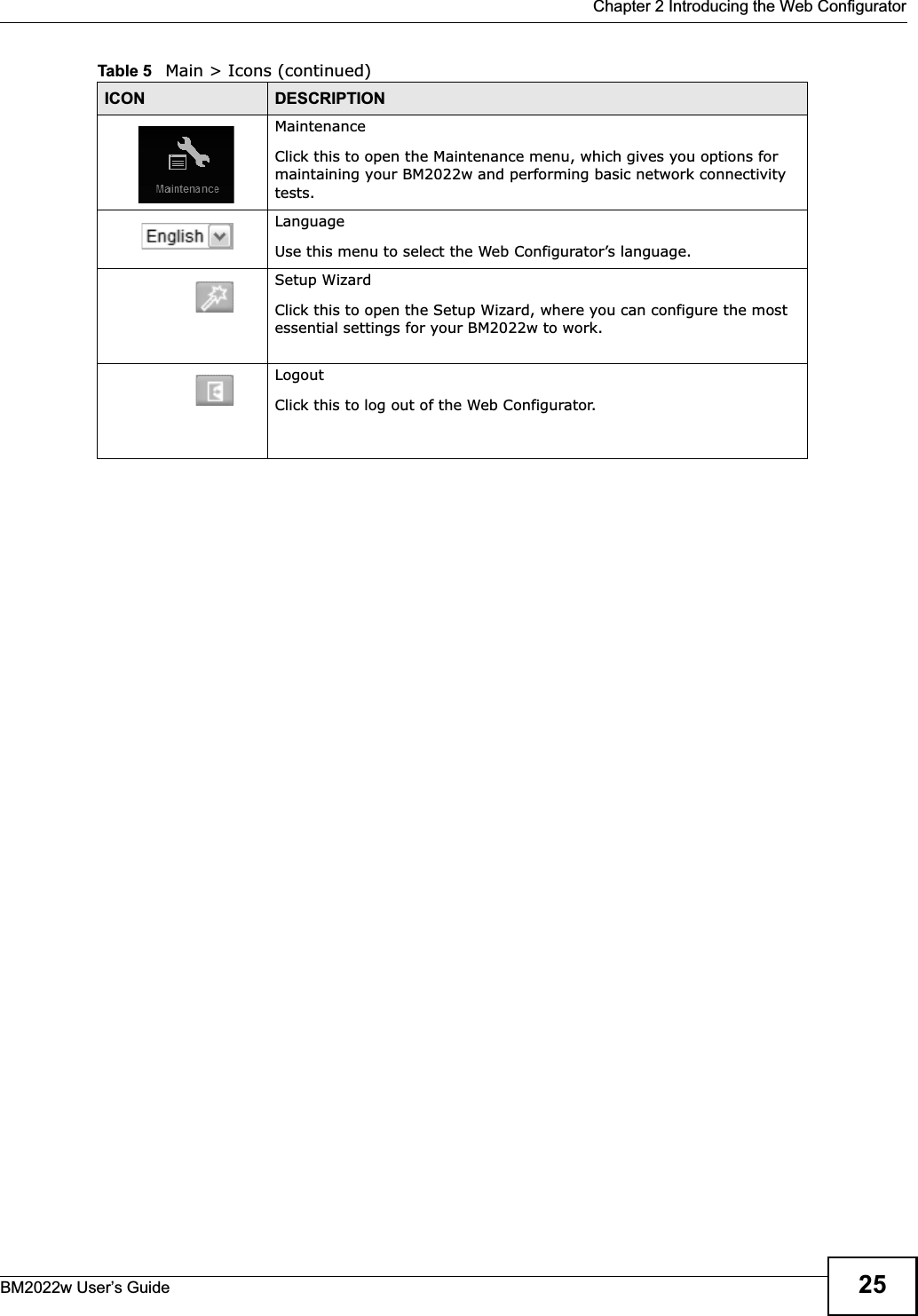

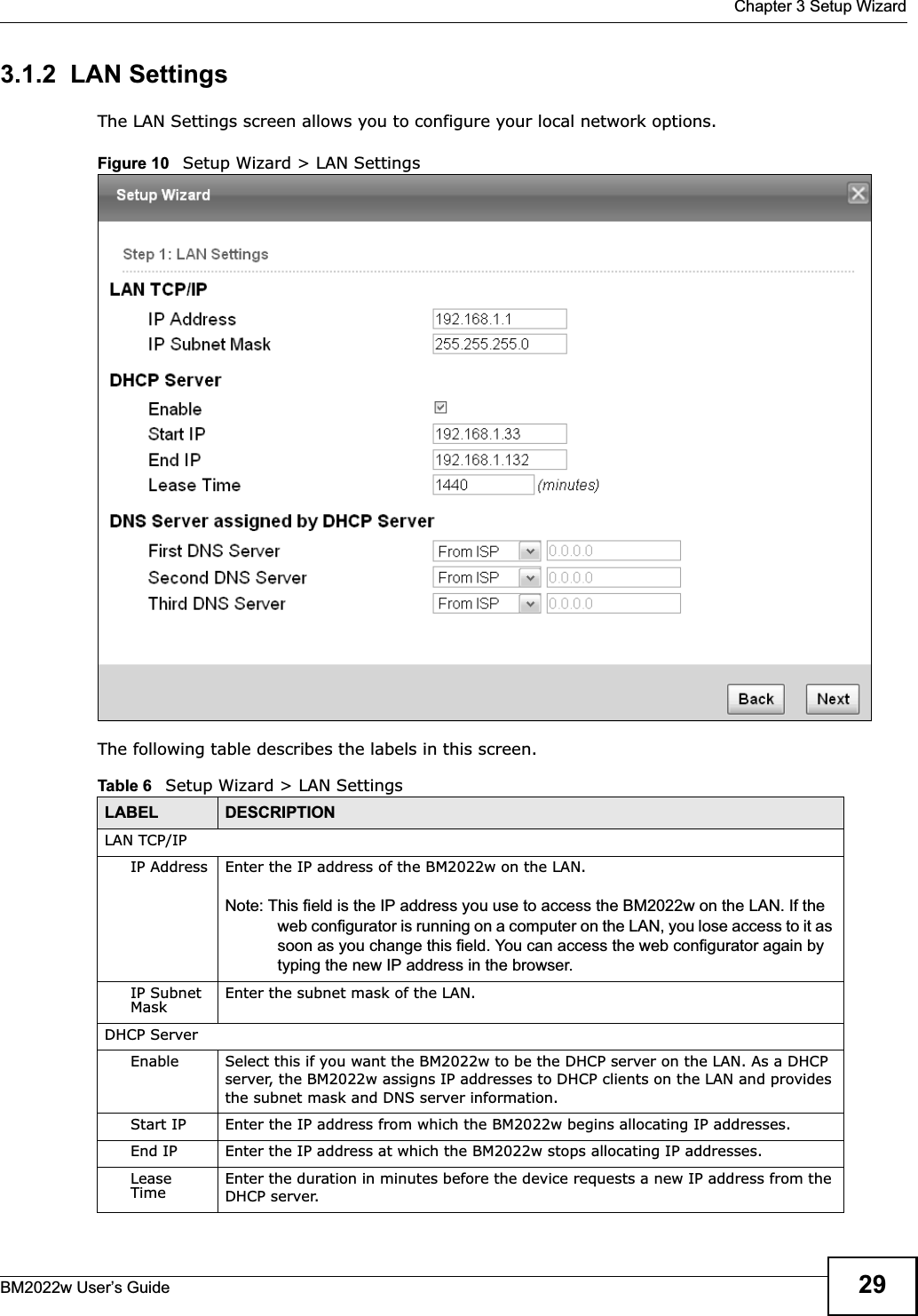

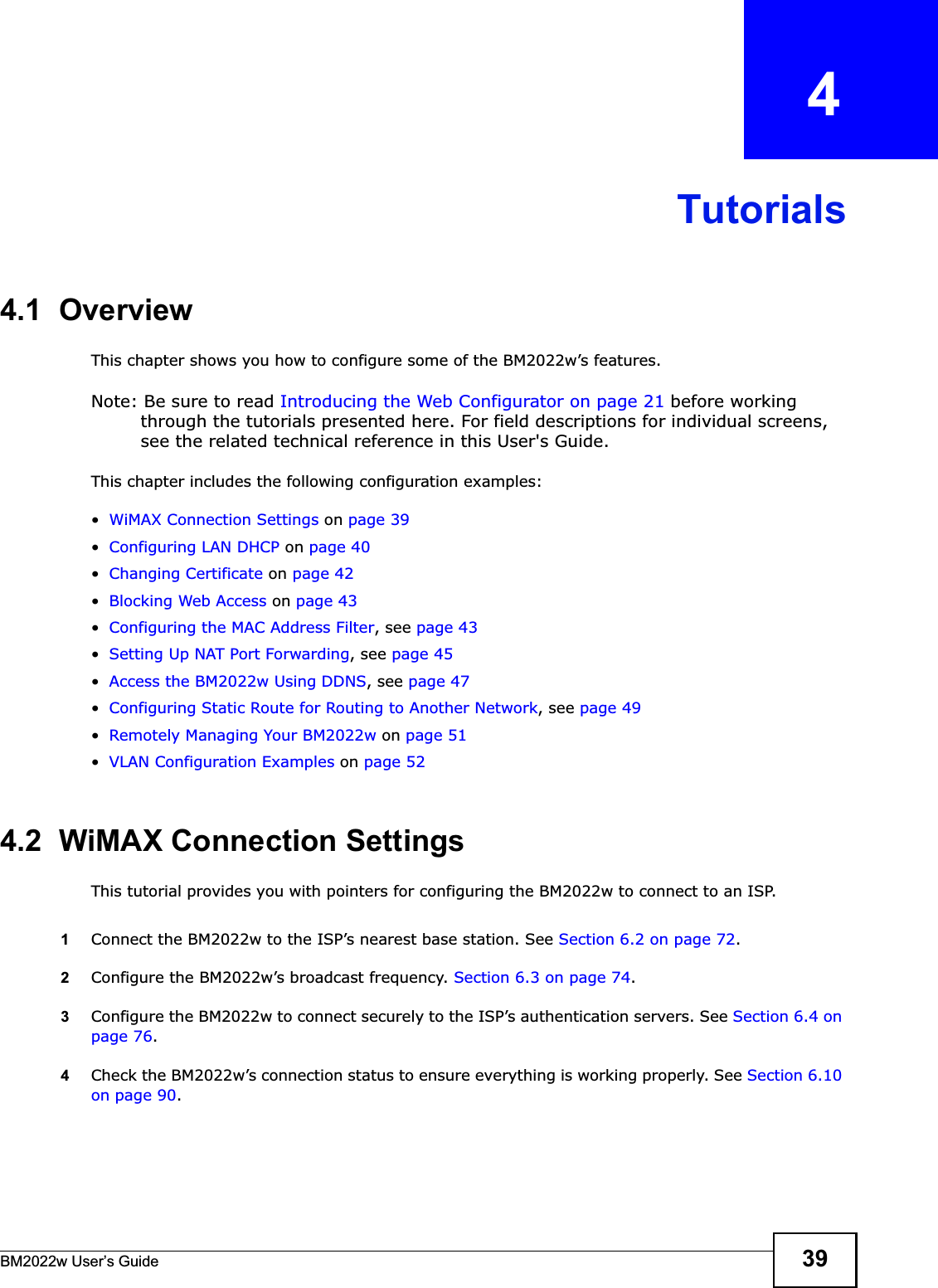
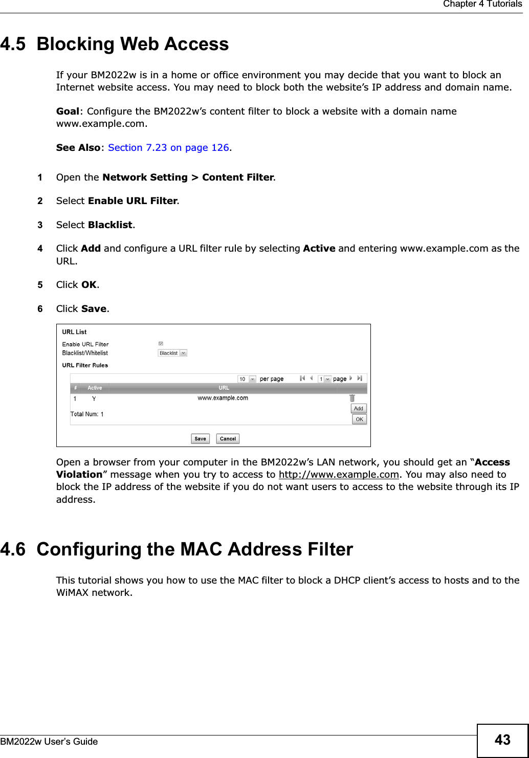
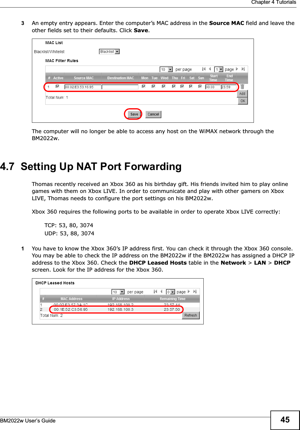
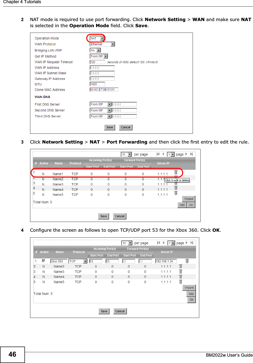
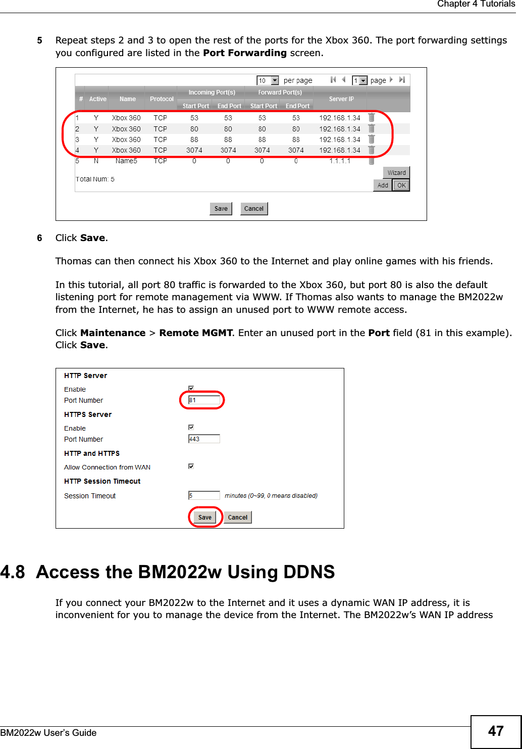
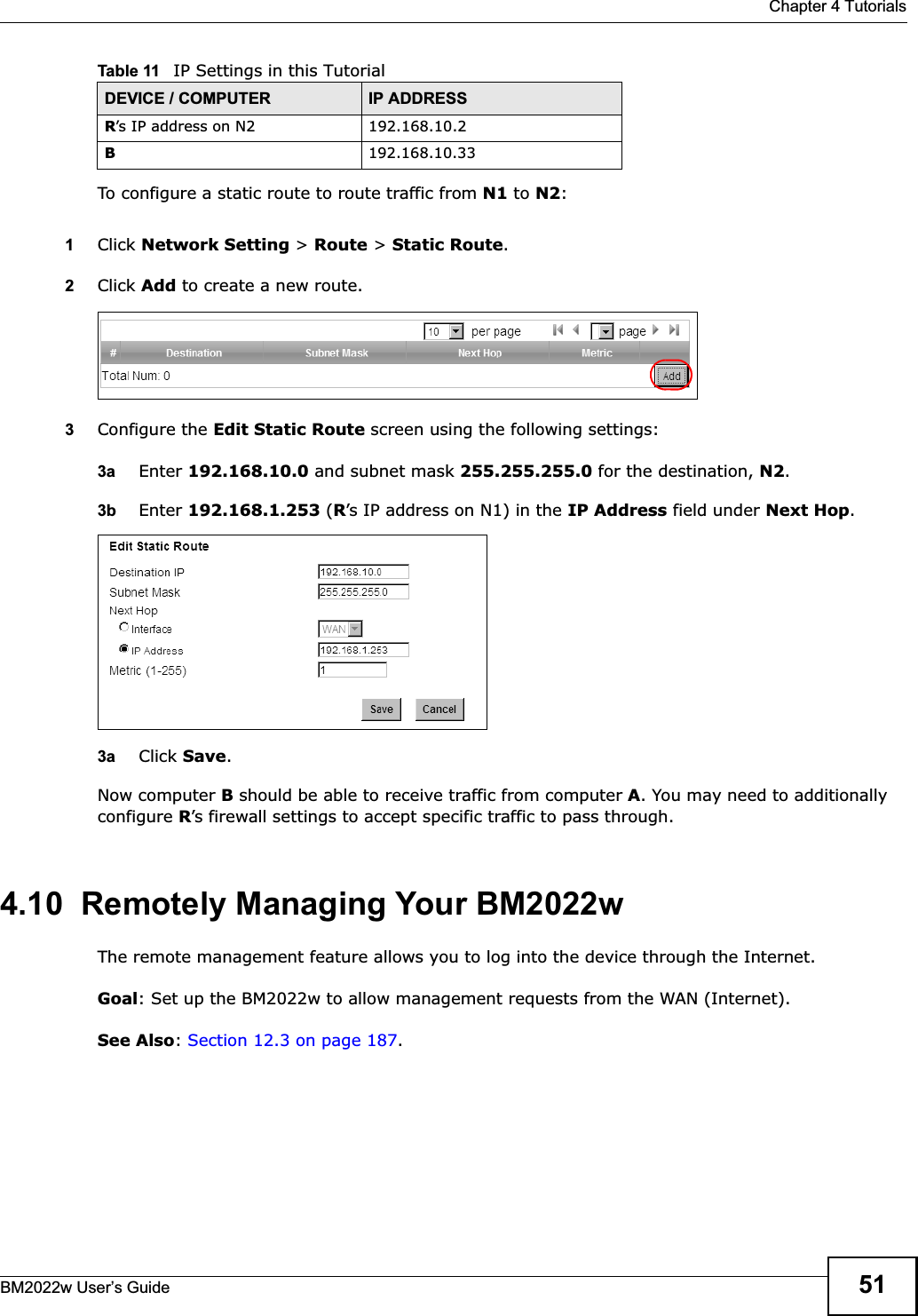
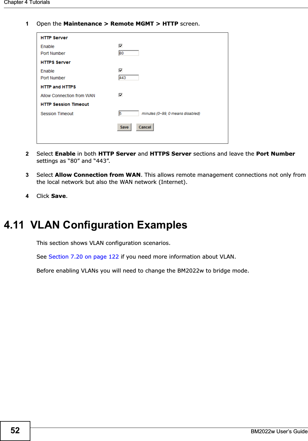
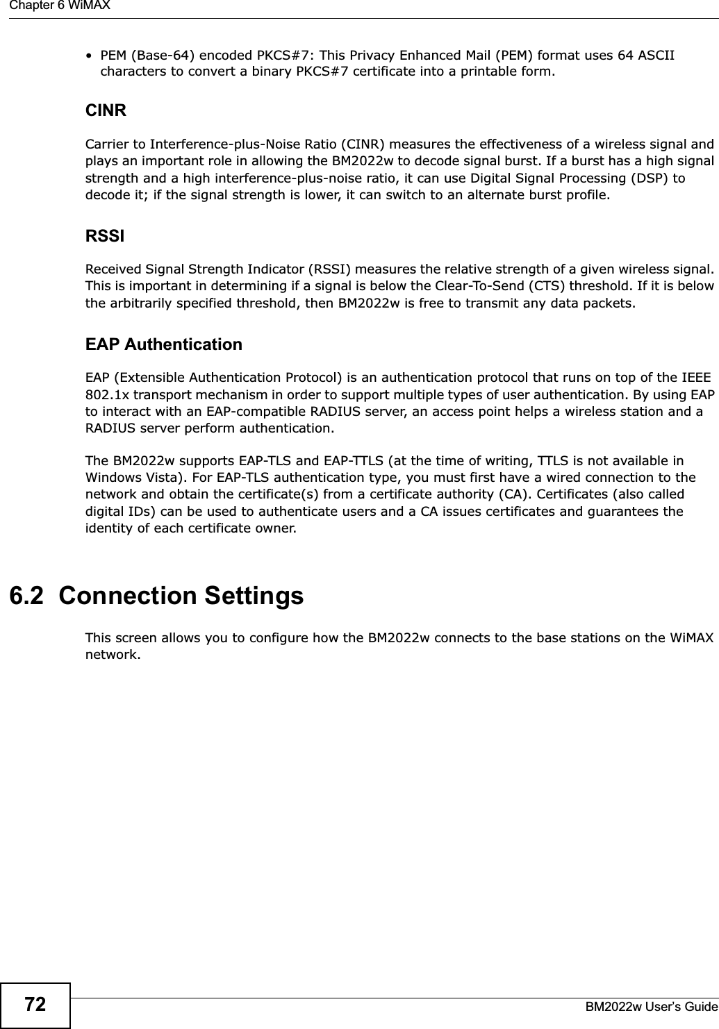
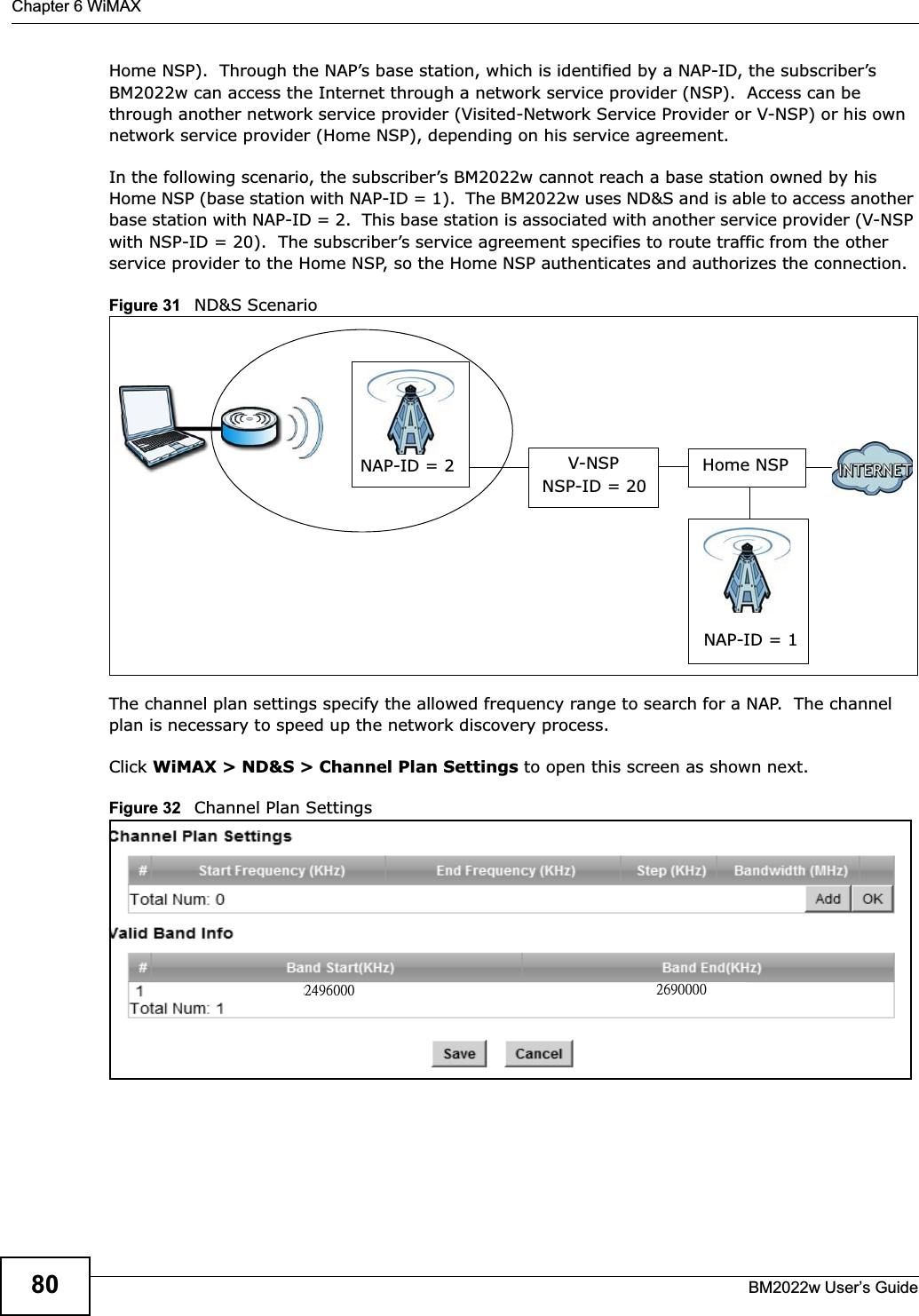
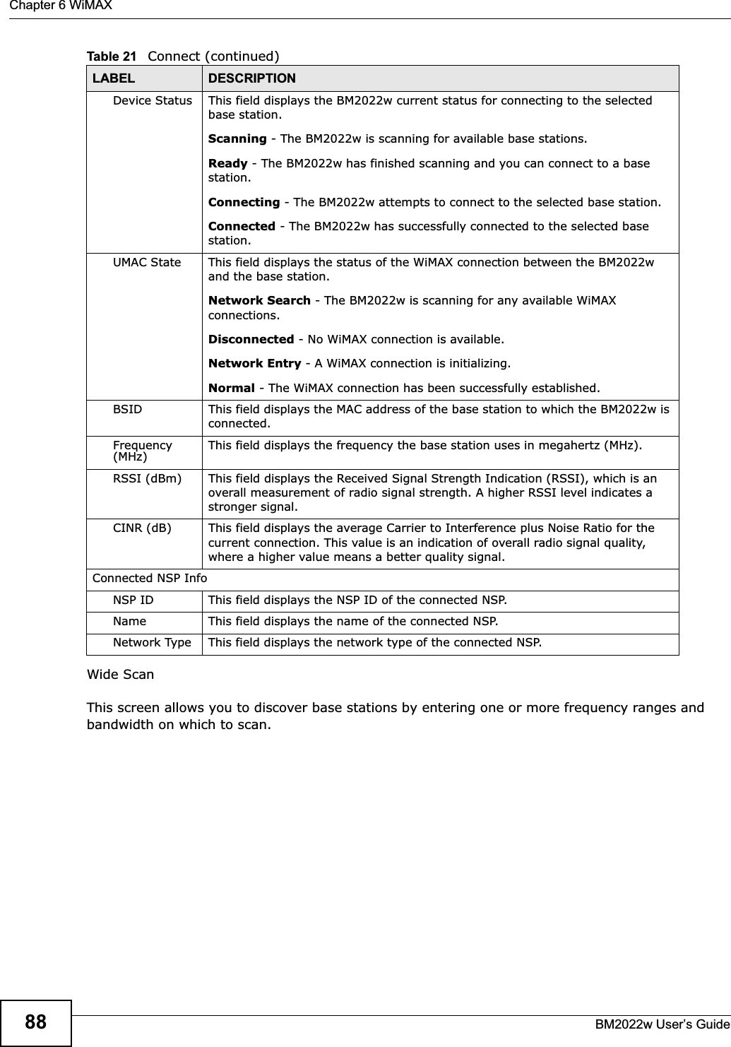
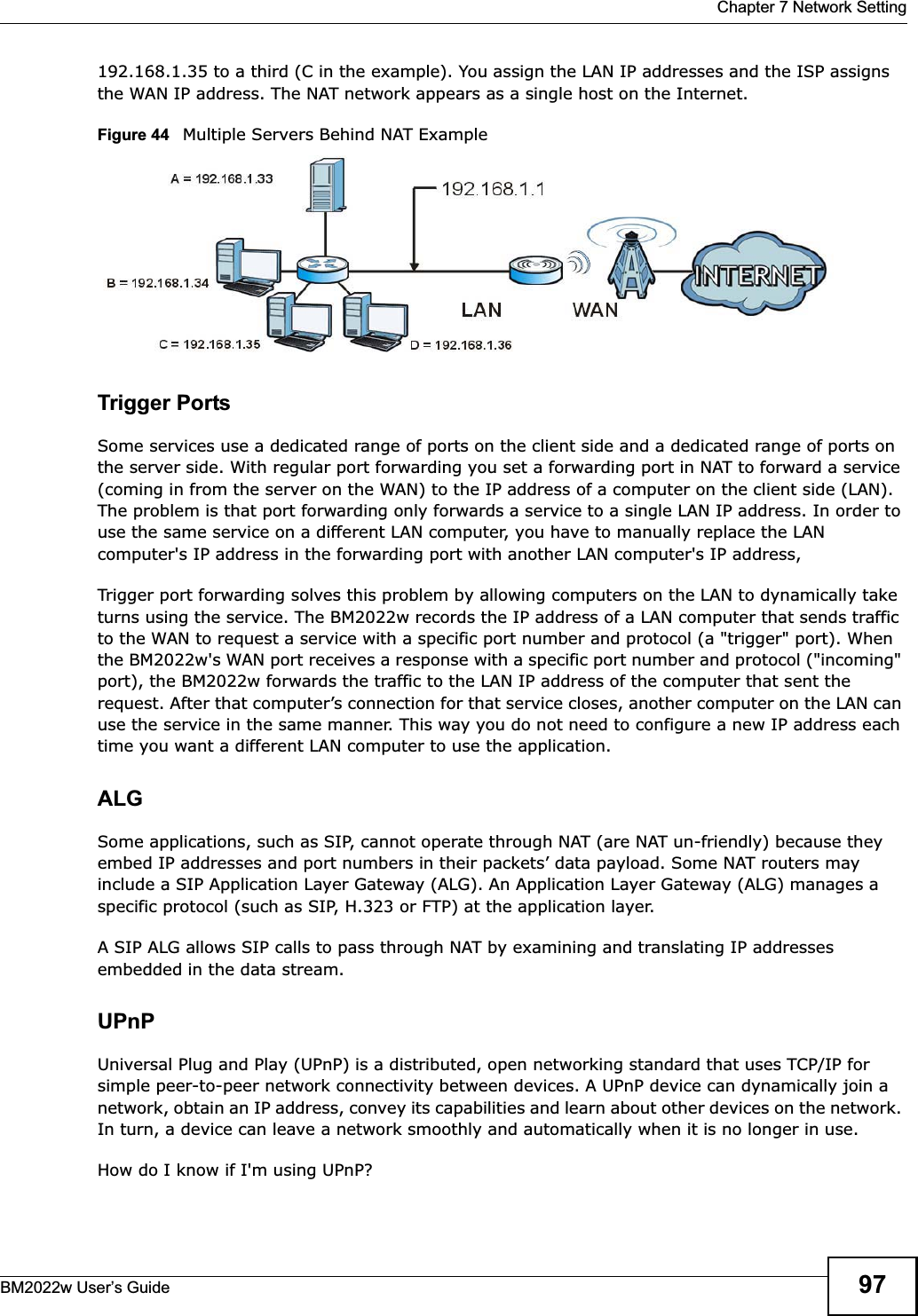
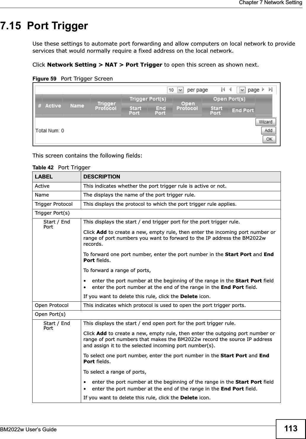
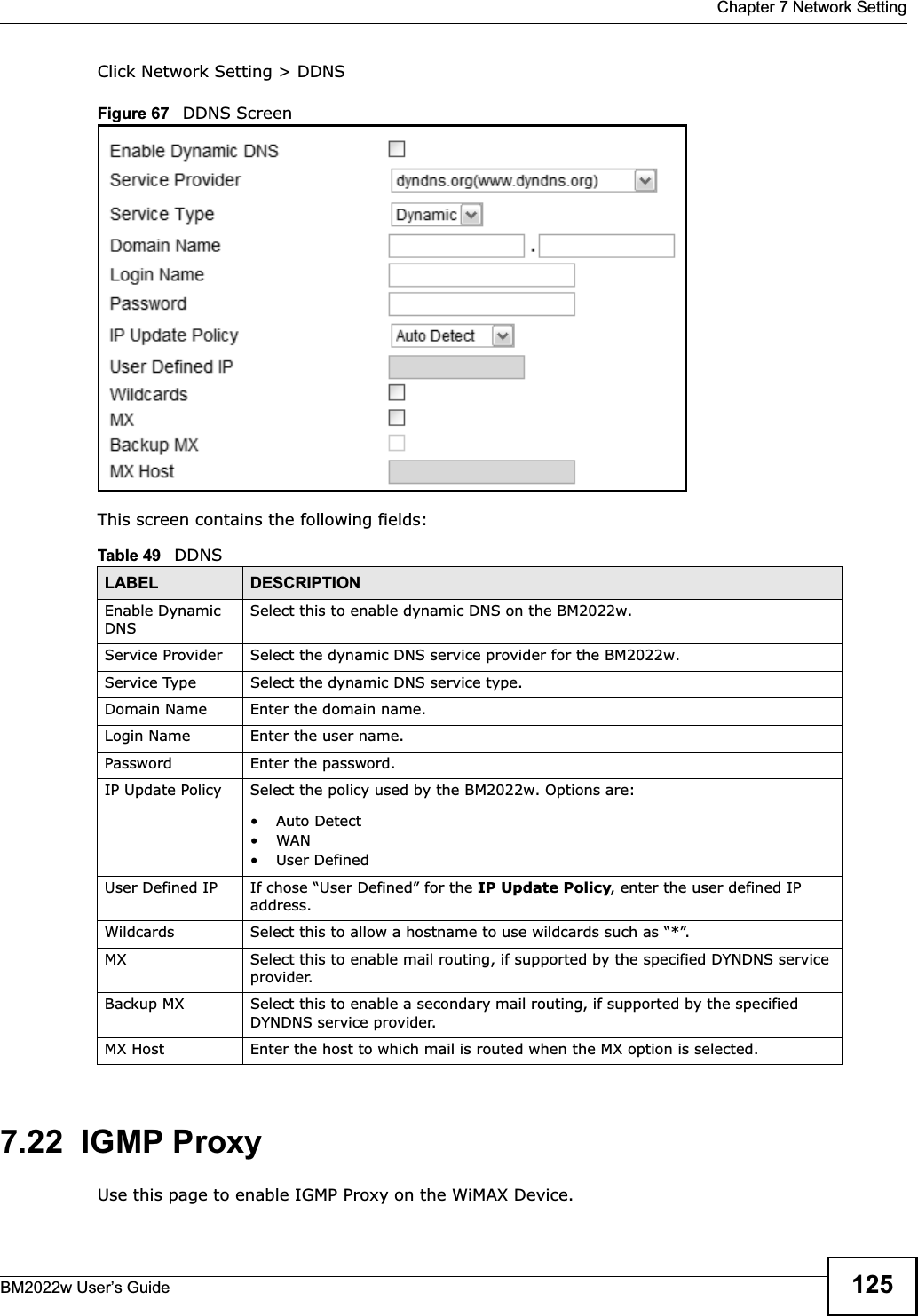
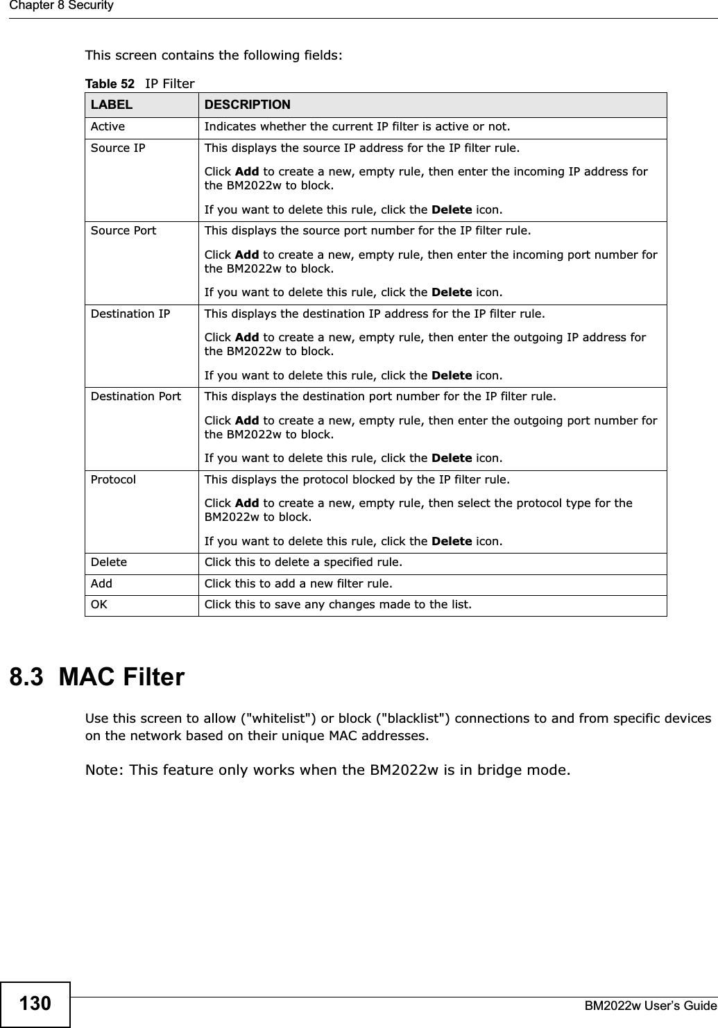
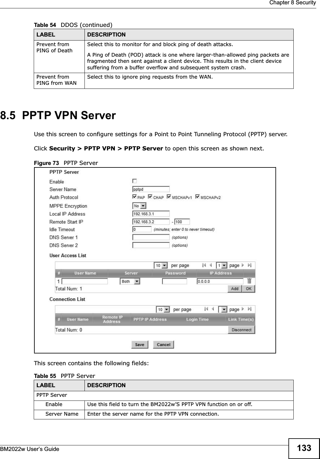
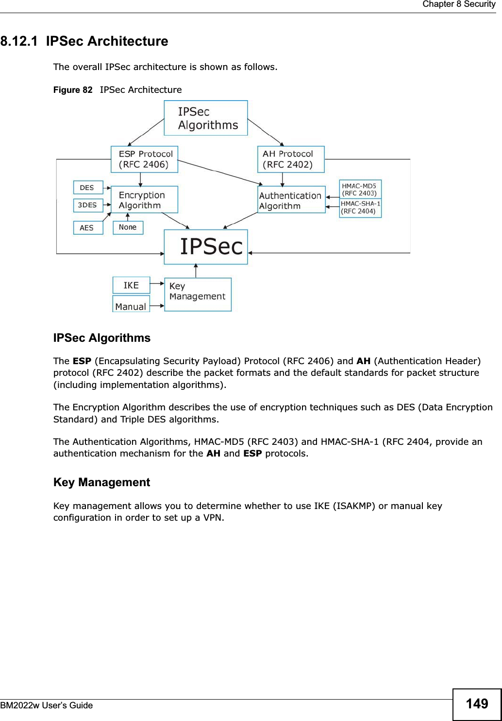
![Chapter 4 TutorialsBM2022w User’s Guide 491Select Enable Dynamic DNS.2Select dyndns.org for the service provider.3Select Dynamic for the service type.4Type mywimax.dyndns.org in the Domain Name field.5Enter the user name (UserName1) and password (12345).6Select WAN IP for the IP update policy.7Click Save.4.8.3 Testing the DDNS SettingNow you should be able to access the BM2022w from the Internet. To test this:1Open a web browser on the computer (using the IP address a.b.c.d) that is connected to the Internet.2Type http://mywimax.dyndns.org and press [Enter].3The BM2022w’s login page should appear. You can then log into the BM2022w and manage it.4.9 Configuring Static Route for Routing to Another NetworkIn order to extend your Intranet and control traffic flowing directions, you may connect a router to the BM2022w’s LAN. The router may be used to separate two department networks. This tutorial shows how to configure a static routing rule for two network routings.In the following figure, router R is connected to the BM2022w’s LAN. R connects to two networks, N1 (192.168.1.x/24) and N2 (192.168.10.x/24). If you want to send traffic from computer A (in](https://usermanual.wiki/MitraStar-Technology/HES209M2W.User-Manual-Part-1/User-Guide-1603517-Page-48.png)