MitraStar Technology HES209M2W WiMAX Indoor VoIP Wi-Fi IAD User Manual User s guide Update
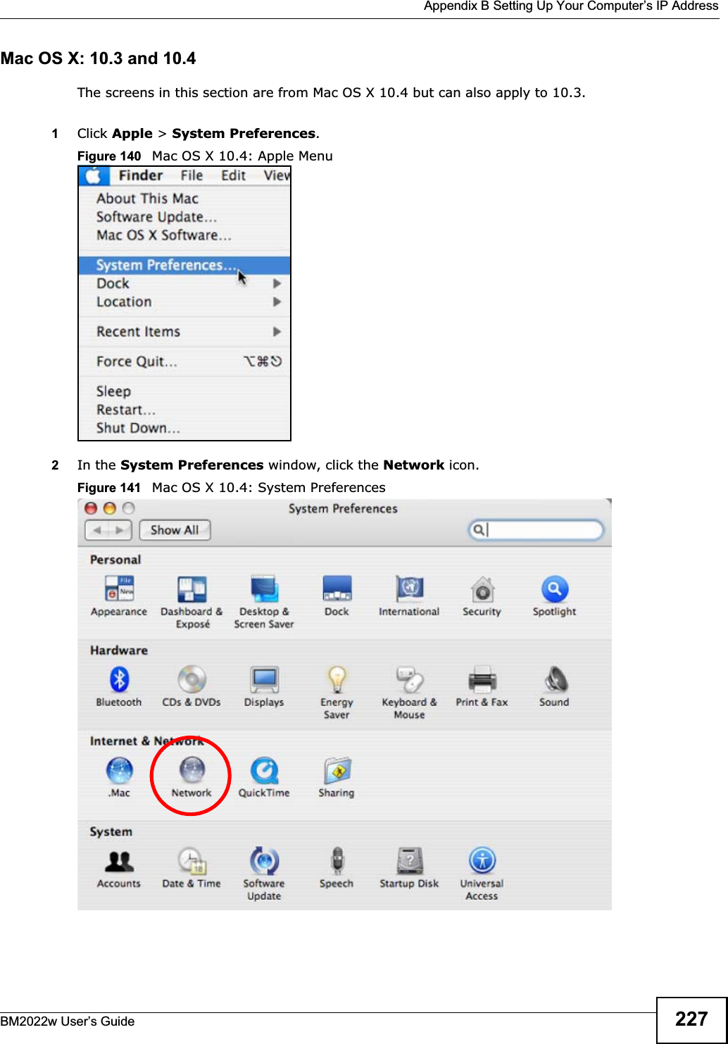
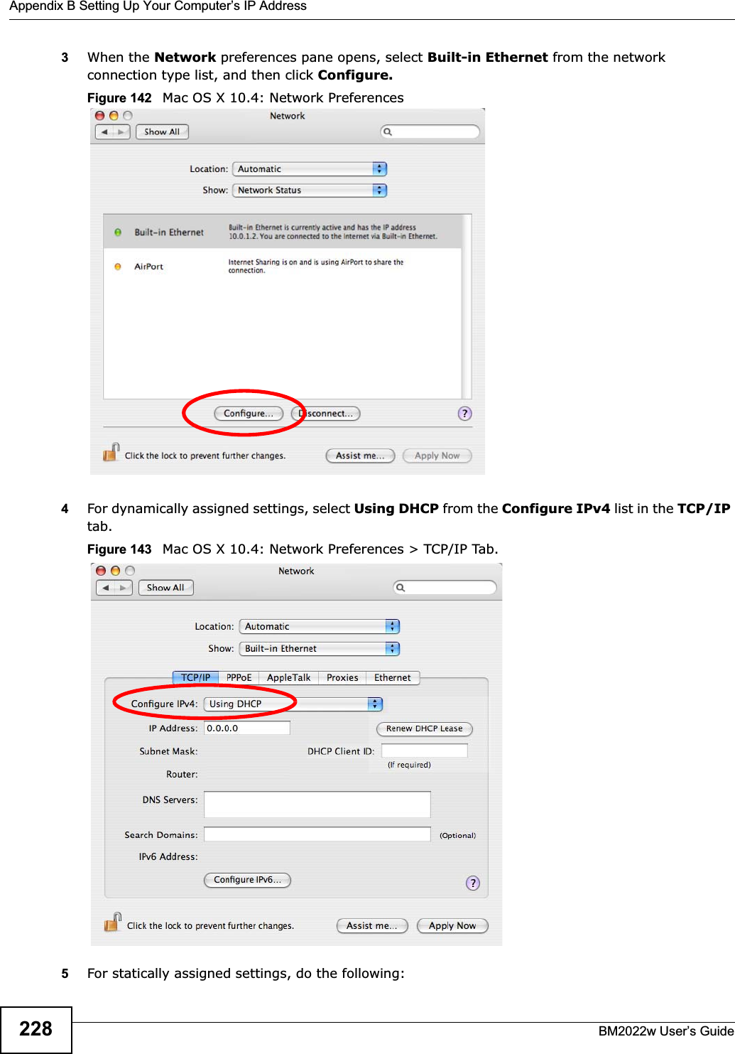
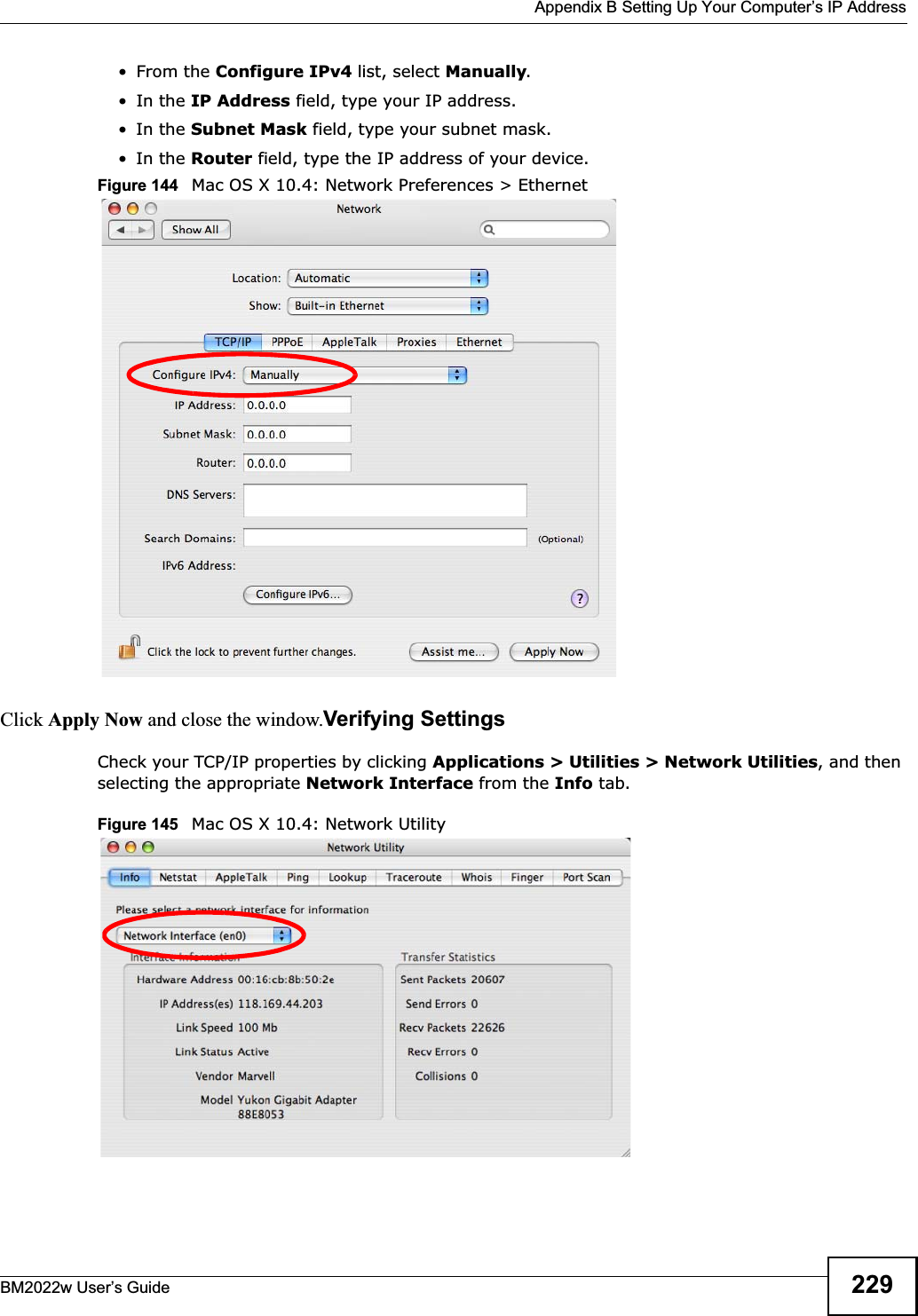
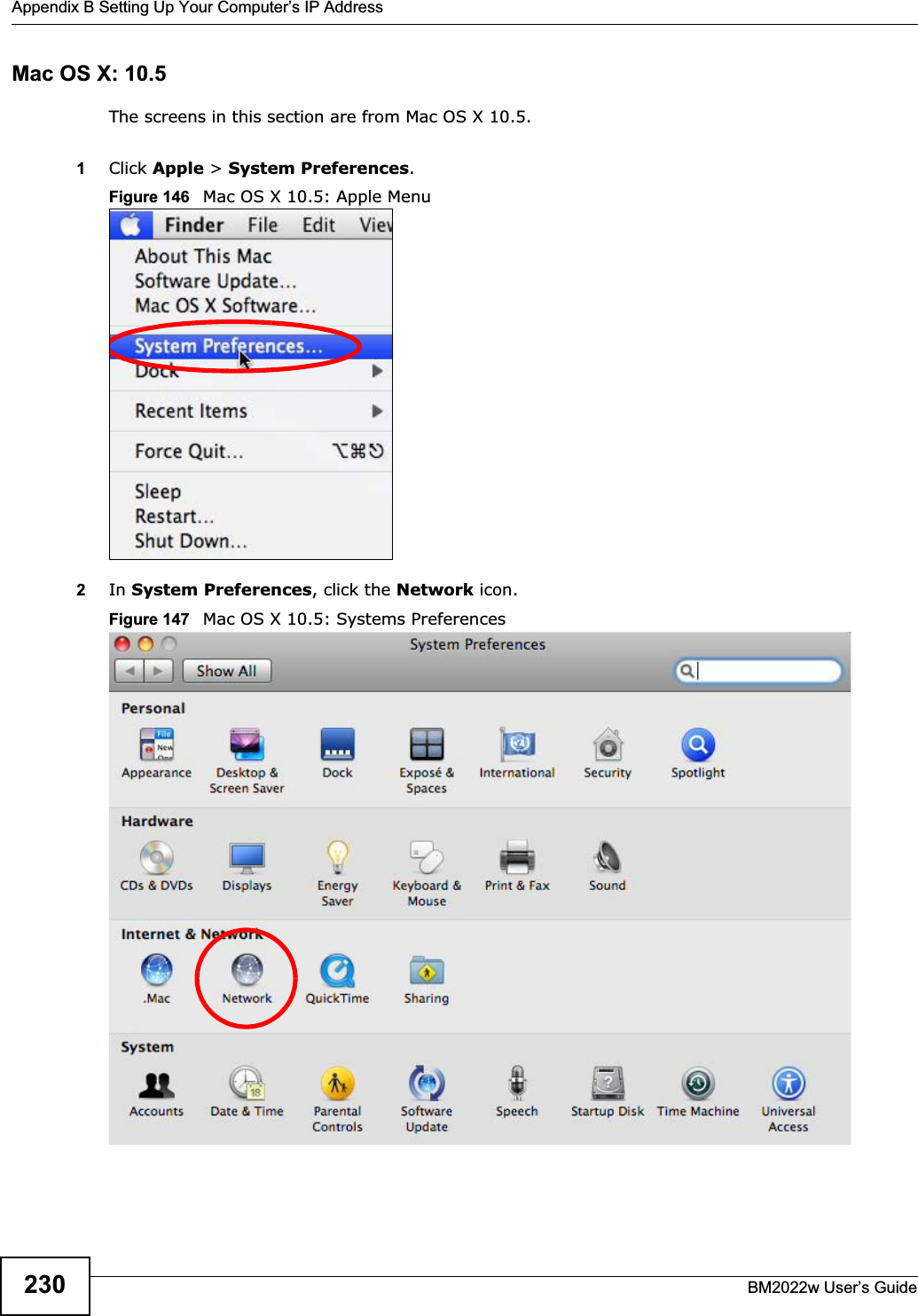
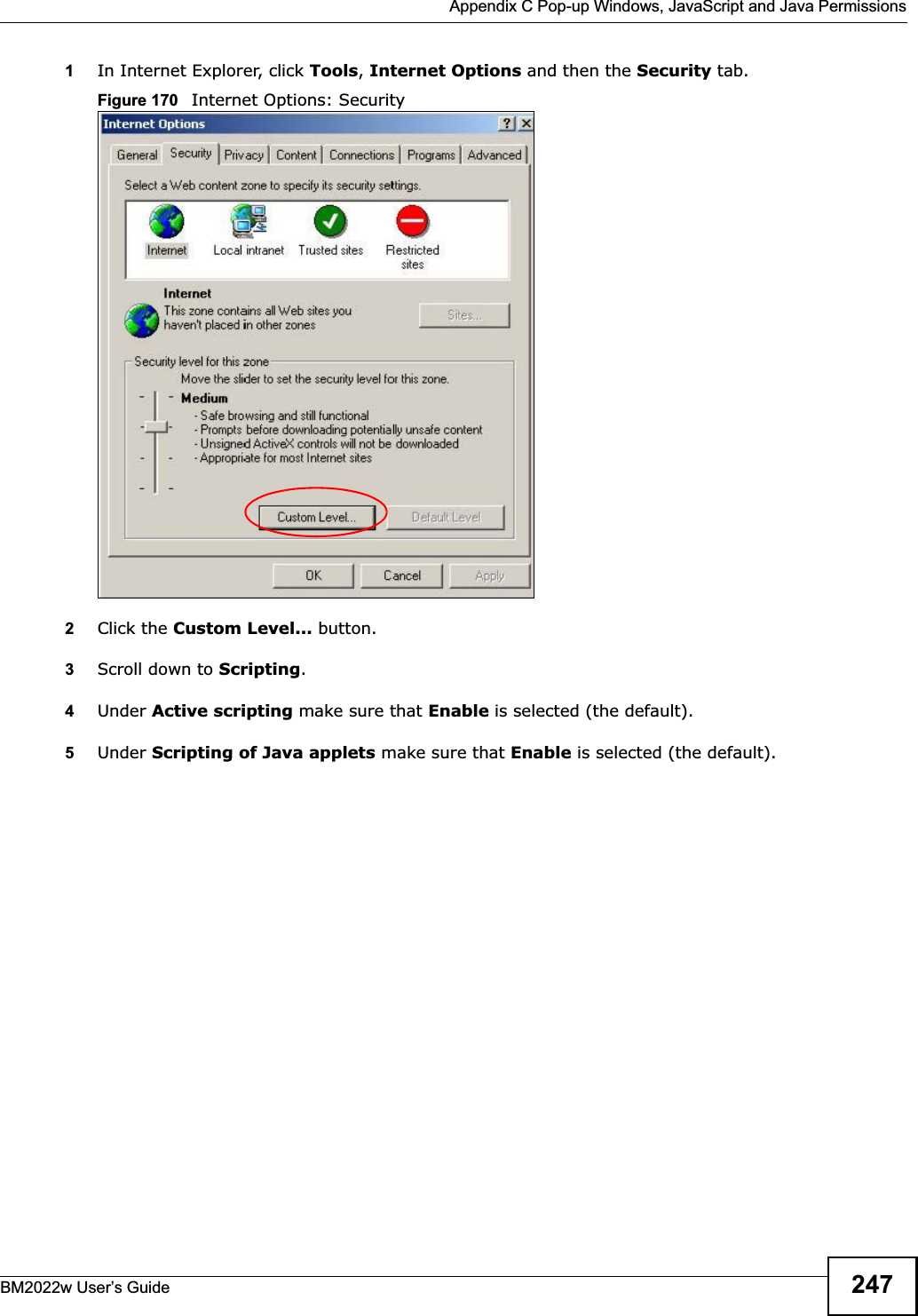
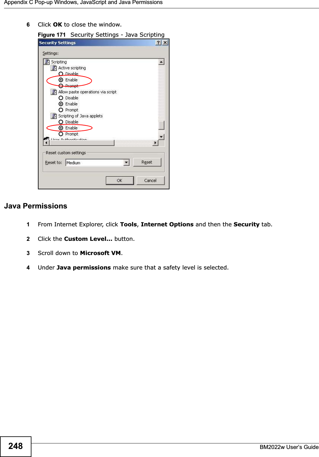
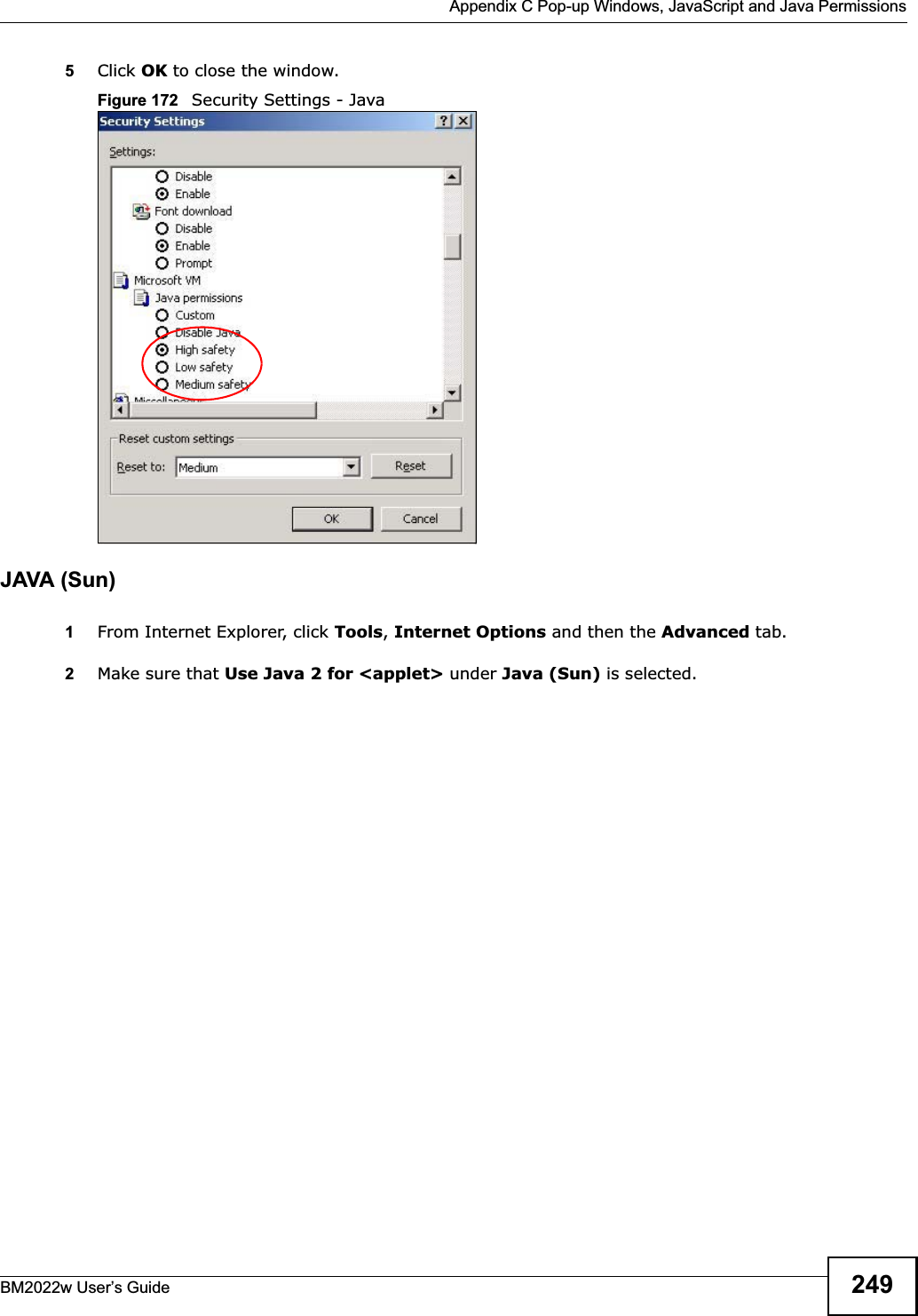
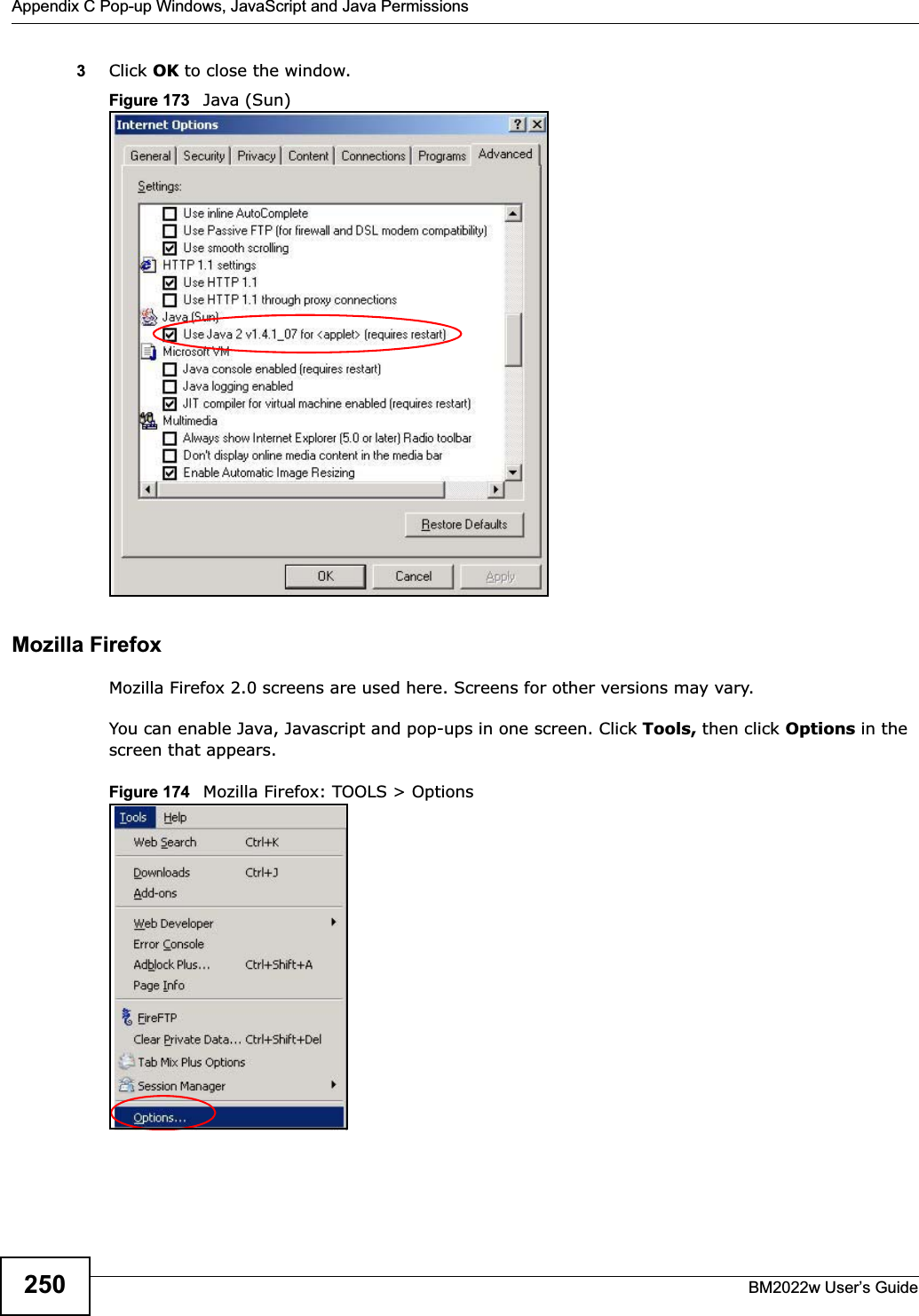
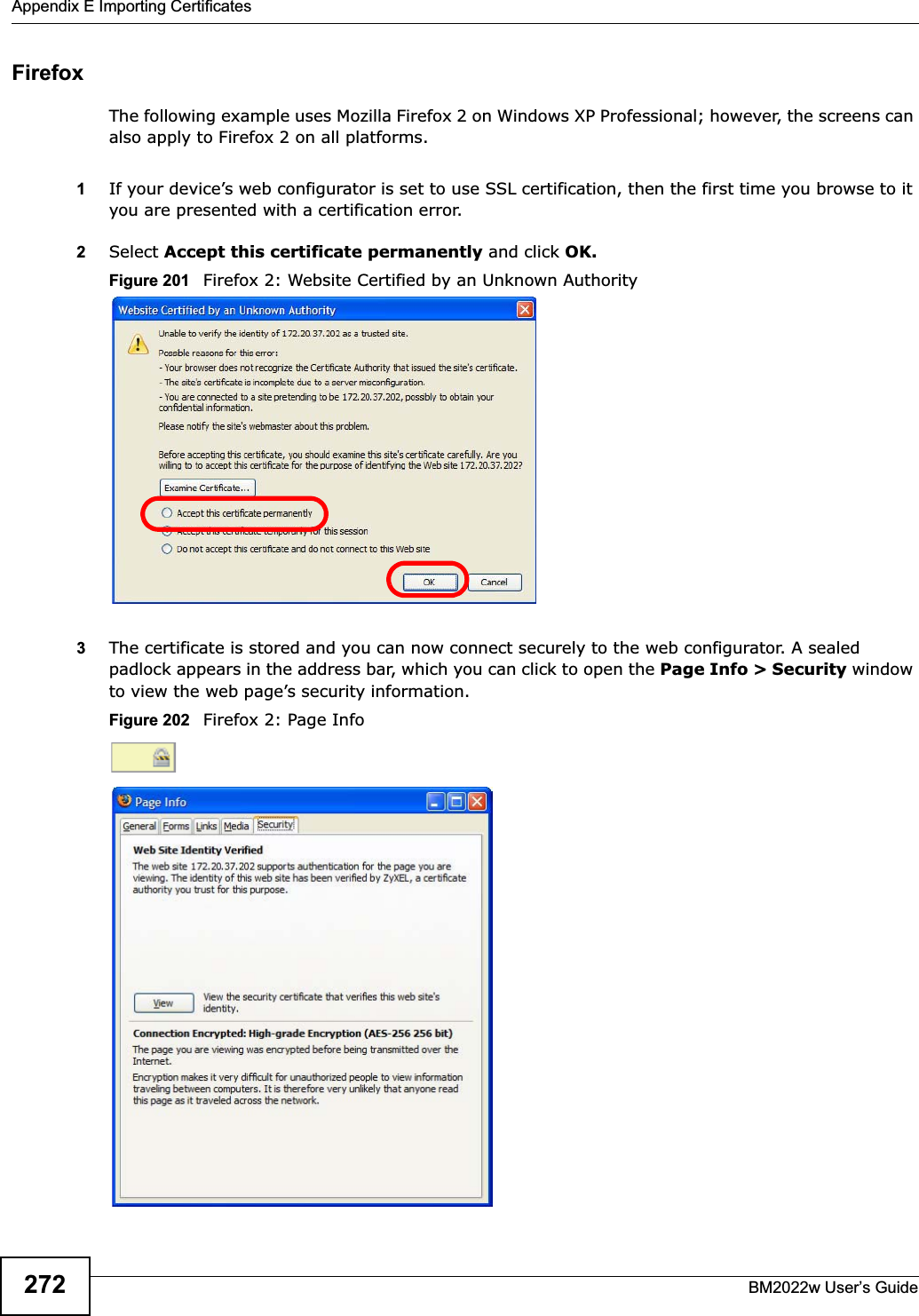
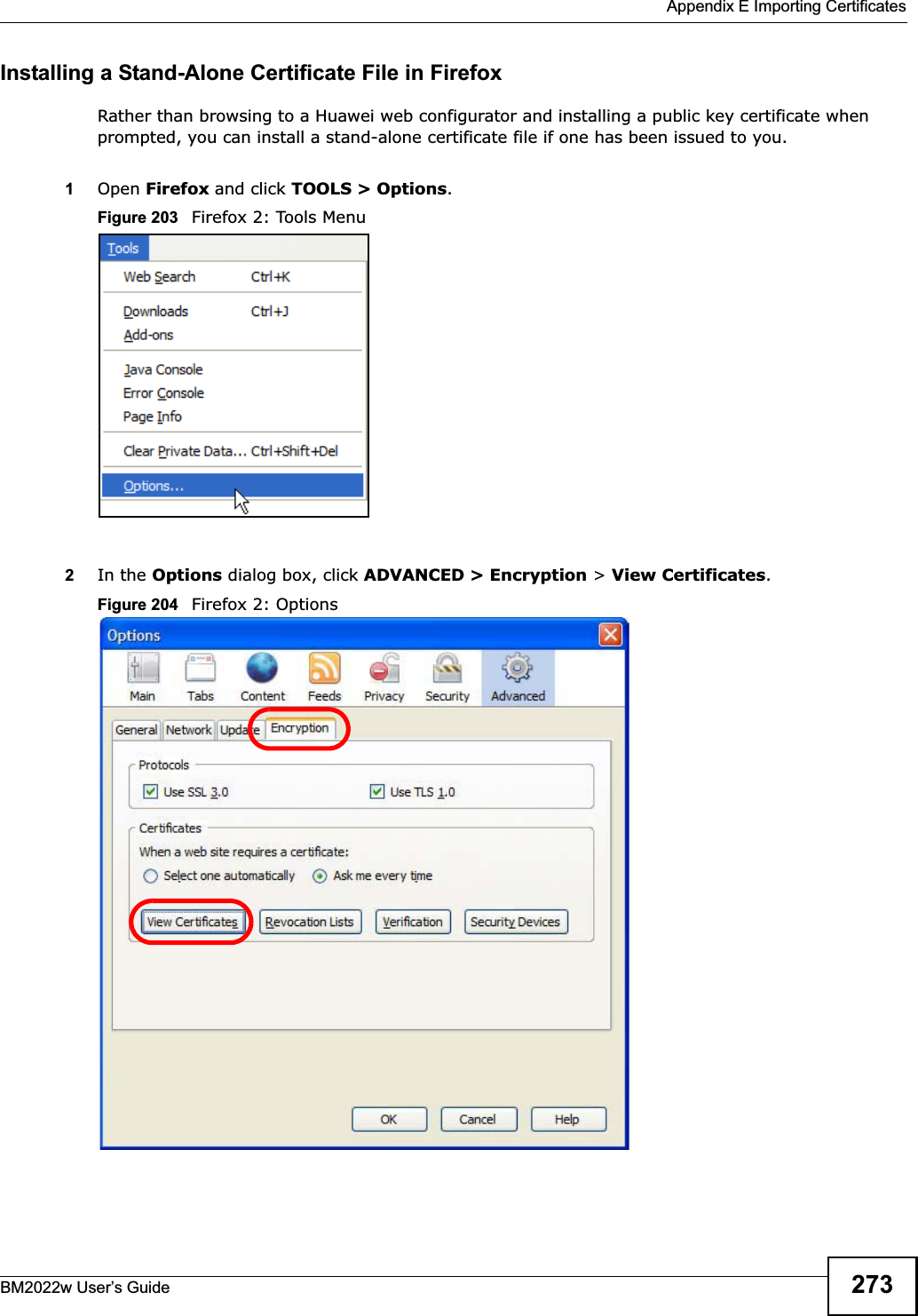
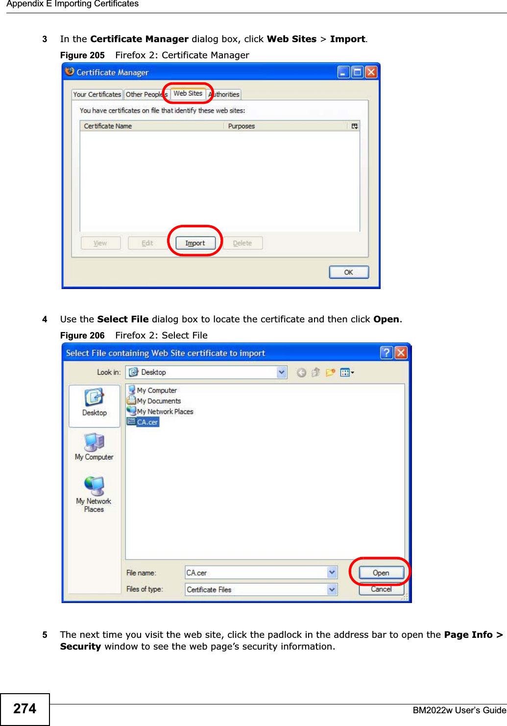
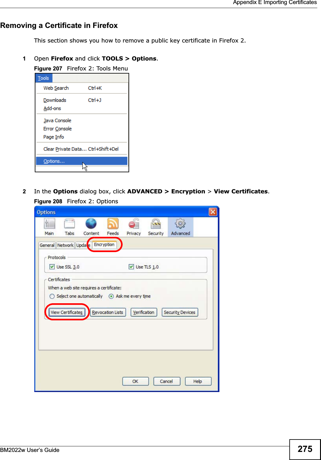
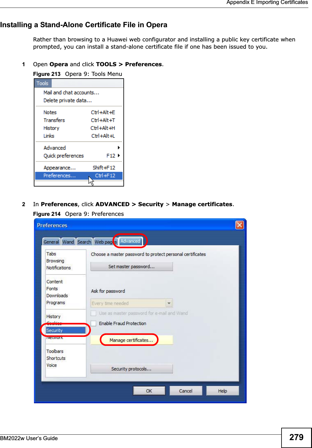
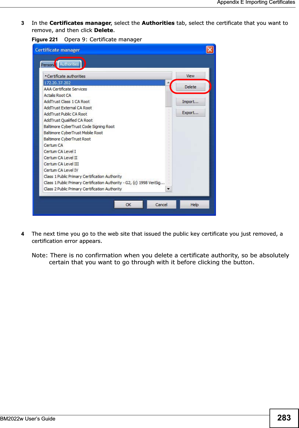
MitraStar Technology Corporation WiMAX Indoor VoIP Wi-Fi IAD User s guide Update
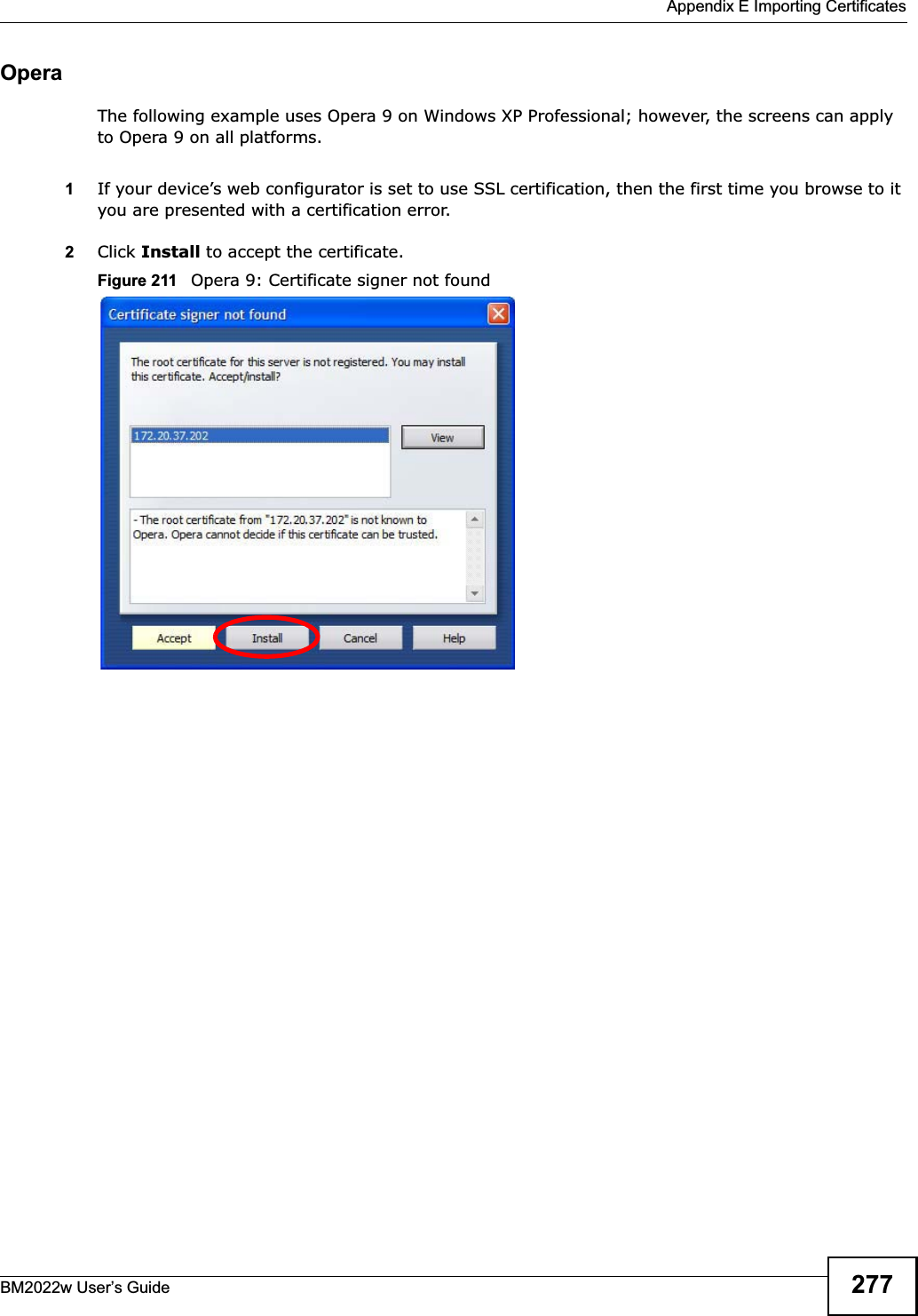
UserManual.wiki
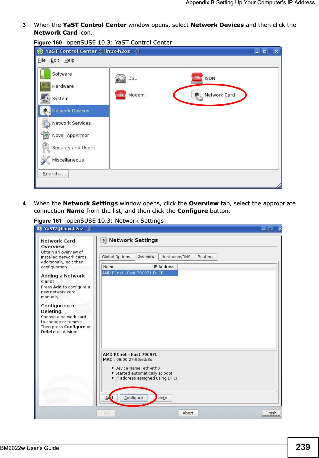
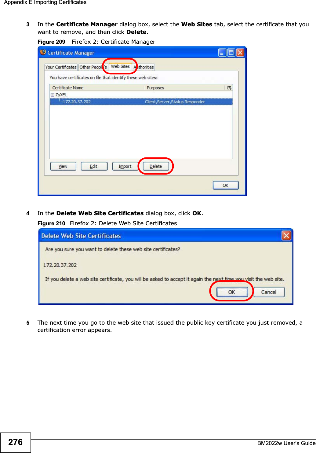
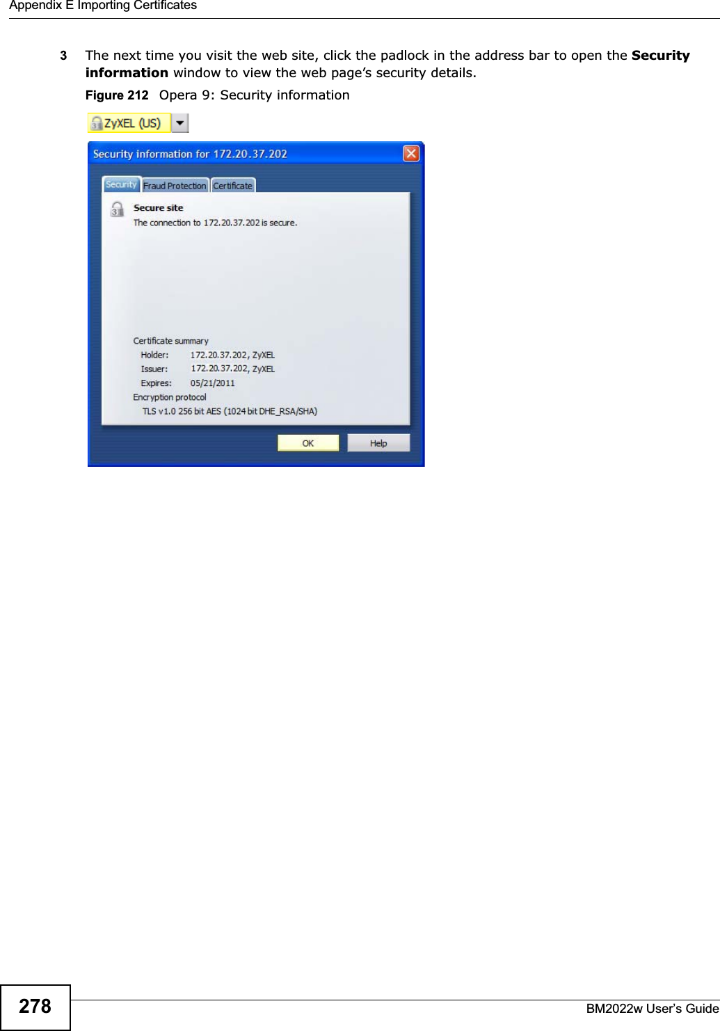
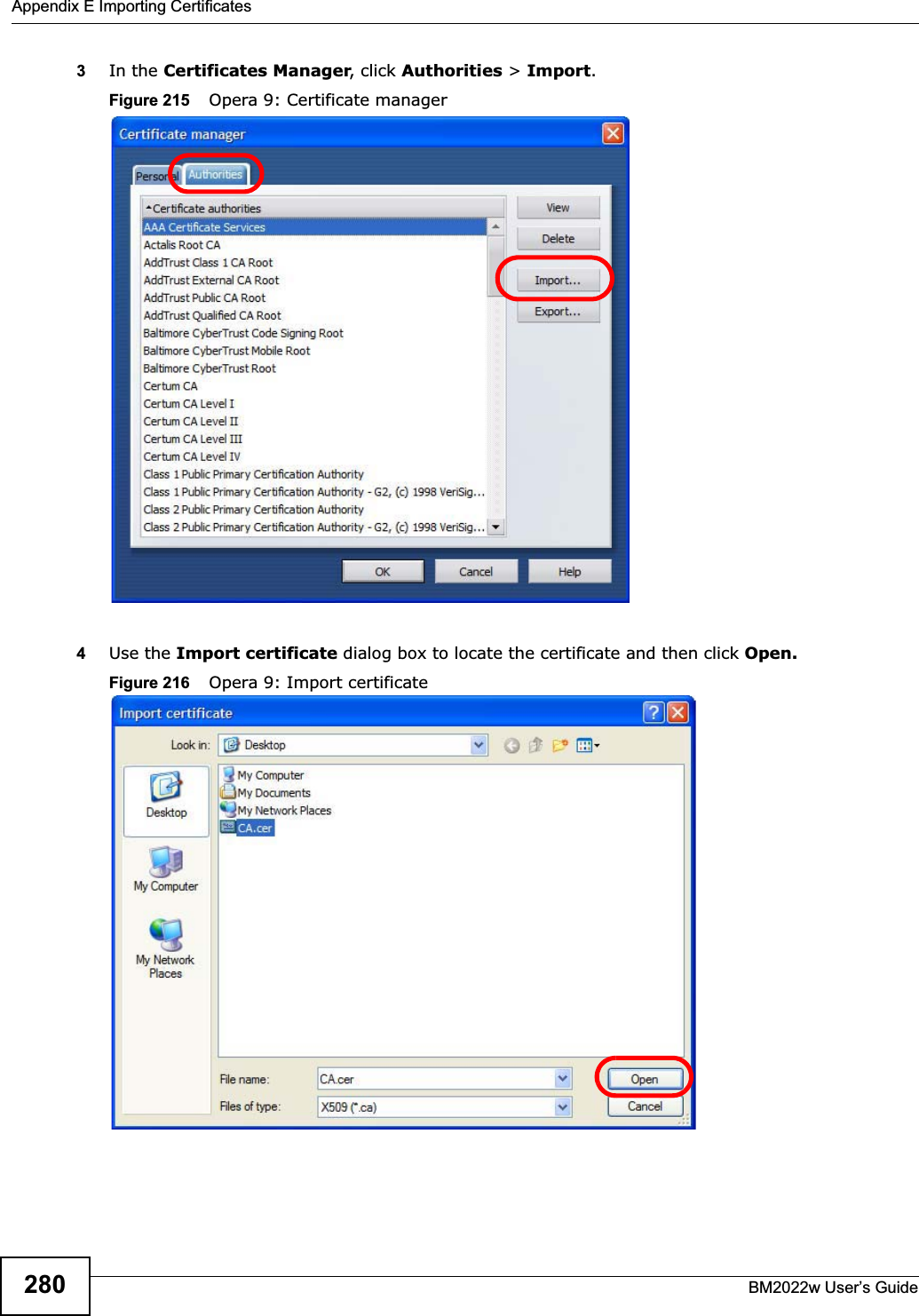
>
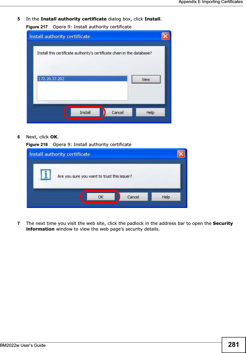
MitraStar Technology
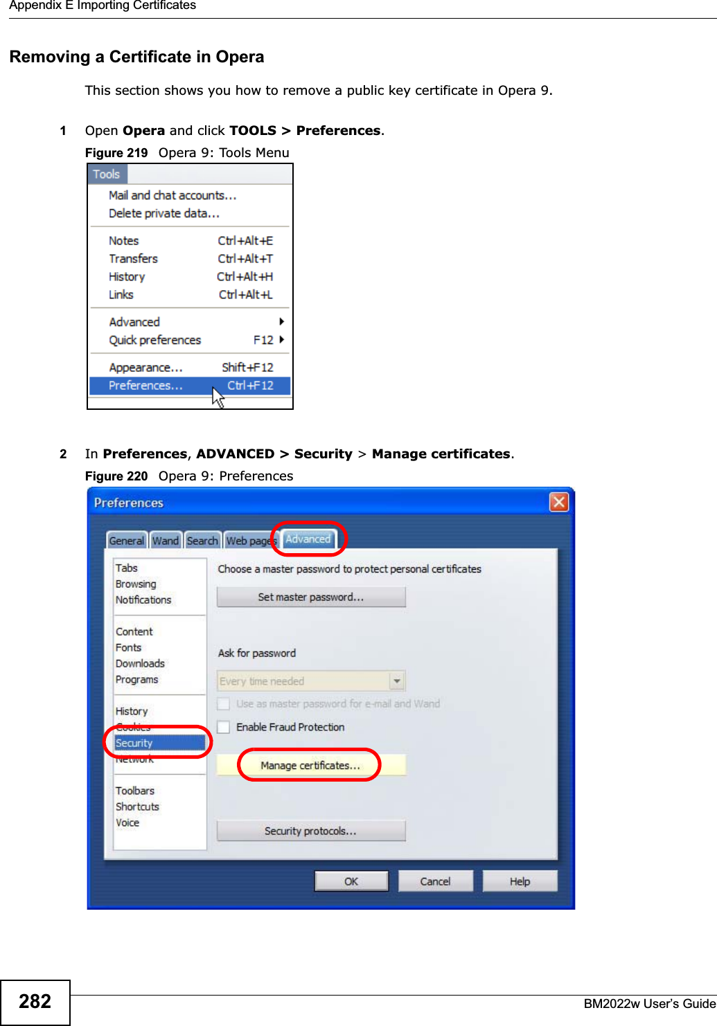
>
HES209M2W User Manual
>
User Manual Part 2
Contents
1.
User Manual Part 1
2.
User Manual Part 2
User Manual Part 2
Navigation menu
Upload a User Manual
Namespaces
Wiki Guide
HTML
PDF
Info
Views
User Manual
Discussion / Help
Navigation
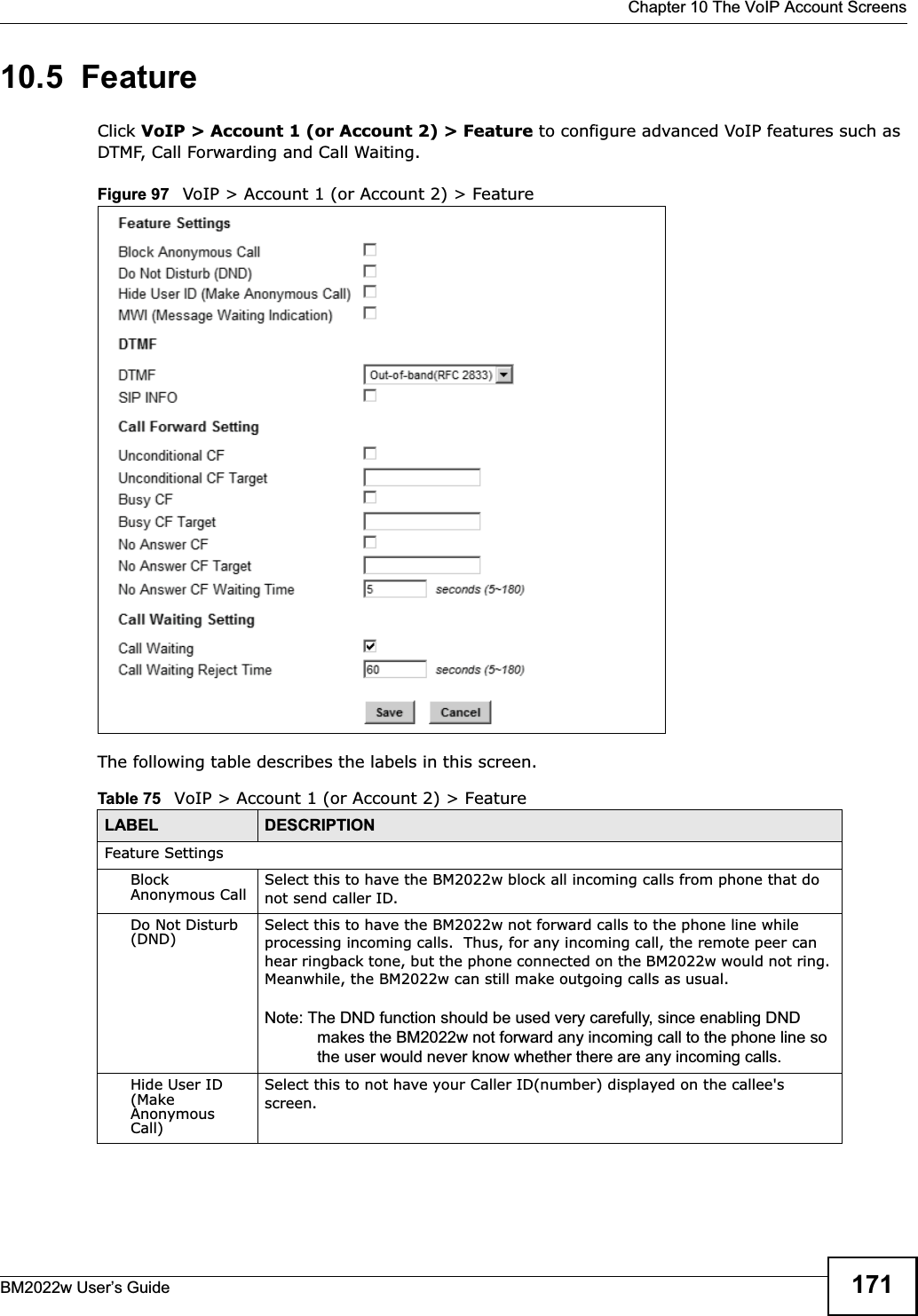
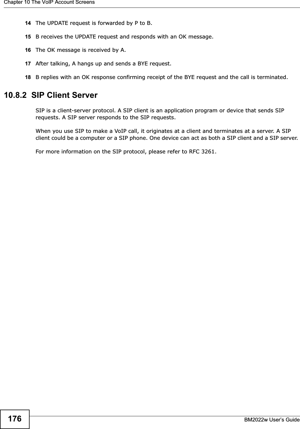

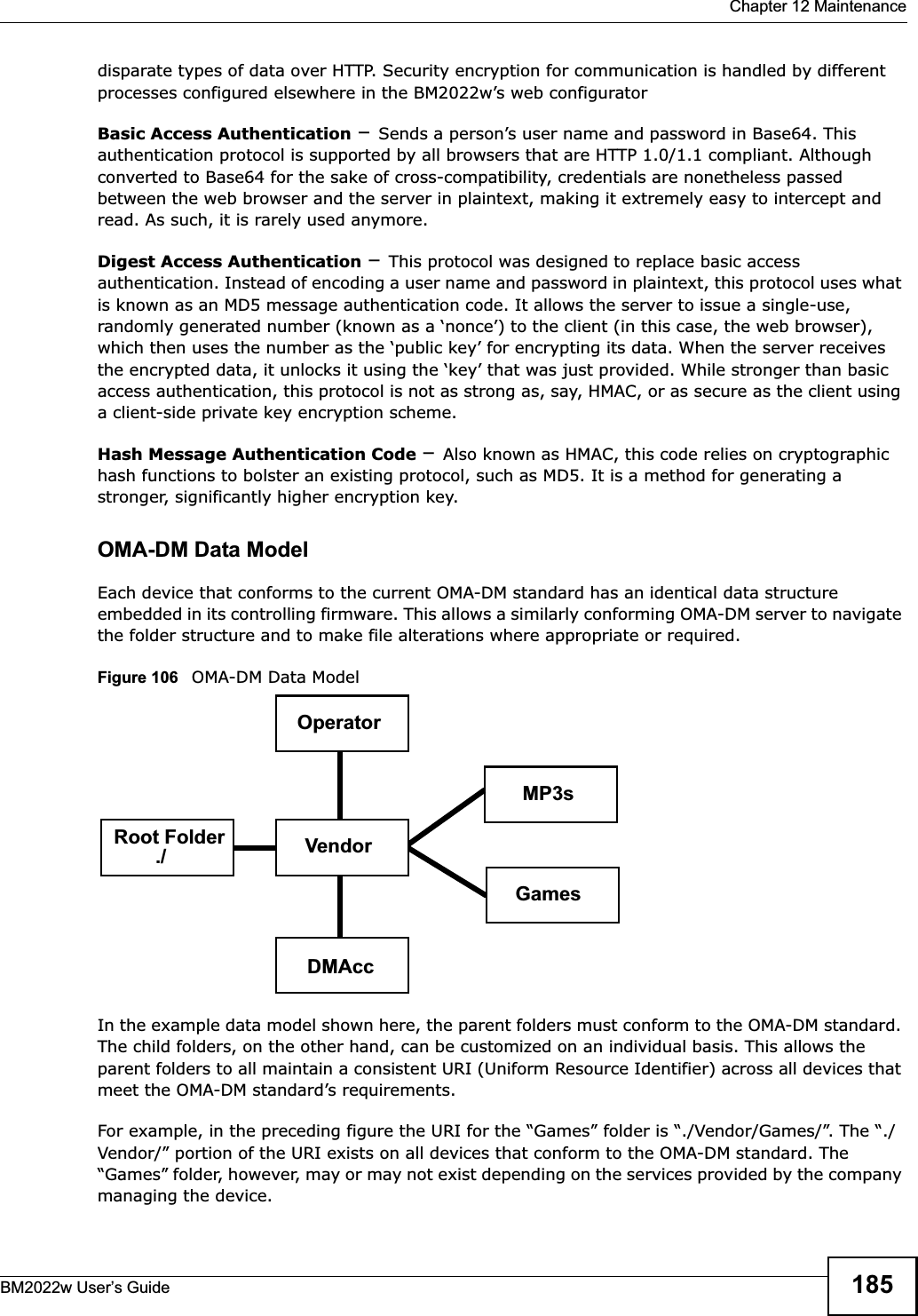
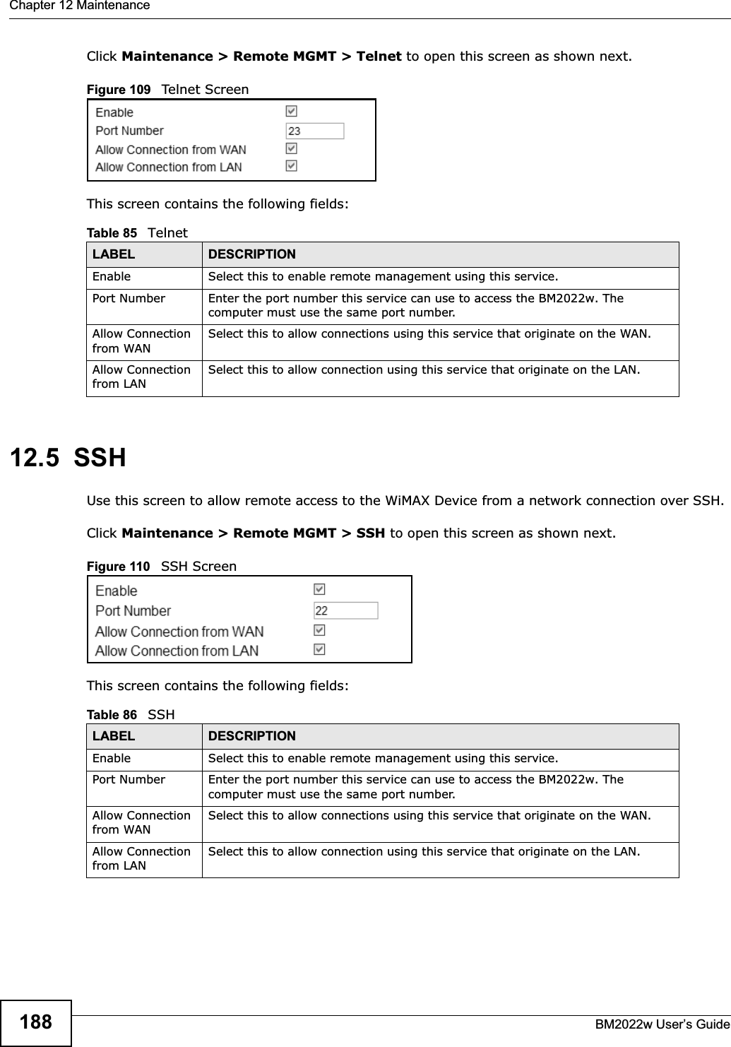
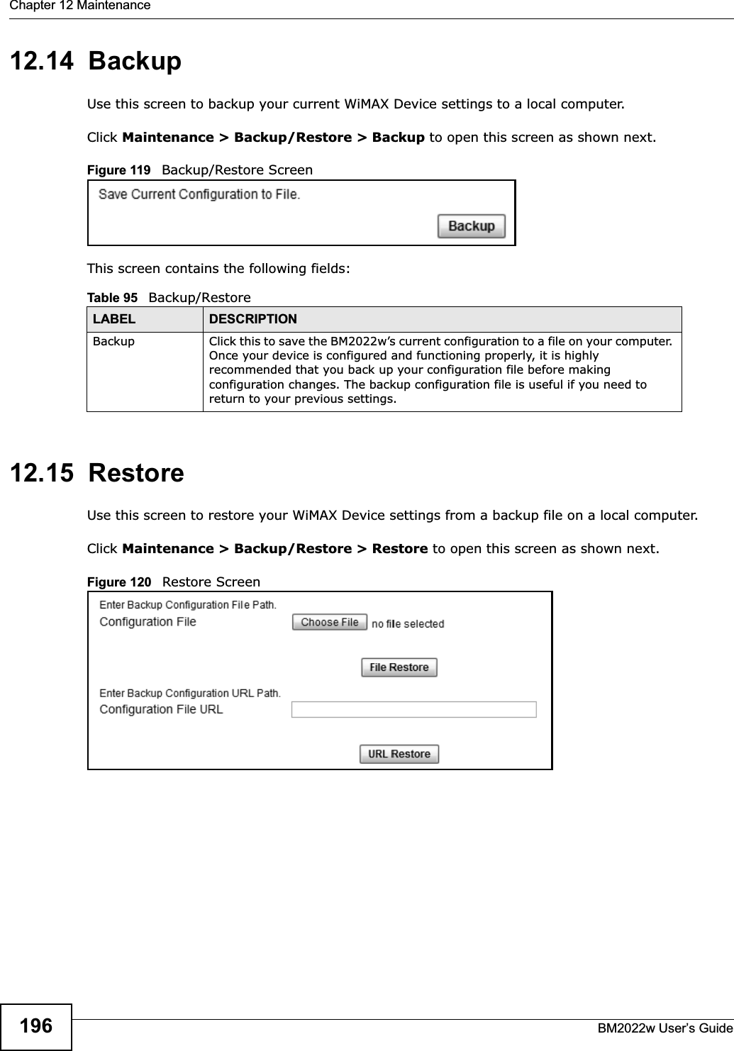
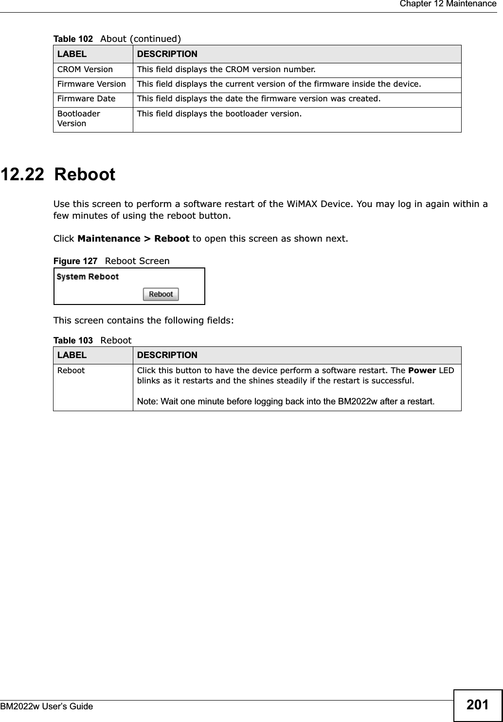

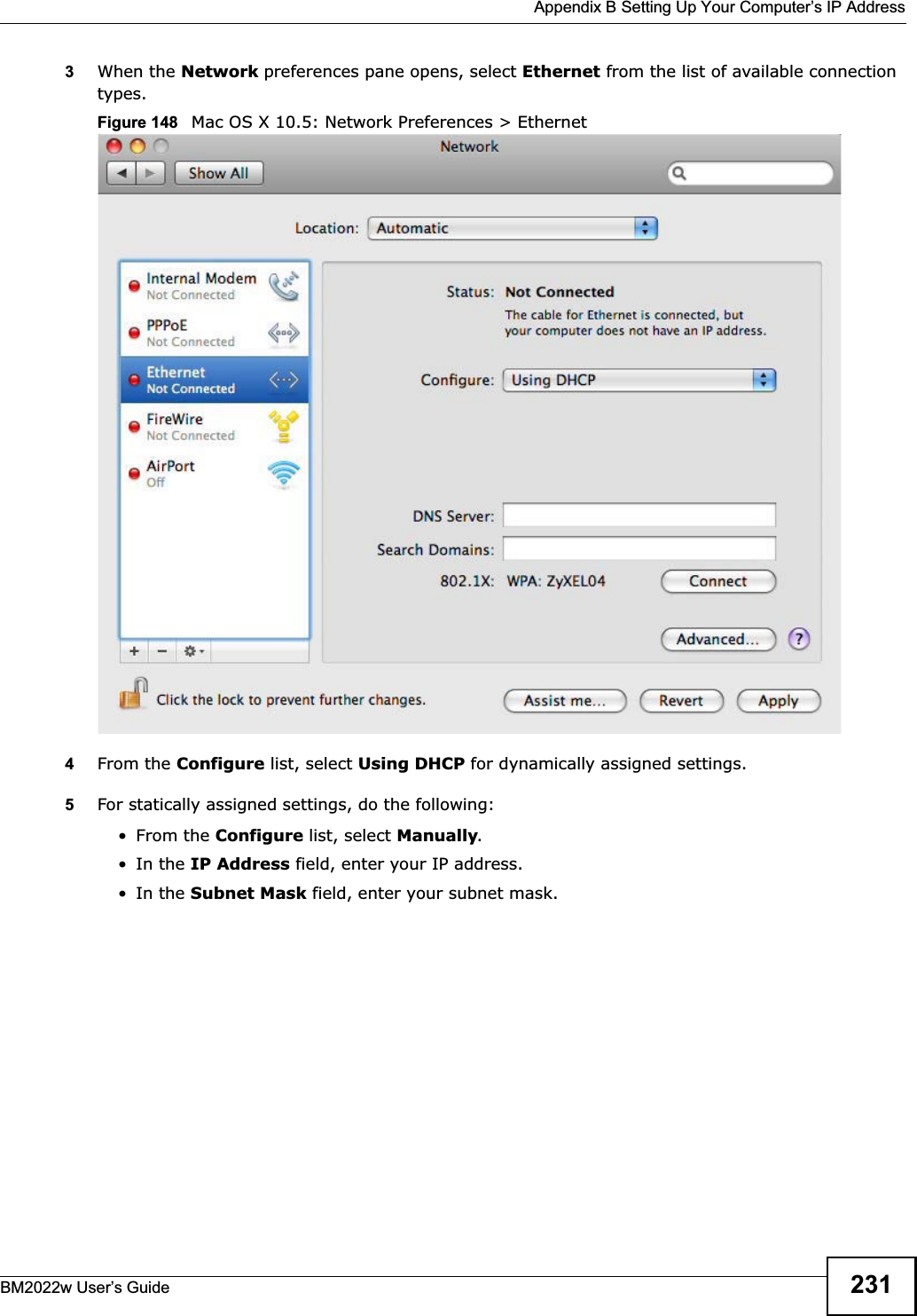
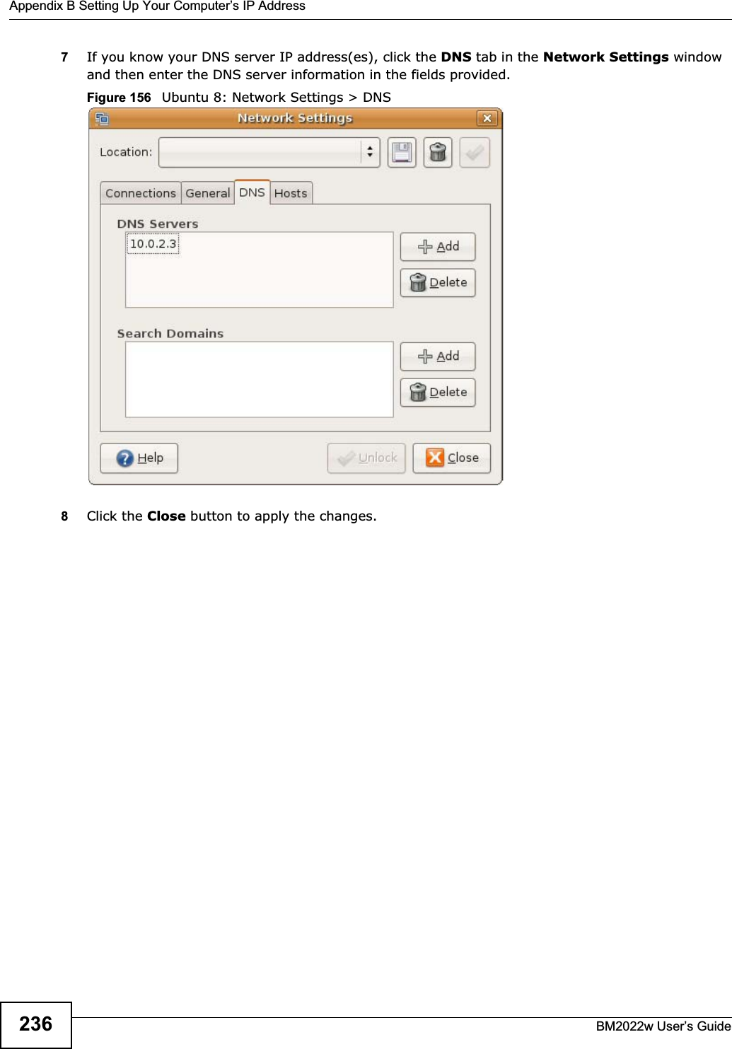
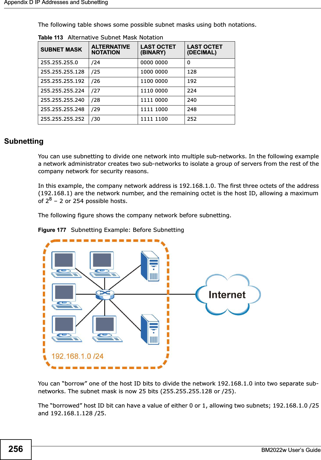
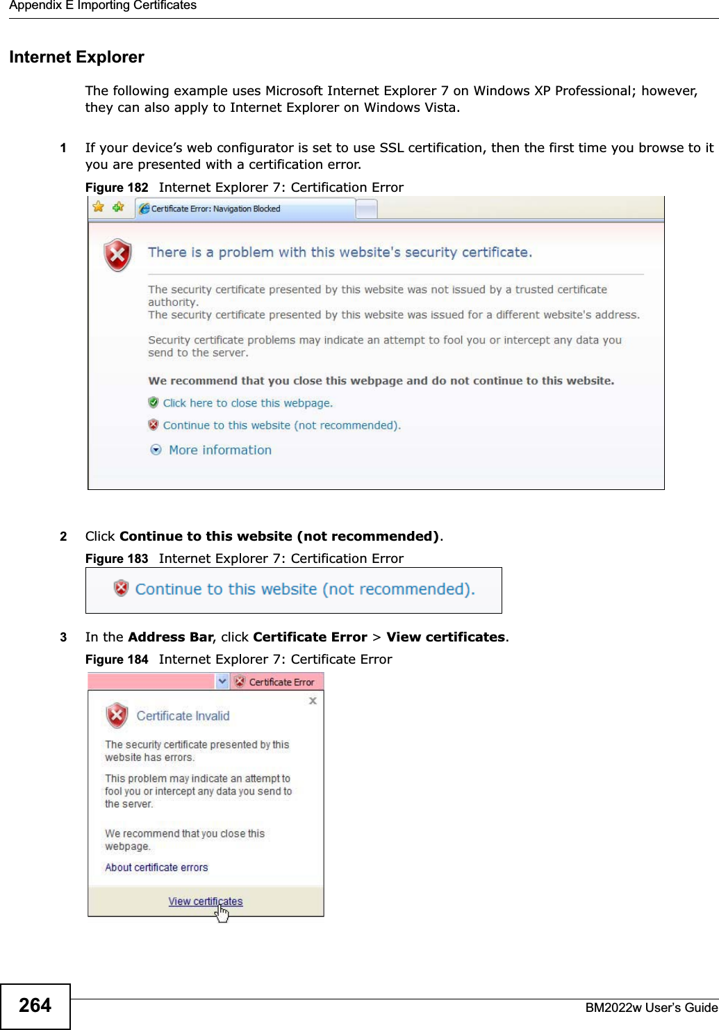
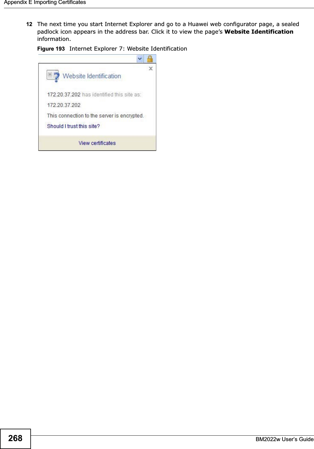
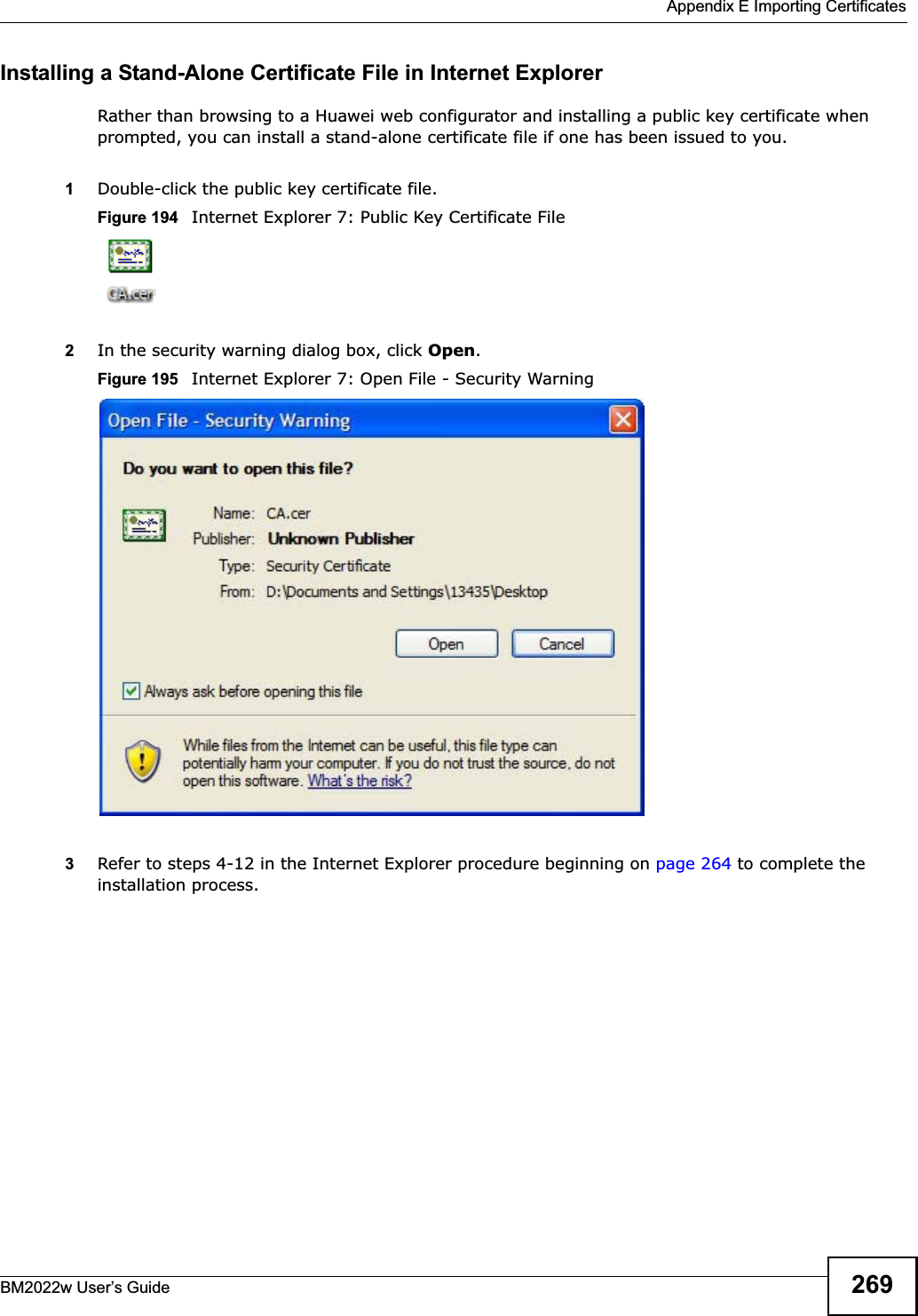
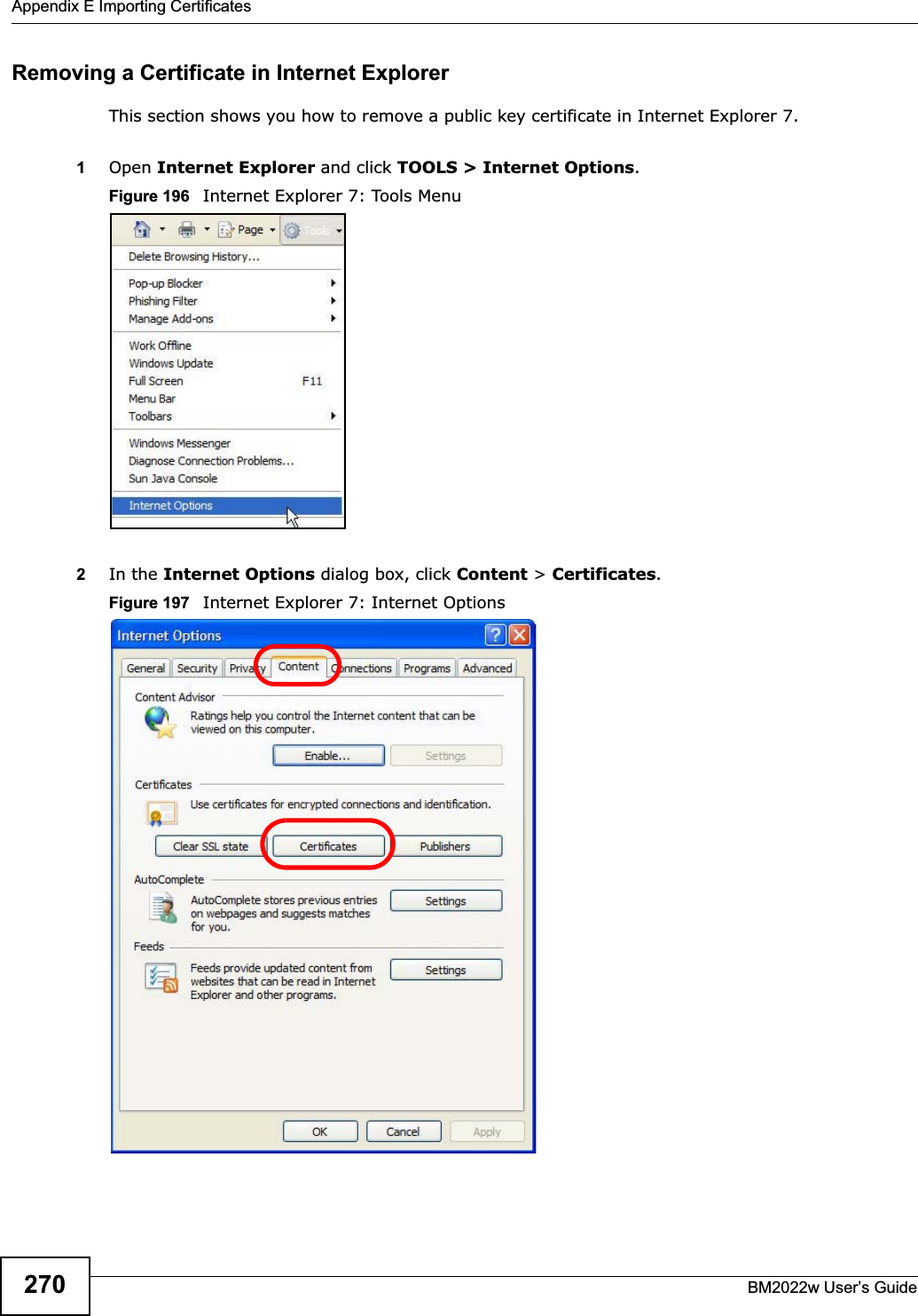
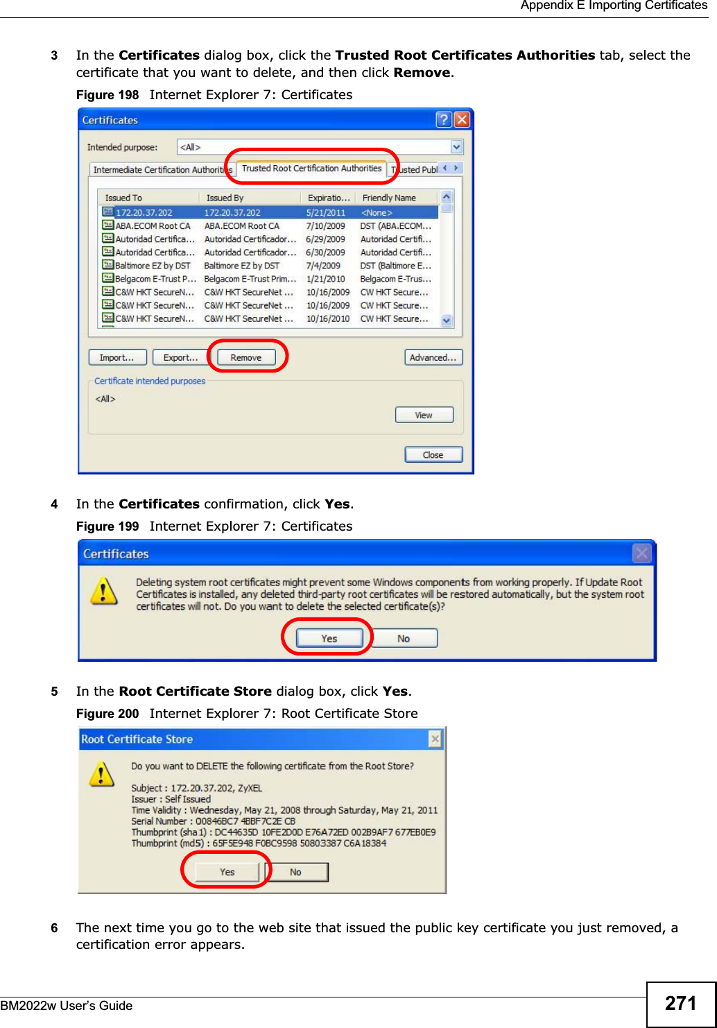
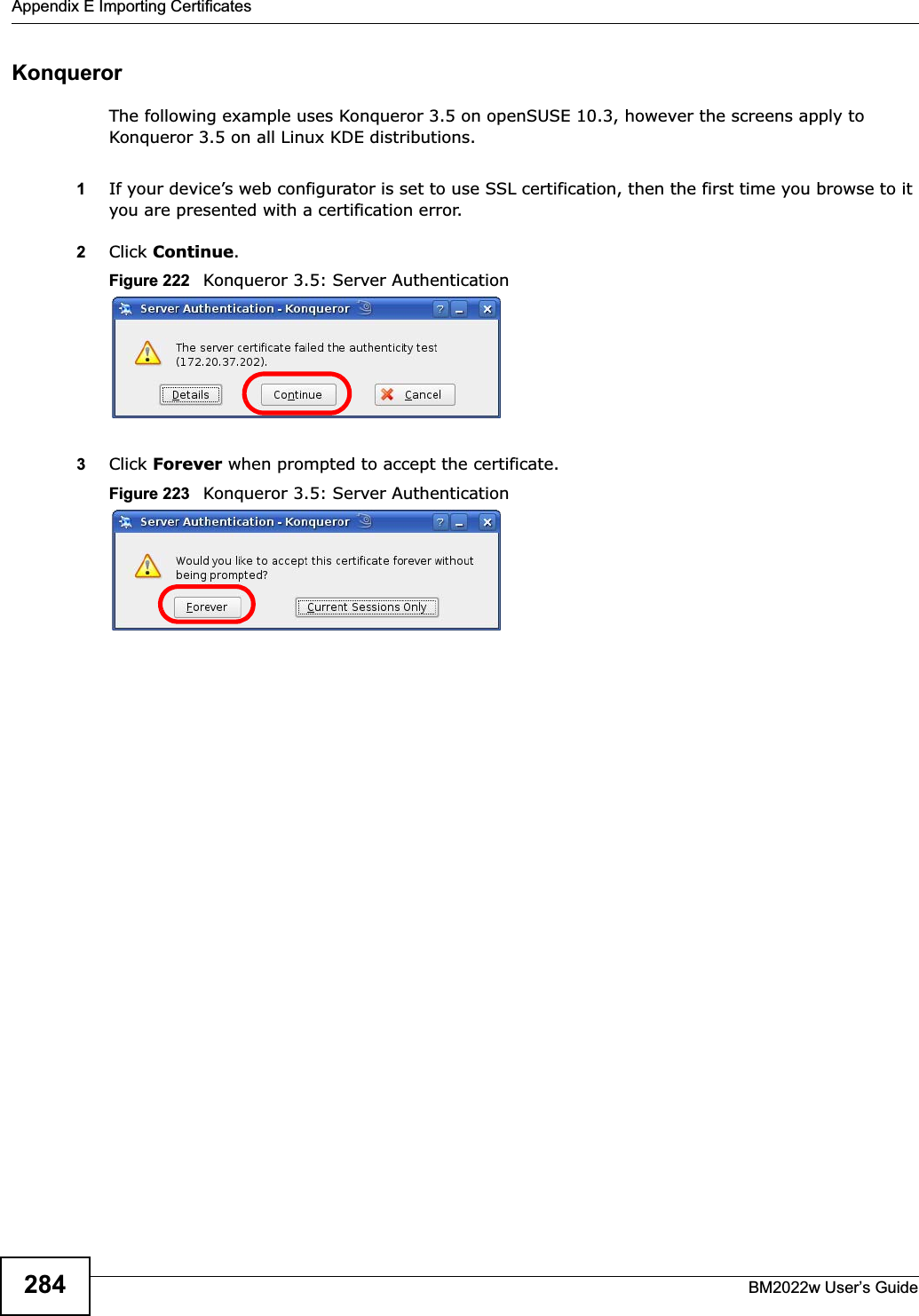
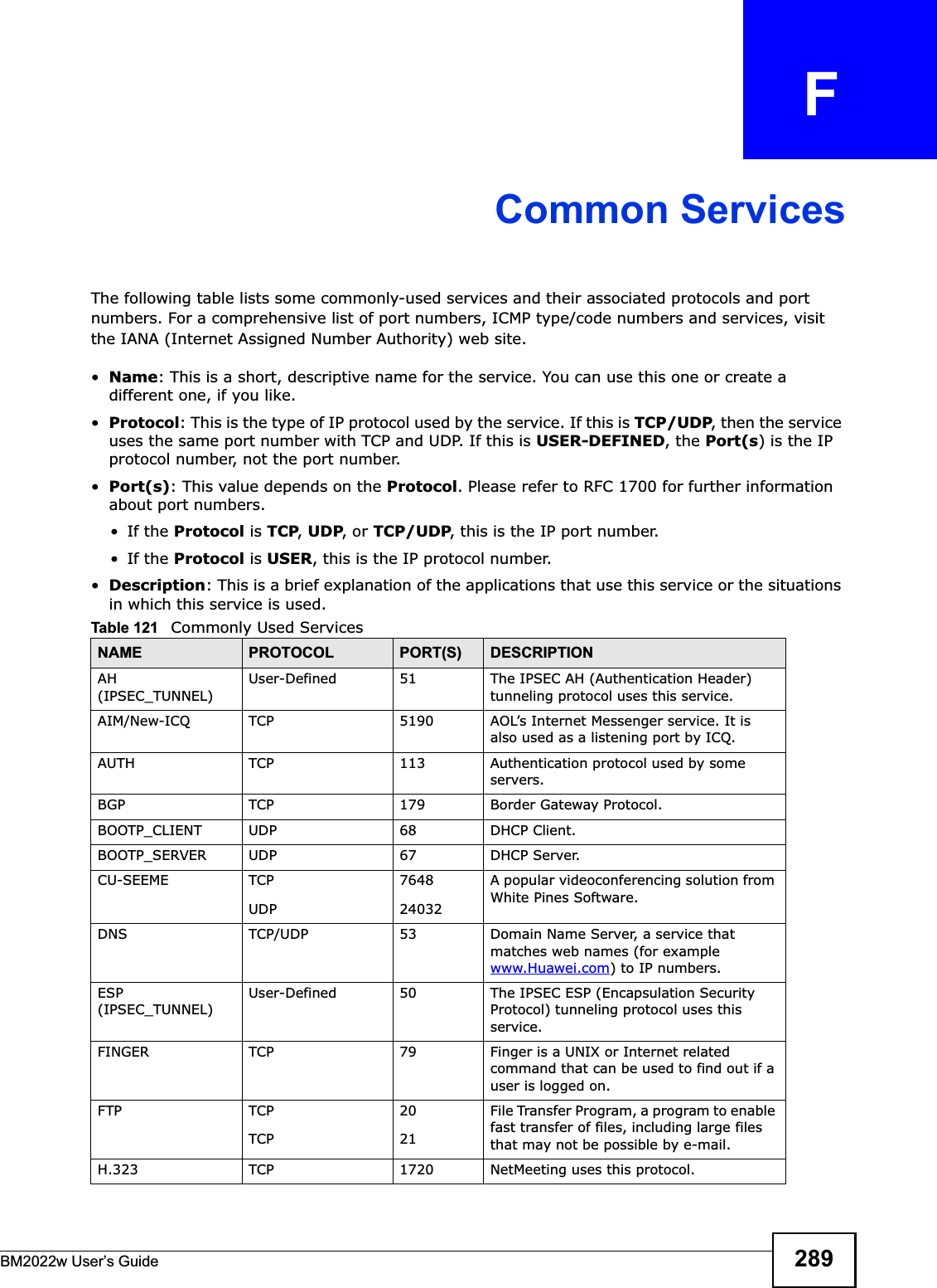
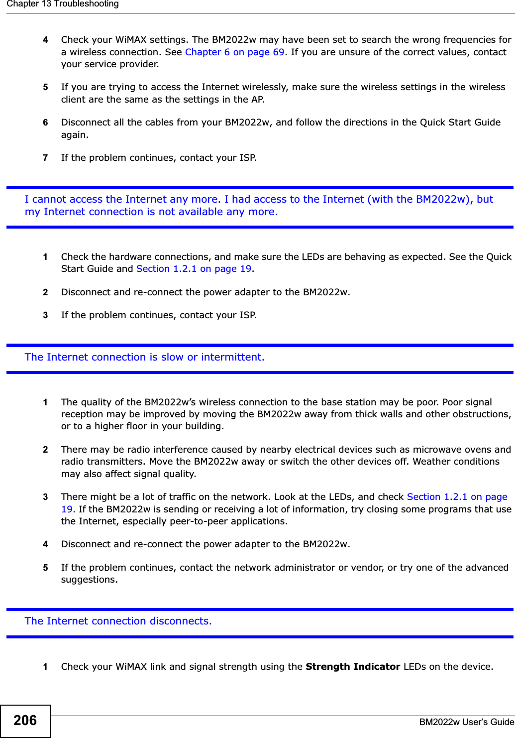
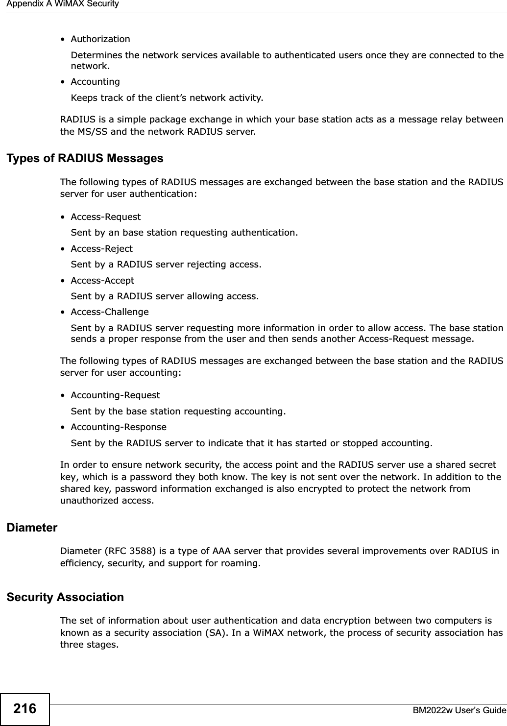
![Chapter 13 TroubleshootingBM2022w User’s Guide 2056If the problem continues, contact the network administrator or vendor, or try one of the advanced suggestions.Advanced Suggestions• Try to access the BM2022w using another service, such as Telnet. If you can access the BM2022w, check the remote management settings and firewall rules to find out why the BM2022w does not respond to HTTP.• If your computer is connected wirelessly, use a computer that is connected to a LAN/ETHERNETport.I can see the Login screen, but I cannot log in to the BM2022w.1Make sure you have entered the user name and password correctly. The default user name is admin, and the default password is 1234. These fields are case-sensitive, so make sure [Caps Lock] is not on.2You cannot log in to the web configurator while someone is using Telnet to access the BM2022w. Log out of the BM2022w in the other session, or ask the person who is logged in to log out.3Disconnect and re-connect the power adapter or cord to the BM2022w.4If this does not work, you have to reset the BM2022w to its factory defaults. See Section 12.16 on page 197.I cannot Telnet to the BM2022w.See the troubleshooting suggestions for I cannot see or access the Login screen in the web configurator. Ignore the suggestions about your browser.13.3 Internet AccessI cannot access the Internet.1Check the hardware connections, and make sure the LEDs are behaving as expected. See the Quick Start Guide and Section 1.2.1 on page 19.2Make sure you entered your ISP account information correctly in the wizard. These fields are case-sensitive, so make sure [Caps Lock] is not on.3Check your security settings. See Chapter 8 on page 129.](https://usermanual.wiki/MitraStar-Technology/HES209M2W.User-Manual-Part-2/User-Guide-1603518-Page-49.png)
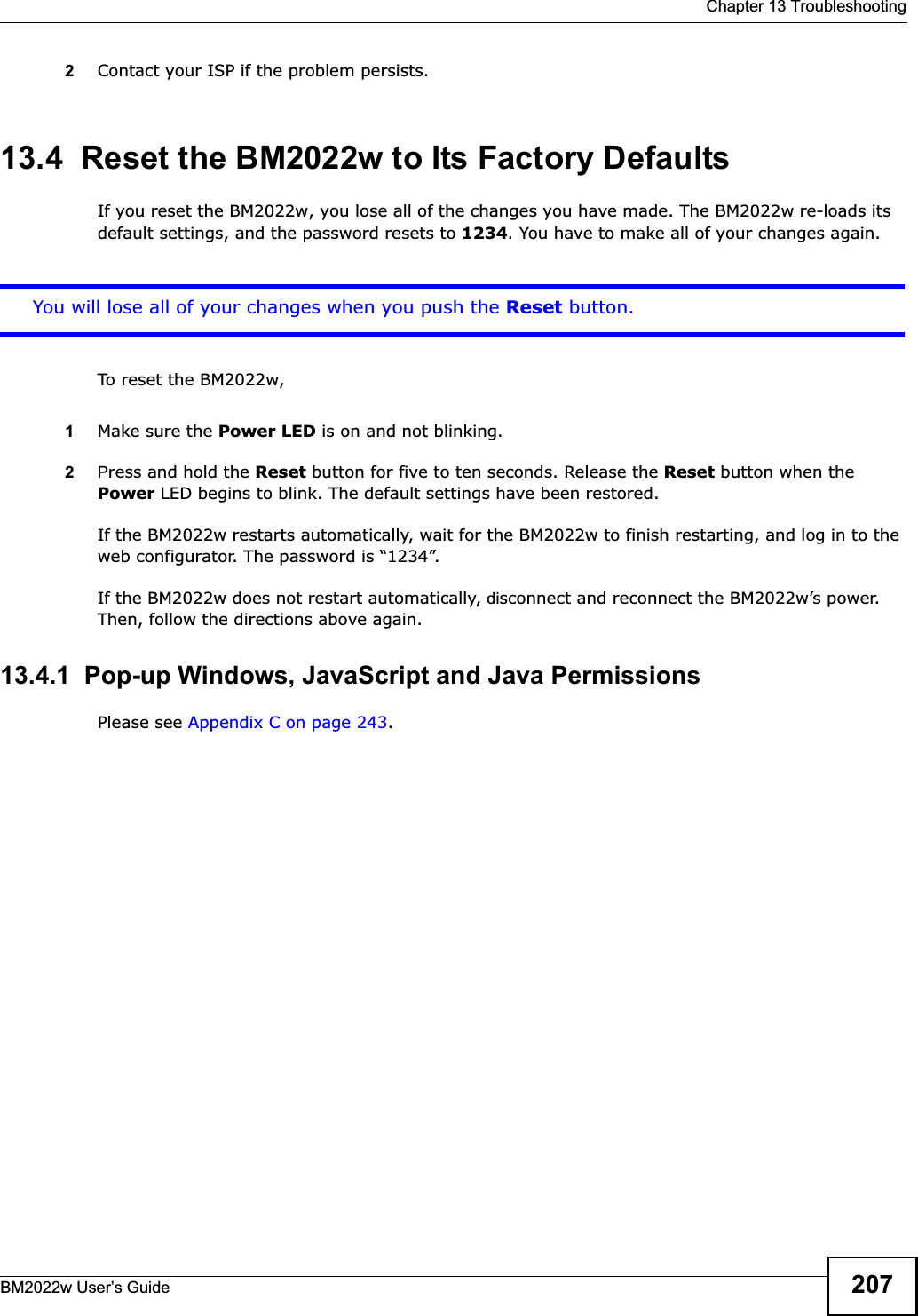

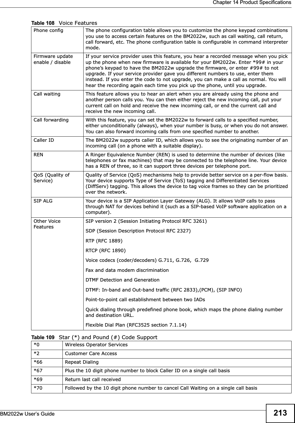
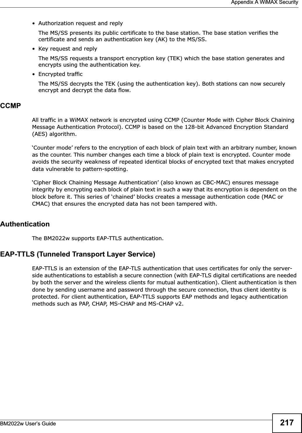

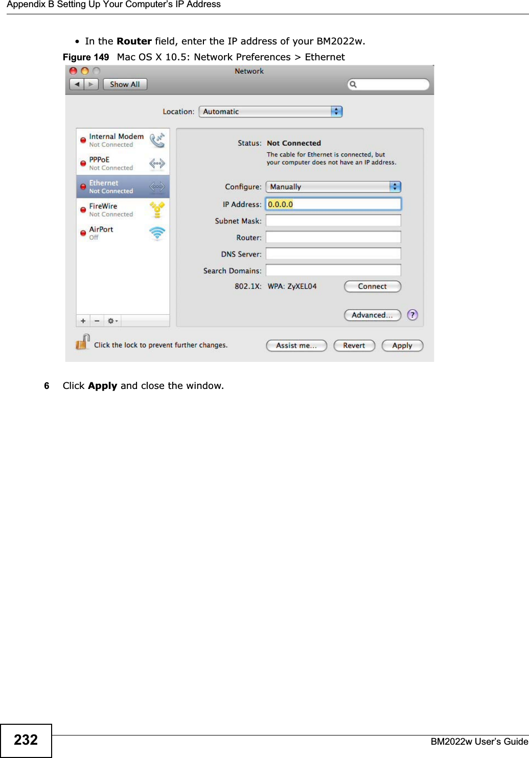
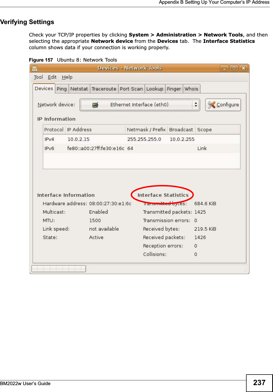
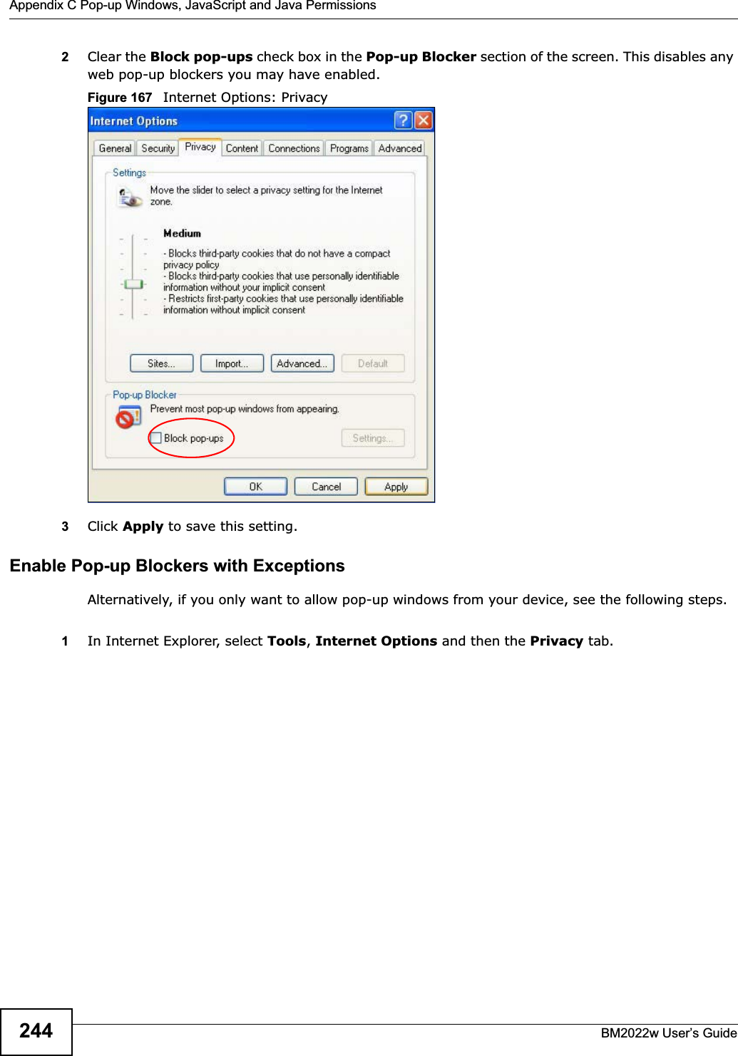
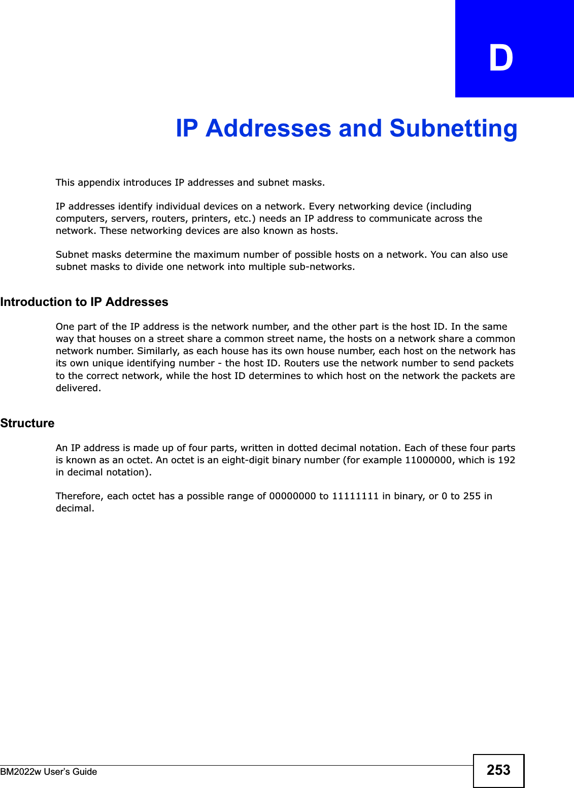
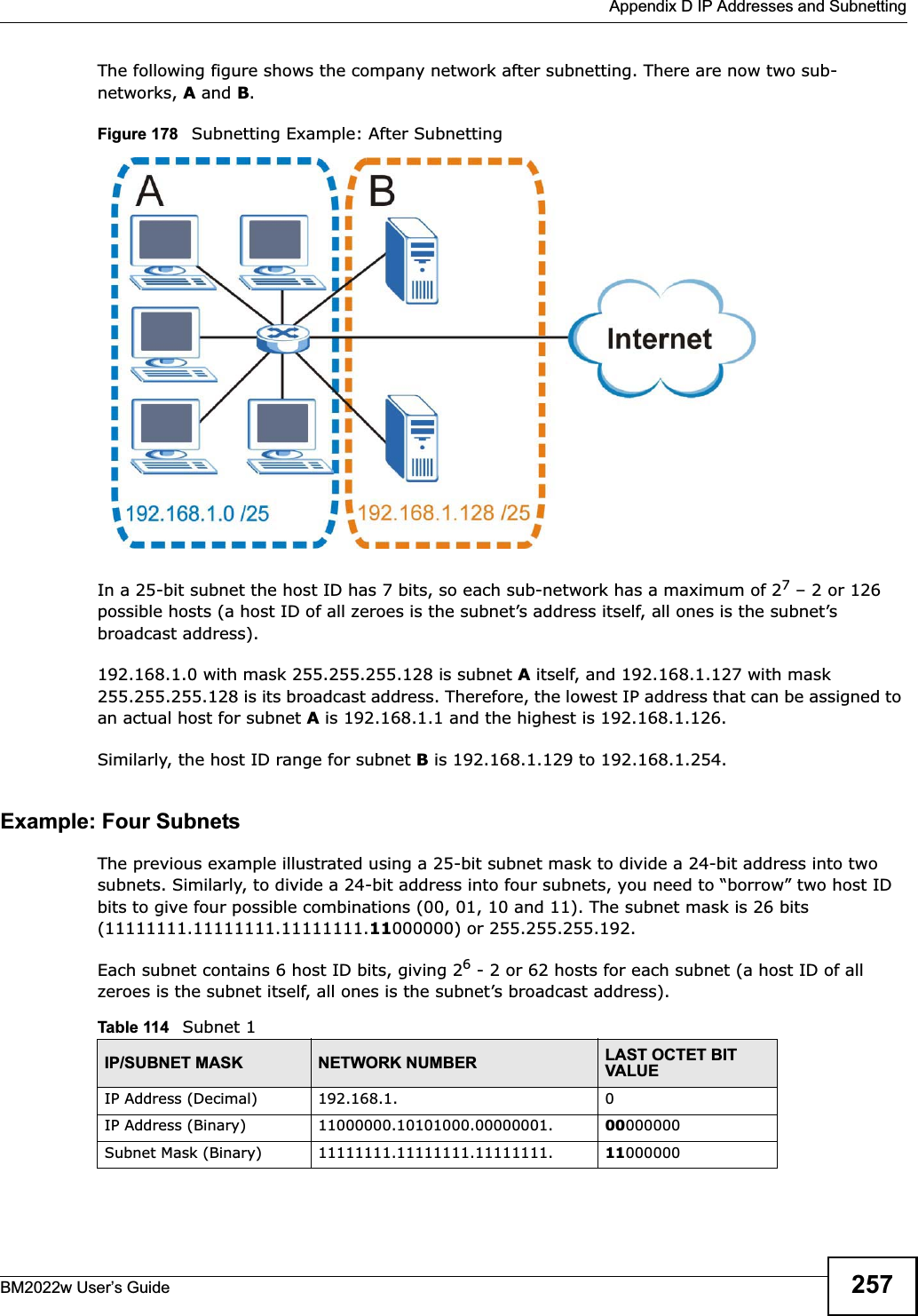
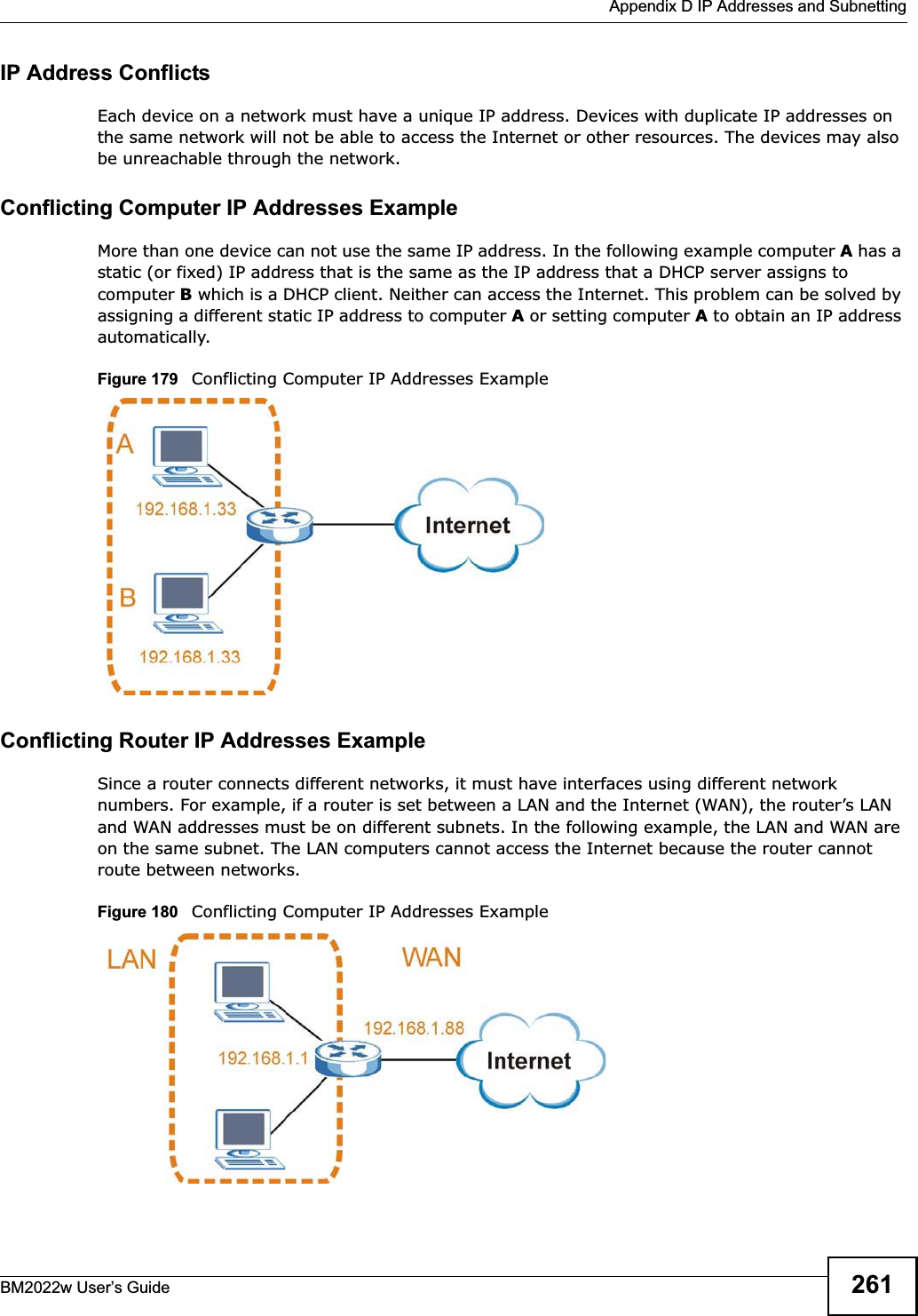
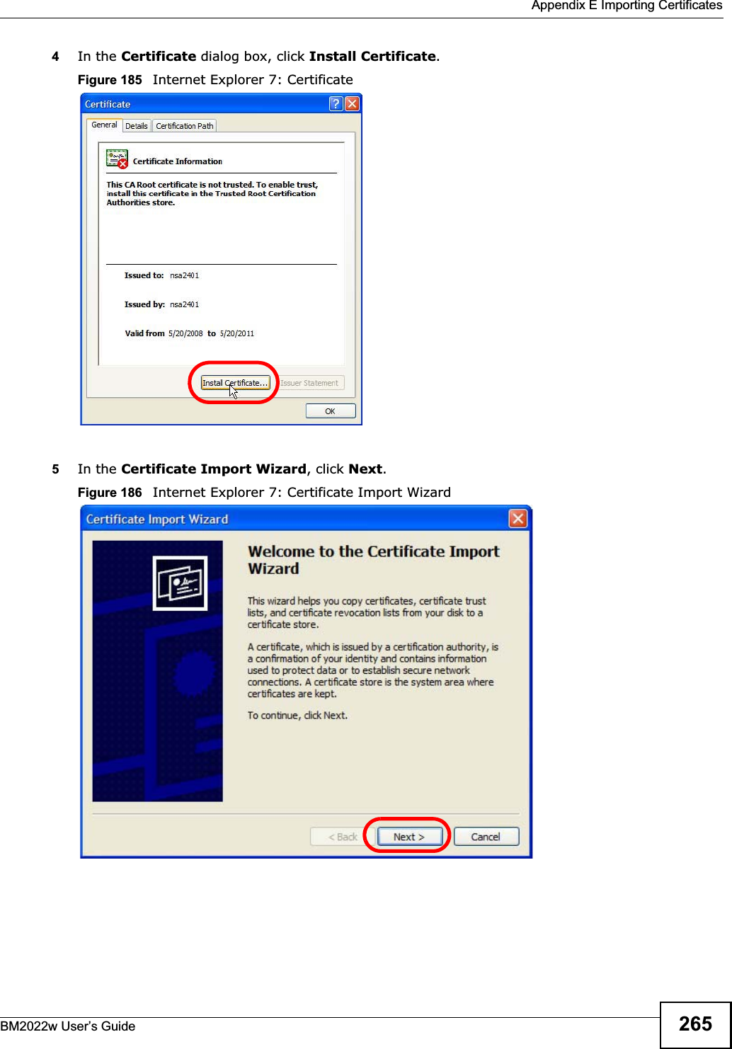
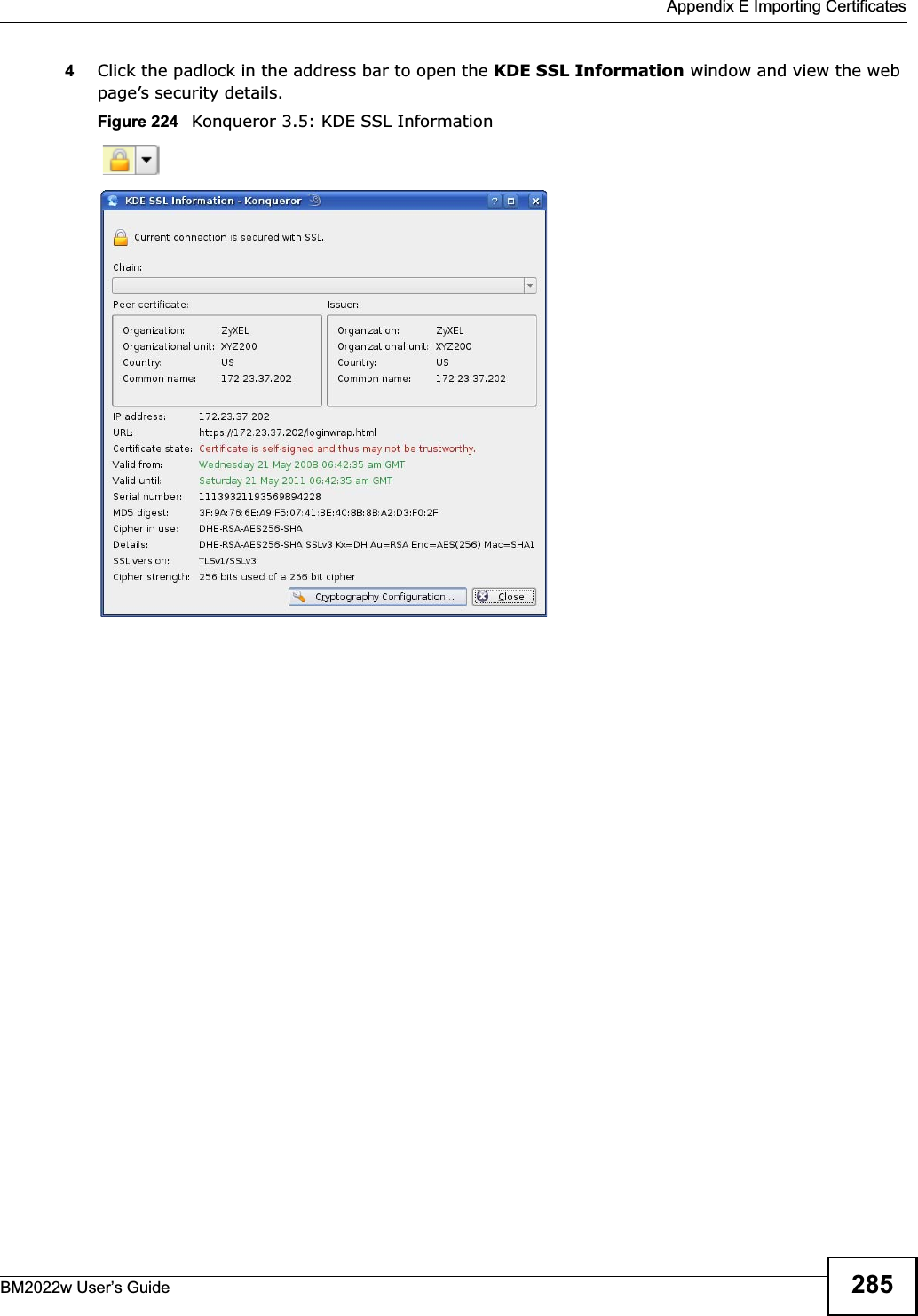
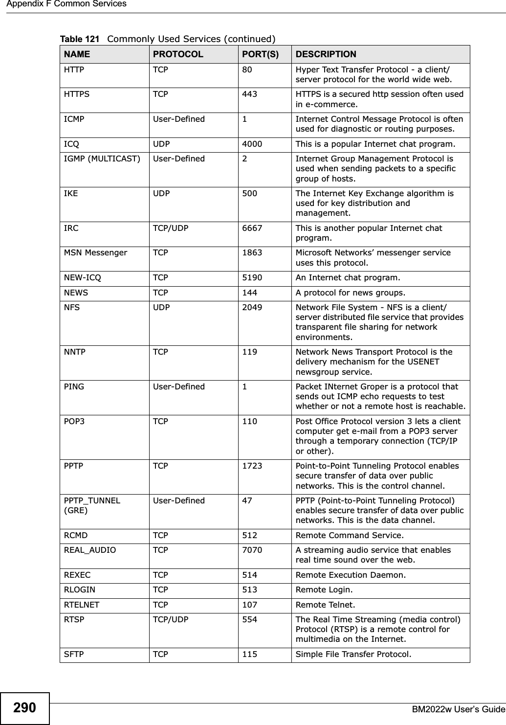
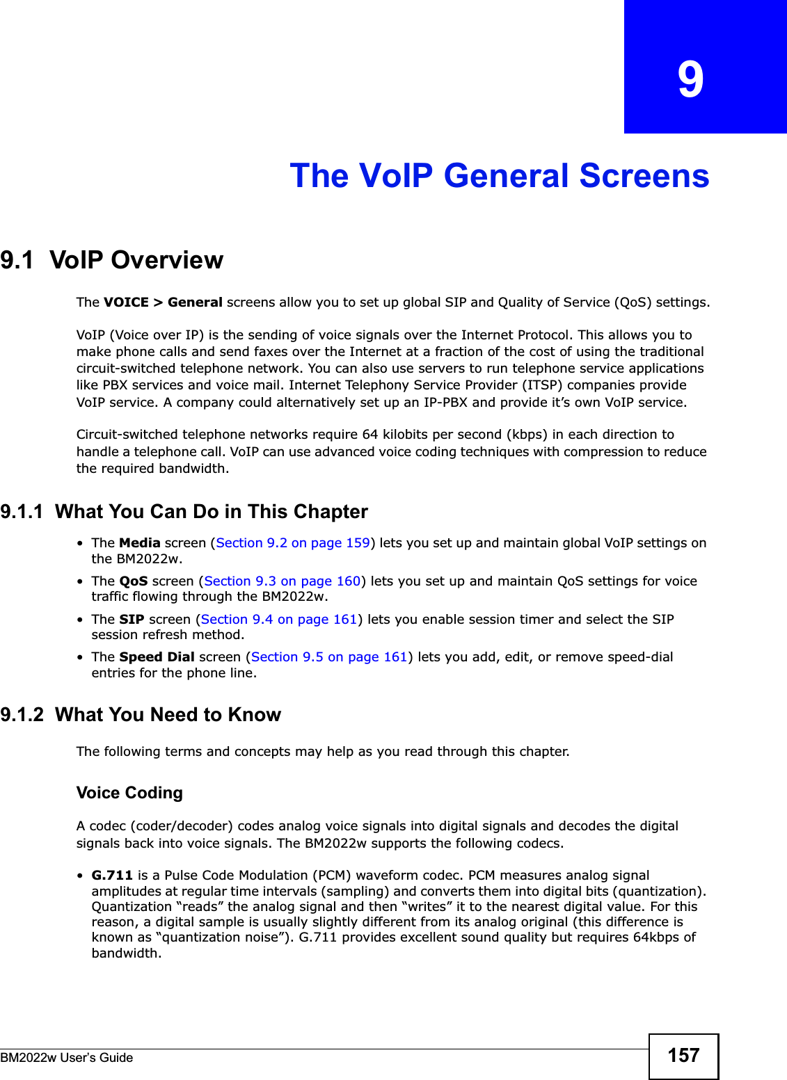
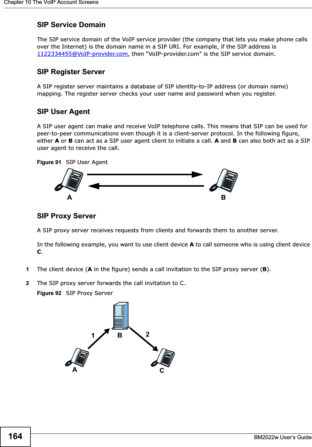
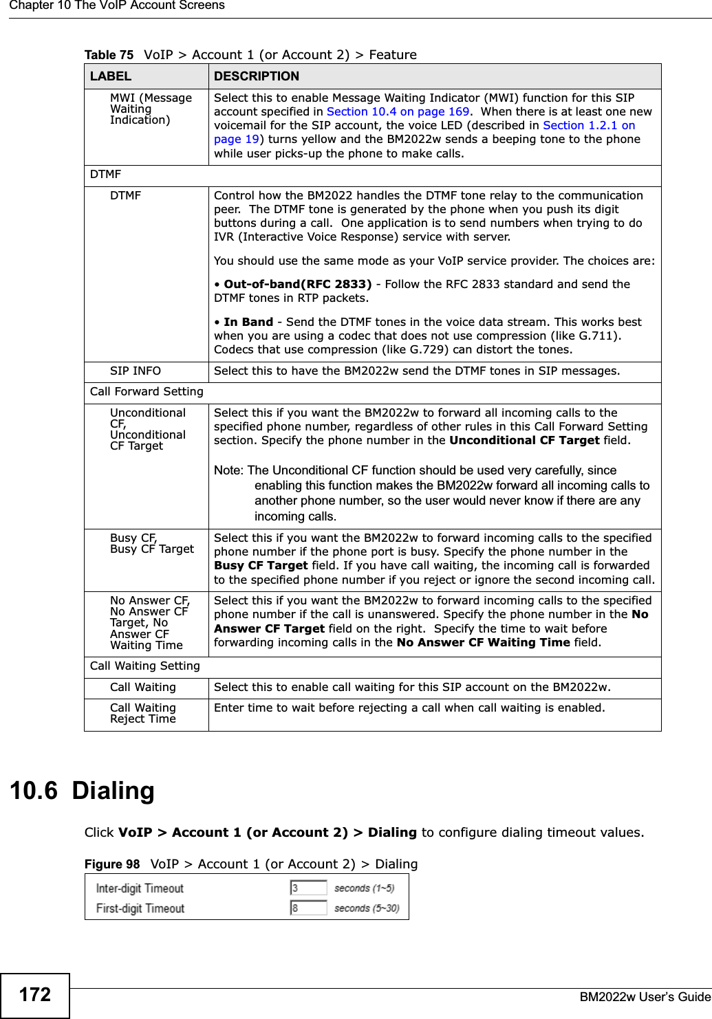
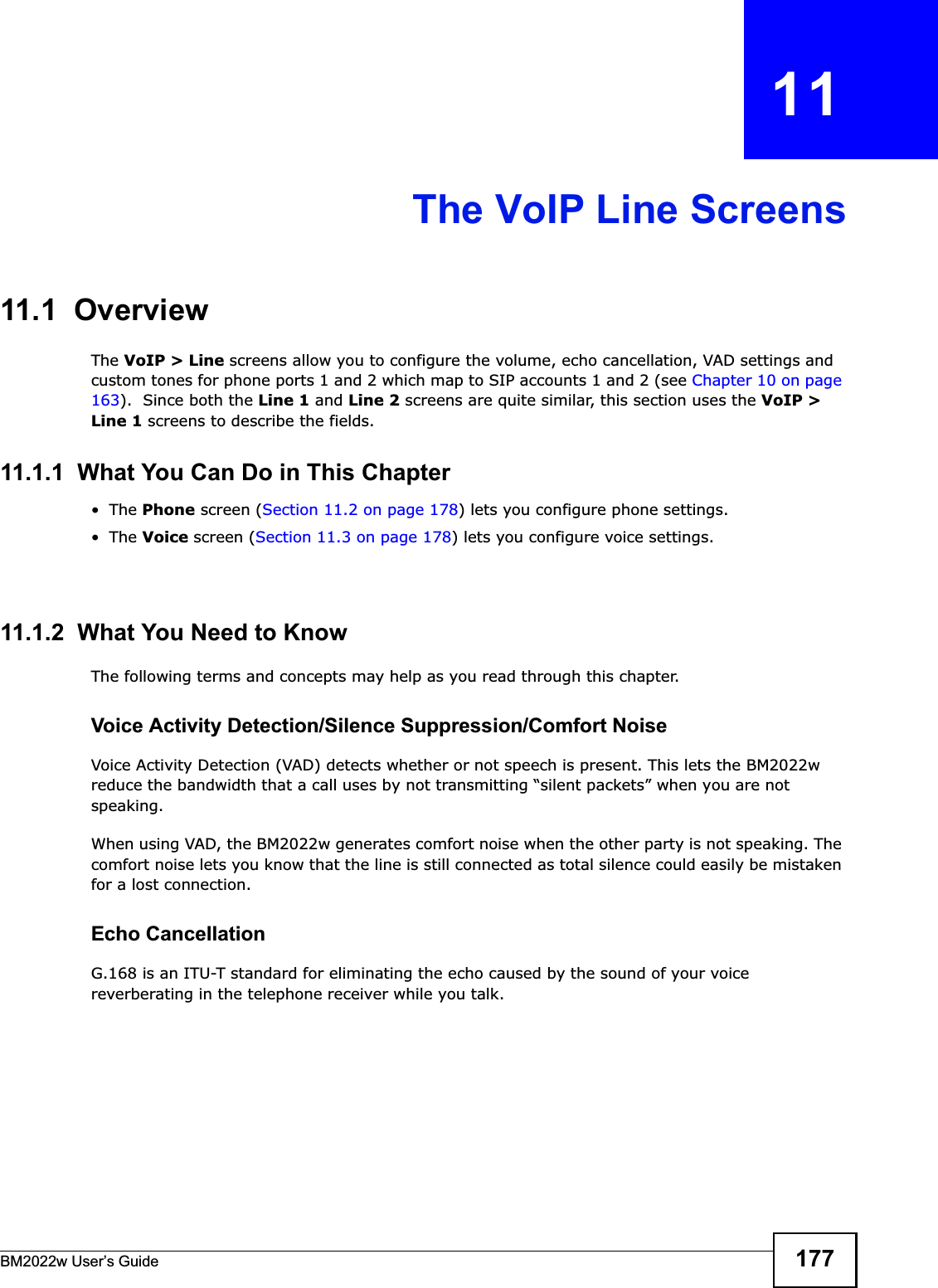
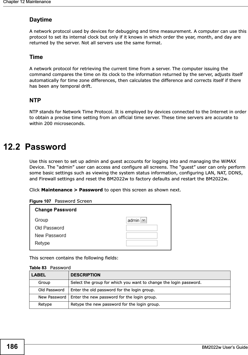
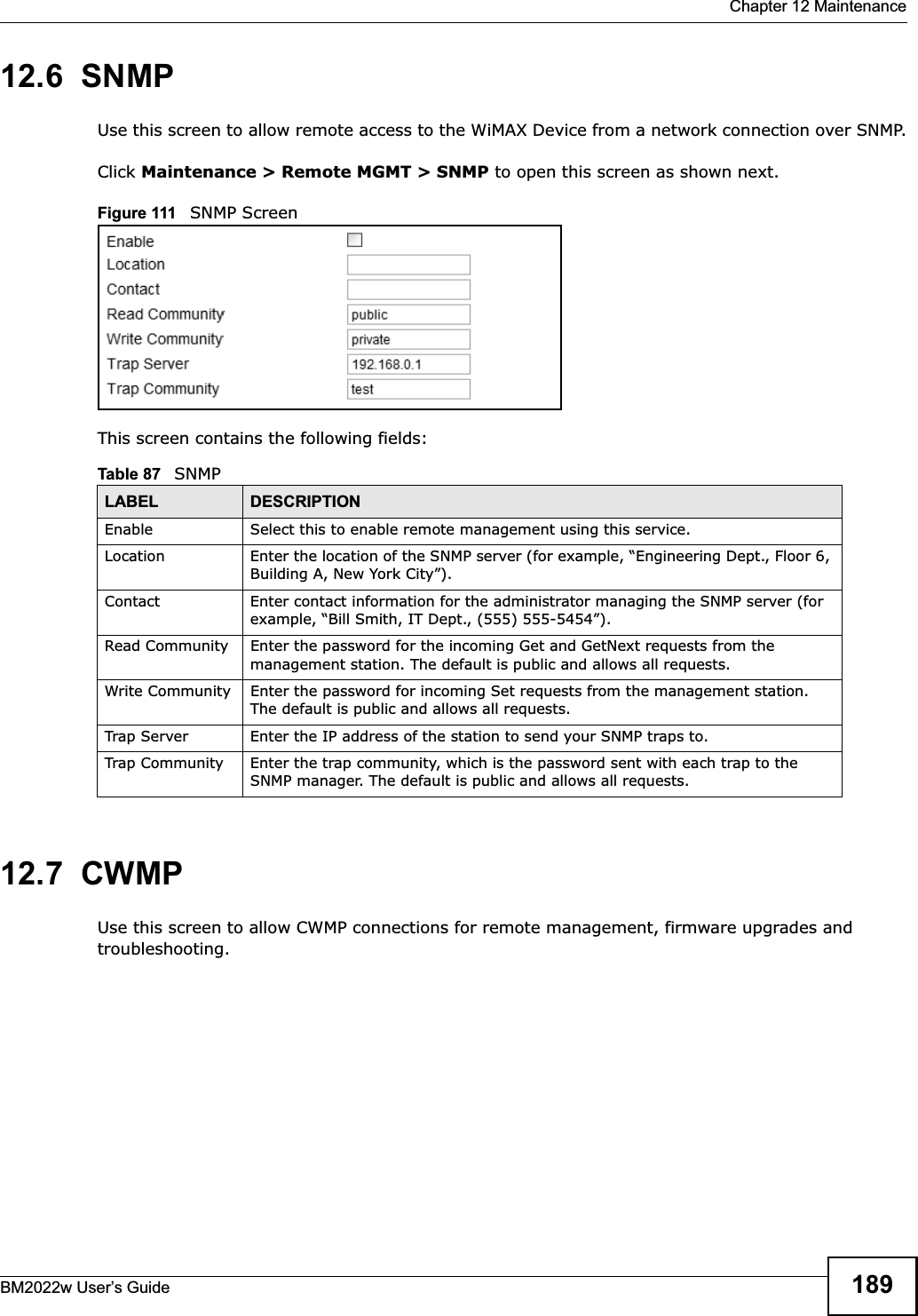
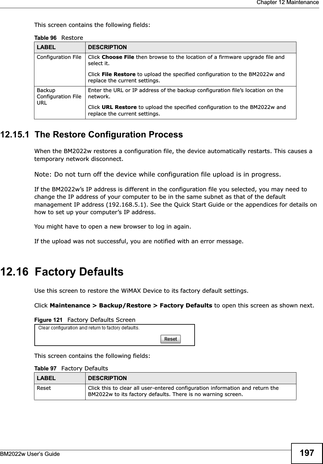
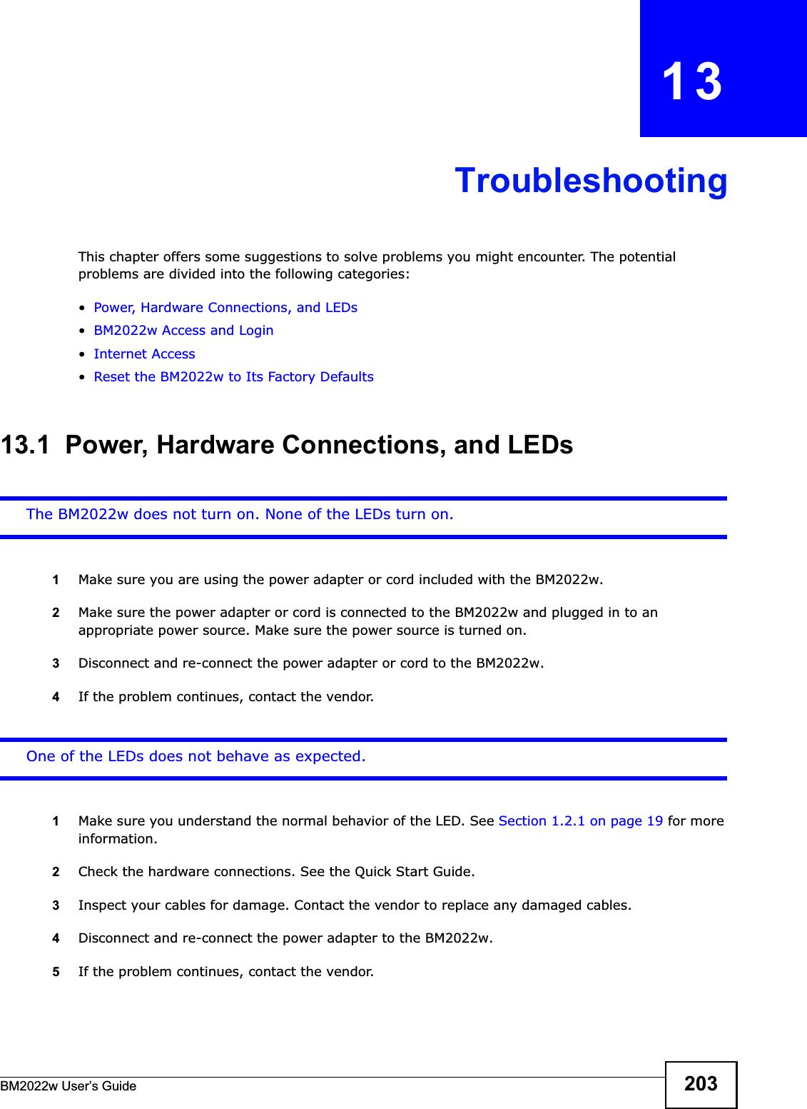
![Appendix B Setting Up Your Computer’s IP AddressBM2022w User’s Guide2225The Internet Protocol TCP/IP Properties window opens.Figure 132 Windows XP: Internet Protocol (TCP/IP) Properties6Select Obtain an IP address automatically if your network administrator or ISP assigns your IP address dynamically.Select Use the following IP Address and fill in the IP address,Subnet mask, and Default gateway fields if you have a static IP address that was assigned to you by your network administrator or ISP. You may also have to enter a Preferred DNS server and an Alternate DNSserver, if that information was provided.7Click OK to close the Internet Protocol (TCP/IP) Properties window.Click OK to close the Local Area Connection Properties window.Verifying Settings1Click Start > All Programs > Accessories > Command Prompt.2In the Command Prompt window, type "ipconfig" and then press [ENTER]. You can also go to Start > Control Panel > Network Connections, right-click a network connection, click Status and then click the Support tab to view your IP address and connection information.](https://usermanual.wiki/MitraStar-Technology/HES209M2W.User-Manual-Part-2/User-Guide-1603518-Page-66.png)
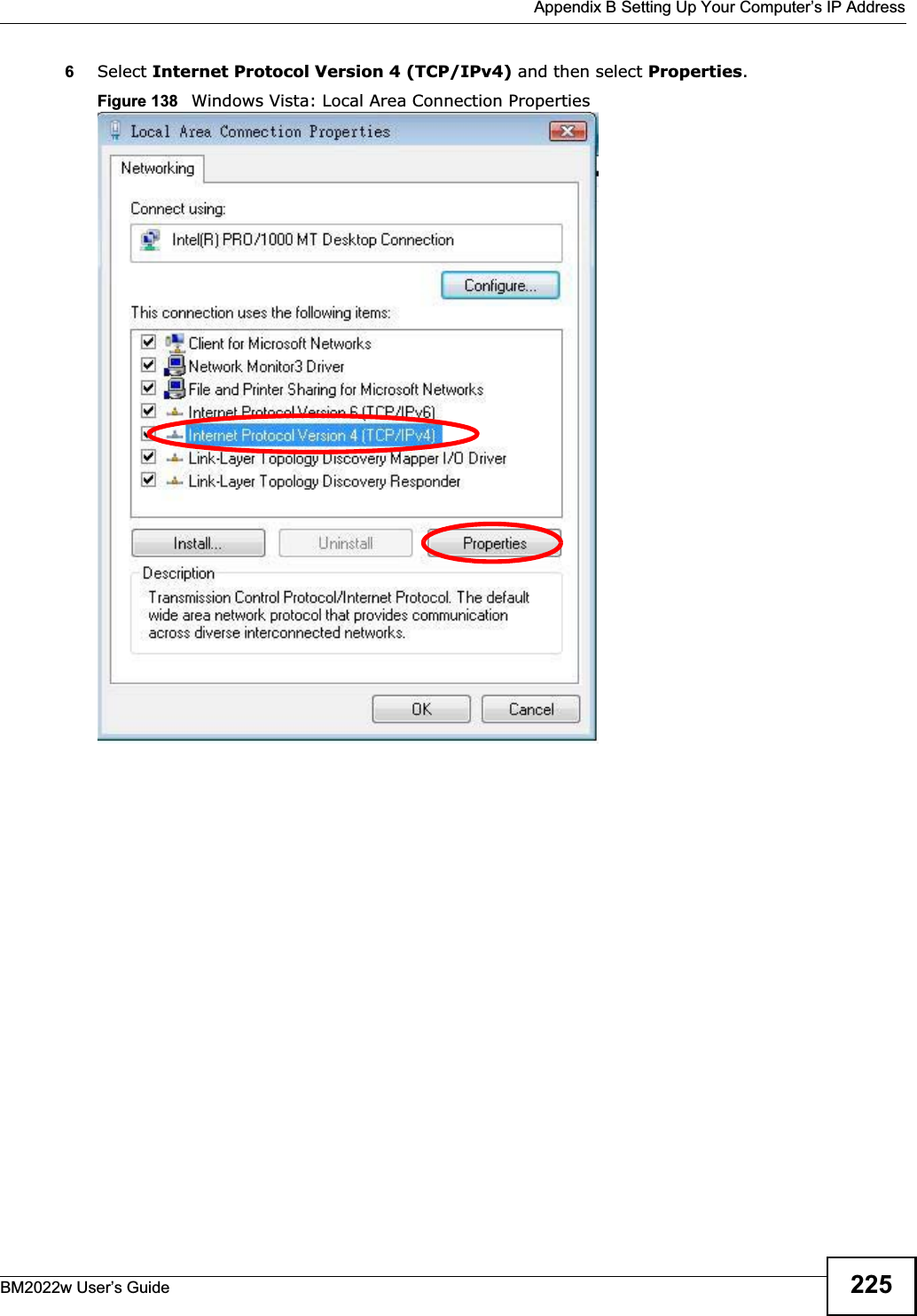
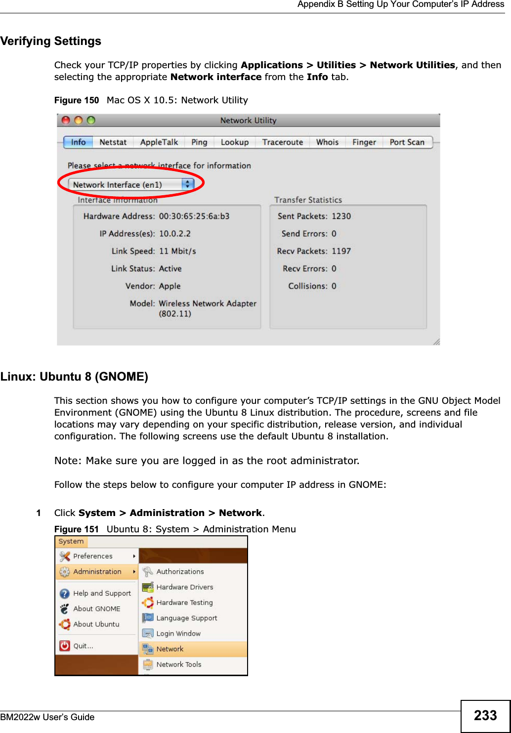
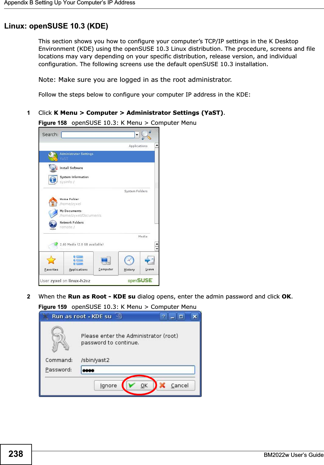
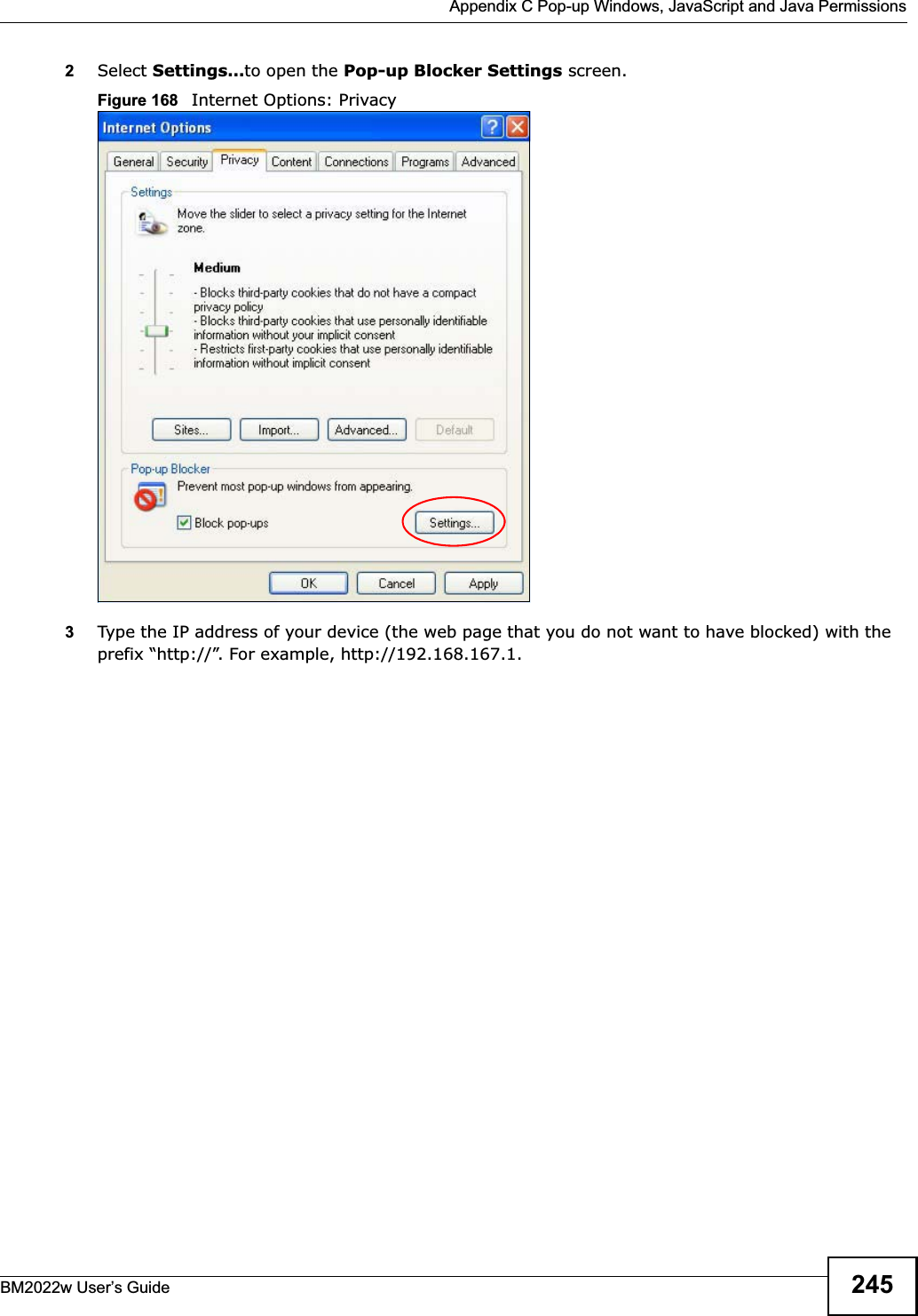
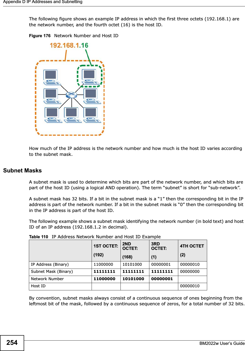
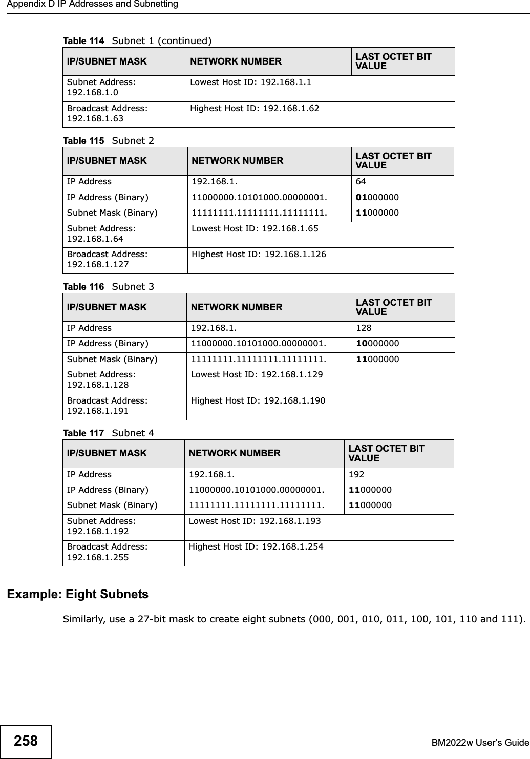
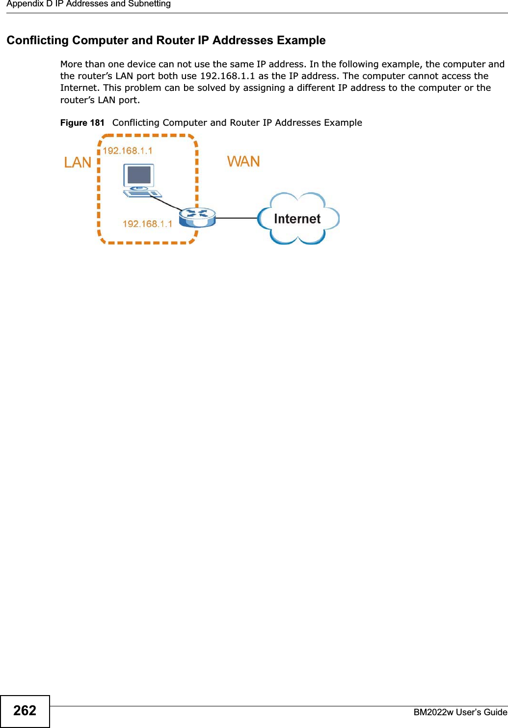
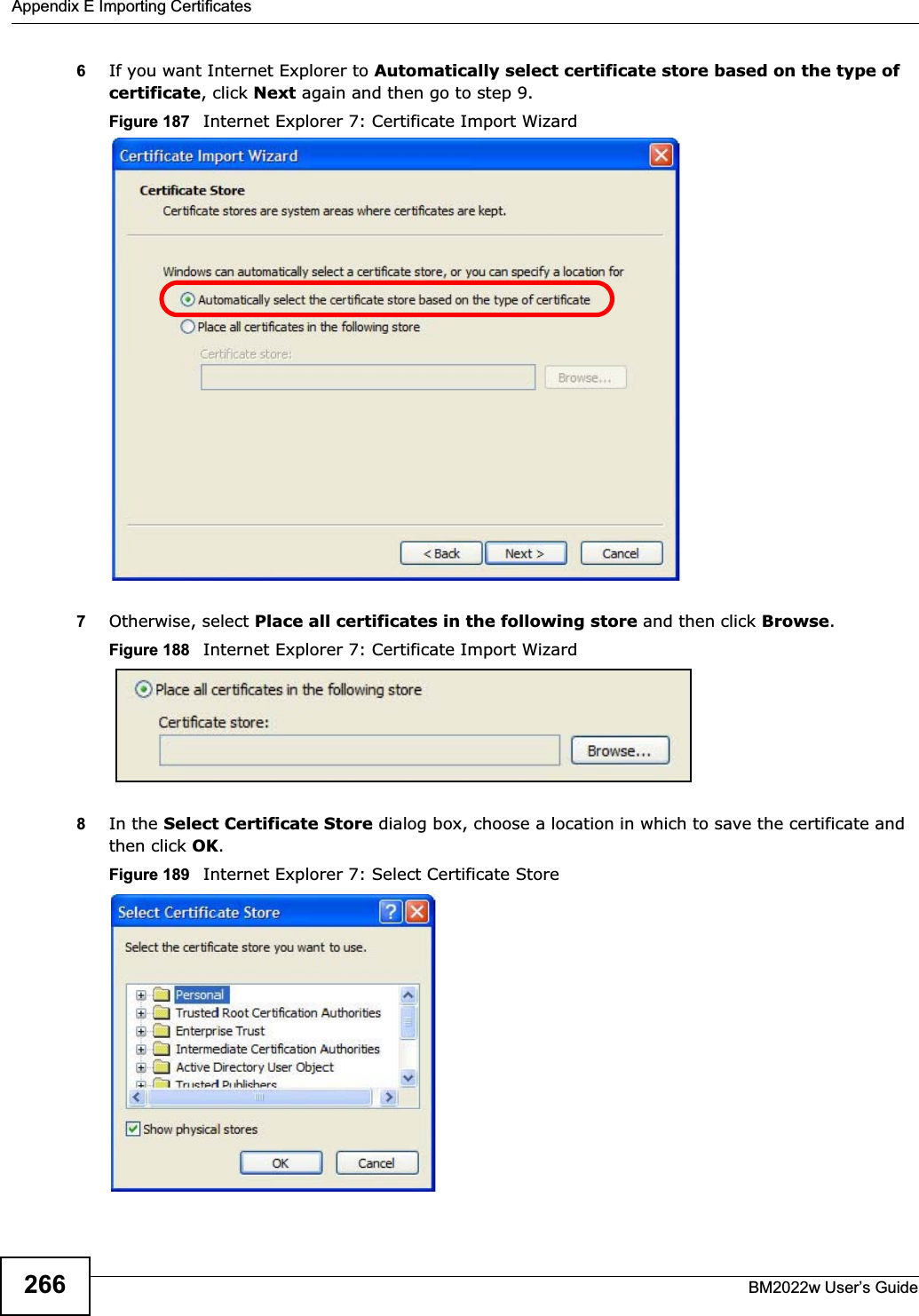
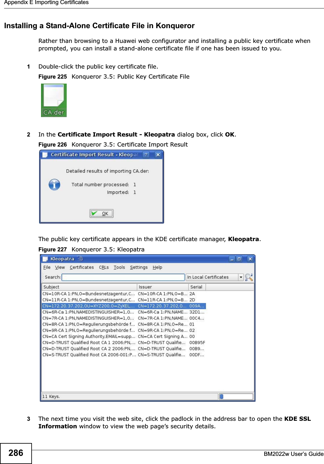
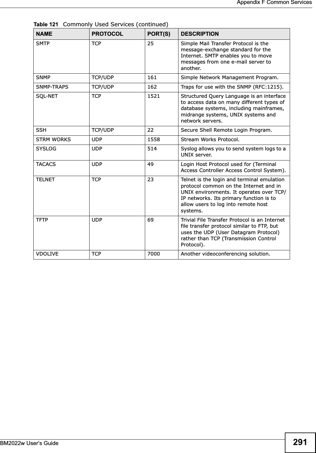
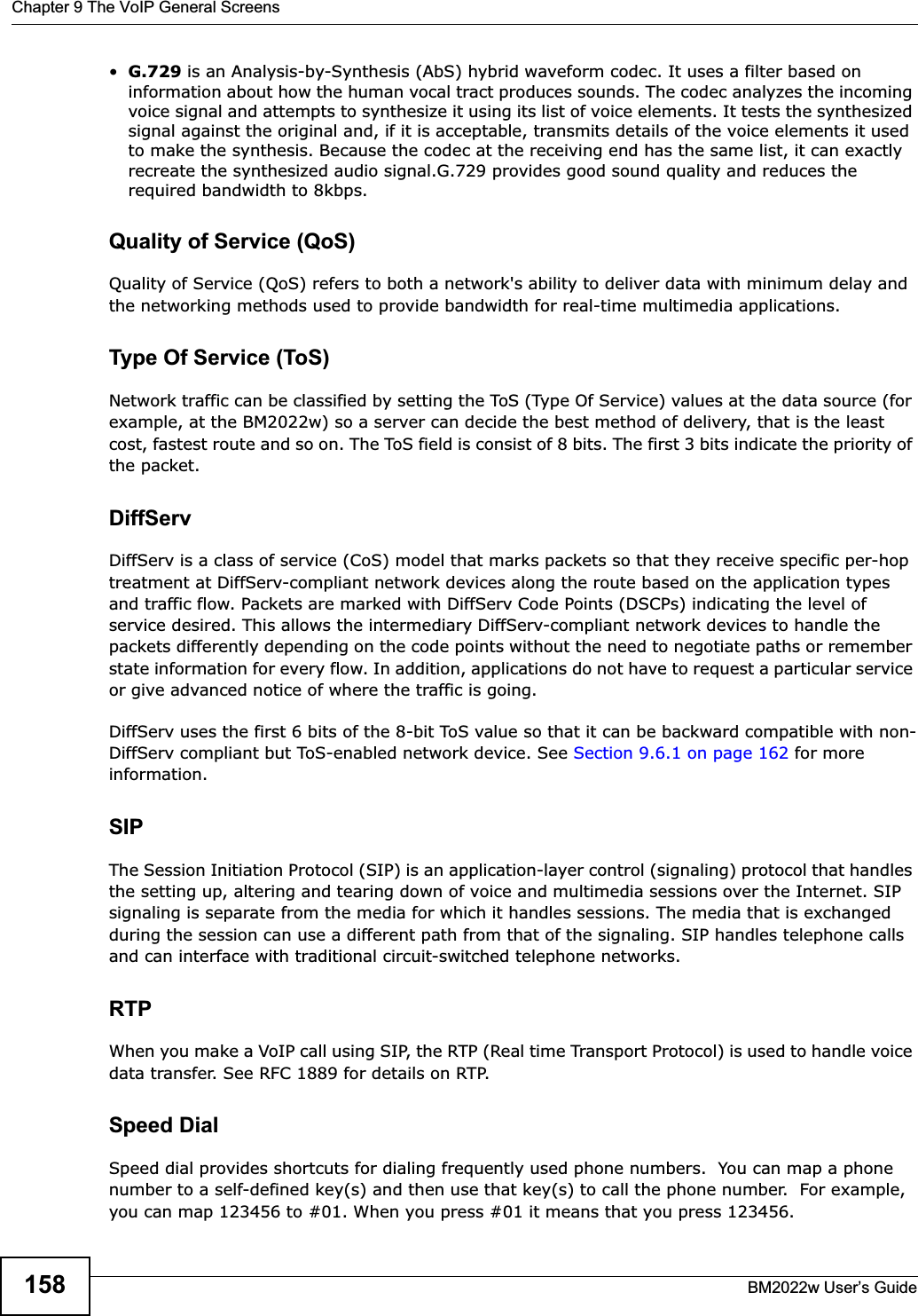
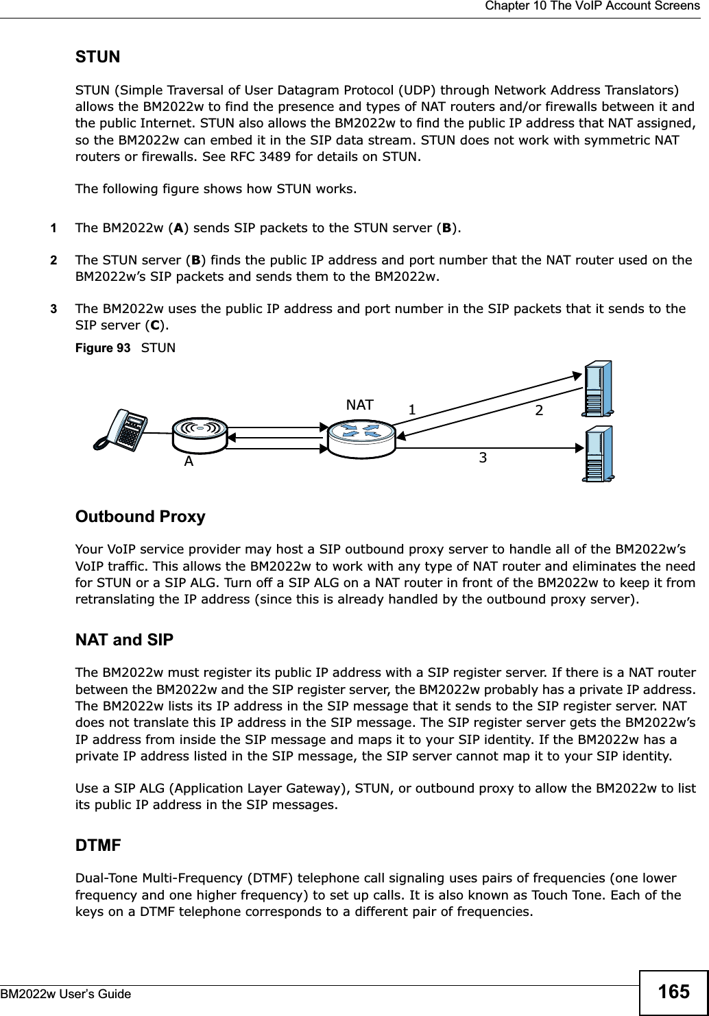
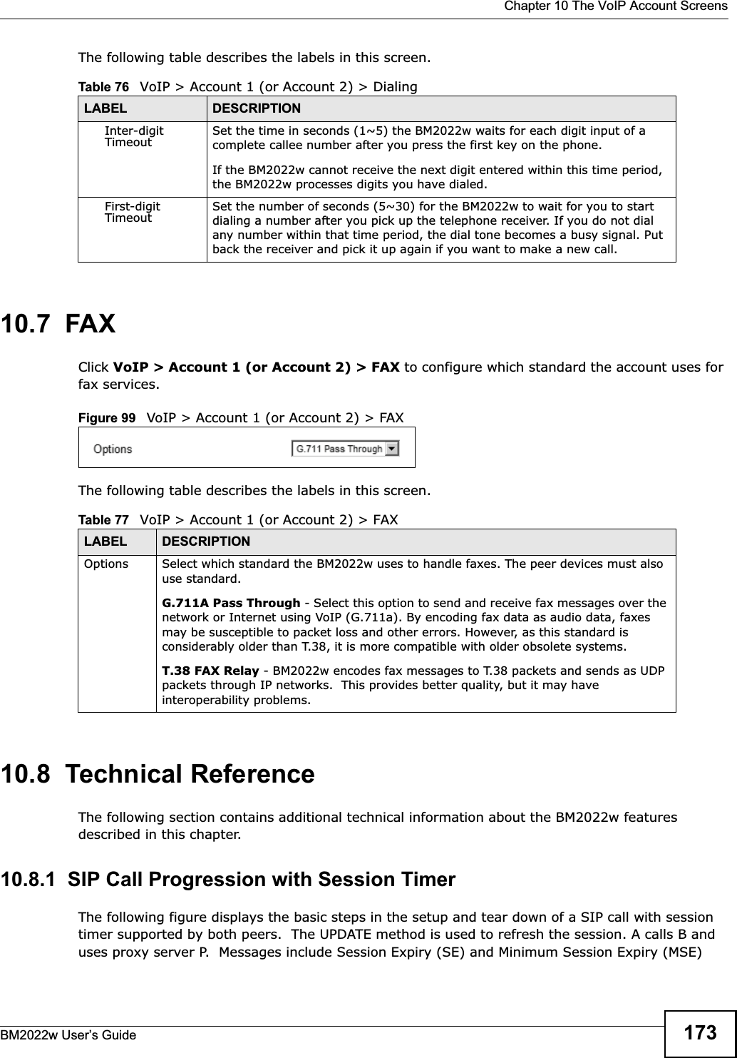
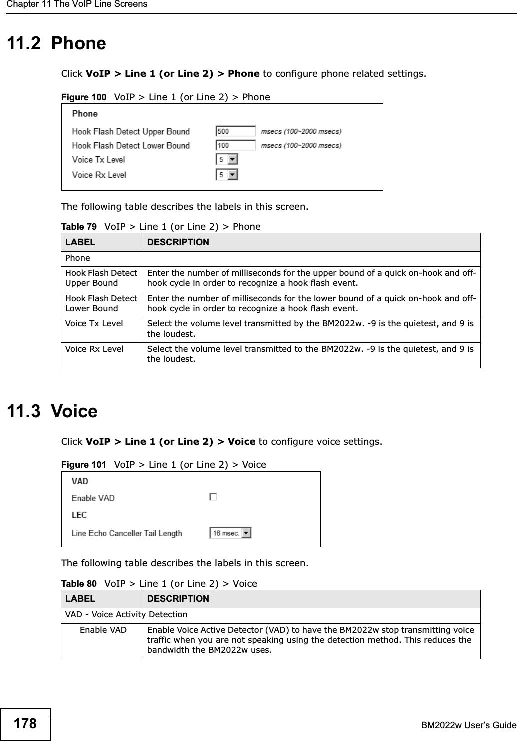
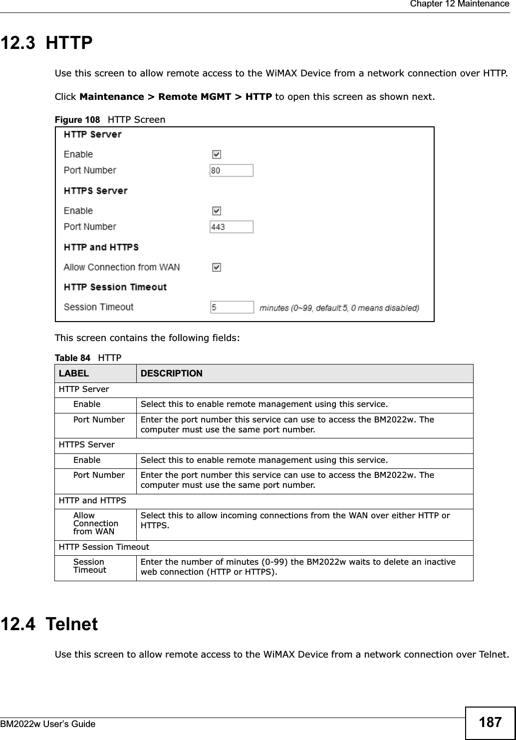
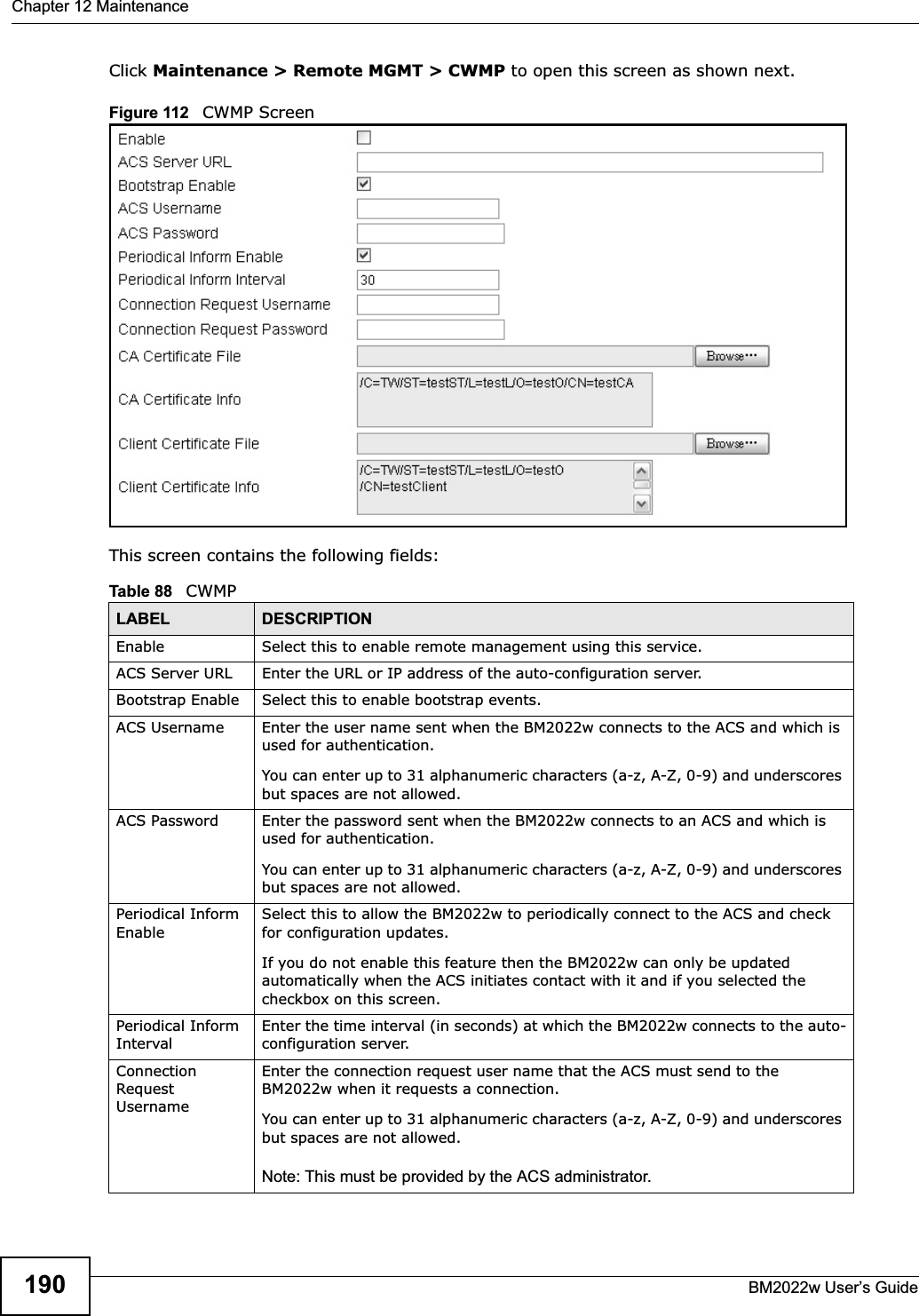
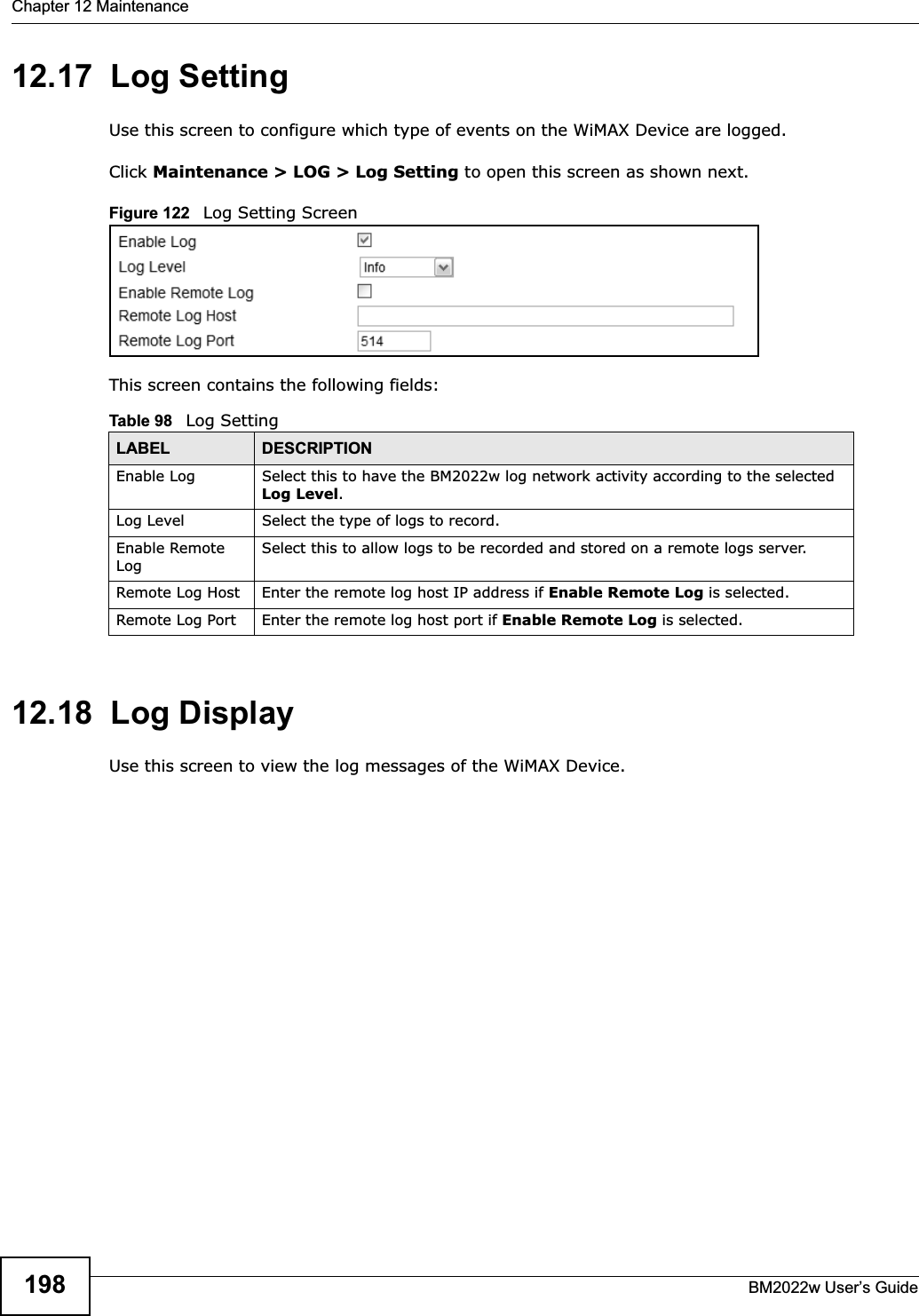
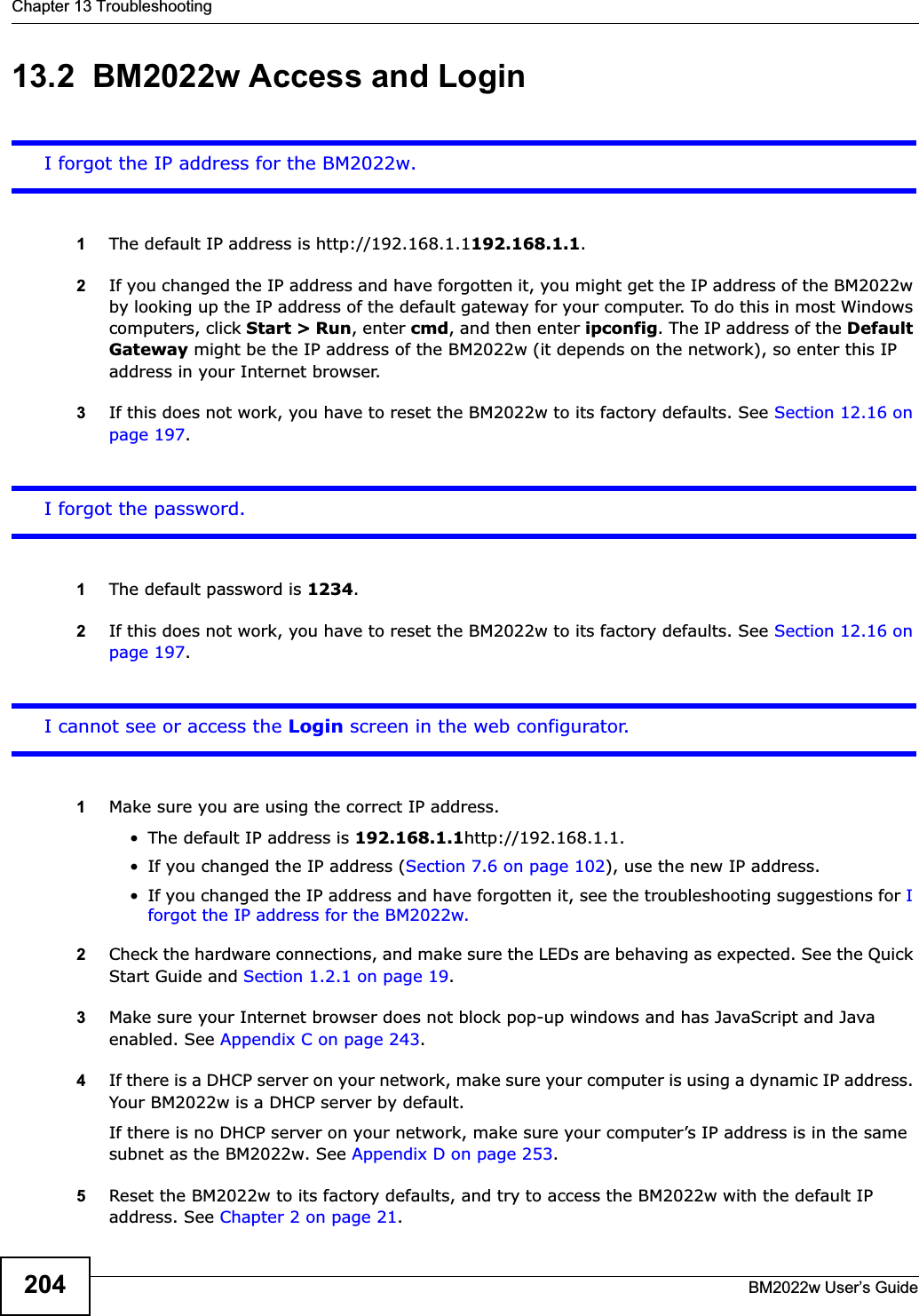
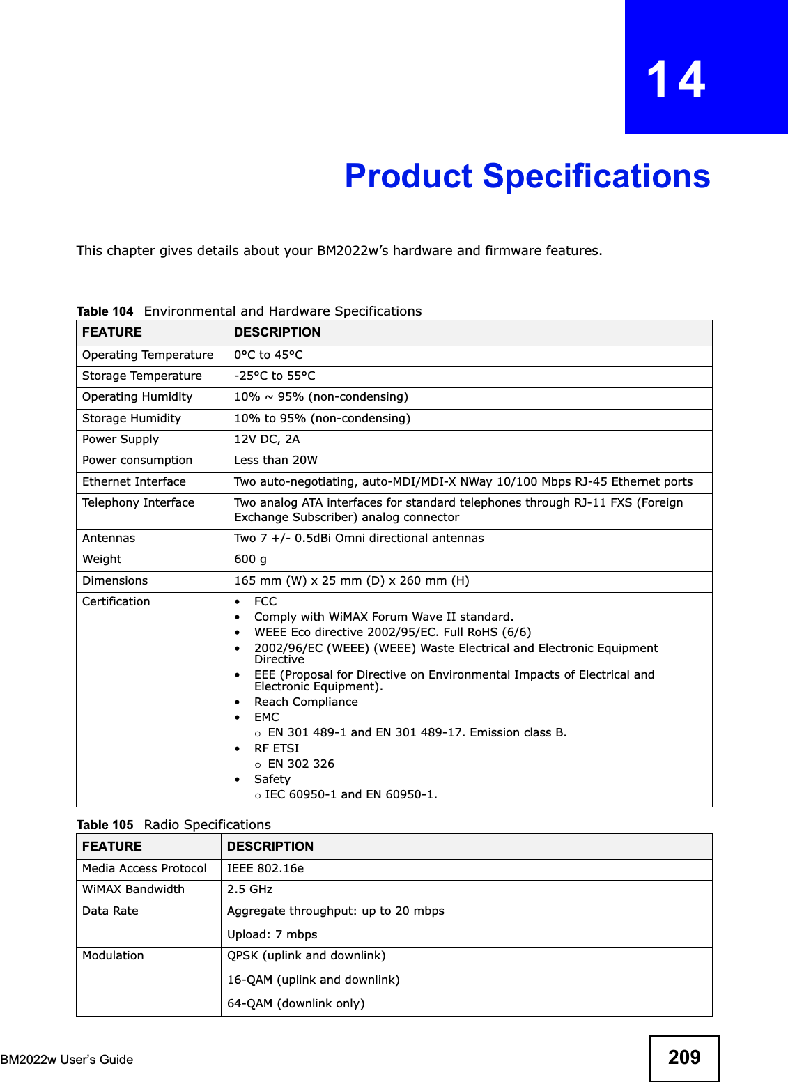
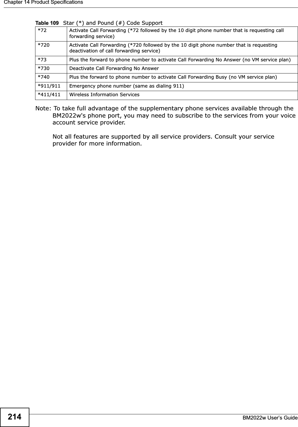
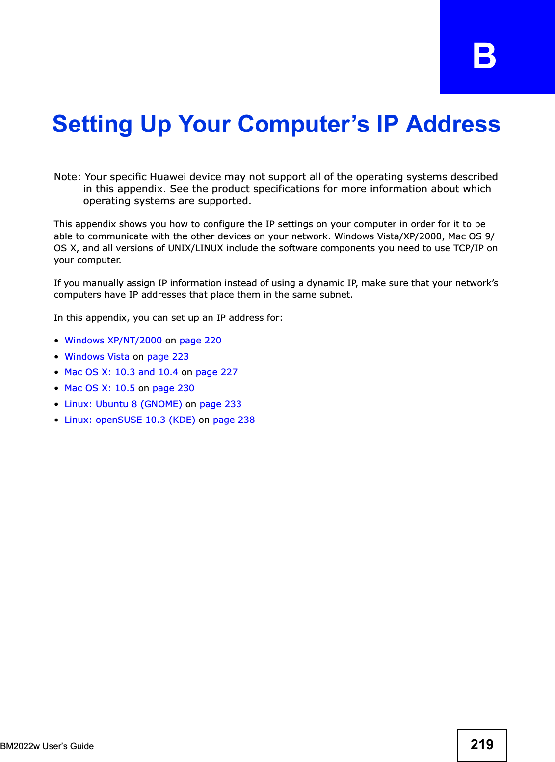
![Appendix B Setting Up Your Computer’s IP AddressBM2022w User’s Guide2267The Internet Protocol Version 4 (TCP/IPv4) Properties window opens.Figure 139 Windows Vista: Internet Protocol Version 4 (TCP/IPv4) Properties8Select Obtain an IP address automatically if your network administrator or ISP assigns your IP address dynamically.Select Use the following IP Address and fill in the IP address,Subnet mask, and Default gateway fields if you have a static IP address that was assigned to you by your network administrator or ISP. You may also have to enter a Preferred DNS server and an Alternate DNSserver, if that information was provided.Click Advanced.9Click OK to close the Internet Protocol (TCP/IP) Properties window.Click OK to close the Local Area Connection Properties window.Verifying Settings1Click Start > All Programs > Accessories > Command Prompt.2In the Command Prompt window, type "ipconfig" and then press [ENTER]. You can also go to Start > Control Panel > Network Connections, right-click a network connection, click Status and then click the Support tab to view your IP address and connection information.](https://usermanual.wiki/MitraStar-Technology/HES209M2W.User-Manual-Part-2/User-Guide-1603518-Page-70.png)