MitraStar Technology M4G-301 TD-LTE OUTDOOR CPE User Manual
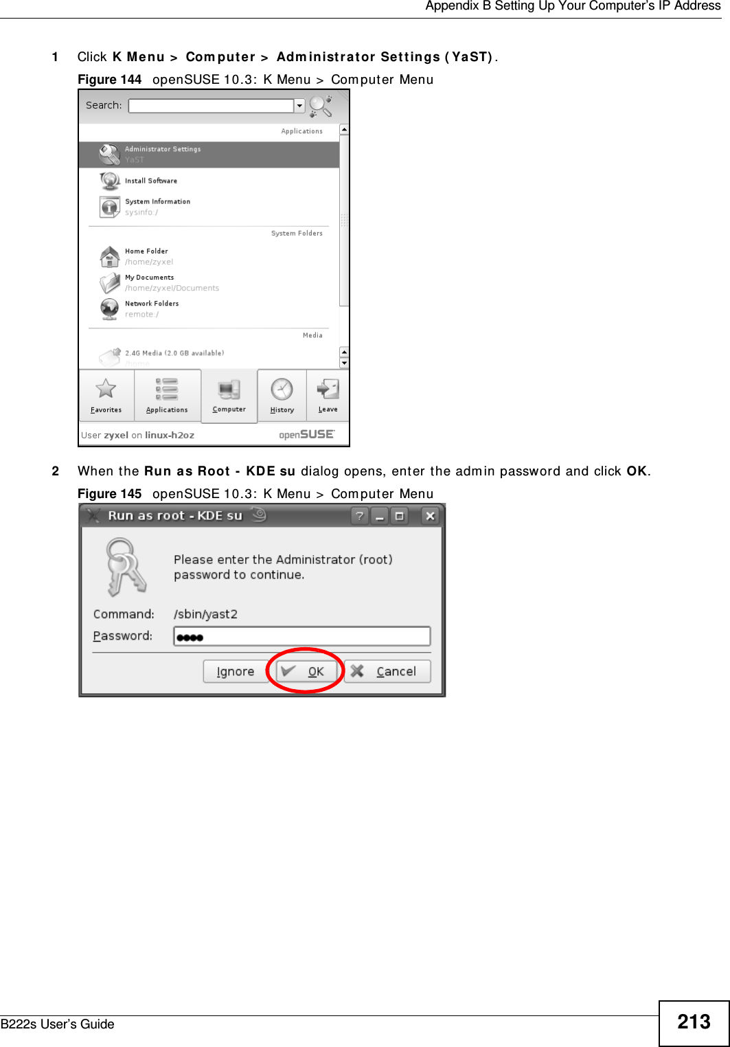
MitraStar Technology Corporation TD-LTE OUTDOOR CPE
UserManual.wiki
>
MitraStar Technology
>
M4G 301 User Manual
User Manual
Navigation menu
Upload a User Manual
Namespaces
Wiki Guide
HTML
PDF
Info
Views
User Manual
Discussion / Help
Navigation

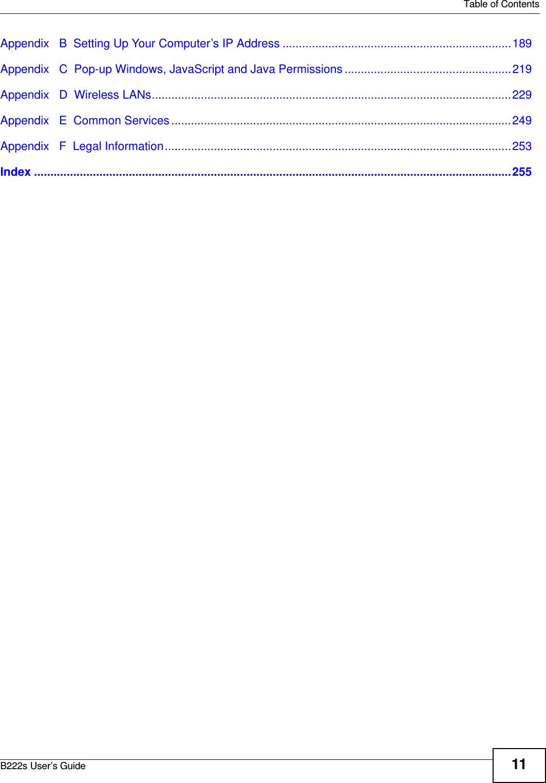


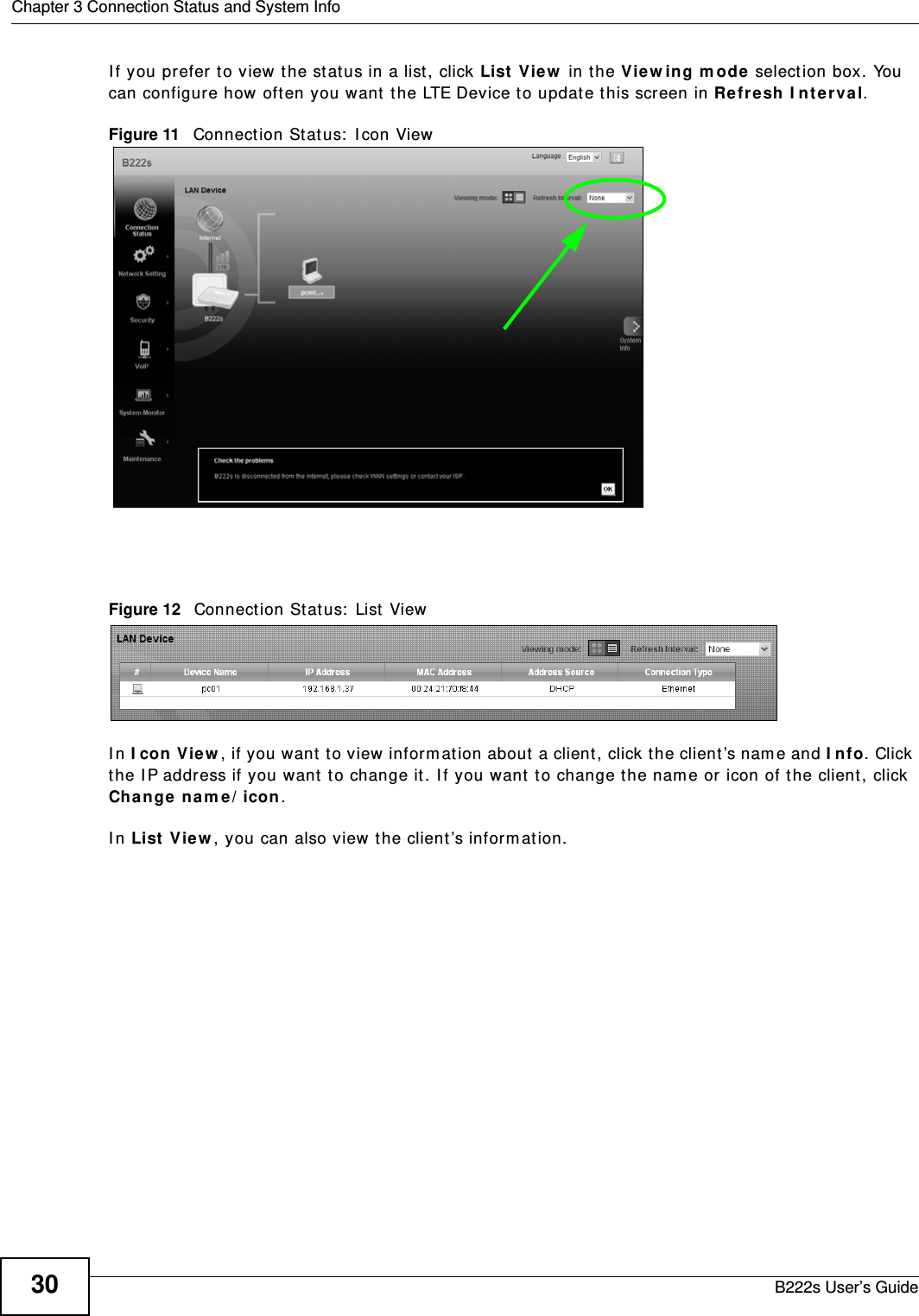

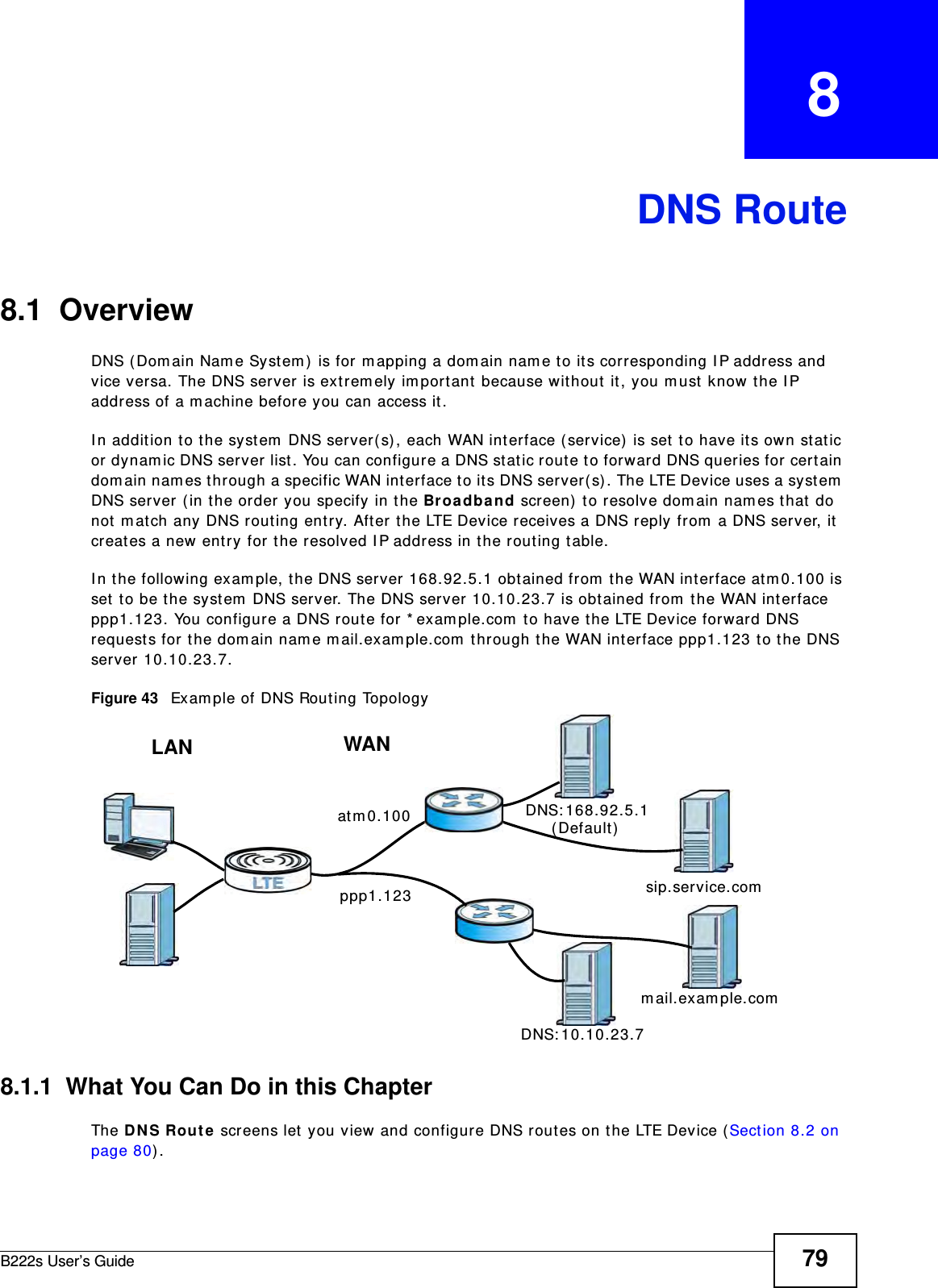


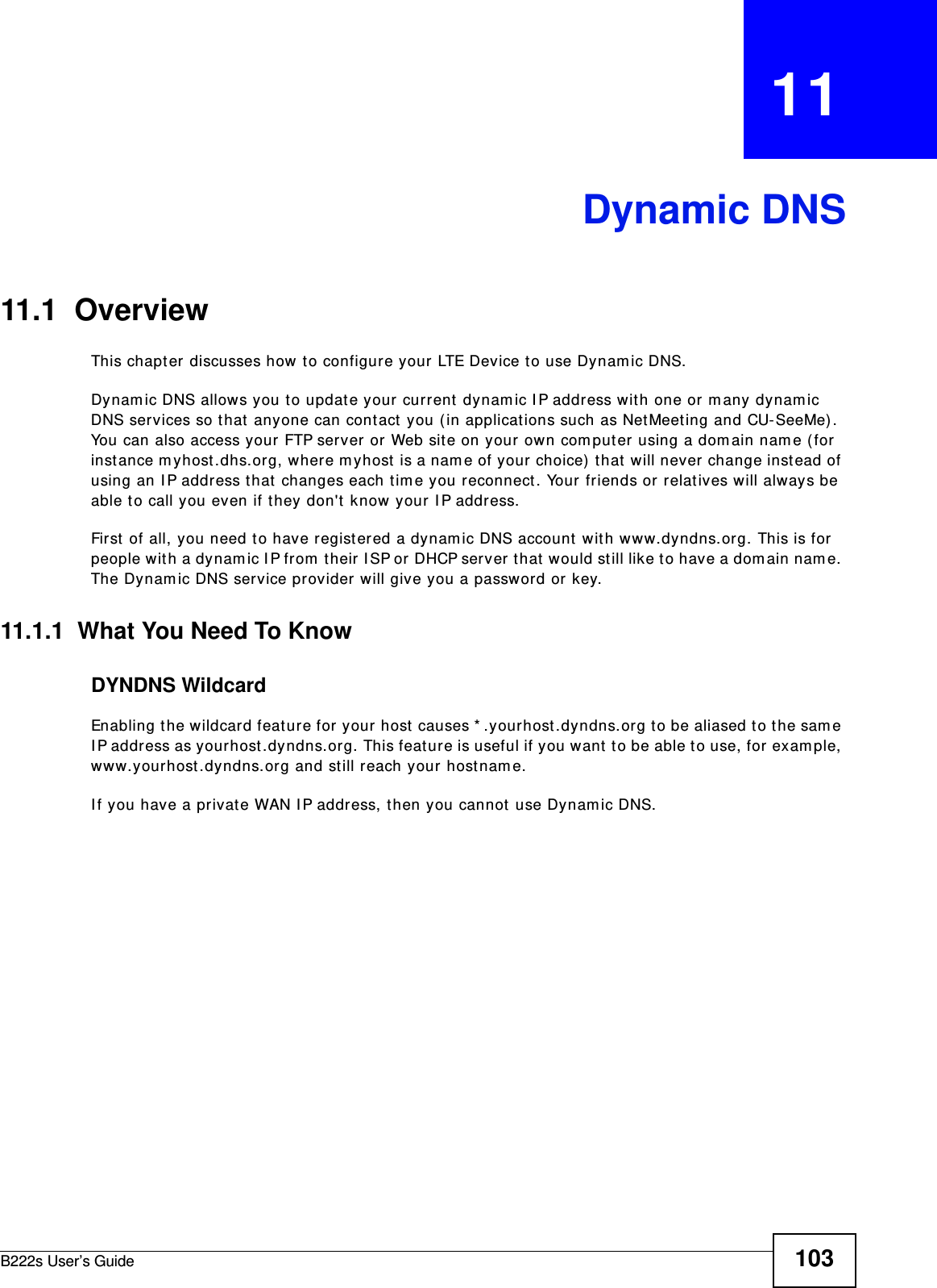
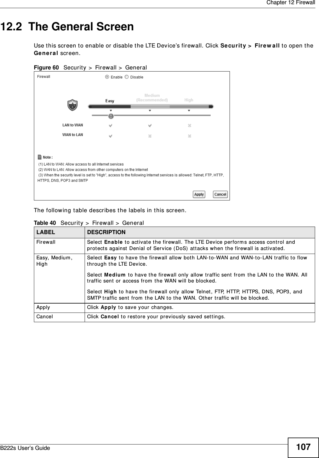

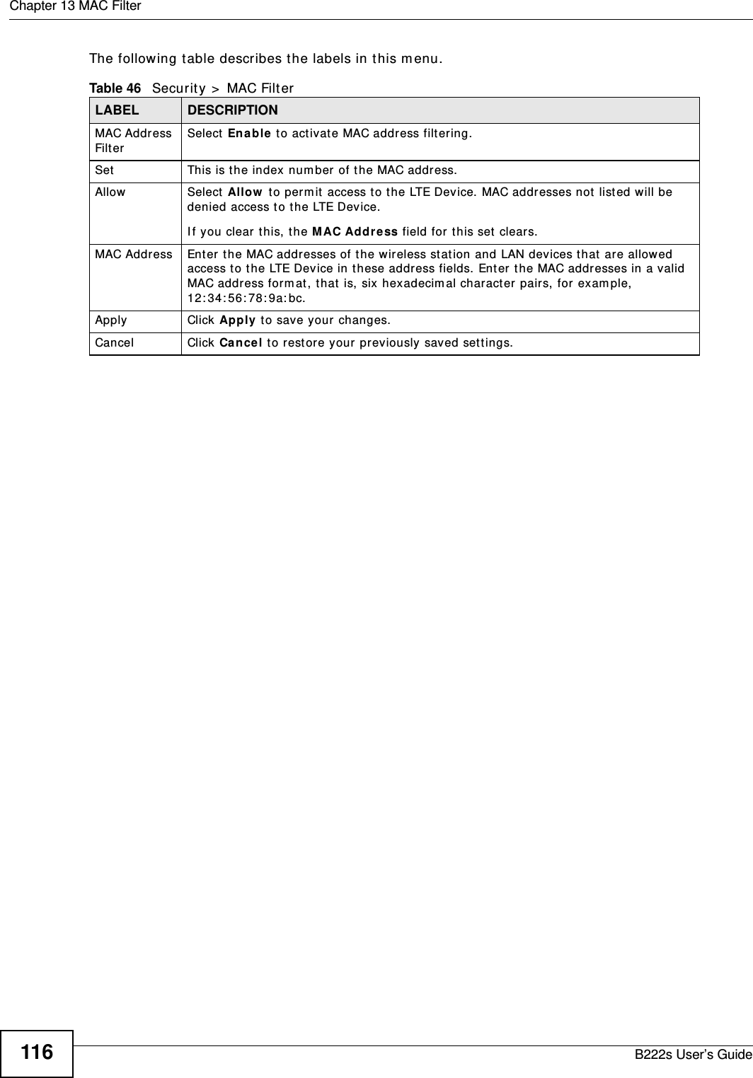

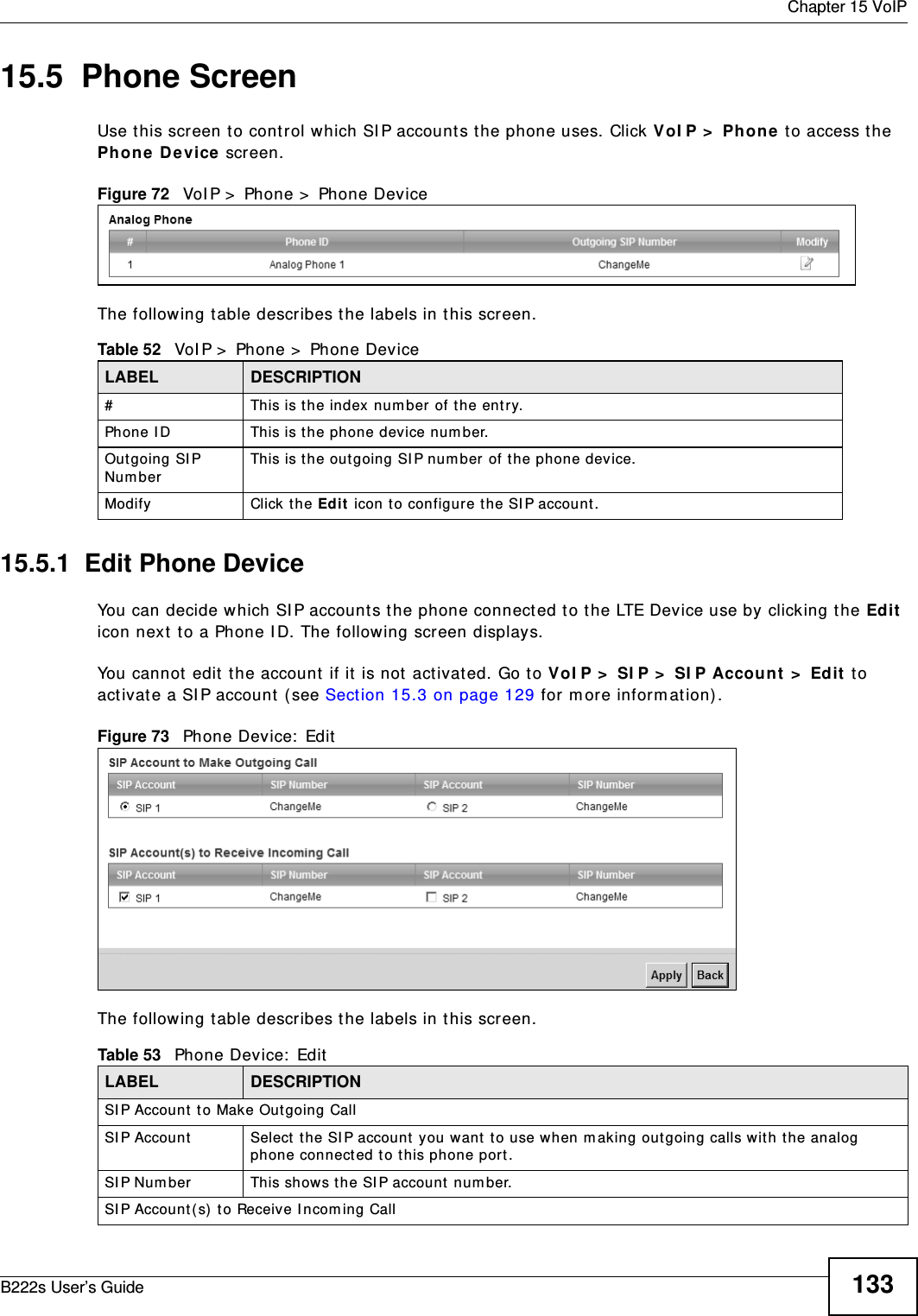

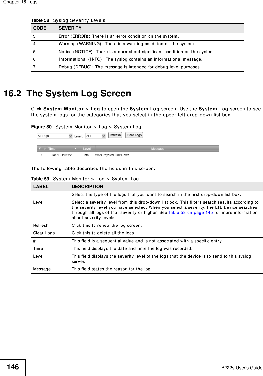

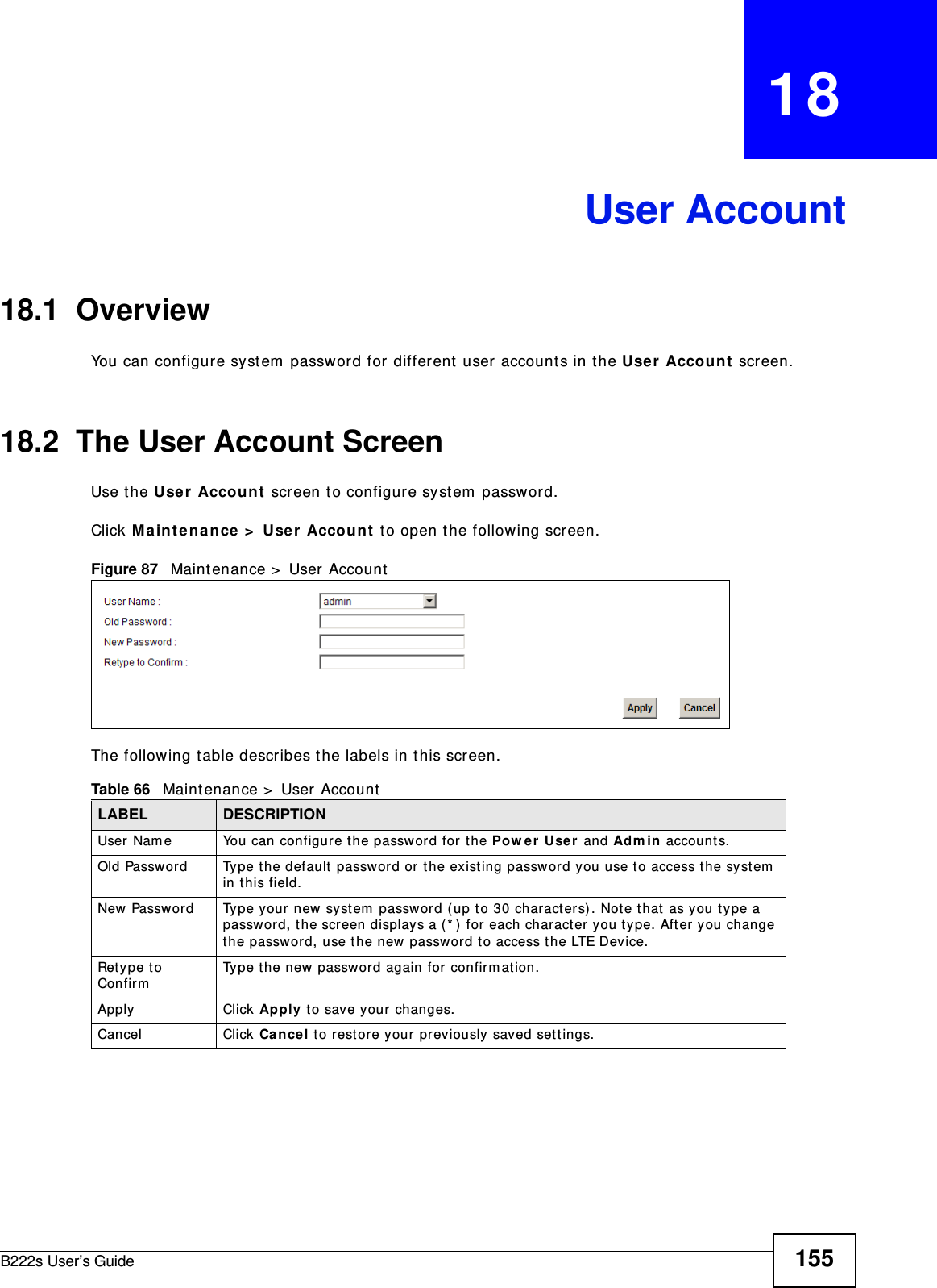


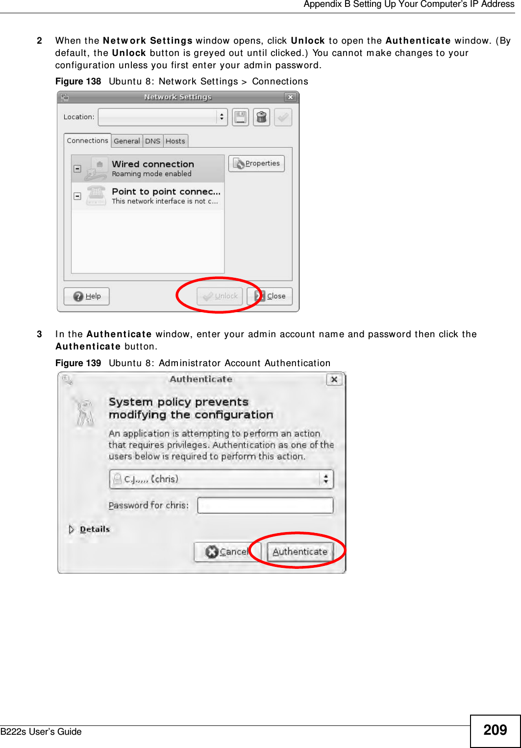
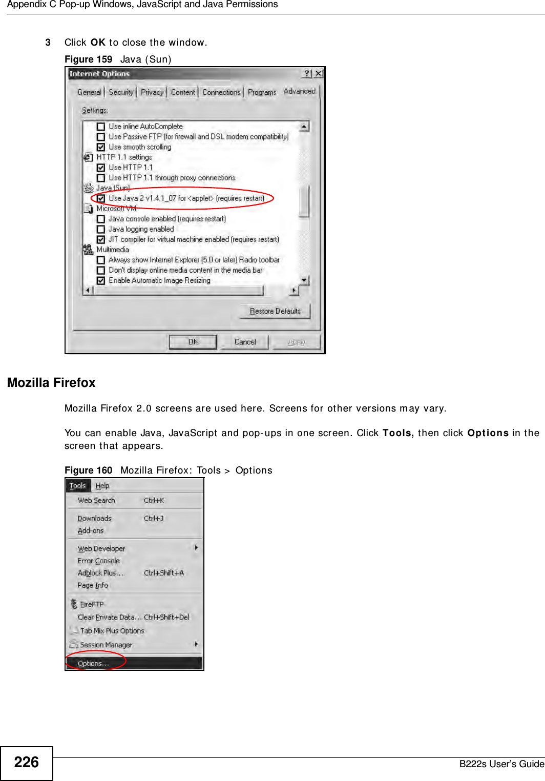
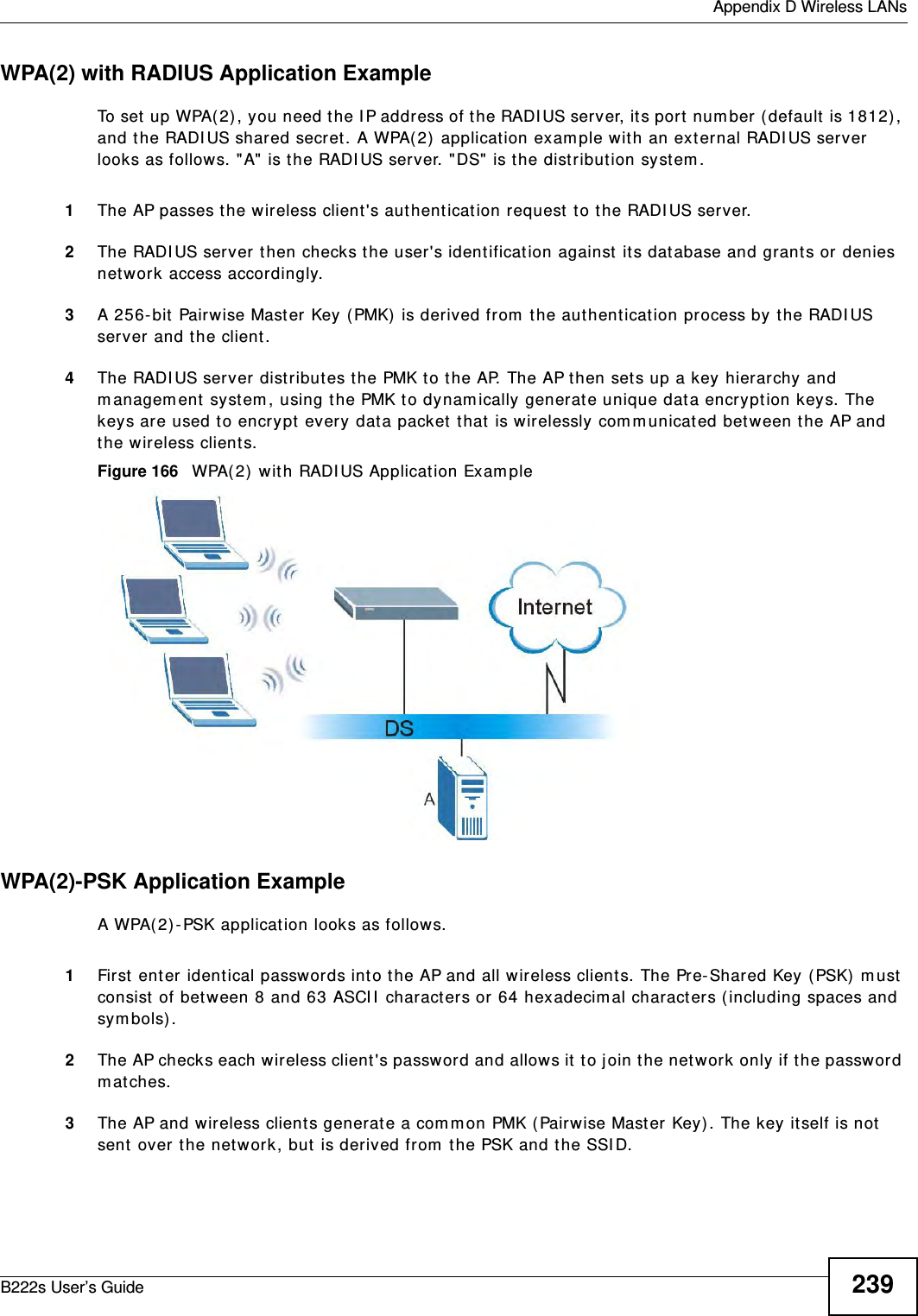
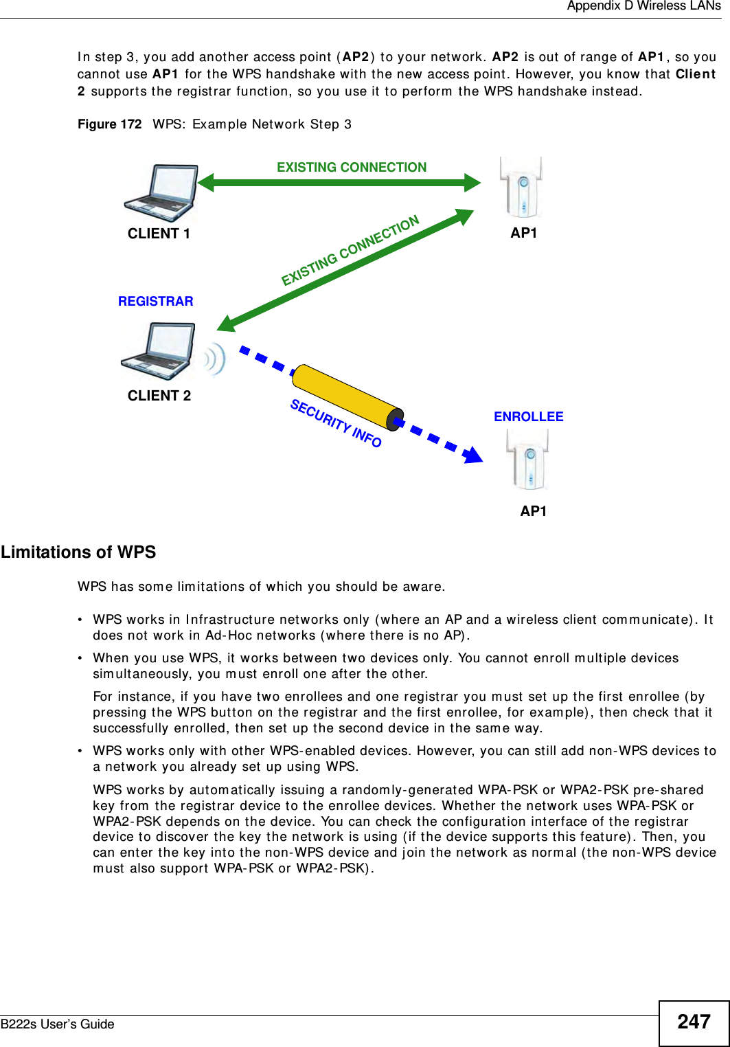
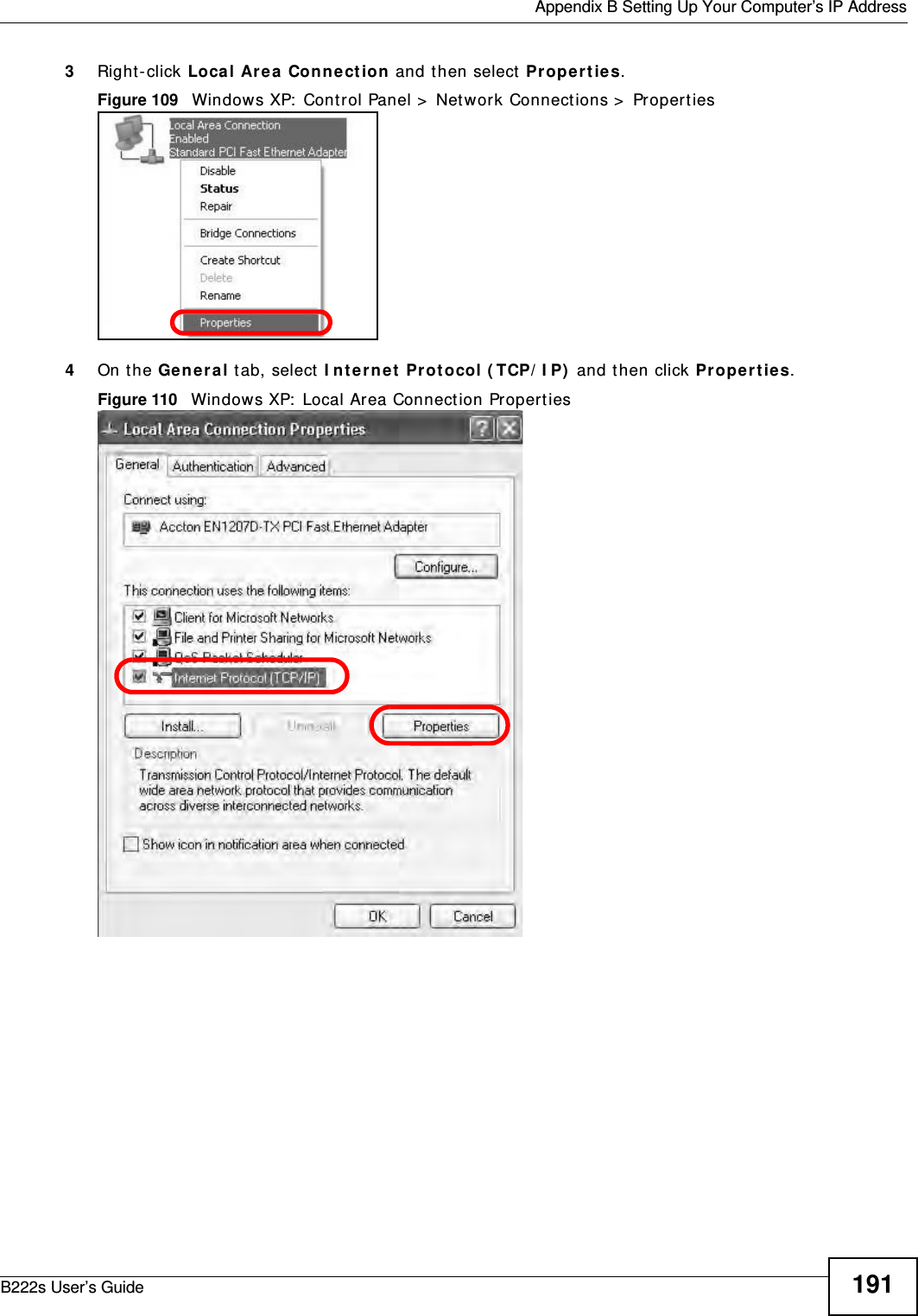
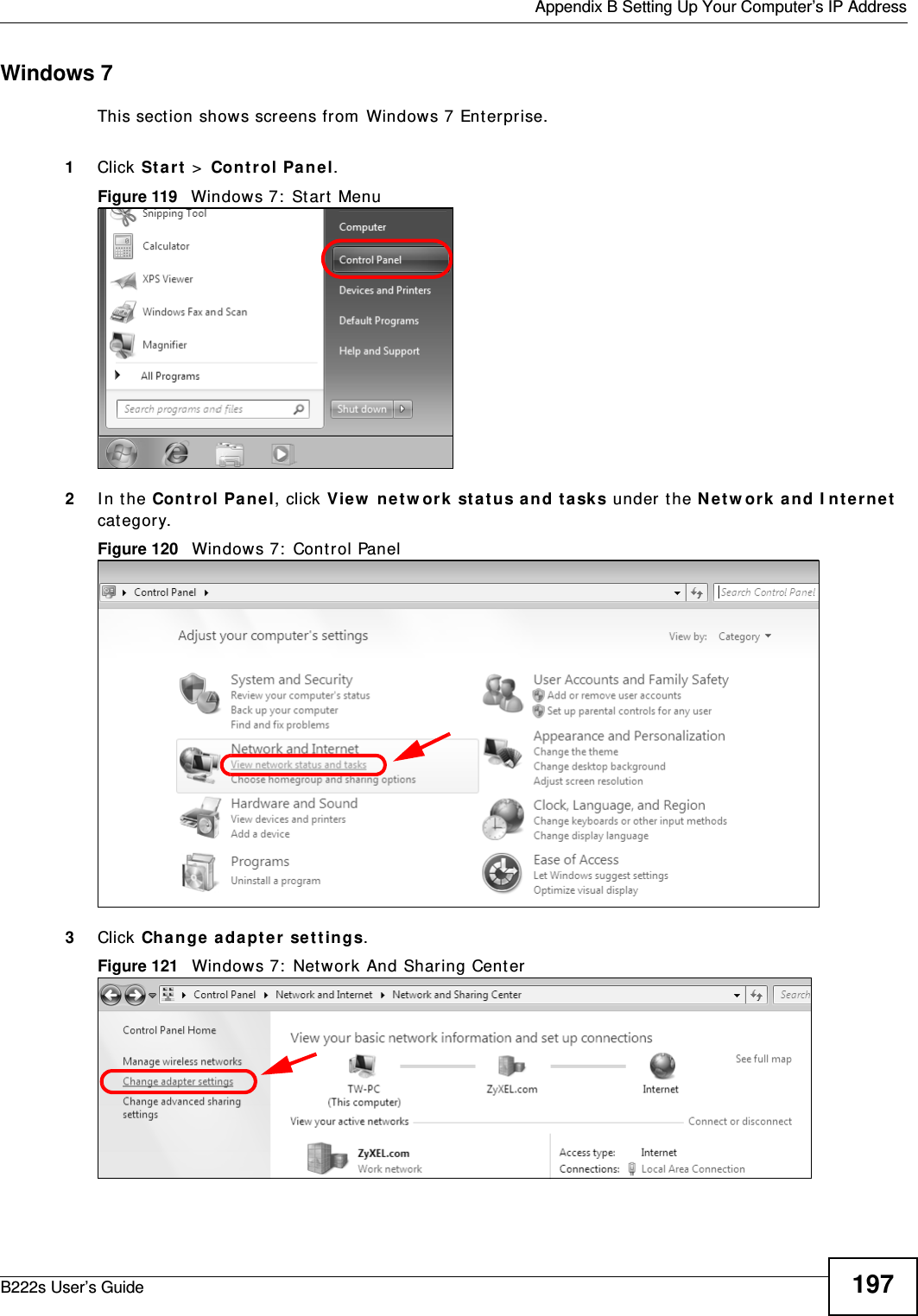
![Chapter 26 TroubleshootingB222s User’s Guide 1754Reset t he device t o its factory default s, and try t o access the LTE Device w it h t he default I P address. See Sect ion 1.7 on page 20. 5I f t he problem cont inues, cont act t he net work adm inistrat or or vendor, or try one of the advanced suggest ions.Adva nced Suggest ions• Try t o access t he LTE Device using anot her service, such as Telnet . I f you can access t he LTE Device, check t he rem ot e m anagem ent settings and firewall rules t o find out why t he LTE Device does not respond t o HTTP. • I f your com puter is connect ed to t he W AN port or is connect ed wirelessly, use a com put er t hat is connected t o a ETH ERN ET port .I can see t he Login screen, but I cannot log in t o t he LTE Device.1Make sure you have entered the user nam e and password cor rect ly. The default user nam e is adm in. These fields are case- sensitive, so m ake sure [ Caps Lock] is not on. 2You cannot log in to t he web configurator while som eone is using Telnet t o access t he LTE Device. Log out of the LTE Device in t he ot her session, or ask t he person who is logged in to log out . 3Turn t he LTE Device off and on. 4I f t his does not work, you have t o r eset the device t o it s factory default s. See Sect ion 26.2 on page 173.26.4 Internet AccessI cannot access t he I nt ernet .1Check the hardware connect ions, and m ake sure t he LEDs are behaving as expect ed. See t he Quick St art Guide and Section 1.6 on page 18. 2Make sur e you ent ered your serv ice provider’s LTE APN inform at ion correctly.3I f you are trying t o access t he I nternet wirelessly, m ake sure t he wireless sett ings in t he wireless client are t he sam e as the set t ings in the AP. 4I f you are t rying t o access t he I nternet wirelessly, m ake sure you have enabled t he wireless LAN by the W PS/ W LAN but ton or t he Net w or k Set t ing > W irele ss > Ge ne r a l screen.5Disconnect all t he cables fr om your device, and follow t he directions in the Quick St ar t Guide again. 6I f t he problem cont inues, cont act your I SP.](https://usermanual.wiki/MitraStar-Technology/M4G-301/User-Guide-1730649-Page-175.png)
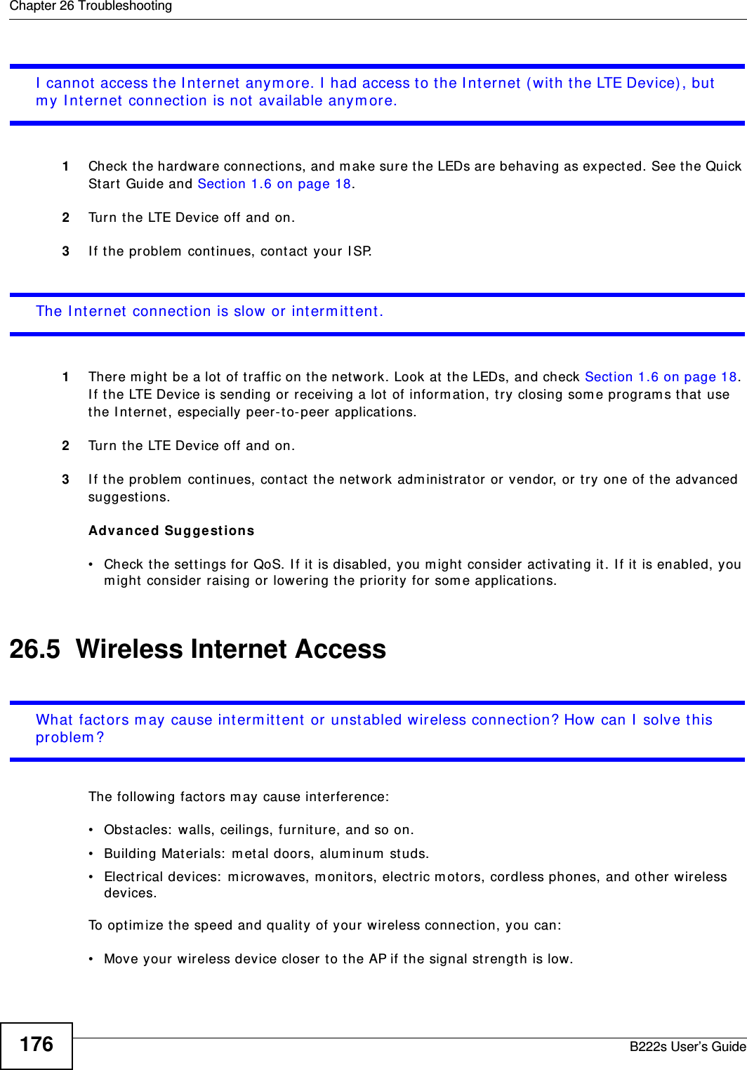
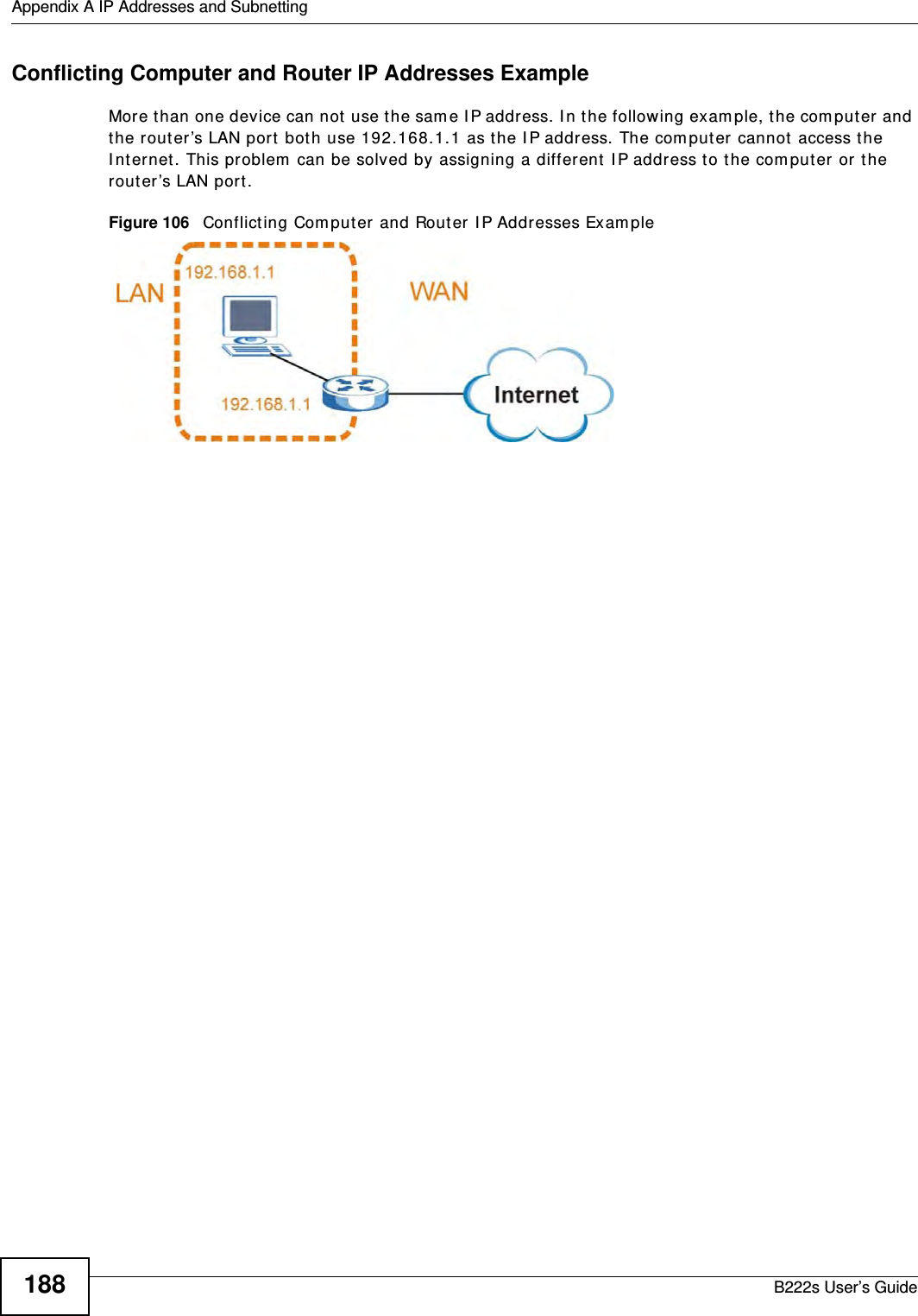
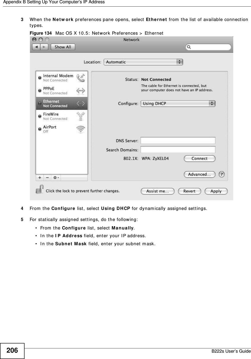
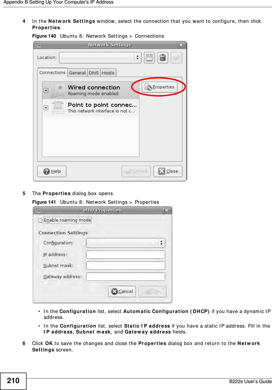
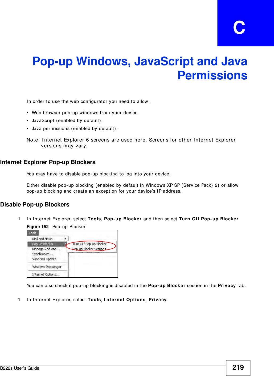
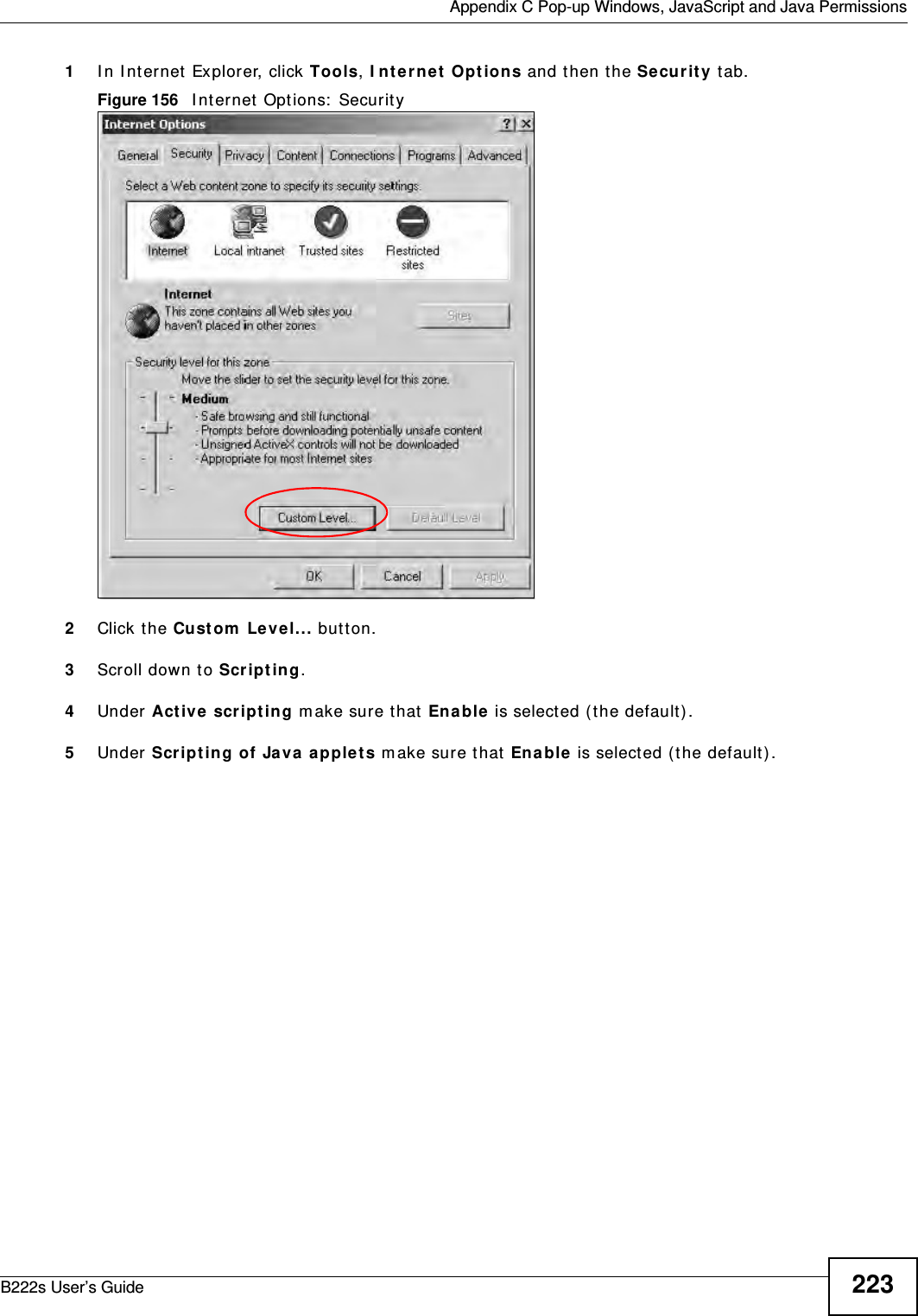
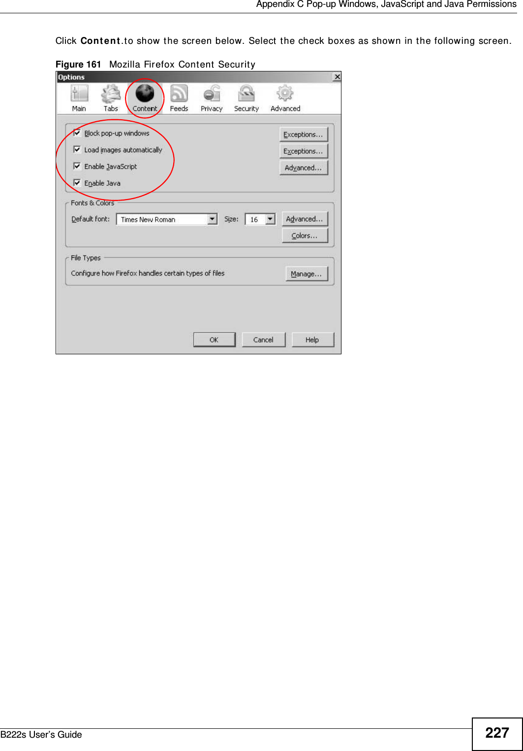
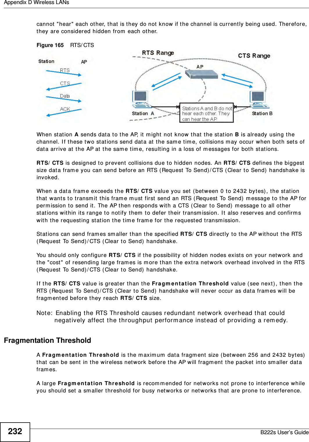
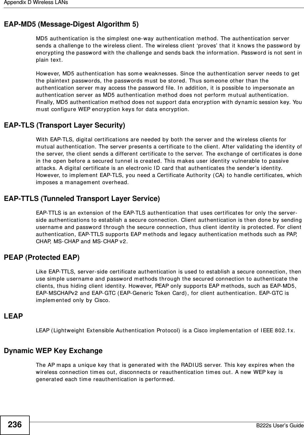
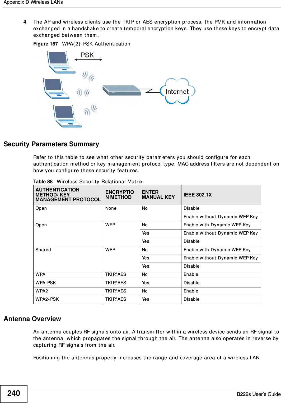
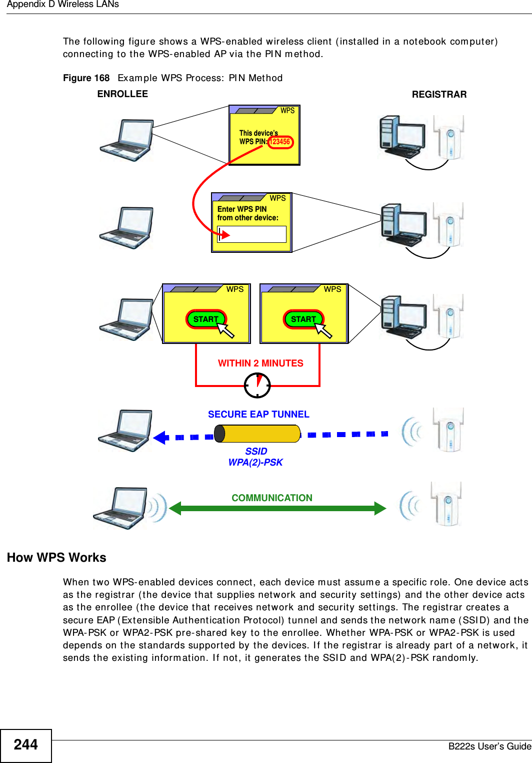
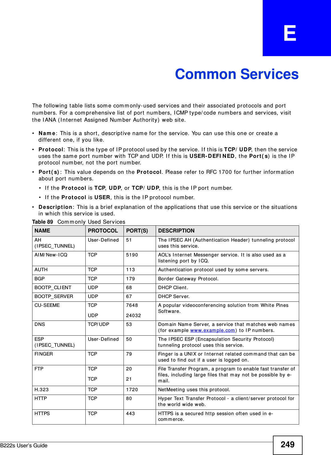
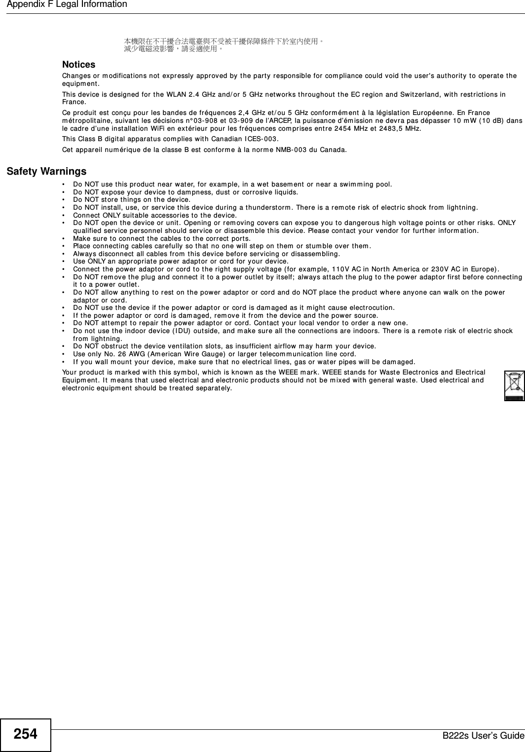
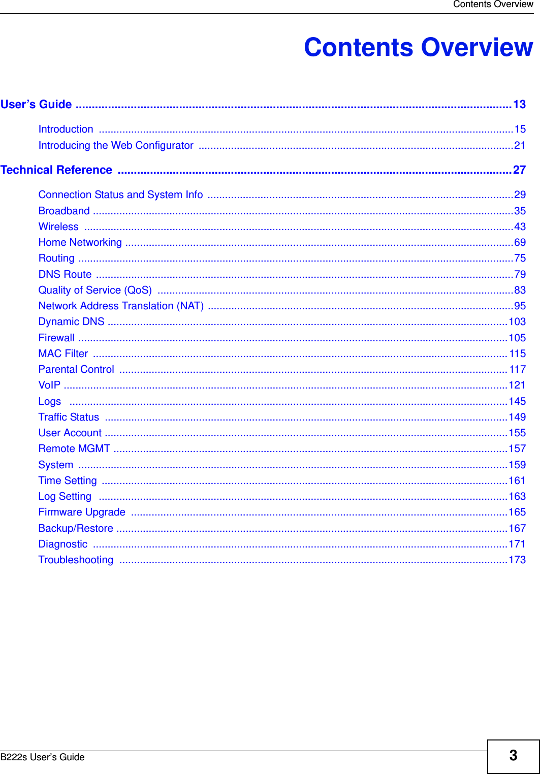
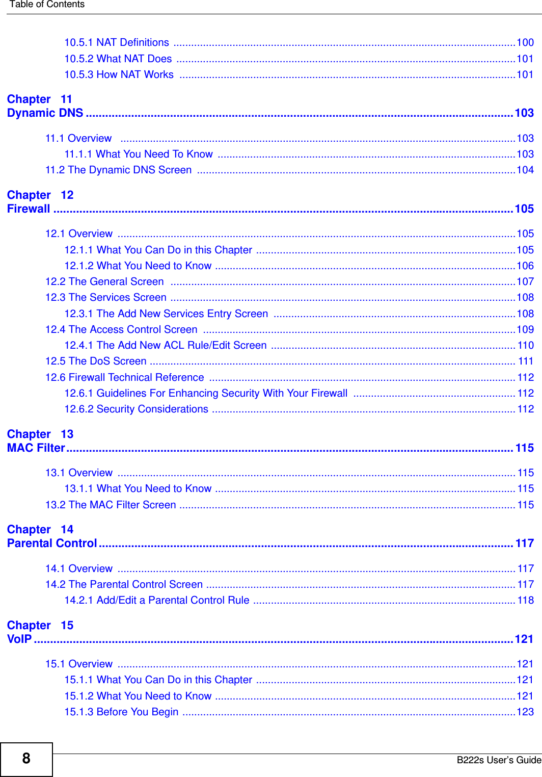
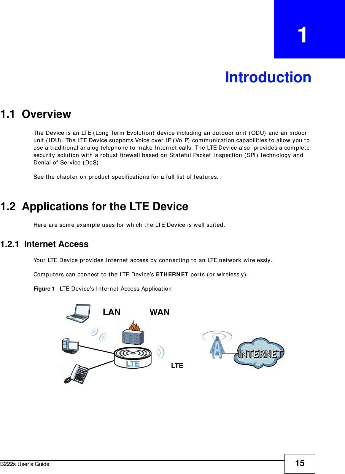
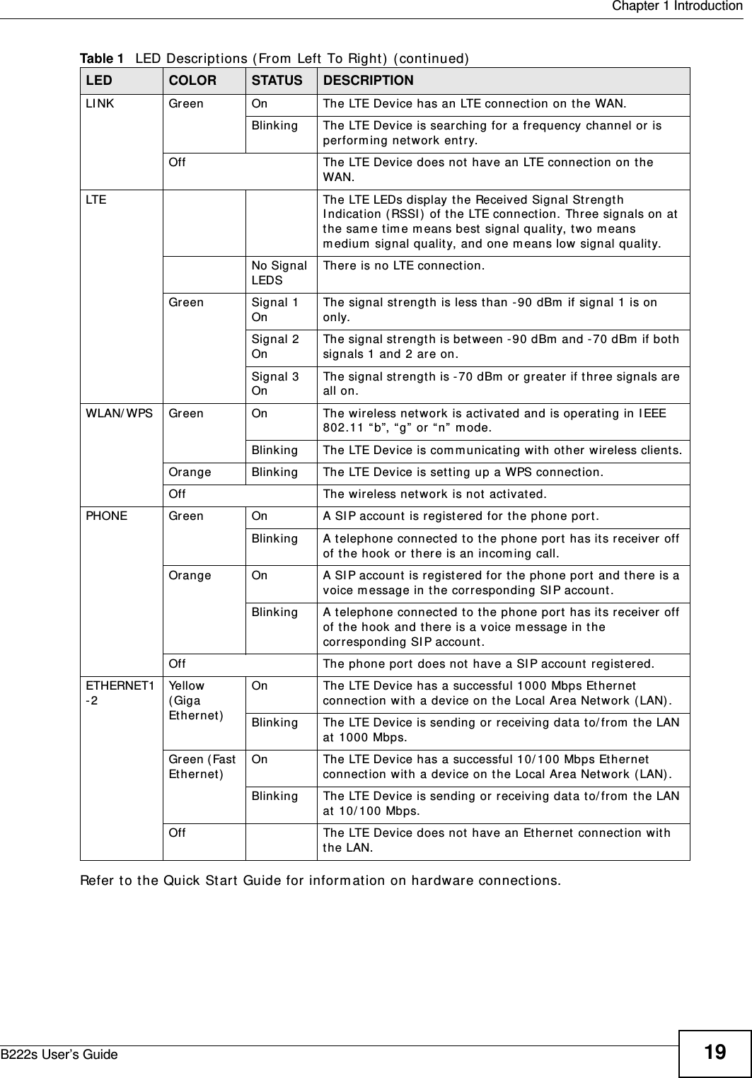
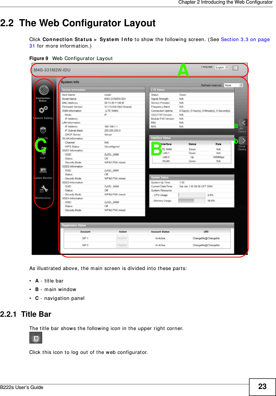
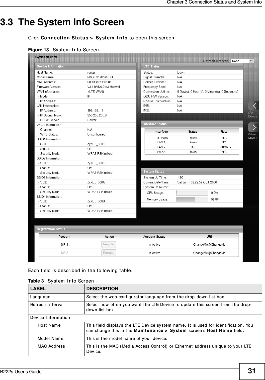
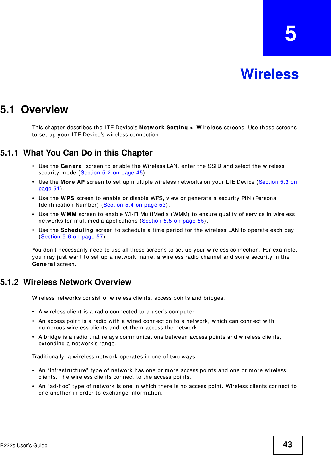
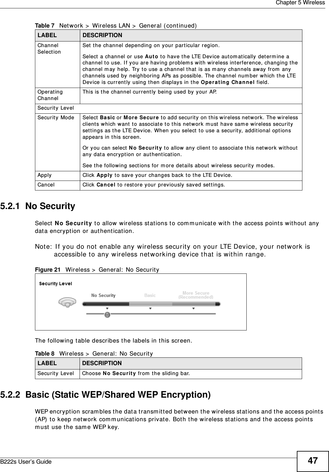
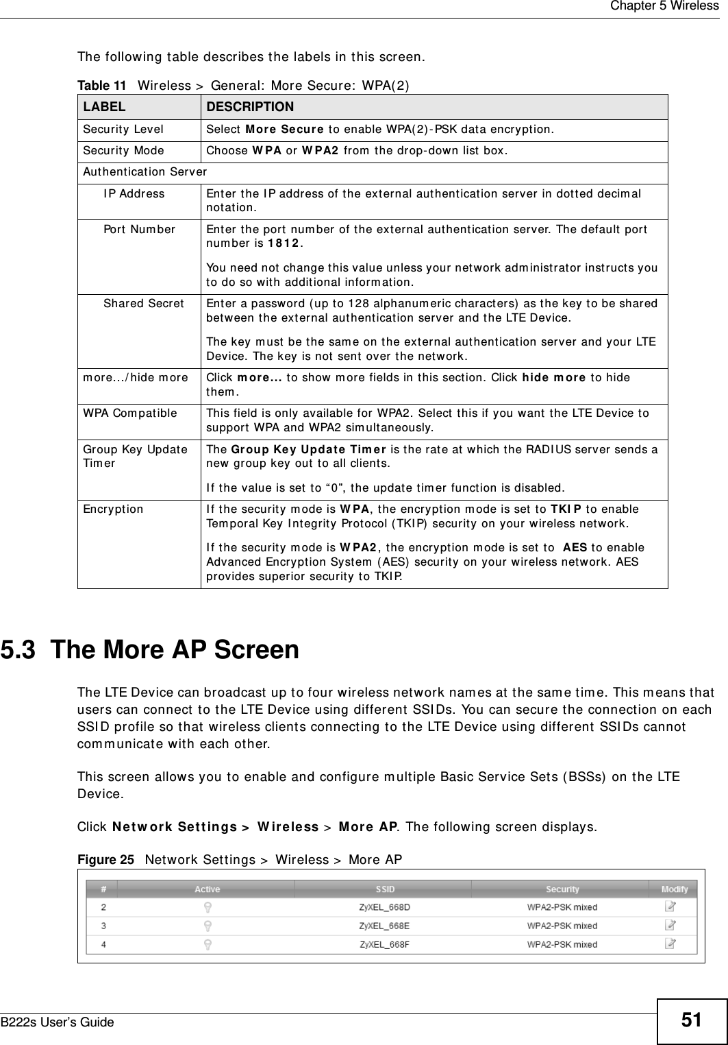
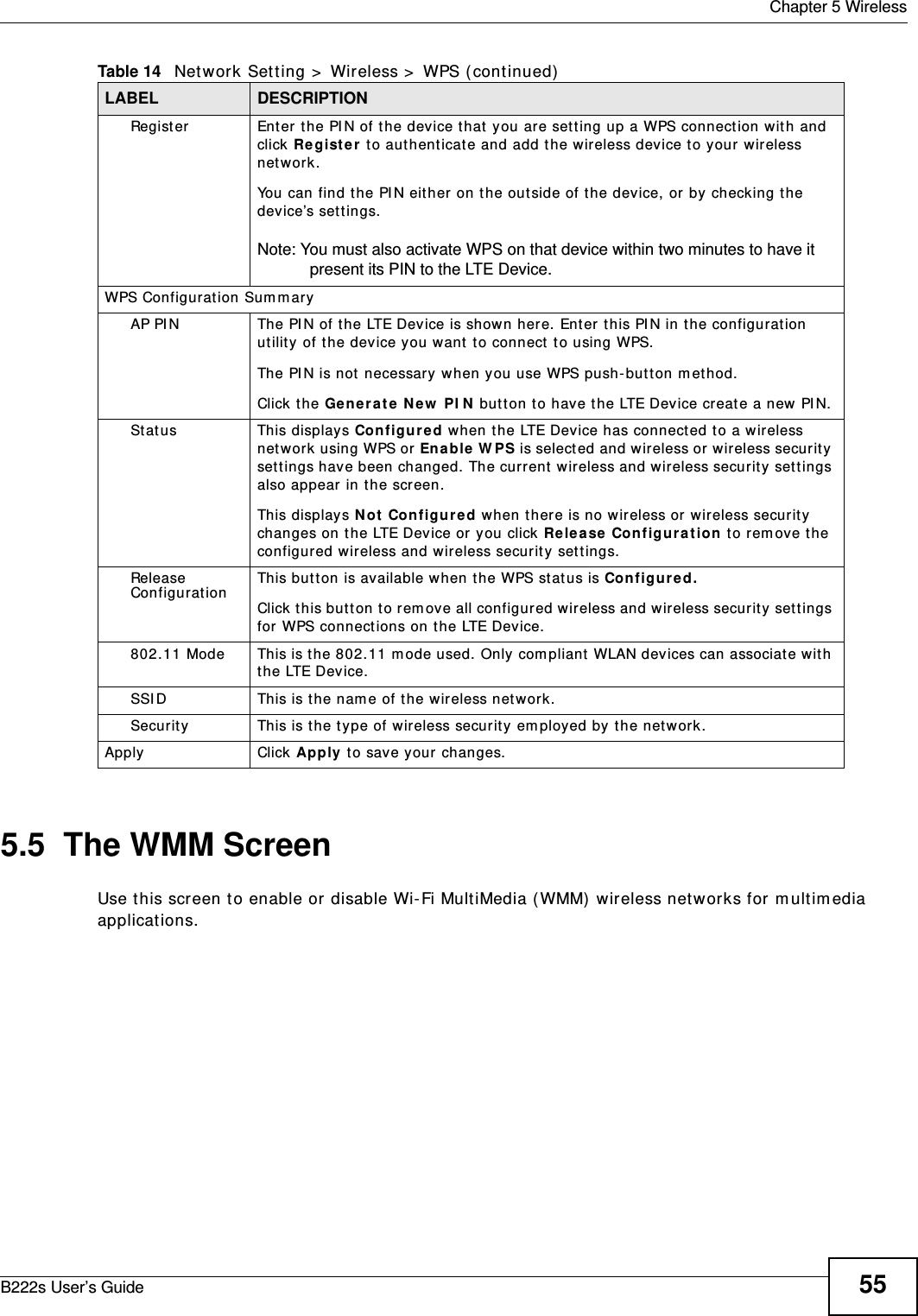
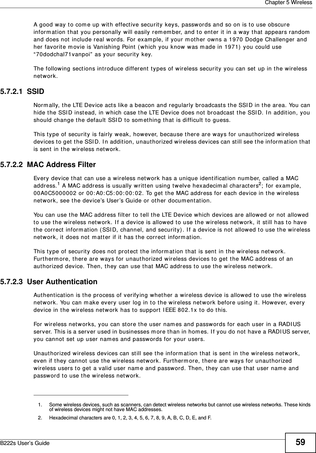
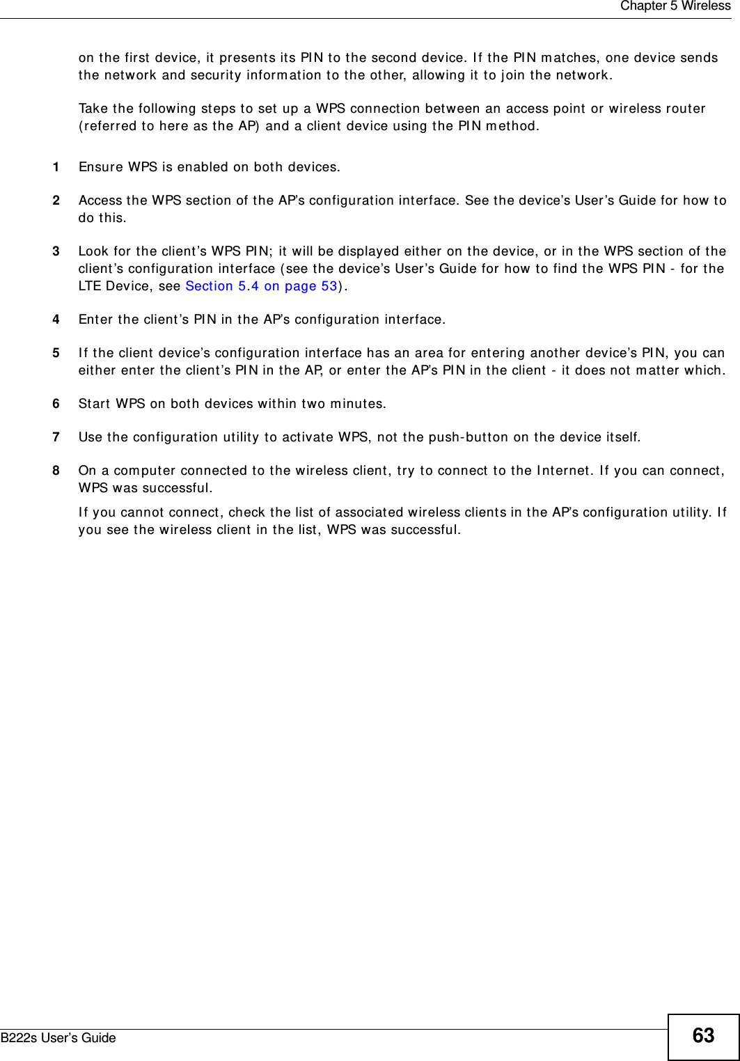
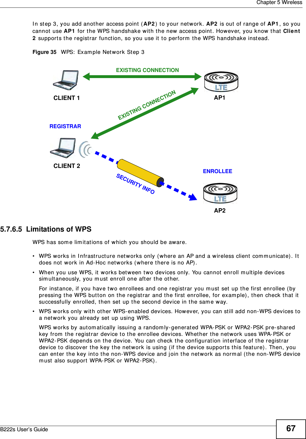
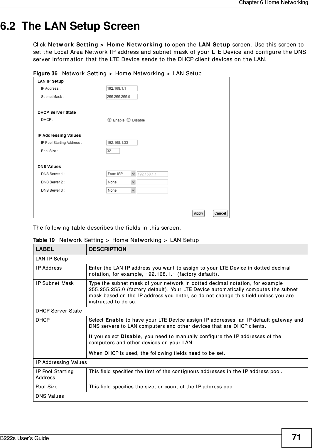
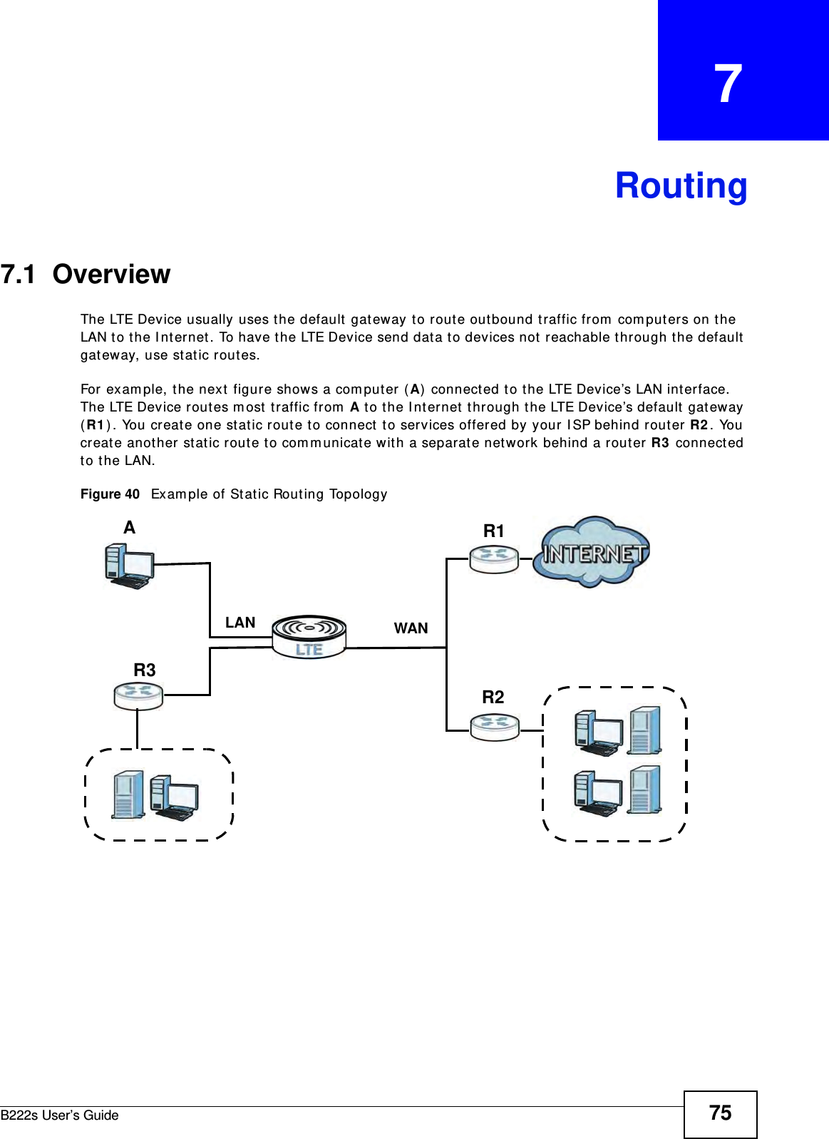
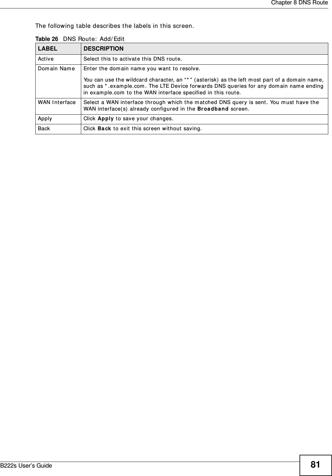
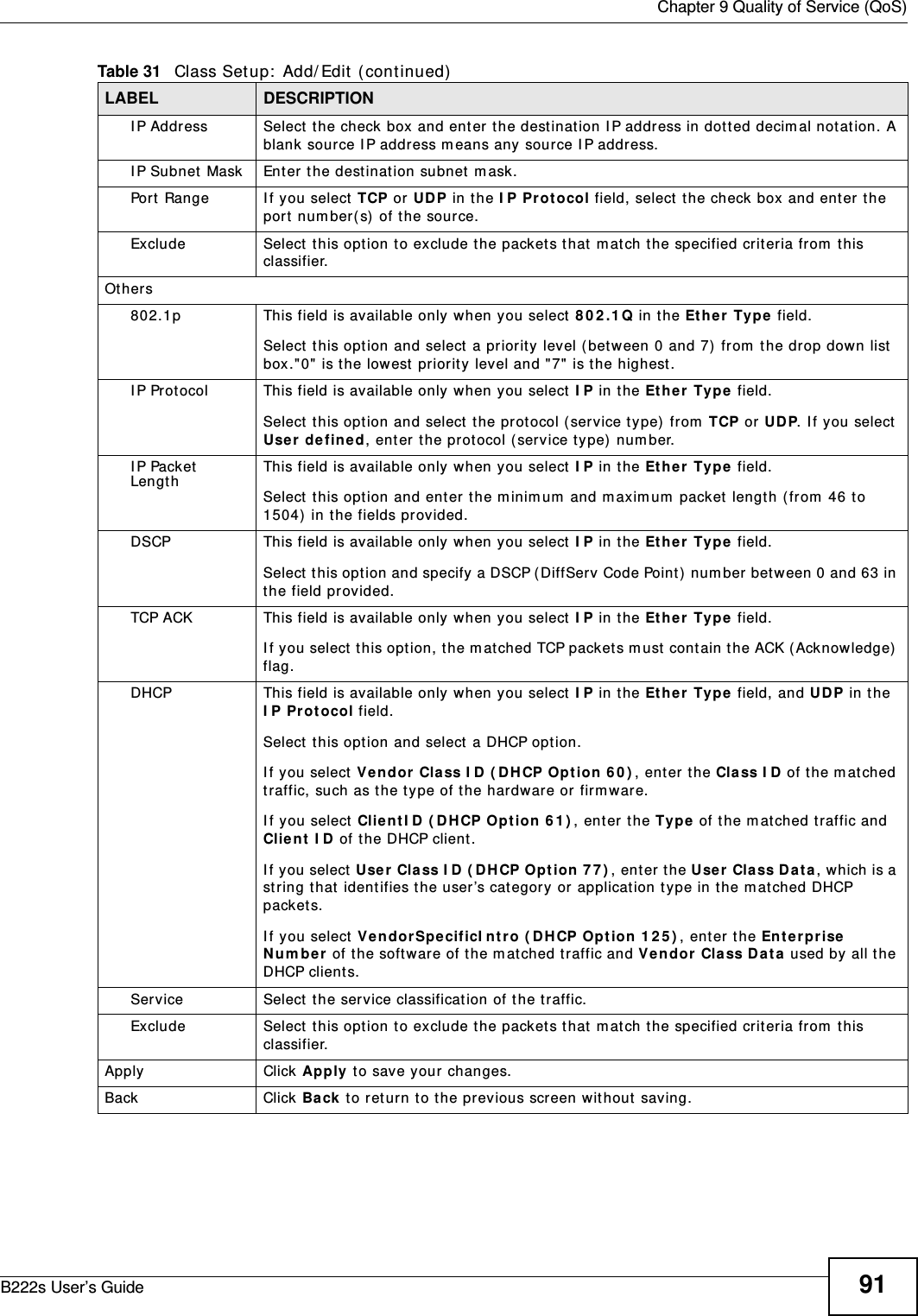
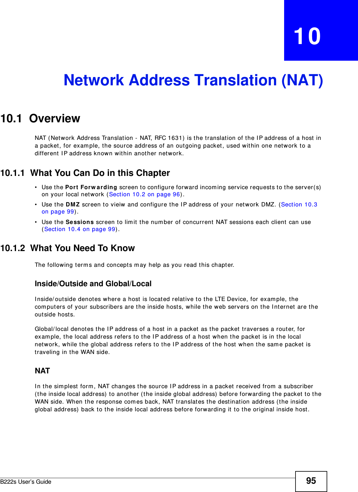
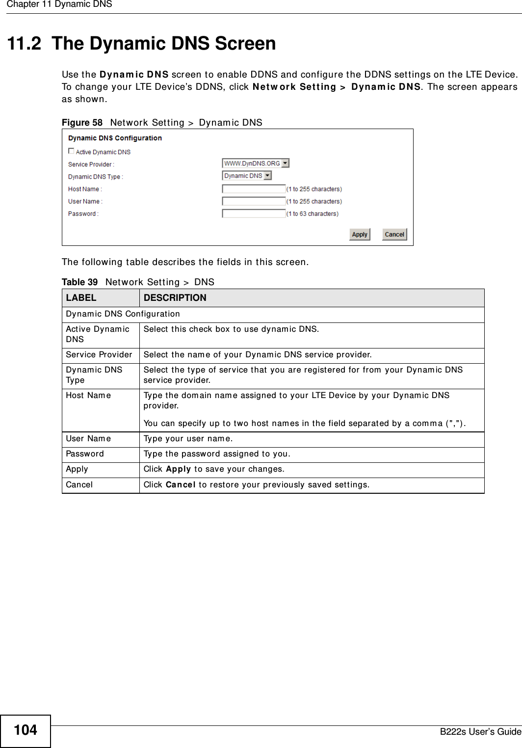
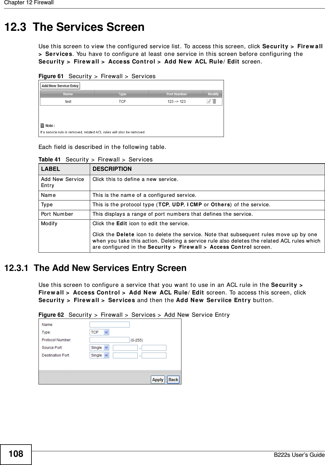
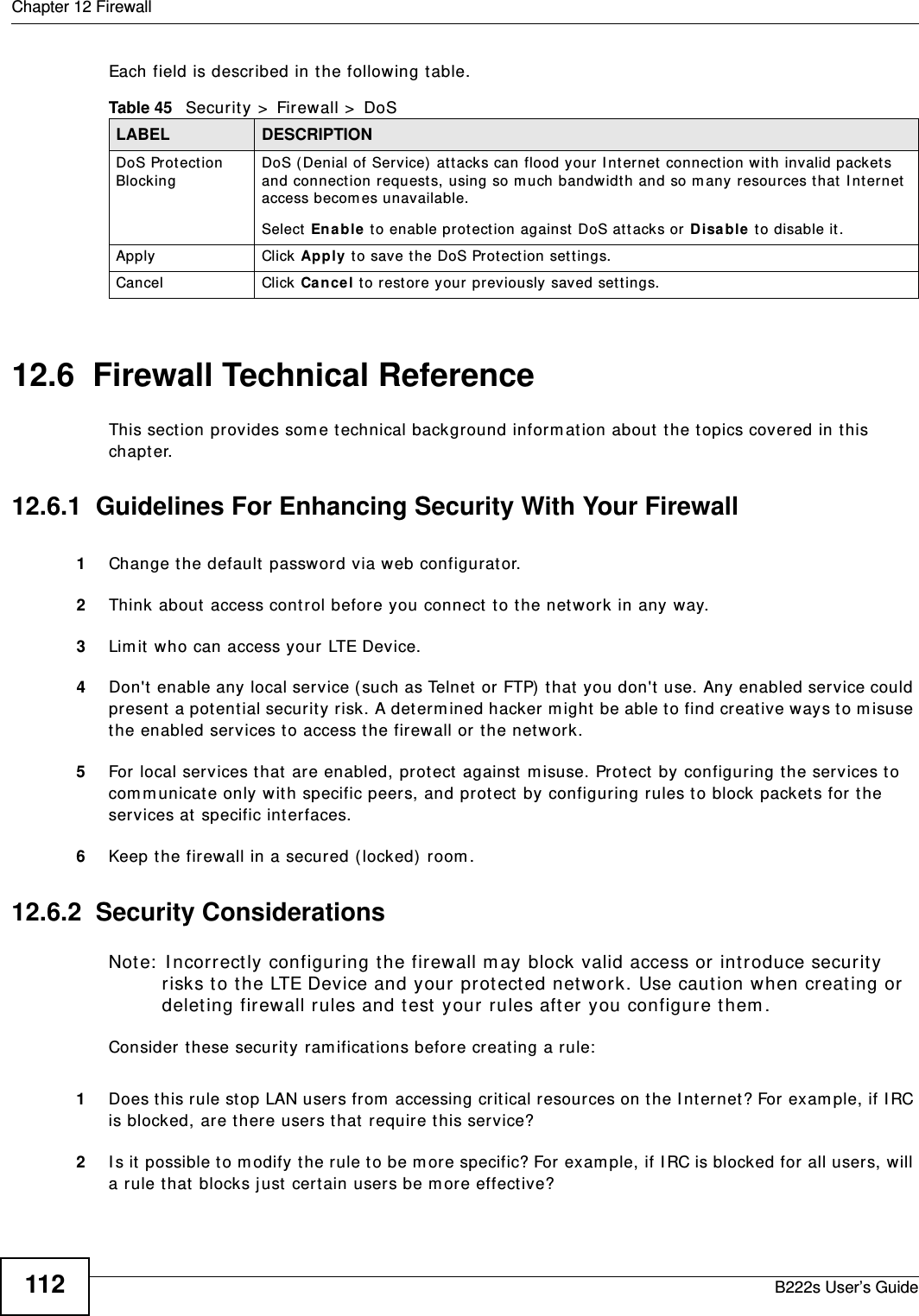
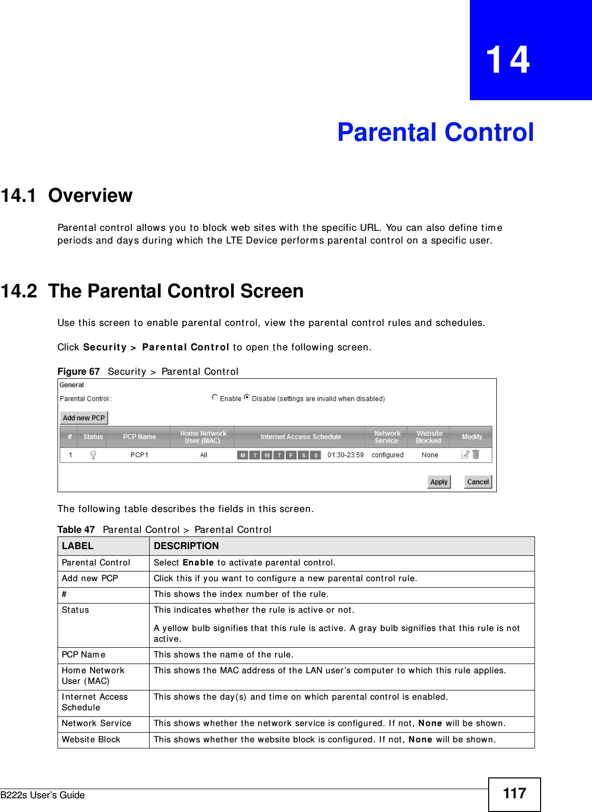
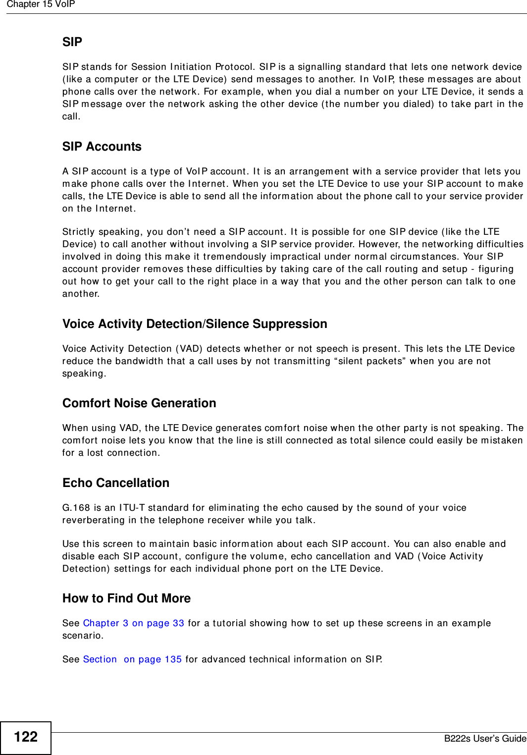
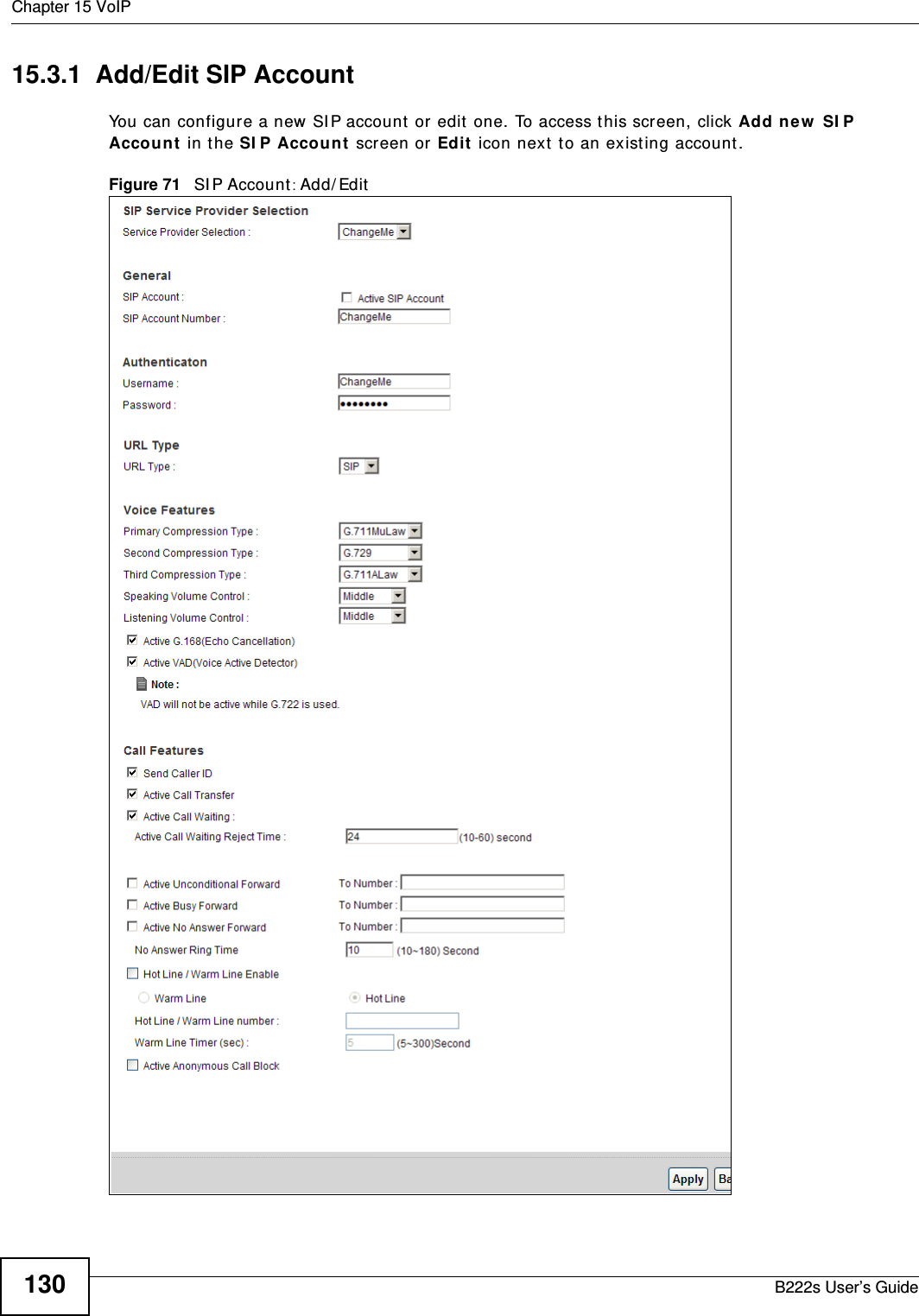
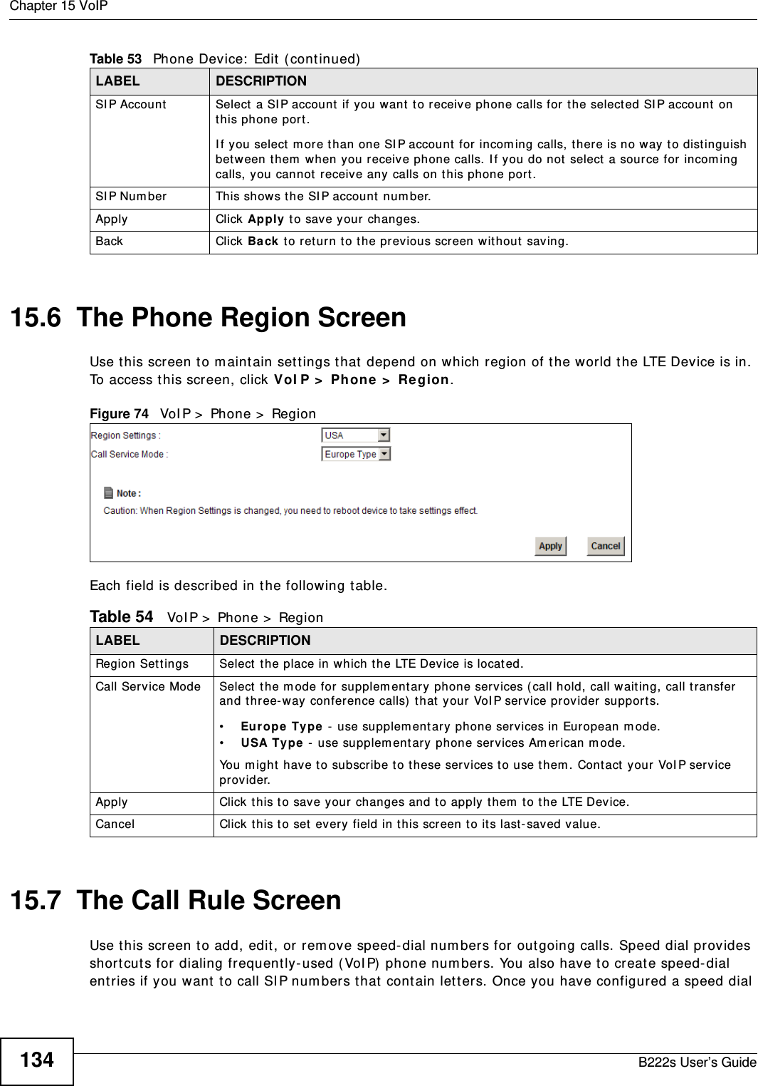
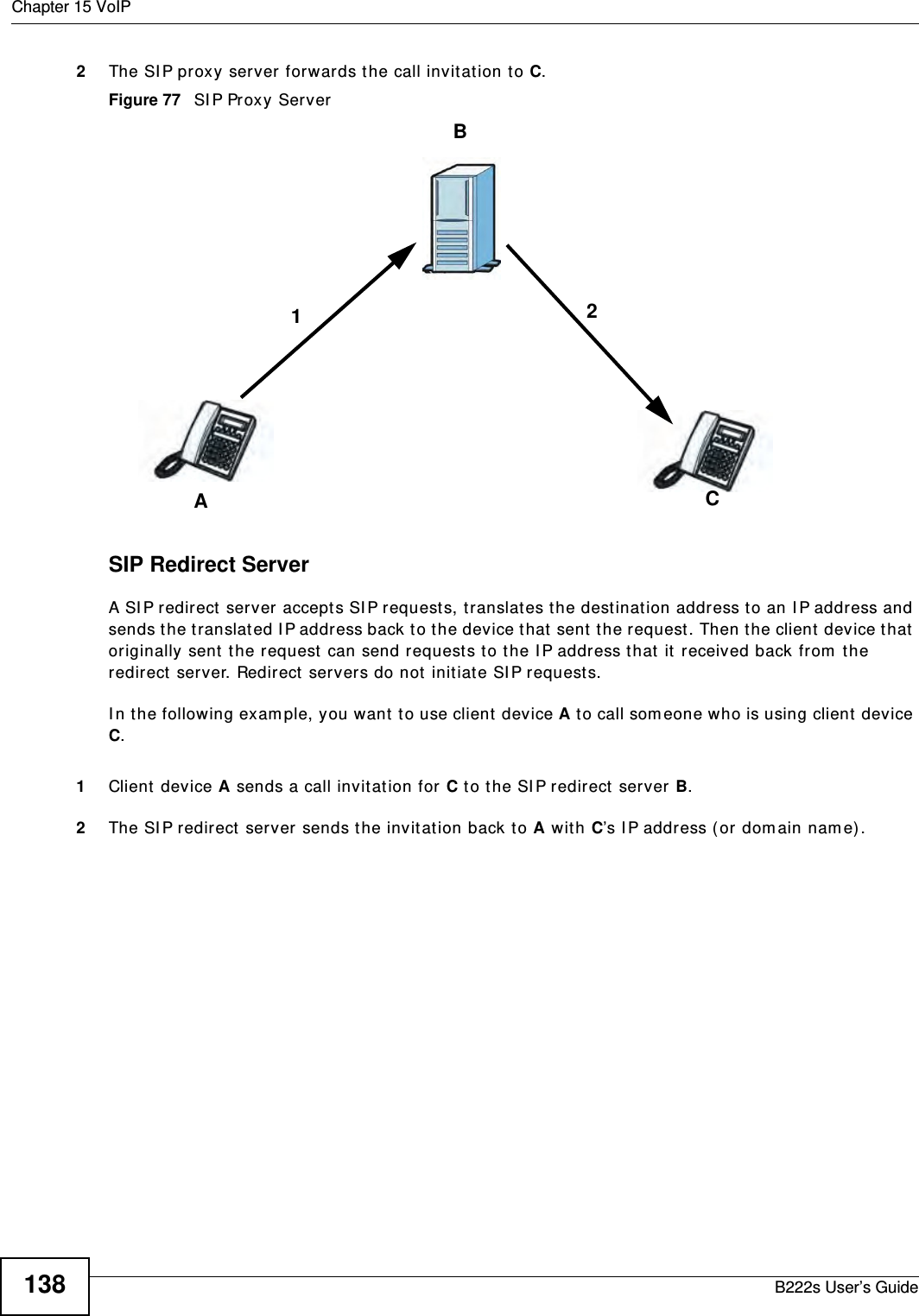
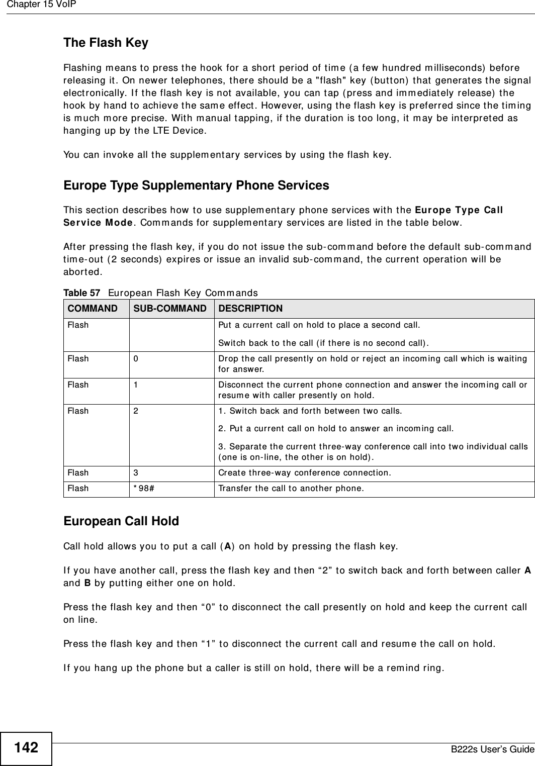
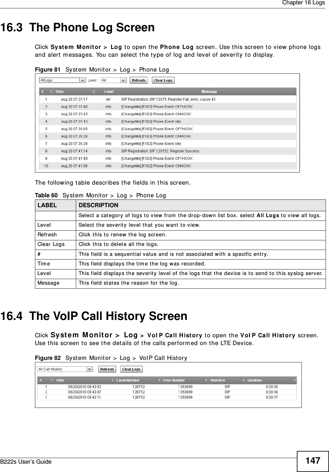
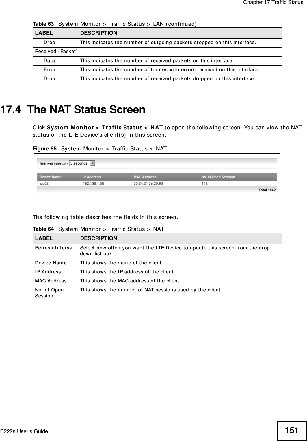
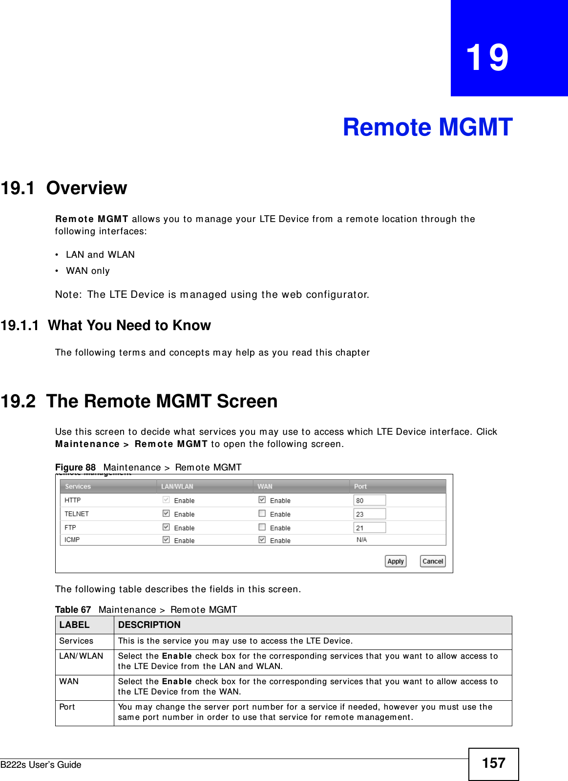
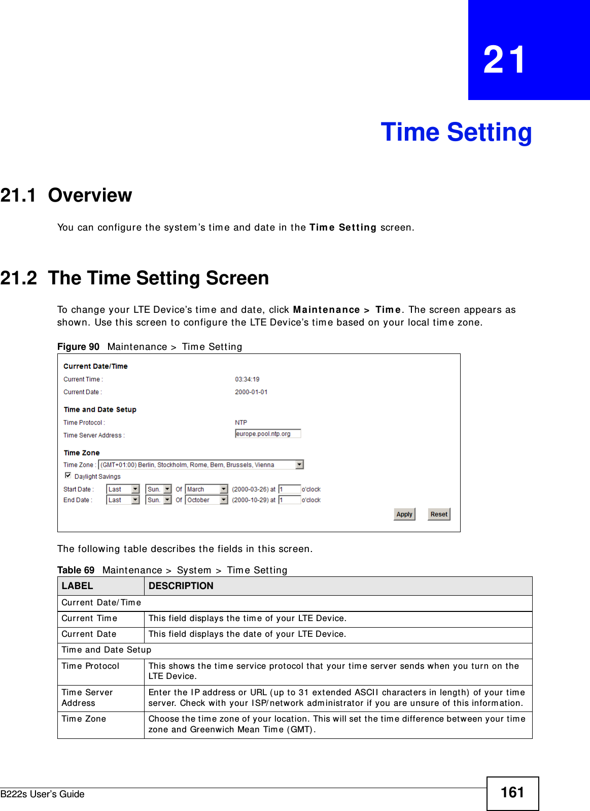
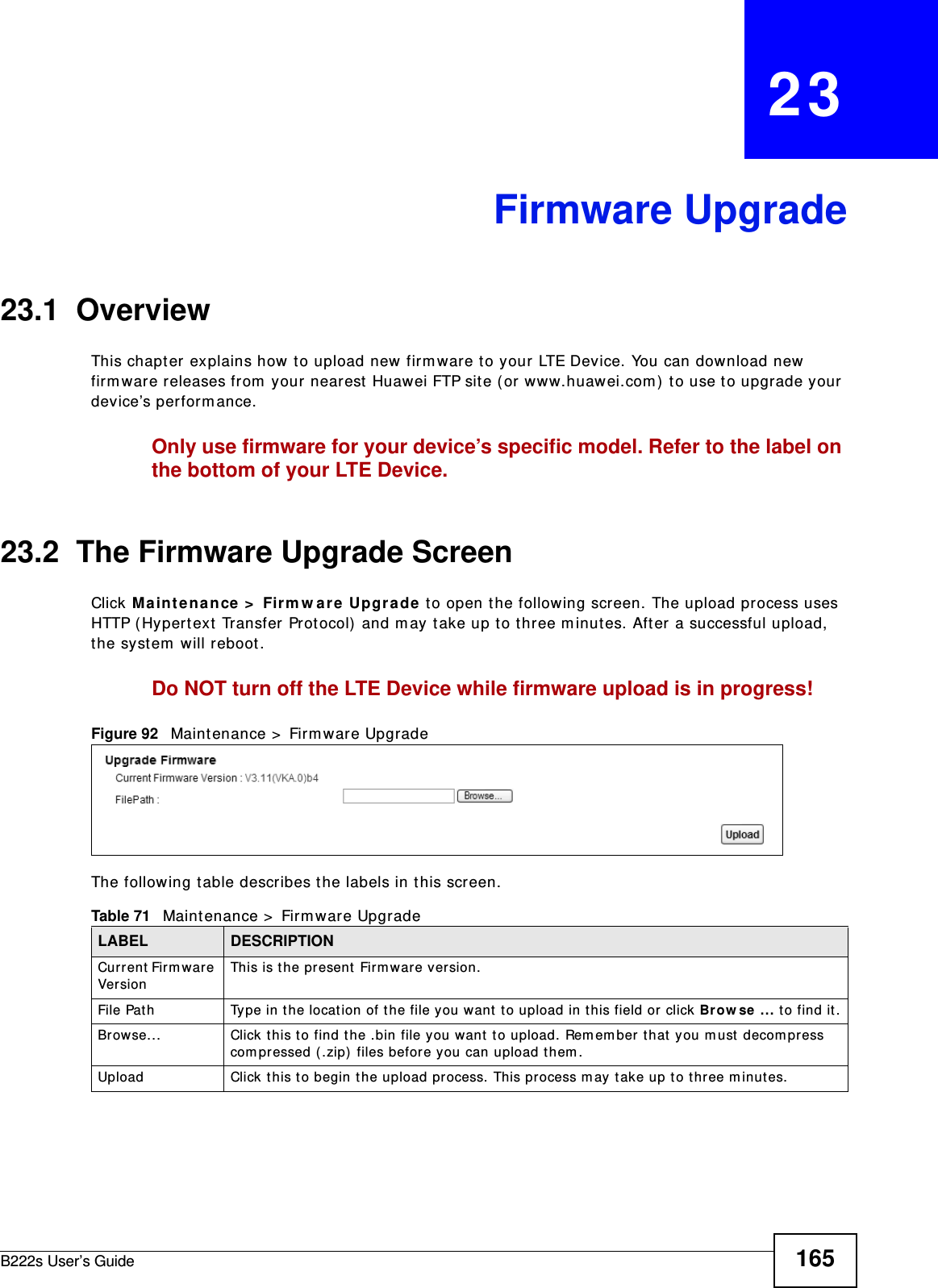
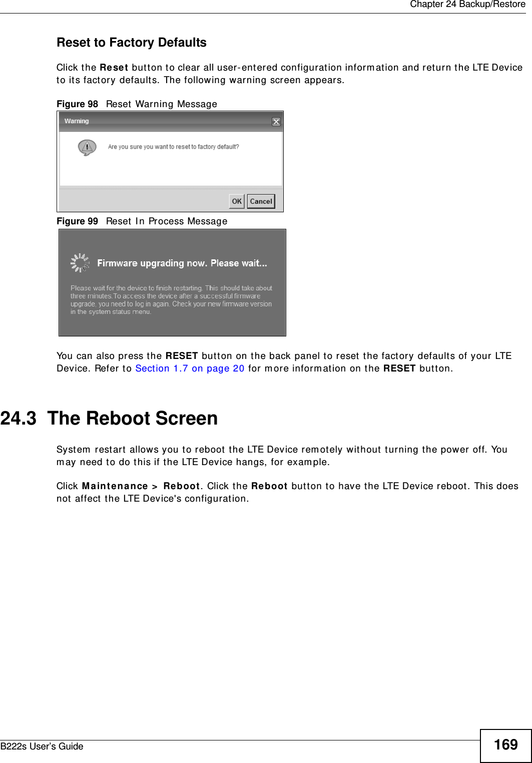
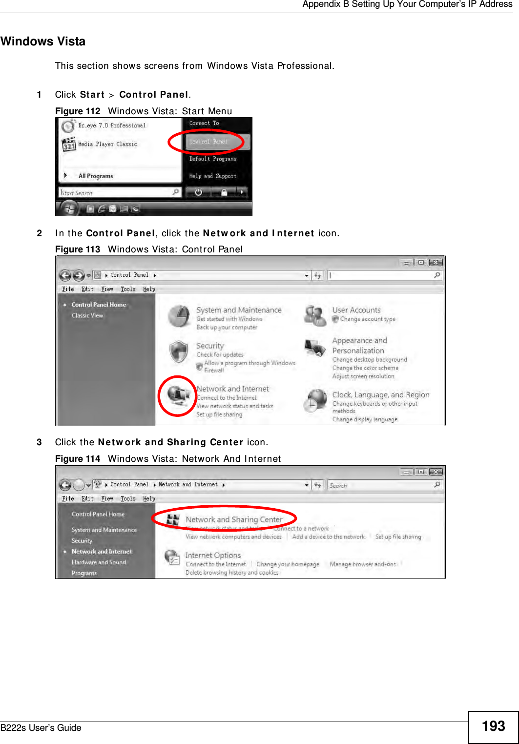
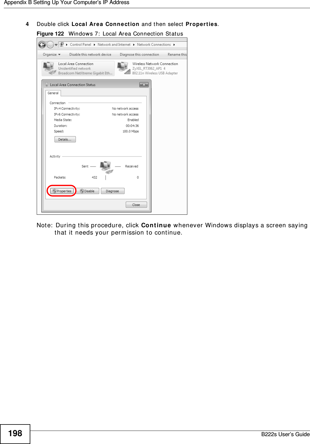
![Appendix B Setting Up Your Computer’s IP AddressB222s User’s Guide1925The I nt e rne t Prot ocol TCP/ I P Pr ope r t ies window opens.Figure 111 Windows XP: I nternet Protocol ( TCP/ I P) Propert ies6Select Obt ain an I P a ddr e ss a ut om at ica lly if your net work adm inist rat or or I SP assigns your I P address dynam ically.Select Use t he follow ing I P Addr e ss and fill in t he I P a ddr e ss, Subne t m ask, and De fa ult ga t e w ay fields if you have a st at ic I P address that was assigned t o you by your network adm inist rat or or I SP. You m ay also have t o ent er a Pre ferre d D N S ser ver and an Alt e r n at e DN S ser ve r , if t hat inform ation was provided.7Click OK t o close t he I nt er n e t Pr ot ocol ( TCP/ I P) Prope r t ies window.8Click OK t o close t he Loca l Area Conn e ct ion Pr ope r t ie s window.Verifying Settings1Click St a r t > All Progra m s > Acce ssories > Com m a nd Prom pt .2I n t he Com m and Prom pt window, t ype " ipconfig" and t hen press [ ENTER] . You can also go t o St ar t > Cont rol Pa nel > N et w or k Conn e ct ions, right- click a net work connection, click Sta t us and t hen click the Support t ab to view your I P address and connection inform at ion.](https://usermanual.wiki/MitraStar-Technology/M4G-301/User-Guide-1730649-Page-192.png)
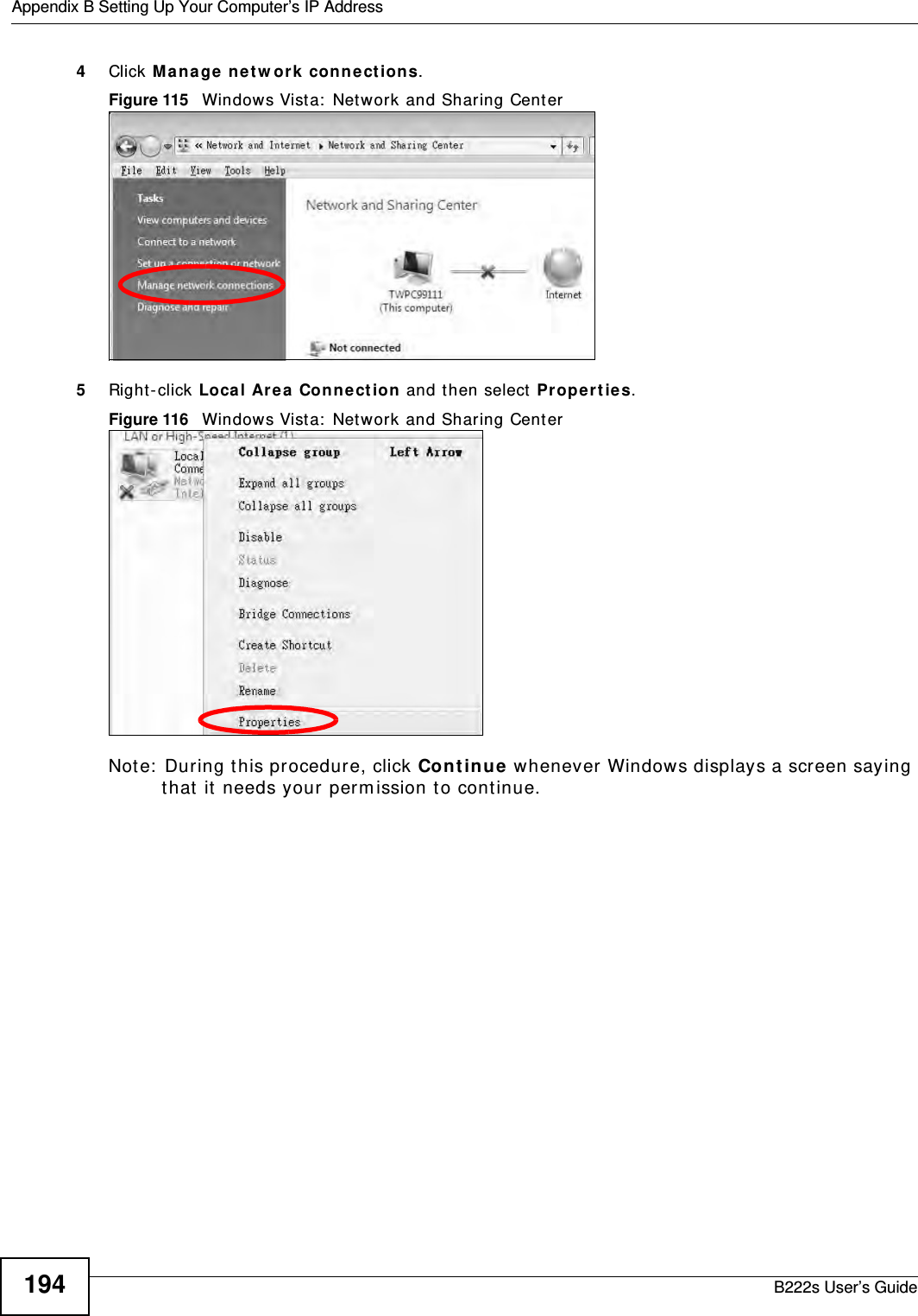
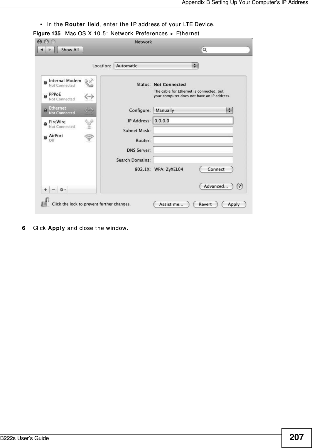
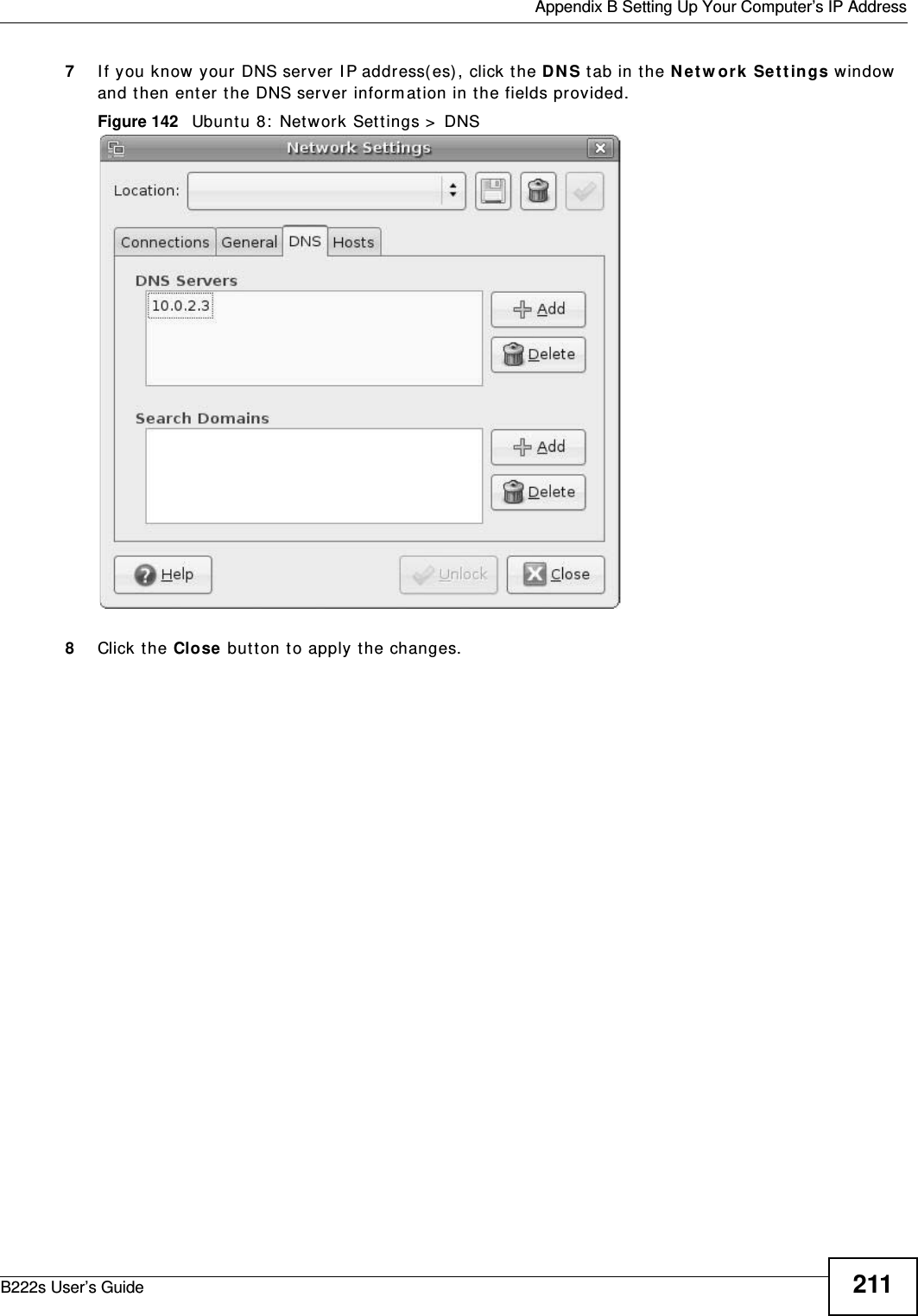
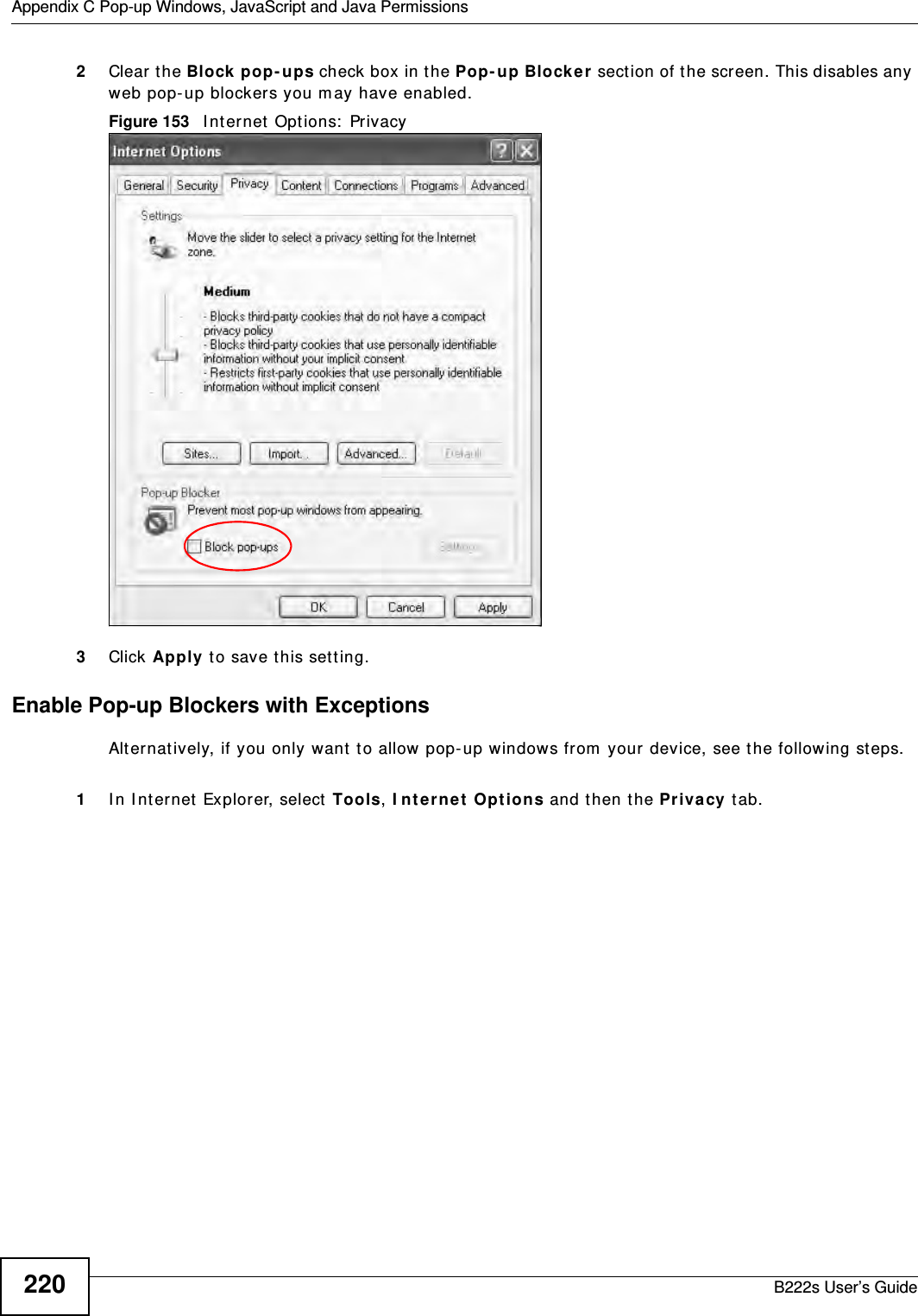
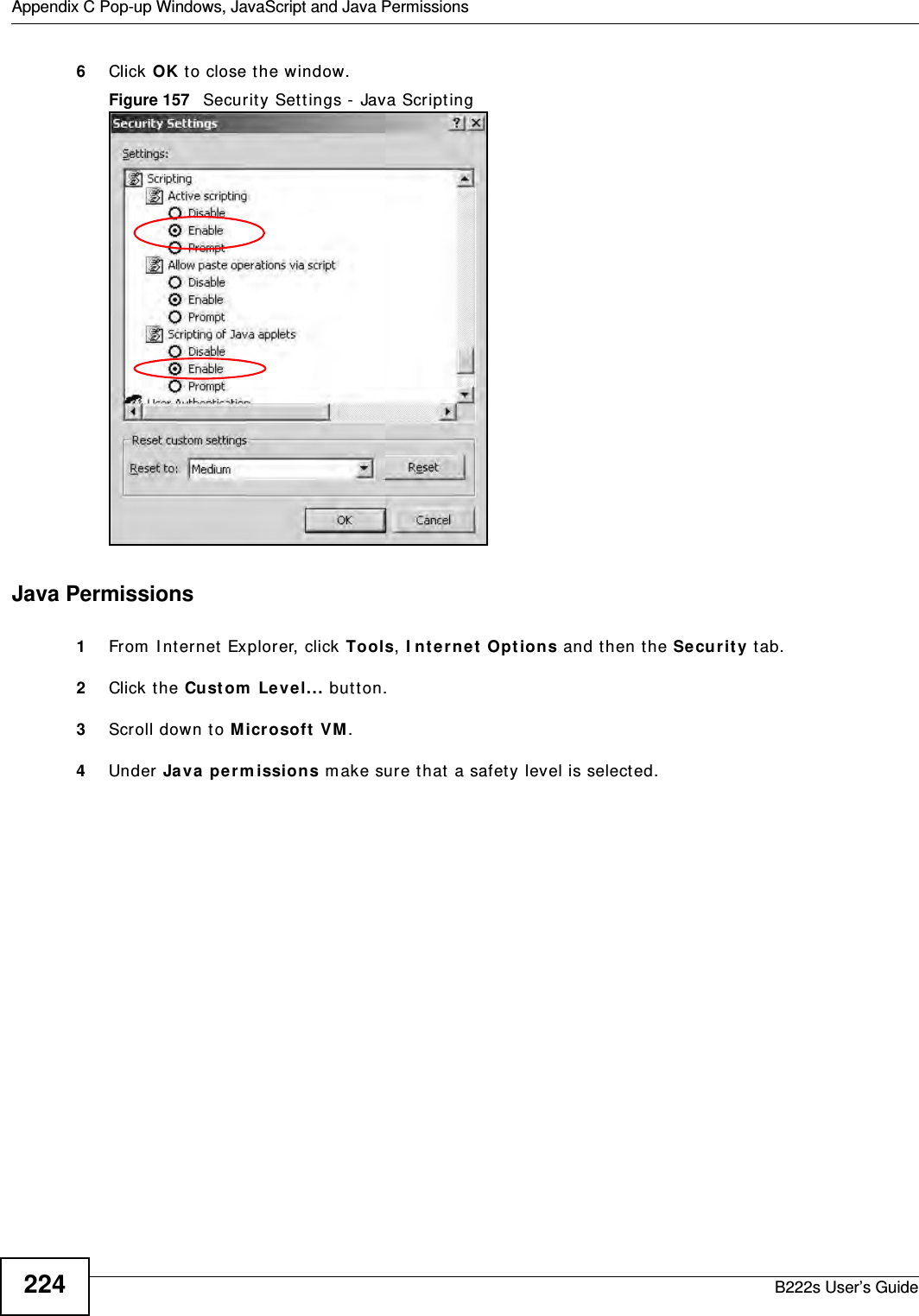
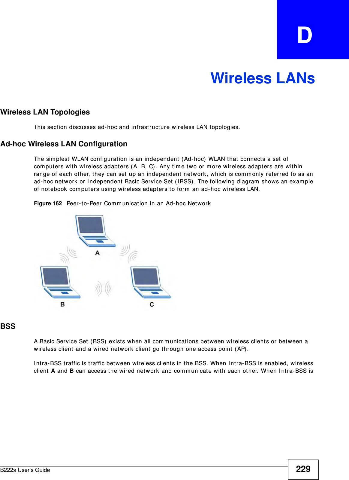
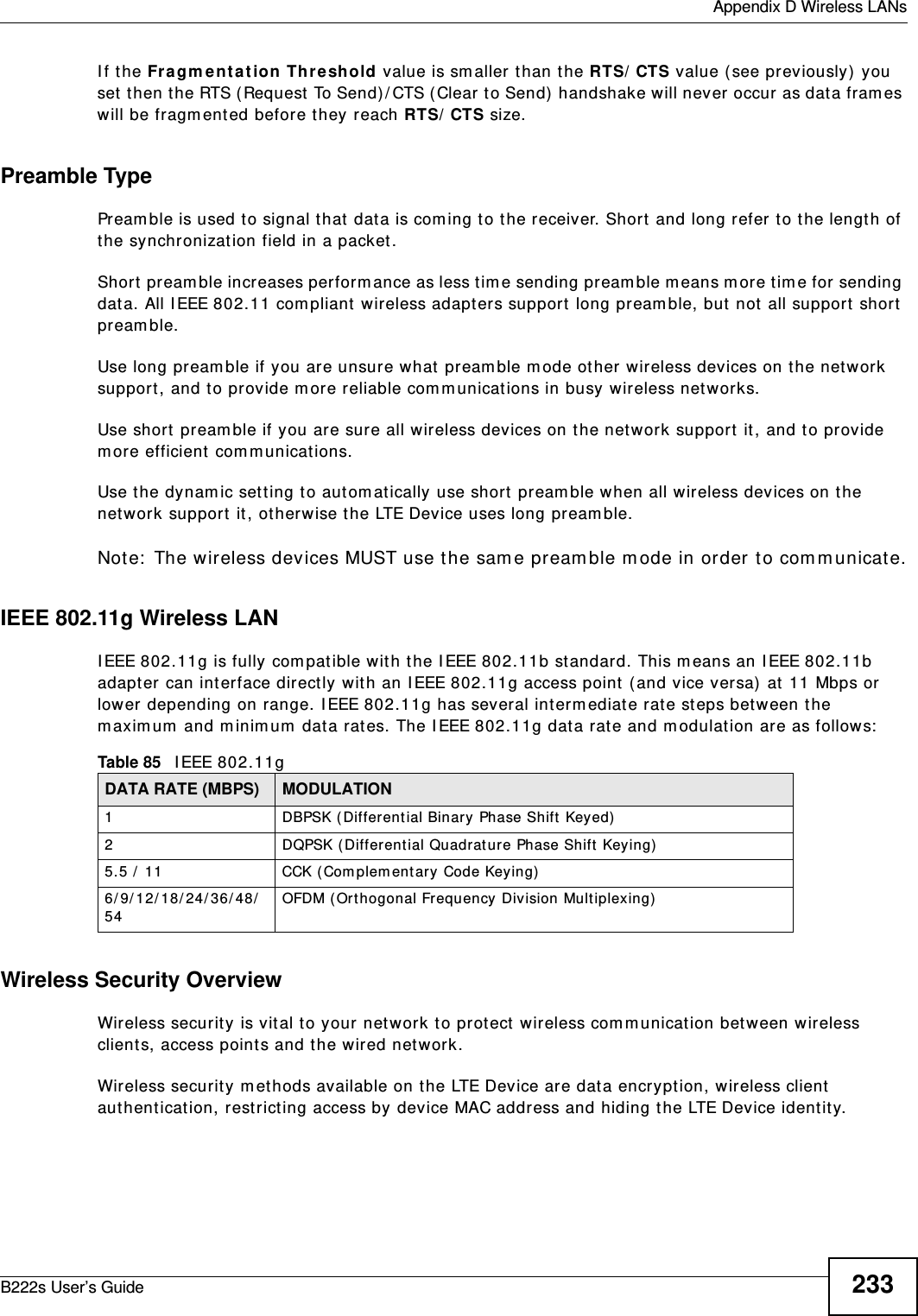
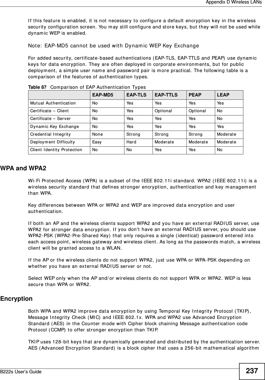
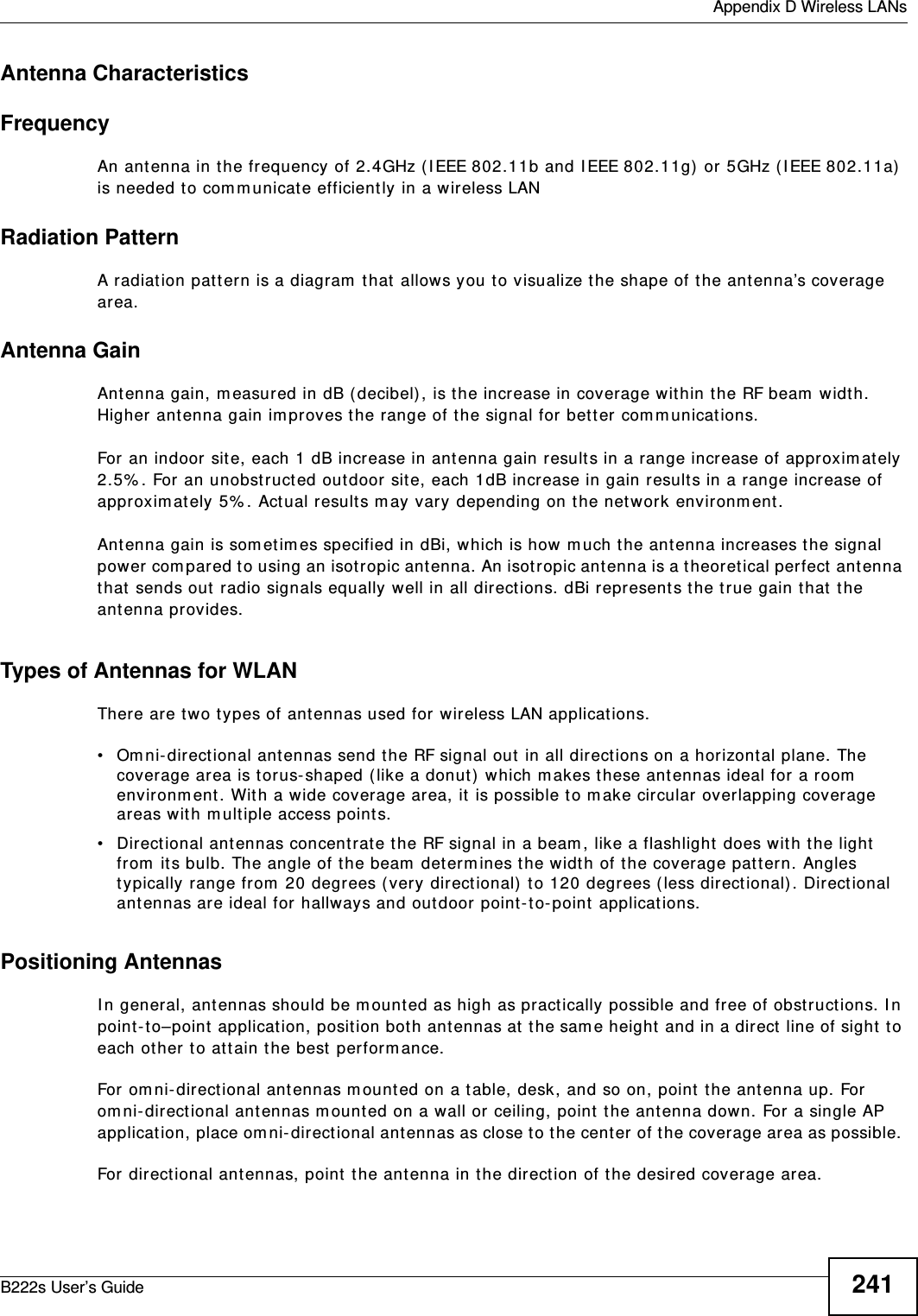
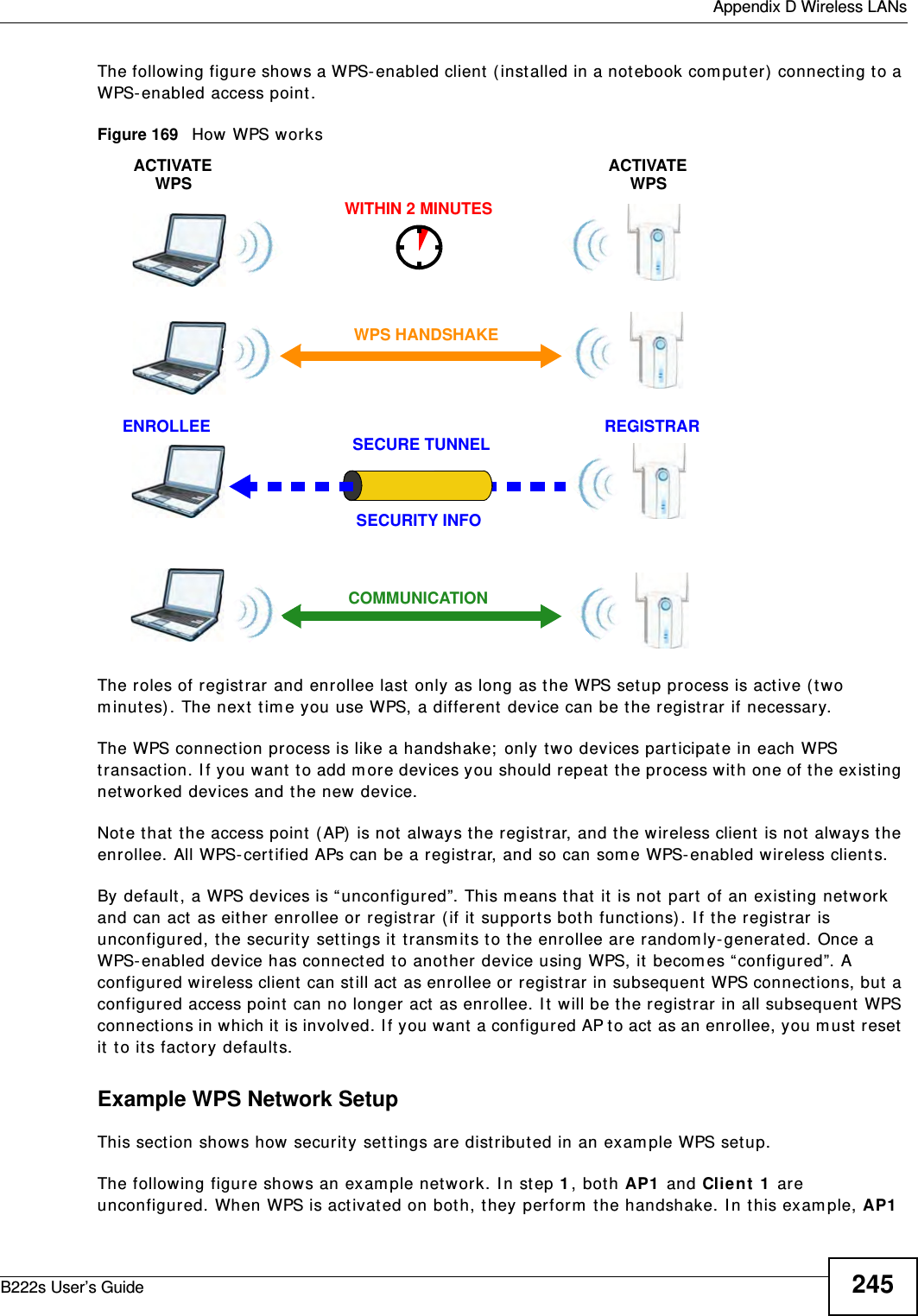
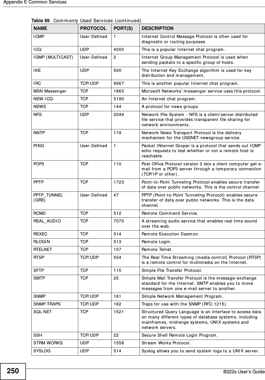
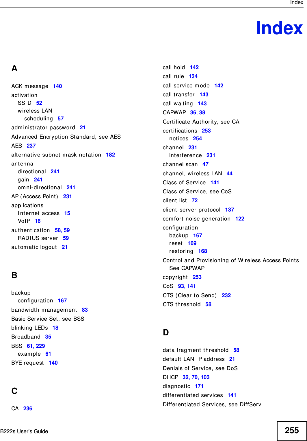
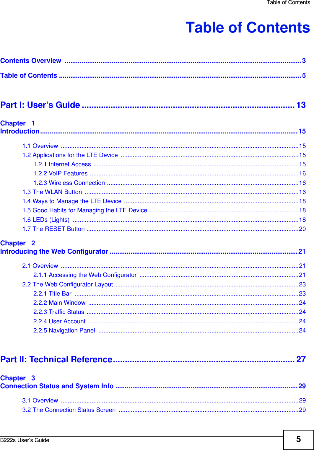
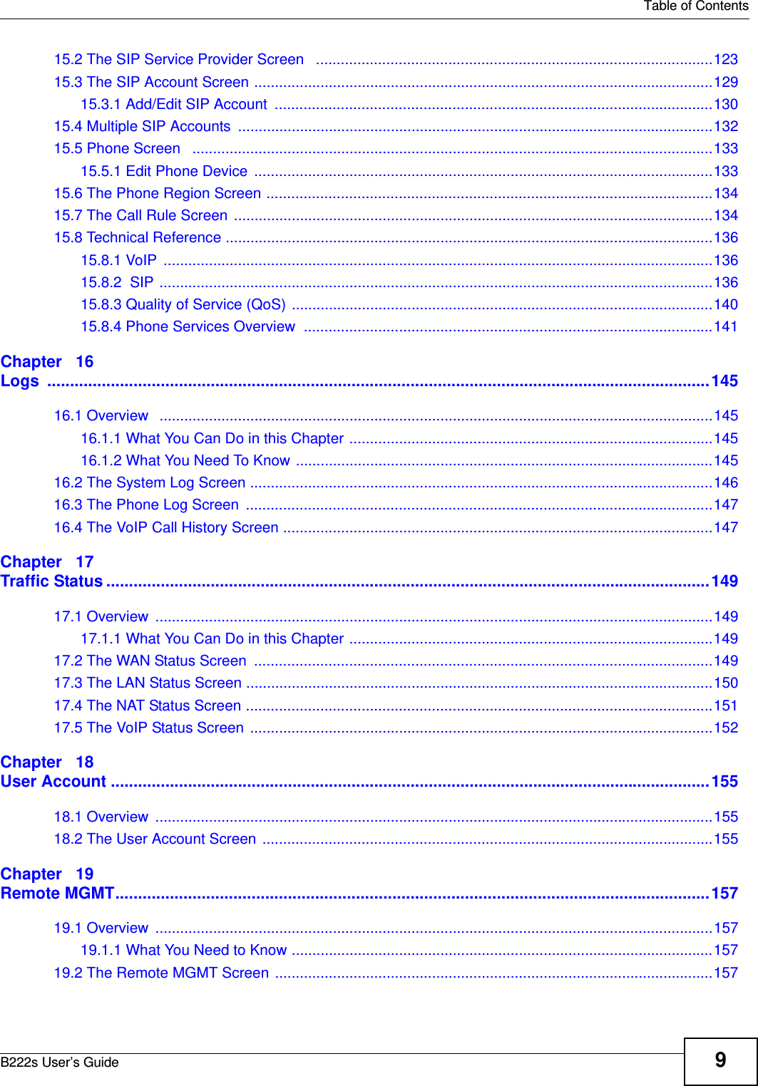
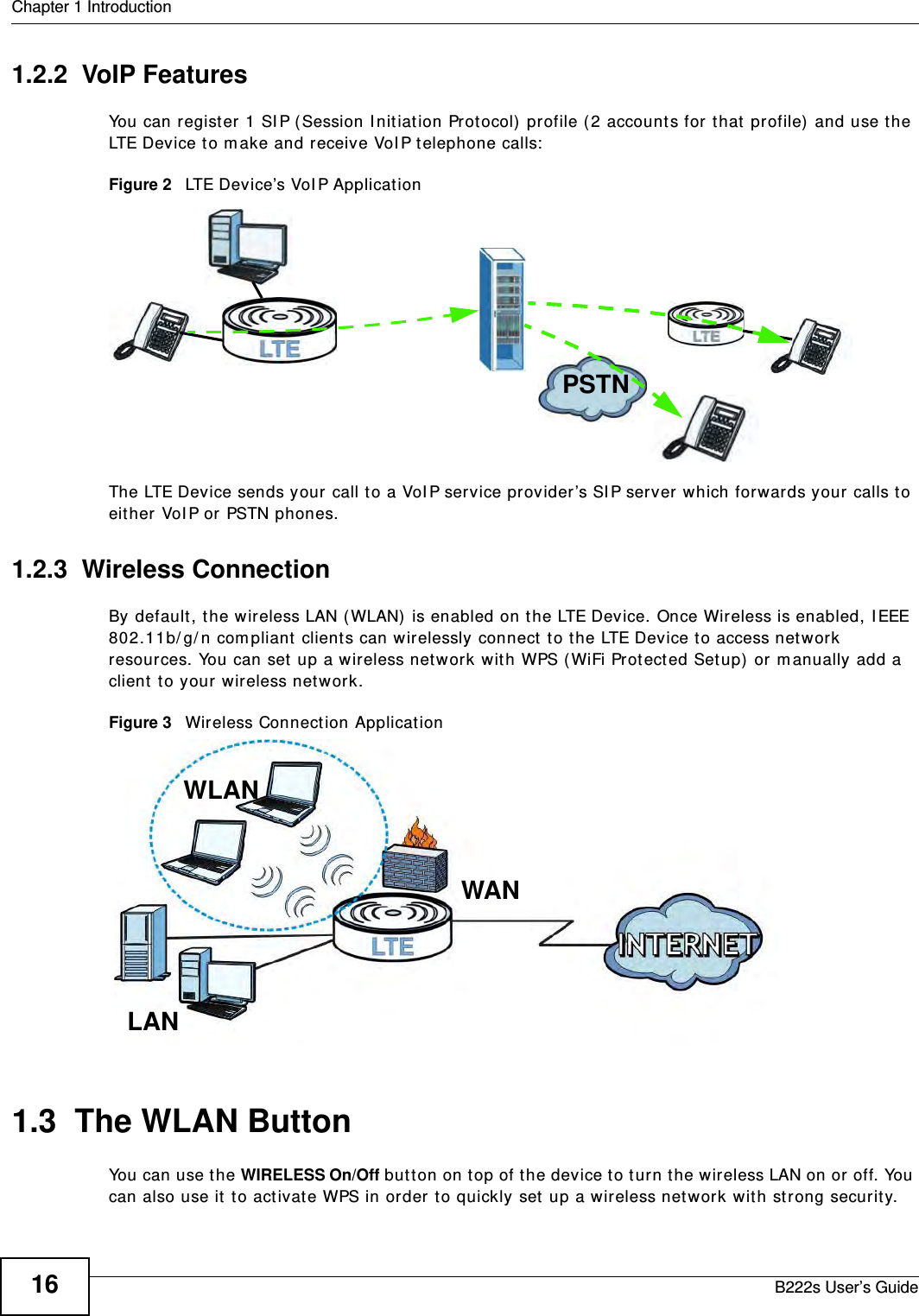
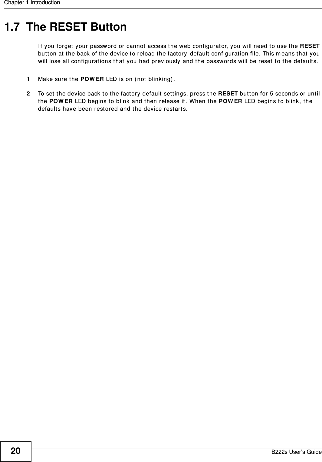
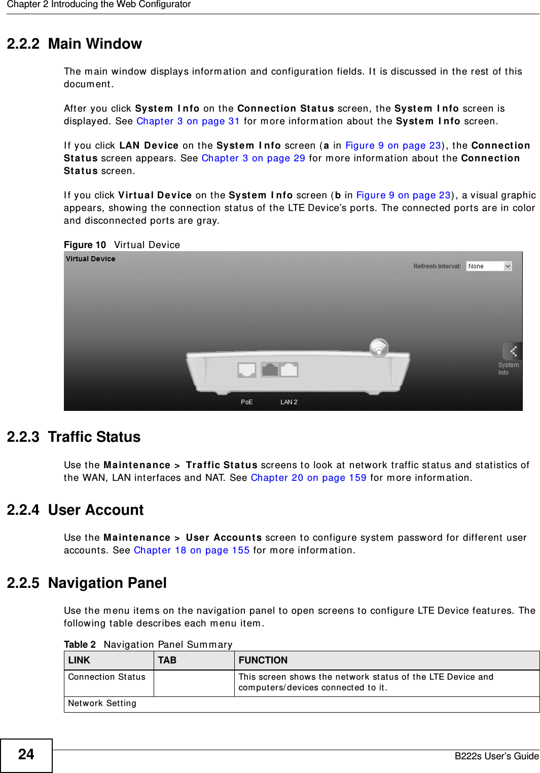
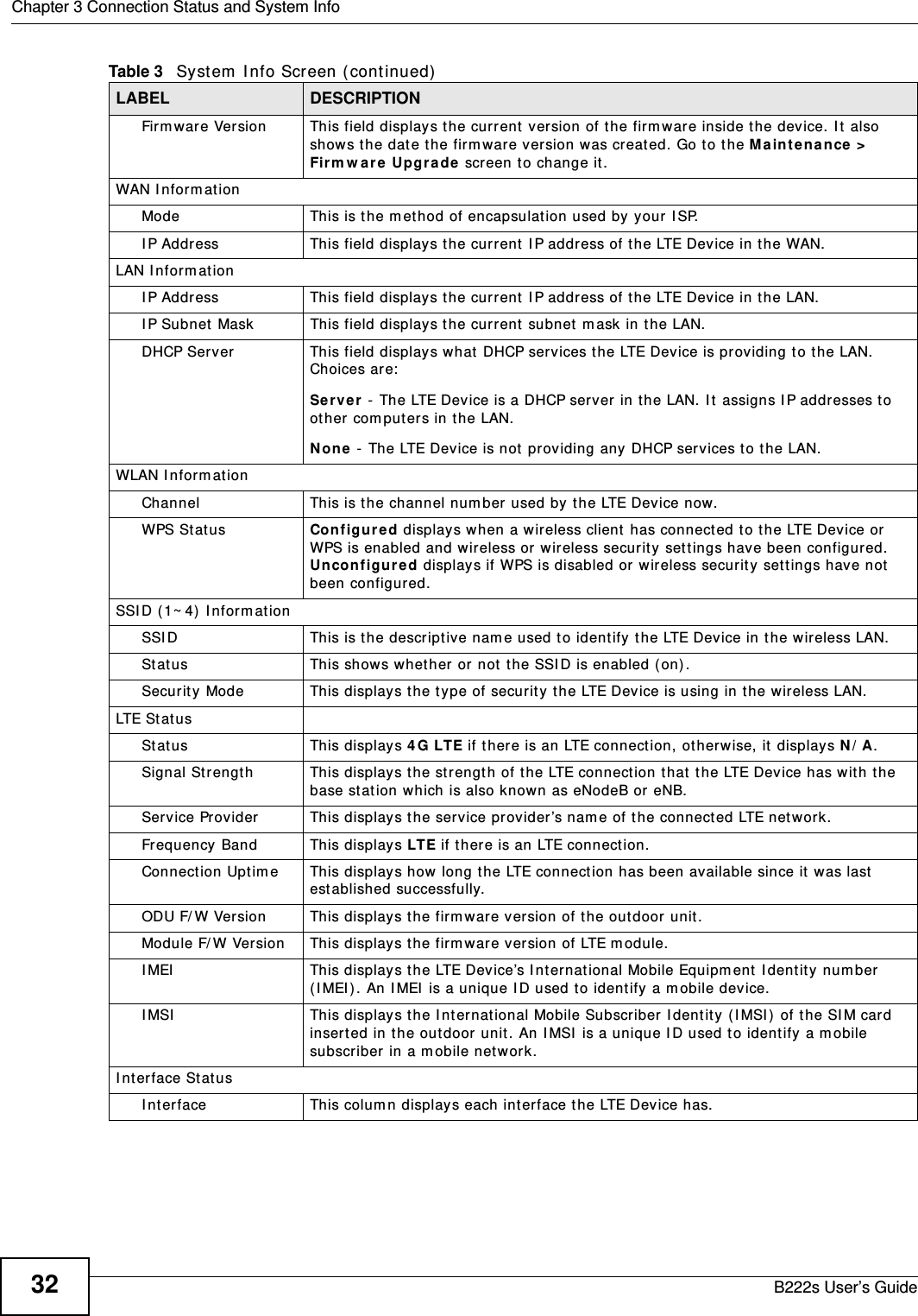
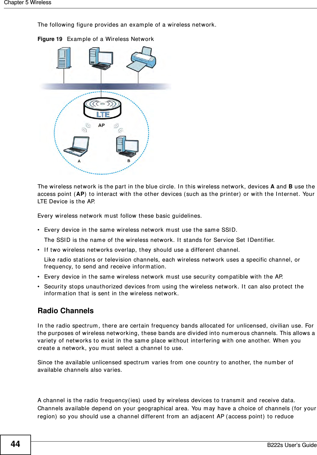
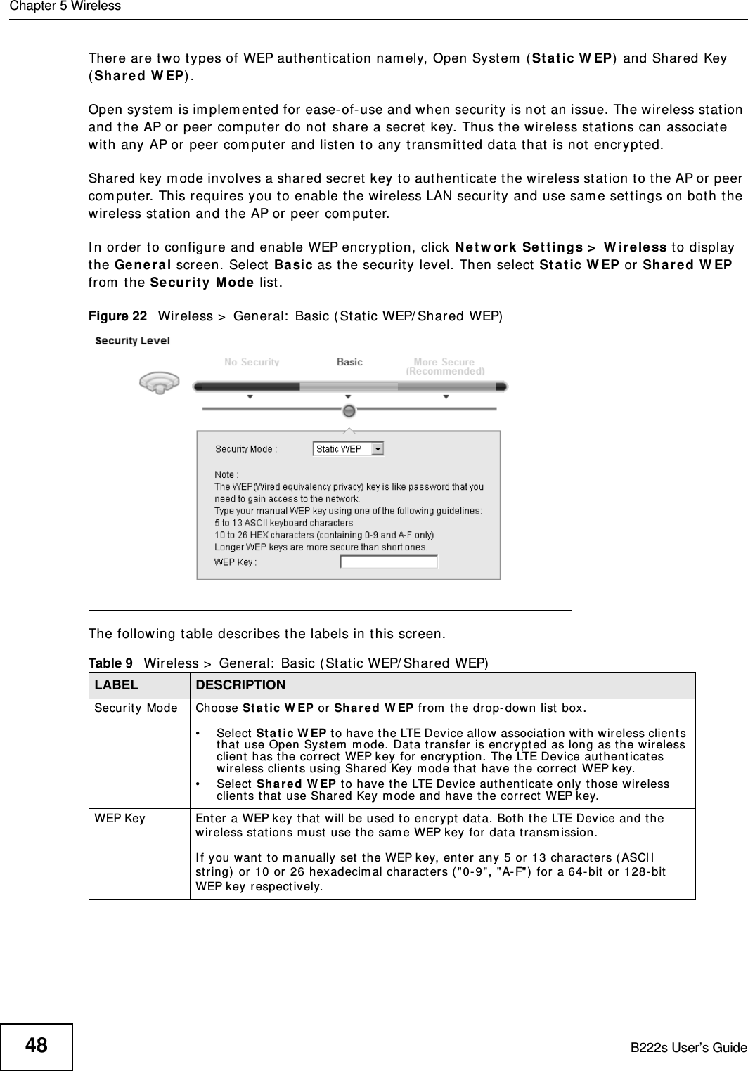
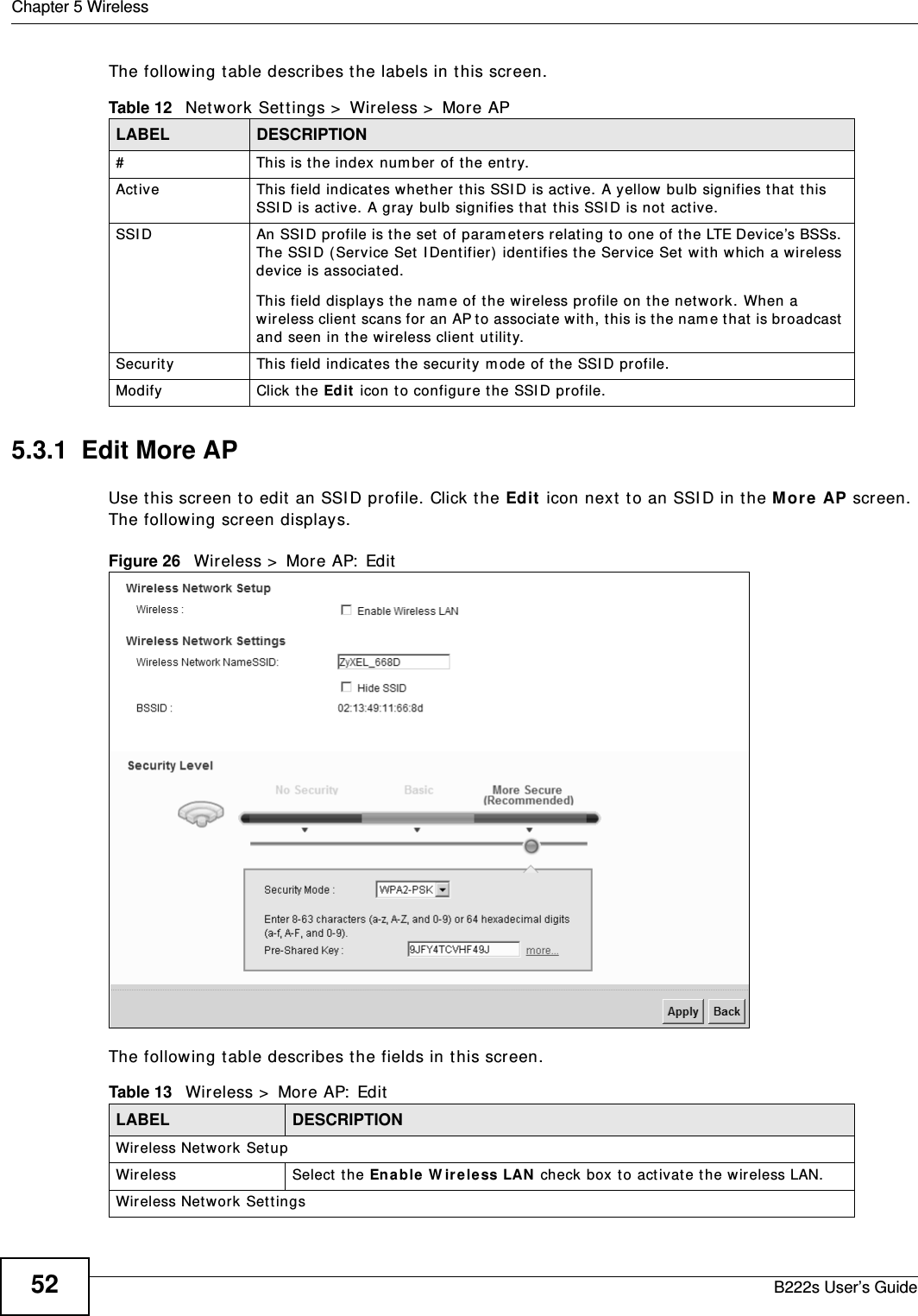
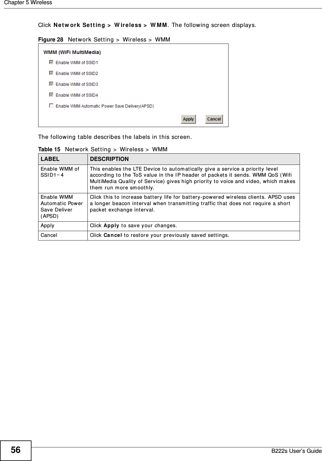
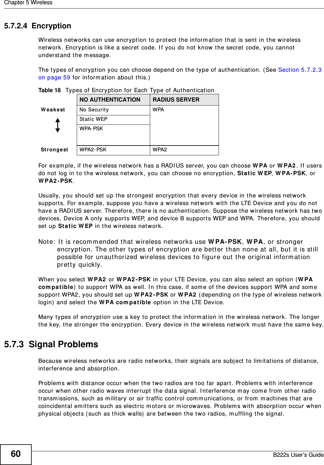
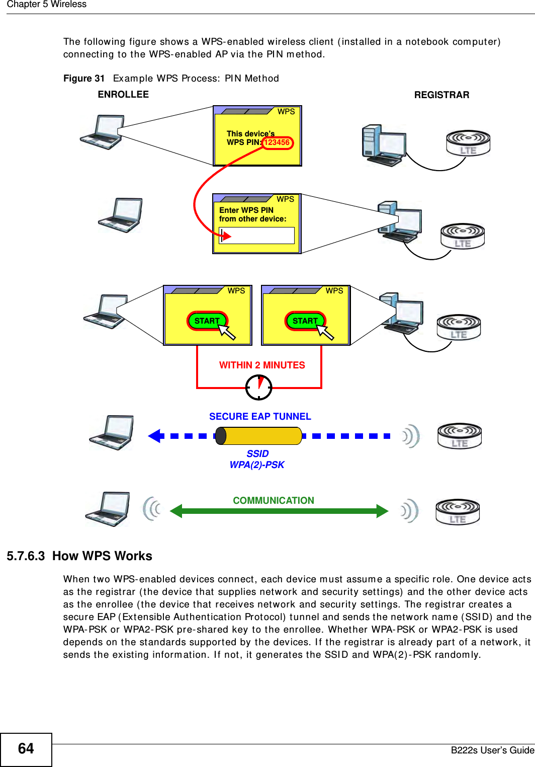
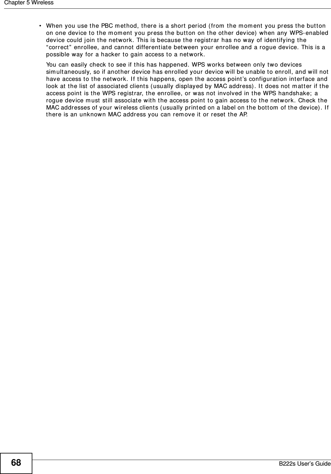
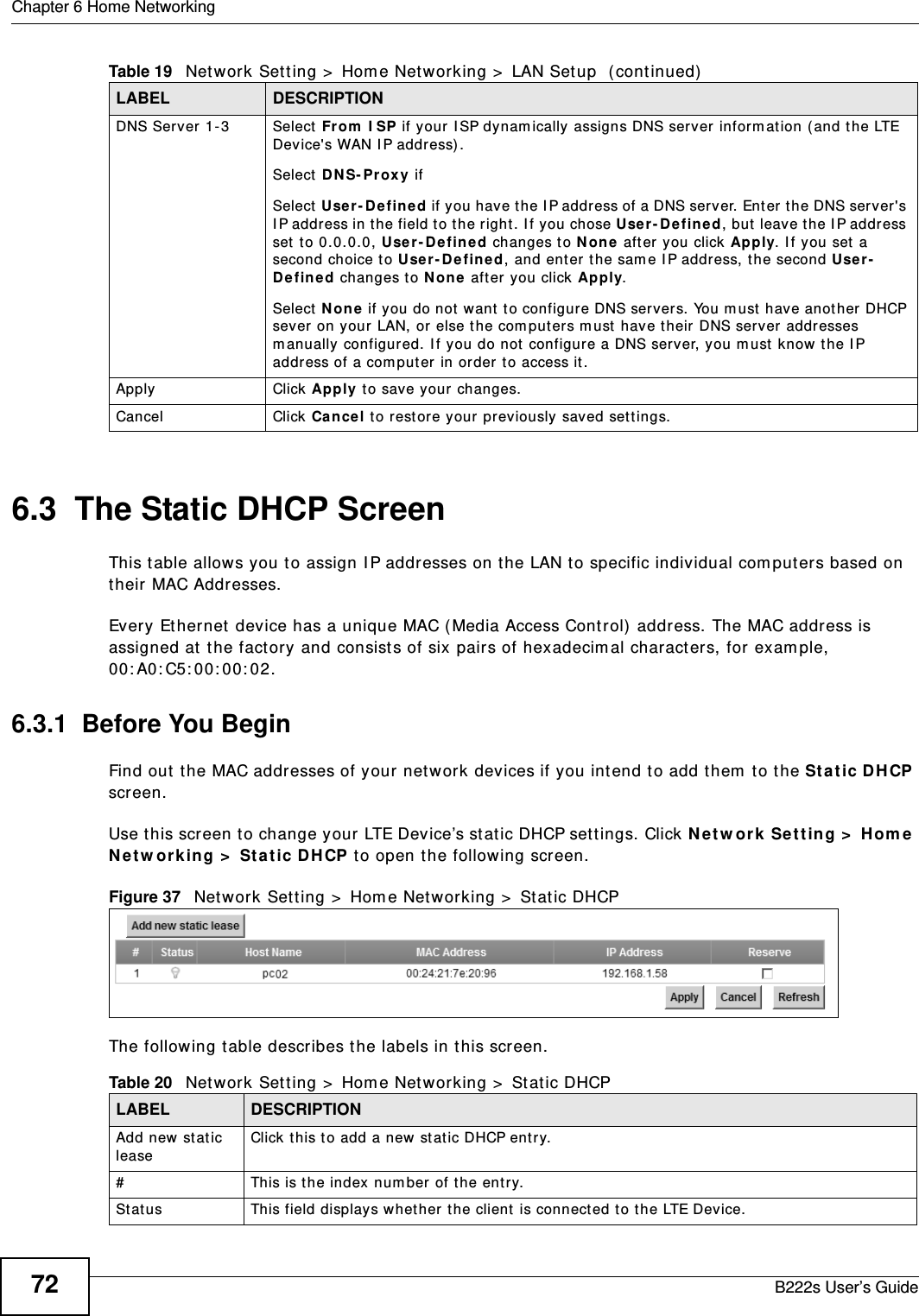
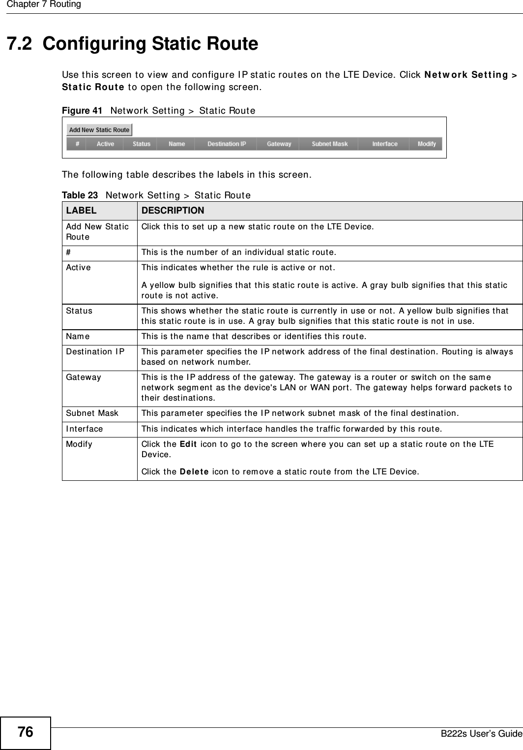
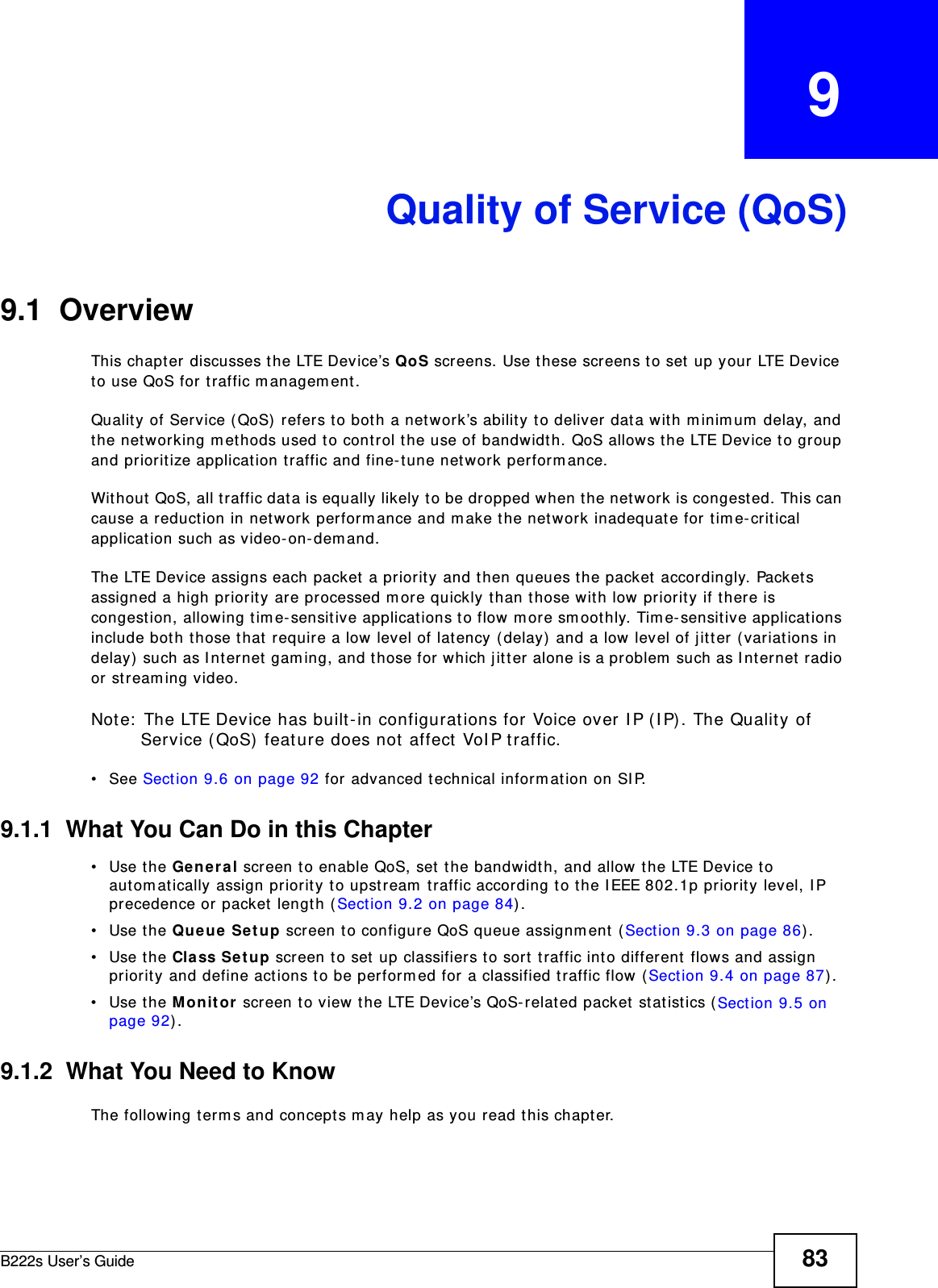
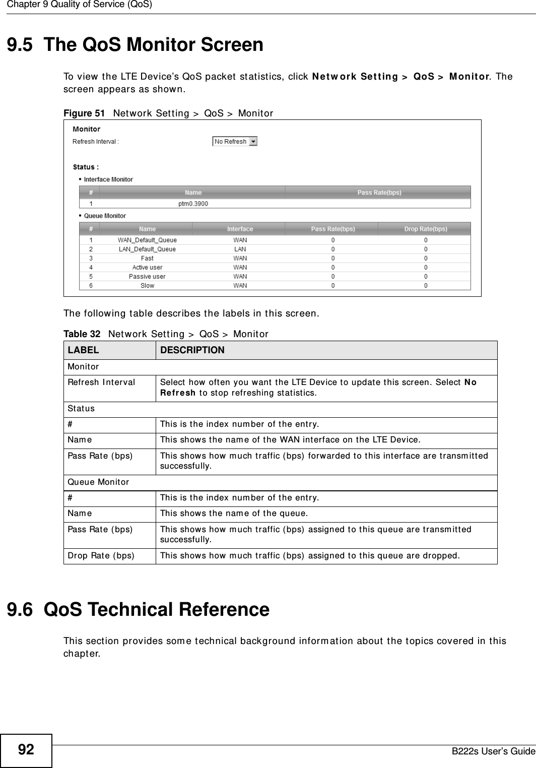
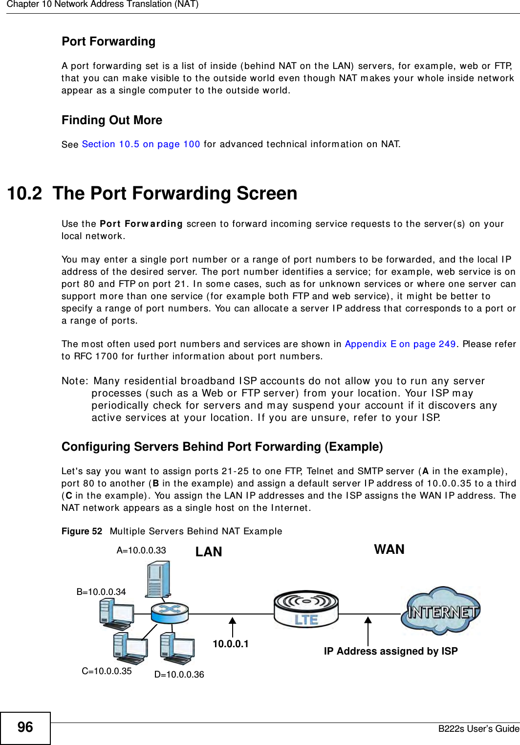
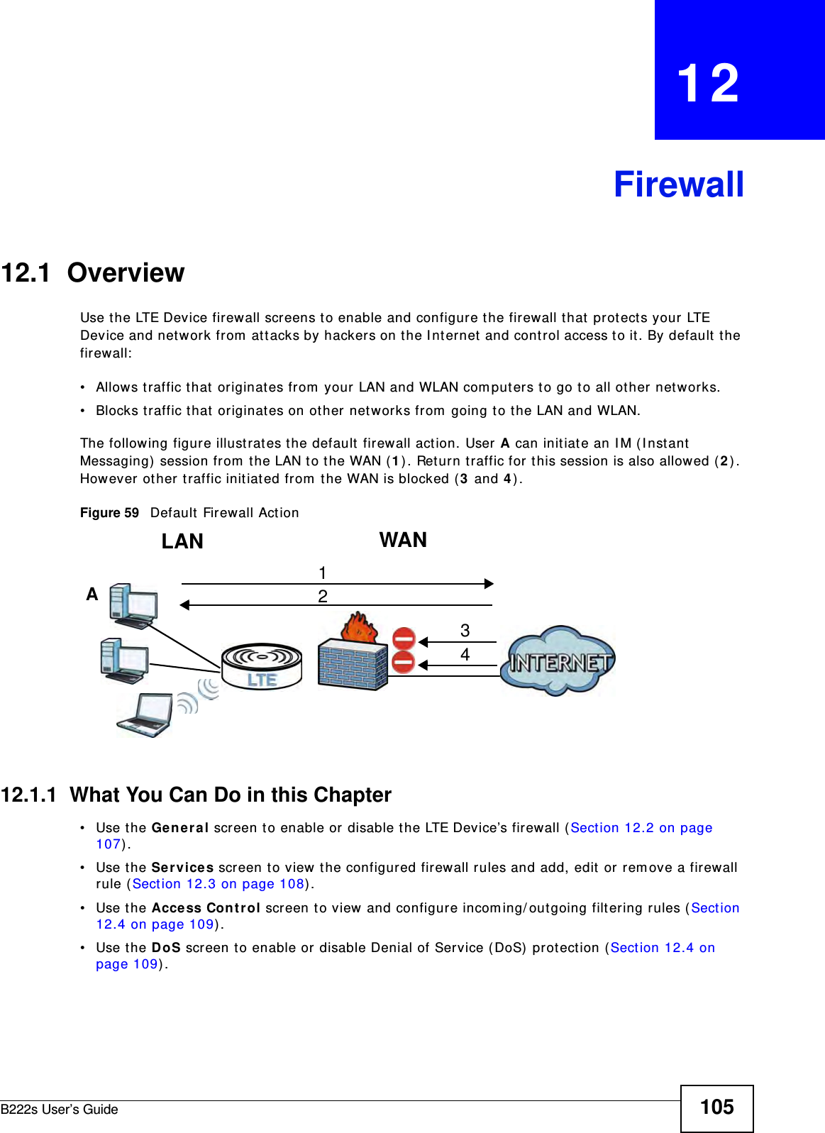
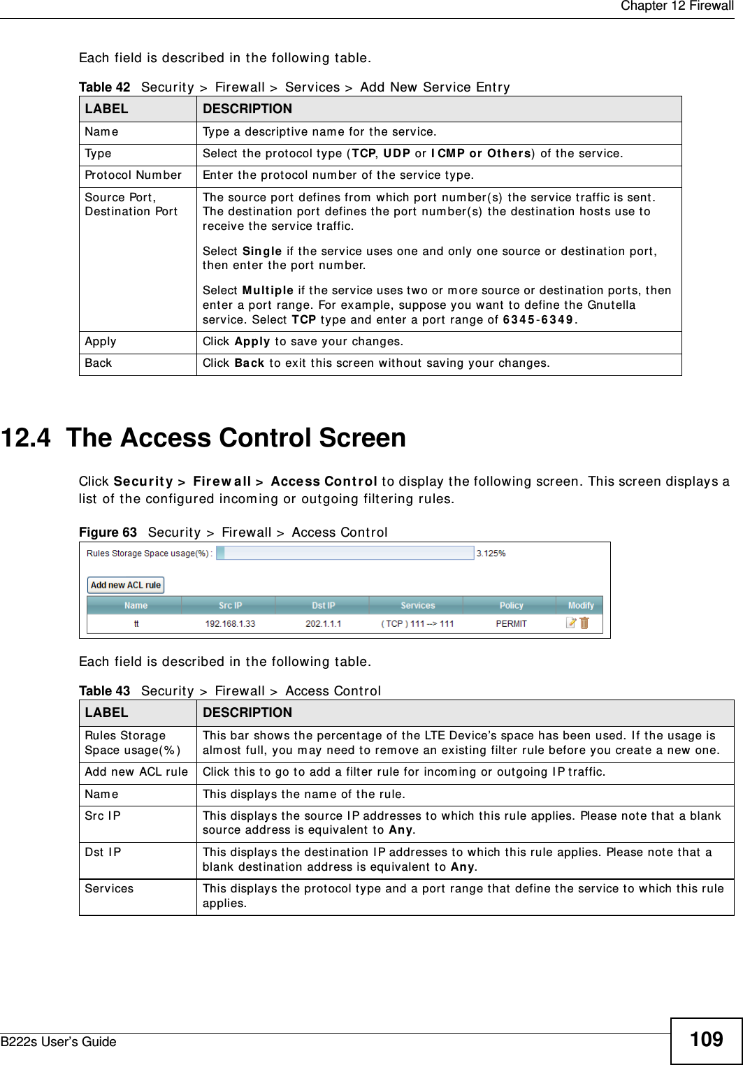
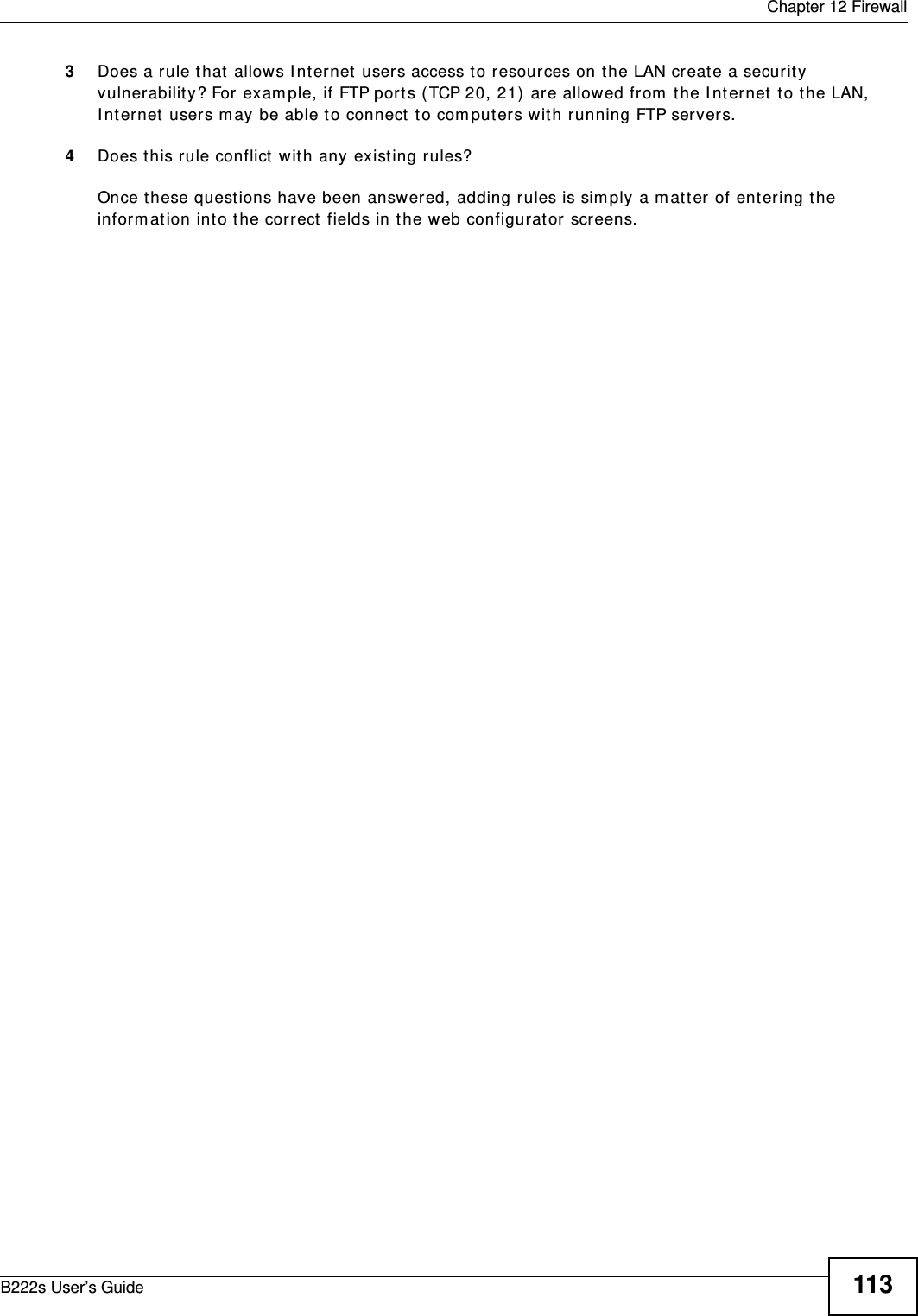
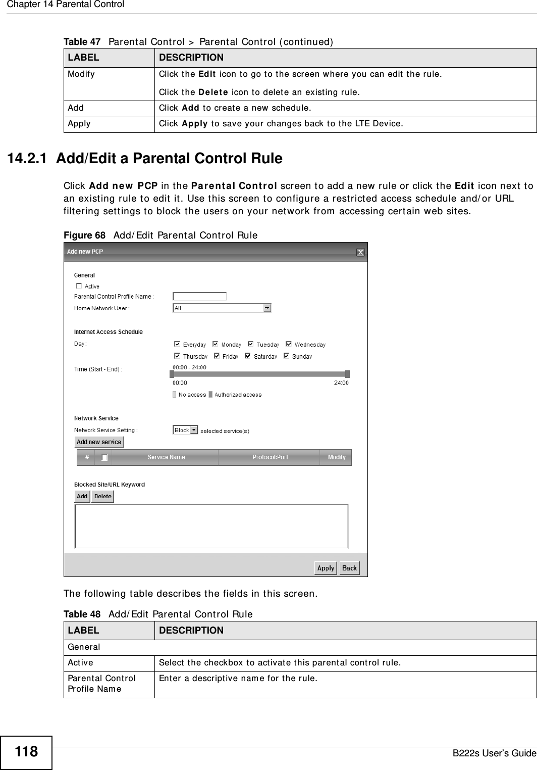
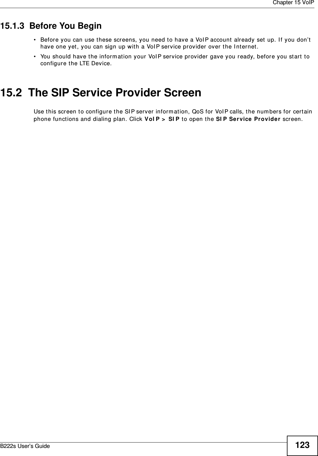
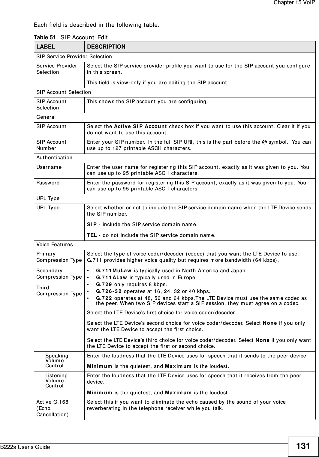
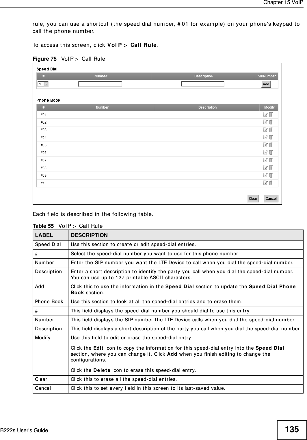
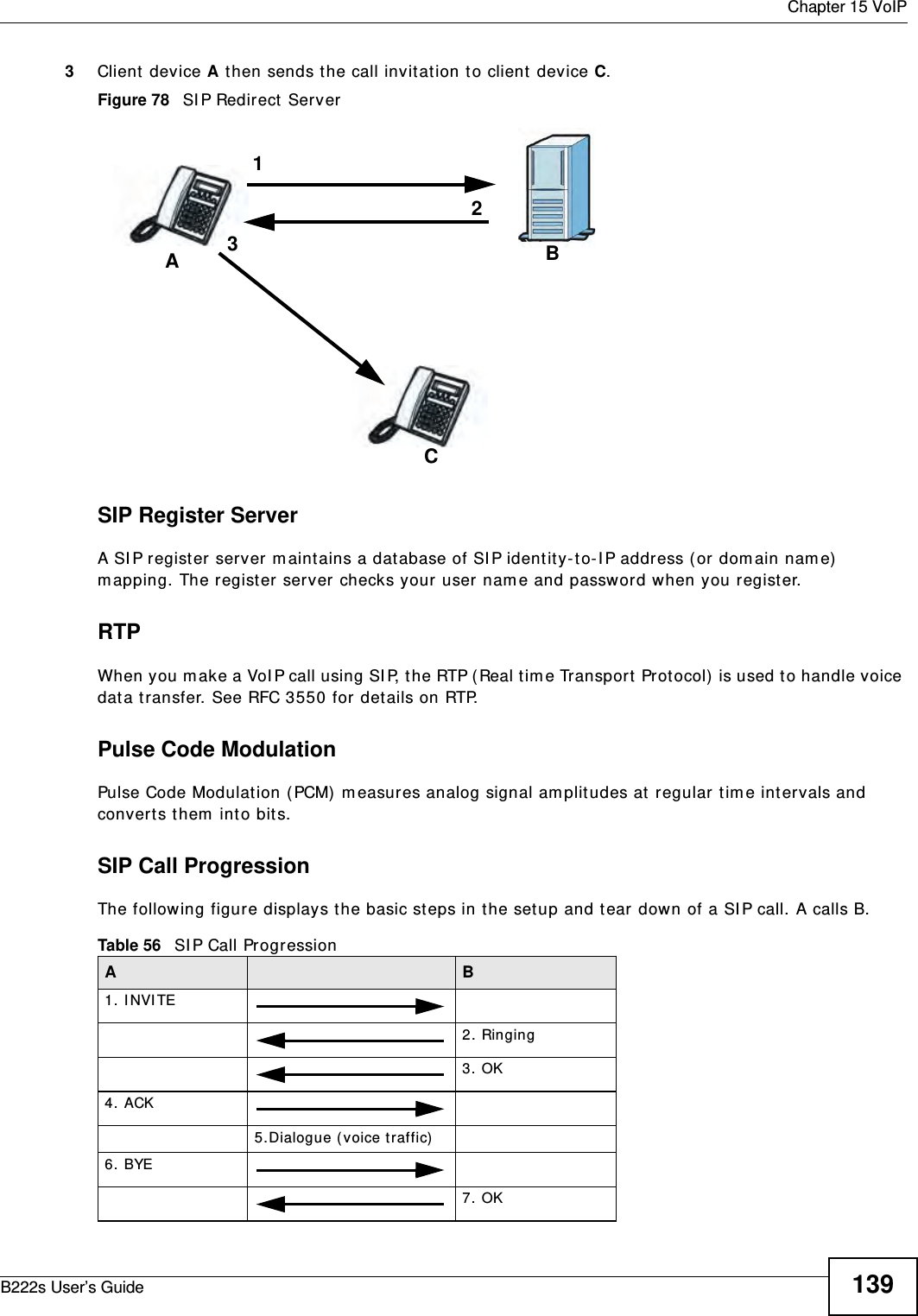
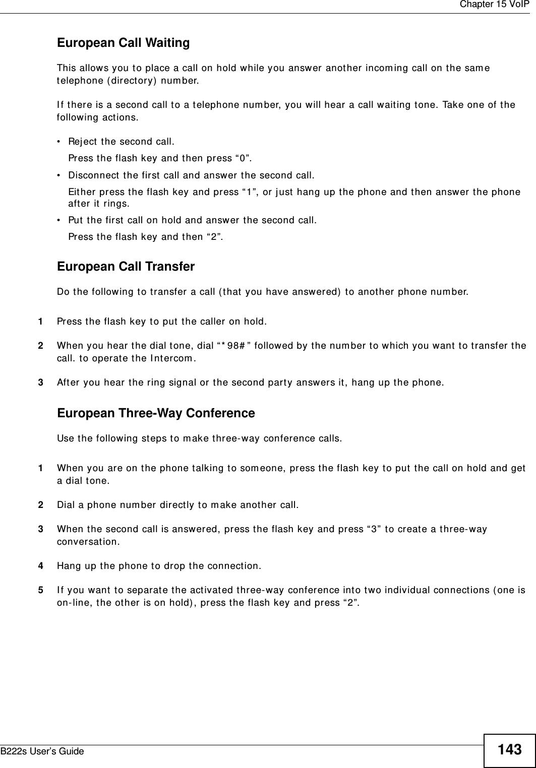
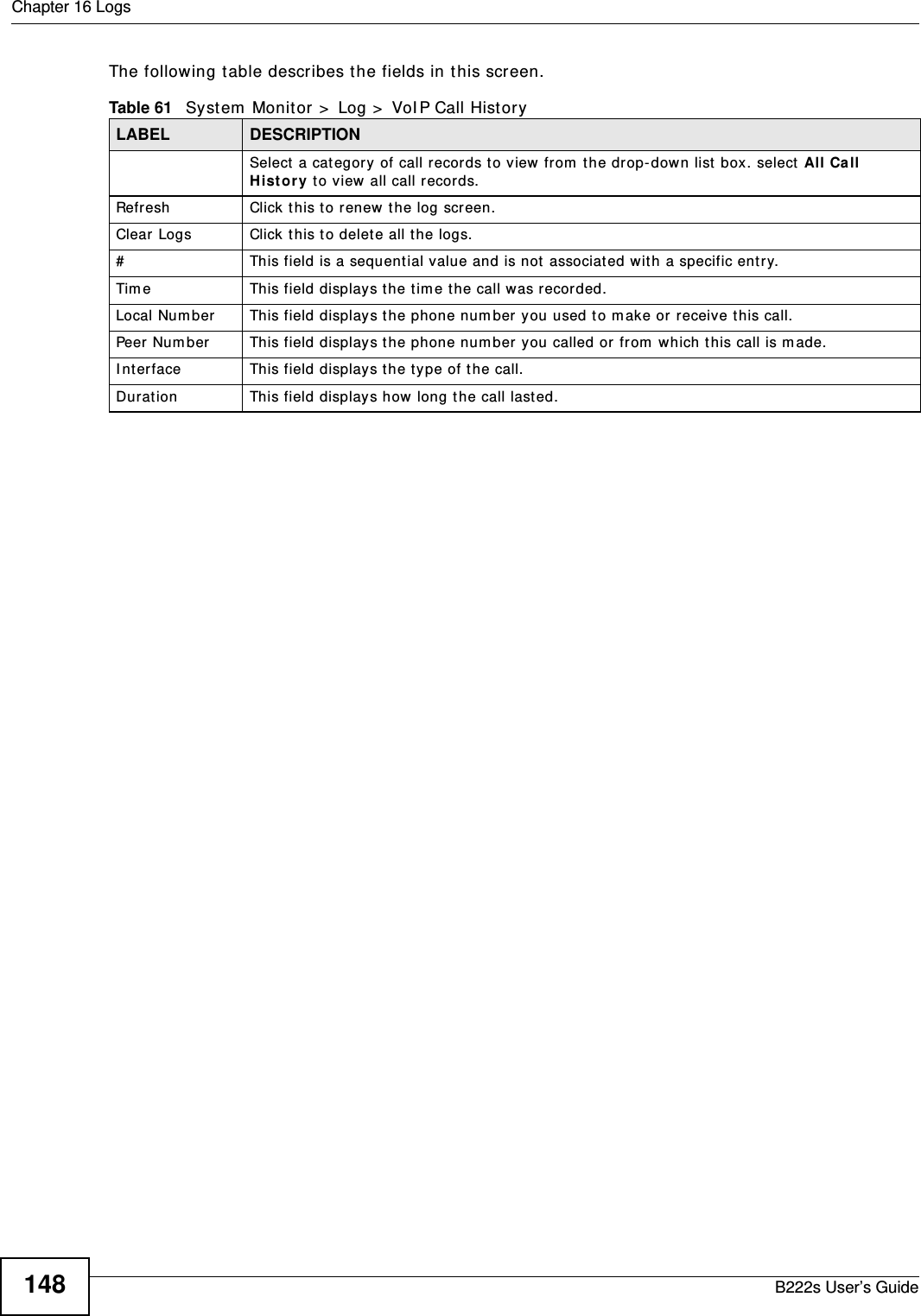
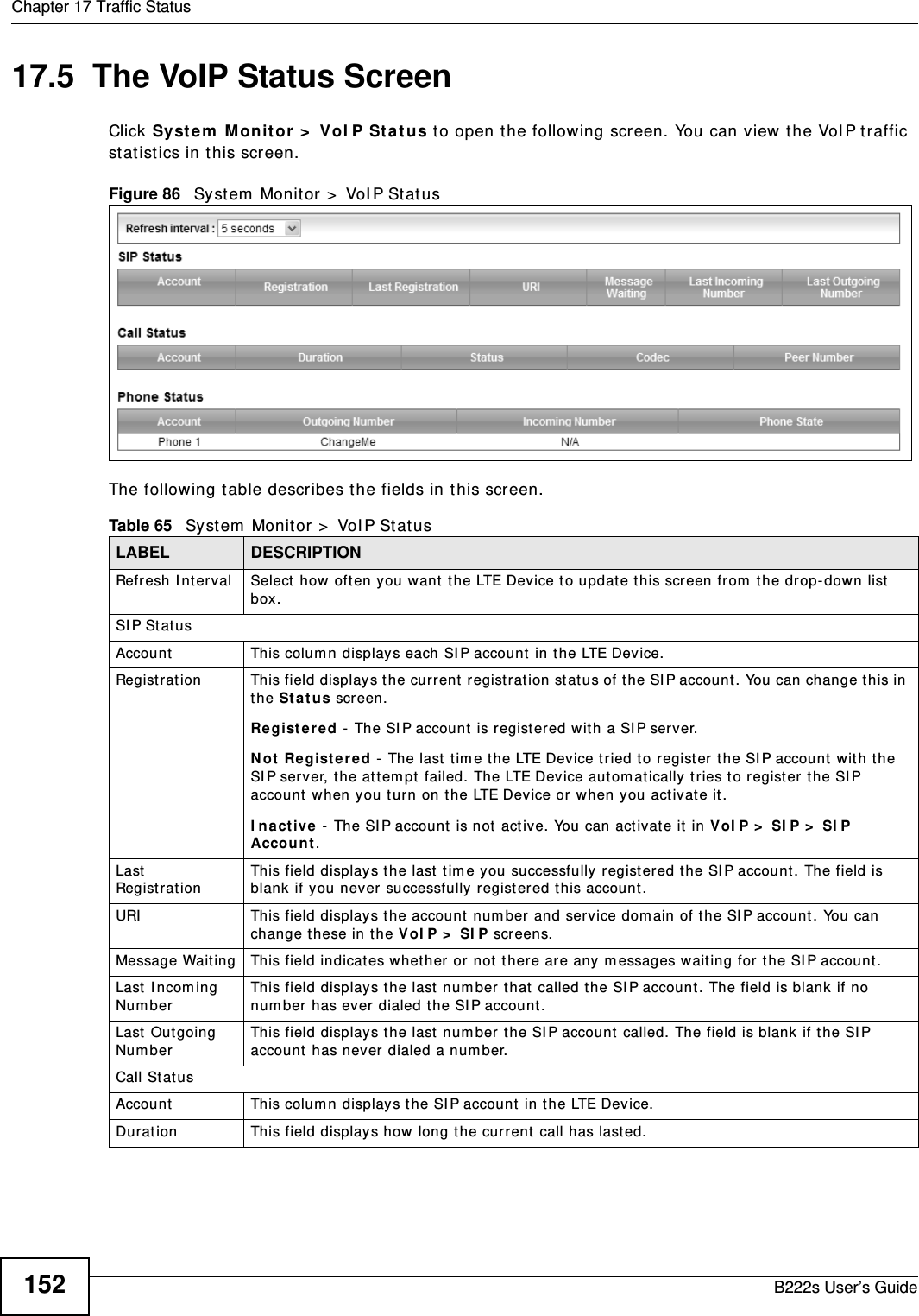
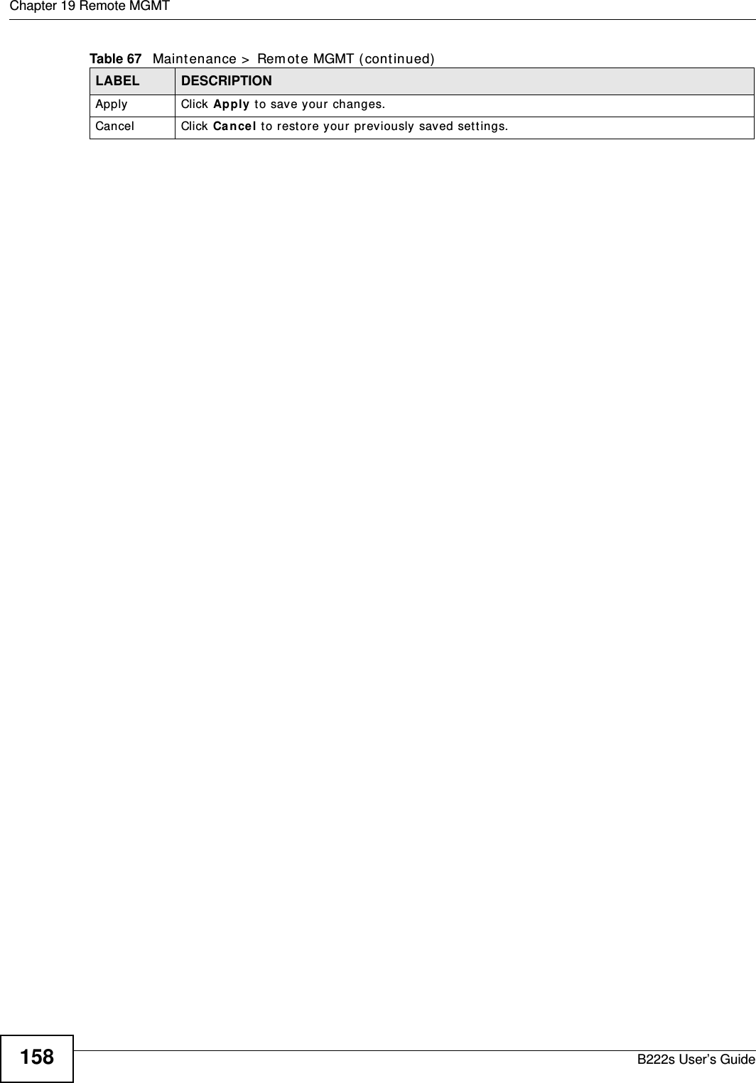
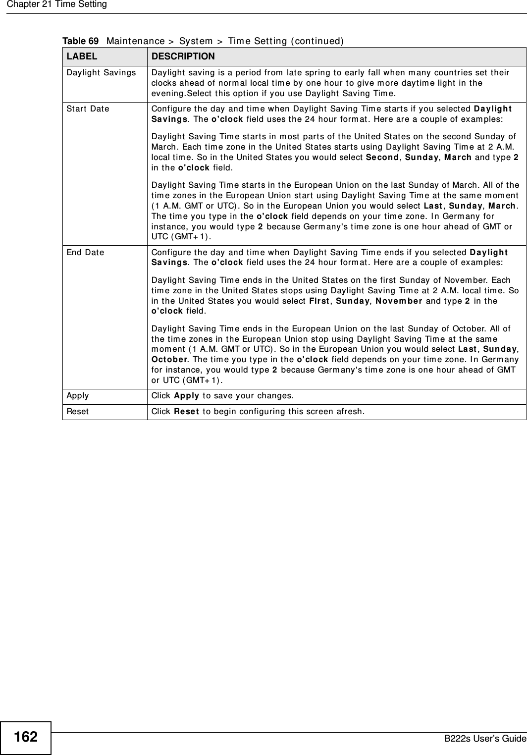
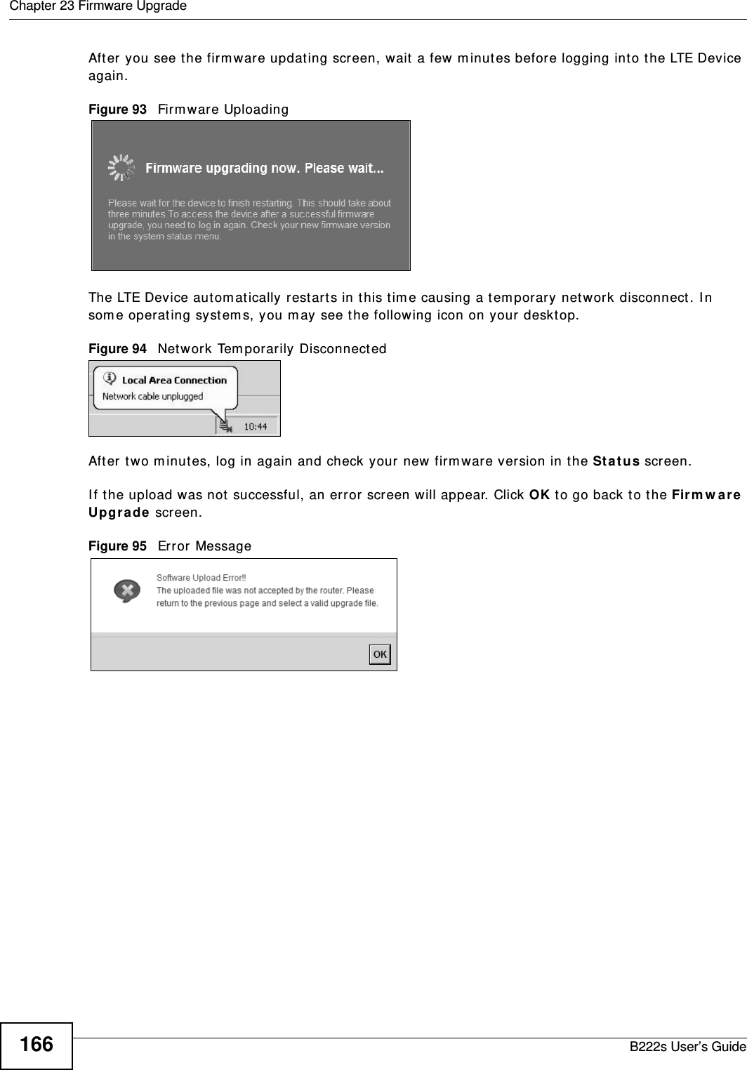
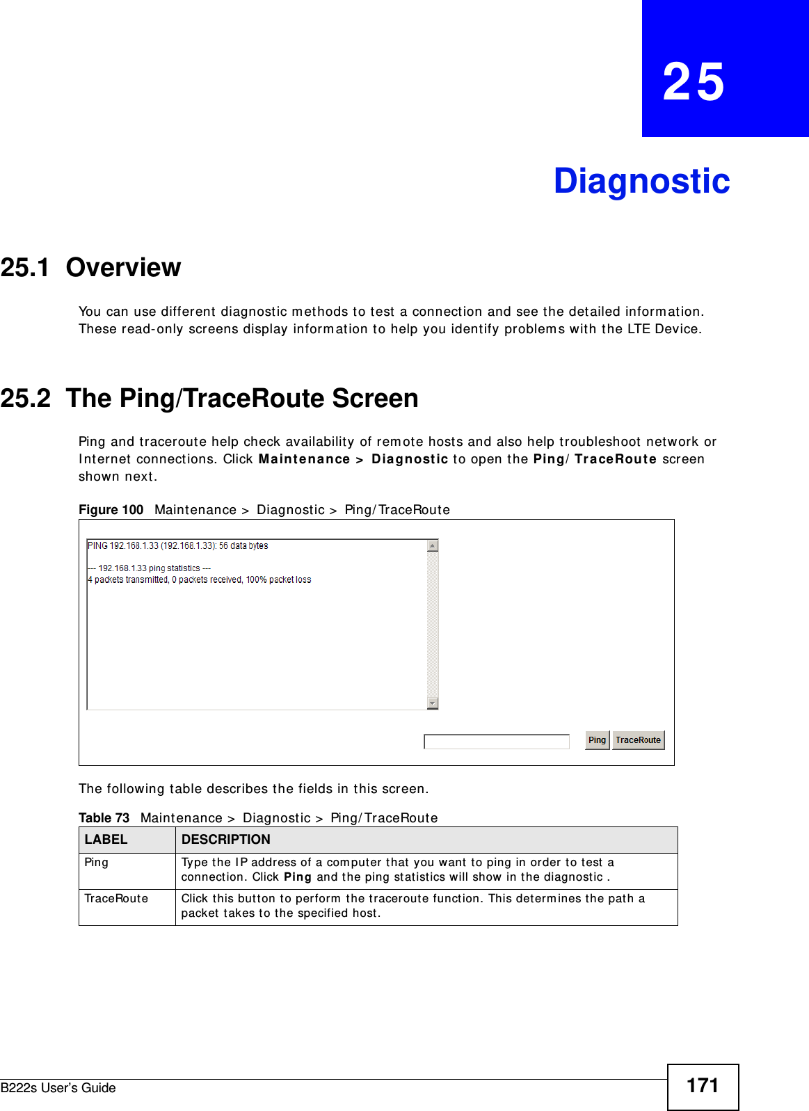
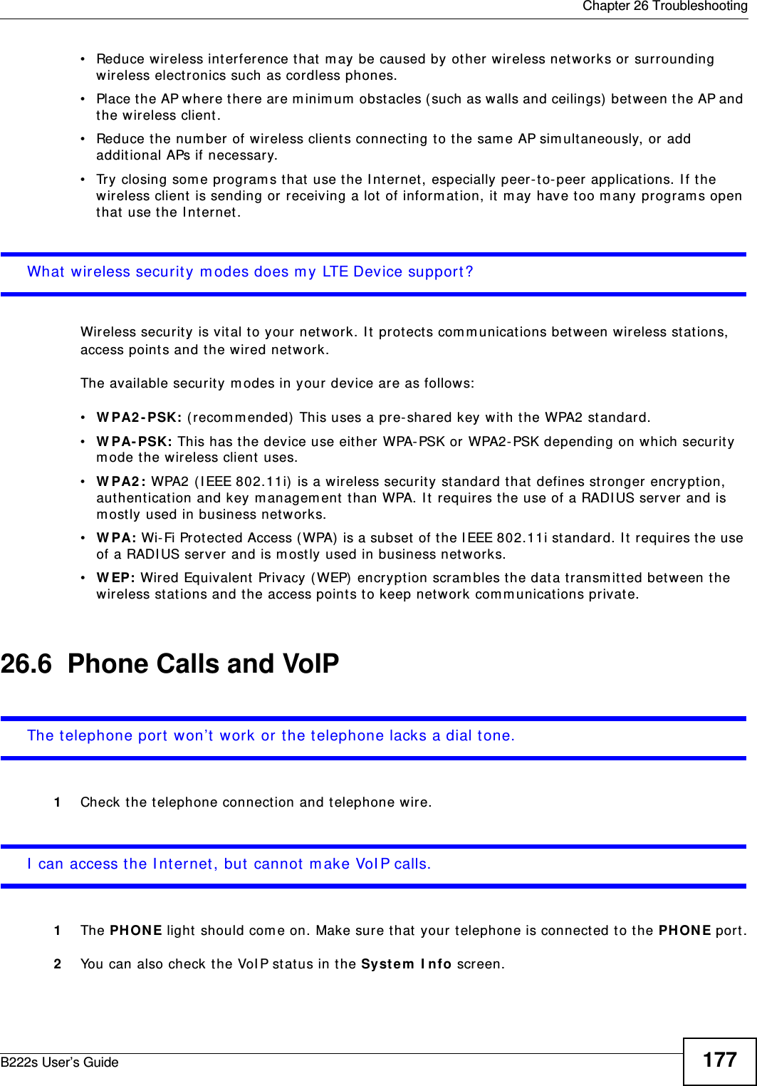
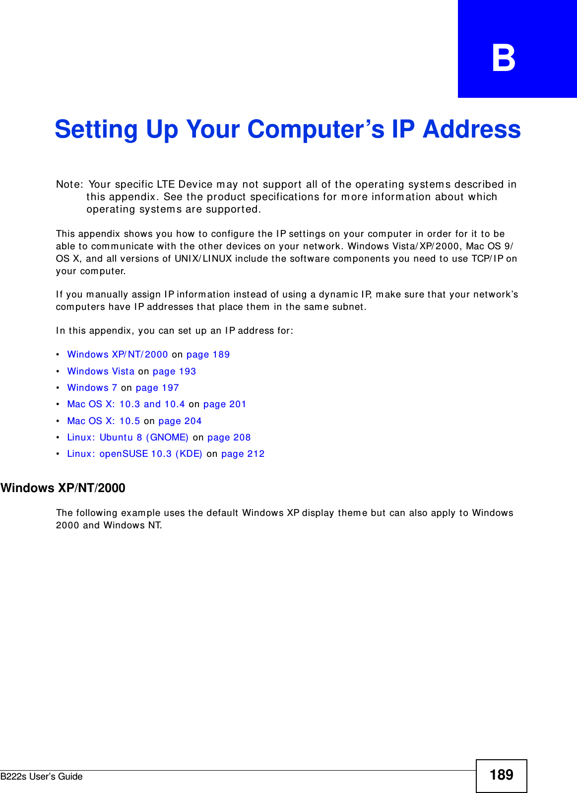
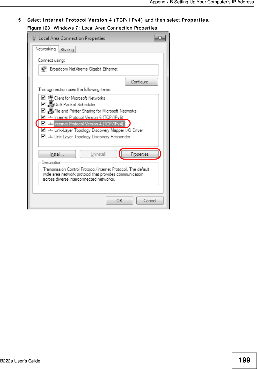
![Appendix B Setting Up Your Computer’s IP AddressB222s User’s Guide1967The I nt e rne t Prot ocol Version 4 ( TCP/ I Pv4 ) Pr opert ies window opens.Figure 118 Windows Vist a: I nt ernet Protocol Version 4 (TCP/ IPv4) Propert ies8Select Obt ain an I P a ddr e ss a ut om at ica lly if your net work adm inist rat or or I SP assigns your I P address dynam ically.Select Use t he follow ing I P Addr e ss and fill in t he I P a ddr e ss, Subne t m ask, and De fa ult ga t e w ay fields if you have a st at ic I P address that was assigned t o you by your network adm inist rat or or I SP. You m ay also have t o ent er a Pre ferre d D N S ser ver and an Alt e r n at e DN S ser ve r , if t hat inform ation was provided.Click Adva nced.9Click OK t o close t he I nt er n e t Pr ot ocol ( TCP/ I P) Prope r t ies window.10 Click OK t o close t he Loca l Area Conn e ct ion Pr ope r t ie s window.Verifying Settings1Click St a r t > All Progra m s > Acce ssories > Com m a nd Prom pt .2I n t he Com m and Prom pt window, t ype " ipconfig" and t hen press [ ENTER] . You can also go t o St ar t > Cont rol Pa nel > N et w or k Conn e ct ions, right- click a net work connection, click Sta t us and t hen click the Support t ab to view your I P address and connection inform at ion.](https://usermanual.wiki/MitraStar-Technology/M4G-301/User-Guide-1730649-Page-196.png)
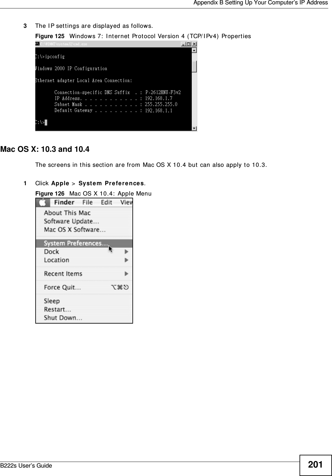
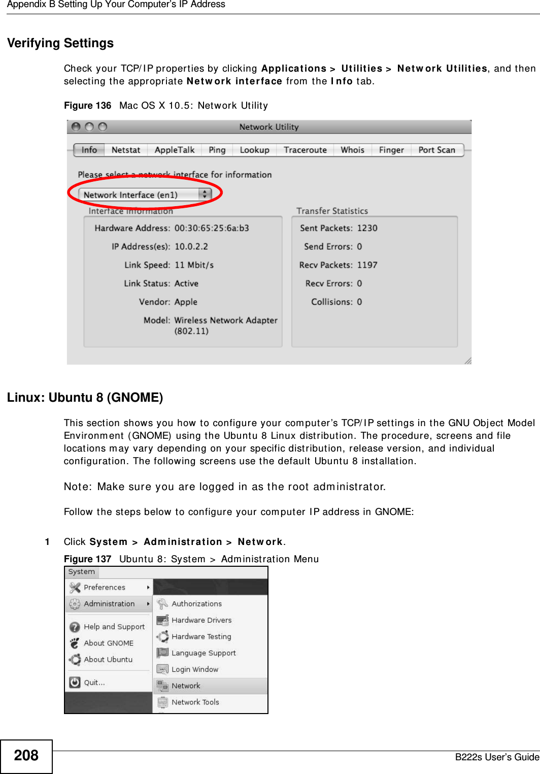
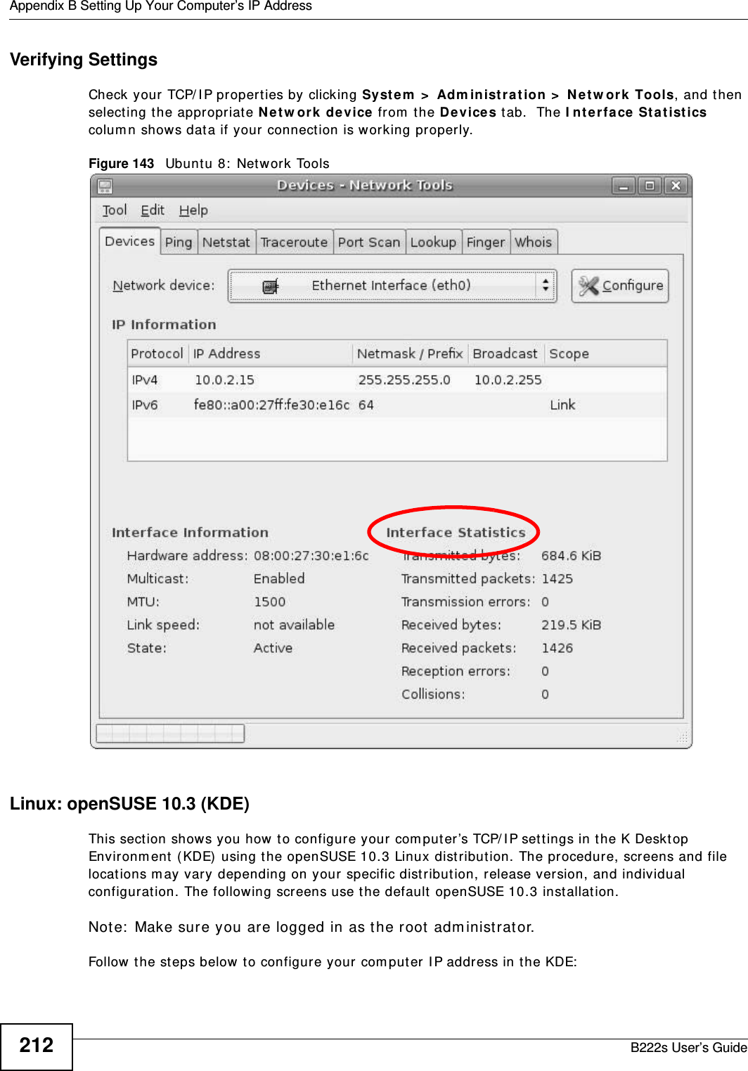
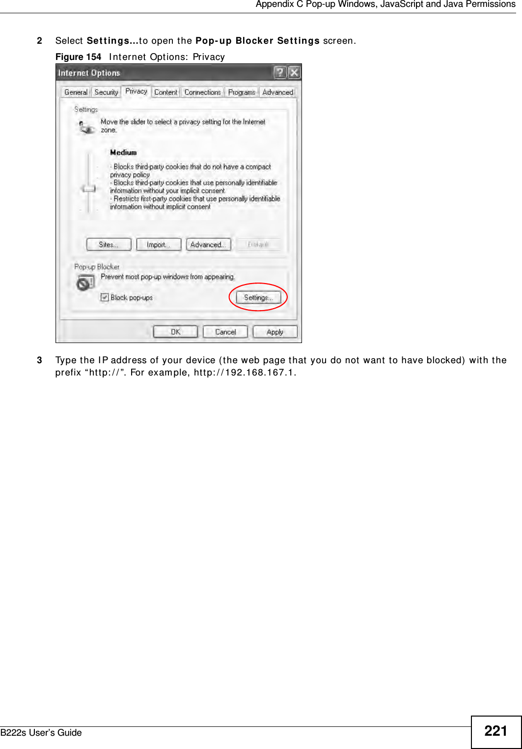
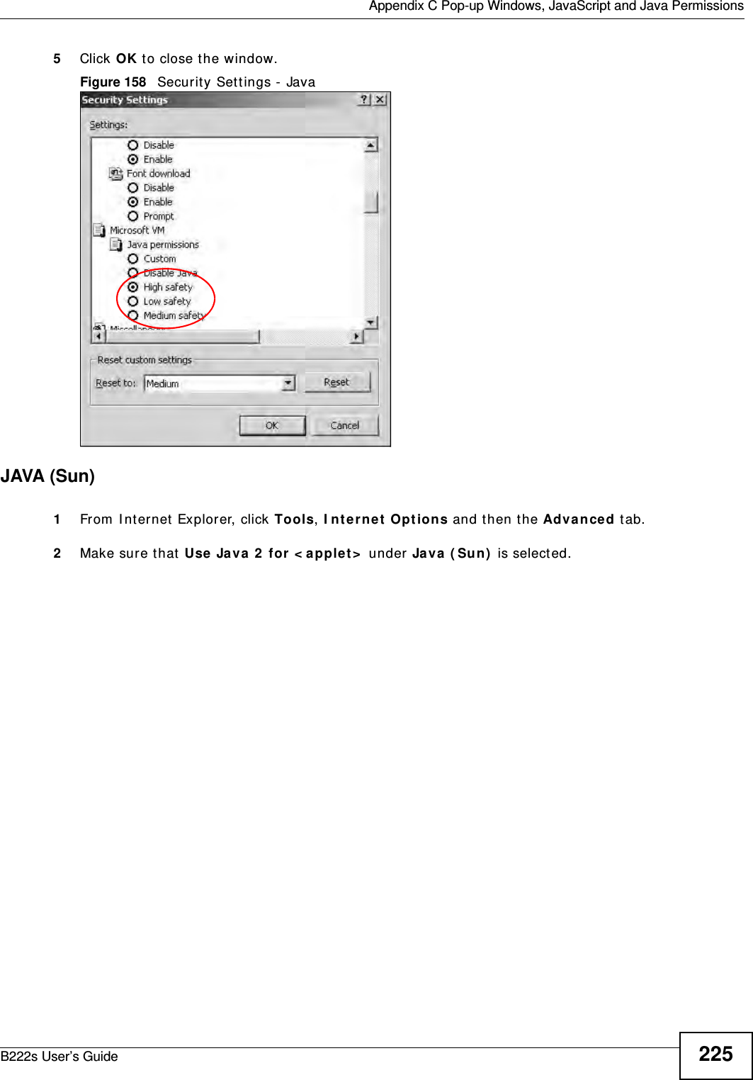
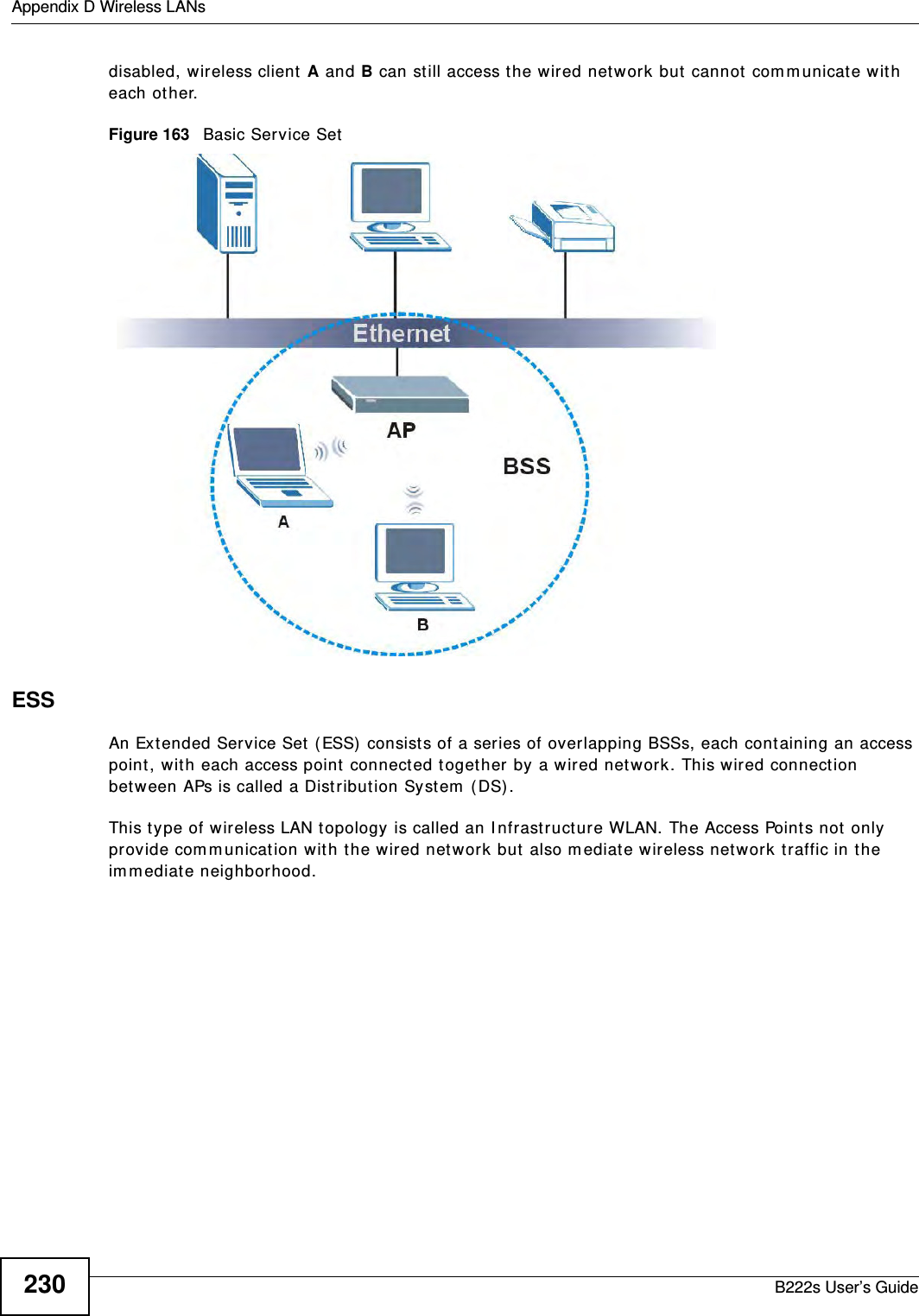
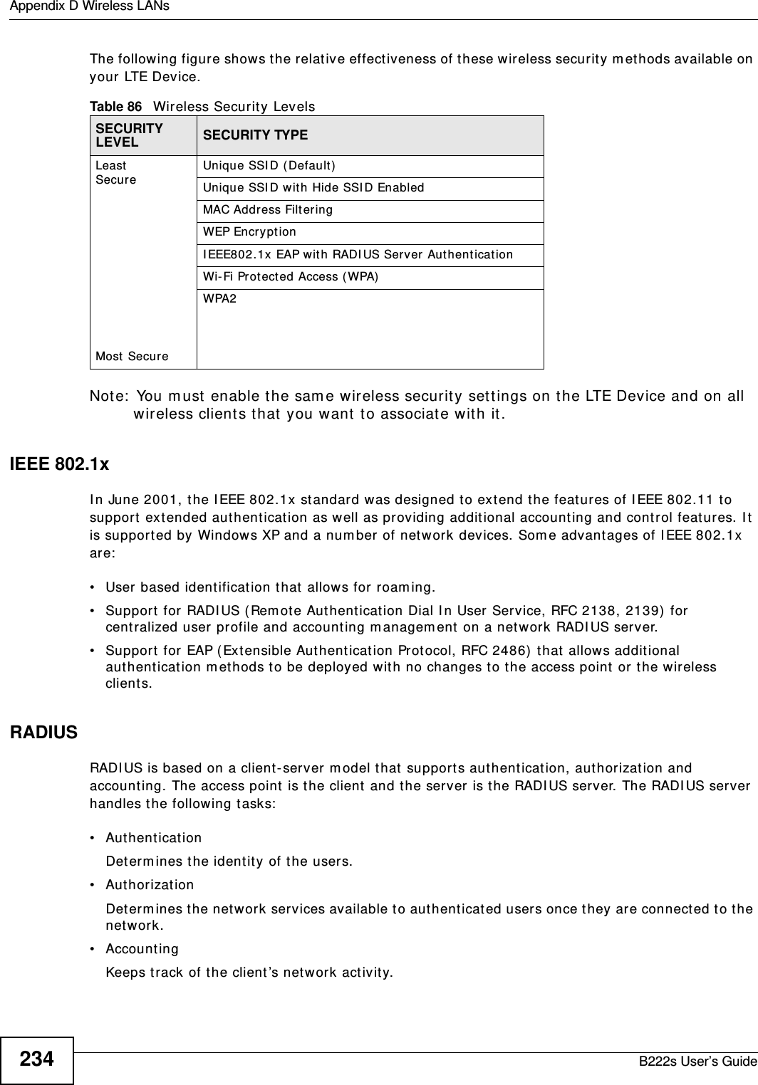
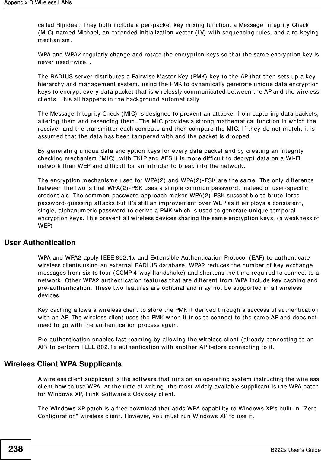
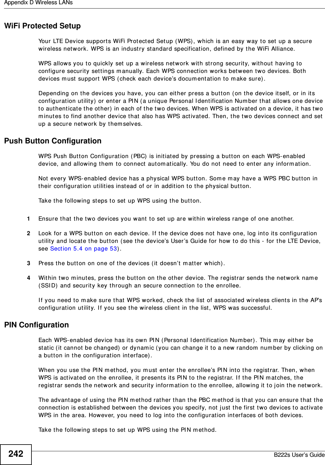
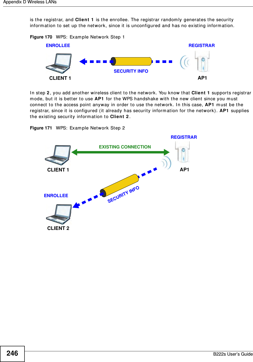
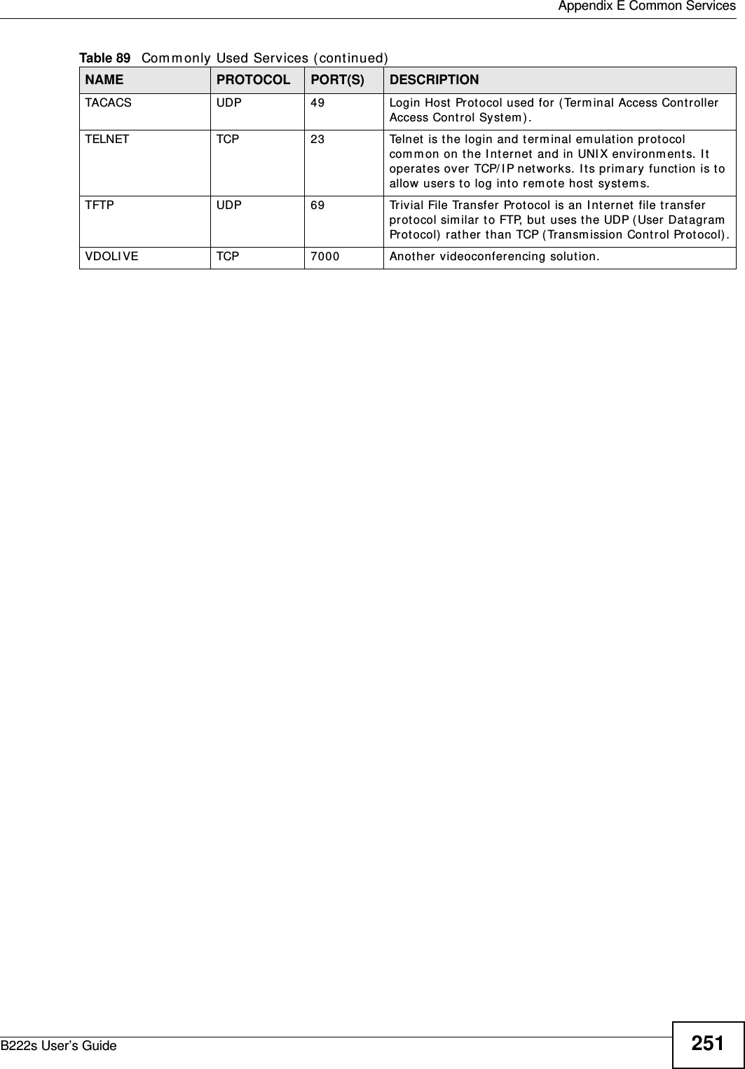
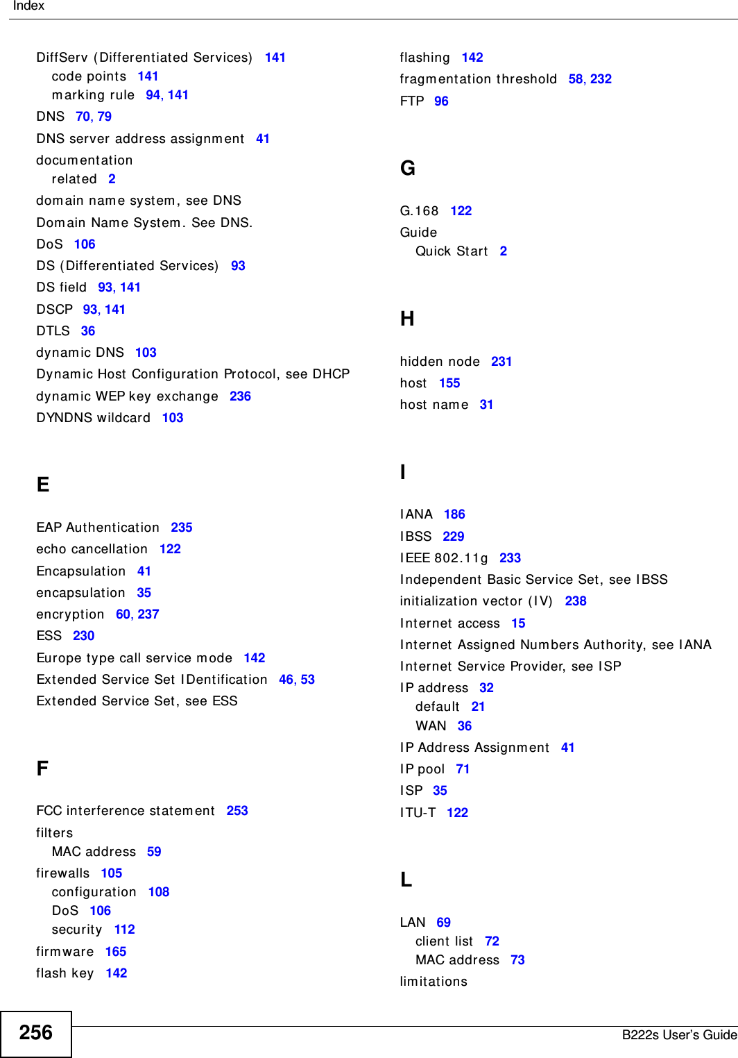
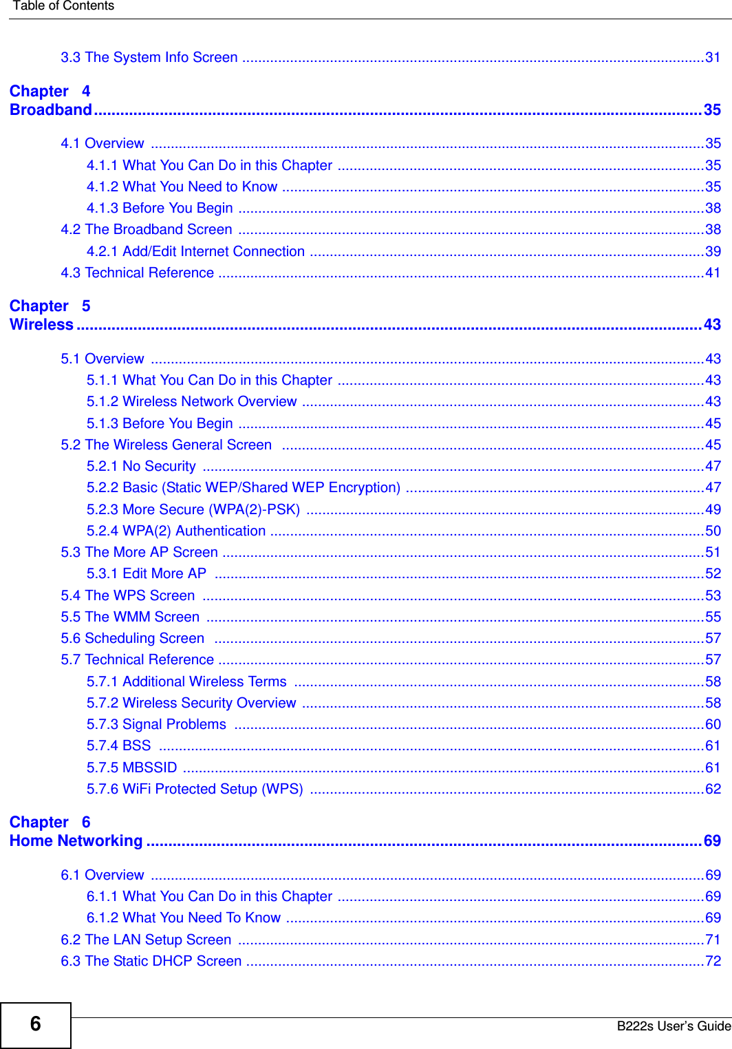
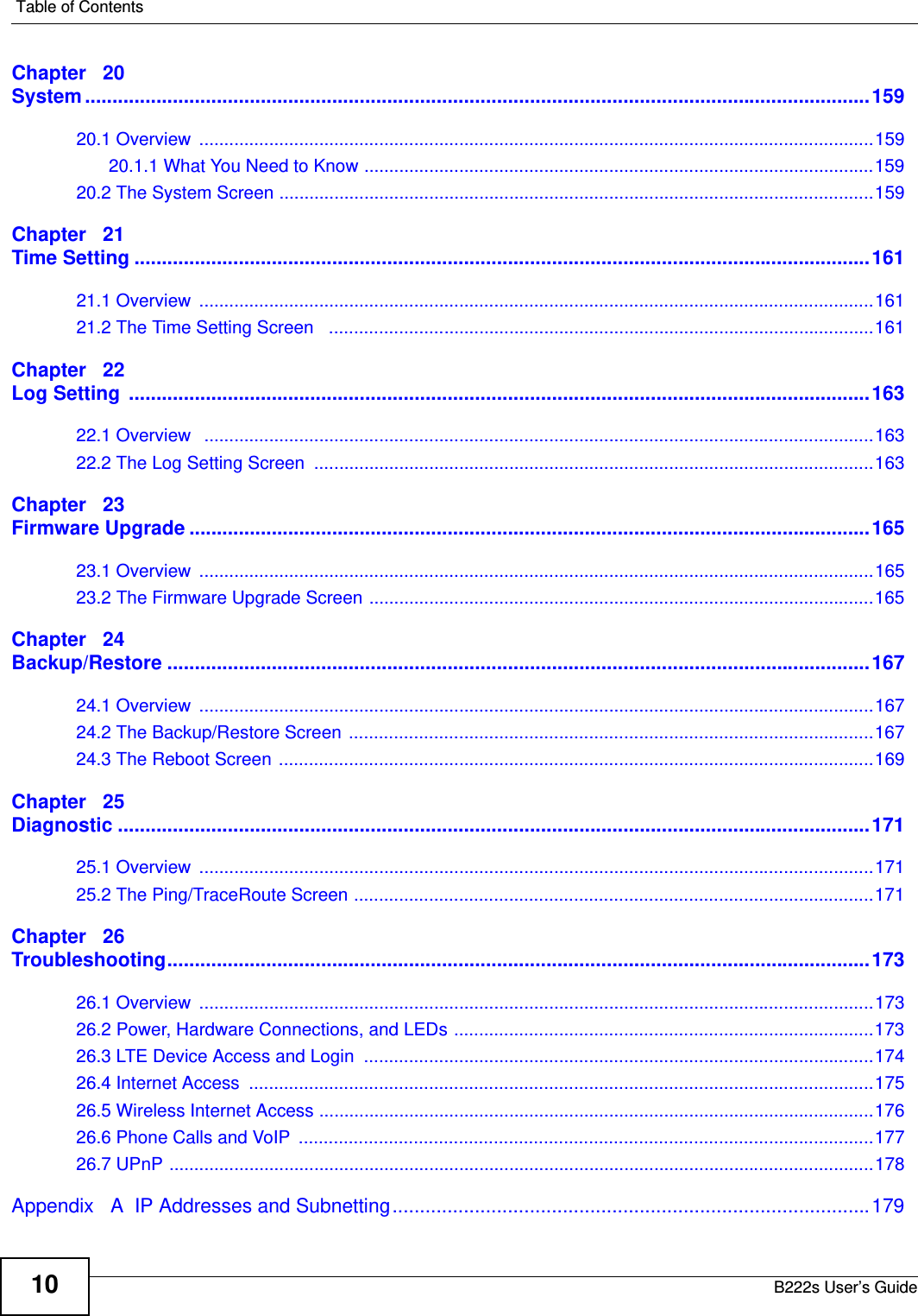
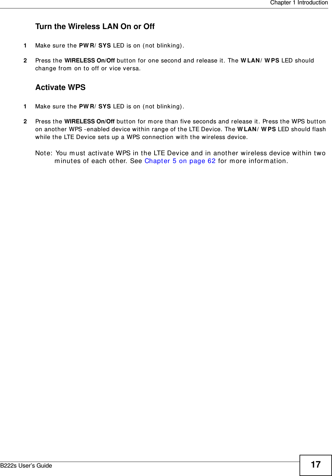
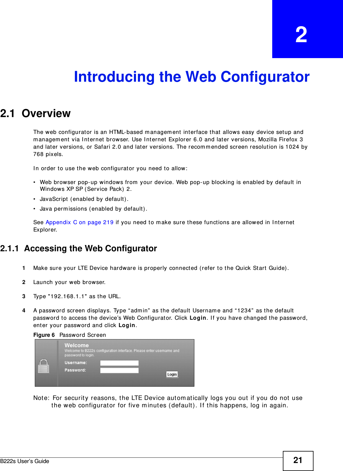
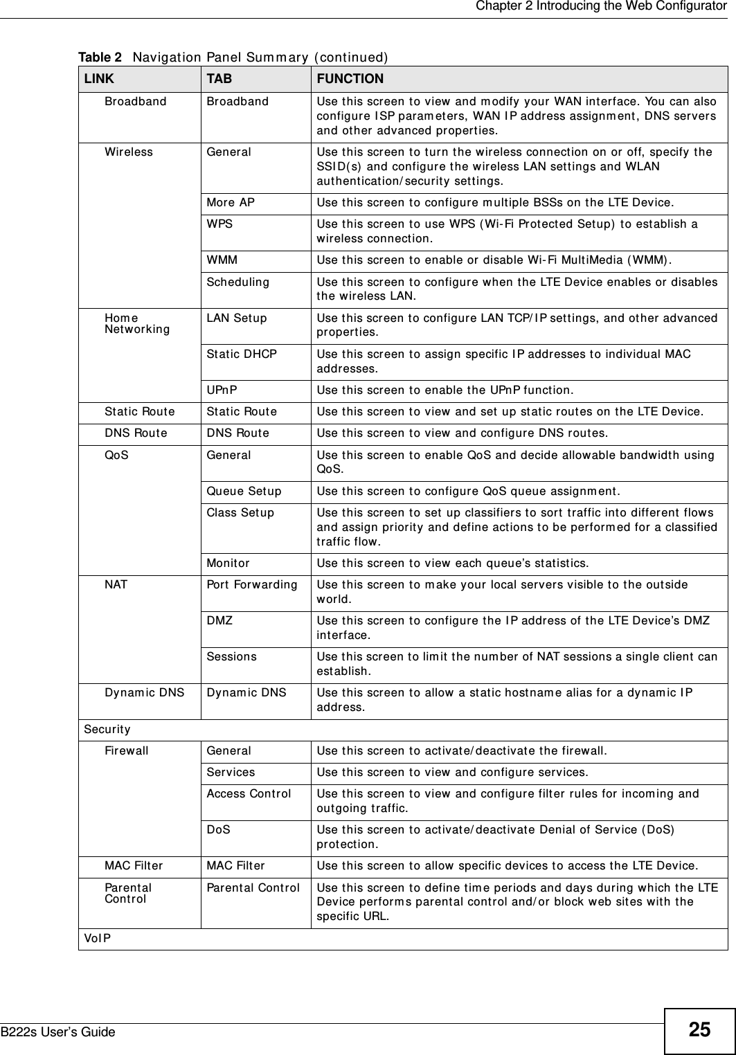
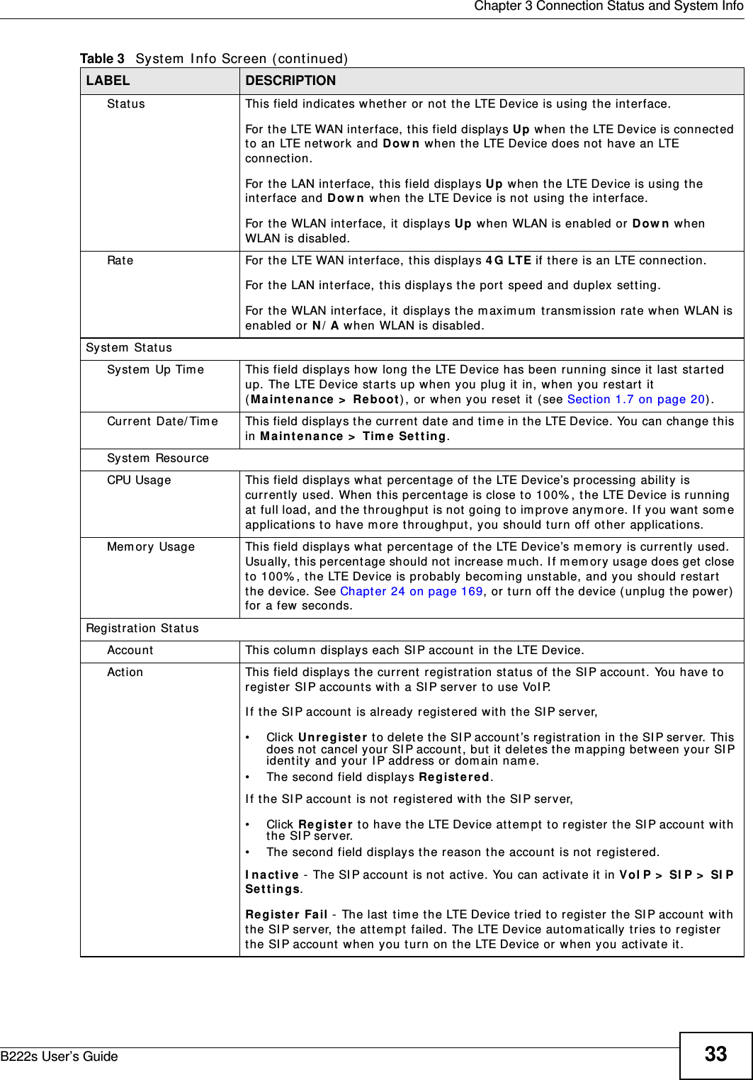
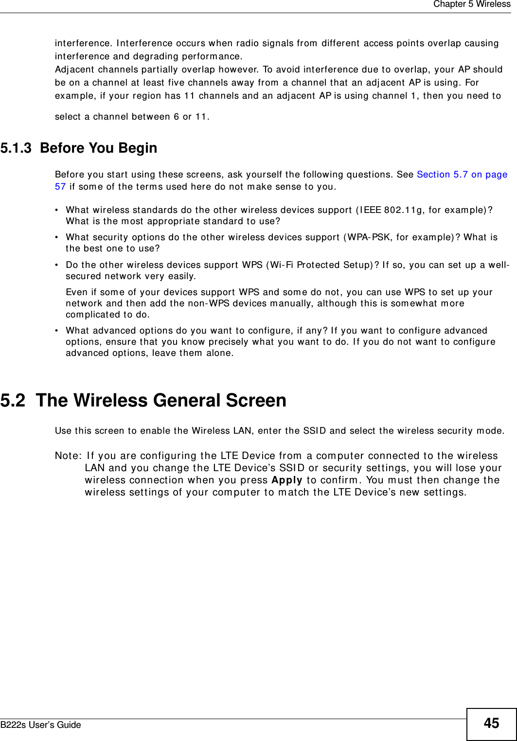
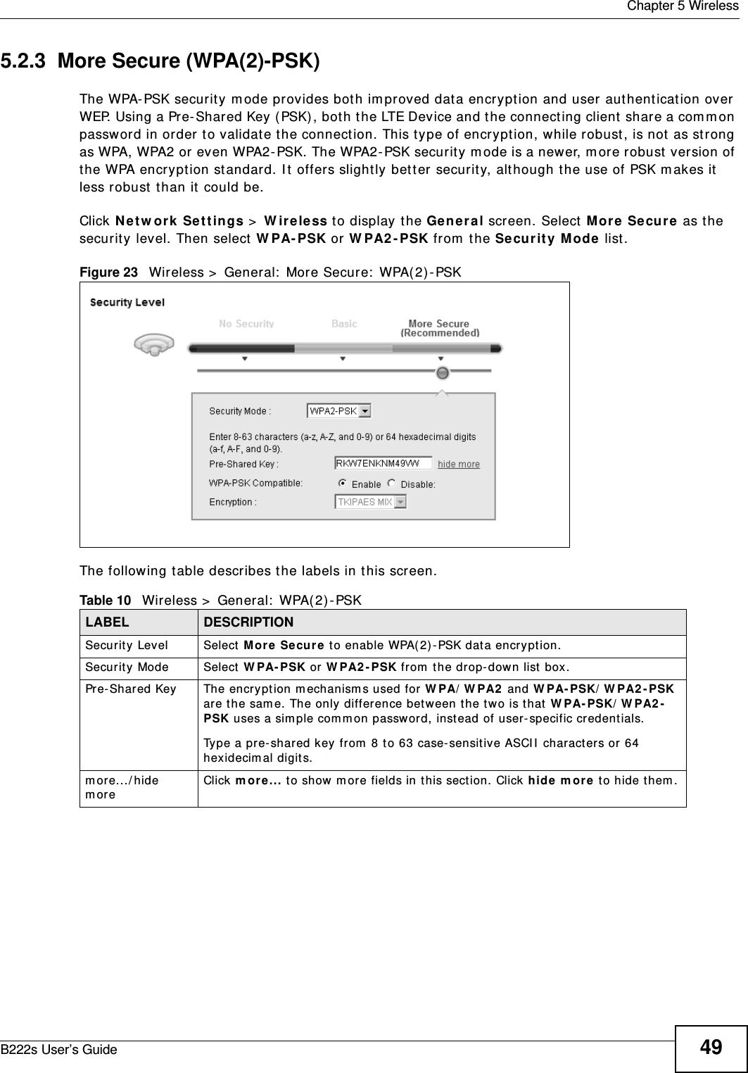
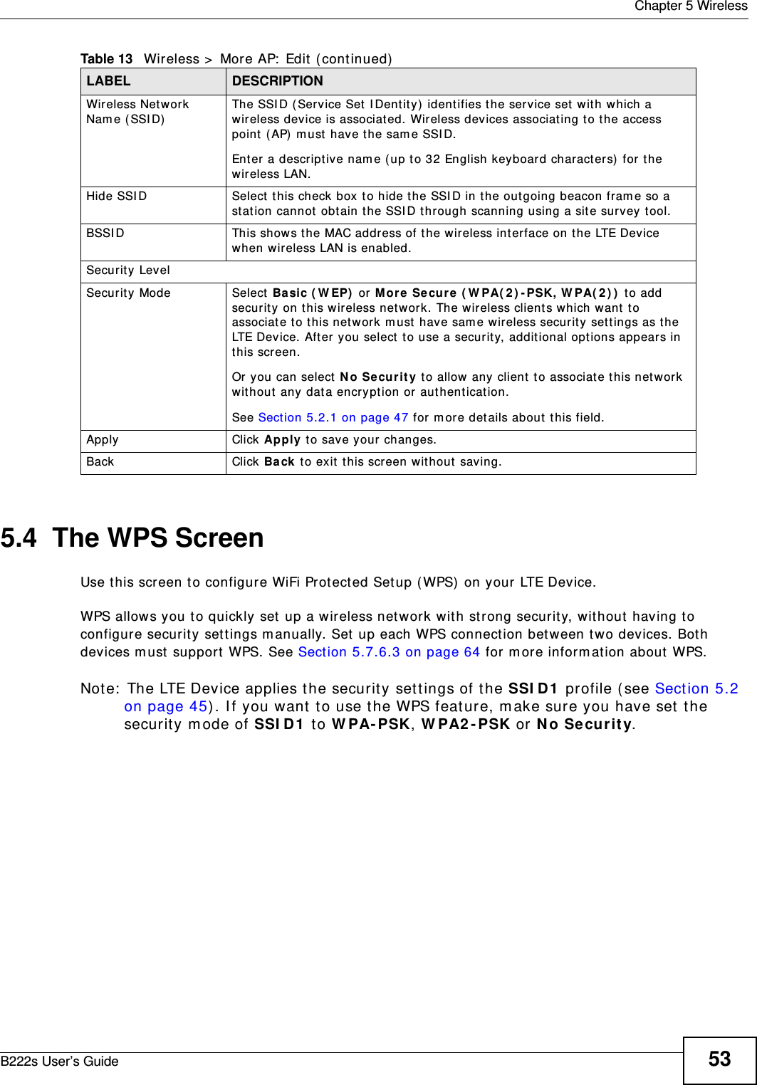
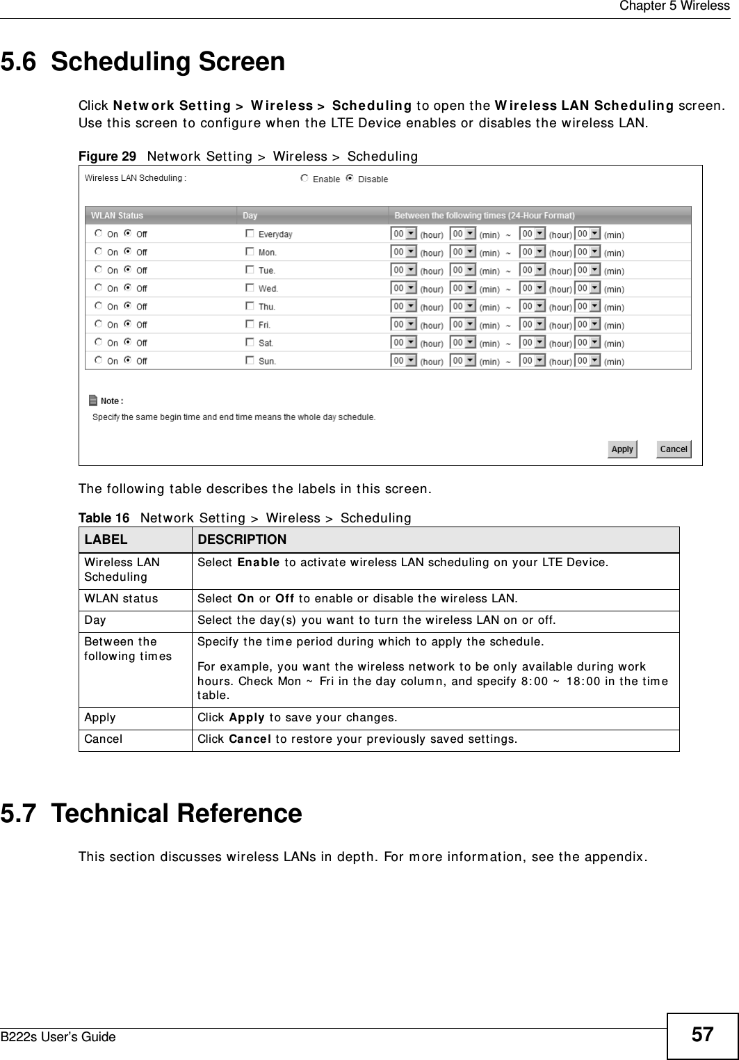
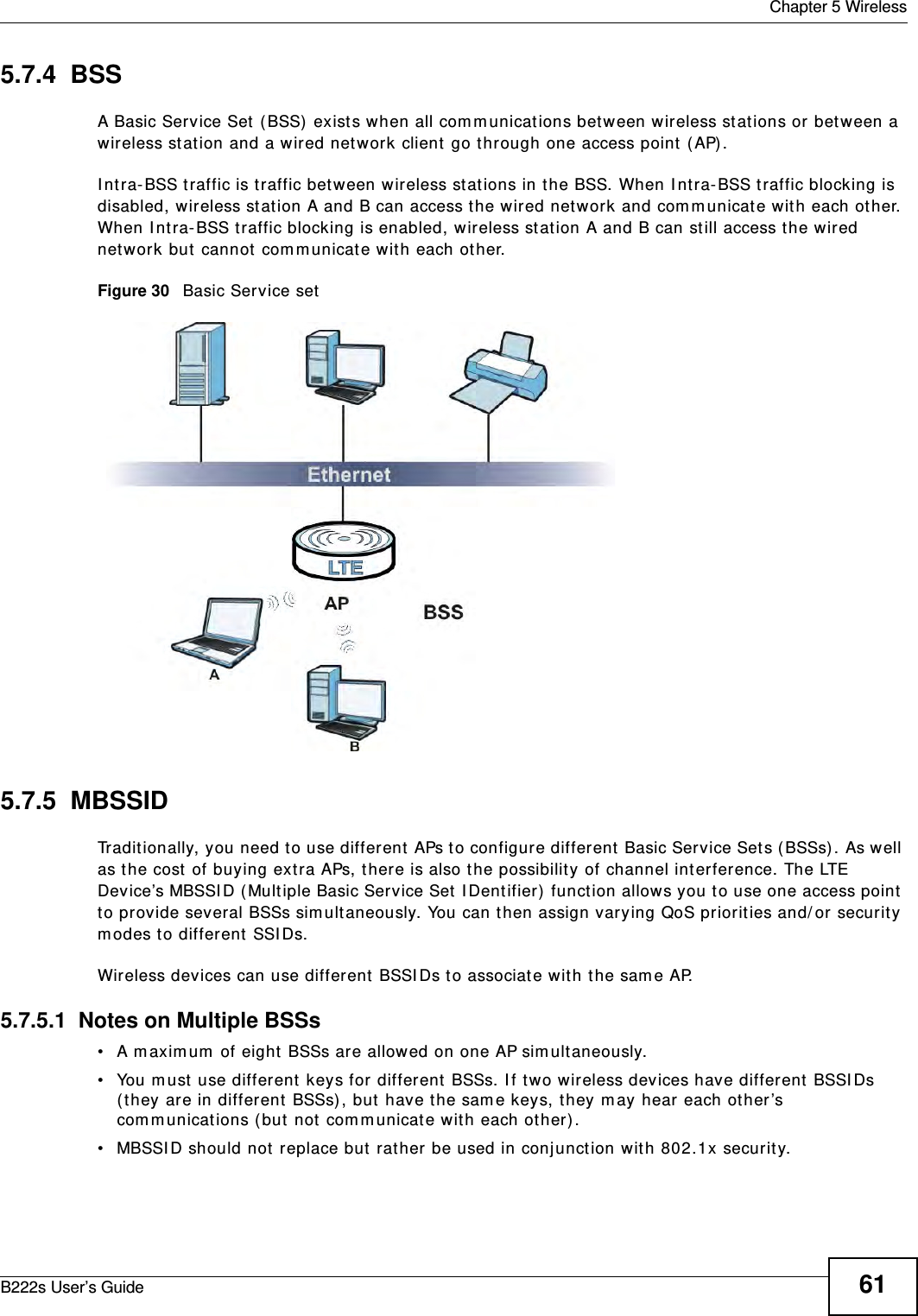
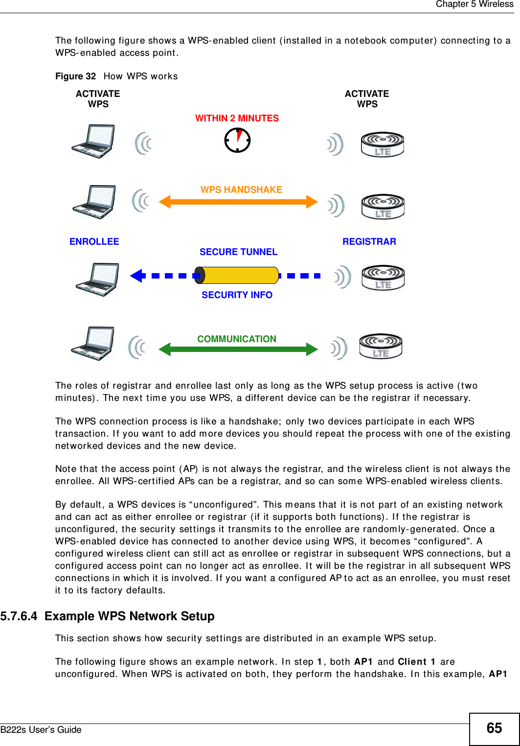
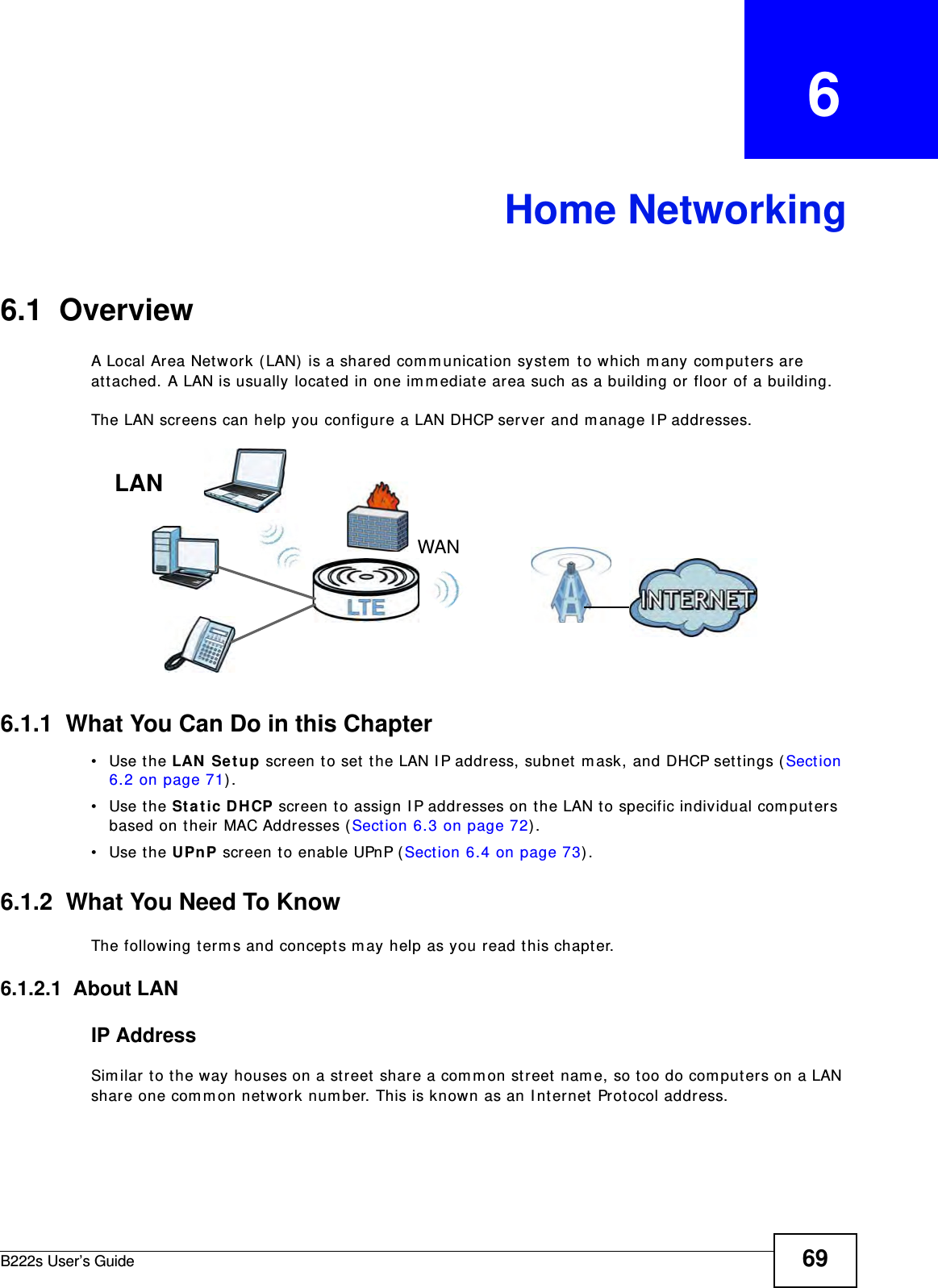
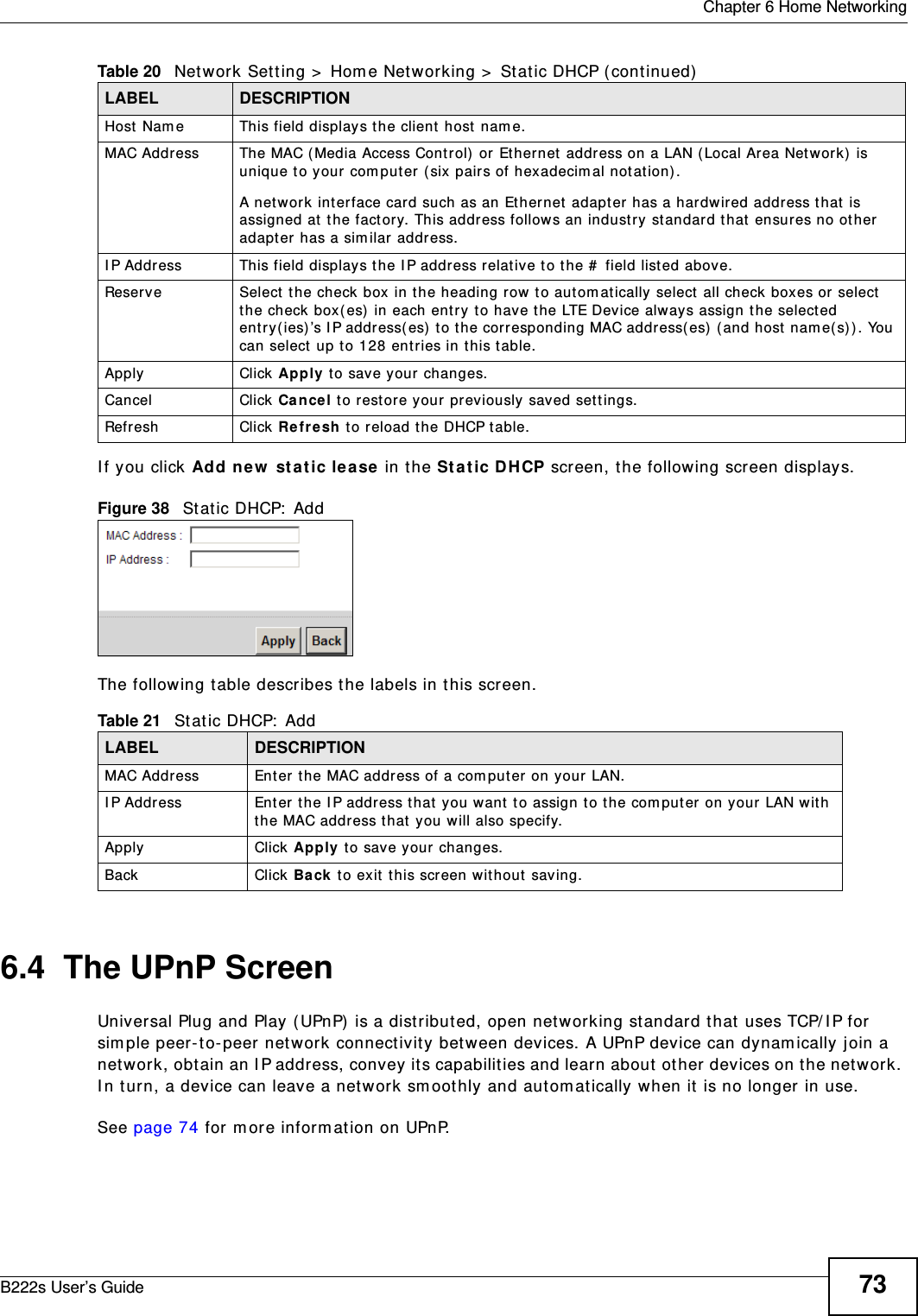
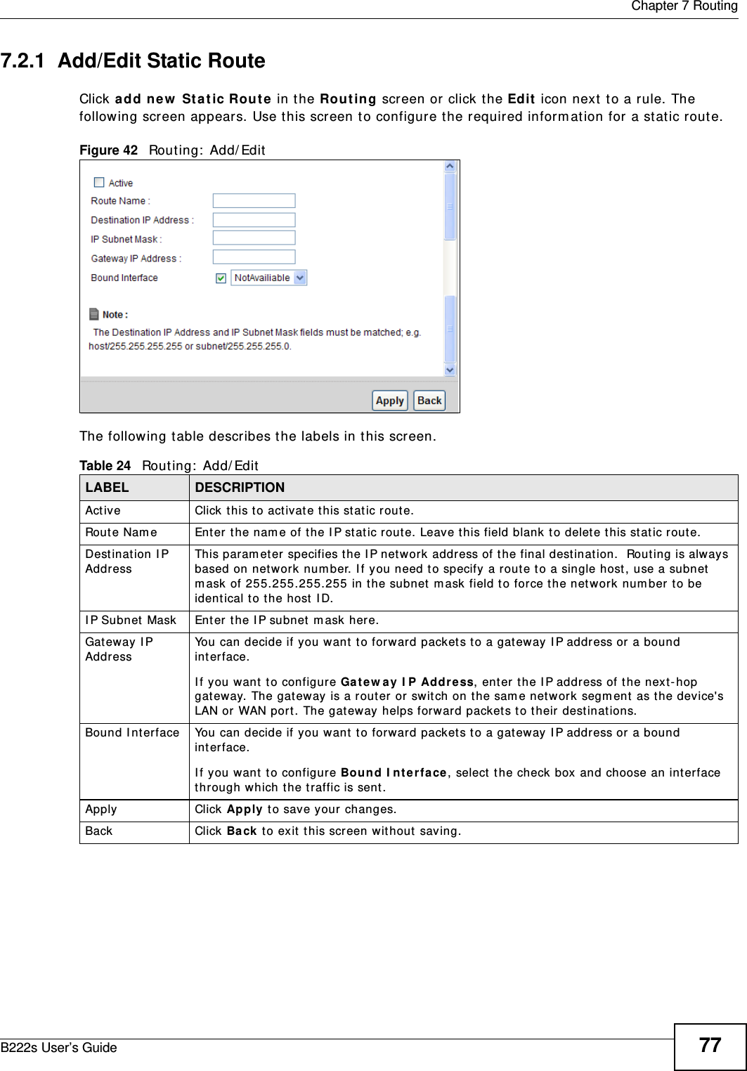
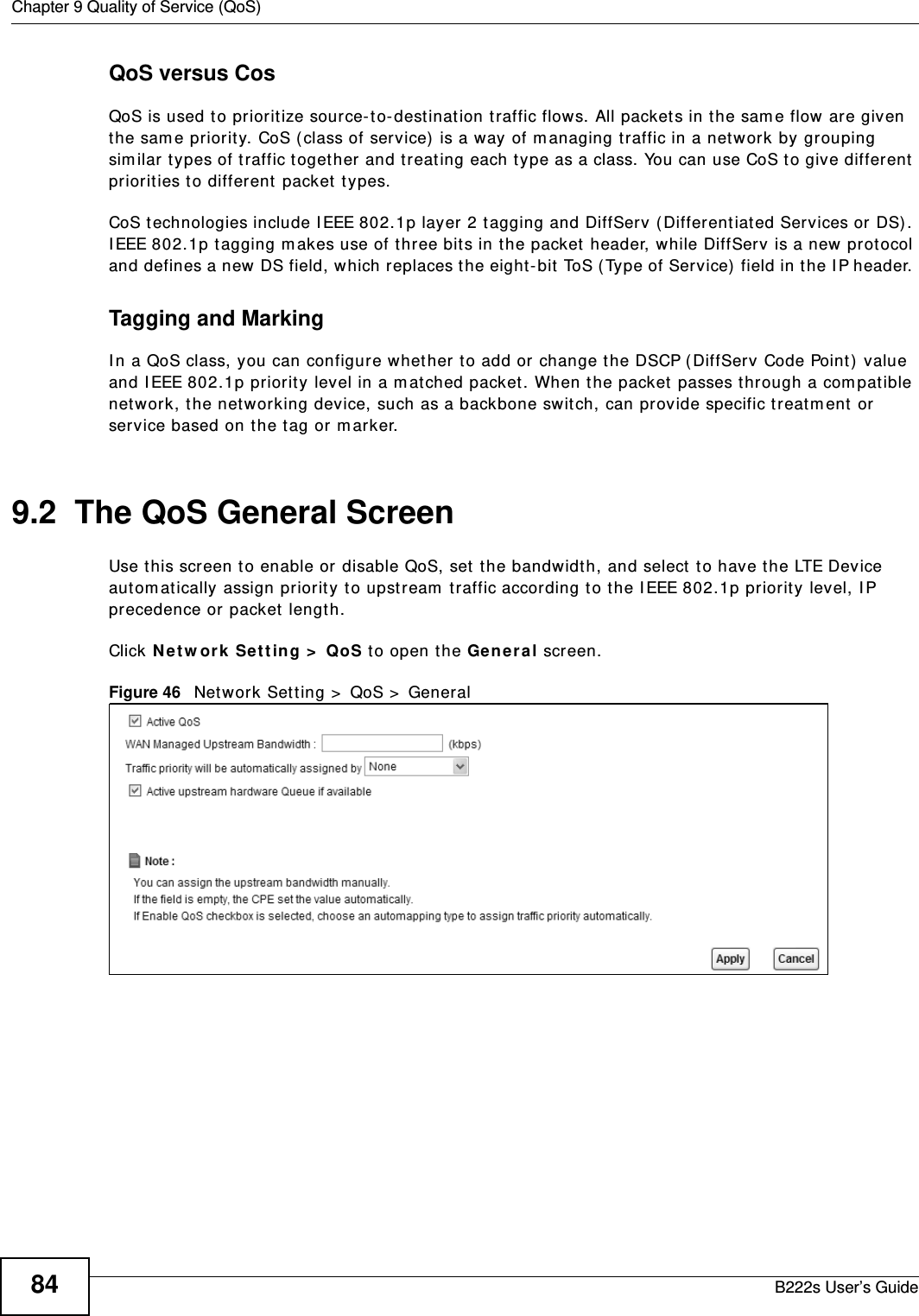
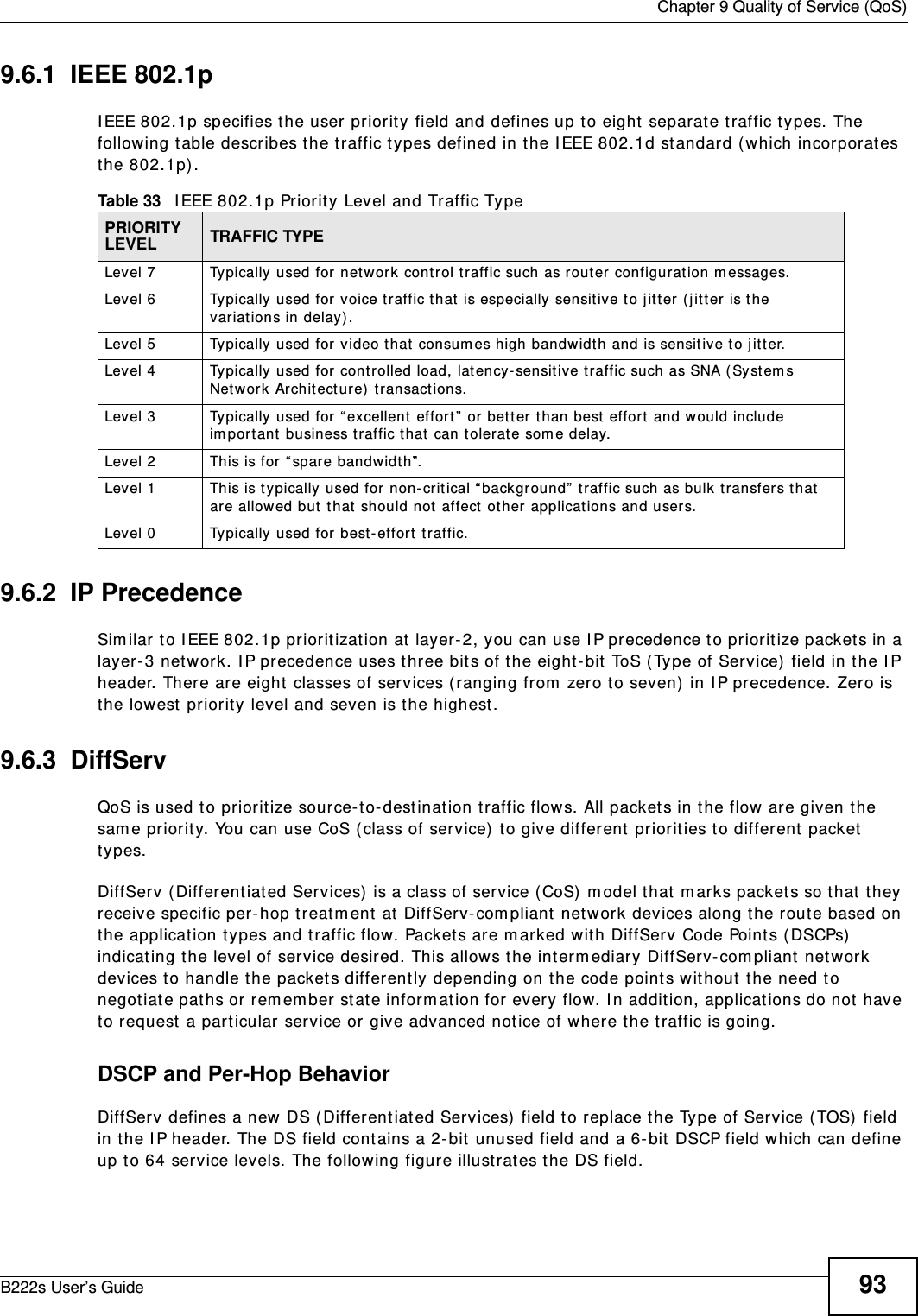
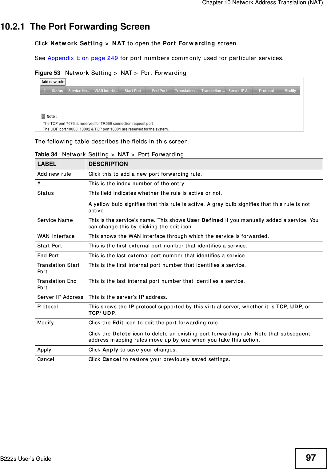
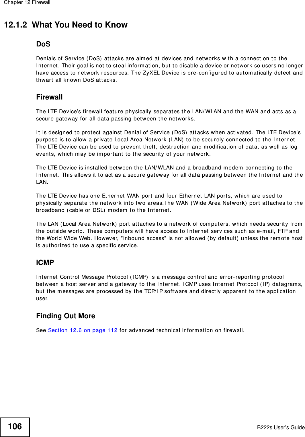
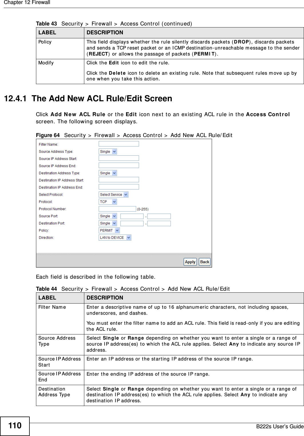
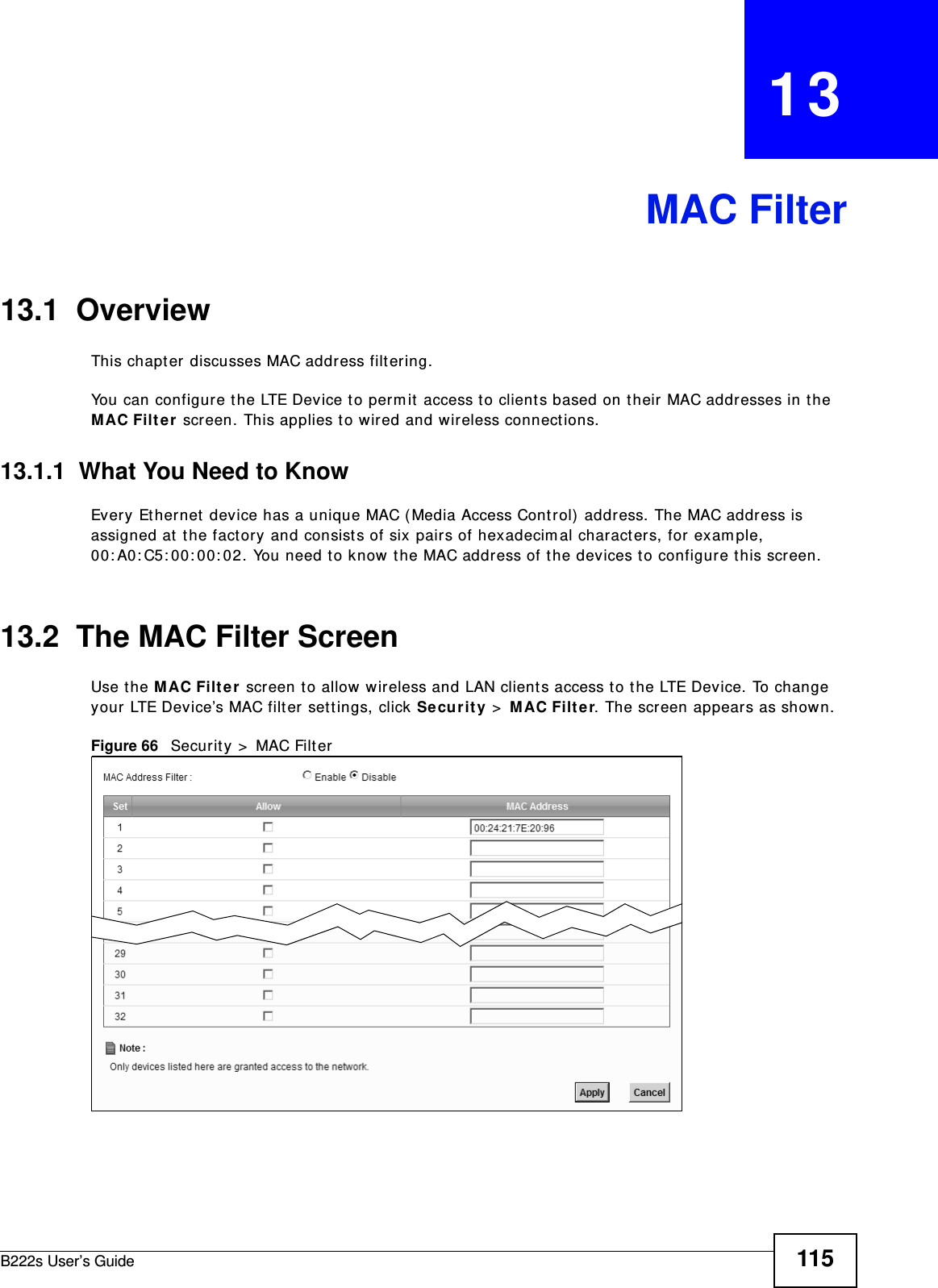
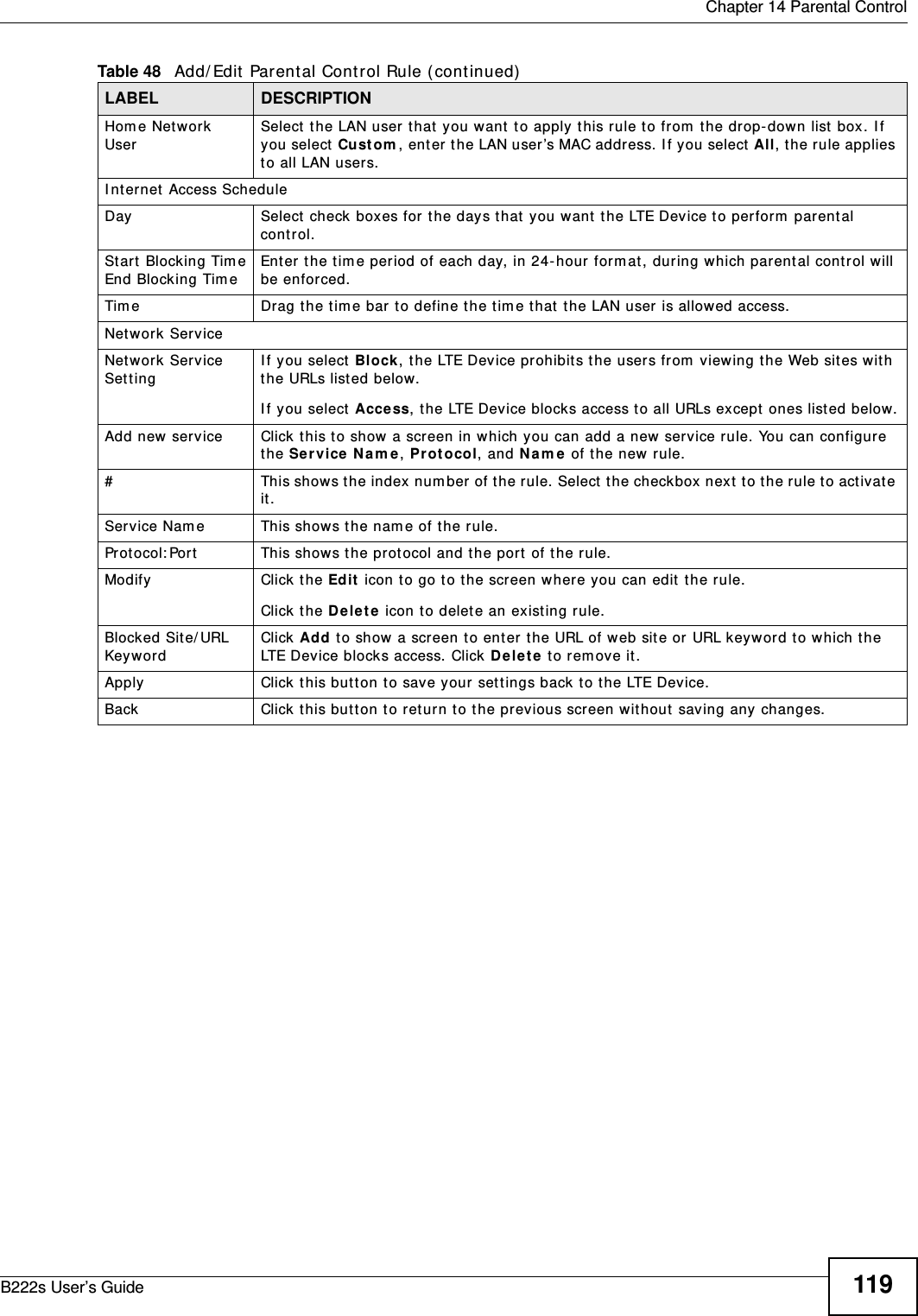
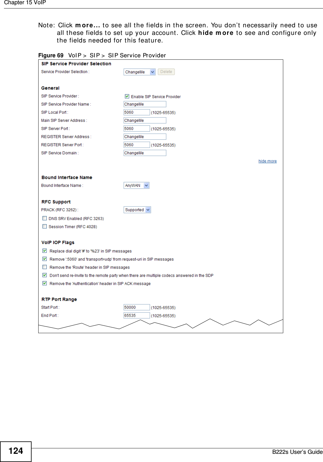
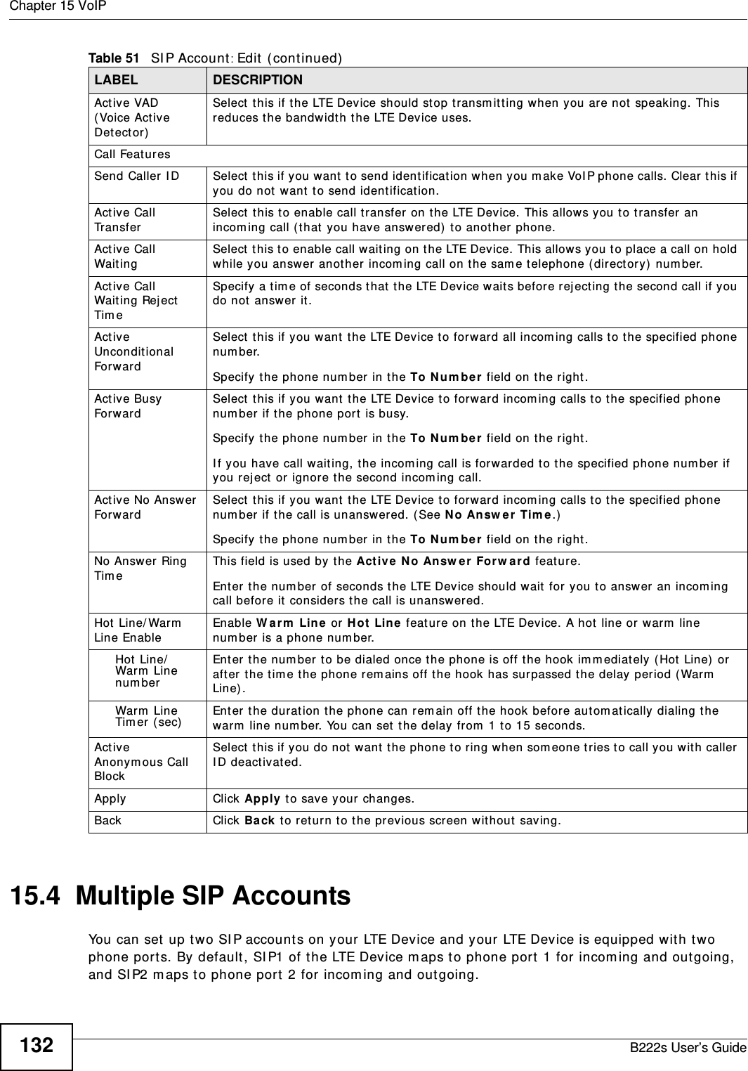
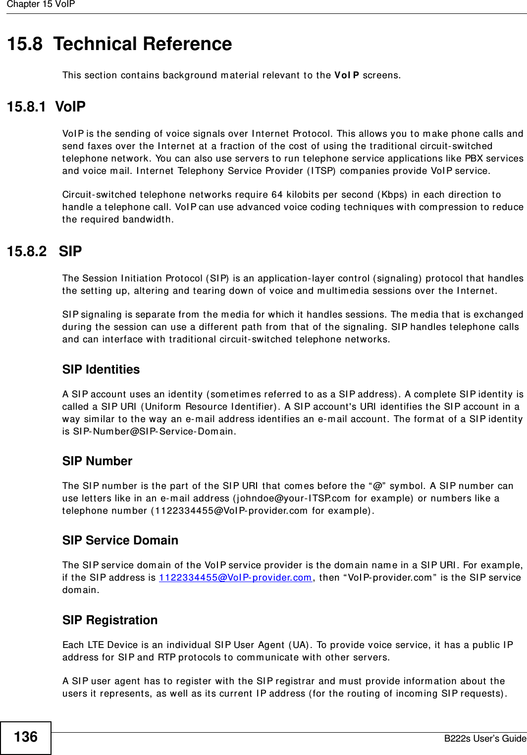
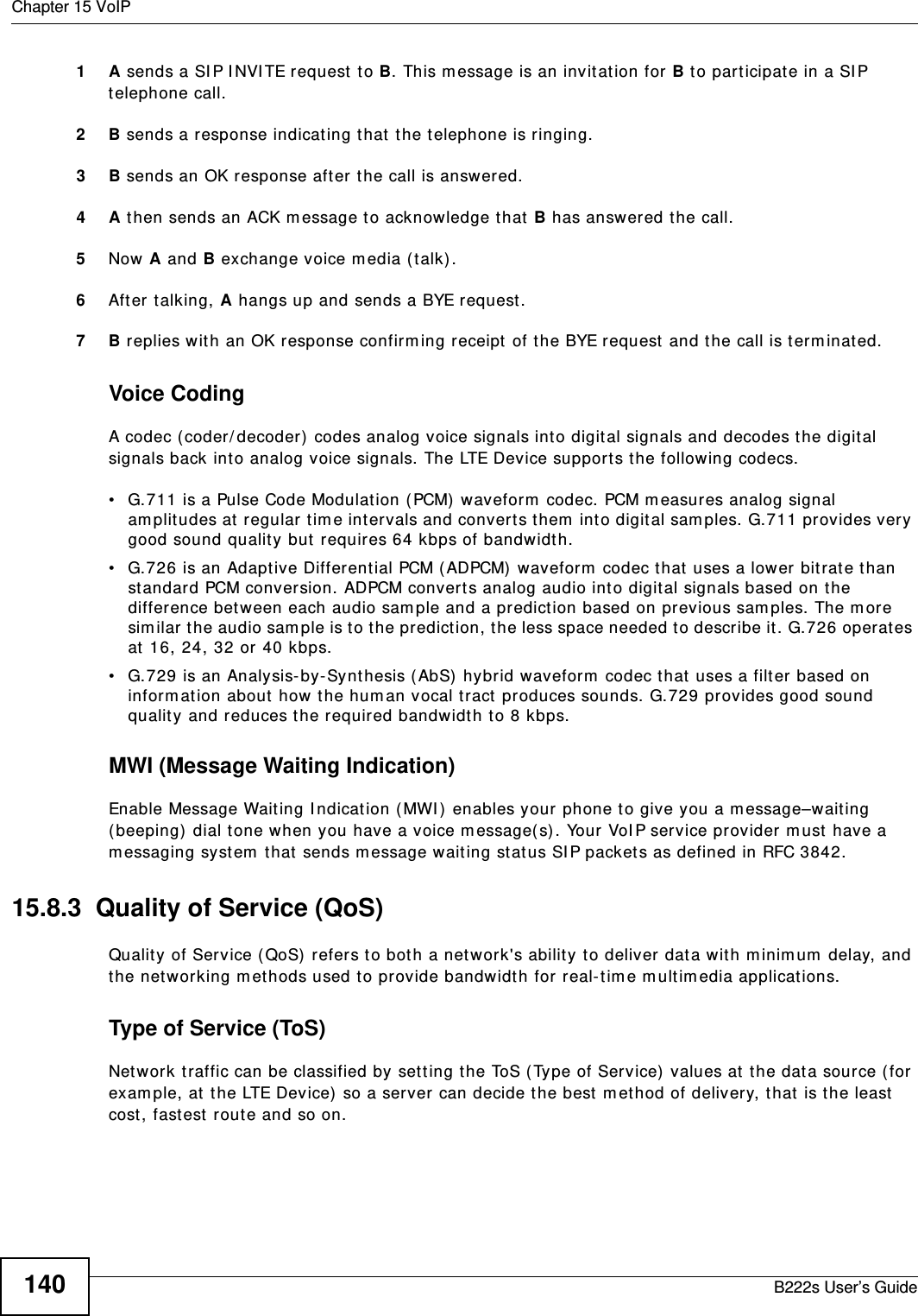
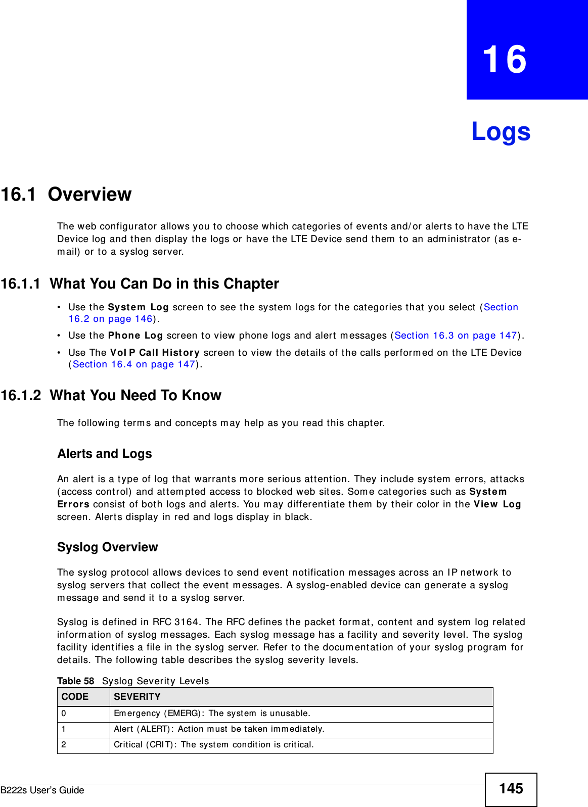
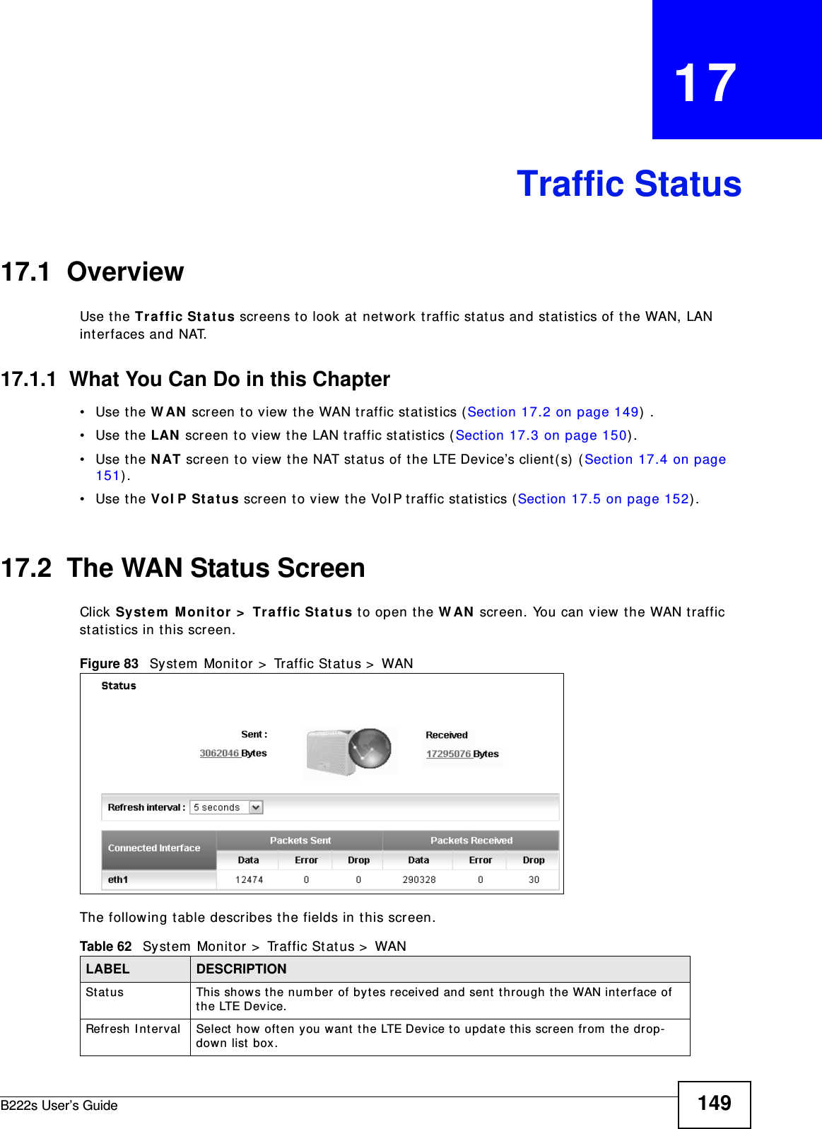
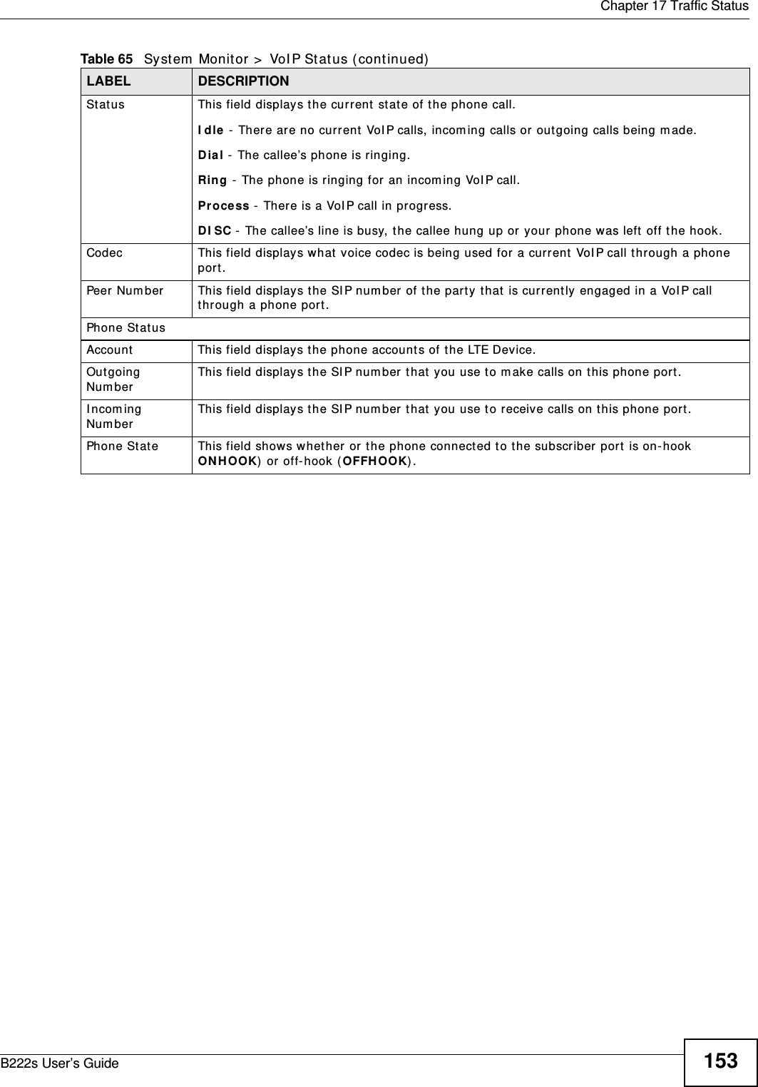
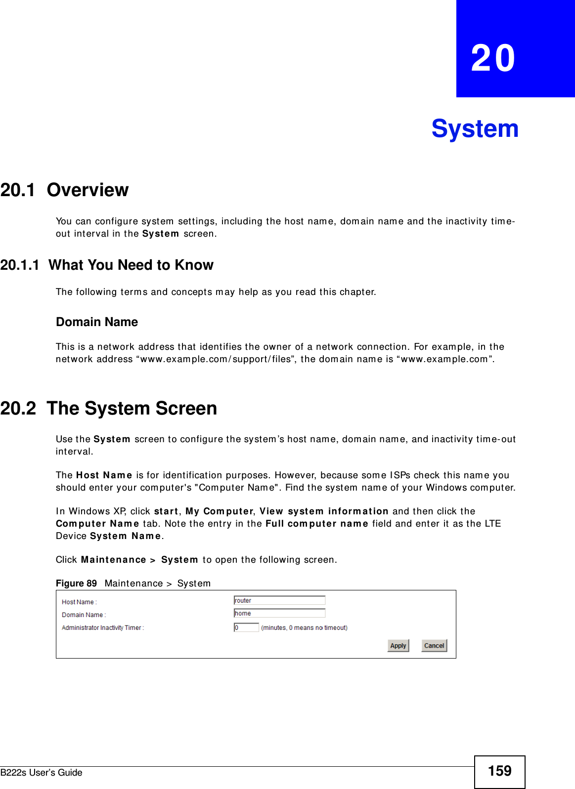
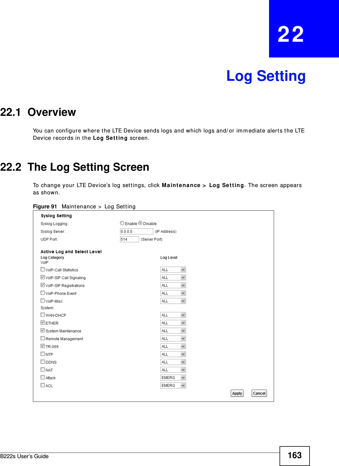
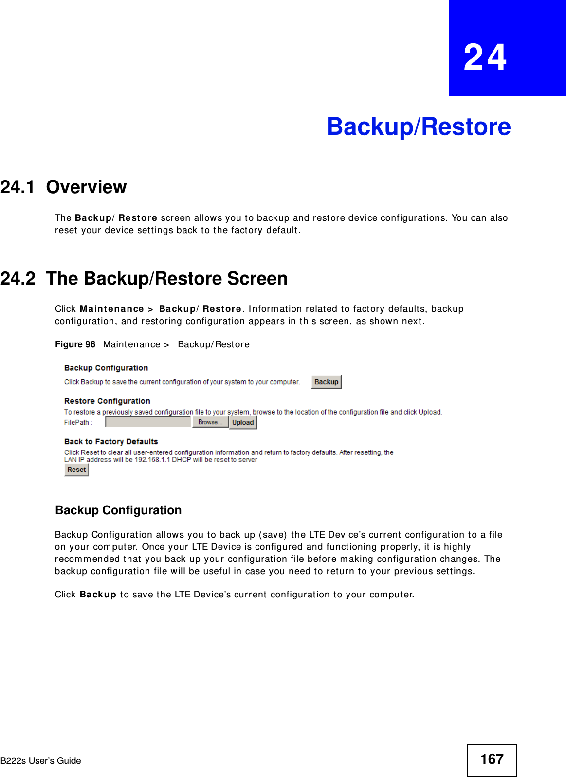
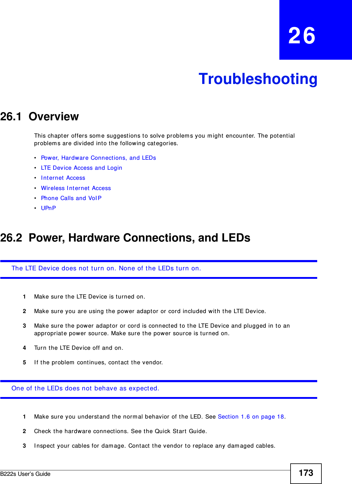
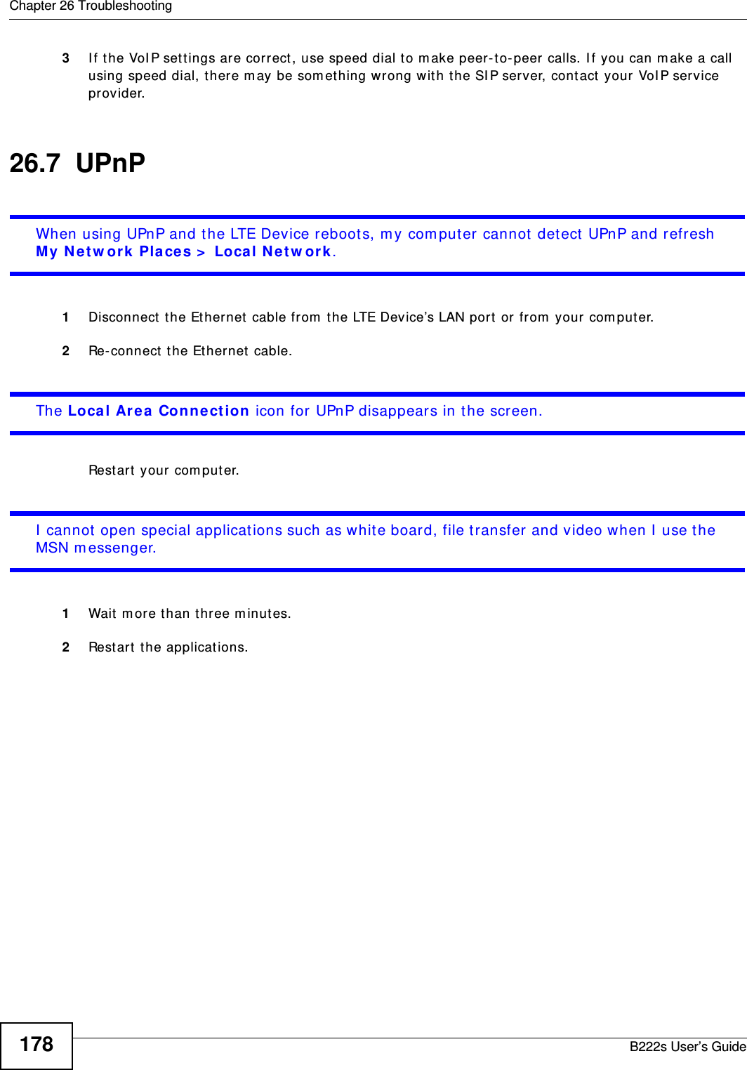
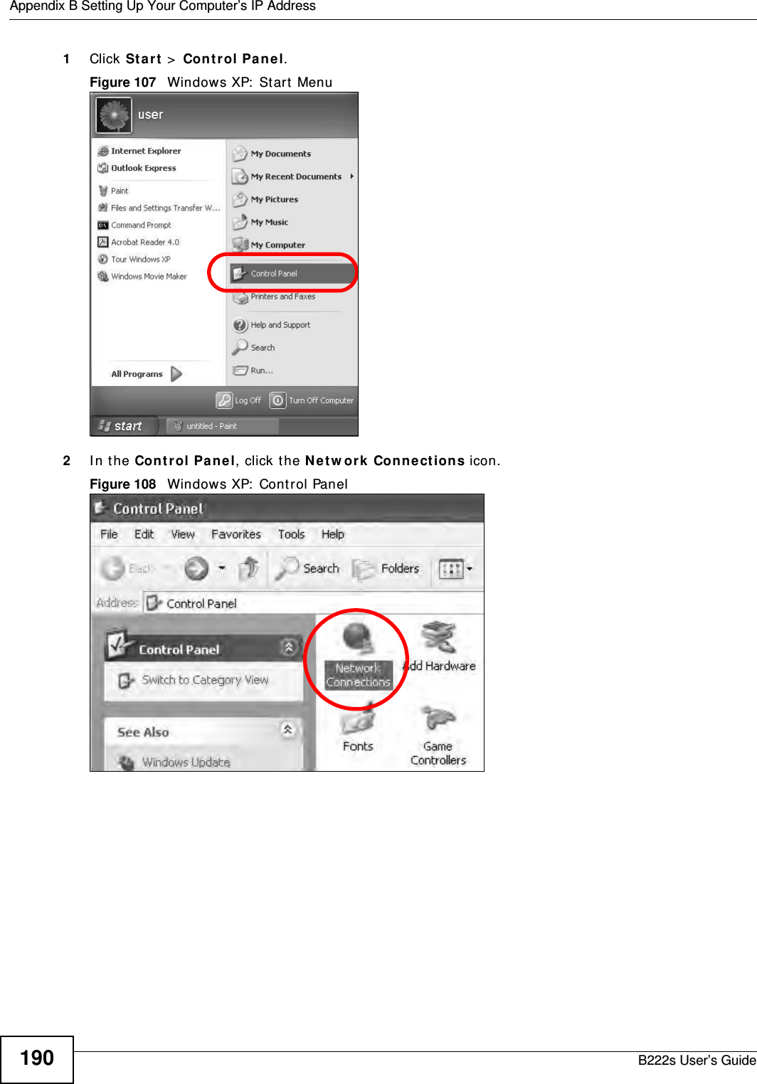
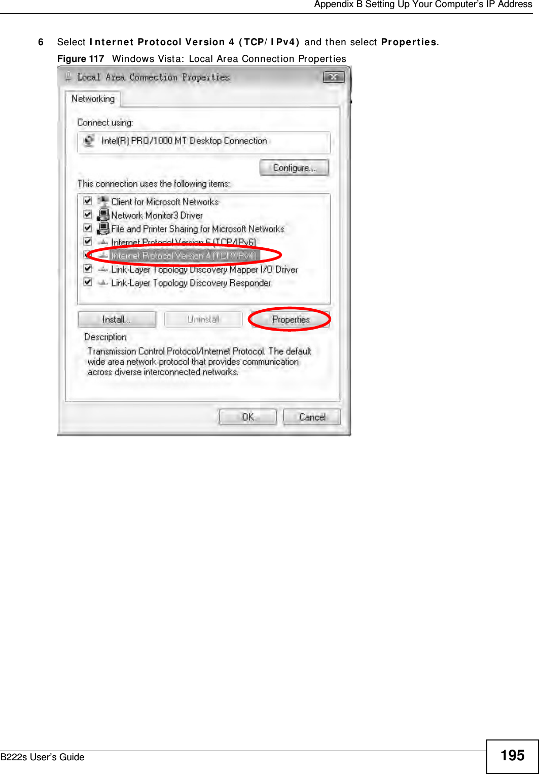
![Appendix B Setting Up Your Computer’s IP AddressB222s User’s Guide2006The I nt e rne t Prot ocol Version 4 ( TCP/ I Pv4 ) Pr opert ies window opens.Figure 124 Windows 7: I nternet Protocol Version 4 ( TCP/ I Pv4) Propert ies7Select Obt ain an I P a ddr e ss a ut om at ica lly if your net work adm inist rat or or I SP assigns your I P address dynam ically.Select Use t he follow ing I P Addr e ss and fill in t he I P a ddr e ss, Subne t m ask, and De fa ult ga t e w ay fields if you have a st at ic I P address that was assigned t o you by your network adm inist rat or or I SP. You m ay also have t o ent er a Pre ferre d D N S ser ver and an Alt e r n at e DN S ser ve r , if t hat inform ation was provided. Click Advanced if you want t o configure advanced set tings for I P, DNS and WI NS. 8Click OK t o close t he I nt er n e t Pr ot ocol ( TCP/ I P) Prope r t ies window.9Click OK t o close t he Loca l Area Conn e ct ion Pr ope r t ie s window.Verifying Settings1Click St a r t > All Progra m s > Acce ssories > Com m a nd Prom pt .2I n t he Com m and Prom pt window, t ype " ipconfig" and t hen press [ ENTER] .](https://usermanual.wiki/MitraStar-Technology/M4G-301/User-Guide-1730649-Page-200.png)