MitraStar Technology M4G-301 TD-LTE OUTDOOR CPE User Manual
MitraStar Technology Corporation TD-LTE OUTDOOR CPE
User Manual
www.zyxel.com
www.huawei.com
B222s
LTE Outdoor CPE
IMPORTANT!
Copyright © 2012
Huawei Technologies Co., LTD.
Edition 1, 6/ 2012
Default Login Details
Web
Address
ht tp: / / 192.168.1.1
User Nam e adm in
Passw or d 1234

B222s User’s Guide2
Graphics in this book m ay differ slightly from the product due t o differences in operat ing system s,
operating system versions, or if you installed updated firm ware/ software for your device. Every
effor t has been m ade t o ensure t hat t he inform ation in t his m anual is accurat e.
Related Documentation
• Quick Start Guide
The Quick St art Guid show s how t o connect t he LTE Device and access the Web Configurat or
wizards. ( See t he w izard real t im e help for inform ation on configuring each screen.) I t also
contains a connect ion diagram and package content s list.
Note: I t is recom m ended you use t he Web Configurator to configure t he LTE Device.

Contents Overview
B222s User’s Guide 3
Contents Overview
User’s Guide .......................................................................................................................................13
Introduction .............................................................................................................................................15
Introducing the Web Configurator ...........................................................................................................21
Technical Reference ..........................................................................................................................27
Connection Status and System Info ........................................................................................................29
Broadband ...............................................................................................................................................35
Wireless ..................................................................................................................................................43
Home Networking ....................................................................................................................................69
Routing ....................................................................................................................................................75
DNS Route ..............................................................................................................................................79
Quality of Service (QoS) .........................................................................................................................83
Network Address Translation (NAT) ........................................................................................................95
Dynamic DNS ........................................................................................................................................103
Firewall ..................................................................................................................................................105
MAC Filter ............................................................................................................................................. 115
Parental Control .................................................................................................................................... 117
VoIP .......................................................................................................................................................121
Logs .....................................................................................................................................................145
Traffic Status .........................................................................................................................................149
User Account .........................................................................................................................................155
Remote MGMT ......................................................................................................................................157
System ..................................................................................................................................................159
Time Setting ..........................................................................................................................................161
Log Setting ...........................................................................................................................................163
Firmware Upgrade ................................................................................................................................165
Backup/Restore .....................................................................................................................................167
Diagnostic .............................................................................................................................................171
Troubleshooting ....................................................................................................................................173

Contents Overview
B222s User’s Guide
4

Table of Contents
B222s User’s Guide 5
Table of Contents
Contents Overview ..............................................................................................................................3
Table of Contents .................................................................................................................................5
Part I: User’s Guide ......................................................................................... 13
Chapter 1
Introduction.........................................................................................................................................15
1.1 Overview ...........................................................................................................................................15
1.2 Applications for the LTE Device ........................................................................................................15
1.2.1 Internet Access ........................................................................................................................15
1.2.2 VoIP Features ..........................................................................................................................16
1.2.3 Wireless Connection ................................................................................................................16
1.3 The WLAN Button .............................................................................................................................16
1.4 Ways to Manage the LTE Device ......................................................................................................18
1.5 Good Habits for Managing the LTE Device .......................................................................................18
1.6 LEDs (Lights) ....................................................................................................................................18
1.7 The RESET Button ............................................................................................................................20
Chapter 2
Introducing the Web Configurator ....................................................................................................21
2.1 Overview ...........................................................................................................................................21
2.1.1 Accessing the Web Configurator .............................................................................................21
2.2 The Web Configurator Layout ...........................................................................................................23
2.2.1 Title Bar ...................................................................................................................................23
2.2.2 Main Window ...........................................................................................................................24
2.2.3 Traffic Status ............................................................................................................................24
2.2.4 User Account ...........................................................................................................................24
2.2.5 Navigation Panel .....................................................................................................................24
Part II: Technical Reference............................................................................ 27
Chapter 3
Connection Status and System Info .................................................................................................29
3.1 Overview ...........................................................................................................................................29
3.2 The Connection Status Screen .........................................................................................................29

Table of Contents
B222s User’s Guide
6
3.3 The System Info Screen ....................................................................................................................31
Chapter 4
Broadband...........................................................................................................................................35
4.1 Overview ...........................................................................................................................................35
4.1.1 What You Can Do in this Chapter ............................................................................................35
4.1.2 What You Need to Know ..........................................................................................................35
4.1.3 Before You Begin .....................................................................................................................38
4.2 The Broadband Screen .....................................................................................................................38
4.2.1 Add/Edit Internet Connection ...................................................................................................39
4.3 Technical Reference ..........................................................................................................................41
Chapter 5
Wireless ...............................................................................................................................................43
5.1 Overview ...........................................................................................................................................43
5.1.1 What You Can Do in this Chapter ............................................................................................43
5.1.2 Wireless Network Overview .....................................................................................................43
5.1.3 Before You Begin .....................................................................................................................45
5.2 The Wireless General Screen ..........................................................................................................45
5.2.1 No Security ..............................................................................................................................47
5.2.2 Basic (Static WEP/Shared WEP Encryption) ...........................................................................47
5.2.3 More Secure (WPA(2)-PSK) ....................................................................................................49
5.2.4 WPA(2) Authentication .............................................................................................................50
5.3 The More AP Screen .........................................................................................................................51
5.3.1 Edit More AP ...........................................................................................................................52
5.4 The WPS Screen ..............................................................................................................................53
5.5 The WMM Screen .............................................................................................................................55
5.6 Scheduling Screen ...........................................................................................................................57
5.7 Technical Reference ..........................................................................................................................57
5.7.1 Additional Wireless Terms .......................................................................................................58
5.7.2 Wireless Security Overview .....................................................................................................58
5.7.3 Signal Problems ......................................................................................................................60
5.7.4 BSS .........................................................................................................................................61
5.7.5 MBSSID ...................................................................................................................................61
5.7.6 WiFi Protected Setup (WPS) ...................................................................................................62
Chapter 6
Home Networking ...............................................................................................................................69
6.1 Overview ...........................................................................................................................................69
6.1.1 What You Can Do in this Chapter ............................................................................................69
6.1.2 What You Need To Know .........................................................................................................69
6.2 The LAN Setup Screen .....................................................................................................................71
6.3 The Static DHCP Screen ...................................................................................................................72

Table of Contents
B222s User’s Guide 7
6.3.1 Before You Begin .....................................................................................................................72
6.4 The UPnP Screen .............................................................................................................................73
Chapter 7
Routing ................................................................................................................................................75
7.1 Overview ...........................................................................................................................................75
7.2 Configuring Static Route ...................................................................................................................76
7.2.1 Add/Edit Static Route .............................................................................................................77
Chapter 8
DNS Route ...........................................................................................................................................79
8.1 Overview ...........................................................................................................................................79
8.1.1 What You Can Do in this Chapter ............................................................................................79
8.2 The DNS Route Screen ....................................................................................................................80
8.2.1 Add/Edit DNS Route Edit ........................................................................................................80
Chapter 9
Quality of Service (QoS).....................................................................................................................83
9.1 Overview ...........................................................................................................................................83
9.1.1 What You Can Do in this Chapter ............................................................................................83
9.1.2 What You Need to Know ..........................................................................................................83
9.2 The QoS General Screen .................................................................................................................84
9.3 The Queue Setup Screen .................................................................................................................86
9.3.1 Add/Edit a QoS Queue ...........................................................................................................87
9.4 The Class Setup Screen .................................................................................................................87
9.4.1 Add/Edit QoS Class ................................................................................................................89
9.5 The QoS Monitor Screen .................................................................................................................92
9.6 QoS Technical Reference .................................................................................................................92
9.6.1 IEEE 802.1p ............................................................................................................................93
9.6.2 IP Precedence .........................................................................................................................93
9.6.3 DiffServ ....................................................................................................................................93
Chapter 10
Network Address Translation (NAT)..................................................................................................95
10.1 Overview ........................................................................................................................................95
10.1.1 What You Can Do in this Chapter ..........................................................................................95
10.1.2 What You Need To Know .......................................................................................................95
10.2 The Port Forwarding Screen ..........................................................................................................96
10.2.1 The Port Forwarding Screen .................................................................................................97
10.2.2 The Port Forwarding Edit Screen ..........................................................................................98
10.3 The DMZ Screen .............................................................................................................................99
10.4 The Sessions Screen ......................................................................................................................99
10.5 Technical Reference ......................................................................................................................100

Table of Contents
B222s User’s Guide
8
10.5.1 NAT Definitions ....................................................................................................................100
10.5.2 What NAT Does ...................................................................................................................101
10.5.3 How NAT Works ..................................................................................................................101
Chapter 11
Dynamic DNS ....................................................................................................................................103
11.1 Overview ......................................................................................................................................103
11.1.1 What You Need To Know .....................................................................................................103
11.2 The Dynamic DNS Screen ............................................................................................................104
Chapter 12
Firewall ..............................................................................................................................................105
12.1 Overview .......................................................................................................................................105
12.1.1 What You Can Do in this Chapter ........................................................................................105
12.1.2 What You Need to Know ......................................................................................................106
12.2 The General Screen .....................................................................................................................107
12.3 The Services Screen .....................................................................................................................108
12.3.1 The Add New Services Entry Screen ..................................................................................108
12.4 The Access Control Screen ..........................................................................................................109
12.4.1 The Add New ACL Rule/Edit Screen ................................................................................... 110
12.5 The DoS Screen ............................................................................................................................ 111
12.6 Firewall Technical Reference ........................................................................................................ 112
12.6.1 Guidelines For Enhancing Security With Your Firewall ....................................................... 112
12.6.2 Security Considerations ....................................................................................................... 112
Chapter 13
MAC Filter.......................................................................................................................................... 115
13.1 Overview ....................................................................................................................................... 115
13.1.1 What You Need to Know ...................................................................................................... 115
13.2 The MAC Filter Screen .................................................................................................................. 115
Chapter 14
Parental Control................................................................................................................................ 117
14.1 Overview ....................................................................................................................................... 117
14.2 The Parental Control Screen ......................................................................................................... 117
14.2.1 Add/Edit a Parental Control Rule ......................................................................................... 118
Chapter 15
VoIP ....................................................................................................................................................121
15.1 Overview .......................................................................................................................................121
15.1.1 What You Can Do in this Chapter ........................................................................................121
15.1.2 What You Need to Know ......................................................................................................121
15.1.3 Before You Begin .................................................................................................................123

Table of Contents
B222s User’s Guide 9
15.2 The SIP Service Provider Screen ................................................................................................123
15.3 The SIP Account Screen ...............................................................................................................129
15.3.1 Add/Edit SIP Account ..........................................................................................................130
15.4 Multiple SIP Accounts ...................................................................................................................132
15.5 Phone Screen ..............................................................................................................................133
15.5.1 Edit Phone Device ...............................................................................................................133
15.6 The Phone Region Screen ............................................................................................................134
15.7 The Call Rule Screen ....................................................................................................................134
15.8 Technical Reference ......................................................................................................................136
15.8.1 VoIP .....................................................................................................................................136
15.8.2 SIP ......................................................................................................................................136
15.8.3 Quality of Service (QoS) ......................................................................................................140
15.8.4 Phone Services Overview ...................................................................................................141
Chapter 16
Logs ..................................................................................................................................................145
16.1 Overview ......................................................................................................................................145
16.1.1 What You Can Do in this Chapter ........................................................................................145
16.1.2 What You Need To Know .....................................................................................................145
16.2 The System Log Screen ................................................................................................................146
16.3 The Phone Log Screen .................................................................................................................147
16.4 The VoIP Call History Screen ........................................................................................................147
Chapter 17
Traffic Status .....................................................................................................................................149
17.1 Overview .......................................................................................................................................149
17.1.1 What You Can Do in this Chapter ........................................................................................149
17.2 The WAN Status Screen ...............................................................................................................149
17.3 The LAN Status Screen .................................................................................................................150
17.4 The NAT Status Screen .................................................................................................................151
17.5 The VoIP Status Screen ................................................................................................................152
Chapter 18
User Account ....................................................................................................................................155
18.1 Overview .......................................................................................................................................155
18.2 The User Account Screen .............................................................................................................155
Chapter 19
Remote MGMT...................................................................................................................................157
19.1 Overview .......................................................................................................................................157
19.1.1 What You Need to Know ......................................................................................................157
19.2 The Remote MGMT Screen ..........................................................................................................157

Table of Contents
B222s User’s Guide
10
Chapter 20
System ...............................................................................................................................................159
20.1 Overview .......................................................................................................................................159
20.1.1 What You Need to Know ......................................................................................................159
20.2 The System Screen .......................................................................................................................159
Chapter 21
Time Setting ......................................................................................................................................161
21.1 Overview .......................................................................................................................................161
21.2 The Time Setting Screen .............................................................................................................161
Chapter 22
Log Setting .......................................................................................................................................163
22.1 Overview ......................................................................................................................................163
22.2 The Log Setting Screen ................................................................................................................163
Chapter 23
Firmware Upgrade ............................................................................................................................165
23.1 Overview .......................................................................................................................................165
23.2 The Firmware Upgrade Screen .....................................................................................................165
Chapter 24
Backup/Restore ................................................................................................................................167
24.1 Overview .......................................................................................................................................167
24.2 The Backup/Restore Screen .........................................................................................................167
24.3 The Reboot Screen .......................................................................................................................169
Chapter 25
Diagnostic .........................................................................................................................................171
25.1 Overview .......................................................................................................................................171
25.2 The Ping/TraceRoute Screen ........................................................................................................171
Chapter 26
Troubleshooting................................................................................................................................173
26.1 Overview .......................................................................................................................................173
26.2 Power, Hardware Connections, and LEDs ....................................................................................173
26.3 LTE Device Access and Login ......................................................................................................174
26.4 Internet Access .............................................................................................................................175
26.5 Wireless Internet Access ...............................................................................................................176
26.6 Phone Calls and VoIP ...................................................................................................................177
26.7 UPnP .............................................................................................................................................178
Appendix A IP Addresses and Subnetting.......................................................................................179

Table of Contents
B222s User’s Guide 11
Appendix B Setting Up Your Computer’s IP Address ......................................................................189
Appendix C Pop-up Windows, JavaScript and Java Permissions ...................................................219
Appendix D Wireless LANs..............................................................................................................229
Appendix E Common Services ........................................................................................................249
Appendix F Legal Information..........................................................................................................253
Index ..................................................................................................................................................255

Table of Contents
B222s User’s Guide
12

13
PART I
User’s Guide

14
B222s User’s Guide 15
CHAPTER 1
Introduction
1.1 Overview
The Device is an LTE ( Long Term Evolut ion) device including an out door unit ( ODU) and an indoor
unit ( I DU). The LTE Device supports Voice over I P ( VoI P) com m unicat ion capabilit ies t o allow you t o
use a t radit ional analog t elephone t o m ake I nternet calls. The LTE Device also provides a com plet e
securit y solution wit h a robust firewall based on St ateful Packet I nspection ( SPI ) t echnology and
Denial of Service ( DoS) .
See t he chapt er on product specificat ions for a full list of features.
1.2 Applications for the LTE Device
Here are som e exam ple uses for which t he LTE Device is well suit ed.
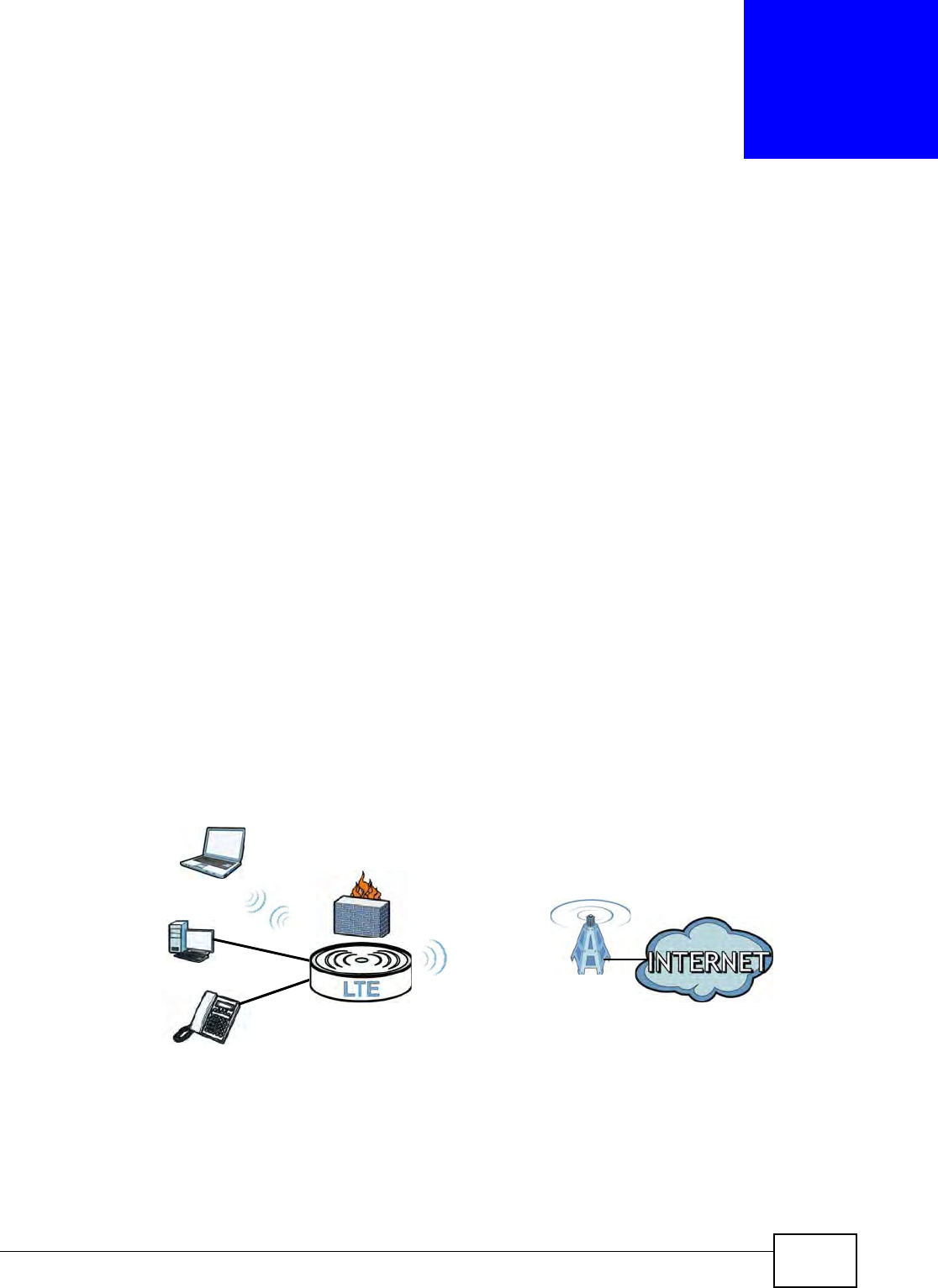
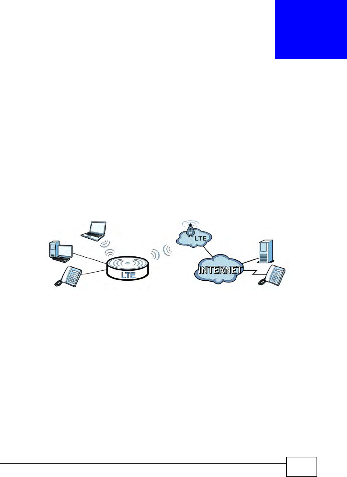
1.2.1 Internet Access
Your LTE Device provides I nternet access by connect ing t o an LTE net w ork wirelessly.
Com put ers can connect to the LTE Device’s ETH ERN ET port s (or wirelessly) .
Figure 1 LTE Device’s I nternet Access Applicat ion
LAN WAN
LTE
Chapter 1 Introduction
B222s User’s Guide
16
1.2.2 VoIP Features
You can regist er 1 SI P ( Session I nitiat ion Prot ocol) profile ( 2 account s for t hat profile) and use t he
LTE Device t o m ake and receive VoI P telephone calls:
Figure 2 LTE Device’s VoI P Application
The LTE Device sends your call t o a VoI P service provider’s SI P server which forwards your calls t o
eit her VoI P or PSTN phones.
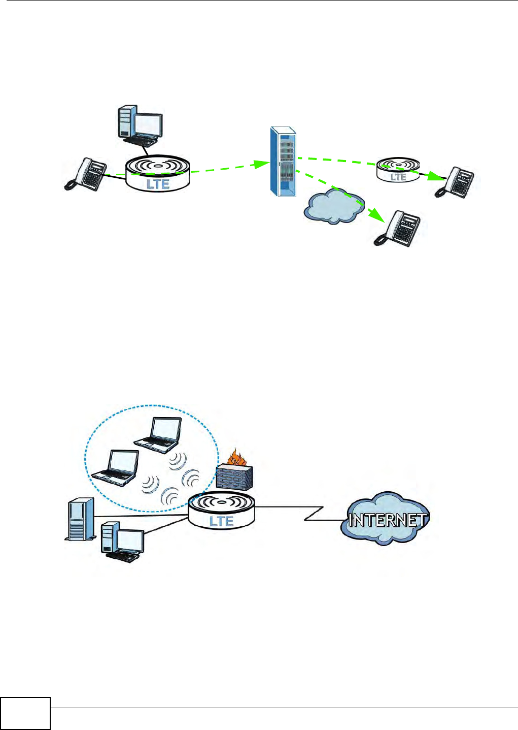
1.2.3 Wireless Connection
By default, t he wireless LAN ( WLAN) is enabled on t he LTE Device. Once Wireless is enabled, I EEE
802.11b/ g/ n com pliant client s can wirelessly connect t o t he LTE Device t o access net work
resources. You can set up a wireless network with WPS ( WiFi Protected Set up) or m anually add a
client t o your wireless net work.
Figure 3 Wireless Connection Applicat ion
1.3 The WLAN Button
You can use the WIRELESS On/Off butt on on t op of t he device t o t urn the wir eless LAN on or off. You
can also use it to activat e WPS in order t o quickly set up a wireless net work wit h strong securit y.
PSTN
LAN
WLAN
WAN

Chapter 1 Introduction
B222s User’s Guide 17
Turn the Wireless LAN On or Off
1Make sure t he PW R/ SYS LED is on ( not blinking) .
2Press t he WIRELESS On/Off but t on for one second and release it . The W LAN / W PS LED should
change from on to off or vice versa.
Activate WPS
1Make sure t he PW R/ SYS LED is on ( not blinking) .
2Press t he WIRELESS On/Off butt on for m ore than five seconds and release it . Press t he WPS but ton
on anot her WPS - enabled device wit hin range of the LTE Device. The W LAN / W PS LED should flash
while the LTE Device sets up a WPS connect ion w it h t he wireless device.
Not e: You m ust act ivat e WPS in t he LTE Device and in another wireless device within t wo
m inut es of each other. See Chapter 5 on page 62 for m ore inform at ion.
Chapter 1 Introduction
B222s User’s Guide
18
1.4 Ways to Manage the LTE Device
• Web Configurat or. This is for m anagem ent of the LTE Device using a ( support ed) web browser.
1.5 Good Habits for Managing the LTE Device
Do t he following t hings regularly t o m ake the LTE Device m ore secur e and to m anage t he LTE
Device m ore effect ively.
• Change t he password. Use a password that ’s not easy t o guess and that consist s of different
types of charact ers, such as num bers and let t ers.
• Writ e down the password and put it in a safe place.
• Back up t he configurat ion ( and m ake sur e you know how t o restore it ) . Restoring an earlier
working configurat ion m ay be useful if the device becom es unst able or even crashes. I f you
forget your password to access t he Web Configurat or, you will have t o r eset the LTE Device t o its
fact ory default set tings. I f you backed up an earlier configurat ion file, you would not have t o
tot ally re- configure t he LTE Device. You could sim ply restore your last configurat ion. Keep in
m ind t hat backing up a configurat ion file will not back up passwords used t o set up PPPoE and
VoI P. Writ e down any inform ation your I SP provides you.
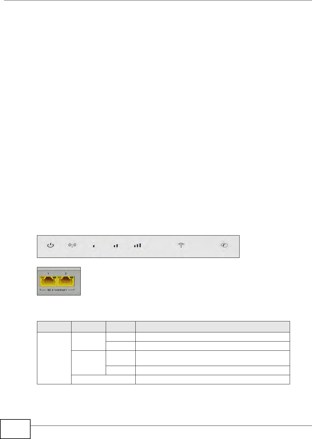
1.6 LEDs (Lights)
The following graphic displays t he labels of t he LEDs.
Figure 4 LEDs on t he Top of t he Device
Figure 5 LEDs on t he Et hernet Ports
None of the LEDs are on if the LTE Device is not receiving power.
Table 1 LED Descript ions ( From Left To Right )
LED COLOR STATUS DESCRIPTION
PWR/ SYS Green On The LTE Device is receiv ing power and ready for use.
Blinking The LTE Device is booting up.
Red On The LTE Device detected an error while self- test ing, or t here
is a device m alfunct ion.
Blinking The LTE Device is upgrading t he firm ware.
Off The LTE Device is not receiv ing power.

Chapter 1 Introduction
B222s User’s Guide 19
Refer t o t he Quick St ar t Guide for infor m ation on hardware connect ions.
LI NK Green On The LTE Dev ice has an LTE connection on the WAN.
Blinking The LTE Device is sear ching for a frequency channel or is
perform ing net work ent r y.
Off The LTE Device does not have an LTE connection on the
WAN.
LTE Th e LTE LED s d i sp la y t h e Received Signal Strengt h
I ndicat ion ( RSSI ) of t he LTE connection. Three signals on at
the sam e t im e m eans best signal quality, tw o m eans
m edium signal quality, and one m eans low signal quality.
No Signal
LEDS
There is no LTE connection.
Green Signal 1
On
The signal strengt h is less t han - 90 dBm if signal 1 is on
only.
Signal 2
On
The signal st rength is bet ween -90 dBm and -70 dBm if both
signals 1 and 2 are on.
Signal 3
On
The signal st rengt h is - 70 dBm or great er if t hree signals are
all on.
WLAN/ WPS Green On The wir eless net work is activat ed and is operat ing in I EEE
802.11 “ b”, “ g” or “ n” m ode.
Blinking The LTE Device is com m unicat ing wit h ot her w ireless client s.
Orange Blinking The LTE Device is sett ing up a WPS connect ion.
Off The wireless net wor k is not act ivat ed.
PHONE Green On A SI P account is regist ered for t he phone port .
Blinking A telephone connected t o the phone port has its receiver off
of t he hook or there is an incom ing call.
Orange On A SI P account is regist ered for t he phone port and there is a
voice m essage in t he corresponding SI P account .
Blinking A telephone connected t o the phone port has its receiver off
of t he hook and t here is a voice m essage in t he
corresponding SI P account.
Off The phone port does not have a SI P account registered.
ETHERNET1
- 2
Ye l l o w
( Giga
Et hernet )
On The LTE Device has a successful 1000 Mbps Ethernet
connect ion wit h a device on the Local Area Net work ( LAN) .
Blinking The LTE Device is sending or receiving data to/ from the LAN
at 1000 Mbps.
Green ( Fast
Et hernet )
On The LTE Device has a successful 10/ 100 Mbps Ethernet
connect ion wit h a device on the Local Area Net work ( LAN) .
Blinking The LTE Device is sending or receiving data to/ from the LAN
at 10/ 100 Mbps.
Off The LTE Device does not have an Ethernet connect ion with
the LAN.
Table 1 LED Descript ions ( From Left To Right ) ( cont inued)
LED COLOR STATUS DESCRIPTION

Chapter 1 Introduction
B222s User’s Guide
20
1.7 The RESET Button
I f you forget your passw ord or cannot access t he web configurator, you will need t o use t he RESET
but ton at t he back of the device t o reload t he factory- default configuration file. This m eans t hat you
will lose all configurations that you had previously and the passwords will be reset to t he default s.
1Make sure t he POW ER LED is on ( not blinking) .
2To set t he device back t o t he factory default sett ings, pr ess t he RESET but ton for 5 seconds or until
the POW ER LED begins t o blink and t hen release it . When t he POW ER LED begins t o blink, the
defaults have been restored and t he device restar t s.

B222s User’s Guide 21
CHAPTER 2
Introducing the Web Configurator
2.1 Overview
The web configurator is an HTML- based m anagem ent int erface t hat allows easy device set up and
m anagem ent via I nt ernet browser. Use I nt ernet Explorer 6.0 and later versions, Mozilla Firefox 3
and lat er versions, or Safari 2.0 and lat er versions. The recom m ended screen resolut ion is 1024 by
768 pixels.
I n order t o use t he web configurat or you need t o allow:
• Web browser pop- up windows from your device. Web pop- up blocking is enabled by default in
Windows XP SP (Service Pack) 2.
• JavaScript ( enabled by default ).
• Java perm issions ( enabled by default) .
See Appendix C on page 219 if you need t o m ake sure these functions are allowed in I nt ernet
Explorer.
2.1.1 Accessing the Web Configurator
1Make sure your LTE Device hardware is properly connect ed ( refer t o t he Quick St art Guide) .
2Launch your web br owser.
3Type "192.168.1.1" as t he URL.
4A password screen displays. Ty pe “ adm in” as t he default Usernam e and “1234” as t he default
passw ord to access the device’s Web Configurat or. Click Login. I f you have changed t he passwor d,
enter your password and click Login.
Figure 6 Password Screen
Note: For security reasons, t he LTE Device aut om at ically logs you out if you do not use
the web configurator for five m inutes ( default) . I f t his happens, log in again.
Chapter 2 Introducing the Web Configurator
B222s User’s Guide
22
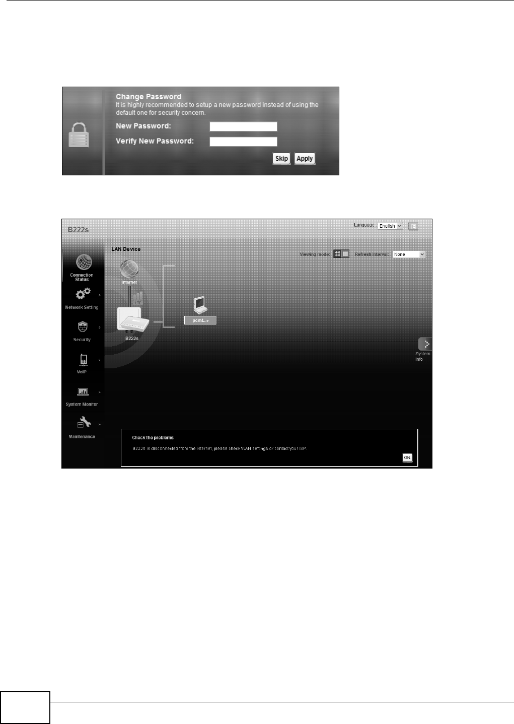
5The following screen displays if you have not yet changed your password. I t is st rongly
recom m ended you change t he default password. Ent er a new password, ret ype it t o confirm and
click Apply; alternat ively click Skip t o proceed t o t he m ain m enu if you do not want t o change the
passw ord now.
Figure 7 Change Passwor d Screen
6The Connection Sta t us screen appears.
Figure 8 Connection Stat us
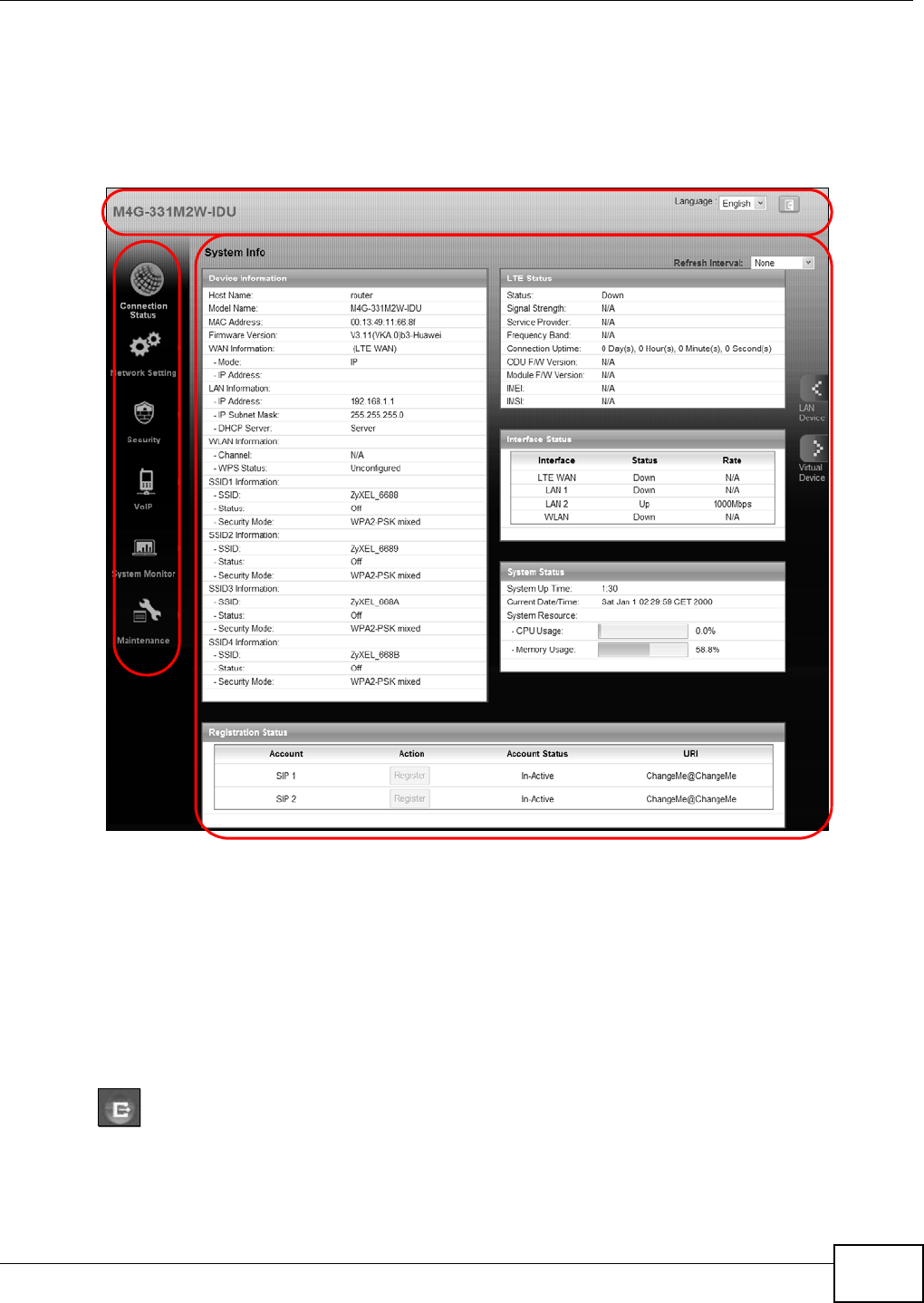
7Click Syst e m I nfo to display the Syst em I nfo screen, where you can view t he LTE Device’s
int erface and system inform at ion.
Chapter 2 Introducing the Web Configurator
B222s User’s Guide 23
2.2 The Web Configurator Layout
Click Con n e ct ion St a tus > Syst e m I nfo t o show the following screen. (See Sect ion 3.3 on page
31 for m ore inform ation.)
Figure 9 Web Configurat or Layout
As illustrat ed above, t he m ain screen is divided int o t hese parts:
•A - t it le bar
•B - m ain w indow
•C - navigat ion panel
2.2.1 Title Bar
The tit le bar shows t he following icon in t he upper right corner.
Click t his icon to log out of t he web configurat or.
B
C
A
a
b
Chapter 2 Introducing the Web Configurator
B222s User’s Guide
24
2.2.2 Main Window
The m ain window displays inform ation and configurat ion fields. I t is discussed in t he rest of this
docum ent .
Aft er you click System I nfo on the Connect ion St at us screen, t he Syst e m I nfo screen is
displayed. See Chapt er 3 on page 31 for m ore inform at ion about t he Syst em I nfo screen.
I f you click LAN Device on t he Syst em I nfo screen ( a in Figure 9 on page 23) , the Conn ect ion
St a tu s screen appears. See Chapt er 3 on page 29 for m ore inform ation about t he Connection
St a t u s screen.
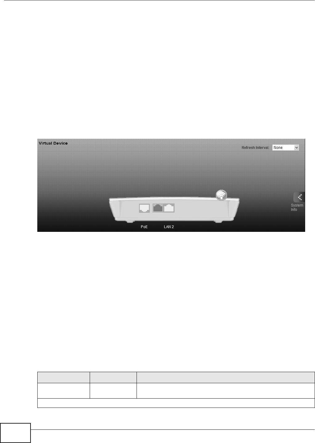
I f you click Virt ua l D e vice on t he Syst e m I n fo screen ( b in Figure 9 on page 23), a visual graphic
appears, showing t he connect ion st at us of t he LTE Device’s ports. The connected port s are in color
and disconnect ed port s are gray.
Figure 10 Virt ual Device
2.2.3 Traffic Status
Use t he M a int e n a nce > Tr a ffic St at us screens t o look at net w ork t raffic st atus and stat ist ics of
the WAN, LAN int erfaces and NAT. See Chapter 20 on page 159 for m ore infor m ation.
2.2.4 User Account
Use t he M a int e n a nce > User Accou nt s screen t o configure system passw ord for different user
account s. See Chapt er 18 on page 155 for m ore inform ation.
2.2.5 Navigation Panel
Use t he m enu item s on the navigat ion panel to open screens t o configure LTE Device feat ures. The
following t able describes each m enu item .
Table 2 Navigat ion Panel Sum m ary
LINK TAB FUNCTION
Connection St at us This screen shows t he net work stat us of the LTE Device and
com put ers/ dev ices connected t o it.
Net work Set t ing

Chapter 2 Introducing the Web Configurator
B222s User’s Guide 25
Broadband Broadband Use t his screen t o view and m odify your WAN interface. You can also
configur e I SP param et ers, WAN I P address assignm ent , DNS servers
and other advanced properties.
Wireless General Use t his screen to t urn t he wir eless connect ion on or off, specify the
SSI D(s) and configure t he wireless LAN sett ings and WLAN
aut hent icat ion/ securit y set tings.
More AP Use t his screen t o configure m ult iple BSSs on t he LTE Device.
WPS Use t his screen to use WPS ( Wi- Fi Prot ect ed Setup) to establish a
wireless connection.
WMM Use t his screen to enable or disable Wi- Fi Mult iMedia ( WMM) .
Scheduling Use t his screen t o configure when t he LTE Device enables or disables
the wireless LAN.
Hom e
Net working
LAN Setup Use t his screen t o configure LAN TCP/ I P sett ings, and ot her advanced
propert ies.
St at ic DHCP Use t his screen t o assign specific I P addresses t o individual MAC
addresses.
UPnP Use t his screen t o enable the UPnP function.
St at ic Route St at ic Rout e Use t his screen t o view and set up st at ic rout es on t he LTE Device.
DNS Rou t e DNS Rout e Use this screen t o view and configure DNS r outes.
QoS General Use t his screen t o enable QoS and decide allowable bandwidt h using
QoS.
Queue Set up Use t his screen t o configure QoS queue assignm ent .
Class Set up Use t his screen to set up classifiers t o sort t raffic int o different flows
and assign priorit y and define act ions t o be perform ed for a classified
traffic flow.
Monitor Use this screen to view each queue’s stat ist ics.
NAT Port Forwarding Use t his screen t o m ake your local servers visible to t he out side
world.
DMZ Use t his screen to configure t he I P address of t he LTE Device’s DMZ
interface.
Sessions Use t his screen to lim it t he num ber of NAT sessions a single client can
est ablish.
Dynam ic DNS Dynam ic DNS Use t his screen t o allow a stat ic host nam e alias for a dy nam ic I P
address.
Security
Firewall General Use t his screen to act ivate/ deact ivate the firewall.
Services Use t his screen to view and configure services.
Access Cont rol Use t his screen to view and configure filt er rules for incom ing and
outgoing traffic.
DoS Use this screen to act ivate/ deactivat e Denial of Service ( DoS)
prot ection.
MAC Filt er MAC Filt er Use t his screen t o allow specific dev ices t o access the LTE Device.
Par ent al
Cont rol
Parental Cont rol Use t his screen t o define t im e periods and days during which t he LTE
Device perform s parent al cont rol and/ or block web sites with the
specific URL.
VoI P
Table 2 Navigat ion Panel Sum m ary ( cont inued)
LINK TAB FUNCTION

Chapter 2 Introducing the Web Configurator
B222s User’s Guide
26
SI P SI P Ser vice
Provider
Use t his screen t o configure your LTE Device’s Voice over I P set t ings.
SI P Account Use t his screen t o set up inform at ion about your SI P account and
configur e audio sett ings such as volum e levels for t he phones
connected t o the LTE Device.
Phone Phone Dev ice Use t his screen t o set which phone port s use which SI P account s.
Region Use t his screen to select your location.
Call Rule Speed Dial Use t his screen t o configur e speed dial for SI P phone num bers t hat
you call oft en.
System Monit or
Log Sy st em Log Use t his screen t o view t he syst em logs for t he cat egories that you
select .
Phone Log Use t his screen to view t he LTE Device’s phone logs.
VoI P Call Hi st or y Use t his screen to view t he LTE Device’s VoI P call hist ory.
Traffic St at us WAN Use t his scr een t o v iew t he st at us of all net w or k t raffic going t hr ough
the WAN port of t he LTE Device.
LAN Use t h is scr een t o v iew t he st at us of all net w or k t raffic going t hr ough
t he LAN port s of t he LTE Device.
NAT Use this screen t o view t he st at us of NAT sessions on t he LTE Device.
Vo I P St at u s VoI P St at u s Use t his screen t o view t he SI P, phone, and call stat us of t he LTE
Device.
Maint enance
User s Account Users Account Use t his screen t o configure t he passwords your user account s.
Rem ot e MGMT Rem ot e MGMT Use t his screen t o enable specific t raffic dir ect ions for net work
services.
Sy st em Sy st em Use t his screen t o configure t he LTE Device’s nam e, dom ain nam e,
m anagem ent inact ivit y tim e- out .
Tim e Set t ing Tim e Sett ing Use this screen t o change your LTE Device’s t im e and dat e.
Log Set t ing Log Set t ing Use t his screen to select which logs and/ or im m ediate alert s your
device is t o record. You can also set it t o e-m ail t he logs t o you.
Firm ware
Upgrade
Firm ware
Upgrade
Use t his screen to upload firm ware t o your device.
Backup/
Rest or e
Backup/ Restore Use t his screen t o backup and r est ore your device’s configurat ion
( sett ings) or reset the fact ory default set tings.
Reboot Reboot Use t his screen to reboot the LTE Device without turning t he power
off.
Diagnostic Ping/ TraceRoute Use t his screen t o t est t he connections t o ot her devices.
Aut o Prov ision Aut o Prov ision Use t his screen to configure aut o provision w hich aut om atically
updat es t he lat est firm ware and configurat ion t o t he LTE Device.
Table 2 Navigat ion Panel Sum m ary ( cont inued)
LINK TAB FUNCTION

27
PART II
Technical Reference
The appendices pr ovide general inform ation. Som e det ails m ay not apply t o your LTE Device.

28

B222s User’s Guide 29
CHAPTER 3
Connection Status and System Info
3.1 Overview
Aft er you log int o t he web configurat or, t he Con nect ion St a tu s screen appear s. This shows the
network connect ion st at us of the LTE Device and client s connected t o it.
Use t he Syst em I nfo screen to look at t he current status of t he device, system resour ces,
int erfaces (LAN, WAN and WLAN) , and SI P account s. You can also regist er and unregist er SI P
account s.
I f you click Vir t ual D e v ice on t he Syst e m I nfo screen, a visual graphic appears, showing the
connect ion st at us of t he LTE Device’s por t s. See Sect ion 2.2.2 on page 24 for m ore inform ation.
3.2 The Connection Status Screen
Use t his screen to view t he net work connect ion st at us of t he device and it s clients. A warning
m essage appears if t here is a connect ion pr oblem .
Chapter 3 Connection Status and System Info
B222s User’s Guide
30
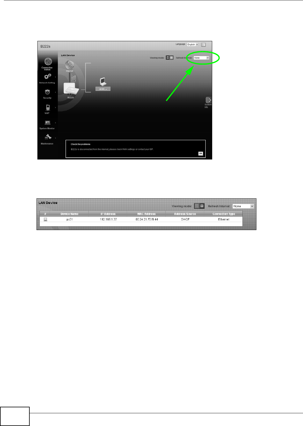
I f you prefer t o view t he status in a list , click List View in the View in g m ode select ion box. You
can configur e how often you want t he LTE Device t o update this screen in Ref re sh I nt erval.
Figure 11 Connect ion St at us: I con View
Figure 12 Connection Status: List View
I n I con Vie w , if you want t o view inform at ion about a client, click the client ’s nam e and I nfo. Click
the I P address if you want t o change it . I f you want t o change t he nam e or icon of t he client, click
Cha nge nam e / icon .
I n List Vie w , you can also view t he client ’s inform ation.
Chapter 3 Connection Status and System Info
B222s User’s Guide 31
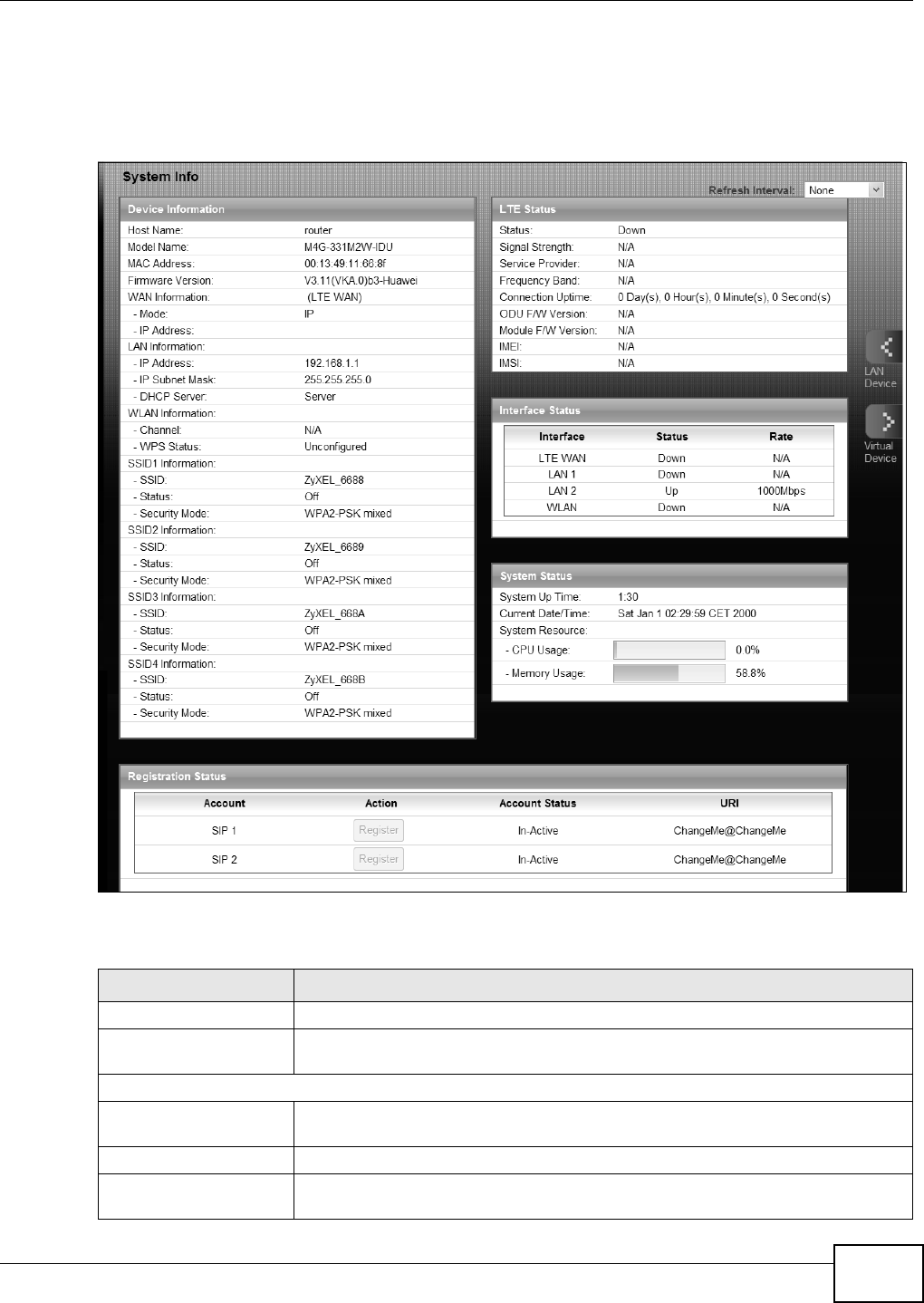
3.3 The System Info Screen
Click Con ne ct ion St a t us > Syst e m I nf o t o open t his screen.
Figure 13 System I nfo Scr een
Each field is described in t he following t able.
Table 3 System I nfo Screen
LABEL DESCRIPTION
Language Select t he web configurat or language from the drop-down list box.
Refresh I nt erval Select how oft en y ou want the LTE Device t o update this screen from t he dr op-
down list box.
Device I nform at ion
Host Nam e This field displays t he LTE Device system nam e. I t is used for ident ificat ion. You
can change this in the M aint e na nce > Syst em screen’s Host N a m e field.
Model Nam e This is t he m odel nam e of your device.
MAC Address This is t he MAC ( Media Access Contr ol) or Ethernet address unique t o your LTE
Device.

Chapter 3 Connection Status and System Info
B222s User’s Guide
32
Firm ware Version This field displays the current version of the firm ware inside t he device. I t also
shows t he date t he firm ware version was created. Go to t he Maint e na nce >
Firm w ar e Upgra de screen t o change it.
WAN I nform at ion
Mode This is t he m et hod of encapsulat ion used by your I SP.
I P Address This field displays t he current I P address of t he LTE Dev ice in the WAN.
LAN I nform at ion
I P Address This field displays t he current I P address of t he LTE Dev ice in the LAN.
I P Subnet Mask This field displays t he current subnet m ask in t he LAN.
DHCP Server This field displays what DHCP services t he LTE Device is pr oviding t o the LAN.
Choices are:
Ser ve r - The LTE Device is a DHCP server in t he LAN. I t assigns I P addresses t o
ot her com puters in t he LAN.
N on e - The LTE Device is not providing any DHCP services t o the LAN.
WLAN I nform at ion
Channel This is t he channel num ber used by t he LTE Device now.
WPS Stat us Configur ed displays when a wireless client has connect ed to t he LTE Dev ice or
WPS is enabled and wireless or wireless secur ity set t ings have been configured.
Unconfigu r ed displays if WPS is disabled or wireless securit y sett ings have not
been configur ed.
SSI D ( 1~ 4) I nform at ion
SSI D This is t he descript ive nam e used t o identify t he LTE Device in the w ireless LAN.
St at us This shows w hether or not t he SSI D is enabled ( on) .
Securit y Mode This displays t he type of securit y the LTE Device is using in t he w ireless LAN.
LTE St at u s
St at us This displays 4 G LTE if t here is an LTE connection, ot herwise, it displays N / A.
Signal Strengt h This displays t he strengt h of t he LTE connect ion t hat the LTE Device has wit h t he
base st at ion w hich is also known as eNodeB or eNB.
Service Provider This displays t he ser vice provider’s nam e of t he connect ed LTE net work.
Frequency Band This displays LTE if there is an LTE connection.
Connection Upt im e This display s how long t he LTE connection has been available since it was last
est ablished successfully.
ODU F/ W Ver sion This displays t he firm ware version of t he out door unit .
Module F/ W Ver sion This displays t he firm ware version of LTE m odule.
I MEI This displays t he LTE Device’s I nt er nat ional Mobile Equipm ent I dent it y num ber
( I MEI ). An I MEI is a unique I D used to ident ify a m obile device.
I MSI This displays the I nt ernat ional Mobile Subscriber I dent it y ( I MSI ) of t he SI M card
inserted in the out door unit . An I MSI is a unique I D used t o ident ify a m obile
subscr iber in a m obile networ k.
I nt erface St atus
I nt erface This colum n displays each interface t he LTE Device has.
Table 3 System I nfo Screen ( continued)
LABEL DESCRIPTION

Chapter 3 Connection Status and System Info
B222s User’s Guide 33
St at us This field indicat es whet her or not t he LTE Dev ice is using t he int erface.
For t he LTE WAN interface, t his field displays Up w hen t he LTE Device is con nect ed
to an LTE netw ork and Dow n when t he LTE Device does not have an LTE
con nect ion.
For t he LAN int erface, t his field displays Up w hen t he LTE Device is using t he
int erface and D ow n when t he LTE Device is not using t he int erface.
For t he WLAN int erface, it displays Up w hen WLAN is enabled or Dow n when
WLAN is disabled.
Rat e For t he LTE WAN int erface, this displays 4 G LTE if t here is an LTE connect ion.
For t he LAN int erface, t his displays t he port speed and duplex set t ing.
For t he WLAN int erface, it displays t he m axim um t ransm ission rat e when WLAN is
enabled or N / A when WLAN is disabled.
System Stat us
Syst em Up Tim e This field displays how long the LTE Device has been running since it last st art ed
up. The LTE Device start s up w hen you plug it in, when you restart it
(Ma int ena nce > Reboot) , or when you reset it (see Section 1.7 on page 20) .
Current Dat e/ Tim e This field display s t he current dat e and t im e in t he LTE Device. You can change t his
in M a int en a nce > Tim e Set t ing.
System Resource
CPU Usage This field displays what percent age of t he LTE Device’s processing abilit y is
currently used. When t his per centage is close t o 100% , the LTE Device is running
at full load, and t he t hroughput is not going to im prove any m ore. I f you want som e
applicat ions t o have m ore t hroughput , you should t urn off other applicat ions.
Mem ory Usage This field displays what percent age of t he LTE Device’s m em ory is current ly used.
Usually, this percent age should not increase m uch. I f m em or y usage does get close
to 100% , the LTE Device is pr obably becom ing unstable, and you should rest art
the device. See Chapter 24 on page 169, or t ur n off t he device (unplug t he power)
for a few seconds.
Regist r at ion Stat us
Account This colum n displays each SI P account in t he LTE Device.
Action This field displays t he current registrat ion stat us of t he SI P account . You have t o
register SI P account s wit h a SI P server t o use VoI P.
I f t he SI P account is alr eady registered with t he SI P serv er,
• Click U nr e gist e r to delet e the SI P account ’s registrat ion in t he SI P server. This
does not cancel your SI P account , but it delet es t he m apping between your SI P
ident it y and your I P addr ess or dom ain nam e.
• The second field displays Re gist e r e d.
I f t he SI P account is not registered with t he SI P serv er,
• Click Re gist e r to have the LTE Device at t em pt to regist er t he SI P account w ith
the SI P serv er.
• The second field displays t he reason the account is not registered.
I na ct iv e - The SI P account is not active. You can act ivat e it in VoI P > SI P > SI P
Se t t in gs.
Regist er Fail - The last t im e t he LTE Device tr ied t o regist er t he SI P account w it h
the SI P server, the att em pt failed. The LTE Device aut om at ically t ries t o r egist er
the SI P account when you t urn on t he LTE Device or when you act ivate it .
Table 3 System I nfo Screen ( continued)
LABEL DESCRIPTION

Chapter 3 Connection Status and System Info
B222s User’s Guide
34
Account St at us This shows Act iv e w hen t he SI P account has been registered and r eady for use or
I n- Act iv e w hen the SI P account is not yet registered.
URI This field displays t he account num ber and service dom ain of t he SI P account. You
can change these in VoI P > SI P > SI P Se t t ings.
Table 3 System I nfo Screen ( continued)
LABEL DESCRIPTION
B222s User’s Guide 35
CHAPTER 4
Broadband
4.1 Overview
This chapt er discusses t he LTE Device’s Broa dband screens. Use t hese screens t o configure your
LTE Device for I nt ernet access.
A WAN ( Wide Ar ea Networ k) connect ion is an out side connection to anot her net work or t he
I nt ernet. I t connect s your private networks, such as a LAN ( Local Area Network) and ot her
networks, so t hat a com puter in one location can com m unicat e wit h com put ers in other locat ions.
This LTE Device support s LTE connection for t he WAN only.
Figure 14 LAN and WAN
4.1.1 What You Can Do in this Chapter
• Use the Broa dband screen t o view, rem ove or add an LTE WAN int erface. You can also configure
the WAN sett ings on t he LTE Device for I nternet access ( Sect ion 4.2 on page 38) .
4.1.2 What You Need to Know
The following term s and concept s m ay help as you read this chapt er.
Encapsulation Method
Encapsulation is used t o include dat a from an upper layer prot ocol into a lower layer prot ocol. To set
up a WAN connection t o t he I nt ernet, you need to use t he sam e encapsulat ion m et hod used by your
I SP ( I nternet Service Provider) .
WAN
LAN
Chapter 4 Broadband
B222s User’s Guide
36
WAN IP Address
The WAN I P address is an I P address for the LTE Device, which m akes it accessible from an outside
network. I t is used by t he LTE Device t o com m unicat e with ot her devices in ot her networks. I t can
be stat ic ( fixed) or dynam ically assigned by t he I SP each t im e the LTE Device t ries t o access t he
I nt ernet.
I f your I SP assigns you a stat ic WAN I P address, they should also assign you t he subnet m ask and
DNS server I P address(es).
APN
Access Point Nam e ( APN) is a unique st ring which indicates an LTE net work. An APN is required for
LTE stations t o ent er t he LTE net work and t hen t he I nternet .
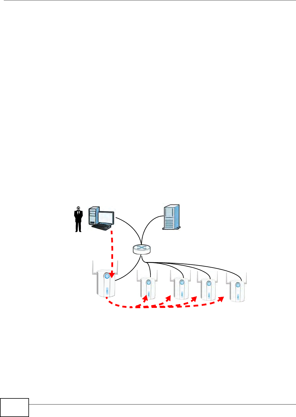
CAPWAP
The LTE Device supports CAPWAP. This is ZyXEL’s im plem ent ation of the CAPWAP prot ocol (RFC
5415) .
The CAPWAP dat aflow is protect ed by Dat agram Transport Layer Securit y (DTLS) .
The following figure illust rat es a CAPWAP wireless network. You ( U) configure t he AP cont roller ( C),
which then autom atically updat es the configurat ions of t he m anaged APs ( M1 ~ M 4 ) .
Figure 15 CAPWAP Net work Exam ple
Note: The LTE Device can be a st andalone AP ( default ), a CAPWAP m anaged AP, or a
CAPWAP AP controller.
CAPWAP Discovery and Management
The link between CAPWAP- enabled access points proceeds as follows:
1An AP in m anaged AP m ode j oins a wired net w ork ( receives a dynam ic I P address) .
U
CM1 M2 M3 M4
DHCP SERVER

Chapter 4 Broadband
B222s User’s Guide 37
2The AP sends out a discovery request , looking for an AP in CAPWAP AP cont roller m ode.
3I f t here is an AP controller on t he net work, it receives t he discovery request. I f t he AP controller is
in Ma nual m ode it adds t he details of t he AP to it s Un m a nage d Acce ss Point s list , and you
decide which available APs t o m anage. I f t he AP is in Alw a ys Acce pt m ode, it aut om at ically adds
the AP t o its M a nage d Acce ss Point s list and provides the m anaged AP wit h default configuration
inform ation, as well as securely transm itt ing the DTLS pre- shared key. The m anaged AP is ready for
association wit h wireless clients.
Managed AP Finds the Controller
A m anaged LTE Device can find t he cont roller in one of the following ways:
• Manually specify t he controller ’s I P address using t he com m ands. See t he LTE Device CLI
Reference Guide for details.
• Get the cont roller’s I P address from a DHCP server wit h t he controller ’s I P address configured as
option 138.
• Broadcast ing t o discover t he controller wit hin t he broadcast dom ain.
The AP controller m ust have a st at ic I P address; it cannot be a DHCP client .
CAPWAP and IP Subnets
By default, CAPWAP works only bet ween devices wit h I P addresses in the sam e subnet ( see the
appendices for inform at ion on I P addresses and subnet t ing) .
However, you can configure CAPWAP t o operat e between devices wit h I P addresses in different
subnet s by doing t he following.
• Activat e DHCP. Your net work’s DHCP server m ust support opt ion 138 defined in RFC 5415.
• Configure DHCP opt ion 138 wit h t he I P address of the CAPWAP AP cont roller on your network.
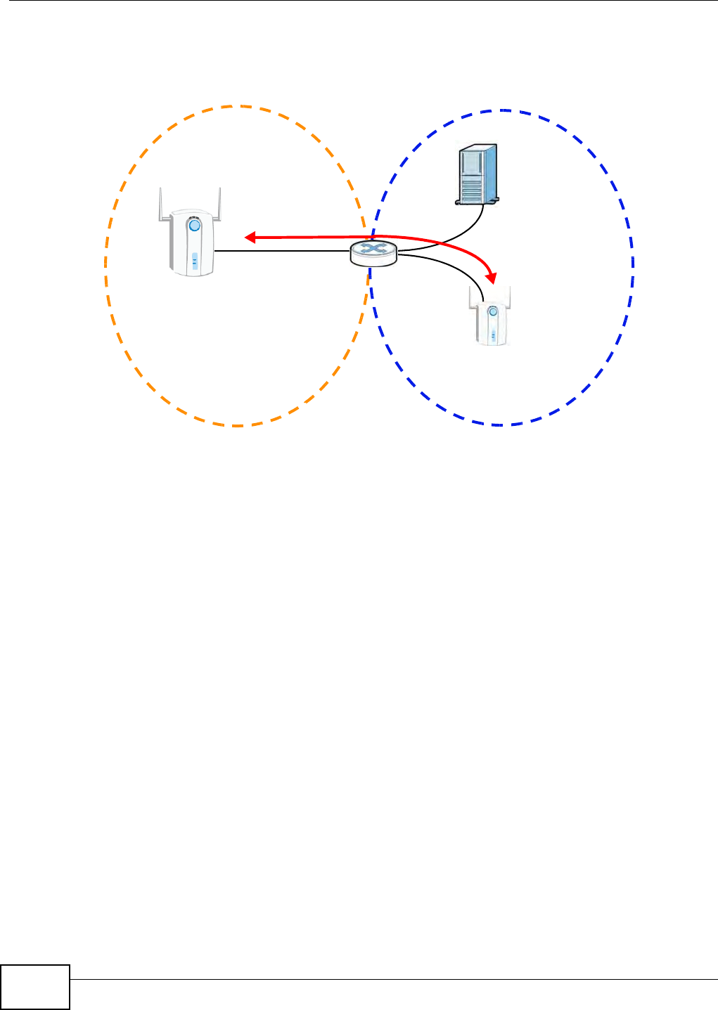
Chapter 4 Broadband
B222s User’s Guide
38
DHCP Opt ion 138 allows t he CAPWAP m anagem ent request ( from t he AP in m anaged AP m ode) to
reach t he AP controller in a different subnet , as shown in t he following figure.
Figure 16 CAPWAP and DHCP Option 138
Notes on CAPWAP
This sect ion lists som e additional feat ures of ZyXEL’s im plem ent ation of the CAPWAP prot ocol.
• When the AP cont roller uses it s int er nal Rem ote Authent icat ion Dial I n User Service ( RADI US)
server, m anaged APs also use t he AP cont roller ’s aut hent icat ion server t o aut hent icat e wireless
clients.
• I f a m anaged AP’s link t o t he AP cont roller is broken, the m anaged AP continues t o use t he
wir eless sett ings wit h which it was last provided.
4.1.3 Before You Begin
You m ay need t o know your I nt ernet access set tings such as LTE APN, WAN I P address and SI M
card’s PI N code if the I N TERN ET light on your LTE Device is off. Get this inform ation from your
service provider.
4.2 The Broadband Screen
The LTE Device m ust have a WAN int erface t o allow users t o use t he LTE connect ion to access the
I nt ernet. Use t he Br oa dba nd screen to view or m odify a WAN int erface. You can also configure t he
LTE Device as par t of a Cont rol And Provisioning of Wireless Access Points ( CAPWAP) net w ork in t his
screen.
SUBNET 1 SUBNET 2
AP
CONTROLLER
MANAGED
AP
DHCP
SERVER
+ OPTION 138
CAPWAP
TRAFFIC
(STATIC IP)
Chapter 4 Broadband
B222s User’s Guide 39
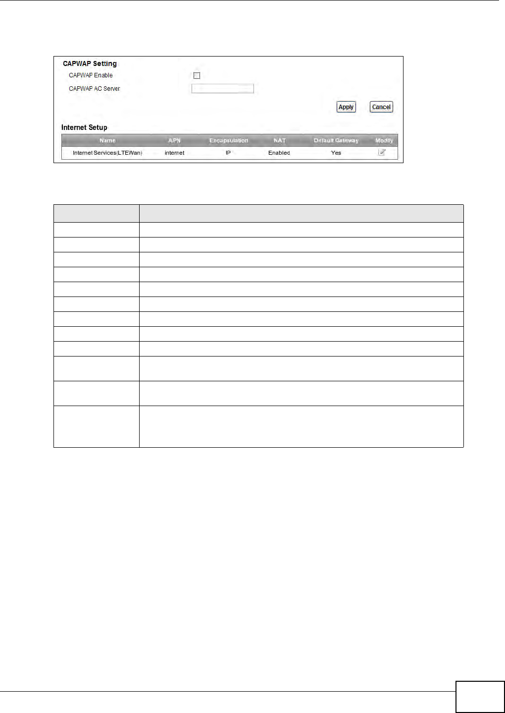
Click N et w ork Set t ing > Broadband. The following screen opens.
Figure 17 Net work Set ting > Broadband
The following t able describes t he fields in t his screen.
4.2.1 Add/Edit Internet Connection
Use t his screen to configure a WAN connect ion. The screen varies depending on the interface type,
encapsulation, and WAN service ty pe you select .
Table 4 Network Set t ing > Broadband
LABEL DESCRIPTION
CAPWAP Set t ing
CAPWAP Enable Select t his t o activat e ??
CAPWAP AC Server Enter t he I P address of t he AC server.??
Apply Click t his to save t he change in this section.
Cancel Click t his t o restore your previously saved set t ings in this sect ion.
I nter net Set up
Nam e This is t he serv ice nam e of t he connect ion.
APN This is t he nam e of t he LTE net work t o which t he LTE Device will connect.
Encapsulat ion This show s t he m et hod of encapsulation used by t his connect ion.
NAT This shows whet her NAT is act ivated or not for this connect ion. NAT is not
available when t he connect ion uses t he bridging serv ice.
Default Gat eway This show s whet her the LTE Device uses the int erface of t his connect ion as t he
system default gat eway.
Modify Click the Edit icon t o configure t he connection.
Click the D e le t e icon to delet e this connect ion from t he Device. A window
displays asking y ou t o confirm t hat you want to delete t he connection.
Chapter 4 Broadband
B222s User’s Guide
40
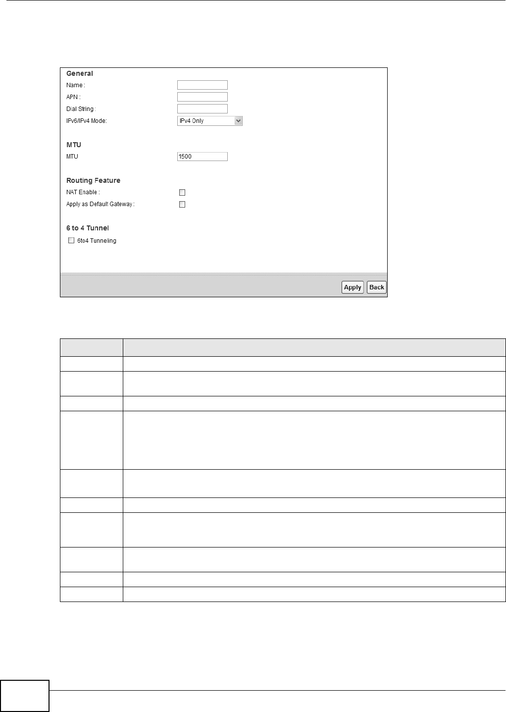
Click t he Add ne w W AN I n t erfa ce in the N et w ork Set t ing > Broadband screen or t he Edit icon
next t o t he connection you want t o configure, t he screen displays as shown next .
Figure 18 Broadband Add/ Edit
The following t able describes t he fields in t his screen.
Table 5 Broadband Add/ Edit
LABEL DESCRIPTION
Nam e Specify t he nam e for t his WAN interface.??
APN Ent er t he Access Point Nam e ( APN) of an LTE network, w hich your serv ice provider gave
you.??
Dial String Enter the dial st ring of your 3G net card.??
I Pv6/ I Pv4
Mode
Select I Pv4 On ly if you j ust connect t his WAN interface t o an I Pv4 net work.
Select I Pv6 / I Pv4 Dua l St a ck if y ou connect this WAN int erface t o bot h an I Pv 6 and an I Pv4
net works.
Select I Pv6 On ly if you j ust connect t his WAN interface to an I Pv6 net work.??
MTU The Maxim um Transm ission Unit ( MTU) defines t he size of t he largest packet allowed on an
interface or connection. Ent er t he MTU for this WAN int erface in t his field.
NAT Enable Select this t o act ivat e NAT on t he WAN.
Apply as
Default
Gateway
??
6to4
Tunneling
Select this if you need to t ransm it I Pv6 packets over t he I Pv4 net work t hrough t his WAN
interface, t he I Pv 6 packet s are encapsulat ed inside I Pv4 packet s. ??
Apply Click Apply t o save your changes.
Back Click Back t o return to t he previous screen.

Chapter 4 Broadband
B222s User’s Guide 41
4.3 Technical Reference
The following section cont ains additional technical inform ation about t he LTE Device feat ures
described in this chapt er.
Encapsulation
Be sure t o use t he encapsulation m et hod required by your I SP. The LTE Device support s t he
following m et hods:
IP Address Assignment
A static I P is a fixed I P t hat your I SP gives you. A dynam ic I P is not fixed; t he I SP assigns you a
different one each t im e. The Single User Account feature can be enabled or disabled if you have
eit her a dynam ic or stat ic I P. However the encapsulation m et hod assigned influences your choices
for I P address and default gateway.
DNS Server Address Assignment
Use Dom ain Nam e System ( DNS) t o m ap a dom ain nam e to it s corresponding I P address and vice
versa, for instance, t he I P address of ww w.zyxel.com is 204.217.0.2. The DNS server is ext rem ely
im port ant because wit hout it, you m ust know t he I P address of a com puter before you can access
it .
The LTE Device can get t he DNS server addresses in the follow ing ways.
1The I SP tells you t he DNS server addresses, usually in t he form of an inform ation sheet, when you
sign up. I f your I SP gives you DNS server addresses, m anually enter t hem in the DNS server fields.
2I f your I SP dynam ically assigns t he DNS server I P addresses ( along wit h t he LTE Device’s WAN I P
address) , set t he DNS server fields t o get t he DNS ser ver addr ess from t he I SP.
LTE Frequency Band Table
See t he following table for t he frequency bands used in LTE wireless t echnologies.
Table 6 LTE Wireless Technologies
BAND
UPLINK (UL) OPERATING BAND
BASE STATION RECEIVE
CPE TRANSMIT
DOWNLINK (DL) OPERATING BAND
BASE STATION TRANSMIT
CPE RECEIVE
DUPLEX
MODE
UL (LOW - HIGH) DL (LOW - HIGH)
1 1920 MHz – 1980 MHz 2110 MHz – 2170 MHz FDD
2 1850 MHz – 1910 MHz 1930 MHz – 1990 MHz FDD
3 1710 MHz – 1785 MHz 1805 MHz – 1880 MHz FDD
4 1710 MHz – 1755 MHz 2110 MHz – 2155 MHz FDD
5 824 MHz – 849 MHz 869 MHz – 894MHz FDD
6 830 MHz – 840 MHz 875 MHz – 885 MHz FDD
7 2500 MHz – 2570 MHz 2620 MHz – 2690 MHz FDD

Chapter 4 Broadband
B222s User’s Guide
42
8 880 MHz – 915 MHz 925 MHz – 960 MHz FDD
9 1749.9 MHz – 1784.9 MHz 1844.9 MHz – 1879.9 MHz FDD
10 1710 MHz – 1770 MHz 2110 MHz – 2170 MHz FDD
11 1427.9 MHz – 1447.9 MHz 1475.9 MHz – 1495.9 MHz FDD
12 699 MHz – 716 MHz 729 MHz – 746 MHz FDD
13 777 MHz – 787 MHz 746 MHz – 756 MHz FDD
14 788 MHz – 798 MHz 758 MHz – 768 MHz FDD
15 Reserved Reserved FDD
16 Reserved Reserved FDD
17 704 MHz – 716 MHz 734 MHz – 746 MHz FDD
18 815 MHz – 830 MHz 860 MHz – 875 MHz FDD
19 830 MHz – 845 MHz 875 MHz – 890 MHz FDD
20 832 MHz – 862 MHz 791 MHz – 821 MHz FDD
21 1447.9 MHz – 1462.9 MHz 1495.9 MHz – 1510.9 MHz FDD
...
24 1626.5 MHz – 1660.5 MHz 1525 MHz – 1559 MHz FDD
...
33 1900 MHz – 1920 MHz 1900 MHz – 1920 MHz TDD
34 2010 MHz – 2025 MHz 2010 MHz – 2025 MHz TDD
35 1850 MHz – 1910 MHz 1850 MHz – 1910 MHz TDD
36 1930 MHz – 1990 MHz 1930 MHz – 1990 MHz TDD
37 1910 MHz – 1930 MHz 1910 MHz – 1930 MHz TDD
38 2570 MHz – 2620 MHz 2570 MHz – 2620 MHz TDD
39 1880 MHz – 1920 MHz 1880 MHz – 1920 MHz TDD
40 2300 MHz – 2400 MHz 2300 MHz – 2400 MHz TDD
41 2496 MHz 2690 MHz 2496 MHz 2690 MHz TDD
42 3400 MHz – 3600 MHz 3400 MHz – 3600 MHz TDD
43 3600 MHz – 3800 MHz 3600 MHz – 3800 MHz TDD
Note 1: Band 6 is not applicable
Table 6 LTE Wireless Technologies
BAND
UPLINK (UL) OPERATING BAND
BASE STATION RECEIVE
CPE TRANSMIT
DOWNLINK (DL) OPERATING BAND
BASE STATION TRANSMIT
CPE RECEIVE
DUPLEX
MODE
UL (LOW - HIGH) DL (LOW - HIGH)

B222s User’s Guide 43
CHAPTER 5
Wireless
5.1 Overview
This chapt er describes t he LTE Device’s N e t w or k Se t ting > W ir e less screens. Use these screens
to set up your LTE Device’s wireless connect ion.
5.1.1 What You Can Do in this Chapter
• Use the Genera l screen to enable t he Wireless LAN, ent er t he SSI D and select t he wireless
securit y m ode ( Sect ion 5.2 on page 45) .
• Use the M or e AP scr een t o set u p m ult iple w ir eless net w or ks on your LTE Dev ice ( Sect ion 5.3 on
page 51) .
• Use the W PS screen to enable or disable WPS, view or generat e a security PI N ( Personal
I dent ificat ion Num ber) ( Sect ion 5.4 on page 53) .
• Use the W MM screen to enable Wi- Fi MultiMedia ( WMM) t o ensure quality of service in wireless
networks for m ult im edia applications (Sect ion 5.5 on page 55) .
• Use the Sche duling screen to schedule a tim e period for t he wireless LAN t o operate each day
(Section 5.6 on page 57) .
You don’t necessarily need t o use all t hese screens t o set up your wireless connect ion. For exam ple,
you m ay just want t o set up a net w ork nam e, a wireless radio channel and som e securit y in the
Gen e ra l screen.
5.1.2 Wireless Network Overview
Wireless networks consist of wireless client s, access point s and bridges.
• A wireless client is a radio connected t o a user’s com put er.
• An access point is a radio with a wir ed connection t o a net work, which can connect with
num erous wireless clients and let t hem access t he network.
• A bridge is a radio t hat relays com m unicat ions bet ween access point s and wireless clients,
ext ending a networ k’s range.
Traditionally, a wireless net work operat es in one of two ways.
• An “ infrastructure” t ype of net work has one or m ore access point s and one or m ore wireless
clients. The w ireless client s connect t o the access point s.
• An “ ad- hoc” t ype of net work is one in which t here is no access point . Wireless client s connect t o
one anot her in order to exchange inform ation.
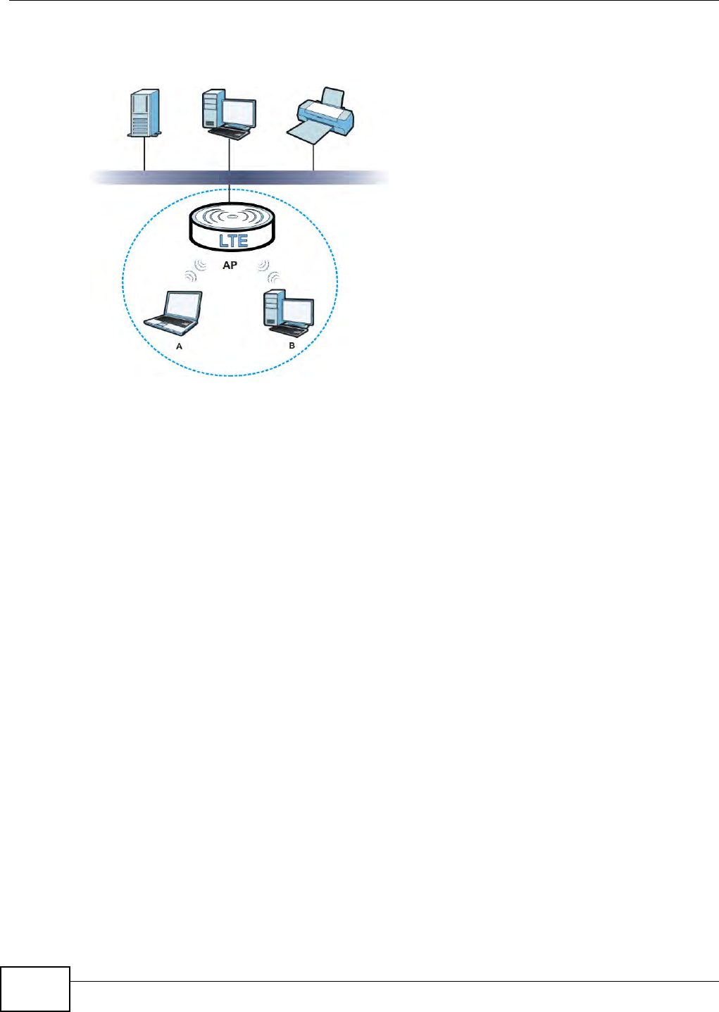
Chapter 5 Wireless
B222s User’s Guide
44
The following figure provides an exam ple of a wireless net work.
Figure 19 Exam ple of a Wireless Networ k
The wireless net work is the part in the blue circle. I n this wir eless net w ork, devices A and B use t he
access point ( AP) t o int eract wit h t he ot her devices ( such as t he printer) or with the I nt ernet . Your
LTE D ev i c e i s t h e AP.
Every wireless net work m ust follow these basic guidelines.
• Every device in t he sam e wireless network m ust use t he sam e SSI D.
The SSI D is t he nam e of t he wireless net work. I t st ands for Service Set I Dent ifier.
• I f t wo wireless net works overlap, they should use a different channel.
Like radio stat ions or television channels, each wireless net work uses a specific channel, or
frequency, t o send and receive inform at ion.
• Every device in t he sam e wireless network m ust use security com pat ible w it h t he AP.
• Securit y st ops unaut horized devices from using t he wireless net work. I t can also prot ect the
inform ation that is sent in t he wireless net work.
Radio Channels
I n t he radio spectrum , t here are cert ain frequency bands allocated for unlicensed, civilian use. For
the pur poses of wireless networking, t hese bands ar e divided int o num erous channels. This allows a
variet y of networ ks to exist in t he sam e place wit hout interfering wit h one anot her. When you
creat e a net work, you m ust select a channel to use.
Since the available unlicensed spectrum varies fr om one count ry t o anot her, the num ber of
available channels also var ies.
A channel is t he radio frequency( ies) used by wir eless devices t o t ransm it and receive data.
Channels available depend on your geographical area. You m ay have a choice of channels ( for your
region) so you should use a channel different from an adjacent AP ( access point ) t o reduce

Chapter 5 Wireless
B222s User’s Guide 45
int erference. I nt erference occurs when radio signals from different access point s overlap causing
int erference and degrading perform ance.
Adj acent channels part ially overlap however. To avoid interference due to overlap, your AP should
be on a channel at least five channels away from a channel t hat an adj acent AP is using. For
exam ple, if your region has 11 channels and an adj acent AP is using channel 1, t hen you need t o
select a channel bet ween 6 or 11.
5.1.3 Before You Begin
Before you start using t hese screens, ask yourself t he following quest ions. See Section 5.7 on page
57 if som e of t he t erm s used here do not m ake sense to you.
• What wireless st andards do the ot her wireless devices support ( I EEE 802.11g, for exam ple)?
What is t he m ost appropriat e standard to use?
• What security options do t he ot her wireless devices support ( WPA-PSK, for exam ple) ? What is
the best one t o use?
• Do t he ot her wireless devices support WPS ( Wi-Fi Prot ected Set up) ? I f so, you can set up a well-
secured network very easily.
Even if som e of your devices support WPS and som e do not , you can use WPS t o set up your
network and t hen add t he non-WPS devices m anually, although this is som ewhat m ore
com plicated to do.
• What advanced opt ions do you want t o configure, if any? I f you want t o configure advanced
options, ensure t hat you know precisely what you want t o do. I f you do not want t o configure
advanced opt ions, leave them alone.
5.2 The Wireless General Screen
Use t his screen to enable t he Wireless LAN, ent er the SSI D and select the wireless securit y m ode.
Not e: I f you are configur ing t he LTE Device from a com put er connect ed to t he wireless
LAN and you change t he LTE Device’s SSI D or security sett ings, you will lose your
wireless connection when you press Apply to confirm . You m ust then change t he
wireless set tings of your com put er t o m at ch t he LTE Device’s new sett ings.

Chapter 5 Wireless
B222s User’s Guide
46
Click N e t w or k Set ting > W ir e less t o open t he Gen e r a l screen. Select t he Enable W ir e less LAN
checkbox t o show t he Wir eless configurations.
Figure 20 Net work Set ting > Wireless > General
The following t able describes t he labels in t his screen.
Table 7 Network > Wireless LAN > General
LABEL DESCRIPTION
Wireless Net work Set up
Wireless Select t he Enable W ir eless LAN check box to activat e the wireless LAN.
Wireless Net work Sett ings
Wireless
Net work Nam e
( SSI D)
The SSI D ( Service Set I Dentit y) ident ifies the ser vice set w ith which a wireless
device is associated. Wireless devices associat ing t o t he access point ( AP) m ust
have the sam e SSI D.
Enter a descript ive nam e ( up to 32 English keyboard charact ers) for the wireless
LAN.
Hide SSI D Select this check box t o hide t he SSI D in t he out going beacon fram e so a st at ion
cannot obt ain t he SSI D t hrough scanning using a site survey t ool.
BSSI D This show s t he MAC address of t he w ireless int erface on t he LTE Device when
wireless LAN is enabled.
Mode Select This m akes sure t hat only com pliant WLAN devices can associat e wit h t he LTE
Device.
Select 8 0 2 .1 1 b/ g/ n to allow I EEE802.11b, I EEE802.11g and I EEE802.11n
com pliant WLAN dev ices t o associat e wit h the LTE Device. The transm ission rat e of
your LTE Device m ight be r educed.
Select 8 0 2 .1 1 b/ g t o allow bot h I EEE802.11b and I EEE802.11g com pliant WLAN
devices t o associate with the LTE Device. The t ransm ission rate of your LTE Device
m ight be reduced.
Select 8 0 2 .1 1 g On ly to allow only I EEE 802.11g com pliant WLAN devices t o
associat e wit h the LTE Device. Select 8 0 2 .1 1 n only in 2 .4 G band to allow only
I EEE 802.11n com pliant WLAN devices wit h the sam e frequency range ( 2.4 GHz) t o
associat e wit h the LTE Device.
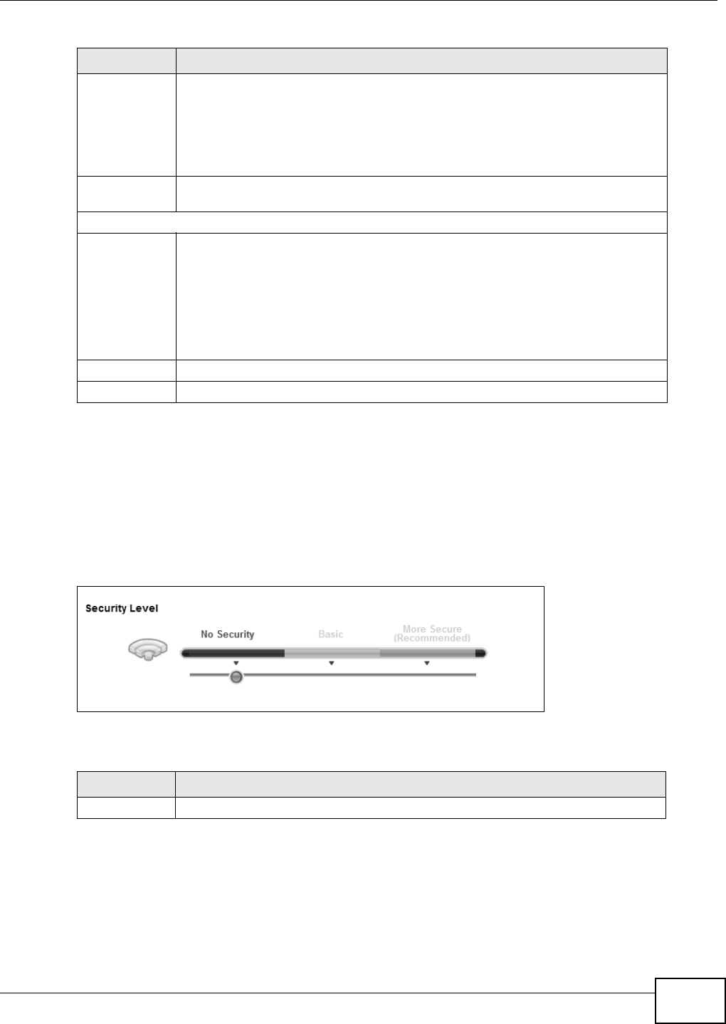
Chapter 5 Wireless
B222s User’s Guide 47
5.2.1 No Security
Select N o Secur it y to allow wireless st ations to com municate with the access points wit hout any
dat a encrypt ion or aut hent icat ion.
Not e: I f you do not enable any wireless securit y on your LTE Device, your net wor k is
accessible to any wireless net working device that is within range.
Figure 21 Wireless > General: No Securit y
The following t able describes t he labels in t his screen.
5.2.2 Basic (Static WEP/Shared WEP Encryption)
WEP encrypt ion scram bles t he data t ransm itted bet ween the wireless stations and the access points
( AP) t o keep network com munications privat e. Bot h t he wireless stat ions and the access point s
m ust use t he sam e WEP key.
Channel
Selection
Set t he channel depending on your part icular region.
Select a channel or use Au t o to have t he LTE Device aut om atically det erm ine a
channel t o use. I f you are having problem s wit h wireless int erference, changing t he
channel m ay help. Try t o use a channel that is as m any channels away from any
channels used by neighboring APs as possible. The channel num ber which t he LTE
Device is currently using t hen displays in the Ope ra t ing Chan ne l field.
Operating
Channel
This is t he channel current ly being used by your AP.
Securit y Level
Securit y Mode Select Ba sic or M or e Secure t o add securit y on this wireless networ k. The w ireless
client s which want to associate t o t his net work m ust have sam e wireless security
sett ings as t he LTE Device. When you select t o use a security, additional opt ions
appear s in t his screen.
Or you can select N o Secur it y to allow any client t o associate t his netw ork wit hout
any dat a encrypt ion or aut hent ication.
See t he following sections for m ore details about wireless securit y m odes.
Apply Click Apply to save your changes back t o t he LTE Device.
Cancel Click Can cel t o rest ore your previously saved set t ings.
Table 7 Network > Wireless LAN > General ( cont inued)
LABEL DESCRIPTION
Table 8 Wireless > General: No Securit y
LABEL DESCRIPTION
Securit y Level Choose N o Secur it y from t he sliding bar.
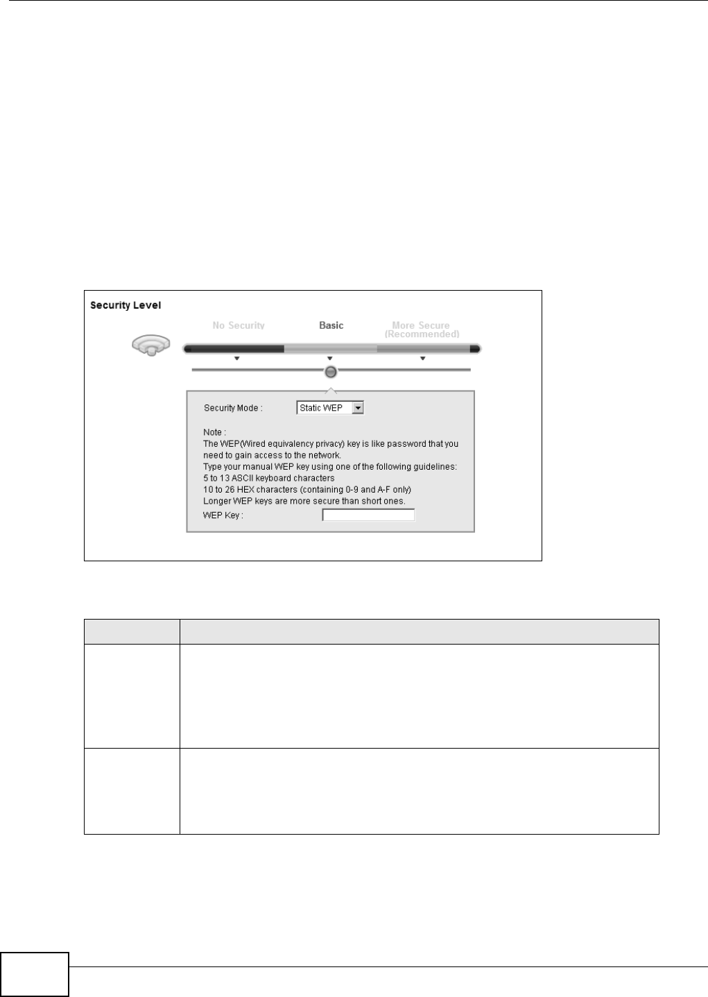
Chapter 5 Wireless
B222s User’s Guide
48
There are two t ypes of WEP aut hent icat ion nam ely, Open System (St a tic W EP) and Shared Key
(Sha red W EP) .
Open system is im plem ent ed for ease- of- use and when securit y is not an issue. The wireless st ation
and t he AP or peer com put er do not share a secret key. Thus the wireless stat ions can associate
wit h any AP or peer com puter and listen t o any transm it t ed data t hat is not encrypt ed.
Shared key m ode involves a shared secret key t o aut hent icat e t he wireless st ation t o t he AP or peer
com puter. This r equires you t o enable t he wireless LAN securit y and use sam e sett ings on both the
wir eless stat ion and t he AP or peer com put er.
I n order t o configure and enable WEP encrypt ion, click N et w or k Set tings > W ire less t o display
the Gene ra l screen. Select Basic as t he security level. Then select St a tic W EP or Shar e d W EP
from the Se cu r it y Mode list .
Figure 22 Wireless > General: Basic ( Static WEP/ Shared WEP)
The following t able describes t he labels in t his screen.
Table 9 Wireless > General: Basic (St at ic WEP/ Shared WEP)
LABEL DESCRIPTION
Securit y Mode Choose St a t ic W EP or Sha r ed W EP from the drop-down list box.
• Select St at ic W EP t o have t he LTE Device allow association w it h w ireless client s
that use Open System m ode. Data t ransfer is encrypt ed as long as t he wireless
client has the correct WEP key for encrypt ion. The LTE Dev ice aut hent icat es
wireless client s using Shared Key m ode t hat have t he correct WEP key.
• Select Sha re d W EP to have t he LTE Device authent icat e only those w ireless
client s t hat use Shared Key m ode and have the correct WEP key.
WEP Key Enter a WEP key t hat will be used t o encrypt dat a. Both the LTE Device and t he
wireless stat ions m ust use t he sam e WEP key for data t ransm ission.
I f you want to m anually set t he WEP key, ent er any 5 or 13 charact ers ( ASCI I
st ring) or 10 or 26 hexadecim al charact ers ( "0- 9", "A- F") for a 64- bit or 128- bit
WEP key r espect ively.
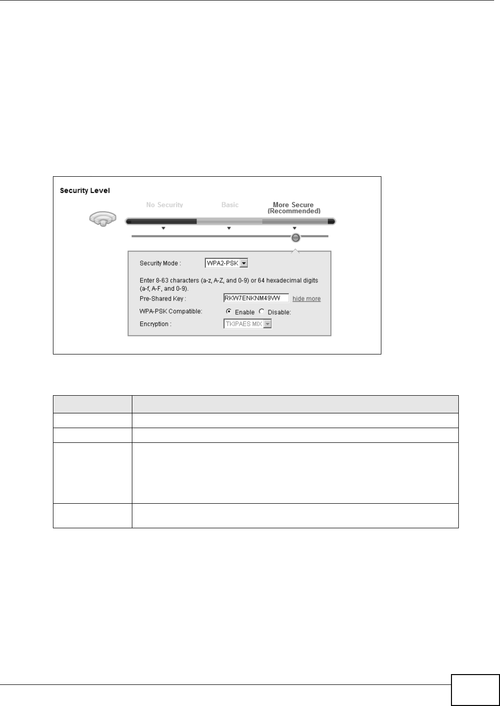
Chapter 5 Wireless
B222s User’s Guide 49
5.2.3 More Secure (WPA(2)-PSK)
The WPA- PSK security m ode provides bot h im pr oved data encrypt ion and user aut hent icat ion over
WEP. Using a Pre- Shared Key ( PSK) , both t he LTE Device and t he connect ing client share a com m on
passw ord in order t o validate t he connect ion. This t ype of encrypt ion, while robust, is not as st r ong
as WPA, WPA2 or ev en WPA2 - PSK. Th e WPA2 - PSK secu r it y m ode is a n ew er, m or e r obu st v er sion of
the WPA encrypt ion st andard. I t offers slight ly bett er securit y, although t he use of PSK m akes it
less robust than it could be.
Click N et w ork Set t ings > W ir e less t o display t he General screen. Select M or e Secur e as the
securit y level. Then select W PA- PSK or W PA2 - PSK from the Securit y Mode list .
Figure 23 Wireless > General: More Secure: WPA(2) - PSK
The following t able describes t he labels in t his screen.
Table 10 Wireless > General: WPA(2) - PSK
LABEL DESCRIPTION
Securit y Level Select M ore Se cur e t o enable WPA( 2) - PSK data encryption.
Securit y Mode Select W PA- PSK or W PA2 - PSK from t he drop- down list box.
Pre- Shared Key The encryption m echanism s used for W PA/ W PA2 and W PA- PSK/ W PA2 - PSK
are t he sam e. The only difference between the tw o is t hat W PA- PSK/ W PA2 -
PSK uses a sim ple com m on password, instead of user-specific cr edent ials.
Type a pre- shared key from 8 t o 63 case-sensit ive ASCI I charact ers or 64
hexidecim al digit s.
m ore.../ hide
m ore
Click m ore ... t o show m ore fields in t his sect ion. Click hide m or e t o hide t hem .
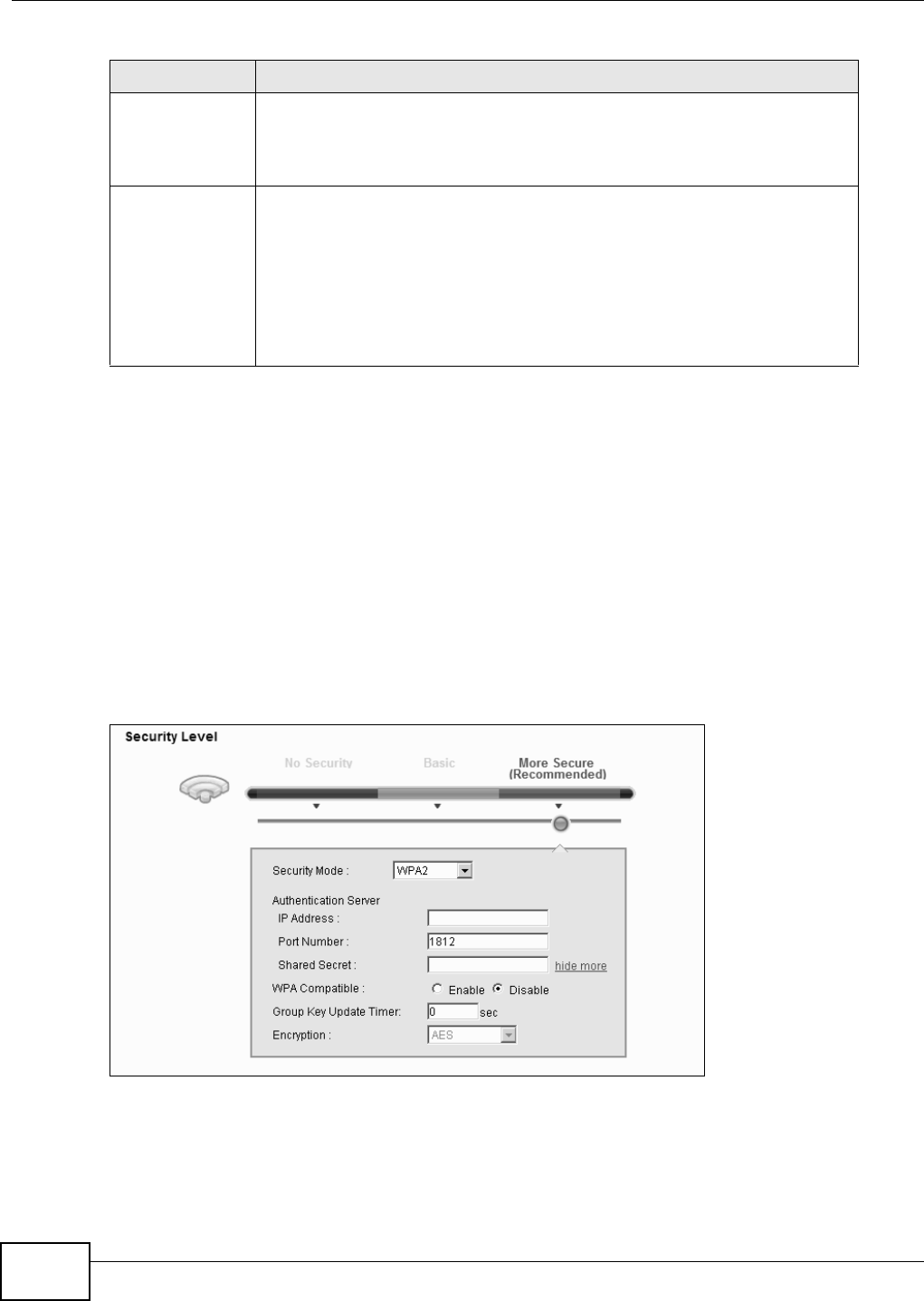
Chapter 5 Wireless
B222s User’s Guide
50
5.2.4 WPA(2) Authentication
The WPA2 securit y m ode is current ly t he m ost robust form of encrypt ion for wireless networks. I t
requires a RADI US server t o authenticate user credent ials and is a full im plem ent at ion the securit y
prot ocol. Use t his secur it y option for m axim um prot ection of your network. However, it is t he least
backwards com pat ible wit h older devices.
The WPA securit y m ode is a securit y subset of WPA2. I t requires the presence of a RADI US server
on your network in order t o validate user credentials. This encrypt ion standar d is slight ly older t han
WPA2 and t herefor e is m ore com pat ible wit h older devices.
Click N et w ork Set t ings > W ir e less t o display t he General screen. Select M or e Secur e as the
securit y level. Then select W PA or W PA2 from t he Se curit y Mode list.
Figure 24 Wireless > General: More Secure: WPA(2)
WPA-PSK
Com pat ible
This field appear s when you choose W PA- PSK2 as the Securit y M ode.
Check t his field t o allow wireless devices using W PA- PSK secur ity m ode t o
connect t o your LTE Device. The LTE Device support s WPA- PSK and WPA2- PSK
sim ult aneou sly.
Encrypt ion I f t he securit y m ode is W PA- PSK, t he encrypt ion m ode is set to TKI P t o enable
Tem poral Key I nt egrity Pr ot ocol ( TKI P) secur ity on your w ireless netw ork.
I f t he security m ode is W PA- PSK2 and W PA- PSK Com pa t ible is disabled, the
encryption m ode is set to AES to enable Advanced Encrypt ion System ( AES)
securit y on your wireless net work. AES provides superior securit y t o TKI P.
I f t he security m ode is W PA- PSK2 and W PA- PSK Com pa t ible is enabled, the
encryption m ode is set t o TKI PAES MI X t o allow bot h TKI P and AES types of
securit y in your wireless net work.
Table 10 Wireless > General: WPA(2) -PSK ( cont inued)
LABEL DESCRIPTION

Chapter 5 Wireless
B222s User’s Guide 51
The following t able describes t he labels in t his screen.
5.3 The More AP Screen
The LTE Device can broadcast up to four wireless net w ork nam es at t he sam e t im e. This m eans t hat
users can connect t o t he LTE Device using different SSI Ds. You can secure t he connection on each
SSI D pr ofile so t hat wireless client s connecting t o t he LTE Device using different SSI Ds cannot
com municate with each ot her.
This screen allows you t o enable and configure m ult iple Basic Service Sets ( BSSs) on t he LTE
Device.
Click N et w or k Set t ings > W ireless > M or e AP. The following screen displays.
Figure 25 Net work Set tings > Wireless > More AP
Table 11 Wireless > General: More Secure: WPA( 2)
LABEL DESCRIPTION
Securit y Level Select M ore Secur e t o enable WPA( 2) - PSK data encryption.
Securit y Mode Choose W PA or W PA2 from t he drop- down list box .
Aut hent icat ion Serv er
I P Address Ent er the I P address of t he ext ernal aut hent icat ion server in dott ed decim al
not at ion.
Port Nu m ber Ent er t he port num ber of the ext ernal aut hent icat ion server. The default port
num ber is 1 8 1 2 .
You need not change t his value unless your network adm inist rat or inst ructs you
to do so w ith addit ional inform at ion.
Shared Secret Enter a password ( up t o 128 alphanum eric charact ers) as t he key t o be shared
bet ween t he ext ernal aut hent icat ion serv er and t he LTE Device.
The key m ust be t he sam e on t he ext ernal authentication server and your LTE
Device. The key is not sent over t he net work.
m ore.../ hide m ore Click m or e ... t o show m or e fields in t his section. Click hide m ore to hide
t hem .
WPA Com pat ible This field is only available for WPA2. Select this if you want t he LTE Device to
support WPA and WPA2 sim ult aneously.
Group Key Update
Tim er
The Gr oup Key Upda t e Tim er is the rate at which the RADI US server sends a
new group key out t o all client s.
I f t he value is set t o “ 0”, the update t im er function is disabled.
Encrypt ion I f t he security m ode is W PA, the encrypt ion m ode is set t o TKI P t o enable
Tem poral Key I ntegrit y Prot ocol ( TKI P) securit y on your wireless netw ork.
I f t he security m ode is W PA2 , t he encryption m ode is set t o AES to enable
Advanced Encrypt ion System ( AES) securit y on your wireless net work . AES
provides superior securit y to TKI P.
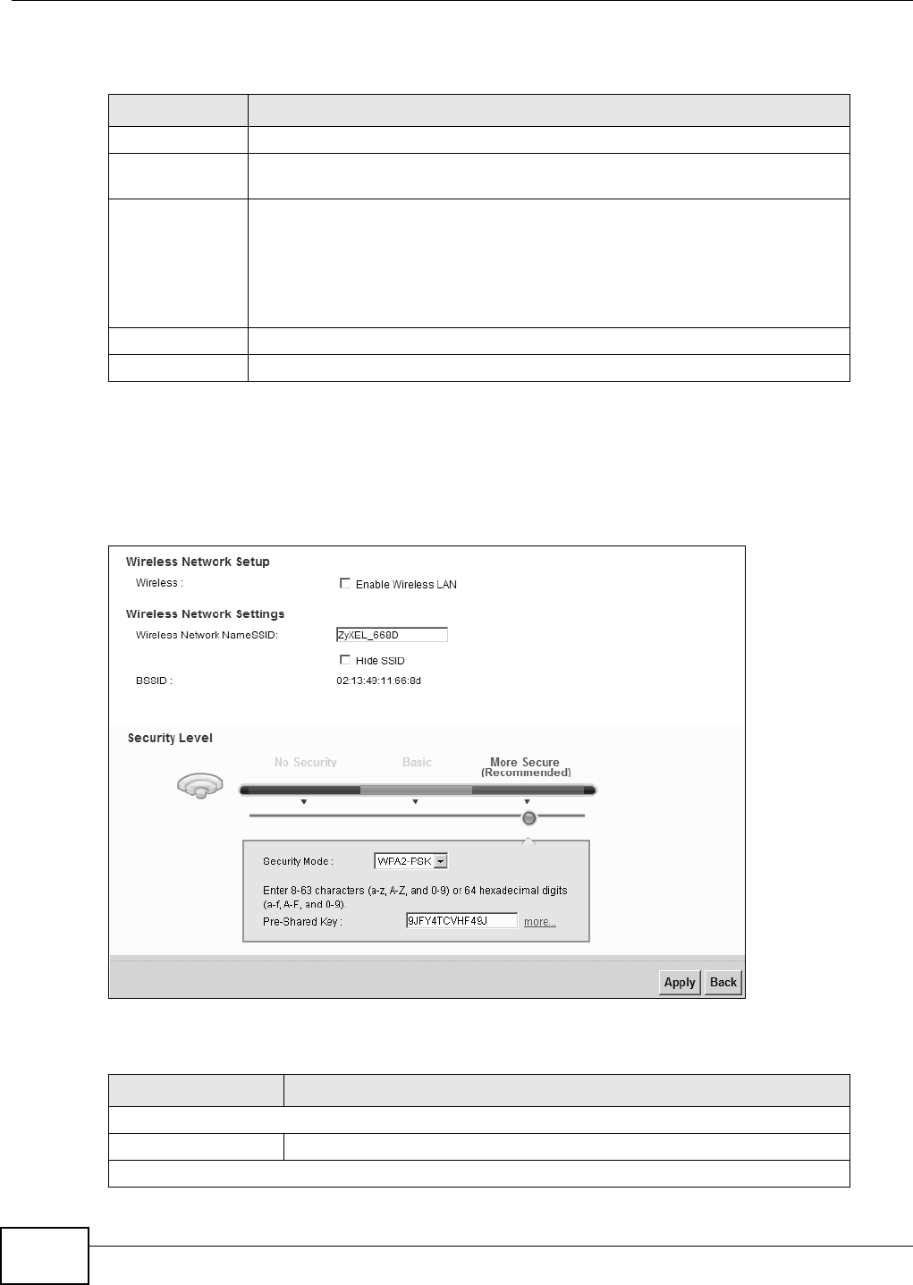
Chapter 5 Wireless
B222s User’s Guide
52
The following t able describes t he labels in t his screen.
5.3.1 Edit More AP
Use t his screen to edit an SSI D profile. Click the Ed it icon next t o an SSI D in t he M or e AP screen.
The following screen displays.
Figure 26 Wireless > More AP: Edit
The following t able describes t he fields in t his screen.
Table 12 Network Sett ings > Wireless > More AP
LABEL DESCRIPTION
# This is t he index num ber of the ent ry.
Act ive This field indicat es whet her this SSI D is act ive. A yellow bulb signifies t hat t his
SSI D is active. A gray bulb signifies t hat t his SSI D is not act ive.
SSI D An SSI D profile is t h e set of param et er s relating t o one of t he LTE Device’s BSSs.
The SSI D ( Service Set I Dent ifier) ident ifies t he Service Set wit h w hich a w ireless
device is associat ed.
This field displays t he nam e of t he wireless pr ofile on t he net work . When a
wireless client scans for an AP t o associat e w ith, this is t he nam e t hat is broadcast
and seen in t he wireless client utility.
Secur it y This field indicat es t he securit y m ode of t he SSI D profile.
Modify Click the Edit icon t o configure t he SSI D profile.
Table 13 Wireless > More AP: Edit
LABEL DESCRIPTION
Wireless Net work Set up
Wireless Select t he Enable W ireless LAN check box to activat e the w ireless LAN.
Wireless Net work Sett ings

Chapter 5 Wireless
B222s User’s Guide 53
5.4 The WPS Screen
Use t his screen to configure WiFi Prot ected Setup ( WPS) on your LTE Device.
WPS allows you t o quickly set up a wireless network with st rong securit y, wit hout having to
configure securit y sett ings m anually. Set up each WPS connect ion bet ween two devices. Both
devices m ust support WPS. See Section 5.7.6.3 on page 64 for m ore inform ation about WPS.
Not e: The LTE Device applies the securit y set tings of t he SSI D1 profile (see Sect ion 5.2
on page 45) . I f you want t o use t he WPS feat ure, m ake sure you have set t he
securit y m ode of SSI D1 t o W PA- PSK, W PA2 - PSK or N o Securit y.
Wireless Net work
Nam e ( SSI D)
The SSI D ( Service Set I Dentit y) identifies the service set wit h w hich a
wireless device is associat ed. Wireless devices associat ing t o t he access
point ( AP) m ust have t he sam e SSI D.
Enter a descript ive nam e (up t o 32 English keyboard charact ers) for t he
wireless LAN.
Hide SSI D Select this check box t o hide t he SSI D in t he out going beacon fram e so a
st at ion cannot obt ain the SSI D t hrough scanning using a site survey t ool.
BSSI D This shows t he MAC address of the wireless interface on t he LTE Device
when wireless LAN is enabled.
Securit y Level
Securit y Mode Select Ba sic ( W EP) or More Se cu re ( W PA( 2 ) - PSK, W PA( 2 ) ) t o add
securit y on t his wireless netw ork. The wireless client s w hich want t o
associat e t o t his net work m ust have sam e w ireless security set t ings as t he
LTE Dev ice. Aft er you select to use a security, addit ional opt ions appears in
t his screen.
Or you can select N o Secur it y t o allow any client to associat e this net work
wit hout any dat a encrypt ion or aut henticat ion.
See Sect ion 5.2.1 on page 47 for m ore det ails about t his field.
Apply Click Apply t o save your changes.
Back Click Back t o exit this screen wit hout saving.
Table 13 Wireless > More AP: Edit ( cont inued)
LABEL DESCRIPTION
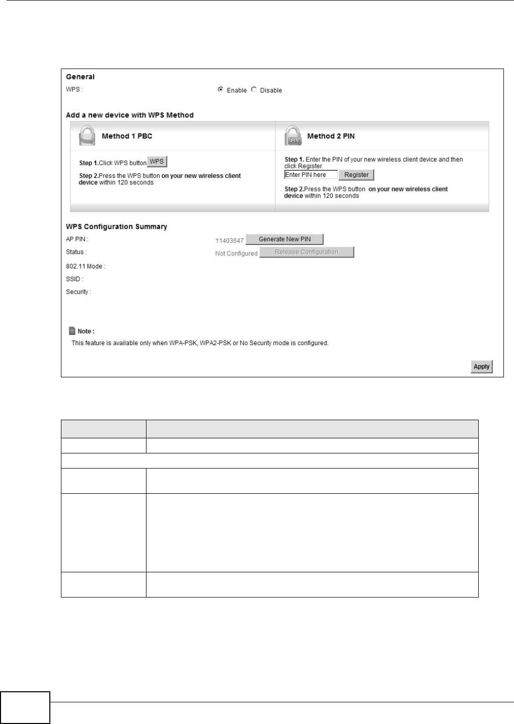
Chapter 5 Wireless
B222s User’s Guide
54
Click N e t w ork Set ting > W irele ss > W PS. The following screen displays. Select Ena ble and click
Apply t o act ivat e t he WPS funct ion. Then you can configure t he WPS sett ings in t his screen.
Figure 27 Net work Set ting > Wireless > WPS
The following t able describes t he labels in t his screen.
Table 14 Network Sett ing > Wireless > WPS
LABEL DESCRIPTION
Enable WPS Select En able t o act ivat e WPS on t he LTE Device.
Add a new device wit h WPS Met hod
Method 1 PBC Use this section t o set up a WPS wireless netw ork using Push But ton
Configuration ( PBC).
WPS Click this but t on t o add anot her WPS- enabled wir eless device (within wir eless
range of t he LTE Device) to your wireless network . This but t on m ay either be a
physical but t on on t he out side of device, or a m enu but t on sim ilar t o the W PS
but t on on this screen.
Note: You must press the other wireless device’s WPS button within two minutes
of pressing this button.
Method 2 PI N Use t his sect ion to set up a WPS wireless network by ent ering t he PI N (Personal
I dent ificat ion Num ber) of t he client int o t he LTE Device.

Chapter 5 Wireless
B222s User’s Guide 55
5.5 The WMM Screen
Use t his screen t o enable or disable Wi- Fi MultiMedia ( WMM) wireless networks for m ult im edia
applications.
Regist er Enter t he PI N of the device t hat you are set t ing up a WPS connect ion wit h and
click Re g ist e r t o aut hent icat e and add t he wireless device t o your w ireless
net work.
You can find t he PI N either on t he out side of t he device, or by checking t he
device’s set t ings.
Note: You must also activate WPS on that device within two minutes to have it
present its PIN to the LTE Device.
WPS Configurat ion Sum mary
AP PI N The PI N of the LTE Device is shown here. Enter this PI N in t he configuration
ut ility of t he device you want t o connect t o using WPS.
The PI N is not necessary when you use WPS push- but t on m et hod.
Click t he Gene r at e N ew PI N but t on t o have the LTE Device create a new PI N.
St at us This displays Configure d when the LTE Device has connect ed t o a wireless
net work using WPS or Enable W PS is select ed and wireless or w ireless securit y
set t ings have been changed. The current wireless and wireless securit y set t ings
also appear in t he screen.
This displays N ot Con figur e d w hen t here is no wireless or wireless secur ity
changes on t he LTE Device or you click Re le a se Configur a t ion t o rem ove t he
configured wireless and wir eless securit y sett ings.
Release
Configuration
This but ton is available when t he WPS stat us is Con figu re d.
Click t his but t on t o rem ove all configured wireless and wir eless securit y set tings
for WPS connect ions on the LTE Device.
802.11 Mode This is t he 802.11 m ode used. Only com pliant WLAN devices can associate wit h
the LTE Device.
SSI D This is t he nam e of t he wireless netw ork.
Securit y This is t he t ype of wireless securit y em ployed by t he net work.
Apply Click Apply t o save your changes.
Table 14 Network Sett ing > Wireless > WPS ( cont inued)
LABEL DESCRIPTION
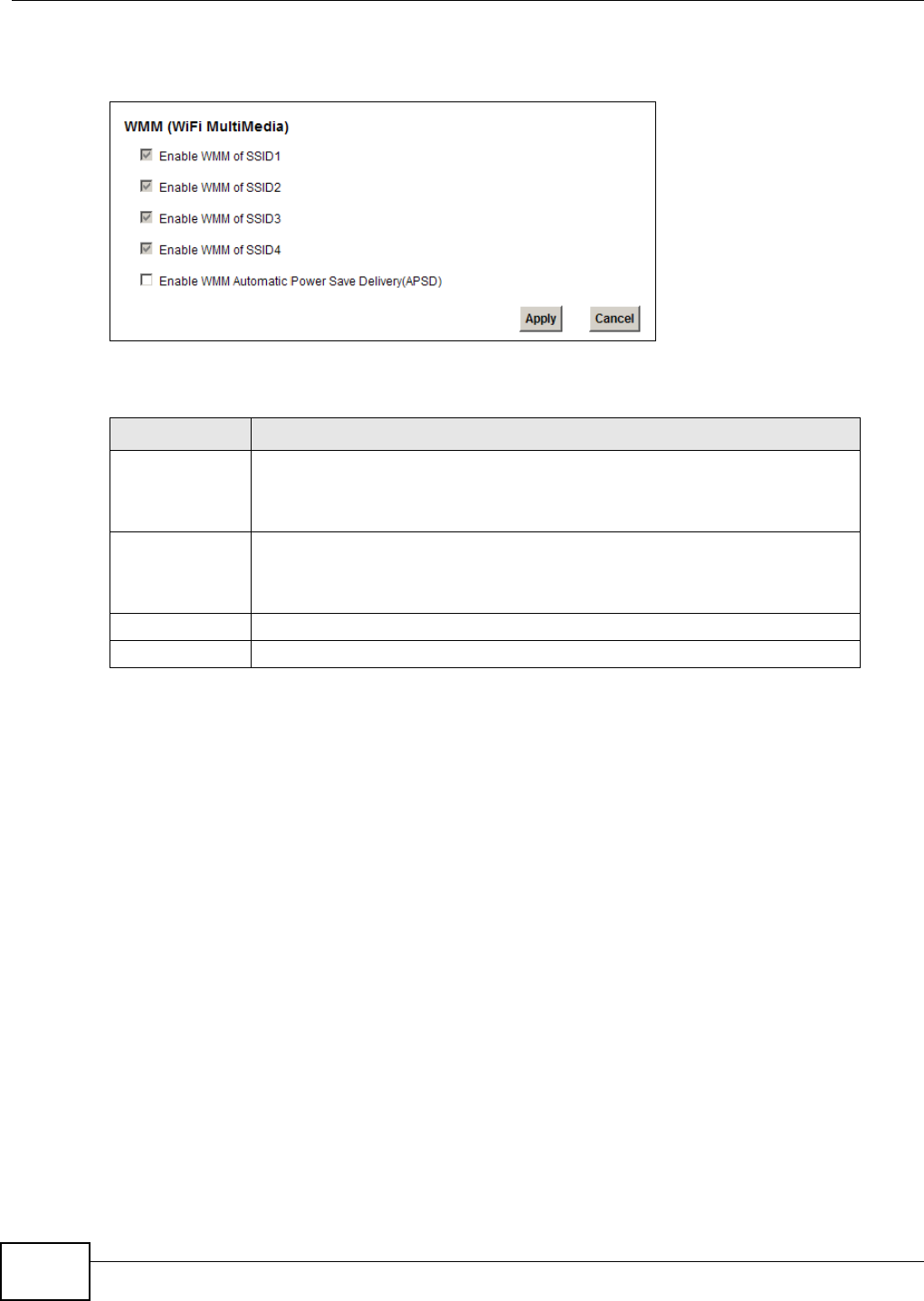
Chapter 5 Wireless
B222s User’s Guide
56
Click N et w or k Set t ing > W irele ss > W MM . The following screen displays.
Figure 28 Net work Set ting > Wireless > WMM
The following t able describes t he labels in t his screen.
Table 15 Network Sett ing > Wireless > WMM
LABEL DESCRIPTION
Enable WMM of
SSI D1~ 4
This enables t he LTE Device to autom at ically give a ser vice a priorit y level
according t o the ToS value in t he I P header of pack ets it sends. WMM QoS ( Wifi
MultiMedia Qualit y of Service) gives high priority t o voice and video, w hich m akes
them run m ore sm oot hly.
Enable WMM
Autom atic Power
Save Deliver
( APSD)
Click t his t o increase bat t ery life for bat t ery-powered wireless clients. APSD uses
a longer beacon int erval w hen t ransm itt ing t raffic t hat does not require a short
packet exchange int erval.
Apply Click Apply t o save your changes.
Cancel Click Ca n ce l to restore your previously saved sett ings.
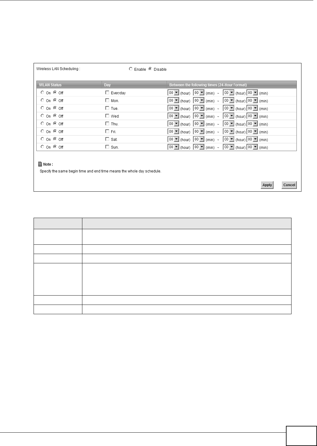
Chapter 5 Wireless
B222s User’s Guide 57
5.6 Scheduling Screen
Click Net w or k Set t ing > W irele ss > Sch e duling t o open t he W ir e less LAN Schedu lin g screen.
Use t his screen t o configure when t he LTE Device enables or disables t he wireless LAN.
Figure 29 Net work Set ting > Wireless > Scheduling
The following t able describes t he labels in t his screen.
5.7 Technical Reference
This sect ion discusses wireless LANs in depth. For m ore inform at ion, see t he appendix.
Table 16 Network Sett ing > Wir eless > Scheduling
LABEL DESCRIPTION
Wireless LAN
Scheduling
Select Ena ble t o act ivate wireless LAN scheduling on your LTE Device.
WLAN stat us Select On or Off t o enable or disable t he wireless LAN.
Day Select the day(s) you want to t urn t he wir eless LAN on or off.
Bet w een t he
following tim es
Specify t he t im e period during which to apply t he schedule.
For exam ple, you want t he wireless netw ork t o be only available during w ork
hours. Check Mon ~ Fri in the day colum n, and specify 8: 00 ~ 18: 00 in the tim e
table.
Apply Click Apply t o save your changes.
Cancel Click Can cel to restore your previously saved sett ings.

Chapter 5 Wireless
B222s User’s Guide
58
5.7.1 Additional Wireless Terms
The following t able describes som e wireless network t erm s and acronym s used in the LTE Device’s
web configurat or.
5.7.2 Wireless Security Overview
By their nature, radio com m unicat ions are sim ple to int ercept . For w ireless data networks, this
m eans t hat anyone wit hin range of a wireless net work without security can not only read the dat a
passing over the airwaves, but also j oin the network. Once an unaut horized person has access t o
the network, he or she can st eal inform at ion or int roduce m alwar e ( m alicious soft ware) intended t o
com prom ise t he network. For t hese reasons, a variety of security system s have been developed t o
ensure that only authorized people can use a wireless dat a net work, or understand t he data carried
on it .
These security standards do t wo t hings. First , t hey aut hent icat e. This m eans t hat only people
present ing t he right credent ials ( oft en a usernam e and password, or a “ key” phrase) can access t he
network. Second, they encr ypt . This m eans t hat the inform at ion sent over t he air is encoded. Only
people wit h t he code key can understand t he inform at ion, and only people who have been
authent icat ed are given t he code key.
These security standards vary in effect iveness. Som e can be broken, such as t he old Wired
Equivalent Protocol ( WEP) . Using WEP is bet t er t han using no securit y at all, but it will not keep a
det erm ined at tacker out . Other security standards are secure in t hem selves but can be br oken if a
user does not use t hem properly. For exam ple, the WPA-PSK securit y standard is very secure if you
use a long key which is difficult for an at t acker ’s software to guess - for exam ple, a twenty- letter
long st ring of apparent ly random num bers and let t ers - but it is not very secure if you use a short
key which is very easy t o guess - for exam ple, a three- lett er w ord from t he dictionary.
Because of t he dam age t hat can be done by a m alicious at tacker, it ’s not j ust people who have
sensit ive inform ation on t heir network who should use securit y. Everybody who uses any wireless
network should ensure t hat effect ive securit y is in place.
Table 17 Addit ional Wireless Term s
TERM DESCRIPTION
RTS/ CTS Threshold I n a wireless network w hich covers a large area, wir eless devices are
som etim es not aware of each ot her’s presence. This m ay cause t hem t o
send infor m at ion to t he AP at t he sam e t im e and result in inform ation
colliding and not getting t hrough.
By set ting t his value lower t han t he default value, t he wir eless devices m ust
som et im es get perm ission t o send inform ation to t he LTE Device. The lower
the value, t he m ore oft en t he devices m ust get perm ission.
I f this value is greater t han the fragm entat ion t hreshold value ( see below),
then w ireless devices never have t o get perm ission t o send inform at ion to
the LTE Device.
Pream ble A pream ble affects t he t im ing in your wireless netw ork. There are t wo
pream ble m odes: long and short . I f a device uses a different pream ble m ode
than t he LTE Device does, it cannot com m unicate w ith the LTE Device.
Aut hent icat ion The process of verifying whet her a wireless device is allowed t o use t he
wireless net work.
Fragm ent ation
Threshold
A sm all fragm ent ation t hreshold is recom m ended for busy network s, while a
larger t hreshold pr ovides fast er perform ance if the net work is not very busy.

Chapter 5 Wireless
B222s User’s Guide 59
A good way t o com e up with effective securit y keys, passwords and so on is t o use obscur e
inform ation that you personally will easily rem em ber, and t o ent er it in a way t hat appears random
and does not include real words. For exam ple, if your m ot her owns a 1970 Dodge Challenger and
her favorite m ovie is Vanishing Point ( which you know was m ade in 1971) you could use
“ 70dodchal71vanpoi” as your security key.
The following sections int roduce different types of w ireless securit y you can set up in t he wireless
network.
5.7.2.1 SSID
Norm ally, t he LTE Device acts like a beacon and regularly broadcast s the SSI D in the area. You can
hide t he SSI D instead, in which case t he LTE Device does not broadcast t he SSI D. I n addit ion, you
should change t he default SSI D t o som et hing that is difficult t o guess.
This t ype of securit y is fairly weak, however, because there are ways for unauthorized wireless
devices t o get the SSI D. I n addit ion, unauthorized w ireless devices can st ill see t he inform ation t hat
is sent in t he wireless net work.
5.7.2.2 MAC Address Filter
Every device t hat can use a wireless net w ork has a unique ident ificat ion num ber, called a MAC
address.1 A MAC address is usually writ t en using t welve hexadecim al charact ers2; for exam ple,
00A0C5000002 or 00: A0: C5: 00: 00: 02. To get t he MAC addr ess for each device in t he wireless
network, see the device’s User’s Guide or ot her docum ent at ion.
You can use t he MAC address filt er to t ell the LTE Device which devices are allowed or not allowed
to use t he wireless net work. I f a device is allowed t o use t he wireless net work, it still has t o have
the correct inform ation ( SSI D, channel, and securit y) . I f a device is not allowed t o use t he wireless
network, it does not m att er if it has t he correct inform ation.
This t ype of securit y does not protect t he inform ation t hat is sent in t he wireless net work.
Furt herm ore, t here are ways for unauthorized wireless devices t o get t he MAC address of an
authorized device. Then, they can use t hat MAC address to use t he wireless net work.
5.7.2.3 User Authentication
Aut hent icat ion is t he process of verifying whet her a wireless device is allowed to use t he wireless
networ k. You can m ake every user log in t o t he wireless net work before using it . However, every
device in the wireless net work has t o support I EEE 802.1x to do this.
For wireless net works, you can store the user nam es and passwords for each user in a RADI US
server. This is a server used in businesses m ore t han in hom es. I f you do not have a RADI US server,
you cannot set up user nam es and passwords for your users.
Unaut horized wireless devices can still see t he inform ation t hat is sent in t he wireless net w ork,
even if they cannot use the wireless net work. Furt herm ore, t here are ways for unaut horized
wireless user s t o get a valid user nam e and password. Then, t hey can use that user nam e and
passw ord to use t he wireless network.
1. Some wireless devices, such as scanners, can detect wireless networks but cannot use wireless networks. These kinds
of wireless devices might not have MAC addresses.
2. Hexadecimal characters are 0, 1, 2, 3, 4, 5, 6, 7, 8, 9, A, B, C, D, E, and F.

Chapter 5 Wireless
B222s User’s Guide
60
5.7.2.4 Encryption
Wireless net works can use encrypt ion to prot ect t he inform at ion that is sent in t he wireless
network. Encryption is like a secret code. I f you do not know t he secret code, you cannot
underst and t he m essage.
The types of encrypt ion you can choose depend on t he t ype of aut hent icat ion. ( See Sect ion 5.7.2.3
on page 59 for inform ation about t his.)
For exam ple, if the wireless net work has a RADI US server, you can choose W PA or W PA2 . I f users
do not log in to t he wireless net work, you can choose no encrypt ion, St a tic W EP, W PA- PSK, or
W PA2 - PSK.
Usually, you should set up the st r ongest encrypt ion that every device in the wireless net work
support s. For exam ple, suppose you have a wireless net work with the LTE Device and you do not
have a RADI US server. Therefor e, t here is no aut hent icat ion. Suppose t he wireless net w ork has two
devices. Device A only support s WEP, and device B support s WEP and WPA. Therefore, you should
set up St at ic W EP in t he wireless net work.
Not e: I t is recom m ended t hat wireless networks use W PA- PSK, W PA, or stronger
encrypt ion. The ot her types of encryption are bet ter t han none at all, but it is still
possible for unaut horized wireless devices to figure out t he original inform at ion
pret ty quickly.
When you select W PA2 or W PA2 - PSK in your LTE Device, you can also select an option ( W PA
com pa t ible ) t o support WPA as well. I n t his case, if som e of t he devices support WPA and som e
support WPA2, you should set up W PA2 - PSK or W PA2 ( depending on t he t ype of wireless net work
login) and select t he W PA com pat ible option in t he LTE Device.
Many t ypes of encrypt ion use a key to prot ect t he inform ation in t he wireless network. The longer
the key, t he stronger the encrypt ion. Every device in t he wireless network m ust have the sam e key.
5.7.3 Signal Problems
Because wireless networks are radio net works, their signals are subj ect to lim itat ions of distance,
int erference and absorpt ion.
Problem s w it h distance occur when t he t wo radios are t oo far apart . Problem s with int erference
occur when other radio waves interrupt the data signal. I nt er ference m ay com e from ot her radio
transm issions, such as m ilitary or air t raffic control com m unicat ions, or from m achines t hat are
coincident al em itt ers such as elect ric m otors or m icrowaves. Problem s wit h absorpt ion occur when
physical objects ( such as t hick walls) are bet w een t he t wo radios, m uffling t he signal.
Table 18 Types of Encrypt ion for Each Type of Aut hent icat ion
NO AUTHENTICATION RADIUS SERVER
W eak e st No Security WPA
St at ic WEP
WPA- PSK
St r on ge st WPA2- PSK WPA2
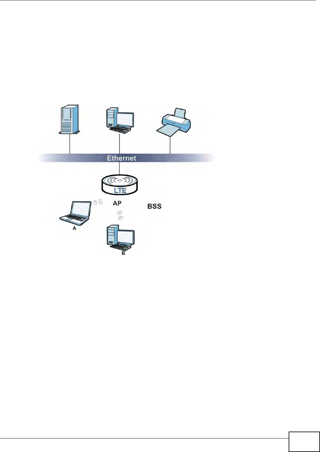
Chapter 5 Wireless
B222s User’s Guide 61
5.7.4 BSS
A Basic Service Set ( BSS) exist s when all com m unicat ions bet ween wireless stations or between a
wir eless stat ion and a wired network client go t hrough one access point ( AP) .
I nt ra- BSS t raffic is t raffic bet w een wireless stations in t he BSS. When I nt ra- BSS t raffic blocking is
disabled, wireless st at ion A and B can access the wired network and com municate wit h each other.
When I nt ra- BSS t raffic blocking is enabled, wir eless stat ion A and B can st ill access the wired
network but cannot com m unicate wit h each ot her.
Figure 30 Basic Service set
5.7.5 MBSSID
Traditionally, you need to use different APs to configure different Basic Service Sets ( BSSs) . As w ell
as t he cost of buying ext ra APs, there is also t he possibility of channel int erference. The LTE
Device’s MBSSI D ( Multiple Basic Service Set I Dent ifier) function allows you t o use one access point
to provide several BSSs sim ultaneously. You can t hen assign varying QoS priorities and/ or security
m odes t o different SSI Ds.
Wireless devices can use different BSSI Ds t o associate with t he sam e AP.
5.7.5.1 Notes on Multiple BSSs
• A m axim um of eight BSSs are allowed on one AP sim ultaneously.
• You m ust use different keys for different BSSs. I f t wo wireless devices have different BSSI Ds
( t hey are in different BSSs) , but have the sam e keys, they m ay hear each ot her ’s
com munications ( but not com m unicate with each ot her) .
• MBSSI D should not replace but rather be used in conj unct ion wit h 802.1x securit y.

Chapter 5 Wireless
B222s User’s Guide
62
5.7.6 WiFi Protected Setup (WPS)
Your LTE Device supports WiFi Prot ected Setup ( WPS), which is an easy way t o set up a secure
wir eless net w ork. WPS is an industry st andard specification, defined by t he WiFi Alliance.
WPS allows you t o quickly set up a wireless network with st rong securit y, wit hout having to
configure securit y settings m anually. Each WPS connect ion works bet ween t wo devices. Bot h
devices m ust support WPS ( check each device’s docum ent at ion to m ake sure).
Depending on t he devices you have, you can either press a butt on ( on t he device it self, or in it s
configurat ion utility) or ent er a PI N (a unique Personal I dent ificat ion Num ber t hat allows one device
to aut hent icat e t he ot her) in each of the two devices. When WPS is act ivated on a device, it has t wo
m inut es to find anot her device t hat also has WPS activat ed. Then, t he t wo devices connect and set
up a secure net work by t hem selves.
5.7.6.1 Push Button Configuration
WPS Push Butt on Configuration ( PBC) is init iated by pressing a butt on on each WPS- enabled
device, and allowing them t o connect aut om at ically. You do not need to ent er any inform at ion.
Not every WPS- enabled device has a physical WPS button. Som e m ay have a WPS PBC but ton in
their configuration ut ilit ies instead of or in addition t o t he physical but ton.
Take t he following st eps t o set up WPS using t he butt on.
1Ensure that t he t wo devices you want t o set up are wit hin wireless range of one another.
2Look for a WPS butt on on each device. I f t he device does not have one, log int o its configurat ion
utility and locate t he but ton ( see the device’s User’s Guide for how to do this - for t he LTE Device,
see Section 5.4 on page 53) .
3Press t he butt on on one of t he devices ( it doesn’t m atter w hich) . For t he LTE Device you m ust press
the WPS butt on for m ore than three seconds.
4Wit hin t wo m inut es, press t he butt on on t he other device. The registrar sends t he network nam e
( SSI D) and security key through an secure connect ion t o t he enrollee.
I f you need to m ake sure t hat WPS worked, check t he list of associat ed wireless clients in t he AP’s
configurat ion ut ilit y. I f you see t he wireless client in t he list , WPS was successful.
5.7.6.2 PIN Configuration
Each WPS-enabled device has its ow n PI N ( Personal I dent ificat ion Num ber) . This m ay eit her be
st at ic ( it cannot be changed) or dynam ic ( in som e devices you can generat e a new PI N by clicking
on a but ton in t he configurat ion int erface) .
Use t he PI N m et hod inst ead of t he push- but t on configuration ( PBC) m ethod if you want to ensur e
that t he connect ion is established between t he devices you specify, not j ust the first two devices t o
act ivat e WPS in range of each ot her. However, you need t o log into t he configurat ion int erfaces of
both devices t o use the PI N m ethod.
When you use t he PI N m ethod, you m ust enter t he PI N from one device ( usually t he wireless client )
int o t he second device ( usually the Access Point or wireless router) . Then, when WPS is activat ed

Chapter 5 Wireless
B222s User’s Guide 63
on the first device, it present s it s PI N t o t he second device. I f the PI N m atches, one device sends
the network and security inform ation t o t he ot her, allowing it t o j oin the network.
Take t he following st eps t o set up a WPS connection bet ween an access point or wireless rout er
( referred t o here as t he AP) and a client device using the PI N m ethod.
1Ensure WPS is enabled on bot h devices.
2Access t he WPS section of t he AP’s configurat ion int erface. See t he device’s User’s Guide for how to
do this.
3Look for t he client ’s WPS PI N; it will be displayed either on the device, or in t he WPS sect ion of the
client ’s configuration interface ( see the device’s User’s Guide for how t o find t he WPS PI N - for the
LTE Device, see Sect ion 5.4 on page 53) .
4Enter t he client ’s PI N in the AP’s configurat ion interface.
5I f t he client device’s configurat ion interface has an area for ent ering anot her device’s PI N, you can
eit her enter t he client ’s PI N in t he AP, or enter t he AP’s PI N in the client - it does not m att er which.
6St art WPS on bot h devices wit hin t wo m inut es.
7Use t he configurat ion utility t o activat e WPS, not the push-butt on on t he device it self.
8On a com puter connect ed t o t he wireless client , t ry t o connect t o t he I nt ernet . I f you can connect,
WPS was successful.
I f you cannot connect , check the list of associat ed wireless client s in the AP’s configuration utility. I f
you see t he wireless client in t he list , WPS was successful.
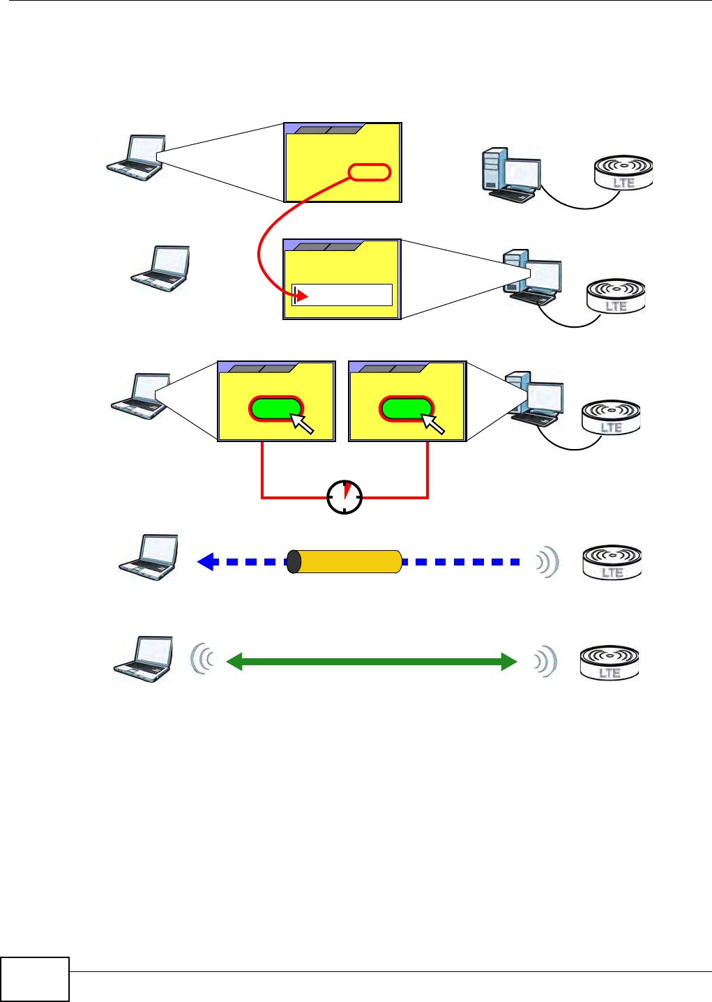
Chapter 5 Wireless
B222s User’s Guide
64
The following figure shows a WPS- enabled wireless client ( installed in a not ebook com puter)
connecting to t he WPS-enabled AP via t he PI N m ethod.
Figure 31 Exam ple WPS Pr ocess: PI N Method
5.7.6.3 How WPS Works
When two WPS- enabled devices connect , each device m ust assum e a specific role. One device acts
as t he registrar ( the device t hat supplies net w ork and securit y settings) and t he ot her device acts
as t he enrollee ( the device t hat receives net w ork and securit y set tings. The registrar creat es a
secure EAP ( Ext ensible Aut hent icat ion Prot ocol) t unnel and sends t he net work nam e ( SSI D) and t he
WPA- PSK or WPA2- PSK pre- shared key to t he enrollee. Whet her WPA-PSK or WPA2- PSK is used
depends on t he standards support ed by t he devices. I f the registrar is already part of a net w ork, it
sends t he existing inform ation. I f not , it generat es the SSI D and WPA( 2) -PSK random ly.
ENROLLEE
SECURE EAP TUNNEL
SSID
WPA(2)-PSK
WITHIN 2 MINUTES
COMMUNICATION
This device’s
WPS
Enter WPS PIN
WPS
from other device:
WPS PIN: 123456
WPS
START
WPS
START
REGISTRAR
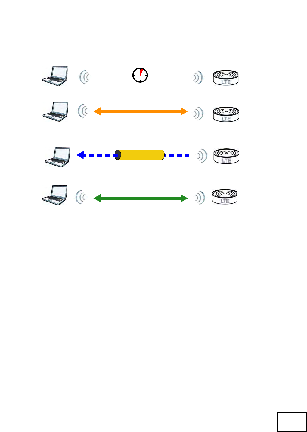
Chapter 5 Wireless
B222s User’s Guide 65
The following figure shows a WPS- enabled client ( inst alled in a notebook com put er) connect ing t o a
WPS- enabled access point .
Figure 32 How WPS w orks
The roles of registrar and enrollee last only as long as the WPS set up process is active ( t wo
m inut es) . The next t im e you use WPS, a differ ent device can be t he regist rar if necessary.
The WPS connect ion process is like a handshake; only two devices part icipat e in each WPS
transact ion. I f you want t o add m ore devices you should repeat t he process wit h one of t he exist ing
networked devices and the new device.
Note that t he access point ( AP) is not always t he registrar, and t he wireless client is not always the
enrollee. All WPS- cert ified APs can be a registrar, and so can som e WPS- enabled wireless client s.
By default , a WPS devices is “ unconfigured”. This m eans t hat it is not par t of an existing net w ork
and can act as eit her enrollee or registrar ( if it support s bot h funct ions) . I f the registrar is
unconfigured, the securit y sett ings it t ransm its t o the enrollee are random ly- generat ed. Once a
WPS- enabled device has connect ed t o another device using WPS, it becom es “ configured”. A
configured w ireless client can still act as enrollee or regist rar in subsequent WPS connections, but a
configured access point can no longer act as enrollee. I t will be t he registrar in all subsequent WPS
connect ions in which it is involved. I f you want a configured AP t o act as an enrollee, you m ust reset
it t o its factory defaults.
5.7.6.4 Example WPS Network Setup
This sect ion shows how securit y set t ings are dist ributed in an exam ple WPS setup.
The following figure shows an exam ple net work. I n st ep 1, both AP1 and Client 1 are
unconfigured. When WPS is activat ed on bot h, t hey perform t he handshake. I n t his exam ple, AP1
SECURE TUNNEL
SECURITY INFO
WITHIN 2 MINUTES
COMMUNICATION
ACTIVATE
WPS
ACTIVATE
WPS
WPS HANDSHAKE
REGISTRARENROLLEE
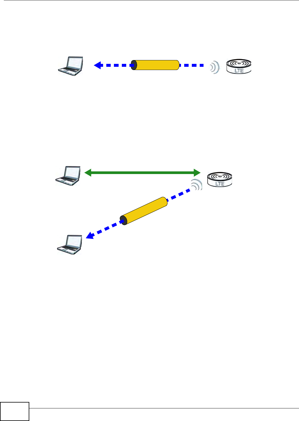
Chapter 5 Wireless
B222s User’s Guide
66
is t he regist rar, and Client 1 is t he enrollee. The regist rar random ly generates t he security
inform ation t o set up t he net wor k, since it is unconfigur ed and has no existing inform at ion.
Figure 33 WPS: Exam ple Net work St ep 1
I n step 2 , you add anot her wir eless client t o t he network. You know t hat Clien t 1 support s registrar
m ode, but it is bett er to use AP1 for t he WPS handshake w it h t he new client since you m ust
connect t o t he access point anyway in order t o use t he net work. I n this case, AP1 m ust be t he
registrar, since it is configured ( it already has securit y inform ation for the network) . AP1 supplies
the existing securit y inform at ion t o Clien t 2 .
Figure 34 WPS: Exam ple Net work St ep 2
REGISTRARENROLLEE
SECURITY INFO
CLIENT 1 AP1
REGISTRAR
CLIENT 1 AP1
ENROLLEE
CLIENT 2
EXISTING CONNECTION
SECURITY INFO
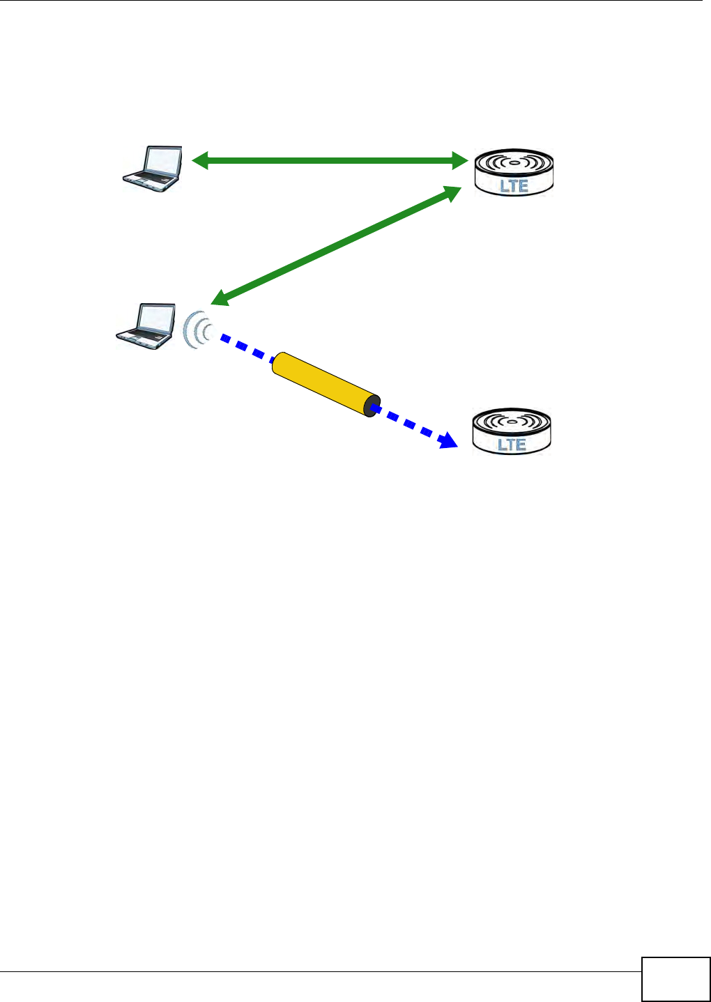
Chapter 5 Wireless
B222s User’s Guide 67
I n step 3, you add another access point (AP2 ) t o your net w ork. AP2 is out of range of AP1 , so you
cannot use AP1 for the WPS handshake w it h t he new access point . However, you know t hat Clie n t
2 support s the registrar funct ion, so you use it t o perform t he WPS handshake inst ead.
Figure 35 WPS: Exam ple Net work St ep 3
5.7.6.5 Limitations of WPS
WPS has som e lim itat ions of which you should be aware.
• WPS works in I nfrast ruct ure net works only ( where an AP and a wireless client com municate) . I t
does not work in Ad- Hoc net w orks (where there is no AP) .
• When you use WPS, it wor ks bet ween t wo devices only. You cannot enroll m ultiple devices
sim ultaneously, you m ust enroll one after the other.
For inst ance, if you have t w o enrollees and one registrar you m ust set up t he first enrollee ( by
pressing the WPS but ton on t he registrar and the first enrollee, for exam ple) , t hen check t hat it
successfully enrolled, t hen set up the second device in t he sam e way.
• WPS works only wit h other WPS-enabled devices. However, you can st ill add non-WPS devices t o
a network you already set up using WPS.
WPS works by aut om atically issuing a random ly- generat ed WPA- PSK or WPA2- PSK pre- shared
key from t he regist rar device to the enrollee devices. Whet her t he net work uses WPA-PSK or
WPA2- PSK depends on t he device. You can check t he configurat ion int erface of t he regist rar
device t o discover t he key the network is using ( if t he device support s this feat ure). Then, you
can ent er the key into t he non-WPS device and j oin t he net work as norm al (t he non-WPS device
m ust also support WPA- PSK or WPA2- PSK) .
CLIENT 1 AP1
REGISTRAR
CLIENT 2
EXISTING CONNECTION
SECURITY INFO
ENROLLEE
AP2
EXISTING CONNECTION

Chapter 5 Wireless
B222s User’s Guide
68
• When you use the PBC m et hod, t here is a short period (from t he m om ent you press t he but t on
on one device to t he m om ent you press t he butt on on the ot her device) when any WPS-enabled
device could j oin the network. This is because t he regist rar has no way of identifying the
“ correct” enrollee, and cannot different iate bet ween your enrollee and a rogue device. This is a
possible way for a hacker t o gain access t o a net w ork.
You can easily check to see if t his has happened. WPS works bet w een only two devices
sim ultaneously, so if anot her device has enrolled your device w ill be unable t o enroll, and will not
have access t o t he net work. I f this happens, open t he access point ’s configurat ion interface and
look at t he list of associat ed client s ( usually displayed by MAC address). I t does not m at t er if the
access point is t he WPS regist rar, t he enrollee, or was not involved in the WPS handshake; a
rogue device m ust still associate with the access point t o gain access t o t he net work. Check t he
MAC addresses of your wireless clients ( usually print ed on a label on t he bot t om of t he device). I f
there is an unknown MAC address you can rem ove it or reset t he AP.
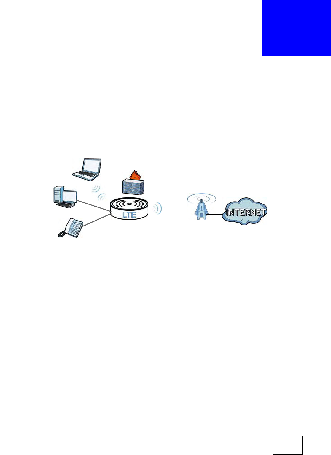
B222s User’s Guide 69
CHAPTER 6
Home Networking
6.1 Overview
A Local Ar ea Network ( LAN) is a shar ed com m unication system t o which m any com puters are
att ached. A LAN is usually located in one im m ediat e area such as a building or floor of a building.
The LAN screens can help you configure a LAN DHCP server and m anage I P addresses.
6.1.1 What You Can Do in this Chapter
• Use the LAN Set up screen t o set t he LAN I P address, subnet m ask, and DHCP sett ings ( Sect ion
6.2 on page 71) .
• Use the St a t ic DH CP screen to assign I P addresses on t he LAN to specific individual com put ers
based on their MAC Addresses ( Sect ion 6.3 on page 72) .
• Use the UPnP screen t o enable UPnP ( Sect ion 6.4 on page 73) .
6.1.2 What You Need To Know
The following term s and concept s m ay help as you read this chapt er.
6.1.2.1 About LAN
IP Address
Sim ilar t o t he way houses on a street shar e a com m on str eet nam e, so t oo do com put ers on a LAN
share one com m on net work num ber. This is know n as an I nternet Prot ocol address.
WAN
LAN

Chapter 6 Home Networking
B222s User’s Guide
70
Subnet Mask
The subnet m ask specifies t he net work num ber port ion of an I P address. Your LTE Device will
com pute the subnet m ask autom at ically based on t he I P address that you ent ered. You don't need
to change t he subnet m ask com put ed by the LTE Device unless you are instruct ed t o do ot herw ise.
DHCP
DHCP ( Dynam ic Host Configurat ion Prot ocol) allows client s t o obt ain TCP/ I P configurat ion at st ar t-
up from a server. This LTE Device has a built- in DHCP ser ver capability t hat assigns I P addresses
and DNS servers t o system s that support DHCP client capability.
DNS
DNS ( Dom ain Nam e System ) m aps a dom ain nam e t o its corresponding I P address and vice versa.
The DNS server is ext rem ely im port ant because w it hout it , you m ust know t he I P address of a
com puter before you can access it. The DNS server addresses you ent er when you set up DHCP are
passed t o t he client m achines along w it h t he assigned I P address and subnet m ask.
6.1.2.2 About UPnP
How do I know if I'm using UPnP?
UPnP hardware is ident ified as an icon in the Net work Connections folder ( Window s XP) . Each UPnP
com patible device inst alled on your net work will appear as a separate icon. Selecting t he icon of a
UPnP device w ill allow you t o access t he inform ation and propert ies of t hat device.
Cautions with UPnP
The autom at ed nature of NAT t raversal applicat ions in establishing t heir own services and opening
firewall port s m ay present net work security issues. Net work inform ation and configuration m ay also
be obtained and m odified by users in som e net work environm ent s.
When a UPnP device j oins a net work, it announces it s pr esence with a m ulticast m essage. For
securit y reasons, the LTE Device allows m ulticast m essages on the LAN only.
All UPnP- enabled devices m ay com m unicat e freely wit h each ot her wit hout additional configurat ion.
Disable UPnP if t his is not your int ent ion.
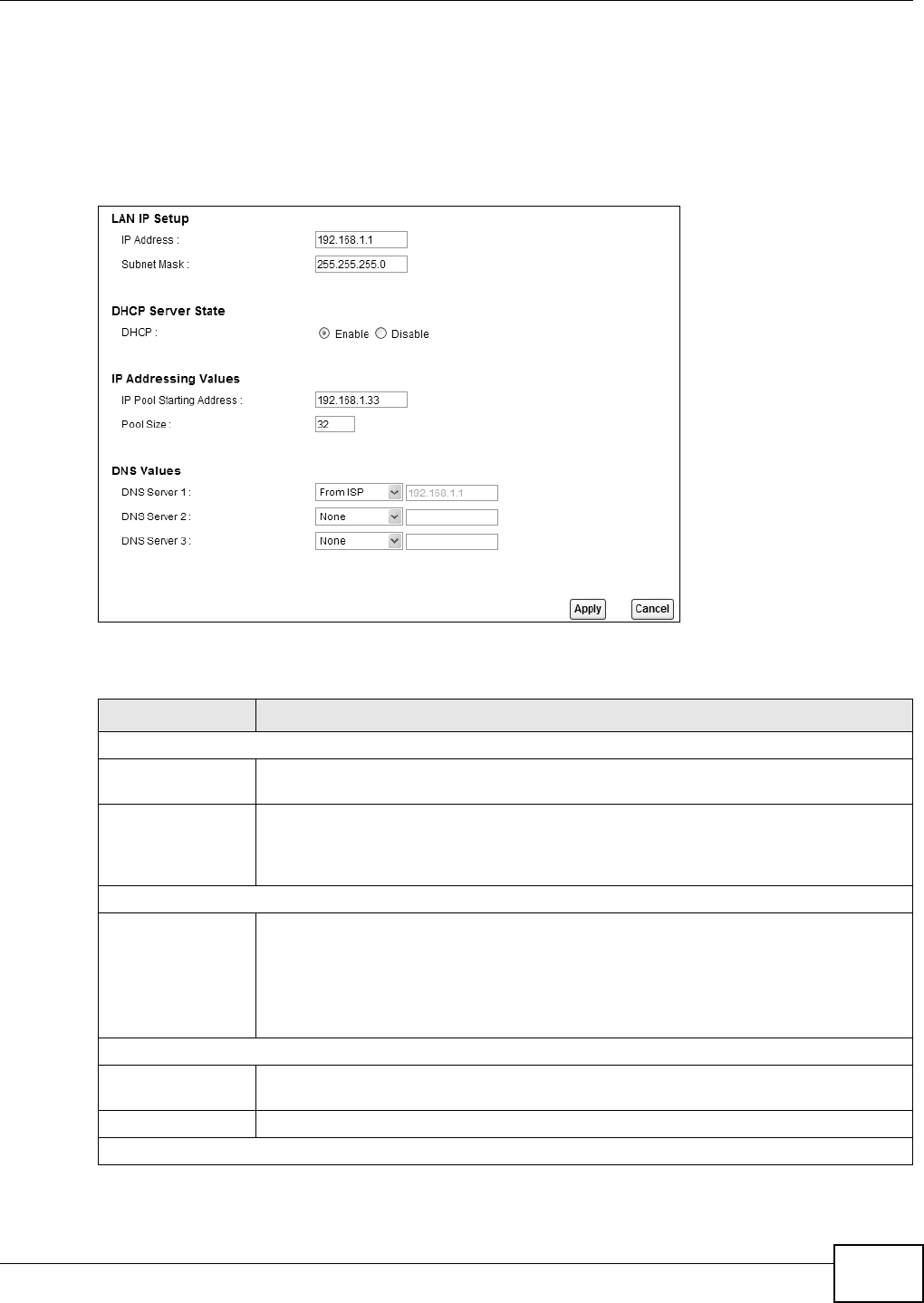
Chapter 6 Home Networking
B222s User’s Guide 71
6.2 The LAN Setup Screen
Click N et w ork Set t ing > Hom e N e tw or k ing t o open t he LAN Se t up screen. Use this screen to
set t he Local Area Networ k I P address and subnet m ask of your LTE Device and configure t he DNS
server inform ation t hat t he LTE Device sends t o t he DHCP client devices on t he LAN.
Figure 36 Net work Set ting > Hom e Net w orking > LAN Setup
The following t able describes t he fields in t his screen.
Table 19 Network Sett ing > Hom e Networking > LAN Setup
LABEL DESCRIPTION
LAN I P Set up
I P Address Enter t he LAN I P address you want t o assign t o your LTE Device in dot t ed decim al
notat ion, for exam ple, 192.168.1.1 (factor y default ) .
I P Subnet Mask Type t he subnet m ask of your net work in dot ted decim al notat ion, for exam ple
255.255.255.0 (fact ory default ) . Your LTE Device autom at ically com put es t he subnet
m ask based on t he I P address you ent er, so do not change this field unless you are
instr ucted to do so.
DHCP Server St at e
DHCP Select Ena ble t o have your LTE Device assign I P addresses, an I P default gateway and
DNS server s t o LAN com put ers and other devices t hat are DHCP clients.
I f you select Disa ble, you need t o m anually configure t he I P addresses of t he
com puter s and ot her devices on your LAN.
When DHCP is used, the follow ing fields need to be set .
I P Addressing Values
I P Pool St art ing
Address
This field specifies the fir st of t he cont iguous addresses in t he I P address pool.
Pool Size This field specifies t he size, or count of t he I P address pool.
DNS Values
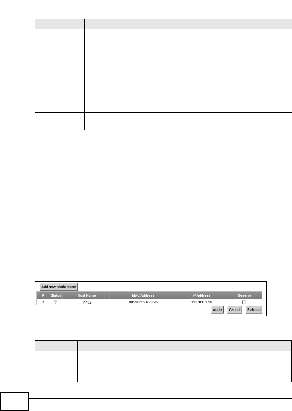
Chapter 6 Home Networking
B222s User’s Guide
72
6.3 The Static DHCP Screen
This t able allows you t o assign I P addresses on the LAN to specific individual com put ers based on
their MAC Addresses.
Every Et hernet device has a unique MAC ( Media Access Cont rol) address. The MAC address is
assigned at the fact ory and consist s of six pairs of hexadecim al charact ers, for exam ple,
00: A0: C5: 00: 00: 02.
6.3.1 Before You Begin
Find out t he MAC addresses of your network devices if you int end to add t hem t o t he St at ic D HCP
screen.
Use t his screen t o change your LTE Device’s stat ic DHCP sett ings. Click N et w ork Set ting > Hom e
N e t w or k in g > St at ic DH CP t o open t he following screen.
Figure 37 Net work Set ting > Hom e Net w orking > Stat ic DHCP
The following t able describes t he labels in t his screen.
DNS Server 1-3 Select From I SP if your I SP dynam ically assigns DNS server inform at ion ( and t he LTE
Device's WAN I P address).
Select D NS- Prox y if
Select User- Defined if you have t he I P address of a DNS ser ver. Ent er t he DNS server's
I P address in t he field to t he r ight . I f you chose User - Defin ed, but leave t he I P address
set t o 0.0.0.0, User - Define d changes t o N on e aft er you click Apply. I f you set a
second choice t o U se r- De fine d, and enter t he sam e I P address, t he second Use r-
De fined changes t o N o ne aft er you click Apply.
Select N o ne if you do not want t o configure DNS servers. You m ust have anot her DHCP
sever on your LAN, or else t he com put ers m ust have t heir DNS server addresses
m anually configured. I f you do not configure a DNS serv er, you m ust know the I P
address of a com put er in order t o access it .
Apply Click Apply to save your changes.
Cancel Click Ca ncel to restore your previously saved set t ings.
Table 19 Network Sett ing > Hom e Net working > LAN Setup (continued)
LABEL DESCRIPTION
Table 20 Network Set t ing > Hom e Net working > Static DHCP
LABEL DESCRIPTION
Add new stat ic
lease
Click t his to add a new st at ic DHCP ent ry.
# This is t he index num ber of the entr y.
St at us This field displays whet her t he client is connect ed t o t he LTE Device.
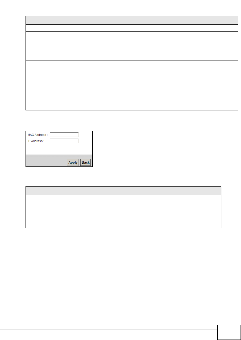
Chapter 6 Home Networking
B222s User’s Guide 73
I f you click Add ne w st a t ic lease in t he St at ic D HCP screen, t he following screen displays.
Figure 38 St at ic DHCP: Add
The following t able describes t he labels in t his screen.
6.4 The UPnP Screen
Universal Plug and Play ( UPnP) is a dist r ibut ed, open net working st andard t hat uses TCP/ I P for
sim ple peer- to- peer net w ork connect ivit y bet ween devices. A UPnP device can dynam ically j oin a
network, obtain an I P address, convey it s capabilit ies and learn about ot her devices on t he net work.
I n t urn, a device can leave a net w ork sm oothly and autom atically w hen it is no longer in use.
See page 74 for m ore inform at ion on UPnP.
Host Nam e This field displays the client host nam e.
MAC Address The MAC (Media Access Cont rol) or Et hernet addr ess on a LAN ( Local Ar ea Networ k) is
unique t o your com put er ( six pairs of hexadecim al not ation) .
A network interface card such as an Ethernet adapter has a hardwired address t hat is
assigned at the factory. This address follows an indust ry st andard t hat ensures no ot her
adapter has a sim ilar address.
I P Address This field displays t he I P address relative t o t he # field list ed above.
Reserve Select the check box in t he heading row to aut om at ically select all check boxes or select
the check box( es) in each ent ry t o have t he LTE Device always assign t he selected
ent ry ( ies) ’s I P address(es) t o t he corresponding MAC address( es) ( and host nam e(s)) . You
can select up to 128 ent ries in t his t able.
Apply Click Apply t o save your changes.
Cancel Click Ca ncel t o rest ore your previously saved sett ings.
Refresh Click Re fresh t o reload t he DHCP t able.
Table 21 Static DHCP: Add
LABEL DESCRIPTION
MAC Address Ent er the MAC address of a com puter on your LAN.
I P Address Enter t he I P address t hat you want to assign to t he com put er on your LAN w ith
t he MAC addr ess t hat you will also specify.
Apply Click Apply to save your changes.
Back Click Back t o exit t his screen w it hout saving.
Table 20 Network Sett ing > Hom e Net working > Stat ic DHCP ( cont inued)
LABEL DESCRIPTION

Chapter 6 Home Networking
B222s User’s Guide
74
Use t he following scr een t o configure t he UPnP sett ings on your LTE Device. Click N e t w or k Set t ing
> Hom e N e t w ork ing > St a t ic D HCP > UPn P to display the screen shown next .
Figure 39 Net work Set ting > Hom e Net w orking > UPnP
The following t able describes t he labels in t his screen.
Table 22 Network Sett ings > Hom e Networking > UPnP
LABEL DESCRIPTION
UPnP Select Enable t o act ivat e UPnP. Be aware that anyone could use a UPnP applicat ion t o open the
web configurat or's login screen without ent ering the LTE Device's I P address ( alt hough you m ust
st ill ent er the password t o access t he w eb configurat or) .
Apply Click Ap ply t o save your changes.
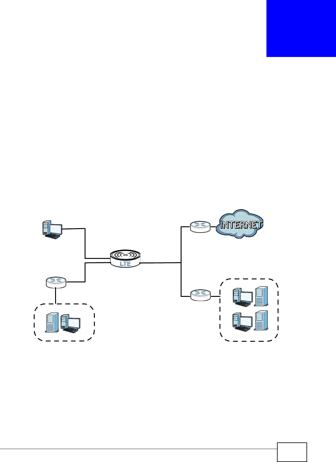
B222s User’s Guide 75
CHAPTER 7
Routing
7.1 Overview
The LTE Device usually uses the default gat eway t o route out bound t raffic from com puters on t he
LAN to t he I nternet . To have t he LTE Device send dat a t o devices not reachable t hrough t he default
gat eway, use stat ic rout es.
For exam ple, the next figure shows a com puter (A) connected t o t he LTE Device’s LAN int erface.
The LTE Device rout es m ost t raffic from A t o t he I nternet t hrough t he LTE Device’s default gat eway
(R1 ) . You creat e one st at ic rout e t o connect t o services offered by your I SP behind rout er R2 . You
creat e another static rout e t o com m unicat e with a separat e net work behind a router R3 connect ed
to t he LAN.
Figure 40 Exam ple of Stat ic Routing Topology
WAN
R1
R2
A
R3
LAN

Chapter 7 Routing
B222s User’s Guide
76
7.2 Configuring Static Route
Use t his screen t o view and configure I P stat ic rout es on the LTE Device. Click N et w or k Set t ing >
St a tic Rout e to open t he following screen.
Figure 41 Net work Set ting > Stat ic Rout e
The following t able describes t he labels in t his screen.
Table 23 Network Sett ing > St atic Rout e
LABEL DESCRIPTION
Add New Stat ic
Rout e
Click t his t o set up a new st atic rout e on the LTE Device.
#This is t he num ber of an individual stat ic rout e.
Act ive This indicat es whether t he rule is act ive or not .
A yellow bulb signifies t hat this stat ic rout e is act ive. A gray bulb signifies that t his stat ic
rout e is not act ive.
St atus This shows whet her t he stat ic rout e is curr ent ly in use or not . A yellow bulb signifies t hat
this stat ic rout e is in use. A gray bulb signifies t hat t his stat ic rout e is not in use.
Nam e This is t he nam e that describes or identifies t his route.
Dest inat ion I P This param et er specifies the I P netw ork address of t he final dest ination. Rout ing is always
based on network num ber.
Gateway This is t he I P address of t he gatew ay. The gateway is a r out er or swit ch on t he sam e
net work segm ent as the device's LAN or WAN por t. The gateway helps forward packet s t o
their dest inat ions.
Subnet Mask This param et er specifies the I P network subnet m ask of the final dest ination.
I nt erface This indicates which interface handles t he t raffic forwarded by this route.
Modify Click the Ed it icon t o go t o t he screen where you can set up a stat ic rout e on t he LTE
Device.
Click t he De le t e icon t o r em ove a st at ic rout e from t he LTE Device.
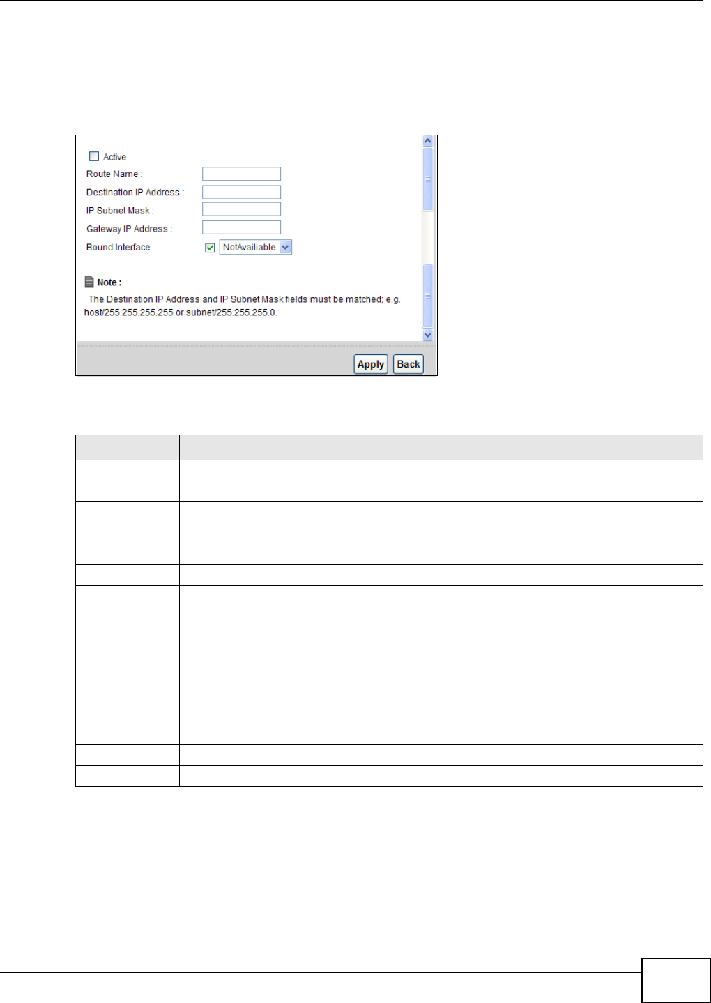
Chapter 7 Routing
B222s User’s Guide 77
7.2.1 Add/Edit Static Route
Click a dd ne w St a t ic Rout e in t he Rou t in g screen or click the Edit icon next t o a rule. The
follow ing screen appears. Use t his screen t o configure the required inform at ion for a stat ic rout e.
Figure 42 Rout ing: Add/ Edit
The following t able describes t he labels in t his screen.
Table 24 Rout ing: Add/ Edit
LABEL DESCRIPTION
Act ive Click this t o activate t his st at ic rout e.
Rout e Nam e Enter the nam e of the I P static rout e. Leave t his field blank t o delete this stat ic rout e.
Dest inat ion I P
Address
This param et er specifies the I P network address of t he final dest ination. Rout ing is always
based on netw ork num ber. I f you need t o specify a r oute t o a single host , use a subnet
m ask of 255.255.255.255 in t he subnet m ask field t o force the netw ork num ber t o be
ident ical t o t he host I D.
I P Subnet Mask Enter t he I P subnet m ask here.
Gateway I P
Address
You can decide if you want t o for ward packets t o a gateway I P address or a bound
interface.
I f you want t o configure Gat e w a y I P Addre ss, ent er the I P address of t he next- hop
gat eway. The gat eway is a rout er or switch on t he sam e netw ork segm ent as t he device's
LAN or WAN port. The gateway helps forward packet s t o their destinat ions.
Bound I nt erface You can decide if you want t o forwar d packets t o a gateway I P address or a bound
interface.
I f you want t o configure Bou nd I nt e r face, select the check box and choose an int erface
through w hich t he t raffic is sent.
Apply Click Apply t o save your changes.
Back Click Ba ck to exit t his screen wit hout saving.

Chapter 7 Routing
B222s User’s Guide
78
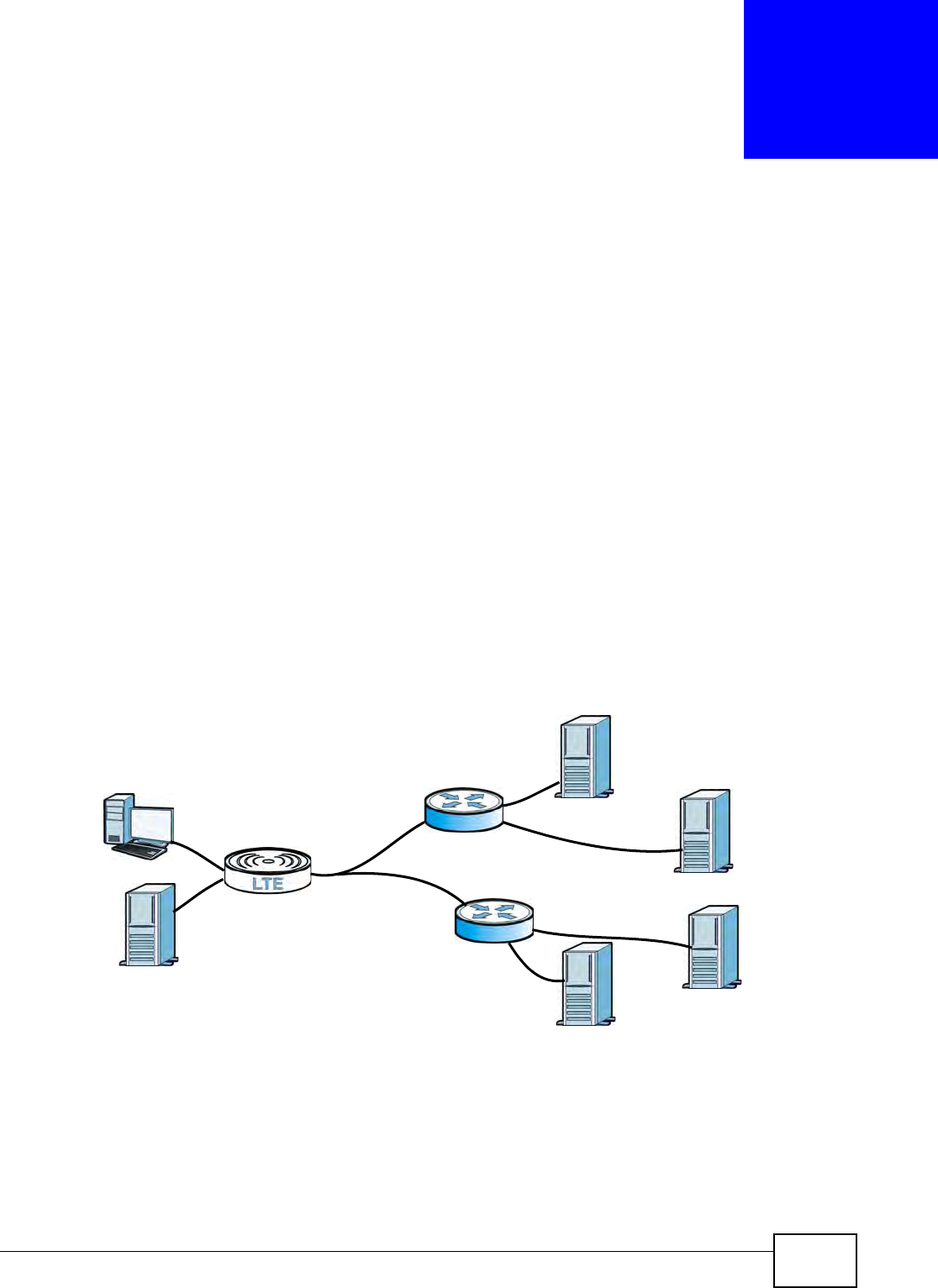
B222s User’s Guide 79
CHAPTER 8
DNS Route
8.1 Overview
DNS ( Dom ain Nam e System ) is for m apping a dom ain nam e t o its corresponding I P address and
vice versa. The DNS server is ext rem ely im port ant because wit hout it , you m ust know the I P
address of a m achine befor e you can access it.
I n addition t o t he system DNS server( s) , each WAN interface ( service) is set to have it s own stat ic
or dynam ic DNS server list. You can configure a DNS stat ic rout e t o forward DNS queries for cert ain
dom ain nam es t hrough a specific WAN int erface t o its DNS server( s). The LTE Device uses a system
DNS server (in t he order you specify in t he Broa dband screen) t o resolve dom ain nam es t hat do
not m atch any DNS rout ing ent ry. Aft er t he LTE Device receives a DNS reply from a DNS ser ver, it
creat es a new ent ry for t he resolved I P address in t he routing table.
I n t he following exam ple, t he DNS server 168.92.5.1 obt ained from t he WAN interface atm 0.100 is
set t o be t he system DNS server. The DNS server 10.10.23.7 is obt ained from t he WAN int erface
ppp1.123. You configure a DNS rout e for * exam ple.com t o have t he LTE Device forward DNS
request s for t he dom ain nam e m ail.exam ple.com t hrough the WAN int erface ppp1.123 t o t he DNS
server 10.10.23.7.
Figure 43 Exam ple of DNS Rout ing Topology
8.1.1 What You Can Do in this Chapter
The DN S Rou t e screens let you view and configure DNS rout es on the LTE Device (Section 8.2 on
page 80) .
WAN
LAN
at m 0.100
ppp1.123
DNS: 10.10.23.7
DNS: 168.92.5.1
sip.service.com
m ail.exam ple.com
( Default )
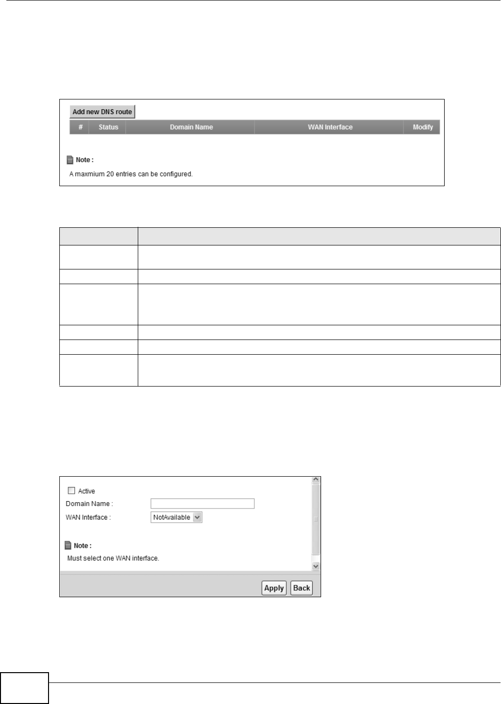
Chapter 8 DNS Route
B222s User’s Guide
80
8.2 The DNS Route Screen
The DN S Rou t e screens let you view and configure DNS rout es on t he LTE Device. Click N et w or k
Set t ing > D NS Rout e t o open t he D N S Rout e screen.
Figure 44 Net work Set ting > DNS Rout e
The following t able describes t he labels in t his screen.
8.2.1 Add/Edit DNS Route Edit
Click Add ne w DN S r out e in t he DN S Rou t e screen or t he Ed it icon next t o an exist ing DNS
rout e. Use t his screen t o configure t he required inform at ion for a DNS route.
Figure 45 DNS Route: Add/ Edit
Table 25 Network Sett ing > DNS Route
LABEL DESCRIPTION
Add new DNS
route
Click t his t o creat e a new entr y.
#This is t he num ber of an individual DNS route.
St atus This shows whether t he DNS rout e is currently in use or not .
A yellow bulb signifies t hat t his DNS route is in use. A gray bulb signifies t hat t his DNS
route is not in use.
Dom ain Nam e This is t he dom ain nam e t o which t he DNS rout e applies.
WAN I nt erface This is t he WAN int erface t hrough which t he m atched DNS request is routed.
Modify Click the Ed it icon to configure a DNS route on t he LTE Device.
Click t he D e le t e icon t o rem ove a DNS rout e from t he LTE Device.

Chapter 8 DNS Route
B222s User’s Guide 81
The following t able describes t he labels in t his screen.
Table 26 DNS Rout e: Add/ Edit
LABEL DESCRIPTION
Act ive Select t his t o act ivate t his DNS r oute.
Dom ain Nam e Ent er t he dom ain nam e you want to resolve.
You can u se t he w i ld car d ch ar act er, an “ * ” ( ast er isk ) as t he lef t m o st p ar t of a d om ain n am e,
such as * .exam ple.com . The LTE Device forwards DNS queries for any dom ain nam e ending
in exam ple.com to t he WAN int erface specified in t his route.
WAN I nt erface Select a WAN interface t hrough which t he m atched DNS query is sent . You m ust have t he
WAN interface( s) already configured in t he Br oadb an d screen.
Apply Click Apply t o save your changes.
Back Click Back t o exit this screen wit hout saving.

Chapter 8 DNS Route
B222s User’s Guide
82

B222s User’s Guide 83
CHAPTER 9
Quality of Service (QoS)
9.1 Overview
This chapt er discusses t he LTE Device’s QoS screens. Use t hese screens to set up your LTE Device
to use QoS for traffic m anagem ent .
Quality of Service ( QoS) refers to bot h a network’s ability t o deliver data with m inim um delay, and
the net working m ethods used t o cont rol t he use of bandwidth. QoS allows the LTE Device t o group
and prioritize applicat ion traffic and fine- t une network perform ance.
Wit hout QoS, all t raffic dat a is equally likely t o be dropped when t he net work is congested. This can
cause a reduct ion in network perform ance and m ake t he net work inadequate for t im e- critical
application such as video-on- dem and.
The LTE Device assigns each packet a pr iorit y and t hen queues t he packet accordingly. Packet s
assigned a high priorit y are pr ocessed m ore quickly than t hose with low priorit y if t here is
congestion, allowing tim e- sensit ive applications to flow m ore sm oothly. Tim e- sensitive applicat ions
include bot h t hose t hat require a low level of lat ency (delay) and a low level of j itt er (variat ions in
delay) such as I nternet gam ing, and t hose for which j itt er alone is a problem such as I nt ernet radio
or st ream ing video.
Note: The LTE Device has built -in configurations for Voice over I P ( I P) . The Quality of
Service ( QoS) feature does not affect VoI P t raffic.
• See
Section 9.6 on page 92 for advanced t echnical inform ation on SI P.
9.1.1 What You Can Do in this Chapter
• Use the Genera l screen to enable QoS, set the bandwidt h, and allow t he LTE Device t o
autom atically assign priorit y t o upstream traffic according to t he I EEE 802.1p pr iorit y level, I P
precedence or packet length ( Section 9.2 on page 84) .
• Use the Queue Se t up screen t o configure QoS queue assignm ent (Sect ion 9.3 on page 86) .
• Use the Cla ss Set up screen t o set up classifiers t o sort t raffic into different flows and assign
priorit y and define actions to be perform ed for a classified traffic flow (Sect ion 9.4 on page 87) .
• Use the M on it o r screen t o view the LTE Device’s QoS- relat ed packet st atist ics ( Sect ion 9.5 on
page 92) .
9.1.2 What You Need to Know
The following term s and concept s m ay help as you read this chapt er.
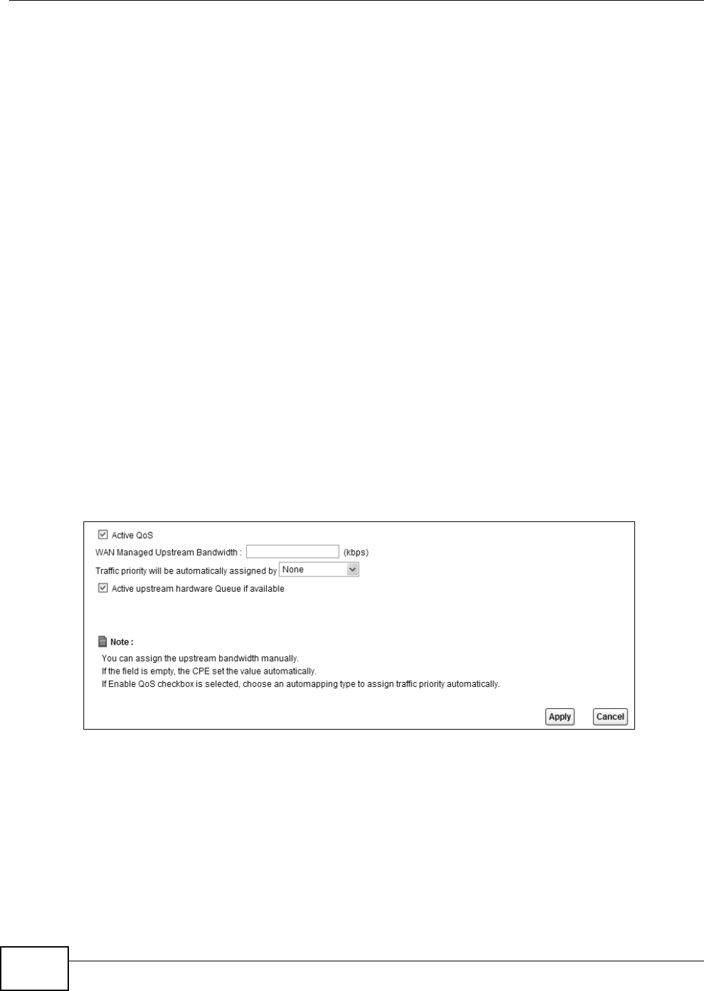
Chapter 9 Quality of Service (QoS)
B222s User’s Guide
84
QoS versus Cos
QoS is used t o priorit ize source-t o-dest ination t raffic flows. All packet s in the sam e flow are given
the sam e priorit y. CoS ( class of service) is a way of m anaging t raffic in a network by grouping
sim ilar t ypes of t raffic together and t reat ing each ty pe as a class. You can use CoS t o give differ ent
priorit ies to different packet t ypes.
CoS technologies include I EEE 802.1p layer 2 t agging and DiffServ ( Different iated Services or DS) .
I EEE 802.1p t agging m akes use of t hree bits in the packet header, while DiffServ is a new prot ocol
and defines a new DS field, which r eplaces t he eight- bit ToS ( Type of Service) field in the I P header.
Tagging and Marking
I n a QoS class, you can configure whet her to add or change t he DSCP ( DiffServ Code Point ) value
and I EEE 802.1p priorit y level in a m atched packet . When the packet passes t hr ough a com patible
network, the networking device, such as a backbone switch, can provide specific t reatm ent or
service based on t he t ag or m arker.
9.2 The QoS General Screen
Use t his screen to enable or disable QoS, set t he bandwidt h, and select t o have the LTE Device
autom atically assign priorit y t o upstream traffic according to t he I EEE 802.1p priorit y level, I P
precedence or packet length.
Click N et w ork Set t ing > QoS t o open t he Gen er a l screen.
Figure 46 Net work Set ting > QoS > General

Chapter 9 Quality of Service (QoS)
B222s User’s Guide 85
The following t able describes t he labels in t his screen.
Table 27 Network Sett ing > QoS > General
LABEL DESCRIPTION
Act ive QoS Select t he check box t o t urn on QoS t o im prove your net wor k perform ance.
You can give prior ity t o t raffic t hat t he LTE Device for wards out through t he WAN
interface. Give high priority t o voice and v ideo t o m ake them run m ore sm oot hly.
Sim ilar ly, g iv e low pr ior i t y t o m an y lar ge file dow n load s so t h at t hey do n ot r edu ce
the qualit y of ot her applications.
WAN Managed
Upstr eam
Bandwidth
Enter t he am ount of bandwidt h for t he WAN int erface that you want t o allocat e
using QoS.
The recom m endation is t o set t his speed t o m at ch t he int erface’s act ual
t ransm ission speed. For exam ple, set t he WAN inter face speed to 1000 kbps if
your I nt ernet connect ion has an upstream t ransm ission speed of 1 Mbps.
Set t ing t his num ber higher t han the interface’s act ual t ransm ission speed will stop
lower prior ity t raffic from being sent if higher priority t raffic uses all of t he actual
bandw idt h.
I f you set t his num ber low er t han t he int erface’s actual transm ission speed, t he
LTE Device will not use som e of t he int erface’s available bandwidt h.
Leave t his field blank to have t he LTE Device set t his value aut om atically.
Traffic priority
will be
aut om at ically
assigned by
These fields are ignored if upst ream t raffic m at ches a class you configured in t he
Cla ss Set u p scr een.
I f you select Et her ne t Pr ior it y, I P Pre cede nce or Pack et Le ngt h and t raffic
does not m at ch a class configured in t he Cla ss Set up screen, t he LTE Device
assigns priorit y to unm at ched t raffic based on t he I EEE 802.1p priority level, I P
precedence or packet lengt h.
See Sect ion 9.6.1 on page 93 for m ore infor m at ion.
Act ive upstream
har dw ar e Queue
if available
??
Apply Click Apply t o save your changes.
Cancel Click Ca ncel t o rest or e your previously saved set t ings.
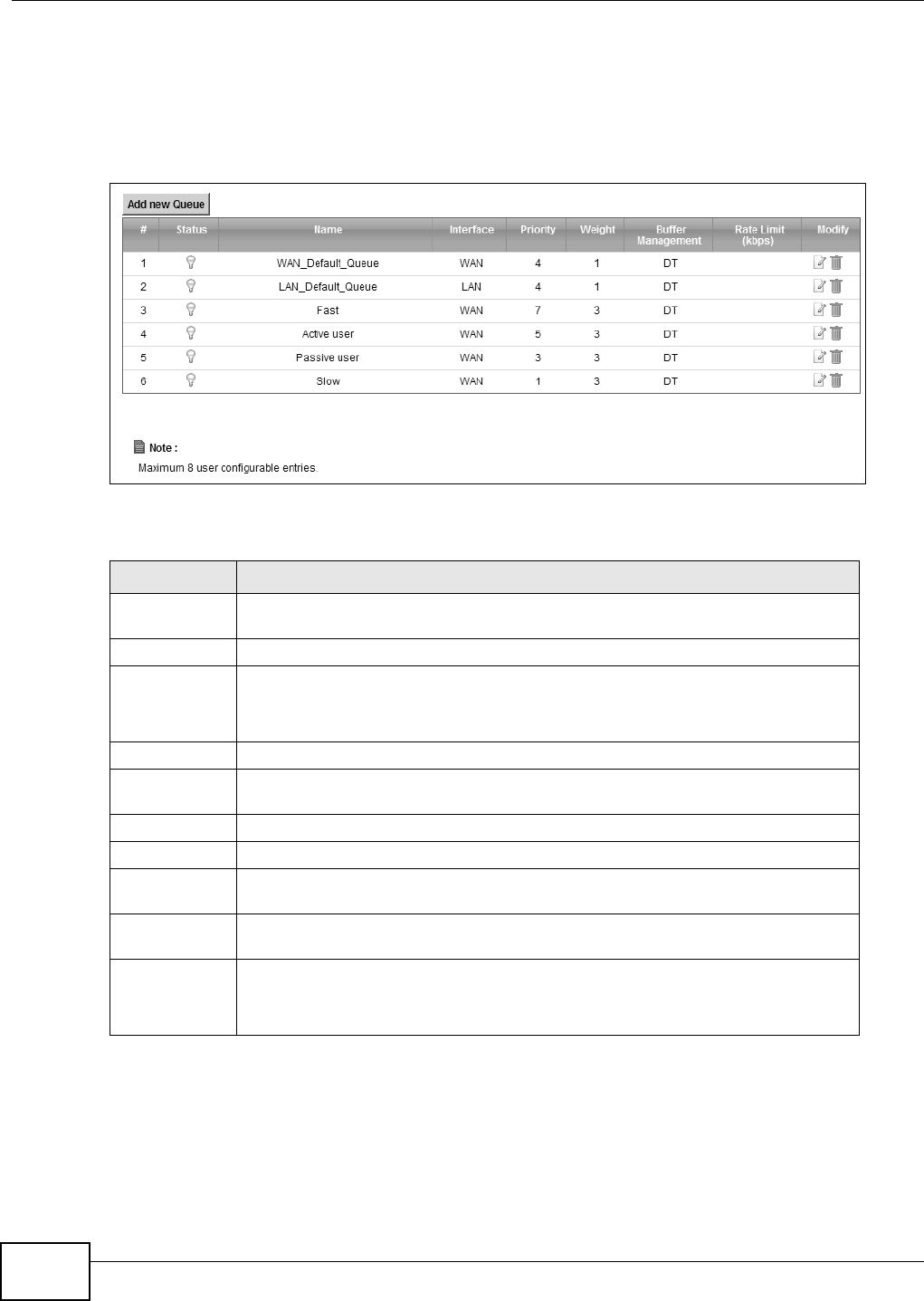
Chapter 9 Quality of Service (QoS)
B222s User’s Guide
86
9.3 The Queue Setup Screen
Use t his screen to configure QoS queue assignm ent . Click N e t w or k Set t ing > QoS > Que u e
Set u p to open t he screen as shown next.
Figure 47 Net work Set ting > QoS > Queue Setup
The following t able describes t he labels in t his screen.
Table 28 Network Set ting > QoS > Queue Set up
LABEL DESCRIPTION
Add new
Queue
Click t his t o creat e a new entr y.
#This is t he index num ber of this ent ry.
St atus This indicat es whet her t he queue is active or not.
A yellow bulb signifies t hat this queue is act ive. A gray bulb signifies t hat t his queue
is not act ive.
Nam e This show s t he descriptive nam e of t his queue.
I nt erface This show s t he nam e of t he LTE Device’s interface t hr ough which t raffic in this
queue passes.
Priorit y This shows t he priorit y of t his queue.
Wei gh t This shows t he weight of this queue.
Buffer
Managem ent
This show s t he queue m anagem ent algorithm used by t he LTE Dev ice.
Rat e Lim it
( k bps)
This shows t he m axim um transm ission rat e allow ed for t raffic on this queue.
Modify Click the Ed it icon t o edit t he queue.
Click t he D e le t e icon t o delet e an exist ing queue. Not e that subsequent r ules m ove
up by one when you take this action.
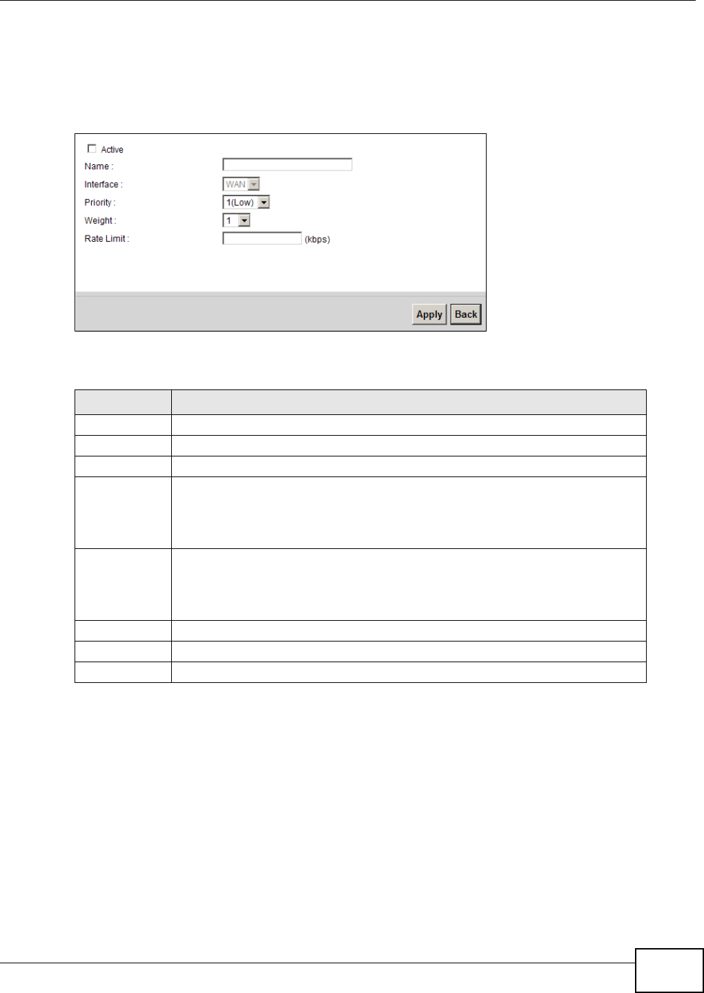
Chapter 9 Quality of Service (QoS)
B222s User’s Guide 87
9.3.1 Add/Edit a QoS Queue
Use t his screen to configure a queue. Click Add ne w queue in the Qu e ue Se t up screen or t he
Edit icon next t o an existing queue.
Figure 48 Queue Set up: Add/ Edit
The following t able describes t he labels in t his screen.
9.4 The Class Setup Screen
Use t his screen to add, edit or delet e QoS classifiers. A classifier groups t raffic int o dat a flows
according t o specific criteria such as t he source addr ess, dest inat ion address, sour ce port num ber,
destinat ion por t num ber or incom ing int erface. For exam ple, you can configure a classifier to select
traffic from t he sam e prot ocol port ( such as Telnet ) t o form a flow.
You can give different pr ior it ies t o t raffic that t he LTE Device forwards out t hrough t he WAN
int erface. Give high prior it y t o voice and video t o m ake t hem run m ore sm oot hly. Sim ilarly, give low
priorit y t o m any large file downloads so t hat t hey do not reduce t he qualit y of ot her applicat ions.
Table 29 Queue Setup: Add/ Edit
LABEL DESCRIPTION
Act ive Select t o enable or disable t his queue.
Nam e Ent er t he descript ive nam e of this queue.
I nt erface This show s t he int erface of this queue.
Priorit y Select t he priority level ( from 1 t o 7) of this queue.
The larger the num ber, the higher the priority level. Traffic assigned t o higher
prior ity queues gets t hrough fast er while t raffic in lower priorit y queues is dr opped
if t he net work is congested.
Wei gh t Select t he weight ( from 1 t o 15) of t his queue.
I f two queues have t he sam e pr iorit y lev el, t he LTE Device divides t he bandwidth
across t he queues according t o their weight s. Queues wit h larger weight s get m ore
bandw idt h than queues wit h sm aller weight s.
Rat e Lim it Specify the m ax im um t ransm ission rate (in Kbps) allowed for t raffic on t his queue.
Apply Click Apply to save your changes.
Back Click Ba ck t o return t o the previous screen wit hout saving.
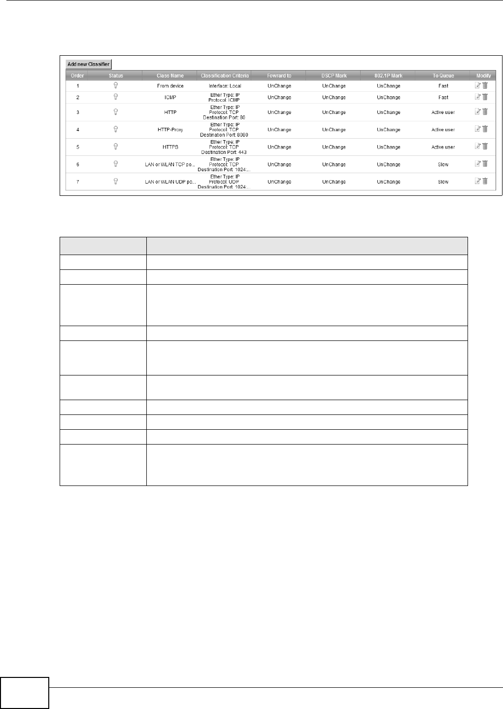
Chapter 9 Quality of Service (QoS)
B222s User’s Guide
88
Click N et w ork Set t ing > QoS > Cla ss Set up t o open t he following screen.
Figure 49 Net work Set ting > QoS > Class Set up
The following t able describes t he labels in t his screen.
Table 30 Network Sett ing > QoS > Class Set up
LABEL DESCRIPTION
Add new Classifier Click t his t o creat e a new classifier.
Order This field displays t he or der num ber of the classifier.
St atus This indicat es whet her t he classifier is active or not.
A yellow bulb signifies t hat t his classifier is active. A gray bulb signifies t hat t his
classifier is not active.
Class Nam e This is t he nam e of t he classifier.
Classification
Crit eria
This shows criteria specified in this classifier, for exam ple t he interface from
which traffic of this class should com e and t he source MAC address of t raffic
that m at ches t his classifier.
For w ar d t o This is t he int erface t hrough which traffic t hat m at ches t his classifier is
forwarded out .
DSCP Mark This is t he DSCP num ber added t o t raffic of t his classifier.
802.1p Mark This is t he I EEE 802.1p priorit y level assigned to t raffic of t his classifier.
To Q u e u e This is t he nam e of t he queue in which traffic of this classifier is put .
Modify Click the Ed it icon to edit t he classifier.
Click t he D e le t e icon t o delete an existing classifier. Not e that subsequent
rules m ove up by one when you t ake t his action.
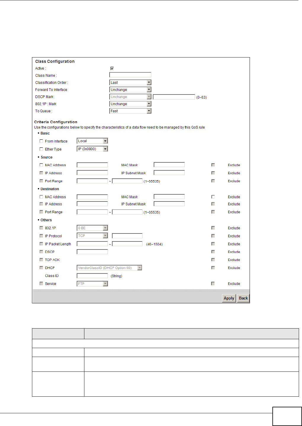
Chapter 9 Quality of Service (QoS)
B222s User’s Guide 89
9.4.1 Add/Edit QoS Class
Click Add new Classifie r in the Cla ss Set up screen or t he Edit icon next t o an existing classifier
to configure it .
Figure 50 Class Setup: Add/ Edit
The following t able describes t he labels in t his screen.
Table 31 Class Set up: Add/ Edit
LABEL DESCRIPTION
Class Configurat ion
Act ive Select t o enable t his classifier.
Class Nam e Enter a descript ive nam e of up to 32 print able English keyboard charact ers, including
spaces.
Classification Order Select an exist ing num ber for where you want t o put this classifier t o m ove t he classifier
to t he num ber you select ed aft er clicking Apply.
Select La st to put t his rule in t he back of t he classifier list .

Chapter 9 Quality of Service (QoS)
B222s User’s Guide
90
For w ar d t o
I nt erface
Select a WAN int erface through w hich traffic of t his class will be forwarded out . I f you
select Uncha ng e, t he LTE Device forward t raffic of t his class according t o t he default
routing t able.
DSCP Mark This field is available only when you select t he Et he r Type check box in Crit er ia
Con fig ur at ion - Ba sic sect ion.
I f you select Ma r k , enter a DSCP value wit h w hich t he LTE Device replaces t he DSCP
field in t he packets.
I f you select Unchange , t he LTE Device keep the DSCP field in t he packets.
802.1p Mark Select a prior it y level wit h which the LTE Device replaces t he I EEE 802.1p priorit y field in
the packets.
I f you select Unchange , the LTE Device keep the 802.1p priorit y field in t he packet s.
To Q u e u e Select a queue t hat applies t o this class.
You should have configured a queue in t he Que ue Se t u p screen already.
Crit eria Configuration
Use t he follow ing fields t o configur e t he crit eria for t raffic classificat ion.
Basic
From I nterface Select whether t he traffic class com es from t he LAN or a wireless int erface.
Ether Type Select a predefined applicat ion to configure a class for t he m at ched t raffic.
I f you select I P, you also need t o configure source or destinat ion MAC address, I P
address, DHCP opt ions, DSCP value or the prot ocol t ype.
I f you select 8 0 2 1 Q, you can configure an 802.1p prior ity level in the Ot h e r s section.
Source
MAC Address Select the check box and enter t he source MAC address of t he packet .
MAC Mask Type t he m ask for t he specified MAC address to determ ine which bits a packet’s MAC
address should m at ch.
Enter “ f” for each bit of t he specified source MAC address t hat t he t raffic’s MAC address
should m at ch. Enter “ 0“ for t he bit ( s) of t he m at ched t raffic’s MAC address, which can
be of any hexadecim al charact er( s). For exam ple, if you set t he MAC address t o
00: 13: 49: 00: 00: 00 and t he m ask t o ff: ff: ff: 00: 00: 00, a packet with a MAC address of
00: 13: 49: 12: 34: 56 m atches t his crit eria.
I P Address Select t he check box and ent er the source I P address in dot t ed decim al not at ion. A
blank source I P address m eans any source I P address.
I P Subnet Mask Enter the source subnet m ask.
Port Rang e I f you select TCP or UDP in the I P Pr otocol field, select t he check box and ent er the
port num ber( s) of t he source.
Exclude Select t his option t o exclude the packet s t hat m at ch t he specified criteria from t his
classifier.
Dest inat ion
MAC Address Select the check box and ent er t he destination MAC address of t he packet .
MAC Mask Type t he m ask for t he specified MAC address to determ ine which bits a packet’s MAC
address should m at ch.
Enter “ f” for each bit of t he specified source MAC address t hat t he t raffic’s MAC address
should m at ch. Enter “ 0“ for t he bit ( s) of t he m at ched t raffic’s MAC address, which can
be of any hexadecim al charact er( s). For exam ple, if you set t he MAC address t o
00: 13: 49: 00: 00: 00 and t he m ask t o ff: ff: ff: 00: 00: 00, a packet with a MAC address of
00: 13: 49: 12: 34: 56 m atches t his crit eria.
Table 31 Class Set up: Add/ Edit ( cont inued)
LABEL DESCRIPTION

Chapter 9 Quality of Service (QoS)
B222s User’s Guide 91
I P Address Select the check box and enter t he dest inat ion I P address in dot t ed decim al not ation. A
blank source I P address m eans any source I P address.
I P Subnet Mask Ent er t he destinat ion subnet m ask.
Port Rang e I f you select TCP or UDP in the I P Pr otocol field, select t he check box and ent er the
port num ber( s) of t he source.
Exclude Select t his option t o exclude the packet s t hat m at ch t he specified criteria from t his
classifier.
Ot hers
802.1p This field is available only when you select 8 0 2 .1 Q in t he Ethe r Type field.
Select t his opt ion and select a priorit y level ( between 0 and 7) from t he drop down list
box." 0" is t he lowest priorit y level and "7" is t he highest .
I P Prot ocol This field is available only when you select I P in t he Eth er Type field.
Select this option and select t he prot ocol ( service type) from TCP or UD P. I f you select
User de fined , enter the prot ocol ( service type) num ber.
I P Packet
Lengt h
This field is available only when you select I P in the Et he r Type field.
Select this option and enter t he m inim um and m axim um packet length (from 46 to
1504) in the fields provided.
DSCP This field is available only when you select I P in t he Et he r Type field.
Select this option and specify a DSCP (DiffServ Code Point ) num ber between 0 and 63 in
the field provided.
TCP ACK This field is available only when you select I P in the Et he r Type field.
I f you select this option, t he m at ched TCP packets m ust contain t he ACK ( Acknow ledge)
flag.
DHCP This field is available only when you select I P in the Et he r Type field, and UD P in the
I P Prot ocol field.
Select this opt ion and select a DHCP option.
I f you select Ve nd or Cla ss I D ( DH CP Opt ion 6 0 ) , ent er t he Class I D of the m at ched
traffic, such as t he t ype of t he hardware or firm ware.
I f you select Clie nt I D ( D H CP Opt ion 6 1 ) , ent er the Type of the m atched t raffic and
Clien t I D of t he DHCP client.
I f you select User Class I D ( D H CP Opt ion 7 7 ) , enter t he Use r Class D at a , which is a
st ring t hat ident ifies t he user’s category or applicat ion type in t he m atched DHCP
packet s.
I f you select Ven dor SpecificI nt ro ( DH CP Option 1 2 5 ) , ent er t he Ent er pr ise
N u m be r of t he soft ware of the m atched t raffic and Ven dor Cla ss Da t a used by all t he
DHCP clients.
Service Select the service classification of t he t raffic.
Exclude Select t his option t o exclude the packet s t hat m at ch t he specified criteria from t his
classifier.
Apply Click Apply t o save you r changes.
Back Click Back to ret urn t o the previous screen wit hout saving.
Table 31 Class Set up: Add/ Edit ( cont inued)
LABEL DESCRIPTION
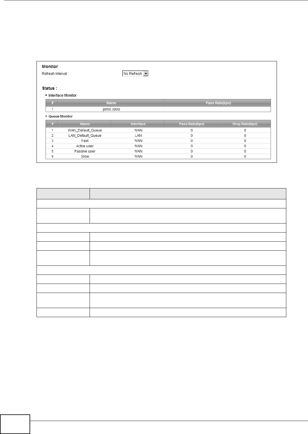
Chapter 9 Quality of Service (QoS)
B222s User’s Guide
92
9.5 The QoS Monitor Screen
To view the LTE Device’s QoS packet statistics, click N et w or k Set t ing > QoS > M on it o r. The
screen appears as shown.
Figure 51 Net work Set ting > QoS > Monit or
The following t able describes t he labels in t his screen.
9.6 QoS Technical Reference
This sect ion provides som e t echnical background inform ation about t he t opics covered in t his
chapt er.
Table 32 Network Sett ing > QoS > Monit or
LABEL DESCRIPTION
Monitor
Refresh I nt erval Select how oft en you want t he LTE Dev ice to update this screen. Select No
Refre sh t o stop refreshing stat istics.
St atus
# This is t he index num ber of t he ent r y.
Nam e This show s t he nam e of t he WAN int erface on t he LTE Device.
Pass Rat e ( bps) This shows how m uch traffic ( bps) forwarded t o t his int erface are t ransm itt ed
successfully.
Queue Monit or
# This is t he index num ber of t he ent r y.
Nam e This show s t he nam e of t he queue.
Pass Rat e ( bps) This shows how m uch traffic ( bps) assigned to t his queue ar e t ransm itt ed
successfully.
Drop Rat e ( bps) This shows how m uch traffic ( bps) assigned t o t his queue are dropped.

Chapter 9 Quality of Service (QoS)
B222s User’s Guide 93
9.6.1 IEEE 802.1p
I EEE 802.1p specifies t he user priorit y field and defines up to eight separat e t raffic t ypes. The
following t able describes t he t raffic types defined in t he I EEE 802.1d st andard ( which incor porat es
the 802.1p) .
9.6.2 IP Precedence
Sim ilar t o I EEE 802.1p prioritizat ion at layer- 2, you can use I P precedence t o priorit ize packet s in a
layer- 3 net work. I P precedence uses t hree bits of t he eight- bit ToS ( Type of Service) field in t he I P
header. There are eight classes of services ( ranging from zero t o seven) in I P precedence. Zero is
the lowest priorit y level and seven is the highest .
9.6.3 DiffServ
QoS is used t o priorit ize source-t o- destination t raffic flows. All packet s in the flow are given the
sam e priorit y. You can use CoS ( class of service) t o give different priorit ies t o different packet
types.
DiffSer v ( Different iated Services) is a class of service (CoS) m odel t hat m arks packets so t hat they
receive specific per- hop t reat m ent at DiffServ- com pliant net work devices along t he rout e based on
the application t ypes and t raffic flow. Packets are m arked wit h DiffServ Code Points ( DSCPs)
indicating t he level of service desired. This allows t he int erm ediar y DiffServ- com pliant network
devices t o handle t he packets differently depending on t he code point s wit hout t he need to
negotiat e pat hs or rem em ber st ate inform at ion for every flow. I n addit ion, applicat ions do not have
to request a part icular ser vice or give advanced notice of where t he t raffic is going.
DSCP and Per-Hop Behavior
DiffServ defines a new DS ( Differentiat ed Services) field to replace the Type of Service (TOS) field
in the I P header. The DS field cont ains a 2- bit unused field and a 6- bit DSCP field w hich can define
up t o 64 service levels. The following figure illust rat es the DS field.
Table 33 I EEE 802.1p Prior it y Level and Traffic Type
PRIORITY
LEVEL TRAFFIC TYPE
Level 7 Typically used for net work cont rol traffic such as rout er configurat ion m essages.
Level 6 Typically used for voice t raffic t hat is especially sensitiv e t o j it t er ( j it t er is t he
var iat ions in delay) .
Level 5 Typically used for video that consum es high bandwidt h and is sensitiv e t o j it ter.
Level 4 Typically used for controlled load, lat ency- sensitive t raffic such as SNA ( System s
Net work Archit ect ure) t ransact ions.
Level 3 Typically used for “ excellent effort ” or bet t er t han best effort and w ould include
im port ant business t raffic t hat can t olerat e som e delay.
Level 2 This is for “ spare bandwidth”.
Level 1 This is t ypically used for non- critical “ background” traffic such as bulk t ransfers t hat
are allow ed but that should not affect other applicat ions and users.
Level 0 Typically used for best- effort t raffic.

Chapter 9 Quality of Service (QoS)
B222s User’s Guide
94
DSCP is backward com patible wit h t he t hree precedence bit s in t he ToS oct et so that non- DiffServ
com pliant , ToS-enabled net work device will not conflict wit h t he DSCP m apping.
The DSCP value determ ines t he forwarding behavior, t he PHB ( Per- Hop Behavior) , t hat each packet
get s across t he DiffServ net work. Based on t he m arking rule, different kinds of traffic can be
m ar ked for different kinds of forwarding. Resources can t hen be allocated according to t he DSCP
values and t he configured policies.
DSCP ( 6 bit s) Unused ( 2 bit s)

B222s User’s Guide 95
CHAPTER 10
Network Address Translation (NAT)
10.1 Overview
NAT ( Net work Address Translat ion - NAT, RFC 1631) is the t ranslation of t he I P address of a host in
a packet , for exam ple, t he source address of an out going packet , used within one net work t o a
different I P address known within anot her network.
10.1.1 What You Can Do in this Chapter
• Use the Port For w arding screen t o configure forward incom ing service request s to t he server( s)
on your local network ( Sect ion 10.2 on page 96) .
• Use the DMZ screen t o vieiw and configure t he I P address of your net work DMZ. ( Sect ion 10.3
on page 99) .
• Use the Sessions screen to lim it the num ber of concurrent NAT sessions each client can use
(Section 10.4 on page 99) .
10.1.2 What You Need To Know
The following term s and concept s m ay help as you read this chapt er.
Inside/Outside and Global/Local
I nside/ out side denot es where a host is located relat ive t o t he LTE Device, for exam ple, t he
com puters of your subscribers are the inside hosts, while t he web servers on the I nt ernet are the
out side host s.
Global/ local denot es the I P address of a host in a packet as t he packet traverses a r out er, for
exam ple, t he local address refers t o the I P address of a host when the packet is in t he local
network, while t he global address refers t o t he I P address of t he host w hen t he sam e packet is
traveling in t he WAN side.
NAT
I n t he sim plest form , NAT changes the sour ce I P address in a packet received from a subscriber
( t he inside local address) t o anot her ( the inside global address) before forwarding t he packet t o t he
WAN side. When t he response com es back, NAT t ranslat es the destinat ion address ( the inside
global addr ess) back t o t he inside local address before forwarding it t o the original inside host.
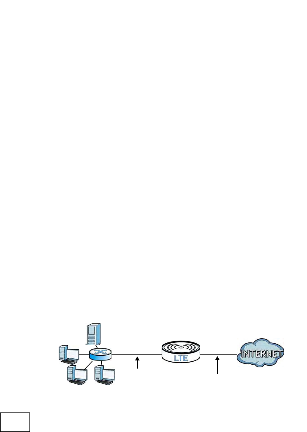
Chapter 10 Network Address Translation (NAT)
B222s User’s Guide
96
Port Forwarding
A port forwarding set is a list of inside (behind NAT on t he LAN) servers, for exam ple, web or FTP,
that you can m ake visible to t he out side w orld even though NAT m akes your whole inside network
appear as a single com put er to t he out side wor ld.
Finding Out More
See Sect ion 10.5 on page 100 for advanced technical inform at ion on NAT.
10.2 The Port Forwarding Screen
Use t he Port For w arding screen to forward incom ing service requests t o t he server( s) on your
local net work.
You m ay ent er a single port num ber or a range of port num bers t o be forwarded, and t he local I P
address of the desired server. The port num ber identifies a service; for exam ple, web service is on
port 80 and FTP on port 21. I n som e cases, such as for unknown ser vices or where one server can
support m ore t han one service ( for exam ple bot h FTP and web service) , it m ight be bett er to
specify a range of port num bers. You can allocate a server I P address t hat corresponds t o a port or
a range of port s.
The m ost oft en used port num bers and services are shown in Appendix E on page 249. Please refer
to RFC 1700 for furt her inform ation about port num bers.
Note: Many resident ial broadband I SP account s do not allow you t o run any server
processes ( such as a Web or FTP server) from your locat ion. Your I SP m ay
periodically check for servers and m ay suspend your account if it discovers any
act ive services at your locat ion. I f you ar e unsure, r efer t o your I SP.
Configuring Servers Behind Port Forwarding (Example)
Let's say you want t o assign port s 21- 25 t o one FTP, Telnet and SMTP server (A in t he exam ple) ,
port 80 t o another ( B in t he exam ple) and assign a default server I P address of 10.0.0.35 to a t hird
(C in the exam ple) . You assign t he LAN I P addr esses and t he I SP assigns t he WAN I P address. The
NAT net work appears as a single host on t he I nt er net .
Figure 52 Mult iple Servers Behind NAT Exam ple
A=10.0.0.33
D=10.0.0.36
C=10.0.0.35
B=10.0.0.34
WAN
LAN
10.0.0.1 IP Address assigned by ISP
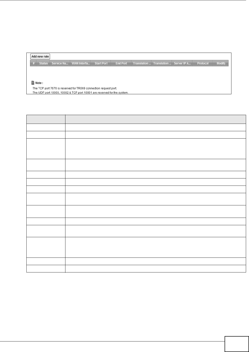
Chapter 10 Network Address Translation (NAT)
B222s User’s Guide 97
10.2.1 The Port Forwarding Screen
Click N et w ork Set t ing > N AT t o open t he Port Forw ar ding screen.
See Appendix E on page 249 for port num bers com m only used for part icular services.
Figure 53 Net work Set ting > NAT > Por t Forwarding
The following t able describes t he fields in t his screen.
Table 34 Network Sett ing > NAT > Por t Forwarding
LABEL DESCRIPTION
Add new rule Click t his t o add a new port forwarding rule.
#This is t he index num ber of t he ent ry.
St atus This field indicat es whether the rule is active or not .
A yellow bulb signifies t hat t his rule is active. A gray bulb signifies t hat t his rule is not
act ive.
Service Nam e This is t he ser vice’s nam e. This show s User De fin ed if you m anually added a service. You
can change t his by clicking the edit icon.
WAN I nt erface This shows t he WAN int erface t hrough which the ser vice is forw arded.
St art Port This is t he first ext ernal port num ber t hat identifies a service.
End Port This is t he last ext ernal port num ber that ident ifies a service.
Translat ion Start
Por t
This is t he first internal port num ber t hat ident ifies a service.
Tr a n sl a t io n En d
Por t
This is t he last int ernal port num ber t hat ident ifies a service.
Server I P Address This is t he server ’s I P address.
Prot ocol This show s t he I P prot ocol support ed by t his virtual server, whet her it is TCP, UDP, or
TCP/ UD P.
Modify Click the Ed it icon to edit t he port forwarding rule.
Click t he D e le t e icon to delet e an existing port forwarding rule. Note that subsequent
address m apping rules m ove up by one when you t ake t his action.
Apply Click Apply t o save your changes.
Cancel Click Ca ncel to restore your previously saved set t ings.
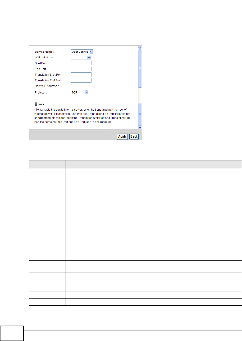
Chapter 10 Network Address Translation (NAT)
B222s User’s Guide
98
10.2.2 The Port Forwarding Edit Screen
This screen let s you creat e or edit a port forwarding rule. Click Add n e w rule in the Por t
Forw ar din g screen or t he Edit icon next t o an exist ing rule t o open t he following screen.
Figure 54 Port Forwarding: Add/ Edit
The following t able describes t he labels in t his screen.
Table 35 Port For warding: Add/ Edit
LABEL DESCRIPTION
Service Nam e Ent er a nam e t o ident ify this rule using keyboard charact ers ( A-Z, a-z, 1- 2 and so on) .
WAN I nt erface Select t he WAN interface t hrough w hich the ser vice is forwarded.
St art Port Enter t he original dest ination port for t he packet s.
To forward only one port, enter the port num ber again in t he Ex t e r na l End Por t field.
To forward a ser ies of port s, enter t he start port num ber her e and t he end port num ber in
the Ex t e rn al End Por t field.
End Port Ent er t he last port of the original destinat ion port range.
To forward only one port, enter t he port num ber in the Ext e r na l St ar t Por t field above
and t hen ent er it again in t his field.
To forward a series of port s, ent er t he last port num ber in a series that begins with t he
port num ber in the Ex t er nal St a rt Por t field above.
Translation Start
Por t
This shows t he port num ber t o which you want the LTE Device t o translat e t he incom ing
port . For a range of ports, ent er t he first num ber of t he range t o which y ou want the
incom ing por ts t ranslated.
Tr a n sl a t io n En d
Por t
This show s t he last port of t he t ranslated port range.
Server I P
Address
Enter t he inside I P address of t he virt ual server here.
Prot ocol Ty pe Select t he prot ocol support ed by t his virt ual server. Choices are TCP, UDP, or TCP/ UD P.
Apply Click Apply t o save you r changes.
Back Click Back t o return t o t he pr evious screen wit hout saving.
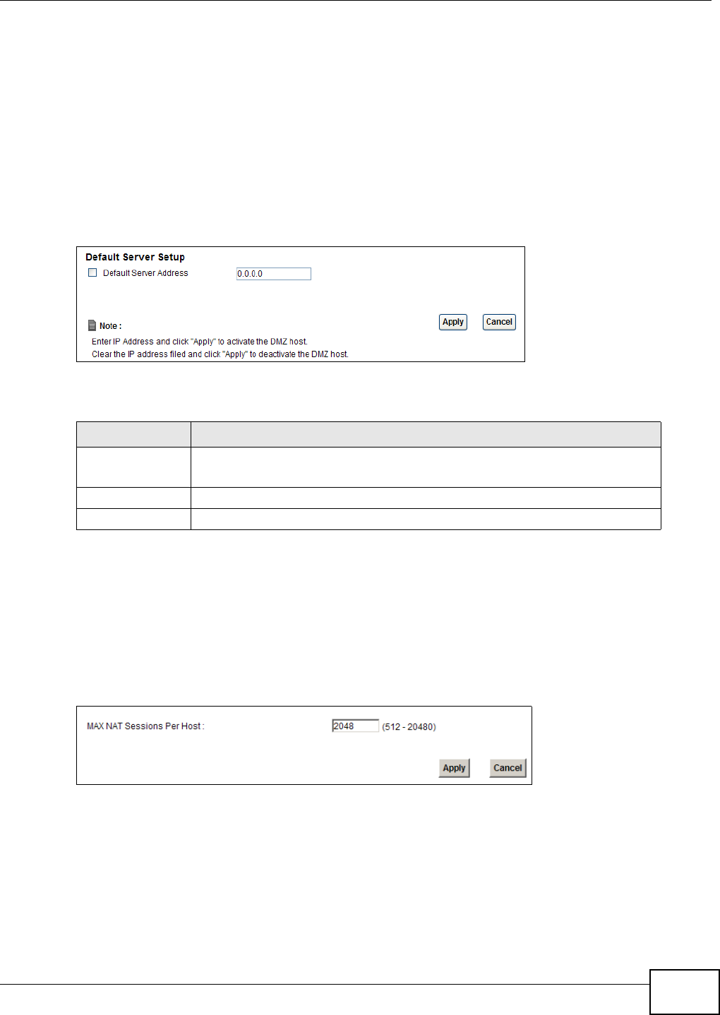
Chapter 10 Network Address Translation (NAT)
B222s User’s Guide 99
10.3 The DMZ Screen
Use t his page t o set the I P address of your net work DMZ ( if you have one) for t he LTE Device. All
incom ing packet s received by t his LTE Device’s WAN int erface will be forwarded t o t he default
server you set.
Click N et w ork Set t ing > N AT > DMZ t o display the following screen.
Note: The configurat ion you set in t his screen t akes priorit y t han t he N et w ork Se tt in g >
N AT > Port Forw a rding screen.
Figure 55 Net work Set ting > NAT > DMZ
The following t able describes t he fields in t his screen.
10.4 The Sessions Screen
Use t he Se ssion s screen t o lim it t he num ber of concurrent NAT sessions each client can use.
Click N et w ork Set t ing > N AT > Sessions t o display the following screen.
Figure 56 Net work Set ting > NAT > Sessions
Table 36 Network Sett ing > NAT > DMZ
LABEL DESCRIPTION
Default Server
Address Ent er t he I P address of your network DMZ host , if you have one. 0 .0 .0 .0 m eans
this feature is disabled.
Apply Click Apply t o save your changes.
Cancel Click Ca nce l t o rest ore your previously saved set t ings.

Chapter 10 Network Address Translation (NAT)
B222s User’s Guide
100
The following t able describes t he fields in t his screen.
10.5 Technical Reference
This sect ion provides som e t echnical background inform ation about t he t opics covered in t his
chapt er.
10.5.1 NAT Definitions
I nside/ out side denot es where a host is located relat ive t o t he LTE Device, for exam ple, t he
com puters of your subscribers are the inside hosts, while t he web servers on the I nt ernet are the
out side host s.
Global/ local denot es the I P address of a host in a packet as t he packet traverses a r out er, for
exam ple, t he local address refers t o the I P address of a host when the packet is in t he local
network, while t he global address refers t o t he I P address of t he host w hen t he sam e packet is
traveling in t he WAN side.
Note that inside/ out side refers t o t he locat ion of a host , while global/ local refers t o the I P address
of a host used in a packet . Thus, an inside local addr ess ( I LA) is the I P addr ess of an inside host in
a packet when t he packet is st ill in t he local network, while an inside global address ( I GA) is t he I P
address of the sam e inside host when t he packet is on t he WAN side. The following t able
sum m arizes t his inform ation.
NAT never changes the I P addr ess ( either local or global) of an out side host.
Table 37 Network Sett ing > NAT > Sessions
LABEL DESCRIPTION
MAX NAT Session Use this field to set a com m on lim it t o t he num ber of concurrent NAT sessions
each client com put er can have.
I f only a few clients use peer t o peer applications, you can raise t his num ber t o
im prove t heir perform ance. With heavy peer to peer applicat ion use, lower t his
num ber t o ensure no single client uses t oo m any of t he available NAT sessions.
Apply Click Apply t o save your changes.
Cancel Click Ca nce l t o rest ore your previously saved set t ings.
Table 38 NAT Definit ions
ITEM DESCRIPTION
I nside This refers t o t he host on t he LAN.
Outside This refers t o t he host on t he WAN.
Local This refers t o t he packet addr ess ( sour ce or dest inat ion) as t he packet travels on t he
LAN.
Global This refers t o t he packet address ( sour ce or dest inat ion) as t he packet travels on t he
WAN.
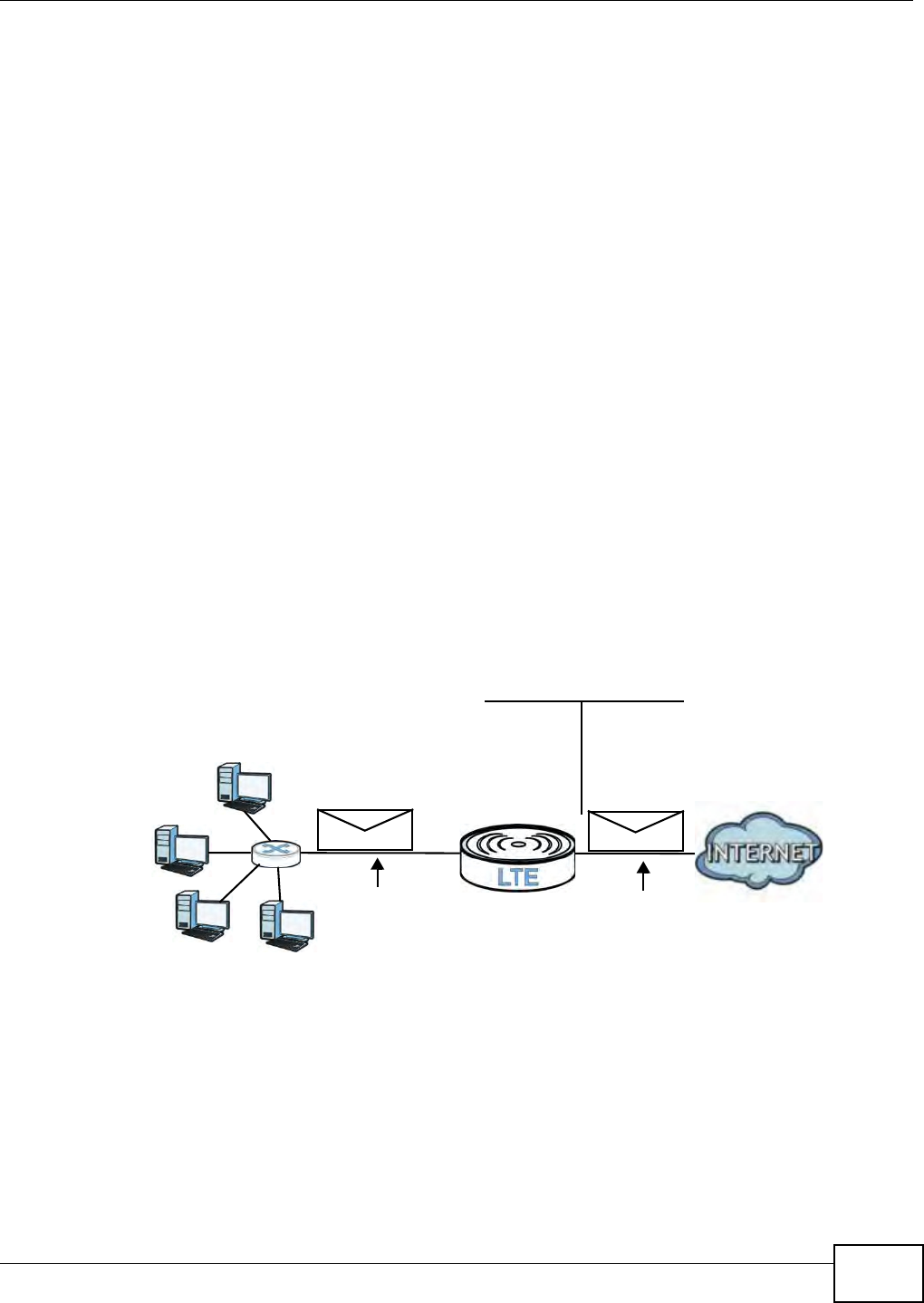
Chapter 10 Network Address Translation (NAT)
B222s User’s Guide 101
10.5.2 What NAT Does
I n t he sim plest form , NAT changes the sour ce I P address in a packet received from a subscriber
( t he inside local address) t o anot her ( the inside global address) before forwarding t he packet t o t he
WAN side. When t he response com es back, NAT t ranslat es the destinat ion address ( the inside
global addr ess) back t o t he inside local address before forwarding it t o t he original inside host . Not e
that t he I P address ( eit her local or global) of an out side host is never changed.
The global I P addresses for t he inside hosts can be eit her st atic or dynam ically assigned by t he I SP.
I n addit ion, you can designat e servers, for exam ple, a web ser ver and a Telnet server, on your local
network and m ake t hem accessible t o the outside world. I f you do not define any servers, NAT
offers t he additional benefit of firewall prot ection. With no servers defined, your LTE Device filt ers
out all incom ing inquiries, t hus prevent ing int ruders from probing your net work. For m ore
inform ation on I P address t ranslat ion, refer to RFC 1631, The I P Network Address Translator ( NAT) .
10.5.3 How NAT Works
Each packet has t wo addresses – a sour ce address and a destinat ion address. For outgoing packet s,
the I LA ( I nside Local Address) is the source address on t he LAN, and t he I GA ( I nside Global
Address) is t he source address on t he WAN. For incom ing packets, t he I LA is the dest inat ion
address on t he LAN, and t he I GA is t he dest ination address on t he WAN. NAT m aps privat e ( local)
I P addr esses t o globally unique ones r equired for com m unication wit h hosts on ot her networks. I t
replaces t he original I P source address ( and TCP or UDP source port num bers for Many- to- One and
Many-t o-Many Overload NAT m apping) in each packet and t hen forwards it to t he I nternet . The LTE
Device keeps t rack of the original addresses and port num bers so incom ing reply packet s can have
their original values restored. The following figure illust rat es this.
Figure 57 How NAT Works
192.168.1.13
192.168.1.10
192.168.1.11
192.168.1.12 SA
192.168.1.10
SA
IGA1
Inside Local
IP Address
192.168.1.10
192.168.1.11
192.168.1.12
192.168.1.13
Inside Global
IP Address
IGA 1
IGA 2
IGA 3
IGA 4
NAT Table
WAN
LAN
Inside Local
Address (ILA)
Inside Global
Address (IGA)

Chapter 10 Network Address Translation (NAT)
B222s User’s Guide
102

B222s User’s Guide 103
CHAPTER 11
Dynamic DNS
11.1 Overview
This chapt er discusses how to configure your LTE Device t o use Dynam ic DNS.
Dynam ic DNS allows you t o updat e your current dynam ic I P address wit h one or m any dynam ic
DNS services so that anyone can cont act you ( in applications such as NetMeet ing and CU- SeeMe) .
You can also access your FTP server or Web sit e on your own com puter using a dom ain nam e ( for
instance m yhost .dhs.org, where m yhost is a nam e of your choice) t hat will never change instead of
using an I P address t hat changes each t im e you reconnect . Your friends or relatives will always be
able to call you even if t hey don't know your I P address.
First of all, you need t o have regist ered a dynam ic DNS account wit h www.dyndns.org. This is for
people wit h a dynam ic I P from their I SP or DHCP server that would still like to have a dom ain nam e.
The Dynam ic DNS service provider will give you a password or key.
11.1.1 What You Need To Know
DYNDNS Wildcard
Enabling t he wildcard feat ure for your host causes * .yourhost .dyndns.org t o be aliased t o the sam e
I P addr ess as yourhost.dyndns.org. This feat ure is useful if you want t o be able t o use, for exam ple,
www.yourhost.dyndns.org and st ill reach your host nam e.
I f you have a privat e WAN I P address, t hen you cannot use Dynam ic DNS.
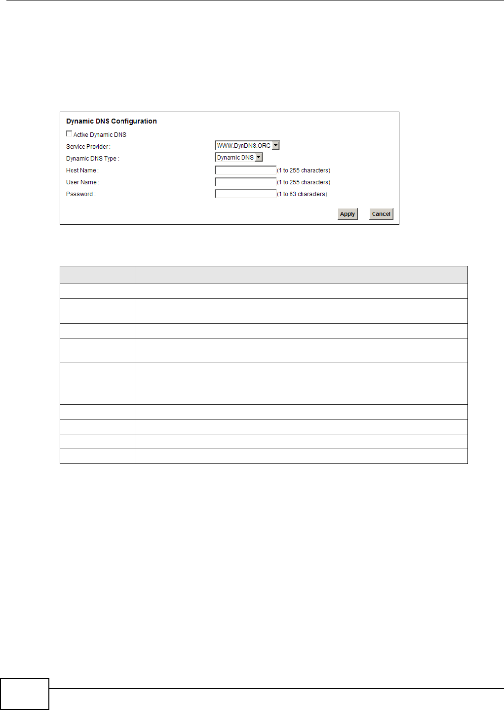
Chapter 11 Dynamic DNS
B222s User’s Guide
104
11.2 The Dynamic DNS Screen
Use t he D y na m ic DN S screen t o enable DDNS and configure t he DDNS settings on the LTE Device.
To change your LTE Device’s DDNS, click Net w or k Set t ing > Dynam ic D N S. The screen appears
as shown.
Figure 58 Net work Set ting > Dynam ic DNS
The following t able describes t he fields in t his screen.
Table 39 Network Sett ing > DNS
LABEL DESCRIPTION
Dynam ic DNS Configurat ion
Act ive Dynam ic
DNS
Select this check box t o use dy nam ic DNS.
Service Provider Select the nam e of your Dynam ic DNS ser vice provider.
Dynam ic DNS
Ty p e
Select t he type of serv ice that you are regist ered for from your Dy nam ic DNS
serv ice pr ovider.
Host Nam e Type t he dom ain nam e assigned t o your LTE Device by your Dynam ic DNS
provider.
You can specify up to tw o host nam es in t he field separated by a com m a ( ",") .
User Nam e Type your user nam e.
Passwor d Type t he password assigned t o you.
Apply Click Apply t o save your changes.
Cancel Click Ca ncel t o rest ore your previously saved set t ings.
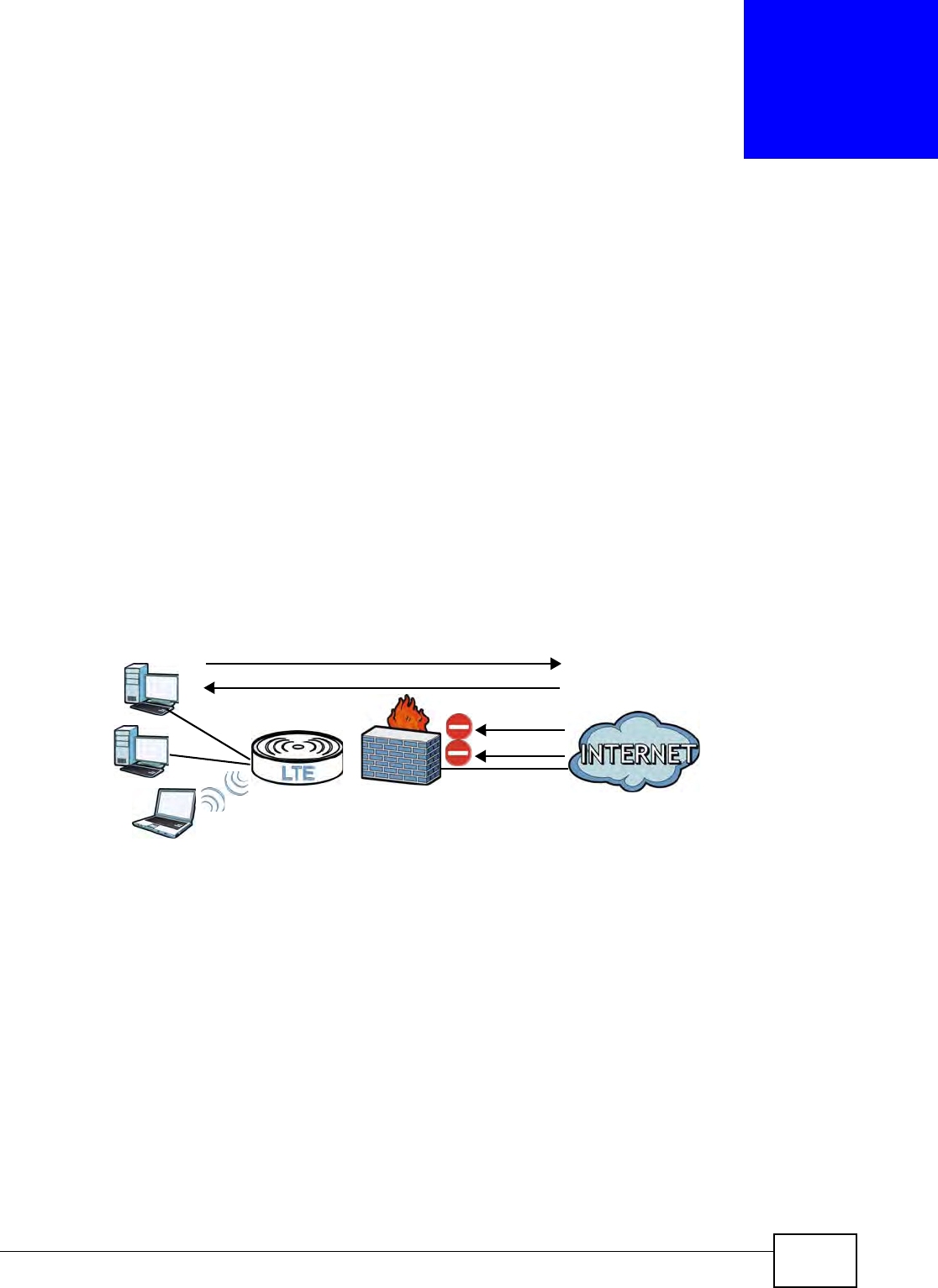
B222s User’s Guide 105
CHAPTER 12
Firewall
12.1 Overview
Use t he LTE Device firewall screens to enable and configure the firewall that protect s your LTE
Device and network fr om at t acks by hacker s on t he I nt ernet and cont rol access t o it. By default the
firewall:
• Allows traffic t hat originat es from your LAN and WLAN com put ers t o go t o all ot her networks.
• Blocks t raffic t hat originat es on ot her networks from going t o the LAN and WLAN.
The following figure illust rat es t he default fir ewall act ion. User A can initiat e an I M ( I nst ant
Messaging) session from the LAN to t he WAN (1) . Ret urn traffic for t his session is also allowed ( 2) .
However other t raffic init iated from t he WAN is blocked ( 3 and 4) .
Figure 59 Default Firewall Act ion
12.1.1 What You Can Do in this Chapter
• Use the Genera l screen t o enable or disable t he LTE Device’s firewall (Sect ion 12.2 on page
107) .
• Use the Ser vices screen to view t he configur ed firewall rules and add, edit or rem ove a firewall
rule ( Sect ion 12.3 on page 108) .
• Use the Access Cont rol screen t o view and configure incom ing/ out going filt ering rules ( Sect ion
12.4 on page 109) .
• Use the DoS screen to enable or disable Denial of Service ( DoS) prot ection ( Sect ion 12.4 on
page 109) .
WAN
LAN
3
4
1
2
A

Chapter 12 Firewall
B222s User’s Guide
106
12.1.2 What You Need to Know
DoS
Denials of Service ( DoS) at tacks are aim ed at devices and networks wit h a connect ion t o t he
I nt ernet. Their goal is not t o steal inform ation, but to disable a device or net work so users no longer
have access to net work resour ces. The ZyXEL Device is pre- configured t o autom atically detect and
thwart all known DoS at tacks.
Firewall
The LTE Device’s firewall feat ure physically separat es the LAN/ WLAN and the WAN and act s as a
secure gateway for all data passing bet w een t he net works.
I t is designed to prot ect against Denial of Serv ice (DoS) at t acks when act ivat ed. The LTE Device's
purpose is to allow a private Local Area Net work ( LAN) t o be securely connected to t he I nt ernet.
The LTE Device can be used t o prevent t heft , dest ruct ion and m odificat ion of dat a, as well as log
events, which m ay be im portant t o t he securit y of your network.
The LTE Device is installed between t he LAN/ WLAN and a broadband m odem connect ing t o t he
I nt ernet. This allows it to act as a secure gateway for all dat a passing bet ween t he I nt ernet and the
LAN.
The LTE Device has one Et hernet WAN port and four Ethernet LAN port s, which are used t o
physically separate the network int o two areas.The WAN ( Wide Area Net work) port at t aches to t he
broadband (cable or DSL) m odem to t he I nternet .
The LAN (Local Ar ea Networ k) port at taches t o a net w ork of com put ers, which needs securit y from
the out side world. These com put ers will have access t o I nt ernet services such as e- m ail, FTP and
the World Wide Web. However, "inbound access" is not allowed ( by default ) unless t he rem ot e host
is aut horized t o use a specific service.
ICMP
I nt ernet Cont rol Message Protocol ( I CMP) is a m essage control and error- report ing prot ocol
bet ween a host ser ver and a gat eway to t he I nternet . I CMP uses I nternet Prot ocol (I P) dat agram s,
but t he m essages are processed by the TCP/ I P soft ware and dir ectly apparent to t he applicat ion
user.
Finding Out More
See Sect ion 12.6 on page 112 for advanced technical inform at ion on firewall.
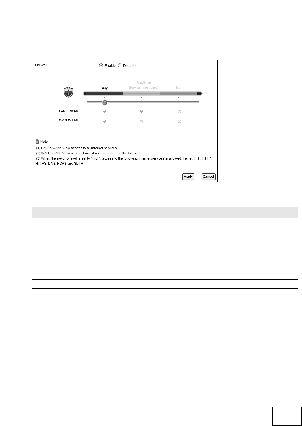
Chapter 12 Firewall
B222s User’s Guide 107
12.2 The General Screen
Use t his screen t o enable or disable t he LTE Device’s firewall. Click Securit y > Fir e w a ll t o open t he
Gen e ra l screen.
Figure 60 Secur it y > Firewall > General
The following t able describes t he labels in t his screen.
Table 40 Security > Firewall > General
LABEL DESCRIPTION
Fir ewall Select En able to act ivat e the firewall. The LTE Device perform s access cont rol and
prot ects against Denial of Service (DoS) at t acks w hen t he firewall is act ivated.
Easy, Medium ,
High
Select Ea sy to have the firewall allow bot h LAN- to-WAN and WAN- t o- LAN t raffic t o flow
t hr ough t he LTE Device.
Select Me dium t o have t he firewall only allow t raffic sent from t he LAN to t he WAN. All
traffic sent or access from t he WAN will be blocked.
Select High to have t he firewall only allow Telnet, FTP, HTTP, HTTPS, DNS, POP3, and
SMTP t raffic sent from the LAN t o the WAN. Other t raffic will be blocked.
Apply Click Apply t o save your changes.
Cancel Click Ca n ce l t o r est ore your previously saved set t ings.
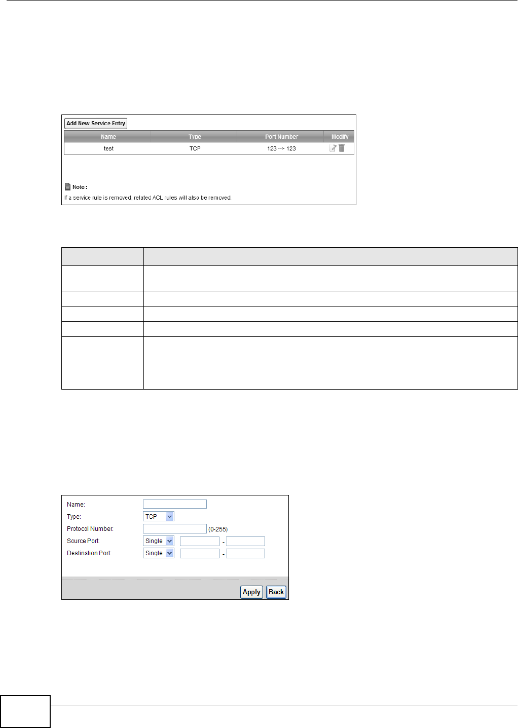
Chapter 12 Firewall
B222s User’s Guide
108
12.3 The Services Screen
Use t his screen t o view the configured service list . To access t his screen, click Securit y > Fire w all
> Ser vices. You have to configure at least one ser vice in this screen before configuring t he
Security > Fir e w a ll > Access Con t rol > Add N ew ACL Rule/ Edit screen.
Figure 61 Secur it y > Firewall > Ser vices
Each field is described in t he following t able.
12.3.1 The Add New Services Entry Screen
Use t his screen t o configure a service t hat you want t o use in an ACL rule in t he Secur it y >
Fir e w a ll > Access Con t rol > Add N e w ACL Rule/ Edit screen. To access t his screen, click
Security > Fir e w a ll > Ser vices and t hen t he Add New Serviice Ent r y but t on.
Figure 62 Secur it y > Firewall > Services > Add New Service Entry
Table 41 Security > Firewall > Services
LABEL DESCRIPTION
Add New Service
Ent ry
Click t his t o define a new service.
Nam e This is t he nam e of a configured service.
Ty p e This is t he prot ocol t ype ( TCP, UD P, I CMP or Ot h e rs) of t he service.
Por t Num ber This displays a range of port num bers t hat defines t he service.
Modify Click the Ed it icon t o edit t he ser vice.
Click t he D e le t e icon to delet e the ser vice. Not e t hat subsequent rules m ov e up by one
when you take t his action. Delet ing a serv ice rule also deletes t he relat ed ACL rules which
are configured in t he Secur it y > Fire w all > Acce ss Cont r ol screen.
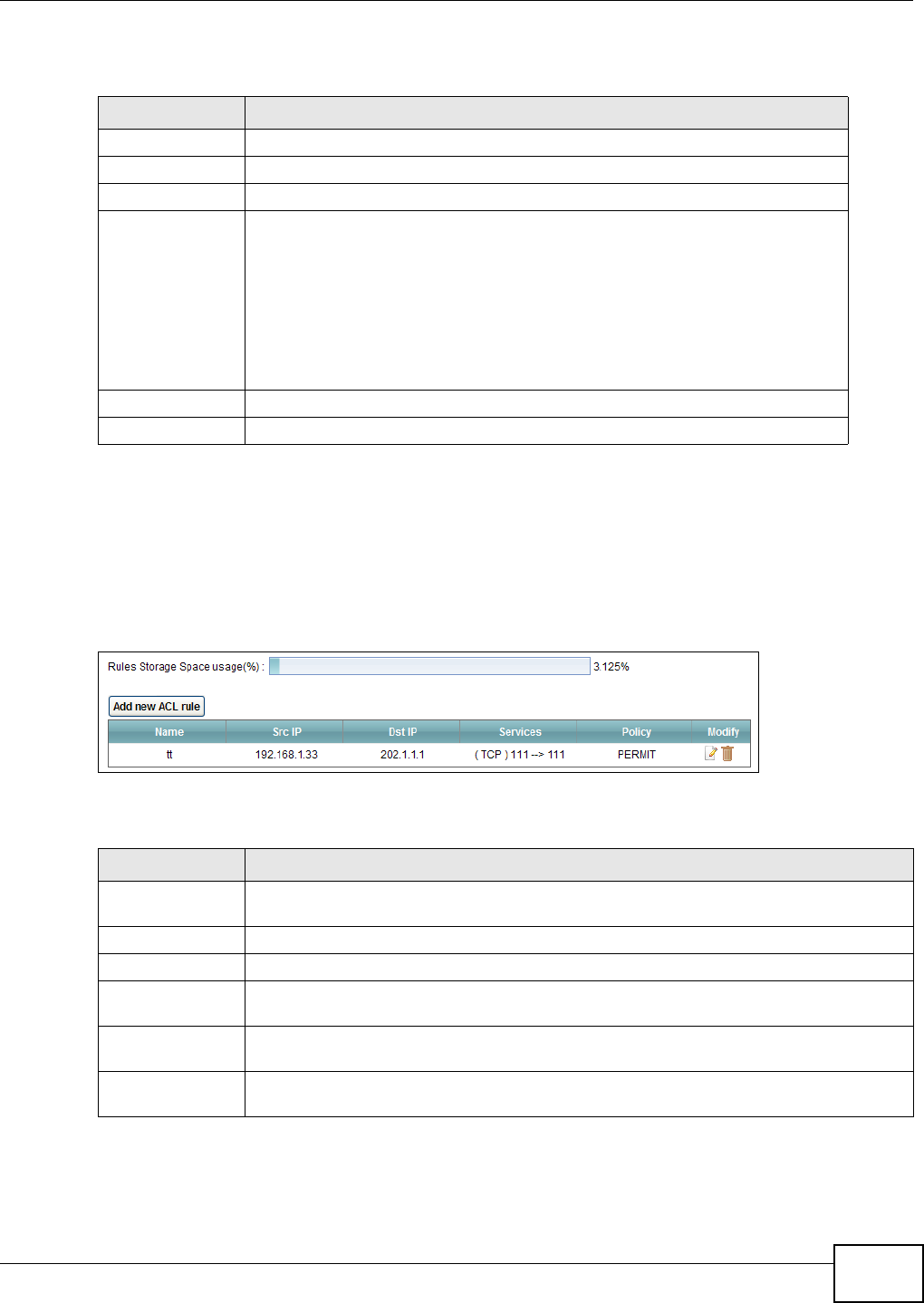
Chapter 12 Firewall
B222s User’s Guide 109
Each field is described in t he following t able.
12.4 The Access Control Screen
Click Securit y > Fir ew all > Access Con t rol t o display t he following screen. This screen displays a
list of the configured incom ing or out going filt ering rules.
Figure 63 Secur it y > Firewall > Access Cont rol
Each field is described in t he following t able.
Table 42 Security > Firewall > Services > Add New Service Ent ry
LABEL DESCRIPTION
Nam e Type a descriptive nam e for t he service.
Ty p e Select the prot ocol t ype ( TCP, UDP or I CMP or Oth er s) of the service.
Prot ocol Num ber Ent er the prot ocol num ber of t he service type.
Source Port,
Dest inat ion Por t
The source port defines from which port num ber( s) t he ser vice t raffic is sent .
The destinat ion port defines t he port num ber(s) t he dest inat ion host s use t o
receive t he service t raffic.
Select Single if t he service uses one and only one sour ce or dest ination port ,
then ent er the port num ber.
Select M ultiple if t he ser vice uses t wo or m ore source or dest inat ion por ts, t hen
ent er a port range. For exam ple, suppose you want t o define t he Gnutella
service. Select TCP t ype and ent er a port range of 6 3 4 5 -6 3 4 9 .
Apply Click Apply t o save you r changes.
Back Click Ba ck t o exit t his screen wit hout saving your changes.
Table 43 Security > Firewall > Access Control
LABEL DESCRIPTION
Rules Storage
Space usage( % )
This bar show s t he percent age of t he LTE Device’s space has been used. I f the usage is
alm ost full, you m ay need to rem ove an existing filt er r ule before you creat e a new one.
Add new ACL rule Click t his t o go t o add a filt er rule for incom ing or out going I P t raffic.
Nam e This displays t he nam e of t he rule.
Src I P This displays t he source I P addr esses t o w hich t his rule applies. Please note that a blank
source address is equivalent t o Any.
Dst I P This displays t he dest inat ion I P addr esses to which t his r ule applies. Please note t hat a
blank destinat ion address is equivalent t o Any.
Services This displays the prot ocol type and a port range t hat define t he ser vice t o which t his rule
applies.
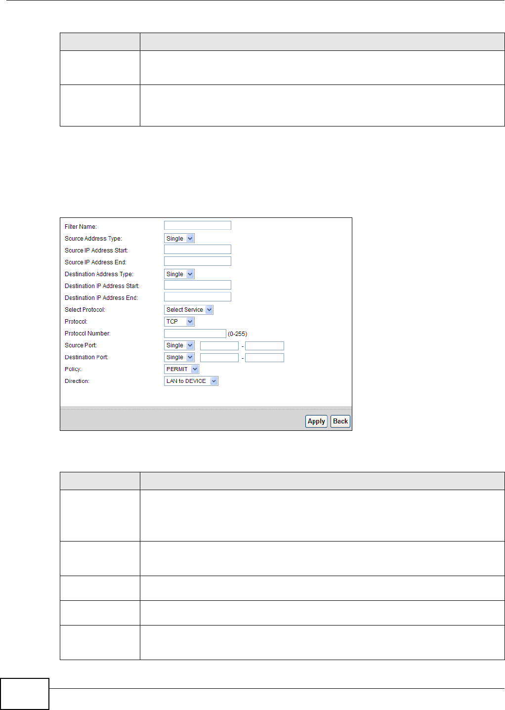
Chapter 12 Firewall
B222s User’s Guide
110
12.4.1 The Add New ACL Rule/Edit Screen
Click Add N ew ACL Ru le or t he Edit icon next t o an existing ACL rule in t he Acce ss Cont rol
screen. The following screen displays.
Figure 64 Secur it y > Firewall > Access Cont rol > Add New ACL Rule/ Edit
Each field is described in t he following t able.
Policy This field displays whether the rule silent ly discards packet s ( D ROP), discards packet s
and sends a TCP reset packet or an I CMP dest inat ion- unreachable m essage t o t he sender
(REJECT) or allows t he passage of packets ( PERM I T) .
Modify Click the Ed it icon to edit t he rule.
Click t he D e le t e icon to delet e an existing rule. Note that subsequent rules m ove up by
one when y ou t ake this action.
Table 43 Security > Firewall > Access Control (continued)
LABEL DESCRIPTION
Table 44 Security > Firewall > Access Control > Add New ACL Rule/ Edit
LABEL DESCRIPTION
Filt er Nam e Ent er a descr ipt ive nam e of up t o 16 alphanum eric charact ers, not including spaces,
underscores, and dashes.
You m ust enter t he filt er nam e t o add an ACL r ule. This field is read- only if you are editing
the ACL rule.
Source Addr ess
Ty p e
Select Single or Ra nge depending on w het her you want to ent er a single or a range of
source I P address( es) t o which the ACL rule applies. Select Any t o indicate any source I P
address.
Sour ce I P Addr ess
St art
Enter an I P address or t he st art ing I P address of t he source I P range.
Sour ce I P Addr ess
End
Enter t he ending I P address of t he source I P range.
Dest inat ion
Address Type
Select Single or Ra nge depending on w het her you want to ent er a single or a range of
destinat ion I P address( es) t o which t he ACL rule applies. Select Any t o indicat e any
destinat ion I P address.
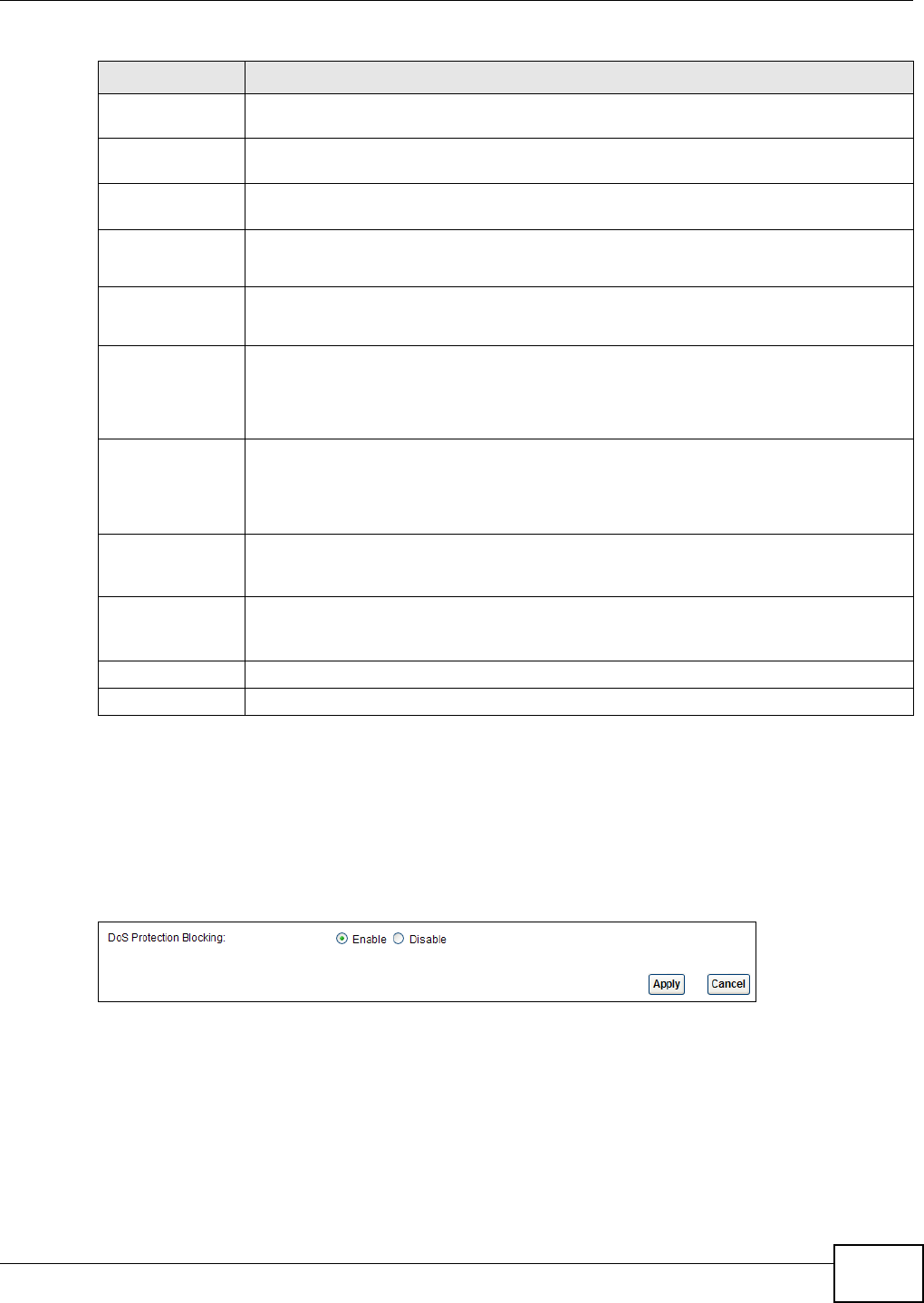
Chapter 12 Firewall
B222s User’s Guide 111
12.5 The DoS Screen
Click Secur it y > Fire w all > DoS t o display the following screen. Use t his screen t o enable or
disable Denial of Service ( DoS) protect ion.
Figure 65 Secur it y > Firewall > DoS
Dest inat ion I P
Address St art
Enter an I P address or t he st art ing I P address of t he destination I P range.
Dest inat ion I P
Address End
Enter t he ending I P address of the destinat ion I P range.
Select Prot ocol Select t he nam e of a configured service or select Se lect Ser vice to define a new service
in t his screen.
Prot ocol This field is available when you select Sele ct Se r vice in Se lect Pr ot ocol.
Choose the prot ocol t ype (TCP, UDP, I CMP or O t he r s) of t he service.
Prot ocol Num ber This field is available when you select Ot he r s in P ro t oco l.
Enter t he pr otocol num ber of the service type to w hich t his ACL rule applies.
Source Port This field is displayed only when you select Select Ser vice in Sele ct Pr otocol and TCP
or UDP in P rot o col.
Select Single or Ra nge and t hen ent er a single port num ber or the range of port
num bers of the source. Select An y t o indicat e any source port.
Dest inat ion Por t This field is displayed only when you select Select Ser vice in Select Pr otocol and TCP
or UDP in P rot o col.
Select Single or Ra nge and t hen ent er a single port num ber or the range of port
num bers of t he dest inat ion. Select Any t o indicate any destinat ion port .
Policy Use the drop- dow n list box t o select whether t o silent ly discard ( D ROP) , deny and send
an I CMP dest inat ion- unreachable m essage t o the sender of (REJECT) or allow t he
passage of ( PERM I T) packets that m atch this rule.
Direct ion Use t he drop- down list box to select t he direction of traffic t o which t his rule applies. The
possible options are LAN t o DEVI CE, LAN t o W AN , W AN t o LAN , and W AN t o
DEVI CE.
Apply Click Apply t o save you r changes.
Back Click Ba ck t o exit t his screen wit hout saving your changes.
Table 44 Security > Firewall > Access Control > Add New ACL Rule/ Edit ( cont inued)
LABEL DESCRIPTION

Chapter 12 Firewall
B222s User’s Guide
112
Each field is described in t he following t able.
12.6 Firewall Technical Reference
This sect ion provides som e t echnical background inform ation about t he t opics covered in t his
chapt er.
12.6.1 Guidelines For Enhancing Security With Your Firewall
1Change t he default password via web configurat or.
2Think about access control befor e you connect t o t he net work in any way.
3Lim it who can access your LTE Device.
4Don't enable any local service ( such as Telnet or FTP) t hat you don't use. Any enabled service could
present a pot ent ial security risk. A det erm ined hacker m ight be able to find creat ive ways to m isuse
the enabled services to access t he firewall or t he net work.
5For local services t hat are enabled, pr ot ect against m isuse. Prot ect by configuring t he ser vices to
com municate only wit h specific peers, and protect by configuring rules t o block packets for t he
services at specific int erfaces.
6Keep t he firewall in a secured (locked) room .
12.6.2 Security Considerations
Note: I ncorrectly configuring t he firewall m ay block valid access or introduce securit y
risks to the LTE Device and your protected net work. Use caution when creat ing or
delet ing firewall rules and t est your rules after you configure t hem .
Consider t hese securit y ram ifications before creat ing a rule:
1Does t his rule stop LAN users from accessing crit ical r esources on t he I nt ernet ? For exam ple, if I RC
is blocked, are t here users t hat require t his service?
2I s it possible t o m odify t he rule t o be m ore specific? For exam ple, if I RC is blocked for all users, will
a rule t hat blocks j ust cert ain users be m ore effect ive?
Table 45 Security > Firewall > DoS
LABEL DESCRIPTION
DoS Prot ect ion
Blocking
DoS ( Denial of Service) att acks can flood your I nt ernet connect ion w it h invalid packets
and connection request s, using so m uch bandwidt h and so m any resources t hat I nt ernet
access becom es unavailable.
Select En able to enable prot ect ion against DoS at t acks or D isa ble to disable it .
Apply Click Apply to save t he DoS Prot ect ion set t ings.
Cancel Click Ca nce l t o rest ore your previously saved set t ings.

Chapter 12 Firewall
B222s User’s Guide 113
3Does a rule t hat allows I nt ernet users access t o resources on the LAN creat e a security
vulnerability? For exam ple, if FTP port s (TCP 20, 21) are allowed from the I nt ernet t o t he LAN,
I nt ernet user s m ay be able t o connect t o com put ers wit h running FTP servers.
4Does t his rule conflict with any existing rules?
Once t hese questions have been answered, adding rules is sim ply a m atter of ent ering the
inform ation int o t he correct fields in t he web configurator screens.

Chapter 12 Firewall
B222s User’s Guide
114
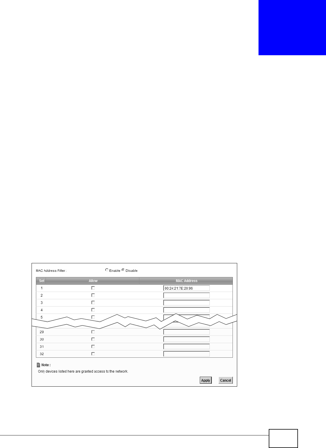
B222s User’s Guide 115
CHAPTER 13
MAC Filter
13.1 Overview
This chapt er discusses MAC address filt ering.
You can configure t he LTE Device t o perm it access to client s based on t heir MAC addresses in t he
MAC Filt er screen. This applies to wired and wireless connect ions.
13.1.1 What You Need to Know
Every Et hernet device has a unique MAC ( Media Access Cont rol) address. The MAC address is
assigned at the fact ory and consist s of six pairs of hexadecim al charact ers, for exam ple,
00: A0: C5: 00: 00: 02. You need t o know the MAC address of t he devices t o configure t his screen.
13.2 The MAC Filter Screen
Use t he M AC Filter screen t o allow wireless and LAN clients access t o t he LTE Device. To change
your LTE Device’s MAC filter settings, click Secur it y > M AC Filte r. The screen appears as shown.
Figure 66 Securit y > MAC Filt er

Chapter 13 MAC Filter
B222s User’s Guide
116
The following t able describes t he labels in t his m enu.
Table 46 Security > MAC Filt er
LABEL DESCRIPTION
MAC Address
Filt er
Select En able t o act ivat e MAC address filt ering.
Set This is t he index num ber of the MAC address.
Allow Select Allow to perm it access t o the LTE Device. MAC addresses not list ed will be
denied access t o t he LTE Device.
I f you clear this, t he MAC Addr e ss field for t his set clears.
MAC Address Enter t he MAC addresses of t he wireless st at ion and LAN devices that are allowed
access t o t he LTE Device in these address fields. Ent er t he MAC addresses in a valid
MAC address form at , that is, six hexadecim al charact er pairs, for exam ple,
12: 34: 56: 78: 9a: bc.
Apply Click Apply t o save you r changes.
Cancel Click Can cel t o rest ore your previously saved set t ings.
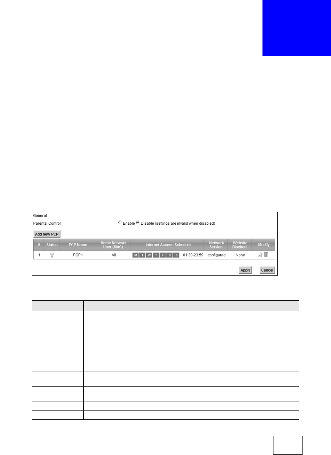
B222s User’s Guide 117
CHAPTER 14
Parental Control
14.1 Overview
Parent al cont rol allows you to block web sites wit h t he specific URL. You can also define t im e
periods and days during w hich t he LTE Device perform s parent al cont rol on a specific user.
14.2 The Parental Control Screen
Use t his screen to enable parent al cont rol, view t he parent al cont rol rules and schedules.
Click Secur it y > Pa r e nt a l Con t rol t o open t he following screen.
Figure 67 Securit y > Parental Control
The following t able describes t he fields in t his screen.
Table 47 Parent al Control > Parent al Cont rol
LABEL DESCRIPTION
Parent al Control Select En able t o activate parental cont rol.
Add new PCP Click t his if you want to configure a new parent al cont r ol rule.
#This shows t he index num ber of the r ule.
St atus This indicat es whether t he rule is active or not .
A yellow bulb signifies t hat t his rule is act ive. A gray bulb signifies t hat t his r ule is not
act ive.
PCP Nam e This show s t he nam e of t he rule.
Hom e Net work
User ( MAC)
This shows t he MAC address of t he LAN user’s com put er t o which t his rule applies.
I nt ernet Access
Schedule
This shows t he day( s) and t im e on which parent al control is enabled.
Net work Service This shows whether t he networ k ser vice is configured. I f not , N o ne will be shown.
Web sit e Block This shows whet her t he websit e block is configured. I f not , N on e w ill be shown.
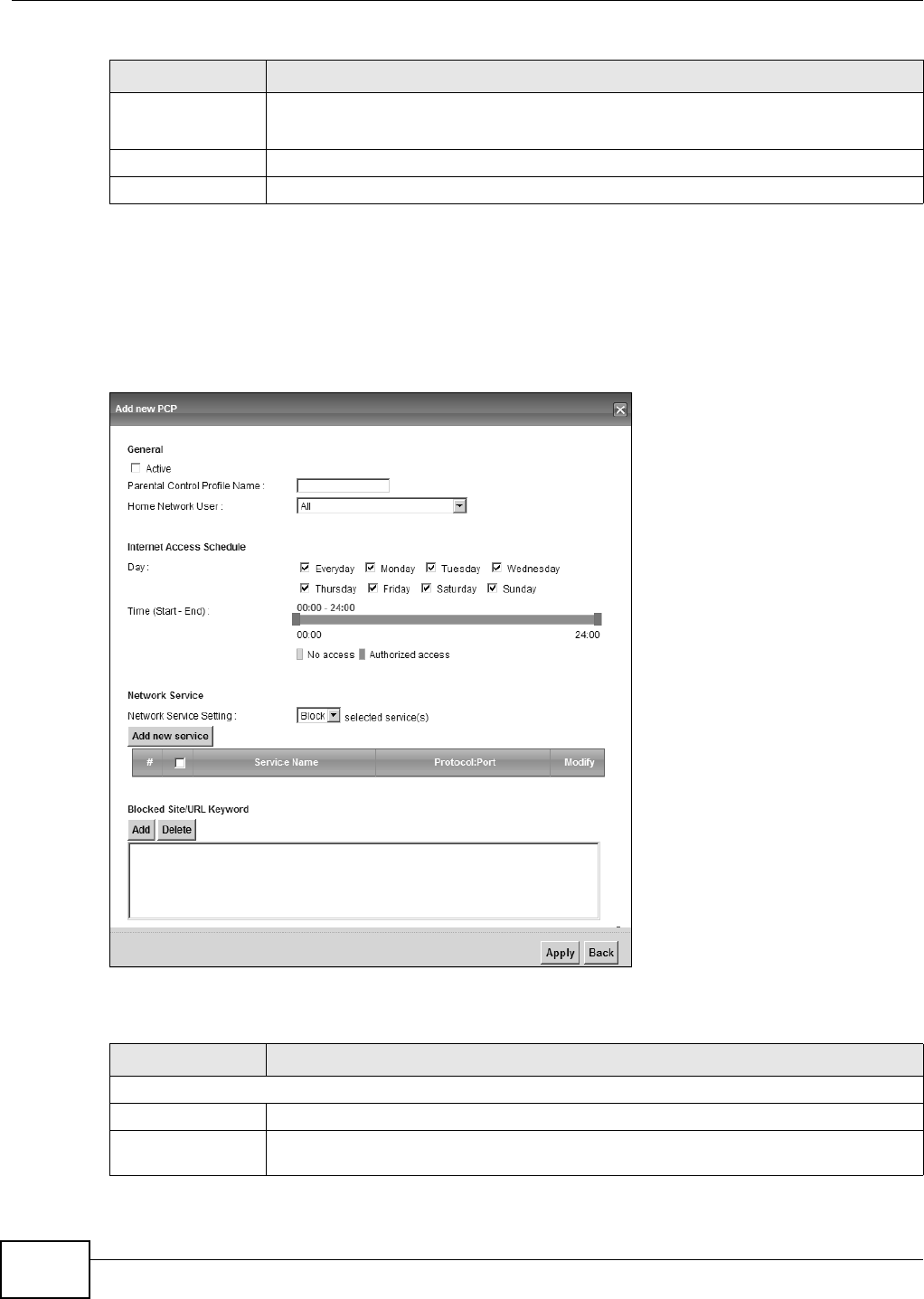
Chapter 14 Parental Control
B222s User’s Guide
118
14.2.1 Add/Edit a Parental Control Rule
Click Add new PCP in t he Pa r ent a l Con t rol screen t o add a new rule or click t he Edit icon next t o
an existing rule t o edit it. Use this screen to configure a restrict ed access schedule and/ or URL
filt ering set tings t o block the users on your net work from accessing certain web sit es.
Figure 68 Add/ Edit Par ent al Cont rol Rule
The following t able describes t he fields in t his screen.
Modify Click the Edit icon to go t o the screen where you can edit the r ule.
Click the D e le t e icon to delet e an existing rule.
Add Click Add to create a new schedule.
Apply Click Apply t o save your changes back t o the LTE Device.
Table 47 Parent al Control > Parent al Cont rol ( continued)
LABEL DESCRIPTION
Table 48 Add/ Edit Parental Control Rule
LABEL DESCRIPTION
General
Act ive Select the check box t o act ivat e this par ent al cont rol rule.
Parent al Control
Profile Nam e
Enter a descript ive nam e for t he rule.

Chapter 14 Parental Control
B222s User’s Guide 119
Hom e Net work
User
Select t he LAN user that you want t o apply t his rule to from the drop-down list box. I f
you select Cu st o m , ent er the LAN user’s MAC address. I f you select All, the r ule applies
t o all LAN user s.
I nt ernet Access Schedule
Day Select check boxes for t he days t hat you want the LTE Device to perform par ent al
cont rol.
St art Blocking Tim e
End Block ing Tim e
Enter the tim e period of each day, in 24- hour form at, during which parent al contr ol will
be enforced.
Tim e Drag t he t im e bar t o define t he t im e t hat the LAN user is allowed access.
Net work Service
Net work Service
Sett ing
I f you select Block, t he LTE Device prohibit s t he users from viewing t he Web sit es w it h
t he URLs listed below.
I f you select Access, t he LTE Device blocks access t o all URLs except ones list ed below.
Add new service Click this t o show a screen in which y ou can add a new service r ule. You can configure
the Ser vice N a m e, Pr ot ocol, and N a m e of t he new rule.
#This show s t he index num ber of t he rule. Select t he checkbox next t o the rule t o activat e
it.
Service Nam e This show s t he nam e of t he rule.
Prot ocol: Port This shows t he prot ocol and t he port of t he r ule.
Modify Click the Edit icon to go t o the screen where you can edit the r ule.
Click the D e le t e icon to delet e an existing rule.
Blocked Site/ URL
Ke y w or d
Click Add t o show a screen t o ent er t he URL of w eb sit e or URL keyword to which the
LTE Device blocks access. Click D e le t e t o rem ove it.
Apply Click t his but ton to save your set t ings back to t he LTE Device.
Back Click t his but t on t o ret urn t o the previous screen wit hout saving any changes.
Table 48 Add/ Edit Parental Control Rule (continued)
LABEL DESCRIPTION

Chapter 14 Parental Control
B222s User’s Guide
120

B222s User’s Guide 121
CHAPTER 15
VoIP
15.1 Overview
Use t his chapt er t o:
• Connect an analog phone t o t he LTE Device.
• Make phone calls over t he I nternet , as well as the regular phone net w ork.
• Configure set t ings such as speed dial.
• Configure network sett ings t o opt im ize the voice qualit y of your phone calls.
15.1.1 What You Can Do in this Chapter
These screens allow you t o configure your LTE Device t o m ake phone calls over t he I nt ernet and
your regular phone line, and t o set up t he phones you connect t o t he LTE Device.
• Use the SI P Se r vice Provide r screen t o configure t he SI P server infor m ation, QoS for VoI P
calls, t he num bers for cert ain phone funct ions ( Sect ion 15.2 on page 123) .
• Use the SI P Accou nt screen t o set up inform ation about your SI P account, control which SI P
account s t he phones connect ed to t he LTE Device use and configur e audio set tings such as
volum e levels for t he phones connected t o t he LTE Device ( Sect ion 15.3 on page 129) .
• Use the Ph one De vice screen t o cont rol which SI P account s t he phones connect ed t o t he LTE
Device use ( Sect ion 15.5 on page 133) .
• Use the Re gion screen t o change set t ings t hat depend on t he country you are in ( Sect ion 15.6
on page 134) .
• Use the Call Ru le screen t o set up short cuts for dialing frequently- used ( VoI P) phone num bers
(Section 15.7 on page 134) .
You don’t necessarily need t o use all t hese scr eens t o set up your account . I n fact , if your service
provider did not supply inform ation on a part icular field in a screen, it is usually best to leave it at
it s default sett ing.
15.1.2 What You Need to Know
The following term s and concept s m ay help as you read this chapt er.
VoIP
VoI P stands for Voice over I P. I P is t he I nternet Prot ocol, which is t he m essage- carrying standard
the I nt er net runs on. So, Voice over I P is t he sending of voice signals ( speech) over the I nt ernet ( or
anot her net work that uses t he I nternet Prot ocol) .

Chapter 15 VoIP
B222s User’s Guide
122
SIP
SI P st ands for Session I nitiat ion Prot ocol. SI P is a signalling standard that let s one network device
( like a com puter or the LTE Device) send m essages to anot her. I n VoI P, t hese m essages are about
phone calls over t he net work. For exam ple, when you dial a num ber on your LTE Device, it sends a
SI P m essage over t he net work asking the ot her device ( the num ber you dialed) t o t ake part in t he
call.
SIP Accounts
A SI P account is a type of VoI P account . I t is an arrangem ent wit h a service provider t hat let s you
m ake phone calls over t he I nternet . When you set the LTE Device t o use your SI P account t o m ake
calls, t he LTE Device is able t o send all the inform ation about t he phone call t o your service prov ider
on t he I nternet .
St r ictly speaking, you don’t need a SI P account . I t is possible for one SI P device ( like the LTE
Device) t o call anot her without involving a SI P service provider. However, t he net w orking difficult ies
involved in doing t his m ake it t rem endously im practical under norm al circum stances. Your SI P
account provider rem oves these difficulties by taking care of t he call rout ing and set up - figuring
out how to get your call t o the right place in a way that you and t he ot her person can t alk t o one
anot her.
Voice Activity Detection/Silence Suppression
Voice Activit y Det ection ( VAD) det ects whether or not speech is present . This let s the LTE Device
reduce t he bandwidt h t hat a call uses by not t ransm itt ing “ silent packet s” when you are not
speaking.
Comfort Noise Generation
When using VAD, the LTE Device generat es com fort noise when t he ot her part y is not speaking. The
com fort noise let s you know t hat t he line is still connected as t otal silence could easily be m ist aken
for a lost connect ion.
Echo Cancellation
G.168 is an I TU-T st andard for elim inat ing t he echo caused by the sound of your voice
reverberating in the telephone receiver while you t alk.
Use t his screen to m aint ain basic infor m ation about each SI P account . You can also enable and
disable each SI P account , configure t he volum e, echo cancellat ion and VAD ( Voice Act ivit y
Det ection) settings for each individual phone port on t he LTE Device.
How to Find Out More
See Chapt er 3 on page 33 for a t ut orial showing how t o set up these scr eens in an exam ple
scenario.
See Sect ion on page 135 for advanced technical inform ation on SI P.

Chapter 15 VoIP
B222s User’s Guide 123
15.1.3 Before You Begin
• Before you can use t hese screens, you need t o have a VoI P account already set up. I f you don’t
have one yet, you can sign up wit h a VoI P service provider over t he I nternet .
• You should have t he inform ation your VoI P service provider gave you ready, before you start t o
configure the LTE Device.
15.2 The SIP Service Provider Screen
Use t his screen t o configure t he SI P server inform ation, QoS for VoI P calls, the num bers for cert ain
phone functions and dialing plan. Click VoI P > SI P to open the SI P Se r vice Provide r screen.
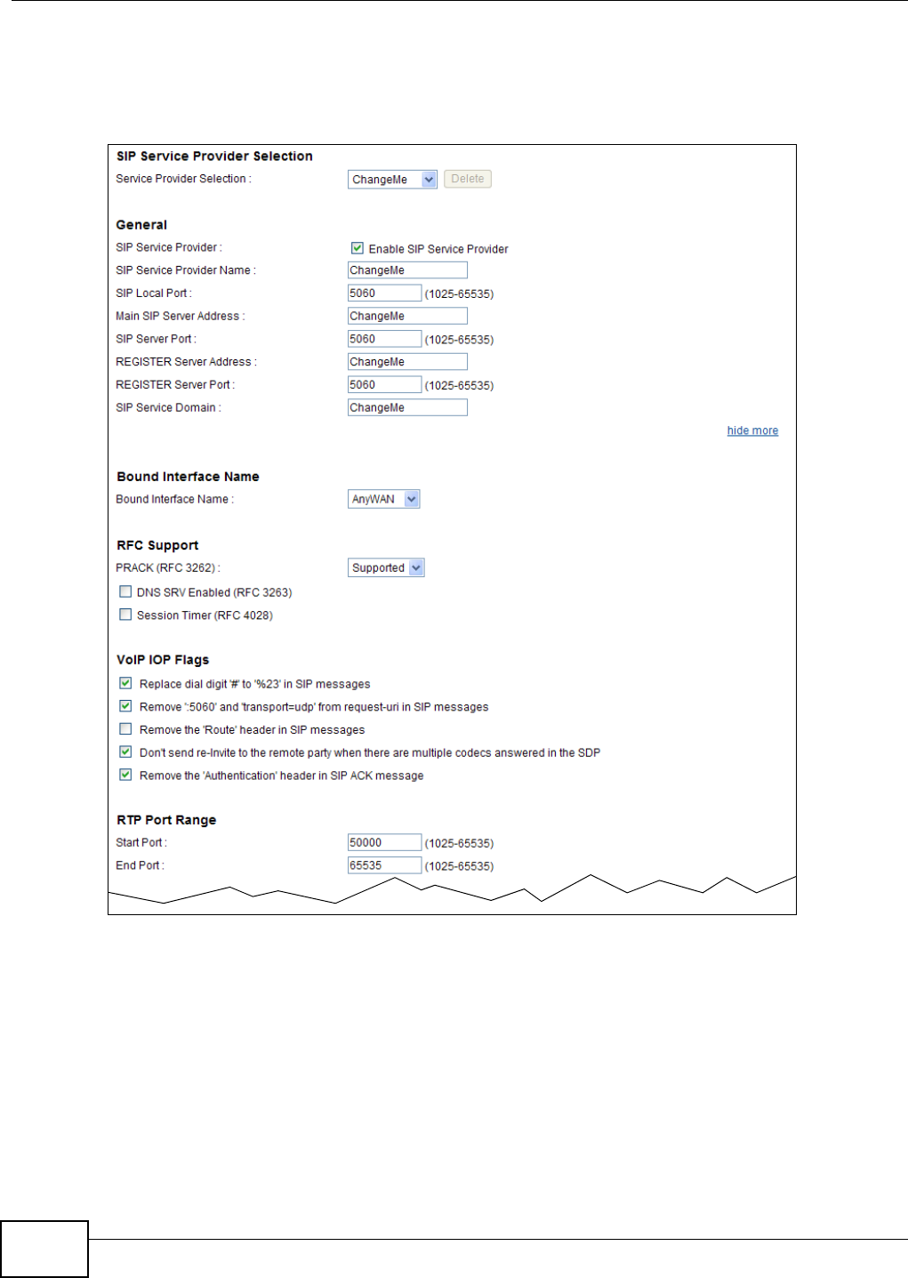
Chapter 15 VoIP
B222s User’s Guide
124
Not e: Click m or e ... to see all the fields in t he screen. You don’t necessarily need t o use
all these fields t o set up your account . Click hide m ore to see and configure only
the fields needed for t his feat ure.
Figure 69 VoI P > SI P > SI P Service Provider
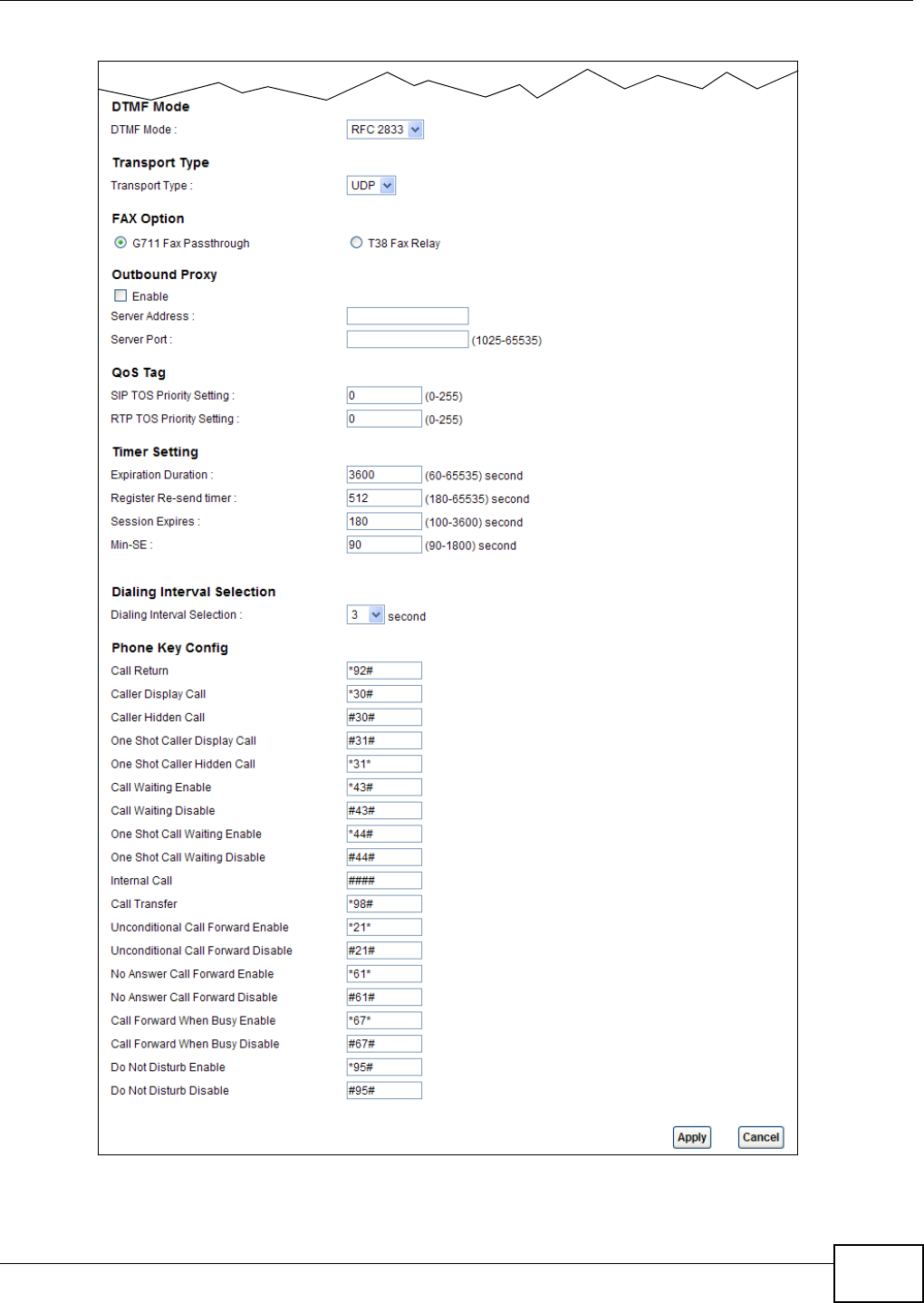
Chapter 15 VoIP
B222s User’s Guide 125

Chapter 15 VoIP
B222s User’s Guide
126
The following t able describes t he labels in t his screen.
Table 49 VoI P > SI P > SI P Service Provider
LABEL DESCRIPTION
SI P Service Provider Selection
Service Provider
Selection
Select the SI P service provider pr ofile you want to use for the SI P account you configure
in t his screen. I f you change this field, t he screen aut om at ically refreshes.
General
SI P Service
Provider
Select t his if you want the LTE Device to use t his SI P provider. Clear it if you do not want
the LTE Device t o use t his SI P provider.
SI P Service
Provider Nam e
Enter t he nam e of your SI P service provider.
SI P Local Port Ent er t he LTE Device’s list ening port num ber, if your VoI P service prov ider gave you one.
Ot herwise, keep t he default value.
Main SI P Server
Address
Enter t he I P address or dom ain nam e of t he SI P server provided by your VoI P service
provider. You can use up to 95 print able ASCII charact ers. I t does not m at t er whet her t he
SI P server is a proxy, redirect or register server.
SI P Server Port Ent er t he SI P server ’s listening port num ber, if your VoI P service provider gave you one.
Ot herwise, keep t he default value.
REGI STER Server
Address
Enter t he I P address or dom ain nam e of t he SI P regist er server, if your VoI P service
provider gave you one. Ot herw ise, ent er t he sam e address you ent ered in t he SI P Ser ver
Addre ss field. You can use up to 95 print able ASCI I charact ers.
REGI STER Server
Por t
Enter t he SI P r egister server’s listening port num ber, if your VoI P service provider gave
you one. Otherwise, ent er the sam e port num ber you ent ered in t he SI P Se rve r Port
field.
SI P Service
Dom ain
Enter t he SI P service dom ain nam e. I n the full SI P URI , t his is t he part after t he @
sym bol. You can use up to 127 print able ASCII Extended set charact ers.
RFC Support
PRACK ( RFC
3262)
RFC 3262 defines a m echanism to provide r eliable t ransm ission of SI P pr ovisional
response m essages, which convey inform ation on t he processing progress of t he request .
This uses t he opt ion t ag 100r el and t he Provisional Response ACKnowledgem ent ( PRACK)
m et hod.
Select Suppor t e d or Requ ir ed t o have the LTE Device include a SI P Require/ Support ed
header field wit h t he option t ag 100rel in all I NVI TE requests. When the LTE Device
receiv es a SI P response m essage indicat ing t hat t he phone it called is ringing, the LTE
Device sends a PRACK m essage t o have bot h sides confirm t he m essage is received.
I f you select Suppor t ed, t he peer device support s t he opt ion t ag 100rel t o send
provisional responses r eliably.
I f you select Re quir e d, the peer device requires the opt ion t ag 100rel t o send provisional
responses reliably.
Select Disable d to t urn off t his funct ion.
DNS SRV Enabled
( RFC 3263)
Select t his option t o have t he LTE Device use DNS procedur es to resolve t he SI P dom ain
and find t he SI P server ’s I P address, port num ber and suppor ted t ransport pr otocol( s).
The LTE Device first uses DNS Nam e Aut hority Pointer ( NAPTR) records t o det erm ine the
transport prot ocols support ed by t he SI P ser ver. I t then perform s DNS Ser vice ( SRV)
query to det erm ine the port num ber for t he prot ocol. The LTE Device r esolves the SI P
server’s I P address by a st andard DNS address record lookup.
Session Tim er
( RFC 4028)
Select this t o have t he LTE Device support RFC 4028.
This m akes sure t hat SI P sessions do not hang and t he SI P line can alw ays be available
for use.
RTP Port Range

Chapter 15 VoIP
B222s User’s Guide 127
St art Port
End Port
Enter t he list ening port num ber( s) for RTP t raffic, if your VoI P service prov ider gave you
this inform at ion. Otherwise, keep t he default values.
To ent er one port num ber, enter t he por t num ber in t he St a r t Por t and End Por t fields.
To ent er a range of port s,
• ent er t he port num ber at t he beginning of t he range in the Sta r t Port field.
• ent er the port num ber at t he end of the range in the End Por t field.
DTMF Mode Cont rol how t he LTE Device handles the t ones t hat your t elephone m akes when you push
it s but t ons. You should use the sam e m ode your VoI P serv ice pr ovider uses.
RFC2 8 3 3 - send t he DTMF tones in RTP packets.
PCM - send the DTMF t ones in the voice data stream . This m et hod works best when you
are using a codec t hat does not use com pression ( like G.711) . Codecs that use
com pression ( like G.729 and G.726) can distort t he t ones.
SI P I N FO - send t he DTMF t ones in SI P m essages.
Tr a n sp o r t Ty p e
Tr a n sp o r t Ty p e Select t he t ransport layer prot ocol UDP or TCP ( usually UDP) used for SI P.
FAX Opt ion This field cont rols how t he LTE Device handles fax m essages.
G711 Fax
Passt h rou gh
Select this if t he LTE Device should use G.711 t o send fax m essages. The peer devices
m ust also use G.711.
T38 Fax Relay Select this if the LTE Device should send fax m essages as UDP or TCP/ I P packet s t hrough
I P net works. This provides bet t er qualit y, but it m ay have int er- operability problem s. The
peer devices m ust also use T.38.
Outbound Proxy
Enable Select t his if your VoI P service provider has a SI P out bound server t o handle voice calls.
This allows t he LTE Device t o work wit h any type of NAT rout er and elim inat es t he need
for STUN or a SI P ALG. Turn off any SI P ALG on a NAT r ou t er in front of t he LTE Dev ice t o
keep it from re- t ranslating t he I P address ( since t his is already handled by the outbound
proxy server) .
Server Addr ess Ent er the I P addr ess or dom ain nam e of t he SI P outbound proxy server.
Server Port Enter t he SI P out bound proxy server’s listening port , if your VoI P ser vice provider gave
you one. Otherwise, keep t he default value.
QoS Tag
SI P TOS Pr iority
Sett ing
Enter t he DSCP ( DiffServ Code Point ) num ber for SI P m essage t ransm issions. The LTE
Device creat es Class of Service (CoS) priority t ags wit h t his num ber t o SI P t raffic t hat it
t ransm it s.
RTP TOS Priority
Sett ing
Enter t he DSCP ( DiffServ Code Point ) num ber for RTP voice t ransm issions. The LTE Device
creat es Class of Service (CoS) priority t ags with t his num ber t o RTP t raffic t hat it
t ransm it s.
Tim er Setting
Expiration
Durat ion
Enter t he num ber of seconds your SI P account is registered wit h t he SI P regist er server
before it is delet ed. The LTE Device aut om at ically t ries t o re- regist er your SI P account
when one- half of t his t im e has passed. ( The SI P register server m ight have a different
expir at ion .)
Regist er Re- send
t im er
Ent er the num ber of seconds t he LTE Device wait s before it tries again t o register t he SI P
account, if t he first try failed or if t here is no response.
Session Expires Enter t he num ber of seconds t he LTE Device lets a SI P session rem ain idle (w ithout traffic)
before it autom atically disconnects the session.
Table 49 VoI P > SI P > SI P Service Prov ider ( cont inued)
LABEL DESCRIPTION

Chapter 15 VoIP
B222s User’s Guide
128
Min-SE Enter the m inim um num ber of seconds t he LTE Dev ice lets a SI P session rem ain idle
( wit hout t raffic) before it aut om at ically disconnects t he session. When t wo SI P devices
st art a SI P session, they m ust agree on an expiration tim e for idle sessions. This field is
the short est expirat ion t im e t hat t he LTE Device accept s.
Dialing I nterval Selection
Dialing I nt erval
Selection
Ent er the num ber of seconds t he LTE Device should wait aft er you stop dialing num bers
before it m akes t he phone call. The value depends on how quickly you dial phone
num bers.
Phone Key Config
Use this section t o cust om ize t he phone keypad com binations you use to access cert ain feat ures on the LTE
Device.
Call Return Thi s cod e is u sed t o t u r n t he call r et u r n f eat ure on. Wit h call ret urn, you can place a call t o
the last num ber that called you ( eit her answered or m issed) .
Caller Display Call This code is used t o display t he caller I D for outgoing calls.
Caller Hidden Call This code is used to hide t he caller I D for out going calls.
One Shot Caller
Display Call
This code is used t o display t he caller I D only for t he phone call your are going to m ake.
One Shot Caller
Hidden Call
This code is used t o hide t he caller I D only for t he phone call your ar e going t o m ake.
Call Wait ing
Enable
This code is used t o turn the Call Wait ing feat ure on. With call wait ing, you hear a special
beep notifying another incom ing call while you are answering a call. I t allows you to place
the first incom ing call on hold and answer the second call so t hat you won’t m iss any
im port ant calls.
Call Wait ing
Disable
This code is used t o t urn t he Call Wait ing feature off.
One Shot Call
Wait ing Enable
This code is used t o enable call wait ing only for the phone call your are going to m ake.
See t he descript ion for t he Call Wait ing Enable field for m or e inform at ion.
One Shot Call
Wait ing Disable
This code is used t o disable one shot call waiting.
I nt ernal Call Th i s cod e is u sed t o en ab le in t er n al call s t hat allow s y o u t o call fr om on e p h on e t o an ot h er
phone connect ed t o t he LTE Device.
Call Transfer This code is used t o enable call t ransfer that allows you t o t ransfer an incom ing call ( t hat
you have answ ered) to anot her phone.
Unconditional Call
Forward Enable
This code is used t o enable unconditional call forwarding. I ncom ing calls are alway s
forwarded t o a specified num ber w it hout any condit ion.
Unconditional Call
Forward Disable
This code is used t o disable uncondit ional call forwarding.
No Answer Call
Forward Enable
This code is used t o enable call for warding when t here is no answer at a SI P num ber.
No Answer Call
Forward Disable
This code is used t o disable call for warding when t here is no answer at a SI P num ber.
Call Forward
When Busy
Enable
This code is used t o enable call forwarding w hen the phone is busy.
Call Forward
When Busy
Disable
This code is used t o disable call forwarding w hen the phone is busy.
Do Not Disturb
Enable
This code is used t o t urn t he Do Not Dist urb feature on. This has t he LTE Device not
forward calls to t he phone line.
Table 49 VoI P > SI P > SI P Service Prov ider ( cont inued)
LABEL DESCRIPTION
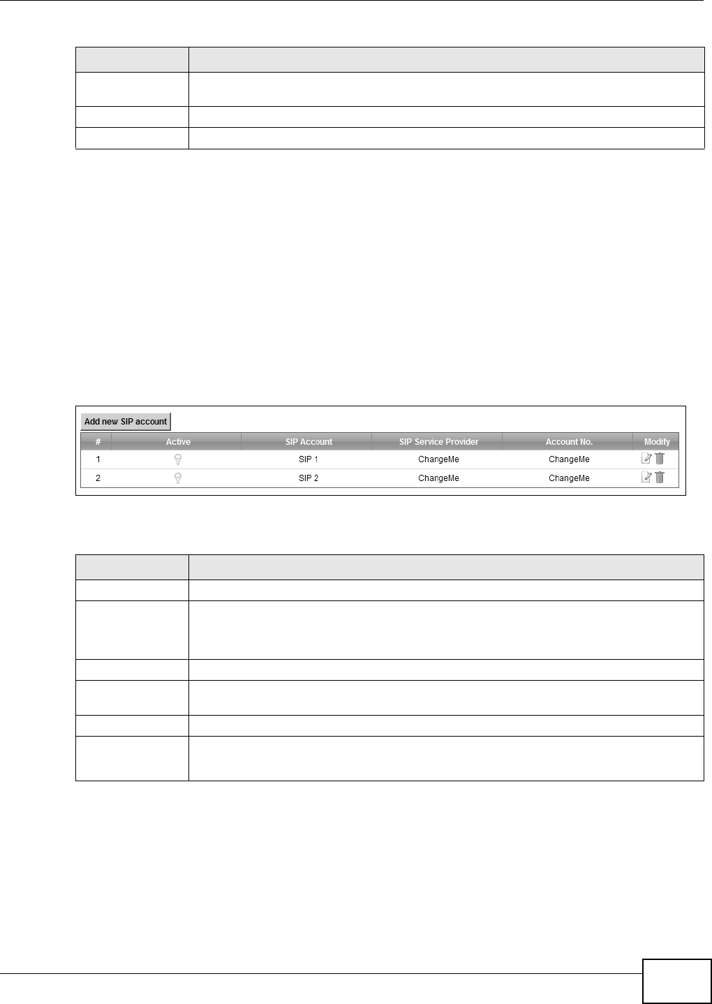
Chapter 15 VoIP
B222s User’s Guide 129
15.3 The SIP Account Screen
The LTE Device uses a SI P account t o m ake out going VoI P calls and check if an incom ing call’s
destinat ion num ber m atches your SI P account ’s SI P num ber. I n order t o m ake or receive a VoI P
call, you need t o enable and configure a SI P account, and m ap it t o a phone port . The SI P account
contains inform ation t hat allows your LTE Device t o connect t o your VoI P service provider.
See Sect ion 15.3 on page 129 for how t o m ap a SI P account t o a phone port .
To access t he following screen, click VoI P > SI P > SI P Account .
Figure 70 VoI P > SI P > SI P Account
The following t able describes t he labels in t his screen.
Do Not Disturb
Disable
This code is used t o t urn t he Do Not Dist urb feature off.
Apply Click Apply t o save your changes.
Cancel Click Can cel t o rest ore your previously saved set t ings.
Table 49 VoI P > SI P > SI P Service Prov ider ( cont inued)
LABEL DESCRIPTION
Table 50 VoI P > SI P > SI P Account
LABEL DESCRIPTION
# This is t he index num ber of t he ent ry.
Active This show s whether t he SI P account is act ivated or not.
A yellow bulb signifies t hat t his SI P account is activat ed. A gray bulb signifies t hat t his SI P
account is act ivated.
SI P Account This shows t he nam e of the SI P account.
SI P Service
Provider
This show s t he nam e of t he SI P service pr ovider.
Account No. This shows t he SI P num ber.
Modify Click t he Ed it icon t o configure t he SI P account.
Click t he D e le t e icon to delet e t his SI P account from t he LTE Device.
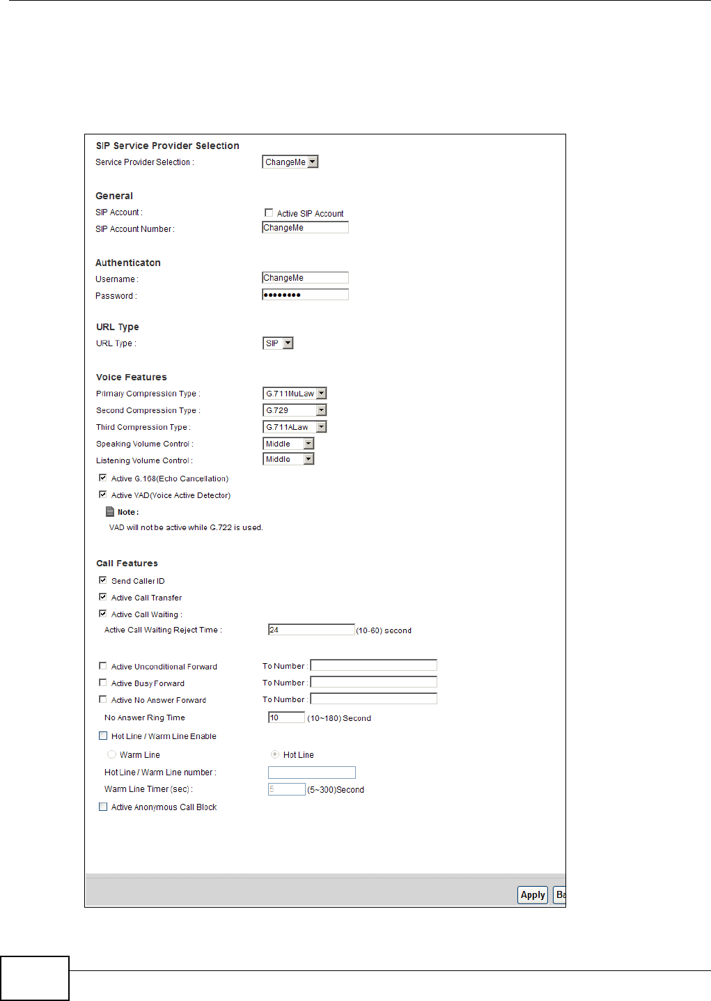
Chapter 15 VoIP
B222s User’s Guide
130
15.3.1 Add/Edit SIP Account
You can configure a new SI P account or edit one. To access this scr een, click Add new SI P
Accou nt in t he SI P Accou nt screen or Ed it icon next to an exist ing account .
Figure 71 SI P Account : Add/ Edit

Chapter 15 VoIP
B222s User’s Guide 131
Each field is described in t he following t able.
Table 51 SI P Account: Edit
LABEL DESCRIPTION
SI P Service Provider Selection
Service Provider
Selection
Select the SI P service provider pr ofile you want to use for the SI P account you configure
in t his screen.
This field is view-only if you are edit ing the SI P account.
SI P Account Selection
SI P Account
Selection
This show s t he SI P account you are configur ing.
General
SI P Account Select the Active SI P Account check box if you want t o use t his account . Clear it if you
do not want t o use t his account .
SI P Account
Nu m ber
Ent er your SI P num ber. I n t he full SI P URI , t his is t he part before t he @ sy m bol. You can
use up to 127 printable ASCII charact ers.
Au t hent icat ion
Usernam e Enter t he user nam e for regist ering t his SI P account, exactly as it was given t o you. You
can use up t o 95 printable ASCI I characters.
Password Enter t he password for regist ering t his SI P account , exactly as it was given t o you. You
can use up t o 95 printable ASCI I characters.
URL Type
URL Ty pe Select whether or not t o include t he SI P service dom ain nam e when t he LTE Device sends
the SI P num ber.
SI P - include t he SI P service dom ain nam e.
TEL - do not include the SI P service dom ain nam e.
Voice Feat ur es
Prim ary
Com pression Type
Secondary
Com pression Type
Third
Com pression Type
Select t he t ype of voice coder/ decoder ( codec) t hat you w ant t he LTE Device t o use.
G.711 provides higher voice qualit y but requires m ore bandw idt h ( 64 kbps) .
•G.7 1 1 M uLaw is typically used in Nor th Am erica and Japan.
•G.7 1 1 ALaw is ty pically used in Europe.
•G.7 2 9 only requir es 8 kbps.
•G.7 2 6 - 3 2 operat es at 16, 24, 32 or 40 kbps.
•G.7 2 2 operates at 48, 56 and 64 kbps.The LTE Device m ust use t he sam e codec as
the peer. When two SI P devices start a SI P session, they m ust agr ee on a codec.
Select t he LTE Device’s first choice for voice coder/ decoder.
Select the LTE Device’s second choice for voice coder/ decoder. Select N on e if you only
want t he LTE Device t o accept the fir st choice.
Select t he LTE Device’s third choice for voice coder/ decoder. Select N o ne if you only want
the LTE Device t o accept t he fir st or second choice.
Speaking
Vo lu m e
Cont rol
Ent er the loudness t hat t he LTE Device uses for speech t hat it sends t o the peer device.
Minim um is t he quiet est , and Ma x im u m is t he loudest .
Listening
Vo lu m e
Cont rol
Enter t he loudness t hat the LTE Device uses for speech that it receives from t he peer
device.
Minim um is t he quiet est , and Ma x im u m is t he loudest .
Active G.168
( Echo
Cancellation)
Select t his if you want to elim inat e t he echo caused by the sound of your voice
rever berating in the telephone receiver w hile you t alk.

Chapter 15 VoIP
B222s User’s Guide
132
15.4 Multiple SIP Accounts
You can set up t wo SI P account s on your LTE Device and your LTE Device is equipped w it h t wo
phone port s. By default , SI P1 of t he LTE Device m aps to phone port 1 for incom ing and out going,
and SI P2 m aps to phone port 2 for incom ing and out going.
Act ive VAD
( Voice Active
Detect or)
Select t his if the LTE Dev ice should st op t ransm it ting when you are not speaking. This
reduces t he bandwidth the LTE Device uses.
Call Features
Send Caller I D Select t his if you want t o send identificat ion w h en y ou m ak e VoI P ph on e calls. Cl ear t his if
you do not want to send identificat ion.
Act ive Call
Tr a n s f e r
Select t his to enable call t ransfer on t he LTE Device. This allows you to t ransfer an
incom ing call (t hat you have answ ered) t o anot her phone.
Act ive Call
Wait in g
Select t his t o enable call w ait ing on the LTE Device. This allows you t o place a call on hold
while you answer anot her incom ing call on the sam e t elephone (directory) num ber.
Act ive Call
Wait ing Rej ect
Tim e
Specify a t im e of seconds t hat the LTE Device wait s before rej ect ing t he second call if you
do not answer it .
Act ive
Unconditional
For w ar d
Select this if you want the LTE Device to forward all incom ing calls to t he specified phone
num ber.
Specify the phone num ber in t he To N um ber field on t he r ight .
Act ive Busy
For w ar d
Select t his if you want the LTE Device t o forward incom ing calls t o the specified phone
num ber if the phone port is busy.
Specify the phone num ber in t he To N um ber field on t he right .
I f you have call wait ing, t he incom ing call is forwarded t o t he specified phone num ber if
you rej ect or ignore the second incom ing call.
Act ive No Answer
For w ar d
Select t his if you want the LTE Device t o forward incom ing calls t o the specified phone
num ber if t he call is unanswered. ( See N o An sw e r Tim e.)
Specify the phone num ber in t he To N um ber field on t he right .
No Answer Ring
Tim e
This field is used by t he Act ive N o An sw e r Forw ar d feat ure.
Ent er the num ber of seconds t he LTE Device should wait for you t o answer an incom ing
call before it considers t he call is unanswer ed.
Hot Line/ Warm
Line Enable
Enable W ar m Line or Hot Line feat ure on the LTE Device. A hot line or warm line
num ber is a phone num ber.
Hot Line/
Warm Line
num ber
Enter t he num ber to be dialed once t he phone is off t he hook im m ediat ely ( Hot Line) or
aft er t he t im e the phone rem ains off the hook has surpassed the delay period ( Warm
Line) .
Warm Line
Tim er ( sec)
Enter t he durat ion t he phone can r em ain off t he hook before aut om at ically dialing t he
warm line num ber. You can set t he delay from 1 t o 15 seconds.
Act ive
Anonym ous Call
Block
Select this if you do not want t he phone t o ring when som eone t ries t o call you wit h caller
I D deactivat ed.
Apply Click Apply t o save your changes.
Back Click Back t o return t o t he previous screen w it hout saving.
Table 51 SI P Account: Edit ( cont inued)
LABEL DESCRIPTION
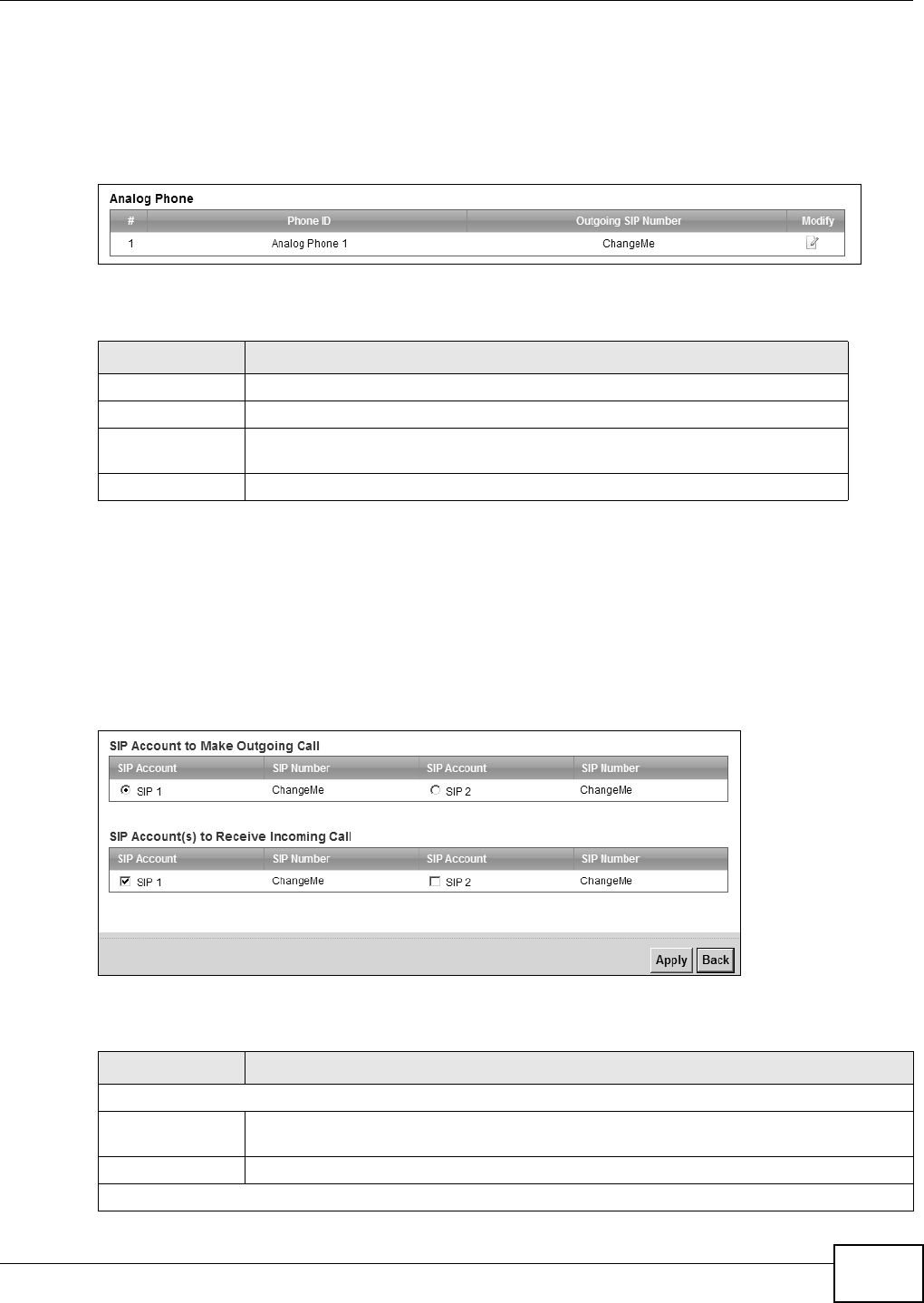
Chapter 15 VoIP
B222s User’s Guide 133
15.5 Phone Screen
Use t his screen t o cont rol which SI P accounts t he phone uses. Click VoI P > Ph on e t o access the
Phone De vice screen.
Figure 72 VoI P > Phone > Phone Device
The following t able describes t he labels in t his screen.
15.5.1 Edit Phone Device
You can decide which SI P accounts t he phone connected to t he LTE Device use by clicking the Edit
icon next t o a Phone I D. The following screen displays.
You cannot edit the account if it is not act ivated. Go to VoI P > SI P > SI P Account > Edit t o
act ivat e a SI P account (see Sect ion 15.3 on page 129 for m ore inform ation) .
Figure 73 Phone Device: Edit
The following t able describes t he labels in t his screen.
Table 52 VoI P > Phone > Phone Device
LABEL DESCRIPTION
# This is t he index num ber of t he ent ry.
Phone I D This is the phone device num ber.
Outgoing SI P
Nu m ber
This is t he out going SI P num ber of t he phone device.
Modify Click t he Ed it icon t o configure t he SI P account.
Table 53 Phone Device: Edit
LABEL DESCRIPTION
SI P Account t o Make Out going Call
SI P Account Select the SI P account you want to use when m aking outgoing calls with the analog
phone connect ed t o t his phone port .
SI P Num ber This shows t he SI P account num ber.
SI P Account ( s) t o Receive I ncom ing Call
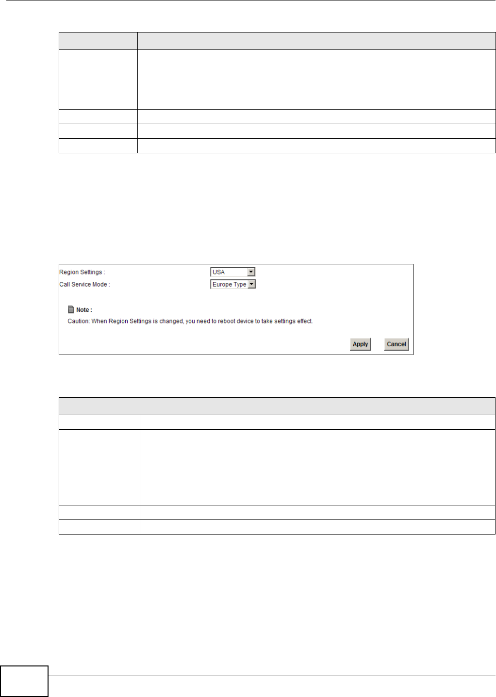
Chapter 15 VoIP
B222s User’s Guide
134
15.6 The Phone Region Screen
Use t his screen t o m aint ain set t ings t hat depend on which region of the world t he LTE Device is in.
To access t his screen, click VoI P > Phone > Region.
Figure 74 VoI P > Phon e > Reg i on
Each field is described in t he following t able.
15.7 The Call Rule Screen
Use t his screen t o add, edit , or rem ove speed-dial num bers for out going calls. Speed dial provides
short cut s for dialing frequent ly- used ( VoI P) phone num bers. You also have t o creat e speed-dial
entries if you want t o call SI P num bers t hat contain let ters. Once you have configured a speed dial
SI P Account Select a SI P account if you want t o receiv e phone calls for t he selected SI P account on
this phone por t.
I f you select m or e t han one SI P account for incom ing calls, t here is no way t o distinguish
bet ween t hem when you receive phone calls. I f you do not select a source for incom ing
calls, y ou cannot receive any calls on this phone port.
SI P Num ber This shows t he SI P account num ber.
Apply Click Apply t o save your changes.
Back Click Back t o return t o t he previous screen w it hout saving.
Table 53 Phone Device: Edit ( cont inued)
LABEL DESCRIPTION
Table 54 VoI P > Phone > Region
LABEL DESCRIPTION
Region Set t ings Select the place in which the LTE Device is locat ed.
Call Service Mode Select t he m ode for supplem ent ary phone ser vices ( call hold, call wait ing, call t ransfer
and three-way conference calls) t hat your VoI P serv ice provider support s.
•Eur ope Type - use supplement ary phone services in European m ode.
•USA Type - use supplem ent ary phone services Am erican m ode.
You m ight have t o subscribe t o t hese services t o use t hem . Cont act your VoI P service
provider.
Apply Click t his t o save your changes and t o apply t hem to t he LTE Device.
Cancel Click t his t o set every field in this screen to it s last- saved value.
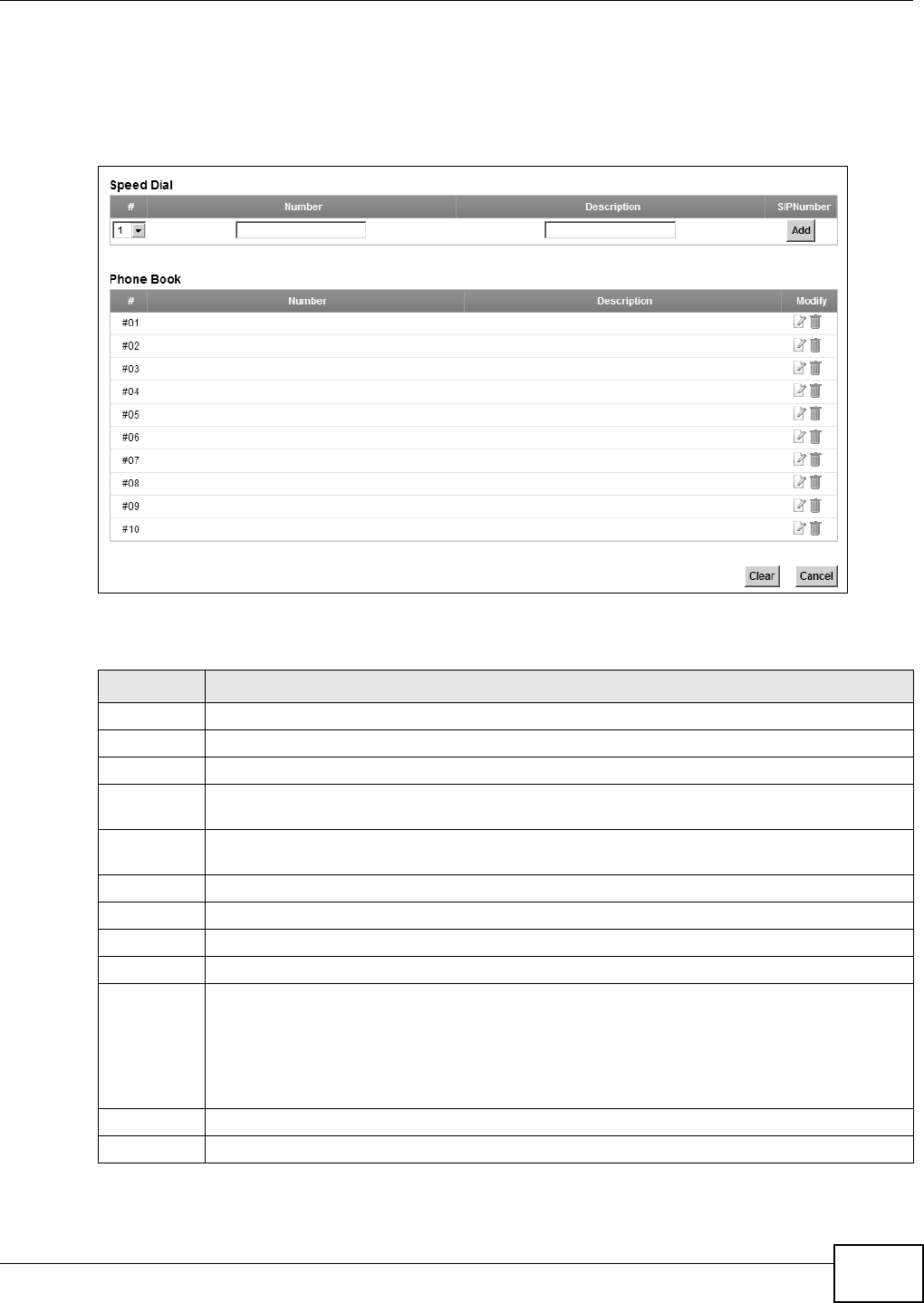
Chapter 15 VoIP
B222s User’s Guide 135
rule, you can use a short cut ( t he speed dial num ber, # 01 for exam ple) on your phone's keypad to
call the phone num ber.
To access t his screen, click VoI P > Call Ru le.
Figure 75 VoI P > Call Rule
Each field is described in t he following t able.
Table 55 VoI P > Call Rule
LABEL DESCRIPTION
Speed Dial Use this section to creat e or edit speed- dial entr ies.
#Select t he speed- dial num ber you want t o use for t his phone num ber.
Num ber Enter the SI P num ber you want the LTE Device t o call when you dial the speed- dial num ber.
Description Enter a short descript ion t o identify t he party you call when you dial the speed- dial num ber.
You can use up t o 127 printable ASCII charact ers.
Add Click t his to use the inform at ion in the Spe ed Dial sect ion to updat e the Spee d D ial Phone
Book sect ion.
Phone Book Use t his section t o look at all the speed- dial entries and t o erase them .
# This field displays t he speed- dial num ber you should dial t o use t his entry.
Num ber This field displays t he SI P num ber the LTE Device calls when you dial t he speed- dial num ber.
Descript ion This field displays a short description of the part y you call w hen you dial t he speed- dial num ber.
Modify Use t his field t o edit or erase t he speed- dial entry.
Click t he Ed it icon t o copy t he inform at ion for t his speed- dial ent ry into t he Spee d Dia l
section, where y ou can change it . Click Add when you finish edit ing t o change t he
configurations.
Click t he D e le t e icon t o erase t his speed- dial entry.
Clear Click t his to erase all t he speed- dial ent ries.
Cancel Click t his t o set every field in this screen to it s last - saved value.

Chapter 15 VoIP
B222s User’s Guide
136
15.8 Technical Reference
This sect ion cont ains background m aterial relevant t o the VoI P screens.
15.8.1 VoIP
VoI P is t he sending of voice signals over I nt ernet Protocol. This allows you t o m ake phone calls and
send faxes over the I nt ernet at a fraction of the cost of using t he t radit ional circuit- switched
telephone network. You can also use servers to run t elephone service applicat ions like PBX services
and voice m ail. I nt ernet Telephony Service Provider ( I TSP) com panies provide VoI P service.
Circuit- swit ched t elephone net works require 64 kilobit s per second (Kbps) in each direct ion to
handle a t elephone call. VoI P can use advanced voice coding t echniques wit h com pression to reduce
the required bandwidt h.
15.8.2 SIP
The Session I nit iation Prot ocol ( SI P) is an application- layer control ( signaling) prot ocol t hat handles
the set ting up, altering and t ear ing down of voice and m ultim edia sessions over t he I nt ernet .
SI P signaling is separat e from t he m edia for which it handles sessions. The m edia t hat is exchanged
during t he session can use a different path from t hat of the signaling. SI P handles t elephone calls
and can interface wit h t radit ional circuit- switched t elephone net works.
SIP Identities
A SI P account uses an ident it y (som et im es referred to as a SI P address). A com plet e SI P ident it y is
called a SI P URI ( Uniform Resour ce I dent ifier) . A SI P account 's URI ident ifies t he SI P account in a
way sim ilar t o t he way an e-m ail addr ess identifies an e-m ail account . The form at of a SI P identit y
is SI P- Num ber@SI P-Service-Dom ain.
SIP Number
The SI P num ber is t he part of t he SI P URI t hat com es before t he “ @” sym bol. A SI P num ber can
use let ters like in an e-m ail address ( j ohndoe@your-I TSP.com for exam ple) or num bers like a
telephone num ber (1122334455@VoI P- provider.com for exam ple) .
SIP Service Domain
The SI P ser vice dom ain of t he VoI P service provider is t he dom ain nam e in a SI P URI . For exam ple,
if the SI P address is 1 12 23 34 45 5@VoI P- pr ov ider.com , then “ VoI P- provider.com ” is t he SI P ser vice
dom ain.
SIP Registration
Each LTE Device is an individual SI P User Agent ( UA). To provide voice ser vice, it has a public I P
address for SI P and RTP prot ocols to com m unicat e wit h ot her ser vers.
A SI P user agent has t o register wit h t he SI P registrar and m ust provide inform at ion about t he
users it represent s, as well as it s current I P address (for the rout ing of incom ing SI P request s) .
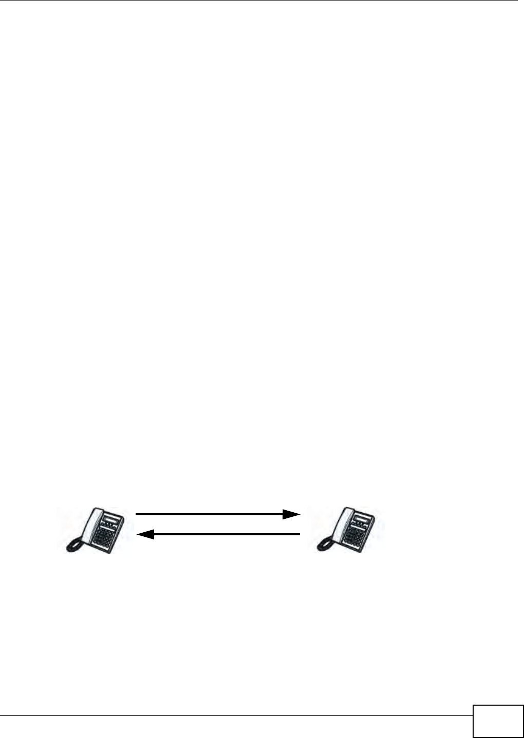
Chapter 15 VoIP
B222s User’s Guide 137
Aft er successful registrat ion, t he SI P server know s t hat t he users ( ident ified by t heir dedicat ed SI P
URI s) are represent ed by t he UA, and knows t he I P address to which t he SI P request s and
responses should be sent .
Registration is initiat ed by t he User Agent Client ( UAC) running in the VoI P gat eway ( t he LTE
Device) . The gat eway m ust be configur ed with inform at ion lett ing it know where to send t he
REGI STER m essage, as well as t he relevant user and authorization dat a.
A SI P registrat ion has a lim ited lifespan. The User Agent Client m ust renew it s regist rat ion wit hin
this lifespan. I f it does not do so, the registrat ion dat a w ill be delet ed from t he SI P regist rar's
dat abase and the connection broken.
The LTE Device at t em pts t o register all enabled subscriber port s w hen it is swit ched on. When you
enable a subscriber port t hat was previously disabled, t he LTE Device at tem pt s to register t he por t
im m ediat ely.
Authorization Requirements
SI P registrat ions ( and subsequent SI P requests) requir e a usernam e and password for
authorization. These credent ials ar e validat ed via a challenge / response system using t he HTTP
digest m echanism ( as det ailed in RFC3261, "SI P: Session I nit iation Prot ocol") .
SIP Servers
SI P is a client- server prot ocol. A SI P client is an applicat ion program or device t hat sends SI P
requests. A SI P server responds t o t he SI P requests.
When you use SI P to m ake a VoI P call, it originates at a client and t erm inates at a server. A SI P
client could be a com put er or a SI P phone. One device can act as bot h a SI P client and a SI P server.
SIP User Agent
A SI P user agent can m ake and receive VoI P telephone calls. This m eans t hat SI P can be used for
peer- to-peer com m unications even t hough it is a client- server protocol. I n the following figure,
eit her A or B can act as a SI P user agent client t o initiat e a call. A and B can also both act as a SI P
user agent t o receive t he call.
Figure 76 SI P User Agent
SIP Proxy Server
A SI P proxy server receives requests from client s and forwards t hem to anot her server.
I n t he following exam ple, you want t o use client device A t o call som eone who is using client device
C.
1The client device ( A in t he figure) sends a call invitat ion to t he SI P pr oxy ser ver B.
AB
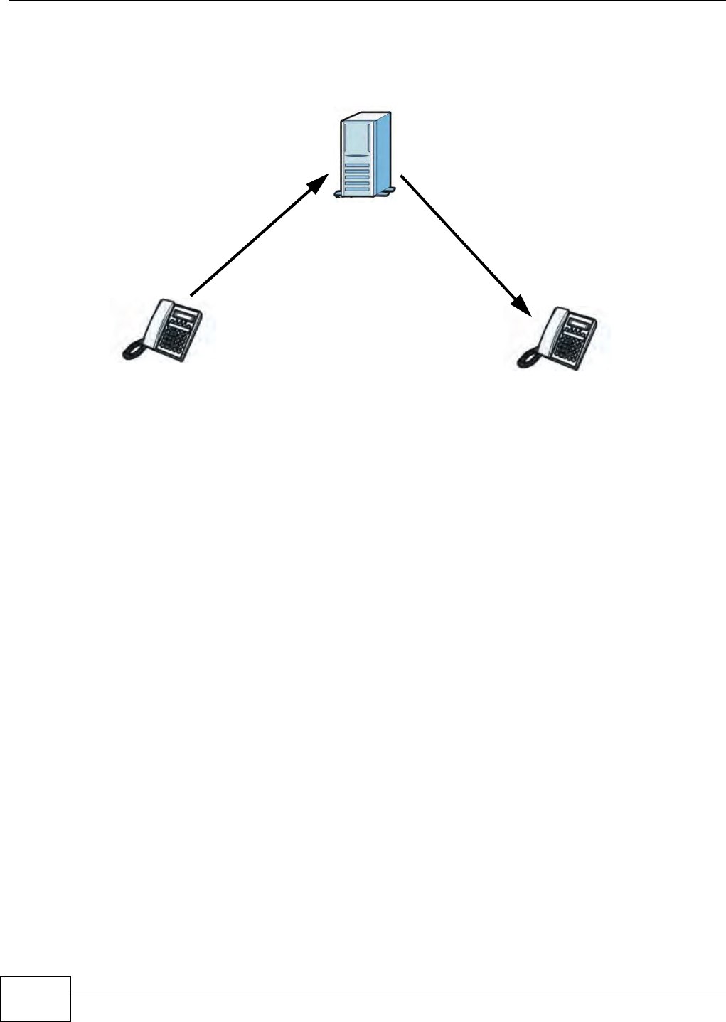
Chapter 15 VoIP
B222s User’s Guide
138
2The SI P proxy server forwards the call invit ation t o C.
Figure 77 SI P Proxy Server
SIP Redirect Server
A SI P redirect server accept s SI P requests, t ranslat es the destinat ion address t o an I P address and
sends t he t ranslat ed I P address back t o t he device that sent t he request . Then t he client device t hat
originally sent t he request can send request s t o the I P address that it received back from the
redirect server. Redirect servers do not init iate SI P request s.
I n t he following exam ple, you want t o use client device A t o call som eone who is using client device
C.
1Client device A sends a call invitat ion for C t o t he SI P redirect server B.
2The SI P redirect server sends t he invitat ion back t o A wit h C’s I P address ( or dom ain nam e) .
B
AC
12
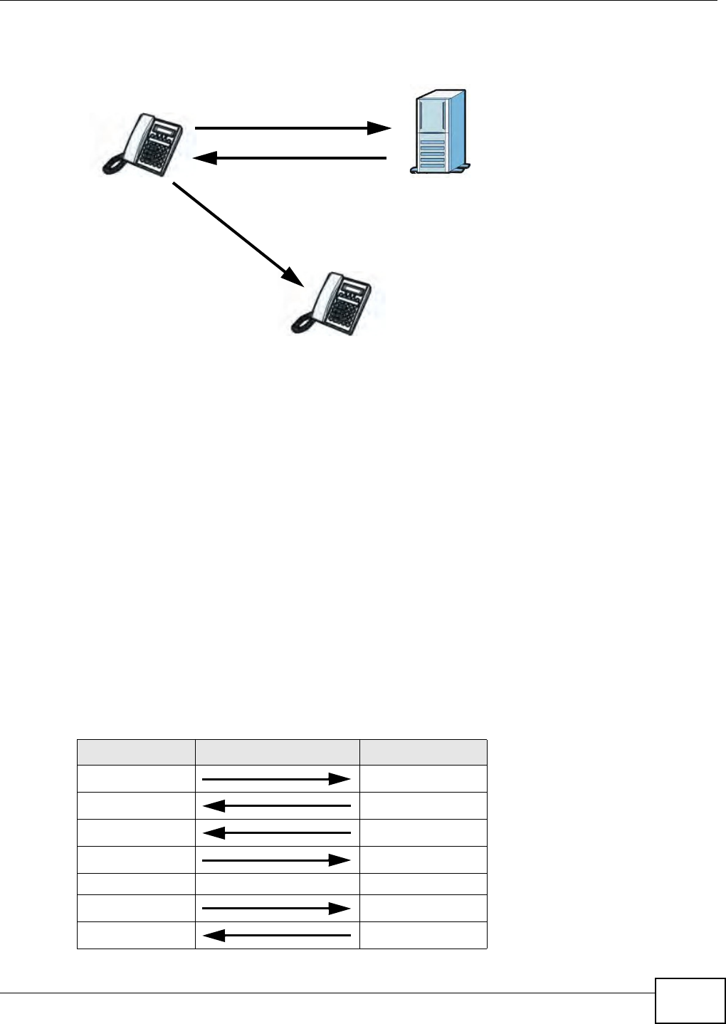
Chapter 15 VoIP
B222s User’s Guide 139
3Client device A then sends t he call invitat ion to client device C.
Figure 78 SI P Redirect Server
SIP Register Server
A SI P register server m aint ains a dat abase of SI P identit y- to- I P addr ess ( or dom ain nam e)
m apping. The register server checks your user nam e and password when you regist er.
RTP
When you m ake a VoI P call using SI P, t he RTP ( Real t im e Transpor t Prot ocol) is used t o handle voice
dat a t ransfer. See RFC 3550 for det ails on RTP.
Pulse Code Modulation
Pulse Code Modulation ( PCM) m easures analog signal am plit udes at regular t im e int ervals and
converts t hem int o bit s.
SIP Call Progression
The following figure displays t he basic steps in t he set up and tear down of a SI P call. A calls B.
Table 56 SI P Call Progression
A B
1. I NVI TE
2. Ringing
3. OK
4. ACK
5.Dialogue ( voice t raffic)
6. BYE
7. OK
1
2
3
AB
C

Chapter 15 VoIP
B222s User’s Guide
140
1 A sends a SI P I NVI TE request t o B. This m essage is an invit at ion for B t o participate in a SI P
telephone call.
2 B sends a response indicat ing t hat t he t elephone is r inging.
3 B sends an OK response aft er the call is answered.
4 A t hen sends an ACK m essage to acknowledge t hat B has answered t he call.
5Now A and B exchange voice m edia ( talk) .
6Aft er t alking, A hangs up and sends a BYE request.
7 B r eplies w it h an OK response confirm ing receipt of t he BYE request and the call is term inat ed.
Voice Coding
A codec (coder/ decoder) codes analog voice signals int o digit al signals and decodes the digit al
signals back int o analog voice signals. The LTE Device support s t he following codecs.
• G.711 is a Pulse Code Modulation ( PCM) waveform codec. PCM m easures analog signal
am plitudes at regular t im e int ervals and convert s t hem into digit al sam ples. G.711 provides very
good sound qualit y but requires 64 kbps of bandwidth.
• G.726 is an Adapt ive Differential PCM ( ADPCM) waveform codec t hat uses a low er bitrat e t han
st andard PCM conversion. ADPCM conver t s analog audio int o digit al signals based on the
difference bet w een each audio sam ple and a prediction based on previous sam ples. The m ore
sim ilar t he audio sam ple is t o t he prediction, the less space needed t o describe it . G.726 operat es
at 16, 24, 32 or 40 kbps.
• G.729 is an Analysis-by- Synthesis ( AbS) hybrid waveform codec that uses a filt er based on
inform ation about how t he hum an vocal t ract produces sounds. G.729 provides good sound
qualit y and reduces t he required bandwidth t o 8 kbps.
MWI (Message Waiting Indication)
Enable Message Waiting I ndication ( MWI ) enables your phone t o give you a m essage–wait ing
( beeping) dial t one when you have a voice m essage( s) . Your VoI P service provider m ust have a
m essaging syst em that sends m essage wait ing stat us SI P packets as defined in RFC 3842.
15.8.3 Quality of Service (QoS)
Quality of Service ( QoS) refers t o bot h a net work's abilit y t o deliver data wit h m inim um delay, and
the networking m et hods used t o provide bandwidth for real- tim e m ult im edia applicat ions.
Type of Service (ToS)
Net work t raffic can be classified by sett ing t he ToS ( Type of Service) values at t he data source ( for
exam ple, at the LTE Device) so a server can decide t he best m et hod of delivery, t hat is t he least
cost , fast est rout e and so on.

Chapter 15 VoIP
B222s User’s Guide 141
DiffServ
DiffServ is a class of service ( CoS) m odel that m arks packets so t hat t hey receive specific per- hop
treat m ent at DiffServ- com pliant network devices along the rout e based on t he applicat ion t ypes
and t raffic flow. Packet s are m arked with DiffServ Code Point s ( DSCP) indicating t he level of service
desired. This allows t he int erm ediary DiffServ- com pliant net work devices t o handle t he packet s
different ly depending on t he code points wit hout t he need t o negot iat e pat hs or rem em ber st at e
inform ation for every flow. I n addition, applicat ions do not have t o request a part icular service or
give advanced not ice of where the t raffic is going.3
DSCP and Per-Hop Behavior
DiffServ defines a new DS ( Differentiat ed Services) field to replace the Type of Service (TOS) field
in the I P header. The DS field cont ains a 2- bit unused field and a 6- bit DSCP field w hich can define
up t o 64 service levels. The following figure illust rat es the DS field.
DSCP is backward com patible wit h t he t hree precedence bit s in t he ToS oct et so that non- DiffServ
com pliant , ToS-enabled net work device w ill not conflict wit h t he DSCP m apping.
Figure 79 DiffServ: Differentiat ed Service Field
The DSCP value determ ines t he forwarding behavior, t he PHB ( Per- Hop Behavior) , t hat each packet
get s across t he DiffServ net work. Based on t he m arking rule, different kinds of t raffic can be
m ar ked for different priorit ies of forwarding. Resources can t hen be allocated according t o t he DSCP
values and t he configured policies.
15.8.4 Phone Services Overview
Supplem ent ar y services such as call hold, call waiting, and call t ransfer. are generally available from
your VoI P service provider. The LTE Device support s the following services:
• Call Hold
• Call Wait ing
• Making a Second Call
• Call Transfer
• Three-Way Conference
• I nt ernal Calls
• Do not Dist urb
Note: To t ake full advant age of t he supplem ent ary phone services available t hrough t he
LTE Device's phone port s, you m ay need to subscribe t o t he services from your VoI P
service provider.
3. The LTE Device does not support DiffServ at the time of writing.
DSCP
( 6- bit )
Unused
(2-bit)

Chapter 15 VoIP
B222s User’s Guide
142
The Flash Key
Flashing m eans t o press the hook for a short period of t im e ( a few hundr ed m illiseconds) before
releasing it . On newer t elephones, t here should be a " flash" key ( but t on) t hat generates the signal
elect ronically. I f the flash key is not available, you can tap ( press and im m ediat ely release) t he
hook by hand t o achieve t he sam e effect . However, using t he flash key is pr eferred since t he t im ing
is m uch m ore precise. Wit h m anual tapping, if t he durat ion is t oo long, it m ay be interpret ed as
hanging up by the LTE Device.
You can invoke all t he supplem ent ar y services by using t he flash key.
Europe Type Supplementary Phone Services
This section describes how t o use supplem ent ary phone services wit h t he Eu r ope Type Ca ll
Service Mode . Com m ands for supplem ent ary services ar e list ed in the table below.
Aft er pressing the flash key, if you do not issue t he sub- com m and before t he default sub- com m and
tim e-out ( 2 seconds) expires or issue an invalid sub- com m and, t he current operat ion will be
abort ed.
European Call Hold
Call hold allows you t o put a call ( A) on hold by pressing t he flash key.
I f you have anot her call, press t he flash key and t hen “ 2” t o swit ch back and fort h between caller A
and B by put t ing eit her one on hold.
Press t he flash key and then “ 0” t o disconnect t he call pr esently on hold and keep the current call
on line.
Press t he flash key and then “ 1” t o disconnect t he current call and resum e the call on hold.
I f you hang up the phone but a caller is st ill on hold, t here will be a rem ind ring.
Table 57 European Flash Key Com m ands
COMMAND SUB-COMMAND DESCRIPTION
Flash Put a current call on hold t o place a second call.
Swit ch back t o the call ( if t here is no second call).
Flash 0 Drop t he call present ly on hold or rej ect an incom ing call which is wait ing
for answer.
Flash 1 Disconnect the curr ent phone connect ion and answ er the incom ing call or
resum e wit h caller present ly on hold.
Flash 2 1. Swit ch back and forth bet ween t wo calls.
2. Put a current call on hold to answer an incom ing call.
3. Separat e t he current t hree- way conference call int o two individual calls
( one is on-line, t he ot her is on hold).
Flash 3 Creat e t hree- way conference connection.
Flash * 98# Transfer t he call t o another phone.

Chapter 15 VoIP
B222s User’s Guide 143
European Call Waiting
This allows you t o place a call on hold while you answ er another incom ing call on t he sam e
telephone ( direct ory) num ber.
I f t here is a second call to a t elephone num ber, you will hear a call wait ing t one. Take one of t he
following act ions.
• Rej ect t he second call.
Press t he flash key and then press “ 0”.
• Disconnect the first call and answer t he second call.
Eit her press the flash key and press “ 1”, or j ust hang up the phone and t hen answ er the phone
after it rings.
• Put t he first call on hold and answer the second call.
Press t he flash key and then “ 2”.
European Call Transfer
Do t he following t o transfer a call (t hat you have answered) t o anot her phone num ber.
1Press t he flash key t o put t he caller on hold.
2When you hear t he dial t one, dial “ * 98# ” followed by t he num ber to which you want t o t ransfer the
call. t o operat e t he I nt ercom .
3Aft er you hear t he ring signal or t he second part y answers it, hang up t he phone.
European Three-Way Conference
Use t he following steps to m ake t hree-way conference calls.
1When you are on t he phone talking to som eone, press the flash key to put t he call on hold and get
a dial t one.
2Dial a phone num ber direct ly t o m ake another call.
3When the second call is answered, press t he flash key and press “ 3” t o creat e a t hree- way
conversation.
4Hang up the phone t o drop t he connect ion.
5I f you want t o separate t he activated t hree-way conference int o t wo individual connect ions ( one is
on- line, t he ot her is on hold) , press t he flash key and press “ 2”.

Chapter 15 VoIP
B222s User’s Guide
144

B222s User’s Guide 145
CHAPTER 16
Logs
16.1 Overview
The web configurat or allows you to choose w hich cat egories of events and/ or alert s to have t he LTE
Device log and t hen display the logs or have t he LTE Device send t hem t o an adm inistrat or ( as e-
m ail) or t o a syslog server.
16.1.1 What You Can Do in this Chapter
• Use the Syst e m Log screen t o see the syst em logs for the cat egories t hat you select ( Sect ion
16.2 on page 146) .
• Use the Ph one Log screen t o view phone logs and alert m essages (Section 16.3 on page 147) .
• Use The VoI P Call H ist or y screen t o view the det ails of t he calls perform ed on t he LTE Device
(Section 16.4 on page 147) .
16.1.2 What You Need To Know
The following term s and concept s m ay help as you read this chapt er.
Alerts and Logs
An alert is a t ype of log t hat warrant s m ore serious at tent ion. They include syst em errors, att acks
( access control) and at tem pted access t o blocked web sites. Som e categories such as Syst em
Er r or s consist of bot h logs and alert s. You m ay different iat e t hem by t heir color in the Vie w Log
screen. Alert s display in red and logs display in black.
Syslog Overview
The syslog prot ocol allow s devices to send event not ification m essages across an I P net work t o
syslog servers t hat collect the event m essages. A syslog-enabled device can generat e a syslog
m essage and send it t o a syslog server.
Syslog is defined in RFC 3164. The RFC defines t he packet form at , cont ent and system log relat ed
inform ation of syslog m essages. Each syslog m essage has a facilit y and severit y level. The syslog
facilit y ident ifies a file in t he syslog server. Refer t o t he docum ent at ion of your syslog program for
det ails. The following t able describes t he syslog severity levels.
Table 58 Syslog Severit y Levels
CODE SEVERITY
0 Em ergency ( EMERG) : The system is unusable.
1 Alert ( ALERT): Act ion m ust be taken im m ediately.
2 Crit ical (CRI T) : The syst em condit ion is crit ical.
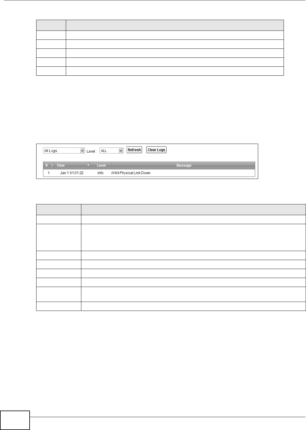
Chapter 16 Logs
B222s User’s Guide
146
16.2 The System Log Screen
Click Sy st e m M on it or > Log t o open t he Syst e m Log screen. Use the Syst em Log screen t o see
the system logs for the cat egories t hat you select in t he upper left drop- down list box.
Figure 80 Sy st em Monit or > Log > Sy st em Log
The following t able describes t he fields in t his screen.
3 Error (ERROR): There is an error condition on t he syst em .
4 Warning ( WARNI NG): There is a warning condit ion on t he system .
5 Not ice (NOTI CE) : There is a norm al but significant condition on t he syst em .
6 I nform at ional (I NFO): The syslog cont ains an inform at ional m essage.
7 Debug ( DEBUG) : The m essage is int ended for debug- level purposes.
Table 58 Syslog Severit y Levels
CODE SEVERITY
Table 59 Syst em Monit or > Log > Syst em Log
LABEL DESCRIPTION
Select t he t ype of t he logs t hat you want t o search in t he first drop- dow n list box.
Level Select a severit y level from t his drop- dow n list box. This filt ers sear ch result s accor ding t o
the severit y level you have selected. When you select a severity, t he LTE Device sear ches
through all logs of t hat severit y or higher. See Table 58 on page 145 for m or e inform at ion
about severit y levels.
Refresh Click t his t o renew t he log screen.
Clear Logs Click this t o delete all t he logs.
#This field is a sequent ial value and is not associated with a specific ent ry.
Tim e This field displays t he date and tim e t he log was recorded.
Level This field displays the severit y level of t he logs that t he device is to send to t his syslog
server.
Message This field stat es t he reason for t he log.
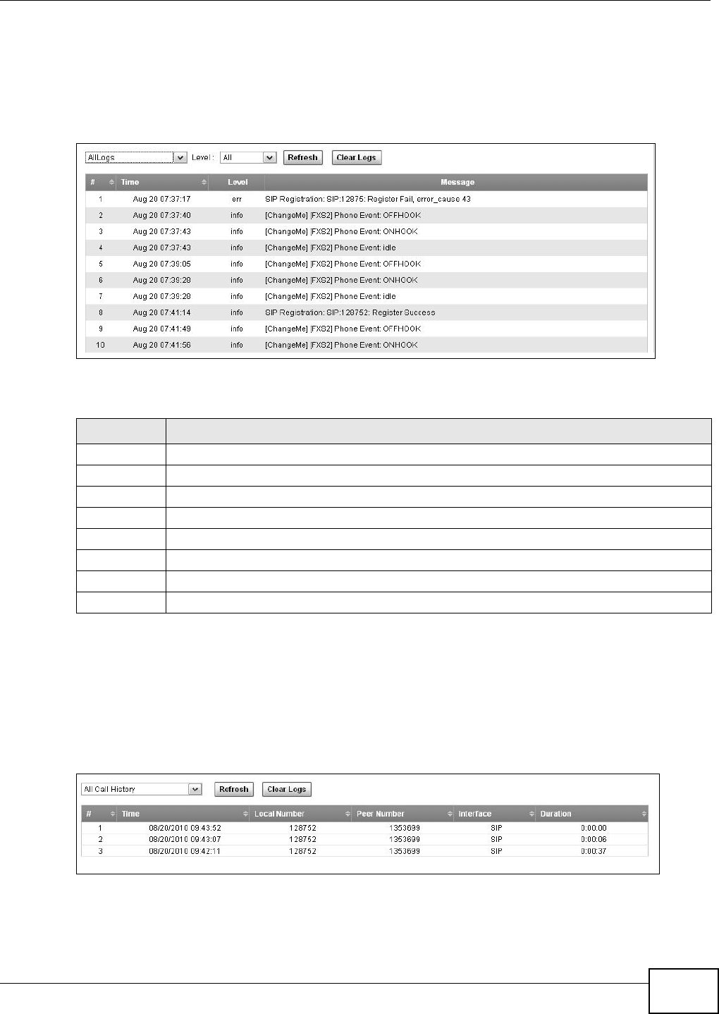
Chapter 16 Logs
B222s User’s Guide 147
16.3 The Phone Log Screen
Click Syst e m Monit or > Log t o open t he Phone Log screen. Use this screen to view phone logs
and alert m essages. You can select t he type of log and level of severit y to display.
Figure 81 System Monit or > Log > Phone Log
The following t able describes t he fields in t his screen.
16.4 The VoIP Call History Screen
Click Syst e m M onit or > Log > VoI P Ca ll Hist or y to open t he VoI P Ca ll H istory screen.
Use t his screen to see t he details of t he calls perform ed on t he LTE Device.
Figure 82 System Monitor > Log > VoI P Call Hist ory
Table 60 Syst em Monit or > Log > Phone Log
LABEL DESCRIPTION
Select a cat egor y of logs t o v iew fr om t he drop- down list box. select All Logs t o view all logs.
Level Select t he severit y level t hat you want to view.
Refresh Click t his t o renew t he log screen.
Clear Logs Click t his t o delet e all t he logs.
#This field is a sequential value and is not associat ed wit h a specific ent ry.
Tim e This field displays t he t im e t he log was recorded.
Level This field displays t he severit y level of t he logs t hat t he device is t o send t o t his syslog server.
Message This field st at es t he reason for t he log.

Chapter 16 Logs
B222s User’s Guide
148
The following t able describes t he fields in t his screen.
Table 61 Syst em Monit or > Log > VoI P Call Hist ory
LABEL DESCRIPTION
Select a category of call recor ds t o view from the drop- down list box. select All Ca ll
History t o view all call records.
Refresh Click this t o renew the log screen.
Clear Logs Click t his t o delete all t he logs.
#This field is a sequential value and is not associated w it h a specific entry.
Tim e This field displays t he t im e the call was recorded.
Local Num ber This field displays t he phone num ber you used t o m ake or r eceive t his call.
Peer Num ber This field displays t he phone num ber you called or from which this call is m ade.
I nt erface This field displays t he type of t he call.
Durat ion This field displays how long t he call lasted.
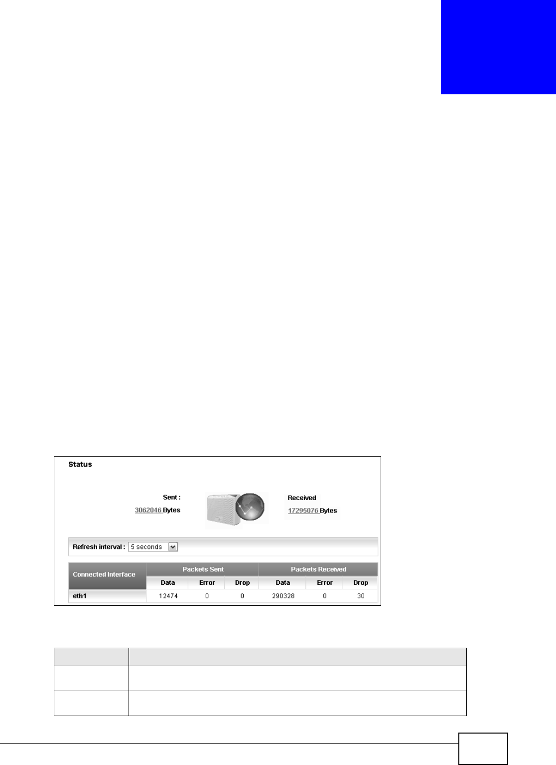
B222s User’s Guide 149
CHAPTER 17
Traffic Status
17.1 Overview
Use t he Tra ffic St at us screens t o look at network traffic stat us and st at ist ics of t he WAN, LAN
int erfaces and NAT.
17.1.1 What You Can Do in this Chapter
• Use the W AN screen t o view the WAN t raffic stat ist ics (Section 17.2 on page 149) .
• Use the LAN screen t o view the LAN t raffic statistics ( Sect ion 17.3 on page 150) .
• Use the N AT scr een t o view t he NAT stat us of t he LTE Device’s client ( s) ( Sect ion 17.4 on page
151) .
• Use the VoI P Sta t us screen to view t he VoI P traffic stat ist ics (Sect ion 17.5 on page 152) .
17.2 The WAN Status Screen
Click Syst e m Monit or > Tr affic St a tus t o open t he W AN screen. You can view t he WAN t raffic
st at ist ics in t his screen.
Figure 83 System Monitor > Traffic Stat us > WAN
The following t able describes t he fields in t his screen.
Table 62 Syst em Monit or > Traffic St atus > WAN
LABEL DESCRIPTION
St atus This shows t he num ber of bytes received and sent t hrough the WAN int erface of
the LTE Device.
Refresh I nt erval Select how oft en y ou want the LTE Device t o updat e t his screen fr om t he drop-
down list box.
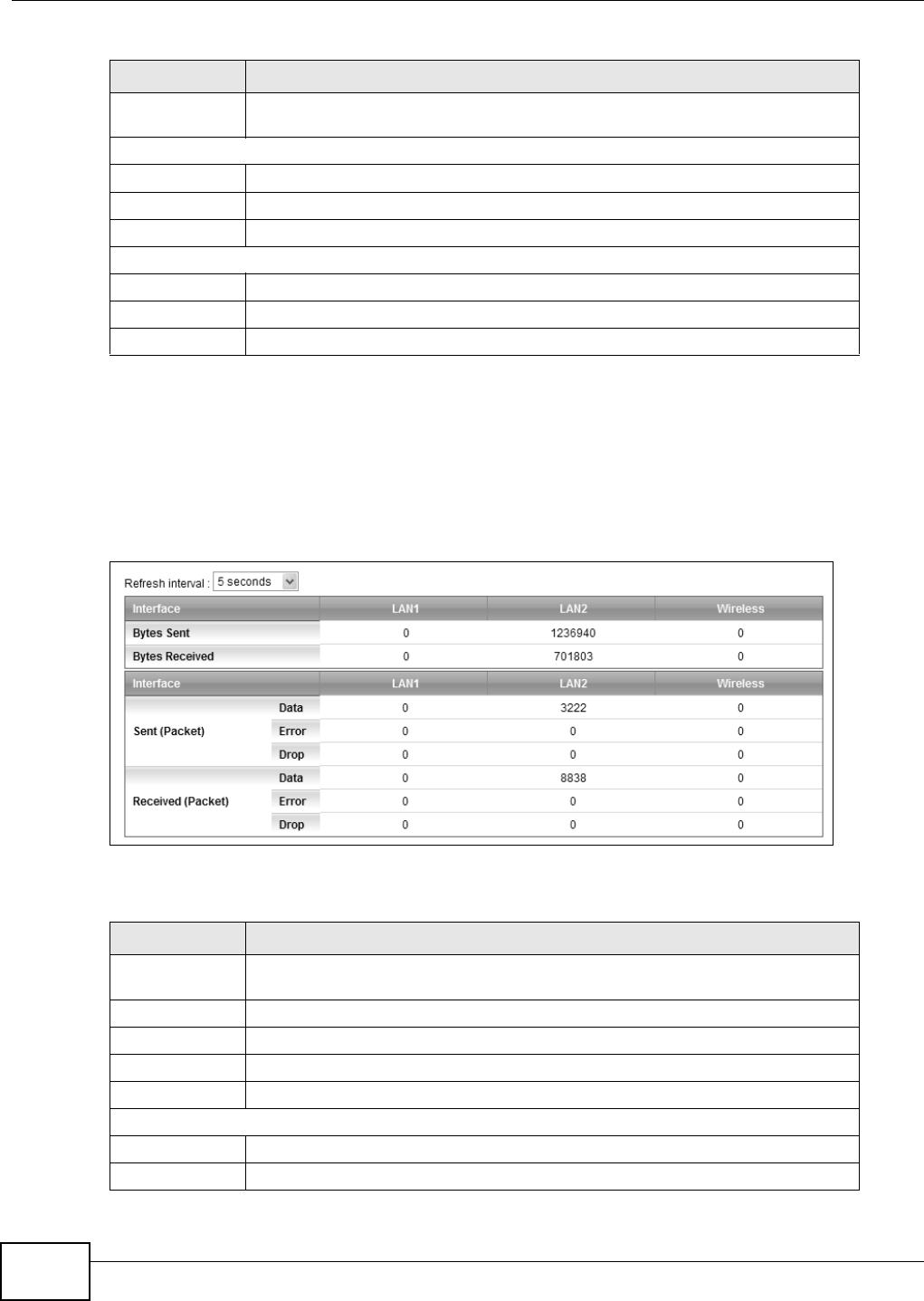
Chapter 17 Traffic Status
B222s User’s Guide
150
17.3 The LAN Status Screen
Click Syst e m Monit or > Tra ffic St a tu s > LAN t o open the following screen. You can view the LAN
traffic stat ist ics in this screen.
Figure 84 System Monitor > Traffic Stat us > LAN
The following t able describes t he fields in t his screen.
Connect ed
I nt erface
This shows t he nam e of t he WAN interface t hat is currently connect ed.
Packets Sent
Data This indicates t he num ber of t ransm it ted packets on t his int erface.
Error This indicates t he num ber of fram es w it h errors t ransm it t ed on this int erface.
Drop This indicates t he num ber of out going packet s dropped on t his int erface.
Packets Received
Data This indicates t he num ber of received packets on this int erface.
Error This indicates t he num ber of fram es wit h errors received on t his interface.
Drop This indicates t he num ber of received packet s dropped on t his interface.
Table 62 Syst em Monit or > Traffic St atus > WAN (continued)
LABEL DESCRIPTION
Table 63 Syst em Monit or > Traffic St atus > LAN
LABEL DESCRIPTION
Refresh I nt erval Select how oft en y ou want the LTE Device t o updat e t his screen fr om t he drop-
down list box.
I nt erface This shows t he LAN or WLAN int erface.
Byt es Sent This indicat es t he num ber of by t es t ransm it t ed on t his int erface.
By t es Received This indicat es t he num ber of byt es received on this int erface.
I nt erface This shows t he LAN or WLAN int erface.
Sent (Packet)
Data This indicates t he num ber of t ransm it ted packets on t his int erface.
Error This indicates t he num ber of fram es w it h errors t ransm it t ed on this int erface.
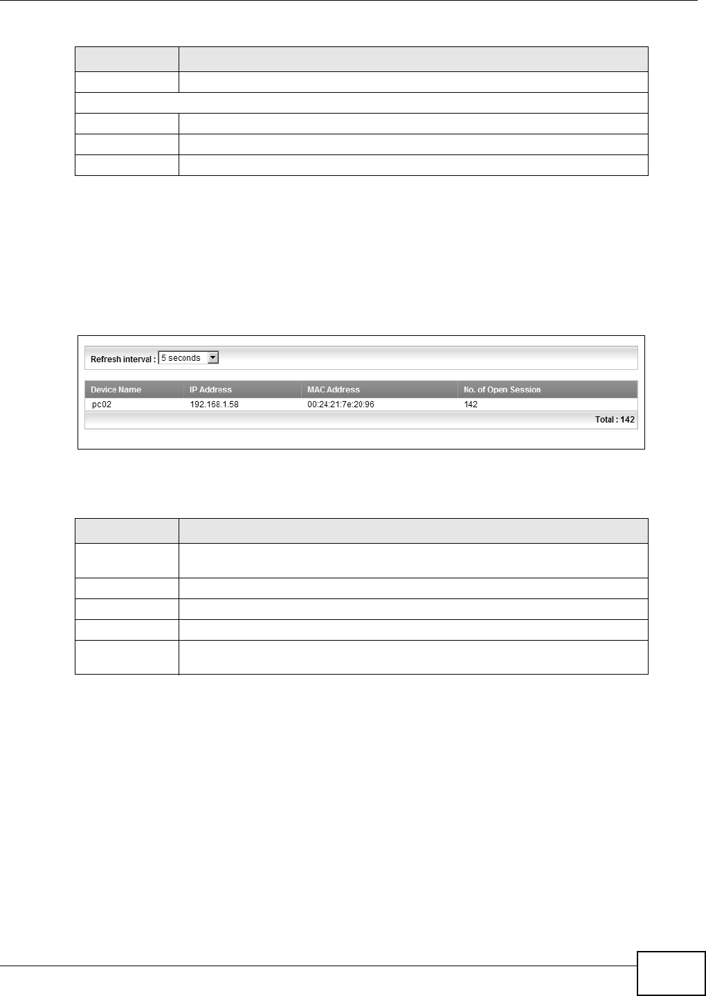
Chapter 17 Traffic Status
B222s User’s Guide 151
17.4 The NAT Status Screen
Click Syst e m Monit or > Tr a ffic St a tus > N AT t o open t he following screen. You can view t he NAT
st at us of t he LTE Device’s client( s) in t his screen.
Figure 85 System Monitor > Traffic Stat us > NAT
The following t able describes t he fields in t his screen.
Drop This indicates t he num ber of out going packet s dropped on t his int erface.
Receiv ed ( Packet )
Data This indicates t he num ber of received packets on this int erface.
Error This indicates t he num ber of fram es wit h errors received on t his interface.
Drop This indicates t he num ber of received packet s dropped on t his interface.
Table 63 Syst em Monit or > Traffic St atus > LAN ( cont inued)
LABEL DESCRIPTION
Table 64 Syst em Monit or > Traffic St atus > NAT
LABEL DESCRIPTION
Refresh I nt erval Select how oft en y ou want the LTE Device t o updat e t his screen fr om t he drop-
down list box.
Device Nam e This show s the nam e of the client.
I P Address This shows t he I P address of t he client .
MAC Address This shows t he MAC addr ess of t he client .
No. of Open
Session
This shows t he num ber of NAT sessions used by the client .
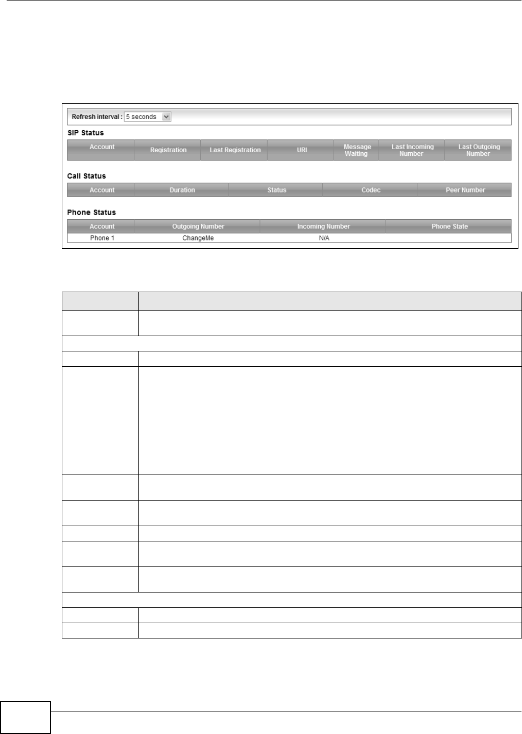
Chapter 17 Traffic Status
B222s User’s Guide
152
17.5 The VoIP Status Screen
Click Syst e m Monit or > V oI P St at us to open the following screen. You can view the VoI P t raffic
st at ist ics in t his screen.
Figure 86 Sy st em Monit or > VoI P St at us
The following t able describes t he fields in t his screen.
Table 65 Syst em Monit or > VoI P St at us
LABEL DESCRIPTION
Refresh I nt erval Select how oft en you want the LTE Device t o updat e t his screen from t he drop- dow n list
box.
SI P Stat us
Account This colum n displays each SI P account in t he LTE Device.
Regist rat ion This field displays t he current regist rat ion st atus of t he SI P account . You can change t his in
the St a t u s screen.
Regist e re d - The SI P account is registered wit h a SI P server.
N ot Regist er ed - The last t im e the LTE Device t ried t o register the SI P account wit h t he
SI P server, t he at t em pt failed. The LTE Device autom atically t ries t o regist er t he SI P
account when you t urn on the LTE Device or when you activat e it .
I na ct ive - The SI P account is not act ive. You can activate it in VoI P > SI P > SI P
Acco un t .
Last
Reg ist rat ion
This field displays t he last t im e you successfully registered t he SI P account . The field is
blank if you never successfully regist ered this account .
URI This field displays t he account num ber and service dom ain of t he SI P account. You can
change t hese in t he V oI P > SI P screens.
Message Waiting This field indicat es whether or not there are any m essages waiting for t he SI P account .
Last I ncom ing
Nu m ber
This field displays t he last num ber t hat called the SI P account . The field is blank if no
num ber has ever dialed the SI P account.
Last Out going
Nu m ber
This field displays t he last num ber t he SI P account called. The field is blank if t he SI P
account has never dialed a num ber.
Call Status
Account This colum n displays t he SI P account in t he LTE Device.
Durat ion This field displays how long t he cur rent call has last ed.

Chapter 17 Traffic Status
B222s User’s Guide 153
St atus This field displays t he current st at e of the phone call.
I dle - There are no current VoI P calls, incom ing calls or out going calls being m ade.
Dia l - The callee’s phone is ringing.
Ring - The phone is ringing for an incom ing VoI P call.
Pr oce ss - There is a VoI P call in progress.
DI SC - The callee’s line is busy, t he callee hung up or your phone was left off the hook.
Codec This field displays what voice codec is being used for a current VoI P call t hrough a phone
port .
Peer Num ber This field displays t he SI P num ber of t he part y t hat is current ly engaged in a VoI P call
through a phone port.
Phone Stat us
Account This field displays the phone accounts of the LTE Device.
Outgoing
Num ber
This field displays t he SI P num ber t hat you use to m ake calls on this phone port .
I ncom ing
Num ber
This field displays t he SI P num ber t hat you use to receive calls on t his phone port .
Phone St ate This field shows whether or t he phone connect ed t o the subscriber port is on- hook
ON H OOK) or off- hook ( O FFH OO K) .
Table 65 Syst em Monit or > VoI P St atus ( cont inued)
LABEL DESCRIPTION

Chapter 17 Traffic Status
B222s User’s Guide
154
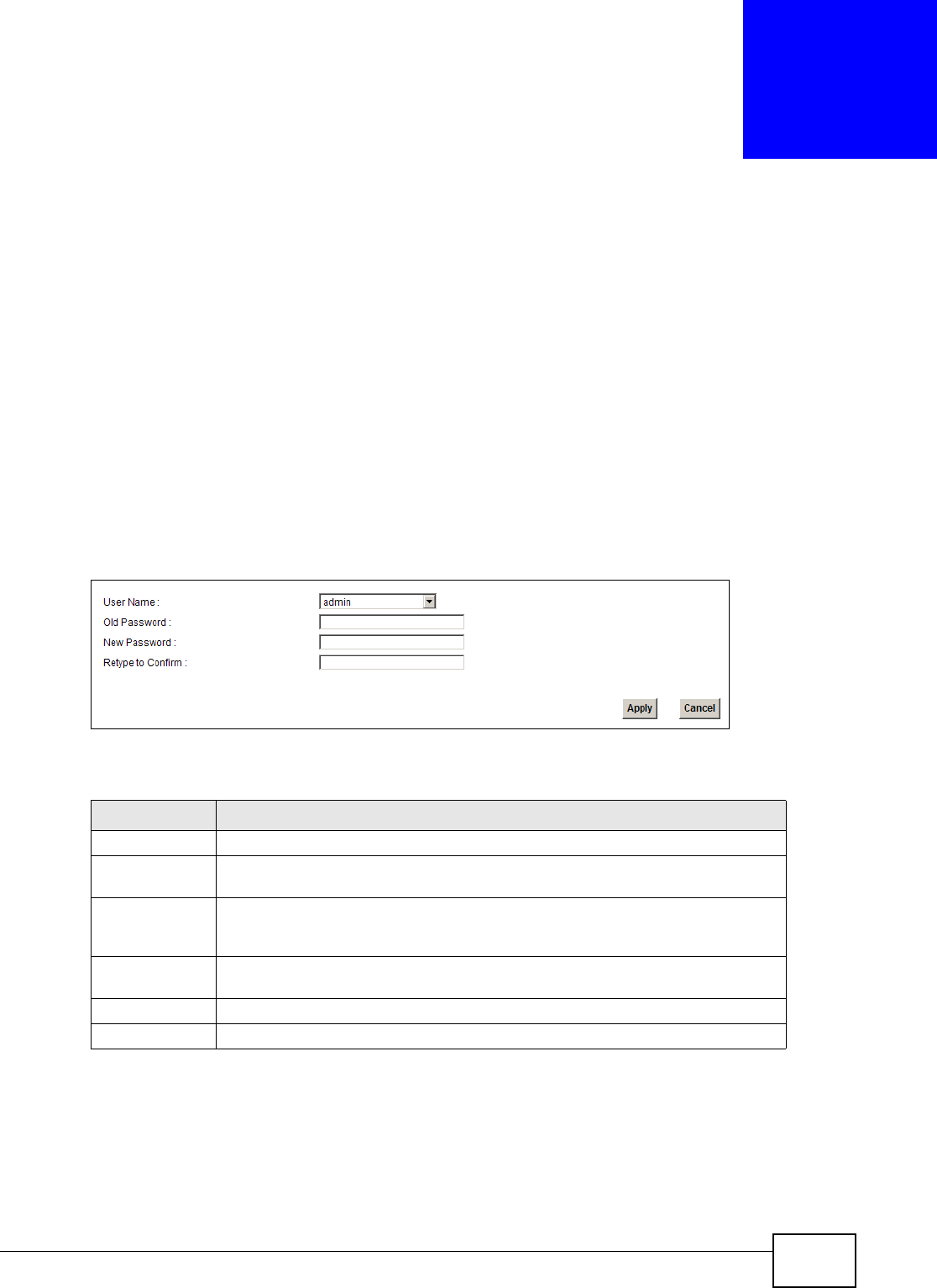
B222s User’s Guide 155
CHAPTER 18
User Account
18.1 Overview
You can configure syst em passw ord for different user account s in the User Accou nt screen.
18.2 The User Account Screen
Use t he Use r Accoun t screen t o configure system passw ord.
Click M a int e na nce > User Account t o open t he following screen.
Figure 87 Maint enance > User Account
The following t able describes t he labels in t his screen.
Table 66 Maint enance > User Account
LABEL DESCRIPTION
User Nam e You can configure the password for t he Pow er User and Adm in account s.
Old Password Type t he default password or t he existing password you use to access the syst em
in t his field.
New Password Type your new system password ( up to 30 characters). Note t hat as you t ype a
passwor d, t he screen displays a ( * ) for each character you t ype. Aft er you change
the password, use t he new password t o access t he LTE Device.
Ret ype t o
Confirm
Type t he new password again for confirm at ion.
Apply Click Apply t o save your changes.
Cancel Click Ca ncel t o rest ore your previously saved sett ings.

Chapter 18 User Account
B222s User’s Guide
156
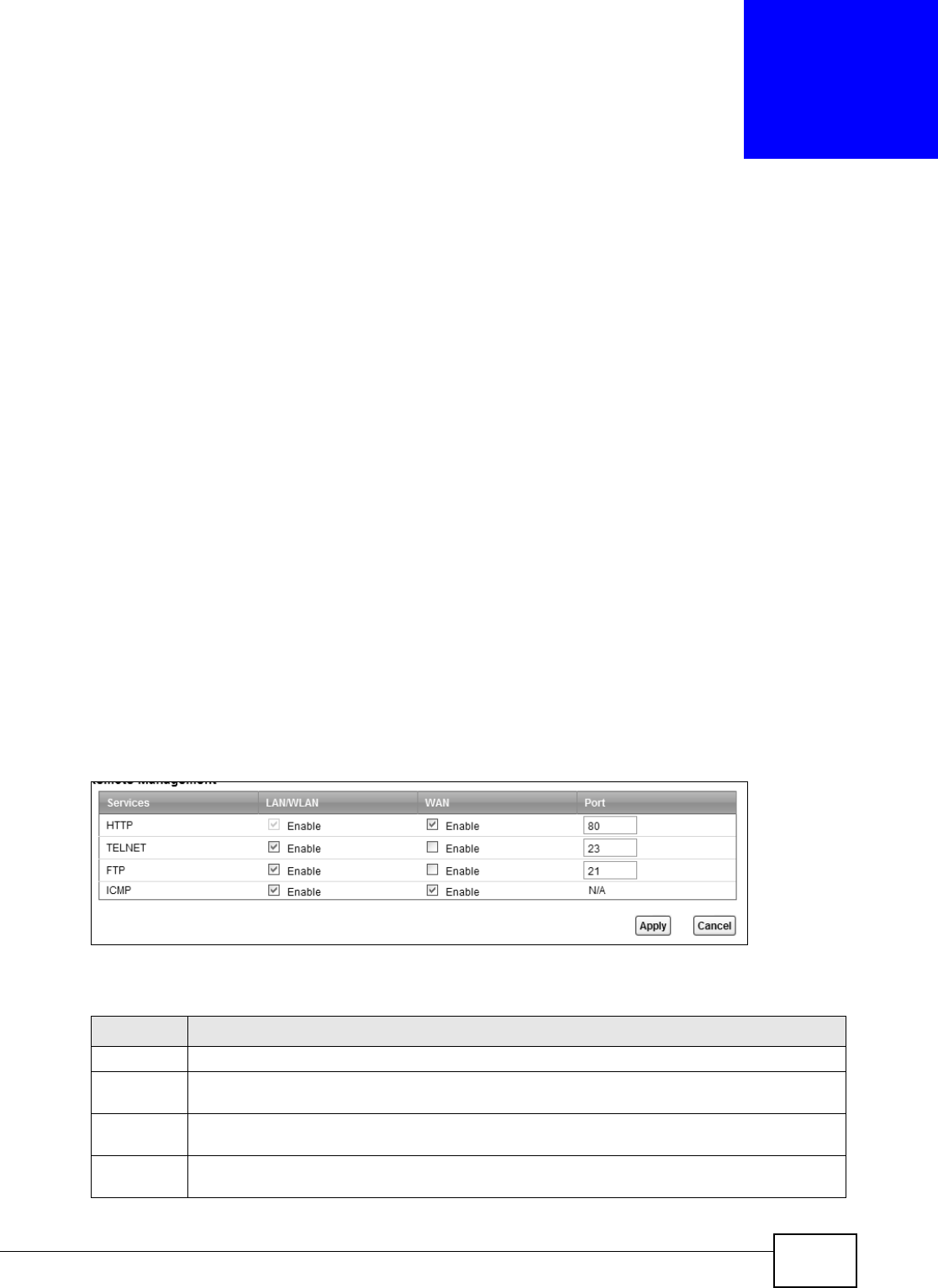
B222s User’s Guide 157
CHAPTER 19
Remote MGMT
19.1 Overview
Re m ot e MGMT allow s you t o m anage your LTE Device from a rem ote location t hrough t he
follow ing int erfaces:
• LAN and WLAN
• WAN only
Note: The LTE Device is m anaged using t he web configurator.
19.1.1 What You Need to Know
The following term s and concept s m ay help as you read this chapt er
19.2 The Remote MGMT Screen
Use t his screen to decide what ser vices you m ay use t o access which LTE Device int erface. Click
Ma int en a n ce > Rem ot e MGMT to open the following screen.
Figure 88 Maint enance > Rem ote MGMT
The following t able describes t he fields in t his screen.
Table 67 Maintenance > Rem ot e MGMT
LABEL DESCRIPTION
Services This is t he service you m ay use t o access the LTE Dev ice.
LAN/ WLAN Select the Ena ble check box for the corresponding services t hat you want to allow access t o
the LTE Device from the LAN and WLAN.
WAN Select the Ena ble check box for t he corresponding serv ices t hat you want to allow access t o
the LTE Device from the WAN.
Por t You m ay change the server port num ber for a service if needed, how ever you m ust use t he
sam e por t num ber in order t o use t hat service for r em ot e m anagem ent .

Chapter 19 Remote MGMT
B222s User’s Guide
158
Apply Click Apply to save your changes.
Cancel Click Ca ncel t o rest ore your previously saved sett ings.
Table 67 Maintenance > Rem ot e MGMT ( cont inued)
LABEL DESCRIPTION

B222s User’s Guide 159
CHAPTER 20
System
20.1 Overview
You can configure syst em set t ings, including t he host nam e, dom ain nam e and the inactivity t im e-
out int erval in t he Syst e m screen.
20.1.1 What You Need to Know
The following term s and concept s m ay help as you read this chapt er.
Domain Name
This is a network address that ident ifies t he owner of a network connect ion. For exam ple, in the
network address “ www.exam ple.com / support / files”, t he dom ain nam e is “ www.exam ple.com ”.
20.2 The System Screen
Use t he Sy st em screen t o configure t he system ’s host nam e, dom ain nam e, and inactivity t im e- out
int erval.
The H ost N am e is for ident ification purposes. However, because som e I SPs check t his nam e you
should ent er your com put er's "Com puter Nam e". Find t he syst em nam e of your Windows com put er.
I n Windows XP, click st a r t , My Com put e r, View syst em inform a t ion and t hen click t he
Com put e r N a m e t ab. Note t he ent ry in t he Full com put er na m e field and ent er it as the LTE
Device Syst em Na m e .
Click M a int e n a n ce > Syst e m t o open t he following screen.
Figure 89 Maint enance > System

Chapter 20 System
B222s User’s Guide
160
The following t able describes t he labels in t his screen.
Table 68 Maintenance > Sy stem
LABEL DESCRIPTION
Host Nam e Choose a descriptive nam e for identificat ion purposes. I t is recom m ended you
ent er your com put er ’s “ Com puter nam e” in this field. This nam e can be up to 30
alphanum eric charact ers long. Spaces are not allowed, but dashes “- ” and
underscores "_" are accept ed.
Dom ain Nam e Ent er t he dom ain nam e ( if you know it ) here. I f you leave this field blank, t he I SP
m ay assign a dom ain nam e via DHCP.
The dom ain nam e entered by you is given prior it y over t he I SP assigned dom ain
nam e.
Adm inist rator
I nact ivity Tim er
Type how m any m inut es a m anagem ent session (eit her via t he web configurat or)
can be left idle before t he session t im es out . The default is 5 m inut es. Aft er it
tim es out you have t o log in w ith your password again. Ver y long idle tim eout s
m ay have securit y risks. A value of "0" m eans a m anagem ent session never t im es
out, no m att er how long it has been left idle ( not recom mended) .
Apply Click t his t o save your changes back to t he LTE Device.
Cancel Click this t o begin configuring t his screen afresh.
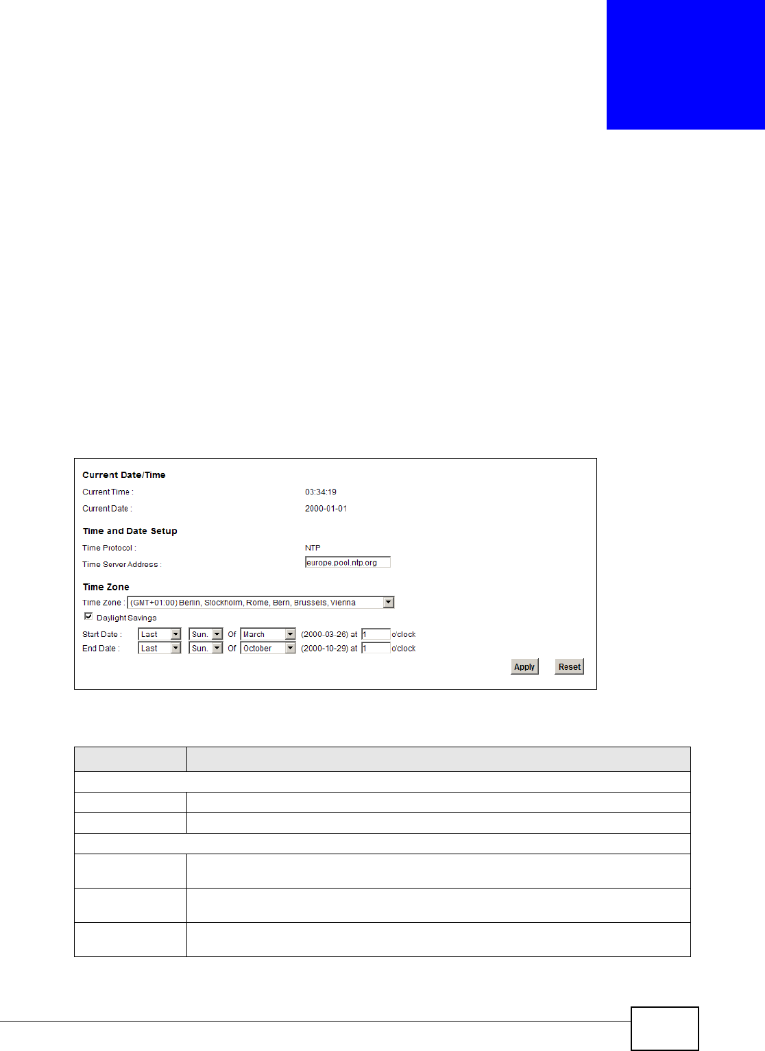
B222s User’s Guide 161
CHAPTER 21
Time Setting
21.1 Overview
You can configure t he syst em ’s t im e and dat e in t he Tim e Se t t in g scr een.
21.2 The Time Setting Screen
To change your LTE Device’s t im e and date, click M a int e n a n ce > Tim e . The screen appears as
shown. Use this screen to configure t he LTE Device’s t im e based on your local t im e zone.
Figure 90 Maint enance > Tim e Sett ing
The following t able describes t he fields in t his screen.
Table 69 Maintenance > System > Tim e Set ting
LABEL DESCRIPTION
Current Dat e/ Tim e
Current Tim e This field displays the tim e of your LTE Device.
Current Dat e This field displays the dat e of your LTE Device.
Tim e and Date Set up
Tim e Prot ocol This show s t he t im e ser vice prot ocol that your t im e server sends when you turn on t he
LTE D e v i c e .
Tim e Server
Address
Enter t he I P address or URL ( up t o 31 extended ASCI I charact ers in length) of your t im e
server. Check with your I SP/ network adm inist rat or if you are unsure of this inform at ion.
Tim e Zone Choose t he t im e zone of your locat ion. This will set the tim e difference bet ween your t im e
zone and Greenwich Mean Tim e ( GMT) .

Chapter 21 Time Setting
B222s User’s Guide
162
Daylight Savings Daylight saving is a period from late spring t o early fall when m any countr ies set their
clocks ahead of norm al local t im e by one hour t o give m or e daytim e light in the
evening.Select this opt ion if you use Daylight Saving Tim e.
St art Dat e Configur e t he day and t im e when Daylight Saving Tim e st art s if you select ed Da ylight
Savings. The o'clock field uses t he 24 hour form at . Here are a couple of exam ples:
Daylight Saving Tim e start s in m ost par ts of the Unit ed St ates on t he second Sunday of
March. Each tim e zone in t he Unit ed St at es st art s using Daylight Saving Tim e at 2 A.M.
local tim e. So in t he Unit ed St at es you would select Second , Sunda y, Ma rch and t ype 2
in t he o'clock field.
Day lig ht Sav in g Tim e st ar t s in t he Eu r opean Un ion on t he last Sun day of Mar ch. All of t he
t im e zones in the European Union start using Daylight Saving Tim e at t he sam e m om ent
( 1 A.M. GMT or UTC) . So in t he European Union you w ould select La st , Sun day, Ma rch.
The t im e you type in the o'clock field depends on your t im e zone. I n Germ any for
instance, you would type 2 because Germ any's t im e zone is one hour ahead of GMT or
UTC ( GMT+ 1) .
End Dat e Configure t he day and tim e when Daylight Saving Tim e ends if you select ed Da ylight
Savings. The o'clock field uses t he 24 hour form at . Here are a couple of exam ples:
Daylight Saving Tim e ends in t he Unit ed St ates on t he first Sunday of Nov em ber. Each
t im e zone in t he Unit ed Stat es stops using Daylight Saving Tim e at 2 A.M. local tim e. So
in t he Unit ed St at es you would select Fir st , Sunda y, N ov em be r and type 2 in t he
o'clock field.
Daylight Saving Tim e ends in t he Eur opean Union on t he last Sunday of Oct ober. All of
the t im e zones in t he European Union stop using Daylight Saving Tim e at the sam e
m om ent ( 1 A. M. GMT or UTC) . So in t he Eu r op ean Un ion y ou w ou ld select La st , Su nda y,
Oct o be r. The t im e you t y pe in t he o 'cl ock field depends on your t im e zone. I n Ger m any
for instance, you w ould t ype 2 because Germ any's t im e zone is one hour ahead of GMT
or UTC ( GMT+ 1) .
Apply Click Apply t o save your changes.
Reset Click Reset t o begin configuring this scr een afresh.
Table 69 Maintenance > System > Tim e Sett ing ( cont inued)
LABEL DESCRIPTION

B222s User’s Guide 163
CHAPTER 22
Log Setting
22.1 Overview
You can configure where t he LTE Device sends logs and which logs and/ or im m ediate alerts t he LTE
Device records in the Log Set t ing screen.
22.2 The Log Setting Screen
To change your LTE Device’s log sett ings, click Maint enance > Log Se t t in g. The screen appears
as shown.
Figure 91 Maint enance > Log Set t ing

Chapter 22 Log Setting
B222s User’s Guide
164
The following t able describes t he fields in t his screen.
Table 70 Maintenance > Log Sett ing
LABEL DESCRIPTION
Syslog Sett ing
Syslog Logging The LTE Device sends a log t o an ext ernal syslog server. Select t he Ena ble check box t o
enable syslog logging.
Syslog Server Ent er t he server nam e or I P address of the syslog server t hat will log t he selected
cat egories of logs.
UDP Port Ent er the port num ber used by t he syslog server.
Active Log and Select Level
Log Category Select t he cat egories of logs t hat you want t o record.
Log Level Select the sev erit y level of logs t hat you w ant t o r ecord. I f you want t o record all logs,
select ALL.
Apply Click Apply t o save your changes.
Cancel Click Ca ncel t o rest ore your previously saved set t ings.

B222s User’s Guide 165
CHAPTER 23
Firmware Upgrade
23.1 Overview
This chapt er explains how t o upload new firm ware t o your LTE Device. You can download new
firm ware releases from your nearest Huawei FTP site ( or www.huawei.com ) to use t o upgrade your
device’s perform ance.
Only use firmware for your device’s specific model. Refer to the label on
the bottom of your LTE Device.
23.2 The Firmware Upgrade Screen
Click M a int e nance > Firm w ar e Upgra de to open the following screen. The upload process uses
HTTP ( Hypert ext Transfer Prot ocol) and m ay take up to t hree m inutes. Aft er a successful upload,
the system will reboot .
Do NOT turn off the LTE Device while firmware upload is in progress!
Figure 92 Maint enance > Firm war e Upgrade
The following t able describes t he labels in t his screen.
Table 71 Maintenance > Firm ware Upgrade
LABEL DESCRIPTION
Cur ren t Fir m war e
Ve r sion
This is t he present Firm war e version.
File Path Type in t he locat ion of the file you want t o upload in t his field or click Br ow se ... to find it .
Br owse... Click t his t o find t he .bin file you want t o upload. Rem em ber t hat you m ust decom press
com pressed (.zip) files befor e you can upload t hem .
Upload Click t his to begin t he upload process. This process m ay t ake up t o t hree m inut es.
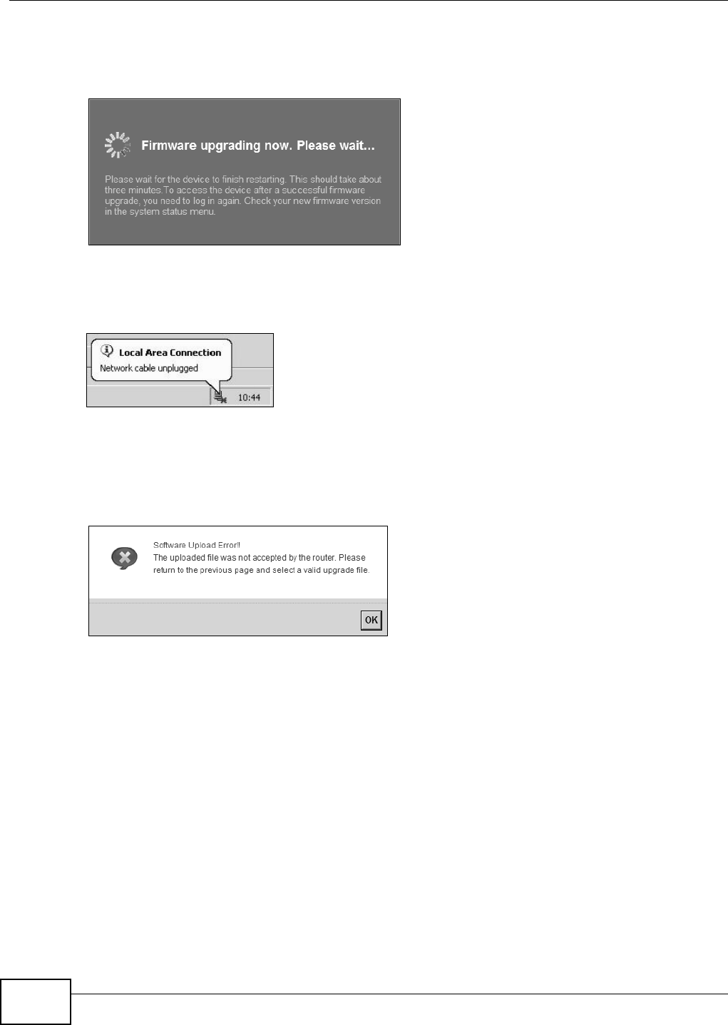
Chapter 23 Firmware Upgrade
B222s User’s Guide
166
Aft er you see t he firm ware updat ing screen, wait a few m inutes before logging int o the LTE Device
again.
Figure 93 Firm ware Uploading
The LTE Device aut om at ically restart s in this tim e causing a t em porar y network disconnect. I n
som e operat ing system s, you m ay see t he following icon on your deskt op.
Figure 94 Net work Tem porarily Disconnect ed
Aft er t wo m inut es, log in again and check your new firm ware version in t he St a t u s screen.
I f t he upload was not successful, an error screen will appear. Click OK t o go back to t he Fir m w a r e
Upgrade screen.
Figure 95 Error Message

B222s User’s Guide 167
CHAPTER 24
Backup/Restore
24.1 Overview
The Ba ck up/ Re st or e screen allows you to backup and rest ore device configurations. You can also
reset your device sett ings back to t he factory default .
24.2 The Backup/Restore Screen
Click M a in t e na nce > Ba ck u p/ Rest or e. I nform ation relat ed to factory defaults, backup
configurat ion, and restoring configuration appear s in this screen, as shown next .
Figure 96 Maint enance > Backup/ Rest ore
Backup Configuration
Backup Configurat ion allows you t o back up ( save) t he LTE Device’s current configurat ion to a file
on your com puter. Once your LTE Device is configured and funct ioning pr operly, it is highly
recom m ended t hat you back up your configurat ion file before m aking configurat ion changes. The
backup configurat ion file will be useful in case you need to return t o your previous sett ings.
Click Ba ckup t o save the LTE Device’s current configurat ion t o your com put er.
Chapter 24 Backup/Restore
B222s User’s Guide
168
Restore Configuration
Restore Configurat ion allows you t o upload a new or previously saved configurat ion file from your
com put er to your LTE Device.
Do not turn off the LTE Device while configuration file upload is in
progress.
Aft er t he LTE Device configuration has been restored successfully, the login screen appears. Login
again to restart t he LTE Device.
The LTE Device aut om at ically restart s in this t im e causing a tem porary net w ork disconnect . I n
som e operat ing system s, you m ay see t he following icon on your deskt op.
Figure 97 Net work Tem porarily Disconnect ed
I f you rest ore t he default configurat ion, you m ay need to change t he I P address of your com puter
to be in the sam e subnet as t hat of the default device I P address ( 192.168.1.1) . See Appendix B on
page 189 for det ails on how to set up your com put er ’s I P address.
I f t he upload was not successful, an error screen will appear. Click OK t o go back t o t he
Con fig ur a t ion screen.
Table 72 Rest ore Configurat ion
LABEL DESCRIPTION
File Path Type in t he location of t he file you want to upload in this field or click Br ow se ... t o
find it .
Br owse... Click t his t o find t he file you want to upload. Rem em ber t hat you m ust decom press
com pressed ( .ZI P) files before you can upload them .
Upload Click t his t o begin the upload process.
Reset Click t his t o reset your device set t ings back t o the factory default.
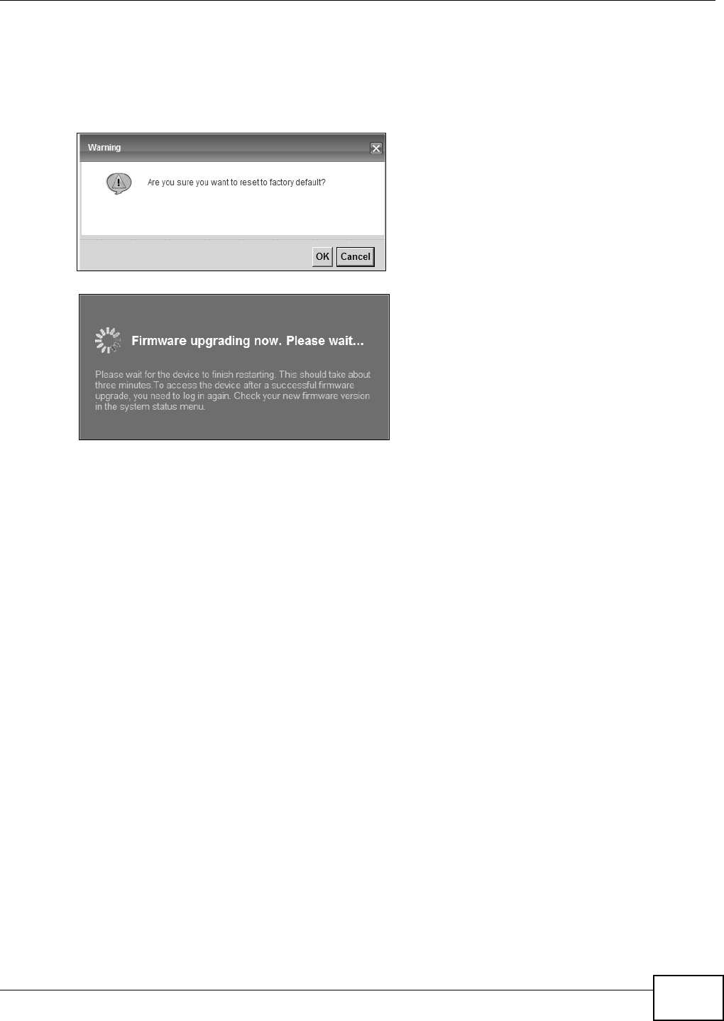
Chapter 24 Backup/Restore
B222s User’s Guide 169
Reset to Factory Defaults
Click t he Re se t but t on t o clear all user- ent ered configurat ion inform at ion and ret urn the LTE Device
to it s fact ory default s. The following warning screen appears.
Figure 98 Reset Warning Message
Figure 99 Reset I n Process Message
You can also press t he RESET but t on on t he back panel t o reset t he fact ory default s of your LTE
Device. Refer to Section 1.7 on page 20 for m ore inform at ion on the RESET but ton.
24.3 The Reboot Screen
System rest art allows you t o reboot t he LTE Device rem otely wit hout t urning t he power off. You
m ay need t o do t his if t he LTE Device hangs, for exam ple.
Click M a int e n a n ce > Reboot . Click the Re boot but ton t o have the LTE Device r eboot . This does
not affect t he LTE Device's configurat ion.

Chapter 24 Backup/Restore
B222s User’s Guide
170
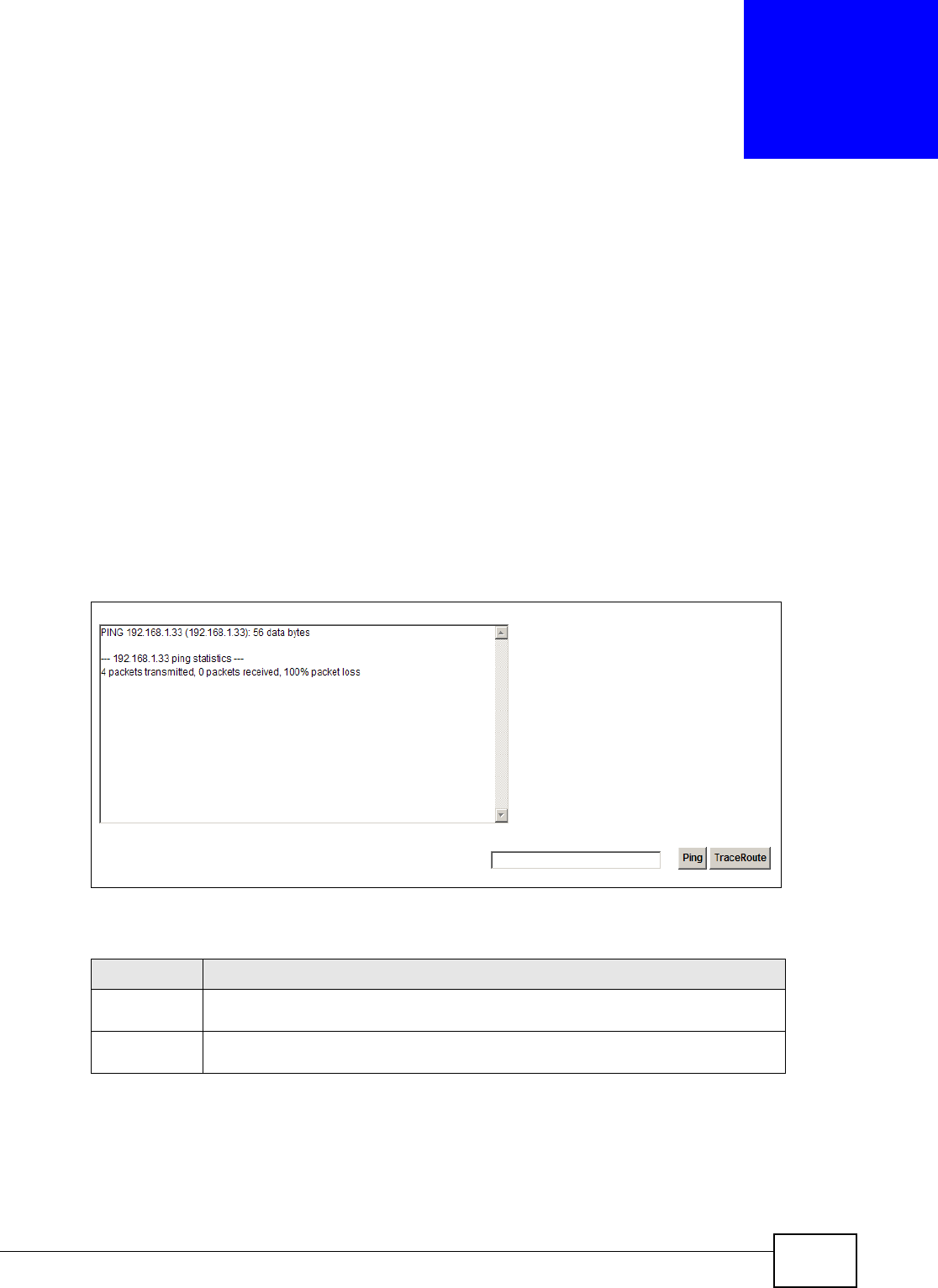
B222s User’s Guide 171
CHAPTER 25
Diagnostic
25.1 Overview
You can use different diagnost ic m ethods t o t est a connect ion and see t he detailed infor m ation.
These read-only screens display inform ation t o help you ident ify problem s wit h t he LTE Device.
25.2 The Ping/TraceRoute Screen
Ping and t raceroute help check availability of rem ote host s and also help t r oubleshoot net work or
I nt ernet connections. Click Maint ena nce > D ia gn ost ic t o open t he Pin g/ Tr a ce Rou t e screen
shown next .
Figure 100 Maint enance > Diagnostic > Ping/ TraceRout e
The following t able describes t he fields in t his screen.
Table 73 Maintenance > Diagnost ic > Ping/ TraceRoute
LABEL DESCRIPTION
Ping Type the I P address of a com puter that you want to ping in order to t est a
connect ion. Click Pin g and t he ping st at ist ics will show in t he diagnostic .
Tr a c e Ro u t e Click t his but t on t o perform t he t raceroute funct ion. This det erm ines t he pat h a
packet t akes t o the specified host.

Chapter 25 Diagnostic
B222s User’s Guide
172

B222s User’s Guide 173
CHAPTER 26
Troubleshooting
26.1 Overview
This chapt er offers som e suggest ions t o solve problem s you m ight encount er. The potential
problem s are divided int o t he following categories.
•Power, Hardware Connections, and LEDs
•LTE Device Access and Login
•I nt ernet Access
•Wireless I nt ernet Access
•Phone Calls and VoI P
•UPnP
26.2 Power, Hardware Connections, and LEDs
The LTE Device does not t urn on. None of t he LEDs t urn on.
1Make sure the LTE Device is t urned on.
2Make sure you are using the power adapt or or cord included with t he LTE Device.
3Make sure the power adapt or or cord is connect ed t o t he LTE Device and plugged in t o an
appropriate power source. Make sur e t he power source is t urned on.
4Turn t he LTE Device off and on.
5I f t he problem cont inues, cont act t he vendor.
One of the LEDs does not behave as expected.
1Make sure you understand t he norm al behavior of t he LED. See Sect ion 1.6 on page 18.
2Check the hardware connect ions. See the Quick St ar t Guide.
3I nspect your cables for dam age. Contact the vendor t o replace any dam aged cables.

Chapter 26 Troubleshooting
B222s User’s Guide
174
4Turn t he LTE Device off and on.
5I f t he problem cont inues, cont act t he vendor.
26.3 LTE Device Access and Login
I forgot t he I P address for t he LTE Device.
1The default I P address is 192.168.1.1.
2I f you changed t he I P address and have forgot t en it, you m ight get the I P address of t he LTE Device
by looking up t he I P address of the default gat eway for your com put er. To do t his in m ost Windows
com puters, click Sta rt > Ru n, ent er cm d, and t hen ent er ipconfig. The I P address of t he De fa ult
Ga t ew a y m ight be t he I P address of t he LTE Device ( it depends on the network) , so ent er t his I P
address in your I nt ernet brow ser.
3I f t his does not work, you have t o reset t he device to it s fact ory default s. See Sect ion 1.7 on page
20.
I forgot t he password.
1The default adm in password is 1 2 3 4 and t he default user password is 1 2 3 4 .
2I f you can’t rem em ber the password, you have t o r eset the device to it s factory default s. See
Section 1.7 on page 20.
I cannot see or access t he Login screen in the web configurat or.
1Make sure you are using t he correct I P address.
• The default I P address is 192.168.1.1.
• I f you changed t he I P address, use t he new I P address.
• I f you changed t he I P address and have forgot t en it, see t he t roubleshooting suggestions for I
forgot t he I P address for t he LTE Device.
2Check the hardware connect ions, and m ake sure t he LEDs are behaving as expect ed. See t he Quick
St art Guide.
3Make sure your I nt ernet browser does not block pop- up windows and has JavaScript and Java
enabled. See Appendix C on page 219.

Chapter 26 Troubleshooting
B222s User’s Guide 175
4Reset t he device t o its factory default s, and try t o access the LTE Device w it h t he default I P
address. See Sect ion 1.7 on page 20.
5I f t he problem cont inues, cont act t he net work adm inistrat or or vendor, or try one of the advanced
suggest ions.
Adva nced Suggest ions
• Try t o access t he LTE Device using anot her service, such as Telnet . I f you can access t he LTE
Device, check t he rem ot e m anagem ent settings and firewall rules t o find out why t he LTE Device
does not respond t o HTTP.
• I f your com puter is connect ed to t he W AN port or is connect ed wirelessly, use a com put er t hat is
connected t o a ETH ERN ET port .
I can see t he Login screen, but I cannot log in t o t he LTE Device.
1Make sure you have entered the user nam e and password cor rect ly. The default user nam e is
adm in. These fields are case- sensitive, so m ake sure [ Caps Lock] is not on.
2You cannot log in to t he web configurator while som eone is using Telnet t o access t he LTE Device.
Log out of the LTE Device in t he ot her session, or ask t he person who is logged in to log out .
3Turn t he LTE Device off and on.
4I f t his does not work, you have t o r eset the device t o it s factory default s. See Sect ion 26.2 on page
173.
26.4 Internet Access
I cannot access t he I nt ernet .
1Check the hardware connect ions, and m ake sure t he LEDs are behaving as expect ed. See t he Quick
St art Guide and Section 1.6 on page 18.
2Make sur e you ent ered your serv ice provider’s LTE APN inform at ion correctly.
3I f you are trying t o access t he I nternet wirelessly, m ake sure t he wireless sett ings in t he wireless
client are t he sam e as the set t ings in the AP.
4I f you are t rying t o access t he I nternet wirelessly, m ake sure you have enabled t he wireless LAN by
the W PS/ W LAN but ton or t he Net w or k Set t ing > W irele ss > Ge ne r a l screen.
5Disconnect all t he cables fr om your device, and follow t he directions in the Quick St ar t Guide again.
6I f t he problem cont inues, cont act your I SP.

Chapter 26 Troubleshooting
B222s User’s Guide
176
I cannot access t he I nt ernet anym ore. I had access t o the I nt ernet (with the LTE Device), but
m y I nt ernet connection is not available anym ore.
1Check the hardware connect ions, and m ake sure t he LEDs are behaving as expect ed. See t he Quick
St art Guide and Section 1.6 on page 18.
2Turn t he LTE Device off and on.
3I f t he problem cont inues, cont act your I SP.
The I nt ernet connection is slow or int erm itt ent .
1There m ight be a lot of t raffic on t he network. Look at t he LEDs, and check Section 1.6 on page 18.
I f t he LTE Device is sending or receiving a lot of inform at ion, try closing som e program s t hat use
the I nt ernet , especially peer- t o-peer applications.
2Turn t he LTE Device off and on.
3I f t he problem cont inues, cont act t he net work adm inistrat or or vendor, or try one of the advanced
suggest ions.
Adva nced Suggest ions
• Check the set tings for QoS. I f it is disabled, you m ight consider activating it . I f it is enabled, you
m ight consider raising or lowering t he priority for som e applicat ions.
26.5 Wireless Internet Access
What factors m ay cause int erm it tent or unstabled wireless connect ion? How can I solve t his
problem ?
The following fact ors m ay cause interference:
• Obst acles: walls, ceilings, furnit ure, and so on.
• Building Materials: m etal doors, alum inum st uds.
• Electrical devices: m icrowaves, m onitors, elect ric m ot ors, cordless phones, and ot her wireless
devices.
To optim ize t he speed and qualit y of your wireless connect ion, you can:
• Move your wireless device closer to t he AP if t he signal st rengt h is low.

Chapter 26 Troubleshooting
B222s User’s Guide 177
• Reduce wireless int erference t hat m ay be caused by ot her wir eless net works or sur rounding
wir eless electronics such as cordless phones.
• Place t he AP where t here are m inim um obstacles ( such as walls and ceilings) bet ween t he AP and
the wireless client .
• Reduce t he num ber of wireless client s connecting to t he sam e AP sim ultaneously, or add
addit ional APs if necessary.
• Try closing som e program s that use t he I nternet , especially peer- t o-peer applications. I f t he
wir eless client is sending or receiving a lot of inform at ion, it m ay have too m any pr ogram s open
that use t he I nternet .
What wireless security m odes does m y LTE Device support ?
Wireless securit y is vit al to your network. I t prot ects com m unicat ions between w ireless stat ions,
access points and t he wired net work.
The available security m odes in your device are as follows:
•W PA2 - PSK: ( recom m ended) This uses a pre- shared key wit h t he WPA2 st andard.
•W PA- PSK: This has t he device use either WPA-PSK or WPA2- PSK depending on which securit y
m ode t he wireless client uses.
•W PA2 : WPA2 (I EEE 802.11i) is a wireless security standar d that defines stronger encrypt ion,
authent icat ion and key m anagem ent than WPA. I t requires t he use of a RADI US server and is
m ost ly used in business net works.
•W PA: Wi- Fi Prot ected Access ( WPA) is a subset of t he I EEE 802.11i st andard. I t requires t he use
of a RADI US server and is m ost ly used in business networks.
•W EP: Wired Equivalent Privacy (WEP) encrypt ion scram bles t he data transm itt ed bet ween t he
wir eless stat ions and t he access point s t o keep net work com m unicat ions private.
26.6 Phone Calls and VoIP
The t elephone port won’t work or t he t elephone lacks a dial t one.
1Check the t elephone connection and t elephone wire.
I can access t he I nt ernet , but cannot m ake VoI P calls.
1The PH ON E light should com e on. Make sure t hat your t elephone is connected t o the PH ON E port .
2You can also check the VoI P st at us in t he Syst e m I nfo screen.

Chapter 26 Troubleshooting
B222s User’s Guide
178
3I f t he VoI P settings are correct , use speed dial t o m ake peer- to- peer calls. I f you can m ake a call
using speed dial, t here m ay be som ething wrong with the SI P server, contact your VoI P service
provider.
26.7 UPnP
When using UPnP and t he LTE Device reboot s, m y com puter cannot det ect UPnP and refresh
My N et w ork Place s > Local N et w or k.
1Disconnect the Et hernet cable from t he LTE Device’s LAN port or from your com put er.
2Re- connect the Et hernet cable.
The Local Are a Conne ct ion icon for UPnP disappears in t he screen.
Restart your com put er.
I cannot open special applications such as whit e board, file transfer and video when I use the
MSN m essenger.
1Wait m ore t han t hree m inutes.
2Restart t he applications.

B222s User’s Guide 179
APPENDIX A
IP Addresses and Subnetting
This appendix introduces I P addresses and subnet m asks.
I P addr esses ident ify individual devices on a net work. Every net working device (such as com put ers,
servers, rout ers, and printers) needs an I P addr ess t o com m unicat e across t he net work. These
networking devices are also known as hosts.
Subnet m asks det erm ine the m axim um num ber of possible hosts on a net work. You can also use
subnet m asks t o divide one network into m ult iple sub- net works.
Introduction to IP Addresses
One part of t he I P address is t he net work num ber, and t he ot her part is the host I D. I n t he sam e
way t hat houses on a street share a com mon street nam e, t he hosts on a net work share a com m on
network num ber. Sim ilarly, as each house has it s own house num ber, each host on t he network has
it s own unique ident ifying num ber - t he host I D. Rout ers use t he net work num ber t o send packet s
to t he correct network, while the host I D determ ines t o which host on t he network t he packet s are
delivered.
Structure
An I P address is m ade up of four part s, writ ten in dot t ed decim al notat ion (for exam ple,
192.168.1.1) . Each of t hese four part s is known as an octet. An octet is an eight - digit binary
num ber ( for exam ple 11000000, which is 192 in decim al not at ion).
Therefore, each octet has a possible range of 00000000 to 11111111 in binary, or 0 t o 255 in
decim al.
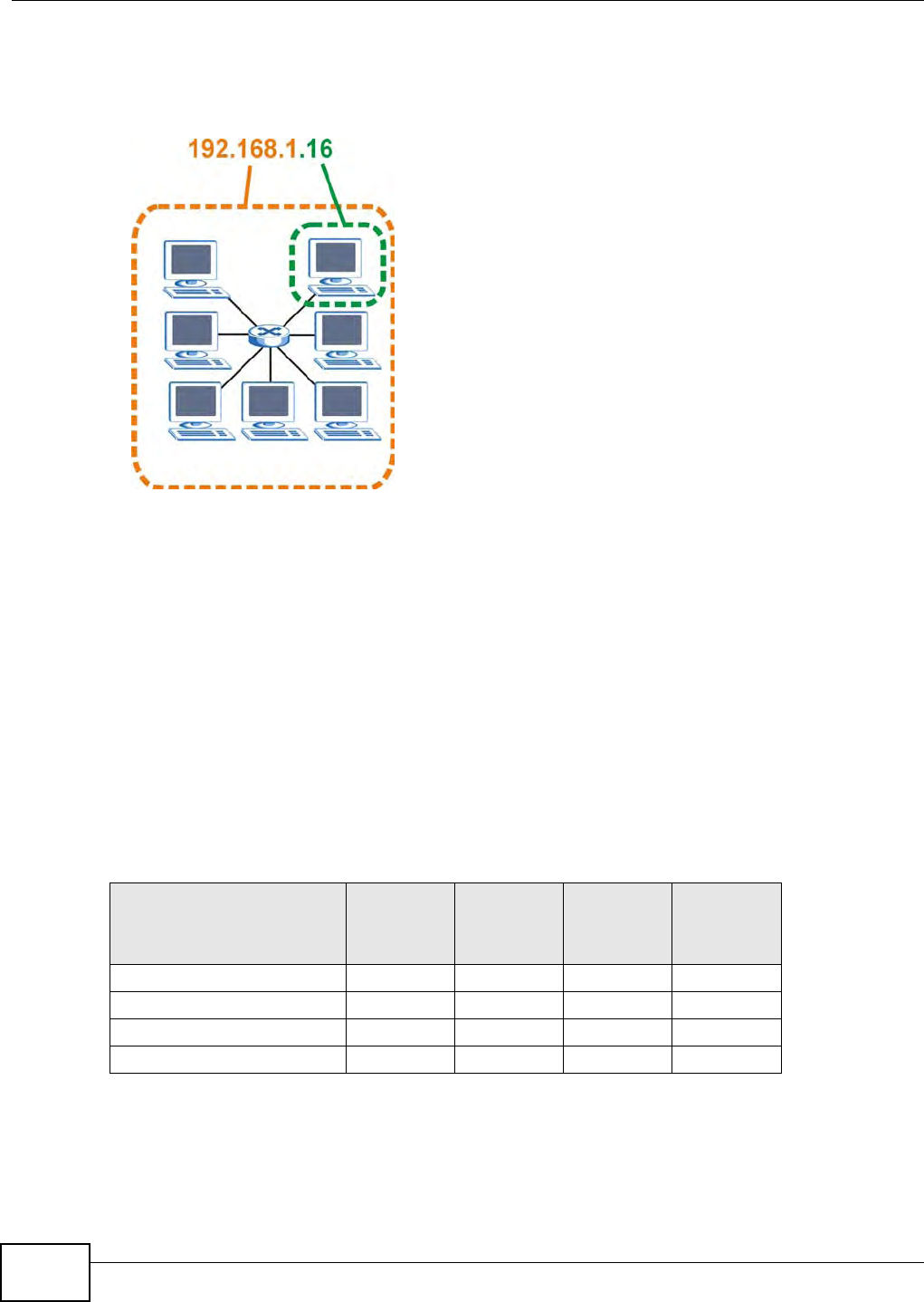
Appendix A IP Addresses and Subnetting
B222s User’s Guide
180
The following figure shows an exam ple I P address in which t he first t hree oct et s ( 192.168.1) are
the network num ber, and t he fourth octet ( 16) is t he host I D.
Figure 101 Net work Num ber and Host I D
How m uch of the I P address is t he network num ber and how m uch is t he host I D var ies according
to t he subnet m ask.
Subnet Masks
A subnet m ask is used t o det erm ine w hich bit s are part of t he net work num ber, and which bits are
par t of t he host I D (using a logical AND operation) . The term “ subnet ” is short for “ sub- net work”.
A subnet m ask has 32 bits. I f a bit in t he subnet m ask is a “ 1” t hen the corresponding bit in t he I P
address is part of t he net work num ber. I f a bit in the subnet m ask is “ 0” t hen t he corresponding bit
in the I P address is part of t he host I D.
The following exam ple shows a subnet m ask identifying the network num ber ( in bold t ext ) and host
I D of an I P address ( 192.168.1.2 in decim al) .
By convent ion, subnet m asks always consist of a continuous sequence of ones beginning from t he
leftm ost bit of t he m ask, followed by a continuous sequence of zeros, for a t otal num ber of 32 bits.
Table 74 I P Address Net work Num ber and Host I D Exam ple
1ST OCTET:
(192)
2ND
OCTET:
(168)
3RD
OCTET:
(1)
4TH OCTET
(2)
I P Address ( Binary) 11000000 10101000 00000001 00000010
Subnet Mask ( Binary) 1 1 1 1 1 1 1 1 1 1 1 1 1 1 1 1 1 1 1 1 1 1 1 1 00000000
Net work Num ber 1 1 0 0 0 0 0 0 1 0 1 0 1 0 0 0 0 0 0 0 0 0 0 1
Host I D 00000010

Appendix A IP Addresses and Subnetting
B222s User’s Guide 181
Subnet m asks can be referred to by t he size of t he network num ber part ( the bit s wit h a “ 1” value) .
For exam ple, an “ 8-bit m ask” m eans t hat t he first 8 bit s of t he m ask are ones and t he rem aining 24
bits are zeroes.
Subnet m asks are expressed in dot ted decim al not at ion j ust like I P addresses. The following
exam ples show t he binary and decim al notat ion for 8- bit , 16- bit , 24- bit and 29- bit subnet m asks.
Network Size
The size of the network num ber det erm ines t he m axim um num ber of possible hosts you can have
on your network. The larger t he num ber of net work num ber bits, the sm aller the num ber of
rem aining host I D bits.
An I P address wit h host I Ds of all zeros is the I P address of t he net work ( 192.168.1.0 wit h a 24- bit
subnet m ask, for exam ple) . An I P address with host I Ds of all ones is t he broadcast address for t hat
network ( 192.168.1.255 wit h a 24- bit subnet m ask, for exam ple).
As t hese t wo I P addresses cannot be used for individual hosts, calculate the m axim um num ber of
possible host s in a network as follows:
Notation
Since the m ask is always a cont inuous num ber of ones beginning from the left, followed by a
continuous num ber of zeros for t he rem ainder of t he 32 bit m ask, you can sim ply specify t he
num ber of ones instead of writing the value of each octet. This is usually specified by w rit ing a “ / ”
follow ed by the num ber of bits in t he m ask aft er the address.
For exam ple, 192.1.1.0 / 25 is equivalent t o saying 192.1.1.0 wit h subnet m ask 255.255.255.128.
Table 75 Subnet Masks
BINARY
DECIMAL
1ST OCTET 2ND OCTET 3RD OCTET 4TH OCTET
8-bit m ask 11111111 00000000 00000000 00000000 255.0.0.0
16- bit m ask 11111111 11111111 00000000 00000000 255.255.0.0
24- bit m ask 11111111 11111111 11111111 00000000 255.255.255.0
29- bit m ask 11111111 11111111 11111111 11111000 255.255.255.248
Table 76 Maxim um Host Num bers
SUBNET MASK HOST ID SIZE MAXIMUM NUMBER OF
HOSTS
8 bits 255.0.0.0 24 bit s 224 – 2 16777214
16 bit s 255.255.0.0 16 bit s 216 – 2 65534
24 bit s 255.255.255.0 8 bits 28 – 2 254
29 bit s 255.255.255.248 3 bit s 23 – 2 6
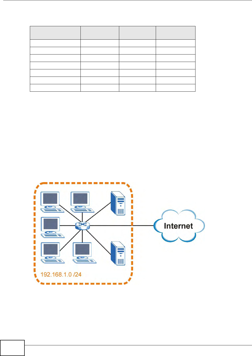
Appendix A IP Addresses and Subnetting
B222s User’s Guide
182
The following t able shows som e possible subnet m asks using bot h notat ions.
Subnetting
You can use subnet t ing t o divide one net work int o m ult iple sub- net works. I n t he following exam ple
a network adm inistrat or cr eat es two sub- net works to isolat e a group of servers from the rest of the
com pany network for securit y reasons.
I n t his exam ple, t he com pany network addr ess is 192.168.1.0. The first three oct et s of the address
( 192.168.1) are the network num ber, and the rem aining oct et is the host I D, allowing a m axim um
of 28 – 2 or 254 possible host s.
The following figure shows t he com pany net work before subnet t ing.
Figure 102 Subnet ting Exam ple: Before Subnet t ing
You can “borrow” one of the host I D bit s t o divide t he net work 192.168.1.0 int o t wo separat e sub-
networks. The subnet m ask is now 25 bit s ( 255.255.255.128 or / 25) .
The “ borrowed” host I D bit can have a value of either 0 or 1, allowing t wo subnet s; 192.168.1.0 / 25
and 192.168.1.128 / 25.
Table 77 Alternat ive Subnet Mask Notat ion
SUBNET MASK ALTERNATIVE
NOTATION
LAST OCTET
(BINARY)
LAST OCTET
(DECIMAL)
255.255.255.0 / 24 0000 0000 0
255.255.255.128 / 25 1000 0000 128
255.255.255.192 / 26 1100 0000 192
255.255.255.224 / 27 1110 0000 224
255.255.255.240 / 28 1111 0000 240
255.255.255.248 / 29 1111 1000 248
255.255.255.252 / 30 1111 1100 252
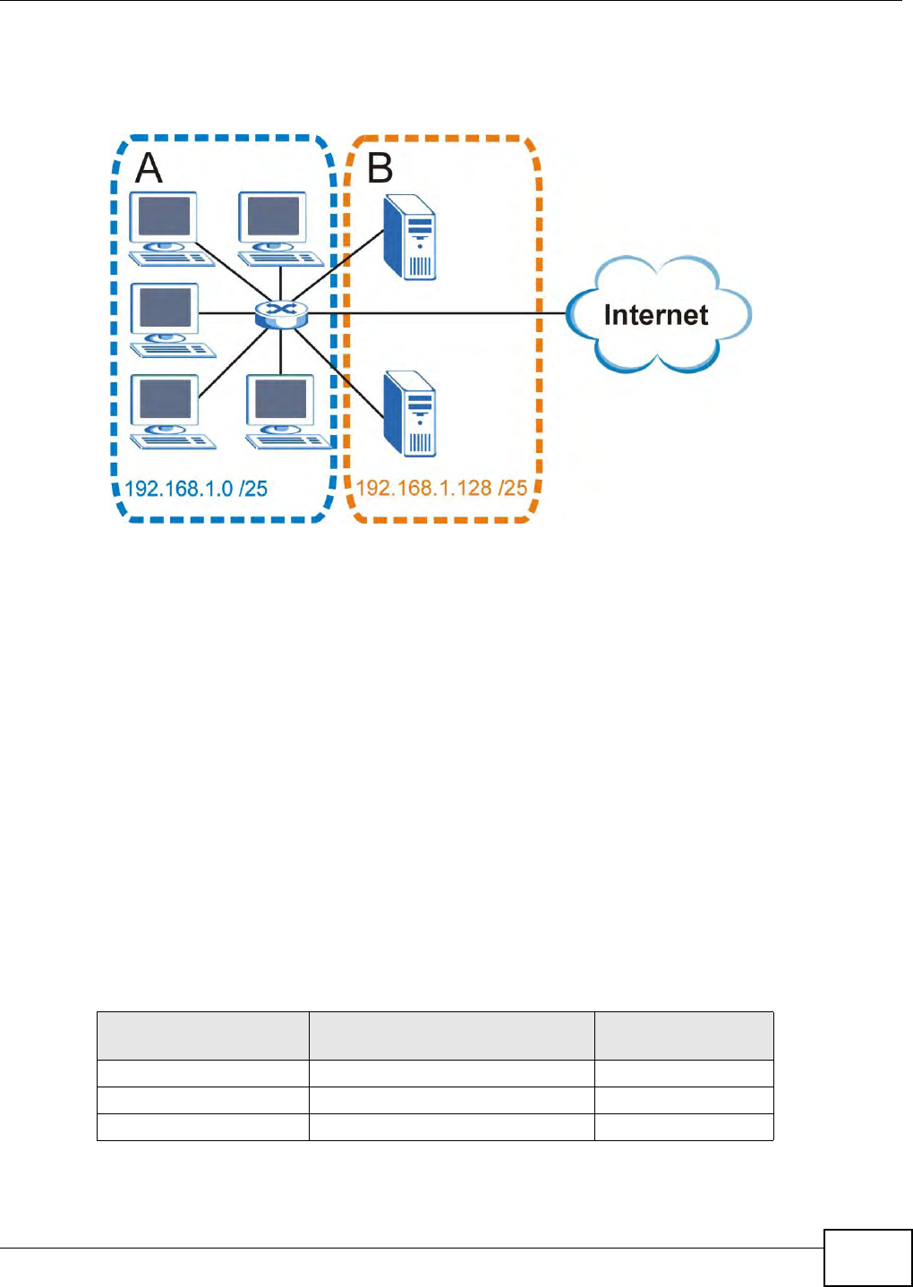
Appendix A IP Addresses and Subnetting
B222s User’s Guide 183
The following figure shows t he com pany network aft er subnetting. There are now t wo sub-
networ ks, A and B.
Figure 103 Subnet ting Exam ple: After Subnet t ing
I n a 25- bit subnet t he host I D has 7 bit s, so each sub- net work has a m axim um of 27 – 2 or 126
possible host s (a host I D of all zeroes is the subnet ’s address it self, all ones is t he subnet ’s
broadcast address) .
192.168.1.0 wit h m ask 255.255.255.128 is subnet A it self, and 192.168.1.127 wit h m ask
255.255.255.128 is it s broadcast address. Therefore, the lowest I P address that can be assigned t o
an act ual host for subnet A is 192.168.1.1 and t he highest is 192.168.1.126.
Sim ilarly, t he host I D range for subnet B is 192.168.1.129 t o 192.168.1.254.
Example: Four Subnets
The previous exam ple illustrat ed using a 25- bit subnet m ask to divide a 24- bit address int o two
subnet s. Sim ilarly, t o divide a 24- bit address int o four subnet s, you need t o “ bor row” t wo host I D
bits t o give four possible com binat ions ( 00, 01, 10 and 11) . The subnet m ask is 26 bit s
(11111111.11111111.11111111.1 1 000000) or 255.255.255.192.
Each subnet cont ains 6 host I D bits, giving 26 - 2 or 62 hosts for each subnet ( a host I D of all
zeroes is t he subnet it self, all ones is t he subnet ’s broadcast address) .
Table 78 Subnet 1
IP/SUBNET MASK NETWORK NUMBER LAST OCTET BIT
VALUE
I P Address ( Decim al) 192.168.1. 0
I P Address ( Binary) 11000000.10101000.00000001. 0 0 000000
Subnet Mask ( Binary) 11111111.11111111.11111111. 1 1 000000
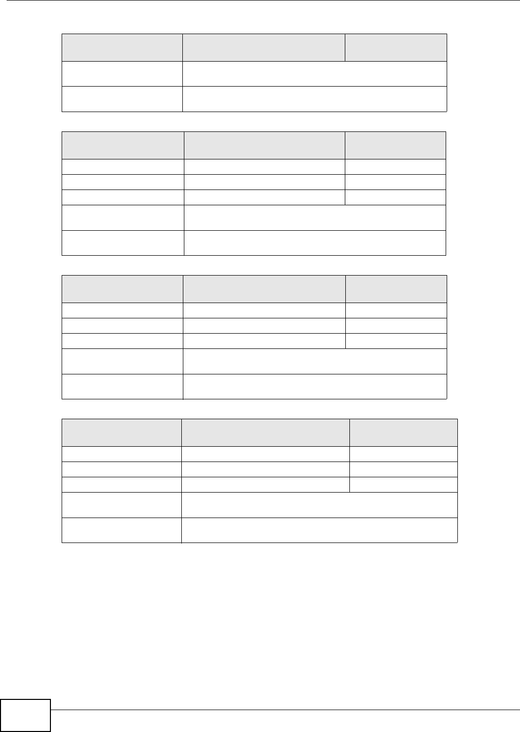
Appendix A IP Addresses and Subnetting
B222s User’s Guide
184
Example: Eight Subnets
Sim ilarly, use a 27- bit m ask t o creat e eight subnet s (000, 001, 010, 011, 100, 101, 110 and 111) .
Subnet Address:
192.168.1.0
Lowest Host I D: 192.168.1.1
Broadcast Address:
192.168.1.63
Highest Host I D: 192.168.1.62
Table 79 Subnet 2
IP/SUBNET MASK NETWORK NUMBER LAST OCTET BIT
VALUE
I P Address 192.168.1. 64
I P Address ( Binary) 11000000.10101000.00000001. 0 1 000000
Subnet Mask ( Binary) 11111111.11111111.11111111. 1 1 000000
Subnet Address:
192.168.1.64
Lowest Host I D: 192.168.1.65
Broadcast Address:
192.168.1.127
Highest Host I D: 192.168.1.126
Table 80 Subnet 3
IP/SUBNET MASK NETWORK NUMBER LAST OCTET BIT
VALUE
I P Address 192.168.1. 128
I P Address ( Binary) 11000000.10101000.00000001. 1 0 000000
Subnet Mask ( Binary) 11111111.11111111.11111111. 1 1 000000
Subnet Address:
192.168.1.128
Lowest Host I D: 192.168.1.129
Broadcast Address:
192.168.1.191
Highest Host I D: 192.168.1.190
Table 81 Subnet 4
IP/SUBNET MASK NETWORK NUMBER LAST OCTET BIT
VALUE
I P Address 192.168.1. 192
I P Address ( Binary) 11000000.10101000.00000001. 1 1 000000
Subnet Mask ( Binary) 11111111.11111111.11111111. 1 1 000000
Subnet Address:
192.168.1.192
Lowest Host I D: 192.168.1.193
Broadcast Address:
192.168.1.255
Highest Host I D: 192.168.1.254
Table 78 Subnet 1 ( cont inued)
IP/SUBNET MASK NETWORK NUMBER LAST OCTET BIT
VALUE

Appendix A IP Addresses and Subnetting
B222s User’s Guide 185
The following t able shows I P address last octet values for each subnet .
Subnet Planning
The following table is a sum m ar y for subnet planning on a net work wit h a 24- bit net work num ber.
The following table is a sum m ar y for subnet planning on a net work wit h a 16- bit net work num ber.
Table 82 Eight Subnet s
SUBNET SUBNET
ADDRESS FIRST ADDRESS LAST
ADDRESS
BROADCAST
ADDRESS
1 0 1 30 31
232 33 62 63
364 65 94 95
496 97 126 127
5128 129 158 159
6160 161 190 191
7192 193 222 223
8224 225 254 255
Table 83 24- bit Networ k Num ber Subnet Planning
NO. “BORROWED”
HOST BITS SUBNET MASK NO. SUBNETS NO. HOSTS PER
SUBNET
1255.255.255.128 ( / 25) 2126
2255.255.255.192 ( / 26) 462
3255.255.255.224 ( / 27) 830
4255.255.255.240 ( / 28) 16 14
5255.255.255.248 ( / 29) 32 6
6255.255.255.252 ( / 30) 64 2
7255.255.255.254 ( / 31) 128 1
Table 84 16- bit Networ k Num ber Subnet Planning
NO. “BORROWED”
HOST BITS SUBNET MASK NO. SUBNETS NO. HOSTS PER
SUBNET
1255.255.128.0 (/ 17) 232766
2255.255.192.0 (/ 18) 416382
3255.255.224.0 (/ 19) 88190
4255.255.240.0 (/ 20) 16 4094
5255.255.248.0 (/ 21) 32 2046
6255.255.252.0 (/ 22) 64 1022
7255.255.254.0 (/ 23) 128 510
8255.255.255.0 (/ 24) 256 254
9255.255.255.128 ( / 25) 512 126
10 255.255.255.192 ( / 26) 1024 62
11 255.255.255.224 ( / 27) 2048 30
12 255.255.255.240 ( / 28) 4096 14

Appendix A IP Addresses and Subnetting
B222s User’s Guide
186
Configuring IP Addresses
Where you obt ain your net work num ber depends on your particular sit uat ion. I f t he I SP or your
network adm inistrat or assigns you a block of registered I P addresses, follow t heir instructions in
select ing t he I P addresses and t he subnet m ask.
I f t he I SP did not explicitly give you an I P net work num ber, t hen m ost likely you have a single user
account and the I SP will assign you a dynam ic I P address when t he connect ion is established. I f this
is t he case, it is recom m ended t hat you select a net w ork num ber from 192.168.0.0 to
192.168.255.0. The I nt ernet Assigned Num ber Aut horit y (I ANA) reserved t his block of addresses
specifically for privat e use; please do not use any ot her num ber unless you are t old ot herw ise. You
m ust also enable Network Address Translation ( NAT) on t he LTE Device.
Once you have decided on the net work num ber, pick an I P address for your LTE Device t hat is easy
to rem em ber ( for instance, 192.168.1.1) but m ake sure t hat no ot her device on your net work is
using t hat I P address.
The subnet m ask specifies t he net work num ber port ion of an I P address. Your LTE Device will
com pute the subnet m ask autom at ically based on t he I P address that you ent ered. You don't need
to change t he subnet m ask com put ed by the LTE Device unless you are instruct ed t o do ot herw ise.
Private IP Addresses
Every m achine on t he I nternet m ust have a unique address. I f your net works ar e isolat ed from the
I nt ernet ( running only bet w een two branch offices, for exam ple) you can assign any I P addresses t o
the host s without problem s. However, t he I nternet Assigned Num bers Aut horit y ( I ANA) has
reserved the following t hree blocks of I P addresses specifically for private networks:
• 10.0.0.0 — 10.255.255.255
• 172.16.0.0 — 172.31.255.255
• 192.168.0.0 — 192.168.255.255
You can obt ain your I P address from t he I ANA, from an I SP, or it can be assigned from a private
network. I f you belong to a sm all organizat ion and your I nt ernet access is t hrough an I SP, t he I SP
can provide you wit h t he I nternet addresses for your local networks. On the other hand, if you are
par t of a m uch larger organization, you should consult your net w ork adm inistrat or for t he
appropriate I P addresses.
Regardless of your part icular situat ion, do not creat e an arbit rar y I P address; always follow t he
guidelines above. For m ore inform at ion on address assignm ent , please refer t o RFC 1597, Address
Allocation for Privat e I nt ernets and RFC 1466, Guidelines for Managem ent of I P Address Space.
13 255.255.255.248 ( / 29) 8192 6
14 255.255.255.252 ( / 30) 16384 2
15 255.255.255.254 ( / 31) 32768 1
Table 84 16- bit Network Num ber Subnet Planning (continued)
NO. “BORROWED”
HOST BITS SUBNET MASK NO. SUBNETS NO. HOSTS PER
SUBNET
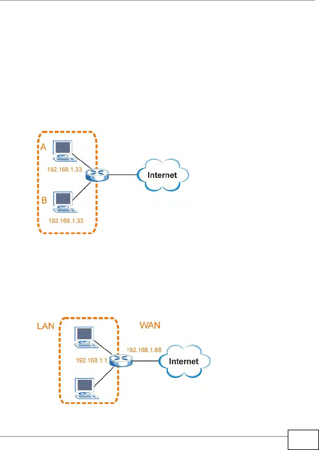
Appendix A IP Addresses and Subnetting
B222s User’s Guide 187
IP Address Conflicts
Each device on a net work m ust have a unique I P address. Devices wit h duplicate I P addresses on
the sam e net work will not be able t o access t he I nternet or other resources. The devices m ay also
be unreachable t hrough the network.
Conflicting Computer IP Addresses Example
More t han one device can not use t he sam e I P address. I n the following exam ple com put er A has a
st at ic ( or fixed) I P address that is t he sam e as t he I P address t hat a DHCP server assigns t o
com puter B which is a DHCP client . Neit her can access t he I nternet . This problem can be solved by
assigning a different st atic I P address to com put er A or sett ing com puter A t o obt ain an I P addr ess
autom atically.
Figure 104 Conflicting Com put er I P Addresses Exam ple
Conflicting Router IP Addresses Example
Since a rout er connects different net works, it m ust have int erfaces using different net work
num bers. For exam ple, if a rout er is set bet ween a LAN and the I nt ernet ( WAN) , t he rout er ’s LAN
and WAN addresses m ust be on different subnet s. I n t he following exam ple, t he LAN and WAN are
on the sam e subnet . The LAN com puters cannot access the I nt ernet because the rout er cannot
rout e bet ween networ ks.
Figure 105 Conflicting Com put er I P Addresses Exam ple
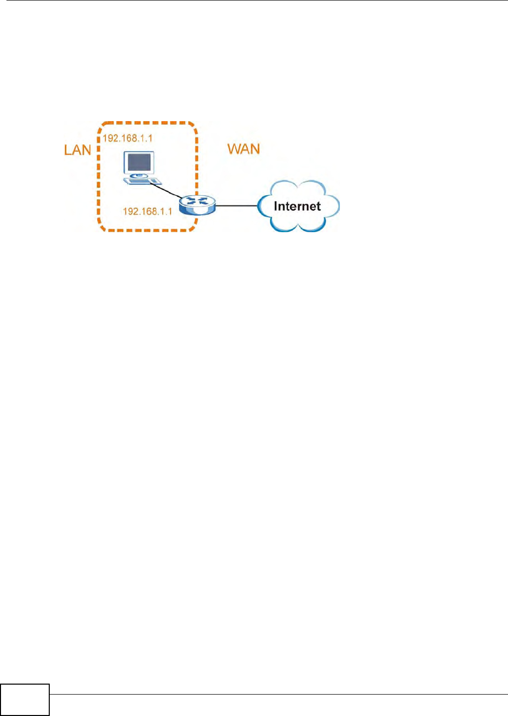
Appendix A IP Addresses and Subnetting
B222s User’s Guide
188
Conflicting Computer and Router IP Addresses Example
More than one device can not use t he sam e I P address. I n the follow ing exam ple, the com put er and
the rout er’s LAN port bot h use 192.168.1.1 as t he I P address. The com put er cannot access the
I nt ernet. This problem can be solved by assigning a different I P address t o t he com puter or the
rout er ’s LAN port .
Figure 106 Conflicting Com put er and Router I P Addresses Exam ple

B222s User’s Guide 189
APPENDIX B
Setting Up Your Computer’s IP Address
Note: Your specific LTE Device m ay not support all of t he operat ing system s described in
this appendix. See the product specifications for m ore inform at ion about which
operat ing system s are supported.
This appendix shows you how t o configure t he I P set t ings on your com put er in order for it to be
able to com municate wit h t he ot her devices on your net work. Window s Vista/ XP/ 2000, Mac OS 9/
OS X, and all versions of UNI X/ LI NUX include the soft ware com ponent s you need to use TCP/ I P on
your com put er.
I f you m anually assign I P inform ation instead of using a dynam ic I P, m ake sure t hat your net work’s
com puters have I P addresses t hat place them in t he sam e subnet .
I n t his appendix, you can set up an I P address for:
•Windows XP/ NT/ 2000 on page 189
•Windows Vist a on page 193
•Windows 7 on page 197
•Mac OS X: 10.3 and 10.4 on page 201
•Mac OS X: 10.5 on page 204
•Linux: Ubunt u 8 ( GNOME) on page 208
•Linux: openSUSE 10.3 (KDE) on page 212
Windows XP/NT/2000
The following exam ple uses t he default Windows XP display t hem e but can also apply t o Windows
2000 and Windows NT.
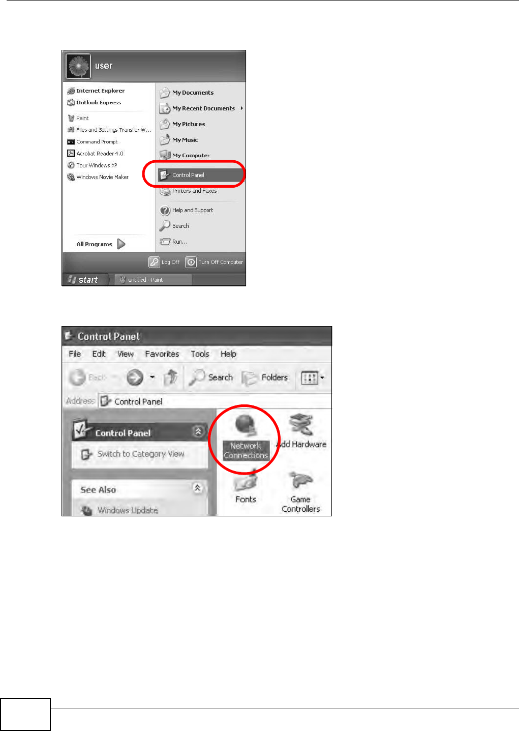
Appendix B Setting Up Your Computer’s IP Address
B222s User’s Guide
190
1Click St ar t > Cont r ol Pa n e l.
Figure 107 Windows XP: Start Menu
2I n t he Cont rol Pane l, click t he N e t w ork Conne ct ions icon.
Figure 108 Windows XP: Control Panel
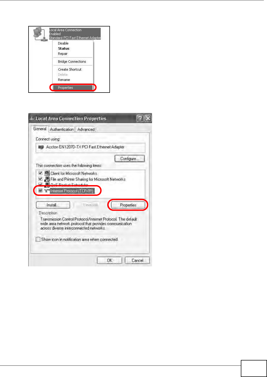
Appendix B Setting Up Your Computer’s IP Address
B222s User’s Guide 191
3Right- click Loca l Area Con ne ct ion and t hen select Pr op er t ie s.
Figure 109 Windows XP: Control Panel > Network Connect ions > Propert ies
4On t he Gene r a l tab, select I nt er n e t Pr ot ocol ( TCP/ I P) and t hen click Pr ope rt ie s.
Figure 110 Windows XP: Local Area Connection Propert ies
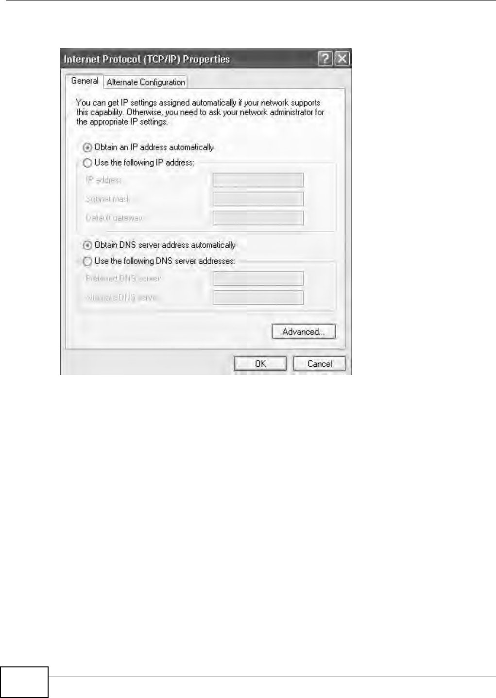
Appendix B Setting Up Your Computer’s IP Address
B222s User’s Guide
192
5The I nt e rne t Prot ocol TCP/ I P Pr ope r t ies window opens.
Figure 111 Windows XP: I nternet Protocol ( TCP/ I P) Propert ies
6Select Obt ain an I P a ddr e ss a ut om at ica lly if your net work adm inist rat or or I SP assigns your I P
address dynam ically.
Select Use t he follow ing I P Addr e ss and fill in t he I P a ddr e ss, Subne t m ask, and De fa ult
ga t e w ay fields if you have a st at ic I P address that was assigned t o you by your network
adm inist rat or or I SP. You m ay also have t o ent er a Pre ferre d D N S ser ver and an Alt e r n at e DN S
ser ve r , if t hat inform ation was provided.
7Click OK t o close t he I nt er n e t Pr ot ocol ( TCP/ I P) Prope r t ies window.
8Click OK t o close t he Loca l Area Conn e ct ion Pr ope r t ie s window.
Verifying Settings
1Click St a r t > All Progra m s > Acce ssories > Com m a nd Prom pt .
2I n t he Com m and Prom pt window, t ype " ipconfig" and t hen press [ ENTER] .
You can also go t o St ar t > Cont rol Pa nel > N et w or k Conn e ct ions, right- click a net work
connection, click Sta t us and t hen click the Support t ab to view your I P address and connection
inform at ion.

Appendix B Setting Up Your Computer’s IP Address
B222s User’s Guide 193
Windows Vista
This sect ion shows screens from Windows Vista Professional.
1Click St a r t > Cont rol Pane l.
Figure 112 Windows Vist a: Start Menu
2I n t he Cont rol Pane l, click t he N e t w ork and I nt ernet icon.
Figure 113 Windows Vist a: Cont rol Panel
3Click t he N e tw or k a nd Sharing Ce nt er icon.
Figure 114 Windows Vist a: Net work And I nt ernet
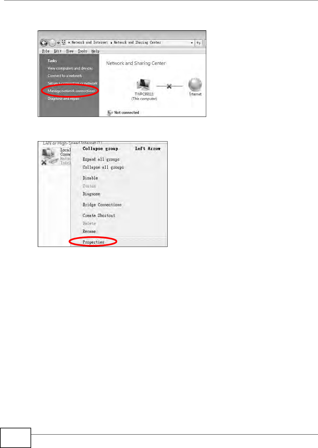
Appendix B Setting Up Your Computer’s IP Address
B222s User’s Guide
194
4Click M a n a ge n e t w or k con nect ions.
Figure 115 Windows Vist a: Net work and Sharing Cent er
5Right- click Loca l Area Con ne ct ion and t hen select Pr op er t ie s.
Figure 116 Windows Vist a: Net work and Sharing Cent er
Note: During this procedure, click Cont inue whenever Windows displays a screen saying
that it needs your perm ission t o cont inue.
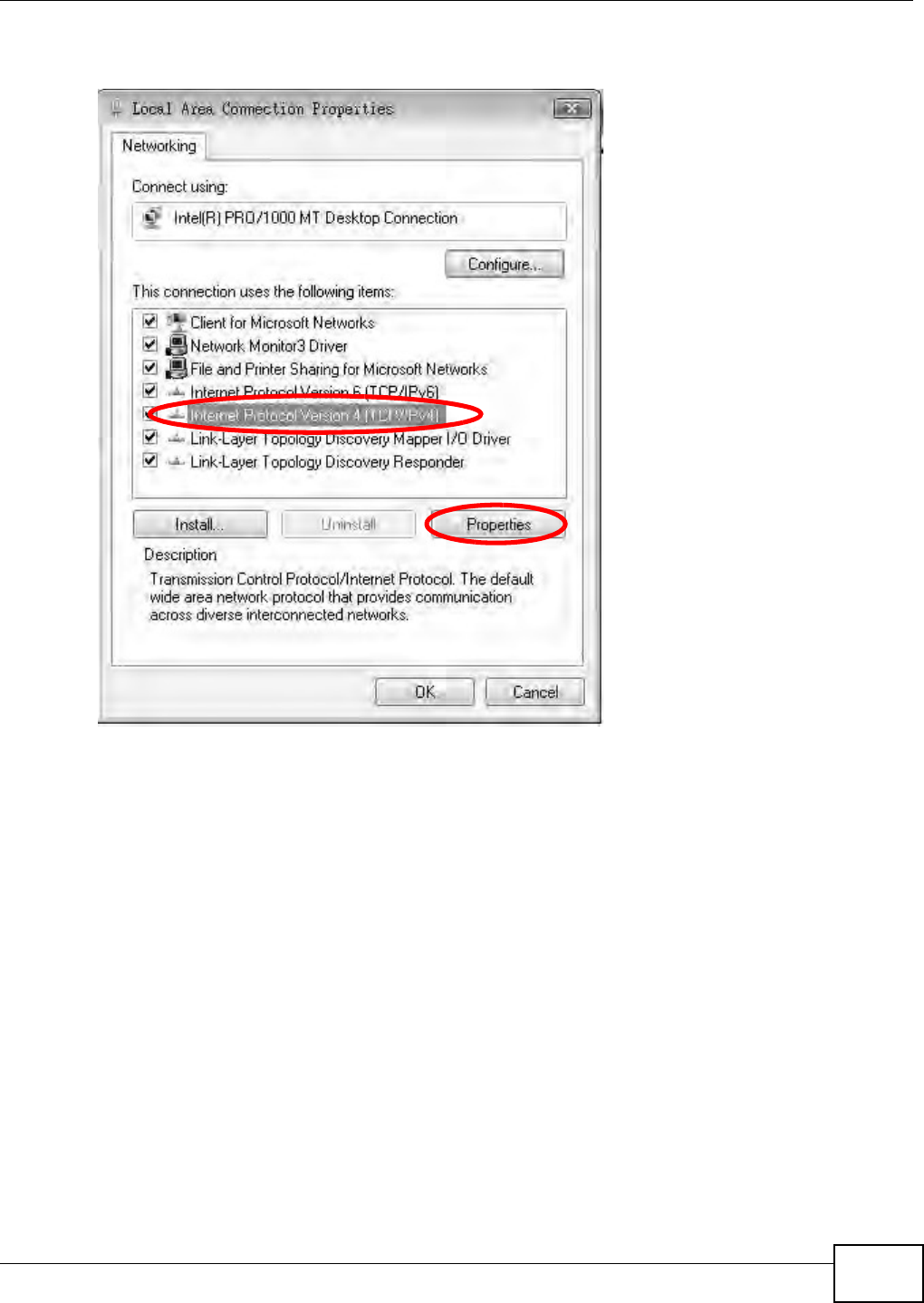
Appendix B Setting Up Your Computer’s IP Address
B222s User’s Guide 195
6Select I nt e r n e t Prot ocol Ve r sion 4 ( TCP/ I Pv4 ) and t hen select Pr op er t ie s.
Figure 117 Windows Vista: Local Area Connection Pr opert ies
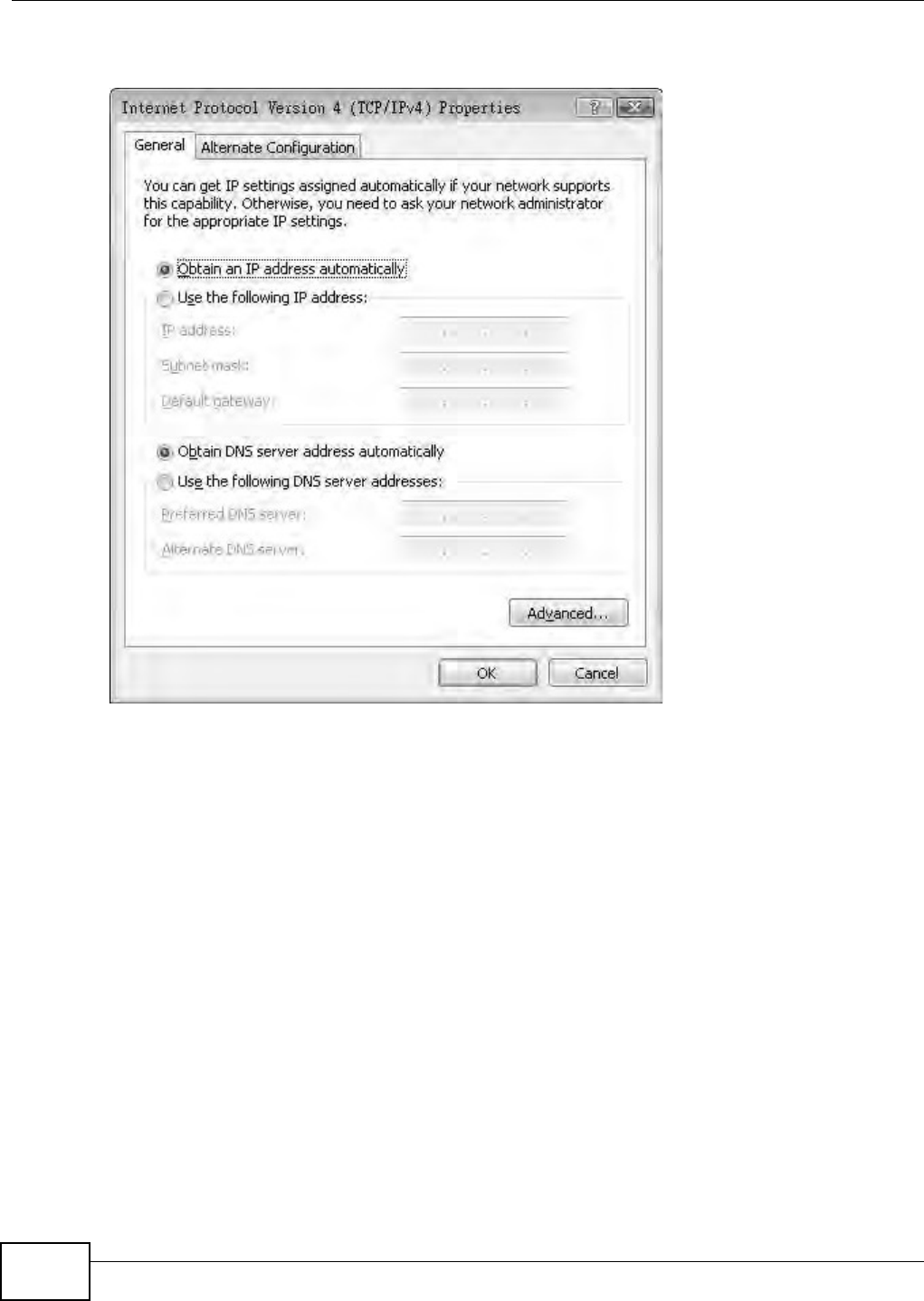
Appendix B Setting Up Your Computer’s IP Address
B222s User’s Guide
196
7The I nt e rne t Prot ocol Version 4 ( TCP/ I Pv4 ) Pr opert ies window opens.
Figure 118 Windows Vist a: I nt ernet Protocol Version 4 (TCP/ IPv4) Propert ies
8Select Obt ain an I P a ddr e ss a ut om at ica lly if your net work adm inist rat or or I SP assigns your I P
address dynam ically.
Select Use t he follow ing I P Addr e ss and fill in t he I P a ddr e ss, Subne t m ask, and De fa ult
ga t e w ay fields if you have a st at ic I P address that was assigned t o you by your network
adm inist rat or or I SP. You m ay also have t o ent er a Pre ferre d D N S ser ver and an Alt e r n at e DN S
ser ve r , if t hat inform ation was provided.Click Adva nced.
9Click OK t o close t he I nt er n e t Pr ot ocol ( TCP/ I P) Prope r t ies window.
10 Click OK t o close t he Loca l Area Conn e ct ion Pr ope r t ie s window.
Verifying Settings
1Click St a r t > All Progra m s > Acce ssories > Com m a nd Prom pt .
2I n t he Com m and Prom pt window, t ype " ipconfig" and t hen press [ ENTER] .
You can also go t o St ar t > Cont rol Pa nel > N et w or k Conn e ct ions, right- click a net work
connection, click Sta t us and t hen click the Support t ab to view your I P address and connection
inform at ion.
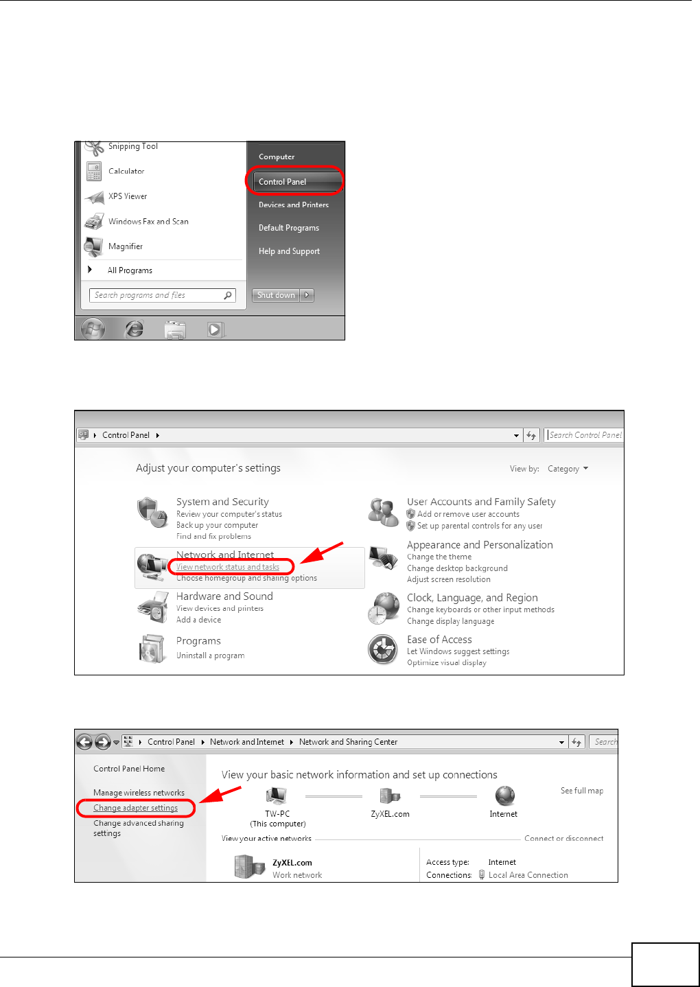
Appendix B Setting Up Your Computer’s IP Address
B222s User’s Guide 197
Windows 7
This sect ion shows screens from Windows 7 Ent erprise.
1Click St a r t > Cont rol Pane l.
Figure 119 Windows 7: Start Menu
2I n t he Cont rol Pane l, click View n e t w ork st a t us a n d t ask s under t he N e t w or k a n d I nt e rne t
cat egory.
Figure 120 Windows 7: Control Panel
3Click Change ada pt e r set tings.
Figure 121 Windows 7: Network And Sharing Cent er
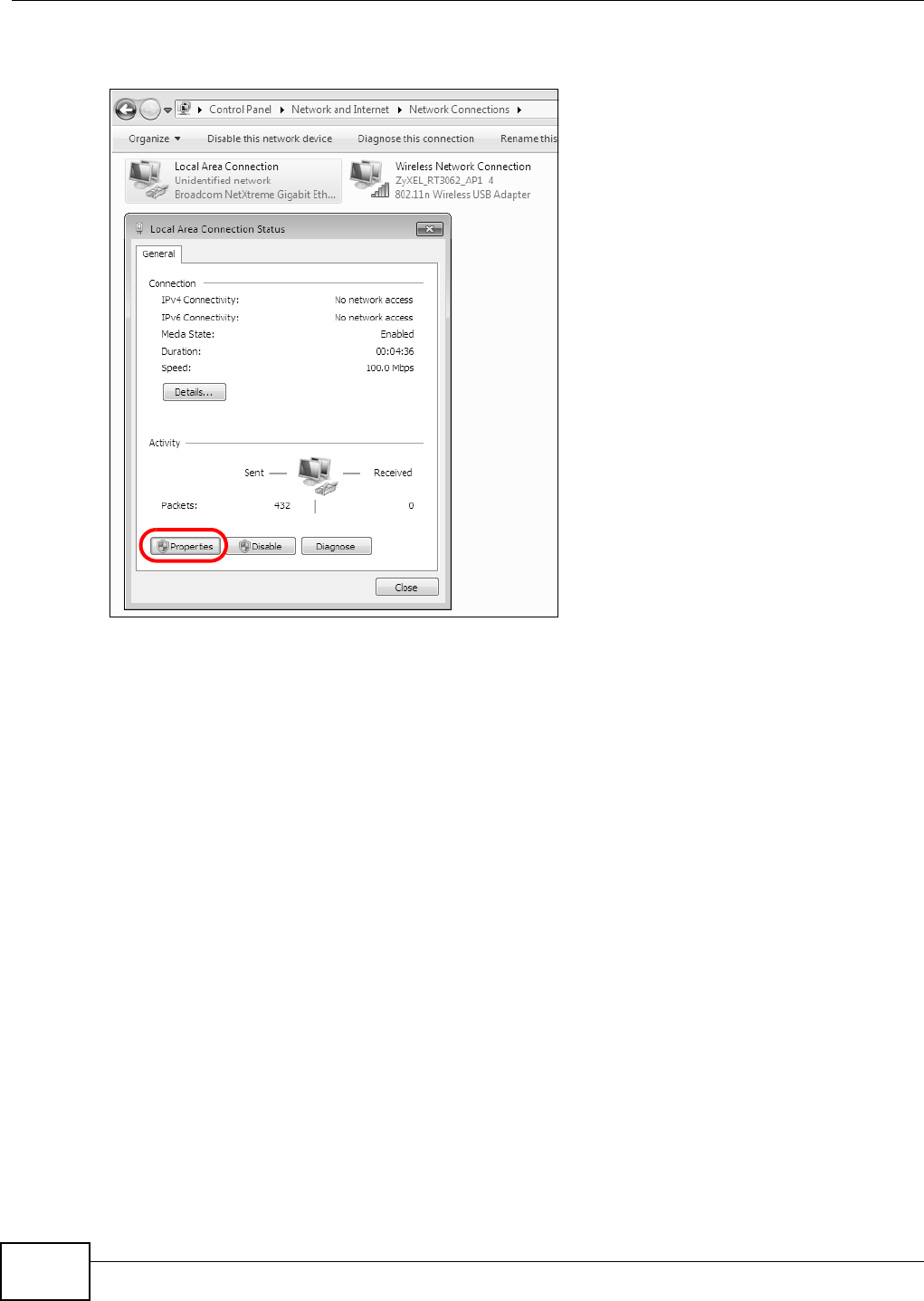
Appendix B Setting Up Your Computer’s IP Address
B222s User’s Guide
198
4Double click Local Ar e a Conne ct ion and t hen select Pr op er t ie s.
Figure 122 Windows 7: Local Area Connect ion Stat us
Note: During this procedure, click Cont inue whenever Windows displays a screen saying
that it needs your perm ission t o cont inue.
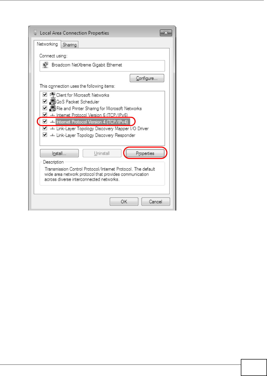
Appendix B Setting Up Your Computer’s IP Address
B222s User’s Guide 199
5Select I nt e r n e t Prot ocol Ve r sion 4 ( TCP/ I Pv4 ) and t hen select Pr op er t ie s.
Figure 123 Windows 7: Local Area Connect ion Pr opert ies
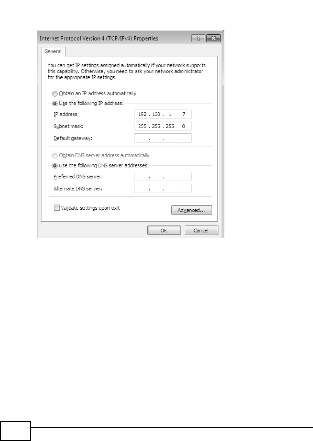
Appendix B Setting Up Your Computer’s IP Address
B222s User’s Guide
200
6The I nt e rne t Prot ocol Version 4 ( TCP/ I Pv4 ) Pr opert ies window opens.
Figure 124 Windows 7: I nternet Protocol Version 4 ( TCP/ I Pv4) Propert ies
7Select Obt ain an I P a ddr e ss a ut om at ica lly if your net work adm inist rat or or I SP assigns your I P
address dynam ically.
Select Use t he follow ing I P Addr e ss and fill in t he I P a ddr e ss, Subne t m ask, and De fa ult
ga t e w ay fields if you have a st at ic I P address that was assigned t o you by your network
adm inist rat or or I SP. You m ay also have t o ent er a Pre ferre d D N S ser ver and an Alt e r n at e DN S
ser ve r , if t hat inform ation was provided. Click Advanced if you want t o configure advanced
set tings for I P, DNS and WI NS.
8Click OK t o close t he I nt er n e t Pr ot ocol ( TCP/ I P) Prope r t ies window.
9Click OK t o close t he Loca l Area Conn e ct ion Pr ope r t ie s window.
Verifying Settings
1Click St a r t > All Progra m s > Acce ssories > Com m a nd Prom pt .
2I n t he Com m and Prom pt window, t ype " ipconfig" and t hen press [ ENTER] .
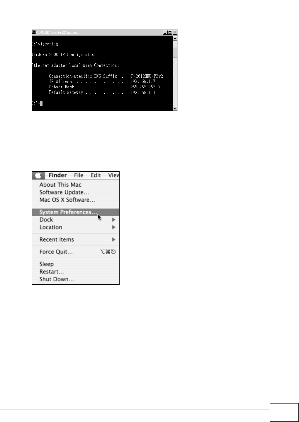
Appendix B Setting Up Your Computer’s IP Address
B222s User’s Guide 201
3The I P set tings ar e displayed as follows.
Figure 125 Windows 7: I nternet Protocol Version 4 ( TCP/ I Pv4) Propert ies
Mac OS X: 10.3 and 10.4
The screens in t his section are from Mac OS X 10.4 but can also apply t o 10.3.
1Click Apple > Syst em Pr eference s.
Figure 126 Mac OS X 10.4: Apple Menu
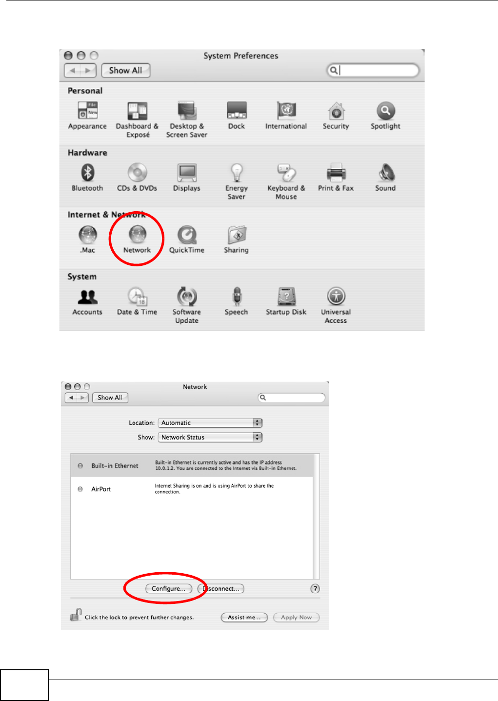
Appendix B Setting Up Your Computer’s IP Address
B222s User’s Guide
202
2I n t he Syst e m Preferences w indow, click the N et w or k icon.
Figure 127 Mac OS X 10.4: System Preferences
3When the N e t w o rk preferences pane opens, select Built - in Et he r n e t from the network
connection t ype list, and t hen click Configure .
Figure 128 Mac OS X 10.4: Network Pr eferences
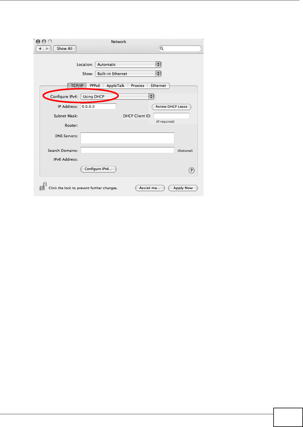
Appendix B Setting Up Your Computer’s IP Address
B222s User’s Guide 203
4For dynam ically assigned set tings, select Using DH CP from t he Configu re I Pv4 list in t he TCP/ I P
tab.
Figure 129 Mac OS X 10.4: Network Preferences > TCP/ I P Tab.
5For stat ically assigned set t ings, do the follow ing:
• From the Configur e I Pv4 list , select M a n ua lly.
• In the I P Address field, ty pe your I P address.
• In the Subn et M a sk field, t ype your subnet m ask.
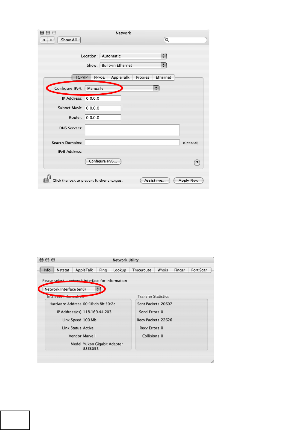
Appendix B Setting Up Your Computer’s IP Address
B222s User’s Guide
204
• In the Rou t e r field, type the I P address of your device.
Figure 130 Mac OS X 10.4: Network Preferences > Et hernet
6Click Apply N ow and close t he window.
Verifying Settings
Check your TCP/ IP propert ies by clicking Applicat ions > Ut ilit ies > N e t w ork Ut ilit ies, and t hen
select ing t he appropriat e N et w or k I nt e rfa ce from the I nfo tab.
Figure 131 Mac OS X 10.4: Network Ut ilit y
Mac OS X: 10.5
The screens in t his section ar e from Mac OS X 10.5.
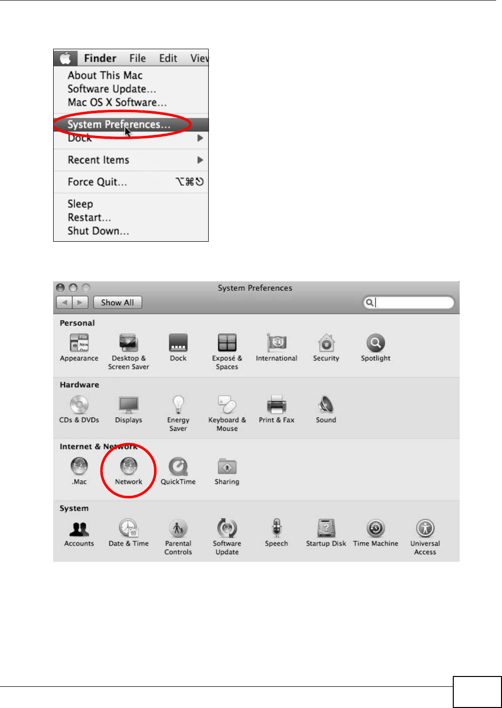
Appendix B Setting Up Your Computer’s IP Address
B222s User’s Guide 205
1Click Apple > Syst em Pr eference s.
Figure 132 Mac OS X 10.5: Apple Menu
2I n Syst e m Pr efere n ces, click the N e t w or k icon.
Figure 133 Mac OS X 10.5: System s Preferences
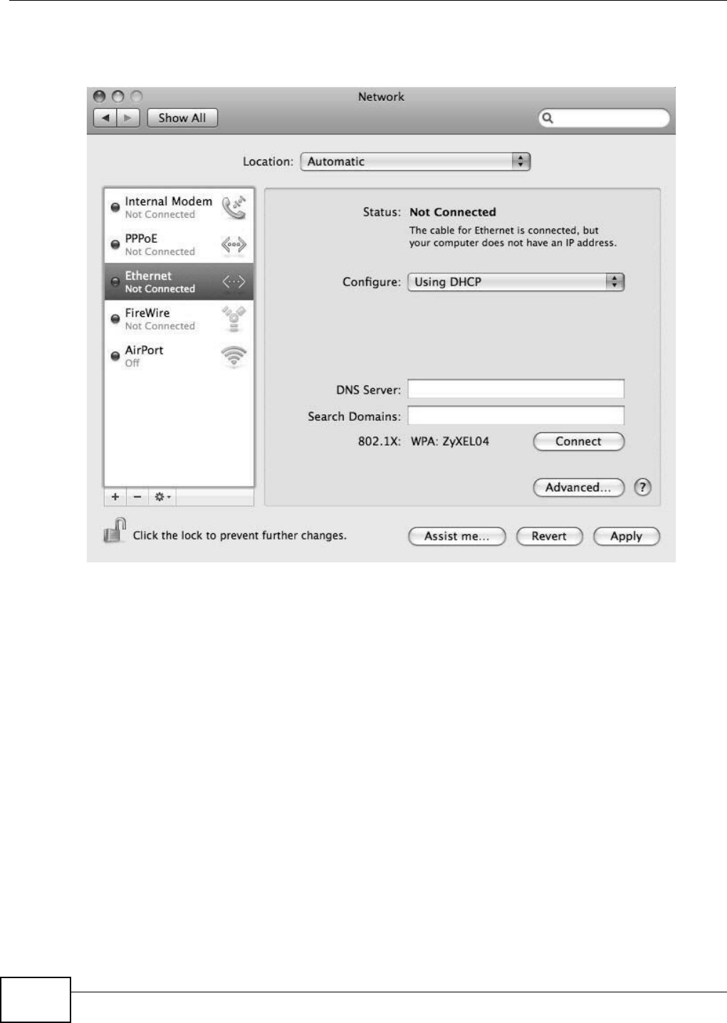
Appendix B Setting Up Your Computer’s IP Address
B222s User’s Guide
206
3When the N e t w or k preferences pane opens, select Et he r ne t from t he list of available connect ion
types.
Figure 134 Mac OS X 10.5: Network Preferences > Et hernet
4From t he Configur e list , select Using D H CP for dynam ically assigned set tings.
5For stat ically assigned set t ings, do the follow ing:
• From the Configur e list, select M anually.
• In the I P Address field, ent er your I P address.
• In the Subn et M a sk field, ent er your subnet m ask.
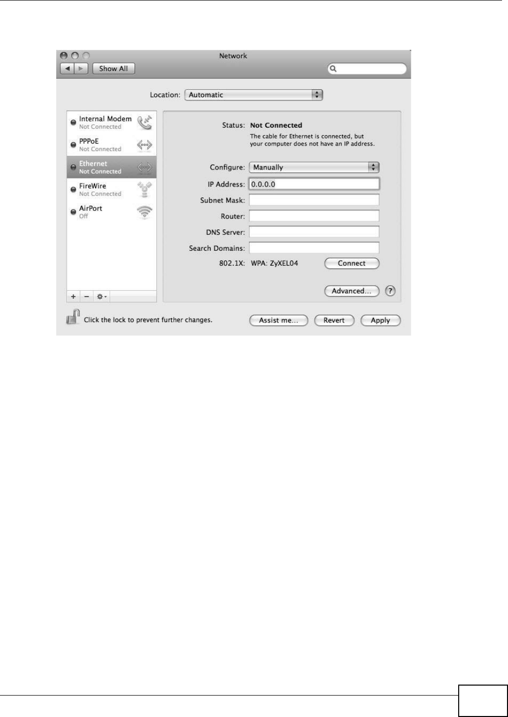
Appendix B Setting Up Your Computer’s IP Address
B222s User’s Guide 207
• In the Rou t e r field, enter t he I P address of your LTE Device.
Figure 135 Mac OS X 10.5: Network Preferences > Et hernet
6Click Apply and close t he window.
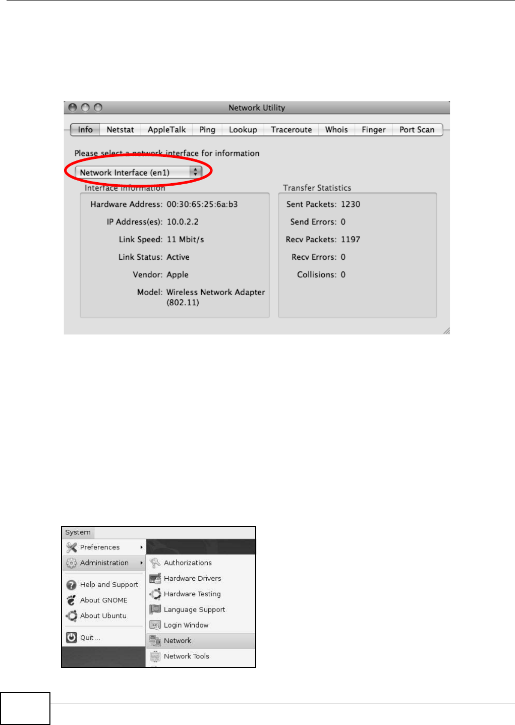
Appendix B Setting Up Your Computer’s IP Address
B222s User’s Guide
208
Verifying Settings
Check your TCP/ IP propert ies by clicking Applicat ions > Ut ilit ies > N e t w ork Ut ilit ies, and t hen
select ing t he appropriat e N et w or k in t er face from the I nfo tab.
Figure 136 Mac OS X 10.5: Network Ut ilit y
Linux: Ubuntu 8 (GNOME)
This sect ion shows you how to configure your com put er ’s TCP/ I P set tings in t he GNU Object Model
Environm ent ( GNOME) using t he Ubunt u 8 Linux dist ribut ion. The pr ocedur e, screens and file
locations m ay vary depending on your specific distribut ion, release version, and individual
configurat ion. The following screens use t he default Ubuntu 8 inst allat ion.
Not e: Make sure you are logged in as the root adm inistrat or.
Follow t he steps below t o configure your com puter I P address in GNOME:
1Click System > Adm inist ra t ion > N e t w ork .
Figure 137 Ubunt u 8: System > Adm inistrat ion Menu
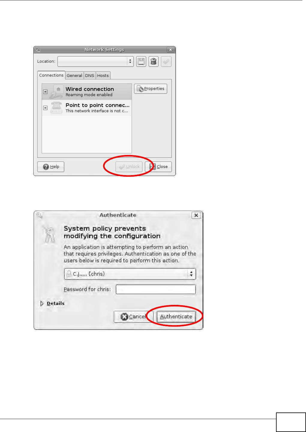
Appendix B Setting Up Your Computer’s IP Address
B222s User’s Guide 209
2When the N e t w or k Set t ings window opens, click Unlock t o open t he Au t he n t ica t e window. ( By
default, t he Unlock butt on is greyed out until clicked.) You cannot m ake changes t o your
configurat ion unless you first enter your adm in password.
Figure 138 Ubunt u 8: Network Sett ings > Connect ions
3I n t he Au t he nt ica t e window, ent er your adm in account nam e and password t hen click the
Au t he n t ica t e butt on.
Figure 139 Ubunt u 8: Adm inistrator Account Aut hent icat ion
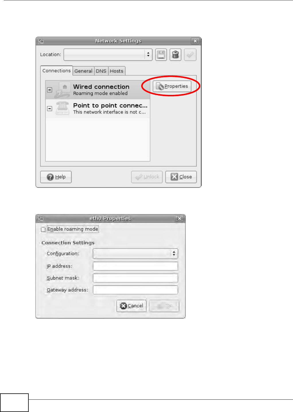
Appendix B Setting Up Your Computer’s IP Address
B222s User’s Guide
210
4I n t he N et w or k Set t ings window, select t he connect ion that you want to configure, t hen click
Pr ope r t ie s.
Figure 140 Ubunt u 8: Network Sett ings > Connect ions
5The Pr op er t ie s dialog box opens.
Figure 141 Ubunt u 8: Network Set tings > Propert ies
• In the Configurat ion list, select Aut om at ic Con figurat ion ( DH CP) if you have a dynam ic I P
address.
• In the Configur a tion list, select St at ic I P a ddr e ss if you have a st atic I P address. Fill in the
I P a ddr ess, Subnet m a sk , and Gat ew a y address fields.
6Click OK t o save t he changes and close the Pr op er t ie s dialog box and ret urn to t he N e t w ork
Se t t in gs screen.
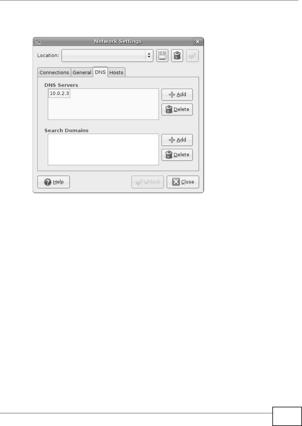
Appendix B Setting Up Your Computer’s IP Address
B222s User’s Guide 211
7I f you know your DNS server I P addr ess( es) , click the D N S tab in t he N et w or k Se t tings window
and t hen ent er t he DNS server inform ation in t he fields provided.
Figure 142 Ubunt u 8: Network Set tings > DNS
8Click t he Close butt on t o apply the changes.
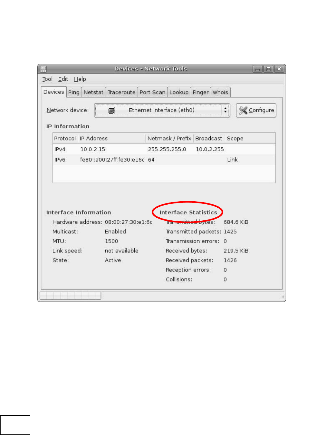
Appendix B Setting Up Your Computer’s IP Address
B222s User’s Guide
212
Verifying Settings
Check your TCP/ I P pr operties by clicking Syst em > Adm inist r a tion > N et w or k Tools, and then
select ing t he appropriat e N et w or k device fr om the De vices t ab. The I nt er face St a t ist ics
colum n shows dat a if your connection is working properly.
Figure 143 Ubunt u 8: Network Tools
Linux: openSUSE 10.3 (KDE)
This sect ion shows you how to configur e your com puter’s TCP/ I P sett ings in t he K Deskt op
Envir onm ent ( KDE) using t he openSUSE 10.3 Linux dist ribution. The procedure, screens and file
locations m ay vary depending on your specific distribut ion, release version, and individual
configurat ion. The following screens use t he default openSUSE 10.3 installat ion.
Not e: Make sure you are logged in as the root adm inistrat or.
Follow t he steps below t o configure your com puter I P address in t he KDE:
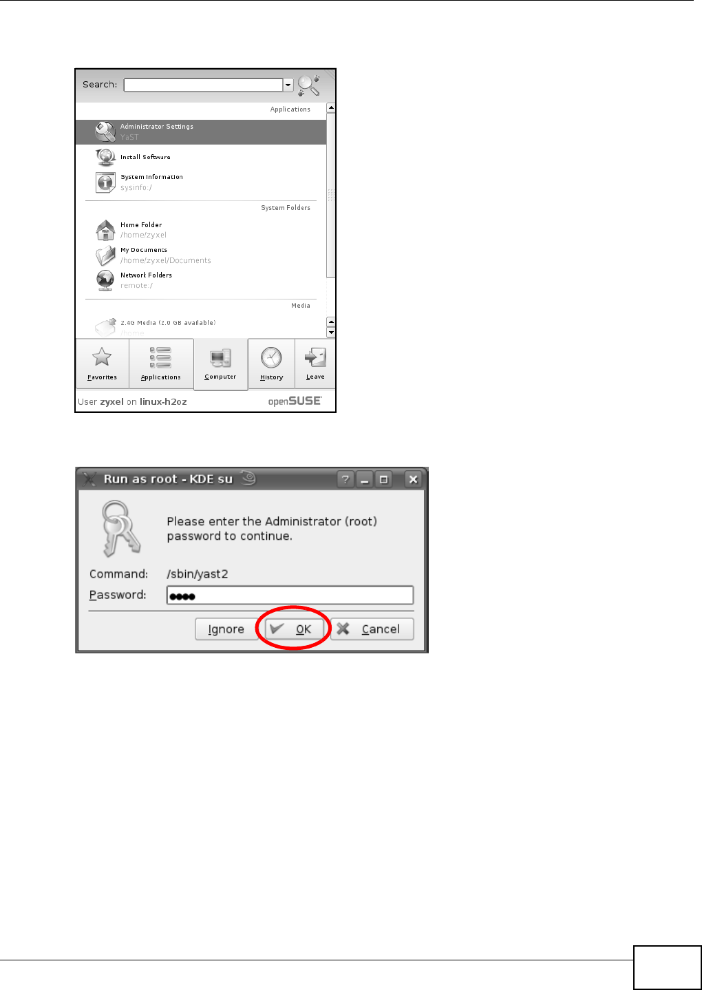
Appendix B Setting Up Your Computer’s IP Address
B222s User’s Guide 213
1Click K Menu > Com pu t er > Adm inist r a t or Set tings ( Ya ST) .
Figure 144 openSUSE 10.3: K Menu > Com put er Menu
2When the Run a s Root - KD E su dialog opens, enter t he adm in password and click OK.
Figure 145 openSUSE 10.3: K Menu > Com put er Menu
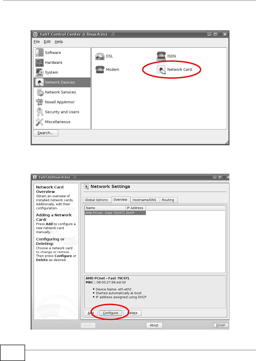
Appendix B Setting Up Your Computer’s IP Address
B222s User’s Guide
214
3When the YaST Cont rol Ce n t er window opens, select N et w or k De vices and t hen click the
N e t w ork Ca r d icon.
Figure 146 openSUSE 10.3: YaST Control Cent er
4When the N e t w or k Set t ings w indow opens, click t he Overvie w t ab, select t he appr opriat e
connection N a m e from t he list , and t hen click the Configure butt on.
Figure 147 openSUSE 10.3: Net work Sett ings
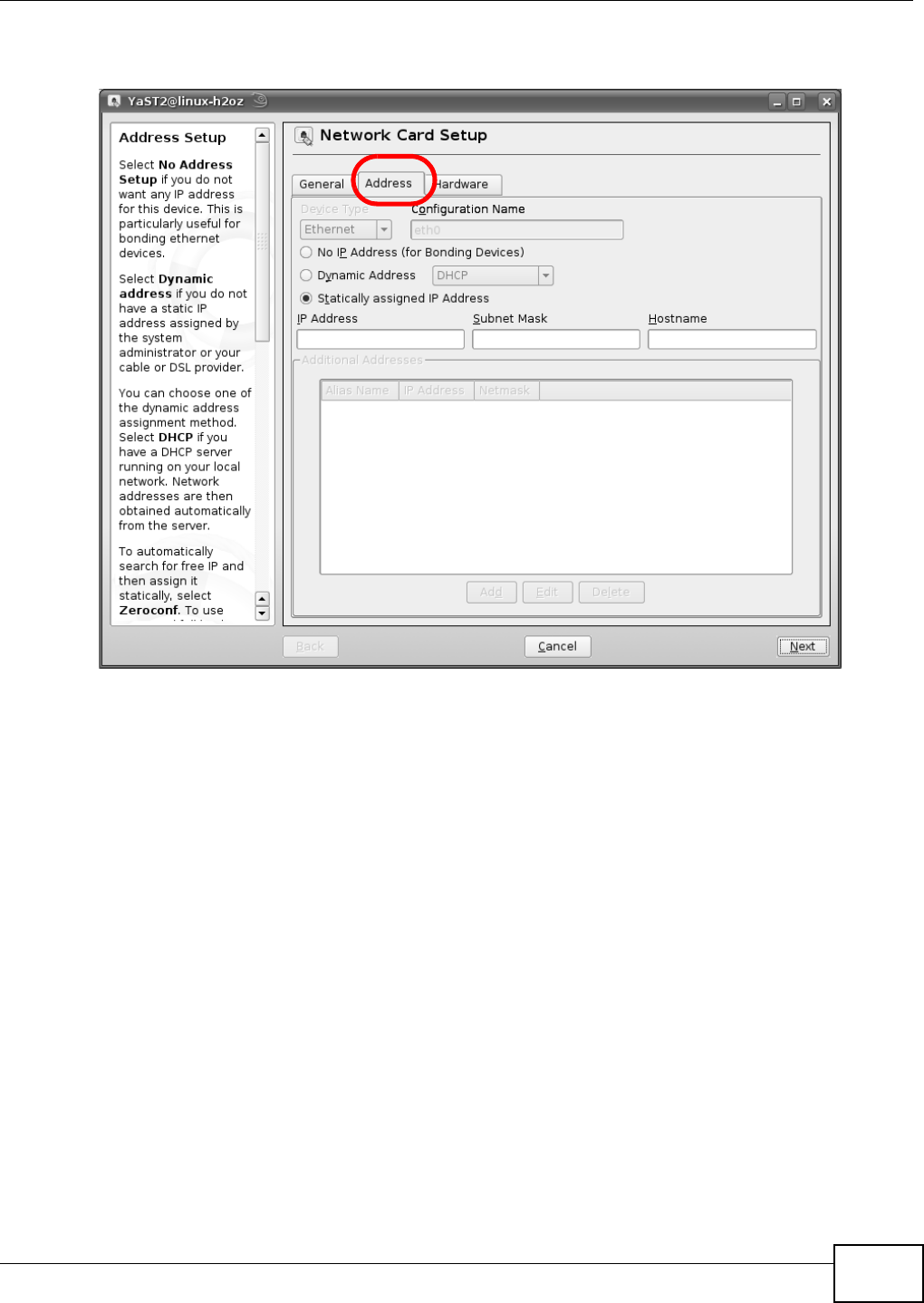
Appendix B Setting Up Your Computer’s IP Address
B222s User’s Guide 215
5When the N e t w or k Car d Se t up window opens, click t he Address t ab
Figure 148 openSUSE 10.3: Network Card Set up
6Select D ynam ic Addr e ss ( D HCP) if you have a dynam ic I P address.
Select St at ically a ssigned I P Addr ess if you have a st at ic I P address. Fill in the I P a ddress,
Subnet m a sk , and H ost nam e fields.
7Click N e x t t o save the changes and close t he N et w ork Ca r d Set up window.
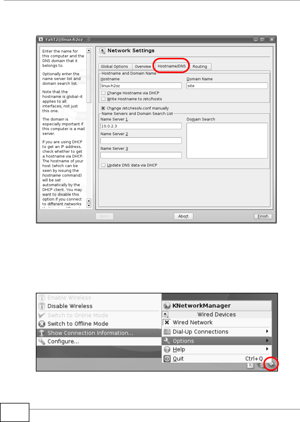
Appendix B Setting Up Your Computer’s IP Address
B222s User’s Guide
216
8I f you know your DNS server I P addr ess( es) , click the H ost n am e / D N S tab in N et w or k Set tings
and t hen ent er t he DNS server inform at ion in the fields provided.
Figure 149 openSUSE 10.3: Net work Sett ings
9Click Finish t o save your sett ings and close t he window.
Verifying Settings
Click t he KN et w or k Ma na ger icon on the Ta sk ba r t o check your TCP/ I P propert ies. From t he
Opt io ns sub-m enu, select Show Conne ct ion I nfor m at ion.
Figure 150 openSUSE 10.3: KNet work Manager
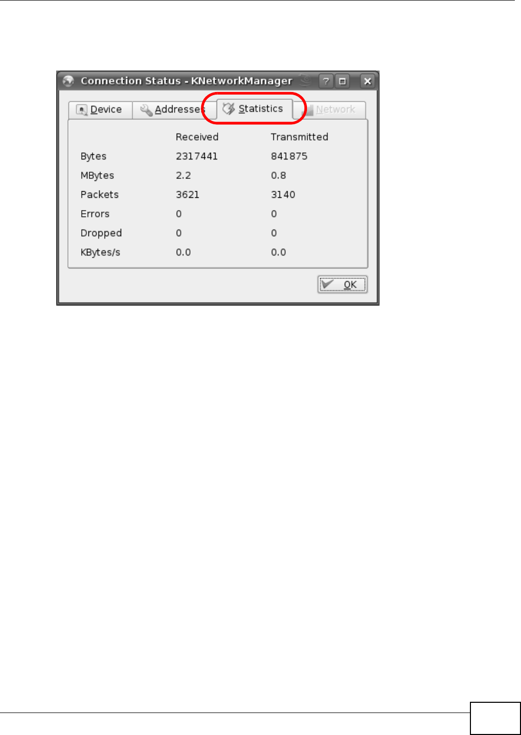
Appendix B Setting Up Your Computer’s IP Address
B222s User’s Guide 217
When the Connect ion St at us - KN e t w or k Ma na ge r window opens, click the St a tist ics t ab t o
see if your connect ion is working properly.
Figure 151 openSUSE: Connect ion St at us - KNetwork Manager

Appendix B Setting Up Your Computer’s IP Address
B222s User’s Guide
218
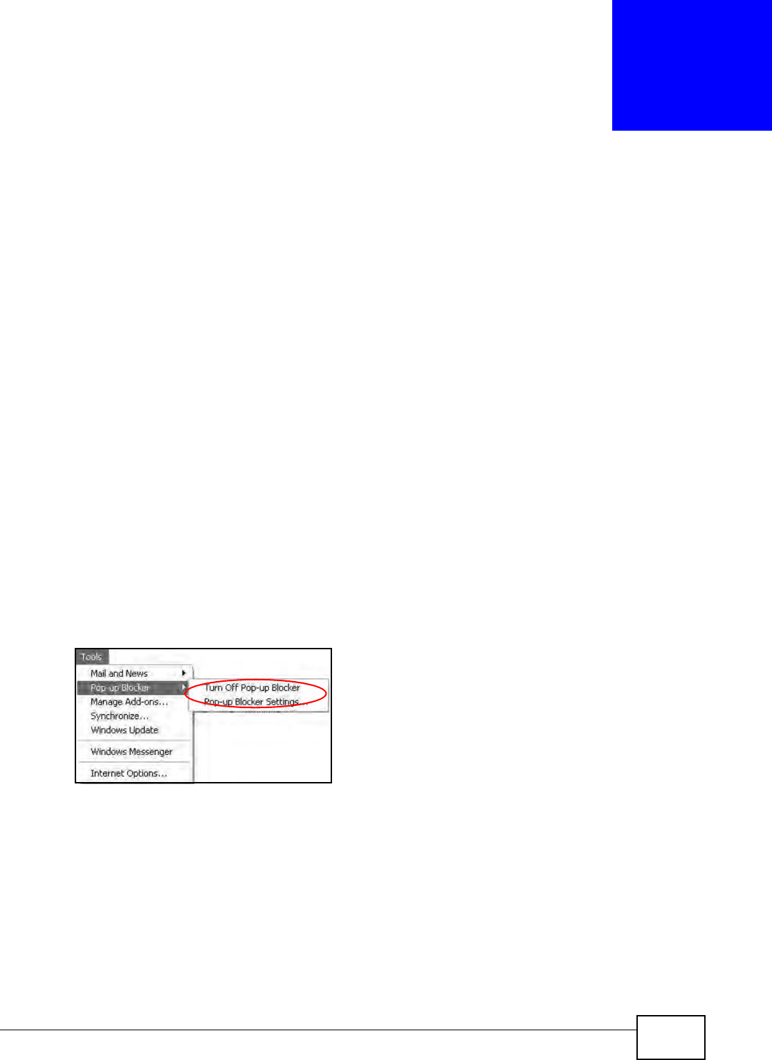
B222s User’s Guide 219
APPENDIX C
Pop-up Windows, JavaScript and Java
Permissions
I n order t o use t he web configurat or you need t o allow:
• Web browser pop- up windows from your device.
• JavaScript ( enabled by default ).
• Java perm issions ( enabled by default) .
Not e: I nt ernet Explorer 6 screens are used here. Screens for other I nternet Explorer
versions m ay vary.
Internet Explorer Pop-up Blockers
You m ay have t o disable pop- up blocking to log int o your device.
Eit her disable pop- up blocking (enabled by default in Windows XP SP ( Service Pack) 2) or allow
pop- up blocking and creat e an except ion for your device’s I P address.
Disable Pop-up Blockers
1I n I nternet Explor er, select Tools, Pop- up Blocker and then select Tur n Off Pop- up Block e r.
Figure 152 Pop- up Blocker
You can also check if pop- up blocking is disabled in t he Pop- up Block e r sect ion in t he Privacy t ab.
1I n I nternet Explor er, select Tools, I nt er net Options, Priva cy.
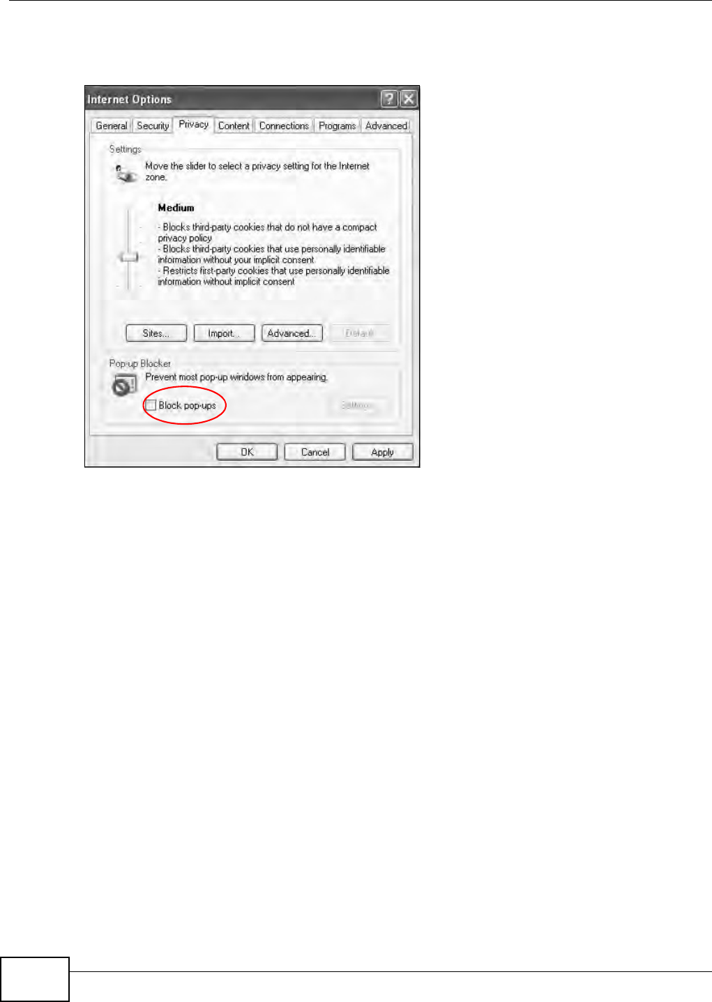
Appendix C Pop-up Windows, JavaScript and Java Permissions
B222s User’s Guide
220
2Clear t he Block pop- ups check box in t he Pop- up Block er section of t he screen. This disables any
web pop-up blockers you m ay have enabled.
Figure 153 I nt ernet Opt ions: Privacy
3Click Apply t o save this sett ing.
Enable Pop-up Blockers with Exceptions
Alt ernat ively, if you only want t o allow pop- up windows from your device, see t he following steps.
1I n I nternet Explor er, select Tools, I nt er net Options and t hen t he Pr iva cy tab.
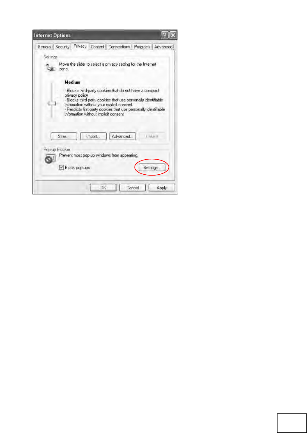
Appendix C Pop-up Windows, JavaScript and Java Permissions
B222s User’s Guide 221
2Select Se t t in gs…t o open t he Pop- up Block er Set t ings screen.
Figure 154 I nt ernet Opt ions: Privacy
3Type t he I P address of your device ( the web page t hat you do not want t o have blocked) wit h t he
prefix “ ht t p: / / ”. For exam ple, htt p: / / 192.168.167.1.
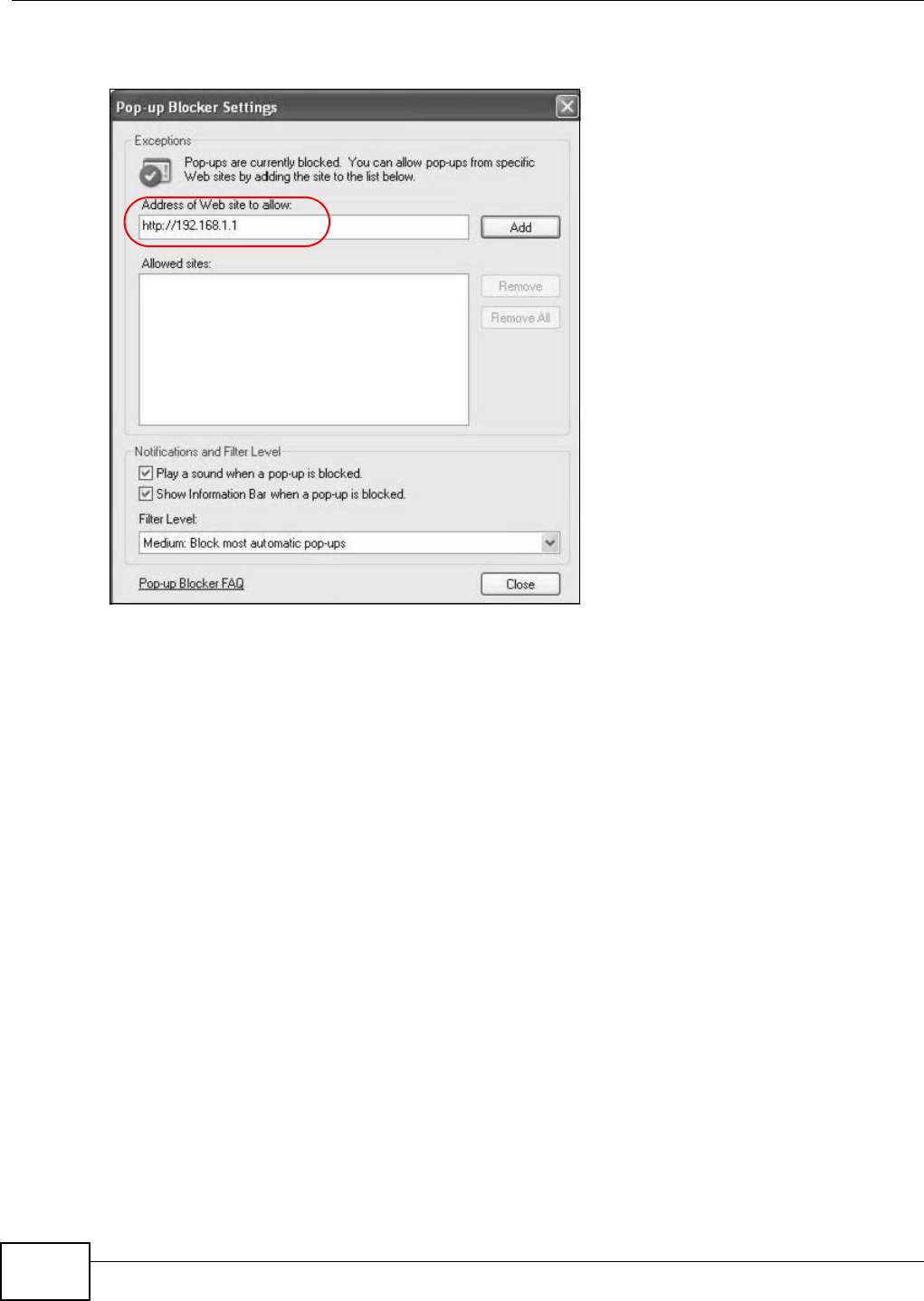
Appendix C Pop-up Windows, JavaScript and Java Permissions
B222s User’s Guide
222
4Click Add t o m ove the I P address t o t he list of Allow e d sit es.
Figure 155 Pop-up Blocker Set t ings
5Click Close t o ret urn to t he Pr iva cy screen.
6Click Apply t o save this sett ing.
JavaScript
I f pages of t he web configurat or do not display properly in I nternet Explorer, check that JavaScript
are allowed.
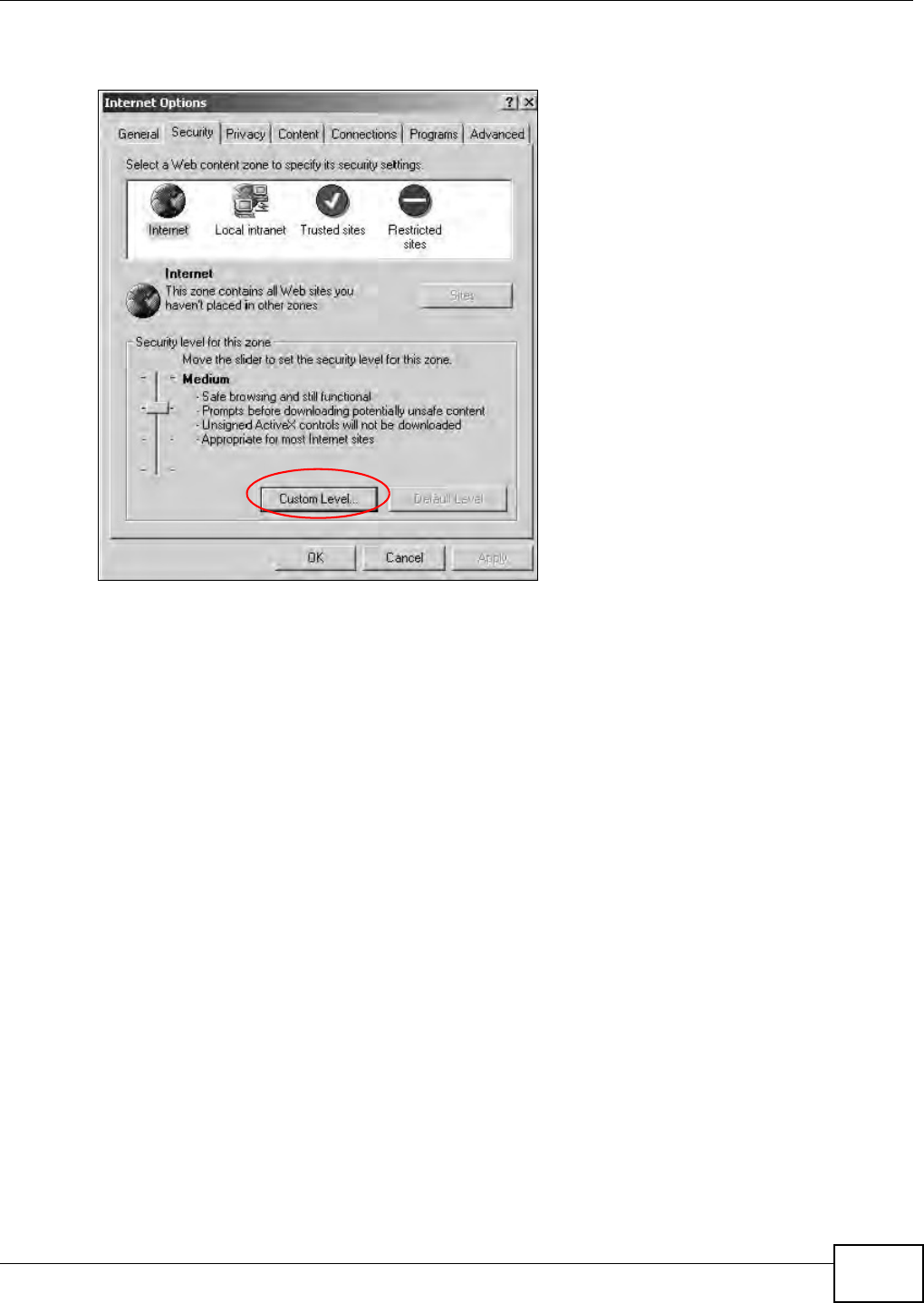
Appendix C Pop-up Windows, JavaScript and Java Permissions
B222s User’s Guide 223
1I n I nternet Explorer, click Tools, I nt e r net Opt ions and t hen t he Se cur it y tab.
Figure 156 I nt ernet Opt ions: Security
2Click t he Cust om Leve l... butt on.
3Scroll down t o Scr ip t in g.
4Under Act ive scr ipt ing m ake sure t hat Ena ble is select ed ( t he default ) .
5Under Script ing of Java apple t s m ake sur e t hat Ena ble is select ed ( t he default ) .
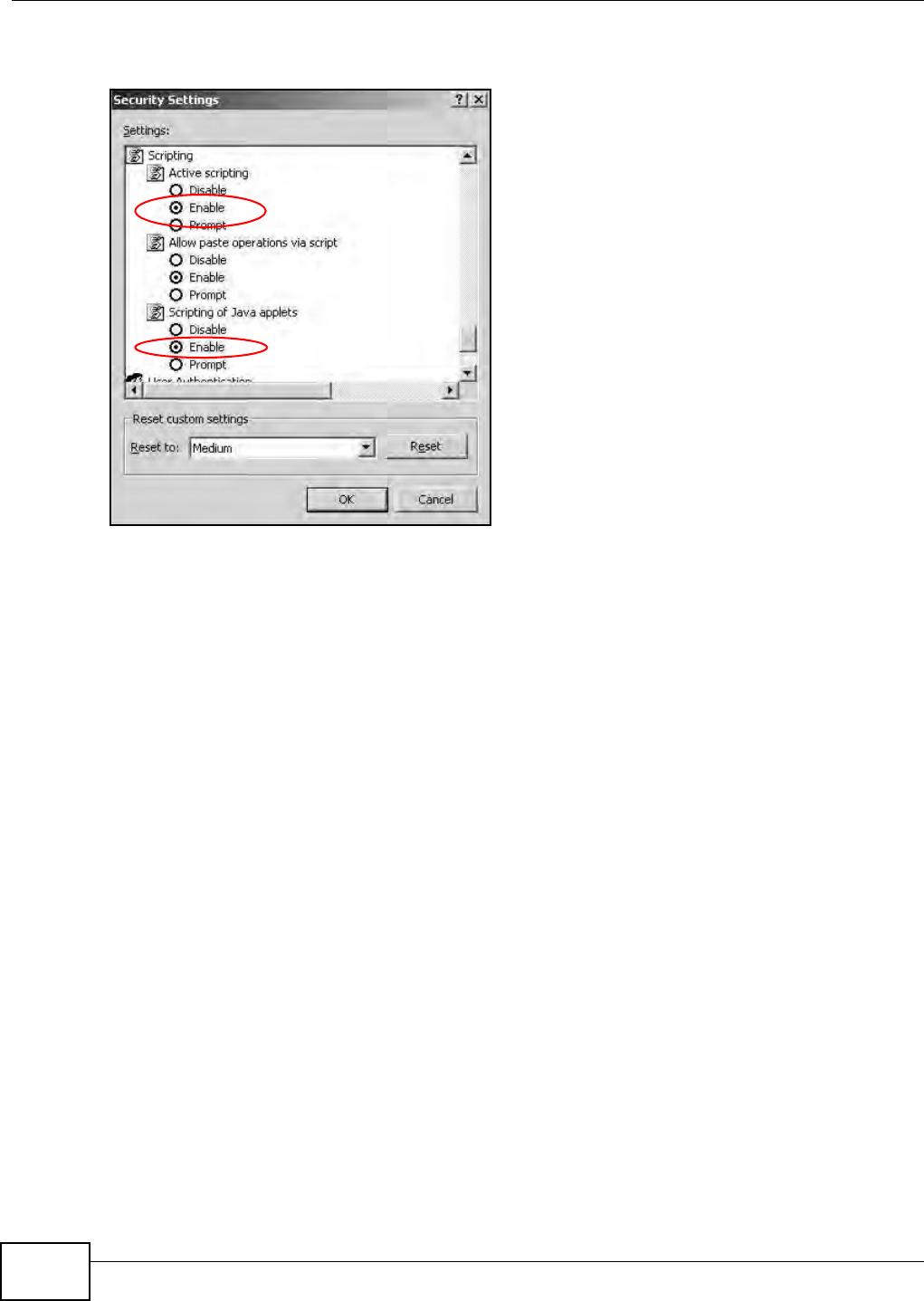
Appendix C Pop-up Windows, JavaScript and Java Permissions
B222s User’s Guide
224
6Click OK t o close t he window.
Figure 157 Securit y Set t ings - Java Script ing
Java Permissions
1From I nt ernet Explorer, click Tools, I nt e r net Opt ions and t hen t he Securit y tab.
2Click t he Cust om Leve l... butt on.
3Scroll down t o M icrosoft VM .
4Under Java perm ission s m ake sure that a safet y level is select ed.
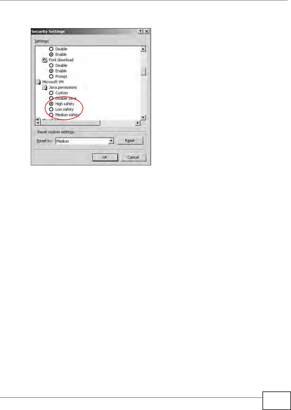
Appendix C Pop-up Windows, JavaScript and Java Permissions
B222s User’s Guide 225
5Click OK t o close t he window.
Figure 158 Securit y Set t ings - Java
JAVA (Sun)
1From I nt ernet Explorer, click Tools, I nt e r net Opt ions and t hen t he Adva nced t ab.
2Make sur e t hat Use Ja va 2 for < apple t > under Java ( Sun) is select ed.
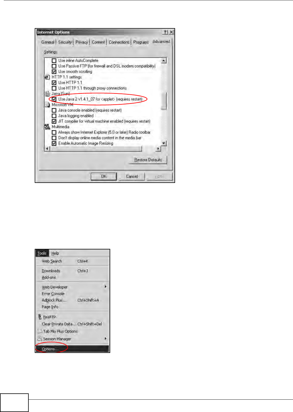
Appendix C Pop-up Windows, JavaScript and Java Permissions
B222s User’s Guide
226
3Click OK t o close t he window.
Figure 159 Java (Sun)
Mozilla Firefox
Mozilla Firefox 2.0 screens are used here. Screens for ot her versions m ay vary.
You can enable Java, JavaScript and pop-ups in one screen. Click Tools, t hen click Opt ions in the
screen t hat appears.
Figure 160 Mozilla Firefox: Tools > Opt ions
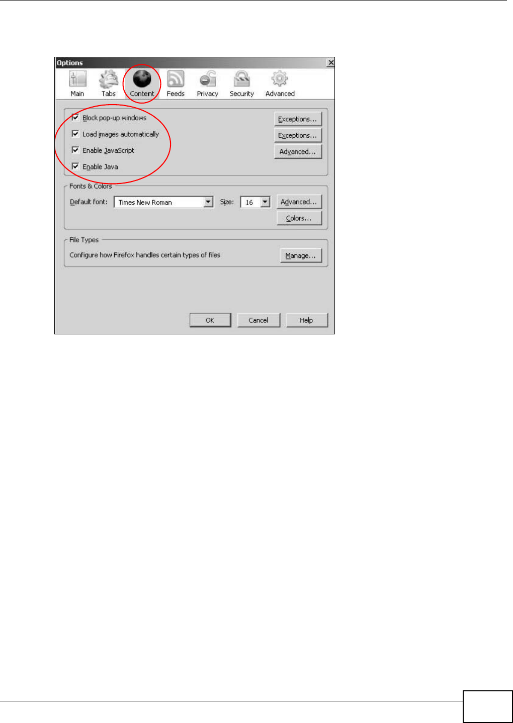
Appendix C Pop-up Windows, JavaScript and Java Permissions
B222s User’s Guide 227
Click Cont ent .to show t he screen below. Select t he check boxes as shown in t he following screen.
Figure 161 Mozilla Firefox Cont ent Security

Appendix C Pop-up Windows, JavaScript and Java Permissions
B222s User’s Guide
228
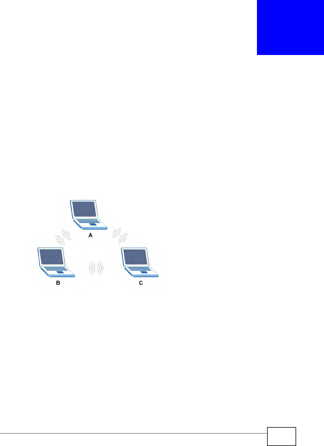
B222s User’s Guide 229
APPENDIX D
Wireless LANs
Wireless LAN Topologies
This sect ion discusses ad- hoc and infrastructure wireless LAN t opologies.
Ad-hoc Wireless LAN Configuration
The sim plest WLAN configurat ion is an independent ( Ad- hoc) WLAN t hat connects a set of
com puters wit h wireless adapt ers ( A, B, C). Any t im e t wo or m ore wireless adapt ers are within
range of each other, t hey can set up an independent net w ork, which is com m only referred to as an
ad- hoc net work or I ndependent Basic Service Set ( I BSS) . The following diagram show s an exam ple
of not ebook com put ers using wireless adapt ers t o for m an ad- hoc wireless LAN.
Figure 162 Peer- t o- Peer Com m unicat ion in an Ad- hoc Network
BSS
A Basic Service Set ( BSS) exists when all com m unicat ions bet ween wireless client s or bet w een a
wir eless client and a wired net work client go t hrough one access point (AP) .
I nt ra- BSS t raffic is t raffic bet ween wireless client s in t he BSS. When I nt ra- BSS is enabled, wireless
client A and B can access t he wired network and com m unicate with each ot her. When I nt ra- BSS is
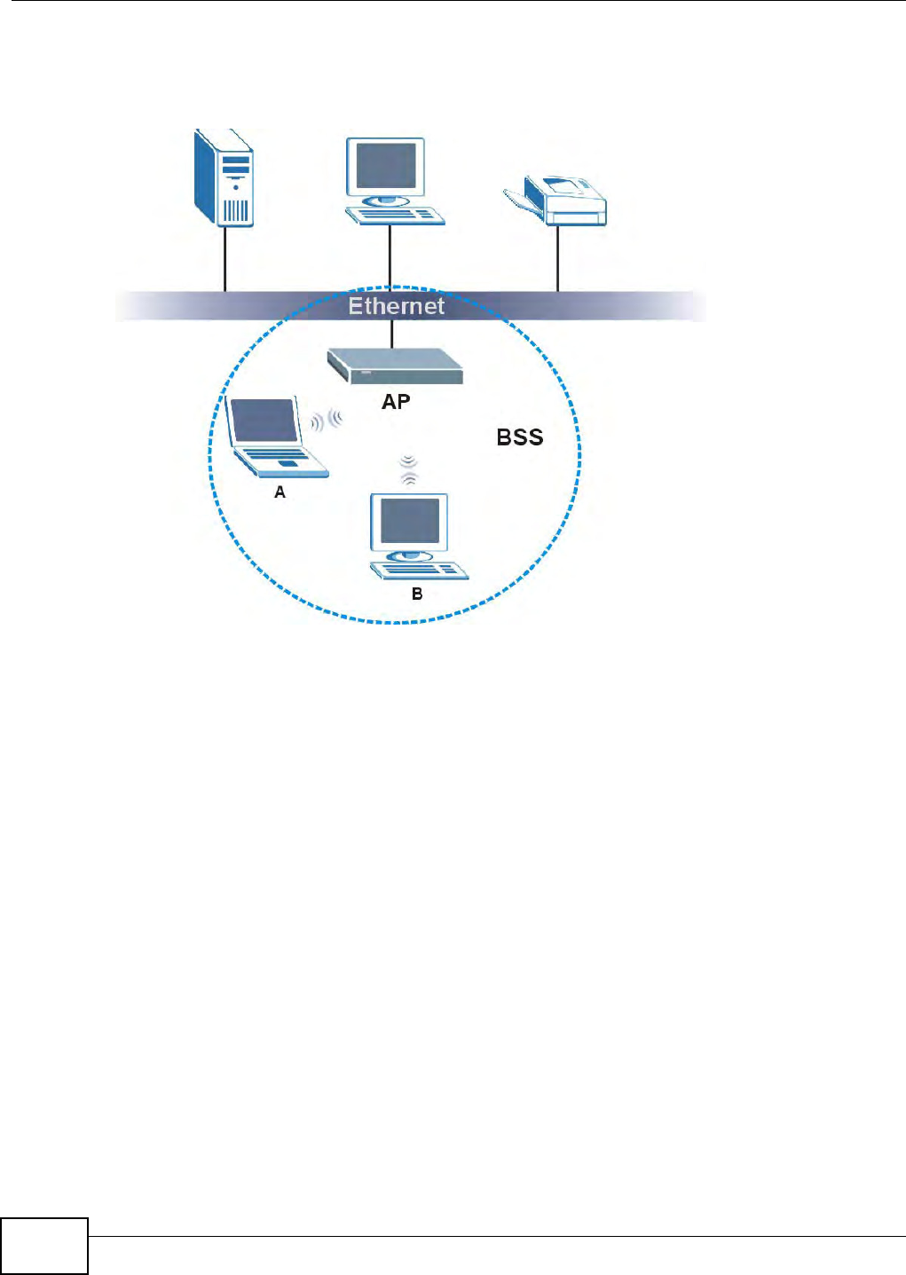
Appendix D Wireless LANs
B222s User’s Guide
230
disabled, wireless client A and B can st ill access the wir ed net work but cannot com m unicat e with
each ot her.
Figure 163 Basic Service Set
ESS
An Ext ended Service Set ( ESS) consist s of a series of overlapping BSSs, each cont aining an access
point , w it h each access point connect ed t oget her by a wired network. This wired connect ion
bet ween APs is called a Distribut ion System ( DS) .
This t y pe of w ireless LAN t opology is called an I nfrastructure WLAN. The Access Point s not only
provide com m unicat ion wit h t he wired net w ork but also m ediat e wireless network traffic in t he
im m ediat e neighborhood.
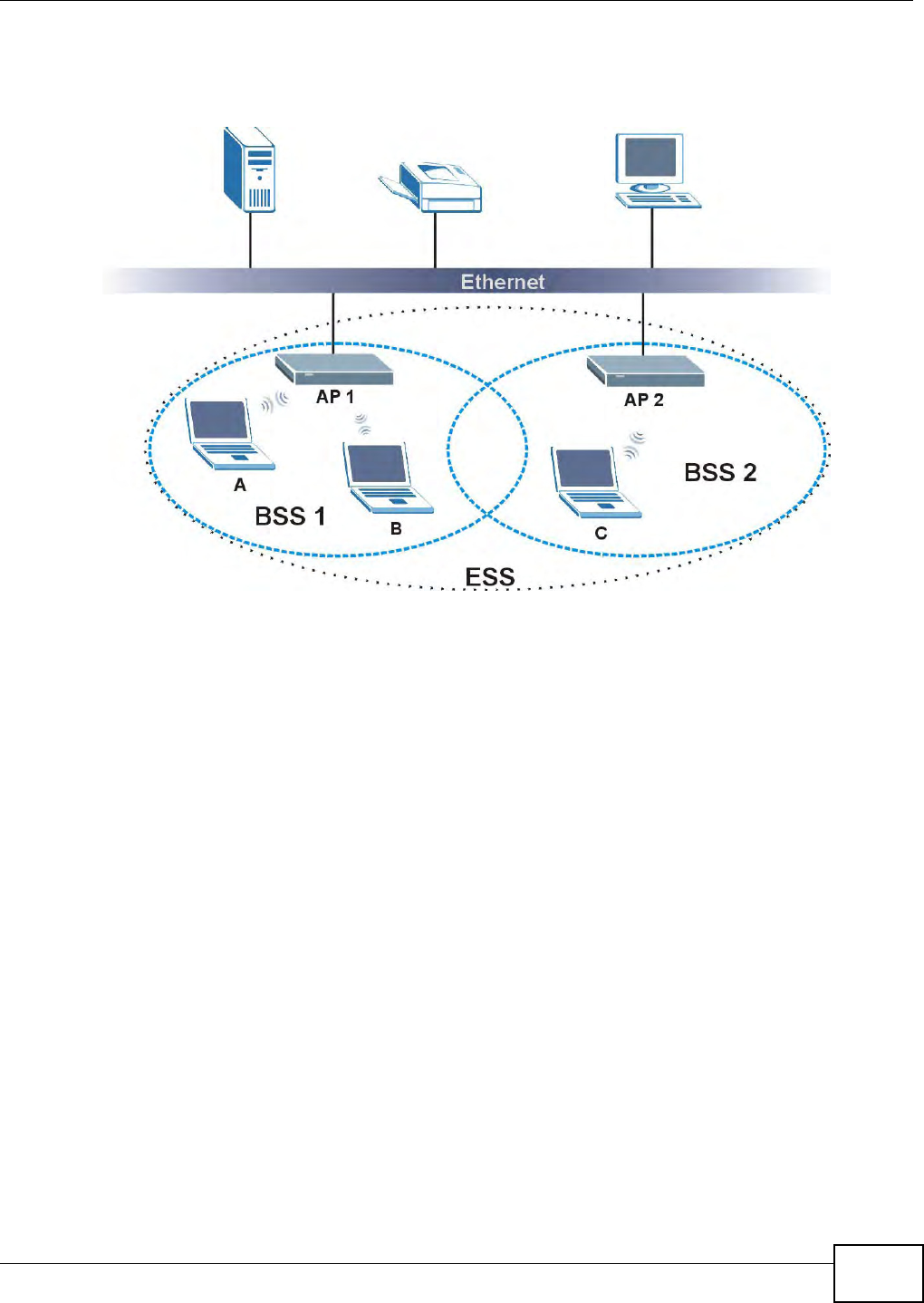
Appendix D Wireless LANs
B222s User’s Guide 231
An ESSI D ( ESS I Dent ificat ion) uniquely ident ifies each ESS. All access point s and t heir associat ed
wir eless client s wit hin t he sam e ESS m ust have the sam e ESSI D in order t o com m unicat e.
Figure 164 I nfrastructure WLAN
Channel
A channel is t he radio frequency( ies) used by wireless devices t o t ransm it and receive data.
Channels available depend on your geographical ar ea. You m ay have a choice of channels ( for your
region) so you should use a channel different from an adjacent AP ( access point ) t o reduce
int erference. I nt erference occurs when radio signals from different access point s overlap causing
int erference and degrading perform ance.
Adj acent channels part ially overlap however. To avoid interference due t o overlap, your AP should
be on a channel at least five channels away from a channel t hat an adj acent AP is using. For
exam ple, if your region has 11 channels and an adjacent AP is using channel 1, t hen you need t o
select a channel bet ween 6 or 11.
RTS/CTS
A hidden node occurs when two stat ions are wit hin range of the sam e access point, but are not
wit hin range of each ot her. The following figur e illust rat es a hidden node. Both st at ions ( STA) are
wit hin range of t he access point ( AP) or wireless gat eway, but out- of- range of each ot her, so t hey
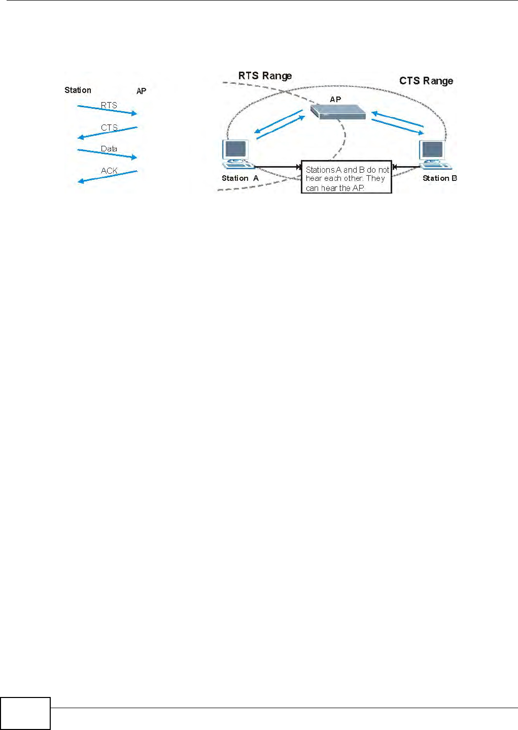
Appendix D Wireless LANs
B222s User’s Guide
232
cannot "hear" each ot her, t hat is t hey do not know if t he channel is currently being used. Therefore,
they are considered hidden from each ot her.
Figure 165 RTS/ CTS
When st at ion A sends dat a t o t he AP, it m ight not know t hat t he st ation B is already using t he
channel. I f t hese t wo stations send dat a at t he sam e t im e, collisions m ay occur when both set s of
dat a arrive at the AP at t he sam e t im e, resulting in a loss of m essages for both stat ions.
RTS/ CTS is designed to prevent collisions due t o hidden nodes. An RTS/ CTS defines the biggest
size data fram e you can send before an RTS ( Request To Send)/ CTS ( Clear to Send) handshake is
invoked.
When a dat a fram e exceeds t he RTS/ CTS value you set ( between 0 t o 2432 byt es) , t he stat ion
that want s to t ransm it t his fram e m ust first send an RTS (Request To Send) m essage t o t he AP for
perm ission t o send it. The AP t hen responds wit h a CTS ( Clear t o Send) m essage t o all ot her
st at ions wit hin it s range t o notify t hem to defer t heir t ransm ission. I t also reserves and confirm s
wit h t he request ing stat ion the tim e fram e for t he request ed t ransm ission.
St ations can send fram es sm aller t han t he specified RTS/ CTS direct ly to t he AP wit hout the RTS
( Request To Send) / CTS ( Clear t o Send) handshake.
You should only configure RTS/ CTS if t he possibility of hidden nodes exists on your net work and
the "cost " of resending large fram es is m ore than t he ext ra net work overhead involved in t he RTS
( Request To Send) / CTS ( Clear t o Send) handshake.
I f t he RTS/ CTS value is great er than the Fra gm e n t at ion Threshold value (see next ) , t hen the
RTS ( Request To Send) / CTS ( Clear t o Send) handshake will never occur as dat a fram es will be
fragm ented before t hey reach RTS/ CTS size.
Note: Enabling the RTS Threshold causes redundant net work overhead t hat could
negat ively affect the throughput perfor m ance instead of providing a rem edy.
Fragmentation Threshold
A Fr a gm e nt at ion Thr eshold is the m axim um dat a fragm ent size ( between 256 and 2432 byt es)
that can be sent in t he wireless net work before t he AP will fragm ent t he packet int o sm aller dat a
fram es.
A large Fra gm e n t at ion Thr eshold is recom m ended for networks not prone t o interference while
you should set a sm aller t hreshold for busy net works or net works t hat are prone t o interference.

Appendix D Wireless LANs
B222s User’s Guide 233
I f t he Fr a gm ent at ion Thr e sh old value is sm aller t han t he RTS/ CTS value ( see previously) you
set t hen t he RTS (Request To Send)/ CTS ( Clear to Send) handshake will never occur as dat a fram es
will be fragm ented before they reach RTS/ CTS size.
Preamble Type
Pream ble is used t o signal t hat dat a is com ing t o t he receiver. Short and long refer to t he length of
the synchronizat ion field in a packet.
Short pream ble incr eases perform ance as less tim e sending pream ble m eans m ore tim e for sending
dat a. All I EEE 802.11 com pliant wireless adapt ers support long pream ble, but not all support short
pream ble.
Use long pream ble if you are unsure what pream ble m ode ot her wireless devices on t he net work
support , and to provide m ore reliable com m unicat ions in busy wireless net w orks.
Use short pream ble if you are sure all wireless devices on t he network support it , and t o provide
m ore efficient com m unicat ions.
Use t he dynam ic setting t o aut om at ically use short pream ble w hen all wireless devices on t he
network support it , ot herwise the LTE Device uses long pream ble.
Not e: The wireless dev ices MUST use the sam e pream ble m ode in order t o com m unicate.
IEEE 802.11g Wireless LAN
I EEE 802.11g is fully com pat ible w ith the I EEE 802.11b st andard. This m eans an I EEE 802.11b
adapt er can int erface direct ly with an I EEE 802.11g access point ( and vice versa) at 11 Mbps or
lower depending on range. I EEE 802.11g has several interm ediate rate st eps bet ween the
m axim um and m inim um data rat es. The I EEE 802.11g dat a rat e and m odulation are as follows:
Wireless Security Overview
Wireless securit y is vit al to your network to prot ect wireless com m unicat ion bet w een wireless
clients, access point s and t he wired network.
Wireless securit y m ethods available on the LTE Device are data encrypt ion, wireless client
authent icat ion, restrict ing access by device MAC address and hiding t he LTE Device identit y.
Table 85 I EEE 802.11g
DATA RATE (MBPS) MODULATION
1 DBPSK ( Differential Binary Phase Shift Keyed)
2 DQPSK (Different ial Quadrat ur e Phase Shift Keying)
5.5 / 11 CCK ( Com plem ent ary Code Keying)
6/9/12/18/24/36/48/
54
OFDM ( Or t hogonal Frequency Division Mult iplexing)

Appendix D Wireless LANs
B222s User’s Guide
234
The following figure shows t he relat ive effect iveness of t hese w ireless security m et hods available on
your LTE Device.
Note: You m ust enable the sam e wireless security set tings on t he LTE Device and on all
wireless client s t hat you want t o associate wit h it .
IEEE 802.1x
I n June 2001, t he I EEE 802.1x st andard was designed t o ext end the feat ures of I EEE 802.11 t o
support ext ended aut hent icat ion as well as providing additional account ing and control features. I t
is support ed by Windows XP and a num ber of network devices. Som e advant ages of I EEE 802.1x
are:
• User based ident ification t hat allows for roam ing.
• Support for RADI US ( Rem ote Aut hent icat ion Dial I n User Service, RFC 2138, 2139) for
cent ralized user profile and accounting m anagem ent on a network RADI US server.
• Support for EAP ( Ext ensible Aut hent icat ion Prot ocol, RFC 2486) t hat allows addit ional
authent icat ion m ethods t o be deployed with no changes t o t he access point or t he wireless
clients.
RADIUS
RADI US is based on a client- server m odel t hat support s authentication, authorization and
account ing. The access point is the client and t he server is t he RADI US server. The RADI US server
handles t he following tasks:
• Aut hent icat ion
Determ ines t he ident ity of t he user s.
• Authorization
Determ ines t he network services available to aut hent icat ed users once t hey are connect ed t o t he
network.
• Account ing
Keeps t rack of t he client ’s net work act ivit y.
Table 86 Wireless Security Levels
SECURITY
LEVEL SECURITY TYPE
Least
Secure
Most Secure
Unique SSI D ( Default)
Unique SSI D wit h Hide SSI D Enabled
MAC Address Filtering
WEP Encrypt ion
I EEE802.1x EAP with RADI US Ser ver Aut hent icat ion
Wi-Fi Prot ect ed Access ( WPA)
WPA2

Appendix D Wireless LANs
B222s User’s Guide 235
RADI US is a sim ple package exchange in which your AP acts as a m essage relay between t he
wir eless client and t he net work RADI US server.
Types of RADIUS Messages
The following t ypes of RADI US m essages are exchanged between the access point and t he RADI US
server for user authentication:
• Access- Request
Sent by an access point request ing aut hent icat ion.
• Access- Rej ect
Sent by a RADI US server rej ecting access.
• Access-Accept
Sent by a RADI US server allowing access.
• Access- Challenge
Sent by a RADI US server r equesting m ore inform at ion in order t o allow access. The access point
sends a proper response from the user and t hen sends anot her Access- Request m essage.
The following t ypes of RADI US m essages are exchanged between the access point and t he RADI US
server for user account ing:
• Accou nt in g- Request
Sent by t he access point request ing account ing.
• Accou nt in g- Respon se
Sent by t he RADI US server to indicate that it has started or st opped accounting.
I n order t o ensure network secur it y, t he access point and t he RADI US ser ver use a shared secret
key, w hich is a password, t hey both know. The key is not sent over t he network. I n addit ion to t he
shared key, password inform ation exchanged is also encrypted t o protect t he network from
unauthorized access.
Types of EAP Authentication
This sect ion discusses som e popular aut hent icat ion t ypes: EAP- MD5, EAP-TLS, EAP-TTLS, PEAP and
LEAP. Your wireless LAN device m ay not support all authent icat ion t ypes.
EAP ( Extensible Aut hent icat ion Prot ocol) is an aut hent icat ion prot ocol that runs on t op of t he I EEE
802.1x transport m echanism in order t o support m ultiple types of user authenticat ion. By using EAP
to int eract wit h an EAP- com pat ible RADI US server, an access point helps a wireless station and a
RADI US server perform aut hent icat ion.
The type of authentication you use depends on t he RADI US server and an int erm ediary AP( s) t hat
support s I EEE 802.1x. .
For EAP-TLS aut hent icat ion type, you m ust first have a wired connection t o t he net work and obt ain
the cert ificat e( s) from a cert ificat e aut horit y ( CA) . A cert ificat e ( also called digit al I Ds) can be used
to aut hent icat e users and a CA issues cert ificat es and guarantees t he ident ity of each cert ificat e
owner.

Appendix D Wireless LANs
B222s User’s Guide
236
EAP-MD5 (Message-Digest Algorithm 5)
MD5 aut hent icat ion is t he sim plest one- way aut hent icat ion m ethod. The aut hent icat ion server
sends a challenge t o t he wireless client. The wireless client ‘proves’ t hat it know s t he password by
encrypt ing t he password wit h t he challenge and sends back the inform at ion. Password is not sent in
plain t ext .
However, MD5 authentication has som e w eaknesses. Since t he aut hent icat ion server needs t o get
the plaint ext passwords, t he passwords m ust be stored. Thus som eone other t han t he
authent icat ion server m ay access the password file. I n addit ion, it is possible t o im personat e an
authent icat ion server as MD5 aut hent icat ion m et hod does not perform m ut ual aut hent icat ion.
Finally, MD5 aut hent icat ion m et hod does not support dat a encrypt ion with dynam ic session key. You
m ust configure WEP encrypt ion keys for data encr ypt ion.
EAP-TLS (Transport Layer Security)
Wit h EAP-TLS, digit al cert ificat ions are needed by both the server and t he wireless clients for
m ut ual authentication. The server present s a cert ificat e t o t he client. Aft er validat ing t he ident ity of
the ser ver, t he client sends a different cert ificate t o the server. The exchange of cert ificat es is done
in t he open before a secured t unnel is creat ed. This m akes user ident ity vulnerable t o passive
att acks. A digit al cert ificat e is an electronic I D card that aut hent icat es the sender’s ident ity.
However, t o im plem ent EAP-TLS, you need a Cert ificat e Authority ( CA) t o handle cert ificat es, which
im poses a m anagem ent overhead.
EAP-TTLS (Tunneled Transport Layer Service)
EAP-TTLS is an ext ension of t he EAP-TLS aut hent icat ion t hat uses cert ificat es for only t he server-
side aut hent icat ions t o establish a secure connect ion. Client authentication is t hen done by sending
usernam e and password t hrough the secure connection, t hus client ident ity is protected. For client
authent icat ion, EAP-TTLS support s EAP m et hods and legacy aut hent icat ion m et hods such as PAP,
CHAP, MS-CHAP and MS- CHAP v2.
PEAP (Protected EAP)
Like EAP-TTLS, server- side cer t ificat e aut hent icat ion is used t o establish a secure connect ion, then
use sim ple usernam e and password m ethods t hrough t he secured connect ion to aut hent icat e t he
clients, t hus hiding client ident ity. However, PEAP only supports EAP m ethods, such as EAP- MD5,
EAP- MSCHAPv2 and EAP- GTC ( EAP- Generic Token Card), for client aut hent icat ion. EAP- GTC is
im plem ented only by Cisco.
LEAP
LEAP ( Light weight Ext ensible Authent icat ion Protocol) is a Cisco im plem ent ation of I EEE 802.1x.
Dynamic WEP Key Exchange
The AP m aps a unique key t hat is generat ed with t he RADI US server. This key expires when the
wir eless connect ion t im es out , disconnect s or reauthent icat ion t im es out. A new WEP key is
generat ed each t im e reauthent icat ion is perform ed.

Appendix D Wireless LANs
B222s User’s Guide 237
I f t his feature is enabled, it is not necessary t o configure a default encrypt ion key in t he wireless
securit y configurat ion screen. You m ay still configure and st ore keys, but they will not be used while
dynam ic WEP is enabled.
Note: EAP- MD5 cannot be used with Dynam ic WEP Key Exchange
For added securit y, cert ificat e- based aut henticat ions ( EAP-TLS, EAP-TTLS and PEAP) use dynam ic
keys for data encr ypt ion. They are oft en deployed in corporat e environm ent s, but for public
deploym ent , a sim ple user nam e and password pair is m ore pract ical. The following table is a
com parison of t he feat ures of aut hent icat ion t ypes.
WPA and WPA2
Wi- Fi Prot ect ed Access ( WPA) is a subset of the I EEE 802.11i standard. WPA2 ( I EEE 802.11i) is a
wir eless securit y st andard t hat defines stronger encrypt ion, authent icat ion and key m anagem ent
than WPA.
Key differences between WPA or WPA2 and WEP are im proved dat a encrypt ion and user
authent icat ion.
I f bot h an AP and the wir eless client s support WPA2 and you have an ext ernal RADI US server, use
WPA2 for stronger data encrypt ion. I f you don't have an ext ernal RADI US server, you should use
WPA2- PSK ( WPA2- Pre-Shared Key) t hat only requires a single ( ident ical) password ent ered into
each access point , wireless gat eway and w ireless client . As long as t he passwords m atch, a wireless
client will be grant ed access to a WLAN.
I f t he AP or the wireless client s do not support WPA2, j ust use WPA or WPA- PSK depending on
whet her you have an ext ernal RADI US server or not .
Select WEP only when t he AP and/ or wireless clients do not support WPA or WPA2. WEP is less
secure t han WPA or WPA2.
Encryption
Bot h WPA and WPA2 im prove dat a encrypt ion by using Tem poral Key I ntegrit y Protocol ( TKI P) ,
Message I nt egrity Check ( MI C) and I EEE 802.1x. WPA and WPA2 use Advanced Encrypt ion
St andard ( AES) in t he Count er m ode wit h Cipher block chaining Message aut hent icat ion code
Prot ocol ( CCMP) t o offer st ronger encryption t han TKI P.
TKI P uses 128- bit keys t hat are dynam ically generated and distribut ed by t he aut hent icat ion server.
AES (Advanced Encrypt ion St andard) is a block cipher that uses a 256- bit m athem at ical algorit hm
Table 87 Com parison of EAP Aut hent icat ion Types
EAP-MD5 EAP-TLS EAP-TTLS PEAP LEAP
Mutual Aut hent icat ion No Yes Yes Ye s Yes
Cer t ificat e – Client No Yes Opt ional Opt ional No
Cert ificat e – Server No Yes Yes Yes No
Dynam ic Key Exchange No Ye s Yes Ye s Ye s
Credential I nt egrit y None Strong Strong St rong Moderat e
Deploym ent Difficult y Easy Hard Moderate Moderate Moderate
Client I dentity Prot ection No No Yes Yes No

Appendix D Wireless LANs
B222s User’s Guide
238
called Rij ndael. They both include a per- packet key m ixing function, a Message I ntegrit y Check
( MI C) nam ed Michael, an ext ended init ialization vect or (I V) wit h sequencing rules, and a re- keying
m echanism .
WPA and WPA2 regularly change and rot ate the encrypt ion keys so t hat t he sam e encrypt ion key is
never used twice.
The RADI US server dist ribut es a Pairwise Master Key ( PMK) key to t he AP t hat t hen sets up a key
hierarchy and m anagem ent system , using the PMK to dynam ically generate unique dat a encrypt ion
keys t o encrypt every dat a packet t hat is wirelessly com m unicat ed between the AP and the wireless
clients. This all happens in t he background aut om at ically.
The Message I nt egrity Check ( MI C) is designed t o prevent an at t acker from capt uring data packets,
alt ering them and resending t hem . The MI C provides a strong m athem atical function in which t he
receiver and the t ransm itter each com put e and t hen com pare t he MI C. I f t hey do not m atch, it is
assum ed t hat t he dat a has been t am pered wit h and the packet is dropped.
By generating unique dat a encrypt ion keys for every data packet and by creating an int egrity
checking m echanism ( MI C) , w it h TKI P and AES it is m ore difficult to decrypt data on a Wi- Fi
network than WEP and difficult for an intruder t o break int o t he network.
The encrypt ion m echanism s used for WPA( 2) and WPA( 2) -PSK are t he sam e. The only difference
bet ween t he t wo is that WPA(2) - PSK uses a sim ple com m on password, instead of user- specific
credentials. The com m on- password approach m akes WPA( 2) -PSK suscept ible t o brut e- force
passw ord- guessing at t acks but it’s still an im provem ent over WEP as it em ploys a consist ent ,
single, alphanum eric password to derive a PMK which is used t o generate unique t em poral
encrypt ion keys. This prevent all wireless devices sharing t he sam e encrypt ion keys. ( a weakness of
WEP)
User Authentication
WPA and WPA2 apply I EEE 802.1x and Extensible Aut hent icat ion Prot ocol ( EAP) t o authenticate
wir eless client s using an ext ernal RADI US dat abase. WPA2 reduces t he num ber of key exchange
m essages from six to four (CCMP 4-way handshake) and short ens the tim e required t o connect t o a
network. Ot her WPA2 authentication feat ures t hat are different from WPA include key caching and
pre- aut hent icat ion. These t wo features are opt ional and m ay not be support ed in all w ireless
devices.
Key caching allows a wireless client t o st ore t he PMK it derived through a successful aut hent icat ion
wit h an AP. The w ireless client uses t he PMK when it t ries t o connect t o t he sam e AP and does not
need t o go wit h t he aut hent icat ion process again.
Pre- aut hent icat ion enables fast roam ing by allowing t he wireless client ( already connect ing t o an
AP) t o perform I EEE 802.1x aut hent icat ion wit h anot her AP before connecting to it .
Wireless Client WPA Supplicants
A wireless client supplicant is the soft ware t hat runs on an operat ing system instructing t he wireless
client how to use WPA. At t he t im e of writing, the m ost widely available supplicant is t he WPA pat ch
for Windows XP, Funk Soft ware's Odyssey client .
The Windows XP pat ch is a free dow nload t hat adds WPA capabilit y t o Windows XP's built- in " Zero
Configurat ion" wireless client. However, you m ust run Windows XP t o use it.
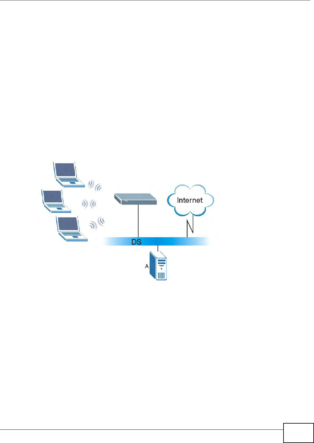
Appendix D Wireless LANs
B222s User’s Guide 239
WPA(2) with RADIUS Application Example
To set up WPA(2) , you need the I P address of the RADI US server, it s port num ber ( default is 1812) ,
and t he RADI US shared secret . A WPA( 2) application exam ple wit h an ext er nal RADI US server
looks as follows. " A" is t he RADI US server. "DS" is t he distribut ion system .
1The AP passes t he wireless client 's aut hent icat ion request t o t he RADI US server.
2The RADI US ser ver t hen checks t he user's ident ification against its dat abase and grants or denies
network access accordingly.
3A 256- bit Pairwise Mast er Key ( PMK) is der ived from the authent icat ion process by t he RADI US
server and t he client .
4The RADI US server dist ribut es the PMK t o t he AP. The AP t hen set s up a key hierarchy and
m anagem ent syst em , using t he PMK t o dynam ically generat e unique data encrypt ion keys. The
keys are used t o encrypt every dat a packet that is wirelessly com municated bet ween t he AP and
the wireless client s.
Figure 166 WPA( 2) wit h RADI US Applicat ion Exam ple
WPA(2)-PSK Application Example
A WPA(2) -PSK application looks as follows.
1First ent er identical passw ords int o t he AP and all wireless client s. The Pre- Shared Key (PSK) m ust
consist of bet ween 8 and 63 ASCI I charact ers or 64 hexadecim al characters ( including spaces and
sy m bols) .
2The AP checks each w ireless client 's passw ord and allows it t o j oin the network only if t he password
m at ches.
3The AP and wireless client s generat e a com m on PMK ( Pairwise Mast er Key) . The key it self is not
sent over t he net work, but is derived from t he PSK and t he SSI D.
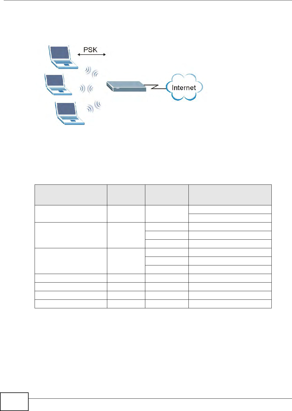
Appendix D Wireless LANs
B222s User’s Guide
240
4The AP and wireless client s use t he TKI P or AES encrypt ion process, the PMK and inform ation
exchanged in a handshake t o creat e t em poral encr ypt ion keys. They use t hese keys t o encrypt dat a
exchanged bet ween t hem .
Figure 167 WPA( 2) -PSK Aut hent icat ion
Security Parameters Summary
Refer t o this t able t o see what ot her secur it y param et ers you should configure for each
authent icat ion m et hod or key m anagem ent pr ot ocol t ype. MAC address filt ers are not dependent on
how you configure these security feat ures.
Antenna Overview
An ant enna couples RF signals onto air. A t ransm itt er wit hin a w ireless device sends an RF signal to
the ant enna, which propagat es the signal t hrough the air. The ant enna also operat es in reverse by
capt uring RF signals from t he air.
Positioning t he ant ennas properly increases the range and coverage area of a wireless LAN.
Table 88 Wireless Security Relat ional Mat r ix
AUTHENTICATION
METHOD/ KEY
MANAGEMENT PROTOCOL
ENCRYPTIO
N METHOD
ENTER
MANUAL KEY IEEE 802.1X
Open None No Disable
Enable wit hout Dynam ic WEP Key
Open WEP No Enable wit h Dy nam ic WEP Key
Ye s Enable wit hout Dynam ic WEP Key
Ye s Disable
Shared WEP No Enable wit h Dynam ic WEP Key
Ye s Enable wit hout Dynam ic WEP Key
Ye s Disable
WPA TKI P/ AES No Enable
WPA-PSK TKI P/ AES Yes Disable
WPA2 TKI P/ AES No Enable
WPA2- PSK TKI P/ AES Yes Disable

Appendix D Wireless LANs
B222s User’s Guide 241
Antenna Characteristics
Frequency
An ant enna in t he frequency of 2.4GHz ( I EEE 802.11b and I EEE 802.11g) or 5GHz ( I EEE 802.11a)
is needed t o com m unicat e efficiently in a wir eless LAN
Radiation Pattern
A radiat ion pat t er n is a diagram t hat allows you t o visualize t he shape of t he ant enna’s coverage
area.
Antenna Gain
Ant enna gain, m easured in dB ( decibel), is t he increase in coverage wit hin t he RF beam widt h.
Higher antenna gain im proves t he range of the signal for bet ter com m unications.
For an indoor site, each 1 dB increase in antenna gain result s in a range increase of approxim at ely
2.5% . For an unobstructed outdoor site, each 1dB increase in gain results in a range increase of
approxim at ely 5% . Actual result s m ay vary depending on the network environm ent .
Ant enna gain is som et im es specified in dBi, which is how m uch the ant enna increases t he signal
power com pared to using an isotropic antenna. An isotropic ant enna is a theoretical perfect ant enna
that sends out radio signals equally well in all direct ions. dBi represent s the true gain t hat t he
antenna provides.
Types of Antennas for WLAN
There are two t ypes of antennas used for wireless LAN applications.
• Om ni- direct ional ant ennas send the RF signal out in all direct ions on a horizont al plane. The
coverage area is t orus- shaped ( like a donut ) which m akes these ant ennas ideal for a room
environm ent . With a wide coverage area, it is possible to m ake circular overlapping coverage
areas wit h m ultiple access point s.
• Direct ional antennas concent rat e t he RF signal in a beam , like a flashlight does wit h t he light
from it s bulb. The angle of the beam determ ines t he width of t he coverage pat t ern. Angles
typically range from 20 degrees (very directional) t o 120 degrees (less direct ional) . Direct ional
antennas are ideal for hallways and out door point- t o-point applications.
Positioning Antennas
I n general, ant ennas should be m ount ed as high as practically possible and free of obstructions. I n
point- to–point application, posit ion both ant ennas at t he sam e height and in a direct line of sight to
each ot her t o at tain the best perform ance.
For om ni- direct ional ant ennas m ount ed on a table, desk, and so on, point t he ant enna up. For
om ni- direct ional ant ennas m ount ed on a wall or ceiling, point t he ant enna down. For a single AP
application, place om ni- directional ant ennas as close t o t he cent er of the coverage area as possible.
For direct ional ant ennas, point t he ant enna in t he direction of t he desired coverage area.

Appendix D Wireless LANs
B222s User’s Guide
242
WiFi Protected Setup
Your LTE Device supports WiFi Prot ected Setup ( WPS), which is an easy way t o set up a secure
wir eless net w ork. WPS is an industry st andard specification, defined by t he WiFi Alliance.
WPS allows you t o quickly set up a wireless network with st rong securit y, wit hout having to
configure securit y settings m anually. Each WPS connect ion works bet ween t wo devices. Bot h
devices m ust support WPS ( check each device’s docum ent at ion to m ake sure).
Depending on t he devices you have, you can either press a butt on ( on t he device it self, or in it s
configurat ion utility) or ent er a PI N (a unique Personal I dent ificat ion Num ber t hat allows one device
to aut hent icat e t he ot her) in each of the two devices. When WPS is act ivated on a device, it has t wo
m inut es to find anot her device t hat also has WPS activat ed. Then, t he t wo devices connect and set
up a secure net work by t hem selves.
Push Button Configuration
WPS Push Butt on Configuration ( PBC) is init iated by pressing a butt on on each WPS- enabled
device, and allowing them t o connect aut om at ically. You do not need to ent er any inform at ion.
Not every WPS- enabled device has a physical WPS button. Som e m ay have a WPS PBC but ton in
their configuration ut ilit ies instead of or in addition t o t he physical but ton.
Take t he following st eps t o set up WPS using t he butt on.
1Ensure that t he t wo devices you want t o set up are wit hin wireless range of one another.
2Look for a WPS butt on on each device. I f t he device does not have one, log int o its configurat ion
utility and locate t he but ton ( see the device’s User’s Guide for how to do this - for t he LTE Device,
see Section 5.4 on page 53) .
3Press t he butt on on one of t he devices (it doesn’t m att er which) .
4Wit hin t wo m inut es, press t he butt on on t he other device. The registrar sends t he network nam e
( SSI D) and security key through an secure connect ion t o t he enrollee.
I f you need to m ake sure t hat WPS worked, check t he list of associat ed wireless clients in t he AP’s
configurat ion ut ilit y. I f you see t he wireless client in t he list , WPS was successful.
PIN Configuration
Each WPS-enabled device has its ow n PI N ( Personal I dent ificat ion Num ber) . This m ay eit her be
st at ic ( it cannot be changed) or dynam ic ( you can change it t o a new random num ber by clicking on
a but ton in t he configuration int erface).
When you use t he PI N m ethod, you m ust ent er the enrollee’s PI N int o t he registrar. Then, when
WPS is act ivated on t he enrollee, it presents its PI N t o t he registrar. I f t he PI N m at ches, the
registrar sends the network and securit y inform ation t o t he enrollee, allowing it to j oin the net work.
The advant age of using t he PI N m ethod rather t han t he PBC m et hod is t hat you can ensure t hat the
connection is est ablished between the devices you specify, not j ust the fir st two devices to activate
WPS in t he area. However, you need t o log int o t he configurat ion interfaces of bot h devices.
Take t he following st eps t o set up WPS using t he PI N m ethod.

Appendix D Wireless LANs
B222s User’s Guide 243
1Decide which device you want t o be the registrar ( usually t he AP) and which you want t o be the
enrollee ( usually the client ).
2Look for t he enrollee’s WPS PI N; it m ay be displayed on t he device. I f you don’t see it, log into t he
enrollee’s configuration interface and locat e t he PI N. Select t he PI N connect ion m ode ( not PBC
connect ion m ode) . See t he device’s User ’s Guide for how to do this - for the LTE Device, see Sect ion
5.4 on page 53.
3Log into t he configuration ut ility of t he registrar. Select t he PI N connection m ode ( not t he PBC
connection m ode). Locate t he place where you can ent er t he enrollee’s PI N ( if you are using t he LTE
Device, see Sect ion 5.4 on page 53) . Ent er t he PI N from t he enrollee device.
4Activat e WPS on bot h devices within t wo m inut es.
Note: Use t he configurat ion utilit y t o activate WPS, not t he push-but ton on t he device
it self.
5On a com puter connect ed t o t he wireless client , t ry t o connect t o t he I nt ernet . I f you can connect,
WPS was successful.
I f you cannot connect , check the list of associat ed wireless client s in the AP’s configuration utility. I f
you see t he wireless client in t he list , WPS was successful.
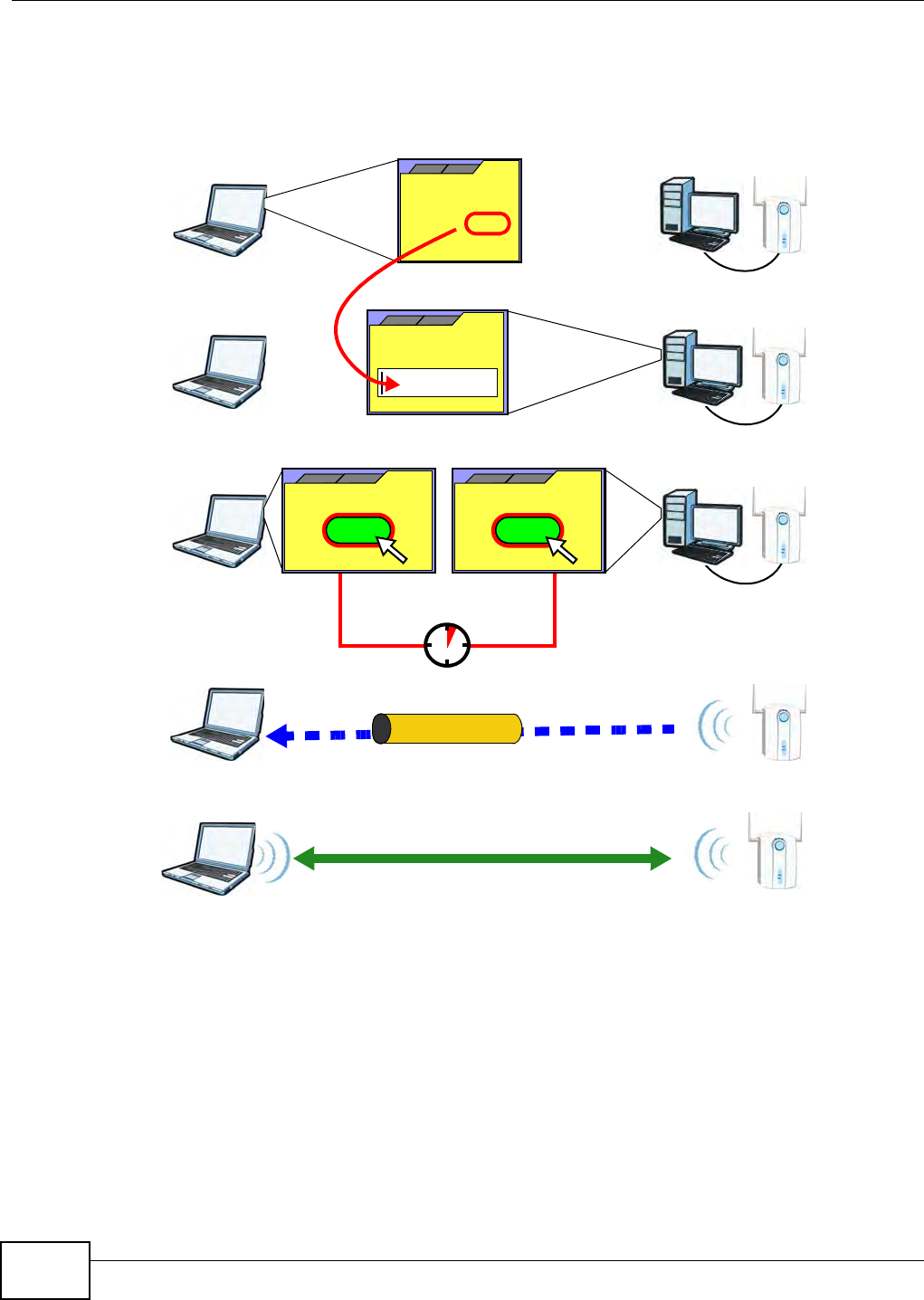
Appendix D Wireless LANs
B222s User’s Guide
244
The following figure shows a WPS- enabled wireless client ( installed in a not ebook com puter)
connecting to t he WPS-enabled AP via t he PI N m ethod.
Figure 168 Exam ple WPS Process: PI N Met hod
How WPS Works
When two WPS- enabled devices connect , each device m ust assum e a specific role. One device acts
as t he registrar ( the device t hat supplies net w ork and securit y settings) and t he ot her device acts
as t he enrollee ( the device t hat receives net w ork and securit y set tings. The registrar creat es a
secure EAP ( Ext ensible Aut hent icat ion Prot ocol) t unnel and sends t he net work nam e ( SSI D) and t he
WPA- PSK or WPA2- PSK pre- shared key to t he enrollee. Whet her WPA-PSK or WPA2- PSK is used
depends on t he standards support ed by t he devices. I f the registrar is already part of a net w ork, it
sends t he existing inform ation. I f not , it generat es the SSI D and WPA( 2) -PSK random ly.
ENROLLEE
SECURE EAP TUNNEL
SSID
WPA(2)-PSK
WITHIN 2 MINUTES
COMMUNICATION
This device’s
WPS
Enter WPS PIN
WPS
from other device:
WPS PIN: 123456
WPS
START
WPS
START
REGISTRAR
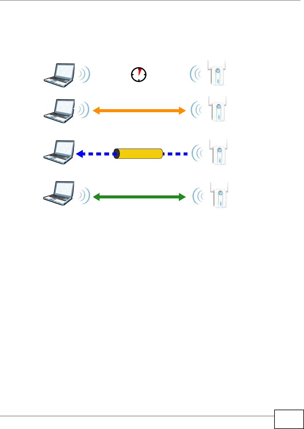
Appendix D Wireless LANs
B222s User’s Guide 245
The following figure shows a WPS- enabled client ( inst alled in a notebook com put er) connect ing t o a
WPS- enabled access point .
Figure 169 How WPS works
The roles of registrar and enrollee last only as long as the WPS set up process is active ( t wo
m inut es) . The next t im e you use WPS, a differ ent device can be t he regist rar if necessary.
The WPS connect ion process is like a handshake; only two devices part icipat e in each WPS
transact ion. I f you want t o add m ore devices you should repeat t he process wit h one of t he exist ing
networked devices and the new device.
Note that t he access point ( AP) is not always t he registrar, and t he wireless client is not always the
enrollee. All WPS- cert ified APs can be a registrar, and so can som e WPS- enabled wireless client s.
By default , a WPS devices is “ unconfigured”. This m eans t hat it is not par t of an existing net w ork
and can act as eit her enrollee or registrar ( if it support s bot h funct ions) . I f the registrar is
unconfigured, the securit y sett ings it t ransm its t o the enrollee are random ly- generat ed. Once a
WPS- enabled device has connect ed t o another device using WPS, it becom es “ configured”. A
configured w ireless client can still act as enrollee or regist rar in subsequent WPS connections, but a
configured access point can no longer act as enrollee. I t will be t he registrar in all subsequent WPS
connect ions in which it is involved. I f you want a configured AP t o act as an enrollee, you m ust reset
it t o its factory defaults.
Example WPS Network Setup
This sect ion shows how securit y set t ings are dist ributed in an exam ple WPS setup.
The following figure shows an exam ple net work. I n st ep 1, both AP1 and Client 1 are
unconfigured. When WPS is activat ed on bot h, t hey perform t he handshake. I n t his exam ple, AP1
SECURE TUNNEL
SECURITY INFO
WITHIN 2 MINUTES
COMMUNICATION
ACTIVATE
WPS
ACTIVATE
WPS
WPS HANDSHAKE
REGISTRARENROLLEE
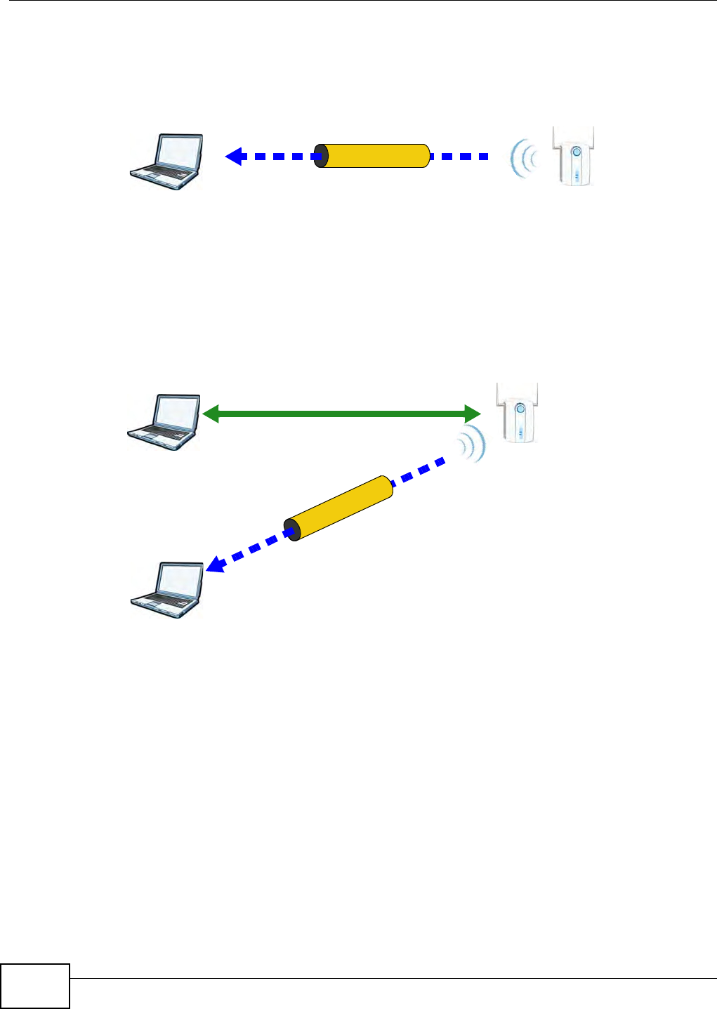
Appendix D Wireless LANs
B222s User’s Guide
246
is t he regist rar, and Client 1 is t he enrollee. The regist rar random ly generates t he security
inform ation t o set up t he net wor k, since it is unconfigur ed and has no existing inform at ion.
Figure 170 WPS: Exam ple Network Step 1
I n step 2 , you add anot her wir eless client t o t he network. You know t hat Clien t 1 support s registrar
m ode, but it is bett er to use AP1 for t he WPS handshake w it h t he new client since you m ust
connect t o t he access point anyway in order t o use t he net work. I n this case, AP1 m ust be t he
registrar, since it is configured ( it already has securit y inform ation for the network) . AP1 supplies
the existing securit y inform at ion t o Clien t 2 .
Figure 171 WPS: Exam ple Network Step 2
REGISTRARENROLLEE
SECURITY INFO
CLIENT 1 AP1
REGISTRAR
CLIENT 1 AP1
ENROLLEE
CLIENT 2
EXISTING CONNECTION
SECURITY INFO
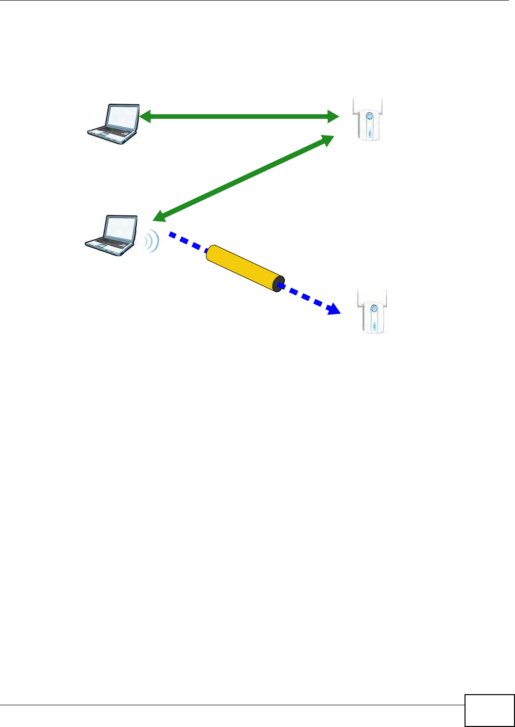
Appendix D Wireless LANs
B222s User’s Guide 247
I n step 3, you add another access point (AP2 ) t o your net w ork. AP2 is out of range of AP1 , so you
cannot use AP1 for the WPS handshake w it h t he new access point . However, you know t hat Clie n t
2 support s the registrar funct ion, so you use it t o perform t he WPS handshake inst ead.
Figure 172 WPS: Exam ple Network Step 3
Limitations of WPS
WPS has som e lim itat ions of which you should be aware.
• WPS works in I nfrast ruct ure net works only ( where an AP and a wireless client com municate) . I t
does not work in Ad- Hoc net w orks (where there is no AP) .
• When you use WPS, it wor ks bet ween t wo devices only. You cannot enroll m ultiple devices
sim ultaneously, you m ust enroll one after the other.
For inst ance, if you have t w o enrollees and one registrar you m ust set up t he first enrollee ( by
pressing the WPS but ton on t he registrar and the first enrollee, for exam ple) , t hen check t hat it
successfully enrolled, t hen set up the second device in t he sam e way.
• WPS works only wit h other WPS-enabled devices. However, you can st ill add non-WPS devices t o
a network you already set up using WPS.
WPS works by aut om atically issuing a random ly- generat ed WPA- PSK or WPA2- PSK pre- shared
key from t he regist rar device to the enrollee devices. Whet her t he net work uses WPA-PSK or
WPA2- PSK depends on t he device. You can check t he configurat ion int erface of t he regist rar
device t o discover t he key the network is using ( if t he device support s this feat ure). Then, you
can ent er the key into t he non-WPS device and j oin t he net work as norm al (t he non-WPS device
m ust also support WPA- PSK or WPA2- PSK) .
CLIENT 1 AP1
REGISTRAR
CLIENT 2
EXISTING CONNECTION
SECURITY INFO
ENROLLEE
AP1
EXISTING CONNECTION

Appendix D Wireless LANs
B222s User’s Guide
248
• When you use the PBC m et hod, t here is a short period (from t he m om ent you press t he but t on
on one device to t he m om ent you press t he butt on on the ot her device) when any WPS-enabled
device could j oin the network. This is because t he regist rar has no way of identifying the
“ correct” enrollee, and cannot different iate bet ween your enrollee and a rogue device. This is a
possible way for a hacker t o gain access t o a net w ork.
You can easily check to see if t his has happened. WPS works bet w een only two devices
sim ultaneously, so if anot her device has enrolled your device w ill be unable t o enroll, and will not
have access t o t he net work. I f this happens, open t he access point ’s configurat ion interface and
look at t he list of associat ed client s ( usually displayed by MAC address). I t does not m at t er if the
access point is t he WPS regist rar, t he enrollee, or was not involved in the WPS handshake; a
rogue device m ust still associate with the access point t o gain access t o t he net work. Check t he
MAC addresses of your wireless clients ( usually print ed on a label on t he bot t om of t he device). I f
there is an unknown MAC address you can rem ove it or reset t he AP.

B222s User’s Guide 249
APPENDIX E
Common Services
The following t able list s som e com m only-used services and t heir associat ed prot ocols and port
num bers. For a com prehensive list of port num bers, I CMP type/ code num bers and services, visit
the I ANA ( I nt ernet Assigned Num ber Aut horit y) web sit e.
•N a m e : This is a short , descript ive nam e for t he service. You can use t his one or creat e a
different one, if you like.
•Pr ot ocol: Th is is t h e t y p e of I P p r ot ocol u sed b y t h e ser v ice. I f t h is is TCP/ UDP, t hen t he service
uses t he sam e port num ber wit h TCP and UDP. I f this is U SER- D EFI N ED, the Po rt ( s) is the I P
prot ocol num ber, not t he port num ber.
•Po rt ( s) : This value depends on t he Pr ot ocol. Please refer t o RFC 1700 for furt her inform ation
about port num bers.
• If the Pr ot ocol is TCP, UD P, or TCP/ UDP, this is the I P port num ber.
• If the Pr ot ocol is USER, t his is t he I P prot ocol num ber.
•D e scr ip t ion : This is a brief explanat ion of the applicat ions that use t his service or the situat ions
in which t his service is used.
Table 89 Com m only Used Ser vices
NAME PROTOCOL PORT(S) DESCRIPTION
AH
( I PSEC_ TUNNEL)
User - Defined 51 The I PSEC AH ( Aut henticat ion Header) t unneling prot ocol
uses this service.
AI M/ New- I CQ TCP 5190 AOL’s I nt ernet Messenger service. I t is also used as a
list ening por t by I CQ.
AUTH TCP 113 Aut hent ication prot ocol used by som e ser vers.
BGP TCP 179 Bor der Gateway Prot ocol.
BOOTP_CLI ENT UDP 68 DHCP Client .
BOOTP_SERVER UDP 67 DHCP Server.
CU-SEEME TCP
UDP
7648
24032
A popular videoconferencing solut ion from White Pines
Soft ware.
DNS TCP/ UDP 53 Dom ain Nam e Server, a serv ice t hat m at ches web nam es
( for exam ple www. exam ple.com ) to I P num bers.
ESP
( I PSEC_ TUNNEL)
User - Defined 50 The I PSEC ESP (Encapsulat ion Securit y Prot ocol)
tunneling protocol uses this ser vice.
FI NGER TCP 79 Fin ger is a UNI X or I nt er net related com m and t hat can be
used to find out if a user is logged on.
FTP TCP
TCP
20
21
File Transfer Program , a program to enable fast t ransfer of
files, including large files t hat m ay not be possible by e-
m ail.
H.323 TCP 1720 NetMeet ing uses t his pr otocol.
HTTP TCP 80 Hyper Text Transfer Prot ocol - a client / server pr otocol for
the world wide web.
HTTPS TCP 443 HTTPS is a secur ed htt p session oft en used in e-
com m erce.

Appendix E Common Services
B222s User’s Guide
250
I CMP User - Defined 1I nt ernet Cont rol Message Protocol is often used for
diagnost ic or rout ing purposes.
I CQ UDP 4000 This is a popular I nt ernet chat program .
I GMP ( MULTI CAST) User - Def ined 2I nt ernet Group Managem ent Prot ocol is used w hen
sending packet s t o a specific group of host s.
I KE UDP 500 The I nt ernet Key Exchange algorit hm is used for key
distribution and m anagem ent .
I RC TCP/ UDP 6667 This is anot her popular I nt ernet chat program .
MSN Messenger TCP 1863 Microsoft Networks’ m essenger serv ice uses t his pr otocol.
NEW- I CQ TCP 5190 An I nt ernet chat program .
NEWS TCP 144 A protocol for news groups.
NFS UDP 2049 Net wor k File Syst em - NFS is a client / server dist ributed
file service t hat provides transparent file sharing for
net wor k environm ent s.
NNTP TCP 119 Net work News Transport Prot ocol is t he delivery
m echanism for t he USENET newsgroup serv ice.
PI NG User - Defin ed 1Packet I Nternet Groper is a pr otocol that sends out I CMP
echo request s t o t est whether or not a rem ot e host is
reachable.
POP3 TCP 110 Post Office Pr ot ocol version 3 let s a client com put er get e-
m ail from a POP3 server t hrough a t em porary connect ion
( TCP/ I P or ot her) .
PPTP TCP 1723 Point- to- Point Tunneling Prot ocol enables secure t ransfer
of dat a over public netw orks. This is the cont r ol channel.
PPTP_TUNNEL
( GRE)
User - Defined 47 PPTP ( Point- t o- Point Tunneling Prot ocol) enables secur e
transfer of dat a over public netw orks. This is t he dat a
channel.
RCMD TCP 512 Rem ot e Com m and Service.
REAL_AUDI O TCP 7070 A st ream ing audio service t hat enables real tim e sound
over the w eb.
REXEC TCP 514 Rem ot e Execu t ion Daem on.
RLOGI N TCP 513 Rem ot e Login.
RTELNET TCP 107 Rem ot e Telnet .
RTSP TCP/ UDP 554 The Real Tim e St ream ing ( m edia cont rol) Prot ocol ( RTSP)
is a rem ote cont rol for m ultim edia on the I nternet.
SFTP TCP 115 Sim ple File Transfer Pr otocol.
SMTP TCP 25 Sim ple Mail Transfer Prot ocol is t he m essage- exchange
st andard for t he I nt ernet. SMTP enables you to m ove
m essages from one e-m ail server t o anot her.
SNMP TCP/ UDP 161 Sim ple Network Managem ent Program .
SNMP-TRAPS TCP/ UDP 162 Traps for use wit h t he SNMP ( RFC: 1215).
SQL- NET TCP 1521 Str uct ured Query Language is an interface t o access data
on m any different types of database system s, including
m ainfram es, m idrange system s, UNI X syst em s and
net work servers.
SSH TCP/ UDP 22 Secure Shell Rem ot e Login Program .
STRM WORKS UDP 1558 St ream Works Prot ocol.
SYSLOG UDP 514 Syslog allows y ou t o send syst em logs t o a UNI X ser ver.
Table 89 Com m only Used Ser vices ( cont inued)
NAME PROTOCOL PORT(S) DESCRIPTION

Appendix E Common Services
B222s User’s Guide 251
TACACS UDP 49 Login Host Prot ocol used for ( Term inal Access Cont roller
Access Cont rol Syst em ).
TELNET TCP 23 Telnet is t he login and t erm inal em ulat ion pr ot ocol
com m on on the I nt ernet and in UNI X env ironm ent s. I t
operat es over TCP/ I P netw orks. I ts prim ary function is to
allow users t o log into rem ote host syst em s.
TFTP UDP 69 Tr ivial File Transfer Protocol is an I nt ernet file t ransfer
prot ocol sim ilar to FTP, but uses t he UDP ( User Dat agram
Prot ocol) rat her t han TCP (Transm ission Cont rol Prot ocol) .
VDOLI VE TCP 7000 Anot her videoconferencing solut ion.
Table 89 Com m only Used Ser vices ( cont inued)
NAME PROTOCOL PORT(S) DESCRIPTION

Appendix E Common Services
B222s User’s Guide
252

B222s User’s Guide 253
APPENDIX F
Legal Information
L'ut ilisation de cet equipem ent ( 2.4GHz wireless LAN) est soum ise à cert aines restrict ions: cet
equipem ent peut êt re ut ilisé à l'int erieur d'un batim ent en utilisant t out es les frequences de 2400 a
2483.5MHz ( Chaine 1- 13) . Pour une utilisat ion en envir onem ent ext er ieur, les frequences
com prises ent r e 2400- 2454 MHz peuvent êt r e ut ilisé. Pour les dernières restr ictions, voir ht t p: / /
w ww. ar t - telecom .fr.
For 2.4- GHz wireless LAN operat ion of t his product, certain rest rictions apply. This equipm ent m ay
use t he ent ire- 2400- MHz to 2483.5- MHz frequency band ( channels 1 t hrough 13) for indoor
applications. For out door use, only 2400- 2454 MHz frequency band m ay be used. For t he lat est
requirem ent s, see ht t p: / / www.art- t elecom .fr.
Certifications (Class B)
Federal Communications Commission (FCC) Interference Statement
The device com plies with Part 15 of FCC rules. Operat ion is subj ect t o t he following t w o conditions:
• This device m ay not cause harm ful int erfer ence.
• This device m ust accept any int erfer ence r eceived, including int erference that m ay cause undesired operat ions.
This device has been t est ed and found t o com ply with t he lim its for a Class B digital device pursuant to Part 15 of t he FCC Rules. These
lim its ar e designed t o provide reasonable prot ection against h arm ful int erference in a resident ial installat ion. This dev ice generat es, uses,
and can radiat e radio frequency energy, and if not installed and used in accor dance wit h the inst ruct ions, m ay cause harm ful int erference
to radio com m u nicat ions. However, t here is no guarant ee t hat interfer ence will not occur in a part icular inst allat ion.
I f t his device does cause harm ful interference t o radio/ television recept ion, w hich can be determ ined by t urning the device off and on, t he
user is encouraged t o try to correct the interference by one or m ore of t he following m easures:
1Reorient or r elocat e t he receiving antenna.
2I ncrease t he separation between t he equipm ent and t he r eceiver.
3Connect t he equipm ent int o an out let on a circuit different from that to which t he receiver is connected.
4Consult t he dealer or an experienced radio/ TV t echnician for help.
FCC Caution: Any changes or m odificat ions not ex pressly approved by the part y responsible for com pliance could void t he user's aut hority
to operat e t his equipm ent .
FCC Radiation Exposure Statement
The ODU m ust be fixed-m ount ed on out door per m anent struct ures t o sat isfy RF exposure requirem ent s.
• This device m eet s the governm ent's requirem ent s for exposur e t o radio wav es.
• This device is designed and m anufactured not t o exceed the emission lim it s for exposure to radio frequency (RF) energy set by the
Federal Com municat ions Com m ission of t he U.S. Governm ent .
• This device com plies w it h FCC radiat ion exposur e lim it s set fort h for an uncont rolled envir onm ent . I n order t o avoid t he possibility of
exceeding the FCC radio fr equency exposure lim its, hum an proxim ity t o t he indoor device ( I DU) ant enna shall not be less than 20cm ;
t o t he out door device (ODU) ant enna shall not be less t han 35cm during nor m al oper at ion.
• This t ransm it t er m ust not be co- locat ed or operating in conj unct ion w it h any ot her ant enna or t ransm it t er.
• I EEE 802.11b, 802.11g or 802.11n(20MHz) operation of this product in t he U.S.A. is firm ware-lim it ed t o channels 1 t hr ough 11. I EEE
802.11n( 40MHz) operation of t his pr oduct in t he U.S.A. is firm ware-lim it ed t o channels 3 t hrough 9.
• I EEE 802.11b or 802.11g operation of t his product in t he U.S.A. is firm war e-lim it ed t o channels 1 t hr ough 11.

Appendix F Legal Information
B222s User’s Guide
254
本機限在不干擾合法電臺與不受被干擾保障條件下於室使用
減少電磁波影響,請妥適使用
Notices
Changes or m odificat ions not expressly appr oved by t he part y r esponsible for com pliance could void t he user's authority to operat e t he
equipm ent .
This device is designed for t he WLAN 2. 4 GHz and/ or 5 GHz networks t hr oughout t he EC region and Sw it zerland, w it h rest r ict ions in
France.
Ce produit est conçu pour les bandes de fréquences 2,4 GHz et / ou 5 GHz conform ément à la législat ion Européenne. En France
m ét ropolit aine, suivant les décisions n° 03- 908 et 03-909 de l’ARCEP, la puissance d’ém ission ne devra pas dépasser 10 m W ( 10 dB) dans
le cadre d’une installat ion WiFi en ext érieur pour les fréquences com pr ises ent re 2454 MHz et 2483,5 MHz.
This Class B digit al apparatus com plies w it h Canadian I CES-003.
Cet appareil nu m érique de la classe B est conform e à la norm e NMB- 003 du Canada.
Safety Warnings
• Do NOT use this product near wat er, for exam ple, in a wet basem ent or near a swim m ing pool.
• Do NOT expose your device t o dam pness, dust or cor rosive liquids.
• Do NOT st ore things on t he dev ice.
• Do NOT inst all, use, or service t his device during a t hunderstorm . There is a r em ot e r isk of elect ric shock fr om light n ing.
• Connect ONLY suitable accessories t o t he device.
• Do NOT open t he device or unit . Opening or r em oving covers can expose you t o dangerous high volt age points or ot her r isks. ONLY
qualified service personnel should serv ice or disassem ble this device. Please con t act your vendor for furt her inform ation.
• Make sure to connect t he cables t o t he correct port s.
• Place connect ing cables carefully so t hat no one will st ep on t h em or st um ble over t hem .
• Always disconnect all cables from this device before servicing or disassem bling.
• Use ONLY an appropriate power adapt or or cord for your dev ice.
• Connect t he pow er adaptor or cord t o the right supply voltage ( for exam ple, 110V AC in Nor t h Am erica or 230V AC in Europe).
• Do NOT rem ove the plug and connect it to a power outlet by itself; alw ays attach the plug t o t he power adapt or first before connect ing
it t o a power out let .
• Do NOT allow anyt hing to rest on the power adapt or or cord and do NOT place the pr oduct where anyone can walk on t he power
adaptor or cord.
• Do NOT use t he device if t he power adapt or or cor d is dam aged as it m ight cause elect r ocut ion.
• I f t he power adaptor or cord is dam aged, rem ove it from the device and the pow er sour ce.
• Do NOT att em pt to repair t he power adaptor or cor d. Contact your local vendor to order a new one.
• Do not use the indoor dev ice ( I DU) outside, and m ake sure all the connect ions are indoors. There is a rem ot e r isk of electric shock
from lightning.
• Do NOT obst r uct t he device vent ilat ion slot s, as insu fficient airflow m ay harm your dev ice.
• Use only No. 26 AWG ( Am erican Wire Gauge) or larger t elecom m unicat ion line cord.
• I f you wall m ount your device, m ake sure t hat no elect r ical lines, gas or wat er pipes w ill be dam aged.
Your produ ct is m ar ked with this sy m bol, which is known as t he WEEE m ark. WEEE stan ds for Wast e Elect r onics and Electrical
Equipm ent. I t m eans t hat used electrical and electronic products should not be m ixed wit h general wast e. Used elect rical and
electronic equ ipm ent should be treat ed separat ely.

Index
B222s User’s Guide 255
Index
A
ACK m essage 140
act ivat ion
SSI D 52
wir eless LAN
scheduling 57
adm inist rat or passwor d 21
Advanced Encrypt ion St andard, see AES
AES 237
alt ernat ive subnet m ask not at ion 182
antenna
directional 241
gain 241
om n i- dir ect ion al 241
AP ( Access Point ) 231
applications
I nt ernet access 15
VoI P 16
authentication 58, 59
RADI US server 59
autom atic logout 21
B
backup
configurat ion 167
bandwidth m anagem ent 83
Basic Ser vice Set, see BSS
blinking LEDs 18
Broadband 35
BSS 61, 229
exam ple 61
BYE request 140
C
CA 236
call hold 142
call rule 134
call service m ode 142
call transfer 143
call wait ing 143
CAPWAP 36, 38
Certificat e Authorit y, see CA
cert ificat ions 253
not ices 254
channel 231
int erference 231
channel scan 47
channel, wireless LAN 44
Class of Service 141
Class of Ser vice, see CoS
client list 72
client- server prot ocol 137
com fort noise generat ion 122
configurat ion
backup 167
reset 169
restoring 168
Cont rol and Provisioning of Wireless Access Point s
See CAPWAP
copyright 253
CoS 93, 141
CTS ( Clear t o Send) 232
CTS t hreshold 58
D
dat a fragm ent t hreshold 58
default LAN I P address 21
Denials of Service, see DoS
DHCP 32, 70, 103
diagnost ic 171
different iated services 141
Differentiat ed Services, see DiffServ

Index
B222s User’s Guide256
DiffServ ( Different iat ed Services) 141
code point s 141
m ar king rule 94, 141
DNS 70, 79
DNS server address assignm ent 41
docum ent ation
relat ed 2
dom ain nam e system , see DNS
Dom ain Nam e System . See DNS.
DoS 106
DS ( Different iated Services) 93
DS field 93, 141
DSCP 93, 141
DTLS 36
dynam ic DNS 103
Dynam ic Host Configurat ion Prot ocol, see DHCP
dynam ic WEP key exchange 236
DYNDNS wildcard 103
E
EAP Aut henticat ion 235
echo cancellat ion 122
Encapsulat ion 41
encapsulation 35
encrypt ion 60, 237
ESS 230
Europe type call service m ode 142
Ext ended Service Set I Dent ificat ion 46, 53
Ext ended Service Set , see ESS
F
FCC int erference stat em ent 253
filt ers
MAC address 59
firewalls 105
configurat ion 108
DoS 106
securit y 112
firm ware 165
flash key 142
flashing 142
fragm entat ion threshold 58, 232
FTP 96
G
G.168 122
Guide
Quick St ar t 2
H
hidden node 231
host 155
host nam e 31
I
I ANA 186
I BSS 229
I EEE 802.11g 233
I ndependent Basic Service Set, see I BSS
init ializat ion vector ( I V) 238
I nt ernet access 15
I nt ernet Assigned Num bers Aut horit y, see I ANA
I nt ernet Service Provider, see I SP
I P addr ess 32
default 21
WAN 36
I P Address Assignm ent 41
I P pool 71
I SP 35
I TU-T 122
L
LAN 69
client list 72
MAC address 73
lim itat ions

Index
B222s User’s Guide 257
wir eless LAN 60
WPS 67
listening port 127
Local Area Net work, see LAN
login
passw ords 21
logout 21
aut om at ic 21
logs 145, 163
M
MAC 31, 115
MAC address 73
filt er 59
MAC address filt ering 115
MAC filt er 115
Managem ent Mode
CAPWAP and DHCP 37
CAPWAP and I P Subnets 37
m anaged AP 36
m anaging t he device
good habit s 18
using FTP. See FTP.
MBSSI D 61
Media access control 115
Media Access Cont rol, see MAC Address
Message I nt egrity Check, see MI C
MI C 237
m odel nam e 31
m ult im edia 136
Mult iple BSS, see MBSSI D
N
NAT 96, 186
definitions 100
how it work s 101
what it does 101
Net work Address Translation, see NAT
network m ap 24
non- proxy calls 134
O
OK response 140
ot her docum entat ion 2
P
Pairwise Master Key ( PMK) 238, 239
passphrase 48
passw ords 21
PBC 62
peer- t o-peer calls 134
Per- Hop Behavior, see PHB
PHB 94, 141
phone book
speed dial 134
PI N, WPS 62
exam ple 64
port s 18
PPP over Ethernet , see PPPoE
PPPoE 35
pr eam ble 58
pr eam ble m ode 233
prot ocol 35
PSK 238
Push But ton Configuration, see PBC
push but ton, WPS 62
Q
QoS 83, 84, 93, 140
Quality of Service, see QoS
Quick St ar t Guide 2, 21
R
RADI US 234
m essage t ypes 235
m essages 235
shared secret key 235
RADI US server 59

Index
B222s User’s Guide258
Real t im e Transport Prot ocol, see RTP
relat ed docum ent at ion 2
Request To Send, see RTS
reset 169
RESET but t on 20
restart 169
restoring configuration 168
RFC 1631 95
RFC 1889 139
RFC 3164 145
rout er features 15
RTP 139
RTS ( Request To Send) 232
threshold 231, 232
RTS t hr esh old 58
S
safet y warnings 254
scan 47
scheduling
wir eless LAN 57
securit y
wir eless LAN 58
securit y, network 112
service access control 157
Service Set 46, 53
Session I nit iation Prot ocol, see SI P
silence suppression 122
SI P 136
account 136
call pr ogression 139
client 137
identit ies 136
I NVI TE request 140
num ber 136
proxy server 137
redirect server 138
register server 139
servers 137
service dom ain 136
URI 136
user agent 137
speed dial 134
SSI D 59
act ivat ion 52
MBSSI D 61
st at ic route 75
st at us 29
st at us indicat ors 18
subnet 179
subnet m ask 180
subnet t ing 182
supplem ent ary services 141
syslog
prot ocol 145
severit y levels 145
syst em
firm ware 165
passw ords 21
st at us 29
Sy st em I nfo 31
syst em nam e 31, 160
T
Tem poral Key I nt egrit y Protocol, see TKI P
The 36
three- way conference 143
thresholds
dat a fragm ent 58
RTS/ CTS 58
TKI P 237
To S 140
Type of Service, see ToS
U
Uniform Resource I dent ifier 136
Universal Plug and Play, see UPnP
upgrading firm ware 165
UPnP 73
securit y issues 70

Index
B222s User’s Guide 259
V
VAD 122
ver sion
firm ware
ver sion 32
voice act ivit y detect ion 122
voice coding 140
VoI P 136
features 16
peer- t o-peer calls 134
VoI P feat ures 16
VoI P st at us 152
W
WAN
Wide Area Network, see WAN 35
warnings 254
Web Configurat or 21
web configurat or
passw ords 21
WEP 48, 60
WEP Encrypt ion 49
Wi- Fi Prot ected Access, see WPA
wir eless
securit y 233
wir eless client WPA supplicant s 238
wir eless LAN 43
authentication 58, 59
BSS 61
exam ple 61
channel 44
encrypt ion 60
exam ple 44
fragm entat ion threshold 58
lim itat ions 60
MAC address filt er 59
MBSSI D 61
pr eam ble 58
RADI US server 59
RTS/ CTS t hr esh old 58
scheduling 57
securit y 58
SSI D 59
act ivat ion 52
WEP 60
WPA 60
WPA- PSK 60
WPS 62, 64
exam ple 65
lim itat ions 67
PI N 62
push but ton 62
wir eless net work
exam ple 43
wir eless security 233
WLAN 43
auto- scan channel 47
int erference 231
passphrase 48
scheduling 57
securit y param et ers 240
see also w ireless.
WEP 48
WLAN but ton 17
WPA 60, 237
key caching 238
pre-aut hent icat ion 238
user authent icat ion 238
vs WPA- PSK 238
wir eless client supplicant 238
wit h RADI US application exam ple 239
WPA2 237
user authent icat ion 238
vs WPA2-PSK 238
wir eless client supplicant 238
wit h RADI US application exam ple 239
WPA2- Pre-Shared Key, see WPA2- PSK
WPA2- PSK 237, 238
applicat ion exam ple 239
WPA- PSK 60, 237, 238
applicat ion exam ple 239
WPS 62, 64
exam ple 65
lim itat ions 67
PI N 62
exam ple 64
push but ton 62