Mitsubishi Electric 485SR Time Lapse VCR User Manual KR4024TN 00 cover
Mitsubishi Electric Corp Time Lapse VCR KR4024TN 00 cover
users manual

Ultrak Corporate Headquarters:
1301 Waters Ridge Drive, Lewisville, TX 75057
(800)796-2288 • (972)353-6500 • FAX (972)353-6670
KR4096HN-A
TIME LAPSE VIDEO
CASSETTE RECORDER
OPERATION
INSTRUCTIONS
i
WARNING
RISK OF ELECTRIC SHOCK
DO NOT OPEN
WARNING: TO REDUCE THE RISK OF ELECTRIC
SHOCK, DO NOT REMOVE COVER (OR BACK).
NO USER-SERVICEABLE PARTS INSIDE.
REFER SERVICING TO QUALIFIED SERVICE
PERSONNEL.
The lightning flash with arrowhead
symbol, within an equilateral triangle, is
intended to alert the user to the
presence of uninsulated “dangerous
voltage” within the product’s enclosure
that may be of sufficient magnitude to
constitute a risk of electric shock.
The exclamation point within an
equilateral triangle is intended to alert
the user to the presence of important
operating and maintenance (servicing)
instructions in the literature
accompanying the appliance.
WARNING:
TO PREVENT FIRE OR SHOCK HAZARD, DO
NOT EXPOSE THIS APPLIANCE TO RAIN OR
MOISTURE.
CAUTION:
TO PREVENT ELECTRIC SHOCK DO NOT USE
THIS (POLARIZED) PLUG WITH AN EXTENSION
CORD, RECEPTACLE OR OTHER OUTLET
UNLESS THE BLADES CAN BE FULLY INSERTED
TO PREVENT BLADE EXPOSURE.
La fléche symbolisant l’éclair dans un
triangle équilateral a pour objet de tirer
l’attention de l’utilisateur sur le fait, qu’il y a
des “tensions dangereuses” non-isolées à
l’intérieur de l’enceinte du produit qui
peuvent être suffisamment impor-tantes
pour conduire au risque d’électrocution.
Le point d’exclamation au sein d’un triangle
équilateral a pour objet de tirer l’attention de
l’utilisateur sur le fait qu’il y a des
instructions de mise en service et
d’entretien (de réparation) dans les fiches
descriptives de l’apprareil qui doivent
obligatoirement être respectées.
AVERTISSEMENT:
AFIN D’ÉVITER TOUT RISQUE D’INCENDIE OU
D’ÉLECTROCUTION, NE PAS EXPOSER CET
APPAREIL À LA PLUIE NI À L’HUMIDITÉ.
ATTENTION:
POUR PRÉVENIR LES CHOCS ÉLECTRIQUES NE
PAS UTILISER CETTE FICHE POLARISÉE AVEC UN
PROLONGATEUR, UNE PRISE DE COURANT OU
UNE AUTRE SORTIE DE COURANT, SAUF SI LES
LAMES PEUVENT ÊTRE INSÉRÉES À FOND SANS
EN LAISSER AUCUNE PARTIE À DÉCOUVERT.
AVERTISSEMENT
DANGER D’ÉLECTROCUTION
NE PAS OUVRIR
AVERTISSEMENT: POUR ÉLIMINER TOUT RISQUE
D’ÉLECTRO-CUTION, NE PAS OUVRIR LE COUVERCLE
(OU LA PARTIE ARRIÈRE). AUCUNE PIECE RÉPARABLE
PAR L’UTILISATEUR NE SE TROUVE À L’INTÉRIEUR.
POUR TOUTE INTERVENTION D’ENTRETIEN OU DE
RÉPARATION SE CONFIER AUX TECHNICIENS
QUALIFIÉS.

Important Safeguards
Please read all these instructions carefully regarding your VCR before you begin operating it.
Follow all warnings and instructions marked on the VCR.
1 Read Instructions
All the safety and operating instructions should be read before
the product is operated.
2 Retain Instructions
The safety and operating instructions should be retained for
future reference.
3 Heed Warnings
All warnings on the product and in the operating instructions
should be adhered to.
4 Follow Instructions
All operating and use instructions should be followed.
5 Cleaning
Unplug this product from the wall outlet before cleaning. Do
not use liquid cleaners or aerosol cleaners. Use a damp cloth
for cleaning.
6 Attachments
Do not use attachments not recommended by the product
manufacturer as they may cause hazards.
7 Water and Moisture
Do not use this product near water — for example, near a bath
tub, wash bowl, kitchen sink, laundry tub, in a wet basement,
or near a swimming pool, and the like.
8 Accessories
Do not place this product on an unstable cart, stand, tripod,
bracket, or table. The product may fall, causing serious injury
to a child or adult, and serious damage to the product. Use
only with a cart, stand, tripod, bracket, or table recommended
by the manufacturer, or sold with the product. Any mounting of
the product should follow the manufacturer’s instructions, and
should use a mounting accessory recommended by the manu-
facturer.
9A product and cart combination should be moved with care.
Quick stops, excessive force, and uneven surfaces may
cause the product and cart combination to overturn.
11 Power Sources
This product should be operated only from the type of power
source indicated on the marking label. If you are not sure of
the type of power supply to your home, consult your product
dealer or local power company. For products intended to op-
erate from battery power, or other sources, refer to the operat-
ing instructions.
12 Grounding or Polarization
This video product is equipped with a 3-wire grounding-type
plug, a plug having a third (grounding) pin. This plug will only
fit into a grounding-type power outlet. This is safety feature. If
you are unable to insert the plug into the outlet, contact your
electrician to replace your obsolete outlet. Do not defeat the
safety purpose of the grounding-type plug.
13 Power-Cord Protection
Power-supply cords should be routed so that they are not likely
to be walked on or pinched by items placed upon or against
them, paying particular attention to cords at plugs, conven-
ience receptacles, and the point where they exit from the prod-
uct.
14 Lightning
For added protection for this product during a lightning storm,
or when it is left unattended and unused for long periods of
time, unplug it from the wall outlet and disconnect the antenna
or cable system. This will prevent damage to the product due
to lightning and power-line surges.
15 Overloading
Do not overload wall outlets, extension cords, or integral con-
venience receptacles as this can result in fire risk or electric
shock.
16 Object and Liquid Entry
Never push objects of any kind into this product through open-
ings as they may touch dangerous voltage points or short-out
parts that could result in a fire or electric shock. Never spill
liquid of any kind on the product.
17 Servicing
Do not attempt to service this product yourself as opening or
removing covers may expose you to dangerous voltage or other
hazards. Refer all servicing to qualified service personnel.
18 Damage Requiring Service
Unplug this product from the wall outlet and refer servicing to
qualified service personnel under the following conditions:
(a) When the power-supply cord or plug is damaged.
(b) If liquid has been spilled, or objects have fallen into the
product.
(c) If the product has been exposed to rain or water.
(d) If the product does not operate normally by following the
operating instructions. Adjust only those controls that are
covered by the operating instructions as an improper ad-
justment of other controls may result in damage and will
often require extensive work by a qualified technician to
restore the product to its normal operation.
(e) If the product has been dropped or damaged in any way.
(f) When the product exhibits a distinct change in perform-
ance – this indicates a need for service.
10 Ventilation
Slots and openings in the cabinet are provided for ventilation
and to ensure reliable operation of the product and to protect it
from overheating, and these openings must not be blocked or
covered. The openings should never be blocked by placing
the product on a bed, sofa, rug, or other similar surface. This
product should not be placed in a built-in installation such as a
bookcase or rack unless proper ventilation is provided or the
manufacturer’s instructions have been adhered to.
ii

19 Replacement Parts
When replacement parts are required, be sure the service tech-
nician has used replacement parts specified by the manufac-
turer or have the same characteristics as the original part.
Unauthorized substitutions may result in fire, electric shock or
other hazards.
20 Safety Check
Upon completion of any service or repairs to this product, ask
the service technician to perform safety checks to determine
that the product is in proper operating condition.
21 Heat
The product should be situated away from heat sources such
as radiators, heat registers, stoves, or other products (includ-
ing amplifiers) that produce heat.
INFORMATION
This equipment has been tested and found to comply with
the limits for a Class B digital device, pursuant to Part 15
of the FCC Rules. These limits are designed to provide
reasonable protection against harmful interference in a
residential installation. This equipment generates, uses,
and can radiate radio frequency energy and, if not in-
stalled and used in accordance with the instructions, may
cause harmful interference to radio communications.
However, there is no guarantee that interference will not
occur in a particular installation. If this equipment does
cause harmful interference to radio or television recep-
tion, which can be determined by turning the equipment
off and on, try to correct the interference by one or more
of these measures:
• Reorient or relocate the receiving antenna
• Increase the separation between the equipment and
receiver
• Connect the equipment into an outlet on a different
circuit than the receiver is connected
• Consult the dealer or an experienced radio/TV tech-
nician for help
Changes or modifications not expressly approved by the party
responsible for compliance could void the user’s author-
ity to operate the equipment.
iii
Important Safeguards (Cont.)
INFORMATION
This Class B digital apparatus complies with Canadian ICES-
003.
INFORMATION
Cet appareil numérique de la classe B est conforme à la
norme NMB-003 du Canada.
Note
A point to notice
Info.
Supplementary information
Introduction 1
Reference page
Caution and Care
CONDENSATION IS THE ENEMY OF VIDEO RECORDERS
WHAT IS CONDENSATION?
1. When a very cold drink is poured into a glass, the water droplets which form on the outer surface of the glass are an example of
condensation.
2. If the VCR is exposed to a rapid increase in temperature (such as warming it in a cold room or after transporting it from a cold
location to a warm one) condensation may form on the tape transport mechanism inside the VCR. By heating the inside of the
VCR, it can dry up the moisture and prevent damage to the VCR or video tape from condensation. To do this, plug the VCR in
and switch the VCR POWER to ON. Leave the VCR on for at least 2 hours before using it for recording or playback.
CONDENSATION IS LIKELY TO OCCUR WHEN:
1. The VCR is moved inside from outdoors or from a cold room to a warm one.
2. A cold room is heated quickly.
3. Humidity is high.
Note
• Avoid using the VCR where cold air (e.g., from an air conditioner) will blow directly on it.
Never place anything containing water on top of the VCR; (e.g., vases, cups, etc.).
Heavy objects (e.g., TV) should never be placed on the VCR
NEVER TOUCH OR INSERT ANY OBJECT INSIDE THE VCR
Touching the inside of the cabinet or inserting foreign objects of any kind not only creates a safety hazard but can also cause
extensive damage.
PROTECT THE POWER CORD
Damage to the power cord may cause fire or shock hazard. When unplugging the power cord, hold it by the plug only and pull out
carefully.
UNPLUG THE POWER CORD DURING A LONG ABSENCE
Turn the power off and unplug the power cord during a long absence.
MAINTAIN GOOD VENTILATION
Do not obstruct the ventilation holes on the VCR. For maximum ventilation, place the unit on a hard level surface only, and ensure it
is not covered during use.
WHEN NOT IN USE
When you finish operating the VCR, always unload the cassette and turn the VCR off.
CABINET CARE
Never use petroleum-based cleaners. Clean with a soft cloth moistened with soap and water and wipe dry. PVC cables or leads
should not be left in contact with the cabinet surface for long periods.
INSTALLATION LOCATION
For excellent performance and lasting reliability, install in a location that is:
1. Well ventilated, out of direct sunlight and away from direct heat.
2. A solid, vibration-free surface.
3. Free from high humidity, excessive dust and away from magnetic fields.
Note
Never move the VCR without first removing the tape.
CARE OF THE VIDEO CASSETTE TAPES
• Avoid vibration or shock.
• Do not place near a strong magnetic field (e.g., a motor, transformer or magnet).
• Never place or store in direct sunlight.
• Avoid dusty places.
• Place the cassette in its case and store vertically.
• Never store tape in high humidity.
WARNING:
The included power cord is used for 120 V, 60 Hz.
Never connect any outlet or power supply having a different voltage or frequency.

2Introduction
Note
A point to notice
Info.
Supplementary information
Features
Up to 96 hours of recording: in addition to regular 6-hour recording modes, it has 18-, 30-, 48-, 72- and 96-hour time lapse
modes (using T-120 tape).
Audio Recording
High Resolution and Image Quality
Remote operation by RS-485 controller
Automatic Head Cleaning
Easy Menu Setting on Screen
Easy Cueing with Alarm Recording
One Button Recording Check
All or Part Front Panel Lock
Protection against Power Failure
Variety of Search Functions
Contents
Important Safeguards .............................................ii - iii
Introduction
Caution and Care ......................................................... 1
Features ....................................................................... 2
Controls and Functions ................................................ 3
Front View............................................................................ 3
Fluorescent Display ............................................................. 4
Rear View ............................................................................ 5
Basic Functions
Loading/Unloading a Tape ........................................... 6
Manual Recording ........................................................ 7
Playback ...................................................................... 8
Adjusting the Clock ...................................................... 9
Advanced Functions
Recording Techniques................................................ 10
Timer Recording ................................................................ 10
Alarm Recording................................................................ 11
Emergency Recording ....................................................... 12
Series Recording ............................................................... 12
Remote Recording ............................................................ 13
Repeat Recording ............................................................. 13
One Shot/Interval Recording ............................................. 13
Synchronous Recording .................................................... 14
Additional Features .................................................... 15
Memory Backup in Case of Power Failure ........................ 15
After a Power Failure......................................................... 15
Displaying/Clearing the Power Loss List ........................... 15
Displaying/Clearing the Alarm List..................................... 15
Tape Usage and Elapsed Time of VCR ............................. 16
Lock Function .................................................................... 16
Special Effects Playback............................................ 16
Still Picture ........................................................................ 16
Shuttle Ring ....................................................................... 16
Shuttle Hold ....................................................................... 16
Direct Shuttle Ring ............................................................ 16
Frame or Field Playback ................................................... 17
Adjustment during Playback ...................................... 17
Tracking Adjustment .......................................................... 17
Vertical Adjustment ............................................................ 17
Searching Techniques ................................................ 18
Counter Memory Stop ....................................................... 18
Skip Search ....................................................................... 18
Index Search ..................................................................... 18
Time Date Search.............................................................. 19
Using RS-485 Interface .............................................. 20
Configuring the Time Lapse VCR ...................................... 20
RS-485 Setting .................................................................. 20
Connecting to a RS-485 Controller ................................... 20
Commands from RS-485 Controller .................................. 21
Commands and Responses .............................................. 22
Installation
Connections for Various Functions ............................ 26
Connecting with CCTV Camera, Monitor and Sensor ....... 26
Alarm Recording Connection ............................................ 26
Series Recording Connection ............................................ 27
Remote Recording Connection ......................................... 27
Synchronous Recording Connection ................................. 27
Connection for External Time Clock Adjustment ............... 27
Setting the Clock ........................................................ 28
Setting the Menus ...................................................... 29
Menu Chart ........................................................................ 29
Language Selection ........................................................... 30
Main Menu ......................................................................... 30
Display ............................................................................... 30
Timer Program................................................................... 30
Recording Set Up .............................................................. 30
Rear Terminal .................................................................... 31
Maintenance ...................................................................... 31
First Time Set Up ............................................................... 32
RS-485 .............................................................................. 32
Others
Remote Controller (Optional) ..................................... 33
Before Calling for Service .......................................... 34
Warning Display ......................................................... 36
Control Input/Output Signals and Circuit.................... 37
Specifications ............................................................. 38
Recording Options for Various Needs
• Daily/weekly/holiday timer recording
• Alarm recording
• Series recording
• Remote recording
• Repeat recording
• One shot/Interval recording
• Synchronous recording
Special Playback Features
• Still picture
• Speed search using shuttle ring
• Frame-by-frame and field-by-field playback using jog
dial
Accessories
1 User’s manual
1 Power cord
1 Warranty card
Introduction 3
Reference page
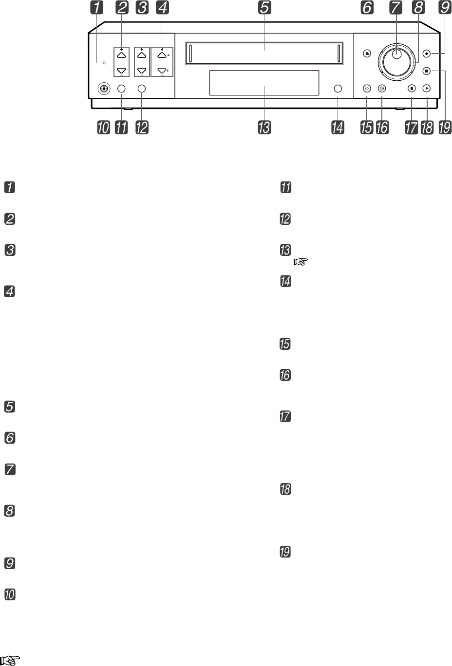
Controls and Functions
Front View
Lock button
Press to lock the VCR into the current mode.
REC/PLAY MODE buttons
Press to select the recording or playback speed.
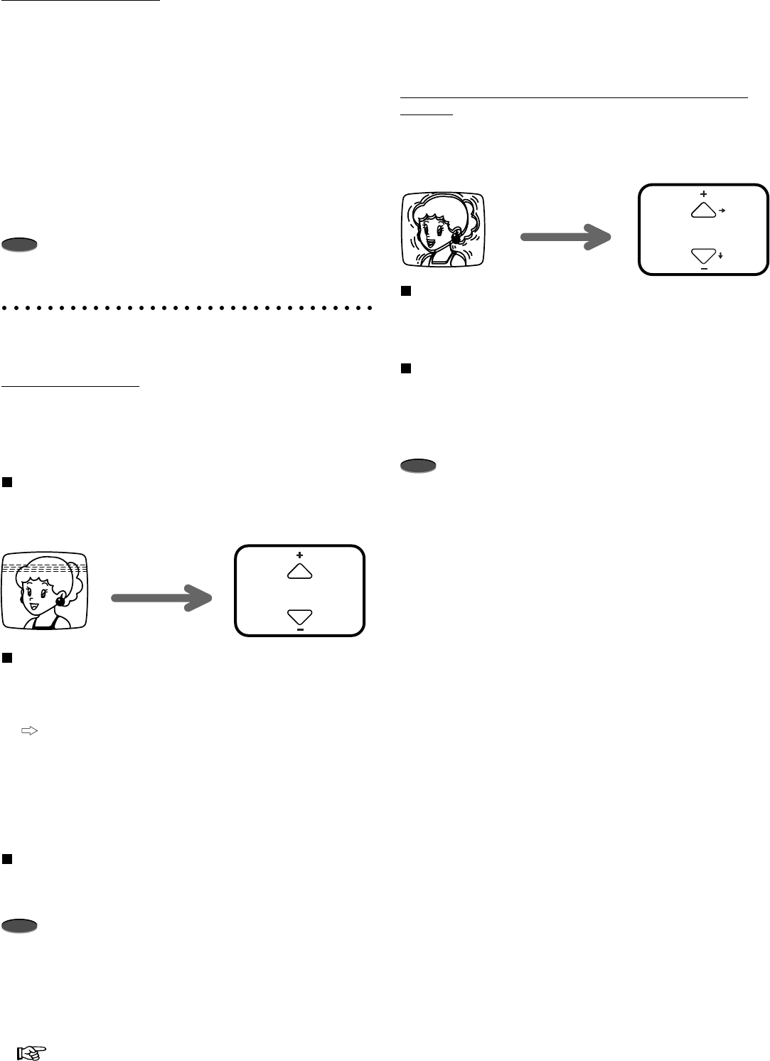
TRACKING buttons
Press to reduce/eliminate the noise during playback, slow
playback, etc.
POSITION/VERTICAL ADJUST buttons
• When the day and present time display is shown on the
monitor screen, press the top button to move the display
to the right forward or bottom button to move it down.
During an alarm recording or if an warning is displayed on
screen, the day and present time display cannot be
moved.
• If screen images are blurred vertically during still picture or
special effects playback, press to reduce/eliminate the
picture vibration.
Cassette Loading Slot
Cassette is inserted in this slot for loading.
EJECT button
Press to remove the cassette.
JOG dial
Use to forward/reverse a tape frame-by-frame (field-by-field)
or to set the menus.
SHUTTLE ring
When the VCR is in stop mode, turn to the right to forward a
tape or to the left to rewind.
Also, use for special effects playback or to set the menus.
RECORD button
Press to begin recording.
VIDEO OUT connector
Output connector for video signal (RCA pin). Connect a
monitor here.
COUNTER RESET button
Press to reset the counter to “00000”.
SEARCH button
Press to display the <SEARCH FUNCTION> menu.
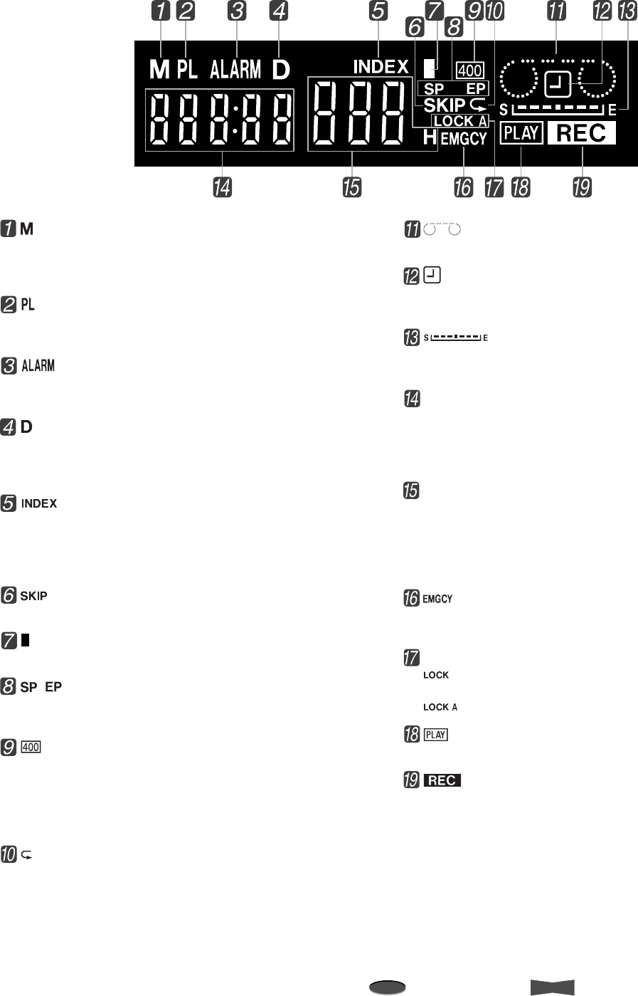
Fluorescent Display
next page
MENU button
When the VCR is turned on, press to display the <MAIN
MENU>. Press again to exit the menu.
When the VCR is turned off, press this button for more than
3 seconds to adjust the VCR’s time and date.
POWER button
Press to turn the VCR POWER on or off.
TIMER RECORD button
Press to start timer recording, when you have programmed
your VCR to record.
PAUSE/SHUTTLE HOLD button
During recording, press to stop the tape movement
temporarily. Press again to continue the recording.
During playback, press to obtain a still picture.
During special effects playback using SHUTTLE ring, press
to fix the playback speed.
PLAY button
When the VCR is in stop mode, press to playback a
previously recorded tape.
During recording, press for more than 1.5 seconds to check
recording function.
STOP button
Press to stop all tape related functions.
TRACKING POSITION
VERTICAL ADJUST
VIDEO OUT RESET
REC/PLAY
MODE
SEARCH
EJECT
MENU POWER
TIMER RECORD
PAUSE
SHUTTLE HOLD
PLAY
STOP
RECORD
COUNTER
4Introduction
Note
A point to notice
Info.
Supplementary information
Controls and Functions (Cont.)
Fluorescent Display
(Counter Memory Stop/Month) indicator
Illuminates during the counter memory stop.
Also, illuminates when the month (of time and date) is being
entered via the front panel.
(Power Loss) indicator
Illuminates when the VCR is turned on after a power failure
occurs during recording.
(Alarm Recording) indicator
Flashes during alarm recording and stays on when the alarm
recording is finished.
(Time Date Search/Day) indicator
Illuminates during the time date search.
Also, illuminates when the day (of time and date) is being
entered via the front panel.
(Index Search) indicator
Flashes when recording an index signal and illuminates
during the index number setup and the index search. (Index
number is shown on the Recording and Playback Mode
display.)
(Skip Search) indicator
Illuminates during the skip search.
(Daylight Saving Time) indicator
Illuminates when “DAYLIGHT SAVINGS” is set to “ON”.
, (Tape Speed) indicator
Indicates the tape speed.
SP is standard play; EP is extended play.
(Super Resolution) indicator
Illuminates during the recording, during the playback using a
tape recorded in Super Resolution mode and when a tape
recorded in Super Resolution mode is inserted to the VCR,
providing “SUPER RESOLUTION” in “RECORDING SET
UP” menu is set to “ON”.
(Repeat) indicator
Illuminates when “TAPE END” in “FIRST TIME SET UP”
menu is set to “REPEAT” or “ALARM•PROT”.
(Cassette Status) indicator
Illuminates when a tape is inserted.
(Timer Recording) indicator
Illuminates when the VCR is in stand-by for timer recording
or during timer recording.
(Tape Remaining) indicator
Indicates the position on the tape. S indicates the Start of
the tape and E indicates the End of the tape.
Counter/Clock display
While the VCR is turned on, indicates the relative position on
the tape. (The Counter stops counting where no recording is
made on the tape.) When it is off, (when set) the clock (24-
hour format) is shown.
Recording and Playback Mode/Index Number display
Displays the number corresponding to a selected recording
or playback mode. The mode shown here varies by the
“TAPE LENGTH” setting (T-120 or T-160) setting in “FIRST
TIME SET UP” menu. Also, displays the index number
during the index number setup and the index search.
(Emergency Recording) indicator
Illuminates when “EMERGENCY REC” in “RECORDING
SET UP” menu is set to “ON”.
Lock/Lock All indicator
: illuminates when all buttons (except RECORD
button and EJECT button) are locked.
: illuminates when all buttons are locked.
(Playback) indicator
Illuminates during playback.
(Recording) indicator
Illuminates during recording.
Introduction 5
Reference page
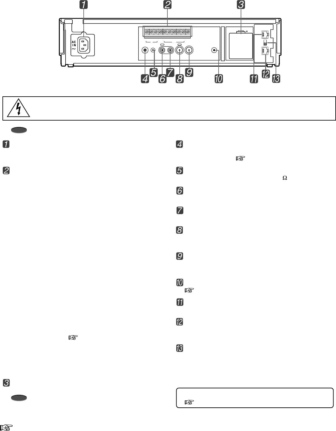
Rear View
AC power socket
This socket connects to the power cord. Insert the cord
firmly.
Input terminals
ALM IN
Use for alarm recording. The alarm sensor is connected
here.
RST IN
Use to stop alarm recording.
• When “ALARM REC DURATION” in “RECORDING
SET UP” menu is set to “MAN1”, the alarm recording
stops when a signal is input to this terminal. The alarm
reset switch is connected here.
• When set to other than “MAN1”, it can be used to
adjust the VCR’s clock.
REC IN
Use to start/stop recording or for series recording.
GND
When a lead connected to other terminals requires a ground,
connect the ground lead here.
Output terminals
ALM OUT
Use to indicate an alarm recording to an external alarm.
MODE OUT
Use to indicate the VCR’s mode of operation.
• When “MODE OUT” in “REAR TERMINAL” menu is
set to “CLOCK ADJ”, the clock of all connected VCR’s
can be adjusted. ( page 28)
CLK OUT
Use to control an external camera switcher.
CALL OUT
Use to indicate when a tape reaches its end during
recording or if there has been a problem during recording.
Battery Box
Battery is stored here.
Note
• This VCR contains a special battery. Consult your dealer
to replace it.
REMOTE jack
Remote control is possible by connecting the remote control
unit (R-9100) here. ( page 33)
MIC IN jack
Input jack for a microphone rated at 600 impedance.
AUDIO IN connector
Audio input connector (RCA pin).
AUDIO OUT connector
Audio output connector (RCA pin).
VIDEO IN connector
Input connector for video signal (BNC connector). Connect
cameras here.
VIDEO OUT connector
Output connector for video signal (BNC connector).
Connect a monitor here.
RESET button
page 38
RS-485 IN terminal (RJ-45 connector)
Input terminal to connect with a RS-485 controller.
RS-485 OUT terminal (RJ-45 connector)
Output terminal to connect with other time lapse VCR with
RS-485 interface.
TERMINATE switch
Use to setup the termination (only when using the RS-485
terminal).
ON : use to turn on the termination.
OFF : use to turn off the termination.
For the rating of each connector at the rear panel of VCR,
page 37.
AUDIO VIDEO
OUT OUTIN
REMOTE MIC
IN
RESET
ALM RST
IN
REC GND ALM
MODE
CLK
OUT
CALL
BATTERY
OPEN
RS-485
ON
IN
OUT
TERMINATE
OFF
Note
Ensure the power cord is not plugged into the outlet before connecting to any rear terminals.
Warning:
The included power cord is used for 120 V, 60 Hz.
Never connect to any outlet or power supply having a different voltage or frequency.
6
Note
A point to notice
Info.
Supplementary information
Basic Functions
Tapes can be loaded into your VCR as long as the VCR is
plugged into an outlet. Even if the VCR is turned off, loading a
tape will automatically cause it to turn on. Use only video
cassette tapes marked or .
Important notice:
• Use high grade (HG) tapes for super resolution
recording. We recommend to use S-VHS tapes for
super resolution recording at L18H-L40H mode.
• It is recommended to use T-120 tape. Do not use
tapes longer than T-160.
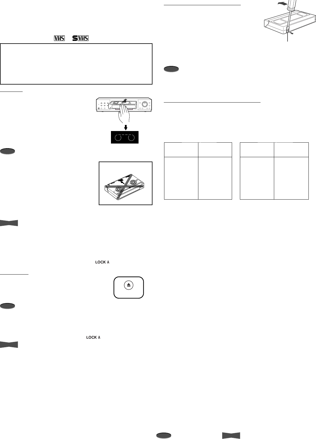
Loading
1. Insert the tape into the cassette slot
by holding it so that the long narrow
edge with the contents label faces
towards you.
• The Cassette Status indicator
illuminates on the fluorescent
display when the tape is
inserted.
Note
• Your VCR has a protection circuit
which will eject the tape if it is loaded
improperly. If the VCR ejects the
tape, remove it completely and
check that the long narrow edge with
the contents label is facing towards
you, and the clear plastic window
that shows the video tape is facing
upwards. Wait a few seconds, and
try inserting the tape again.
Info.
• The VCR automatically turns on when the tape is loaded,
AUTO POWER ON.
• The VCR automatically plays back the tape if the erase
prevention tab is removed, AUTO PLAY.
• You cannot insert a tape when all of the VCR’s all buttons
are locked and the Lock All indicator ( ) is illuminating.
Unloading
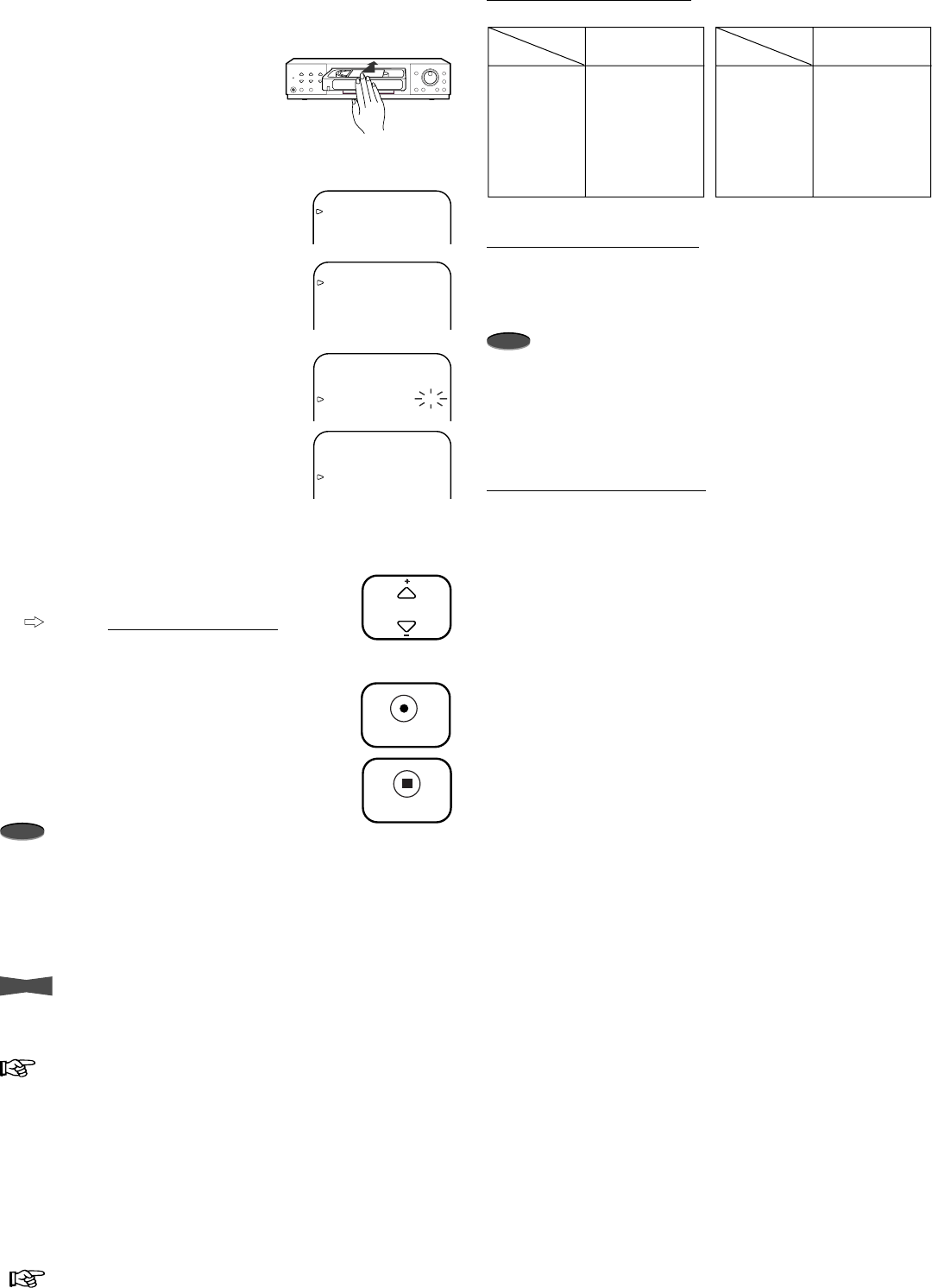
1. Press EJECT button on the front panel
of the VCR.
2. Remove the tape.
Note
• When ejecting the tape during recording, press STOP button
once to stop recording and then press EJECT button to
unload the tape.
• You cannot eject a tape when all of the VCR’s buttons are
locked and the Lock All indicator ( ) is illuminating.
Info.
• The VCR will eject a tape even if the power to the VCR is
turned off (as long as the VCR is plugged into an outlet),
POWER OFF EJECT.
erase
prevention
tab
Loading/Unloading a Tape
6H
L18H
L30H
48H
72H
96H
0H
50
35
20
20
15
15
1
Recording
time mode Number of
tape use
8H
L24H
L40H
64H
96H
128H
0H
45
30
10
5
3
3
1
Recording
time mode Number of
tape use
In case of T-120 setting In case of T-160 setting
EJECT
INCORRECT
Preventing accidental erase
Tapes come with an erase prevention
tab which, when removed, prevents the
tape’s contents from being erased or
recorded over. If the tape you insert in
the VCR has the erase prevention tab
removed, your VCR will automatically
eject it if you attempt to record on it.
Note
• We recommend that you take any broken or torn tapes to a
professional for repair. The adhesives on many common
types of tape could damage the head of your VCR.
Recommended number of tape use
It is recommended that the cassette tape be replaced with a new
one depending on the recording time mode and type of tape
used. Providing TAPE LENGTH of FIRST TIME SET UP menu is
set to the same type the tape you use.
7
Reference page Basic Functions
1. Turn on the VCR and peripheral devices.
2. Load a tape with an erase
prevention tab intact.
Steps 3 to 7 for activating Super Resolution recording mode.
3. Press MENU button.
•<MAIN MENU> appears.
4. Turn JOG to select RECORDING SET
UP and turn SHUTTLE to the right.
•<RECORDING SET UP> menu
appears.
5. Turn JOG to select SUPER
RESOLUTION and turn SHUTTLE to
the right.
6. Turn JOG to select ON and turn
SHUTTLE to the right.
7. Press MENU button.
• The day and present time display
appears on screen.
8. Press REC/PLAY MODE button to select
the desired recording mode.
Refer to Recording/playback time on
the next column for the actual
recording/playback time .
9. Press RECORD button to begin recording.
10. Press STOP button to stop recording.
Note
• If the tape you insert in your VCR has the erase prevention
tab removed, your VCR will automatically eject it if you
attempt to record on it.
• The RECORD button will not function unless a tape is in stop
or pause mode.
• A tape recorded by this VCR may not be played back correctly
by another VCR.
Info.
• Press the PAUSE button to momentarily stop recording.
Press it again to resume recording. To protect the tape, the
pause mode is automatically cancelled after about 5 minutes.
page 32 for the VCR’s function when the tape reaches its
end during recording.
Manual Recording
REC/PLAY
MODE
RECORD
STOP
<MAIN MENU>
DISPLAY
TIMER PROGRAM
RECORDING SET UP
REAR TERMINAL
<RECORDING SET UP>
ALARM REC MODE 6H
ALARM REC DURATION 1M
EMERGENCY REC OFF
SUPER RESOLUTION OFF
ONE SHOT•FIELD 1
ONE SHOT•INTERVAL SHOT
<RECORDING SET UP>
ALARM REC MODE 6H
ALARM REC DURATION 1M
EMERGENCY REC OFF
SUPER RESOLUTION OFF
ONE SHOT•FIELD 1
ONE SHOT•INTERVAL SHOT
<RECORDING SET UP>
ALARM REC MODE 6H
ALARM REC DURATION 1M
EMERGENCY REC OFF
SUPER RESOLUTION ON
ONE SHOT•FIELD 1
ONE SHOT•INTERVAL SHOT
Recording/playback time
Audio recording/playback
The 2H (playback only), 6H, 8H modes and the modes with the
letter “L” (L18H, L24H, L30H and L40H) are for audio recording
and playback on the linear track.
Note
• Audio will not be recorded if cables for audio are not
connected to the AUDIO IN connector or the microphone is
not connected to the MIC IN jack.
• The longer the recording mode is set, the worse the sound
quality gets. In L30H or L40H mode, the sound quality is of
the degree that the speaking voice can be heard.
Recording Check Function
When the VCR is recording, press the PLAY button for more than
1.5 seconds and then release. The tape will rewind a little and
then playback the recording just made. When the tape reaches
the position where the PLAY button was pressed, the VCR starts
recording again.
* is for playback only
T-120 T-160
TAPE LENGTH
setting
2H*
6H
L18H
L30H
48H
72H
96H
2:00
6:00
18:00
30:00
54:00
78:00
102:00
2:40
8:00
24:00
40:00
72:00
104:00
136:00
2H*
8H
L24H
L40H
64H
96H
128H
Recording
time mode
TAPE LENGTH
setting
Recording
time mode
(hours : minutes)
8
Note
A point to notice
Info.
Supplementary information
Basic Functions
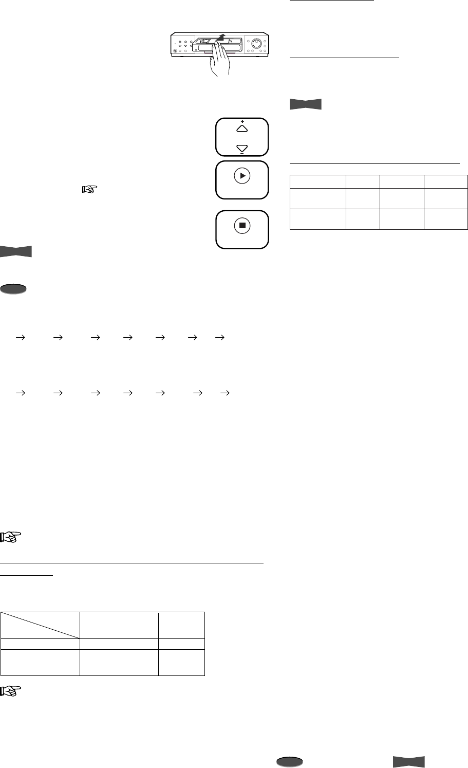
1. Turn on the VCR and peripheral devices.
2. Load a pre-recorded tape.
3. Repeat steps 3 to 7 in Manual
Recording for activating Super Resolution
playback mode.
4. Press REC/PLAY MODE button to select
the desired playback mode.
5. Press PLAY button to start playback.
• If noise occurs during playback, adjust
the tracking, page 17.
6. Press STOP button to stop playback.
Info.
• VCR automatically plays back the tape of which the erase
prevention tab removed, AUTO PLAY.
Note
• Playback mode
When TAPE LENGTH in FIRST TIME SET UP menu is set
to T-120, the playback mode is switched in the order of 6H
L18H L30H 48H 72H 96H 0H 6H... (for
a tape recorded in the recording mode longer than 6H
mode).
When TAPE LENGTH in FIRST TIME SET UP menu is set
to T-160, the playback mode is switched in the order of 8H
L24H L40H 64H 96H 128H 0H 8H...
(for a tape recorded in the recording mode longer than 8H
mode).
– A tape recorded in SP mode using other VCR can only
be played back in 2H mode.
• Picture jitter or noise may occur when the tape is played
back in L18H, L24H, L30H or L40H mode even if the tape
was recorded in its respective mode.
• When a pre-recorded tape is used for recording, the colored
noise may appear on the beginning of the playback picture.
• There is normal sound playback only when a tape recorded in
6H, 8H, L18H, L24H, L30H or L40H mode is played back in
its respective mode.
page 18-19 to find a picture you wish to view.
When the tape reaches its end during playback/fast
forwarding
VCR’s function varies by the setting of TAPE END in the FIRST
TIME SET UP menu.
page 32 for TAPE END setting.
VCR’s function
Fast
Forward
Playback
TAPE END
setting
STOP or REWIND
REPEAT or
ALARM•PROT
Stop
VCR automatically rewinds
to the beginning of the tape
and stops.
Stop
Stop
REC/PLAY
MODE
STOP
PLAY
Rewinding a tape
While the tape is stopped, turn SHUTTLE to the left.
To stop rewinding, press STOP button.
Fast forwarding a tape
While the tape is stopped, turn SHUTTLE to the right.
To stop fast forwarding, press STOP button.
Info.
• The fast forward/rewind time of a T-120 tape is approximately
2 minutes, however, the time varies by the type of a tape you
use.
Audio playback and picture quality
2H/6HPlayback mode
Audio
playback Very
good
Picture
Quality
48H-128HL18H-L40H
Not
available
Good
GoodGood
Very
good
Playback
9
Reference page Basic Functions
JOG dial
SHUTTLE ring
Info.
Use of JOG dial and SHUTTLE ring for menu setting
JOG dial
•Use JOG by placing a finger in the indent and turning.
• Turning JOG to the right moves the selection forward.
Turning it to the left moves the selection back.
• If the selection is not flashing, turn JOG to the right to move
the cursor ( ) down one position then to the left to move
back to your selection.
SHUTTLE ring
• If you turn SHUTTLE to the right/left end and release it,
SHUTTLE comes back to the center position automatically.
• Navigate to the next menu layer by turning SHUTTLE to the
right. Return to the previous menu layer by turning
SHUTTLE to the left.
Adjusting the Clock
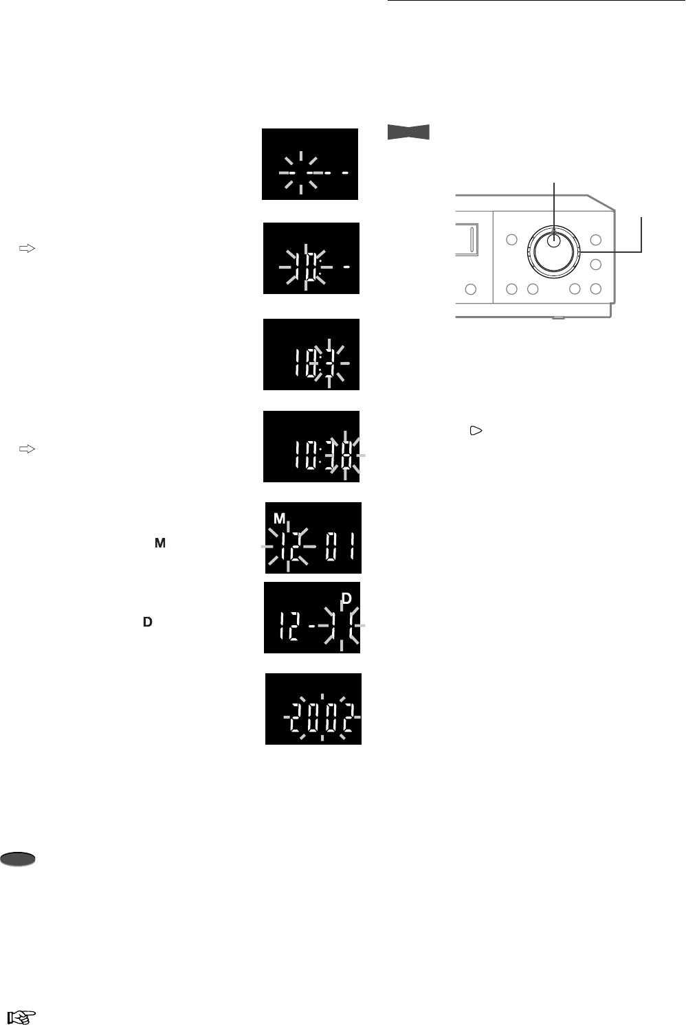
You can adjust the VCR’s clock from the front panel, even though
the VCR is turned off. This function lets you to set the information
in the order of time, month, day and year. The hour time is
entered twice. This is due to the daylight saving time.
Example : Setting the day and present time to 10:38 a.m., 11th
December, 2002.
1. When the VCR and peripheral devices
are turned off, press MENU button for
more than 3 seconds.
• The hour digits of the clock on the
fluorescent display starts flashing.
2. Turn JOG to set the hour digits.
When the flashing item is same as the
current time, turn SHUTTLE without
turning JOG.
3. Turn SHUTTLE to the right to make the
10-minute digit flash and turn JOG to
adjust.
4. Turn SHUTTLE to the right to make the 1-
minute digit flash and turn JOG to adjust.
To finish the clock adjustment now,
press MENU button for more than 3
seconds.
5. Turn SHUTTLE to the right to make the
month digits flash and turn JOG to adjust.
• The Month indicator ( ) illuminates.
6. Turn SHUTTLE to the right to make the
day digits flash and turn JOG to adjust.
• The Day indicator ( ) illuminates.
7. Turn SHUTTLE to the right to make the
year digits flash and turn JOG to adjust.
8. Turn SHUTTLE to the right.
• The VCR’s clock is set now.
9. Repeat steps 1 and 2 and turn SHUTTLE to the left to exit
after hour mark is entered the second time.
Note
• Time and Date information can also be entered via the Menu
System (FIRST TIME SETUP/TIME DATE ADJUST).
When adjusting the clock to the exact second
Set the clock as described to the left, but set 1-minute digit to one
or two minutes ahead of the reference time being used. After the
step 7 to the left, when reference time reaches 00 second of the
minute you have chosen, turn SHUTTLE to the right. The VCR’s
clock now corresponds to the reference time to the nearest
second.
10 Advanced Functions
Note
A point to notice
Info.
Supplementary information
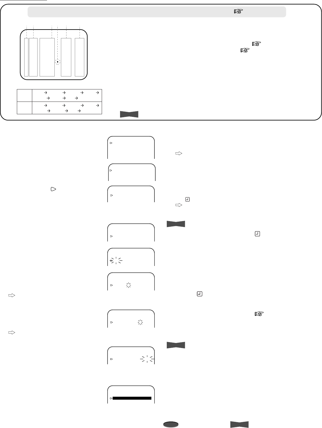
Recording Techniques
<PROGRAM TO RECORD>
DW START END HR
1 --- --:-- --:-- ------
2 --- --:-- --:-- ------
3 --- --:-- --:-- ------
4 --- --:-- --:-- ------
5 --- --:-- --:-- ------
6 --- --:-- --:-- ------
7 --- --:-- --:-- ------
8 --- --:-- --:-- ------
165432 1) Program number
Up to 8 programs can be set.
2) Day of the week display
• Display HLD to apply HOLIDAY SET UP setting ( next page).
• Display SPL to apply SPECIAL DW setting ( next page).
• Display DAY to record at the programmed time everyday.
3) Recording start-time
4) Next day indicator (•)
Recording continues to the following day.
5) Recording end-time
6) Recording mode
• Recording mode varies by the TAPE LENGTH setting of FIRST
TIME SET UP menu. See the table shown to the left.
• Timer recording will not be performed when set to SKIP.
Info.
• Time is displayed in 24-hour format.
Accurately preset the day and present time before timer programming. ( page 9 or 28)
Timer Recording
<MAIN MENU>
DISPLAY
TIMER PROGRAM
RECORDING SET UP
REAR TERMINAL
MAINTENANCE
CLOCK/FIRST TIME SET UP
<TIMER PROGRAM>
PROGRAM TO RECORD
HOLIDAY SET UP
SPECIAL DW MON-SAT
<PROGRAM TO RECORD>
DW START END HR
1 DAY 08:00 20:00 L30EP
2 --- --:-- --:-- ------
3
--- --
:
-- --
:
-- ------
<PROGRAM TO RECORD>
DW START END HR
1 DAY 08:00 20:00 L30EP
2 --- --:-- --:-- ------
3 --- --:-- --:-- ------
<PROGRAM TO RECORD>
DW START END HR
1 DAY 08:00 20:00 L30EP
2 TUE --:-- --:-- ------
3 --- --:-- --:-- ------
<PROGRAM TO RECORD>
DW START END HR
1 DAY 08:00 20:00 L30EP
2 TUE 12:00 --:-- ------
3 --- --:-- --:-- ------
<PROGRAM TO RECORD>
DW START END HR
1 DAY 08:00 20:00 L30EP
2 TUE 12:00 15:00 ------
3 --- --:-- --:-- ------
<PROGRAM TO RECORD>
DW START END HR
1 DAY 08:00 20:00 L30EP
2 TUE 12:00 15:00 L18EP
3 --- --:-- --:-- ------
<PROGRAM TO RECORD>
DW START END HR
1 DAY 08:00 20:00 L30EP
2TUE 12:00 15:00 L18EP
3 --- --:-- --:-- ------
Example : Setting number 2 to L18H mode timer recording from
12:00 to 15:00 every Tuesday.
1. Press MENU button.
•<MAIN MENU> appears.
2. Turn JOG to select TIMER PROGRAM
and turn SHUTTLE to the right.
•<TIMER PROGRAM> menu appears.
3. When the cursor ( ) is next to
PROGRAM TO RECORD, turn
SHUTTLE to the right.
•<PROGRAM TO RECORD> menu
appears.
4. Turn JOG to select the program
number and turn SHUTTLE to the right
to select.
5. In the DW column, turn JOG to select
the Day of the Week. Turn SHUTTLE to
the right to select.
6. In the START column, turn JOG to
select the
hour
digits of the start time.
Turn SHUTTLE to the right when done.
Set the
10-minutes
digit and
1-
minute
digit in a similar fashion.
7. In the END column, turn JOG to select
the
hour
digits of the end time. Turn
SHUTTLE to the right when done.
Set the
10-minute
digit and
1-minute
digit in a similar fashion.
8. In the HR column, turn JOG to select
the RECORDING mode.
Setup step 9 to make recording while the REC IN terminal is
grounded. If not, go to step 10.
9. Press MENU button.
• The program you are currently
setting is highlighted.
• Press MENU button again to
cancel.
10. Turn SHUTTLE to the right when done. (Cursor flashing will
stop.)
• If the program has not been set completely, the DW
column will continue to flash.
Repeat steps 4 to 10 to set 2 or more programs at once.
11. Press MENU button.
• The day and present time display appears on screen.
12. Press TIMER RECORD button.
• The VCR is turned off and the Timer Recording indicator
() illuminates on the fluorescent display.
When TIMER RECORD button is pressed during the
programmed period, the VCR starts recording
immediately.
Info.
When the Timer Recording indicator ( ) starts flashing, check for
the following conditions:
a) A tape is not inserted.
b) A tape without erase prevention tab is inserted.
c) Day and present time has not been set.
d) Timer program has not been set.
e) Menu item has been set (flashing).
– Remedy -
1. Press TIMER RECORD button to turn off the Timer Recording
indicator( ).
2. a) Insert a tape.
b) Insert a tape with erasure prevention tab intact.
c) Set the day and present time ( page 9 or 28)
d) Confirm the program.
e) Turn SHUTTLE to the right to stop flashing.
3. Press TIMER RECORD button to turn on the Timer Recording
indicator.
Info.
• To erase a program:
Select the program number you wish to erase, turn SHUTTLE
to the right (DW column flashes) and then turn SHUTTLE to
the left.
T-120
T-160 8EP L24EP L40EP 64EP
96EP 128EP 0EP SKIP
6EP L18EP L30EP 48EP
72EP 96EP 0EP SKIP
11Advanced Functions
Reference page
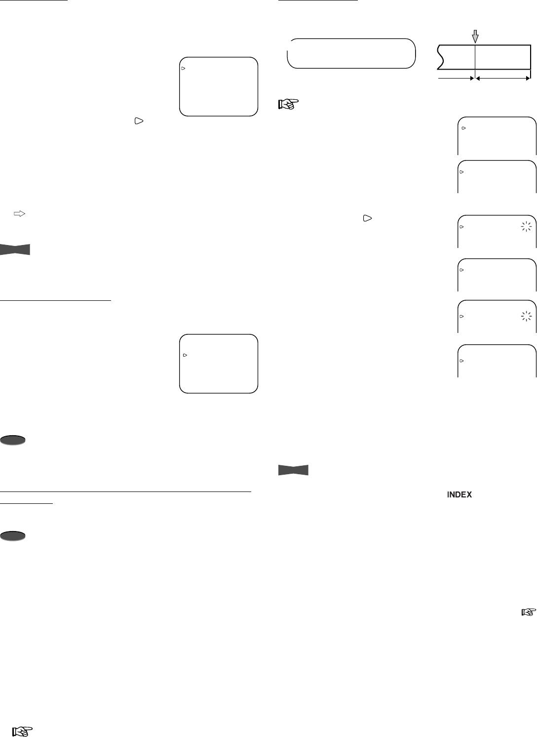
Alarm Recording
If an alarm occurs, the VCR switches to alarm recording.
page 26 for alarm recording connection
Example)
When ALARM REC MODE is set to L30H and
ALARM REC DURATION is 10 min.
Alarm signal input
L30H
Recording
10 min
Recording Alarm Recording
<MAIN MENU>
DISPLAY
TIMER PROGRAM
RECORDING SET UP
REAR TERMINAL
MAINTENANCE
CLOCK/FIRST TIME SET UP
<RECORDING SET UP>
ALARM REC MODE 6H
ALARM REC DURATION 1M
EMERGENCY REC OFF
SUPER RESOLUTION ON
ONE SHOT•FIELD 1
<RECORDING SET UP>
ALARM REC MODE 6H
ALARM REC DURATION 1M
EMERGENCY REC OFF
SUPER RESOLUTION ON
ONE SHOT•FIELD 1
<RECORDING SET UP>
ALARM REC MODE L30H
ALARM REC DURATION 1M
EMERGENCY REC OFF
SUPER RESOLUTION ON
ONE SHOT•FIELD 1
<RECORDING SET UP>
ALARM REC MODE L30H
ALARM REC DURATION 1M
EMERGENCY REC OFF
SUPER RESOLUTION ON
ONE SHOT•FIELD 1
<RECORDING SET UP>
ALARM REC MODE L30H
ALARM REC DURATION 10M
EMERGENCY REC OFF
SUPER RESOLUTION ON
ONE SHOT•FIELD 1
Special day of the week
Set the recording period by specifying the start and end day of
the week for timer recording.
1. Display <TIMER PROGRAM> menu.
2. Turn JOG to select SPECIAL DW and
turn SHUTTLE to the right.
3. Turn JOG to set the start and end day
of the week, and turn SHUTTLE to the
right.
4. Press MENU button.
• The day and present time display appears on screen.
Note
• Start day of the week and end day of the week cannot be
identical.
When the recording period of 2 or more programs are
overlapped
The VCR always gives priority to the higher-numbered program.
Note
• To make sure that the HOLIDAY SET UP setting is applied
correctly, set a timer program with HLD in DW column to the
higher-numbered program.
<TIMER PROGRAM>
PROGRAM TO RECORD
HOLIDAY SET UP
SPECIAL DW MON-SAT
Holiday set up
Up to 20 days per year can be set for Holiday for when the timer
recording will be performed, or if HR in PROGRAM TO
RECORD menu is set to SKIP, the timer recording will not be
performed during the programmed period.
1. Display <TIMER PROGRAM> menu.
2. Turn JOG to select HOLIDAY SET UP
and turn SHUTTLE to the right.
•<HOLIDAY SET UP> menu
appears.
3. Turn JOG to move the cursor ( ) and
turn SHUTTLE to the right.
• Each time JOG is turned to the right, the cursor moves
towards right-forward direction.
4. Turn JOG to select the month you want, and turn SHUTTLE
to the right.
5. Turn JOG to select the day you want, and turn SHUTTLE to
the right.
Repeat steps 3 to 5 to set 2 or more days at once.
6. Press MENU button.
• The day and present time display appears on screen.
Info.
• To erase the pre-set month and day, turn SHUTTLE to the
left while the month item is flashing.
<HOLIDAY SET UP>
01/01 01/15 02/11 03/22
04/29 05/03 05/04 05/05
07/20 09/15 09/23 10/10
11/03 11/23 12/23 - - / - -
- - / - - - - / - - - - / - - - - / - -
MONTH / DAY
1. Press MENU button.
• <MAIN MENU> appears.
2. Turn JOG to select RECORDING SET
UP and turn SHUTTLE to the right.
•<RECORDING SET UP> menu
appears.
3. When the cursor ( ) is next to ALARM
REC MODE, turn SHUTTLE to the
right.
4. Turn JOG to set the alarm recording
mode you want and turn SHUTTLE to
the right.
5. Turn JOG to select ALARM REC
DURATION and turn SHUTTLE to the
right.
6. Turn JOG to set the alarm recording
duration you want and turn SHUTTLE
to the right.
• When set to MAN 1, alarm
recording continues until RST IN terminal is grounded.
• When set to MAN 2, alarm recording continues while ALM
IN terminal is grounded.
7. Press MENU button.
• The day and present time display appears on screen.
Info.
• The index signal is automatically recorded when an alarm
recording begins. (The Index indicator ( ) flashes on the
fluorescent display).
• Even if an alarm recording is proceeding, the new alarm
recording starts when the next alarm signal is input. (While
an index signal is being recorded and then the next alarm
signal is input, the second signal may not be detected during
skip or index search.)
• An alarm recording continues until its end during timer
recording, even if the timer recording end-time is reached.
• An alarm recording will be cancelled if the tape reaches its end.
• If the interval between two alarm recording start-times is too
short, the skip or index search may not function correctly. (
for the minimum interval between two alarm recording start-
times, go to page 18)
12 Advanced Functions
Note
A point to notice
Info.
Supplementary information
Alarm recording counter
01-01-’02 09:30:00 A0001
<RECORDING SET UP>
ALARM REC MODE L30H
ALARM REC DURATION 10M
EMERGENCY REC ON
SUPER RESOLUTION ON
ONE SHOT•FIELD 1
ONE SHOT•INTERVAL SHOT
Emergency Recording
The VCR automatically starts an alarm recording when an alarm
signal is input even if the VCR is in stop mode, turned off or in
stand-by for timer recording. After an emergency recording, the
VCR automatically returns to its original state.
1. After step 6 of
Alarm Recording
, turn
JOG to select EMERGENCY REC and
turn SHUTTLE to the right.
2. Turn JOG to select ON and turn
SHUTTLE to the right.
• The Emergency Recording indicator
() illuminates on the fluorescent display.
Display during alarm recording
• During the alarm recording, the alarm
recording counter will automatically be
displayed on screen if DISPLAY MODE
( page 30) is set to 1, 2 or 3.
• The Alarm Recording indicator ( ) on
the fluorescent display flashes during
alarm recording and stays on when the
alarm recording is finished.
• The alarm recording counter shows up to 9999 alarm
recordings, then it is reset to 0000 and continues counting.
• When initializing the alarm recording list, the alarm recording
counter will also be reset.
Series Recording 1
Series recording is possible if two or more of these units are
connected. When the first VCR’s tape reaches its end or an
error occurs on VCR, the second VCR automatically begins
recording.
1. Press MENU button.
• <MAIN MENU> appears.
2. Turn JOG to select REAR TERMINAL
and turn SHUTTLE to the right.
•<REAR TERMINAL> menu
appears.
Step 3 and 4 on 1st VCR only:
3. When the cursor ( ) is next to CALL
OUT, turn SHUTTLE to the right.
4. Turn JOG to select WRNG•TAPE END
and turn SHUTTLE to the right.
Step 5 and 6 on 2nd VCR only:
5. Turn JOG to select REC IN and turn
SHUTTLE to the right.
6. Turn JOG to select SERIES and turn
SHUTTLE to the right.
7. Press MENU button.
• The day and present time display appears on screen.
<MAIN MENU>
DISPLAY
TIMER PROGRAM
RECORDING SET UP
REAR TERMINAL
MAINTENANCE
<REAR TERMINAL>
CALL OUT WRNG
CLOCK OUT REC- 1
MODE OUT REC
REC IN REC-START/STOP
<REAR TERMINAL>
CALL OUT WRNG
CLOCK OUT REC- 1
MODE OUT REC
REC IN REC-START/STOP
<REAR TERMINAL>
CALL OUT WRNG•TAPE END
CLOCK OUT REC- 1
MODE OUT REC
REC IN REC-START/STOP
<REAR TERMINAL>
CALL OUT WRNG
CLOCK OUT REC- 1
MODE OUT REC
REC IN REC-START/STOP
<REAR TERMINAL>
CALL OUT WRNG
CLOCK OUT REC- 1
MODE OUT REC
REC IN SERIES
<MAIN MENU>
DISPLAY
TIMER PROGRAM
RECORDING SET UP
REAR TERMINAL
MAINTENANCE
CLOCK/FIRST TIME SET UP
<FIRST TIME SET UP>
TIME DATE ADJUST
TAPE END STOP
QUASI V-SYNC ON
VIDEO MODE AUTO
TAPE LENGTH T-120
<FIRST TIME SET UP>
TIME DATE ADJUST
TAPE END STOP
QUASI V-SYNC ON
VIDEO MODE AUTO
TAPE LENGTH T-120
<FIRST TIME SET UP>
TIME DATE ADJUST
TAPE END REWIND
QUASI V-SYNC ON
VIDEO MODE AUTO
TAPE LENGTH T-120
Series Recording 2
Series Recording 2
provides a function: when the first VCR’s tape
reaches its end, the second VCR automatically begins recording.
When the tape in second VCR finishes, the first VCR starts
recording again. (The two VCRs keep recording one after
another.) Setup both 1st and 2nd VCRs as in the steps below.
1. Repeat step 1 to 6 of
Series Recording 1
.
Steps 3 to 6 must be set to both 1st and 2nd VCRs.
2. Turn SHUTTLE to the left.
• <MAIN MENU> appears.
3. Turn JOG to select CLOCK/FIRST
TIME SET UP and turn SHUTTLE to
the right.
•<FIRST TIME SET UP> menu
appears.
4. Turn JOG to select TAPE END and turn
SHUTTLE to the right.
5. Turn JOG to select REWIND and turn
SHUTTLE to the right.
6. Press MENU button.
• The day and present time display appears on screen.
page 27 for series recording connection
Note
• Timer or emergency recording function cannot be used with
series recording at the same time.
Recording Techniques (Cont.)
13Advanced Functions
Reference page
<MAIN MENU>
DISPLAY
TIMER PROGRAM
RECORDING SET UP
REAR TERMINAL
MAINTENANCE
<RECORDING SET UP>
ALARM REC MODE 6H
ALARM REC DURATION 1M
EMERGENCY REC OFF
SUPER RESOLUTION ON
ONE SHOT•FIELD 1
ALARM REC MODE 6H
ALARM REC DURATION 1M
EMERGENCY REC OFF
SUPER RESOLUTION ON
ONE SHOT•FIELD 1
ONE SHOT•INTERVAL 10S
ALARM
REC
MODE
6
H
ALARM REC DURATION 1M
EMERGENCY REC OFF
SUPER RESOLUTION ON
ONE SHOT•FIELD 5
ONE SHOT•INTERVAL 10S
ALARM REC DURATION 1M
EMERGENCY REC OFF
SUPER RESOLUTION ON
ONE SHOT•FIELD 5
ONE SHOT•INTERVAL 10S
One shot/Interval Recording
One shot recording allows you to control the number of fields to
be recorded when the RECORD button is pressed or the REC IN
terminal is grounded. Interval recording is made at the selected
number of fields and at the selected interval.
1. Press REC/PLAY MODE button on the front panel to set the
recording mode to 0H.
2. Press MENU button.
•<MAIN MENU> appears.
3. Turn JOG to select RECORDING SET
UP and turn SHUTTLE to the right.
•<RECORDING SET UP> menu
appears.
4. Turn JOG to select ONE SHOT•FIELD
and turn SHUTTLE to the right.
5. Turn JOG to select the number of
recording field and turn SHUTTLE to
the right.
6. Turn JOG to select ONE
SHOT•INTERVAL and turn SHUTTLE
to the right.
For one shot recording, setup step 7 only:
7. Turn JOG to select SHOT and turn
SHUTTLE to the right.
For interval recording, setup step 8 only:
8. Turn JOG to select the recording
interval and turn SHUTTLE to the right.
9. Press RECORD button.
• The one shot recording will be on standby mode.
• The VCR starts the interval recording with the interval time
selected in step 8 above.
10. To start one shot recording, press RECORD button again or
switch the REC IN terminal on the rear panel to the ground.
ALARM REC DURATION 1M
EMERGENCY REC OFF
SUPER RESOLUTION ON
ONE SHOT•FIELD 5
ONE SHOT•INTERVAL SHOT
ALARM REC DURATION 1M
EMERGENCY REC OFF
SUPER RESOLUTION ON
ONE SHOT•FIELD 5
ONE SHOT•INTERVAL 30S
Remote Recording
This function permits you to control the start/end of recording
from the remote place. The VCR starts recording while the REC
IN terminal is grounded.
1. Display <REAR TERMINAL> menu.
2. Set REC IN to REC-START/STOP.
3. Press MENU button.
• The day and present time display
appears on screen.
page 27 for remote recording connection.
Note
• An index signal will not be recorded during remote recording.
• Series or timer recording function cannot be used with remote
recording at the same time.
Repeat Recording
With this function, when the tape reaches its end during
recording, the VCR rewinds the tape and starts recording again.
1. Press MENU button.
•<MAIN MENU> appears.
2. Turn JOG to select CLOCK/FIRST
TIME SET UP and turn SHUTTLE to
the right.
•<FIRST TIME SET UP> menu
appears.
3. Turn JOG to select TAPE END and turn
SHUTTLE to the right.
4. Turn JOG to select REPEAT or
ALARM•PROT and turn SHUTTLE to
the right.
Refer to the table below for
REPEAT and ALARM•PROT.
Repeat indicator ( ) illuminates on
the fluorescent display.
5. Press MENU button.
• The day and present time display appears on screen.
<REAR TERMINAL>
CALL OUT WRNG•TAPE END
CLOCK OUT REC- 1
MODE OUT REC
REC IN REC-START/STOP
<MAIN MENU>
DISPLAY
TIMER PROGRAM
RECORDING SET UP
REAR TERMINAL
MAINTENANCE
CLOCK/FIRST TIME SET UP
<FIRST TIME SET UP>
TIME DATE ADJUST
TAPE END STOP
QUASI V-SYNC ON
VIDEO MODE AUTO
TAPE LENGTH T-120
BUZZER WRNG
<FIRST TIME SET UP>
TIME DATE ADJUST
TAPE END STOP
QUASI V-SYNC ON
VIDEO MODE AUTO
TAPE LENGTH T-120
BUZZER WRNG
<FIRST TIME SET UP>
TIME DATE ADJUST
TAPE END REPEAT
QUASI V-SYNC ON
VIDEO MODE AUTO
TAPE LENGTH T-120
BUZZER WRNG
TAPE END
setting
REPEAT
REWIND
ALARM•
PROT
STOP The tape stops.
When there are alarm
recordings on tape When there is NO alarm
recording on tape
The tape stops.(*)
The tape is rewound
automatically to the
beginning and then
recording is resumed.
The tape is rewound automatically to the
beginning (except in timer recording) and
then stops.
The tape is rewound automatically to the
beginning and then recording is resumed
(also recording over existing alarms).
When the tape reaches its end during recording
The following functions are automatically engaged when the tape
ends during recording.
* To repeat recording on the same tape again, eject the tape
once and reinsert.
14 Advanced Functions
Note
A point to notice
Info.
Supplementary information
Synchronous Recording
A number of camera images can be mixed together through a
camera switcher and then recorded separetely onto several
VCRs. A camera is assigned to each VCR with the VCR
recording only the camera image it has been assigned. This
allows recording without gaps.
If you have 3 VCRs, the video signal from 3 cameras can be
recorded separetely by connecting the switcher as shown below:
1. Press MENU button.
•<MAIN MENU> appears.
2. Turn JOG to select REAR TERMINAL
and turn SHUTTLE to the right.
•<REAR TERMINAL> menu
appears.
3. Turn JOG to select REC IN and turn
SHUTTLE to the right.
Steps 4 to 7 on VCR1 only:
4. Turn JOG to select SERIES or REC-
START/STOP and turn SHUTTLE to
the right.
• If the recording start signal is
available on the switcher, select
SYNC REC.
5. Turn JOG to select CLOCK OUT and
turn SHUTTLE to the right.
6. Turn JOG to select T/L-REC and turn
SHUTTLE to the right.
7. Turn JOG to select F and turn
SHUTTLE to the right.
Step 8 on all VCRs except VCR1:
8. Turn JOG to select SYNC REC and
turn SHUTTLE to the right.
9. Press MENU button.
• The day and present time appears on screen.
page 27 for synchronous recording connection.
REC REC REC
REC REC REC
REC REC REC
CAMERA1 CAMERA2 CAMERA3 CAMERA1 CAMERA2 CAMERA3 CAMERA1 CAMERA2
V-SYNC
SWITCHER / switching
cameras
/ recording
start signal
VCR1 / recording
/ clock out
VCR2 / recording
/ clock out
VCR3 / recording
/ clock out
VCRRecording time mode
L18H, L24H
L30H, L40H 3
5
Number of cameras
Multiple of 3
Multiple of 5
<MAIN MENU>
DISPLAY
TIMER PROGRAM
RECORDING SET UP
REAR TERMINAL
MAINTENANCE
<REAR TERMINAL>
CALL OUT WRNG•TAPE END
CLOCK OUT REC- 1
MODE OUT REC
REC IN SERIES
<REAR TERMINAL>
CALL OUT WRNG•TAPE END
CLOCK OUT REC- 1
MODE OUT REC
REC IN SERIES
<REAR TERMINAL>
CALL OUT WRNG•TAPE END
CLOCK OUT REC- 1
MODE OUT REC
REC IN REC-START/STOP
<REAR TERMINAL>
CALL OUT WRNG•TAPE END
CLOCK OUT REC- 1
MODE OUT REC
REC IN SERIES
<REAR TERMINAL>
CALL OUT WRNG•TAPE END
CLOCK OUT T/L REC- 1
MODE OUT REC
REC IN SERIES
<REAR TERMINAL>
CALL OUT WRNG•TAPE END
CLOCK OUT T/L REC- F
MODE OUT REC
REC IN SERIES
<REAR TERMINAL>
CALL OUT WRNG•TAPE END
CLOCK OUT REC- 1
MODE OUT REC
REC IN SYNC REC
Note
• The recording mode must be set to L18H, L24H, L30H or
L40H.
• The suitable number of VCRs and cameras to be connected
are shown below:
Recording Techniques (Cont.)
15Advanced Functions
Reference page
Additional Features
Memory backup in case of power failure
This VCR includes a built-in backup memory, so the preset day
and present time will remain in memory even if there is a power
failure. However, if the power cord is disconnected for a long
period of time (2-3 months), the present time may not be
accurate. In this case, set the clock again.
Info.
• The battery is fully charged if the VCR’s power cord is
plugged into the outlet for 40 or more hours per week.
• If the battery is fully charged, even if the power cord is not
plugged in, the following settings will remain in memory for
up to 31 days:
– The day and present time display
– Timer program
– Alarm list/Power loss list
– Number of tape uses/Elapsed time of the VCR
– Counter display
– Recording/Playback mode
Note
• When ALARM REC DURATION of the RECORDING SET
UP menu is set to MAN1 or MAN2 and a power failure
occurs during the alarm recording, the VCR may not return
to the alarm recording mode when the power comes back
on.
After a power failure
If a power failure occurs during manual,
timer or alarm recording, the VCR will
return to the recording mode when the
power comes back on. The Power Failure
symbol (X) will be displayed for about 1
minute on screen and the Power Loss
indicator ( ) will illuminate on the
fluorescent display when the power comes
back on. If a power failure occurs while the
VCR’s power is on, the VCR will turn on by
itself when the power comes back on.
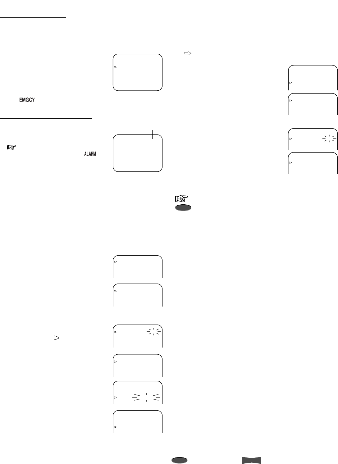
Displaying/clearing the power loss list
Displaying the power loss list
The power failure start time is logged in the VCR’s Power Loss
List. To view the list, please follow the steps listed below.
1. Press MENU button.
•<MAIN MENU> appears.
2. Turn JOG to select MAINTENANCE
and turn SHUTTLE to the right.
•<MAINTENANCE> menu appears.
3. Turn JOG to select POWER LOSS
LIST and turn SHUTTLE to the right.
•<POWER LOSS LIST> appears.
4. Press MENU button.
• The day and present time appears
on screen.
Note
• Up to 3 power failure start times will be displayed. If more
than 3 failures have occurred, the first start time and the last
2 start times will be displayed on the list.
01-01-’02 TUE
00:00:00 X L30
<MAINTENANCE>
POWER LOSS LIST
ALARM LIST
ALL MENU INITIALIZE
POWER LOSS LIST CLEAR
ALARM LIST CLEAR
<REPEAT REC TIMES> 0
<ELAPSED TIME> 0H
<POWER LOSS LIST>
01 01-31-’02 00:00
02
03
Clearing the power loss list
1. Select POWER LOSS LIST CLEAR in
<MAINTENANCE> menu and turn
SHUTTLE to the right.
2. Turn SHUTTLE to the left to clear the
list.
•<MAINTENANCE> menu appears.
To exit the menu without clearing
the list, press MENU button.
3. Press MENU button.
• Once the list is cleared, the Power Loss indicator ( ) will
go off.
Displaying/clearing the alarm list
Displaying the alarm list
The alarm recording start time/date are logged in the VCR’s
Alarm List. To view the list, please follow the steps listed below.
1. Press MENU button.
•<MAIN MENU> appears.
2. Turn JOG to select MAINTENANCE
and turn SHUTTLE to the right.
•<MAINTENANCE> menu appears.
3. Turn JOG to select ALARM LIST and
turn SHUTTLE to the right.
•<ALARM LIST> appears.
4. Press MENU button.
• The day and present time appears
on screen.
Note
• Maximum of 9,999 alarm recording start times will be
counted.
• Up to 8 alarm recording start times/dates will be displayed.
If more than 8 alarm recordings have occurred, the first start
time and the last 7 start times will be displayed on the list.
Clearing the alarm list
1. Select ALARM LIST CLEAR in
<MAINTENANCE> menu and turn
SHUTTLE to the right.
2. Turn SHUTTLE to the left to clear the
list.
•<MAINTENANCE> menu appears.
To exit the menu without clearing
the list, press MENU button.
3. Press MENU button.
• Once the list is cleared, the Alarm Recording indicator
() on the fluorescent display will go off.
POWER LOSS LIST CLEAR
Turn the SHUTTLE RING
then POWER LOSS LIST
will be cleared.
<MAINTENANCE>
POWER LOSS LIST
ALARM LIST
ALL MENU INITIALIZE
POWER LOSS LIST CLEAR
ALARM LIST CLEAR
<REPEAT REC TIMES> 0
<ELAPSED TIME> 0H
<ALARM LIST>
0001 01-31-’02 00:00
0002
0003
0004
0005
0006
0007
0008
ALARM LIST CLEAR
Turn the SHUTTLE RING
then ALARM LIST will be
cleared.
16 Advanced Functions
Note
A point to notice
Info.
Supplementary information
Special Effects Playback
The following convenient functions are available. Audio output is
muted during special effects playback.
Still picture
1. Press PAUSE button during playback.
• Press PAUSE button again to resume the playback.
Shuttle ring
By turning the SHUTTLE ring during still picture, you can obtain a
variety of playback speeds as shown below.
1. Turn SHUTTLE to the right or left during still picture.
• The playback speed varies by the angle of SHUTTLE ring.
• When SHUTTLE ring is released, it comes back to the
center position and the playback picture stays at still.
Shuttle hold
When the SHUTTLE ring is released, the playback speed can be
fixed to one selected.
1. Turn SHUTTLE to the right or left to obtain a desired playback
speed, then press PAUSE button.
2. Release SHUTTLE.
Cancelling the shuttle hold playback
1. Press PAUSE button once to go back to the still picture and
press once again to return to the playback.
Direct shuttle ring
By turning the SHUTTLE ring during playback, you can obtain
some of special effects playback as shown below.
Tape usage and elapsed time of VCR
REPEAT REC TIMES indicates how many times a tape has
been recorded over since it was first
inserted.
ELAPSED TIME indicates the total time the VCR has
been used for recording or playback.
1. Press MENU button.
•<MAIN MENU> appears.
2. Turn JOG to select MAINTENANCE
and turn SHUTTLE to the right.
•<REPEAT REC TIMES> and
<ELAPSED TIME> are shown at
the bottom of the <MAINTENANCE> menu.
3. Press MENU button.
• The day and present time display appears on screen.
Note
• <REPEAT REC TIMES> is:
– counted when the tape ends during recording (except
when TAPE END of FIRST TIME SET UP menu is set to
STOP)
– memorized even if the VCR is turned off
– reset when a tape is inserted
– shown up to 200 times. OVER is shown if exceeds 200
times.
• <ELAPSED TIME> is shown up to 89,999 hours.
Lock function
Each time the LOCK button is pressed, the Lock/Lock All
indicator illuminates on the fluorescent display in the order of
(No display) ... All or some of the
buttons on the front panel of VCR are locked, and the VCR is
kept in the current condition. To release the lock, press LOCK
button until nothing is displayed on the fluorescent display.
: All buttons except RECORD button and EJECT
button are locked.
: All buttons are locked.
(No display): No buttons are locked.
Additional Features (Cont.)
( ) indicates the playback speed of
the recorded tape in 2H mode.
15(7)
9(5)
2
1
1/7
1/15
1/30 8
9
10
11
7
56
15(7)
9(5)
311/7
1/15
1/30
4
3
2
1
1 Reverse high speed search
2 Reverse speed search
3 Reverse fast playback (x3)
4 Reverse playback
5 Reverse slow
6 Still
7 Slow playback
8 Normal playback
9 Fast playback (x2)
10 Forward speed search
11 Forward high speed search
( ) indicates the playback speed of
the recorded tape in 2H mode.
15(7)
9(5)9(5)
2
7
5
6
15(7)
3
4
3
2
1
1 Reverse high speed search
2 Reverse speed search
3 Reverse fast playback (x3)
4 Normal playback
5 Fast playback (x2)
6 Forward speed search
7 Forward high speed search
<MAINTENANCE>
POWER LOSS LIST
ALARM LIST
ALL MENU INITIALIZE
POWER LOSS LIST CLEAR
ALARM LIST CLEAR
<REPEAT REC TIMES> 0
<ELAPSED TIME> 0H
17Advanced Functions
Reference page
Adjustment during Playback
Tracking adjustment
If noise appears in the picture during playback, reverse/forward
slow playback, fast playback, reverse playback, frame or field
playback, you can reduce or eliminate it by adjusting the
tracking.
How to adjust during playback
1. Press TRACKING button (+) or (–) to achieve the best
picture.
How to adjust during reverse/forward slow playback,
fast playback, reverse playback, frame or field playback
1. During still picture, turn SHUTTLE to obtain the respective
playback mode.
If noise appears in frame or field playback, set to slow
playback.
2. While turning SHUTTLE, press PAUSE button.
• The playback picture is fixed at the selected speed.
3. Release SHUTTLE.
4. Press TRACKING button (+) or (–) to achieve the best
picture.
Initializing the tracking
The tracking will be reset to its initial setting by pressing both
TRACKING buttons (+) and (–) together during playback.
Note
• Adjust the tracking at each playback mode or the type of
playback (fast playback, reverse playback, etc.), since the
method of tracking adjustment varies.
• Although the tracking is adjusted during reverse playback or
reverse slow playback, the noise may remain on screen.
If noise appears
TRACKING
Frame or field playback
1. To forward frames or fields one by one, turn JOG during still
picture.
• Turn to the right to forward.
• Turn to the left to reverse.
To forward frames or fields continuously, keep turning JOG
during still picture.
• Keep turning to the right to forward frames (fields)
continuously.
• Keep turning to the left to reverse frames (fields)
continuously.
To stop frame or field playback, release JOG.
• The playback picture stays at still.
Note
• Noise bars may appear on the picture while switching
between forward and reverse frame or field playback.
• When a picture recorded in 6H or 8H mode is played back in
L18H, L24H, L30H or L40H mode, noise may appear on
screen after the adjustment.
• The noise bars will move continuously when a TRACKING
button is depressed.
Vertical adjustment (picture vibration at the top and
bottom)
The picture vibration during still picture, fast playback or
playback at L18H-128H or 0H mode can be reduced or
eliminated by the following steps.
How to adjust
1. Press PAUSE button during playback.
2. Press VERTICAL ADJUST button (+) or (–) to reduce or
eliminate the picture vibration.
Initializing the vertical adjustment
The vertical adjustment will be reset to its initial setting by
pressing both VERTICAL ADJUST buttons (+) and (–) together
during still picture, fast playback or playback at L18H-128H or 0H
mode.
Note
• Horizontal vibration cannot be corrected with VERTICAL
ADJUST buttons.
•VERTICAL ADJUST buttons will not work, when QUASI V-
SYNC of FIRST TIME SET UP menu is set to OFF.
• The picture vibration during still picture, frame or field
playback may not be adjusted with VERTICAL ADJUST
buttons.
When the picture is vibrating
POSITION
VERTICAL ADJUST
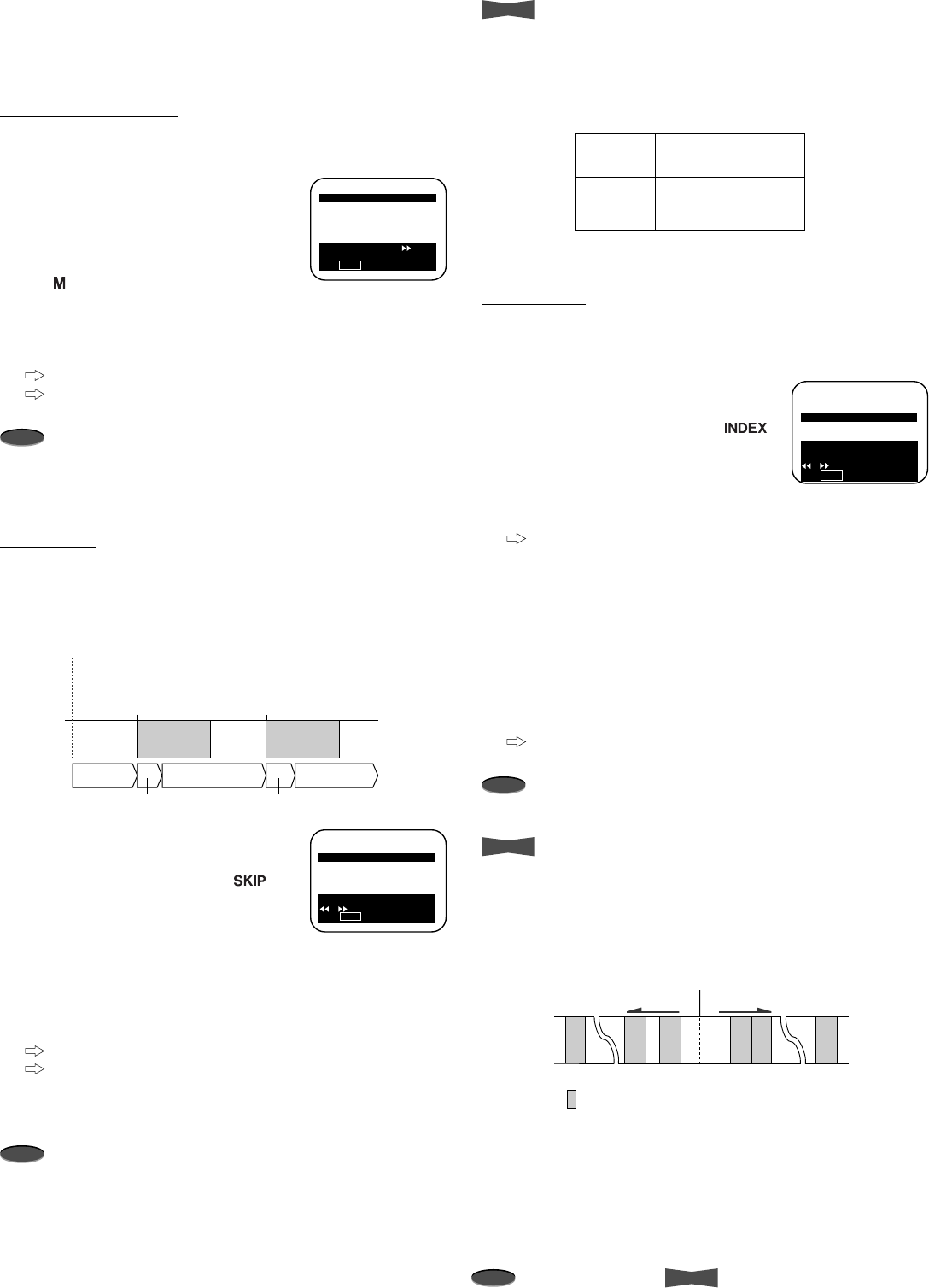
18 Advanced Functions
Note
A point to notice
Info.
Supplementary information
<SEARCH FUNCTION>
COUNTER MEMORY STOP
SKIP SEARCH
INDEX SEARCH 1
TIME DATE SEARCH
Use JOG to adjust,
turn the SHUTTLE RING
or to execute.
Press STOP to exit.
Reverse direction Fast forward direction
-255 -2 -1
Present position
+2+1 +255
Alarm Recording
Searching Techniques
The various search functions help you find pictures you wish to
view.
Counter memory stop
Rewinds a tape until the counter on the fluorescent display
reaches “00000” and stops.
1. Press SEARCH button once.
•<SEARCH FUNCTION> menu
appears and COUNTER MEMORY
STOP is highlighted.
• The Counter Memory Stop indicator
() illuminates on the fluorescent
display.
2. Turn SHUTTLE to the right.
• The VCR starts rewinding the tape.
To quit while rewinding, press STOP button.
To exit the <SEARCH FUNCTION> menu without
rewinding, press STOP button.
Note
• When the counter on the fluorescent display indicates
“00000”, COUNTER MEMORY STOP of the SEARCH
FUNCTION menu cannot be selected.
Skip search
During fast forwarding or rewinding, the VCR plays back a tape
(at 2H, 6H or 8H mode) for about 4 seconds where an index
signal is recorded. This process is repeated until the end or
beginning of the tape is reached.
1. Press SEARCH button until SKIP
SEARCH is highlighted.
• The Skip Search indicator ( )
illuminates on the fluorescent
display.
2. Turn SHUTTLE to the right or left.
• Turning to the right proceeds the search in the forward
direction.
• Turning to the left proceeds the search in the reverse
direction.
To quit while searching, press STOP button.
To exit the <SEARCH FUNCTION> menu without
searching, press STOP button.
3. When you find a picture you wish to view, press PLAY button.
Note
• The index signal may be difficult to locate in some recording
conditions.
• Audio output is muted during the skip search.
<SEARCH FUNCTION>
COUNTER MEMORY STOP
SKIP SEARCH
INDEX SEARCH
TIME DATE SEARCH
Turn the SHUTTLE RING
or to execute
Press STOP to exit.
Info.
• Skip search or index search may not function if the interval
between two alarm recording start-times is too short. The
table below indicates the minimum interval between two alarm
recording start-times for the skip or index search to work
correctly.
Index search
During fast forwarding or rewinding, the VCR will search for an
index signal you have selected. When the index signal is found,
the VCR will play back in still picture.
1. Press SEARCH button until INDEX
SEARCH is highlighted.
• The Index Search indicator ( )
illuminates on the fluorescent
display.
2. Turn JOG to select an index number
(between 1 and 255) you wish to find.
To exit the <SEARCH FUNCTION>
menu without searching, press
STOP button.
3. Turn SHUTTLE to the right or left to start searching.
• Turning SHUTTLE to the right proceeds the search in the
forward direction.
• Turning SHUTTLE to the left proceeds the search in the
reverse direction.
• The index number shown on the fluorescent display will
decrease one by one as each index signal goes by.
To quit while searching, press STOP button.
Note
• The index signal may be difficult to locate in some recording
conditions.
Info.
How to count index number
• Index number is the count from the present position. The
index number of one alarm recording before the present
position is “-1”. One after is “+1”.
• Maximum count is ±255 alarm recordings.
Minimum interval
between two alarm
recording start-times
Alarm
recording
mode
6H(8H)
L18H(L24H)
L30H(L40H)
approx. 15 sec.
approx. 2 min.
approx. 2 min.
( ) appears when TAPE LENGTH is set to T-160.
ALARM
RECORDING ALARM
RECORDING
Present position
Index
Fast forward
Fast forward
Index
Approx. 4 sec.
playback Approx. 4 sec.
playback
Fast forward
<SEARCH FUNCTION>
COUNTER MEMORY STOP
SKIP SEARCH
INDEX SEARCH
TIME DATE SEARCH
Turn the SHUTTLE RING
to execute.
Press STOP to exit.
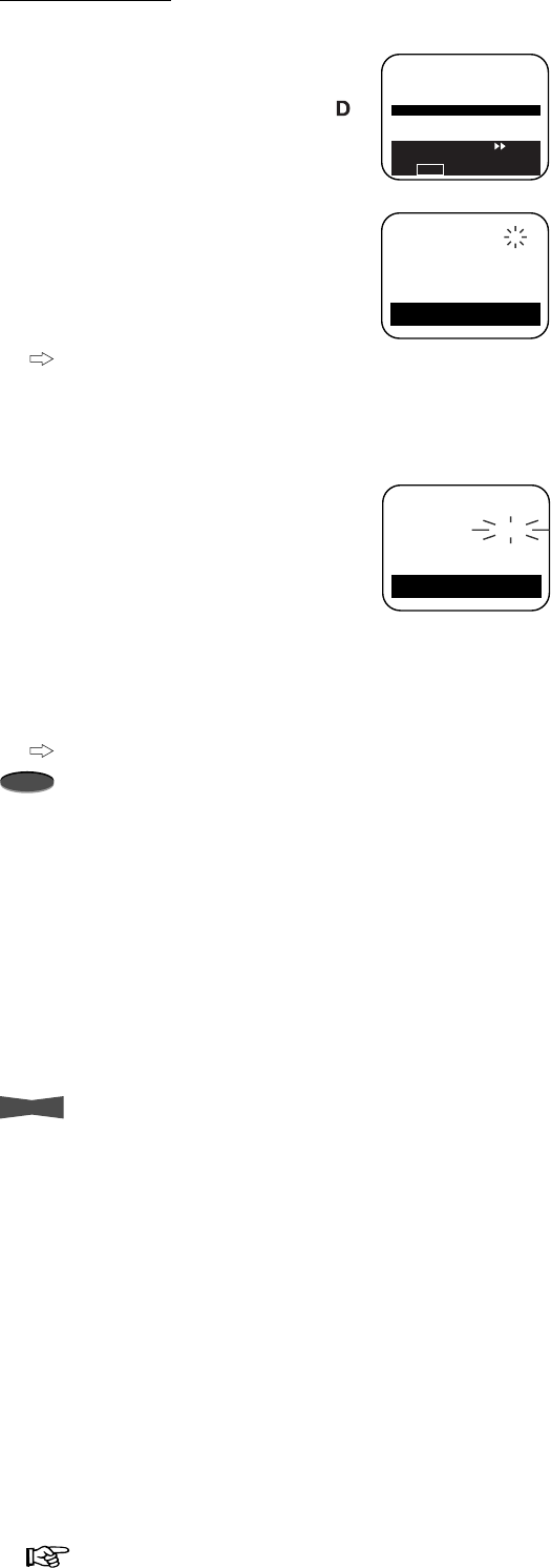
19Advanced Functions
Reference page
<SEARCH FUNCTION>
COUNTER MEMORY STOP
SKIP SEARCH
INDEX SEARCH
TIME DATE SEARCH
Turn the SHUTTLE RING
to go the search menu.
Press STOP to exit.
<TIME DATE SEARCH>
TIME 00:00
DATE 13
DIRECTION REVERSE
Use JOG to adjust,
and ENTER.
<TIME DATE SEARCH>
TIME 03:25
DATE 24
DIRECTION FORWARD
Use JOG to adjust,
and ENTER to start.
Time date search
You can easily find a picture recorded at specific date and time.
1. Press SEARCH button until TIME
DATE SEARCH is highlighted.
• The Time Date Search indicator ( )
illuminates on the fluorescent
display.
2. Turn SHUTTLE to the right.
•<TIME DATE SEARCH> menu
appears.
3. Turn JOG to set
hour digits
of TIME
you wish to find and turn SHUTTLE to
the right.
To exit the <TIME DATE SEARCH>
menu without searching, turn
SHUTTLE to the left several times.
4. Set
10-minute digit
and
1-minute digit
of TIME, DATE and
DIRECTION in a similar fashion.
• Searches in the forward direction of
the tape when DIRECTION is set to
FORWARD.
• Searches in the reverse direction of
the tape when DIRECTION is set to
REVERSE.
5. Turn SHUTTLE to the right to start
searching.
• When the recorded picture is found, it is shown at still
picture.
To quit while searching, press STOP button.
Note
• An index mark is written on a tape at each hour (1:00, 2:00
and so on) during recording. The time date search cannot be
resumed if the index mark of the hour (set in step 3) is not
recorded on a tape.
Example: When the VCR recorded from 8:15 to 17:30 on a
tape, only pictures recorded between 9:00 and 17:30 can be
found using the time date search.
• The time date search may not function correctly, if you use a
tape with a poor recording quality or with alarm recordings
recorded at several recording mode.
• The time date search will not function when using a tape
recorded with other VCRs or a tape recorded without setting
the current day and time.
Info.
• When the desired part of the tape is not found in the selected
direction, the VCR automatically searches in the opposite
direction.
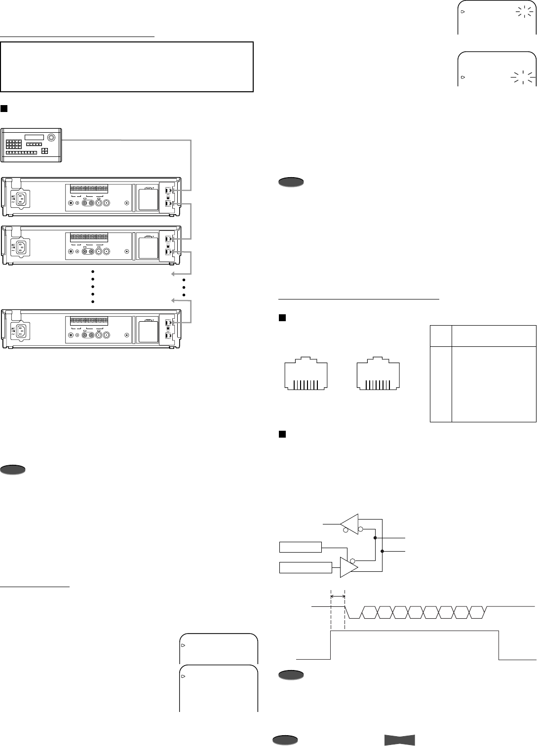
20 Advanced Functions
Note
A point to notice
Info.
Supplementary information
Using RS-485 Interface
Configuring the Time Lapse VCR
Important notice:
• Before connecting the hardware, unplug the power
cord of the VCR from the wall outlet, and turn the RS-
485 controller power off.
Connecting the VCRs to a RS-485 controller
1. Connect the cable to the RS-485 terminal of the RS-485
controller.
2. Connect the other end of cable to RS-485 IN terminal on the
VCR.
3. Connect the other end of the cable to RS-485 OUT terminal
of the 1st VCR and the other end of cable to RS-485 IN
terminal on the 2nd VCR.
4. Continue this process until the last (up to 127) VCR is
connected.
Note
• RS-485 remote control is through a RJ-45 connector on the
rear panel. RS-485 remote connection requires two wires.
One wire connects to the RS-485 RXA and the other connects
to the RS-485 RXB. Connect RXS and RXB externally, or set
the TERMINATE switch to ON. If more than two units are
connected, connect only one VCR with RXS and RXB
externally, or set the TERMINATE switch to ON.
• Twist the wires together to help eliminate noise from the
signal.
RS-485 Setting
Set the RS-485 interface board setting by using the on screen
menu of the VCR.
1. Press MENU button.
•<MAIN MENU> appears.
2. Turn JOG to select CLOCK/FIRST
TIME SET UP and turn SHUTTLE to
the right.
•<FIRST TIME SET UP> menu
appears.
3. Turn JOG to select RS-485 and turn
SHUTTLE to the right.
•<RS-485> menu appears.
4. Change the parameter value by turning
JOG to the left or right and turn
SHUTTLE to the right to store the new
value.
5 Repeat step 4 until all of the items are set.
•<FIRST TIME SET UP> menu appears after setting VCR
GROUP.
6. Press MENU button.
• The day and present time display appears on screen.
Note
• Set TRANSMISSION RATE to the same value as the
controlling RS-485 controller.
• When VCRs have a unique VCR ADDRESS (from VCR01 to
VCR127), VCRs can be controlled remotely via a RS-485
controller.
• When the group number (from 01 to 15) is set, the multiple
VCRs set to the same number will be controlled at the same
time.
Connecting to a RS-485 Controller
Physical protocol of RS-485
Data communication settings
Synchronization Asynchronous
Transmittion rate 1200/2400/4600/9600/19200 bps
Start bit length 1bit
Stop bit length 1bit
Data length 8bit
Parity bit Nil
Note
• When the RS-485 controller sends the command to the
VCR, enable the RS-485 driver of the controller to send the
data before sending Start bit (before T=1bit or more).
<MAIN MENU>
DISPLAY
TIMER PROGRAM
RECORDING SET UP
REAR TERMINAL
<FIRST TIME SET UP>
TIME DATE ADJUST
TAPE END STOP
QUASI V-SYNC ON
VIDEO MODE AUTO
TAPE LENGTH T-120
BUZZER WRNG
RS-485
<RS-485>
TRANSMISSION RATE 9600
STATUS OFF
VCR ADDRESS VCR01
VCR GROUP NONE
<RS-485>
TRANSMISSION RATE 9600
STATUS OFF
VCR ADDRESS VCR01
VCR GROUP NONE
RS-485
ON
IN
OUT
TERMINATE
OFF
AUDIO VIDEO
OUT OUTIN
REMOTE MIC
IN
RESET
ALM RST
IN
REC GND ALM
MODE
CLK
OUT
CALL
BATTERY
OPEN
RS-485
ON
IN
OUT
TERMINATE
OFF
AUDIO VIDEO
OUT OUTIN
REMOTE MIC
IN
RESET
ALM RST
IN
REC GND ALM
MODE
CLK
OUT
CALL
BATTERY
OPEN
RS-485
ON
IN
OUT
TERMINATE
OFF
AUDIO VIDEO
OUT OUTIN
REMOTE MIC
IN
RESET
ALM RST
IN
REC GND ALM
MODE
CLK
OUT
CALL
BATTERY
OPEN
RS-485 Controller
1st VCR
2nd VCR
127th VCR
To RS-485 terminal
To RS-485 IN terminal
To RS-485 OUT terminal
To RS-485 IN terminal
To RS-485 OUT terminal
To RS-485 IN terminal
To RS-485 OUT terminal
To RS-485 IN terminal
RS-485 IN
RJ-45 connector
1
23
4567
8
RS-485 OUT
RJ-45 connector
1
23
4567
8
No.
1
2
3
4
5
6
7
8
Pin Assignment
NO CONNECTION
NO CONNECTION
RXS
RXB (Data –)
NO CONNECTION
RXA (Data +)
NO CONNECTION
NO CONNECTION
Data enable
RXB
RXA
Command data D
R
Data
enable
Command
data
Start
bit Stop
bit
T
D0 D1 D2 D3 D4 D5 D6 D7
21Advanced Functions
Reference page
Commands from RS-485 Controller
The commands sent from the RS-485 controller to the VCR and
responses produced by the VCR are detailed in this section.
• Input the “VCR ADDRESS (eg. VCR01)” that you want to
control and “, (comma)” before inputting the command code.
• When you want to control all the VCRs set to the same
group number, input “GROUP (eg. GRP01)” that you want to
control and “, (comma)” before inputting the command
codes.
• When you want to control all connected VCRs, input “ALL”
and “, (comma)” before inputting the command codes.
*CR indicates carriage return code (0DH).
Example 1:
Fast forward the tape in the VCR of the ID number VCR02.
*CR indicates carriage return code (0DH).
*2Status or error code will be sent from the VCR when
STATUS in the RS-485 menu is set to ON.
Example 2:
When the VCRs from VCR28 to VCR34 are set to GROUP03,
and switch on the all VCR of the GROUP number 03.
*CR indicates carriage return code (0DH).
* When the commands are sent for the group of VCRs, status
or error code will not be sent from the VCRs.
Example 3:
Set the clock of the all VCR connected to 12:27.
*CR indicates carriage return code (0DH).
* When the commands are send for ALL VCRs, status or error
code will not be sent from the VCR.
Sending commands
from the RS-485
controller
Status or error code
from the VCR to
RS-485 controller
Meanings
Command for fast forwarding
(VCR02)
Command received (VCR02)
*2
Command carried out (VCR02)
*2
VCR02, FF CR
VCR02, RC CR *2
VCR02, EX CR *2
Format : Command
Codes
VCR ADDRESS,
GROUP or ALL
Parameter
1,
Parameter
2,,Parameter
nCR
Format : Command
Codes
VCR ADDRESS
Parameter
1,
Parameter
2,,Parameter
nCR
Command : Commands set to the VCR.
Status : Response codes from the VCR to outside.
Sending commands
from the RS-485
controller
Status or error code
from the RS-485
controller
Meanings
Command for setting all
VCRs’ clock at 12:27
ALL,SC12,27 CR
GRP03,PW1 CR Power ON command
Sending commands
from the RS-485
controller
Status or error code
from the VCR to
RS-485 controller
Meanings
22 Advanced Functions
Note
A point to notice
Info.
Supplementary information
NO.
1
2
3
4
5
6
7
8
9
10
11
12
13
14
15
16
17
18
19
20
21
22
23
24
25
26
27
28
29
30
31
32
33
Commands
PW
PW0
PW1
EJ
SP
PB
RP
FF
RW
RC
CM
PU
PU0
PU1
FA
RA
LK
LK0
LK1
SF
SR
IF
IR
IN
TR
TR0
TR1
TP
SS
LO
LM
CR
CT
Functions
Power ON/OFF
Power OFF
Power ON
Eject
Stop
Playback
Reverse playback
Fast forward
Rewind
Recording
Counter memory stop
Pause ON/OFF
Pause OFF
Pause ON
Frame adavance (when still)
Reverse frame adavance (when still)
Lock OFF
Lock ON
Lock All ON
Skip search (forward)
Skip search (reverse)
Index search (forward)
( =001-255)
Index search (reverse)
( =001-255)
Enquiry about current index No.
(during index search)
Timer recording ON/OFF
Timer recording OFF
Timer recording ON
Enquiry about current executing timer
program No.
Enquiry about current VCR status
Lock ON/OFF or Lock All ON/OFF
:0=OFF, 1=ON
Enquiry about current lock status and
lock mode
Counter reset
Enquiry about current counter display
value
Explanation of status
Command received and carried out
Index No. is =001-255
Command received and carried out
Timer program No. is =1-8
(Note)ER08,when not timer recording
Power off, cassette in
Power off, cassette out
Power on, cassette in
Power on, cassette out
Fast forward underway
Rewind underway
Recording underway
Recording pause underway
Playback underway
Reverse playback underway
Forward speed search underway
Reverse speed search underway
Still underway
Counter memory stop underway
Skip search (fast forward) underway
Skip search (rewind) underway
Playback during skip search
Index search (fast forward) underway
Index search (rewind) underway
Rewind during repeat recording
Alarm recording underway
Timer recording underway
Standby for timer recording
Timer recording error underway
Time date search standby underway
Time date FF search underway
Time date REW search underway
Time date search or point adjustment
underway
Recording check underway
Alarm recording Index writing underway
Time date index writing underway
Oneshot recording underway
Frame advance underway
Reverse frame advance underway
Command received and carried out
: 0=Lock off, 1=Lock on
2=Lock All on
Command received and carried out
=00000-99999
Status after normal execution
RC EX
RC ID
RC EX
RC TN
RC ST00
RC ST01
RC ST02
RC ST03
RC ST04
RC ST05
RC ST06
RC ST07
RC ST08
RC ST09
RC ST10
RC ST11
RC ST12
RC ST13
RC ST14
RC ST15
RC ST16
RC ST17
RC ST18
RC ST19
RC ST20
RC ST21
RC ST22
RC ST23
RC ST24
RC ST25
RC ST26
RC ST27
RC ST29
RC ST30
RC ST31
RC ST32
RC ST33
RC ST34
RC EX
RC LM
RC EX
RC CT
*1
O
O
O
O
O
O
O
O
O
O
O
O
O
O
O
O
O
O
O
O
O
O
O
–
O
O
O
–
–
O
–
O
–
*2
–
–
–
–
–
–
–
–
–
–
–
–
–
–
–
–
–
–
–
–
–
–
–
O
–
–
–
O
O
–
O
–
O
CR CR CR
CR
CR CR
CR
CR CR
CR CR
CR CR
CR CR
CR CR
CR CR
CR CR
CR CR
CR CR
CR CR
CR CR
CR CR
CR CR
CR CR
CR CR
CR CR
CR CR
CR CR
CR CR
CR CR
CR CR
CR CR
CR CR
CR CR
CR CR
CR CR
CR CR
CR CR
CR CR
CR CR
CR CR
CR CR
CR CR
CR CR
CR CR
CR CR
CR CR
CR CR
CR CR
CR
CR
CR
CR
CR
CR
CR
CR
CR
CR
CR
CR
CR
CR
CR
CR
CR
CR
CR
CR
CR
CR
CR
CR
CR
CR
CR
CR
CR
CR
CR
CR
Using RS-485 Interface (Cont.)
Commands and Responses
•CR indicates carriage return code (0DH).
• indicates one character or number. (eg. indicates three characters or numbers.)
• *1: the command available for “ALL” VCRs or the “GROUP” of the VCRs. (All commands are available for controlling the specified
VCR ADRESS.)
• *2: the command for which the VCR sends the status even when the STATUS in RS-485 menu is set to OFF.
23Advanced Functions
Reference page
NO.
34
35
36
37
38
39
40
41
42
43
44
45
46
47
48
49
Commands
MC
MD
DP
DP
PI
SD (1), (2),
(3)
DT
SC (1), (2)
TM
TD
PS (1), (2)
LC
DP131 PG (1),
(2), (3), (4),
(5), (6), (7),
(8) DP
PM
DP131 CA
DP
DW (1), (2)
Functions
Switch over REC/PLAY mode to
= 006, L18, L30, 048, 072, 096,000
Enquiry about current REC/PLAY mode
Change menu to the next layer
Switch screen page to
:
000=present time display
100=MAIN MENU
110=DISPLAY menu
120=SEARCH FUNCTION menu
121=TIME DATE SEARCH menu
130=TIMER PROGRAM menu
131=PROGRAM TO RECORD menu
132=HOLIDAY SET UP menu
140=RECORDING SET UP menu
150=REAR TERMINAL menu
160=MAINTENANCE menu
161=POWER LOSS LIST
162=ALARM LIST
163=ALL MENU INITIALZE
164=POWER LOSS LIST CLEAR
165=ALARM LIST CLEAR
170=FIRST TIME SET UP menu
171=TIME DATE ADJUST menu
172=RS-485 menu
Enquiry about current screen page
Current date setting
(1):Month, (2):Day, (3) :Year
Enquiry about current date
Current time setting
(1):Hour, (2):Minute
Enquiry about current time
Enquiry about power failure symbol
Time and date display position
(1):Horizontal
=01-30 (mode 1,size large)
=01-52 (mode 1,size small)
=01-39 (mode 2,3 size large)
=01-62 (mode 2,3 size small)
(2):Vertical
=01-37 (mode 1,size large or small)
=01-35 (mode 2,3 size large or small)
Enquiry about time and date display
position
Timer program setting
(1)Program No.=1-8
(2):Day of the week (0=SUN, 1=MON,
2=TUE, 3=WED, 4=THU, 5=FRI, 6=SAT,
7=DAY, 8=SPL,9=HLD)
(3):Rec. starting hour=00-23
(4):Rec. starting minute=00-59
(5):Rec. ending hour=00-23
(6):Rec. ending minute=00-59
(7):Rec. time mode= 006, L18, L30, 048,
072, 096, 000, SKP
(8):REC mode 1=EP, 3=EP/EXT
(EXT= external timer recording)
Enquiry about setting contents of timer
program No. ( =1-8)
Clear contents of timer program No. ( =1-8)
Setting the special day of the week
(1):Start day of the week (0-6)
(2):End day of the week (0-6)
0=SUN, 1=MON, 2=TUE, 3=WED,
4=THU, 5=FRI, 6=SAT
Status after normal exection
RC EX
RC MD (1)
RC EX
RC ON (1) (2)
RC EX
RC TD (1), (2), (3), (4)
RC EX
RC TI (1), (2), (3)
RC MK
RC EX
RC LT (1), (2)
RC EX
RC MP (1), (2), (3), (4), (5), (6),
(7) (8)
RC EX
(Cannot accept this command when (1)
and (2)are the same number)
Explanation of status
Command received and carried out
(1): (same as item 34)
Command received and carried out
(1):(same as item 37),
050=LANGUAGE SELECT
(2) : 0=Setting completed,
1=Setting underway
Command received and carried out
(1),- (3):(same as item 39)
(4):Day of the week
0=SUN, 1=MON, 2=TUE,
3=WED, 4=THU, 5=FRI, 6=SAT
Command received and carried out
(1):Hour, (2):Minute, (3):Second
: 0=Not Displayed, 1=Displayed
Command received and carried out
(1), (2) : (same as item 44)
Command received and carried out
(Note) An error (ER08) will occur if an
attempt is made to program a timer program
number that has already been set. Clear the
timer program contents with the "CA "
command and then retry.
(1),- (8) (=same as item 46)
Command received and carried out
*1
O
–
O
O
–
O
–
O
–
–
O
–
O
–
O
O
*2
–
O
–
–
O
–
O
–
O
O
–
O
–
O
–
–
CR CR
CR CR
CR
CR CR
CR CR
CR CR
CR
CR
CR
CR
CR CR
CR CR
CR CR
CR CR
CR CR
CR CR
CR CR
CR
CR
CR
CR
CR
CR
CR
CR
CR
CR
CR
CR
CR CR
CR
CRCR
CR
CR
Send the commands no. 46 and 48 when the VCR is in STOP mode.
24 Advanced Functions
Note
A point to notice
Info.
Supplementary information
NO.
50
51
52
53
54
55
56
57
58
59
60
61
62
63
64
65
66
67
68
69
70
71
72
73
74
75
76
77
78
79
80
81
82
83
84
85
86
87
88
89
90
91
Commands
DW?
AM
AS1
AD
AS0
EM
EM0
EM1
AS2
TE
FS0
DM
DM?
CH0
CH1
FS1
CO (1), (2)
RO
MO
RM
CU
CU?
BL
BL?
ST
BZ
BR
FS2
BP
OS
OF
OI
OI?
AN
AT
CA
PN
PT
PC
MI
HM?
WN
Functions
Enquiry about setting of the special day of
the week
Alarm recording mode setting
=06, 18, 30
Enquire of alarm recording mode setting
Alarm REC duration setting
:0=MAN1, 1=MAN2, 2=15S, 3=30S,
4=45S, 5=1M, 6=2M, 7=5M, 8=10M
Enquiry about alarm REC duration setting
Emergency REC ON/OFF
Emergency REC OFF
Emergency REC ON
Enquiry about emergency REC setting
Tape end movement setting
: 0=STOP, 1=REWIND, 2=REPEAT,
3=ALARM•PROT (protect)
Enquiry about tape end movement set
Display mode setting =1-4
Enquiry about display mode setting
Set date character display size "SMALL"
Set date character display size "LARGE"
Enquiry about date character display size
Clock out setting
(1):0=REC, 1=T/L REC
(2):01, 02, 03, 04, 05, 10, 15, 20, 25,
30, 50, 60, 00(output by field)
Enquiry about clock out setting
Mode out setting
: 0=REC, 1=PLAY, 2=POWER,
3=TAPE IN, 4=TAPE REMAIN,
5=CLOCK ADJ
Enquiry about MODE OUT setting
CALL OUT setting :0=OFF, 1=ON
Receive the command only when the
signal at the CALL OUT terminal is
switched to the active condition.
Enquiry about CALL OUT setting
Blue Back setting : 0=OFF, 1=ON
Enquiry about Blue Back setting
Set menu item to flash :0=OFF, 1=ON
Buzzer setting
: 0=WRNG, 1=WRNG•TAPE END,
2=WRNG•REMAIN, 3=OFF
Buzzer ON/OFF setting :0=OFF, 1=ON
Enquiry about buzzer setting
Enquiry about buzzer status
One shot field setting
: 01, 02, 03, 04, 05, 10, 20, 30
Enquiry about one shot field setting
Oneshot interval setting
: 0=SHOT, 1=10S, 2=15S, 3=30S
4=45S, 5=1M, 6=2M, 7=3M
Enquiry about one shot interval setting
Enquiry about current alarm REC. No.
Enquiry about alarm list
: 0=about the first alarm recording
1-7=about the last to seventh last
alarm recording
Clearing alarm list
Enquiry about current power loss No.
Enquiry about power loss list
: 0=about the first power loss
1=about the second last power loss
2=about the last power loss
Clearing power loss list
Initializing the menu setting
Enquiry about the elapsed time
Enquiry about warning information
Status after normal execution
RC DW (1), (2)
RC EX
RC AM
RC EX
RC AP
RC EX
RC EG
RC EX
RC TE
RC EX
RC DM
RC EX
RC CZ
RC EX
RC CD (1), (2)
RC EX
RC MR
RC EX
RC CU
RC EX
RC BL
RC EX
RC EX
RC BZ
RC SW
RC EX
RC SD
RC EX
RC OI
RC AN
RC AT (1), (2), (3), (4), (5)
RC EX
RC PN
RC PT (1), (2), (3), (4), (5)
RC EX
RC HM
RC WN
Explanation of status
(1):Start day (of the week) (0-6)
(2):End day (of the week) (0-6)
0=SUN, 1=MON, 2=TUE, 3=WED,
4=THU, 5=FRI, 6=SAT
Command received and carried out
=06, 18, 30
Command received and carried out
:(same as item 53)
Command received and carried out
:0=OFF, 1=ON
Command received and carried out
:(same as item 59)
Command received and carried out
=1-4
Command received and carried out
Command received and carried out
: 0=SMALL, 1=LARGE
Command received and carried out
(1), (2):(same as item 66)
Command received and carried out
: (same as item 68)
Command received and carried out
: 0=OFF, 1=ON
Command received and carried out
: 0=OFF, 1=ON
Command received and carried out
Command received and carried out
: (same as item 75)
: 0=OFF (not ring), 1=ON (ring)
Command received and carried out
:(same as item 79)
Command received and carried out
:(same as item 81)
=0000-9999
(1):Month, (2):Day, (3):Year,
(4):Hour, (5):Minute
Command received and carried out
=00-99
(1):Month, (2):Day, (3):Year,
(4):Hour, (5):Minute
Command received and carried out
:=hour
:Warning No.
00=no malfunction, 01=tape end
03=video input missing
04=clogged head
05=reel rotation trouble
06=loading motor trouble
07=capstan motor trouble
08=drum motor trouble, 09=tape loose
10=switching power short, 11=cut tape
*1
–
O
–
O
–
O
O
O
–
O
–
O
–
O
O
–
O
–
O
–
O
–
O
–
O
O
O
–
–
O
–
O
–
–
–
O
–
–
O
O
–
–
*2
O
–
O
–
O
–
–
–
O
–
O
–
O
–
–
O
–
O
–
O
–
O
–
O
–
–
–
O
O
–
O
–
O
O
O
–
O
O
–
–
O
O
CR CR CR
CR CR
CR CR
CR CR
CR CR
CR CR
CR CR
CR CR
CR CR
CR CR
CR CR
CR CR
CR CR
CR CR
CR CR
CR CR
CR CR
CR CR
CR CR
CR CR
CR
CR CR
CR CR
CR CR
CR CR
CR CR
CR CR
CR CR
CR
CR CR
CR
CR
CR CR
CR CR
CR CR
CR CR
CR CR
CR CR
CR CR
CR
CR
CR
CR
CR
CR
CR
CR
CR
CR
CR
CR
CR
CR
CR
CR
CR
CR
CR
CR
CR
CR
CR
CR
CR
CR
CR
CR
CR
CR
CR
CR
CR
Using RS-485 Interface (Cont.)
25Advanced Functions
Reference page
NO.
92
93
94
95
96
97
98
99
100
101
102
103
104
105
106
107
108
109
110
111
112
113
114
115
116
117
118
119
120
Commands
CA0
RI
RI?
QV
QM
CL
RL
SM
SM?
RS?
TL
TL?
LP?
TF (1), (2),
(3)
TB (1), (2),
(3)
TS?
MQ
SB1
MM
SB3
RN?
SV?
HL (1), (2),
(3)
EH
HC
HR
HR0
HR1
HR?
Functions
Clearing the warning "ER05"
REC IN setting
: 0=SERIES, 1=REC-START/STOP
2=SYNC REC
Enquiry about REC IN setting
QUASI-VSYNC setting :0=OFF, 1=ON
Enquiry about QUASI-VSYNC setting
CALL OUT setting
: 0=WRNG, 1=WRNG•TAPE END
2=WRNG•REMAIN
Enquiry about CALL OUT setting
DAYLIGHT SAVING setting
: 0=OFF, 1=ON, 2=AUTO
Enquiry about DAYLIGHT SAVINGS
setting
Enquiry about REPEAT REC TIMES
Tape length setting
: 0=T-120, 1=T-160
Enquiry about tape length setting
Enquiry about tape remaining time
Time date search (forward) setting
(1):Day, (2):Hour, (3):Minute
Time date search (reverse) setting
(1):Day, (2):Hour, (3):Minute
Enquiry about time date search setting
VIDEO MODE setting
: 1=B/W, 2=AUTO
Enquiry about VIDEO MODE
Menu language selection
: 0=English, 1=French, 2=Spanish
Enquiry about selected menu language
Enquiry about recording/playback mode,
SP/EP
Enquiry about recording format
Holiday set up setting
(1):Position No. 01-20, (2):Month,
(3):Day
Clearing holiday set up setting
: Position No. 01-20
Enquiry about holiday set up setting on
line 1 to 5
: Line No. 1-5
Super Resolution ON/OFF
Super Resolution OFF
Super Resolution ON
Enquiry about Super Resolution setting
Status after normal execution
RC EX
RC RI
RC EX
RC QV
RC EX
RC CL
RC EX
RC SM
RC RS
RC RSOVER
RC EX
RC TL
RC LP (1), (2)
RC EX
RC TS (1) (2) (3)
RC EX
RC SQ
RC EX
RC SP
RC RN
RC SV
RC EX
RC HC (1), (2), (1), (2), (1), (2),
(1), (2), (1), (2)
RC EX
RC HR
Explanation of status
Command received and carried out
:(same as item 93)
Command received and carried out
: 0=OFF, 1=ON
Command received and carried out
:(same as item 97)
Command received and carried out
: 0=OFF, 1=ON, 2=AUTO OFF,
3=AUTO ON
: 000-200
OVER (more than 201 times)
Command received and carried out
:(same as item 102)
(1):Hour, (2):Minute
Command received and carried out
(1):Day, (2):Hour, (3):Minute
Command received and carried out
: (same as item 108)
Command received and carried out
: (same as item 110)
8=Language is not selected
: 0=SP, 1=EP
: 0=VHS, 2=Super Resolution
Command received and carried out
(1):Month, (2):Day
Command received and carried out
: 0=OFF, 1=ON
*1
O
O
–
O
–
O
–
O
–
–
O
–
–
O
O
–
O
–
O
–
–
–
O
O
–
O
O
O
–
*2
–
–
O
–
O
–
O
–
O
O
–
O
O
–
–
O
–
O
–
O
O
O
–
–
O
–
–
–
O
CR CR CR
CR CR
CR CR
CR CR
CR CR
CR CR
CR CR
CR CR
CR CR
CR CR
CR
CR
CR CR
CR CR
CR CR
CR CR
CR CR
CR CR
CR CR
CR CR
CR CR
CR CR
CR CR
CR CR
CR CR
CR CR
CR
CR
CR
CR
CR
CR
CR
CR
CR
CR
CR
CR
CR
CR
CR
CR
CR
CR
CR
CR
CR
CR
CR
CR
CR
CR
CR
NO.
1
2
3
4
5
6
7
Errors
ER00
ER01
ER02
ER03
ER04
ER05
ER06
Meaning of error
No power supply
No cassette loaded
Broken tape tab (unable to record)
Beginning of the tape
Tape end
Problem with the tape, video input or VCR mechanism
Present time or timer program not yet set
NO.
8
9
10
11
12
13
Errors
ER07
ER08
ER10
ER11
ER12
ER13
Meaning of error
Alarm REC underway (Unable to change setting)
Unfeasible
Incorrect command
Incorrect parameter
Overflow of the VCR's command receive buffer
Data not received correctly
Error code
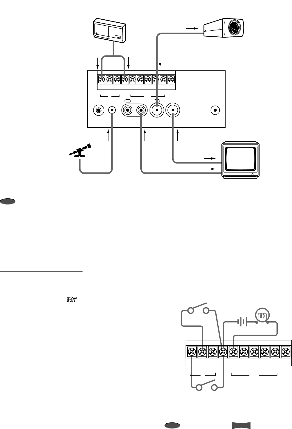
26 Installation
Note
A point to notice
Info.
Supplementary information
Connections for Various Functions
Alarm Recording Connection
The alarm can be confirmed from a distance by connecting the
ALM OUT terminal with an existing alarm system panel or other
peripherals such as a buzzer. Connect the VCR and other
peripherals as to the right. ( page 11 for the menu setting and
page 37 for the rating of each terminal)
Alarm set switch
Alarm reset switch External alarm lamp
and buzzer
RST
IN
REC GND ALMALM
MODE
CLK
OUT
CALL
AUDIO VIDEO
OUT OUTIN
REMOTE
IN
RESET
RST
IN
REC GND ALMALM
MODE
CLK
OUT
CALL
MIC
VIDEO
OUT
AUDIO
OUT
MIC
IN
VIDEO IN
AUDIO IN
SENSOR CCTV CAMERA
ALM IN GND
VIDEO
IN
VIDEO OUT
MONITOR
MICROPHONE
Connecting with CCTV camera, monitor and sensor
Note
• Monitor to be connected
– Connecting with a CCTV monitor (for surveillance) is recommended.
– Connecting with some monitors may cause picture vibration and/or picture distortion at the top or bottom of the image at still
picture or normal playback.
– A television for domestic use may easily cause the picture vibration and distortion.
– A monitor can also be connected to the VIDEO OUT connector on the front panel.
• CCTV camera to be connected
– Do not connect ‘Color’ and ‘Black & White’ cameras together.
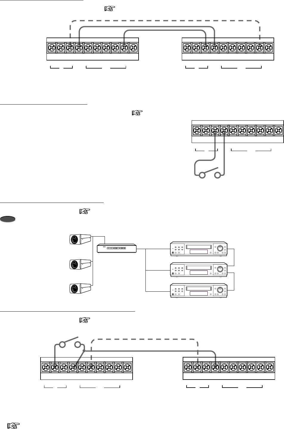
27Installation
Reference page
Switcher
1st VCR
VIDEO IN
VIDEO IN
VIDEO IN
CLK OUT
REC IN
CLK OUT
REC IN
2nd VCR
3rd VCR
Camera 1
Camera 2
Camera 3
Synchronous Recording Connection
Connect VCRs as shown below. ( page 14 for the menu setting)
Note
The number of VCRs to be connected varies by the recording time mode selected.
Connection for External Time Clock Adjustment
Connect VCRs as shown below. ( next page for the menu setting and page 37 for the rating of each terminal)
2nd VCR1st VCR
Switch
RST
IN
REC GND ALMALM
MODE
CLK
OUT
CALL RST
IN
REC GND ALMALM
MODE
CLK
OUT
CALL
*1 : When connecting the MODE OUT terminal of the first VCR with the RST IN terminal of the second VCR,
the on-screen clock of the second VCR can be adjusted to that of the first VCR.
*1
Remote Recording Connection
Connect the VCR with a remote switch as to the right. ( page 13 for the menu setting and page 37 for the rating of each
terminal)
Remote switch
RST
IN
REC GND ALMALM
MODE
CLK
OUT
CALL
Series Recording Connection
Connect VCRs to be used as shown below.( page 12 for the menu setting)
*1 : This connection is necessary
in case of
Series Recording 2
.
*1
1st VCR
RST
IN
REC GND ALMALM
MODE
CLK
OUT
CALL
2nd VCR
RST
IN
REC GND ALMALM
MODE
CLK
OUT
CALL
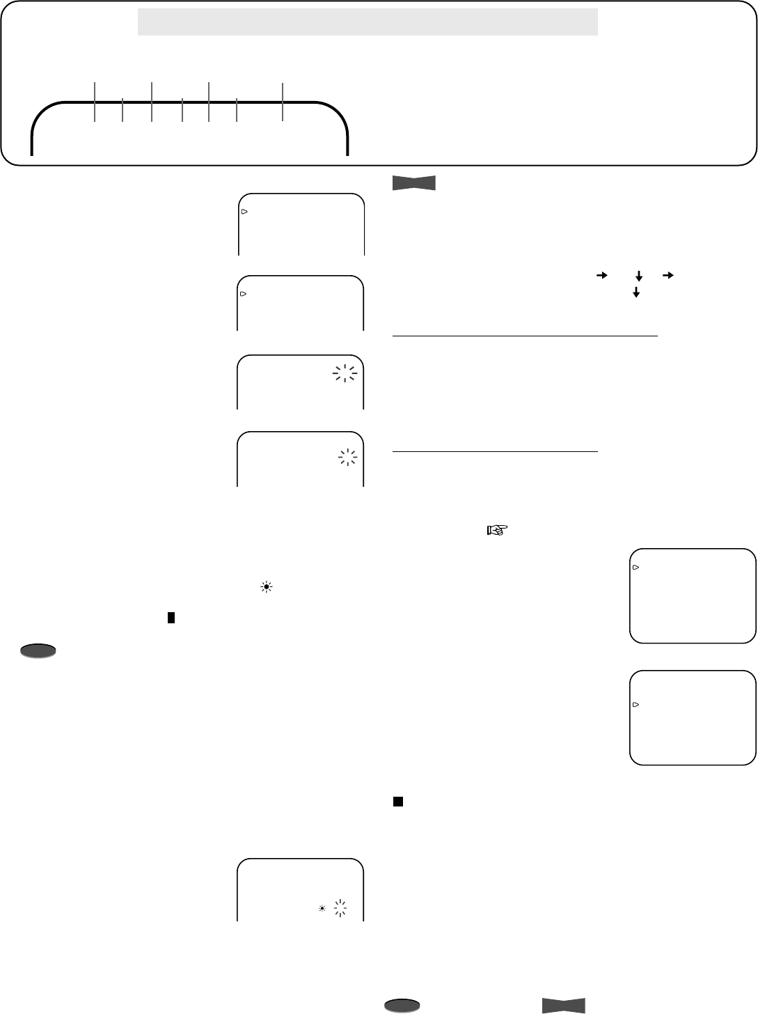
28 Installation
Note
A point to notice
Info.
Supplementary information
Example : Setting the day and present
time to 8:25 p.m., 9 July, 2002.
1. Press MENU button.
• <MAIN MENU> appears.
2. Turn JOG to select CLOCK/FIRST
TIME SET UP and turn SHUTTLE to
the right.
• <FIRST TIME SET UP> menu
appears.
3. Turn JOG to select TIME DATE
ADJUST and turn SHUTTLE to the
right.
•<TIME DATE ADJUST> menu
appears.
4. Turn JOG to set DAYLIGHT
SAVINGS and turn SHUTTLE to the
right.
• When set to ON, the clock moves forward one hour.
• When set to AUTO, the clock moves forward one hour
from the 1st Sunday of April (at 2 a.m.) to the last Sunday
of October (at 3 a.m.).
• When set to ON or AUTO and the clock is put forward one
hour, the Daylight Saving Time symbol ( ) is shown next
to the hour digit of TIME on screen and the Daylight
Saving Time indicator ( ) illuminates on the fluorescent
display.
Note
• When the DAYLIGHT SAVINGS is set to AUTO, the
programmed recordings starting or finishing in the daylight
saving time changeover period may not be recorded
correctly.
• The daylight saving time may vary from the one above
depending on your region or the year, in this case, set
DAYLIGHT SAVINGS to ON or OFF manually.
5. Turn JOG to show “07” for MONTH and turn SHUTTLE to the
right.
6. Set DAY, YEAR, TIME (hour digits, 10-minute digit and 1-
minute digit) in a similar fashion.
7. Turn SHUTTLE to the right while the
1-minute digit of TIME is flashing.
• The setting is now complete.
•<FIRST TIME SET UP> menu
appears.
8. Press MENU button.
• The day and present time display appears on screen.
Setting the Clock
<MAIN MENU>
DISPLAY
TIMER PROGRAM
RECORDING SET UP
REAR TERMINAL
MAINTENANCE
CLOCK/FIRST TIME SET UP
<FIRST TIME SET UP>
TIME DATE ADJUST
TAPE END STOP
QUASI V-SYNC ON
VIDEO MODE AUTO
TAPE LENGTH T-120
<TIME DATE ADJUST>
DAYLIGHT SAVINGS OFF
MONTH 01
DAY 31
YEAR 2002
TIME 00:00:00
• ’02 indicates year 2002.
• The clock is shown in 24-hour format.
• Alarm recording counter is shown during alarm recording only.
<TIME DATE ADJUST>
DAYLIGHT SAVINGS AUTO
MONTH 01
DAY 31
YEAR 2002
TIME 00:00:00
<TIME DATE ADJUST>
DAYLIGHT SAVINGS AUTO
MONTH 07
DAY 09
YEAR 2002
TIME 20:25:00
Accurately set the day and present time before timer programming.
MonthDay Year Hour
Alarm
Recording
Counter
Second
Minute
07-09-’02 20:25:00 A0001
<RECORDING SET UP>
ALARM REC MODE 6H
ALARM REC DURATION 1M
EMERGENCY REC OFF
SUPER RESOLUTION ON
ONE SHOT•FIELD 1
ONE SHOT•INTERVAL SHOT
<REAR TERMINAL>
CALL OUT WRNG•TAPE END
CLOCK OUT REC- 1
MODE OUT CLOCK ADJ
REC IN SERIES
Info.
• When DAYLIGHT SAVINGS is set to ON or OFF and a tape
is not inserted in the VCR, DAYLIGHT SAVINGS can be
switched to ON or OFF on the front panel of the VCR by
pressing STOP button and EJECT button together.
• To move the displayed position of the day and present time on
screen, press POSITION button () or ( ). ( ) moves the
display in a right-forward direction and () in a downward
direction.
Setting the current time to exact second
Set the clock as described above, but set minute digits to one or
two minutes ahead of the reference time being used. When the
reference time reaches 00 seconds of the minute you have set,
turn SHUTTLE to the right. The VCR’s clock now corresponds to
the reference time to the nearest second.
External time clock adjustment
The VCR’s clock can be set to the nearest hour by connecting
with an external clock. When 2 or more VCRs are connected
together, the clock can be set to the 1st VCR’s clock
simultaneously. Make the following settings to all VCRs you wish
to set the clock. ( previous page for the connection)
1. Press MENU button.
•<MAIN MENU> appears.
2. Set ALARM REC DURATION of
<RECORDING SET UP> menu to
other than MAN1.
3. Set MODE OUT of <REAR
TERMINAL> menu to CLOCK ADJ.
4. Press MENU button.
• The day and present time
display appears on screen.
How the external time clock adjustment works
When the RST IN terminal is grounded at the rear panel, the
clock is automatically set to the nearest hour.
Example:
• When the display shows 11:29:59, the clock is adjusted to
11:00:00.
• When the display shows 11:30:00, the clock is adjusted to
12:00:00.
When more than 2 VCRs are connected and the clock of the 1st
VCR is adjusted to the nearest hour, the additional VCRs will also
be set to the nearest hour.
29Installation
Reference page
Set the menus by the following steps.
1. Press MENU button.
•<MAIN MENU> appears.
2. Turn JOG to the left or right to select the desired item.
• When turned to the right, the cursor moves downward.
• When turned to the left, the cursor moves upward.
3. Turn SHUTTLE to the right.
• The desired item is selected and the menu appears.
4. Turn JOG to the left or right to select item.
5. Turn SHUTTLE to the right, then the setting item flashes.
6. Turn JOG to the left or right to change the setting.
7. Turn SHUTTLE to the right to set.
8. Press MENU button.
• The day and present time display appears.
Setting the Menus
01-01-’02 16:26:48
<MAIN MENU>
DISPLAY
TIMER PROGRAM
RECORDING SET UP
REAR TERMINAL
MAINTENANCE
CLOCK/FIRST TIME SET UP
Use JOG to select,
and ENTER.
Press MENU to exit.
<DISPLAY>
DISPLAY MODE 2
TIME DATE SIZE SMALL
BLUE BACK OFF
e.g.<MODE 2>
01-01-’01 MON
00:00:00 L30
<TIMER PROGRAM>
PROGRAM TO RECORD
HOLIDAY SET UP
SPECIAL DW MON-SAT
<RECORDING SET UP>
ALARM REC MODE 6H
ALARM REC DURATION 1M
EMERGENCY REC OFF
SUPER RESOLUTION ON
ONE SHOT•FIELD 1
ONE SHOT•INTERVAL SHOT
<REAR TERMINAL>
CALL OUT WRNG•TAPE END
CLOCK OUT REC- 1
MODE OUT REC
REC IN SERIES
<MAINTENANCE>
POWER LOSS LIST
ALARM LIST
ALL MENU INITIALIZE
POWER LOSS LIST CLEAR
ALARM LIST CLEAR
<REPEAT REC TIMES> 0
<ELAPSED TIME> 0H
<FIRST TIME SET UP>
TIME DATE ADJUST
TAPE END STOP
QUASI V-SYNC ON
VIDEO MODE AUTO
TAPE LENGTH T-120
BUZZER WRNG
RS-485
<TIME DATE ADJUST>
DAYLIGHT SAVINGS OFF
MONTH 01
DAY 01
YEAR 2002
TIME 00:00:00
<POWER LOSS LIST>
01 01-01-’02 00:00
02
03
<ALARM LIST>
0001 01-01-’02 00:00
0002
0003
0004
0005
0006
0007
0008
ALL MENU INITIALIZE
Turn the SHUTTLE RING
then all MENU will be
initialized.
POWER LOSS LIST CLEAR
Turn the SHUTTLE RING
then POWER LOSS LIST
will be cleared.
ALARM LIST CLEAR
Turn the SHUTTLE RING
then ALARM LIST will be
cleared.
<PROGRAM TO RECORD>
DW START END HR
1 DAY 12:00 15:00 L30EP
2 TUE 12:00 15:00 L18EP
3 WED 12:00 15:00 6EP
4 THU 12:00 15:00 6EP
5 FRI 12:00 15:00 L30EP
6 HLD 12:00 15:00 SKIP
7 SUN 12:00 15:00 L30EP
8 SPL 20:00 22:00 SKIP
<HOLIDAY SET UP>
01/01 01/15 02/11 03/22
04/29 05/03 05/04 05/05
07/20 09/15 09/23 10/10
11/03 11/23 12/23 - - / - -
- - / - - - - / - - - - / - - - - / - -
MONTH / DAY
<RS-485>
TRANSMISSION RATE 9600
STATUS OFF
VCR ADDRESS VCR01
VCR GROUP NONE
The Day and Present Time Display
JOG dial
SHUTTLE ring
MENU button
Menu Chart
30 Installation
Note
A point to notice
Info.
Supplementary information
Setting the Menus (Cont.)
DISPLAY
Setting the display mode (DISPLAY
MODE)
1 : Shows date and present time.
2 : Shows date, day of the week,
present time and recording mode.
3 : Displays nothing. In case of alarm
recording, displays same items as
DISPLAY MODE 2.
4 : Displays nothing.
<DISPLAY>
DISPLAY MODE 1
TIME DATE SIZE SMALL
BLUE BACK OFF
e.g.<MODE 1>07-09-’02 00:00:00
Month
Day Year
Hour
Alarm
Recording
Counter*
Second
Minute
07-09-’02 20:25:00 A0001
DISPLAY MODE 1
Month
Day
Day of
the Week
Year
Hour
Alarm
Recording
Counter*
Second
Minute
07-09-’02 TUE A0001
20:25:00 6
Recording
Mode
DISPLAY MODE 2 and 3
RECORDING SET UP
Setting the alarm recording mode
(ALARM REC MODE)
Sets the alarm recording time mode.
• Providing TAPE LENGTH in FIRST
TIME SET UP menu is set to T-120.
When JOG is turned, the display will
be switched in the order of 6H
L18H L30H 6H ...
• Providing TAPE LENGTH in FIRST TIME SET UP menu is set
to T-160.
When JOG is turned, the display will be switched in the order
of 8H L24H L40H 8H ...
Setting the alarm recording duration (ALARM REC
DURATION)
Sets the duration of the alarm recording period. When JOG is
turned, the display will be switched in the order of 1M (minute)
2M 5M 10M MAN1 MAN2 15S (second) 30S
45S 1M ...
Setting the emergency recording (EMERGENCY REC)
ON : Starts alarm recording when the ALM IN terminal is
grounded while the VCR is recording, in stop mode,
turned off or in stand-by mode for timer recording.
OFF : Starts alarm recording when the ALM IN terminal is
grounded during recording.
Setting the super resolution (SUPER RESOLUTION)
ON : Recording/playback is made at over 400 lines of
resolution.
OFF : Recording/playback is made at VHS mode.
<RECORDING SET UP>
ALARM REC MODE 6H
ALARM REC DURATION 1M
EMERGENCY REC OFF
SUPER RESOLUTION ON
ONE SHOT•FIELD 1
ONE SHOT•INTERVAL SHOT
TIMER PROGRAM
page 10, Timer Recording.
ENGLISH
FRANÇAIS
ESPAÑOL
Use JOG to select,
and ENTER .
LANGUAGE SELECTION
The menu which appears on screen offers 3 languages, English
(ENGLISH), Spanish (ESPAÑOL) or French (FRANÇAIS).
This menu appears by pressing MENU button, when the VCR is
turned on for the first time after the purchase or when RESET
button is pressed during use.
1. Press MENU button.
• The menu as shown to the right
appears.
2. Turn JOG to select the desired
language.
3. Turn SHUTTLE to the right.
•<MAIN MENU> in the selected language appears on
screen.
4. Press MENU button to exit.
Note
• After first time setup and selection of the language to be used,
the only way to go back and access the main menu in the
three languages is to PRESS the RESET button found on the
rear panel. The RESET button can be accessed with a small
pointed object. Once the RESET button is pressed, repeat
steps 1 to 4 above.
MAIN MENU
DISPLAY
Sets the display format of the date
and present time on screen.
TIMER PROGRAM
Sets the timer recording.
RECORDING SET UP
Sets the alarm recording mode,
alarm recording duration and emergency recording, etc.
REAR TERMINAL
Sets the frequency division ratio of CLOCK OUT, output signal
of CALL OUT terminal and MODE OUT terminal, etc.
MAINTENANCE
Displays the power loss list and alarm list, etc. Also, initializes
all menu settings, clears the power loss list and alarm list.
CLOCK/FIRST TIME SET UP
Sets the present time and the operation at the tape end, etc.
<MAIN MENU>
DISPLAY
TIMER PROGRAM
RECORDING SET UP
REAR TERMINAL
MAINTENANCE
CLOCK/FIRST TIME SET UP
Use JOG to select,
and ENTER.
Press MENU to exit.
* shown when DISPLAY MODE 1, 2 or 3 is selected.
Setting the size of letter for date and present time display
(TIME DATE SIZE)
SMALL : The size of the letters become small.
LARGE : The size of the letters become large.
Setting the background color (BLUE BACK)
ON : The blue colored screen overlays on the recorded
picture when the menu is displayed on the monitor.
OFF : The recorded picture is overlaid with the menu display.
Note
• When the setting is OFF and the video signal is not input, the
blue colored screen overlays on the recorded picture when
the menu is displayed on the monitor.
• When the setting is ON and the video signal is not input, the
background color will be in blue. Also, the warning “NO
SIGNAL” flashes on screen and “noSIg” flashes on the
fluorescent display during recording.
31Installation
Reference page
<MAINTENANCE>
POWER LOSS LIST
ALARM LIST
ALL MENU INITIALIZE
POWER LOSS LIST CLEAR
ALARM LIST CLEAR
<REPEAT REC TIMES> 0
<ELAPSED TIME> 0H
ALL MENU INITIALIZE
Turn the SHUTTLE RING
then all MENU will be
initialized.
MAINTENANCE
Displaying the power loss list
(POWER LOSS LIST)
page 15
Displaying the alarm list (ALARM
LIST)
page 15
Initializing all menu settings (ALL MENU INITIALIZE)
All menus will be initialized except timer programs.
1. Press MENU button.
•<MAIN MENU> appears.
2. Turn JOG to select MAINTENANCE and turn SHUTTLE to
the right.
•<MAINTENANCE> menu appears.
3. Turn JOG to select ALL MENU
INITIALIZE and turn SHUTTLE to
the right.
•<ALL MENU INITIALIZE> menu
appears.
4. Turn SHUTTLE to the left.
• The setting of all menus (except TIMER PROGRAM) will
return to its initial setting.
5. Press MENU button.
• The day and present time display appears on screen.
Clearing the power loss list (POWER LOSS LIST CLEAR)
page 15
Clearing the alarm list (ALARM LIST CLEAR)
page 15
Displaying number of tape use (REPEAT REC TIMES)
page 16
Displaying the elapsed time of VCR (ELAPSED TIME)
page 16
REAR TERMINAL
Setting the operation mode of the
CALL OUT terminal (CALL OUT)
Sets the mode of call signal output from
the CALL OUT terminal. If any
abnormalities occur with the VCR
during recording, the call signal is
output from the CALL OUT terminal on
the rear panel regardless of CALL OUT
setting.
WRNG•TAPE END : The VCR outputs a call signal when the
tape reaches its end during recording or
when a malfunction occurs during recording.
The VCR’s function when the tape ends
depends on the setting of TAPE END in
FIRST TIME SET UP menu ( next page).
WRNG•REMAIN : The VCR outputs a call signal when a
malfunction occurs during recording or when
the tape has approximately 9 minutes (at 6H
mode) left during recording.
WRNG : The VCR outputs a call signal only when a
malfunction occurs during recording.
Setting the recording mode and frequency division ratio
(CLOCK OUT)
Sets the recording mode and the frequency division ratio of clock
pulse output from the CLOCK OUT terminal.
• Setting the recording mode during the clock pulse output
REC : When recording in any mode.
T/L REC : When recording in time-lapse mode (L18H-128H
or 0H).
• Setting the frequency division ratio of the clock pulse output.
When JOG is turned, the display will be switched in the order
of 1 2 3 4 5 10 15 20 25 30 50
60 F (field) 1 ...
The numbers 1 to 60 indicate the number of frames at 6H
recording mode and the number of fields at time lapse
recording modes. (One frame consists of two fields.) When
set to F (field), one field is selected.
Setting the operation mode of the MODE OUT terminal
(MODE OUT)
A mode signal is output under the following circumstances.
REC : During recording.
PLAY : During playback.
POWER : While the VCR is turned on.
TAPE IN : When a tape is inserted in the VCR.
TAPE REMAIN
: When the tape has approximately 9 minutes (at
6H mode) left.
CLOCK ADJ : When the clock indicates “00(min.):00(s)”.
(The signal is output for 1 second only.)
Setting the operation mode of REC IN terminal (REC IN)
SERIES : Recording starts when the REC IN terminal
is grounded.
REC-START/STOP: Recording continues while the REC IN
terminal is grounded. If the signal is input
for a short period, the VCR may not start
recording.
SYNC REC : The video signal from the multiple of 3 or 5
cameras can be recorded separately by
connecting a switcher ( page 14 for the
menu setting and page 27 for the
connection).
Setting the number of fields in oneshot recording (ONE
SHOT•FIELD)
Sets the number of recorded fields in the oneshot recording
mode. When JOG is turned, the display will be switched in the
order of 1 2 3 4 5 10 20 30 1 ...
Setting the interval time in the oneshot recording (ONE
SHOT•INTERVAL)
Sets the interval time in the oneshot recording mode. When JOG
is turned, the display will be switched in the order of SHOT
10S (second) 15S 30S 45S 1M (minute) 2M
3M SHOT ...
<REAR TERMINAL>
CALL OUT WRNG•TAPE END
CLOCK OUT REC- 1
MODE OUT REC
REC IN SERIES
32 Installation
Note
A point to notice
Info.
Supplementary information
RS-485
Setting the transmission rate
(TRANSMISSION RATE)
When JOG is turned, the display will be
switched in the order of 9600 (bps)
19200 1200 2400 4600
9600 ...
Setting of status (STATUS)
ON : The status will be sent from the VCR when the
command for the specified VCR ADRESS is send.
OFF : The status will not be sent from the VCR when the
command for the specified VCR ADRESS is send.
For the commands which are specified in *2 column of
the Commands and Responses on page 21 to 24, the
VCR sends the status even when STATUS is set to
OFF.
Setting the ID number of the VCR (VCR ADDRESS)
When JOG is turned, the display will be switched in the order of
VCR01 VCR02 ..... VCR126 VCR127.
Note
• Assign a different VCR ADRESS for each connected VCRs.
Setting the group number of the VCR (VCR GROUP)
When JOG is turned, the display will be switched in the order of
NONE GRP01 GRP02 ..... GRP14 GRP15.
<RS-485>
TRANSMISSION RATE 9600
STATUS OFF
VCR ADRESS VCR01
VCR GROUP NONE
FIRST TIME SET UP
Setting the present time, date and
Daylight Saving Time settings (TIME
DATE ADJUST)
page 28
Setting operation of VCR when the
tape reaches its end during recording
or playback (TAPE END)
The VCR’s function when the tape reaches its end during
recording is as follows.
STOP : The tape stops, the indication “End” appears on
the fluorescent display and “TAPE END” on
screen. When CALL OUT is set to
WRNG•TAPE END, a call signal is output from
the CALL OUT terminal.
REWIND : Rewinds the tape to the beginning and stops
(except during timer recording). When CALL
OUT is set to WRNG•TAPE END and a tape
reaches its end, a call signal is output for 2
seconds from the CALL OUT terminal.
REPEAT : Rewinds the tape to the beginning and resumes
the recording. When CALL OUT is set to
WRNG•TAPE END and a tape reaches its end,
a call signal is output for 2 seconds from the
CALL OUT terminal.
ALARM•PROT (alarm protection) :
If any alarm recordings are present on the tape
and the tape stops, the indication “End” appears
on the fluorescent display and “TAPE END” on
screen. When CALL OUT is set to
WRNG•TAPE END, a call signal is output from
the CALL OUT terminal. If there is no alarm
recording, the VCR rewinds the tape to the
beginning and resumes the recording.
Go to page 8 for the VCR’s function when the tape reaches
its end during playback.
Setting Quasi-V-sync on or off (QUASI V-SYNC)
ON : Quasi-V-sync. signal is inserted to the video output
signal in the special effects playback ( page 16) or
normal playback in L18H-128H or 0H mode.
OFF : Quasi-V-sync. signal is not inserted.
Note
• Some multiplexers may require QUASI V-SYNC to be OFF
in order to work properly.
Setting the playback/recording color mode (VIDEO MODE)
AUTO : The VCR automatically switches the circuits according
to type of the input/playback video signal, color or
black & white.
B/W : Select for recording or playback in black & white.
Setting the tape length (TAPE LENGTH)
T-120 : Select when using a T-120 tape.
T-160 : Select when using a T-160 tape.
Setting to sound buzzer during warning (BUZZER)
WRNG : The buzzer sounds when there is any
malfunction in the VCR.
WRNG•TAPE END : The buzzer sounds when there is any
malfunction in the VCR or the tape
reaches its end.
<FIRST TIME SET UP>
TIME DATE ADJUST
TAPE END STOP
QUASI V-SYNC ON
VIDEO MODE AUTO
TAPE LENGTH T-120
BUZZER WRNG
RS-485
WRNG•REMAIN : The buzzer sounds when there is any
malfunction in the VCR or the tape has
approximately 9 minutes (at 6H mode) left.
OFF : The buzzer does not sound.
Note
• To stop the buzzer:
Press MENU button once. If <MAIN MENU> appears, press
MENU button again to exit the menu. When the VCR is
locked, press LOCK button to unlock the VCR, then the
buzzer stops.
Setting the Menus (Cont.)
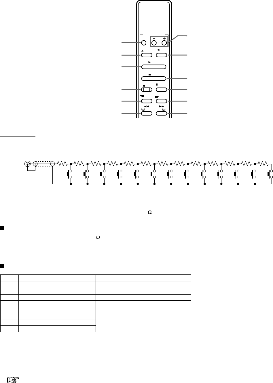
33Others
Reference page
Remote Controller (Optional)
Remote Jack
Circuit
1) Resistor : Metal film resistor 1/4 W, resistance tolerance ± 1%
Temperature factor ± 100 PPM/°C
2) Button switch : Momentary, ON resistor 200 or under
3) Connector MJ : Miniature jack, 2.5 mm in diameter, comply with JISC6560
Operational conditions
1) Isolation resistor : 200 M or over (in connector MJ)
2) Floating capacity : 0.1 µF or under (in connector MJ)
3) Environmental temperature : 5-40 °C (common with VCR)
4) Relative temperature : Max. 80 % (common with VCR)
Remote control switch functions
Shielded cable
MJ
12345678910111213
62 kΩ13 kΩ15 kΩ16 kΩ20 kΩ22 kΩ27 kΩ30 kΩ36 kΩ43 kΩ56 kΩ75 kΩ100 kΩ
SW SW SW SW SW SW SW SW SW SW SW SW SW
Position
1
2
3
4
5
6
7
8
EJECT
STOP
RECORDING
PAUSE
PLAYBACK
REVERSE PLAYBACK
FAST FORWARD
REWIND
Function
Position
9
10
11
12
13
FORWARD FRAME SHIFT
REVERSE FRAME SHIFT
(
+
)
REC/PLAY MODE
(
–
)
REC/PLAY MODE
(Not available)
Function
The optional remote controller (R-9100) provides remote operation of the VCR. Connect to the REMOTE terminal at the VCR’s rear
panel before use.
PLAY
EJECT
SP/EP
STOP
REC PAUSE
/STILL
FR ADV
REV
FR ADV
FF
//
REW
REC/PLAY MODE
STOP button
REV PLAY button
REC/PLAY MODE
(–) (+) button
PAUSE/STILL button
FR ADV button
FF button
PLAY button
(Not available)
EJECT button
REC button
REV FR ADV button
REW button
REV
PLAY
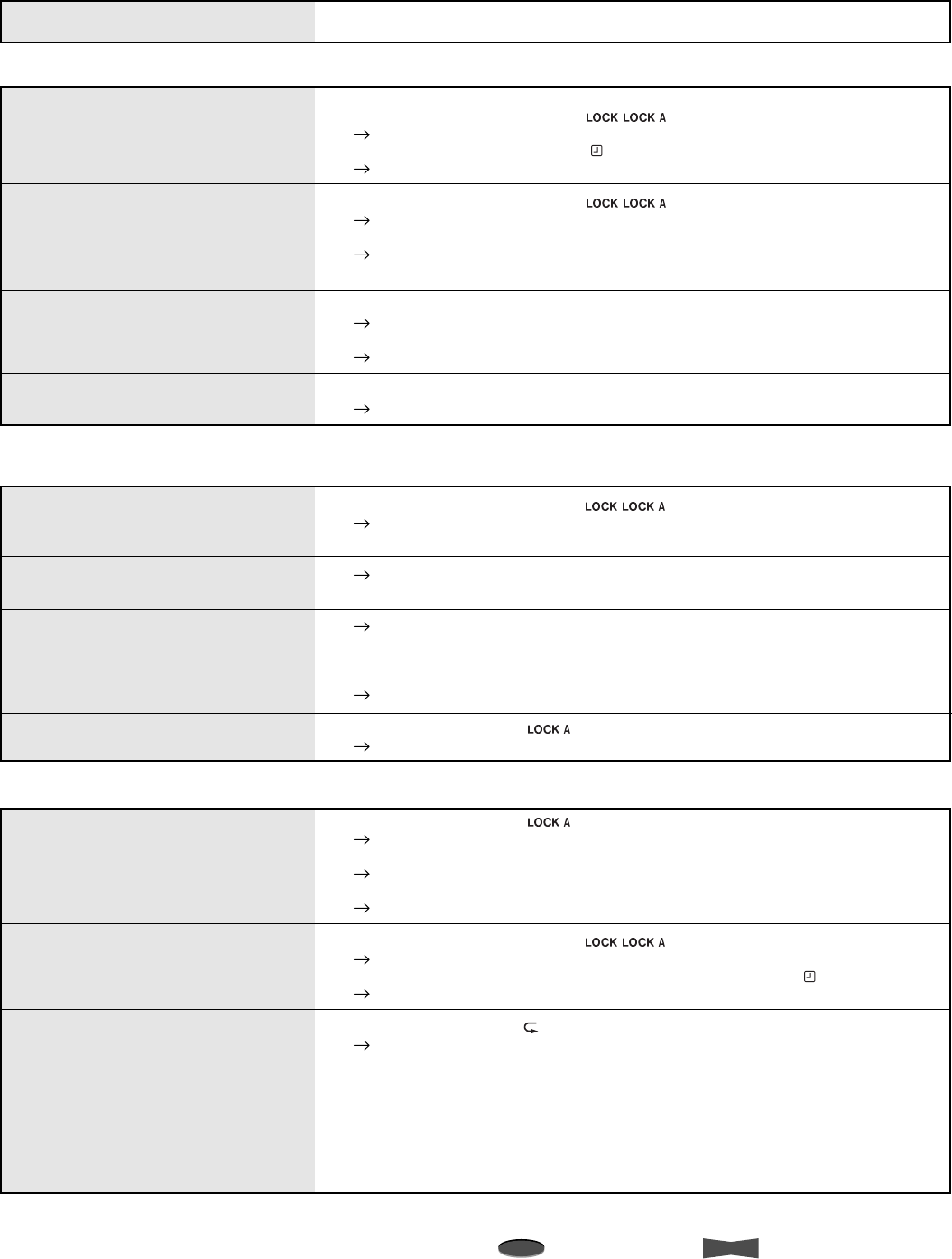
34 Others
Note
A point to notice
Info.
Supplementary information
Before Calling for Service
Symptom
Installation
No power supplied to VCR.
The VCR POWER is ON but the VCR
does not operate.
No picture is obtained on the MONITOR
screen.
The picture is not clear on the monitor.
• Has the power cord been disconnected from the outlet?
• Is the Lock or Lock All indicator ( /) illuminated?
Press LOCK button on the front panel several times to unlock the VCR.
• Is the Timer Recording indicator ( ) illuminated?
Press TIMER RECORD button on the front panel to cancel the timer recording.
• Is the Lock or Lock All indicator ( /) illuminated?
Press LOCK button on the front panel several times to unlock the VCR.
• Safety devices are in operation.
Press RESET button on the rear panel using a pointed instrument. And then
turn the power on again.
• Is the monitor or the camera connected correctly?
Check the connection.
• Is the connecting cable properly connected, or is the cable defective?
Check the connection and also check the snapping of a wire in the cable.
• Is the camera focused?
See the user’s manual for your camera and focus the camera correctly.
Function/operation
No operation when any tape operation
button is pressed.
The present time is not correct even if
using the VCR everyday.
The power cord has been disconnected
for less than 31 days but the present
time has been reset.
A tape cannot be loaded.
Remedy
• Is the Lock or Lock All indicator ( / ) illuminated?
Press LOCK button on the front panel several times to unlock the VCR.
• Is a cassette inserted?
Make sure the power cord is connected to the outlet for approximately 40 or
more hours per week when using it everyday.
Make sure the power cord is connected to the outlet for approximately 40 or
more hours per week when using it everyday.
• The reserved contents may be erased even within 31 days depending on the
charging time of the power failure compensation circuit.
Set the present time setting again.
• Is the Lock All indicator ( ) illuminated?
Press LOCK button on the front panel once to unlock the VCR.
Recording
Recording does not work by pressing
the RECORD button.
Recording cannot be stopped by
pressing the STOP button.
Repeat recording does not work.
• Is the Lock All indicator ( ) illuminated?
Press LOCK button on the front panel once to unlock the VCR.
• Has the cassette’s erasure prevention tab been broken off?
Load the cassette with its erasure prevention tab intact.
• Has the tape run out?
Rewind the tape or load a new tape.
• Is the Lock or Lock All indicator ( / ) illuminated?
Press LOCK button on the front panel several times to unlock the VCR.
• Is the VCR in timer recording mode (Timer recording indicator ( ) is illuminating)?
Press TIMER RECORD button once.
• Is the Repeat indicator ( ) illuminated?
Set TAPE END in the FIRST TIME SET UP menu to REPEAT or
ALARM•PROT.
When TAPE END in the FIRST TIME SET UP menu is set to ALARM•PROT,
repeat recording does not work using a tape with an alarm recording.
When a tape reaches its end during the emergency recording (recording
started while the VCR is stopped or the VCR power is off), the VCR rewinds
the tape and stops (recording does not start again) even though TAPE END in
the FIRST TIME SET UP menu is set to REPEAT.
When you find any problem with this VCR, first check the following. If you still cannot solve the problem, stop using the VCR, unplug
it from an outlet and contact your dealer.
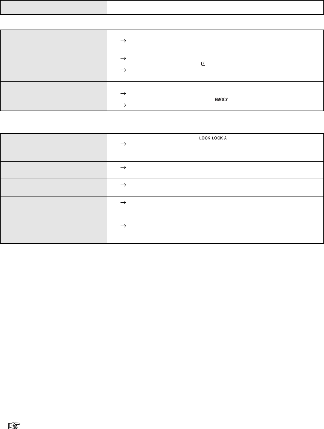
35Others
Reference page
Recording (continued)
No operation when the PLAY button is
pressed.
Noise bars in the picture during
playback.
Playback speed is fast or slow.
The picture vibrates at the top and
bottom when in still picture mode.
Clear camera pictures during recording
but during playback the picture is not
clear.
Timer recording does not operate.
Alarm recording does not work.
• Is the Lock or Lock All indicator ( / ) illuminated?
Press LOCK button on the front panel several times to unlock the VCR.
• Is a cassette inserted?
• Has the tape run out?
Adjust the tracking by pressing TRACKING buttons on the front panel.
Adjust the playback speed by pressing REC/PLAY MODE buttons on the front
panel.
Adjust the picture by pressing VERTICAL ADJUST buttons on the front panel.
• The video heads may be clogged.
Eject the cassette, insert it again and wait for more than 5 seconds. Repeat
this step for 4 to 5 times. If this does not correct the problem contact your
dealer.
• Have the day and present time been set accurately?
Set the day and present time again.
• Have the recording start-time, recording end-time and the recording mode been
set accurately?
Confirm the settings on the <PROGRAM TO RECORD>.
• Is the Timer Recording indicator ( ) illuminated?
If not, press TIMER RECORD button on the front panel to stand by the timer
recording.
• Is the external switch connected correctly?
Check the connection.
• Is the Emergency Recording indicator ( ) illuminated?
Set EMERGENCY REC in the RECORDING SET UP menu to ON.
Playback
Symptom Remedy

36 Others
Note
A point to notice
Info.
Supplementary information
Warning Display
Self-diagnostic function
This VCR uses a self-diagnostic function to detect an internal malfunction during recording. When a malfunction occurs in the VCR
during recording, the indicator corresponding to each malfunction illuminates on the fluorescent display and/or on screen.
The type of malfunction corresponding to the indicator and countermeasures are given below.
When the tape ends
When the tape reaches its end during recording, “End” illuminates on the fluorescent display and “TAPE END” illuminates on screen.
The warning indicators will not illuminate, if TAPE END in FIRST TIME SET UP menu is set to REPEAT, ALARM•PROT (when no
alarm recording is made) or REWIND.
Lack of video signal input
The indicator “NO SIGNAL” appears on screen and “noSIg” flashes on the fluorescent display when the VCR cannot get any video
input signal during recording. The video input signal will not be obtained in case of any malfunction such as a broken video cable or
POWER to the camera is turned off.
To turn off the indicatorRemedy
Fluorescent
display Monitor
The tape ends during
recording.
Cause
TAPE END
NO SIGNAL
CHECK Tape/deck trouble
during recording
Lack of video signal input
during recording Check for loose
connections.
Rewind the tape or
press the EJECT button
First, check the cassette. If there seems to be nothing wrong with
the cassette, try the recording operation again. If the indicator
“CHECK” is still displayed on the monitor, replace the cassette with
a new one and try the operation again. If this does not clear the
indicator unplug the power cord and contact your dealer.
When a video signal is restored or the
recording mode is cleared, the indicator
on the fluorescent display and screen
turns off.
Turn off the indicator on the fluorescent
display and screen by pressing the
EJECT button or rewinding the tape.
End
noSIg
(the display
starts flashing)
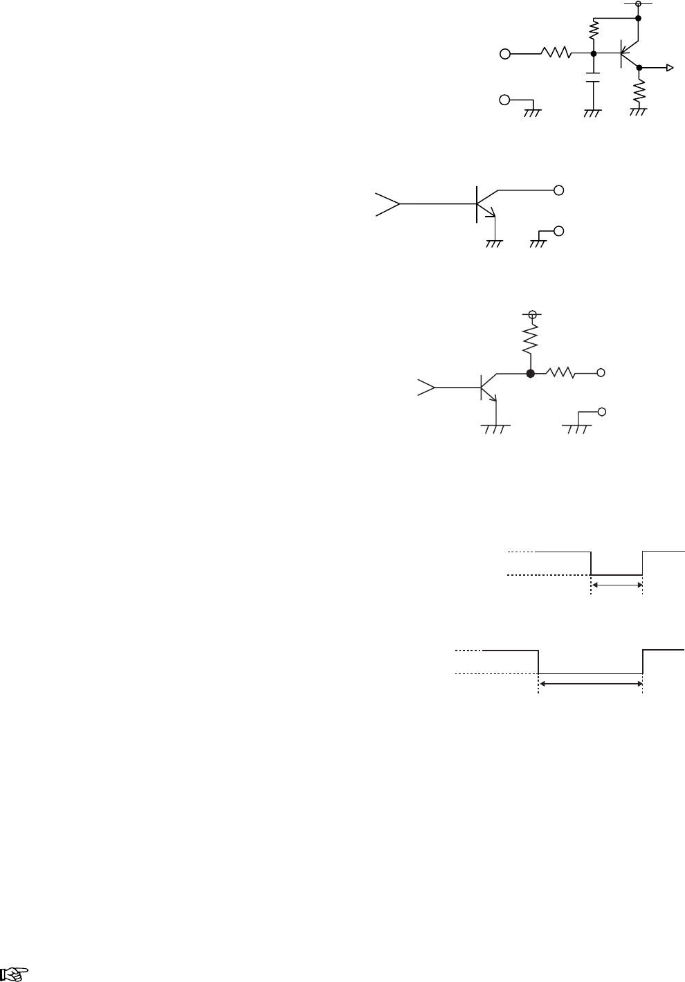
37Others
Reference page
Control Input/Output Signals and Circuit
16 ms
+12 V
0 V
8 ms
+12 V
0 V
CLK OUT signal
• When F is selected in CLOCK OUT of REAR TERMINAL
menu (at 6H or 8H mode) or while recording in L18H-128H or
0H mode.
• When REC-1 to REC-60 is selected in CLOCK OUT of REAR
TERMINAL menu (at 6H or 8H mode).
CLK OUT terminals (screw)
DC 12 V
10 kΩ
GND
CLK OUT
10 kΩ
<Interface circuit inside the VCR>
ALM/MODE/CALL OUT terminals (screw)
Active : “L” level voltage (0 to + 0.4 V) output;
max. drive current 50 mA (+5 V DC)/10 mA
(+24 V DC)
Non active : Open; max. voltage +24 V DC
GND
ALM/MODE/CALL OUT
<Interface circuit inside the VCR>
ALM/RST/REC IN terminals (screw)
Active : When input terminals are short-circuited to
GND or “L” level voltage (0 to +1.6 V) applied.
Time for active : 0.1 sec. or over.
Non active : Open the input.
DC 5 V
10 kΩ
22 kΩ
22 kΩ
0.047 µF
GND
ALM/RST/REC IN
<Interface circuit inside the VCR>
38 Others
Note
A point to notice
Info.
Supplementary information
Specifications
Weight and dimensions shown are approximate.
Design and specifications are subject to change without notice.
Note
If the VCR is not working correctly or showing an unusual indication on the fluorescent display, press RESET button at the rear panel with a pointed
instrument. When pressed, Date/Present time/ALARM LIST/POWER LOSS LIST/Counter display/Recording and Playback mode will be set to the
default setting and the VCR turns off.
To restart the VCR, press POWER button to turn on the VCR and then set the day and present time.
Connectors
ALM Input : Screw terminal for starting alarm recording
RST Input : Screw terminal for finishing alarm recording or for
adjusting on-screen clock
REC Input : Screw terminal for starting/finishing recording or for
series recording
GND : Screw terminal for ground
ALM Output : Screw terminal for output while alarm recording is
under way
CLK Output : Screw terminal to command camera switching
MODE Output : Screw terminal for indication of VCR selected mode
CALL Output : Screw terminal for external warning device or for
series recording
REMOTE Jack : Jack for connecting the remote control unit
RS-485 Interface
: RJ-45 (female) connector
Video
Input : 1.0 V (p-p), 75 , BNC plug
Output <Rear> : 1.0 V (p-p), 75 , BNC plug
Output <Front> : 1.0 V (p-p), 75 , RCA plug
Signal-to-Noise Ratio : Better than 42 dB
Horizontal Resolution : More than 400 lines (
Super Resolution mode
)
More than 240 lines (VHS mode)
Audio
Input <Line In> : 308 mV (rms), 50 k , RCA plug
Input <MIC In> : 0.346 mV (rms), 600 , mini jack
Output : 388 mV (rms), 1 k , RCA plug
Signal-to-Noise Ratio : Better than 43 dB
Frequency Response : 70 Hz - 4 kHz (6H mode)
General
Power Source : AC 100-230 V ± 10%, 50/60 Hz
(The included power cord is used for
120 V, 60 Hz.)
Power Consumption : Approx. 20 watts
Television System : EIA standard 525 lines, 60 field NTSC-
type color system
Color Signal : Low frequency conversion, sub-carrier
phase shift recording
Tape Format : VHS 1/2” width high-density video
cassette tape
Tape Speed and Recording : See below (*1)
Fast Forward/Rewind Time : Approx. 120 seconds with T-120 tape
Approx. 160 seconds with T-160 tape
Operating Temperature : 41 °F to 104 °F (5 °C to 40 °C)
Relative Humidity : Max. 80 %
Dimensions
(Jog dial included)
: 16.7 (W) x 12.3 (D) x 3.7 (H) (in.)
425 (W) x 313 (D) x 95 (H) (mm)
Weight : 9.7 lbs (4.4 kg)
Heads-Video : 4 rotary heads
Luminance Signal : Frequency modulation recording
Audio Track : 1 track
Audio/Control : 1 stationary head
Erase : 1 full-track head
Motors : 3 motors-drum/capstan direct drive
system
Battery Backup : Lasts 31 days
(*1)
Tape Speed and Recording Time :
Mode
T-120 T-160
6H (EP)
L18H (EP)
L30H (EP)
48H (EP)
72H (EP)
96H (EP)
0H (EP)
Time
(hour:minute)
Speed
(mm/s)
11.12
3.71
2.22
–
–
–
–
Recording
Interval
(s/field)
0.0167
0.050
0.083
0.150
0.217
0.284
–
Recording Fields
per Second
(fields/s)
60
20
12
6.7
4.6
3.5
–
Tape Drive
Continuous
Continuous (Slow)
Continuous (Slow)
Time Lapse
Time Lapse
Time Lapse
Time Lapse
Audio Signal
Recordable
Recordable
Recordable
Not recorded
Not recorded
Not recorded
Not recorded
Video Signal
Continuous
Time Lapse
Time Lapse
Time Lapse
Time Lapse
Time Lapse
Time Lapse
6:00
18:00
30:00
54:00
78:00
102:00
–
Mode
8H (EP)
L24H (EP)
L40H (EP)
64H (EP)
96H (EP)
128H (EP)
0H (EP)
Time
(hour:minute)
8:00
24:00
40:00
72:00
104:00
136:00
–