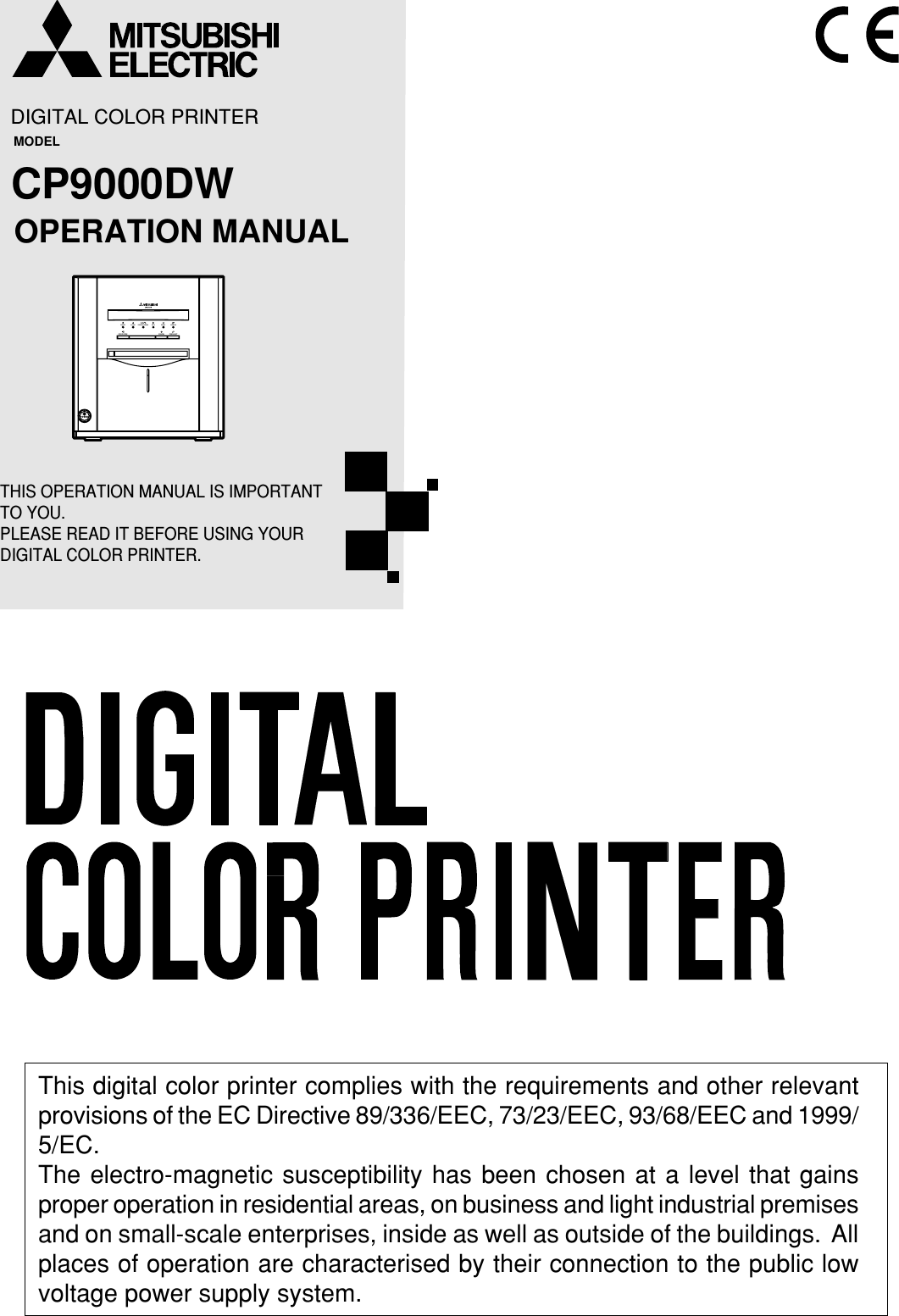
Mitsubishi Electric CP9000DW Digital Color Printer User Manual 01 cover
Mitsubishi Electric Corp Digital Color Printer 01 cover
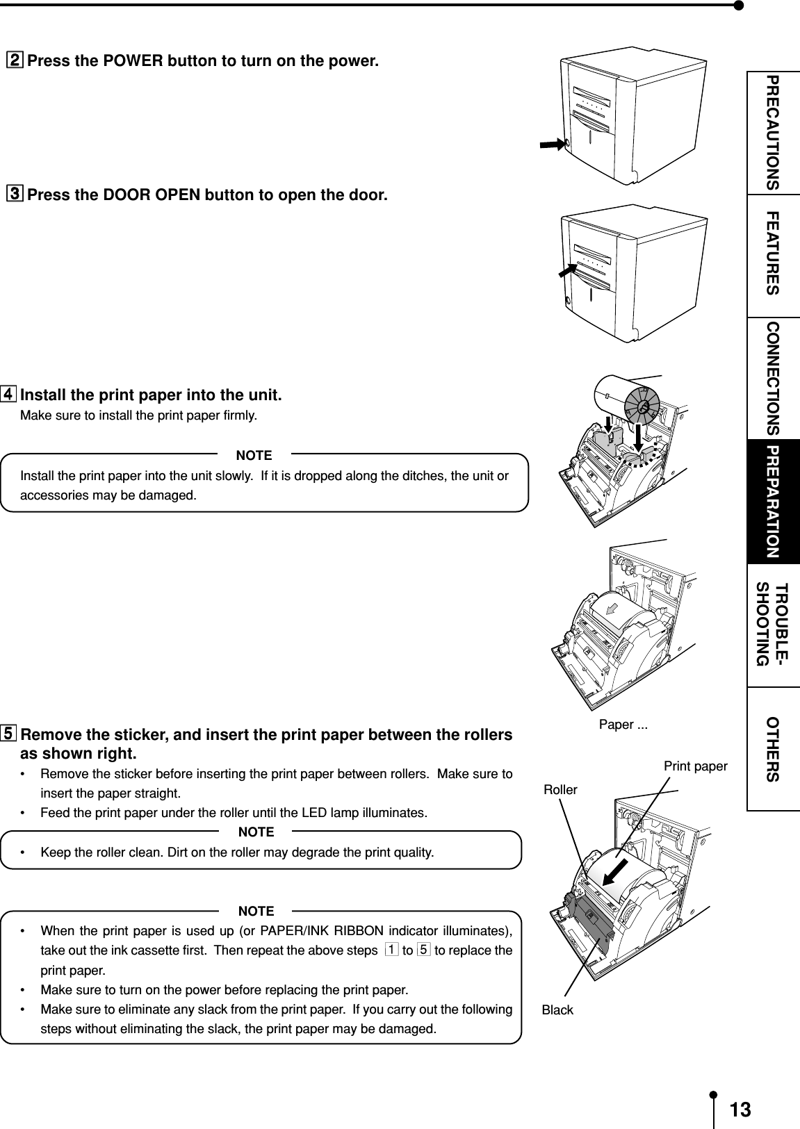
UserManual.wiki
>
Mitsubishi Electric
>
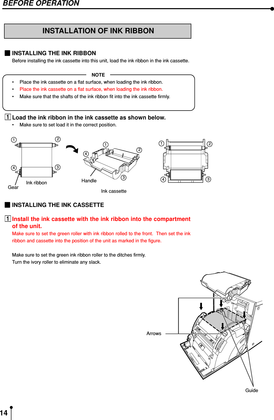
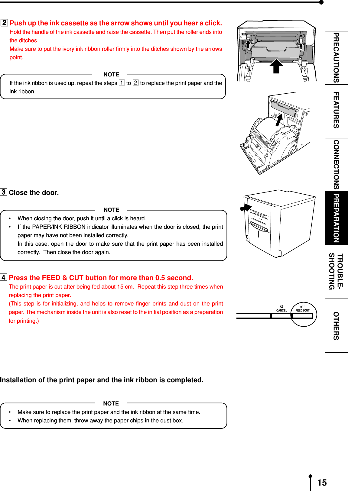
CP9000DW User Manual
Manual
Navigation menu
Upload a User Manual
Namespaces
Wiki Guide
HTML
PDF
Info
Views
User Manual
Discussion / Help
Navigation