Mitsubishi Electronics Digital Garage Door Opener Fx3U Users Manual ENET L USER'S
FX3U to the manual c77e852e-c715-41af-bd3f-5fd5117ce0f2
2015-02-09
: Mitsubishi-Electronics Mitsubishi-Electronics-Mitsubishi-Digital-Electronics-Garage-Door-Opener-Fx3U-Users-Manual-556698 mitsubishi-electronics-mitsubishi-digital-electronics-garage-door-opener-fx3u-users-manual-556698 mitsubishi-electronics pdf
Open the PDF directly: View PDF ![]() .
.
Page Count: 284 [warning: Documents this large are best viewed by clicking the View PDF Link!]
- Front Cover
- SAFETY PRECAUTIONS
- CONTENTS
- About Manuals
- Associated Manuals
- Applicable Standard
- The Manual's Usage and Structure
- About the Generic Terms and Abbreviations
- 1 OVERVIEW
- 2 SYSTEM CONFIGURATIONS
- 3 SPECIFICATIONS
- 3.1 Performance Specifications
- 3.2 Data Codes for Communication
- 3.3 Relationship between the External Devices and Additional Functions for Each Communication Function
- 3.4 Ethernet Module Function List
- 3.5 List of Setting Items for Ethernet Modules
- 3.6 List of Applications and Assignments of the Buffer Memory
- 4 SETTINGS AND PROCEDURES PRIOR TO OPERATION
- 5 COMMUNICATION PROCEDURE
- 6 FIXED BUFFER COMMUNICATION (WITH THE PROCEDURE EXIST CONTROL METHOD)
- 7 FIXED BUFFER COMMUNICATION (WITH THE NO PROCEDURE CONTROL METHOD)
- 8 COMMUNICATION USING MC PROTOCOL
- 9 WHEN COMMUNICATING DATA USING THE MC PROTOCOL
- 9.1 Message Formats and Control Procedures
- 9.2 List of Commands and Functions for The MC protocol
- 9.3 Device Memory Read/Write
- 9.3.1 Commands and device range
- 9.3.2 Batch read in bit units (command: 00)
- 9.3.3 Batch write in bit units (command: 02)
- 9.3.4 Test in bit units (random write) (command: 04)
- 9.3.5 Batch read in word units (command: 01)
- 9.3.6 Batch write in word units (command: 03)
- 9.3.7 Test in word units (random write) (command: 05)
- 9.4 Remote RUN/STOP, PLC model name code read
- 9.5 Loopback Test
- 10 USING THE E-MAIL FUNCTION
- 10.1 E-mail Function
- 10.2 Configuration and Environment of the Applicable System
- 10.3 Precautions for Using the E-mail Function
- 10.4 E-mail Specifications
- 10.5 Processing Procedure of the E-mail Function
- 10.6 E-mail Settings
- 10.7 Sending E-mail (Attached Files) by the PLC
- 10.8 Sending E-mail (Main Text) by the PLC
- 11 TROUBLESHOOTING
- APPENDIX
- Warranty
- Revised History
- Back Cover

FX3U-ENET-L
USER'S MANUAL
A - 1 A - 1
SAFETY PRECAUTIONS
(Read these precautions before use.)
Before installation, operation, maintenance or inspection of this product, thoroughly read through and
understand this manual and all of the associated manuals. Also, take care to handle the module properly and
safely.
This manual classifies the safety precautions into two categories: "DANGER" and "CAUTION."
Depending on the circumstances, procedures indicated by CAUTION may also cause severe injury.
It is important to follow all precautions for personal safety.
Store this manual in a safe place so that it can be taken out and read whenever necessary. Always
forward it to the end user.
[Design Precautions]
DANGER
To prevent malfunctions of the PLC system that may be caused by illegal e-mail, take proper
countermeasures (such as virus detection) so that illegal e-mail is not received by the mail
server of this module.
If it is necessary to ensure the security of the PLC system against unauthorized access from
external devices via the Internet, appropriate measures must be incorporated by the user.
When controlling the PLC (modifying data) while it is in operation by connecting computer
peripheral devices to the main unit or connecting personal computers to the extension device,
make sure to have an interlock circuit outside of the PLC to ensure safe system operation.
Do not write any data in the "system area" of the buffer memory of the extension device. When
writing a value to the buffer memory including "System Area," pay close attention not to change
the system bit. If data is written to the "system area" or the "use prohibited" signal is output,
there is a risk that the PLC system may malfunction.
When the program examples introduced in this manual are applied to the actual system,
examine the safety of the control in the target system.
DANGER
Indicates that incorrect handling may cause hazardous conditions,
resulting in death or severe injury.
Indicates that incorrect handling may cause hazardous conditions,
resulting in medium or slight personal injury or physical damage.
CAUTION
A - 2 A - 2
[Design Precautions]
[Installation Precautions]
CAUTION
When the status control (remote RUN/STOP) of the PLC is performed from the external device,
select the "Always wait for OPEN" parameter set by an user in advance. (Select with the initial
timing setting (BFM#24 b8) in the operational setting.) When "Do not wait for OPEN" is selected,
the communication line at remote STOP is closed. The communication line cannot be reopened
on the PLC side after that, and the remote RUN from the external device cannot start.
CAUTION
Use the product within the generic environment specifications described in chapter 3 of this
manual.
Never use the product in areas with excessive dust, oily smoke, conductive dusts, corrosive gas
(salt air, Cl2, H2S, SO2 or NO2), flammable gas, vibration or impacts, or exposed to high
temperature, condensation, or rain and wind.
If the product is used in such conditions, electric shock, fire, malfunctions, deterioration or
damage may occur.
When drilling screw holes or wiring, make sure cutting or wire debris does not enter the
ventilation slits.
Failure to do so may cause fire, equipment failures or malfunctions.
Be sure to remove the dust proof sheet from the PLC's ventilation port when installation work is
completed. Failure to do so may cause fire, equipment failures or malfunctions.
Connect the extension cables securely to their designated connectors.
Unsecured connection may cause malfunctions.
A - 3 A - 3
[Wiring Instructions]
DANGER
Before mounting or wiring the module, make sure to shut off all of the external power supply.
Failure to do so may cause electric shocks or damage the module.
When turning on the power and operating after mounting or wiring the module, make sure to
install the accessory terminal covers to the product.
Otherwise, it may cause electric shocks.
CAUTION
Make sure to place the communication cables and the power cables in a duct or fasten them
using a clamp.
If the cables are not placed in a duct or fastened with a clamp, their positions can be unstable,
moved and pulled inadvertently. This may damage the module and the cables, or cause the
module malfunction due to unsecured cable connections.
When disconnecting the communication cables and the power cables, do not pull the cables.
When disconnecting a cable with a connector, hold the connector to the module by hand and
pull it out to remove the cable.
When disconnecting a cable connected to a terminal block, loosen the screws on the terminal
block before removing the cable.
If a cable is pulled while being connected, it may cause the module malfunction or damage the
module and the cable.
Do not bundle the control line and the communication cables together with or lay it close to the
main circuit or power line. As a guideline, lay the control line and the communication cables at
least 100mm (3.94") or more away from the main circuit or power line.
Noise may cause malfunctions.
Before connecting twisted pair cables, the ground pin brush grounded via a resistor enables
discharging static electricity on the cables effectively. This can prevent the electrostatic
discharge to the product.
A - 4 A - 4
[Setup and Maintenance Precautions]
[Precautions When Disposing of This Product]
[Transportation Precautions]
DANGER
Do not touch any terminal while the PLC's power is on.
Doing so may cause electric shock or malfunctions.
Before cleaning or retightening terminal screws and module mounting screws, externally cut off
all phases of the power supply.
Failure to do so may cause electric shock, fire, malfunctions and product damage.
Before modifying or disrupting the program, forcible output, RUN and STOP while they are in
operation, carefully read through this manual and the associated manuals and ensure the safety
of the operation.
An operation error may damage the machinery or cause accidents.
CAUTION
Do not disassemble or modify the PLC.
Doing so may cause fire, equipment failures, or malfunctions.
For repair, contact your local Mitsubishi Electric distributor.
Cut off all phases of the power supply externally before installation or wiring work in order to
avoid damage to the product or electric shock.
CAUTION
Dispose of this product as an industrial waste.
CAUTION
The PLC is a precision instrument. During transportation, avoid impacts larger than those
specified in the general specifications of the PLC main unit manual.
Failure to do so may cause failures in the PLC.
After transportation, verify the operations of the PLC.
Other company and product names herein are either trademarks or registered trademarks of their respective owners.
Microsoft , Windows 2000, Outlook , Visual C++ and Visual Basic are either registered trademarks or trade-
marks of Microsoft Corporation in the United States and/or other countries.
This manual confers no industrial property rights or any rights of any other kind, nor does it confer any patent
licenses. Mitsubishi Electric Corporation cannot be held responsible for any problems involving industrial property
rights which may occur as a result of using the contents noted in this manual.

A - 5 A - 5
CONTENTS
SAFETY PRECAUTIONS .....................................................................................................................A- 1
CONTENTS ..........................................................................................................................................A- 5
About Manuals ......................................................................................................................................A- 9
Associated Manuals..............................................................................................................................A- 9
Applicable Standard..............................................................................................................................A-10
The Manual's Usage and Structure.......................................................................................................A-12
About the Generic Terms and Abbreviations ........................................................................................A-14
1 OVERVIEW 1- 1 to 1- 9
1.1 Overview of the Ethernet Module................................................................................................... 1- 1
1.2 Features of the Ethernet Module ................................................................................................... 1- 3
1.3 Software Configuration .................................................................................................................. 1- 7
2 SYSTEM CONFIGURATIONS 2- 1 to 2- 3
2.1 Applicable Systems........................................................................................................................ 2- 1
2.2 Devices Required for Network Configuration.................................................................................2- 2
3 SPECIFICATIONS 3- 1 to 3-25
3.1 Performance Specifications ........................................................................................................... 3- 1
3.2 Data Codes for Communication..................................................................................................... 3- 3
3.3 Relationship between the External Devices and Additional Functions for Each Communication
Function ......................................................................................................................................... 3- 5
3.4 Ethernet Module Function List ....................................................................................................... 3- 6
3.5 List of Setting Items for Ethernet Modules ..................................................................................... 3- 7
3.6 List of Applications and Assignments of the Buffer Memory .......................................................... 3- 8
4 SETTINGS AND PROCEDURES PRIOR TO OPERATION 4- 1 to 4-17
4.1 Loading and Installation ................................................................................................................. 4- 1
4.1.1 Handling precautions ............................................................................................................... 4- 1
4.1.2 Installation environment ........................................................................................................... 4- 2
4.2 Settings and Procedures Prior to Starting the Operation............................................................... 4- 3
4.3 Components of the Ethernet Module ............................................................................................. 4- 5
4.4 Connecting to the Network............................................................................................................. 4- 7
4.4.1 Connecting to the 10BASE-T/100BASE-TX network............................................................... 4- 8
4.5 Ethernet Module Setting ................................................................................................................ 4- 9
4.6 Operational Settings ...................................................................................................................... 4-10
4.7 Self-Diagnostic Tests ..................................................................................................................... 4-14
4.7.1 Self loopback test..................................................................................................................... 4-14
4.7.2 Hardware test (H/W Test) ........................................................................................................ 4-15
4.8 Maintenance and Inspection .......................................................................................................... 4-16
4.8.1 Maintenance and inspection .................................................................................................... 4-16
4.8.2 Installing and uninstalling the module ...................................................................................... 4-17

A - 6 A - 6
5 COMMUNICATION PROCEDURE 5- 1 to 5-46
5.1 Overview of the Communication Procedure .................................................................................. 5- 1
5.2 Initial Processing............................................................................................................................ 5- 3
5.2.1 Initial processing ...................................................................................................................... 5- 3
5.2.2 Initial settings ........................................................................................................................... 5- 4
5.2.3 Re-initialization......................................................................................................................... 5-10
5.3 Router Relay Parameter ................................................................................................................ 5-13
5.4 Confirming the Completion of the Initial Processing ...................................................................... 5-15
5.4.1 PING command (Personal computer Ethernet module) .................................................... 5-16
5.4.2 Loop back test (Communication using MC protocol) ............................................................... 5-17
5.5 Open Settings ................................................................................................................................ 5-18
5.5.1 Fixed buffer connection (connection No. 1 and connection No. 2) .......................................... 5-18
5.5.2 MELSOFT/MC protocol connections (connection No. 3 and connection No. 4) ...................... 5-24
5.6 Open Processing/Close Processing of the Connection ................................................................. 5-25
5.6.1 Active open processing/close processing ................................................................................ 5-27
5.6.2 Passive open processing/close processing ............................................................................. 5-33
5.6.3 UDP/IP open processing/close processing.............................................................................. 5-40
5.7 Pairing Open .................................................................................................................................. 5-43
5.7.1 Pairing open............................................................................................................................. 5-43
5.7.2 Example of pairing open settings............................................................................................. 5-44
5.8 Hub Connection Status Monitor Function ...................................................................................... 5-46
6 FIXED BUFFER COMMUNICATION
(WITH THE PROCEDURE EXIST CONTROL METHOD) 6- 1 to 6-18
6.1 Control Method .............................................................................................................................. 6- 1
6.2 Sending Control Method ................................................................................................................ 6- 3
6.3 Receiving Control Method.............................................................................................................. 6- 6
6.3.1 Receive processing with the main program ............................................................................. 6- 6
6.4 Data Format ................................................................................................................................... 6- 8
6.4.1 Header ..................................................................................................................................... 6- 8
6.4.2 Application data ....................................................................................................................... 6- 9
6.5 Programming ................................................................................................................................. 6-13
6.5.1 Precautions when creating programs ...................................................................................... 6-13
6.5.2 Fixed buffer communication program example (with the procedure exist control method)...... 6-14
7 FIXED BUFFER COMMUNICATION
(WITH THE NO PROCEDURE CONTROL METHOD) 7- 1 to 7-14
7.1 Control Method .............................................................................................................................. 7- 1
7.2 Sending Control Method ................................................................................................................ 7- 4
7.3 Receiving Control Method.............................................................................................................. 7- 6
7.3.1 Receive processing with the main program ............................................................................. 7- 6
7.4 Data Format ................................................................................................................................... 7- 8
7.5 Programming ................................................................................................................................. 7- 9
7.5.1 Precautions when creating programs ...................................................................................... 7- 9
7.5.2 Fixed buffer communication program example (with the no procedure control method) ......... 7-10

A - 7 A - 7
8 COMMUNICATION USING MC PROTOCOL 8- 1 to 8- 5
8.1 Data Communication Function....................................................................................................... 8- 1
8.1.1 Accessing the PLC using MC protocol..................................................................................... 8- 1
8.1.2 How to Read the Control Procedures of the MC Protocol ....................................................... 8- 2
8.1.3 Access Timing on the PLC Side .............................................................................................. 8- 3
8.1.4 PLC setting for performing data communication...................................................................... 8- 4
8.1.5 Precautions on Data Communication ...................................................................................... 8- 4
9 WHEN COMMUNICATING DATA USING THE MC PROTOCOL 9- 1 to 9-40
9.1 Message Formats and Control Procedures ................................................................................... 9- 1
9.1.1 How to read the command reference section .......................................................................... 9- 1
9.1.2 Message format and control procedure ................................................................................... 9- 3
9.1.3 Contents of data designation items.......................................................................................... 9- 7
9.1.4 Character area transmission data............................................................................................ 9-11
9.2 List of Commands and Functions for The MC protocol.................................................................. 9-15
9.3 Device Memory Read/Write ........................................................................................................... 9-16
9.3.1 Commands and device range .................................................................................................. 9-16
9.3.2 Batch read in bit units (command: 00) ..................................................................................... 9-19
9.3.3 Batch write in bit units (command: 02)..................................................................................... 9-21
9.3.4 Test in bit units (random write) (command: 04) ....................................................................... 9-23
9.3.5 Batch read in word units (command: 01) ................................................................................. 9-25
9.3.6 Batch write in word units (command: 03)................................................................................. 9-29
9.3.7 Test in word units (random write) (command: 05) ................................................................... 9-33
9.4 Remote RUN/STOP, PLC model name code read ........................................................................ 9-35
9.4.1 Commands and control contents ............................................................................................. 9-35
9.4.2 Remote RUN (command: 13) / Remote STOP(Command: 14) ............................................... 9-36
9.4.3 PLC model name read (command: 15).................................................................................... 9-38
9.5 Loopback Test ............................................................................................................................... 9-39
9.5.1 Loopback test (command: 16) ................................................................................................. 9-39
10 USING THE E-MAIL FUNCTION 10- 1 to 10-19
10.1 E-mail Function .......................................................................................................................... 10- 1
10.1.1 E-mail send by the PLC ....................................................................................................... 10- 1
10.2 Configuration and Environment of the Applicable System......................................................... 10- 3
10.3 Precautions for Using the E-mail Function.................................................................................10- 4
10.4 E-mail Specifications.................................................................................................................. 10- 5
10.5 Processing Procedure of the E-mail Function............................................................................ 10- 6
10.6 E-mail Settings........................................................................................................................... 10- 7
10.7 Sending E-mail (Attached Files) by the PLC.............................................................................. 10-10
10.7.1 When sending data as an attached file................................................................................ 10-10
10.7.2 Contents of the attached files .............................................................................................. 10-16
10.8 Sending E-mail (Main Text) by the PLC.....................................................................................10-17
10.8.1 When sending data as main text of e-mail........................................................................... 10-17

A - 8 A - 8
11 TROUBLESHOOTING 11- 1 to 11-42
11.1 How to Check Errors Using LED Displays ................................................................................. 11- 2
11.1.1 Checking error display ......................................................................................................... 11- 2
11.1.2 How to turn off COM.ERR LED and to read/clear error information .................................... 11- 4
11.2 How to Check an Error Through FX Configurator-EN-L ............................................................ 11- 6
11.2.1 Buffer memory that can be monitored with the FX Configurator-EN-L diagnostic function.. 11- 7
11.2.2 Ethernet diagnostics ............................................................................................................ 11- 9
11.3 Checking the error information by the buffer memory batch monitoring function ...................... 11-10
11.4 Error Code List........................................................................................................................... 11-11
11.4.1 Type of error incident ........................................................................................................... 11-11
11.4.2 End codes (Complete codes) returned to an external device during data communication.. 11-17
11.4.3 Abnormal codes returned during communication using MC protocol .................................. 11-18
11.4.4 Error codes stored in the buffer memory ............................................................................. 11-19
11.5 Troubleshooting Flowchart......................................................................................................... 11-32
11.5.1 Sending errors during fixed buffer communication
(common to procedure exist and no procedure).................................................................. 11-35
11.5.2 Receiving errors during fixed buffer communication
(common to procedure exist and no procedure).................................................................. 11-37
11.5.3 Errors in communication using MC protocol ........................................................................ 11-40
11.5.4 Sending errors during e-mail communication ...................................................................... 11-42
APPENDIX App- 1 to App-26
Appendix 1 Processing Time ...........................................................................................................App- 1
Appendix 2 ASCII Code List ............................................................................................................App- 4
Appendix 3 References....................................................................................................................App- 4
Appendix 4 Program Examples .......................................................................................................App- 5
Appendix 4.1 Program example for communication using MC protocol -1 ...................................App- 6
Appendix 4.2 Program example for communication using MC protocol -2 ...................................App-14
Appendix 5 Differences between the Ethernet and the IEEE802.3 .................................................App-19
Appendix 6 ICMP Protocol Supported by the Ethernet Module .......................................................App-19
Appendix 7 Setting Value Recording Sheets ...................................................................................App-20
Appendix 8 Versioin Information ......................................................................................................App-25

A - 9 A - 9
About Manuals
This manual explains the mounting of FX3U-ENET-L, the specifications, broadcast
functions and communication methods.
For the instructions and programs of the sequence as well as the parameter settings
by FX Configurator-EN-L, also refer to the following manuals.
Associated Manuals
How to obtain manuals
For the necessary product manuals or documents, consult with the Mitsubishi
Electric dealer.
Manual name Manual No. Description
FX3U-ENET-L
User's Manual
JY997D38001
Additional Manual
MODEL CODE: 09R722
This manual
FX3U-ENET-L
INSTALLATION MANUAL
JY997D37801
Supplied with product Installation of FX3U-ENET-L
FX3U Series
HARDWARE MANUAL
JY997D18801
Supplied with product
Extracts the I/O specifications, wiring, and
installation of FX3U Series PLC from FX3U Series
User's Manual - Hardware Edition.
FX3U Series User's Manual
- Hardware Edition
JY997D16501
Additional Manual
MODEL CODE: 09R516
Explains FX3U Series PLC specification details for
I/O, wiring, installation, and maintenance.
FX3UC(D, DSS) Series
HARDWARE MANUAL
JY997D28601
Supplied with product
Extracts the I/O specifications, wiring, and installation
of FX3UC(D, DSS) Series PLC from
FX3UC Series User's Manual - Hardware Edition.
FX3UC-32MT-LT-2
HARDWARE MANUAL
JY997D31601
Supplied with product
Extracts the I/O specifications, wiring, and
installation of FX3UC-32MT-LT-2 from FX3UC Series
User's Manual - Hardware Edition.
FX3UC Series User's Manual
- Hardware Edition
JY997D28701
Additional Manual
MODEL CODE: 09R519
Explains FX3UC Series PLC specification details for
I/O, wiring, installation, and maintenance.
FX3G/FX3U/FX3UC Series
Programming Manual
- Basic & Applied Instruction
Edition
JY997D16601
Additional Manual
MODEL CODE: 09R517
Describes PLC programming for basic/ applied
instructions and devices.
FX Configurator-EN-L
Operation Manual
JY997D38401
MODEL CODE: 09R929 The operation method of FX Configurator-EN-L

A - 10 A - 10
Applicable Standard
Certification of UL, cUL standards
The following product has UL and cUL certification.
UL, cUL File Number: E95239
Models: MELSEC FX3U series manufactured
FX3U-ENET-L
Regarding the standards that comply with the main unit, please refer to either the FX
series product catalog or consult with your nearest Mitsubishi product provider.
Compliance with EC directive (CE Marking)
This note does not guarantee that an entire mechanical module produced in
accordance with the contents of this note will comply with the following standards.
Compliance to EMC directive and LVD directive of the entire mechanical module
should be checked by the user / manufacturer. For more details please contact the
local Mitsubishi Electric sales site.
Regarding the standards that comply with the main unit, please refer to either the FX
series product catalog or consult with your nearest Mitsubishi product provider.
Requirement for Compliance with EMC directive
The following products have shown compliance through direct testing (of the
identified standards below) and design analysis (through the creation of a technical
construction file) to the European Directive for Electromagnetic Compatibility
(2004/108/EC) when used as directed by the appropriate documentation.
Attention
• This product is designed for use in industrial applications.
• Manufactured by:
Mitsubishi Electric Corporation
2-7-3 Marunouchi, Chiyoda-ku, Tokyo, 100-8310 Japan
• Manufactured at:
Mitsubishi Electric Corporation Himeji Works
840 Chiyoda-machi, Himeji, Hyogo, 670-8677 Japan
• Authorized Representative in the European Community:
Mitsubishi Electric Europe B.V.
Gothaer Str. 8, 40880 Ratingen, Germany
Type: Programmable Controller (Open Type Equipment)
Models: MELSEC FX3U series manufactured
from October 1st, 2009 FX3U-ENET-L
Standard Remark
EN61131-2:2003
Programmable controllers
- Equipment requirements and tests
Complies with all relevant aspects of the following standards.
EMI
• Radiated Emissions
• Conducted Emissions
EMC
• Radiated electromagnetic field immunity
• Fast Transient burst
• Electrostatic discharge
• High-energy surge
• Voltage drops and interruptions
• Conducted RF
• Power frequency magnetic field
A - 11 A - 11
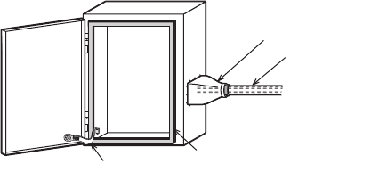
Caution to conform with EC Directives
• Installation in Enclosure
Programmable logic controllers are open-type devices that must be installed and
used within conductive control cabinets. Please use the programmable logic
controller while installed within a conductive shielded control cabinet. Please secure
the cabinet door to the control cabinet (for conduction).
Installation within a control cabinet greatly affects the safety of the system and aids
in shielding noise from the programmable logic controller.
• Control cabinet
- The control cabinet must be conductive.
- Ground the control cabinet with the thickest possible grounding cable.
- To ensure that there is electric contact between the control cabinet and its door,
connect the cabinet and its doors with thick wires.
- In order to suppress the leakage of radio waves, the control cabinet structure must
have minimal openings. Also, wrap the cable holes with a shielding cover or other
shielding devices.
- The gap between the control cabinet and its door must be as small as possible by
attaching EMI gaskets between them.
*1. These wires are used to improve the conductivity between the door and control
cabinet.
Shielding cover
Shielded cable
Wires*1 EMI gasket

A - 12 A - 12
The Manual's Usage and Structure
How to use this manual
In this manual, explanations are given for each application of the Ethernet modules
(FX3U-ENET-L).
Please use this manual using the following key items below as a reference.
(1) Features and utility lists
(a) Features and functions
• Chapter 1 describes the features of the Ethernet modules.
• Chapter 3 describes the common functions and specifications of the
Ethernet modules.
(b) Items included in this package and network configured items
• Section 2.2 describes the system configuration of the Ethernet module.
Parts and components other than those packaged with the module must
be purchased separately by the user.
(2) Processing required prior to starting the operation of the Ethernet
module
(a) Startup procedure
• Section 4.2 describes an outline of the procedures to do before starting the
operation of the Ethernet module.
(b) Connection to the Ethernet network.
• Section 2.2 describes the devices required to connect to the Ethernet
network.
• Section 4.4 describes the connection methods for each type of interface.
(c) Parameter settings required before starting Ethernet module operation
• Section 3.6 describes the parameter settings required in order to use each
function.
Confirm the required parameters, set them according to the relevant
section, and save the setting values in the PLC to which the Ethernet
module is installed.
• Section 4.5 describes the types of Ethernet parameter setting in order to
use the Ethernet module.
(d) Checking for Ethernet module failures
• Section 4.7 describes the self-diagnostic test for the Ethernet module.
(e) Checking for connection errors with the external devices
• Subsection 5.4.1 describes how to check for connection errors using the
"PING" command.
• Subsection 5.4.2 describes how to check for connection errors by
performing the loopback test through MC protocol-based communication.

A - 13 A - 13
(3) Connection between the Ethernet module and external devices
(a) Communication procedures
• Section 5.1 describes an outline of the communication procedures
(b) Connections with the external devices
• Section 5.6 describes the connections (open and close processing) for
each communication method (TCP/IP) and the open method (Active,
Passive), including programming procedures.
(4) Details on the data communication functions
(a) Communication functions
• Section 1.2 describes an overview of the Ethernet module communication
functions and related section numbers that can be referenced for more
detailed explanations.
(5) Data communication functions and programming
(a) Reading from and writing to the PLC
• Data is read from and written to the PLC with communication functions
using MC protocol.
• Chapter 8 is an overview of the communication functions using MC protocol.
• Chapter 9 is a detail on the communication functions using MC protocol.
(b) Sending and receiving data between the PLC and the external devices
• Data communication between the PLC and external devices is performed
with the fixed buffer communication functions.
• Chapters 6 and 7 explains the communication functions and programming
using the fixed buffers.
(6) Checking for error occurrences and taking corrective actions
(a) Error codes
• Chapter 11 describes troubleshooting, how to check for errors, and the
contents and reference for error codes.
(b) Error code storase area in the buffer memory of the Ethernet module
• Section 11.3 describes the error code storage areas in the buffer memory.
FX Configurator-EN-L (FX3U-ENET-L Configuration tool)
Using FX Configurator-EN-L to set parameters, the sequence programs for
communicating with external devices can be simplified.
For details on the parameter settings from FX Configurator-EN-L, refer to the FX
Configurator-EN-L operation manual.

A - 14 A - 14
About the Generic Terms and Abbreviations
This manual uses the following generic terms and abbreviations to describe the
Model FX3U-ENET-L Ethernet interface block.
Generic Term/Abbreviation Description
Ethernet Address
A machine-specific address that is also referred to as the MAC (Media Access Control
Address). This is used to identify the addresses of external devices over a network.
The Ethernet address of the Ethernet module can be verified on BFM.
Ethernet module Abbreviation for the FX3U-ENET-L Ethernet Interface block
(Described as the Ethernet module or FX3U-ENET-L in the figures)
Ethernet network Abbreviation for 10BASE-T and 100BASE-TX networks
GX Developer
Abbreviation for GX Developer (SWnD5C-GPPW-E). (n in the model name is 4 or later)
External device Generic term for personal computers, computers, workstations (WS) and Ethernet
module etc. that are connected by Ethernet for data communication
Personal computer Generic term for an IBM PC/AT (or IBM compatible) personal computer
Main unit Generic name for FX Series PLC main unit
FX Configurator-EN-L
Software for setting the Ethernet module parameters. FX Configurator-EN-L (FX3U-
ENET-L Configuration tool) can set the independent startup method, and the startup
method from the [tool] menu in GX Developer.
1 - 1
OVERVIEW1
1 - 1
1
MELSEC-F
1OVERVIEW
This manual provides information on the specifications of the Ethernet interface block,
FX3U-ENET-L (hereinafter called FX3U-ENET-L or the Ethernet module), as well as
the procedures before starting operation, the control procedures and data
communication method for communicating with external devices, maintenance,
inspection, and troubleshooting.
When the program examples introduced in this manual are applied to an actual
system, examine the safety of the control in the target system before use.
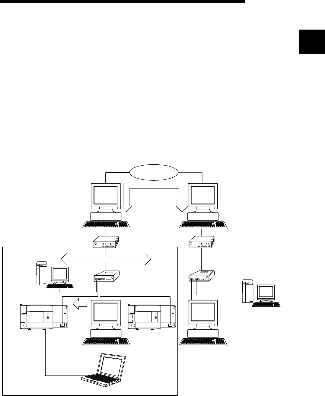
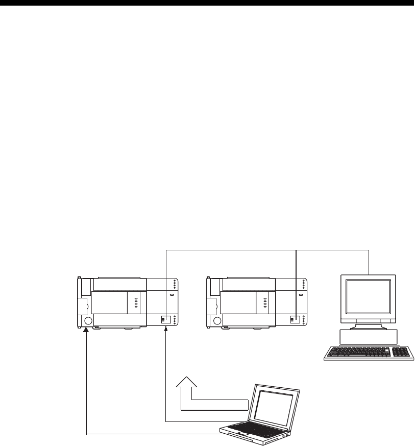
1.1 Overview of the Ethernet Module
The Ethernet module is an interface module on the PLC side for connecting the FX
3U
/
FX3UC series PLC with the host system, such as a personal computer work station,
and other PLCs using the TCP/IP or UDP/IP communication protocol via Ethernet
(100BASE-TX, 10BASE-T).
Router Router
Network Range (Only within LAN)
Local
station
External device
GX Developer
Internet service
Provider
Internet service
Provider
External device
Internet
(Public dial-up line)
Mail server Hub Hub Mail server

1 - 2
OVERVIEW1
1 - 2
1
MELSEC-F
1) Collection and modification of PLC data
(Communication using the MELSEC Communication Protocol (referred
to below as the MC Protocol))
2) Transmission and reception of arbitrary data to/from external devices
(Communication using fixed buffers)
3) Data transmission by e-mail
(When using the e-mail function)
POINT
The module operation is not guaranteed if any of the following connection is
used. Check the module operation on the user side.
• Connections using the Internet (general public line) (Connections using
Internet connection service provided by Internet service providers and
telecommunications carriers)
• Connections using devices in which a firewall is installed
• Connections using broadband routers
• Connections using wireless LAN
1 - 3
MELSEC-F
OVERVIEW1
1 - 3
1.2 Features of the Ethernet Module
(1) Data communication using MC protocol (Details are explained in
Chapter 8 and Chapter 9)
Using MC protocol, the device data of the PLC can be read from/written to the
host system.
This protocol is a passive protocol that communicates data solely according to
the requests from the host system. It does not require a sequence program for
data communication after a connection is established.
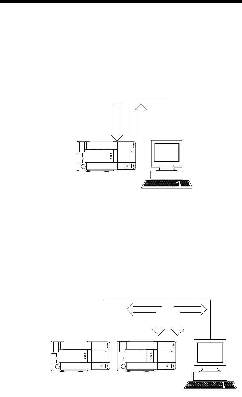
(2) Communication using fixed buffers (Details are explained in
Chapters 6 and 7)
With communication using fixed buffers, a maximum of 1023 words of arbitrary
data can be sent or received between PLCs or between the PLC and an arbitrary
device.
An Ethernet module is provided with 2 fixed buffer data areas each with 1023
word storage space, and each is assigned as either a sending or receiving buffer
for an arbitrary device.
Since communication using MC protocol is passive, communication using fixed
buffers is an active protocol. Data can be sent from the PLC side to another PLC
and an arbitrary device when equipment errors occur or when some specified
conditions are satisfied.
External device
Local station
Command
Response
Receive/send Receive/send
External device
External device
Local station
1 - 4
MELSEC-F
OVERVIEW1
1 - 4
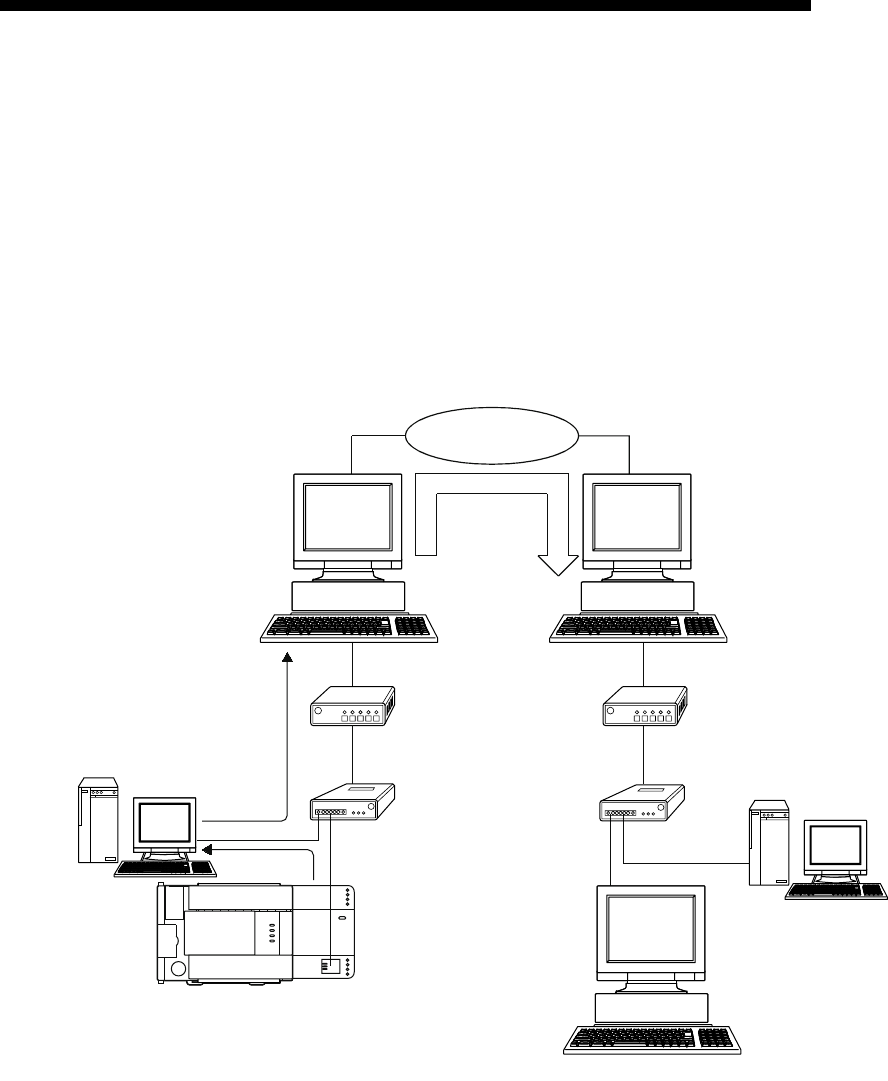
(3) Sending by e-mail (Details are explained in Chapter 10)
In "E-mail send", data can be sent to and from an external device at a remote
location using e-mails via an internet connection.
(a) Sending e-mail from the PLC
The following data can be sent by e-mail.
1) Sending data as attached files
Up to 2k words of data can be sent to from a personal computer or other
Ethernet module with mail function as a file attached to an e-mail.
2) Sending data as main text
Up to 256 words of data can be sent to a personal computer or portable
terminal in the main text of an e-mail.
Internet
(Public dial-up line)
Router Router
Local station
External device
Internet service
provider
Internet service
provider
E-mail
sending
Hub
Mail server
Mail server
Hub
Mail send
1 - 5
MELSEC-F
OVERVIEW1
1 - 5
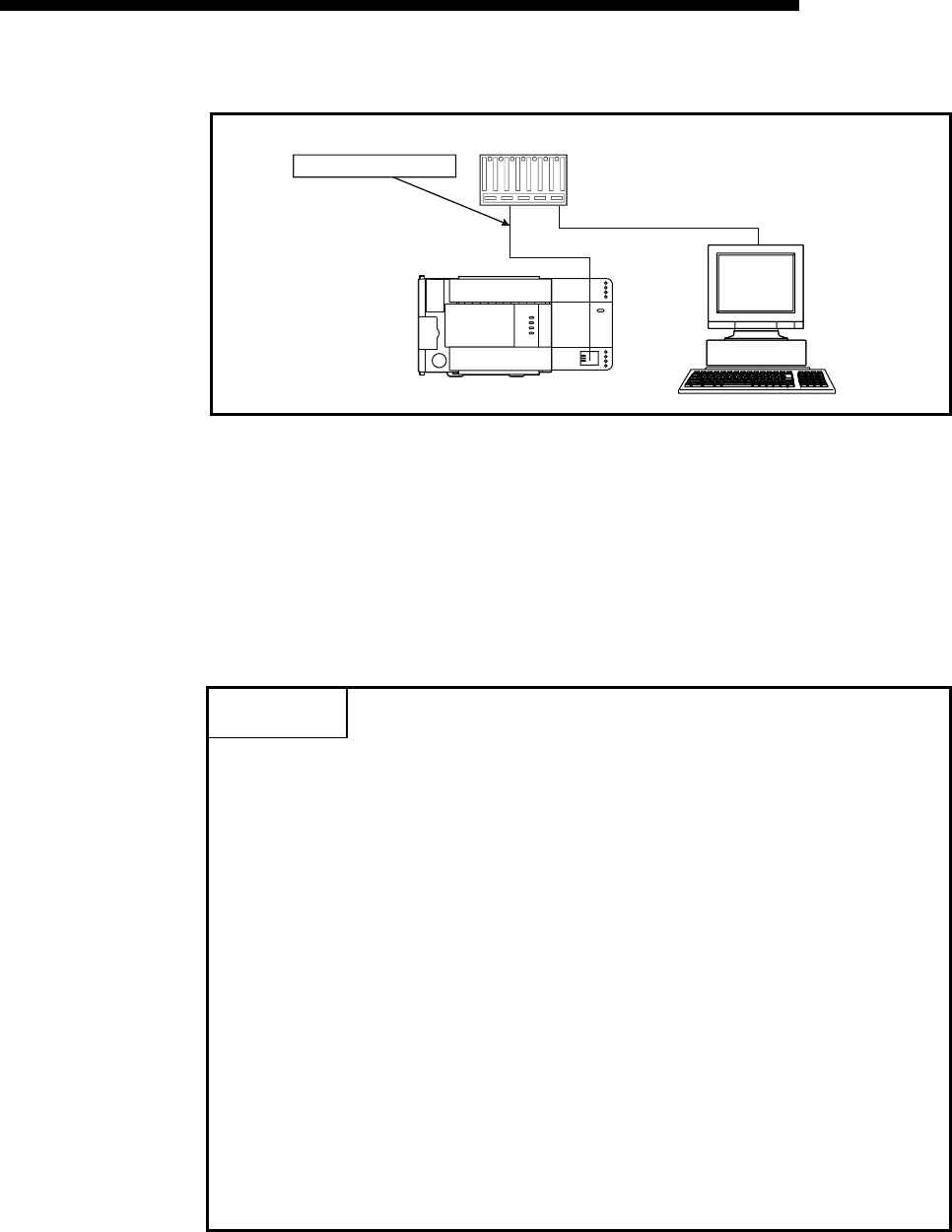
(4) Connecting FX Configurator-EN-L (Details are explained in the
Operating Manuals for FX Configurator-EN-L)
(a) Simplifying sequence programs using FX Configurator-EN-L
FX Configurator-EN-L supports the parameter setting function to perform the
Ethernet module initialization and the open processing with external devices.
By setting up the following parameters with FX Configurator-EN-L, access is
enabled from the external device to the PLC. It can also simplify sequence
programs used to perform communication by Ethernet modules.
• IP address setting • E-mail settings
• Port number setting • Each timer setting
• Protocol type setting
For more information on setting up the Ethernet module, see Section 3.5,
"List of Setting Items for Ethernet Modules" and other applicable reference
sections.
*1 Access is enabled only when MELSOFT connection is set in the open
method of the Ethernet module.
*2 The open settings is not set for the initial state of the Ethernet module.
Set it through serial communication.
Local station
External device
External device
Ethernet*1
FX Configurator-EN-L
Parameter setting
Serial communication*2
1 - 6
MELSEC-F
OVERVIEW1
1 - 6
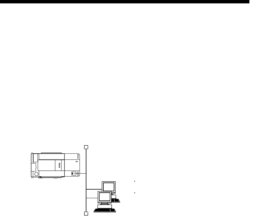
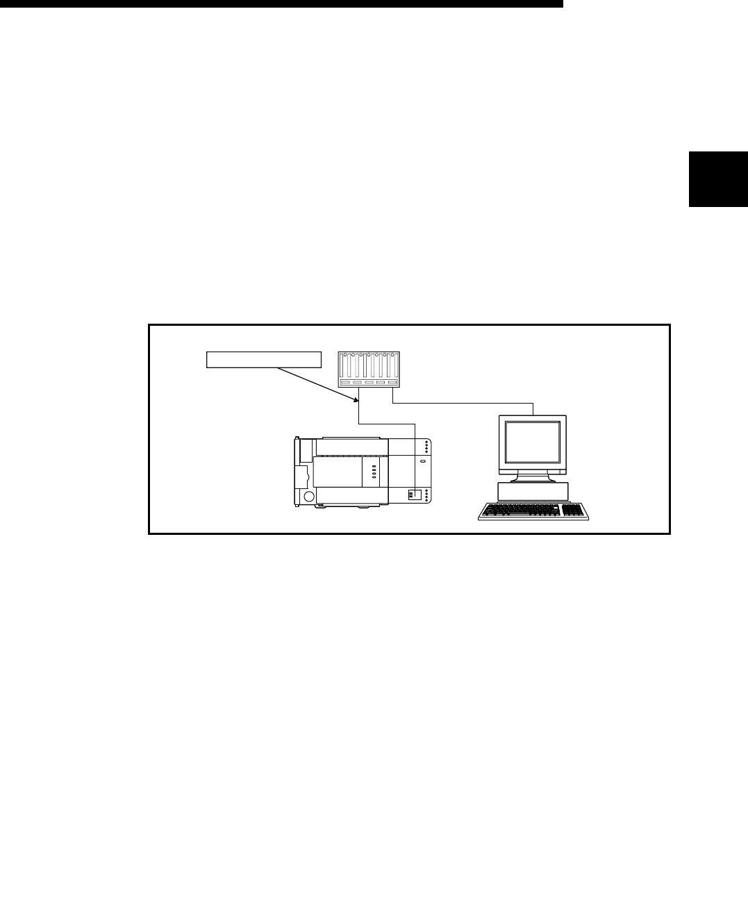
(b) Connecting multiple MELSOFT products (GX Developer, MX Component)
This product can be connected with one or more MELSOFT product, via
TCP/IP communication (through the in-house LAN, etc.) or UDP/IP
communication (through the in-house LAN, etc.).
1) Connection via TCP/IP communication
• If a MELSOFT product is to be connected with the FX Configurator-
EN-L open settings, a maximum of two units can be connected with
MELSOFT product.
• If a MELSOFT product is to be connected, the settings of buffer
memory for the MELSOFT connection or the following settings using
FX Configurator-EN-L are required.
For FX Configurator-EN-L, on the "Open settings" screen, set "TCP" in
the protocol field of the connection number to be used, and "MELSOFT
connection" in the open method field. (See Section 5.5.)
Connection via TCP/IP communication only
Multiple units (Maximum two units)
(Protocol used)(External device)
For use when the user specifies a MELSOFT
connection.
"Ethernet open setting" parameter is needed.
1 - 7
MELSEC-F
OVERVIEW1
1 - 7
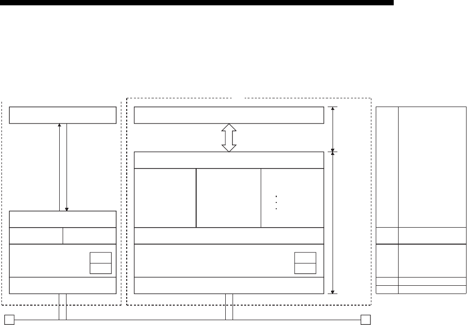
1.3 Software Configuration
The Ethernet modules support the TCP/IP and UDP/IP protocols.
(1) TCP (Transmission Control Protocol)
This protocol guarantees data credibility and reliability in communication between
a personal computer/work station and PLC that are connected via network, and
provides the following functions:
• Creates a logical connection by establishing a connection (logical line) as if a
dedicated line was created between external devices.
• Up to 4 connections can be established and communicated with at the same
time in the Ethernet module.
• Data reliability is maintained by the sequence control using the sequence
numbers, the data retransmission function and the check sum.
• The communication data flow can be controlled by operations using Windows.
User program
Buffer memory
Communication
using fixed buffers
Communication
using the MC protocol
Communication
by e-mails
TCP/UDP
IP ICMP
ARP
Ethernet
(100BASE-TX,10BASE-T)
TCP
IP
UDP
Ethernet
(100BASE-TX, 10BASE-T)
ICMP
ARP
System call
PLC
Ethernet
module
Personal computer/work-station(example) PLC
Main Unit
SMTP
POP3
DNS
OSI reference model corres-
ponding to the PLC configuration
(Layers)
Application layer
Presentation layer
Session layer
7
6
5
Transport layer4
Network layer3
Data link layer2
Physical layer
1
Socket
FROM/TO instruction

1 - 8
MELSEC-F
OVERVIEW1
1 - 8
(2) UDP (User Datagram Protocol)
This protocol may not guarantee data credibility or reliability in communication
between a personal computer/work station and PLC that are connected via
network. Thus, even if the data does not reach the target node, it will not be
retransmitted.
• Because it is connectionless, communication efficiency is much improved than
TCP/IP.
• A check sum is used to increase the reliability of the communication data.
When greater reliability must be maintained, a user application or TCP should
be used for retrying operation.
(3) IP (Internet Protocol)
• Communication data is sent and received in datagram format.
• Communication data can be divided and reassembled.
• Routing option is not supported.
(4) ARP (Address Resolution Protocol)
• This protocol is used to get the Ethernet physical addresses from the IP
addresses.
(5) ICMP (Internet Control Message Protocol)
• This protocol is used to exchange errors which occur on an IP network and
various information related to the network.
• Provides a function to transmit IP error messages.
• See Appendix for information regarding the types of ICMP supported.
(6) DNS (Domain Name System)
• This system translates IP addresses to names that are easy to remember by
the user.
(7) SMTP (Simple Mail Transfer Protocol)
• This protocol transfers mail.
(8) POP3 (Post Office Protocol Ver. 3)
• This protocol transfers mail received by a mail server to a local computer.
(9) Flag bit of TCP/IP (SYN, ACK, PSH, FIN, RST, and URG)
In communication using TCP, these flag bits indicate segments where
connection/disconnection or response confirmation is executed or emergency
data is included.
1) SYN (Synchronized Flag)
When this bit is ON (1), it indicates that the initial sequence number value
is set in the sequence number field.
This bit is used when the connection is newly opened.
2) ACK (Acknowledgment Flag)
When this bit is ON (1), it indicates that ACK (confirmation response
number) field is valid.
It also indicates that this segment includes the information on response
confirmation.
When this bit is OFF (0), it indicates that ACK (confirmation response
number) field is invalid.

1 - 9
MELSEC-F
OVERVIEW1
1 - 9
3) PSH (Push Flag)
When this bit is ON (1), the host that has received this segment sends the
data to the upper application with high priority.
This bit is to be turned ON when the data should be sent to an external
device as soon as possible.
When this bit is OFF (0), the timing when the received data is sent to the
upper application depends on the TCP layer of the receiving side.
4) FIN (Fin Flag)
When this bit is ON (1), it indicates that there is no more data to be sent
from the segment source and that the send source wants to disconnect.
However, data can be received from the external device.
The connection is on until the segment whose FIN bit is ON is received
from the external device.
5) RST (Reset Flag)
When this bit is ON (1), the host from which the segment has sent
disconnects unilaterally (forcibly).
Disconnection by this method is used when an unrecoverable error with
the normal method has occurred or when the host has been restored after
being down.
6) URG (Urgent Flag)
When this bit is ON (1), it indicates that this data segment includes the
emergency data flag.
2 - 1
SYSTEM CONFIGURATIONS2
2 - 1
2
MELSEC-F
2 SYSTEM CONFIGURATIONS
This section explains the system configurations that may be combined with the
Ethernet modules.
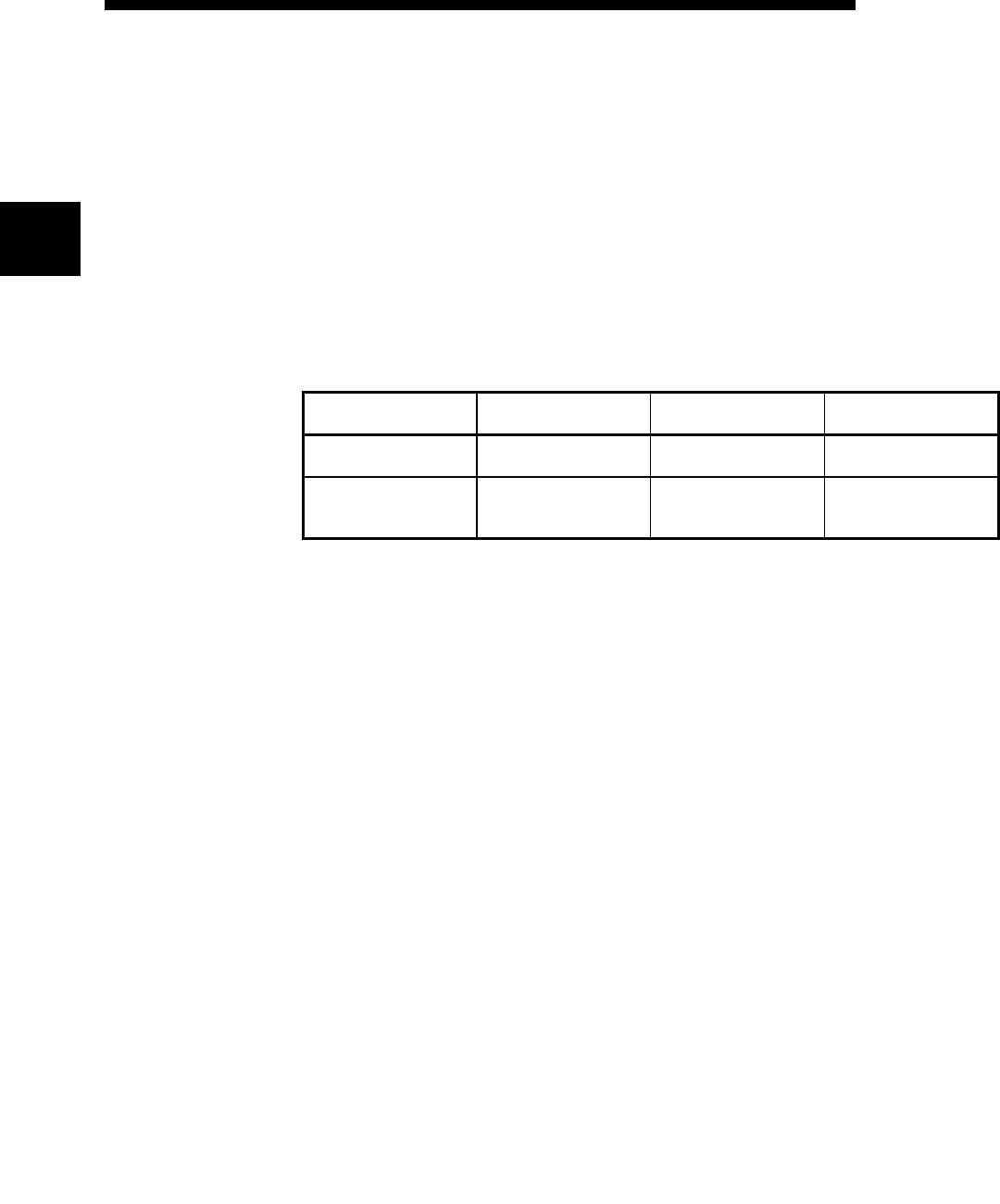
2.1 Applicable Systems
Ethernet modules can be used with the following systems:
(1) Applicable PLC and number of modules that can be mounted
The following table lists the PLC where the Ethernet module can be mounted and
the number of modules that can be mounted.
(2) Applicable software packages
When using the Ethernet module, the FX Configurator-EN-L for software
packages applicable to the Ethernet module can be used.
Refer to the manual of FX Configurator-EN-L for the details.
1) The Ethernet module is set with FX Configurator-EN-L
[Configurable by BFM].
2) To use FX Configurator-EN-L, either of the following software
should be installed.
• GX Developer (V 8.88S or later)
3) For starting FX Configurator-EN-L, the following shows two
kinds of methods.
• Independently starting FX Configurator-EN-L
• Starting from [Tools] menu of GX Developer
4) The installation form of FX Configurator-EN-L differs depend-
ing on sales territory or country of this product.
Consult with the dealer of this product for details.
Series name Compatible version Number of I/O points
occupied
Number of modules that can
be mounted
FX3U System version V2.21 or
more 8 points for input or output 1
FX3UC
(An FX
2NC
-CNV-IF or
FX
3UC
-1PS-5V is necessary)
System version V2.21 or
more 8 points for input or output 1
2 - 2
SYSTEM CONFIGURATIONS2
2 - 2
2
MELSEC-F
2.2 Devices Required for Network Configuration
This section explains the devices that are required to configure a network.
Network installation work requires sufficient safeguard; ask a network specialist for
installation.
When connecting FX3U-ENET-L to a network, either a 10BASE-T or 100BASE-
TX can be used.
The Ethernet module detects whether it is 10BASE-T or 100BASE-TX, and the
full-duplex or half-duplex transmission mode according to the hub.
For connection to the hub without the auto detection function, set the half-duplex
mode on the hub side.
(1) Connection using the 100BASE-TX
Use devices that satisfy the standards of IEEE802.3 and 100BASE-TX.
• Shielded twisted pair cable (STP cable), category 5
* Straight cables can be used.
(Correct operation is not guaranteed if a crossed cable is used to connect to
an external device via the 100BASE-TX of the Ethernet module. However, it
is possible to use crossed cables to connect two Ethernet modules for data
communication or to connect an Ethernet module.)
•RJ45 plug
• 100Mbps hub
External device
Twisted pair cable
Hub
* Up to 2 levels are allowed
for cascade connection
Ethernet module
2 - 3
MELSEC-F
SYSTEM CONFIGURATIONS2
2 - 3
(2) Connection using the 10BASE-T
Use devices that satisfy the standards of IEEE802.3 and 10BASE-T.
• Shielded twisted pair cable (STP cable), category 3 (4, 5)
* Straight cables can be used.
(Correct operation is not guaranteed if a crossed cable is used to connect to
an external device via the 10BASE-T of the Ethernet module. However, it is
possible to use crossed cables to connect two Ethernet modules for data
communication or to connect an Ethernet module.)
•RJ45 plug
• 10Mbps hub
POINT
• During the high-speed communication (100 M bps) via 100BASE-TX
connection, a communication error may occur due to the effect of high
frequency noise from devices other than PLC in a given installation
environment.The following describes countermeasures on the FX3U-ENET-L
side to prevent the effect of high frequency noise for construction of a network
system.
(1) Wiring connection
• Do not bundle the twisted pair cables with the main circuit and power wires,
and do not install them close to each other.
• They should be installed at least 100 mm (3.94 in) away from each other.
• Make sure to place the twisted pair cables in a duct.
(2) Communication method
• Data communication with an external device is performed using TCP/IP
communication.
• Increase the number of communication retries as necessary.
[When the error cannot be solved]
• Communication is performed at a data transmission rate of 10 M bps by
changing the connection hub for the FX3U-ENET-L to a hub capable of
handling 10 M bps.
External device
Twisted pair cable
Hub
* Up to 4 levels are allowed
for cascade connection
Ethernet module
3 - 1
SPECIFICATIONS3
3 - 1
3
MELSEC-F
3 SPECIFICATIONS
This section explains the Ethernet module performance specifications and
transmission specifications.
For the general specifications, refer to the packaged manual and the User’s Manual of
the PLC main unit.
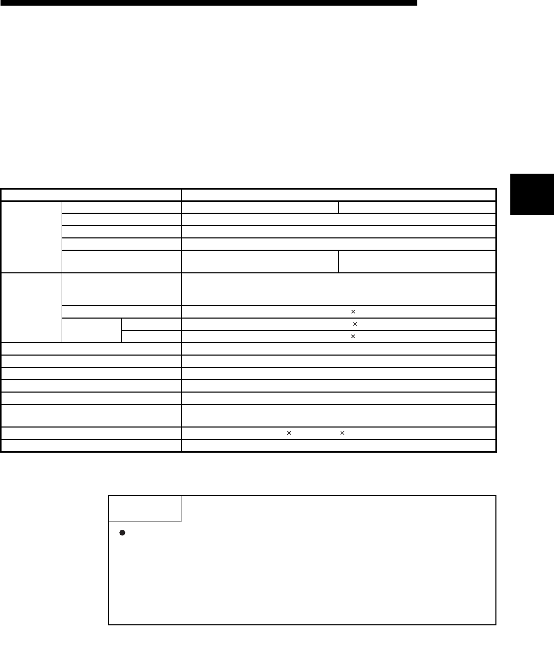
3.1 Performance Specifications
The following explains the performance specifications of the Ethernet module.
*1 Length between the Hub and node.
Item Specification
Transmission
specifications
Data transmission speed 100 M bps 10 M bps
Communication mode Full-duplex/Half-duplex
Transmission method Base band
Maximum segment length 100 m (328' 1") *1
Maximum number of
nodes/connection Cascade connection Maximum 2 stages Cascade connection Maximum 4 stages
Transmission
data storage
memory
Number of simultaneously open
connections allowed
4 connections
Fixed buffer communication: up to 2 connections (C1 and C2)
MELSOFT connection + MC protocol: up to 2 connections (C3 and C4)
Fixed buffer 1023 word 2
E-mail Attached file 2048 words 1
Main text 256 words 1
Number of I/O occupied points 8 points
Power supply 24V DC +20%, -15%, ripple (p-p) less than 5%
Allowable instantaneous power failure time Operation can be continued upon occurrence of instantaneous power failure for 1 ms or less.
External 24V current consumption 240 mA
Number of connectable units to the main unit 1
Applicable PLC FX3U/FX3UC PLC
Ver. 2.21 or later
External dimensions 90 (3.55") (H) 55 (2.17") (W) 87 (3.43") (D) [mm] (inches)
Weight 0.3 kg (0.66 lbs)
POINT
The module operation is not guaranteed if any of the following connection is
used. Check the module operation on the user side.
• Connections using the Internet (general public line) (Connections using
Internet connection service provided by Internet service providers and
telecommunications carriers)
• Connections using devices in which a firewall is installed
• Connections using broadband routers
• Connections using wireless LAN
3 - 2
SPECIFICATIONS3
3 - 2
3
MELSEC-F
*1 The setting is required only when "POP before SMTP" is selected in the SMTP authentication method.
NOTE
The following explains each of the transmission specification items.
Item Specification
E-mail
Transmission
specifications
Transmission
data
Data size Attached file 2048 words 1
Main text 256 words 1
Data transfer method When sending: Sends either a file as attachment or main text (select one).
Subject US-ASCII format or ISO-2022-JP (Base64)
Attached file format MIME format
MIME Version 1.0
Data of attached file format
Binary/ASCII/CSV can be selected.
File name: XXXX.bin (binary), XXXX.asc (ASCII), XXXX.csv (CSV)
(CSV: Comma Separated Value)
Division of attached file Cannot be divided (only one file can be sent)
When sending (encode)
Subject : Base64/7 bits
Main text : 7 bits
Attached file : Base64
Encryption No
Compression No
Communication with mail server
SMTP
Port number 1 to 65535 SMTP: 25 (initial)
SMTP-AUTH: 587
Authentication method
• No authentication
• SMTP-AUTH (PLAIN, LOGIN, CRAM-MD5)
• POP before SMTP
POP Port number*1 1 to 65535 POP3: 110 (initial)
Operation check mailer Microsoft Corporation (Outlook Express 6.0)
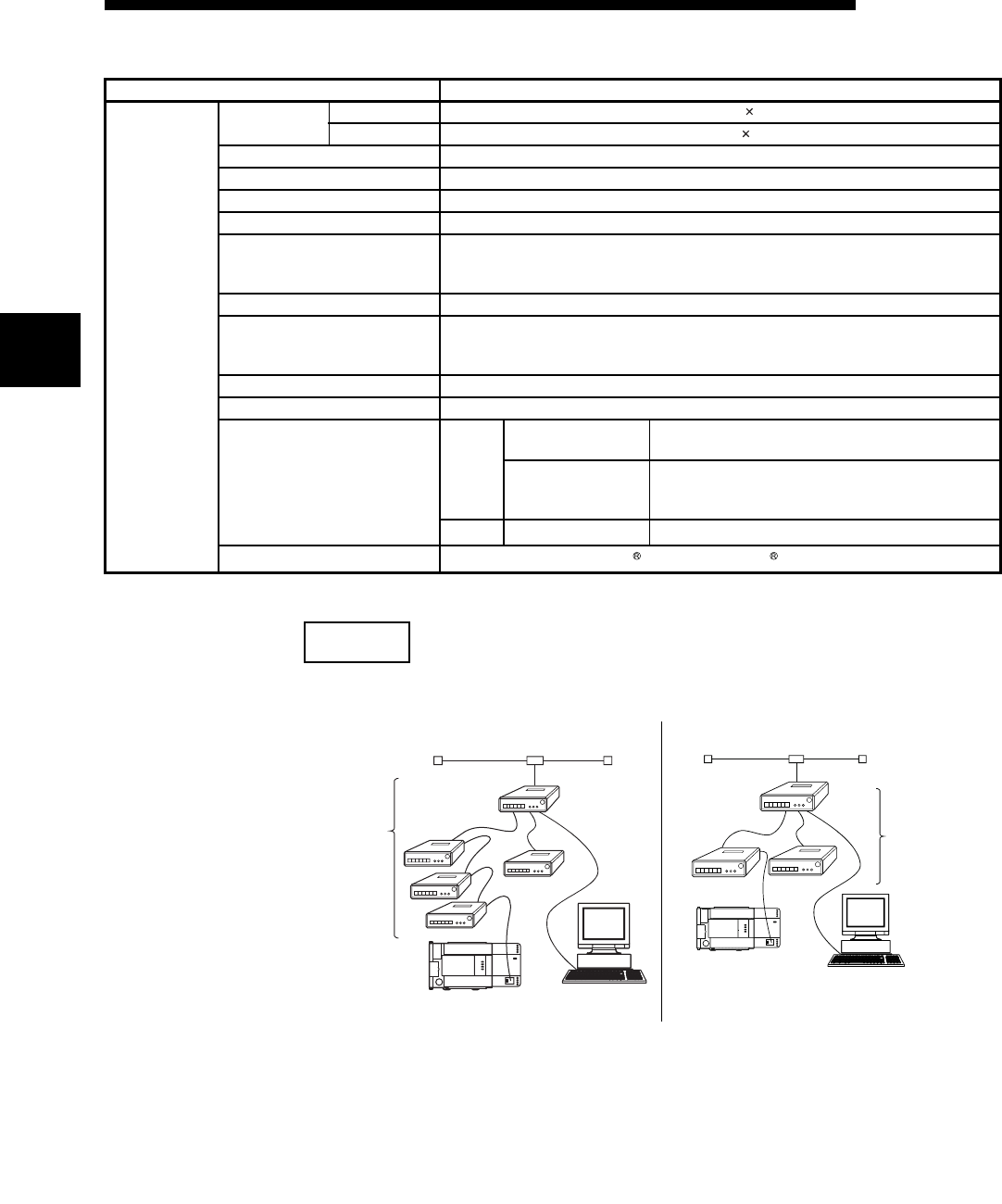
[Connecting using the 10BASE-T] [Connecting using the 100BASE-TX]
Hub
Maxmum 100m Maxmum
100m
Up to
4 levels
Up to (2) levels are
allowed for cascade
connection.
Hub
Maxmum 5m
Maxmum
100m
3 - 3
MELSEC-F
SPECIFICATIONS3
3 - 3
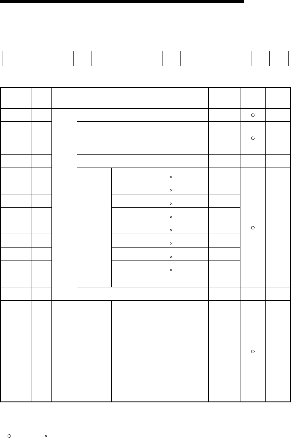
3.2 Data Codes for Communication
This section explains the data codes used in the communication between the
Ethernet module and the external device or the PLC.
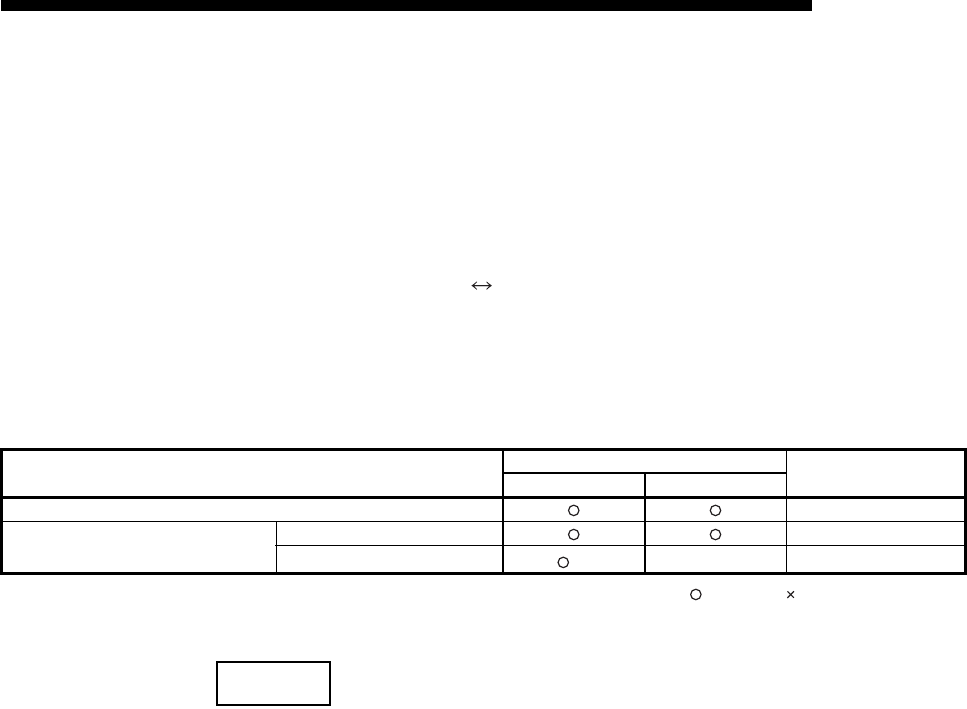
(1) The data codes used while communicating are listed below.
1) Ethernet module External device
Data can be communicated by selecting either binary code or ASCII code
in the data code setting of FX Configurator-EN-L or the PLC, as shown
below.
For more details about binary code/ASCII code changeover, refer to
Section 4.6, "Communication Settings".
: Selectable : Cannot be communicated
*1 Communication is performed in binary code regardless of the communication code setting.
NOTE
When sending e-mail, communication is performed using the data code handled by
each function, regardless of the setting of the communication data code.
Data communication function Communication data code Reference chapter
Binary code ASCII code
Communication using MC protocol Chapter 8,9
Communication using fixed buffer
Procedure exist Chapter 6
No procedure (*1)— Chapter 7
3 - 4
MELSEC-F
SPECIFICATIONS3
3 - 4
2) Ethernet module PLC
Data is sent and received in binary code.
(2) When communicating using ASCII code, 1-byte binary code data is automatically
converted into 2-byte ASCII code data and then transmitted.
(3) The amount of data that can be communicated at one time between the Ethernet
module and an external device is determined by the function used and the data
code (binary of ASCII) selected in "Operation setting" - "Communication data
code setting" of the FX Configurator-EN-L.
The following shows the maximum sizes of communication data that can be sent
at a time with each data communication function.
Data communication function Exchangeable data size
Communication using MC protocol The maximum number of point that can be designated
with each command/instruction : Maximum of 32 words
Communication using fixed buffer Procedure exist 1017 words (Binary code) 508 words (ASCII code)
No procedure 2046 bytes
Sending by e-mail
Attached file : Maximum of 2048 words
or
Main text : Maximum of 256 bytes
PLC Binary code
Ethernet module
Commu-
nication
data
storage
area BIN/ASCII
conversion
ASCII code
External
device
Binary code
ASCII code data
31H,35H
"1","5"
(Two bytes)
31H,32 H,33H,34H
"1","2","3","4"
(Four bytes)
Binary code data
15H
(One byte)
1234H
(Two bytes)
(Example)
3 - 5
MELSEC-F
SPECIFICATIONS3
3 - 5
3.3 Relationship between the External Devices and Additional Functions for Each
Communication Function
This section explains which external devices data communication can be performed
with and which additional functions can be used for each function.
(1) Communicability with external devices using various functions
The following table lists the communicability with external devices using various
functions.
: Can communicate : Cannot communicate
FX3U-ENET-L: FX Series Ethernet interface module
QJ71E71: Q Series Ethernet interface module
*1 The mail server is required separately.
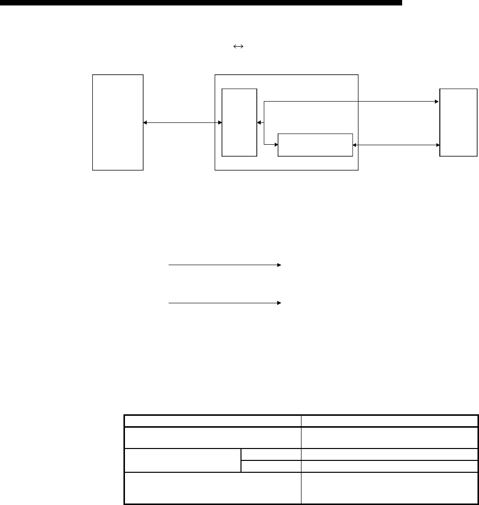
(2) Relationship with additional functions
The following table lists the correspondence between functions and their
additional functions that can be used.
: Available : Not available or this function does not correspond to any of the functions in the function column.
Function
External device
Personal computer
FX3U-ENET-L
Personal computer
FX3U-ENET-L
FX3U-ENET-L
FX3U-ENET-L
FX3U-ENET-L
QJ71E71
QJ71E71
FX3U-ENET-L
Communication using MC protocol
Communication using the fixed buffer
Sending/receiving e-mail *1 *1
Communication function
Additional function Communication method
Router relay
communication
(router relay function)
Existence check of
external device
Communication via pairing
open TCP/IP UDP/IP
Communication using MC protocol
Communication using
the fixed buffer
Procedure exist
No procedure
Sending e-mail

3 - 6
MELSEC-F
SPECIFICATIONS3
3 - 6
3.4 Ethernet Module Function List
This section shows a list of Ethernet module functions.
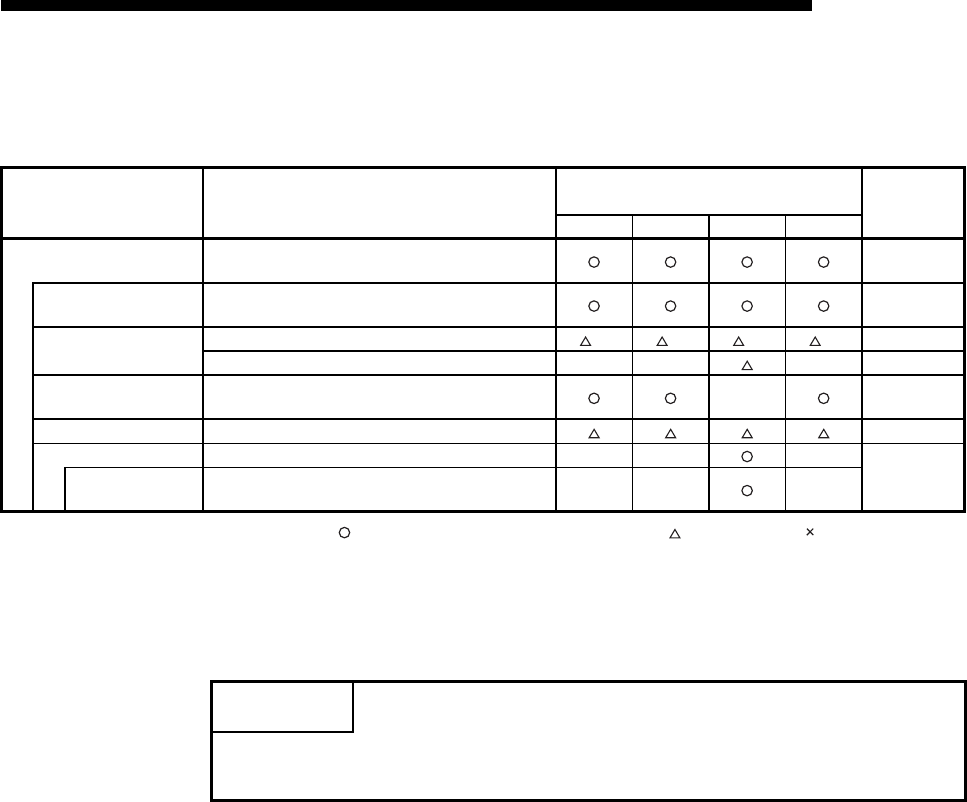
(1) Basic functions of the Ethernet module
The Ethernet module can perform the communications shown in the table below
via TCP/IP or UDP/IP communication.
(2) Additional functions of the Ethernet module
The following table lists the additional functions of the Ethernet module that can
be used.
(3) Status check of the Ethernet module
Checks that the Ethernet module is working and can communicate normally.
Function Description Reference section
Communication using
MC protocol
Subset of A
compatible 1E
frame
Reads/writes PLC data from/to an external device. Chapter 8, 9
Communication using
the fixed buffer
Procedure exist Sends/receives arbitrary data between the PLC and the
external device using the fixed buffer of the Ethernet module.
Chapter 6
No procedure Chapter 7
Sending e-mail Sends data via e-mail.
• Sending by the PLC Chapter 10
Function Description Reference section
Router relay communication (router relay
function)
Performs data communication via a router or gateway. (The router
relay function is not a function by which the Ethernet module works as
a router.)
Section 5.3
Existence check of external device (Existence
check function)
Checks whether or not the external device is working normally after a
connection is established (open processing).
Subsection 5.2.2 and
Section 5.5
Communication via pairing open Pairs and then opens a reception connection and a transmission
connection (for fixed buffer). Section 5.7
MELSOFT connection (GX Developer, etc.)
Connects MELSOFT products (GX Developer, etc.) via TCP/IP
communication (through the in-house LAN, etc. ). It is possible to
connect multiple MELSOFT products at the same time. It is also
possible to connect multiple MELSOFT products simultaneously.
Section 1.2 (4)
Manual of each
MELSOFT product
Function Description Reference section
Self loopback test Checks the Ethernet module's sending/receiving function and line
connection status. Subsection 4.7.1
Hardware test Tests the RAM and ROM of the Ethernet module. Subsection 4.7.2
Communication error storage
When a data communication error occurs, this function stores the
error information (error log), including the message subheader and
IP address of the external device for a maximum of 16 pairs in the
buffer memory.
Chapter 11
3 - 7
MELSEC-F
SPECIFICATIONS3
3 - 7
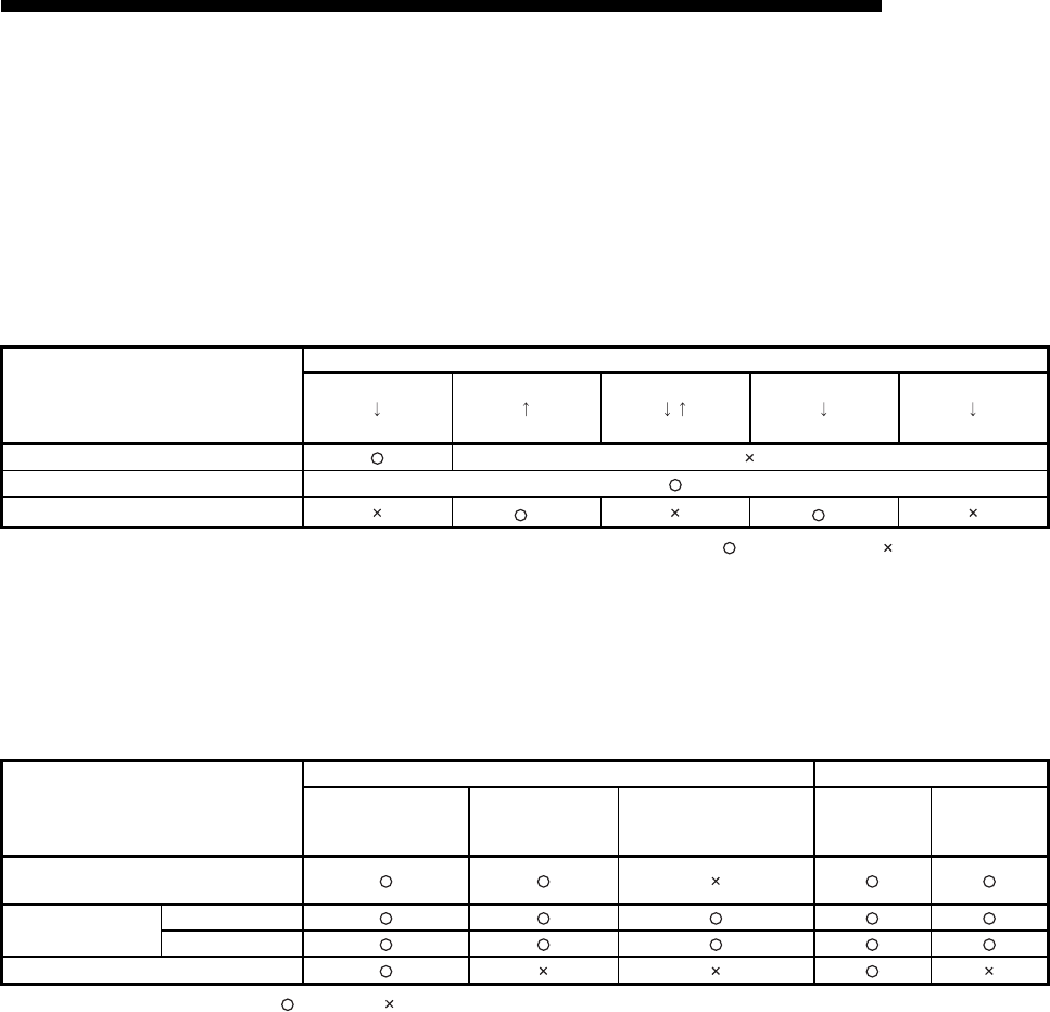
3.5 List of Setting Items for Ethernet Modules
The following table lists the parameter setting items that are set using Ethernet Module.
: Must be set when the applicable function is used. : Set as needed : Setting is not required.
*1 The meanings of the abbreviations used in the table above are as follows:
MC: Communication using MC protocol
Mail: E-mail
Fixed: Communication using the fixed buffer
*2 Setting is not necessary if initial values are being used.
Parameter setting item Description of setting
Function and parameter setting
requirement (*1)Reference
section
MC Fixed Mail
MELSOFT
Ethernet module settings Settings for using the Ethernet module as a network
module. Section 4.5
Operational settings Set the common items between the modules.
These settings are required for the initial processing. Section 4.6
Initial settings Set the data communication timer values. *2 *2 *2 *2 Section 5.2
Set the DNS server's IP address. — — — Section 10.6
Open settings Set up the open processing for connection in order to
perform data communication with the external device. — Section 5.5
Router relay parameter Set the router relay of Ethernet. Section 5.3
E-mail settings Perform settings for sending e-mail. — — —
Section 10.6
Send mail address
setting Set the destination mail address. — — —
POINT
Parameters set in FX Configurator-EN-L are saved in the Ethernet module's flash
ROM.

3 - 8
MELSEC-F
SPECIFICATIONS3
3 - 8
3.6 List of Applications and Assignments of the Buffer Memory
Data transmission/reception between Ethernet Module and PLC is performed via the
Ethernet Module buffer memory (hereinafter called BFM).
Reading/writing data in the buffer memory from the PLC must be performed by the
FROM/TO instructions (instructions that can access BFM).
In addition, the initial value of the buffer memory or the internally stored value is
written when the power is turned on.
(1) Configuration of the buffer memory
Buffer memory consists of a user area and a system area, as listed below.
(a) User areas
1) The areas where the user writes/reads data.
2) A user area consists of a parameter area for initial processing and data
communication, an area for data communication, and an area for storing
communication status and communication error data.
3) Reading/writing data to the user area should be performed according to
the instructions in the corresponding detailed explanation section.
Data communication may take longer if continually executed; therefore,
execute only when needed.
(b) System areas
The areas used by the Ethernet module
Important
Do not write data in the "system areas" of the buffer memory.
If data is written to any of the system areas, the PLC system may not operate
properly.
When writing a value to the buffer memory including "System Area," pay close
attention not to change the system bit.
3 - 9
MELSEC-F
SPECIFICATIONS3
3 - 9
(2) Assignments of the buffer memory
A buffer memory consists of 16 bits per address.
<Bit configuration diagram>
The following shows the buffer memory addresses.
(a) Initial processing parameter (BFM #0 to 31)
(Continues on the next page)
*1 Attribute R : Read, W : Write, — : Use prohibited
*2 Saving to Flash ROM from FX Configurator-EN-L allowed/prohibited
(Settings are saved in the flash ROM of the Ethernet module.)
: Setting allowed : Setting prohibited
BFM number Attribute
*1Application Name
Initial value
Decimal
(Hexadecimal)
Flash ROM
save (*2)
Reference
section
Decimal
(Hexadecimal)
0 to 1
(0 to 1H)R/W
Initial
processing
parameter
setting area
Local station Ethernet module IP address (Initial value 192.168.1.254)
3232236030
(C0A801FE H)Section 4.6
2
(2H)R/W
Special function settings
• Router relay function (b5, b4)
00: Do not use (initial)
01: Use
Bits other than above are reserved for system use.
0
(0000 H)
Section 5.3
3
(3H)— System area — — —
4
(4H)R/W
Monitoring timer
TCP ULP (existence function) timer value
Setting time = setting value 500 ms
60
(3C H)
Section 5.2
5
(5H)R/W TCP zero window timer value
Setting time = setting value 500 ms
20
(14 H)
6
(6H)R/W TCP resend timer value
Setting time = setting value 500 ms
20
(14 H)
7
(7H)R/W TCP end timer value
Setting time = setting value 500 ms
40
(28 H)
8
(8H)R/W IP assembly timer value
Setting time = setting value 500 ms
10
(A H)
9
(9H)R/W Response monitoring timer value
Setting time = setting value 500 ms
60
(30 H)
10
(AH)R/W Destination existence confirmation starting interval
Setting time = setting value 500 ms
1200
(480 H)
11
(BH)R/W Destination existence confirmation interval timer
Setting time = setting value 500 ms
20
(14 H)
12
(CH)R/W Destination existence confirmation resend timer 3
(3 H)
13 to 23
(D to 17H)— System area — — —
24
(18H)R/W
Initial pro-
cessing
parameter
setting area
Communication
condition setting
area
(Operational Set-
tings)
Communication condition setting (Operational Set-
tings) area
• Communication data code setting (b1)
0: Communication in binary code
1: Communication in ASCII code
• TCP Existence confirmation setting (b4)
0: Use the Ping
1: Use the KeepAlive
• Send frame setting (b5)
0: Ethernet frame
1: IEEE 802.3 frame
• Initial timing setting (b8)
0: Do not wait for OPEN (communication
impossible at STOP time)
1:
Always wait for OPEN (communication
possible at STOP time)
Bits other than above are reserved for system use.
0
(0H)
Section 4.6
b15 b14 b13 b12 b11 b10 b9 b8 b7 b6 b5 b4 b3 b2 b1 b0

3 - 10
MELSEC-F
SPECIFICATIONS3
3 - 10
(Continued from the previous page)
BFM number
Attribute Application Name
Initial value
Decimal
(Hexadecimal)
Flash
ROM
save
Reference
section
Decimal
(Hexadecimal)
25
(19H)R/W
Flash ROM
control
Flash ROM
writing control
area
Flash ROM writing control
0000H: Normal status
9872H: Write command for configuration data
to a flash ROM.
Automatically returns to 0000H after
writing to a flash ROM
9981H: Write command for configuration data
to a flash ROM (return to the status at
factory shipment).
Automatically returns to 0000H after
writing to a flash ROM
0
(0000H)
—
26
(1AH)R/W Flash ROM
writing status
Flash ROM writing status
0000H: Initial status
9981H: During the flash ROM writing
0001H: Flash ROM writing completion
0002H: Flash ROM writing error (Flash ROM
fault)
The status is updated by write command
0
(0000H)
27
(1BH)R Initial completion 0000H: Initial incompletion
0001H: Initial completion (in conjunction with b0 of BFM#28)
0
(0000H)
Subsection
5.2.1
28
(1CH)RModule status
area
Stores Ethernet module status
b0: INIT 1: Initial processing normally completed
0: —
b1: System bit
b2: 100M/10M 1: 100Mbps
0: 10Mbps/When not connected
b3: ERR. 1: Setting abnormal display
0: Setting normal display
b4: COM.ERR 1: Communication abnormal display
0: Communication normal display
b5: 1: Initial processing abnormally completed
0: —
b6: 1: Open processing abnormally completed
0: —
b7: 1: Link signal ON 0: Link signal OFF
b8: Connection No.1 1: Open 0: Closed
b9: Connection No.2 1: Open 0: Closed
b10: Connection No.3 1: Open 0: Closed
b11: Connection No.4 1: Open 0: Closed
b0 and b5 are cleared at re-initialization request.
b6 is cleared at open request.
0
(0000H)Section 4.3
29
(1DH)R/W Error code
storage
Stores the first error code (when the value of this BFM number is
0000H)
Writing 0000H resets the error.
0
(0000H)
Section
11.3
30
(1EH)RModel code
storage Model code (K7132) 7132
(1BDCH) —
31
(1FH)— System area ———
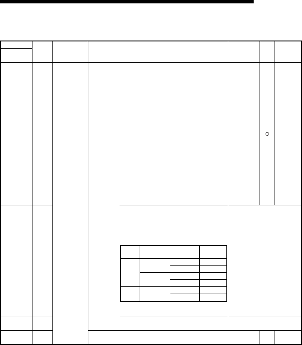
3 - 11
MELSEC-F
SPECIFICATIONS3
3 - 11
(b) Communication parameter setting area (BFM #32 to 102)
(Continues on the next page)
BFM number
Attribute Application Name
Initial value
Decimal
(Hexadecimal)
Flash
ROM
save
Reference
section
Decimal
(Hexadecimal)
32
(20H)R/W
Communication
parameters
setting area
Connection
usage setting
area
Connection No. 1
• Usage of fixed buffer (b0)
0: For sending or fixed buffer communication is
not executed
1: For receiving
• Destination existence confirmation (b1)
0: No confirm
1: Confirm
• Pairing open (b7)
0: No pairs
1: Pairs
• Communication method (protocol) (b8)
0: TCP/IP
1: UDP/IP
• Fixed buffer communication (b9)
0: Procedure exist
1: No procedure
• Open system (b15, b14)
00: Active open or UDP/IP
01: Use prohibited
10: Unpassive open
11: Fullpassive open
Bits other than above are reserved for system use.
0
(0H)Section 5.5
33
(21H)R/W
Connection No. 2
(bit configuration is the same as connection No.1)
"0" must be selected in the pairing open setting (b7).
(same as connection No.1)
34
(22H)R/W
Connection No.3
Select either value shown in the table below when
selecting MC protocol.
Set "A002H" when selecting MELSOFT connection.
Any other value cannot be set.
(same as connection No.1)
35
(23H)R/W Connection No. 4
(same as connection No.3) (same as connection No.1)
36 to 39
(24 to 27H)— System area — — —
Protocol Open system Existence
confirmation Setting value
TCP
Unpassive Performed 8403H
Not performed 8401H
Fullpassive Performed C403H
Not performed C401H
UDP — Performed 0503H
Not performed 0501H
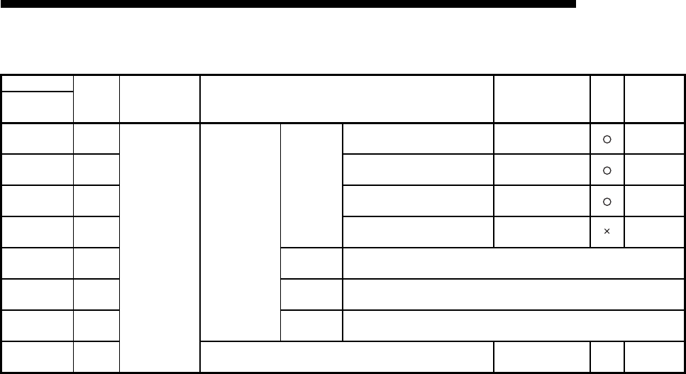
3 - 12
MELSEC-F
SPECIFICATIONS3
3 - 12
(Continued from the previous page)
BFM number
Attribute Application Name
Initial value
Decimal
(Hexadecimal)
Flash
ROM
save
Reference
section
Decimal
(Hexadecimal)
40
(28H)R/W
Communication
parameters
setting area
Communication
address setting
area
Connection
No. 1
Local station Port No. 0
(0H)Section 5.5
41 to 42
(29 to 2AH)R/W Destination IP address 0
(0H)Section 5.5
43
(2BH)R/W Destination Port No. 0
(0H)Section 5.5
44 to 46
(2C to 2EH)R/W Destination Ethernet address (FFFFFFFFFFFFH)—
47 to 53
(2F to 35H)R/W Connection
No. 2 (Same as connection No. 1)
54 to 60
(36 to 3CH)R/W Connection
No. 3 (Same as connection No. 1)
61 to 67
(3D to 43H)R/W Connection
No. 4 (Same as connection No. 1)
68 to 102
(44 to 66 H)— System area — — —
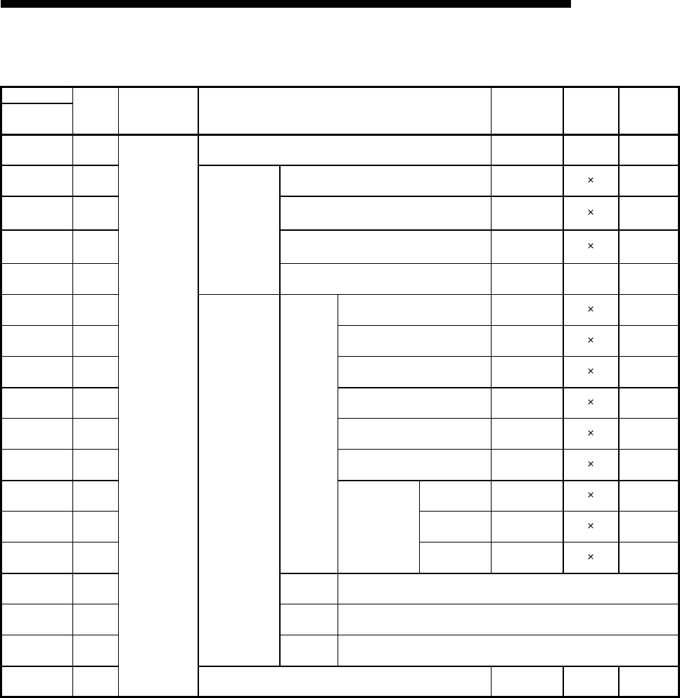
3 - 13
MELSEC-F
SPECIFICATIONS3
3 - 13
(c) Communication status storage area (BFM #103 to 226)
(Continues on the next page)
*1 Initial processing writes IP and Ethernet address.
*2 Supported in connections No. 1 and 2 only.
BFM number
Attribute Application Name
Initial value
Decimal
(Hexadecimal)
Flash ROM
save
Reference
section
Decimal
(Hexadecimal)
103 to 104
(67 to 68H)—
Communication
status storage
area
System area — — —
105
(69H)R
Area for initial
processing
Initial error code 0
(0H)
Section 11.4
106 to 107
(6A to 6BH)R Local station IP address 0*1
(0H)—
108 to 110
(6C to 6EH)R Local station Ethernet address 0*1
(0H)—
111 to 119
(6F to 77H)— System area — — —
120
(78H)R
Connection
information area
Connection
No. 1
Local station Port No. 0
(10H)—
121 to 122
(79 to 7AH)R Destination IP address 0
(0H)—
123
(7BH)R Destination Port No. 0
(0H)—
124
(7CH)R Open error code 0
(0H)
Section 11.4
125
(7DH)RFixed buffer sending error code*20
(0H)
Section 11.4
126
(7EH)R Connection end code 0
(0H)
Section 11.4
127
(7FH)R
Fixed buffer
communication
time
*2
(unit : 10ms)
Maximum value
0
(0H)—
128
(80H)R
Minimum value
0
(0H)—
129
(81H)RCurrent value 0
(0H)—
130 to 139
(82 to 8BH)R
Connection
No. 2
(Same as connection No. 1)
140 to 149
(8C to 95H)R
Connection
No. 3
(Same as connection No. 1)
150 to 159
(96 to 9FH)R
Connection
No. 4
(Same as connection No. 1)
160 to 199
(A0 to C7H)— System area — — —

3 - 14
MELSEC-F
SPECIFICATIONS3
3 - 14
(Continued from the previous page)
*1 It varies after initialization.
*2 Values written to BFM #202 will become active the next time the module is powered ON.
(The value returns to 0 when each running mode execution is complete.)
BFM number
Attribute Application Name
Initial value
Decimal
(Hexadecimal)
Flash ROM
save
Reference
section
Decimal
(Hexadecimal)
200
(C8H)R
Communication
status storage
area
Module
status area
Stores Ethernet module status
(The same specification as BFM#28 "Module status
area")
0*1
(0H)—
201
(C9H)R
Hub connection status area
• Communication mode (b9)
0: Half duplex
1: Full duplex
• Hub connection status (b10)
0: Hub not connected/disconnected
1: Hub connected
• Data transmission speed (b14)
0: Operating at 10BASE-T
1: Operating at 100BASE-TX
Bits other than above are reserved for system use.
—Section
5.8
202
(D0H)R
Operation mode settings
0: Online
1: Offline
2: Self loopback test
3: Hardware test
4 to F: System area
0*2
(0H)—
203
(CBH)R
Status of settings
• Communication data code setting (b1)
0: Communication in binary code
1: Communication in ASCII code
• TCP Existence confirmation setting (b4)
0: Use the Ping
1: Use the KeepAlive
• Send frame setting (b5)
0: Ethernet frame
1: IEEE802.3 frame
• Initial timing setting (b8)
0: Do not wait for OPEN
(Communications impossible at STOP time)
1: Always wait for OPEN
(Communication possible at STOP time)
Bits other than above are reserved for system use.
4
(04H)
Section
4.7
204 tos 226
(E0 to E2H)— System area — — —

3 - 15
MELSEC-F
SPECIFICATIONS3
3 - 15
(d) Error log partition area (BFM #227 to 511)
(Continues on the next page)
BFM number
Attribute Application Name
Initial value
Decimal
(Hexadecimal)
Flash ROM
save
Reference
section
Decimal
(Hexadecimal)
227
(E3H)R
Error log area
Number of error occurrences 0
(0H)Section 11.4
228
(E4H)R Error log write pointer
229
(E5H)R
Error log block
area
Error log
block 1
Error code/end code
0
(0H)Section 11.4
230
(E6H)R Subheader
231
(E7H)R Command code
232
(E8H)R Connection No.
233
(E9H)R Local station Port No.
234 to 235
(EA to EBH)R Destination IP address
236
(ECH)R Destination Port No.
237
(EDH)R System area — — —
238 to 246
(EE to F6H)RError log
block 2 (Same as error log block 1)
247 to 255
(F7 to FFH)RError log
block 3 (Same as error log block 1)
256 to 264
(100 to 108H)RError log
block 4 (Same as error log block 1)
265 to 273
(109 to 111H)RError log
block 5 (Same as error log block 1)
274 to 282
(112 to 11AH)RError log
block 6 (Same as error log block 1)
283 to 291
(11B to 123H)RError log
block 7 (Same as error log block 1)
292 to 300
(124 to 12CH)RError log
block 8 (Same as error log block 1)
301 to 309
(12D to 135H)RError log
block 9 (Same as error log block 1)
310 to 318
(136 to 13EH)RError log
block 10 (Same as error log block 1)
319 to 327
(13F to 147H)RError log
block 11 (Same as error log block 1)
328 to 336
(148 to 150H)RError log
block 12 (Same as error log block 1)
337 to 345
(151 to 159H)RError log
block 13 (Same as error log block 1)
346 to 354
(15A to 162H)RError log
block 14 (Same as error log block 1)
355 to 363
(163 to 16BH)RError log
block 15 (Same as error log block 1)
364 to 372
(16C to 174H)RError log
block 16 (Same as error log block 1)
373 to 375
(175 to 177H)— System area — — —

3 - 16
MELSEC-F
SPECIFICATIONS3
3 - 16
(Continued from the previous page)
BFM number
Attribute Application Name
Initial value
Decimal
(Hexadecimal)
Flash ROM
save
Reference
section
Decimal
(Hexadecimal)
376 to 377
(178 to 179H)R
Error log area Status for each
protocol
IP
Received IP packet count
0
(0H)
Section 11.3
378 to 379
(17A to 17BH)RReceived IP packet count discarded
due to sum check error
380 to 381
(17C to 17DH)R Sent IP packet total count
382 to 397
(17E to 18DH)— System area — — —
398 to 399
(18E to 18FH)R
Simultaneous transmission error
detection count
(Receiving descripter deletion count)
0
(0H)
Section 11.5
POINT (3)
400 to 407
(190 to 197H)— System area — —
—
408 to 409
(198 to 199H)R
ICMP
Received ICMP packet count
0
(0H)
410 to 411
(19A to 19BH)RReceived ICMP packet count
discarded due to sum check error
412 to 413
(19C to 19DH)R Sent ICMP packet total count
414 to 415
(19E to 19FH)REcho request total count of received
ICMP packets
416 to 417
(1A0 to 1A1H)REcho reply total count of sent ICMP
packets
418 to 419
(1A2 to 1A3H)REcho request total count of sent ICMP
packets
420 to 421
(1A4 to 1A5H)REcho reply total count of received
ICMP packets
422 to 439
(1A6 to 1B7H)— System area — —
440 to 441
(1B8 to 1B9H)R
TCP
Received TCP packet count
0
(0H)
442 to 443
(1BA to 1BBH)RReceived TCP packet count
discarded due to sum check error
444 to 445
(1BC to 1BDH)R Sent TCP packet total count
446 to 471
(1BE to 1D7H)— System area –– ––
472 to 473
(1D8 to 1D9H)R
UDP
Received UDP packet count
0
(0H)
474 to 475
(1DA to 1DBH)RReceived UDP packet count
discarded due to sum check error
476 to 477
(1DC to 1DDH)R Sent UDP packet total count
478 to 481
(1DE to 1E1H)— System area — —
482 to 491
(1E2 to 1EBH)— System area — —
492 to 493
(1EC to 1EDH)R
Receivi
ng error
Framing error count 0
(0H)
494 to 495
(1EE to 1EFH)R Overflow count 0
(0H)
496 to 497
(1F0 to 1F1H)R CRC error count 0
(0H)
498 to 511
(1F2 to 1FFH)— System area — —

3 - 17
MELSEC-F
SPECIFICATIONS3
3 - 17
(e) Router relay parameter setting area (BFM #512 to 1599)
BFM number
Attribute Application Name
Initial value
Decimal
(Hexadecimal)
Flash ROM
save
Reference
section
Decimal
(Hexadecimal)
512 to 513
(200 to 201H)R/W
Router relay
parameter
setting area
Sub-net mask 0
(0H)Section 5.3
514 to 515
(202 to 203H)R/W Default router IP address
516 to 1599
(204 to 63FH)— System area — — —

3 - 18
MELSEC-F
SPECIFICATIONS3
3 - 18
(f) Open/close control (BFM #1600 to 1663)
(Continues on the next page)
*1 Required only when MC protocol is set.
BFM number
Attribute Application Name
Initial value
Decimal
(Hexadecimal)
Flash ROM
save
Reference
section
Decimal
(Hexadecimal)
1600
(640H)R/W Re-
initialization
• Write value
Re-initialization request
0001H : Re-initialization ([COM.ERR.] LED OFF)
0002H : Re-initialization after reading data in Flash ROM
([COM.ERR.] LED OFF)
0005H : Re-initialization ([COM.ERR.] LED retains status.)
0006H : Re-initialization after reading data in Flash ROM
([COM.ERR.] LED retains status.)
• Read value
0008H : During re-initialization
8000H : At re-initialization completion
C000H : At re-initialization error
• In the re-initialization standby, the write value is read directly.
0
(0000H)—
1601
(641H)R/W COM.ERR.
Off
[COM.ERR.] Off request
• Write value
0001H: [COM.ERR.] LED Off request
• Read value
0002H: Stores at normal completion
• 0001H is read while ready until LED OFF operation starts
0
(0000H)—
1602
(642H)R/W
For open/close
control
Open/Close
command/status
Connection No.1 Open/Close command
• Write value
0001H: Open command
8000H: Close command
• Read value
b0=0 : Open command enabled
b0=1 : Open command disabled
0000H : Close status
(Including when FIN is sent from
the external device)
0003H : Open request or Listen being pro-
cessed (b1, b0: ON)
0005H : Open status (b2, b0: ON)
0009H : Close request being processed
(b3, b0: ON)
0010H :
Open error (Closed status) (b4: ON)
0015H : Open error (Open status) (b5: ON)
0001H : During open standby
8000H : During close standby
0
(0000H)Chapter 5
1603
(643H)R/W Connection No.2 Open/Close command (Same as connection No.1)
1604
(644H)R/W Connection No.3 Open/Close command*1(Same as connection No.1)
1605
(645H)R/W Connection No.4 Open/Close command*1(Same as connection No.1)
1606 to 1609
(646 to 649H)— System area — — —
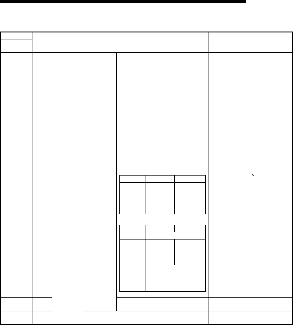
3 - 19
MELSEC-F
SPECIFICATIONS3
3 - 19
(Continued from the previous page)
BFM number
Attribute Application Name
Initial value
Decimal
(Hexadecimal)
Flash ROM
save
Reference
section
Decimal
(Hexadecimal)
1610
(64AH)R/W
For fixed buffer
communication
Fixed buffer
communication
Transmission/
reception
request/Execution
result
When sending request or reception complete
confirmation signal of connection No.1
• For sending
1) Write value
0001H: Sending request
2) Read value
0001H: Transmission ready
0002H: Between data being sent to while
waiting for a response (only when
procedure exists)
0004H: Stored when transmission
complete If instantly receiving the
next data, depending on the
timing of FROM instruction, 0001H
is stored without reading 0004H
0008H: Stored when transmission error
0000H: Stored when the open processing
or close processing is completed
• For receiving
1) Write value
2) Read value
0
(0000H)
Chapter 6,
Chapter 7
1611
(64BH)R/W When sending request or reception complete
confirmation signal of connection No.2 (Same as connection No.1)
1612 to 1663
(64C to 67FH)— System area — — —
Write value Procedure No procedure
0002H
Response
transmission
to an
external
device
Allows the
following data
to be received
Read value Procedure No procedure
0001HAt data reception
0004H
Response
transmission
complete
Acceptance
for the data
reception
complete
0008H
Receiving process cannot be
normally completed
0000H
Stores after open/close
process

3 - 20
MELSEC-F
SPECIFICATIONS3
3 - 20
(g) Fixed buffer area (BFM #1664 to 9855)
BFM number
Attribute Application Name
Initial value
Decimal
(Hexadecimal)
Flash ROM
save
Reference
section
Decimal
(Hexadecimal)
1664
(680H)R/W
Fixed buffer
data area
Fixed buffer
No. 1
Data length 0
(0H)
Chapter 6,
Chapter 7
1665 to 2687
(681 to A7FH)R/W Fixed buffer data
2688
(A80H)R/W Fixed buffer
No.2
Data length 0
(0H)
Chapter 6,
Chapter 7
2689 to 3711
(A81 to E7FH)R/W Fixed buffer data
3712 to 9855
(E80 to 267FH)— System area — — —
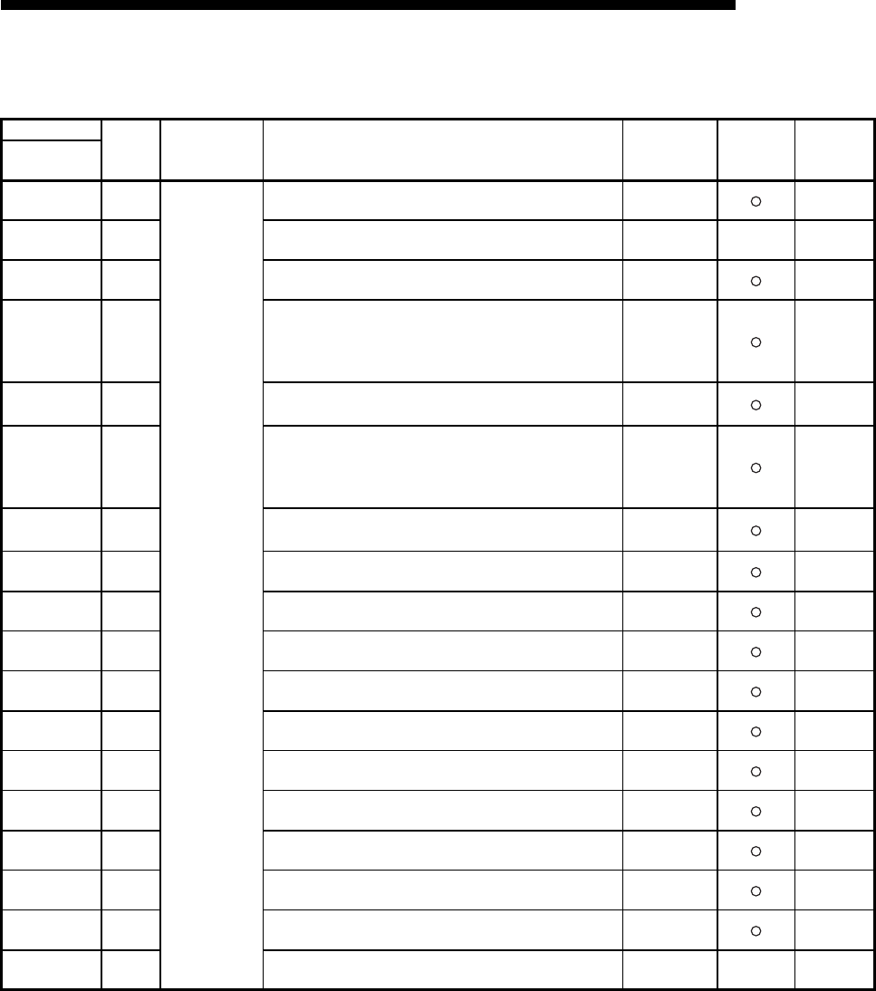
3 - 21
MELSEC-F
SPECIFICATIONS3
3 - 21
(h) Mail send parameter settings (BFM #9856 to 20479)
(Continues on the next page)
BFM number
Attribute Application Name
Initial value
Decimal
(Hexadecimal)
Flash ROM
save
Reference
section
Decimal
(Hexadecimal)
9856 to 9887
(2680 to 269FH)R/W
Shared area for
e-mail buffers
Local station mail address (Maximum of 64 characters) "\0" Chapter 10
9888 to 9912
(26A0 to 26B8
H
)
— System area — — Chapter 10
9913 to 9920
(26B9 to 26C0
H
)
R/W Password to the POP3 server (16 characters) "\0" Chapter 10
9921
(26C1
H
)
R/W
Method for designating SMTP server
0: Domain name designation
1: IP address designation (Decimal)
2: IP address designation (Hexadecimal)
1 Chapter 10
9922 to 9953
(26C2 to 26E1
H
)
R/W Domain name of the SMTP server (maximum 64 characters)
or IP address*1 0.0.0.0 Chapter 10
9954
(26E2
H
)
R/W
Method for designating POP3 server
0: Domain name designation
1: IP address designation (Decimal)
2: IP address designation (Hexadecimal)
1 Chapter 10
9955 to 9986
(26E3 to 2702
H
)
R/W Domain name of the POP3 server (maximum 64 characters)
or IP address*1 0.0.0.0 Chapter 10
9987 to10018
(2703 to 2722
H
)
R/W Send destination address 1 "\0" Chapter 10
10019 to 10050
(2723 to 2742
H
)
R/W Send destination address 2 "\0" Chapter 10
10051 to 10082
(2743 to 2762
H
)
R/W Send destination address 3 "\0" Chapter 10
10083 to 10114
(2763 to 2782
H
)
R/W Send destination address 4 "\0" Chapter 10
10115 to 10146
(2783 to 27A2
H
)
R/W Send destination address 5 "\0" Chapter 10
10147 to 10178
(27A3 to 27C2
H
)
R/W Send destination address 6 "\0" Chapter 10
10179 to 10210
(27C3 to 27E2
H
)
R/W Send destination address 7 "\0" Chapter 10
10211 to 10242
(27E3 to 2802
H
)
R/W Send destination address 8 "\0" Chapter 10
10243 to 10274
(2803 to 2822
H
)
R/W Send destination address 9 "\0" Chapter 10
10275 to 10306
(2823 to 2842
H
)
R/W Send destination address 10 "\0" Chapter 10
10307 to 10332
(2843 to 285C
H
)
— System area — — Chapter 10

3 - 22
MELSEC-F
SPECIFICATIONS3
3 - 22
(Continued from the previous page)
BFM number
Attribute Application Name
Initial value
Decimal
(Hexadecimal)
Flash ROM
save
Reference
section
Decimal
(Hexadecimal)
10333
(285DH)R/W Mail sending
command
• Write value
Mail sending instruction (0001H)
• Read value
Returns to "0000H" when mail sending commences
Multiple requesting exists. (0002H)
0
(0000H)
Chapter 10
10334
(285EH)RMail sending
status
Initial status (0000H)
Mail sending normally completed (0001H)
Mail sending abnormally completed (0002H)
While mail being sent (8000H)
0
(0000H)
Chapter 10
10335
(285FH)R
Error codes
when sending
e-mail
When sending mail to a single address, depending on the sending
instruction (BFM #10333: 0001H), the memory is cleared and the
first error code found is stored. When sending mail to multiple
addresses, the first error code found is stored, even after other
errors. "
The second error and later errors are not stored.
0
(0000H)
Chapter 10
10336
(2860H)RSending result
of e-mail
Send destination address 1 Success (b0: ON) / Failure (b0: OFF)
to
Send destination address 10 Success (b9: ON) / Failure (b9: OFF)
0
(0000H)
Chapter 10
10337
(2861H)R/W
Sending
designation
of e-mail
Turns on the bit of the mail address that sends an e-mail.
Sending destination address 1 Enable (b0: ON) / Disable (b0: OFF)
to
Sending destination address 10 Enable (b9: ON) / Disable (b9: OFF)
Initialized into 0000H by mail sending instruction, and the bit is
updated sequentially depending on the sending result.
0
(0000H)
Chapter 10
10338
(2862H)R/W Attached file
format
0000H: Sends the attached file in binary format (maximum 2048
words)
0001H:
Sends the attached file in ASCII format (maximum 2048 words)
0002H:
Sends the attached file in CSV format (maximum 2048 words)
0004H:
Sends the attached file as a text mail (maximum 256 words)
0
(0000H)
Chapter 10
10339 to 10402
(2863 to 28A2
H
)
R/W Subject Stores a subject (maximum 128 characters) "\0" —
10403
(28A3H)R/W Word count of
attached file
Designates the word count of main text (0 to 256)/attached file (0
to 2048)
0
(0000H)—
10404 to 12451
(28A4 to 30A3
H
)
R/W Main text of
attached file Stores a main text or an attached file "\0" —
12452 to 20479
(30A4 to 4FFF
H
)
— System area ———
*1 (example)192. 168. 0. 10 C0 A8 00 0A
4) 3) 2) 1)
SMTP : BFM#9922
POP3 : BFM#9955
H L
2) 1)
SMTP : BFM#9923
POP3 : BFM#9956 4) 3)
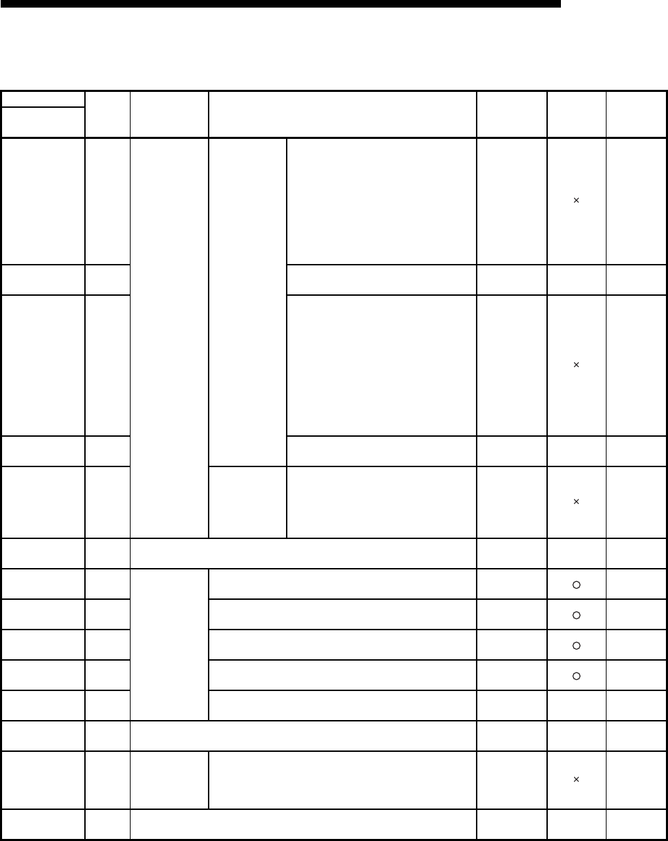
3 - 23
MELSEC-F
SPECIFICATIONS3
3 - 23
(i) Connection status storage area (BFM #20480 to 22639)
BFM number
Attribute Application Name
Initial value
Decimal
(Hexadecimal)
Flash ROM
save
Reference
section
Decimal
(Hexadecimal)
20480
(5000H)R
Connection
status storage
area
Connection
status
information area
Open complete signal
0: Open incomplete
1: Open completed
• Connection No. 1 (b0)
• Connection No. 2 (b1)
• Connection No. 3 (b2)
• Connection No. 4 (b3)
TCP : 1 by connection establishment
UDP : 1 by communication enabled
0
(0H)Section 5.6
20481
(5001H)— System area — — —
20482
(5002H)R
Open request signal
0: No open request
1: Open being requested
• Connection No. 1 (b0)
• Connection No. 2 (b1)
• Connection No. 3 (b2)
• Connection No. 4 (b3)
TCP Passive : 1 by listen
Active : 1 by open process
UDP : 1 by communication enabled
0
(0H)Section 5.6
20483 to 20484
(5003 to 5004H)— System area — — —
20485
(5005H)RFixed buffer
information area
Fixed buffer reception status signal
0: Data not received
1: Data being received
• Connection No. 1 (b0)
• Connection No. 2 (b1)
0
(0H)Chapter 7
20486 to 20504
(5006 to 5018H)—System area ———
20505 to 20506
(5019 to 501A H)R/W
System port
information area
DNS server 1 IP address 0
(0H)
Section
10.6
20507 to 20508
(501B to 501C H)R/W DNS server 2 IP address 0
(0H)
Section
10.6
20509 to 20510
(501D to 501E H)R/W DNS server 3 IP address 0
(0H)
Section
10.6
20511 to 20512
(501F to 0520 H)R/W DNS server 4 IP address 0
(0H)
Section
10.6
20513 to 20591
(5021 to 506F H)— System area — — —
20592 to 20994
(5070 to 5202H)—System area ———
20995
(5203H)R/W
"Interrupt
detection"
status storage
area
Interrupt detection count 0
(0H)—
20996 to 22639
(5204 to 586F
H
)
—System area ———

3 - 24
MELSEC-F
SPECIFICATIONS3
3 - 24
(j) E-mail status storage area (BFM #22640 to 31999)
(Continues on the next page)
*1 The timestamp for an email that had a communication error with the mail server is stored in BCD code in the following manner.
BFM number
Attribute Application Name
Initial value
Decimal
(Hexadecimal)
Flash ROM
save
Reference
section
Decimal
(Hexadecimal)
22640 to 23354
(5870 to 5B3AH)—
E-mail status
storage area
Send
System area — — —
23355
(5B3BH)R Number of mails normally completed
0
(0H)
Section
11.4
23356
(5B3CH)R Attached files sent count
23357
(5B3DH)R Sent to the SMTP server count
23358
(5B3EH)R Number of mails abnormally completed
23359
(5B3FH)R Error log write count
23360
(5B40H)R Error log write pointer
23361
(5B41H)R
Error log block 1
Error code
0
(0H)
Section
11.4
23362
(5B42H)R Command code
23363 to 23370
(5B43 to 5B4AH)RTo
23371 to 23374
(5B4B to 5B4EH)RDate *1
23375 to 23404
(5B4F to 5B6CH)R Subject
23405 to 23448
(5B6D to 5B98
H
)
R Error log block 2 (Same as error log block 1)
23449 to 23492
(5B99 to 5BC4
H
)
R Error log block 3 (Same as error log block 1)
23493 to 23536
(5BC5 to 5BF0
H
)
R Error log block 4 (Same as error log block 1)
23537 to 23580
(5BF1 to 5C1C
H
)
R Error log block 5 (Same as error log block 1)
23581 to 23624
(5C1D to 5C48
H
)
R Error log block 6 (Same as error log block 1)
23625 to 23668
(5C49 to 5C74
H
)
R Error log block 7 (Same as error log block 1)
23669 to 23712
(5C75 to 5CA0
H
)
R Error log block 8 (Same as error log block 1)
23713 to 24319
(5CA1 to 5EFF
H
)
— System area — — —
Month (01 to 12H
)
)
)
b15 b8
to
Lower 2-digits of year
(00
to 99
H)
b7 b0
to
Hour (00 to 23HDate (01 to 31H)
Second (00 to 59HMinutes (00 to 59H)
Higher 2-digits of year
(00
to 99
H
)
Day of the week (0 to 6)
b15 b8
to b7 b0
to
b15 b8
to b7 b0
to
b15 b8
to b7 b0
to
SUN:0 to SAT:6
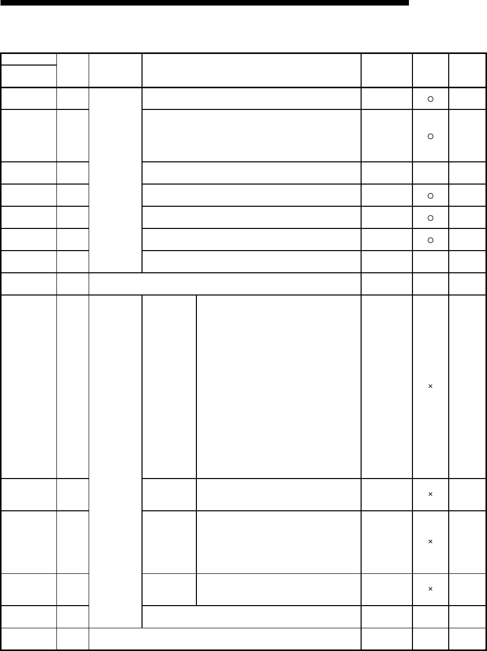
3 - 25
MELSEC-F
SPECIFICATIONS3
3 - 25
(Continued from the previous page)
BFM number
Attribute Application Name
Initial value
Decimal
(Hexadecimal)
Flash ROM
save
Reference
section
Decimal
(Hexadecimal)
24320
(5F00H)R/W
Mail Function
SMTP server port number 25
(19H)
Section
10.6
24321
(5F01H)R/W
SMTP authentication setting
0: No authentication
1: SMTP-AUTH
2: POP before SMTP
Any other value is handled as "0".
0
(0H)
Section
10.6
24322, 24323
(5F02, 5F03H)— System area — — —
24324 to 24355
(5F04 to 5F23H)R/W SMTP login ID (64 characters) "\0" Section
10.6
24356 to 24387
(5F24 to 5F43H)R/W SMTP password (64 characters) "\0" Section
10.6
24388
(5F44H)R/W POP3 server port number 110
(6EH)
Section
10.6
24389 to 24575
(5F45 to 5FFFH)— System area — — —
24576 to 31799
(6000 to 7C37H)— System area ———
31800
(7C38H)R/W
Error information
clear
Error informa-
tion to be
cleared
Designates the error information to be cleared
0000H:
Clears initial error code (BFM#105)
0001 to 0004
H:
Clears the open error code of
connection 1 to 8 (BFM#124, 134,
144, 154, 164).
Each of the following connection
corresponds.
0001H: Connection 1
0002H: Connection 2
0003H: Connection 3
0004H: Connection 4
0100H: Clears the error log block area
(BFM#227 to 372) to 0.
0101H: Clears communication status (status
for each protocol) (BFM#376 to 511)
0103H:
Clears communication status (E-mail
receive status) (BFM#23353 to 23712)
FFFFH: Clears all of the above
0
(0000H)—
31801
(7C39H)R/W COM.ERR. Off
Designates the function to be cleared
0000H : [COM.ERR.] LED Off, error code clear
FFFFH: Error log clear
0
(0000H)—
31802
(7C40H)R/W Executing error
clear
Executes error clear
• Write value
0001H: Executes error clear
• Write value
0002H: Stored at error clear
The result is stored in BFM#31803
0
(0000H)—
31803
(7C41H)R/W
Result of
execution error
clear
Stores result of execution error clear
0000H: Normally executed
Other than 0000H: Error code
0
(0000H)—
31804 to 31999
(7C42 to 7CFF
H
)
— System area — — —
32000 to 32639
(7D00 to 7F7F
H
)
— System area ———
4 - 1
SETTINGS AND PROCEDURES PRIOR TO OPERATION4
4 - 1
4
MELSEC-F
4 SETTINGS AND PROCEDURES PRIOR TO OPERATION
This chapter explains the settings and procedures required prior to operating the
Ethernet module in a system.
4.1 Loading and Installation
This section explains precautions for Ethernet module handling from unpacking to
installation, as well as the installation environment common to all modules.
For more details on module mounting and installation, refer to the Installation Manual
supplied with the Ethernet module.
4.1.1 Handling precautions
The following explains precautions for Ethernet module handling:
(1) Since it is made of resin, the Ethernet module case should not be dropped or
subjected to any shock.
(2) Tighten the module terminal and fixing screws within the following specified
clamping torque range:
Screw location Tightening torque range
External power supply terminal screw (M3 screw) 0.5 to 0.8 N•m
Unit-affixing screw ( M4 screw ) 0.78 to 1.08 N•m
DANGER Do not touch the terminals and connectors while the power is on.
Doing so may result in electric shocks and malfunctions.
Make sure to turn off all phases of the external power supply before cleaning or
re-tightening the screws. Failure to do so may cause damages or malfunctions of
the module.
If the screws are loose, it may cause the module to short circuit, malfunction or
fall off.
Tightening the screws excessively may damage the screws and/or the module
and cause the module to short circuit, malfunction or fall off.
Do not write any data in the "System area" of the buffer memory on the module.
4 - 2
SETTINGS AND PROCEDURES PRIOR TO OPERATION4
4 - 2
4
MELSEC-F
4.1.2 Installation environment
This section explains the installation environment for the PLC. When installing the
PLC, the following environments must be avoided:
• Locations where the ambient temperature exceeds the range of 0 to 55 .
• Locations where the ambient humidity exceeds the range of 5 to 95 % RH.
• Locations where condensation occurs due to a sudden temperature change.
• Locations where there are corrosive or flammable gases.
• Locations exposed to considerable amounts of conductive powdery substances
such as dust and iron filing, oil mist, salt, or organic solvents.
• Locations exposed to direct sunlight.
• Locations exposed to strong electric or magnetic fields.
• Locations where vibrations or impacts are directly applied to the main unit.
CAUTION Be careful not to let any foreign matter such as wire chips get inside the module.
They may cause fire, as well as breakdowns and malfunctions of the module.
Never disassemble or modify the module.
This may cause breakdowns, malfunctions, injuries or fire.
When attaching or removing the base module and all expansion module special
blocks, make sure to cut all external power supplies.
Failure to do so may cause the module to breakdown or malfunction.
Tighten the terminal screws using the specified torque.
If the terminal screws are loose, it may cause the module to short-circuit,
malfunction or fall off.
Tightening the terminal screws excessively may damage the screws and/or the
module and cause the module to short-circuit, malfunction or fall off.
Do not directly touch the conducting parts and electronic parts of the module.
This may cause the module to malfunction or fail.
When disposing of this product, treat it as industrial waste.
A protective sheet is pasted on the upper part of the module in order to prevent
foreign matter such as wire chips to get inside the module while wiring.
Do not remove this protective sheet during wiring work.
However, be sure to remove the protective sheet before operating the module to
allow heat radiation during operation.
Before performing control operations (especially data modifications, program
modifications and operating-status modifications) on the PLC in operation, be
sure to confirm the safety.
For basic module status control (remote RUN/STOP and similar controls)
previous parameter settings should normally be set to open. If these conditions
are not met, after a remote STOP, the communication line is closed from another
node and cannot be re-opened, so remote RUN cannot start.
CAUTION Use the PLC in the operating environment that meets the general specifications
described in the user's manual of the PLC to use.
Using the PLC in any other operating environments may cause electric shocks,
fires or malfunctions, or may damage or degrade the module.
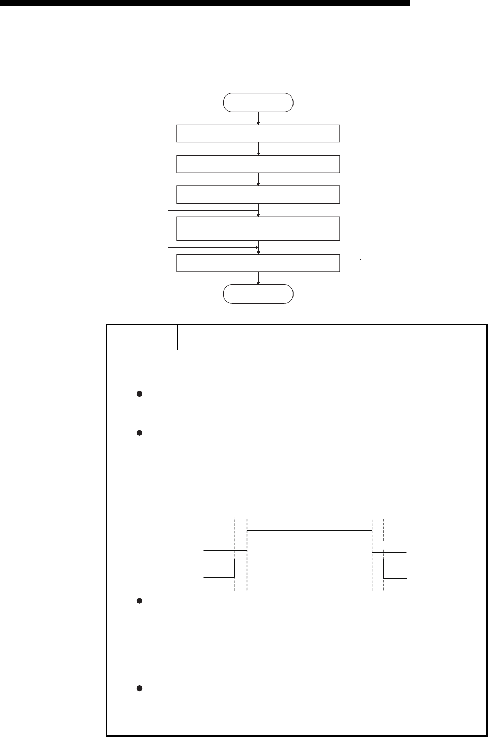
4 - 3
MELSEC-F
SETTINGS AND PROCEDURES PRIOR TO OPERATION4
4 - 3
4.2 Settings and Procedures Prior to Starting the Operation
The following shows a flow of the procedure that is required prior to operating:
POINT
(1) When the parameter settings are added or modified using the
FX Configurator-EN-L, the settings differs depending on the connection
condition to the Ethernet module as shown below.
When directly connected to the PLC
After the parameter settings are added or modified, re-initialization
processing can be automatically performed.
When connected via Ethernet
The added or modified parameter settings are not reflected.
To operate the Ethernet module after the parameter settings are added or
modified with FX Configurator-EN-L, first save the parameter values,
second reboot the Ethernet's module power.
(2) Timing for powering ON
Power ON the PLC and the Ethernet module with the timing as shown below.
When turning the system power ON
Turn the power of the Ethernet module ON first, and then turn ON the
power of the PLC after that when different power source is used for the
PLC and Ethernet module.
It is possible to supply power to the Ethernet module from the 24 VDC
service power supply of the PLC. (Pay attention to the current capacity of
the service power supply of the PLC.)
When turning the system power OFF
Turn the power of the PLC and Ethernet module OFF at the same time.
Or turn OFF the power of the PLC first, and then turn OFF the power of the
Ethernet module after that.
Procedures prior
to operation
Create a program for each communication
Operation
See Section 4.4, "Connecting
to the Network."
See Section 4.5, "Settings from
Ethernet Parameters."
See Section 5.4, "Confirming the Completion
of the Initial Processing."
See applicable
communication function
Connect the Ethernet module to the base module and
wire the 24VDC power supply.
Connect the Ethernet module to the Ethernet network.
Send the "Ping" command from an external device and
confirm the completion of the Ethernet module initial
processing
Setting the Ethernet module network parameters .
ON
ON OFF
PLC
Ethernet
module
OFF

4 - 4
MELSEC-F
SETTINGS AND PROCEDURES PRIOR TO OPERATION4
4 - 4
Important
(1) Do not write any data in the "System area" of Ethernet module buffer memory.
(2) When status control (such as remote RUN/STOP) from a external device is
used for the PLC, the user should select "Always wait for OPEN" beforehand
using the setting parameters. (Select using initial timing in the operation
settings.)
If "Do not wait for OPEN" is selected, the communication line will be closed
during remote STOP. After that, communication cannot be reopened from the
PLC side and remote run from the external device will not work.
(3) When the Ethernet module is replaced, reset the parameters.
(4) When the Ethernet module is replaced, reboot the external device as well. (If
the external device retains the Ethernet address, it may be impossible to
continue communication because when a module is replaced the Ethernet
address changes.)
In the same way, when the external device (personal computer, etc.)is
replaced, reboot the Ethernet module.
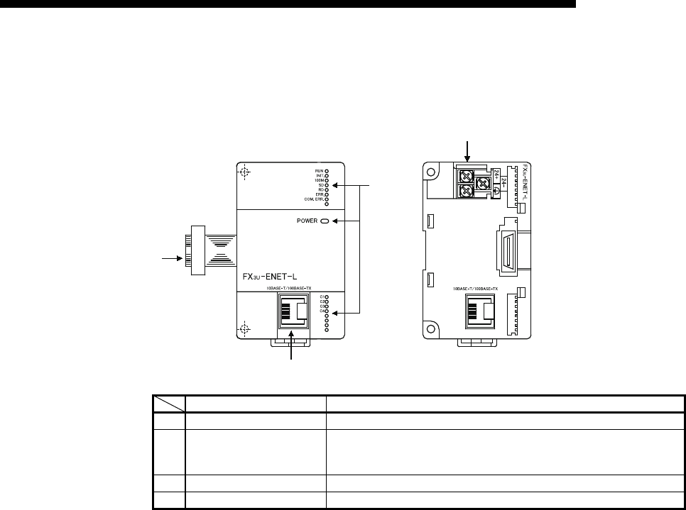
4 - 5
MELSEC-F
SETTINGS AND PROCEDURES PRIOR TO OPERATION4
4 - 5
4.3 Components of the Ethernet Module
This section shows the components of the Ethernet module.
Name Description
1) LED display Refer to the contents of the LED displays (1).
2) 10BASE-T/100BASE-TX
connector (RJ45)
Connector for connecting the Ethernet module to the 10BASE-T/100BASE-TX.
(Ethernet module chooses between 10BASE-T and 100BASE-TX according to
the hub.)
3) Extension cable Cables to connect to the PLC
4) External 24VDC terminal Power supply terminal for 24VDC
1)
2)
3)
4)
View with the cover removed
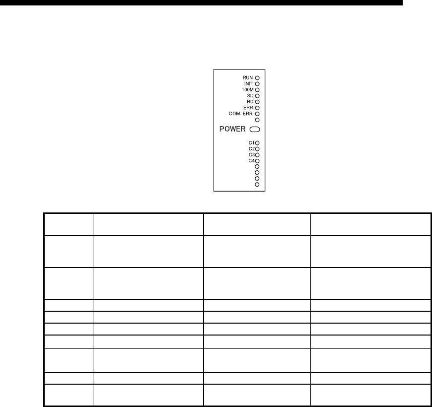
4 - 6
MELSEC-F
SETTINGS AND PROCEDURES PRIOR TO OPERATION4
4 - 6
(1) LED display contents (*1)
*1 Refer to Subsection 11.1.1 for causes of error displays and the corresponding corrective
actions.
*2 The [ERR.] LED turns on in the following cases:
• When the parameter written is incorrect.
• When the checksum of the parameter written is not identical.
• When an error has occurred in the Ethernet module and operation is disabled due to the error.
*3 Refer to Subsection 11.1.1 for the status when the [COM.ERR.] LED is on.
LED name Display description When the LED is on When the LED is off
RUN Normal operation display
Normal
(when FROM/TO instruction can
be executed from PLC side)
Abnormal
(when WDT is in operation)
INIT. Initial processing status display Normal completion
Not processed
(when execution failed initial
processing)
100M Transmission speed display 100Mbps 10Mbps/When not connected
SD Data sending display Data being sent Data not being sent
RD Data receiving status display Data being received Data not being received
ERR. Setting abnormal display Abnormal *2 Normal setting
COM.ERR. Communication abnormal display Communication abnormal
occurrence *3 Normal communication in progress
POWER Module power status Power is on Power is off
C1 to C4 TCP/IP, UDP status of the
connections
TCP/IP : Connection Established
UDP : Open
TCP/IP : Connection not Established
UDP : Closed
4 - 7
MELSEC-F
SETTINGS AND PROCEDURES PRIOR TO OPERATION4
4 - 7
4.4 Connecting to the Network
The following explains how to connect the Ethernet module to the 100BASE-TX/
10BASE-T networks.
Some precautions that should be observed while connecting the Ethernet module are
also shown below. Pay close attention to safety and use the Ethernet module
properly.
(1) Sufficient network knowledge and safety precautions are required when installing
100BASE-TX or 10BASE-T networks. Consult a specialist when connecting
cable terminals or installing trunk line cables, etc.
(2) Use a connection cable conforming to the standards shown in Section 2.2.
CAUTION Do not bundle the control wires and the communication cables with the main
circuit and the power wires, and do not install them close to each other. They
should be installed at least 100 mm (3.94 in.) away from each other. Failure to do
so may generate noise that may cause malfunctions.
Make sure to place the communication and power cables to be connected to the
module in a duct or fasten them using a clamp.
If the cables are not placed in a duct or fastened with a clamp, their positions may
be unstable or moved, and they may be pulled inadvertently. This may damage
the module and the cables or cause the module to malfunction because of faulty
cable connections.
When disconnecting the communication and power cables from the module,
do not pull the cables by hand.
When disconnecting a cable with a connector, hold the connector to the
module by hand and pull it out to remove the cable.
When disconnecting a cable without a connector, loosen the screws on the
terminal block first before removing the cable.
If a cable is pulled while connected to the module, it may cause the module to
malfunction or damage the module and the cable.
POINT
Cautions regarding powering the hub, PLC and Ethernet module simultaneously.
On some hubs, for a fixed period of time immediately after powering up, even if
packets are sent from the Ethernet device, there are cases when packets are not
sent to the external device. For this case, create a sequence program that waits a
sufficient amount of time after powering up before sending packets.
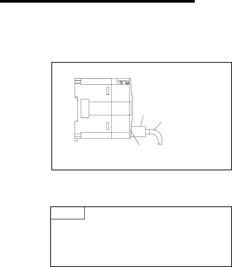
4 - 8
MELSEC-F
SETTINGS AND PROCEDURES PRIOR TO OPERATION4
4 - 8
4.4.1 Connecting to the 10BASE-T/100BASE-TX network
This section explains how to connect the Ethernet module to the 10BASE-T,
100BASE-TX network.
The following shows the connection diagram for the twisted paid cable.
<Operating procedure>
(Step 1) Connect the twisted-pair cable to the hub.
(Step 2) Connect the twisted-pair cable to the Ethernet module.
POINT
(1) The Ethernet module detects whether it is 10BASE-T or 100BASE-TX, and in
full-duplex or half-duplex transmission mode automatically according to the
hub.
For connection to the hub without the auto detection function, set the half-
duplex mode on the hub side.
(2) For 10BASE-T or 100BASE-TX connection required devices and a sample
system configuration, refer to Section 2.2 (1) and (2).
RJ45 type modular
RJ45 type modular jack
shielded twisted-pair cable
(Category 3, 5, 5e)

4 - 9
MELSEC-F
SETTINGS AND PROCEDURES PRIOR TO OPERATION4
4 - 9
4.5 Ethernet Module Setting
Setting the Ethernet module as a network module.
The settings found must always be set in order to use the Ethernet module.
(1) "Operational settings" (Details are explained in Section 4.6)
This is for setting common items for when other modules use the Ethernet
module.
This settings must always be set, since they are required for the Ethernet initial
processing.
(2) "Initial settings" (Details are explained in Section 5.2)
This is for setting common timer values for TCP/IP communication to be used in
the Ethernet module as well as for setting the DNS server in order to use the e-
mail function.
It is not necessary to set the timer values when communicating using the initial
timer values.
(3) "Open settings" (Details are explained in Section 5.5)
This is for setting connection open processing, buffer memory for fixed buffer
communication and MC protocol to communicate data with an external device.
(4) "Router relay parameter (Routing information)" (Details are
explained in Section 5.3.)
The following setting for data communication with external devices are set:
• Communicating with external devices connected to other Ethernet networks
via a router
(5) "E-mail settings" (Details are explained in Section 10.6)
These settings are for using the e-mail transmission.
Ethernet parameter settings are written to buffer memory with a ladder program, and
the contents are stored in the Ethernet module's flash ROM.
Also, the contents can be set with FX Configurator-EN-L.
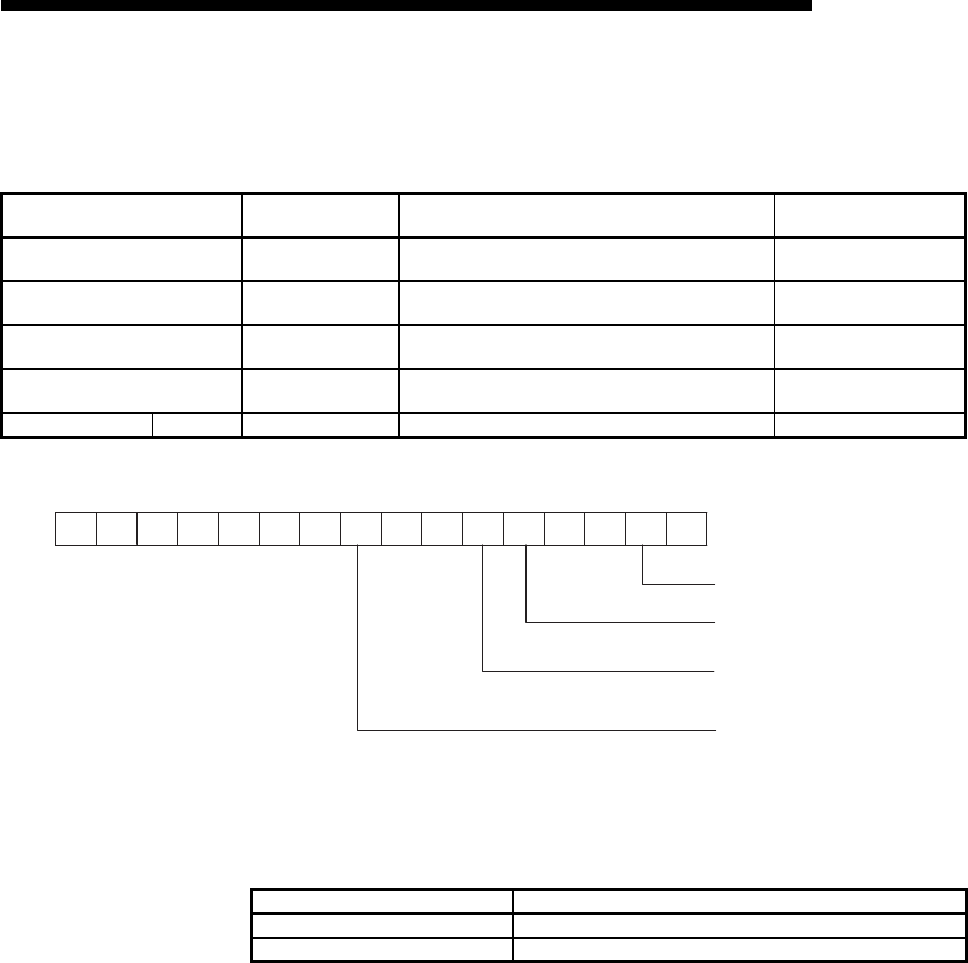
4 - 10
MELSEC-F
SETTINGS AND PROCEDURES PRIOR TO OPERATION4
4 - 10
4.6 Operational Settings
This section explains how to set the operations parameters.
(1) Communication data code (BFM#24 b1)
(a) Select the format of the communication data when communicating with an
external device.
(b) For more details on the data communication codes, see Section 3.2, "Data
Codes for Communication."
Setting name BFM number [Decimal]
(bit number) Setting description Setting range/selection
Communication data code 24 (b1) Select the communication data code. OFF : Binary code
ON : ASCII code
TCP Existence confirmation setting 24 (b4) Select the existence check method for TCP communication ON : Use KeepAlive
OFF : Use Ping
Send frame setting 24 (b5) Select the frame format to send OFF : Ethernet (V2.0)
ON : IEEE 802.3
Initial Timing 24 (b8) Perform the setting for opening OFF : Do not wait for OPEN
ON : Always wait for OPEN
IP Address setting IP Address 0 to 1 Set the IP address of the local station. -
Name of setting Description of setting
Binary code Communicate using binary data.
ASCII code Communicate using ASCII data.
[BFM#24
i
n
iti
a
l
process
i
ng parame
t
er se
tti
ng area
]
b15 b14 b13 b12 b11 b10 b9 b8 b7 b6 b5 b4 b3 b2 b1 b0
(1) Communication data code setting
(2) TCP Existence confirmation setting
(3) Send frame setting
(4) Initial
timing setting
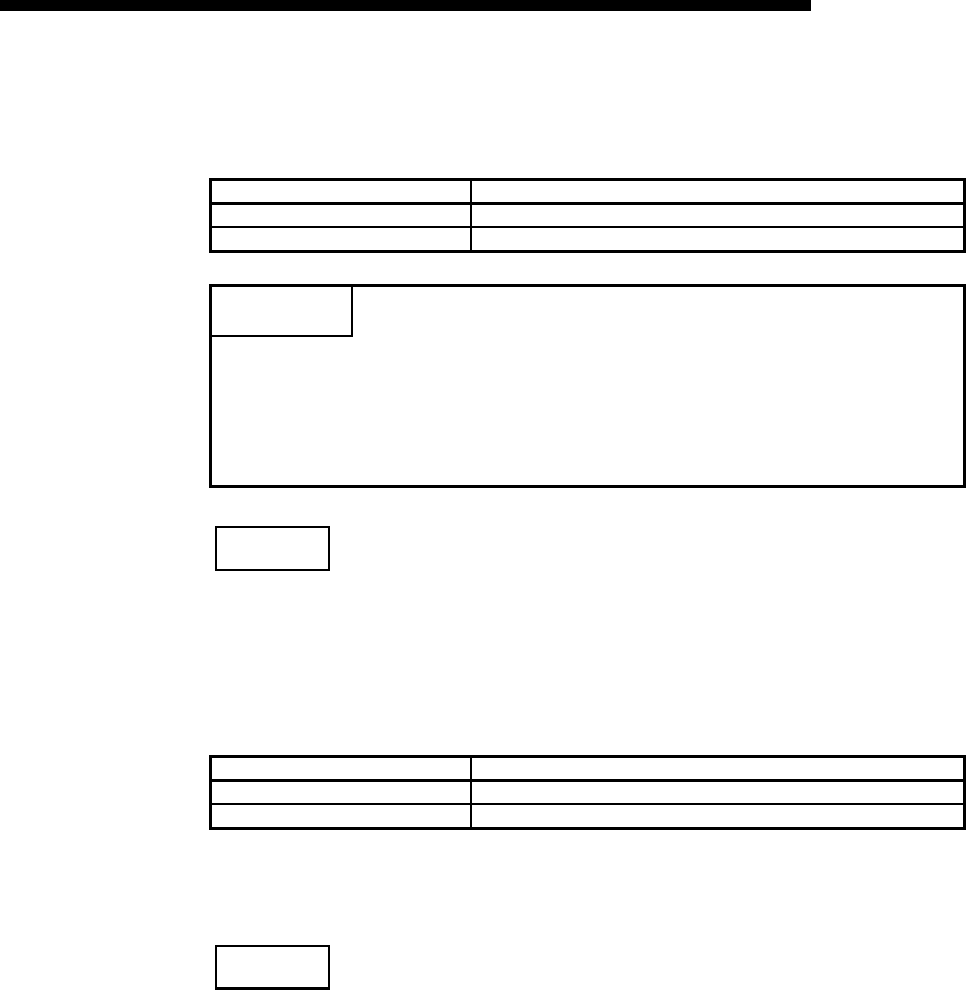
4 - 11
MELSEC-F
SETTINGS AND PROCEDURES PRIOR TO OPERATION4
4 - 11
(2) TCP Existence confirmation setting (BFM #24 b4)
Select the existence check method for TCP communication.
For the existence check function, refer to Subsection 5.2.2.
NOTE
When adjusting settings with FX Configurator-EN-L, select "Operating Settings" at
the initial screen and adjust the settings at the "Ethernet Operating Settings" screen.
(3) Send frame setting (BFM #24 b5)
(a) Select the frame of the Ethernet header for the data link layer to be sent by
the Ethernet module.
(b) When receiving data from the external device, reception should occur
regardless of whether the Ethernet frame or IEEE802.3 frame is used
NOTE
(1) Transmission using Ethernet frames is generally recommended.
(2) When communication with the external device fails, check whether or not
communication is possible using a PING command.
Name of setting Description of setting
Use the KeepAlive Checks connection status with KeepAlive.
Use the Ping Checks connection status with Ping.
POINT
(1) "Operational settings" parameters must always be set.
If the settings are changed, the power to the PLC and the Ethernet module
must be turned off once and then turned on again.
(2) If re-initialization of the Ethernet module is required due to the occurrence of
an error, perform re-initialization using a sequence program.
Setting item Description of setting
Ethernet (V2.0) Transmits using an Ethernet frame.
IEEE802.3 Transmits using an IEEE802.3 frame.

4 - 12
MELSEC-F
SETTINGS AND PROCEDURES PRIOR TO OPERATION4
4 - 12
(4) Initial Timing (BFM#24 b8)
(a) Select the timing to open connections for which TCP-Passive open or UDP
open are selected with the "Open settings" parameter (*1).
*1 For more details on the open settings, see Section 5.5 "Open Settings".
*2 If the sequence program of the local station's PLC executes the close processing, the station is not placed
in the OPEN request wait status after the connection is shut off.
(b) In the following cases, open/close processing is required with instructions
written to the buffer memory (BFM #1602 to 1605).
• When "Do not wait for OPEN" is selected in the initial timing settings.
• If the "Open settings" are not performed for a connection.
• If "TCP-Active" is selected in the "Open settings" for a connection.
For detail on the open/close processing, see Section 5.6 "Open Processing/
Close Processing of the Connection".
Name of setting Description of setting
Do not wait for OPEN
(Communication
impossible after STOP)
• Execute open/close processing using a sequence program.
• Communication cannot be performed while the PLC is in the STOP status.
Always wait for OPEN
(Communication possible
after STOP)
• Passive open and UDP open connections always wait for open according to the parame-
ter settings (a sequence program for open/close processing is not required) (*2).
• Communication can be performed while the PLC is in the STOP status.
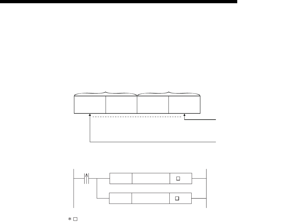
4 - 13
MELSEC-F
SETTINGS AND PROCEDURES PRIOR TO OPERATION4
4 - 13
(5) IP Address settings - IP address (BFM #0 to 1)
(a) Set the IP address of the local station according to the specified input format
(decimal or hexadecimal).
It should be set so that the local station Ethernet module and the
communicating external device have the same class and sub-net address
(two words).
(b) It is necessary to use the router relay function in order to communicate with
an external device on another Ethernet network (different sub-net address).
For more details, see Section 5.3, "Router Relay Parameter".
(c) Set the IP address after consulting a network administrator (the person who
plans the network and manages IP addresses).
[IP address]
Values bits 7 to 0
Values bits 31 to 24
to
BFM #1 BFM #0
U \G0
DMOV H0C0A801FE
(Example) Program for "192.168.1.254 (C0 A8 01 FE
H
)"
corresponds to the module number.
U \G25
MOV H9872
IP adress "192.168.1.254
(C0 A8 01 FE
H
)" is stored
in BFM #0, #1
Write command for configuration
data to a flash ROM.
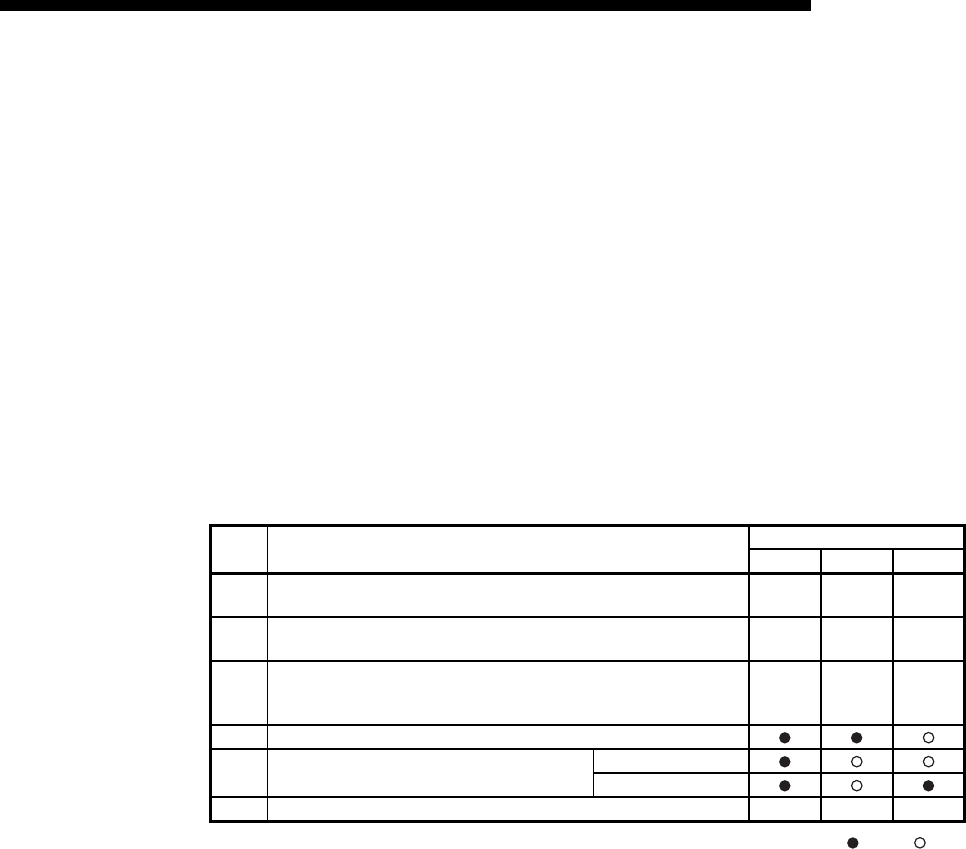
4 - 14
MELSEC-F
SETTINGS AND PROCEDURES PRIOR TO OPERATION4
4 - 14
4.7 Self-Diagnostic Tests
This section explains the self-diagnostic tests for checking the hardware and
transmission and reception function of the Ethernet module.
4.7.1 Self loopback test
The following explains the self loopback test that is used to check the hardware
including the Ethernet module's transmission and reception circuit.
The self loopback test transmits a test message within the Ethernet module to check if
the same message can be received or not. (Connection to the hub is not necessary.)
The following explains the procedure for performing the self loopback test. The test
takes approximately five seconds to complete.
The test result can be judged from the LED displays on the front of the Ethernet
module.
: Lit : Off
The following are probable causes of errors.
• Ethernet module hardware error
• Ethernet line error
An error code is stored in the error log area (BFM#229) in the buffer memory of the
Ethernet module; the error content can then be checked from GX Developer. (See
Sections 11.2 and 11.3.)
Step Description of operation Status of LED
[RUN] [C1] [ERR.]
1Perform a self loopback test in operation mode
( "0002H" is written to BFM #202). ———
2The contents of BFM#202 are written to the flash ROM
("9872H" is written to BFM#25). ———
3
• Turn off the PLC and the Ethernet module.
• Set the RUN/STOP switch to the STOP side
• Reboot the PLC's and the Ethernet module's power.
———
4 The test is in execution.
5The test results are shown on the LED after
approximately 5 seconds.
Normal
Error
6 Turn off the PLC and the Ethernet module. — — —
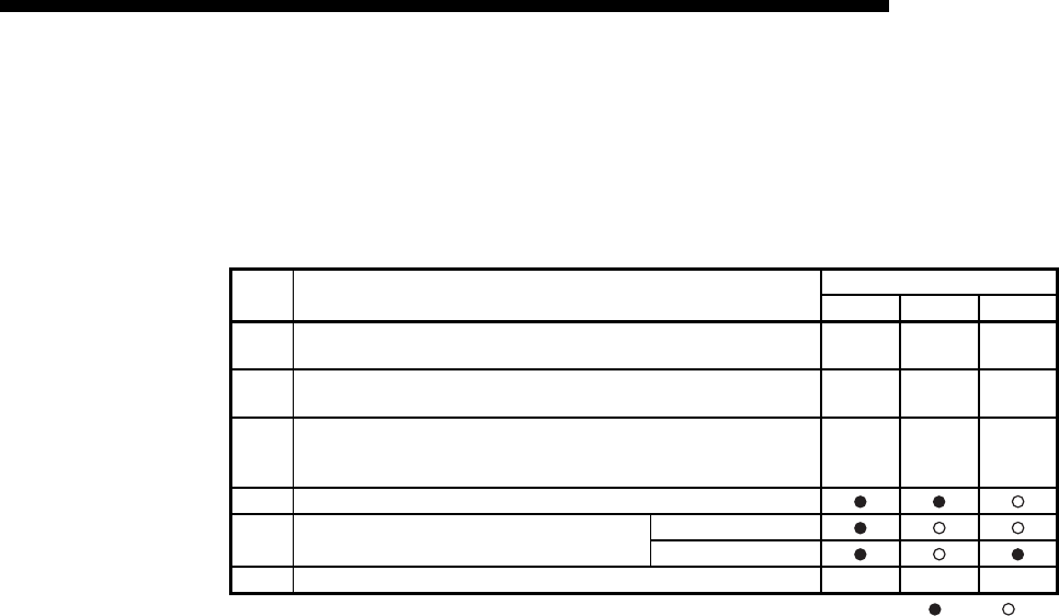
4 - 15
MELSEC-F
SETTINGS AND PROCEDURES PRIOR TO OPERATION4
4 - 15
4.7.2 Hardware test (H/W Test)
This section explains the RAM and ROM tests for the Ethernet module. The
procedure for the hardware test is as shown in the table below.
The test results are judged from the LED displays on the front of the Ethernet module.
: Lit : Off
The following are probable causes of errors.
• Ethernet module RAM/ROM error
An error code is stored in the error log area (BFM #229) in the buffer memory of the
Ethernet module; the error content can then be checked from GX Developer. (See
Sections 11.2 and 11.3.)
Step Description of operation Status of LED
[RUN] [C1] [ERR.]
1Perform a hardware test in operation mode.
("0003H" is written to BFM #202) ———
2The contents of BFM#202 are written to the flash ROM
("9872H" is written to BFM#25) ———
3
• Turn off the PLC and the Ethernet module.
• Set the RUN/STOP switch to the STOP side.
• Reboot the PLC's and the Ethernet module's power.
———
4 The test is in execution.
5The test results are shown on the LED after
approximately 5 seconds.
Normal
Error
6 Turn off the PLC and the Ethernet module. — — —
4 - 16
MELSEC-F
SETTINGS AND PROCEDURES PRIOR TO OPERATION4
4 - 16
4.8 Maintenance and Inspection
This section explains the maintenance and inspection as well as the installing and
uninstalling of the Ethernet module.
4.8.1 Maintenance and inspection
The Ethernet module does not need to be inspected for anything particular other than
checking whether or not the connections of cables and the terminal screws are loose.
Maintain and inspect the system according to the same inspection items as described
in the user's manual for the PLC in order to use it in optimal operating conditions.
DANGER Do not touch the terminals and connectors while the power is on.
Doing so may cause in electric shocks and malfunctions.
Make sure to turn off all phases of the external power supply before cleaning
or re-tightening the screws. Failure to do so may cause damages or
malfunctions of the module.
If the screws are loose, it may cause the module to short-circuit, malfunction
or fall off.
Tightening the screws excessively may damage the screws and/or the
module and cause the module to short circuit, malfunction or fall off.
CAUTION Be careful not to let any foreign matter such as wire chips get inside the module.
They may cause fire, as well as breakdowns and malfunctions of the module.
Never disassemble or modify the module.
This may cause breakdowns, malfunctions, injuries or fire.

4 - 17
MELSEC-F
SETTINGS AND PROCEDURES PRIOR TO OPERATION4
4 - 17
4.8.2 Installing and uninstalling the module
Before installing or uninstalling the Ethernet module, make sure to read Section 4.1,
"Handling Precautions" thoroughly, ensure the safety of the installation, and handle
the module properly according to the instructions.
The following explains the procedures when installing/uninstalling the Ethernet
module.
<Operation procedure when replacing the Ethernet module> (*1)
(Step 1) Read and save the parameters from the Ethernet module using
FX Configurator-EN-L (*2)
(Step 2) Turn off the power supply to the base module, the extension device, and
the Ethernet module.
(Step 3) Remove the network cable and Ethernet module.
(Step 4) Set up and start up the new Ethernet module according to Section 4.2,
"Settings and Procedures Prior to Starting the Operation." (*3)
(Step 5) Reset the external device. (*4)
*1 It is recommended to record and save parameters not only when the Ethernet
module is replaced but also when parameters for the Ethernet module are
created or modified.
*2 When FX Configurator-EN-L is not installed :
1) Monitor the buffer memory in the Ethernet module using GX Developer, and
record set values of the parameters for the Ethernet module.
For details on the parameters, refer to Section 4.6 "Operational Settings",
Section 5.2 "Initial Processing", Section 5.3 "Router Relay Parameter" and
Section 5.5 "Open Settings".
2) After replacing Ethernet module, write the setting value into BFM by
GX Developer.
3) Write the setting value into the Flash ROM by BFM#25.
*3 When the Ethernet module is replaced, use the FX Configurator-EN-L to reset
the parameters.
*4 When the Ethernet module is replaced, reset the external device as well. (If the
external device retains the Ethernet address, it may be impossible to continue
communication because when a module is replaced the Ethernet address
changes.)
In the same way, when the external device (personal computer, etc.)is replaced,
restart the Ethernet module.
<Operation procedure when replacing the FX base module>
(Step 1) Turn off the power supply to the FX base module and the Ethernet
module.
(Step 2) Replace the FX base module. (See the Manual of FX base module.)
(Step 3) Turn on the power.
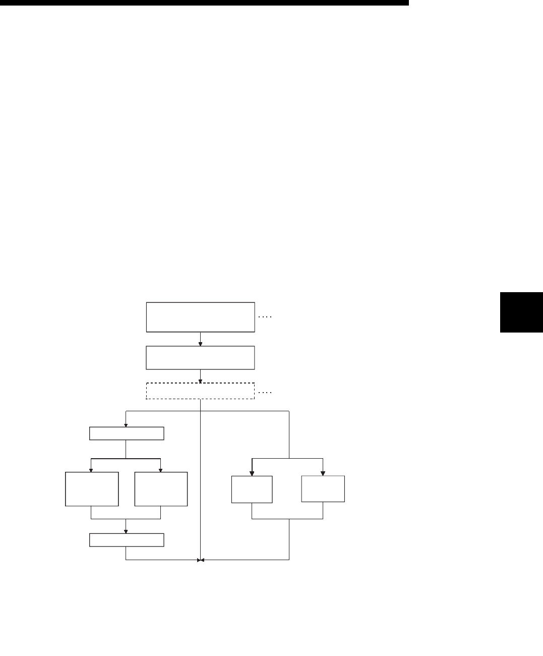
5 - 1
COMMUNICATION PROCEDURE5
5 - 1
5
MELSEC-F
5 COMMUNICATION PROCEDURE
This chapter gives an overview of the communication procedure using the Ethernet
module, as well as the required initial processing of the Ethernet prior to data
communication and the open processing for communication with an external device.
The sequence program can be effectively simplified by setting the parameters of the
Ethernet module supported by FX Configurator-EN-L.
5.1 Overview of the Communication Procedure
This section gives an overview of the procedure for performing data communication
with external devices via the Ethernet module.
• Start data communication by establishing connections with external devices via the
initial or open processing.
• End data communication by closing the connection, and, as a result, terminating all
communication processing.
The following diagram illustrates the communication procedure:
(There is no connection since UDP/IP does not have a notion of connection.)
Open processing
Set parameters for the
Ethernet module using sequence
program or FX Configurator-EN-L
Start the PLC and Ethernet
module
Automatically processed.
Ethernet module initial processing
See
Section
5.6.
MELSOFT
connection
E-mail
sending
Communication
using
the MC
protocol
Communication
using
fixed
buffers
Close processing
See
Section
5.6.
See Section 4.6, "Operational Settings."
See Section 5.2, "Initial Processing.
See Section 5.3, "Router Relay Parameter."
See Section 5.5, "Open Settings."
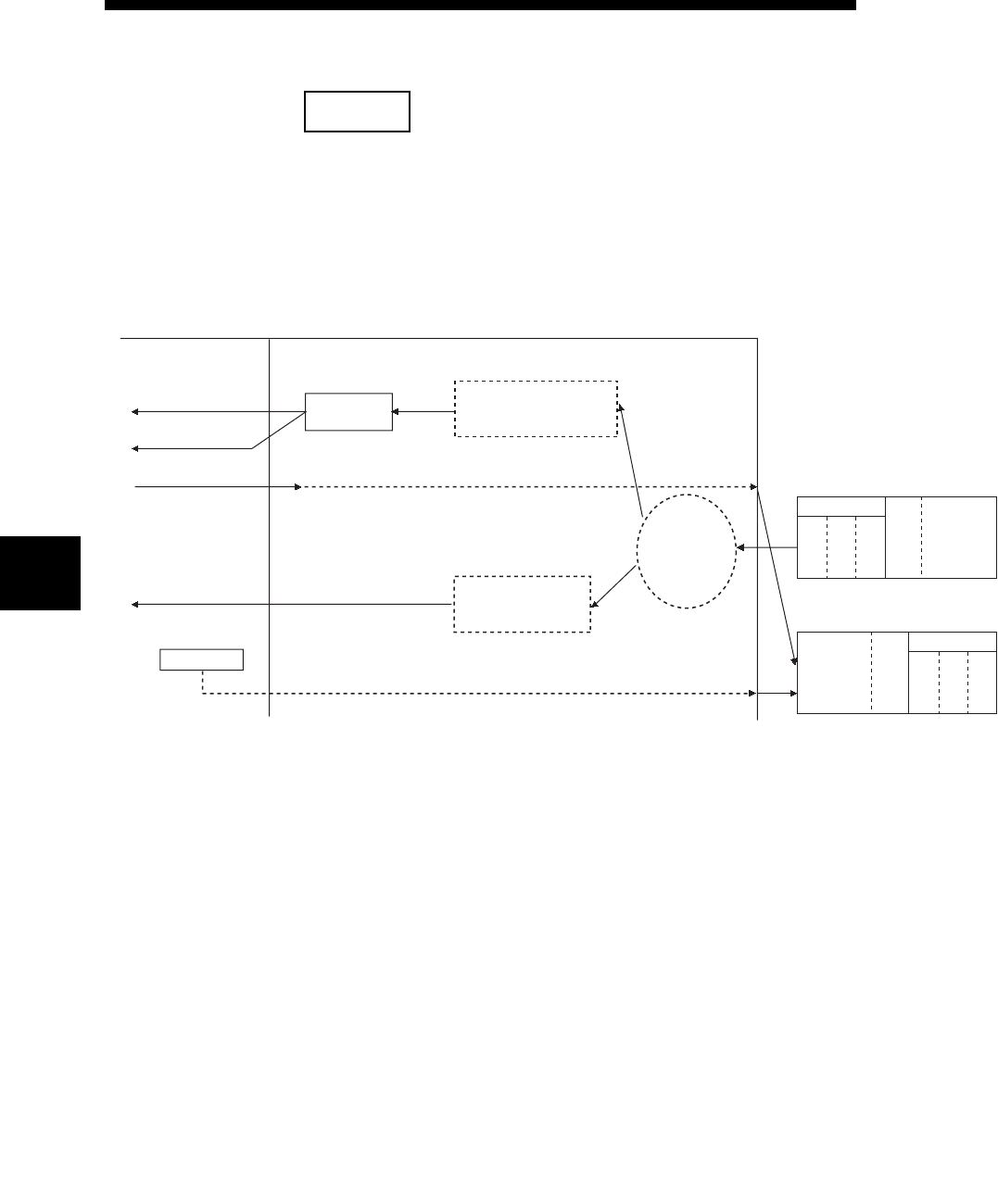
5 - 2
COMMUNICATION PROCEDURE5
5 - 2
5
MELSEC-F
NOTE
The following communication can be performed with an open device on other end.
• Communication using MC protocol
• Sending/receiving in fixed buffer communication (procedure exists)
Request from an external
device (receive)
Header
Ethernet
IP
TCP
Sub header
Application
data
Response to the request (send)
Header
Ethernet
IP
TCP
Sub header
Application
data
Ethernet modulePLC
(Subheader code)
When receiving communication request data from an external device
Store data
received
Fixed buffer communication
(Procedure exists)
(communication)
Communication using
the MC protocol
(read/write)
Device memory, etc.
Data
00 to 05H
13 to 16H
80 to 85H
93 to 96H
OS
Confirm the
request contents
with the
subheader.
E0H
60H
* For receiving when the
communication is open
Receive completion signal
Receive data acquisition
processing
Receive data normal
completion BFM operation
Head
Head
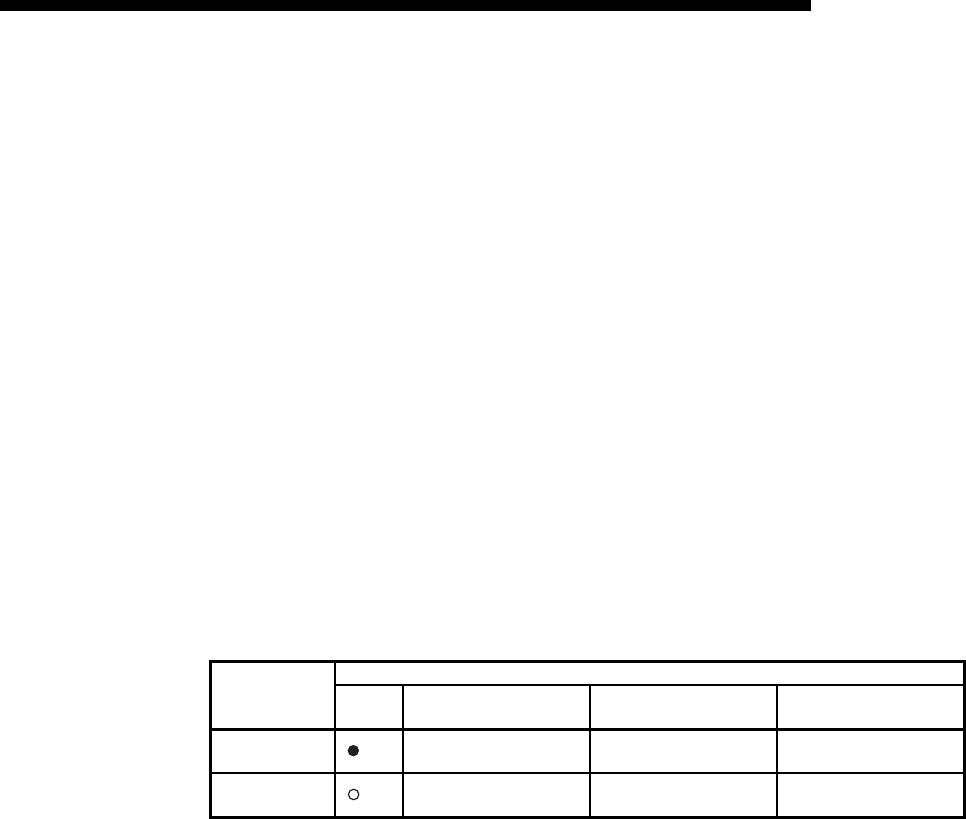
5 - 3
MELSEC-F
COMMUNICATION PROCEDURE5
5 - 3
5.2 Initial Processing
This section explains the initial processing of the Ethernet module.
5.2.1 Initial processing
The initial processing enables data communication with an external device by setting
the parameters required for data communication via the Ethernet module.
Set the following parameters in the sequence program, write them to the Ethernet
module; the initial processing of the Ethernet module is then performed by one of the
following methods.
• Re- initialization request (Write the re-initialization request (0001H, 0002H, 0005H or
0006H) to BFM #1600.)
• Power ON the Ethernet module again.
(1) Parameters required for initial processing
• "Operational settings" :(See Section 4.6.)
• "Initial settings" :(See Subsection 5.2.2.)
(2) Confirmation of initial processing result
If the initial processing does not complete normally, correct the above parameter
setting value and write to the Ethernet module. Then re-initialize the Ethernet
module.
Initial processing
Ethernet module
INIT.LED Initial normal completion
signal (BFM#28 b0)
Initial abnormal completion
signal (BFM#28 b5)
Initial normal completion
signal (BFM#27)
At normal
completion : On ON OFF 0001H
At abnormal
completion : Off OFF ON 0000H

5 - 4
MELSEC-F
COMMUNICATION PROCEDURE5
5 - 4
5.2.2 Initial settings
This section explains the initial settings.
*1 Details are explained in Section 10.6.
Setting item name BFM number
[Decimal] Description of setting Setting range/options
Timer
setting
TCP ULP timer 4 Set the time of packet existence at TCP data transmission. 2 to 32767
TCP zero window timer 5 Set the interval for checking the reception enabled status. 2 to 32767
TCP resend timer 6 Set the time to resend at TCP data transmission. 2 to 32767
TCP end timer 7 Set the confirmation wait time at TCP close processing. 2 to 32767
IP assembly timer 8 Set the wait time for division data packets. 1 to 32766
Response monitoring timer 9 Set the response wait time. 2 to 32767
Destination existence
confirmation starting interval 10 Set the time to start confirming existence of an external device after
communication with it has terminated. 1 to 32767
Destination existence
confirmation interval timer 11 Set the time interval between reconfirming existence. 1 to 32767
Destination existence
confirmation resend timer 12 Set the number of times to reconfirm existence when a response to
the existence confirmation is not received. 1 to 32767
DNS setting
(*1)
IP address of DNS server 1 20505 to 20506 Set IP address of DNS server 1. —
IP address of DNS server 2 20507 to 20508 Set IP address of DNS server 2. —
IP address of DNS server 3 20509 to 20510 Set IP address of DNS server 3. —
IP address of DNS server 4 20511 to 20512 Set IP address of DNS server 4. —

5 - 5
MELSEC-F
COMMUNICATION PROCEDURE5
5 - 5
(1) Timer setting - TCP ULP timer (BFM#4)
(a) This item sets the time of packet existence during TCP data sending.
This timer is passed through the parameter when TCP opens or data is sent.
(b) Set the value in the range from 2 to 32767.
(c) Timer setting = setting value 500 ms
(2) Timer setting - TCP zero window timer (BFM#5)
(a) The window indicates the reception buffer on the receiving side.
(b) When there is no more space in the receiving buffer (window size = 0) on the
receiving side, data communication has to wait until enough space is made.
When this occurs, the sending side sends a sending window confirmation
packet to the receiving side after the TCP zero window timer value has been
reached, and confirms the reception enabled status.
(c) Set the value in the range from 2 to 32767.
(d) Timer setting = setting value 500 ms
(3) Timer setting - TCP resend timer (BFM#6)
(a) Set the resend time if ACK is not returned during TCP opening or data
transmission. This timer is also used for the existence time of the ARP
function.
(ARP is resent in "TCP resend timer" value/2 if a response is not returned
after the sent ARP request.)
(b) Set the value in the range from 2 to 32767.
(c) Timer setting = setting value 500 ms
(4) Timer setting - TCP end timer (BFM#7)
(a) When the TCP connection is closed from the local station, this timer sets the
monitoring time for how long the local station waits for a FIN request from an
external device after it sends a FIN request and the external device returns
an ACK.
(b) If the FIN request cannot be received from the external device before the
time designated by the TCP end timer setting, a RST should be sent to the
external device to forcibly close the connection.
(c) Set the value in the range from 2 to 32767.
(d) Timer setting = setting value 500 ms

5 - 6
MELSEC-F
COMMUNICATION PROCEDURE5
5 - 6
(5) Timer setting - IP assembly timer (BFM#8)
(a) Communication data may be divided on the IP level due to the buffer
restriction at the sending or receiving station.
(b) Set the value in the range from 1 to 32766.
(c) Timer setting = setting value 500 ms
(6) Timer setting - Response monitoring timer (BFM#9)
(a) This timer setting sets the following times.
1) The time to wait for a response after sending a command.
2) The time to wait for the last message after receiving the first message
when the message is divided.
(b) Set the value in the range from 2 to 32767.
(c) Timer setting = setting value 500 ms
(7) Timer setting - Destination existence confirmation starting interval
(BFM#10)
(a) This timer sets the time interval before attempting to confirm the existence of
an external side when an open connection for which existence confirmation
is required does not respond.
(b) Set the value in the range from 1 to 32767.
(c) Timer setting = setting value 500 ms
(8) Timer setting - Destination existence confirmation interval timer
(BFM#11)
(a) This timer sets the time interval before reconfirming the existence of an
external device on an open connection for which existence confirmation is
required that does not respond.
(b) Set the value in the range from 1 to 32767.
(c) Timer setting = setting value 500 ms
(9) Timer setting - Destination existence confirmation resend timer
(BFM#12)
(a) This timer sets the number of times to reconfirm existence when there is no
response from an external device on an open connection for which existence
confirmation is required.
(b) Set the value in the range from 1 to 32767.
(10)DNS setting - IP address of DNS server n (*1)
*1 The DNS setting is set when the e-mail sending function is used.
Refer to Chapter 10, "E-mail Function".
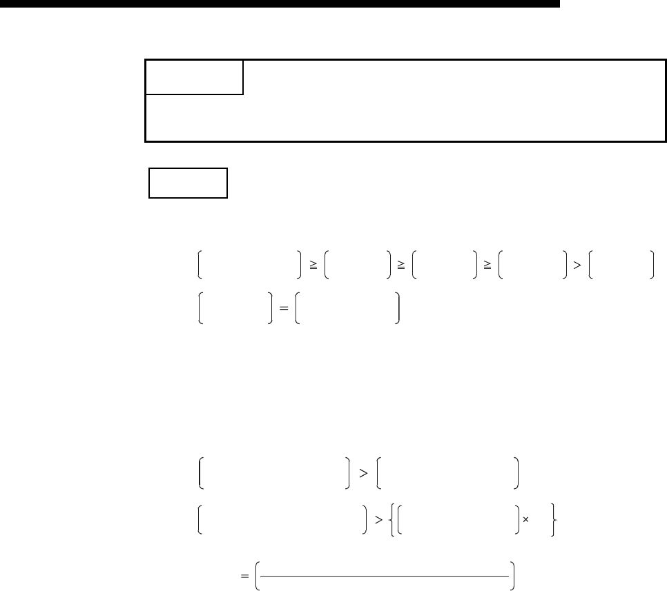
5 - 7
MELSEC-F
COMMUNICATION PROCEDURE5
5 - 7
NOTE
(1) Set the value of each timer on the Ethernet module side such that the following
relations are met.
•
•
Furthermore, when connecting a line using Mitsubishi products, you should make
sure that both nodes have the same settings.
(2) Set the value of each timer on the external device side such way that the
following relations are met.
Communication errors such as transmission timeouts may occur more frequently
if the timer values are not set so that they satisfy the following relationships.
•
•
Example1: Number of TCP segment transmissions when communicating via the
same line
The maximum segment size is 1460 bytes via the same line (without
going through a router) and the number of TCP segment
transmissions is as follows:
• n = 1, if the size of the message transmitted by the Ethernet module
is 1460 bytes or less.
• n = 2, if the size of the message transmitted by the Ethernet module
is greater than 1460 bytes.
Example2: Number of TCP segment transmissions when communicating via
separate lines
The maximum segment size is at least 536 bytes on a separate line
(via router, etc.) and the number of TCP segment transmissions is as
follows:
• n = 1, if the size of the message transmitted by the Ethernet module
is 536 bytes or less.
• n = 2, if the size of the message transmitted by the Ethernet module
is greater than 536 bytes and no more than 1072 bytes.
• n = 3, if the size of the message transmitted by the Ethernet module
is greater than 1072 bytes and no more than 1608 bytes.
POINT
To adjust settings with FX Configurator-EN-L, select "Initial Settings" from the
initial screen, and make the settings at the "Ethernet Initial Settings" screen.
Response monitoring
timer value
TCP ULP
timer value
TCP end
timer value
TCP resend
timer value
IP assembly
timer value
TCP resend
timer value
TCP zero window
timer value
TCP resend timer value on
the external device side
TCP resend timer value on
the external device side
Monitoring timer value for the
external device application software
*1
*1 n is the number of TCP segment transmissions and can be obtained via the following calculation:
n(fractions below decimal
point are rounded up)
Size of the message transmitted by the Ethernet module
Maximum segment size
TCP ULP timer value on
the Ethernet module side n
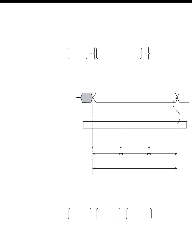
5 - 8
MELSEC-F
COMMUNICATION PROCEDURE5
5 - 8
TCP ULP
timer value
TCP end
timer value
=TCP resend
timer value
=
(Each timer value should be identical.)
(3) When communication errors occur, the setting value should be changed to
increase the number of retries.
The number of retries is obtained by using the following equation:
(In case of the initial values, 2 = (60/20) - 1)
•
Example: Assuming the values are set in such a way that the number of retries is
two, a data transmission error will occur at the timing shown in the
figure below if data transmission fails (when communicating using fixed
buffer).
(4) Perform the following setting in order to eliminate the retries explained in (3) (i.e.,
to set the number of retries to 0).
•
(5) The target existence check is a function whereby the Ethernet module checks
whether or not a remote device is functioning normally by sending an existence
check message and then waiting to see whether a response message is
received. It is used if a connection to a remote device is open but communication
with the remote device has not been performed for a certain period of time.
(a) The existence check function has two methods of checking: PING and
KeepAlive.
The Ethernet module performs each of the existence checks based on the
setting values explained in (7) to (9) of this section and the existence check
setting of the open settings (refer to Section 5.5 (6)).
The existence check function (Ping or KeepAlive) can be selected at the time
of operation setting or re-initialization.
For the operation setting, refer to Section 4.6.
Refer to Subsection 5.2.3 for the explanation on re-initialization.
Number
of retries
TCP ULP timer value
TCP resend timer value -1
R
0002H
Data
command
Ethernet module
First retry Second retry
AAA
TCP ULP timeout value
A : TCP resend timer value
(The time after which the data should be retransmitted when
an "ACK" is not returned after sending data.)
Transmission request
and status
#1610, #1611
W
0001H
R
0008H
TCP ULP
timer value
TCP end
timer value
=TCP resend
timer value
=
(Each timer value should be identical.)

5 - 9
MELSEC-F
COMMUNICATION PROCEDURE5
5 - 9
1) Checking by KeepAlive
This method is used for a connection opened via the TCP/IP protocol.
The Ethernet module performs an existence check by sending an
existence check ACK message to a remote device with which
communication has not been performed for a certain period of time and
waiting to see whether or not a response is received. (*1)
*1 The connection is cut off if the remote device does not support the
TCP KeepAlive function (response to KeepAlive ACK messages).
2) Checking by PING
This method is used for a connection opened via the TCP/IP or UDP/IP
protocol.
The Ethernet module performs an existence check by sending a PING
command (using the ICMP echo request/response function) to a remote
device with which communication has not been performed for a certain
period of time and waiting to see whether or not a response is received.
(*2)
*2 Note that the Ethernet module automatically returns an echo
response packet when it receives a PING echo request command.
(It sends a response to the received PING command even if the
connection used in the data communication with the remote device
is closed.)
(b) The following actions are taken if a response message cannot be received
(an error is detected) from the remote device.
• The corresponding connection will be forcibly closed (the line is
disconnected). (*3)
*3 It is possible to reopen it with a user program.
• The open completion signal (the corresponding bit of BFM#20480) is
turned off and, the error code (C035H) is stored in places such as the open
error code storage area.
Also, the open/close status (BFM #1602 to 1605) value becomes "0000H".
Example: Assuming the values are set under the condition that the number of
retries is three, the Ethernet module performs target existence check at
the timing shown in the figure below.
(An example of existence check by PING)
Ethernet module
PING
command
PING
command
(Retransmitted)
PING
command
(Retransmitted)
Open completion signal
BFM#20480
Last
communication
Target
existence
check starting
interval timer
value
Target
existence
check interval
timer value
Target
existence
check interval
timer value

5 - 10
MELSEC-F
COMMUNICATION PROCEDURE5
5 - 10
5.2.3 Re-initialization
Re-initialization is performed in order to place the Ethernet module into its startup
status without actually restarting the PLC.
Re-initialization of the Ethernet module can be performed in a sequence program.
The purposes of and how to program the re-initialization of the Ethernet module are
explained below.
NOTE
When FX Configurator-EN-L is being used, re-initialization can be performed after
downloading the parameters.
However, if it is connected to the Ethernet module via Ethernet, re-initialization
cannot be performed.
Re-initialize from the sequence program.
(1) Purposes of performing re-initialization
(a) To update address information of an external device maintained by the
Ethernet module
The Ethernet module maintains the IP address of the external device with
which it has been communicating and the corresponding Ethernet address
(MAC address). This is done in order to prevent other devices from
accessing the PLC illegally using the IP address of an external device with
which communication was performed normally. (*1)
For this reason it is necessary to re-initialize in order to clear the address
information of the external device maintained by the Ethernet module in case
a module or board on the external device side has been replaced due to
failure.
*1 Ethernet address is unique to a device. No devices share the same
Ethernet address.
(b) To change the IP address of the Ethernet module of the local station
If the system is changed, it is possible to restart communication with external
devices by changing the IP address (for the Ethernet module of the local
station) in the operation settings (see Section 4.6).
(c) To change the communication condition setting values
It is possible to restart communication with external devices by changing the
communication conditions in the operation settings (see Section 4.6).
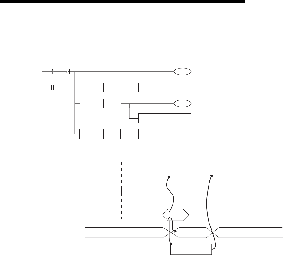
5 - 11
MELSEC-F
COMMUNICATION PROCEDURE5
5 - 11
(2) Programming and timing for re-initialization
The programming and timing for re-initialization is shown below:
• Program example for the unit No. 1
1) It is confirmed whether the initial processing has been completed
normally.
2) All data communication currently being performed with external devices
is terminated, and close processing will be performed on all connections.
3) "0001H ", "0002H ", "0005H " or "0006H " is written to BFM#1600.
(Initial normal completion signal: BFM#27 "0001H ")
(Open completion signal: BFM#20480 "All OFF(0H)")
4) When re-initialization is completed, the value in BFM#1600 will be 8000H
(normal completion) or C000H (abnormal completion).
* If the re-initialization is completed abnormally, the error code is stored
in the following area.
Initial error code storage area (BFM#105)
<<Re-initialization>>
Instruction
= H0001
= H8000
= HC000
MOVP
Processing upon normal
completion
Processing upon abnormal
completion
H0001
Upon completion of Ethernet
module initial processing,
re-initialization is performed
Re-initialization request self-holding
Self-holding cancel
Processing upon normal completion
Abnormal end
BFM #27 is set to "0000
H
"
at abnormal end.
U1\
G1600
U1\
G1600
U1\
G1600
U1\
G27
M1
M0
M0
M1
Close processing Re-initialization
Initial Processing normal completion signal
BFM#27=0000H/0001H
Open completion signal
BFM#20480
Re-initialization request
TO BFM#1600
Re-initialization status
FROM BFM#1600
1)
2)
3)
4) 8000H(Normal completion)/
C000H(Abnormal completion)
0001H
0002H
0000H
Module initialization
(Normal)
(Abnormal)
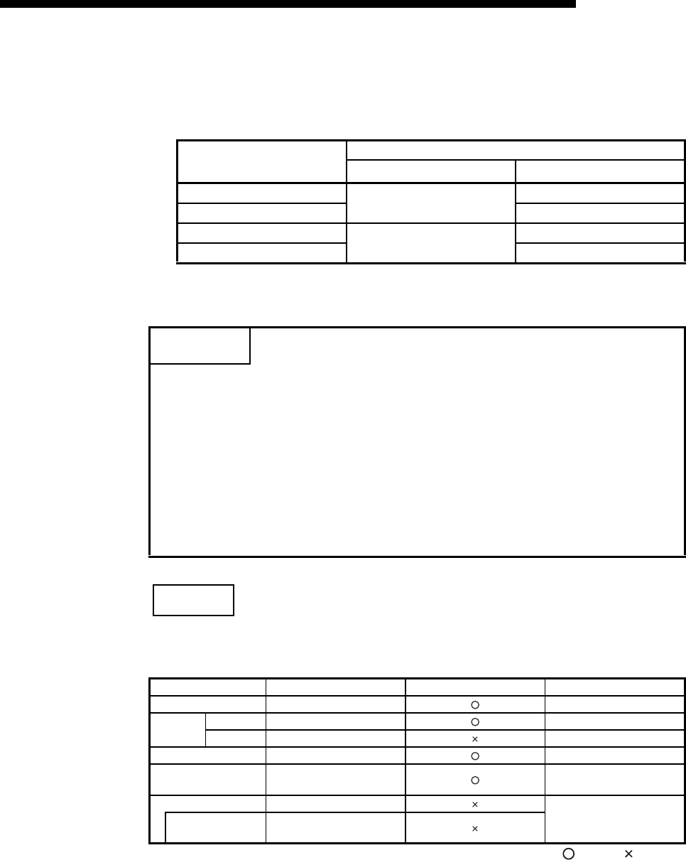
5 - 12
MELSEC-F
COMMUNICATION PROCEDURE5
5 - 12
(3) Operation for re-initialization
Operation for re-initialization differs as follows, depending on the value written to
BFM#1600.
*1: When re-reading the flash ROM, the re-initialization is performed in the same status as
when the power supply is turned on.
NOTE
It is possible to change the operational settings when re-initializing by a sequence
program.
: Valid, : Invalid
Written value Operation
COM. ERR LED Re-reading flash ROM*1
0001HTurns off Not re-read
0002HRe-read
0005HNo change Not re-read
0006HRe-read
POINT
Please keep the following points in mind when re-initializing the Ethernet module.
(Failure to do so may cause errors in the data communication with the external
devices.)
(1) Be sure to end all current data communication with external devices and
close all connections before re-initializing.
(2) Be sure to reset external devices if the IP address of the Ethernet module has
been changed. (If an external device maintains the Ethernet address of a
device with which it communicates, the communication may not work after the
IP address of the Ethernet module has been changed.)
Parameter setting item BFM number [decimal] Parameter changes Reference section
Operational settings 24 Section 4.6
Initial
settings
Timer setting
4 to 12 Section 5.2
DNS settings
— Section 5.2
Open settings 32 to 39 Section 5.5
Router relay parameter
settings 512 to 515 Section 5.3
E-mail settings 9856 to 10306
Chapter 10
Send mail address
setting 9987 to 10306
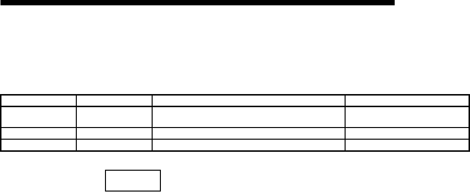
5 - 13
MELSEC-F
COMMUNICATION PROCEDURE5
5 - 13
5.3 Router Relay Parameter
This section explains the router relay parameter.
NOTE
When making settings with the FX Configurator-EN-L, select [Router Relay
Parameters] from the initial screen and adjust the settings at the [Ethernet Router
Relay Parameter Settings] screen.
(1) Router relay function (BFM#2 b4,b5)
(a) Set whether the router relay function will be used or not.
The router relay function is not needed when communicating with the target
device on the same Ethernet network (the subnet address of the IP address
is the same).
(b) The router relay function allows communication with devices on other
Ethernet networks via routers and gateways.
(The router relay function does not mean a function to act as a router.)
(c) One router can be set for the router relay function.
Setting item name BFM number [Decimal] Description of setting Setting range/options
Router relay function 2
(b4, b5) Select whether the router relay function is not used or is used. 00 : Use
01 : Not used
Sub-net mask pattern 512, 513 Set the sub-net mask. C0000000 to FFFFFFFCH
Router IP address 514, 515 Set the IP address of the router to be routed through. Other than 00000000H and FFFFFFFFH
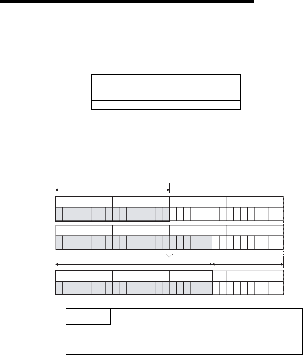
5 - 14
MELSEC-F
COMMUNICATION PROCEDURE5
5 - 14
(2) Subnet mask pattern (BFM#512, 513)
(a) Set the subnet mask. *1 (Setting range: C0000000 to FFFFFFFCH)
Consult the network administrator for the setting.
(b) When not using the subnet mask, set any of the following table values
according to the class.
*1 Ethernet networks include small-scaled network systems where multiple
devices are connected to one Ethernet hub along with medium and large-
scaled network systems where multiple small-scaled networks are
connected by routers, etc.
The subnet mask logically divides one network, where many devices are
connected, into multiple sub-networks to facilitate administration.
(3) Router IP address (BFM#514, 515)
Set the IP address of the router to be used when FX3U-ENET-L communicates
with the target device on another Ethernet network (refer to (4) below).
Set the value that satisfies the following conditions.
• Condition 1: The IP address class is either A, B or C.
• Condition 2: The sub-net address of the default router is the same as that of
the local station Ethernet module.
• Condition 3: The host address bits are not all "0" or all "1".
Class Mask value
Class A FF000000H
Class B FFFF0000H
Class C FFFFFF00H
POINT
(1) All devices on the same sub-network must have a common subnet mask.
(2) When not administrated by the sub-network, the connected devices need not
have a subnet mask. (Set the network address of the corresponding class.)
10000001
81H
00000101
05H
00101111
2FH
00000001
01H
FFH00H
FFHFCH
11111111 0000000011111111111111 00
00000001100000010000010100101111
(Example) Class B
81H05H2FH01H
IP address
Subnet mask
IP address
Network address
Subnet address Host address

5 - 15
MELSEC-F
COMMUNICATION PROCEDURE5
5 - 15
5.4 Confirming the Completion of the Initial Processing
The initial processing for the Ethernet module completes by selecting re-initialization,
then turning the power ON again, or re-initializing via buffer memory operations after
parameters are written to the Ethernet module.
(When the processing is completed normally, the [INIT.] LED on the front of the
Ethernet module turns on.)
• "Operational settings" parameter
• "Initial settings" parameter
This section explains how to check the completion of the initial processing.
POINT
The status of the Ethernet module becomes communication enabled when the
initial processing is completed normally. See reference sections for each
communication function to perform communication.
When the initial processing has not been completed normally, do the following to
check the error contents, take corrective actions, then execute the initial
processing again.
• Check the error code using the "Parameter status" of the Ethernet diagnostics.
(See Section 11.2.)
• Check the contents of the error corresponding to the error code, then take
corrective actions. (See Section 11.3 and Section 11.4.)

5 - 16
MELSEC-F
COMMUNICATION PROCEDURE5
5 - 16
5.4.1 PING command (Personal computer Ethernet module)
The following example illustrates how to confirm the completion of the initial
processing by issuing the PING command to the local station's Ethernet module from
an external device connected on the same Ethernet network. (In the example, the
confirmation is made between devices whose IP address class and sub-net address
are identical.)
<Designation method>
ping IP address
<Example>
IP address of the Ethernet module: 192.0.1.254
<When the PING command does not respond successfully>
Check the following items and send the PING command again.
• Check the Ethernet module's attachment.
• Check the connection to the Ethernet network.
• Check the contents of each parameter written to the Ethernet module.
• Check the operation condition of the Ethernet module (are there any
irregularities?).
• Check the IP address of the Ethernet module dictated by the PING command.
C:\>ping 192.0.1.254 Execute the ping command
Pinging 192.0.1.254 with 32 bytes of data:
Reply from 192.0.1.254: bytes=32 time=1ms TTL=128
Reply from 192.0.1.254: bytes=32 time<10ms TTL=128
Reply from 192.0.1.254: bytes=32 time<10ms TTL=128
Reply from 192.0.1.254: bytes=32 time<10ms TTL=128
Ping statistics for 192.0.1.254:
Packets: Sent = 4, Received = 4, Lost = 0 (0% loss)
Approximate round trip times in milli-seconds:
Minimum = 0ms, Maximum = 1ms, Average = 0ms
C:\>_
Example of screen at normal completion
C:\>ping 192.0.1.254 Execute the ping command
Pinging 192.0.1.254 with 32 bytes of data:
Request timed out:
Request timed out:
Request timed out:
Request timed out:
Ping statistics for 192.0.1.254:
Packets: Sent = 4, Received = 0, Lost = 4 (100% loss)
Approximate round trip times in milli-seconds:
Minimum = 0ms, Maximum = 0ms, Average = 0ms
C:\>_
Example of screen at abnormal completion
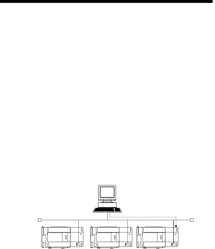
5 - 17
MELSEC-F
COMMUNICATION PROCEDURE5
5 - 17
5.4.2 Loop back test (Communication using MC protocol)
The loop back test can be performed with communication using MC protocol in order
to check the completion status of the initial processing for the target Ethernet module.
The following is an overview of the loop back test for communication using MC
protocol. See Chapter 9 for details.
(1) Loop back test for communication using MC protocol
The loop back test is a function designed to check the following:
• Whether a line has been properly connected to the test target Ethernet module.
• Whether the parameters for the Ethernet module have been correctly set.
• Whether the initial processing for the Ethernet module has been completed
normally.
• Whether the program for the external device is running correctly.
(2) It is necessary to connect lines when performing communication using MC
protocol with the user port on the Ethernet module side.
Perform the open processing for the connection to be used on the Ethernet
module side.
(3) This function can only be used for the Ethernet module of the local station. The
function cannot be used for the Ethernet module of another station via a network
system.
Ethernet
(Loop back test
target station)
(Loop back test target station)

5 - 18
MELSEC-F
COMMUNICATION PROCEDURE5
5 - 18
5.5 Open Settings
This section explains the open setting.
A sequence program can perform open processing (establishing connection) with up
to a maximum of 4 external device stations
Once a connection is established with an external device, it is possible to
communicate using MC protocol, fixed buffer communication.
Thus, the open processing is required even when communicating using MC protocol.
NOTE
When adjusting settings in FX Configurator-EN-L, select the [Open Settings] from
the initial screen and adjust the settings at the [Ethernet Open Settings] screen.
5.5.1 Fixed buffer connection (connection No. 1 and connection No. 2)
*1 "1 (Pairs)" cannot be selected in connection No. 2.
(1) Protocol
(connection numbers 1, 2; BFM#32, 33 b8)
(a) Select the protocol for each connection.
(b) For protocols (TCP/UDP), see 1.3, "Software Configuration".
Setting item name BFM number [Decimal] Description of setting Setting range/options
Protocol 32, 33
(b8) Set the communication method (protocol). OFF : TCP/IP
ON : UDP/IP
Open system 32, 33
(b15, b14) Select the connection open system.
00 : Active open
10 : Unpassive open
11 : Fullpassive open
Fixed buffer 32, 33
(b0) Select the usage of the fixed buffer. OFF : Send
ON : Receive
Fixed buffer
communication
32, 33
(b10, b9) Select which protocol is used for fixed buffer communication. 00 : Procedure exist
01 : No procedure
Pairing open*132, 33
(b7) Select whether pairing open is used or not. OFF : Pairs
ON : No pairs
Existence confirmation 32, 33
(b1)
Select whether the continued existence of a destination station
for a connection should be confirmed or not.
OFF : No confirm
ON : Confir
Local station Port No. 40, 47 Set the local station's port No. 1025 to 5548 or 5552 to 65534
Destination IP address 41 to 42, 48 to 49 Set the IP address of an external device. 1 to FFFFFFFEH
Dest. Port No. 43, 50 Set the port No. of an external device. 1025 to 65534
Name of setting Description of setting
TCP Communicate using TCP/IP.
UDP Communicate using UDP/IP.
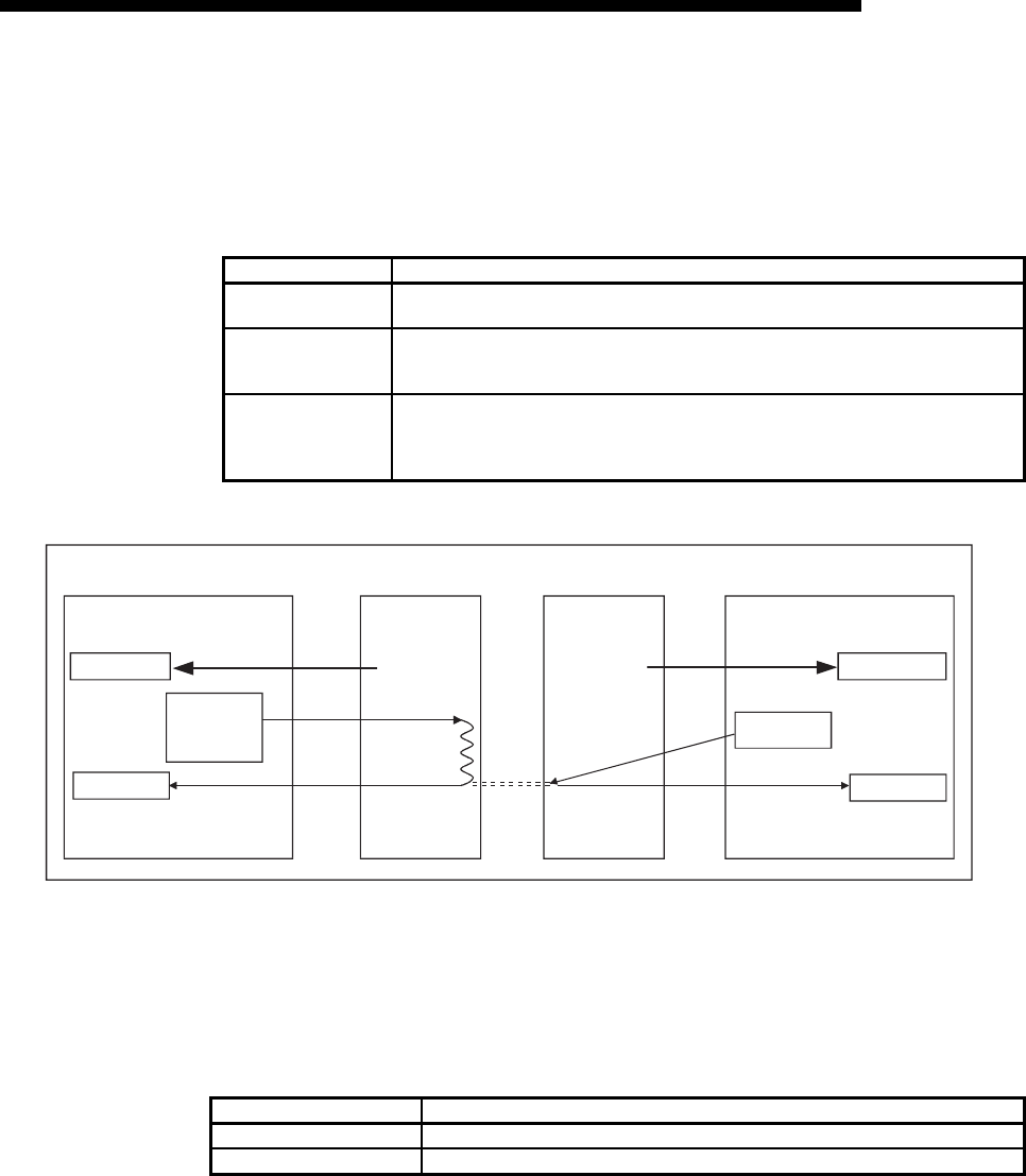
5 - 19
MELSEC-F
COMMUNICATION PROCEDURE5
5 - 19
(2) Open system
(connection numbers 1, 2; BFM#32, 33 b15, b14)
(a) Select the connection open system for each connection for which "TCP" is
selected in "(1) Protocol". If "UDP" is selected, the specification of this item is
not required.
(3) Fixed buffer
(connection numbers 1, 2; BFM#32, 33 b0)
(a) Here it is selected whether the fixed buffer corresponding to each applicable
connection number will be used for sending or receiving when
communicating using the fixed buffers.
(b) When both sending and receiving are performed with an external device
using fixed buffer communication, one buffer for sending and one for
receiving are required. Thus, two connections should be set.
Name of setting Description of setting
Active Perform active open processing to an external device that waits for a passive open
(Fullpassive/Unpassive) on the TCP connection.
Unpassive
Perform passive open processing on the TCP connection addressing all the devices connected
to a network.
(The local station is placed in the wait status to wait for an Active open request to be sent.)
Fullpassive
Perform passive open processing on the TCP connection, only addressing specific devices.
(The local station is placed in the wait status to wait for an Active open request to be sent.)
The local station waits for an Active open request from the opposite station set in "(8)
Destination IP address".
Name of setting Description of setting
Send For sending.
Receive For receiving.
PLC main unit PLC main unit
Initial completion
Active open
Fullpass ive/
Unpassove
open
Initial completion
Open completion
Active open
Ethernet module
Ethernet module
Initial request
Initial completion
Open request
Open completion
Initial request
Initial completion
Open completion
Open
Wait for open
request
FROM instruction
TO instruction
FROM instructionFROM instruction
TO instruction
FROM instruction

5 - 20
MELSEC-F
COMMUNICATION PROCEDURE5
5 - 20
(4) Fixed buffer communication
(connection numbers 1, 2; BFM#32, 33 b9 to b10)
(a) For this item, select the communication method when communicating using
the fixed buffers.
(5) Pairing open
(connection numbers 1 only; BFM#32 b7)
(a) Select whether or not the Ethernet module's receiving and sending
connections are made into one pair and connected to one port of an external
device when using fixed buffer communication (Either one among
[Procedure exist] or [No procedure] can be specified).
For more detail, see [Section 5.7 Pairing Open].
(b) "Pairs" can be selected only in connection No. 1.
If "Pairs" is selected in connection No. 2, an error will occur when the
connections are opened.
• Error information is stored in the error log area (BFM#227 to 511) in the
buffer memory.
• The open error code is stored in BFM#134.
Name of setting Description of setting
Procedure exist • In fixed buffer communication, data is communicated in 1:1 by handshaking with the
external device.
No procedure
• The no procedure fixed buffer communication uses dedicated connections.
• The PLC and external devices communicate data in 1:1
• The handshaking with an external device must be performed using a sequence program.
Name of setting Description of setting
No pairs Does not use the pairing open method.
Pairs Uses the pairing open method.

5 - 21
MELSEC-F
COMMUNICATION PROCEDURE5
5 - 21
(6) Existence confirmation
(connection numbers 1, 2; BFM#32, 33 b1)
(a) This setting selects whether or not the Ethernet module should confirm that
an external device still operates normally when there is no communication
for a fixed period of time. The open processing for the connection with the
external device must have been completed.
(b) When an error occurs in the existence confirmation, the Ethernet module
performs the following processing.
• Forcibly closes the line and stores the error information in the error log
area (BFM#227 to 511) of the buffer memory.
• Turns off the open completion signal (BFM#20480) and stores the open
error code in BFM#124, 134.
(c) If the external device will be changed while a UDP/IP connection is open,
"No confirm" should be selected.
If "Confirm" is selected, the Ethernet module will confirm the existence of the
first destination after the UDP/IP connection is opened. Existence
confirmation is not performed for the changed destination, i.e. the newly
selected external device.
(7) Local station Port No.
(connection numbers 1, 2; BFM#40, 47)
(a) In this item the port number of each connection for the Ethernet module is
set.
(b) The setting values are designated in the range from 1025 to 5548 and from
5552 to 65534. Set port numbers that are not already used by other ports.
(c) Set the port numbers for the Ethernet module upon consulting a network
administrator.
(8) Destination IP address
(connection numbers 1, 2; BFM#41 to 42, 48 to 49)
(a) Set the IP addresses (two words) for external devices in the chosen input
format.
(b) The IP addresses of external devices must be given values other than 0H,
FFFFFFFFH.
(c) Set the IP addresses of external devices upon consulting a network
administrator.
Name of setting Description of setting
No confirm Do not confirm the existence of the external device.
Confirm
Confirm the existence of the external device.
For details on the settings of the existence confirmation time and others, see Section 5.2,
"Initial Settings".
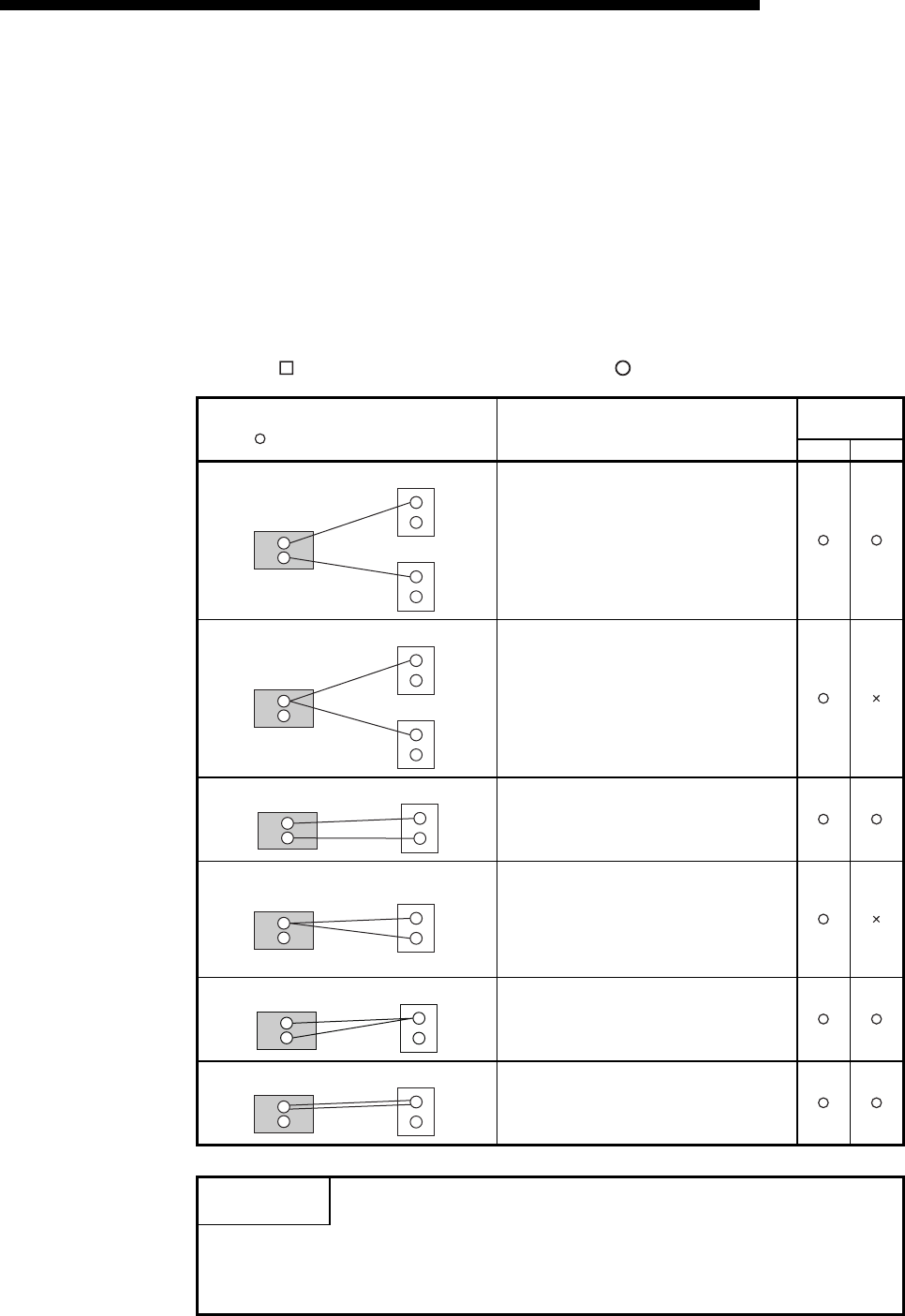
5 - 22
MELSEC-F
COMMUNICATION PROCEDURE5
5 - 22
(9) Destination Port No.
(connection numbers 1, 2; BFM#43, 50)
(a) Set the port numbers of the external devices for each connection.
(b) The port numbers of the external devices are set in the range from 1025 to
65534.
(c) Set the port numbers for the external device upon consulting a network
administrator.
(d) The following table provides some precautions that should be observed
when setting port numbers.
( in the diagram indicates a device and indicates a port number.)
Status of connection establishment
( : Port (indicates port number)) Description of connection
Communication
protocol
TCP UDP
When connecting to multiple external devices, set
multiple port numbers for the local station.
When connecting to multiple external devices, set
a single port number for the local station.
(However, it is necessary to open a connection for
each external device)
This cannot be chosen when the local station is
Unpassive.
When connecting to multiple ports of an external
device, set multiple port numbers for the Ethernet
module.
When connecting to multiple ports of an external
device, set a single port number for the Ethernet
module. (However, it is necessary to open a
connection for each external device port)
This cannot be chosen when the local station is
Unpassive.
When connecting to the same port of an external
device, set multiple port numbers for the Ethernet
module. (However, it is necessary to open a
connection for each Ethernet module port)
Setting multiple ports numbers for the same port
of an external device and the Ethernet module is
possible only when pairing open is set.
Important
Make sure to set parameters for connections that communicate by Passive open
or UDP open when [Always wait for OPEN (communication possible at STOP
time)] is selected in the Operation settings (see Section 4.6).
Ethernet module
External device
External device
Ethernet module
External device
External device
Ethernet module External device
Ethernet module External device
Ethernet module External device
Ethernet module External device
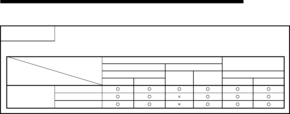
5 - 23
MELSEC-F
COMMUNICATION PROCEDURE5
5 - 23
POINT
Set parameters according to the open method to be used for open connection.
Communication system
open system
TCP UDP
Active Passive
Parameter
ARP function of external device Un-passive Full-passive ARP function of external device
Yes No Yes No
Communication
address
Local station Port No.
Destination IP address
Destination Port No.
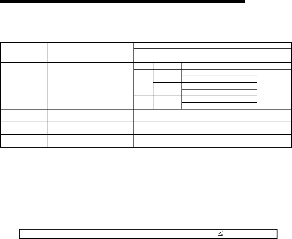
5 - 24
MELSEC-F
COMMUNICATION PROCEDURE5
5 - 24
5.5.2 MELSOFT/MC protocol connections (connection No. 3 and connection No. 4)
*1 Used to connect MELSOFT products through TCP/IP communication.
It performs passive open processing of TCP connection for all MELSOFT products connected to the
network. (It waits for an Active open request given to its own station.)
*2 Regardless of the initial timing setting in the operation settings (refer to Section 4.6), this connection
will always wait for the open status.
*3 The set connection is used only for data communication with MELSOFT products.
*4 Set connections for all connected MELSOFT products when connecting two or more MELSOFT
products at the same time.
Up to 2 connections can be set.
(1) Local station Port No. (connection numbers 3, 4; BFM#54, 61)
Select this item when using connections for MC protocol.
(a) In this item the port number of each connection for the Ethernet module is
set in Decimal.
(b) The setting values are designated in the range from 1025 to 5548 and from
5552 to 65534. Set port numbers that are not already used by other ports.
(c) Set the port numbers for the Ethernet module upon consulting a network
administrator.
(2) Destination IP address (connection numbers 3, 4; BFM#55 to 56,
62 to 63)
Select this item when using connections for MC protocol.
(a) Set the IP addresses (two words) for external devices in the chosen input
format (decimal/hexadecimal).
(b) The IP addresses of external devices must be given values other than
0H,FFFFFFFFH.
(c) Set the IP addresses of external devices upon consulting a network
administrator.
(3) Destination Port No. (connection numbers 3, 4; BFM#57, 64)
Select this item when using connections for MC protocol.
(a) Set the port numbers of the external devices for each connection.
(b) The port numbers of the external devices are set in the range from 1025 to
65534.
(c) Set the port numbers for the external device upon consulting a network
administrator.
(d) Refer to Paragraph 5.5.1 (9) for cautions on setting the port number.
Setting item name BFM number
[Decimal] Description of setting
Setting range/options
MC protocol MELSOFT
connection*1
Connection usage 34, 35 Set the connection
usage
Protocol Open system Existence confirmation Setting value Setting value
TCP
Unpassive Confirm 8403H
A002H*2 *3 *4
No confirm 8401H
Fullpassive Confirm C403H
No confirm C401H
UDP — Confirm 0503H
No confirm 0501H
Local station Port No. 54, 61 Set the local station's
port No 1025 to 5548 or 5552 to 65534 Setting is not
required
Destination IP address 55 to 56, 62 to 63 Set the IP address of an
external device 1H to FFFFFFFEHSetting is not
required
Dest. Port No. 57, 64 Set the port No. of an
external device 40H to FFFFHSetting is not
required
Number of MELSOFT connections + Number of MC protocol connections 2

5 - 25
MELSEC-F
COMMUNICATION PROCEDURE5
5 - 25
5.6 Open Processing/Close Processing of the Connection
This section explains the open processing/close processing using sequence
programs.
(1) Open processing
(a) The purpose of the open processing is to establish a connection with an
external device in order to perform the following forms of data
communication.
They can be performed with an external device opened by the user.
• Sending/receiving using the fixed buffers (Procedure exists/No procedure)
: Connections No. 1 and 2 only
• Communication using MC protocol ("Unpassive open (MC)" or "Full
passive open (MC)" in the open system setting) must be set.
: Connections No. 3 and 4 only
(b) When the following is set by the parameter settings, the open processing
should be performed in a sequence program.
1) In the Operational settings (Section 4.6)
When "Do not wait for OPEN" is set in the "Initial timing setting".
2) In the open settings (Section 5.5)
When "Active" is set in the "OPEN system" setting.
(c) In order to perform open processing, the initial processing must be complete
(BFM #28b0: ON) and the hub communication status (BFM #28b7: ON) must
be on.
(d) A connection with an external device must be established (open processing)
when communicating using either the MC protocol, fixed buffers. (*1)
Two types of data communication mentioned above can also be performed
with an external device opened by the user.
*1 Since the Ethernet module recognizes the external device by the IP
address, the open processing is required for UDP communication.
(e) Up to a maximum of 4 connections can be opened to external devices.
However, two buffers are required when communicating with the same
external device using fixed buffer communication, so in this case the number
of external devices that can be communicated with will be lower.
POINT
During communication using MC protocol, if data communication is to continue
even after the Ethernet module installed PLC, has been placed in the STOP
status, enable "Always wait for OPEN (communication possible at STOP time)"
under "Initial timing setting" (see 4.6, "Operation Settings").

5 - 26
MELSEC-F
COMMUNICATION PROCEDURE5
5 - 26
(2) Close processing
(a) The purpose of the close processing is to disconnect (cancel) the connection
with the external device established by open processing mentioned
previously.
(b) The close processing is used when terminating a connection with an
external device, changing an external device of a connection, changing
communication conditions, etc.
(c) Perform the close processing for connections established by open
processing using sequence programs.
(d) Determine the timing of close processing with the external device.
The examples in the following sections describe the procedures for establishing a
connection from the Ethernet module to an external device and subsequently closing
it again by open and close processing for connection number 1.
• TCP/IP Active open : See 5.6.1, "Active open processing/close processing".
• TCP/IP Passive open : See 5.6.2, "Passive open processing/close processing".
• UDP/IP Open : See 5.6.3, "UDP/IP open processing/close processing".
POINT
Except when the close processing is requested, the open completion signal
(applicable bit of BFM#20480) automatically turns off and the communication line
is closed in the following cases:
(1) When the existence confirmation function times out (see Section 5.5).
(2) When a close or RST command is received from an external device.
(3) When the Active open request is received again from the external device in
the open completion status of TCP.
After returning ACK to the external device, the Ethernet module closes the
connection when the RST command is received from the external device.
However, when receiving the Active open request again from the external
device with a different IP address or port No., the Ethernet module only sends
the RST command. (It does not close the connection.)
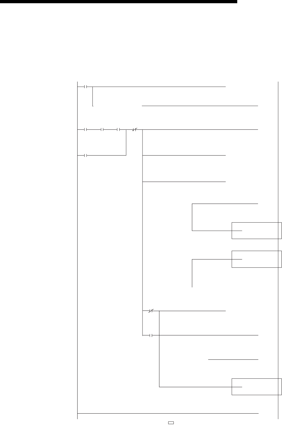
5 - 27
MELSEC-F
COMMUNICATION PROCEDURE5
5 - 27
5.6.1 Active open processing/close processing
This section explains the procedure for opening and closing a connection with an
external device from the Ethernet module.
• Program example for the unit No. 1
<<Open processing for connection No.1>>
M8000
M100
X000 M117 M103
X000
M102
[= D100 H15 ]
[= D100 H10 ]
[= D100 H5 ]
]H0D100[=
[MOV K4M110
(M102
(M103
]
[INCP D0 ]
[INCP D1 ]
[INCP D2 ]
[END ]
[MOVP H8000 ]
)
(M101 )
(M100 )
)
U1\
G28
Open
request
Link
status
Cancel of
self-
holding
at close
M0
Initial
completion
status
Open request
(self-holding)
Status Status read
Open request
(self-holding)
(M0
Initial
completion
status
[MOVP H1
U1\
G1602 ]
OPEN
instruction/
status
Reading
value
of #1602
Reading
value
of #1602
Reading
value
of #1602
Open
completed
Open normal completion
processing
Open abnormal completion
processing
Normal open processing
Open abnormal processing
Open
request
Closed
(self-
holding)
OPEN
instruction/
status
Closed
(self-holding)
Cancel of
self-holding
at close
U1\
G1602
Close count
CLOSE normal
completion processing
Reading
value
of #1602
[MOV
U1\
G1602 D100 ]
OPEN
instruction/
status
Reading
value
of #1602
[=
U1\
G27 H1 ]
Initial
completion
signal
User applications are described at the area enclosed with .
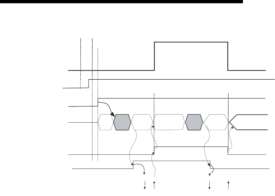
5 - 28
MELSEC-F
COMMUNICATION PROCEDURE5
5 - 28
1) After communicating the parameter settings, confirm the normal
completion of the Ethernet module initial processing.
(Initial completion signal BFM#27 "0001H")
2) Confirm that the Ethernet module and hub are connected. (BFM#28
b7:ON)
3) Start the open processing writing with pulse execution instruction 0001H
to BFM#1602.
4) The Ethernet module executes the open processing.
• Sends the open request (SYN).
5) When the open processing completes normally
Data communication is enabled.
When the open processing completes abnormally (*1)
• The open error code is stored in the buffer memory.(*2)
• Open error detection (BFM#1602 "0010H" or "0015H")
• Area for module status (BFM#28 b6:ON)
6) Start the close processing writing 8000H to BFM#1602.
7) The Ethernet module executes the close processing.
• Sends the close request (FIN).
8) When the close processing completes normally (*3)
• Open completion signal BFM#20480 b0 : ON
• BFM#1602 "0005H"
• Open completion signal (BFM#2048 b0) : OFF
• Open/Close instruction status (BFM#1602 "0000 H ")
Open status
Open allowed status
Closed status
Initial normal completion
BFM#27=0001H
OPEN/ CLOSE instruction
status BFM#1602
Open completion signal
BFM#20480
Power-on 1) Parameter update
completed
2)
3)
4) 5) 7) 8)
FINSYN
SYN+ACK
Open request signal
CLOSE
status
0000H
OPEN
processing
0003H
CLOSE
processing
0009H
CLOSE
status
0000
H
FIN+ACK
Hub connected signal
BFM #28b7
BFM#20482
OPEN
instruction
W0001H
OPEN status
0005H
(OPEN failure
0010H)
CLOSE
instruction
W8000H
Hub connected
6)
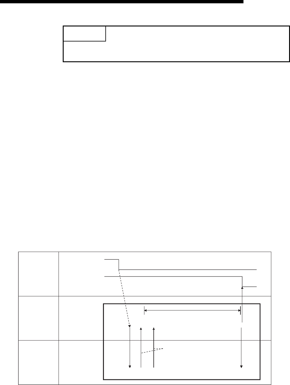
5 - 29
MELSEC-F
COMMUNICATION PROCEDURE5
5 - 29
*1 Processing when the open processing is abnormally completed
(TCP)
When opening from the Ethernet module under a normal situation,
if the Ethernet module sends a SYN, the external device returns
an ACK and a SYN.
However, if the Ethernet module sends a SYN and then the
external device returns a RST, the open abnormal completion
(BFM#28 b6) is immediately turned on and open processing ends.
*2 The open status and error code at abnormal end can be confirmed
with the following buffer memory.
• Each connection open abnormal code area of the
communication status storage area
(Connection numbers 1 to 4; BFM#120 to 159)
• Error log area (BFM#227 to 372)
• Error codes stored in the open error code area are cleared when
writing "0001H" to the BFM #1602 to 1605 to perform the open
operation.
*3 Processing when the close processing is abnormally completed
(TCP) When closing normally from the Ethernet module, the
Ethernet module sends a FIN request and the external device
returns an ACK and a FIN. However, if an ACK and a FIN are not
returned because the external device is faulty, the Ethernet
module forcibly disconnects the connection (sends a RST
message).
POINT
This example uses connection number 1 for explanation. Use the corresponding
BFM No. and bits for other connection numbers.
PLC
Ethernet
module
Ethernet
Open request signal
(CLOSE processing
execution)
Open completion
signal
Close abnormal processing
FIN is not sent after waiting for the TCP
end timer
FIN
ACK
1)
2)
3)
4)
5)
6)
7)
FIN RST
At normal completion

5 - 30
MELSEC-F
COMMUNICATION PROCEDURE5
5 - 30
1) The open request signal turns off by writing "8000H" to the BFM#1602.
2) The Ethernet module executes the close processing.
3) The Ethernet module sends a FIN request to the external device.
4) The external device sends back FIN and ACK messages in reply to the
FIN request sent by the Ethernet module.
(When the reply is not returned, the Ethernet module sends the FIN
request again.)
5) The Ethernet module waits for the external device to send an ACK and a
FIN.
(The module waits for the amount of time set in the TCP end timer value.
For details on how to set it, see Section 5.2, "Initial Settings".)
If the ACK and FIN messages are received at this point, it returns an ACK
as in the normal processing.
6) If an ACK and a FIN are not received within the time designated by the
TCP end timer, an RST message is sent to the external device.
7) The Ethernet module determines that the close procedure is completed
and turns off the open completion signal regardless of the status of the
external device.
NOTE
(1) When the procedure above is performed, the Ethernet module determines that
the closing of the external device is executed normally, thus the close
processing result is not stored in the error log area.
(2) The procedure described above is a special function of the Ethernet module; it
is not available for general TCP/IP protocols.

5 - 31
MELSEC-F
COMMUNICATION PROCEDURE5
5 - 31
Program example
This example explains a program for open processing/close processing when
Active open is selected in the Open system setting.
(1) Execution environment for the program example
(a) The Ethernet module is connected to the second special module. (The unit
number is setting 1)
(b) The unit number specified at the sequence program and FX Configurator-
EN-L is 1.
(c) Make Operation settings in the following manner.
(d) Make open settings in the following manner.
(e) The following contact signals are used in the program.
(f) The area enclosed with in the program example should be used when
the [Open settings] Ethernet module parameters are not set for
FX Configurator-EN-L.
This part of the program is not required when the [Open settings] parameters
are used for FX Configurator-EN-L.
(2) Outline of the program example
(a) After each parameter is set in FX Configurator-EN-L or the sequence
program and written to the Ethernet module, re-initialize or power ON the
module again and confirm the completion of the initial processing via buffer
memory operations.
(b) The Ethernet module performs the open processing for connection No. 1 to
the external device set in the [Open settings] or control data.
(c) The close processing for connection No. 1 is performed according to the
close instruction to the Ethernet module or the close request from the
external device.
Communication data code : Binary code (BFM#24 b1 : OFF)
Initial timing :Do not wait for OPEN (Communications
impossible at STOP time) (BFM#24 b8 : OFF)
IP address : 10.97.85.222 (0A.61.55.DEH) (BFM#106 to
107)
Protocol :TCP (BFM#32 b8 : OFF)
Open system : Active (BFM#32 b14, b15 : 00H)
Fixed buffer : Send (BFM#32 b0 : OFF)
Fixed buffer communication
procedure : Procedure exist (BFM#32 b9 : OFF)
Pairing open : Disable (BFM#32 b7 : OFF)
Existence confirmation : No confirm (BFM#32 b1 : OFF)
Local station Port No. : 4096 (BFM#40)
Transmission target device
IP address : 10.97.85.223 (0A.61.55.DFH) (BFM#41 to 42)
Transmission target device
Port No. : 8192 (BFM#43)
Ethernet module status : M110 to M115
Connection No.1 open/close status and instruction : D100
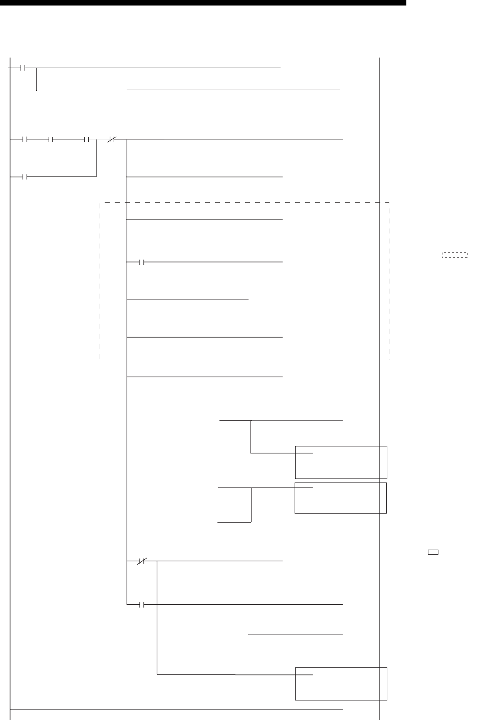
5 - 32
MELSEC-F
COMMUNICATION PROCEDURE5
5 - 32
• Program example for the unit No. 1
X000
M100
M103
X000
M102
[= D100 H5 ]
]H10D100[=
]H0D100[=
[MOV D100
(M100
(M101
(M102
(M103
]
)
[MOVP H0 ]
[MOVP K4096 ]
[MOV K8192 ]
[END ]
[MOVP H1 ]
[MOVP H8000 ]
)
)
)
H0A6155DF[DMOVP ]
U1\
G1602
Open
request
M0
Initial
completion
status
M117
Link
status
Cancel
of self-
holding
at close
U1\
G32
U1\
G40
U1\
G43
U1\
G41
U1\
G1602
U1\
G1602
Open request
(Self-holding)
Reading
value
of #1602
Reading
value
of #1602
]H15D100[=
Reading
value
of #1602
Reading
value
of #1602
Reading value
of #1602
OPEN instruction
transmission
completed
Closed
(Self-holding)
Closed
(Self-
holding)
Open
request
Connection
No.1
application
Host port
No.
Target IP
address
Target
port No.
Open
completed
OPEN
instruction
transmission
completed
OPEN
instruction
transmission
completed
Cancel of
self-holding
at close
Open request
(Self-holding)
M8000
[MOV K4M110 ]
U1\
G28
Status Read of status
(M0
Initial
completion
status
[=
U1\
G27 H1 ]
Initial
completion
signal
[INCP D0 ]
[INCP D1 ]
[INCP D2 ]
Close normal
completion
count
Open
normally
completed
Open
abnormally
completed
User applications are
described at the area
enclosed with .
The area inside
indicates a program example
when "Open settings" is not
provided in the parameter
settings for the Ethernet
module using FX Configurator-
EN-L.
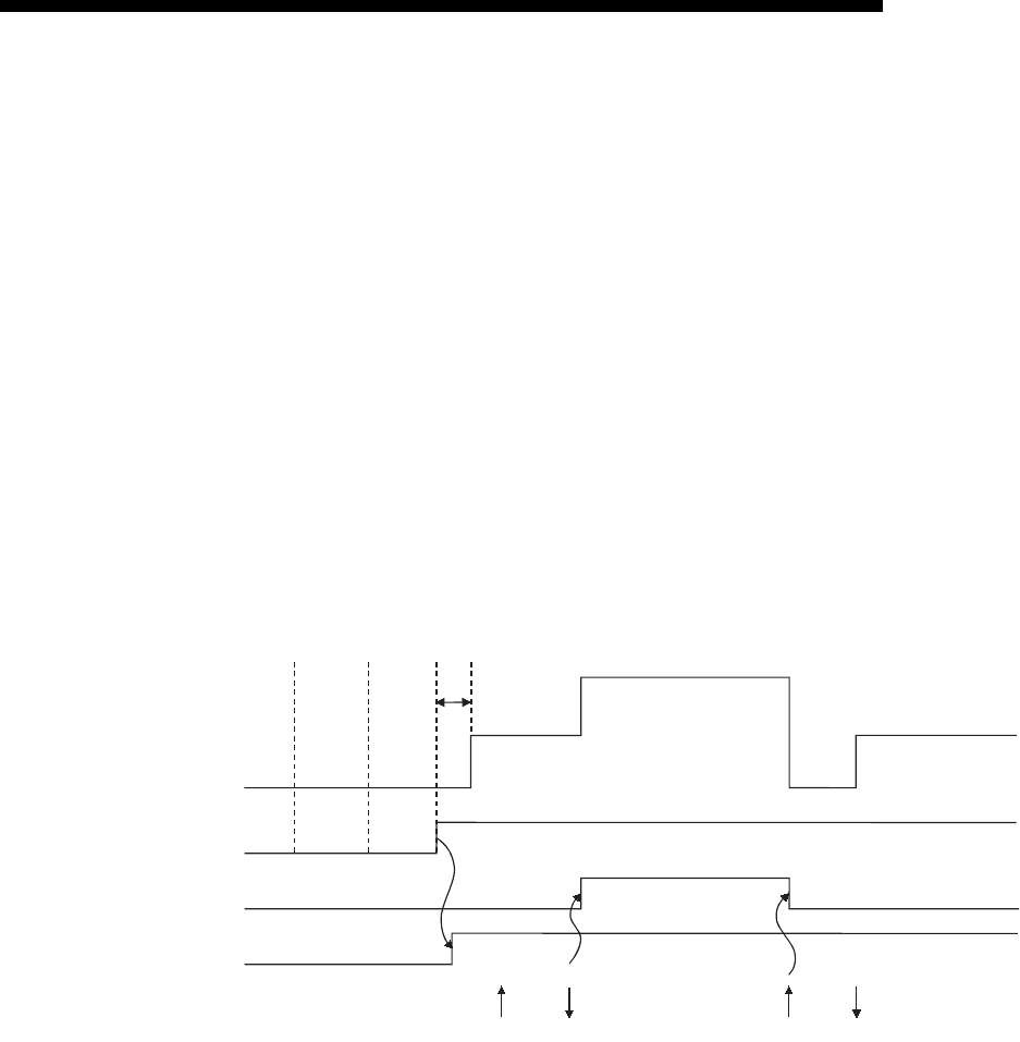
5 - 33
MELSEC-F
COMMUNICATION PROCEDURE5
5 - 33
5.6.2 Passive open processing/close processing
This section explains the procedure for opening and closing a connection with the
Ethernet module via an external device.
The operations of Passive open processing/close processing differ depending on
whether "Always wait for OPEN" or "Do not wait for OPEN" is selected, as shown in
this section.
(1) When "Always wait for OPEN" is selected in the operational setting
This is an explanation of (BFM #24 b8: ON) open processing/close processing
when initial timing settings for Operational Settings are set to be always wait
OPEN (Communication Possible at STOP).
In this case, sequence programs for open processing and close processing are
not required because the Ethernet module keeps the connection in the always
wait for the OPEN status according to the [Open settings] parameter setting.
For detail on the [Open settings] parameter, see Section 5.5, "Open Settings".
*1 An open request (SYN) received after the normal completion of an
initial processing and before the Ethernet module is placed in the
open acknowledge enabled status generates an error, and the
Ethernet module sends a connection forced close (RST).
Open status
Open allowed status
(Listen status)
(Active open acknowledge
enabled)
Close status
Initial normal completion
BFM#27="0001H"
Open completion signal
BFM#20480
Power-on
Parameter
communication
completed 1)
2)
FIN
3)
SYN + ACK FIN + ACK
Open allowed status
BFM#20482
SYN
4)
(*1)

5 - 34
MELSEC-F
COMMUNICATION PROCEDURE5
5 - 34
1) After the parameters are sent, the normal completion of the Ethernet
module initial processing is confirmed (Initial normal completion signal
BFM#27 "0001H")
After the initial processing is normally completed, the connection is
placed in the open allowed status and the Ethernet module waits for an
open request from the external device.
2) The Ethernet module starts the open processing upon receiving the open
request (SYN) from the external device.
When the open processing is normally completed (Open/close status
(BFM#1602 "0005H")), the open completion signal (BFM#20480 b0) turns
on and data communication is enabled.
3) The Ethernet module starts the close processing upon receiving the
close request (FIN) from the external device.
When the close processing is completed (BFM#1602 "0000H"), the open
completion signal (BFM#20480 b0) turns off and data communication is
disabled.
4) After the Ethernet module's internal processing is Rissn/completed, the
connection returns to the open acknowledge enabled status.
NOTE
For Passive open connections for which [Always wait for OPEN (Communication
possible at STOP time)] is selected in [Operational settings], the connection open/
close processing of the Ethernet module side is performed according to the open/
close request from the external device.
When the close processing is performed from the Ethernet module (this station), the
applicable connection will not return to the open acknowledge enabled status after
the close processing, even if [Always wait for OPEN (communication possible at
STOP time)] is selected in [Operational settings].
(It requires the same open processing and close processing as the connection for
Passive open for which [Do not wait for OPEN (communication impossible at STOP)]
is selected.)
(2) When "Do not wait for OPEN" is selected in the operational setting
When initial timing settings of operational settings are at [Do not wait for OPEN
(communication impossible at STOP time)], the (BFM #24 b8: OFF) open
processing/close processing is performed as explained below.
Since open processing/close processing is executed by a sequence program, an
external device can be changed while the connection is established.
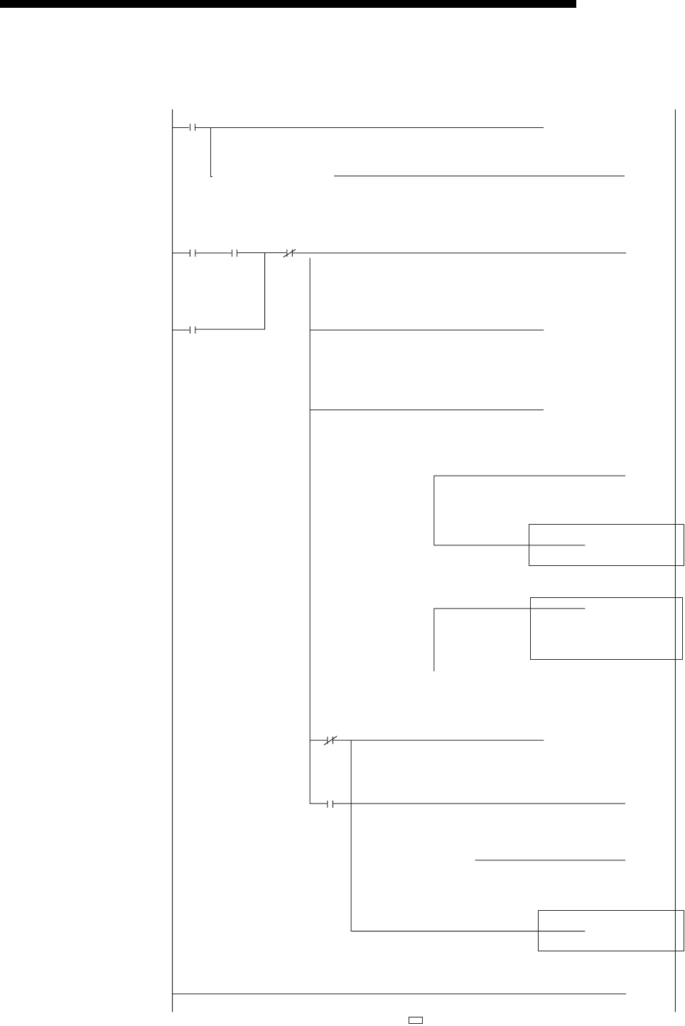
5 - 35
MELSEC-F
COMMUNICATION PROCEDURE5
5 - 35
• Program example for the unit No. 1
X000
M100
M103
X000
M102
[= D100 H15 ]
[= D100 H10 ]
[= D100 H5 ]
[= D100 H3 ]
]H0D100[=
[MOV D100
X0:ON Open
X0:OFF Close
(M100
(M101
(M102
(M103
]
[MOVP H1 ]
)
[INCP D0 ]
[INCP D1 ]
[INCP D2 ]
[END ]
[MOVP H8000 ]
)
)
)
U1\
G1602
Open
request
Cancel of
self-
holding
at close
Open request
(Self-holding)
Open
request
(Self-
holding)
Open
request
Reading
value
of #1602
Reading
value
of #1602
Reading
value
of #1602
Reading
value
of #1602
Closed
(Self-
holding)
Closed
(Self-
holding)
Reading
value
of #1602
OPEN
instruction/
status
Reading
value
of #1602
OPEN
instruction/
status
OPEN
instruction/
status
Rissn/Open
completed
Normal open
Number of
abnormal
open
completions
Close normal completion count
Cancel of
self-holding
at close
Close normal processing
U1\
G1602
U1\
G1602
Number of normal open completions
M8000
[MOV K4M110 ]
U1\
G28
Status Read of status
(M0
Initial
completion
status
[= H1 ]
U1\
G27
Initial
completion
signal
M0
Initial
completion
status
User applications are described at the area enclosed with .
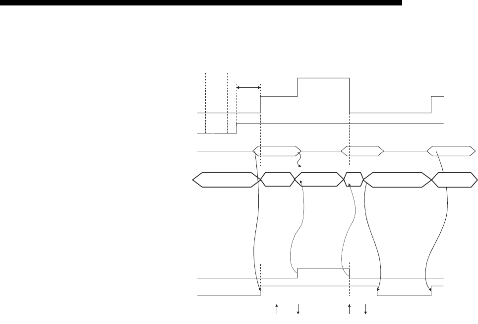
5 - 36
MELSEC-F
COMMUNICATION PROCEDURE5
5 - 36
*1 If an open request (SYN) received after the normal completion of an
initial processing and before the Ethernet module is placed in the
open acknowledge enabled status, an error is generated, and the
Ethernet module sends a connection forced close (RST).
1) After communicating the parameter settings, confirm the normal
completion of the Ethernet module initial processing.
(Initial normal completion signal (BFM#27 "0001H":)
2) Start the open processing by writing "0001H" to the BFM#1602.
(Open request signal (BFM#20482 b0) : ON
3) OPEN possible (Listen status) from external device. (Open/close status
BFM #1602 "0003H")
4) The Ethernet module starts the open processing upon receiving the open
request (SYN) from the external device.
At normal completion
Data communication is enabled.
At abnormal completion
5) The Ethernet module starts the close processing upon receiving the
close request (FIN) from the external device.
When the close processing is completed, the open completion signal
turns off and data communication is disabled.
• Open completion signal (#BFM20480 b0) : ON
• BFM#1602 : 0005H
• Open completion signal : OFF
• The open error code is stored in the buffer memory
• Open abnormal detection signal (BFM28 b6) : ON
• OPEN/CLOSE instruction status (BFM#1602 "0010H" or "0015H")
Open status
Open allowed status (closed)
(Active open acknowledge
enabled)
Closed status
Initial normal completion
BFM#27="0001H"
OPEN/ CLOSE operation
TO BFM#1602
OPEN/ CLOSE status
FROM BFM#1602
Open completion signal
BFM#20480
Power-on
Parameter
communication
completed
1)
2)
3)
4) 5)
FINSYN
SYN+ACK
Open allowed status
FIN+ACK
BFM#20482
0001H8000H0001H
(*1)
0003H0000H0005H0003H0000H
0009
H

5 - 37
MELSEC-F
COMMUNICATION PROCEDURE5
5 - 37
NOTE
(1) If the settings of the connection need modifying, the modifications should be
done before writing the open instruction to the buffer memory.
(2) Once open processing is executed, an open request cannot be canceled before
the open processing is completed.
Write the close instruction to the buffer memory after the open processing has
been completed.
POINT
This example uses connection number 1 for explanation. Use the appropriate
BFM signals and bits for other connection numbers.

5 - 38
MELSEC-F
COMMUNICATION PROCEDURE5
5 - 38
Program example
This example explains a program for open processing/close processing when
Unpassive open is selected in the open system setting.
(1) Execution environment for the program example
(a) The Ethernet module is connected to the second special module. (The unit
number is setting 1)
(b) The unit number specified at the sequence program and in FX Configurator-
EN-L is 1.
(c) Adjust Operation settings in the following manner.
(d) Make open settings in the following manner.
(e) The following contact signals are used in the program.
X000 Open instruction
M100 Open request self-hold
M101 Open complete
M102 Closed indicator self-hold
M103 Cancel self-hold when closed
(2) Outline of the program example
(a) The open processing for connection No. 1 of the Ethernet module is
performed.
After the completion of the open processing, connection No. 1 waits for the
open request from the external device.
(b) The close processing for connection No. 1 is performed according to the
close instruction (X000=OFF) to the Ethernet module.
Communication data code : Binary code (BFM#24 b1 : OFF)
Initial timing : Do not wait for OPEN (Communications
impossible at STOP time) (BFM#24 b8 : OFF)
IP address : 10.97.85.223 (0A.61.55.DFH) (BFM#106 to 107)
Protocol :TCP (BFM#32 b8 : OFF)
Open system : Unpassive (BFM#32 b14, b15 : 10H)
Fixed buffer : Send (BFM#32 b0 : ON)
Fixed buffer
communication procedure : Procedure exist (BFM#32 b9 : OFF)
Pairing open : Disable (BFM#32 b7 : OFF)
Existence confirmation : No confirm (BFM#32 b1 : OFF)
Local station Port No. : 8192 (BFM#40)
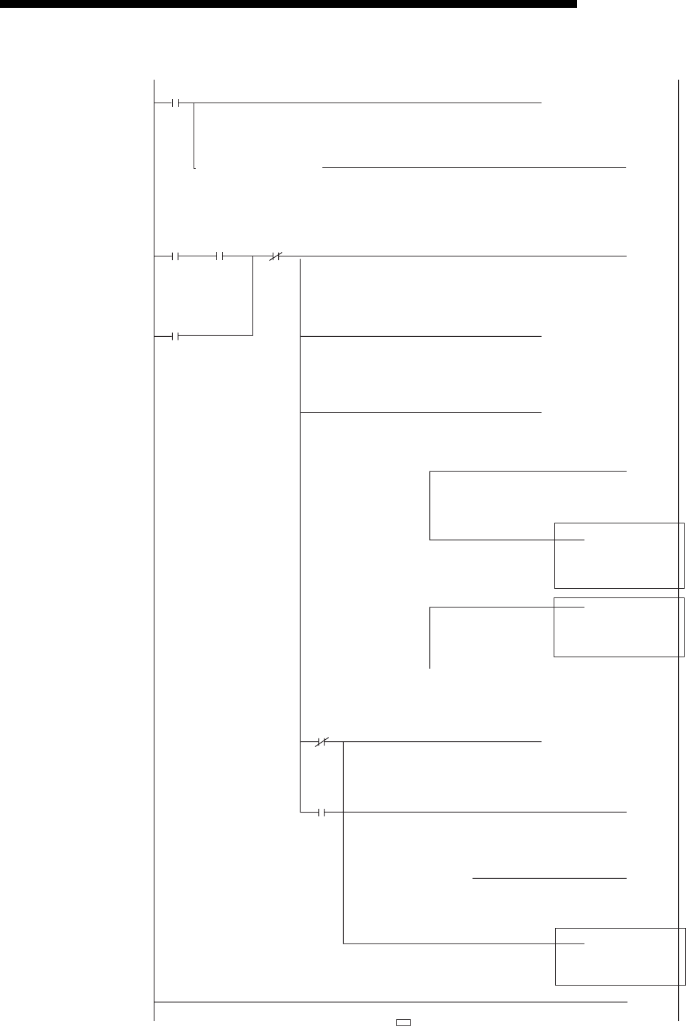
5 - 39
MELSEC-F
COMMUNICATION PROCEDURE5
5 - 39
• Program example for the unit No. 1
X000
M100
M103
X000
M102
[= D100 H15 ]
[= D100 H10 ]
[= D100 H5 ]
[= D100 H3 ]
]H0D100[=
[MOV D100
(M100
(M101
(M102
(M103
]
[MOVP H1 ]
)
[INCP D0 ]
[INCP D1 ]
[INCP D2 ]
[END ]
[MOVP H8000 ]
)
)
)
U1\
G1602
Open
request
Cancel of
self-
holding
at close
Open request
(Self-holding)
Open
request
(Self-
holding)
Open
request
Reading
value
of #1602
Reading
value
of #1602
Reading
value
of #1602
Reading
value
of #1602
Closed
(Self-
holding)
Closed
(Self-
holding)
Reading
value
of #1602
OPEN
instruction/
status
Reading
value
of #1602
OPEN
instruction/
status
OPEN
instruction/
status
Rissn/Open
completed
Number of
abnormal
open
completions
Number of
normal
open
completions
Close normal
completion
count
Cancel of
self-holding
at close
U1\
G1602
U1\
G1602
M0
Initial
completion
status
M8000
[MOV K4M110 ]
U1\
G28
Status Read status
(M0
Initial
completion
status
[=
U1\
G27 H1 ]
Initial
completion
signal
User applications are described at the area enclosed with .

5 - 40
MELSEC-F
COMMUNICATION PROCEDURE5
5 - 40
5.6.3 UDP/IP open processing/close processing
The following explains the UDP/IP open processing.
The operations of the open processing/close processing in UDP/IP differ depending
on whether "Always wait for OPEN" or "Do not wait for OPEN" is selected in the initial
timing settings (BFM #24 b8) from operational settings.
(1) When "Always wait for OPEN" is selected in the operational
settings (Communications possible at STOP time)
According to the Open settings (BFM#32), a selected connection for the UDP/IP
communication is established automatically after the Ethernet module installed
station has been restarted, and data transmission/reception is enabled.
Sequence programs for open processing and close processing are not required.
For details on the [Open settings] parameter, see Section 5.5, "Open Settings".
NOTE
When performing the open and close processing by writing to the buffer memory
from the Ethernet module side, even if [Always wait for OPEN (Communications
impossible at STOP time)] is selected at [Operational settings], it is required to use
the sequence program to process all that follows the processing for the applicable
connection.
If "Do not wait for OPEN (Communication impossible at STOP time)" is selected,
open processing and close processing need to be done in the same manner as a
connection.
(2) When "Do not wait for OPEN" is selected in the operational settings
(Communications impossible at STOP time)
In this case, the open processing and close processing in the sequence program
shown in the next page are required. Data transmission and reception are
enabled after the open processing is normally completed.
Perform the open processing and close processing by writing "0001H" in
BFM#1602 to 1605.
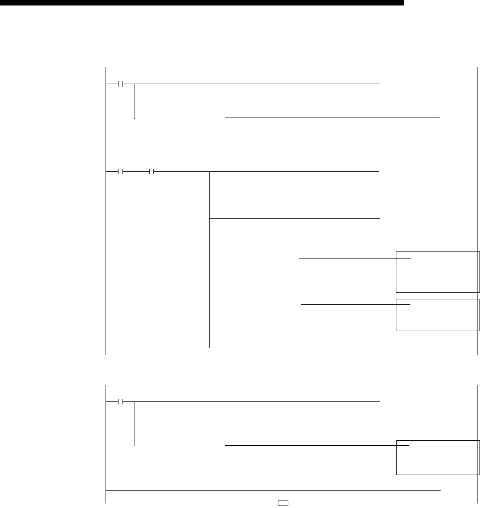
5 - 41
MELSEC-F
COMMUNICATION PROCEDURE5
5 - 41
• Program example for the unit No. 1
X000
[= D100 H15 ]
[= D100 H10 ]
[= D100 H5 ]
[MOV D100 ]
[INCP D0 ]
[INCP D1 ]
U1\
G1602
Open
request
OPEN
instruction/
status
Open
abnormal
processing
Open
normal
completion
signal
M0
Initial
completion
status
M8000
[MOV K4M110 ]
U1\
G28
Status Status
read value
(M0
Initial
completion
status
[=
U1\
G27 H1 ]
Initial
completion
signal
<<Open processing for connection No.1>>
[MOVP H1 ]
OPEN
instruction/
status
U1\
G1602
[INCP D2 ]
[END ]
Close
request
Closel
normal
processing
X001
[MOVP ]H8000
[=
U1\
G1602 H0 ]
OPEN
instruction/
status
<<Close processing for connection No.1>>
OPEN
instruction/
status
U1\
G1602
User applications are described at the area enclosed with .
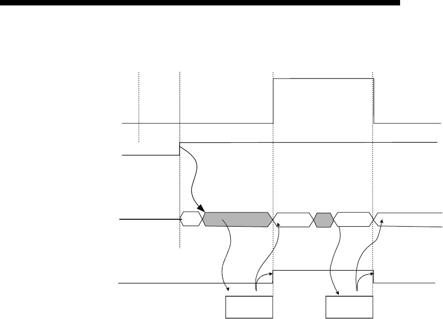
5 - 42
MELSEC-F
COMMUNICATION PROCEDURE5
5 - 42
1) After communicating the parameter settings, confirm the normal
completion of the Ethernet module initial processing.
(Initial normal completion signal (BEF#27) : 0001H)
2) Start the open processing by writing 0001H to the BFM#1602.
3) The Ethernet module executes the open processing.
(Internal processing only)
4) When the open processing completes normally
Data communication is enabled.
When the open processing completes abnormally
5) Start the close processing by writing 8000H to the BFM#1602.
6) The Ethernet module executes the close processing.
(Internal processing only)
7) When the close processing completes normally
(Open request signal (BFM#20482 b0) : ON)
• Open completion signal (BFM#20482 b0) : ON
• Reading value of BFM#1602 : 0005H
• Open status (BFM#1602) : 0010H or 0015H
• Open abnormal detection signal (BFM#28 b6) : ON
• Open/Close instruction status (BFM#1602) : 0000H
Open status
Closed status
Initial normal completion
BFM#27=001
Open completion signal
BFM#20480
Internal
processing
Internal
processing
Power-on
Parameter
update completed
1)
2)
3) 4) 6) 7)
OPEN/CLOSE instruction
and status BFM#1602 R0005H
R
0000H
R
0000H
W0001HW
8000H
R
0009H
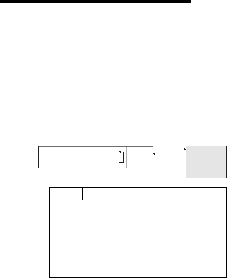
5 - 43
MELSEC-F
COMMUNICATION PROCEDURE5
5 - 43
5.7 Pairing Open
The following explains communication using the paring open method via the Ethernet
module.
5.7.1 Pairing open
Pairing open is an opening method for establishing a connection in which the local
station and the external device use a single port for each, by pairing the receiving and
sending connections through fixed buffer communication (both the procedure exists
and no procedure are allowed) of the Ethernet module.
By designating the pairing open method, data communication can be performed with
two connections by performing open processing for only one port.
The procedure for performing the open/close processing for pairing open is explained
below.
[Example]
POINT
(1) When setting the pairing open method, the fixed buffer of the applicable
connection number (for receiving only) and the fixed buffer of the next
consecutive connection number (for sending only) are paired in the order of
receiving, then sending.
For the applicable connection (for receiving only), choose connection No. 1.
(2) The range of external devices that can be communicated by the pairing open
method are limited to devices on the Ethernet to which the Ethernet module is
connected and devices connected with the router relay function (see Section
5.3, "Router Relay Parameter").
(3) By the open/close processing of the applicable connection (for receiving only)
for which the pairing open method has been set, the open/close processing of
the next connection (for sending only) will automatically be performed.
Ethernet module
Connection No. 1 fixed buffer (for receiving)
Connection No. 2 fixed buffer (for sending)
(TCP/IP or UDP/IP communication)
Send data
Port
Receive data
External device
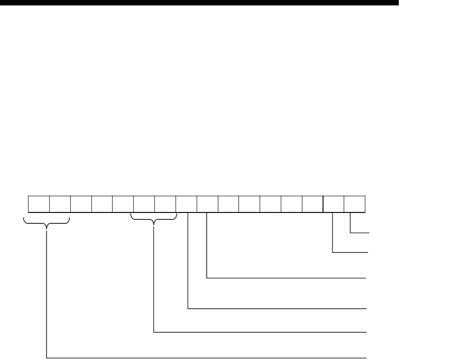
5 - 44
MELSEC-F
COMMUNICATION PROCEDURE5
5 - 44
5.7.2 Example of pairing open settings
This section explains the settings in order to communicate in the pairing open method
by giving an example.
• Connection No. 1 and 2 are used.
(When connection No. 1 is specified at pairing open settings, connection No. 2 is
automatically used as pairing.
Therefore, connection No. 2 cannot be specified as pairing.)
(1) Fixed buffer (BFM#32 b0)
In the open pairing, the applicable connection No. and the subsequent
connection No. are paired. Set the applicable connection No. to "Receive" and
the next connection number to "Send".
(2) Existence confirmation (BFM#32 b1)
If existence confirmation is going to be executed, set the receiving connection to
"Confirm".
If existence confirmation is not going to be executed, select "No confirm".
(3) Pairing open (BFM#32 b7)
Set connection No. 1 as the receiving connection by selecting "Pairs", and set
connection No. 2 as the sending connection by selecting "No pairs".
(4) Protocol (BFM#32 b8)
Both "TCP/IP" and "UDP/IP" are allowed.
(5) Fixed buffer communication (BFM#32 b9, b10)
Both "Procedure exist" and "No procedure" can be selected.
(6) Open system (BFM#32 b14, b15)
All the open systems - "Active", "Unpassive", and "Fullpassive" - can be set.
[BFM#32 Connection usage setting area]
b15 b14 b13 b12 b11 b10 b9 b8 b7 b6 b5 b4 b3 b2 b1 b0
(1) Fixed buffer
(2) Existence confirmation
(3) Pairing open
(4) Protocol
(5) Fixed buffer communication
(6) Open system

5 - 45
MELSEC-F
COMMUNICATION PROCEDURE5
5 - 45
(7) Local station Port No. (BFM#40, 47)
Set this for the receiving connection for receiving only. (Setting is not required for
the sending connection.)
Set the port number upon consulting a network administrator.
(8) Destination IP address (BFM#41 to 42, 48 to 49)
(a) If the setting is not required
• Open system: At [Unpassive] setting
(b) If the setting is required
Set for the receiving connection only upon consulting a network
administrator.
• Open system: At [Active] and [Fullpassive] setting
• Protocol: At [UDP/IP] setting
(9) Destination Port No. (BFM#43, 50)
(a) If the setting is not required
• Open system: At [Unpassive] setting
(b) If the setting is required
Set for the receiving connection only upon consulting a network
administrator.
• Open system: At [Active] and [Fullpassive] setting
• Protocol: At [UDP/IP] setting
NOTE
When making settings in the FX Configurator-EN-L, select [Open Settings] from the
initial screen and at the [Ethernet Open Settings] screen, set "Pairing Open" to
"Yes".
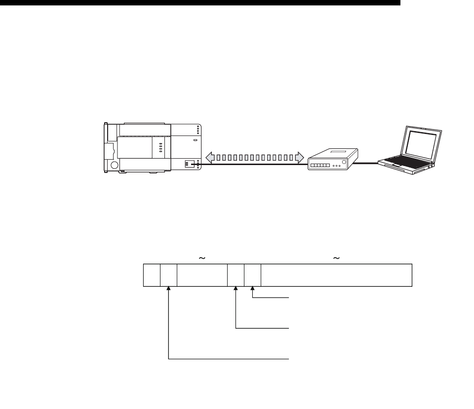
5 - 46
MELSEC-F
COMMUNICATION PROCEDURE5
5 - 46
5.8 Hub Connection Status Monitor Function
The current connection status of the Ethernet module and hub, the transmission
speed, and the number of times the Ethernet module detected disconnection can be
checked at the following buffer memory addresses.
(1) Hub connection status area (BFM#201)
Stores the current connection status of the FX3U-ENET-L and hub and the
transmission speed.
(2) Disconnection detection count storage area (BFM#20995)
(a) Stores the number of disconnection detection times after initial processing is
completed.
Disconnection is detected in any of the following cases.
• Disconnection between Ethernet module and hub
• Cable removal from hub side connector
• Hub power-off
• Cable removal from Ethernet module side connector
(b) If an error has occurred 65536 times or more, a count stops at FFFFH
(65535).
Write "0" to this area using a sequence program to clear the stored value.
Ethernet module Hub External device
10BASE-T/100BASE-TX,
Full duplex/half duplex
b15 b14
BFM#201
b13 b11 b10 b9 b8 b0
1) Communication mode
0: Half duplex
1: Full duplex
2) Hub connection status
0: Hub not connected/disconnected
1: Hub connected
3) Data transmission speed
0: Operating at 10BASE-T
1: Operating at 100BASE-TX
1)2)3)
(Bits other than above are reserved for system use.)
*1 When a switching hub is used, it may not be displayed correctly.
*1
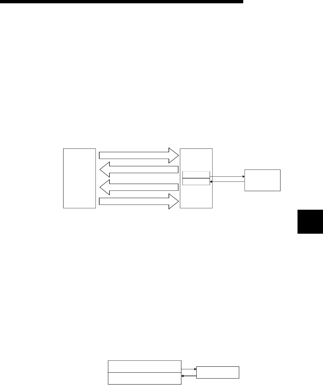
6 - 1
FIXED BUFFER COMMUNICATION (WITH THE PROCEDURE EXIST
CONTROL METHOD)
6
6 - 1
6
MELSEC-F
6 FIXED BUFFER COMMUNICATION (WITH THE PROCEDURE EXIST
CONTROL METHOD)
This chapter explains how the PLC and external device communicate in a 1:1 mode
using the fixed buffers (with the procedure exist control method) of the Ethernet
module.
6.1 Control Method
The following explains how communication is performed using the fixed buffers and
the procedure exist control method.
In communication using the fixed buffers, data transmission from the PLC and the
external device is executed through handshaking.
(1) The data flow during communication is as follows.
(2) Data can be communicated with the following external devices.
• Device on the Ethernet to which the Ethernet module is connected.
• Devices connected with the router relay function (see Section 5.3)
As shown in the diagram below, when using each fixed buffer (No. 1, No. 2), the
destination devices and usage conditions (for sending/receiving, procedure exist/
no procedure, etc.) should be set when the connection via the Ethernet module is
opened to fix the external device for each buffer.
(a) At TCP/IP communication
It is allowed to change external devices only when the open completion
signal of the applicable connection is off.
(b) At UDP/IP communication
External devices can be changed regardless of the status of the applicable
connection.
("Destination IP address" and "Destination Port No." in the communication
address setting area can be changed. However, the "Local station Port No."
cannot be changed.)
When changing external devices, do not use the "Pairing open" and
"Existence confirmation" functions.
Fixed buffer
No.1
No.2 External device
TO instruction (Transmission request)
FROM instruction (Reading the data received)
FROM instruction (Transmission complete)
TO instruction (Reception complete)
(For sending)
(For receiving)
FX
3U
main
unit
For sending to external device 1
Fixed buffer No. 1
External device 1
For receiving from external
device 1
Fixed buffer No. 2

6 - 2
FIXED BUFFER COMMUNICATION (WITH THE PROCEDURE EXIST
CONTROL METHOD)
6
6 - 2
6
MELSEC-F
(3) At data sending/receiving, the Ethernet module processes the following.
(a) When sending data
In response to the fixed buffer communication transmission request (write
"0001H" to BFM #1610, #1611), the Ethernet module sends the data of the
fixed buffer stored in the fixed buffer area (BFM #1664 to 3711) to the the
specified external device (BFM #40 to 53). (*1)
(b) When receiving data
The Ethernet module processes the received data if the data is received
from an external device set in the communication setting area that
corresponds to fixed buffer No. n. (*1)
If data is received from an external device not set in the connection
information area of the buffer memory, the Ethernet module ignores the
received data to the PLC side.
*1 In case of TCP/IP Unpassive open, data is communicated with an
external device stored in the connection information area corresponding
to fixed buffer No. n.
POINT
In communication where the procedure exist control method is selected, the data
can be communicated by the following methods after the open processing is
completed.
• Fixed buffer communication with the procedure exist control method (sending or
receiving)
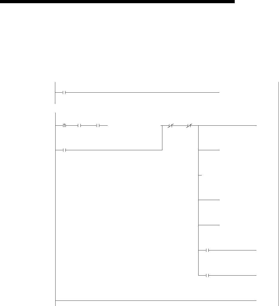
6 - 3
MELSEC-F
FIXED BUFFER COMMUNICATION (WITH THE PROCEDURE EXIST
CONTROL METHOD)
6
6 - 3
6.2 Sending Control Method
This section explains the control method when data is sent from the Ethernet module
to an external device using the fixed buffer No. 1 and the area corresponding to
connection No. 1 as an example.
• Program example for the unit No. 1
X002
M200
D101.2
D101.3
* <<Sending 32 words from D1000 to the external device>>
D1000[BMOVP K32 ]
[MOVP K32 ]
[MOVP H1 ]
[MOV D101 ]
(M201 )
(M200 )
(M202 )
[END ]
M201 M202
Send
instruction
Transmission
normally
completed
Transmission
abnormally completed
Send instruction
(Self-holding)
Send
instruction
(Self-holding)
Number of
send words
in the fixed
buffer No.1
U1\
G1664
U1\
G1665
U1\
G1610
Value of
BFM#1610
Value of
BFM#1610
Head of
send data
Fixed
buffer No.1
U1\
G1610
Transmission
request/status
Value of
BFM#1610
Transmission
request/status
Transmission
normally
completed
Transmission
abnormally
completed
M8000
[MOV K4M300 ]
* <<Reading the status of Ethernet module>>
U1\
G28
Initial
completed
M300 M307
[= H5 ]
Initial
completed
HUB
connection
completed
OPEN
instruction/status
U1\
G1602
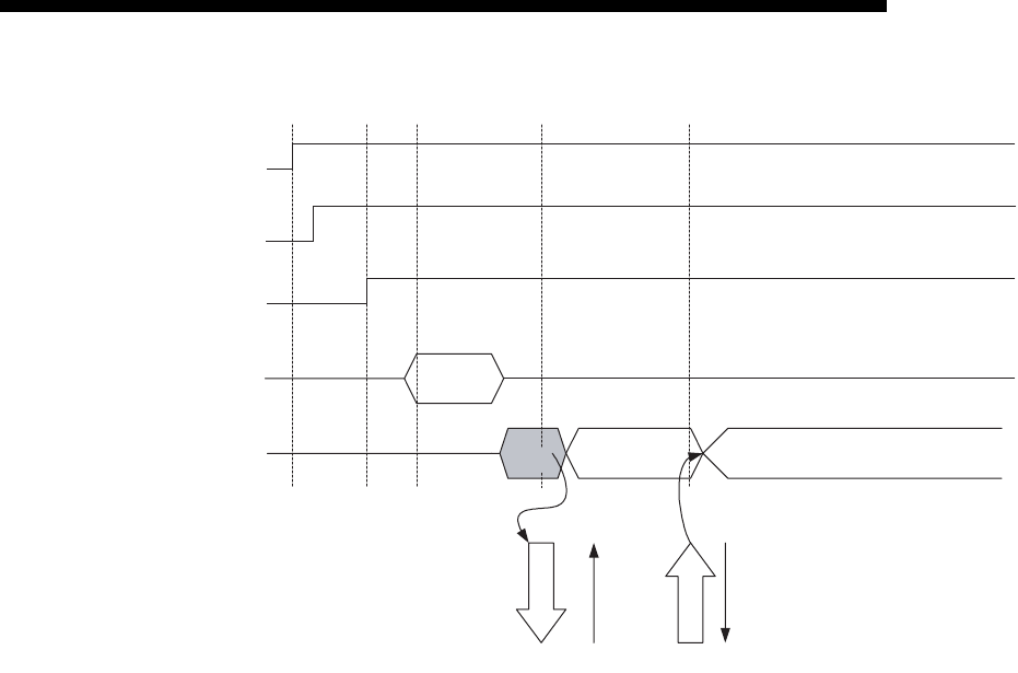
6 - 4
MELSEC-F
FIXED BUFFER COMMUNICATION (WITH THE PROCEDURE EXIST
CONTROL METHOD)
6
6 - 4
1) Confirm the normal completion of the initial processing.
2) Confirm that the link status is normal between the Ethernet module and
the connected HUB.
3) Confirm the normal completion of the open processing of connection
No. 1
4) Write the send data word count and the send data in the fixed buffer data
area (communication address setting area: BFM#1664 to 2687) by TO
instruction.
5) Write "0001H" in the fixed buffer communication transmission request
(BFM#1610).
6) The size of send data in the fixed buffer (No. 1) area designated by the
send data length is sent to the designated external device (set in the
open processing).
The value in BFM#1610 becomes "0002H".
7) Upon receiving the data from the Ethernet module, the external device
returns a "Response" to the Ethernet module.
8) Upon receiving the "Response" from the external device, the Ethernet
module ends the data transmission.
If the "Response" is not returned within the response monitoring time
values (see Section 5.2), a data send error occurs.
At normal completion
Fixed buffer transmission result (BFM#1610) : 0004H
At abnormal completion
Fixed buffer transmission result (BFM#1610) : 0008H
If the data transmission is abnormally completed, execute the send
process again writing "0001H" in BFM#1610.
R
0002H
Initial processing normally
completed BFM#=0001H
OPEN/CLOSE instruction status
BFM#1602=0005H
Write the send data word
count and the send data
in BFM
TO
Fixed buffer send instruction
and transmission completion
BFM#1610
W
0001H
R
0004H(Success)/0008H(Error issued)
1)
3)
4)
5)
6)
8)
Initial
processing
Send data
writing
Open
processing
Response
receiving
7)
Data sending
Response
Data sending
ACK (TCP only)
ACK (TCP only)
HUB connection is signal
BFM #28 b7 2)

6 - 5
MELSEC-F
FIXED BUFFER COMMUNICATION (WITH THE PROCEDURE EXIST
CONTROL METHOD)
6
6 - 5
POINT
The destination setting (see Section 5.5) for a connection whose parameters are
set in FX Configurator-EN-L becomes valid when the open completion signal
(BFM#20480 corresponding bit) of the Ethernet module switches from off to on.
The setting also becomes valid when the each value in BFM#1602 to #1605 is
"0005H" for Connection No.1 to 4.
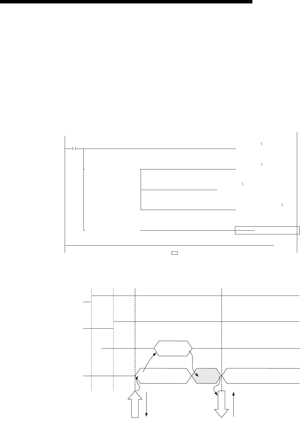
6 - 6
MELSEC-F
FIXED BUFFER COMMUNICATION (WITH THE PROCEDURE EXIST
CONTROL METHOD)
6
6 - 6
6.3 Receiving Control Method
This section explains the control method when the Ethernet module receives data
from an external device.
6.3.1 Receive processing with the main program
This section explains the receiving process to be performed with the main program,
using an example in which the fixed buffer No. 2 and the area corresponding to
connection No. 2.
• Program example for the unit No. 0
M8000
[BMOV D1000 D101 ]
[MOV D101 ]
[MOV D100 ]
[MOV H2 ]
[= D100 H1 ]
[= D100 H8 ] [INCP D102 ]
]
[END
* <<Storing the data received from the external device to the fixed buffer No.2 in D1000 and later>>
* <Receiving status
* <Obtaining received word count
* <Read of received data
* <Write of receiving completion
* <Receiving failed
>
>
>
>
>
U0
G1611
U0
G2688
U0
G1611
U0
G2689
Receive abnormal processing
User applications are described at the area enclosed with .
ACK
(only TCP)
5)
Response
ACK
(only TCP)
2)
Data receiving
W
0002H
Initial processing normal
completion
OPEN/CLOSE instruction status
BFM #1602=0005H
Received word count and
received data written to PLC FROM instruction
Fixed buffer received status and
received completion message
BFM #1611
R
0001H
R
0004H (Success)/0008H (Error issued)
Initial
processing
Open
processing
Response
sending
Data
receiving
1)
3) 4)
6)

6 - 7
MELSEC-F
FIXED BUFFER COMMUNICATION (WITH THE PROCEDURE EXIST
CONTROL METHOD)
6
6 - 7
1) Confirm the normal completion of the open processing of connection
No. 2.
2) Upon receiving data from the designated external device (set in the open
processing), the Ethernet module processes the following.
• Stores the received data to the fixed buffer (No. 2) area.
Receive data length : The head address area of the target fixed
address
Receive data : Area beginning from the head address of the
target fixed buffer + 1
• Fixed buffer receive status signal (BFM#20485 b1) : ON
• Fixed buffer communication receive result (BFM#1611) : 0001H
3) Execute the FROM instruction to read the received word length and
received data to the PLC.
4) Execute the TO instruction to write "0002H" in the fixed buffer
communication receive result (BFM#1611).
5) Return "Response" to communication destination.
6) The receive processing is performed.
At normal completion
• Fixed buffer transmission results (BFM#1611) : 0004H
At abnormal completion
• Fixed buffer transmission results (BFM#1611) : 0008H
POINT
(1) The destination setting (see Section 5.5) for a connection whose parameters
are set with FX Configurator-EN-L becomes valid when the open completion
signal (BFM#20480 corresponding bit) of the Ethernet module switches from
off to on.
(2) Execute data receiving process when the corresponding connection's bit in
the fixed buffer receive status signal storage area (BFM#20485) of the buffer
memory switches from off to on or when the value "0001H" is stored in the
fixed buffer communication receive results (BFM#1610, 1611).
(3) At abnormal data receiving, each buffer memory status is shown in the
following.
(For connection No. 2)
• The fixed buffer receive completion signal (BFM#20485 b1) remains off.
• The fixed buffer communication receive result (BFM#1611) remains
"0008H".
• Data is not stored in the fixed buffer (No.2) area.

6 - 8
MELSEC-F
FIXED BUFFER COMMUNICATION (WITH THE PROCEDURE EXIST
CONTROL METHOD)
6
6 - 8
6.4 Data Format
When communicating between the Ethernet module and an external device, the data
format explained below is used.
The communication data consists of a "header" and "application data" as follows:
6.4.1 Header
The header for TCP/IP or UDP/IP is used. In case of the Ethernet module, the
Ethernet module adds and deletes the header. Thus, the user does not need to set it.
(Details of the size of the header section)
1) In case of TCP/IP
2) In case of UDP/IP
Header Application data
Maximum of 2040 bytes
Ethernet
14 bytes
IP
20 bytes
TCP
20 bytes
Ethernet
(14 bytes)
IP
(20 bytes)
UDP
(8 bytes)
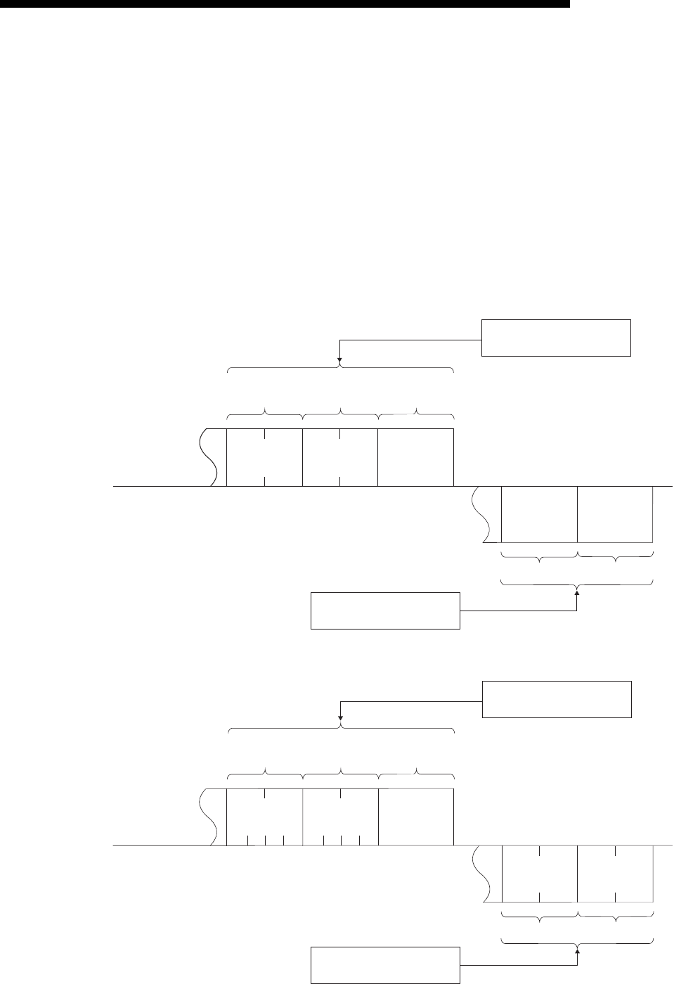
6 - 9
MELSEC-F
FIXED BUFFER COMMUNICATION (WITH THE PROCEDURE EXIST
CONTROL METHOD)
6
6 - 9
6.4.2 Application data
As shown below, the data code in the application data can be expressed in either
binary code or ASCII code. Switching between binary code and ASCII code is
performed via the communication data code setting (BFM #24 b1 OFF: binary code,
ON: ASCII code).
(When setting using the FX Configurator-EN-L, select [Operational Settings] from the
initial screen, and adjust the settings from the [Operational Settings] screen.)
For more details, see Section 4.6, "Operational Settings".
(1) Format
(a) Communication using binary code
(b) Communication using ASCII code
Subheader
LH
2 bytes
LH
2 bytes
Text
(command)
Maximum
1017 words
(2 bytes used per word)
Subheader End code
1 byte 1 byte
Application data section
(response)
Communication
request
source side
Communication request
destination side
Data length
setting
Application data section
(command message)
Subheader
4 bytes 4 bytes
Text
(command)
Maximum
508 words
(4 bytes used per word)
Subheader End code
2 bytes 2 bytes
Communication
request
source side
Communication request
destination side
Data length
setting
L
H--L
H--
L
H
LH
Application data section
(command message)
Application data section
(response)
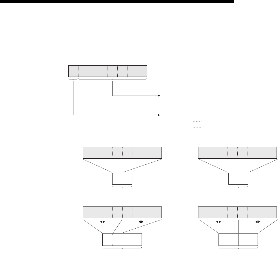
6 - 10
MELSEC-F
FIXED BUFFER COMMUNICATION (WITH THE PROCEDURE EXIST
CONTROL METHOD)
6
6 - 10
(2) Subheader
The format of the subheader is as shown below.
The user does not need to set the subheader when using the Ethernet module
since the Ethernet module adds and deletes it.
b7 b6 b5 b4 b3 b2 b1 b0
Command/response flag
1100000
Command/response type
(The bit status indicated in the figure shows that
communication using fixed buffers is being performed.)
At command 0
At response 1
00H60H
Subheader
Communication using
binary code
30H30H30H
Subheader
Communication using
A
SCII code 36H
"6" 6H"0" 0H
E0H
Subheader
45H
Subheader
30H
"E" EH"0" 0H
Command
to
b7 b0
10 100000
Response
to
b7 b0
11 100000
to
b7 b0
10 100000
to
b7 b0
11 100000
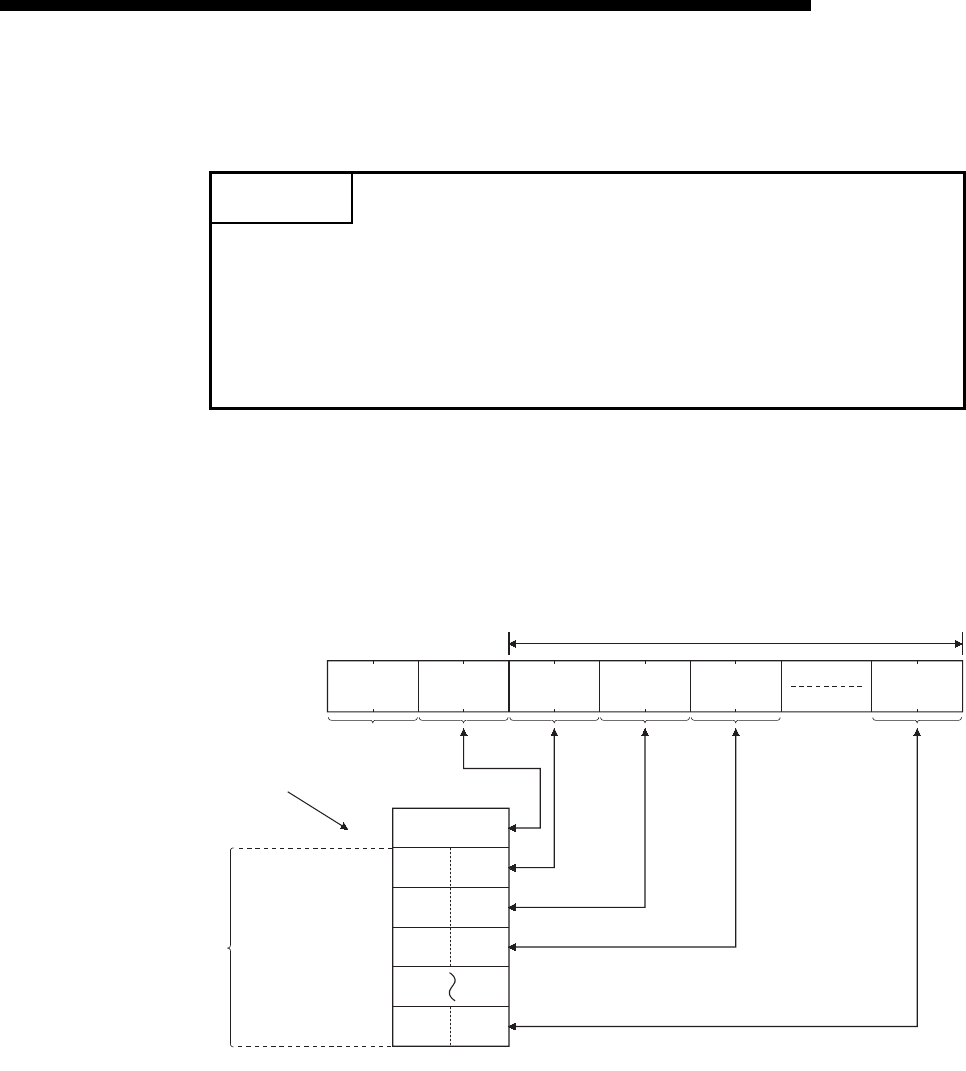
6 - 11
MELSEC-F
FIXED BUFFER COMMUNICATION (WITH THE PROCEDURE EXIST
CONTROL METHOD)
6
6 - 11
(3) Data length setting
This value indicates the data size of the text (command) section.
(4) Text (command)
The format of the command/response when communicating using fixed buffers is
configured as follows.
(a) Communication using binary code
POINT
The data length can be designated in the following range:
• Communication using binary code : Maximum of 1017 words
• Communication using ASCII code : Maximum of 508 words (*1)
*1 Since data is sent/received as ASCII data, the communication data size is
approximately half of the data size when using binary code.
(L)
00H(H)
60H(L) (H) (L) (H) (L) (H) (L) (H)
Maximum of 1017 words
Subheader
(L)(H)
(L)(H)
(L)(H)
(L)(H)
Data length
setting
1 word (2 bytes)
Send/
receive
data
Data designation/
storage device
for sending/
receiving instructions
Command format
n+1
n+2
n+3
Data length
setting
n
n+
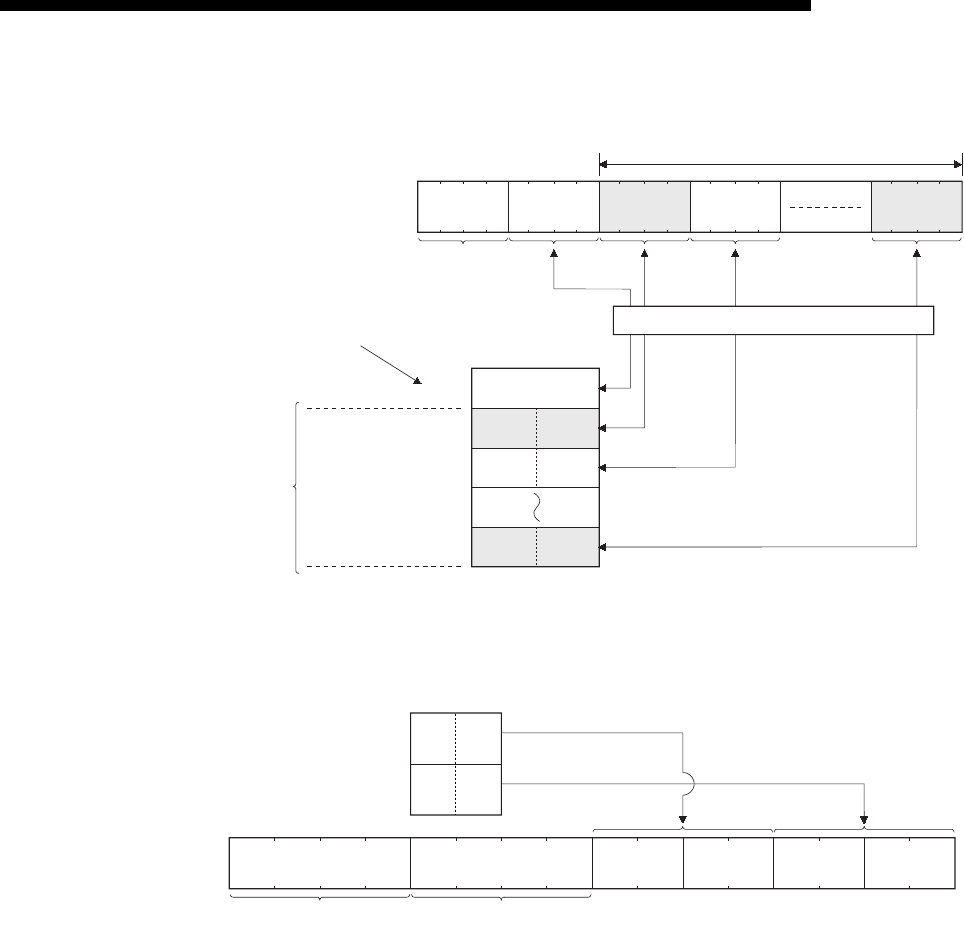
6 - 12
MELSEC-F
FIXED BUFFER COMMUNICATION (WITH THE PROCEDURE EXIST
CONTROL METHOD)
6
6 - 12
(b) Communication using ASCII code
(Example)
(5) End codes
For more details on the end codes added to a response when communicating
using fixed buffers, see Subsection 11.4.1.
End codes are stored in the communication status storage area of the buffer
memory.
36H
Maximum of 1016 words
Subheader
(H) (L)
Data length
setting
1 word (2 bytes)
Send/
receive
data
(Maximum of
508 words)
Data designation/
storage device
for sending/
receiving instructions
Command format
n+1
n+2
n + data length
setting
30H30H30H(H) to (L) (H) to (L) (H) to (L) (H) to (L)
ASCII-BIN conversion
n
(H) (L)
(H) (L)
Data length
n+1
n+2
Subheader
34
H
12
H
78
H
56
H
(H) to (L) (H) (L)
to
36
H
30
H
30
H
30
H
30
H
30
H
32
H
31
H
32
H
33
H
34
H
35
H
37
H
38
H
36
H
30
H

6 - 13
MELSEC-F
FIXED BUFFER COMMUNICATION (WITH THE PROCEDURE EXIST
CONTROL METHOD)
6
6 - 13
6.5 Programming
This section explains the programming method when the Ethernet module
communicates with an external device using fixed buffers and the procedure exist
control method.
6.5.1 Precautions when creating programs
(1) In order to communicate using the fixed buffer, the initial processing and the
connection open processing must be completed.
(2) The contents of the parameter settings have been loaded into the Ethernet
module when the Ethernet module open completion signal (BFM#20480
corresponding bit) switches from off to on.
(3) The data length (word count) is established using the instruction for procedure
exist communication control method.
If the send data length exceeds this range at data sending, a communication
error occurs and the data is not sent.
(4) Reading or writing to the buffer memory using fixed buffer communication.
• Data sending
Write the send data in the buffer memory (BFM#1664 to #3711).
Write "0001H" in BFM#1610, #1611 to send the data.
• Data receiving
Check the data received (BFM#1610, #1611: "0001Hs") and read the received
data to the PLC (BFM#1664 to #3711).
After reading out, write "0002H" in BFM#1610, #1611 to send the response.
(5) The following should be observed when using a connection opened by UDP.
External devices can be switched by modifying the setting values in the
communication address setting area of the communication parameter setting
area before sending/receiving data. Thus, data can be sent to multiple external
devices sequentially. When sending/receiving, make sure to switch between
external devices properly so that no communication problems occur.
(6) For data (command) transmission, the next data (command) should be after the
data commnication is complete (such as after receiving a response) for the
transmission of the previous data (command).

6 - 14
MELSEC-F
FIXED BUFFER COMMUNICATION (WITH THE PROCEDURE EXIST
CONTROL METHOD)
6
6 - 14
6.5.2 Fixed buffer communication program example (with the procedure exist control method)
This section explains the programming method in order to communicate data
(procedure exist control method) with an external device using the fixed buffers.
(1) Execution environment for the program example
(a) Send program (FX3U-1st station)
1) Connection No. 1 is used for fixed buffer sending.
2) The unit number specified in the sequence program and
FX Configurator-EN-L is 0.
3) The communication parameter settings are assumed to have been set as
described in Subsection 5.6.1, "Active open processing/close
processing".
(see the table below)
4) Fixed buffer No. 1 send data
: Stored in D1000 to D1031
5) Fixed buffer No. 1 send instruction complete device
: M201
6) Fixed buffer No. 1 send instruction abnormal complete device
: M202
7) Fixed buffer No. 1 send instruction complete status
: D101
[Operational settings]
[Open settings]
Setting name Settings in FX Configurator-EN-L Settings in the program
Communication data code setting Binary code BFM#24 b1:OFF
Initial timing Do not wait for OPEN
(Communications impossible at STOP time) BFM#24 b8:OFF
Local station IP address 10.97.85.222 (0A.61.55.DEH) BFM#106 to 108
Send frame setting Ethernet (V2.0) BFM#24 b5:OFF
TCP Existence confirmation setting Use the Ping BFM#24 b4:OFF
Setting name Settings in FX Configurator-EN-L (No.1) Settings in the program
protocol TCP BFM#32 b8:OFF
Open system Active BFM#32 b14,b15:00
Fixed buffer Sending BFM#32 b0:OFF
Fixed buffer communication Procedure exist BFM#32 b9:OFF
Paring open No pairs BFM#32 b7:OFF
Existence confirmation No confirm BFM#32 b1:OFF
Local station Port No.[Decimal]
4096 BFM#40
Destination IP address 10.97.85.223 (0A.61.55.DFH) BFM#41,42
Destination Port No.[Decimal] 8192 BFM#43
FX3U-1st station FX3U-2nd station
6 - 15
MELSEC-F
FIXED BUFFER COMMUNICATION (WITH THE PROCEDURE EXIST
CONTROL METHOD)
6
6 - 15
(b) Receive program (FX3U-2nd station)
1) Connection No. 1 is used to process the fixed buffer receiving in the main
program.
2) The unit number specified at the sequence program and
FX Configurator-EN-L is 0.
3) Make Operational Settings in the following manner.
Communication data code : Binary code (BFM#24 b1 : OFF)
Initial timing : Always wait for OPEN (Communications
possible at STOP time) (BFM#24 b8 : ON)
IP address : 10.97.85.223 (0A.61.55.DFH)
(BFM#106 to 107)
4) Adjust Open settings in the following manner.
Protocol : TCP (BFM#32 b8 : OFF)
Open system : Fullpassive (BFM#32 b14, b15 : 10H)
Fixed buffer : Receive (BFM#32 b0 : ON)
Fixed buffer communication procedure
: Procedure exist (BFM#32 b9 : OFF)
Pairing open : Disable (BFM#32 b7 : OFF)
Existence confirmation : No confirm (BFM#32 b1 : OFF)
Connection No.1 Local station Port No.
: 8192 (BFM#40) (For use in main program)
5) Fixed buffer No. 1 receive data : Stored in D1000 to D1031
6) Fixed buffer No. 1 receive status : D100
[Operational settings]
[Open settings]
Setting name Settings in FX Configurator-EN-L Settings in the program
Communication data code setting Binary code BFM#24 b1:OFF
Initial timing Always wait for OPEN
(Communications impossible at STOP time) BFM#24 b8:ON
Local station IP address 10.97.85.223 (0A.61.55.DFH) BFM#106 to 108
Send frame setting Ethernet (V2.0) BFM#24 b5:OFF
TCP Existence confirmation setting Use the Ping BFM#24 b4:OFF
Setting name Settings in FX Configurator-EN-L (No.2) Settings in the program
protocol TCP BFM#32 b8:OFF
Open system Fullpassive BFM#32 b14,b15:10
Fixed buffer Receive BFM#32 b0:ON
Fixed buffer communication Procedure exist BFM#32 b9:OFF
Paring open No pairs BFM#32 b7:OFF
Existence confirmation No confirm BFM#32 b1:OFF
Local station Port No.[Decimal]
8192 BFM#40
Destination IP address 10.97.85.222 (0A.61.55.DEH) BFM#41,42
Destination Port No.[Decimal] 4096 BFM#43
POINT
Make sure to have sufficient device memory according to the maximum data
length sent in order to prevent device areas used for other purposes from being
overwritten by the received data.

6 - 16
MELSEC-F
FIXED BUFFER COMMUNICATION (WITH THE PROCEDURE EXIST
CONTROL METHOD)
6
6 - 16
(2) Outline of the program example
(a) Send program (Ethernet module-1st station)
1) After setting each parameter with FX Configurator-EN-L or a sequence
program and writing to the Ethernet module, select re-initial, power ON
the module again, or confirm that the initial processing is completed via
buffer memory operations.
2) Perform open processing (Active open) of connection No. 1. (*1)
3) Communicate with the PLC using fixed buffer communication
(procedure exist sending).
4) After sending is complete, perform close processing of connection
No. 1. (*1)
*1 Use the program example described in Subsection 5.6.1, "Active open
processing/close processing" for the sequence program that executes
the open processing/close processing.
(b) Receive program (Ethernet module -2nd station)
1) After setting each parameter with FX Configurator-EN-L or a sequence
program and writing to the Ethernet module, select re-initial, power ON
the module again, or confirm that the initial processing is
completed via buffer memory operations.
If the initial processing is normally completed, connection No. 1 wait for
an Active open request from the external device.
2) Transfer data from the external device using fixed buffer communication
(procedure exist sending).
3) The data received by the corresponding fixed buffer data area in the
Ethernet module is read to the PLC.
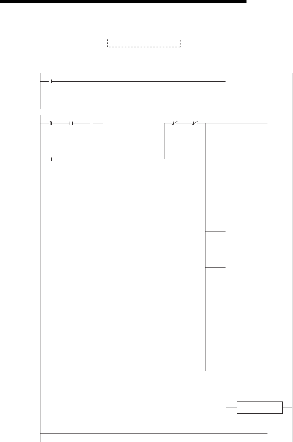
6 - 17
MELSEC-F
FIXED BUFFER COMMUNICATION (WITH THE PROCEDURE EXIST
CONTROL METHOD)
6
6 - 17
(Send program)
(See Subsection 5.6.1)
• Program example for the unit No. 0
Open processing program
M8000
M200
X002 M307 M201 M202M300
D101.2
D101.3
[= H5 ]
[MOV K4M300
(M200
(M202
(M201
]
[MOVP K32 ]
D1000[BMOVP K32 ]
)
[END ]
[MOVP H1 ]
[MOV D101 ]
)
)
)
* <<Reading the status of Ethernet module>>
* <<Sending 32 words from D1000 to the external device>>
U0\
G1602
Send
instruction
Initial
completed
HUB
connection
completed
OPEN
instruction/status
Transmission
normally
completed
Transmission
abnormally completed
U0\
G1664
U0\
G1665
U0\
G1610
U0\
G1610
U0\
G28
Transmission
abnormally
completed
Transmission
normally
completed
Send
instruction
(Self-holding)
Send
instruction
(Self-holding)
Initial
completed
Head of
send data
Fixed
buffer No.1
Send
request/
status
Send
request/
status
Value of
BFM#1610
Number of
send words
in the fixed
buffer No.1
Value of
BFM
#1610
Value of
BFM
#1610
Normal completion
processing
Abnormal completion
processing

6 - 18
MELSEC-F
FIXED BUFFER COMMUNICATION (WITH THE PROCEDURE EXIST
CONTROL METHOD)
6
6 - 18
(Receive program)
• Program example for the unit No. 0
M8000 [MOV
U0\
G1610 D100 ]
[MOV H2 ]
[INCP D102 ]
[BMOV D1000 D101 ]
[MOV
U0\
G1664 D101 ][= D100 H1 ]
[= D100 H8 ]
[END ]
* <<Storing the data received from the external device to the fixed buffer No.1 in D1000 and later>>
* <Receiving status
* <Obtaining received word count
* <Read of received data
* <Write of receiving completion
Receive abnormal processing
* <Receiving failed
>
>
>
>
>
U0\
G1665
U0\
G1610
User applications are described at the area enclosed with .
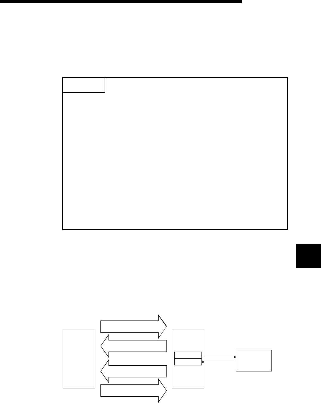
7 - 1
FIXED BUFFER COMMUNICATION (WITH THE NO PROCEDURE
CONTROL METHOD)
7
7 - 1
7
MELSEC-F
7 FIXED BUFFER COMMUNICATION (WITH THE NO PROCEDURE
CONTROL METHOD)
This chapter explains how the PLC and external device communicate using the fixed
buffers (with the no procedure control method) via the Ethernet module.
7.1 Control Method
The following explains how communication is performed using the fixed buffers and
the no procedure control method.
In communication using the fixed buffers, data transmission from the PLC and the
external device is executed using the no procedure control method.
(1) The data flow during communication is as follows.
POINT
The following points describe the difference from the "Procedure exist" using fixed
buffer communication:
1) It is possible to send and receive data which match the message format of the
external device.
At data sending, subheader, data length, etc. are not included in the
application data field of a message; only the data in the fixed buffer is sent.
Upon data reception, all the data in the message excluding the header is
stored in the fixed buffer.
2) A response to data receiving is not sent.
3) Communication is performed using binary code regardless of the
communication data code settings (see Section 4.6, "Operational Settings").
4) The maximum application data area is 2046 bytes per communication.
5) The applicable connection is dedicated to the no procedure fixed buffer
communication.
As with the procedure fixed buffer communication, and communication using
MC protocol cannot be performed at the same time as the no procedure fixed
buffer communication.
Fixed buffer
No.1
No.2 External
device
FROM instruction
(Reading the received data)
FROM instruction
(Transmission complete)
TO instruction
(Sending request)
TO instruction
(Reception complete)
FX
3U
main
unit
(For sending)
(For receiving)
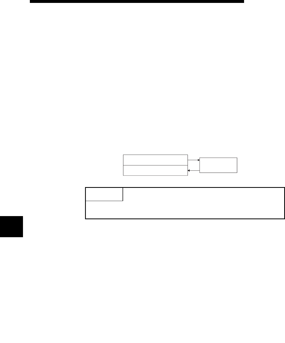
7 - 2
FIXED BUFFER COMMUNICATION (WITH THE NO PROCEDURE
CONTROL METHOD)
7
7 - 2
7
MELSEC-F
(2) Data can be communicated with the following external devices.
• Device on the Ethernet to which the Ethernet module is connected.
• Devices connected with the router relay function (see Section 5.3)
As shown in the diagram below, when using each fixed buffer (No. 1, No. 2), the
destination devices and usage conditions (for sending/receiving, procedure exist/
no procedure, etc.) should be set when the connection via the Ethernet module is
opened to fix the external device for each buffer.
(a) At TCP/IP communication
It is allowed to change external devices only when the open completion
signal of the applicable connection is off.
(b) At UDP/IP communication
External devices can be changed regardless of the status of the applicable
connection.
("Destination IP address" and "Destination Port No." in the communication
address setting area can be changed. However, "Local station Port No."
cannot be changed.)
When changing external devices, do not use the "Pairing open" and
"Existence confirmation" functions.
POINT
The connections for which no procedure is selected are dedicated to the fixed
buffer sending or receiving after the completion of open processing.
For sending to external
device 1
For receiving from external
device 1
External device 1
Fixed buffer No. 1
Fixed buffer No. 2

7 - 3
MELSEC-F
FIXED BUFFER COMMUNICATION (WITH THE NO PROCEDURE
CONTROL METHOD)
7
7 - 3
(3) At data sending/receiving, the Ethernet module processes the following.
1) When sending data
The fixed buffer communication transmission request (writing "0001H " in
BFM#1610, #1611) allows the fixed buffer data stored in the fixed buffer
data area (BFM#1664 to #3711) to be sent to the specified external
device (BFM#40 to #53). (*1)
2) When receiving data
The Ethernet module processes the received data if it is received from an
external device set in the communication setting area that corresponds to
fixed buffer No. n. (*1)
Also, when the Ethernet module stores the received data in the
corresponding fixed buffer in the receive processing, it updates the
destination IP address and destination port No. in the corresponding
fixed buffer connection information area (BFM#120 to #139)
If data is received from an external device not set in the connection
information area of the buffer memory, the Ethernet module ignores the
received data.
*1 In case of TCP/IP Unpassive open, data is communicated with an
external device stored in the connection information area of the buffer
memory.

7 - 4
MELSEC-F
FIXED BUFFER COMMUNICATION (WITH THE NO PROCEDURE
CONTROL METHOD)
7
7 - 4
7.2 Sending Control Method
This section explains the control method when data is sent from the Ethernet module
to an external device using fixed buffer No. 1 and the area corresponding to
connection No. 1 as an example.
• Program example for the unit No. 0
M8000
X002 M300 M307 M201
D101.2
D101.3
M202
M200
D1000[BMOVP K16 ]
[MOVP K32 ]
[MOV K4M300 ]
[MOVP H1 ]
[MOV
U0\
G1664
D101 ]
[= H5 ]
]
[END
)
(M202
)
(M201
)
(M200
* <<Reading the status of Ethernet module>>
* <<Sending 32 words from D1000 to the external device>>
U0\
G28
Send
instruction
Initial
completed
HUB
connection
completed
OPEN
instruction/status
Transmission
normally
completed
Transmission
abnormally completed
Initial
completed
Send instruction
(Self-holding)
U0\
G1665
U0\
G1610
U0\
G1602
Number of
send bytes
in the fixed
buffer No.1
Head of
send data
Fixed
buffer No.1
Send
request/
status
Send
request/
status
U0\
G1610
Value of
BFM#1610
Value of
BFM#1610
Value of
BFM#1610
Transmission
normally
completed
Transmission
abnormally
completed
Send
instruction
(Self-holding)
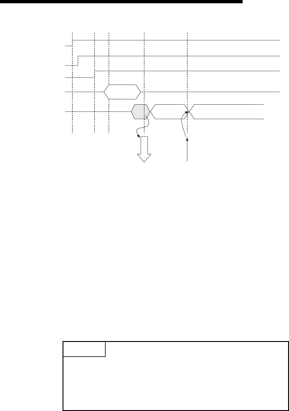
7 - 5
MELSEC-F
FIXED BUFFER COMMUNICATION (WITH THE NO PROCEDURE
CONTROL METHOD)
7
7 - 5
1) Confirm normal completion of the initial processing.
2) Confirm that the Ethernet module is connected to the hub.
(BFM#28 b7:ON)
3)
Confirm the normal completion of the open processing for connection No. 1.
4) Write the byte count for send data and the send data to the fixed buffer
data area (BFM#1664 to #2687) by TO instruction.
5) Write "0001H" in the fixed buffer transmission request (BFM#1610).
6) Only the size of the send data in the fixed buffer (No. 1) designated by
the send data length is sent to the designated external device.
The value of BFM#1610 becomes "0002H ".
7) The Ethernet module terminates the data transmission.
At normal completion
• Fixed buffer transmission results (BFM#1610) : 0004H
At abnormal completion
• Fixed buffer transmission results (BFM#1610) : 0008H
If the data transmission is abnormally completed, rewrite "0001H" in
BFM#1610 and execute the send processing again.
POINT
The following precaution should be observed when communicating using UDP/IP:
• When the Ethernet module's internal processing is normally completed, data
send processing ends even if the communication line between the PLC and an
external device is disconnected because of cable disconnection, etc. It is
recommended to send/receive data using a user defined communication
procedure.
ACK
(only TCP)
5)
2)
Data receiving
W
0001H
R
0002H
R
0004H (Success)/0008H (Failure)
Initial
processing
Open
Processing
Write
sent data Data sending
Response
receiving
1)
3)
4)
7)
Initial processing normal
completion
BFM#27=0001H
HUB connection is signal
BFM#28 b7
OPEN/CLOSE instruction status
BFM#1602=0005H
Write sent byte count
and sent data to BFM
Fixed buffer send instruction
and send completion
BFM#1610
TO instruction
6)

7 - 6
MELSEC-F
FIXED BUFFER COMMUNICATION (WITH THE NO PROCEDURE
CONTROL METHOD)
7
7 - 6
7.3 Receiving Control Method
This section explains the control method when the Ethernet module receives data
from an external device.
7.3.1 Receive processing with the main program
This section explains the receiving process to be performed with the main program,
using an example in which the fixed buffer No. 2 and the area corresponding to
connection No. 2.
• Program example for the unit No. 0
U0\
G2688
Received
data count
M8000
[ADD H1 D101
Received
data count
]
[MOV D100
Receiving
status
]
[MOV H2 ]
D101 ]
[INCP D102
Receive
abnormal
processing
]
[= D100
Receiving
status
H1 ]
[= D100
Receiving
status
H8 ]
]
[END
* <<Storing the data received from the external device to the fixed buffer No.2 in D1000 and after>>
U0\
G1611
Receiving
instruction/status
[MOV D101
Received
data count
]
D101
Received
data count
[BMOV D1000
Receive data
storage head
D103
Received
word count
]
U0\
G2689
Fixed buffer
No.2
[DIV H2 D103
Received
word count
]D101
Received
data count
U0\
G1611
Receiving
instruction/
status
* <Adjustment when an odd number of data bytes is received
* <
Word count from number of receive data
>
>
User applications are described at the area enclosed with .
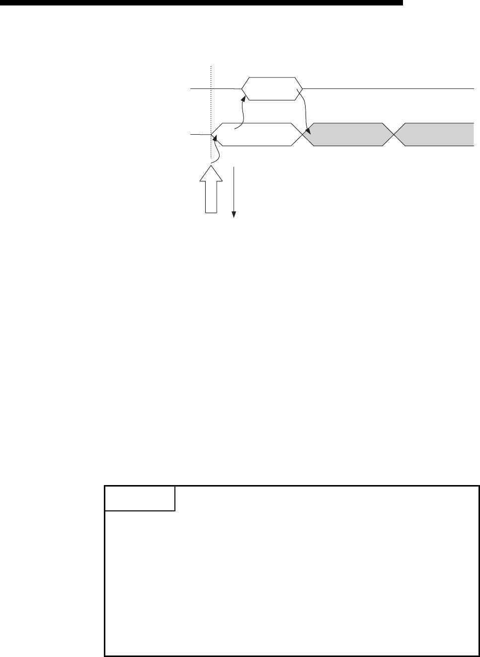
7 - 7
MELSEC-F
FIXED BUFFER COMMUNICATION (WITH THE NO PROCEDURE
CONTROL METHOD)
7
7 - 7
1) Upon receiving data from the designated external device (set in the open
processing), the Ethernet module processes the following.
• Stores the received data to the fixed buffer (No. 2) area.
(Area beginning from the head address of the target fixed buffer + 1)
• Stores the data length to the head address area of the target fixed
address (*1)
• Fixed buffer communication receive results (BFM#1611) : 0001H
• Fixed buffer receive status signal (BFM#20485 b1) : ON
*1 The received data length is expressed by a byte count.
When an odd number of data bytes is received, the last byte of
received data is stored at the lower byte of the last data storage area.
(The higher byte becomes a non-constant value.)
2) Execute the FROM instruction to read out the receive byte length and
receive data to the PLC.
3) Execute the TO instruction to write "0002H" in the fixed buffer
communication receive results (BFM#1611).
4) Result of the receiving processing is indicated.
POINT
(1) The destination setting (see Section 5.5) for a connection whose parameters
are set in FX Configurator-EN-L becomes valid when the open completion
signal (BFM#20480 corresponding bit) of the Ethernet module switches from
off to on.
(2) When data is received and the data in the buffer memory's fixed buffer is set,
BFM #1610, #1611 is set to "0001H".
(3) At abnormal data receiving, each buffer memory status becomes as follows.
• Fixed buffer receive completion signal (BFM#20485 b1) remains off.
• Fixed buffer communication receive results (BFM#1611): 0008H
• Data is not stored in the fixed buffer (No.2) area.
Read the word count
for the received data
and receive data
FROM
instruction
Notice the receive status
and receive completion
of the fixed buffer
BFM#1611
R
BFM#1611=0001H
Data receiving
ACK(only in TCP)
1)
2)
Data
receiving
W
0002H
3)
R
0004H(Success)
/0008H(Error issued)
4)

7 - 8
MELSEC-F
FIXED BUFFER COMMUNICATION (WITH THE NO PROCEDURE
CONTROL METHOD)
7
7 - 8
7.4 Data Format
When communicating between the Ethernet module and an external device, the data
format explained below is used.
The communication data consists of a "header" and "application data" as shown
below.
(1) Header
The header for TCP/IP or UDP/IP is used. In case of the Ethernet module, the
Ethernet module adds and deletes the header. Thus, the user does not need to
set it.
(Details of the size of the header section)
1) In case of TCP/IP
2) In case of UDP/IP
(2) Application Data
The data code in the application data is expressed in binary code.
Communication is performed using binary code, regardless of the set
communication data (see Section 4.6).
NOTE
The subheader and data length that are added for communications using the fixed
buffers in the procedure exist control method are not present for communications in
the no procedure control method. All data is treated as valid text.
Header Application data
Ethernet
14 bytes
IP
20 bytes
TCP
20 bytes
Ethernet
14 bytes
IP
20 bytes
UDP
8 bytes
Text (command)
Maximum of 2046 bytes

7 - 9
MELSEC-F
FIXED BUFFER COMMUNICATION (WITH THE NO PROCEDURE
CONTROL METHOD)
7
7 - 9
7.5 Programming
This section explains the programming method when the Ethernet module
communicates with an external device using fixed buffers and the no-procedure
control method.
7.5.1 Precautions when creating programs
(1) In order to communicate using the fixed buffers, the initial processing and the
connection open processing must be completed.
(2) The contents of the parameter settings have been loaded into the Ethernet
module when the Ethernet module open completion signal (BFM#20480
corresponding bit) switches from off to on.
(3) The data length (byte count) is established using the instruction for no procedure
communication.
If the send data length exceeds this range at data sending, a communication
error occurs and the data is not be sent.
(4) Reading or writing to the buffer memory using fixed buffer communication.
• When sending data
Write the send data to the buffer memory (BFM#1664 to #3711).
Write "0001H" in BFM#1610, #1611 before sending the data.
• When receiving data
Check that data has been received (BFM#1610, #1611: "0001H") and read out
the received data (BFM#1664 to #3711) to the PLC.
(5) The following should be observed when using a connection opened by UDP.
• External devices can be switched by modifying the setting values in the
communication address setting area of the communication parameter setting
area before sending/receiving data. Thus, data can be sent to multiple external
devices sequentially. When sending/receiving, make sure to switch between
external devices properly so that no communication problems occur.
(6) Message data length is not included in a packet when communicating with the no
procedure.
The Ethernet module stores the size of the received message (packet) in the
receive data length storage area and turns on the fixed buffer receiving status
signal (BFM#20485 corresponding bit).
It is recommended to employ a check system, such as including the data length
and data type code in the application data of a message, so that the byte count
and data type in the application data can be identified by the receiving side.

7 - 10
MELSEC-F
FIXED BUFFER COMMUNICATION (WITH THE NO PROCEDURE
CONTROL METHOD)
7
7 - 10
7.5.2 Fixed buffer communication program example (with the no procedure control method)
This section explains the programming method in order to communication data (through
the no procedure control method) with an external device using the fixed buffers.
(1) Execution environment for the program example
(a) Send program (FX3U-1st station)
1) Connection No. 1 is used for fixed buffer sending.
2) The communication parameters settings are assumed to have been set
as described in Subsection 5.6.1, "Active open processing/close
processing" except the "Fixed buffer communication" parameter.
(see the table below)
3) Fixed buffer No. 1 send data
: Stored in D1000 to D1031
4) Fixed buffer No. 1 send Send instruction complete device
: M201
5) Fixed buffer No. 1 send Send instruction abnormal complete device
: M202
6) Fixed buffer No. 1 send Send instruction complete status
: D101
[Operational settings]
[Open settings]
Setting name Settings in FX Configurator-EN-L Settings in the program
Communication data code setting Binary code BFM#24 b1:OFF
Initial timing Do not wait for OPEN
(Communications impossible at STOP time) BFM#24 b8:OFF
Local station IP address 10.97.85.222 (0A.61.55.DEH) BFM#106 to 108
Send frame setting Ethernet (V2.0) BFM#24 b5:OFF
TCP Existence confirmation setting Use the Ping BFM#24 b4:OFF
Setting name Settings in FX Configurator-EN-L (No.1) Settings in the program
protocol TCP BFM#32 b8:OFF
Open system Active BFM#32 b14,b15:00
Fixed buffer Sending BFM#32 b0:OFF
Fixed buffer communication No procedure BFM#32 b9:ON
Paring open No pairs BFM#32 b7:OFF
Existence confirmation No confirm BFM#32 b1:OFF
Local station Port No.[Decimal]
4096 BFM#40
Destination IP address 10.97.85.223 (0A.61.55.DFH) BFM#41,42
Destination Port No.[Decimal] 8192 BFM#43
FX3U-1st station FX3U-2nd station

7 - 11
MELSEC-F
FIXED BUFFER COMMUNICATION (WITH THE NO PROCEDURE
CONTROL METHOD)
7
7 - 11
(b) Receive program (FX3U -2nd station)
1) Connection No. 2 is used to process the fixed buffer receiving.
2) The unit number specified at the sequence program and
FX Configurator-EN-L is 0.
3) Make Operation settings in the following manner.
Communication data code : Binary code
Initial timing : Do not wait for OPEN (Communications
impossible at STOP time)
Local station IP address : 10.97.85.223 (0A.61.55.DFH)
4) Adjust open settings in the following manner.
Protocol : TCP
Open system : Fullpassive
Fixed buffer : Receive
Fixed buffer communication procedure
: No procedure exist (BFM#33 b9 : ON)
Pairing open : Disable (BFM#33 b7 : OFF)
Existence confirmation : No confirm (BFM#33 b1 : OFF)
Local station Port No. : 8192 (BFM#47)
5) Fixed buffer No.1 receive data.
: Stored in D1000 to D1031
6) Fixed buffer No.1 receive instruction complete status.
: D100
[Operational settings]
[Open setting]
Setting name Settings in FX Configurator-EN-L Settings in the program
Communication data code setting Binary code BFM#24 b1:OFF
Initial timing Always wait for OPEN
(Communications impossible at STOP time) BFM#24 b8:ON
Local station IP address 10.97.85.223 (0A.61.55.DFH) BFM#106 to 108
Send frame setting Ethernet (V2.0) BFM#24 b5:OFF
TCP Existence confirmation setting Use the Ping BFM#24 b4:OFF
Setting name Settings in FX Configurator-EN-L (No.2) Settings in the program
protocol TCP BFM#33 b8:OFF
Open system Fullpassive BFM#33 b14,b15:10
Fixed buffer Receive BFM#33 b0:ON
Fixed buffer communication No procedure BFM#33 b9:ON
Paring open No pairs BFM#33 b7:OFF
Existence confirmation No confirm BFM#33 b1:OFF
Local station Port No.[Decimal]
8192 BFM#47
Destination IP address 10.97.85.222 (0A.61.55.DEH) BFM#48,49
Destination Port No.[Decimal] 4096 BFM#50
POINT
Make sure to have sufficient device memory according to the maximum data
length sent in order to prevent device areas used for other purposes from being
overwritten by the received data.

7 - 12
MELSEC-F
FIXED BUFFER COMMUNICATION (WITH THE NO PROCEDURE
CONTROL METHOD)
7
7 - 12
(2) Outline of the program example
(a) Send program (FX3U-1st station)
1) After setting each parameter with FX Configurator-EN-L or a sequence
program and writing to the Ethernet module, power ON the module
again, or confirm that the initial processing is completed via buffer
memory operations.
2) Perform open processing (Active open) for connection No. 1. (*1)
3) Communicate data from the PLC using fixed buffer communication (no
procedure sending).
4) After data sending is complete, perform close processing for
connection No. 1. (*1)
*1 Use the program example described in Subsection 5.6.1, "Active open
processing/close processing" for the sequence program that executes
the open processing/close processing.
Make sure to change the "Fixed buffer communication" setting from
"Procedure exist" to "No procedure".
(b) Receive program (FX3U-2nd station)
1) After setting each parameter with FX Configurator-EN-L or a sequence
program and writing to the Ethernet module select re-initial and power
ON the module again, or confirm that the initial processing is completed
via buffer memory operations.
If the initial processing is normally completed, connection No. 2 waits for
an Active open request from the external device.
2) Transfer data from the external device using fixed buffer communication
(no procedure sending).
3) The data received by the corresponding fixed buffer data area in the
Ethernet module is read to the PLC.

7 - 13
MELSEC-F
FIXED BUFFER COMMUNICATION (WITH THE NO PROCEDURE
CONTROL METHOD)
7
7 - 13
(Send program)
• Program example for the unit No. 0
M8000
X002 M300 M307 M201
D101.2
D101.3
M202
M200
D1000[BMOVP K16 ]
[MOVP K32 ]
[MOV K4M300 ]
[MOVP H1 ]
[MOV
U0\
G1664
D101 ]
[= H5 ]
]
[END
)
(M202
)
(M201
)
(M200
* <<Reading the status of Ethernet module>>
* <<Sending 32 words from D1000 to the external device>>
U0\
G28
Send
instruction
Initial
completed
HUB
connection
completed
OPEN
instruction/status
Transmission
normally
completed
Transmission
abnormally completed
Initial
completed
Send instruction
(Self-holding)
U0\
G1665
U0\
G1610
U0\
G1602
Number of
send bytes
in the fixed
buffer No.1
Head of
send data
Fixed
buffer No.1
Send
request/
status
Send
request/
status
U0\
G1610
Value of
BFM#1610
Value of
BFM#1610
Value of
BFM#1610
Transmission
normally
completed
Transmission
abnormally
completed
Send
instruction
(Self-holding)
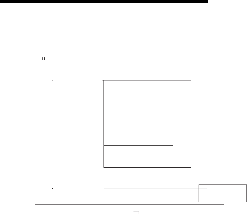
7 - 14
MELSEC-F
FIXED BUFFER COMMUNICATION (WITH THE NO PROCEDURE
CONTROL METHOD)
7
7 - 14
(Receive program)
•
Program example for the unit No. 0
U0\
G2688
Received
data count
M8000
[ADD H1 D101
Received
data count
]
[MOV D100
Receiving
status
]
[MOV H2 ]
[MOV D101 ]
[INCP D102
Receive
abnormal
processing
]
[= D100
Receiving
status
H1 ]
[= D100
Receiving
status
H8 ]
]
[END
* <<Storing the data received from the external device to the fixed buffer No.2 in D1000 and after>>
U0\
G1611
Receiving
instruction/status
[MOV D101
Received
data count
]
D101
Received
data count
[BMOV D1000
Receive data
storage head
D103
Received
word count
]
U0\
G2689
Fixed buffer
No.2
[DIV H2 D103
Received
word count
]D101
Received
data count
U0\
G1611
Receiving
instruction/
status
* <Adjustment when an odd number of data bytes is received
* <
Word count from number of receive data
>
>
User applications are described at the area enclosed with .
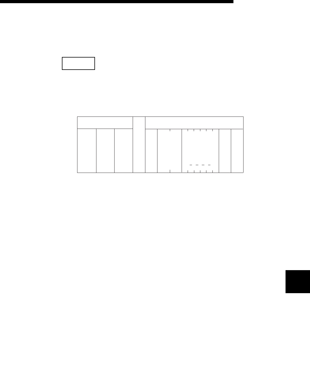
8 - 1
COMMUNICATION USING MC PROTOCOL8
8 - 1
8
MELSEC-F
8 COMMUNICATION USING MC PROTOCOL
This chapter gives an overview of the MC protocol.
NOTE
The frame type of MC protocol (data communication messages) used by the
external device to access the PLC via this product is equivalent to A compatible 1E
frame.
8.1 Data Communication Function
The MC protocol is the abbreviated name of the MELSEC protocol that is a
communication system for the PLCs. Using this protocol, the external devices can
read or write device data from/to the PLC via the Ethernet module.
Any external devices on which application programs can be installed and which can
send and receive data in accordance with the MELSEC PLC protocol can access the
PLC using MC Protocol.
8.1.1 Accessing the PLC using MC protocol
This section explains the main functions for accessing the PLC using MC protocol.
On the PLC side, the Ethernet module sends and receives data based on the
instructions (protocol) from the external devices, so the PLC side does not require
sequence programs for data communication.
(1) Data read/write
This function reads/writes data from/to the PLC device memory to which the
Ethernet module is connected.
By reading and writing data, the PLC operation monitoring, dzata analysis and
production management can be performed on the external device side.
LHH
Head device
Text (Command)
ACPU
monitoring
timer
PC
No.
Subheader
Header
Ethernet
(14 bytes)
IP
(20 bytes)
TCP
/
UDP
L
(Command message for the A compatible 1E frame)
Number of
device points
00H0AH00H00H00H00H20H40H0CH00H
FFH64H
(Example)
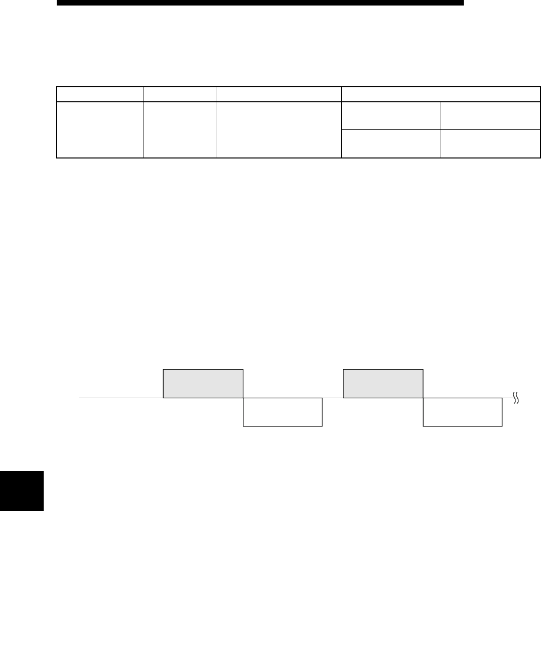
8 - 2
COMMUNICATION USING MC PROTOCOL8
8 - 2
8
MELSEC-F
(2) Remote control of the PLC
This function executes remote RUN/STOP operations.
Remote operations of the PLC can be performed from the external device side.
*1 Time required for communication in binary code is shorter because the amount of communication data is
approximately a half of what is required for communication in ASCII code data.
8.1.2 How to Read the Control Procedures of the MC Protocol
This section explains the control procedures when an external device accesses the
PLC using MC protocol.
(1) Transmission of command messages
Data communication through the MC protocol is performed using half-duplex
communication.
When accessing the PLC, send the next command message after receiving a
response message from the PLC side for the previous command message
transmission.
(2) When a normal completion response message to a command
message cannot be received
1) If an abnormal completion response message is received
Handle the case according to the error code in the response message.
2) If the response message cannot be received or nothing can be received
Send the command message again after the monitoring time of the response
monitor timer.
* Modify the value of the monitoring time as needed.
Send frame Communication data code Function
Communication
using MC protocol
A compatible 1E
frame. ASCII code or binary code *1
Device memory read/
write
Batch read/write in bit/
word units
Remote control of the
PLC
Remote RUN
Remote STOP
External device side
PLC side
(Command message) (Command message)
(Response message) (Response message)
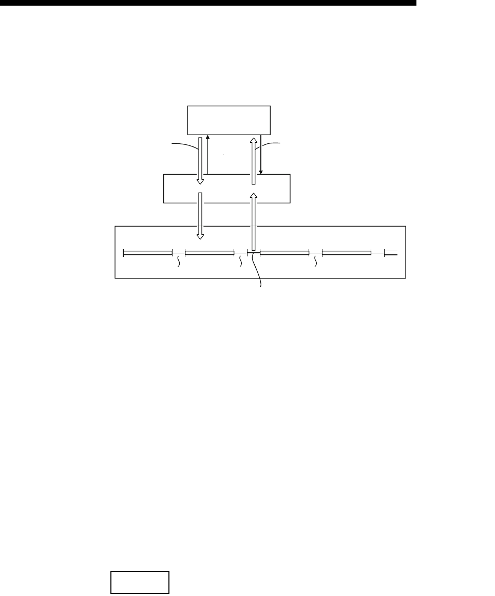
8 - 3
MELSEC-F
COMMUNICATION USING MC PROTOCOL8
8 - 3
8.1.3 Access Timing on the PLC Side
The following diagram illustrates the access timing on the PLC side when an external
device accesses the PLC via the Ethernet module.
1) A command message is transmitted from the external device to the PLC
side.
2) Upon receiving a command message from the external device, the
Ethernet module on the PLC side sends a data read/write request to the
PLC according to the content of the command.
3) The PLC reads/writes data according to the request from the external
device at the time of executing the sequence program's END instruction,
and passes the processing result to the Ethernet module.
4) Upon receiving the processing result from the PLC, the Ethernet module
sends a response message including the processing result to the
external device that originated the request.
*1 The ACK response shown in the diagram is sent/received between the
Ethernet module and the external device respectively when the access
via the Ethernet module is performed by TCP/IP communication.
It is different from the response to the processing requested by the
external device in the command message (the processing result).
When access via the Ethernet module is performed by UDP/IP, the ACK
response indicated by *1 is not sent.
NOTE
Regarding the scan time of the PLC
1) While the PLC is performed by required command, access command to the
Ethernet module and the PLC is processed during every END processing.
(The scan time becomes longer according to the amount of time it takes to
process the command.)
2) When multiple external devices issue access requests to the Ethernet module at
the same time, the processing requested from the external devices may have to
wait for multiple END processing executions depending on the timing of the
requests.
(*1)
(*1)
STEP 0
END STEP 0 END STEP 0 END STEP 0 END
External device
Read/write command
(command)
Ethernet module
ACK
ACK
Reply to the
command (response)
4)1)
3)2)
PLC
END processing END processing END processing
Processing of the command from the external device

8 - 4
MELSEC-F
COMMUNICATION USING MC PROTOCOL8
8 - 4
8.1.4 PLC setting for performing data communication
Data communication via MC protocol is enabled by adjusting the following settings
using FX Configurator-EN-L and writing the parameters to the Ethernet module.
1) Operational settings (see Section 4.6.)
2) Initial settings (see Section 5.2)
3) Open settings (see Subsection 5.5.2)
8.1.5 Precautions on Data Communication
This section explains some precautions that should be observed when performing
data communication between an external device and the Ethernet module.
(1) Precautions that should be observed when performing data
communication via the Ethernet module
(a) Perform read/write only when the buffer memory status of Ethernet module
is the following.
If the initial normal completion signal (BFM# 27 [0001H]) and the open
completion signal (BFM#20480 corresponding bit) of the used connection is
ON (open completion status), it is possible to communicate from an external
device using MC protocol without regard to the existence of a sequence
program. (Only connections No. 3 and 4 are available in communication
using MC protocol.)
(b) Use the UDP connection set to "Always wit for OPEN (BFM #24 b8: ON)" in
the initial timing setting in the operation settings. Or use the passive open
connection in the case of TCP.
(c) Communication using MC protocol is enabled only when the communication
parameter for an open connection is set to "MC protocol usable" in
"Connection usage" as described in the table in Subsection 5.5.2.
To set this using FX Configurator-EN-L, select the open settings from the
initial screen, and when a protocol is TCP, select [Unpassive(MC)] or
[Fullpassive(MC)] in [Open system].
(d) Replacing the Ethernet module
The Ethernet address (MAC address) differs depending on the device.
When the Ethernet module is replaced due to breakdown, reboot any
external devices also.
Similarly, reboot the Ethernet module even when an external device is
replaced (such as a personal computer).

8 - 5
MELSEC-F
COMMUNICATION USING MC PROTOCOL8
8 - 5
MEMO
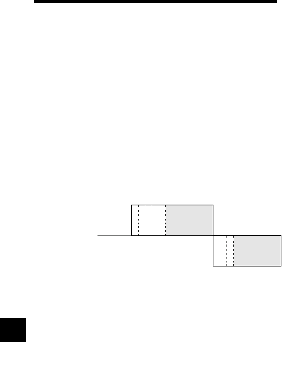
9 - 1
WHEN COMMUNICATING DATA USING THE MC PROTOCOL9
9 - 1
9
MELSEC-F
9 WHEN COMMUNICATING DATA USING THE MC PROTOCOL
This chapter explains the message format, how to designate data items in a message
and restrictions for data communication with an Ethernet module using MC protocol
with A compatible 1E frames.
9.1 Message Formats and Control Procedures
This section explains the message format and control procedure for each command
when data communication is performed using A compatible 1E frames.
The MC protocol for the Ethernet module is a subset of A compatible 1E frames.
Both TCP/IP and UDP can be used as lower layer protocol and support both ASCII
code and binary code.
9.1.1 How to read the command reference section
The following explains how to read the message explanation diagrams shown in each
of the command description Sections 9.3 through 9.5.
(1) When an external device reads data from the PLC
1) Area A indicates transmission from the external device to the PLC.
2) Area B indicates transmission from the PLC to the external device.
3) The program of the external device is generated so that the data is
transmitted sequentially from left to right. (For example: in case of
area A, data should be sequentially sent from Header to the right.)
(Command message)
External
device side
Header
Subheader
PC No.
Monitoring
timer
PLC side
Header
Subheader
Complete code
Area B
(Response message)
Area A
9 - 2
WHEN COMMUNICATING DATA USING THE MC PROTOCOL9
9 - 2
9
MELSEC-F
(2) When an external device writes data to the PLC
1) Area C indicates transmission from the external device to the PLC.
2) The program of the external device is generated so that the data is
transmitted sequentially from left to right. (For example: in case of
area C, data should be sequentially sent from Header to the right.)
POINT
When the PLC receives a command message from an external device, it
completes processing of the data in area A/C, then sends a response message
and waits for the next command message (neutral state).
External
device side
(Command message)
PLC side
Header
Subheader
PC No.
Monitoring
timer
Area C
Header
Subheader
Complete code
(Response message)
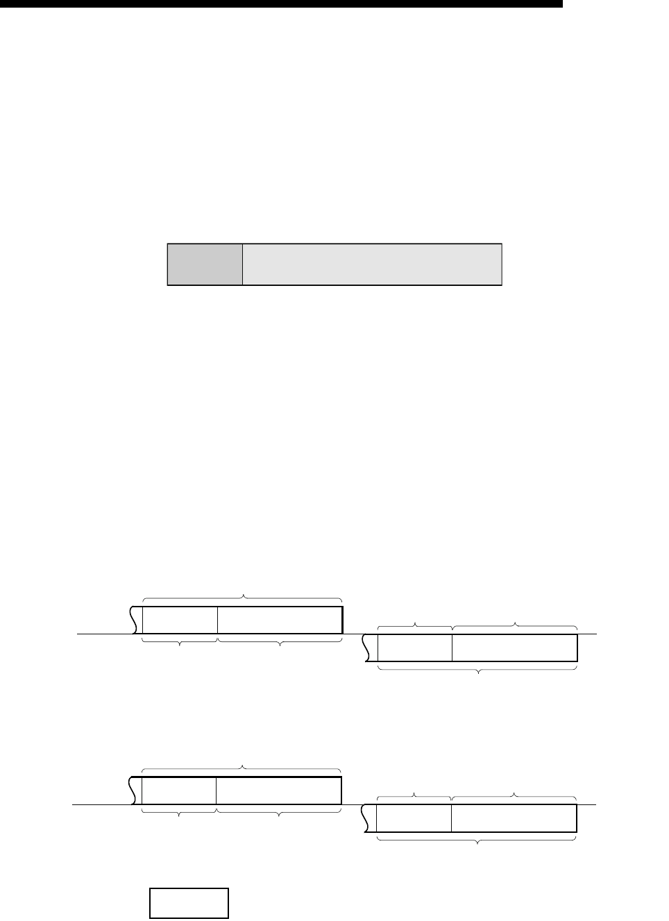
9 - 3
MELSEC-F
WHEN COMMUNICATING DATA USING THE MC PROTOCOL9
9 - 3
9.1.2 Message format and control procedure
This section explains the message format and control procedure.
(1) Message format
This section explains the message format for transmission between the Ethernet
module and an external device.
The communication data consists of "header" and "application data" as shown
below.
(a) Header
The header for TCP/IP or UDP/IP is used. The user does not need to specify
it; the Ethernet module attaches it.
(b) Application data
The application data is largely divided into "subheader" and "text" as shown
below.
The subheader represents command/response and the setting value is
predetermined.
The text contains the request data (command) and response data
(response) for each function and this data is determined by the prescribed
format (for a more detailed description, see sections 9.3 and later).
(c) Format in the application data field
• Communication in ASCII code
• Communication in binary code
NOTE
When communicating in the MC protocol, the user does not need to specify a
response for a command from an external device; the Ethernet module generates it
and then responds.
Header Application data
Application data
External
device
side
PLC side
Subheader Text (command)
2 bytes Differs depending
on function
2 bytes
Differs depending on
function and
normal/abnormal
completion
Subheader Text (response)
Application data
Application data
External
device
side Subheader Text (command)
1 byte Differs depending
on function
PLC side
1 byte
Differs depending on
function and
normal/abnormal
completion
Subheader Text (response)
Application data
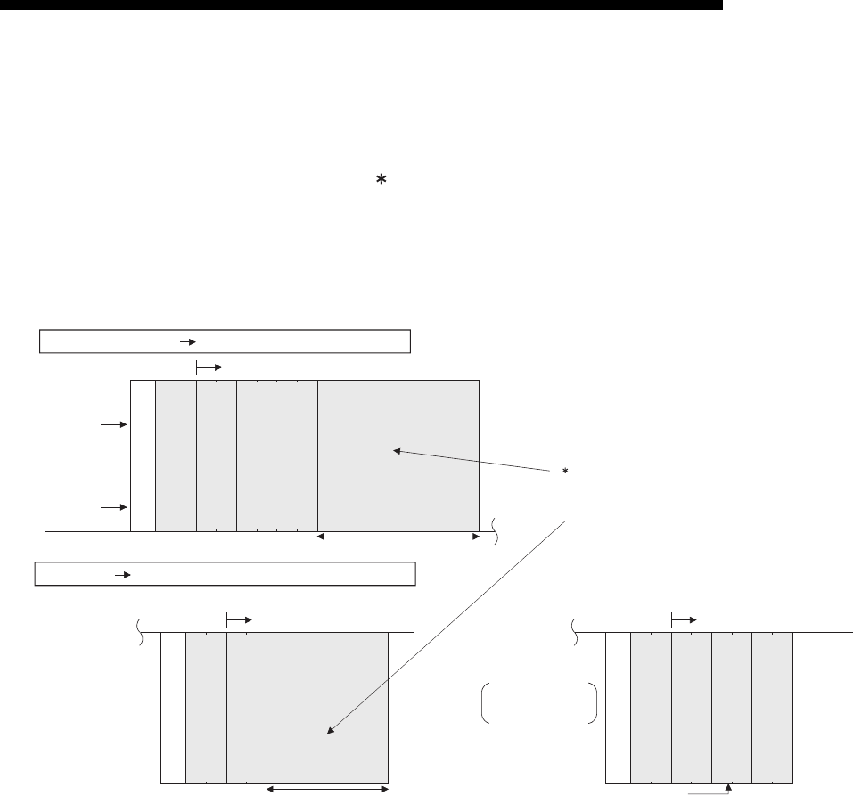
9 - 4
MELSEC-F
WHEN COMMUNICATING DATA USING THE MC PROTOCOL9
9 - 4
(2) Control procedure
The following diagrams illustrate the control procedure for communicating with
the MC protocol and the order of data items in the application data field.
The header section shown in the message explanation diagram of this section
corresponds to the portion of the message explanation diagrams indicated in
Subsection 9.3.2 and later.
See Subsection 9.1.3 regarding the content of data items in the message format
and data specification method.
(a) Communication in ASCII code
1) When reading data from the local station PLC at the external device side
External device side PLC side (Command message)
(Data name)
(Example)
Header
00FF
-
A
Subheader
PC No.
Monitoring
timer
Character area A
The contents and arrangement of the data items in
the text differs according to the function to use.
See the sections explaining functions found in
Subsection 9.3.2 and after for details
PLC side
Text (Command)
External device side (Response message)
(Normal completion)
Text (Response)
Header
Subheader
Complete code
Character area B
(Abnormal completion)
Text (Response)
Header
Subheader
Complete code
Abnormal code
When complete code
5BH is returned
30H
38H
80
HL
00
Exists only when the complete code is "5B."
38H
80
HL
5B
HL
1200
30H
HLHL
000
30H30H30H
46H46H41H
30H30H30H30H30H30H35H42H31H32H
-
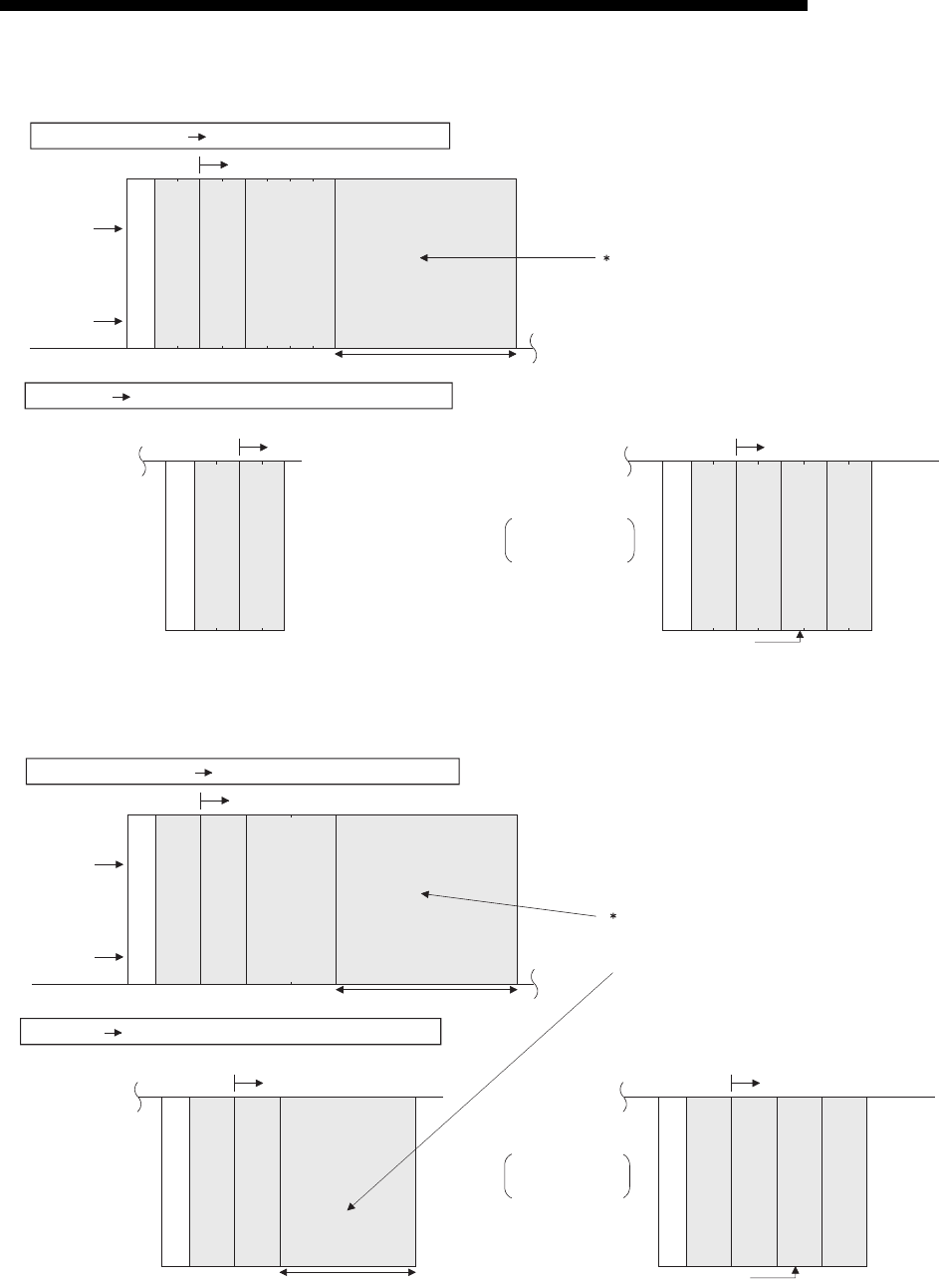
9 - 5
MELSEC-F
WHEN COMMUNICATING DATA USING THE MC PROTOCOL9
9 - 5
2) When writing data to the local station PLC from the external device side
(b) Communication in binary code
1) When reading data from the local station PLC at the external device side
External device side PLC side (Command message)
Text (Command)
(Data name)
Header
Subheader
PC No.
Monitoring
timer
Character area C
PLC side External device side (Response message)
(Normal completion)
Header
Subheader
Complete code
Text (Response)
The contents and arrangement of the data items in
the text differs according to the function to use.
See the sections explaining functions found in
Subsection 9.3.2 and after for details
(Abnormal completion)
Text (Response)
Header
Subheader
Complete code
Abnormal code
When complete code
5BH is returned
Exists only when the complete code is "5B."
(Example)
HH
LL
--
FFA
000
0
2
30H30H30H30H
32H46H46H41H
HL
8200
30H30H32H38H32H
32H
38H30H
30H31H
35H42H
HHL L
85
21
200
B
External device side PLC side (Command message)
(Data name)
(Example)
Header
Subheader
PC No.
Monitoring
timer
Text (Command)
Character area A
The contents and arrangement of the data items in
the text differs according to the function to use.
See the sections explaining functions found in
Subsection 9.3.2 and after for details
LH
00HFFH0AH00H
PLC side External device side (Response message)
(Normal completion) (Abnormal completion)
Text (Response)
Header
Subheader
Complete code
00H80H
Character area B
When complete code
5BH is returned
Exists only when the complete code is "5B."
Text (Response)
Header
Subheader
Complete code
80H00H
12H
5BH
Abnormal code
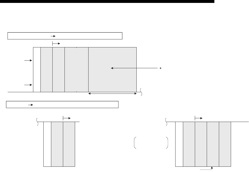
9 - 6
MELSEC-F
WHEN COMMUNICATING DATA USING THE MC PROTOCOL9
9 - 6
2) When writing data to the local station PLC from the external device side
External device side PLC side (Command message)
PLC side External device side (Response message)
(Normal completion) (Abnormal completion)
Text (Command)
(Data name)
(Example)
Header
Subheader
PC No.
Monitoring
timer
LH
02HFFH0AH00H
The contents and arrangement of the data items in
the text differs according to the function to use.
See the sections explaining functions found in
Subsection 9.3.2 and after for details
Text (Response)
Header
Subheader
Complete code
When complete code
5BH is returned
Text (Response)
Header
Subheader
Complete code
Abnormal code
Character area C
00H82H
Exists only when the complete code is "5B."
00H
82H5BH12H
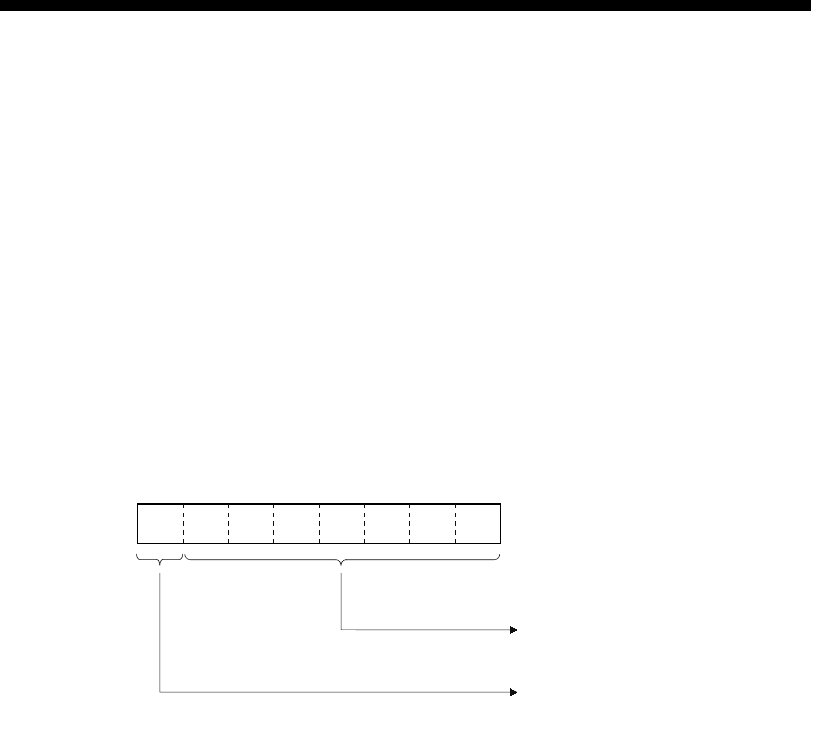
9 - 7
MELSEC-F
WHEN COMMUNICATING DATA USING THE MC PROTOCOL9
9 - 7
9.1.3 Contents of data designation items
This section explains the data items of commands and responses when
communicating using MC protocol.
In the response that is returned by the Ethernet module to an external device, the
data is automatically specified by the Ethernet module; the user does not need to
specify it.
(1) Header
The header for TCP/IP or UDP/IP is used. The user does not need to specify it at
the PLC side; the Ethernet module attaches it.
(2) Subheader
The format of the subheader is configured as follows.
(3) PC number
The PC number is fixed at a value of "FFH".
(a) When communicating in binary code, the PC number is expressed in binary
value.
(b) When communicating in ASCII code, the PC number is expressed in
hexadecimal ASCII code.
(4) Monitoring timer
This is a timer for setting the period of time that the Ethernet module should wait
after outputting a read/write request to the PLC until the result is returned.
(a) Specify the value as shown below.
0000H (0): : Waits infinitely *1
0001 to FFFFH (1 to 65535) : Wait time (in units of 250 ms)
*1 It keeps waiting until a response is returned from the PLC.
(b) For normal data communications, using a value within the setting range of 1
to 40 (0.25 to 10s) is recommended.
(5) Character field (command)
This data contains the Ethernet module commands that indicate functions for
when an external device reads/writes data from/to the target PLC station.
The contents and order of data in the Character field (command) field differ
depending on the function used.
The order of data items for each function is explained in each function's reference
section in Subsection 9.3.2. and later.
B7 B6 B5 B4 B3 B2 B1 B0
Command/response type
(This differs for each function. For details,
see Section 9.2 and later.)
Command/response flag
For command: 0
For response: 1

9 - 8
MELSEC-F
WHEN COMMUNICATING DATA USING THE MC PROTOCOL9
9 - 8
(6) Character field (response)
This data contains data read/processing result when an external device reads/
writes data from/to the target PLC station.
The contents and order of data in the Character field (response) differ depending
on the function used.
The order or data items at normal completion for each function is explained in
each function's reference section in Subsection 9.3.2. and later.
(7) Complete code
The result of processing when an external device reads/writes data from/to the
target PLC station is indicated by the following values.
00H: Normal completion
Other than 00H: Abnormal completion (50 to 60H)
(a) When communicating in binary code, the complete code is expressed in
binary values.
(b) When communicating in ASCII code, the complete code is expressed in
hexadecimal ASCII code.
(c) When the complete code indicates abnormal completion, check the content
and take an action according to the troubleshooting section of Chapter 11.
When the complete code is 5BH/"5B," the abnormal code data (10 to 18H)
and 00H/"00" are included immediately after.
(8) Abnormal code
This value indicates the nature of the error when the processing result of reading/
writing data from/to the target PLC station by an external device is faulty and the
complete code is 5BH/"5B." (Abnormal code: 10 to 18H)
(a) When communicating in binary code, the abnormal code is expressed in
binary values.
(b) When communicating in ASCII code, the abnormal code is expressed in
hexadecimal ASCII code.
(c) Check the content and take an action according to the troubleshooting
section of Chapter 11.
POINT
The data code (ASCII/binary) when sending/receiving commands and responses
between the Ethernet module and an external device is determined in the
operation settings in FX Configurator-EN-L.
The external device communicating with Ethernet module should send the values
specified in each data item in the commands and responses in the above setting
using the code shown below. Also, it should receive the corresponding values in
the code shown below.
In the explanation hereafter in this section, the values specified in each item in a
command and response are shown in binary values.
(1) Communication in binary code
Unless specifically stated, the value shown in each explanation is sent/
received in the designated order (L to H) since it is in binary.
(2) Communication in ASCII code
Unless specifically stated, the value shown in each explanation is converted
to hexadecimal ASCII code and sent/received in the designated order (H to
L).
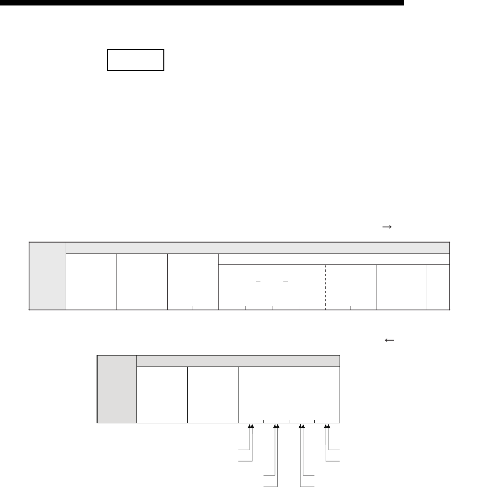
9 - 9
MELSEC-F
WHEN COMMUNICATING DATA USING THE MC PROTOCOL9
9 - 9
NOTE
The following example shows the designation of the subheader to the monitoring
timer when communicating using MC protocol under the following conditions.
(Designated value)
(1) Format when communicating in binary code
(a) The order when sending a command (external device Ethernet module)
(b) The order when receiving a response (external device Ethernet module)
• Target station : FX3U/FX3UC series to which FX3U-ENET-L is connected : FFH
• Function used : Device memory batch read (bit units) : 00H
• Monitoring timer value : 2500 ms : 000AH
Application data
00 FF 0AH00H64H00H00H00H20H4DH08H00HHH
Header
(M)
(H) (L) (H) (L) (H)
(L)
Subheader PC number Monitoring
timer Character field (command)
(Head device number) (Device name) Number of
device points
(Local station) (2500 ms) (8 points)
(100)
80H00H10H10H01H10H
M100(ON) M107(OFF)
M101(OFF) M106(ON)
M102(ON) M105(ON)
M103(OFF) M104(OFF)
Application data
Header
Subheader Complete
code
Character field (response)
on/off status of the
designated device
(Normal
completion)
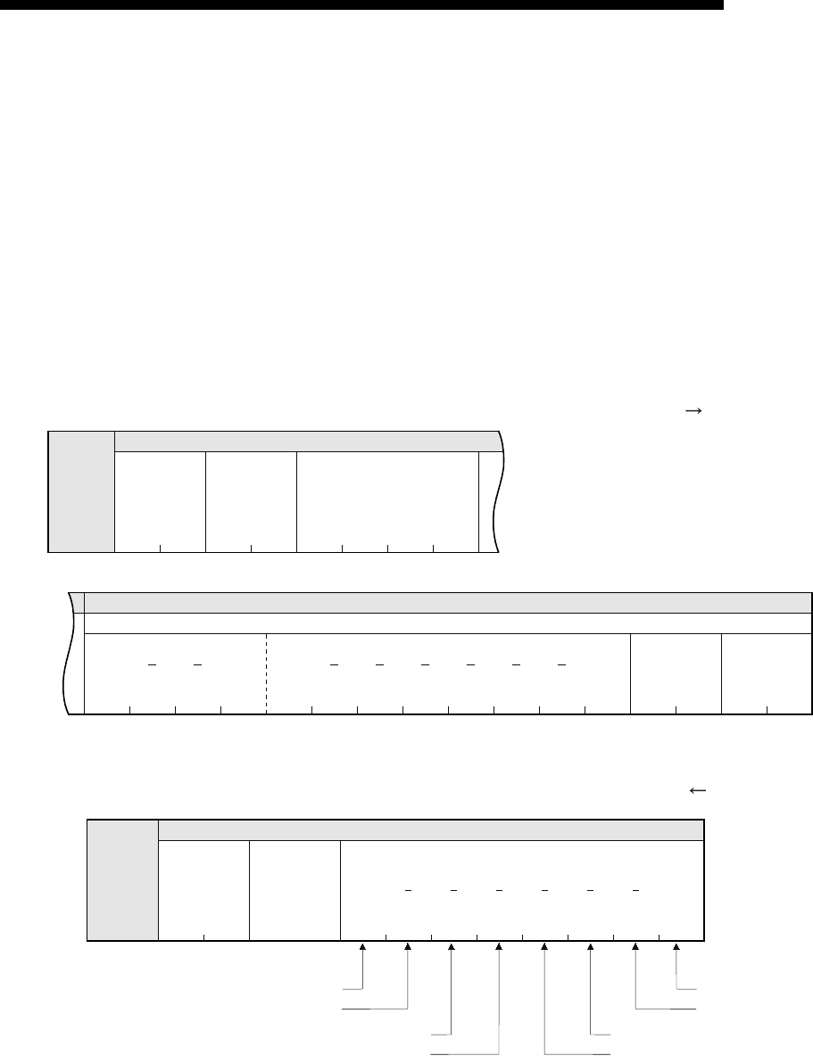
9 - 10
MELSEC-F
WHEN COMMUNICATING DATA USING THE MC PROTOCOL9
9 - 10
(2) Format when communicating in ASCII code
(a) The order when sending a command (external device Ethernet module)
(b) The order when receiving a response (external device Ethernet module)
30
H
30
H
46
H
46
H
30
H
30
H
30
H
41
H
"0" "0" "F" "F" "0" "0" "0" "A"
(L)(H)(L)(H)
30
H
30
H
38
H
30
H
34
H
36
H
30
H
30
H
30
H
30
H
30
H
30
H
30
H
32
H
44
H
34
H
"0""0""8""0""4""0""0""0""0""0""0""0""2""D""4" "6"
(H) (L) (H) (L)
(H) (L)
(100)
Header
Application data
Subheader PC number Monitoring timer
(Local station) (2500 ms)
Application data
Text (command)
(Device name) (Head device number) Number of
device points
(M) (8 points)
31H30H31H30H
M100(ON) M107(OFF)
M101(OFF)
M102(ON) M105(ON)
M103(OFF) M104(OFF)
30H
30H
30H
38H30H31H31H30H
8
M106(ON)
"0" "0"
(H)
"0"
(L)
"1"
(H)
"0" "1" "0" "0" "1" "1" "0"
(L)
Header
Subheader Complete
(Normal
completion)
Application data
Text (response)
ON/OFF status of the designated device
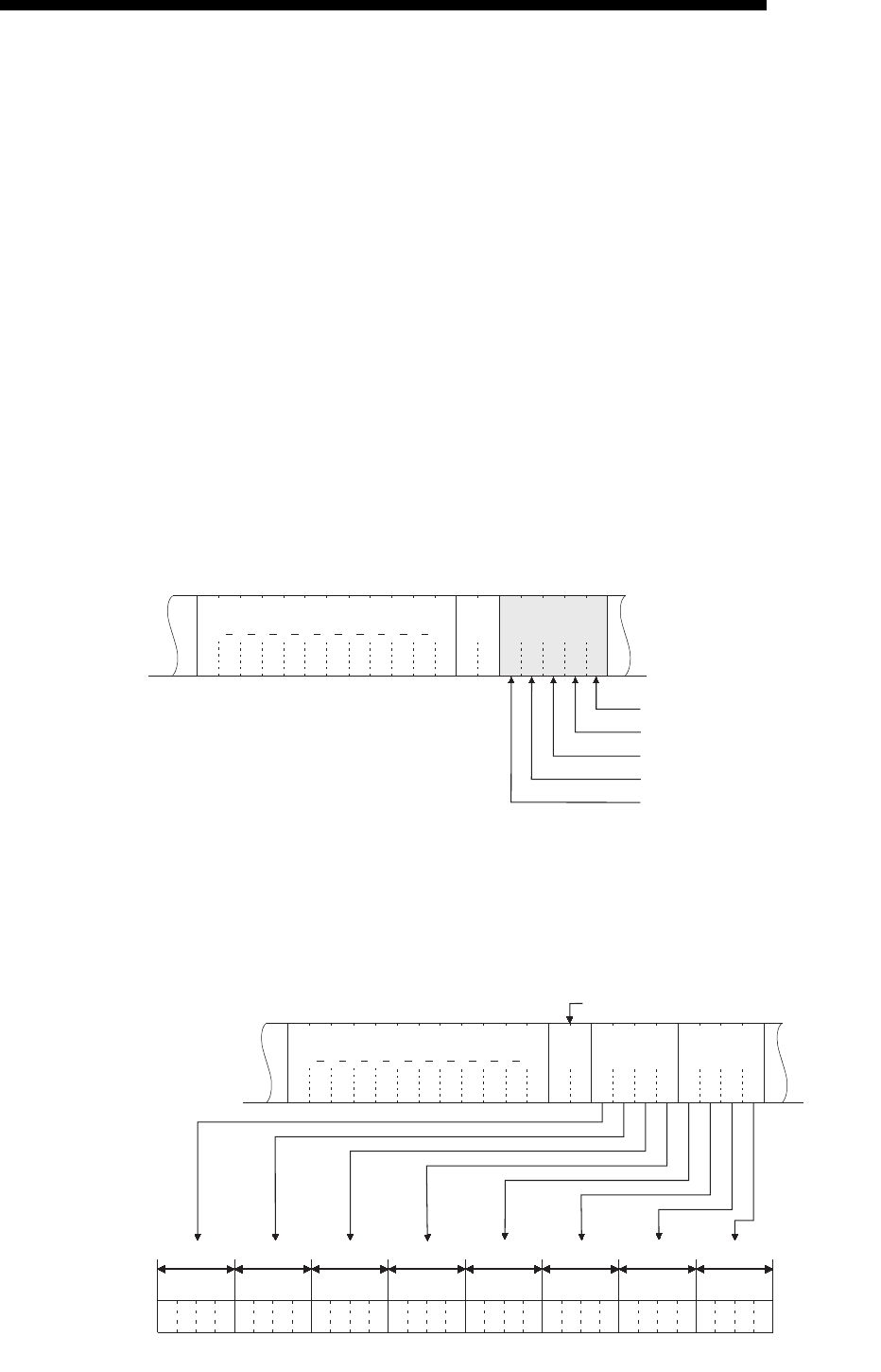
9 - 11
MELSEC-F
WHEN COMMUNICATING DATA USING THE MC PROTOCOL9
9 - 11
9.1.4 Character area transmission data
This section explains how to transmit the bit device data and word device data
handled in the character areas, as well as the order of transmission when
communicating data between an external device and the PLC by each command.
The transmission data shown in the examples is contained in character area B when
reading, and in character area C when writing, testing.
(1) Data communication using ASCII code
(a) When reading to or writing from a bit device memory
The bit device memory can be read and written in bit units (one device point)
or word units (16 device points).
How data is transmitted in each case is explained below.
1) Bit units (one point)
In case of bit units, the bit device memory is handled from the designated
head device for the number of designated device points sequentially from
the left. They are expressed as "1" (31H) if the device is on or "0" (30H) if
the device is off.
(Example)
Indicating the ON/OFF status of five points from M10
2) Word units (16 points)
When the bit device memory is handled as word units, each word is
expressed in hexadecimal values in 4-bit units sequentially from the
higher bit.
(Example)
Indicating the ON/OFF status of 32 points from M16
Indicates that M14 is ON
Indicates that M13 is OFF
Indicates that M12 is ON
Indicates that M11 is OFF
Indicates that M10 is ON
0
30H
0
30H
A
41H
0
30H
5
35H
1
31H
0
30H
1
31H
0
30H
1
31H
0
30H
0
30H
0
30H
0
30H
44H
D
34H
4
LLHH
2
32H
0
30H
0
30H
Head device Device
point Data
0
30H
0
30H
A
41H
B
42H
1
31H
2
32H
3
33H
4
34H
C
43H
D
44H
1
31H
0
30H
0
30H
2
32H
B15
10101011000100100011
B14 B13 B12 B11B10 B9 B8 B7 B6 B5 B4 B3 B2 B1 B0
010011001101
B15 B14 B13 B12 B11B10 B9 B8 B7 B6 B5 B4 B3 B2 B1 B0
AB12 3 4 CD
31 30 29 28 27 26 25 24 23 22 21 20 19 18 17 16 47 46 45 44 43 42 41 40 39 38 37 36 35 34 33 32
30H
0
30H
0
32H
2
44H
D
34H
4
LH
0
30H
0
30H
0
30H
Head device Device
point Data Data
The device point is "02" in 16-point units.
1: Indicates ON
0: Indicates OFF
MM MM MM MM MM MM MM MM MM MM MM MM MM MM MM MM
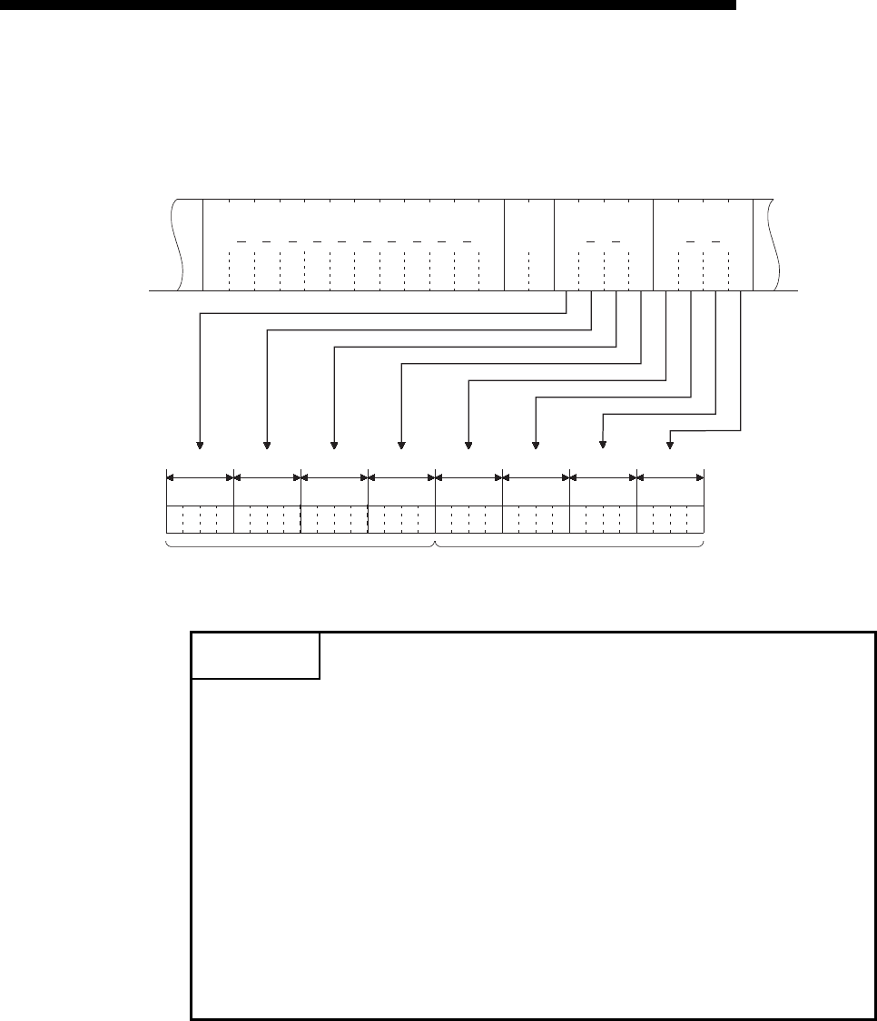
9 - 12
MELSEC-F
WHEN COMMUNICATING DATA USING THE MC PROTOCOL9
9 - 12
(b) When reading from or writing to a word device memory
Each word of the word device memory is expressed in hexadecimal values
in 4-bit units sequentially from the higher bit.
(Example)
Indicating the storage contents of data registers D350 and D351
POINT
(1) When designating alphabet letters in the character area, use upper case
code.
(2) When data other than an integer value (real number, character string, etc.)
was stored in a word device memory to be read, the stored value is read as an
integer value.
(Example 1)
When the real number (0.75) is stored in D0 and D1, it is read as the
following integer values:
D0 = 0000H, D1 = 3F40H
(Example 2)
When the character string ("12AB") is stored in D2 and D3, it is read as the
following integer values:
D2 = 3231H, D3 = 4241H
30
H
00
30
H
0
30
H
0
30
H
1
31
H
5
35
H
6
36
H
A
41
H
B
42
H
1
31
H
7
37
H
0
30
H
F
46
H
5
35
H
E
35
H
0
30
H
2
32
H
32
H
2
LHL
HL
HL
34
H
4
34
H
4
H
30
H
30
H
00
B15
01010110101010110001
B14B13B12 B11B10B9 B8 B7 B6 B5 B4 B3 B2 B1 B0
011100001111
B15B14 B13B12 B11B10B9 B8 B7 B6 B5 B4 B3 B2 B1 B0
56AB170F
Head device Device
point
Data Data
1: Indicates ON
0: Indicates OFF
The content of D350 indicates 56ABH
(22187 in decimal)
The content of D351 indicates 170FH
(5903 in decimal)
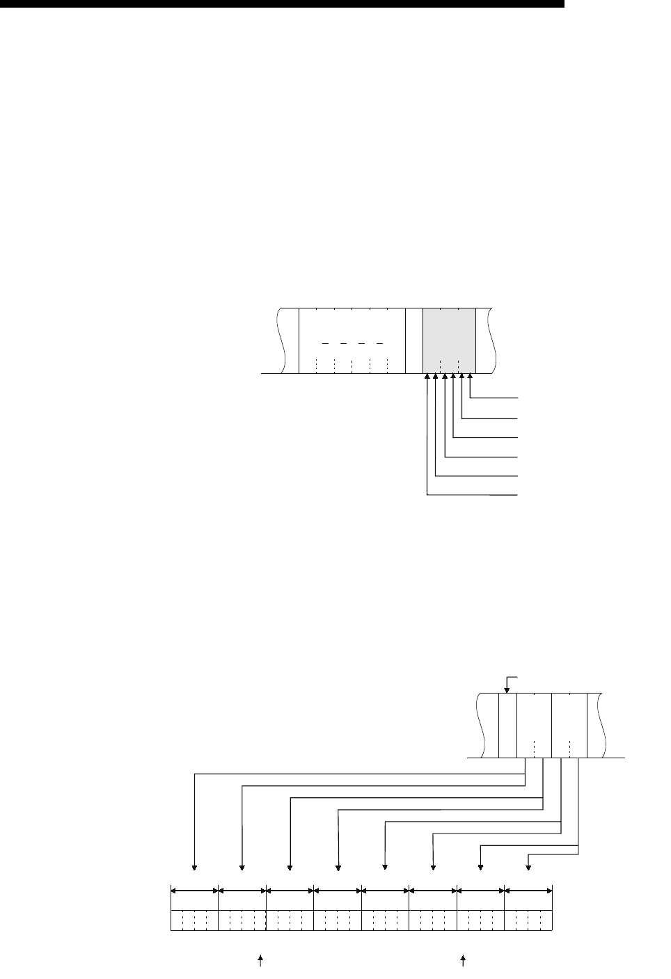
9 - 13
MELSEC-F
WHEN COMMUNICATING DATA USING THE MC PROTOCOL9
9 - 13
(2) Data communication using binary code
(a) When reading to or writing from the bit device memory
The bit device memory can be read and written in bit units (one device point)
or word units (16 device points).
How data is transmitted in each case is explained below.
1) Bit units (one point)
In case of bit units, four bits designate one point and the bit device
memory is handled from the designated head device for the number of
designated device points sequentially from the left. They are expressed
as "1" if the device is ON or "0" if the device is OFF.
(Example)
Indicating the ON/OFF status of five points from M10
2) Word units (16 points)
In case of word units, one bit designates one point and the bit device
memory is handled from the designated head device for the number of
designated device points sequentially from the left. They are expressed
in 16-point units in the order, low byte (L: bits 0 to 7) to high byte (H: bits
8 to 15).
(Example)
Indicating the ON/OFF status of 32 points from M16
0AH
L
00H00H
H
20H
00H40H05H10H10H10H
Head
device Data
Expressed by dummy when the point is
an odd number
Indicates that M14 is ON
Indicates that M13 is OFF
Indicates that M12 is ON
Indicates that M11 is OFF
Indicates that M10 is ON
Device point
02H12HABHCDH34H
B7
00010010101010111100
B6 B5 B4 B3 B2 B1 B0
B15 B14 B13 B12
B11B10 B9 B8
110100110100
B7 B6 B5 B4 B3 B2 B1 B0
B15 B14 B13 B12
B11 B10 B9 B8
12ABCD34
23 22 21 20 19 18 17 16 31 30 29 28 27 26 25 24 39 38 37 36 35 34 33 32 47 46 45 44 43 42 41 40
LH
Data
The device point is "02" in 16-point units.
1: Indicates ON
0: Indicates OFF
MM MM MM MM MM MM MM MM MM MM MM MM MM MM MM MM
34CDH
LH
Data
AB12H
Device point
Head End
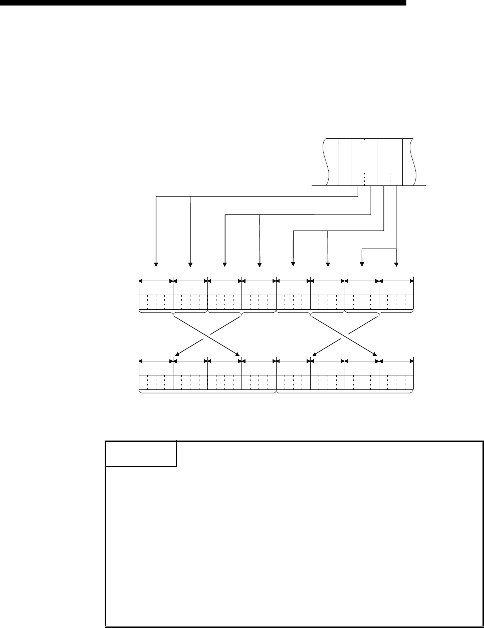
9 - 14
MELSEC-F
WHEN COMMUNICATING DATA USING THE MC PROTOCOL9
9 - 14
(b) Reading from or writing to a word device memory
Each word of a word device memory is designated by 16 bits and the
designated number of points from the designated head device are
sequentially expressed in one-point units in the order, low byte (L: bits 0 to 7)
to high byte (H: bits 8 to 15).
(Example)
Indicating the storage contents of data registers D350 and D351
POINT
(1) When data other than an integer value (real number, character string, etc.)
was stored in a word device memory to be read, the module reads the stored
value as an integer value.
(Example 1)
When the real number (0.75) is stored in D0 and D1, it is read as the
following integer values:
D0 = 0000H, D1 = 3F40H
(Example 2)
When the character string ("12AB") is stored in D2 and D3, it is read as the
following integer values:
D2 = 3231H, D3 = 4241H
02HABH56 H0FH17H
B7
10101011010101100000
B6 B5 B4 B3 B2 B1 B0
B15 B14 B13 B12
B11B10 B9 B8
111100110111
B7 B6 B5 B4 B3 B2 B1 B0
B15 B14 B13 B12
B11 B10 B9 B8
AB560 F17
LH
B15
01010110101010110001
B14 B13 B12
B11 B10 B9 B8 B7 B6 B5 B4 B3 B2 B1 B0
011100001111
B15 B14 B13 B12
B11 B10 B9 B8 B7 B6 B5 B4 B3 B2 B1 B0
56AB170F
Data
1: Indicates ON
0: Indicates OFF
170FH
LH
Data
56AB H
Device point
The content of D350 indicates 56ABH
(22187 in decimal)
The content of D351 indicates 170FH
(5903 in decimal)
(L)
(H)
(L)
(H)
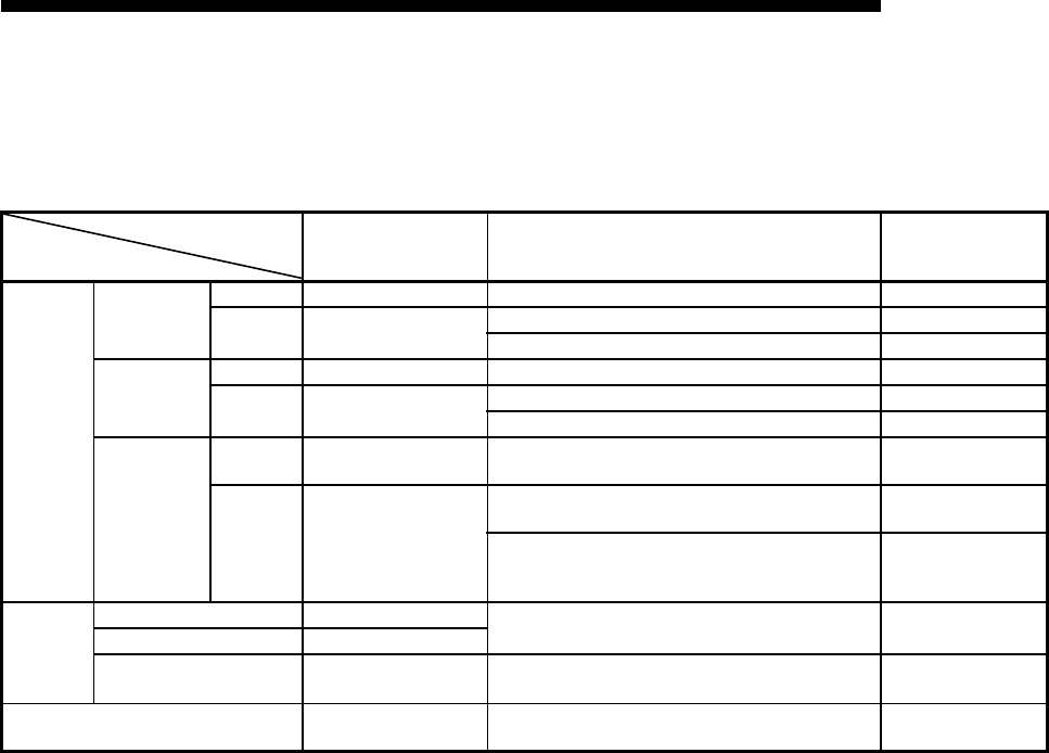
9 - 15
MELSEC-F
WHEN COMMUNICATING DATA USING THE MC PROTOCOL9
9 - 15
9.2 List of Commands and Functions for The MC protocol
The following table lists the commands and functions when an external device
accesses the PLC.
*1 When the double word data is read using the user program, etc., read out the 32bit data at once.
Function
-
Command/response type Processing
Number of points
processed per
communication
Device
memory
Batch read
Bit units 00HReads bit devices (X, Y, M, S, T, C) in 1-point units. 256 points
Word units 01H
Reads bit devices (X, Y, M, S, T, C ) in 16-point units. 32 words (512 points)
Reads word devices (D, R, T, C ) in 1-point units. (*1) 64 points
Batch write
Bit units 02HWrites to bit devices (X, Y, M, S, T, C ) in 1-point units. 160 points
Word units 03H
Writes to bit devices (X, Y, M, S, T, C ) in 16-point units. 10 words (160 points)
Writes to word devices (D, R, T, C ) in 1-point units. 64 points
Test
(Random write)
Bit units 04H
Sets/resets bit devices (X, Y, M, S, T, C) in 1-point units
by arbitrarily designating the devices and device number. 80 points
Word units 05H
Sets/resets bit devices (X, Y, M, S, T, C) in 16-point units
by arbitrarily designating the devices and device number. 10 words (160 points)
Sets/resets word devices (D, R, T, C) in 1-point units by
arbitrarily designating the devices and device numbers.
Not applicable for 32 bit devices from C200 to C255.
10 points
PLC control
Remote RUN 13HRequests the remote RUN/STOP to PLC.
Remote STOP 14H
PLC model name read 15HReads PLC model name code.
Loop test 16H
Returns the character received from the other node to
that node with the data as it is. 254 bytes

9 - 16
MELSEC-F
WHEN COMMUNICATING DATA USING THE MC PROTOCOL9
9 - 16
9.3 Device Memory Read/Write
This section explains the designations in the control procedure when reading from
and writing to the device memory by providing an example.
9.3.1 Commands and device range
(1) Commands used for reading from and writing to the device memory
Item Command/response type Processing Number of points processed per
communication
Batch read
Bit units 00HReads bit devices (X, Y, M, S, T, C) in 1-point units. 256 points
Word units 01H
Reads bit devices (X, Y, M, S, T, C) in 16-point units. 32 words (512 points)
Reads word devices (D, R, T, C) in 1-point units. 64 points
Batch write
Bit units 02H
Writes to bit devices (X, Y, M, S, T, C ) in 1-point
units. 160 points
Word units 03H
Writes to bit devices (X, Y, M. S, T, C) in 16-point
units. 10 words (160 points)
Writes to word devices (D, R, T, C ) in 1-point units. 64 points
Test
(random write)
Bit units 04H
Sets/resets bit devices (X, Y, M, S, T, C ) in 1-point
units by arbitrarily designating the devices and
device number.
80 points
Word units 05H
Sets/resets bit devices (X, Y, M, S, T, C ) in 16-point
units by arbitrarily designating the devices and
device numbers.
10 words (160 points)
Writes to word devices (D, R, T, C, etc.) in 1-point
units by arbitrarily designating the devices and
device numbers.
Not applicable for 32 bit devices from C200 to C255.
10 points
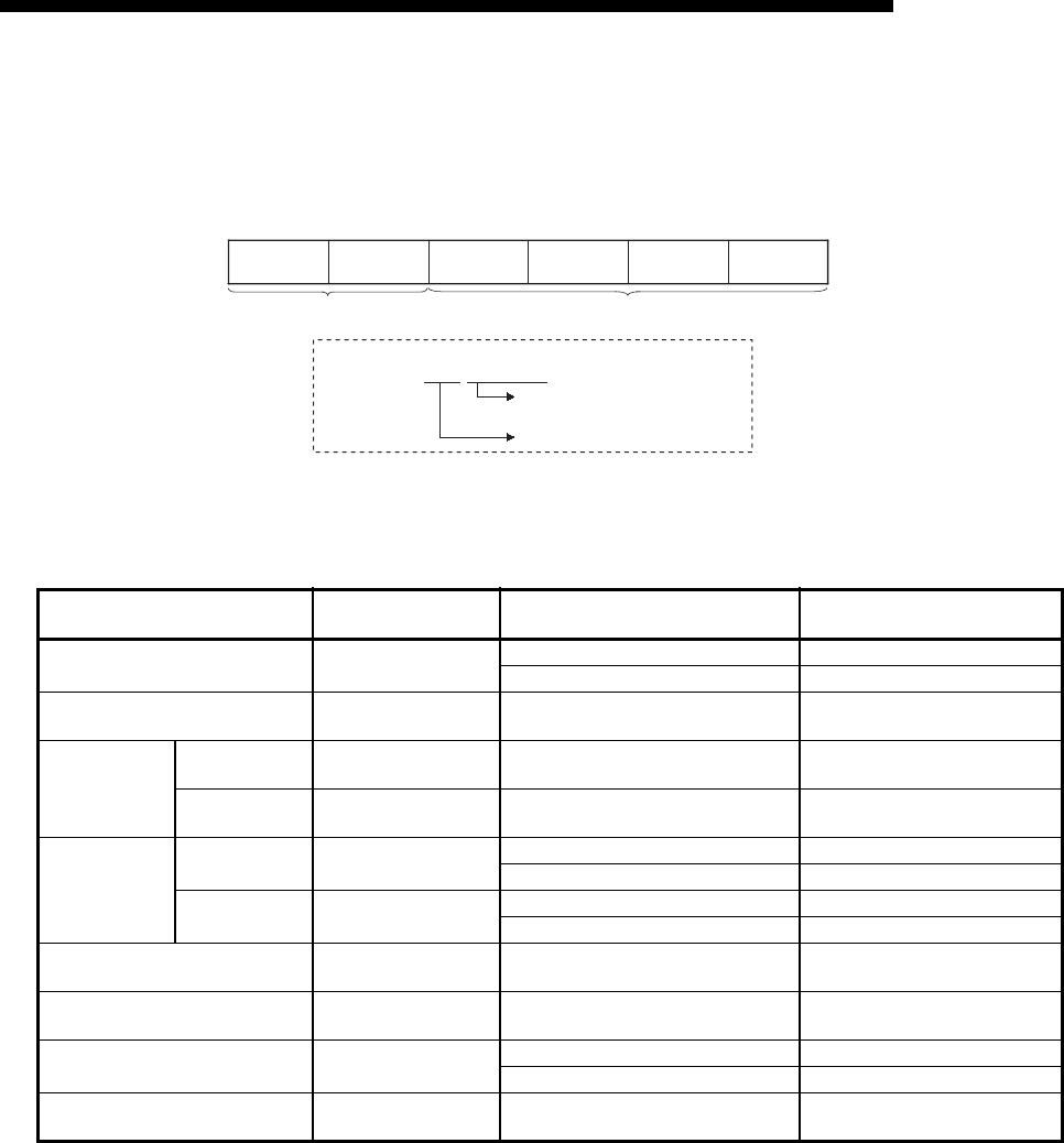
9 - 17
MELSEC-F
WHEN COMMUNICATING DATA USING THE MC PROTOCOL9
9 - 17
(2) Designation method and accessible range of devices.
(a) In device read/write, each device is set by a device code and number as
shown in the diagram below.
(b) The following table outlines the device codes and numbers.
Device list
Device Device code Device range Device number
Data register D
(44H, 20H)
D0 to D7999 0000 to 1F3FH
D8000 to D8511 1F40 to 213FH
Extension register R
(52H, 20H)R0 to R32767 0000 to 7FFFH
Timer
Current value TN
(54H, 4EH)T0 to T511 0000 to 01FFH
Contact TS
(54H, 53H)T0 to T511 0000 to 01FFH
Counter
Current value CN
(43H, 4EH)
C0 to C199 0000 to 00C7H
C200 to C255 00C8 to 00FFH
Contact CS
(43H, 53H)
C0 to C199 0000 to 00C7H
C200 to C255 00C8 to 00FFH
Input X
(58H, 20H)X0 to X377 0000 to 00FFH
Output Y
(59H, 20H)Y0 to Y377 0000 to 00FFH
Internal relay M
(4DH, 20H)
M0 to M7679 0000 to 1DFFH
M8000 to M8511 1F40 to 213FH
State S
(53H, 20H)S0 to S4095 0000 to 0FFFH
B15 B0 B31 B0
to to
Device code Device number (Set in hexadecimal)
[Example] In case of D100
D100 = 4420 00000064H
Device number (hexadecimal)
Device code

9 - 18
MELSEC-F
WHEN COMMUNICATING DATA USING THE MC PROTOCOL9
9 - 18
POINT
(1) Bit devices and word devices are classified according to the following.
Bit devices : X, Y, M, S, T (contact), C (contact)
Word devices : T (current value), C (current value), D, R
(2) When word units are designated, always make the head device number of a
bit device a multiple of 16 (0, 16... in decimal representation).
For X and Y is expressed in octadecimal, the device numbers that can be
designated are X00, X20, X40,,, or Y00, Y20, Y40,,,.
Also, special M relays M8000 or later can be specified (8000 + multiples of
16).
(3) The special relays (M8000 to M8511) and special registers (D8000 to D8511)
are divided into read only, write only and system use registers.
If writing takes place outside the writing enabled range, a PLC error may
occur.
See the Programming Manual for detailed descriptions of the special relays
and the special registers.
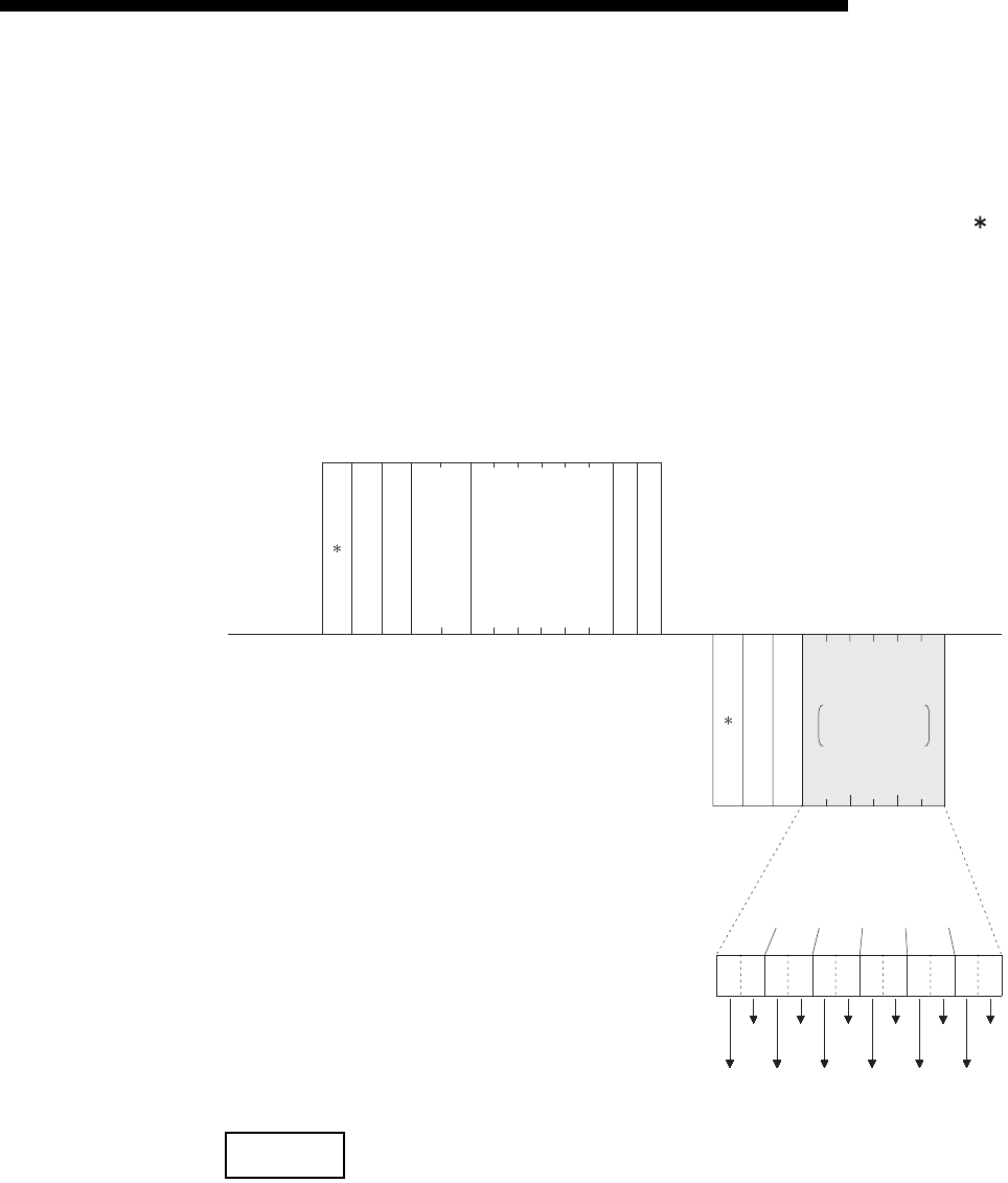
9 - 19
MELSEC-F
WHEN COMMUNICATING DATA USING THE MC PROTOCOL9
9 - 19
9.3.2 Batch read in bit units (command: 00)
The examples shown in this section explain the command/response format when
batch-reading the bit device memory.
For more details on the order and contents of data items of the areas marked by " "
shown in the control procedure diagram, see Subsection 9.1.2.
[Control procedure]
Reading the on/off status of M100 to M111 of the PLC on which the FX3U-ENET-L is
loaded.
(1) Communication in binary code
NOTE
Use the designation "00H" when the number of device points is 256 points.
0AH64H00H
Subheader
PC No.
Number of device points
Head device
(Data name)
External device
side
(Example)
(Data name)
PLC side
(Example)
00HFFH00H00H00H20H4DH0CH00H
80H
Subheader
Complete code
00H10H10H10H10H10H10H
Data for the number
of designed device
points
Characters for the
number of device
points
0
10
10
10
10
10
1
Status
of M100
Status
of M101
Status
of M102
Status
of M103
Status
of M104
Status
of M105
Status
of M106
Status
of M107
Status
of M108
Status
of M109
Status
of M110
Status
of M111
Monitoring
timer
HL L- - - - H
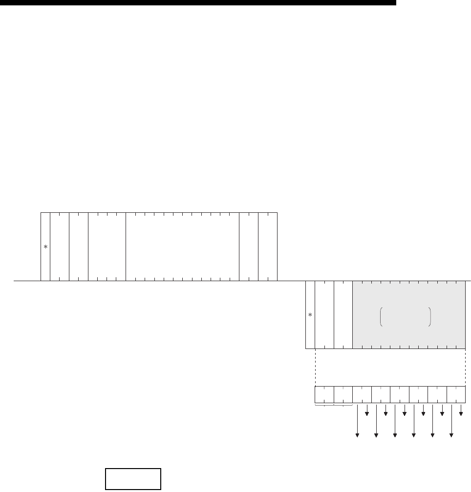
9 - 20
MELSEC-F
WHEN COMMUNICATING DATA USING THE MC PROTOCOL9
9 - 20
(2) Communication in ASCII code
NOTE
(1) Use the designation "00H" when the number of device points is 256 points.
(2) If the number of device points designated is an odd number, one byte of
dummy data (30H) will be added to the response data. For example, if three
points are read, data for four points is returned. The last byte is dummy data.
F
46H30H
0
30H
0
30H
0
41H
A
30H
0
30H
0
30H
0
F
46H
HLH LH
0
30H
HL
34H
4
36H
6
30H
0
43H
C2
32H
D
44H30H
0
30H
0
30H
0
30H
0
LHL
30H
0
30H
0
30H
0
30H
0
30H
0
34H
4
30H
0
38H
8
31H
1
HL
30H
0
30H
0
30H
0
LH H L
30H
0
30H
0
30H
0
30H
0
HLHL
30H
0
31H
1
31H
1
31H
1
HL
30H
0
30H
0
30H
0
38H
8
31H
1
30H
0
30H
0
30H
0
30H
0
30H
0
30H
0
30H
0
30H
0
31H
1
31H
1
31H
1
(80H)(00
H)
Status of
M100
(ON)
Status of
M101
(OFF)
Status of
M102
(OFF)
Status of
M103
(OFF)
Status of
M104
(ON)
Status of
M105
(OFF)
Status of
M106
(ON)
Status of
M107
(ON)
Status of
M108
(OFF)
Status of
M109
(OFF)
Status of
M110
(OFF)
Status of
M111
(OFF)
------
-- ----
Subheader
PC No.
Number of
device points
Head device
(Data name)
External device
side
(Example)
(Data name)
PLC side
(Example)
Monitoring
timer
Subheader
Complete code
Data for the number
of designed device
points
Characters for the
number of device
points
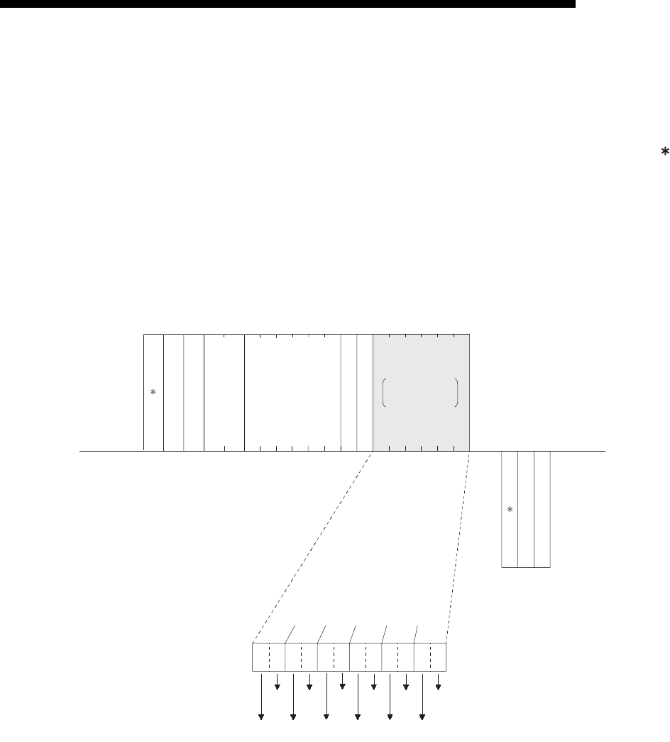
9 - 21
MELSEC-F
WHEN COMMUNICATING DATA USING THE MC PROTOCOL9
9 - 21
9.3.3 Batch write in bit units (command: 02)
The examples shown in this section explain the command/response format when
batch writing to the bit device memory.
For more details on the order and contents of data items of the areas marked by " "
shown in the control procedure diagram, see Subsection 9.1.2.
[Control procedure]
Writing the on/off status of M50 to M61 of the PLC on which the Ethernet module is
loaded.
(1) Communication in binary code
0AH32H 00H
(Data name)
External device
side
(Example)
(Data name)
PLC side
(Example)
02HFFH00H00H00H20H0CH00H
82H00H
HL L
4DH01H11 H01H00H00H01H
HLHLHLH
1
01
11
00
00
01
0
M50
(OFF)
M51
(ON)
M52
M53
(ON)
M54
(OFF)
M56
(OFF)
M55
(ON)
M58
(OFF)
M59
(OFF)
M60
(OFF)
M61
(ON)
(ON)
M57
(OFF)
----
Subheader
PC No.
Number of device points
Head device
Monitoring
timer
Data for the number
of designed device
points
Characters for the
number of device
points
Subheader
Complete code
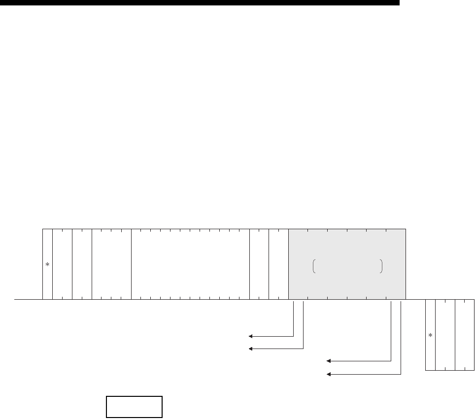
9 - 22
MELSEC-F
WHEN COMMUNICATING DATA USING THE MC PROTOCOL9
9 - 22
(2) Communication in ASCII code
NOTE
If the number of device points to be set is an odd number, add one byte of dummy
data (30H) at the end of data written. For example, when writing three points, add the
dummy data (30H) at the end.
(Data name)
External device
side
(Example)
(Data name)
PLC side
(Example)
38H
8
30H
H
This designates to turn M50 ON
32H
2
30H
L
This designates to turn M51 ON
This designates to turn M60 OFF
This designates to turn M61 ON
30H
0
HL
0
30H
C
43H
0
30H
1
31H
1
31H
1
31H
0
30H
0
30H
F
46H30H
0
30H
0
30H
0
30H
A
F
46H
HLH L
32H
22
32H
H
32H
2
44H
D
34H
4
33H
3
30H
0
30H
0
30H
0
30H
0
30H
0
30H
0
30H
0
L
00
---
---------
----
Subheader
Complete code
Subheader
PC No.
Number of
device points
Head device
Monitoring
timer
Data for the number
of designed device points
Characters for the
number of device points
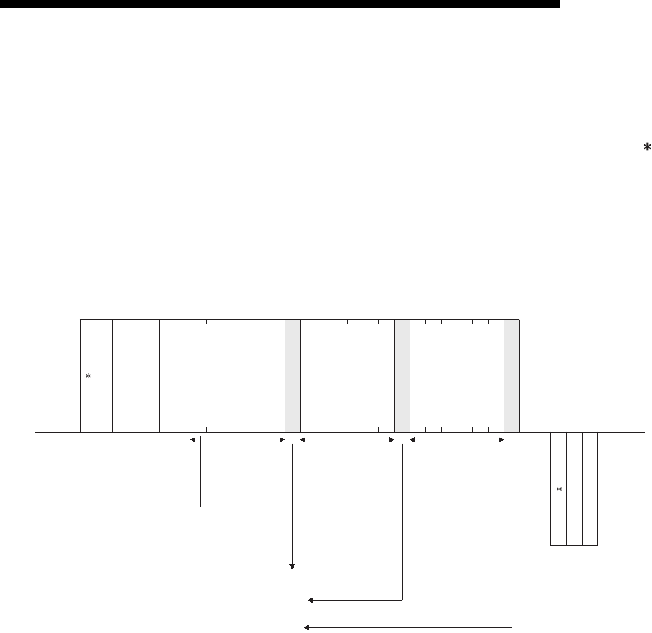
9 - 23
MELSEC-F
WHEN COMMUNICATING DATA USING THE MC PROTOCOL9
9 - 23
9.3.4 Test in bit units (random write) (command: 04)
The examples shown in this section explain the command/response format when
writing data by designating bit device memories arbitrarily.
For more details on the order and contents of data items of the areas marked by " "
shown in the control procedure diagram, see Subsection 9.1.2.
[Control procedure]
Specifying Y45 to ON, M60 to OFF, and S38 to ON at the PLC on which the Ethernet
module is loaded.
(1) Communication in binary code
H
FFH0AH00H01H3CH
(Data name)
External device
side
(Example)
(Data name)
PLC side
(Example)
4DH
04H
Designated deviceDesignated device
03H00H
00
H00H00H20H59H00H00H00H20H00H26H00H00H20H01H
53H
ON/OFF designation
L
00H
25H
LH LHH
Designated device
84H00H
Y45
(Octadecimal)
M60 S38
Designates to turn Y45 ON.
Designates to turn M60 OFF.
Designates to turn S38 ON.
L
- --- ---- -- --
Subheader
PC No.
Number of device points
Monitoring
timer
ON/OFF designation
ON/OFF designation
Subheader
Complete code
45 (Octadecimal) = 25 (Hexadecimal)
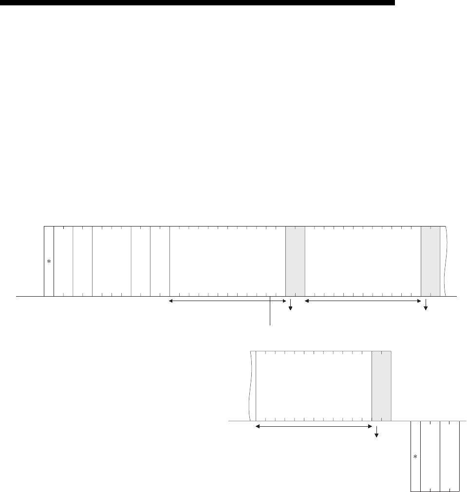
9 - 24
MELSEC-F
WHEN COMMUNICATING DATA USING THE MC PROTOCOL9
9 - 24
(2) Communication in ASCII code
(Data name)
External device
side
(Example)
Designated device
Y45
Designated device
M60
S38
ON Y45 OFF M60
ON S38
Designated device
9
39H
0
30H
4
34H
F
H
46H
L
F
46H
H
0
30H
0
30H
0
30H
L
A
41H
H
0
30H
L
3
33H
0
30H
0
30H
H
5
35H
2
32H
0
30H
0
30H
0
30H
0
30H
0
30H
0
30H
0
30H
2
32H
L
5
35H
H
0
30H
L
1
31H
H
4
34H
D
44H
2
32H
0
30H
0
30H
0
30H
0
30H
0
30H
0
30H
0
30H
3
33H
L
C
43H
H
0
30H
L
0
30H
5
H
35H
3
33H
2
32H
0
30H
0
30H
0
30H
0
30H
0
30H
0
30H
0
30H
2
32H
L
6
36H
H
0
30H
L
1
31H
----------
4
34H
0
30H
0
30H
38H
8
L
H
-- ---------- ----------
Subheader
PC No.
Number of
device points
Monitoring
timer
ON/OFF
designation
ON/OFF
designation
ON/OFF
designation
(Data name)
PLC side
(Example)
Subheader
Complete code
45 (Octadecimal) = 25 (Hexadecimal)
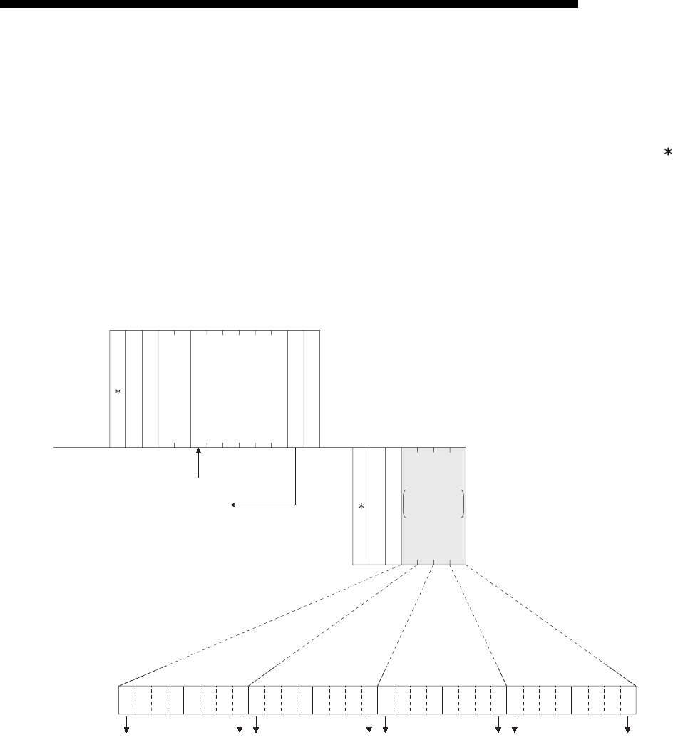
9 - 25
MELSEC-F
WHEN COMMUNICATING DATA USING THE MC PROTOCOL9
9 - 25
9.3.5 Batch read in word units (command: 01)
The examples shown in this section explain the command/response format when
batch reading the word device memory and the bit device memory (16 point units).
For more details on the order and contents of data items of the areas marked by " "
shown in the control procedure diagram, see Subsection 9.1.2.
[Control procedure]
Reading the on/off status of Y100 to Y137 (32 points) of the PLC on which the
Ethernet module is loaded.
(1) Communication in binary code
H
0AH00H00H
40H00H00H20H59H02H00H
LL H
0
11
10
10
00
00
10
01
11
10
11
01
01
01
0
Y130
Y137
Y120
Y127
Y110
Y117
Y100
00H9DH82H3EH55H
LHLH
1
01
0
01HFFH
81H
Y107
----
(Data name)
External device
side
(Example)
(Data name)
PLC side
(Example)
Subheader
PC No.
Number of device points
Head device
Monitoring
timer
Subheader
Complete code
Data for the
number of designed
device points
Characters for the
number of device
points
totototo
Y100 (Octadecimal) = 40 (Hexadecimal)
32/16 = 2 points
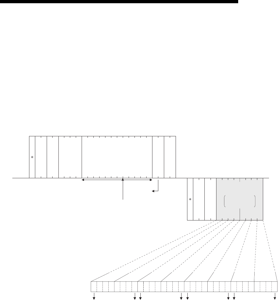
9 - 26
MELSEC-F
WHEN COMMUNICATING DATA USING THE MC PROTOCOL9
9 - 26
(2) Communication in ASCII code
30H
38H
30H
0
31H
41H35H
Y100
32/16 = 2 points
31H
1
46H
F
HL
F
46H
0
HL
00A5
30H30H39H
9
32H
2
30H
0
30H
0
30H
0
30H
0
30H
0
30H
0
30H
0
HL
34H
4
30H
0
H
30H
0
L
32H
2
30H
0
30H
0
8
H
10
30H
L
0
30H
HL
8
38H
2
32H
9
39H
D
44H
5
35H
3
33H
E
45H
HL
5
35H
"8" "2" "9" "D" "5" "5" "3" "E"
10000010100111010101010100111110
Y120Y127Y110Y117 Y130Y137Y100Y107
-- ----------
-- --
(Data name)
External device
side
(Example)
(Data name)
PLC side
(Example)
Subheader
PC No.
Number of
device points
Head device
Monitoring
timer
Subheader
Complete code
Data for the number
of designed device
points
Characters for the
number of device
points
to to to to
Y100 (Octadecimal) = 40 (Hexadecimal)
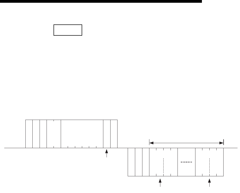
9 - 27
MELSEC-F
WHEN COMMUNICATING DATA USING THE MC PROTOCOL9
9 - 27
NOTE
C200 to C255 (Current Values) Batch Read
Since C200 to C255 are 32 bit devices, the device points should be specified as
twice as much as the points actually read.
Also, make sure that the device points are specified by an even number.
If they are specified by an odd number, the batch read cannot be performed. (Error
code 57H will be stored)
Example) When 32 devices are read at one access from C220 to C251 in the PLC
on which the Ethernet module is mounted.
(1) When communicating in binary code
*
01
H
FF
H
L
0A
H
H
00
H
*
81
H
00
H
43
H
4E
H
DC
H
00
H
00
H
00
H
40
H
00
H
4E
H
61
H
BC
H
00
H
40
H
01
H
B9
H
02
H
12345678=00BC614E
H
45678912=02B90140
H
CN220
Low
16bit
High
16bit
Low
16bit
High
16bit
L - H L - H L - H L - H
L - - - - H
(Data name)
External
device side
(Example)
(Data name)
PLC side
(Example)
PC No.
Subheader
4 bytes x 32=128 bytes
Monitoring
timer
Head device
Number of
device points
Head data
Subheader
Last data
Complete code
32 points x 2 = 64 word
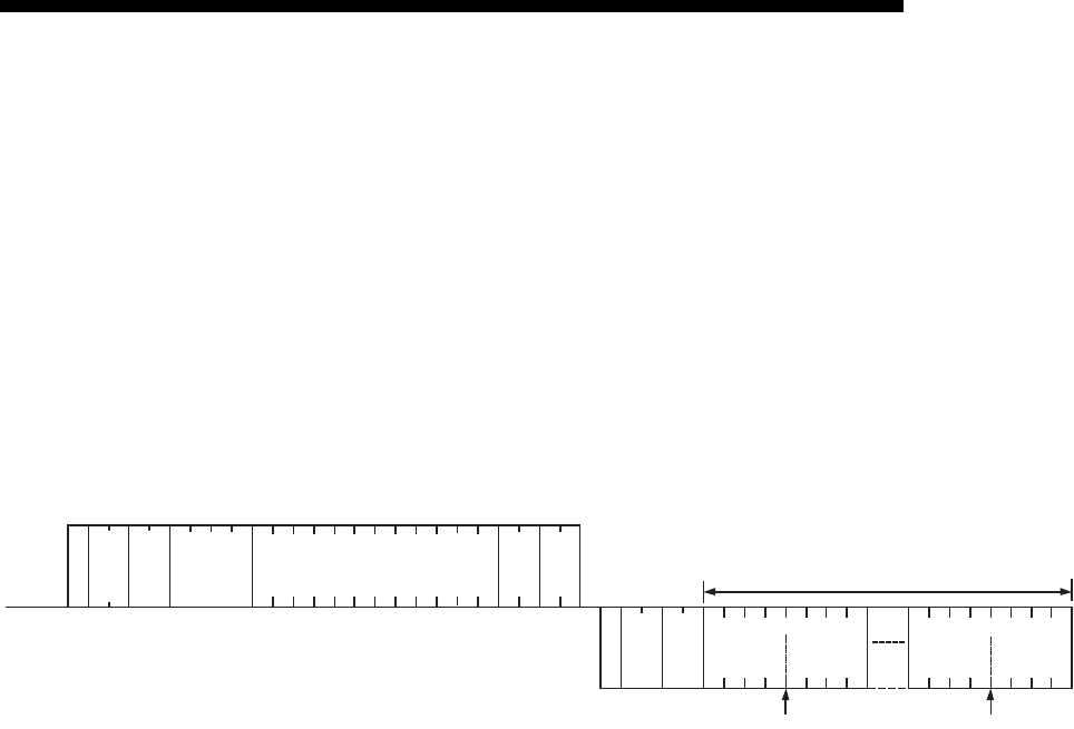
9 - 28
MELSEC-F
WHEN COMMUNICATING DATA USING THE MC PROTOCOL9
9 - 28
(2) When communicating in ASCII code
*
0
30
H
H
F
46
H
*
1
31
H
L
F
46
H
H
0
30
H
-
0
30
H
-
0
30
H
L
A
41
H
8
38
H
1
31
H
L
0
30
H
H
0
30
H
34
H
33
H
34
H
45
H
30
H
30
H
30
H
30
H
30
H
30
H
44
H
43
H
12345678=00BC614E
H
45678912=02B90140
H
36
H
31
H
34
H
45
H
30
H
30
H
42
H
43
H
30
H
31
H
34
H
30
H
30
H
32
H
42
H
39
H
4 0
H L
34
H
30
H
0 0
30
H
30
H
4
3
4 E 0 0 0
0
0 0
D
C
H - - - - - - - - - - L
6 1 4 E 0 0 B C
H - - L H - - L
0 1 4 0 0 2 B 9
H - - L H - - L
(Data name)
External
device side
(Example)
(Data name)
PLC side
(Example)
Last data
(4 bytes x 2) x 32=256bytes
Monitoring
timer
Sub-
header
PC No.
Head device
Number
of device
points
Sub-
header
Complete
code
Head data
Low 16bit High 16bit Low 16bit High 16bit
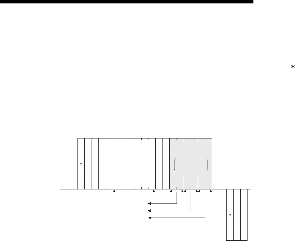
9 - 29
MELSEC-F
WHEN COMMUNICATING DATA USING THE MC PROTOCOL9
9 - 29
9.3.6 Batch write in word units (command: 03)
The examples shown in this section explain the command/response format when
batch writing to a word device memory and bit device memory (16 point units).
For more details on the order and contents of data items of the areas marked by " "
shown in the control procedure diagram, see Subsection 9.1.2.
[Control procedure]
Writing data to D100 to D102 of the PLC on which the Ethernet module is loaded.
(1) Communication in binary code
03HFFH0AH
L
00H
H
64H00H20H44H03H00H34H12H76H98H09H01H
LH
00H00H
HLHLHL
83H00H
Data to be written to D100
Data to be written to D101
Data to be written to D102
D100
----
(Data name)
External device
side
(Example)
(Data name)
PLC side
(Example)
Subheader
PC No.
Number of device points
Head device
Monitoring
timer
Data for the number
of designed device
points
Characters for the
number of device
points
Subheader
Complete code
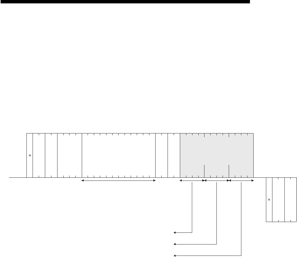
9 - 30
MELSEC-F
WHEN COMMUNICATING DATA USING THE MC PROTOCOL9
9 - 30
(2) Communication in ASCII code
F
30H
0
38H
D100
33H
3
46H46H30H
0
30H
0
30H
0
41H
A
34H
4
34H
4
32H
2
30H
0
30H
0
30H
0
30H
0
30H
0
30H
0
30H
0
36H
6
34H
4
30H
0
33H
3
30H
0
30H
0
31H
1
32H
2
33H
3
34H
4
39H
9
38H
8
37H
7
36H
6
30H
0
31H
1
30H
0
39H
9F
HLH LH LHL
8
33H
3
30H
0
30H
0
Data to be written to D100
Data to be written to D101
Data to be written to D102
-- ---------- H L-- H L-- H L--
HL
(Data name)
External device
side
(Example)
(Data name)
PLC side
(Example)
Subheader
PC No.
Number of
device points
Head device
Monitoring
timer
Data for the number of
designed device points
(Characters for the number of device points)
Subheader
Complete code
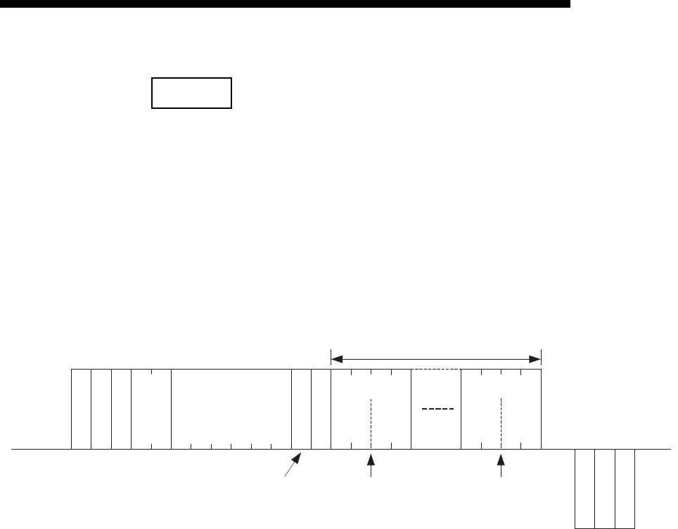
9 - 31
MELSEC-F
WHEN COMMUNICATING DATA USING THE MC PROTOCOL9
9 - 31
NOTE
C200 to C255 (Current Values) Batch Write
Since C200 toC255 are 32 bit devices, the device points should be specified twice
as much as the points actually read.
Also, make sure that the device points are specified by even number.
If they are specified by odd number, the batch read cannot be performed. (Error code
57H will be stored)
Example) When 32 points are written at one access from C220 to C251 in the PLC
on which the Ethernet module is mounted.
(1) When communicating in binary code
*
03
H
FF
H
L
0A
H
H
00
H
*
83
H
00
H
43
H
4E
H
DC
H
00
H
00
H
00
H
40
H
00
H
40
H
01
H
B9
H
02
H
12345678=00BC614E
H
45678912=02B90140
H
CN220
4E
H
61
H
BC
H
00
H
L - H L - H L - H L - H
L - - - - H
(2 bytes x 2) x 32 = 128 bytes
(Data name)
External
device side
(Example)
(Data name)
PLC side
(Example)
Complete code
Subheader
PC No.
Monitoring
timer
Head device
Number of
device points
Subheader
Low
16bit
High
16bit
Low
16bit
High
16bit
Head data Last data
32 points x 2 = 64word
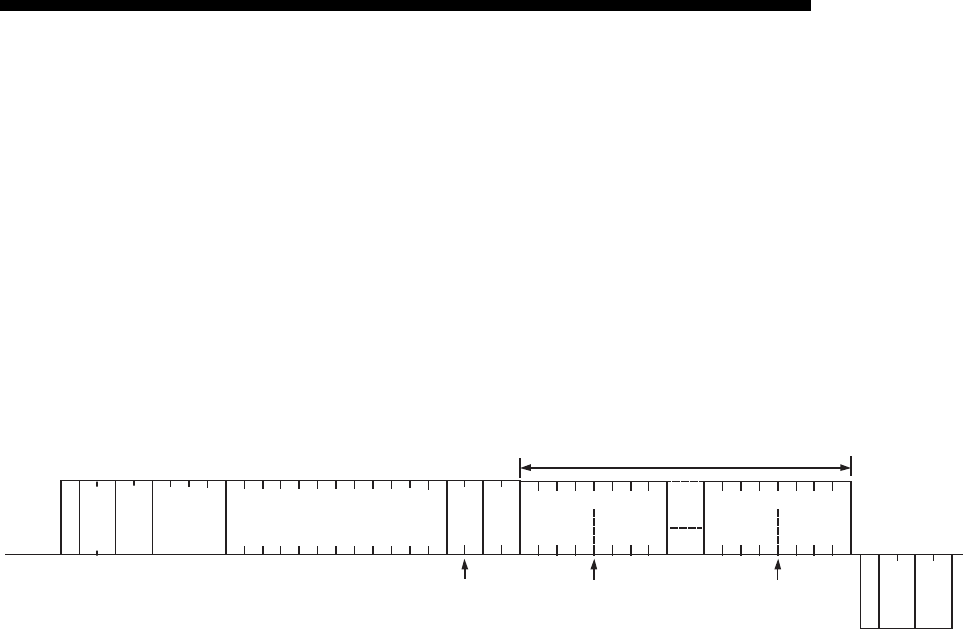
9 - 32
MELSEC-F
WHEN COMMUNICATING DATA USING THE MC PROTOCOL9
9 - 32
(2) When communicating in ASCII code
*
0
30
H
H
F
46
H
*
3
33
H
L
F
46
H
H
0
30
H
-
0
30
H
-
0
30
H
L
A
41
H
8
38
H
3
33
H
L
0
30
H
H
0
30
H
34
H
33
H
34
H
45
H
30
H
30
H
30
H
30
H
30
H
30
H
44
H
43
H
12345678=00BC614E
H
45678912=02B90140
H
36
H
31
H
34
H
45
H
30
H
30
H
42
H
43
H
30
H
31
H
34
H
30
H
30
H
32
H
42
H
39
H
H L
4 0
34
H
30
H
0 0
30
H
30
H
H - - - - - - - - - - L
4 3 4 E 0 0 0 0 0 0 D C 6 1 4 E 0 0 B C 0 1 4 0 0 2 B 9
H - - L H - - L H - - L H - - L
High16bitLow16bitHigh16bitLow16bit
32 points x 2 = 64word
(Data name)
External
device side
(Example)
(Data name)
PLC side
(Example)
Complete
code
Sub-
header
PC No.
Monitoring
timer Head device
Number
of device
points
(4 bytes
x 2)
x 32 = 256 bytes
Head data Last data
Sub-
header
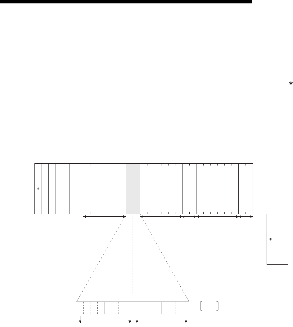
9 - 33
MELSEC-F
WHEN COMMUNICATING DATA USING THE MC PROTOCOL9
9 - 33
9.3.7 Test in word units (random write) (command: 05)
The examples shown in this section explain the command/response format when
writing data by designating word device memories and bit device memories (16 point
units) arbitrarily. These examples are not applicable for writing the current values of
C200 to C255 (32-bit devices).
For more details on the order and contents of data items of the areas marked by " "
shown in the control procedure diagram, see Subsection 9.1.2.
[Control procedure]
Specifying Y20 to Y37 to on/off, R26 to "1234H," and the current value of C18 to "50H"
at the PLC on which the Ethernet module is loaded.
(1) Communication in binary code
Current value of CN18 50H
1234H
Y30Y37Y20Y27
0010100101111011
Y20 R26
1....ON
0....OFF
05HFFH0AH03H00H80H00H00H00H20H59H29H7BH1AH00H00H00H20H52H34H12H12H00H00H00H4EH43H50H00H
00H
85H
00H
LL-HLH---HL-HL--- HL- HL--- H
(Data name)
External device
side
(Example)
(Data name)
PLC side
(Example)
Subheader
PC No.
Number of device points
Monitoring
timer
Designated device
Subheader
Complete code
to to
Designated device Designated device
Device data
(ON/OFF designation)
Device data
Device data
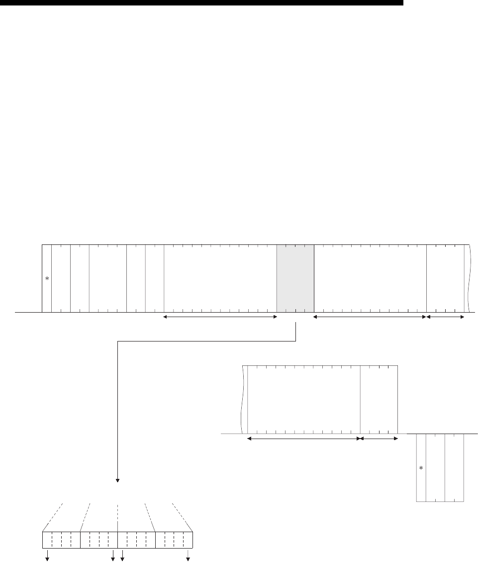
9 - 34
MELSEC-F
WHEN COMMUNICATING DATA USING THE MC PROTOCOL9
9 - 34
(2) Communication in ASCII code
Y20
30H35H46H46H30H30H30H41H30H33H30H30H35H39H32H30H31H30H37H42H32H39H35H32H32H30H31H41H
34H33H34H45H30H30H30H30H30H30H31H32H30H30H
38H35H30H30H
Designated device
R26
Current value of CN18
1234H
50H
31H32H33H34H
35H30H
0111101100101001
Y20Y27Y30Y37
HLH--L
30H
30H30H
30H
30H
30H30H30H30H30H30H30H
05FF000A03005920 107B295220 1A1234000000 000000
HL H-- L
-------- H--LH-- L
-------- H--L
H-LHL
434E000000120050
--------- --
HL
8500
(Data name)
External device
side
(Example)
Subheader
PC No.
Number of
device points
Monitoring
timer
(Data name)
PLC side
(Example)
Subheader
Complete code
to to
Y20 (Octadecimal) = 10 (Hexadecimal)
Designated device Device dataDevice data
(ON/OFF
designation)
Device dataDesignated device

9 - 35
MELSEC-F
WHEN COMMUNICATING DATA USING THE MC PROTOCOL9
9 - 35
9.4 Remote RUN/STOP, PLC model name code read
This function is used to remotely RUN/STOP a PLC and read the model name of a
PLC from an external device.
9.4.1 Commands and control contents
This section describes the commands and control contents of the control procedure
when controlling the status of the PLC.
(1) Commands
Function Command / Response type Processing
Remote RUN 13H
Requests remote RUN (execute operation)
Executes a forced RUN regardless of the RUN/STOP switch status of PLC.
Remote STOP 14H
Requests remote STOP (stop operation)
Executes a forced STOP regardless of the RUN/STOP switch status of PLC.
PLC model name read 15HRequest to read the model name of the PLC.
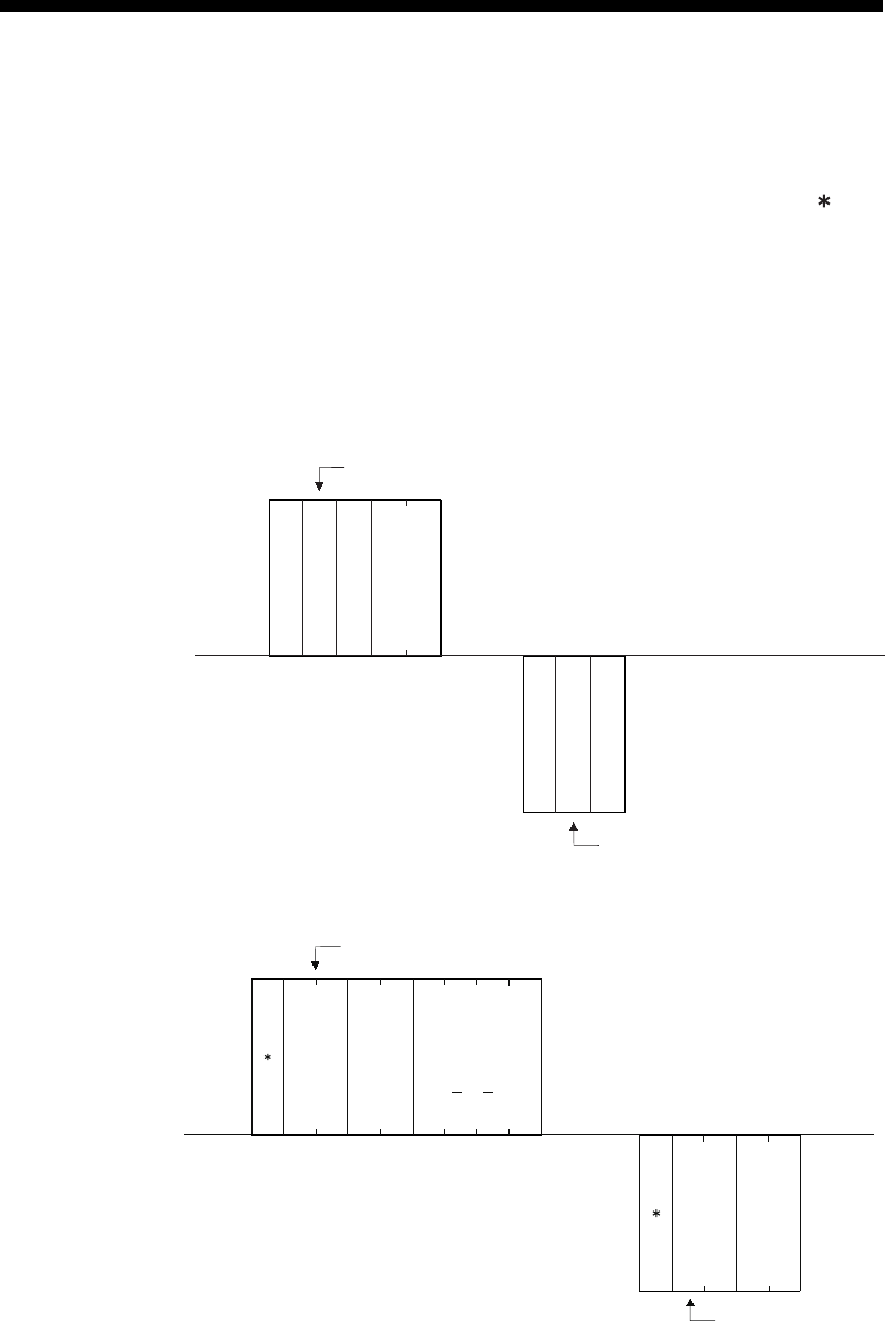
9 - 36
MELSEC-F
WHEN COMMUNICATING DATA USING THE MC PROTOCOL9
9 - 36
9.4.2 Remote RUN (command: 13) / Remote STOP(Command: 14)
The examples shown in this section explain the control procedure of remote RUN.
The order and content of data items of the areas marked by " " shown in the control
procedure diagram differ depending on the module used as well as the frame and
format used for communication.
See the detailed information described in Subsection 9.1.2.
[Control procedure]
(1) Executing remote RUN while communicating in binary code
(2) Executing remote RUN while communicating in ASCII code
(Data name)
93
H
FF
H
0A
H
00
H
LH
/94
H
13
H
/14
H
00
H
External device
side
(Example)
(Data name)
(Example)
PLC side
Subcommand
PC No.
Monitoring
timer
Complete code
Subcommand
For remote STOP 14
H
For remote RUN 13
H
For remote STOP 94
H
For remote RUN 93
H
*
*
F
31 H
1
33 H
3
46 H46 H30 H
0
30 H
0
30 H
0
41H
AF
HL H L
39H
9
33 H
3
30H
0
30H
0
HL
(Data name)
External device
side
(Example)
(Data name)
(Example)
PLC side
Subcommand
PC No.
Monitoring
timer
Complete code
Subcommand
For remote RUN 3933H (93H)
For remote STOP 3934H (94H)
For remote RUN 3133H (13H)
For remote STOP 3134H (14H)

9 - 37
MELSEC-F
WHEN COMMUNICATING DATA USING THE MC PROTOCOL9
9 - 37
POINT
• When executing the remote RUN/STOP using other external devices or
computer link, the remote RUN/STOP is executed in the order of execution.
• When the power of PLC is turned on, then off, and then on again with the
remote RUN/STOP executed, the remote RUN/STOP status is canceled and
the setting of the PLC's RUN/STOP switch becomes valid.
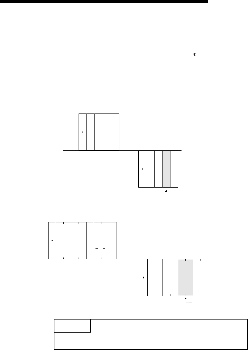
9 - 38
MELSEC-F
WHEN COMMUNICATING DATA USING THE MC PROTOCOL9
9 - 38
9.4.3 PLC model name read (command: 15)
The examples shown in this section explains the control procedure for reading the
model name of the PLC.
The order and content of data items of the areas marked by " " shown in the control
procedure diagram differ depending on the module used as well as the frame and
format used for communication.
See the detailed information described in Subsection 9.1.2.
[Control procedure]
(1) Data communication in binary code
(2) Data communication in ASCII code
POINT
Distinguish the PLC model name by the model name code.
"F3H", which is the model code of FX3U/FX3UC, is read as the PLC model name.
(Data name)
External device
side
(Example)
(Data name)
(Example)
PLC side
Subcommand
PC No.
Monitoring
timer
Complete code
Subcommand
FFH0AH00 H
LH
95 H
15 H
00 HF3 H00 H
PLC model name
Model name of
FX3U/FX3UC
(Data name)
F
31H
1
35 H
5
46H46 H30 H
0
30 H
0
30 H
0
41H
AF
HL H L
39 H
9
35 H
5
30 H
0
30 H
0
46 H
F
33 H
3
30 H
0
30 H
0
HL
External device
side
(Example)
(Data name)
(Example)
PLC side
Subcommand
PC No.
Monitoring
timer
Complete code
Subcommand
PLC model name
Model name of
FX3U/FX3UC
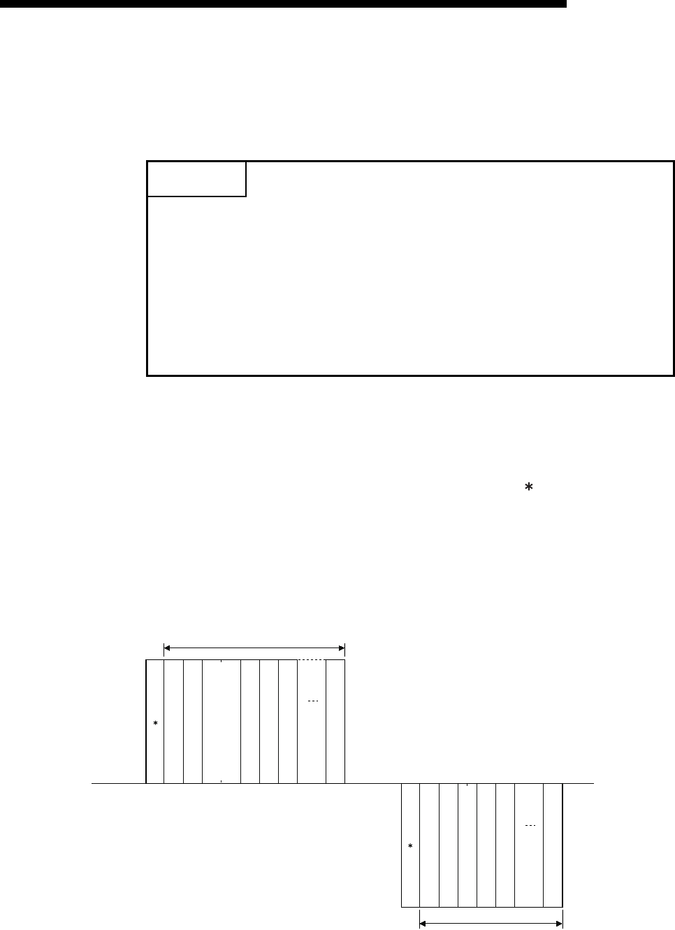
9 - 39
MELSEC-F
WHEN COMMUNICATING DATA USING THE MC PROTOCOL9
9 - 39
9.5 Loopback Test
A loopback test checks whether or not the communication function between an
external device and the Ethernet module operates normally. The examples show the
control procedure using this function.
9.5.1 Loopback test (command: 16)
The examples shown in this section explain the control procedure for an external
device performing a loopback test with the Ethernet unit.
The order and content of data items of the areas marked by " " shown in the control
procedure diagram differ depending on the module used as well as the frame and
format used for communication.
See the detailed information described in Subsection 9.1.2.
[Control procedure]
(1) Performing a loopback test while communicating in binary code
POINT
(1) A loopback test checks whether or not the connection between the external
device and the Ethernet module is correct and that the data communication
function operates properly when the FX3U-ENET-L is started up or when a
problem occurs.
(2) Use the following data for loopback tests.
Send the head part first.
• When communicating in binary code
Maximum of 254 bytes of numerical values (00 to FFH).
• When communicating in ASCII code
Maximum of 254 single-byte characters ("0" to "9", "A" to "F").
(Data name)
External device
side
(Example)
(Data name)
(Example)
PLC side
Subcommand
PC No.
Monitoring
timer
Complete code
Subcommand
16 HFFH0A H00 H
LH
96 H00 H
Data length
(1 to 254 bytes)
Head send data
Second send data
Last send data
Data length
(1 to 254 bytes)
Head send data
Second send data
Last send data
Designated byte length+5bytes
Designated byte length+3bytes
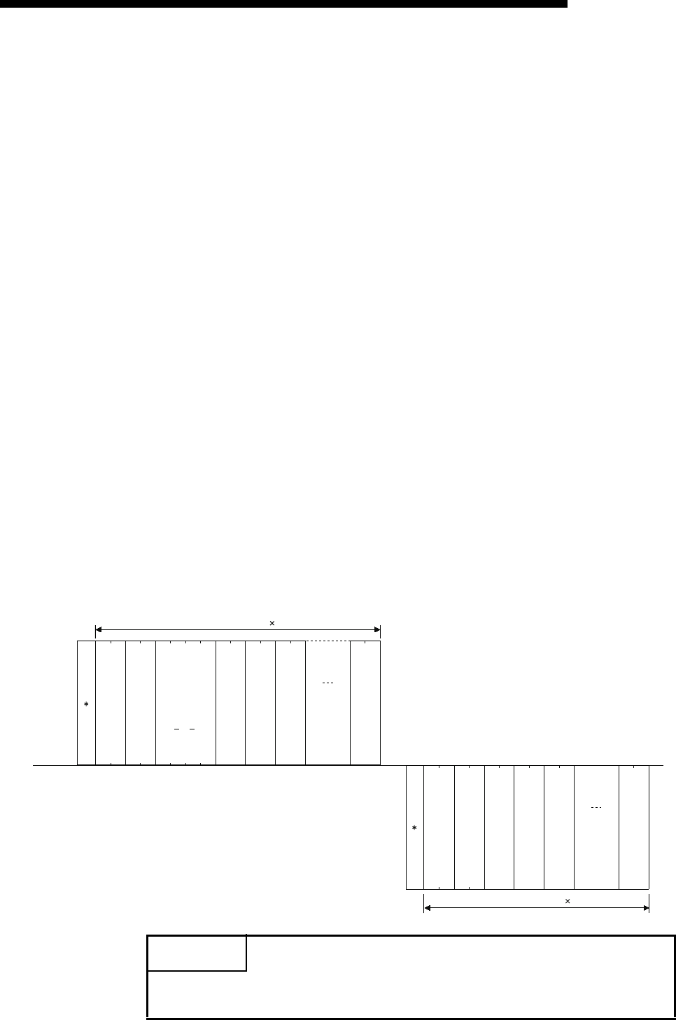
9 - 40
MELSEC-F
WHEN COMMUNICATING DATA USING THE MC PROTOCOL9
9 - 40
(2) Performing a loopback test while communicating in ASCII code
POINT
The number of the loopback data transmitted by an external device is returned to
the external device it is.
31
H
36
H
46
H
46
H
30
H
30
H
30
H
41
H
6
H
F
L
F1
H
0 0
L
A0
LHLHLHLH
39
H
36
H
30
H
30
H
6
H
0
L
09
LHLHLHLH
(Data name)
External device
side
(Example)
(Data name)
(Example)
PLC side
Subcommand
PC No.
Monitoring
timer
Complete code
Subcommand
Data length
(1 to 254 bytes)
Head send data
Second send data
Last send data
Data length
(1 to 254 bytes)
Head send data
Second send data
Last send data
(Designated byte length 2)+10bytes
(Designated byte length 2)+6bytes
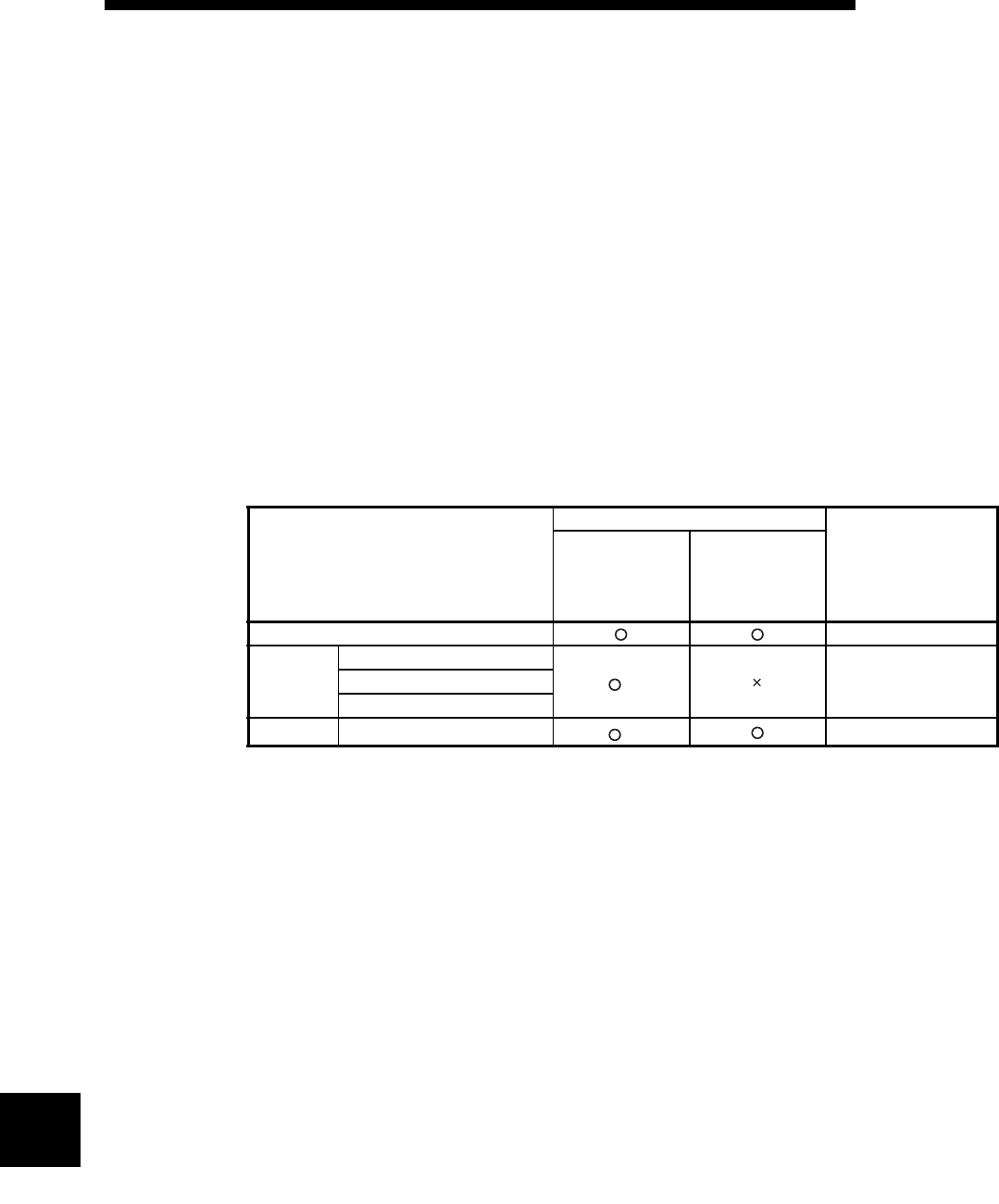
10 - 1
USING THE E-MAIL FUNCTION10
10 - 1
10
MELSEC-F
10 USING THE E-MAIL FUNCTION
This chapter explains e-mail functions of the Ethernet module.
10.1 E-mail Function
The e-mail function sends e-mails to PCs or PLCs at a remote location using the
network (via the mail server).
The PLC sends e-mails using sequence programs and buffer memory.
10.1.1E-mail send by the PLC
(1) Sending e-mail by the PLC
When sending an e-mail, the PLC sends the PLC information of a station
connected to an Ethernet module as a file attached to the e-mail or in the text of
the e-mail to an external device such as a PC.
*1 It is not possible to send an attached file and main text at the same time.
(a) Sending e-mail from the PLC
Data is transmitted via the main text or attached file of an e-mail.
1) For an attached file, device data and other information is sent by
converting into binary/ASCII/CSV data format.
2) For the main text, ASCII code data (character string data) created by a
sequence program is sent.
Sending e-mail by the PLC
External device
Remark
PC
Portable terminal
(device that
cannot handle
attached files)
Subject —
Attached
file
Binary format
*1Maximum 2k wordsBinary to ASCII conversion
Binary to CSV conversion
Main text Designating using ASCII data *1Maximum 256 words.
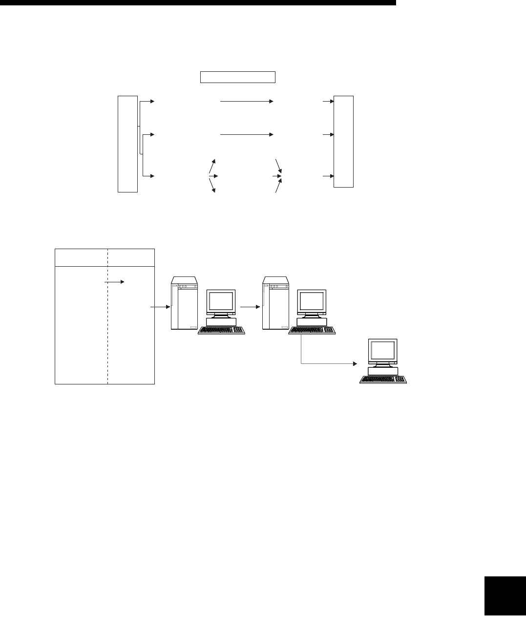
10 - 2
USING THE E-MAIL FUNCTION10
10 - 2
10
MELSEC-F
(2) Data conversion method used by the Ethernet module
The following shows the data conversion method used by the Ethernet module.
(3) Flow of the e-mail
The following diagram illustrates the flow of e-mail sent by the PLC to the
external device:
[When sending by the Ethernet module]
1) Send an e-mail to the mail server of the local station's Ethernet module.
2) The mail server of the local station's Ethernet module sends the e-mail to
the receive mail server of the send destination device.
[When receiving by a PC]
3) Mails can be received using applications such as e-mail software.
When sending e-mails
PLC Subject
(ASCII data)
Main text
(ASCII data)
Attached file
(binary data)
(Binary data)
(ASCII data)
(CSV data)
Encode
(Base64)
Mail
server
Encode
(7bit)
Encode
(Base64/7bit)
Operation for sending e-mails
(FROM/TO instruction)
PLC
Mail send
Ethernet
module
Mail server
PC
1) 2)
3)
Mail server
FROM/TO
instruction
(Mail send)
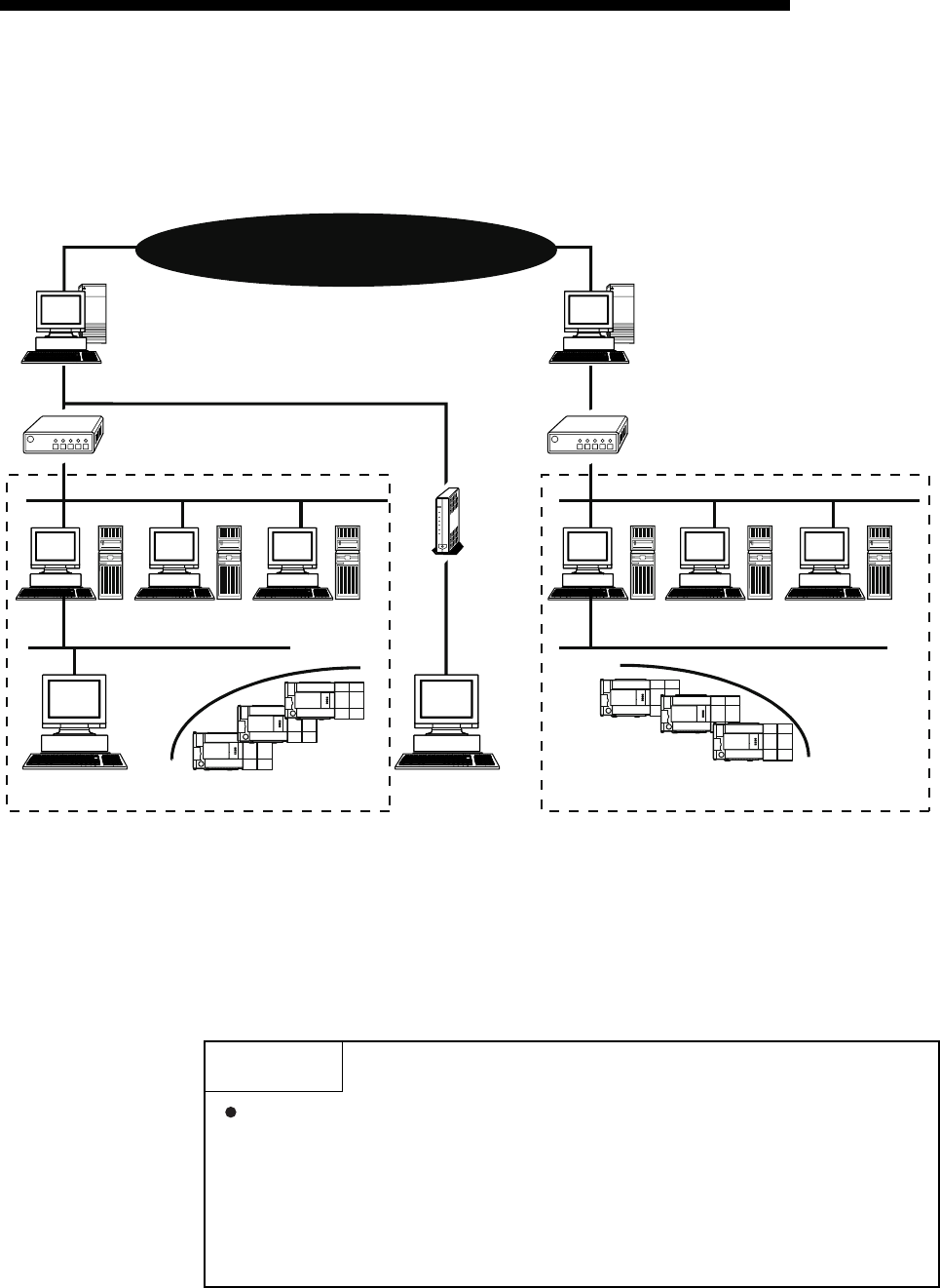
10 - 3
MELSEC-F
USING THE E-MAIL FUNCTION10
10 - 3
10.2 Configuration and Environment of the Applicable System
This section explains the environment and system configuration for using the e-mail
function from the Ethernet module.
(1) E-mails can be sent in an environment where the Internet service is available as
shown above. (Ethernet modules do not send e-mails directly via the internet
connection. The mail server sends e-mails.)
(2) Set each Internet mail setting value for the Ethernet module and PC following the
directions from the system administrator.
(3) Each of the Ethernet module parameters for using the e-mail function is set with
FX Configurator-EN-L or a sequence program.
POINT
The module operation is not guaranteed if any of the following connection is
used. Check the module operation on the user side.
• Connections using the Internet (general public line) (Connections using
Internet connection service provided by Internet service providers and
telecommunications carriers)
• Connections using devices in which a firewall is installed
• Connections using broadband routers
• Connections using wireless LAN
Internet
(Public line)
Internet service provider Internet service provider
Public line
Access range of Ethernet module Access range of Ethernet module
Router Router
TA/modem
Ethernet
Proxy server DNS server SMTP/POP3
(Mail server)
Proxy server DNS server SMTP/POP3
(Mail server)
Ethernet Ethernet
External device Ethernet module External device
Ethernet module
Ethernet

10 - 4
MELSEC-F
USING THE E-MAIL FUNCTION10
10 - 4
10.3 Precautions for Using the E-mail Function
The following explains precautions when using the e-mail function of the Ethernet
module.
(1) Precautions regarding the system
(a) Design the system so that the entire system operates normally at all times
when sending e-mails to/from a running system and controlling the PLC.
(2) Precautions regarding the external device
(a) E-mails can be sent to PLC stations in which Q series Ethernet modules are
installed.
(b) To send files to the Ethernet module as attachments to e-mail, specify the
encoding method (Base 64/7 bits/Quoted Printable) of the attached files.
(3) Common precautions
(a) The maximum sizes of data that can be sent by the Ethernet module are as
follows:
• Data size of attached files: Up to 2048 words
• Data size of main text: Up to 256 words (Sending only)
(b) Mail that is sent do not support encrypted data, compressed data, and data
conversion.
(c) If the external device cannot be found when sending an e-mail from the
Ethernet module, the user can check the error code in the buffer memory.
* If an external device cannot be found when sending e-mail using the
operation of buffer memory, failure of e-mail transmission may not be
recognized, depending on the operation of the mail server. Be sure to
verify the receiver's e-mail address in advance.
* Error codes are stored within BFM#10335. (For details on error codes,
refer to section 11.4.)
(d) The e-mail function is supported for SMTP.
(e) When e-mail communication errors occur, check the error codes stored in
the mail send error log area of the buffer memory.
(f) When the receive data of an e-mail sent is abnormal (garbled characters,
etc.), review the transmission data format (binary/ASCII/CSV) designated
with BFM#10338.
* The Subject should be in ASCII code data format. (It is not converted to
ASCII format.)
(g) Confirm with a system administrator regarding the minimum time intervals
for accessing the mail server when sending e-mail, reading received e-mail,
and inquiring whether or not there is any received e-mail.
Depending on the mail server's security setting, frequent access may be
prohibited.
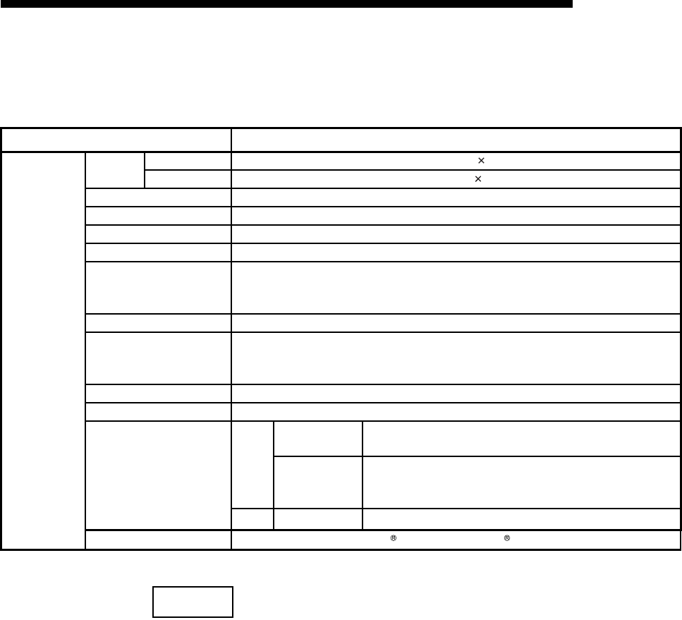
10 - 5
MELSEC-F
USING THE E-MAIL FUNCTION10
10 - 5
10.4 E-mail Specifications
The following table lists the specifications of the e-mail function.
NOTE
Mail terminology list:
DNS server: Server that manages networks
SMTP server: Server that delivers (transfers) e-mail between mail servers
POP3 server: Server that transfers received e-mail addressed to subscribers to
the corresponding subscribers
Item Specification
Transmission
specifications
Transmission
data
Data size Attached file 2048 words 1
Main text 256 words 1
Data transfer method When sending: Sends either a file as attachment or main text (select one).
Subject US-ASCII format or ISO-2022-JP (Base 64)
Attached file format MIME format
MIME Version 1.0
Data of attached file format
Binary/ASCII/CSV can be selected.
File name: XXXX.bin (binary), XXXX.asc (ASCII), XXXX.csv (CSV)
(CSV: Comma Separated Value)
Division of attached file Cannot be divided (only one file can be sent)
When sending (encode)
Subject: Base 64/7 bits
Main text: 7 bits
Attached file: Base 64
Encryption No
Compression No
Communication with mail
server
SMTP
Port number 1 to 65535 No authentication, POP before SMTP: 25 (initial)
SMTP-AUTH: 587
Authentication
method
• No authentication
• SMTP-AUTH (PLAIN, LOGIN, CRAM-MD5)
• POP before SMTP
POP Port number 1 to 65535 POP3: 110 (initial)
Operation check mailer Microsoft Corporation Outlook Express 6
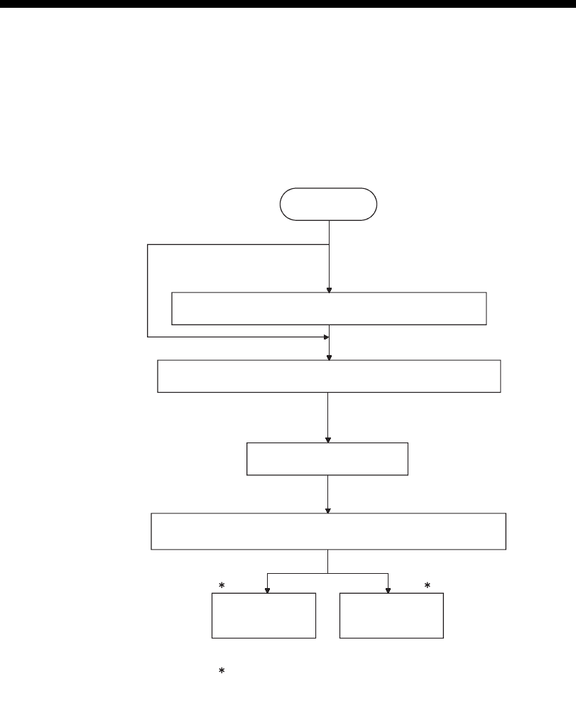
10 - 6
MELSEC-F
USING THE E-MAIL FUNCTION10
10 - 6
10.5 Processing Procedure of the E-mail Function
The following flowchart illustrates the procedure that is required before sending
e-mails:
Start
When DNS is not used
When DNS is used
Register the DNS server
See Section 10.6 (1)
Register the mail address of the local station's Ethernet module
Register the mail address of
the external device
See Section 10.6 (3)
Send data as
an attached file
of an e-mail
Send data as
main text of e-mail
See Section 10.7 See Section 10.8
The open and close processing of
the communication line for
sending e-mails is automatically
executed by the Ethernet module.
1 1
1
Setting the email parameters using FX Configurator-EN-L or the
ladder and re-initialize the Ethernet module.
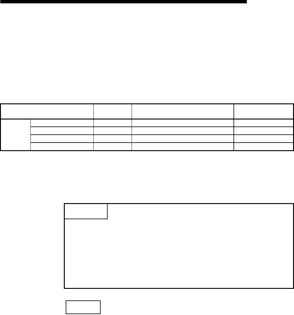
10 - 7
MELSEC-F
USING THE E-MAIL FUNCTION10
10 - 7
10.6 E-mail Settings
This section explains the settings required to send e-mails.
(1) DNS settings
Specify the IP address of the DNS server when setting the mail server name
using the domain name from the e-mail settings (see (2)).
(a) DNS settings
Set the IP addresses of the domain name system (DNS) servers designated
by a system administrator.
1) Designate the IP addresses of the DNS servers 1 to 4.
NOTE
To adjust settings using FX Configurator-EN-L, select [Initial Settings] from the initial
screen and adjust the settings at the initial settings screen.
Setting name BFM number
[Decimal] Description of setting Setting range/options
DNS setting
IP address of DNS server 1 20505 to 20506 Set IP address of DNS server 1. —
IP address of DNS server 2 20507 to 20508 Set IP address of DNS server 2. —
IP address of DNS server 3 20509 to 20510 Set IP address of DNS server 3. —
IP address of DNS server 4 20511 to 20512 Set IP address of DNS server 4. —
POINT
(1) The DNS servers manage networks.
DNS settings are required to allow search for the SMTP server or POP3
server from a domain name.
(2) Adjust the DNS settings when the mail server name shown in item (2) is
specified with a domain name.
Setting is not required when it is specified with an IP address.
(3) When obtaining the IP addresses from a domain name, the DNS servers are
searched sequentially starting from the first DNS server.

10 - 8
MELSEC-F
USING THE E-MAIL FUNCTION10
10 - 8
(2) E-mail settings
Set in order to use the e-mail function.
[Setting item]
*1 The setting is required only when "POP before SMTP" is selected in the SMTP authentication method.
(a) General settings
Designate the mail setting values that have been registered with the mail
registration information designated by the system administrator.
1) Password:
Designate the mail password of the local station's Ethernet module.*1
2) Mail address:
Designate the mail address of the local station's Ethernet module.
(b) Mail server name
Set the IP addresses or domain name of the mail servers designated by the
system administrator.
1) Select the input format (decimal/hexadecimal) of the IP addresses.
2) Set the IP address or sending mail server (SMTP) domain name.
3) Set the IP address or receiving mail server (POP3) domain name.*1
4) Set port numbers of the outgoing mail server (SMTP).
5) Set port numbers of the incoming mail server (POP3).*1
*1 The setting is required only when "POP before SMTP" is selected in the
SMTP authentication methed.
Setting item BFM number
[Decimal] Description of setting item Setting range/option
General set-
ting
Password 9913 to 9920 Set the password to the POP3 server
(16 characters or fewer) —
Mail address 9856 to 9887 Set the mail address for the Ethernet
module (64 characters or fewer) —
Mail server
name
SMTP
setting
Specification
method 9921 Select send mail server specification
method
0: Domain name specification
1: Decimal
2: Hexadecimal
STMP server
name / IP address 9922 to 9953
Set the sending mail server domain
name (64 characters or less) or IP
address
IP address setting :
00000001 to FFFFFFFEH
SMTP server port
number*1 24320 Set port numbers of the outgoing mail
server. (initial: 25) 1 to 65535
POP
setting*1
Specification
method 9954 Select receive mail server specificas-
tion method
0: Domain name specification
1: Decimal
2: Hexadecimal
POP server name
/ IP address 9955 to 9986
Set the IP address or receiving mail
server domain name (64 characters or
less)
IP address setting :
00000001 to FFFFFFFEH
POP3 server port
number*1 24388 Set port numbers of the incoming mail
server. (initial: 110) 1 to 65535
SMTP
authentication
setting
SMTP authentication method 24321 Set the authentication method for the
outgoing mail server.
0: No authentication
1: SMTP-AUTH
2: POP before SMTP
SMTP login ID 24324 to 24355 Set the login ID of the outgoing mail
server (64 characters or fewer) —
SMTP password 24356 to 24387 Set the password of the outgoing mail
server (64 characters or fewer) —

10 - 9
MELSEC-F
USING THE E-MAIL FUNCTION10
10 - 9
(c) SMTP authentication setting
1) Set the authentication method for the outgoing mail server (SMTP).
The steps 2) and 3) below are required when "SMTP-AUTH" is selected in
the SMTP authentication method.
2) Set the login ID of the outgoing mail server (SMTP).
3) Set the password of the outgoing mail server (SMTP).
NOTE
To adjust the settings in FX Configurator-EN-L, select [Email Settings] from the initial
screen and adjust the settings from the email settings screen.
(3) Send mail address setting
Register the e-mail address of the external devices where e-mail is to be sent.
[Setting item]
(a) Send mail address
1) Designate the mail addresses of a maximum of 10 external devices to
which mail is being sent from the local station's Ethernet module. (Only
one e-mail address can be specified for each area.)
2) When sending e-mail by the Ethernet module, specify the send e-mail
address by the bit 0 to 9 of BFM#10337.
NOTE
To adjust the settings in FX Configurator-EN-L, select [Email Settings] from the initial
screen and adjust the settings from the email settings screen.
POINT
• The mail server must be designated in order to use the e-mail function. (See
POINT of (1).)
Setting Item name BFM number
[Decimal] Description of setting Setting
range/Selections
Send mail address 1
to
Send mail address 10
9987
to
10306
Set the mail address of the transmission
destination (1 to 10) —

10 - 10
MELSEC-F
USING THE E-MAIL FUNCTION10
10 - 10
10.7 Sending E-mail (Attached Files) by the PLC
This section explains how to send attached files when sending e-mails.
10.7.1When sending data as an attached file
The following explains the buffer memory addresses and program for sending e-mail.
The following instruction shows how to store data in an attached file and send it to an
external device.
1) Check whether mail can be sent or not.
(BFM#10334 b15: OFF)
2) Designate the destination of the mail.
Turn the bit corresponding to the e-mail destination address to ON in BFM#10337.
To send to all of the mail addresses registered, write to "3FFH".
3) Write the mail data to the following buffer memory addresses.
(Subject: BFM#10339 to 10402)
(Attached file format: BFM#10338)
(Word count of attached file: BFM#10403)
(Contents of main text or attached file: BFM#10404 to 12451)
4) Write "0001H" in BFM#10333 to send the mail.
5) Read BFM#10334 to check if mail was correctly sent.

10 - 11
MELSEC-F
USING THE E-MAIL FUNCTION10
10 - 11
The table below shows the buffer memory to be used for sending mail.
(1) Send using the sequence program
The following explains how an e-mail is sent by the sequence program.
See (3) sending data for detail.
BFM number
Items Contents
Decimal
(Hexadecimal)
10333
(285DH)Mail sending command Start mail sending (0001H)
Ignore (0000H)
10334
(285EH)Mail sending status
Initial status (0000H)
Mail sending normally completed (0001H)
Mail sending abnormally completed (0002H)
Mail being sent (8000H)
10335
(285FH)
Error codes when sending
e-mail
When sending mail, the error code is cleared by the mail sending command (BFM
#10333: 0001H), and error code is stored if an error occurs.
When sending mail to multiple addresses, the first error code found is stored, even
after other errors.
The second error and later errors are not stored.
10336
(2860H)Result of sending e-mail
Sending destination address 1 Success (b0: ON) / Failure (b0: OFF)
to
Sending destination address 10 Success (b9: ON) / Failure (b9: OFF)
10337
(2861H)
Designation Address
of e-mail
Turns the bit of the e-mail destination address to ON.
Sending destination address 1 Enable (b0: ON) / Disable (b0: OFF)
to
Sending destination address 10 Enable (b9: ON) / Disable (b9: OFF)
10338
(2862H)Attached file format
Sends the attached file in binary format (0000H)
Sends the attached file in ASCII format (0001H)
Sends the attached file in CSV format (0002H)
Sends the attached file as a text mail (0004H)
10339 to 10402
(2863 to 28A2H)Subject
Stores a subject (maximum 128 characters)
Subject consists of the send destination number and the character data designated by
the sequence program.
(It is not converted to ASCII format.)
* The Subject should be designated in ASCII characters in the sequence program.
* When the subject consists of less than 128 characters, write "\0" at the end of the
subject
10403
(28A3H)Word count of attached file Designates the word count of attached file (0 to 2048)
10404 to 12451
(28A4 to 30A3H)Main text or attached file Stores a main text or an attached file
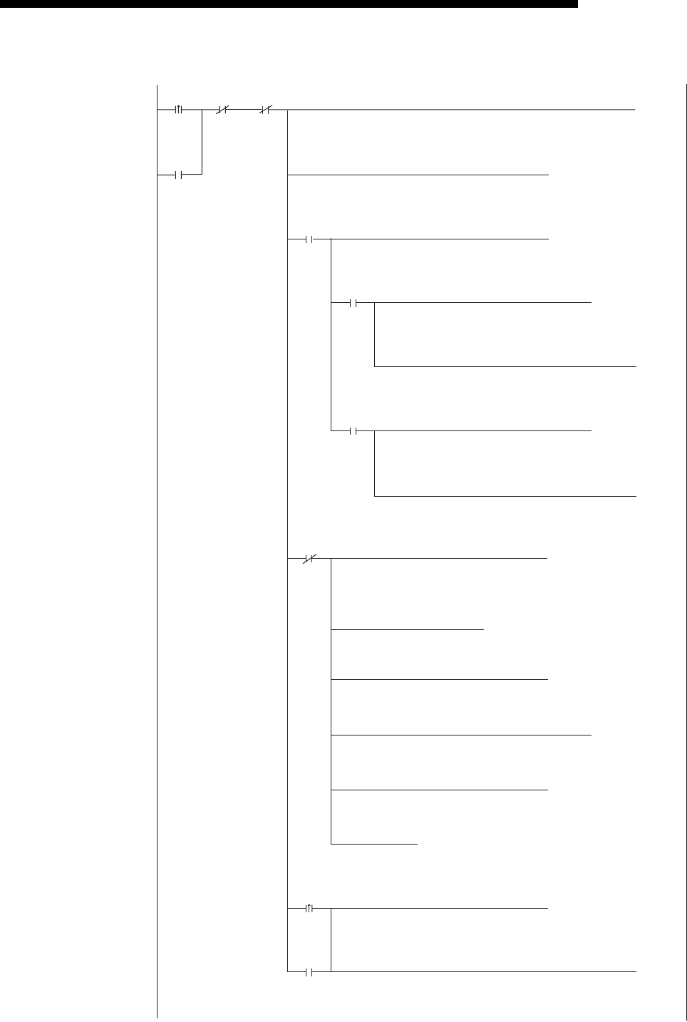
10 - 12
MELSEC-F
USING THE E-MAIL FUNCTION10
10 - 12
• Program example for the unit No. 1
X000
M100
M102 M103
M101
D100.1
D100.0
D100.F
M8029
M101
[MOV D100
K1000
(C1
]
[MOV D101 ]
[PLS M103 ]
[PLS M102 ]
[CALLP P0 ]
[MOVP H3 ]
[MOVP H1 ]
[MOVP K3
U1\
G10403 ]
[MOVP H1
U1\
G10333 ]
"testmail msend"[$MOVP ]
R1000
Head of
attached
data
K10404K1[WBFM K2048 K32 ]
(M100 )
K1000
(C0 )
)
(M101 )
U1\
G10334
U1\
G10336
U1\
G10337
U1\
G10339
U1\
G10338
Mail
sending
instru-
ction
Mail
normally
completed
Mail abnormally
completed
Mail sending
request
(Self-holding)
Mail sending
request
(Self-holding)
Individual
success
and failure
Individual
success
and failure
Mail
sending
(Self-
holding)
Mail
sending
status
Write of
attached
data
completed
Mail
sending
(Self-holding)
Mail
sending
status
Mail
sending
status
Mail
sending
status
Mail
sending
status
Success
count
Mail
abnormally
completed
Mail
normally
completed
Failure
count
Setting
of send
destination
bit
Subject
Mail
sending
format
Attachment
size
Mail
sending
instruction
Mail
sending
(Self-
holding)
Creates
text data

10 - 13
MELSEC-F
USING THE E-MAIL FUNCTION10
10 - 13
M8000
[MOV R1234 R1000 ]
]
[MOV H5678 R1001
R1002
]
[MOV R9ABC ]
[FEND
[SRET ]
[END ]
P0
Head of
attached
data
[ZRST R1000 R1002 ]
Head of
attached
data
Creates
text data
M8000
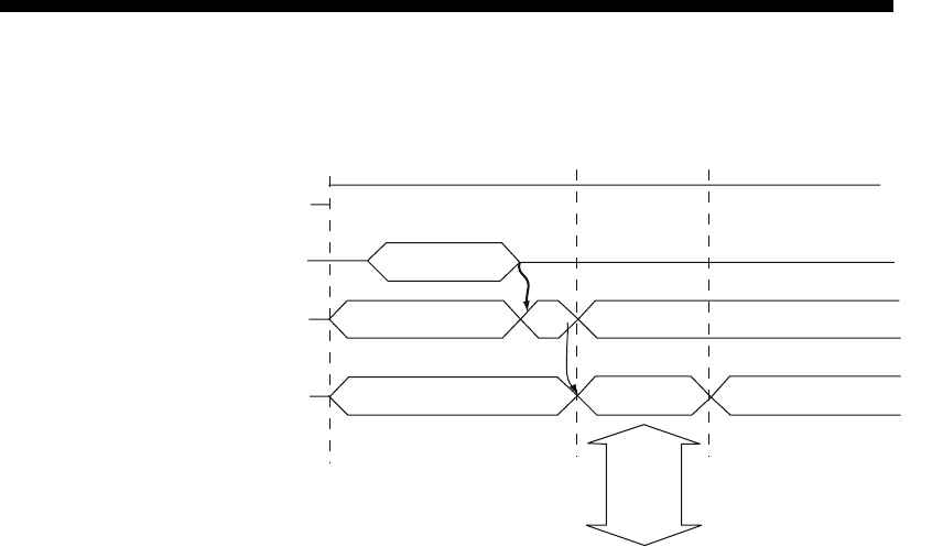
10 - 14
MELSEC-F
USING THE E-MAIL FUNCTION10
10 - 14
(2) Execution timing of the instruction
1) Check whether the initial processing has been completed normally.
2) Write mail data to the buffer memory.
(Mail sending destination: BFM#10337 b0 to b9)
(Subject: BFM#10339 to 10402)
(Attached file format: BFM#10338)
(Word count of attached file: BFM#10403)
(Contents of main texts or attached files: BFM#10404 to 12451)
3) Write "0001H" in BFM#10333.*1
The e-mail is sent to the mail server.
4) When sending to the mail server is complete, the result is stored in
BFM#10334.*2
*1 Specify the attached file format by writing a parameter in BFM#10338
before sending e-mail.
0000H: Sends the attached file in binary format
0001H: Sends the attached file in ASCII format
0002H: Sends the attached file in CSV format
0004H: Sends the attached file as a text mail
*2 For details on causes of errors, see "Troubleshooting" in Chapter 11.
(a) Designate binary format when communicating between Ethernet modules.
The name of the attached file is mmddhhss.bin (system date.bin).
mm: Month dd: Date hh: Hour ss: minute
(b) Designate either binary format, ASCII format or CSV format when a PC/UNIX
receives e-mail sent from an Ethernet module.
1) When binary format is designated
The name of the attached file is mmddhhss.bin (system date.bin).
mm: month dd: day hh: hour ss: minute
2) When ASCII format is designated
The name of the attached file is mmddhhss.asc (system date.asc).
mm: month dd: day hh: hour ss: minute
3) When CSV format is designated
The name of the attached file is mmddhhss.csv (system date.csv).
mm: month dd: day hh: hour ss: minute
* For details on how to receive e-mails, see (3).
* The system date for the file name is the data managed by the PLC in
which the Ethernet module is installed.
0000H
0000H0001H0000H
8000H
1)
2)
3)
4)
Initial
processing
Mail
sending start
Mail sending
completed
Initial processing
normal completion
Writing the necessary data
for sending a mail to BFM
Mail sending request
BFM#10333
Mail sending status
BFM#10334
Writing the mail
data to BFM
0001H (Normally completed)
0002H (Abnormally completed)
Communication
with a SMTP
server
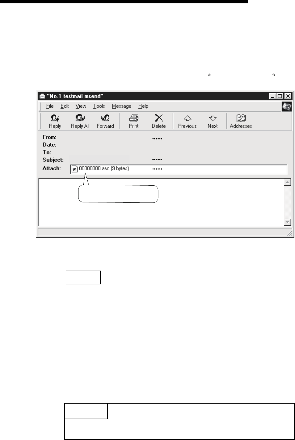
10 - 15
MELSEC-F
USING THE E-MAIL FUNCTION10
10 - 15
(3) Receiving with a personal computer
The following explains how a PC/UNIX receives e-mails sent from the Ethernet
module.
After setting an environment with application software that processes e-mails,
e-mails can be received on a receive message screen as shown below.
(Example) The following shows an example of the received e-mail.
(The screen display shows Microsoft Corporation's Outlook
Express 6.)
(a) From
Displays the mail address of the Ethernet module.
NOTE
By entering the mail addresses of the send destination devices in the address book,
the registered names (display names) can be displayed and makes management
easier.
(b) Subject
This indicates the transmission destination No. (*1) and the Subject
written by a sequence program.
*1 The Ethernet module automatically adds this number, sequentially
starting from 00001.
(After the maximum number (99999) is reached, the number starts from
00000.)
(c) Attached file
This indicates the name of the attached file sent by the Ethernet module.
POINT
Data in the attached file in CSV format can be read in cell units in Excel, etc., for
each word of data.
Mail address of Ethernet module
(b)
(c)
123456789abc
<Data contents for attached files>
Mail address of external device
(a)
"No.00001 testmail msend"
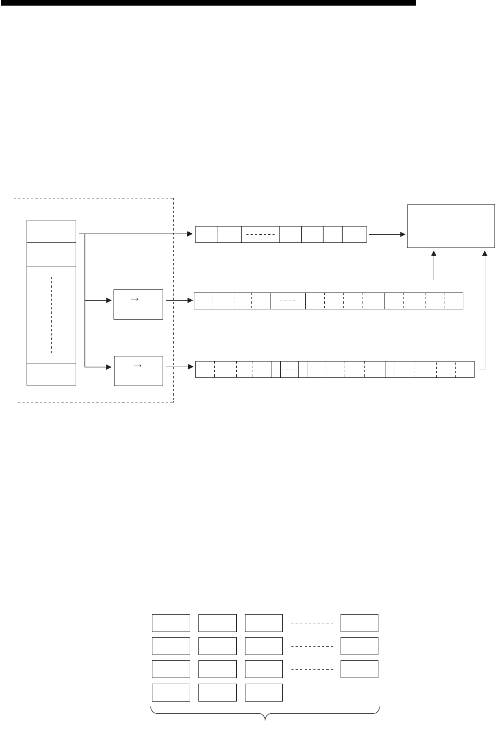
10 - 16
MELSEC-F
USING THE E-MAIL FUNCTION10
10 - 16
10.7.2Contents of the attached files
The following explains the contents of the attached file data.
The data format of the attached file is ASCII code (ASCII format, CSV format) or
binary code (binary format).
The following example shows the transmission contents for each data format (binary/
ASCII/CSV) when the Ethernet module sends the data register value as an attached
file.
(1) When sending from the Ethernet module
(2) Data configuration in CSV format
Data in CSV format can be used as control data for the cell units in Excel, etc.
Data in CSV format handled by the Ethernet module is the data expressed as
follows.
• 1 word (16 bits) binary data is converted to four digit ASCII code when
expressed as a hexadecimal. (4 bytes of ASCII code)
• When handling multiple word data, insert comma data between each word
(4 bytes of ASCII code).
Data is sent in the following arrangement.
Arrangement of data
1) In addition to the data conversion and insertion described above, CR
(code: 0DH) and LF (code: 0AH) are inserted for each 8 words of data.
2) The arrangement of data sent in CSV format is shown below.
"C" "B" "A" "9" "8" "7" "6" "5" "4" "3" "2" "1"
BFM#
10413
BFM#
10404
10405
10413
1234H
5678H
9ABCH
9AHBCH56H78H12H34H
"C" "B" "A" "9" "8" "7" "6" "5" "4" "3" "2" "1"
,,,
External device
In case of binary
In case of ASCII
In case of CSV
Ethernet module
BIN ASCII
conversion
BIN CSV
conversion
BFM#
10413
BFM#
10413
BFM#
10405
BFM#
10405
BFM#
10405
BFM#
10404
BFM#
10404
BFM#
10404
,
D8 ,D9 D10 D15
D16 ,D17 D18 D23
D24 ,D25 D26
8 device
(8-word unit)
D0 D1 D2 D7 [CR + LF]
[CR + LF]
,
,
,
,
,
,
,
[CR + LF]
[CR + LF]

10 - 17
MELSEC-F
USING THE E-MAIL FUNCTION10
10 - 17
10.8 Sending E-mail (Main Text) by the PLC
This section explains how to send the main text of e-mail.
10.8.1When sending data as main text of e-mail
The following explains the buffer memory address and sequence program for sending
e-mail.
This section explains how to store the data in main text and send it to the external
device.
1) Check whether mail can be sent or not.
(BFM#10334 b15: OFF)
2) Destination of the mail.
Turn the bit corresponding to the e-mail destination address to ON in
BFM#10337.
To send to all of the mail addresses registered (maximum 10 addresses),
write 3FFH.
3) Write the mail data to the following buffer memory addresses.
(Subject: BFM#10339 to 10403)
(Attached file format: Set "0004H" : BFM#10338)
(Mail text/word count of attached file : BFM#10403)
(Contents of main text: BFM#10404 to BFM#12451)
4) Write "0001H" to BFM#10333 to send the mail.
5) Read the value in BFM#10334 to check if mail was correctly sent.

10 - 18
MELSEC-F
USING THE E-MAIL FUNCTION10
10 - 18
The table below shows the buffer memory to be used for sending mail.
BFM number
Item Description
Decimal
(Hexadecimal)
10333
(285DH)Mail sending command Start mail sending (0001H)
Ignored (0000H)
10334
(285EH)Mail sending status
Initial status (0000H)
Mail sending normal completed (0001H)
Mail sending abnormal completed (0002H)
Mail being sent (8000H)
10335
(285FH)
Error codes when sending
e-mail
When sending mail, the error code is cleared by the mail sending command (BFM
#10333: 0001H), and error code is stored if an error occurs.
When sending mail to multiple addresses, the first error code found is stored, even
after other errors.
The second error and later errors are not stored.
10336
(2860H)Sending result of e-mail
Sending destination address 1 Success (b0: ON) / Failure (b0: OFF)
to
Sending destination address 10 Success (b9: ON) / Failure (b9: OFF)
10337
(2861H)Destination Address of e-mail
Turns the bit of mail destination address to ON.
Sending destination address 1 Enable (b0: ON) / Disable (b0: OFF)
to
Sending destination address 10 Enable (b9: ON) / Disable (b9: OFF)
10338
(2862H)Attached file format Write 0004H for sending the attached file as main text.
10339 to 10402
(2863 to 28A2H)Subject
Stores a subject (maximum 128 characters)
Subject consists of the send destination number and the character data designated
by the sequence program.
(It is not converted to ASCII format.)
*The Subject should be designated in ASCII characters in the sequence program.
*When the subject consists of less than 128 characters, write "\0" at the end of the
subject.
10403
(28A3H)Word count of attached file Designates the word count of main text (0 to 256)
10404 to 12451
(28A4 to 30A3H)Main text data
Stores a main text or an attached data
Main texts are not converted to ASCII format by the Ethernet module.
*It should be designated in ASCII characters in the sequence program.
*The following binary code data is processed as control codes:
0D0AH: Line feed code CR + LF
00H: End of main text
*It is recommended to use 78 characters or less in a single line of main text.
(Be sure to add a line feed code CR + LF (0D0AH) at the end of the main text lines.)
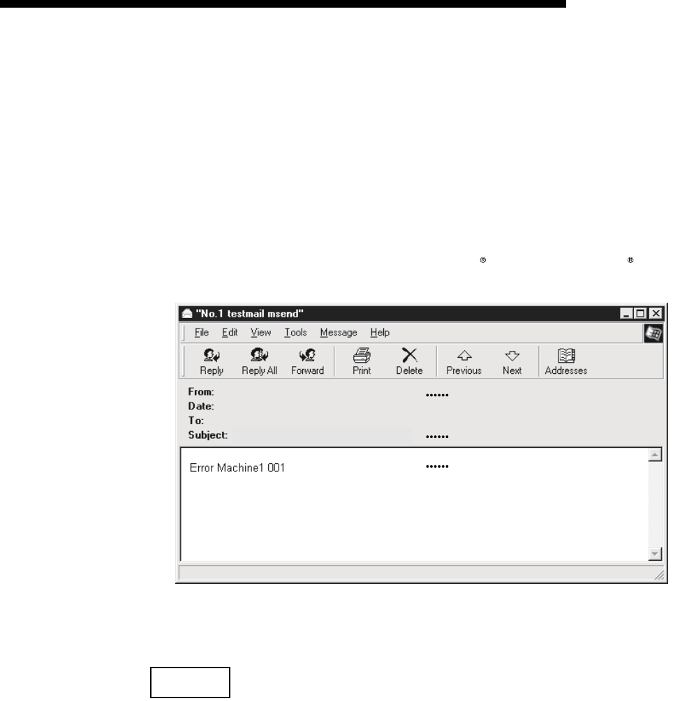
10 - 19
MELSEC-F
USING THE E-MAIL FUNCTION10
10 - 19
(1) Send using the sequence program
Method for sending e-mails by the sequence program is similar to the one by an
attached file.
See Subsection 10.7.1 for sample programs for sending e-mail from PLC.
(2) Receiving by a personal computer
The following explains how a PC/UNIX/portable terminal receives e-mail sent
from the Ethernet module.
After setting an environment for using the Internet with application software that
processes e-mails, e-mails can be received on a receive message screen as
shown below.
(Example) The following shows an example of a received e-mail.
(The screen display shows Microsoft Corporation's Outlook
Express 6.)
(a) From
Displays the e-mail address of the Ethernet module.
NOTE
By entering the mail addresses of the send destination devices in the address book,
the registered names (display names) can be displayed and makes management
easier.
(b) Subject
This indicates the transmission destination No. (*1) and the Subject written
by a sequence program.
*1 The Ethernet module automatically adds this number, sequentially,
starting from 00001.
(After the maximum number (99999) is reached, the number starts again
from 00000.)
(c) Main text of e-mail
This indicates the main text of the e-mail sent by the Ethernet module.
Mail address of Ethernet module
(b)
(c)
Mail address of external device
(a)
"No.00001 testmail msend"

11 - 1
TROUBLESHOOTING11
11 - 1
11
MELSEC-F
11 TROUBLESHOOTING
This section explains the contents of the errors that may occur during communication
between the Ethernet module and an external device as well as the troubleshooting
procedures.
The following are methods for checking if there is an error on the Ethernet module
side and the contents of the error.
Use one of the following methods to check if there is an error and its content, then
take corrective actions.
(1) Check using the display LED on the front of the Ethernet module
(See Section 11.1.)
The display LED on/off status can be used to check if an error is occurring in the
Ethernet module.
(2) Check through FX Configurator-EN-L
FX Configurator-EN-L can be used to check various conditions of the Ethernet
module as well as the error code corresponding to the contents of the error
occurring and to perform tests.
(a) Ethernet diagnostics (See Subsection 11.2.2.)
1) PING test (See Subsection 5.4.1.)
2) COM. ERR off (See Subsections 11.1.2 and 11.2.1.)
(3) Check through GX Developer
(a) Buffer memory batch monitor
The error code can be checked by monitoring the buffer memory of the
Ethernet module.
(4) Check the contents of the error using the error code (See Section
11.4.)
The contents of the error can be checked using the error code confirmed on the
dedicated screen above or by monitoring the buffer memory by referring to
Section 11.4.
NOTE
If line errors and other errors occur when connecting devices of multiple
manufacturers, the users needs to isolate the malfunctioning parts using line
analyzers, etc.

11 - 2
TROUBLESHOOTING11
11 - 2
11
MELSEC-F
11.1 How to Check Errors Using LED Displays
This section describes the errors that can be checked with the LED displays on the
front of the Ethernet module.
11.1.1 Checking error display
The following can be checked with the LED displays on the front of the Ethernet
module.
<Ethernet module LED>
(Continues on the following page)
LED name Status to check Cause/corrective action
1 RUN Turns off after powering on
the Ethernet module.
1) Watchdog timer error
• A watchdog timer (approximately 600 ms) error is detected by the self diagnosis
function of the Ethernet module.
2) Base module power is OFF, or the extension cable is not connected.
2INIT. Off
1) Failed to re-initialization due to a parameter error
• Check/correct the parameter setting values for the Ethernet modules using a sequence
program or the FX Configurator-EN-L and re-download.
2) Base module power is OFF, or the extension cable is not connected.
3 100M Does not turn on
1) Using 10Mbps HUB
• Initial processing.
• Replace with 100Mbps HUB.
2) Does not turn on using 100Mbps HUB
• Check the connection of the connectors on the Ethernet side and the HUB side.
• Replace the cable.
4ERR. Turns on after powering on
the Ethernet module.
1) Module parameter setting error
• Check/correct the parameter setting values for the Ethernet modules using the
sequence program or the FX Configurator-EN-L and re-download.
2) PLC error
• When the PLC [RUN] LED is off/flashing, or the [ERR.] LED is on, check the content of
the error occurring in the PLC and correct the problem.
3) Ethernet module error (H/W error)
4) Base module power is OFF, or the extension cable is not connected.
5COM.ERR.
Turns on after powering on
the Ethernet module.
Or turns on temporarily
1) Check the contents of the error using the error codes stored by the error detection of the
following processing and remove the causes.
• Initial processing
• Fixed buffer send processing
• E-mail send processing
• Open processing
• MC protocol communication processing
• Other processing (processing for which error codes are stored in the error log area)
2) For a list of error codes, see Section 11.4.

11 - 3
MELSEC-F
TROUBLESHOOTING11
11 - 3
(Continued from the previous page)
*1 Confirm the completion for the initial processing and check whether or not there is any problem in the cable
connection and the Ethernet lines.
See Section 5.4, "Confirming the completion of the Initial Processing" for details on confirming the
completion for the initial processing. (Perform either one of the "Confirming the completion of the initial
processing completion" actions described in Section 5.4.)
LED name Status to check Cause/corrective action
6SD The [SD] LED does not flash
at data sending.
1) [ERR.] or [COM.ERR] LED turns on.
Remove the factors that turn on the [ERR.] or [COM.ERR] LED.
2) Program reviewing is required
Review the sequence program for sending.
7RD [RD] LED stays off and data
cannot be received.
1) [ERR.] or [COM.ERR] LED turns on.
Remove the factors that turn on the [ERR.] or [COM.ERR] LED.
2) Poor cable connection
Check the connection of the cable. (*1)
3) Local station IP address setting error
If the cable connection is all right, review each setting value of the local station IP
address, router setting, and sub-net mask settings using FX Configurator-EN-L.
4) Program reviewing is required
Review the sequence program for sending.
8 C1 to C4 Does not turn on
1) Poor cable connection
Check the connection of the cable.
2) Program or parameter reviewing is required
• Check the program or parameter.
• Check error contents with the diagnosis function of FX Configurator-EN-L.
POINT
The on/off status of the [INIT], [OPEN], [ERR.] and [COM.ERR] LEDs is stored in
the module status area (BFM#28) of the buffer memory.
For more details, see Section 3.6, "List of Applications and Assignments of the
Buffer Memory".
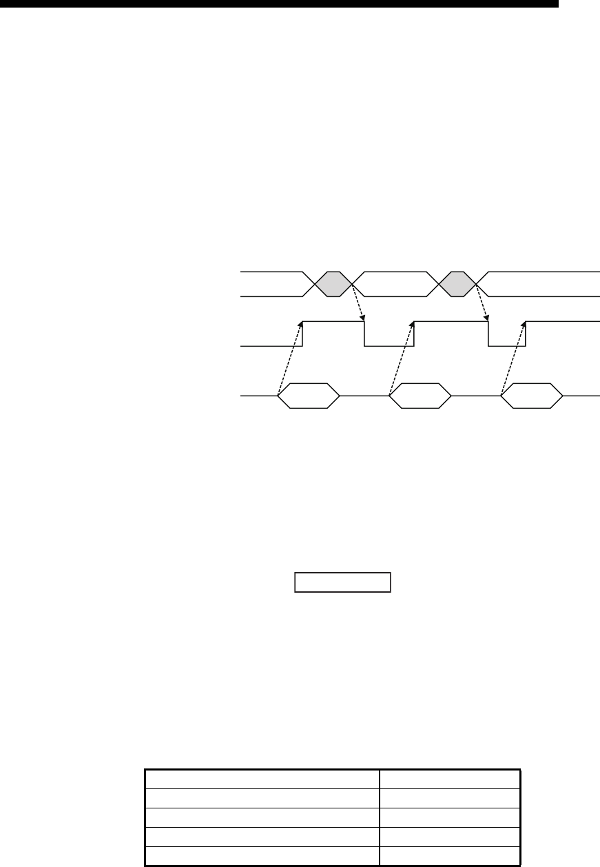
11 - 4
MELSEC-F
TROUBLESHOOTING11
11 - 4
11.1.2 How to turn off COM.ERR LED and to read/clear error information
This section explains how to turn off [COM.ERR] LED and to read/clear error
information using a sequence program.
(1) How to turn off [COM.ERR] LED using buffer memory
The [COM.ERR] LED on the front of the Ethernet module is turned on when a
communication error occurs in an external device. (BFM#28...b4: ON)
(a) The [COM.ERR] LED is turned off by writing "0001H" to the off request signal
(BFM#1601).
(b) The off processing is performed by writing "0001H" to BFM#1601.
(c) The error information in the error log area of the buffer memory is not cleared
(deleted) even if "0001H" is written to BFM#1601.
(2) How to turn off [COM.ERR] LED on the "Ethernet diagnostics"
screen of FX Configurator-EN-L (See Subsection 11.2.2.)
(a) Clicking on the button turns the [COM.ERR] LED off.
(b) The error information in the error log area of the buffer memory is not cleared
(deleted).
(3) Reading buffer memory to read error information
Read the error information stored in the buffer memory of Ethernet module.
The "Initial alarm code" and each connection's "Open alarm code" are stored in the
following buffer memory.
Initial error code BFM#105
Error code for connection 1 BFM#124
Error code for connection 2 BFM#134
Error code for connection 3 BFM#144
Error code for connection 4 BFM#154
[COM.ERR] LED off request signal
BFM#1601=0001H
[COM.ERR] LED on
BFM#28, b4
Error occurrence
(LED on) (LED off) (LED off)
(LED on)
(LED on)
R
0000H
W
0001H
R
0002H
W
0001H
R
0002H
Error
occurrence
Error
occurrence
Error
occurrence
COM.ERR off
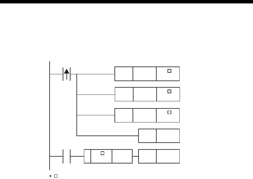
11 - 5
MELSEC-F
TROUBLESHOOTING11
11 - 5
(4) How to clear error information by writing to buffer memory
Writing to BFM#31800 to 31802 allows clearing the error information and turning
off COM.ERR.
MOV
SET
HFFFF U \
G31800
U \
G31802
MOV H0000 U \
G31801
MOV H0001
M100
U \
G31802
Set error information to clear
Error log and LED off instruction
Error clear execution processing
Set a flag that indicates that the
error is being cleared
Reset a flag that indicates that the
error is being cleared after the erro
r
has been cleared.
RST M100
= H0002
M100
corresponds to the module number.
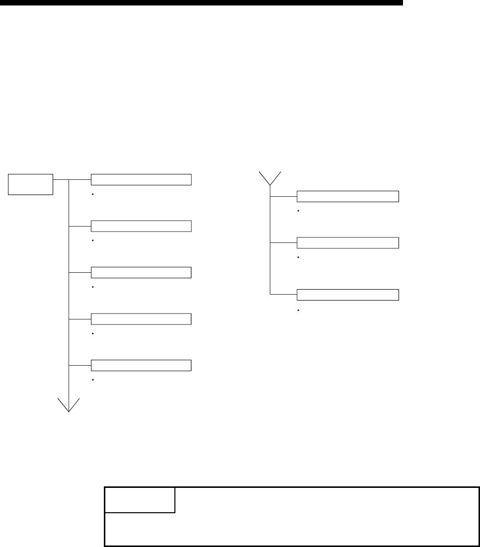
11 - 6
MELSEC-F
TROUBLESHOOTING11
11 - 6
11.2 How to Check an Error Through FX Configurator-EN-L
The status of the various settings for the Ethernet module can be checked using the
FX Configurator-EN-L functions.
(1) Ethernet diagnostics (See Section 11.2.2.)
The block status of an Ethernet module, parameter settings, communication
status, error log and others can be checked using the diagnostic function.
The following are the functions of the diagnostics.
(2) Buffer memory batch monitor (See Section 11.3.)
The buffer memory of an Ethernet module is monitored.
POINT
See Subsection 11.2.1 for the buffer memory that can be checked on the
"Ethernet diagnostics" screen.
Diagnostics Parameter status
Error log
Status of each connection
Status of each protocol
LED status
Send e-mail information
PING test
COM.ERR. off
Checks the stored parameters after the
initial processing for the Ethernet module.
(See Section 5.2.)
See Section 5.4
Checks the error stored in the error log area.
(See Section 11.4.)
Checks the status of each connection after the
connection to the external device is established
with the open processing. (See Section 5.6.)
Checks the communication status of each
protocol supported by the Ethernet module.
Checks the on/off status of the LED on the
front of the Ethernet module. (See Section 11.1.)
Checks the information for sent e-mail.
(See Section 11.4.)
Turns off the [COM.ERR.] LED on the front
of the Ethernet module.
See Subsection 11.1.2
Checks the completion of the initial processing
with the issuance of the PING command.
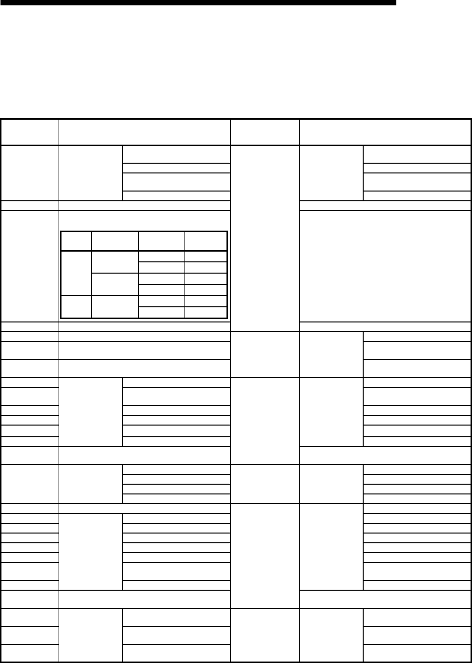
11 - 7
MELSEC-F
TROUBLESHOOTING11
11 - 7
11.2.1 Buffer memory that can be monitored with the FX Configurator-EN-L diagnostic
function
The following is a list of the buffer memory addresses that can be displayed on the
"Ethernet diagnostics" screen of FX Configurator-EN-L.
*1 Supported in the connections No. 1 and 2 only.
BFM address
Decimal
(hexadecimal)
Applicable buffer memory Ethernet diagnostics
display screen Display contents
32 (20H) Connection No.1
D Destination existence
confirmation (b1)
Status of each
connection
Connection No.1
Existence confirmation
Pairing open (b7) Paring open
Communication system (protocol)
(b8) Protocol
Open system (b15, b14) Open system
33 (21H) Connection No.2 (same as connection No.1) Connection No.2 (same as connection No.1)
34 (22H)
Connection No.3
Connection No.3 (same as connection No.1)
35 (23H) Connection No.4 (same as connection No.3) Connection No.4 (same as connection No.1)
105 (69H) Initial error code
Parameter status Module information
Initial error code
106 to 107
(6A to 6B H)Local station IP address IP address
108 to 110
(6C to 6E H)Local station Ethernet address Ethernet address
120 (78 H)
Connection No.1
Local station Port No. (Decimal)
Status of each
connection
Connection No.1
Local station Port No.
121 to 122
(79 to 7A H)Destination IP address Destination IP address
123 (7B H) Destination Port No. Destination Port No.
124 (7C H) Open error code Open error code
125 (7D H)Fixed buffer sending error code*1 Fixed buffer transfer error code*1
126 (7E H) Connection end code Connection end code
130 to 159
(82 to 9F H)Connection No.2 to 4 (same as connection No.1) Connection No.2 to 4 (same as connection No.1)
200 (C8 H) LED on/off status
[INIT.]LED (b0)
LED status LED display status
INIT.
[C1] to [C4] LED (b8 to b11) C1 toC4
[ERR.]LED (b3) ERR.
[COM.ERR.] LED (b4) COM.ERR.
227 (E3 H) Number of error occurrence
Error log
Latest
Number of error occurrences
229 (E5 H)
Error log block 1
Error code/End code Error code/End code
230 (E6 H) Subheader Subheader
231 (E7 H) Command code Command code
232 (E8 H) Connection No. Connection No.
233 (E9 H) Local station Port No. (Decimal) Local station Port No.
234 to 235
(EA to EB H)Destination IP address Destination IP address
236 (EC H) Destination Port No. Destination Port No.
238 to 372
(EE to 174 H)Error log block 2 to 16 (same as error log block 1) No.2 to 16 (same as the latest error log block)
376 to 377
(178 to 179 H)
IP
Received IP packet count
Status of each
protocol IP packet
Total number of echo reply sends
378 to 379
(17A to 17B H)
Received IP packet count
discarded due to sum check error Total number echo request sends
380 to 381
(17C to 17D H)Sent IP packet total count Total number echo reply receives
Protocol Open system Existence
confirmation Setting value
TCP
Unpassive Performed 8403H
Not performed 8401H
Fullpassive Performed C403H
Not performed C401H
UDP — Performed 0503H
Not performed 0501H
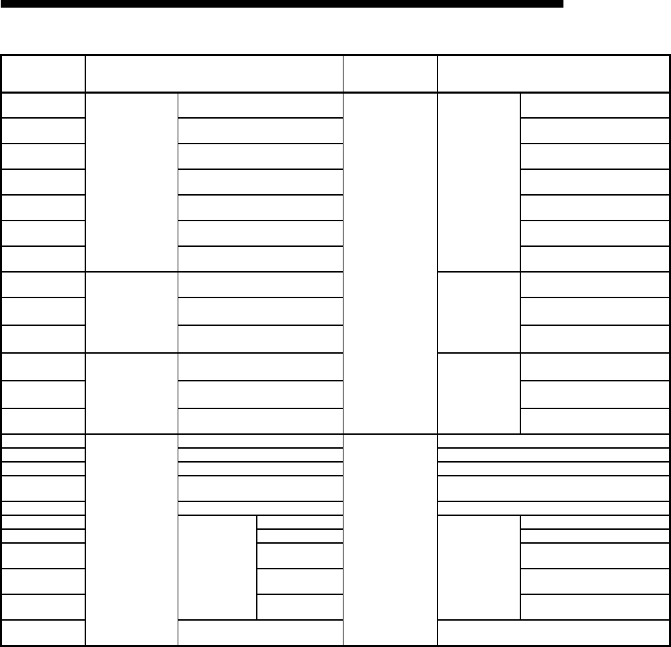
11 - 8
MELSEC-F
TROUBLESHOOTING11
11 - 8
BFM address
Decimal
(hexadecimal)
Applicable buffer memory Ethernet diagnostics
display screen Display contents
408 to 409
(198 to 199 H)
ICMP
Received ICMP packet count
Status of each
protocol
ICMP packet
Total number of receives
410 to 411
(19A to 19B H)
Received ICMP packet count
discarded due to Sum check error
Total number of Sum check error
annulments
412 to 413
(19C to 19D H)Sent ICMP packet total count Total number of sends
414 to 415
(19E to 19F H)
Echo request total count of received
ICMP packets
Total number echo request
receives
416 to 417
(1A0 to 1A1 H)
Echo reply total count of sent ICMP
packets Total number of echo reply sends
418 to 419
(1A2 to 1A3 H)
Echo request total count of sent
ICMP packets
Total number of echo request
sends
420 to 421
(1A4 to 1A5 H)
Echo reply total count of received
ICMP packets
Total number of echo reply
receives
440 to 441
(1B8 to 1B9 H)
TCP
Received TCP packet count
TCP packet
Total number of receives
442 to 443
(1BA to 1BB H)
Received TCP packet count
discarded due to Sum check error
Total number of Sum check error
annulments
444 to 445
(1BC to 1BD H)Sent TCP packet total count Total number of sends
472 to 473
(1D8 to 1D9 H)
UDP
Received UDP packet total count
UDP packet
Total number of receives
474 to 475
(1DA to 1DB H)
Received UDP packet count
discarded due to Sum check error
Total number of Sum check error
annulments
476 to 477
(1DC to 1DD H)Sent UDP packet total count Total number of sends
23355 (5B3B H)
Send
Number of mails normally completed
Send e-mail
information
Number of mails normally completed
23356 (5B3C H) Number of attached file sends Number of attached file sends
23357 (5B3D H) Number of sends to the server Number of sends to the server
23358 (5B3E H)Number of mails abnormally
completed Number of mails abnormally completed
23359 (5B3F H) Number of error log writes Number of error log writes
23361 (5B41 H)
Error log block 1
Error code
Latest error log
Error code
23362 (5B42 H) Command code Command code
23363 to 23370
(5B43 to 5B4A H)To To
23371 to 23374
(5B4B to 5B4E H)Send date Send date
23375 to 23404
(5B4F to 5B6C H)Subject Subject
23405 to 23712
(5B6D to 5CA0 H)
Error log block 2 to 8
(same as error log block 2 to 16)
Error log block 2 to 8
(same as error log block 1)
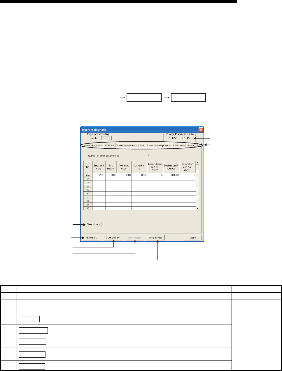
11 - 9
MELSEC-F
TROUBLESHOOTING11
11 - 9
11.2.2 Ethernet diagnostics
[Purpose]
The block status of an Ethernet module, parameter settings, communication status,
error log and others can be checked using the Ethernet diagnostic function of
FX Configurator-EN-L.
[Operating procedure]
FX Configurator-EN-L
[Ethernet diagnostics screen]
[Explanation of items]
No. Item Description Setting range
1 Change IP address display Switches the IP address display between decimal and hexadecimal. Decimal/hexadecimal
2Selection from the various
information monitors
Various types of information for the Ethernet module can be monitored.
(See Subsection 11.2.1 for the buffer memory corresponding to the display contents.)
—
3Performs the PING test on the external device. (See Subsection 5.4.1, Subsection
5.4.2.)
4 Clicking this button turns the [COM.ERR.] LED off. (See Subsection 11.1.2.)
5Clicking this button executes the Ethernet diagnostics.
The display is updated during monitoring.
6Clicking this button stops the Ethernet diagnostics.
The display is retained while monitoring is stopped.
7 Clicking this button executes the clears the log.
Diagnostics Diagnostics
7)
3)
4)
5)
6)
1)
2)
PING test
COM. ERR off
Start monitor
Stop monitor
Clear history

11 - 10
MELSEC-F
TROUBLESHOOTING11
11 - 10
11.3 Checking the error information by the buffer memory batch monitoring function
It is explained here how the Ethernet module errors can be checked from GX
Developer.
Error codes stored in the buffer memory of the Ethernet module can be monitored
using the "Buffer memory batch monitoring" function of GX Developer.
[Operating procedure]
(Step 1) Select [Online] - [Monitor] - [Buffer memory batch] from the GX Developer
menu bar, and start the "Buffer memory batch monitoring" screen.
(Step 2) Enter [Module start address:].
Assign a special module number to each base module following the order
that 0 is assigned to the rightmost module, 1 to the second rightmost module,
and goes same up to 7.
However, for FX3UC-32MT-LT(-2) which incorporates the CC-Link/LT
function, the first special module will be assigned with No.1.
(Step 3) Enter [Buffer memory start address:].
Enter the buffer memory address to be monitored, using the selected input
format (decimal/hexadecimal).
For a list of the buffer memory addresses where error codes are stored, see
Section 11.4, "Error Code List".
(Example)
When monitoring the initial abnormal code (BFM #105):
Enter "105" + "decimal"
(Step 4) Click the button.
The contents of the buffer memory after the specified address are displayed.
(In case of the above example, the contents of 105H and succeeding
addresses are displayed.)
NOTE
The display format can by modified as follows:
For details, refer to the "Operating Manual" for GX Developer.
POINT
To see if the PLC base module recognizes the FX
3U
-ENET-L or not, monitor BFM
#30.
If BFM #30's value is K7132, the FX3U-ENET-L is being recognized.
Monitor format : Bits & words/ Multiple bit points/ Multiple word points
Display : 16-bit integer/32-bit integer/real number/ASCII character
Numerical value : Decimal/hexadecimal
Start Monitor

11 - 11
MELSEC-F
TROUBLESHOOTING11
11 - 11
11.4 Error Code List
This section explains the error codes (abnormal codes) for the errors that may occur
in each processing when communicating data between the Ethernet module and an
external device as well as those generated by processing requests from the local
station's FX series PLC.
11.4.1 Type of error incident
The details of errors and error handling procedures are described.
* For error codes sent back by data communication using MX Component, refer to the MX Component Programming Manual.
Type of error Description Error code storage buffer memory Explanation
1 Errors occurring in initial processing • Setting value error
• Initial processing error
BFM#105............. Initial error code
(Communication status storage area)
Subsection
11.4.4
2 Errors occurring in open processing • Setting value error
• Open processing error
BFM#124............. Open error code
(Communication status storage area)
3Errors occurring in fixed buffer
sending to an external device
• Designated data error
• Sending error
BFM#125..............Fixed buffer sending error code
BFM#126..............Connection end code
(Communication status storage area)
4
Errors occurring in fixed buffer
communication with an external
device
• Designated data error
• Communication error
(exclude 3 above)
BFM#126...............Connection end code
(Communication status storage area)
5
Errors returned to an external device
when communicating with the
external device
• Errors returned in fixed buffer communication (end code) Subsection
11.4.2
• Error returned in communication
using MC protocol
End codes when A compatible 1E frame commands
are used
Subsection
11.4.2
Error codes when A compatible 1E frame commands
are used
Subsection
11.4.3
6
Errors occurring while
communicating with an external
device (including the causes shown
in the description column), and
whose error codes are stored in the
error log area.
• Designated data errors
• Errors whose source cannot be
confirmed
• Errors that occurred while
communicating using MC protocol
BFM#229
(Error log area)
Subsection
11.4.4
7 Errors occurring when sending e-mail • Setting data error
• Sending error
BFM#23355 Send
(E-mail status storage area)
Subsection
11.4.4

11 - 12
MELSEC-F
TROUBLESHOOTING11
11 - 12
(1) Initial error code (BFM#105)
(a) This address stores the error codes generated when the initial processing is
executed.
(b) Error codes are stored as binary values when the initial abnormal completion
signal (BFM#28...b5) is on.
(c) An error code is cleared when the initial normal completion signal
(BFM#27"0001H", BFM#28...b0: ON) is turns on, but can also be cleared by
the following operations.
1) Writing the value in BFM#1600 to perform re-initialization or turning off
the PLC and Ethernet module
2) Re-downloading the parameter with FX Configurator-EN-L or sequence
pragram
(2) Open error code
(connection numbers: 1 to 4; BFM#124 to 154)
(a) These addresses store the result of the open processing for the applicable
connections.
(b) The results of the open processing are stored in binary values.
0 : Normal completion
Other than 0 : Abnormal completion (BFM#28 b6: ON)
(c) An error code is cleared by the following operations.
1) Reopening the connection that caused an open error
2) Performing the re-initial processing by writing the value to BFM#1600
(3) Fixed buffer sending error code
(connection numbers: 1 to 2; BFM#125 to 135)
(a) These addresses store error codes generated when an error in data sending
to an external device occurs during fixed buffer communication using the
applicable connection.
(b) A sending error code is cleared when the next data sending is normally
completed.
(4) Connection end code
(connection numbers: 1 to 2; BFM#126 to 136)
(a) These addresses store end codes returned from an external device as a
response during the fixed buffer communication using the applicable
connection.
(b) Determine how to handle the end codes in the responses by arranging with
the particular external device.

11 - 13
MELSEC-F
TROUBLESHOOTING11
11 - 13
(5) Error log area (BFM#227 to 372)
This area stores the following errors.
• Errors whose source cannot be confirmed
• Errors that occurred during communications using the random access buffer
• Errors that occurred during communications using MC protocol
(a) Number of error occurrences (BFM#227)
1) This address stores the number of errors registered in the error log block
area.
2) When errors occur more than 65536 times, the count is stopped at
FFFFH (65535).
(b) Error log write pointer (BFM#228)
1) This address stores the error log block number where the latest error
logging is registered.
0 : No error. (No registration of error log)
1 or more : Error log block number where the latest error logging is
registered
* If the pointer value is "16", it means that the latest error logging is
registered in the error log block 16 area.
2) When 17 or more errors occur, the registration of error logging starts from
error log block 1 area again.
(c) Error log block - Error code/end code (starting from BFM#229)
1) In the error code/end code area, error codes are stored that indicate error
content. (See Section 11.3.)
(d) Error block - Subheader (starting from BFM#230)
1) The subheader code of a faulty message is stored in bits 0 to 7 of the
corresponding area. ("0" is stored in bits 8 to 15).
2) For errors below the TCP and UDP levels, "0" is stored.
(e) Error log block - Command code (starting from BFM#231)
1) This block stores the command code of a errors message.
2) "0" is stored in the following case.
• For messages not containing a command code
• For errors below the TCP and UDP levels (because their commands
are unknown)
POINT
(1) An error log block area consists of sixteen error log blocks that have the same
data order.
(2) The error information continues to be stored into the following areas even if
the count of the error occurrences is stopped and no longer stored:
• Error log write pointer storage area
• Error log block
Command code
b15 b0
to

11 - 14
MELSEC-F
TROUBLESHOOTING11
11 - 14
(f) Error log block - Connection No. (starting from BFM#232)
1) The faulty connection No. is stored in bits 0 to 3 of the corresponding
area. ("0" is stored in bits 4 to 15).
2) For errors below the TCP and UDP levels, "0" is stored.
(g) Error log block - Local station Port No. (starting from BFM#233)
1) This block stores the local station's port No. when an error occurred.
2) "0" is stored for errors below the TCP and UDP levels.
(h) Error log block - Destination IP address (starting from BFM#234)
1) This block stores the IP address of an external device when an error
occurred.
2) "0" is stored in the following cases.
• For errors below the IP level
• When an error response was relayed through the PLC.
(i) Error log block - Destination Port No. (starting from BFM#236)
1) This block stores the external device's port No. when an error occurred.
2) "0" is stored for errors below the TCP and UDP levels.
(j) Status for each protocol (BFM#376 to 511)
1) This address stores the count of the occurrence for the applicable
contents of each protocol's condition.
(The value counted by the Ethernet module.)
2) When the count value exceeds two words, the count stops at
FFFFFFFFH (4294967295).
POINT
Values stored in the buffer memory are cleared when the Ethernet module's local
station is powered on. (They are not cleared during the initial processing.)
Normally, it is not necessary to read this area; so, read it as needed during
maintenance.

11 - 15
MELSEC-F
TROUBLESHOOTING11
11 - 15
(6) E-mail status storage area (BFM#22640 to 24575)
* When the storage count exceeds FFFFH times, the count starts from 0H again.
(a) E-mail status storage area for sending (BFM#23355 to 23712)
1) Number of mails normally completed (BFM#23355)
• This address stores a cumulative count of how many times the
Ethernet module transferred send mails to the Send mail server.
2) Attached file sending count (BFM#23356)
• This address stores a cumulative count of how many times the
Ethernet module sent mails with files attached.
3) Sending to the server count (BFM#23357)
• This address stores a cumulative count of sending to the send mail
server.
4) Number of mails abnormally completed (BFM#23358)
• This address stores a cumulative count of communication error
occurrences that are returned when requesting sending to the
transmitting mail server.
5) Error log write count (BFM#23359)
• This address stores a cumulative count of registrations made to the
sending error log block area.
0 : No mail was sent.
1 or more :The number of normal completions of mail sending
0 : No mail with files attached has been sent.
1 or more :The number of normal completions of mail sending with
files attached
0 : No mail was sent to the server.
1 or more :Cumulative count of sending to the server
0 : No communication error between servers, or no
transmission has been made
1 or more :Cumulative count of communication error occurrences
0 : No error, or no inquiry has been made to the server.
1 or more :Cumulative count of registrations made to the error log
block area

11 - 16
MELSEC-F
TROUBLESHOOTING11
11 - 16
6) Sending error log write pointer (BFM#23360)
• This address stores the error log block area number where the latest
sending error logging is registered.
* If the pointer value is "8", it means that the latest error logging is
registered in the sending error log block 8 area.
• When 9 or more sending errors occur, the registration of sending error
logging starts from sending error log block 1 area again.
7) Error log block - Error code (BFM#23361 onwards)
• This block stores the error codes that indicate the contents of errors.
(See Section 11.4.)
8) Error log block - Command code (BFM#23362 onwards)
• This block stores the system command codes for the error causing
messages.
9) Error log block - To (BFM#23363 onwards)
• This block stores eight words from the beginning of the sending source
mail address of an error causing e-mail during communication with the
mail server, in ASCII code characters.
(Example)
If the sending source mail address was
"use@from.add.sample.co.jp",
"use@from.add.sam" is stored as ASCII code characters.
10)Error log block - Date (BFM#23371 onwards)
• This block stores the time and date on which the e-mail is sent in BCD
code.
• The order of date and time to be stored is the same as for the date and
time of e-mail reception shown in (a) 11).
11) Error log block - Subject (BFM#23375 onwards)
• This block stores 30 words from the beginning of the Subject of the
e-mail.
•A Subject is not stored successfully if it contains characters other than
alphanumeric and ASCII code.
0 : No error. (No registration of sending error log)
1 or more :Error log block number where the latest sending error
logging is registered
POINT
The sending error log block area consists of eight error log blocks that have the
same order of data items.
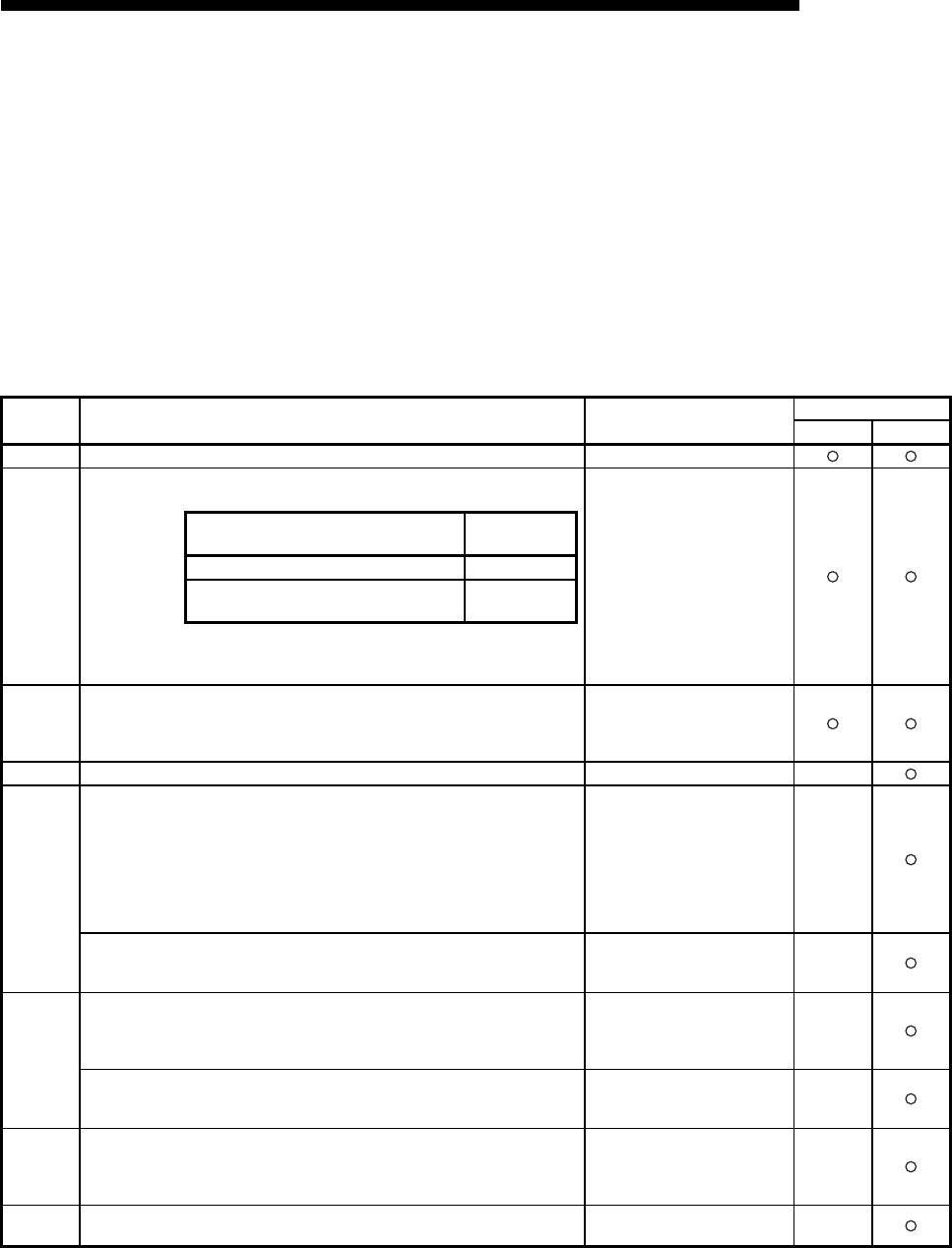
11 - 17
MELSEC-F
TROUBLESHOOTING11
11 - 17
11.4.2 End codes (Complete codes) returned to an external device during data
communication
This section explains the end codes (complete codes) that are added to responses
when communicating using the fixed buffer or the MC protocol.
For more details on the error codes that are added to responses during
communication using A compatible 1E frames through the MC protocol, see
Subsection 11.4.3.
For more details on the end codes (error codes) that are stored in the buffer memory
of the Ethernet module, see Subsection 11.4.4.
Fixed : Fixed buffer communication MC : Communication using MC protocol
End code Description Processing Communication function
Fixed MC
00H• Normal completion -
50H
• Codes for command/response type of subheader are not within the
specifications.
• In communication using the fixed buffer, if the data length setting is less than the
actual data count, the remaining data is determined as the second data and
processed. In this case, a subheader undefined command type error may occur.
• Check and correct command/
response type set by an
external device.
(The Ethernet module
automatically adds command/
response type; the user does
not need to set these.)
See NOTE in Subsection
11.4.4.
• Check and correct the data
length.
54H
• When "ASCII code communication" is selected (BFM #24b1: ON) in the
[Communication data code settings] of operational settings parameters of
FX Configurator-EN-L, ASCII code data that cannot be converted to binary code
was received from an external device.
• Check and correct the send
data of the external device.
56H• Device designation from an external side is incorrect. • Correct the device designated.
57H
• The number of points for a command designated by an external device exceeds
the maximum number of processing points for each processing (number of
processes that can be executed per communication).
• Head device number to the designated points exceeds the maximum addresses
(device number).
• When performing batch read/write operations on C200 to C255, the address
(device numbers), which was designated with the odd number of points, is
exceeded.
• Correct the designated points
or device number.
• Byte length of a command does not conform to the specifications.
• When writing data, the set number of data points written is different from the
value of the designated number.
• Check the data length of the
command and redo the data
setting.
58H
• Head device number of a command designated by an external device is set
outside the range that can be designated.
• Designate the appropriate
values within the range that
are allowed for each
processing.
• A word device is designated in a command for bit devices.
• The head number of bit devices is designated by a value other than a multiple of
16 in a command for word devices.
• Correct the command or the
designated device.
5BH• The PLC and the Ethernet module cannot communicate.
• The PLC cannot process requests from an external device.
• Fix the faulty parts by referring
to the abnormal codes
appended to the end codes
(see Subsection 11.4.3).
60H• Communication time between the Ethernet module and the PLC exceeded PLC
monitoring timer value.
• Increase the monitoring timer
value.
Communication processing Command/
response type
Communication using fixed buffer 60H
Communication using MC protocol 00 to 05 H
13 to 16 H
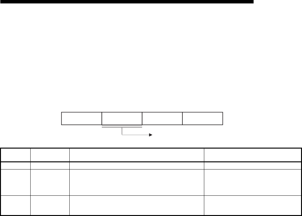
11 - 18
MELSEC-F
TROUBLESHOOTING11
11 - 18
11.4.3 Abnormal codes returned during communication using MC protocol
This section explains the abnormal codes (error codes) that are added to responses
when communicating using MC protocol (An abnormal code is added only when an
end code is "5B".)
For more details on the end codes (error codes) that are added to responses, see
Subsection 11.4.2.
For more details on the end codes (error codes) that are stored in the buffer memory
of the Ethernet module, see Subsection 11.4.4.
Error code
(hexadecimal) Error Description of error Corrective action
10HPC number error The PC number designated was not "FF". (1)Set the PC number to "FF"..
11HMode error
Poor communication between the Ethernet module and the PLC
(1)After the Ethernet module receives a request successfully from an
external device, the Ethernet module and the PLC could not
communicate for some reason (noise, etc.).
(1)Communicate again. If an error occurs again,
check noise, etc. and replace the Ethernet
module, then communicate again.
18HRemote error Remote RUN/STOP not accessible.
The PLC base module status is CPU ERR or PROG ERR.
(1)Check whether or not the base module has a
CPU ERR (light on) or PROG ERR (flashing
light).
00H
Abnormal code
Response format Subheader End code
When an abnormal code is stored, the end code is "5BH."
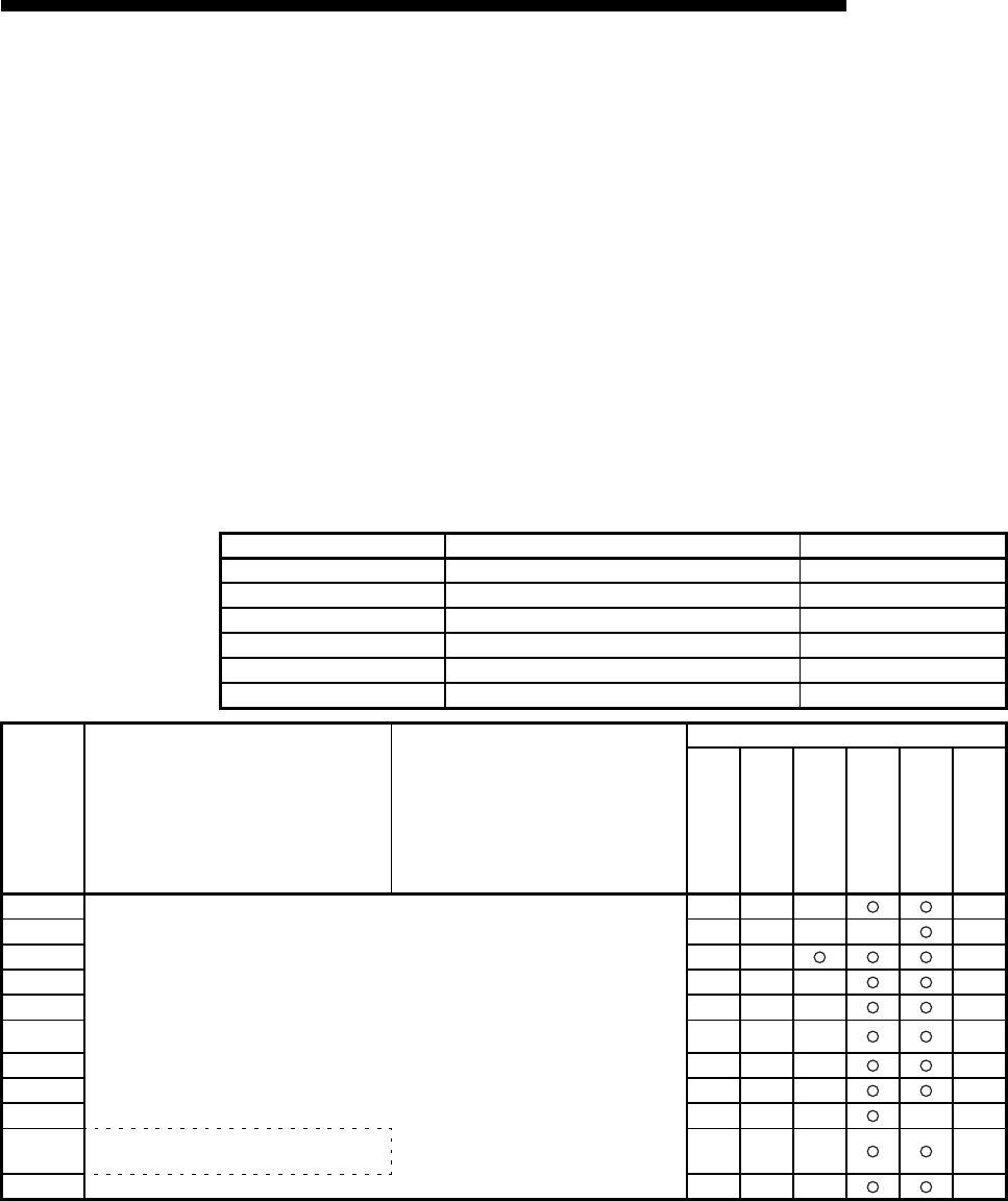
11 - 19
MELSEC-F
TROUBLESHOOTING11
11 - 19
11.4.4 Error codes stored in the buffer memory
When an error occurs at each data communication processing between the Ethernet
module and an external device, the error code (abnormal code) is stored in the buffer
memory of the Ethernet module. This section explains the contents of this type of
errors and error handling procedures.
The "Storage destination" column in the error code list indicates the buffer memory
where the applicable error code is stored.
The names used for the explanation indicated in the "Storage destination" column
corresponding to the buffer memory error code storage areas shown in the table
below. (Error codes whose storage destination is not written are returned to the
external device.)
Note that the buffer memory may store error codes of the messages returned from the
external device. For error codes not shown in this manual, refer to the manual of the
external device and check the returned messages.
Name used for explanation Buffer memory Buffer memory address
Initial Initial abnormal code area BFM#105
Open Open abnormal code area BFM#124...
Fixed sending Fixed buffer sending abnormal code area BFM#125...
Connection Connection end code/error log area BFM#126...
Error code Error code/end code area BFM#229...
E-mail log E-mail error log area BFM#23361...
Error code
(abnormal
code)
Description of error Error handling
Storage destination
Initial
Open
Fixed
sending
Connection
Error code
E-mail log
BFM#
105
BFM#
124
BFM#
125
BFM#
126
BFM#
229
BFM#
23361
0050H
0051H
0052HThe content of these errors and the error handling for each error code is the same as the end
codes (0050 to 0060H) returned to the external device.
Check the explanation of the applicable code shown in Subsection 11.4.1, and take actions
accordingly.
0054H
0055H
0056H
0057H
0058H
0059H
005BH
Read and handle the error code and end code
area.
0060H

11 - 20
MELSEC-F
TROUBLESHOOTING11
11 - 20
Error code
(abnormal
code)
Description of error Error handling
Storage destination
Initial
Open
Fixed
sending
Connection
Error code
E-mail log
BFM#
105
BFM#
124
BFM#
125
BFM#
126
BFM#
229
BFM#
23361
C001H
• At initial processing, the IP address setting
value of the Ethernet module is incorrect.
• When using the router relay function, the
setting value of the sub-net mask field is
incorrect.
• Correct the IP address.
Set the class to A/B/C.
• Correct the sub-net mask.
C002H
At initial setting, some of the various timer
setting values are outside the allowable range.
• Review and correct the necessary timer
values at initial processing.
C004H
The setting value of the sub-net mask field is
incorrect.
• Correct the sub-net mask and execute the
initial processing again.
C005H
• The setting value of the default router IP
address for the router relay function is
incorrect.
• Network address (network address after sub-
net mask) of the default router IP address is
different from the network address of the local
station's Ethernet module IP address.
• Correct the default router IP address and
execute the initial processing again.
• Set the network address to the same network
address as the local station's Ethernet
module IP address.
C006H
The setting value of the sub-net address for the
router relay function is incorrect.
• Correct the sub-net address and execute the
initial processing again.
C007H
• The setting value of the router IP address for
the router relay function is incorrect.
• Network address (network address after sub-
net mask) of router IP address is different
from the network address of the local station's
Ethernet module IP address.
• Correct the router IP address and execute
the initial processing again.
• Set the network address to the same network
address as the local station's Ethernet
module IP address.
C010H
At open processing, the setting value of the
Ethernet module port number is incorrect. • Correct the port number.
C011H
At open processing, the setting value of an
external device's port number is incorrect. • Correct the port number.
C012H
The port number set is used in a connection
already opened by TCP/IP.
• Review and correct the port numbers of the
Ethernet module and external device.
C013H
The port number used in a connection already
opened is set in UDP/IP open processing.
• Review and correct the port number of the
Ethernet module.
C014H
Initial processing and open processing of the
Ethernet module is not completed.
• Execute the initial processing and open
processing.
C015H
At open processing, the setting value of an
external device's IP address is incorrect.
• Correct the IP address.
Set the class to A/B/C.
C016H
The pairing open processing of the connection
(or the next connection) designated for pairing
open has already been completed.
• Check that the open processing of both of
the target connections for pairing open is not
executed.
• Review the combination for pairing open.
C017H
A connection could not be established during
the open processing of a TCP connection.
• Check the operation of the external device.
• Check the open processing of the external
device.
• Correct the open settings of the
communication parameters.
• Review the Ethernet module's port number
and the IP address/port number and open
system of the external device.
• Check that the connection cable is not
dislocated.
C018H
The setting value of an external device's IP
address is incorrect.
* When TCP is used, FFFFFFFFH
cannot be set as an IP address.
• Correct the IP address.

11 - 21
MELSEC-F
TROUBLESHOOTING11
11 - 21
Error code
(abnormal
code)
Description of error Error handling
Storage destination
Initial
Open
Fixed
sending
Connection
Error code
E-mail log
BFM#
105
BFM#
124
BFM#
125
BFM#
126
BFM#
229
BFM#
23361
C020HData length exceeds the allowable range.
• Correct the data length.
• If the data transmitted is larger than the
allowable size, divide and then send it.
C021H
An abnormal end response was received after a
transmission using fixed buffers.
• Read the end code of the response from the
connection end code/error log area, and
handle as needed.
C022H
• A response could not be received within the
response monitoring timer value.
• The applicable connection was closed while
waiting for a response.
• Check the operation of the external device.
• Review and correct the response monitoring
timer value.
• Check the open status of the applicable
connection.
C023H
• The open processing for the applicable
connection is not completed.
• The applicable connection is closed.
• Execute the open processing of the
applicable connection.
C030HA sending error occurred.
• Check the operation of the external device.
• Send after an arbitrarily selected time has
elapsed because packets may be congested
on the line.
• Check that the connection cable is not
dislocated.
C032H
A TCP ULP timeout error occurred in the TCP/
IP communication.
(An external device does not return ACK.)
• Check the operation of the external device.
• Correct the TCP ULP timeout value and
execute the initial processing again.
• Send after an arbitrarily selected time has
elapsed because packets may be congested
on the line.
• Check that the connection cable is not
dislocated.
C033H
An external device side with the set IP address
does not exist.
• Review and correct the external device's IP
address and the Ethernet address.
• If the external device has the ARP function,
set the initial value. If not, set the Ethernet
address of the external device.
• Check the operation of the external device.
• Send after an arbitrarily selected time has
elapsed because packets may be congested
on the line.
• Check that the connection cable is not
dislocated.
• Just after powering ON, there are cases
when the connected hub is not booted, so
send will occur after an arbitrary time period
has elapsed.
C035H
The existence of an external device could not
be confirmed within the response monitoring
timer value.
• Check the operation of the external device.
• Review and correct each setting value for the
existence confirmation.
• Check that the connection cable is not
dislocated.
C040H
• Not all the data could be received within the
response monitoring timer value.
• Sufficient data for the data length could not
be received.
• The remaining part of a message divided at
the TCP/IP level could not be received within
the response monitoring timer value.
• Review and correct the data length of the
communication data.
• Review and correct each setting value at the
initial processing because the packets may
be congested on the line.
• Send the same data from the external device
again.
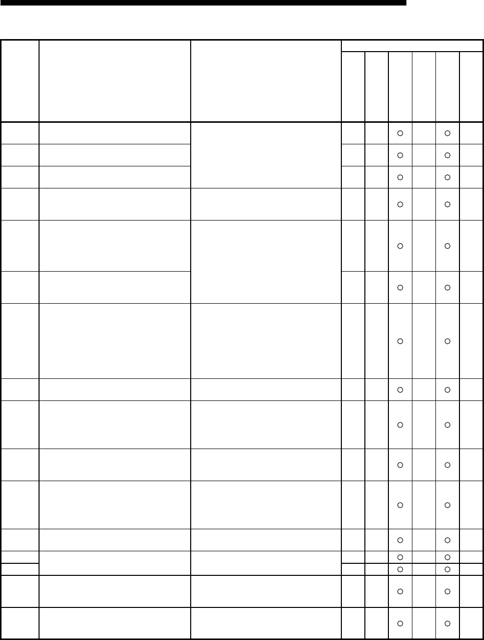
11 - 22
MELSEC-F
TROUBLESHOOTING11
11 - 22
*1 When this error occurs, the COM.ERR light turns on, but turns off again about one second later.
Error code
(abnormal
code)
Description of error Error handling
Storage destination
Initial
Open
Fixed
sending
Connection
Error code
E-mail log
BFM#
105
BFM#
124
BFM#
125
BFM#
126
BFM#
229
BFM#
23361
C041H
When TCP is used, the checksum of the receive
data is incorrect. • Review the checksum on the external device
side and send the correct value.
• Investigate the conditions of the line (noise,
distance between the line and power line,
contact of each device, etc.)
C042H
When UDP is used, the checksum of the
receive data is incorrect.
C043H
The checksum in header of IP packet received
is incorrect.
C044H
to
C048H
An error packet of ICMP was received.
• Check the operation of the external device.
• Check that the connection cable is not
dislocated.
C049HAn error packet of ICMP was received.
• Check the operation of the external device.
• Send after an arbitrarily selected time has
elapsed because packets may be congested
on the line.
• Check that the connection cable is not
dislocated.
• Correct the IP assembly timer value of the
external device existence timer timeout.
C04AH
An error packet of ICMP was received.
(An IP assembly timeout error occurred in an
external device.)
*1
C04BH
An IP assembly timeout error occurred.
(The remaining part of divided data could not be
received and a timeout occurred.)
• Check the operation of the external device.
• Send after an arbitrarily selected time has
elapsed because packets may be congested
on the line.
• Check that the connection cable is not
dislocated.
• Correct the IP assembly timer value and
execute the initial processing again.
C04CH
Cannot send because there is no space in the
internal buffer, e.g. the IP header buffer.
• Send the same data again and check that the
response is received.
C050H
ASCII code data that cannot be converted to
binary code is received when ASCII code
communication is set in the operational settings
of the Ethernet module.
• Select binary code communication in the
operational settings, and restart the Ethernet
module.
• Correct the data sent from the external side
and send again.
C051H
to
C054H
The number of read/write points is outside the
allowable range.
• Correct the number of read/write points and
send to the Ethernet module again.
C056H
• Read/write request exceeds the maximum
address.
• Address is 0.
• Correct the head address or the number of
read/write points and send to the Ethernet
module again.
(The maximum address must not be
exceeded.)
C059H
Incorrect designation of command and
subcommand. • Review the content of the request.
C05AHThe Ethernet module cannot read from/write to
the designated device. • Examine the device to be read/written.
C05BH
C05CH
The content of a request is incorrect.
(Requesting read/write in bit units to word
devices.)
• Correct the content of the request and send
to the Ethernet module again.
(Correction of subcommand, etc.)
C05EH
Communication time between the Ethernet
module and PLC exceeded the monitoring
timer.
• Increase the monitoring timer value.
• Check whether or not the PLC operates
normally.

11 - 23
MELSEC-F
TROUBLESHOOTING11
11 - 23
Error code
(abnormal
code)
Description of error Error handling
Storage destination
Initial
Open
Fixed
sending
Connection
Error code
E-mail log
BFM#
105
BFM#
124
BFM#
125
BFM#
126
BFM#
229
BFM#
23361
C05FH
The request could not be executed on the target
PLC.
• Correct the network number and PC number.
• Correct the content of the read/write request.
C060H
The content of a request is incorrect.
(Incorrect data was designated for bit devices,
etc.)
• Correct the content of the request and send
to the Ethernet module again.
(Correction of data, etc.)
C072H
The content of a request is incorrect.
(Requested read/write in bit units to word
devices.)
• Check whether the content can be requested
to the target PLC.
• Correct the content of the request and send it
to the Ethernet module again.
C073H
Request was not supported by the Ethernet
module of the target PLC. • Review the content of the request.
C086H
A message exceeding the receive message
size was received.
• Correct the send message size from the
requesting source.
C091H
System Error
(Flash ROM write error) (*1)
C093H
System Error
(The parameters written to flash ROM are
abnormal.)
(*1)
C0B5H
Data that could not be processed by the PLC/
Ethernet module was designated.
• Review the content of the request.
• Cancel the current request.
C0B9H
The open processing of the applicable
connection is has not been completed.
• Execute the open processing.
• Check the operation of the external device.
C0BAH
Cannot acknowledge sending request since the
close processing is being executed via the
CLOSE instruction.
• Execute the open processing and make a
sending request.
C0BBH
System error
• The OS detected any error. (*1)
C0BCHDesignated communication line is closed. • Open the communication line.
• Review the target connection number.
C0BDH
Cannot send by acknowledging continuous
requests.
• Check whether or not requests are made
continuously without waiting for responses.
C0BEHSystem error
• The OS detected any error. (*1)
C0BFH
C0C0H
The receiving completion confirmation signal
was turned on when the receiving completion
signal was not on.
• Review and correct the program.
C0C1HThe transmission interval of UDP is too short.
• Check whether or not sending requests are
repeated.
• Make the sending interval longer.
C0C2H
to
C0C3H
Systevm error
• The OS detected any error. (*1)
C0C4 H
Re-initialization was started during
communication
• Execute re-initialization after closing all
connections.
C0C5 H
• A sending request was made to an external
device whose class/network address are
different from those of the local station when
the router relay function is not used.
• The setting of the router relay parameter is
incorrect.
• Execute the initial processing by setting that
the router relay function should be used.
• Set the correct data for the router relay
parameter.
• Correct the IP address of the external device
and execute the open processing.
• Check that the network address is correct.
When it is changed, execute the initial
processing again.
C0C6H
System error
• The OS detected any error. (*1)

11 - 24
MELSEC-F
TROUBLESHOOTING11
11 - 24
Error code
(abnormal
code)
Description of error Error handling
Storage destination
Initial
Open
Fixed
sending
Connection
Error code
E-mail log
BFM#
105
BFM#
124
BFM#
125
BFM#
126
BFM#
229
BFM#
23361
C0C7HAn Ethernet module system error occurred.
• Execute the initial processing again.
• Execute the processing by referring Section
11.5 POINT (3).
C0C8H
to
C0CAH
System error
• The OS detected any error. (*1)
C0CBH
Another sending request was made when the
sending processing has not been completed.
• Make the next sending request after the
previous sending is completed.
C0CCHSystem error
• The OS detected any error. (*1)
C0CFH
C0D9HIncorrect subcommand value was designated. • Correct the designated value for the
subcommand.
C0DAH
A response to the PING test could not be
received within the time of the communication
time check.
• Review the IP address/host name of the
Ethernet module for the PING test.
• Change the status of the Ethernet module for
the PING to allow communication (to the
status after the initial processing is
completed).
C0DBH
There is an error in the IP address/host name of
the Ethernet module for the PING test.
• Review the IP address/host name of the
Ethernet module for the PING test.
C0DCH
to
C0DDH
System error
• The OS detected any error. (*1)
C0DFH
C0E0H
to
C0EFH
An error was detected in the PLC.
• Check the connection cables between the
PLC, extended I/Os or special module.
• Check that no error has occurred in the PLC.
If an error is found, take corrective actions
according to error description of the PLC.
• Replace the PLC and/or special function
block.
C0F0H
An Ethernet module RAM abnormality was
detected in the hardware test.
• Conduct a hardware test again. If an
abnormality is detected again, the Ethernet
module hardware may be faulty.
Consult your nearest branch office or dealer
with the details of the errors.
C0F1H
An Ethernet module ROM abnormality was
detected in the hardware test.
• Conduct a hardware test again. If an
abnormality is detected again, the Ethernet
module hardware may be faulty.
Consult your nearest branch office or dealer
with the details of the errors.
C0F4H
to
C0F6H
System error
• The OS detected any error. (*1)
C0F8 H
Attempted to access to a buffer memory No. for
which no base module of the PLC exists.
• Check the sequence program again.
• Check whether or not there is a contact
failure on the extension connector.
• Check whether or not there are any factors
possibly causing noise.
• The Ethernet module hardware may be
faulty.
Consult your nearest branch office or dealer
with the details of the errors.

11 - 25
MELSEC-F
TROUBLESHOOTING11
11 - 25
Error code
(abnormal
code)
Description of error Error handling
Storage destination
Initial
Open
Fixed
sending
Connection
Error code
E-mail log
BFM#
105
BFM#
124
BFM#
125
BFM#
126
BFM#
229
BFM#
23361
C0F9 H
Handshake error on TO instruction with a base
module
• Check whether or not there is a contact
failure on the extension connector.
• Check whether or not there are any factors
possibly causing noise.
• The Ethernet module hardware may be
faulty.
Consult your nearest branch office or dealer
with the details of the errors.
C0FAH
Base module 5V error
• There is no power to the base module
• The extension connector is not connected
• The Ethernet module was turned on before
the base module.
• Check that power to the base module is ON.
• Check that there are no connection errors on
the extension connector.
• Turn on the base module and Ethernet
module at the same time.
• There may be a hardware problem with the
Ethernet module or the base module.
Consult your nearest branch office or dealer
with the details of the errors.
C0FBH
Error detected at base module
• An error is occurring at the base module
• The extension connector is not connected
• Review the sequence program.
• Check that there are no connection errors
with the extension connector.
• There may be a hardware problem with the
Ethernet module or the base module.
Consult your nearest branch office or dealer
with the details of the errors.
C100H
System error
• The OS detected any error. (*1)
C101H
A response could not be received from the DNS
client.
• Check the address of the DNS server.
• Check whether or not it is possible to
communicate with the DNS server using the
Ping command.
• Check that the IP addresses of the local
station and DNS server are in the same
class. (If the class is different, check the
router setting.)
C102H
A response from the SMTP layer could not be
received.
• Check that the SMTP server name is
registered in DNS.
• Delete the SMTP server name, change to the
IP address setting, and check the operation.
• Check whether or not it is possible to
communicate with the SMTP server using
the Ping command.
C103HDNS settings incorrect. • Check the DNS mail address.
• Check the content of the DNS setting.
C104H
to
C106H
System error
• The OS detected any error. (*1)
C110H
C111H
A response could not be received from the DNS
client.
• Check cable, hub, etc.
• Check whether or not it is possible to
communicate with the DNS server using the
Ping command.
C112H
A response from the POP3 layer could not be
received.
• Check that the POP3 server name is
registered in DNS.
• Delete the POP3 server name, change to the
IP address setting, and check the operation.
• Check whether or not it is possible to
communicate with the POP3 server using the
Ping command.

11 - 26
MELSEC-F
TROUBLESHOOTING11
11 - 26
Error code
(abnormal
code)
Description of error Error handling
Storage destination
Initial
Open
Fixed
sending
Connection
Error code
E-mail log
BFM#
105
BFM#
124
BFM#
125
BFM#
126
BFM#
229
BFM#
23361
C115H
to
C118H
System error
• The OS detected any error. (*1)
C11CHMail address not found.
• Check whether the mail setting of the
parameter setting is correct or not.
• When the mail server and Ethernet module
are connected via the router, check whether
the router setting is correct or not.
• Test-send a mail to the address where it will
be received without fail. When the test is
normally completed, recheck whether the
domain name after "@" is correct or not.
C11DH
The size of the attached file exceeded the
allowable size.
• Check that the attached file is less than
2 k word.
• Check that the sending side did not divide
the file.
C120HCould not open the SMTP server.
• Check the port number of the SMTP server
setting.
• Check whether or not it is possible to
communicate with the SMTP server using
the Ping command.
C121H
Cannot communicate with the SMTP server.
(Error response)
• Check the port number of the SMTP server
setting.
• Check if the SMTP server is busy.
C122H
Cannot communicate with the SMTP server.
(Abort) • Check if the SMTP server is busy.
C123H
Cannot communicate with the SMTP server.
(Reset response) • Check if the SMTP server is busy.
C124HA response from the SMTP server timed out.
• Check whether or not the SMTP server is
faulty.
• Check whether or not there is too much load
on the network.
C125HForcefully disconnected from the SMTP server. • Check whether or not the SMTP server is
faulty.
C126HCould not close the SMTP server.
• Check whether or not the SMTP server is
faulty.
• Check whether or not there is too much load
on the network.
C127H
Closing the SMTP server gave an error
response.
• Check whether or not the SMTP server is
faulty.
C130H
Communication channel is closed because the
service is not available. • Check the status of the SMTP server.
C131H
The SMTP server was performing processing
and an error response was received.
• Check if a user name not registered in the
server was designated.
• Send again after arbitrary set time has
passed.
C132H
The SMTP server was performing processing
and an error response was received.
(Local error)
• Check the status of the SMTP server.
C133H
The SMTP server was performing processing
and an error response was received.
(Insufficient memory area)
• Check the status of the SMTP server.
C134H
to
C137H
System error
• The OS detected any error. (*1)
C138H
The SMTP server was performing processing
and an error response was received.
(Mailbox not found)
• Check that the Ethernet module's mail
address is set correctly.

11 - 27
MELSEC-F
TROUBLESHOOTING11
11 - 27
Error code
(abnormal
code)
Description of error Error handling
Storage destination
Initial
Open
Fixed
sending
Connection
Error code
E-mail log
BFM#
105
BFM#
124
BFM#
125
BFM#
126
BFM#
229
BFM#
23361
C139H
System error
• The OS detected any error. (*1)
C13AH
The SMTP server was performing processing
and an error response was received.
(Exceeded the allocation of memory area)
• Check the status of the SMTP server.
C13BH
The SMTP server was performing processing
and an error response was received.
(Illegal mail box name)
• Check that the Ethernet module's mail
address is set correctly.
C13CH
System error
• The OS detected any error. (*1)
C13DHSMTP server authentication error.
• Check whether the SMTP login ID and SMTP
password are correct.
• Check the SMTP server status.
C13EHSMTP server authentication nonsupport error
• Check whether the SMTP server supports
authentication.
• Set [SMTP authentication method] to [No
authentication] or [POP before SMTP].
C140HCould not open the POP3 server.
• Check the port number of the POP3 server
setting.
• Check whether or not it is possible to
communicate with the POP3 server using the
Ping command.
C141H
Cannot communicate with the POP3 server.
(Error response)
• Check the port number of the POP3 server
setting.
• Check if the POP3 server is busy.
C142H
Cannot communicate with the POP3 server.
(Abort) • Check if the POP3 server is busy.
C143H
Cannot communicate with the POP3 server.
(Reset response) • Check if the POP3 server is busy.
C144H
Could not receive a response from the POP3
server.
• Check whether or not the POP3 server is
faulty.
• Check whether or not there is too much load
on the network.
• Check that the correct password is being
sent to the POP3 server.
C145HForcibly disconnected from the POP3 server. • Check whether or not the POP3 server is
faulty.
C146HCould not close the POP3 server.
• Check whether or not the POP3 server is
faulty.
• Check whether or not there is too much load
on the network.
C147H
Closing the POP3 server gave an error
response.
• Check whether or not the POP3 server is
faulty.
C150HPOP3 server authentication error • Check the status of the POP3 server.
C151H
The Ethernet module's mail address (e-mail
address setting parameter) is different from the
account name in the mailbox on the server side.
• Check the account name in the mailbox on
the server side and correct the mailbox
account set for the Ethernet module.
C152H
The Ethernet module's password (e-mail setting
parameter) is different from the password on the
server side.
• Check the password on the server side and
correct the password set for the Ethernet
module.
C153H
An error occurred when getting the received
mail list.
(Failed to obtain the list of arrived mail at the
POP3 server.)
• Check the status of the POP3 server.
• Send again after arbitrary set time has
passed.

11 - 28
MELSEC-F
TROUBLESHOOTING11
11 - 28
Error code
(abnormal
code)
Description of error Error handling
Storage destination
Initial
Open
Fixed
sending
Connection
Error code
E-mail log
BFM#
105
BFM#
124
BFM#
125
BFM#
126
BFM#
229
BFM#
23361
C160H
Received a response from the DNS server after
timeout. • Check whether or not there is too much load
on the network.
• Check the status of the DNS server.
C161H
Could not receive a response from the DNS
server.
C162H
An error is returned from DNS server.
• Check if the DNS server's IP address setting
is correct or not.
• Check if the mail server name setting (SMTP
server name, POP server name) is correct or
not.
• Check with the network administrator or
similar person that the DNS function of the
server set in the DNS setting" is being
performed.
C163H
C171H
to
C17FH
C180H
Multiple instructions for e-mail sending
• Mail sending instruction was issued while
sending a mail.
• Issue the instruction for sending a mail after
checking the mail send status.
C1A0HAn illegal request was made.
• Execute again.
If the same error occurs, the Ethernet
module's hardware may be faulty.
Consult your nearest branch office or dealer
with the details of the errors.
C1A2HA response to a request could not be received. • Review and correct the response wait time.
C1A5H
The designation of the target station or clear
target were incorrect.
• Correct the designated value of the target
station or clear target.
C1A6HIncorrect connection number was designated. • Designate the connection number within the
range of 1 to 4.
C1A7HIncorrect network number was designated. • Correct the designated value of the network
number.
C1ACHIncorrect resent count was designated. • Correct the designated value of the resent
count.
C1ADHIncorrect data length was designated. • Correct the designated value of the data
length.
C1AEH
Incorrect mail sending data length and header
length were designated.
• Correct the designated values of sending
data length and header length.
• Sending data length should be equal or
longer than the header length.
C1AFHIncorrect port number was designated. • Correct the designated value of the port
number.
C1B0H
The open processing of the designated
connection is already completed.
• Execute the open processing after executing
the close processing.
C1B1H
The open processing of the designated
connection has not been completed. • Execute the open processing.
C1B2H
The OPEN/CLOSE instruction is being
executed in the designated connection.
• Execute after the OPEN/CLOSE instruction
is completed.
C1B3H
Another sending/receiving instruction is being
executed on the designated channel.
• Change the channel number.
• Execute after the sending/receiving
instruction is completed.
C1B6H
Incorrect mail destination number was
designated.
• Review the designated value of the mail
designation number.
• Review the sending mail address setting
parameter.
C203H
System error
• The OS detected any error. (*1)
C206H
System error
• The OS detected any error. (*1)
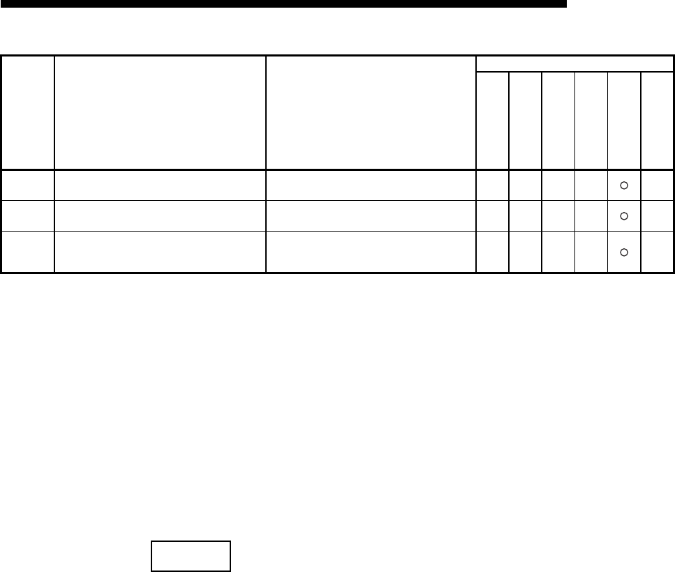
11 - 29
MELSEC-F
TROUBLESHOOTING11
11 - 29
* 1 Take corrective action using the following procedure.
1) Check whether the expansion connectors are connected correctly.
2) Check whether the operating environment of the Ethernet module is within the general
specifications range of the module.
3) Check whether the power supply capacity is sufficient or not.
4) Check whether the hardware of the Ethernet module, power supply block and PLC are normal
according to the manuals of the corresponding modules.
If any module is faulty, please request your local Mitsubishi service center or representative to
have it serviced.
5) If the problem cannot be solved through the above steps, please consult your local Mitsubishi
service center or representative, explaining the operation/communication conditions at the time of
error occurrence and the information stored in the error log area within the buffer memory of the
Ethernet module.
NOTE
Depending on the restrictions of the buffers of the local station and external device,
data may be divided for communication.
Data received separately is restored (reassembled) by the Ethernet module to be
communicated using the fixed buffer, etc. The received data is restored
(reassembled) based on the data length in the communication data.
The Ethernet module performs the following processing if data among the
communication data is incorrect.
Error code
(abnormal
code)
Description of error Error handling
Storage destination
Initial
Open
Fixed
sending
Connection
Error code
E-mail log
BFM#
105
BFM#
124
BFM#
125
BFM#
126
BFM#
229
BFM#
23661
C281H
Improper usage setting of connections for fixed
buffer
• Review and correct the set value for usage of
connections No. 1 and 2.
C282H
Improper usage setting of connections for
MELSOFT connection/MC protocol
• Review and correct the set value for usage of
connections No. 3 and 4.
C300 H
A response could not be received within the
response monitoring timer value.
• Check the operation of the external device.
• Review and correct the response monitoring
timer value.
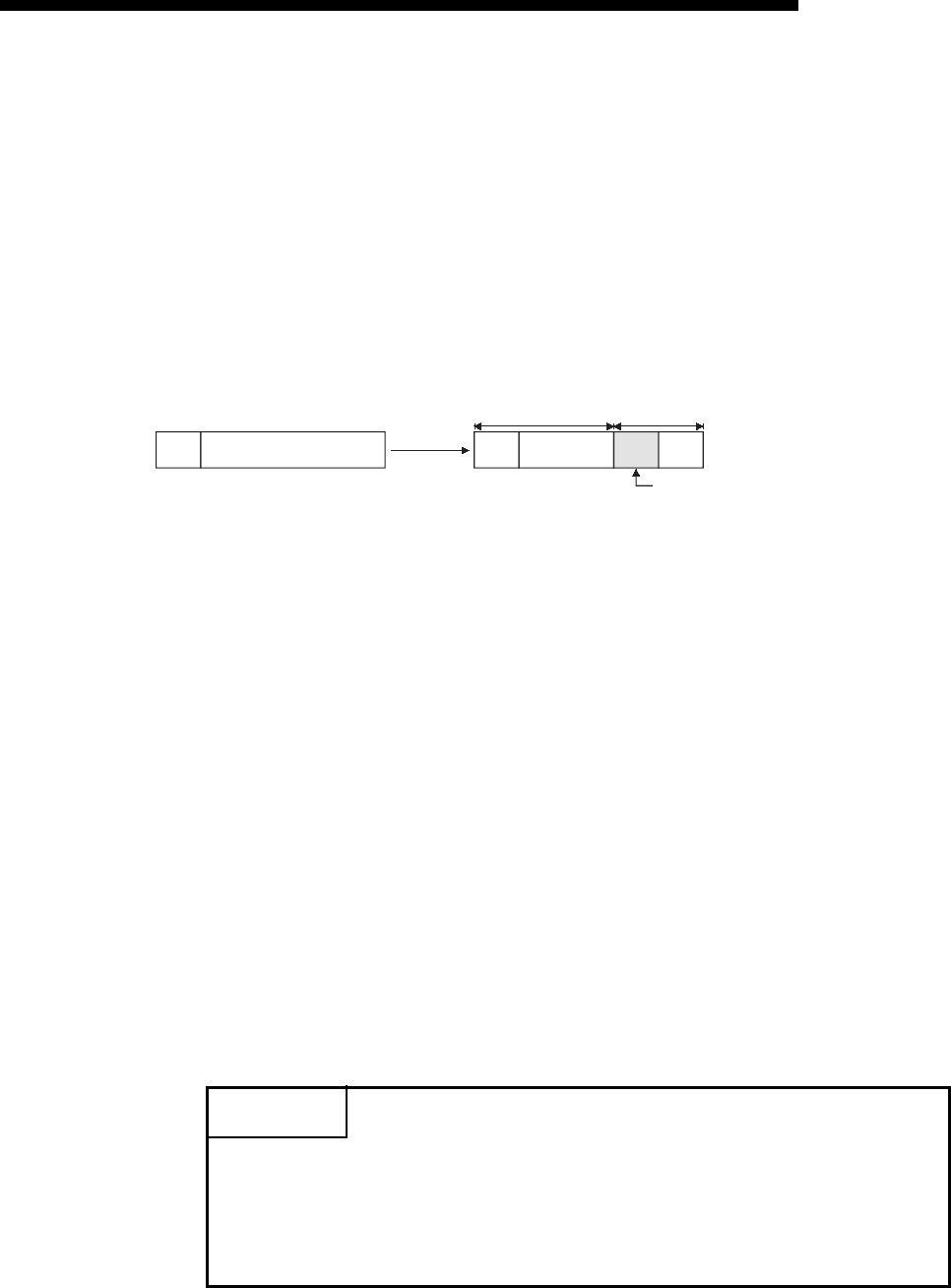
11 - 30
MELSEC-F
TROUBLESHOOTING11
11 - 30
(1) When communication is performed using fixed buffer (with procedure)
(a) If the data length specified immediately after the subheader is smaller than
the amount of text data received
1) The data immediately following the part of the text data equivalent to the
data length specified immediately after the subheader will be regarded as
the next message.
2) Since the header of each message will be a subheader, the Ethernet
module performs processing according to the code in the subheader.
3) If the subheader contains a code that is not recognized by the Ethernet
module, the Ethernet module will send a response to the external device
notifying it of abnormal completion.
At this point, the Ethernet module returns a response containing a code
obtained by changing the most significant bit of the code processed as
subheader to 1.
For example, if the subheader field of a command is 65H, the subheader of
the response will become E5H.
(b) If the data length specified immediately after the subheader is larger than the
amount of text data received
1) The Ethernet module waits for the reception of the remaining missing
data.
2) If the remaining data could be received within the time allotted by the
response monitoring timer, the Ethernet module performs processing
according to the code in the subheader.
3) If the remaining data could not be received within the time allotted by the
response monitoring timer, the Ethernet module performs the following
processing.
• Sends the ABORT (RST) instruction to the external device and closes
the line.
• Notifies the PLC side about occurrence of an open error via the open
error detection signal (BFM#28.b6=ON)
• Stores the error code in the open error code storage area. (The error
code is not stored in the error log storage area.)
POINT
Designate the actual data size of the text field for "data length" specified in the
application data field of a message sent from the external device to the Ethernet
module.
The Ethernet module never sends text whose size is different from the specified
data length to the external device.
Sub
Header
Sub
Header
(First data) (Second data)
Data determined by the Ethernet moduleData sent by an external device
This section is processed as a subheader.

11 - 31
MELSEC-F
TROUBLESHOOTING11
11 - 31
(2) When communication is performed using fixed buffer (non-procedure)
Since no message data length is specified in non-procedure communication, the
data received is stored in the receive buffer area as is.
It is recommended to set up some method of checking that the data is received
correctly. This can be achieved for instance by including the data length and data
type code in the application data of the message, so that the number of bytes and
type of application data can be identified on the receiving side.
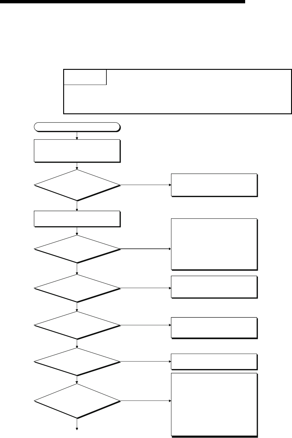
11 - 32
MELSEC-F
TROUBLESHOOTING11
11 - 32
11.5 Troubleshooting Flowchart
This section explains some simple troubleshooting procedures when the Ethernet
module and an external device have communication problems in a flowchart format.
(*1)
POINT
If trouble occurs when using the Ethernet module, check the block status, error
status and others for the Ethernet module using the Ethernet diagnostic function of
FX Configurator-EN-L described in Subsection 11.2.2.
Data cannot be communicated.
Check whether or not an error
occurred in the PLC base unit to
which the Ethernet module is installed.
Did an error
that makes the PLC
stop processing
occur?
Check the status of the applicable
Ethernet module.
Refer to the troubleshooting section
in the applicable PLC ’s user’s
manual and fix the problems.
YES
NO
Is the Ethernet module’s
[RUN] LED on?
NO
YES
Is the connection cable
securely connected?
NO Lock the cable securely.
Is the Ethernet module’s
[ERR.] LED on?
Check whether or not a parameter
error occurred. If an error is found,
first correct it and then re-download.
NO
Is the Ethernet module’s
[COM.ERR.] LED on?
NO Check the error contents using the
diagnostics function of
FX Configurator-EN-L.
Is the data code
(binary/ASCII) setting of the
communication data
correct?
NO
YES
Data cannot be sent/received
because the data code is different in
sending node and receiving node
and the command can therefore not
be successfully decoded.
Change the setting in
[Communicational data code] of
[Operational settings] using
FX Configurator-EN-L.
(See Section 4.6.) (*2)
1)
Turn on the PLC and Ethernet module
again.
If the [RUN] LED does not turn on
even after resetting, the Ethernet
module’s hardware may be faulty.
Replace the Ethernet module and
restart all the external devices that
communicate with the local station.
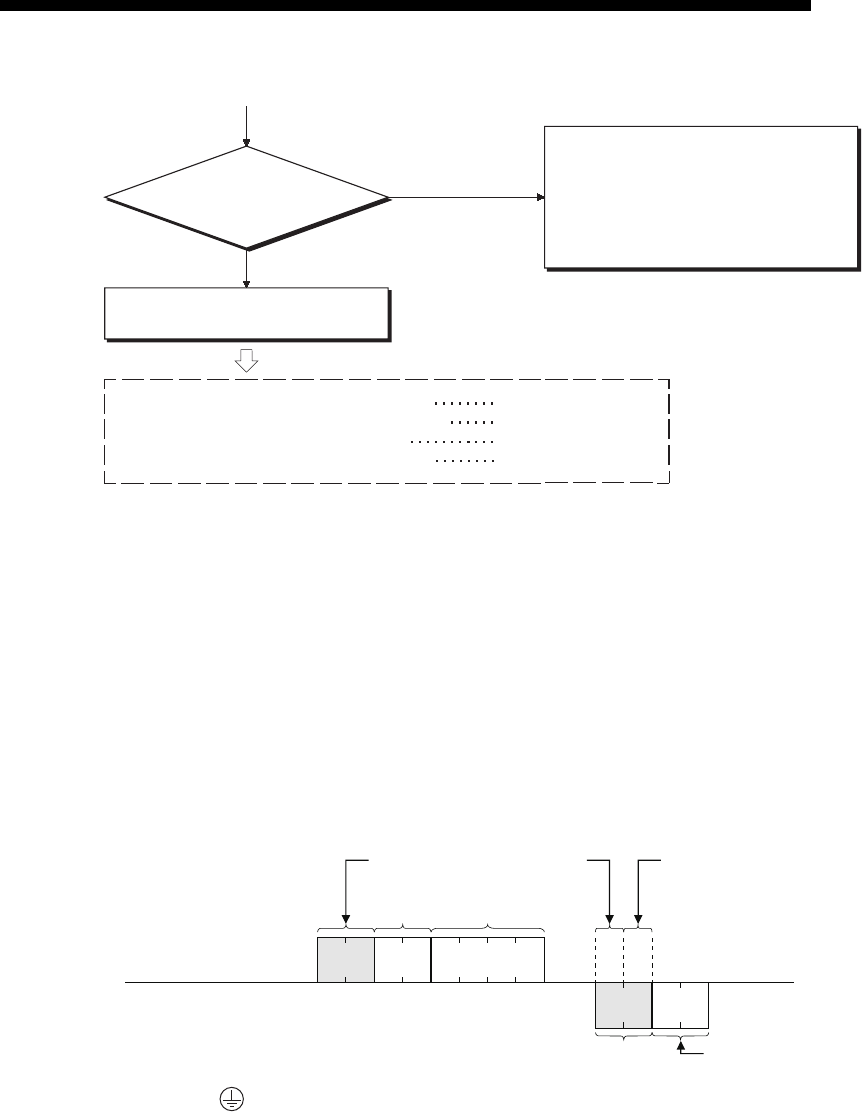
11 - 33
MELSEC-F
TROUBLESHOOTING11
11 - 33
*1 See Section 11.1 when the value of BFM#27 is "0000H" or when the display LED COM.ERR (communication error
detection display) lights up.
(Check an error code that is stored in the buffer memory in reaction to an error occurrence, then check the contents
of the error and take corrective actions by referring to Section 11.4.)
*2 Error codes not found in the error code list may be returned to the external device side if the communication data
settings on the Ethernet module side (see Section 4.6) and the data code settings on the external device side are
different.
The Ethernet module cannot decode commands correctly if data with different data codes is received. The Ethernet
module returns error responses according to the communication data code settings.
[example] When communication is performed using a fixed buffer.
*3 If the FG ( )terminals of the Ethernet module are not set, the communication line is closed (disconnected) due to
the effects of noise, and as a result communication with an external device may not be performed.
Is initial
processing normally completed
(BFM#27=
"0001H")
NO
(BFM#27=
"0001H")
YES
Check and fix the faulty part for each
communication processing.
Sending error in fixed buffer communication See Subsection 11.5.1.
Receiving error in fixed buffer communication See Subsection 11.5.2.
Error in the MC protocol communication See Subsection 11.5.3.
Send error during communication by e-mail See Subsection 11.5.4.
1)
Perform initial processing.
(See Subsection 5.2.1.)
If the initial processing parameters set
with FX Configurator-EN-L and the
sequence program for initial processing
overlap, delete the sequence program
for initial processing.
60H00H
Text
End code
Subheader
Data length
Subheader
External device side
(Set to binary code)
The external device side
receives this portion
as an end code.
45H30H35H34H
Subheader
Ethernet module side
(Set to ASCII code)

11 - 34
MELSEC-F
TROUBLESHOOTING11
11 - 34
POINT
(1) When the Ethernet module is replaced due to an error, reboot the following
external devices and restart data communication:
(If the external device retains the Ethernet address, it may be impossible to
continue communication because when a module is replaced the Ethernet
address changes.)
In the same way, when the external device (personal computer, etc.) is
replaced, restart the Ethernet module.
• All external devices that communicated with the station whose Ethernet
module was replaced.
• All external devices that communicated with other station's PLC via a
station whose Ethernet module was replaced.
(2) When connecting a device to the Ethernet module, see the following sections
for the required devices and connection method:
Section 2.2: Devices Required for Network Configuration
Section 4.4: Connecting to the Network
(3) If the Ethernet module could not receive messages sent from external
devices frequently, check the values stored in the following buffer memory.
(a) Simultaneous transmission error detection count storage area (BFM#398
to 399) and Error/End code storage area for each error log block
(BFM#229...)
When the error detection count number is high or when the error code
C0C7H has been stored, high load may be applied to the Ethernet
connection line to transfer data among connected devices.
To reduce the load to the Ethernet line, it is necessary to take corrective
measures such as dividing the network or reducing the data transmission
frequency.
Consult your network administrator and take appropriate measures.
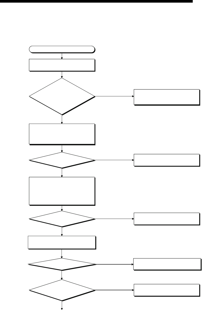
11 - 35
MELSEC-F
TROUBLESHOOTING11
11 - 35
11.5.1 Sending errors during fixed buffer communication
(common to procedure exist and no procedure)
Sending error
Check the open status of the
connection with an external device.
Are the
corresponding connection
LEDs (C1-C2) lit?
If so, modify the program.
Read the open abnormal code (BFM
#229...) of the error log area and
check that no errors have occurred.
NO
YES
Have parameter
errors occurred?
NO
YES
Fix the error according to the error
code (see Section 11.4).
Is the parameter,
IP address of the external device,
correct?
NO
YES
1)
Execute the open processing of the
applicable connection. (For details,
see Section 5.6.)
Read the content of the communication
abnormal code storage area (BFM
#125, 135) corresponding to the
fixed buffer of the buffer memory and
check whether or not a communication
error has occurred.
Has a communication
error occurred?
NO
YES
Fix the error according to the error
code (see Section 11.4).
Correct the IP address of the external
device.
1) NO
YES
Check that "send" is set in the
parameter open settings.
Are the open settings
set to "send"? Change parameters to "send".
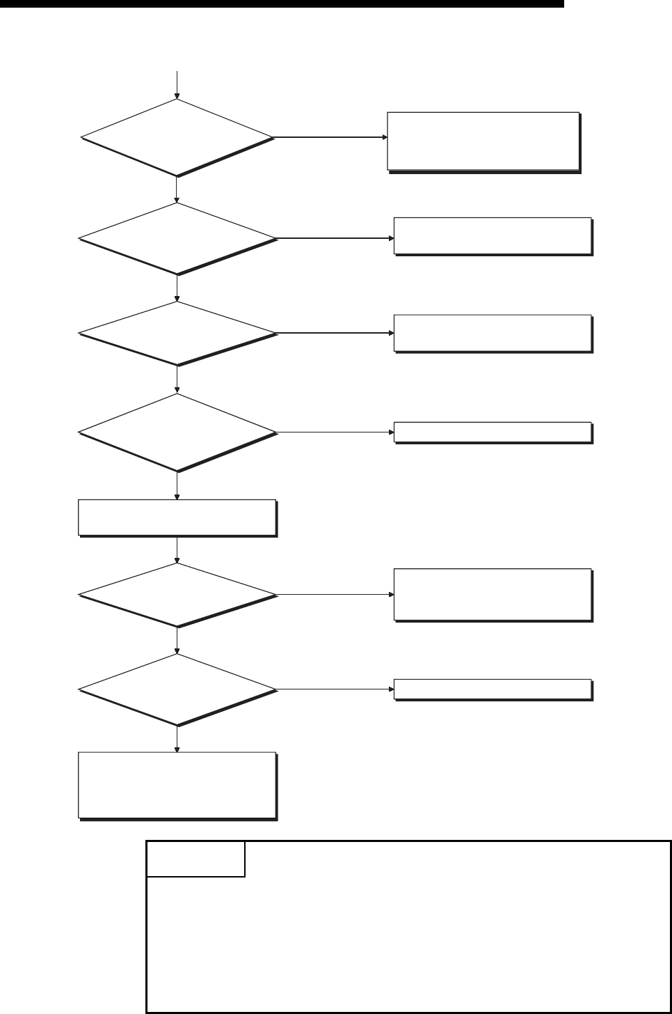
11 - 36
MELSEC-F
TROUBLESHOOTING11
11 - 36
POINT
If the external device communicates normally, the following conditions occur.
For TCP communication
When the external device's open status is complete, LEDs C1, C2, which are in
correspondence with connections 1, 2, turn on.
For UDP communication
When external device communication is possible, LEDs C1, C2, which are in
correspondence with connections 1, 2, turn on.
Was the "0001H" written to
from BFM#1610, 1611?
NO
YES
Is the word
count (procedure) or byte
count (non-procedure) set at the
head of the fixed
buffer?
NO
YES
Check the communication status of
the external device.
1)
Correct the write condition of
BFM#1610, 1611.
Write the data length.
NO
YES
Check the fixed buffer transfer error
code of BFM#125, 135
Does the external
device operate normally? NO
YES
Fix the faulty part of the external
device. (If the receiving side is also an
Ethernet module, see Section 11.4.)
Are there any
open errors or initial errors
in the error log area?
NO
YES
Check and fix the faulty part.
The Ethernet module hardware on the
sending side may be faulty.
Consult your nearest branch office or
dealer with the details of the errors.
Is the read value of
BFM#1610, 1611 "0004H"?
Does the
communication protocol
(TCP/UDP) match that of
the external device?
NO
YES
Match the protocol with the
communication protocol (TCP/UDP) of
the external device. (For details, see
Section 5.5.)
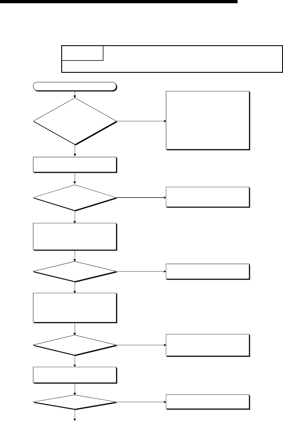
11 - 37
MELSEC-F
TROUBLESHOOTING11
11 - 37
11.5.2 Receiving errors during fixed buffer communication
(common to procedure exist and no procedure)
POINT
Perform error code reading while the connection is open.
NO
YES
1)
NO
YES
Receiving error
Check the open status of the
connection with an external device.
NO
YES
Execute the open processing of the
applicable connection.
(For details, see Section 5.6.)
Read the open abnormal code (BFM
#124, 134) of the communication status
storage area and check that no errors
have occurred.
Have parameter errors
occurred?
Fix the error according to the parameter
error code (see Section 11.4).
Read the content of the communication
abnormal code storage area (BFM #125,
135) corresponding to the fixed buffer
of the buffer memory and check whether
or not a communication error has occurred.
Has a
communication error occurred in the
error log area?
Fix the error according to the
communication error code in the error log
area (see Section 11.4).
NO
YES
Check that "receive" is set in the parameter
open settings.
Receive is set Change parameters to "receive".
NO
YES
Do the expected length
of data to be received and
the amount of data actually
received match?
Are the corresponding
connection LEDs (C1, C2 ) lit?
If the amount of actually received data is
smaller than the length of data expected to
be received, the subsequent processing
must allow reception of the remaining data.
If the amount of actually received data is
larger than the length of data expected to
be received, the subsequent data should
be treated as the next request message or
as unnecessary data.
(See NOTE in 11.4.4 section for further
details.)
1)
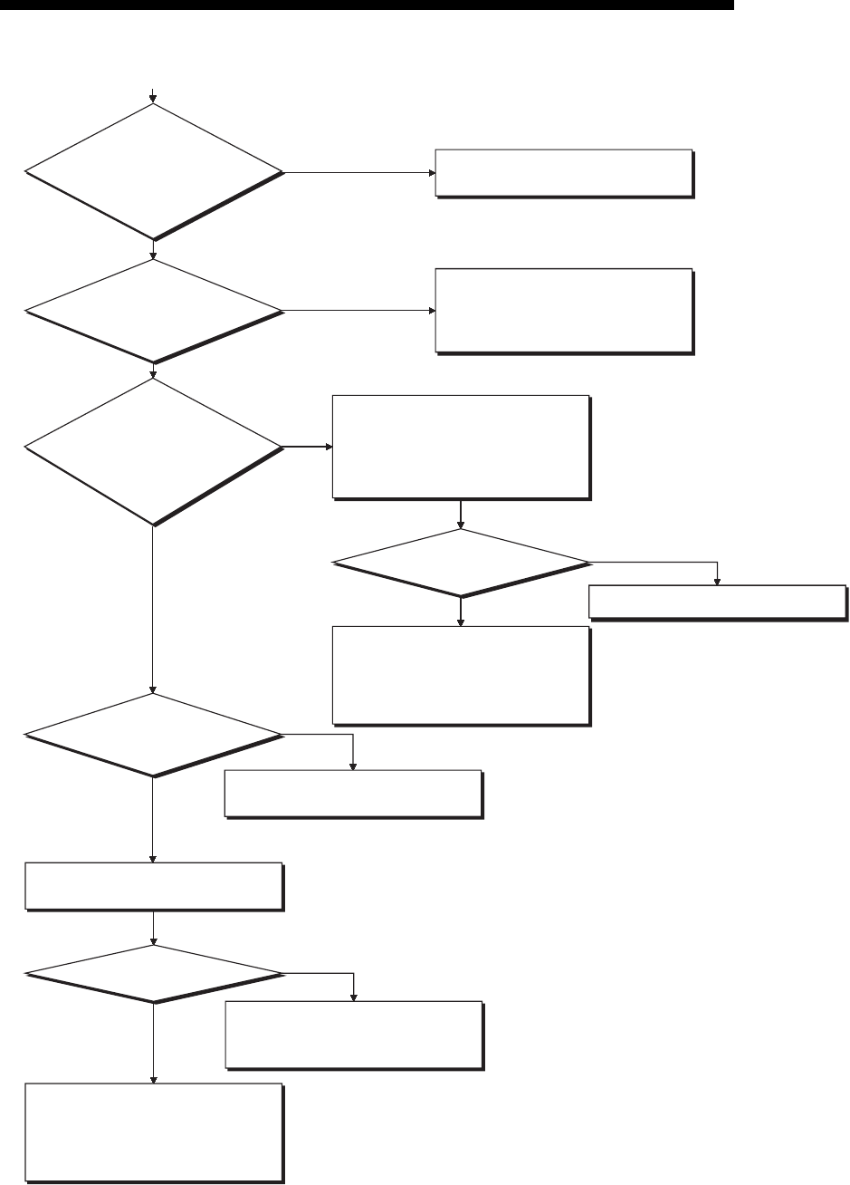
11 - 38
MELSEC-F
TROUBLESHOOTING11
11 - 38
Does the external device
operate normally?
YES
The Ethernet module hardware on
the sending side may be faulty.
Consult your nearest branch office or
dealer with the details of the errors.
NO
Check the device on the sending
side. (If the sending side is also an
Ethernet module, see Section 11.4.)
NO
1)
Data may not have been set from the
external device.
Check the sending side.
(If the sending side is also an
Ethernet module, see Section 11.4.)
Fix the faulty part of the device on
sending side.
Did the error
occur in the device on the
sending side?
NO
YES
YES
YES
NO
YES
Does the communication
protocol (TCP/UDP) match with that
of the external device?
Is the parameter
for IP address of the
external device correct?
Is each Port No.
of the local and the
external station
correct?
NO
YES
Correct the IP address of the external
device.
The Ethernet module on receiving
side may be faulty. Consult your
nearest branch office or dealer with
the details of the errors.
Check the communication status
of the device on the sending side.
Is "0002H" written to
BFM#1610, 1611?
Change the condition for writing
"0002H" to BFM#1610, 1611.
Match the protocol with the
communication protocol (TCP/UDP)
of the external device.
(For details, see Section 5.5.)
Is the receive
completion signal
(corresponding bit of BFM#20485)
of the applicable fixed buffer on?
Is the value of BFM#1610,
1611 set to
0001
H
?
NO

11 - 39
MELSEC-F
TROUBLESHOOTING11
11 - 39
POINT
If the external device communicates normally, the following conditions occur.
For TCP communication
When the external device's open status is complete, LEDs C1, C2, which are in
correspondence with connections 1, 2, turn on.
For UDP communication
When external device communication is possible, LEDs C1, C2, which are in
correspondence with connections 1, 2 turn on.
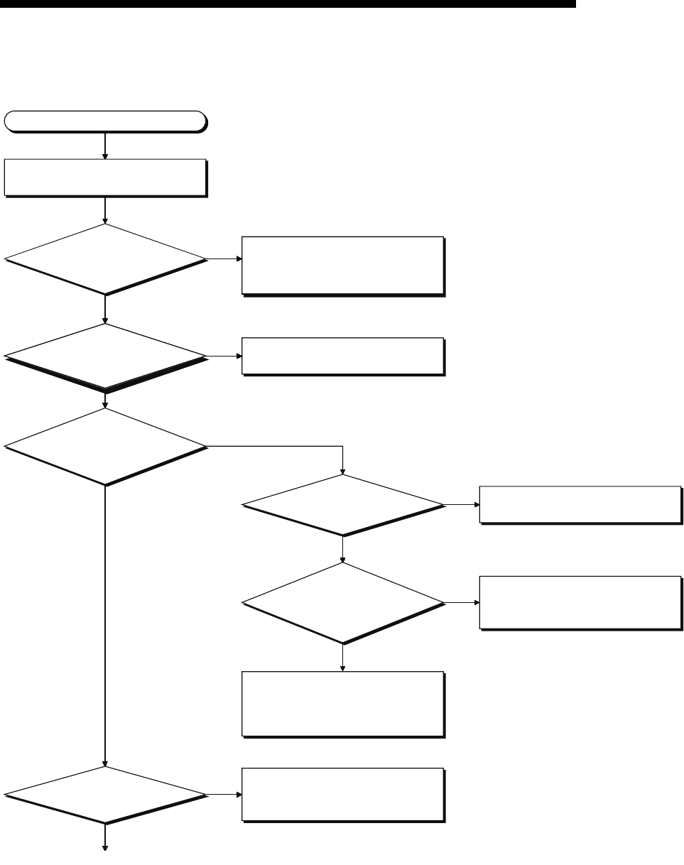
11 - 40
MELSEC-F
TROUBLESHOOTING11
11 - 40
11.5.3 Errors in communication using MC protocol
Communication error
Check the open status of the
connection with the external device.
Are the corres-
ponding connection LEDs
(C3, C4) lit?
NO
YES
Was a command sent
form the external device?
NO
YES
Send the command to the Ethernet
module.
Was a response
returned to the device that sent
the command?
NO
YES
YES
1)
Execute the open processing of the
applicable connection. (For details,
see Section 5.6.)
Is the IP address
designation of the command
correct?
NO
YES
Correct the IP address and send
the command again.
NO
YES
Match the communication protocol
(TCP/UDP) with the external device.
(For details, see Section 5.5.)
Is the end code of
the response "0"?
NO Fix the faulty part according to
the description of the end and
abnormalcodes (see Section 11.4).
Does the
communication protocol
(TCP/UDP) match with that of the
external device?
The command may not be sent to the
Ethernet module from the external
device on the command sending
side. Check the sending side.
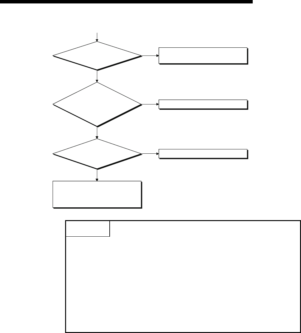
11 - 41
MELSEC-F
TROUBLESHOOTING11
11 - 41
POINT
• If the external device communicates normally, the following conditions occur.
For TCP communication
When the external device's open status is complete, LEDs C3, C4, which are
in correspondence with connections 3, 4, turn on.
For UDP communication
When external device communication is possible, LEDs C3, C4, which are in
correspondence with connections 3, 4, turn on.
• In connections used for communication using MC protocol, it is necessary to set
the communication parameter to "MC protocol usable" in "Connection usage" as
described in the table in Subsection 5.5.2, or select "Unpassive open (MC)" or
"Fullpassivel open (MC)" in the open system settings in FX Configurator-EN-L .
Is the IP address of the
command correct?
NO
1)
Correct the IP address and send the
command again.
YES
Are the
command formats,
such as command type, device
designation, and address
designation, designated
correctly?
NO
YES
NO
YES
Check and fix the faulty part.
Correct the command format.
Are there any open
errors or initial errors in the error
log area?
The Ethernet module hardware may
be faulty. Consult your nearest dealer
with the details of the errors.
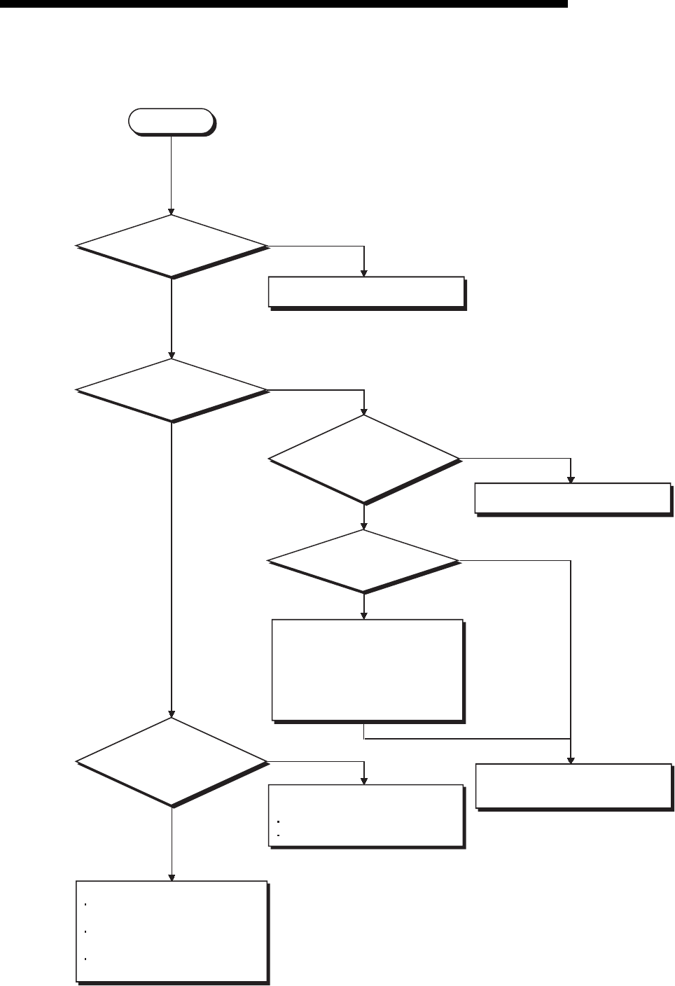
11 - 42
MELSEC-F
TROUBLESHOOTING11
11 - 42
11.5.4 Sending errors during e-mail communication
Is "0001H" written to
BFM#10333?
NO
YES Correct the condition for writing to
BFM#10333.
Set the server port numbers correctly.
Is the value of
BFM#10334 set to "0001H"?
Is the SMTP authentication
setting used?
NO
NO
NO
YES
YES
YES
Can the error
response be received from
the mail server using the mail
receiving operation?
Confirm with the system administrator
that the following are set correctly:
DNS settings
E-mail settings
YES
NO
Check the following items.
Sending error
E-mail parameter settings of the
Ethernet module
Whether or not the mail server's
system is down
Whether or not there is an error
on the communication path
Are the mail server
port numbers set correctly in
BFM#24320 and 24388?
When "SMTP-AUTH" is selected,
check whether the SMTP login ID and
password are set correctly.
When "POP before SMTP" is selected,
check whether the POP password and
local mail address are set correctly.
Modify the contents of error based on
the e-mail sending error log
(Refer to Section 11.4).
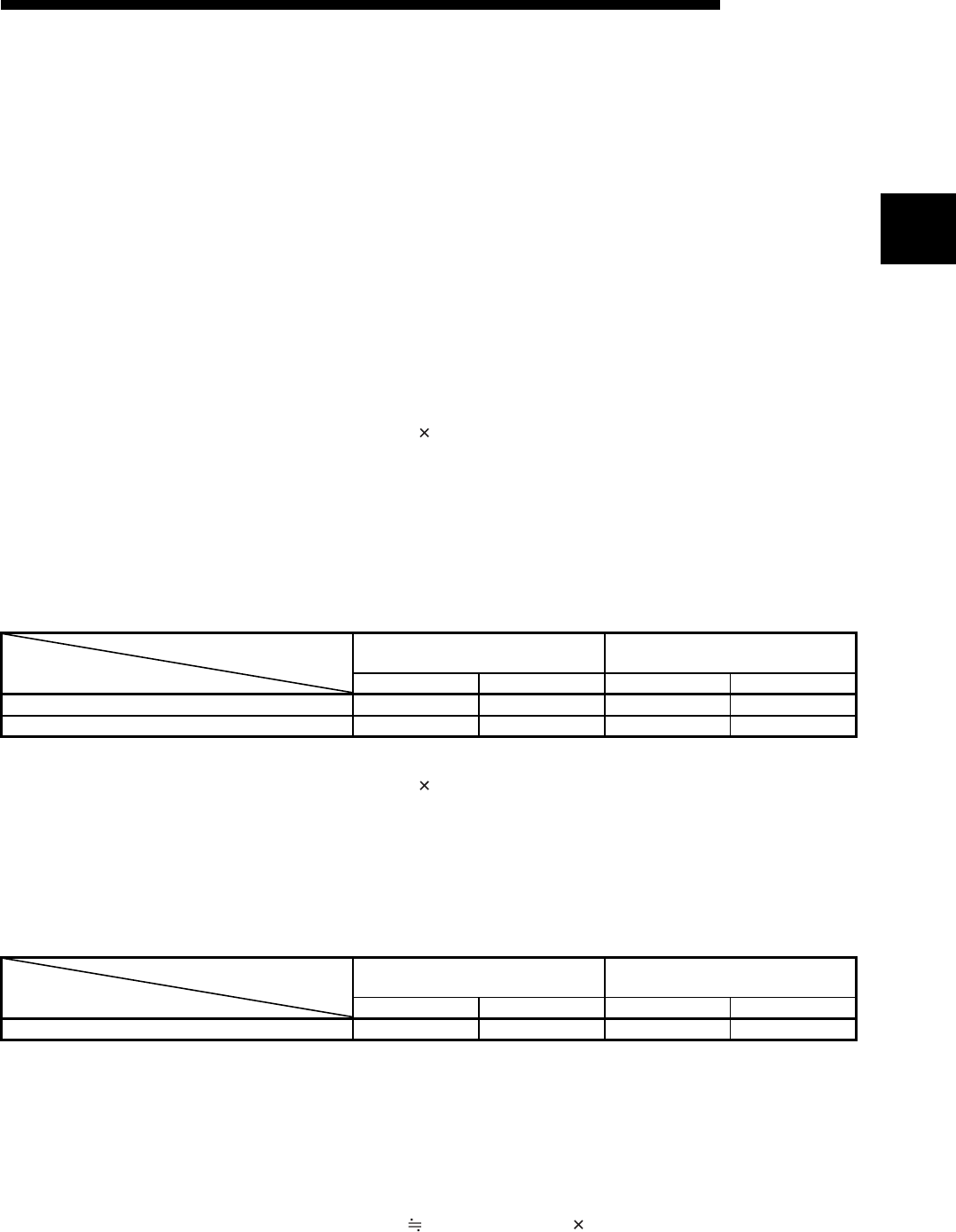
App - 1
APPENDIX
App - 1
App
MELSEC-F
APPENDIX
Appendix 1 Processing Time
Calculate the minimum processing time for each function using the expressions below.
Note that the processing time may become longer depending on the load factor on the
network (how congested the line is), the window size of each connected device, the
number of connections used concurrently, and how the system is configured. Use the
values obtained from the expressions below as a guideline for the processing time
when communication is performed using only one connection.
(1) Minimum processing time of communication using the fixed buffer
(communication between the Ethernet module)
(a) Communication using the fixed buffer (Procedure exist)
Tfs = St + Ke + (Kdf Df) + Sr
(b) Communication using the fixed buffer (No procedure)
Tfs = St + Ke + (Kdf Df)
[Calculation example]
Calculate the time from the start of sending to the completion of sending
(unit: ms) when the FX3U-ENET-L communicate using TCP/IP and send
32 words of binary code data using fixed buffer communication
(procedure exist).
• Assume that the scan time on the receiving side is 30 ms and the
scan time on the transmission side is 25 ms:
67 (ms) 30 + 12 + (0.0065 32) + 25
Tfs :Time from the start of sending to the completion of sending
(unit: ms)
St :Sending station scan time
Ke, Kdf :Constant (see the table below)
Df :Word count of send data
Sr :Receiving station scan time
Communication using TCP/IP Communication using UDP/IP
Ke Kdf Ke Kdf
Data communication using binary code 12 0.0065 10 0.0069
Data communication using ASCII code 12 0.030 10 0.029
Tfs :Time from the start of sending to the completion of sending
(unit: ms)
St :Sending station scan time
Ke, Kdf :Constant (see the table below)
Df :Byte count of send data
Communication using TCP/IP Communication using UDP/IP
Ke Kdf Ke Kdf
Data communication using binary code 7 0.0018 4 0.0014
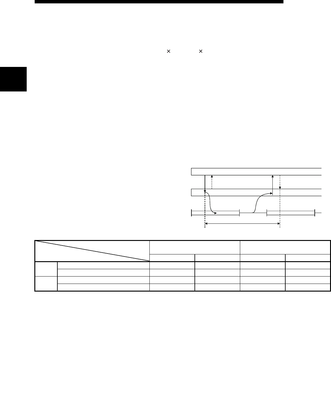
App - 2
APPENDIX
App - 2
App
MELSEC-F
(2) Minimum processing time of communication using MC protocol
(batch read and batch write)
Tfs = Ke + (Kdt Df) + Scr number of scans required for processing +
ACK processing time of external device
*1 The timing sequence from when the Ethernet module receives the
request data from the personal computer until it completes processing is
shown below.
Tfs :Time from when Ethernet module receives request data
from personal computer until it completes processing (unit:
ms) *1
Ke, Kdt :Constant (refer to the table below)
Df :Number of request data words + number of response data
words (Application data part)
Scr :Scan time
Communication using TCP/IP Communication using UDP/IP
Ke Kdt Ke Kdt
Batch
read
Data communication using binary code 14 0.009 13 0.008
Data communication using ASCII code 18 0.015 13 0.017
Batch
write
Data communication using binary code 14 0.009 13 0.008
Data communication using ASCII code 16 0.027 14 0.027
External device
(personal computer)
Ethernet module
PLC scan time
Command
message
Tfs
ACK
(TCP only)
Step 0 END Step 0 END
Response
message
ACK
(TCP only)

App - 3
MELSEC-F
APPENDIX
App - 3
[Calculation example 1]
Calculate the required time (unit: ms) to complete the processing of a
data request from a PC after receiving it, when the Ethernet module and
the PC perform TCP/IP communication and read 32 points of ASCII
code data from the data register (D) in the PLC using MC protocol
communication.
• Assume that the scan time of the FX
3U
-ENET-L installed station is 40
ms:
59.17 + ACK processing time of the external device (ms)
18 + (0.015 (12 + 66)) + 40 1 + ACK processing time of the
external device
Command data length = 12 words
Response data length = 66 words
[Calculation example 2]
Calculate the required time (unit: ms) the FX3U-ENET-L takes to
complete the processing of a data request from a PC after receiving it,
when the Ethernet module and the PC performs TCP/IP communication
and writes 32 points of ASCII code data to the data register (D) in the
PLC using MC protocol communication.
• Assume that the scan time of the FX
3U
-ENET-L installed station is 40
ms:
58.11 (ms) 16 + (0.027 (76 + 2)) + 40 1
Command data length = 76 words
Response data length = 2 words

App - 4
MELSEC-F
APPENDIX
App - 4
Appendix 2 ASCII Code List
Appendix 3 References
For details on TCP/IP, refer to the DDN Protocol Handbook (3 volumes).
Publisher
DDN Network Information Center
SRI International
333 Ravenswood Avenue, EJ291
Menlo Park, California 94025
RFC Number
TCP RFC793
UDP RFC768
IP RFC791
ICMP RFC792
ARP RFC826
MSD
LSD
01234567
000 001 010 011 100 101 110 111
0 0000 NUL DLE (SP) 0 @ P ` p
1 0001 SOH DC1 ! 1 A Q a q
2 0010 STX DC2 “ 2 B R b r
3 0011 ETX DC3 # 3 C S c s
4 0100 EOT DC4 $ 4 D T d t
5 0101 ENQ NAK % 5 E U e u
60110 ACK SYN & 6 F V f v
7 0111 BEL ETB ’ 7 G W g w
8 1000 BS CAN ( 8 H X h x
9 1001 HT EM ) 9 I Y i y
A 1010 LF SUB : J Z j z
B 1011 VT ESC + ; K [ k {
C1100 FF FS , < L \ l |
D1101 CR GS — = M ] m }
E 1110 SO RS . > N ^ n ~
F 1111 SI US / ? O _ o DEL
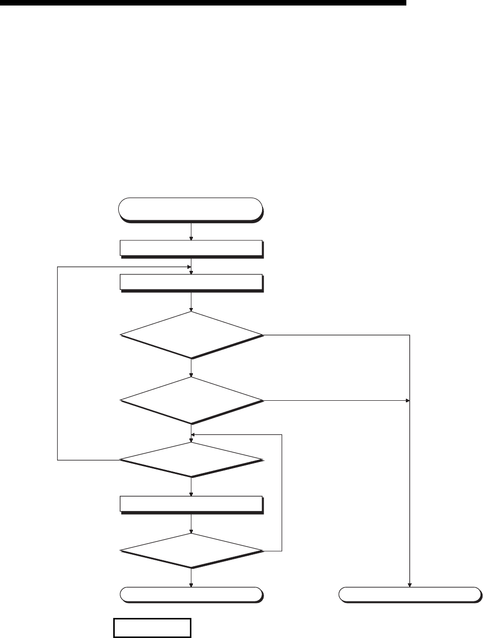
App - 5
MELSEC-F
APPENDIX
App - 5
Appendix 4 Program Examples
The program examples presented in this section test the connection between the
Ethernet module and an external device (personal computer) that is connected to the
same Ethernet.
For each program, only the minimum programming that is required to perform the
communication test is done. Modify the IP address, port number and other values
according to your system configuration. In addition, abnormal handling may be added.
(1) Receive processing of target device
A receive processing example on the target device side is shown below.
For Ethernet communications, the TCP socket functions are used inside the
personal computer. However, these functions do not have any limits. Therefore,
when the "send" function is executed once to transmit data, the receiving end (node)
needs to execute the "recv" function once or more in order to read the data ("send"
and "recv" is not proportional to 1:1 execution). For this reason, the receiving
procedure explained above, is required.
Background
Request message/transmission processing
Response message/reception processing
Is the TCP connection open?
The TCP connection is closed
Timeout of monitoring timer
Error handlingEnd
If a response message to the
next request was received
Receive remaining
response messages
Insufficient size
of data received
Check the size of the received data
Was the reception data
received within the time allotted
by the monitoring timer?
Response message processing
Have all the received
messages been processed?
Communication processing
on the external device side

App - 6
MELSEC-F
APPENDIX
App - 6
Appendix 4.1 Program example for communication using MC protocol -1
The following explains a program, its execution environment and the contents of data
communication .
(1) Execution environment of the program example
(a) PLC side
(b) External device side
(2) Outline of the program example
(a) Sequence program on the PLC side
Parameters are set from FX Configurator-EN-L.
(Sequence program is not required)
(b) Program on the external device side
Executes the following read/write data communication with the PLC using
the library mentioned above.
• Write in word units (for 5 points from D0 to D4)
• Read in word units (for 5 points from D0 to D4)
1) Base module of the Ethernet installed station : FX3U/FX3UC
2) Ethernet module No. : No.1
3) Ethernet module IP address : 172.16.56.99 (AC.10.38.63H)
4) Ethernet module port number : 10000
5) FX Configurator-EN-L setting
• Operational settings : See "(3) FX Configurator-EN-L setting
(a)" on the next page
• Open settings : See "(3) FX Configurator-EN-L setting
(b)" on the next page
1) Operation environment : Microsoft Windows 2000
Operating system
2) Ethernet interface board model name : WINSOCK compatible board
3) Library : WSOCK32.LIB
4) Software development environment : Microsoft Corporation Visual
C++ .NET
5) Ethernet address : Setting not required because
the ARP function is available
6) IP address : Receive at Active open
7) Port number : Receive at Active open
(c) Communication protocol : TCP/IP

App - 7
MELSEC-F
APPENDIX
App - 7
(3) FX Configurator-EN-L settings
Set the PLC parameters as follows.
(a) Operation settings
(b) Open settings
Communication data code : ASC II
Initial timing : Always wait for OPEN (Communication
possible at STOP time)
IP address : 172.16.56.99 (AC.10.38.63H)
Protocol : TCP
Open system : Unpassive (MC)
Existence confirmation : No confirm
Local station Port No. : 10000
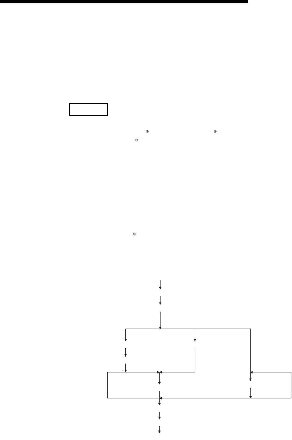
App - 8
MELSEC-F
APPENDIX
App - 8
(4) Program on the external device side
The program example of the external device shown below accesses the FX3U of
the station in which the Ethernet module is installed.
When this program is executed, the contents of the following communication
messages are displayed in sequence:
1) Batch write command message in word units
2) Batch write response message in word units
3) Batch read command message in word units
4) Batch read response message in word units
(1) The following explains an outline of the compiling procedure for a program
created using Microsoft Corporation Visual C++ .NET
1) Start Visual C++ .
2) Prepare for program creation.
Select "New Project" from the project tab, select "Win32 console project",
and create an empty project with the name "ENETSAMP".
3) Add ENETSAMP.C to the project and create a program.
(See the program example on the next page.)
4) Compile the created file from the compile screen of the build menu.
5) From the project menu property setting screen, add WSOCK32.LIB to the
linker addition dependency files.
6) Create an executable file (ENETSAMP.EXE) on the build screen of the build
menu.
7) End Visual C++ .NET.
8) Execute ENETSAMP.EXE.
(2) Outline of the procedure for calling the socket routine
REMARK
Start
socket()
bind()
Passive open Active open UDP
listen() connect()
accept()
send()/recv() sendto()/recvfrom()
shutdown()
closesocket
Complete
(Create socket)
(Bind)
(Open)
(Communicate)
(Disable sending/receiving)
(Close)

App - 9
MELSEC-F
APPENDIX
App - 9
#include <stdio.h>
#include <winsock.h>
#define FLAG_OFF 0 // Completion flag OFF
#define FLAG_ON 1 // Completion flag ON
#define SOCK_OK 0 // Normal completion
#define SOCK_NG -1 // Abnormal completion
#define BUF_SIZE 4096 // Receive buffer size
#define ERROR_INITIAL 0 // Initial error
#define ERROR_SOCKET 1 // Socket creation error
#define ERROR_BIND 2 // Bind error
#define ERROR_CONNECT 3 // Connection error
#define ERROR_SEND 4 // Send error
#define ERROR_RECEIVE 5 // Receive error
#define ERROR_SHUTDOWN 6 // Shutdown error
#define ERROR_CLOSE 7 // Line close error
//Definitions for checking the receiving sizes
//#define RECV_ANS_1 4 // Receiving size of response message in reply to device write (1E frame)
//#define RECV_ANS_2 24 // Receiving size of response message in reply to device read (1E frame)
typedef struct sck_inf{
struct in_addr my_addr;
unsigned short my_port;
struct in_addr FX_IP_addr;
unsigned short FX_port;
};
int nErrorStatus; // Error information storage variable
int Dmykeyin; // Dummy key input
int Closeflag; // Connection completion flag
SOCKET socketno;
/ ***************************************************************** /
/ **
Sample program
This program is a sample program to conduct a
connection test between the Ethernet block and
target device.
This program accesses the data register (D) of
the Base Module installed together with the
Ethernet block.
Copyright(C) 2009 Mitsubishi Electric
Corporation
All Rights Reserved
** /
/ ** ** /
/ ** ** /
/ ** ** /
/ ** ** /
/ ** ** /
/ ** ** /
/ ** ** /
/ ** ** /
/ ** ** /
/ ** ** /
/ ** ** /
/ **
/ **
/ **
/ **
** /
** /
** /
** /
/ ***************************************************************** /

App - 10
MELSEC-F
APPENDIX
App - 10
int main()
{
WORD wVersionRequested=MAKEWORD(1,1); // Winsock Ver 1.1 request
WSADATA wsaData;
int length; // Communication data length
unsigned char s_buf[BUF_SIZE]; // Send buffer
unsigned char r_buf[BUF_SIZE]; // Receive buffer
int rbuf_idx; // Receive data storage head index
int recv_size; // Number of receive data
struct sck_inf sc;
struct sockaddr_in hostdata; // External device side data
struct sockaddr_in FX3UENET_L; // Ethernet block side data
void Sockerror(int); // Error handling function
unsigned long ulCmdArg ; // Non-blocking mode setting flag
sc.my_addr.s_addr=htonl(INADDR_ANY); // External device side IP address
sc.my_port=htons(0); // External device side port number
sc.FX_IP_addr.s_addr=inet_addr("172.16.56.99"); // Ethernet block side IP address
// (AC103863h)
sc.FX_port=htons(10000); // Ethernet block side port number
Closeflag=FLAG_OFF; // Connection completion flag off
nErrorStatus=WSAStartup(wVersionRequested,&wsaData); // Winsock Initial processing
if (nErrorStatus!=SOCK_OK) {
Sockerror(ERROR_INITIAL); // Error handling
return (SOCK_NG);
}
printf ("Winsock Version is %ld.%ld\n",HIBYTE(wsaData.wVersion),LOBYTE(wsaData.wVersion));
printf ("FX3U-ENET-L Test Start\n");
socketno=socket(AF_INET,SOCK_STREAM,0); // Create socket for TCP/IP
if (socketno==INVALID_SOCKET){
Sockerror (ERROR_SOCKET); // Error handling
return(SOCK_NG);
}
hostdata.sin_family=AF_INET;
hostdata.sin_port=sc.my_port;
hostdata.sin_addr.s_addr=sc.my_addr.s_addr;
if(bind(socketno,(LPSOCKADDR)&hostdata,sizeof(hostdata))!=SOCK_OK){
// Bind
Sockerror(ERROR_BIND); // Error handling
return(SOCK_NG);
}
FX3UENET_L.sin_family=AF_INET;
FX3UENET_L.sin_port=sc.FX_port;
FX3UENET_L.sin_addr.s_addr=sc.FX_IP_addr.s_addr;
if(connect(socketno,(LPSOCKADDR)&FX3UENET_L,sizeof(FX3UENET_L))!=SOCK_OK){
// Connection (Active open)
Sockerror(ERROR_CONNECT); // Error handling
return(SOCK_NG);
}

App - 11
MELSEC-F
APPENDIX
App - 11
Closeflag=FLAG_ON; // Connection completion flag ON
// Go to non-blocking mode
ulCmdArg = 1;
ioctlsocket(socketno, FIONBIO, &ulCmdArg); // Set to non-blocking mode
strcpy(s_buf, "03FF000A4420000000000500112233445566778899AA");
// D0 to D4 batch write request (1E frame)
length=(int)strlen(s_buf);
if(send(socketno,s_buf,length,0)==SOCKET_ERROR){ // Data sending
Sockerror(ERROR_SEND); // Error handling
return (SOCK_NG);
}
printf("\n send data\n%s\n",s_buf);
// Perform receiving size check and receiving processing simultaneously
rbuf_idx = 0; // Receive data storage head index initialization
recv_size = 0; // Initialize the number of receive data
while(1) {
length = recv(socketno, &r_buf[rbuf_idx], (BUF_SIZE - rbuf_idx), 0);
// Response data receiving
if(length == 0) { // Is connection cut off?
Sockerror(ERROR_RECIEVE); // Error handling
return (SOCK_NG);
}
if(length == SOCKET_ERROR) {
nErrorStatus = WSAGetLastError();
if(nErrorStatus != WSAEWOULDBLOCK) {
Sockerror(ERROR_RECIEVE); // Error handling
return (SOCK_NG);
} else {
continue; // Repeat until messages are received
}
} else {
rbuf_idx += length; // Update the receive data storage
// position
recv_size += length; // Update the number of receive data
if(recv_size >= RECV_ANS_1) // Have all response messages been
// received?
break; // Stop repeating as messages have
// been received
}
}
r_buf[rbuf_idx] = '\0' ; // Set NULL at the end of receive data
printf("\n receive data\n%s\n",r_buf);
strcpy(s_buf, "01FF000A4420000000000500"); // D0 to D4 batch read request
// (1E frame)
length=(int)strlen(s_buf);
if(send(socketno,s_buf,length,0)==SOCKET_ERROR){ // Data sending
Sockerror(ERROR_SEND); // Error handling
return (SOCK_NG);
}
printf("\n send data\n%s\n",s_buf);
// Perform receiving size check and receiving processing simultaneously
rbuf_idx = 0; // Receive data storage head index
// initialization
recv_size = 0; // Initialize the number of receive data

App - 12
MELSEC-F
APPENDIX
App - 12
while(1) {
length = recv(socketno, &r_buf[rbuf_idx], (BUF_SIZE - rbuf_idx), 0);
// Response data receiving
if(length == 0) { // Is connection cut off?
Sockerror(ERROR_RECIEVE); // Error handling
return (SOCK_NG);
}
if(length == SOCKET_ERROR) {
nErrorStatus = WSAGetLastError();
if(nErrorStatus != WSAEWOULDBLOCK) {
Sockerror(ERROR_RECIEVE); // Error handling
return (SOCK_NG);
} else {
continue; // Repeat until messages are received
}
} else {
rbuf_idx += length; // Update the receive data storage
// position
recv_size += length; // Update the number of receive data
if(recv_size >= RECV_ANS_2) // Have all response messages been
// received?
break; // Stop repeating as messages have
// been received
}
}
r_buf[rbuf_idx] = '\0' ; // Set NULL at the end of receive data
printf("\receive data\n%s\n", r_buf);
if(shutdown(socketno,2)!=SOCK_OK){ // Processing to disable
// sending/receiving
Sockerror(ERROR_SHUTDOWN); // Error handling
return(SOCK_NG);
}
if(closesocket(socketno)!=SOCK_OK){ // Close processing
Sockerror(ERROR_CLOSE); // Error handling
return(SOCK_NG);
}
Closeflag=FLAG_OFF; // Connection completion flag off
WSACleanup(); // Release Winsock.DLL
printf("\nFX3U-ENET-L Test End.\n\n Normally completed. \n");
printf("Press any key to exit the program.\n");
Dmykeyin=getchar(); // Wait for key input
return(SOCK_OK);
}
void Sockerror(int error_kind) // Error handling function
{
if(error_kind==ERROR_INITIAL){
printf("Initial processing is abnormal.");
}
else{
nErrorStatus=WSAGetLastError();
switch(error_kind){
case ERROR_SOCKET:
printf("Failed to create socket.");
break;

App - 13
MELSEC-F
APPENDIX
App - 13
case ERROR_BIND:
printf("Failed to bind.");
break;
case ERROR_CONNECT:
printf("Failed to establish connection.");
break;
case ERROR_SEND:
printf("Sending failed.");
break;
case ERROR_RECIEVE:
printf("Receiving failed.");
break;
case ERROR_SHUTDOWN:
printf("Failed to shutdown.");
break;
case ERROR_CLOSE:
printf("Failed to close normally.");
break;
}
}
printf("Error code is %d.\n", nErrorStatus);
if(Closeflag==FLAG_ON){
nErrorStatus=shutdown(socketno,2); // Shutdown processing
nErrorStatus=closesocket(socketno); // Close processing
Closeflag=FLAG_OFF; // Connection completion flag off
}
printf("Press any key to exit the program.\n");
Dmykeyin=getchar(); // Wait for a key input
WSACleanup(); // Release Winsock.DLL
return;
}

App - 14
MELSEC-F
APPENDIX
App - 14
Appendix 4.2 Program example for communication using MC protocol -2
This section explains an example of an external device program that reads/writs data
from the PLC.
A sample program, its execution environment and contents of data communication
are shown below.
(1) Execution environment of the program example
1) The settings of the PLC side are the same as those of the execution
environment described in Section 4.1 (1) (a) and (3) of Appendix.
2) The settings of the external device side are the same as those of the
execution environment described in Section 4.1 (1) (b) of Appendix,
except for the following including the software development:
• Software development environment:Microsoft Corporation Visual
Basic .NET
• Arbitrary numbers are assigned for the IP address and port number.
3) The communication protocol is TCP/IP
(2) Outline of the program example
With the A-compatible 1E frame command (01: batch read in word units), this
program reads data from D0 to D4 (five points) of the PLC of the station on which
the Ethernet module is mounted.
(3) Outline of the sample program
(a) Create a new project and form.
(b) Create the (example) window shown in (4) below using " Button" and "List
Box" in the toolbox.
(c) Create the program shown in (5).
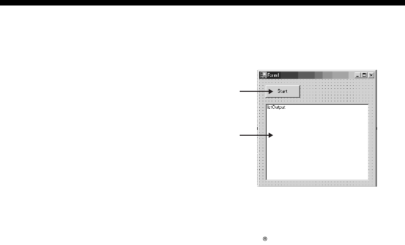
App - 15
MELSEC-F
APPENDIX
App - 15
(4) Window example (Form 1)
(5) Sample program (Form 1)
Parts in italic are created automatically by Visual Basic .NET, so no input is required.
Only input where written in bold.
Option Explicit On
Option Strict On
Imports System.Net.Sockets
Public Class Form1
Inherits System.Windows.Forms.Form
#Region " Windows Code created by Form Designer "
Public Sub New()
MyBase.New()
' This call is necessary for Windows Form Designer.
InitializeComponent()
' InitializeComponent() Initialization is added after the call.
End Sub
' The Form overwrites dispose to execute after-processing in the component list.
Protected Overloads Overrides Sub Dispose(ByVal disposing As Boolean)
If disposing Then
If Not (components Is Nothing) Then
components.Dispose()
End If
End If
MyBase.Dispose(disposing)
End Sub
' Necessary for Windows Form Designer.
Private components As System.ComponentModel.IContainer
(Object name)
Start
Connect to the Ethernet module
and perform communications
1st Output
Display data that was read from
the Ethernet module

App - 16
MELSEC-F
APPENDIX
App - 16
Memo: The following procedure is necessary for Windows Form Designer.
Change by using Windows Form Designer.
Do not use code editor to change.
Friend WithEvents Start As System.Windows.Forms.Button
Friend WithEvents lstOutput As System.Windows.Forms.ListBox
<System.Diagnostics.DebuggerStepThrough()> Private Sub InitializeComponent()
Me.Start = New System.Windows.Forms.Button
Me.lstOutput = New System.Windows.Forms.ListBox
Me.SuspendLayout()
'
'Start
'
Me.Start.Location = New System.Drawing.Point(16, 16)
Me.Start.Name = "Start"
Me.Start.Size = New System.Drawing.Size(88, 32)
Me.Start.TabIndex = 0
Me.Start.Text = "Start"
'
'lstOutput
'
Me.lstOutput.ItemHeight = 12
Me.lstOutput.Location = New System.Drawing.Point(16, 64)
Me.lstOutput.Name = "lstOutput"
Me.lstOutput.Size = New System.Drawing.Size(264, 196)
Me.lstOutput.TabIndex = 1
'
'Form1
'
Me.AutoScaleBaseSize = New System.Drawing.Size(5, 12)
Me.ClientSize = New System.Drawing.Size(296, 273)
Me.Controls.Add(Me.lstOutput)
Me.Controls.Add(Me.Start)
Me.Name = "Form1"
Me.Text = "Form1"
Me.ResumeLayout(False)
End Sub
#End Region
Private Sub Start_Click(ByVal sender As System.Object, ByVal e As System.EventArgs) Handles
Start.Click
Dim IpAddress As String
Dim PortNum As Integer
Dim Client As TcpClient
Dim Buffer() As Byte
Dim InBuff(1532) As Byte
Dim TxCommand As String

App - 17
MELSEC-F
APPENDIX
App - 17
Dim RxResponse As String
Dim Temp As String
Dim j As Integer
Dim Dreg(5) As Double
Dim DregStr$
Dim SubHeader$
' IP Address specification
IpAddress = "172.16.56.99"
' Port Number specification
PortNum = 10000
Client = New TcpClient
'Line connection processing
Try
Client.Connect(IpAddress, PortNum)
Catch ex As Exception
MsgBox("Connection with the server failed, and the following code was returned:
"& ex.Message, 0, "connection error")
Exit Sub
End Try
'Read D0 to D4 (5 points) with the A-compatible 1E frame command.
TxCommand = "01ff000a4420000000000500"
Buffer = System.Text.Encoding.Default.GetBytes(TxCommand.ToCharArray)
'Sending a read command
Client.GetStream().Write(Buffer, 0, Buffer.Length)
'Waiting for a response from an Ethernet block
While Not Client.GetStream().DataAvailable()
Application.DoEvents()
End While
If Client.GetStream().DataAvailable() Then
Client.GetStream().Read(InBuff, 0, InBuff.Length)
RxResponse = System.Text.Encoding.Default.GetString(InBuff)
SubHeader = Mid$(RxResponse, 3, 2)
If SubHeader = "00" Then 'Normal response
Temp = "" 'Initialization of an output character string
For j = 0 To 4
DregStr$ = Mid(RxResponse, j * 4 + 5, 4)
Dreg(j) = Val("&H" + DregStr$)
Temp = Temp + Format(Dreg(j), "#####0") + " "
Next
lstOutput.Items.Insert(lstOutput.Items.Count, Temp)
ElseIf SubHeader = "5B" Then ' In an abnormal response, an abnormal code is added.
Temp = "Terminate Code = " & SubHeader & " Error Code = " & Mid$(RxResponse, 5, 2)
lstOutput.Items.Insert(lstOutput.Items.Count, Temp)
Else
Temp = "Terminate Code = " & SubHeader
lstOutput.Items.Insert(lstOutput.Items.Count, Temp)

App - 18
MELSEC-F
APPENDIX
App - 18
End If
lstOutput.SelectedIndex = lstOutput.Items.Count - 1
End If
' Line disconnection processing
Client.GetStream().Close()
Client.Close()
End Sub
End Class
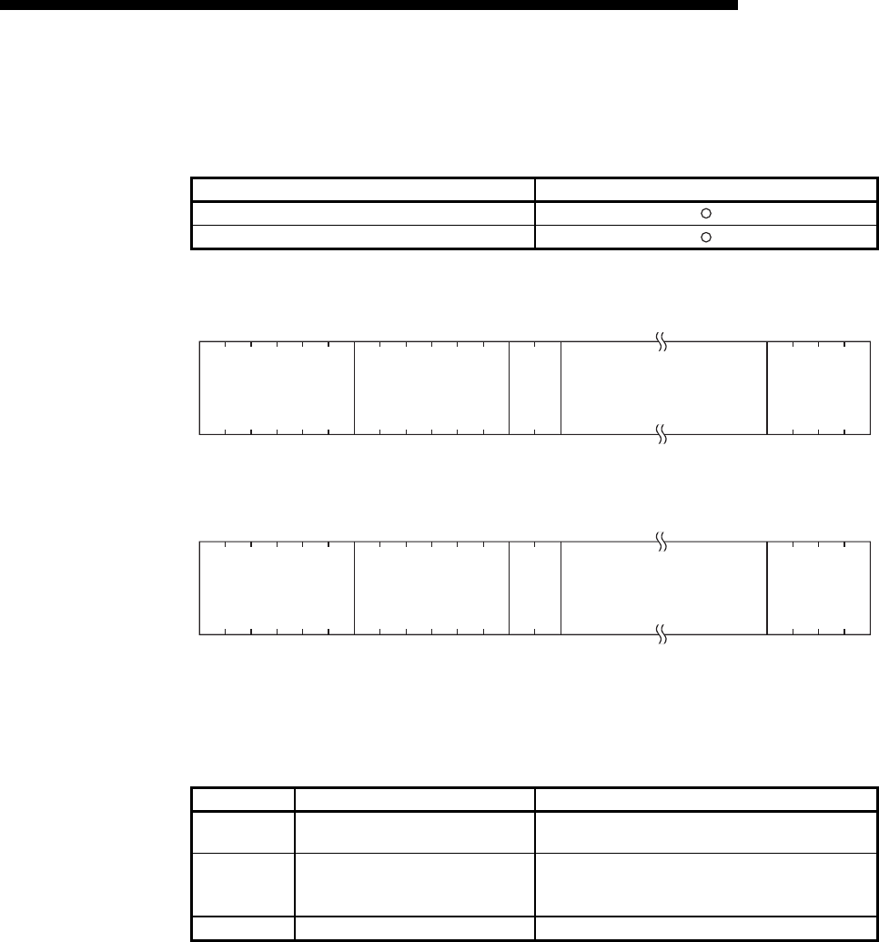
App - 19
MELSEC-F
APPENDIX
App - 19
Appendix 5 Differences between the Ethernet and the IEEE802.3
The following shows the Ethernet header in the data link layer supported by the
Ethernet module.
(1) Ethernet
(2) IEEE802.3
Appendix 6 ICMP Protocol Supported by the Ethernet Module
The following table outlines the types of ICMP supported by the Ethernet module and
the processing performed by the Ethernet module.
*1 The Ethernet module can simultaneously receive two ICMP ECHO requests (type 8, Ping message), which are used for
existence confirmation, etc., and handles them accordingly.
When three or more ICMP ECHO requests are received at the same time, the third and succeeding requests will be
ignored.
If a response is not returned to the external device when an ICMP ECHO request is sent to the Ethernet module, send
an ICMP ECHO request to the Ethernet module again.
The Ethernet module is able to receive a maximum of 1460 bytes ICMP message at one time.
Do not send an ICMP message request exceeding 1460 bytes to the Ethernet module.
Ethernet data link layer header Ethernet module
Ethernet frame (V 2.0) specification
IEEE802.3 (ISO/IEC8802.3) frame specification
ICMP Type ICMP name/description Processing by the Ethernet module
0Echo Reply
Result of IP packet loopback
Upon receiving an Echo Request, the Ethernet module
sends this message.
8Echo Request
Requests loopback of IP packet
If destination existence confirmation is set in the buffer
memory, the Ethernet module sends this message when
attempting to confirm the existence of the target. (*1)
Others — Ignored by the Ethernet module. (Not supported)
Destination address Source address Type Data (46 to 1500 bytes) FCS
Destination address Source address Length Data (46 to 1500 bytes) FCS
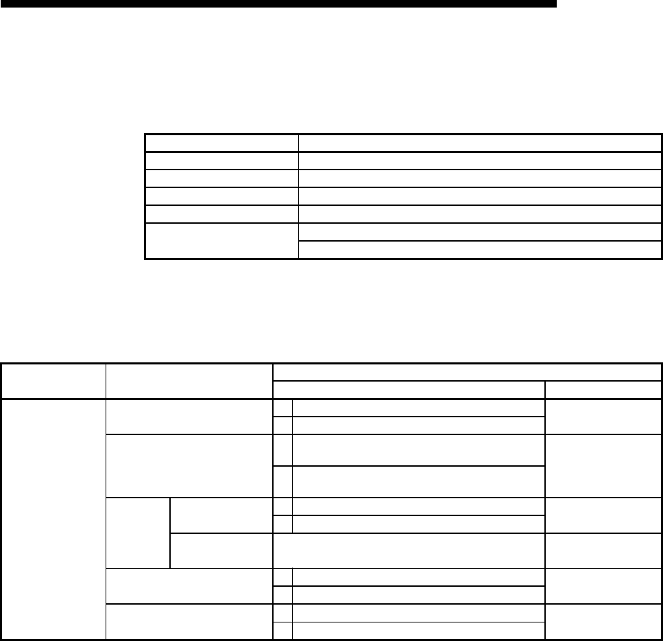
App - 20
MELSEC-F
APPENDIX
App - 20
Appendix 7 Setting Value Recording Sheets
This section provides setting value recording sheets for parameters set with
FX Configurator-EN-L Make copies as needed.
Recording sheet 1
[Block number ]
Setting value recording sheet No. FX Configurator-EN-L setting screen
Recording sheet 1 Ethernet operations
Recording sheet 2 Ethernet initial settings
Recording sheet 3 Ethernet open settings
Recording sheet 4 Setting the Ethernet relay parameter
Recording sheet 5 Ethernet E-mail settings
Ethernet mail address settings
FX Configurator-EN-L
setting screen Data item Setting data
Setting value Remark
Ethernet Operations
Communication data code setting Binary code communication
ASCII code communication
Initial Timing
Do not wait for OPEN (Communications impossible at
STOP time)
Always wait for OPEN (Communication possible at STOP
time)
IP address
setting
Input format Decimal IP address
Input format
Hexadecimal
IP address . . . Adjust to input format
Send frame setting Ethernet (V2.0)
IEEE802.3
TCP Existence
Confirmation setting
Use the KeepAlive
Use the Ping
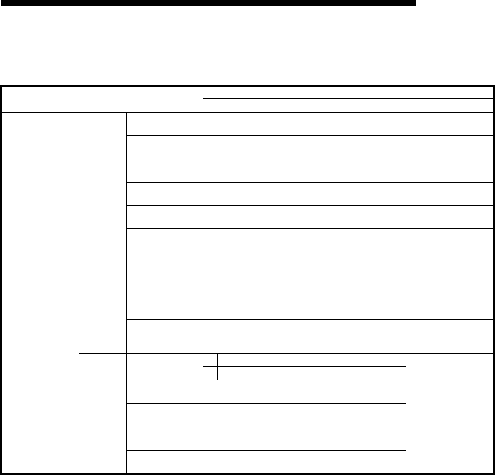
App - 21
MELSEC-F
APPENDIX
App - 21
Recording sheet 2
[Block number ]
FX Configurator-EN-L
setting screen Data item Setting data
Setting value Remark
Ethernet Initial settings
Timer setting
TCP ULP Timer initial: 60 (unit: 500 ms)
TCP zero
window Timer initial: 20 (unit: 500 ms)
TCP resend timer initial: 20 (unit: 500 ms)
TCP end timer initial: 40 (unit: 500 ms)
IP assembly timer initial: 10 (unit: 500 ms)
Response monitoring
timer initial: 60 (unit: 500 ms)
Destination existence
confirmation
starting interval
initial: 1200 (unit: 500 ms)
Destination existence
confirmation
Interval timer
initial: 20 (unit: 500 ms)
Destination existence
confirmation resend
timer
initial: 3 (times)
DNS setting
Input format Decimal DNS server IP address
Input format
Hexadecimal
DNS server 1
IP address . . .
Adjust to input format
DNS server 2
IP address . . .
DNS server 3
IP address . . .
DNS server 4
IP address . . .

App - 22
MELSEC-F
APPENDIX
App - 22
Recording Sheet 3
[Block number ]
FX Configurator-EN-L
setting screen Data item Setting data
Setting value Remark
Ethernet open settings
Connection
No.
Protocol TCP
UDP
Open system
Active
Setting not required if
UDP is selected.
Unpassive
Fullpassive
Fixed buffer Send
Receive
Fixed buffer
communication
Procedure exist
No procedure
Paring open No pairs
Pairs
Existence confirmation
No confirm
Confirm
Local station Port No.
Input format: Hexadecimal
Destination
IP address
Decimal Destination IP address
input format
Hexadecimal
. . . Adjust to input format
Destination Port No.
Input format: Hexadecimal
Connection
No.
Protocol TCP
UDP
Open system
Active
Unpassive
Fullpassive
Fixed buffer Send
Receive
Fixed buffer
communication
Procedure exist
No procedure
Paring open No pairs
Pairs
Existence confirmation
No confirm
Confirm
Local station Port No.
Input format: Hexadecimal
Destination
IP address
Decimal Destination IP address
input format
Hexadecimal
. . . Adjust to input format
Destination Port No.
Input format: Hexadecimal

App - 23
MELSEC-F
APPENDIX
App - 23
Recording sheet 4
[Block number ]
FX Configurator-EN-L
setting screen Data item Setting data
Setting value Remark
Setting the Ethernet
relay parameter
Sub-net mask pattern . . . Adjust to input format
Default router IP address . . . Adjust to input format
Input format Decimal Router information Input
format
Hexadecimal
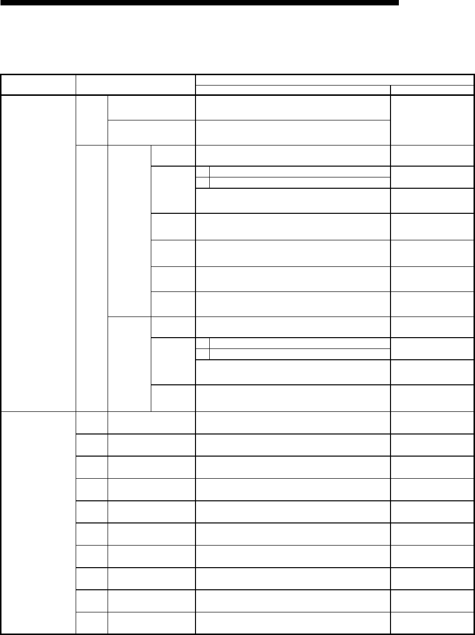
App - 24
MELSEC-F
APPENDIX
App - 24
Recording sheet 5
[Block number ]
FX Configurator-EN-L
setting screen Data item Setting data
Setting value Remark
Ethernet e-mail settings
General
settings
Password
Mail address
Mail
Server
name
SMTP
setting
SMTP
Server name
IP address
Decimal IP address input format
Hexadecimal
. . .
Adjust to input format
SMTP
server port
number
Setting range: 1 to 65535
Initial value: 25
SMTP
authentication
method
SMTP
login ID
SMTP
Password
POP setting
POP
Server name
IP address
Decimal IP address input format
Hexadecimal
. . .
Adjust to input format
POP3
server port
number
Setting range: 1 to 65535
Initial value: 110
Ethernet send mail
address settings
No.1 Send mail address
No.2 Send mail address
No.3 Send mail address
No.4 Send mail address
No.5 Send mail address
No.6 Send mail address
No.7 Send mail address
No.8 Send mail address
No.9 Send mail address
No.10 Send mail address
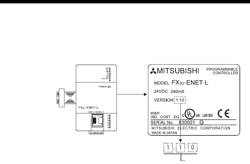
App - 25
MELSEC-F
APPENDIX
App - 25
Appendix 8 Versioin Information
Ethernet Module version is shown as "VERSION" on the label attached to the right
side of the module as seen from the front.
Version
Right side

App - 26
MELSEC-F
APPENDIX
App - 26
MEMO
Warranty
Please confirm the following product warranty details before using this product.
1. Gratis Warranty Term and Gratis Warranty
Range
If any faults or defects (hereinafter "Failure") found to be
the responsibility of Mitsubishi occurs during use of the
product within the gratis warranty term, the product shall
be repaired at no cost via the sales representative or
Mitsubishi Service Company. However, if repairs are
required onsite at domestic or overseas location,
expenses to send an engineer will be solely at the
customer's discretion. Mitsubishi shall not be held
responsible for any re-commissioning, maintenance, or
testing on-site that involves replacement of the failed
module.
[Gratis Warranty Term]
The gratis warranty term of the product shall be for one
year after the date of purchase or delivery to a
designated place. Note that after manufacture and
shipment from Mitsubishi, the maximum distribution
period shall be six (6) months, and the longest gratis
warranty term after manufacturing shall be eighteen (18)
months. The gratis warranty term of repair parts shall not
exceed the gratis warranty term before repairs.
[Gratis Warranty Range]
1) The range shall be limited to normal use within the
usage state, usage methods and usage
environment, etc., which follow the conditions and
precautions, etc., given in the instruction manual,
user's manual and caution labels on the product.
2) Even within the gratis warranty term, repairs shall
be charged for in the following cases.
a) Failure occurring from inappropriate storage or
handling, carelessness or negligence by the
user. Failure caused by the user's hardware or
software design.
b) Failure caused by unapproved modifications,
etc., to the product by the user.
c) When the Mitsubishi product is assembled into
a user's device, Failure that could have been
avoided if functions or structures, judged as
necessary in the legal safety measures the
user's device is subject to or as necessary by
industry standards, had been provided.
d) Failure that could have been avoided if
consumable parts (battery, backlight, fuse, etc.)
designated in the instruction manual had been
correctly serviced or replaced.
e) Relay failure or output contact failure caused by
usage beyond the specified Life of contact
(cycles).
f) Failure caused by external irresistible forces
such as fires or abnormal voltages, and Failure
caused by force majeure such as earthquakes,
lightning, wind and water damage.
g) Failure caused by reasons unpredictable by
scientific technology standards at time of
shipment from Mitsubishi.
h) Anyother failure found not to be the
responsibility of Mitsubishi or that admitted not
to be so by the user.
2. Onerous repair term after discontinuation of
production
1) Mitsubishi shall accept onerous product repairs for
seven (7) years after production of the product is
discontinued.
Discontinuation of production shall be notified with
Mitsubishi Technical Bulletins, etc.
2) Product supply (including repair parts) is not
available after production is discontinued.
3. Overseas service
Overseas, repairs shall be accepted by Mitsubishi's local
overseas FA Center. Note that the repair conditions at
each FA Center may differ.
4. Exclusion of loss in opportunity and secondary
loss from warranty liability
Regardless of the gratis warranty term, Mitsubishi shall
not be liable for compensation of damages caused by
any cause found not to be the responsibility of
Mitsubishi, loss in opportunity, lost profits incurred to the
user or third person by Failures of Mitsubishi products,
special damages and secondary damages whether
foreseeable or not , compensation for accidents, and
compensation for damages to products other than
Mitsubishi products, replacement by the user,
maintenance of on-site equipment, start-up test run and
other tasks.
5. Changes in product specifications
The specifications given in the catalogs, manuals or
technical documents are subject to change without prior
notice.
6. Product application
1) In using the Mitsubishi MELSEC programmable
logic controller, the usage conditions shall be that
the application will not lead to a major accident
even if any problem or fault should occur in the
programmable logic controller device, and that
backup and fail-safe functions are systematically
provided outside of the device for any problem or
fault.
2) The Mitsubishi programmable logic controller has
been designed and manufactured for applications in
general industries, etc. Thus, applications in which
the public could be affected such as in nuclear
power plants and other power plants operated by
respective power companies, and applications in
which a special quality assurance system is
required, such as for Railway companies or Public
service purposes shall be excluded from the
programmable logic controller applications.
In addition, applications in which human life or
property that could be greatly affected, such as in
aircraft, medical applications, incineration and fuel
devices, manned transportation, equipment for
recreation and amusement, and safety devices,
shall also be excluded from the programmable logic
controller range of applications.
However, in certain cases, some applications may
be possible, providing the user consults their local
Mitsubishi representative outlining the special
requirements of the project, and providing that all
parties concerned agree to the special
circumstances, solely at the users discretion.

Revised History
Date Revision Description
10/2009 A First Edition

HEAD OFFICE: TOKYO BULDING, 2-7-3 MARUNOUCHI, CHYODA-KU, TOKYO 100-8310, JAPAN
HIMEJI WORKS: 840, CHIYODA CHO, HIMEJI, JAPAN
JY997D38001A
(MEE)
Effective Oct. 2009
Specifications are subject to change without notice.
MODEL FX3U-ENET-L-U-E
MODEL CODE 09R722
FX3U-ENET-L
USER’S MANUAL
