Mitsubishi Electronics Digital Portable Multimedia Player Got1000 Users Manual Series Connection (Mitsubishi Products) For GT Works3 (ELE)
GOT1000 to the manual 8be7cf51-f2a9-4e72-b23b-5d480278e534
2015-02-09
: Mitsubishi-Electronics Mitsubishi-Electronics-Mitsubishi-Digital-Electronics-Portable-Multimedia-Player-Got1000-Users-Manual-556773 mitsubishi-electronics-mitsubishi-digital-electronics-portable-multimedia-player-got1000-users-manual-556773 mitsubishi-electronics pdf
Open the PDF directly: View PDF ![]() .
.
Page Count: 754 [warning: Documents this large are best viewed by clicking the View PDF Link!]
- SAFETY PRECAUTIONS
- INTRODUCTION
- CONTENTS
- MANUALS
- QUICK REFERENCE
- ABBREVIATIONS AND GENERIC TERMS
- HOW TO READ THIS MANUAL
- 1. PREPARATORY PROCEDURES FOR MONITORING
- MITSUBISHI PLC CONNECTIONS
- 2. DEVICE RANGE THAT CAN BE SET
- 3. ACCESS RANGE FOR MONITORING
- 3.1 Access Range for Monitoring Stations on Network Systems
- 3.2 Access Range for Monitoring when Using Ethernet Connection
- 3.3 CC-Link System Access Range for Monitoring
- 3.4 Data Link System (MELSECNET/B, (II)) Access Range for Monitoring
- 3.5 Access Range for Monitoring when Connecting FXCPU
- 3.6 Connection to Remote I/O Station in MELSECNET/ H Network System
- 3.7 Connection to the Head Module of CC-Link IE Field Network System
- 4. HOW TO MONITOR REDUNTANT SYSTEM
- 4.1 Connection to Remote I/O Station in MELSECNET/ H Network System
- 4.2 Direct CPU Connection
- 4.3 CC-Link Connection (Intelligent Device Station)
- 4.4 CC-Link Connection (Via G4)
- 4.5 MELSECNET/H and MELSECNET/10 Connections (Network Systems)
- 4.6 CC-Link IE Controller Network Connection (Network System)
- 4.7 Ethernet Connection
- 4.8 Connection to the Redundant Type Extension Base Unit
- 4.8.1 Computer link connection (Connection to the Serial communication module mounted on the redundant type extension base unit)
- 4.8.2 Ethernet connection (Connection to the Ethernet module mounted on redundant type extension base unit)
- 4.8.3 CC-Link connection (intelligent device station) (Connection to the CC-Link module mounted on redundant type extension base unit)
- 4.8.4 CC-Link connection (Via G4) (Connection to the CC-Link module mounted on redundant type extension base unit)
- 4.9 Q Redundant Setting
- 4.10 Switch the Monitor Target to the Control System Using the Script Function
- 5. BUS CONNECTION
- 5.1 Connectable Model List
- 5.2 System Configuration
- 5.2.1 Connecting to QCPU
- 5.2.2 Connecting to QnACPU or AnCPU
- 5.2.3 Connection to QnASCPU or AnSCPU
- 5.2.4 Connection to A0J2HCPU
- 5.2.5 Connection to motion controller CPU (A273UCPU, A273UHCPU(-S3), A373UCPU(-S3))
- 5.2.6 Connecting to motion controller CPU (A171SCPU(-S3(N)), A171SHCPU(N), A172SHCPU(N), A173UHCPU(-S1))
- 5.3 GOT Side Settings
- 5.4 Precautions
- 5.4.1 GT15-C [ ] EXSS-1, GT15-C [ ] BS
- 5.4.2 Turning the GOT ON
- 5.4.3 Powering OFF the GOT, reapplying the power (OFF to ON)
- 5.4.4 Reset switch on GOT
- 5.4.5 Powering OFF or resetting the PLC
- 5.4.6 Position of the GOT
- 5.4.7 When the GOT is bus- connected to a PLC CPU without the communication driver written
- 5.4.8 When designing the system
- 5.4.9 When assigning GOT I/O signals
- 5.4.10 When connecting to a QCPU (Q mode)
- 5.4.11 When connecting to a QnA(S)CPU or An(S)CPU type
- 5.4.12 When connecting multiple GOTs
- 5.4.13 When using a PLC CPU in the direct mode
- 5.4.14 When connecting to a Q4ARCPU redundant system
- 5.4.15 When monitoring the Q170MCPU
- 5.4.16 Troubleshooting
- 6. DIRECT CONNECTION TO CPU
- 7. COMPUTER LINK CONNECTION
- 8. ETHERNET CONNECTION
- 8.1 Connectable Model List
- 8.2 System Configuration
- 8.3 GOT Side Settings
- 8.4 PLC Side Setting
- 8.4.1 Connecting to Built-in Ethernet port CPU (one-to-one connection)
- 8.4.2 Connecting to Built-in Ethernet port CPU (multiple connection)
- 8.4.3 Connecting to Ethernet module (Q/L Series)
- 8.4.4 Connecting to C Controller module
- 8.4.5 Connecting to Ethernet module (QnA Series)
- 8.4.6 Connecting to Ethernet module (A Series)
- 8.4.7 Connecting to Ethernet module (FX Series)
- 8.4.8 Connecting to Display I/F (CNC C70)
- 8.4.9 Connecting to CC-Link IE Field Network Ethernet Adapter Module
- 8.4.10 Connecting to PERIPHERAL I/F (Built-in Ethernet port Motion Controller CPU)
- 8.5 Precautions
- 9. MELSECNET/H CONNECTION (PLC TO PLC NETWORK)
- 10. MELSECNET/10 CONNECTION (PLC TO PLC NETWORK)
- 11. CC-Link IE CONTROLLER NETWORK CONNECTION
- 12. CC-Link IE FIELD NETWORK CONNECTION
- 13. CC-Link CONNECTION (INTELLIGENT DEVICE STATION)
- 13.1 Connectable Model List
- 13.2 System Configuration
- 13.3 GOT Side Settings
- 13.4 PLC Side Setting
- 13.4.1 Connecting to CC-Link module (Q Series) with Ver.1 compatible
- 13.4.2 Connecting to CC-Link module (Q Series) with Ver.2 compatible
- 13.4.3 Connecting to CC-Link module (Q Series) with Ver.1/Ver.2 compatibles mixed
- 13.4.4 Connecting to MELSEC-L series with CC-Link Ver.1 compatible
- 13.4.5 Connecting to MELSEC-L series with CC-Link Ver.2 compatible
- 13.4.6 Connecting to CC-Link module (QnA Series)
- 13.4.7 Connecting to CC-Link module (A Series)
- 13.5 Precautions
- 14. CC-Link CONNECTION (Via G4)
- MITSUBISHI FA DEVICE CONNECTIONS
- 15. INVERTER CONNECTION
- 15.1 Connectable Model List
- 15.2 System Configuration
- 15.3 Connection Diagram
- 15.4 GOT Side Settings
- 15.5 FREQROL Series Inverter Side Settings
- 15.5.1 Connecting FREQROL-S500, S500E, F500J series
- 15.5.2 Connecting FREQROL-E500 series
- 15.5.3 Connecting FREQROL-F500, F500L series
- 15.5.4 Connecting FREQROL-A500, A500L series
- 15.5.5 Connecting FREQROL-V500, V500L series
- 15.5.6 Connecting FREQROL-E700 series
- 15.5.7 Connecting FREQROL-D700 series
- 15.5.8 Connecting FREQROL-F700/700P series
- 15.5.9 Connecting FREQROL-F700PJ series
- 15.5.10 Connecting FREQROL-A700 series
- 15.5.11 Connecting MD-CX522-K(-A0)
- 15.5.12 Station number setting
- 15.6 Device Range that Can Be Set
- 15.7 Precautions
- 16. SERVO AMPLIFIER CONNECTION
- 17. ROBOT CONTROLLER CONNECTION
- 18. CNC CONNECTION
- MULTIPLE GOT CONNECTIONS
- 19. GOT MULTI-DROP CONNECTION
- 20. MULTIPLE-GT14, GT12, GT11, GT10 CONNECTION FUNCTION
- MULTI-CHANNEL FUNCTION
- 21. MULTI-CHANNEL FUNCTION
- 21.1 What is Multi-channel Function?
- 21.2 System Configuration
- 21.3 GOT Side Settings
- 21.3.1 Basics of interface selection
- 21.3.2 General flow from system selection to drawing
- 21.3.3 Determining the connection type and channel No. (System selection)
- 21.3.4 Determining the GOT side interface (Interface selection)
- 21.3.5 Setting for communication settings
- 21.3.6 Items to be checked before starting drawing
- 21.4 Precautions
- 21.5 Multi-channel Function Check Sheet
- FA TRANSPARENT FUNCTION
- 22. FA TRANSPARENT FUNCTION
- 22.1 FA Transparent Function
- 22.2 Compatible Software
- 22.3 List of Models that Can Be Monitored
- 22.4 System Configuration
- 22.4.1 GX Developer, GX Works2, GX LogViewer, MX Component, MX Sheet, LCPU Logging Configuration Tool, Setting/Monitoring tool for C Controller module
- 22.4.2 PX Developer, GX Configurator
- 22.4.3 MT Developer, MT Works2
- 22.4.4 MR Configurator, MR Configurator2
- 22.4.5 FR Configurator
- 22.4.6 FX Configurator-FP, FX Configurator-EN
- 22.4.7 RT ToolBox2
- 22.4.8 NC Configurator
- 22.5 GOT Side Settings
- 22.6 Personal Computer Side Setting
- 22.6.1 Accessing the PLC by the GX Developer, PX Developer, GX Configurator
- 22.6.2 Accessing by GX Works2
- 22.6.3 Accessing by GX LogViewer
- 22.6.4 Accessing PLC by GX Configurator-QP
- 22.6.5 Accessing by the MT Developer
- 22.6.6 Accessing by the MT Works2
- 22.6.7 Accessing the servo amplifier by the MR Configurator
- 22.6.8 Accessing the servo amplifier by the MR Configurator2
- 22.6.9 Accessing the inverter by the FR Configurator
- 22.6.10 Accessing PLC by FX Configurator-FP
- 22.6.11 Accessing by FX Configurator- EN
- 22.6.12 Accessing by RT ToolBox2
- 22.6.13 Accessing by NC Configurator
- 22.6.14 Accessing by MELSOFT Navigator
- 22.6.15 Accessing by LCPU Logging Configuration Tool
- 22.6.16 Accessing by Setting/ Monitoring tool for C Controller module
- 22.7 Precautions
- INDEX
- REVISIONS
- WARRANTY
- INDEX MENU
BUS CONNECTION
BUS CONNECTION
DIRECT CONNECTION TO CPU
DIRECT CONNECTION TO CPU
COMPUTER LINK CONNECTION
COMPUTER LINK CONNECTION
ETHERNET CONNECTION
ETHERNET CONNECTION
MELSECNET/H CONNECTION
MELSECNET/H CONNECTION
MELSECNET/10 CONNECTION
MELSECNET/10 CONNECTION
CC-Link IE CONNECTION
CC-Link IE CONNECTION
CC-Link CONNECTION
CC-Link CONNECTION
INVERTER CONNECTION
INVERTER CONNECTION
SERVO AMPLIFIER CONNECTION
SERVO AMPLIFIER CONNECTION
ROBOT CONTROLLER CONNECTION
ROBOT CONTROLLER CONNECTION
CNC CONNECTION
CNC CONNECTION
GOT MULTI-DROP CONNECTION
GOT MULTI-DROP CONNECTION
MULTIPLE-GT14, GT12, GT11, GT10 CONNECTION FUNCTION
MULTIPLE-GT14, GT12, GT11, GT10 CONNECTION FUNCTION
MULTI-CHANNEL FUNCTION
MULTI-CHANNEL FUNCTION
FA TRANSPARENT FUNCTION
FA TRANSPARENT FUNCTION
BUS CONNECTION
DIRECT CONNECTION TO CPU
COMPUTER LINK CONNECTION
ETHERNET CONNECTION
MELSECNET/H CONNECTION
MELSECNET/10 CONNECTION
CC-Link IE CONNECTION
CC-Link CONNECTION
INVERTER CONNECTION
SERVO AMPLIFIER CONNECTION
ROBOT CONTROLLER CONNECTION
CNC CONNECTION
GOT MULTI-DROP CONNECTION
MULTIPLE-GT14, GT12, GT11, GT10 CONNECTION FUNCTION
MULTI-CHANNEL FUNCTION
FA TRANSPARENT FUNCTION
Series
(Mitsubishi Products)
Connection Manual
for GT Works3 (ELE)
A - 1
SAFETY PRECAUTIONS
(Always read these precautions before using this equipment.)
Before using this product, please read this manual and the relevant manuals introduced in this manual
carefully and pay full attention to safety to handle the product correctly.
The precautions given in this manual are concerned with this product.
In this manual, the safety precautions are ranked as "WARNING" and "CAUTION".
Note that the caution level may lead to a serious accident according to the circumstances.
Always follow the instructions of both levels because they are important to personal safety.
Please save this manual to make it accessible when required and always forward it to the end user.
[DESIGN PRECAUTIONS]
WARNING
●Some failures of the GOT, communication unit or cable may keep the outputs on or off.
An external monitoring circuit should be provided to check for output signals which may lead to a
serious accident.
Not doing so can cause an accident due to false output or malfunction.
●If a communication fault (including cable disconnection) occurs during monitoring on the GOT,
communication between the GOT and PLC CPU is suspended and the GOT becomes inoperative.
For bus connection : The CPU becomes faulty and the GOT becomes inoperative.
For other than bus connection : The GOT becomes inoperative.
A system where the GOT is used should be configured to perform any significant operation to the
system by using the switches of a device other than the GOT on the assumption that a GOT
communication fault will occur.
Not doing so can cause an accident due to false output or malfunction.
●Do not use the GOT as the warning device that may cause a serious accident.
An independent and redundant hardware or mechanical interlock is required to configure the device
that displays and outputs serious warning.
Failure to observe this instruction may result in an accident due to incorrect output or malfunction.
WARNING Indicates that incorrect handling may cause hazardous conditions,
resulting in death or severe injury.
CAUTION Indicates that incorrect handling may cause hazardous conditions,
resulting in medium or slight personal injury or physical damage.

A - 2
[DESIGN PRECAUTIONS]
WARNING
●Incorrect operation of the touch switch(s) may lead to a serious accident if the GOT backlight is gone
out.
When the GOT backlight goes out, the display section dims, while the input of the touch switch(s)
remains active.
This may confuse an operator in thinking that the GOT is in "screensaver" mode, who then tries to
release the GOT from this mode by touching the display section, which may cause a touch switch to
operate.
Note that the following occurs on the GOT when the backlight goes out.
<When using the GT1655-V, Handy GOT, GT15, GT14, GT12, GT11, or GT105 >
The POWER LED blinks (green/orange) and the monitor screen appears blank.
<When using the GT1695, GT1685, GT1675, GT1672, GT1665, or GT1662>
The POWER LED blinks (green/orange) and the monitor screen appears dimmed.
<When using the GT104 >
The monitor screen appears blank.
<When using the GT103 or GT102 >
The monitor screen appears dimmed.
●The display section of the GT16, GT1595-X, GT14, GT12 or GT1020 are an analog-resistive type
touch panel.
If you touch the display section simultaneously in 2 points or more, the switch that is located around
the center of the touched point, if any, may operate.
Do not touch the display section in 2 points or more simultaneously.
Doing so may cause an accident due to incorrect output or malfunction.
●When programs or parameters of the controller (such as a PLC) that is monitored by the GOT are
changed, be sure to reset the GOT or shut off the power of the GOT at the same time.
Not doing so can cause an accident due to false output or malfunction.
CAUTION
●Do not bundle the control and communication cables with main-circuit, power or other wiring.
Run the above cables separately from such wiring and keep them a minimum of 100mm apart.
Not doing so noise can cause a malfunction.
●Do not press the GOT display section with a pointed material as a pen or driver.
Doing so can result in a damage or failure of the display section.
●When the GOT is connected to the Ethernet network, the available IP address is restricted according
to the system configuration.
• When multiple GOTs are connected to the Ethernet network:
Do not set the IP address (192.168.0.18) for the GOTs and the controllers in the network.
• When a single GOT is connected to the Ethernet network:
Do not set the IP address (192.168.0.18) for the controllers except the GOT in the network.
Doing so can cause the IP address duplication. The duplication can negatively affect the
communication of the device with the IP address (192.168.0.18).
The operation at the IP address duplication depends on the devices and the system.
●Turn on the controllers and the network devices to be ready for communication before they
communicate with the GOT.
Failure to do so can cause a communication error on the GOT.

A - 3
[MOUNTING PRECAUTIONS]
WARNING
●Be sure to shut off all phases of the external power supply used by the system before mounting or
removing the GOT to/from the panel.
Not switching the power off in all phases can cause a unit failure or malfunction.
●Be sure to shut off all phases of the external power supply used by the system before mounting or
removing the communication unit, option function board or multi-color display board onto/from the
GOT.
Not doing so can cause the unit to fail or malfunction.
●Before mounting an optional function board or Multi-color display board, wear a static discharge wrist
strap to prevent the board from being damaged by static electricity.
CAUTION
●Use the GOT in the environment that satisfies the general specifications described in the User's
Manual.
Not doing so can cause an electric shock, fire, malfunction or product damage or deterioration.
●When mounting the GOT to the control panel, tighten the mounting screws in the specified torque
range.
Undertightening can cause the GOT to drop, short circuit or malfunction.
Overtightening can cause a drop, short circuit or malfunction due to the damage of the screws or the
GOT.
●When loading the communication unit or option unit to the GOT (GT16, GT15), fit it to the extension
interface of the GOT and tighten the mounting screws in the specified torque range.
Undertightening can cause the GOT to drop, short circuit or malfunction.
Overtightening can cause a drop, failure or malfunction due to the damage of the screws or unit.
●When mounting the multi-color display board onto the GOT (GT15), connect it to the corresponding
connector securely and tighten the mounting screws within the specified torque range.
Loose tightening may cause the unit and/or GOT to malfunction due to poor contact.
Overtightening may damage the screws, unit and/or GOT; they might malfunction.
●When mounting the option function board onto the GOT (GT16), connect it to the corresponding
connector securely and tighten the mounting screws within the specified torque range.
●When mounting an optional function board onto the GOT(GT15), fully connect it to the connector
until you hear a click.
●When mounting an optional function board onto the GOT(GT11), fully connect it to the connector.
●When inserting a CF card into the GOT(GT16, GT15, GT11), push it into the CF card interface of
GOT until the CF card eject button will pop out.
Failure to do so may cause a malfunction due to poor contact.
●When inserting/removing a SD card into/from the GOT(GT14), turn the SD card access switch off in
advance.
Failure to do so may corrupt data within the SD card.
A - 4
[MOUNTING PRECAUTIONS]
[WIRING PRECAUTIONS]
CAUTION
●When inserting/removing a CF card into/from the GOT(GT16, GT15, GT11), turn the CF card access
switch off in advance.
Failure to do so may corrupt data within the CF card.
●When removing a SD card from the GOT(GT14), make sure to support the SD card by hand, as it
may pop out.
Failure to do so may cause the SD card to drop from the GOT and break.
●When removing a CF card from the GOT, make sure to support the CF card by hand, as it may pop
out.
Failure to do so may cause the CF card to drop from the GOT and break.
●When installing a USB memory to the GOT(GT16, GT14), make sure to install the USB memory to
the USB interface firmly.
Failure to do so may cause a malfunction due to poor contact.
●
Before removing the USB memory from the GOT(GT16, GT14), operate the utility screen for removal.
After the successful completion dialog box is displayed, remove the memory by hand carefully.
Failure to do so may cause the USB memory to drop, resulting in a damage or failure of the memory.
●For closing the USB environmental protection cover, fix the cover by pushing the mark on the latch
firmly to comply with the protective structure.
●Remove the protective film of the GOT.
When the user continues using the GOT with the protective film, the film may not be removed.
●Operate and store the GOT in environments without direct sunlight, high temperature, dust, humidity,
and vibrations.
●When using the GOT in the environment of oil or chemicals, use the protective cover for oil.
Failure to do so may cause failure or malfunction due to the oil or chemical entering into the GOT.
WARNING
●Be sure to shut off all phases of the external power supply used by the system before wiring.
Failure to do so may result in an electric shock, product damage or malfunctions.
CAUTION
●Please make sure to ground FG terminal and LG terminal and protective ground terminal of the GOT
power supply section by applying Class D Grounding (Class 3 Grounding Method) or higher which is
used exclusively for the GOT.
Not doing so may cause an electric shock or malfunction.
●Be sure to tighten any unused terminal screws with a torque of 0.5 to 0.8N•m.
Failure to do so may cause a short circuit due to contact with a solderless terminal.
●Use applicable solderless terminals and tighten them with the specified torque.
If any solderless spade terminal is used, it may be disconnected when the terminal screw comes
loose, resulting in failure.

A - 5
[WIRING PRECAUTIONS]
[TEST OPERATION PRECAUTIONS]
CAUTION
●Correctly wire the GOT power supply section after confirming the rated voltage and terminal
arrangement of the product.
Not doing so can cause a fire or failure.
●Tighten the terminal screws of the GOT power supply section in the specified torque range.
Undertightening can cause a short circuit or malfunction.
Overtightening can cause a short circuit or malfunction due to the damage of the screws or the GOT.
●Exercise care to avoid foreign matter such as chips and wire offcuts entering the GOT.
Not doing so can cause a fire, failure or malfunction.
●The module has an ingress prevention label on its top to prevent foreign matter, such as wire offcuts,
from entering the module during wiring.
Do not peel this label during wiring.
Before starting system operation, be sure to peel this label because of heat dissipation.
●Plug the bus connection cable by inserting it into the connector of the connected unit until it "clicks".
After plugging, check that it has been inserted snugly.
Not doing so can cause a malfunction due to a contact fault.
●Plug the communication cable into the connector of the connected unit and tighten the mounting and
terminal screws in the specified torque range.
Undertightening can cause a short circuit or malfunction.
Overtightening can cause a short circuit or malfunction due to the damage of the screws or unit.
●Plug the QnA/ACPU/Motion controller (A series) bus connection cable by inserting it into the
connector of the connected unit until it "clicks".
After plugging, check that it has been inserted snugly.
Not doing so can cause a malfunction due to a contact fault.
WARNING
●Before performing the test operations of the user creation monitor screen (such as turning ON or
OFF bit device, changing the word device current value, changing the settings or current values of
the timer or counter, and changing the buffer memory current value), read through the manual
carefully and make yourself familiar with the operation method.
During test operation, never change the data of the devices which are used to perform significant
operation for the system.
False output or malfunction can cause an accident.

A - 6
[STARTUP/MAINTENANCE PRECAUTIONS]
WARNING
●When power is on, do not touch the terminals.
Doing so can cause an electric shock or malfunction.
●Correctly connect the battery connector.
Do not charge, disassemble, heat, short-circuit, solder, or throw the battery into the fire.
Doing so will cause the battery to produce heat, explode, or ignite, resulting in injury and fire.
●Before starting cleaning or terminal screw retightening, always switch off the power externally in all
phases.
Not switching the power off in all phases can cause a unit failure or malfunction.
Undertightening can cause a short circuit or malfunction.
Overtightening can cause a short circuit or malfunction due to the damage of the screws or unit.
CAUTION
●Do not disassemble or modify the unit.
Doing so can cause a failure, malfunction, injury or fire.
●Do not touch the conductive and electronic parts of the unit directly.
Doing so can cause a unit malfunction or failure.
●The cables connected to the unit must be run in ducts or clamped.
Not doing so can cause the unit or cable to be damaged due to the dangling, motion or accidental
pulling of the cables or can cause a malfunction due to a cable connection fault.
●When unplugging the cable connected to the unit, do not hold and pull the cable portion.
Doing so can cause the unit or cable to be damaged or can cause a malfunction due to a cable
connection fault.
●Do not drop or apply strong impact to the unit.
Doing so may damage the unit.
●Do not drop or give an impact to the battery mounted to the unit.
Doing so may damage the battery, causing the battery fluid to leak inside the battery.
If the battery is dropped or given an impact, dispose of it without using.
●Before touching the unit, always touch grounded metal, etc. to discharge static electricity from
human body, etc.
Not doing so can cause the unit to fail or malfunction.
●Replace battery with GT15-BAT(GT16, GT15) or GT11-50BAT(GT14, GT12, GT11, GT10) by
Mitsubishi electric Co. only.
Use of another battery may present a risk of fire or explosion.
●Dispose of used battery promptly.
Keep away from children. Do not disassemble and do not dispose of in fire.

A - 7
[TOUCH PANEL PRECAUTIONS]
[BACKLIGHT REPLACEMENT PRECAUTIONS]
[DISPOSAL PRECAUTIONS]
CAUTION
●For the analog-resistive film type touch panels, normally the adjustment is not required. However,
the difference between a touched position and the object position may occur as the period of use
elapses. When any difference between a touched position and the object position occurs, execute
the touch panel calibration.
●When any difference between a touched position and the object position occurs, other object may be
activated. This may cause an unexpected operation due to incorrect output or malfunction.
WARNING
●Be sure to shut off all phases of the external power supply of the GOT (and the PLC CPU in the case
of a bus topology) and remove the GOT from the control panel before replacing the backlight (when
using the GOT with the backlight replaceable by the user).
Not doing so can cause an electric shock.
Replacing a backlight without removing the GOT from the control panel can cause the backlight or
control panel to drop, resulting in an injury.
CAUTION
●Wear gloves for the backlight replacement when using the GOT with the backlight replaceable by the
user.
Not doing so can cause an injury.
●Before replacing a backlight, allow 5 minutes or more after turning off the GOT when using the GOT
with the backlight replaceable by the user.
Not doing so can cause a burn from heat of the backlight.
CAUTION
●When disposing of the product, handle it as industrial waste.
●When disposing of this product, treat it as industrial waste. When disposing of batteries, separate
them from other wastes according to the local regulations.
(For details of the battery directive in EU member states, refer to the User's Manual of the GOT to be
used.)

A - 8
[TRANSPORTATION PRECAUTIONS]
CAUTION
●When transporting lithium batteries, make sure to treat them based on the transport regulations.
(For details on models subject to restrictions, refer to the User's Manual for the GOT you are using.)
●Make sure to transport the GOT main unit and/or relevant unit(s) in the manner they will not be
exposed to the impact exceeding the impact resistance described in the general specifications of the
User's Manual, as they are precision devices.
Failure to do so may cause the unit to fail.
Check if the unit operates correctly after transportation.

A - 9
SAFETY PRECAUTIONS .........................................................................................................................A - 1
INTRODUCTION ......................................................................................................................................A - 9
CONTENTS ..............................................................................................................................................A - 9
MANUALS............................................................................................................................................... A - 20
QUICK REFERENCE .............................................................................................................................A - 22
ABBREVIATIONS AND GENERIC TERMS ...........................................................................................A - 24
HOW TO READ THIS MANUAL .............................................................................................................A - 29
1.PREPARATORY PROCEDURES FOR MONITORING
1.1 Setting the Communication Interface............................................................................................... 1 - 3
1.1.1 Setting connected equipment (Channel setting)................................................................... 1 - 4
1.1.2 I/F communication setting................................................................................................... 1 - 12
1.1.3 Precautions......................................................................................................................... 1 - 14
1.2 Writing the Project Data and OS onto the GOT............................................................................. 1 - 15
1.2.1 Writing the project data and OS onto the GOT................................................................... 1 - 15
1.2.2 Checking the project data and OS writing on GOT ............................................................ 1 - 16
1.3 Option Devices for the Respective Connection ............................................................................. 1 - 17
1.3.1 Communication module...................................................................................................... 1 - 17
1.3.2 Option unit .......................................................................................................................... 1 - 18
1.3.3 Conversion cables .............................................................................................................. 1 - 18
1.3.4 Connector conversion adapter ........................................................................................... 1 - 18
1.3.5 Serial Multi-Drop Connection Unit ...................................................................................... 1 - 18
1.3.6 RS-232/485 signal conversion adapter .............................................................................. 1 - 18
1.3.7 Installing a unit on another unit (Checking the unit installation position) ............................ 1 - 19
1.4 Connection Cables for the Respective Connection ....................................................................... 1 - 26
1.4.1 GOT connector specifications ............................................................................................ 1 - 26
1.4.2 Coaxial cable connector connection method...................................................................... 1 - 29
1.4.3 Terminating resistors of GOT ............................................................................................. 1 - 30
1.4.4 Setting the RS-232/485 signal conversion adaptor ............................................................ 1 - 33
1.5 Verifying GOT Recognizes Connected Equipment........................................................................ 1 - 34
1.6 Checking for Normal Monitoring .................................................................................................... 1 - 39
1.6.1 Check on the GOT.............................................................................................................. 1 - 39
1.6.2 Confirming the communication state on the GOT side (For Ethernet connection) ............. 1 - 45
1.6.3 Confirming the communication state to each station (Station monitoring function)............ 1 - 47
1.6.4 Check on GX Developer.................................................................................................... 1 - 50
1.6.5 Check on GX Works2 .........................................................................................................1 - 54
1.6.6 Check on the PLC ............................................................................................................. 1 - 55
INTRODUCTION
Thank you for choosing Mitsubishi Graphic Operation Terminal (Mitsubishi GOT).
Read this manual and make sure you understand the functions and performance of the GOT thoroughly
in advance to ensure correct use.
CONTENTS

A - 10
MITSUBISHI PLC CONNECTIONS
2.DEVICE RANGE THAT CAN BE SET
2.1 MELSEC-QnU/DC, Q17nD/M/NC/DR, CRnD-700........................................................................... 2 - 8
2.2 MELSEC-L ....................................................................................................................................... 2 - 9
2.3 MELSEC-QnA/Q/QS, MELDAS C6 * ............................................................................................. 2 - 10
2.4 MELSEC-Q (Multi)/Q Motion ......................................................................................................... 2 - 11
2.5 MELSEC-A .................................................................................................................................... 2 - 12
2.6 MELSEC-FX .................................................................................................................................. 2 - 13
2.7 MELSEC-WS ................................................................................................................................. 2 - 14
3.ACCESS RANGE FOR MONITORING
3.1 Access Range for Monitoring Stations on Network Systems........................................................... 3 - 2
3.1.1 MELSECNET/H, MELSECNET/10, CC-Link IE Controller Network,
CC-Link IE Field Network ..................................................................................................... 3 - 2
3.2 Access Range for Monitoring when Using Ethernet Connection ................................................... 3 - 13
3.3 CC-Link System Access Range for Monitoring.............................................................................. 3 - 14
3.4 Data Link System (MELSECNET/B, (II)) Access Range for Monitoring ........................................ 3 - 17
3.5 Access Range for Monitoring when Connecting FXCPU............................................................... 3 - 18
3.6 Connection to Remote I/O Station in MELSECNET/H Network System........................................ 3 - 19
3.7 Connection to the Head Module of CC-Link IE Field Network System .......................................... 3 - 22
4.HOW TO MONITOR REDUNTANT SYSTEM
4.1 Connection to Remote I/O Station in MELSECNET/H Network System.......................................... 4 - 8
4.1.1 Direct CPU connection (Direct CPU connection to the remote I/O station) .......................... 4 - 8
4.1.2 Computer link connection
(Connection to serial communication module mounted on remote I/O station) .................... 4 - 9
4.1.3 Ethernet connection (Connection to Ethernet module mounted on remote I/O station) ..... 4 - 10
4.2 Direct CPU Connection.................................................................................................................. 4 - 11
4.2.1 When using one GOT .........................................................................................................4 - 11
4.2.2 When using two GOTs........................................................................................................4 - 12
4.2.3 Precautions when connecting a GOT directly to a PLC CPU in the redundant system
without making Q redundant setting ................................................................................... 4 - 13
4.3 CC-Link Connection (Intelligent Device Station)............................................................................ 4 - 18
4.4 CC-Link Connection (Via G4) ........................................................................................................ 4 - 20
4.5 MELSECNET/H and MELSECNET/10 Connections (Network Systems) ...................................... 4 - 22
4.6 CC-Link IE Controller Network Connection (Network System)...................................................... 4 - 23
4.7 Ethernet Connection ...................................................................................................................... 4 - 24
4.8 Connection to the Redundant Type Extension Base Unit.............................................................. 4 - 25
4.8.1 Computer link connection (Connection to the Serial communication module mounted
on the redundant type extension base unit)........................................................................ 4 - 25
4.8.2 Ethernet connection (Connection to the Ethernet module mounted on redundant type
extension base unit)............................................................................................................4 - 26
4.8.3 CC-Link connection (intelligent device station) (Connection to the CC-Link module
mounted on redundant type extension base unit)............................................................... 4 - 27

A - 11
4.8.4 CC-Link connection (Via G4)
(Connection to the CC-Link module mounted on redundant type extension base unit) ..... 4 - 28
4.9 Q Redundant Setting ..................................................................................................................... 4 - 29
4.10 Switch the Monitor Target to the Control System Using the Script Function ................................. 4 - 31
4.10.1 Method for using the station number switching function..................................................... 4 - 31
4.10.2 Method for using the screen changing function .................................................................. 4 - 38
5.BUS CONNECTION
5.1 Connectable Model List ................................................................................................................... 5 - 2
5.2 System Configuration ...................................................................................................................... 5 - 5
5.2.1 Connecting to QCPU ............................................................................................................ 5 - 5
5.2.2 Connecting to QnACPU or AnCPU ...................................................................................... 5 - 9
5.2.3 Connection to QnASCPU or AnSCPU................................................................................ 5 - 12
5.2.4 Connection to A0J2HCPU .................................................................................................. 5 - 18
5.2.5 Connection to motion controller CPU
(A273UCPU, A273UHCPU(-S3), A373UCPU(-S3)) ........................................................... 5 - 19
5.2.6 Connecting to motion controller CPU
(A171SCPU(-S3(N)), A171SHCPU(N), A172SHCPU(N), A173UHCPU(-S1))................... 5 - 24
5.3 GOT Side Settings......................................................................................................................... 5 - 30
5.3.1 Setting communication interface (Communication settings)............................................... 5 - 30
5.3.2 Communication detail settings............................................................................................ 5 - 30
5.4 Precautions.................................................................................................................................... 5 - 34
5.4.1 GT15-C [ ] EXSS-1, GT15-C [ ] BS .................................................................................. 5 - 34
5.4.2 Turning the GOT ON .......................................................................................................... 5 - 34
5.4.3 Powering OFF the GOT, reapplying the power (OFF to ON) ............................................. 5 - 35
5.4.4 Reset switch on GOT ......................................................................................................... 5 - 35
5.4.5 Powering OFF or resetting the PLC ................................................................................... 5 - 35
5.4.6 Position of the GOT ............................................................................................................ 5 - 35
5.4.7 When the GOT is bus-connected to a PLC CPU without the communication driver
written ................................................................................................................................. 5 - 35
5.4.8 When designing the system ............................................................................................... 5 - 36
5.4.9 When assigning GOT I/O signals ....................................................................................... 5 - 36
5.4.10 When connecting to a QCPU (Q mode) ............................................................................. 5 - 36
5.4.11 When connecting to a QnA(S)CPU or An(S)CPU type ...................................................... 5 - 37
5.4.12 When connecting multiple GOTs ........................................................................................ 5 - 38
5.4.13 When using a PLC CPU in the direct mode ....................................................................... 5 - 38
5.4.14 When connecting to a Q4ARCPU redundant system ......................................................... 5 - 39
5.4.15 When monitoring the Q170MCPU ...................................................................................... 5 - 39
5.4.16 Troubleshooting.................................................................................................................. 5 - 39
6.DIRECT CONNECTION TO CPU
6.1 Connectable Model List ................................................................................................................... 6 - 2
6.2 System Configuration ...................................................................................................................... 6 - 6
6.2.1 Connecting to QCPU ............................................................................................................ 6 - 6
6.2.2 Connecting to LCPU............................................................................................................. 6 - 7
6.2.3 Connecting to QnACPU........................................................................................................ 6 - 8
6.2.4 Connecting to ACPU ............................................................................................................ 6 - 9
6.2.5 Connecting to FXCPU ........................................................................................................6 - 10
6.2.6 Connecting to WSCPU ....................................................................................................... 6 - 20
6.2.7 Connecting to the motion controller CPU ........................................................................... 6 - 20

A - 12
6.3 Connection Diagram ...................................................................................................................... 6 - 22
6.3.1 RS-232 cable ...................................................................................................................... 6 - 22
6.3.2 RS-422 cable ...................................................................................................................... 6 - 23
6.4 GOT Side Settings......................................................................................................................... 6 - 25
6.4.1 Setting communication interface (Communication settings)............................................... 6 - 25
6.4.2 Communication detail settings............................................................................................ 6 - 25
6.5 Precautions.................................................................................................................................... 6 - 28
7.COMPUTER LINK CONNECTION
7.1 Connectable Model List ................................................................................................................... 7 - 2
7.1.1 PLC/Motion controller CPU................................................................................................... 7 - 2
7.1.2 Serial communication module/Computer link module........................................................... 7 - 6
7.2 System Configuration ...................................................................................................................... 7 - 7
7.2.1 Connecting to QCPU (Q mode) ............................................................................................ 7 - 7
7.2.2 Connecting to LCPU ............................................................................................................. 7 - 8
7.2.3 Connecting to QCPU (A mode) ............................................................................................ 7 - 9
7.2.4 Connecting to QnACPU (QnACPU type)............................................................................ 7 - 10
7.2.5 Connecting to QnACPU (QnASCPU type) ......................................................................... 7 - 11
7.2.6 Connecting to ACPU (AnCPU type) ................................................................................... 7 - 13
7.2.7 Connecting to ACPU (AnSCPU type, A0J2HCPU, A2CCPUC) ......................................... 7 - 14
7.3 Connection Diagram ...................................................................................................................... 7 - 15
7.3.1 RS-232 cable ...................................................................................................................... 7 - 15
7.3.2 RS-422 cable ...................................................................................................................... 7 - 17
7.4 GOT Side Settings......................................................................................................................... 7 - 19
7.4.1 Setting communication interface (Communication settings)............................................... 7 - 19
7.4.2 Communication detail settings............................................................................................ 7 - 19
7.5 PLC Side Setting ........................................................................................................................... 7 - 22
7.5.1 Connecting serial communication module (Q, L Series)..................................................... 7 - 22
7.5.2 Connecting serial communication module (QnA Series) .................................................... 7 - 24
7.5.3 Connecting computer link module ...................................................................................... 7 - 25
7.6 Precautions.................................................................................................................................... 7 - 29
8.ETHERNET CONNECTION
8.1 Connectable Model List ................................................................................................................... 8 - 2
8.1.1 PLC/Motion controller CPU................................................................................................... 8 - 2
8.1.2 Ethernet module ................................................................................................................... 8 - 6
8.2 System Configuration ...................................................................................................................... 8 - 7
8.2.1 Connection to Ethernet module ............................................................................................ 8 - 7
8.2.2 Connection to Built-in Ethernet port CPU or C Controller module ...................................... 8 - 11
8.2.3 Connecting to Display I/F.................................................................................................... 8 - 12
8.2.4 Connection to CC-Link IE Field Network Ethernet Adapter Module ................................... 8 - 13
8.2.5 Connecting to PERIPHERAL I/F (Built-in Ethernet port Motion Controller CPU) ............... 8 - 14
8.3 GOT Side Settings......................................................................................................................... 8 - 15
8.3.1 Setting communication interface (Communication settings)............................................... 8 - 15
8.3.2 Communication detail settings............................................................................................ 8 - 15
8.3.3 Ethernet setting................................................................................................................... 8 - 17
8.3.4 Routing parameter setting ..................................................................................................8 - 18
8.4 PLC Side Setting ........................................................................................................................... 8 - 20
8.4.1 Connecting to Built-in Ethernet port CPU (one-to-one connection) .................................... 8 - 20

A - 13
8.4.2 Connecting to Built-in Ethernet port CPU (multiple connection)......................................... 8 - 22
8.4.3 Connecting to Ethernet module (Q/L Series)...................................................................... 8 - 24
8.4.4 Connecting to C Controller module .................................................................................... 8 - 27
8.4.5 Connecting to Ethernet module (QnA Series) .................................................................... 8 - 30
8.4.6 Connecting to Ethernet module (A Series) ......................................................................... 8 - 33
8.4.7 Connecting to Ethernet module (FX Series)....................................................................... 8 - 38
8.4.8 Connecting to Display I/F (CNC C70)................................................................................. 8 - 42
8.4.9 Connecting to CC-Link IE Field Network Ethernet Adapter Module ................................... 8 - 44
8.4.10 Connecting to PERIPHERAL I/F (Built-in Ethernet port Motion Controller CPU) ............... 8 - 46
8.5 Precautions.................................................................................................................................... 8 - 49
9.MELSECNET/H CONNECTION (PLC TO PLC NETWORK)
9.1 Connectable Model List ................................................................................................................... 9 - 2
9.1.1 PLC/Motion controller CPU ..................................................................................................9 - 2
9.1.2 MELSECNET/H network module.......................................................................................... 9 - 6
9.2 System Configuration ...................................................................................................................... 9 - 7
9.2.1 Connecting to optical loop system........................................................................................ 9 - 7
9.2.2 Connecting to the coaxial bus system .................................................................................. 9 - 7
9.3 GOT Side Settings........................................................................................................................... 9 - 9
9.3.1 Setting communication interface (Communication settings)................................................. 9 - 9
9.3.2 Communication detail settings..............................................................................................9 - 9
9.3.3 Routing parameter setting ..................................................................................................9 - 10
9.4 PLC Side Settings.......................................................................................................................... 9 - 11
9.4.1 System configuration .......................................................................................................... 9 - 11
9.4.2 Switch setting of MELSECNET/H network module ............................................................ 9 - 11
9.4.3 Parameter setting ............................................................................................................... 9 - 12
9.4.4 [Controller Setting] of GT Designer3 .................................................................................. 9 - 15
9.5 Precautions.................................................................................................................................... 9 - 16
10.MELSECNET/10 CONNECTION (PLC TO PLC NETWORK)
10.1 Connectable Model List ................................................................................................................. 10 - 2
10.1.1 PLC/Motion controller CPU ................................................................................................ 10 - 2
10.1.2 MELSECNET/H (NET/10 mode), MELSECNET/10 network module ................................. 10 - 6
10.2 System Configuration .................................................................................................................... 10 - 7
10.2.1 Connecting to optical loop system...................................................................................... 10 - 7
10.2.2 Connecting to the coaxial bus system ................................................................................ 10 - 8
10.3 GOT Side Settings......................................................................................................................... 10 - 9
10.3.1 Setting communication interface (Communication settings)............................................... 10 - 9
10.3.2 Communication detail settings............................................................................................ 10 - 9
10.3.3 Routing parameter setting ................................................................................................ 10 - 10
10.3.4 Switch setting (Only when MELSECNET/10 communication unit is used)....................... 10 - 11
10.4 PLC Side Setting ......................................................................................................................... 10 - 12
10.4.1 Connecting to MELSECNET/H network module .............................................................. 10 - 12
10.4.2 Connecting to MELSECNET/10 network module (QnA Series) ....................................... 10 - 17
10.4.3 Connecting to MELSECNET/10 network module (A Series) ............................................ 10 - 21
10.5 Precautions.................................................................................................................................. 10 - 26

A - 14
11.CC-Link IE CONTROLLER NETWORK CONNECTION
11.1 Connectable Model List ................................................................................................................. 11 - 2
11.1.1 PLC/Motion controller CPU.................................................................................................11 - 2
11.1.2 CC-Link IE Controller Network communication unit............................................................ 11 - 6
11.2 System Configuration .................................................................................................................... 11 - 7
11.2.1 Connecting to optical loop system ...................................................................................... 11 - 7
11.3 GOT side settings .......................................................................................................................... 11 - 8
11.3.1 Setting communication interface (Communication settings)............................................... 11 - 8
11.3.2 Communication detail settings............................................................................................ 11 - 8
11.3.3 Routing parameter setting .................................................................................................. 11 - 9
11.4 PLC Side Setting ......................................................................................................................... 11 - 10
11.5 Precautions.................................................................................................................................. 11 - 16
12.CC-Link IE FIELD NETWORK CONNECTION
12.1 Connectable Model List ................................................................................................................. 12 - 2
12.1.1 PLC/Motion controller CPU.................................................................................................12 - 2
12.1.2 CC-Link IE Field Network communication unit ................................................................... 12 - 6
12.2 System Configuration .................................................................................................................... 12 - 7
12.2.1 Connecting to CC-Link IE Field Network communication unit ............................................ 12 - 7
12.3 GOT side settings .......................................................................................................................... 12 - 8
12.3.1 Setting communication interface (Communication settings)............................................... 12 - 8
12.3.2 Communication detail settings............................................................................................ 12 - 8
12.3.3 Routing parameter setting .................................................................................................. 12 - 9
12.4 PLC Side Setting ......................................................................................................................... 12 - 10
12.5 Precautions.................................................................................................................................. 12 - 13
13.CC-Link CONNECTION (INTELLIGENT DEVICE STATION)
13.1 Connectable Model List ................................................................................................................. 13 - 2
13.1.1 PLC/Motion controller CPU.................................................................................................13 - 2
13.1.2 CC-Link module .................................................................................................................. 13 - 5
13.2 System Configuration .................................................................................................................... 13 - 6
13.2.1 Connecting with CC-Link Ver.1 compatible ........................................................................ 13 - 6
13.2.2 Connecting with CC-Link Ver.2 compatible ........................................................................ 13 - 7
13.2.3 Connecting with CC-Link Ver.1/Ver.2 compatibles mixed .................................................. 13 - 8
13.3 GOT Side Settings ......................................................................................................................... 13 - 9
13.3.1 Setting communication interface (Communication settings)............................................... 13 - 9
13.3.2 Communication detail settings............................................................................................ 13 - 9
13.3.3 Switch setting
(Only when MODEL GT15-75J61BT13-Z CC-Link communication unit is used) ............. 13 - 11
13.4 PLC Side Setting ......................................................................................................................... 13 - 12
13.4.1 Connecting to CC-Link module (Q Series) with Ver.1 compatible .................................... 13 - 13
13.4.2 Connecting to CC-Link module (Q Series) with Ver.2 compatible .................................... 13 - 16
13.4.3 Connecting to CC-Link module (Q Series) with Ver.1/Ver.2 compatibles mixed .............. 13 - 20
13.4.4 Connecting to MELSEC-L series with CC-Link Ver.1 compatible..................................... 13 - 24
13.4.5 Connecting to MELSEC-L series with CC-Link Ver.2 compatible..................................... 13 - 25
13.4.6 Connecting to CC-Link module (QnA Series) ................................................................... 13 - 27
13.4.7 Connecting to CC-Link module (A Series)........................................................................ 13 - 31
13.5 Precautions.................................................................................................................................. 13 - 39

A - 15
14.CC-Link CONNECTION (Via G4)
14.1 Connectable Model List ................................................................................................................. 14 - 2
14.1.1 PLC/Motion controller CPU ................................................................................................ 14 - 2
14.1.2 CC-Link module/peripheral module .................................................................................... 14 - 5
14.2 System Configuration .................................................................................................................... 14 - 6
14.2.1 Connecting to QCPU (Q mode) .......................................................................................... 14 - 6
14.2.2 Connecting to LCPU........................................................................................................... 14 - 7
14.3 Connection Diagram ...................................................................................................................... 14 - 8
14.3.1 RS-232 cable...................................................................................................................... 14 - 8
14.3.2 RS-422 cable...................................................................................................................... 14 - 8
14.4 GOT Side Settings......................................................................................................................... 14 - 9
14.4.1 Setting communication interface (Communication settings)............................................... 14 - 9
14.4.2 Communication detail settings............................................................................................ 14 - 9
14.5 PLC Side Settings........................................................................................................................ 14 - 11
14.5.1 Connecting AJ65BT-G4-S3 .............................................................................................. 14 - 11
14.5.2 Connecting AJ65BT-R2N ................................................................................................. 14 - 12
14.5.3 Switch setting of CC-Link module (Q series) .................................................................... 14 - 14
14.5.4 [Network parameter] of GX Developer ............................................................................. 14 - 14
14.5.5 Parameter setting (when connecting to C Controller module).......................................... 14 - 15
14.5.6 [Controller Setting] of GT Designer3 ................................................................................ 14 - 16
14.6 Precautions.................................................................................................................................. 14 - 17
MITSUBISHI FA DEVICE CONNECTIONS
15.INVERTER CONNECTION
15.1 Connectable Model List ................................................................................................................. 15 - 2
15.2 System Configuration .................................................................................................................... 15 - 3
15.2.1 Connecting to FREQROL-A500/A500L/F500/F500L/V500/V500L..................................... 15 - 3
15.2.2 Connecting to FREQROL-E500/S500/S500E/F500J/D700/F700PJ .................................. 15 - 7
15.2.3 Connecting to FREQROL E700........................................................................................ 15 - 10
15.2.4 Connecting to FREQROL-A700/F700/700P..................................................................... 15 - 14
15.2.5 Connecting to MD-CX522-K(-A0) ..................................................................................... 15 - 18
15.3 Connection Diagram .................................................................................................................... 15 - 21
15.3.1 RS-422 cable.................................................................................................................... 15 - 21
15.4 GOT Side Settings....................................................................................................................... 15 - 29
15.4.1 Setting communication interface (Communication settings)............................................. 15 - 29
15.4.2 Communication detail settings.......................................................................................... 15 - 29
15.5 FREQROL Series Inverter Side Settings..................................................................................... 15 - 31
15.5.1 Connecting FREQROL-S500, S500E, F500J series ........................................................ 15 - 31
15.5.2 Connecting FREQROL-E500 series................................................................................. 15 - 32
15.5.3 Connecting FREQROL-F500, F500L series..................................................................... 15 - 33
15.5.4 Connecting FREQROL-A500, A500L series .................................................................... 15 - 34
15.5.5 Connecting FREQROL-V500, V500L series .................................................................... 15 - 35
15.5.6 Connecting FREQROL-E700 series................................................................................. 15 - 36
15.5.7 Connecting FREQROL-D700 series................................................................................. 15 - 37
15.5.8 Connecting FREQROL-F700/700P series........................................................................ 15 - 38
15.5.9 Connecting FREQROL-F700PJ series............................................................................. 15 - 40
15.5.10 Connecting FREQROL-A700 series................................................................................. 15 - 41
15.5.11 Connecting MD-CX522-K(-A0) ......................................................................................... 15 - 42

A - 16
15.5.12 Station number setting...................................................................................................... 15 - 43
15.6 Device Range that Can Be Set .................................................................................................... 15 - 44
15.7 Precautions.................................................................................................................................. 15 - 47
16.SERVO AMPLIFIER CONNECTION
16.1 Connectable Model List ................................................................................................................. 16 - 2
16.2 System Configuration .................................................................................................................... 16 - 3
16.2.1 Connecting to the MELSERVO-J2-Super Series................................................................ 16 - 3
16.2.2 Connecting to the MELSERVO-J2M Series ....................................................................... 16 - 4
16.2.3 Connecting to the MELSERVO-J4, J3 Series..................................................................... 16 - 5
16.3 Connection Diagram ...................................................................................................................... 16 - 8
16.3.1 RS-232 cable ...................................................................................................................... 16 - 8
16.3.2 RS-422 cable ...................................................................................................................... 16 - 9
16.4 GOT Side Settings ....................................................................................................................... 16 - 12
16.4.1 Setting communication interface (Communication settings)............................................. 16 - 12
16.4.2 Communication detail settings.......................................................................................... 16 - 12
16.5 Setting on Servo Amplifier Side ................................................................................................... 16 - 14
16.5.1 Connecting to the MELSERVO-J2-Super Series.............................................................. 16 - 14
16.5.2 Connecting to the MELSERVO-J2M Series ..................................................................... 16 - 15
16.5.3 Connecting to the MELSERVO-J4,J3 Series.................................................................... 16 - 16
16.5.4 Station number setting...................................................................................................... 16 - 16
16.6 Device Range that Can Be Set .................................................................................................... 16 - 17
16.7 Precautions.................................................................................................................................. 16 - 45
17.ROBOT CONTROLLER CONNECTION
17.1 Connectable Model List ................................................................................................................. 17 - 2
17.2 System Configuration .................................................................................................................... 17 - 2
17.2.1 Connecting to robot controller (CRnD-700) ........................................................................ 17 - 2
17.3 GOT Side Settings ......................................................................................................................... 17 - 3
17.3.1 Setting communication interface (Communication settings)............................................... 17 - 3
17.3.2 Communication detail settings............................................................................................ 17 - 3
17.3.3 Ethernet setting................................................................................................................... 17 - 5
17.4 PLC Side Settings.......................................................................................................................... 17 - 6
17.4.1 Connecting to robot controller (CRnD-700) ........................................................................ 17 - 6
17.5 Device Range that Can Be Set ...................................................................................................... 17 - 8
17.6 Precautions.................................................................................................................................... 17 - 8
18.CNC CONNECTION
18.1 Connectable Model List ................................................................................................................. 18 - 2
18.2 System Configuration .................................................................................................................... 18 - 3
18.2.1 Direct connection to CPU ................................................................................................... 18 - 3
18.2.2 MELSECNET/10 connection (PLC to PLC network) .......................................................... 18 - 4
18.2.3 CC-Link connection (intelligent device station)................................................................... 18 - 5
18.2.4 Ethernet connection............................................................................................................ 18 - 6
18.3 Connection Diagram ...................................................................................................................... 18 - 7
18.3.1 RS-232 cable ...................................................................................................................... 18 - 7

A - 17
18.4 GOT Side Settings......................................................................................................................... 18 - 8
18.4.1 Setting communication interface (Communication settings)............................................... 18 - 8
18.4.2 Communication detail settings............................................................................................ 18 - 8
18.4.3 Ethernet setting ................................................................................................................ 18 - 13
18.4.4 Switch setting ................................................................................................................... 18 - 13
18.5 CNC Side Settings....................................................................................................................... 18 - 16
18.5.1 MELSECNET/10 connection ............................................................................................ 18 - 16
18.5.2 CC-Link (ID) connection ...................................................................................................18 - 19
18.5.3 Ethernet connection.......................................................................................................... 18 - 21
18.6 Device Range that Can Be Set.................................................................................................... 18 - 23
18.7 Precautions.................................................................................................................................. 18 - 23
18.7.1 Direct connection to CPU ................................................................................................. 18 - 23
18.7.2 MELSECNET/10 connection ............................................................................................ 18 - 23
18.7.3 CC-Link (ID) connection ...................................................................................................18 - 23
18.7.4 Ethernet connection.......................................................................................................... 18 - 24
MULTIPLE GOT CONNECTIONS
19.GOT MULTI-DROP CONNECTION
19.1 CPU that can be Monitored ........................................................................................................... 19 - 2
19.2 Connectable Model List ................................................................................................................. 19 - 3
19.3 System Configuration .................................................................................................................. 19 - 14
19.4 Connection Diagram .................................................................................................................... 19 - 15
19.4.1 RS-485 cable.................................................................................................................... 19 - 15
19.5 GOT Side Settings....................................................................................................................... 19 - 23
19.5.1 Setting communication interface (communication settings) ............................................. 19 - 23
19.5.2 Communication detail settings.......................................................................................... 19 - 23
19.6 Setting of Serial Multi-Drop Connection Unit ............................................................................... 19 - 24
19.6.1 Write the OS ..................................................................................................................... 19 - 24
19.6.2 Setting communication interface (Communication settings)............................................. 19 - 24
19.6.3 Setting switches................................................................................................................ 19 - 28
19.7 Setting of connection conversion adapter....................................................................................19 - 29
19.7.1 Setting switches................................................................................................................ 19 - 29
19.8 Precautions.................................................................................................................................. 19 - 30
20.MULTIPLE-GT14, GT12, GT11, GT10 CONNECTION FUNCTION
20.1 Connectable Model List ................................................................................................................. 20 - 2
20.2 System Configuration .................................................................................................................... 20 - 2
20.2.1 Connecting the GOT to PLC via RS-232 interface ............................................................. 20 - 2
20.2.2 Connecting the GOT to PLC via RS-422 interface ............................................................. 20 - 4
20.3 Connection Diagram ...................................................................................................................... 20 - 5
20.3.1 RS-232 Cable ..................................................................................................................... 20 - 5
20.3.2 RS-422 cable...................................................................................................................... 20 - 6
20.4 GOT Side Settings......................................................................................................................... 20 - 7
20.4.1 Setting communication interface (Communication settings)............................................... 20 - 7
20.4.2 Communication detail settings............................................................................................ 20 - 9
20.5 Precautions.................................................................................................................................. 20 - 11

A - 18
MULTI-CHANNEL FUNCTION
21.MULTI-CHANNEL FUNCTION
21.1 What is Multi-channel Function?.................................................................................................... 21 - 2
21.2 System Configuration .................................................................................................................... 21 - 4
21.2.1 Bus connection and serial connection ................................................................................ 21 - 4
21.2.2 Ethernet multiple connection ..............................................................................................21 - 6
21.3 GOT Side Settings ......................................................................................................................... 21 - 7
21.3.1 Basics of interface selection ............................................................................................... 21 - 7
21.3.2 General flow from system selection to drawing ................................................................ 21 - 12
21.3.3 Determining the connection type and channel No. (System selection) ............................ 21 - 13
21.3.4 Determining the GOT side interface (Interface selection)................................................. 21 - 23
21.3.5 Setting for communication settings................................................................................... 21 - 35
21.3.6 Items to be checked before starting drawing .................................................................... 21 - 39
21.4 Precautions.................................................................................................................................. 21 - 41
21.4.1 Precautions for hardware..................................................................................................21 - 41
21.4.2 Precautions for use........................................................................................................... 21 - 41
21.5 Multi-channel Function Check Sheet ........................................................................................... 21 - 42
FA TRANSPARENT FUNCTION
22.FA TRANSPARENT FUNCTION
22.1 FA Transparent Function ............................................................................................................... 22 - 2
22.2 Compatible Software ..................................................................................................................... 22 - 2
22.3 List of Models that Can Be Monitored.......................................................................................... 22 - 11
22.4 System Configuration .................................................................................................................. 22 - 26
22.4.1 GX Developer, GX Works2, GX LogViewer, MX Component, MX Sheet, LCPU Logging
Configuration Tool, Setting/Monitoring tool for C Controller module ................................ 22 - 26
22.4.2 PX Developer, GX Configurator........................................................................................ 22 - 29
22.4.3 MT Developer, MT Works2............................................................................................... 22 - 30
22.4.4 MR Configurator, MR Configurator2 ................................................................................. 22 - 32
22.4.5 FR Configurator ................................................................................................................ 22 - 34
22.4.6 FX Configurator-FP, FX Configurator-EN ......................................................................... 22 - 34
22.4.7 RT ToolBox2..................................................................................................................... 22 - 35
22.4.8 NC Configurator................................................................................................................ 22 - 35
22.5 GOT Side Settings ....................................................................................................................... 22 - 36
22.5.1 Setting communication interface....................................................................................... 22 - 36
22.6 Personal Computer Side Setting ................................................................................................. 22 - 39
22.6.1 Accessing the PLC by the GX Developer, PX Developer, GX Configurator..................... 22 - 39
22.6.2 Accessing by GX Works2 ................................................................................................. 22 - 43
22.6.3 Accessing by GX LogViewer ............................................................................................ 22 - 52
22.6.4 Accessing PLC by GX Configurator-QP ........................................................................... 22 - 53
22.6.5 Accessing by the MT Developer ....................................................................................... 22 - 54
22.6.6 Accessing by the MT Works2 ........................................................................................... 22 - 55
22.6.7 Accessing the servo amplifier by the MR Configurator..................................................... 22 - 58
22.6.8 Accessing the servo amplifier by the MR Configurator2................................................... 22 - 58
22.6.9 Accessing the inverter by the FR Configurator ................................................................. 22 - 58
22.6.10 Accessing PLC by FX Configurator-FP ............................................................................ 22 - 59
22.6.11 Accessing by FX Configurator-EN .................................................................................... 22 - 60

A - 19
22.6.12 Accessing by RT ToolBox2 .............................................................................................. 22 - 61
22.6.13 Accessing by NC Configurator ......................................................................................... 22 - 63
22.6.14 Accessing by MELSOFT Navigator .................................................................................. 22 - 63
22.6.15 Accessing by LCPU Logging Configuration Tool.............................................................. 22 - 64
22.6.16 Accessing by Setting/ Monitoring tool for C Controller module ........................................ 22 - 64
22.7 Precautions.................................................................................................................................. 22 - 67
22.7.1 Precautions common to each software ............................................................................ 22 - 67
22.7.2 When using GX Developer, GX Woks2............................................................................ 22 - 69
22.7.3 When using MT Developer, MT Works2........................................................................... 22 - 71
22.7.4 When using MR Configurator, MR Configurator2 ............................................................. 22 - 72
22.7.5 When using FR Configurator ............................................................................................ 22 - 72
INDEX
REVISIONS

A - 20
MANUALS
The following table lists the manual relevant to this product.
Refer to each manual for any purpose.
Screen creation software manuals
Connection manuals
Extended and option function manuals
GT SoftGOT1000 manuals
Manual Name Packaging Manual Number
(Model code)
GT Works3 Version1 Installation Procedure Manual Enclosed in product -
GT Designer3 Version1 Screen Design Manual (Fundamentals) 1/2, 2/2 Stored in CD-ROM SH-080866ENG
(1D7MB9)
GT Designer3 Version1 Screen Design Manual (Functions) 1/2, 2/2 Stored in CD-ROM SH-080867ENG
(1D7MC1)
GT Simulator3 Version1 Operating Manual for GT Works3 Stored in CD-ROM SH-080861ENG
(1D7MB1)
GT Converter2 Version3 Operating Manual for GT Works3 Stored in CD-ROM SH-080862ENG
(1D7MB2)
Manual Name Packaging Manual Number
(Model code)
GOT1000 Series Connection Manual (Mitsubishi Products) for GT Works3 (ELE) Stored in CD-ROM SH-080898ENG
(1D7MC9)
GOT1000 Series Connection Manual (Non-Mitsubishi Products 1) for GT Works3 Stored in CD-ROM SH-080869ENG
(1D7MC3)
GOT1000 Series Connection Manual (Non-Mitsubishi Products 2) for GT Works3 Stored in CD-ROM SH-080870ENG
(1D7MC4)
GOT1000 Series Connection Manual (Microcomputer, MODBUS Products, Peripherals) for GT
Works3 Stored in CD-ROM SH-080871ENG
(1D7MC5)
GOT1000 Series Connection Manual (α2 Connection) for GT Works3 (ELE) Stored in CD-ROM JY997D39201
Manual Name Packaging Manual Number
(Model code)
GOT1000 Series Gateway Functions Manual for GT Works3 Stored in CD-ROM SH-080858ENG
(1D7MA7)
GOT1000 Series MES Interface Function Manual for GT Works3 Stored in CD-ROM SH-080859ENG
(1D7MA8)
GOT1000 Series User's Manual (Extended Functions, Option Functions) for GT Works3 Stored in CD-ROM SH-080863ENG
(1D7MB3)
Manual Name Packaging Manual Number
(Model code)
GT SoftGOT1000 Version3 Operating Manual for GT Works3 (ELE) Stored in CD-ROM SH-080966ENG
(1D7MD7)

A - 21
GT16 manuals
GT15 manuals
GT14 manuals
GT12 manuals
GT11 manuals
GT10 manuals
Manual Name Packaging Manual Number
(Model code)
GT16 User's Manual (Hardware) Stored in CD-ROM SH-080928ENG
(1D7MD3)
GT16 User's Manual (Basic Utility) Stored in CD-ROM SH-080929ENG
(1D7MD4)
GT16 Handy GOT User's Manual Stored in CD-ROM
JY997D41201
JY997D41202
(09R821)
Manual Name Packaging Manual Number
(Model code)
GT15 User's Manual Stored in CD-ROM SH-080528ENG
(1D7M23)
Manual Name Packaging Manual Number
(Model code)
GT14 User's Manual Stored in CD-ROM JY997D44801
(09R823)
Manual Name Packaging Manual Number
(Model code)
GT12 User's Manual Stored in CD-ROM SH-080977ENG
(1D7ME1)
Manual Name Packaging Manual Number
(Model code)
GT11 User's Manual Stored in CD-ROM JY997D17501
(09R815)
GT11 Handy GOT User's Manual Stored in CD-ROM
JY997D20101
JY997D20102
(09R817)
Manual Name Packaging Manual Number
(Model code)
GT10 User's Manual Stored in CD-ROM JY997D24701
(09R819)

A - 22
QUICK REFERENCE
Creating a project
Connecting a controller to the GOT
Transferring data to the GOT
Obtaining the specifications and operation methods of GT Designer3
GT Designer3 Version1 Screen Design Manual
(Fundamentals) 1/2, 2/2
Setting available functions on GT Designer3
Creating a screen displayed on the GOT
Obtaining useful functions to increase efficiency of drawing
Setting details for figures and objects
GT Designer3 Version1 Screen Design Manual (Functions)
1/2, 2/2
Setting functions for the data collection or trigger action
Setting functions to use peripheral devices
Simulating a created project on a personal computer GT Simulator3 Version1 Operating Manual for GT Works3
Obtaining information of Mitsubishi products applicable to the GOT
GOT1000 Series Connection Manual (Mitsubishi Products) for
GT Works3 (ELE)
Connecting Mitsubishi products to the GOT
Connecting multiple controllers to one GOT (Multi-channel function)
Establishing communication between a personal computer and a
controller via the GOT (FA transparent function)
Obtaining information of Non-Mitsubishi products applicable to the GOT • GOT1000 Series Connection Manual (Non-Mitsubishi
Products 1) for GT Works3
• GOT1000 Series Connection Manual (Non-Mitsubishi
Products 2) for GT Works3
Connecting Non-Mitsubishi products to the GOT
Obtaining information of peripheral devices applicable to the GOT GOT1000 Series Connection Manual (Microcomputer,
MODBUS Products, Peripherals) for GT Works3
Connecting peripheral devices including a barcode reader to the GOT
Connecting α2 with GOT GOT1000 Series Connection Manual (α2 Connection) for GT
Works3 (ELE)
Writing data to the GOT
GT Designer3 Version1 Screen Design Manual
(Fundamentals) 1/2, 2/2
Reading data from the GOT
Verifying a editing project to a GOT project

A - 23
Others
Obtaining specifications (including part names, external dimensions, and
options) of each GOT
• GT16 User's Manual (Hardware)
• GT16 Handy GOT User's Manual
• GT15 User's Manual
• GT14 User's Manual
• GT12 User's Manual
• GT11 User's Manual
• GT11 Handy GOT User's Manual
• GT10 User's Manual
Installing the GOT
Operating the utility
• GT16 User's Manual (Basic Utility)
• GT16 Handy GOT User's Manual
• GT15 User's Manual
• GT14 User's Manual
• GT12 User's Manual
• GT11 User's Manual
• GT11 Handy GOT User's Manual
• GT10 User's Manual
Configuring the gateway function GOT1000 Series Gateway Functions Manual for GT Works3
Configuring the MES interface function GOT1000 Series MES Interface Function Manual for GT
Works3
Configuring the extended function and option function GOT1000 Series User's Manual (Extended Functions, Option
Functions) for GT Works3
Using a personal computer as the GOT GT SoftGOT1000 Version3 Operating Manual for GT Works3
(ELE)
A - 24
ABBREVIATIONS AND GENERIC TERMS
GOT
Abbreviations and generic terms Description
GOT1000
Series
GT1695 GT1695M-X Abbreviation of GT1695M-XTBA, GT1695M-XTBD
GT1685 GT1685M-S Abbreviation of GT1685M-STBA, GT1685M-STBD
GT1675
GT1675M-S Abbrevuation GT1575-STBA, GT1575-STBD
GT1675M-V Abbreviation of GT1675M-VTBA, GT1675M-VTBD
GT1675-VN Abbreviation of GT1675-VNBA, GT1675-VNBD
GT1672 GT1672-VN Abbreviation of GT1672-VNBA, GT1672-VNBD
GT1665
GT1665M-S Abbreviation of GT1665M-STBA, GT1665M-STBD
GT1665M-V Abbreviation of GT1665M-VTBA, GT1665M-VTBD
GT1662 GT1662-VN Abbreviation of GT1662-VNBA, GT1662-VNBD
GT1655 GT1655-V Abbreviation of GT1655-VTBD
GT16 Abbreviation of GT1695, GT1685, GT1675, GT1672, GT1665, GT1662, GT1655, GT16 Handy GOT
GT1595 GT1595-X Abbreviation of GT1595-XTBA, GT1595-XTBD
GT1585
GT1585V-S Abbreviation of GT1585V-STBA, GT1585V-STBD
GT1585-S Abbreviation of GT1585-STBA, GT1585-STBD
GT157
GT1575V-S Abbreviation of GT1575V-STBA, GT1575V-STBD
GT1575-S Abbreviation of GT1575-STBA, GT1575-STBD
GT1575-V Abbreviation of GT1575-VTBA, GT1575-VTBD
GT1575-VN Abbreviation of GT1575-VNBA, GT1575-VNBD
GT1572-VN Abbreviation of GT1572-VNBA, GT1572-VNBD
GT156
GT1565-V Abbreviation of GT1565-VTBA, GT1565-VTBD
GT1562-VN Abbreviation of GT1562-VNBA, GT1562-VNBD
GT155
GT1555-V Abbreviation of GT1555-VTBD
GT1555-Q Abbreviation of GT1555-QTBD, GT1555-QSBD
GT1550-Q Abbreviation of GT1550-QLBD
GT15 Abbreviation of GT1595, GT1585, GT157 , GT156 , GT155
GT145
GT1455-Q Abbreviation of GT1455-QTBDE, GT1455-QTBD
GT1450-Q Abbreviation of GT1450-QLBDE, GT1450-QLBD
GT14 Abbreviation of GT1455-Q, GT1450-Q
GT1275 GT1275-V Abbreviation of GT1275-VNBA, GT1275-VNBD
GT1265 GT1265-V Abbreviation of GT1265-VNBA, GT1265-VNBD
GT12 Abbreviation of GT1275, GT1265
GT115
GT1155-Q Abbreviation of GT1155-QTBDQ, GT1155-QSBDQ, GT1155-QTBDA, GT1155-QSBDA,
GT1155-QTBD, GT1155-QSBD
GT1150-Q Abbreviation of GT1150-QLBDQ, GT1150-QLBDA, GT1150-QLBD
GT11 Abbreviation of GT115 , Handy GOT
GT105
GT1055-Q Abbreviation of GT1055-QSBD
GT1050-Q Abbreviation of GT1050-QBBD
GT104
GT1045-Q Abbreviation of GT1045-QSBD
GT1040-Q Abbreviation of GT1040-QBBD
GT1030
Abbreviation of GT1030-LBD, GT1030-LBD2, GT1030-LBL, GT1030-LBDW, GT1030-LBDW2,
GT1030-LBLW, GT1030-LWD, GT1030-LWD2, GT1030-LWL, GT1030-LWDW, GT1030-LWDW2,
GT1030-LWLW, GT1030-HBD, GT1030-HBD2, GT1030-HBL, GT1030-HBDW, GT1030-HBDW2,
GT1030-HBLW, GT1030-HWD, GT1030-HWD2, GT1030-HWL, GT1030-HWDW, GT1030-HWDW2,
GT1030-HWLW
GT1020
Abbreviation of GT1020-LBD, GT1020-LBD2, GT1020-LBL, GT1020-LBDW, GT1020-LBDW2,
GT1020-LBLW, GT1020-LWD, GT1020LWD2, GT1020-LWL, GT1020-LWDW, GT1020-LWDW2,
GT1020-LWLW
GT10 Abbreviation of GT105 , GT104 , GT1030, GT1020

A - 25
Communication unit
*1 A9GT-QJ71LP23+GT15-75IF900 set
*2 A9GT-QJ71BR13+GT15-75IF900 set
*3 A8GT-J61BT13+GT15-75IF900 set
Option unit
*1 GT15-CFEX+GT15-CFEXIF+GT15-C08CF set
GOT1000
Series
Handy
GOT
GT16
Handy
GOT
GT1665HS-V Abbreviation of GT1665HS-VTBD
GT11
Handy
GOT
GT1155HS-Q Abbreviation of GT1155HS-QSBD
GT1150HS-Q Abbreviation of GT1150HS-QLBD
GT SoftGOT1000 Abbreviation of GT SoftGOT1000
GOT900 Series Abbreviation of GOT-A900 Series, GOT-F900 Series
GOT800 Series Abbreviation of GOT-800 Series
Abbreviations and generic terms Description
Bus connection unit GT15-QBUS, GT15-QBUS2, GT15-ABUS, GT15-ABUS2, GT15-75QBUSL,
GT15-75QBUS2L, GT15-75ABUSL, GT15-75ABUS2L
Serial communication unit GT15-RS2-9P, GT15-RS4-9S, GT15-RS4-TE
RS-422 Conversion Unit GT15-RS2T4-9P, GT15-RS2T4-25P
Ethernet communication unit GT15-J71E71-100
MELSECNET/H communication unit GT15-J71LP23-25, GT15-J71BR13
MELSECNET/10 communication unit GT15-75J71LP23-Z*1, GT15-75J71BR13-Z*2
CC-Link IE Controller Network communication
unit GT15-J71GP23-SX
CC-Link IE Field Network communication unit GT15-J71GF13-T2
CC-Link communication unit GT15-J61BT13, GT15-75J61BT13-Z*3
Interface converter unit GT15-75IF900
Serial multi-drop connection unit GT01-RS4-M
Connector conversion adapter GT10-9PT5S
RS-232/485 signal conversion adapter GT14-RS2T4-9P
Abbreviations and generic terms Description
Printer unit GT15-PRN
Video/RGB unit
Video input unit GT16M-V4, GT15V-75V4
RGB input unit GT16M-R2, GT15V-75R1
Video/RGB input unit GT16M-V4R1, GT15V-75V4R1
RGB output unit GT16M-ROUT, GT15V-75ROUT
Multimedia unit GT16M-MMR
CF card unit GT15-CFCD
CF card extension unit*1 GT15-CFEX-C08SET
External I/O unit GT15-DIO, GT15-DIOR
Sound output unit GT15-SOUT
Fingerprint unit GT15-80FPA
Abbreviations and generic terms Description

A - 26
Option
Abbreviations and generic terms Description
Memory card
CF card
GT05-MEM-16MC, GT05-MEM-32MC, GT05-MEM-64MC, GT05-MEM-128MC,
GT05-MEM-256MC, GT05-MEM-512MC, GT05-MEM-1GC, GT05-MEM-2GC,
GT05-MEM-4GC, GT05-MEM-8GC, GT05-MEM-16GC
SD card L1MEM-2GBSD, L1MEM-4GBSD
Memory card adaptor GT05-MEM-ADPC
Option function board GT16-MESB, GT15-FNB, GT15-QFNB, GT15-QFNB16M,
GT15-QFNB32M, GT15-QFNB48M, GT11-50FNB, GT15-MESB48M
Battery GT15-BAT, GT11-50BAT
Protective Sheet
For GT16
GT16-90PSCB, GT16-90PSGB, GT16-90PSCW, GT16-90PSGW,
GT16-80PSCB, GT16-80PSGB, GT16-80PSCW, GT16-80PSGW,
GT16-70PSCB, GT16-70PSGB, GT16-70PSCW, GT16-70PSGW,
GT16-60PSCB, GT16-60PSGB, GT16-60PSCW, GT16-60PSGW,
GT16-50PSCB, GT16-50PSGB, GT16-50PSCW, GT16-50PSGW,
GT16-90PSCB-012, GT16-80PSCB-012, GT16-70PSCB-012,
GT16-60PSCB-012, GT16-50PSCB-012, GT16H-60PSC
For GT15
GT15-90PSCB, GT15-90PSGB, GT15-90PSCW, GT15-90PSGW,
GT15-80PSCB, GT15-80PSGB, GT15-80PSCW, GT15-80PSGW,
GT15-70PSCB, GT15-70PSGB, GT15-70PSCW, GT15-70PSGW,
GT15-60PSCB, GT15-60PSGB, GT15-60PSCW, GT15-60PSGW,
GT15-50PSCB, GT15-50PSGB, GT15-50PSCW, GT15-50PSGW
For GT14 GT14-50PSCB, GT14-50PSGB, GT14-50PSCW, GT14-50PSGW
For GT12 GT11-70PSCB, GT11-65PSCB
For GT11 GT11-50PSCB, GT11-50PSGB, GT11-50PSCW, GT11-50PSGW, GT11H-50PSC
For GT10
GT10-50PSCB, GT10-50PSGB, GT10-50PSCW, GT10-50PSGW,
GT10-40PSCB, GT10-40PSGB, GT10-40PSCW, GT10-40PSGW,
GT10-30PSCB, GT10-30PSGB, GT10-30PSCW, GT10-30PSGW,
GT10-20PSCB, GT10-20PSGB, GT10-20PSCW, GT10-20PSGW
Protective cover for oil GT05-90PCO, GT05-80PCO, GT05-70PCO, GT05-60PCO, GT05-50PCO,
GT16-50PCO, GT10-40PCO, GT10-30PCO, GT10-20PCO
USB environmental protection cover GT16-UCOV, GT16-50UCOV, GT15-UCOV, GT14-50UCOV, GT11-50UCOV
Stand GT15-90STAND, GT15-80STAND, GT15-70STAND, A9GT-50STAND, GT05-50STAND
Attachment GT15-70ATT-98, GT15-70ATT-87, GT15-60ATT-97, GT15-60ATT-96,
GT15-60ATT-87, GT15-60ATT-77, GT15-50ATT-95W, GT15-50ATT-85
Backlight
GT16-90XLTT, GT16-80SLTT, GT16-70SLTT, GT16-70VLTT, GT16-70VLTTA, GT16-70VLTN,
GT16-60SLTT, GT16-60VLTT, GT16-60VLTN, GT15-90XLTT, GT15-80SLTT, GT15-70SLTT,
GT15-70VLTT, GT15-70VLTN, GT15-60VLTT, GT15-60VLTN
Multi-color display board GT15-XHNB, GT15-VHNB
Connector conversion box GT11H-CNB-37S, GT16H-CNB-42S
Emergency stop sw guard cover GT11H-50ESCOV, GT16H-60ESCOV
Memory loader GT10-LDR
Memory board GT10-50FMB
Panel-mounted USB port extension GT14-C10EXUSB-4S, GT10-C10EXUSB-5S

A - 27
Software
License key (for GT SoftGOT1000)
Abbreviations and generic terms Description
GT Works3 Abbreviation of the SW DNC-GTWK3-E and SW DNC-GTWK3-EA
GT Designer3 Abbreviation of screen drawing software GT Designer3 for GOT1000 series
GT Simulator3 Abbreviation of screen simulator GT Simulator3 for GOT1000/GOT900 series
GT SoftGOT1000 Abbreviation of monitoring software GT SoftGOT1000
GT Converter2 Abbreviation of data conversion software GT Converter2 for GOT1000/GOT900 series
GT Designer2 Classic Abbreviation of screen drawing software GT Designer2 Classic for GOT900 series
GT Designer2 Abbreviation of screen drawing software GT Designer2 for GOT1000/GOT900 series
iQ Works Abbreviation of iQ Platform compatible engineering environment MELSOFT iQ Works
MELSOFT Navigator Generic term for integrated development environment software included in the SW DNC-IQWK (iQ
Platform compatible engineering environment MELSOFT iQ Works)
GX Works2 Abbreviation of SW DNC-GXW2-E and SW DNC-GXW2-EA type programmable controller
engineering software
GX Simulator2 Abbreviation of GX Works2 with the simulation function
GX Simulator Abbreviation of SW D5C-LLT-E(-EV) type ladder logic test tool function software packages
(SW5D5C-LLT (-EV) or later versions)
GX Developer Abbreviation of SW D5C-GPPW-E(-EV)/SW D5F-GPPW-E type software package
GX LogViewer Abbreviation of SW DNN-VIEWER-E type software package
PX Developer Abbreviation of SW D5C-FBDQ-E type FBD software package for process control
MT Works2
Abbreviation of motion controller engineering environment MELSOFT MT Works2 (SW DNC-MTW2-E)
MT Developer Abbreviation of SW RNC-GSV type general start-up support software for motion controller Q series
MR Configurator2 Abbreviation of SW DNC-MRC2-E type Servo Configuration Software
MR Configurator Abbreviation of MRZJW -SETUP type servo set up software
FR Configurator Abbreviation of Inverter Setup Software (FR-SW -SETUP-WE)
NC Configurator Abbreviation of CNC parameter setting support tool NC Configurator
FX Configurator-FP Abbreviation of parameter setting, monitoring, and testing software packages for FX3U-20SSC-H
(SW D5C-FXSSC-E)
FX Configurator-EN Abbreviation of FX3U-ENET type Ethernet module setting software (SW1D5C-FXENET-E)
RT ToolBox2 Abbreviation of robot program creation software (3D-11C-WINE)
MX Component Abbreviation of MX Component Version (SW D5C-ACT-E, SW D5C-ACT-EA)
MX Sheet Abbreviation of MX Sheet Version (SW D5C-SHEET-E, SW D5C-SHEET-EA)
LCPU Logging Configuration Tool Abbreviation of LCPU Logging Configuration Tool (SW1DNN-LLUTL-E)
Abbreviations and generic terms Description
License key GT15-SGTKEY-U, GT15-SGTKEY-P

A - 28
Others
Abbreviations and generic terms Description
IAI Abbreviation of IAI Corporation
AZBIL Abbreviation of Azbil Corporation (former Yamatake Corporation)
OMRON Abbreviation of OMRON Corporation
KEYENCE Abbreviation of KEYENCE CORPORATION
KOYO EI Abbreviation of KOYO ELECTRONICS INDUSTRIES CO., LTD.
SHARP Abbreviation of Sharp Manufacturing Systems Corporation
JTEKT Abbreviation of JTEKT Corporation
SHINKO Abbreviation of Shinko Technos Co., Ltd.
CHINO Abbreviation of CHINO CORPORATION
TOSHIBA Abbreviation of TOSHIBA CORPORATION
TOSHIBA MACHINE Abbreviation of TOSHIBA MACHINE CO., LTD.
HITACHI IES Abbreviation of Hitachi Industrial Equipment Systems Co., Ltd.
HITACHI Abbreviation of Hitachi, Ltd.
FUJI FA Abbreviation of Fuji Electric FA Components & Systems Co., Ltd.
PANASONIC Abbreviation of Panasonic Corporation
FUJI SYS Abbreviation of Fuji Electric Systems Co., Ltd.
YASKAWA Abbreviation of YASKAWA Electric Corporation
YOKOGAWA Abbreviation of Yokogawa Electric Corporation
ALLEN-BRADLEY Abbreviation of Allen-Bradley products manufactured by Rockwell Automation, Inc.
GE FANUC Abbreviation of GE Fanuc Automation Corporation
LS IS Abbreviation of LS Industrial Systems Co., Ltd.
SCHNEIDER Abbreviation of Schneider Electric SA
SICK Abbreviation of SICK AG
SIEMENS Abbreviation of Siemens AG
RKC Abbreviation of RKC INSTRUMENT INC.
HIRATA Abbreviation of Hirata Corporation
MURATEC Abbreviation of Muratec products manufactured by Muratec Automation Co., Ltd.
α2 Abbreviation of α2 Simple Application Controller
PLC Generic term for programmable logic controllers of each manufacturer
Temperature controller Generic term for temperature controllers of each manufacturer
Indicating controller Generic term for indicating controllers of each manufacturer
Control equipment Generic term for control equipment manufactured by each corporation
Controller Generic term for controllers of each manufacturer
PC CPU module Abbreviation of PC CPU Unit manufactured by CONTEC CO., LTD
GOT (server) Abbreviation of GOTs that use the server function
GOT (client) Abbreviation of GOTs that use the client function
Windows® font
Abbreviation of TrueType font (Other than the True Type fonts settable with GT Designer3) and
OpenType font available for Windows®
Intelligent function module Indicates the modules other than the PLC CPU, power supply module and I/O module that are mounted
to the base unit
MODBUS®/RTU Generic term for protocols designed to use MODBUS® protocol messages on a serial communication
MODBUS®/TCP Generic term for the protocol designed to use MODBUS® protocol messages on a TCP/IP network
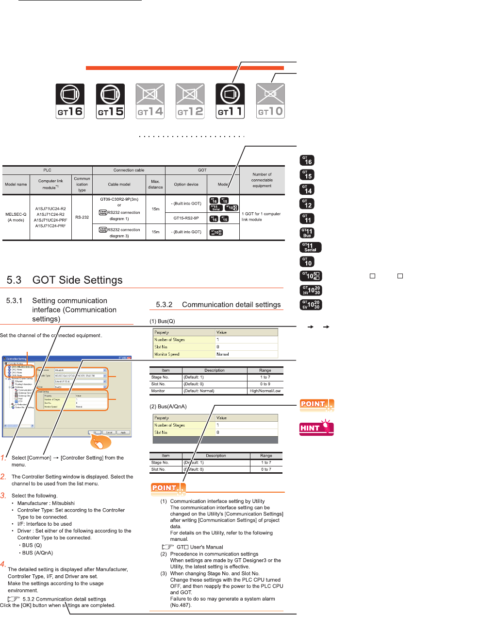
A - 29
HOW TO READ THIS MANUAL
Symbols
Following symbols are used in this manual.
Since the above page was created for explanation purpose, it differs from the actual page.
Not connectable model name
Connectable model name
BUS CONNECTION
5.1 Connectable Model List 5 - 2
Applicable model name
Shows GT16.
Shows GT15.
Shows GT11.
Shows GT11 (BUS).
Shows GT10.
Shows GT11 (SERIAL).
Shows GT1020,GT1030 (input power supply : 24V).
Shows GT1020,GT1030 (input power supply : 5V).
Shows GT105 ,GT104 .
Indicates the location of related content.
Indicates the operation steps.
[ ]: Indicates the setting items displayed on
the software and GOT screen.
1. 2. 3.
…
Refers to the information required.
Refers to information useful
for operation.
2.
3.
4.
Click!
Shows GT14.
Shows GT12.
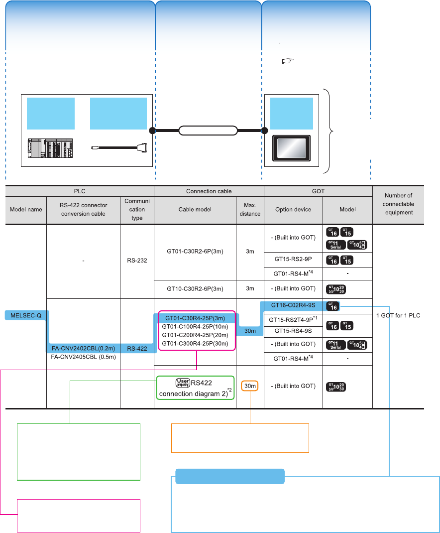
A - 30
About system configuration
The following describes the system configuration of each connection included in this manual.
Since the above page was created for explanation purpose, it differs from the actual page.
The configuration of The configuration of
equipment connected equipment connected
to GOT is shown.to GOT is shown.
The cable connecting The cable connecting
the GOT to the the GOT to the
equipment is shown.equipment is shown.
The configuration of The configuration of
the GOT connected to the GOT connected to
equipment is shown.equipment is shown.
RS-422 connector
conversion Cable
QCPU GOT
Connection cable A representative example
of the system configuration
is described with an
illustration.
Indicates the connection diagram
number of cables to be prepared by
the user.
Refer to the connection diagram
section in each chapter.
Indicates the commercially available
cable models that can be used.
Indicates the maximum distance between
the PLC and GOT.
1) Connect the RS-422 conversion cable [FA-CNV2402CBL] to the [MELSEC-Q].
2) Connect the option [GT16-C02R4-9S] to [GT16].
3) Connect [MELSEQ-Q] and [GT16] with the connection cable [GT01-C30R4-25P].
System Configuration ExamplesSystem Configuration Examples
(When connecting the PLC [MELSEC-Q] and GT16, with RS-422 cable)
System Configuration Examples
The configuration of
equipment connected
to GOT is shown.
The cable connecting
the GOT to the
equipment is shown.
The configuration of
the GOT connected to
equipment is shown.
For the option devices,
refer to the following.
1.3 Option Devices for
the Respective
Connection

1
1
PREPARATORY
PROCEDURES FOR
MONITORING
2
DEVICE RANGE
THAT CAN BE SET
3
ACCESS RANGE
FOR MONITORING
4
HOW TO MONITOR
REDUNTANT
SYSTEM
5
BUS CONNECTION
6
DIRECT
CONNECTION TO
CPU
7
COMPUTER LINK
CONNECTION
8
ETHERNET
CONNECTION
1 - 1
1.PREPARATORY PROCEDURES
FOR MONITORING
1.1 Setting the Communication Interface . . . . . . . . . . . . . . . . . . 1 - 3
1.2 Writing the Project Data and OS onto the GOT . . . . . . . . . 1 - 15
1.3 Option Devices for the Respective Connection . . . . . . . . . 1 - 17
1.4 Connection Cables for the Respective Connection . . . . . . 1 - 26
1.5 Verifying GOT Recognizes Connected Equipment . . . . . . 1 - 34
1.6 Checking for Normal Monitoring. . . . . . . . . . . . . . . . . . . . . 1 - 39
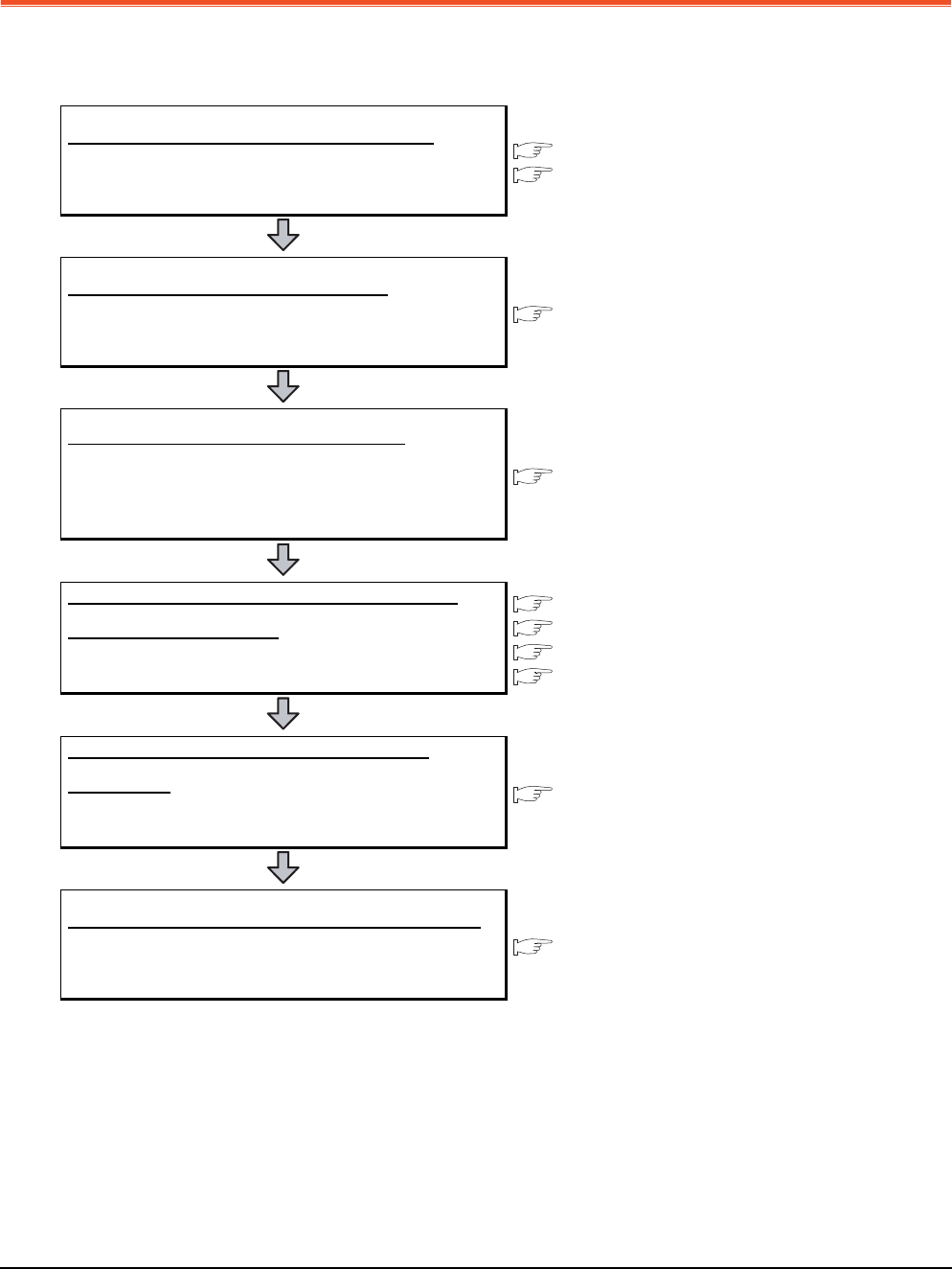
1 - 2 1. PREPARATORY PROCEDURES FOR MONITORING
1. PREPARATORY PROCEDURES FOR
MONITORING
The following shows the procedures to be taken before monitoring and corresponding reference sections.
Setting the communication interface
Determine the connection type and channel No. to be used, and
perform the communication setting.
1.1 Setting the Communication Interface
Each chapter GOT Side Settings
Writing the project data and OS
Write the standard monitor OS, communication driver, option
OS, project data and communication settings onto the GOT.
1.2.1 Writing the project data and OS onto the GOT
Verifying the project data and OS
Verify the standard monitor OS, communication driver, option
OS, project data and communication settings are properly
written onto the GOT.
1.2.2 Checking the project data and OS writing on GOT
Attaching the communication unit and
connecting the cable
Mount the optional equipment and prepare/connect the
connection cable according to the connection type.
1.3 Option Devices for the Respective Connection
1.4 Connection Cables for the Respective Connection
Each chapter System Configuration
Each chapter Connection Diagram
Verifying GOT recognizes connected
equipment
Verify the GOT recognizes controllers on [Communication
Settings] of the Utility.
1.5 Verifying GOT Recognizes Connected Equipment
Verifying the GOT is monitoring normally
Verify the GOT is monitoring normally using Utility, Developer,
etc.
1.6 Checking for Normal Monitoring
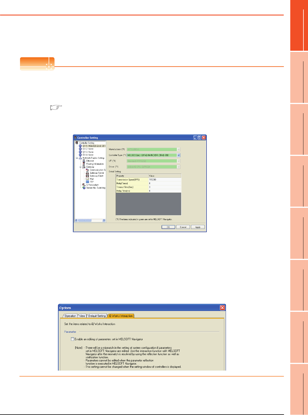
1. PREPARATORY PROCEDURES FOR MONITORING
1.1 Setting the Communication Interface
1 - 3
1
PREPARATORY
PROCEDURES FOR
MONITORING
2
DEVICE RANGE
THAT CAN BE SET
3
ACCESS RANGE
FOR MONITORING
4
HOW TO MONITOR
REDUNTANT
SYSTEM
5
BUS CONNECTION
6
DIRECT
CONNECTION TO
CPU
7
COMPUTER LINK
CONNECTION
8
ETHERNET
CONNECTION
1.1 Setting the Communication Interface
Set the communication interface of GOT and the connected equipment.
When using the GOT at the first time, make sure to set the channel of communication interface and the communication
driver before writing to GOT.
Set the communication interface of the GOT at [Controller Setting] and [I/F Communication Setting] in GT Designer3.
POINTPOINTPOINT
When using the parameter reflection function of MELSOFT Navigator.
The system configuration of MELSOFT Navigator can be reflected to the project of GT Designer3 using the
parameter function of MELSOFT Navigator.
For details of the parameter functions of MELSOFT Navigator, refer to the following.
Help of MELSOFT Navigator
(1) The color of the cells for the items which are reflected to GT Designer3 from MELSOFT Navigator changes to
green. Set items, which are displayed in green cells, from the MELSOFT Navigator. When changing in GT
Designer3, refer to the following (3).
(2) When setting the communication interface for the connection with the iQ Works untargeted equipment, set
[Set with GT Designer3] to the channel connected at [Input Detailed Configuration Information] in MELSOFT
Navigator and make the settings at [Controller Setting] in GT Designer3.
(3) To make the items reflected from MELSOFT Navigator editable on GT Designer3, select the [Option] menu
and put a check mark at [Enable an editing of parameters set in MELSOFT Navigator] in the [iQ Works
Interaction] tab.
However, when the items set in MELSOFT Navigator are edited in GT Designer3, the interaction function with
MELSOFT Navigator is unavailable due to a mismatch with the system configuration of MELSOFT Navigator.
Eliminate mismatches using the parameter verification function etc. before using the interaction function of
MELSOFT Navigator.
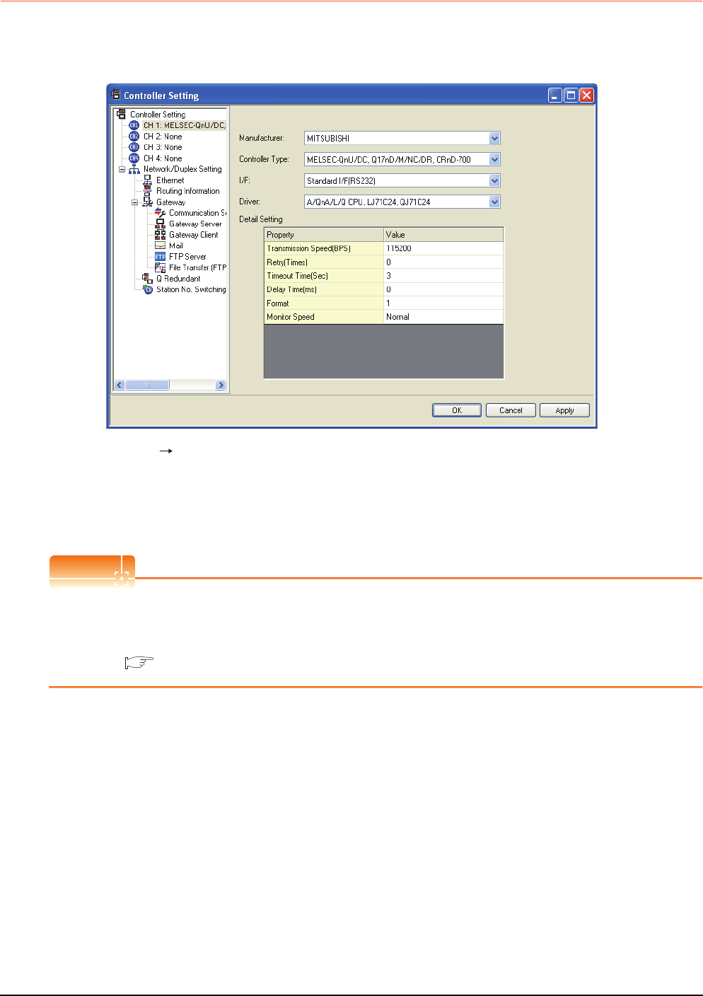
1 - 4 1. PREPARATORY PROCEDURES FOR MONITORING
1.1 Setting the Communication Interface
1.1.1 Setting connected equipment (Channel setting)
Set the channel of the equipment connected to the GOT.
Setting
1. Select [Common] [Controller Setting] from the menu.
2.
The Controller Setting dialog box appears. Select the channel No. to be used from the list menu.
3. Refer to the following explanations for the setting.
POINTPOINTPOINT
Channel No.2 to No.4
Use the channel No.2 to No.4 when using the Multi-channel function.
For details of the Multi-channel function, refer to the following.
Mitsubishi Products 21. MULTI-CHANNEL FUNCTION
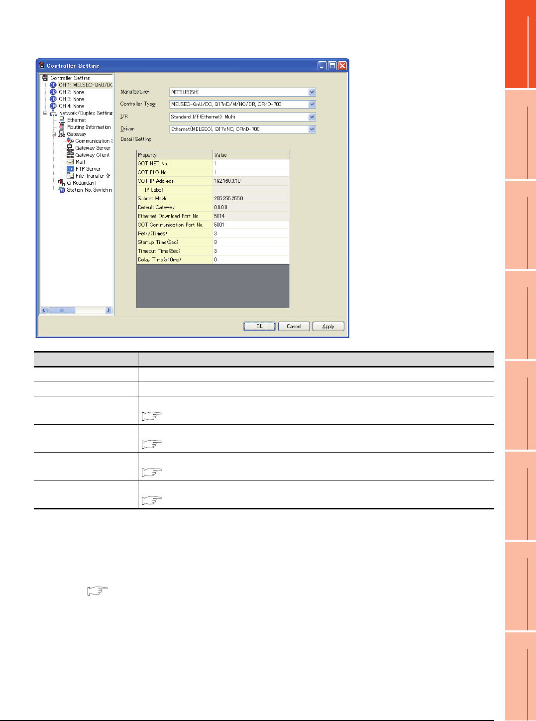
1. PREPARATORY PROCEDURES FOR MONITORING
1.1 Setting the Communication Interface
1 - 5
1
PREPARATORY
PROCEDURES FOR
MONITORING
2
DEVICE RANGE
THAT CAN BE SET
3
ACCESS RANGE
FOR MONITORING
4
HOW TO MONITOR
REDUNTANT
SYSTEM
5
BUS CONNECTION
6
DIRECT
CONNECTION TO
CPU
7
COMPUTER LINK
CONNECTION
8
ETHERNET
CONNECTION
Setting item
This section describes the setting items of the Manufacturer, Controller Type, Driver and I/F.
When using the channel No.2 to No.4, put a check mark at [Use CH*].
(1) Setting [Driver]
The displayed items for a driver differ according to the settings [Manufacturer], [Controller Type] and [I/F].
When the driver to be set is not displayed, confirm if [Manufacturer], [Controller Type] and [I/F] are correct.
For the settings, refer to the following.
[Setting the communication interface] section in each chapter
Item Description
Use CH* Select this item when setting the channel No.2 to No.4.
Manufacturer Select the manufacturer of the equipment to be connected to the GOT.
Type
Select the type of the equipment to be connected to the GOT. For the settings, refer to the following.
(2)Setting [Controller Type]
I/F
Select the interface of the GOT to which the equipment is connected.For the settings, refer to the following.
(3)Setting [I/F]
Driver
Select the communication driver to be written to the GOT. For the settings, refer to the following.
(1)Setting [Driver]
Detail Setting
Make settings for the transmission speed and data length of the communication driver.
Refer to each chapter of the equipment to be connected to the GOT.

1 - 6 1. PREPARATORY PROCEDURES FOR MONITORING
1.1 Setting the Communication Interface
(2) Setting [Controller Type]
The types for the selection differs depending on the PLC to be used.
For the settings, refer to the following.
*1 When using the multiple CPU system
When using the GOT to monitor the multiple CPU system of
other station, select [MELSEC-Q(Multi)/Q-Motion], or
[MELSEC-QnU/DC,Q17nD/M/NC/DR,CRnD-700] for the
type regardless of the host PLC CPU type.
*2 When connecting to the remote I/O station in the
MELSECNET/H network system, set the type to [MELSEC-
QnA/Q/QS, MELDAS C6 *].
Type Model name
For GT16, GT15, GT14, GT12, GT11
MELSEC-Q(MULTI)/Q MOTION
For GT10
MELSEC-Q(MULTI)
Q00CPU
Q01CPU
Q02CPU
Q02HCPU
Q06HCPU
Q12HCPU
Q25HCPU
Q02PHCPU
Q06PHCPU
Q12PHCPU
Q25PHCPU
Q172CPU
Q173CPU
Q172CPUN
Q173CPUN
Q172HCPU
Q173HCPU
For GT16, GT15, GT12*1*2
MELSEC-QnU/DC, Q17nD/M/NC/DR, CRnD-700
For GT14, GT11*1
MELSEC-QnU/DC, Q17nD/M/NC/DR
For GT10*1
MELSEC-QnU/DC
Q00UJCPU
Q00UCPU
Q01UCPU
Q02UCPU
Q03UDCPU
Q04UDHCPU
Q06UDHCPU
Q10UDHCPU
Q13UDHCPU
Q20UDHCPU
Q26UDHCPU
Q03UDECPU
Q04UDEHCPU
Q06UDEHCPU
Q10UDEHCPU
Q13UDEHCPU
Q20UDEHCPU
Q26UDEHCPU
Q50UDEHCPU
Q100UDEHCPU
Q03UDVCPU
Q04UDVCPU
Q06UDVCPU
Q13UDVCPU
Q26UDVCPU
Q12DCCPU-V
Q24DHCCPU-V
For GT16, GT15, GT12*1*2
MELSEC-QnU/DC, Q17nD/M/NC/DR, CRnD-700
For GT14, GT11*1
MELSEC-QnU/DC, Q17nD/M/NC/DR
For GT10*1
MELSEC-QnU/DC
Q172DCPU
Q173DCPU
Q172DCPU-S1
Q173DCPU-S1
Q172DSCPU
Q173DSCPU
Q170MCPU
MR-MQ100
CNC C70
(Q173NCCPU)
CRnQ-700
(Q172DRCPU)
CRnD-700
For GT16, GT15, GT12*1*2
MELSEC-QnA/Q/QS, MELDAS C6*
For GT14, GT11*1
MELSEC-QnA/Q, MELDAS C6*
For GT10*1
MELSEC-QnA/Q
Q00JCPU
Q00CPU
Q01CPU
Q02CPU
Q02HCPU
Q06HCPU
Q12HCPU
Q25HCPU
Q02PHCPU
Q06PHCPU
Q12PHCPU
Q25PHCPU
Q12PRHCPU
Q25PRHCPU
QS001CPU*3
Q2ACPU
Q2ACPU-S1
Q3ACPU
Q4ACPU
Q4ARCPU
Q2ASCPU
Q2ASCPU-S1
Q2ASHCPU
Q2ASHCPU-S1
MELDAS C6 (FCA C6)
MELDAS C64 (FCA C64)
MELSEC-L
L02CPU
L26CPU
L26CPU-BT
L02CPU-P
L26CPU-PBT
L02SCPU
NZ2GF-ETB
Type Model name

1. PREPARATORY PROCEDURES FOR MONITORING
1.1 Setting the Communication Interface
1 - 7
1
PREPARATORY
PROCEDURES FOR
MONITORING
2
DEVICE RANGE
THAT CAN BE SET
3
ACCESS RANGE
FOR MONITORING
4
HOW TO MONITOR
REDUNTANT
SYSTEM
5
BUS CONNECTION
6
DIRECT
CONNECTION TO
CPU
7
COMPUTER LINK
CONNECTION
8
ETHERNET
CONNECTION
Type Model name
MELSEC-A
A2UCPU
A2UCPU-S1
A3UCPU
A4UCPU
A2ACPU
A2ACPUP21
A2ACPUR21
A2ACPU-S1
A2ACPUP21-S1
A2ACPUR21-S1
A3ACPU
A3ACPUP21
A3ACPUR21
A1NCPU
A1NCPUP21
A1NCPUR21
A2NCPU
A2NCPUP21
A2NCPUR21
A2NCPU-S1
A2NCPUP21-S1
A2NCPUR21-S1
A3NCPU
A3NCPUP21
A3NCPUR21
A2USCPU
A2USCPU-S1
A2USHCPU-S1
A1SCPU
A1SCPUC24-R2
A1SHCPU
A2SCPU
A2SCPU-S1
A2SHCPU
A2SHCPU-S1
A1SJCPU
A1SJCPU-S3
A1SJHCPU
A0J2HCPU
A0J2HCPUP21
A0J2HCPUR21
A0J2HCPU-DC24
A2CCPU
A2CCPUP21
A2CCPUR21
A2CCPUC24
A2CCPUC24-PRF
A2CJCPU-S3
A1FXCPU
A273UCPU
A273UHCPU
A273UHCPU-S3
MELSEC-A
A373UCPU
A373UCPU-S3
A171SCPU
A171SCPU-S3
A171SCPU-S3N
A171SHCPU
A171SHCPUN
A172SHCPU
A172SHCPUN
A173UHCPU
A173UHCPU-S1
MELSEC-FX
FX0
FX0S
FX0N
FX1
FX2
FX2C
FX1S
FX1N
FX2N
FX1NC
FX2NC
FX3G
FX3GC
FX3U
FX3UC
MELSEC-FX(Ethernet) FX3U
FX3UC
MELSEC-WS WS0-CPU0
WS0-CPU1
MELSERVO-J2M-P8A
MELSERVO-J2M-P8A
MELSERVO-J2M-*DU
MELSERVO-J2M-*DU
MELSERVO-J2S-*A MELSERVO-J2S-*A
MELSERVO-J2S-*CP
MELSERVO-J2S-*CP
MELSERVO-J2S-*CL
MELSERVO-J2S-*CL
MELSERVO-J3-*A MELSERVO-J3-*A
MELSERVO-J3-*T MELSERVO-J3-*T
MELSERVO-J4-*A MELSERVO-J4-*A
FREQROL 500/700 Series
FREQROL-S500
FREQROL-S500E
FREQROL-E500
FREQROL-F500
FREQROL-F500L
FREQROL-F500J
FREQROL-A500
FREQROL-A500L
FREQROL-V500
FREQROL-V500L
FREQROL-E700
FREQROL-F700
FREQROL-F700P
FREQROL-F700PJ
FREQROL-A700
Type Model name
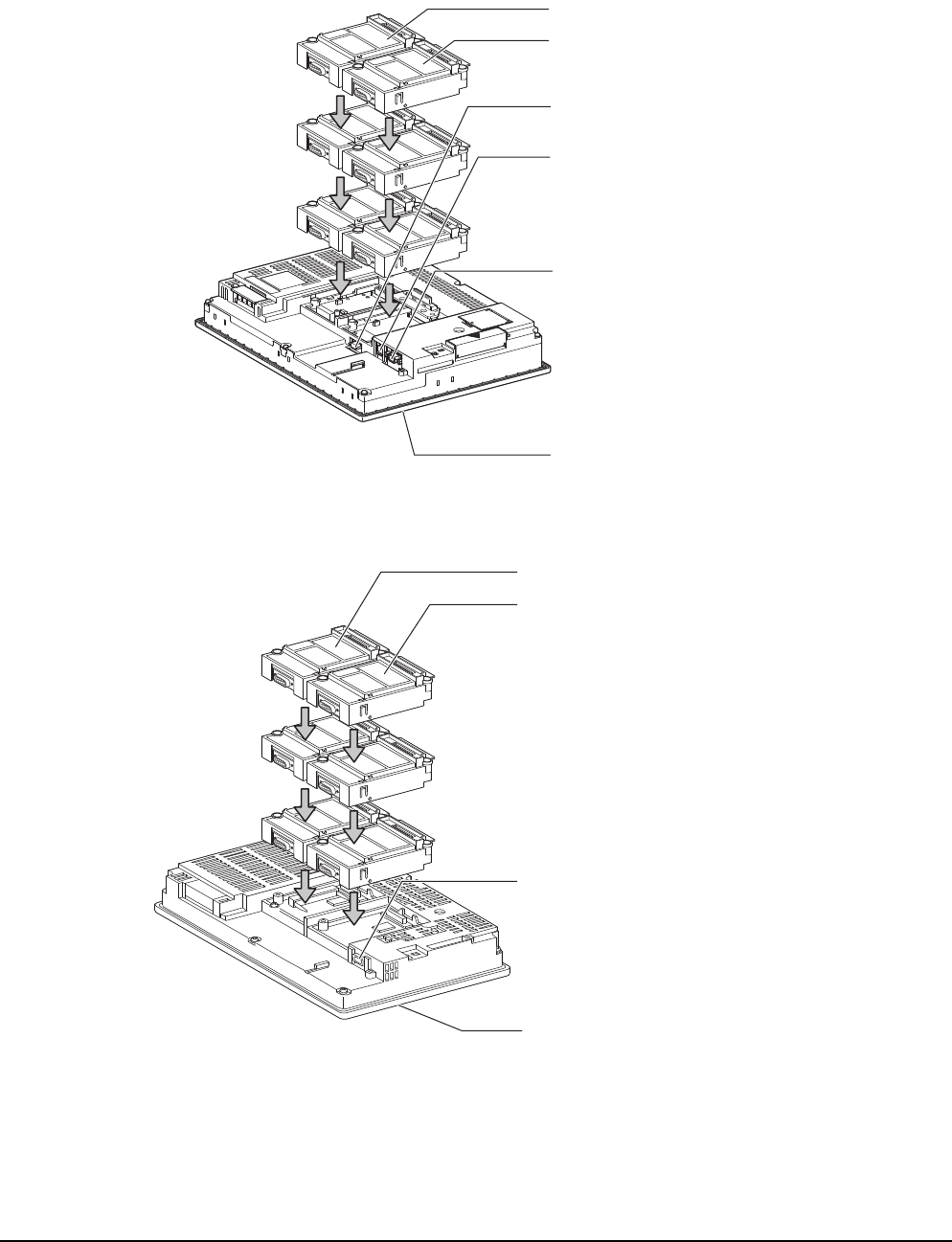
1 - 8 1. PREPARATORY PROCEDURES FOR MONITORING
1.1 Setting the Communication Interface
(3) Setting [I/F]
The interface differs depending on the GOT to be used.
Set the I/F according to the connection and the position of communication unit to be mounted onto the GOT.
(a) GT16
(b) GT15
3rd stage
Extension interface 1
Extension interface 2
Standard interface 1
(RS-232 interface built in the GOT)
2nd stage
1st stage
Standard interface 2
(USB interface built in the GOT)
(Example: In the case of the GT1685)
Standard interface 3
(RS-422/485 interface built in the GOT)
Standard interface 4
(Ethernet interface built in the GOT)
3rd stage
Extension interface 1
Extension interface 2
Standard interface 1
(RS-232 interface built in the GOT)
2nd stage
1st stage
Standard interface 2
(USB interface built in the GOT)
(Example: In the case of the GT1575)
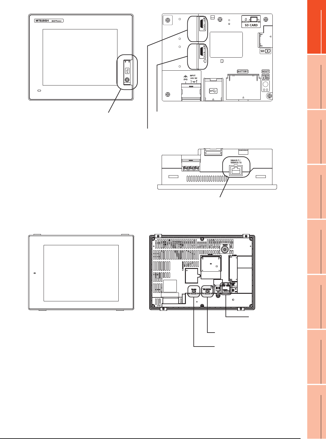
1. PREPARATORY PROCEDURES FOR MONITORING
1.1 Setting the Communication Interface
1 - 9
1
PREPARATORY
PROCEDURES FOR
MONITORING
2
DEVICE RANGE
THAT CAN BE SET
3
ACCESS RANGE
FOR MONITORING
4
HOW TO MONITOR
REDUNTANT
SYSTEM
5
BUS CONNECTION
6
DIRECT
CONNECTION TO
CPU
7
COMPUTER LINK
CONNECTION
8
ETHERNET
CONNECTION
(c) GT14
(d) GT12
Standard interface 4
(GOT built-in Ethernet interface)
Standard interface 3
(GOT built-in USB interface)
[Front view]] [Rear view]
[Under view]
Standard interface 1
(GOT built-in RS-422 interface)
Standard interface 2
(GOT built-in RS-232 interface)
Standard interface 1
(GOT built-in RS-422 interface)
Standard interface 2
(GOT built-in RS-232 interface)
Standard interface 4
(GOT built-in Ethernet interface)
[Front view] [Rear view]
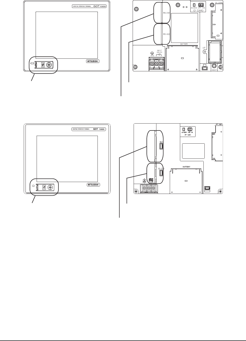
1 - 10 1. PREPARATORY PROCEDURES FOR MONITORING
1.1 Setting the Communication Interface
(e) GT11
•GT11 Serial
•GT11 Bus
Standard interface 3
(GOT built-in USB interface)
[Front view] [Rear view]
Standard interface 1
(GOT built-in RS-422 interface)
Standard interface 2
(GOT built-in RS-232 interface)
Standard interface 3
(GOT built-in USB interface)
Standard interface 2
(GOT built-in RS-232 interface)
Standard interface 1
(GOT built-in Bus interface)
[Front view] [Rear view]
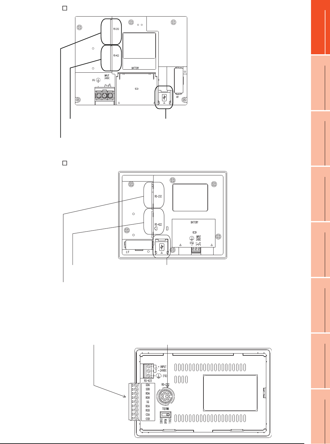
1. PREPARATORY PROCEDURES FOR MONITORING
1.1 Setting the Communication Interface
1 - 11
1
PREPARATORY
PROCEDURES FOR
MONITORING
2
DEVICE RANGE
THAT CAN BE SET
3
ACCESS RANGE
FOR MONITORING
4
HOW TO MONITOR
REDUNTANT
SYSTEM
5
BUS CONNECTION
6
DIRECT
CONNECTION TO
CPU
7
COMPUTER LINK
CONNECTION
8
ETHERNET
CONNECTION
(f) GT105
(g) GT104
(h) GT1020, GT1030
Standard interface 1
(GOT built-in RS-422 interface)
Standard interface 2
(GOT built-in RS-232 interface)
Standard interface 3
(GOT built-in USB interface)
[Rear view]
Standard interface 3
(GOT built-in USB interface)
Standard interface 1
(GOT built-in RS-422 interface)
Standard interface 2
(GOT built-in RS-232 interface)
Standard interface 1
(GOT built-in RS-422 interface)
or (GOT built-in RS-232 interface)
Standard interface 2
(GOT built-in RS-232 interface)
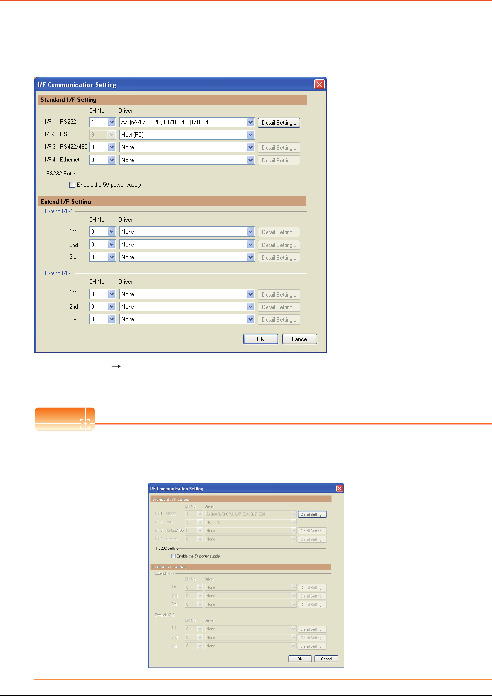
1 - 12 1. PREPARATORY PROCEDURES FOR MONITORING
1.1 Setting the Communication Interface
1.1.2 I/F communication setting
This function displays the list of the GOT communication interfaces.
Set the channel and the communication driver to the interface to be used.
Setting
1. Select [Common] [I/F Communication Setting] from the menu.
2. The I/F Communication Setting dialog box appears. Make the settings with reference to the following explanation.
POINTPOINTPOINT
When using the parameter reflection function of MELSOFT Navigator.
When setting [Controller Setting] in GT Designer3 using the parameter function of MELSOFT Navigator, all of I/F
Communication Setting are grayout and cannot be edited.Set these items at [Controller Setting] or [Peripheral Unit
Setting].
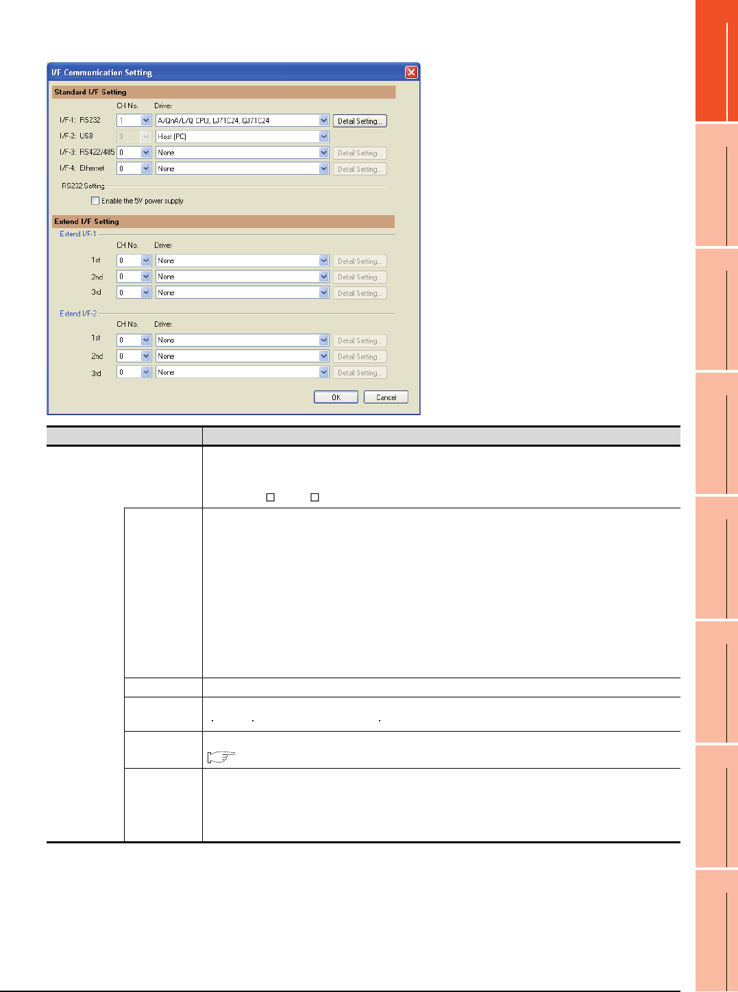
1. PREPARATORY PROCEDURES FOR MONITORING
1.1 Setting the Communication Interface
1 - 13
1
PREPARATORY
PROCEDURES FOR
MONITORING
2
DEVICE RANGE
THAT CAN BE SET
3
ACCESS RANGE
FOR MONITORING
4
HOW TO MONITOR
REDUNTANT
SYSTEM
5
BUS CONNECTION
6
DIRECT
CONNECTION TO
CPU
7
COMPUTER LINK
CONNECTION
8
ETHERNET
CONNECTION
Setting item
The following describes the setting items for the standard I/F setting and extension I/F setting.
(Continued to next page)
Item Description
Standard I/F setting
Set channel No. and drivers to the GOT standard interfaces.
GT16, GT14, GT12: Standard I/F-1, Standard I/F-2, Standard I/F-3, Standard I/F-4
GT15, GT1030, GT1020: Standard I/F-1, Standard I/F-2
GT11, GT105 , GT104 : Standard I/F-1, Standard I/F-2, Standard I/F-3
CH No.
Set the CH No. according to the intended purpose.
The number of channels differs depending on the GOT to be used.
0: Not used
1 to 4: Used for connecting a controller of channel No. 1 to 4 set in Setting connected equipment (Channel
setting)
8: Used for fingerprint authentication, barcode function, RFID function, remote personal computer operation
(serial), report function (when using the serial printer), hard copy function (when using the serial printer) or GOT
(extended computer)
9: Used for connecting Host (PC) or Host (modem)
*: Used for remote personal computer operation (Ethernet), Ethernet download, gateway function or MES
interface function
Multi: Used for Ethernet multiple connection
I/F The communication type of the GOT standard interface is displayed.
Driver Set the driver for the device to be connected.
None Host (Personal computer) Each communication driver for connected devices
Detail Setting
Make settings for the transmission speed and data length of the communication driver.
Refer to each chapter of the equipment to be connected to the GOT.
RS232 Setting
To validate the 5V power supply function in RS232, mark the [Enable the 5V power supply] checkbox.
The RS232 setting is invalid in the following cases.
• CH No. of [I/F-1: RS232] is [9] in GT15 and 16.
• CH No. of [I/F-1: RS232] is [9] or [8] in GT14.
• For GT12, GT11 and GT10

1 - 14 1. PREPARATORY PROCEDURES FOR MONITORING
1.1 Setting the Communication Interface
POINTPOINTPOINT
Channel No., drivers, [RS232 Setting]
(1) Channel No.2 to No.4
Use the channel No.2 to No.4 when using the Multi-channel function.
For details of the Multi-channel function, refer to the following.
Mitsubishi Products 21. MULTI-CHANNEL FUNCTION
(2) Drivers
The displayed items for a driver differ according to the settings [Manufacturer], [Controller Type] and [I/F].
When the driver to be set is not displayed, confirm if [Manufacturer], [Controller Type] and [I/F] are correct.
[Setting the communication] section in each chapter
(3) [RS232 Setting] of GT14
Do not use [RS232 Setting] of GT14 for other than the 5V power feeding to the RS-232/485 signal conversion
adaptor.
For details, refer to the following manual.
GT14 User's Manual 7.11 RS-232/485 Signal Conversion Adaptor
1.1.3 Precautions
(1) When using the multiple CPU system
When using the GOT to monitor the multiple CPU system of other stations, select [MELSEC-Q(Multi)/Q-Motion]
or [MELSEC-QnU, Q17nD/M/NC/DR, CRnD-700] for the type, regardless of the host PLC CPU type (QCPU,
QnACPU, ACPU). When other models are selected, the setting of the CPU No. becomes unavailable.
(2) Precautions for changing model
(a) When devices that cannot be converted are included.
When setting of [Manufacturer] or [Controller Type] is changed, GT Designer3 displays the device that
cannot be converted (no corresponding device type, or excessive setting ranges as [??]. In this case, set
the device again.
(b) When the changed Manufacturer or Controller Type does not correspond to the network.
The network will be set to the host station.
(c) When the Manufacturer or Controller Type is changed to [None]
The GT Designer3 displays the device of the changed channel No. as [??]. In this case, set the device
again.
Since the channel No. is retained, the objects can be reused in other channel No. in a batch by using the
[Device Bach Edit], [CH No. Batch Edit] or [Device List].
Item Description
Extension I/F setting Set the communication unit attached to the extension interface of the GOT.
CH No.
Set the CH No. according to the intended purpose.
The number of channels differs depending on the GOT to be used.
0: Not used
1 to 4: Used for connecting a controller of channel No. 1 to 4 set in Setting connected equipment (Channel
setting)
5 to 7: Used for barcode function, RFID function, remote personal computer operation (serial), report function
(when using the serial printer) or hard copy function (when using the serial printer)
* : Used for remote personal computer operation (Ethernet), video display function, multimedia function,
operation panel function, external I/O function, RGB display function, report function (when using a
PictBridge compatible printer), hard copy function (when using a PictBridge compatible printer), sound
output function, functions with the CF card unit or CF card extension unit, Ethernet download, gateway
function or MES interface function
Driver Set the driver for the device to be connected.
None Each driver for connected devices
Detail Setting
Make settings for the transmission speed and data length of the communication driver.
Refer to each chapter of the equipment to be connected to the GOT.
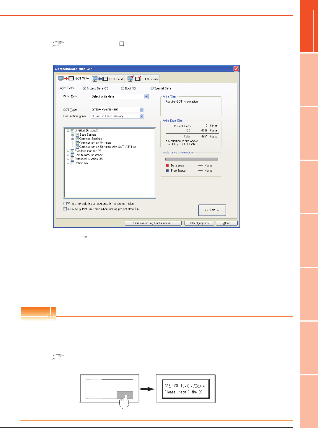
1. PREPARATORY PROCEDURES FOR MONITORING
1.2 Writing the Project Data and OS onto the GOT
1 - 15
1
PREPARATORY
PROCEDURES FOR
MONITORING
2
DEVICE RANGE
THAT CAN BE SET
3
ACCESS RANGE
FOR MONITORING
4
HOW TO MONITOR
REDUNTANT
SYSTEM
5
BUS CONNECTION
6
DIRECT
CONNECTION TO
CPU
7
COMPUTER LINK
CONNECTION
8
ETHERNET
CONNECTION
1.2 Writing the Project Data and OS onto the GOT
Write the standard monitor OS, communication driver, option OS, project data and communication settings onto the GOT.
For details on writing to GOT, refer to the following manual.
GT Designer3 Version Screen Design Manual
1.2.1 Writing the project data and OS onto the GOT
1. Select [Communication] [Write to GOT…] from the menu.
2. The [Communication configuration] dialog box appears.
Set the communication setting between the GOT and the personal computer.
Click the [OK] button when settings are completed.
3. The [GOT Write] tab appears on the [Communicate with GOT] dialog box.
Select the [Project data, OS] radio button of the Write Data.
4. Check-mark a desired standard monitor OS, communication driver, option OS, extended function OS, and
Communication Settings and click the [GOT Write] button.
POINTPOINTPOINT
Writing communication driver onto GT10
When writing a communication driver onto the GT10 in which a Boot OS Ver. under F or a standard monitor OS
Ver. under 01.08.00 is written, turn on the GOT in the OS transfer mode.
For details, refer to the following manual.
GT10 User's Manual
(Operating of transmission mode)
Turn on the GOT while the bottom right corner is touched.
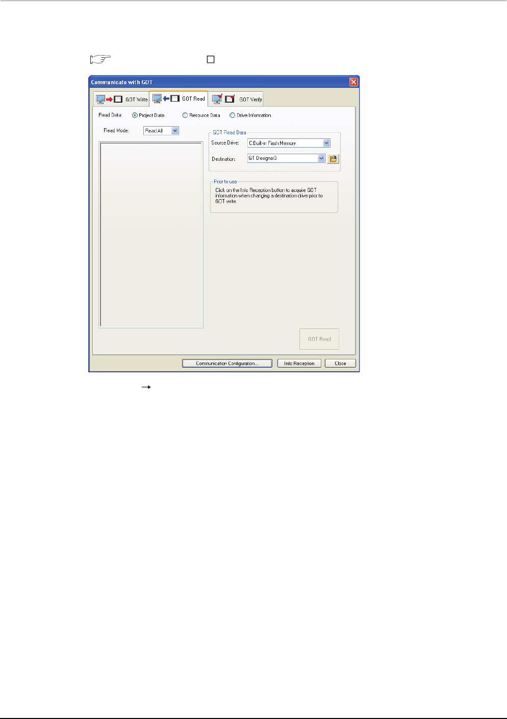
1 - 16 1. PREPARATORY PROCEDURES FOR MONITORING
1.2 Writing the Project Data and OS onto the GOT
1.2.2 Checking the project data and OS writing on GOT
Confirm if the standard monitor OS, communication driver, option OS, project data and communication settings are
properly written onto the GOT by reading from GOT using GT Designer3.
For reading from the GOT, refer to the following manual.
GT Designer3 Version Screen Design Manual
1. Select [Communication] [Read from GOT…] from the menu.
2. The [Communication configuration] dialog box appears.
Set the communication setting between the GOT and the personal computer.
Click the [OK] button when settings are completed.
3. The [GOT Read] tab appears on the [Communicate with GOT] dialog box.
Select the [Drive information] radio button of the Read Data.
4. Click the [Info Reception] button.
5. Confirm that the project data and OS are written correctly onto the GOT.

1. PREPARATORY PROCEDURES FOR MONITORING
1.3 Option Devices for the Respective Connection
1 - 17
1
PREPARATORY
PROCEDURES FOR
MONITORING
2
DEVICE RANGE
THAT CAN BE SET
3
ACCESS RANGE
FOR MONITORING
4
HOW TO MONITOR
REDUNTANT
SYSTEM
5
BUS CONNECTION
6
DIRECT
CONNECTION TO
CPU
7
COMPUTER LINK
CONNECTION
8
ETHERNET
CONNECTION
1.3 Option Devices for the Respective Connection
The following shows the option devices to connect in the respective connection type.
For the specifications, usage and connecting procedure on option devices, refer to the respective device manual.
1.3.1 Communication module
Product name Model Specifications
Bus connection unit
GT15-QBUS For QCPU (Q mode), motion controller CPU (Q series)
Bus connection (1ch) unit standard model
GT15-QBUS2 For QCPU (Q mode), motion controller CPU (Q series)
Bus connection (2ch) unit standard model
GT15-ABUS For A/QnACPU, motion controller CPU (A series)
Bus connection (1ch) unit standard model
GT15-ABUS2 For A/QnACPU, motion controller CPU (A series)
Bus connection (2ch) unit standard model
GT15-75QBUSL For QCPU (Q mode), motion controller CPU (Q series)
Bus connection (1ch) unit slim model
GT15-75QBUS2L For QCPU (Q mode), motion controller CPU (Q series)
Bus connection (2ch) unit slim model
GT15-75ABUSL For A/QnACPU, motion controller CPU (A series)
Bus connection (1ch) unit slim model
GT15-75ABUS2L For A/QnACPU, motion controller CPU (A series)
Bus connection (1ch) unit slim model
Serial communication module
GT15-RS2-9P RS-232 serial communication unit (D-sub 9-pin (male))
GT15-RS4-9S RS-422/485 serial communication unit (D-sub 9-pin (female))
GT15-RS4-TE RS-422/485 serial communication unit (terminal block)
RS-422 conversion unit
GT15-RS2T4-9P
RS-232 RS-422 conversion unit
RS-422 side connector 9-pin
GT15-RS2T4-25P RS-422 side connector 25-pin
MELSECNET/H
Communication module
GT15-J71LP23-25 Optical loop unit
GT15-J71BR13 Coaxial bus unit
MELSECNET/10
Communication module
GT15-75J71LP23-Z Optical loop unit (A9GT-QJ71LP23 + GT15-75IF900 set)
GT15-75J71BR13-Z Coaxial bus unit (A9GT-QJ71BR13 + GT15-75IF900 set)
CC-Link IE Controller Network
communication unit GT15-J71GP23-SX Optical loop unit
CC-Link IE Field Network
communication unit GT15-J71GF13-T2 CC-Link IE Field Network (1000BASE-T) unit
CC-Link communication unit
GT15-J61BT13 Intelligent device station unit CC-LINK Ver. 2 compatible
GT15-75J61BT13-Z Intelligent device station unit
(A8GT-61BT13 + GT15-75IF900 set)
Ethernet communication unit GT15-J71E71-100 Ethernet (100Base-TX) unit
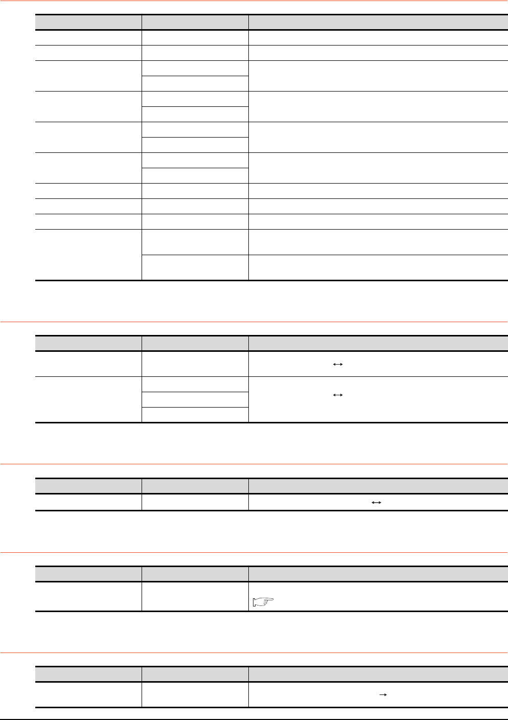
1 - 18 1. PREPARATORY PROCEDURES FOR MONITORING
1.3 Option Devices for the Respective Connection
1.3.2 Option unit
1.3.3 Conversion cables
1.3.4 Connector conversion adapter
1.3.5 Serial Multi-Drop Connection Unit
1.3.6 RS-232/485 signal conversion adapter
Product name Model Specifications
Printer unit GT15-PRN USB slave (PictBridge) for connecting printer 1 ch
Multimedia unit GT16M-MMR For video input signal (NTSC/PAL) 1 ch, playing movie
Video input unit
GT16M-V4
For video input signal (NTSC/PAL) 4 ch
GT15V-75V4
RGB input unit
GT16M-R2
For analog RGB input signal 2 ch
GT15V-75R1
Video/RGB input unit
GT16M-V4R1
For video input signal (NTSC/PAL) 4 ch, for analog RGB mixed input signal 1 ch
GT15V-75V4R1
RGB output unit
GT16M-ROUT
For analog RGB output signal 1 ch
GT15V-75ROUT
CF card unit GT15-CFCD For CF card installation (B drive) For GOT back face CF card eject
CF card extension unit GT15-CFEX-C08SET For CF card installation (B drive) For control panel front face CF card eject
Sound output unit GT15-SOUT For sound output
External I/O unit
GT15-DIOR
For the connection to external I/O device or operation panel (Negative Common
Input/Source Type Output)
GT15-DIO For the connection to external I/O device or operation panel (Positive Common
Input/Sink Type Output)
Product name Model Specifications
RS-422 connector conversion
Cable GT16-C02R4-9S RS-422/485 (Connector) RS-422 connector conversion cable (D-sub 9-pin)
RS-485 terminal block
conversion modules
FA-LTBGTR4CBL05
RS-422/485 (Connector) RS-485 (Terminal block)
Supplied connection cable dedicated for the conversion unit
FA-LTBGTR4CBL10
FA-LTBGTR4CBL20
Product name Model Specifications
Connector conversion adapter GT10-9PT5S RS-422/485 (D-Sub 9-pin connector) RS-422/485 (Terminal block)
Product name Model Specifications
Serial multi-drop
connection unit GT01-RS4-M
GOT multi-drop connection module
Mitsubishi Products 19. GOT MULTI-DROP CONNECTION
Product name Model Specifications
RS-232/485 signal conversion
adapter GT14-RS2T4-9P RS-232 signal (D-Sub 9-pin connector) RS-485 signal (Terminal block)
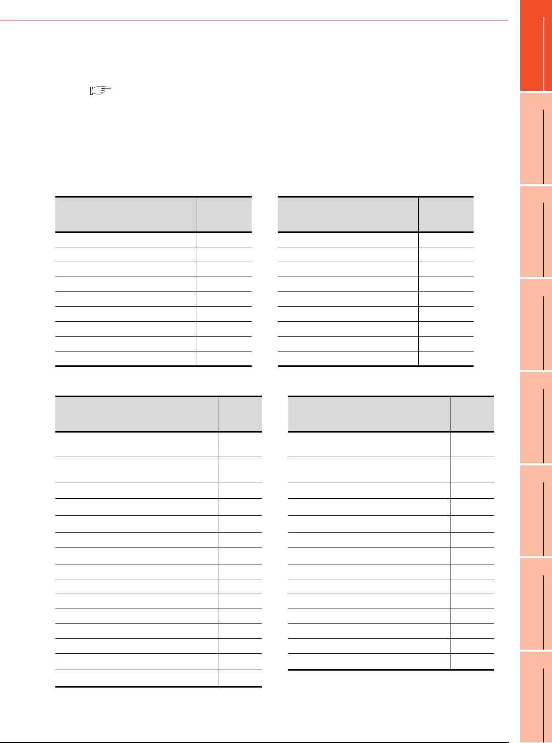
1. PREPARATORY PROCEDURES FOR MONITORING
1.3 Option Devices for the Respective Connection
1 - 19
1
PREPARATORY
PROCEDURES FOR
MONITORING
2
DEVICE RANGE
THAT CAN BE SET
3
ACCESS RANGE
FOR MONITORING
4
HOW TO MONITOR
REDUNTANT
SYSTEM
5
BUS CONNECTION
6
DIRECT
CONNECTION TO
CPU
7
COMPUTER LINK
CONNECTION
8
ETHERNET
CONNECTION
1.3.7 Installing a unit on another unit (Checking the unit installation position)
This section describes the precautions for installing units on another unit.
For the installation method of each unit, refer to the User's Manual for the communication unit and option unit you are
using.
For the method for installing a unit on another unit, refer to the following.
User's Manual of GOT used.
Calculating consumed current
For using multiple extension units, a bar code reader, or a RFID controller, the total current for the extension units,
bar code reader, or RFID controller must be within the current that the GOT can supply.
For the current that the GOT can supply and the current for the extension units, bar code reader, or RFID controller,
refer to the following tables. Make sure that the total of consumed current is within the capacity of the GOT.
(1) Current supply capacity of the GOT
(2) Current consumed by an extension unit/barcode reader/RFID controller
*1 Value used for calculating the current consumption of the multi-channel function.
For the specifications of the unit, refer to the manual included with the unit.
*2 When the GOT supplies power to a barcode reader or a RFID controller from the standard interface, add their consumed current.
(Maximum value is less than 0.3 A)
GOT type
Current supply
capacity
(A)
GOT type
Current supply
capacity
(A)
GT1695M-X 2.4 GT1595-X 2.13
GT1685M-S 2.4 GT1585V-S 1.74
GT1675M-S 2.4 GT1585-S 1.74
GT1675M-V 2.4 GT1575V-S 2.2
GT1675-VN, GT1672-VN 2.4 GT1575-S 2.2
GT1665M-S 2.4 GT1575-V, GT1572-VN 2.2
GT1665M-V 2.4 GT1565-V, GT1562-VN 2.2
GT1662-VN 2.4 GT1555-V 1.3
GT1655-V 1.3 GT1555-Q, GT1550-Q 1.3
Module type
Consumed
current
(A)
Module type
Consumed
current
(A)
GT15-QBUS, GT15-QBUS,
GT15-75QBUSL, GT15-75QBUS2L 0.275*1 GT16M-R2 0*1
GT15-ABUS, GT15-ABUS2,
GT15-75ABUSL, GT15-75ABUS2L 0.12 GT15V-75R1 0.2*1
GT15-RS2-9P 0.29 GT16M-V4R1 0.12*1
GT15-RS4-9S 0.33 GT15V-75V4R1 0.2*1
GT15-RS4-TE 0.3 GT16M-ROUT 0.11*1
GT15-RS2T4-9P 0.098 GT15V-75ROUT 0.11
GT15-J71E71-100 0.224 GT16M-MMR 0.27*1
GT15-J71GP23-SX 1.07 GT15-CFCD 0.07
GT15-J71LP23-25 0.56 GT15-CFEX-C08SET 0.15
GT15-J71BR13 0.77 GT15-SOUT 0.08
GT15-J61BT13 0.56 GT15-DIO 0.1
Bar code reader *2 GT15-DIOR 0.1
GT15-PRN 0.09 RFID controller *2
GT16M-V4 0.12*1 GT15-80FPA 0.22
GT15V-75V4 0.2*1
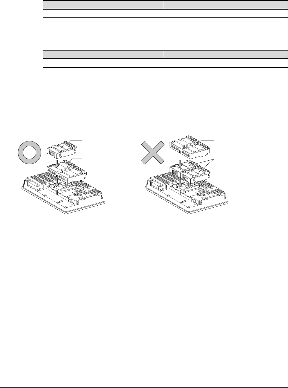
1 - 20 1. PREPARATORY PROCEDURES FOR MONITORING
1.3 Option Devices for the Respective Connection
(3) Calculation example
(a) When connecting the GT15-J71BR13, GT15-RS4-9S (3 units), GT15-J71E71-100 (For the gateway function)
and a bar code reader (0.12 A) to the GT1575-V
Since the calculated value is within the capacity of the GOT, they can be connected to the GOT.
(b) When connecting the GT15-J71BR13, GT15-RS4-9S (2 units), GT15-J71E71-100 (For the gateway function)
and a bar code reader (0.12 A) to the GT1585-S
Since the calculated value exceeds the capacity of the GOT, such configuration is not allowed.
When using a bus connection unit
The installation position varies depending on the bus connection unit to be used.
(1) Wide bus units (GT15-75QBUS(2)L, GT15-75ABUS(2)L, GT15-QBUS2, GT15-ABUS2)
Install a bus connection unit in the 1st stage of the extension interface.
If a bus connection unit is installed in the 2nd stage or above, the unit cannot be used.
Example: Installing a bus connection unit and serial communication units
Current supply capacity of GOT (A) Total consumed current (A)
2.2 0.77+0.33+0.33+0.33+0.224+0.12=2.104
Current supply capacity of GOT (A) Total consumed current (A)
1.74 0.77+0.33+0.33+0.224+0.12=1.774
Serial communication unit
Bus connection unit
Bus connection unit
Serial communication unit
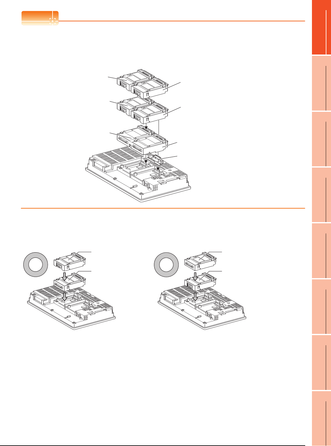
1. PREPARATORY PROCEDURES FOR MONITORING
1.3 Option Devices for the Respective Connection
1 - 21
1
PREPARATORY
PROCEDURES FOR
MONITORING
2
DEVICE RANGE
THAT CAN BE SET
3
ACCESS RANGE
FOR MONITORING
4
HOW TO MONITOR
REDUNTANT
SYSTEM
5
BUS CONNECTION
6
DIRECT
CONNECTION TO
CPU
7
COMPUTER LINK
CONNECTION
8
ETHERNET
CONNECTION
POINTPOINTPOINT
Cautions for using GT15-QBUS2 and GT15-ABUS2
The stage number of communication units installed on the next stage of GT15-QBUS2 or GT15-ABUS2 are
recognized by the GOT differently depending on the extension interface position.
For communication units installed in the extension interface 2 side, even if the communication unit is physically
installed in the 2nd stage position, the GOT recognizes the position as the 1st stage.
(2) Standard size bus connection unit (GT15-QBUS and GT15-ABUS)
A bus connection unit can be installed in any position (1st to 3rd stage) of the extension interface.
Example: Installing a bus connection unit and serial communication units
Recognized as the
3rd stage of extend
interface 1
Recognized as the 2nd stage
of extend interface 2
Recognized as the 1st stage
of extend interface 2
Recognized as the
2nd stage of extend
interface 1
Recognized as the 1st stage
of extend interface 1
GT15-QBUS2, GT15-ABUS2
Relay connector
Serial communication unit
Bus connection unit
Bus connection unit
Serial communication unit
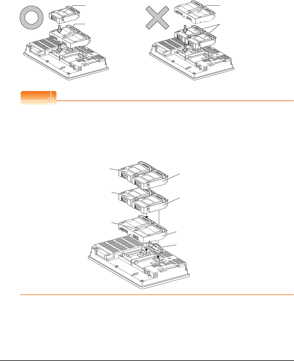
1 - 22 1. PREPARATORY PROCEDURES FOR MONITORING
1.3 Option Devices for the Respective Connection
When using a MELSECNET/H communication unit, CC-Link IE Controller Network
communication unit, CC-Link IE Field Network communication unit, or CC-Link communication
unit (GT15-J61BT13)
Install a MELSECNET/H communication unit, CC-Link IE Controller Network communication unit, CC-Link IE Field
Network communication unit, or CC-Link communication unit in the 1st stage of an extension interface.
These communication units cannot be used if installed in the 2nd or higher stage.
Example: When installing a MELSECNET/H communication unit and a serial communication unit
POINTPOINTPOINT
Precautions for using a MELSECNET/H communication unit, CC-Link IE Controller Network communication unit,
CC-Link IE Field Network communication unit, CC-Link communication unit (GT15-J61BT13)
The installed stage number of communication units installed on the next stage of MELSECNET/H communication
unit, CC-Link IE Controller Network communication unit, CC-Link IE Field Network communication unit, or CC-Link
communication unit are recognized by the GOT differently depending on the extension interface position.
For communication units installed in the extension interface 2 side, even if the communication unit is physically
installed in the 2nd stage position, the GOT recognizes the position as the 1st stage.
Serial communication unit
MELSECNET/H
communication unit
MELSECNET/H
communication unit
Serial communication unit
Recognized as the 3rd stage
of extension interface 1 Recognized as the 2nd stage
of extension interface 2
Recognized as the 1st stage
of extension interface 2
Recognized as the 2nd stage
of extension interface 1
Recognized as the 1st stage
of extension interface 1
MELSECNET/H communication unit
Relay connector
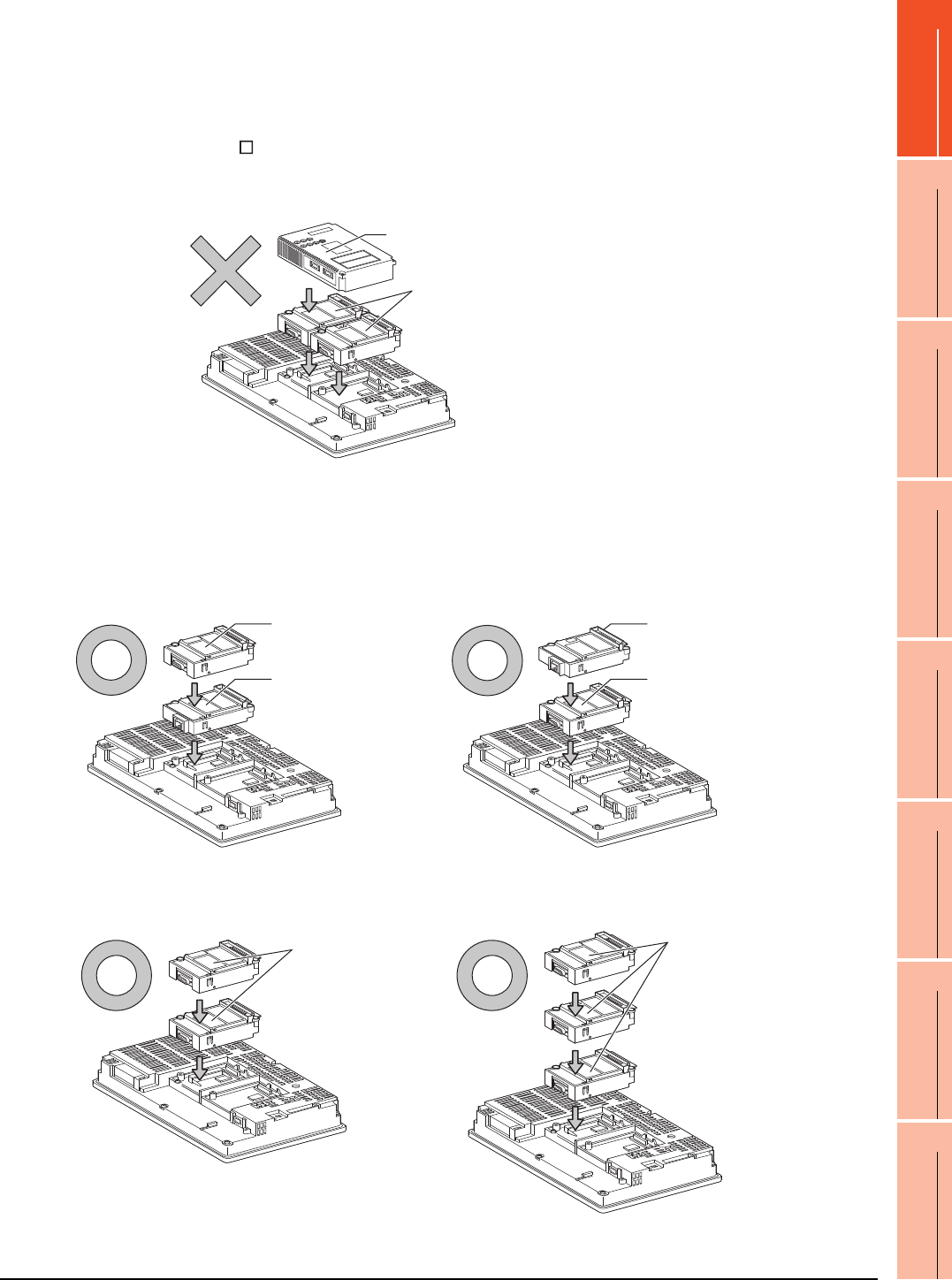
1. PREPARATORY PROCEDURES FOR MONITORING
1.3 Option Devices for the Respective Connection
1 - 23
1
PREPARATORY
PROCEDURES FOR
MONITORING
2
DEVICE RANGE
THAT CAN BE SET
3
ACCESS RANGE
FOR MONITORING
4
HOW TO MONITOR
REDUNTANT
SYSTEM
5
BUS CONNECTION
6
DIRECT
CONNECTION TO
CPU
7
COMPUTER LINK
CONNECTION
8
ETHERNET
CONNECTION
When using a MELSECNET/10 communication unit (GT15-75J71LP23-Z, GT15- 75J71BR13-
Z) or CC-Link communication unit (GT15-75J61BT13-Z)
Install a MELSECNET/10 communication unit (GT15-75J71LP23-Z, GT15-75J71BR13-Z) or CC-Link communication
unit (GT15-75J61BT13-Z) at the 1st stage of the extension interface.
These communication units cannot be used if installed in the 2nd or higher stage.
For GT16 and the GT155 , the MELSECNET/10 communication unit (GT15-75J71LP23-Z, GT15- 75J71BR13-Z)
and the CC-Link communication unit (GT15-75J61BT13-Z) are not applicable.
Example: When installing a MELSECNET/10 communication unit and a serial communication unit
When using an Ethernet communication unit
An Ethernet communication unit can be installed in any position (1st to 3rd stage) of the extension interface.
For GT16, the Ethernet communication unit is not applicable.
Use the Ethernet interface built in the GOT.
Example: When installing an Ethernet communication unit and a serial communication unit
When using a serial communication unit
A serial communication unit can be installed in any position (1st to 3rd stage) of the extension interface.
Serial communication unit
MELSECNET/10
communication unit
Serial communication unit
Ethernet
communication unit
Ethernet
communication unit
Serial communication unit
Serial
communication
unit
Serial
communication
unit
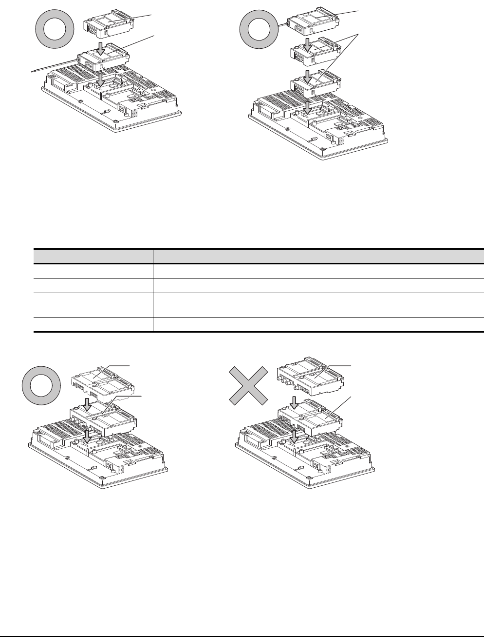
1 - 24 1. PREPARATORY PROCEDURES FOR MONITORING
1.3 Option Devices for the Respective Connection
When using the printer unit, sound output unit, or external I/O unit
The printer unit, sound output unit, or external I/O unit can be installed in any position (1st to 3rd stage) of the
extension interface.
Example: When installing a printer unit
When using the video input unit, RGB input unit, video/RGB input unit, RGB output unit, or
multimedia unit
Install the video input unit, RGB input unit, video/RGB input unit, RGB output unit, or multimedia unit at the 1st stage
of the extension interface.These units cannot be used if installed in the 2nd or higher stage.
When any of these units is used, the communication units indicated below must be installed in the 2nd stage of the
extension interface.
Example: When installing a video input unit and a MELSECNET/H communication unit
Communication unit Model
Bus connection unit GT15-QBUS2, GT15-ABUS2
MELSECNET/H communication unit GT15-J71LP23-25, GT15-J71BR13
CC-Link IE Controller Network
communication unit GT15-J71GP23-SX
CC-Link communication unit GT15-J61BT13
Printer unit
Communication
unit Printer unit
Communication
unit
MELSECNET/H
communication unit
Video/RGB
input unit
Video/RGB
input unit
MELSECNET/H
communication unit
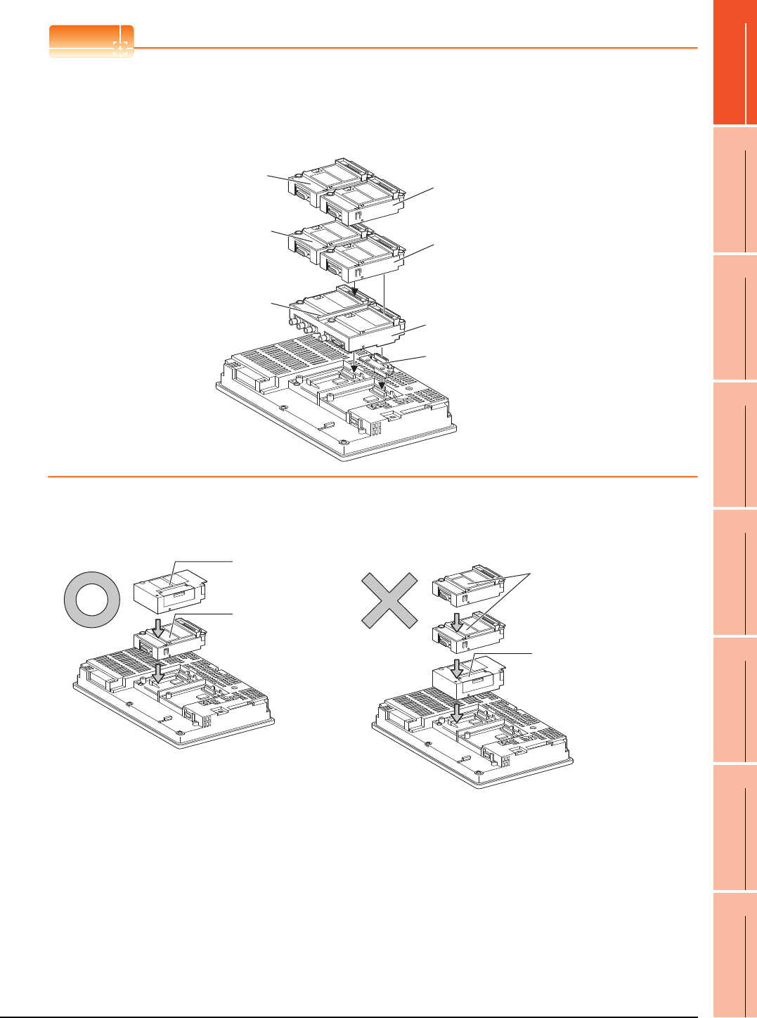
1. PREPARATORY PROCEDURES FOR MONITORING
1.3 Option Devices for the Respective Connection
1 - 25
1
PREPARATORY
PROCEDURES FOR
MONITORING
2
DEVICE RANGE
THAT CAN BE SET
3
ACCESS RANGE
FOR MONITORING
4
HOW TO MONITOR
REDUNTANT
SYSTEM
5
BUS CONNECTION
6
DIRECT
CONNECTION TO
CPU
7
COMPUTER LINK
CONNECTION
8
ETHERNET
CONNECTION
POINTPOINTPOINT
Precautions for video input unit, RGB input unit, video/RGB input unit, RGB output unit, and multimedia unit
When a communication unit is installed on any of the units above, the stage number of the communication unit
recognized by the GOT varies according to the extension interface.
For communication units installed in the extension interface 2 side, even if the communication unit is physically
installed in the 2nd stage position, the GOT recognizes the position as the 1st stage.
When using CF card unit or CF card extension unit
Install the CF card unit or CF card extension unit on the extension interface at the last.
The following figures show how to install the CF card unit.
Recognized as the 3rd stage of
extension interface 1 Recognized as the 2nd stage
of extension interface 2
Recognized as the 1st stage
of extension interface 2
Recognized as the 2nd stage of
extension interface 1
Recognized as the 1st stage of
extension interface 1
Video/RGB input unit
Relay connector
Serial communication
unit
CF card unit
CF card unit
Serial communication
unit
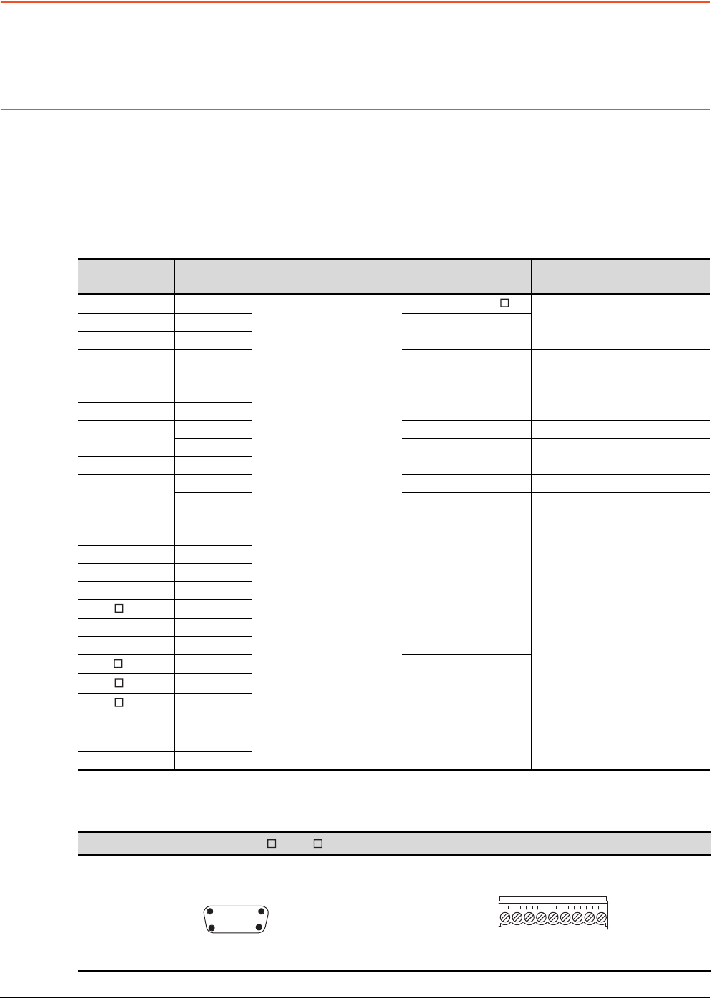
1 - 26 1. PREPARATORY PROCEDURES FOR MONITORING
1.4 Connection Cables for the Respective Connection
1.4 Connection Cables for the Respective Connection
To connect the GOT to a device in the respective connection type, connection cables between the GOT and a device are
necessary.
For cables needed for each connection, refer to each chapter for connection.
1.4.1 GOT connector specifications
The following shows the connector specifications on the GOT side.
Refer to the following table when preparing connection cables by the user.
RS-232 interface
Use the following as the RS-232 interface and RS-232 communication unit connector on the GOT. For the GOT side
connection cable, use a connector and connector cover applicable to the GOT connector.
(1) Connector specifications
*1 For the procedure to check the GT15 hardware version, refer to the GT15 User's Manual.
*2 The terminal block (MC1.5/9-ST-3.5 or corresponding product) of the cable side is packed together with the GT1030, GT1020.
(2) Connector pin arrangement
GOT Hardware
version*1 Connector type Connector model Manufacturer
GT16 ―
9-pin D-sub (male)
inch screw fixed type
17LE-23090-27(D4C )
DDK Ltd.
GT1595-X ―17LE-23090-27(D4CK)
GT1585V-S ―
GT1585-STBA B or later GM-C9RMDU11 Honda Tsushin Kogyo Co., Ltd.
C
17LE-23090-27(D4CK) DDK Ltd.GT1585-STBD ―
GT1575V-S ―
GT1575-STBA B or later GM-C9RMDU11 Honda Tsushin Kogyo Co., Ltd.
C17LE-23090-27(D4CK) DDK Ltd.
GT1575-STBD ―
GT1575-VTBA D or later GM-C9RMDU11 Honda Tsushin Kogyo Co., Ltd.
E
17LE-23090-27(D4CK)
DDK Ltd.
GT1575-VTBD ―
GT1575-VN ―
GT1572-VN ―
GT1565-V ―
GT1562-VN ―
GT155 ―
GT14 ―
GT12 ―
GT115 -Q ―
17LE-23090-27(D3CC)
GT105 -Q ―
GT104 -Q ―
GT1030, GT1020
―9-pin terminal block*2 MC1.5/9-G-3.5BK PHOENIX CONTACT Inc
GT15-RS2-9P ―9-pin D-sub (male)
inch screw fixed type 17LE-23090-27(D3CC) DDK Ltd.
GT01-RS4-M ―
GT16, GT15, GT14, GT12, GT11, GT105 , GT104 , GT01-RS4-M GT1030, GT1020
9-pin D-sub (male)
GOT main part connecto
r
see from the front
15
69
See from the back of a
GOT main part
9-pin terminal block
SD
RD
ER
DR
SG
CS
RS
NC
NC
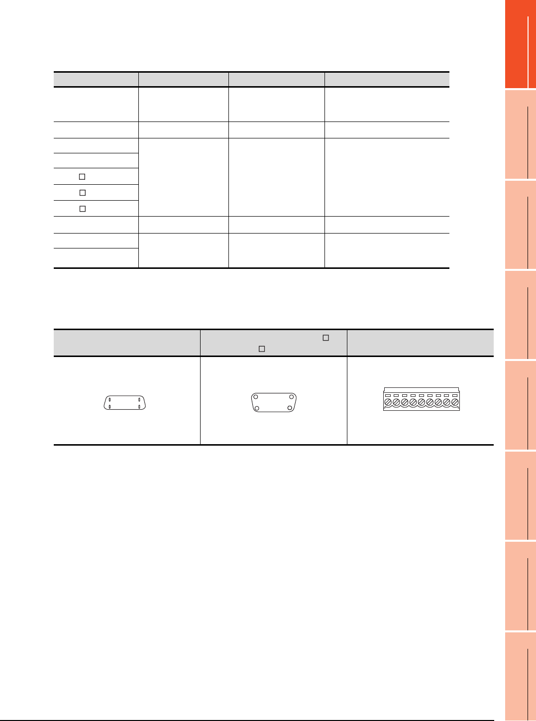
1. PREPARATORY PROCEDURES FOR MONITORING
1.4 Connection Cables for the Respective Connection
1 - 27
1
PREPARATORY
PROCEDURES FOR
MONITORING
2
DEVICE RANGE
THAT CAN BE SET
3
ACCESS RANGE
FOR MONITORING
4
HOW TO MONITOR
REDUNTANT
SYSTEM
5
BUS CONNECTION
6
DIRECT
CONNECTION TO
CPU
7
COMPUTER LINK
CONNECTION
8
ETHERNET
CONNECTION
RS-422 interface
Use the following as the RS-422 interface and the RS-422/485 communication unit connector on the GOT.
For the GOT side of the connection cable, use a connector and connector cover applicable to the GOT connector.
(1) Connector model
*1 When connecting to the RS-422/485 interface, use HDR-E14MAG1+ as a cable connector.
To use HDR-E14MAG1+, a dedicated pressure welding tool is required.
For details on the connector and pressure welding tool, contact Honda Tsushin Kogyo Co., Ltd.
*2 The terminal block (MC1.5/9-ST-3.5 or corresponding product) of the cable side is packed together with the GT1030, GT1020.
(2) Connector pin arrangement
GOT Connector type Connector model Manufacturer
RS-422 conversion unit
9-pin D-sub (female)
M2.6 millimeter screw
fixed type
17LE-13090-27(D2AC) DDK Ltd.
GT16*1 14-pin (female) HDR-EC14LFDT1-SLE+ Honda Tsushin Kogyo Co., Ltd.
GT14
9-pin D-sub (female)
M2.6 millimeter screw
fixed type
17LE-13090-27(D3AC) DDK Ltd.
GT12
GT115 -Q
GT105 -Q
GT104 -Q
GT1030, GT1020 9-pin terminal block*2 MC1.5/9-G-3.5BK PHOENIX CONTACT Inc.
GT15-RS4-9S 9-pin D-sub (female)
M2.6 millimeter screw
fixed type
17LE-13090-27(D3AC) DDK Ltd.
GT01-RS4-M
GT16 GT15, GT14, GT12, GT11, GT105 ,
GT104 , GT01-RS4-M GT1030, GT1020
14-pin (female)
GOT main part connector
see from the front
814
17
9-pin D-sub (female)
GOT main part connector
see from the front
51
96
See from the back of a
GOT main part
9-pin terminal block
SDA
SDB
RDA
RDB
SG
RSB
RSA
CSA
CSB
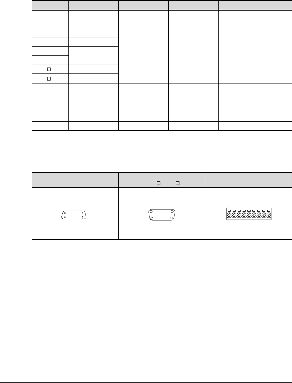
1 - 28 1. PREPARATORY PROCEDURES FOR MONITORING
1.4 Connection Cables for the Respective Connection
RS-485 interface
Use the following as the RS-485 interface and the RS-422/485 communication unit connector on the GOT.
For the GOT side of the connection cable, use a connector and connector cover applicable to the GOT connector.
(1) Connector model
*1 For the checking procedure of the hardware version, refer to the User's Manual.
*2 When connecting to the RS-422/485 interface, use HDR-E14MAG1+ as a cable connector.
To use HDR-E14MAG1+, a dedicated pressure welding tool is required.
For details on the connector and pressure welding tool, contact Honda Tsushin Kogyo Co., Ltd..
*3 The terminal block (MC1.5/9-ST-3.5 or corresponding product) of the cable side is packed together with the GT1030, GT1020.
(2) Connector pin arrangement
GOT Hardware version*1 Connector type Connector model Manufacturer
GT16*2 ―14-pin (female) HDR-EC14LFDT1-SLE+ Honda Tsushin Kogyo Co., Ltd.
GT14 ―
9-pin D-sub (female)
M2.6 millimeter screw
fixed type
17LE-13090-27(D3AC) DDK Ltd.
GT12 ―
GT1155-QTBD C or later
GT1155-QSBD
F or later
GT1150-QLBD
GT105 -Q C or later
GT104 -Q A or later
GT1030 B or later
9-pin terminal block*3 MC1.5/9-G-3.5BK PHOENIX CONTACT Inc
GT1020 E or later
GT15-RS4-9S ―
9-pin D-sub (female)
M2.6 millimeter screw
fixed type
17LE-13090-27(D3AC) DDK Ltd.
GT15-RS4-TE ――SL-SMT3.5/10/90F BOX Weidmuller interconnections inc
GT16 GT15, GT14, GT12, GT11,
GT105 , GT104 GT1030, GT1020
14-pin (female)
GOT main part connector
see from the front
814
17
9-pin D-sub (female)
GOT main part connector
see from the front
51
96
See from the back of a
GOT main part
9-pin terminal block
SDA
SDB
RDA
RDB
SG
RSB
RSA
CSA
CSB
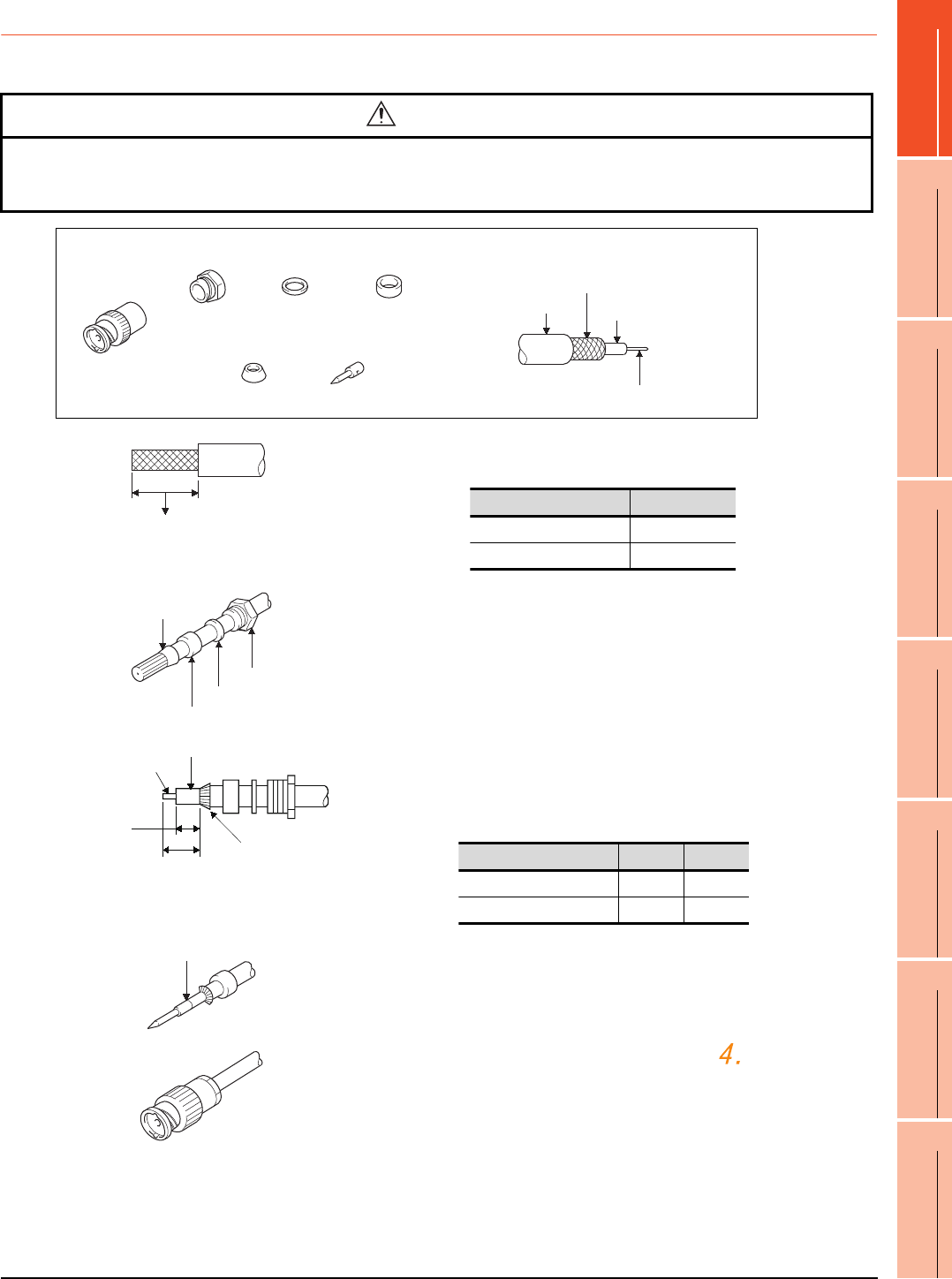
1. PREPARATORY PROCEDURES FOR MONITORING
1.4 Connection Cables for the Respective Connection
1 - 29
1
PREPARATORY
PROCEDURES FOR
MONITORING
2
DEVICE RANGE
THAT CAN BE SET
3
ACCESS RANGE
FOR MONITORING
4
HOW TO MONITOR
REDUNTANT
SYSTEM
5
BUS CONNECTION
6
DIRECT
CONNECTION TO
CPU
7
COMPUTER LINK
CONNECTION
8
ETHERNET
CONNECTION
1.4.2 Coaxial cable connector connection method
The following describes the method for connecting the BNC connector (connector plug for coaxial cable) and the cable.
Precautions for soldering
Note the following precautions when soldering the internal conductor and contact.
• Make sure that the solder does not bead up at the soldered section.
• Make sure there are no gaps between the connector and cable insulator or they do not cut into each other.
• Perform soldering quickly so the insulation material does not become deformed.
CAUTION
-Solder the coaxial cable connectors properly.
Insufficient soldering may result in malfunctions.
Nut Washer Gasket
Clamp Contact
Components of the BNC connector
Plug shell
Outer sheath
External conductor
Insulating material
Internal conductor
Structure of the coaxial cable
1. Remove the external sheath of the coaxial cable with
dimensions as shown below.
2. Pass the nut, washer, gasket, and clamp through the coaxial
cable as shown on the left and loosen the external conductor.
3. Cut the external conductor, insulting material, and internal
conductor with the dimensions as shown below.
Note that the external conductor should be cut to the same
dimension as the tapered section of the clamp and smoothed
down to the clamp.
4. Solder the contact to the internal conductor.
5. Insert the connector assembly shown in into the plug
shell and screw the nut into the plug shell.
A
Cut this portion of the outer sheath
Cable in use A
3C-2V 15mm
5C-2V, 5C-2V-CCY 10mm
Clamp
Gasket
Washer
Nut
Internal conductor
Insulating material
C
BClamp and external
conductor
Cable in use B C
3C-2V 6mm 3mm
5C-2V, 5C-2V-CCY 7mm 5mm
Solder here
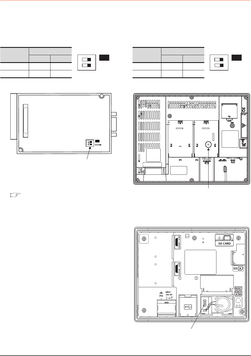
1 - 30 1. PREPARATORY PROCEDURES FOR MONITORING
1.4 Connection Cables for the Respective Connection
1.4.3 Terminating resistors of GOT
The following shows the terminating resistor specifications on the GOT side.
When setting the terminating resistor in each connection type, refer to the following.
RS-422/485 communication unit
Set the terminating resistor using the terminating
resistor setting switch.
*1 The default setting is "Disable".
• For RS-422/485 communication unit
RS-232/485 signal conversion adapter
For details, refer to the following.
1.4.4 Setting the RS-232/485 signal conversion
adaptor
GT16
Set the terminating resistor using the terminating
resistor setting switch.
*1 The default setting is "Disable".
• For GT1685M-S
GT14
Set the terminating resistor using the terminating
resistor setting switch.
Terminating
resistor*1
Switch No.
1 2
100 OHM ON ON
Disable OFF OFF
SW1
ON
12
ON
SW1
ON
12
Rear view of RS-422/485 communication unit.
Terminating resistor setting switch
Terminating
resistor*1
Switch No.
1 2
Enable ON ON
Disable OFF OFF
SW1
ON
12
Terminating resistor setting switch
(inside the cover)
Terminating resistor selector switch
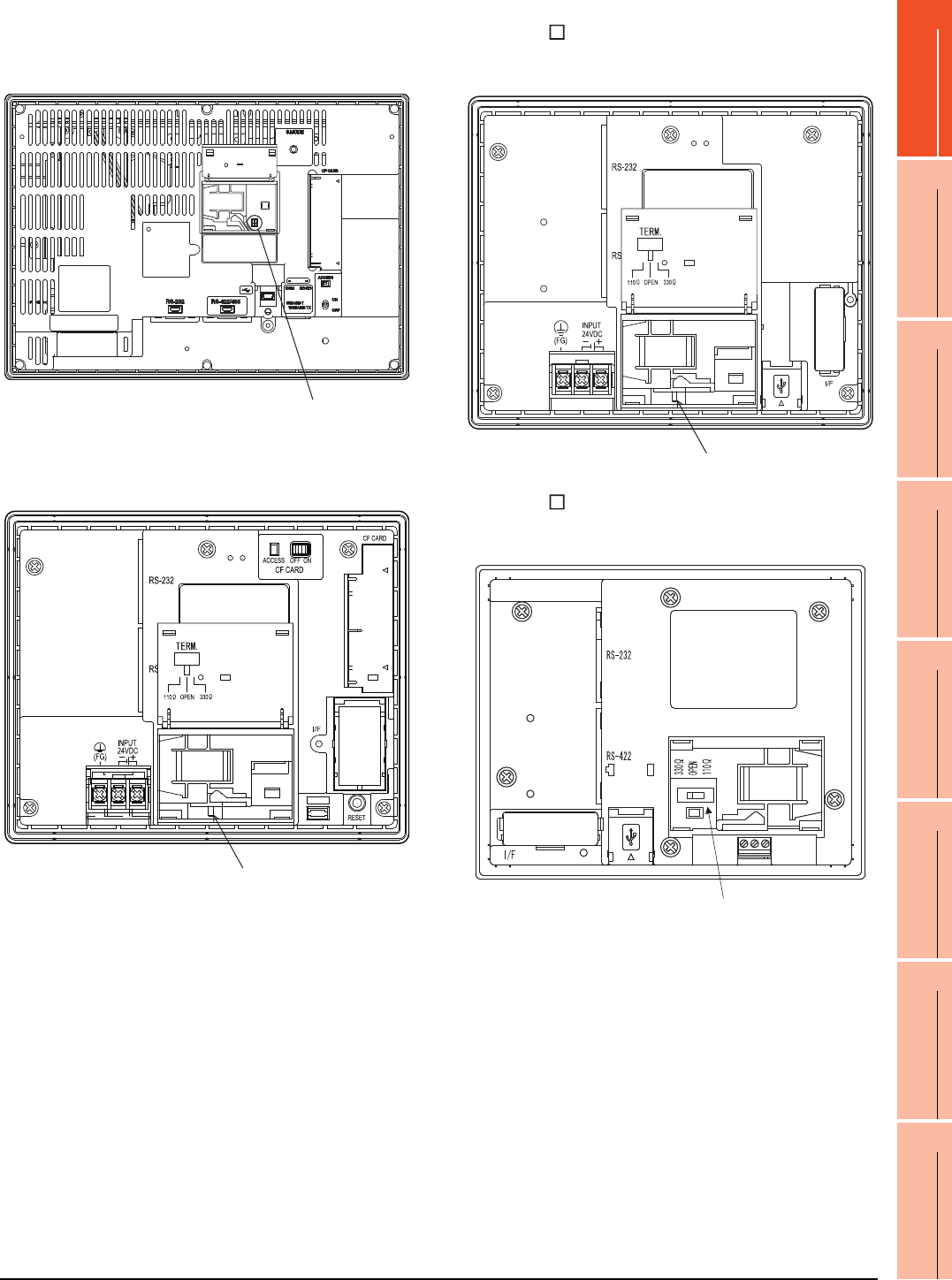
1. PREPARATORY PROCEDURES FOR MONITORING
1.4 Connection Cables for the Respective Connection
1 - 31
1
PREPARATORY
PROCEDURES FOR
MONITORING
2
DEVICE RANGE
THAT CAN BE SET
3
ACCESS RANGE
FOR MONITORING
4
HOW TO MONITOR
REDUNTANT
SYSTEM
5
BUS CONNECTION
6
DIRECT
CONNECTION TO
CPU
7
COMPUTER LINK
CONNECTION
8
ETHERNET
CONNECTION
GT12
Set the terminating resistor using the terminating
resistor setting switch.
GT11
Set the terminating resistor using the terminating
resistor setting switch.
GT105
Set the terminating resistor using the terminating
resistor setting switch.
GT104
Set the terminating resistor using the terminating
resistor setting switch.
Terminating resistor selector switch
Terminating resistor selector switch
Terminating resistor selector switch
Terminating resistor selector switch
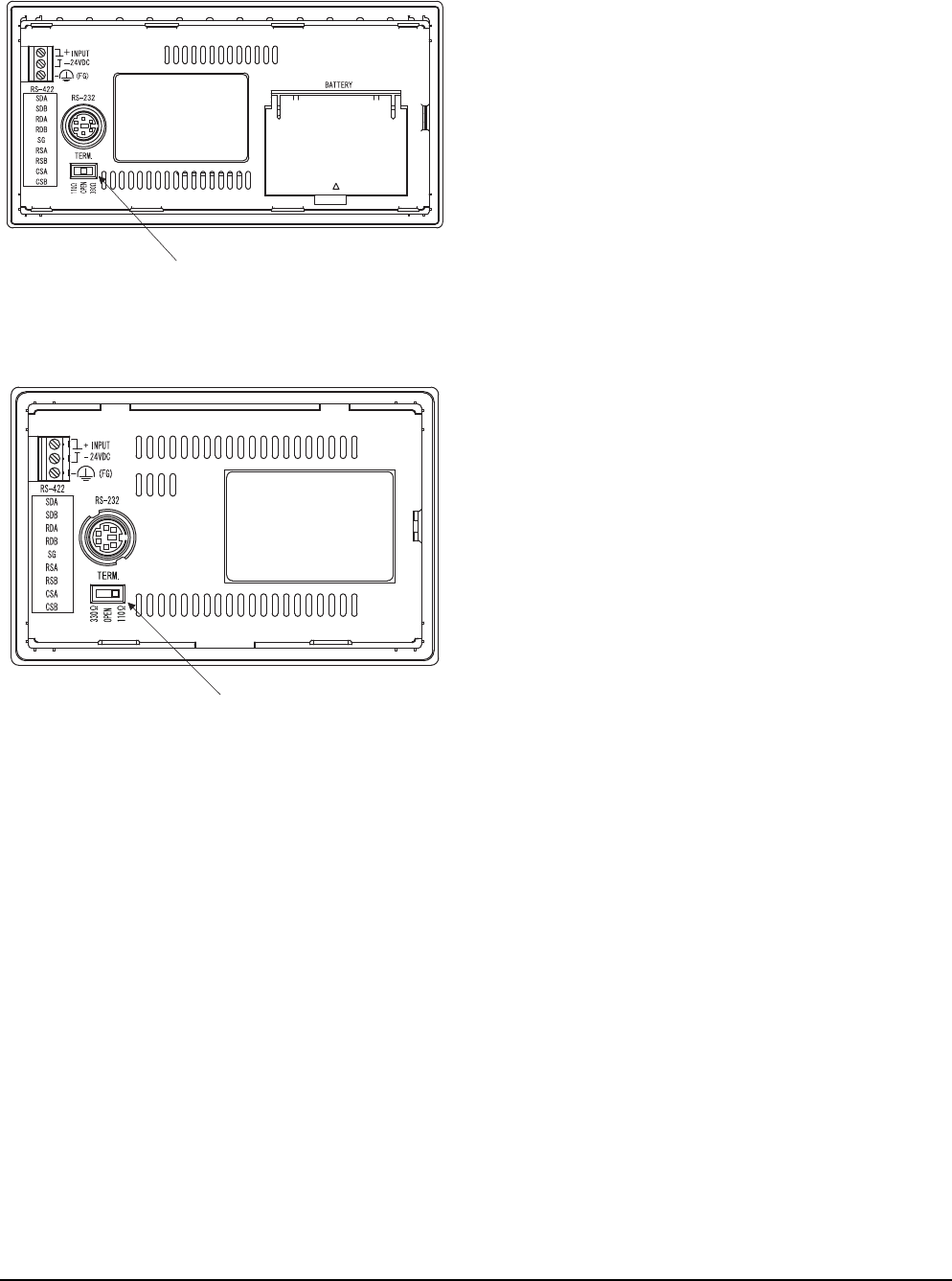
1 - 32 1. PREPARATORY PROCEDURES FOR MONITORING
1.4 Connection Cables for the Respective Connection
GT1030
Set the terminating resistor using the terminating
resistor setting switch.
GT1020
Set the terminating resistor using the terminating
resistor setting switch.
Terminating resistor selector switch
Terminating resistor selector switch
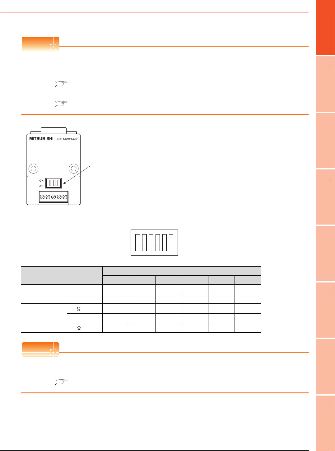
1. PREPARATORY PROCEDURES FOR MONITORING
1.4 Connection Cables for the Respective Connection
1 - 33
1
PREPARATORY
PROCEDURES FOR
MONITORING
2
DEVICE RANGE
THAT CAN BE SET
3
ACCESS RANGE
FOR MONITORING
4
HOW TO MONITOR
REDUNTANT
SYSTEM
5
BUS CONNECTION
6
DIRECT
CONNECTION TO
CPU
7
COMPUTER LINK
CONNECTION
8
ETHERNET
CONNECTION
1.4.4 Setting the RS-232/485 signal conversion adaptor
Set the 2-wire/4-wire terminating resistor setting switch according to the connection type.
POINTPOINTPOINT
Enable the 5V power supply
Make sure to validate "Enable the 5V power supply" in the [RS232 Setting] to operate the RS-232/485 signal
conversion adaptor.
1.1.2 I/F communication setting
When validating the function using the utility function of the GOT main unit, refer to the following manual.
GT14 User's Manual 8.2 Utility Function List
Setting the 2-wire/4-wire terminating resistor setting switch
POINTPOINTPOINT
RS-232/485 signal conversion adapter
For details on the RS-232/485 signal conversion adapter, refer to the following manual.
GT14-RS2T4-9P RS-232/485 Signal Conversion Adapter User's Manual
2-wire/4-wire terminating resistor setting switch
1O
2N
3
4
5
6
Setting item Set value
Switch No.
123456
2-wire/4-wire
2-wire (1Pair) ON ON - - - OFF
4-wire (2Pair) OFF OFF - - - OFF
Terminating resistor
110 --ONOFFOFFOFF
OPEN - - OFF OFF OFF OFF
330 --OFFONONOFF
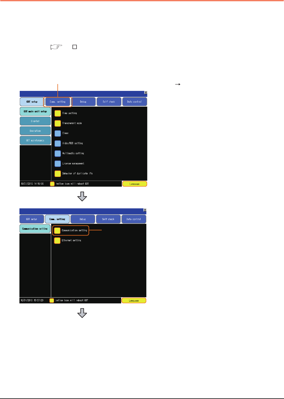
1 - 34 1. PREPARATORY PROCEDURES FOR MONITORING
1.5 Verifying GOT Recognizes Connected Equipment
1.5 Verifying GOT Recognizes Connected Equipment
Verify the GOT recognizes controllers on [Communication Settings] of the Utility.
• Channel number of communication interface, communication drivers allocation status
• Communication unit installation status
For details on the Utility, refer to the following manual.
GT User's Manual
When using GT16, GT12
(For GT16)
1. After powering up the GOT, touch [Main menu]
[Communication setting] from the Utility.
2. Touch [Communication setting].
1.
2.
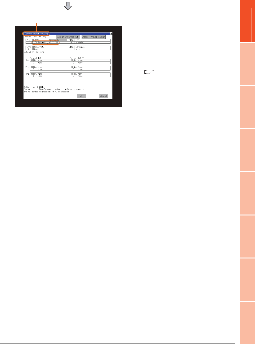
1. PREPARATORY PROCEDURES FOR MONITORING
1.5 Verifying GOT Recognizes Connected Equipment
1 - 35
1
PREPARATORY
PROCEDURES FOR
MONITORING
2
DEVICE RANGE
THAT CAN BE SET
3
ACCESS RANGE
FOR MONITORING
4
HOW TO MONITOR
REDUNTANT
SYSTEM
5
BUS CONNECTION
6
DIRECT
CONNECTION TO
CPU
7
COMPUTER LINK
CONNECTION
8
ETHERNET
CONNECTION
3. The [Communication Settings] appears.
4. Verify that the communication driver name to
be used is displayed in the communication
interface box to be used.
5. When the communication driver name is not
displayed normally, carry out the following
procedure again.
1.1Setting the Communication Interface
3. 4.
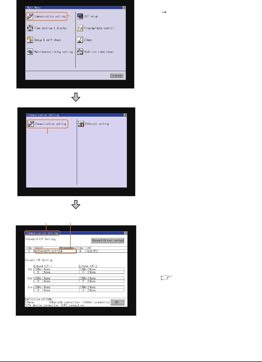
1 - 36 1. PREPARATORY PROCEDURES FOR MONITORING
1.5 Verifying GOT Recognizes Connected Equipment
For GT15, GT14 or GT11
1. After powering up the GOT, touch [Main Menu]
[Communication setting] from the Utility.
2. Touch [Communication setting].
(The screen on the left is not displayed on
GT11.)
3. The [Communication Setting] appears.
4. Verify that the communication driver name to
be used is displayed in the box for the
communication interface to be used.
5. When the communication driver name is not
displayed normally, carry out the following
procedure again.
1.1Setting the Communication Interface
1.
2.
3. 4.
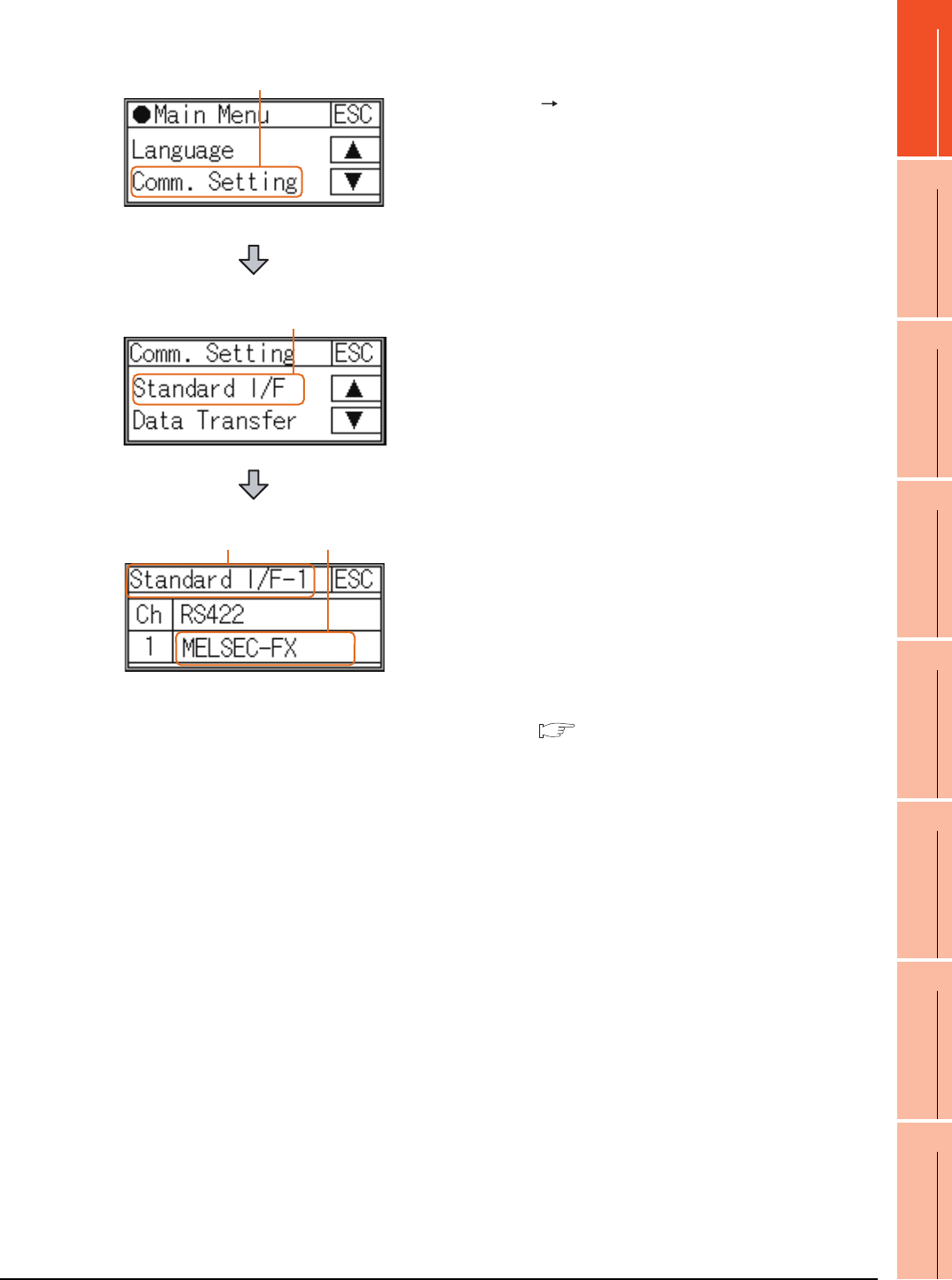
1. PREPARATORY PROCEDURES FOR MONITORING
1.5 Verifying GOT Recognizes Connected Equipment
1 - 37
1
PREPARATORY
PROCEDURES FOR
MONITORING
2
DEVICE RANGE
THAT CAN BE SET
3
ACCESS RANGE
FOR MONITORING
4
HOW TO MONITOR
REDUNTANT
SYSTEM
5
BUS CONNECTION
6
DIRECT
CONNECTION TO
CPU
7
COMPUTER LINK
CONNECTION
8
ETHERNET
CONNECTION
For GT10
1. After powering up the GOT, touch [Main Menu]
[Comm. Setting] from the Utility.
2. Touch [Standard I/F] on [Comm. Setting].
3. The [Standard I/F] appears.
4. Verify that the communication driver name to
be used is displayed in the box for the
communication interface to be used.
5. When the communication driver name is not
displayed normally, carry out the following
procedure again.
1.1Setting the Communication Interface
1.
2.
3. 4.
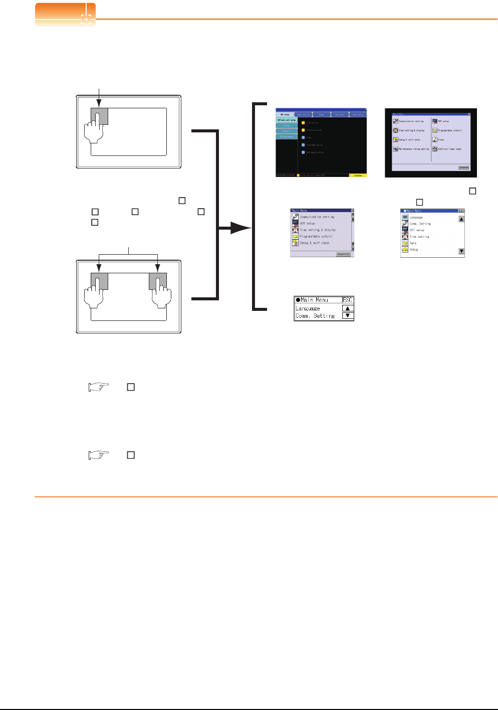
1 - 38 1. PREPARATORY PROCEDURES FOR MONITORING
1.5 Verifying GOT Recognizes Connected Equipment
POINTPOINTPOINT
Utility
(1) How to display Utility (at default)
(2) Utility call
When setting [Pressing time] to other than 0 second on the setting screen of the utility call key, press and hold
the utility call key until the buzzer sounds.For the setting of the utility call key, refer to the following.
GT User's Manual
(3) Communication interface setting by the Utility
The communication interface setting can be changed on the Utility's [Communication setting] after writing
[Communication Settings] of project data.
For details on the Utility, refer to the following manual.
GT User's Manual
(4) Precedence in communication settings
When settings are made by GT Designer3 or the Utility, the latest setting is effective.
When using GT16, GT1595, GT14, GT12 or GT1020
Utility call key
1-point press on GOT screen upper-left corner
Utility call key
Simultaneous 2-point press
(When using GT15)(When using GT16, GT12)
Utility display
When using GT1585, GT157 ,
GT156 , GT155 , GT11, GT105 ,
GT104 or GT1030
(When using GT14, GT11)
(When using GT1030,GT1020)
(When using GT105 ,
GT104 )
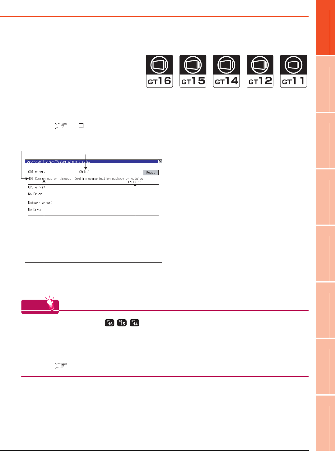
1. PREPARATORY PROCEDURES FOR MONITORING
1.6 Checking for Normal Monitoring
1 - 39
1
PREPARATORY
PROCEDURES FOR
MONITORING
2
DEVICE RANGE
THAT CAN BE SET
3
ACCESS RANGE
FOR MONITORING
4
HOW TO MONITOR
REDUNTANT
SYSTEM
5
BUS CONNECTION
6
DIRECT
CONNECTION TO
CPU
7
COMPUTER LINK
CONNECTION
8
ETHERNET
CONNECTION
1.6 Checking for Normal Monitoring
1.6.1 Check on the GOT
Check for errors occurring on the GOT
Presetting the system alarm to project data allows you to identify errors occurred on the GOT, PLC CPU, servo
amplifier and communications.
For details on the operation method of the GOT Utility screen, refer to the following manual.
GT User's Manual
(When using GT15)
HINTHINTHINT
Advanced alarm popup display
With the advanced alarm popup display function, alarms are displayed as a popup display regardless of whether
an alarm display object is placed on the screen or not (regardless of the display screen).
Since comments can be flown from right to left, even a long comment can be displayed all.
For details of the advanced popup display, refer to the following manual.
GT Designer3 Screen Design Manual
Error code Communication Channel No.
Error message Time of occurrence
(Displayed only for errors)
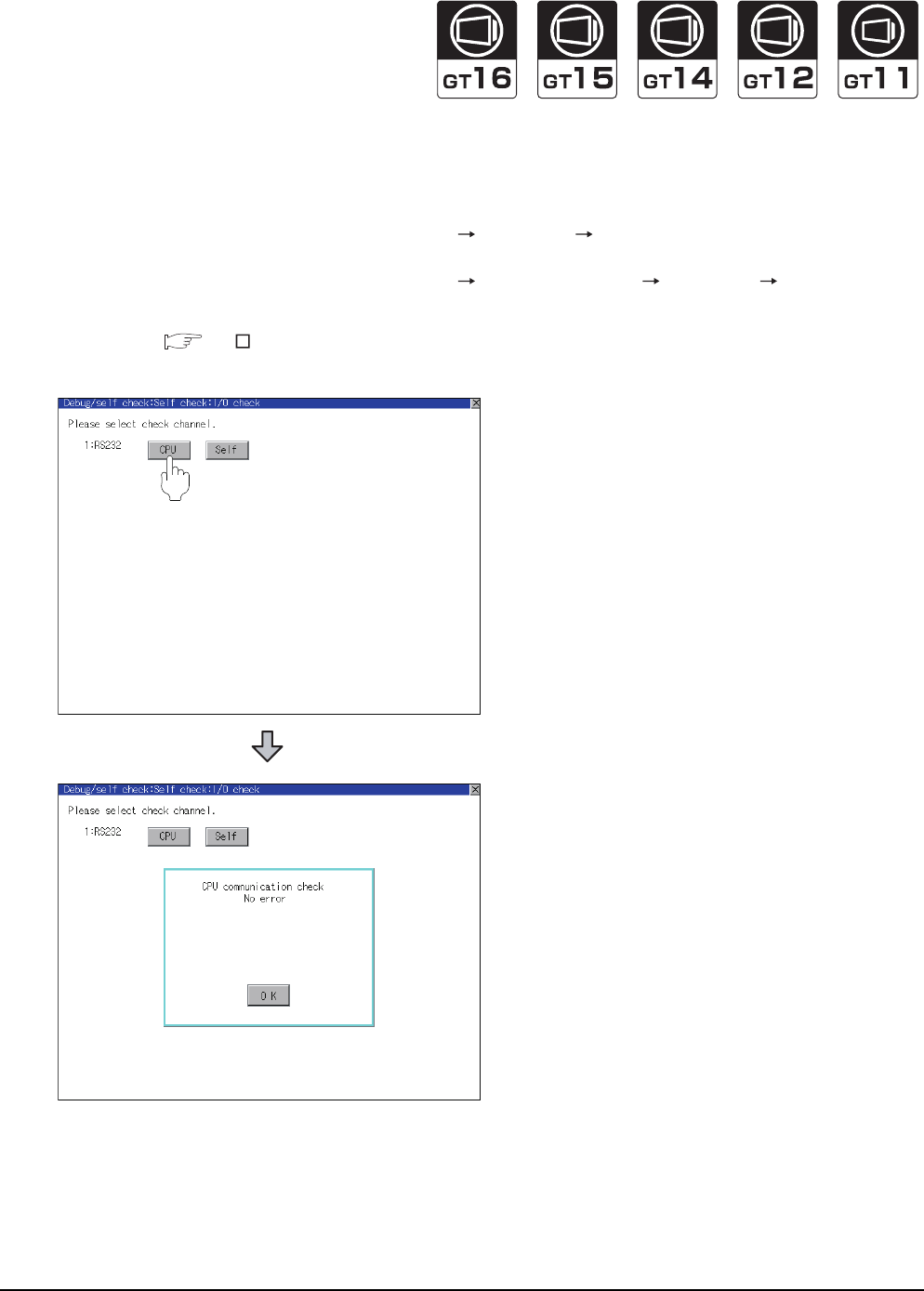
1 - 40 1. PREPARATORY PROCEDURES FOR MONITORING
1.6 Checking for Normal Monitoring
Perform an I/O check
Whether the PLC can communicate with the GOT or not can be checked by the I/O check function.
If this check ends successfully, it means correct communication interface settings and proper cable connection.
Display the I/O check screen by Main Menu.
• For GT16, GT12
Display the I/O check screen by [Main menu] [Self check] [I/O check].
• For GT15, GT14, GT11
Display the I/O check screen by [Main menu] [Debug & self check] [Self check] [I/O check].
For details on the I/O check, refer to the following manual:
GT User's Manual
1.
Touch [CPU] on the I/O check screen.
Touching [
CPU
] executes the communication
check with the connected PLC.
2. When the communication screen ends
successfully, the screen on the left is displayed.
1.
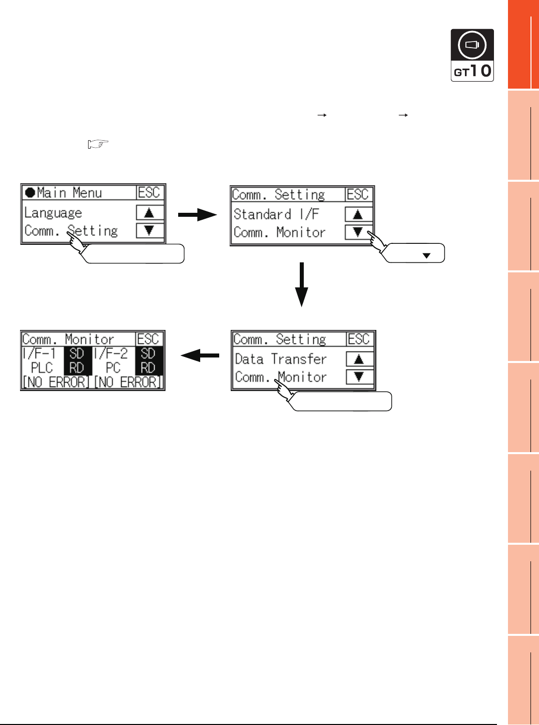
1. PREPARATORY PROCEDURES FOR MONITORING
1.6 Checking for Normal Monitoring
1 - 41
1
PREPARATORY
PROCEDURES FOR
MONITORING
2
DEVICE RANGE
THAT CAN BE SET
3
ACCESS RANGE
FOR MONITORING
4
HOW TO MONITOR
REDUNTANT
SYSTEM
5
BUS CONNECTION
6
DIRECT
CONNECTION TO
CPU
7
COMPUTER LINK
CONNECTION
8
ETHERNET
CONNECTION
Communication monitoring function
The communication monitoring is a function that checks whether the PLC can communicate with the GOT.
If this check ends successfully, it means correct communication interface settings and proper cable connection.
Display the communication monitoring function screen by [Main Menu] [Comm. Setting] [Comm. Monitor].
For details on the communication monitoring function, refer to the following manual:
GT10 User's Manual
(Operation of communication monitoring function screen)
Main Menu
Touch [Comm. Setting] Touch [ ]
Communication settings
Touch [Comm. Monitor]
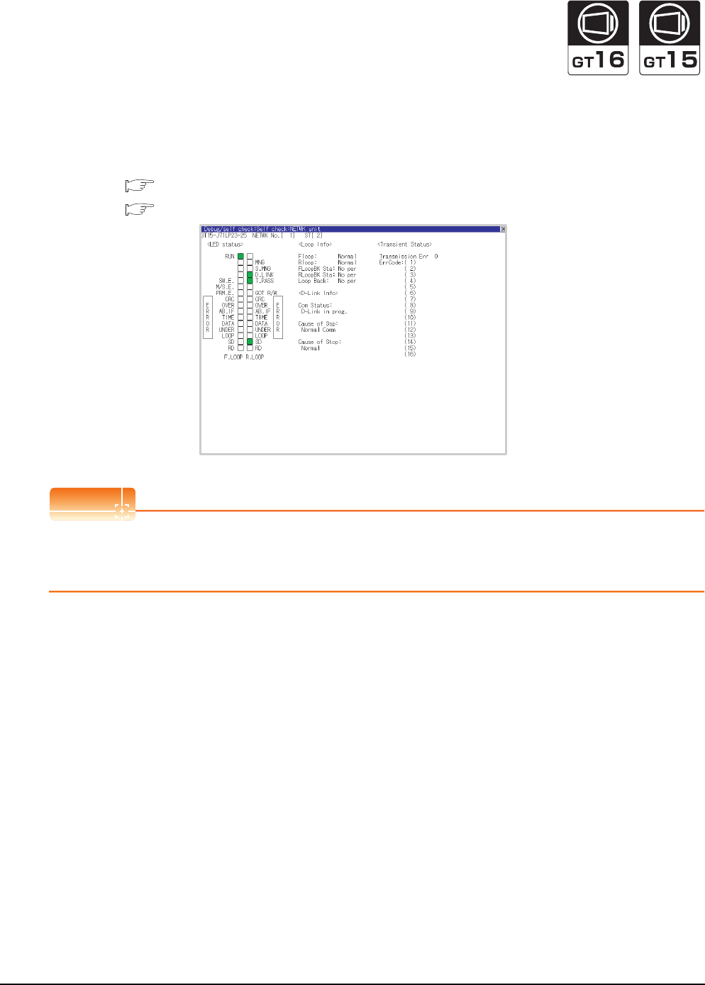
1 - 42 1. PREPARATORY PROCEDURES FOR MONITORING
1.6 Checking for Normal Monitoring
Confirming the communication status with network unit by GOT
(1) For MELSECNET/H, MELSECNET/10 network system
The communication status between the GOT and the MELSECNET/H, MELSECNET/10 network system can be
confirmed by the Utility screen of the GOT.
For details on the operation method of the GOT Utility screen, refer to the following manual.
GT16 User's Manual (Basic Utility)
GT15 User's Manual
POINTPOINTPOINT
Communication unit for displaying network module status
Use the GT15-J71LP23-25 or GT15-J71BR13 for displaying the network module status on the GOT.
The GOT cannot display the network module status with GT15-75J71LP23-Z or GT15-75J71BR13-Z.
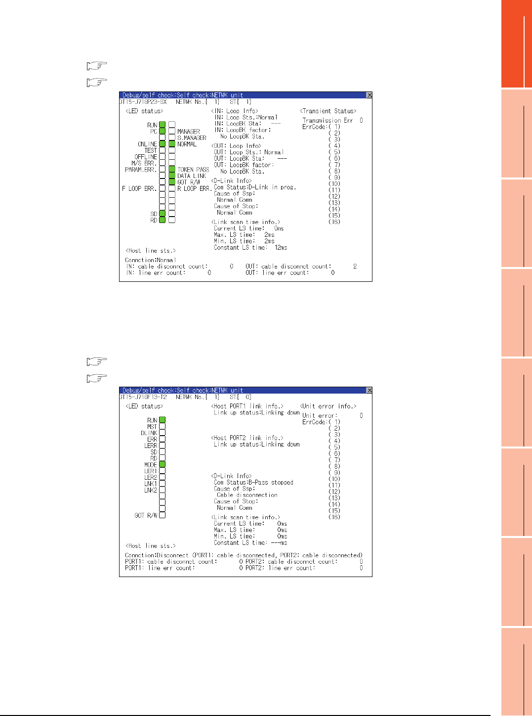
1. PREPARATORY PROCEDURES FOR MONITORING
1.6 Checking for Normal Monitoring
1 - 43
1
PREPARATORY
PROCEDURES FOR
MONITORING
2
DEVICE RANGE
THAT CAN BE SET
3
ACCESS RANGE
FOR MONITORING
4
HOW TO MONITOR
REDUNTANT
SYSTEM
5
BUS CONNECTION
6
DIRECT
CONNECTION TO
CPU
7
COMPUTER LINK
CONNECTION
8
ETHERNET
CONNECTION
(2) For CC-Link IE Controller Network system
The communication status between the GOT and CC-Link IE Controller Network can be confirmed by the utility
screen of the GOT.
For details on the operation method of the GOT Utility screen, refer to the following manual.
GT16 User's Manual (Basic Utility)
GT15 User's Manual
(3) For CC-Link IE Field Network system
The communication status between the GOT and CC-Link IE Field Network can be confirmed by the utility
screen of the GOT.
For details on the operation method of the GOT Utility screen, refer to the following manual.
GT16 User's Manual (Basic Utility)
GT15 User's Manual
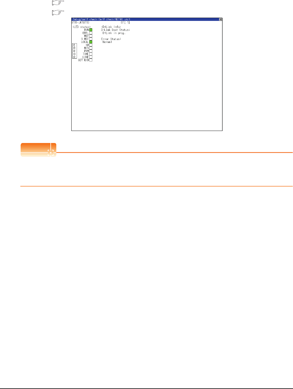
1 - 44 1. PREPARATORY PROCEDURES FOR MONITORING
1.6 Checking for Normal Monitoring
(4) For CC-Link system
The communication status between the GOT and the CC-Link System can be confirmed by the Utility screen of
the GOT.
For details on the operation method of the GOT Utility screen, refer to the following manual.
GT16 User's Manual (Basic Utility)
GT15 User's Manual
POINTPOINTPOINT
CC-Link communication unit when network module status display is made
When displaying the network module status, use the CC-Link communication unit of MODEL GT15-J61BT13.
For the MODEL GT15-75J61BT13-Z, the network module status cannot be displayed.
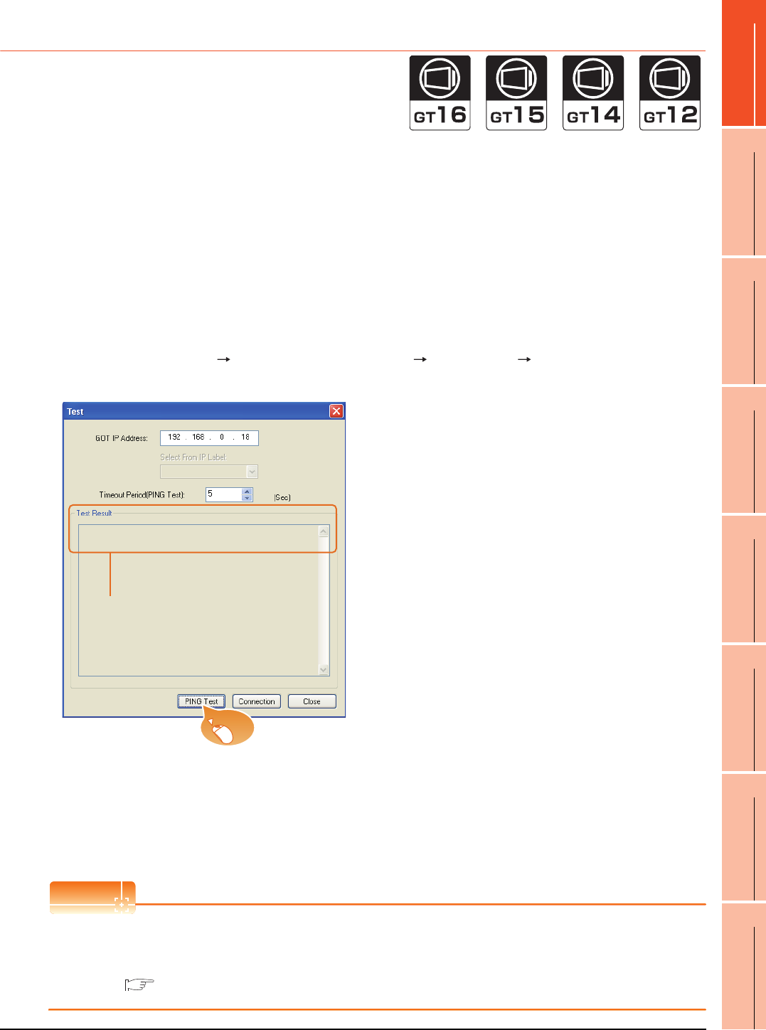
1. PREPARATORY PROCEDURES FOR MONITORING
1.6 Checking for Normal Monitoring
1 - 45
1
PREPARATORY
PROCEDURES FOR
MONITORING
2
DEVICE RANGE
THAT CAN BE SET
3
ACCESS RANGE
FOR MONITORING
4
HOW TO MONITOR
REDUNTANT
SYSTEM
5
BUS CONNECTION
6
DIRECT
CONNECTION TO
CPU
7
COMPUTER LINK
CONNECTION
8
ETHERNET
CONNECTION
1.6.2 Confirming the communication state on the GOT side (For Ethernet
connection)
Confirming the communication state on Windows®, GT Designer3
(1) When using the Command Prompt of Windows®
Execute a Ping command at the Command Prompt of Windows®.
(a) When normal communication
C:\>Ping 192.168.0.18
Reply from 192.168.0.18: bytes=32time<1ms TTL=64
(b) When abnormal communication
C:\>Ping 192.168.0.18
Request timed out.
(2) When using the [PING Test] of GT Designer3
Select [Communication] [Communication configuration] [Ethernet] and [Connection Test] to display
[PING Test].
(3) When abnormal communication
At abnormal communication, check the followings and execute the Ping command again.
• Mounting condition of Ethernet communication unit
• Cable connecting condition
• Confirmation of [Communication Settings]
• IP address of GOT specified by Ping command
POINTPOINTPOINT
Ethernet diagnostics of GX Developer
Ethernet diagnostics of GX Developer is available to a Ping test from the PLC.
For details of Ethernet diagnostics of GX Developer, refer to the following manual.
User's manual of the Ethernet module
1. Specify the [GOT IP Address] of the [PING
Test] and click the [PING Test] button.
2. The [Test Result] is displayed after the [PING
Test] is finished.
2.
1.
Click!

1 - 46 1. PREPARATORY PROCEDURES FOR MONITORING
1.6 Checking for Normal Monitoring
Confirming the communication state on the GOT (For GT16, GT14)
[PING Test] can be confirmed by the Utility screen of the GOT.
For details on the operation method of the GOT Utility screen, refer to the following manual.
GT16 User's Manual (Basic Utility)
GT14 User's Manual
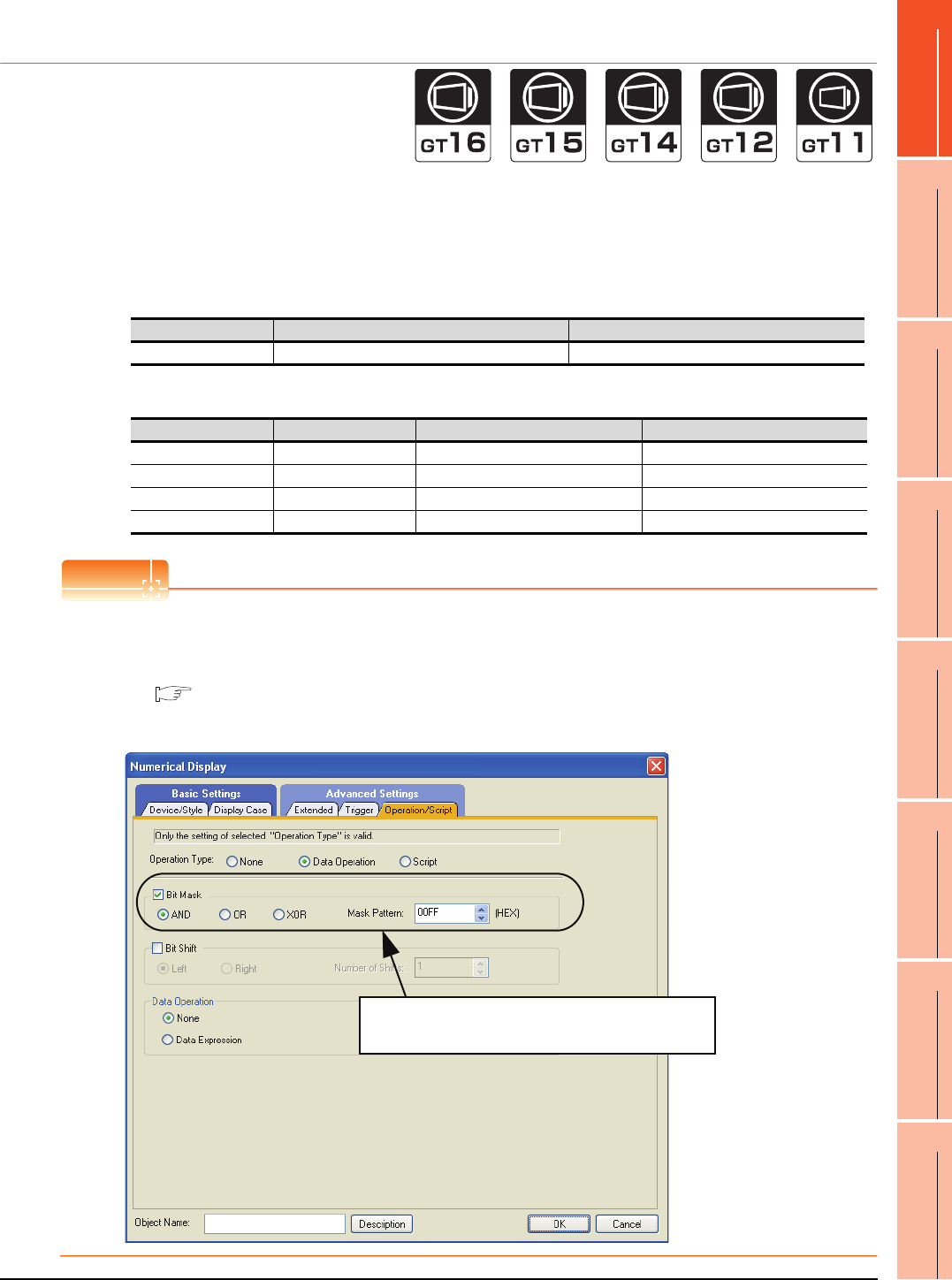
1. PREPARATORY PROCEDURES FOR MONITORING
1.6 Checking for Normal Monitoring
1 - 47
1
PREPARATORY
PROCEDURES FOR
MONITORING
2
DEVICE RANGE
THAT CAN BE SET
3
ACCESS RANGE
FOR MONITORING
4
HOW TO MONITOR
REDUNTANT
SYSTEM
5
BUS CONNECTION
6
DIRECT
CONNECTION TO
CPU
7
COMPUTER LINK
CONNECTION
8
ETHERNET
CONNECTION
1.6.3 Confirming the communication state to each station (Station monitoring
function)
The station monitoring function detects the faults (communication timeout) of the stations monitored by the GOT.
When detecting the abnormal state, it allocates the data for the faulty station to the GOT special register (GS).
(1) No. of faulty stations
(a) Ethernet connection (Except for Ethernet multiple connection)
Total No. of the faulty CPU is stored.
(b) Ethernet multiple connection
Total No. of the faulty connected equipment is stored.
POINTPOINTPOINT
When monitoring GS230 on Numerical Display
When monitoring GS230 on Numerical Display, check [mask processing] with data operation tab as the following.
For the data operation, refer to the following manual.
GT Designer3 Screen Design Manual
-Numerical Display (Data Operation tab)
Device b15 to b8 b7 to b0
GS230 (00H fixed) No. of faulty stations
Channel Device b15 to b8 b7 to b0
Ch1 GS280 (00H fixed) No. of faulty stations
Ch2 GS300 (00H fixed) No. of faulty stations
Ch3 GS320 (00H fixed) No. of faulty stations
Ch4 GS340 (00H fixed) No. of faulty stations
Set [mask processing] to the upper eight bits (b8
to b15) of GS230 on Numerical Display.
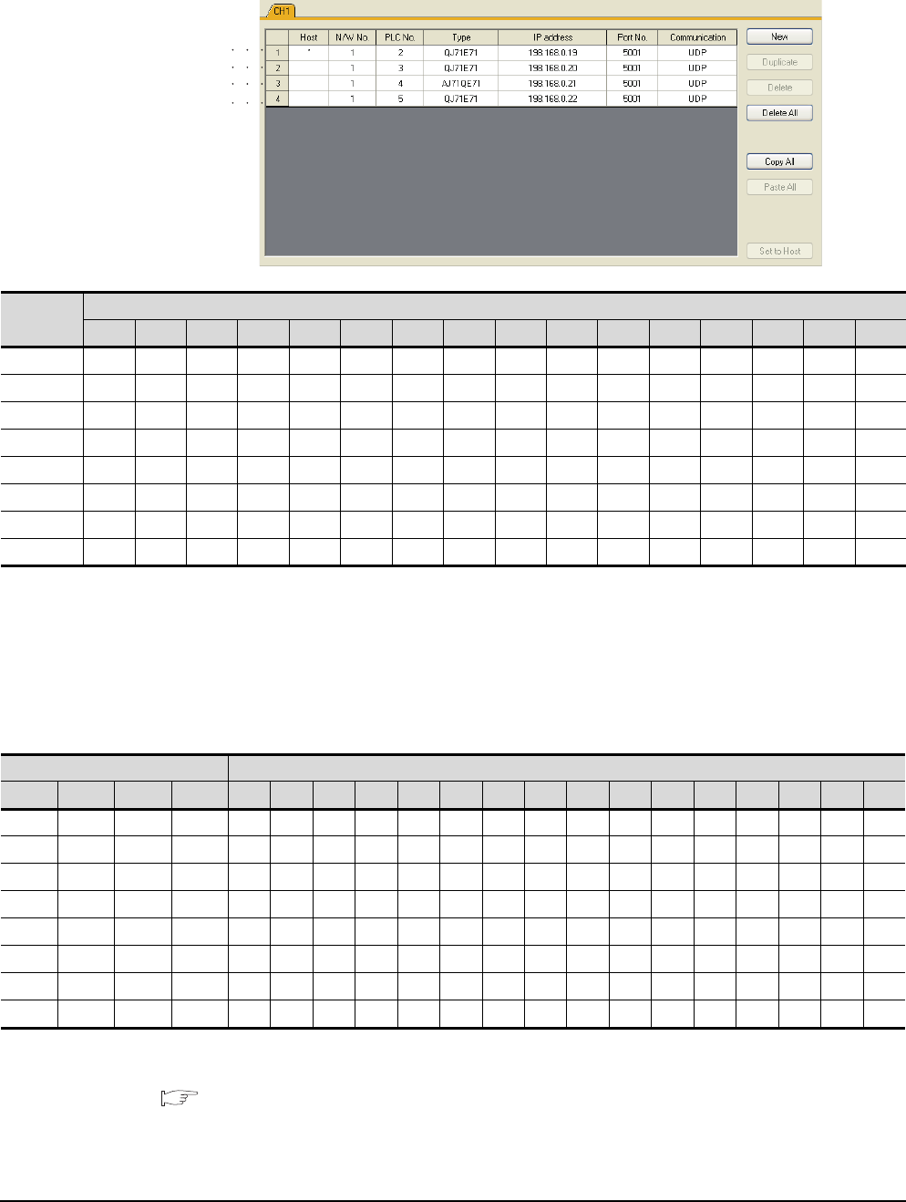
1 - 48 1. PREPARATORY PROCEDURES FOR MONITORING
1.6 Checking for Normal Monitoring
(2) Faulty station information (GS231 to GS238)
The bit corresponding to the faulty station is set.(0: Normal, 1: Abnormal)
The bit is reset after the fault is recovered.
(a) Ethernet connection (Except for Ethernet multiple connection)
(b) Ethernet multiple connection, servo amplifier connection, inverter connection
The station number to which each device corresponds changes according to the connection/non
connection with Ethernet.
With Ethernet connection: 1 to 128
With other than Ethernet connection: 0 to 127
Example) With Ethernet connection, when PC No. 100 CPU connecting to Ch3 is faulty, GS327.b3 is set.
The following table shows the case with Ethernet connection.
For details on the GS Device, refer to the following manual.
GT Designer3 Screen Design Manual (Fundamentals) Appendix.2.3 GOT special register (GS)
GS231 bit 0
GS231 bit 1
GS231 bit 2
GS231 bit 3
Device
PLC No.
b15 b14 b13 b12 b11 b10 b9 b8 b7 b6 b5 b4 b3 b2 b1 b0
GS231 16151413121110987654321
GS232 32 31 30 29 28 27 26 25 24 23 22 21 20 19 18 17
GS233 48 47 46 45 44 43 42 41 40 39 38 37 36 35 34 33
GS234 64 63 62 61 60 59 58 57 56 55 54 53 52 51 50 49
GS235 80 79 78 77 76 75 74 73 72 71 70 69 68 67 66 65
GS236 96 95 94 93 92 91 90 89 88 87 86 85 84 83 82 81
GS237 112 111 110 109 108 107 106 105 104 103 102 101 100 99 98 97
GS238 128 127 126 125 124 123 122 121 120 119 118 117 116 115 114 113
Device PLC No./Station No.
Ch1 Ch2 Ch3 Ch4 b15 b14 b13 b12 b11 b10 b9 b8 b7 b6 b5 b4 b3 b2 b1 b0
GS281GS301GS321GS34116151413121110987654321
GS282 GS302 GS322 GS342 32 31 30 29 28 27 26 25 24 23 22 21 20 19 18 17
GS283 GS303 GS323 GS343 48 47 46 45 44 43 42 41 40 39 38 37 36 35 34 33
GS284 GS304 GS324 GS344 64 63 62 61 60 59 58 57 56 55 54 53 52 51 50 49
GS285 GS305 GS325 GS345 80 79 78 77 76 75 74 73 72 71 70 69 68 67 66 65
GS286 GS306 GS326 GS346 96 95 94 93 92 91 90 89 88 87 86 85 84 83 82 81
GS287 GS307 GS327 GS347 112 111 110 109 108 107 106 105 104 103 102 101 100 99 98 97
GS288 GS308 GS328 GS348 128 127 126 125 124 123 122 121 120 119 118 117 116 115 114 113

1. PREPARATORY PROCEDURES FOR MONITORING
1.6 Checking for Normal Monitoring
1 - 49
1
PREPARATORY
PROCEDURES FOR
MONITORING
2
DEVICE RANGE
THAT CAN BE SET
3
ACCESS RANGE
FOR MONITORING
4
HOW TO MONITOR
REDUNTANT
SYSTEM
5
BUS CONNECTION
6
DIRECT
CONNECTION TO
CPU
7
COMPUTER LINK
CONNECTION
8
ETHERNET
CONNECTION
(3) Network No., station No. notification
The network No. and station No. of the GOT in Ethernet connection are stored at GOT startup.
If connected by other than Ethernet, 0 is stored.
Device Description
CH1 CH2 CH3 CH4
GS376 GS378 GS380 GS382 Network No. (1 to 239)
GS377 GS379 GS381 GS383 Station No. (1 to 64)
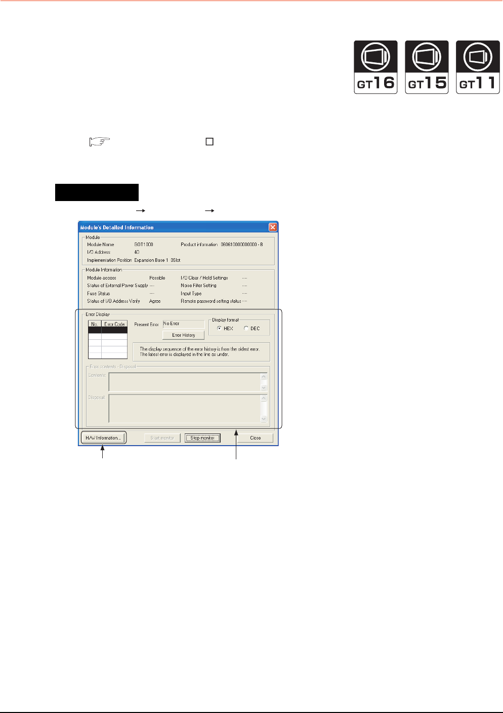
1 - 50 1. PREPARATORY PROCEDURES FOR MONITORING
1.6 Checking for Normal Monitoring
1.6.4 Check on GX Developer
Check if the PLC CPU recognizes the GOT (For bus connection) (QCPU (Q mode) only)
Using the [System monitor] of GX Developer, check if the PLC CPU recognizes the GOT or not.
For the GX Developer operation method, refer to the following manual.
GX Developer Version Operating Manual
(1) Check the Module Name, I/O Address and Implementation Position. (The display example is based on GX
Developer Version 8)
GX Developer [Diagnostics] [System monitor]
Startup procedure
No error displayed
at all times
Not displayed
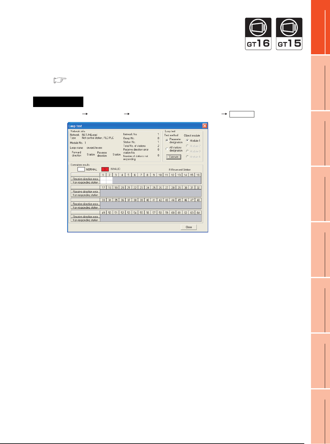
1. PREPARATORY PROCEDURES FOR MONITORING
1.6 Checking for Normal Monitoring
1 - 51
1
PREPARATORY
PROCEDURES FOR
MONITORING
2
DEVICE RANGE
THAT CAN BE SET
3
ACCESS RANGE
FOR MONITORING
4
HOW TO MONITOR
REDUNTANT
SYSTEM
5
BUS CONNECTION
6
DIRECT
CONNECTION TO
CPU
7
COMPUTER LINK
CONNECTION
8
ETHERNET
CONNECTION
Checking the wiring state (For optical loop system only)
Check if the optical fiber cable is connected correctly in [Loop test] of GX Developer.
For the GX Developer operation method, refer to the following manual.
Q Corresponding MELSECNET/H Network System Reference Manual (PLC to PLC network)
(2) Check the [Receive direction error station] (The display example on GX Developer Version 8)
GX Developer [Diagnostics] [MELSECNET (II)/10/H diagnostics]
Startup procedure
Loop test
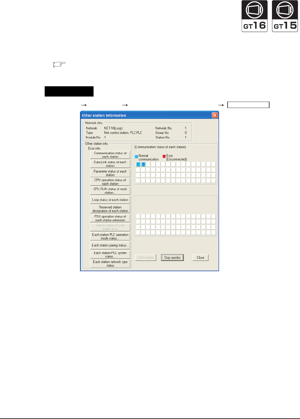
1 - 52 1. PREPARATORY PROCEDURES FOR MONITORING
1.6 Checking for Normal Monitoring
Checking if the GOT is performed the data link correctly
(1) For MELSECNET/H, MELSECNET/10 network system
Check if the GOT is performed the data link correctly in [Other station information].
For the GX Developer operation method, refer to the following manual.
Q Corresponding MELSECNET/H Network System Reference Manual (PLC to PLC network)
(a) Check [Communication status of each station] and [Data-Link status of each station] (The display example
on GX Developer Version 8)
GX Developer [Diagnostics] [MELSECNET (II)/10/H diagnostics]
Startup procedure
Other station info.
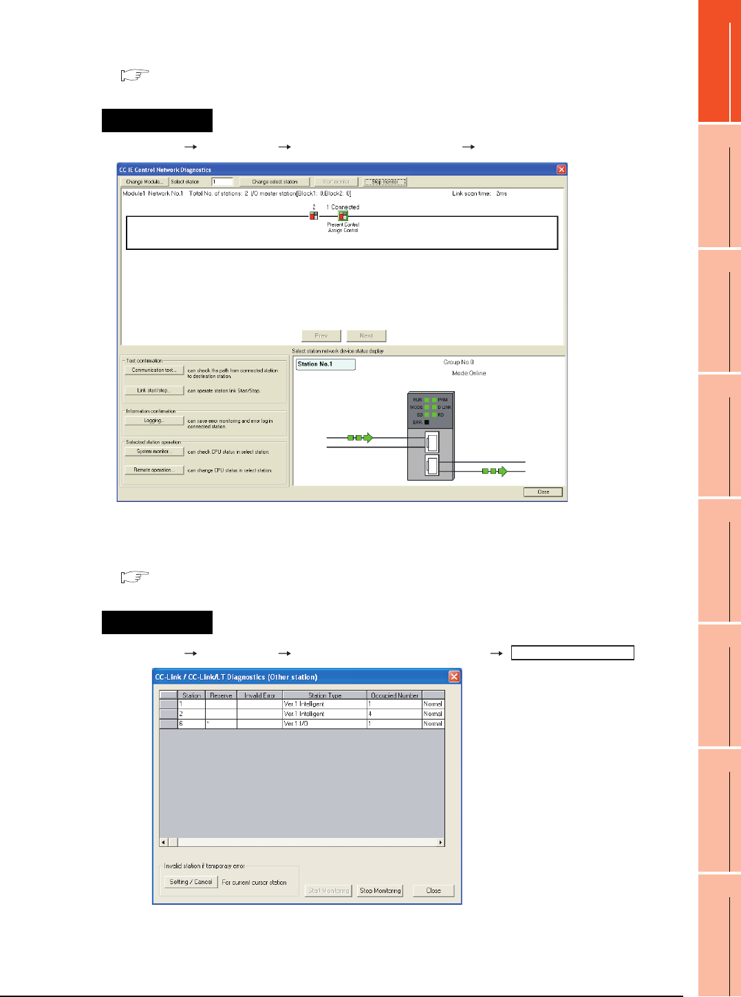
1. PREPARATORY PROCEDURES FOR MONITORING
1.6 Checking for Normal Monitoring
1 - 53
1
PREPARATORY
PROCEDURES FOR
MONITORING
2
DEVICE RANGE
THAT CAN BE SET
3
ACCESS RANGE
FOR MONITORING
4
HOW TO MONITOR
REDUNTANT
SYSTEM
5
BUS CONNECTION
6
DIRECT
CONNECTION TO
CPU
7
COMPUTER LINK
CONNECTION
8
ETHERNET
CONNECTION
(2) For CC-Link IE Controller Network system
Use [CC IE Control diagnostics…] of GX Developer to check if the GOT is correctly performed the data link.
For the GX Developer operation method, refer to the following manual.
CC-Link IE Controller Network Reference Manual
(a) Check the [Select station network device status display] (The display example on GX Developer Version 8)
GX Developer [Diagnostics] [CC IE Control diagnostics…] [CC IE Control Network Diagnostics]
(3) For CC-Link system
Use [Monitoring other station] of the GX Developer to check if the GOT is correctly performed the data link.
For the GX Developer operation method, refer to the following manual.
CC-Link System Master/Local Module User's Manual QJ61BT11N
(a) Check the [Status] (The display example on GX Developer Version 8)
GX Developer [Diagnostics] [CC-Link / CC-Link LT diagnostics]
Startup procedure
Startup procedure
Monitoring other station
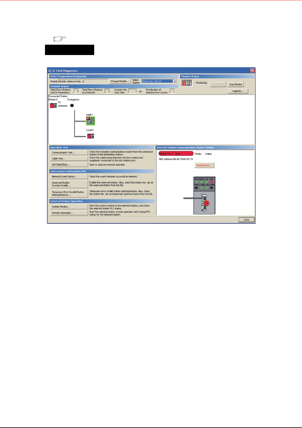
1 - 54 1. PREPARATORY PROCEDURES FOR MONITORING
1.6 Checking for Normal Monitoring
1.6.5 Check on GX Works2
For CC-Link IE Field Network system
Use [CC IE Field diagnostics] of GX Works2 to check if the GOT is correctly performed the data link.
For the GX Works2 operation method, refer to the following manual.
MELSEC-Q CC-Link IE Field Network Master/Local Module User's Manual
GX Works2 → [diagnostics] → [CC IE Field diagnostics]
Startup procedure

1. PREPARATORY PROCEDURES FOR MONITORING
1.6 Checking for Normal Monitoring
1 - 55
1
PREPARATORY
PROCEDURES FOR
MONITORING
2
DEVICE RANGE
THAT CAN BE SET
3
ACCESS RANGE
FOR MONITORING
4
HOW TO MONITOR
REDUNTANT
SYSTEM
5
BUS CONNECTION
6
DIRECT
CONNECTION TO
CPU
7
COMPUTER LINK
CONNECTION
8
ETHERNET
CONNECTION
1.6.6 Check on the PLC
Checking the wiring state of the optical fiber cable (For CC-Link IE Controller Network only)
Check if the fiber-optic cable is connected correctly to all the modules in the CC-Link IE Controller Network.
Perform the line test from the control station of the CC-Link IE Controller Network to check the wiring state of the
fiber-optic cable.
For the line testing method, refer to the following manual.
CC-Link IE Controller Network Reference Manual
Checking the wiring state of the CC-Link dedicated cable (For CC-Link system only)
Check if the CC-Link dedicated cable is connected correctly to all the modules in the CC-Link system.
Perform the line test from the master station of the CC-Link System to check the wiring state of the CC-Link
dedicated cable.
For the line testing method, refer to the following manuals.
CC-Link System Master/Local Module User's Manual QJ61BT11N
CC-Link System Master/Local Module User's Manual AJ61QBT11, A1SJ61QBT11
CC-Link System Master/Local Module User's Manual AJ61BT11, A1SJ61BT11

1 - 56 1. PREPARATORY PROCEDURES FOR MONITORING
1.6 Checking for Normal Monitoring

MITSUBISHI PLC CONNECTIONS
2. DEVICE RANGE THAT CAN BE SET . . . . . . . . . . . . . . . . . .2 - 1
3. ACCESS RANGE FOR MONITORING . . . . . . . . . . . . . . . . .3 - 1
4. HOW TO MONITOR REDUNTANT SYSTEM . . . . . . . . . . . .4 - 1
5. BUS CONNECTION. . . . . . . . . . . . . . . . . . . . . . . . . . . . . . . .5 - 1
6. DIRECT CONNECTION TO CPU . . . . . . . . . . . . . . . . . . . . .6 - 1
7. COMPUTER LINK CONNECTION . . . . . . . . . . . . . . . . . . . .7 - 1
8. ETHERNET CONNECTION. . . . . . . . . . . . . . . . . . . . . . . . . .8 - 1
9. MELSECNET/H CONNECTION (PLC TO PLC NETWORK)
. . . . . . . . . . . . . . . . . . . . . . . . . . . . . . . . . . . . . . . . . . . . . . . .9 - 1
10. MELSECNET/10 CONNECTION (PLC TO PLC NETWORK)
. . . . . . . . . . . . . . . . . . . . . . . . . . . . . . . . . . . . . . . . . . . . . . .10 - 1
11. CC-Link IE CONTROLLER NETWORK CONNECTION . . .11 - 1
12. CC-Link IE FIELD NETWORK CONNECTION
. . . . . . . . . . . . . . . . . . . . . . . . . . . . . . . . . . . . . . . . . . . . . . .12 - 1
13. CC-Link CONNECTION (INTELLIGENT DEVICE STATION)
. . . . . . . . . . . . . . . . . . . . . . . . . . . . . . . . . . . . . . . . . . . . . . .13 - 1
14. CC-Link CONNECTION (Via G4). . . . . . . . . . . . . . . . . . . . .14 - 1


2
1
PREPARATORY
PROCEDURES FOR
MONITORING
2
DEVICE RANGE
THAT CAN BE SET
3
ACCESS RANGE
FOR MONITORING
4
HOW TO MONITOR
REDUNTANT
SYSTEM
5
BUS CONNECTION
6
DIRECT
CONNECTION TO
CPU
7
COMPUTER LINK
CONNECTION
8
ETHERNET
CONNECTION
2 - 1
2.
DEVICE RANGE THAT CAN BE SET
2.1 MELSEC-QnU/DC, Q17nD/M/NC/DR, CRnD-700 . . . . . . . 2 - 8
2.2 MELSEC-L . . . . . . . . . . . . . . . . . . . . . . . . . . . . . . . . . . . . . 2 - 9
2.3 MELSEC-QnA/Q/QS, MELDAS C6 * . . . . . . . . . . . . . . . . 2 - 10
2.4 MELSEC-Q (Multi)/Q Motion. . . . . . . . . . . . . . . . . . . . . . . .2 - 11
2.5 MELSEC-A . . . . . . . . . . . . . . . . . . . . . . . . . . . . . . . . . . . . 2 - 12
2.6 MELSEC-FX . . . . . . . . . . . . . . . . . . . . . . . . . . . . . . . . . . . 2 - 13
2.7 MELSEC-WS . . . . . . . . . . . . . . . . . . . . . . . . . . . . . . . . . . 2 - 14

2 - 2 2. DEVICE RANGE THAT CAN BE SET
2. DEVICE RANGE THAT CAN BE SET
The device ranges that can be set for the Mitsubishi PLCs are as follows.
Note that the device ranges in the following tables are the maximum values that can be set in GT Designer3.
The device specifications of controllers may differ depending on the models, even though belonging to the same series.
Please make the setting according to the specifications of the controller actually used.
When a non-existent device or a device number outside the range is set, other objects with correct device settings may
not be monitored.
2.1 MELSEC-QnU/DC, Q17nD/M/NC/DR, CRnD-700 *1
2.2 MELSEC-L
2.3 MELSEC-QnA/Q/QS, MELDAS C6 * *2
2.4 MELSEC-Q (Multi)/Q Motion*3
2.5 MELSEC-A
2.6 MELSEC-FX
2.7 MELSEC-WS
*1 The PLC names differ depending on the type of GOT.
• GT11: MELSEC-QnU/DC, Q17nD/M/NC/DR
• GT10: MELSEC-QnU/DC
*2 The PLC names differ depending on the type of GOT.
• GT11: MELSEC-QnA/Q, MELDAS C6 *
• GT10: MELSEC-QnA/Q
*3 The PLC names differ depending on the type of GOT.
• GT10: MELSEC-Q (MULTI)
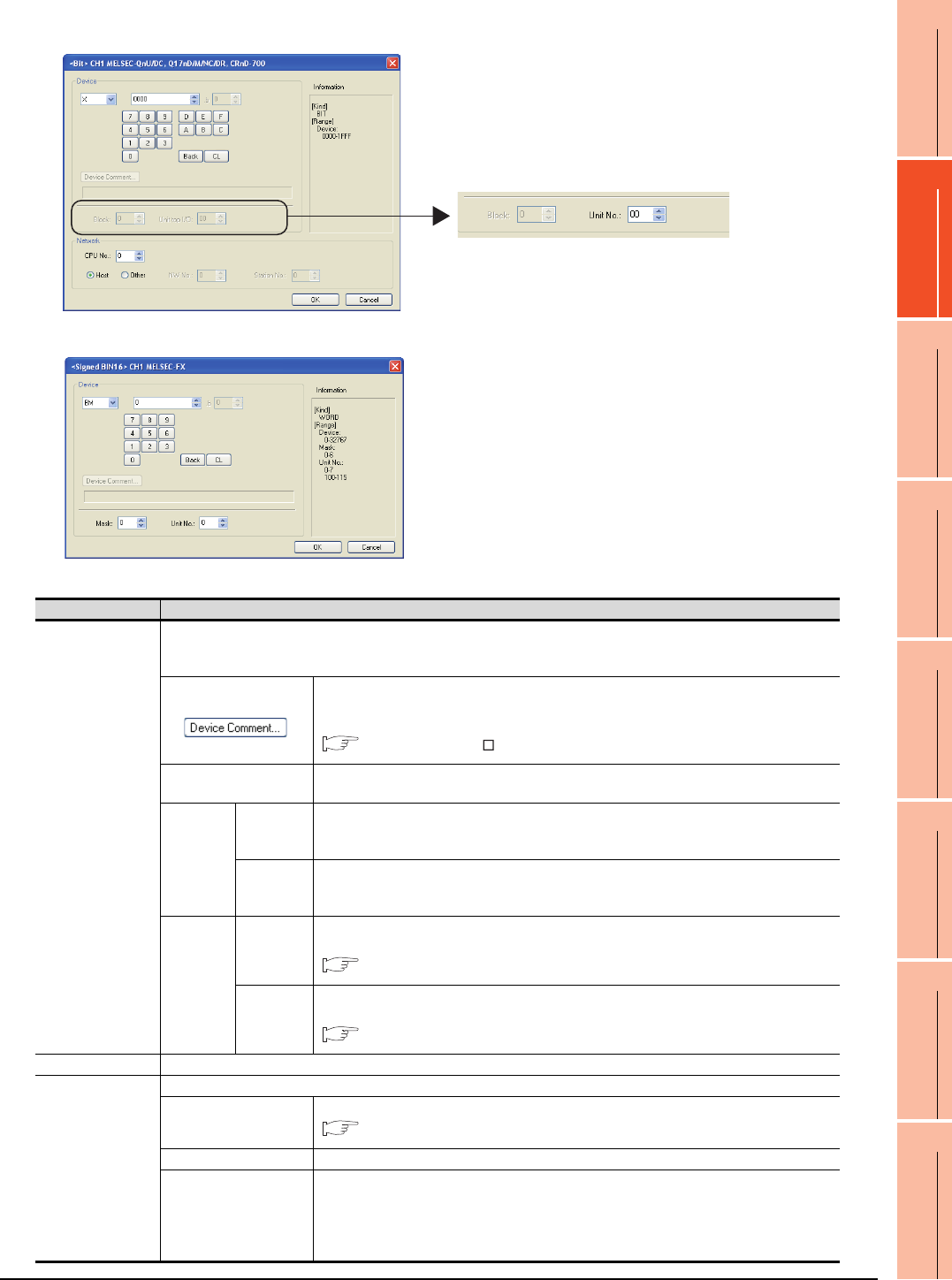
2. DEVICE RANGE THAT CAN BE SET
2 - 3
1
PREPARATORY
PROCEDURES FOR
MONITORING
2
DEVICE RANGE
THAT CAN BE SET
3
ACCESS RANGE
FOR MONITORING
4
HOW TO MONITOR
REDUNTANT
SYSTEM
5
BUS CONNECTION
6
DIRECT
CONNECTION TO
CPU
7
COMPUTER LINK
CONNECTION
8
ETHERNET
CONNECTION
Setting item
(For MELSEC-QnU/DC, Q17nD/M/NC/DR, CRnD-700)
(For MELSEC-FX)
When selecting buffer memory (G) with the following controllers
MELSEC-QnU/DC, Q17nD/M/NC/DR, CRnD-700
MELSEC-L
MELSEC-QnA/Q/QS, MELDAS C6 *
MELSEC-Q(MULTI)/Q MOTION
Item Description
Device
Set the device name, device number, and bit number.
The bit number can be set only by specifying the bit of word device.
When setting buffer memory (BM) and (G), set the buffer memory address in the space for the device number.
Reading the device comment data created by GX Developer and confirming the device
comment/device name are available during device setting.
For details on the procedure to refer to the device comment, refer to the following.
GT Designer3 Version Screen Design Manual
Block Set the block number of the extended file register.
This item can be set only when the extended file register (ER) is selected.
Intelligent
function
module
Unit top I/O
Set when the buffer memory (BM) is selected.
Set the head I/O number of the buffer memory for the intelligent function module.
Set the first 2 digits of the 3-digit head I/O number.
Unit No.
Set when the buffer memory (G) is selected.
Set the head I/O number of the buffer memory for the intelligent function module.
Set the first 2 digits of the 3-digit head I/O number.
MELSEC-
FX buffer
memory
Mask type
Set for using the buffer memory of MELSEC-FX series.
Set the mask type for monitoring or writing only specified bits of the buffer memory.
(4) Setting of the mask type (MELSEC-FX)
Unit No.
Set for using the buffer memory of MELSEC-FX series.
Set the module No. of the special function unit or special function block to monitor or write.
(5) Setting of the module No. (MELSEC-FX)
Information Displays the device type and its setting range selected in [Device].
Network
Set the station number of the controller to be monitored.
CPU No.
Set the CPU No. of the controller.
(1) Setting of the CPU No.
Host Select this item for monitoring the host controller.
Other
Select this for monitoring other controllers.
After selecting the item, set the station number and network number of the controller to be
monitored.
NW No.: Set the network No.
Station No.: Set the station No.
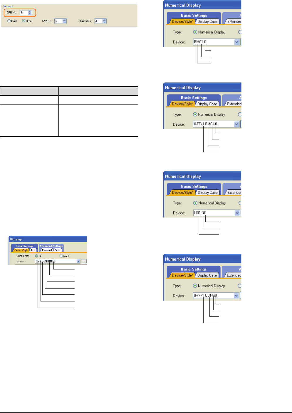
2 - 4 2. DEVICE RANGE THAT CAN BE SET
(1) Setting of the CPU No.
(a) When monitoring a single CPU system
Set to 0.
(b) When monitoring a multiple CPU system
Set the CPU No. (0 to 4) in [CPU No.] when
monitoring a multiple CPU system.
When [CPU No.] is set to "0", the monitoring target
differs depending on the connection method.
(2) When monitoring link relay (B) and link register (W)
assigned in link parameter and network parameter.
Set the device link relay (B) and link register (W)
running cyclic communication as [Host].
If it is set as [Other] in the network setting, the cyclic
transmission is changed to the transient transmission
regardless of the network type, resulting in delay of the
object display.
(3) Setting the device by inputting directly from the
keyboard
When setting the device by inputting directly from the
keyboard, set the items as follows.
(For devices except BM and G)
(For device BM and CPU No. 0)
(For device BM and CPU No. 1 to 4)
(For device G and CPU No. 0)
(For device G and CPU No. 1 to 4)
Connection method Monitoring target
• Direct CPU connection Connected PLC CPU
• Bus connection
• Computer link connection
• MELSECNET connection
• Ethernet connection
• CC-Link connection
Control CPU
Bit condition
Device number
Device name
CPU No.
PLC station number
N/W No.
Channel No.
Device number
Head I/O number of buffer memory
Device name
Device number
Head I/O number of buffer memory
Device name
CPU No. 1 to 4
Device number
Device name
Unit No.
Device number
Device name
Unit No.
CPU No. 1 to 4
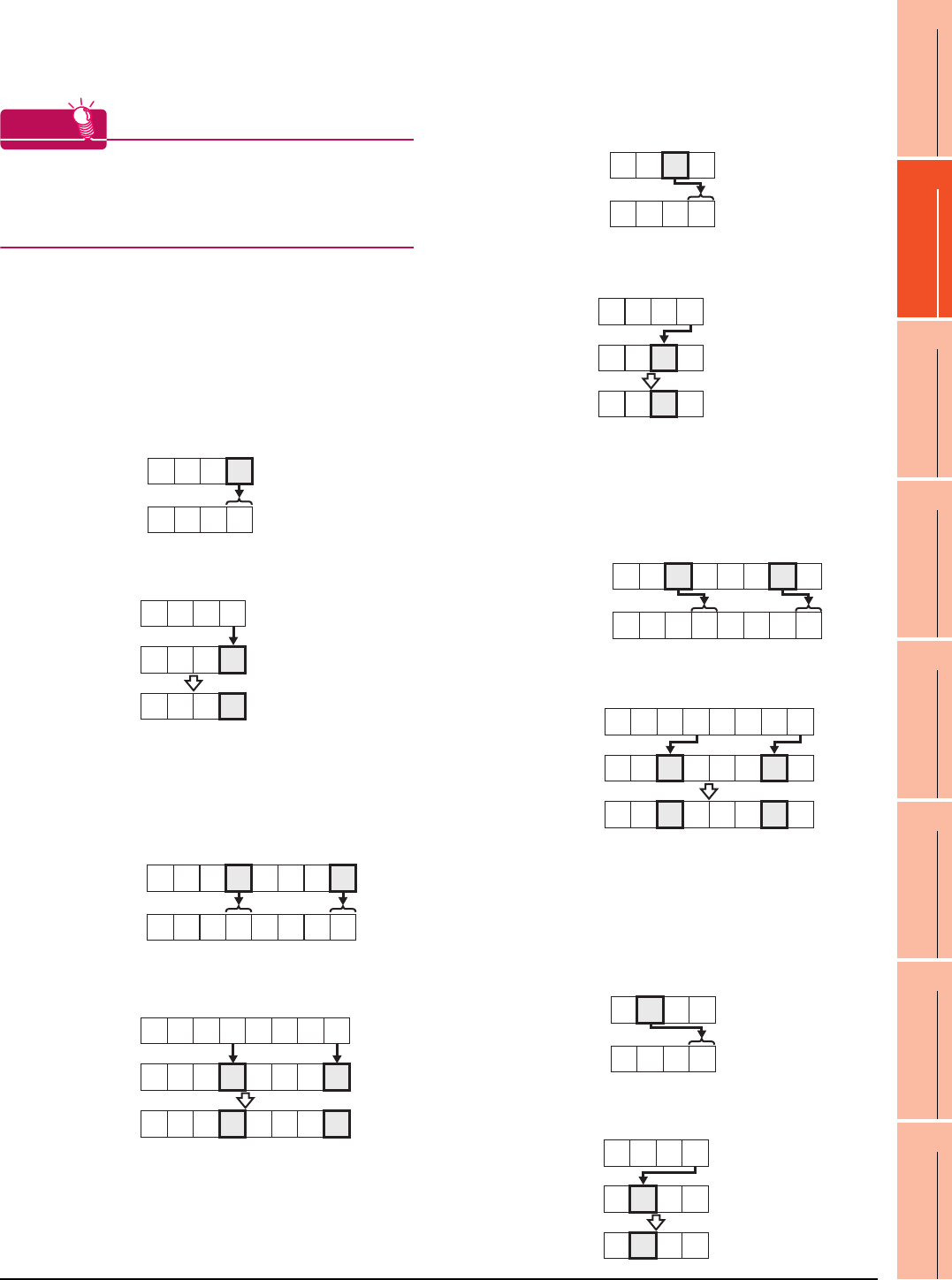
2. DEVICE RANGE THAT CAN BE SET
2 - 5
1
PREPARATORY
PROCEDURES FOR
MONITORING
2
DEVICE RANGE
THAT CAN BE SET
3
ACCESS RANGE
FOR MONITORING
4
HOW TO MONITOR
REDUNTANT
SYSTEM
5
BUS CONNECTION
6
DIRECT
CONNECTION TO
CPU
7
COMPUTER LINK
CONNECTION
8
ETHERNET
CONNECTION
(4) Setting of the mask type (MELSEC-FX)
Set the item for monitoring or writing only the specified
bits of the buffer memory.
HINTHINTHINT
Mask type
The mask type is effective when using for the buffer
memories divided per 4 bits, such as an analog input
block.
(a) Mask type 0
Monitor and write the buffer memory value directly.
(b) Mask type 1
•(For 16 bits)
Monitor and write only b0 to b3 of the buffer
memory.
Example:
The monitor value is 0001H when monitoring
BM=4321H as mask type 1.
BM0=0001H when writing input value 4321H to
BM0=0000H as mask type 1.
•(For 32 bits)
Monitor and write only b0 to b3 and b16 to 19 of
the buffer memory.
Example:
The monitor value is 00050001H when monitoring
BM0=87654321H as mask type 1.
BM0=00050001H when writing input value
87654321H to BM0=00000000H as mask type 1.
(c) Mask type 2
•(For 16 bits)
Monitor and write only b4 to b7 of the buffer
memory.
Example:
The monitor value is 0002H when monitoring
BM0=4321H as mask type 2.
BM0=0010H when writing input value 4321H to
BM0=0000H as mask type 2.
•(For 32 bits)
Monitor and write only b4 to b7 and b20 to 23 of
the buffer memory.
Example:
The monitor value is 00060002H when monitoring
BM0=87654321H as mask type 2.
BM0=00500010H when writing input value
87654321H to BM0=00000000H as mask type 2.
(d) Mask type 3
•(For 16 bits)
Monitor and write only b8 to b11 of the buffer
memory.
Example:
The monitor value is 0003H when monitoring
BM0=4321H as mask type 3.
BM0=0100H when writing input value 4321H to
BM0=0000H as mask type 3.
BM0
Monitor value
H
4321
0001
H
BM0
(Before writing)
(After writing)
BM0
Input value H
4321
0000
H
0001
H
H
BM0 87654321
00050001
H
Monitor value
H
BM0
87654321
00000000
H
Input value
BM0 00050001
H
(Before writing)
(After writing)
BM0
Monitor value
H
4321
0002
H
BM0
(Before writing)
(After writing)
BM0
Input value H
4321
0000
H
0010
H
H
BM0 87654321
00060002
H
Monitor value
H
BM0
87654321
00000000
H
Input value
BM0 00500010
H
(Before writing)
(After writing)
BM0
Monitor value
H
4321
0003
H
BM0
(Before writing)
(After writing)
BM0
Input value H
4321
0000
H
0100
H
2 - 6 2. DEVICE RANGE THAT CAN BE SET
• (For 32 bits)
Monitor and write only b8 to b11 and b28 to 31 of
the buffer memory.
Example:
The monitor value is 00070003H when monitoring
BM0=87654321H as mask type 3.
BM0=05000100H when writing input value
87654321H to BM0=00000000H as mask type 3.
(e) Mask type 4
• (For 16 bits)
Monitor and write only b12 to b15 of the buffer
memory.
Example:
The monitor value is 0004H when monitoring
BM0=4321H as mask type 4.
BM0=1000H when writing input value 4321H to
BM0=0000H as mask type 4.
• (For 32 bits)
Monitor and write only b12 to b15 and b28 to 31
of the buffer memory.
Example:
The monitor value is 00080004H when monitoring
BM0=87654321H as mask type 4.
BM0=50001000H for writing input value
87654321H to BM0=00000000H as mask type 4.
(f) Mask type 5
•(For 16 bits)
Monitor and write only b0 to b7 of the buffer
memory.
Example:
The monitor value is 0021H when monitoring
BM0=4321H as mask type 5.
BM0=0021H when writing input value 4321H to
BM0=0000H as mask type 5.
•(For 32 bits)
Monitor and write only b0 to b7 and b16 to 23 of
the buffer memory.
Example:
The monitor value is 00650021H when monitoring
BM0=87654321H as mask type 5.
BM0=00650021H when writing input value
87654321H to BM0=00000000H as mask type 5.
(g) Mask type 6
•(For 16 bits)
Monitor and write only b8 to b15 of the buffer
memory.
Example:
The monitor value is 0043H when monitoring
BM0=4321H as mask type 6.
BM0=2100H when writing input value 4321H to
BM0=0000H as mask type 6.
H
BM0 87654321
00070003
H
Monitor value
H
BM0
87654321
00000000
H
Input value
BM0 05000100
H
(Before writing)
(After writing)
BM0
Monitor value
H
4321
0004
H
BM0
(Before writing)
(After writing)
BM0
Input value H
4321
0000
H
1000
H
H
BM0 87654321
00080004
H
Monitor value
H
BM0
87654321
00000000
H
Input value
BM0 50001000
H
(Before writing)
(After writing)
BM0
Monitor value
H
4321
0021
H
BM0
(Before writing)
(After writing)
BM0
Input value H
4321
0000
H
0021
H
H
BM0
87654321
00650021
H
Monitor value
H
BM0
87654321
00000000
H
Input value
BM0 00650021
H
(Before writing)
(After writing)
BM0
Monitor value
H
4321
0043
H
BM0
(Before writing)
(After writing)
BM0
Input value H
4321
0000
H
2100
H
2. DEVICE RANGE THAT CAN BE SET
2 - 7
1
PREPARATORY
PROCEDURES FOR
MONITORING
2
DEVICE RANGE
THAT CAN BE SET
3
ACCESS RANGE
FOR MONITORING
4
HOW TO MONITOR
REDUNTANT
SYSTEM
5
BUS CONNECTION
6
DIRECT
CONNECTION TO
CPU
7
COMPUTER LINK
CONNECTION
8
ETHERNET
CONNECTION
•(For 32 bits)
Monitor and write only b8 to b15 and b24 to 31 of
the buffer memory.
Example:
The monitor value is 00870043H when monitoring
BM0=87654321H as mask type 6.
BM0=65002100H when writing input value
87654321H to BM0=00000000H as mask type 6.
(5) Setting of the module No. (MELSEC-FX)
Set the module No. of the special function unit or
special function block to monitor or write.
The module No.0 to No.7 are assigned in order for the
nearest module or block from the main unit. For details
of the module No., refer to the following.
User's Manual (Hardware) of MELSEC-FX
(a) Direct specification
Specify the module No. (No.0 to No.7) of the
special function unit or special function block
directly, to monitor or write when setting the
devices.
(b) Indirect specification*1
Specify the module No. of the special function unit
or special function block indirectly, to monitor or
write when setting the devices, by using the 16-bit
GOT internal data register (GD10 to GD25).
When specifying the station No. from 100 to 115 on
GT Designer3, the value of GD10 to GD25
corresponding to the module No. will be the
module No. of the special function unit or special
function block.
*1 The module No. cannot be specified indirectly for the multi-
drop connection.
Module No. Compatible
device Setting range
100 GD10 0 to 7
For the setting other than the above,
error (dedicated device is out of range)
will occur.
If a non-existent module No. is set, a
timeout error occurs.
101 GD11
::
114 GD24
115 GD25
H
BM0 87654321
00870043
H
Monitor value
H
BM0
87654321
00000000
H
Input value
BM0
65002100
H
(Before writing)
(After writing)
2 - 8 2. DEVICE RANGE THAT CAN BE SET
2.1 MELSEC-QnU/DC, Q17nD/M/NC/DR, CRnD-700
2.1 MELSEC-QnU/DC, Q17nD/M/NC/DR, CRnD-700
The table below shows the device ranges in [MELSEC-
QnU/DC, Q17nD/M/NC/DR, CRnD-700]*10 as the
controller type.
*1 Do not set a file register by GT Designer3 when executing
multiple programs with the file of the file register set at [Use
the same file name as the program] by the PLC parameter of
GX Developer.
Otherwise, read/write at GOT will be erroneous.
*2 Available for file register of block No. switched with the RSET
instruction.
*3 Available for file register of block No. of file name switched
with the QDRSET instruction.
*4 GOT treats them in units of 32k (32768 points).
*5 Only the intelligent function module on the station connected
to GOT can be specified.
Set within the address range of the buffer memory existing in
the target intelligent function module.
*6 Do not use local devices set in the MELSEC-Q system.
Otherwise, normal monitoring is not performed.
*7 Even though Universal model QCPU processes 64-bit data,
the GOT cannot monitor 64-bit data.
*8 This is not supported by GT10.
*9 This cannot be monitored when in GOT multi-drop
connection.
*10 For GT14, GT11 and GT10, the controller type is as follows.
• GT14, GT11: MELSEC-QnU/DC, Q17nD/M/NC/DR
• GT10: MELSEC-QnU/DC
*11 For monitoring the internal relay (M) or data register (D) of a
C Controller module, configure the settings related to the
device functions in the device setting tab of the language
controller setting utility.
*12 The device No. must be set in multiples of 16.
Device name*7 Setting range
Device No.
representation
Bit device
Input (X) X0 to X3FFF
Hexadecimal
Output (Y) Y0 to Y3FFF
Internal relay (M)*4*6*11 M0 to M61439
Decimal
Latch relay (L) L0 to L32767
Annunciator (F) F0 to F32767
Link relay (B)*4 B0 to B9FFFF
Hexadecimal
Timer*6 Contact (TT) TT0 to TT32767
Decimal
Coil (TC) TC0 to TC32767
Counter*6 Contact (CT) CT0 to CT32767
Coil (CC) CC0 to CC32767
Special relay (SM) SM0 to SM2255
Retentive
timer*6
Contact (SS) SS0 to SS32767
Coil (SC) SC0 to SC32767
Step relay (S) S0 to S32767
Link special relay (SB) SB0 to SB7FFF
Hexadecimal
Word device bit
Specified bit of the
following word devices
(Except Timer, Counter,
Retentive timer, Index
register and Buffer
memory)
―
Word device
Data register (D)*4*6*11 D0 to D4910079 Decimal
Special data register (SD)
SD0 to SD2255
Link register (W)*4 W0 to W4AEBFF
Hexadecimal
Timer (current value) (TN)
*6
TN0 to TN32767
Decimal
Counter (current value)
(CN)*6 CN0 to CN32767
Retentive timer
(current value) (SN)*6 SN0 to SN32767
Link special register (SW)
SW0 to SW7FFF
Hexadecimal
File register (R)*1*2 R0 to R32767
Decimal
Extension
file register
(ER)
*1
Block 0 to 255
Device ER0 to ER32767
Extension file register
(ZR)*1*3*4
ZR0 to ZR4849663
Index register (Z) Z0 to Z19
Buffer memory
(Intelligent function module)
(BM)
*5
BM0 to BM32767
Buffer memory
(Intelligent function module)
(G)
*4*5
G0 to G65535
Ww*8*9 Ww0 to Ww1FFF
Hexadecimal
Wr*8*9 Wr0 to Wr1FFF
Multiple CPU high speed
transmission memory (U3E0) U3E010000 to U3E024335
Multiple CPU high speed
transmission memory (U3E1) U3E110000
to
U3E124335
Multiple CPU high speed
transmission memory (U3E2) U3E210000
to
U3E224335
Multiple CPU high speed
transmission memory (U3E3) U3E310000
to
U3E324335
Motion device (#) #0 to #12287 Decimal
Bit device word*8*12
Converting the above bit
devices into words
(Except Timer, Counter
and Retentive timer)
―
Device name*7 Setting range
Device No.
representation
2. DEVICE RANGE THAT CAN BE SET
2.2 MELSEC-L
2 - 9
1
PREPARATORY
PROCEDURES FOR
MONITORING
2
DEVICE RANGE
THAT CAN BE SET
3
ACCESS RANGE
FOR MONITORING
4
HOW TO MONITOR
REDUNTANT
SYSTEM
5
BUS CONNECTION
6
DIRECT
CONNECTION TO
CPU
7
COMPUTER LINK
CONNECTION
8
ETHERNET
CONNECTION
2.2 MELSEC-L
The device ranges that can be set when selecting
[MELSEC-L] as the controller type are as follows. *1 Do not set a file register by GT Designer3 when executing
multiple programs with the file of the file register set at [Use
the same file name as the program] by the PLC parameter of
GX Developer.
Otherwise, read/write at GOT will be erroneous.
*2 Available for file register of block No. switched with the RSET
instruction.
*3 Available for file register of block No. of file name switched
with the QDRSET instruction.
*4 GOT treats them in units of 32k (32768 points).
*5 Only the intelligent function module on the station connected
to GOT can be specified.
Set within the address range of the buffer memory existing in
the target intelligent function module.
*6 Do not use local devices set in the MELSEC-L system.
Otherwise, normal monitoring is not performed. (The data
register (D) can be used for D32768 or later.)
*7 This is not supported by GT10.
*8 This cannot be monitored when in GOT multi-drop
connection.
*9 The device No. must be set in multiples of 16.
Device name Setting range
Device No.
representation
Bit device
Input (X) X0 to X3FFF
Hexadecimal
Output (Y) Y0 to Y3FFF
Internal relay (M)*4*6 M0 to M61439
Decimal
Latch relay (L) L0 to L32767
Annunciator (F) F0 to F32767
Link relay (B)*4 B0 to BEFFF
Hexadecimal
Timer*6 Contact (TT) TT0 to TT32767
Decimal
Coil (TC) TC0 to TC32767
Counter*6 Contact (CT) CT0 to CT32767
Coil (CC) CC0 to CC32767
Special relay (SM) SM0 to SM2047
Retentive
timer*6
Contact (SS) SS0 to SS32767
Coil (SC) SC0 to SC32767
Step relay (S) S0 to S8191
Link special relay (SB) SB0 to SB7FFF
Hexadecimal
Word device bit
Specified bit of the
following word devices
(Except Timer, Counter,
Retentive timer, Index
register and Buffer
memory)
―
Word device
Data register (D)*4*6 D0 to D421887 Decimal
Special data register (SD)
SD0 to SD2047
Link register (W)*4 W0 to W66FFF
Hexadecimal
Timer (current value) (TN)
*6
TN0 to TN32767
Decimal
Counter (current value)
(CN)*6 CN0 to CN32767
Retentive timer
(current value) (SN)*6 SN0 to SN32767
Link special register (SW)
SW0 to SW7FFF
Hexadecimal
File register (R)*1*2 R0 to R32767
Decimal
Extension file register
(ZR)*1*3*4 ZR0 to ZR393215
Index register (Z) Z0 to Z19
Buffer memory
(Intelligent function module)
(BM)
*5
BM0 to BM32767
Buffer memory
(Intelligent function module)
(G)
*4*5
G0 to G65535
Ww
*7*8
Ww0 to Ww1FFF
Hexadecimal
Wr
*7*8
Wr0 to Wr1FFF
Bit device word*7*9
Converting the above bit
devices into words
(Except Timer contact
and Counter contact)
―

2 - 10 2. DEVICE RANGE THAT CAN BE SET
2.3 MELSEC-QnA/Q/QS, MELDAS C6 *
2.3 MELSEC-QnA/Q/QS, MELDAS C6 *
The device ranges that can be set when selecting
[MELSEC-QnA/Q/QS, MELDAS C6*]*13 as the controller
type are as follows.
*1 Do not set a file register by GT Designer3 when executing
multiple programs with the file of the file register set at [Use
the same file name as the program] by the PLC parameter of
GX Developer.(Except MELSEC-QnA)
Otherwise, read/write at GOT will be erroneous.
*2 Available for file register of block No. switched with the RSET
instruction.
*3 Available for file register of block No. of file name switched
with the QDRSET instruction.
*4 GOT treats them in units of 32k (32768 points).
*5 Only the intelligent function module on the station connected
to GOT can be specified.
Set within the address range of the buffer memory existing in
the target intelligent function module.
*6 The device No. must be set in multiples of 16.
*7 When monitoring MELDAS C6/64, if a word device outside
the range is set, the value becomes indefinite.
When a bit device outside the range is set, the object may
not be displayed or the set function may fail to operate.
Check the set device using the device list of GT Designer3.
*8 Devices used by the MELDAS C6/64 system cannot be
used.
*9 Do not use local devices set in the MELSEC-Q system.
Otherwise, normal monitoring is not performed.
*10 This is not supported by GT10.
*11 This cannot be monitored when in GOT multi-drop
connection.
*12 Only reading is possible from QS001CPU.
*13 For GT14, GT11 and GT10, the controller type is as follows.
• GT14, GT11: MELSEC-QnA/Q, MELDAS C6 *
• GT10: MELSEC-QnA/Q
Device name*7 *8 *12 Setting range
Device No.
representation
Bit device
Input (X) X0 to X3FFF
Hexadecimal
Output (Y) Y0 to Y3FFF
Internal relay (M)*9 M0 to M32767
Decimal
Latch relay (L) L0 to L32767
Annunciator (F) F0 to F32767
Link relay (B) B0 to B7FFF
Hexadecimal
Timer*9 Contact (TT) TT0 to TT32767
Decimal
Coil (TC) TC0 to TC32767
Counter*9 Contact (CT) CT0 to CT32767
Coil (CC) CC0 to CC32767
Special relay (SM) SM0 to SM2047
Retentive
timer*9
Contact (SS) SS0 to SS32767
Coil (SC) SC0 to SC32767
Step relay (S) S0 to S32767
Link special relay (SB) SB0 to SB7FFF
Hexadecimal
Word device bit
Specified bit of the
following word devices
(Except Timer, Counter,
Retentive timer, Index
register and Buffer
memory)
―
Word device
Data register (D)*9 D0 to D32767 Decimal
Special data register (SD) SD0 to SD2047
Link register (W) W0 to W7FFF
Hexadecimal
Timer (current value) (TN)
*9
TN0 to TN32767
Decimal
Counter (current value)
(CN)*9 CN0 to CN32767
Retentive timer
(current value) (SN)*9 SN0 to SN32767
Link special register (SW) SW0 to SW7FFF
Hexadecimal
File register (R)*1*2 R0 to R32767
Decimal
Extension
file register
(ER)
*1*10*11
Block 0 to 255
Device R0 to R32767
Extension file register
(ZR)*1*3*4*10*11 ZR0 to
ZR1042431
Index register (Z) Z0 to Z15
Buffer memory
(Intelligent function module)
(BM)
*5*10*11
BM0 to BM32767
Buffer memory
(Intelligent function module)
(G)
*4*5*10*11
G0 to G65535
Ww*10*11 Ww0 to Ww1FFF
Hexadecimal
Wr*10*11 Wr0 to Wr1FFF
Bit device word*6*10
Converting the above bit
devices into words
(Except Timer, Counter
and Retentive timer)
―
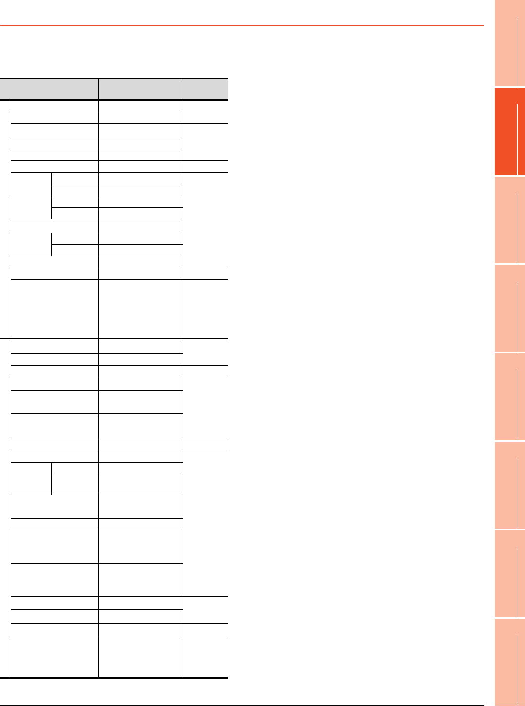
2. DEVICE RANGE THAT CAN BE SET
2.4 MELSEC-Q (Multi)/Q Motion
2 - 11
1
PREPARATORY
PROCEDURES FOR
MONITORING
2
DEVICE RANGE
THAT CAN BE SET
3
ACCESS RANGE
FOR MONITORING
4
HOW TO MONITOR
REDUNTANT
SYSTEM
5
BUS CONNECTION
6
DIRECT
CONNECTION TO
CPU
7
COMPUTER LINK
CONNECTION
8
ETHERNET
CONNECTION
2.4 MELSEC-Q (Multi)/Q Motion
The device ranges that can be set when selecting
[MELSEC-Q (Multi)/Q Motion]*13 as the controller type are
as follows.
(When using the QCPU)
* For details of *1 to *6, refer to 2.3 MELSEC-QnA/Q/QS,
MELDAS C6 *.
*7 This is not supported by GT10.
*8 This cannot be monitored when in GOT multi-drop
connection.
(When using the Q Motion)
*9 When setting special internal relay M9000 to M9255, use SM
for the device name and set the value subtracted 9000 for
the device number (0 to 255).
*10 The setting range is D9000 to D9255 when setting the
special data register.
*11 D8192 to D8999 and D9256 to D9999 are out of the valid
setting range.
(When using the QCPU/Q Motion)
*12 Do not use local devices set in the MELSEC-Q (Multi)/Q
Motion system.
Otherwise, normal monitoring is not performed.
*13 For GT10, the controller type is [MELSEC-Q(Multi)].
Device name Setting range
Device No.
representation
Bit device
Input (X) X0 to X1FFF
Hexadecimal
Output (Y) Y0 to Y1FFF
Internal relay (M)*12 M0 to M32767
Decimal
Latch relay (L) L0 to L32767
Annunciator (F) F0 to F32767
Link relay (B) B0 to B7FFF
Hexadecimal
Timer*12 Contact (TT) TT0 to TT32767
Decimal
Coil (TC) TC0 to TC32767
Counter
*12
Contact (CT) CT0 to CT32767
Coil (CC) CC0 to CC32767
Special relay (SM)*9 SM0 to SM2047
Retentive
timer*12
Contact (SS) SS0 to SS32767
Coil (SC) SC0 to SC32767
Step relay (S) S0 to S32767
Link special relay (SB) SB0 to SB7FF
Hexadecimal
Word device bit
Specified bit of the
following word devices
(Except Timer, Counter,
Retentive timer, Index
register and Buffer
memory)
―
Word device
Data register (D)*10*11*12 D0 to D32767 Decimal
Special data register (SD) SD0 to SD2047
Link register (W) W0 to W7FFF
Hexadecimal
Timer (current value) (TN)
*12
TN0 to TN32767
Decimal
Counter (current value)
(CN)*12 CN0 to CN32767
Retentive timer
(current value) (SN)*12 SN0 to SN32767
Link special register (SW) SW0 to SW7FF
Hexadecimal
File register (R)*1*2 R0 to R32767
Decimal
Extension
file register
(ER)
*1*7*8
Block 0 to 255
Device R0 to R32767
Extension file register
(ZR)*1*3*4*7*8 ZR0 to
ZR1042431
Index register (Z) Z0 to Z15
Buffer memory
(Intelligent function module)
(BM)
*5*7*8
BM0 to BM32767
Buffer memory
(Intelligent function module)
(G)
*4*5*7*8
G0 to G65535
Ww*7*8 Ww0 to Ww7FF
Hexadecimal
Wr*7*8 Wr0 to Wr7FF
Motion device (#)*7*8 #0 to #8191 Decimal
Bit device word*6*7
Converting the above bit
devices into words
(Except Timer, Counter
and Retentive timer)
―
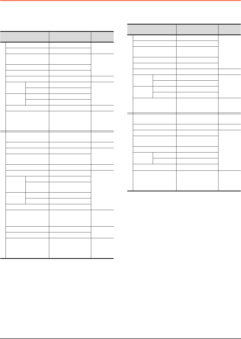
2 - 12 2. DEVICE RANGE THAT CAN BE SET
2.5 MELSEC-A
2.5 MELSEC-A
The device ranges that can be set when selecting
[MELSEC-A] as the controller type are as follows.
(1) For GT16, GT15, GT14, GT12, GT11
*1 In the computer link connection, the bit specification writing
of the word device to the ER29-0 (block 29 of the extension
file register) or later of A3ACPU, A3UCPU, or A4UCPU is
not available.
When the bit specification writing of the word device is
required, use the range of block No. 0 to 28.
*2 In the computer link connection, writing to the index register
(e.g., the touch switch function, numerical input function) is
not available.
*3 Only the intelligent function module on the station connected
to GOT can be specified.
Set within the address range of the buffer memory existing in
the target intelligent function module.
*4 The device No. must be set in multiples of 16.
*5 If the special internal relay (M) is converted to the word
device, treat 9000 of the device No. as 0 and set in multiples
of 16.
Example: M9000, M9016, M9240
(2) For GT10, GOT MULTI-DROP CONNECTION
*1 In the computer link connection, writing to the index register
(e.g., the touch switch function, numerical input function) is
not available.
*2 With the computer link connection, the GOT cannot read/
write data from/to the accumulator.
*3 This is not supported by GT10.
*4 The device No. must be set in multiples of 16.
*5 If the special internal relay (M) is converted to the word
device, treat 9000 of the device No. as 0 and set in multiples
of 16.
Example: M9000, M9016, M9240
Device name Setting range
Device No.
representation
Bit device
Input (X) X0 to X1FFF
Hexadecimal
Output (Y) Y0 to Y1FFF
Internal relay/Special
internal relay (M) M0 to M32767
Decimal
Latch relay (L) L0 to L32767
Annunciator (F) F0 to F32767
Link relay (B) B0 to B7FFF
Hexadecimal
Timer Contact (TT) TT0 to TT32767
Decimal
Coil (TC) TC0 to TC32767
Counter Contact (CT) CT0 to CT32767
Coil (CC) CC0 to CC32767
Link special relay (SB) SB0 to SB7FF
Hexadecimal
Word device bit
Specified bit of the
following word devices
(Except Index register
and Buffer memory)
―
Word device
Data register/Special data
register (D) D0 to D32767 Decimal
Link register (W) W0 to W7FFF
Hexadecimal
Timer (current value) (TN) TN0 to TN32767
Decimal
Counter (current value)
(CN) CN0 to CN32767
Link special register (SW) SW0 to SW7FF
Hexadecimal
File register (R) R0 to R32767
Decimal
Extension
file register
(ER)
*1
Block 1 to 255
Device ER0 to ER32767
Index
register*2
(Z) Z0 to Z15
(V) V0 to V6
Accumulator (A) A0 to A1
Buffer memory
(Intelligent function module)
(BM)
*3
BM0 to BM32767 Decimal
Ww Ww0 to Ww7FF
Hexadecimal
Wr Wr0 to Wr7FF
Bit device word*4*5
Converting the above bit
devices into words
(Except Timer and
Counter)
―
Device name Setting range
Device No.
representation
Bit device
Input (X) X0 to X1FFF
Decimal
Output (Y) Y0 to Y1FFF
Internal relay/
Special internal relay (M) M0 to M9255
Latch relay (L) L0 to L8191
Annunciator (F) F0 to F2047
Link relay (B) B0 to B1FFF
Hexadecimal
Timer Contact (TT) TT0 to TT2047
Decimal
Coil (TC) TC0 to TC2047
Counter Contact (CT) CT0 to CT1023
Coil (CC) CC0 to CC1023
Word device bit
Specified bit of the
following word devices
(Except Index register)
―
Word device
Data register/
Special data register (D) D0 to D9255 Decimal
Link register (W) W0 to W1FFF
Hexadecimal
Timer (current value) (TN) TN0 to TN2047
Decimal
Counter (current value)
(CN) CN0 to CN1023
File register (R) R0 to R8191
Index
register*1
(Z) Z0 to Z6
(V) V0 to V6
Accumulator (A)*2 A0 to A1
Bit device word*3*4*5
Converting the above bit
devices into words
(Except Timer and
Counter)
―
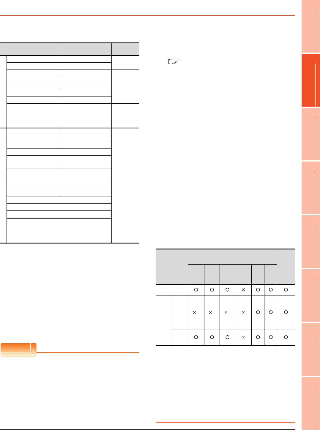
2. DEVICE RANGE THAT CAN BE SET
2.6 MELSEC-FX
2 - 13
1
PREPARATORY
PROCEDURES FOR
MONITORING
2
DEVICE RANGE
THAT CAN BE SET
3
ACCESS RANGE
FOR MONITORING
4
HOW TO MONITOR
REDUNTANT
SYSTEM
5
BUS CONNECTION
6
DIRECT
CONNECTION TO
CPU
7
COMPUTER LINK
CONNECTION
8
ETHERNET
CONNECTION
2.6 MELSEC-FX
The device ranges that can be set when selecting
[MELSEC-FX] as the controller type are as follows.
*1 When executing the touch switch function set during the bit
specification of the word device, do not write any data to the
word device through the sequence program.
*2 The device No. must be set in multiples of 16.
*3 Only 16-bit (1-word) designation is allowed.
*4 For CS0 to CS199, only 16-bit (1-word) designation is
allowed.
For CS200 to CS255, only 32-bit (2-word) designation is
allowed.
*5 Monitoring or writing is not possible in the continuous device
designation mode.
In addition, setting values of the timer and counter, which are
not used for the program, cannot be monitored. If monitoring
is executed, a reading error occurs.
*6 This is not supported by GT10.
*7 Can be used only for special blocks or special units
compatible with FX1N, FX1NC, FX2N, FX2NC, FX3G, FX3GC,
FX3U, FX3UC.
(Except FX0N-3A, FX2N-2AD, and FX2N-2DA)
POINTPOINTPOINT
(1) Precautions when using the buffer memory
• When the power supply of the special block or
special module is turned off, the contents of the
buffer memory are initialized, except for some
keeping areas.
• When the buffer memory is monitored by the
GOT, the PLC scan time may increase instantly.
• Use the 16 bit specification for the buffer
memory of 16 bit data. Use the 32 bit
specification for the buffer memory of 32 bit data.
If using the 16 bit specification for a buffer
memory of 32 bit data, monitoring and writing
may not be executed normally.
For the data size of each buffer memory, refer to
the following.
User's Manual of the special block or special
module
• When reading from/writing to the special block or
special module by interrupt processing of the
sequence program, monitoring/writing from GOT
to the buffer memory may not be executed
normally.
(2) How to select a keyword protection level
For equipment that are allowed to operate the FX
PLC online, 3 levels of protection level can be set.
When monitoring or changing settings by any
online equipment is required, set a keyword
referring to the following.
(a) When setting the keyword only
Select a protection level by the initial letter of
the keyword.
All operation protect: Set a keyword with the
initial letter "A", "D" to "F", or "0" to "9".
Incorrect write/read protect: Set a keyword
with the initial letter "B".
Incorrect write protect: Set a keyword with the
initial letter "C".
(b) When setting the keyword and 2nd keyword
Select a protection level by [Registration
condition].
(3) Monitoring availability at each keyword protection
level
The following shows the device monitoring
availability at each keyword protection level.
*1 When the T, C set values are specified indirectly, changing
devices is available.
(4) Difference between all online operations
prohibition and all operations prohibition
When specifying all online operations prohibition,
displaying devices and inputting data with
programming tools or GOT are all prohibited.
When all operations are prohibited, displaying
devices and inputting data with the GOT are
enabled while all operations using programming
tools are prohibited.
Device name Setting range
Device No.
representation
Bit device
Input relay (X) X0 to X377 Octal
Output relay (Y) Y0 to Y377
Auxiliary relay (M) M0 to M7679
Decimal
Special auxiliary relay (M) M8000 to M8511
State (S) S0 to S4095
Timer contact (T) T0 to T511
Counter contact (C) C0 to C255
Word device bit*1
Specified bit of the
following word devices
(Except Timer (set value)
and Counter (set value))
―
Word device
Data register (D) D0 to D0999
Decimal
File register (D) D1000 to D7999
Special data register (D) D8000 to D8511
Timer (current value) (T) T0 to T511
Counter (current value)
(C) C0 to C255
Timer (set value) (TS)*3*5 TS0 to TS511
Counter (set value)
(CS)*4*5 CS0 to CS255
Extension register (R) R0 to
R32767
Index register (V) V0 to V7
Index register (Z) Z0 to Z7
Buffer memory (BM)*7 BM0 to
BM32767
Bit device word*2*6
Converting the above bit
devices into words
(Except Timer contact
and Counter contact)
Item
When registering the
keyword only
When registering the
keyword and 2nd
keyword
Keyword
not
registered
or
protection
cancelled
All
operation
protect
Incorrect
write/
read
protect
Incorrect
write
protect
All online
operation
protect
Read/
write
protect
Write
protect
Monitoring
devices
Changing
devices
T, C set
value
and file
register
(D1000
and the
following)
*1 *1 *1
Other
than
above
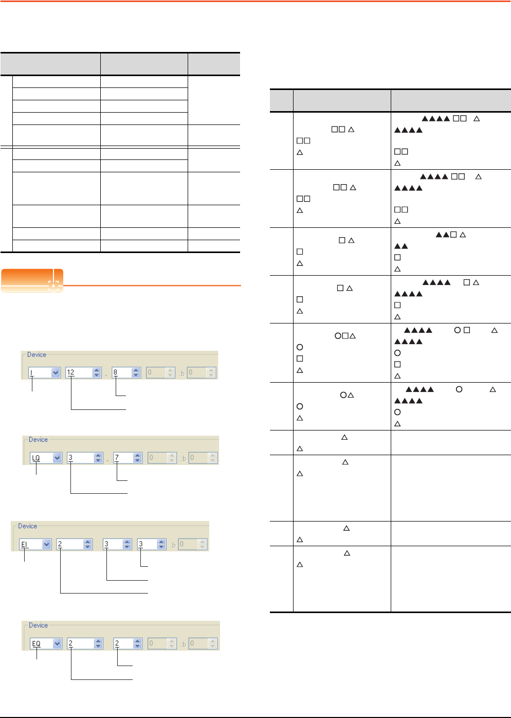
2 - 14 2. DEVICE RANGE THAT CAN BE SET
2.7 MELSEC-WS
2.7 MELSEC-WS
The device ranges that can be set when selecting
[MELSEC-WS] as the controller type are as follows.
POINTPOINTPOINT
(1) Devices of MELSEC-WS
Only reading is possible for all devices.
(2) Device settings of MELSEC-WS
• Input(I), Output(Q)
• Logic result(LQ), Logic input(LI)
• EFI input(EI)
• EFI output(EQ)
(3) Engineering software for MELSEC-WS and device
representation of GT Designer3
The engineering software for MELSEC-WS and
the device representation of GT Designer3 are
different. Set the device by referring to the
following table.
*1 When the mapping position is changed by the MELSEC-WS
engineering software, a mismatch occurs between virtual
devices on GOT and MELSEC-WS mapping devices.
When mapping is changed, use D devices or LD devices.
Device Setting range Device No.
representation
Bit device
Input (I) I1.1 to I12.8
Decimal
+Decimal
Output (Q) Q1.1 to Q12.8
Logic result (LQ) LQ0.0 to LQ3.7
Logic input (LI) LI0.0 to LI3.7
Word device bit Specified bit of the
following word devices -
Word device
Data (byte)(D) D0 to D99 Decimal
Data (word)(W) W0 to W49
EFI input (byte)(EI) EI110 to EI233
Decimal
+Decimal
+Decimal
EFI output (byte)(EQ) EQ10 to EQ22 Decimal
+Decimal
Logic input (byte)(LD) LD0 to LD3 Decimal
Logic input (word)
(LW) LW0 to LW1 Decimal
Device
name
Input position(1 to 8)
Module number(1 to 12)
Device
name Bit position(0 to 7)
Byte number(0 to 3)
Device
name Device number(1 to 3)
Byte number(0 to 3)
EFI number(1 to 2)
Device
name
EFI number(1 to 3)
Byte number(0 to 2)
Device
GT Designer3 Engineering software for
MELSEC-WS
I*1
I.
(1-12(Dec)): Module number
(1-8): Input position
[].I
: I/O model name
(such as XTIO)
(1-12(Dec)): Module number
(1-8): Input position
Q*1
Q.
(1-12(Dec)): Module number
(1-8): Output position
[].Q
: I/O model name
(such as XTIO)
(1-12(Dec)): Module number
(1-8): Output position
LQ*1
LQ .
(0-3): Byte number
(0-7): Bit position
.
: "Result"
(0-3): Byte number
(0-7): Bit position
LI*1
LI .
(0-3): Byte number
(0-7): Bit position
[0] . .
: CPU type (CPU0, CPU1)
(0-3): Byte number
(0-7): Bit position
EI*1
EI
(1-2): EFI number
(1-3): Device number
(0-3): Byte number
[0].EFI : , Byte
: CPU type (CPU0, CPU1)
(1-2): EFI number
(1-3): Device number
(0-3): Byte number
EQ*1
EQ
(1-2): EFI number
(0-2): Byte number
[0].EFI :1, Byte
: CPU type (CPU0, CPU1)
(1-2): EFI number
(0-2): Byte number
DD
(0-99(Dec)): Byte number
RS232 data
(Safety controller to RS232)
W
W
(0-49(Dec)): Word number
Word virtualization of D
device
W0= (D1(Upper bits),
D0(Lower bits))
GOT independent device
(Not available)
LD LD
(0-3): Byte number
RS232 data
(Safety controller to RS232)
LW
LW
(0-1): Word number
Word virtualization of LD
device
LW0= (LD1(Upper bits),
LD0(Lower bits))
GOT independent device
(Not available)
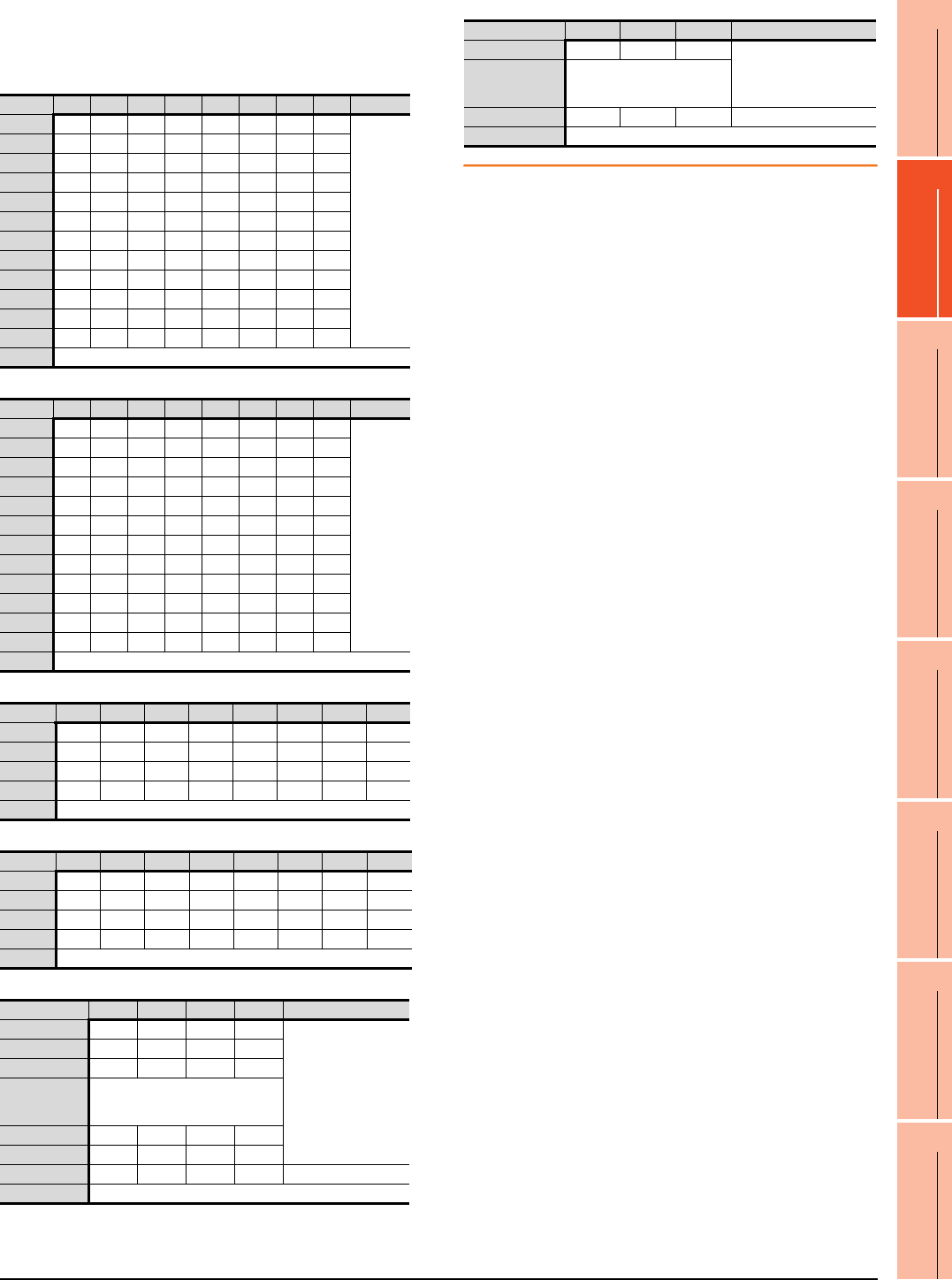
2. DEVICE RANGE THAT CAN BE SET
2.7 MELSEC-WS
2 - 15
1
PREPARATORY
PROCEDURES FOR
MONITORING
2
DEVICE RANGE
THAT CAN BE SET
3
ACCESS RANGE
FOR MONITORING
4
HOW TO MONITOR
REDUNTANT
SYSTEM
5
BUS CONNECTION
6
DIRECT
CONNECTION TO
CPU
7
COMPUTER LINK
CONNECTION
8
ETHERNET
CONNECTION
(4) When using offset specification
When setting devices using the offset function, the
device values are as follows.
(a) Input(I)
(b) Output(Q)
(c) Logic result(LQ)
(d) Logic input(LI)
(e) EFI input(EI)
(f) EFI output(EQ)
Offset +0 +1 +2 +3 +4 +5 +6 +7 +8 to +15
+0 I1.1 I1.2 I1.3 I1.4 I1.5 I1.6 I1.7 I1.8
Fixed to 0
(OFF)
+16 I2.1 I2.2 I2.3 I2.4 I2.5 I2.6 I2.7 I2.8
+32 I3.1 I3.2 I3.3 I3.4 I3.5 I3.6 I3.7 I3.8
+48 I4.1 I4.2 I4.3 I4.4 I4.5 I4.6 I4.7 I4.8
+64 I5.1 I5.2 I5.3 I5.4 I5.5 I5.6 I5.7 I5.8
+80 I6.1 I6.2 I6.3 I6.4 I6.5 I6.6 I6.7 I6.8
+96 I7.1 I7.2 I7.3 I7.4 I7.5 I7.6 I7.7 I7.8
+112 I8.1 I8.2 I8.3 I8.4 I8.5 I8.6 I8.7 I8.8
+128 I9.1 I9.2 I9.3 I9.4 I9.5 I9.6 I9.7 I9.8
+144 I10.1 I10.2 I10.3 I10.4 I10.5 I10.6 I10.7 I10.8
+160 I11.1 I11.2 I11.3 I11.4 I11.5 I11.6 I11.7 I11.8
+176 I12.1 I12.2 I12.3 I12.4 I12.5 I12.6 I12.7 I12.8
+192 Device range error
Offset +0 +1 +2 +3 +4 +5 +6 +7 +8 to +15
+0 Q1.1 Q1.2 Q1.3 Q1.4 Q1.5 Q1.6 Q1.7 Q1.8
Fixed to 0
(OFF)
+16 Q2.1 Q2.2 Q2.3 Q2.4 Q2.5 Q2.6 Q2.7 Q2.8
+32 Q3.1 Q3.2 Q3.3 Q3.4 Q3.5 Q3.6 Q3.7 Q3.8
+48 Q4.1 Q4.2 Q4.3 Q4.4 Q4.5 Q4.6 Q4.7 Q4.8
+64 Q5.1 Q5.2 Q5.3 Q5.4 Q5.5 Q5.6 Q5.7 Q5.8
+80 Q6.1 Q6.2 Q6.3 Q6.4 Q6.5 Q6.6 Q6.7 Q6.8
+96 Q7.1 Q7.2 Q7.3 Q7.4 Q7.5 Q7.6 Q7.7 Q7.8
+112 Q8.1 Q8.2 Q8.3 Q8.4 Q8.5 Q8.6 Q8.7 Q8.8
+128 Q9.1 Q9.2 Q9.3 Q9.4 Q9.5 Q9.6 Q9.7 Q9.8
+144
Q10.1 Q10.2 Q10.3 Q10.4 Q10.5 Q10.6 Q10.7 Q10.8
+160
Q11.1 Q11.2 Q11.3 Q11.4 Q11.5 Q11.6 Q11.7 Q11.8
+176
Q12.1 Q12.2 Q12.3 Q12.4 Q12.5 Q12.6 Q12.7 Q12.8
+192 Device range error
Offset +0 +1 +2 +3 +4 +5 +6 +7
+0 LQ0.0 LQ0.1 LQ0.2 LQ0.3 LQ0.4 LQ0.5 LQ0.6 LQ0.7
+8 LQ1.0 LQ1.1 LQ1.2 LQ1.3 LQ1.4 LQ1.5 LQ1.6 LQ1.7
+16 LQ2.0 LQ2.1 LQ2.2 LQ2.3 LQ2.4 LQ2.5 LQ2.6 LQ2.7
+24 LQ3.0 LQ3.1 LQ3.2 LQ3.3 LQ3.4 LQ3.5 LQ3.6 LQ3.7
+32 Device range error
Offset +0 +1 +2 +3 +4 +5 +6 +7
+0 LI0.0 LI0.1 LI0.2 LI0.3 LI0.4 LI0.5 LI0.6 LI0.7
+8 LI1.0 LI1.1 LI1.2 LI1.3 LI1.4 LI1.5 LI1.6 LI1.7
+16 LI2.0 LI2.1 LI2.2 LI2.3 LI2.4 LI2.5 LI2.6 LI2.7
+24 LI3.0 LI3.1 LI3.2 LI3.3 LI3.4 LI3.5 LI3.6 LI3.7
+32 Device range error
Offset +0 +1 +2 +3 +8 to +15
+0 EI11 0 EI111 EI112 EI 113
Fixed to 0
+16 EI120 EI121 EI122 EI123
+32 EI130 EI131 EI132 EI133
+48
:
+240
Fixed to 0
+256 EI210 EI211 EI212 EI213
+272 EI220 EI221 EI222 EI223
+288 EI230 EI231 EI232 EI233 Device range error
+302 Device range error
Offset +0 +1 +2 +3 to +15
+0 EQ10 EQ11 EQ12
Fixed to 0
+16
:
+240
Fixed to 0
+256 EQ20 EQ21 EQ22 Device range error
+272 Device range error

2 - 16 2. DEVICE RANGE THAT CAN BE SET
2.7 MELSEC-WS

3
1
PREPARATORY
PROCEDURES FOR
MONITORING
2
DEVICE RANGE
THAT CAN BE SET
3
ACCESS RANGE
FOR MONITORING
4
HOW TO MONITOR
REDUNTANT
SYSTEM
5
BUS CONNECTION
6
DIRECT
CONNECTION TO
CPU
7
COMPUTER LINK
CONNECTION
8
ETHERNET
CONNECTION
3 - 1
3.
ACCESS RANGE FOR MONITORING
3.1 Access Range for Monitoring Stations on Network Systems
. . . . . . . . . . . . . . . . . . . . . . . . . . . . . . . . . . . . . . . . . . . . . . . .3 - 2
3.2 Access Range for Monitoring when Using Ethernet Connection
. . . . . . . . . . . . . . . . . . . . . . . . . . . . . . . . . . . . . . . . . . . . . . .3 - 13
3.3 CC-Link System Access Range for Monitoring . . . . . . . . . .3 - 14
3.4 Data Link System (MELSECNET/B, (II)) Access Range for
Monitoring . . . . . . . . . . . . . . . . . . . . . . . . . . . . . . . . . . . . . .3 - 17
3.5 Access Range for Monitoring when Connecting FXCPU . . .3 - 18
3.6 Connection to Remote I/O Station in MELSECNET/H Network
System . . . . . . . . . . . . . . . . . . . . . . . . . . . . . . . . . . . . . . . . .3 - 19
3.7 Connection to the Head Module of CC-Link IE Field Network
System . . . . . . . . . . . . . . . . . . . . . . . . . . . . . . . . . . . . . . . . .3 - 22
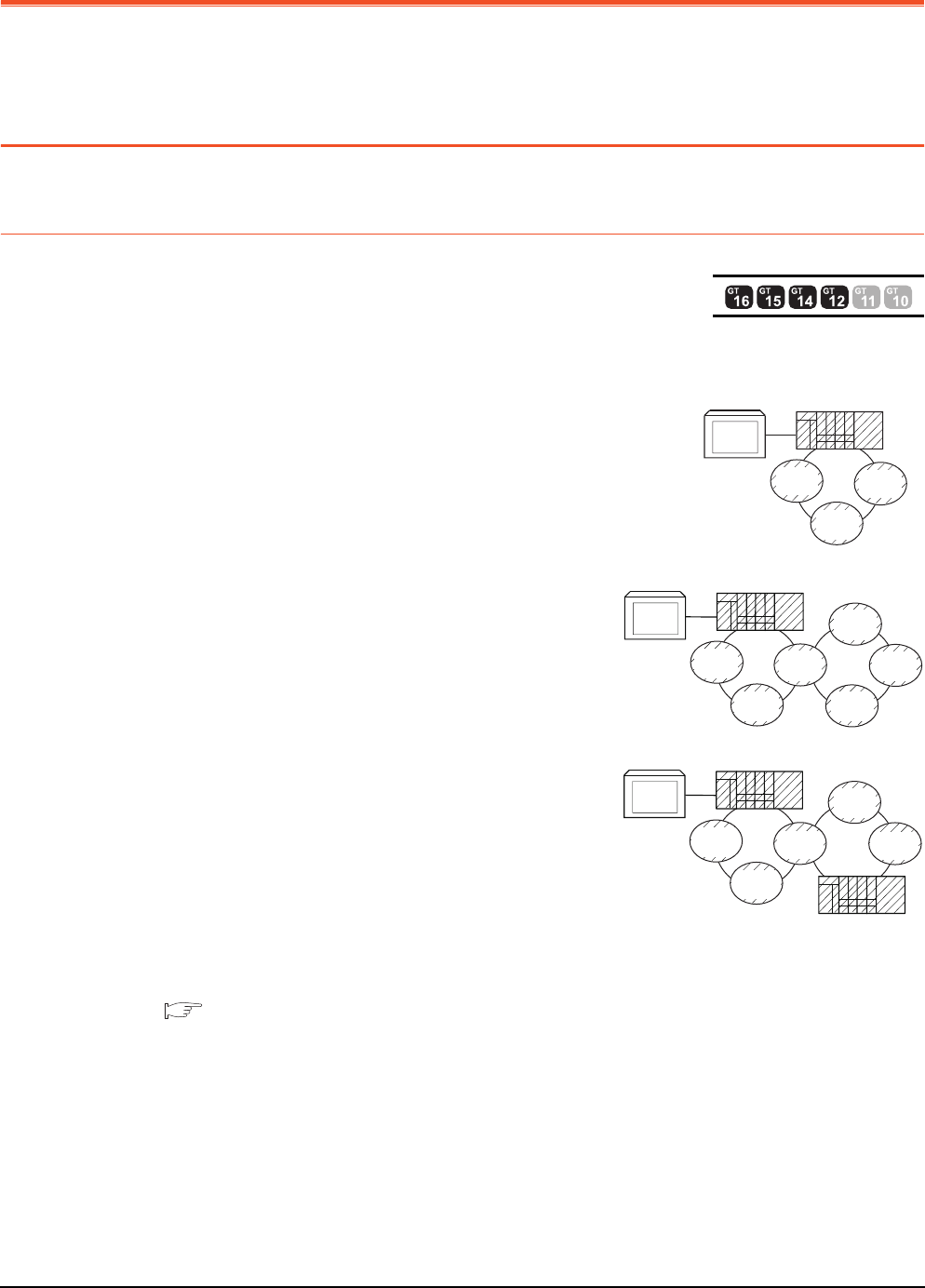
3 - 2 3. ACCESS RANGE FOR MONITORING
3.1 Access Range for Monitoring Stations on Network Systems
3. ACCESS RANGE FOR MONITORING
3.1 Access Range for Monitoring Stations on Network
Systems
3.1.1 MELSECNET/H, MELSECNET/10, CC-Link IE Controller Network, CC-Link
IE Field Network
Bus connection
(1) When connecting to multiple CPU system
• The GOT can monitor the control station and all the normal stations on the
network.
• The GOT can monitor the control station and all the normal
stations on other networks.
(For monitoring stations on other networks, be sure to set the
routing parameter)
When the Universal model QCPU is used as a relay station, the
GOT can monitor stations with the station No.65 or later in the CC-
Link IE controller network.
• When connecting to the multiple CPU system, the GOT can
monitor CPU No.1 to No.4.
• Devices of other stations (other than devices B and W that are allocated by the network parameter) may not
allow monitoring depending on their PLC CPU.
■ Monitor accessible range of other stations and setting method of monitor devices (Examples 1
to 2)
• The motion controller CPU (Q Series) at other stations cannot be monitored.
*1 The control station and normal station correspond to the master station and local station in the CC-Link IE field network
respectively.
GOT
Normal
station
Normal
station
Normal
station
Control station
*1
GOT
Normal
station
Normal
station
Normal
station
Control station
Normal
station
Control
station
Normal
station
*1
GOT
Normal
station
Normal
station
Normal
station
Control station
Control
station
Normal
station
Normal station
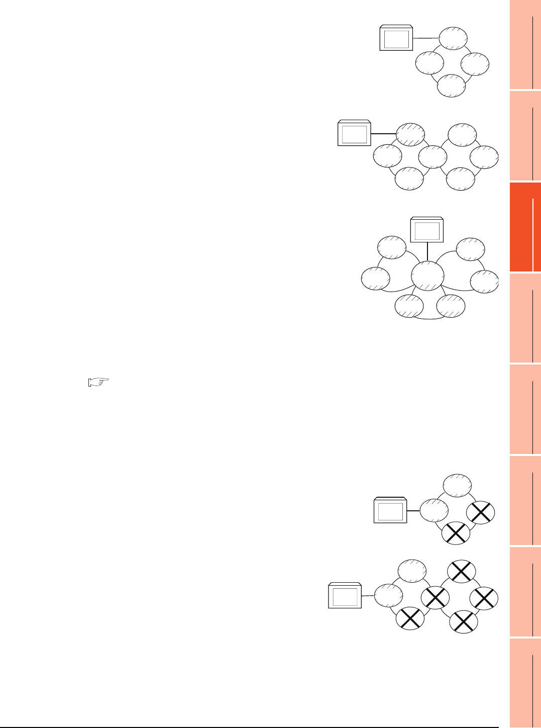
3. ACCESS RANGE FOR MONITORING
3.1 Access Range for Monitoring Stations on Network Systems
3 - 3
1
PREPARATORY
PROCEDURES FOR
MONITORING
2
DEVICE RANGE
THAT CAN BE SET
3
ACCESS RANGE
FOR MONITORING
4
HOW TO MONITOR
REDUNTANT
SYSTEM
5
BUS CONNECTION
6
DIRECT
CONNECTION TO
CPU
7
COMPUTER LINK
CONNECTION
8
ETHERNET
CONNECTION
(2) When connecting to QCPU (Q mode)/QnACPU/AnUCPU
• The GOT can monitor the control station and all the normal stations on the
network.
• The GOT can monitor the control station and all the normal
stations on other networks.
(For monitoring stations on other networks, be sure to set the
routing parameter)
When the Universal model QCPU is used as a relay station, the
GOT can monitor stations with the station No.65 or later in the CC-
Link IE controller network.
• When connected to a relay station and the data link system is included,
the master station and local stations can be monitored.
• When connected to a relay station, it is not necessary to designate the
data link parameter [Effective unit number for accessing other stations]
for the PLC CPU of the connected station. (Even if designated, the
parameter is ignored)
• Devices of other stations (other than devices B and W that are allocated by the network parameter) may not
allow monitoring depending on their PLC CPU.
■ Monitor accessible range of other stations and setting method of monitor devices (Examples 1
to 2)
*1 The control station and normal station correspond to the master station and local station in the CC-Link IE field network
respectively.
(3) When connecting to AnACPU/AnNCPU
• The GOT can monitor the control station on the network.
When the PLC CPU on the control station is the QCPU (Q mode) or
QnACPU, the GOT cannot monitor devices other than B and W assigned
for the network parameter.
• The GOT cannot monitor normal stations on the network.
• The GOT cannot monitor any stations on the other networks.
GOT
Normal
station
Normal
station
Normal
station
Control
station
*1
*1
GOT
Normal
station
Normal
station
Normal
station
Normal
station
Control
station
Normal
station
Control
station
GOT
Normal
station
Normal
station
M station
L station
Control
station
Normal
station
Control
station
L station
GOT
Normal
station
Normal
station
Control
station
Normal
station
GOT
Normal
station
Normal
station
Control
station
Normal
station
Control
station
Normal
station
Normal
station
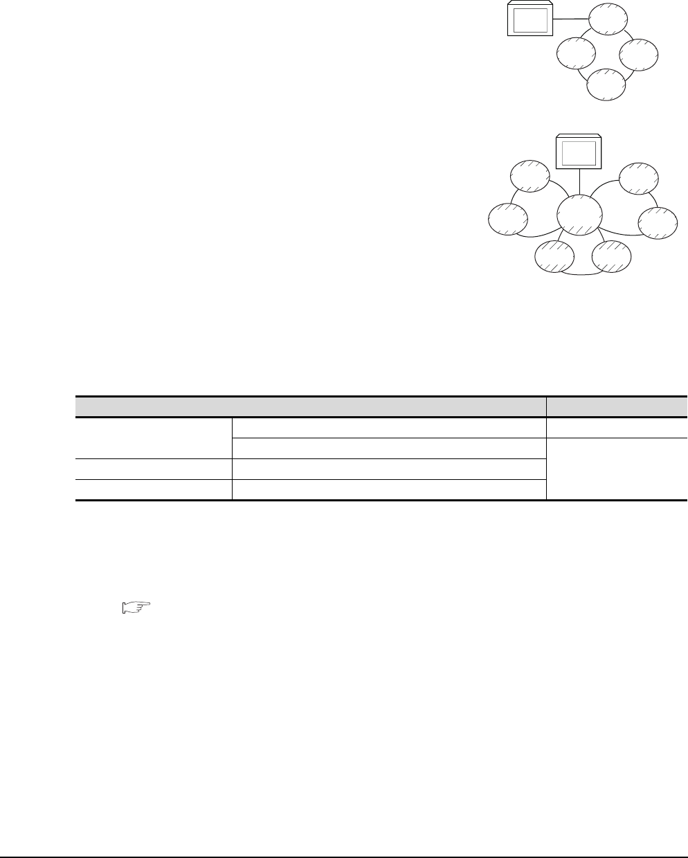
3 - 4 3. ACCESS RANGE FOR MONITORING
3.1 Access Range for Monitoring Stations on Network Systems
Direct CPU connection/computer link connection
(1) When connecting to multiple CPU system
• Corresponding to the access range described in ■ Bus connection (1).
(2) When connecting to QCPU (Q mode)/QnACPU
• Corresponding to the access range described in ■ Bus connection (2).
(3) When connecting to QCPU (A mode)/AnUCPU
• The GOT can monitor the control station and all the normal stations
on the network.
For monitoring devices (other than B and W assigned for the network
parameter) of other stations, the GOT cannot monitor the devices of
the PLC CPU that is the QCPU (Q mode) or QnACPU.
• If connected to a relay station, use data link parameter [Effective unit
number for accessing other stations] to designate the unit number
that is connected to the network to be monitored.
(4) When connecting to AnACPU/AnNCPU
• Corresponding to the access range described in ■ Bus connection (3).
(5) When connecting to motion controller CPU (Q series), CNC (CNC C70), or robot controller (CRnQ-700)
via direct CPU connection
Monitor the motion controller CPU (Q series), CNC (CNC C70), or robot controller (CRnQ-700) via the following
QCPUs in the multiple CPU system.
*1 The control station and normal station correspond to the master station and local station in the CC-Link IE field network
respectively.
CC-Link connection (intelligent device station), CC-Link connection (via G4)
• Only the station connected to the GOT can be monitored.
■ Monitor accessible range of other stations and setting method of monitor devices Example 6:
When using CC-Link connection (intelligent device station) /CC-Link connection (via G4)
• When the station connected to the GOT is in the multiple CPU system, the GOT can monitor CPU No.1 to
No.4.
• The GOT cannot monitor other stations.
Controller Relay CPU
Motion controller CPU (Q Series)
Q172HCPU, Q173HCPU QCPU (Q mode)
Q172DCPU, Q173DCPU
QnUCPUCNC (CNC C70) Q173NCCPU
Robot controller (CRnQ-700) Q172DRCPU
GOT
Normal
station
Normal
station
Normal
station
Control
station
*1
*1
GOT
Normal
station
Normal
station
M station
L station
Control
station
Normal
station
Control
station
L station

3. ACCESS RANGE FOR MONITORING
3.1 Access Range for Monitoring Stations on Network Systems
3 - 5
1
PREPARATORY
PROCEDURES FOR
MONITORING
2
DEVICE RANGE
THAT CAN BE SET
3
ACCESS RANGE
FOR MONITORING
4
HOW TO MONITOR
REDUNTANT
SYSTEM
5
BUS CONNECTION
6
DIRECT
CONNECTION TO
CPU
7
COMPUTER LINK
CONNECTION
8
ETHERNET
CONNECTION
MELSECNET/H connection, MELSECNET/10 connection, CC-Link IE Controller Network
connection, CC-Link IE Field Network connection
POINTPOINTPOINT
Precautions for cyclic transmission
When transmitting cyclic transmission with a GOT, even if link device X and/or Y are assigned to a GOT when
setting the network parameter for the control station, the GOT cannot access the host station.
When transmitting cyclic transmission, use link device B and/or W.
• The GOT is regarded as a normal station and monitors the control station and all normal stations on the
network.
When the monitoring target is a PLC CPU within a multiple CPU system, the GOT can monitor CPU No. 1 to
CPU No. 4 by specifying CPU No.
• When monitoring other networks, a CPU on another Ethernet, MELSECNET/H, MELSECNET/10, CC-Link IE
Controller Network, or CC-Link field network is accessible via the PLC CPU.
However, the GOT cannot monitor the CNC C70 on other networks.
On the Ethernet network, only QCPU (Q mode) and QnACPU can be accessed.
• When monitoring other networks in MELSECNET/10 connection, install the MELSECNET/H communication
unit on the GOT.
• To monitor other networks, setting of routing parameters is required.
For routing parameter setting, refer to the following manuals.
Routing parameter setting for the GOT
9. MELSECNET/H CONNECTION (PLC TO PLC NETWORK)
10. MELSECNET/10 CONNECTION (PLC TO PLC NETWORK)
11. CC-Link IE CONTROLLER NETWORK CONNECTION
12. CC-Link IE FIELD NETWORK CONNECTION
Routing parameter setting for the PLC CPU (MELSECNET/H network system, MELSECNET/10 network
system)
Q Corresponding MELSECNET/H Network System Reference Manual (PLC to PLC network)
Routing parameter setting for the PLC CPU (When connecting to the CC-Link IE Controller Network)
CC-Link IE Controller Network Reference Manual
Routing parameter setting for the PLC CPU (When connecting to the CC-Link IE Field Network)
CC-Link IE Field Network Master/Local Module User's Manual
• If devices of other stations (other than devices B and W that are allocated by the network parameter) are
monitored, monitoring may not be available depending on the PLC CPU of the network system to be monitored.
■ Monitor accessible range of other stations and setting method of monitor devices Example 5:
When using MELSECNET/10 connection

3 - 6 3. ACCESS RANGE FOR MONITORING
3.1 Access Range for Monitoring Stations on Network Systems
POINTPOINTPOINT
Precautions when using the QCPU redundant system
When monitoring other networks, do not set the QCPU redundant system as a relay station.
If the QCPU redundant system is set as a relay station, the GOT cannot switch the monitoring target automatically
when the system is switched.
(A timeout error occurs due to failed monitoring)
Monitoring devices of other stations on the network
If devices of other stations on the network system are monitored, the display speed will be significantly reduced.
Therefore, monitor the link relay (B) and link register (W) that are allocated by the network parameter.
Monitoring devices of other networks (Bus connection, CPU direct connection, computer link
connection)
• Be sure to designate the routing parameter to the PLC CPU of the connected station.
• If another network is monitored, the display speed of object etc. will be significantly reduced.
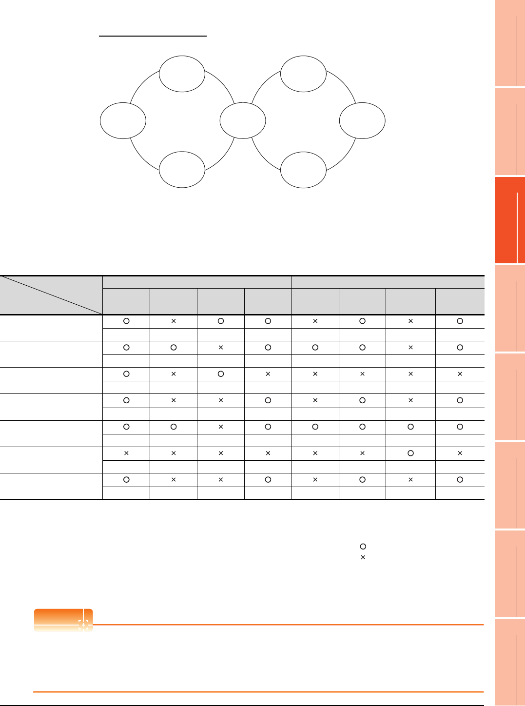
3. ACCESS RANGE FOR MONITORING
3.1 Access Range for Monitoring Stations on Network Systems
3 - 7
1
PREPARATORY
PROCEDURES FOR
MONITORING
2
DEVICE RANGE
THAT CAN BE SET
3
ACCESS RANGE
FOR MONITORING
4
HOW TO MONITOR
REDUNTANT
SYSTEM
5
BUS CONNECTION
6
DIRECT
CONNECTION TO
CPU
7
COMPUTER LINK
CONNECTION
8
ETHERNET
CONNECTION
Monitor accessible range of other stations and setting method of monitor devices
Example 1: When using bus connection
• Monitor accessible range of devices (other than B or W) of other stations or other networks
Specify the accessing network No. or station as shown in the following table.
(1) To monitor B or W of the connected station (host station) assigned with a network parameter, specify the host
station.
(2) To monitor another station (other than B or W) or another network, specify the station (network No. and station
No.).
POINTPOINTPOINT
Monitoring link device B or W
For monitoring devices B and W that are allocated by the link parameter, use the host device number even when
designating devices allocated to another station.
Otherwise, the display speed will be reduced.
Station to be accessed
Station
connected to GOT
Network No.1 Network No.2
AnU (1-1) QnA (1-2) AnA (1-3) AnU (1-4) QnA (2-1) AnU (2-2) AnN (2-3) AnU (2-4)
AnU (1-1)
Host ── Other (1-3) Other (1-4) ── Other (2-2) ── Other (2-4)
QnA (1-2)
Other (1-1) Host ── Other (1-4) Other (2-1) Other (2-2) ── Other (2-4)
AnA (1-3)
Other (0-0) ── Host ── ── ── ── ──
AnU
(1-4)
(2-2) Other (1-1) ── ── Host ── Host ── Other (2-4)
QnA (2-1)
Other (1-1) Other (1-2) ── Other (1-4) Host Other (2-2) Other (2-3) Other (2-4)
AnN (2-3)
── ── ── ── ── ── Host ──
AnU (2-4)
Other (1-1) ── ── Other (1-4) ── Other (2-2) ── Host
How to read the table
Upper line: Accessibility
: Accessible
: Not accessible
Lower line: Network settings
Host
Other (Network No. - Station number)
Control station Control station
AnU
(1-1)
QnA
(2-1)
AnN
(2-3)
AnU
(1-4)
(2-2)
AnA
(1-3)
Network No.1 Network No.2
QnA
(1-2) (2-4)
AnU
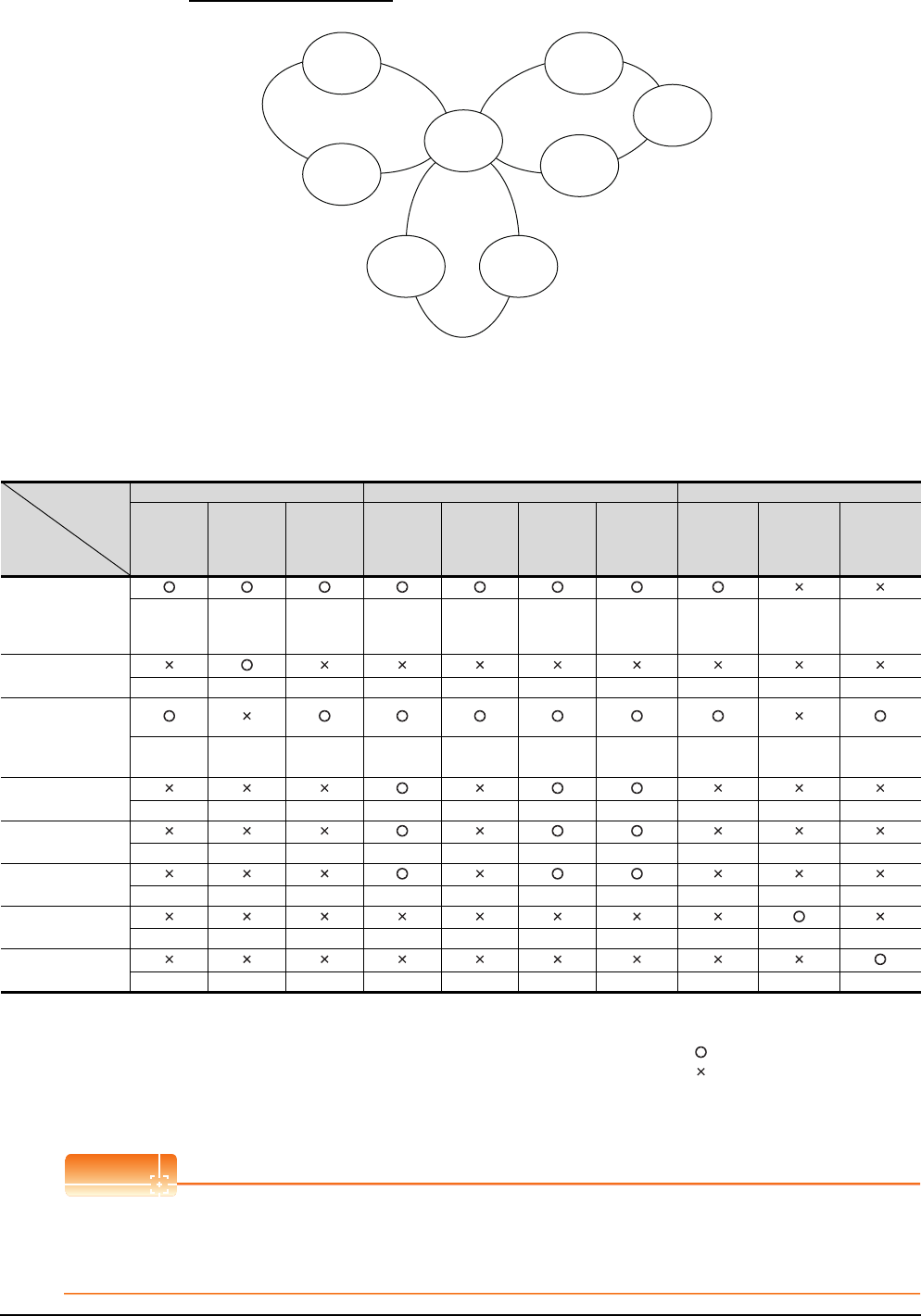
3 - 8 3. ACCESS RANGE FOR MONITORING
3.1 Access Range for Monitoring Stations on Network Systems
Example 2: When using bus connection
• Monitor accessible range of devices (other than B or W) of other stations or other networks
Specify the accessing network No. or station as shown in the following table.
(1) To monitor B or W of the connected station (host station) assigned with a network parameter, specify the host
station.
(2) To monitor another station (other than B or W) or another network, specify the station (network No. and station
No.).
*1 When monitoring the data link system, designate the network No. as 0.
POINTPOINTPOINT
Monitoring link device B or W
For monitoring devices B and W that are allocated by the link parameter, use the host device number even when
designating devices allocated to another station.
Otherwise, the display speed will be reduced.
Station to be
accessed
Station
connected to GOT
Network No.1 Network No.2 Data link system
QnA (1-1) AnA (1-2) QnA (1-3) AnU (2-1) QnA (2-2) AnU (2-3) AnU (2-4) QnA (M) QnA (L1) AnA (L2)
QnA (1-1) Host
Other (1-2) Other (1-3) Other (2-1) Other (2-2) Other (2-3)
Other (2-4)
Other (1-3)
or
Other (2-2)
── ──
AnA (1-2) ── Host ── ── ── ── ── ── ── ──
QnA
(1-3)
(2-2)
Other (1-1)
── Host
Other (2-1)
Host
Other (2-3)
Other (2-4) Host ── Other
(0-2)*1
(M)
AnU (2-1) ── ── ── Host ──
Other (2-3)
Other (2-4) ── ── ──
AnU (2-3) ── ── ──
Other (2-1)
── Host Other (2-4) ── ── ──
AnU (2-4) ── ── ──
Other (2-1)
──
Other (2-3)
Host ── ── ──
QnA (L1) ── ── ── ── ── ── ── ── Host ──
AnA (L2) ── ── ── ── ── ── ── ── ── Host
How to
read the
table
Upper line: Accessibility
: Accessible
: Not accessible
Lower line: Network settings
Host
Other (Network No. - Station number)
Control station
Network No.2Network No.1
Data link
system
Control station
QnA
(1-1)
AnA
(1-2)
QnA
(L1)
AnA
(L2)
AnU
(2-1)
AnU
(2-3)
AnU
(2-4)
QnA
(1-3)
(2-2)
(M)
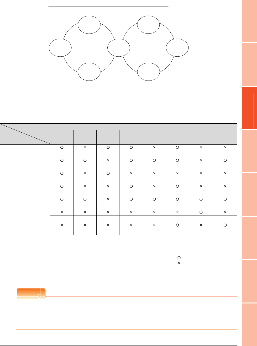
3. ACCESS RANGE FOR MONITORING
3.1 Access Range for Monitoring Stations on Network Systems
3 - 9
1
PREPARATORY
PROCEDURES FOR
MONITORING
2
DEVICE RANGE
THAT CAN BE SET
3
ACCESS RANGE
FOR MONITORING
4
HOW TO MONITOR
REDUNTANT
SYSTEM
5
BUS CONNECTION
6
DIRECT
CONNECTION TO
CPU
7
COMPUTER LINK
CONNECTION
8
ETHERNET
CONNECTION
Example 3: When using CPU direct connection or computer link connection
• Monitor accessible range of devices (other than B or W) of other stations or other networks
Specify the accessing network No. or station as shown in the following table.
(1) To monitor B or W of the connected station (host station) assigned with a network parameter, specify the host
station.
(2) To monitor another station (other than B or W) or another network, specify the station (network No. and station
No.).
POINTPOINTPOINT
Monitoring link device B or W
For monitoring devices B and W that are allocated by the link parameter, use the host device number even when
designating devices allocated to another station.
Otherwise, the display speed will be reduced.
Station to be accessed
Station
connected to GOT
Network No.1 Network No.2
AnU (1-1) Q(Q mode)
(1-2) AnA (1-3) AnU (1-4) QnA (2-1) AnU (2-2) AnN (2-3) AnU (2-4)
AnU (1-1)
Host ── Other (1-3) Other (1-4) ── Other (2-2) ── ──
Q (Q mode) (1-2)
Other (1-1) Host ── Other (1-4) Other (2-1) Other (2-2) ── Other (2-4)
AnA (1-3)
Other (0-0) ── Host ── ── ── ── ──
AnU (1-4)
(2-2) Other (1-1) ── ── Host ── Host ── ──
QnA (2-1)
Other (1-1) Other (1-2) ── Other (1-4) Host Other (2-2) Other (2-3) Other (2-4)
AnN (2-3)
── ── ── ── ── ── Host ──
AnU (2-4)
── ── ── ── ── Other (2-2) ── Host
How to read the table
Upper line: Accessibility
: Accessible
: Not accessible
Lower line: Network settings
Host
Other (Network No. - Station number)
Control station Control station
Network No.1 Network No.2
AnU
(1-1)
Q(Q mode)
(1-2)
AnA
(1-3)
AnN
(2-3)
AnU
(2-4)
QnA
(2-1)
AnU
(1-4)
(2-2)
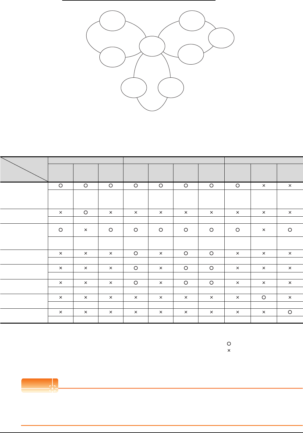
3 - 10 3. ACCESS RANGE FOR MONITORING
3.1 Access Range for Monitoring Stations on Network Systems
Example 4: When using CPU direct connection or computer link connection
• Monitor accessible range of devices (other than B or W) of other stations or other networks
Specify the accessing network No. or station as shown in the following table.
(1) To monitor B or W of the connected station (host station) assigned with a network parameter, specify the host
station.
(2) To monitor another station (other than B or W) or another network, specify the station (network No. and station
No.).
*1 When monitoring the data link system, designate the network No. as 0.
POINTPOINTPOINT
Monitoring link device B or W
For monitoring devices B and W that are allocated by the link parameter, use the host device number even when
designating devices allocated to another station.
Otherwise, the display speed will be reduced.
Station to be
accessed
Station
connected to GOT
Network No.1 Network No.2 Data link system
QnA (1-1) AnA (1-2) QnA (1-3) AnU (2-1) QnA (2-2) AnU (2-3) AnU (2-4) QnA (M) QnA (L1) AnA (L2)
Q (Q mode) (1-1) Host
Other (1-2) Other (1-3) Other (2-1) Other (2-2) Other (2-3)
Other (2-4)
Other (1-3)
or
Other (2-2)
── ──
AnA (1-2)
── Host ── ── ── ── ── ── ── ──
QnA
(1-3)
(2-2)
Other (1-1)
── Host
Other (2-1)
Host
Other (2-3)
Other (2-4) Host ── *1
Other (0-2)
(M)
AnU (2-1)
── ── ── Host ──
Other (2-3)
Other (2-4) ── ── ──
AnU (2-3)
── ── ──
Other (2-1)
── Host Other (2-4) ── ── ──
AnU (2-4)
── ── ──
Other (2-1)
──
Other (2-3)
Host ── ── ──
QnA (L1)
── ── ── ── ── ── ── ── Host ──
AnA (L2)
── ── ── ── ── ── ── ── ── Host
How to
read the
table
Upper line: Accessibility
: Accessible
: Not accessible
Lower line: Network settings
Host
Other (Network No. - Station number)
Control station
AnU
(2-4)
QnA
(1-3)
(2-2)
(M)
Network No.2
AnU
(2-1)
Network No.1
AnA
(1-2)
QnA
(L1)
AnA
(L2)
Data link
system
Control station
Q(Q mode)
(1-1)
AnU
(2-3)
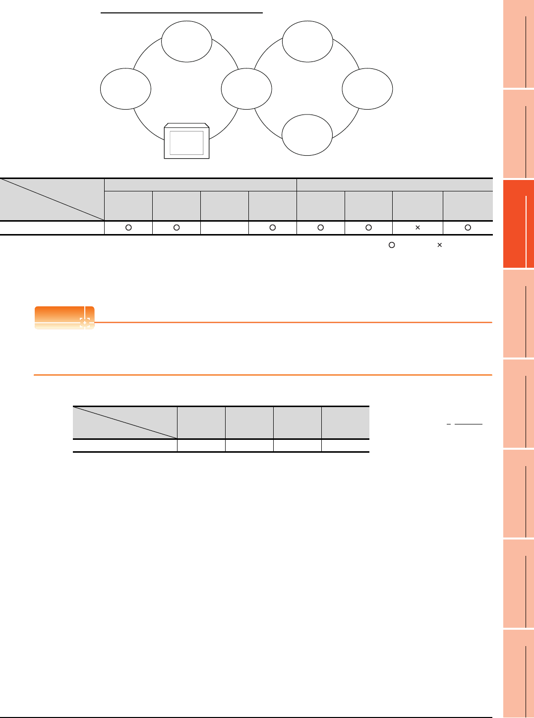
3. ACCESS RANGE FOR MONITORING
3.1 Access Range for Monitoring Stations on Network Systems
3 - 11
1
PREPARATORY
PROCEDURES FOR
MONITORING
2
DEVICE RANGE
THAT CAN BE SET
3
ACCESS RANGE
FOR MONITORING
4
HOW TO MONITOR
REDUNTANT
SYSTEM
5
BUS CONNECTION
6
DIRECT
CONNECTION TO
CPU
7
COMPUTER LINK
CONNECTION
8
ETHERNET
CONNECTION
Example 5: When using MELSECNET/10 connection
• Monitor access range for other station devices (other than B and W)
: Accessible : Not accessible
• Designating network No. and station number for setting monitor device
(a) Monitoring devices B and W that are allocated by network parameter
NW No.: 1, Station number: Host
POINTPOINTPOINT
For monitoring devices B and W that are allocated by the link parameter, use the local device number if designating
devices allocated to another station.
Otherwise, the display speed will be reduced.
(b) Monitoring other stations (other than B and W)
Station to be accessed
Station
connected to GOT
Network No.1 Network No.2
QnA
(1-1)
Q (Q mode)
(1-2)
GOT
(1-3)
AnU
(1-4)
Q (Q mode)
(2-1)
QnA
(2-2)
AnN
(2-3)
AnU
(2-4)
GOT (1-3) ――
QnA
(1-1)
AnU
(1-4)
(2-4)
GOT
(1-3)
Q (Q mode) Network No. 1 Network No. 2
(1-2)
Q (Q mode)
(2-1)
QnA
(2-2)
AnN
(2-3)
Station to be accessed
Station
connected to GOT
QnA
(1-1)
Q (Q mode)
(1-2)
GOT
(1-3)
AnU
(1-4) How to read the table 1, Other (2)
↑ ↑
GOT (1-3) 1, Other (1) 1, Other (2) ―― 1, Other (4) NW No. Station number
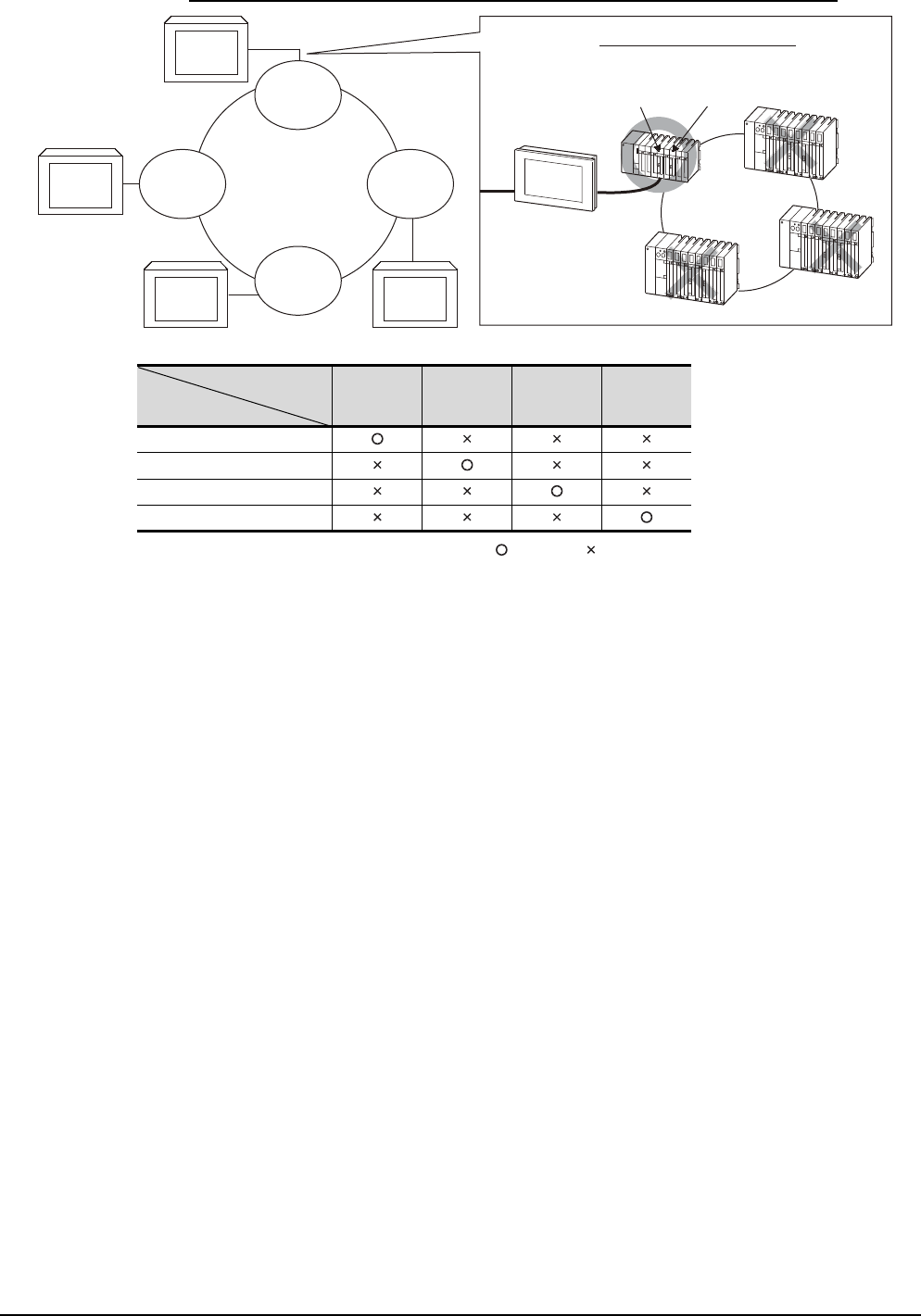
3 - 12 3. ACCESS RANGE FOR MONITORING
3.1 Access Range for Monitoring Stations on Network Systems
Example 6: When using CC-Link connection (intelligent device station) /CC-Link connection (via G4)
: Accessible : Not accessible
Station to be accessed
Station
connected to GOT
QnA
(1-1)
Q (Q mode)
(1-2)
AnA
(1-3)
AnN
(1-4)
QnA (1-1)
Q(Q mode) (1-2)
AnA (1-3)
AnN (1-4)
Network module
(1-2)
CC-Link Master
module (0 station)
Network
System
CC-Link System
Q(Q mode)
(1-2)
AnA
(1-3)
QnA
(1-1)
AnN
(1-4) GOTGOT
GOT
GOT
Image of CC-Link Connection
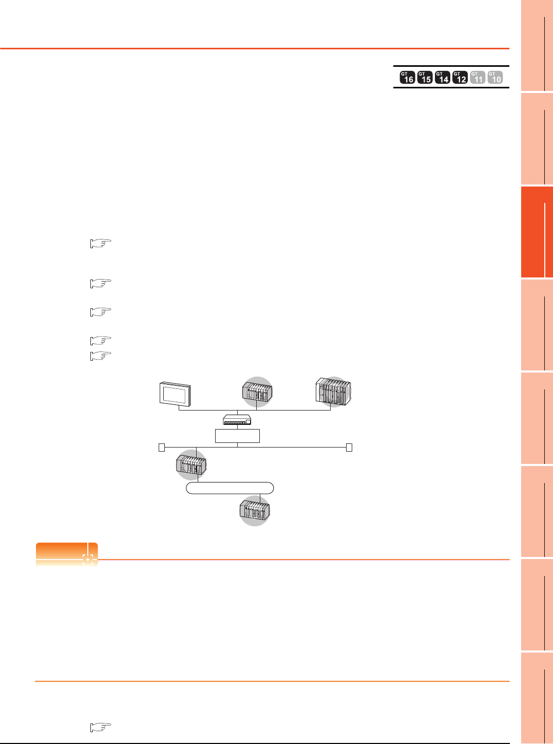
3. ACCESS RANGE FOR MONITORING
3.2 Access Range for Monitoring when Using Ethernet Connection
3 - 13
1
PREPARATORY
PROCEDURES FOR
MONITORING
2
DEVICE RANGE
THAT CAN BE SET
3
ACCESS RANGE
FOR MONITORING
4
HOW TO MONITOR
REDUNTANT
SYSTEM
5
BUS CONNECTION
6
DIRECT
CONNECTION TO
CPU
7
COMPUTER LINK
CONNECTION
8
ETHERNET
CONNECTION
3.2 Access Range for Monitoring when Using Ethernet
Connection
Access range
(1) MITSUBISHI PLC
The PLC can be monitored via the Ethernet module set in the Ethernet setting on GT Designer3.
The GOT can access CPUs on another Ethernet, MELSECNET/H, MELSECNET/10, CC-Link IE Controller
Network, or CC-Link field network via the QCPU or QnACPU.
However, the GOT cannot monitor the CNC C70 on other networks.
(The GOT cannot monitor the AnNCPU on the CC-Link IE Controller Network, MELSECNET/H, and
MELSECNET/10 networks)
For monitoring CPUs on the MELSECNET/H, MELSECNET/10, CC-Link IE Controller Network, and CC-Link
field network, set the routing parameter.
For the routing parameter setting, refer to the following manuals.
• Routing parameter setting of the GOT
8. ETHERNET CONNECTION
• Routing parameter setting for accessing CPUs on the MELSECNET/H network system, or MELSECNET/10
network system
Q corresponding MELSECNET/H Network System Reference Manual (PLC to PLC network)
• Routing parameter setting for accessing CPUs on the CC-Link IE Controller Network
CC-Link IE Controller Network Reference Manual
• Routing parameter setting for accessing CPUs on the CC-Link IE Field Network
MELSEC-Q CC-Link IE Field Network Master/Local Module User's Manual
CC-Link IE Field Network Ethernet Adapter Module User's Manual
Monitoring via the MELSECNET (II) or MELSECNET/B network cannot be performed.
POINTPOINTPOINT
(1) Host in the Ethernet connection
While the GOT is handled as the host in MELSECNET/H, MELSECNET/10 or CC-Link connection, the station
(Ethernet module) set as the host in the Ethernet setting of GT Designer3 is handled as the host in Ethernet
connection.
(2) Precautions when using the QCPU redundant system
When monitoring other networks, do not set the QCPU redundant system as a relay station.
If the QCPU redundant system is set as a relay station, the GOT cannot switch the monitoring target
automatically when the system is switched.
(A timeout error occurs due to failed monitoring)
Various settings
For the Ethernet setting by GT Designer3, refer to the following.
8. ETHERNET CONNECTION
MELSECNET/H etc.
GOT
Gateway
(Router etc.)
Hub etc.
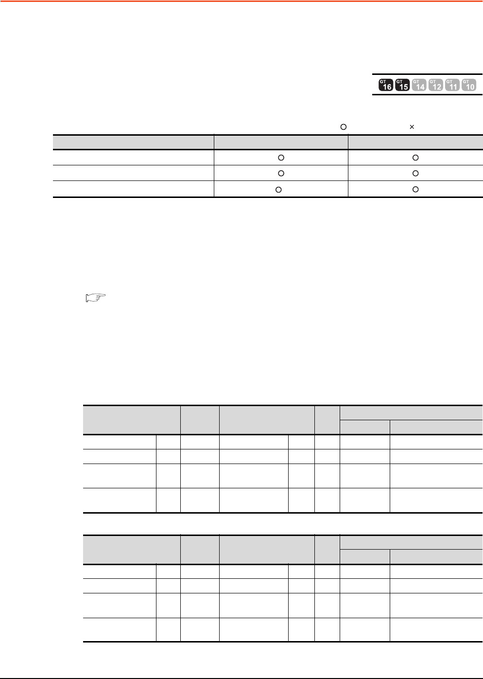
3 - 14 3. ACCESS RANGE FOR MONITORING
3.3 CC-Link System Access Range for Monitoring
3.3 CC-Link System Access Range for Monitoring
When using Bus connection/CPU direct connection/computer link connection
Only connected stations can be monitored.
When using CC-Link connection (intelligent device station)
(1) Access range
The master station and local station can be monitored.
: Can be monitored, : Cannot be monitored
*1 Monitoring is available only when the CC-Link communication module is the GT15-J61BT13.
All devices RX, RY, RWw and RWr that are allocated to the master station by the CC-Link parameter setting can
be monitored.
When the monitor target is the multi-PLC system, CPU No. 1 to No. 4 can be monitored.
The device range of RX, RY, RWw, RWr to be allocated to the GOT differs according to the setting of the number
of CC-Link communication units (one station/four station) occupied.
For details on the number of CC-Link stations occupied, refer to the following manual .
User's manual of the CC-Link master unit to be connected
(2) Setting device name and device number
(a) Monitoring devices RX, RY, RWw and RWr that are allocated to the master station by CC-Link parameter
setting
Use the following device names.
For devices RX, RY, RWw and RWr, designate the addresses allocated by station number setting.
• In the case of CC-Link Ver.2 (Device names to be refreshed automatically are indicated as X, Y, and D.)
• In the case of CC-Link Ver.1 (Device names to be refreshed automatically are indicated as X, Y, and D.)
Monitor target Monitoring by cyclic transmission Monitoring by transient transmission
Master station (Remote network Ver.2 mode)
Local station Station No.1 (Ver.1 compatible)
Local station Station No.6 (Ver.2 compatible) *1
Device name on PLC CPU Automatic
refresh
Device name on master
station
Link
scan
GT Designer3 settings
Device name Set device range
Input X ←Remote input RX ←XX0 to X1FFF
Output Y →Remote output RY →YY0 to Y1FFF
Register (write area) D ←Remote register
(write area) RWw ←Ww Ww0 to Ww7FF
Register (read area) D →Remote register
(read area) RWr →Wr Wr0 to Wr7FF
Device name on PLC CPU Automatic
refresh
Device name on master
station
Link
scan
GT Designer3 settings
Device name Set device range
Input X ←Remote input RX ←X X0 to X7FF
Output Y →Remote output RY →Y Y0 to Y7FF
Register (write area) D ←Remote register
(write area) RWw ←Ww Ww0 to WwFF
Register (read area) D →Remote register
(read area) RWr →Wr Wr0 to WrFF

3. ACCESS RANGE FOR MONITORING
3.3 CC-Link System Access Range for Monitoring
3 - 15
1
PREPARATORY
PROCEDURES FOR
MONITORING
2
DEVICE RANGE
THAT CAN BE SET
3
ACCESS RANGE
FOR MONITORING
4
HOW TO MONITOR
REDUNTANT
SYSTEM
5
BUS CONNECTION
6
DIRECT
CONNECTION TO
CPU
7
COMPUTER LINK
CONNECTION
8
ETHERNET
CONNECTION
(b) Monitoring PLC CPU devices of other stations
Set the device name and device No.
2. DEVICE RANGE THAT CAN BE SET
(3) Setting NW No. and station number
(a) When monitoring devices RX, RY, RWw and RWr that are allocated to the master station by CC-Link
parameter setting
NW No.: 0, PLC station number: Local
(b) When monitoring PLC CPU devices of another station
NW No. 0, PLC station number: Other (Station number: n)
(n: Station number of another station to be monitored (0: Master station, 1-64: Local station))
POINTPOINTPOINT
For monitoring devices RX, RY, RWw and RWr that are allocated by CC-Link parameter, use the local device even
if designating devices allocated to another station.
Otherwise, the display speed will be reduced.
When using CC-Link connection (via G4) (Q series only)
(1) Access range
GT16, GT15 and GT14 can monitor the master station and local stations.
GT10 and GT11 can monitor the master station only.
(2) Setting NW No. and station number
(a) When monitoring master station
NW No.: 0, PLC station number: Host/other (station number: 0)
(b) When monitoring local station
NW No.: 0, PLC station number: Other (station number: 1 to 64)
(3) Setting device name and device number
Set the device name and device No.
2. DEVICE RANGE THAT CAN BE SET
3 - 16 3. ACCESS RANGE FOR MONITORING
3.3 CC-Link System Access Range for Monitoring
Monitoring overview
The following two methods are available for monitoring by the GOT with CC-Link communication unit.
*1 This program is not required if the CC-Link parameter setting sequence program and GOT communication sequence program
satisfy the following conditions.
• Use a QCPU (Q mode) or QnACPU whose number given in the DATE field of the rating plate is "9707B" or later as the PLC
CPU of the master station.
• Use GX Developer or SW2 -GPPW and make CC-Link parameter setting and batch refresh device setting in the CC-Link
setting on the package.
For details of the connection method, refer to the following manual .
User's manual of the CC-Link master unit to be connected
*2 For whether the data can be sent to/received from the CC-Link Ver. 2 compatible station by transient transmission and cyclic
transmission, refer to the following.
■ When using CC-Link connection (intelligent device station)
POINTPOINTPOINT
In transient transmission, connection of several (five or more as a guideline) intelligent device stations (GOTs and
intelligent device units) reduces the data communication speed.
To raise the data communication speed, increase the CC-Link system, for example, and do not connect five or
more intelligent device stations to a single CC-Link system.
Monitoring method Monitoring by transient transmission*2 Monitoring by cyclic transmission*2
Contents Devices of the PLC CPU on the CC-Link system master and
local station are specified and monitored.
All remote inputs/outputs and remote registers assigned to
the Master station by CC-Link parameter setting are
specified and monitored.
Advantage
The CC-Link parameter setting sequence program is
required. However, the GOT communication sequence
program is not needed.*1
The data communication processing speed is high.
Disadvantage The data communication processing speed is lower than
that of cyclic transmission.
• Writing from the GOT (read command from the master
station) can be performed only to remote outputs and
remote registers assigned to the GOT of the master
station and to the GOT internal registers.
• GOT communication sequence program is required.*1
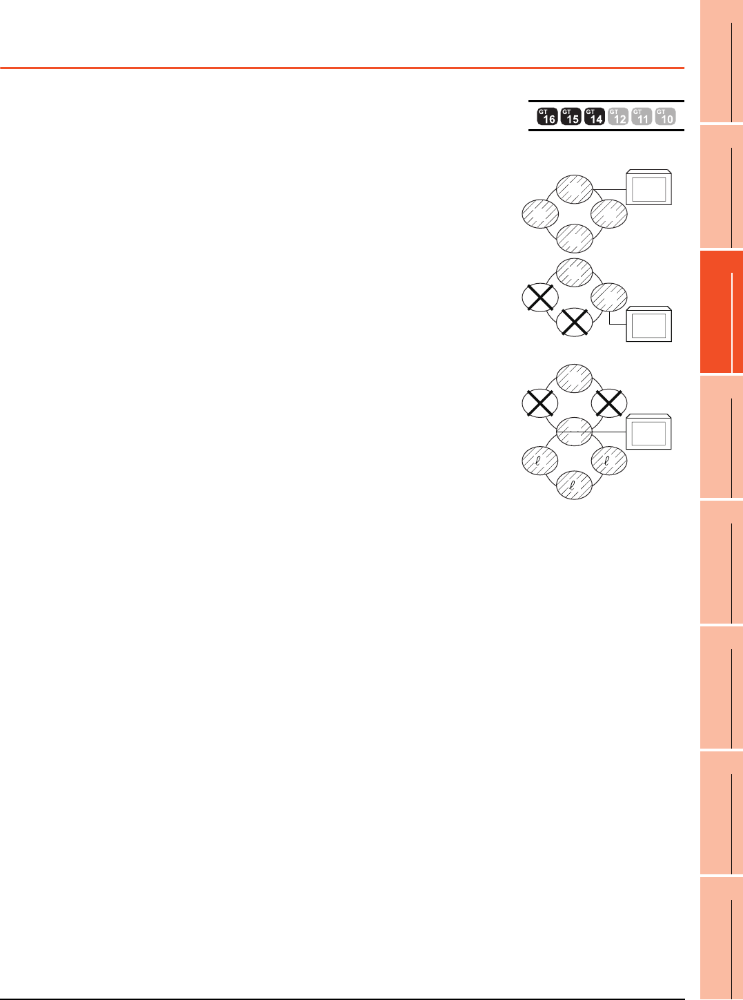
3. ACCESS RANGE FOR MONITORING
3.4 Data Link System (MELSECNET/B, (II)) Access Range for Monitoring
3 - 17
1
PREPARATORY
PROCEDURES FOR
MONITORING
2
DEVICE RANGE
THAT CAN BE SET
3
ACCESS RANGE
FOR MONITORING
4
HOW TO MONITOR
REDUNTANT
SYSTEM
5
BUS CONNECTION
6
DIRECT
CONNECTION TO
CPU
7
COMPUTER LINK
CONNECTION
8
ETHERNET
CONNECTION
3.4 Data Link System (MELSECNET/B, (II)) Access
Range for Monitoring
Bus connection, CPU direct connection, Computer link connection
(1) When connecting to the master station
• Local stations can be monitored.
When the PLC CPU of the local station is QnACPU, devices other than B
and W that are allocated by the link parameter cannot be monitored.
(2) When connecting to the local station
• The master station can be monitored.
However, when the PLC CPU of the local station is QnACPU, devices other
than B and W that are allocated by the link parameter cannot be monitored.
• Other local stations cannot be monitored.
(3) When connecting to the master station on the third layer
• The master station on the second layer and local stations on the third layer
can be monitored.
However, when the PLC CPU of the local station is QnACPU, devices other
than B and W that are allocated by the link parameter cannot be monitored.
• Local stations on the second layer cannot be monitored.
Monitoring devices of other stations
If devices of other stations on the data link system are monitored, the display speed will be significantly reduced.
Therefore monitor the link relay (B) and link register (W) that are allocated by the link parameter.
L3
M
L1
L2
GOT
L1
L2
M
L3
GOT
GOT
L3
M
L1
L2
m
2
13
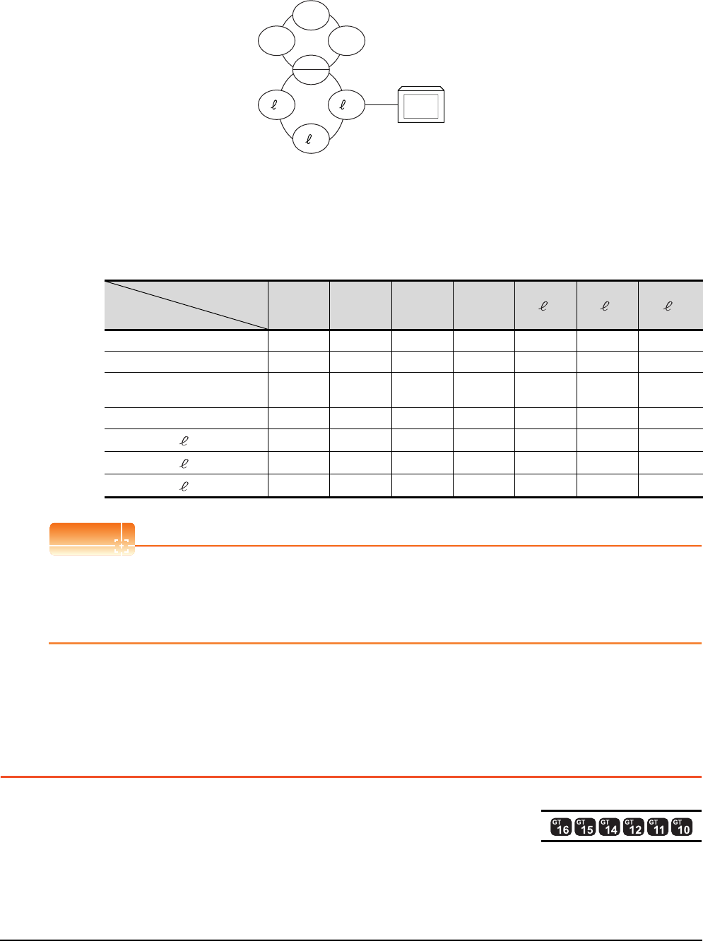
3 - 18 3. ACCESS RANGE FOR MONITORING
3.5 Access Range for Monitoring when Connecting FXCPU
Setting method of monitor device
The following example describes the method of setting the network No. and the station numbers when setting
monitor devices .
(1) Monitoring the connected station (host station) and B and W allocated by the link parameter
Specify the host station.
(2) Monitoring devices of other stations
Network No.: 0, Station number: Refer to the following table.
Setting of the station No.
POINTPOINTPOINT
Monitoring link device B or W
For monitoring devices B and W that are allocated by the link parameter, use the host device number even when
designating devices allocated to another station.
Otherwise, the display speed will be reduced.
3.5 Access Range for Monitoring when Connecting
FXCPU
The access range that can be monitored for the direct CPU connection is only the connected CPU. (The GOT cannot
monitor other stations.)
The access range that can be monitored for the Ethernet connection is the host and others.
The access range that can be monitored for the multi-drop communication is only the CPU to which the serial multi-drop
connection unit (GT01-RS4-M) is connected directly.
Station to be accessed
Station
connected to GOT
ML1 L2
mL3 1 2 3
M Host Other 1 Other 2 Other 3 ―― ―
L1 Other 0 Host ―――― ―
L2
mOther 0 ―Host ―Other 1 Other 2 Other 3
L3 Other 0 ――Host ―― ―
1――Other 0 ―Host ――
2――Other 0 ――Host ―
3――Other 0 ―――Host
L3
M
L1
GOT
L2
m
2
13
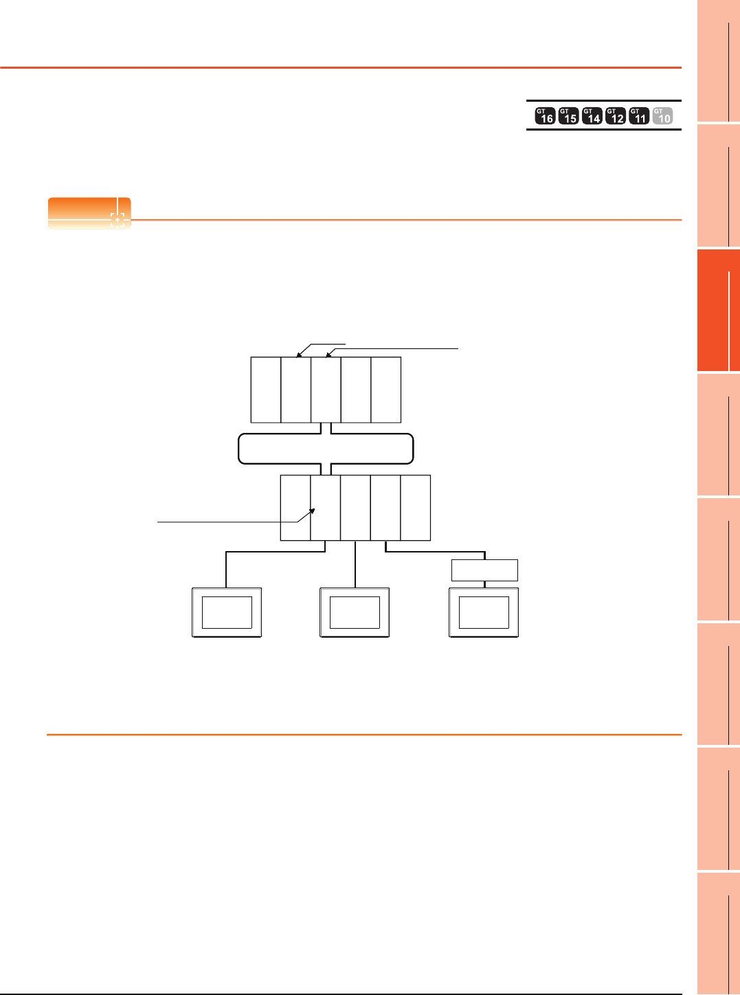
3. ACCESS RANGE FOR MONITORING
3.6 Connection to Remote I/O Station in MELSECNET/H Network System
3 - 19
1
PREPARATORY
PROCEDURES FOR
MONITORING
2
DEVICE RANGE
THAT CAN BE SET
3
ACCESS RANGE
FOR MONITORING
4
HOW TO MONITOR
REDUNTANT
SYSTEM
5
BUS CONNECTION
6
DIRECT
CONNECTION TO
CPU
7
COMPUTER LINK
CONNECTION
8
ETHERNET
CONNECTION
3.6 Connection to Remote I/O Station in MELSECNET/
H Network System
When connected to the remote I/O station of the MELSECNET/H network system, the GOT can monitor the PLC CPU of
the master station.
When connecting the GOT to the remote I/O station, use the following connection methods.
POINTPOINTPOINT
(1) Connection to remote I/O station of MELSECNET/B, (II) or /10
The GOT cannot be connected to the remote I/O station on the MELSECNET/B, (II) data link system and
MELSECNET/10 network system.
Connect the GOT to the remote I/O station on the MELSECNET/H network system.
(2) Connection to GT11 and remote I/O station on MELSECNET/H
GT11 can not access the master station on MELSECNET/H network system.
GT11 can access only the connected host station (remote I/O station).
Monitor
target
Network No.1
Station No.0
(master station)
QJ71LP21-25
Q33B
MELSECNET/H remote I/O Network
Network No.1
Station No.1
(remote I/O station)
QJ72LP25-25
QJ71C24N
Q33B
QJ71E71-100
Empty
Power supply
module
Empty
Empty
Power supply
module
PLC CPU
Hub
(1) Direct CPU
GOT
(3) Ethernet connection
GOT
(2) Computer link
GOT
connection connection

3 - 20 3. ACCESS RANGE FOR MONITORING
3.6 Connection to Remote I/O Station in MELSECNET/H Network System
Direct CPU connection
(1) The network units (QJ72LP25-25, QJ72LP25G, QP72BR15) of the remote I/O station are handled as PLC CPU.
Connect the GOT to the RS-232 interface of the network unit.
For cables required for connection with the network module and other details, refer to the following.
6. DIRECT CONNECTION TO CPU
(2) Specify a type including MELSEC-Q (including multiple), or MELSEC-QnU for the controller type on GT
Designer3. Then, specify [[NW No.] (Network No. of the remote I/O network) to 1, and specify [Station No.]
(Master station) to 0.] as the monitoring target in the network setting of the device setting dialog box. (GT16,
GT15 only)
The GOT monitors stations on the MELSECNET/H network with the transient transmission.
Therefore, a longer time-lag occurs for displaying objects compared with directly monitoring the PLC CPU.
For displaying objects with a shorter time-lag, execute the cyclic transmission so that the GOT can monitor link
devices B and W of the host station set in the MELSECNET/H network.
For settings required for the PLC CPU, refer to the following manual.
Q Corresponding MELSECNET/H Network System Reference Manual (Remote I/Q network)
(3) To monitor other networks, set the routing parameter to the PLC CPU as necessary. For routing parameter
settings of the PLC CPU, refer to the following manual.
Q corresponding MELSECNET/H Network System Reference Manual (PLC to PLC network)
Computer link connection
(1) Connect the GOT to the serial communication module (QJ71C24, QJ71C24-R2, QJ71C24N, QJ71C24N-R2,
QJ71C24N-R4) or modem interface module (QJ71CMO) mounted on the remote I/O station.
For the cables required for connection with the serial communication module or modem interface module and
other details, refer to the following.
7. COMPUTER LINK CONNECTION
(2) Specify a type including MELSEC-Q (including multiple), or MELSEC-QnU for the controller type on GT
Designer3. Then, specify [[NW No.] (Network No. of the remote I/O network) to 1, and specify [Station No.]
(Master station) to 0.] as the monitoring target in the network setting of the device setting dialog box. (GT16,
GT15 only)
The GOT monitors stations on the MELSECNET/H network with the transient transmission.
Therefore, a longer time-lag occurs for displaying objects compared with directly monitoring the PLC CPU.
For displaying objects with a shorter time-lag, execute the cyclic transmission so that the GOT can monitor link
devices B and W of the host station set in the MELSECNET/H network.
For settings required for the PLC CPU, refer to the following manual.
Q Corresponding MELSECNET/H Network System Reference Manual (Remote I/Q network)
(3) To monitor other networks, set the routing parameter to the PLC CPU as necessary. For routing parameter
settings of the PLC CPU, refer to the following manual.
Q corresponding MELSECNET/H Network System Reference Manual (PLC to PLC network)

3. ACCESS RANGE FOR MONITORING
3.6 Connection to Remote I/O Station in MELSECNET/H Network System
3 - 21
1
PREPARATORY
PROCEDURES FOR
MONITORING
2
DEVICE RANGE
THAT CAN BE SET
3
ACCESS RANGE
FOR MONITORING
4
HOW TO MONITOR
REDUNTANT
SYSTEM
5
BUS CONNECTION
6
DIRECT
CONNECTION TO
CPU
7
COMPUTER LINK
CONNECTION
8
ETHERNET
CONNECTION
Ethernet connection
(1) Connect the GOT to the Ethernet module (QJ71E71-100, QJ71E71-B5, QJ71E71-B2, QJ71E71) mounted on
the remote I/O station.
For details of cables and others required for connecting the GOT to the Ethernet module, refer to the following.
8. ETHERNET CONNECTION
(2) Specify a type including MELSEC-Q (including multiple), or MELSEC-QnU for the controller type on GT
Designer3. Then, specify [[NW No.] (Network No. of the remote I/O network) to 1, and specify [Station No.]
(Master station) to 0.] as the monitoring target in the network setting of the device setting dialog box. (GT16,
GT15 only)
The GOT monitors stations on the MELSECNET/H network with the transient transmission.Therefore, a longer
time-lag occurs for displaying objects compared with directly monitoring the PLC CPU.
For displaying objects with a shorter time-lag, execute the cyclic transmission so that the GOT can monitor link
devices B and W of the remote I/O station.
For settings required for the PLC CPU, refer to the following manual.
Q Corresponding MELSECNET/H Network System Reference Manual (Remote I/Q network)
(3) To monitor other networks, set the routing parameter to the GOT and PLC CPU as necessary. For routing
parameter settings of the GOT, refer to the following manual.
8. ETHERNET CONNECTION
For routing parameter settings of the PLC CPU, refer to the following manual.
Q corresponding MELSECNET/H Network System Reference Manual (PLC to PLC network)
Restrictions on connection to remote I/O station
The GOT does not allow the clock of the master station to be set in the clock setting of the utility function.
The master station clock will not change even if the clock setting is made.
Use GX Developer or a similar software to set the PLC CPU clock of the master station.
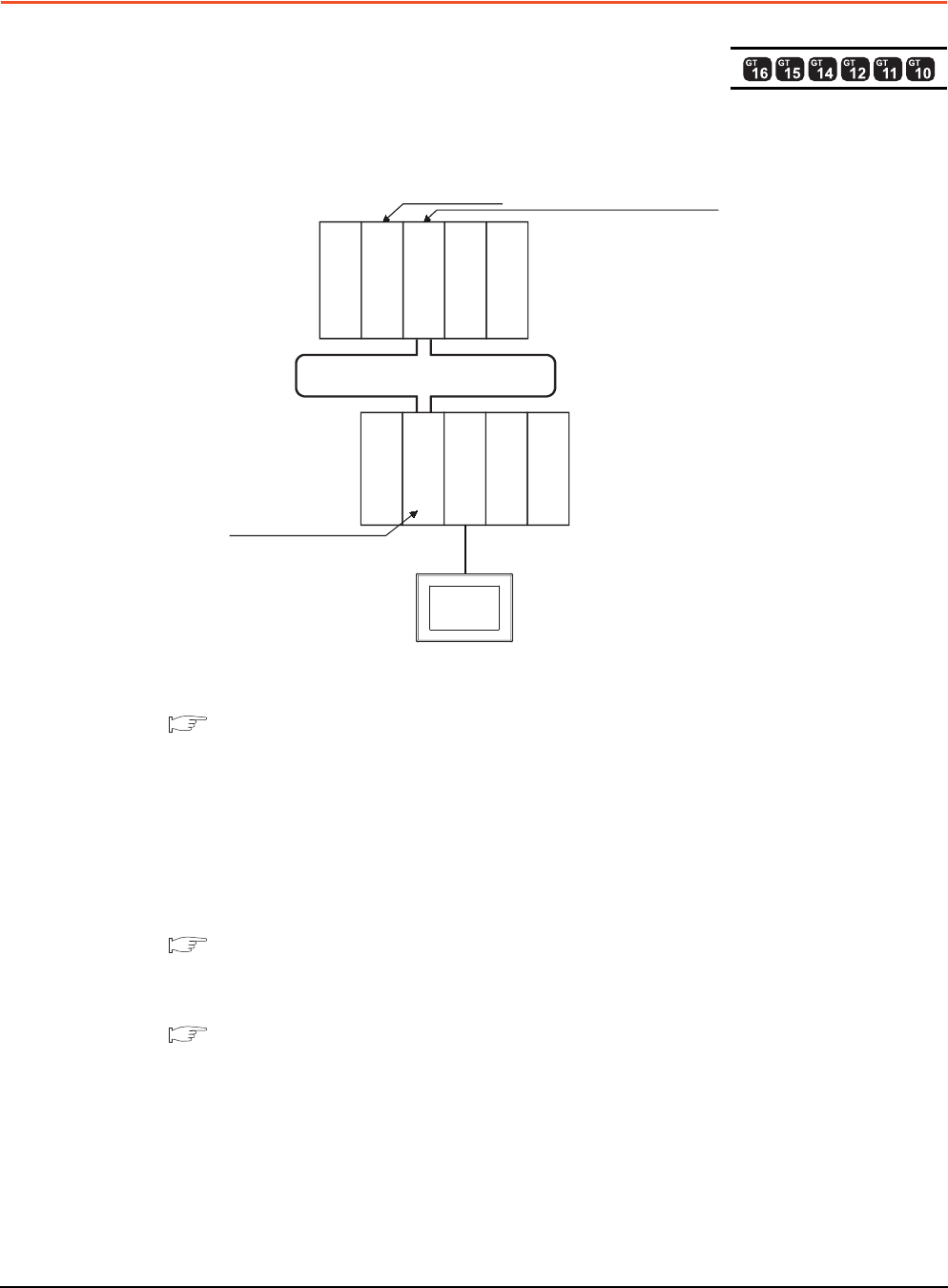
3 - 22 3. ACCESS RANGE FOR MONITORING
3.7 Connection to the Head Module of CC-Link IE Field Network System
3.7 Connection to the Head Module of CC-Link IE Field
Network System
When connected to the head module of the CC-Link IE Field Network, the GOT can monitor the PLC CPUs of the master
station and local stations. When connecting the GOT to the head module, use the following connection methods.
Computer link connection
(1) Connect the GOT to the serial communication module (LJ71C24, LJ71C24-R2) mounted on the head module.
For cables required for connection with the serial communication module and other details, refer to the following.
7. COMPUTER LINK CONNECTION
(2) Specify a GOT type which includes MELSEC-QnU in the controller type on GT Designer3. Then, specify
[Network No. 1 (Network No. of CC-Link IE Field Network), Station No. 0 (Master station)] as the monitoring
target in the network setting of the device setting dialog box. (GT16, GT15, GT14 only)
In this case, the GOT monitoring is performed by transient transmission of the CC-Link IE Field Network.
Therefore, a longer time-lag occurs for displaying objects compared with directly monitoring the PLC CPU.
For displaying objects with a shorter time-lag, execute the cyclic transmission so that the GOT can monitor link
devices B and W of the host station set in the CC-Link field network.
For settings required for the PLC CPU, refer to the following manual.
MELSEC-L CC-Link IE Field Network Head Module User's Manual
(3) To monitor other networks, set the routing parameter to the PLC CPU as necessary. For routing
parameter setting of the PLC CPU, refer to the following manual.
MELSEC-L CC-Link IE Field Network Head Module User's Manual
Monitor target Network No. 1, Station No. 0
Network No. 1,
Station No. 1
QJ71GF11-T2
CC-Link IE Field Network
LJ72GF15-T2
LJ71C24
GOT
Empty
Power supply
module
Power supply
module
Empty
CLP CPU
LX40C6
LY10R2
Q33B

3. ACCESS RANGE FOR MONITORING
3.7 Connection to the Head Module of CC-Link IE Field Network System
3 - 23
1
PREPARATORY
PROCEDURES FOR
MONITORING
2
DEVICE RANGE
THAT CAN BE SET
3
ACCESS RANGE
FOR MONITORING
4
HOW TO MONITOR
REDUNTANT
SYSTEM
5
BUS CONNECTION
6
DIRECT
CONNECTION TO
CPU
7
COMPUTER LINK
CONNECTION
8
ETHERNET
CONNECTION
POINTPOINTPOINT
Connection between GT11, GT10 and head module of CC-Link IE Field Network
GT11, GT10 can not access the master station on CC-Link IE Field Network.
GT11, GT10 can access only the connected host station (head module).
Restrictions on connection to head module
The GOT does not allow the clock of the master station to be set in the clock setting of the utility function.
The master station clock will not change even if the clock setting is made.
Use GX Works or similar software to set the PLC CPU clock of the master station.

3 - 24 3. ACCESS RANGE FOR MONITORING
3.7 Connection to the Head Module of CC-Link IE Field Network System

4
1
PREPARATORY
PROCEDURES FOR
MONITORING
2
DEVICE RANGE
THAT CAN BE SET
3
ACCESS RANGE
FOR MONITORING
4
HOW TO MONITOR
REDUNTANT
SYSTEM
5
BUS CONNECTION
6
DIRECT
CONNECTION TO
CPU
7
COMPUTER LINK
CONNECTION
8
ETHERNET
CONNECTION
4 - 1
4.HOW TO MONITOR REDUNTANT
SYSTEM
4.1 Connection to Remote I/O Station in MELSECNET/H Network
System . . . . . . . . . . . . . . . . . . . . . . . . . . . . . . . . . . . . . . . . . .4 - 8
4.2 Direct CPU Connection . . . . . . . . . . . . . . . . . . . . . . . . . . . . 4 - 11
4.3 CC-Link Connection (Intelligent Device Station) . . . . . . . . .4 - 18
4.4 CC-Link Connection (Via G4). . . . . . . . . . . . . . . . . . . . . . . .4 - 20
4.5 MELSECNET/H and MELSECNET/10 Connections (Network
Systems) . . . . . . . . . . . . . . . . . . . . . . . . . . . . . . . . . . . . . . .4 - 22
4.6 CC-Link IE Controller Network Connection (Network System)
. . . . . . . . . . . . . . . . . . . . . . . . . . . . . . . . . . . . . . . . . . . . . . .4 - 23
4.7 Ethernet Connection . . . . . . . . . . . . . . . . . . . . . . . . . . . . . .4 - 24
4.8 Connection to the Redundant Type Extension Base Unit . .4 - 25
4.9 Q Redundant Setting . . . . . . . . . . . . . . . . . . . . . . . . . . . . . .4 - 29
4.10 Switch the Monitor Target to the Control System Using the Script
Function . . . . . . . . . . . . . . . . . . . . . . . . . . . . . . . . . . . . . . . .4 - 31
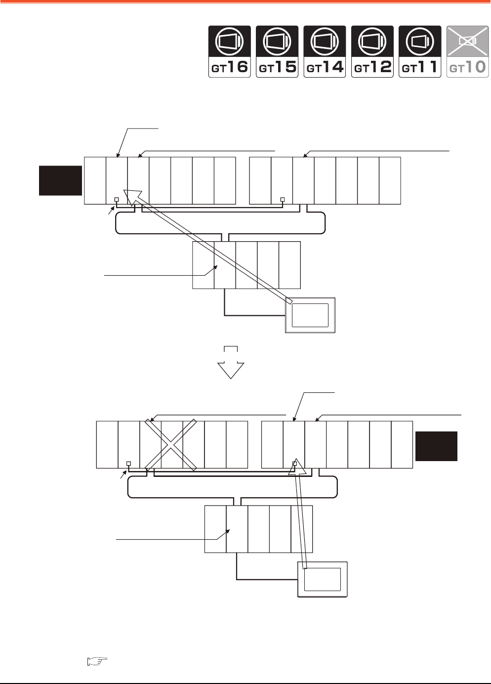
4 - 2 4. HOW TO MONITOR REDUNTANT SYSTEM
4.
HOW TO MONITOR REDUNTANT SYSTEM
This section explains the restrictions on the connection methods and other information applicable when the QCPU
redundant system is monitored by the GOT.
In a redundant system, the monitoring can be performed with the monitoring target specified as the control system or the
standby system on the GOT. By specifying the monitoring target PLC CPU as the control system of the redundant
system, the monitoring target is automatically changed to the PLC CPU in the control system when system switching
occurs.
To enable this automatic changing of the monitoring target at the GOT, settings are required in the GT Designer3.
4.9 Q Redundant Setting
Monitor
target
MELSECNET/H remote I/O network
CPU direct
connection
GOT
Station No. 0
(Multiplexed remote master station)
Q25PRHCPU
QJ71LP21-25
QJ71BR11
QJ71E71-100
QJ61BT11N
Station No. 1
(Multiplexed remote sub master station)
Standby
system
(System B)
Q25PRHCPU
QJ71LP21-25
QJ71BR11
QJ71E71-100
QJ61BT11N
Station No. 2
(remote I/O station)
Tracking cable
QJ72LP25-25
QJ71C24N
The GOT monitors
the control system
PLC CPU.
When an error occurs in System A, System B switches from standby system to control system.
Monitor target
MELSECNET/H remote I/O network
CPU direct
connection
GOT
Station No. 0
(Multiplexed remote master station)
Standby
system
(System A)
Q25PRHCPU
QJ71LP21-25
QJ71BR11
QJ71E71-100
QJ61BT11N
Station No. 1
(Multiplexed remote sub master station)
Q25PRHCPU
QJ71LP21-25
QJ71BR11
QJ71E71-100
QJ61BT11N
Station No. 2
(remote I/O station)
Tracking cable
QJ72LP25-25
QJ71C24N
The GOT monitors the PLC CPU
of the new control system after
system switching.
Empty
Empty
Power supply
module
Power supply
module
Empty
Empty
Power supply
module
Power supply
module
Empty
Empty
Power supply
module
Empty
Empty
Power supply
module
Control
system
(System A)
Control
system
(System B)

4. HOW TO MONITOR REDUNTANT SYSTEM
4 - 3
1
PREPARATORY
PROCEDURES FOR
MONITORING
2
DEVICE RANGE
THAT CAN BE SET
3
ACCESS RANGE
FOR MONITORING
4
HOW TO MONITOR
REDUNTANT
SYSTEM
5
BUS CONNECTION
6
DIRECT
CONNECTION TO
CPU
7
COMPUTER LINK
CONNECTION
8
ETHERNET
CONNECTION
The following connection methods are available for the QCPU redundant system.
• Connection to remote I/O station in MELSECNET/H network system
(1) Direct CPU connection (Remote I/O station of MELSECNET/H network system)
4.1.1 Direct CPU connection (Direct CPU connection to the remote I/O station)
(2) Computer link connection (Serial communication module mounted on remote I/O station of MELSECNET/H
network system)
4.1.2 Computer link connection (Connection to serial communication module mounted on remote
I/O station)
(3) Ethernet connection (Ethernet module mounted on the remote I/O station of the MELSECNET/H network
system)
4.1.3 Ethernet connection (Connection to Ethernet module mounted on remote I/O station)
• Direct CPU connection
4.2 Direct CPU Connection
• CC-Link connection (intelligent device station)
4.3 CC-Link Connection (Intelligent Device Station)
• CC-Link connection (Via G4)
4.4 CC-Link Connection (Via G4)
• MELSECNET/H connection, MELSECNET/10 connection (Network system)
4.5 MELSECNET/H and MELSECNET/10 Connections (Network Systems)
• CC-Link IE Controller Network connection (Network system)
4.6 CC-Link IE Controller Network Connection (Network System)
• Ethernet connection
4.7 Ethernet Connection
• Connection to the redundant type extension base unit
(1) Computer link connection (Serial communication module mounted on the redundant type extension base unit)
4.8.1 Computer link connection (Connection to the Serial communication module mounted on the
redundant type extension base unit)
(2) Ethernet connection (Ethernet module mounted on the redundant type extension base unit)
4.8.2 Ethernet connection (Connection to the Ethernet module mounted on redundant type
extension base unit)
(3) CC-Link connection (intelligent device station) (CC-Link module mounted on the redundant type extension base
unit)
4.8.3 CC-Link connection (intelligent device station) (Connection to the CC-Link module
mounted on redundant type extension base unit)
(4) CC-Link connection (Via G4) (CC-Link module mounted on the redundant type extension base unit)
4.8.4 CC-Link connection (Via G4) (Connection to the CC-Link module mounted on redundant
type extension base unit)
For details of PLC CPUs that can be monitored in each connection method of GOT, refer to the following.
Monitorable controllers of each chapter
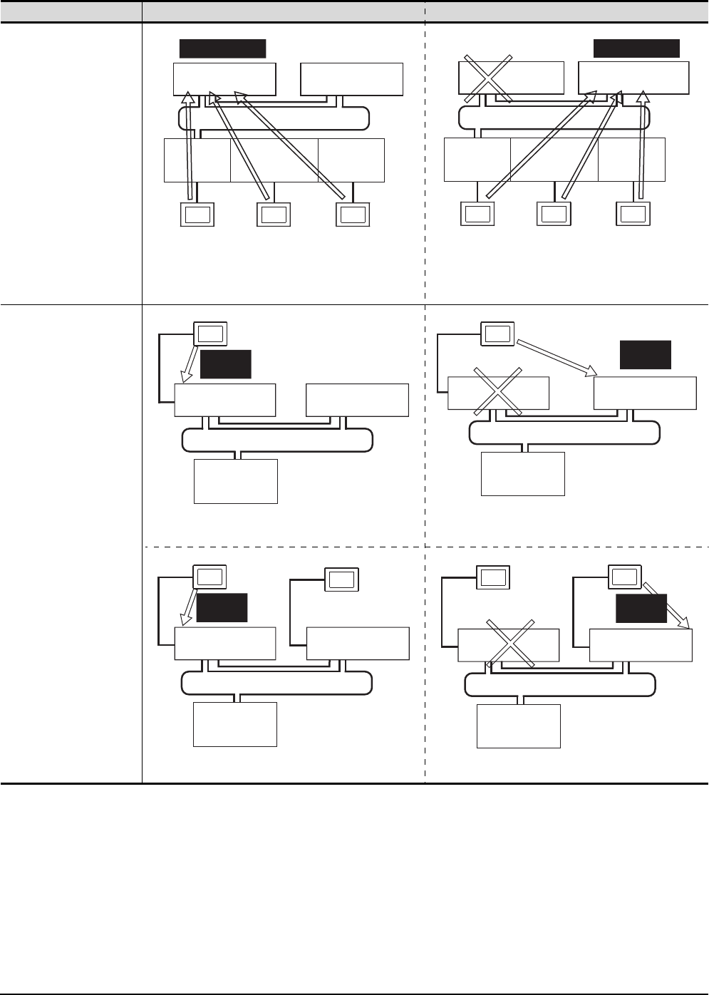
4 - 4 4. HOW TO MONITOR REDUNTANT SYSTEM
The following table shows the features of each connection method.
Connection type Before system switching After system switching
• Direct CPU connection
(Remote I/O station of
MELSECNET/H network
system)
• Computer link connection
(Serial communication
module mounted on the
remote I/O station on
MELSECNET/H network
system)
• Ethernet connection
(Ethernet module mounted
on the remote I/O station
of the MELSECNET/H
network system)
The monitoring target is automatically changed to the control
system PLC CPU.
• Direct CPU connection
By the Q redundant setting, the GOT automatically changes
the monitoring target to the PLC CPU in the control system.*1
Monitor the PLC CPU of the control system by GOT1. Monitor the PLC CPU of the control system by GOT2.
Control system
Multiplexed remote
master station
MELSECNET/H remote I/O network
Standby system
Multiplexed remote
sub master station
GOT1
Direct CPU
connection
GOT3
Ethernet
connection
GOT2
Computer link
connection
Remote
I/O station
Ethernet
module
Serial
communication
module
Standby system Control system
MELSECNET/H remote I/O network
Multiplexed remote
sub master station
GOT1
Direct CPU
connection
GOT3
Ethernet
connection
GOT2
Computer link
connection
Remote
I/O station
Ethernet
module
Serial
communication
module
Multiplexed remote
master station
GOT
MELSECNET/H remote I/O network
Standby system
Remote I/O
station
Control
system
Multiplexed remote
master station
Multiplexed remote
sub-master station
GOT
MELSECNET/H remote I/O network
Remote I/O
station
Multiplexed remote
master station
Multiplexed remote
sub-master station
Standby system
Control
system
GOT1 GOT2
MELSECNET/H remote I/O network
Remote I/O
station
Multiplexed remote
master station
Multiplexed remote
sub-master station
Standby system
Control
system
GOT1 GOT2
MELSECNET/H remote I/O network
Remote I/O
station
Multiplexed remote
master station
Multiplexed remote
sub-master station
Standby system
Control
system
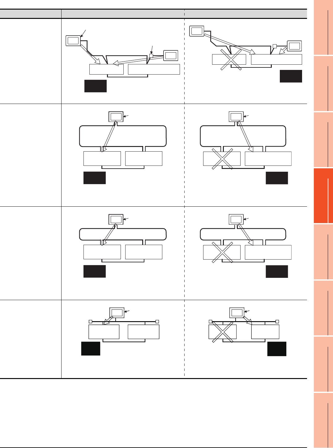
4. HOW TO MONITOR REDUNTANT SYSTEM
4 - 5
1
PREPARATORY
PROCEDURES FOR
MONITORING
2
DEVICE RANGE
THAT CAN BE SET
3
ACCESS RANGE
FOR MONITORING
4
HOW TO MONITOR
REDUNTANT
SYSTEM
5
BUS CONNECTION
6
DIRECT
CONNECTION TO
CPU
7
COMPUTER LINK
CONNECTION
8
ETHERNET
CONNECTION
Connection type Before system switching After system switching
• CC-Link connection
(intelligent device station)
• CC-Link connection (Via
G4)
The monitoring target is automatically changed to the control
system PLC CPU.
• MELSECNET/H
connection, MELSECNET/
10 connection
(Network system)
By the Q redundant setting, the GOT automatically changes
the monitoring target to the PLC CPU in the control system.*2
• CC-Link IE Controller
Network connection
(Network system)
By the Q redundant setting, the GOT automatically changes
the monitoring target to the PLC CPU in the control system.*2
• Ethernet connection
By the Q redundant setting, the GOT automatically changes
the monitoring target to the PLC CPU in the control system.*2
Intelligent device station
Master station
GOT1
Standby master station
AJ65BT-G4-S3
CC-Link GOT2
Control
system
Standby
system
Master station
Standby master station
Control
system
Standby
system
GOT1
CC-Link
GOT2
GOT
Station No.3
(normal station)
MELSECNET/H PLC to PLC network
(MELSECNET/H mode or
MELSECNET/10 mode)
Station No.1
(control station)
Station No.2
(normal station)
Control
system
Standby
system
GOT Station No.3
(normal station)
MELSECNET/H PLC to PLC network
(MELSECNET/H mode or
MELSECNET/10 mode)
Station No.1
(normal station)
Station No.2
(sub control station)
Control
system
Standby
system
GOT Station No.3
(normal station)
Station No.1
(control station)
Station No.2
(normal station)
Control
system
Standby
system
CC-Link IE Controller Network
GOT Station No.3
(normal station)
Station No.1
(normal station)
Station No.2
(sub control station)
Control
system
Standby
system
CC-Link IE Controller Network
GOT
Control
system
Standby
system
Station No. 3
Station No. 1 Station No. 2
Ethernet
GOT
Standby
system
Control
system
Station No. 3
Station
No. 1
Station
No. 2
Ethernet
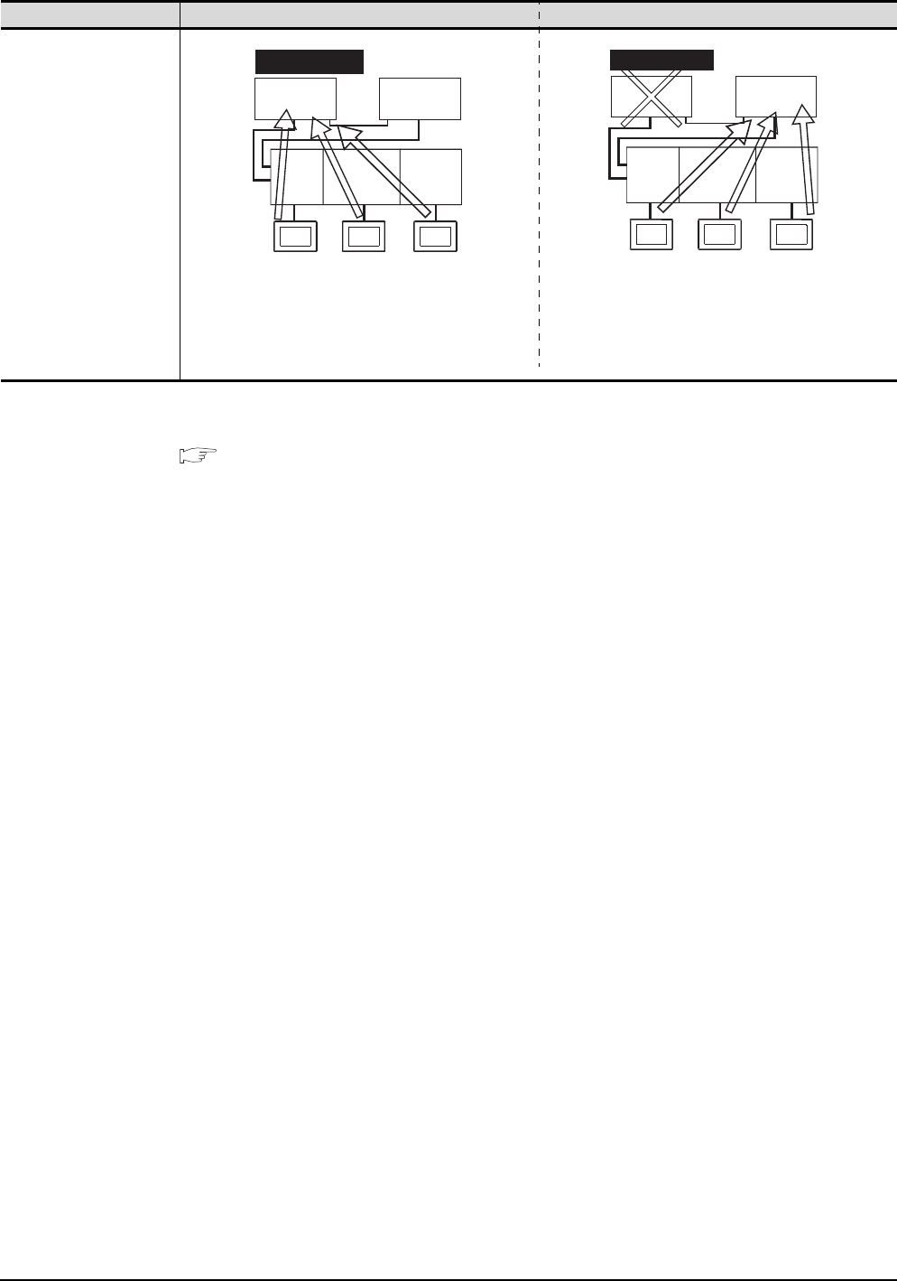
4 - 6 4. HOW TO MONITOR REDUNTANT SYSTEM
*1 To monitor the control system after the system switching without the Q redundant setting, change the cable connection from the
PLC CPU in the previous control system to the control system after system switching.
*2 To monitor the control system after the system switching without the Q redundancy setting, refer to the following.
4.10Switch the Monitor Target to the Control System Using the Script Function
Connection type Before system switching After system switching
• Computer link connection
(Serial communication
module mounted on the
redundant type extension
base unit)
• Ethernet connection
(Ethernet module mounted
on the redundant type
extension base unit)
• CC-Link connection
(intelligent device station)
(CC-Link module mounted
on the redundant type
extension base unit)
• CC-Link connection (Via
G4)
(CC-Link module mounted
on the redundant type
extension base unit)
CC-Link
module
Serial
communication
module
Ethernet
module
CC-Link
connection
Computer link
connection
Ethernet
connection
GOT3
GOT2
GOT1
Control system
Station
No. 1
Station
No. 2
CC-Link
module
Serial
communication
module
Ethernet
module
CC-Link
connection
Computer link
connection
Ethernet
connection
GOT3
GOT2
GOT1
Control system
Station
No. 1
Standby system
Station
No. 2

4. HOW TO MONITOR REDUNTANT SYSTEM
4 - 7
1
PREPARATORY
PROCEDURES FOR
MONITORING
2
DEVICE RANGE
THAT CAN BE SET
3
ACCESS RANGE
FOR MONITORING
4
HOW TO MONITOR
REDUNTANT
SYSTEM
5
BUS CONNECTION
6
DIRECT
CONNECTION TO
CPU
7
COMPUTER LINK
CONNECTION
8
ETHERNET
CONNECTION
POINTPOINTPOINT
Precautions for monitoring the QCPU redundant system
(1) A system alarm may be detected when the system is switched in a redundant system.
When Q redundant setting is made : "450 Path has changed or timeout occurred in redundant system."
When Q redundant setting is not made : "402 Communication timeout. Confirm communication pathway or
modules."
However, even if the error occurs, the GOT automatically resumes monitoring and there are no problems in
the monitoring operation.
(2) The system alarm is displayed when the system is switched due to cable disconnection etc. (when the path is
changed).
The system alarm is not displayed when the system is switched by the user.
(3) When connected to the remote I/O station, the GOT can monitor only the following GOT functions.
Monitoring function System monitoring function
(4) When connected to the remote I/O station, the GOT does not allow the PLC CPU clock of the master station
to be set in the clock setting of the utility.
The master station clock will not change even if the clock setting is made.
Use GX Developer or a similar software to set the PLC CPU clock of the master station.
(5) When the Q redundant setting is not made, the GOT does not automatically change the monitoring target
even if system switching occurs in the redundant system. When the GOT is connected to the standby system,
data written to a device are overwritten by the data of the control system, failing to be reflected.
In this case, when data are written to a device in the standby system normally, the system alarm "315 Device
writing error. Correct device." is not detected.
(6) For monitoring the QCPU redundant system when connecting to MELSECNET/H, use QCPU of function
version D or later, with the upper five digits later than "07102".
Also, use GX Developer of Version 8.29F or later.
(7) A message "Unable to communicate with CPU." is displayed when the system switching occurs while an
option function such as the ladder monitor is used.
(8) In the MELSECNET/H connection or MELSECNET/10 connection, when the control station of the
MELSECNET/H network or MELSECNET/10 network fails and is taken over by a station outside the QCPU
redundant system, the timeout is detected as the system alarm.
If this occurs, the monitor display speed may slow down.
(9) In the direct CPU connection, the GOT fails to automatically change the monitoring target in the following
cases.
• When the power supply to the CPU where the GOT is connected is OFF
• When the cable connecting the GOT with the CPU is broken
• When the tracking is disabled
(10) If the Q redundant setting is made for a system that is not a QCPU redundant system, no error occurs at the
start up of the GOT and the GOT operates normally.
In this case, if an abnormality (such as powering OFF, or communication timeout error) occurs at the PLC
CPU for which the Q redundant setting has been made, the PLC CPU may operate in a different way from the
monitoring target change mode that was set in the Q redundant setting.
(11) If the QCPU redundant system is in the debug mode, do not make the Q redundant system setting for the
GOT side when connecting the GOT.
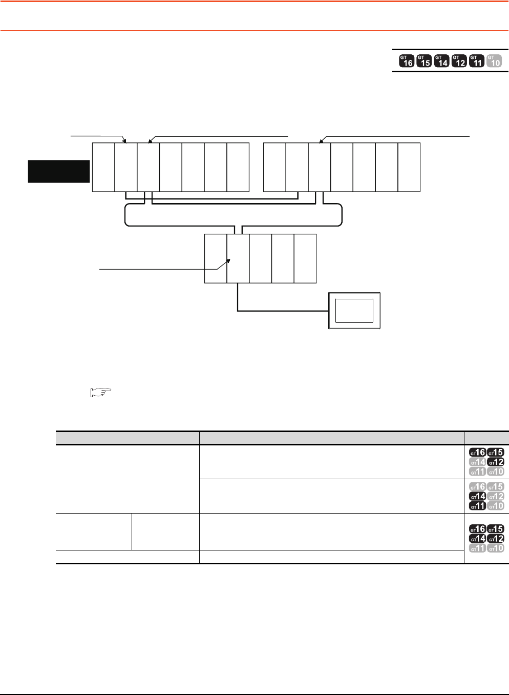
4 - 8 4. HOW TO MONITOR REDUNTANT SYSTEM
4.1 Connection to Remote I/O Station in MELSECNET/H Network System
4.1 Connection to Remote I/O Station in MELSECNET/
H Network System
4.1.1 Direct CPU connection (Direct CPU connection to the remote I/O station)
This section explains the direct CPU connection that connects the GOT to the remote I/O station of the MELSECNET/H
network system.
The following shows an example of connecting the GOT to the remote I/O station of the MELSECNET/H network system.
(1) Connection method
Connect the GOT to the RS-232 interface of the network module (QJ72LP25-25, QJ72LP25G, QJ72BR15) on
the remote I/O station of the MELSECNET/H network system.
For details, refer to the following.
6. DIRECT CONNECTION TO CPU
(2) GT Designer3 setting
Set GT Designer3 as follows.
In this case, the GOT monitoring is performed by transient transmission of the MELSECNET/H network
system.Therefore, a longer time-lag occurs for displaying objects compared with directly monitoring the PLC
CPU.
For displaying objects with a shorter time-lag, execute the cyclic transmission so that the GOT can monitor link
devices B and W of the host station set in the MELSECNET/H network.
(3) Monitoring target change when system switching occurs in a redundant system
When the system switching occurs, the multiplexed remote sub master station switched to the control system
takes over the master operation of MELSECNET/H.
Since the GOT monitors the master station, the monitoring target is automatically changed to the PLC CPU that
is operating as the master.
Setting item Settings Model
Controller Type
MELSEC-QnA/Q/QS, MELDAS C6*
MELSEC-QnA/Q, MELDAS C6*
Device setting
(Network setting)
Host Host
Remote master
station
Other (NW No. 1 (network No. of remote I/O network),
Station No. 0 (master station))
Q Redundant Setting Do not set the item.
Monitor target
MELSECNET/H remote I/O network
CPU direct connection
GOT
Network No. 1, Station No. 0
(Multiplexed remote master station)
Control system
(System A)
Q25PRHCPU
QJ71LP21-25
QJ71BR11
QJ71E71-100
QJ61BT11N
Network No. 1, Station No. 1
(Multiplexed remote sub master station)
Standby system
(System B)
Q25PRHCPU
QJ71LP21-25
QJ71BR11
QJ71E71-100
QJ61BT11N
QJ72LP25-25
QJ71C24N
Network No. 1, Station No. 2
(Remote I/O station)
Empty
Empty
Power supply
module
Empty
Power supply
module
Empty
Power supply
module
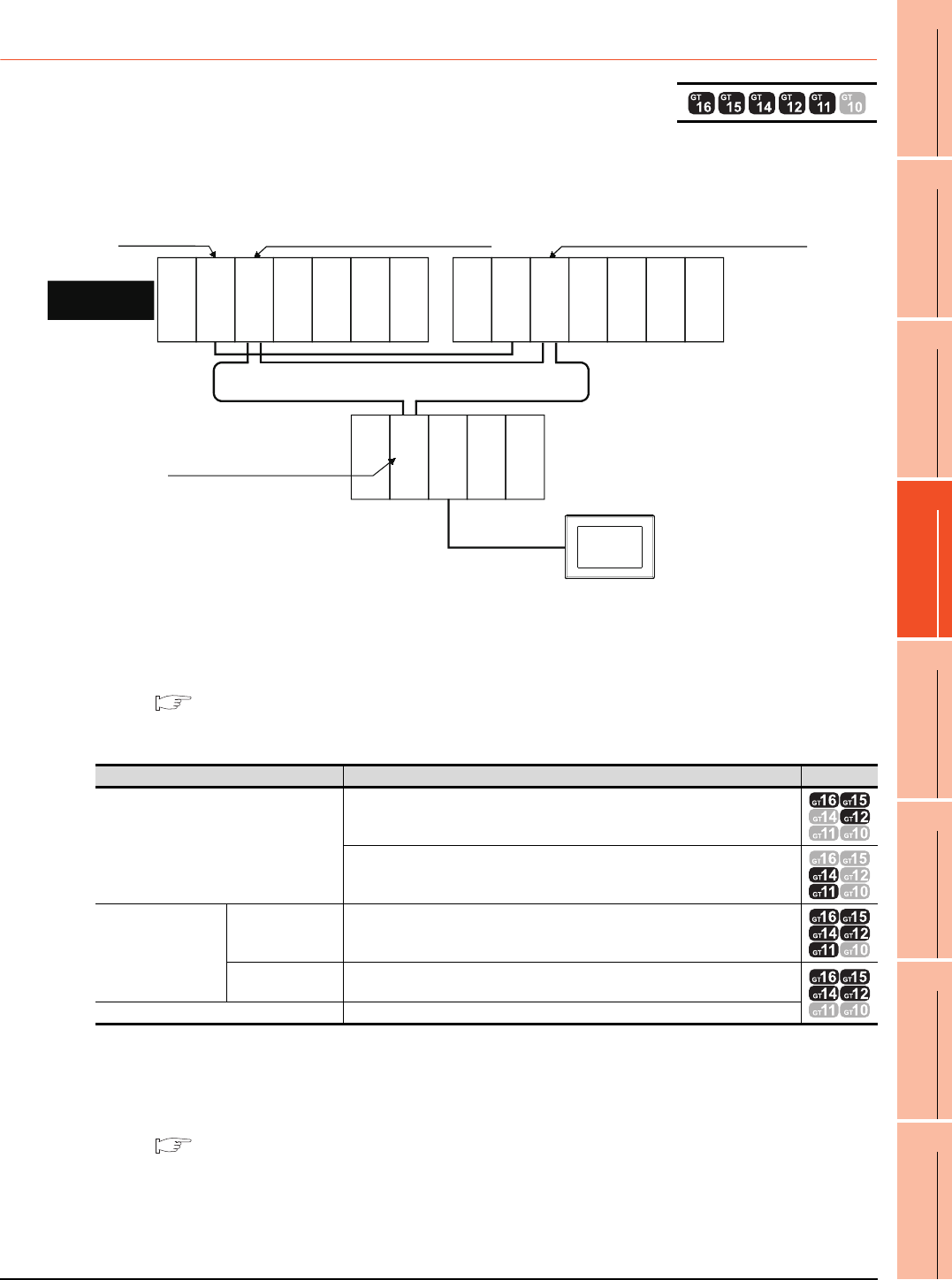
4. HOW TO MONITOR REDUNTANT SYSTEM
4.1 Connection to Remote I/O Station in MELSECNET/H Network System
4 - 9
1
PREPARATORY
PROCEDURES FOR
MONITORING
2
DEVICE RANGE
THAT CAN BE SET
3
ACCESS RANGE
FOR MONITORING
4
HOW TO MONITOR
REDUNTANT
SYSTEM
5
BUS CONNECTION
6
DIRECT
CONNECTION TO
CPU
7
COMPUTER LINK
CONNECTION
8
ETHERNET
CONNECTION
4.1.2 Computer link connection (Connection to serial communication module
mounted on remote I/O station)
This section explains the computer link connection that connects the GOT to the serial communication module mounted
on the remote I/O station of the MELSECNET/H network system.
The following shows an example of connecting the GOT to the serial communication module mounted on the remote I/O
station of the MELSECNET/H network system.
(1) Connection method
Connect the GOT to the serial communication module (QJ71C24, QJ71C24-R2, QJ71C24N, QJ71C24N-R2,
QJ71C24N-R4) or modem interface module (QJ71CM0) mounted on the remote I/ O station of the
MELSECNET/H network system.
For details, refer to the following.
7. COMPUTER LINK CONNECTION
(2) GT Designer3 setting
Set GT Designer3 as follows.
In this case, the GOT monitoring is performed by transient transmission of the MELSECNET/H network system.
Therefore, a longer time-lag occurs for displaying objects compared with directly monitoring the PLC CPU.
For displaying objects with a shorter time-lag, execute the cyclic transmission so that the GOT can monitor link
devices B and W of the host station set in the MELSECNET/H network.
For details, refer to the following manual.
Q Corresponding MELSECNET/H Network System Reference Manual (Remote I/Q network)
(3) Monitoring target change when system switching occurs in a redundant system
When the system switching occurs, the multiplexed remote sub master station switched to the control system
takes over the master operation of MELSECNET/H.
Since the GOT monitors the master station, the monitoring target is automatically changed to the PLC CPU that
is operating as the master.
Setting item Settings Model
Controller Type
MELSEC-QnA/Q/QS, MELDAS C6*
MELSEC-QnA/Q, MELDAS C6*
Device setting
(Network setting)
Host Host
Remote master
station
Other (NW No. 1 (network No. of remote I/O network),
Station No. 0 (master station))
Q Redundant Setting Do not set the item.
Monitor target
MELSECNET/H remote I/O network
Computer link connection
GOT
Network No. 1, Station No. 0
(Multiplexed remote master station)
Q25PRHCPU
QJ71LP21-25
QJ71BR11
QJ71E71-100
QJ61BT11N
Network No. 1, Station No. 1
(Multiplexed remote sub master station)
Standby system
(System B)
Q25PRHCPU
QJ71LP21-25
QJ71BR11
QJ71E71-100
QJ61BT11N
QJ72LP25-25
QJ71C24N
Network No. 1, Station No. 2
(Remote I/O station)
Empty
Empty
Empty
Empty
Power
supply module
Power
supply module
Power
supply module
Control system
(System A)
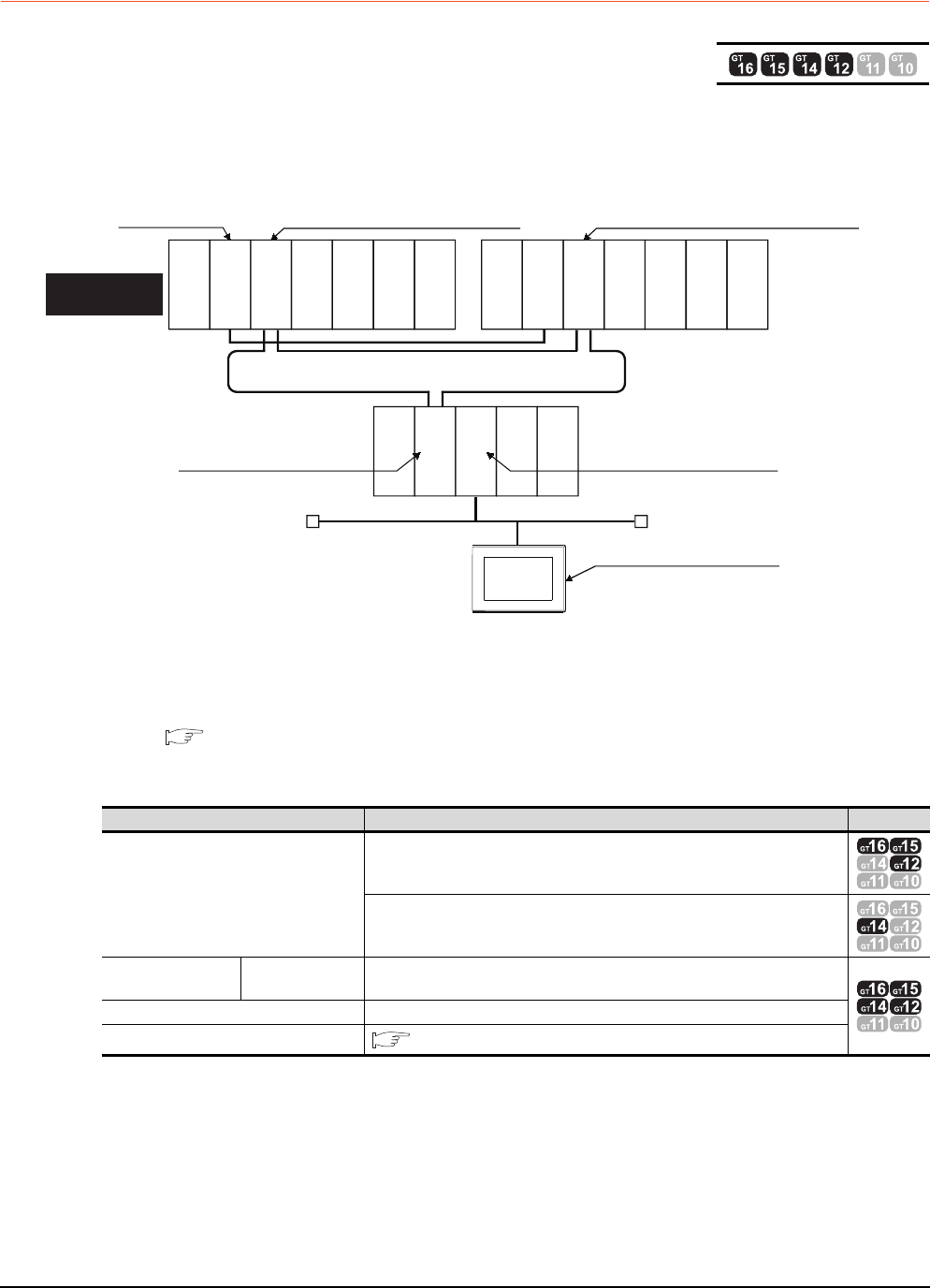
4 - 10 4. HOW TO MONITOR REDUNTANT SYSTEM
4.1 Connection to Remote I/O Station in MELSECNET/H Network System
4.1.3 Ethernet connection (Connection to Ethernet module mounted on remote I/O
station)
This section explains the Ethernet connection for connecting the GOT to the Ethernet module mounted on the remote I/
O station of the MELSECNET/H network system.
The following shows an example of connecting the GOT to the Ethernet module mounted on the I/O station of the
MELESCNET/H network system.
(1) Connection method
Connect the GOT to the Ethernet module (QJ71E71-100, QJ71E71-B5, QJ71E71-B2, QJ71E71) mounted on
the remote I/O station of the MELSECNET/H network system.
For details, refer to the following.
8. ETHERNET CONNECTION
(2) GT Designer3 setting
Set GT Designer3 as follows.
(3) Monitoring target change when system switching occurs in a redundant system
When the system switching occurs, the multiplexed remote sub master station switched to the control system
takes over the master operation of MELSECNET/H.
Since the GOT monitors the master station, the monitoring target is automatically changed to the PLC CPU that
is operating as the master.
Setting item Settings Model
Controller Type
MELSEC-QnA/Q/QS, MELDAS C6*
MELSEC-QnA/Q, MELDAS C6*
Device setting
(Network setting) Other station Other (NW No. 1 (network No. of remote I/O network),
Station No. 0 (master station))
Q Redundant Setting Do not set the item.
Routing Information Setting 8. ETHERNET CONNECTION
Monitor target
Control system
(System A)
Network No. 1, Station No. 0
(Multiplexed remote master station)
Network No. 1, Station No. 2
(remote I/O station)
Network No. 2, Station No. 3
Network No. 2, Station No. 2
Ethernet
GOT
MELSECNET/H remote I/O network
Network No. 1, Station No. 1
(Multiplexed remote sub master station)
Standby system
(System B)
Power supply
module
Q25PRHCPU
Q25PRHCPU
QJ71LP21-25
QJ72LP25-25
QJ71E71-100
QJ71LP21-25
QJ71BR11
QJ71BR11
QJ71E71-100
QJ61BT11N Power supply
module
Power supply
module
Empty
Empty
Empty
Empty
QJ71E71-100
QJ61BT11N
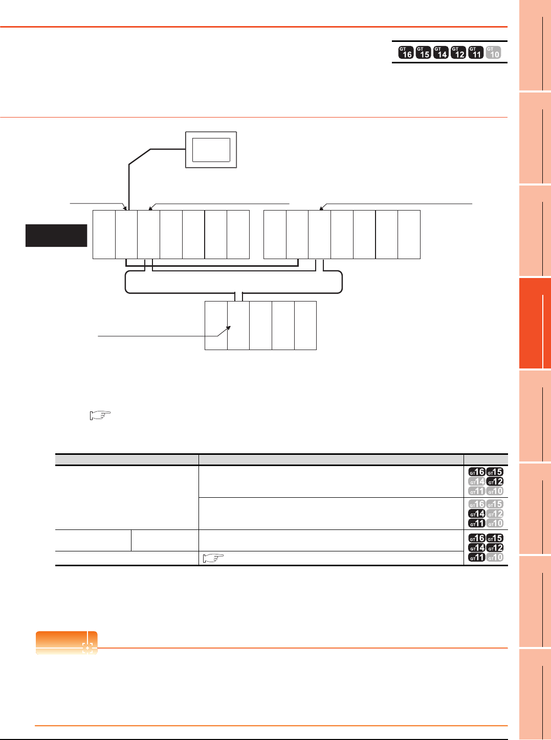
4. HOW TO MONITOR REDUNTANT SYSTEM
4.2 Direct CPU Connection
4 - 11
1
PREPARATORY
PROCEDURES FOR
MONITORING
2
DEVICE RANGE
THAT CAN BE SET
3
ACCESS RANGE
FOR MONITORING
4
HOW TO MONITOR
REDUNTANT
SYSTEM
5
BUS CONNECTION
6
DIRECT
CONNECTION TO
CPU
7
COMPUTER LINK
CONNECTION
8
ETHERNET
CONNECTION
4.2 Direct CPU Connection
This section describes the direct CPU connection by which a GOT is connected to a PLC CPU in the redundant system.
Two methods for the CPU direct connection, using one or two GOTs, are available.
4.2.1 When using one GOT
(1) Connection method
Connect the GOT to the RS-232 interface of the control system CPU module (Q12PRHCPU, Q25PRHCPU) of
the redundant system.
For details, refer to the following.
6. DIRECT CONNECTION TO CPU
(2) GT Designer3 setting
Set GT Designer3 as follows.
(3) Monitoring target change when system switching occurs in a redundant system
When the system switching occurs, the PLC CPU (other station) of the control system after system switching
takes over the host station operation.
Since the GOT monitors the control system, the monitoring target is automatically changed to other station.
POINTPOINTPOINT
To monitor the control system without Q redundant setting
If the system switching occurs when the Q redundant setting is not made, the GOT cannot change the monitoring
target at the occurrence of system switching since it monitors the connected PLC CPU (host station).
As a countermeasure, change the cable connection from the PLC CPU in the previous control system to the control
system after system switching.
Setting item Settings Model
Controller Type
MELSEC-QnA/Q/QS, MELDAS C6*
MELSEC-QnA/Q, MELDAS C6*
Device setting
(Network setting) Host Host
Q Redundant Setting 4.9 Q Redundant Setting
Monitor target
MELSECNET/H remote I/O network
CPU direct connection
GOT
Network No. 1, Station No. 0
(Multiplexed remote master station)
Control system
(System A)
Q25PRHCPU
Power
supply module
QJ71LP21-25
QJ71BR11
QJ71E71-100
QJ61BT11N
Empty
Power
supply module
Empty
Power
supply module
Empty
Empty
Network No. 1, Station No. 1
(Multiplexed remote sub master station)
Standby system
(System B)
QJ72LP25-25
QJ71C24N
Network No. 1, Station No. 2
(remote I/O station)
Q25PRHCPU
QJ71LP21-25
QJ71BR11
QJ71E71-100
QJ61BT11N
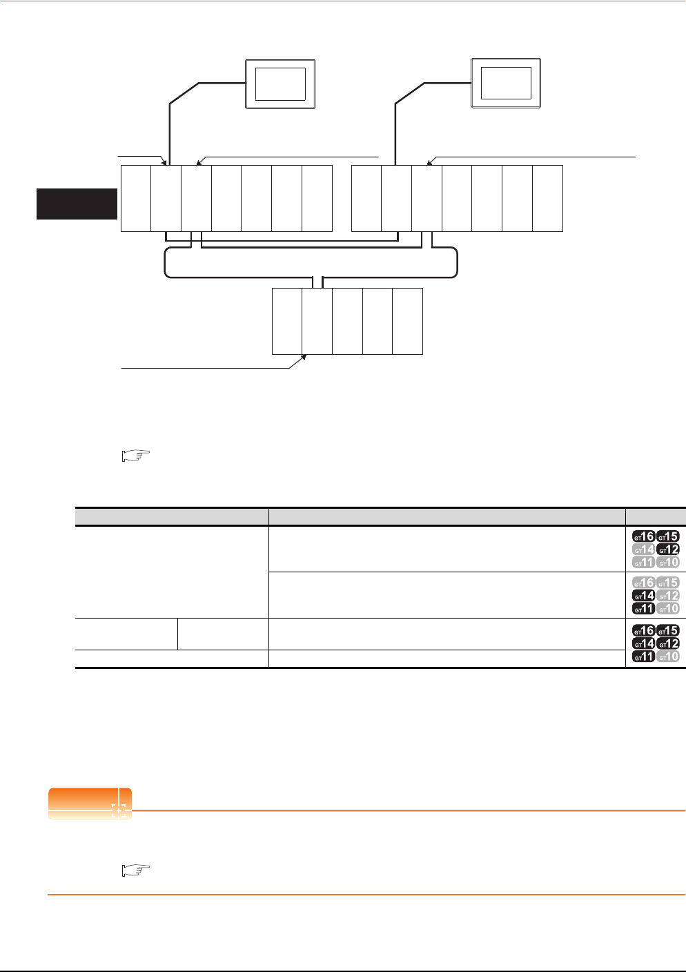
4 - 12 4. HOW TO MONITOR REDUNTANT SYSTEM
4.2 Direct CPU Connection
4.2.2 When using two GOTs
Connect a GOT to each PLC CPU to respond to the system switching.
(1) Connection method
Connect GOTs to the RS-232 interface of the control system and standby system CPU modules (Q12PRHCPU,
Q25PRHCPU) of the redundant system.
For details, refer to the following.
6. DIRECT CONNECTION TO CPU
(2) GT Designer3 setting
Set GT Designer3 as follows.
(3) Monitoring target change when system switching occurs in a redundant system
When the system switching occurs, the GOT cannot change the monitor target automatically in response to the
system switching.
The GOT that is connected to the control system CPU module after system switching continues the monitoring.
Different from the case using one GOT, no cable reconnection is required.
POINTPOINTPOINT
To automatically change the monitoring target after system switching using one GOT, make the Q redundant
settings.
4.9 Q Redundant Setting
Setting item Settings Model
Controller Type
MELSEC-QnA/Q/QS, MELDAS C6*
MELSEC-QnA/Q, MELDAS C6*
Device setting
(Network setting) Host Host
Q Redundant Setting Do not set the item.
Monitor
target
Network No. 1, Station No. 0
(Multiplexed remote master station)
Network No. 1, Station No. 1
(Multiplexed remote sub master station)
Network No. 1, Station No. 2
(remote I/O station)
Power supply
module
Power supply
module
Power supply
module
MELSECNET/H remote I/O network
CPU direct connection
GOT1
Control system
(System A)
Empty
Q25PRHCPU
QJ71LP21-25
QJ71BR11
QJ71E71-100
QJ61BT11N
Standby system
(System B)
QJ72LP25-25
QJ71C24N
Empty
Q25PRHCPU
QJ71LP21-25
QJ71BR11
QJ71E71-100
QJ61BT11N
Empty
Empty
CPU direct connection
GOT2
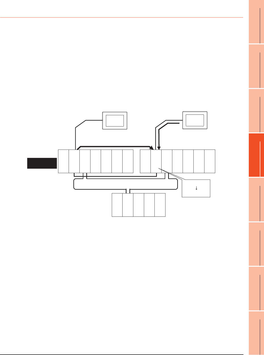
4. HOW TO MONITOR REDUNTANT SYSTEM
4.2 Direct CPU Connection
4 - 13
1
PREPARATORY
PROCEDURES FOR
MONITORING
2
DEVICE RANGE
THAT CAN BE SET
3
ACCESS RANGE
FOR MONITORING
4
HOW TO MONITOR
REDUNTANT
SYSTEM
5
BUS CONNECTION
6
DIRECT
CONNECTION TO
CPU
7
COMPUTER LINK
CONNECTION
8
ETHERNET
CONNECTION
4.2.3 Precautions when connecting a GOT directly to a PLC CPU in the redundant
system without making Q redundant setting
(1) As the GOT monitors exclusively the PLC CPU that is directly connected to, the monitor target cannot be
changed in response to the system switching of the redundant system.
To change the target monitor in response to the system switching, change the target of the connection cable
between the GOT and PLC CPU to the other PLC CPU, or configure the system using GOTs connected to each
PLC CPU.
(2) In CPU direct connection, when monitoring a PLC CPU in the redundant system, only the PLC CPU that is
directly connected to the GOT can be monitored.
(3) When connected to the standby system PLC CPU, the writing of the GOT to a device in the connected PLC
CPU is not reflected. Design a monitor screen that disables writing to the standby system.
In the redundant system, the tracking function transfers device data from control system to standby system.
When the tracking function is enabled, the device value of the standby system PLC CPU is overwritten by the
device value transferred from the control system to the standby system even if the GOT writes to the standby
system PLC CPU (Numerical input, Ascii input, Script, Recipe, or others).
As countermeasures to the above, perform the following.
• Display a monitor screen which indicates that "the connected PLC CPU is the standby system" on a GOT
when connecting the GOT to the standby system PLC CPU.
• To display the specified monitor screen when connecting the GOT to the standby system PLC CPU, use the
special relay SM1515 (Control status identification flag) of the PLC CPU.
(When the SM1515 is OFF, the connected PLC CPU is the standby system)
• Control the operation of each object by the SM1515, which is set for the operation condition.
• For the screen switching device, use a GOT internal device.
If a device of the PLC CPU is used, the Status Observation operation of the GOT may be disabled since the
device data of the PLC CPU will is overwritten by the device value transferred with the redundant system
tracking function.
1) Numerically input D100=100
from the GOT.
1) D100=100
2) D100=5
2) Tracks D100=5 from control
system to standby system.
Power supply
module
Power supply
module
Power supply
module
MELSECNET/H remote I/O network
CPU direct connection CPU direct connection
GOT1
Control system
(System A)
Empty
Empty
Empty
Empty
Q25PRHCPU
QJ71LP21-25
QJ71BR11
QJ71E71-100
QJ61BT11N
Standby system
(System B)
QJ72LP25-25
QJ71C24N
Q25PRHCPU
QJ71LP21-25
QJ71BR11
QJ71E71-100
QJ61BT11N
GOT2
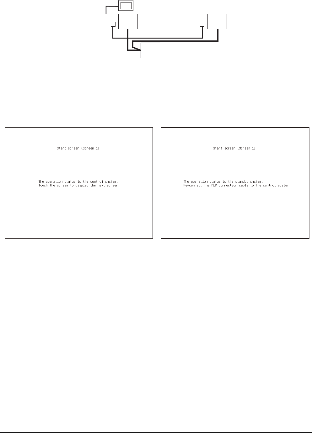
4 - 14 4. HOW TO MONITOR REDUNTANT SYSTEM
4.2 Direct CPU Connection
The following diagram shows an example of screen setting using SM1515.
System configuration example: when using one GOT
Create a monitor screen on the base screen 1 that performs the following operations for when connecting a
GOT to control system and standby system.
1) When connecting to the control system, the monitor screen displays a message calling a touch switch
operation, by which the screen switches to the next screen.
2) When connecting to the standby system, the monitor screen displays a message calling the reconnection of
the connection cable.
1) When connecting to the control system 2) When connecting to the standby system
GOT
Control
system
(System A)
Q25PRH
CPU
QJ71
BR11
Standby
system
(System B)
Station
No. 0
Q25PRH
CPU
QJ71
BR11
Station
No. 1
QJ72
BR15
Station
No. 2
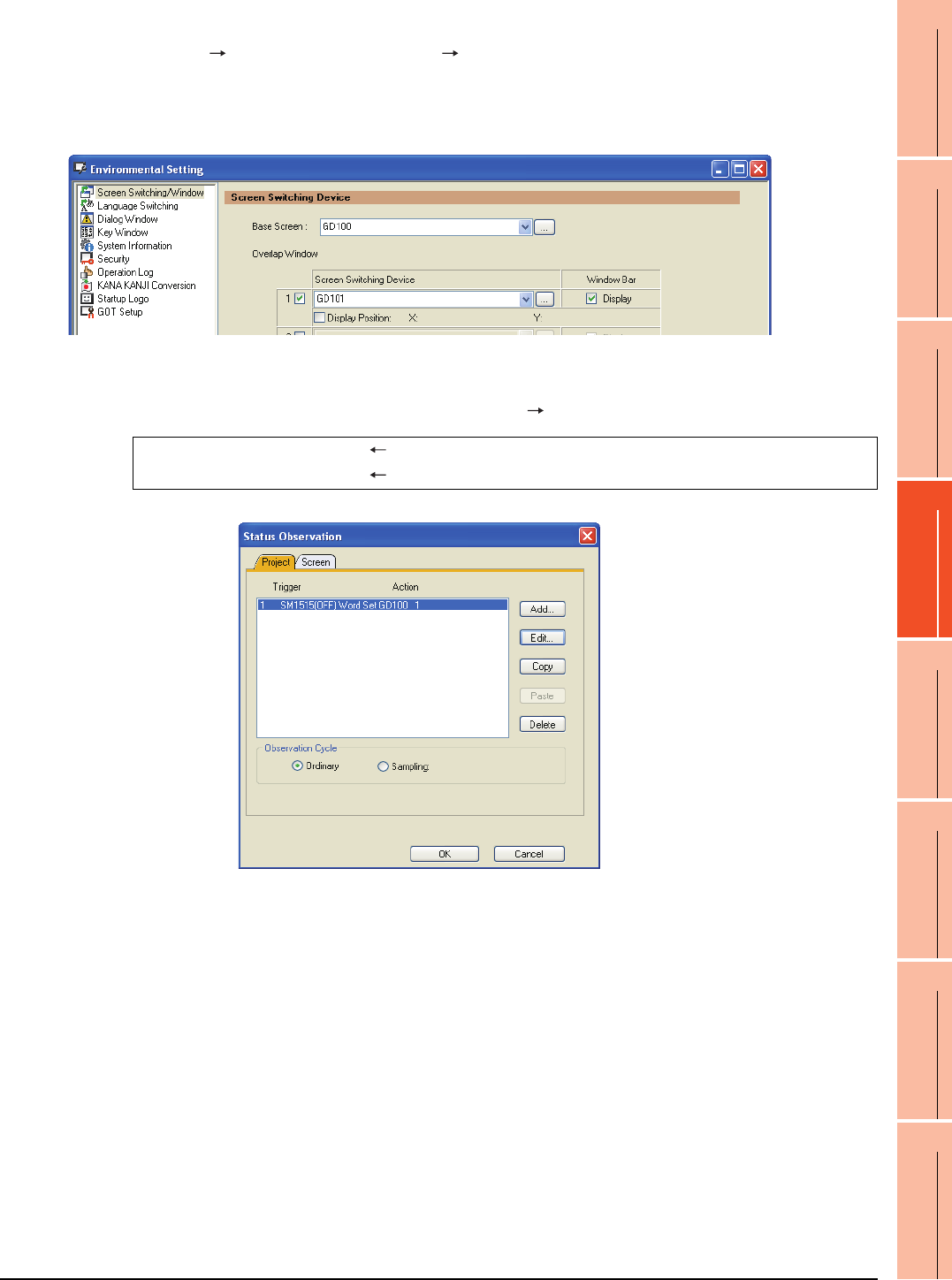
4. HOW TO MONITOR REDUNTANT SYSTEM
4.2 Direct CPU Connection
4 - 15
1
PREPARATORY
PROCEDURES FOR
MONITORING
2
DEVICE RANGE
THAT CAN BE SET
3
ACCESS RANGE
FOR MONITORING
4
HOW TO MONITOR
REDUNTANT
SYSTEM
5
BUS CONNECTION
6
DIRECT
CONNECTION TO
CPU
7
COMPUTER LINK
CONNECTION
8
ETHERNET
CONNECTION
1. Set the screen switching device of the base screen.
Choose [Common] [GOT Environmental Setting] [Screen Switching/Window], and set the internal device
GD100 as the base screen switching device.
(Do not use PLC CPU devices for the screen switching device. If used, the Status Observation operation of the GOT
may be disabled since the device data of the PLC CPU is overwritten by the device value transferred with the
redundant system tracking function)
2. Set the Status Observation.
Make the setting so that the base screen 1 is displayed when the connected PLC CPU is the standby system
(SM1515 is OFF) in the project specified by selecting [Common] [Status Observation].
Create the status observation in the project on the Project tab.
Condition 1 : SM1515 (while OFF) When the SM1515 is OFF, the connected PLC CPU is the standby system.
Operation : GD100=1 The screen switches to the base screen 1.
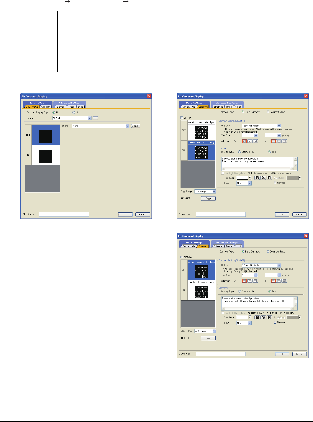
4 - 16 4. HOW TO MONITOR REDUNTANT SYSTEM
4.2 Direct CPU Connection
3. Set the comment display on the base screen 1.
Set a comment to be displayed on the base screen 1 depending on the system status (ON/OFF of the SM1515) of
the connected PLC CPU using the Comment Display (Bit).
Select [Object] [Comment Display] [Bit Comment] and set Comment Display (Bit).
Device/Style tab
Device : SM1515
Shape : None
Comment tab : Basic Comment
Comment Display Type Text (ON) : The operation status is control system.
Touch the screen to display the next screen.
Comment Display Type Text (OFF) : The operation status is standby system.
Reconnect the PLC connection cable to the control system CPU.
1) Device/Style tab screen 2) Comment tab screen (ON status)
3) Comment tab screen (OFF status)
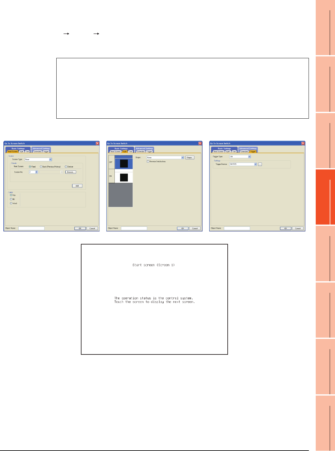
4. HOW TO MONITOR REDUNTANT SYSTEM
4.2 Direct CPU Connection
4 - 17
1
PREPARATORY
PROCEDURES FOR
MONITORING
2
DEVICE RANGE
THAT CAN BE SET
3
ACCESS RANGE
FOR MONITORING
4
HOW TO MONITOR
REDUNTANT
SYSTEM
5
BUS CONNECTION
6
DIRECT
CONNECTION TO
CPU
7
COMPUTER LINK
CONNECTION
8
ETHERNET
CONNECTION
4. Set the touch switches on the base screen 1.
By using the go to screen switch function, set a touch switch for shifting the screen to the next screen with a screen
touch, when the connected PLC CPU is the control system (SM1515 is ON).
Select [Object] [Switch] [Go To Screen Switch] and set the screen switching function.
Set the same size for the touch switch as the base screen size so that touching any place of the screen enables the
switch operation.
Next Screen tab
Screen Type : Base
Go To Screen : Fixed 2
Style tab
Display Style : None (Shape)
Trigger tab
Trigger Type : ON
Trigger Device : SM1515
1) Next Screen tab 2) Style tab screen 3) Trigger tab screen
The following shows the created base screen 1.
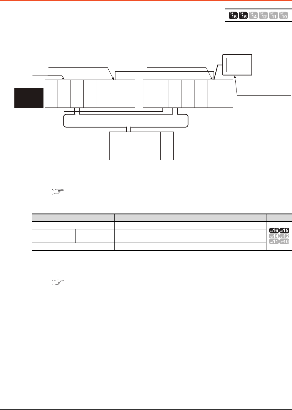
4 - 18 4. HOW TO MONITOR REDUNTANT SYSTEM
4.3 CC-Link Connection (Intelligent Device Station)
4.3 CC-Link Connection (Intelligent Device Station)
This section describes the CC-Link connection (intelligent device station) that connects the GOT set as the intelligent
device station to the CC-Link network.
The following shows an example of connecting the GOT set as the intelligent device station to the CC-Link network.
(1) Connection method
Connect the CC-Link network system to the GOT.
For details, refer to the following.
13. CC-Link CONNECTION (INTELLIGENT DEVICE STATION)
(2) GT Designer3 setting
Set GT Designer3 as follows.
As the monitoring method, "monitoring by transient transmission" and "monitoring by cyclic transmission" are
available. Each monitor method has advantages and disadvantages.
For details, refer to the following.
3.3 CC-Link System Access Range for Monitoring
Setting item Settings Model
Controller Type MELSEC-QnA/Q/QS, MELDAS C6*
Device setting
(Network setting) Master station Other (NW No. 0, Station No. 0 (master station))
Q Redundant Setting Do not set the item.
Monitor target
MELSECNET/H remote I/O network
CC-Link connection
Power
supply module
GOT
Network No. 0, Station No. 0
(Master station)
Control
system
(System A)
Empty
Q25PRHCPU
QJ71LP21-25
QJ71BR11
QJ71E71-100
QJ61BT11N
Network No. 0,
Station No. 2
(Intelligent device station)
Empty
Standby system
(System B)
Q25PRHCPU
QJ71LP21-25
QJ71BR11
QJ71E71-100
QJ61BT11N
QJ72LP25-25
QJ71C24N
CC-Link
Network No. 0, Station No. 1
(Standby master station)
Power
supply module
Power
supply module
Empty
Empty

4. HOW TO MONITOR REDUNTANT SYSTEM
4.3 CC-Link Connection (Intelligent Device Station)
4 - 19
1
PREPARATORY
PROCEDURES FOR
MONITORING
2
DEVICE RANGE
THAT CAN BE SET
3
ACCESS RANGE
FOR MONITORING
4
HOW TO MONITOR
REDUNTANT
SYSTEM
5
BUS CONNECTION
6
DIRECT
CONNECTION TO
CPU
7
COMPUTER LINK
CONNECTION
8
ETHERNET
CONNECTION
(3) Monitoring target change when system switching occurs in a redundant system
(a) System switching due to an alarm occurred in the control system
When system switching occurs, the CC-Link switches the station No. 0 of the master station and the station
No. 1 of the standby master station on the network.
The CC-Link module of the new control system after system switching takes over the control as the master
station.
Since the GOT monitors the master station, the monitoring target is automatically changed to the new
control system after system switching.
(b) System switching due to a network communication error occurred in other than the CC-Link of the control
system, or due to switching by the user
When system switching occurs, the CC-Link does not switch the station No. 0 of the master station and the
station No. 1 of the standby master station on the network.
The CC-Link module of the new control system after system switching takes over the control as the
standby master station.
Since the GOT monitors the master station, the monitoring target is not automatically changed to the new
control system after system switching.
To automatically change the monitoring target of the GOT to the new control system after system switching,
switch the data link control from the standby master station to the master station by the sequence program
of the new control system.
For details of the sequence program, refer to the following manual.
QnPRHCPU User's Manual (Redundant System)
(Sample Programs when Using CC-Link)
POINTPOINTPOINT
CC-Link network setting
To automatically change the monitoring target in the QCPU redundant system when using the CC-Link connection,
set the CC-Link master station as System A and the standby master station as System B.
For details of using the CC-Link network in the redundant system, refer to the following manual.
CC-Link System Master/Local Module User's Manual
QnPRHCPU User's Manual (Redundant System)
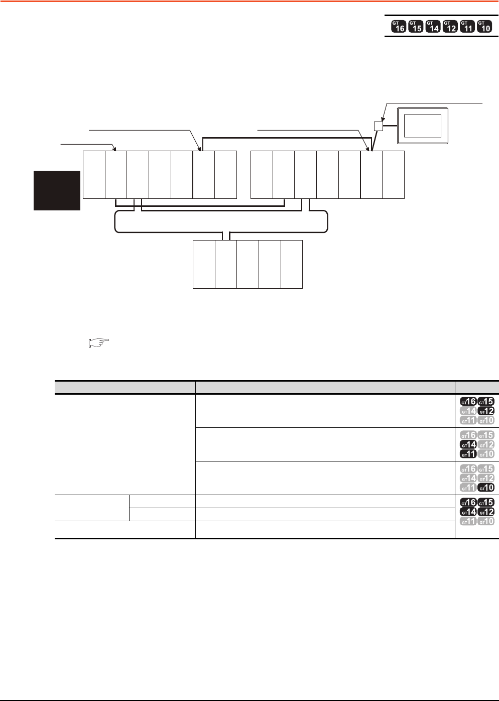
4 - 20 4. HOW TO MONITOR REDUNTANT SYSTEM
4.4 CC-Link Connection (Via G4)
4.4 CC-Link Connection (Via G4)
This section explains the CC-Link connection (via G4) that connects the GOT to the AJ65BT-G4-S3 of the CC-Link
network.
The following shows an example of connecting the GOT to the AJ65BT-G4-S3 of the CC-Link network.
(1) Connection method
Connect the AJ65BT-G4-S3 of the CC-Link network to the GOT.
For details, refer to the following.
14. CC-Link CONNECTION (Via G4)
(2) GT Designer3 setting
Set GT Designer3 as follows.
*1 Only master station can be monitored in GT11 and GT10.The setting of GT Designer3 is not necessary.
Setting item Settings Model
Controller Type
MELSEC-QnA/Q/QS, MELDAS C6*
MELSEC-QnA/Q, MELDAS C6*
MELSEC-QnA/Q
Device setting
(Network setting)
Master station Host
*1
Local station Other (Local station in other than redundant system)
Q Redundant Setting Do not set the item.
Monitor target
Power supply
module
MELSECNET/H remote I/O network
GOT
Network No. 0, Station No. 0
(Master station)
Control
system
(System A)
Empty
Q25PRHCPU
QJ71LP21-25
QJ71BR11
QJ71E71-100
QJ61BT11N
Empty
Standby system
(System B)
Q25PRHCPU
QJ71LP21-25
QJ71BR11
QJ71E71-100
QJ61BT11N
QJ72LP25-25
QJ71C24N
CC-Link
Network No. 0, Station No. 1
(Standby master station)
Network No. 0, Station No. 2
(AJ65BT-G4-S3)
Power supply
module
Power supply
module
Empty
Empty

4. HOW TO MONITOR REDUNTANT SYSTEM
4.4 CC-Link Connection (Via G4)
4 - 21
1
PREPARATORY
PROCEDURES FOR
MONITORING
2
DEVICE RANGE
THAT CAN BE SET
3
ACCESS RANGE
FOR MONITORING
4
HOW TO MONITOR
REDUNTANT
SYSTEM
5
BUS CONNECTION
6
DIRECT
CONNECTION TO
CPU
7
COMPUTER LINK
CONNECTION
8
ETHERNET
CONNECTION
(3) Monitoring target change when system switching occurs in a redundant system
(a) System switching due to an alarm occurred in the control system
When system switching occurs, the CC-Link switches the station No. 0 of the master station and the station
No. 1 of the standby master station on the network.
The CC-Link module of the new control system after system switching takes over the control as the master
station.
Since the GOT monitors the master station, the monitoring target is automatically changed to the new
control system after system switching.
(b) System switching due to a network communication error occurred in other than the CC-Link of the control
system, or due to switching by the user
When system switching occurs, the CC-Link does not switch the station No. 0 of the master station and the
station No. 1 of the standby master station on the network.
The CC-Link module of the new control system after system switching takes over the control as the
standby master station.
Since the GOT monitors the master station, the monitoring target is not automatically changed to the new
control system after system switching.
To automatically change the monitoring target of the GOT to the new control system after system switching,
switch the data link control from the standby master station to the master station by the sequence program
of the new control system.
For details of the sequence program, refer to the following manual.
QnPRHCPU User's Manual (Redundant System)
(Sample Programs when Using CC-Link)
POINTPOINTPOINT
CC-Link network setting
To automatically change the monitoring target in the QCPU redundant system when using the CC-Link connection,
set the CC-Link master station as System A and the standby master station as System B.
For details of using the CC-Link network in the redundant system, refer to the following manual.
CC-Link System Master/Local Module User's Manual
QnPRHCPU User's Manual (Redundant System)
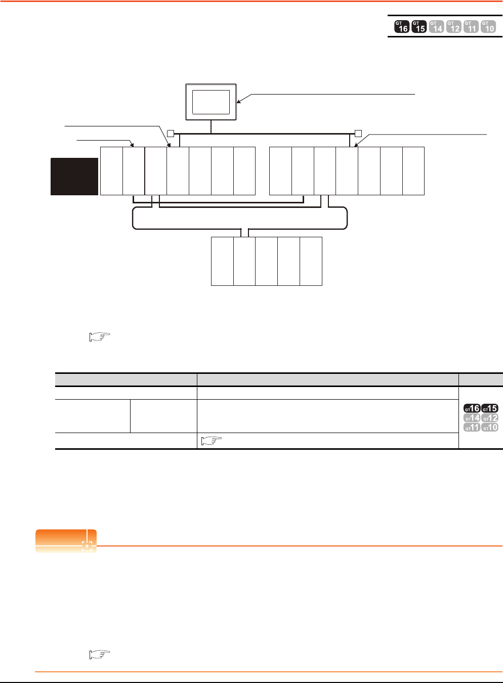
4 - 22 4. HOW TO MONITOR REDUNTANT SYSTEM
4.5 MELSECNET/H and MELSECNET/10 Connections (Network Systems)
4.5 MELSECNET/H and MELSECNET/10 Connections
(Network Systems)
This section explains the MELSECNET/H and MELSECNET/10 connections (network systems) that connect the GOT to
the MELSECNET/H and MELSECNET/10 network system.
The following provides an example of connecting the GOT set as a normal station to the MELSECNET/ H network
system.
(1) Connection method
Connect the MELSECNET/H network system to the GOT.
For details, refer to the following.
9. MELSECNET/H CONNECTION (PLC TO PLC NETWORK)
(2) GT Designer3 setting
Set GT Designer3 as follows.
(3) Monitoring target change when system switching occurs in a redundant system
When system switching occurs, the network module station No. 2 changes from the normal station to the sub
control station and takes over the control of the MELSECNET/H network system.
Since the GOT monitors the control system, the monitoring target is automatically changed to the network
module station No. 2.
POINTPOINTPOINT
To monitor the control system without Q redundant setting
When system switching occurs, the network module station No. 2 changes from the normal station to the sub
control station and takes over the control of the MELSECNET/H network system.
Since the GOT monitors the station of the specified station number, the monitoring target cannot be changed to the
station No. 2 in response to the system switching.
As a countermeasure, create a screen to monitor the PLC CPU of the control system by switching the station
numbers between System A and System B using the script function.
4.10 Switch the Monitor Target to the Control System Using the Script Function
Setting item Settings Model
Controller Type MELSEC-QnA/Q/QS, MELDAS C6*
Device setting
(Network setting) Other station
Other (NW No. 1 (network No. of PLC to PLC network),
Station No. ** (** indicates the station number of the control system. Station No. 1,
in the above example))
Q Redundant Setting 4.9 Q Redundant Setting
Monitor target
MELSECNET/H remote I/O network
Power supply
module
Empty
Empty
GOT
Network No. 1, Station No. 1
(Control station)
Control
system
(System A)
Empty
Q25PRHCPU
QJ71LP21-25
QJ71BR11
QJ71E71-100
QJ61BT11N
Empty
Standby
system
(System B)
Q25PRHCPU
QJ71LP21-25
QJ71BR11
QJ71E71-100
QJ61BT11N
QJ72LP25-25
QJ71C24N
Network No. 1, Station No. 3 (Normal station)
Network No. 1, Station No. 2
(Normal station)
MELSECNET/H PLC to PLC network
(MELSECNET/H mode or
MELSECNET/10 mode)
Power supply
module
Power supply
module
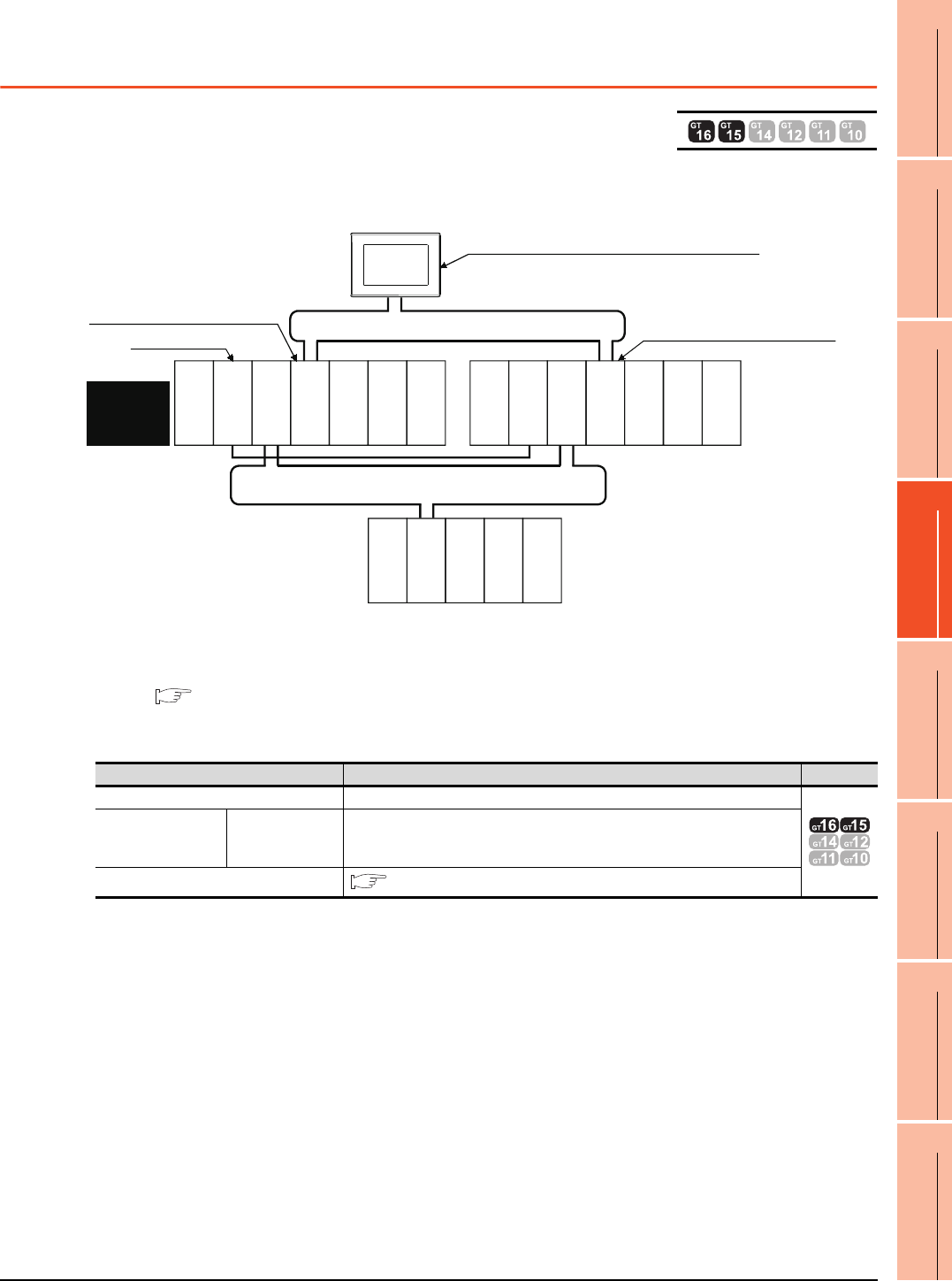
4. HOW TO MONITOR REDUNTANT SYSTEM
4.6 CC-Link IE Controller Network Connection (Network System)
4 - 23
1
PREPARATORY
PROCEDURES FOR
MONITORING
2
DEVICE RANGE
THAT CAN BE SET
3
ACCESS RANGE
FOR MONITORING
4
HOW TO MONITOR
REDUNTANT
SYSTEM
5
BUS CONNECTION
6
DIRECT
CONNECTION TO
CPU
7
COMPUTER LINK
CONNECTION
8
ETHERNET
CONNECTION
4.6 CC-Link IE Controller Network Connection (Network
System)
This section explains the CC-Link IE Controller Network connection (network system) that connects the GOT to the CC-
Link IE controller network.
The following shows an example of connecting the GOT set as a normal station to the CC-Link IE Controller Network.
(1) Connection method
Connect the GOT to the CC-Link IE Controller Network.
For details, refer to the following.
11. CC-Link IE CONTROLLER NETWORK CONNECTION
(2) GT Designer3 setting
Set GT Designer3 as described below.
(3) Monitoring target change when system switching occurs in a redundant system
When system switching occurs, the network module station No.2 changes from a normal station to the sub
control station, and the system with the module takes over the control of the CC-Link IE Controller Network as
the control system.
Since the GOT monitors the control system, the monitoring target is automatically changed to the network
module station No. 2.
Setting item Settings Model
Controller Type MELSEC-QnA/Q/QS, MELDAS C6*
Device setting
(Network) Other station
Other (NW No.1 (Network No. of CC-Link IE Controller Network),
Station No. ** (** indicates the station number of the control system. Station No. 1
in the above example))
Q Redundant Setting 4.9 Q Redundant Setting
GOT
Q25PRHCPU
QJ71LP21-25
QJ71GP21-SX
QJ71E71-100
QJ61BT11N
Q25PRHCPU
QJ71LP21-25
QJ71GP21-SX
QJ71E71-100
QJ61BT11N
QJ72LP25-25
QJ71C24N
Network No. 1, Station No. 1
(Control station)
Network No. 1, Station No. 3 (Normal station)
Monitor target
Network No. 1, Station No. 2
(Normal station)
CC-Link IE Controller Network
Power supply
module
Power supply
module
Standby
system
(System B)
Empty
Empty
Control
system
(System A)
MELSECNET/H remote I/O network
Power supply
module
Empty
Empty
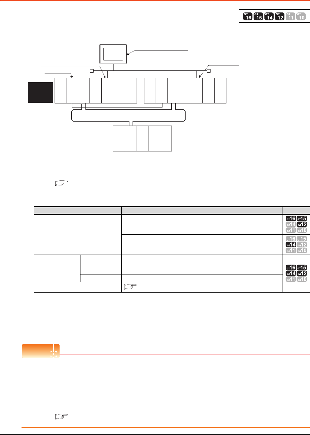
4 - 24 4. HOW TO MONITOR REDUNTANT SYSTEM
4.7 Ethernet Connection
4.7 Ethernet Connection
This section explains the Ethernet connection that connects the GOT to the Ethernet network system.
The following shows an example of connecting the GOT to the Ethernet network.
(1) Connection method
Connect the Ethernet network system to the GOT.
For details, refer to the following.
8. ETHERNET CONNECTION
(2) GT Designer3 setting
Set GT Designer3 as follows.
(3) Monitoring target change when system switching occurs in a redundant system
When system switching occurs, Ethernet module station No. 2 takes over the control of the Ethernet network
system as the control system.
Since the GOT monitors the control system, he monitoring target is automatically changed to the Ethernet
module station No. 2.
POINTPOINTPOINT
When monitoring control system without Q redundant setting (Only GT16, GT15 and GT14)
When system switching occurs, Ethernet module station No. 2 takes over the control of the Ethernet network
system as the control system.
Since the GOT monitors the station of the specified station number, the monitoring target cannot be changed to the
station No. 2 in response to the system switching.
As a countermeasure, create a screen to monitor the PLC CPU of the control system by switching the station
numbers between System A and System B using the script function.
4.10 Switch the Monitor Target to the Control System Using the Script Function
Setting item Settings Model
Controller Type
MELSEC-QnA/Q/QS, MELDAS C6*
MELSEC-QnA/Q, MELDAS C6*
Device setting
(Network setting)
Other station
Other (NW No. 1 (network No. of Ethernet),
Station No. ** (** indicates the station number of the control system. Station No. 1,
in the above example))
Host Host
Q Redundant Setting 4.9 Q Redundant Setting
Monitor target
MELSECNET/H remote I/O network
Power supply
module
Empty
GOT
Network No. 1, Station No. 1
Control
system
(System A)
Empty
Q25PRHCPU
QJ71LP21-25
QJ71BR11
QJ71E71-100
QJ61BT11N
Empty
Standby
system
(System B)
Q25PRHCPU
QJ71LP21-25
QJ71BR11
QJ71E71-100
QJ61BT11N
QJ72LP25-25
QJ71C24N
Network No. 1, Station No. 3
Network No. 1,
Station No. 2
Ethernet
Power supply
module
Power supply
module
Empty
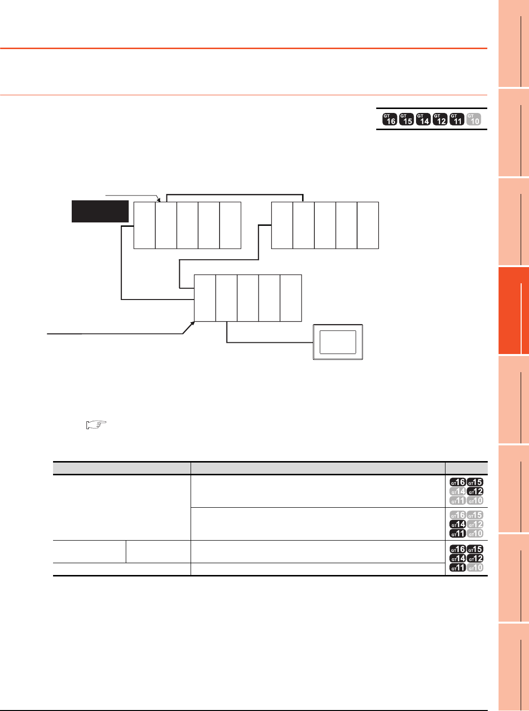
4. HOW TO MONITOR REDUNTANT SYSTEM
4.8 Connection to the Redundant Type Extension Base Unit
4 - 25
1
PREPARATORY
PROCEDURES FOR
MONITORING
2
DEVICE RANGE
THAT CAN BE SET
3
ACCESS RANGE
FOR MONITORING
4
HOW TO MONITOR
REDUNTANT
SYSTEM
5
BUS CONNECTION
6
DIRECT
CONNECTION TO
CPU
7
COMPUTER LINK
CONNECTION
8
ETHERNET
CONNECTION
4.8 Connection to the Redundant Type Extension Base
Unit
4.8.1 Computer link connection (Connection to the Serial communication module
mounted on the redundant type extension base unit)
This section explains the computer link connection for connecting the GOT to the serial communication module mounted
on the redundant type extension base unit.
The following shows an example of connecting the GOT to the serial communication module mounted on the redundant
type extension base unit.
(1) Connection method
Connect the GOT to the serial communication module (QJ71C24N) mounted on the redundant type extension
base unit.
For details, refer to the following.
7. COMPUTER LINK CONNECTION
(2) GT Designer3 setting
Set GT Designer3 as follows.
(3) Monitoring target change when system switching occurs in a redundant system
When the system switching occurs, the GOT automatically changes the monitoring target to the PLC CPU
switched to the control system.
Setting item Settings Model
Controller Type
MELSEC-QnA/Q/QS, MELDAS C6*
MELSEC-QnA/Q, MELDAS C6*
Device setting
(Network setting) Host Host
Q Redundant Setting Do not set the item.
Computer link
connection
Redundant type extension base unit
Monitor target
Control system
(System A)
GOT
Standby system
(System B)
Power supply
module
Power supply
module
Power supply
module
Q25PRHCPU
QJ71C24N
Q25PRHCPU
QJ71BR11
QJ71BR11
Empty
Empty
Empty
Empty
Empty
Empty
Empty
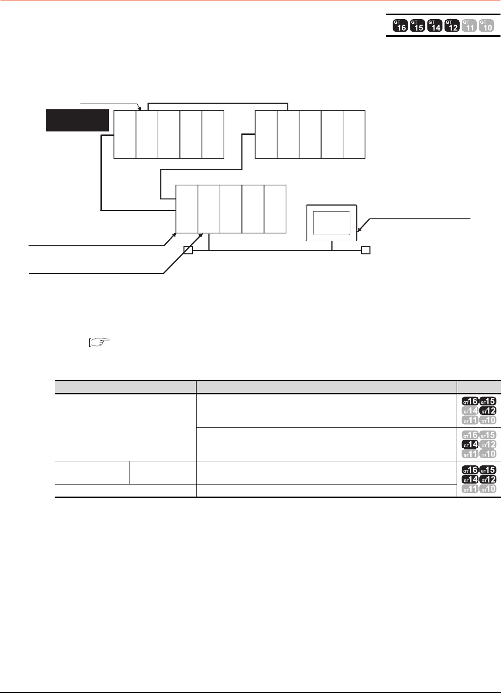
4 - 26 4. HOW TO MONITOR REDUNTANT SYSTEM
4.8 Connection to the Redundant Type Extension Base Unit
4.8.2 Ethernet connection (Connection to the Ethernet module mounted on
redundant type extension base unit)
This section explains the Ethernet connection for connecting the GOT to the Ethernet module mounted on the redundant
type extension base unit.
The following shows an example of connecting the GOT to the Ethernet module mounted on the redundant type
extension base unit.
(1) Connection method
Connect the GOT to the Ethernet module (QJ71E71-100, QJ71E71-B5, QJ71E71-B2) mounted on the
redundant type extension base unit.
For details, refer to the following.
8. ETHERNET CONNECTION
(2) GT Designer3 setting
Set GT Designer3 as follows.
(3) Monitoring target change when system switching occurs in a redundant system
When the system switching occurs, the GOT automatically changes the monitoring target to the PLC CPU
switched to the control system.
Setting item Settings Model
Controller Type
MELSEC-QnA/Q/QS, MELDAS C6*
MELSEC-QnA/Q, MELDAS C6*
Device setting
(Network setting) Host Host
Q Redundant Setting Do not set the item.
Monitor target
Control system
(System A)
GOT
Standby system
(System B)
Power supply
module
Power supply
module
Power supply
module
Q25PRHCPU
QJ71E71-100
Q25PRHCPU
QJ71BR11
QJ71BR11
Empty
Empty
Empty
Empty
Empty
Empty
Empty
Ethernet connection
Redundant type extension base unit
Network No.2, Station No.1
(Ethernet module)
Network No. 2, Station No. 2
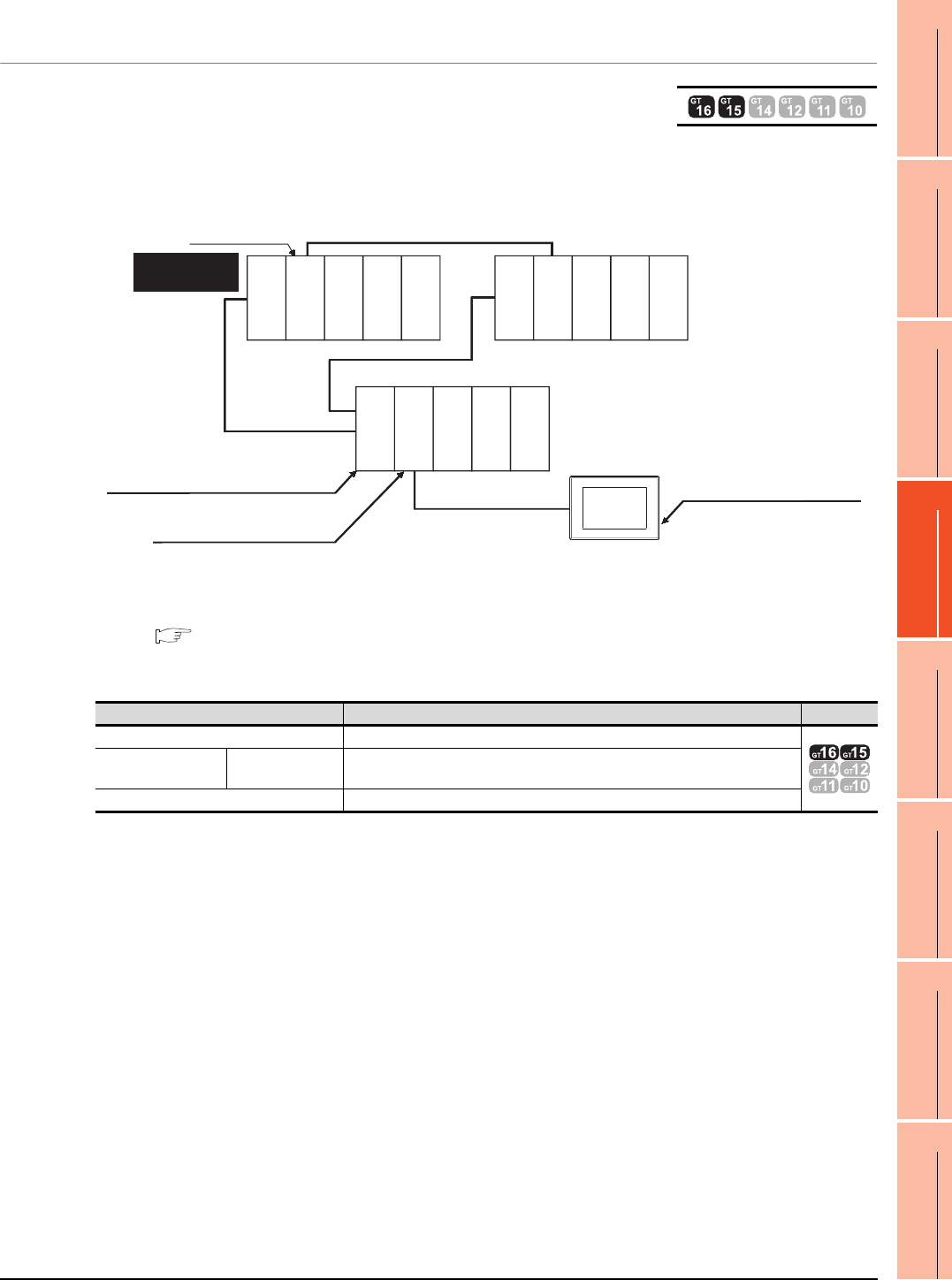
4. HOW TO MONITOR REDUNTANT SYSTEM
4.8 Connection to the Redundant Type Extension Base Unit
4 - 27
1
PREPARATORY
PROCEDURES FOR
MONITORING
2
DEVICE RANGE
THAT CAN BE SET
3
ACCESS RANGE
FOR MONITORING
4
HOW TO MONITOR
REDUNTANT
SYSTEM
5
BUS CONNECTION
6
DIRECT
CONNECTION TO
CPU
7
COMPUTER LINK
CONNECTION
8
ETHERNET
CONNECTION
4.8.3 CC-Link connection (intelligent device station) (Connection to the CC-Link
module mounted on redundant type extension base unit)
This section explains the CC-Link connection for connecting the GOT to the CC-Link module mounted on the redundant
type extension base unit.
The following shows an example of connecting the GOT to the CC-Link module mounted on the redundant type
extension base unit.
(1) Connection method
Connect the GOT to the CC-Link module (QJ61BT11N) mounted on the redundant type extension base unit.
For details, refer to the following.
13. CC-Link CONNECTION (INTELLIGENT DEVICE STATION)
(2) GT Designer3 setting
Set GT Designer3 as follows.
(3) Monitoring target change when system switching occurs in a redundant system
When the system switching occurs, the GOT automatically changes the monitoring target to the PLC CPU
switched to the control system.
Setting item Settings Model
Controller Type MELSEC-QnA/Q/QS, MELDAS C6*
Device setting
(Network setting) Master station Other (NW No. 0, Station No. 0 (master station))
Q Redundant Setting Do not set the item.
Monitor target
Control system
(System A)
GOT
Standby system
(System B)
Power supply
module
Power supply
module
Power supply
module
Q25PRHCPU
QJ61BT11N
Q25PRHCPU
QJ71BR11
QJ71BR11
Empty
Empty
Empty
Empty
Empty
Empty
Empty
CC-Link connection
Redundant type extension base unit
Network No. 0, Station No. 0
(Master station)
Network No. 0, Station No. 1
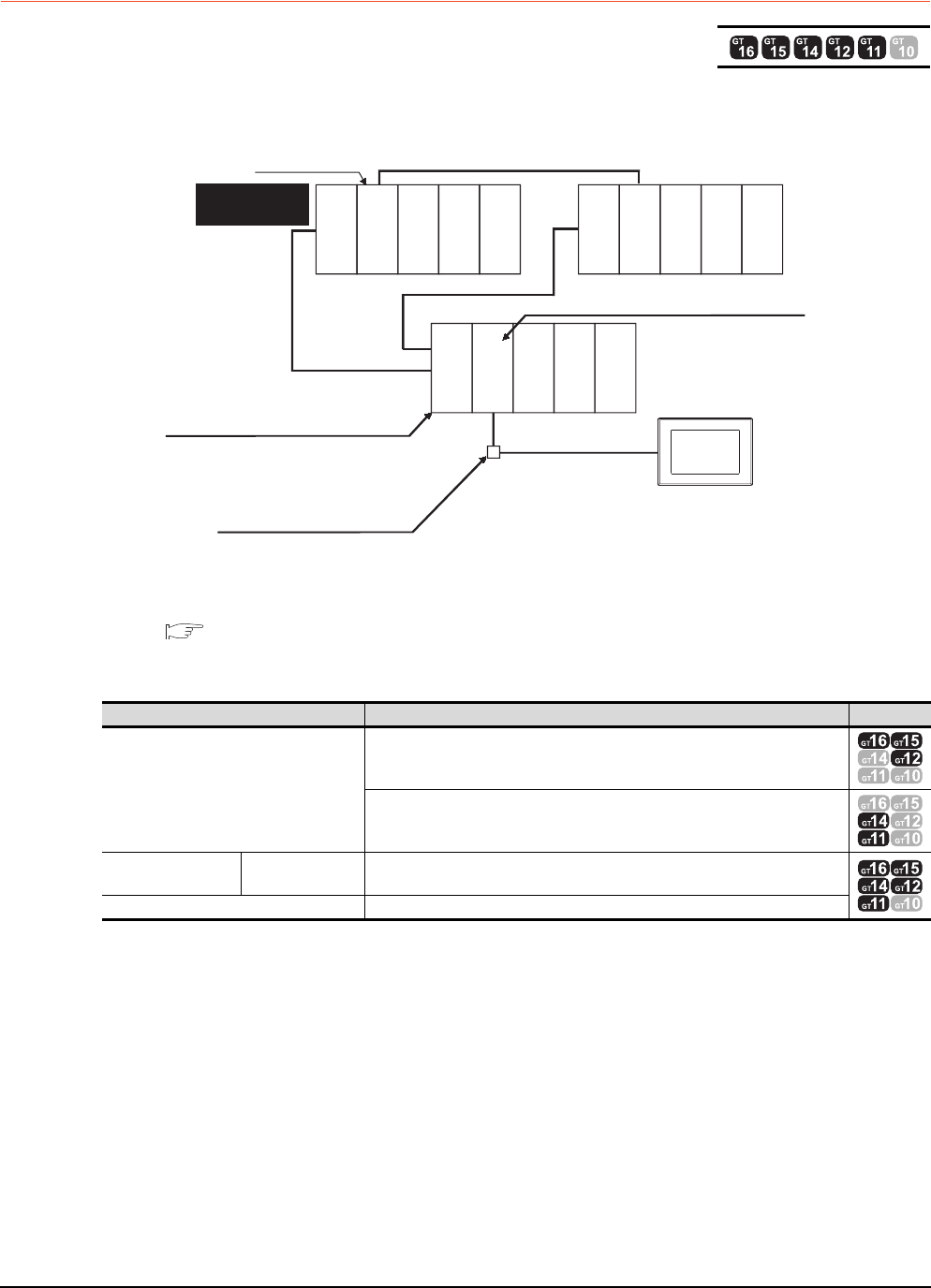
4 - 28 4. HOW TO MONITOR REDUNTANT SYSTEM
4.8 Connection to the Redundant Type Extension Base Unit
4.8.4 CC-Link connection (Via G4) (Connection to the CC-Link module mounted
on redundant type extension base unit)
This section explains the CC-Link connection (Via G4) for connecting the GOT to the CC-Link module mounted on the
redundant type extension base unit via the AJ65BT-G4-S3.
The following shows an example of connecting the GOT to the AJ65BT-G4-S3 of the CC-Link network.
(1) Connection method
Connect the AJ65BT-G4-S3 of the CC-Link network to the GOT.
For details, refer to the following.
14. CC-Link CONNECTION (Via G4)
(2) GT Designer3 setting
Set GT Designer3 as follows.
(3) Monitoring target change when system switching occurs in a redundant system
When the system switching occurs, the GOT automatically changes the monitoring target to the PLC CPU
switched to the control system.
Setting item Settings Model
Controller Type
MELSEC-QnA/Q/QS, MELDAS C6*
MELSEC-QnA/Q, MELDAS C6*
Device setting
(Network setting) Master station Other (NW No.0, Station No.0 or FF (master station))
Q Redundant Setting Do not set the item.
Monitor target
Control system
(System A)
GOT
Standby system
(System B)
Power supply
module
Power supply
module
Power supply
module
Q25PRHCPU
QJ61BT11N
Q25PRHCPU
QJ71BR11
QJ71BR11
Empty
Empty
Empty
Empty
Empty
Empty
Empty
CC-Link
connection
Redundant type extension base unit
Network No. 0, Station No. 1
(AJ65BT-G4-S3)
Network No. 0, Station No. 0
(Master station)
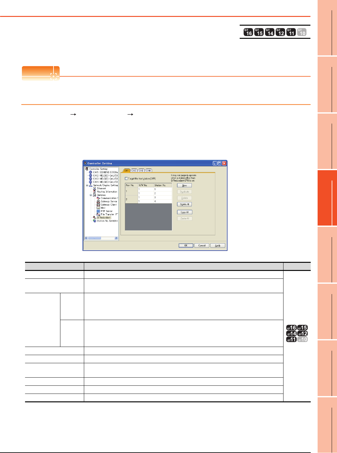
4. HOW TO MONITOR REDUNTANT SYSTEM
4.9 Q Redundant Setting
4 - 29
1
PREPARATORY
PROCEDURES FOR
MONITORING
2
DEVICE RANGE
THAT CAN BE SET
3
ACCESS RANGE
FOR MONITORING
4
HOW TO MONITOR
REDUNTANT
SYSTEM
5
BUS CONNECTION
6
DIRECT
CONNECTION TO
CPU
7
COMPUTER LINK
CONNECTION
8
ETHERNET
CONNECTION
4.9 Q Redundant Setting
The following explains the setting for automatically change the monitoring target of the GOT when monitoring a QCPU
redundant system.
POINTPOINTPOINT
Before making the Q redundant setting
In the Q redundant setting, do not set stations other than redundant CPUs.
1. Select [Common] [Controller Setting] [Q Redundant] from the menu.
2. The setting dialog box appears. Make the settings with reference to the following explanation.
3. Make the settings for the Q redundant setting.
In the Q Redundant Setting dialog box, settings can be made for each channel of the controller.
(Example: Ethernet connection (Station No. 5), redundant CPU pair No. 1 and No. 2, redundant CPU station No. 1 to 4)
For details of *1, refer to the explanation below.
*2 GT14, GT12, GT11 are applicable to built-in serial interface only.
Item Contents Model
CH1 to CH4 Select a tab of the CH No. for the Q redundant setting.
*2
Target at its own Station
(0-FF)
Select this item to monitor the control system as a host station.
(In Ethernet connection, not available even when selected)
Pair No.*1
NW No.
Set the network No. (1 to 225) for each of pair numbers (1 to 64).
Upper row: Setting for the first redundant CPU.
Lower row: Setting for the second redundant CPU.
(The same value as the value set for the first redundant CPU is displayed)
Station
No.
Set the station No. (1 to 63) of the redundant CPU for each of pair numbers (1 to 64).
Upper row: Setting for the first redundant CPU.
Lower row: Setting for the second redundant CPU.
(The value of "Setting for the first redundant CPU" + 1 is displayed)
New Create a new pair No.
Duplicate Copies one setting of the selected pair number to append it at the last line.
Delete Deletes one setting of the selected pair.
After deletion, the succeeding pair numbers are renumbered to fill the deleted pair number.
Delete All Deletes the setting of all pair numbers.
Copy All Copies the Q redundant setting on the selected CH No. tab.
Paste All Pastes the copied Q redundant setting in the selected CH No. tab.
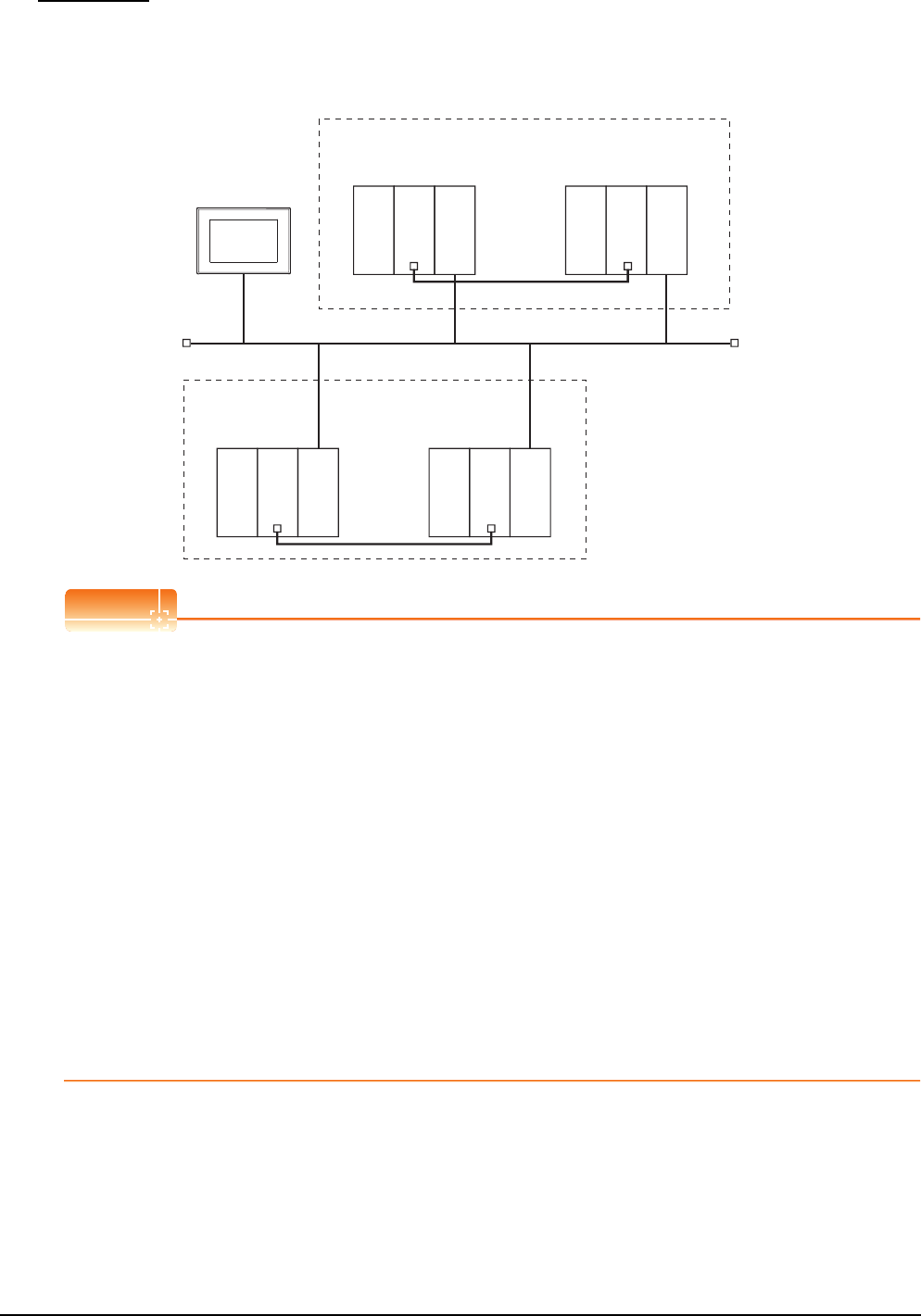
4 - 30 4. HOW TO MONITOR REDUNTANT SYSTEM
4.9 Q Redundant Setting
*1 Pair number
Redundant CPU pair means the redundant CPUs (System A / System B) in the redundant system configuration.
Pair number is the number assigned to each redundant CPU pair.
Example: Ethernet connection (Pair No. 1 and Pair No. 2)
POINTPOINTPOINT
Precautions for making Q redundant setting
Pay attention to the following items when making the Q redundant setting.
• In the setting, station Nos. of the System A CPU and System B CPU must be adjacent numbers to be set as a
pair.
As long as adjacent numbers are used, allocation of them to the System A CPU and System B CPU may be
determined as desired.
• Pairing of the last station No. and station No. 1 (Example: Station No. 64 and station No. 1) is not allowed.
• Make sure that the QCPU in the station for which Q redundant setting is made is a redundant CPU.
If any of the QCPUs to which the Q redundant setting is made is not a redundant CPU, the GOT fails to
automatically change the monitoring target to the control system when the system is switched.
• When making the Q redundant setting for MELSECNET/H, MELSECNET/10, or Ethernet connections, check
the station Nos. of network modules before the setting. If the settings of the Q redundant setting and the actual
network module station Nos. are not matched, the GOT fails to automatically change the monitoring target to
the control system when the system is switched.
• The redundant pair number setting is necessary in the Q redundant setting when the monitoring target changes
automatically at the system switching with the host station specified in Ethernet connection. (The "Target at its
own Station (0-FF)" function of the Q redundant setting is not valid in Ethernet connection.)
• GOT supports the backup mode (separate mode), which is the operation mode of the QCPU redundant system,
and does not support the debug mode.
GOT
<System A>
Redundant CPU pair (No.1)
Ethernet (Network No.1)
Station
No.1
Station
No.5
Station
No.2
<System B>
Q25PRHCPU
Power supply
module
Power supply
module
QJ71E71-100
Q25PRHCPU
QJ71E71-100
<System A>
Redundant CPU
pair (No.2) Station
No.3
Station
No.4
<System B>
Q25PRHCPU
Power supply
module
Power supply
module
QJ71E71-100
Q25PRHCPU
QJ71E71-100
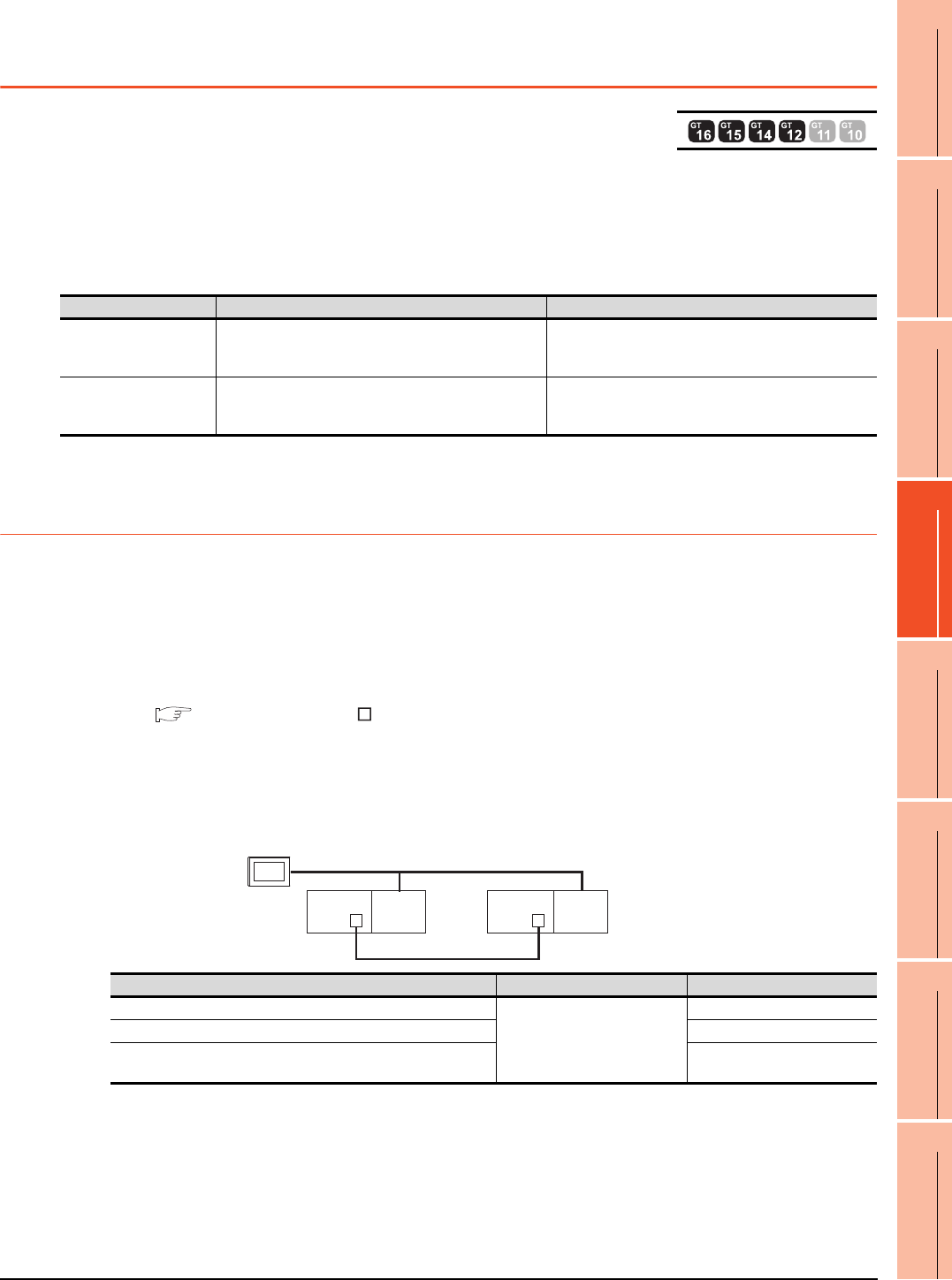
4. HOW TO MONITOR REDUNTANT SYSTEM
4.10 Switch the Monitor Target to the Control System Using the Script Function
4 - 31
1
PREPARATORY
PROCEDURES FOR
MONITORING
2
DEVICE RANGE
THAT CAN BE SET
3
ACCESS RANGE
FOR MONITORING
4
HOW TO MONITOR
REDUNTANT
SYSTEM
5
BUS CONNECTION
6
DIRECT
CONNECTION TO
CPU
7
COMPUTER LINK
CONNECTION
8
ETHERNET
CONNECTION
4.10 Switch the Monitor Target to the Control System
Using the Script Function
The following explains how to create a script screen, to be used for the MELSECNET/H or MELSECNET/10
connection (network system), or Ethernet connection, that automatically changes the monitoring target (Station No.)
at the occurrence of system switching even if the Q redundant setting is not made.
The script executes the station number switching function or screen switching function.
The following shows the advantages and disadvantages of the station number switching function and screen
switching function.
The following explains how to use each function.
4.10.1 Method for using the station number switching function
• As a feature of this function, monitor screens for Station No. 1 (control system) and Station No. 2 (standby system)
can be created on one screen.
• If the system switching occurs, the GOT can change the monitoring target to the control system PLC CPU on the
same monitor screen.
• To achieve this, the script of the GOT monitors the special relay SM1515 (Control system identification flag) of the
PLC CPU and stores the station number of the latest control system into the station number switching device.
• Restrictions: Some objects do not allow the station number to be switched.
GT Designer3 Version Screen Design Manual
Setting method (For MELSECNET/H connection, MELSECNET/10 connection)
System configuration example 1: MELSECNET/H connection, MELSECNET/10 connection
Function Advantage Disadvantage
Station number switching
function
The monitor screens for Station No. 1 (control system)
and Station No. 2 (standby system) can be created on one
screen.
Some objects do not allow the station number to be
switched.
Screen switching function All objects can be used since monitor screens are created
for each station number.
Monitor screens must be created separately for Station
No. 1 (control system) and Station No. 2 (standby
system).
Connected module Network No. Station No.
MELSECNET/H network module of control system
1
1
MELSECNET/H network module of standby system 2
GOT connected to MELSECNET/H network or MELSECNET/10
network 3
MELSECNET/H
(MELSECNET/H mode or MELSECNET/10 mode)
Network No. 1
GOT
Station
No. 3
Control system
(System A)
Q25PRH
CPU
QJ71
BR11
Standby system
(System B)
Station No. 1
Q25PRH
CPU
QJ71
BR11
Station No. 2
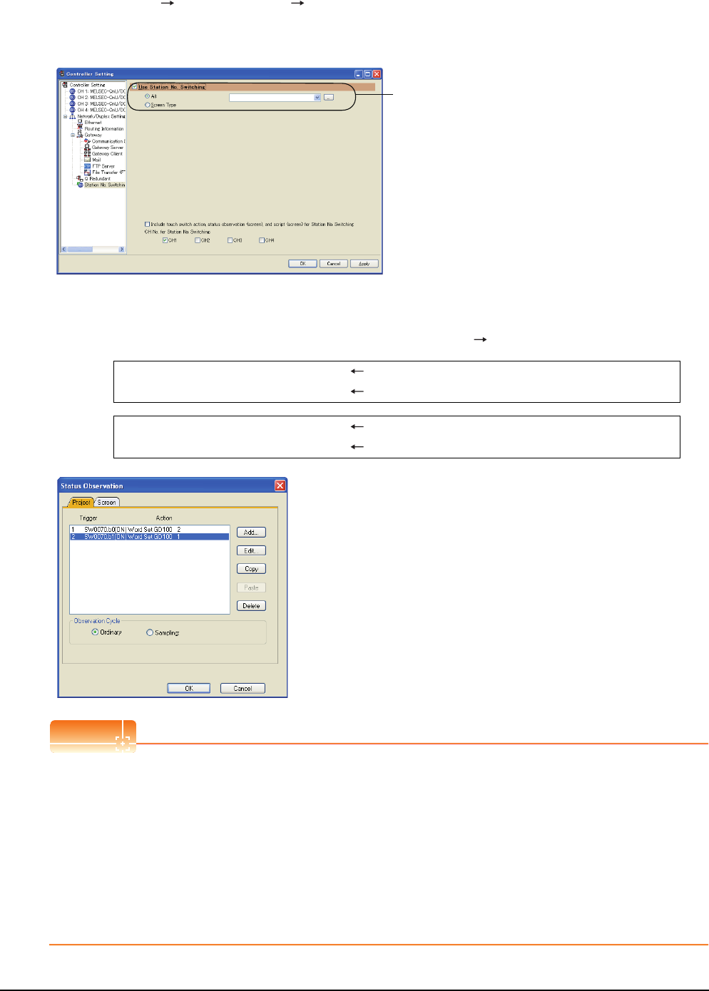
4 - 32 4. HOW TO MONITOR REDUNTANT SYSTEM
4.10 Switch the Monitor Target to the Control System Using the Script Function
1. Set the station number switching device.
Select [Common] [Controller Setting] [Station No. Switching], and set the internal device GD100 as the
station number switching device.
Do not use a device of PLC CPU as a screen switching device. Since the device information is transferred by the
tracking transfer function of the redundant system, the status observation may be disabled.
2. Set the status observation.
Make the settings so that the station number is switched when the faulty station information (SW70) of
MELSECNET/H turns ON in the project specified by selecting [Common] [Status Observation].
Create the status observation in the project on the Project tab.
POINTPOINTPOINT
Setting for the status observation function
For the status observation function, hexadecimals cannot be used.
To use the status observation function, set the N/W No. and the station No. of the PLC CPU in [Unsigned BIN].
(For the status observation function, set [Unsigned BIN] for [Storing Device])
Example:
When N/W No.: 1 and Station No.: 1 (0101H)
Set "257".
When N/W No.: 10 and Station No.: 10 (0A0AH)
Set "2570".
Set here.
Condition 1 : SW70.b0 (while ON) When b0 is ON, Station No. 1 is abnormal.
Operation : GD100=2 Station No. is changed to 2.
Condition 1 : SW70.b1 (while ON) When b1 is ON, Station No. 2 is abnormal.
Operation : GD100=1 Station No. is changed to 1.
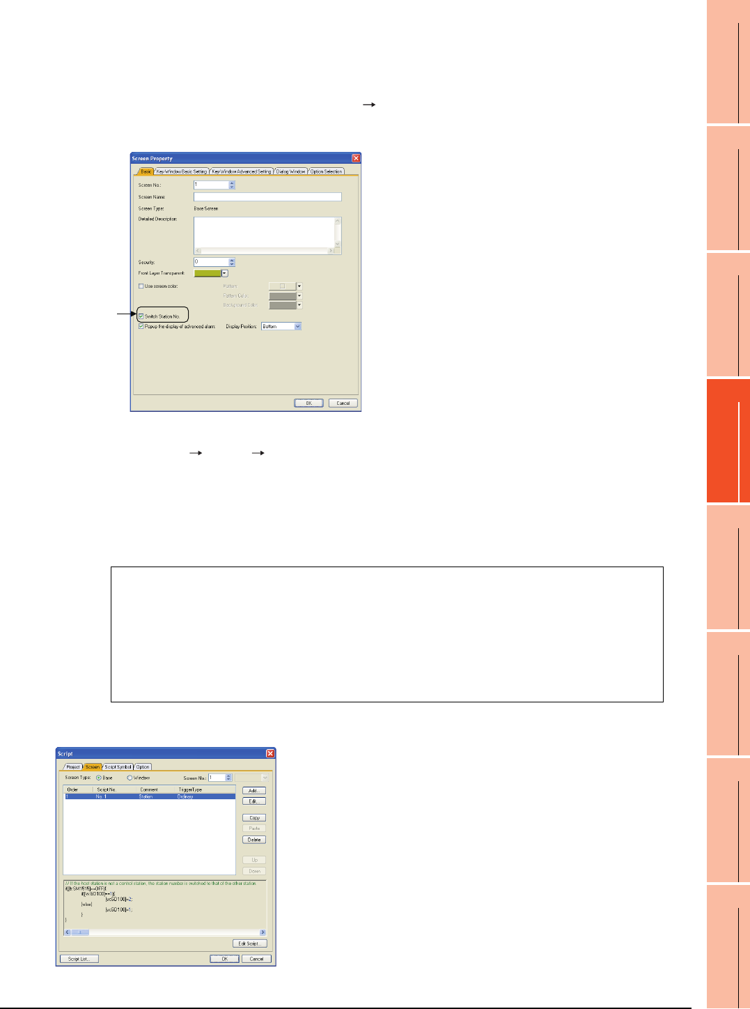
4. HOW TO MONITOR REDUNTANT SYSTEM
4.10 Switch the Monitor Target to the Control System Using the Script Function
4 - 33
1
PREPARATORY
PROCEDURES FOR
MONITORING
2
DEVICE RANGE
THAT CAN BE SET
3
ACCESS RANGE
FOR MONITORING
4
HOW TO MONITOR
REDUNTANT
SYSTEM
5
BUS CONNECTION
6
DIRECT
CONNECTION TO
CPU
7
COMPUTER LINK
CONNECTION
8
ETHERNET
CONNECTION
3. Create a monitor screen.
For MELSECNET/H connection, MELSECNET/10 connection or Ethernet connection: (Common)
In the device setting (network setting) of each object, set Network No. 1 and Station No. 1 of the control system.
4. Validate the station number switching function.
On the Basic tab screen specified by selecting [Screen] [Screen Property], select the item [Switch Station No.] to
validate the station number changing function.
Make this setting for each monitor screen.
5. Change the station number switching device value in the script.
By selecting [Common] [Script] [Script], create a script for each monitor screen that checks the SM1515
status of the current monitor station, and if it is OFF (standby system), changes the station number switching device
value.
Set the trigger type of the script as [Ordinary] or [Sampling(about 3s)].
• Screen script for MELSECNET/H connection and MELSECNET/10 connection:
Set the created script for each screen on the Screen tab.
// If the host station is not a control station, the station number is switched to that of the other station.
if([b:SM1515]==OFF){
if([w:GD100]==1){
[w:GD100]=2;
}else{
[w:GD100]=1;
}
}
Check here.
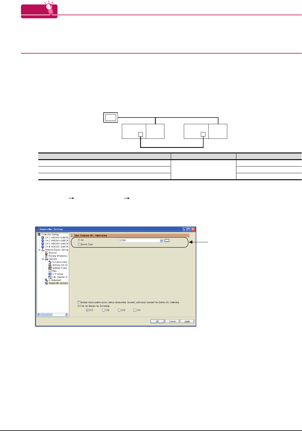
4 - 34 4. HOW TO MONITOR REDUNTANT SYSTEM
4.10 Switch the Monitor Target to the Control System Using the Script Function
HINTHINTHINT
When the MELSECNET/H network is connected to the redundant system only, SW56 (current control station) can
be set as the station number switching device.
In this case, even if the system switching occurs, the GOT always monitors the station number that is currently the
control station.
Setting method (Ethernet connection)
System configuration example 2: Ethernet connection
1. Set the station number switching device.
Select [Common] [Controller Setting] [Station No. Switching], and set the internal device GD100 as the
station number switching device.
Do not use a device of PLC CPU as a screen switching device. Since the device information is transferred by the
tracking transfer function of the redundant system, the status observation may be disabled.
Connected module Network No. Station No.
Ethernet module of control system
1
1
Ethernet module of standby system 2
GOT connected to the Ethernet network 3
Ethernet
Network No. 1
GOT
Station No. 3
Control system
(System A)
Q25PRH
CPU
QJ71
E71
Standby system
(System B)
Station No. 1
Q25PRH
CPU
QJ71
E71
Station No. 2
Set here.
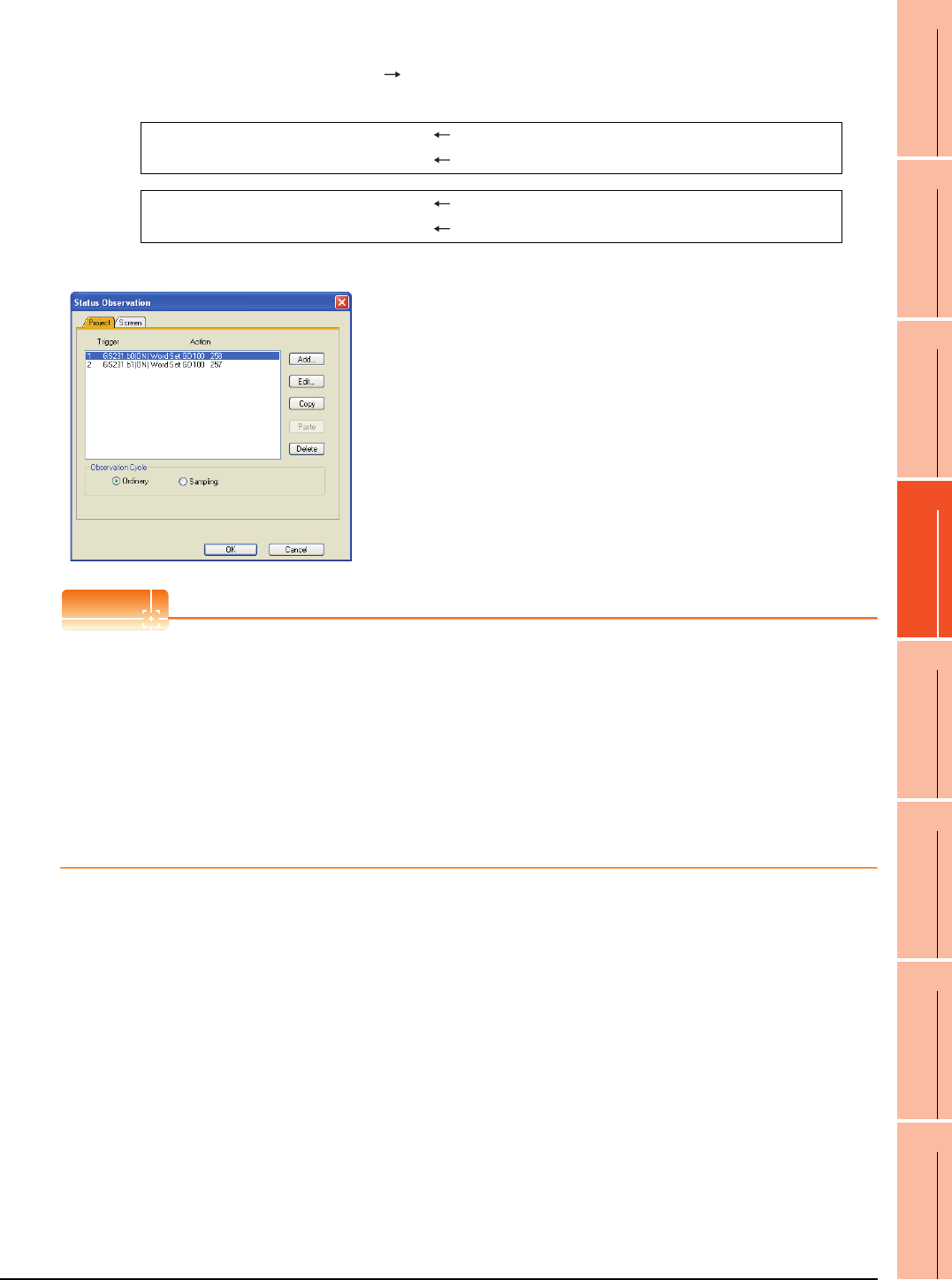
4. HOW TO MONITOR REDUNTANT SYSTEM
4.10 Switch the Monitor Target to the Control System Using the Script Function
4 - 35
1
PREPARATORY
PROCEDURES FOR
MONITORING
2
DEVICE RANGE
THAT CAN BE SET
3
ACCESS RANGE
FOR MONITORING
4
HOW TO MONITOR
REDUNTANT
SYSTEM
5
BUS CONNECTION
6
DIRECT
CONNECTION TO
CPU
7
COMPUTER LINK
CONNECTION
8
ETHERNET
CONNECTION
2. Set the status observation.
Make the setting so that the station number is switched when the faulty station information (GS231) from the station
monitoring specified by selecting [Common] [Status Observation] turns ON.
(For Network No. 1 and Station No. 2, set "258"(0102H))
Create the status observation in the project on the Project tab.
POINTPOINTPOINT
Setting for the status observation function
For the status observation function, hexadecimals cannot be used.
To use the status observation function, set the N/W No. and the station No. of the PLC CPU in [Unsigned BIN].
(For the status observation function, set [Unsigned BIN] for [Storing Device])
Example:
When N/W No.: 1 and Station No.: 1 (0101H)
Set "257".
When N/W No.: 10 and Station No.: 10 (0A0AH)
Set "2570".
3. Create a monitor screen.
For MELSECNET/H connection, MELSECNET/10 connection or Ethernet connection: (Common)
In the device setting (network setting) of each object, set Network No. 1 and Station No. 1 of the control system.
Condition 1 : GS231.b0 (while ON) When b0 is ON, Station No. 1 is abnormal.
Operation : GD100=258(0102H) Station No. is changed to 2.
Condition 1 : GS231.b1 (while ON) When b1 is ON, Station No. 2 is abnormal.
Operation : GD100=257(0101H) Station No. is changed to 1.
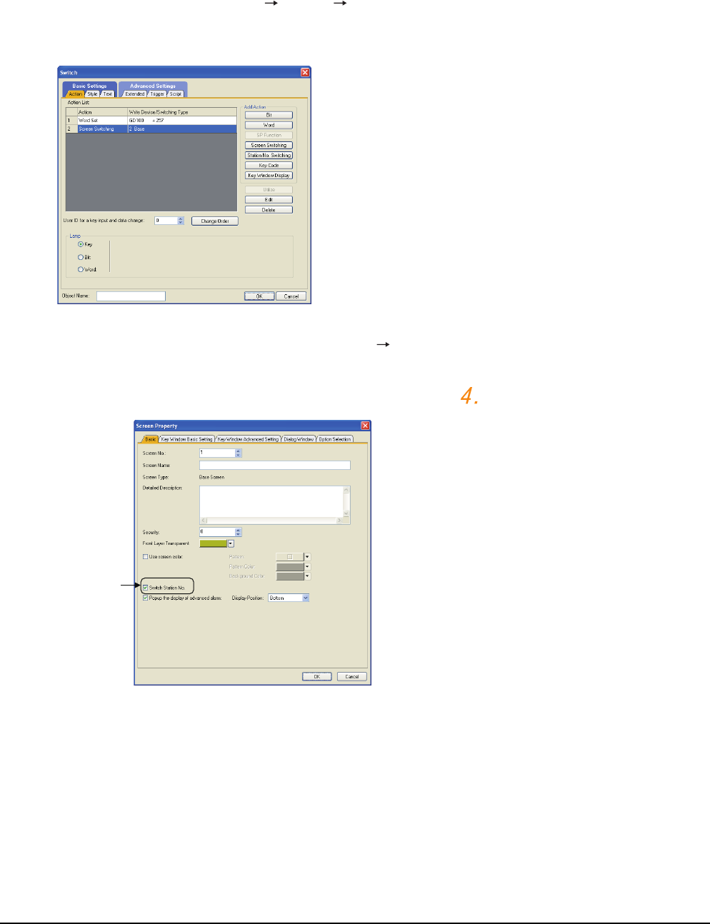
4 - 36 4. HOW TO MONITOR REDUNTANT SYSTEM
4.10 Switch the Monitor Target to the Control System Using the Script Function
4. On the screen 1, set the switch for writing the station No. 1 to the station number switching device.
After the GOT is started up, the station number switching device value of the GOT is "0".
For Ethernet connection, the monitor becomes abnormal when the station number switching device value is "0".
Therefore, set the switch for writing the station number to the station number switching device and the switch for
shifting to the monitor screen on the screen 1.
To make this setting, select [Object] [Switch] [Switch].
The following shows an example of setting GD100=257 (0101H: Network No. 1, Station No. 1) and base screen=2
to one switch.(Base screen 2 is the actually monitoring screen)
5. Validate the station number switching function.
On the Basic tab screen specified by selecting [Screen] [Property], select the item [Switch Station No.] to
validate the station number changing function.
Make this setting for each monitor screen.
However, do not make this setting on the screen 1 created in the item above.
Check here.
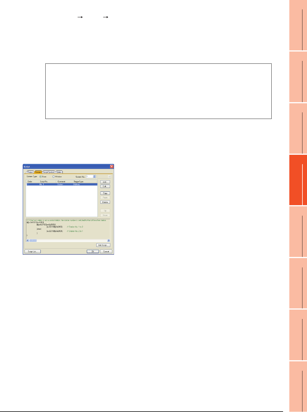
4. HOW TO MONITOR REDUNTANT SYSTEM
4.10 Switch the Monitor Target to the Control System Using the Script Function
4 - 37
1
PREPARATORY
PROCEDURES FOR
MONITORING
2
DEVICE RANGE
THAT CAN BE SET
3
ACCESS RANGE
FOR MONITORING
4
HOW TO MONITOR
REDUNTANT
SYSTEM
5
BUS CONNECTION
6
DIRECT
CONNECTION TO
CPU
7
COMPUTER LINK
CONNECTION
8
ETHERNET
CONNECTION
6. Change the station number switching device value in the script.
By selecting [Common] [Script] [Script], create a script for each monitor screen that checks the SM1515
status of the current monitor station, and if it is OFF (standby system), changes the station number switching device
value.
Set the trigger type of the script as [Ordinary] or [Sampling(about 3s)].
• Screen script for Ethernet connection:
For the Ethernet connection, create a script so that the network No. and station number are set to the station
switching device.
For Network No. 1 and Station No. 2, create "[w:GD100]=0x0102".
Set the created script for each screen on the Screen tab.
// If the host station is not a control station, the station number is switched to that of the other station.
if([b:SM1515]==OFF){
if([w:GD100]==0x0101){ // Station No. 1 to 2
[w:GD100]=0x0102;
}else{ // Station No. 2 to 1
[w:GD100]=0x0101;
}
}
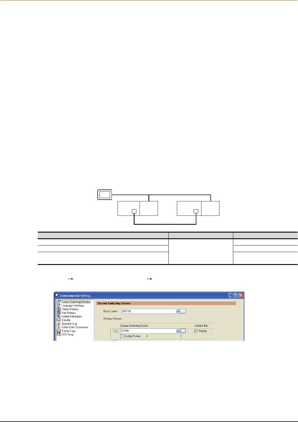
4 - 38 4. HOW TO MONITOR REDUNTANT SYSTEM
4.10 Switch the Monitor Target to the Control System Using the Script Function
4.10.2 Method for using the screen changing function
• As a feature of this function, monitor screens are created for each station number.
When the system switching occurs, the GOT can change the monitoring target to the control system PLC CPU on the
other monitor screen.
• To achieve this, the script of the GOT monitors the special relay SM1515 (Control system identification flag) of the
PLC CPU and stores the screen number corresponding to the latest station number of the control system into the
screen switching devices.
• Precautions:
There are the following 8 different screen switching devices.Set the screen switching devices for all screens to be
used.
(1) Base screen switching device
(2) Overlap window 1 switching device
(3) Overlap window 2 switching device
(4) Overlap window 3 switching device
(5) Overlap window 4 switching device
(6) Overlap window 5 switching device
(7) Superimpose window 1 switching device
(8) Superimpose window 2 switching device
Setting method (For MELSECNET/H connection, MELSECNET/10 connection)
System configuration example 1: MELSECNET/H connection, MELSECNET/10 connection
1. Set the screen switching device of the base screen.
Select [Common] [GOT Environmental Setting] [Screen Switching/Window], and set the internal device
GD100 as the base screen switching device.
MELSECNET/H
(MELSECNET/H mode or MELSECNET/10 mode)
Network No. 1
GOT
Station No. 3
Control system
(System A)
Q25PRH
CPU
QJ71
BR11
Standby system
(System B)
Station No. 1
Q25PRH
CPU
QJ71
BR11
Station No. 2
Connected module Network No. Station No.
MELSECNET/H network module of control system
1
1
MELSECNET/H network module of standby system 2
GOT connected to MELSECNET/H network or MELSECNET/10
network 3
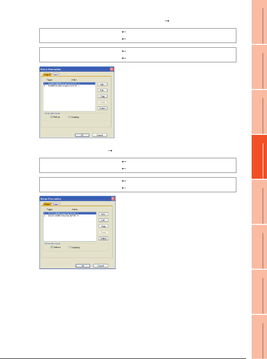
4. HOW TO MONITOR REDUNTANT SYSTEM
4.10 Switch the Monitor Target to the Control System Using the Script Function
4 - 39
1
PREPARATORY
PROCEDURES FOR
MONITORING
2
DEVICE RANGE
THAT CAN BE SET
3
ACCESS RANGE
FOR MONITORING
4
HOW TO MONITOR
REDUNTANT
SYSTEM
5
BUS CONNECTION
6
DIRECT
CONNECTION TO
CPU
7
COMPUTER LINK
CONNECTION
8
ETHERNET
CONNECTION
2. Set the status observation.
Set the status observation so that the station number is switched when the faulty station information (SW70) of
MELSECNET/H turns ON in the project specified by choosing [Common] [Status Observation].
Make the setting so that the station number is switched when the faulty station information (GS231) from the station
monitoring specified by selecting [Common] [Status Observation] turns ON.
Condition 1 : SW70.b0 (while ON) When b0 is ON, Station No. 1 is abnormal.
Operation : GD100=2 Screen No. is changed to 2.
Condition 1 : SW70.b1 (while ON) When b1 is ON, Station No. 2 is abnormal.
Operation : GD100=1 Screen No. is changed to 1.
Condition 1 : GS231.b0 (while ON) When b0 is ON, Station No. 1 is abnormal.
Operation : GD100=2 Screen No. is changed to 2.
Condition 1 : GS231.b1 (while ON) When b1 is ON, Station No. 2 is abnormal.
Operation : GD100=1 Screen No. is changed to 1.
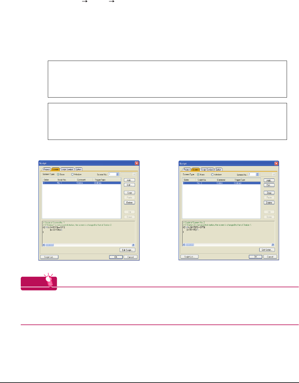
4 - 40 4. HOW TO MONITOR REDUNTANT SYSTEM
4.10 Switch the Monitor Target to the Control System Using the Script Function
3. Set monitor screens.
For MELSECNET/H connection, MELSECNET/10 connection or Ethernet connection: (Common)
• Create a monitor screen with each object whose network setting is Station No. 1 on Screen No. 1 (1-1).
• Create a monitor screen with each object whose network setting is Station No. 2 on Screen No. 2 (1-2).
4. Change the screen switching device value in the script.
By selecting [Common] [Script] [Script], create a script for each monitor screen that checks the SM1515
status of the current monitor station, and if it is OFF (standby system), changes the station number switching device
value.
Set the trigger type of the script as [Ordinary] or [Sampling(about 3s)].
Screen scripts for MELSECNET/H connection and MELSECNET/10 connection:
The same script can be used for MELSECNET/H connection, MELSECNET/10 connection and Ethernet
connection.
HINTHINTHINT
When the MELSECNET/H network is connected to the redundant system only, SW56 (current control station) can
be set as the screen switching device.
In this case, even if the system switching occurs, the GOT always monitors the station number that is currently the
control station.
// Script of Screen No. 1
// If Station 1 is not a control station, the screen is changed to that of Station 2.
if([1-1:b:SM1515]==OFF){
[w:GD100]=2;
}
// Script of Screen No. 2
// If Station 2 is not a control station, the screen is changed to that of Station 1.
if([1-2:b:SM1515]==OFF){
[w:GD100]=1;
}
Script screen of Screen No. 1 Script screen of Screen No. 2
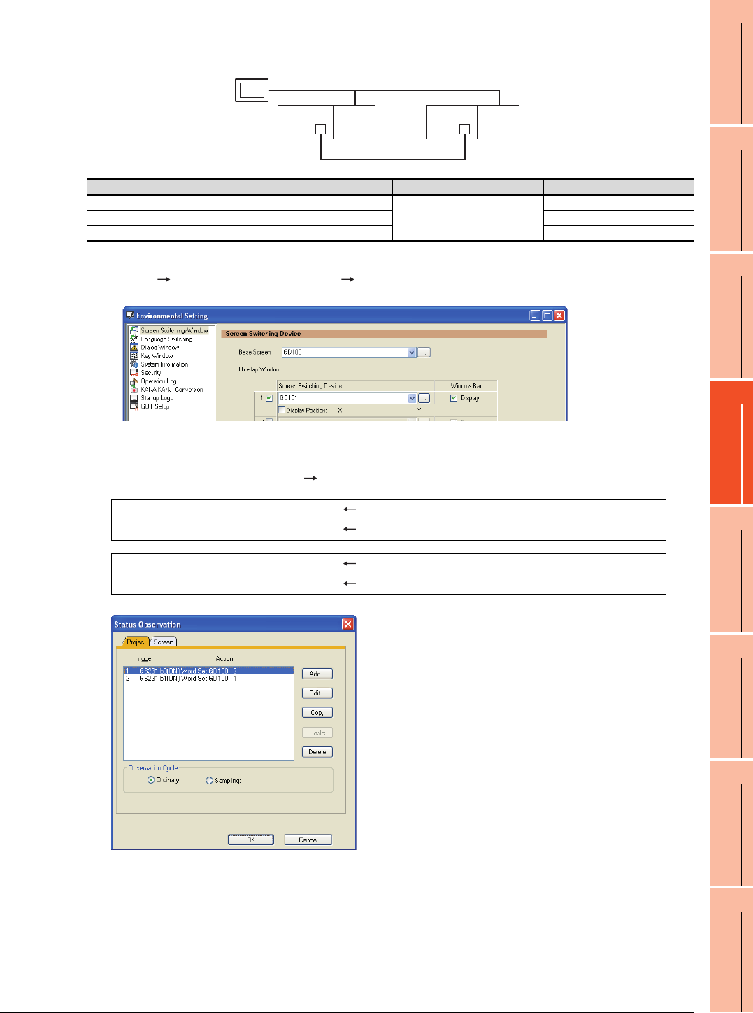
4. HOW TO MONITOR REDUNTANT SYSTEM
4.10 Switch the Monitor Target to the Control System Using the Script Function
4 - 41
1
PREPARATORY
PROCEDURES FOR
MONITORING
2
DEVICE RANGE
THAT CAN BE SET
3
ACCESS RANGE
FOR MONITORING
4
HOW TO MONITOR
REDUNTANT
SYSTEM
5
BUS CONNECTION
6
DIRECT
CONNECTION TO
CPU
7
COMPUTER LINK
CONNECTION
8
ETHERNET
CONNECTION
Setting method (Ethernet connection)
System configuration example 2: Ethernet connection
1. Set the screen switching device of the base screen.
Select [Common] [GOT Environmental Setting] [Screen Switching/Window], and set the internal device
GD100 as the base screen switching device.
2. Set the status observation.
Make the setting so that the station number is switched when the faulty station information (GS231) from the station
monitoring specified by selecting [Common] [Status Observation] turns ON.
3. Set monitor screens.
For MELSECNET/H connection, MELSECNET/10 connection or Ethernet connection: (Common)
• Create a monitor screen with each object whose network setting is Station No. 1 on Screen No. 1 (1-1).
• Create a monitor screen with each object whose network setting is Station No. 2 on Screen No. 2 (1-2).
Ethernet
Network No. 1
GOT
Station No. 3
Control system
(System A)
Q25PRH
CPU
QJ71
E71
Standby system
(System B)
Station No. 1
Q25PRH
CPU
QJ71
E71
Station No. 2
Connected module Network No. Station No.
Ethernet module of control system
1
1
Ethernet module of standby system 2
GOT connected to the Ethernet network 3
Condition 1 : GS231.b0 (while ON) When b0 is ON, Station No. 1 is abnormal.
Operation : GD100=2 Screen No. is changed to 2.
Condition 1 : GS231.b1 (while ON) When b1 is ON, Station No. 2 is abnormal.
Operation : GD100=1 Screen No. is changed to 1.
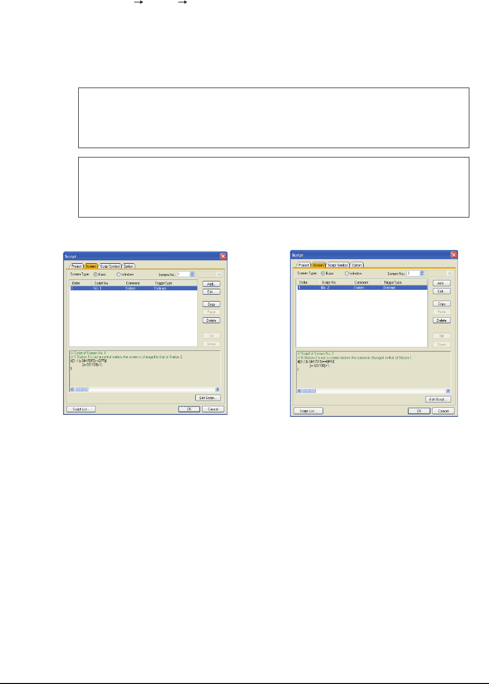
4 - 42 4. HOW TO MONITOR REDUNTANT SYSTEM
4.10 Switch the Monitor Target to the Control System Using the Script Function
4. Change the screen switching device value in the script.
By selecting [Common] [Script] [Script], create a script for each monitor screen that checks the SM1515
status of the current monitor station, and if it is OFF (standby system), changes the station number switching device
value.
Set the trigger type of the script as [Ordinary] or [Sampling(about 3s)].
Screen script for Ethernet connection:
The same script can be used for MELSECNET/H connection, MELSECNET/10 connection and Ethernet
connection.
// Script of Screen No. 1
// If Station 1 is not a control station, the screen is changed to that of Station 2.
if([1-1:b:SM1515]==OFF){
[w:GD100]=2;
}
// Script of Screen No. 2
// If Station 2 is not a control station, the screen is changed to that of Station 1.
if([1-2:b:SM1515]==OFF){
[w:GD100]=1;
}
Script screen of Screen No. 1 Script screen of Screen No. 2
5
1
PREPARATORY
PROCEDURES FOR
MONITORING
2
DEVICE RANGE
THAT CAN BE SET
3
ACCESS RANGE
FOR MONITORING
4
HOW TO MONITOR
REDUNTANT
SYSTEM
5
BUS CONNECTION
6
DIRECT
CONNECTION TO
CPU
7
COMPUTER LINK
CONNECTION
8
ETHERNET
CONNECTION
5 - 1
5.BUS CONNECTION
5.1 Connectable Model List . . . . . . . . . . . . . . . . . . . . . . . . . . . . 5 - 2
5.2 System Configuration. . . . . . . . . . . . . . . . . . . . . . . . . . . . . . 5 - 5
5.3 GOT Side Settings . . . . . . . . . . . . . . . . . . . . . . . . . . . . . . . 5 - 30
5.4 Precautions . . . . . . . . . . . . . . . . . . . . . . . . . . . . . . . . . . . . 5 - 34
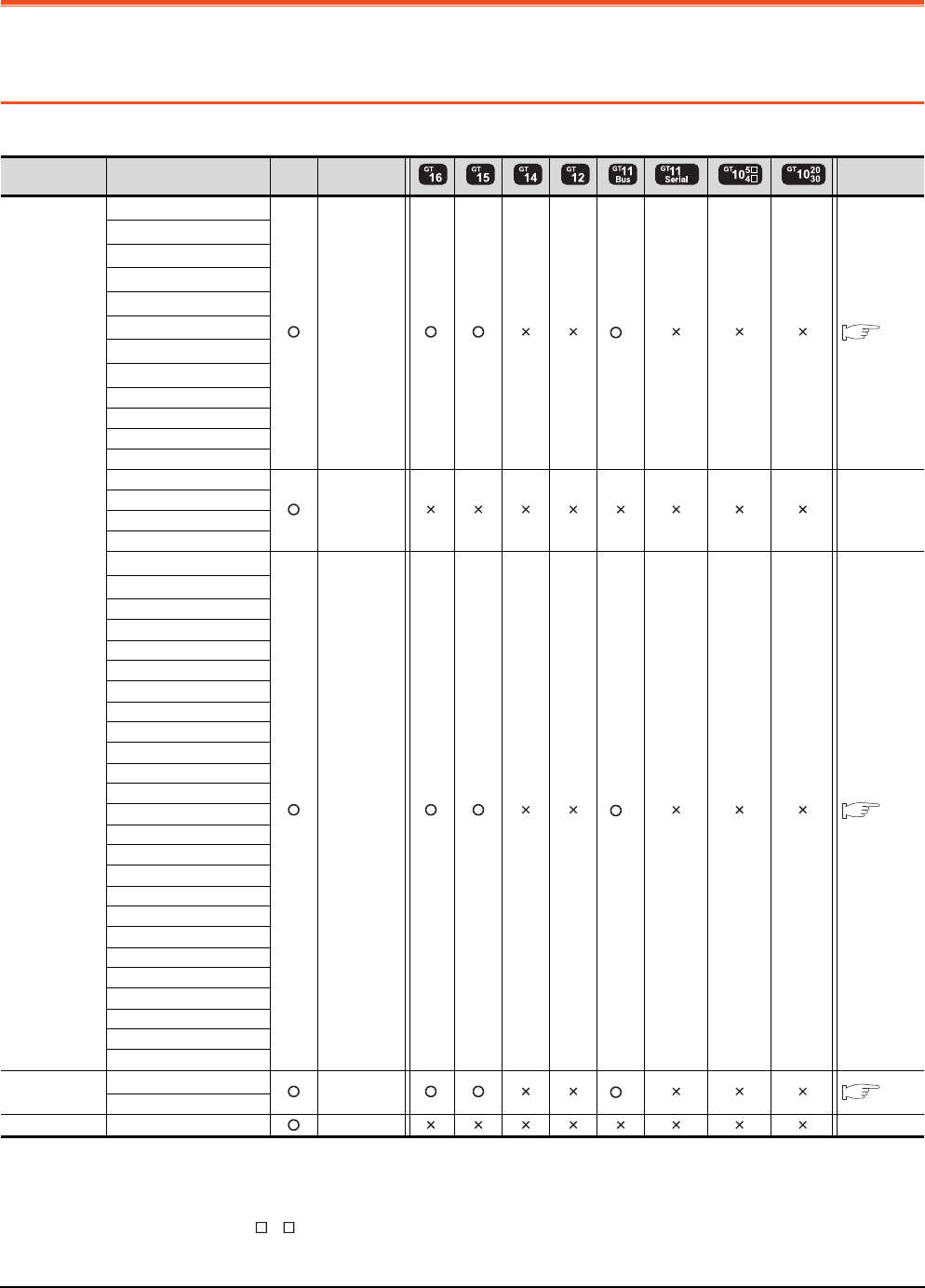
5 - 2 5. BUS CONNECTION
5.1 Connectable Model List
5. BUS CONNECTION
5.1 Connectable Model List
The following table shows the connectable models.
(Continued to next page)
*1 When using the bus extension connector box, attach it to the extension base unit. (Connecting it to the main base unit is not
allowed.)
*2 For the multiple CPU system configuration, use CPU function version B or later.
*3 Only GT115 -Q BDQ can be connected.
*4 Use a module with the upper five digits later than 12042.
*5 When a slim base is used, a bus connection cannot be established.
Series Model name Clock
Communication
type
Refer to
MELSEC-Q
(Q mode)*5
Q00JCPU*1
Bus
connection
*3 5.2.1
Q00CPU*2
Q01CPU*2
Q02CPU*2
Q02HCPU*2
Q06HCPU*2
Q12HCPU*2
Q25HCPU*2
Q02PHCPU
Q06PHCPU
Q12PHCPU
Q25PHCPU
Q12PRHCPU (Main base)
- -
Q25PRHCPU (Main base)
Q12PRHCPU (Extension base)
Q25PRHCPU (Extension base)
Q00UJCPU*1
Bus
connection
*3 5.2.1
Q00UCPU
Q01UCPU
Q02UCPU
Q03UDCPU
Q04UDHCPU
Q06UDHCPU
Q10UDHCPU
Q13UDHCPU
Q20UDHCPU
Q26UDHCPU
Q03UDECPU
Q04UDEHCPU
Q06UDEHCPU
Q10UDEHCPU
Q13UDEHCPU
Q20UDEHCPU
Q26UDEHCPU
Q50UDEHCPU
Q100UDEHCPU
Q03UDVCPU
Q04UDVCPU
Q06UDVCPU
Q13UDVCPU
Q26UDVCPU
C Controller
module
Q12DCCPU-V*4 Bus
connection
*3 5.2.1
Q24DHCCPU-V
MELSEC-QS QS001CPU - -
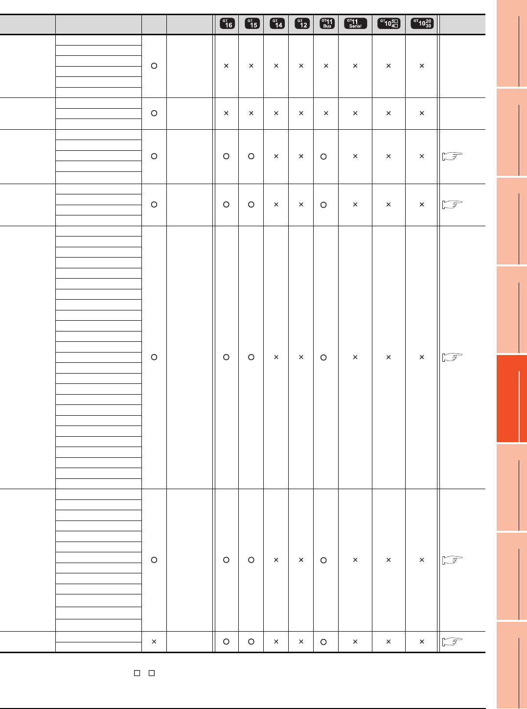
5. BUS CONNECTION
5.1 Connectable Model List
5 - 3
1
PREPARATORY
PROCEDURES FOR
MONITORING
2
DEVICE RANGE
THAT CAN BE SET
3
ACCESS RANGE
FOR MONITORING
4
HOW TO MONITOR
REDUNTANT
SYSTEM
5
BUS CONNECTION
6
DIRECT
CONNECTION TO
CPU
7
COMPUTER LINK
CONNECTION
8
ETHERNET
CONNECTION
(Continued to next page)
*1 Only GT115 -Q BDA can be connected.
*2 Bus-connect the GOT on the last redundant extension base A68RB (version B or later) for the Q4ARCPU redundant system.
*3 When an extension base unit is connected, a bus connection cannot be established.
Series Model name Clock
Communication
type
Refer to
MELSEC-L
L02CPU
- -
L26CPU
L26CPU-BT
L02CPU-P
L26CPU-PBT
L02SCPU
MELSEC-Q
(A mode)
Q02CPU-A
- -Q02HCPU-A
Q06HCPU-A
MELSEC-QnA
(QnACPU)
Q2ACPU
Bus
connection
*1 5.2.2
Q2ACPU-S1
Q3ACPU
Q4ACPU
Q4ARCPU*2
MELSEC-QnA
(QnASCPU)
Q2ASCPU
Bus
connection
*1 5.2.3
Q2ASCPU-S1
Q2ASHCPU
Q2ASHCPU-S1
MELSEC-A
(AnCPU)
A2UCPU
Bus
connection
*1 5.2.2
A2UCPU-S1
A3UCPU
A4UCPU
A2ACPU
A2ACPUP21
A2ACPUR21
A2ACPU-S1
A2ACPUP21-S1
A2ACPUR21-S1
A3ACPU
A3ACPUP21
A3ACPUR21
A1NCPU
A1NCPUP21
A1NCPUR21
A2NCPU
A2NCPUP21
A2NCPUR21
A2NCPU-S1
A2NCPUP21-S1
A2NCPUR21-S1
A3NCPU
A3NCPUP21
A3NCPUR21
MELSEC-A
(AnSCPU)
A2USCPU
Bus
connection
*1 5.2.3
A2USCPU-S1
A2USHCPU-S1
A1SCPU
A1SCPUC24-R2
A1SHCPU
A2SCPU
A2SCPU-S1
A2SHCPU
A2SHCPU-S1
A1SJCPU*3
A1SJCPU-S3*3
A1SJHCPU*3
MELSEC-A A0J2HCPU Bus
connection
*1 5.2.4
A0J2HCPUP21
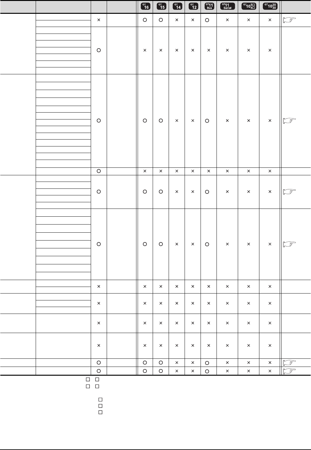
5 - 4 5. BUS CONNECTION
5.1 Connectable Model List
*1 Only GT115 -Q BDA can be connected.
*2 Only GT115 -Q BDQ can be connected.
*3 When using SV13, SV22, or SV43, use the motion controller CPU on which any of the following main OS version is installed.
• SW6RN-SV13Q : 00E or later
• SW6RN-SV22Q : 00E or later
• SW6RN-SV43Q : 00B or later
*4 Use main modules with the following product numbers.
• Q172CPU: Product number K******* or later
• Q173CPU: Product number J******* or later
*5 Connect Q170MCPU to QC30B directly, or to the extension base unit (Q52B/Q55B).
*6 When using an extension base, use the A168.
Series Model name Clock
Communication
type
Refer to
MELSEC-A
A0J2HCPUR21
Bus connection
*1 5.2.4
A0J2HCPU-DC24
A2CCPU
- -
A2CCPUP21
A2CCPUR21
A2CCPUC24
A2CCPUC24-PRF
A2CJCPU-S3
A1FXCPU
Motion
controller
CPU
(Q Series)
Q172CPU*3*4
Bus connection
*2 5.2.1
Q173CPU*3*4
Q172CPUN*3
Q173CPUN*3
Q172HCPU
Q173HCPU
Q172DCPU
Q173DCPU
Q172DCPU-S1
Q173DCPU-S1
Q172DSCPU
Q173DSCPU
Q170MCPU*5
MR-MQ100 - -
Motion
controller
CPU
(A Series)
A273UCPU
Bus connection
*1 5.2.5
A273UHCPU
A273UHCPU-S3
A373UCPU
A373UCPU-S3
A171SCPU*6
Bus connection
*1 5.2.6
A171SCPU-S3*6
A171SCPU-S3N*6
A171SHCPU*6
A171SHCPUN*6
A172SHCPU*6
A172SHCPUN*6
A173UHCPU*6
A173UHCPU-S1*6
MELSEC-WS WS0-CPU0 - -
WS0-CPU1
MELSECNET/H
Remote I/O
station
QJ72LP25-25
- -QJ72LP25G
QJ72BR15
CC-Link IE
Field Network
head module
LJ72GF15-T2 - -
CC-Link IE
Field Network
Ethernet
adapter module
NZ2GF-ETB - -
CNC C70 Q173NCCPU
Bus connection
*2 5.2.1
Robot controller CRnQ-700 (Q172DRCPU)
Bus connection
*2 5.2.1
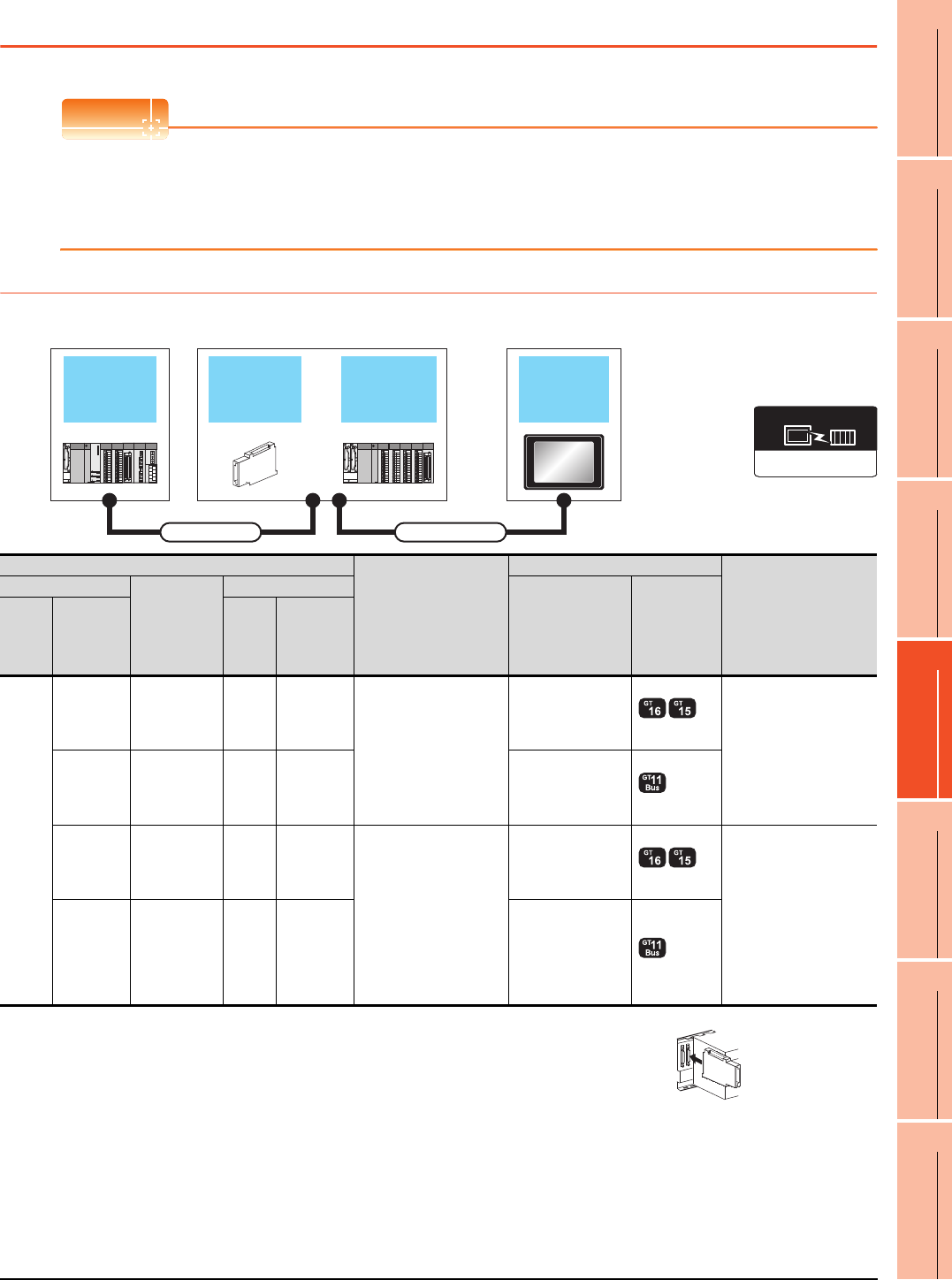
5. BUS CONNECTION
5.2 System Configuration
5 - 5
1
PREPARATORY
PROCEDURES FOR
MONITORING
2
DEVICE RANGE
THAT CAN BE SET
3
ACCESS RANGE
FOR MONITORING
4
HOW TO MONITOR
REDUNTANT
SYSTEM
5
BUS CONNECTION
6
DIRECT
CONNECTION TO
CPU
7
COMPUTER LINK
CONNECTION
8
ETHERNET
CONNECTION
5.2 System Configuration
POINTPOINTPOINT
When "CONTROL BUS ERR" or "UNIT VERIFY ERR" occurs
It can be considered that noise due to a long bus connection cable causes a malfunction.
Check whether a signal line such as bus cable is placed near the equipment to operate. If the line is close to the
equipment, make a distance of 100mm or more from the equipment.
5.2.1 Connecting to QCPU
When one GOT is connected
*1 For the extension cables, refer to the MELSEC-Q catalog (L(NA)08032).
*2 When installing the GOT 13.2m or more away from the main base unit, the bus extension
connector box is required.
Attach the bus extension connector box to the extension connector of the base unit.
Also, connect the connection cable to the bus extension connector box.
When using no extension base unit: Attach it to the main base unit.
When using the extension base unit: Attach it to the extension base unit on the last stage.
*3 When using Q00JCPU or Q00UJCPU, attach the bus extension connector to the extension base unit. (Connecting it to the main
base unit is not allowed)
*4 When using the following functions, use GT15-QBUS(2). GT15-75QBUS(2)L cannot be used.
Used for remote personal computer operation (serial), video display function, multimedia function, operation panel function,
external I/O function, RGB display function, report function (when using a PictBridge compatible printer), hard copy function
(when using a PictBridge compatible printer), sound output function, functions with the CF card unit or CF card extension unit,
Ethernet download, gateway function or MES interface function
However, Ethernet download, gateway function and MES interface function can be used for GT16 by using the Ethernet interface.
Extension base
unit
Bus extension
connector box GOTMain base unit
Extension cable Connection cable
Communication driver
Bus(Q)
PLC
Connection cable
GOT
Max. distance
Main base
Extension
cable*1
Extension base
Option device*4 Model
Main
base
Bus
extension
connector
box*2
Extens
ion
base
Bus
extension
connector
box*2
Main
base
----
GT15-QC06B(0.6m)
GT15-QC12B(1.2m)
GT15-QC30B(3m)
GT15-QC50B(5m)
GT15-QC100B(10m)
GT15-75QBUSL
GT15-75QBUS2L
GT15-QBUS
GT15-QBUS2
Between main base and
GOT: 13.2m
(Including the extension
cable length)
-
Extension
cable
(13.2m or
less)
Extens
ion
base
- - (Built into GOT)
A9GT
-QCNB*3 ---
GT15-QC06B(0.6m)
GT15-QC12B(1.2m)
GT15-QC30B(3m)
GT15-QC50B(5m)
GT15-QC100B(10m)
GT15-QC150BS(15m)
GT15-QC200BS(20m)
GT15-QC250BS(25m)
GT15-QC300BS(30m)
GT15-QC350BS(35m)
GT15-75QBUSL
GT15-75QBUS2L
GT15-QBUS
GT15-QBUS2 Between main base and
GOT: 37m
(Including the extension
cable length)
-
Extension
cable
(13.2m or
less)
Extens
ion
base
A9GT
-QCNB - (Built into GOT)
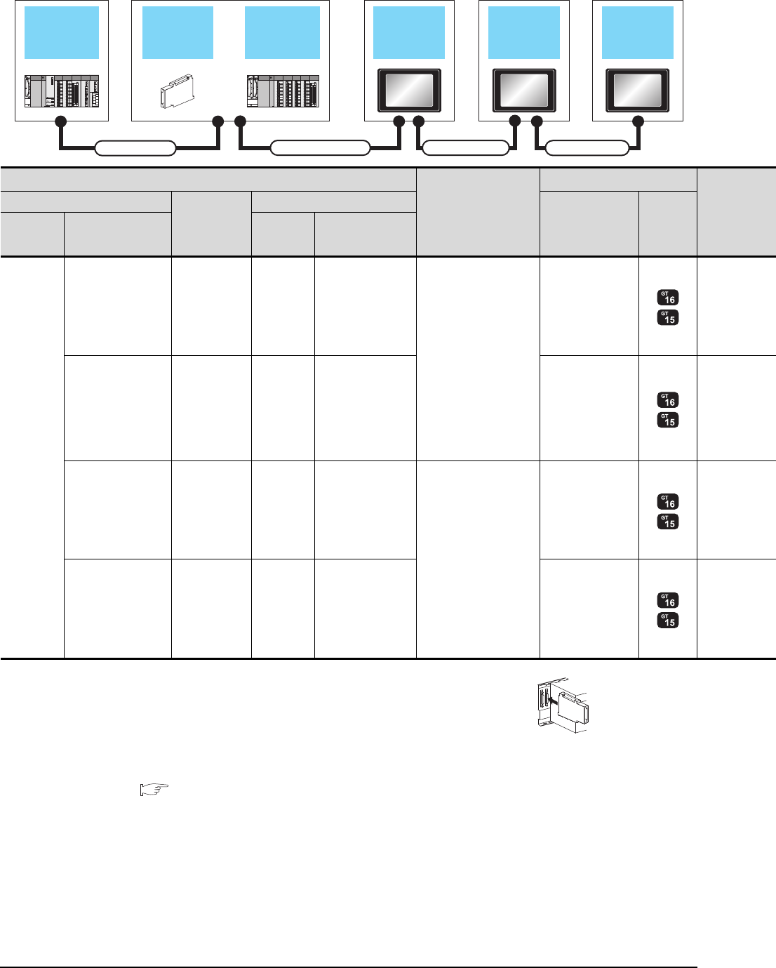
5 - 6 5. BUS CONNECTION
5.2 System Configuration
When 2 to 5 GOTs are connected
*1 For the extension cables, refer to the MELSEC-Q catalog (L(NA)08032).
*2 When installing the GOT 13.2m or more away from the main base unit, the bus extension
connector box is required.
Attach the bus extension connector box to the extension connector of the base unit.
When using no extension base unit: Attach it to the main base unit.
When using the extension base unit: Attach it to the extension base unit on the last stage.
Also, connect the connection cable to the bus extension connector box.
Set the bus extension connector box to the same Stage No. as that of the GOT unit.
For details on the Stage No. setting, refer to the following.
5.3.1 Setting communication interface (Communication settings)
*3 When using Q00JCPU or Q00UJCPU, attach the bus extension connector to the extension base unit. (Connecting it to the main
base unit is not allowed)
Extension base
unit
Bus extension
connector box 1st GOT Intermediary
GOT
GOT
(Terminating
station)
Main base unit
Extension cable Connection cable 1)
Connection cable 2) Connection cable 3)
PLC
Connection cable 1)
GOT (1st)*5
Main base Extension
cable
*1
Extension base
Option device
*6*7 Model
Main base Bus extension
connector box*2
Extension
base
Bus extension
connector box*2
Main base
----
GT15-QC06B(0.6m)
GT15-QC12B(1.2m)
GT15-QC30B(3m)
GT15-QC50B(5m)
GT15-QC100B(10m)
GT15-75QBUS2L
GT15-QBUS2
-
Extension
cable
(13.2m or less)
Extension
base -GT15-75QBUS2L
GT15-QBUS2
A9GT-QCNB*3 -- -
GT15-QC06B(0.6m)
GT15-QC12B(1.2m)
GT15-QC30B(3m)
GT15-QC50B(5m)
GT15-QC100B(10m)
GT15-QC150BS(15m)
GT15-QC200BS(20m)
GT15-QC250BS(25m)
GT15-QC300BS(30m)
GT15-QC350BS(35m)
GT15-75QBUS2L
GT15-QBUS2
-
Extension
cable
(13.2m or less)
Extension
base A9GT-QCNB GT15-75QBUS2L
GT15-QBUS2
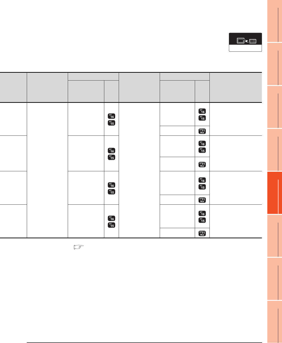
5. BUS CONNECTION
5.2 System Configuration
5 - 7
1
PREPARATORY
PROCEDURES FOR
MONITORING
2
DEVICE RANGE
THAT CAN BE SET
3
ACCESS RANGE
FOR MONITORING
4
HOW TO MONITOR
REDUNTANT
SYSTEM
5
BUS CONNECTION
6
DIRECT
CONNECTION TO
CPU
7
COMPUTER LINK
CONNECTION
8
ETHERNET
CONNECTION
*4 When connecting 3 or more GOTs, the overall cable length is restricted.
5.4.12 When connecting multiple GOTs
*5 The connection of multiple GOTs
When connecting to multiple GOTs with GT 16, GT15 and GT11 mixed, use GT11 as a terminal.
*6 The bus connection unit
GT15-75QBUSL, GT15-QBUS: Used for a terminal GOT. (Not available for an intermediary GOT)
GT15-75QBUS2L, GT15-QBUS2: Used for an intermediary GOT. (Can be used for a terminal GOT)
*7 When using the following functions, use GT15-QBUS(2). GT15-75QBUS(2)L cannot be used.
Used for remote personal computer operation (serial), video display function, multimedia function, operation panel function,
external I/O function, RGB display function, report function (when using a PictBridge compatible printer), hard copy function
(when using a PictBridge compatible printer), sound output function, functions with the CF card unit or CF card extension unit,
Ethernet download, gateway function or MES interface function
However, Ethernet download, gateway function and MES interface function can be used for GT16 by using the Ethernet interface.
Communication driver
Bus(Q)
Connection cable 2)
GOT (intermediary)*4*5
Connection cable 3)
GOT (terminal)*4*5
Max. distance
Option device
*6*7 Model Option device
*6*7 Model
GT15-QC06B(0.6m)
GT15-QC12B(1.2m)
GT15-QC30B(3m)
GT15-QC50B(5m)
GT15-QC100B(10m)
GT15-QC150BS(15m)
GT15-QC200BS(20m)
GT15-QC250BS(25m)
GT15-QC300BS(30m)
GT15-QC350BS(35m)
GT15-75QBUS2L,
GT15-QBUS2
GT15-QC06B(0.6m)
GT15-QC12B(1.2m)
GT15-QC30B(3m)
GT15-QC50B(5m)
GT15-QC100B(10m)
GT15-QC150BS(15m)
GT15-QC200BS(20m)
GT15-QC250BS(25m)
GT15-QC300BS(30m)
GT15-QC350BS(35m)
GT15-75QBUSL,
GT15-75QBUS2L,
GT15-QBUS,
GT15-QBUS2
Between main base and GOT
(1st): 13.2m
Between main base and GOT
(terminal): 37m
- (Built into GOT)
GT15-75QBUS2L,
GT15-QBUS2
GT15-75QBUSL,
GT15-75QBUS2L,
GT15-QBUS,
GT15-QBUS2
Between main base and GOT
(1st): 13.2m (Including the
extension cable length)
Between main base and GOT
(terminal): 37m (Including the
extension cable length)
- (Built into GOT)
GT15-75QBUS2L,
GT15-QBUS2
GT15-75QBUSL,
GT15-75QBUS2L,
GT15-QBUS,
GT15-QBUS2
Between main base and GOT
(terminal): 37m
- (Built into GOT)
GT15-75QBUS2L,
GT15-QBUS2
GT15-75QBUSL,
GT15-75QBUS2L,
GT15-QBUS,
GT15-QBUS2
Between main base and GOT
(terminal):
37m (Including the extension
cable length)
- (Built into GOT)

5 - 8 5. BUS CONNECTION
5.2 System Configuration

5. BUS CONNECTION
5.2 System Configuration
5 - 9
1
PREPARATORY
PROCEDURES FOR
MONITORING
2
DEVICE RANGE
THAT CAN BE SET
3
ACCESS RANGE
FOR MONITORING
4
HOW TO MONITOR
REDUNTANT
SYSTEM
5
BUS CONNECTION
6
DIRECT
CONNECTION TO
CPU
7
COMPUTER LINK
CONNECTION
8
ETHERNET
CONNECTION
5.2.2 Connecting to QnACPU or AnCPU
When one GOT is connected
*1 For the extension cables, refer to MELSEC-A/QnA catalog (L(NA)08024).
*2 When installing the GOT 6.6m or more away from the main base unit, the bus connector conversion box is required.
*3 When using GT15-C EXSS-1, follow the precautions below.
5.4.1 GT15-C [ ] EXSS-1, GT15-C [ ] BS
*4 When using the following functions, use GT15-ABUS(2). GT15-75ABUS(2)L cannot be used.
Used for remote personal computer operation (serial), video display function, multimedia function, operation panel function,
external I/O function, RGB display function, report function (when using a PictBridge compatible printer), hard copy function
(when using a PictBridge compatible printer), sound output function, functions with the CF card unit or CF card extension unit,
Ethernet download, gateway function or MES interface function
However, Ethernet download, gateway function and MES interface function can be used for GT16 by using the Ethernet interface.
Extension base
unit
Bus extension
connector box GOT
Main base unit
Extension cable
Connection cable 1) Connection cable 2)
Communication driver
Bus(A/QnA)
PLC
Connection cable 2)
GOT
Max. distance
Main
base
Extension
cable
*1
Extens
ion
base
Connection cable 1)
Bus
connector
conversion
box
*2
Option device
Model
Main
base
-- - -
GT15-C12NB(1.2m)
GT15-C30NB(3m)
GT15-C50NB(5m)
GT15-75ABUSL
GT15-75ABUS2L
GT15-ABUS
GT15-ABUS2
Between main base and
GOT: 6.6m
- (Built into GOT)
--
GT15-AC06B(0.6m)
GT15-AC12B(1.2m)
GT15-AC30B(3m)
GT15-AC50B(5m)
A7GT
-CNB
GT15-C100EXSS-1(10m)
GT15-C200EXSS-1(20m)
GT15-C300EXSS-1(30m)
*3
GT15-75ABUSL
GT15-75ABUS2L
GT15-ABUS
GT15-ABUS2
Between main base and
GOT: 36.6m
(Including between main
base and bus connector
conversion box)
Between main base and
bus connector conversion
box: 6.6m
- (Built into GOT)
Main
base
Extension
cable
Extens
ion
base
--
GT15-C12NB(1.2m)
GT15-C30NB(3m)
GT15-C50NB(5m)
GT15-75ABUSL
GT15-75ABUS2L
GT15-ABUS
GT15-ABUS2
Between main base and
GOT: 6.6m
(Including the extension
cable length)
- (Built into GOT)
GT15-AC06B(0.6m)
GT15-AC12B(1.2m)
GT15-AC30B(3m)
GT15-AC50B(5m)
A7GT
-CNB
GT15-C100EXSS-1(10m)
GT15-C200EXSS-1(20m)
GT15-C300EXSS-1(30m)
GT15-75ABUSL
GT15-75ABUS2L
GT15-ABUS
GT15-ABUS2
Between main base and
GOT: 36.6m
Between main base and
bus connector conversion
box: 6.6m
(Including the extension
cable length)
- (Built into GOT)
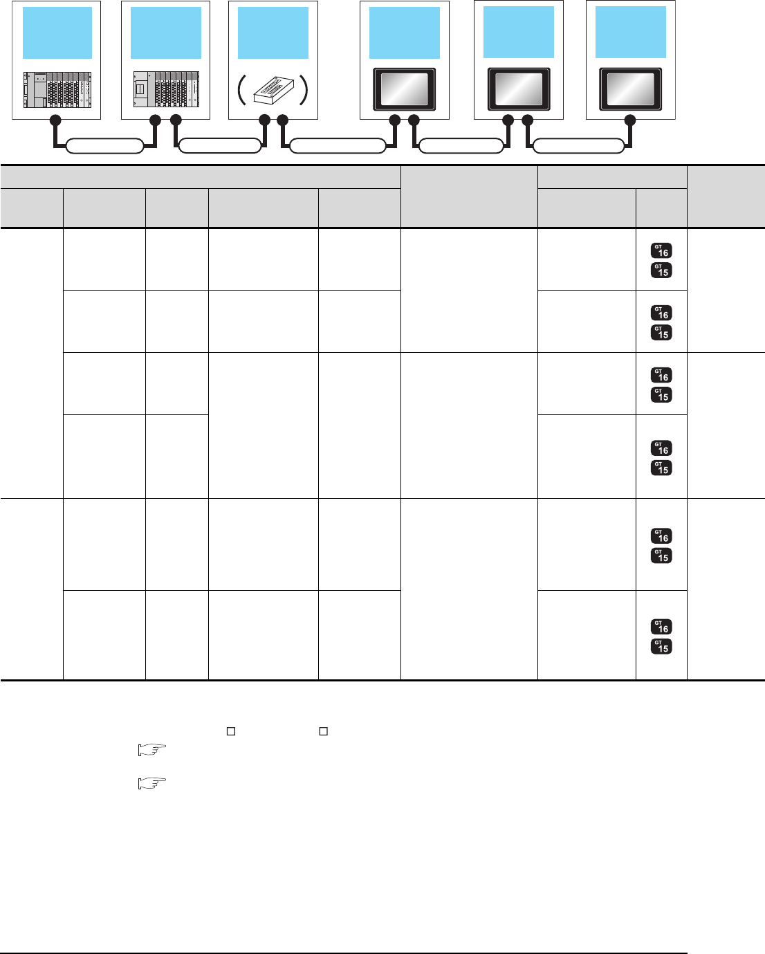
5 - 10 5. BUS CONNECTION
5.2 System Configuration
When 2 to 3 GOTs are connected
*1 For the extension cables, refer to MELSEC-A/QnA catalog (L(NA)08024).
*2 When installing the GOT 6.6m or more away from the main base unit, the bus connector conversion box is required.
*3 When connecting to multiple GOTs with GT 16, GT15 and GT11 mixed, use GT11 as a terminal.
*4 When using GT15-C EXSS-1 or GT15-C BS, connect as following precautions.
5.4.1 GT15-C [ ] EXSS-1, GT15-C [ ] BS
*5 The number of connectable GOTs is restricted according to the CPU type and the number of intelligent function modules.
5.4.12 When connecting multiple GOTs
Extension base
unit
Bus extension
connector box 1st GOTMain base unit
Connection cable 2)
Extension cable
2nd GOT 3rd GOT
Connection cable 3) Connection cable 4)
Connection cable 1)
PLC*5
Connection cable 2)
GOT (1st)*3
Main base Extension
cable*1
Extension
base Connection cable 1)
Bus connector
conversion box
*2
Option device
*6*7 Model
Main base
-- - -
GT15-C12NB(1.2m)
GT15-C30NB(3m)
GT15-C50NB(5m)
GT15-75ABUS2L
GT15-ABUS2
Extension cable Extension
base -- GT15-75ABUS2L
GT15-ABUS2
--
GT15-AC06B(0.6m)
GT15-AC12B(1.2m)
GT15-AC30B(3m)
GT15-AC50B(5m)
A7GT-CNB
GT15-C100EXSS-1(10m)
GT15-C200EXSS-1(20m)
*4
GT15-75ABUS2L
GT15-ABUS2
Extension cable Extension
base
GT15-75ABUS2L
GT15-ABUS2
Main base
-- - -
GT15-C12NB(1.2m)
GT15-C30NB(3m)
GT15-C50NB(5m)
GT15-75ABUS2L
GT15-ABUS2
Extension cable Extension
base -- GT15-75ABUS2L
GT15-ABUS2
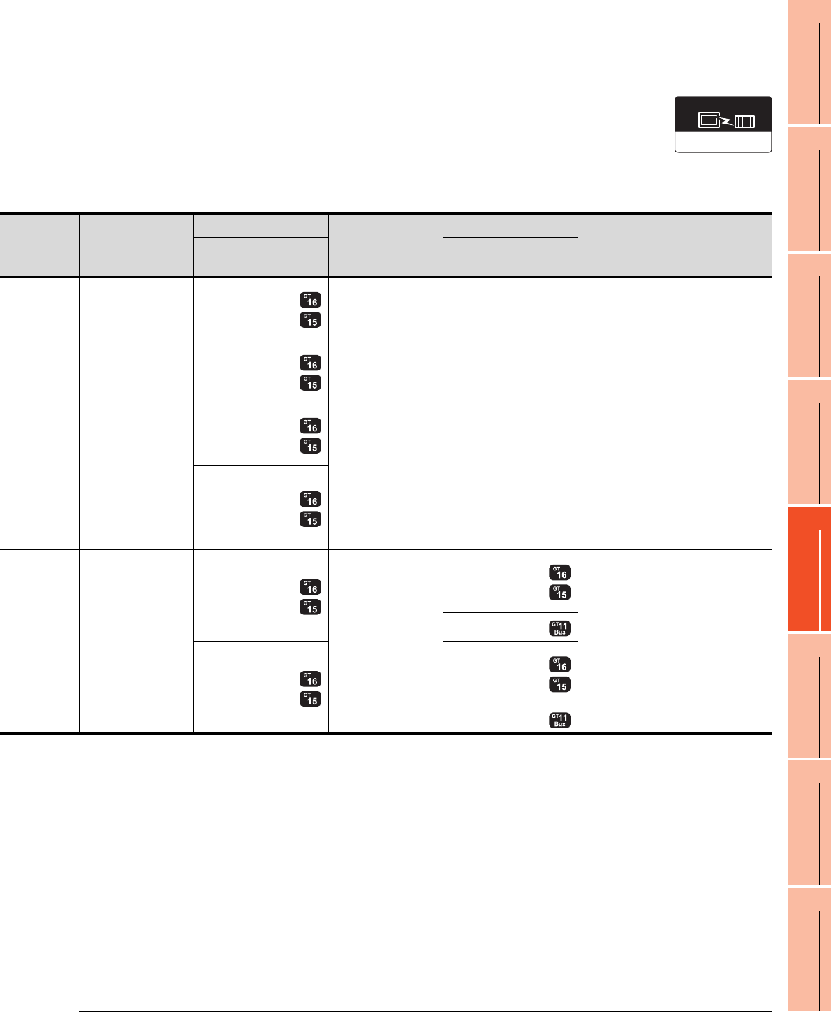
5. BUS CONNECTION
5.2 System Configuration
5 - 11
1
PREPARATORY
PROCEDURES FOR
MONITORING
2
DEVICE RANGE
THAT CAN BE SET
3
ACCESS RANGE
FOR MONITORING
4
HOW TO MONITOR
REDUNTANT
SYSTEM
5
BUS CONNECTION
6
DIRECT
CONNECTION TO
CPU
7
COMPUTER LINK
CONNECTION
8
ETHERNET
CONNECTION
*6 About the bus connection unit
GT15-75ABUSL, GT15-ABUS: Used for a terminal GOT. (Not available for an intermediary GOT)
GT15-75ABUS2L, GT15-ABUS2: Used for an intermediary GOT. (Can be used for a terminal GOT)
*7 When using the following functions, use GT15-ABUS(2). GT15-75ABUS(2)L cannot be used.
Used for remote personal computer operation (serial), video display function, multimedia function, operation panel function,
external I/O function, RGB display function, report function (when using a PictBridge compatible printer), hard copy function
(when using a PictBridge compatible printer), sound output function, functions with the CF card unit or CF card extension unit,
Ethernet download, gateway function or MES interface function
However, Ethernet download, gateway function and MES interface function can be used for GT16 by using the Ethernet interface.
Communication driver
Bus(A/QnA)
Connection cable 3)
GOT (2nd)*3*5
Connection cable 4)
GOT (3rd)*3*5
Max. distance
Option device
*6*7
Model
Option device
*6*7
Model
GT15-C07BS(0.7m)
GT15-C12BS(1.2m)
GT15-C30BS(3m)
GT15-C50BS(5m)
GT15-C100BS(10m)
GT15-C200BS(20m)
GT15-C300BS(30m)
*4
GT15-75ABUSL
GT15-75ABUS2L
GT15-ABUS
GT15-ABUS2
--
Between main base and GOT(1st): 6.6m
(Including the extension cable length)
Between GOT (1st) and GOT (2nd): 30m
Between main base and GOT (2nd):
36.6m
(Including the extension cable length)
GT15-75ABUSL
GT15-75ABUS2L
GT15-ABUS
GT15-ABUS2
GT15-C07BS(0.7m)
GT15-C12BS(1.2m)
GT15-C30BS(3m)
GT15-C50BS(5m)
GT15-C100BS(10m)
GT15-C200BS(20m)
*4
GT15-75ABUSL
GT15-75ABUS2L
GT15-ABUS
GT15-ABUS2
--
Between main base and bus connector
conversion box: 6.6m
(Including the extension cable length)
Between bus connector conversion box
and GOT (2nd): 30m
Between main base and GOT (2nd):
36.6m
(Including the extension cable length)
GT15-75ABUSL
GT15-75ABUS2L
GT15-ABUS
GT15-ABUS2
GT15-C07BS(0.7m)
GT15-C12BS(1.2m)
GT15-C30BS(3m)
GT15-C50BS(5m)
GT15-C100BS(10m)
GT15-C200BS(20m)
*4
GT15-75ABUS2L
GT15-ABUS2 GT15-C07BS(0.7m)
GT15-C12BS(1.2m)
GT15-C30BS(3m)
GT15-C50BS(5m)
GT15-C100BS(10m)
GT15-C200BS(20m)
*4
GT15-75ABUSL
GT15-75ABUS2L
GT15-ABUS
GT15-ABUS2 Between main base and GOT(1st): 6.6m
(Including the extension cable length)
Between GOT (1st) and GOT (3rd): 30m
Between main base and GOT (3rd): 36.6m
(Including the extension cable length)
- (Built into GOT)
GT15-75ABUS2L
GT15-ABUS2
GT15-75ABUSL
GT15-75ABUS2L
GT15-ABUS
GT15-ABUS2
- (Built into GOT)
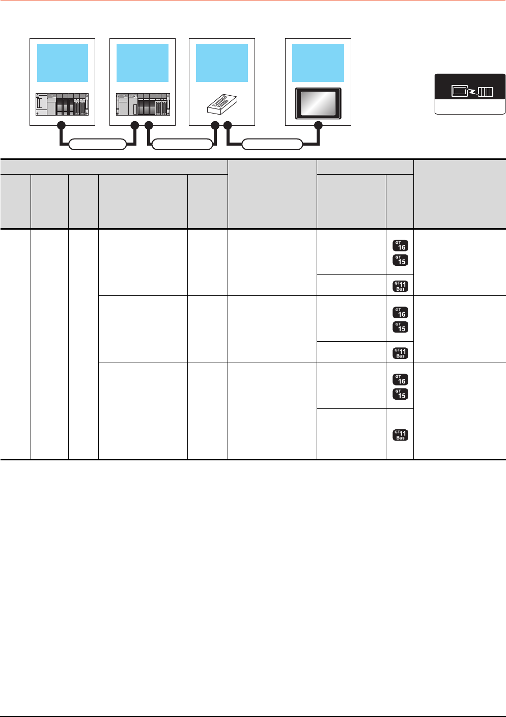
5 - 12 5. BUS CONNECTION
5.2 System Configuration
5.2.3 Connection to QnASCPU or AnSCPU
When one GOT is connected
Main base unit Bus extension
connector box GOT
Extension base
unit
Connection cable 1) Connection cable 2)
Extension cable
Communication driver
Bus(A/QnA)
PLC
Connection cable 2)
GOT
Max. distance
Extens
ion
base
Extension
cable
*1
Main
base Connection cable 1)
Bus
connector
conversion
box
*2
Option device*4
Model
--
Main
base
--
GT15-A1SC07B(0.7m)
GT15-A1SC12B(1.2m)
GT15-A1SC30B(3m)
GT15-A1SC50B(5m)
GT15-75ABUSL
GT15-75ABUS2L
GT15-ABUS
GT15-ABUS2
Between main base and
GOT: 5m
- (Built into GOT)
--
GT15-C100EXSS-1(10m)
GT15-C200EXSS-1(20m)
GT15-C300EXSS-1(30m)
*3
GT15-75ABUSL
GT15-75ABUS2L
GT15-ABUS
GT15-ABUS2
Between main base and
GOT: 30m
- (Built into GOT)
GT15-A1SC05NB(0.45m)
GT15-A1SC07NB(0.7m)
GT15-A1SC30NB(3m)
GT15-A1SC50NB(5m)
A7GT
-CNB
GT15-C100EXSS-1(10m)
GT15-C200EXSS-1(20m)
GT15-C300EXSS-1(30m)
*3
GT15-75ABUSL
GT15-75ABUS2L
GT15-ABUS
GT15-ABUS2
Between main base and
GOT: 35m
(Including between main
base and bus connector
conversion box)
Between main base and
bus connector conversion
box: 5m
- (Built into GOT)
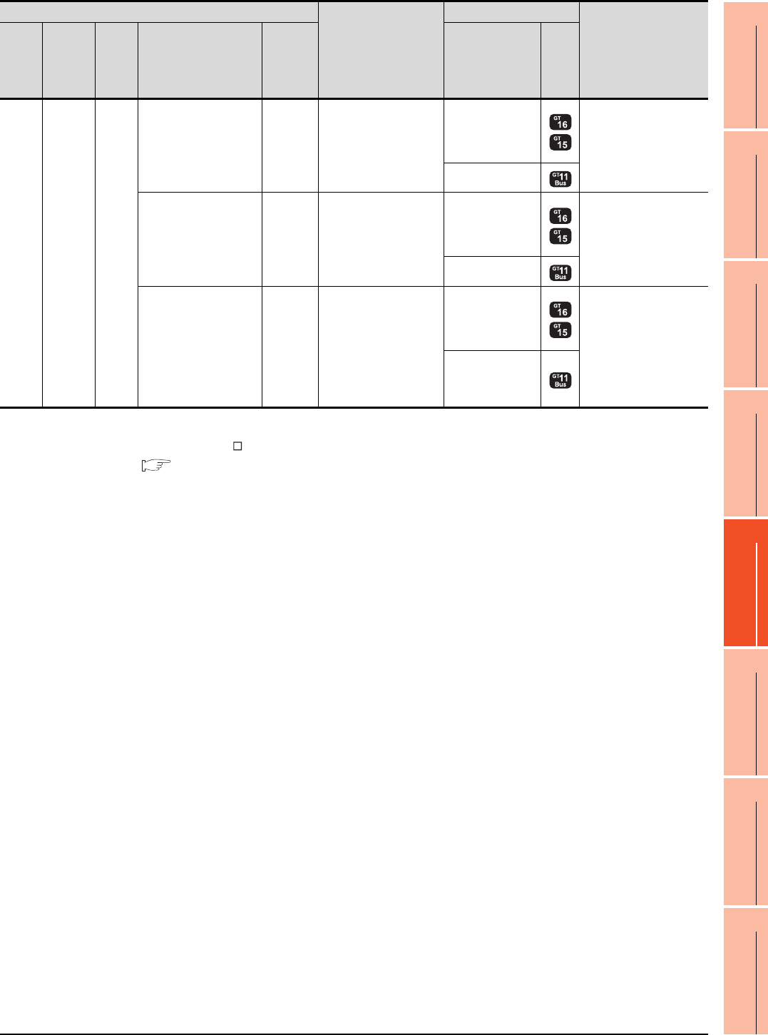
5. BUS CONNECTION
5.2 System Configuration
5 - 13
1
PREPARATORY
PROCEDURES FOR
MONITORING
2
DEVICE RANGE
THAT CAN BE SET
3
ACCESS RANGE
FOR MONITORING
4
HOW TO MONITOR
REDUNTANT
SYSTEM
5
BUS CONNECTION
6
DIRECT
CONNECTION TO
CPU
7
COMPUTER LINK
CONNECTION
8
ETHERNET
CONNECTION
*1 For details on the extension cables, refer to the MELSEC-A/QnA catalog (L(NA)8024).
*2 When installing the GOT 30m or more away from the main base unit, the bus connector conversion box is required.
*3 When using GT15-C EXSS-1, connect as the following precautions.
5.4.1 GT15-C [ ] EXSS-1, GT15-C [ ] BS
*4 When using the following functions, use GT15-ABUS(2). GT15-75ABUS(2)L cannot be used.
Used for remote personal computer operation (serial), video display function, multimedia function, operation panel function,
external I/O function, RGB display function, report function (when using a PictBridge compatible printer), hard copy function
(when using a PictBridge compatible printer), sound output function, functions with the CF card unit or CF card extension unit,
Ethernet download, gateway function or MES interface function
However, Ethernet download, gateway function and MES interface function can be used for GT16 by using the Ethernet interface.
Extens
ion
base
Extension
cable
Main
base
--
GT15-A1SC07B(0.7m)
GT15-A1SC12B(1.2m)
GT15-A1SC30B(3m)
GT15-A1SC50B(5m)
GT15-75ABUSL
GT15-75ABUS2L
GT15-ABUS
GT15-ABUS2
Between extension base
and GOT: 6m
(Including the extension
cable length)
- (Built into GOT)
--
GT15-C100EXSS-1(10m)
GT15-C200EXSS-1(20m)
GT15-C300EXSS-1(30m)
*3
GT15-75ABUSL
GT15-75ABUS2L
GT15-ABUS
GT15-ABUS2
Between extension base
and GOT: 36m
(Including the extension
cable length)
- (Built into GOT)
GT15-A1SC05NB(0.45m)
GT15-A1SC07NB(0.7m)
GT15-A1SC30NB(3m)
GT15-A1SC50NB(5m)
A7GT
-CNB
GT15-C100EXSS-1(10m)
GT15-C200EXSS-1(20m)
GT15-C300EXSS-1(30m)
*3
GT15-75ABUSL
GT15-75ABUS2L
GT15-ABUS
GT15-ABUS2
Between extension base
and GOT: 36m
Between extension base
and bus connector
conversion box: 6m
(Including the extension
cable length)
- (Built into GOT)
PLC
Connection cable 2)
GOT
Max. distance
Extens
ion
base
Extension
cable
*1
Main
base Connection cable 1)
Bus
connector
conversion
box
*2
Option device*4
Model
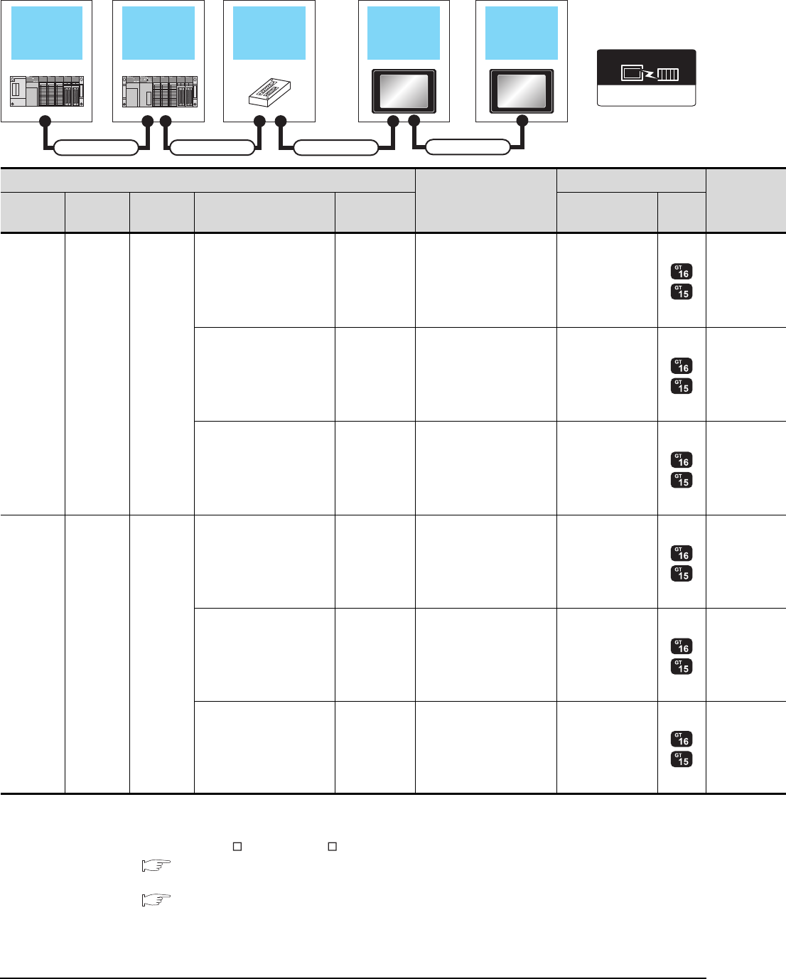
5 - 14 5. BUS CONNECTION
5.2 System Configuration
When two GOTs are connected
*1 For the extension cables, refer to MELSEC-A/QnA catalog (L(NA)08024).
*2 When installing the 1st GOT 30m or more away from the main base unit, the bus connector conversion box is required.
*3 When connecting to multiple GOTs with GT 16, GT15 and GT11 mixed, use GT11 as a terminal.
*4 When using GT15-C EXSS-1 or GT15-C BS, connect as following precautions.
5.4.1 GT15-C [ ] EXSS-1, GT15-C [ ] BS
*5 The number of connectable GOTs is restricted according to the CPU type and the number of intelligent function modules.
5.4.12 When connecting multiple GOTs
Extension base
unit
Bus extension
connector box 1st GOT
Main base unit
Connection cable 1) Connection cable 2)
Extension cable
2nd GOT
Connection cable 3)
Communication driver
Bus(A/QnA)
PLC*5
Connection cable 2)
GOT (1st)*3
Extension
base
Extension
cable*1 Main base Connection cable 1) Bus connector
conversion box
Option device
*6*7 Model
- - Main base
--
GT15-A1SC07B(0.7m)
GT15-A1SC12B(1.2m)
GT15-A1SC30B(3m)
GT15-A1SC50B(5m)
GT15-75ABUS2L
GT15-ABUS2
--
GT15-C100EXSS-1(10m)
GT15-C200EXSS-1(20m)
*4
GT15-75ABUS2L
GT15-ABUS2
GT15-A1SC05NB(0.45m)
GT15-A1SC07NB(0.7m)
GT15-A1SC30NB(3m)
GT15-A1SC50NB(5m)
A7GT-CNB*2
GT15-C100EXSS-1(10m)
GT15-C200EXSS-1(20m)
*4
GT15-75ABUS2L
GT15-ABUS2
Extension
base
Extension
cable Main base
--
GT15-A1SC07B(0.7m)
GT15-A1SC12B(1.2m)
GT15-A1SC30B(3m)
GT15-A1SC50B(5m)
GT15-75ABUS2L
GT15-ABUS2
--
GT15-C100EXSS-1(10m)
GT15-C200EXSS-1(20m)
*4
GT15-75ABUS2L
GT15-ABUS2
GT15-A1SC05NB(0.45m)
GT15-A1SC07NB(0.7m)
GT15-A1SC30NB(3m)
GT15-A1SC50NB(5m)
A7GT-CNB*2
GT15-C100EXSS-1(10m)
GT15-C200EXSS-1(20m)
*4
GT15-75ABUS2L
GT15-ABUS2
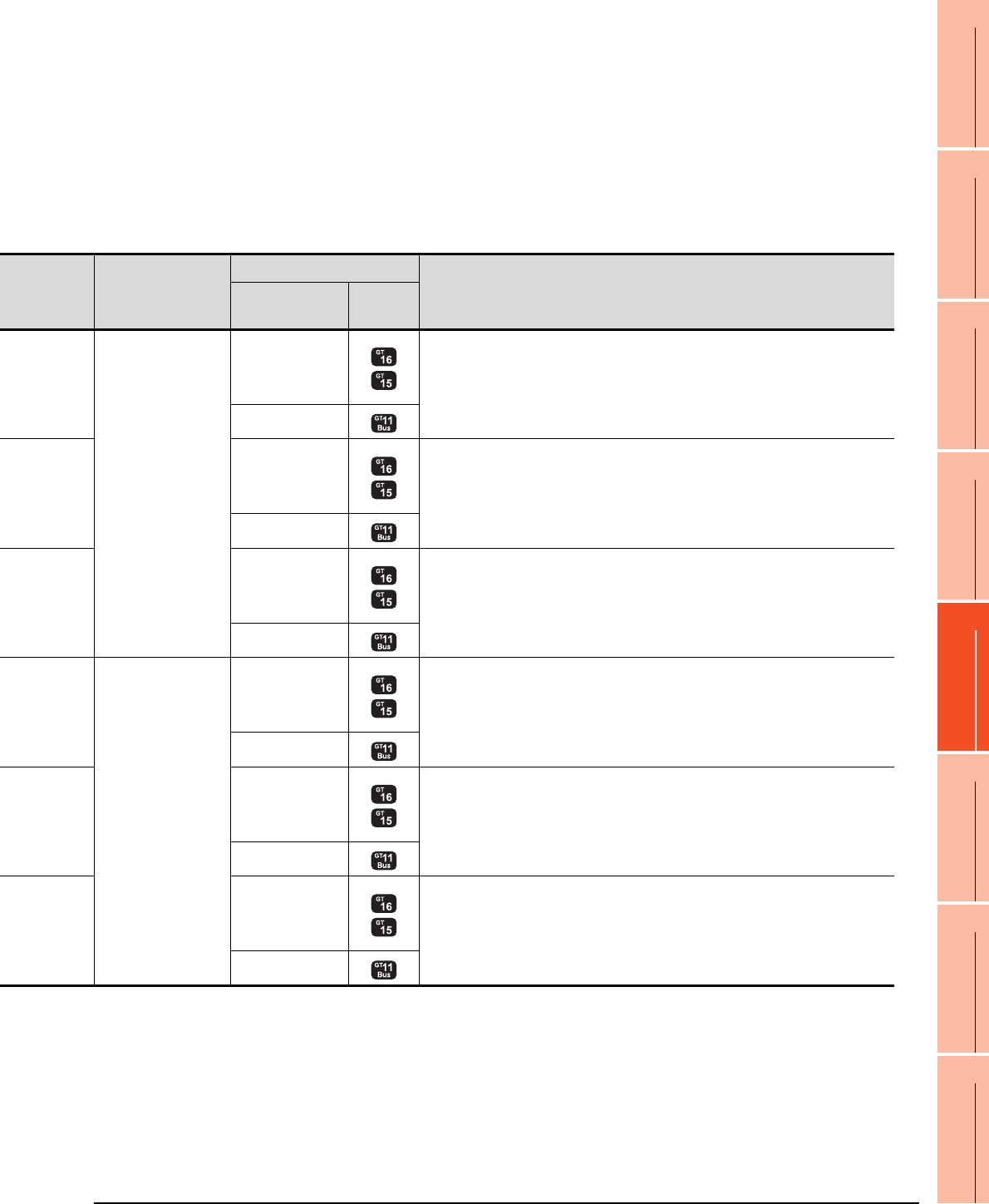
5. BUS CONNECTION
5.2 System Configuration
5 - 15
1
PREPARATORY
PROCEDURES FOR
MONITORING
2
DEVICE RANGE
THAT CAN BE SET
3
ACCESS RANGE
FOR MONITORING
4
HOW TO MONITOR
REDUNTANT
SYSTEM
5
BUS CONNECTION
6
DIRECT
CONNECTION TO
CPU
7
COMPUTER LINK
CONNECTION
8
ETHERNET
CONNECTION
*6 About the bus connection unit
GT15-75ABUSL, GT15-ABUS: Used for a terminal GOT. (Not available for an intermediary GOT)
GT15-75ABUS2L, GT15-ABUS2: Used for an intermediary GOT. (Can be used for a terminal GOT)
*7 When using the following functions, use GT15-ABUS(2). GT15-75ABUS(2)L cannot be used.
Used for remote personal computer operation (serial), video display function, multimedia function, operation panel function,
external I/O function, RGB display function, report function (when using a PictBridge compatible printer), hard copy function
(when using a PictBridge compatible printer), sound output function, functions with the CF card unit or CF card extension unit,
Ethernet download, gateway function or MES interface function
However, Ethernet download, gateway function and MES interface function can be used for GT16 by using the Ethernet interface.
Connection cable 3)
GOT (2nd)*3*5
Max. distance
Option device
*6*7 Model
GT15-C07BS(0.7m)
GT15-C12BS(1.2m)
GT15-C30BS(3m)
GT15-C50BS(5m)
GT15-C100BS(10m)
GT15-C200BS(20m)
GT15-C300BS(30m)
*4
GT15-75ABUSL
GT15-75ABUS2L
GT15-ABUS
GT15-ABUS2
Between main base and GOT(1st): 5m
Between GOT (1st) and GOT (2nd): 30m
Between main base and GOT (2nd): 35m
- (Built into GOT)
GT15-75ABUSL
GT15-75ABUS2L
GT15-ABUS
GT15-ABUS2 Between main base and GOT (2nd): 30m
- (Built into GOT)
GT15-75ABUSL
GT15-75ABUS2L
GT15-ABUS
GT15-ABUS2
Between main base and bus connector conversion box: 5m
Between bus connector conversion box and GOT (2nd): 30m
Between main base and GOT (2nd): 35m
- (Built into GOT)
GT15-C07BS(0.7m)
GT15-C12BS(1.2m)
GT15-C30BS(3m)
GT15-C50BS(5m)
GT15-C100BS(10m)
GT15-C200BS(20m)
GT15-C300BS(30m)
*4
GT15-75ABUSL
GT15-75ABUS2L
GT15-ABUS
GT15-ABUS2
Between extension base and GOT (1st): 6m (Including the extension cable length)
Between GOT (1st) and GOT (2nd): 30m
Between extension base and GOT (2nd): 36m (Including the extension cable length)
- (Built into GOT)
GT15-75ABUSL
GT15-75ABUS2L
GT15-ABUS
GT15-ABUS2
Between main base and GOT (2nd): 30m
Between extension base and GOT (2nd): 36m (Including the extension cable length)
- (Built into GOT)
GT15-75ABUSL
GT15-75ABUS2L
GT15-ABUS
GT15-ABUS2
Extension base and bus connector conversion box: 6m (Including extension cable length)
Between bus connector conversion box and GOT (2nd): 30m
Between extension base and GOT (2nd): 36m (Including the extension cable length)
- (Built into GOT)
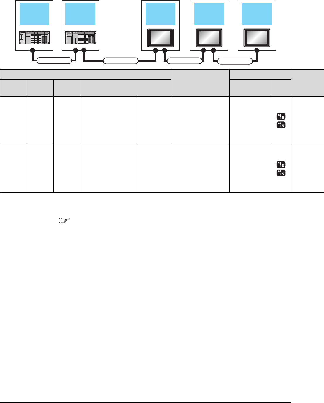
5 - 16 5. BUS CONNECTION
5.2 System Configuration
When three GOTs are connected
*1 For the extension cables, refer to MELSEC-A/QnA catalog (L(NA)08024).
*2 The connection of multiple GOTs
When connecting to multiple GOTs with GT 16, GT15 and GT11 mixed, use GT11 as a terminal.
*3 The number of connectable GOTs is restricted according to the CPU type and the number of intelligent function modules.
5.4.12 When connecting multiple GOTs
Extension base
unit 1st GOTMain base unit
Connection cable 2)
Extension cable
2nd GOT
Connection cable 3)
3rd GOT
Connection cable 4)
PLC*3
Connection cable 2)
GOT (1st)*2
Extension
base
Extension
cable*1 Main base Connection cable 1) Bus connector
conversion box
Option device
*5*6 Model
- - Main base - -
GT15-A1SC07B(0.7m)
GT15-A1SC12B(1.2m)
GT15-A1SC30B(3m)
GT15-A1SC50B(5m)
GT15-75ABUS2L
GT15-ABUS2
Extension
base
Extension
cable Main base - -
GT15-A1SC07B(0.7m)
GT15-A1SC12B(1.2m)
GT15-A1SC30B(3m)
GT15-A1SC50B(5m)
GT15-75ABUS2L
GT15-ABUS2
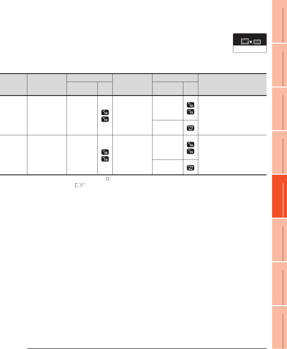
5. BUS CONNECTION
5.2 System Configuration
5 - 17
1
PREPARATORY
PROCEDURES FOR
MONITORING
2
DEVICE RANGE
THAT CAN BE SET
3
ACCESS RANGE
FOR MONITORING
4
HOW TO MONITOR
REDUNTANT
SYSTEM
5
BUS CONNECTION
6
DIRECT
CONNECTION TO
CPU
7
COMPUTER LINK
CONNECTION
8
ETHERNET
CONNECTION
*4 When using GT15-C BS, connect as following precautions.
5.4.1 GT15-C [ ] EXSS-1, GT15-C [ ] BS
*5 The bus connection unit
GT15-75ABUSL, GT15-ABUS: Used for a terminal GOT. (Not available for an intermediary GOT)
GT15-75ABUS2L, GT15-ABUS2: Used for an intermediary GOT. (Can be used for a terminal GOT)
*6 When using the following functions, use GT15-ABUS(2). GT15-75ABUS(2)L cannot be used.
Used for remote personal computer operation (serial), video display function, multimedia function, operation panel function,
external I/O function, RGB display function, report function (when using a PictBridge compatible printer), hard copy function
(when using a PictBridge compatible printer), sound output function, functions with the CF card unit or CF card extension unit,
Ethernet download, gateway function or MES interface function
However, Ethernet download, gateway function and MES interface function can be used for GT16 by using the Ethernet interface.
Connection cable 3)
GOT (2nd)*2*3
Connection cable 4)
GOT (3rd)*2*3
Max. distance
Option device
*5*6 Model Option device
*5*6 Model
GT15-C07BS(0.7m)
GT15-C12BS(1.2m)
GT15-C30BS(3m)
GT15-C50BS(5m)
GT15-C100BS(10m)
GT15-C200BS(20m)
*4
GT15-75ABUS2L
GT15-ABUS2
GT15-C07BS(0.7m)
GT15-C12BS(1.2m)
GT15-C30BS(3m)
GT15-C50BS(5m)
GT15-C100BS(10m)
GT15-C200BS(20m)
*4
GT15-75ABUSL
GT15-75ABUS2L
GT15-ABUS
GT15-ABUS2
Between main base and GOT(1st): 5m
Between GOT (1st) and GOT (3rd): 30m
Between main base and GOT (3rd): 35m
- (Built into GOT)
GT15-C07BS(0.7m)
GT15-C12BS(1.2m)
GT15-C30BS(3m)
GT15-C50BS(5m)
GT15-C100BS(10m)
GT15-C200BS(20m)
*4
GT15-75ABUS2L
GT15-ABUS2
GT15-C07BS(0.7m)
GT15-C12BS(1.2m)
GT15-C30BS(3m)
GT15-C50BS(5m)
GT15-C100BS(10m)
GT15-C200BS(20m)
*4
GT15-75ABUSL
GT15-75ABUS2L
GT15-ABUS
GT15-ABUS2
Between extension base and GOT (1st): 6m
(Including the extension cable length)
Between GOT (1st) and GOT (3rd): 30m
Between extension base and GOT (3rd): 36m
(Including the extension cable length)
- (Built into GOT)
Communication driver
Bus(A/QnA)
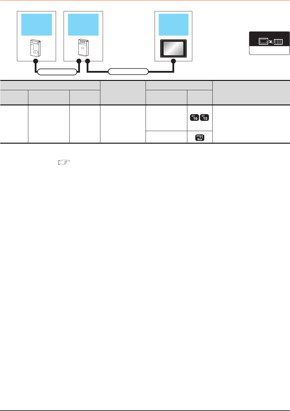
5 - 18 5. BUS CONNECTION
5.2 System Configuration
5.2.4 Connection to A0J2HCPU
*1 The number of connectable GOTs is restricted depending on the number of intelligent function modules mounted to the
A0J2HCPU.
5.4.12 When connecting multiple GOTs
*2 When using the following functions, use GT15-ABUS(2). GT15-75ABUS(2)L cannot be used.
Used for remote personal computer operation (serial), video display function, multimedia function, operation panel function,
external I/O function, RGB display function, report function (when using a PictBridge compatible printer), hard copy function
(when using a PictBridge compatible printer), sound output function, functions with the CF card unit or CF card extension unit,
Ethernet download, gateway function or MES interface function
However, Ethernet download, gateway function and MES interface function can be used for GT16 by using the Ethernet interface.
Power supply
module GOTPLC
Connection cable 2)
Connection cable 1)
Communication driver
Bus(A/QnA)
PLC
Connection cable 2)
GOT1000 series*1
Max. distance
Model name Connection cable 1) Power supply
module Option device*2 Model
A0J2HCPU
A0J2C03(0.3m)
A0J2C06(0.55m)
A0J2C10(1m)
A0J2C20(2m)
A0J2-PW GT15-J2C10B(1m)
GT15-75ABUSL
GT15-75ABUS2L
GT15-ABUS
GT15-ABUS2
Between PLC and GOT: 6.6m
Between power supply module and
GOT: 1m
- (Built into GOT)
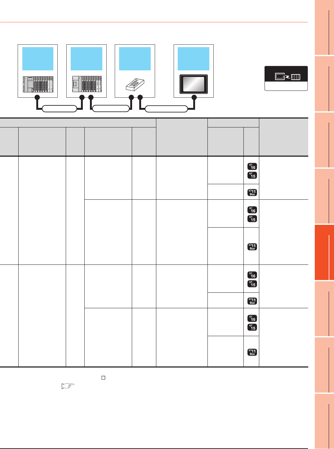
5. BUS CONNECTION
5.2 System Configuration
5 - 19
1
PREPARATORY
PROCEDURES FOR
MONITORING
2
DEVICE RANGE
THAT CAN BE SET
3
ACCESS RANGE
FOR MONITORING
4
HOW TO MONITOR
REDUNTANT
SYSTEM
5
BUS CONNECTION
6
DIRECT
CONNECTION TO
CPU
7
COMPUTER LINK
CONNECTION
8
ETHERNET
CONNECTION
5.2.5 Connection to motion controller CPU
(A273UCPU, A273UHCPU(-S3), A373UCPU(-S3))
When one GOT is connected
*1 When installing the GOT 30m or more away from the main base unit, the bus connector conversion box is required.
*2 When using GT15-C EXSS-1, connect as the following precautions.
5.4.1 GT15-C [ ] EXSS-1, GT15-C [ ] BS
*3 When using the following functions, use GT15-ABUS(2). GT15-75ABUS(2)L cannot be used.
Used for remote personal computer operation (serial), video display function, multimedia function, operation panel function,
external I/O function, RGB display function, report function (when using a PictBridge compatible printer), hard copy function
(when using a PictBridge compatible printer), sound output function, functions with the CF card unit or CF card extension unit,
Ethernet download, gateway function or MES interface function
However, Ethernet download, gateway function and MES interface function can be used for GT16 by using the Ethernet interface.
Extension base
unit
Bus extension
connector box GOTMain base unit
Connection cable 1)
Connection cable 2)
Extension cable
Communication driver
Bus(A/QnA)
PLC
Connection cable 2)
GOT1000 Series
Max. distance
Main
base Extension cable
Extens
ion
base
Connection cable 1)
Bus
connector
conversion
box
*1
Option device
*3
Model
Main
base --
--
GT15-A370C12B-S1(1.2m)
GT15-A370C25B-S1(2.5m)
GT15-75ABUSL
GT15-75ABUS2L
GT15-ABUS
GT15-ABUS2
Between main base
and GOT: 2.5m
-
(Built into GOT)
GT15-A370C12B(1.2m)
GT15-A370C25B(2.5m)
A7GT
-CNB
GT15-C100EXSS-1(10m)
GT15-C200EXSS-1(20m)
GT15-C300EXSS-1(30m)
*2
GT15-75ABUSL
GT15-75ABUS2L
GT15-ABUS
GT15-ABUS2
Between main base
and GOT: 32.5m
(Including between
main base and bus
connector conversion
box)
Between main base
and bus connector
conversion box: 2.5m
-
(Built into GOT)
Main
base
GT15-A370C12B(1.2m)
GT15-A370C25B(2.5m)
Extens
ion
base
--
GT15-C12NB(1.2m)
GT15-C30NB(3m)
GT15-C50NB(5m)
GT15-75ABUSL
GT15-75ABUS2L
GT15-ABUS
GT15-ABUS2
Between main base
and GOT: 6.6m
(Including the
extension cable
length)
-
(Built into GOT)
GT15-AC06B(0.6m)
GT15-AC12B(1.2m)
GT15-AC30B(3m)
GT15-AC50B(5m)
A7GT
-CNB
GT15-C100EXSS-1(10m)
GT15-C200EXSS-1(20m)
GT15-C300EXSS-1(30m)
*2
GT15-75ABUSL
GT15-75ABUS2L
GT15-ABUS
GT15-ABUS2
Between main base
and GOT: 36.6m
Between main base
and bus connector
conversion box: 6.6m
(Including the
extension cable
length)
-
(Built into GOT)
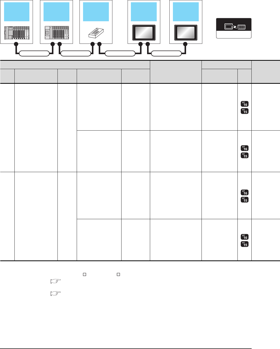
5 - 20 5. BUS CONNECTION
5.2 System Configuration
When two GOTs are connected
*1 When installing the 1st GOT 30m or more away from the main base unit, the bus connector conversion box is required.
*2 When connecting to multiple GOTs with GT 16, GT15 and GT11 mixed, use GT11 as a terminal.
*3 When using GT15-C EXSS-1 or GT15-C BS, connect as following precautions.
5.4.1 GT15-C [ ] EXSS-1, GT15-C [ ] BS
*4 The number of connectable GOTs is restricted according to the CPU type and the number of intelligent function modules.
5.4.12 When connecting multiple GOTs
Extension base
unit
Bus extension
connector box 1st GOTMain base unit
Connection cable 1) Connection cable 2)
Extension cable
2nd GOT
Connection cable 3)
Communication driver
Bus(A/QnA)
PLC*4
Connection cable 2)
GOT (1st)*2
Main
base Extension cable
Extension
base
Connection cable 1) Bus connector
conversion box Option device*5*6 Model
Main
base --
--
GT15-A370C12B-S1(1.2m)
GT15-A370C25B-S1(2.5m)
GT15-75ABUS2L
GT15-ABUS2
GT15-A370C12B(1.2m)
GT15-A370C25B(2.5m) A7GT-CNB*1
GT15-C100EXSS-1(10m)
GT15-C200EXSS-1(20m)
*3
GT15-75ABUS2L
GT15-ABUS2
Main
base
GT15-A370C12B(1.2m)
GT15-A370C25B(2.5m)
Extension
base
--
GT15-C12NB(1.2m)
GT15-C30NB(3m)
GT15-C50NB(5m)
GT15-75ABUS2L
GT15-ABUS2
GT15-AC06B(0.6m)
GT15-AC12B(1.2m)
GT15-AC30B(3m)
GT15-AC50B(5m)
A7GT-CNB*1
GT15-C100EXSS-1(10m)
GT15-C200EXSS-1(20m)
*3
GT15-75ABUS2L
GT15-ABUS2
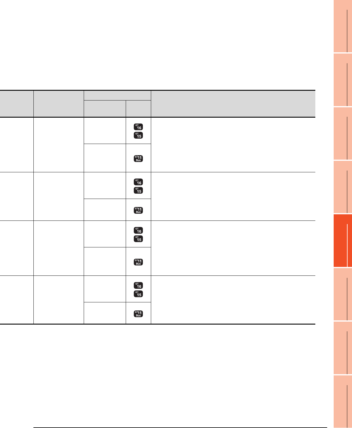
5. BUS CONNECTION
5.2 System Configuration
5 - 21
1
PREPARATORY
PROCEDURES FOR
MONITORING
2
DEVICE RANGE
THAT CAN BE SET
3
ACCESS RANGE
FOR MONITORING
4
HOW TO MONITOR
REDUNTANT
SYSTEM
5
BUS CONNECTION
6
DIRECT
CONNECTION TO
CPU
7
COMPUTER LINK
CONNECTION
8
ETHERNET
CONNECTION
*5 The bus connection unit
GT15-75ABUSL, GT15-ABUS: Used for a terminal GOT. (Not available for an intermediary GOT)
GT15-75ABUS2L, GT15-ABUS2: Used for an intermediary GOT. (Can be used for a terminal GOT)
*6 When using the following functions, use GT15-ABUS(2). GT15-75ABUS(2)L cannot be used.
Used for remote personal computer operation (serial), video display function, multimedia function, operation panel function,
external I/O function, RGB display function, report function (when using a PictBridge compatible printer), hard copy function
(when using a PictBridge compatible printer), sound output function, functions with the CF card unit or CF card extension unit,
Ethernet download, gateway function or MES interface function
However, Ethernet download, gateway function and MES interface function can be used for GT16 by using the Ethernet interface.
Connection cable 3)
GOT (2nd)*2*4
Max. distance
Option device*5*6 Model
GT15-C07BS(0.7m)
GT15-C12BS(1.2m)
GT15-C30BS(3m)
GT15-C50BS(5m)
GT15-C100BS(10m)
GT15-C200BS(20m)
GT15-C300BS(30m)
*3
GT15-75ABUSL
GT15-75ABUS2L
GT15-ABUS
GT15-ABUS2
Between main base and GOT(1st): 2.5m
Between GOT (1st) and GOT (2nd): 30m
Between main base and GOT (2nd): 32.5m
- (Built into GOT)
GT15-C07BS(0.7m)
GT15-C12BS(1.2m)
GT15-C30BS(3m)
GT15-C50BS(5m)
GT15-C100BS(10m)
GT15-C200BS(20m)
*3
GT15-75ABUSL
GT15-75ABUS2L
GT15-ABUS
GT15-ABUS2
Between main base and bus connector conversion box: 2.5m
Between bus connector conversion box and GOT (2nd): 30m
Between main base and GOT (2nd): 32.5m
- (Built into GOT)
GT15-C07BS(0.7m)
GT15-C12BS(1.2m)
GT15-C30BS(3m)
GT15-C50BS(5m)
GT15-C100BS(10m)
GT15-C200BS(20m)
GT15-C300BS(30m)
*3
GT15-75ABUSL
GT15-75ABUS2L
GT15-ABUS
GT15-ABUS2
Between main base and GOT (1st): 6.6m (Including the extension cable length)
Between GOT (1st) and GOT (2nd): 30m
Between main base and GOT (2nd): 36.6m (Including the extension cable length)
- (Built into GOT)
GT15-C07BS(0.7m)
GT15-C12BS(1.2m)
GT15-C30BS(3m)
GT15-C50BS(5m)
GT15-C100BS(10m)
GT15-C200BS(20m)
*3
GT15-75ABUSL
GT15-75ABUS2L
GT15-ABUS
GT15-ABUS2
Between main base and bus connector conversion box: 6.6m (Including extension cable
length)
Between bus connector conversion box and GOT (2nd): 30m
Between main base and GOT (2nd): 36.6m (Including the extension cable length)
- (Built into GOT)
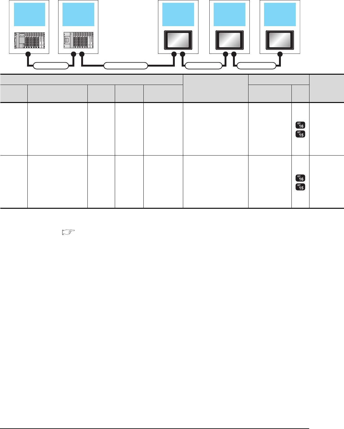
5 - 22 5. BUS CONNECTION
5.2 System Configuration
When 2 to 3 GOTs are connected*2
*1 The connection of multiple GOTs
When connecting to multiple GOTs with GT 16, GT15 and GT11 mixed, use GT11 as a terminal.
*2 The number of connectable GOTs is restricted according to the CPU type and the number of intelligent function modules.
5.4.12 When connecting multiple GOTs
Extension base
unit 1st GOT
Main base unit
Connection cable 2)
Extension cable
2nd GOT 3rd GOT
Connection cable 3)
Connection cable 4)
PLC*2
Connection cable 2)
GOT (1st)*1
Extension
base Extension cable Main base Connection
cable 1)
Bus connector
conversion box Option device*4*5 Model
- - Main base - - GT15-A370C12B-S1(1.2m)
GT15-A370C25B-S1(2.5m)
GT15-75ABUS2L
GT15-ABUS2
Extension
base
GT15-A370C12B(1.2m)
GT15-A370C25B(2.5m) Main base - -
GT15-C12NB(1.2m)
GT15-C30NB(3m)
GT15-C50NB(5m)
GT15-75ABUS2L
GT15-ABUS2
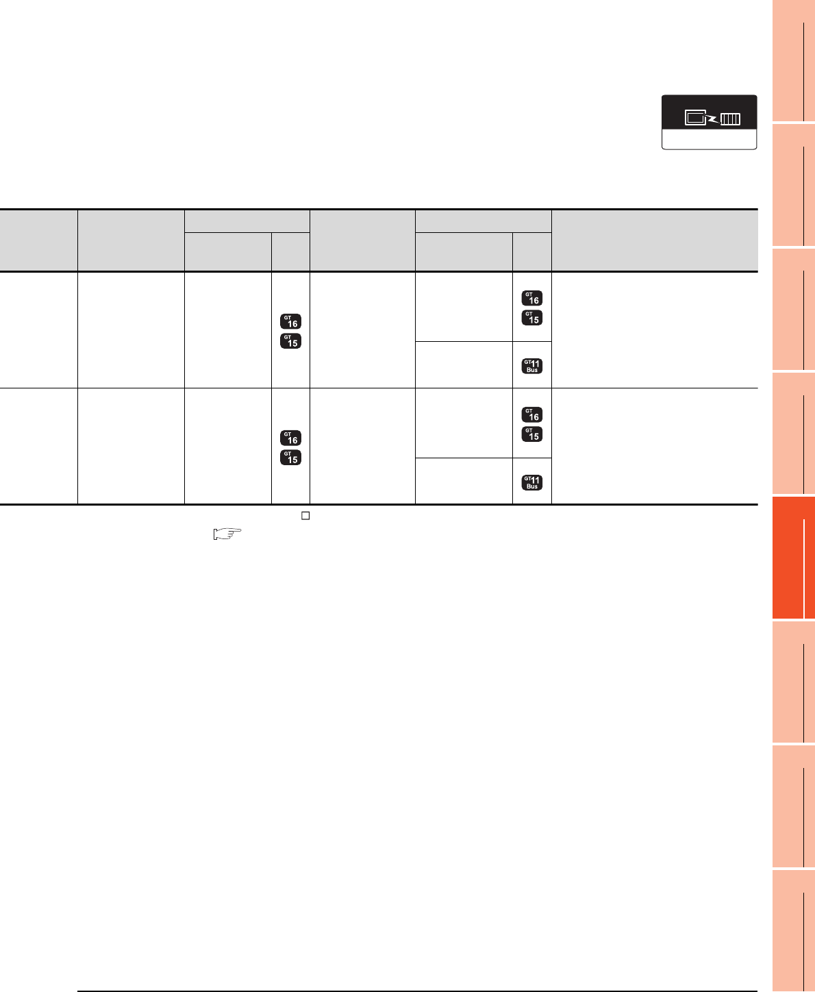
5. BUS CONNECTION
5.2 System Configuration
5 - 23
1
PREPARATORY
PROCEDURES FOR
MONITORING
2
DEVICE RANGE
THAT CAN BE SET
3
ACCESS RANGE
FOR MONITORING
4
HOW TO MONITOR
REDUNTANT
SYSTEM
5
BUS CONNECTION
6
DIRECT
CONNECTION TO
CPU
7
COMPUTER LINK
CONNECTION
8
ETHERNET
CONNECTION
*3 When using GT15-C BS, connect as following precautions.
5.4.1 GT15-C [ ] EXSS-1, GT15-C [ ] BS
*4 The bus connection unit
GT15-75ABUSL, GT15-ABUS: Used for a terminal GOT. (Not available for an intermediary GOT)
GT15-75ABUS2L, GT15-ABUS2: Used for an intermediary GOT. (Can be used for a terminal GOT)
*5 When using the following functions, use GT15-ABUS(2). GT15-75ABUS(2)L cannot be used.
Used for remote personal computer operation (serial), video display function, multimedia function, operation panel function,
external I/O function, RGB display function, report function (when using a PictBridge compatible printer), hard copy function
(when using a PictBridge compatible printer), sound output function, functions with the CF card unit or CF card extension unit,
Ethernet download, gateway function or MES interface function
However, Ethernet download, gateway function and MES interface function can be used for GT16 by using the Ethernet interface.
Connection cable 3)
GOT (2nd)*2*3
Connection cable 4)
GOT (3rd)*2*3
Max. distance
Option device*4*5 Model Option device*4*5 Model
GT15-C07BS(0.7m)
GT15-C12BS(1.2m)
GT15-C30BS(3m)
GT15-C50BS(5m)
GT15-C100BS(10m)
GT15-C200BS(20m)
*3
GT15-75ABUS2L
GT15-ABUS2
GT15-C07BS(0.7m)
GT15-C12BS(1.2m)
GT15-C30BS(3m)
GT15-C50BS(5m)
GT15-C100BS(10m)
GT15-C200BS(20m)
*3
GT15-75ABUSL
GT15-75ABUS2L
GT15-ABUS
GT15-ABUS2
Between main base and GOT(1st): 2.5m
Between GOT (1st) and GOT (3rd): 30m
Between main base and GOT (3rd): 32.5m
- (Built into GOT)
GT15-C07BS(0.7m)
GT15-C12BS(1.2m)
GT15-C30BS(3m)
GT15-C50BS(5m)
GT15-C100BS(10m)
GT15-C200BS(20m)
*3
GT15-75ABUS2L
GT15-ABUS2
GT15-C07BS(0.7m)
GT15-C12BS(1.2m)
GT15-C30BS(3m)
GT15-C50BS(5m)
GT15-C100BS(10m)
GT15-C200BS(20m)
*3
GT15-75ABUSL
GT15-75ABUS2L
GT15-ABUS
GT15-ABUS2
Between main base and GOT(1st): 6.6m
(Including the extension cable length)
Between GOT (1st) and GOT (3rd): 30m
Between main base and GOT (3rd): 36.6m
(Including the extension cable length)
- (Built into GOT)
Communication driver
Bus(A/QnA)
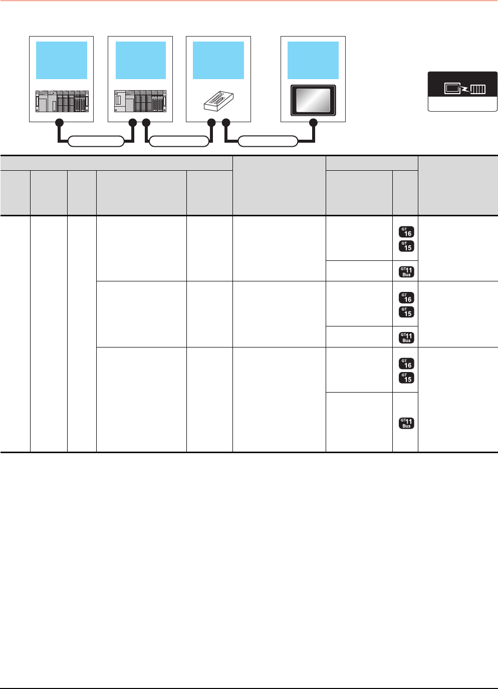
5 - 24 5. BUS CONNECTION
5.2 System Configuration
5.2.6 Connecting to motion controller CPU (A171SCPU(-S3(N)), A171SHCPU(N),
A172SHCPU(N), A173UHCPU(-S1))
When one GOT is connected
Main base unit Bus extension
connector box GOT
Extension base
unit
Connection cable 1) Connection cable 2)
Extension cable
Communication driver
Bus(A/QnA)
PLC
Connection cable 2)
GOT1000 Series
Max. distance
Main
base
Extension
cable
*1
Extens
ion
base*2
Connection cable 1)
Bus
connector
conversion
box
Option device*5
Model
Main
base --
--
GT15-A1SC07B(0.7m)
GT15-A1SC12B(1.2m)
GT15-A1SC30B(3m)
GT15-75ABUSL
GT15-75ABUS2L
GT15-ABUS
GT15-ABUS2
Between main base
and GOT: 3m
- (Built into GOT)
--
GT15-C100EXSS-1(10m)
GT15-C200EXSS-1(20m)
GT15-C300EXSS-1(30m)
*4
GT15-75ABUSL
GT15-75ABUS2L
GT15-ABUS
GT15-ABUS2
Between main base
and GOT: 30m
- (Built into GOT)
GT15-A1SC05NB(0.45m)
GT15-A1SC07NB(0.7m)
GT15-A1SC30NB(3m)
A7GT
-CNB*3
GT15-C100EXSS-1(10m)
GT15-C200EXSS-1(20m)
GT15-C300EXSS-1(30m)
*4
GT15-75ABUSL
GT15-75ABUS2L
GT15-ABUS
GT15-ABUS2
Between main base
and GOT: 33m
(Including between
main base and bus
connector conversion
box)
Between main base
and bus connector
conversion box: 3m
- (Built into GOT)
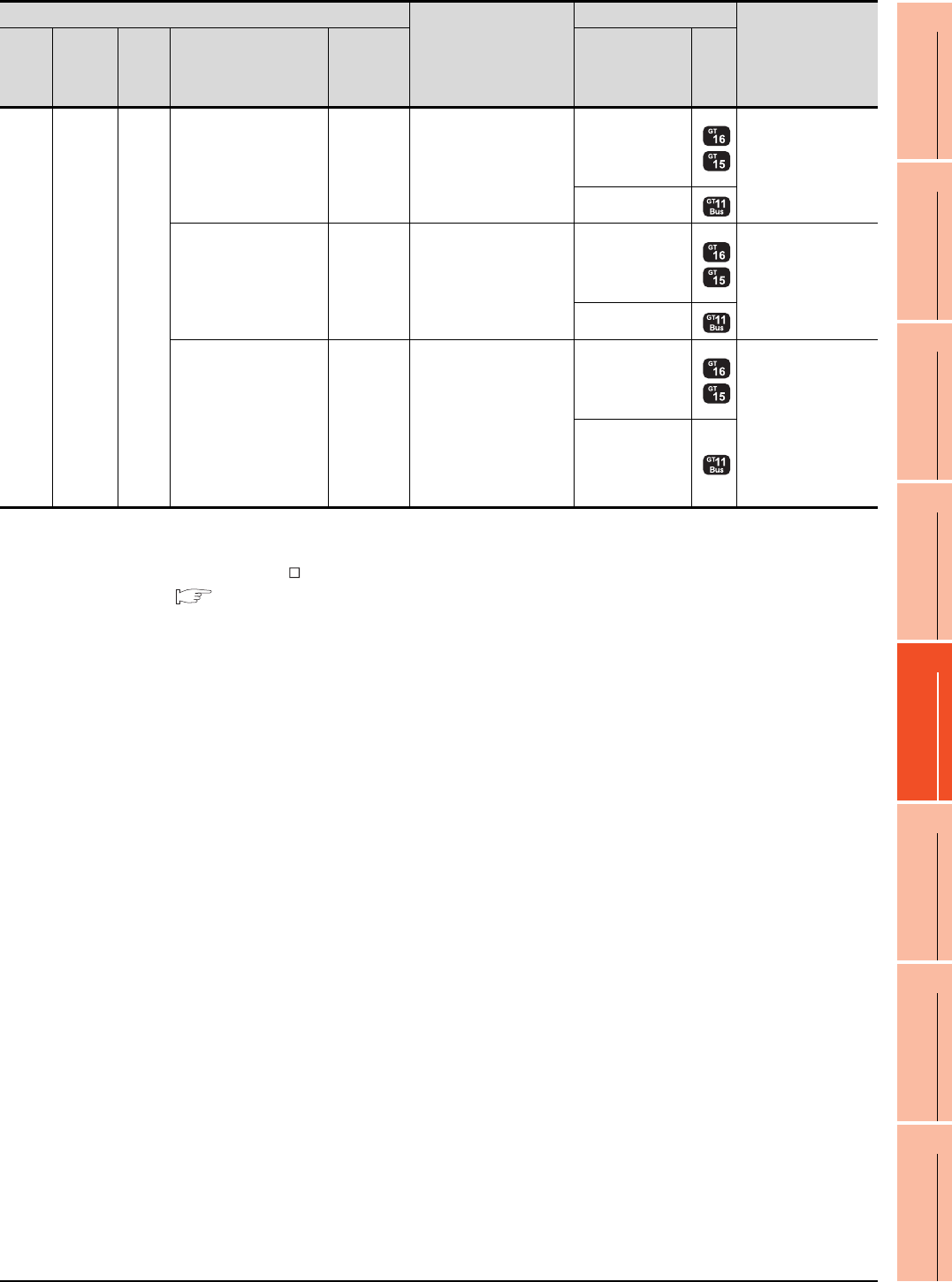
5. BUS CONNECTION
5.2 System Configuration
5 - 25
1
PREPARATORY
PROCEDURES FOR
MONITORING
2
DEVICE RANGE
THAT CAN BE SET
3
ACCESS RANGE
FOR MONITORING
4
HOW TO MONITOR
REDUNTANT
SYSTEM
5
BUS CONNECTION
6
DIRECT
CONNECTION TO
CPU
7
COMPUTER LINK
CONNECTION
8
ETHERNET
CONNECTION
*1 For details on the extension cables, refer to the MELSEC-A/QnA catalog (L(NA)8024).
*2 Use the A168B for the extension base unit.
*3 When installing the GOT 30m or more away from the main base unit, the bus connector conversion box is required.
*4 When using GT15-C EXSS-1, connect as the following precautions.
5.4.1 GT15-C [ ] EXSS-1, GT15-C [ ] BS
*5 When using the following functions, use GT15-ABUS(2). GT15-75ABUS(2)L cannot be used.
Used for remote personal computer operation (serial), video display function, multimedia function, operation panel function,
external I/O function, RGB display function, report function (when using a PictBridge compatible printer), hard copy function
(when using a PictBridge compatible printer), sound output function, functions with the CF card unit or CF card extension unit,
Ethernet download, gateway function or MES interface function
However, Ethernet download, gateway function and MES interface function can be used for GT16 by using the Ethernet interface.
Main
base
Extension
cable
Extens
ion
base
--
GT15-A1SC07B(0.7m)
GT15-A1SC12B(1.2m)
GT15-A1SC30B(3m)
GT15-75ABUSL
GT15-75ABUS2L
GT15-ABUS
GT15-ABUS2
Between extension
base and GOT: 3m
(Including the
extension cable length)
- (Built into GOT)
--
GT15-C100EXSS-1(10m)
GT15-C200EXSS-1(20m)
GT15-C300EXSS-1(30m)
*4
GT15-75ABUSL
GT15-75ABUS2L
GT15-ABUS
GT15-ABUS2
Between extension
base and GOT: 33m
(Including the
extension cable length)
- (Built into GOT)
GT15-A1SC05NB(0.45m)
GT15-A1SC07NB(0.7m)
GT15-A1SC30NB(3m)
A7GT
-CNB*3
GT15-C100EXSS-1(10m)
GT15-C200EXSS-1(20m)
GT15-C300EXSS-1(30m)
*4
GT15-75ABUSL
GT15-75ABUS2L
GT15-ABUS
GT15-ABUS2
Between extension
base and GOT: 33m
Between extension
base and bus
connector conversion
box: 3m
(Including the
extension cable length)
- (Built into GOT)
PLC
Connection cable 2)
GOT1000 Series
Max. distance
Main
base
Extension
cable
*1
Extens
ion
base*2
Connection cable 1)
Bus
connector
conversion
box
Option device*5
Model
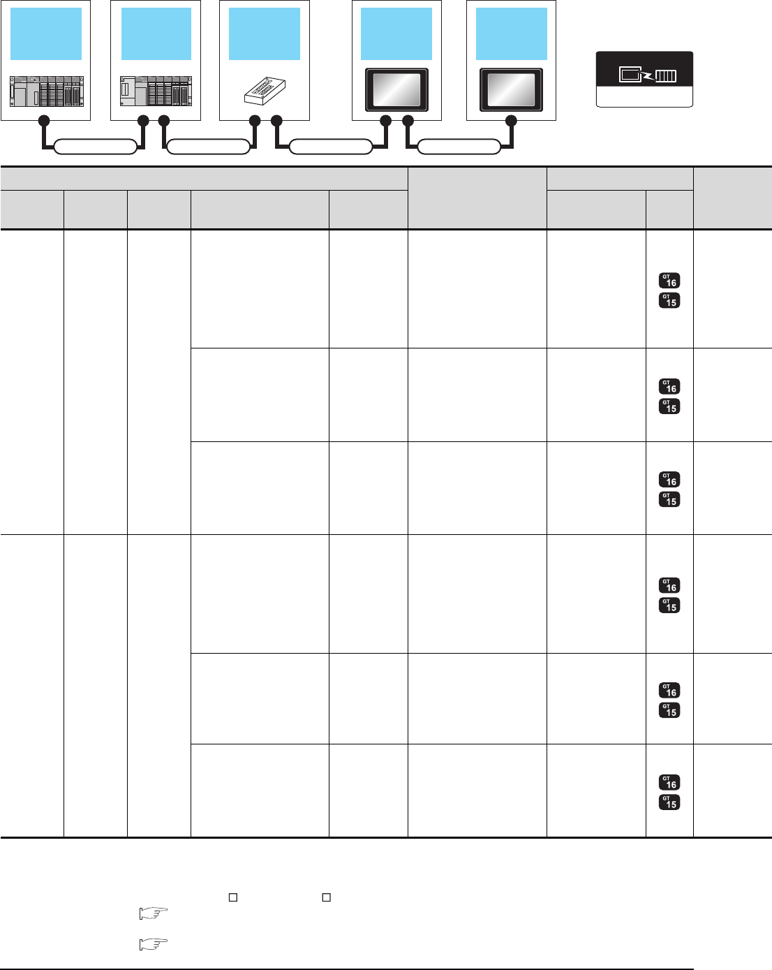
5 - 26 5. BUS CONNECTION
5.2 System Configuration
When two GOTs are connected
*1 For the extension cables, refer to MELSEC-A/QnA catalog (L(NA)08024).
*2 Use the A168B for the extension base unit.
*3 When installing the 1st GOT 30m or more away from the main base unit, the bus connector conversion box is required.
*4 When connecting to multiple GOTs with GT 16, GT15 and GT11 mixed, use GT11 as a terminal.
*5 When using GT15-C EXSS-1 or GT15-C BS, connect as following precautions.
5.4.1 GT15-C [ ] EXSS-1, GT15-C [ ] BS
*6 The number of connectable GOTs is restricted according to the CPU type and the number of intelligent function modules.
5.4.12 When connecting multiple GOTs
Main base unit Bus extension
connector box
Extension base
unit
Connection cable 1) Connection cable 2) Connection cable 3)
Extension cable
1st GOT 2nd GOT
Communication driver
Bus(A/QnA)
PLC*5
Connection cable 2)
GOT (1st)*4
Main base Extension
cable*1
Extension
base*2 Connection cable 1) Bus connector
conversion box Option device*7*8 Model
Main base - -
--
GT15-A1SC07B(0.7m)
GT15-A1SC12B(1.2m)
GT15-A1SC30B(3m)
GT15-75ABUS2L
GT15-ABUS2
--
GT15-C100EXSS-1(10m)
GT15-C200EXSS-1(20m)
*5
GT15-75ABUS2L
GT15-ABUS2
GT15-A1SC05NB(0.45m)
GT15-A1SC07NB(0.7m)
GT15-A1SC30NB(3m)
A7GT-CNB*3
GT15-C100EXSS-1(10m)
GT15-C200EXSS-1(20m)
*5
GT15-75ABUS2L
GT15-ABUS2
Main base Extension
cable
Extension
base
--
GT15-A1SC07B(0.7m)
GT15-A1SC12B(1.2m)
GT15-A1SC30B(3m)
GT15-75ABUS2L
GT15-ABUS2
--
GT15-C100EXSS-1(10m)
GT15-C200EXSS-1(20m)
*5
GT15-75ABUS2L
GT15-ABUS2
GT15-A1SC05NB(0.45m)
GT15-A1SC07NB(0.7m)
GT15-A1SC30NB(3m)
A7GT-CNB*3
GT15-C100EXSS-1(10m)
GT15-C200EXSS-1(20m)
*5
GT15-75ABUS2L
GT15-ABUS2
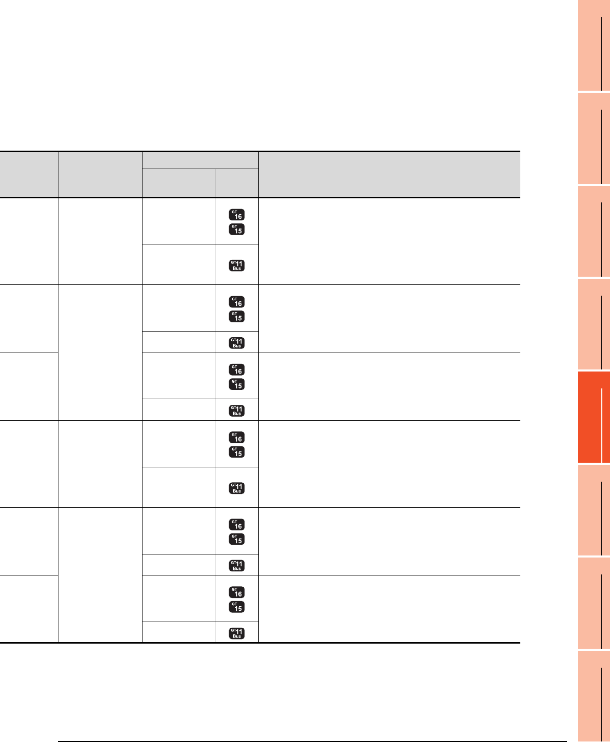
5. BUS CONNECTION
5.2 System Configuration
5 - 27
1
PREPARATORY
PROCEDURES FOR
MONITORING
2
DEVICE RANGE
THAT CAN BE SET
3
ACCESS RANGE
FOR MONITORING
4
HOW TO MONITOR
REDUNTANT
SYSTEM
5
BUS CONNECTION
6
DIRECT
CONNECTION TO
CPU
7
COMPUTER LINK
CONNECTION
8
ETHERNET
CONNECTION
*7 The bus connection unit
GT15-75ABUSL, GT15-ABUS: Used for a terminal GOT. (Not available for an intermediary GOT)
GT15-75ABUS2L, GT15-ABUS2: Used for an intermediary GOT. (Can be used for a terminal GOT)
*8 When using the following functions, use GT15-ABUS(2). GT15-75ABUS(2)L cannot be used.
Used for remote personal computer operation (serial), video display function, multimedia function, operation panel function,
external I/O function, RGB display function, report function (when using a PictBridge compatible printer), hard copy function
(when using a PictBridge compatible printer), sound output function, functions with the CF card unit or CF card extension unit,
Ethernet download, gateway function or MES interface function
However, Ethernet download, gateway function and MES interface function can be used for GT16 by using the Ethernet interface.
Connection cable 3)
GOT (2nd)*4*6
Max. distance
Option device*7*8 Model
GT15-C07BS(0.7m)
GT15-C12BS(1.2m)
GT15-C30BS(3m)
GT15-C50BS(5m)
GT15-C100BS(10m)
GT15-C200BS(20m)
GT15-C300BS(30m)
*5
GT15-75ABUSL
GT15-75ABUS2L
GT15-ABUS
GT15-ABUS2
Between main base and GOT(1st): 3m
Between GOT (1st) and GOT (2nd): 30m
Between main base and GOT (2nd): 33m
- (Built into GOT)
GT15-C07BS(0.7m)
GT15-C12BS(1.2m)
GT15-C30BS(3m)
GT15-C50BS(5m)
GT15-C100BS(10m)
GT15-C200BS(20m)
*5
GT15-75ABUSL
GT15-75ABUS2L
GT15-ABUS
GT15-ABUS2 Between main base and GOT (2nd): 30m
- (Built into GOT)
GT15-75ABUSL
GT15-75ABUS2L
GT15-ABUS
GT15-ABUS2
Between main base and bus connector conversion box: 3m
Between bus connector conversion box and GOT (2nd): 30m
Between main base and GOT (2nd): 33m
- (Built into GOT)
GT15-C07BS(0.7m)
GT15-C12BS(1.2m)
GT15-C30BS(3m)
GT15-C50BS(5m)
GT15-C100BS(10m)
GT15-C200BS(20m)
GT15-C300BS(30m)
*5
GT15-75ABUSL
GT15-75ABUS2L
GT15-ABUS
GT15-ABUS2
Between main base and GOT (1st): 3m (Including the extension cable length)
Between GOT (1st) and GOT (2nd): 30m
Between main base and GOT (2nd): 33m (Including the extension cable length)
- (Built into GOT)
GT15-C07BS(0.7m)
GT15-C12BS(1.2m)
GT15-C30BS(3m)
GT15-C50BS(5m)
GT15-C100BS(10m)
GT15-C200BS(20m)
*5
GT15-75ABUSL
GT15-75ABUS2L
GT15-ABUS
GT15-ABUS2 Between main base and GOT (2nd): 30m
- (Built into GOT)
GT15-75ABUSL
GT15-75ABUS2L
GT15-ABUS
GT15-ABUS2
Between main base and bus connector conversion box: 3m (Including extension
cable length)
Between bus connector conversion box and GOT (2nd): 30m
Between main base and GOT (2nd): 33m (Including the extension cable length)
- (Built into GOT)
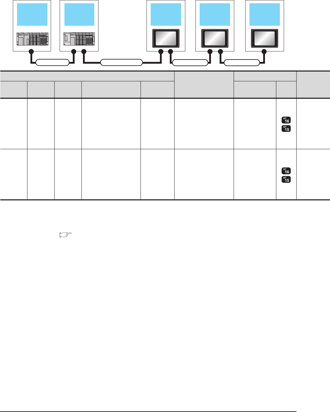
5 - 28 5. BUS CONNECTION
5.2 System Configuration
When 2 to 3 GOTs are connected*4
*1 For the extension cables, refer to MELSEC-A/QnA catalog (L(NA)08024).
*2 Use the A168B for the extension base unit.
*3 The connection of multiple GOTs
When connecting to multiple GOTs with GT 16, GT15 and GT11 mixed, use GT11 as a terminal.
*4 The number of connectable GOTs is restricted according to the CPU type and the number of intelligent function modules.
5.4.12 When connecting multiple GOTs
Main base unit Extension base
unit
Connection cable 2)
Connection cable 3)
Extension cable
1st GOT 2nd GOT
Connection cable 4)
3rd GOT
PLC*3
Connection cable 2)
GOT (1st)*3
Main base Extension
cable*1
Extension
base*2 Connection cable 1) Bus connector
conversion box Option device*6*7 Model
Main base - - - -
GT15-A1SC07B(0.7m)
GT15-A1SC12B(1.2m)
GT15-A1SC30B(3m)
GT15-75ABUS2L
GT15-ABUS2
Main base Extension
cable
Extension
base --
GT15-A1SC07B(0.7m)
GT15-A1SC12B(1.2m)
GT15-A1SC30B(3m)
GT15-75ABUS2L
GT15-ABUS2

5. BUS CONNECTION
5.2 System Configuration
5 - 29
1
PREPARATORY
PROCEDURES FOR
MONITORING
2
DEVICE RANGE
THAT CAN BE SET
3
ACCESS RANGE
FOR MONITORING
4
HOW TO MONITOR
REDUNTANT
SYSTEM
5
BUS CONNECTION
6
DIRECT
CONNECTION TO
CPU
7
COMPUTER LINK
CONNECTION
8
ETHERNET
CONNECTION
*5 When using GT15-C BS, connect as following precautions.
5.4.1 GT15-C [ ] EXSS-1, GT15-C [ ] BS
*6 The bus connection unit
GT15-75ABUSL, GT15-ABUS: Used for a terminal GOT. (Not available for an intermediary GOT)
GT15-75ABUS2L, GT15-ABUS2: Used for an intermediary GOT. (Can be used for a terminal GOT)
*7 When using the following functions, use GT15-ABUS(2). GT15-75ABUS(2)L cannot be used.
Used for remote personal computer operation (serial), video display function, multimedia function, operation panel function,
external I/O function, RGB display function, report function (when using a PictBridge compatible printer), hard copy function
(when using a PictBridge compatible printer), sound output function, functions with the CF card unit or CF card extension unit,
Ethernet download, gateway function or MES interface function
However, Ethernet download, gateway function and MES interface function can be used for GT16 by using the Ethernet interface.
Connection cable 3)
GOT (2nd)*3*4
Connection cable 4)
GOT (3rd)*3*4
Max. distance
Option device*6*7 Model Option device*6*7 Model
GT15-C07BS(0.7m)
GT15-C12BS(1.2m)
GT15-C30BS(3m)
GT15-C50BS(5m)
GT15-C100BS(10m)
GT15-C200BS(20m)
*5
GT15-75ABUS2L
GT15-ABUS2
GT15-C07BS(0.7m)
GT15-C12BS(1.2m)
GT15-C30BS(3m)
GT15-C50BS(5m)
GT15-C100BS(10m)
GT15-C200BS(20m)
*5
GT15-75ABUSL
GT15-75ABUS2L
GT15-ABUS
GT15-ABUS2
Between main base and GOT(1st): 3m
Between GOT (1st) and GOT (3rd): 30m
Between main base and GOT (3rd): 33m
- (Built into GOT)
GT15-C07BS(0.7m)
GT15-C12BS(1.2m)
GT15-C30BS(3m)
GT15-C50BS(5m)
GT15-C100BS(10m)
GT15-C200BS(20m)
*5
GT15-75ABUS2L
GT15-ABUS2
GT15-C07BS(0.7m)
GT15-C12BS(1.2m)
GT15-C30BS(3m)
GT15-C50BS(5m)
GT15-C100BS(10m)
GT15-C200BS(20m)
*5
GT15-75ABUSL
GT15-75ABUS2L
GT15-ABUS
GT15-ABUS2
Between main base and GOT(1st): 3m
(Including the extension cable length)
Between GOT (1st) and GOT (3rd): 30m
Between main base and GOT (3rd): 33m
(Including the extension cable length)
- (Built into GOT)
Communication driver
Bus(A/QnA)
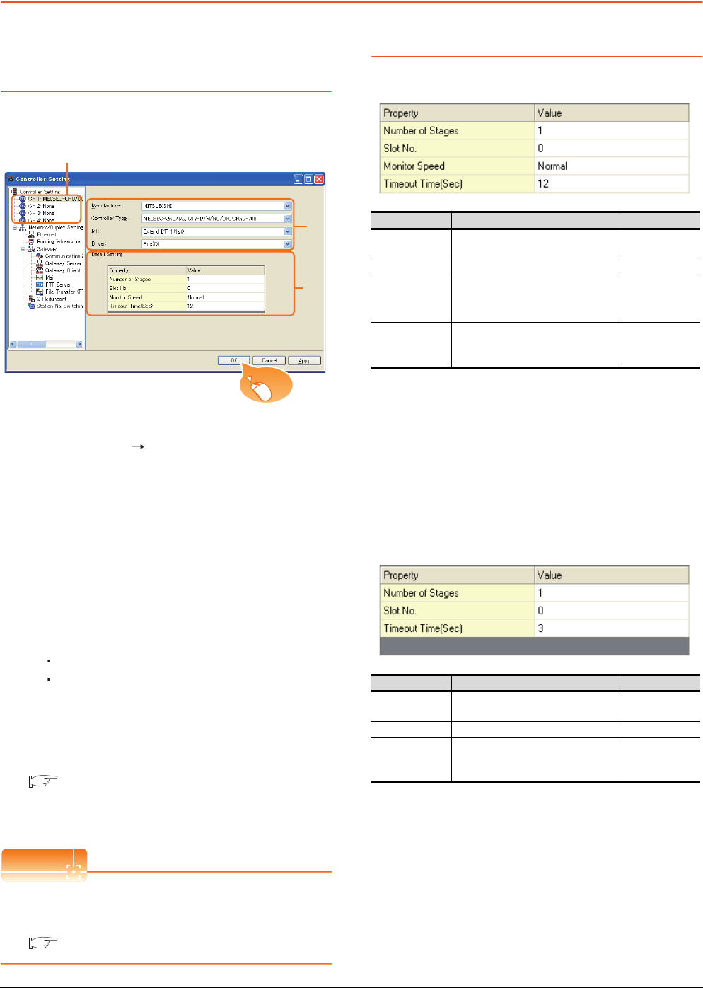
5 - 30 5. BUS CONNECTION
5.3 GOT Side Settings
5.3 GOT Side Settings
5.3.1 Setting communication
interface (Communication
settings)
Set the channel of the connected equipment.
1. Select [Common] [Controller Setting] from the
menu.
2. The Controller Setting window is displayed. Select the
channel to be used from the list menu.
3. Set the following items.
• Manufacturer: Mitsubishi
• Controller Type: Set the option according to the
Controller Type to be connected.
• I/F: Interface to be used
• Driver: Set either of the following option according
to the Controller Type to be connected.
BUS (Q)
BUS (A/QnA)
4. The detailed setting is displayed after Manufacturer,
Controller Type, I/F, and Driver are set.
Make the settings according to the usage
environment.
5.3.2 Communication detail settings
Click the [OK] button when settings are completed.
POINTPOINTPOINT
The settings of connecting equipment can be
confirmed in [I/F Communication Setting].
For details, refer to the following.
1.1.2 I/F communication setting
5.3.2 Communication detail settings
(1) Bus(Q)
*1 This range is effective when collecting a large amount of
data (such as logging and recipe function) on other than the
monitor screen.
However, the range may affect the sequence scan time
when connecting to Q00UJ/Q00U/Q01U/Q02UCPU or Q00J/
Q00/Q01CPU.
If you want to avoid the influence on the sequence scan time,
do not set [High].
(This setting hardly affects QCPUs other than the above.)
*2 Set this range if you want to avoid the influence on the
sequence scan time further than the [Normal] setting when
connecting to Q00UJ/Q00U/Q01U/Q02UCPU or Q00J/Q00/
Q01CPU.
However, the monitor speed may be reduced.
(2) Bus(A/QnA)
2.
3.
4.
Click!
Item Description Range
Number of
Stages (Default: 1) 1 to 7
Slot No. (Default: 0) 0 to 9
Monitor Speed
Set the monitor speed of the GOT.
This setting is not valid in all systems.
(Default: Normal)
High*1/Normal/
Low*2
Timeout Time
(Sec.)
Set the time period for a
communication to time out.
(Default: 12)
12 to 90
Item Description Range
Number of
Stages (Default: 1) 1 to 7
Slot No. (Default: 0) 0 to 7
Timeout Time
(Sec.)
Set the time period for a
communication to time out.
(Default: 3)
3 to 90
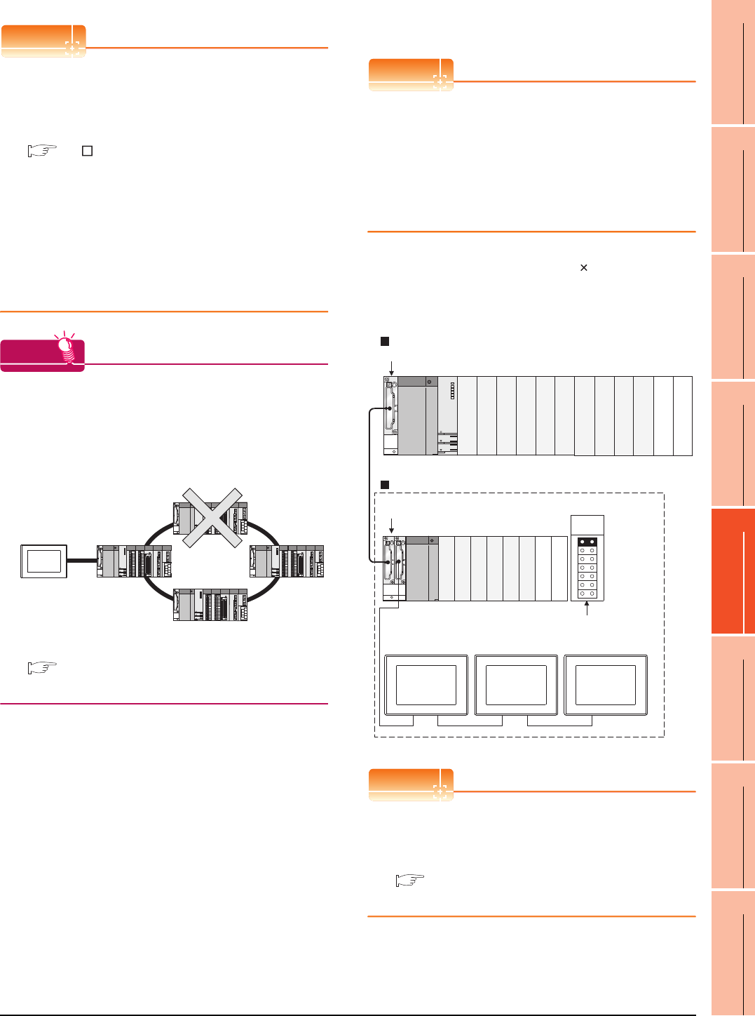
5. BUS CONNECTION
5.3 GOT Side Settings
5 - 31
1
PREPARATORY
PROCEDURES FOR
MONITORING
2
DEVICE RANGE
THAT CAN BE SET
3
ACCESS RANGE
FOR MONITORING
4
HOW TO MONITOR
REDUNTANT
SYSTEM
5
BUS CONNECTION
6
DIRECT
CONNECTION TO
CPU
7
COMPUTER LINK
CONNECTION
8
ETHERNET
CONNECTION
POINTPOINTPOINT
(1) Communication interface setting by Utility
The communication interface setting can be changed
on the Utility's [Communication Settings] after writing
[Communication Settings] of project data.
For details on the Utility, refer to the following manual.
GT User's Manual
(2) Precedence in communication settings
When settings are made by GT Designer3 or the
Utility, the latest setting is effective.
(3) When changing Stage No. and Slot No.
Change these settings with the PLC CPU turned
OFF, and then reapply the power to the PLC CPU
and GOT.
Failure to do so may generate a system alarm
(No.487).
HINTHINTHINT
Cutting the portion of multiple connection of the
controller
By setting GOT internal device, GOT can cut the
portion of multiple connection of the controller. For
example, faulty station that has communication
timeout can be cut from the system.
For details of the setting contents of GOT internal
device, refer to the following manual.
GT Designer3 Version Screen Design Manual
(Fundamentals)
Setting Stage No. and Slot No.
POINTPOINTPOINT
Before setting Stage No. and Slot No.
The PLC CPU recognizes the GOT as follows.
• QCPU (Q mode)
: Intelligent function module of 16 I/O points
• Other than QCPU (Q mode)
: Intelligent function module of 32 I/O points
At the [Detail setting], assign the GOT to an empty I/O
slot on the PLC CPU.
(1) When connecting to QCPU (Q mode)
Set an additional stage (16 points 10 slots) for GOT
connection, and assign a GOT to one of the I/O slots.
(The GOT cannot be assigned to empty slots of the
main base unit or extension base unit.)
POINTPOINTPOINT
When using the bus extension connector box
Set the Stage No. switch on the bus extension
connector box to the same Stage No. as the GOT.
For setting details, refer to the following manual:
A9GT-QCNB Bus Extension Connector Box
User's Manual
Disconnect the
faulty station
Q312B
Q68B
Main base unit
Stage No. :2
Slot No. :0
Stage No. :2
Slot No. :1
Stage No. :2
Slot No. :2
Extension base unit
Stage No. setting
connector
Extension
stage 1
Empty
Empty
Empty
Empty
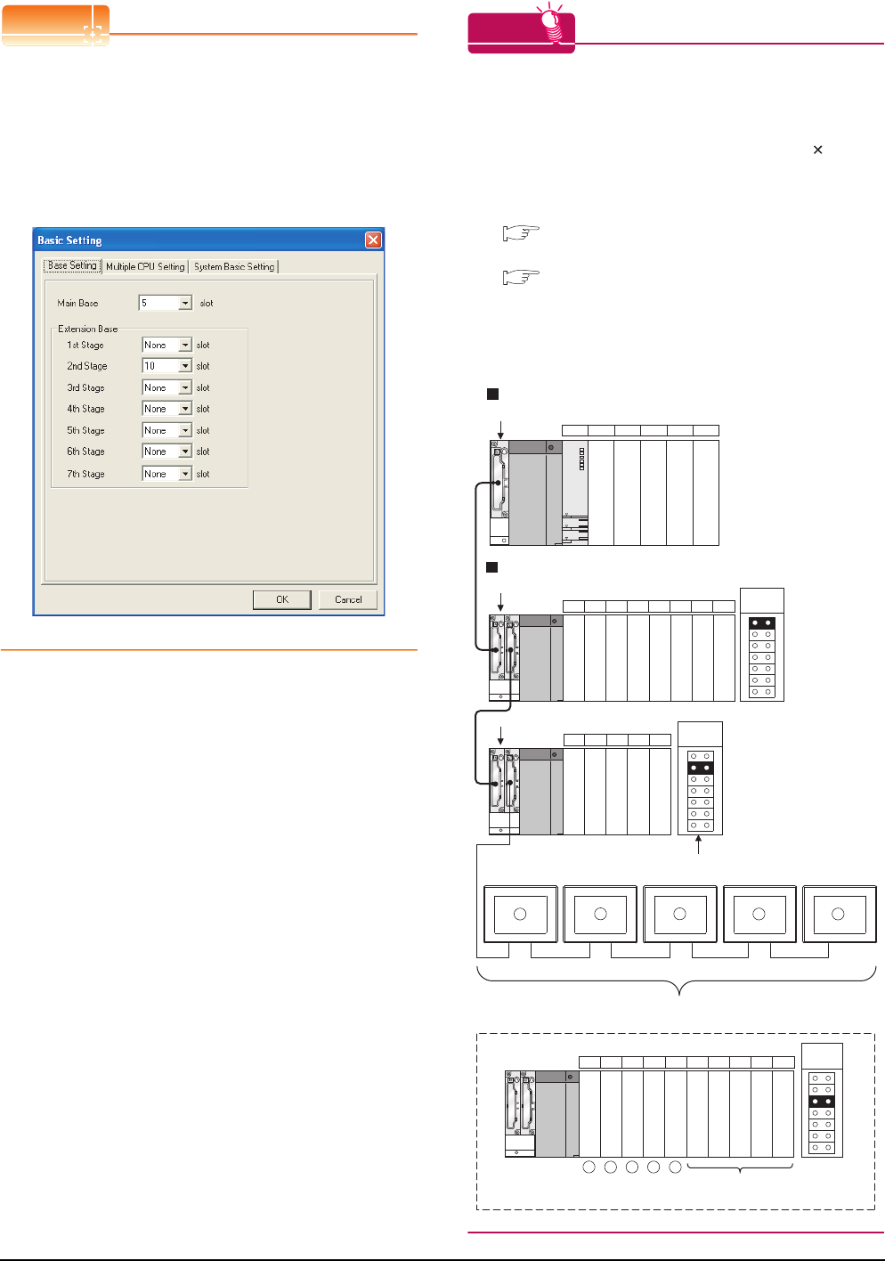
5 - 32 5. BUS CONNECTION
5.3 GOT Side Settings
POINTPOINTPOINT
When connecting to motion controller CPU (Q Series)
In the [Base Setting] on MT Developer, set "10" to the
number of slots for the extension base used for GOT
connection.
HINTHINTHINT
Setting unused I/O slots to empty (0 points) (only when
connecting to QCPU (Q mode))
Setting unused I/O slots as empty slots (0 points) from
"PC parameters" "I/O assignments" of GX Developer
allows you to use I/O numbers of "16 points number
of empty slots" for other purposes.
For details on I/O assignment settings, refer to the
following manual:
QnU User's Manual (Function Explanation,
Program Fundamentals)
Qn(H)/QnPH/QnPRHCPU User's Manual
(Function Explanation, Program Fundamentals)
Example: When setting "2" to Stage No. and "0" to Slot
No. in the communication interface settings,
set "10" to [2nd Stage].
Example: I/O assignment (when 16 points are assigned
to each of all modules installed with the PLC
CPU)
Q35B
Q68B
01CPU 2 3 4 · · · · Slot No.
56789101112
Q65B
13 14 15 16 17
X00 to X0F
X10 to X1F
X20 to X2F
X30 to X3F
X40 to X4F
X60 to X6F
X70 to X7F
X80 to X8F
X90 to X9F
X50 to X5F
XA0 to XAF
XB0 to XBF
XC0 to XCF
XE0 to XEF
XF0 to XFF
X100 to X10F
X110 to X11F
XD0 to XDF
18 19 20 21 22 23 24 25 26 27
Schematic image of Stage No. for GOT connection
viewed from PLC CPU (16 points x 10 slots occupied)
X120 to X12F
X170 to X17F
X130 to X13F
X140 to X14F
X150 to X15F
X160 to X16F
X180 to X18F
X190 to X19F
X1A0 to X1AF
X1B0 to X1BF
Set Empty (0 points)
to unused I/O slots.
Main base unit
Extension base unit
Extension
stage 1
Extension
stage 2
Extension
stage 3
Stage No. setting
connector
1
1
2
2
3
3
4
4
5
5
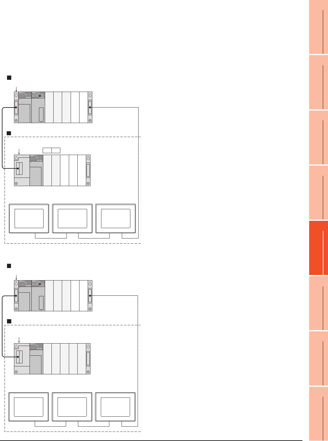
5. BUS CONNECTION
5.3 GOT Side Settings
5 - 33
1
PREPARATORY
PROCEDURES FOR
MONITORING
2
DEVICE RANGE
THAT CAN BE SET
3
ACCESS RANGE
FOR MONITORING
4
HOW TO MONITOR
REDUNTANT
SYSTEM
5
BUS CONNECTION
6
DIRECT
CONNECTION TO
CPU
7
COMPUTER LINK
CONNECTION
8
ETHERNET
CONNECTION
(2) Other than QCPU (Q mode)
Assign the GOT to an empty I/O slot on the extension
base unit.
When there is no extension base unit or no empty I/O
slots are left on an extension base unit, set an
additional stage, and assign the GOT to one of the I/O
slots.
(Assigning the GOT to an empty slot on the main base
unit is not allowed.)
(a) When there is an empty I/O slot on the extension
base unit
(b) When there are no empty I/O slots on the
extension base unit
A1S35B
01
· · · · Slot No.
A1S65B
Main base unit
Extension base unit
Stage No. :1
Slot No. :2
Stage No. :1
Slot No. :3
Stage No. :1
Slot No. :4
Empty
Empty
Empty
Empty
Empty
A1S35B
A1S65B
Main base unit
Extension base unit
Stage No. :2
Slot No. :0
Stage No. :2
Slot No. :1
Stage No. :2
Slot No. :2
Empty
Empty
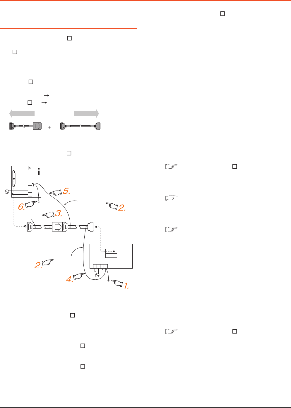
5 - 34 5. BUS CONNECTION
5.4 Precautions
5.4 Precautions
5.4.1 GT15-C [ ] EXSS-1,
GT15-C [ ] BS
(1) Composition of GT15-C EXSS-1
It is composed of GT15-EXCNB (0.5m) and GT15-
C BS (10 to 30m).
Calculate the cable length based on GT15-C100EXSS-
1(10m), GT15-C200EXSS-1(20m) and GT15-
C300EXSS-1(30m).
(2) GT15-C EXSS-1 connector
Connect the connectors as follows:
GT15-EXCNB PLC CPU side
GT15-C BS GOT side
(3) Grounding
(a) When using GT15-C EXSS-1
(b) When using GT15-C BS
Follow the GOT side grounding steps in (a) above
for both GOTs.
5.4.2 Turning the GOT ON
(1) System configuration
The PLC CPU remains in the reset status until the GOT
is started.
Therefore, no sequence program will run until then.
The system configuration, in which the GOT is turned
on from a sequence program, is not available.
(2) Time taken until the PLC runs after power-on of the
GOT
The following time is taken from when the GOT is
powered on until when the PLC runs.
• QCPU (Q mode), motion controller CPU
(Q series): 10 seconds or more
• MELDAS C70: 18 seconds or more
When the GOT starts before the PLC runs, a system
alarm occurs.Adjust the opening screen time in the
GOT setup so that no system alarm occurs.
GT Designer3 Version Screen Design
Manual
(3) Power-up sequence for connection of 3 GOTs or
more (when connecting QCPU (Q mode))
5.4.10 (1)Restrictions in overall cable length to
No. of GOTs
(4) Power-up sequence for connection of the
Q4ARCPU redundant system
5.4.14 (2)Power-On sequence for GOT and
Q4ARCPU redundant system
(5) Power-up sequence for cases other than (3) and (4)
The GOT and PLC can both be started up whichever of
these devices is turned ON first. (There is no specific
sequence in which they are powered ON)
Note, however, that operation is as follows when the
GOT is turned ON followed by the PLC:
When the PLC power is OFF with the GOT turned ON,
the system alarm (No.402: timeout error) is generated.
Upon power-on of the PLC CPU, the GOT
automatically starts monitoring.
Use System Information to reset the alarm.
For the System Information, refer to the following
manual:
GT Designer3 Version Screen Design
Manual
1. Connect the LG and FG terminals of the
terminal block on the GOT unit power and
ground them with a cable.
2. Use the GT15-C BS's FG cable of 28cm
or less.
3. Do not connect the GT15-EXCNB's FG
ground cable.
4. Connect the GT15-C BS's FG cable on
the GOT side to FG of the GOT unit power's
terminal block.
5. Connect the GT15-C BS's FG cable on
the PLC side to FG of the PLC's power
supply module.
6. Connect the LG and FG terminals of the
terminal block on the PLC and ground them
with a cable.
(GT15-EXCNB) (GT15-C□BS)
PLC side GOT side
FG
LG
N
L
PLC
Not connected
(GT15-EXCNB)
GOT
OUT IN
FGLG
NL
2SQ cables to
FG terminals,
28cm or less
2SQ cables to
FG terminals,
28cm or less
(GT15-C□BS)
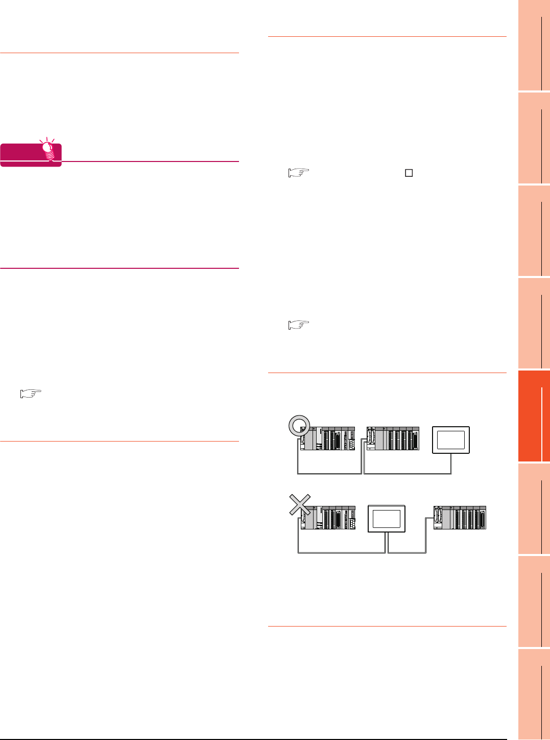
5. BUS CONNECTION
5.4 Precautions
5 - 35
1
PREPARATORY
PROCEDURES FOR
MONITORING
2
DEVICE RANGE
THAT CAN BE SET
3
ACCESS RANGE
FOR MONITORING
4
HOW TO MONITOR
REDUNTANT
SYSTEM
5
BUS CONNECTION
6
DIRECT
CONNECTION TO
CPU
7
COMPUTER LINK
CONNECTION
8
ETHERNET
CONNECTION
5.4.3 Powering OFF the GOT,
reapplying the power (OFF to
ON)
(1) Precautions for reapplying the power to the GOT
(OFF to ON)
Do not power-cycle the GOT (OFF to ON) while the
PLC is ON.
Before doing so, be sure to turn off the PLC first.
HINTHINTHINT
Operations causing automatic reboot of the GOT1000
Series
Since the GOT1000 Series is automatically rebooted
in the following cases, the power does not need to be
reapplied to the GOT (OFF to ON).
• When an OS is written from GT Designer3 or a CF
card
• When utility settings have been changed
(2) When turning OFF the GOT before display of the
user creation screen
When the GOT is turned OFF before the user creation
screen is displayed on the GOT, subsequent
communications may be no longer possible.
In such a case, reapply the power to the PLC CPU and
GOT.
(3) Precautions for connection of 3 GOTs or more (when
connecting QCPU (Q mode))
5.4.10 (1)Restrictions in overall cable length to
No. of GOTs
5.4.4 Reset switch on GOT
When bus connection is used, the reset switch on the GOT
does not function.
5.4.5 Powering OFF or resetting the
PLC
(1) When turning OFF or resetting the PLC during
monitoring
When turning OFF or resetting the PLC during
monitoring, the system alarm (No.402: timeout error) is
generated.
When the PLC CPU is restored, the GOT automatically
resumes monitoring.
Use System Information to reset the alarm.
For the System Information, refer to the following
manual:
GT Designer3 Version Screen Design
Manual
(2) When turning OFF or resetting the PLC CPU before
display of the user creation screen
When the PLC CPU is turned OFF or reset before the
user creation screen is displayed on the GOT,
subsequent communications may be no longer
possible.
In such a case, reapply the power to the PLC CPU and
GOT.
(3) Precautions for connection of 3 GOTs or more (when
connecting QCPU (Q mode))
5.4.10 (1)Restrictions in overall cable length to
No. of GOTs
5.4.6 Position of the GOT
Always connect the GOT to the last base unit.
Connecting a GOT between base units is not allowed.
5.4.7 When the GOT is bus-
connected to a PLC CPU
without the communication
driver written
When the GOT is bus-connected to a PLC CPU without the
standard monitor OS and the communication driver for the
bus connection being written onto the GOT, the PLC CPU
is reset. (GX Developer cannot communicate with the PLC
CPU)
In this case, disconnecting the bus connection cable from
the GOT will cancel the reset status of the PLC CPU.
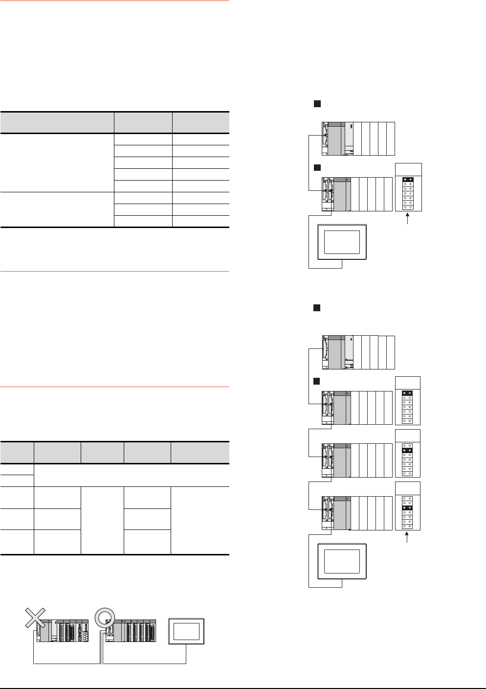
5 - 36 5. BUS CONNECTION
5.4 Precautions
5.4.8 When designing the system
When the GOT is OFF, the following currents are supplied
to the GOT from the PLC CPU side (the power supply
module on the main base unit).(The GOT does not operate
when it is OFF.)
Design the system so that the 5V DC current consumption
of the modules on the main base unit and the total current
consumption of the GOTs will not exceed the rated output
current of 5V DC of the power supply module in use.
5.4.9 When assigning GOT I/O
signals
Do not use the I/O signals assigned to the PLC CPU in
sequence programs, as these signals are used by the GOT
system.
When these signals are used, GOT functions cannot be
assured.
5.4.10 When connecting to a QCPU
(Q mode)
(1) Restrictions in overall cable length to No. of GOTs
The following restrictions apply when 3 of more GOTs
are connected:
(2) When using a Q00JCPU, Q00UJCPU
The bus extension connector box can be connected
only to the extension base unit.
(Connecting it to the main base unit is not allowed)
(3) When using a Q00J/Q00UJ/Q00/Q00U/Q01/Q01U/
Q02UCPU
When a GOT is bus-connected to a Q00JCPU or
Q00UJCPU, number of extension stages including the
GOT must be 2 or less.
When a GOT is bus-connected to a Q00CPU,
Q00UCPU, Q01CPU, Q01UCPU or Q02UCPU,
number of extension stages including the GOT must be
4 or less.
When connecting to No. of GOTs Total current
consumption
When connecting to
QCPU (Q mode)
5 2200mA
4 1760mA
3 1320mA
2880mA
1440mA
Other than QCPU (Q mode)
3360mA
2240mA
1120mA
Number
of GOTs
Overall Cable
Length Restriction Overall Cable
Length Restriction
1(No restrictions)
2
3Less than
25m
(No
restrictions)
25 to 37m Use the same
power supply for
the PLC and all
GOTs, and turn
these devices
ON and OFF
simultaneously.
4Less than
20m 20 to 37m
5Less than
15m 15 to 37m
Q00JCPU,
Q00UJCPU
Stage No. setting
connector
Q00CPU, Q00UCPU, Q01CPU,
Q01UCPU, Q02UCPU
Main base unit
Extension base unit Extension
stage 1
Extension
stage 2
Extension
stage 3
GOT
Stage No. :4
Stage No. setting
connector
Q00JCPU, Q00UJCPU
Main base unit
Extension base unit
GOT
Stage No. :2
Extension
stage 1
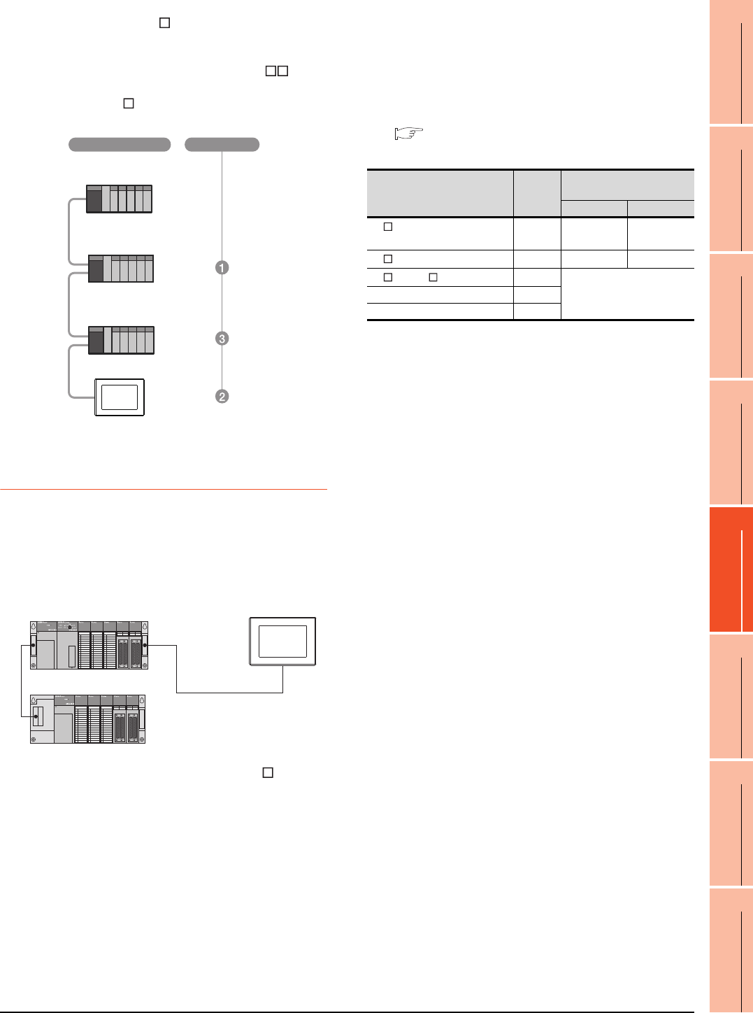
5. BUS CONNECTION
5.4 Precautions
5 - 37
1
PREPARATORY
PROCEDURES FOR
MONITORING
2
DEVICE RANGE
THAT CAN BE SET
3
ACCESS RANGE
FOR MONITORING
4
HOW TO MONITOR
REDUNTANT
SYSTEM
5
BUS CONNECTION
6
DIRECT
CONNECTION TO
CPU
7
COMPUTER LINK
CONNECTION
8
ETHERNET
CONNECTION
(4) When using the QA1S6 B extension base unit
A GOT is physically connected to the last of all
extension base units. In the Stage No. setting, however,
assign the GOT as a stage next to the last Q B type
extension base unit.
Assign the QA1S6 B type extension base unit as a
stage next to the GOT.
5.4.11 When connecting to a
QnA(S)CPU or An(S)CPU type
(1) When connecting with a QnASCPU type and an
AnSCPU type
A GOT can be connected to an extension connector on
only one side of the main base unit.
(Concurrently connecting GOTs to extension
connectors on both sides is not allowed)
(2) In the case of Q4A(R)CPU, Q3ACPU, A3 CPU,
A4UCPU
Empty I/O slots are required within the max. number of
extension stages.
(3) For A0J2HCPU
Assign the GOT to the I/O slots 0 to 3 of extension
stage 1.
(4) In the case of CPUs other than (2) (3) above
Even if the max. number of stages are used with no
empty I/O slots, when there is a free space of 32 I/O
points or more, a GOT can be connected under the
following communication interface setting.
For the communication interface setting, refer to the
following.
5.3.1 Setting communication interface
(Communication settings)
Q38B
Main base unit
Q68B
Extension base unit
QA1S68B
Extension base unit
Stage No.
Connection method
When connecting to
Max.
stage
No.
Communication interface
setting
Stage No. Slot No.
A1 CPU/A2USCPU(-S1)
/QnAS(H)CPU(-S1) 12 0
A2 CPU/Q2ACPU 34 0
A3 CPU/A4 CPU 7
Cannot be used
Q3ACPU/Q4ACPU 7
A0J2HCPU 1
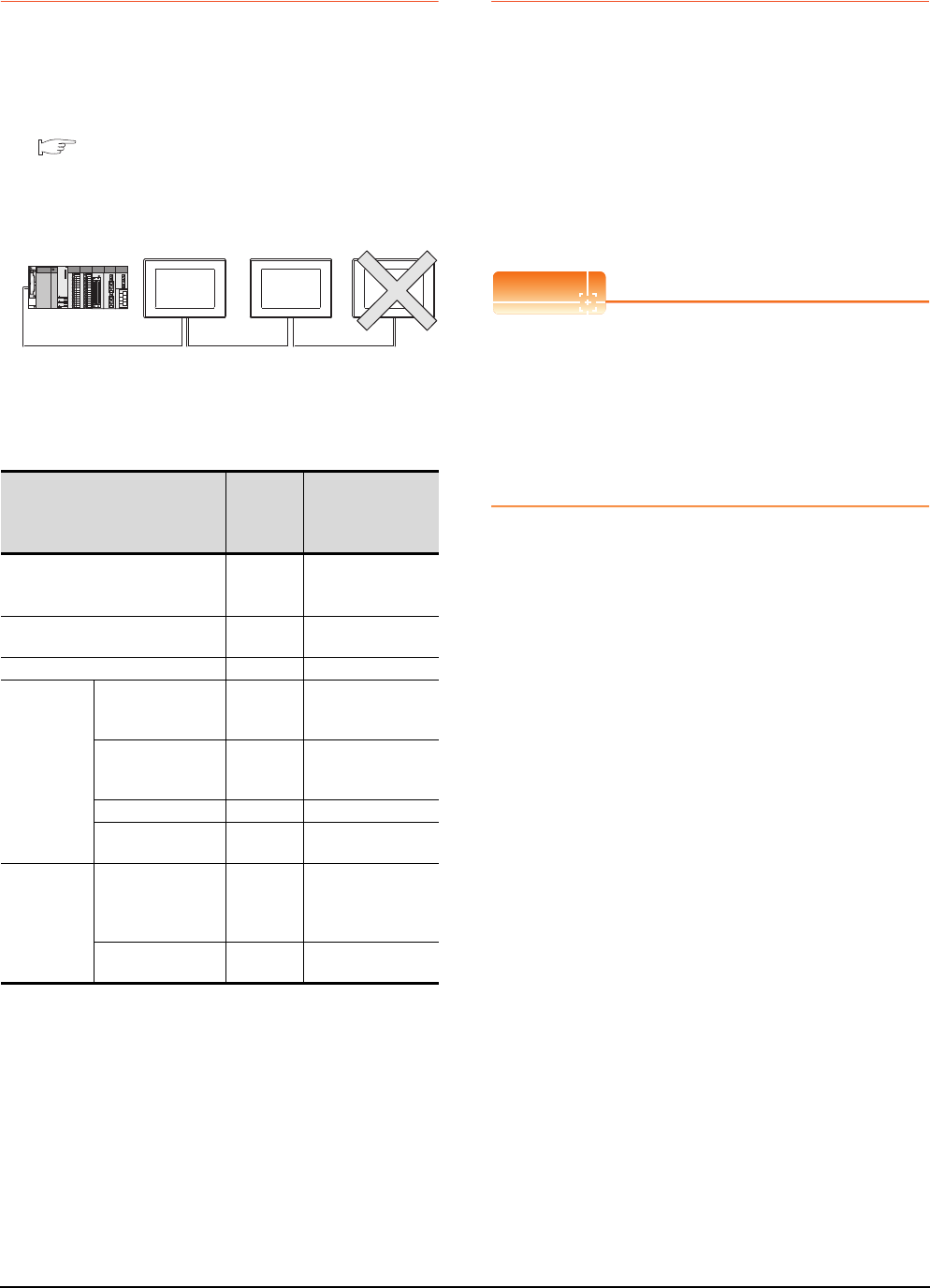
5 - 38 5. BUS CONNECTION
5.4 Precautions
5.4.12 When connecting multiple
GOTs
(1) System including different GOT series
The GOT1000 series can be connected with GOT-A900
series in a system.
When using them together, refer to the following
Technical News.
Precautions when Replacing GOT-A900 Series
with GOT1000 Series (GOT-A-0009)
The GOT1000 series cannot be used with GOTs other
than GOT-A900 series in a system.
(2) Restrictions on No. of GOTs
The number of connectable GOTs is restricted
according to the CPU type and the number of intelligent
function modules.
*1 Indicates the following models:
AD51(S3), AD51H(S3), AD51FD(S3), AD57G(S3),
AJ71C21(S1), AJ71C22(S1), AJ71C23, AJ71C24(S3/S6/
S8), AJ71UC24, AJ71E71(-S3), AJ71E71N-B2/B5/T/B5T,
AJ71E71N3-T, AJ61BT11 (in intelligent mode only),
A1SJ71C24(-R2/PRF/R4),
A1SJ71UC24(-R2/PRF/R4),
A1SJ71E71-B2/B5(-S3),
A1SJ71E71N-B2/B5/T/B5T, A1SJ71E71N3-T, A1SD51S,
A1SJ61BT11 (in intelligent mode only)
*2 Only the A1SD51S can be connected to the QCPU (Q
Mode).
5.4.13 When using a PLC CPU in the
direct mode
Note that when the I/O control mode of the PLC CPU is the
direct mode, and if the 1st GOT is connected to the main or
extension base unit with a 5m extension cable (GT15-
AC50B, GT15-A1SC50NB), the input X of the empty I/O
slot cannot be used.
No restrictions apply when the I/O control mode is the
refresh mode.
On PLC CPUs whose I/O control mode can be selected by
a switch, set the I/O control mode to the refresh mode
before use.
POINTPOINTPOINT
In the cases where input X of an empty I/O slot is used
(1) When input X is assigned on the MELSECNET/10
network
(2) When input X of an empty I/O slot is turned ON/
OFF by the computer link module
(3) When input X of the I/O slot is turned ON/OFF by
the touch switch function (Bit SET/RST/Alternate/
Momentary) of GOT
When connecting to
Number of
connectable
GOTs
Total number of
connectable GOTs
and intelligent
function modules*1
QCPU(Q mode),
motion controller CPU (Q Series) Up to 5
5 GOTs
+ 6 intelligent
function modules*2
QCPU (A mode)
Not
connectable
―――――
QnACPU Up to 3 6 in total
ACPU
AnUCPU,
AnACPU,
A2US(H)CPU
Up to 3 6 in total
AnNCPU,
AnS(H)CPU,
A1SJ(H)CPU
Up to 2 2 in total
A0J2HCPU Up to 1 2 in total
A1FXCPU
Not
connectable
―――――
Motion
controller
CPU
(A Series)
A273UCPU,
A273UHCPU(-S3),
A373UCPU(-S3),
A173UHCPU(-S1)
Up to 3 6 in total
A171SHCPUN,
A172SHCPUN Up to 2 2 in total
GOT-A900GOT1000 GOT800
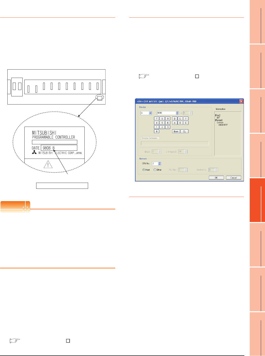
5. BUS CONNECTION
5.4 Precautions
5 - 39
1
PREPARATORY
PROCEDURES FOR
MONITORING
2
DEVICE RANGE
THAT CAN BE SET
3
ACCESS RANGE
FOR MONITORING
4
HOW TO MONITOR
REDUNTANT
SYSTEM
5
BUS CONNECTION
6
DIRECT
CONNECTION TO
CPU
7
COMPUTER LINK
CONNECTION
8
ETHERNET
CONNECTION
5.4.14 When connecting to a
Q4ARCPU redundant system
(1) When the GOT is bus-connected to a Q4ARCPU
redundant system
Connect the GOT to the last redundant extension base
unit (A68RB) of the Q4ARCPU redundant system.
For the redundant extension base units, use version B
or later.
The version can be confirmed in the DATE field of the
rating plate.
POINTPOINTPOINT
Precautions for Q4ARCPU redundant system
configurations
The GOT does not operate normally in the following
system configurations.
(1) When the GOT is bus connected to the bus
switching module (A6RAF) on a redundant main
base unit (A32RB/A33RB)
(2) When the GOT is bus connected to a version-A
redundant main base unit (A68RB)
(2) Power-On sequence for GOT and Q4ARCPU
redundant system
Apply the power to the GOT and Q4ARCPU redundant
system in the following sequence.
1. Turn ON the GOT.
2. After the monitor screen is displayed on the GOT, turn
ON the Q4ARCPU redundant system.
At this time, a timeout is displayed on the system
alarm. Use System Information to reset the alarm.
For the system alarm, refer to the following manual:
GT Designer3 Version Screen Design
Manual
5.4.15 When monitoring the
Q170MCPU
Set [CPU No.] to "2" in the device setting to monitor the
device of the Motion CPU area (CPU No.2).
When the CPU No. is set to "0" or "1", the device on the
PLC CPU area (CPU No.1) is monitored.
When the CPU No. is set to the number other than "0" to
"2", a communication error occurs and the monitoring
cannot be executed.
For setting the CPU No., refer to the following manual.
GT Designer3 Version Screen Design
Manual
Example) Setting dialog box of the bit device
5.4.16 Troubleshooting
For the troubleshooting, refer to the User's Manual for the
GOT you are using.
Caution
Version of redundant extension base unit
Enlarged view of rating plate

5 - 40 5. BUS CONNECTION
5.4 Precautions
6
1
PREPARATORY
PROCEDURES FOR
MONITORING
2
DEVICE RANGE
THAT CAN BE SET
3
ACCESS RANGE
FOR MONITORING
4
HOW TO MONITOR
REDUNTANT
SYSTEM
5
BUS CONNECTION
6
DIRECT
CONNECTION TO
CPU
7
COMPUTER LINK
CONNECTION
8
ETHERNET
CONNECTION
6 - 1
6.DIRECT CONNECTION TO CPU
6.1 Connectable Model List . . . . . . . . . . . . . . . . . . . . . . . . . . . . 6 - 2
6.2 System Configuration. . . . . . . . . . . . . . . . . . . . . . . . . . . . . . 6 - 6
6.3 Connection Diagram . . . . . . . . . . . . . . . . . . . . . . . . . . . . . 6 - 22
6.4 GOT Side Settings . . . . . . . . . . . . . . . . . . . . . . . . . . . . . . . 6 - 25
6.5 Precautions . . . . . . . . . . . . . . . . . . . . . . . . . . . . . . . . . . . . 6 - 28
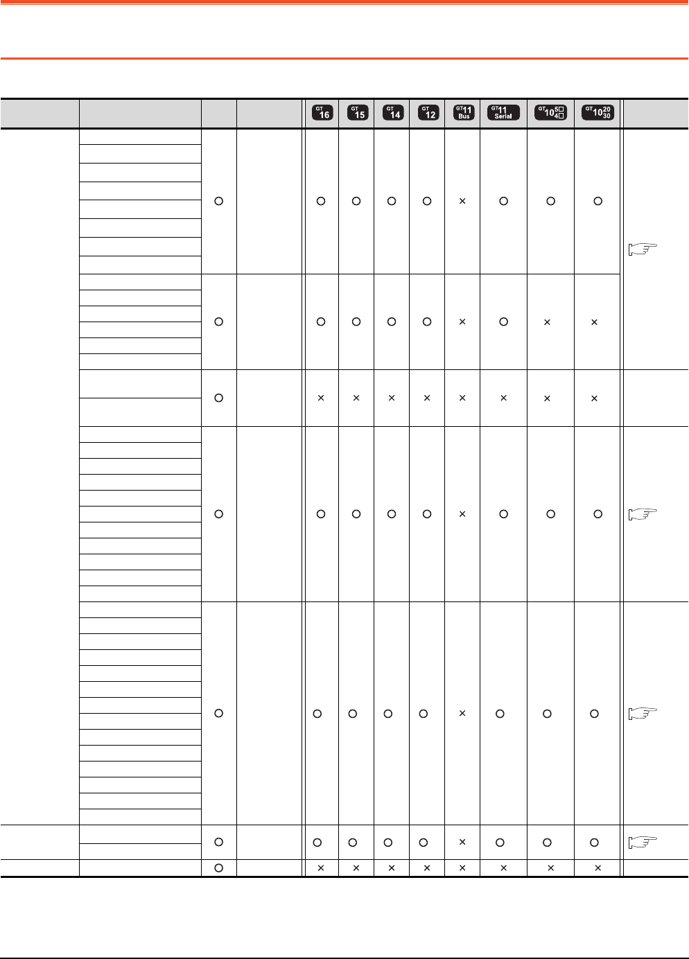
6 - 2 6. DIRECT CONNECTION TO CPU
6.1 Connectable Model List
6. DIRECT CONNECTION TO CPU
6.1 Connectable Model List
The following table shows the connectable models.
(Continued to next page)
*1 When in multiple CPU system configuration, use CPU function version B or later.
*2 Access via the (RS-232) in the multiple CPU system.
*3 Exclude the GT10 from the multiple CPU system configuration.
*4 Use a module with the upper five digits of the serial No. later than 12042.
Series Model name Clock
Communication
type
Refer to
MELSEC-Q
(Q mode)
Q00JCPU
RS-232
RS-422
6.2.1
Q00CPU*1
Q01CPU*1
Q02CPU*1
Q02HCPU*1
Q06HCPU*1
Q12HCPU*1
Q25HCPU*1
Q02PHCPU
RS-232
RS-422
*3 *3
Q06PHCPU
Q12PHCPU
Q25PHCPU
Q12PRHCPU (Main base)
Q25PRHCPU (Main base)
Q12PRHCPU
(Extension base) -*3 *3 -
Q25PRHCPU
(Extension base)
Q00UJCPU
RS-232
RS-422 6.2.1
Q00UCPU
Q01UCPU
Q02UCPU
Q03UDCPU
Q04UDHCPU
Q06UDHCPU
Q10UDHCPU
Q13UDHCPU
Q20UDHCPU
Q26UDHCPU
Q03UDECPU
RS-232 *2 *2 *2 *2 *2 *2 *2 6.2.1
Q04UDEHCPU
Q06UDEHCPU
Q10UDEHCPU
Q13UDEHCPU
Q20UDEHCPU
Q26UDEHCPU
Q50UDEHCPU
Q100UDEHCPU
Q03UDVCPU
Q04UDVCPU
Q06UDVCPU
Q13UDVCPU
Q26UDVCPU
C Controller
module
Q12DCCPU-V*4
RS-232 *2 *2 *2 *2 *2 *2 *2 6.2.1
Q24DHCCPU-V
MELSEC-QS QS001CPU - -
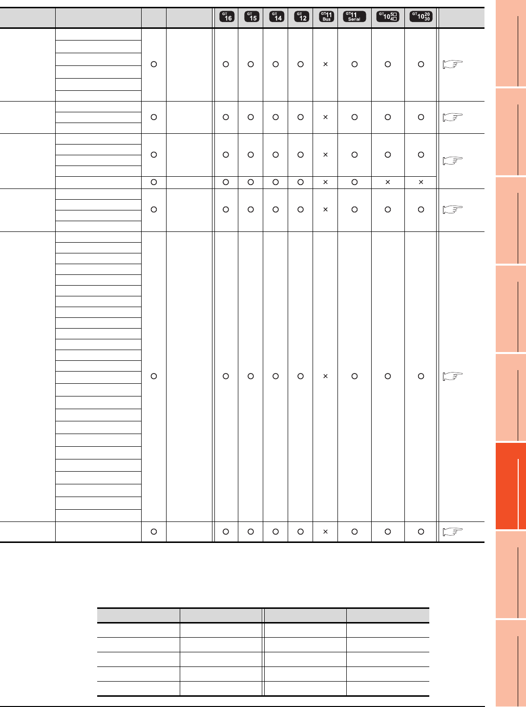
6. DIRECT CONNECTION TO CPU
6.1 Connectable Model List
6 - 3
1
PREPARATORY
PROCEDURES FOR
MONITORING
2
DEVICE RANGE
THAT CAN BE SET
3
ACCESS RANGE
FOR MONITORING
4
HOW TO MONITOR
REDUNTANT
SYSTEM
5
BUS CONNECTION
6
DIRECT
CONNECTION TO
CPU
7
COMPUTER LINK
CONNECTION
8
ETHERNET
CONNECTION
(Continued to next page)
*1 When connecting in direct CPU connection, the adapter L6ADP-R2 is required.
*2 When monitoring AnNCPU or A2SCPU, only the following or later software version is used to write to the CPU.
• AnNCPU(S1) with link: Version L or later, AnNCPU(S1) without link: Version H or later
• A2SCPU: Version H or later
*3 GT10 can be connected to CPUs of the following HW versions or later.
Series Model name Clock
Communication
type
Refer to
MELSEC-L
L02CPU*1
RS-232
RS-422 6.2.2
L26CPU*1
L26CPU-BT*1
L02CPU-P*1
L26CPU-PBT*1
L02SCPU
MELSEC-Q
(A mode)
Q02CPU-A RS-232
RS-422 6.2.1
Q02HCPU-A
Q06HCPU-A
MELSEC-QnA
(QnACPU)*3
Q2ACPU
RS-422
6.2.3
Q2ACPU-S1
Q3ACPU
Q4ACPU
Q4ARCPU RS-422
MELSEC-QnA
(QnASCPU)*3
Q2ASCPU
RS-422 6.2.3
Q2ASCPU-S1
Q2ASHCPU
Q2ASHCPU-S1
MELSEC-A
(AnCPU)
A2UCPU
RS-422 6.2.4
A2UCPU-S1
A3UCPU
A4UCPU
A2ACPU
A2ACPUP21
A2ACPUR21
A2ACPU-S1
A2ACPUP21-S1
A2ACPUR21-S1
A3ACPU
A3ACPUP21
A3ACPUR21
A1NCPU*2
A1NCPUP21*2
A1NCPUR21*2
A2NCPU*2
A2NCPUP21*2
A2NCPUR21*2
A2NCPU-S1*2
A2NCPUP21-S1*2
A2NCPUP21-S1*2
A3NCPU*2
A3NCPUP21*2
A3NCPUP21*2
MELSEC-A
(AnSCPU) A2USCPU RS-422 6.2.4
PLC type HW/SW Version PLC type HW/SW Version
Q2ACPU DA Q2ASCPU AL
Q2ACPU-S1 DA Q2ASCPU-S1 AL
Q3ACPU DA Q2ASHCPU BL
Q4ACPU EA Q2ASHCPU-S1 BL
Q4ARCPU AL - -
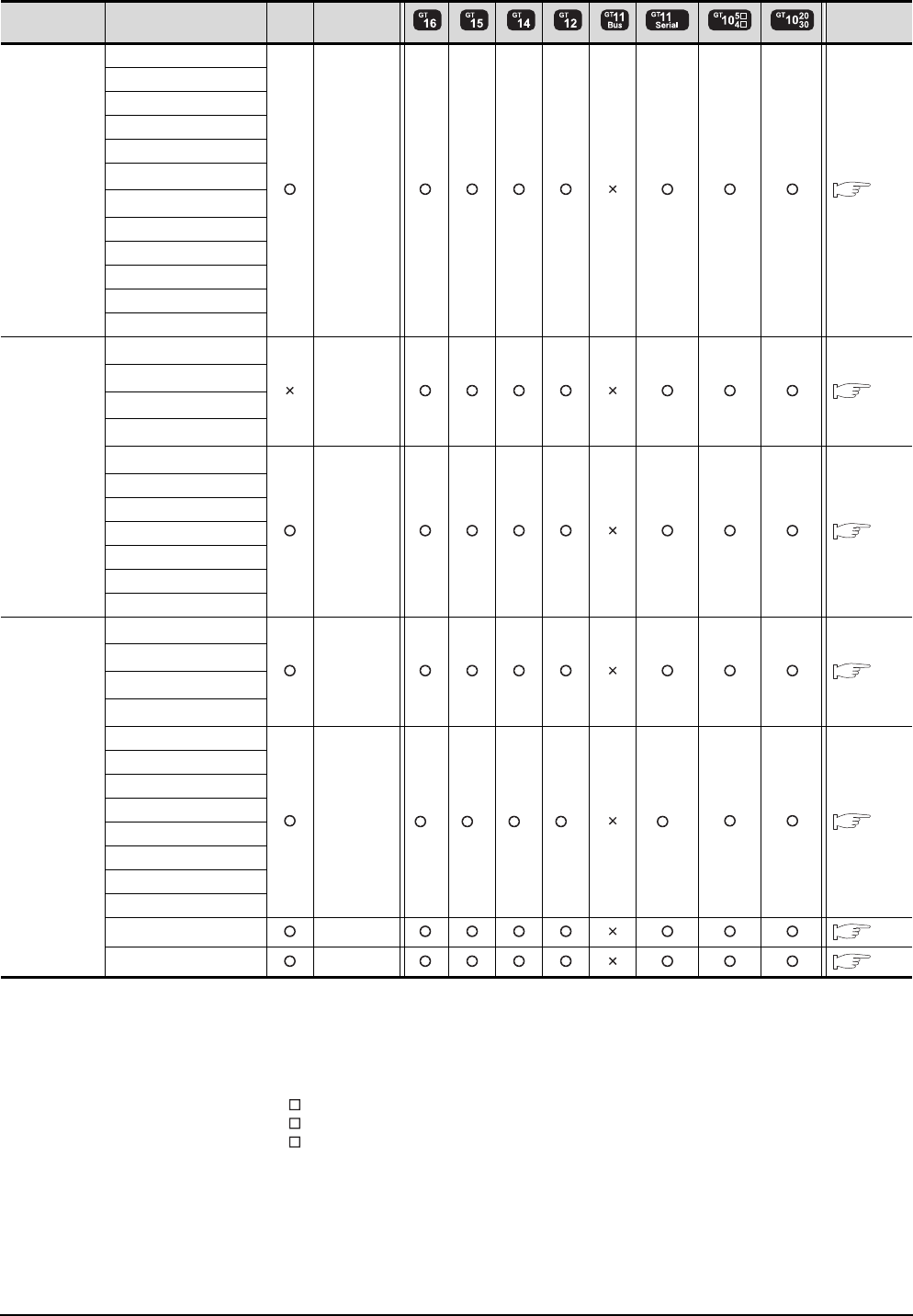
6 - 4 6. DIRECT CONNECTION TO CPU
6.1 Connectable Model List
(Continued to next page)
*1 When monitoring A0J2HCPU, A2CCPU or A2SCPU, only the following or later software version is used to write to the CPU.
• A0J2HCPU (with/without link): Version E or later
• A0J2HCPU-DC24: Version B or later
• A2CCPU, A2SCPU: Version H or later
*2 When using SV13, SV22, or SV43, use the motion controller CPU on which any of the following main OS version is installed.
• SW6RN-SV13Q : 00E or later
• SW6RN-SV22Q : 00E or later
• SW6RN-SV43Q : 00B or later
*3 Use main modules with the following product numbers.
• Q172CPU: Product number K******* or later
• Q173CPU: Product number J******* or later
*4 Access via QCPU (RS-232) in the multiple CPU system.
Series Model name Clock
Communication
type
Refer to
MELSEC-A
(AnSCPU)
A2USCPU-S1
RS-422 6.2.4
A2USHCPU-S1
A1SCPU
A1SCPUC24-R2
A1SHCPU
A2SCPU*1
A2SCPU-S1*1
A2SHCPU
A2SHCPU-S1
A1SJCPU
A1SJCPU-S3
A1SJHCPU
MELSEC-A
A0J2HCPU*1
RS-422 6.2.4
A0J2HCPUP21*1
A0J2HCPUR21*1
A0J2HCPU-DC24*1
A2CCPU*1
RS-422 6.2.4
A2CCPUP21
A2CCPUR21
A2CCPUC24
A2CCPUC24-PRF
A2CJCPU-S3
A1FXCPU
Motion
controller
CPU (Q Series)
Q172CPU*2*3
RS-232
RS-422 6.2.1
Q173CPU*2*3
Q172CPUN*2
Q173CPUN*2
Q172HCPU
RS-232 *4 *4 *4 *4 *4 6.2.1
Q173HCPU
Q172DCPU
Q173DCPU
Q172DCPU-S1
Q173DCPU-S1
Q172DSCPU
Q173DSCPU
Q170MCPU RS-232 6.2.7
MR-MQ100 RS-422 6.2.7
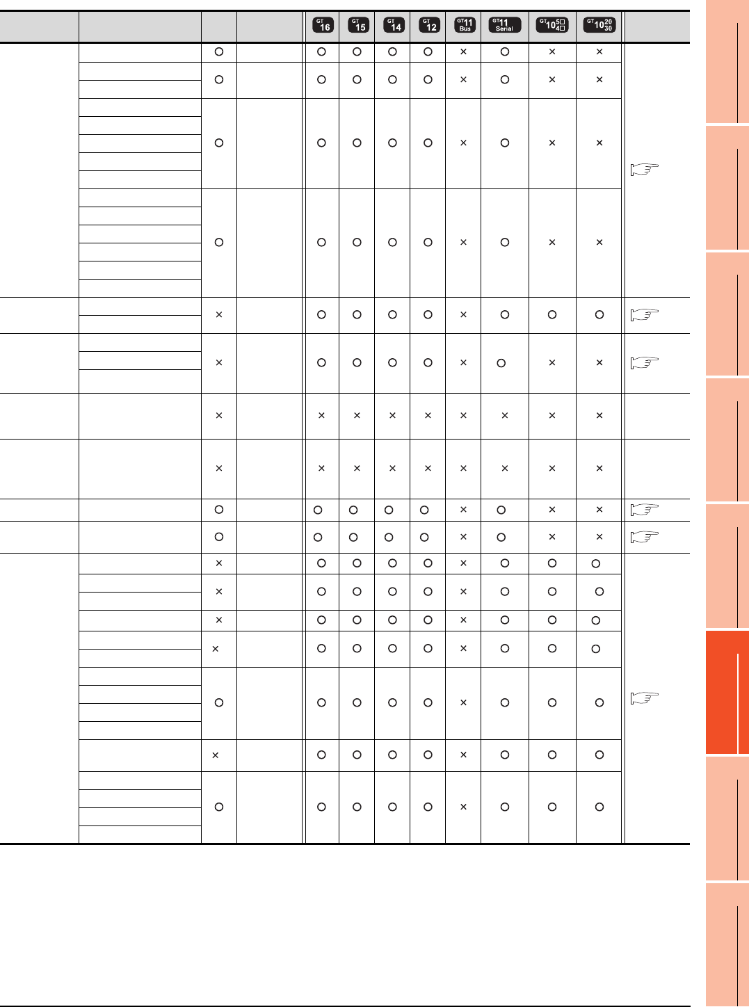
6. DIRECT CONNECTION TO CPU
6.1 Connectable Model List
6 - 5
1
PREPARATORY
PROCEDURES FOR
MONITORING
2
DEVICE RANGE
THAT CAN BE SET
3
ACCESS RANGE
FOR MONITORING
4
HOW TO MONITOR
REDUNTANT
SYSTEM
5
BUS CONNECTION
6
DIRECT
CONNECTION TO
CPU
7
COMPUTER LINK
CONNECTION
8
ETHERNET
CONNECTION
*1 GT11 can not access the master station on MELSECNET/H network system. GT11 can access only the connected host station
(remote I/O station).
*2 Access via QCPU (RS-232) in the multiple CPU system.
*3 It is available by installing the real time clock function board or the EEPROM memory with the real time clock function.
*4 Cannot be connected to products with input voltage 5V.
Series Model name Clock
Communication
type
Refer to
Motion
controller
CPU (A Series)
A273UCPU RS-422
6.2.4
A273UHCPU
RS-422
A273UHCPU-S3
A373UCPU
RS-422
A373UCPU-S3
A171SCPU
A171SCPU-S3
A171SCPU-S3N
A171SHCPU
RS-422
A171SHCPUN
A172SHCPU
A172SHCPUN
A173UHCPU
A173UHCPU-S1
MELSEC-WS WS0-CPU0 RS-232 6.2.6
WS0-CPU1
MELSECNET/
H
Remote I/O
station
QJ72LP25-25
RS-232 *1 6.2.1
QJ72LP25G
QJ72BR15
CC-Link IE
Field Network
head module
LJ72GF15-T2 - -
CC-Link IE
Field Network
Ethernet
adapter module
NZ2GF-ETB - -
CNC C70 Q173NCCPU RS-232 *2 *2 *2 *2 *2 6.2.1
Robot
controller
CRnQ-700
(Q172DRCPU) RS-232 *2 *2 *2 *2 *2 6.2.1
MELSEC-FX
FX0RS-422 *4
6.2.5
FX0S
RS-422
FX0N
FX1RS-422 *4
FX2*3 RS-422 *4
FX2C
FX1S
RS-232
RS-422
FX1N
FX2N
FX1NC
FX2NC *3 RS-232
RS-422
FX3G
RS-232
RS-422
FX3GC
FX3U
FX3UC
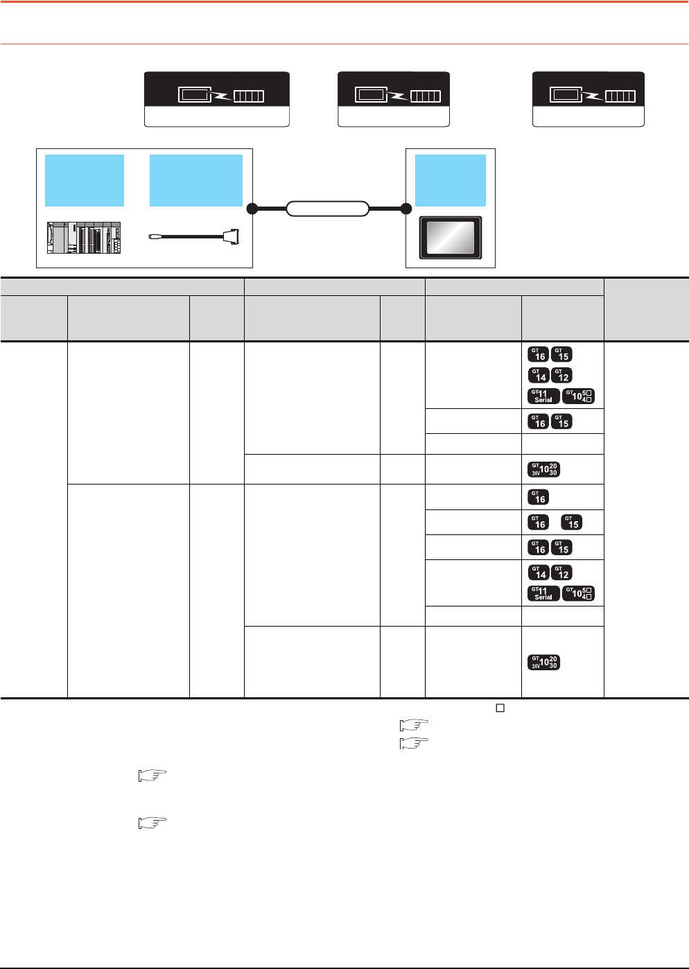
6 - 6 6. DIRECT CONNECTION TO CPU
6.2 System Configuration
6.2 System Configuration
6.2.1 Connecting to QCPU
*1 Connect it to the RS-232 interface (built into GOT). It cannot be mounted on GT155 .
*2 For the connection to GOT, refer to the connection diagram. ( RS232 connection diagram 3))
*3 For the connection to GOT, refer to the connection diagram. ( RS422 connection diagram 2))
*4 For details of the GOT multi-drop connection, refer to the following.
19. GOT MULTI-DROP CONNECTION
*5 GT14, GT12, GT11 and GT10 are available for the multiple-GT14, GT12, GT11, GT10 connection function to connect up to two
GOTs.
20. MULTIPLE-GT14, GT12, GT11, GT10 CONNECTION FUNCTION
*6 Applicable to the QnUCPU only
*7 Use the RS-232 connection model.
*8 Use the RS-422 connection model.
RS-422 connector
conversion cable
QCPU GOT
Connection cable
Communication driver
( For GT16, GT15, GT14, GT12, GT11)
A/QnA/L/Q CPU,LJ71C24,QJ71C24
Communication driver
( For GT10, when connecting to QCPU(Q mode))
QnA/L/Q CPU
Communication driver
MELSEC-A
( For GT10, when connecting to QCPU(A mode))
PLC Connection cable GOT Number of
connectable
equipment*5
Model name RS-422 connector
conversion cable
Communi
cation
type
Cable model
Max.
distance
Option device Model
MELSEC-Q
- RS-232
GT01-C30R2-6P(3m) 3m
- (Built into GOT)
1 GOT for 1 PLC
GT15-RS2-9P
GT01-RS4-M*4 -
GT10-C30R2-6P(3m)
*2 3m - (Built into GOT) *7
FA-CNV2402CBL(0.2m)
FA-CNV2405CBL (0.5m) RS-422
GT01-C30R4-25P(3m)
GT01-C100R4-25P(10m)
GT01-C200R4-25P(20m)
GT01-C300R4-25P(30m)
30m
GT16-C02R4-9S
GT15-RS2T4-9P*1 *6
GT15-RS4-9S
- (Built into GOT)
GT01-RS4-M*4 -
GT10-C30R4-25P(3m)
GT10-C100R4-25P(10m)
GT10-C200R4-25P(20m)
GT10-C300R4-25P(30m)
*3
30m - (Built into GOT) *8
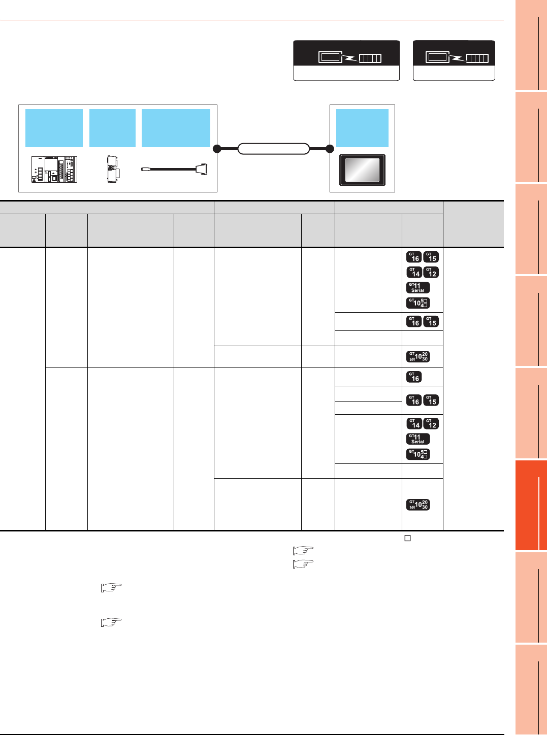
6. DIRECT CONNECTION TO CPU
6.2 System Configuration
6 - 7
1
PREPARATORY
PROCEDURES FOR
MONITORING
2
DEVICE RANGE
THAT CAN BE SET
3
ACCESS RANGE
FOR MONITORING
4
HOW TO MONITOR
REDUNTANT
SYSTEM
5
BUS CONNECTION
6
DIRECT
CONNECTION TO
CPU
7
COMPUTER LINK
CONNECTION
8
ETHERNET
CONNECTION
6.2.2 Connecting to LCPU
*1 Connect it to the RS-232 interface (built into GOT). It cannot be mounted on GT1655 and GT155 .
*2 For the connection to GOT, refer to the connection diagram. ( RS232 connection diagram 3))
*3 For the connection to GOT, refer to the connection diagram. ( RS422 connection diagram 2))
*4 For details of the GOT multi-drop connection, refer to the following.
19. GOT MULTI-DROP CONNECTION
*5 GT14, GT12, GT11 and GT10 are available for the multiple-GT14, GT12, GT11, GT10 connection function to connect up to two
GOTs.
20. MULTIPLE-GT14, GT12, GT11, GT10 CONNECTION FUNCTION
*6 Use the RS-232 connection model.
*7 Use the RS-422 connection model.
RS-422 connector
conversion cable
LCPU Adapter GOT
Connection cable
Communication driver
QnA/L/Q CPU
( For GT10)
Communication driver
( For GT16, GT15, GT14, GT12, GT11)
A/QnA/L/Q CPU,LJ71C24,QJ71C24
PLC Connection cable GOT Number of
connectable
equipment*5
Model
name Adapter RS-422 connector
conversion cable
Communi
cation
type
Cable model
Max.
distance
Option device Model
MELSEC-L
L6ADP-R2 - RS-232
GT01-C30R2-6P(3m) 3m
- (Built into GOT)
1 GOT for 1 PLC
GT15-RS2-9P
GT01-RS4-M*4 -
GT10-C30R2-6P(3m)
*2 3m - (Built into GOT) *6
L6ADP-R2 FA-CNV2402CBL(0.2m)
FA-CNV2405CBL(0.5m) RS-422
GT01-C30R4-25P(3m)
GT01-C100R4-25P(10m)
GT01-C200R4-25P(20m)
GT01-C300R4-25P(30m)
30m
GT16-C02R4-9S
GT15-RS2T4-9P*1
GT15-RS4-9S
- (Built into GOT)
GT01-RS4-M*4 -
GT10-C30R4-25P(3m)
GT10-C100R4-25P(10m)
GT10-C200R4-25P(20m)
GT10-C300R4-25P(30m)
*3
30m - (Built into GOT) *7
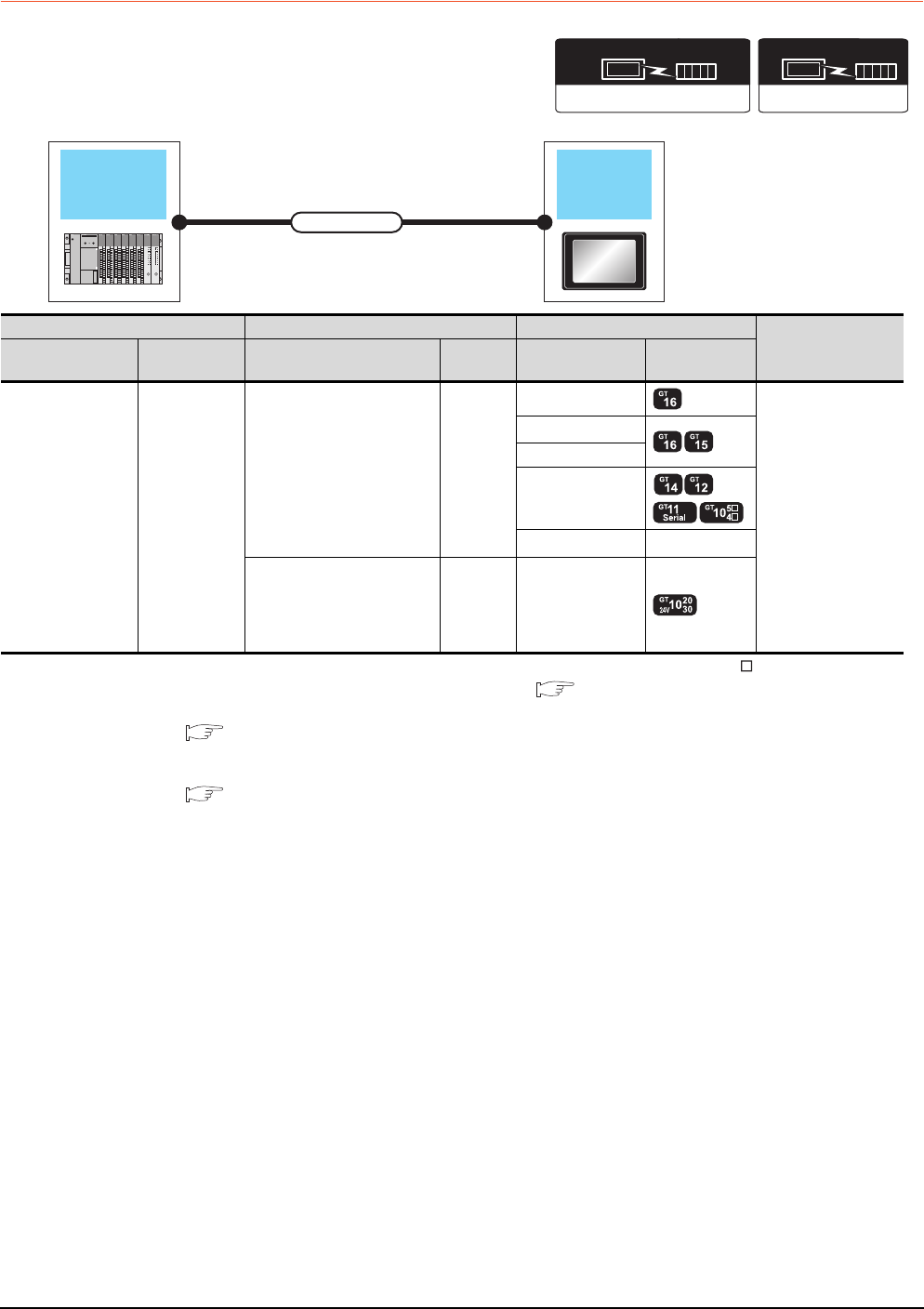
6 - 8 6. DIRECT CONNECTION TO CPU
6.2 System Configuration
6.2.3 Connecting to QnACPU
*1 Connect it to the RS-232 interface (built into GOT). It cannot be mounted on GT1655 and GT155 .
*2 For the connection to GOT, refer to the connection diagram. ( RS422 connection diagram 2))
*3 For details of the GOT multi-drop connection, refer to the following.
19. GOT MULTI-DROP CONNECTION
*4 GT14, GT12, GT11 and GT10 are available for the multiple-GT14, GT12, GT11, GT10 connection function to connect up to two
GOTs.
20. MULTIPLE-GT14, GT12, GT11, GT10 CONNECTION FUNCTION
*5 Use the RS-422 connection model.
QnACPU GOT
Connection cable
Communication driver
( For GT16, GT15, GT14, GT12, GT11)
A/QnA/L/Q CPU,LJ71C24,QJ71C24
Communication driver
QnA/L/Q CPU
( For GT10)
PLC Connection cable GOT Number of
connectable
equipment*4
Model name Communication
type Cable model Max.
distance Option device Model
MELSEC-QnA RS-422
GT01-C30R4-25P(3m)
GT01-C100R4-25P(10m)
GT01-C200R4-25P(20m)
GT01-C300R4-25P(30m)
30m
GT16-C02R4-9S
1 GOT for 1 PLC
GT15-RS2T4-9P*1
GT15-RS4-9S
- (Built into GOT)
GT01-RS4-M*3 -
GT10-C30R4-25P(3m)
GT10-C100R4-25P(10m)
GT10-C200R4-25P(20m)
GT10-C300R4-25P(30m)
*2
30m - (Built into GOT) *5
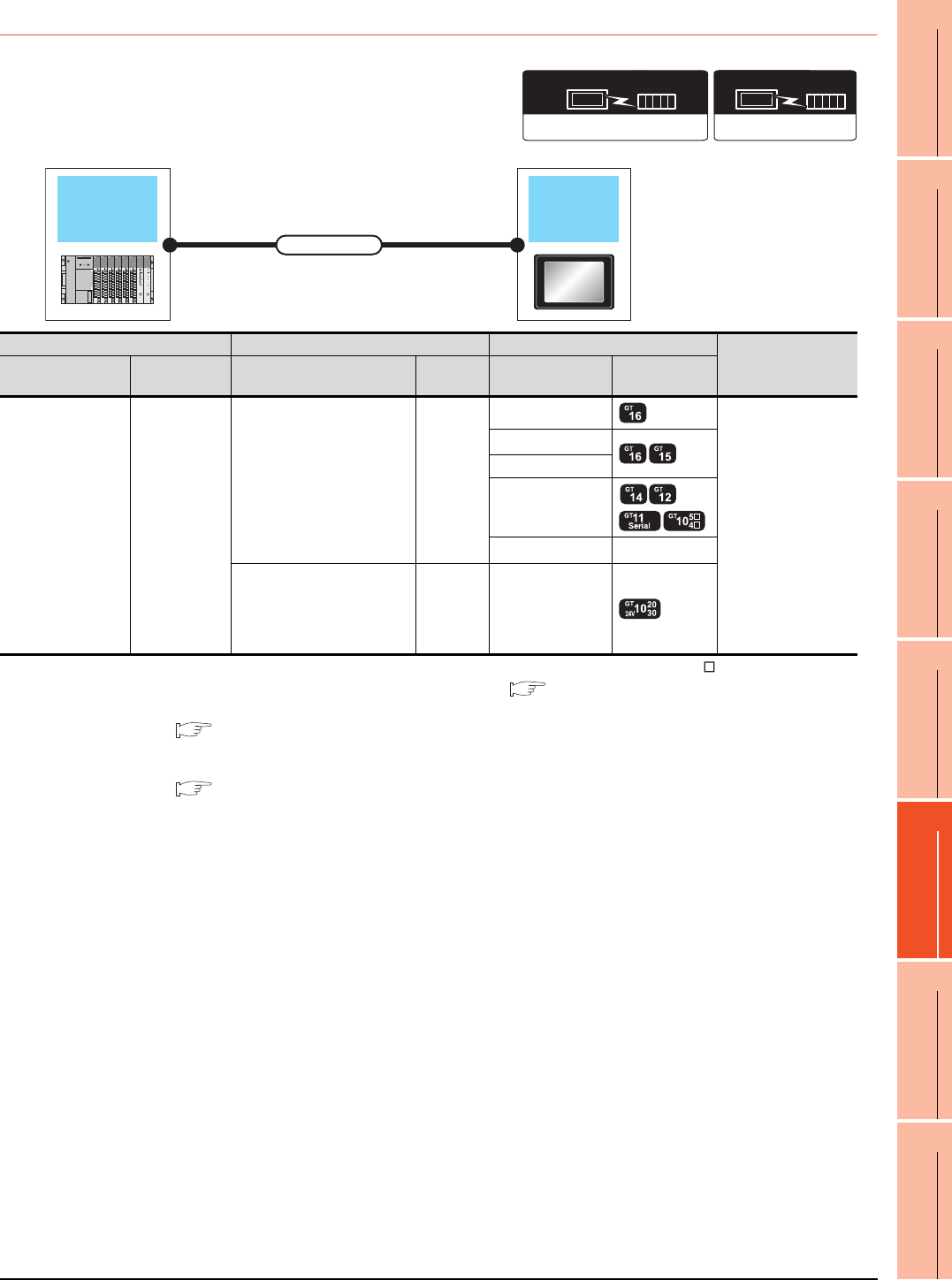
6. DIRECT CONNECTION TO CPU
6.2 System Configuration
6 - 9
1
PREPARATORY
PROCEDURES FOR
MONITORING
2
DEVICE RANGE
THAT CAN BE SET
3
ACCESS RANGE
FOR MONITORING
4
HOW TO MONITOR
REDUNTANT
SYSTEM
5
BUS CONNECTION
6
DIRECT
CONNECTION TO
CPU
7
COMPUTER LINK
CONNECTION
8
ETHERNET
CONNECTION
6.2.4 Connecting to ACPU
*1 Connect it to the RS-232 interface (built into GOT). It cannot be mounted on GT1655 and GT155 .
*2 For the connection to GOT, refer to the connection diagram. ( RS422 connection diagram 2))
*3 For details of the GOT multi-drop connection, refer to the following.
19. GOT MULTI-DROP CONNECTION
*4 GT14, GT12, GT11 and GT10 are available for the multiple-GT14, GT12, GT11, GT10 connection function to connect up to two
GOTs.
20. MULTIPLE-GT14, GT12, GT11, GT10 CONNECTION FUNCTION
*5 Use the RS-422 connection model.
Communication driver
( For GT16, GT15, GT14, GT12, GT11)
A/QnA/L/Q CPU,LJ71C24,QJ71C24
Communication driver
MELSEC-A
( For GT10)
ACPU GOT
Connection cable
PLC Connection cable GOT Number of
connectable
equipment*4
Model name Communication
type Cable model Max.
distance Option device Model
MELSEC-A RS-422
GT01-C30R4-25P(3m)
GT01-C100R4-25P(10m)
GT01-C200R4-25P(20m)
GT01-C300R4-25P(30m)
30m
GT16-C02R4-9S
1 GOT for 1 PLC
GT15-RS2T4-9P*1
GT15-RS4-9S
- (Built into GOT)
GT01-RS4-M*3 -
GT10-C30R4-25P(3m)
GT10-C100R4-25P(10m)
GT10-C200R4-25P(20m)
GT10-C300R4-25P(30m)
*2
30m - (Built into GOT) *5
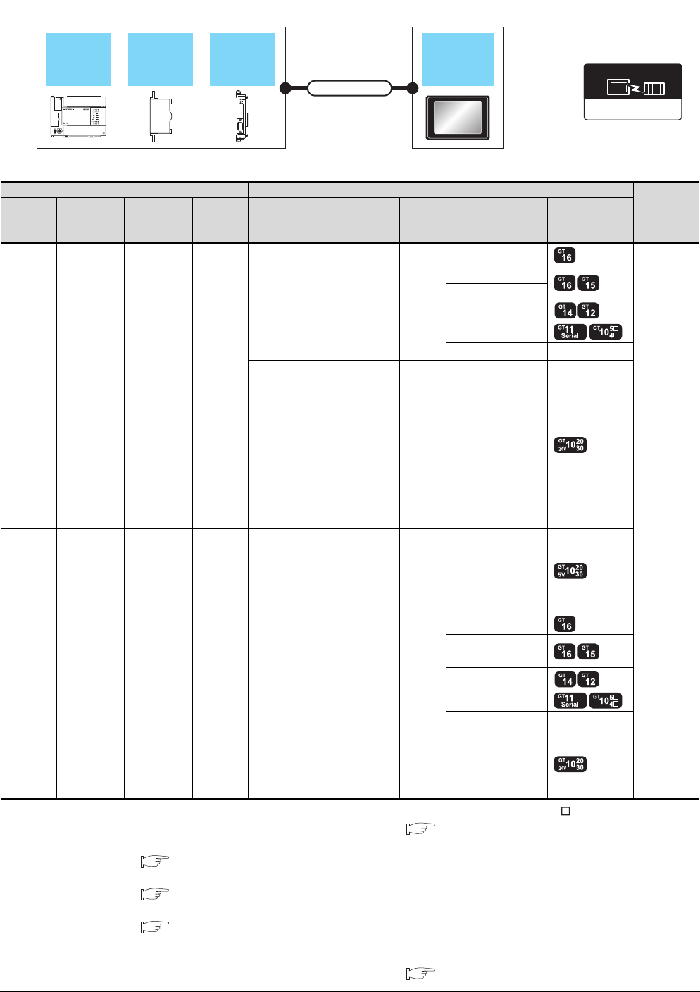
6 - 10 6. DIRECT CONNECTION TO CPU
6.2 System Configuration
6.2.5 Connecting to FXCPU
When connecting to FX0, FX0S, FX0N, FX1, FX2 or FX2C
*1 Connect it to the RS-232 interface (built into GOT). It cannot be mounted on GT1655 and GT155 .
*2 For the connection to GOT, refer to the connection diagram. ( RS422 connection diagram 1))
*3 For details of the GOT multi-drop connection, refer to the following.
19. GOT MULTI-DROP CONNECTION
*4
GT14, GT12, GT11 and GT10 are available for the multiple-GT14, GT12, GT11, GT10 connection function to connect up to two GOTs.
20. MULTIPLE-GT14, GT12, GT11, GT10 CONNECTION FUNCTION
*5 When using function expansion boards or function adapters, confirm the communication settings.
6.5 Precautions Connection to FXCPU (2)When connecting with function extension board or communication special
adapter
*6 Use the RS-422 connection model.
*7 For the connection to GOT, refer to the connection diagram. ( RS422 connection diagram 2))
FXCPU
Function
expansion
board
Function
adapter GOT
Connection cable
MELSEC-FX
Communication driver
PLC Connection cable GOT Number of
connectable
equipment*4
Model
name
Function
expansion
board*5
Function
adapter*5
Communi
cation
type
Cable model
Max.
distance
Option device Model
FX0
FX0S
FX0N
- - RS-422
GT01-C10R4-8P(1m)
GT01-C30R4-8P(3m)
GT01-C100R4-8P(10m)
GT01-C200R4-8P(20m)
GT01-C300R4-8P(30m)
30m
GT16-C02R4-9S
1 GOT for 1
PLC
GT15-RS2T4-9P*1
GT15-RS4-9S
- (Built into GOT)
GT01-RS4-M*3 -
GT10-C10R4-8P(1m)
GT10-C30R4-8P(3m)
GT10-C100R4-8P(10m)
GT10-C200R4-8P(20m)
GT10-C300R4-8P(30m)
GT10-C10R4-8PC(1m)
GT10-C30R4-8PC(3m)
GT10-C100R4-8PC(10m)
GT10-C200R4-8PC(20m)
GT10-C300R4-8PC(30m)
GT10-C10R4-8PL
*2
30m - (Built into GOT) *6
FX0S
FX0N - - RS-422
GT10-C10R4-8P(1m)
GT10-C30R4-8P(3m)
GT10-C10R4-8PC(1m)
GT10-C30R4-8PC(3m)
GT10-C10R4-8PL
*2
3m - (Built into GOT) *6
FX1
FX2
FX2C
- - RS-422
GT01-C30R4-25P(3m)
GT01-C100R4-25P(10m)
GT01-C200R4-25P(20m)
GT01-C300R4-25P(30m)
30m
GT16-C02R4-9S
GT15-RS2T4-9P*1
GT15-RS4-9S
- (Built into GOT)
GT01-RS4-M*3 -
GT10-C30R4-25P(3m)
GT10-C100R4-25P(10m)
GT10-C200R4-25P(20m)
GT10-C300R4-25P(30m)
*7
30m - (Built into GOT) *6
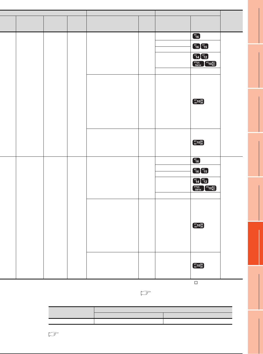
6. DIRECT CONNECTION TO CPU
6.2 System Configuration
6 - 11
1
PREPARATORY
PROCEDURES FOR
MONITORING
2
DEVICE RANGE
THAT CAN BE SET
3
ACCESS RANGE
FOR MONITORING
4
HOW TO MONITOR
REDUNTANT
SYSTEM
5
BUS CONNECTION
6
DIRECT
CONNECTION TO
CPU
7
COMPUTER LINK
CONNECTION
8
ETHERNET
CONNECTION
When connecting to FX1S, FX1N, FX2N, FX1NC, FX2NC (RS-422 connection)
*1 Connect it to the RS-232 interface (built into GOT). It cannot be mounted on GT1655 and GT155 .
*2 GT10-C10R4-8PL(1m) can be available for FX1S, FX1N and FX2N.
*3 For the connection to GOT, refer to the connection diagram. ( RS422 connection diagram 1))
*4 The function expansion board to be used differs according to the type of the FXCPU to be connected.
Use the applicable function expansion board shown in the following table.
*5 For details of the GOT multi-drop connection, refer to the following.
19. GOT MULTI-DROP CONNECTION
PLC Connection cable GOT Number of
connectable
equipment
*6
Model
name
Function
expansion
board*4*7
Function
adapter*7
Communi
cation
type
Cable model
Max.
distance
Option device Model
FX1S
FX1N
FX2N
FX1NC
FX2NC
--RS-422
GT01-C10R4-8P(1m)
GT01-C30R4-8P(3m)
GT01-C100R4-8P(10m)
GT01-C200R4-8P(20m)
GT01-C300R4-8P(30m)
30m
GT16-C02R4-9S
1 GOT for 1
PLC built-in
port
GT15-RS2T4-9P*1
GT15-RS4-9S
- (Built into GOT)
GT01-RS4-M*5 -
GT10-C10R4-8P(1m)
GT10-C30R4-8P(3m)
GT10-C100R4-8P(10m)
GT10-C200R4-8P(20m)
GT10-C300R4-8P(30m)
GT10-C10R4-8PC(1m)
GT10-C30R4-8PC(3m)
GT10-C100R4-8PC(10m)
GT10-C200R4-8PC(20m)
GT10-C300R4-8PC(30m)
GT10-C10R4-8PL(1m)*2
*3
30m - (Built into GOT) *8
GT10-C10R4-8P(1m)
GT10-C30R4-8P(3m)
GT10-C10R4-8PC(1m)
GT10-C30R4-8PC(3m)
GT10-C10R4-8PL(1m)*2
*3
3m - (Built into GOT) *8
FX1S
FX1N
FX2N
FX1N-422-BD
FX2N-422-BD -RS-422
GT01-C10R4-8P(1m)
GT01-C30R4-8P(3m)
GT01-C100R4-8P(10m)
GT01-C200R4-8P(20m)
GT01-C300R4-8P(30m)
30m
GT16-C02R4-9S
1 GOT for 1
function
expansion
board
GT15-RS2T4-9P*1
GT15-RS4-9S
- (Built into GOT)
GT01-RS4-M*5 -
GT10-C10R4-8P(1m)
GT10-C30R4-8P(3m)
GT10-C100R4-8P(10m)
GT10-C200R4-8P(20m)
GT10-C300R4-8P(30m)
GT10-C10R4-8PC(1m)
GT10-C30R4-8PC(3m)
GT10-C100R4-8PC(10m)
GT10-C200R4-8PC(20m)
GT10-C300R4-8PC(30m)
GT10-C10R4-8PL(1m)
*3
30m - (Built into GOT) *8
GT10-C10R4-8P(1m)
GT10-C30R4-8P(3m)
GT10-C10R4-8PC(1m)
GT10-C30R4-8PC(3m)
GT10-C10R4-8PL(1m)
*3
3m - (Built into GOT) *8
Item Function expansion board to be used
When connecting to FX1N or FX1S Series When connecting to FX Series
RS-422 communication FX1N-422-BD FX2N-422-BD

6 - 12 6. DIRECT CONNECTION TO CPU
6.2 System Configuration
*6 GT14, GT12, GT11 and GT10 are available for the multiple-GT14, GT12, GT11, GT10 connection function to connect up to two
GOTs.
20. MULTIPLE-GT14, GT12, GT11, GT10 CONNECTION FUNCTION
*7 When using function expansion boards or function adapters, confirm the communication settings.
6.5 Precautions Connection to FXCPU (2)When connecting with function extension board or communication special
adapter
*8 Use the RS-422 connection model.
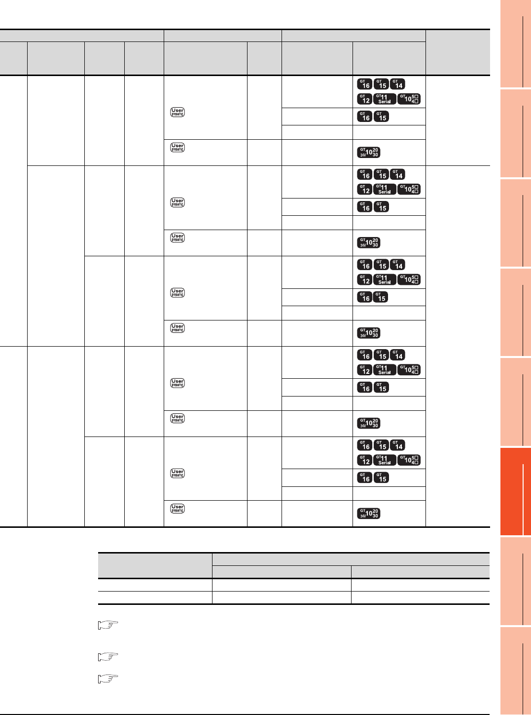
6. DIRECT CONNECTION TO CPU
6.2 System Configuration
6 - 13
1
PREPARATORY
PROCEDURES FOR
MONITORING
2
DEVICE RANGE
THAT CAN BE SET
3
ACCESS RANGE
FOR MONITORING
4
HOW TO MONITOR
REDUNTANT
SYSTEM
5
BUS CONNECTION
6
DIRECT
CONNECTION TO
CPU
7
COMPUTER LINK
CONNECTION
8
ETHERNET
CONNECTION
When connecting to FX1S, FX1N, FX2N, FX1NC, FX2NC (RS-232 connection)
*1 The function expansion board to be used differs according to the type of the FXCPU. Select the function expansion board from
the following table.
*2 For details of the GOT multi-drop connection, refer to the following.
19. GOT MULTI-DROP CONNECTION
*3 GT14, GT12, GT11 and GT10 are available for the multiple-GT14, GT12, GT11, GT10 connection function to connect up to two
GOTs.
20. MULTIPLE-GT14, GT12, GT11, GT10 CONNECTION FUNCTION
*4 When using function expansion boards or function adapters, confirm the communication settings.
6.5 Precautions Connection to FXCPU (2)When connecting with function extension board or communication special
adapter
*5 Use the RS-232 connection model.
PLC Connection cable GOT Number of
connectable
equipment*3
Model
name
Function
expansion
board*1*4
Function
adapter*4
Communi
cation
type
Cable model
Connection diagram
number
Max.
distance
Option device Model
FX1S
FX1N
FX2N
FX1N-232-BD
FX2N-232-BD - RS-232
GT01-C30R2-9S(3m)
or
RS232 connection
diagram 1)
15m
- (Built into GOT)
1 GOT for 1
function
expansion board
GT15-RS2-9P
GT01-RS4-M*2 -
RS232 connection
diagram 4)
15m - (Built into GOT) *5
FX1N-CNV-BD
FX2N-CNV-BD
FX2NC
-232ADP RS-232
GT01-C30R2-9S(3m)
or
RS232 connection
diagram 1)
15m
- (Built into GOT)
1 GOT for 1
function adapter
GT15-RS2-9P
GT01-RS4-M*2 -
RS232 connection
diagram 4)
15m - (Built into GOT) *5
FX0N
-232ADP RS-232
GT01-C30R2-25P(3m)
or
RS232 connection
diagram 2)
15m
- (Built into GOT)
GT15-RS2-9P
GT01-RS4-M*2 -
RS232 connection
diagram 5)
15m - (Built into GOT) *5
FX1NC
FX2NC -
FX2NC
-232ADP RS-232
GT01-C30R2-9S(3m)
or
RS232 connection
diagram 1)
15m
- (Built into GOT)
GT15-RS2-9P
GT01-RS4-M*2 -
RS232 connection
diagram 4)
15m - (Built into GOT) *5
FX0N
-232ADP RS-232
GT01-C30R2-25P(3m)
or
RS232 connection
diagram 2)
15m
- (Built into GOT)
GT15-RS2-9P
GT01-RS4-M*2 -
RS232 connection
diagram 5)
15m - (Built into GOT) *5
Item
Function expansion board to be used
When connecting to FX1N or FX1S Series When connecting to FX Series
RS-232 communication FX1N-232-BD FX2N-232-BD
When the function adapter is used FX1N-CNV-BD FX2N-CNV-BD
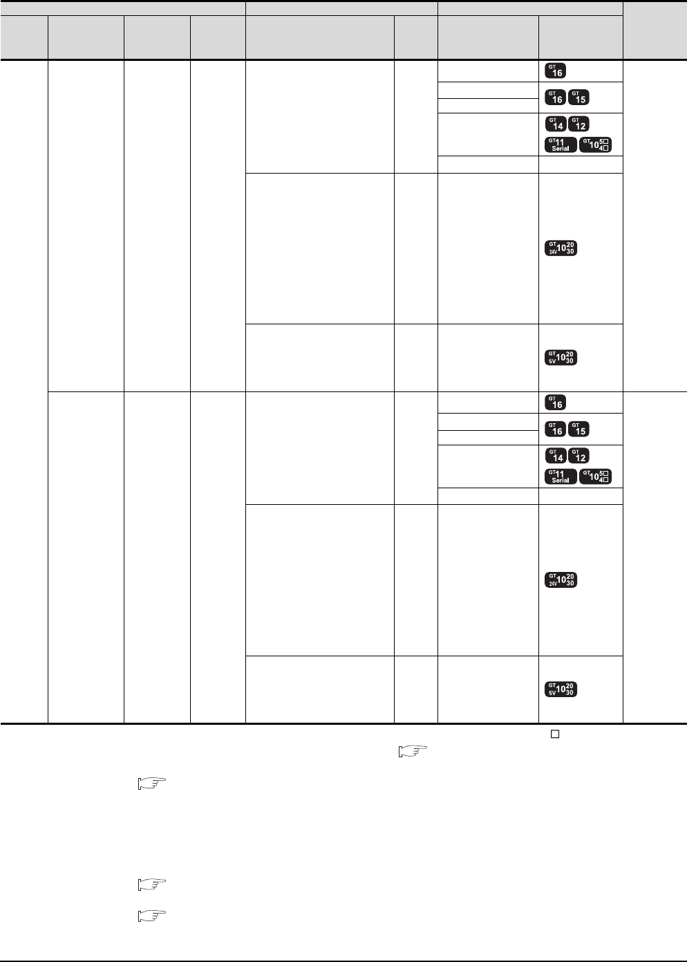
6 - 14 6. DIRECT CONNECTION TO CPU
6.2 System Configuration
When connecting to FX3G (RS-422 connection)
*1 Connect it to the RS-232 interface (built into GOT). It cannot be mounted on GT1655 and GT155 .
*2 For the connection to GOT, refer to the connection diagram. ( RS422 connection diagram 1))
*3 For details of the GOT multi-drop connection, refer to the following.
19. GOT MULTI-DROP CONNECTION
*4 When connecting FX3G series to GT10 (input power supply: 5V), they cannot be connected to standard built-in port (RS-422) and
function expansion board (FX3G-422-BD) simultaneously.
*5 When the function expansion board (communication board) and the function adapter are connected, a GOT and a peripheral
such as a PC with GX Developer installed can be connected to them individually.
GT14, GT12, GT11 and GT10 are available for the multiple-GT14, GT12, GT11, GT10 connection function to connect up to two
GOTs.
20. MULTIPLE-GT14, GT12, GT11, GT10 CONNECTION FUNCTION
*6 When using function expansion boards or function adapters, confirm the communication settings.
6.5 Precautions Connection to FXCPU (2)When connecting with function extension board or communication special
adapter
*7 Use the RS-422 connection model.
PLC Connection cable GOT Number of
connectable
equipment
*5
Model
name
Function
expansion
board*6
Function
adapter*6
Communi
cation
type
Cable model
Max.
distance
Option device Model
FX3G
--RS-422
GT01-C10R4-8P(1m)
GT01-C30R4-8P(3m)
GT01-C100R4-8P(10m)
GT01-C200R4-8P(20m)
GT01-C300R4-8P(30m)
30m
GT16-C02R4-9S
1 GOT for 1
PLC built-in
port
GT15-RS2T4-9P*1
GT15-RS4-9S
- (Built into GOT)
GT01-RS4-M*3 -
GT10-C10R4-8P(1m)
GT10-C30R4-8P(3m)
GT10-C100R4-8P(10m)
GT10-C200R4-8P(20m)
GT10-C300R4-8P(30m)
GT10-C10R4-8PC(1m)
GT10-C30R4-8PC(3m)
GT10-C100R4-8PC(10m)
GT10-C200R4-8PC(20m)
GT10-C300R4-8PC(30m)
*2
30m - (Built into GOT) *7
GT10-C10R4-8P(1m)
GT10-C30R4-8P(3m)
GT10-C10R4-8PC(1m)
GT10-C30R4-8PC(3m)
*2
3m - (Built into GOT) *4*7
FX3G-422-BD - RS-422
GT01-C10R4-8P(1m)
GT01-C30R4-8P(3m)
GT01-C100R4-8P(10m)
GT01-C200R4-8P(20m)
GT01-C300R4-8P(30m)
30m
GT16-C02R4-9S
1 GOT for 1
function
expansion
board
GT15-RS2T4-9P*1
GT15-RS4-9S
- (Built into GOT)
GT01-RS4-M*3 -
GT10-C10R4-8P(1m)
GT10-C30R4-8P(3m)
GT10-C100R4-8P(10m)
GT10-C200R4-8P(20m)
GT10-C300R4-8P(30m)
GT10-C10R4-8PC(1m)
GT10-C30R4-8PC(3m)
GT10-C100R4-8PC(10m)
GT10-C200R4-8PC(20m)
GT10-C300R4-8PC(30m)
*2
30m - (Built into GOT) *7
GT10-C10R4-8P(1m)
GT10-C30R4-8P(3m)
GT10-C10R4-8PC(1m)
GT10-C30R4-8PC(3m)
*2
3m - (Built into GOT) *4
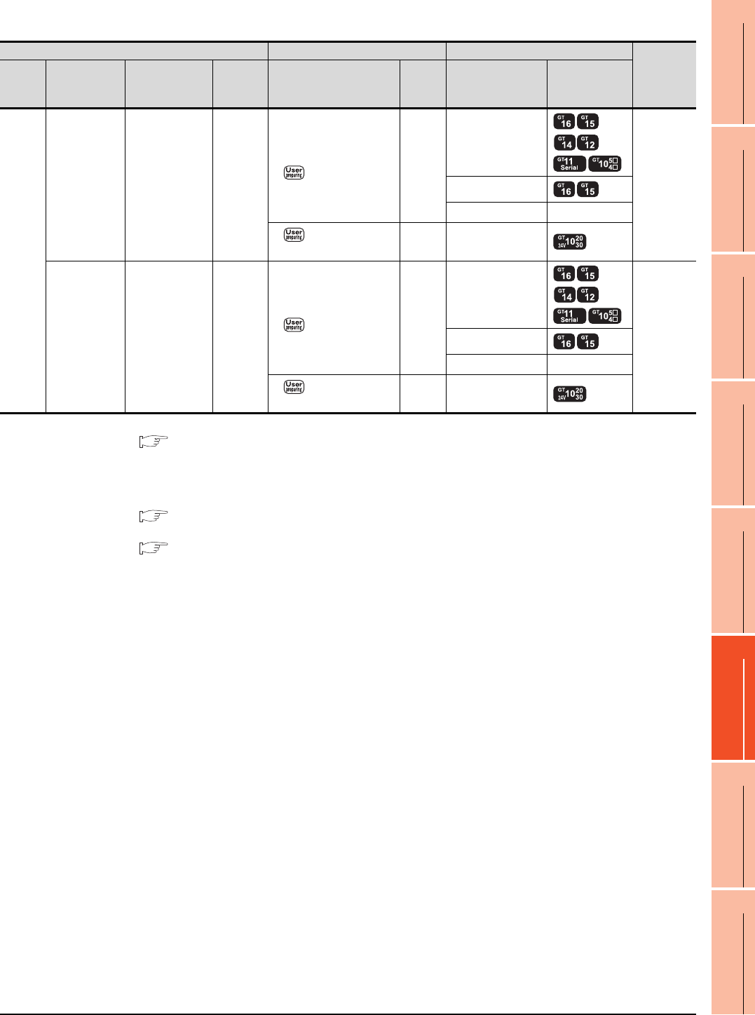
6. DIRECT CONNECTION TO CPU
6.2 System Configuration
6 - 15
1
PREPARATORY
PROCEDURES FOR
MONITORING
2
DEVICE RANGE
THAT CAN BE SET
3
ACCESS RANGE
FOR MONITORING
4
HOW TO MONITOR
REDUNTANT
SYSTEM
5
BUS CONNECTION
6
DIRECT
CONNECTION TO
CPU
7
COMPUTER LINK
CONNECTION
8
ETHERNET
CONNECTION
When connecting to FX3G (RS-232 connection)
*1 For details of the GOT multi-drop connection, refer to the following.
19. GOT MULTI-DROP CONNECTION
*2 When the function expansion board (communication board) and the function adapter are connected, a GOT and a peripheral
such as a PC with GX Developer installed can be connected to them individually.
GT14, GT12, GT11 and GT10 are available for the multiple-GT14, GT12, GT11, GT10 connection function to connect up to two
GOTs.
20. MULTIPLE-GT14, GT12, GT11, GT10 CONNECTION FUNCTION
*3 When using function expansion boards or function adapters, confirm the communication settings.
6.5 Precautions Connection to FXCPU (2)When connecting with function extension board or communication special
adapter
*4 Use the RS-232 connection model.
PLC Connection cable GOT
Number of
connectable
equipment
*2
Model
name
Function
expansion
board*3
Function
adapter*3
Communi
cation
type
Cable model
Connection diagram
number
Max.
distance
Option device Model
FX3G
FX3G-232-BD - RS-232
GT01-C30R2-9S(3m)
or
RS232 connection
diagram 1)
15m
- (Built into GOT)
1 GOT for 1
function
expansion
board
GT15-RS2-9P
GT01-RS4-M*1 -
RS232 connection
diagram 4)
15m - (Built into GOT) *4
-
FX3G-CNV-ADP
+
FX3U-232ADP
RS-232
GT01-C30R2-9S(3m)
or
RS232 connection
diagram 1)
15m
- (Built into GOT)
1 GOT for 1
function
adapter
GT15-RS2-9P
GT01-RS4-M*1 -
RS232 connection
diagram 4)
15m - (Built into GOT) *4
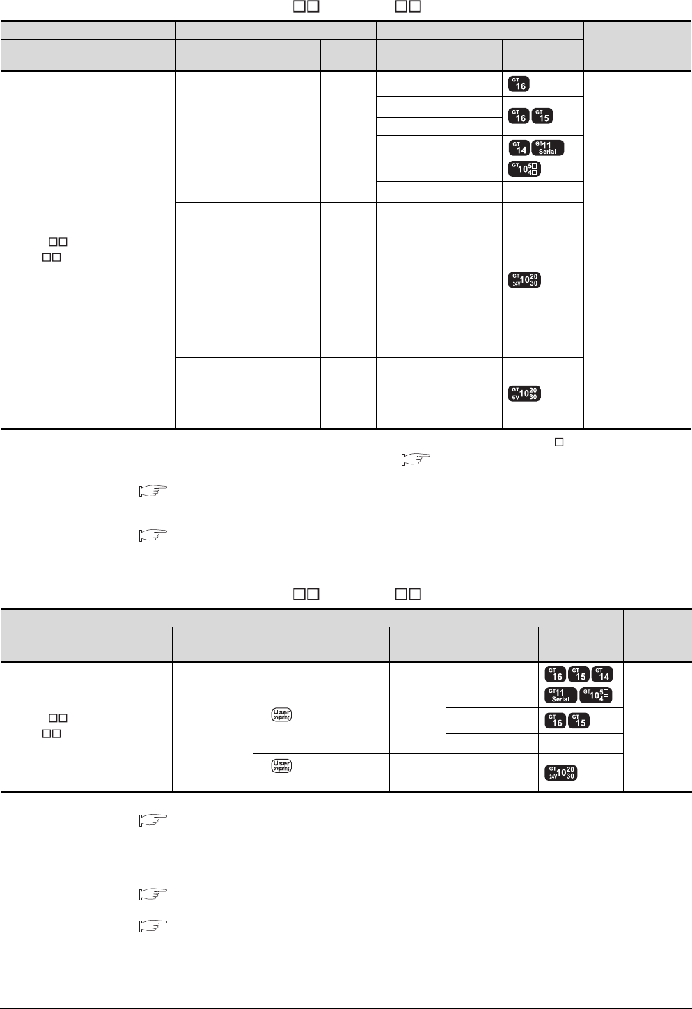
6 - 16 6. DIRECT CONNECTION TO CPU
6.2 System Configuration
When connecting to FX3GC (FX3GC-/D, FX3GC- /DSS) (RS-422 connection)
*1 Connect it to the RS-232 interface (built into GOT). It cannot be mounted on GT1655 and GT155 .
*2 For the connection to GOT, refer to the connection diagram. ( RS422 connection diagram 1))
*3 For details of the GOT multi-drop connection, refer to the following.
19. GOT MULTI-DROP CONNECTION
*4 GT14, GT12, GT11 and GT10 are available for the multiple-GT14, GT12, GT11, GT10 connection function to connect up to two
GOTs.
20. MULTIPLE-GT14, GT12, GT11, GT10 CONNECTION FUNCTION
*5 Use the RS-422 connection model.
When connecting to FX3GC (FX3GC-/D, FX3GC- /DSS) (RS-232 connection)
*1 For details of the GOT multi-drop connection, refer to the following.
19. GOT MULTI-DROP CONNECTION
*2 A GOT and a peripheral such as a PC with GX Developer installed can be connected to the function adapter and the FXCPU
individually.
GT14, GT12, GT11 and GT10 are available for the multiple-GT14, GT12, GT11, GT10 connection function to connect up to two
GOTs.
20. MULTIPLE-GT14, GT12, GT11, GT10 CONNECTION FUNCTION
*3 When using function expansion boards or function adapters, confirm the communication settings.
6.5 Precautions Connection to FXCPU (2)When connecting with function extension board or communication special
adapter
*4 Use the RS-232 connection model.
PLC Connection cable GOT
Number of
connectable
equipment
*4
Model name Communication
type Cable model
Max.
distance
Option device Model
FX3GC-/D
FX3GC-/DSS RS-422
GT01-C10R4-8P(1m)
GT01-C30R4-8P(3m)
GT01-C100R4-8P(10m)
GT01-C200R4-8P(20m)
GT01-C300R4-8P(30m)
30m
GT16-C02R4-9S(0.2m)
1 GOT for 1 PLC built-
in port
GT15-RS2T4-9P*1
GT15-RS4-9S
- (Built into GOT)
GT01-RS4-M*3 -
GT10-C10R4-8P(1m)
GT10-C30R4-8P(3m)
GT10-C100R4-8P(10m)
GT10-C200R4-8P(20m)
GT10-C300R4-8P(30m)
GT10-C10R4-8PC(1m)
GT10-C30R4-8PC(3m)
GT10-C100R4-8PC(10m)
GT10-C200R4-8PC(20m)
GT10-C300R4-8PC(30m)
*2
30m - (Built into GOT) *5
GT10-C10R4-8P(1m)
GT10-C30R4-8P(3m)
GT10-C10R4-8PC(1m)
GT10-C30R4-8PC(3m)
*2
3m - (Built into GOT) *5
PLC Connection cable GOT
Number of
connectable
equipment
*2
Model name Function
adapter
*3
Communication
type
Cable model
Connection diagram number
Max.
distance
Option device Model
FX3GC-/D
FX3GC-/DSSFX3U-232ADP RS-232
GT01-C30R2-9S(3m)
or
RS232 connection
diagram 1)
15m
- (Built into GOT)
1 GOT for 1
function
adapter
GT15-RS2-9P
GT01-RS4-M*1 -
RS232 connection
diagram 4)
15m - (Built into GOT) *4
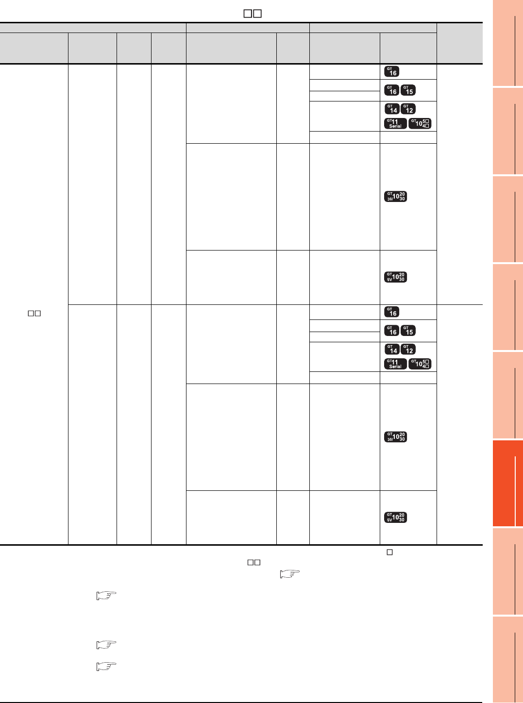
6. DIRECT CONNECTION TO CPU
6.2 System Configuration
6 - 17
1
PREPARATORY
PROCEDURES FOR
MONITORING
2
DEVICE RANGE
THAT CAN BE SET
3
ACCESS RANGE
FOR MONITORING
4
HOW TO MONITOR
REDUNTANT
SYSTEM
5
BUS CONNECTION
6
DIRECT
CONNECTION TO
CPU
7
COMPUTER LINK
CONNECTION
8
ETHERNET
CONNECTION
When connecting to FX3U or FX3UC (FX3UC- -LT(-2)) (RS-422 connection)
*1 Connect it to the RS-232 interface (built into GOT). It cannot be mounted on GT1655 and GT155 .
*2 GT10-C10R4-8PL can be used for FX3U or FX3UC- -LT(-2).
*3 For the connection to GOT, refer to the connection diagram. ( RS422 connection diagram 1))
*4 For details of the GOT multi-drop connection, refer to the following.
19. GOT MULTI-DROP CONNECTION
*5 When the function expansion board (communication board) and the function adapter are connected, a GOT and a peripheral
such as a PC with GX Developer installed can be connected to them individually.
GT14, GT12, GT11 and GT10 are available for the multiple-GT14, GT12, GT11, GT10 connection function to connect up to two
GOTs.
20. MULTIPLE-GT14, GT12, GT11, GT10 CONNECTION FUNCTION
*6 When using function expansion boards or function adapters, confirm the communication settings.
6.5 Precautions Connection to FXCPU (2)When connecting with function extension board or communication special
adapter
*7 Use the RS-422 connection model.
PLC Connection cable GOT Number of
connectable
equipment
*5
Model name
Function
expansion
board*6
Function
adapter
*6
Commu
nication
type
Cable model
Max.
distance
Option device Model
FX3U
FX3UC
(FX3UC- -LT(-2))
- - RS-422
GT01-C10R4-8P(1m)
GT01-C30R4-8P(3m)
GT01-C100R4-8P(10m)
GT01-C200R4-8P(20m)
GT01-C300R4-8P(30m)
30m
GT16-C02R4-9S
1 GOT for 1
PLC built-in
port
GT15-RS2T4-9P*1
GT15-RS4-9S
- (Built into GOT)
GT01-RS4-M*4 -
GT10-C10R4-8P(1m)
GT10-C30R4-8P(3m)
GT10-C100R4-8P(10m)
GT10-C200R4-8P(20m)
GT10-C300R4-8P(30m)
GT10-C10R4-8PC(1m)
GT10-C30R4-8PC(3m)
GT10-C100R4-8PC(10m)
GT10-C200R4-8PC(20m)
GT10-C300R4-8PC(30m)
GT10-C10R4-8PL(1m)*2
*3
30m - (Built into GOT) *7
GT10-C10R4-8P(1m)
GT10-C30R4-8P(3m)
GT10-C10R4-8PC(1m)
GT10-C30R4-8PC(3m)
GT10-C10R4-8PL(1m)*2
*3
3m - (Built into GOT) *7
FX3U-422-BD - RS-422
GT01-C10R4-8P(1m)
GT01-C30R4-8P(3m)
GT01-C100R4-8P(10m)
GT01-C200R4-8P(20m)
GT01-C300R4-8P(30m)
30m
GT16-C02R4-9S
1 GOT for 1
function
expansion
board
GT15-RS2T4-9P*1
GT15-RS4-9S
- (Built into GOT)
GT01-RS4-M*4 -
GT10-C10R4-8P(1m)
GT10-C30R4-8P(3m)
GT10-C100R4-8P(10m)
GT10-C200R4-8P(20m)
GT10-C300R4-8P(30m)
GT10-C10R4-8PC(1m)
GT10-C30R4-8PC(3m)
GT10-C100R4-8PC(10m)
GT10-C200R4-8PC(20m)
GT10-C300R4-8PC(30m)
GT10-C10R4-8PL(1m)*2
*3
30m - (Built into GOT) *7
GT10-C10R4-8P(1m)
GT10-C30R4-8P(3m)
GT10-C10R4-8PC(1m)
GT10-C30R4-8PC(3m)
GT10-C10R4-8PL(1m)*2
*3
3m - (Built into GOT)
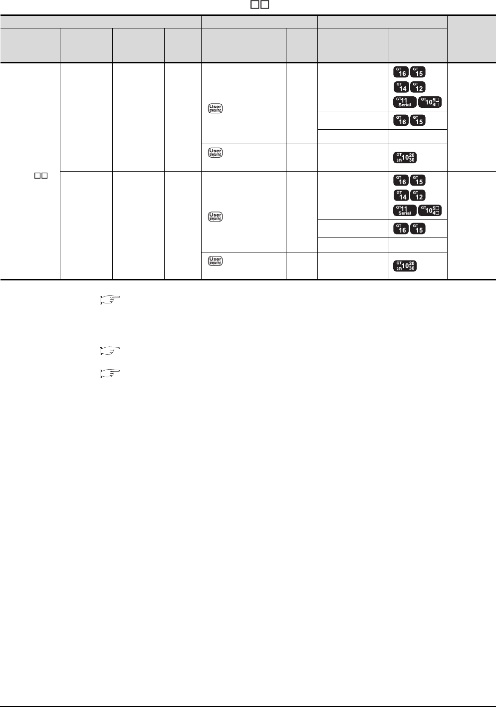
6 - 18 6. DIRECT CONNECTION TO CPU
6.2 System Configuration
When connecting to FX3U or FX3UC (FX3UC- -LT(-2)) (RS-232 connection)
*1 For details of the GOT multi-drop connection, refer to the following.
19. GOT MULTI-DROP CONNECTION
*2 When the function expansion board (communication board) and the function adapter are connected, a GOT and a peripheral
such as a PC with GX Developer installed can be connected to them individually.
GT14, GT12, GT11 and GT10 are available for the multiple-GT14, GT12, GT11, GT10 connection function to connect up to two
GOTs.
20. MULTIPLE-GT14, GT12, GT11, GT10 CONNECTION FUNCTION
*3 When using function expansion boards or function adapters, confirm the communication settings.
6.5 Precautions Connection to FXCPU (2)When connecting with function extension board or communication special
adapter
*4 Use the RS-232 connection model.
PLC Connection cable GOT Number of
connectable
equipment
*2
Model name
Function
expansion
board*3
Function
adapter*3
Commun
ication
type
Cable model
Connection diagram
number
Max.
distance
Option device Model
FX3U
FX3UC
(FX3UC--
LT(-2))
FX3U-232-BD - RS-232
GT01-C30R2-9S(3m)
or
RS232 connection
diagram 1)
15m
- (Built into GOT)
1 GOT for 1
function
expansion
board
GT15-RS2-9P
GT01-RS4-M*1 -
RS232 connection
diagram 4)
15m - (Built into GOT) *4
FX3U-422-BD
FX3U-232-BD
FX3U-CNV-BD
FX3U-232ADP RS-232
GT01-C30R2-9S(3m)
or
RS232 connection
diagram 1)
15m
- (Built into GOT)
1 GOT for 1
function
adapter
GT15-RS2-9P
GT01-RS4-M*1 -
RS232 connection
diagram 4)
15m - (Built into GOT) *4
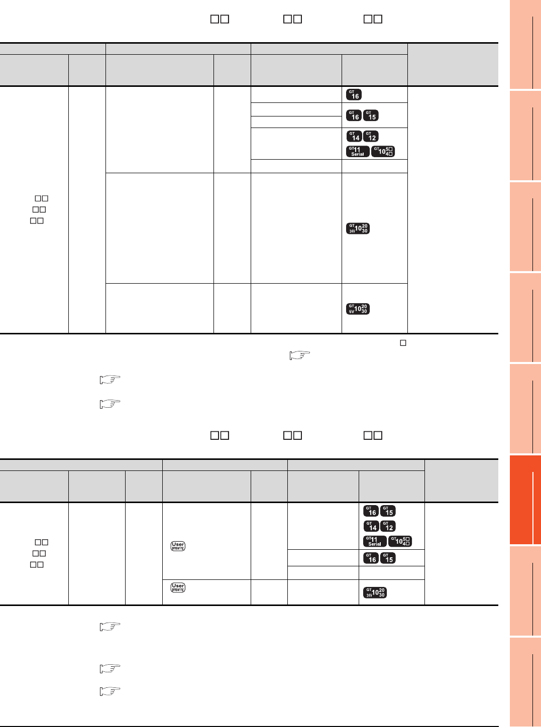
6. DIRECT CONNECTION TO CPU
6.2 System Configuration
6 - 19
1
PREPARATORY
PROCEDURES FOR
MONITORING
2
DEVICE RANGE
THAT CAN BE SET
3
ACCESS RANGE
FOR MONITORING
4
HOW TO MONITOR
REDUNTANT
SYSTEM
5
BUS CONNECTION
6
DIRECT
CONNECTION TO
CPU
7
COMPUTER LINK
CONNECTION
8
ETHERNET
CONNECTION
When connecting to FX3UC (FX3UC-/D, FX3UC-/DS, FX3UC- /DSS) (RS-422
connection)
*1 Connect it to the RS-232 interface (built into GOT). It cannot be mounted on GT1655 and GT155 .
*2 For the connection to GOT, refer to the connection diagram. ( RS422 connection diagram 1))
*3 For details of the GOT multi-drop connection, refer to the following.
19. GOT MULTI-DROP CONNECTION
*4
GT14, GT12, GT11 and GT10 are available for the multiple-GT14, GT12, GT11, GT10 connection function to connect up to two GOTs.
20. MULTIPLE-GT14, GT12, GT11, GT10 CONNECTION FUNCTION
*5 Use the RS-422 connection model.
When connecting to FX3UC (FX3UC-/D, FX3UC-/DS, FX3UC- /DSS) (RS-232
connection)
*1 For details of the GOT multi-drop connection, refer to the following.
19. GOT MULTI-DROP CONNECTION
*2 A GOT and a peripheral such as a PC with GX Developer installed can be connected to the function adapter and the FXCPU
individually.
GT14, GT12, GT11 and GT10 are available for the multiple-GT14, GT12, GT11, GT10 connection function to connect up to two GOTs.
20. MULTIPLE-GT14, GT12, GT11, GT10 CONNECTION FUNCTION
*3 When using function expansion boards or function adapters, confirm the communication settings.
6.5 Precautions Connection to FXCPU (2)When connecting with function extension board or communication special
adapter
*4 Use the RS-232 connection model.
PLC Connection cable GOT
Number of connectable
equipment*4
Model name
Commun
ication
type
Cable model Max.
distance Option device Model
FX3UC-/D
FX3UC-/DS
FX3UC-/DSS
RS-422
GT01-C10R4-8P(1m)
GT01-C30R4-8P(3m)
GT01-C100R4-8P(10m)
GT01-C200R4-8P(20m)
GT01-C300R4-8P(30m)
30m
GT16-C02R4-9S(0.2m)
1 GOT for 1 PLC built-in
port
GT15-RS2T4-9P*1
GT15-RS4-9S
- (Built into GOT)
GT01-RS4-M*3 -
GT10-C10R4-8P(1m)
GT10-C30R4-8P(3m)
GT10-C100R4-8P(10m)
GT10-C200R4-8P(20m)
GT10-C300R4-8P(30m)
GT10-C10R4-8PC(1m)
GT10-C30R4-8PC(3m)
GT10-C100R4-8PC(10m)
GT10-C200R4-8PC(20m)
GT10-C300R4-8PC(30m)
*2
30m - (Built into GOT) *5
GT10-C10R4-8P(1m)
GT10-C30R4-8P(3m)
GT10-C10R4-8PC(1m)
GT10-C30R4-8PC(3m)
*2
3m - (Built into GOT) *5
PLC Connection cable GOT Number of
connectable
equipment*2
Model name Function
adapter*3
Commun
ication
type
Cable model
Connection diagram
number
Max.
distance Option device Model
FX3UC-/D
FX3UC-/DS
FX3UC-/DSS
FX3U-232ADP RS-232
GT01-C30R2-9S(3m)
or
RS232 connection
diagram 1)
15m
- (Built into GOT)
1 GOT for 1 function
adapter
GT15-RS2-9P
GT01-RS4-M*1 -
RS232 connection
diagram 4)
15m - (Built into GOT) *4
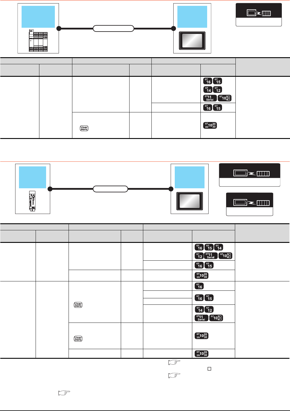
6 - 20 6. DIRECT CONNECTION TO CPU
6.2 System Configuration
6.2.6 Connecting to WSCPU
*1 Use the RS-232 connection model.
6.2.7 Connecting to the motion controller CPU
*1 For the connection to GOT, refer to the connection diagram. ( RS232 connection diagram 3))
*2 Connect it to the RS-232 interface (built into GOT).It cannot be mounted on GT155 .
*3 For the connection to GOT, refer to the connection diagram. ( RS422 connection diagram 5))
*4 GT14, GT12, GT11 and GT10 are available for the multiple-GT14, GT12, GT11, GT10 connection function to connect up to two
GOTs.
20. MULTIPLE-GT14, GT12, GT11, GT10 CONNECTION FUNCTION
*5 Use the RS-232 connection model.
*6 Use the RS-422 connection model.
MELSEC-WS
Communication driver
WSCPU GOT
Connection cable
PLC Connection cable GOT Number of connectable
equipment
Model name Communication
type
Cable model
Connection diagram number
Max.
distance Option device Model
MELSEC-WS RS-232
WS0-C20R2(2m) 2m
- (Built into GOT)
1 GOT for 1 PLC
GT15-RS2-9P
WS0-C20R2(2m)
+
RS232 connection
diagram 6)
2.3m - (Built into GOT) *1
Motion controller
CPU
GOT
Connection cable
Communication driver
( For GT16, GT15, GT14, GT12, GT11)
A/QnA/L/Q CPU,LJ71C24,QJ71C24
Communication driver
QnA/L/Q CPU
( For GT10)
Motion controller CPU Connection cable GOT Number of connectable
equipment*4
Model name Communication
type Cable model Max.
distance Option device Model
Q170MCPU RS-232
GT01-C30R2-6P(3m) 3m
- (Built into GOT)
1 GOT for 1 motion
controller CPU
GT15-RS2-9P
GT10-C30R2-6P(3m)
*1 3m - (Built into GOT) *5
MR-MQ100 RS-422
Q170MIOCBL1M-B(1m)
+
RS422 connection
diagram 3)
30m
GT16-C02R4-9S(0.2m)
1 GOT for 1 motion
controller CPU
GT15-RS2T4-9P*2
GT15-RS4-9S
- (Built into GOT)
Q170MIOCBL1M-B(1m)
+
RS422 connection
diagram 4)
30m - (Built into GOT) *6
Q170MIOCBL1M-A(1m)*3 1m - (Built into GOT) *6

6. DIRECT CONNECTION TO CPU
6.2 System Configuration
6 - 21
1
PREPARATORY
PROCEDURES FOR
MONITORING
2
DEVICE RANGE
THAT CAN BE SET
3
ACCESS RANGE
FOR MONITORING
4
HOW TO MONITOR
REDUNTANT
SYSTEM
5
BUS CONNECTION
6
DIRECT
CONNECTION TO
CPU
7
COMPUTER LINK
CONNECTION
8
ETHERNET
CONNECTION
POINTPOINTPOINT
When connecting to the motion controller CPU (Q Series) other than Q170MCPU, MR-MQ100
A motion controller CPU (Q Series) mounted to the multiple CPU system of the QCPU (Q mode) can be monitored.
The system configuration, connection conditions, and system equipment for connecting a GOT to a motion
controller CPU (Q Series) are the same as those for connecting to the QCPU.
6.2.1 Connecting to QCPU
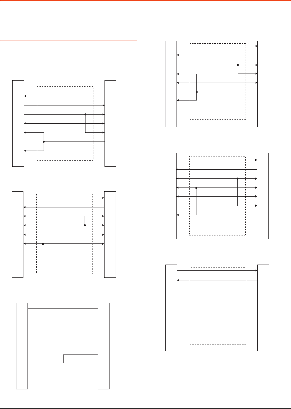
6 - 22 6. DIRECT CONNECTION TO CPU
6.3 Connection Diagram
6.3 Connection Diagram
The following diagram shows the connection between the
GOT and the PLC.
6.3.1 RS-232 cable
Connection diagram
RS232 connection diagram 1)
RS232 connection diagram 2)
RS232 connection diagram 3)
GOT side
1
2
3
4
5
6
7
8
9
FX PLC side
(D-sub 9-pin)
1
3
2
6
5
8
4
7
9
GOT side
FX PLC side
(D-sub 25-pin)
2
3
8
4
5
6
2
3
5
6
7
20
GOT side
(terminal block)
Untied wire color
of GT10-C30R2-6P
Brown
Red
Blue
Yellow
Green
Purple
SD
RD
ER
DR
SG
RS
CS
NC
NC
RS232 connection diagram 4)
RS232 connection diagram 5)
RS232 connection diagram 6)
GOT side
(terminal block)
FX PLC side
(D-sub 9-pin)
2
3
6
8
5
4
7
1
9
SD
RD
ER
DR
SG
RS
CS
NC
NC
GOT side
(terminal block)
FX PLC side
(D-sub 25-pin)
3
2
5
20
7
6
SD
RD
ER
DR
SG
RS
CS
NC
NC
SD
RD
ER
DR
SG
RS
CS
NC
NC
WS0-C20R2(male)side
(D-Sub 9-pin)
GOT side
(terminal block)
3
2
5
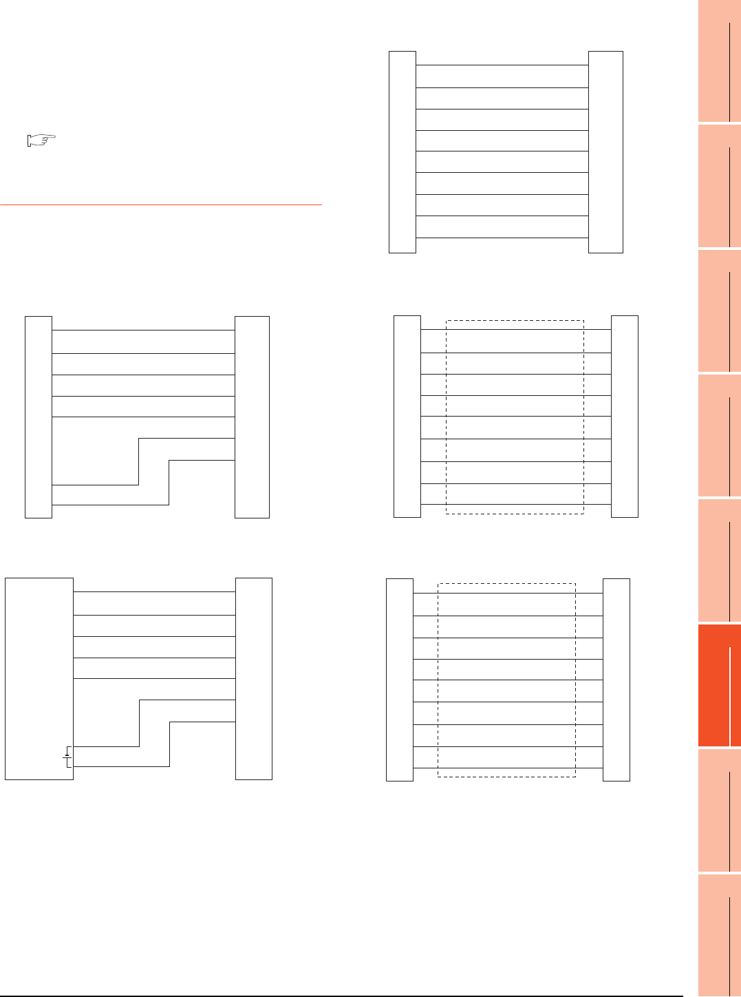
6. DIRECT CONNECTION TO CPU
6.3 Connection Diagram
6 - 23
1
PREPARATORY
PROCEDURES FOR
MONITORING
2
DEVICE RANGE
THAT CAN BE SET
3
ACCESS RANGE
FOR MONITORING
4
HOW TO MONITOR
REDUNTANT
SYSTEM
5
BUS CONNECTION
6
DIRECT
CONNECTION TO
CPU
7
COMPUTER LINK
CONNECTION
8
ETHERNET
CONNECTION
Precautions when preparing a cable
(1) Cable length
The length of the RS-232 cable must be within the
maximum distance specifications.
(2) GOT side connector
For the GOT side connector, refer to the following.
1.4.1 GOT connector specifications
6.3.2 RS-422 cable
Connection diagram
RS422 connection diagram 1)
GT10 (input power supply : 24V)
GT10 (input power supply : 5V)
GOT side
(terminal block)
Untied wire color of
GT10-C□□□R4-8P
Brown
Red
Orange
Yellow
Green
Black
White
SDA
SDB
RDA
RDB
SG
RSA
RSB
CSA
CSB
GOT side
(terminal block)
Untied wire color of
GT10-C□□□R4-8P
Brown
Red
Orange
Yellow
Green
Black
White
SDA
SDB
RDA
RDB
SG
RSA
RSB
INPUT
DC5V
-
+
RS422 connection diagram 2)
RS422 connection diagram 3)
RS422 connection diagram 4)
GOT side
(terminal block)
Untied wire color of
GT10-C□□□R4-25P
Brown
Red
Orange
Yellow
Green
Blue
Purple
Black
White
SDA
SDB
RDA
RDB
SG
RSA
RSB
CSA
CSB
GOT side Q170MIOCBL1M-B side
1
2
3
4
5
6
7
8
9
1
2
3
4
5
6
7
8
9
SDA
RDA
RSA
CSA
SG
SDB
RDB
RSB
CSB
SDA
RDA
RSA
CSA
SG
SDB
RDB
RSB
CSB
GOT side
(terminal block) Q170MIOCBL1M-B side
1
6
2
7
5
3
8
4
9
SDA
SDB
RDA
RDB
SG
RSA
RSB
CSA
CSB
SDA
SDB
RDA
RDB
SG
RSA
RSB
CSA
CSB

6 - 24 6. DIRECT CONNECTION TO CPU
6.3 Connection Diagram
Precautions when preparing a cable
(1) Cable length
The length of the RS-422 cable must be within the
maximum distance specifications.
(2) GOT side connector
For the GOT side connector, refer to the following.
1.4.1 GOT connector specifications
Connecting terminating resistors
(1) GOT side
When connecting a PLC to the GOT, a terminating
resistor must be connected to the GOT.
(a) For GT14, GT11, GT10
Set the terminating resistor selector of the GOT
main unit to "330 ".
For the procedure to set the terminating resistor,
refer to the following.
1.4.3 Terminating resistors of GOT
RS422 connection diagram 5)
GOT side
(terminal block)
United wire color of
Q170MIOCBL1M-A
SDA
SDB
RDA
RDB
SG
RSA
RSB
CSA
CSB
Yellow(Dot mark:Black)
Yellow(Dot mark:Red)
Pink(Dot mark:Black)
Pink(Dot mark:Red)
White(Dot mark:Black)
White(Dot mark:Red)

6. DIRECT CONNECTION TO CPU
6.4 GOT Side Settings
6 - 25
1
PREPARATORY
PROCEDURES FOR
MONITORING
2
DEVICE RANGE
THAT CAN BE SET
3
ACCESS RANGE
FOR MONITORING
4
HOW TO MONITOR
REDUNTANT
SYSTEM
5
BUS CONNECTION
6
DIRECT
CONNECTION TO
CPU
7
COMPUTER LINK
CONNECTION
8
ETHERNET
CONNECTION
6.4 GOT Side Settings
6.4.1 Setting communication
interface (Communication
settings)
POINTPOINTPOINT
GOT Multi- Drop Connection
When using the serial multi-drop connection unit, refer
to the following.
19. GOT MULTI-DROP CONNECTION
Set the channel of the connected equipment.
1. Select [Common] [Controller Setting] from the
menu.
2. The Controller Setting window is displayed. Select the
channel to be used from the list menu.
3. Set the following items.
• Manufacturer: Mitsubishi
• Controller Type: Set according to the Controller
Type to be connected.
• I/F: Interface to be used
• Driver: Set either of the following according to the
Controller Type to be connected.
For GT16, GT15, GT14, GT12, GT11
A/QnA/L/Q CPU, LJ71C24, QJ71C24
MELSEC-FX
MELSEC-WS
For GT10
QnA/L/Q CPU
MELSEC-A
MELSEC-FX
MELSEC-WS
4. The detailed setting is displayed after Manufacturer,
Controller Type, I/F, and Driver are set.
Make the settings according to the usage
environment.
6.4.2Communication detail settings
Click the [OK] button when settings are completed.
POINTPOINTPOINT
The settings of connecting equipment can be
confirmed in [I/F Communication Setting].
For details, refer to the following:
1.1.2 I/F communication setting
6.4.2 Communication detail settings
Make the settings according to the usage environment.
(1) A/QnA/L/Q CPU, LJ71C24, QJ71C24
2.
3.
4.
Click!
Item Description Range
Transmission
Speed
Set this item when change the
transmission speed used for
communication with the connected
equipment.
(Default: 115200bps)
When the setting exceeds the limit of
the connected equipment,
communication is performed at the
fastest transmission speed supported
by the connected equipment.
9600bps,
19200bps,
38400bps,
57600bps,
115200bps
Retry
Set the number of retries to be
performed when a communication
timeout occurs.
(Default: 0time)
0 to 5times
Timeout Time
Set the time period for a communication
to time out.
(Default: 3sec)
3 to 30sec
Delay Time
Set this item to adjust the transmission
timing of the communication request
from the GOT.
(Default: 0ms)
0 to 300 (ms)
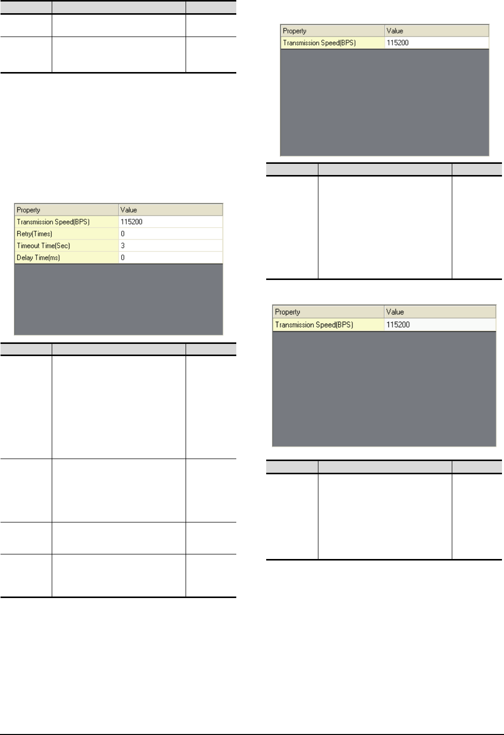
6 - 26 6. DIRECT CONNECTION TO CPU
6.4 GOT Side Settings
*1 This is effective when collecting a large data on other than
the monitor screen (logging, recipe function, etc.). However,
when connecting to Q00J/Q00/Q01CPU, the sequence scan
time may be influenced. If you want to avoid the influence on
the sequence scan time, do not set "High".
(High performance is hardly affected)
*2 Set this item if you want to avoid the influence on the
sequence scan time further than the "Normal" setting when
connecting to Q00J/Q00/Q01CPU. However, the monitor
speed may be reduced.
*3 Set the format to "1".
(2) MELSEC-FX
(a) For GT16, GT15, GT14, GT12, GT11
(b) For GT10
(3) QnA/L/Q CPU (GT10)
Format*3 Select the communication format.
(Default: 1) 1, 2
Monitor Speed
(GT16 only)
Set the monitor speed of the GOT.
This setting is not valid in all systems.
(Default: Normal)
High*1
Normal
Low*2
Item Description Range
Transmission
Speed
Set this item when change the
transmission speed used for
communication with the connected
equipment.
(Default: 115200bps)
When the setting exceeds the limit of the
connected equipment, communication is
performed at the fastest transmission
speed supported by the connected
equipment.
9600bps,
19200bps,
38400bps,
57600bps,
115200bps
Retry
Set the number of retries to be
performed when a communication
timeout occurs. When receiving no
response after retries, the
communication times out.
(Default: 0time)
0 to 5times
Timeout Time
Set the time period for a communication
to time out.
(Default: 3sec)
3 to 30sec
Delay Time
Set this item to adjust the transmission
timing of the communication request
from the GOT.
(Default: 0ms)
0 to 300 (ms)
Item Description Range
Item Description Range
Transmission
Speed
Set this item when change the
transmission speed used for
communication with the connected
equipment.
(Default: 115200bps)
When the setting exceeds the limit of the
connected equipment, communication is
performed at the fastest transmission
speed supported by the connected
equipment.
9600bps,
19200bps,
38400bps,
57600bps,
115200bps
Item Description Range
Transmission
Speed
Set this item when change the transmission
speed used for communication with the
connected equipment.
(Default: 115200bps)
When the setting exceeds the limit of the
connected equipment, communication is
performed at the fastest transmission
speed supported by the connected
equipment.
9600bps,
19200bps,
38400bps,
57600bps,
115200bps
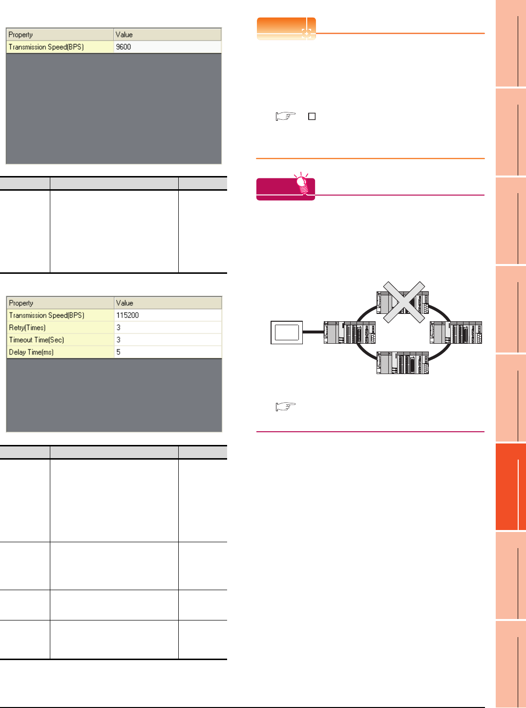
6. DIRECT CONNECTION TO CPU
6.4 GOT Side Settings
6 - 27
1
PREPARATORY
PROCEDURES FOR
MONITORING
2
DEVICE RANGE
THAT CAN BE SET
3
ACCESS RANGE
FOR MONITORING
4
HOW TO MONITOR
REDUNTANT
SYSTEM
5
BUS CONNECTION
6
DIRECT
CONNECTION TO
CPU
7
COMPUTER LINK
CONNECTION
8
ETHERNET
CONNECTION
(4) MELSEC-A (GT10)
(5) MELSEC-WS
POINTPOINTPOINT
(1) Communication interface setting by the Utility
The communication interface setting can be
changed on the Utility's [Communication Settings]
after writing [Communication Settings] of project
data.
For details on the Utility, refer to the following
manual.
GT User's Manual
(2) Precedence in communication settings
When settings are made by GT Designer3 or the
Utility, the latest setting is effective.
HINTHINTHINT
Cutting the portion of multiple connection of the
controller
By setting GOT internal device, GOT can cut the
portion of multiple connection of the controller. For
example, faulty station that has communication
timeout can be cut from the system.
For details of the setting contents of GOT internal
device, refer to the following manual.
GT Designer3 Version Screen Design Manual
(Fundamentals)
Item Description Range
Transmission
Speed
Set this item when change the transmission
speed used for communication with the
connected equipment.
(Default: 9600bps)
When the setting exceeds the limit of the
connected equipment, communication is
performed at the fastest transmission
speed supported by the connected
equipment.
9600bps
Item Description Range
Transmission
Speed
Set this item when change the transmission
speed used for communication with the
connected equipment.
(Default: 115200bps)
When the setting exceeds the limit of the
connected equipment, communication is
performed at the fastest transmission
speed supported by the connected
equipment.
9600bps,
19200bps,
38400bps,
57600bps,
115200bps
Retry
Set the number of retries to be performed
when a communication timeout occurs.
When receiving no response after retries,
the communication times out.
(Default: 3times)
0 to 5times
Timeout Time
Set the time period for a communication to
time out.
(Default: 3sec)
1 to 30sec
Delay Time
Set this item to adjust the transmission
timing of the communication request from
the GOT.
(Default: 5ms)
0 to 300 (ms)
Disconnect the
faulty station
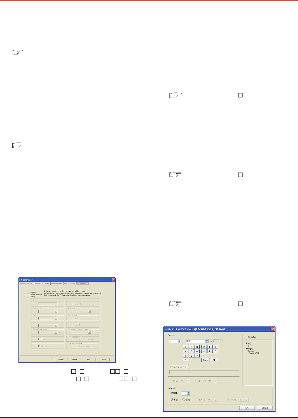
6 - 28 6. DIRECT CONNECTION TO CPU
6.5 Precautions
6.5 Precautions
Connection to FXCPU
(1) When connecting to FX3G/FX3GC/FX3U/FX3UC series
When the keyword of FXCPU (FX3G/FX3GC/FX3U/
FX3UC series) has been set, GOT may not be able to
monitoring.Perform an I/O check again.
( ■ Perform an I/O check) When the result of the I/
O check is normal, check the status of keyword
registration.
(2) When connecting with function extension board or
communication special adapter
When a sequence program and settings that the
FXCPU communicates with devices other than the
GOT are set with software, including GX Developer, the
FXCPU cannot communicate with the GOT.
(a) Settings with sequence program
Check the sequence program and delete the
following.
FX SERIES PROGRAMMABLE
CONTROLLERS USER'S MANUAL - Data
Communication Edition
• No protocol communication (RS instruction)
• Sequence program with the computer link, N:N
network, and parallel link
• Parameter setting
• Set the following special registers to 0.
Except FX3U, FX3UC: D8120
FX3U, FX3UC: D8120, D8400, D8420
FX3G, FX3GC: D8120, D8400, D8420, D8370
(b) Settings with GX Developer
Select [PLC parameter] in [Parameter], and then
click the PLC system(2) tab on the FX parameter
screen.
Uncheck [Operate communication setting], and
then transfer the parameter to the programmable
controller.After the transfer, turn off the
programmable controller, and then turn on the
programmable controller again.
(3) Connection to GT1020-L L , GT1030- L
When connecting GT1020-L L or GT1030- L
to FX3G series, they cannot be connected to standard
built-in port (RS-422) and function expansion board
(FX3G-422-BD) simultaneously.
Connection in the multiple CPU system
When the GOT is connected to multiple CPU system,
the following time is taken until when the PLC runs.
• QCPU (Q mode), motion controller CPU (Q series):
10 seconds or more
• MELDAS C70: 18 seconds or more
When the GOT starts before the PLC runs, a system
alarm occurs.Adjust the opening screen time in the
GOT setup so that no system alarm occurs.
GT Designer3 Version Screen Design
Manual
Connection to LCPU
LCPU may diagnose (check file system, recovering
process, etc.) the SD memory card when turning on the
power or when resetting. Therefore, it takes time until
the SD memory card becomes available. When the
GOT starts before the SD card becomes available, a
system alarm occurs. Adjust the opening screen time in
the GOT setup so that no system alarm occurs.
GT Designer3 Version Screen Design
Manual
Connection to basic model QCPU
Do not set the serial communication function of Q00UJ/
Q00U/Q01U/Q02UCPU, Q00/Q01CPU. If the function
is set, the communication may not be performed.
Connection to Q170MCPU
Set [CPU No.] to "2" in the device setting to monitor the
device of the Motion CPU area (CPU No.2).
When the CPU No. is set to "0" or "1", the device on the
PLC CPU area (CPU No.1) is monitored.
When the CPU No. is set to the number other than "0"
to "2", a communication error occurs and the monitoring
cannot be executed.
For setting the CPU No., refer to the following manual.
GT Designer3 Version Screen Design
Manual
Example) Setting dialog box of the bit device
7
1
PREPARATORY
PROCEDURES FOR
MONITORING
2
DEVICE RANGE
THAT CAN BE SET
3
ACCESS RANGE
FOR MONITORING
4
HOW TO MONITOR
REDUNTANT
SYSTEM
5
BUS CONNECTION
6
DIRECT
CONNECTION TO
CPU
7
COMPUTER LINK
CONNECTION
8
ETHERNET
CONNECTION
7 - 1
7.COMPUTER LINK CONNECTION
7.1 Connectable Model List . . . . . . . . . . . . . . . . . . . . . . . . . . . . 7 - 2
7.2 System Configuration. . . . . . . . . . . . . . . . . . . . . . . . . . . . . . 7 - 7
7.3 Connection Diagram . . . . . . . . . . . . . . . . . . . . . . . . . . . . . 7 - 15
7.4 GOT Side Settings . . . . . . . . . . . . . . . . . . . . . . . . . . . . . . . 7 - 19
7.5 PLC Side Setting . . . . . . . . . . . . . . . . . . . . . . . . . . . . . . . . 7 - 22
7.6 Precautions . . . . . . . . . . . . . . . . . . . . . . . . . . . . . . . . . . . . 7 - 29
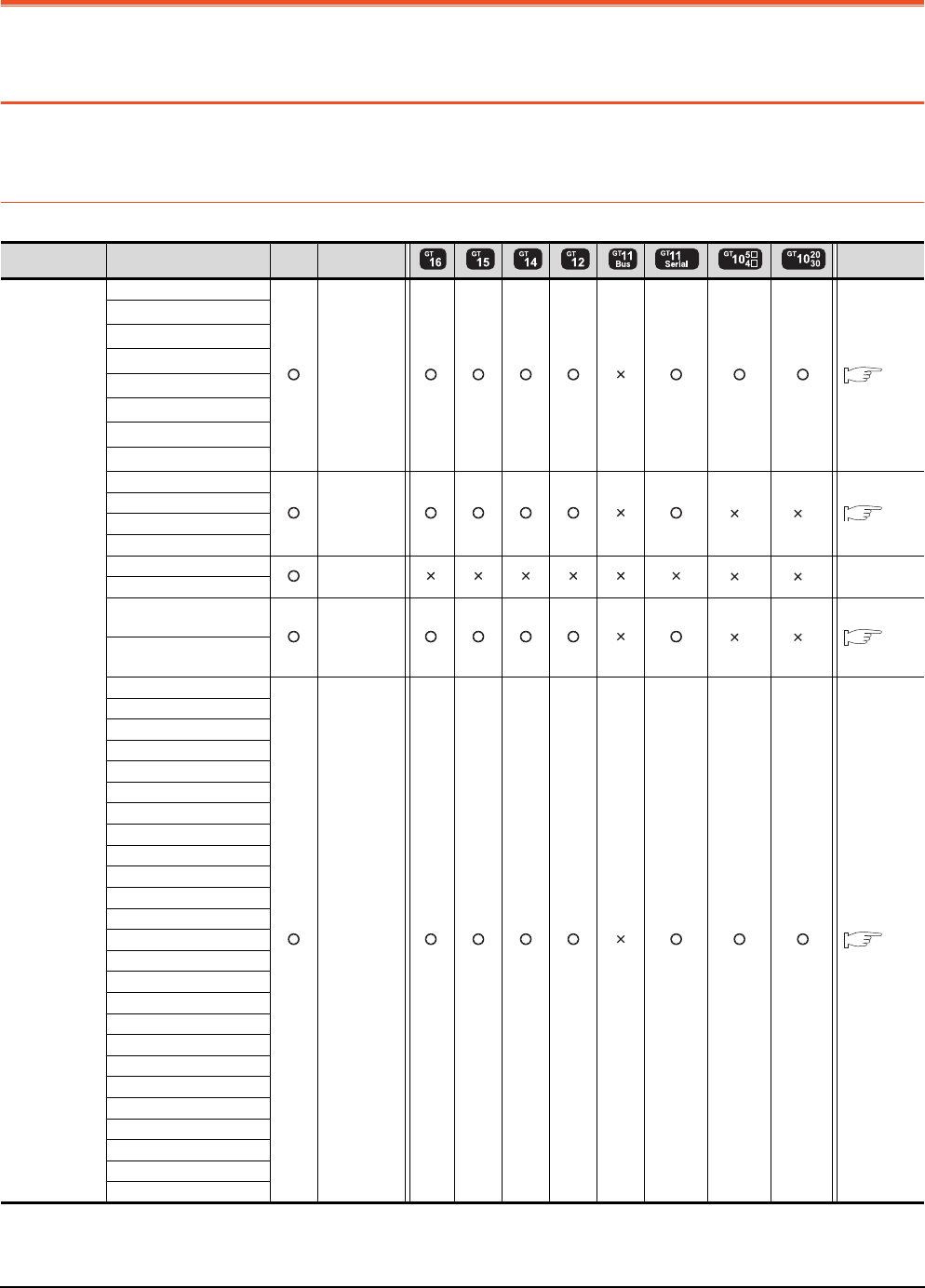
7 - 2 7. COMPUTER LINK CONNECTION
7.1 Connectable Model List
7. COMPUTER LINK CONNECTION
7.1 Connectable Model List
The following table shows the connectable models.
7.1.1 PLC/Motion controller CPU
(Continued to next page)
*1 When in multiple CPU system configuration, use CPU function version B or later.
*2 For GT10, do not include in the multiple CPU system configuration.
Series Model name Clock
Communication
Refer to
MELSEC-Q
(Q mode)
Q00JCPU
RS-232
RS-422 7.2.1
Q00CPU*1
Q01CPU*1
Q02CPU*1
Q02HCPU*1
Q06HCPU*1
Q12HCPU*1
Q25HCPU*1
Q02PHCPU
RS-232
RS-422
*2 *2 7.2.1
Q06PHCPU
Q12PHCPU
Q25PHCPU
Q12PRHCPU (Main base)
-*2 *2 -
Q25PRHCPU (Main base)
Q12PRHCPU
(Extension base) RS-232
RS-422
*2 *2 7.2.1
Q25PRHCPU
(Extension base)
Q00UJCPU
RS-232
RS-422 7.2.1
Q00UCPU
Q01UCPU
Q02UCPU
Q03UDCPU
Q04UDHCPU
Q06UDHCPU
Q10UDHCPU
Q13UDHCPU
Q20UDHCPU
Q26UDHCPU
Q03UDECPU
Q04UDEHCPU
Q06UDEHCPU
Q10UDEHCPU
Q13UDEHCPU
Q20UDEHCPU
Q26UDEHCPU
Q50UDEHCPU
Q100UDEHCPU
Q03UDVCPU
Q04UDVCPU
Q06UDVCPU
Q13UDVCPU
Q26UDVCPU
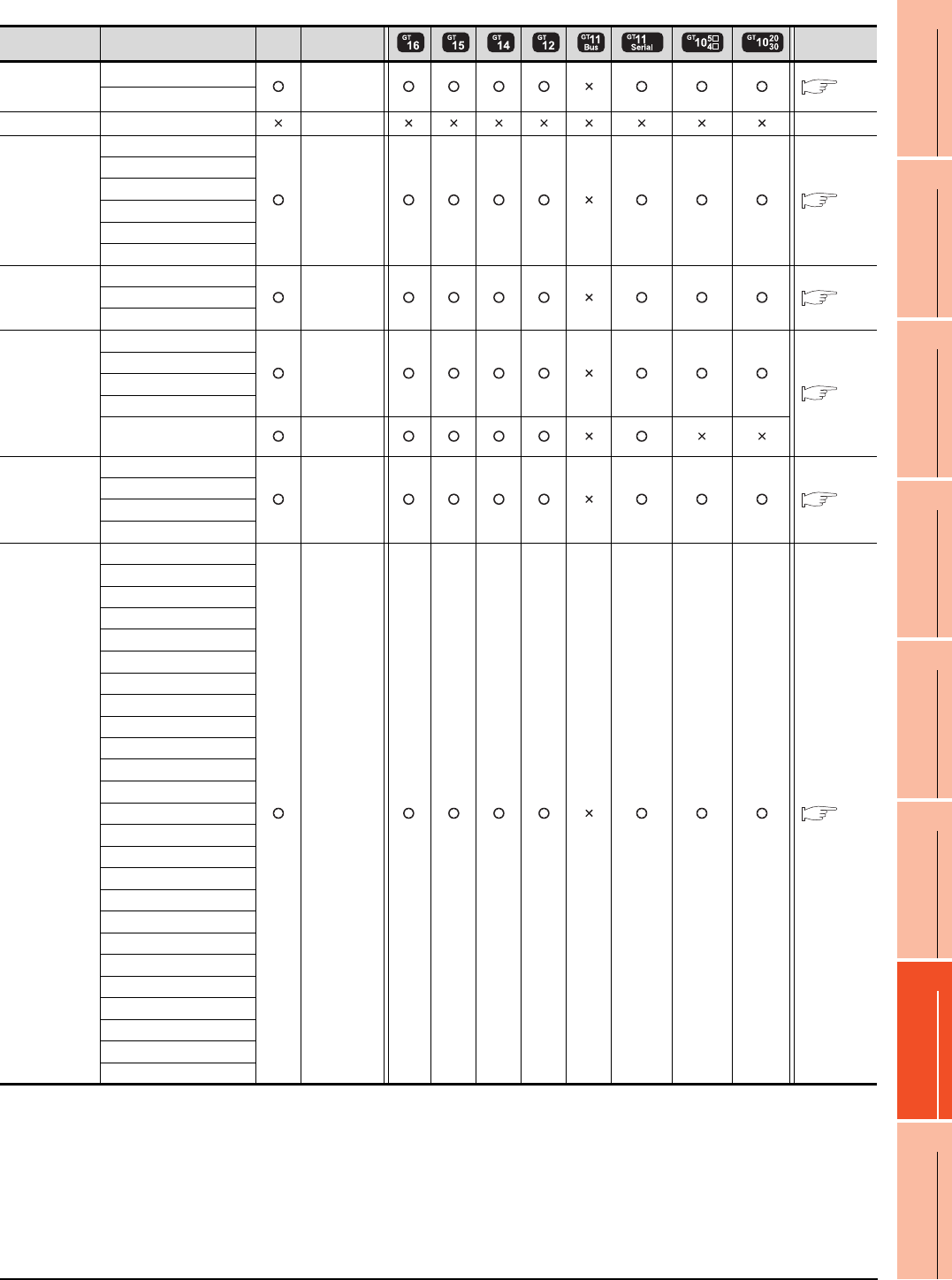
7. COMPUTER LINK CONNECTION
7.1 Connectable Model List
7 - 3
1
PREPARATORY
PROCEDURES FOR
MONITORING
2
DEVICE RANGE
THAT CAN BE SET
3
ACCESS RANGE
FOR MONITORING
4
HOW TO MONITOR
REDUNTANT
SYSTEM
5
BUS CONNECTION
6
DIRECT
CONNECTION TO
CPU
7
COMPUTER LINK
CONNECTION
8
ETHERNET
CONNECTION
(Continued to next page)
*1 Use only modules with the upper five digits of the serial No. later than 12042.
*2 Use the serial port of a serial communication module controlled by another CPU on the multiple CPU.
*3 If the A series computer link module is applied to the QnACPU, the GOT can monitor the devices in the same range on AnACPU.
However, the following devices cannot be monitored.
• Devices added to QnACPU
• Latch relays (L) and step relays (S)
(In case of QnACPU, the latch relay (L) and step relay (S) are different from the internal relay. However, whichever is specified,
an access is made to the internal relay.)
• File register (R)
Series Model name Clock
Communication
Refer to
C Controller
module
Q12DCCPU-V*1*2 RS-232
RS-422 7.2.1
Q24DHCCPU-V*2
MELSEC-QS QS001CPU - -
MELSEC-L
L02CPU
RS-232
RS-422 7.2.2
L26CPU
L26CPU-BT
L02CPU-P
L26CPU-PBT
L02SCPU
MELSEC-Q
(A mode)
Q02CPU-A
RS-232
RS-422 7.2.3
Q02HCPU-A
Q06HCPU-A
MELSEC-QnA
(QnACPU)
*3
Q2ACPU
RS-232
RS-422
7.2.4
Q2ACPU-S1
Q3ACPU
Q4ACPU
Q4ARCPU RS-232
RS-422
MELSEC-QnA
(QnASCPU)
*3
Q2ASCPU
RS-232
RS-422 7.2.5
Q2ASCPU-S1
Q2ASHCPU
Q2ASHCPU-S1
MELSEC-A
(AnCPU)
A2UCPU
RS-232
RS-422 7.2.6
A2UCPU-S1
A3UCPU
A4UCPU
A2ACPU
A2ACPUP21
A2ACPUR21
A2ACPU-S1
A2ACPUP21-S1
A2ACPUR21-S1
A3ACPU
A3ACPUP21
A3ACPUR21
A1NCPU
A1NCPUP21
A1NCPUR21
A2NCPU
A2NCPUP21
A2NCPUR21
A2NCPU-S1
A2NCPUP21-S1
A2NCPUR21-S1
A3NCPU
A3NCPUP21
A3NCPUR21

7 - 4 7. COMPUTER LINK CONNECTION
7.1 Connectable Model List
(Continued to next page)
*1 The computer link module version U or later supports the A2SCPU(S1), A2SHCPU(S1), A1SHCPU, A1SJHCPU and A0J2HCPU.
In addition, A0J2-C214-S1 (A0J2HCPU-dedicated computer link module) cannot be used.
*2 When using SV13, SV22, or SV43, use the motion controller CPU on which any of the following main OS version is installed.
• SW6RN-SV13Q : 00H or later
• SW6RN-SV22Q : 00H or later
• SW6RN-SV43Q : 00B or later
*3 Use main modules with the following product numbers.
• Q172CPU: Product number N******* or later
• Q173CPU: Product number M******* or later
*4 Only the first step can be used on the extension base unit (Q52B/Q55B).
Series Model name Clock
Communication
Refer to
MELSEC-A
(AnSCPU)
A2USCPU
RS-232
RS-422 7.2.7
A2USCPU-S1
A2USHCPU-S1
A1SCPU
A1SCPUC24-R2
A1SHCPU*1
A2SCPU*1
A2SCPU-S1*1
A2SHCPU*1
A2SHCPU-S1*1
A1SJCPU
A1SJCPU-S3
A1SJHCPU*1
MELSEC-A
A0J2HCPU*1
RS-232
RS-422 7.2.7
A0J2HCPUP21*1
A0J2HCPUR21*1
A0J2HCPU-DC24*1
A2CCPU
- -A2CCPUP21
A2CCPUR21
A2CCPUC24 RS-232
RS-422 7.2.7
A2CCPUC24-PRF
A2CJCPU-S3 - -
A1FXCPU
Motion
controller CPU
(Q Series)
Q172CPU*2*3
RS-232
RS-422 7.2.1
Q173CPU*2*3
Q172CPUN*2
Q173CPUN*2
Q172HCPU
Q173HCPU
Q172DCPU
Q173DCPU
Q172DCPU-S1
Q173DCPU-S1
Q172DSCPU
Q173DSCPU
Q170MCPU*4
MR-MQ100 - -
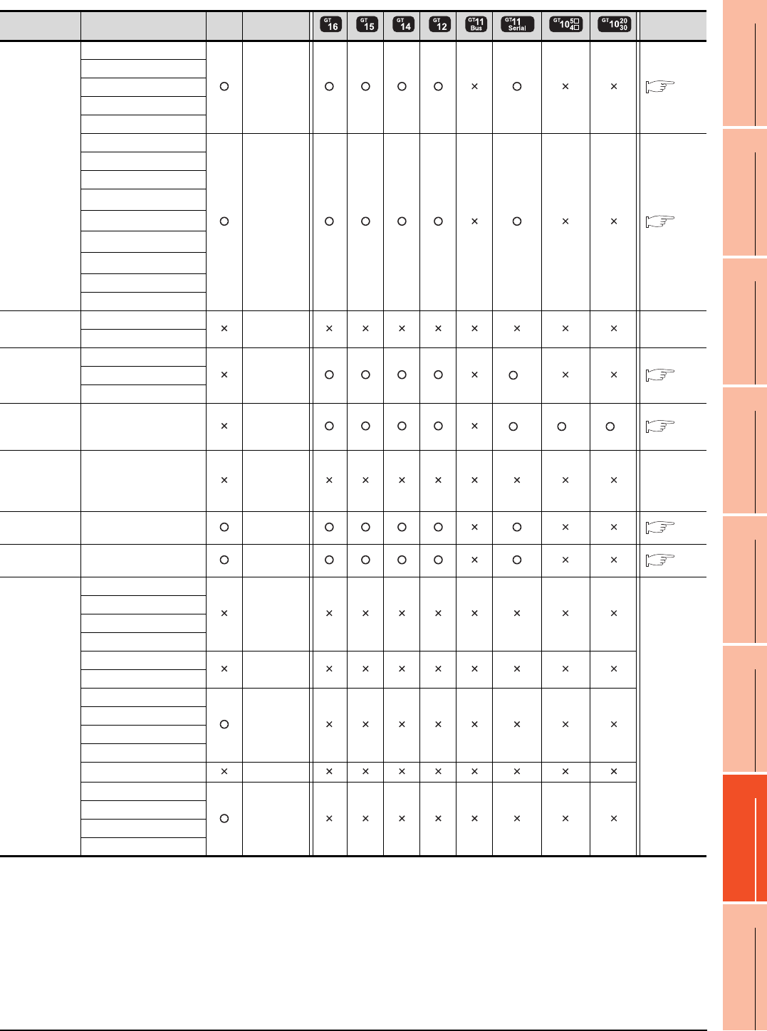
7. COMPUTER LINK CONNECTION
7.1 Connectable Model List
7 - 5
1
PREPARATORY
PROCEDURES FOR
MONITORING
2
DEVICE RANGE
THAT CAN BE SET
3
ACCESS RANGE
FOR MONITORING
4
HOW TO MONITOR
REDUNTANT
SYSTEM
5
BUS CONNECTION
6
DIRECT
CONNECTION TO
CPU
7
COMPUTER LINK
CONNECTION
8
ETHERNET
CONNECTION
*1 GT11 can not access the master station on MELSECNET/H network system. GT11 can access only the connected host station
(remote I/O station).
*2 For computer link connection of A171SHCPU(N) and A172SHCPU(N), use the computer link module whose software version is
version U or later.
*3 GT11,GT10 can not access the master station on CC-Link IE field network system. GT11,GT10 can access only the connected
host station (head module station).
Series Model name Clock
Communication
Refer to
Motion
controller CPU
(A Series)
A273UCPU
RS-232
RS-422 7.2.6
A273UHCPU
A273UHCPU-S3
A373UCPU
A373UCPU-S3
A171SCPU
RS-232
RS-422 7.2.7
A171SCPU-S3
A171SCPU-S3N
A171SHCPU*2
A171SHCPUN*2
A172SHCPU*2
A172SHCPUN*2
A173UHCPU
A173UHCPU-S1
MELSEC-WS
WS0-CPU0
- -
WS0-CPU1
MELSECNET/H
Remote I/O
station
QJ72LP25-25
RS-232
RS-422
*1 7.2.1
QJ72LP25G
QJ72BR15
CC-Link IE
Field Network
head module
LJ72GF15-T2 RS-232
RS-422
*3 *3 *3 7.2.2
CC-Link IE
Field Network
Ethernet
adapter module
NZ2GF-ETB - -
CNC C70 Q173NCCPU RS-232
RS-422 7.2.1
Robot
controller
CRnQ-700
(Q172DRCPU)
RS-232
RS-422 7.2.1
MELSEC-FX
FX0
-
-
FX0S
FX0N
FX1
FX2
-
FX2C
FX1S
-
FX1N
FX2N
FX1NC
FX2NC -
FX3G
-
FX3GC
FX3U
FX3UC

7 - 6 7. COMPUTER LINK CONNECTION
7.1 Connectable Model List
7.1.2 Serial communication module/Computer link module
*1 Communication cannot be performed with RS-485.
A0J2-C214-S1 cannot be used.
*2 Either CH1 or CH2 can be used for the function version A. Both CH1 and CH2 can be used together for the function version B or
later.
*3 Only CH2 can be connected.
*4 Either CH1 or CH2 can be used.
*5 The computer link module version U or later supports the A2SCPU(S1), A2SHCPU(S1), A1SHCPU, A1SJHCPU and A0J2HCPU.
*6 The module operates in the device range on AnACPU.
CPU series Model name*1
MELSEC-Q (Q mode)
Motion controller CPU (Q Series)
MELSECNET/H remote I/O station
CNC C70
Robot controller (CRnQ-700)
QJ71C24*2, QJ71C24-R2*2
QJ71C24N, QJ71C24N-R2, QJ71C24N-R4
QJ71CMO*3, QJ71CMON*3
MELSEC-L LJ71C24, LJ71C24-R2
MELSEC-Q (A mode)
A1SJ71UC24-R2, A1SJ71UC24-R4, A1SJ71UC24-PRF
A1SJ71C24-R2, A1SJ71C24-R4, A1SJ71C24-PRF
MELSEC-QnA (QnACPU)
MELSEC-QnA (QnASCPU)
AJ71QC24*4, AJ71QC24-R2*4, AJ71QC24-R4*4
AJ71QC24N*4, AJ71QC24N-R2*4, AJ71QC24N-R4*4
A1SJ71QC24*4, A1SJ71QC24-R2*4
A1SJ71QC24N*4, A1SJ71QC24N-R2*4
A1SJ71QC24N1*4, A1SJ71QC24N1-R2*4
AJ71UC24*4*6
A1SJ71C24-R2*6, A1SJ71C24-R4*6, A1SJ71C24-PRF*6
A1SJ71UC24-R2*6, A1SJ71UC24-R4*6, A1SJ71C24-PRF*6
MELSEC-A (AnCPU)
MELSEC-A (AnSCPU)
MELSEC-A
Motion controller CPU (A Series)
AJ71UC24*4*5
A1SJ71UC24-R2*5, A1SJ71UC24-R4*5, A1SJ71UC24-PRF*5
A1SJ71C24-R2*5, A1SJ71C24-R4*5, A1SJ71C24-PRF*5
A1SCPUC24-R2*5
A2CCPUC24*4, A2CCPUC24-PRF*4
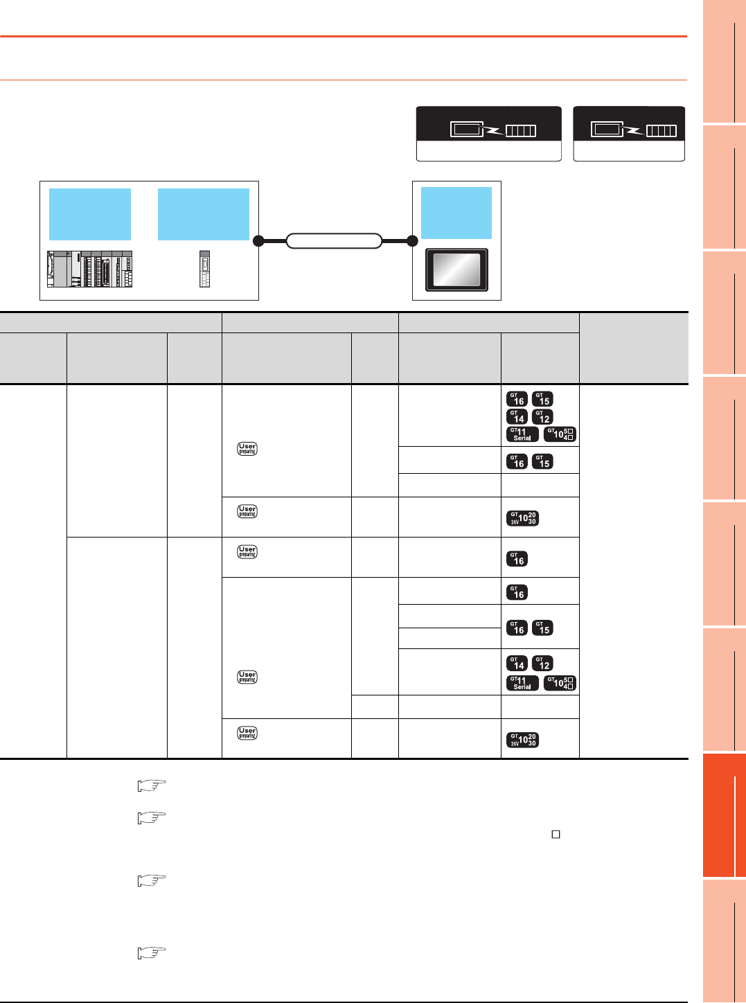
7. COMPUTER LINK CONNECTION
7.2 System Configuration
7 - 7
1
PREPARATORY
PROCEDURES FOR
MONITORING
2
DEVICE RANGE
THAT CAN BE SET
3
ACCESS RANGE
FOR MONITORING
4
HOW TO MONITOR
REDUNTANT
SYSTEM
5
BUS CONNECTION
6
DIRECT
CONNECTION TO
CPU
7
COMPUTER LINK
CONNECTION
8
ETHERNET
CONNECTION
7.2 System Configuration
7.2.1 Connecting to QCPU (Q mode)
*1 For details on the system configuration on the serial communication module side, refer to the following manual.
Q Corresponding Serial Communication Module User’s Manual (Basic)
For details on the system configuration on the modem interface module side, refer to the following manual.
Modem Interface Module User's Manual
*2 Connect it to the RS-232 interface (built into GOT). It cannot be mounted on GT1655 and GT155 .
*3 Two GOTs can be connected with the function version B or later of the serial communication module.
*4 For details of the GOT multi-drop connection, refer to the following.
19. GOT MULTI-DROP CONNECTION
*5 GT14, GT12, GT11 and GT10 are available for the multiple-GT14, GT12, GT11, GT10 connection function to connect up to four
GOTs.
However, when using modem interface modules or serial communication modules (function version A), up to two GOTs can be
connected.
20. MULTIPLE-GT14, GT12, GT11, GT10 CONNECTION FUNCTION
*6 Use the RS-232 connection model.
*7 Use the RS-422 connection model.
Communication driver
( For GT16, GT15, GT14, GT12, GT11)
A/QnA/L/Q CPU,LJ71C24,QJ71C24
Communication driver
QnA/L/Q CPU
( For GT10)
Serial
communication
module
QCPU
(Q mode) GOT
Connection cable
PLC Connection cable GOT
Number of
connectable
equipment*5
Model name
Serial
communication
module*1
Communi
cation
type
Cable model Max.
distance Option device Model
MELSEC-Q
(Q mode)
QJ71C24
QJ71C24N
QJ71C24-R2
QJ71C24N-R2
QJ71CMO
QJ71CMON
RS-232
GT09-C30R2-9P(3m)
or
RS232 connection
diagram 1)
15m
- (Built into GOT)
2 GOTs for 1 serial
communication
module*3
1 GOT for 1 modem
interface module
GT15-RS2-9P
GT01-RS4-M*4 -
RS232 connection
diagram 3)
15m - (Built into GOT) *6
QJ71C24
QJ71C24N
QJ71C24N-R4
RS-422
RS422 connection
diagram 2)
1200m - (Built into GOT)
GT09-C30R4-6C(3m)
GT09-C100R4-6C(10m)
GT09-C200R4-6C(20m)
GT09-C300R4-6C(30m)
or
RS422 connection
diagram 1)
1200m
GT16-C02R4-9S
GT15-RS2T4-9P*2
GT15-RS4-9S
- (Built into GOT)
500m GT01-RS4-M*4 -
RS422 connection
diagram 3)
1200m - (Built into GOT) *7
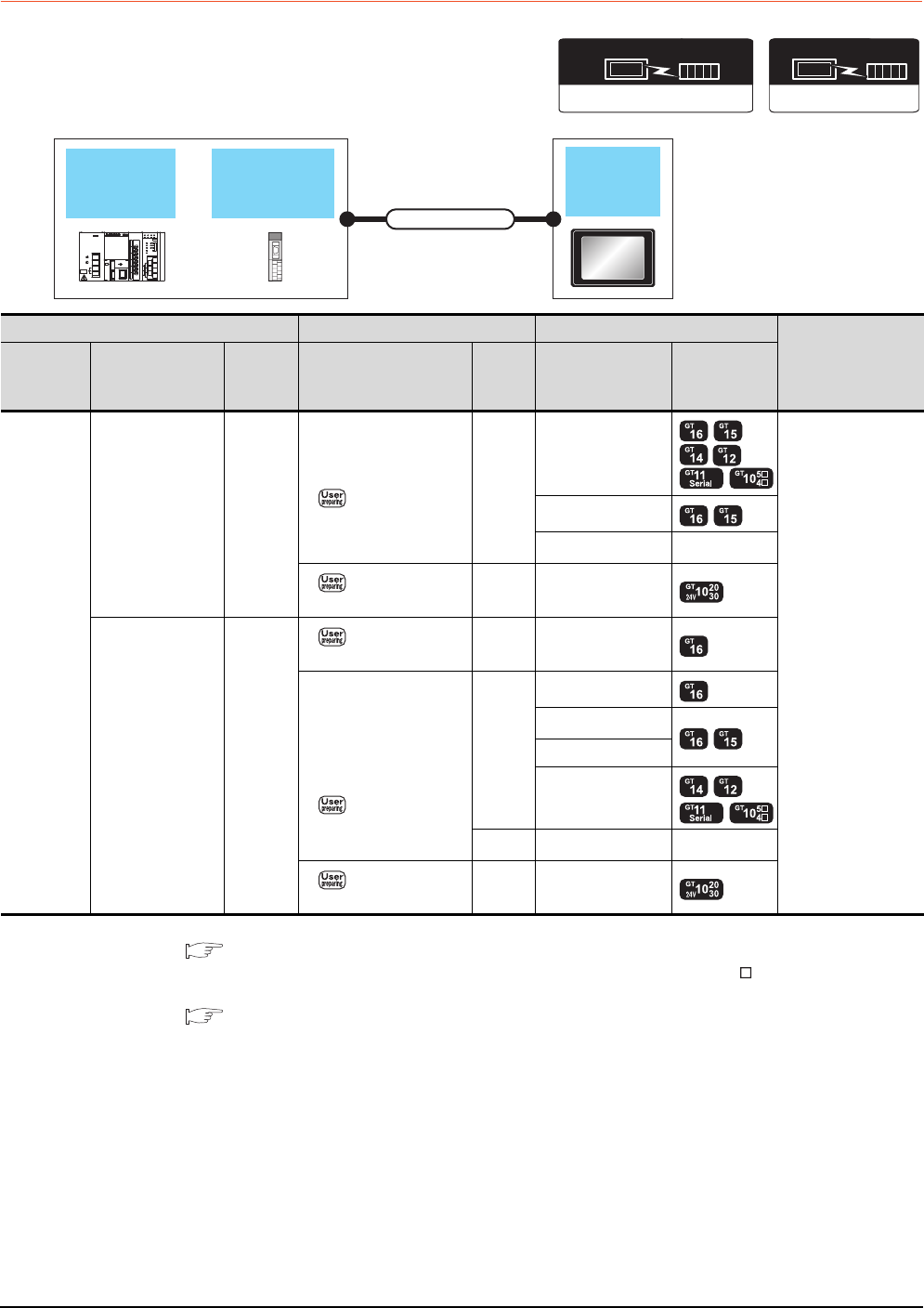
7 - 8 7. COMPUTER LINK CONNECTION
7.2 System Configuration
7.2.2 Connecting to LCPU
*1 For details on the system configuration on the serial communication module side, refer to the following manual.
MELSEC-L Serial Communication Module User's Manual (Basic)
*2 Connect it to the RS-232 interface (built into GOT). It cannot be mounted on GT1655 and GT155 .
*3 For details of the GOT multi-drop connection, refer to the following.
19. GOT MULTI-DROP CONNECTION
*4 Use the RS-232 connection model.
*5 Use the RS-422 connection model.
Communication driver
( For GT16, GT15, GT14, GT12, GT11)
A/QnA/L/Q CPU,LJ71C24,QJ71C24
Communication driver
QnA/L/Q CPU
( For GT10)
Serial
communication
module
LCPU GOT
Connection cable
PLC Connection cable GOT
Number of
connectable
equipment
Model name
Serial
communication
module*1
Communi
cation
type
Cable model Max.
distance Option device Model
MELSEC-L
LJ71C24
LJ71C24-R2 RS-232
GT09-C30R2-9P(3m)
or
RS232 connection
diagram 1)
15m
- (Built into GOT)
2 GOTs for 1 serial
communication
module
GT15-RS2-9P
GT01-RS4-M*3 -
RS232 connection
diagram 3)
15m - (Built into GOT) *4
LJ71C24 RS-422
RS422 connection
diagram 2)
1200m - (Built into GOT)
GT09-C30R4-6C(3m)
GT09-C100R4-6C(10m)
GT09-C200R4-6C(20m)
GT09-C300R4-6C(30m)
or
RS422 connection
diagram 1)
1200m
GT16-C02R4-9S
GT15-RS2T4-9P*2
GT15-RS4-9S
- (Built into GOT)
500m GT01-RS4-M*3 -
RS422 connection
diagram 3)
1200m - (Built into GOT) *5
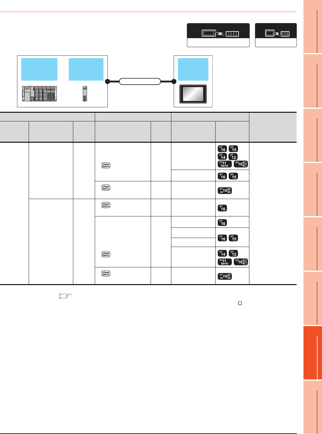
7. COMPUTER LINK CONNECTION
7.2 System Configuration
7 - 9
1
PREPARATORY
PROCEDURES FOR
MONITORING
2
DEVICE RANGE
THAT CAN BE SET
3
ACCESS RANGE
FOR MONITORING
4
HOW TO MONITOR
REDUNTANT
SYSTEM
5
BUS CONNECTION
6
DIRECT
CONNECTION TO
CPU
7
COMPUTER LINK
CONNECTION
8
ETHERNET
CONNECTION
7.2.3 Connecting to QCPU (A mode)
*1 For the system configuration on the computer link module side, refer to the following manual.
Computer Link Module (Com. link func./Print. func.) User’s Manual
*2 Connect it to the RS-232 interface (built into GOT). It cannot be mounted on GT1655 and GT155 .
*3 Use the RS-232 connection model.
*4 Use the RS-422 connection model.
Computer
link module
QCPU
(A mode) GOT
Connection cable
Communication driver
( For GT16, GT15, GT14, GT12, GT11)
A/QnA/L/Q CPU,LJ71C24,QJ71C24
( For GT10)
AJ71C24/UC24
Communication driver
PLC Connection cable GOT
Number of
connectable
equipment
Model name Computer link
module*1
Commun
ication
type
Cable model Max.
distance Option device Model
MELSEC-Q
(A mode)
A1SJ71UC24-R2
A1SJ71C24-R2
A1SJ71UC24-PRF
A1SJ71C24-PRF
RS-232
GT09-C30R2-9P(3m)
or
RS232 connection
diagram 1)
15m
- (Built into GOT)
1 GOT for 1 computer
link module
GT15-RS2-9P
RS232 connection
diagram 3)
15m - (Built into GOT) *3
A1SJ71UC24-R4
A1SJ71C24-R4 RS-422
RS422 connection
diagram 2)
500m - (Built into GOT)
GT09-C30R4-6C(3m)
GT09-C100R4-6C(10m)
GT09-C200R4-6C(20m)
GT09-C300R4-6C(30m)
or
RS422 connection
diagram 1)
500m
GT16-C02R4-9S
GT15-RS2T4-9P*2
GT15-RS4-9S
- (Built into GOT)
RS422 connection
diagram 3)
500m - (Built into GOT) *4
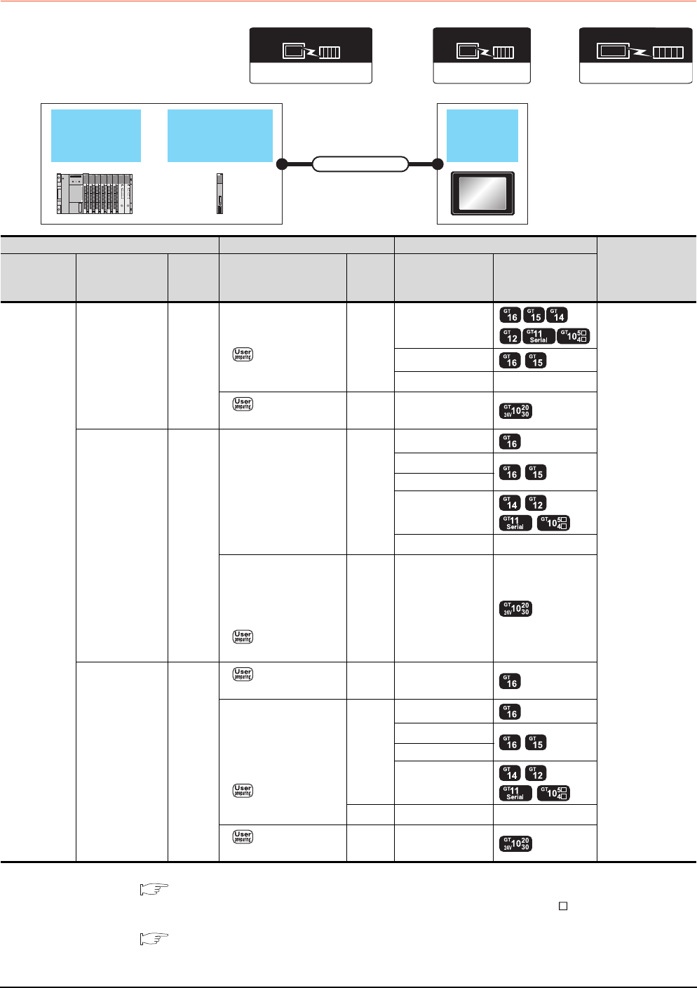
7 - 10 7. COMPUTER LINK CONNECTION
7.2 System Configuration
7.2.4 Connecting to QnACPU (QnACPU type)
*1 For details on the system configuration on the serial communication module side, refer to the following manual.
Serial Communications Module User’s Manual (Modem Function Additional Version)
*2 Connect it to the RS-232 interface (built into GOT). It cannot be mounted on GT1655 and GT155 .
*3 For details of the GOT multi-drop connection, refer to the following.
19. GOT MULTI-DROP CONNECTION
*4 Use the RS-232 connection model.
*5 Use the RS-422 connection model.
Communication driver
AJ71QC24,MELDAS C6*
(GT16, GT15, GT14, GT12, GT11)
Serial communication
module
/Computer link module
QnACPU
(QnACPU type) GOT
Connection cable
AJ71C24/UC24
Communication driver
(When connecting to a computer link module)
Communication driver
QnA/L/Q CPU
( For GT10)
PLC Connection cable GOT
Number of
connectable
equipment
Model name
Serial
communication
module*1
Commun
ication
type
Cable model Max.
distance Option device Model
MELSEC-QnA
(QnACPU)
AJ71QC24
AJ71QC24N
AJ71QC24-R2
AJ71QC24N-R2
RS-232
GT09-C30R2-25P(3m)
or
RS232 connection
diagram 2)
15m
- (Built into GOT)
1 GOT for 1 serial
communication
module
GT15-RS2-9P
GT01-RS4-M*3 -
RS232 connection
diagram 4)
15m - (Built into GOT) *4
AJ71QC24-R4
AJ71QC24N-R4 RS-422
GT01-C30R4-25P(3m)
GT01-C100R4-25P(10m)
GT01-C200R4-25P(20m)
GT01-C300R4-25P(30m)
30m
GT16-C02R4-9S
GT15-RS2T4-9P*2
GT15-RS4-9S
- (Built into GOT)
GT01-RS4-M*3 -
GT10-C30R4-25P(3m)
GT10-C100R4-25P(10m)
GT10-C200R4-25P(20m)
GT10-C300R4-25P(30m)
or
RS422 connection
diagram 4)
30m - (Built into GOT) *5
AJ71QC24
AJ71QC24N
AJ71QC24-R4
AJ71QC24N-R4
RS-422
RS422 connection
diagram 2)
1200m - (Built into GOT)
GT09-C30R4-6C(3m)
GT09-C100R4-6C(10m)
GT09-C200R4-6C(20m)
GT09-C300R4-6C(30m)
or
RS422 connection
diagram 1)
1200m
GT16-C02R4-9S
GT15-RS2T4-9P*2
GT15-RS4-9S
- (Built into GOT)
500m GT01-RS4-M*3 -
RS422 connection
diagram 3)
1200m - (Built into GOT) *5
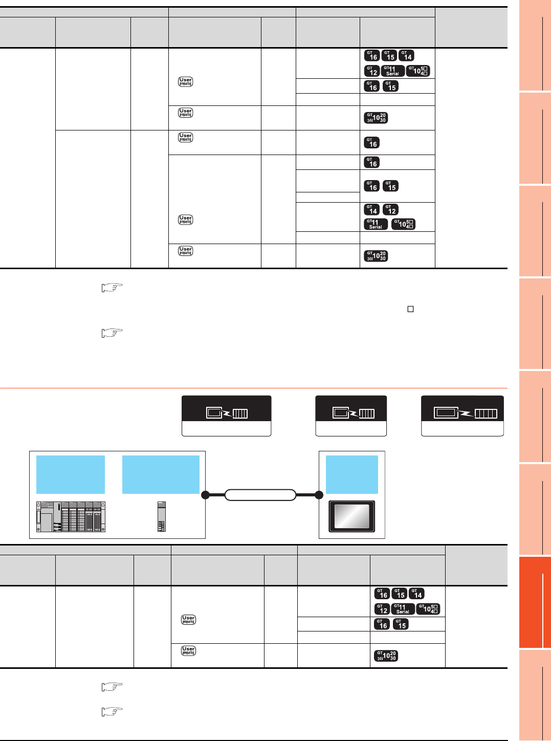
7. COMPUTER LINK CONNECTION
7.2 System Configuration
7 - 11
1
PREPARATORY
PROCEDURES FOR
MONITORING
2
DEVICE RANGE
THAT CAN BE SET
3
ACCESS RANGE
FOR MONITORING
4
HOW TO MONITOR
REDUNTANT
SYSTEM
5
BUS CONNECTION
6
DIRECT
CONNECTION TO
CPU
7
COMPUTER LINK
CONNECTION
8
ETHERNET
CONNECTION
*1 For the system configuration on the computer link module side, refer to the following manual.
Computer Link Module (Com. link func./Print. func.) User’s Manual
When connecting to a computer link module, set the communication driver to [AJ71C24/UC24].
*2 Connect it to the RS-232 interface (built into GOT). It cannot be mounted on GT1655 and GT155 .
*3 For details of the GOT multi-drop connection, refer to the following.
19. GOT MULTI-DROP CONNECTION
*4 Use the RS-232 connection model.
*5 Use the RS-422 connection model.
7.2.5 Connecting to QnACPU (QnASCPU type)
*1 For details on the system configuration on the serial communication module side, refer to the following manual.
Serial Communication Module User's Manual (Modem Function Additional Version)
*2 For details of the GOT multi-drop connection, refer to the following.
19. GOT MULTI-DROP CONNECTION
*3 Use the RS-232 connection model.
PLC Connection cable GOT Number of
connectable
equipment
Model name Computer link
module*1
Commun
ication
type
Cable model Max.
distance Option device Model
MELSEC-QnA
(QnACPU)
AJ71UC24 RS-232
GT09-C30R2-25P(3m)
or
RS232 connection
diagram 2)
15m
- (Built into GOT)
1 GOT for 1
computer link
module
GT15-RS2-9P
GT01-RS4-M*3 -
RS232 connection
diagram 4)
15m - (Built into GOT) *4
AJ71UC24 RS-422
RS422 connection
diagram 2)
500m - (Built into GOT)
GT09-C30R4-6C(3m)
GT09-C100R4-6C(10m)
GT09-C200R4-6C(20m)
GT09-C300R4-6C(30m)
or
RS422 connection
diagram 1)
500m
GT16-C02R4-9S
GT15-RS2T4-
9P*2
GT15-RS4-9S
- (Built into GOT)
GT01-RS4-M*3 -
RS422 connection
diagram 3)
500m - (Built into GOT) *5
Communication driver
AJ71QC24,MELDAS C6*
(GT16, GT15, GT14, GT12, GT11)
Serial communication
module
/Computer link module
QnACPU
(QnACPU type) GOT
Connection cable
AJ71C24/UC24
Communication driver
(When connecting to a computer link module)
Communication driver
QnA/L/Q CPU
( For GT10)
PLC Connection cable GOT Number of
connectable
equipment
Model name Serial communication
module*1
Commun
ication
type
Cable model
Max.
distance
Option device Model
MELSEC-QnA
(QnACPU)
A1SJ71QC24
A1SJ71QC24N
A1SJ71QC24N1
A1SJ71QC24-R2
A1SJ71QC24N-R2
A1SJ71QC24N1-R2
RS-232
GT09-C30R2-9P(3m)
or
RS232 connection
diagram 1)
15m
- (Built into GOT)
1 GOT for 1
serial
communication
module
GT15-RS2-9P
GT01-RS4-M*2 -
RS232 connection
diagram 3)
15m - (Built into GOT) *3
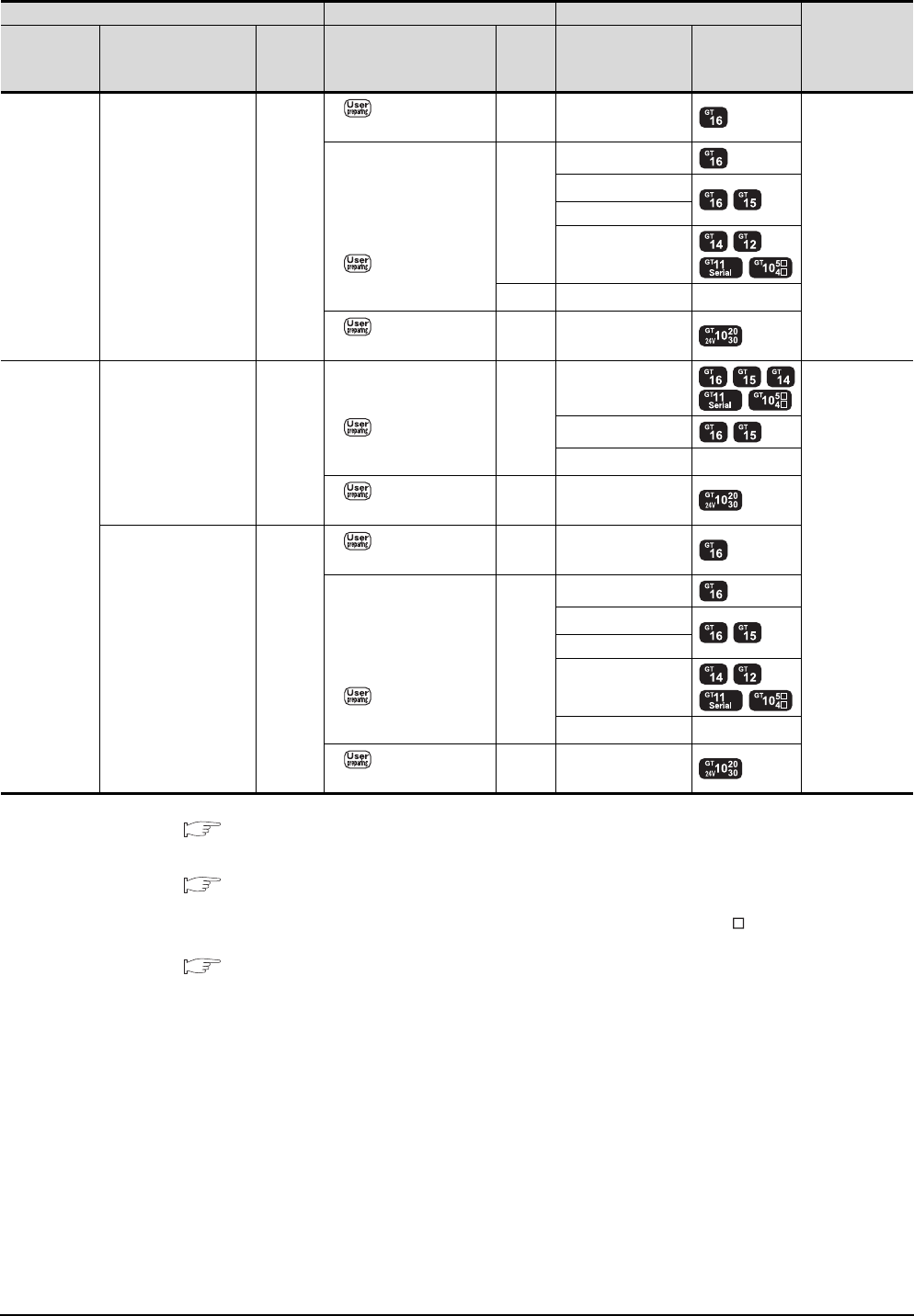
7 - 12 7. COMPUTER LINK CONNECTION
7.2 System Configuration
*1 For details on the system configuration on the serial communication module side, refer to the following manual.
Serial Communication Module User's Manual (Modem Function Additional Version)
For the system configuration on the computer link module side, refer to the following manual.
Computer Link Module (Com. link func./Print. func.) User’s Manual
When connecting to a computer link module, set the communication driver to [AJ71C24/UC24].
*2 Connect it to the RS-232 interface (built into GOT). It cannot be mounted on GT1655 and GT155 .
*3 For details of the GOT multi-drop connection, refer to the following.
19. GOT MULTI-DROP CONNECTION
*4 Use the RS-232 connection model.
*5 Use the RS-422 connection model.
PLC Connection cable GOT
Number of
connectable
equipment
Model name
Serial communication
module
/Computer link module*1
Commun
ication
type
Cable model
Max.
distance
Option device Model
MELSEC-QnA
(QnACPU)
A1SJ71QC24
A1SJ71QC24N
A1SJ71QC24N1
RS-422
RS422 connection
diagram 2)
1200m - (Built into GOT)
1 GOT for 1
serial
communication
module
GT09-C30R4-6C(3m)
GT09-C100R4-6C(10m)
GT09-C200R4-6C(20m)
GT09-C300R4-6C(30m)
or
RS422 connection
diagram 1)
1200m
GT16-C02R4-9S
GT15-RS2T4-9P*2
GT15-RS4-9S
- (Built into GOT)
500m GT01-RS4-M*3 -
RS422 connection
diagram 3)
1200m - (Built into GOT) *5
MELSEC-QnA
(QnACPU)
A1SJ71UC24-R2
A1SJ71C24-R2
A1SJ71UC24-PRF
A1SJ71C24-PRF
RS-232
GT09-C30R2-9P(3m)
or
RS232 connection
diagram 1)
15m
- (Built into GOT)
1 GOT for 1
computer link
module
GT15-RS2-9P
GT01-RS4-M*3 -
RS232 connection
diagram 3)
15m - (Built into GOT) *4
A1SJ71UC24-R4
A1SJ71C24-R4 RS-422
RS422 connection
diagram 2)
500m - (Built into GOT)
GT09-C30R4-6C(3m)
GT09-C100R4-6C(10m)
GT09-C200R4-6C(20m)
GT09-C300R4-6C(30m)
or
RS422 connection
diagram 1)
500m
GT16-C02R4-9S
GT15-RS2T4-9P*2
GT15-RS4-9S
- (Built into GOT)
GT01-RS4-M*3 -
RS422 connection
diagram 3)
500m - (Built into GOT) *5
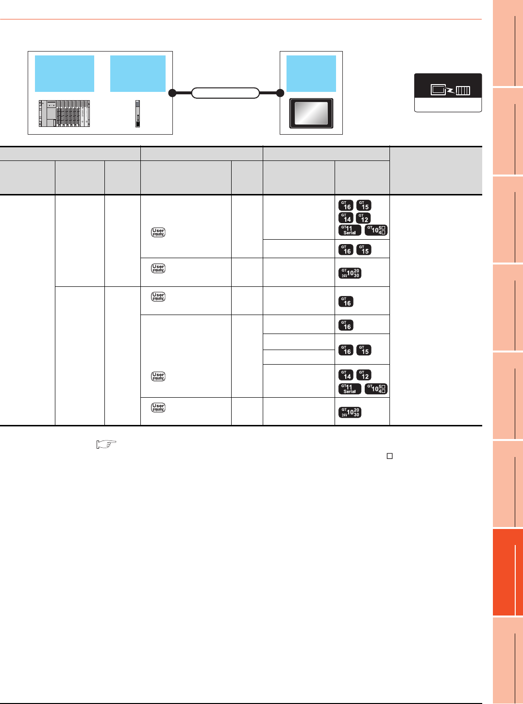
7. COMPUTER LINK CONNECTION
7.2 System Configuration
7 - 13
1
PREPARATORY
PROCEDURES FOR
MONITORING
2
DEVICE RANGE
THAT CAN BE SET
3
ACCESS RANGE
FOR MONITORING
4
HOW TO MONITOR
REDUNTANT
SYSTEM
5
BUS CONNECTION
6
DIRECT
CONNECTION TO
CPU
7
COMPUTER LINK
CONNECTION
8
ETHERNET
CONNECTION
7.2.6 Connecting to ACPU (AnCPU type)
*1 For the system configuration on the computer link module side, refer to the following manual.
Computer Link Module (Com. link func./Print. func.) User’s Manual
*2 Connect it to the RS-232 interface (built into GOT). It cannot be mounted on GT1655 and GT155 .
*3 Use the RS-232 connection model.
*4 Use the RS-422 connection model.
Computer
link module
ACPU
(AnCPU type) GOT
Connection cable
AJ71C24/UC24
Communication driver
PLC Connection cable GOT
Number of connectable
equipment
Model name
Computer link
module
*1
Commun
ication
type
Cable model
Max.
distance
Option device Model
MELSEC-A
(AnCPU)
AJ71UC24 RS-232
GT09-C30R2-25P(3m)
or
RS232 connection
diagram 2)
15m
- (Built into GOT)
1 GOT for 1 computer link
module
GT15-RS2-9P
RS232 connection
diagram 4)
15m - (Built into GOT) *3
AJ71UC24 RS-422
RS422 connection
diagram 2)
500m - (Built into GOT)
GT09-C30R4-6C(3m)
GT09-C100R4-6C(10m)
GT09-C200R4-6C(20m)
GT09-C300R4-6C(30m)
or
RS422 connection
diagram 1)
500m
GT16-C02R4-9S
GT15-RS2T4-9P*2
GT15-RS4-9S
- (Built into GOT)
RS422 connection
diagram 3)
500m - (Built into GOT) *4
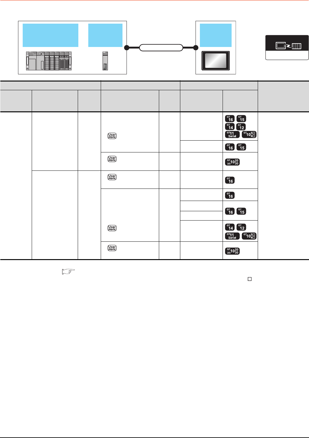
7 - 14 7. COMPUTER LINK CONNECTION
7.2 System Configuration
7.2.7 Connecting to ACPU (AnSCPU type, A0J2HCPU, A2CCPUC)
*1 For the system configuration on the computer link module side, refer to the following manual.
Computer Link Module (Com. link func./Print. func.) User’s Manual
*2 Connect it to the RS-232 interface (built into GOT). It cannot be mounted on GT1655 and GT155 .
*3 Use the RS-232 connection model.
*4 Use the RS-422 connection model.
Computer link
module
ACPU
(AnSPU type)
(A0J2HCPU,A2CCPUC)
GOT
Connection cable
AJ71C24/UC24
Communication driver
PLC Connection cable GOT
Number of connectable
equipment
Model name
Computer link
module
*1
Commun
ication
type
Cable model
Max.
distance
Option device Model
MELSEC-A
(AnSCPU)
(A0J2H)
(A2CCPUC)
A1SJ71UC24-R2
A1SJ71C24-R2
A1SJ71UC24-PRF
A1SJ71C24-PRF
A1SCPUC24-R2
A2CCPUC24
A2CCPUC24-PRF
RS-232
GT09-C30R2-9P(3m)
or
RS232 connection
diagram 1)
15m
- (Built into GOT)
1 GOT for 1 computer
link module
GT15-RS2-9P
RS232 connection
diagram 3)
15m - (Built into GOT) *3
A1SJ71UC24-R4
A1SJ71C24-R4 RS-422
RS422 connection
diagram 2)
500m - (Built into GOT)
GT09-C30R4-6C(3m)
GT09-C100R4-6C(10m)
GT09-C200R4-6C(20m)
GT09-C300R4-6C(30m)
or
RS422 connection
diagram 1)
500m
GT16-C02R4-9S
GT15-RS2T4-9P*2
GT15-RS4-9S
- (Built into GOT)
RS422 connection
diagram 3)
500m - (Built into GOT) *4
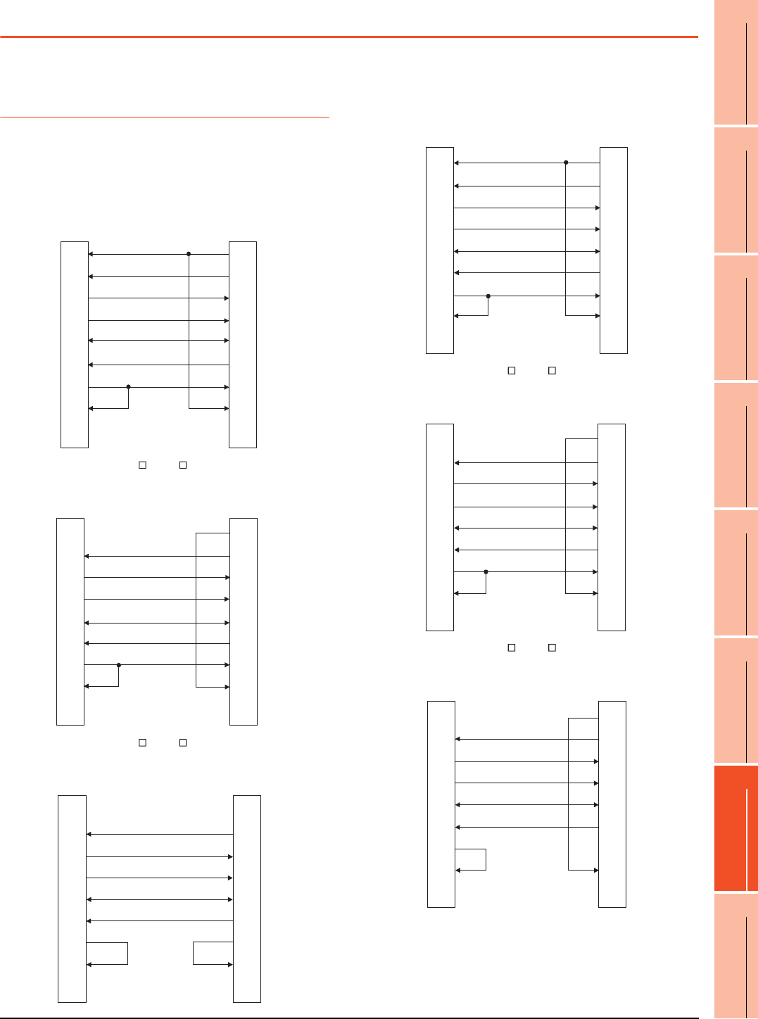
7. COMPUTER LINK CONNECTION
7.3 Connection Diagram
7 - 15
1
PREPARATORY
PROCEDURES FOR
MONITORING
2
DEVICE RANGE
THAT CAN BE SET
3
ACCESS RANGE
FOR MONITORING
4
HOW TO MONITOR
REDUNTANT
SYSTEM
5
BUS CONNECTION
6
DIRECT
CONNECTION TO
CPU
7
COMPUTER LINK
CONNECTION
8
ETHERNET
CONNECTION
7.3 Connection Diagram
The following diagram shows the connection between the
GOT and the PLC.
7.3.1 RS-232 cable
Connection diagram
RS232 connection diagram 1)
PLC side connector D-sub 9-pin
For GT16, GT15
For the GT14, GT12, GT11, GT105 , GT104 , Serial Multi-Drop Unit
(When connecting to the Q/QnA/L Serial Communication Module)
For the GT14, GT12, GT11, GT105 , GT104
(When connecting to the Computer Link Module)
GOT side
(D-Sub 9-pin)
1
2
3
4
5
6
7
8
9
PLC side
7
3
2
6
5
4
1
8
9
CD
RD(RXD)
SD(TXD)
ER(DTR)
SG
DR(DSR)
RS(RTS)
CS(CTS)
-
RS(RTS)
SD(TXD)
RD(RXD)
DR(DSR)
SG
ER(DTR)
CD
CS(CTS)
-
GOT side
(D-Sub 9-pin)
1
2
3
4
5
6
7
8
9
PLC side
7
3
2
6
5
4
1
8
9
NC
RD(RXD)
SD(TXD)
ER(DTR)
SG
DR(DSR)
RS(RTS)
CS(CTS)
-
RS(RTS)
SD(TXD)
RD(RXD)
DR(DSR)
SG
ER(DTR)
CD
CS(CTS)
-
GOT side
(D-Sub 9-pin)
1
2
3
4
5
6
7
8
9
PLC side
1
3
2
6
5
4
7
8
9
NC
RD(RXD)
SD(TXD)
ER(DTR)
SG
DR(DSR)
RS(RTS)
CS(CTS)
-
CD
SD(TXD)
RD(RXD)
DR(DSR)
SG
ER(DTR)
RS(RTS)
CS(CTS)
-
RS232 connection diagram 2)
PLC side connector D-sub 25-pin
For GT16, GT15
For the GT14, GT12, GT11, GT105 , GT104 , Serial Multi-Drop Unit
(When connecting to the Q/QnA Serial Communication Module)
For the GT14, GT12, GT11, GT105 , GT104
(When connecting to the Computer Link Module)
GOT side
(D-Sub 9-pin) PLC side
1
2
3
4
5
6
7
8
9
4
2
3
6
7
20
8
5
1
CD
RD(RXD)
SD(TXD)
ER(DTR)
SG
DR(DSR)
RS(RTS)
CS(CTS)
-
RS(RTS)
SD(TXD)
RD(RXD)
DR(DSR)
SG
ER(DTR)
CD
CS(CTS)
FG
GOT side
(D-Sub 9-pin)
1
2
3
4
5
6
7
8
9
PLC side
4
2
3
6
7
20
8
5
1
NC
RD(RXD)
SD(TXD)
ER(DTR)
SG
DR(DSR)
RS(RTS)
CS(CTS)
-
RS(RTS)
SD(TXD)
RD(RXD)
DR(DSR)
SG
ER(DTR)
CD
CS(CTS)
FG
GOT side
(D-Sub 9-pin)
1
2
3
4
5
6
7
8
9
PLC side
4
2
3
6
7
20
8
5
1
NC
RD(RXD)
SD(TXD)
ER(DTR)
SG
DR(DSR)
RS(RTS)
CS(CTS)
-
RS(RTS)
SD(TXD)
RD(RXD)
DR(DSR)
SG
ER(DTR)
CD
CS(CTS)
FG
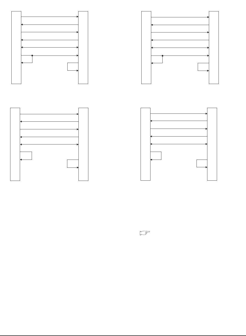
7 - 16 7. COMPUTER LINK CONNECTION
7.3 Connection Diagram
Precautions when preparing a cable
(1) Cable length
The length of the RS-232 cable must be 15m or less.
(2) GOT side connector
For the GOT side connector, refer to the following.
1.4.1 GOT connector specifications
RS232 connection diagram 3)
PLC side connector D-sub 9-pin
For GT1030, GT1020
(When connecting to the Q/QnA/L Serial Communication Module)
For GT1030, GT1020
(When connecting to the Computer Link Module)
GOT side
(terminal block) PLC side
2
3
6
4
5
1
7
8
9
SD
RD
ER
DR
SG
RS
CS
NC
NC
RD(RXD)
SD(TXD)
DR(DSR)
ER(DTR)
SG
CD
RS(RTS)
CS(CTS)
-
GOT side
(terminal block) PLC side
2
3
6
4
5
1
7
8
9
RD(RXD)
SD(TXD)
DR(DSR)
ER(DTR)
SG
CD
RS(RTS)
CS(CTS)
-
SD
RD
ER
DR
SG
RS
CS
NC
NC
RS232 connection diagram 4)
PLC side connector D-sub 25-pin
For GT1030, GT1020
(When connecting to the Q/QnA Serial Communication Module)
For GT1030, GT1020
(When connecting to the Computer Link Module)
GOT side
(terminal block) PLC side
3
2
6
20
7
8
4
5
1
RD(RXD)
SD(TXD)
DR(DSR)
ER(DTR)
SG
CD
RS(RTS)
CS(CTS)
FG
SD
RD
ER
DR
SG
RS
CS
NC
NC
GOT side
(terminal block) PLC side
3
2
6
20
7
8
4
5
1
RD(RXD)
SD(TXD)
DR(DSR)
ER(DTR)
SG
CD
RS(RTS)
CS(CTS)
FG
SD
RD
ER
DR
SG
RS
CS
NC
NC
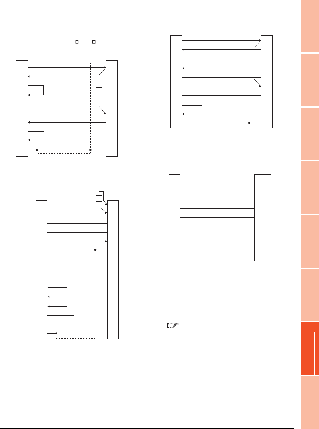
7. COMPUTER LINK CONNECTION
7.3 Connection Diagram
7 - 17
1
PREPARATORY
PROCEDURES FOR
MONITORING
2
DEVICE RANGE
THAT CAN BE SET
3
ACCESS RANGE
FOR MONITORING
4
HOW TO MONITOR
REDUNTANT
SYSTEM
5
BUS CONNECTION
6
DIRECT
CONNECTION TO
CPU
7
COMPUTER LINK
CONNECTION
8
ETHERNET
CONNECTION
7.3.2 RS-422 cable
Connection diagram
Precautions when preparing a cable
(1) Cable length
The length of the RS-422 cable must be 1200m or less.
(2) GOT side connector
For the GOT side connector, refer to the following.
1.4.1 GOT connector specifications
RS422 connection diagram 1)
(For GT16, GT15, GT14, GT12, GT11, GT105 , GT104 ), Serial Multi-Drop Unit
RS422 connection diagram 2)
(For GT16)
GOT side PLC side
1
2
3
4
5
6
7
8
9
-
SDA
RDA
RSA
CSA
SG
SDB
RDB
RSB
CSB
FG
RDA
SDA
-
-
SG
RDB
SDB
-
-
FG
R
GOT side PLC side
1
2
3
4
5
6
7
8
9
10
11
12
13
14
Shell
SDA1(TXD1+)
SDB1(TXD1-)
RDA1(RXD1+)
RDB1(RXD1-)
SDA2(TXD2+)
SDB2(TXD2-)
RDA2(RXD2+)
RDB2(RXD2-)
RSA(RTS+)
RSB(RTS-)
CSA(CTS+)
CSB(CTS-)
SG
NC
RDA
RDB
SDA
SDB
SG
FG
R
RS422 connection diagram 3)
(For GT1030, GT1020)
RS422 connection diagram 4)
(For GT1030, GT1020)
GOT side
(terminal block) PLC side
SDA
RDA
RSA
CSA
SG
SDB
RDB
RSB
CSB
RDA
SDA
-
-
SG
RDB
SDB
-
-
FG
R
GOT side
(terminal block)
Untied wire color of
GT10-C□□□R4-25P
Brown
Red
Orange
Yellow
Green
Blue
Purple
Black
White
SDA
SDB
RDA
RDB
SG
RSA
RSB
CSA
CSB

7 - 18 7. COMPUTER LINK CONNECTION
7.3 Connection Diagram
Connecting terminating resistors
(1) GOT side
When connecting a PLC to the GOT, a terminating
resistor must be connected to the GOT.
(a) For GT16, GT15, GT12
Set the terminating resistor setting switch of the
GOT main unit to "Disable".
(b) For GT14, GT11, GT10
Set the terminating resistor selector to "330 ".
For the procedure to set the terminating resistor, refer
to the following.
1.4.3 Terminating resistors of GOT
(2) Serial communication module or computer link
module side
Connect the terminating resistors (330 1/4W (orange/
orange/brown/ ) ) on the serial communication module
or computer link module side. For details, refer to the
following manual.
User's Manual for the serial communication
module or computer link module
(a) Other than A2CCPUC24(-PRF)
Connect the terminating resistors supplied with the
module across RDA and RDB.
(b) A2CCPUC24(-PRF)
Set TXD and RXD on the terminating resistor
setting pin to "A".
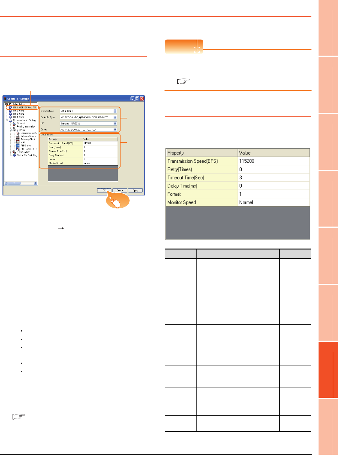
7. COMPUTER LINK CONNECTION
7.4 GOT Side Settings
7 - 19
1
PREPARATORY
PROCEDURES FOR
MONITORING
2
DEVICE RANGE
THAT CAN BE SET
3
ACCESS RANGE
FOR MONITORING
4
HOW TO MONITOR
REDUNTANT
SYSTEM
5
BUS CONNECTION
6
DIRECT
CONNECTION TO
CPU
7
COMPUTER LINK
CONNECTION
8
ETHERNET
CONNECTION
7.4 GOT Side Settings
7.4.1 Setting communication
interface (Communication
settings)
Set the channel of the connected equipment.
1. Select [Common] [Controller Setting] from the
menu.
2. The Controller Setting window is displayed. Select the
channel to be used from the list menu.
3. Set the following items.
• Manufacturer: Mitsubishi
• Controller Type: Set according to the Controller
Type to be connected.
• I/F: Interface to be used
• Driver: Set either of the following according to the
Controller Type to be connected.
For GT16, GT15, GT14, GT12, GT11
A/QnA/L/Q CPU, LJ71C24, QJ71C24
AJ71QC24, MELDAS C6*
AJ71C24/UC24
For GT10
QnA/L/Q CPU
AJ71C24/UC24
4. The detailed setting is displayed after Manufacturer,
Controller Type, I/F, and Driver are set.
Make the settings according to the usage
environment.
7.4.2 Communication detail settings
Click the [OK] button when settings are completed.
POINTPOINTPOINT
The settings of connecting equipment can be
confirmed in [I/F Communication Setting].
For details, refer to the following.
1.1.2 I/F communication setting
7.4.2 Communication detail settings
Make the settings according to the usage environment.
(1) A/QnA/L/Q CPU, LJ71C24, QJ71C24
2.
3.
4.
Click!
Item Description Range
Transmission
Speed
Set this item when change the
transmission speed used for
communication with the connected
equipment.
(Default: 115200bps)
When the setting exceeds the limit of
the connected equipment,
communication is performed at the
fastest transmission speed supported
by the connected equipment.
9600bps,
19200bps,
38400bps,
57600bps,
115200bps
Retry
Set the number of retries to be
performed when a communication
timeout occurs. When receiving no
response after retries, the
communication times out.
(Default: 0time)
0 to 5times
Timeout Time
Set the time period for a communication
to time out.
(Default: 3sec)
3 to 30sec
Delay Time
Set this item to adjust the transmission
timing of the communication request
from the GOT.
(Default: 0ms)
0 to 300 (ms)
Format*3 Select the communication format.
(Default: 1) 1, 2
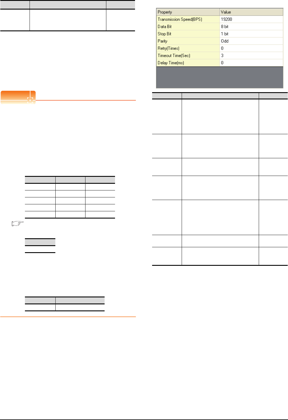
7 - 20 7. COMPUTER LINK CONNECTION
7.4 GOT Side Settings
*1 This is effective when collecting a large data on other than
the monitor screen (logging, recipe function, etc.). However,
when connecting to Q00J/Q00/Q01CPU, the sequence scan
time may be influenced. If you want to avoid the influence on
the sequence scan time, do not set "High".
(High performance is hardly affected)
*2 Set this item if you want to avoid the influence on the
sequence scan time further than the "Normal" setting when
connecting to Q00J/Q00/Q01CPU. However, the monitor
speed may be reduced.
*3 Refer to the following POINT.
POINTPOINTPOINT
Setting [Format]
This setting is required for replacement of F900 series
with GOT1000 series.
(1) To change the communication settings of the
serial communication module which is connected
to F900, set as follows.
The value of Transmission Speed can be set to
115200bps.
(a) [Intelligent function module switch setting] of
PLC
7.5 PLC Side Setting
(b) GOT communication settings
(2) To maintain the communication settings of the
serial communication module which is connected
to F900, set the communication setting of the GOT
as follows.
The value of Transmission Speed remains
38400bps.
(2) AJ71QC24, MELDAS C6*
Monitor Speed
(GT16 only)
Set the monitor speed of the GOT.
This setting is not valid in all systems.
(Default: Normal)
High*1
Normal
Low*2
Switch No. CH1 side CH2 side
Switch 1 0000H-
Switch 2 0000H-
Switch 3 - 0000H
Switch 4 - 0000H
Switch 5 0000H0000H
Format
1
Format Transmission Speed
2 38400bps
Item Description Range
Item Description Range
Transmission
Speed
Set this item when change the
transmission speed used for
communication with the connected
equipment. (Default: 19200bps)
4800bps,
9600bps,
19200bps,
38400bps,
57600bps,
115200bps
Data Bit
Set this item when change the data
length used for communication with the
connected equipment.
(Default: 8bit)
8bit (fixed)
Stop Bit
Specify the stop bit length for
communications.
(Default: 1bit)
1bit (fixed)
Parity
Specify whether or not to perform a
parity check, and how it is performed
during communication.
(Default: Odd)
Odd (fixed)
Retry
Set the number of retries to be
performed when a communication
timeout occurs. When receiving no
response after retries, the
communication times out.
(Default: 0time)
0 to 5times
Timeout Time Set the time period for a communication
to time out. (Default: 3sec) 3 to 30sec
Delay Time
Set this item to adjust the transmission
timing of the communication request
from the GOT. (Default: 0ms)
0 to 300 (ms)
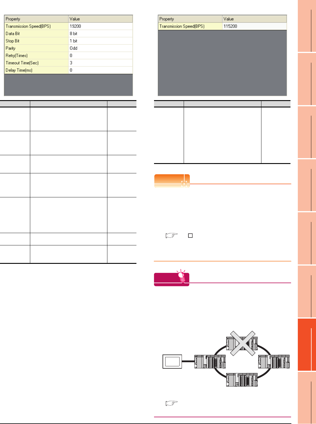
7. COMPUTER LINK CONNECTION
7.4 GOT Side Settings
7 - 21
1
PREPARATORY
PROCEDURES FOR
MONITORING
2
DEVICE RANGE
THAT CAN BE SET
3
ACCESS RANGE
FOR MONITORING
4
HOW TO MONITOR
REDUNTANT
SYSTEM
5
BUS CONNECTION
6
DIRECT
CONNECTION TO
CPU
7
COMPUTER LINK
CONNECTION
8
ETHERNET
CONNECTION
(3) AJ71C24/UC24 (4) QnA/L/Q CPU (GT10)
POINTPOINTPOINT
(1) Communication interface setting by the Utility
The communication interface setting can be
changed on the Utility's [Communication Settings]
after writing [Communication Settings] of project
data.
For details on the Utility, refer to the following
manual.
GT User's Manual
(2) Precedence in communication settings
When settings are made by GT Designer3 or the
Utility, the latest setting is effective.
HINTHINTHINT
Cutting the portion of multiple connection of the
controller
By setting GOT internal device, GOT can cut the
portion of multiple connection of the controller. For
example, faulty station that has communication
timeout can be cut from the system.
For details of the setting contents of GOT internal
device, refer to the following manual.
GT Designer3 Version Screen Design Manual
(Fundamentals)
Item Description Range
Transmission
Speed
Set this item when change the
transmission speed used for
communication with the connected
equipment. (Default: 19200bps)
4800bps,
9600bps,
19200bps
Data Bit
Set this item when change the data
length used for communication with the
connected equipment.
(Default: 8bit)
8bit (fixed)
Stop Bit
Specify the stop bit length for
communications.
(Default: 1bit)
1bit (fixed)
Parity
Specify whether or not to perform a
parity check, and how it is performed
during communication.
(Default: Odd)
Odd (fixed)
Retry
Set the number of retries to be
performed when a communication
timeout occurs. When receiving no
response after retries, the
communication times out.
(Default: 0time)
0 to 5times
Timeout Time Set the time period for a communication
to time out. (Default: 3sec) 3 to 30sec
Delay Time
Set this item to adjust the transmission
timing of the communication request
from the GOT. (Default: 0ms)
0 to 300 (ms)
Item Description Range
Transmission
Speed
Set this item when change the
transmission speed used for
communication with the connected
equipment.
(Default: 115200bps)
When the setting exceeds the limit of
the connected equipment,
communication is performed at the
fastest transmission speed supported
by the connected equipment.
9600bps,
19200bps,
38400bps,
57600bps,
115200bps
Disconnect the
faulty station
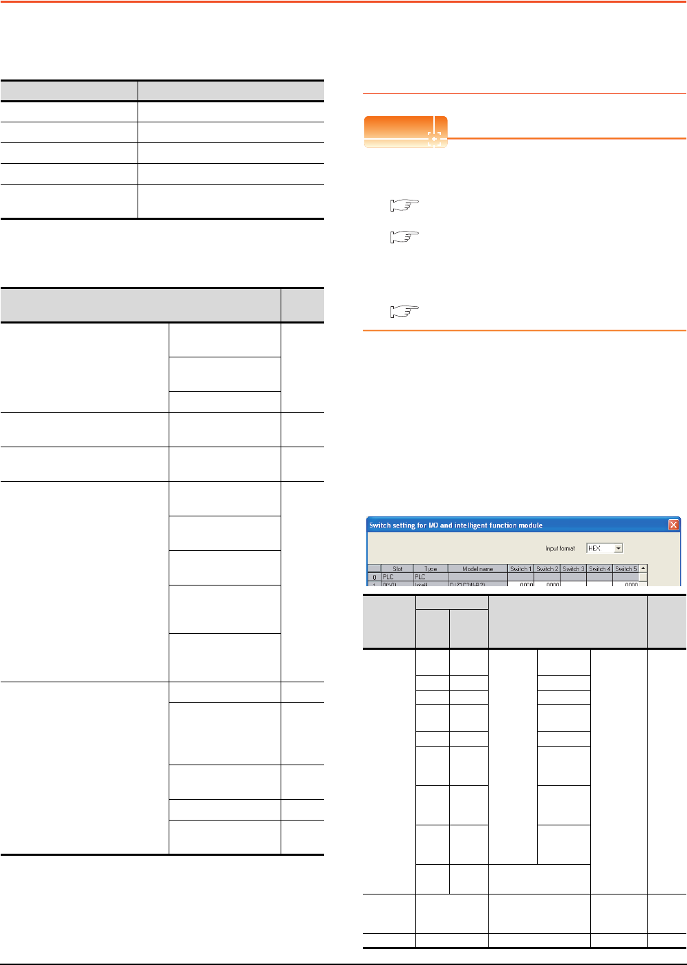
7 - 22 7. COMPUTER LINK CONNECTION
7.5 PLC Side Setting
7.5 PLC Side Setting
The GOT operates under the following transmission
specifications when it is connected to a Mitsubishi PLC in
the computer link connection.
The PLC side settings (the serial communication module,
computer link module) are explained in Section 7.5.1 to
Section 7.5.3.
7.5.1 Connecting serial
communication module (Q, L
Series)
POINTPOINTPOINT
(1) Serial communication module (Q, L Series)
For details of the serial communication module (Q,
L Series), refer to the following manual.
Q Corresponding Serial Communication
Module User’s Manual (Basic)
MELSEC-L Serial Communication Module
User's Manual (Basic)
(2) Modem interface module
For details of the modem interface module, refer to
the following manual.
Modem Interface Module User's Manual
[Intelligent function module switch setting] on
GX Developer
[The intelligent function module switch setting] on GX
Developer is not necessary. (When no [intelligent
function module switch setting] is made, the module
runs in the GX Developer connection mode.)
A module can be also connected to a GOT by making
the following [intelligent function module switch setting]
on GX Developer.
(1) When connecting to the CH1 side
Transmission specifications Setting
Data bit 8bits
Parity bit Yes (Odd)
Stop bit 1bit
Sum check Yes
Transmission speed
(Baud rate)
Set the same transmission speed on
both the GOT and the PLC.
Model Refer
to
Serial communication module
(Q Series)
QJ71C24N,
QJ71C24
7.5.1QJ71C24N-R2,
QJ71C24-R2
QJ71C24N-R4
Modem interface module QJ71CMO,
QJ71CMON 7.5.1
Serial communication module
(L Series)
LJ71C24,
LJ71C24-R2 7.5.1
Serial communication module
(QnA Series)
AJ71QC24N,
AJ71QC24
7.5.2
AJ71QC24N-R2,
AJ71QC24-R2
AJ71QC24N-R4,
AJ71QC24-R4
A1SJ71QC24N1,
A1SJ71QC24N,
A1SJ71QC24
A1SJ71QC24N1-R2,
A1SJ71QC24N-R2,
A1SJ71QC24-R2
Computer link module
AJ71UC24 7.5.3
A1SJ71UC24-R2,
A1SJ71UC24-PRF,
A1SJ71C24-R2,
A1SJ71C24-PRF
7.5.3
A1SJ71UC24-R4,
A1SJ71C24-R4 7.5.3
A1SCPUC24-R2 7.5.3
A2CCPUC24,
A2CCPUC24-PRF 7.5.3
Switch
No.
Bit
Description Set
value*3
Positi
on
Specifi
ed
value
Switch 1
b0 OFF
CH1
transmiss
ion
settings*1
Operation
setting
(Operates
according
to the GOT
side
specificatio
ns.)
0000H
b1 OFF Data Bit
b2 OFF Parity Bit
b3 OFF Even/Odd
parity
b4 OFF Stop bit
b5 OFF
Sum
check
code
b6 OFF
Write
during
RUN
b7 OFF
Setting
modifica-
tions
b8 to
b15 ―CH1 transmission
speed setting*2
Switch 2 ―CH1 Communication
protocol setting
GX
Developer
connection
0000H
Switch 5 ―Station number setting 0th station 0000H
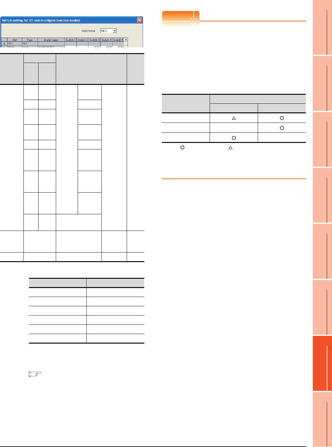
7. COMPUTER LINK CONNECTION
7.5 PLC Side Setting
7 - 23
1
PREPARATORY
PROCEDURES FOR
MONITORING
2
DEVICE RANGE
THAT CAN BE SET
3
ACCESS RANGE
FOR MONITORING
4
HOW TO MONITOR
REDUNTANT
SYSTEM
5
BUS CONNECTION
6
DIRECT
CONNECTION TO
CPU
7
COMPUTER LINK
CONNECTION
8
ETHERNET
CONNECTION
(2) When connecting to the CH2 side
*1 The module operates under the following transmission
specifications.
*2 The serial communication module operates at the
transmission speed set on the GOT.
*3 When the value of switch setting is other than "0", the setting
of [Format] and [Transmission Speed] on the GOT side are
required to be changed.
7.4.2 Communication detail settings
POINTPOINTPOINT
(1) When the [intelligent function module switch
setting] has been set
After writing PLC parameters to the PLC CPU,
turn the PLC CPU OFF then back ON again, or
reset the PLC CPU.
(2) Connection of multiple GOTs
To some serial communication module models,
two GOTs can be connected using both CH1 and
CH2.
: 2 GOTs connectable, : 1 GOT connectable, -: Not applicable
(3) When connecting to the modem interface module
When the modem interface module is connected,
only CH2 can be used.
Switch
No.
Bit
Description Set
value*3
Positi
on
Specifi
ed
value
Switch 3
b0 OFF
CH2
transmiss
ion
settings*1
Operation
setting
(Operates
according
to the GOT
side
specificatio
ns.)
0000H
b1 OFF Data bit
b2 OFF Parity
bit
b3 OFF Even/odd
parity
b4 OFF Stop bit
b5 OFF
Sum
check
code
b6 OFF
Write
during
RUN
b7 OFF
Setting
modifica-
tions
b8 to
b15 ―CH2 transmission
speed setting*2
Switch 4 ―CH2 Communication
protocol setting
GX
Developer
connection
0000H
Switch 5 ―Station number setting 0th station 0000H
Transmission specifications Setting details
Operation setting Independent
Data bit 8bits
Parity bit Yes
Even/odd parity Odd
Stop bit 1bit
Sum check code Yes
Model
Connection of 2 GOTs
Function version A Function version B
QJ71C24(-R2)
QJ71C24N(-R2/R4) -
LJ71C24(-R2) -
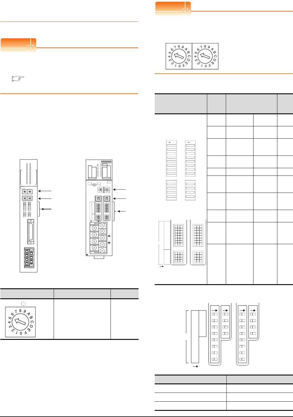
7 - 24 7. COMPUTER LINK CONNECTION
7.5 PLC Side Setting
7.5.2 Connecting serial
communication module (QnA
Series)
POINTPOINTPOINT
Serial communication module (QnA Series)
For details of the serial communication module (QnA
Series), refer to the following manual.
Serial Communication Module User's Manual
(Modem Function Additional Version)
Switch setting on serial communication
module
Set the Station number switches, the Mode setting
switch for the channel used for GOT connection, and
the Transmission specifications switches.
(1) Mode setting switch
*1 The mode switch in the figure is for the AJ71QC24 (N) (-R2/
R4).
POINTPOINTPOINT
When connecting a GOT to CH2
Set the CH1 side mode switch to any other than "0"
(interlocked operation).
(2) Transmission specifications setting switch
*1 The following shows the layout of switches in the case of the
following hardware versions for the module.
Switch settings and switch ON/OFF directions are the same.
Mode setting switch*1 Description Set value
Dedicated protocol (Format 5)
(Binary mode)
5
AJ71QC24N
RUN
CPUR/W
NEU
ACK
NAK
C/N
P/S
PRO
SIO
SD.WAIT
SD
RD
CH1.ERR.
CH2.ERR.
NEU
ACK
NAK
C/N
P/S
PRO
SIO
SD.WAIT
SD
RD
CH.1 CH.2
1
CH1 CH2
STATION
No.
MODE
SW
01
02
03
04
05
06
07
08
09
10
11
12
RDA
RDB
SG
SDA
SDB
NC
FG
CH1
RS-232C
CH2
RS422
RS485
8
4
0
C
8
4
0
C
5
0
5
0
10
AJ71QC24N, AJ71QC24N-R2,
AJ71QC24N-R4,AJ71QC24,
AJ71QC24-R2, AJ71QC24-R4
(3)
(1)
(2)
A1SJ71QC24N
CH1
ERR.
C/N
P/S
PRO
SID
CH2
ERROR
RD
SW.E
NEU
ACK
NAK
SD.W.
SD
STS ERR.
DISPLAY
5
0
5
0
CH1 CH2
10 1
STATION NO.
MODE
A1SJ71QC24N
RUN
RD
C.R/W
NEU
ACK
NAK
SD.W.
SD
ERR.
C/N
P/S
PRO
SIO
AB
CH1 RS-232-C
CH2 RS-422/RS-485
SG
(FG)
(NC)
SDA
SDB
RDA
RDB
8
4
0
C
8
4
0
C
ON
2
1
4
3
6
5
8
7
10
9
12
11
SW
(1)
(3)
(2)
A1SJ71QC24N1, A1SJ71QC24N1-R2
A1SJ71QC24N, A1SJ71QC24N-R2,
A1SJ71QC24, A1SJ71QC24-R2
MODE
CH
Transmission
specifications setting
switch
Setting
switch Description Set
value
AJ71QC24(N)
(-R2/R4)
A1SJ71QC24(N)
(N1)(-R2)*1
SW01 Operation
setting
Independent
operation OFF
SW02 Data bit
setting 8bits ON
SW03
Parity bit
enable/disable
setting
Enable ON
SW04 Even/odd parity
setting Odd OFF
SW05 Stop bit setting 1bit OFF
SW06
Sum check
enable/disable
setting
Enable ON
SW07
Write during
RUN enable/
disable setting
Enable ON
SW08 Setting change
enable/disable
Disable
(prohibit) OFF
SW09
to
SW12
Transmission
speed setting
(Consistent
with the GOT
side
specifications)
See (a)
SW13
to
SW15
―
The switch is
located on
the left side
of the
module.
(only on
AJ71QC24 (-
R2/R4))
All OFF
Target unit Hardware version
A1SJ71QC24 Version E hardware or earlier
A1SJ71QC24-R2 Version D hardware or earlier
A1SJ71QC24N, A1SJ71QC24N-R2 Version A hardware
MODE
CH2CH1
SW
01
02
03
04
05
06
07
08
09
10
11
12
ONON
ON
2
1
4
3
6
5
8
7
10
9
12
11
SW
1
8
2
3
4
5
6
7
9
10
11
12
SW
CH1/2
ON
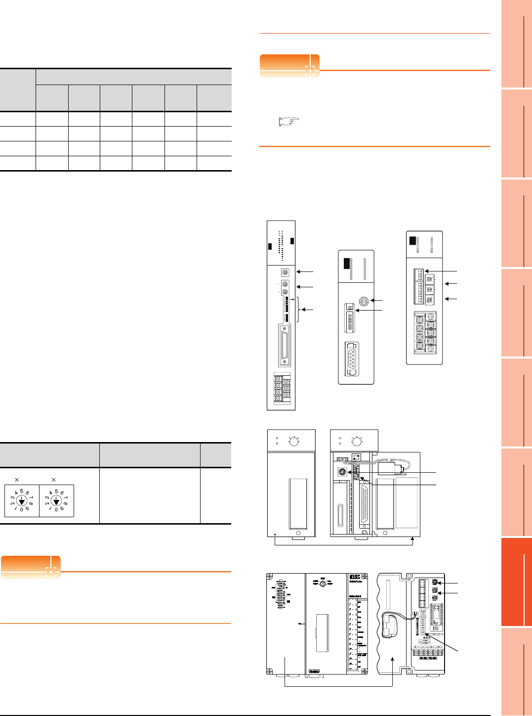
7. COMPUTER LINK CONNECTION
7.5 PLC Side Setting
7 - 25
1
PREPARATORY
PROCEDURES FOR
MONITORING
2
DEVICE RANGE
THAT CAN BE SET
3
ACCESS RANGE
FOR MONITORING
4
HOW TO MONITOR
REDUNTANT
SYSTEM
5
BUS CONNECTION
6
DIRECT
CONNECTION TO
CPU
7
COMPUTER LINK
CONNECTION
8
ETHERNET
CONNECTION
(a) Transmission speed setting (SW09 to SW12)
Set the transmission speed (SW09 to SW12) as
follows.
The transmission speed setting must be consistent
with that of the GOT side.
*1 Only transmission speeds available on the GOT side are
shown.
*2 When the software version of AJ71QC24 (-R2/R4) and
A1SJ71QC24 (-R2) is "L" or earlier, and when 2 devices are
connected to the two interfaces individually, make the setting
so that the total transmission speed of the two interfaces is
within 19200bps.
When the total transmission speed of the two interfaces is
within 19200bps, a controller other than GOT can be
connected to the computer link module.
When only one device is connected to either of the
interfaces, a maximum transmission speed of 19200bps can
be set to the one where the device is connected.In this
instance, set SW09 to SW12 to "OFF" on the other side.
*3 When 3 devices are connected to the two interfaces
individually in the case of AJ71QC24N(-R2/R4),
A1SJ71QC24N(-R2), and A1SJ71QC24N1(-R2), make the
setting so that the total transmission speed of the two
interfaces is within 115200bps (within 230400bps in the case
of A1SJ71QC24N1(-R2)).
When the total transmission speed of the two interfaces is
within 115200bps (within 230400bps in the case of
A1SJ71QC24N1(-R2)), a controller other than GOT can be
connected to the computer link module.
When only one device is connected to either of the
interfaces, a maximum transmission speed of 115200bps
can be set to the one where the device is connected.In this
instance, set SW09 to SW12 to "OFF" on the other side.
*4 This can be set only in the case of AJ71QC24N (-R2/R4),
A1SJ71QC24N (-R2) or A1SJ71QC24N1 (-R2).
(3) Station number switch (for both CH1 and CH2)
*5 The station number switch in the figure is for the AJ71QC24
(N) (-R2/R4).
POINTPOINTPOINT
When the switch setting has been changed
Turn the PLC CPU OFF then ON again, or reset the
PLC CPU.
7.5.3 Connecting computer link
module
POINTPOINTPOINT
Computer link module
For details of the computer link module, refer to the
following manual.
Computer Link Module (Com. link func./Print.
func.) User’s Manual
Switch setting on the computer link module
Set the Mode setting switch, the Transmission
specifications switches and the Station number setting
switches.
Setting
Switch
Transmission speed*1*2*3
4800
bps
9600
bps
19200
bps
38400
bps*4
57600
bps*4
115200
bps*4
SW09 OFF ON OFF ON OFF ON
SW10 OFF OFF ON ON ON ON
SW11 ON ON ON ON OFF OFF
SW12 OFF OFF OFF OFF ON ON
Station number switch*5 Contents Set
value
Set the station number of the
serial communication module
to which an access is made
from the GOT.
0
1
STATION
No.
10
AJ71UC24
(1)
(3)
(2)
AJ71UC24
2 - C / N
2 - P / S
2 - PRO
2 - SIO
4 - C / N
4 - P / S
4 - PRO
4 - SIO
CPUR / W
COM
M . D . M
M . D . L
B0
B1
B2
L 4
L 5
L 6
RUN
2 - SD
2 - RD
2 - NEU
2 - ACK
2 - NAK
4 - NEU
4 - ACK
4 - NAK
4 - SD
4 - RD
L 1
L 2
L 3
MODE
STATION NO.
10
1
SW11
12
13
14
15
16
17
18
21
22
23
24
O N
RS - 422
RS - 485
SDA
SDB
RDA
RDB
SG
FG
NC
RS-232-C
A1SJ71UC24-R2
NEU
ACK
NAK
C/N
NEU
ACK
NAK
C/N
P/S
PRO
SIO
SIO
SW
03
04
05
06
07
08
09
10
11
12
RS-232-C
A1SJ71UC24-R2
MODE
1.FORM1
2.FORM2
3.FORM3
4.FORM4
5.MOFORM
(1)
(2)
A1SJ71UC24-R2,
A1SJ71UC24-PRF,
A1SJ71C24-R2,
A1SJ71C24-PRF
8
0
2
3
5
7
8
0
2
3
5
7
8
9
0
3
4
B
C
D
F
A1SJ71UC24 - R4
SCAN
SCAN E.
SET E.
SIO E.
ST. DWN
MD / L
NEU
NAK
ACK
C / N
P / S
PRO
SIO
COM
MD
RUN
RD
SD
CPU
SW
01
02
03
04
05
06
07
08
09
10
11
12
10
STATION NO.
1
MODE
SDA
SDB
RDA
RDB
SG
FG
NC
RS - 422 / 485
A1SJ71UC24 - R4
(1)
(3)
(2)
A1SJ71UC24-R4,
A1SJ71C24-R4
PULL
MELSEC A1SCPU24-R2
STOP
RUN
RESETRESET
L CLR
RUN
ERROR
STOP
RUN
RESETRESET
L CLR
RUN
ERROR
MELSEC A1SCPU24-R2
MITSUBISHIMITSUBISHI
When the cover is open
When the cover is open
A1SCPUC24-R2
A2CCPUC24, A2CCPUC24-PRF
(1)
(2)
(1)
(3)
(2)
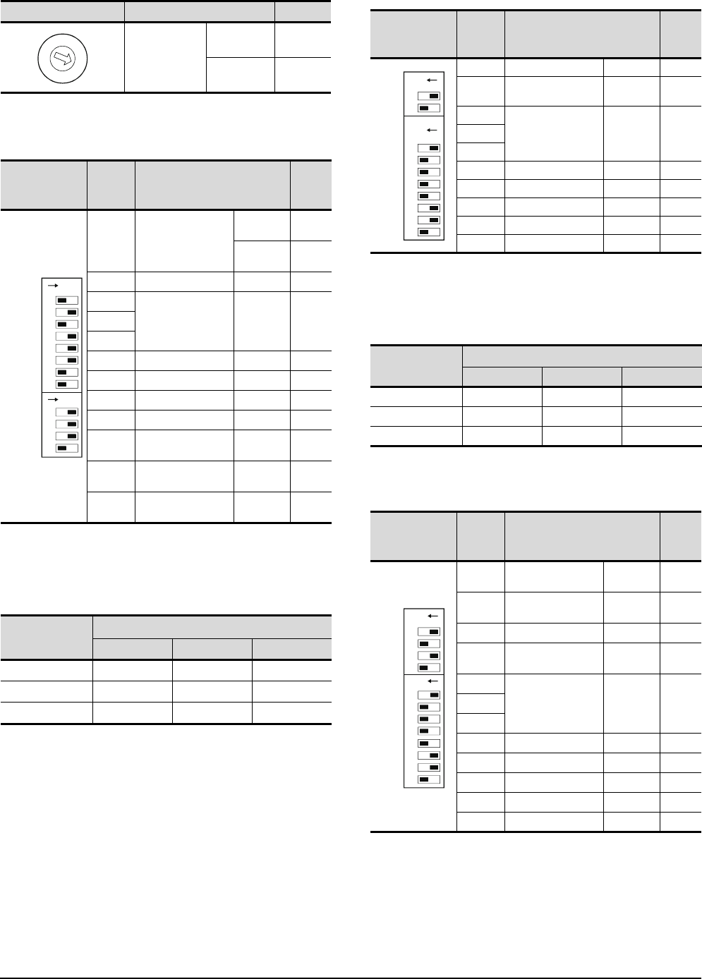
7 - 26 7. COMPUTER LINK CONNECTION
7.5 PLC Side Setting
(1) Mode setting switch
(2) Transmission specifications switch
(a) AJ71UC24
• Transmission speed setting (SW13 to SW15)
Set the transmission speed (SW13 to SW15) as
follows.
The transmission speed setting must be consistent
with that of the GOT side.
*1 Only transmission speeds available on the GOT side
are shown.
(b) A1SJ71UC24-R2, A1SJ71UC24-PRF,
A1SJ71C24-R2, A1SJ71C24-PRF
• Transmission speed setting (SW05 to SW07)
Set the transmission speed (SW05 to SW07) as
follows.
The transmission speed setting must be consistent
with that of the GOT side.
*1 Only transmission speeds available on the GOT side are
shown.
(c) A1SJ71UC24-R4, A1SJ71C24-R4
Mode setting switch Contents Set value
Dedicated
protocol type 1
RS-232
connection 1
RS-422
connection 5
Transmission
specifications
switch
Setting
switch Description Set
value
SW11 Main channel setting
RS-232
connection OFF
RS-422
connection ON
SW12 Data bit setting 8bits ON
SW13
Transmission speed
setting
(Consistent
with the GOT
side
specifications)
See
descripti
ons
below.
SW14
SW15
SW16 Parity bit setting Set ON
SW17 Even/odd parity setting Odd OFF
SW18 Stop bit setting 1bit OFF
SW21 Sum check setting Set ON
SW22 Write during RUN
enabled/disabled setting Enabled ON
SW23 Computer link/multi-drop
selection
Computer
link ON
SW24 Master station/Local
station setting
(Setting
ignored) OFF
Setting switch
Transmission speed*1
4800bps 9600bps 19200bps
SW13 OFF ON OFF
SW14 OFF OFF ON
SW15 ON ON ON
C
B
A
9
8
7
6
5
4
3
2
1
0
F
E
D
ON
SW11
SW12
SW13
SW14
SW15
SW16
SW17
SW18
SW21
SW22
SW23
SW24
ON
Transmission
specifications
switch
Setting
switch Description Set
value
SW03 Unused ―OFF
SW04 Write during RUN
enabled/disabled setting Enabled ON
SW05
Transmission speed
setting
(Consistent
with the GOT
side
specifications)
See
descripti
ons
below.
SW06
SW07
SW08 Data bit setting 8bits ON
SW09 Parity bit setting Set ON
SW10 Even/odd parity setting Odd OFF
SW11 Stop bit setting 1bit OFF
SW12 Sum check setting Set ON
Setting switch Transmission speed*1
4800bps 9600bps 19200bps
SW05 OFF ON OFF
SW06 OFF OFF ON
SW07 ON ON ON
Transmission
specifications
switch
Setting
switch Description Set
value
SW01 Master station/Local
station setting
(Setting
ignored) OFF
SW02 Computer link/multi-drop
selection
Computer
link ON
SW03 Unused ―OFF
SW04 Write during RUN
enabled/disabled setting Enabled ON
SW05
Transmission speed
setting
(Consistent
with the GOT
side
specifications)
See
descripti
ons
below.
SW06
SW07
SW08 Data bit setting 8bits ON
SW09 Parity bit setting Set ON
SW10 Even/odd parity setting Odd OFF
SW11 Stop bit setting 1bit OFF
SW12 Sum check setting Set ON
ON
03
04
05
06
07
08
09
10
11
12
ON
SW
ON
01
02
03
04
05
06
07
08
10
11
12
SW
09
ON
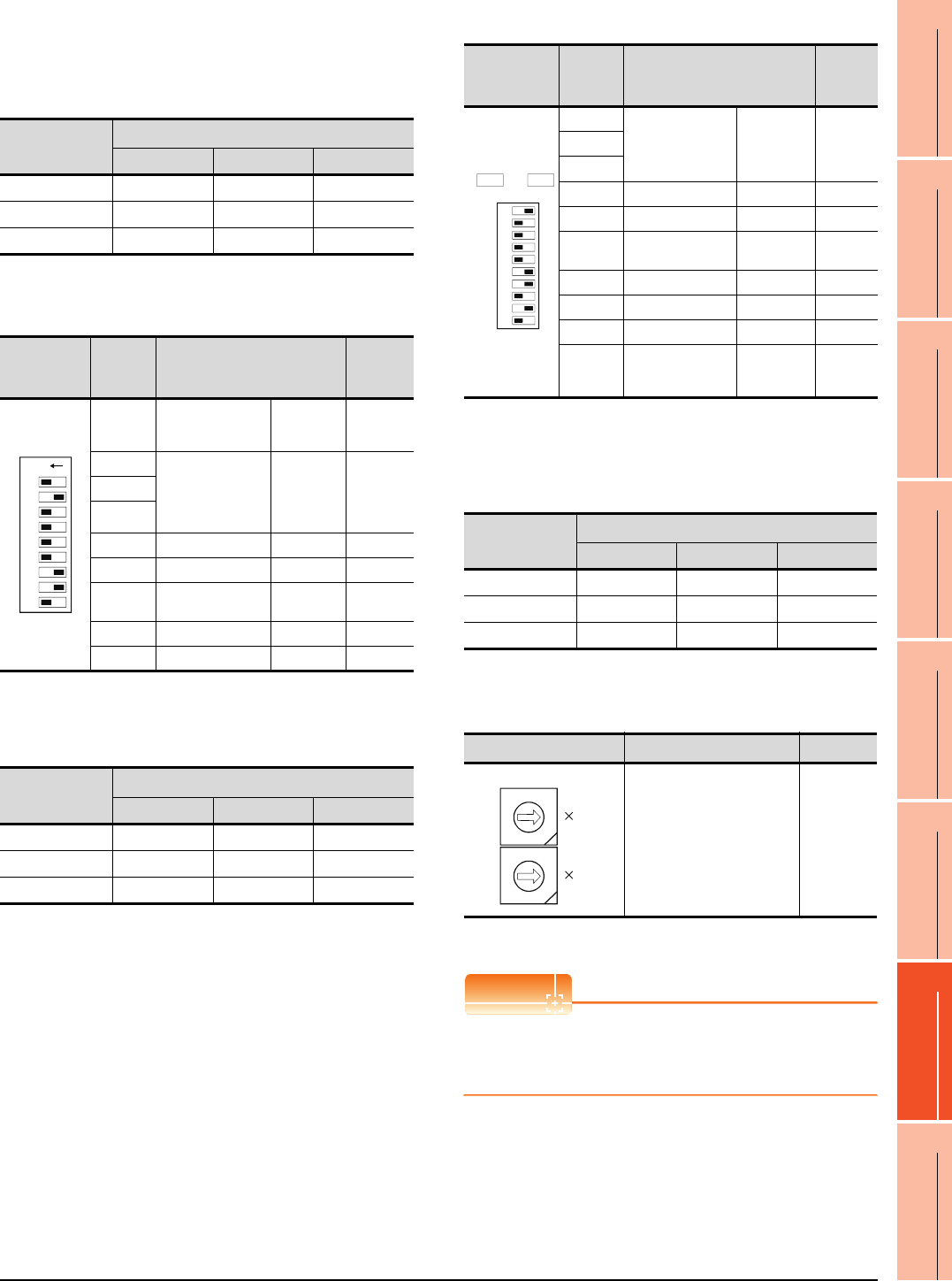
7. COMPUTER LINK CONNECTION
7.5 PLC Side Setting
7 - 27
1
PREPARATORY
PROCEDURES FOR
MONITORING
2
DEVICE RANGE
THAT CAN BE SET
3
ACCESS RANGE
FOR MONITORING
4
HOW TO MONITOR
REDUNTANT
SYSTEM
5
BUS CONNECTION
6
DIRECT
CONNECTION TO
CPU
7
COMPUTER LINK
CONNECTION
8
ETHERNET
CONNECTION
• Transmission speed setting (SW05 to SW07)
Set the transmission speed (SW05 to SW07) as
follows.
The transmission speed setting must be consistent
with that of the GOT side.
*1 Only transmission speeds available on the GOT side are
shown.
(d) A1SCPUC24-R2
• Transmission speed setting (2 to 4)
Set the transmission speed (2 to 4) as follows.
The transmission speed setting must be consistent
with that of the GOT side.
*2 Only transmission speeds available on the GOT side are
shown.
(e) A2CCPUC24, A2CCPUC24-PRF
• Transmission speed setting (SW11 to SW13)
Set the transmission speed (SW11 to SW13) as
follows.
The transmission speed setting must be consistent
with that of the GOT side.
*1 Only transmission speeds available on the GOT side are
shown.
(3) Station number setting switch
*2 The station number setting switch in the figure is for the
A1SJ71UC24-R4.
POINTPOINTPOINT
When the switch setting has been changed
Turn the PLC CPU OFF then ON again, or reset the
PLC CPU.
Setting switch
Transmission speed*1
4800bps 9600bps 19200bps
SW05 OFF ON OFF
SW06 OFF OFF ON
SW07 ON ON ON
Transmission
specifications
switch
Setting
switch Description Set value
1
Write during RUN
enabled/
disabled setting
Enabled ON
2
Transmission speed
setting
(Consistent
with the
GOT side
specification
s)
See
description
s below.
3
4
5 Data bit setting 8bits ON
6 Parity bit setting Set ON
7Even/odd parity
setting Odd OFF
8 Stop bit setting 1bit OFF
9 Sum check setting Set ON
Setting switch
Transmission speed*2
4800bps 9600bps 19200bps
2 OFF ON OFF
3OFFOFFON
4 ONONON
ON
123456789
Transmission
specifications
switch
Setting
switch Description Set
value
SW11
Transmission speed
setting
(Consistent
with the GOT
side
specifications)
See
descriptio
ns below.
SW12
SW13
SW14 Data bit setting 8bits ON
SW15 Parity bit setting Set ON
SW16 Even/odd parity
setting Odd OFF
SW17 Stop bit setting 1bit OFF
SW18 Sum check setting Set ON
SW19 Main channel setting RS-232 OFF
SW20
Write during RUN
enabled/
disabled setting
Enabled ON
Setting switch
Transmission speed*1
4800bps 9600bps 19200bps
SW11 OFF ON OFF
SW12 OFF OFF ON
SW13 ON ON ON
Station number switch*2 Description Set value
Set the station number of the
computer link module to
which an access is made
from the GOT.
0
ON
SW
11
12
13
14
15
16
17
18
19
20
ON OFF
2
1
0
9
8
7
6
5
4
3
2
1
0
9
8
7
6
5
4
3
10
1
STATION NO.
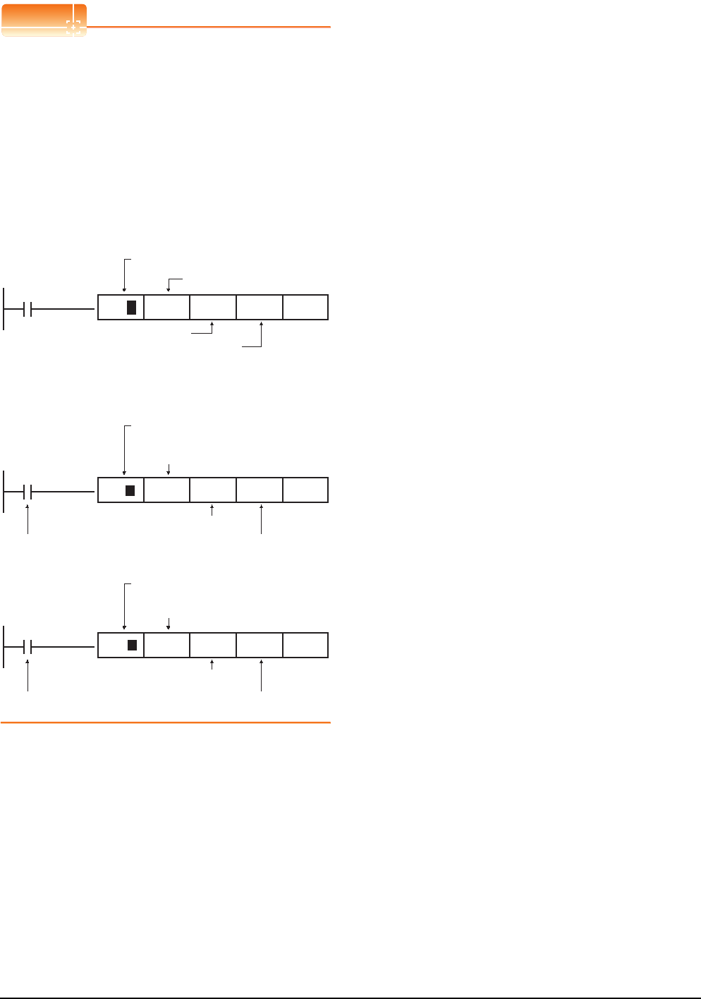
7 - 28 7. COMPUTER LINK CONNECTION
7.5 PLC Side Setting
POINTPOINTPOINT
When connecting the GT14, GT12, GT11, GT10 and
the computer link unit
When the GT14, GT12, GT11, GT10 and the computer
link unit are connected via RS-232C, set the buffer
memory in the computer link unit using the sequence
program so that CD signals are not checked.
Examples of the CPU units equipped with built-in
computer link are explained below also.
(1) In the case of A computer link
Refer to the program example below in which the
I/O signals of the computer link unit are 80 to 9F
(H).
(2) In the case of CPU equipped with built-in
computer link
(a) A1SCPUC24-R2
(b) A2CCPUC2
X87
TO
Write to buffer memory
10B(H):CD terminal will be checked
K1:CD terminal will not be checked
Computer link unit
connection point
H8 H10B K1 K1P
X0E7
TO
Write to buffer memory
10B(H):CD terminal will be checked
K1:CD terminal will be checkedFixed values
Computer link unit connection point
(Fixed values)
H0E H10B K1 K1P
X1E7
TO
Write to buffer memory
10B(H):CD terminal will be checked
K1:CD terminal will not be checkedFixed values
Computer link unit connection point
(Fixed values)
K61 H10B K1 K1P
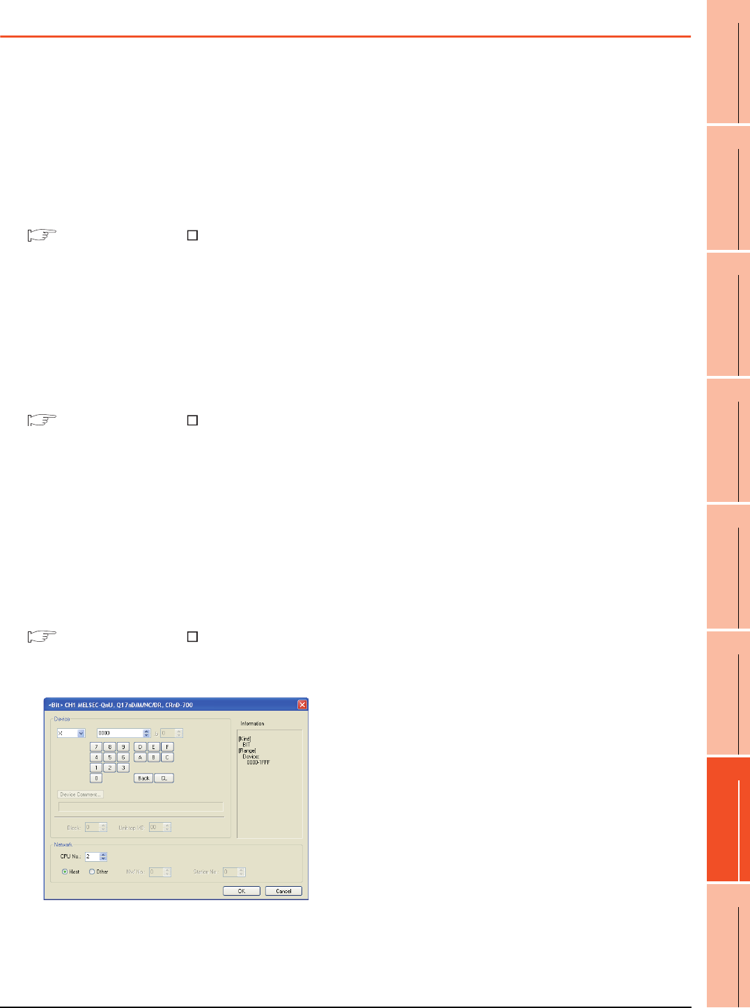
7. COMPUTER LINK CONNECTION
7.6 Precautions
7 - 29
1
PREPARATORY
PROCEDURES FOR
MONITORING
2
DEVICE RANGE
THAT CAN BE SET
3
ACCESS RANGE
FOR MONITORING
4
HOW TO MONITOR
REDUNTANT
SYSTEM
5
BUS CONNECTION
6
DIRECT
CONNECTION TO
CPU
7
COMPUTER LINK
CONNECTION
8
ETHERNET
CONNECTION
7.6 Precautions
Time taken until the PLC runs when
connected in the multiple CPU system
The following time is taken until the PLC runs.
QCPU (Q mode), motion controller CPU (Q series): 10
seconds or more
MELDAS C70: 18 seconds or more
When the GOT starts before the PLC runs, a system
alarm occurs.Adjust the opening screen time in the
GOT setup so that no system alarm occurs.
GT Designer3 Version Screen Design
Manual
Connection to LCPU
LCPU may diagnose (check file system, recovering
process, etc.) the SD memory card when turning on the
power or when resetting. Therefore, it takes time until
the SD memory card becomes available. When the
GOT starts before the SD card becomes available, a
system alarm occurs. Adjust the opening screen time in
the GOT setup so that no system alarm occurs.
GT Designer3 Version Screen Design
Manual
When monitoring the Q170MCPU
Set [CPU No.] to "2" in the device setting to monitor the
device of the Motion CPU area (CPU No.2).
When the CPU No. is set to "0" or "1", the device on the
PLC CPU area (CPU No.1) is monitored.
When the CPU No. is set to the number other than "0"
to "2", a communication error occurs and the monitoring
cannot be executed.
For setting the CPU No., refer to the following manual.
GT Designer3 Version Screen Design
Manual
Example) Setting dialog box of the bit device

7 - 30 7. COMPUTER LINK CONNECTION
7.6 Precautions
8
1
PREPARATORY
PROCEDURES FOR
MONITORING
2
DEVICE RANGE
THAT CAN BE SET
3
ACCESS RANGE
FOR MONITORING
4
HOW TO MONITOR
REDUNTANT
SYSTEM
5
BUS CONNECTION
6
DIRECT
CONNECTION TO
CPU
7
COMPUTER LINK
CONNECTION
8
ETHERNET
CONNECTION
8 - 1
8.ETHERNET CONNECTION
8.1 Connectable Model List . . . . . . . . . . . . . . . . . . . . . . . . . . . . 8 - 2
8.2 System Configuration. . . . . . . . . . . . . . . . . . . . . . . . . . . . . . 8 - 7
8.3 GOT Side Settings . . . . . . . . . . . . . . . . . . . . . . . . . . . . . . . 8 - 15
8.4 PLC Side Setting . . . . . . . . . . . . . . . . . . . . . . . . . . . . . . . . 8 - 20
8.5 Precautions . . . . . . . . . . . . . . . . . . . . . . . . . . . . . . . . . . . . 8 - 49
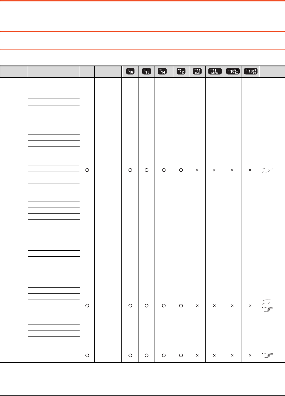
8 - 2 8. ETHERNET CONNECTION
8.1 Connectable Model List
8. ETHERNET CONNECTION
8.1 Connectable Model List
8.1.1 PLC/Motion controller CPU
The following table shows the connectable models.
(Continued to next page)
*1 When in multiple CPU system configuration, use CPU function version B or later.
*2 Use a module with the upper five digits later than 12042.
*3 GT14 models compatible with Ethernet connection are only GT1455-QTBDE and GT1450-QLBDE.
Series Model name Clock
Communication
type
*3 Refer to
MELSEC-Q
(Q mode)
Q00JCPU
Ethernet
8.2.1
Q00CPU*1
Q01CPU*1
Q02CPU*1
Q02HCPU*1
Q06HCPU*1
Q12HCPU*1
Q25HCPU*1
Q02PHCPU
Q06PHCPU
Q12PHCPU
Q25PHCPU
Q12PRHCPU (Main base)
Q25PRHCPU (Main base)
Q12PRHCPU
(Extension base)
Q25PRHCPU
(Extension base)
Q00UJCPU
Q00UCPU
Q01UCPU
Q02UCPU
Q03UDCPU
Q04UDHCPU
Q06UDHCPU
Q10UDHCPU
Q13UDHCPU
Q20UDHCPU
Q26UDHCPU
Q03UDECPU
Ethernet
8.2.1
8.2.2
Q04UDEHCPU
Q06UDEHCPU
Q10UDEHCPU
Q13UDEHCPU
Q20UDEHCPU
Q26UDEHCPU
Q50UDEHCPU
Q100UDEHCPU
Q03UDVCPU
Q04UDVCPU
Q06UDVCPU
Q13UDVCPU
Q26UDVCPU
C Controller
module
Q12DCCPU-V*2
Ethernet
8.2.2
Q24DHCCPU-V
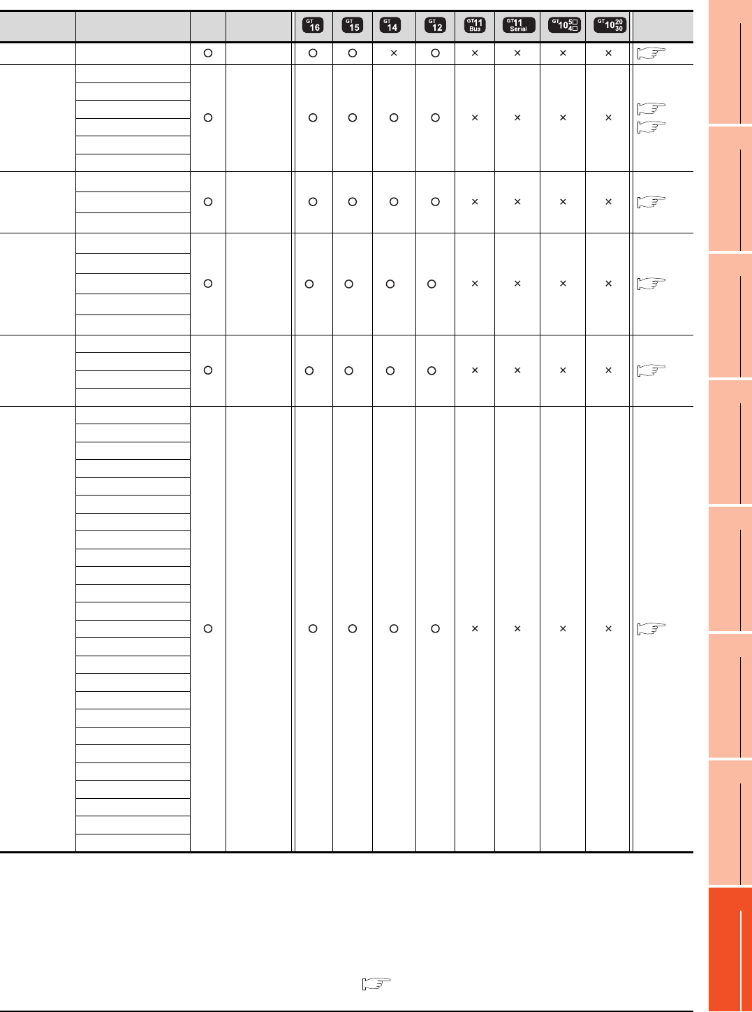
8. ETHERNET CONNECTION
8.1 Connectable Model List
8 - 3
1
PREPARATORY
PROCEDURES FOR
MONITORING
2
DEVICE RANGE
THAT CAN BE SET
3
ACCESS RANGE
FOR MONITORING
4
HOW TO MONITOR
REDUNTANT
SYSTEM
5
BUS CONNECTION
6
DIRECT
CONNECTION TO
CPU
7
COMPUTER LINK
CONNECTION
8
ETHERNET
CONNECTION
(Continued to next page)
*1 If the A series Ethernet module is applied to the QnACPU, the GOT can monitor the devices as the same as the case of AnACPU.
However, the following devices cannot be monitored.
• Devices added to QnACPU
• Latch relays (L) and step relays (S)
(In case of QnACPU, the latch relay (L) and step relay (S) are different from the internal relay. However, whichever is specified,
an access is made to the internal relay.)
• File register (R)
*2 GT14 models compatible with Ethernet connection are only GT1455-QTBDE and GT1450-QLBDE.
*3 Combination with the Ethernet module is restricted. 8.1.2 Ethernet module
Series Model name Clock
Communication
type
*2 Refer to
MELSEC-QS QS001CPU Ethernet
8.2.1
MELSEC-L
L02CPU
Ethernet
8.2.2
8.2.1
L26CPU
L26CPU-BT
L02CPU-P
L26CPU-PBT
L02SCPU
MELSEC-Q
(A mode)
Q02CPU-A*3
Ethernet
8.2.1
Q02HCPU-A*3
Q06HCPU-A*3
MELSEC-QnA
(QnACPU)
Q2ACPU*3
Ethernet *1 *1 *1 *1
8.2.1
Q2ACPU-S1*3
Q3ACPU*3
Q4ACPU*3
Q4ARCPU*3
MELSEC-QnA
(QnASCPU)
Q2ASCPU
Ethernet *1 *1 *1 *1
8.2.1
Q2ASCPU-S1
Q2ASHCPU
Q2ASHCPU-S1
MELSEC-A
(AnCPU)
A2UCPU
Ethernet
8.2.1
A2UCPU-S1
A3UCPU
A4UCPU
A2ACPU
A2ACPUP21
A2ACPUR21
A2ACPU-S1
A2ACPUP21-S1
A2ACPUR21-S1
A3ACPU
A3ACPUP21
A3ACPUR21
A1NCPU
A1NCPUP21
A1NCPUR21
A2NCPU
A2NCPUP21
A2NCPUR21
A2NCPU-S1
A2NCPUP21-S1
A2NCPUR21-S1
A3NCPU
A3NCPUP21
A3NCPUR21
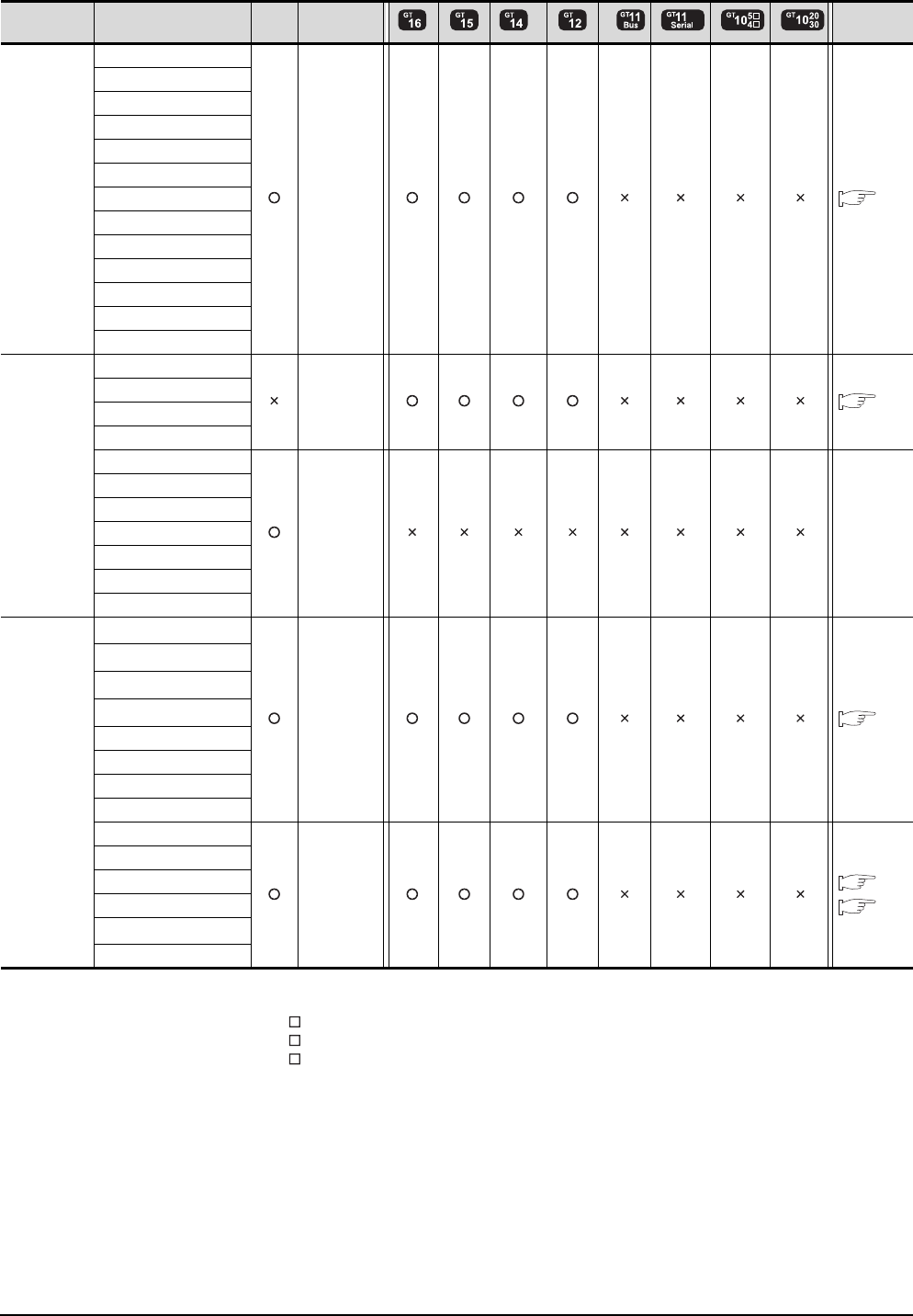
8 - 4 8. ETHERNET CONNECTION
8.1 Connectable Model List
(Continued to next page)
*1 When using SV13, SV22, or SV43, use the motion controller CPU on which any of the following main OS version is installed.
• SW6RN-SV13Q : 00H or later
• SW6RN-SV22Q : 00H or later
• SW6RN-SV43Q : 00B or later
*2 Use main modules with the following product numbers.
• Q172CPU: Product number N******* or later
• Q173CPU: Product number M******* or later
*3 When using Ethernet module, only the first step can be used on the extension base unit (Q52B/Q55B).
*4 GT14 models compatible with Ethernet connection are only GT1455-QTBDE and GT1450-QLBDE.
Series Model name Clock
Communication
type
*4 Refer to
MELSEC-A
(AnSCPU)
A2USCPU
Ethernet
8.2.1
A2USCPU-S1
A2USHCPU-S1
A1SCPU
A1SCPUC24-R2
A1SHCPU
A2SCPU
A2SCPU-S1
A2SHCPU
A2SHCPU-S1
A1SJCPU
A1SJCPU-S3
A1SJHCPU
MELSEC-A
A0J2HCPU
Ethernet
8.2.1
A0J2HCPUP21
A0J2HCPUR21
A0J2HCPU-DC24
A2CCPU
-
-
A2CCPUP21
A2CCPUR21
A2CCPUC24
A2CCPUC24-PRF
A2CJCPU-S3
A1FXCPU
Motion
controller
CPU
(Q Series)
Q172CPU*1*2
Ethernet
8.2.1
Q173CPU*1*2
Q172CPUN*1
Q173CPUN*1
Q172HCPU
Q173HCPU
Q172DCPU
Q173DCPU
Q172DCPU-S1
Ethernet
8.2.1
8.2.5
Q173DCPU-S1
Q172DSCPU
Q173DSCPU
Q170MCPU*3
MR-MQ100
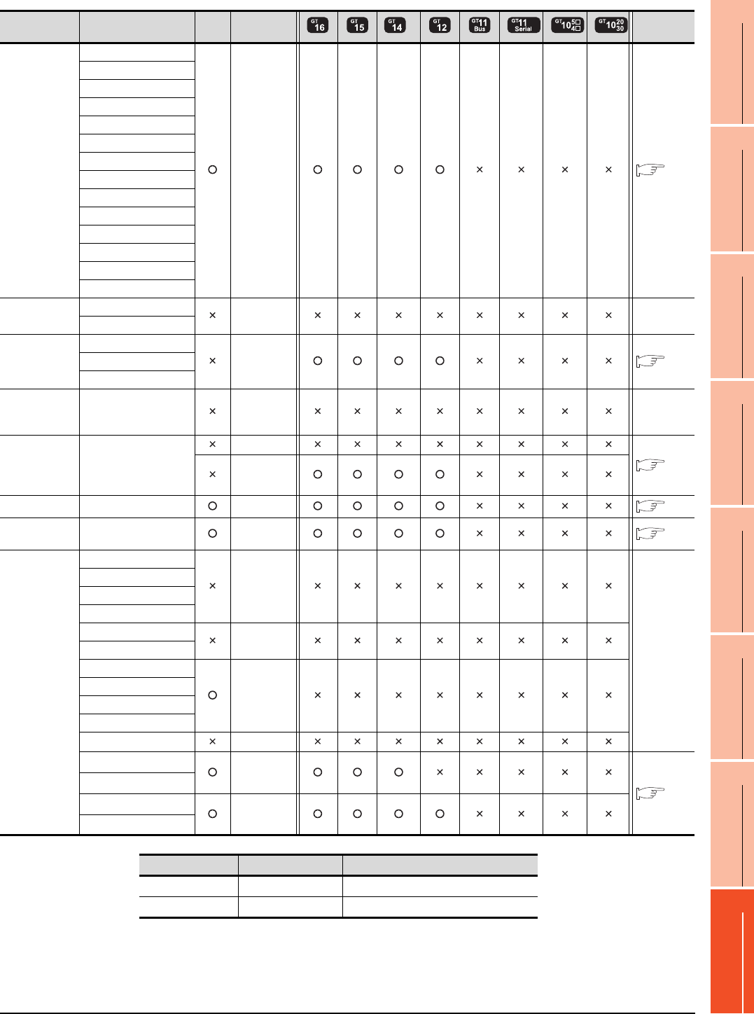
8. ETHERNET CONNECTION
8.1 Connectable Model List
8 - 5
1
PREPARATORY
PROCEDURES FOR
MONITORING
2
DEVICE RANGE
THAT CAN BE SET
3
ACCESS RANGE
FOR MONITORING
4
HOW TO MONITOR
REDUNTANT
SYSTEM
5
BUS CONNECTION
6
DIRECT
CONNECTION TO
CPU
7
COMPUTER LINK
CONNECTION
8
ETHERNET
CONNECTION
*1 The supported version of the main units varies depending on the Ethernet module to be used as shown below.
*2 The Ethernet connection of robot controller can be established only via the Ethernet module (QJ71E71) or Built-in Ethernet port of
QnUDE.
*3 GT14 models compatible with Ethernet connection are only GT1455-QTBDE and GT1450-QLBDE.
Series Model name Clock
Communication
type
*3 Refer to
Motion
controller
CPU
(A Series)
A273UCPU
Ethernet 8.2.1
A273UHCPU
A273UHCPU-S3
A373UCPU
A373UCPU-S3
A171SCPU
A171SCPU-S3
A171SCPU-S3N
A171SHCPU
A171SHCPUN
A172SHCPU
A172SHCPUN
A173UHCPU
A173UHCPU-S1
MELSEC-WS WS0-CPU0 - -
WS0-CPU1
MELSECNET/H
Remote I/O
station
QJ72LP25-25
Ethernet 8.2.1
QJ72LP25G
QJ72BR15
CC-Link IE
Field Network
head module
LJ72GF15-T2 - -
CC-Link IE
Field Network
Ethernet
adapter module
NZ2GF-ETB
CC-Link IE
8.2.4
Ethernet
CNC C70 Q173NCCPU Ethernet 8.2.3
Robot
controller
CRnQ-700
(Q172DRCPU) Ethernet*2 8.2.1
MELSEC-FX
FX0
-
-
FX0S
FX0N
FX1
FX2
-
FX2C
FX1S
-
FX1N
FX2N
FX1NC
FX2NC -
FX3G*1
Ethernet
8.2.1
FX3GC*1
FX3U*1
Ethernet
FX3UC*1
Ethernet module FX3U(C) FX3G(C)
FX3U-ENET Ver. 2.21 or later FX3U-ENET is supported.
FX3U-ENET-ADP Ver. 3.10 or later Ver. 2.00 or later

8 - 6 8. ETHERNET CONNECTION
8.1 Connectable Model List
8.1.2 Ethernet module
*1 If the A series Ethernet module is applied to the QnACPU, the GOT can monitor the devices as the same as the case of AnACPU.
However, the following devices cannot be monitored.
• Devices added to QnACPU
• Latch relays (L) and step relays (S)
(In case of QnACPU, the latch relay (L) and step relay (S) are different from the internal relay. However, whichever is specified,
an access is made to the internal relay.)
• File register (R)
*2 Use B or a later function version of Ethernet module and PLC CPU.
CPU series Ethernet module*1
MELSEC-Q (Q mode)
MELSEC-QS
Motion controller CPU (Q Series)
CNC C70
Robot controller (CRnQ-700)
QJ71E71-100 QJ71E71-B5 QJ71E71-B2 QJ71E71
MELSEC-QnA
AJ71QE71N3-T*2 AJ71QE71N-B5*2 AJ71QE71N-B2*2 AJ71QE71N-T*2
AJ71QE71N-B5T*2 AJ71QE71 AJ71QE71-B5 A1SJ71QE71N3-T*2
A1SJ71QE71N-B5*2 A1SJ71QE71N-B2*2 A1SJ71QE71N-T*2 A1SJ71QE71N-B5T*2
A1SJ71QE71-B5 A1SJ71QE71-B2
MELSEC-Q (A mode)
MELSEC-A
Motion Controller CPU (A Series)
AJ71E71N3-T AJ71E71N-B5 AJ71E71N-B2 AJ71E71N-T
AJ71E71N-B5T AJ71E71-S3 A1SJ71E71N3-T A1SJ71E71N-B5
A1SJ71E71N-B2 A1SJ71E71N-T A1SJ71E71N-B5T A1SJ71E71-B5-S3
A1SJ71E71-B2-S3
MELSEC-FX FX3U-ENET FX3U-ENET-ADP
CC-Link IE Field Network Ethernet adapter module NZ2GF-ETB
MELSEC-L LJ71E71-100
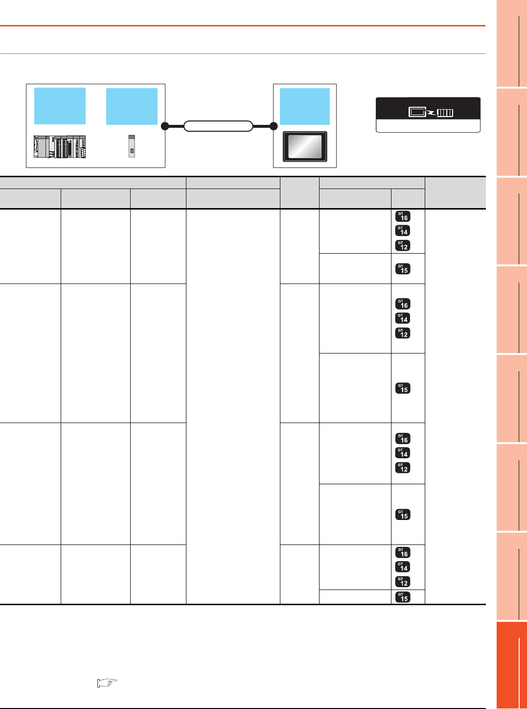
8. ETHERNET CONNECTION
8.2 System Configuration
8 - 7
1
PREPARATORY
PROCEDURES FOR
MONITORING
2
DEVICE RANGE
THAT CAN BE SET
3
ACCESS RANGE
FOR MONITORING
4
HOW TO MONITOR
REDUNTANT
SYSTEM
5
BUS CONNECTION
6
DIRECT
CONNECTION TO
CPU
7
COMPUTER LINK
CONNECTION
8
ETHERNET
CONNECTION
8.2 System Configuration
8.2.1 Connection to Ethernet module
When connecting to MELSEC-Q, QS, QnA, A or motion controller
*1 The destination connected with the twisted pair cable varies with the configuration of the applicable Ethernet network system.
Connect to the Ethernet module, hub, transceiver, or other system equipment corresponding to the applicable Ethernet network
system.
Use cables, connectors, and hubs that meet the IEEE802.3 10BASE-T/100BASE-TX standard.
A cross cable is available for connecting the GOT to the Ethernet module.
*2 When connecting GT16 of the function version A to an equipment that meets the 10BASE (-T/2/5) standard, use the switching
hub and operate in a 10Mbps/100Mbps mixed environment.
For how to check the function version, refer to the following.
GT16 User's Manual (Hardware)
Ethernet
module GOT
Connection cable
PLC CPU
Ethernet(MELSEC),Q17nNC,CRnD-700
Communication driver
PLC Connection cable*1 Maximum
segment
length*3
GOT Number of
connectable
equipment
Model name Ethernet module
*4*5
Communication
type Cable model Option device Model
MELSEC-Q
(Q mode)
MELSEC-QS
Motion controller
CPU (Q Series)*6
QJ71E71-100
QJ71E71-B5
QJ71E71-B2
QJ71E71
Ethernet
Twisted pair cable
• 10BASE-T
Shielded twisted pair
cable (STP) or unshielded
twisted pair cable (UTP):
Category 3, 4, and 5
• 100BASE-TX
Shielded twisted pair
cable (STP):
Category 5 and 5e
100m
- (Built into GOT)
*2
*8*9
128 GOTs*7
(recommended to
16 units or less)
GT15-J71E71-100
MELSEC-QnA
AJ71QE71N3-T
AJ71QE71N-B5
AJ71QE71N-B2
AJ71QE71N-T
AJ71QE71N-B5T
AJ71QE71
AJ71QE71-B5
A1SJ71QE71N3-T
A1SJ71QE71N-B5
A1SJ71QE71N-B2
A1SJ71QE71N-T
A1SJ71QE71N-B5T
A1SJ71QE71-B5
A1SJ71QE71-B2
Ethernet 100m
- (Built into GOT)
*2
*8
GT15-J71E71-100
MELSEC-A
MELSEC-Q
(A mode)
Motion controller
CPU (A Series)
AJ71E71N3-T
AJ71E71N-B5
AJ71E71N-B2
AJ71E71N-T
AJ71E71N-B5T
AJ71E71-S3
A1SJ71E71N3-T
A1SJ71E71N-B5
A1SJ71E71N-B2
A1SJ71E71N-T
A1SJ71E71N-B5T
A1SJ71E71-B5-S3
A1SJ71E71-B2-S3
Ethernet 100m
- (Built into GOT)
*2
*8
GT15-J71E71-100
MELSEC-L LJ71E71-100 Ethernet 100m
- (Built into GOT)
*2
*8
GT15-J71E71-100

8 - 8 8. ETHERNET CONNECTION
8.2 System Configuration
*3 A length between a hub and a node.
The maximum distance differs depending on the Ethernet device to be used.
The following shows the number of the connectable nodes when a repeater hub is used.
• 10BASE-T: Max. 4 nodes for a cascade connection (500m)
• 100BASE-TX: Max. 2 nodes for a cascade connection (205m)
When switching hubs are used, the cascade connection between the switching hubs has no logical limit for the number of
cascades.
For the limit, contact the switching hub manufacturer.
*4 For the system configuration of the Ethernet module, refer to the following manuals.
Q Corresponding Ethernet Interface Module User's Manual (Basic)
For QnA Ethernet Interface Module User’s Manual
For A Ethernet Interface Module User’s Manual
*5 Select one of the following [Controller Type] in [Ethernet] of GT Designer3.
• Ethernet module (Q Series): QJ71E71
• Ethernet module (QnA Series): AJ71QE71
• Ethernet module (A Series): AJ71QE71
For [Ethernet] of GT Designer3, refer to the following.
8.3.3 Ethernet setting
*6 When using the peripheral I/F of Q170MCPU, Q17nDCPU-S1 or MR-MQ100, refer to the following.
8.2.5 Connecting to PERIPHERAL I/F (Built-in Ethernet port Motion Controller CPU)
*7 The number of connectable GOTs for one network is 63 units (at most).
*8 GT14 models compatible with Ethernet connection are only GT1455-QTBDE and GT1450-QLBDE.
*9 GT14 cannot be connected with MELSEC-QS.
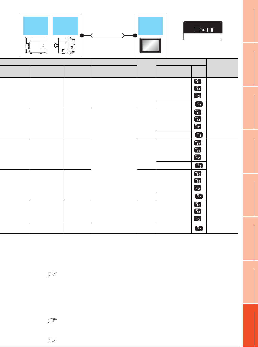
8. ETHERNET CONNECTION
8.2 System Configuration
8 - 9
1
PREPARATORY
PROCEDURES FOR
MONITORING
2
DEVICE RANGE
THAT CAN BE SET
3
ACCESS RANGE
FOR MONITORING
4
HOW TO MONITOR
REDUNTANT
SYSTEM
5
BUS CONNECTION
6
DIRECT
CONNECTION TO
CPU
7
COMPUTER LINK
CONNECTION
8
ETHERNET
CONNECTION
When connecting to MELSEC-FX
*1 The destination connected with the twisted pair cable varies with the configuration of the applicable Ethernet network system.
Connect to the Ethernet module, hub, transceiver or other system equipment corresponding to the applicable Ethernet network
system.
Use cables, connectors, and hubs that meet the IEEE802.3 10BASE-T/100BASE-TX standard.
A cross cable is available for connecting the GOT to the Ethernet module.
*2 When connecting GT16 of the function version A to an equipment that meets the 10BASE (-T/2/5) standard, use the switching
hub and operate in a 10Mbps/100Mbps mixed environment.
For how to check the function version, refer to the following.
GT16 User's Manual (Hardware)
*3 A length between a hub and a node.
The maximum distance differs depending on the Ethernet device to be used.
The following shows the number of the connectable nodes when a repeater hub is used.
• 10BASE-T: Max. 4 nodes for a cascade connection (500m)
• 100BASE-TX: Max. 2 nodes for a cascade connection (205m)
When switching hubs are used, the cascade connection between the switching hubs has no logical limit for the number of
cascades.
For the limit, contact the switching hub manufacturer.
*4 For the system configuration of the Ethernet module, refer to the following manuals.
For FX Ethernet Interface Module User’s Manual
*5 Select one of the following [Controller Type] in [Ethernet] of GT Designer3.
• Ethernet module (FX Series): FX
For [Ethernet] of GT Designer3, refer to the following.
8.3.3 Ethernet setting
Ethernet
module GOT
Connection cable
PLC CPU
Ethernet (FX), Gateway
Communication driver
PLC Connection cable*1 Maximum
segment
length*3
GOT Number of
connectable
equipment
Model name Ethernet module
*4*5
Communication
type Cable model Option device Model
MELSEC-FX
(FX3U, FX3G)FX3U-ENET Ethernet
Twisted pair cable
• 10BASE-T
Shielded twisted pair
cable (STP) or unshielded
twisted pair cable (UTP):
Category 3, 4, and 5
• 100BASE-TX
Shielded twisted pair
cable (STP):
Category 5 and 5e
100m
- (Built into GOT)
*2
*7
2 GOTs
GT15-J71E71-100
MELSEC-FX
(FX3UC, FX3GC)
FX3UC-1PS-5V,
FX2NC-CNV-IF
+
FX3U-ENET*6
Ethernet 100m
- (Built into GOT)
*2
*7
GT15-J71E71-100
MELSEC-FX
(FX3U)
FX3U-CNV-BD,
FX3U-422-BD,
FX3U-232-BD,
+
FX
3U
-ENET-ADP
*8*9
Ethernet 100m
- (Built into GOT)
*2
*7
4 GOTs
GT15-J71E71-100
MELSEC-FX
(FX3UC)FX
3U
-ENET-ADP Ethernet 100m
- (Built into GOT)
*2
*7
GT15-J71E71-100
MELSEC-FX
(FX3G)
FX
3G
-CNV-ADP,
+
FX
3U
-ENET-ADP
*9
Ethernet
100m
- (Built into GOT)
*2
*7
MELSEC-FX
(FX3GC)FX
3U
-ENET-ADP
*9
Ethernet GT15-J71E71-100

8 - 10 8. ETHERNET CONNECTION
8.2 System Configuration
*6 When using an Ethernet module with the FX3UC series, FX2NC-CNV-IF or FX3UC-1PS-5V is required.
*7 GT14 models compatible with Ethernet connection are only GT1455-QTBDE and GT1450-QLBDE.
*8 When using an Ethernet module with the FX3U series, FX3U-CNV-BD, FX3U-422-BD, or FX3U-232-BD is required.
*9 FX3U-ENET-ADP occupies one extension communication adapter CH (Max. 2 CHs) of the FX3U(C). One CPU allows the
connection of only one FX3U-ENET-ADP.
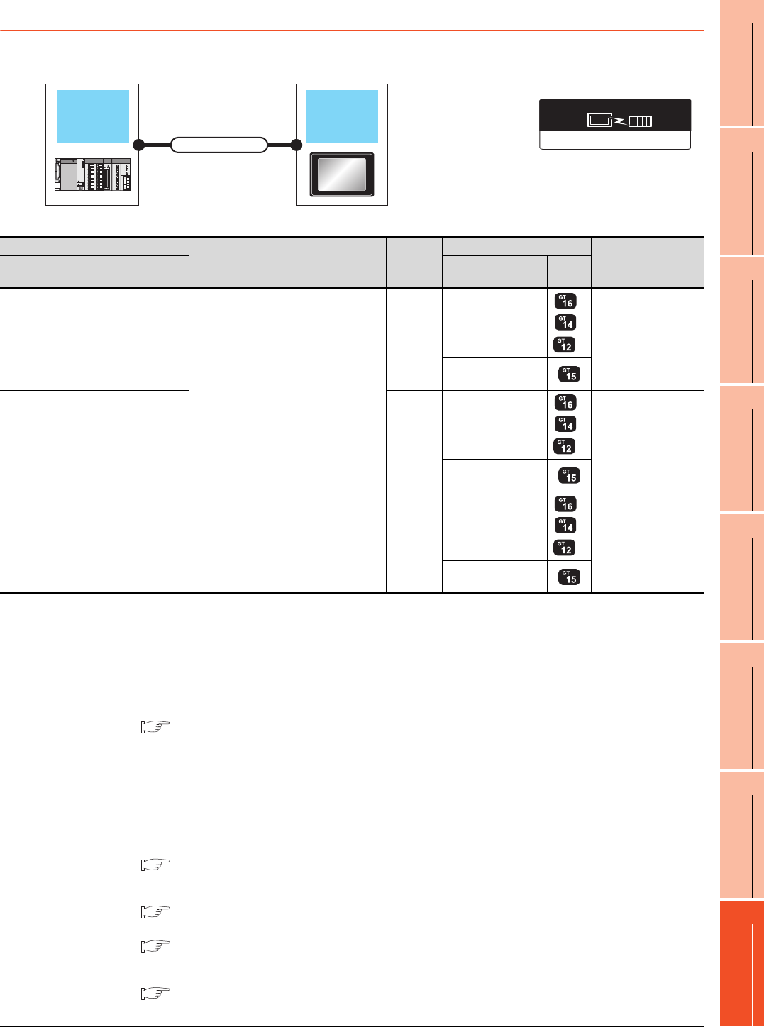
8. ETHERNET CONNECTION
8.2 System Configuration
8 - 11
1
PREPARATORY
PROCEDURES FOR
MONITORING
2
DEVICE RANGE
THAT CAN BE SET
3
ACCESS RANGE
FOR MONITORING
4
HOW TO MONITOR
REDUNTANT
SYSTEM
5
BUS CONNECTION
6
DIRECT
CONNECTION TO
CPU
7
COMPUTER LINK
CONNECTION
8
ETHERNET
CONNECTION
8.2.2 Connection to Built-in Ethernet port CPU or C Controller module
*1 The destination connected with the twisted pair cable varies with the configuration of the applicable Ethernet network system.
Connect to the Ethernet module, hub, transceiver, or other system equipment corresponding to the applicable Ethernet network
system.
Use cables, connectors, and hubs that meet the IEEE802.3 10BASE-T/100BASE-TX standard.
*2 A straight cable is available.
When connecting QnUDE(H) and GOT directly with Ethernet cable, connection by cross cable is available.
*3 When connecting GT16 of the function version A to an equipment that meets the 10BASE (-T/2/5) standard, use the switching
hub and operate in a 10Mbps/100Mbps mixed environment.
For how to check the function version, refer to the following.
GT16 User's Manual (Hardware)
*4 A length between a hub and a node.
The maximum distance differs depending on the Ethernet device to be used.
The following shows the number of the connectable nodes when a repeater hub is used.
• 10BASE-T: Max. 4 nodes for a cascade connection (500m)
• 100BASE-TX: Max. 2 nodes for a cascade connection (205m)
When switching hubs are used, the cascade connection between the switching hubs has no logical limit for the number of
cascades.
For the limit, contact the switching hub manufacturer.
*5 For the system configuration of Built-in Ethernet port QCPU, refer to the following manual.
QCPU User's Manual (Hardware Design, Maintenance and Inspection)
*6 Select [QnUDE(H)] for [Controller Type] in [Ethernet] of GT Designer3.
For [Ethernet] of GT Designer3, refer to the following.
8.3.3 Ethernet setting
*7 For the system configuration of Built-in Ethernet port LCPU, refer to the following manual.
MELSEC-L CPU Module User's Manual (Built-In Ethernet Function)
*8 Select [LCPU] for [Controller Type] in [Ethernet] of GT Designer3.
For [Ethernet] of GT Designer3, refer to the following.
8.3.3 Ethernet setting
*9 GT14 models compatible with Ethernet connection are only GT1455-QTBDE and GT1450-QLBDE.
Ethernet(MELSEC),Q17nNC,CRnD-700
Communication driver
Connecting to
Built-in
Ethernet port
CPU
GOT
Connection cable
PLC
Connection cable*1*2
Maximum
segment
length*4
GOT Number of
connectable
equipment
Model name Communication
type Option device Model
MELSEC-QnUDE(H)
*5*6 Ethernet
Twisted pair cable
• 10BASE-T
Shielded twisted pair cable (STP) or
unshielded twisted pair cable (UTP):
Category 3, 4, and 5
• 100BASE-TX
Shielded twisted pair cable (STP):
Category 5 and 5e
100m
- (Built into GOT)
*3
*9
16 GOTs
GT15-J71E71-100
C Controller module Ethernet 100m
- (Built into GOT)
*3
*9
16 GOTs
GT15-J71E71-100
MELSEC-L*7*8 Ethernet 100m
- (Built into GOT)
*3
*9
16 GOTs
GT15-J71E71-100
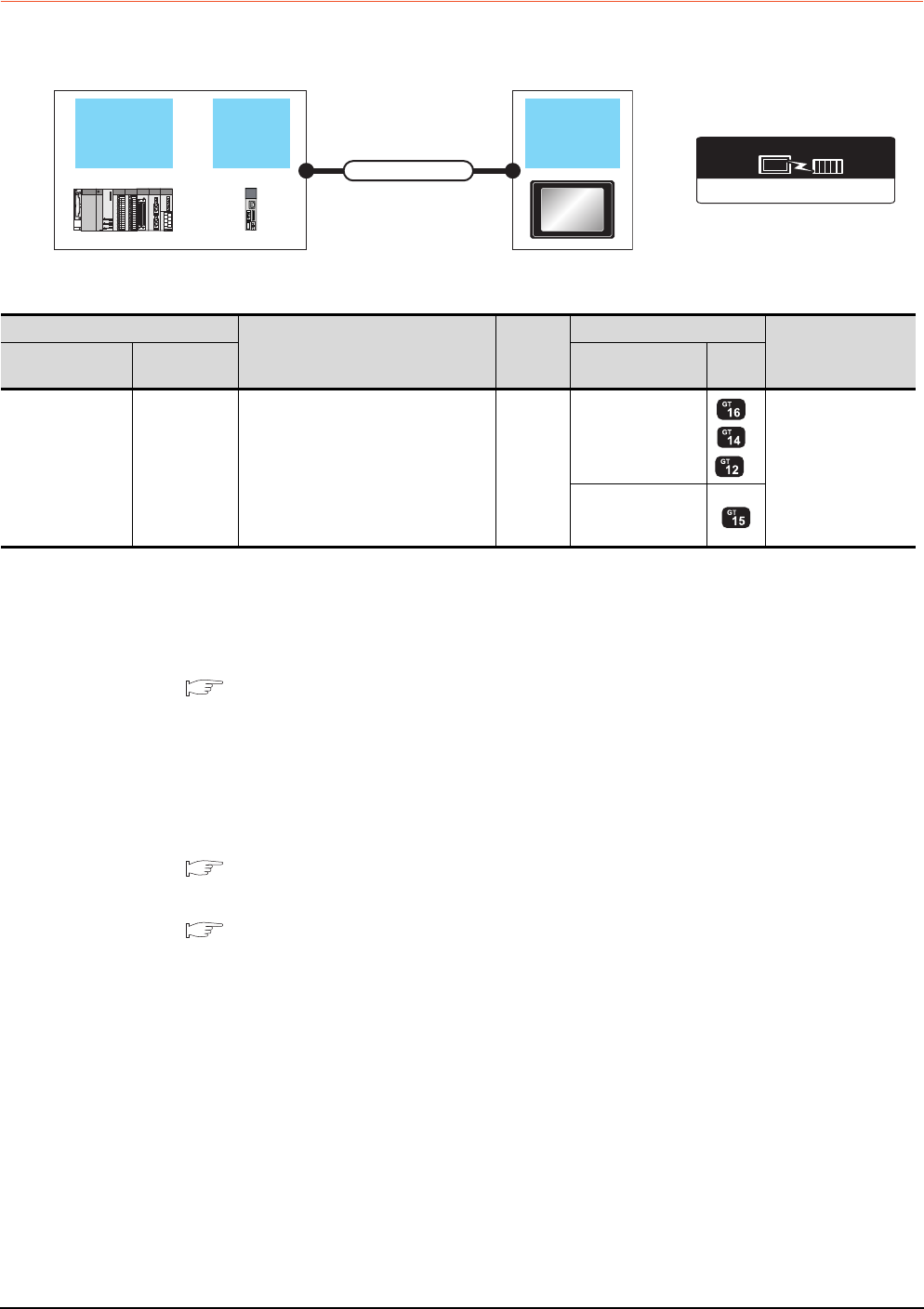
8 - 12 8. ETHERNET CONNECTION
8.2 System Configuration
8.2.3 Connecting to Display I/F
*1 The destination connected with the twisted pair cable varies with the configuration of the applicable Ethernet network system.
Connect to the Ethernet module, hub, transceiver or other system equipment corresponding to the applicable Ethernet network
system.
Use cables, connectors, and hubs that meet the IEEE802.3 10BASE-T/100BASE-TX standard.
*2 When connecting GT16 of the function version A to an equipment that meets the 10BASE (-T/2/5) standard, use the switching
hub and operate in a 10Mbps/100Mbps mixed environment.
For how to check the function version, refer to the following.
GT16 User's Manual (Hardware)
*3 A length between a hub and a node.
The maximum distance differs depending on the Ethernet device to be used.
The following shows the number of the connectable nodes when a repeater hub is used.
• 10BASE-T: Max. 4 nodes for a cascade connection (500m)
• 100BASE-TX: Max. 2 nodes for a cascade connection (205m)
When switching hubs are used, the cascade connection between the switching hubs has no logical limit for the number of
cascades.
For the limit, contact the switching hub manufacturer.
*4 For the system configuration of the CNC C70, refer to the following manual.
C70 Series SET UP MANUAL
*5 Select [Q17nNC] for [Controller Type] in [Ethernet] of GT Designer3.
For [Ethernet] of GT Designer3, refer to the following.
8.3.3 Ethernet setting
*6 GT14 models compatible with Ethernet connection are only GT1455-QTBDE and GT1450-QLBDE.
Ethernet(MELSEC),Q17nNC,CRnD-700
Communication driver
CNC
C70 GOT
Connection cable
PLC CPU
PLC
Connection cable*1
Maximum
segment
length*3
GOT
Number of connectable
equipment
Model name Communication
type Option device Model
CNC C70
(Q173NCCPU)
*4*5
Ethernet
Twisted pair cable
• 10BASE-T
Shielded twisted pair cable (STP) or
unshielded twisted pair cable (UTP):
Category 3, 4, and 5
• 100BASE-TX
Shielded twisted pair cable (STP):
Category 5 and 5e
100m
- (Built into GOT)
*2
*6
16 GOTs for 1 network
GT15-J71E71-100
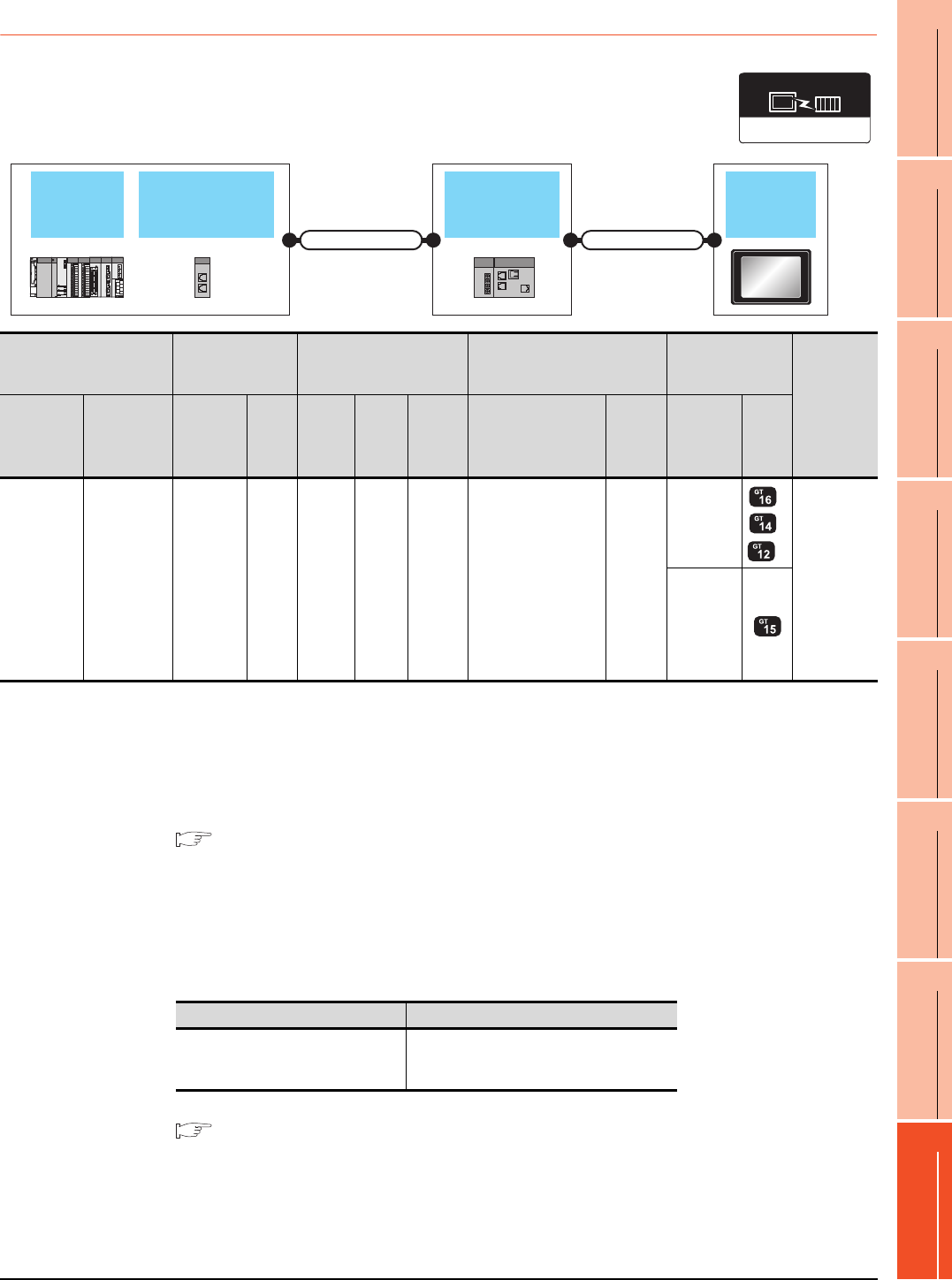
8. ETHERNET CONNECTION
8.2 System Configuration
8 - 13
1
PREPARATORY
PROCEDURES FOR
MONITORING
2
DEVICE RANGE
THAT CAN BE SET
3
ACCESS RANGE
FOR MONITORING
4
HOW TO MONITOR
REDUNTANT
SYSTEM
5
BUS CONNECTION
6
DIRECT
CONNECTION TO
CPU
7
COMPUTER LINK
CONNECTION
8
ETHERNET
CONNECTION
8.2.4 Connection to CC-Link IE Field Network Ethernet Adapter Module
*1 The destination connected with the twisted pair cable varies with the configuration of the applicable Ethernet network system.
Connect to the Ethernet module, hub, transceiver, or other system equipment corresponding to the applicable Ethernet network
system.
Use cables, connectors, and hubs that meet the IEEE802.3 10BASE-T/100BASE-TX standard.
A cross cable is available for connecting the GOT to the Ethernet module.
*2 When connecting GT16 of the function version A to an equipment that meets the 10BASE (-T/2/5) standard, use the switching
hub and operate in a 10Mbps/100Mbps mixed environment.
For how to check the function version, refer to the following.
GT16 User's Manual (Hardware)
*3 A length between a hub and a node.
The maximum distance differs depending on the Ethernet device to be used.
The following shows the number of the connectable nodes when a repeater hub is used.
• 10BASE-T: Max. 4 nodes for a cascade connection (500m)
• 100BASE-TX: Max. 2 nodes for a cascade connection (205m)
When switching hubs are used, the cascade connection between the switching hubs has no logical limit for the number of
cascades.
For the limit, contact the switching hub manufacturer.
*4 Use cables with the following specifications.
*5 For the system configuration on the CC-Link IE Field Network module side, refer to the following manual.
CC-Link IE Field Network Ethernet Adapter Module User's Manual
*6 The number of connectable GOTs for one network is 63 units (at most).
*7 GT14 models compatible with Ethernet connection are only GT1455-QTBDE and GT1450-QLBDE.
CC-Link IE Field
Network Master/
Local module
CC-Link IE
Field Network
Ethernet adapter
module
GOT
QCPU
Connection cable 1) Connection cable 2)
Ethernet(MELSEC),
Q17nNC, CRnD-700
Communication driver
PLC
Connection cable 1)
*4
CC-Link IE
Field Network
Ethernet adapter module
Connection cable 2)*1 GOT
Number of
connectable
equipment
Model name
CC-Link IE
Field Network
Master/Local
module
Cable
model
Max.
distance
Commu
nication
type
Model
name
Commu
nication
type
Cable model
Connection diagram
number
Maximu
m
segment
length*3
Option
device
Model
MELSEC-Q
(Q mode)
Motion
Controller
CPU (Q
Series)
QJ71GF11-T2
Double-
shielded
twisted pair
cable*4
100m CC-Link
IE
NZ2GF
-ETB Ethernet
Twisted pair cable
• 10BASE-T
Shielded twisted pair
cable (STP) or
unshielded twisted
pair cable (UTP):
Category 3, 4, and 5
• 100BASE-TX
Shielded twisted pair
cable (STP):
Category 5 and 5e
100m
- (Built into
GOT)
*2
*7
128 GOTs*6
(recommend
ed to 16 units
or less)
GT15-
J71E71-100
Connector Range
Category 5e or higher
Shielded RJ-45
Cable that satisfies the following specifications:
IEEE802.3 1000BASE-T
ANSI/TIA/EIA-568-B(Category 5e)
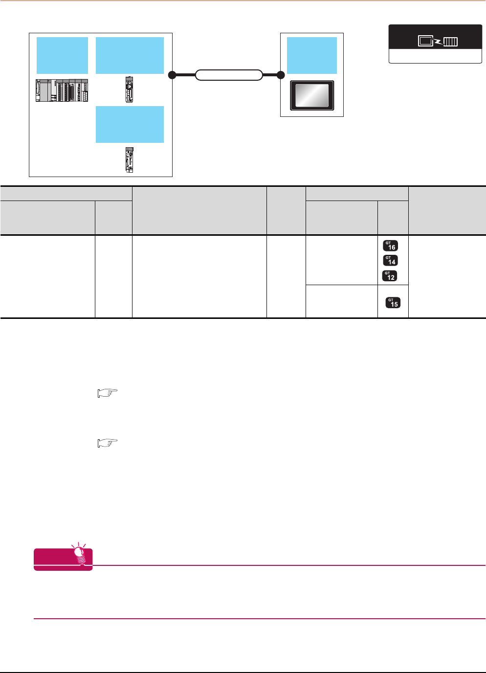
8 - 14 8. ETHERNET CONNECTION
8.2 System Configuration
8.2.5 Connecting to PERIPHERAL I/F (Built-in Ethernet port Motion Controller
CPU)
*1 The destination connected with the twisted pair cable varies with the configuration of the applicable Ethernet network system.
Connect to the Ethernet module, hub, transceiver or other system equipment corresponding to the applicable Ethernet network
system.
Use cables, connectors, and hubs that meet the IEEE802.3 10BASE-T/100BASE-TX standard.
*2 When connecting GT16 of the function version A to an equipment that meets the 10BASE (-T/2/5) standard, use the switching
hub and operate in a 10Mbps/100Mbps mixed environment.
For how to check the function version, refer to the following.
GT16 User's Manual (Hardware)
*3 When using the PERIPHERAL I/F, set as shown below.
• Use the GT Designer3 Version1.12N or later.
• Select [QnUDE(H)] for [Controller Type] in [Ethernet] of GT Designer3.
For [Ethernet] of GT Designer3, refer to the following.
8.3.3 Ethernet setting
*4 A length between a hub and a node.
The maximum distance differs depending on the Ethernet device to be used.
The following shows the number of the connectable nodes when a repeater hub is used.
• 10BASE-T: Max. 4 nodes for a cascade connection (500m)
• 100BASE-TX: Max. 2 nodes for a cascade connection (205m)
When switching hubs are used, the cascade connection between the switching hubs has no logical limit for the number of
cascades.
For the limit, contact the switching hub manufacturer.
*5 GT14 models compatible with Ethernet connection are only GT1455-QTBDE and GT1450-QLBDE.
HINTHINTHINT
Direct connection between PERIPHERAL I/F and GOT
The PERIPHERAL I/F and GOT can be directly connected by using a cross cable for the Ethernet connection
cable.
Q172DCPU-S1
Q173DCPU-S1
Q172DSCPU
Q173DSCPU
GOT
Connection cable
Q170MCPU
MR-MQ100
PLC
CPU
Ethernet(MELSEC),Q17nNC,CRnD-700
Communication driver
PLC
Connection cable*1
Maximum
segment
length*4
GOT
Number of
connectable
equipment
Model name*3
Communi
cation
type
Option device Model
Motion controller CPU
(Q Series)
Q172DCPU-S1
Q173DCPU-S1
Q172DSCPU
Q173DSCPU
Q170MCPU
MR-MQ100
Ethernet
Twisted pair cable
• 10BASE-T
Shielded twisted pair cable (STP) or
unshielded twisted pair cable (UTP):
Category 3, 4, and 5
• 100BASE-TX
Shielded twisted pair cable (STP):
Category 5 and 5e
30m
- (Built into GOT)
*2
*5
16 GOTs for 1 network
GT15-J71E71-100
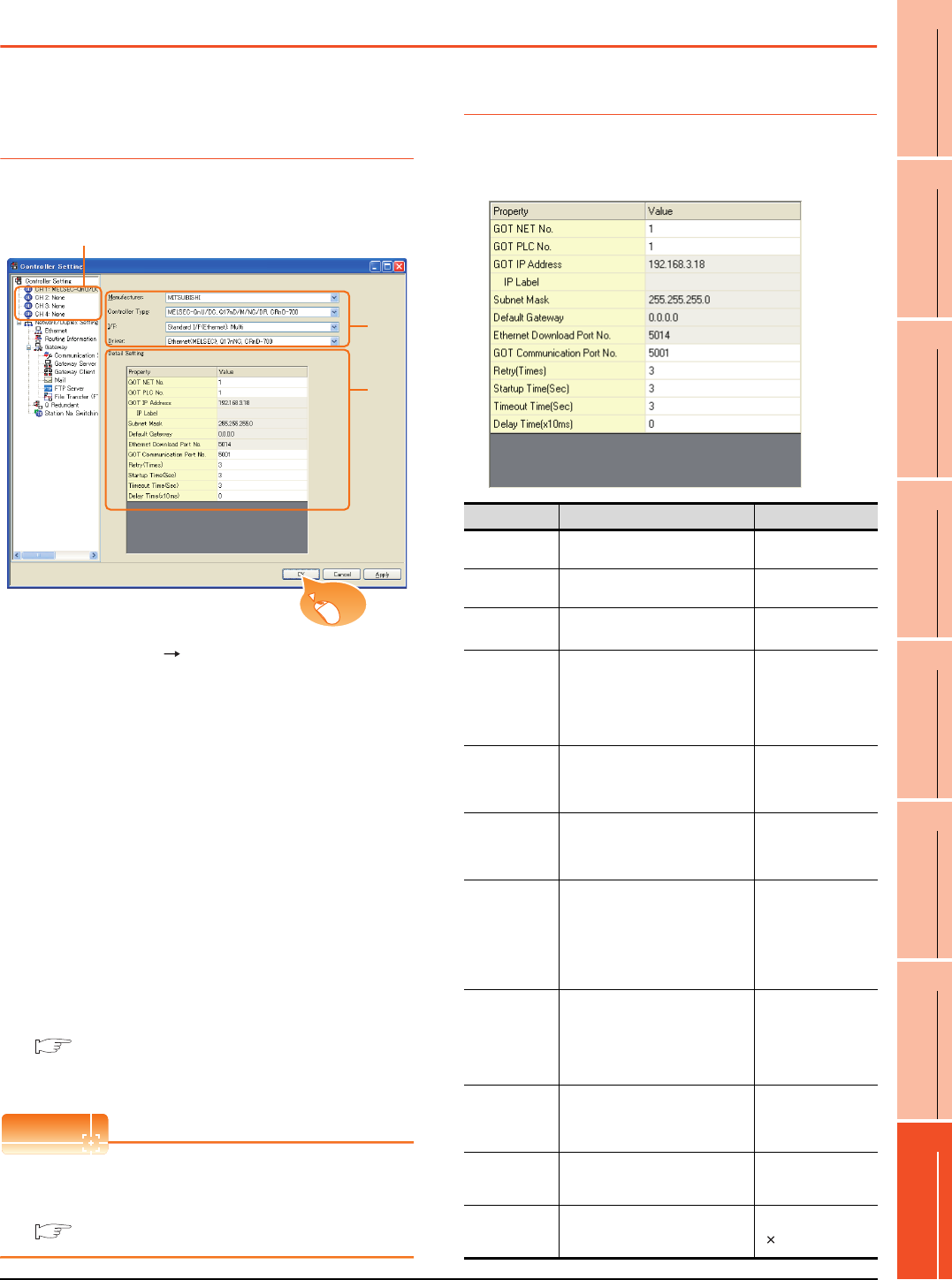
8. ETHERNET CONNECTION
8.3 GOT Side Settings
8 - 15
1
PREPARATORY
PROCEDURES FOR
MONITORING
2
DEVICE RANGE
THAT CAN BE SET
3
ACCESS RANGE
FOR MONITORING
4
HOW TO MONITOR
REDUNTANT
SYSTEM
5
BUS CONNECTION
6
DIRECT
CONNECTION TO
CPU
7
COMPUTER LINK
CONNECTION
8
ETHERNET
CONNECTION
8.3 GOT Side Settings
8.3.1 Setting communication
interface (Communication
settings)
Set the channel of the connected equipment.
1. Select [Common] [Controller Setting] from the
menu.
2. The Controller Setting window is displayed. Select the
channel to be used from the list menu.
3. Set the following items.
• Manufacturer: Mitsubishi
• Controller Type: Set according to the Controller
Type to be connected.
• I/F: Interface to be used
• Driver:
Ethernet(MELSEC), Q17nNC, CRnD-700
Ethernet(FX), Gateway
4. The detailed setting is displayed after Manufacturer,
Controller Type, I/F, and Driver are set.
Make the settings according to the usage
environment.
8.3.2 Communication detail settings
Click the [OK] button when settings are completed.
POINTPOINTPOINT
The settings of connecting equipment can be
confirmed in [I/F Communication Setting].
For details, refer to the following.
1.1.2 I/F communication setting
8.3.2 Communication detail settings
Make the settings according to the usage environment.
GT16, GT14
2.
3.
4.
Click!
Item Description Range
GOT NET No. Set the network No. of the GOT.
(Default: 1) 1 to 239
GOT PLC No. Set the station No. of the GOT.
(Default: 1) 1 to 64
GOT
IP Address*2
Set the IP address of the GOT.
(Default: 192.168.3.18)
0.0.0.0 to
255.255.255.255
Subnet Mask*2
Set the subnet mask for the sub
network. (Only for connection via
router)
If the sub network is not used, the
default value is set.
(Default: 255.255.255.0)
0.0.0.0 to
255.255.255.255
Default
Gateway*2
Set the router address of the default
gateway where the GOT is connected.
(Only for connection via router)
(Default: 0.0.0.0)
0.0.0.0 to
255.255.255.255
Ethernet
Download Port
No.*2
Set the GOT port No. for Ethernet
download.
(Default: 5014)
1024 to 5010,
5014 to 65534
(Except for 5011, 5012,
5013 and 49153)
GOT
Communication
Port No.
Set the GOT port No. for the
connection with the Ethernet module.
• For Ethernet (MELSEC), Q17nNC,
and CRnD-700
(Default: 5001)
• For Ethernet(FX), Gateway
(Default: 5019)
1024 to 5010,
5014 to 65534
(Except for 5011, 5012,
5013 and 49153)
Retry
Set the number of retries to be
performed when a communication
timeout occurs.
When receiving no response after
retries, the communication times out.
(Default: 3times)
0 to 5times
Startup Time
Specify the time period from the GOT
startup until GOT starts the
communication with the PLC CPU.
(Default: 3sec)
3 to 255sec
Timeout Time
*1
Set the time period for a
communication to time out.
(Default: 3sec)
1 to 90sec
Delay Time
Set the delay time for reducing the
load of the network/destination PLC.
(Default: 0ms)
0 to 10000
( 10ms)
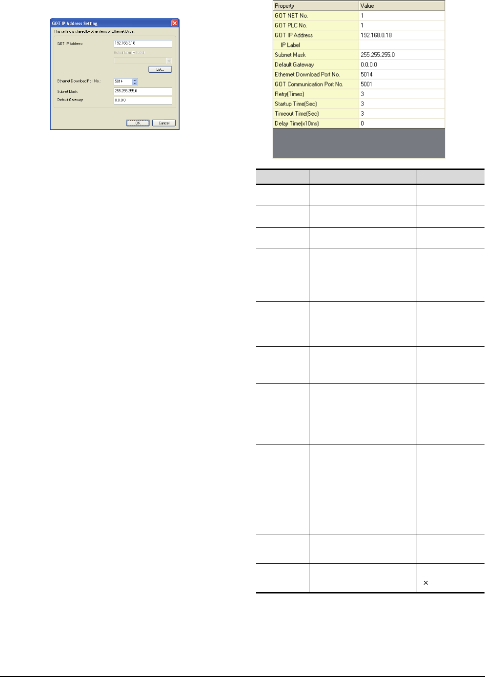
8 - 16 8. ETHERNET CONNECTION
8.3 GOT Side Settings
*1 To connect the GOT with the Ethernet module (Q Series) in
the one-on-one relationship using a cross cable, set
[Timeout Time] to 6sec. or longer.
*2 Click the [Setting] button and perform the setting in the [GOT
IP Address Setting] screen.
GT15
*1 To connect the GOT with the Ethernet module (Q Series) in
the one-on-one relationship using a cross cable, set
[Timeout Time] to 6sec. or longer.
Item Description Range
GOT NET No. Set the network No. of the GOT.
(Default: 1) 1 to 239
GOT PLC No. Set the station No. of the GOT.
(Default: 1) 1 to 64
GOT
IP address
Set the IP address of the GOT.
(Default: 192.168.0.18)
0.0.0.0 to
255.255.255.255
Subnet
Mask
Set the subnet mask for the sub
network.(Only for connection via
router)
If the sub network is not used, the
default value is set.
(Default: 255.255.255.0)
0.0.0.0 to
255.255.255.255
Default
Gateway
Set the router address of the default
gateway where the GOT is
connected.(Only for connection via
router)
(Default: 0.0.0.0)
0.0.0.0 to
255.255.255.255
Ethernet
Download
Port No.
Set the GOT port No. for Ethernet
download.
(Default: 5014)
1024 to 5010,
5014 to 65534
(Except for 5011, 5012,
5013 and 49153)
GOT
Communication
Port No.
Set the GOT port No. for the
connection with the Ethernet module.
• For Ethernet (MELSEC), Q17nNC,
and CRnD-700
(Default: 5001)
• For Ethernet(FX), Gateway
(Default: 5019)
1024 to 5010,
5014 to 65534
(Except for 5011, 5012,
5013 and 49153)
Retry
Set the number of retries to be
performed when a communication
timeout occurs.
When receiving no response after
retries, the communication times out.
(Default: 3times)
0 to 5times
Startup Time
Specify the time period from the GOT
startup until GOT starts the
communication with the PLC CPU.
(Default: 3sec)
3 to 255sec
Timeout Time
*1
Set the time period for a
communication to time out.
(Default: 3sec)
3 to 90sec
Delay
Time
Set the delay time for reducing the
load of the network/destination PLC.
(Default: 0ms)
0 to 10000
( 10ms)

8. ETHERNET CONNECTION
8.3 GOT Side Settings
8 - 17
1
PREPARATORY
PROCEDURES FOR
MONITORING
2
DEVICE RANGE
THAT CAN BE SET
3
ACCESS RANGE
FOR MONITORING
4
HOW TO MONITOR
REDUNTANT
SYSTEM
5
BUS CONNECTION
6
DIRECT
CONNECTION TO
CPU
7
COMPUTER LINK
CONNECTION
8
ETHERNET
CONNECTION
POINTPOINTPOINT
(1) Example of [Detail setting].
For examples of [Detail setting], refer to the
following.
8.4 PLC Side Setting
(2) Communication interface setting by Utility
The communication interface setting can be
changed on the Utility's [Communication Settings]
after writing [Communication Settings] of project
data.
For details on the Utility, refer to the following
manual.
GT User's Manual
(3) Precedence in communication settings
When settings are made by GT Designer3 or the
Utility, the latest setting is effective.
8.3.3 Ethernet setting
*1 Select one of the following [Controller Type].
• Connection to Built-in Ethernet port QCPU: QnUD(V/EH)
• Connection to Built-in Ethernet port Q170MCPU, Q172/
Q173DCPU: QnUDE(H)
• C Controller module: QnD(H)CCPU
• Connection to Built-in Ethernet port LCPU: LCPU
• Ethernet module (NZ2GF-ETB): NZ2GF-ETB
• Q17nNCCPU: Q17nNC
• Ethernet module (Q, L Series): QJ71E71/LJ71E71
• Ethernet module (QnA Series): AJ71QE71
• Ethernet module (A Series): AJ71QE71
• Ethernet module (FX Series): FX
For the applicable Ethernet module, refer to the following.
8.2System Configuration
*2 Set only when selecting "AJ71E71" in [Controller Type].
When other than [AJ71E71] is selected, the port No. is as
follows.
• [QnUDE(H)]:5006(fixed)
• [Q17nNC],[QJ71E71],[AJ71QE71]:5001(fixed)
• [FX]: 5551 (When using FX3U-ENET)
5556 (When using FX3U-ENET-ADP)
*3 When selecting the FX in [Controller Type], the
communication type is the TCP (fixed).
Item Description Range
Host The host is displayed.(The host
is indicated with an asterisk (*).)) -
N/W No.
Set the network No. of the
connected Ethernet module.
(Default: blank)
1 to 239
PLC No.
Set the station No. of the
connected Ethernet module.
(Default: blank)
1 to 64
Type*1
Set the type of the connected
Ethernet module.
(Default: QJ71E71/LJ71E71)
QnUD(V/EH),
QnD(H)CCPU,
LCPU,
Q17nNC,
QJ71E71/LJ71E71,
AJ71QE71,
AJ71E71
FX
NZ2GF-ETB
IP Address
Set the IP address of the
connected Ethernet module.
(Default: blank)
0.0.0.0 to
255.255.255.255
Port No.*2
Set the port No. of the
connected Ethernet module.
(Default: 5001)
1024 to 65534
Communication*3 UDP UDP, TCP
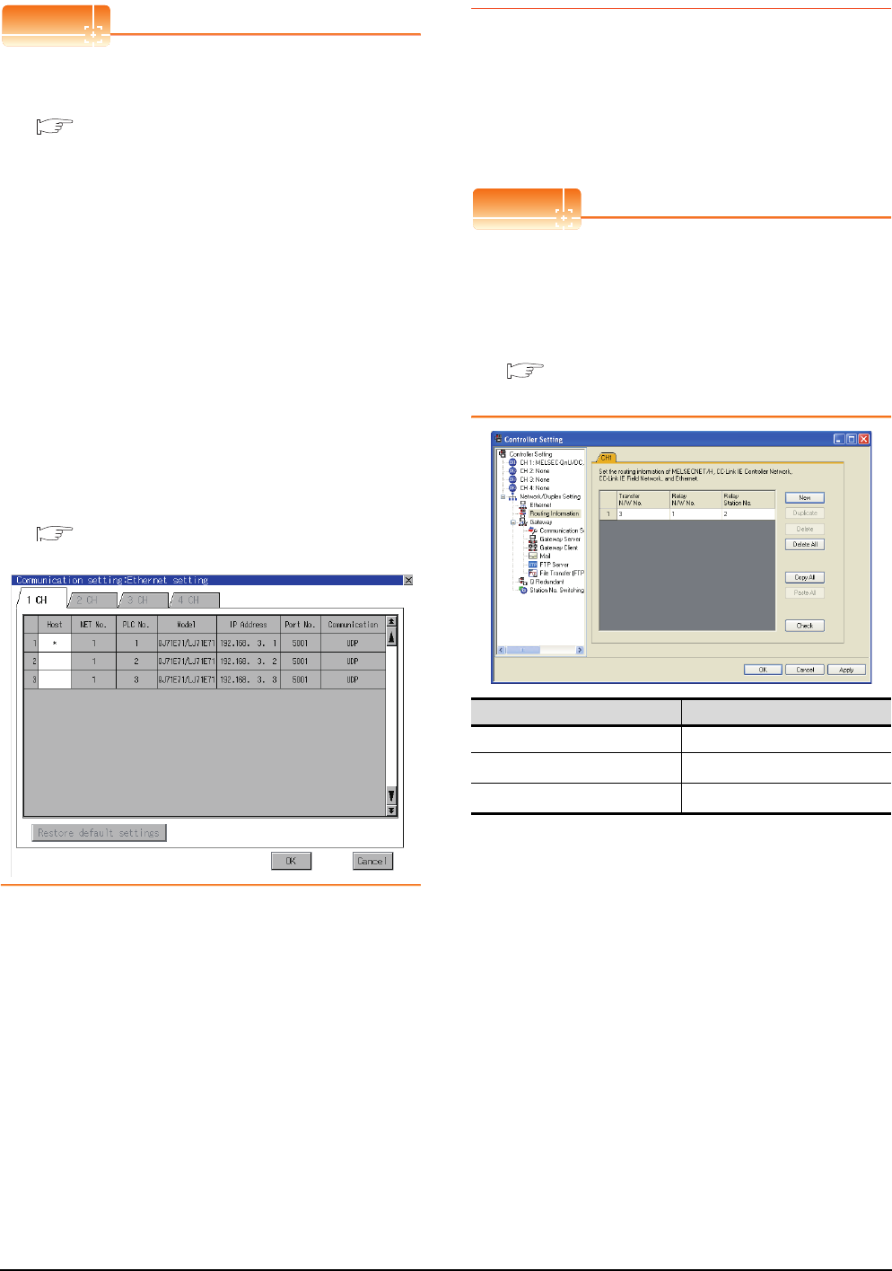
8 - 18 8. ETHERNET CONNECTION
8.3 GOT Side Settings
POINTPOINTPOINT
(1) Example of [Ethernet setting]
For examples of [Ethernet setting], refer to the
following.
8.4 PLC Side Setting
(2) Parameter reflection function of MELSOFT
Navigator
(a) The color of the cells for the items which are
reflected to GT Designer3 from MELSOFT
Navigator changes to green. Set items, which
are displayed in green cells, from the
MELSOFT Navigator.
(b) When the settings of N/W No., PLC No., type
or IP address are reflected to the parameter
from the MELSOFT Navigator, those settings
are added. Items set in advance are not
deleted. However, if the combination of the N/
W No. and the PLC No. or the IP address
overlaps, the item set in advance is
overwritten.
(3) Changing the host on the GOT main unit
The host can be changed by the utility function of
the GOT main unit. For the detailed connection
method, refer to the following manual.
User's Manual of GOT used.
(When using GT16)
8.3.4 Routing parameter setting
Up to 64 [Transfer Network No.]s can be set.
However, the same transfer network number cannot be set
twice or more (multiple times).
Therefore, the one that can access to other station from the
request source host GOT is 64 kinds of [Transfer Network
No.]s.
POINTPOINTPOINT
Routing parameter setting
When communicating within the host network, routing
parameter setting is unnecessary.
For details of routing parameters, refer to the following
manual.
Q Corresponding Ethernet Interface Module
User's Manual (Application)
*1 When accessing to other networks relaying a Build-in
Ethernet port CPU, set the virtual network No. and PLC No.
set in the Ethernet settings on GT Designer3.
Item Range
Transfer Network No. 1 to 239
Relay Network No.*1 1 to 239
Relay Station No.*1 1 to 64

8. ETHERNET CONNECTION
8.3 GOT Side Settings
8 - 19
1
PREPARATORY
PROCEDURES FOR
MONITORING
2
DEVICE RANGE
THAT CAN BE SET
3
ACCESS RANGE
FOR MONITORING
4
HOW TO MONITOR
REDUNTANT
SYSTEM
5
BUS CONNECTION
6
DIRECT
CONNECTION TO
CPU
7
COMPUTER LINK
CONNECTION
8
ETHERNET
CONNECTION
POINTPOINTPOINT
(1) Routing parameter setting of relay station
Routing parameter setting is also necessary for
the relay station.
For the setting, refer to the following.
8.4 PLC Side Setting
(2) Parameter reflection function of MELSOFT
Navigator
(a) The color of the cells for the items which are
reflected to GT Designer3 from MELSOFT
Navigator changes to green. Set items, which
are displayed in green cells, from the
MELSOFT Navigator.
(b) When the settings of Transfer network No.,
Relay network No. or Relay station No. are
reflected to the parameter from the MELSOFT
Navigator, those settings are added. Items set
in advance are not deleted.However, if the
target network No. overlaps, the item set in
advance is overwritten.
(c) The routing information is used manually by
the user when the data is created. Therefore,
after changing the network configuration by
MELSOFT Navigator, create a routing
information again. For details of the creation
of the routing information, refer to the
MELSOFT Navigator help.
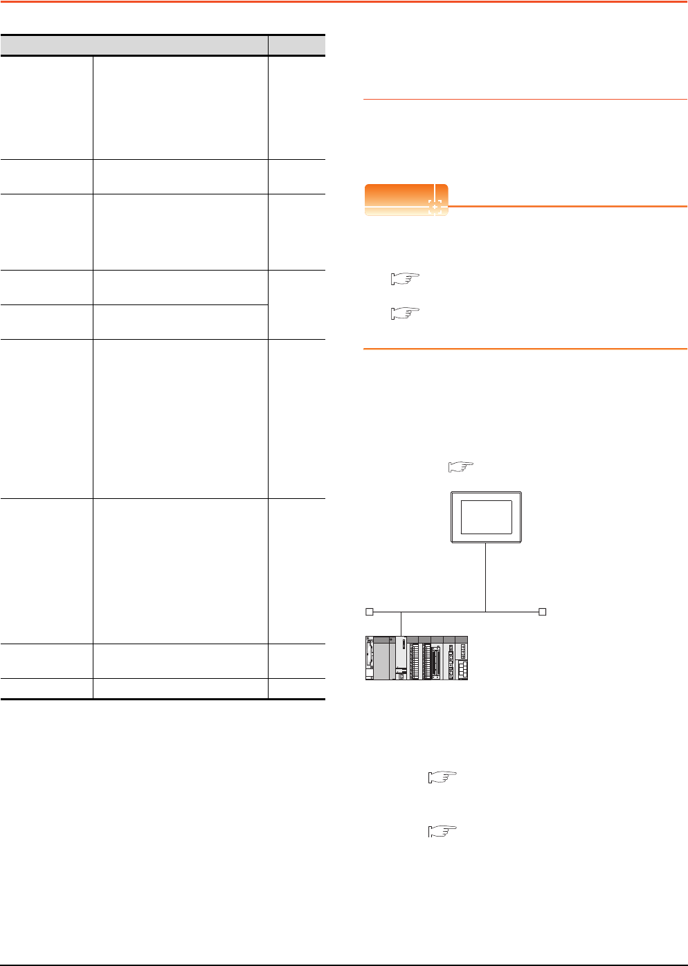
8 - 20 8. ETHERNET CONNECTION
8.4 PLC Side Setting
8.4 PLC Side Setting
8.4.1 Connecting to Built-in Ethernet
port CPU (one-to-one
connection)
This section describes the settings of the GOT and Built-in
Ethernet port CPU in the following case of system
configuration.
POINTPOINTPOINT
Connecting to Built-in Ethernet port CPU
For details of Built-in Ethernet port CPU, refer to the
following manual.
QnUCPU User's Manual (Communication via
Built-in Ethernet Port)
MELSEC-L CPU Module User's Manual (Built-
In Ethernet Function)
System configuration
For connecting one Built-in Ethernet port QCPU to one
GOT, the PLC side settings are not required. Set
[Ethernet] for [Controller Setting] on GT Designer3, and
then connect Built-in Ethernet port QCPU to the GOT.
*1 For the settings when using system devices including a hub
and a transceiver, refer to the following.
8.4.2 Connecting to Built-in Ethernet port CPU
(multiple connection)
*2 These setting items do not exist at the PLC side. However,
the virtual values must be set on the GOT side.
[Controller Setting] and [Ethernet] of GT Designer3
Model Reference
Built-in Ethernet
port QCPU
Q03UDECPU, Q04UDEHCPU,
Q06UDEHCPU, Q10UDEHCPU,
Q13UDEHCPU, Q20UDEHCPU,
Q26UDEHCPU, Q50UDEHCPU,
Q100UDEHCPU, Q03UDVCPU,
Q04UDVCPU, Q06UDVCPU,
Q13UDVCPU, Q26UDVCPU
8.4.1
8.4.2
C Controller
module
Q12DCCPU-V
Q24DHCCPU-V 8.4.4
Built-in Ethernet
port LCPU
L02CPU
L26CPU
L26CPU-BT
L02CPU-P
L26CPU-PBT
8.4.1
8.4.2
Ethernet module
(Q Series)
QJ71E71-100, QJ71E71-B5,
QJ71E71-B2, QJ71E71
8.4.3
Ethernet module
(L Series) LJ71E71-100
Ethernet module
(QnA Series)
AJ71QE71N3-T,
AJ71QE71N-B5,
AJ71QE71N-B2, AJ71QE71N-T,
AJ71QE71N-B5T,
AJ71QE71, AJ71QE71-B5,
A1SJ71QE71N3-T,
A1SJ71QE71N-B5,
A1SJ71QE71N-B2, A1SJ71QE71N-T,
A1SJ71QE71N-B5T,
A1SJ71QE71-B5,
A1SJ71QE71-B2
8.4.5
Ethernet module
(A Series)
AJ71E71N3-T, AJ71E71N-B5,
AJ71E71N-B2, AJ71E71N-T,
AJ71E71N-B5T, AJ71E71-S3,
A1SJ71E71N3-T,
A1SJ71E71N-B5,
A1SJ71E71N-B2,
A1SJ71E71N-T,
A1SJ71E71N-B5T,
A1SJ71E71-B5-S3,
A1SJ71E71-B2-S3
8.4.6
Ethernet module
(FX Series) FX3U-ENET, FX3U-ENET-ADP 8.4.7
CNC C70 Q173NCCPU 8.4.8
<GOT>
(The settings other than the
following are set to the default)
*1
*2
*2
Network No. : 1
PLC No. : 1
IP address : 192.168.3.1
Port No. : 5001
Communication
format
: UDP (fixed)
Network No. : 1 (virtual)
PLC No. : 2 (virtual)
IP address : 192.168.3.39
Port No. : 5006 (fixed)
Communication
format
: UDP (fixed)
<Connecting to Built-in Ethernet port CPU>
(The following settings are set to the default)
[Controller Setting] and [Ethernet] of GT
Designer3
■
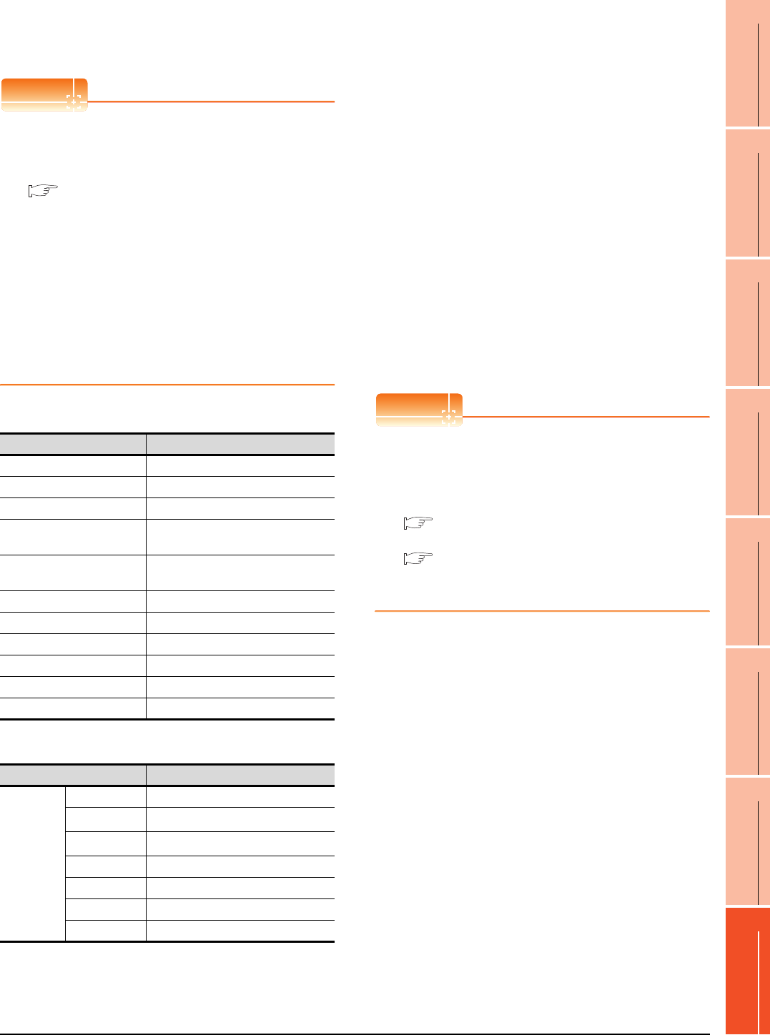
8. ETHERNET CONNECTION
8.4 PLC Side Setting
8 - 21
1
PREPARATORY
PROCEDURES FOR
MONITORING
2
DEVICE RANGE
THAT CAN BE SET
3
ACCESS RANGE
FOR MONITORING
4
HOW TO MONITOR
REDUNTANT
SYSTEM
5
BUS CONNECTION
6
DIRECT
CONNECTION TO
CPU
7
COMPUTER LINK
CONNECTION
8
ETHERNET
CONNECTION
[Controller Setting] and [Ethernet] of GT
Designer3
POINTPOINTPOINT
(1) [Controller Setting] and [Ethernet] of GT
Designer3
For [Controller Setting] and [Ethernet] of GT
Designer3, refer to the following.
8.3.1 Setting communication interface
(Communication settings)
(2) Ethernet setting
When connecting Built-in Ethernet port QCPU or
LCPU to a GOT, the settings items for the network
No. and station No. do not exist at the PLC side.
However, these virtual values must be set on the
GOT side. Therefore, set the network No. and
station No.
Therefore, set the network No. and station No.
Set the network No. that is not existed on the
network system and any station No..
(3) Controller setting
(4) Ethernet setting
*1 Set the same value as that of GOT N/W No.
*2 Set a value different from that of GOT PLC No.
Checking communication state of Connecting
to Built-in Ethernet port CPU
(1) When using the Command Prompt of Windows.
Execute a Ping command at the Command Prompt of
Windows.
(a) When normal communication
C:\>Ping 192.168.3.39
Reply from 192.168.3.2: bytes=32 time
<10ms TTL=32
(b) When abnormal communication
C:\>Ping 192.168.3.39
Request timed out.
(2) When abnormal communication
At abnormal communication, check the followings and
execute the Ping command again.
• Cable connecting condition
• Confirmation of switch and network parameter setting
• Operation state of PLC CPU (faulty or not)
• The IP address of Built-in Ethernet port CPU specified
in the ping command
POINTPOINTPOINT
Ethernet diagnostics of GX Developer
Ethernet diagnostics of GX Developer is available to a
Ping test from the PLC.
For details of Ethernet diagnostics of GX Developer,
refer to the following manual.
QCPU User's Manual (Hardware Design,
Maintenance and Inspection)
MELSEC-L CPU Module User's Manual
(Hardware Design, Maintenance and
Inspection)
Item Set value (Use default value)
GOT NET No. 1
GOT PLC No. 1
GOT IP Address 192.168.3.1
GOT Port No.
(Communication) 5001
GOT Port No.
(Ethernet Download) 5014
Default Gateway 0.0.0.0
Subnet Mask 255.255.255.0
Retry 3times
Startup Time 3sec
Timeout Time 3sec
Delay Time 0ms
Item Set value
Ethernet
setting No.1
Host *
N/W No. 1*1
PLC No. 2*2
Type QnUDE(H), LCPU
IP address 192.168.3.39
Port No. 5006 (fixed)
Communication UDP (fixed)
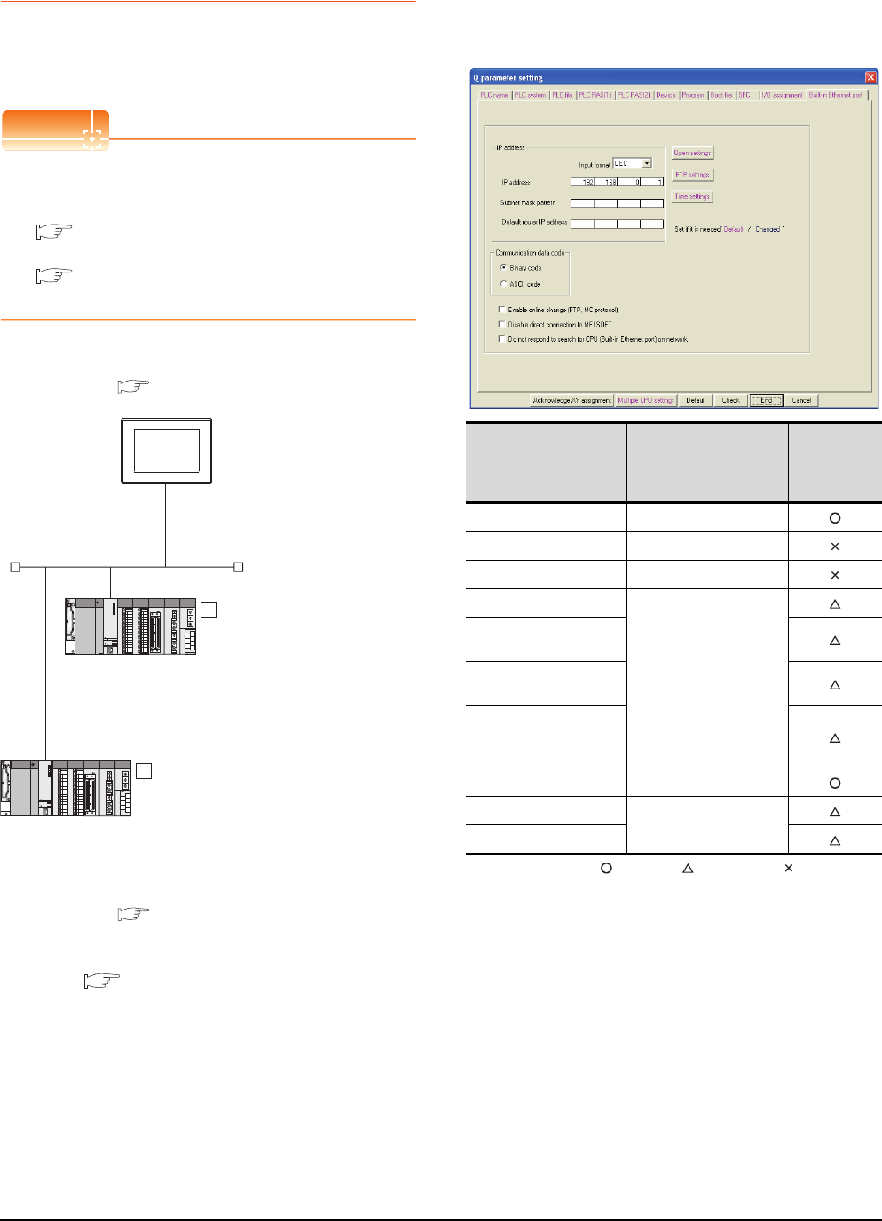
8 - 22 8. ETHERNET CONNECTION
8.4 PLC Side Setting
8.4.2 Connecting to Built-in Ethernet
port CPU (multiple connection)
This section describes the settings of the GOT and Built-in
Ethernet port CPU in the following case of system
configuration.
POINTPOINTPOINT
Connecting to Built-in Ethernet port CPU
For details of Built-in Ethernet port CPU, refer to the
following manual.
QnUCPU User's Manual (Communication via
Built-in Ethernet Port)
MELSEC-L CPU Module User's Manual (Built-
In Ethernet Function)
System configuration
*1 These setting items do not exist at the PLC side. However,
the virtual values must be set on the GOT side.
[Controller Setting] and [Ethernet] of GT Designer3
[Q parameter setting] or [L parameter setting]
for GX Developer
(1) Built-in Ethernet port
Example: [Q parameter setting] screen
: Necessary : As necessary : Not necessary
<GOT>
(The settings other than the
following are set to the default)
Network No. : 1
PLC No. : 1
IP address : 192.168.0.18
Port No. : 5001
Communication
format
: UDP(fixed)
Network No. : 1 (virtual)
PLC No. : 2 (virtual)
IP address : 192.168.0.1
Port No. : 5006(fixed)
Communication
format
: UDP(fixed)
<Connecting to Built-in
Ethernet port CPU>
(The settings other than the
following are set to the default)
1
Network No. : 1 (virtual)
PLC No. : 3 (virtual)
IP address : 192.168.0.2
Port No. : 5006(fixed)
Communication
format
: UDP(fixed)
<Connecting to Built-in Ethernet port CPU>
(The settings other than the following are
set to the default)
2
*1
*1
*1
*1
[Controller Setting] and [Ethernet] of GT
Designer3
■
[Q parameter setting] or [L parameter
setting] for GX Developer
■
Item Set value
Setting
necessity at
GOT
connection
IP address 192.168.0.1
Subnet mask pattern -
Default router IP address -
Communication data code
(Use default value)
Enable online change
(FTP, MC protocol)
Disable direct connection
to MELSOFT
Do not respond to search
for CPU (Built-in Ethernet
port) on network
Open settings Refer to (2).
FTP settings
(Use default value)
Time settings
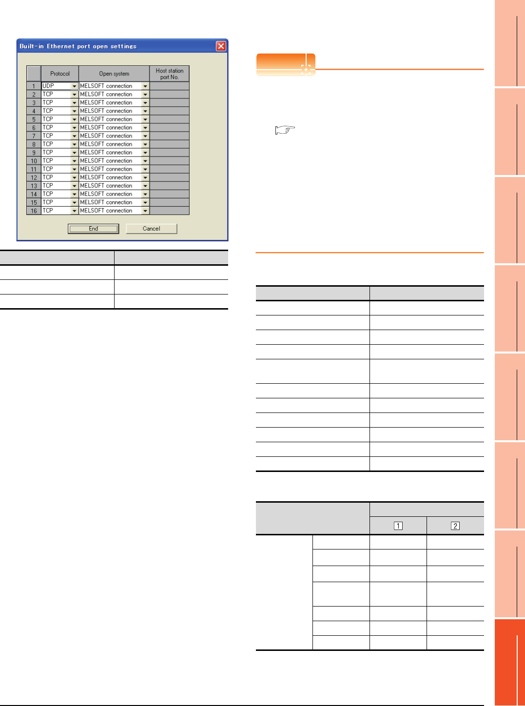
8. ETHERNET CONNECTION
8.4 PLC Side Setting
8 - 23
1
PREPARATORY
PROCEDURES FOR
MONITORING
2
DEVICE RANGE
THAT CAN BE SET
3
ACCESS RANGE
FOR MONITORING
4
HOW TO MONITOR
REDUNTANT
SYSTEM
5
BUS CONNECTION
6
DIRECT
CONNECTION TO
CPU
7
COMPUTER LINK
CONNECTION
8
ETHERNET
CONNECTION
(2) Open settings
The setting is required for all the connected GOTs.
[Controller Setting] and [Ethernet] of GT
Designer3
POINTPOINTPOINT
(3) [Controller Setting] and [Ethernet] of GT
Designer3
For [Controller Setting] and [Ethernet] of GT
Designer3, refer to the following.
8.3.1 Setting communication interface
(Communication settings)
(4) Ethernet setting
When connecting Built-in Ethernet port CPU to a
GOT, the settings items for the network No. and
station No. do not exist at the PLC side. However,
these virtual values must be set on the GOT side.
Therefore, set the network No. and station No.
Set the network No. that is not existed on the
network system and any station No..
(1) Controller setting
(2) Ethernet setting
*1 Set the same value as that of GOT N/W No.
*2 Set a value different from that of the GOT PLC No. and the
PLC No. of other PLCs on the same network.
Item Set value
Protocol UDP (fixed)
Open system MELSOFT connection (fixed)
Host station port No. (Use default value)
Item Set value (Use default value)
GOT NET No. 1
GOT PLC No. 1
GOT IP Address 192.168.0.18
GOT Port No. (Communication) 5001
GOT Port No.
(Ethernet Download) 5014
Default Gateway 0.0.0.0
Subnet Mask 255.255.255.0
Retry 3times
Startup Time 3sec
Timeout Time 3sec
Delay Time 0ms
Item
Set value
Ethernet setting
No.1
Host * -
N/W No. 1*1 1*1
PLC No. 2*2 3*2
Type QnUDE(H),
LCPU
QnUDE(H),
LCPU
IP address 192.168.0.1 192.168.0.2
Port No. 5006 (fixed) 5006 (fixed)
Communication UDP (fixed) UDP (fixed)
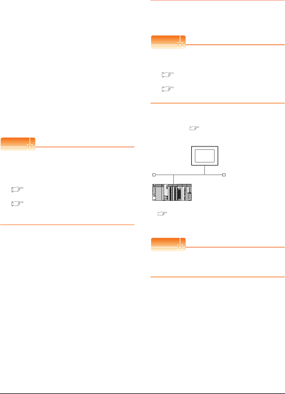
8 - 24 8. ETHERNET CONNECTION
8.4 PLC Side Setting
Checking communication state of Connecting
to Built-in Ethernet port CPU
(1) When using the Command Prompt of Windows.
Execute a Ping command at the Command Prompt of
Windows.
(a) When normal communication
C:\>Ping 192.168.0.1
Reply from 192.168.0.1: bytes=32 time
<10ms TTL=32
(b) When abnormal communication
C:\>Ping 192.168.0.1
Request timed out.
(2) When abnormal communication
At abnormal communication, check the followings and
execute the Ping command again.
• Cable connecting condition
• Confirmation of switch and network parameter setting
• Operation state of PLC CPU (faulty or not)
• The IP address of Built-in Ethernet port CPU specified
in the ping command
POINTPOINTPOINT
Ethernet diagnostics of GX Developer
Ethernet diagnostics of GX Developer is available to a
Ping test from the PLC.
For details of Ethernet diagnostics of GX Developer,
refer to the following manual.
QCPU User's Manual (Hardware Design,
Maintenance and Inspection)
MELSEC-L CPU Module User's Manual
(Hardware Design, Maintenance and
Inspection)
8.4.3 Connecting to Ethernet
module (Q/L Series)
This section describes the settings of the GOT and
Ethernet module (Q Series) in the following case of the
system configuration.
POINTPOINTPOINT
Ethernet module (Q/L Series)
For details of the Ethernet module (Q/L Series), refer
to the following manual.
Q Corresponding Ethernet Interface Module
User's Manual (Basic)
MELSEC-L Ethernet Interface Module User's
Manual (Basic)
System configuration (for Q series)
*1 The Ethernet module is mounted on the base unit slot 0.
The Start I/O No. of the Ethernet module is set to "0".
POINTPOINTPOINT
When connecting to Q170MCPU
When connected to Q170MCPU, the start I/O No. of
the Ethernet module is set to "70".
<GOT> (The settings other than the
following are set to the default)
*1
Network No. : 1
PLC No. : 1
IP address : 192.168.0.18
Port No. : 5001
Communication format : UDP (fixed)
Network No. : 1
PLC No. : 2
IP address : 192.168.0.19
Port No. : 5001
Communication format : UDP(fixed)
<Ethernet module> (The settings other than the
following are set to the default)
[Controller Setting] and [Ethernet] of GT
Designer3
■
■ [Network parameter] of GX Developer
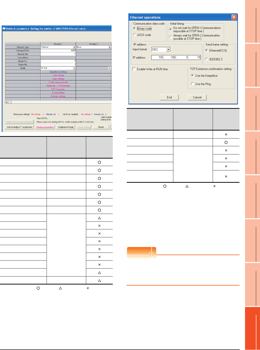
8. ETHERNET CONNECTION
8.4 PLC Side Setting
8 - 25
1
PREPARATORY
PROCEDURES FOR
MONITORING
2
DEVICE RANGE
THAT CAN BE SET
3
ACCESS RANGE
FOR MONITORING
4
HOW TO MONITOR
REDUNTANT
SYSTEM
5
BUS CONNECTION
6
DIRECT
CONNECTION TO
CPU
7
COMPUTER LINK
CONNECTION
8
ETHERNET
CONNECTION
[Network parameter] of GX Developer
(1) Network parameter
: Necessary : As necessary : Not necessary
*1 When using Q170MCPU, set the start I/O to 0070H.
*2 Specify the same network No. as that of the GOT.
*3 Do not set the same station No. as that of the GOT.
*4 Set when using Ethernet module in a redundant QnPRHCPU
system.
(2) Operation setting
: Necessary : As necessary : Not necessary
*1 Because port No. 5001 is fixed, these items operate at the
following setting without relations to the setting given here.
POINTPOINTPOINT
When changing the network parameter
After writing the network parameter to the PLC CPU,
operate the PLC CPU ether turning OFF and then ON
or resetting.
Item Set value
Setting
necessity at
GOT
connection
Network type Ethernet (fixed)
Starting I/O No.*1 0000H
Network No.*2 1
Group No. 0 (fixed)
Station No.*3 2
Mode Online (fixed)
Operation setting Refer to (2)
Initial settings
(Use default value)
Open settings
Router relay parameter
Station No.<->IP information
FTP Parameters
E-mail settings
Interrupt settings
Redundant settings*4
Routing Parameters Refer to (3)
Item Set value
Setting
necessity at
GOT
connection
Communication data code*1 (Use default value)
IP address 192.168.0.19
Initial timing*1
(Use default value)
Send frame setting
Enable Write at RUN time*1
TCP Existence confirmation
setting
• Communication
date code
: [Binary code]
• Initial timing : "Always wait for OPEN"
(Communication is applicable while
stopping the PLC CPU.)
• Enable Write at
RUN time
: [Enable Write at RUN time] (Writing
Data is applicable while running the
PLC CPU.)
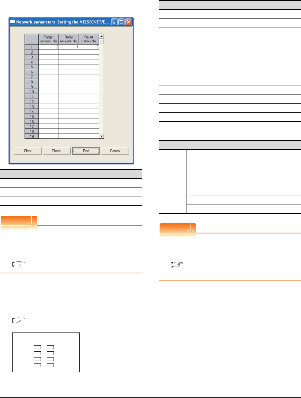
8 - 26 8. ETHERNET CONNECTION
8.4 PLC Side Setting
(3) Routing parameter setting
Up to 64 [Transfer Network No.]s can be set.
However, the same transfer network number cannot be
set twice or more (multiple times).
Therefore, the one that can access to other station from
the request source host GOT is 64 kinds of [Transfer
Network No.]s.
POINTPOINTPOINT
Routing parameter setting of request source
Routing parameter setting is also necessary for the
request source GOT.
For the setting, refer to the following.
8.3.4 Routing parameter setting
(4) Communication confirmation
The INIT. LED on the Ethernet module turns on when
the module is ready to communicate.
For confirming the communication state, refer to the
following.
■Confirming the communication state of
Ethernet module
*1 The LEDs layout of QJ71E71-100.
[Controller Setting] and [Ethernet] of GT
Designer3
(1) Controller setting
(2) Ethernet setting
POINTPOINTPOINT
[Controller Setting] and [Ethernet] of GT Designer3
For [Controller Setting] and [Ethernet] of GT
Designer3, refer to the following.
8.3.1 Setting communication interface
(Communication settings)
Item Range
Target network No. 1 to 239
Relay network No. 1 to239
Relay station No. 1 to 64
QJ71E71-100
RUN
INIT.
OPEN
SD
ERR.
COM.ERR.
RD
100M
*1
Item Set value (Use default value)
GOT NET No. 1
GOT PLC No. 1
GOT IP Address 192.168.0.18
GOT Port No.
(Communication) 5001
GOT Port No.
(Ethernet Download) 5014
Default Gateway 0.0.0.0
Subnet Mask 255.255.255.0
Retry 3times
Startup Time 3sec
Timeout Time 3sec
Delay Time 0ms
Item Set value
Ethernet
setting No.1
Host *
N/W No. 1
PLC No. 2
Type QJ71E71
IP address 192.168.0.19
Port No. 5001 (fixed)
Communication UDP (fixed)
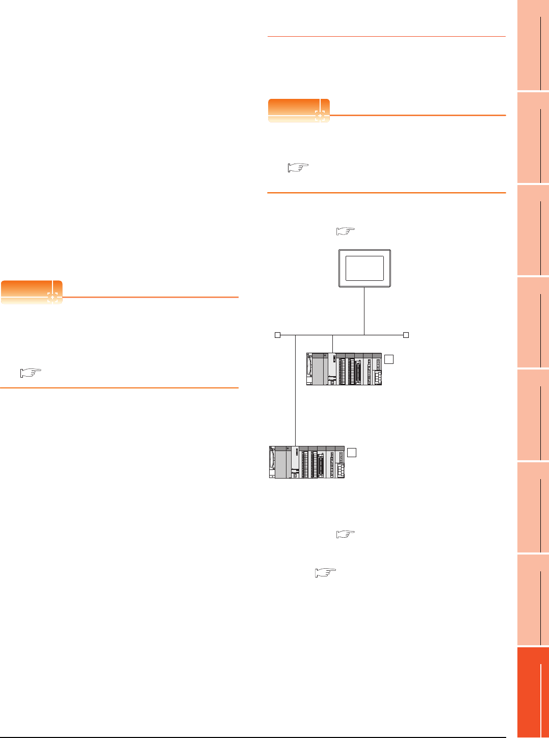
8. ETHERNET CONNECTION
8.4 PLC Side Setting
8 - 27
1
PREPARATORY
PROCEDURES FOR
MONITORING
2
DEVICE RANGE
THAT CAN BE SET
3
ACCESS RANGE
FOR MONITORING
4
HOW TO MONITOR
REDUNTANT
SYSTEM
5
BUS CONNECTION
6
DIRECT
CONNECTION TO
CPU
7
COMPUTER LINK
CONNECTION
8
ETHERNET
CONNECTION
Confirming the communication state of
Ethernet module
(1) When using the Command Prompt of Windows.
Execute a Ping command at the Command Prompt of
Windows.
(a) When normal communication
C:\>Ping 192.168.0.19
Reply from 192.168.0.19: bytes=32 time<1ms
TTL=64
(b) When abnormal communication
C:\>Ping 192.168.0.19
Request timed out.
(2) When abnormal communication
At abnormal communication, check the followings and
execute the Ping command again.
• Mounting condition of Ethernet communication unit
• Cable connecting condition
• Confirmation of switch and network parameter setting
• Operation state of PLC CPU (faulty or not)
• IP address of GOT specified by Ping command
POINTPOINTPOINT
Ethernet diagnostics of GX Developer
Ethernet diagnostics of GX Developer is available to a
Ping test from the PLC.
For details of Ethernet diagnostics of GX Developer,
refer to the following manual.
User's manual of the Ethernet module
8.4.4 Connecting to C Controller
module
This section describes the settings of the GOT and C
Controller module in the following case of the system
configuration.
POINTPOINTPOINT
C Controller module
For details of C Controller module, refer to the
following manual.
C Controller Module User's Manual (Hardware
Design, Function Explanation)
System configuration
*1 These setting items do not exist at the PLC side. However,
the virtual values must be set on the GOT side.
[Controller Setting] and [Ethernet] of GT
Designer3
<GOT>
(The settings other than the
following are set to the default)
Network No. : 1
PLC No. : 1
IP address : 192.168.3.18
Port No. : 5001
Communication
format
: UDP(fixed)
Network No. : 1 (virtual)
PLC No. : 2 (virtual)
IP address : 192.168.3.1
Port No. : 5006(fixed)
Communication
format
: UDP(fixed)
<C controller module>
(The settings other than the
following are set to the default)
1
Network No. : 1 (virtual)
PLC No. : 3 (virtual)
IP address : 192.168.3.2
Port No. : 5006(fixed)
Communication
format
: UDP(fixed)
<C controller module>
(The settings other than the following are
set to the default)
2
*1
*1
*1
*1
[Controller Setting] and [Ethernet] of GT
Designer3
■
Utility setting for C Controller module
■
■
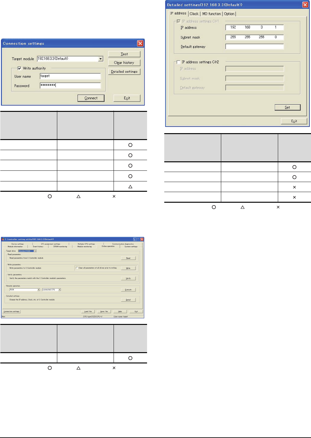
8 - 28 8. ETHERNET CONNECTION
8.4 PLC Side Setting
Utility setting for C Controller module
(1) Q12DCCPU-V
Use SW3PVC-CCPU-E Ver.3.05F or later for the C
Controller setting utility.
(a) Connection settings
: Necessary : As necessary : Not necessary
*1 If the IP address of the C Controller module has been
changed, input the changed IP address or host name.
*2 If the account of the C Controller module has been changed,
input the changed user name and password.
(b) Online operation
: Necessary : As necessary : Not necessary
(c) Detail settings
: Necessary : As necessary : Not necessary
Item Set value
Setting
necessity at
GOT
connection
Target module*1 192.168.3.3 (Default)
Write authority Mark the checkbox
User name*2 target
Password*2 password
Detailed settings -
Item Set value
Setting
necessity at
GOT
connection
Detailed settings Refer to (3)
Item Set value
Setting
necessity at
GOT
connection
IP address 192.168.3.1
Subnet mask 255.255.255.0
Default gateway -
IP address settings CH2 -
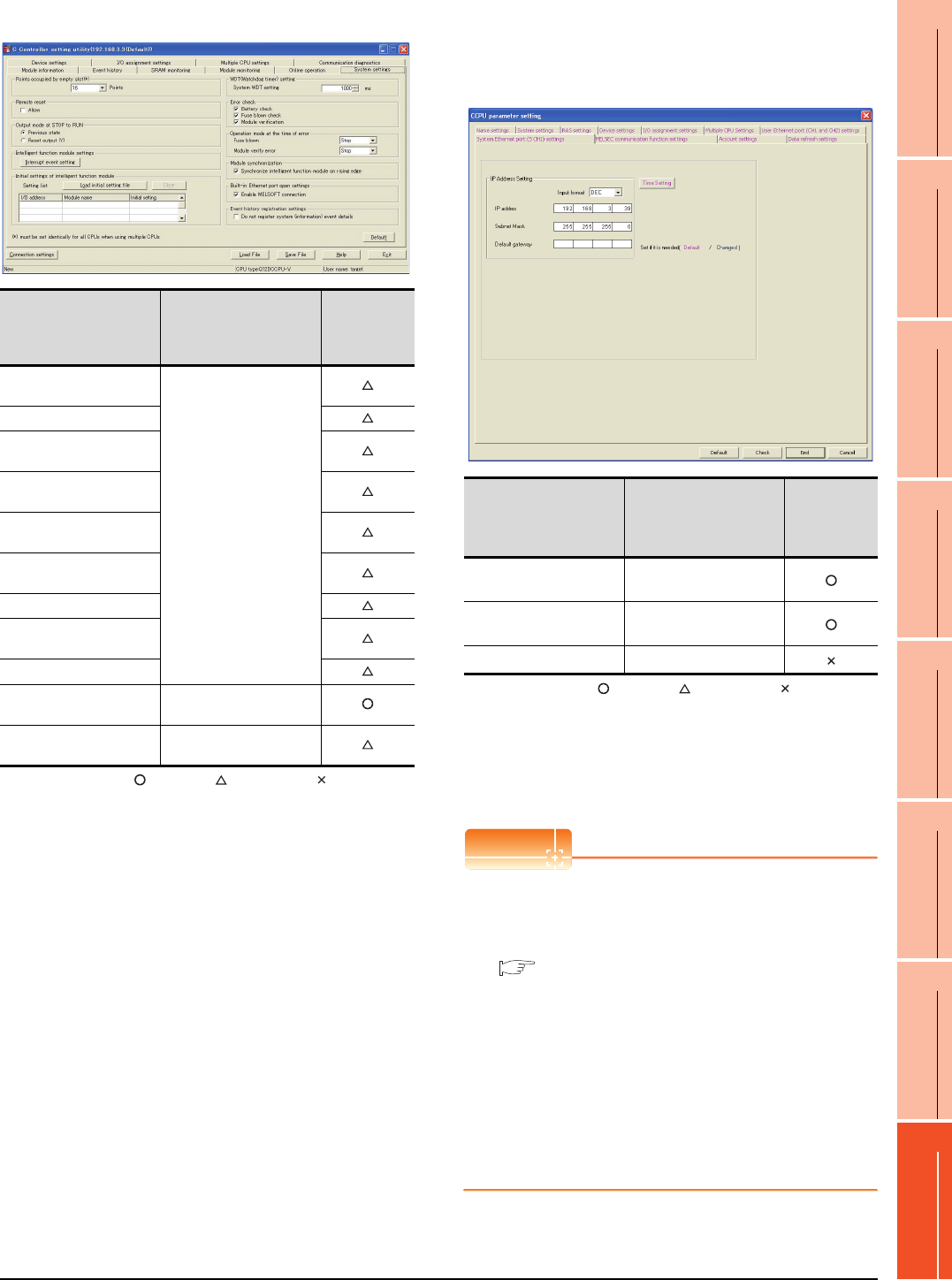
8. ETHERNET CONNECTION
8.4 PLC Side Setting
8 - 29
1
PREPARATORY
PROCEDURES FOR
MONITORING
2
DEVICE RANGE
THAT CAN BE SET
3
ACCESS RANGE
FOR MONITORING
4
HOW TO MONITOR
REDUNTANT
SYSTEM
5
BUS CONNECTION
6
DIRECT
CONNECTION TO
CPU
7
COMPUTER LINK
CONNECTION
8
ETHERNET
CONNECTION
(d) System settings
: Necessary : As necessary : Not necessary
(2) Q24DHCCPU-V
Use SW4PVC-CCPU-E for the C Controller setting
utility.
(a) Connection settings
: Necessary : As necessary : Not necessary
*1 If the IP address of the C Controller module has been
changed, input the changed IP address.
[Controller Setting] and [Ethernet] of GT
Designer3
POINTPOINTPOINT
(1) [Controller Setting] and [Ethernet] of GT
Designer3
For [Controller Setting] and [Ethernet] of GT
Designer3, refer to the following.
8.3.1 Setting communication interface
(Communication settings)
(2) Ethernet setting
When connecting C Controller module to a GOT,
the setting items for the network No. and station
No. do not exist at the PLC side. However, these
virtual values must be set on the GOT side.
Therefore, set the network No. and station No.
Set the network No. that is not existed on the
network system and any station No..
Item Set value
Setting
necessity at
GOT
connection
Points occupied by empty
slot
(Use default value)
Remote reset
Output mode at STOP to
RUN
Intelligent function module
settings
Initial settings of intelligent
function module
WDT (Watchdog timer)
setting
Error check
Operation mode at the
time of error
Module synchronization
Built-in Ethernet port open
settings Mark the checkbox
Event history registration
settings (Use default value)
Item Set value
Setting
necessity at
GOT
connection
IP Address*1 192.168.3.39
(Default)
Subnet Mask 255.255.255.0
(Default)
Default Gateway -
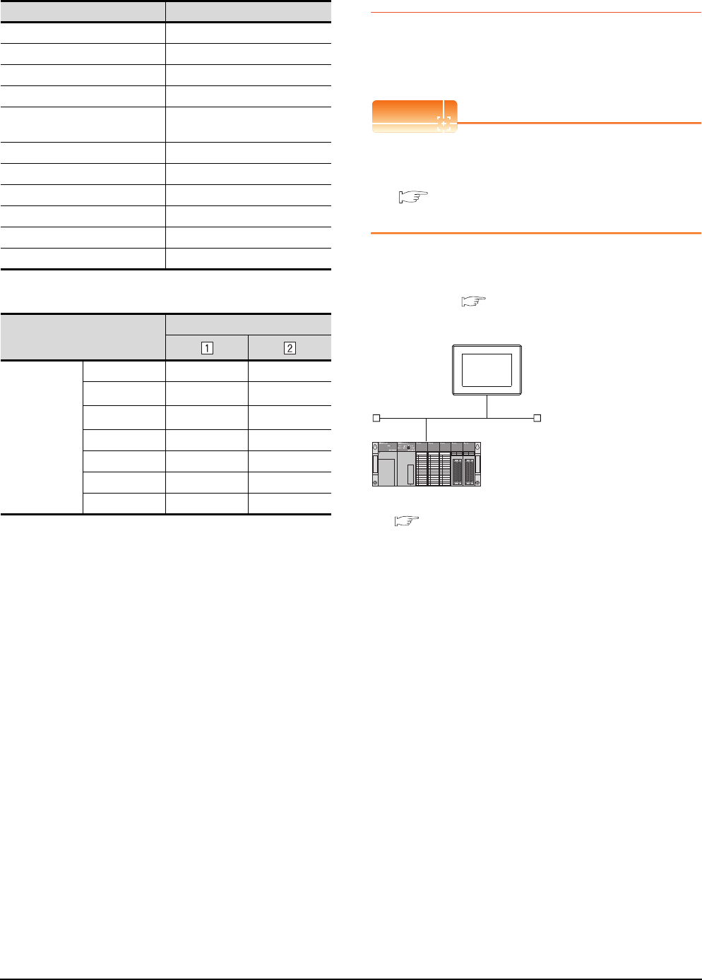
8 - 30 8. ETHERNET CONNECTION
8.4 PLC Side Setting
(1) Controller setting
(2) Ethernet setting
*1 Set the same value as that of GOT N/W No.
*2 Set a value different from that of the GOT PLC No. and the
PLC No. of other PLCs on the same network.
Checking communication state of C
Controller module
(1) When using the Command Prompt of Windows.
Execute a Ping command at the Command Prompt of
Windows.
(a) When normal communication
C:\>Ping 192.168.0.1
Reply from 192.168.0.1: bytes=32 time
<10ms TTL=32
(b) When abnormal communication
C:\>Ping 192.168.0.1
Request timed out.
(2) When abnormal communication
At abnormal communication, check the followings and
execute the Ping command again.
• Cable connecting condition
• Confirmation of switch and network parameter setting
• Operation state of PLC CPU (faulty or not)
• The IP address of C Controller module specified in the
ping command
8.4.5 Connecting to Ethernet
module (QnA Series)
This section describes the settings of the GOT and
Ethernet module (QnA Series) in the following case of the
system configuration.
POINTPOINTPOINT
Ethernet module (QnA Series)
For details of the Ethernet module (QnA Series), refer
to the following manual.
For QnA Ethernet Interface Module User’s
Manual
System configuration
*1 The Ethernet module is mounted on the base unit slot 0.
The Start I/O No. of the Ethernet module is set to "0".
Item Set value (Use default value)
GOT NET No. 1
GOT PLC No. 1
GOT IP Address 192.168.3.18
GOT Port No. (Communication) 5001
GOT Port No.
(Ethernet Download) 5014
Default Gateway 0.0.0.0
Subnet Mask 255.255.255.0
Retry 3times
Startup Time 3sec
Timeout Time 3sec
Delay Time 0ms
Item
Set value
Ethernet setting
No.1
Host * -
N/W No. 1*1 1*1
PLC No. 2*2 3*2
Type QnD(H)CCPU QnD(H)CCPU
IP address 192.168.3.1 192.168.3.2
Port No. 5006 (fixed) 5006 (fixed)
Communication UDP (fixed) UDP (fixed)
<GOT>(The settings other than
the following are set to the default)
Network No. : 1
PLC No. : 1
IP address : 192.168.0.18
Port No. : 5001
Communication format : UDP(fixed)
Network No. : 1
PLC No. : 2
Port No. : 5001
Communication format : UDP(fixed)
<Ethernet module> (The settings other than
the following are set to the default)
*1
IP address : 192.168.0.19
[Controller Setting] and [Ethernet] of GT
Designer3
■
■ Switch settings of Ethernet module
■ [Network parameter] of GX Developer
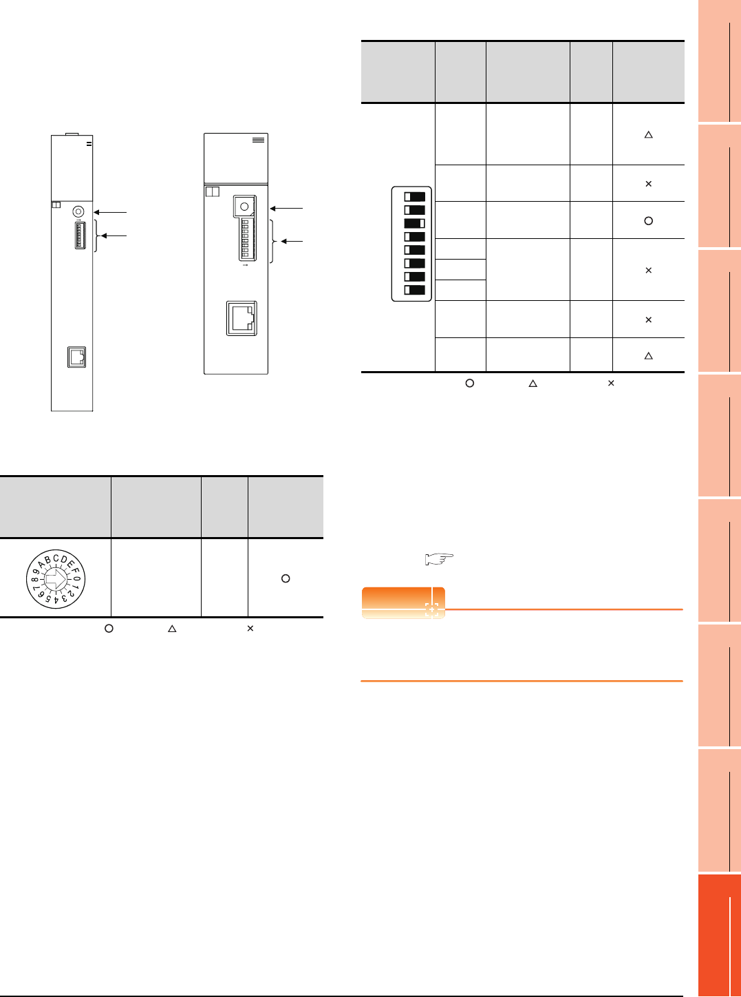
8. ETHERNET CONNECTION
8.4 PLC Side Setting
8 - 31
1
PREPARATORY
PROCEDURES FOR
MONITORING
2
DEVICE RANGE
THAT CAN BE SET
3
ACCESS RANGE
FOR MONITORING
4
HOW TO MONITOR
REDUNTANT
SYSTEM
5
BUS CONNECTION
6
DIRECT
CONNECTION TO
CPU
7
COMPUTER LINK
CONNECTION
8
ETHERNET
CONNECTION
Switch settings of Ethernet module
Set the operation mode setting switch and exchange
condition setting switch.
*1 The figure of AJ71QE71N3-T and
A1SJ71QE71N3-T.
(1) Operation mode setting switch
: Necessary : As necessary : Not necessary
(2) Exchange condition setting switch
: Necessary : As necessary : Not necessary
*2 Because port No. 5001 is fixed, these items operate at the
following setting without relations to the setting given here.
*3 When SW3 is ON, the initial processing is executed
regardless of the initial request signal (Y19).
In addition, communication is applicable while stopping the
PLC CPU.
For the initial processing by using the initial request signal
(Y19), refer to the following manual.
For QnA Ethernet Interface Module User’s Manual
POINTPOINTPOINT
When the switch setting has been changed
Turn the PLC CPU OFF then ON again, or reset the
PLC CPU.
Operation mode setting
switch Description Set
value
Setting
necessity at
GOT
connection
Online 0
(fixed)
10BASE-T
B
4
3
2
1
0
F
E
D
C
A
9
8
7
6
5
RUN BUF1
BUF2
BUF3
BUF4
BUF5
BUF6
BUF7
BUF8
RDY
BSY
SW.ERR.
COM.ERR.
CPU R/W
TEST
TEST ERR.
AJ71QE71N3-T
ON
0:ONLINE
5:TEST4
4:TEST3
3:TEST2
2:TEST1
1:OFFLINE
MODE
SW8
SW7
SW6
SW5
SW4
SW3
SW2
SW1
(1)
(2)
ON
SW1
SW2
SW3
SW4
SW5
SW6
SW7
SW8
10BASE-T
A1SJ71QE71N3-T
4:TEST3
3:TEST2
2:TEST1
1:OFFLINE
0:ONLINE
5:TEST4
MODE
5
6
7
8
9
A
B
C
D
E
F
‚O
1
2
3
4
BSY
SW.ERR.
COM.ERR.
CPU R/W
TEST ERR.
TEST
RDY
RUN BUF1
BUF2
BUF3
BUF4
BUF5
BUF6
BUF7
BUF8
A
1SJ71QE71N3-T
A1SJ71QE71N3-T, A1SJ71QE71N-B5,
A1SJ71QE71N-B2, A1SJ71QE71N-T,
A1SJ71QE71N-B5T, A1SJ71QE71-B5,
A1SJ71QE71-B2
AJ71QE71N3-T, AJ71QE71N-B5,
AJ71QE71N-B2, AJ71QE71N-T,
AJ71QE71N-B5T, AJ71QE71,
AJ71QE71-B5
(1)
(2)
*1
*1
Exchange
condition
setting switch
Setting
switch Description Set
value
Setting
necessity at
GOT
connection
SW1
Selection of line
processing at
TCP timeout
error
OFF
SW2 Data code
setting*2
OFF
(fixed)
SW3 Self start mode
setting*3 ON
SW4
(Must not to be
used)
OFF
(fixed)
SW5
SW6
SW7 CPU exchange
timing setting*2
OFF
(fixed)
SW8 Initial timing
setting OFF
• Data code setting : [Binary code]
• Enable Write at
RUN time
: [Enable Write at RUN time] (Writing
Data is applicable while running the
PLC CPU.)
SW1
SW2
SW3
SW4
SW5
SW6
SW7
SW8
OFF ON
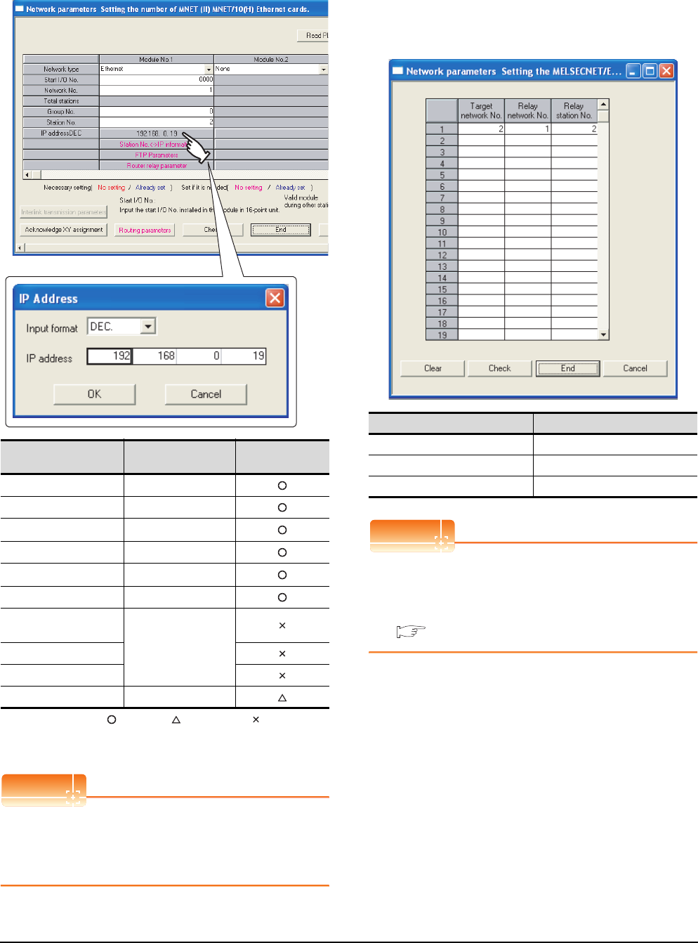
8 - 32 8. ETHERNET CONNECTION
8.4 PLC Side Setting
[Network parameter] of GX Developer
(1) Network parameter
: Necessary : As necessary : Not necessary
*1 Specify the same network No. as that of the GOT.
*2 Do not set the same station No. as that of the GOT.
POINTPOINTPOINT
When changing the network parameter
After writing the network parameter to the PLC CPU,
operate the PLC CPU ether turning OFF and then ON
or resetting.
(2) Routing parameter setting
Up to 64 [Transfer Network No.]s can be set.
However, the same transfer network number cannot be
set twice or more (multiple times).
Therefore, the one that can access to other station from
the request source host GOT is 64 kinds of [Transfer
Network No.]s.
POINTPOINTPOINT
Routing parameter setting of request source
Routing parameter setting is also necessary for the
request source GOT.
For the setting, refer to the following.
8.3.4 Routing parameter setting
Item Set value Setting necessity
at GOT connection
Network type Ethernet (fixed)
Start I/O No. 0000H
Network No.*1 1
Group No. 0 (fixed)
Station No.*2 2
IP address 192.168.0.19
Station No.<->IP
information
(Use default value)
FTP Parameters
Router relay parameter
Routing parameters Refer to (2)
Item Range
Target network No. 1 to 239
Relay network No. 1 to 239
Relay station No. 1 to 64
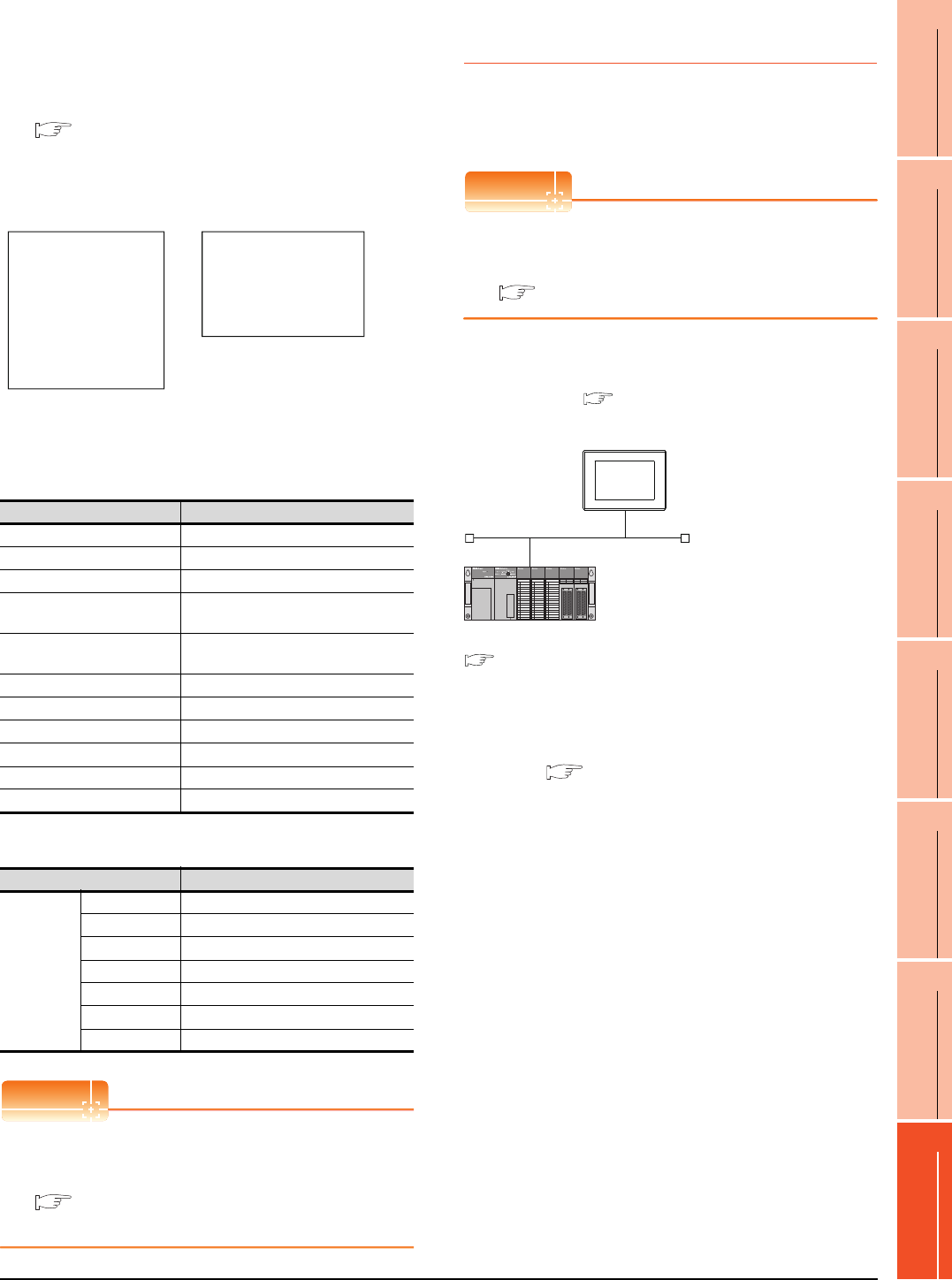
8. ETHERNET CONNECTION
8.4 PLC Side Setting
8 - 33
1
PREPARATORY
PROCEDURES FOR
MONITORING
2
DEVICE RANGE
THAT CAN BE SET
3
ACCESS RANGE
FOR MONITORING
4
HOW TO MONITOR
REDUNTANT
SYSTEM
5
BUS CONNECTION
6
DIRECT
CONNECTION TO
CPU
7
COMPUTER LINK
CONNECTION
8
ETHERNET
CONNECTION
(3) Communication confirmation
The RDY LED on the Ethernet module turn on when
the module is ready to communicate.
For confirming the communication state, refer to the
following.
8.3.4 ■Confirming the communication state of
Ethernet module
[Controller Setting] and [Ethernet] of GT
Designer3
(1) Controller setting
(2) Ethernet setting
POINTPOINTPOINT
[Controller Setting] and [Ethernet] of GT Designer3
For [Controller Setting] and [Ethernet] of GT
Designer3, refer to the following.
8.3.1 Setting communication interface
(Communication settings)
8.4.6 Connecting to Ethernet
module (A Series)
This section describes the settings of the GOT and
Ethernet module (A Series) in the following case of the
system configuration.
POINTPOINTPOINT
Ethernet module (A Series)
For details of the Ethernet module (A Series), refer to
the following manual.
For A Ethernet Interface Module User’s Manual
System configuration
*1 The Ethernet module is mounted on the base unit slot 0.
The Start I/O No. of the Ethernet module is set to "0".
*2 These setting items do not exist at the PLC side. However,
the virtual values must be set on the GOT side.
■ [Controller Setting] and [Ethernet] of GT Designer3
Item Set value (Use default value)
GOT NET No. 1
GOT PLC No. 1
GOT IP Address 192.168.0.18
GOT Port No.
(Communication) 5001
GOT Port No.
(Ethernet Download) 5014
Default Gateway 0.0.0.0
Subnet Mask 255.255.255.0
Retry 3times
Startup Time 3sec
Timeout Time 3sec
Delay Time 0ms
Item Set value
Ethernet
setting No.1
Host *
N/W No. 1
PLC No. 2
Type AJ71QE71
IP address 192.168.0.19
Port No. 5001 (fixed)
Communication UDP (fixed)
RUN BUF1
BUF2
BUF3
BUF4
BUF5
BUF6
BUF7
BUF8
RDY
BSY
SW.ERR.
COM.ERR.
CPU R/W
TEST
TEST ERR.
BSY
SW.ERR.
COM.ERR.
CPU R/W
TEST ERR.
TEST
RDY
RUN BUF1
BUF2
BUF3
BUF4
BUF5
BUF6
BUF7
BUF8
A1SJ71QE71N3-T, A1SJ71QE71N-B5,
A1SJ71QE71N-B2, A1SJ71QE71N-T,
A1SJ71QE71N-B5T,A1SJ71QE71-B5,
A1SJ71QE71-B2
AJ71QE71N3-T, AJ71QE71N-B5,
AJ71QE71N-B2, AJ71QE71N-T,
AJ71QE71N-B5T, AJ71QE71,
AJ71QE71-B5
<GOT> (The settings other than the
following are set to the default)
*2
*2
*1
Network No. : 1
PLC No. : 1
IP address : 192.168.0.18
Port No. : 5001
Communication format : UDP (fixed)
Network No. : 1 (virtual)
PLC No. : 2 (virtual)
IP address : 192.168.0.19
Port No. : 5001
Communication format : UDP(fixed)
<Ethernet module> (The settings other than the
following are set to the default)
[Controller Setting] and [Ethernet] of GT
Designer3
■
■ Switch settings of Ethernet module
■ Sequence program
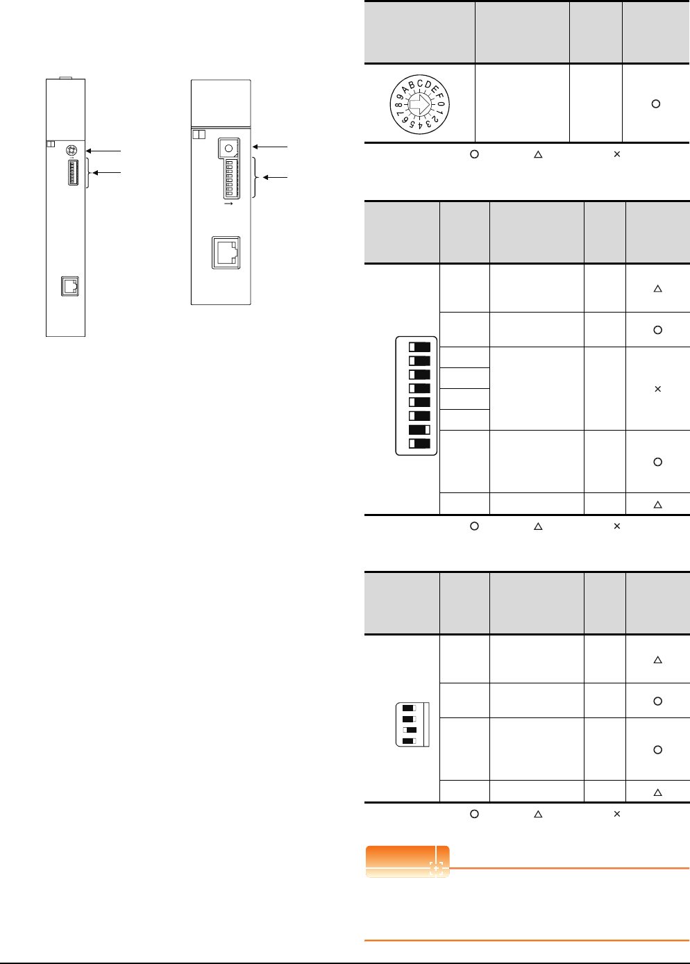
8 - 34 8. ETHERNET CONNECTION
8.4 PLC Side Setting
Switch settings of Ethernet module
Set the operation mode setting switch and exchange
condition setting switch.
*2 The figure of AJ71E71N3-T and A1SJ71E71N3-T.
(1) Operation mode setting switch
: Necessary : As necessary : Not necessary
(2) Exchange condition setting switch*1
: Necessary : As necessary : Not necessary
*1 The exchange condition setting switches of A1SJ71E71-B5-
S3 and A1SJ71E71-B2-S3 are specified as the below.
: Necessary : As necessary : Not necessary
POINTPOINTPOINT
When the switch setting has been changed
Turn the PLC CPU OFF then ON again, or reset the
PLC CPU.
A1SJ71E71N3-T
SW8
SW7
SW6
SW5
SW4
SW3
SW2
SW1
ON
10BASE-T
MODE
0:ONLINE
1:OFFLINE
2:TEST1
3:TEST2
4:TEST3
4
3
2
1
F
E
D
C
B
A
9
8
7
6
5
1SJ71E71N3-T
BSY
SW.ERR.
COM.ERR.
CPU R/W
TEST ERR.
TEST
A
RDY
RUN BUF1
BUF2
BUF3
BUF4
BUF5
BUF6
BUF7
BUF8
0
10BASE-T
4
C
8
J71E71N3-T
RUN BUF1
BUF2
BUF3
BUF4
BUF5
BUF6
BUF7
BUF8
RDY
BSY
SW.ERR.
COM.ERR.
CPU R/W
TEST
TEST ERR.
A
ON
0:ONLINE
4:TEST3
3:TEST2
2:TEST1
1:OFFLIN E
MODE
SW8
SW7
SW6
SW5
SW4
SW3
SW2
SW1
0
(1)
(2)
A1SJ71E71N3-T, A1SJ71E71N-B5,
A1SJ71E71N-B2, A1SJ71E71N-T,
A1SJ71E71N-B5T, A1SJ71E71-B5-S3,
A1SJ71E71-B2-S3
AJ71E71N3-T, AJ71E71N-B5,
AJ71E71N-B2, AJ71E71N-T,
AJ71E71N-B5T, AJ71E71-S3
(1)
(2)
*2
*2
Operation mode
setting switch Description Set value
Setting
necessity at
GOT
connection
Online 0
(fixed)
Exchange
condition
setting switch
Setting
switch Description Set
value
Setting
necessity at
GOT
connection
SW1
Selection of line
processing at TCP
timeout error
OFF
SW2 Data code setting
(binary code)
OFF
(fixed)
SW3
(Must not to be
used)
OFF
(fixed)
SW4
SW5
SW6
SW7
CPU exchange
timing setting
(Enable write at
RUN time)
ON
(fixed)
SW8 Initial timing setting OFF
Exchange
condition
setting switch
Setting
switch Description Set
value
Setting
necessity at
GOT
connection
SW1
Selection of line
processing at TCP
timeout error
OFF
SW2 Data code setting
(binary code)
OFF
(fixed)
SW3
CPU exchange
timing setting
(Enable write at
RUN time)
ON
(fixed)
SW4 Initial timing setting OFF
SW1
SW2
SW3
SW4
SW5
SW6
SW7
SW8
OFF ON
SW1
SW2
SW3
SW4
OFFON
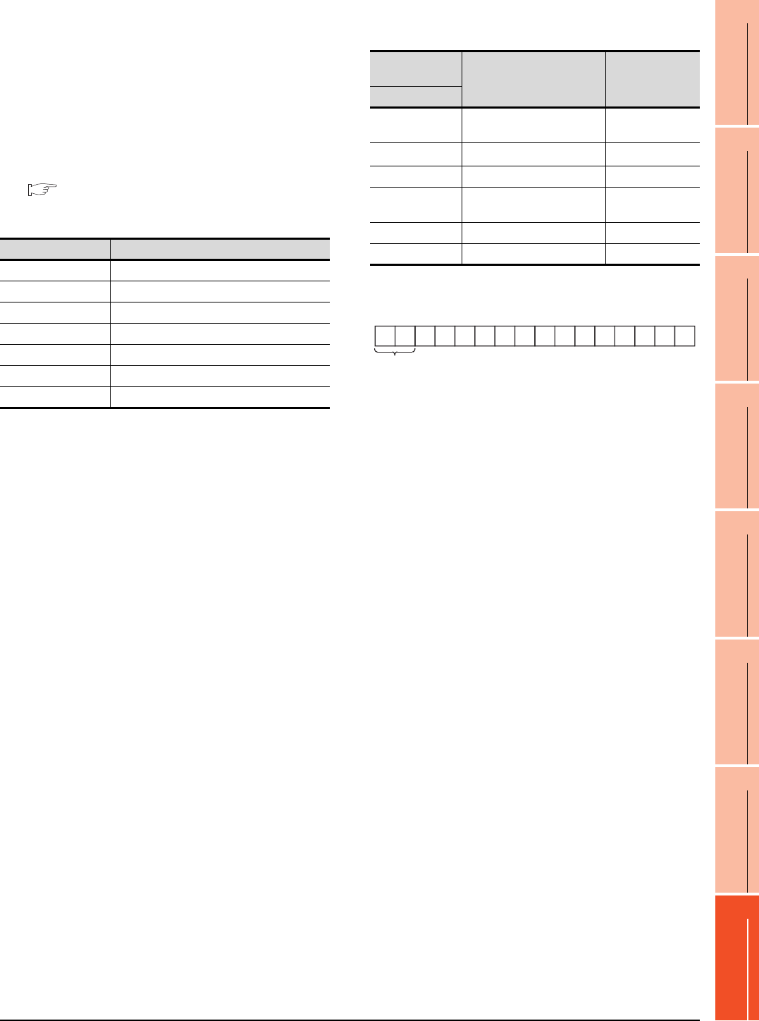
8. ETHERNET CONNECTION
8.4 PLC Side Setting
8 - 35
1
PREPARATORY
PROCEDURES FOR
MONITORING
2
DEVICE RANGE
THAT CAN BE SET
3
ACCESS RANGE
FOR MONITORING
4
HOW TO MONITOR
REDUNTANT
SYSTEM
5
BUS CONNECTION
6
DIRECT
CONNECTION TO
CPU
7
COMPUTER LINK
CONNECTION
8
ETHERNET
CONNECTION
Sequence program
The sequence program for initial processing and
communication line opening processing are required.
(1) Programming condition
This program performs the initial processing of the
Ethernet module and the opening processing of
connection No. 1 when the stopping PLC CPU starts
running.
(a) I/O signal of Ethernet module
For A Ethernet Interface Module User’s Manual
(b) Device used by user
(c) Buffer memory settings used in the present
example
*1 The details of the application setting are shown below.
Settings 1), 2) and 3) can be changed by the user.
4), 5) and 6) are fixed.
Device Application
M102 COM.ERR turned off command
D100 IP address of Ethernet module
D110 Application setting
D111 Port No. of Ethernet module
D112 to D113 IP address of GOT
D114 Port No. of GOT
D200 Initial fault code
Buffer memory
address Item Set value
Dec (Hex)
0 to 1 (0 to 1H) IP address of Ethernet module C0A80013H
(192.168.0.19)
16 (10H)Application setting*1 100H
24 (18H) Port No. of Ethernet module 5001
25 to 26
(19 to 1AH)IP address of GOT FFFFFFFFH
27 (1BH) Port No. of GOT FFFFH (fixed)
80 (50H) Initial fault code ―
1) Fixed buffer application
0: For sending; no exchange
1: For receiving
2) Existence check
0: No
1: Yes
3) Pairing open
0: No
1: Yes
4) Communication format (Set to "1" (UDP/IP).)
0: TCP/IP
1: UDP/IP
5) Fixed buffer exchange (Set to "0" (With procedure).)
0: With procedure
1: Without procedure
6) Open method (Set to "00" (Active, UDP/IP).
00: Active, UDP/IP
10: Unpassive
11: Fullpassive
b15
0
b14
0
b13
0
b12
0
b11
0
b10
0
b9
0
b8
1
b7
0
b6
0
b5
0
b4
0
b3
0
b2
0
b1
0
b0
0
1)2)3)4)5)
6)
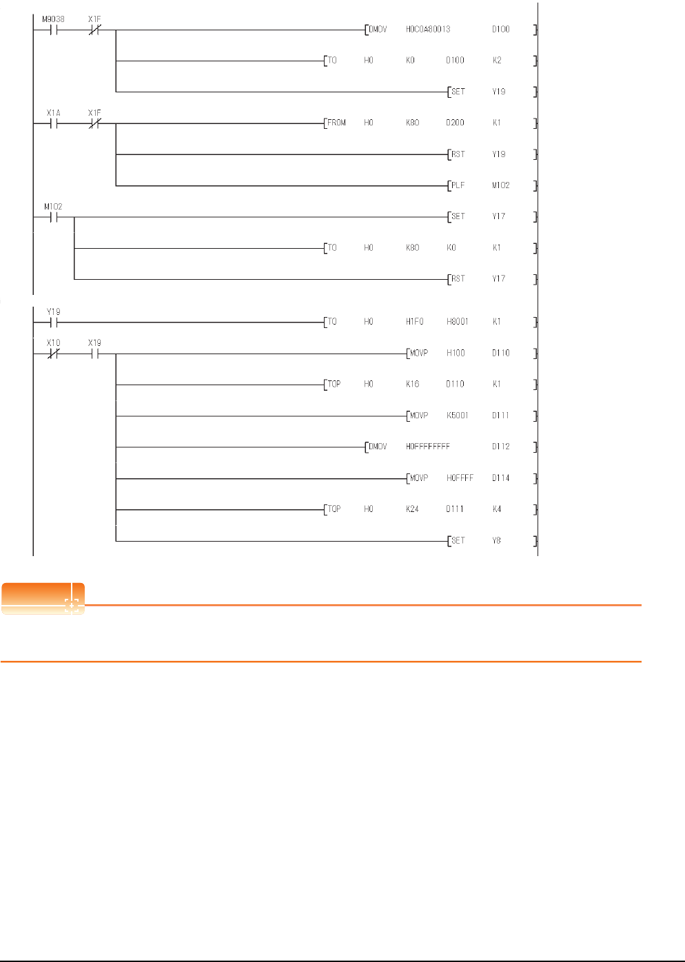
8 - 36 8. ETHERNET CONNECTION
8.4 PLC Side Setting
(2) Example of sequence program
POINTPOINTPOINT
When changing the sequence program
After writing the sequence program to the PLC CPU, operate the PLC CPU ether turning OFF and then ON or resetting.
IP address of Ethernet
module(192.168.0.19)
Initial request
COM. ERR turned off request
Clear the initial fault code.
Set to the permit of
communication while stopping
the PLC CPU.
Communication
format(UDP/IP)
Port No. of Ethernet
module(5001)
IP address of GOT
(When GOT is used, FFFFFFFFH)
Port No. of GOT
(When GOT is used, FFFFH)
Read the initial fault code.
Request to open
Normal
completed
initial
No. 1
open
completed
Initial request
COM.
ERR
turned off
command
Initial
fault
detection
WDT ERR
detection
Turned on
at first scan
only while
running
WDT
ERR
detection
* Initial processing
* Opening processing of communication line
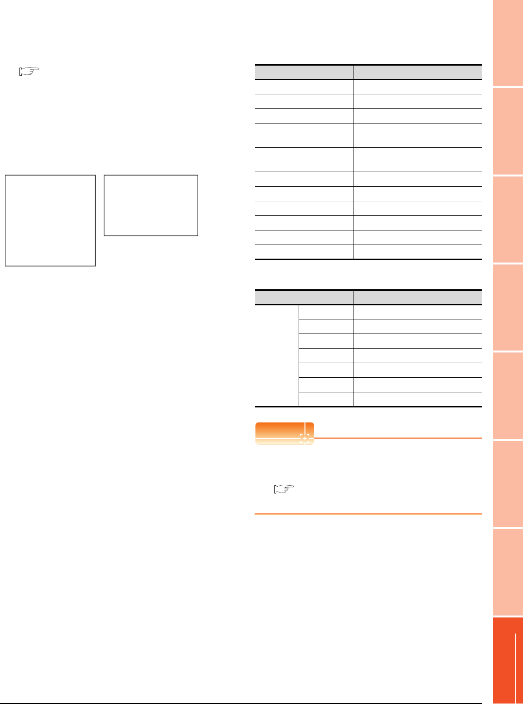
8. ETHERNET CONNECTION
8.4 PLC Side Setting
8 - 37
1
PREPARATORY
PROCEDURES FOR
MONITORING
2
DEVICE RANGE
THAT CAN BE SET
3
ACCESS RANGE
FOR MONITORING
4
HOW TO MONITOR
REDUNTANT
SYSTEM
5
BUS CONNECTION
6
DIRECT
CONNECTION TO
CPU
7
COMPUTER LINK
CONNECTION
8
ETHERNET
CONNECTION
(3) Communication confirmation
The RDY LED on the Ethernet module turn on when
the module is ready to communicate.
For confirming the communication state, refer to the
following.
8.4.3 ■Confirming the communication state of
Ethernet module
The BUF1 LED turns on when the opening processing
of the connection No. 1 is completed in normal at
executing of the sequence program example described
at (2).
[Controller Setting] and [Ethernet] of GT
Designer3
(1) Controller setting
(2) Ethernet setting
POINTPOINTPOINT
[Controller Setting] and [Ethernet] of GT Designer3
For [Controller Setting] and [Ethernet] of GT
Designer3, refer to the following.
8.3.1 Setting communication interface
(Communication settings)
RUN BUF1
BUF2
BUF3
BUF4
BUF5
BUF6
BUF7
BUF8
RDY
BSY
SW.ERR.
COM.ERR.
CPU R/W
TEST
TEST ERR.
BSY
SW.ERR.
COM.ERR.
CPU R/W
TEST ERR.
TEST
RDY
RUN BUF1
BUF2
BUF3
BUF4
BUF5
BUF6
BUF7
BUF8
A1SJ71E71N3-T, A1SJ71E71N-B5,
A1SJ71E71N-B2, A1SJ71E71N-T,
A1SJ71E71N-B5T, A1SJ71E71-B5-S3,
A1SJ71E71-B2-S3
AJ71E71N3-T, AJ71E71N-B5,
AJ71E71N-B2, AJ71E71N-T,
AJ71E71N-B5T, AJ71E71-S3
Item Set value (Use default value)
GOT NET No. 1
GOT PLC No. 1
GOT IP Address 192.168.0.18
GOT Port No.
(Communication) 5001
GOT Port No.
(Ethernet Download) 5014
Default Gateway 0.0.0.0
Subnet Mask 255.255.255.0
Retry 3times
Startup Time 3sec
Timeout Time 3sec
Delay Time 0ms
Item Set value
Ethernet
setting No.1
Host *
N/W No. 1
PLC No. 2
Type AJ71E71
IP address 192.168.0.19
Port No. 5001
Communication UDP (fixed)
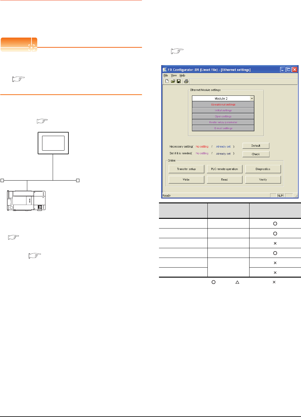
8 - 38 8. ETHERNET CONNECTION
8.4 PLC Side Setting
8.4.7 Connecting to Ethernet
module (FX Series)
This section describes the settings of the GOT and
Ethernet module (FX Series) in the following case of the
system configuration.
POINTPOINTPOINT
Ethernet module (FX Series)
For details of the Ethernet module (FX Series), refer to
the following manual.
FX3U-ENET User's manual
FX3U-ENET-ADP User's manual
System configuration
*1 These setting items do not exist at the PLC side. However,
the virtual values must be set on the GOT side.
■ [Controller Setting] and [Ethernet] of GT
Designer3
Ethernet parameter settings of FX
Configurator-EN
(1) Ethernet settings
Set the Ethernet parameter with FX Configurator-EN.
For using
FX Configurator-EN
, install GX Developer Ver.
8.25B or later on the personal computer.
For details on
FX Configurator-EN
, refer to the following
manual.
FX Configurator-EN
Operation manual
:Required :Set if necessary :Not required
*1 Set the number of the Ethernet module.
<GOT>
(The settings other than the
following are set to the default)
PLC No. : 1
IP address : 192.168.0.18
Port No. : 5019
Communication
format
: TCP (fixed)
PC No. : 2 (virtual)
Network No. : 1 (virtual)
IP address : 192.168.0.19
Port No. : 5551
Communication
format
: TCP (fixed)
<Ethernet module> (The settings other than the
following are set to the default)
*1
*1
[Controller Setting] and [Ethernet] of GT
Designer3
■
■ Ethernet parameter settings of FX Configurator-EN
Item Setting Setting
(with GOT connected)
Module Module 0*1
Operational settings Refer to (2)
Initial settings (Use default value.)
Open settings Refer to (3)
Router relay parameter
(Use default value.)
E-mail settings
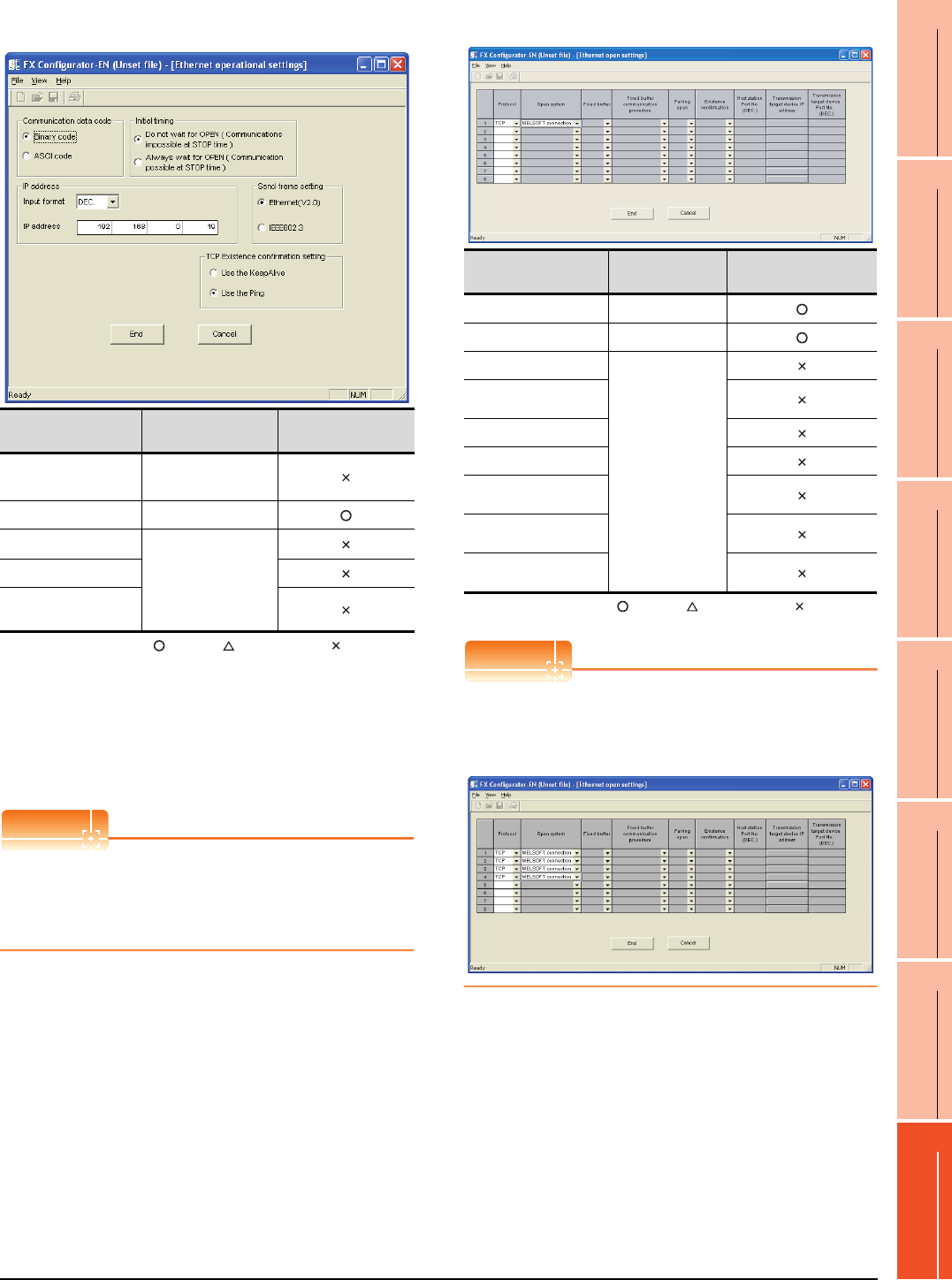
8. ETHERNET CONNECTION
8.4 PLC Side Setting
8 - 39
1
PREPARATORY
PROCEDURES FOR
MONITORING
2
DEVICE RANGE
THAT CAN BE SET
3
ACCESS RANGE
FOR MONITORING
4
HOW TO MONITOR
REDUNTANT
SYSTEM
5
BUS CONNECTION
6
DIRECT
CONNECTION TO
CPU
7
COMPUTER LINK
CONNECTION
8
ETHERNET
CONNECTION
(2) Operational settings
:Required :Set if necessary :Not required
*1 Because the port No. 5551 is fixed, the GOT oper-
ates as follows, regardless of the setting for the item.
• Communication date code : [Binary code]
• Initial timing : [Always wait for OPEN]
(Communications are enabled while the programmable
controller CPU stops.)
*2 The default value of IP address is 192.168.1.254. Set the IP
address corresponding to the system configuration.
POINTPOINTPOINT
When changing Ethernet parameter
After writing the Ethernet parameter to the
programmable controller CPU, turn off and then on, or
reset the programmable controller CPU.
(3) Open settings
:Required :Set if necessary :Not required
POINTPOINTPOINT
When connecting to multiple GOTs and peripheral
devices
The number of protocols equivalent to that of the GOTs
and devices must be set.
Item Setting Setting
(with GOT connected)
Communication
date code*1 (Use default value.)
IP address 192.168.0.19
Initial timing*1
(Use default value.)
Send frame setting
TCP Existence
confirmation setting
Item Setting Setting
(with GOT connected)
Protocol TCP
Open system MELSOFT connection
Fixed buffer
(Use default value.)
Fixed buffer communication
procedure
Pairing open
Existence confirmation
Host station Port No.
(DEC.)
Transmission target device
IP address
Transmission target device
Port No. (DEC.)
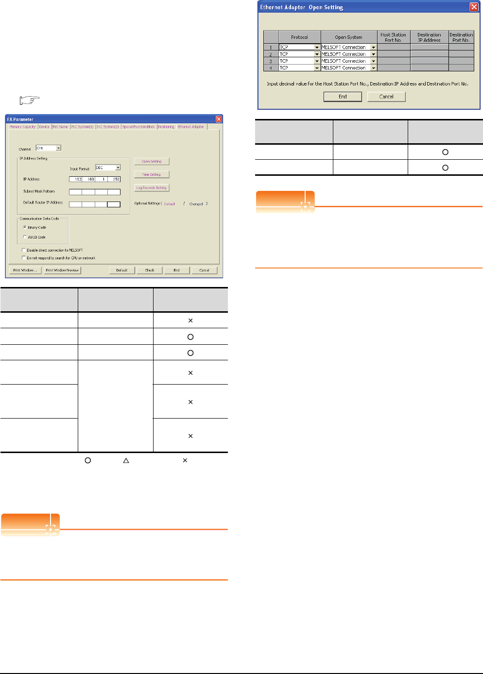
8 - 40 8. ETHERNET CONNECTION
8.4 PLC Side Setting
Ethernet parameter settings of FX3U-ENET-
ADP
(1) Ethernet settings
Set the Ethernet parameter at [FX Parameter] on GX
Works2.
To set FX3U-ENET-ADP, GX Works2 Ver.1.90U or later
is required.
For details on the setting of FX3U-ENET-ADP, refer to
the following manual.
FX3U-ENET-ADP User's Manual
:Required :Set if necessary :Not required
*1 Set a channel according to the installation position of FX3U-
ENET-ADP on the CPU body.
*2 The default value of IP address is 192.168.1.250. Set the IP
address corresponding to the system configuration.
POINTPOINTPOINT
When changing Ethernet parameter
After writing Ethernet parameters to the PLC CPU, turn
the PLC CPU OFF then back ON again.
(2) Open settings
POINTPOINTPOINT
When connecting to multiple GOTs and peripheral
devices
The number of protocols equivalent to that of the GOTs
and devices must be set.
\
Item Setting Setting
(with GOT connected)
Channel CH1 or CH2*1
IP Address 192.168.1.250*2
Open Settings Refer to (2).
Communication Data
Code
(Use default value.)
Disable direct
connection to
MELSOFT
Do not respond to
search for CPU on
network
Item Setting Setting
(with GOT connected)
Protocol TCP
Open System MELSOFT connection
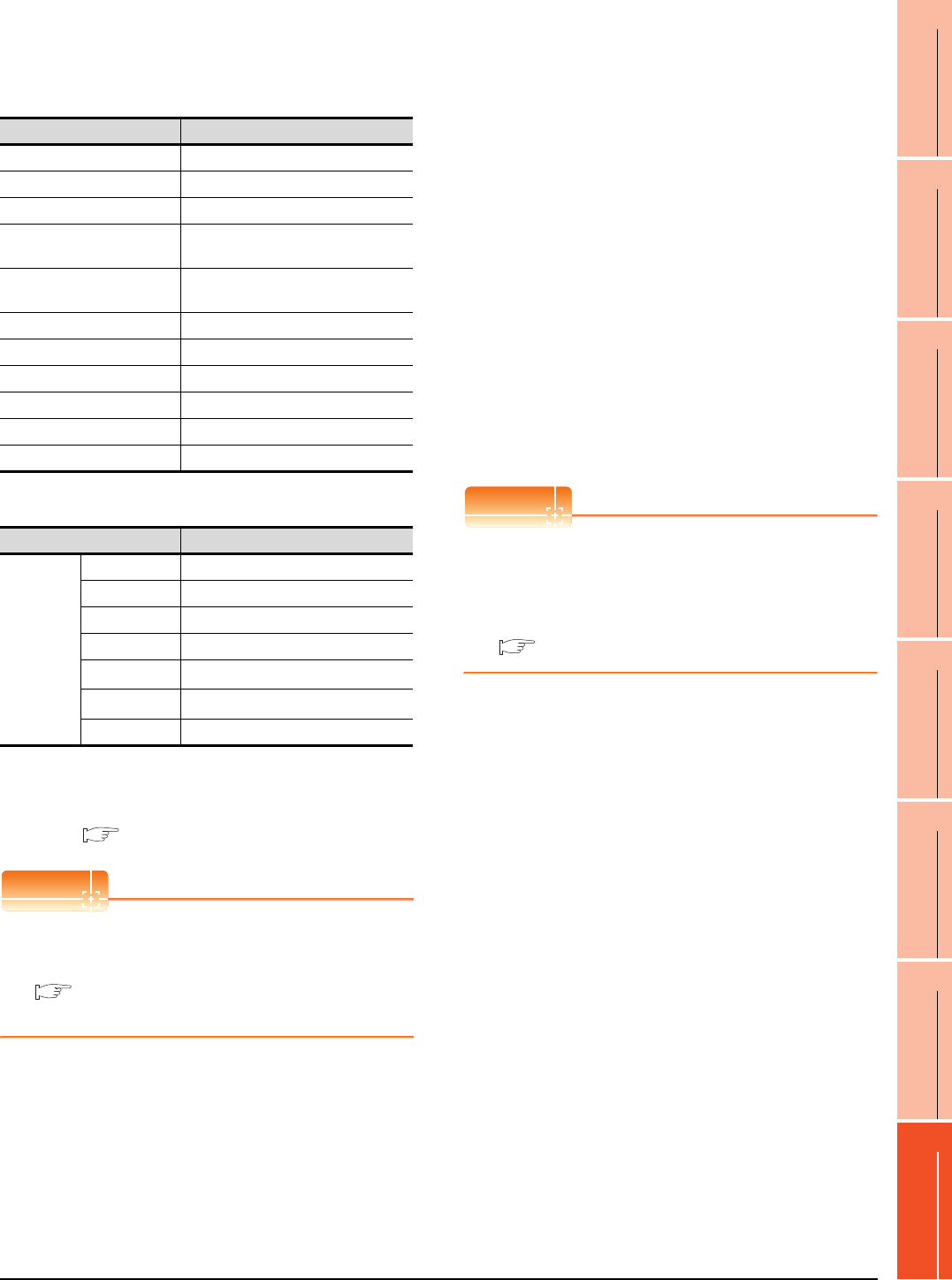
8. ETHERNET CONNECTION
8.4 PLC Side Setting
8 - 41
1
PREPARATORY
PROCEDURES FOR
MONITORING
2
DEVICE RANGE
THAT CAN BE SET
3
ACCESS RANGE
FOR MONITORING
4
HOW TO MONITOR
REDUNTANT
SYSTEM
5
BUS CONNECTION
6
DIRECT
CONNECTION TO
CPU
7
COMPUTER LINK
CONNECTION
8
ETHERNET
CONNECTION
[Controller Setting] and [Ethernet] of GT
Designer3
(1) Controller setting
(2) Ethernet setting
*1 Set the value according to the IP address of the connected
PLC.
*2 Set the value according to the Port No. of the connected
PLC.
For details, refer to the following.
8.3.3 Ethernet setting
POINTPOINTPOINT
[Controller Setting] and [Ethernet] of GT Designer3
For [Controller Setting] and [Ethernet] of GT
Designer3, refer to the following.
8.3.1 Setting communication interface
(Communication settings)
Confirming the communication state of
Ethernet module
(1) When using the Command Prompt of Windows.
Execute a Ping command at the Command Prompt of
Windows.
(a) When normal communication
C:\>Ping 192.168.0.19
Reply from 192.168.0.19: bytes=32 time<1ms
TTL=64
(b) When abnormal communication
C:\>Ping 192.168.0.19
Request timed out.
(2) When abnormal communication
At abnormal communication, check the followings and
execute the Ping command again.
• Mounting condition of Ethernet communication unit
• Cable connecting condition
• Confirmation of switch and network parameter setting
• Operation state of PLC CPU (faulty or not)
• IP address of GOT specified by Ping command
POINTPOINTPOINT
Ethernet diagnostics of FX Configurator-EN
Ethernet diagnostics of FX Configurator-EN is
available to a Ping test from the PLC.
For details of Ethernet diagnostics of FX Configurator-
EN, refer to the following manual.
FX Configurator-EN Operation manual
Item Setting (Use default value.)
GOT NET No. 1
GOT PLC No. 1
GOT IP Address 192.168.0.18
GOT Port No.
(Communication) 5019
GOT Port No.
(Ethernet Download) 5014
Default Gateway 0.0.0.0
Subnet Mask 255.255.255.0
Retry 3times
Startup Time 3sec
Timeout Time 3sec
Delay Time 0ms
Item Setting
Ethernet
setting No.1
Host *
N/W No. 1
PLC No. 2
Type FX (fixed)
IP address 192.168.0.19*1
Port No. 5551*2
Communication TCP (fixed)
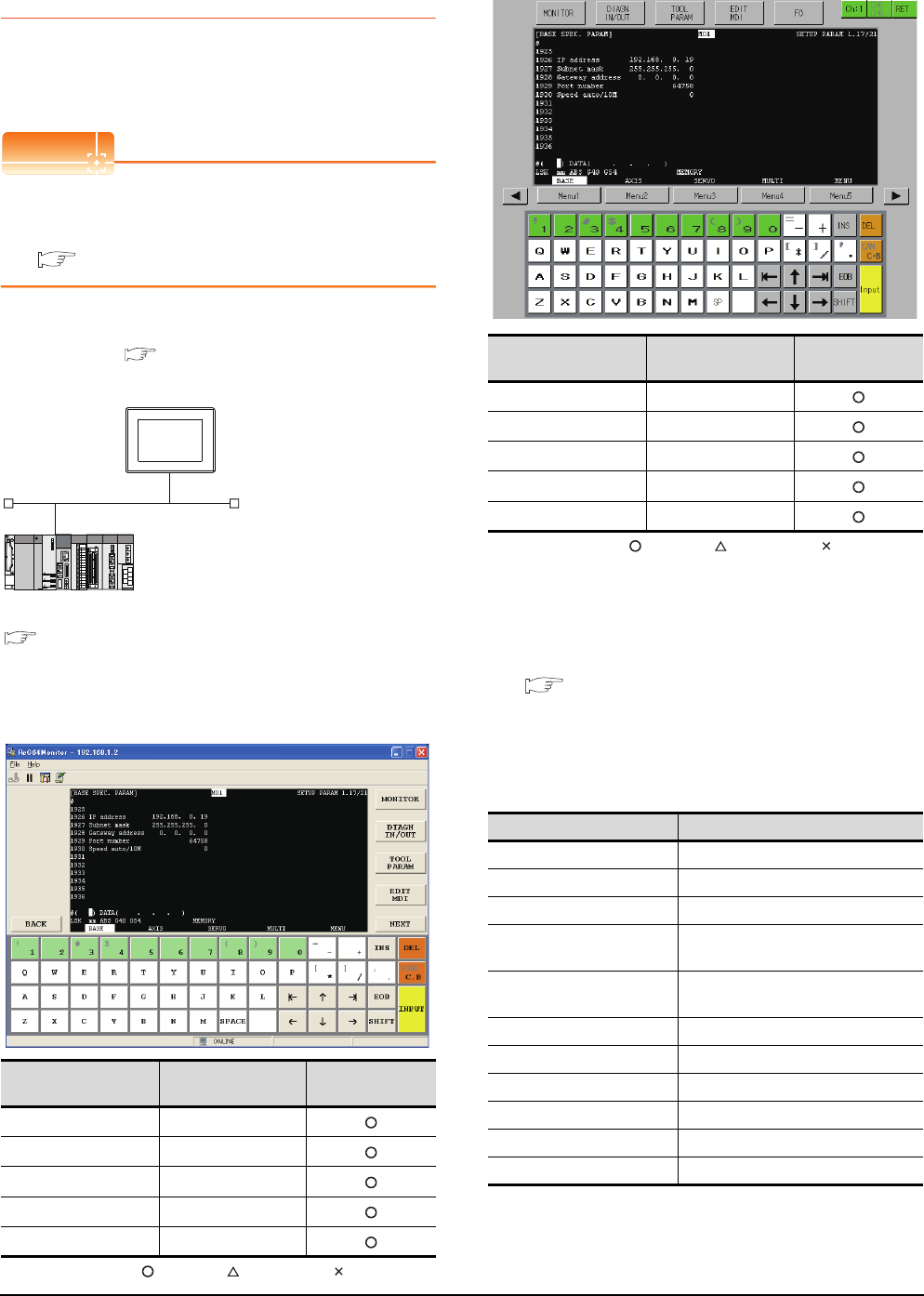
8 - 42 8. ETHERNET CONNECTION
8.4 PLC Side Setting
8.4.8 Connecting to Display I/F
(CNC C70)
This section describes the settings of the GOT and Display
I/F (CNC C70) in the following case of the system
configuration.
POINTPOINTPOINT
Display I/F (CNC C70)
For details of the Display I/F (CNC C70), refer to the
following manual.
C70 Series SET UP MANUAL
System configuration
IP address settings of CNC C70
(1) Remote monitor tool
: Necessary : As necessary : Not necessary
(2) CNC monitor
: Necessary : As necessary : Not necessary
(3) Communication check
The CNC C70 can communicate with the GOT when
INIT.LED of the CNC C70 is lit.
For confirming the communication state, refer to the
following.
■Checking communication state of CNC C70
[Controller Setting] and [Ethernet] of GT
Designer3
(1) Controller setting
Item Set value Setting necessity at
GOT connection
IP address 192.168.0.19
Subnet mask 255.255.255.0
Gateway address 0.0.0.0
Port number 64758 (fixed)
Speed auto/10M 0 (fixed)
<GOT> (The settings other than the
following are set to the default)
Network No. : 1
PLC No. : 1
IP address : 192.168.0.18
Port No. : 5001
Communication format : UDP (fixed)
Network No. : 239
PLC No. : 2
IP address : 192.168.0.19
Port No. : 5001
Communication format : UDP(fixed)
<Q17nNCCPU> (The settings other than the
following are set to the default)
[Controller Setting] and [Ethernet] of GT
Designer3
■
■ IP address settings of CNC C70
Item Set value Setting necessity at
GOT connection
IP address 192.168.0.19
Subnet mask 255.255.255.0
Gateway address 0.0.0.0
Port number 64758 (fixed)
Speed auto/10M 0 (fixed)
Item Set value (Use default value)
GOT NET No. 1
GOT PLC No. 1
GOT IP Address 192.168.0.18
GOT Port No.
(Communication) 5001
GOT Port No.
(Ethernet Download) 5012
Default Gateway 0.0.0.0
Subnet Mask 255.255.255.0
Retry 3times
Startup Time 3sec
Timeout Time 3sec
Delay Time 0ms

8. ETHERNET CONNECTION
8.4 PLC Side Setting
8 - 43
1
PREPARATORY
PROCEDURES FOR
MONITORING
2
DEVICE RANGE
THAT CAN BE SET
3
ACCESS RANGE
FOR MONITORING
4
HOW TO MONITOR
REDUNTANT
SYSTEM
5
BUS CONNECTION
6
DIRECT
CONNECTION TO
CPU
7
COMPUTER LINK
CONNECTION
8
ETHERNET
CONNECTION
(2) Ethernet setting
POINTPOINTPOINT
[Controller Setting] and [Ethernet] of GT Designer3
For [Controller Setting] and [Ethernet] of GT
Designer3, refer to the following.
8.3.1 Setting communication interface
(Communication settings)
Checking communication state of CNC C70
(1) When using the Command Prompt of Windows.
Execute a Ping command at the Command Prompt of
Windows.
(a) When normal communication
C:\>Ping 192.168.0.19
Reply from 192.168.0.19: bytes=32 time<1ms
TTL=64
(b) When abnormal communication
C:\>Ping 192.168.0.19
Request timed out.
(2) When abnormal communication
At abnormal communication, check the followings and
execute the Ping command again.
• Mounting condition of CNC C70
• Cable connecting condition
• Switch settings and network parameter settings
• Operation state of PLC CPU (faulty or not)
• IP address of the CNC C70 specified for the Ping
command
Item Set value
Ethernet
setting No.1
Host *
N/W No. 1
PLC No. 2
Type Q17nNC
IP address 192.168.0.19
Port No. 5001 (fixed)
Communication UDP (fixed)
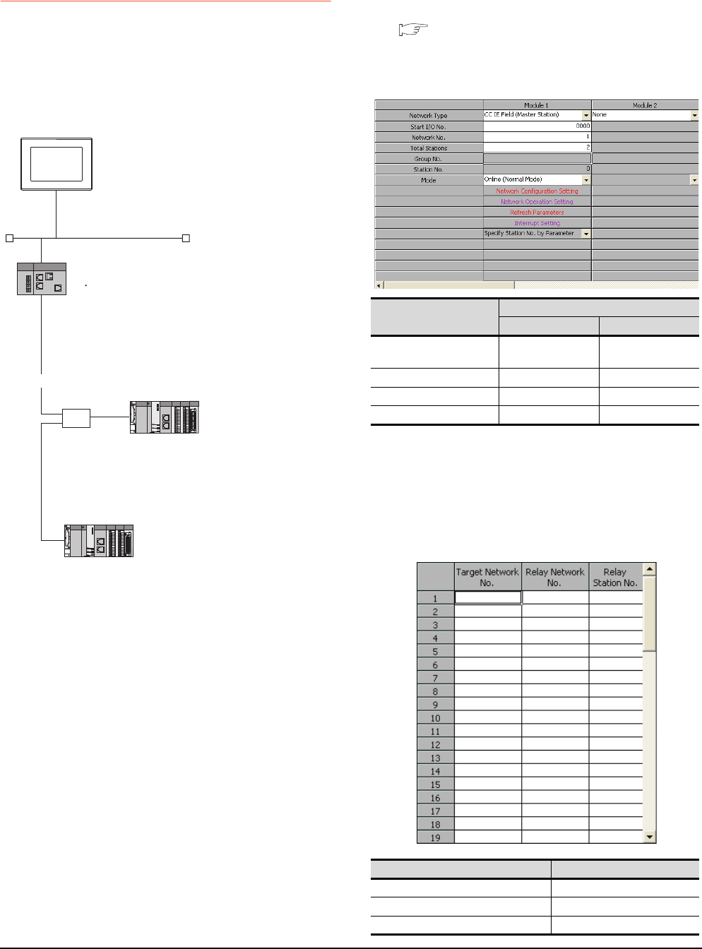
8 - 44 8. ETHERNET CONNECTION
8.4 PLC Side Setting
8.4.9 Connecting to CC-Link IE Field
Network Ethernet Adapter
Module
This section describes the settings of the GOT, Ethernet
adapter module and the PLC in the following system
configuration.
System configuration
*1 Set the GOT network No. according to the third octet
(network No.) of the Ethernet adapter module IP address.
*2 The CC-Link IE Field Network Master/Local module is
mounted on slot 0 of the base unit.
The start I/O No. of the CC-Link IE Field Network Master/
Local module is set at [0].
GX Works2 network parameter
Ethernet/CC IE/MELSECNET
For details of the setting contents of PLC side, refer to the
following manual.
MELSEC-Q CC-Link IE Field Network Master/
Local Module User's Manual
(1) Network Type, Network No., Total Stations setting
Example: Master station setting
(2) Routing parameter setting
Set the followings as necessary.
Up to 64 [Transfer Network No.]s can be set.
However, the same transfer network number cannot be
set twice or more (multiple times).
Therefore, the one that can access to other station from
the request source host GOT is 64 kinds of [Transfer
Network No.]s.
<GOT>
(Use default value for settings other than the following.)
Network No. :3
PC No. :1
IP address :192.168.3.18
Port No. :5001
Communication
format
:UDP (fixed)
Ethernet
CC-Link IE Field Network
HUB
<Ethernet adapter module>
(Use default value for settings other than the following.)
Ethernet setting
IP address
CC-Link IE Field Network setting
Network No.
Station No.
:192.168.3.30
:1
:1
<CC-Link IE Field Network Master/Local module>
(Use default value for settings other than the following.)
Network Type
Network No.
PC No.
Total Stations
: CC IE Field (Master station)
: 1
: 0
: 2
*2
*1
<CC-Link IE Field Network Master/Local module>
(Use default value for settings other than the following.)
Network Type
Network No.
PC No.
: CC IE Field (Local station)
: 1
: 2
*2
Item
Set value
Master station Local station
Network type CC IE Field
(Master station)
CC IE Field
(Local station)
Network No. 1 1
Total Stations 2 -
Station No. 0 (fixed) 2
Item Range
Transfer Network No. 1 to 239
Relay Network No. 1 to 239
Relay Station No. 1 to 64
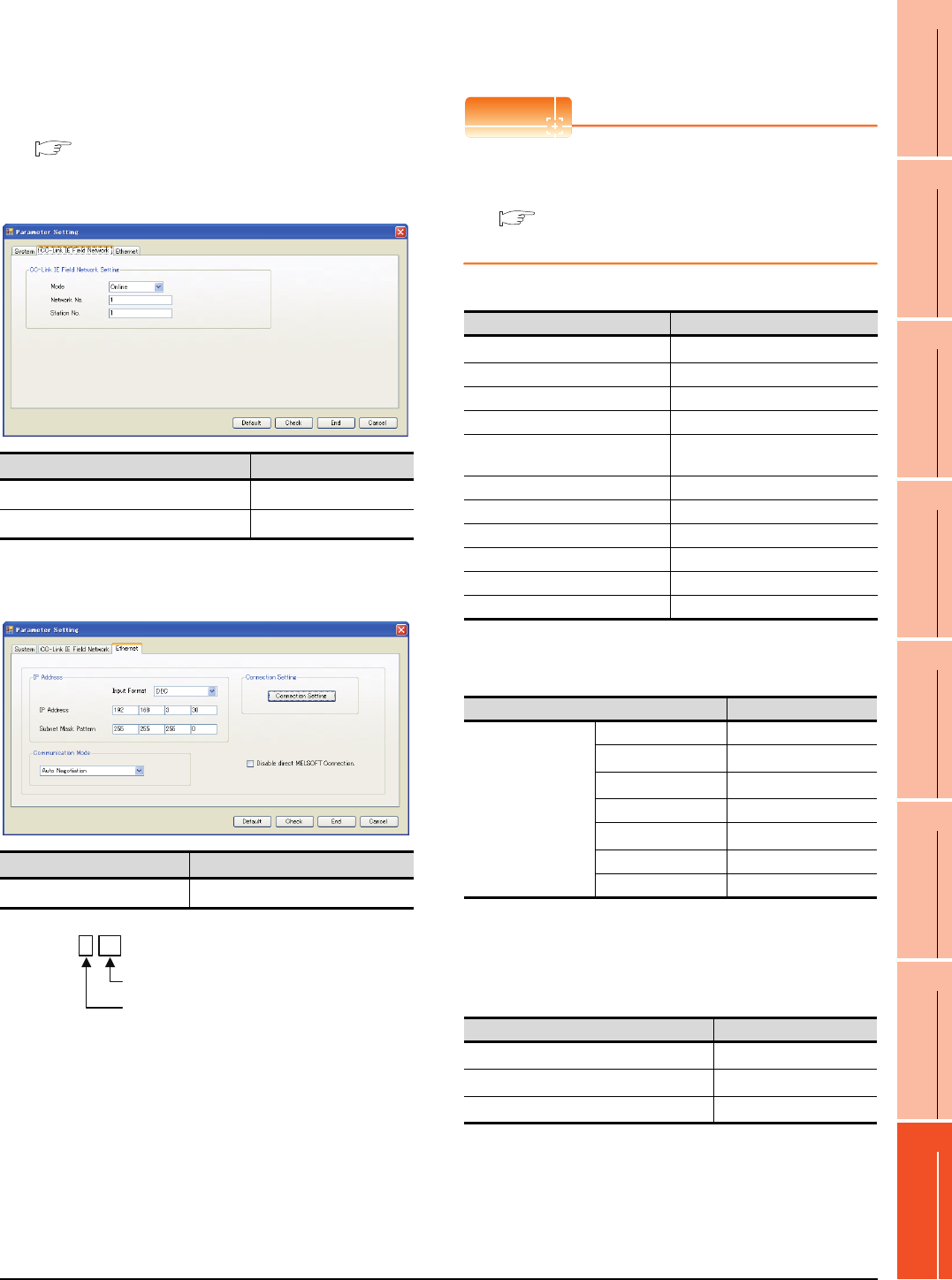
8. ETHERNET CONNECTION
8.4 PLC Side Setting
8 - 45
1
PREPARATORY
PROCEDURES FOR
MONITORING
2
DEVICE RANGE
THAT CAN BE SET
3
ACCESS RANGE
FOR MONITORING
4
HOW TO MONITOR
REDUNTANT
SYSTEM
5
BUS CONNECTION
6
DIRECT
CONNECTION TO
CPU
7
COMPUTER LINK
CONNECTION
8
ETHERNET
CONNECTION
Ethernet Adapter Module setting
Set the parameter with the Ethernet adapter module
setting tool.
For details of the setting method, refer to the following
manual.
CC-Link IE Field Network Ethernet Adapter
Module User's Manual
(1) CC-Link IE Field Network setting
*1 Set the same value as the network No. set on the PLC side.
*2 Set a value other than the network No. set on the PLC side.
(2) Ethernet setting
*1 Set the IP address within the following range.
[Controller Setting] and [Ethernet] of GT
Designer3
POINTPOINTPOINT
[Controller Setting] and [Ethernet] of GT Designer3
For [Controller Setting] and [Ethernet] of GT
Designer3, refer to the following.
8.3.1 Setting communication interface
(Communication settings)
(1) Controller setting
*1 Set the GOT network No. according to the third octet
(network No.) of the Ethernet adapter module IP address.
(2) Ethernet setting
*1 Set according to the third octet (network No.) of the Ethernet
adapter module IP address.
*2 Set according to the fourth octet (PC No.) of the Ethernet
adapter module IP address.
*3 Set according to the Ethernet adapter module IP address.
(3) Routing parameter setting
*1 Set the same value as the Ethernet adapter module network
No.
*2 Set according to the third octet (network No.) of the Ethernet
adapter module IP address.
*3 Set according to the fourth octet (PC No.) of the Ethernet
adapter module IP address.
Item Set value
Network No. 1*1
Station No. 1*2
Item Set value
IP address 192.168.3.30*1
192.168. 3. 30
Set the fourth octet within the range from 1 to 64.
Set the third octet within the range from 1 to 239.
Item Set value (Use default value)
GOT NET No. 3*1
GOT PC No. 1
GOT IP Address 192.168.3.18
GOT Port No. (Communication) 5001
GOT Port No.
(Ethernet Download) 5014
Default Gateway 0.0.0.0
Subnet Mask 255.255.255.0
Retry 3 times
Startup Time 3 sec
Timeout Time 3 sec
Delay Time 0ms
Item Set value
Ethernet Setting
No.1
Host *
N/W No. 3*1
PC No. 30*2
Type NZ2GF-ETB
IP address 192.168.3.30*3
Port No. 5001(fixed)
Communication UDP(fixed)
Item Set value
Transfer Network No. 1*1
Relay Network No. 3*2
Relay Station No. 30*3
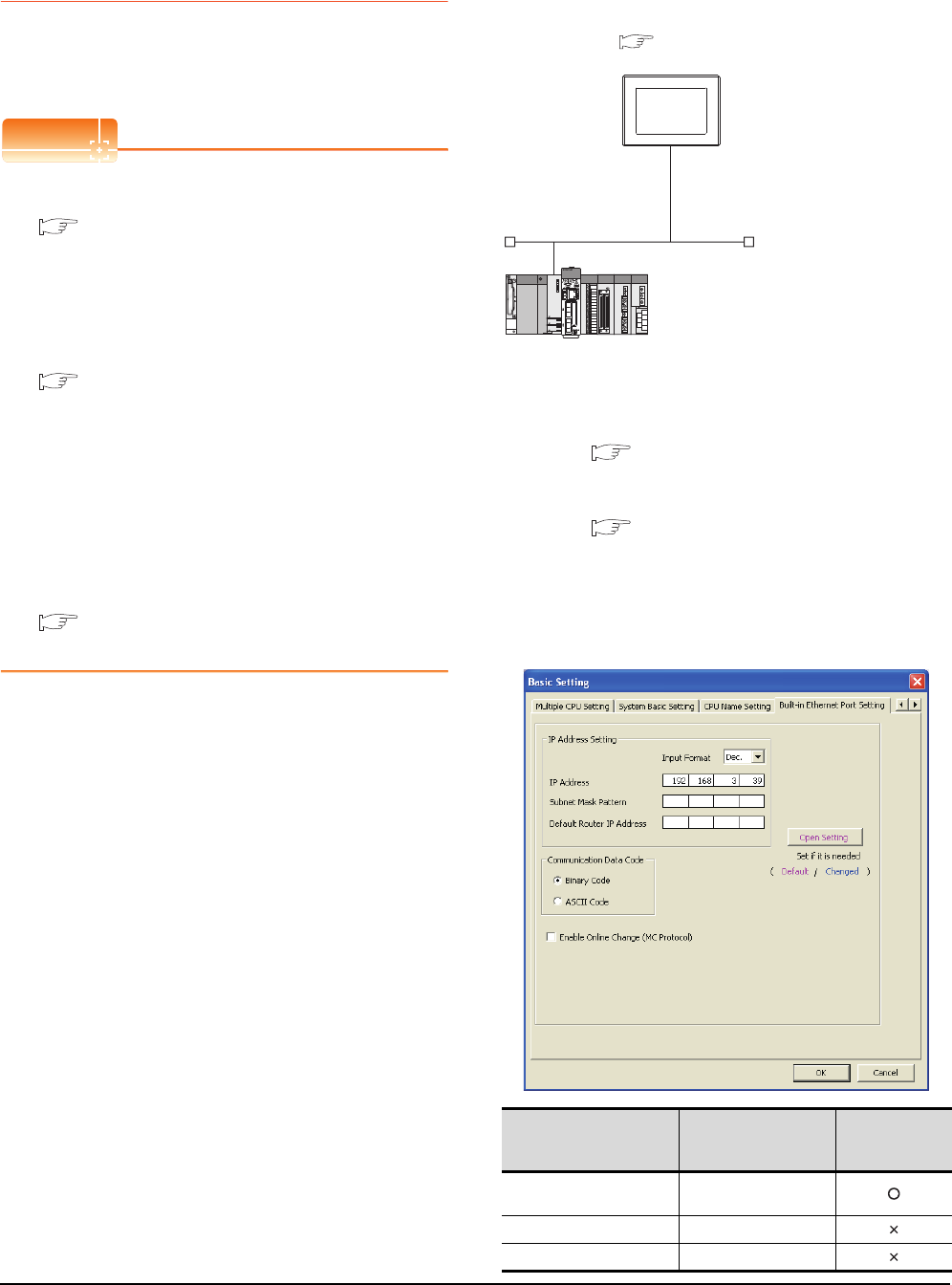
8 - 46 8. ETHERNET CONNECTION
8.4 PLC Side Setting
8.4.10 Connecting to PERIPHERAL
I/F (Built-in Ethernet port
Motion Controller CPU)
This section describes the settings of the GOT and Built-in
Ethernet port Motion Controller CPU in the following case
of system configuration.
POINTPOINTPOINT
(1) GOT type setting
For details, refer to the following.
1.1.1 Setting connected equipment (Channel
setting)
(2) Setting [Controller Type]
(2) CPU No. specification of Q170MCPU
Set whether to monitor the PLC CPU area or the
Motion CPU area of Q170MCPU, in the CPU No.
specification. For details, refer to the following.
8.5 Precautions
(3) PLC type of GX Works2/GX Developer
When creating a program, set the following PLC
type:
• For Q173D(S)CPU/Q172D(S)CPU
QnUD(E)(H)CPU
• For Q170MCPU
Q03UDCPU
(4) Built-in Ethernet port CPU
For details of Built-in Ethernet port CPU, refer to
the following manual.
User's Manual of Q173D(S)CPU/
Q172D(S)CPU and Q170MCPU
System configuration
Leave the Built-in Ethernet port Motion Controller CPU
settings as default in the following system
configuration.
*1 For the settings when using system devices including a hub
and a transceiver, refer to the following.
8.4.2 Connecting to Built-in Ethernet port CPU
(multiple connection)
*2 These setting items do not exist at the PLC side. However,
the virtual values must be set on the GOT side.
■[Controller Setting] and [Ethernet] of GT Designer3
Basic setting of MT Works2
Use the default values of the basic setting for the
system configuration above.
(1) Built-in Ethernet port
Item Set value
Setting necessity
at GOT
connection
IP address 192.168.3.39
(Default)
Subnet mask pattern -
Default router IP address -
<GOT>
(The settings other than the
following are set to the default)
*1
*2
*2
Network No. : 1
PLC No. : 1
IP address : 192.168.3.1
Port No. : 5001
Communication
format
: UDP (fixed)
Network No. : 1 (virtual)
PLC No. : 2 (virtual)
IP address : 192.168.3.39
Open system : MELSOFT connection (fixed)
<Connecting to Built-in Ethernet port CPU>
(The following settings are set to the default)
[Controller Setting] and [Ethernet] of GT Designer3
■
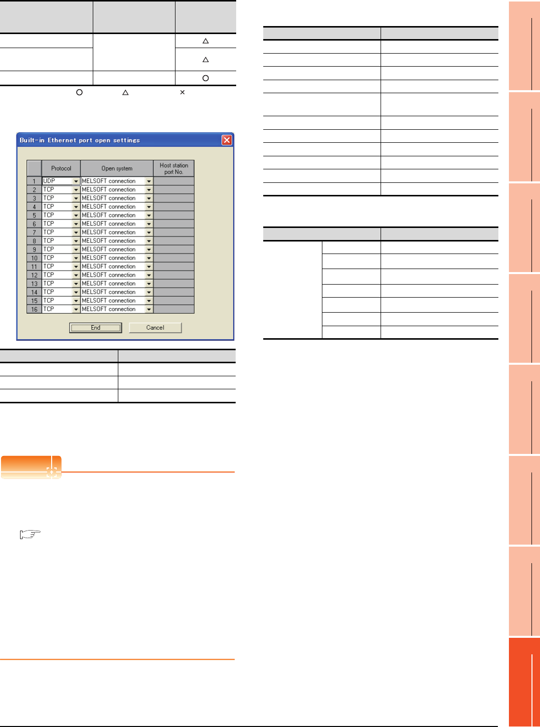
8. ETHERNET CONNECTION
8.4 PLC Side Setting
8 - 47
1
PREPARATORY
PROCEDURES FOR
MONITORING
2
DEVICE RANGE
THAT CAN BE SET
3
ACCESS RANGE
FOR MONITORING
4
HOW TO MONITOR
REDUNTANT
SYSTEM
5
BUS CONNECTION
6
DIRECT
CONNECTION TO
CPU
7
COMPUTER LINK
CONNECTION
8
ETHERNET
CONNECTION
: Necessary : As necessary : Not necessary
(2) Open settings
The setting is required for all the connected GOTs.
[Controller Setting] and [Ethernet] of GT
Designer3
POINTPOINTPOINT
(1) [Controller Setting] and [Ethernet] of GT
Designer3
For [Controller Setting] and [Ethernet] of GT
Designer3, refer to the following.
8.3.1 Setting communication interface
(Communication settings)
(2) Ethernet setting
The settings items for the network No. and station
No. do not exist at the Built-in Ethernet port
Motion Controller CPU side. However, these
virtual values must be set on the GOT side.
Therefore, set the network No. and station No. on
the GOT side. Set the network No. that is not
existed on the network system and any station
No..
(3) Controller setting
(4) Ethernet setting
*1 Set the same value as that of GOT N/W No.
*2 Set a value different from that of GOT PLC No.
*3 Set it to the IP address value of the Built-in Ethernet port
Motion Controller CPU side.
Checking communication state of Connecting
to Built-in Ethernet port CPU
(1) When using the Command Prompt of Windows
Execute a Ping command at the Command Prompt of
Windows.
(a) When normal communication
C:\>Ping 192.168.3.39
Reply from 192.168.3.2: bytes=32 time
<10ms TTL=32
(b) When abnormal communication
C:\>Ping 192.168.3.39
Request timed out.
(2) When abnormal communication
At abnormal communication, check the followings and
execute the Ping command again.
• Cable connecting condition
• Confirmation of switch and network parameter setting
• Operation state of PLC CPU (faulty or not)
• The IP address of Built-in Ethernet port CPU specified
in the Ping command
Communication data code
(Use default value)
Enable online change
(MC protocol)
Open settings Refer to (2)
Item Set value
Protocol UDP (fixed)
Open system MELSOFT connection (fixed)
Host station port No. -
Item Set value
Setting necessity
at GOT
connection Item Setting (Use default value.)
GOT NET No. 1
GOT PC No. 1
GOT IP Address 192.168.3.1
GOT Port No. (Communication) 5001
GOT Port No.
(Ethernet Download) 5014
Default Gateway 0.0.0.0
Subnet Mask 255.255.255.0
Retry 3times
Startup Time 3 sec
Timeout time 3 sec
Delay Time 0ms
Item Set value
Ethernet
setting No.1
Host *
N/W No. 1*1
PC No. 2*2
Type QnUDE(H)
IP address 192.168.3.39*3
Port No. 5006 (fixed)
Communication UDP (fixed)

8 - 48 8. ETHERNET CONNECTION
8.4 PLC Side Setting
POINTPOINTPOINT
Ethernet diagnostics of GX Works2/GX Developer
Ethernet diagnostics of GX Works2/GX Developer is
available to a Ping test from the PLC.
For details of Ethernet diagnostics of GX Works2/GX
Developer, refer to the following manual.
GX Works2 Version1 Operating Manual
(Common)
GX Developer Version8 Operating Manual
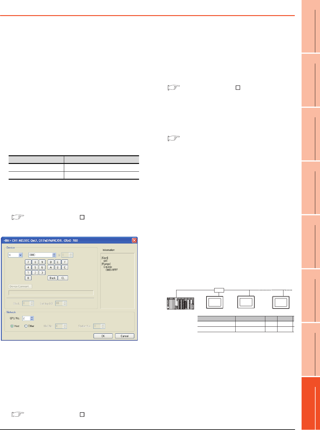
8. ETHERNET CONNECTION
8.5 Precautions
8 - 49
1
PREPARATORY
PROCEDURES FOR
MONITORING
2
DEVICE RANGE
THAT CAN BE SET
3
ACCESS RANGE
FOR MONITORING
4
HOW TO MONITOR
REDUNTANT
SYSTEM
5
BUS CONNECTION
6
DIRECT
CONNECTION TO
CPU
7
COMPUTER LINK
CONNECTION
8
ETHERNET
CONNECTION
8.5 Precautions
Connection to QnA (S) CPU type
Use B or a later function version of Ethernet module
(QnA Series) and PLC CPU (QnA/QnASCPU type).
Connection to QSCPU
The GOT can only read device data and sequence
programs by the ladder monitor function in the QSCPU.
The GOT cannot write any data to the QSCPU.
Connection to Q170MCPU
Set [CPU No.] to "2" in the device setting to monitor the
device of the Motion CPU area (CPU No.2).
When the CPU No. is set to "1", the device on the PLC
CPU area (CPU No.1) is monitored.
When the CPU No. is set to "0", the monitoring target
differs depending on the GOT connection destination.
Refer to the following.
When the CPU No. is set to the number other than "0"
to "2", a communication error occurs and the monitoring
cannot be executed.
For setting the CPU No., refer to the following manual.
GT Designer3 Version Screen Design
Manual
Example) Setting dialog box of the bit device
Connection in the multiple CPU system
When the GOT is connected to multiple CPU system,
the following time is taken until when the PLC runs.
QCPU (Q mode), motion controller CPU (Q series): 10
seconds or more
MELDAS C70: 18 seconds or more
When the GOT starts before the PLC runs, a system
alarm occurs. Adjust the opening screen time in the
GOT setup so that no system alarm occurs.
GT Designer3 Version Screen Design
Manual
Connection to LCPU
LCPU may diagnose (check file system, recovering
process, etc.) the SD memory card when turning on the
power or when resetting. Therefore, it takes time until
the SD memory card becomes available. When the
GOT starts before the SD card becomes available, a
system alarm occurs. Adjust the opening screen time in
the GOT setup so that no system alarm occurs.
GT Designer3 Version Screen Design
Manual
When connecting to multiple GOTs
(1) Setting PLC No.
When connecting two or more GOTs in the Ethernet
network, set each [PLC No.] to the GOT.
8.3.1 Setting communication interface
(Communication settings)
(2) Setting IP address
Do not use the IP address "192.168.0.18" when using
multiple GOTs.
A communication error may occur on the GOT with the
IP address.
(3) Setting for starting up multiple GOTs simultaneously
(When connected to Built-in Ethernet port CPU)
When connecting multiple GOTs to one Built-in
Ethernet port CPU, adjust the timing of GOT
communication start. When the communication
concentrates on the PLC, the communication between
GOT and PLC becomes difficult, and the monitoring by
GOT may not start. As a method for adjusting the
timing, communicating one GOT alone first, and then
communicating the other GOTs is effective.
Set the following items on each GOT.
• [Startup Time] of [Controller Setting], or [Title Display
Time] of [GOT Setup].
• [Timeout Time] of [Controller Setting]
The following shows a setting example.
When connecting to the multiple network
equipment (including GOT) in a segment
By increasing the network load, the transmission speed
between the GOT and PLC may be reduced.
The following actions may improve the communication
performance.
• Using a switching hub
• More high speed by 100BASE-TX (100Mbps)
• Reduction of the monitoring points on GOT
GOT connection destination Monitoring target
QJ71E71 module PLC CPU area (CPU No.1)
PERIPHERAL I/F Motion CPU area (CPU No.2)
QnUDE(H)CPU
GOT2
GOT1 GOT10
Startup Time
GOT1 GOT2 GOT10
Item
Timeout Time
3sec (default)
3sec (default)
4sec 4sec
4sec 4sec
HUB

8 - 50 8. ETHERNET CONNECTION
8.5 Precautions
When setting IP address
Do not use "0" and "255" at the end of an IP address.
(Numbers of *.*.*.0 and *.*.*.255 are used by the
system)
The GOT may not monitor the controller correctly with
the above numbers.
Consult with the administrator of the network before
setting an IP address to the GOT and controller.
When monitoring to another network No. on
the same line
When the network No. of the GOT does not match with
that of the PLC on the same Ethernet, the PLC cannot
be monitored. When monitoring, set the same network
No. as that of the GOT, or connect a Ethernet module to
the PLC and set the routing setting to monitor as other
network.
When the Multi-channel is supported for GT16, set
each channel with the networks No. to monitor.
Remote password for QCPU
Do not set a remote password for QCPU.
Monitoring with GOT becomes unavailable.
When connecting to Built-in Ethernet port of
Built-in Ethernet port CPU
Connect to GOT after turning on the network equipment
such as Built-in Ethernet port CPU or HUB to enable
the communication.
When the communication with Built-in Ethernet port
CPU is not available, a communication error may occur
on the GOT.
The number of connectable CPUs for one
GOT
QCPU : 128 CPUs can be set (10 or less CPUs are
recommended)
FXCPU : 128 CPUs can be set (10 or less CPUs are
recommended)
9
9
MELSECNET/H
CONNECTION (PLC
TO PLC NETWORK)
10
MELSECNET/10
CONNECTION (PLC
TO PLC NETWORK)
11
CC-Link IE CONTROLLER
NETWORK
CONNECTION
12
CC-Link IE FIELD
NETWORK
CONNECTION
13
CC-Link CONNECTION
(INTELLIGENT DEVICE
STATION)
14
CC-Link
CONNECTION
(Via G4)
15
INVERTER
CONNECTION
16
SERVO AMPLIFIER
CONNECTION
9 - 1
9.MELSECNET/H CONNECTION
(PLC TO PLC NETWORK)
9.1 Connectable Model List . . . . . . . . . . . . . . . . . . . . . . . . . . . . . 9 - 2
9.2 System Configuration . . . . . . . . . . . . . . . . . . . . . . . . . . . . . . . 9 - 7
9.3 GOT Side Settings . . . . . . . . . . . . . . . . . . . . . . . . . . . . . . . . . 9 - 9
9.4 PLC Side Settings. . . . . . . . . . . . . . . . . . . . . . . . . . . . . . . . . .9 - 11
9.5 Precautions. . . . . . . . . . . . . . . . . . . . . . . . . . . . . . . . . . . . . . 9 - 16
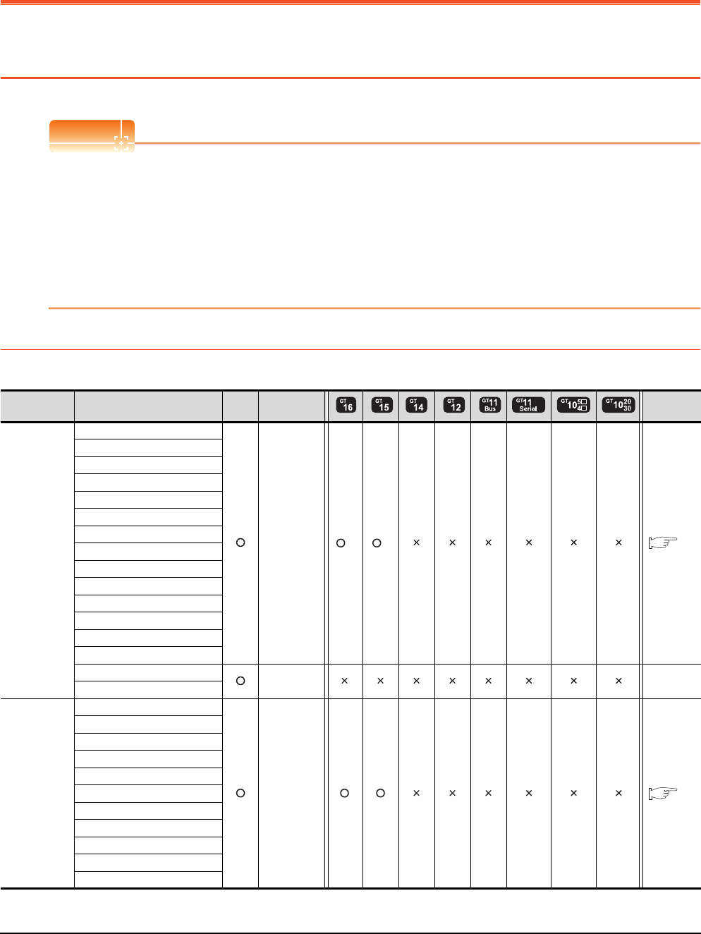
9 - 2 9. MELSECNET/H CONNECTION (PLC TO PLC NETWORK)
9.1 Connectable Model List
9. MELSECNET/H CONNECTION
(PLC TO PLC NETWORK)
9.1 Connectable Model List
POINTPOINTPOINT
(1) Connectable network
When using MELSECNET/H in NET/10 mode, refer to MELSECNET/10 CONNECTION.
Connect the GOT to the following network systems as an ordinary station.
• MELSECNET/H network system (PLC to PLC network) optical loop system
• MELSECNET/H network system (PLC to PLC network) coaxial bus system
(2) MELSECNET/H network module
When connecting the MELSECNET/H network module to the MELSECNET/H network system, specify the
MELSECNET/H Mode or the MELSECNET/H Extended Mode as a network type.
9.1.1 PLC/Motion controller CPU
The following table shows the connectable models.
(Continued to next page)
*1 Use CPU function version B or a later version.
Series Model name Clock
Communication
type Refer to
MELSEC-Q
(Q mode)
Q00JCPU
MELSECNE
T/H
*1 *1 9.2
Q00CPU
Q01CPU
Q02CPU
Q02HCPU
Q06HCPU
Q12HCPU
Q25HCPU
Q02PHCPU
Q06PHCPU
Q12PHCPU
Q25PHCPU
Q12PRHCPU (Main base)
Q25PRHCPU (Main base)
Q12PRHCPU (Extension base) - -
Q25PRHCPU (Extension base)
MELSEC-Q
(Q mode)
Q00UJCPU
MELSECNE
T/H 9.2
Q00UCPU
Q01UCPU
Q02UCPU
Q03UDCPU
Q04UDHCPU
Q06UDHCPU
Q10UDHCPU
Q13UDHCPU
Q20UDHCPU
Q26UDHCPU
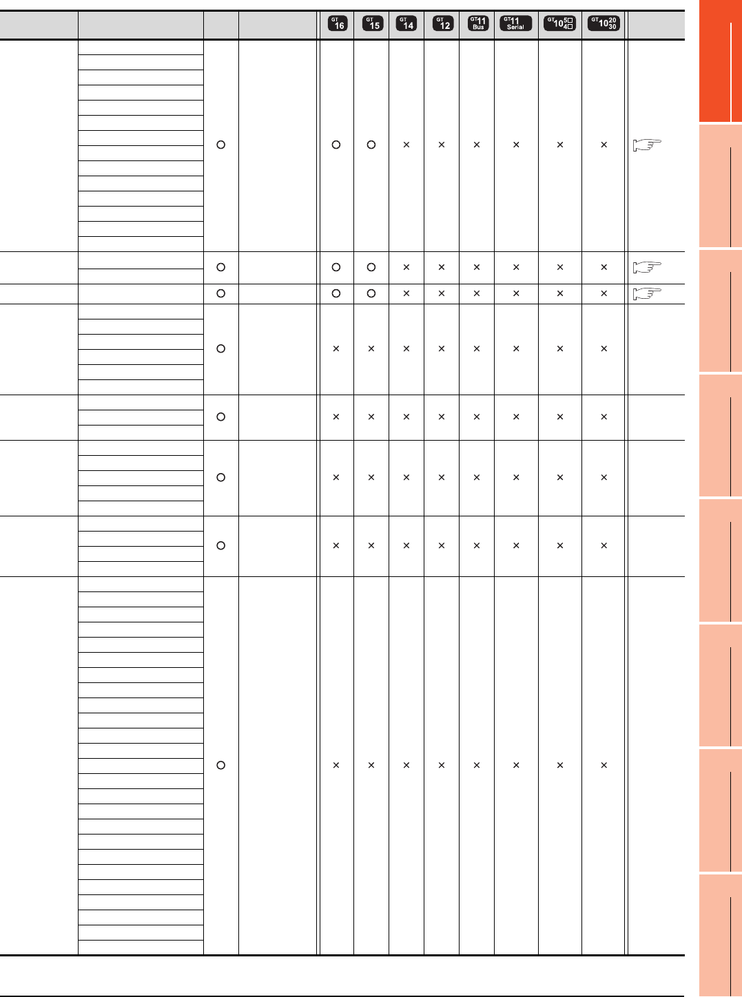
9. MELSECNET/H CONNECTION (PLC TO PLC NETWORK)
9.1 Connectable Model List
9 - 3
9
MELSECNET/H
CONNECTION (PLC
TO PLC NETWORK)
10
MELSECNET/10
CONNECTION (PLC
TO PLC NETWORK)
11
CC-Link IE CONTROLLER
NETWORK
CONNECTION
12
CC-Link IE FIELD
NETWORK
CONNECTION
13
CC-Link CONNECTION
(INTELLIGENT DEVICE
STATION)
14
CC-Link
CONNECTION
(Via G4)
15
INVERTER
CONNECTION
16
SERVO AMPLIFIER
CONNECTION
(Continued to next page)
*1 Use a module with the upper five digits later than 12042.
Series Model name Clock Communication
type Refer to
MELSEC-Q
(Q mode)
Q03UDECPU
MELSECNET/H 9.2
Q04UDEHCPU
Q06UDEHCPU
Q10UDEHCPU
Q13UDEHCPU
Q20UDEHCPU
Q26UDEHCPU
Q50UDEHCPU
Q100UDEHCPU
Q03UDVCPU
Q04UDVCPU
Q06UDVCPU
Q13UDVCPU
Q26UDVCPU
C Controller
module
Q12DCCPU-V*1
MELSECNET/H 9.2
Q24DHCCPU-V
MELSEC-QS QS001CPU MELSECNET/H 9.2
MELSEC-L
L02CPU
- -
L26CPU
L26CPU-BT
L02CPU-P
L26CPU-PBT
L02SCPU
MELSEC-Q
(A mode)
Q02CPU-A
- -Q02HCPU-A
Q06HCPU-A
MELSEC-QnA
(QnACPU)
Q2ACPU
- -
Q2ACPU-S1
Q3ACPU
Q4ACPU
Q4ARCPU
MELSEC-QnA
(QnASCPU)
Q2ASCPU
- -
Q2ASCPU-S1
Q2ASHCPU
Q2ASHCPU-S1
MELSEC-A
(AnCPU)
A2UCPU
- -
A2UCPU-S1
A3UCPU
A4UCPU
A2ACPU
A2ACPUP21
A2ACPUR21
A2ACPU-S1
A2ACPUP21-S1
A2ACPUR21-S1
A3ACPU
A3ACPUP21
A3ACPUR21
A1NCPU
A1NCPUP21
A1NCPUR21
A2NCPU
A2NCPUP21
A2NCPUR21
A2NCPU-S1
A2NCPUP21-S1
A2NCPUR21-S1
A3NCPU
A3NCPUP21
A3NCPUR21

9 - 4 9. MELSECNET/H CONNECTION (PLC TO PLC NETWORK)
9.1 Connectable Model List
(Continued to next page)
*1 When using SV13, SV22, or SV43, use the motion controller CPU on which any of the following main OS version is installed.
• SW6RN-SV13Q : 00H or later
• SW6RN-SV22Q : 00H or later
• SW6RN-SV43Q : 00B or later
*2 Use main modules with the following product numbers.
• Q172CPU: Product number N******* or later
• Q173CPU: Product number M******* or later
*3 Only the first step can be used on the extension base unit (Q52B/Q55B).
Series Model name Clock Communication
type Refer to
MELSEC-A
(AnSCPU)
A2USCPU
- -
A2USCPU-S1
A2USHCPU-S1
A1SCPU
A1SCPUC24-R2
A1SHCPU
A2SCPU
A2SCPU-S1
A2SHCPU
A2SHCPU-S1
A1SJCPU
A1SJCPU-S3
A1SJHCPU
MELSEC-A
A0J2HCPU
- -
A0J2HCPUP21
A0J2HCPUR21
A0J2HCPU-DC24
A2CCPU
- -
A2CCPUP21
A2CCPUR21
A2CCPUC24
A2CCPUC24-PRF
A2CJCPU-S3
A1FXCPU
Motion
controller
CPU
(Q Series)
Q172CPU*1*2
MELSECNET/H 9.2
Q173CPU*1*2
Q172CPUN*1
Q173CPUN*1
Q172HCPU
Q173HCPU
Q172DCPU
Q173DCPU
Q172DCPU-S1
Q173DCPU-S1
Q172DSCPU
Q173DSCPU
Q170MCPU*3
MR-MQ100 - -
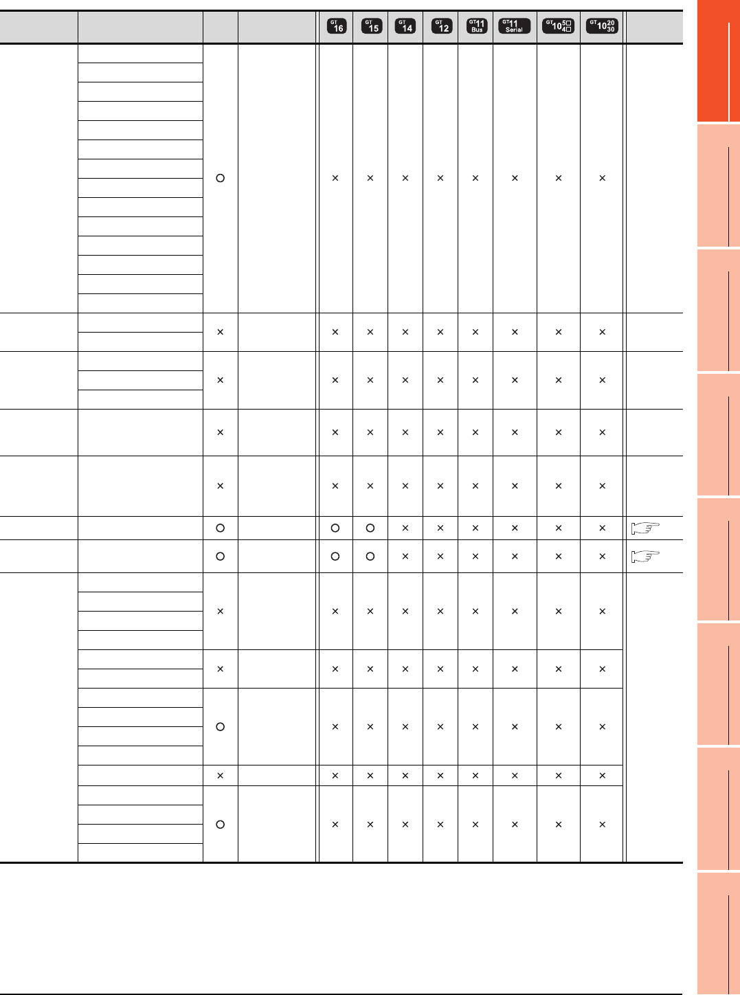
9. MELSECNET/H CONNECTION (PLC TO PLC NETWORK)
9.1 Connectable Model List
9 - 5
9
MELSECNET/H
CONNECTION (PLC
TO PLC NETWORK)
10
MELSECNET/10
CONNECTION (PLC
TO PLC NETWORK)
11
CC-Link IE CONTROLLER
NETWORK
CONNECTION
12
CC-Link IE FIELD
NETWORK
CONNECTION
13
CC-Link CONNECTION
(INTELLIGENT DEVICE
STATION)
14
CC-Link
CONNECTION
(Via G4)
15
INVERTER
CONNECTION
16
SERVO AMPLIFIER
CONNECTION
Series Model name Clock Communication
type Refer to
Motion
controller
CPU
(A Series)
A273UCPU
- -
A273UHCPU
A273UHCPU-S3
A373UCPU
A373UCPU-S3
A171SCPU
A171SCPU-S3
A171SCPU-S3N
A171SHCPU
A171SHCPUN
A172SHCPU
A172SHCPUN
A173UHCPU
A173UHCPU-S1
MELSEC-WS
WS0-CPU0
- -
WS0-CPU1
MELSECNET/H
Remote I/O
station
QJ72LP25-25
- -QJ72LP25G
QJ72BR15
CC-Link IE
Field Network
head module
LJ72GF15-T2 - -
CC-Link IE
Field Network
Ethernet
adapter module
NZ2GF-ETB - -
CNC C70 Q173NCCPU MELSECNET/H 9.2
Robot
controller CRnQ-700 (Q172DRCPU) MELSECNET/H 9.2
MELSEC-FX
FX0
-
-
FX0S
FX0N
FX1
FX2
-
FX2C
FX1S
-
FX1N
FX2N
FX1NC
FX2NC -
FX3G
-
FX3GC
FX3U
FX3UC

9 - 6 9. MELSECNET/H CONNECTION (PLC TO PLC NETWORK)
9.1 Connectable Model List
9.1.2 MELSECNET/H network module
*1 Use function version B or later of the MELSECNET/H network module and CPU.
CPU series
Model name
Optical loop Coaxial bus
MELSEC-Q (Q mode)*1
MELSEC-QS
Motion controller CPU (Q Series)
CNC C70
Robot controller (CRnQ-700)
QJ71LP21
QJ71LP21-25
QJ71LP21S-25
QJ71BR11*1
C Controller module QJ71LP21-25
QJ71LP21S-25 QJ71BR11*1
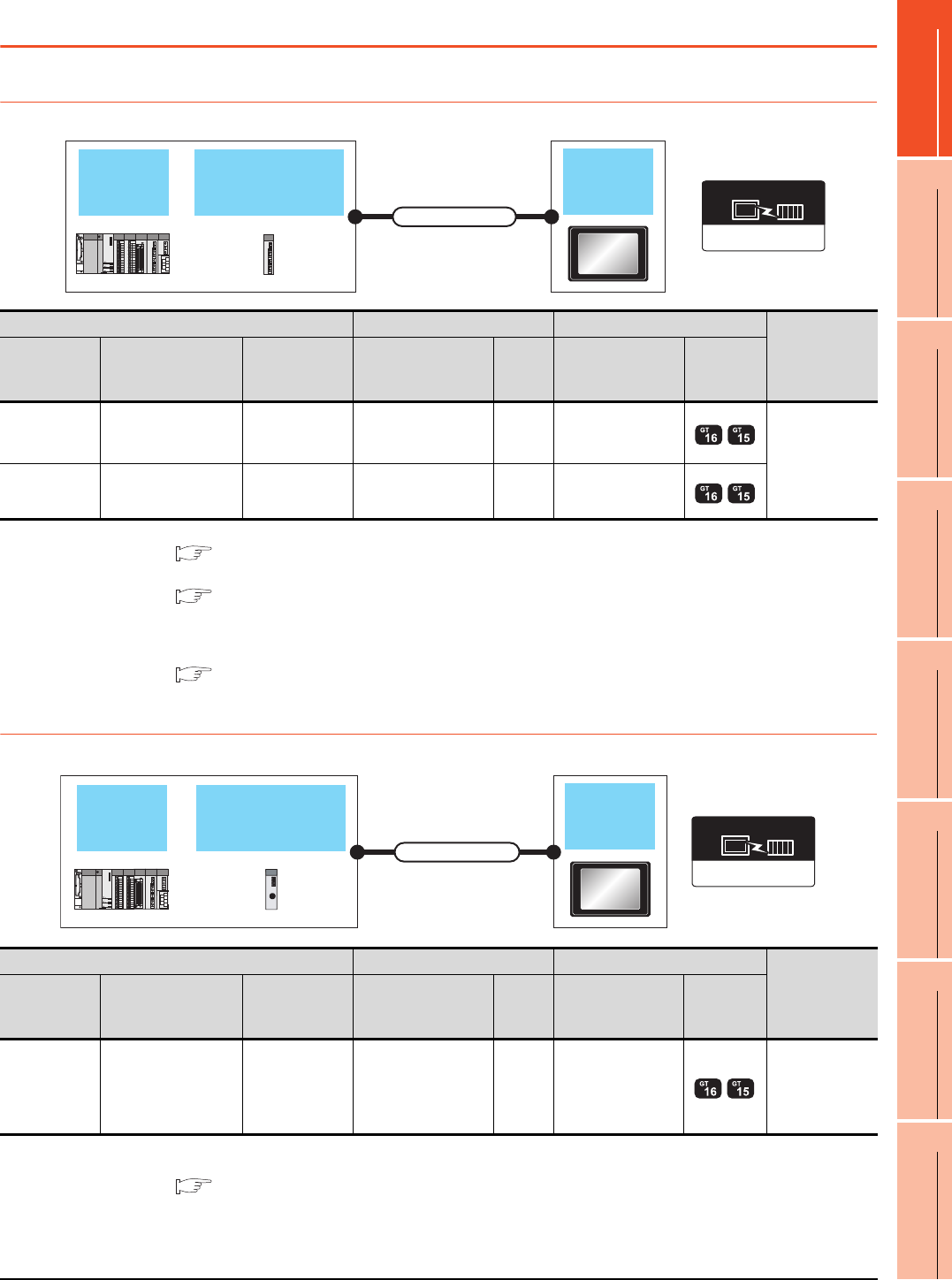
9. MELSECNET/H CONNECTION (PLC TO PLC NETWORK)
9.2 System Configuration
9 - 7
9
MELSECNET/H
CONNECTION (PLC
TO PLC NETWORK)
10
MELSECNET/10
CONNECTION (PLC
TO PLC NETWORK)
11
CC-Link IE CONTROLLER
NETWORK
CONNECTION
12
CC-Link IE FIELD
NETWORK
CONNECTION
13
CC-Link CONNECTION
(INTELLIGENT DEVICE
STATION)
14
CC-Link
CONNECTION
(Via G4)
15
INVERTER
CONNECTION
16
SERVO AMPLIFIER
CONNECTION
9.2 System Configuration
9.2.1 Connecting to optical loop system
*1 For the system configuration of the MELSECNET/H network module, refer to the following manual.
Q corresponding MELSECNET/H Network System Reference Manual (PLC to PLC network)
*2 For the optical fiber cable, refer to the following manual.
Q corresponding MELSECNET/H Network System Reference Manual (PLC to PLC network)
*3 The overall extension cable length and the length between stations vary depending on the cable type to be used and the total
number of stations.
For details, refer to the following manual.
Q corresponding MELSECNET/H Network System Reference Manual (PLC to PLC network)
9.2.2 Connecting to the coaxial bus system
*1 Use a PLC CPU of function version B or a later version.
*2 For the system configuration of the MELSECNET/H network module, refer to the following manual.
Q corresponding MELSECNET/H Network System Reference Manual (PLC to PLC network)
Use a MELSECNET/H network module of function version B or a later version.
MELSECNET/H
network module GOT
Connection cable
QCPU
MELSECNET/H
Communication driver
PLC Connection cable GOT
Number of
connectable
equipment
Model name
MELSECNET/H
network module
*1
Communication
type Cable model Max.
distance Option device Model
MELSEC-Q
MELSEC-QS
QJ71LP21
QJ71LP21-25
QJ71LP21S-25
MELSECNET/H Optical fiber cable*2 *3 GT15-J71LP23-25
63 GOTs
C Controller
module
QJ71LP21-25
QJ71LP21S-25 MELSECNET/H Optical fiber cable*2 *3 GT15-J71LP23-25
MELSECNET/H
network module GOT
Connection cable
QCPU
MELSECNET/H
Communication driver
PLC Connection cable GOT
Number of
connectable
equipment
Model name
MELSECNET/H
Network module
*2
Communication
type Cable model Max.
distance Option device Model
MELSEC-Q
*1
C Controller
module
MELSEC-QS
QJ71BR11 MELSECNET/H Coaxial cable
*3
*4 GT15-J71BR13 31 GOTs

9 - 8 9. MELSECNET/H CONNECTION (PLC TO PLC NETWORK)
9.2 System Configuration
*3 For the coaxial cable, refer to the following manual.
Q corresponding MELSECNET/H Network System Reference Manual (PLC to PLC network)
For the coaxial cable connector connection method, refer to the following.
1.4.2 Coaxial cable connector connection method
*4 The overall extension cable length and the length between stations vary depending on the cable type to be used and the total
number of stations.
For details, refer to the following manual.
Q corresponding MELSECNET/H Network System Reference Manual (PLC to PLC network)
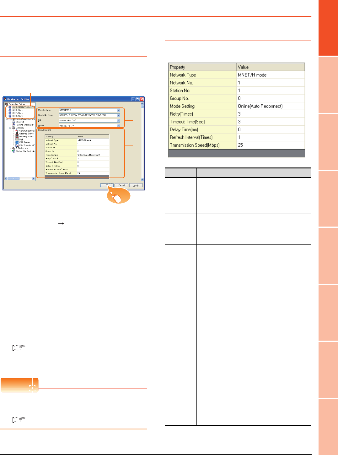
9. MELSECNET/H CONNECTION (PLC TO PLC NETWORK)
9.3 GOT Side Settings
9 - 9
9
MELSECNET/H
CONNECTION (PLC
TO PLC NETWORK)
10
MELSECNET/10
CONNECTION (PLC
TO PLC NETWORK)
11
CC-Link IE CONTROLLER
NETWORK
CONNECTION
12
CC-Link IE FIELD
NETWORK
CONNECTION
13
CC-Link CONNECTION
(INTELLIGENT DEVICE
STATION)
14
CC-Link
CONNECTION
(Via G4)
15
INVERTER
CONNECTION
16
SERVO AMPLIFIER
CONNECTION
9.3 GOT Side Settings
9.3.1 Setting communication
interface (Communication
settings)
Set the channel of the connected equipment.
1. Select [Common] [Controller Setting] from the
menu.
2. The Controller Setting window is displayed. Select the
channel to be used from the list menu.
3. Set the following items.
• Manufacturer: Mitsubishi
• Controller Type: Set according to the Controller
Type to be connected.
• I/F: Interface to be used
• Driver: MELSECNET/H
4. The detailed setting is displayed after Manufacturer,
Controller Type, I/F, and Driver are set.
Make the settings according to the usage
environment.
9.3.2 Communication detail settings
Click the [OK] button when settings are completed.
POINTPOINTPOINT
The settings of connecting equipment can be
confirmed in [I/F Communication Setting].
For details, refer to the following:
1.1.2 I/F communication setting
9.3.2 Communication detail settings
Make the settings according to the usage environment.
2.
3.
4.
Click!
Item Description Range
Network Type Set the network type.
(Default: MNET/H mode)
• MNET/H mode
• MNET/10 mode
• MNET/H
Extended
mode*1
Network No. Set the network No.
(Default: 1) 1 to 239
Station No. Set the station No. of the GOT.
(Default: 1) 1 to 64
Mode Setting
Set the operation mode of the
GOT.
(Default:
Online (auto. reconnection))
•Online
(auto.
reconnection)
• Offline
• Test between
slave station*2
• Self-loopback
test*2
• Internal self-
loopback
test*2
• H/W test*2
Retry
Set the number of retries to be
performed when a communication
timeout occurs.
When no response is received
after retries, a communication
times out.
(Default: 3times)
0 to 5times
Timeout
Time
Set the time period for a
communication to time out.
(Default: 3sec)
3 to 90sec
Delay
Time
Set the delay time for reducing the
load of the network/destination
PLC.
(Default: 0ms)
0 to 300ms

9 - 10 9. MELSECNET/H CONNECTION (PLC TO PLC NETWORK)
9.3 GOT Side Settings
*1 Cannot be set for the QCPU redundant system.
*2 For details, refer to the following manual.
Q corresponding MELSECNET/H Network System
Reference Manual (PLC to PLC network)
POINTPOINTPOINT
(1) Communication interface setting by Utility
The communication interface setting can be
changed on the Utility's [Communication Settings]
after writing [Communication Settings] of project
data.
For details on the RS-422 conversion unit and the
GOT utility, refer to the following manual:
GT User's Manual
(2) Precedence in communication settings
When settings are made by GT Designer3 or the
Utility, the latest setting is effective.
9.3.3 Routing parameter setting
Up to 64 [Transfer Network No.]s can be set.
However, the same transfer network number cannot be set
twice or more (multiple times).
Therefore, the one that can access to other station from the
request source host GOT is 64 kinds of [Transfer Network
No.]s.
POINTPOINTPOINT
Routing parameter setting
When communicating within the host network, routing
parameter setting is unnecessary.
For details of routing parameters, refer to the following
manual.
Q corresponding MELSECNET/H Network
System Reference Manual (PLC to PLC
network)
POINTPOINTPOINT
(1) Routing parameter setting of relay station
Routing parameter setting is also necessary for
the relay station.
For the setting, refer to the following.
9.4 PLC Side Settings
(2) Parameter reflection function of MELSOFT Navigator
(a) The color of the cells for the items which are
reflected to GT Designer3 from MELSOFT
Navigator changes to green. Set items, which
are displayed in green cells, from the
MELSOFT Navigator.
(b) When the settings of Transfer network No.,
Relay network No. or Relay station No. are
reflected to the parameter from the MELSOFT
Navigator, those settings are added. Items set
in advance are not deleted.However, if the
target network No. overlaps, the item set in
advance is overwritten.
(c) The routing information is used manually by
the user when the data is created. Therefore,
after changing the network configuration by
MELSOFT Navigator, create a routing
information again. For details of the creation
of the routing information, refer to the
MELSOFT Navigator help.
Refresh
Interval
Set the number of refreshes to
secure the send/receive data in
station units during
communication.
(Default: 1time)
Valid when [Secured data send/
Secured data receive] Is marked
by the control station side network
parameters of the melsecnet/h
network system.
1 to 1000times
Transmission
Speed
Set the communication
transmission speed.
(Default: 25Mbps)
When specifying [MNET/10
mode] as The network type, only
10mbps can be set applicable.
10Mbps/25Mbps
Item Description Range
Item Range
Transfer Network No. 1 to 239
Relay Network No. 1 to 239
Relay Station No. 1 to 64
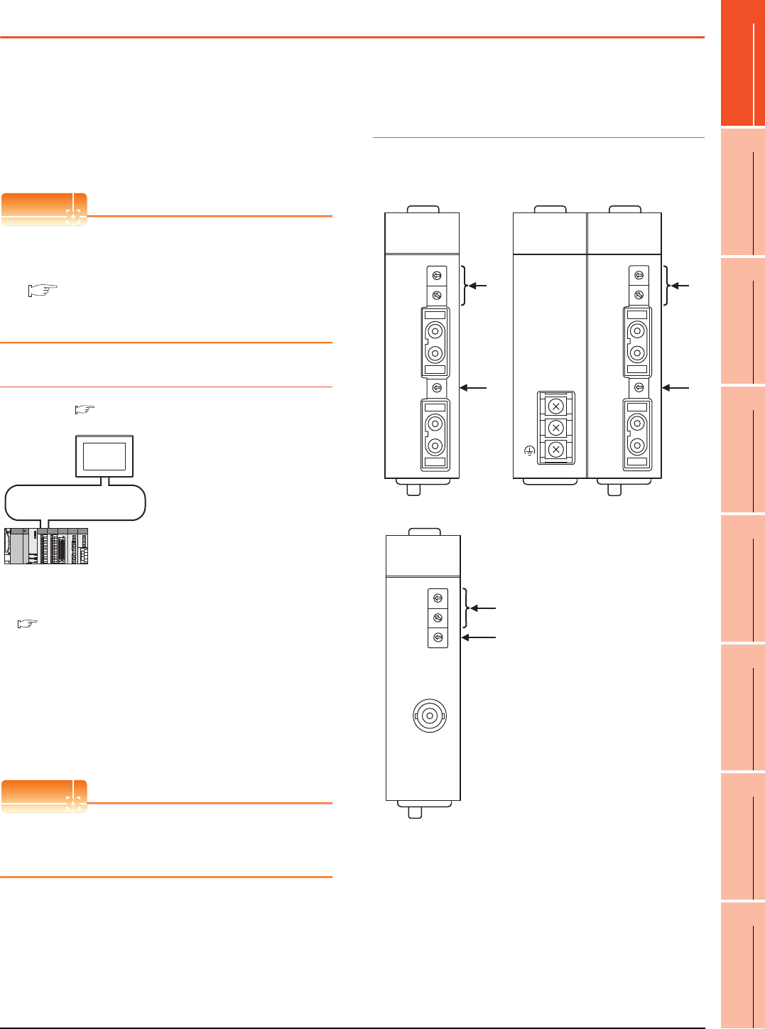
9. MELSECNET/H CONNECTION (PLC TO PLC NETWORK)
9.4 PLC Side Settings
9 - 11
9
MELSECNET/H
CONNECTION (PLC
TO PLC NETWORK)
10
MELSECNET/10
CONNECTION (PLC
TO PLC NETWORK)
11
CC-Link IE CONTROLLER
NETWORK
CONNECTION
12
CC-Link IE FIELD
NETWORK
CONNECTION
13
CC-Link CONNECTION
(INTELLIGENT DEVICE
STATION)
14
CC-Link
CONNECTION
(Via G4)
15
INVERTER
CONNECTION
16
SERVO AMPLIFIER
CONNECTION
9.4 PLC Side Settings
This section describes the settings of the GOT and
MELSECNET/H network module in the case of system
configuration shown as 9.4.1.
When connecting the MELSECNET/H network module to
the MELSECNET/H network system, specify the
MELSECNET/H Mode or the MELSECNET/H Extended
Mode as a network type.
POINTPOINTPOINT
MELSECNET/H network module
For details of the MELSECNET/H network module,
refer to the following manual.
Q corresponding MELSECNET/H Network
System Reference Manual (PLC to PLC
network)
9.4.1 System configuration
*1 The MELSECNET/H network module is mounted at slot 0 of
the base unit.
The start I/O No. of the MELSECNET/H network module is
set at "0".
*2 The network type must be set according to the number of
assignment of send points for each station.
When the number of assignment is 2000 bytes or less:
MELSECNET/H mode
When the number of assignment is 2000 bytes or more:
MELSECNET/H Extended Mode
POINTPOINTPOINT
When connecting to Q170MCPU
When connected to Q170MCPU, the start I/O No. of
the MELSECNET/H network module is set to "70".
9.4.2 Switch setting of
MELSECNET/H network
module
Set the station number setting switch and mode setting
switch.
<MELSECNET/H network module> *1
(Use the default value for settings other than the following.)
Station No. : 1
Mode : Online (10Mbps)
Network type : MNET/H mode (Control station)
Network No. : 1
Total stations : 2
Network range assignment *2:
MELSECNET/H (PLC to PLC network)
<GOT>
(Use the default value for settings other
than the following.)
LB0000
H
to LB00FF
H
LW0000
H
to LW00FF
H
Network type : MNET/H Mode
Network No. : 1
Station No. : 2
Made Setting : Online (auto,reconnection)
Network range assignment *
2
:
Transmission speed : 10Mbps
LB0100
H
to LB01FF
H
LW0100
H
to LW01FF
H
9.4.4 [Controller Setting] of GT Designer3
9.4.2 Switch setting of MELSECNET/H network module
(1) [Network parameter] of GX Developer
MNG
D.LINK
RD
L ERR.
RUN
T.PASS
SD
ERR.
QJ71LP21-25
0
5
9
4
8
3
7
2
6
1
0
5
9
4
8
3
7
2
6
1
STATION NO.
X10
X1
MODE
0
8
F
7
E
6
D
5
C
4
B
A
3
2
9
1
QJ71LP21
-25
IN
OUT
EXT.PW
+24V
24G
24G
0
5
9
4
8
3
7
2
6
1
0
5
9
4
8
3
7
2
6
1
STATION NO.
X10
X1
MODE
0
8
F
7
E
6
D
5
C
4
B
A
3
2
9
1
IN
OUT
MNG
D.LINK
RD
L ERR.
RUN
T.PASS
SD
ERR.
QJ71LP21S-25
QJ71LP21 S-25
EXT.PW
EXT.PW
+24V
24G
(FG)
MNG
D.LINK
RD
L ERR.
RUN
T.PASS
SD
ERR.
0
5
9
4
8
3
7
2
6
1
0
5
9
4
8
3
7
2
6
1
STATION NO.
X10
X1
MODE
0
8
F
7
E
6
D
5
C
4
B
A
3
2
9
1
QJ71BR11
QJ71BR11
(1)
(2)
(1)
(2)
(1)
(2)
QJ71LP21, QJ71LP21-25 QJ71LP21S-25
QJ71BR11
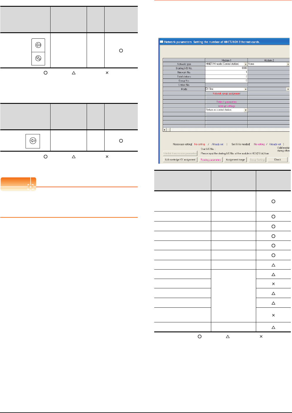
9 - 12 9. MELSECNET/H CONNECTION (PLC TO PLC NETWORK)
9.4 PLC Side Settings
(1) Station number setting switch
: Necessary : As necessary : Not necessary
*1 Do not set the same station No. as that of the GOT.
(2) Mode setting switch
: Necessary : As necessary : Not necessary
*2 Set the same mode setting and transmission speed as those
of the GOT.
POINTPOINTPOINT
When the switch setting has been changed
Turn the PLC CPU OFF then ON again, or reset the
PLC CPU.
9.4.3 Parameter setting
Connecting to MELSEC-Q or QS series
(1) [Network parameter] of GX Developer
(a) Network parameter
: Necessary : As necessary : Not necessary
*1 When using Q170MCPU, set it according to the system
configuration.
*2 Specify the same network No. as that of the GOT.
*3 Set the same mode setting as that of the GOT.
*4 Set it when the MELSECNET/H network module is used in
the redundant QnPRHCPU system.
Station number setting
switch Description Set
value
Setting
necessity at
GOT
connection
Station number
setting
(Station No.1)*1
1
Mode setting switch Description Set
value
Setting
necessity at
GOT
connection
Mode setting
(Online:
10Mbps)*2
0
0
5
9
4
8
3
7
2
6
1
0
5
9
4
8
3
7
2
6
1
STATION NO.
X10
X1
MODE
0
8
F
7
E
6
D
5
C
4
B
A
3
2
9
1
Item Set value
Setting
necessity at
GOT connection
Network type
MNET/H mode
(Control station)
(fixed)
Starting I/O No.*1 0000H
Network No.*2 1
Total stations 2
Group No. 0 (fixed)
Mode*3 Online
Network range assignment Refer to (b).
Refresh parameters
(Use default value)
Interrupt settings
Control station return setting
Redundant settings*4
Interlink transmission
parameters
Routing parameters Refer to (c).
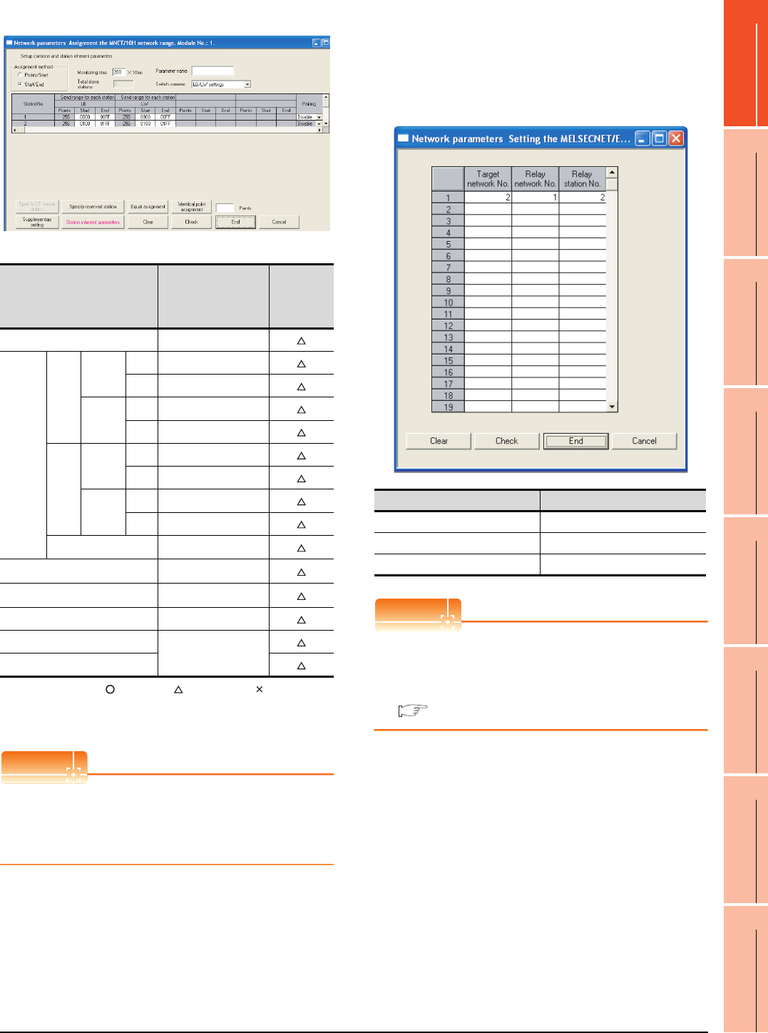
9. MELSECNET/H CONNECTION (PLC TO PLC NETWORK)
9.4 PLC Side Settings
9 - 13
9
MELSECNET/H
CONNECTION (PLC
TO PLC NETWORK)
10
MELSECNET/10
CONNECTION (PLC
TO PLC NETWORK)
11
CC-Link IE CONTROLLER
NETWORK
CONNECTION
12
CC-Link IE FIELD
NETWORK
CONNECTION
13
CC-Link CONNECTION
(INTELLIGENT DEVICE
STATION)
14
CC-Link
CONNECTION
(Via G4)
15
INVERTER
CONNECTION
16
SERVO AMPLIFIER
CONNECTION
(b) Network range assignment
: Necessary : As necessary : Not necessary
*1 Be sure to set the setting to perform the cyclic transmission.
*2 Set it when the MELSECNET/H network module is used in
the redundant QnPRHCPU system.
POINTPOINTPOINT
When changing the network parameter
After writing the network parameter to the PLC CPU,
operate the PLC CPU ether turning OFF and then ON
or resetting.
(c) Routing parameter setting
Up to 64 [Transfer Network No.]s can be set.
However, the same transfer network number
cannot be set twice or more (multiple times).
Therefore, the one that can access to other station
from the request source host GOT is 64 kinds of
[Transfer Network No.]s.
POINTPOINTPOINT
Routing parameter setting of request source
Routing parameter setting is also necessary for the
request source GOT.
For the setting, refer to the following.
9.3.3 Routing parameter setting
Item Set value
Setting
necessity at
GOT
connection
Monitoring time 200
LB/LW
setting*1
Send
range
for
station
(LB)
Station
No.1
Start 0000H
End 00FFH
Station
No.2
Start 0100H
End 01FFH
Send
range
for
station
(LW)
Station
No.1
Start 0000H
End 00FFH
Station
No.2
Start 0100H
End 01FFH
Pairing setting*2 Disable
LX/LY setting*1 No setting
Specify I/O master station*1 No setting
Specify reserved station No setting
Supplementary setting
(Use default value)
Station inherent parameters
Item Range
Target network No. 1 to 239
Relay network No. 1 to 239
Relay station No. 1 to 64
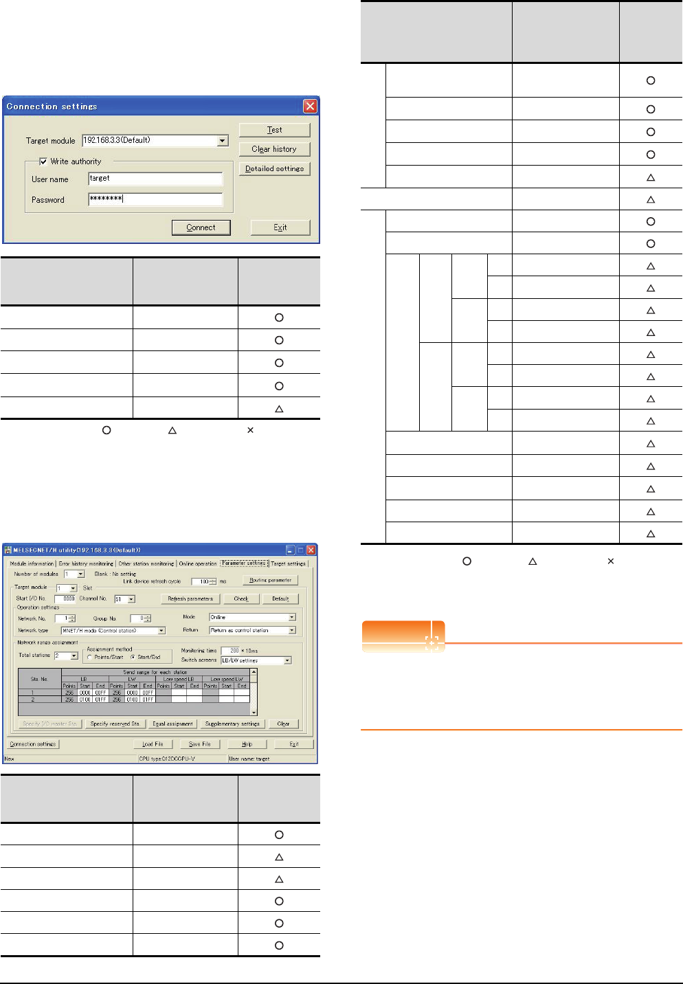
9 - 14 9. MELSECNET/H CONNECTION (PLC TO PLC NETWORK)
9.4 PLC Side Settings
Connecting to C Controller module
Use SW3PVC-CCPU-E Ver.3.05F or later for the
MELSECNET/H utility.
(1) Connection settings
: Necessary : As necessary : Not necessary
*1 If the IP address of the C Controller module has been
changed, input the changed IP address or host name.
*2 If the account of the C Controller module has been changed,
input the changed user name and password.
(2) MELSECNET/H Utility's [Parameter Settings]
(a) Parameter settings
: Necessary : As necessary : Not necessary
*1 Specify the same network No. as that of the GOT.
*2 Set the same mode setting as that of the GOT.
*3 Be sure to set the setting to perform the cyclic transmission.
POINTPOINTPOINT
When changing the network parameter
After writing the network parameter to the C Controller
module, either turn the C Controller module OFF and
then ON or reset it.
Item Set value
Setting
necessity at
GOT connection
Target module*1 192.168.3.3 (Default)
Write authority Mark the checkbox
User name*2 target
Password*2 password
Detailed settings -
Item Set value
Setting
necessity at
GOT connection
Number of modules 1
Link device refresh cycle (Use default value)
Routing parameter Refer to (b).
Target module 1
Start I/O No. 0000H
Channel No. (Use default value)
Item Set value
Setting
necessity at
GOT
connection
Operation settings
Network type MNET/H mode
(Control station)
Network No.*1 1
Group No. 0
Mode*2 Online
Return (Use default value)
Refresh parameters (Use default value)
Network range assignment
Total stations 2
Assignment method Start/End
LB/LW settings*3
Send range for
each station LB
Sta.
No.1
Start 0000H
End 00FFH
Sta.
No.2
Start 0100H
End 01FFH
Send range for
each station LW
Sta.
No.1
Start 0000H
End 00FFH
Sta.
No.2
Start 0100H
End 01FFH
(LX/LY) settings*3 No setting
Monitoring time (Use default value)
Specify I/O master Sta.*3 No setting
Specify reserved Sta. No setting
Supplementary settings (Use default value)
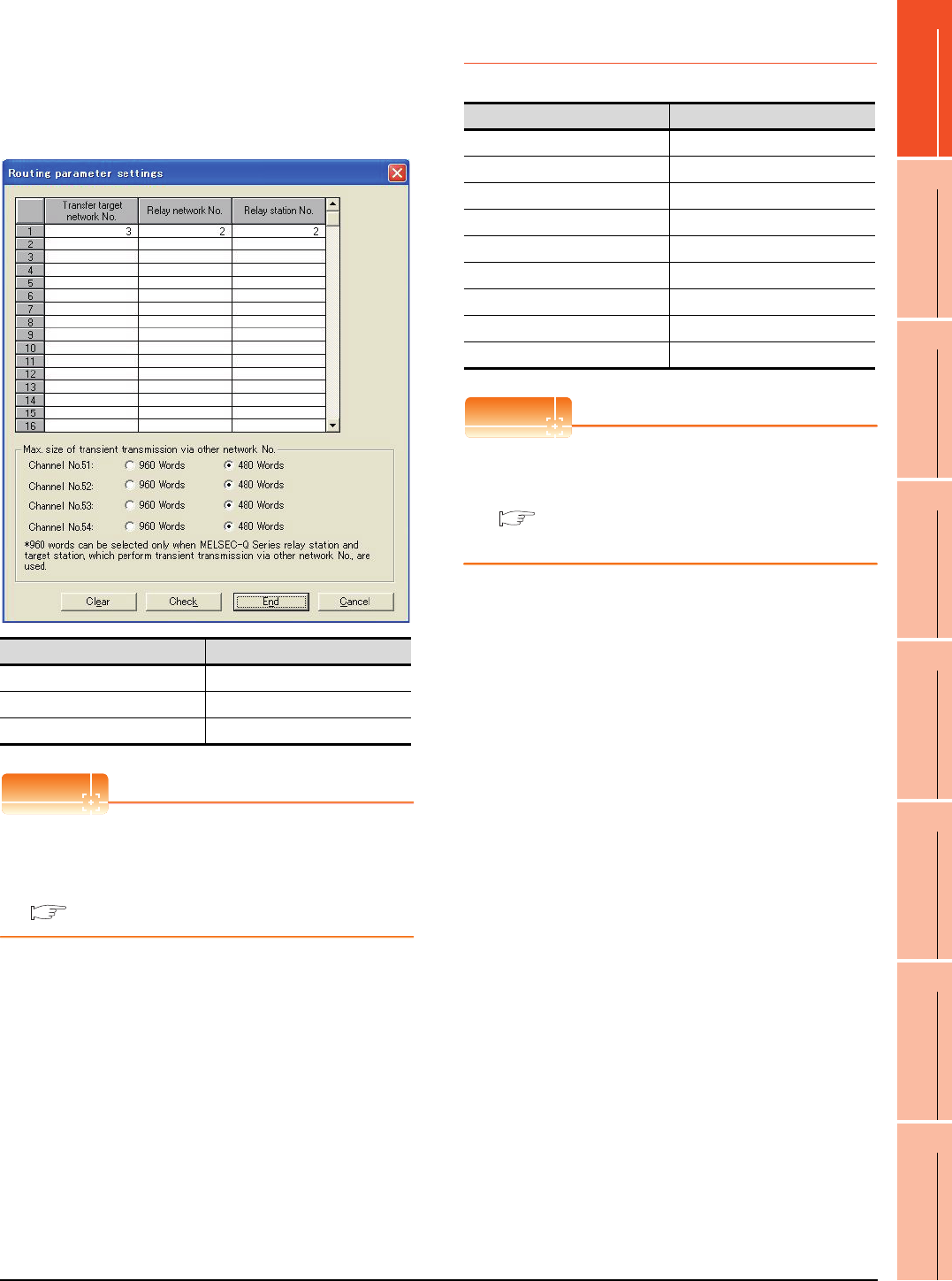
9. MELSECNET/H CONNECTION (PLC TO PLC NETWORK)
9.4 PLC Side Settings
9 - 15
9
MELSECNET/H
CONNECTION (PLC
TO PLC NETWORK)
10
MELSECNET/10
CONNECTION (PLC
TO PLC NETWORK)
11
CC-Link IE CONTROLLER
NETWORK
CONNECTION
12
CC-Link IE FIELD
NETWORK
CONNECTION
13
CC-Link CONNECTION
(INTELLIGENT DEVICE
STATION)
14
CC-Link
CONNECTION
(Via G4)
15
INVERTER
CONNECTION
16
SERVO AMPLIFIER
CONNECTION
(b) Routing parameter setting
Up to 64 [Transfer Network No.]s can be set.
However, the same transfer network number
cannot be set twice or more (multiple times).
Therefore, the one that can access to other station
from the request source host GOT is 64 kinds of
[Transfer Network No.]s.
POINTPOINTPOINT
Routing parameter setting of request source
Routing parameter setting is also necessary for the
request source GOT.
For the setting, refer to the following.
9.3.3 Routing parameter setting
9.4.4 [Controller Setting] of GT
Designer3
POINTPOINTPOINT
[Controller Setting] of GT Designer3
For [Controller Setting], of GT Designer3, refer to the
following.
9.3.1 Setting communication interface
(Communication settings)
Item Range
Transfer target network No. 1 to 239
Relay network No. 1 to 239
Relay station No. 1 to 120
Item Set value
Network Type MNET/H mode
Network No. 1: Network No.1
Station No. 2: Station No.2
Mode Setting Online (auto. reconnection)
Retry count 3times (Use default value)
Timeout Time 3sec (Use default value)
Delay Time 0sec (Use default value)
Refresh Interval 1time (Use default value)
Monitor Speed 10Mbs
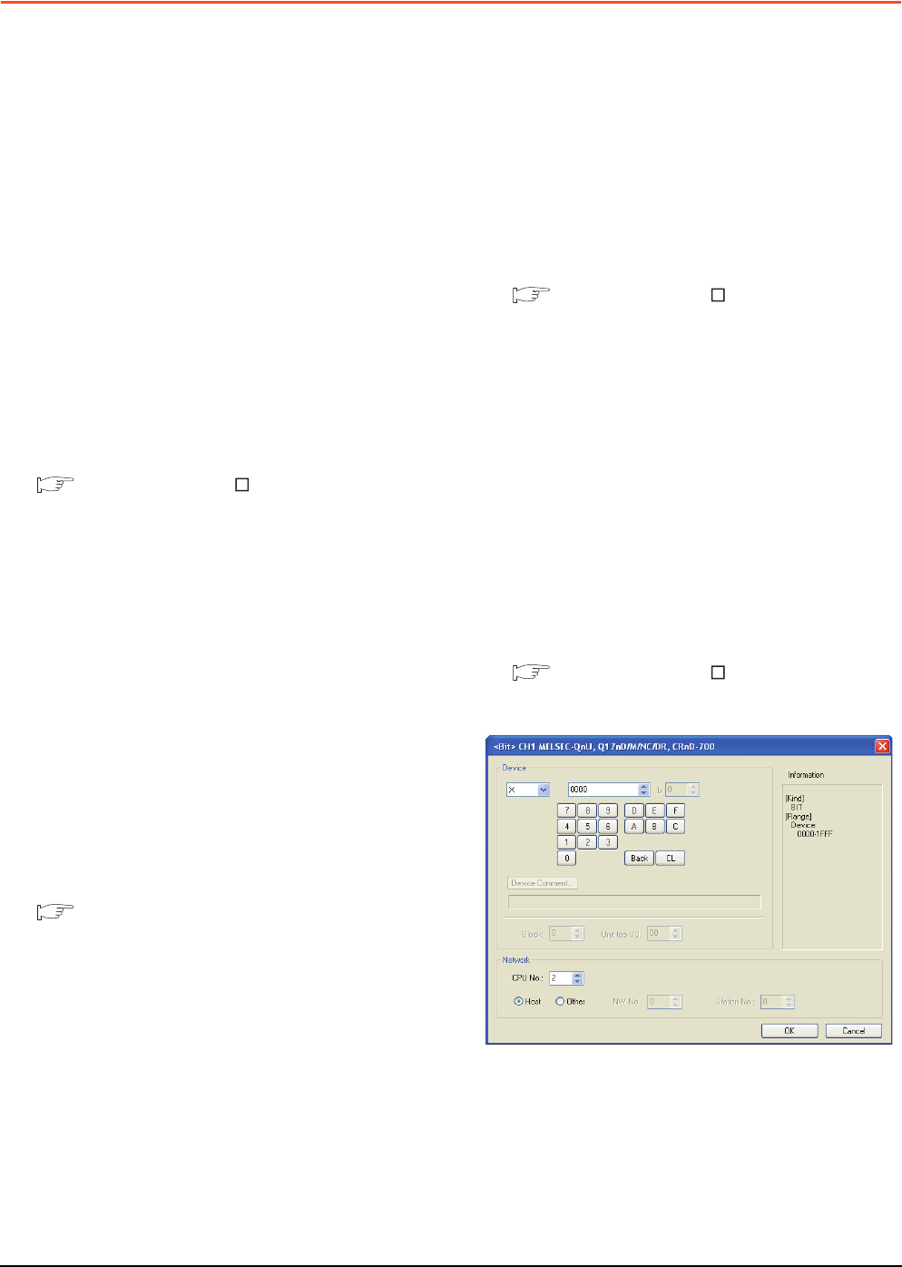
9 - 16 9. MELSECNET/H CONNECTION (PLC TO PLC NETWORK)
9.5 Precautions
9.5 Precautions
Network configuration
Use MELSECNET/H (PLC to PLC network) to
configure a network including the GOT.
The following networks including the GOT cannot be
configured.
• MELSECNET/H (Remote I/O network)
Network type setting
• Specify all the network modules on the same network
as the same network type.
(MELSECNET/H Mode and MELSECNET/H
Extended Mode cannot be mixed.)
• When connecting to MELSECNET/H in the QCPU
redundant system, [MELSECNET/H Extended Mode]
cannot be specified as the network type.
Monitoring range
Only PLC CPU of the same networks No. can be
monitored in GOT.
For details, refer to the following manual.
GT Designer3 Version Screen Design Manual
GOT startup in the MELSECNET/H
connection
In the MELSECNET/H connection, the data link is
started approximately 10 seconds after the GOT
startup.
When a network error occurs in the system
alarm
In the MELSECNET/H connection, when a network
error occurs in the system alarm, the system alarm
message cannot be canceled even though the causes
are removed.
To cancel the system alarm display, restart the GOT.
MELSECNET/H network module version
For version restrictions of the MELSECNET/H network
module, refer to the following manual.
Q corresponding MELSECNET/H Network
System Reference Manual (PLC to PLC
network)
Connection in the multiple CPU system
When the GOT is connected to multiple CPU system,
the following time is taken until when the PLC runs.
QCPU (Q mode), motion controller CPU (Q series): 10
seconds or more
MELDAS C70: 18 seconds or more
When the GOT starts before the PLC runs, a system
alarm occurs. Adjust the opening screen time in the
GOT setup so that no system alarm occurs.
GT Designer3 Version Screen Design Manual
Connection to QSCPU
The GOT can only read device data and sequence
programs by the ladder monitor function in the QSCPU.
The GOT cannot write any data to the QSCPU.
Connection to Q170MCPU
Set [CPU No.] to "2" in the device setting to monitor the
device of the Motion CPU area (CPU No.2).
When the CPU No. is set to "0" or "1", the device on the
PLC CPU area (CPU No.1) is monitored.
When the CPU No. is set to the number other than "0"
to "2", a communication error occurs and the monitoring
cannot be executed.
For setting the CPU No., refer to the following manual.
GT Designer3 Version Screen Design Manual
Example) Setting dialog box of the bit device
10
9
MELSECNET/H
CONNECTION (PLC
TO PLC NETWORK)
10
MELSECNET/10
CONNECTION (PLC
TO PLC NETWORK)
11
CC-Link IE CONTROLLER
NETWORK
CONNECTION
12
CC-Link IE FIELD
NETWORK
CONNECTION
13
CC-Link CONNECTION
(INTELLIGENT DEVICE
STATION)
14
CC-Link
CONNECTION
(Via G4)
15
INVERTER
CONNECTION
16
SERVO AMPLIFIER
CONNECTION
10 - 1
10.MELSECNET/10 CONNECTION
(PLC TO PLC NETWORK)
10.1 Connectable Model List . . . . . . . . . . . . . . . . . . . . . . . . . . . 10 - 2
10.2 System Configuration. . . . . . . . . . . . . . . . . . . . . . . . . . . . . 10 - 7
10.3 GOT Side Settings . . . . . . . . . . . . . . . . . . . . . . . . . . . . . . . 10 - 9
10.4 PLC Side Setting . . . . . . . . . . . . . . . . . . . . . . . . . . . . . . . 10 - 12
10.5 Precautions . . . . . . . . . . . . . . . . . . . . . . . . . . . . . . . . . . . 10 - 26
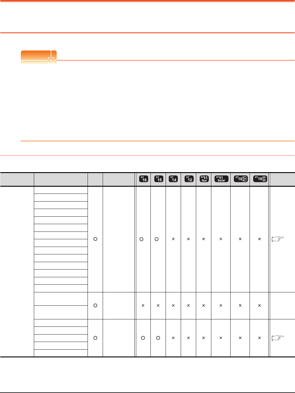
10 - 2 10. MELSECNET/10 CONNECTION (PLC TO PLC NETWORK)
10.1 Connectable Model List
10. MELSECNET/10 CONNECTION (PLC
TO PLC NETWORK)
10.1 Connectable Model List
POINTPOINTPOINT
(1) Connectable network
The MELSECNET/10 connection includes the MELSECNET/H network system used in the MELSECNET/10
mode. The GOT cannot be connected to the remote I/O network.
Connect the GOT to the following network systems as an ordinary station.
• MELSECNET/10 network system (PLC to PLC network) optical loop system
• MELSECNET/10 network system (PLC to PLC network) coaxial bus system
(2) MELSECNET/H network module
When connecting the MELSECNET/H network module to the MELSECNET/10 network system, specify the
MELSECNET/10 Mode as a network type.
10.1.1 PLC/Motion controller CPU
The following table shows the connectable models.
(Continued to next page)
*1 Use CPU function version B or a later version.
Series Model name Clock
Communication
type Refer to
MELSEC-Q
(Q mode)
Q00JCPU
MELSECNET/10
*1 *1
10.2
Q00CPU
Q01CPU
Q02CPU
Q02HCPU
Q06HCPU
Q12HCPU
Q25HCPU
Q02PHCPU
Q06PHCPU
Q12PHCPU
Q25PHCPU
Q12PRHCPU (Main base)
Q25PRHCPU (Main base)
Q12PRHCPU
(Extension base) - -
Q25PRHCPU
(Extension base)
Q00UJCPU
MELSECNET/10
10.2
Q00UCPU
Q01UCPU
Q02UCPU
Q03UDCPU
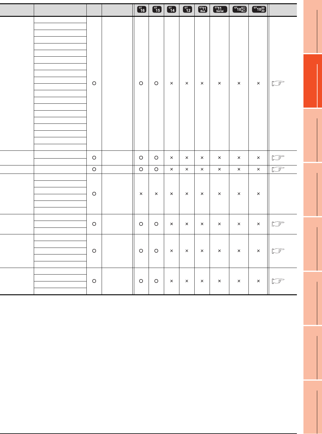
10. MELSECNET/10 CONNECTION (PLC TO PLC NETWORK)
10.1 Connectable Model List
10 - 3
9
MELSECNET/H
CONNECTION (PLC
TO PLC NETWORK)
10
MELSECNET/10
CONNECTION (PLC
TO PLC NETWORK)
11
CC-Link IE CONTROLLER
NETWORK
CONNECTION
12
CC-Link IE FIELD
NETWORK
CONNECTION
13
CC-Link CONNECTION
(INTELLIGENT DEVICE
STATION)
14
CC-Link
CONNECTION
(Via G4)
15
INVERTER
CONNECTION
16
SERVO AMPLIFIER
CONNECTION
(Continued to next page)
*1 Use a module with the upper five digits later than 12042.
Series Model name Clock
Communication
type Refer to
MELSEC-Q
(Q mode)
Q04UDHCPU
MELSECNET/10
10.2
Q06UDHCPU
Q10UDHCPU
Q13UDHCPU
Q20UDHCPU
Q26UDHCPU
Q03UDECPU
Q04UDEHCPU
Q06UDEHCPU
Q10UDEHCPU
Q13UDEHCPU
Q20UDEHCPU
Q26UDEHCPU
Q50UDEHCPU
Q100UDEHCPU
Q03UDVCPU
Q04UDVCPU
Q06UDVCPU
Q13UDVCPU
Q26UDVCPU
C Controller
module
Q12DCCPU-V*1
MELSECNET/10
10.2
Q24DHCCPU-V
MELSEC-QS QS001CPU
MELSECNET/10
10.2
MELSEC-L
L02CPU
- -
L26CPU
L26CPU-BT
L02CPU-P
L26CPU-PBT
L02SCPU
MELSEC-Q
(A mode)
Q02CPU-A
MELSECNET/10
10.2
Q02HCPU-A
Q06HCPU-A
MELSEC-QnA
(QnACPU)
Q2ACPU
MELSECNET/10
10.2
Q2ACPU-S1
Q3ACPU
Q4ACPU
Q4ARCPU
MELSEC-QnA
(QnASCPU)
Q2ASCPU
MELSECNET/10
10.2
Q2ASCPU-S1
Q2ASHCPU
Q2ASHCPU-S1
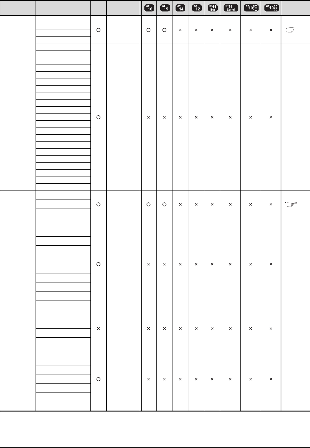
10 - 4 10. MELSECNET/10 CONNECTION (PLC TO PLC NETWORK)
10.1 Connectable Model List
(Continued to next page)
Series Model name Clock
Communication
type Refer to
MELSEC-A
(AnCPU)
A2UCPU
MELSECNET/10
10.2
A2UCPU-S1
A3UCPU
A4UCPU
A2ACPU
- -
A2ACPUP21
A2ACPUR21
A2ACPU-S1
A2ACPUP21-S1
A2ACPUR21-S1
A3ACPU
A3ACPUP21
A3ACPUR21
A1NCPU
A1NCPUP21
A1NCPUR21
A2NCPU
A2NCPUP21
A2NCPUR21
A2NCPU-S1
A2NCPUP21-S1
A2NCPUR21-S1
A3NCPU
A3NCPUP21
A3NCPUR21
MELSEC-A
(AnSCPU)
A2USCPU
MELSECNET/10
10.2
A2USCPU-S1
A2USHCPU-S1
A1SCPU
- -
A1SCPUC24-R2
A1SHCPU
A2SCPU
A2SCPU-S1
A2SHCPU
A2SHCPU-S1
A1SJCPU
A1SJCPU-S3
A1SJHCPU
MELSEC-A
A0J2HCPU
- -
A0J2HCPUP21
A0J2HCPUR21
A0J2HCPU-DC24
A2CCPU
- -
A2CCPUP21
A2CCPUR21
A2CCPUC24
A2CCPUC24-PRF
A2CJCPU-S3
A1FXCPU
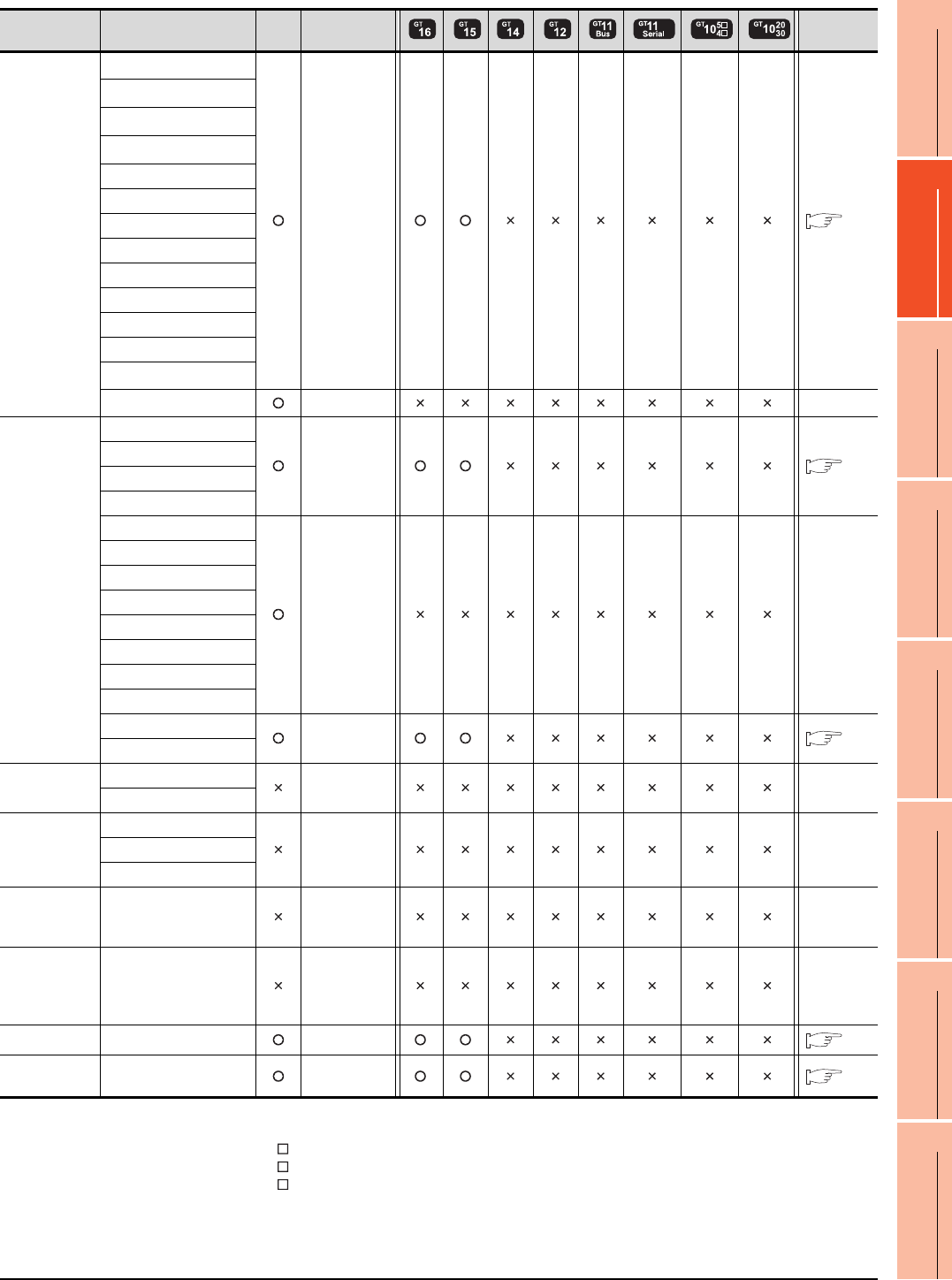
10. MELSECNET/10 CONNECTION (PLC TO PLC NETWORK)
10.1 Connectable Model List
10 - 5
9
MELSECNET/H
CONNECTION (PLC
TO PLC NETWORK)
10
MELSECNET/10
CONNECTION (PLC
TO PLC NETWORK)
11
CC-Link IE CONTROLLER
NETWORK
CONNECTION
12
CC-Link IE FIELD
NETWORK
CONNECTION
13
CC-Link CONNECTION
(INTELLIGENT DEVICE
STATION)
14
CC-Link
CONNECTION
(Via G4)
15
INVERTER
CONNECTION
16
SERVO AMPLIFIER
CONNECTION
(Continued to next page)
*1 When using SV13, SV22 or SV43, use the motion controller CPU on which any of the following main OS version is installed.
• SW6RN-SV13Q : 00H or later
• SW6RN-SV22Q : 00H or later
• SW6RN-SV43Q : 00B or later
*2 Use main modules with the following product numbers.
• Q172CPU: Product number N******* or later
• Q173CPU: Product number M******* or later
*3 Only the first step can be used on the extension base unit (Q52B/Q55B).
Series Model name Clock
Communication
type Refer to
Motion
controller
CPU
(Q Series)
Q172CPU*1*2
MELSECNET/10
10.2
Q173CPU*1*2
Q172CPUN*1
Q173CPUN*1
Q172HCPU
Q173HCPU
Q172DCPU
Q173DCPU
Q172DCPU-S1
Q173DCPU-S1
Q172DSCPU
Q173DSCPU
Q170MCPU*3
MR-MQ100 - -
Motion
controller
CPU
(A Series)
A273UCPU
MELSECNET/10
10.2
A273UHCPU
A273UHCPU-S3
A373UCPU
A373UCPU-S3
- -
A171SCPU
A171SCPU-S3
A171SCPU-S3N
A171SHCPU
A171SHCPUN
A172SHCPU
A172SHCPUN
A173UHCPU
MELSECNET/10
10.2
A173UHCPU-S1
MELSEC-WS
WS0-CPU0
- -
WS0-CPU1
MELSECNET/H
remote I/O
station
QJ72LP25-25
- -QJ72LP25G
QJ72BR15
CC-Link IE
Field Network
head module
LJ72GF15-T2 - -
CC-Link IE
Field Network
Ethernet
adapter module
NZ2GF-ETB - -
CNC C70 Q173NCCPU
MELSECNET/10
10.2
Robot
controller
CRnQ-700
(Q172DRCPU)
MELSECNET/10
10.2
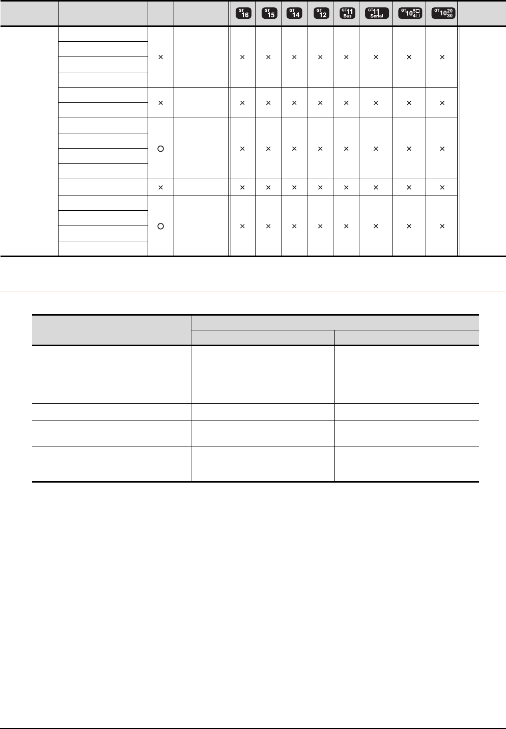
10 - 6 10. MELSECNET/10 CONNECTION (PLC TO PLC NETWORK)
10.1 Connectable Model List
10.1.2 MELSECNET/H (NET/10 mode), MELSECNET/10 network module
*1 Use function version B or later of the CPU and MELSECNET/H network module.
Series Model name Clock
Communication
type Refer to
MELSEC-FX
FX0
-
-
FX0S
FX0N
FX1
FX2
-
FX2C
FX1S
-
FX1N
FX2N
FX1NC
FX2NC -
FX3G
-
FX3GC
FX3U
FX3UC
CPU series
Model name
Optical loop Coaxial bus
MELSEC-Q (Q mode)*1
MELSEC-QS
Motion controller CPU (Q Series)
CNC C70
Robot controller (CRnQ-700)
QJ71LP21, QJ71LP21-25
QJ71LP21S-25 QJ71BR11*1
C Controller module QJ71LP21-25, QJ71LP21S-25 QJ71BR11*1
MELSEC-QnA AJ71QLP21, AJ71QLP21S
A1SJ71QLP21, A1SJ71QLP21S
AJ71QBR11
A1SJ71QBR11
MELSEC-Q (A mode)
MELSEC-A
Motion controller CPU (A Series)
AJ71LP21
A1SJ71LP21
AJ71BR11
A1SJ71BR11
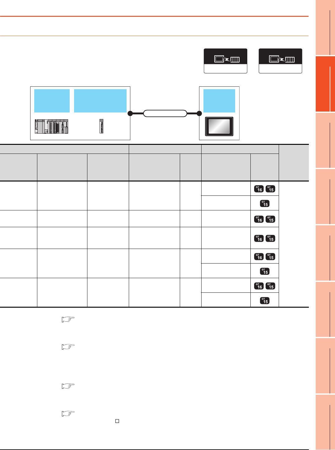
10. MELSECNET/10 CONNECTION (PLC TO PLC NETWORK)
10.2 System Configuration
10 - 7
9
MELSECNET/H
CONNECTION (PLC
TO PLC NETWORK)
10
MELSECNET/10
CONNECTION (PLC
TO PLC NETWORK)
11
CC-Link IE CONTROLLER
NETWORK
CONNECTION
12
CC-Link IE FIELD
NETWORK
CONNECTION
13
CC-Link CONNECTION
(INTELLIGENT DEVICE
STATION)
14
CC-Link
CONNECTION
(Via G4)
15
INVERTER
CONNECTION
16
SERVO AMPLIFIER
CONNECTION
10.2 System Configuration
10.2.1 Connecting to optical loop system
*1 For the system configuration of the MELSECNET/H and MELSECNET/10 network module, refer to the following manuals.
Q corresponding MELSECNET/H Network System Reference Manual (PLC to PLC network)
For QnA/Q4AR MELSECNET/10 Network System Reference Manual
Type MELSECNET/10 Network system (PLC to PLC network) Reference Manual
*2 For the optical fiber cable, refer to the following manual.
Q corresponding MELSECNET/H Network System Reference Manual (PLC to PLC network)
For QnA/Q4AR MELSECNET/10 Network System Reference Manual
Type MELSECNET/10 Network system (PLC to PLC network) Reference Manual
*3 The overall extension cable length and the length between stations vary depending on the cable type to be used and the total
number of stations.
For details, refer to the following manual.
Q corresponding MELSECNET/H Network System Reference Manual (PLC to PLC network)
For QnA/Q4AR MELSECNET/10 Network System Reference Manual
Type MELSECNET/10 Network system (PLC to PLC network) Reference Manual
*4 Specify the MELSECNET/10 Mode as the Communication Settings.For the setting, refer to the following.
10.3.1 Setting communication interface (Communication settings)
*5 Not available for the GT155 .
MELSECNET/H,
MELSECNET/10
network module
PLC GOT
Connection cable
MELSECNET/H
Communication driver
(When MELSECNET/H
communication unit is used)
MELSECNET/10
Communication driver
(When MELSECNET/10
communication unit is used)
PLC Connection cable GOT
Number of
connectable
equipment
Model name
MELSECNET/H,
MELSECNET/10
network module
*1
Communication
type Cable model Max.
distance Option device Model
MELSEC-Q
QJ71LP21
QJ71LP21-25
QJ71LP21S-25
MELSECNET/10 Optical fiber cable
*2 *3
GT15-J71LP23-25
*4
63 GOTs
GT15-75J71LP23-Z
*5
C Controller
module
QJ71LP21-25
QJ71LP21S-25 MELSECNET/10 Optical fiber cable
*2 *3 GT15-75J71LP23-25
*4
MELSEC-QS
QJ71LP21
QJ71LP21-25
QJ71LP21S-25
MELSECNET/10 Optical fiber cable
*2 *3 GT15-75J71LP23-25
*4
MELSEC-QnA
AJ71QLP21
AJ71QLP21S
A1SJ71QLP21
A1SJ71QLP21S
MELSECNET/10 Optical fiber cable
*2 *3
GT15-J71LP23-25
*4
GT15-75J71LP23-Z
*5
MELSEC-A AJ71LP21
A1SJ71LP21 MELSECNET/10 Optical fiber cable
*2 *3
GT15-J71LP23-25
*4
GT15-75J71LP23-Z
*5
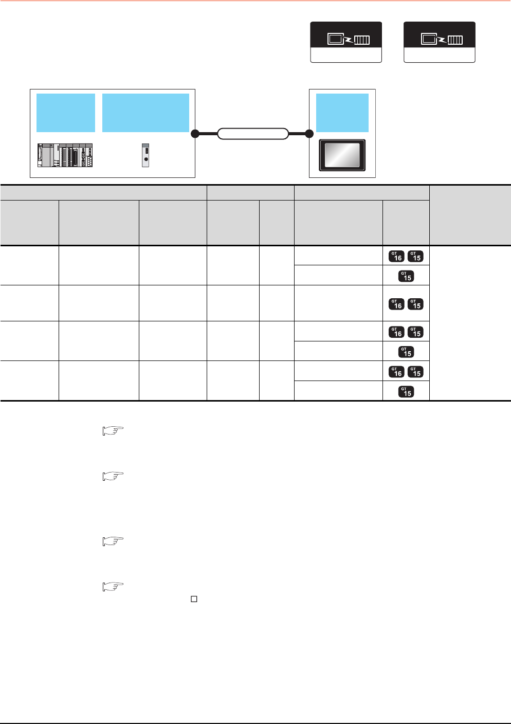
10 - 8 10. MELSECNET/10 CONNECTION (PLC TO PLC NETWORK)
10.2 System Configuration
10.2.2 Connecting to the coaxial bus system
*1 Use a PLC CPU and MELSECNET/H network module of function version B or later.
*2 For the system configuration of the MELSECNET/H and MELSECNET/10 network module, refer to the following manuals.
Q corresponding MELSECNET/H Network System Reference Manual (PLC to PLC network)
For QnA/Q4AR MELSECNET/10 Network System Reference Manual
Type MELSECNET/10 Network system (PLC to PLC network) Reference Manual
*3 For the coaxial cable, refer to the following manuals.
Q corresponding MELSECNET/H Network System Reference Manual (PLC to PLC network)
For QnA/Q4AR MELSECNET/10 Network System Reference Manual
Type MELSECNET/10 Network system (PLC to PLC network) Reference Manual
*4 The overall extension cable length and the length between stations vary depending on the cable type to be used and the total
number of stations.
For details, refer to the following manual.
Q corresponding MELSECNET/H Network System Reference Manual (PLC to PLC network)
For QnA/Q4AR MELSECNET/10 Network System Reference Manual
Type MELSECNET/10 Network system (PLC to PLC network) Reference Manual
*5 Specify the MELSECNET/10 Mode as the Communication Settings.For the setting, refer to the following.
10.3.1 Setting communication interface (Communication settings)
*6 Not available for the GT155 .
MELSECNET/H,
MELSECNET/10
network module
PLC GOT
Connection cable
MELSECNET/H
Communication driver
(When MELSECNET/H
communication unit is used)
MELSECNET/10
Communication driver
(When MELSECNET/10
communication unit is used)
PLC Connection cable GOT
Number of
connectable
equipment
Model name
MELSECNET/H,
MELSECNET/10
network module
*2
Communication
type Cable model Max.
distance Option device Model
MELSEC-Q
*1 QJ71BR11*1 MELSECNET/10 Coaxial cable
*3 *4
GT15-J71BR13*5
31 GOTs
GT15-75J71BR13-Z*6
C Controller
module
MELSEC-QS
QJ71BR11*1 MELSECNET/10 Coaxial cable
*3 *4 GT15-J71BR13*5
MELSEC-QnA AJ71QBR11
A1SJ71QBR11 MELSECNET/10 Coaxial cable
*3 *4
GT15-J71BR13*5
GT15-75J71BR13-Z*6
MELSEC-A AJ71BR11
A1SJ71BR11 MELSECNET/10 Coaxial cable
*3 *4
GT15-J71BR13*5
GT15-75J71BR13-Z*6
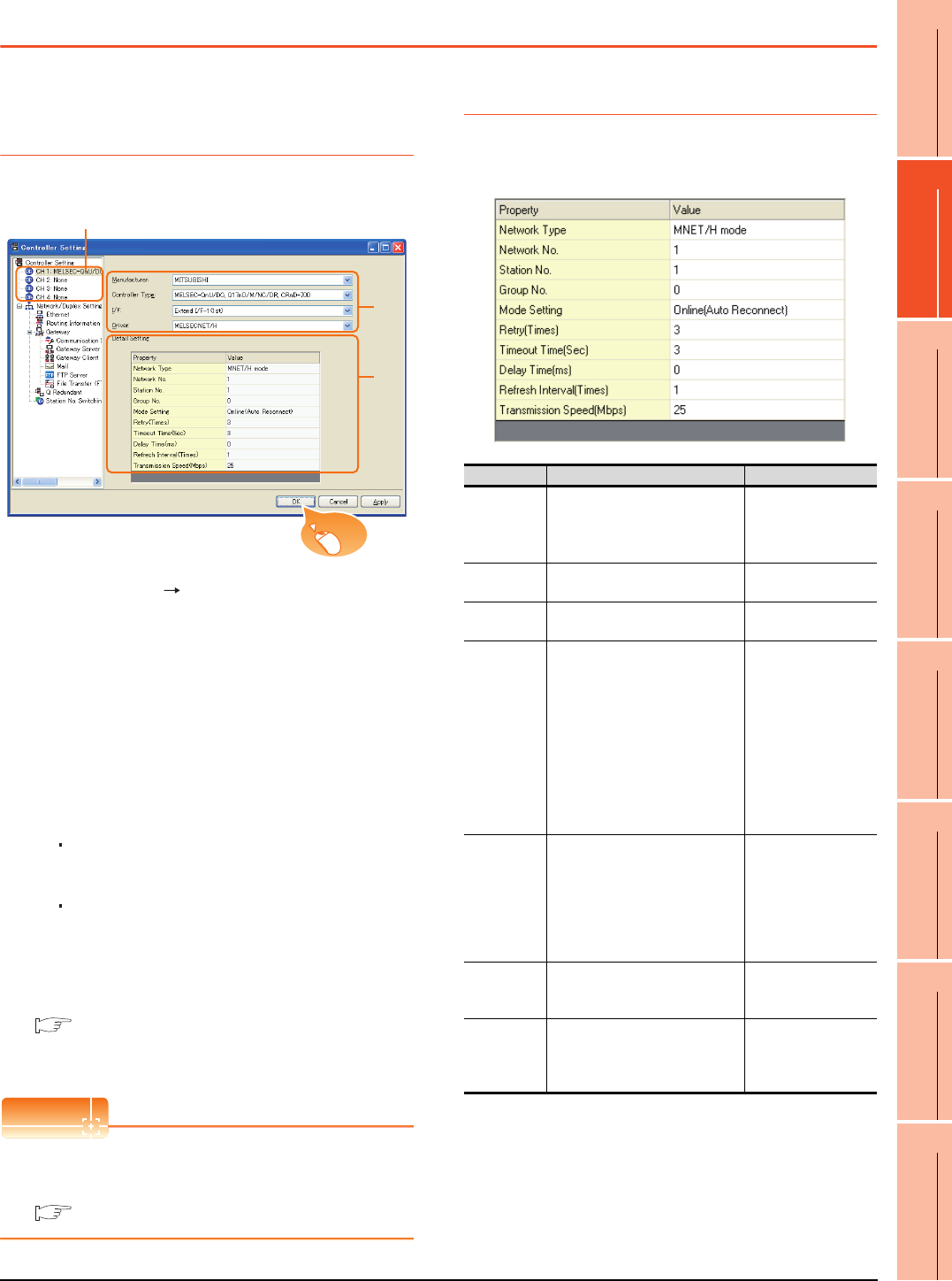
10. MELSECNET/10 CONNECTION (PLC TO PLC NETWORK)
10.3 GOT Side Settings
10 - 9
9
MELSECNET/H
CONNECTION (PLC
TO PLC NETWORK)
10
MELSECNET/10
CONNECTION (PLC
TO PLC NETWORK)
11
CC-Link IE CONTROLLER
NETWORK
CONNECTION
12
CC-Link IE FIELD
NETWORK
CONNECTION
13
CC-Link CONNECTION
(INTELLIGENT DEVICE
STATION)
14
CC-Link
CONNECTION
(Via G4)
15
INVERTER
CONNECTION
16
SERVO AMPLIFIER
CONNECTION
10.3 GOT Side Settings
10.3.1 Setting communication
interface (Communication
settings)
Set the channel of the connected equipment.
1. Select [Common] [Controller Setting] from the
menu.
2. The Controller Setting window is displayed. Select the
channel to be used from the list menu.
3. Set the following items.
• Manufacturer: Mitsubishi
• Controller Type: Set according to the Controller
Type to be connected.
• I/F: Interface to be used
• Driver:
When using the MELSECNET/H communication unit
MELSECNET/H
When using the MELSECNET/10 communication
unit
MELSECNET/10
4. The detailed setting is displayed after Manufacturer,
Controller Type, I/F, and Driver are set.
Make the settings according to the usage
environment.
10.3.2 Communication detail settings
Click the [OK] button when settings are completed.
POINTPOINTPOINT
The settings of connecting equipment can be
confirmed in [I/F Communication Setting].
For details, refer to the following.
1.1.2 I/F communication setting
10.3.2 Communication detail settings
Make the settings according to the usage environment.
(1) MELSECNET/H
2.
3.
4.
Click!
Item Description Range
Network Type Set the network type.
(Default: MNET/H mode)
• MNET/H mode
•MNET/10 mode
• MNET/H Extended
mode*1
Network No. Set the network No.
(Default: 1) 1 to 239
Station No. Set the station No. of the GOT.
(Default: 1) 1 to 64
Mode Setting
Set the operation mode of the
GOT.
(Default:
Online (auto. reconnection))
•Online
(Auto Reconnect)
•Offline
• Test between
slave station*2
• Self-loopback test*2
• Internal self-
loopback
test*2
• H/W test*2
Retry
Set the number of retries to be
performed when a communication
timeout occurs.
When no response is received
after retries, a communication
times out.
(Default: 3times)
0 to 5times
Timeout Time
Set the time period for a
communication to time out.
(Default: 3sec)
3 to 90sec
Delay Time
Set the delay time for reducing the
load of the network/destination
PLC.
(Default: 0ms)
0 to 300ms
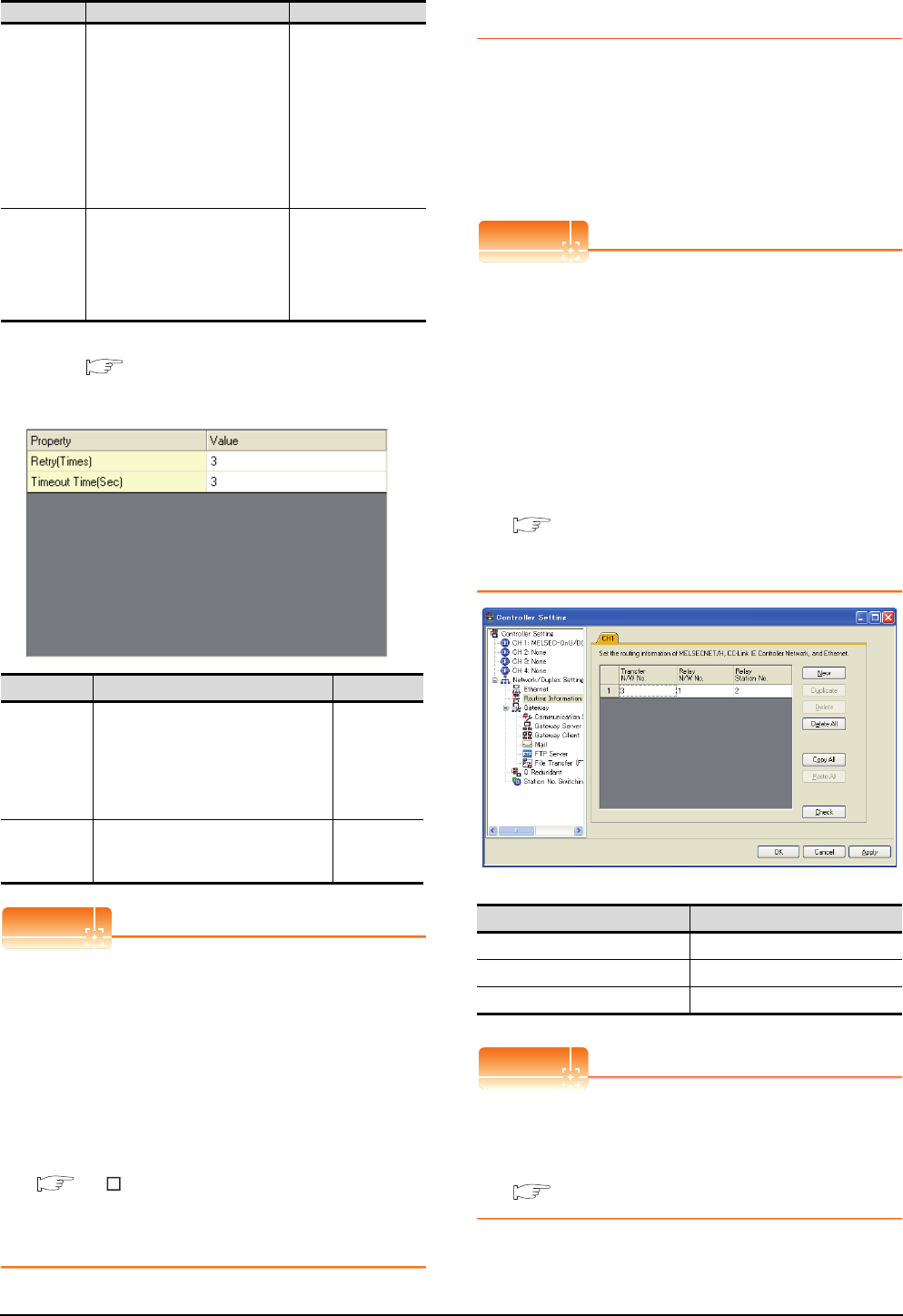
10 - 10 10. MELSECNET/10 CONNECTION (PLC TO PLC NETWORK)
10.3 GOT Side Settings
*1 Cannot be set for the QCPU redundant system.
*2 For details, refer to the following manual.
Q corresponding MELSECNET/H Network System
Reference Manual (PLC to PLC network)
(2) MELSECNET/10
POINTPOINTPOINT
(1) When MELSECNET/H communication unit is used
When connecting the MELSECNET/H network
module to the MELSECNET/10 network system,
specify the [MNET/10 mode] as a [Network Type].
(2) Communication interface setting by the Utility
The communication interface setting can be
changed on the Utility's [Communication Settings]
after writing [Communication Settings] of project
data.
For details on the Utility, refer to the following
manual.
GT User's Manual
(3) Precedence in communication settings
When settings are made by GT Designer3 or the
Utility, the latest setting is effective.
10.3.3 Routing parameter setting
Up to 64 [Transfer Network No.]s can be set.
However, the same transfer network number cannot be set
twice or more (multiple times).
Therefore, the one that can access to other station from the
request source host GOT is 64 kinds of [Transfer Network
No.]s.
POINTPOINTPOINT
(1) Routing parameter setting
When communicating within the host network,
routing parameter setting is unnecessary.
(2) Selection of communication unit
Routing parameters cannot be set in the GT15-
75J71LP23-Z and the GT15-75J71BR13-Z.
When setting routing parameters, use the GT15-
J71LP23-25 or the GT15-J71BR13 according to
the connection type to be used.
For details of routing parameters, refer to the following
manual.
Q corresponding MELSECNET/H Network
System Reference Manual (PLC to PLC
network)
POINTPOINTPOINT
Routing parameter setting of relay station
Routing parameter setting is also necessary for the
relay station.
For the setting, refer to the following.
10.4 PLC Side Setting
Refresh
Interval
Set the number of refreshes to
secure the send/receive data in
station units during
communication.
(Default: 1time)
Valid when "Secured data send/
Secured data receive" is marked
by the control station side network
parameters of the MELSECNET/H
network system.
1 to 1000times
Transmission
Speed
Set the communication
transmission speed.
(Default: 25Mbps)
When specifying [MNET/10 mode]
as the network type, only 10Mbps
can be set applicable.
10Mbps/25Mbps
Item Description Range
Retry
Set the number of retries to be
performed when a communication
timeout occurs.
When no response is received after
retries, a communication times out.
(Default: 3times)
0 to 5times
Timeout Time
Set the time period for a communication
to time out.
(Default: 3sec)
3 to 90sec
Item Description Range
Item Range
Transfer Network No. 1 to 239
Relay Network No. 1 to 239
Relay Station No. 1 to 64
■ Switch setting of MELSECNET/H network module
■ [Network parameter] of GX Developer
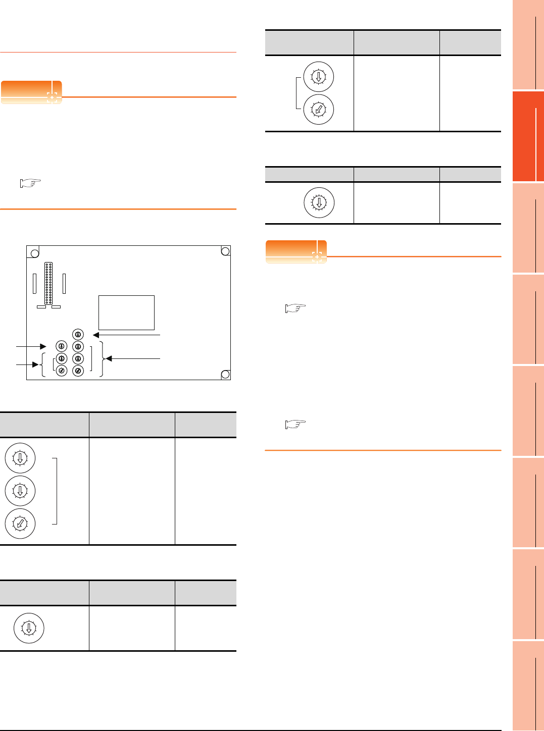
10. MELSECNET/10 CONNECTION (PLC TO PLC NETWORK)
10.3 GOT Side Settings
10 - 11
9
MELSECNET/H
CONNECTION (PLC
TO PLC NETWORK)
10
MELSECNET/10
CONNECTION (PLC
TO PLC NETWORK)
11
CC-Link IE CONTROLLER
NETWORK
CONNECTION
12
CC-Link IE FIELD
NETWORK
CONNECTION
13
CC-Link CONNECTION
(INTELLIGENT DEVICE
STATION)
14
CC-Link
CONNECTION
(Via G4)
15
INVERTER
CONNECTION
16
SERVO AMPLIFIER
CONNECTION
10.3.4 Switch setting (Only when
MELSECNET/10
communication unit is used)
POINTPOINTPOINT
Switch setting of the communication unit
When using the MELSECNET/H communication unit,
the switch setting is not needed.
For details of each setting switch and LED, refer to the
following manual.
GT15 MELSECNET/10 communication unit
User's Manual
(1) Network number setting switch
(2) Group number setting switch
*1 The GOT does not use the group number.
Specify "0".
(3) Station number setting switch
(4) Mode setting switch
POINTPOINTPOINT
(1) Switch setting example
For the switch setting example, refer to the
following.
10.4 PLC Side Setting
(2) When the switch setting is changed
When changing the switch setting after mounting
the MELSECNET/10 communication unit to the
GOT, reset the GOT.
(3) Self check test
Select "6" to "9" as the mode setting switch to
provide a self check test of the MELSECNET/10
communication unit.
For details, refer to the following manual.
GT15 MELSECNET/10 communication unit
User's Manual
Network number setting
switch Description Set value
Set the network No. of
the MELSECNET/10
communication unit.
(Default: 001)
1 to 239
Group number setting
switch Description Set value
Set the group No. of the
MELSECNET/10
communication unit.
(Default: 0)
0:
No group
setting (fixed)*1
8
0
7
F
6
E
5
D
4
C
3
B
2
A
1
9
MODE
5
0
6
1
7
2
8
3
9
4
5
0
6
1
7
2
8
3
9
4
STATION
No.
X10
X1
5
0
6
1
7
2
8
3
9
4
5
0
6
1
7
2
8
3
9
4
NETWORK
No.
X10
5
0
6
1
7
2
8
3
9
4
X100
X1
5
0
6
1
7
2
8
3
9
4
GROUP No.
RUN
PC
DUAL
SW.E
M/S.E
PRM.E
CRC
OVER
AB.IF
TIME
DATA
UNDER
LOOP
SD
RD
POWER
D.LINK
T.PASS
GOT R/W
CRC
OVER
AB.IF
TIME
DATA
UNDER
LOOP
SD
RD
E
R
R
O
R
E
R
R
O
R
F.LOOP
R.LOOP
GT15-75J71LP23-Z, GT15-75J71BR13-Z
(4)
(2)
(1)
(3)
5
0
6
1
7
2
8
3
9
4
5
0
6
1
7
2
8
3
9
4
NETWORK
No.
X10
5
0
6
1
7
2
8
3
9
4
X100
X1
5
0
6
1
7
2
8
3
9
4
GROUP No.
Station number setting
switch Description Set value
Set the station No. of the
MELSECNET/10
communication unit.
Set to not duplicate other
stations in the network.
(Default: 01)
1 to 64: GT15-
75J71LP23-Z
1 to 32: GT15-
75J71BR13-Z
Mode setting switch Description Set value
On-line
(Default: 0) 0
5
0
6
1
7
2
8
3
9
4
5
0
6
1
7
2
8
3
9
4
STATION
No.
X10
X1
8
0
7
F
6
E
5
D
4
C
3
B
2
A
1
9
MODE
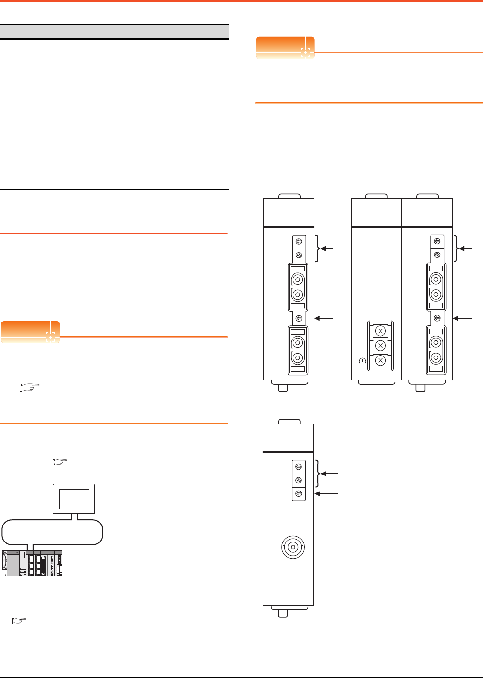
10 - 12 10. MELSECNET/10 CONNECTION (PLC TO PLC NETWORK)
10.4 PLC Side Setting
10.4 PLC Side Setting
10.4.1 Connecting to MELSECNET/H
network module
This section describes the settings of the GOT and
MELSECNET/H network module in the following case of
system configuration.
When connecting the MELSECNET/H network module to
the MELSECNET/10 network system, specify the
MELSECNET/10 Mode as a network type.
POINTPOINTPOINT
MELSECNET/H network module
For details of the MELSECNET/H network module,
refer to the following manual.
Q corresponding MELSECNET/H Network
System Reference Manual (PLC to PLC
network)
System configuration
*1 The MELSECNET/H network module is mounted at slot 0 of
the base unit.
The start I/O No. of the MELSECNET/H network module is
set at "0".
POINTPOINTPOINT
When connecting to Q170MCPU
When connected to Q170MCPU, the start I/O No. of
the MELSECNET/H network module is set to "70".
Switch setting of MELSECNET/H network
module
Set the station number setting switch and mode setting
switch.
Model name Reference
MELSECNET/H network module
QJ71LP21,
QJ71LP21-25,
QJ71LP21S-25,
QJ71BR11
10.4.1
MELSECNET/10 network
module
(QnA Series)
AJ71QLP21,
AJ71QLP21S,
AJ71QBR11,
A1SJ71QLP21,
A1SJ71QLP21S,
A1SJ71QBR11
10.4.2
MELSECNET/10 network
module
(A Series)
AJ71LP21,
AJ71BR11,
A1SJ71LP21,
A1SJ71BR1
10.4.3
<MELSECNET/H network module> *1
(Use the default value for settings other than the following.)
Station No. : 1
Mode : Online (10Mbps)
Network type : MNET/10 mode (Control station)
Network No. : 1
Total stations : 2
Network range assignment: LB0000H to LB00FFH
MELSECNET/10 (PLC to PLC network)
<GOT> (Use the default value for settings other
than the following.)
Station No. : 2
Mode : Online
Network No. : 1
Network range assignment: LB0100
H
to LB01FF
H
LW0100H to LW01FFH
LW0000H to LW00FFH
■ [Controller Setting] of GT Designer3
■ Setting of the MELSECNET/10 communication unit
MNG
D.LINK
RD
L ERR.
RUN
T.PASS
SD
ERR.
QJ71LP21-25
0
5
9
4
8
3
7
2
6
1
0
5
9
4
8
3
7
2
6
1
STATION NO.
X10
X1
MODE
0
8
F
7
E
6
D
5
C
4
B
A
3
2
9
1
QJ71LP21
-25
IN
OUT
EXT.PW
+24V
24G
24G
0
5
9
4
8
3
7
2
6
1
0
5
9
4
8
3
7
2
6
1
STATION NO.
X10
X1
MODE
0
8
F
7
E
6
D
5
C
4
B
A
3
2
9
1
IN
OUT
MNG
D.LINK
RD
L ERR.
RUN
T.PASS
SD
ERR.
QJ71LP21S-25
QJ71LP21 S-25
EXT.PW
EXT.PW
+24V
24G
(FG)
MNG
D.LINK
RD
L ERR.
RUN
T.PASS
SD
ERR.
0
5
9
4
8
3
7
2
6
1
0
5
9
4
8
3
7
2
6
1
STATION NO.
X10
X1
MODE
0
8
F
7
E
6
D
5
C
4
B
A
3
2
9
1
QJ71BR11
QJ71BR11
(1)
(2)
(1)
(2)
(1)
(2)
QJ71LP21, QJ71LP21-25 QJ71LP21S-25
QJ71BR11
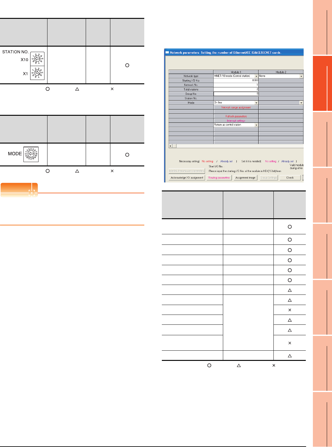
10. MELSECNET/10 CONNECTION (PLC TO PLC NETWORK)
10.4 PLC Side Setting
10 - 13
9
MELSECNET/H
CONNECTION (PLC
TO PLC NETWORK)
10
MELSECNET/10
CONNECTION (PLC
TO PLC NETWORK)
11
CC-Link IE CONTROLLER
NETWORK
CONNECTION
12
CC-Link IE FIELD
NETWORK
CONNECTION
13
CC-Link CONNECTION
(INTELLIGENT DEVICE
STATION)
14
CC-Link
CONNECTION
(Via G4)
15
INVERTER
CONNECTION
16
SERVO AMPLIFIER
CONNECTION
(1) Station number setting switch
: Necessary : As necessary : Not necessary
*1 Do not set the same station No. as that of the GOT.
(2) Mode setting switch
: Necessary : As necessary : Not necessary
POINTPOINTPOINT
When the switch setting has been changed
Turn the PLC CPU OFF then ON again, or reset the
PLC CPU.
Parameter setting (when connecting to
MELSEC-Q or QS series)
(1) [Network parameter] of GX Developer
(a) Network parameter
: Necessary : As necessary : Not necessary
*1 When using Q170MCPU, set it according to the system
configuration.
*2 Specify the same network No. as that of the GOT.
*3 Set it when the MELSECNET/H network module is used in
the redundant QnPRHCPU system.
Station number
setting switch Description Set value
Setting
necessity
at GOT
connection
Station number
setting
(Station No.1)*1
1
Mode setting switch Description Set value
Setting
necessity
at GOT
connection
Mode setting
(Online: 10Mbps) 0 (fixed)
Item Set value
Setting
necessity at
GOT
connection
Network type MNET/10 mode
(Control station) (fixed)
Starting I/O No.*1 0000H
Network No.*2 1
Total stations 2
Group No. 0 (fixed)
Mode Online (fixed)
Network range assignment Refer to (b)
Refresh parameters
(Use default value)
Interrupt settings
Control station return setting
Redundant settings*3
Interlink transmission
parameters
Routing parameters Refer to (c)
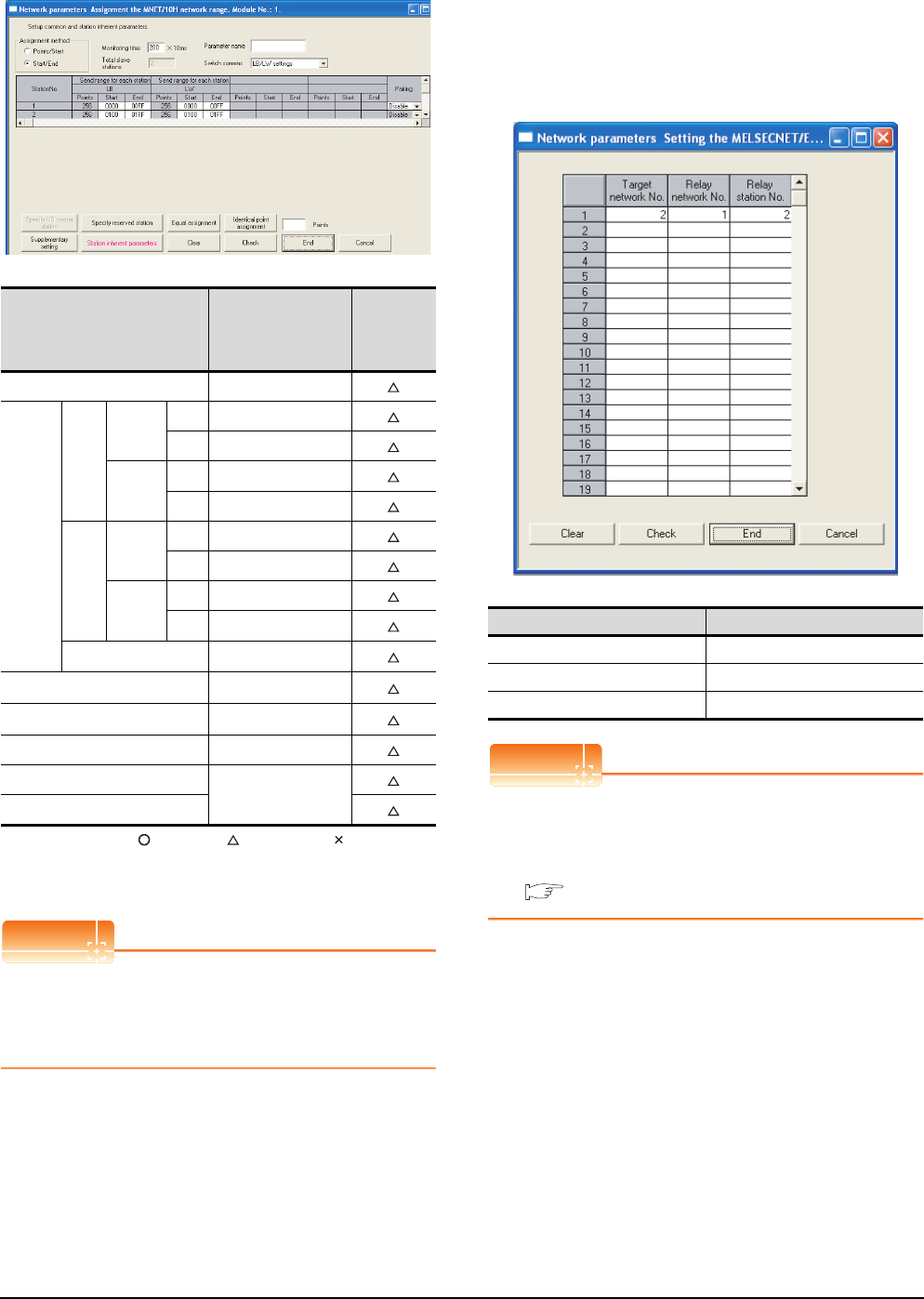
10 - 14 10. MELSECNET/10 CONNECTION (PLC TO PLC NETWORK)
10.4 PLC Side Setting
(b) Network range assignment
: Necessary : As necessary : Not necessary
*1 Be sure to set it to perform the cyclic transmission.
*2 Set it when the MELSECNET/H network module is used in
the redundant QnPRHCPU system.
POINTPOINTPOINT
When changing the network parameter
After writing the network parameter to the PLC CPU,
operate the PLC CPU ether turning OFF and then ON
or resetting.
(c) Routing parameter setting
Up to 64 [Transfer Network No.]s can be set.
However, the same transfer network number
cannot be set twice or more (multiple times).
Therefore, the one that can access to other station
from the request source host GOT is 64 kinds of
[Transfer Network No.]s.
POINTPOINTPOINT
Routing parameter setting of request source
Routing parameter setting is also necessary for the
request source GOT.
For the setting, refer to the following.
10.3.3 Routing parameter setting
Item Set value
Setting
necessity at
GOT
connection
Monitoring time 200
LB/LW
setting*1
Send
range
for
station
(LB)
Station
No.1
Start 0000H
End 00FFH
Station
No.2
Start 0100H
End 01FFH
Send
range
for
station
(LW)
Station
No.1
Start 0000H
End 00FFH
Station
No.2
Start 0100H
End 01FFH
Pairing setting*2 Disable
LX/LY setting*1 No setting
Specify I/O master station*1 No setting
Specify reserved station No setting
Supplementary setting
(Use default value)
Station inherent parameters
Item Range
Target network No. 1 to 239
Relay network No. 1 to 239
Relay station No. 1 to 64
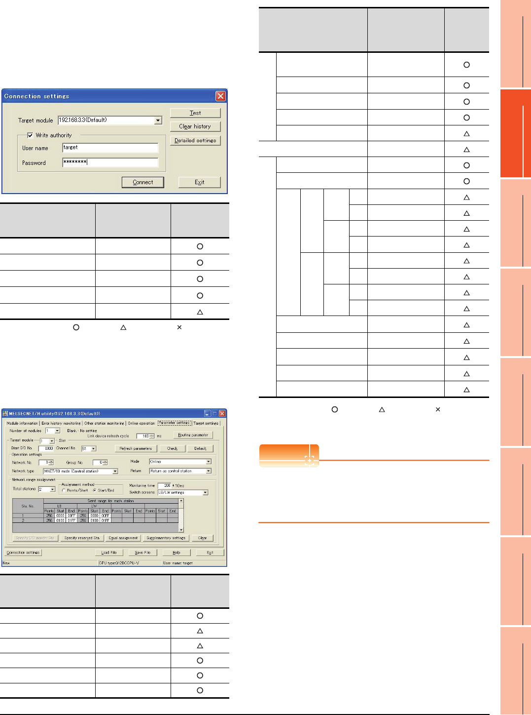
10. MELSECNET/10 CONNECTION (PLC TO PLC NETWORK)
10.4 PLC Side Setting
10 - 15
9
MELSECNET/H
CONNECTION (PLC
TO PLC NETWORK)
10
MELSECNET/10
CONNECTION (PLC
TO PLC NETWORK)
11
CC-Link IE CONTROLLER
NETWORK
CONNECTION
12
CC-Link IE FIELD
NETWORK
CONNECTION
13
CC-Link CONNECTION
(INTELLIGENT DEVICE
STATION)
14
CC-Link
CONNECTION
(Via G4)
15
INVERTER
CONNECTION
16
SERVO AMPLIFIER
CONNECTION
Parameter setting (when connecting to C
Controller module)
Use SW3PVC-CCPU-E Ver.3.05F or later for the
MELSECNET/H utility.
(1) Connection settings
: Necessary : As necessary : Not necessary
*1 If the IP address of the C Controller module has been
changed, input the changed IP address or host name.
*2 If the account of the C Controller module has been changed,
input the changed user name and password.
(2) MELSECNET/H Utility's [Parameter Settings]
(a) Parameter settings
: Necessary : As necessary : Not necessary
*1 Specify the same network No. as that of the GOT.
*2 Be sure to set the setting to perform the cyclic transmission.
POINTPOINTPOINT
When changing the network parameter
After writing the network parameter to the C Controller
module, either turn the C Controller module OFF and
then ON or reset it.
Item Set value
Setting
necessity at
GOT connection
Target module*1 192.168.3.3 (Default)
Write authority Mark the checkbox
User name*2 target
Password*2 password
Detailed settings -
Item Set value
Setting
necessity at
GOT connection
Number of modules 1
Link device refresh cycle (Use default value)
Routing parameter Refer to (b).
Target module 1
Start I/O No. 0000H
Channel No. (Use default value)
Item Set value
Setting
necessity at
GOT
connection
Operation settings
Network type MNET/10 mode
(Control station)
Network No.*1 1
Group No. 0
Mode Online
Return (Use default value)
Refresh parameters (Use default value)
Network range assignment
Total stations 2
Assignment method Start/End
LB/LW settings*2
Send range for
each station LB
Sta.
No.1
Start 0000H
End 00FFH
Sta.
No.2
Start 0100H
End 01FFH
Send range for
each station LW
Sta.
No.1
Start 0000H
End 00FFH
Sta.
No.2
Start 0100H
End 01FFH
(LX/LY) settings*2 No setting
Monitoring time (Use default value)
Specify I/O master Sta.*2 No setting
Specify reserved Sta. No setting
Supplementary settings (Use default value)
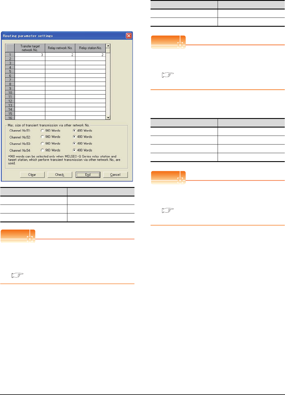
10 - 16 10. MELSECNET/10 CONNECTION (PLC TO PLC NETWORK)
10.4 PLC Side Setting
(b) Routing parameter setting
Up to 64 [Transfer Network No.]s can be set.
However, the same transfer network number
cannot be set twice or more (multiple times).
Therefore, the one that can access to other station
from the request source host GOT is 64 kinds of
[Transfer Network No.]s.
POINTPOINTPOINT
Routing parameter setting of request source
Routing parameter setting is also necessary for the
request source GOT.
For the setting, refer to the following.
10.3.3 Routing parameter setting
[Controller Setting] of GT Designer3
POINTPOINTPOINT
[Controller Setting] of GT Designer3
For the setting method of [Controller Setting] of GT
Designer3, refer to the following.
10.3.1 Setting communication interface
(Communication settings)
Setting of the MELSECNET/10
communication unit
POINTPOINTPOINT
Setting of the MELSECNET/10 communication unit
For the setting method of the MELSECNET/10
communication unit, refer to the following.
10.3.1 Setting communication interface
(Communication settings)
Item Range
Transfer target network No. 1 to 239
Relay network No. 1 to 239
Relay station No. 1 to 120
Item Set value (Use default)
Retry 3times
Timeout Time 3sec
Item Set value
Network number setting switch 1: Network No.1
Group number setting switch 0: No group setting (fixed)
Station number setting switch 2: Station No.2
Mode setting switch 0: Online (fixed)
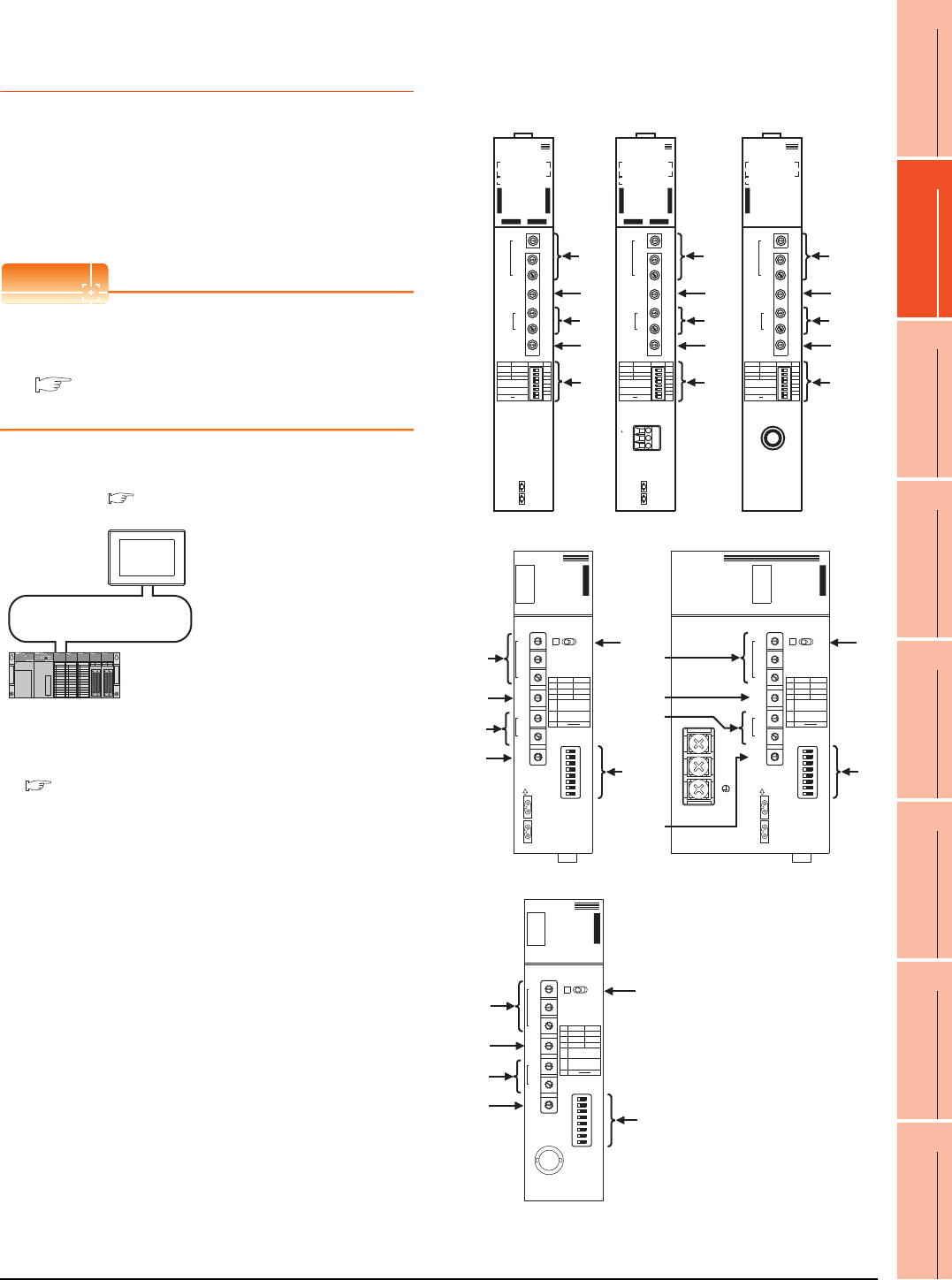
10. MELSECNET/10 CONNECTION (PLC TO PLC NETWORK)
10.4 PLC Side Setting
10 - 17
9
MELSECNET/H
CONNECTION (PLC
TO PLC NETWORK)
10
MELSECNET/10
CONNECTION (PLC
TO PLC NETWORK)
11
CC-Link IE CONTROLLER
NETWORK
CONNECTION
12
CC-Link IE FIELD
NETWORK
CONNECTION
13
CC-Link CONNECTION
(INTELLIGENT DEVICE
STATION)
14
CC-Link
CONNECTION
(Via G4)
15
INVERTER
CONNECTION
16
SERVO AMPLIFIER
CONNECTION
10.4.2 Connecting to MELSECNET/
10 network module (QnA
Series)
This section describes the settings of the GOT and
MELSECNET/10 network module (QnA series) in the
following case of system configuration.
In this section, the network parameter (common
parameter) of GX Developer is taken as an example to
provide explanations.
POINTPOINTPOINT
MELSECNET/10 network module (QnA Series)
For details of the MELSECNET/10 network module
(QnA Series), refer to the following manual.
For QnA/Q4AR MELSECNET/10 Network
System Reference Manual
System configuration
*1 The MELSECNET/10 network module is mounted at slot 0 of
the base unit.
The start I/O No. of the MELSECNET/10 network module is
set at "0".
Switch setting of MELSECNET/10 network
module
Set for each setting switch.
<MELSECNET/10 network module> *1
(Use the default value for settings other than the following.)
Station No.
Mode
Network type
Network No.
Total stations
Network range assignment: B0000H to B00FFH
W0000H to W00FFH
MELSECNET/10 (PLC to PLC network)
<GOT>
(Use the default value for settings other
than the following.)
Station No.
Mode
Network No.
Network range assignment: B0100H to B01FFH
: 2
: Online
: 1
: 1
: 1
: 2
: Online
: MNET/10 (Control station)
W0100H to W01FFH
■ [Controller Setting] of GT Designer3
■ Setting of the MELSECNET/10 communication unit
■ Switch setting of MELSECNET/10 network module
■ [Network parameter] of GX Developer
IN
FRONT SIDE
OUT
NETWORK NO.
X100
X10
X1
GROUP NO.
STATION NO.
X10
X1
MODE
0: ONLINE(A.R)
2: OFFLINE
OFF
PC REMOTE
N.ST MNG
PRM D.PRM
STATION SIZE
(8.16.32.64)
LB/LW SIZE
(2.4.6.8K)
OFFON ON SW
1
2
3
4
5
6
7
8
AJ71QLP21
RUN -
PC -
REMOTE -
DUAL -
SW.E -
M/S.E -
PRM.E -
CRC -
OVER -
AB.IF -
TIME -
DATA -
UNDER -
LOOP -
SD -
RD -
- POWER
- MNG
- S.MNG
- D.LINK
- T.PASS
-
- CPUR/W
- CRC
- OVER
- AB.IF
- TIME
- DATA
- UNDER
- LOOP
- SD
- RD
F.LOOP R.LOOP
10 1
100
E
R
R
O
R
E
R
R
O
R
(1)
(2)
(6)
(3)
(5)
AJ71QLP21
NETWORK NO.
X100
X10
X1
GROUP NO.
STATION NO.
X10
X1
MODE
0: ONLINE(A.R)
2: OFFLINE
OFF
PC REMOTE
N.ST MNG
PRM D.PRM
STATION SIZE
(8.16.32.64)
LB/LW SIZE
(2.4.6.8K)
OFFON ON SW
1
2
3
4
5
6
7
8
AJ71QBR11
RUN -
PC -
REMOTE -
SW.E -
M/S.E -
PRM.E -
CRC -
OVER -
AB.IF -
TIME -
DATA -
UNDER -
SD -
RD -
- POWER
- MNG
- S.MNG
- D.LINK
- T.PASS
-
- CPUR/W
10 1
100
E
R
R
O
R
(1)
(2)
(6)
(3)
(5)
AJ71QBR11
A1SJ71QLP21
A1SJ71QLP21
3
2
0
5
9
4
8
7
6
1
3
2
0
5
9
4
8
7
6
1
3
2
0
5
9
4
8
7
6
1
3
2
0
5
9
4
8
7
6
1
3
2
0
5
9
4
8
7
6
1
3
2
0
5
9
4
8
7
6
1
SW
1
2
3
4
5
6
7
8
OFF
PC
N.ST
PRM
ON
REM.
MNG
D.PRM
ST,SIZE
8,16,32,64
LB/LW SIZE
2,4,6,8k
CRC
OVER
AB. IF
TIME
DATA
UNDER
SD
RD
PW
PC
REM.
SWE.
M/S.E.
PRM E.
R.E.
CPU R/W
RUN
MNG
S.MNG
DUAL
D.LINK
T.PASS
F.E .
‚d
‚q
‚q
‚n
‚q
LR
DISPLAY
(F.L) (R.L.)
NETWORK
NO.
X100
X10
X1
OFF ON
IN
FRONT SIDE
OUT
SW
1
2
3
4
5
6
7
8
GR.NO.
ST.NO.
X10
X1
MODE
MODE
0 : ONLINE(A.R)
2 : OFFLINE
E
6
D
5
C
4
B
3
A
2
9
1
8
0
F
7
(6)
(4)
(1)
(2)
(3)
(5)
A1SJ71QLP21
A1SJ71QLP21S
A1SJ71QLP21S
3
2
0
5
9
4
8
7
6
1
3
2
0
5
9
4
8
7
6
1
3
2
0
5
9
4
8
7
6
1
3
2
0
5
9
4
8
7
6
1
3
2
0
5
9
4
8
7
6
1
3
2
0
5
9
4
8
7
6
1
SW
1
2
3
4
5
6
7
8
OFF
PC
N.ST
PRM
ON
REM.
MNG
D.PRM
ST,SIZE
8,16,32,64
LB/LW SIZE
2,4,6,8k
CRC
OVER
AB. IF
TIME
DATA
UNDER
SD
RD
RUN
MNG
S.MNG
DUAL
D.LINK
T.PASS
F.E .
‚d
‚q
‚q
‚n
‚q
LR
DISPLAY
(F.L) (R.L.)
NETWORK
EXT.P W
NO.
X100
X10
X1
OFF ON
IN
FRONT SIDE
EXT.PW
{24V
24G
FG
OUT
SW
1
2
3
4
5
6
7
8
GR.NO.
ST.NO.
X10
X1
MODE
MODE
0 : ONLINE(A.R)
2 : FOFFLINE
PW
PC
REM.
SWE.
M/S.E.
PRM E.
R.E.
CPU R/W
E
6
D
5
C
4
B
3
A
2
9
1
8
0
F
7
(6)
(4)
(1)
(2)
(3)
(5)
A1SJ71QLP21S
LR
DISPLAY
(F.L) (R.L.)
A1SJ71QBR11
A1SJ71QBR11
3
2
0
5
9
4
8
7
6
1
3
2
0
5
9
4
8
7
6
1
3
2
0
5
9
4
8
7
6
1
3
2
0
5
9
4
8
7
6
1
3
2
0
5
9
4
8
7
6
1
3
2
0
5
9
4
8
7
6
1
SW
1
2
3
4
5
6
7
8
OFF
PC
N.ST
PRM
ON
REM.
MNG
D.PRM
ST,SIZE
8,16,32,64
LB/LW SIZE
2,4,6,8k
CRC
OVER
AB. IF
TIME
DATA
UNDER
SD
RD
PW
PC
REM.
SWE.
M/S.E.
PRM E.
CPU R/W
RUN
MNG
S.MNG
D.LINK
T.PASS
‚d
‚q
‚q
‚n
‚q
NETWORK
NO.
X100
X10
X1
OFF ON
SW
1
2
3
4
5
6
7
8
GR.NO.
ST.NO.
X10
X1
MODE
MODE
0 : ONLINE (A.R)
2 : OFFLINE
E
6
D
5
C
4
B
3
A
2
9
1
8
0
F
7
(6)
(4)
(1)
(2)
(3)
(5)
A1SJ71QBR11
IN
24V
24G
FG
FRONT SIDE
OUT
NETWORK NO.
X100
X10
X1
GROUP NO.
STATION NO.
X10
X1
MODE
0: ONLINE(A.R)
2: OFFLINE
OFF
PC REMOTE
N.ST MNG
PRM D.PRM
STATION SIZE
(8.16.32.64)
LB/LW SIZE
(2.4.6.8K)
OFF
ON ON SW
1
2
3
4
5
6
7
8
AJ71QLP21S
RUN -
PC -
REMOTE -
DUAL -
SW.E -
M/S.E -
PRM.E -
CRC -
OVER -
AB.IF -
TIME -
DATA -
UNDER -
LOOP -
SD -
RD -
- POWER
- MNG
- S.MNG
- D.LINK
- T.PASS
- EX.POWER
- CPUR/W
- CRC
- OVER
- AB.IF
- TIME
- DATA
- UNDER
- LOOP
- SD
- RD
F.LOOP R.LOOP
10 1
100
E
R
R
O
R
E
R
R
O
R
(1)
(2)
(6)
(3)
(5)
AJ71QLP21S
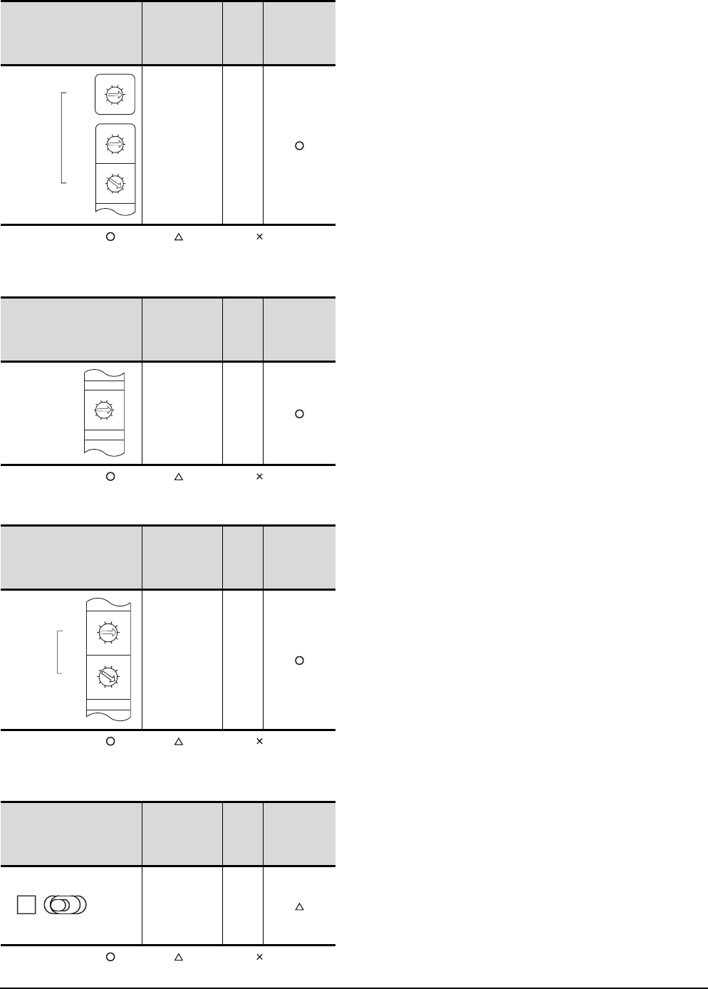
10 - 18 10. MELSECNET/10 CONNECTION (PLC TO PLC NETWORK)
10.4 PLC Side Setting
(1) Network number setting switch
: Necessary : As necessary : Not necessary
*1 Specify the same network No. as that of the GOT.
(2) Group number setting switch
: Necessary : As necessary : Not necessary
(3) Station number setting switch
: Necessary : As necessary : Not necessary
*2 Do not set the same station No. as that of the GOT.
(4) LED indication select switch
: Necessary : As necessary : Not necessary
Network number
setting switch Description Set
value
Setting
necessity at
GOT
connection
Network
No. setting
(Network No.1)*1
1
Group number setting switch Description Set
value
Setting
necessity at
GOT
connection
Group
No. setting
(No group
setting)
0
(fixed)
Station number setting switch Description Set
value
Setting
necessity at
GOT
connection
Station number
setting
(Station No.1)*2
1
LED indication select switch Description Set
value
Setting
necessity at
GOT
connection
LED indication
select L (F.L.)
3
2
0
5
9
4
8
7
6
1
3
2
0
5
9
4
8
7
6
1
3
2
0
5
9
4
8
7
6
1
NETWORK NO.
X100
X10
X1
3
2
0
5
9
4
8
7
6
1
GROUP.NO.
3
2
0
5
9
4
8
7
6
1
3
2
0
5
9
4
8
7
6
1
STATION.NO.
X10
X1
LR
DISPLAY
(F.L) (R.L.)
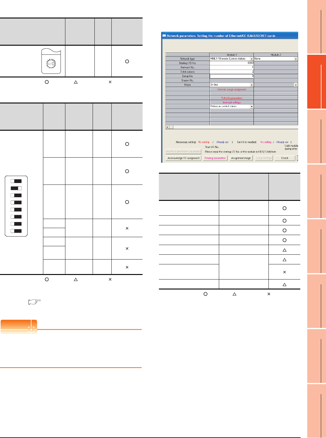
10. MELSECNET/10 CONNECTION (PLC TO PLC NETWORK)
10.4 PLC Side Setting
10 - 19
9
MELSECNET/H
CONNECTION (PLC
TO PLC NETWORK)
10
MELSECNET/10
CONNECTION (PLC
TO PLC NETWORK)
11
CC-Link IE CONTROLLER
NETWORK
CONNECTION
12
CC-Link IE FIELD
NETWORK
CONNECTION
13
CC-Link CONNECTION
(INTELLIGENT DEVICE
STATION)
14
CC-Link
CONNECTION
(Via G4)
15
INVERTER
CONNECTION
16
SERVO AMPLIFIER
CONNECTION
(5) Mode setting switch
: Necessary : As necessary : Not necessary
(6) Condition setting switches
: Necessary : As necessary : Not necessary
*1 The MELSECNET/10 network module can be communicated
by default parameters.
For details, refer to the following manual.
For QnA/Q4AR MELSECNET/10 Network System
Reference Manual
POINTPOINTPOINT
When the switch setting (other than the LED indication
select switch) is changed
Turn the PLC CPU OFF then ON again, or reset the
PLC CPU.
[Network parameter] of GX Developer
(1) Network parameter
: Necessary : As necessary : Not necessary
*1 Specify the same network No. as that of the network number
setting switch of the MELSECNET/10 network module.
Mode setting switch Description Set
value
Setting
necessity at
GOT
connection
Mode setting
(Online)
0
(fixed)
Condition setting
switches
Setting
switch Description Set
value
Setting
necessity at
GOT
connection
SW1
Network type
(PLC to PLC
net-work
(PC))
OFF
(fixed)
SW2
Station type
(Control
station
(MNG))
ON
(fixed)
SW3
Parameter
for using*1
(common
parameter
(PRM))
OFF
(fixed)
SW4 No. of
stations*1
OFF
(fixed)
SW5
SW6 B/W
Tota l BW
points*1
OFF
(fixed)
SW7
SW8 Not used OFF
(fixed)
F
7
E
6
D
5
C
4
B
3
A
2
9
1
0
8
MODE
0 : ONLINE(A.R)
2 : OFFLINE
OFF ON SW
1
2
3
4
5
6
7
8
Item Set value
Setting
necessity at
GOT
connection
Network type MNET/10
(Control station) (fixed)
Start I/O No. 0000H
Network No.*1 1
Total stations 2
Network range assignment Refer to (2)
Refresh parameters
(Use default value)
Interlink transmission
parameters
Routing parameters Refer to (3)
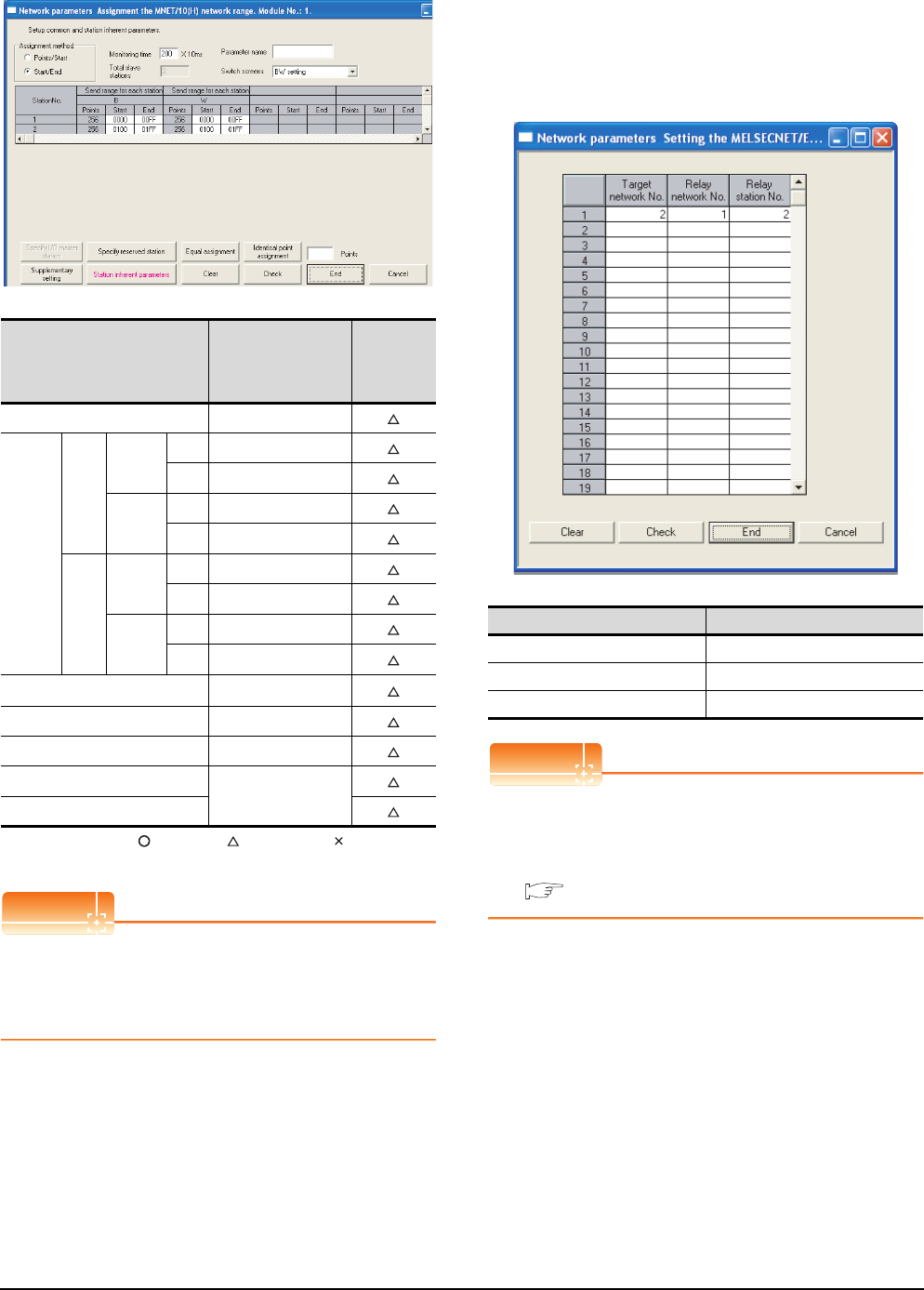
10 - 20 10. MELSECNET/10 CONNECTION (PLC TO PLC NETWORK)
10.4 PLC Side Setting
(2) Network range assignment
: Necessary : As necessary : Not necessary
*1 Be sure to set it to perform the cyclic transmission.
POINTPOINTPOINT
When changing the network parameter
After writing the network parameter to the PLC CPU,
operate the PLC CPU ether turning OFF and then ON
or resetting.
(3) Routing parameter setting
Up to 64 [Transfer Network No.]s can be set.
However, the same transfer network number cannot be
set twice or more (multiple times).
Therefore, the one that can access to other station from
the request source host GOT is 64 kinds of [Transfer
Network No.]s.
POINTPOINTPOINT
Routing parameter setting of request source
Routing parameter setting is also necessary for the
request source GOT.
For the setting, refer to the following.
10.3.3 Routing parameter setting
Item Set value
Setting
necessity at
GOT
connection
Monitoring time 200
BW
setting*1
Send
range
for
each
station
(LB)
Station
No.1
Start 0000H
End 00FFH
Station
No.2
Start 0100H
End 01FFH
Send
range
for
each
station
(LW)
Station
No.1
Start 0000H
End 00FFH
Station
No.2
Start 0100H
End 01FFH
XY setting*1 No setting
Specify I/O master station*1 No setting
Specify reserved station No setting
Supplementary setting
(Use default value)
Station inherent parameters
Item Range
Target network No. 1 to 239
Relay network No. 1 to 239
Relay station No. 1 to 64
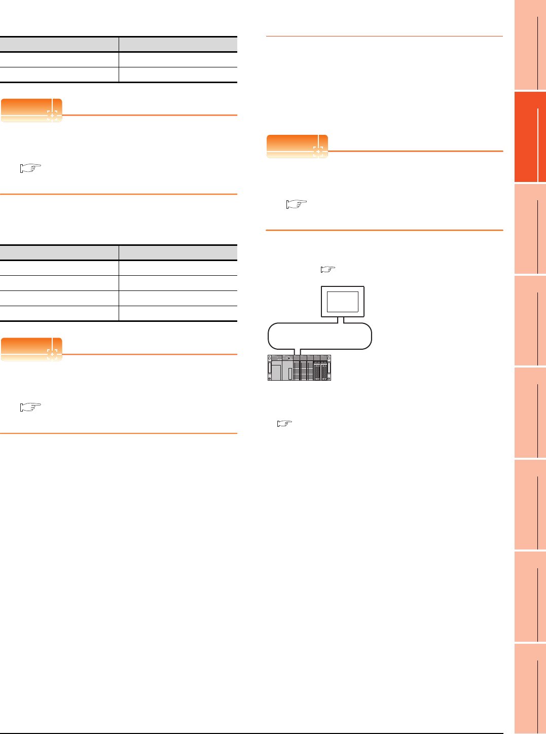
10. MELSECNET/10 CONNECTION (PLC TO PLC NETWORK)
10.4 PLC Side Setting
10 - 21
9
MELSECNET/H
CONNECTION (PLC
TO PLC NETWORK)
10
MELSECNET/10
CONNECTION (PLC
TO PLC NETWORK)
11
CC-Link IE CONTROLLER
NETWORK
CONNECTION
12
CC-Link IE FIELD
NETWORK
CONNECTION
13
CC-Link CONNECTION
(INTELLIGENT DEVICE
STATION)
14
CC-Link
CONNECTION
(Via G4)
15
INVERTER
CONNECTION
16
SERVO AMPLIFIER
CONNECTION
[Controller Setting] of GT Designer3
POINTPOINTPOINT
[Controller Setting] of GT Designer3
For the setting method of [Controller Setting] of GT
Designer3, refer to the following.
10.3.1 Setting communication interface
(Communication settings)
Setting of the MELSECNET/10
communication unit
POINTPOINTPOINT
Setting of the MELSECNET/10 communication unit
For the setting method of the MELSECNET/10
communication unit, refer to the following.
10.3.1 Setting communication interface
(Communication settings)
10.4.3 Connecting to MELSECNET/
10 network module (A Series)
This section describes the settings of the GOT and
MELSECNET/10 network module (A Series) in the
following case of system configuration.
In this section, the network parameter (common
parameter) of GX Developer is taken as an example to
provide explanations.
POINTPOINTPOINT
MELSECNET/10 network module (A Series)
For details of the MELSECNET/10 network module (A
Series), refer to the following manual.
Type MELSECNET/10 Network system (PLC to
PLC network) Reference Manual
System configuration
*1 The MELSECNET/10 network module is mounted at slot 0 of
the base unit.
The start I/O No. of the MELSECNET/10 network module is
set at "0".
Item Set value (Use default)
Retry 3times
Timeout Time 3sec
Item Set value
Network number setting switch 1: Network No.1
Group number setting switch 0: No group setting (fixed)
Station number setting switch 2: Station No.2
Mode setting switch 0: Online (fixed)
<MELSECNET/10 network module> *1
(Use the default value for settings other than the following.)
Station No. : 1
Mode : Online
Network type : MNET/10 (Control station)
Network No. : 1
Total stations : 2
Network range assignment: LB0000H to LB00FFH
LW0000H to LW00FFH
MELSECNET/10 (PLC to PLC network)
<GOT>
(Use the default value for settings other
than the following.)
Station No. : 2
Mode : Online
Network No. : 1
Network range assignment: LB0100
H
to LB01FF
H
LW0100
H
to LW01FF
H
■ [Controller Setting] of GT Designer3
■ Setting of the MELSECNET/10 communication unit
■ Switch setting of MELSECNET/10 network module
■ [Network parameter] of GX Developer
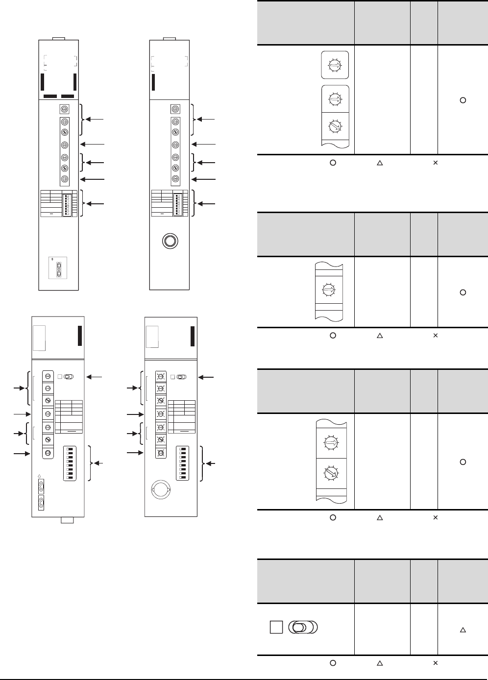
10 - 22 10. MELSECNET/10 CONNECTION (PLC TO PLC NETWORK)
10.4 PLC Side Setting
Switch setting of MELSECNET/10 network
module
Set for each setting switch.
(1) Network number setting switch
: Necessary : As necessary : Not necessary
*1 Specify the same network No. as that of the GOT.
*2 Do not specify a number between 240 and 255.
(2) Group number setting switch
: Necessary : As necessary : Not necessary
(3) Station number setting switch
: Necessary : As necessary : Not necessary
*3 Do not set the same station No. as that of the GOT.
(4) LED indication select switch
: Necessary : As necessary : Not necessary
(6)
(4)
(1)
(2)
(3)
(5)
A1SJ71LP21
A1SJ71LP21
A1SJ71LP21
3
2
0
5
9
4
8
7
6
1
3
2
0
5
9
4
8
7
6
1
3
2
0
5
9
4
8
7
6
1
3
2
0
5
9
4
8
7
6
1
3
2
0
5
9
4
8
7
6
1
3
2
0
5
9
4
8
7
6
1
E
6
D
5
C
4
B
3
A
2
9
1
8
0
F
7
SW
1
2
3
4
5
6
7
8
OFF
PC
N.ST
PRM
ON
REM.
MNG
D.PRM
ST,SIZE
8,16,32,64
LB/LW SIZE
2,4,6,8k
CRC
OVER
AB. IF
TIME
DATA
UNDER
SD
RD
PW
PC
REM.
SWE.
M/S.E.
PRM E.
R.E.
CPU R/W
RUN
MNG
S.MNG
DUAL
D.LINK
T.PAS.
F.E.
E
R
R
O
R
LR
DISPLAY
(F.L) (R.L.)
NETWORK
NO.
X100
X10
X1
OFF ON
IN
FRONT SIDE
OUT
SW
1
2
3
4
5
6
7
8
GR.NO.
ST.NO.
X10
X1
MODE
MODE
(6)
(4)
(1)
(2)
(3)
(5)
A1SJ71BR11
A1SJ71BR11
A1SJ71BR11
3
2
0
5
8
7
3
2
0
5
8
7
3
2
0
5
8
7
3
2
0
5
8
7
3
2
0
5
8
7
3
2
0
5
8
7
D
5
C
4
B
3
9
1
8
0
F
7
SW
1
2
3
4
5
6
7
8
OFF
PC
N.ST
PRM
ON
REM.
MNG
D.PRM
ST,SIZE
8,16,32,64
LB/LW SIZE
2,4,6,8k
CRC
OVER
AB. IF
TIME
DATA
UNDER
SD
RD
PW
PC
REM.
SWE.
M/S.E.
PRM E.
CPU R/W
RUN
MNG
S.MNG
D.LINK
T.PAS.
LR
DISPLAY
NETWORK
NO.
X100
X10
X1
OFF ON
SW
1
2
3
4
5
6
7
8
GR.NO.
ST.NO.
X10
X1
MODE
MODE
0 : ONLINE(A,R)
2 : OFFLINE
(1)
(2)
(6)
(3)
(5)
AJ71LP21
NETWORK NO.
X100
X10
X1
GROUP NO.
STATION NO.
X10
X1
MODE
0: ONLINE(A.R)
2: OFFLINE
OFF
PC REMOTE
N.ST MNG
PRM D.PRM
STATION SIZE
(8.16.32.64)
LB/ LW SIZE
(2.4.6.8K)
OFFON ON SW
1
2
3
4
5
6
7
8
A
J71LP21
RUN -
PC -
REMOTE -
DUAL -
SW.E -
M/S.E -
PRM.E -
CRC -
OVER -
AB.IF -
TIME -
DATA -
UNDER -
LOOP -
SD -
RD -
- POWER
- MNG
- S.MNG
- D.LINK
- T.PASS
- EX.POWER
- CPUR/W
- CRC
- OVER
- AB.IF
- TIME
- DATA
- UNDER
- LOOP
- SD
- RD
F.LOOP R.LOOP
10 1
100
E
R
R
O R
E
R
R
O
R
OUT
IN
FRONT SIDE
E
R
R
O
R
(1)
(2)
(6)
(3)
(5)
AJ71BR11
NETWORK NO.
X100
X10
X1
GROUP NO.
STATION NO.
X10
X1
MODE
0: ONLINE(A.R)
2: OFFLINE
OFF
PC REMOTE
N.ST MNG
PRM D.PRM
STATION SIZE
(8.16.32.64)
LB/LW SIZE
(2.4.6.8K)
OFFON ON SW
1
2
3
4
5
6
7
8
A
J71BR11
RUN -
PC -
REMOTE -
SW.E -
M/S.E -
PRM.E -
CRC -
OVER -
AB.IF -
TIME -
DATA -
UNDER -
SD -
RD -
- POWER
- MNG
- S.MNG
- D.LINK
- T.PASS
-
- CPUR/W
10 1
100
E
R
R
O
R
0 : ONLINE(A,R)
2 : OFFLINE
E
R
R
O
R
Network number
setting switch Description Set
value
Setting
necessity at
GOT
connection
Network
No. setting
(Network
No.1)*1*2
1
Group number
setting switch Description Set
value
Setting
necessity at
GOT
connection
Group No.
setting
(No group
setting)
0
(fixed)
Station number setting switch Description Set
value
Setting
necessity at
GOT
connection
Station number
setting
(Station No.1)*3
1
LED indication select switch Description Set
value
Setting
necessity at
GOT
connection
LED indication
select L (F.L.)
3
2
0
5
9
4
8
7
6
1
3
2
0
5
9
4
8
7
6
1
3
2
0
5
9
4
8
7
6
1
NETWORK NO.
X100
X10
X1
3
2
0
5
9
4
8
7
6
1
GROUP.NO.
3
2
0
5
9
4
8
7
6
1
3
2
0
5
9
4
8
7
6
1
STATION.NO.
X10
X1
LR
DISPLAY
(F.L) (R.L.)
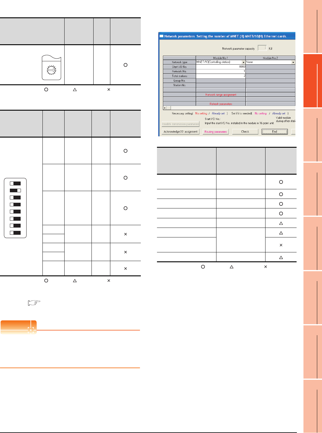
10. MELSECNET/10 CONNECTION (PLC TO PLC NETWORK)
10.4 PLC Side Setting
10 - 23
9
MELSECNET/H
CONNECTION (PLC
TO PLC NETWORK)
10
MELSECNET/10
CONNECTION (PLC
TO PLC NETWORK)
11
CC-Link IE CONTROLLER
NETWORK
CONNECTION
12
CC-Link IE FIELD
NETWORK
CONNECTION
13
CC-Link CONNECTION
(INTELLIGENT DEVICE
STATION)
14
CC-Link
CONNECTION
(Via G4)
15
INVERTER
CONNECTION
16
SERVO AMPLIFIER
CONNECTION
(5) Mode setting switch
: Necessary : As necessary : Not necessary
(6) Condition setting switches
: Necessary : As necessary : Not necessary
*1 The MELSECNET/10 network module can be communicated
by default parameters.
For details, refer to the following manual.
Type MELSECNET/10 Network system (PLC to PLC
network) Reference Manual
POINTPOINTPOINT
When the switch setting (other than the LED indication
select switch) is changed
Turn the PLC CPU OFF then ON again, or reset the
PLC CPU.
[Network parameter] of GX Developer
(1) Network parameter
: Necessary : As necessary : Not necessary
*1 Specify the same network No. as that of the network number
setting switch of the MELSECNET/10 network module.
Mode setting switch Description Set
value
Setting
necessity at
GOT
connection
Mode setting
(Online)
0
(fixed)
Condition setting
switches
Setting
switch Description Set
value
Setting
necessity at
GOT
connection
SW1
Network type
(PLC to PLC
net-work
(PC))
OFF
(fixed)
SW2
Station type
(Control
station
(MNG))
ON
(fixed)
SW3
Parameter
for using*1
(common
parameter
(PRM))
OFF
(fixed)
SW4 No. of
stations*1
OFF
(fixed)
SW5
SW6 Tota l B/ W
points*1
OFF
(fixed)
SW7
SW8 Not used OFF
(fixed)
F
7
E
6
D
5
C
4
B
3
A
2
9
1
0
8
MODE
0:ONLINE(A.R)
2:OFFLINE
OFF ON SW
1
2
3
4
5
6
7
8
Item Set value
Setting
necessity at
GOT
connection
Network type MNET/10
(Control station) (fixed)
Start I/O No. 0000H
Network No.*1 1
Total stations 2
Network range assignment Refer to (2)
Refresh parameters
(Use default value)
Interlink transmission
parameters
Routing parameters Refer to (3)
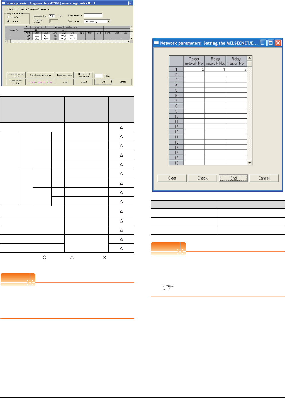
10 - 24 10. MELSECNET/10 CONNECTION (PLC TO PLC NETWORK)
10.4 PLC Side Setting
(2) Network range assignment
: Necessary : As necessary : Not necessary
*1 Be sure to set it to perform the cyclic transmission.
POINTPOINTPOINT
When changing the network parameter
After writing the network parameter to the PLC CPU,
operate the PLC CPU ether turning OFF and then ON
or resetting.
(3) Routing parameter setting
Up to 64 [Transfer Network No.]s can be set.
However, the same transfer network number cannot be
set twice or more (multiple times).
Therefore, the one that can access to other station from
the request source host GOT is 64 kinds of [Transfer
Network No.]s.
POINTPOINTPOINT
Routing parameter setting of request source
Routing parameter setting is also necessary for the
request source GOT.
For the setting, refer to the following.
10.3.3 Routing parameter setting
Item Set value
Setting
necessity at
GOT
connection
Monitoring time 200
LB/LW
setting*1
Send
range
for
each
station
(LB)
Station
No.1
Start 0000H
End 00FFH
Station
No.2
Start 0100H
End 01FFH
Send
range
for
each
station
(LW)
Station
No.1
Start 0000H
End 00FFH
Station
No.2
Start 0100H
End 01FFH
LX/LY setting*1 No setting
Specify I/O master station*1 No setting
Specify reserved station No setting
Supplementary setting
(Use default value)
Station inherent parameters
Item Range
Target network No. 1 to 239
Relay network No. 1 to 239
Relay station No. 1 to 64
10. MELSECNET/10 CONNECTION (PLC TO PLC NETWORK)
10.4 PLC Side Setting
10 - 25
9
MELSECNET/H
CONNECTION (PLC
TO PLC NETWORK)
10
MELSECNET/10
CONNECTION (PLC
TO PLC NETWORK)
11
CC-Link IE CONTROLLER
NETWORK
CONNECTION
12
CC-Link IE FIELD
NETWORK
CONNECTION
13
CC-Link CONNECTION
(INTELLIGENT DEVICE
STATION)
14
CC-Link
CONNECTION
(Via G4)
15
INVERTER
CONNECTION
16
SERVO AMPLIFIER
CONNECTION
[Controller Setting] of GT Designer3
POINTPOINTPOINT
[Controller Setting] of GT Designer3
For the setting method of [Controller Setting] of GT
Designer3, refer to the following.
10.3.1 Setting communication interface
(Communication settings)
Setting of the MELSECNET/10
communication unit
POINTPOINTPOINT
Setting of the MELSECNET/10 communication unit
For the setting method of the MELSECNET/10
communication unit, refer to the following.
10.3.1 Setting communication interface
(Communication settings)
Item Set value (Use default)
Retry 3times
Timeout Time 3sec
Item Set value
Network number setting switch 1: Network No.1
Group number setting switch 0: No group setting (fixed)
Station number setting switch 2: Station No.2
Mode setting switch 0: Online (fixed)

10 - 26 10. MELSECNET/10 CONNECTION (PLC TO PLC NETWORK)
10.5 Precautions
10.5 Precautions
Network configuration
Use the MELSECNET/10 mode of MELSECNET/H
(PLC to PLC network) or MELSECNET/10 (PLC to PLC
network) to configure a network including the GOT.
(1) The following networks including the GOT cannot be
configured.
• MELSECNET/10 (Remote I/O network)
• MELSECNET/H (Remote I/O network)
(2) When configuring the network (MELSECNET/H (PLC
to PLC network) including the GOT, refer to the
following.
9. MELSECNET/H CONNECTION (PLC TO
PLC NETWORK)
Monitoring range
Only PLC CPU of the same networks No. can be
monitored in GOT.
For details, refer to the following manual.
GT Designer3 Version Screen Design
Manual
Starting GOT with MELSECNET/10
connection
With the MESLSECNET/10 connection, the data link
starts approximately 10 seconds after the GOT starts.
When a network error occurs in the system
alarm
When a system alarm regarding a network error occurs
with the MELSECNET/10 connection, the system alarm
is kept displaying on the GOT even though the error
factor is removed.
To cancel the system alarm display, restart the GOT.
Connection in the multiple CPU system
When the GOT is connected to multiple CPU system,
the following time is taken until when the PLC runs.
QCPU (Q mode), motion controller CPU (Q series): 10
seconds or more
MELDAS C70: 18 seconds or more
When the GOT starts before the PLC runs, a system
alarm occurs.Adjust the opening screen time in the
GOT setup so that no system alarm occurs.
GT Designer3 Version Screen Design
Manual
Connection to QCPU (Q mode)
Use function version B or later of the MELSECNET/H
network module and QCPU (Q mode).
Connection to Q17nDCPU, Q170MCPU,
CNC C70, CRnQ-700
The Q17nDCPU, Q170MCPU, CNC C70 and CRnQ-
700 are applicable to the MELSECNET/H connection
(PLC to PLC network) only.
For connecting the GOT to the MELSECNET/10
network system (PLC to PLC network), set the
MELSECNET/H network system (PLC to PLC network)
to the MELSECNET/10 mode.
Connection to QSCPU
The GOT can only read device data and sequence
programs by the ladder monitor function in the QSCPU.
The GOT cannot write any data to the QSCPU.
Connection to Q170MCPU
Set [CPU No.] to "2" in the device setting to monitor the
device of the Motion CPU area (CPU No.2).
When the CPU No. is set to "0" or "1", the device on the
PLC CPU area (CPU No.1) is monitored.
When the CPU No. is set to the number other than "0"
to "2", a communication error occurs and the monitoring
cannot be executed.
For setting the CPU No., refer to the following manual.
GT Designer3 Version Screen Design
Manual
Example) Setting dialog box of the bit device
11
9
MELSECNET/H
CONNECTION (PLC
TO PLC NETWORK)
10
MELSECNET/10
CONNECTION (PLC
TO PLC NETWORK)
11
CC-Link IE CONTROLLER
NETWORK
CONNECTION
12
CC-Link IE FIELD
NETWORK
CONNECTION
13
CC-Link CONNECTION
(INTELLIGENT DEVICE
STATION)
14
CC-Link
CONNECTION
(Via G4)
15
INVERTER
CONNECTION
16
SERVO AMPLIFIER
CONNECTION
11 - 1
11. CC-Link IE CONTROLLER
NETWORK CONNECTION
11.1 Connectable Model List . . . . . . . . . . . . . . . . . . . . . . . . . . . .11 - 2
11.2 System Configuration. . . . . . . . . . . . . . . . . . . . . . . . . . . . . .11 - 7
11.3 GOT side settings . . . . . . . . . . . . . . . . . . . . . . . . . . . . . . . .11 - 8
11.4 PLC Side Setting . . . . . . . . . . . . . . . . . . . . . . . . . . . . . . . .11 - 10
11.5 Precautions . . . . . . . . . . . . . . . . . . . . . . . . . . . . . . . . . . . .11 - 16
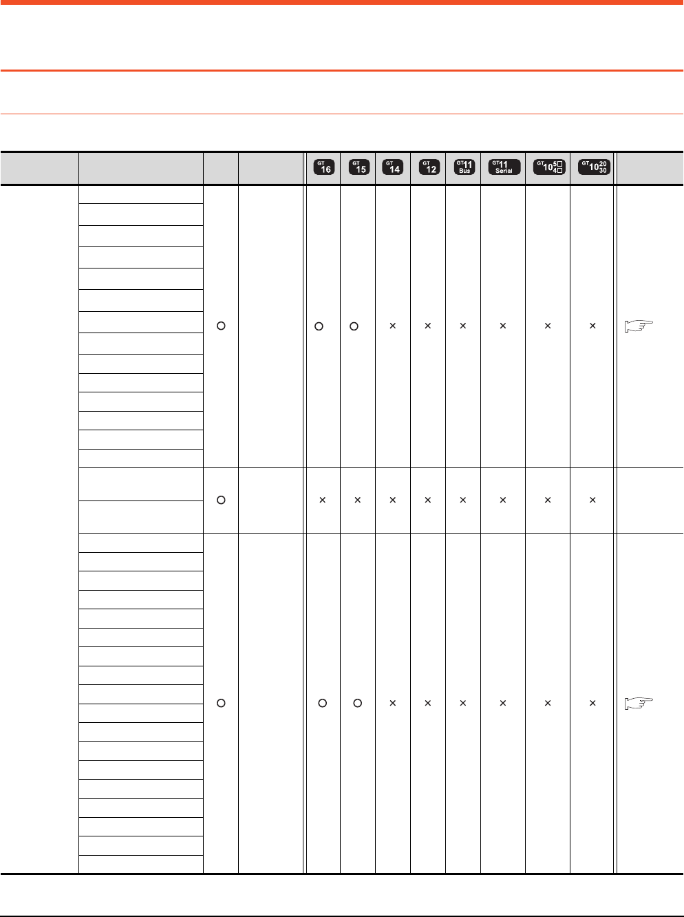
11 - 2 11. CC-Link IE CONTROLLER NETWORK CONNECTION
11.1 Connectable Model List
11. CC-Link IE CONTROLLER NETWORK
CONNECTION
11.1 Connectable Model List
11.1.1 PLC/Motion controller CPU
The following table shows the connectable models.
(Continued to next page)
*1 When in multiple CPU system configuration, use CPU function version B or later.
Series Model name Clock
Communication
type Refer to
MELSEC-Q
(Q mode)
Q00JCPU
CC-Link IE *1 *1 11.2
Q00CPU*1
Q01CPU*1
Q02CPU*1
Q02HCPU*1
Q06HCPU*1
Q12HCPU*1
Q25HCPU*1
Q02PHCPU
Q06PHCPU
Q12PHCPU
Q25PHCPU
Q12PRHCPU (Main base)
Q25PRHCPU (Main base)
Q12PRHCPU
(Extension base)
- -
Q25PRHCPU
(Extension base)
Q00UJCPU
CC-Link IE 11.2
Q00UCPU
Q01UCPU
Q02UCPU
Q03UDCPU
Q04UDHCPU
Q06UDHCPU
Q10UDHCPU
Q13UDHCPU
Q20UDHCPU
Q26UDHCPU
Q03UDECPU
Q04UDEHCPU
Q06UDEHCPU
Q10UDEHCPU
Q13UDEHCPU
Q20UDEHCPU
Q26UDEHCPU
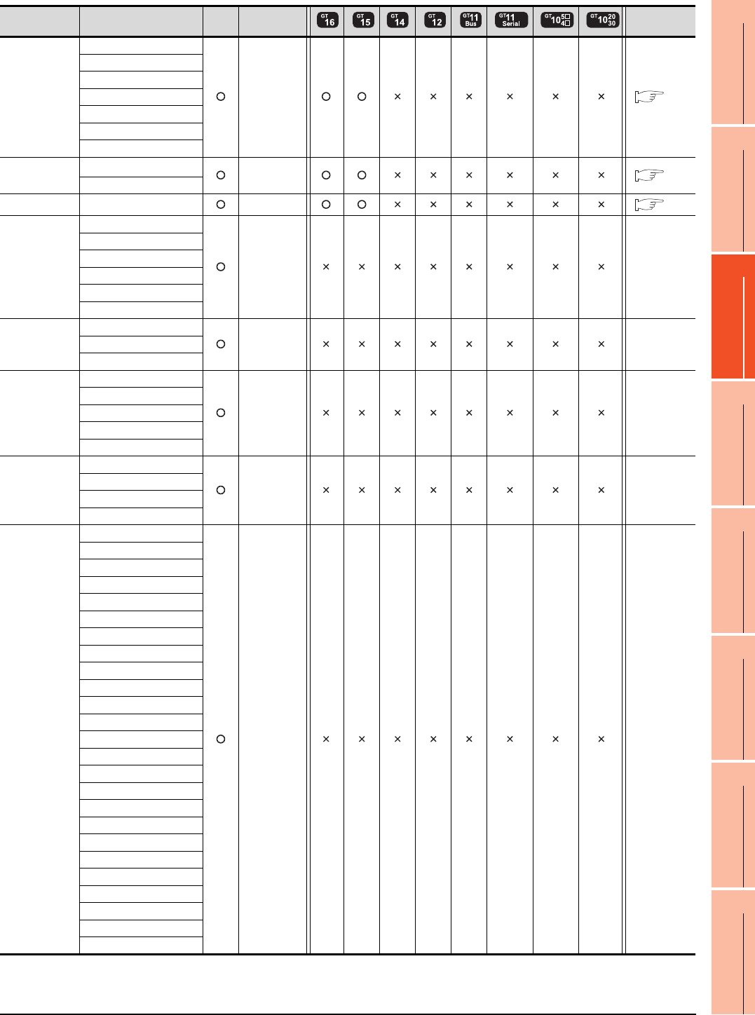
11. CC-Link IE CONTROLLER NETWORK CONNECTION
11.1 Connectable Model List
11 - 3
9
MELSECNET/H
CONNECTION (PLC
TO PLC NETWORK)
10
MELSECNET/10
CONNECTION (PLC
TO PLC NETWORK)
11
CC-Link IE CONTROLLER
NETWORK
CONNECTION
12
CC-Link IE FIELD
NETWORK
CONNECTION
13
CC-Link CONNECTION
(INTELLIGENT DEVICE
STATION)
14
CC-Link
CONNECTION
(Via G4)
15
INVERTER
CONNECTION
16
SERVO AMPLIFIER
CONNECTION
(Continued to next page)
*1 Use a module with the upper five digits later than 12042.
Series Model name Clock
Communication
type Refer to
MELSEC-Q
(Q mode)
Q50UDEHCPU
CC-Link IE 11.2
Q100UDEHCPU
Q03UDVCPU
Q04UDVCPU
Q06UDVCPU
Q13UDVCPU
Q26UDVCPU
C Controller
module
Q12DCCPU-V*1
CC-Link IE 11.2
Q24DHCCPU-V
MELSEC-QS QS001CPU CC-Link IE 11.2
MELSEC-L
L02CPU
- -
L26CPU
L26CPU-BT
L02CPU-P
L26CPU-PBT
L02SCPU
MELSEC-Q
(A mode)
Q02CPU-A
- -Q02HCPU-A
Q06HCPU-A
MELSEC-QnA
(QnACPU)
Q2ACPU
- -
Q2ACPU-S1
Q3ACPU
Q4ACPU
Q4ARCPU
MELSEC-QnA
(QnASCPU)
Q2ASCPU
- -
Q2ASCPU-S1
Q2ASHCPU
Q2ASHCPU-S1
MELSEC-A
(AnCPU)
A2UCPU
- -
A2UCPU-S1
A3UCPU
A4UCPU
A2ACPU
A2ACPUP21
A2ACPUR21
A2ACPU-S1
A2ACPUP21-S1
A2ACPUR21-S1
A3ACPU
A3ACPUP21
A3ACPUR21
A1NCPU
A1NCPUP21
A1NCPUR21
A2NCPU
A2NCPUP21
A2NCPUR21
A2NCPU-S1
A2NCPUP21-S1
A2NCPUR21-S1
A3NCPU
A3NCPUP21
A3NCPUR21
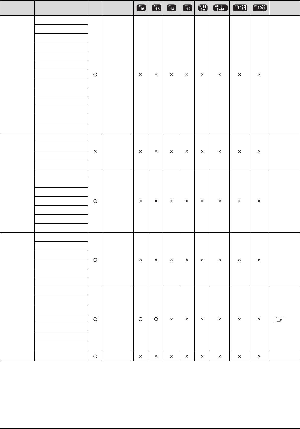
11 - 4 11. CC-Link IE CONTROLLER NETWORK CONNECTION
11.1 Connectable Model List
(Continued to next page)
*1 Only the first step can be used on the extension base unit (Q52B/Q55B).
Series Model name Clock Communicati
on type Refer to
MELSEC-A
(AnSCPU)
A2USCPU
- -
A2USCPU-S1
A2USHCPU-S1
A1SCPU
A1SCPUC24-R2
A1SHCPU
A2SCPU
A2SCPU-S1
A2SHCPU
A2SHCPU-S1
A1SJCPU
A1SJCPU-S3
A1SJHCPU
MELSEC-A
A0J2HCPU
- -
A0J2HCPUP21
A0J2HCPUR21
A0J2HCPU-DC24
A2CCPU
- -
A2CCPUP21
A2CCPUR21
A2CCPUC24
A2CCPUC24-PRF
A2CJCPU-S3
A1FXCPU
Motion
controller
CPU
(Q Series)
Q172CPU
- -
Q173CPU
Q172CPUN
Q173CPUN
Q172HCPU
Q173HCPU
Q172DCPU
CC-Link IE 11.2
Q173DCPU
Q172DCPU-S1
Q173DCPU-S1
Q172DSCPU
Q173DSCPU
Q170MCPU*1
MR-MQ100 - -
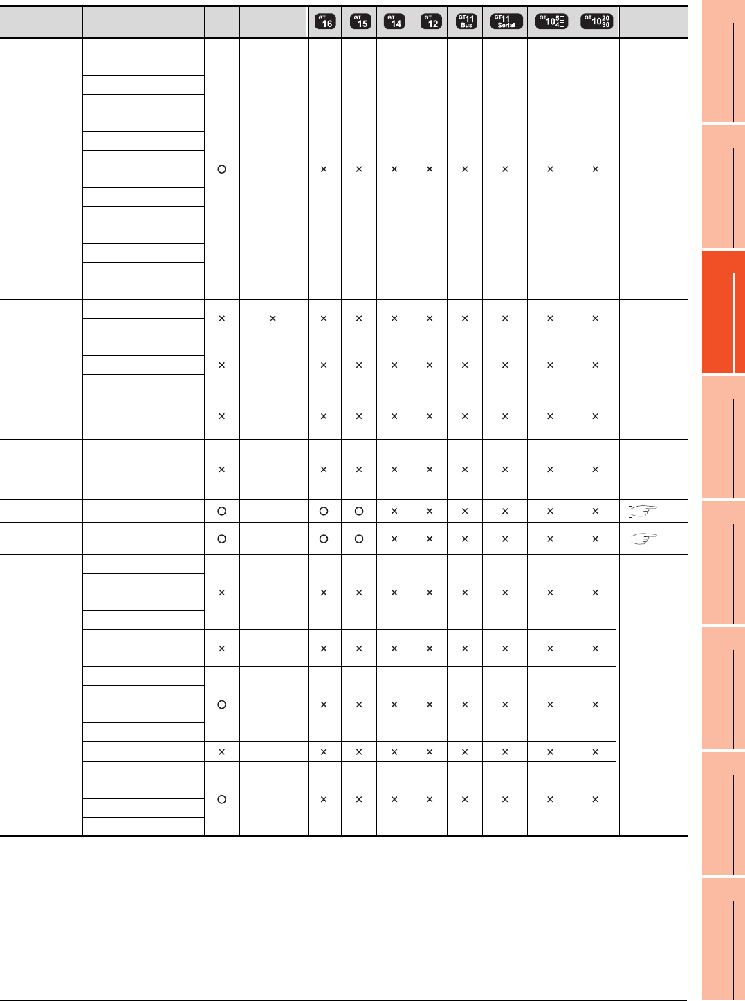
11. CC-Link IE CONTROLLER NETWORK CONNECTION
11.1 Connectable Model List
11 - 5
9
MELSECNET/H
CONNECTION (PLC
TO PLC NETWORK)
10
MELSECNET/10
CONNECTION (PLC
TO PLC NETWORK)
11
CC-Link IE CONTROLLER
NETWORK
CONNECTION
12
CC-Link IE FIELD
NETWORK
CONNECTION
13
CC-Link CONNECTION
(INTELLIGENT DEVICE
STATION)
14
CC-Link
CONNECTION
(Via G4)
15
INVERTER
CONNECTION
16
SERVO AMPLIFIER
CONNECTION
Series Model name Clock
Communication
type Refer to
Motion
controller
CPU
(A Series)
A273UCPU
- -
A273UHCPU
A273UHCPU-S3
A373UCPU
A373UCPU-S3
A171SCPU
A171SCPU-S3
A171SCPU-S3N
A171SHCPU
A171SHCPUN
A172SHCPU
A172SHCPUN
A173UHCPU
A173UHCPU-S1
MELSEC-WS
WS0-CPU0
-
WS0-CPU1
MELSECNET/H
Remote I/O
station
QJ72LP25-25
- -QJ72LP25G
QJ72BR15
CC-Link IE
Field Network
head module
LJ72GF15-T2 - -
CC-Link IE
Field Network
Ethernet
adapter module
NZ2GF-ETB - -
CNC C70 Q173NCCPU CC-Link IE 11.2
Robot
controller
CRnQ-700
(Q172DRCPU) CC-Link IE 11.2
MELSEC-FX
FX0
-
-
FX0S
FX0N
FX1
FX2
-
FX2C
FX1S
-
FX1N
FX2N
FX1NC
FX2NC -
FX3G
-
FX3GC
FX3U
FX3UC

11 - 6 11. CC-Link IE CONTROLLER NETWORK CONNECTION
11.1 Connectable Model List
11.1.2 CC-Link IE Controller Network communication unit
*1 When the CC-Link IE Controller Network is in the extended mode, use a unit with the upper five digits of the serial No. 12052 or
later.
CPU series CC-Link IE Controller Network communication unit*1
MELSEC-Q (Q mode)
C Controller module
MELSEC-QS
Motion controller CPU (Q Series)
CNC C70
Robot controller (CRnQ-700)
QJ71GP21-SX
QJ71GP21S-SX
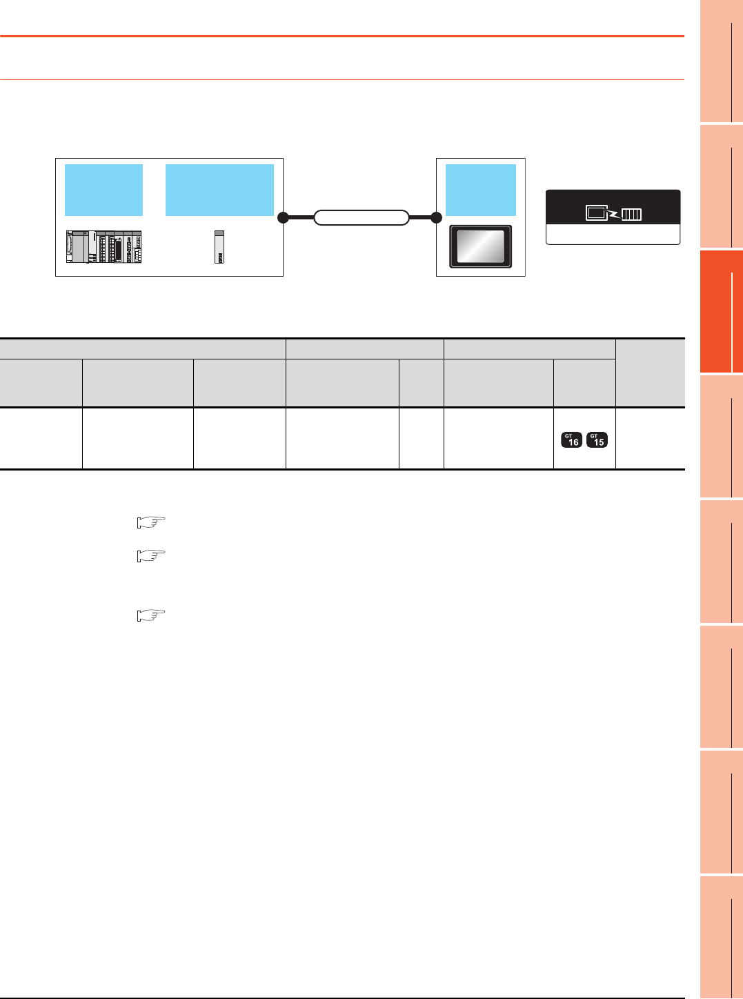
11. CC-Link IE CONTROLLER NETWORK CONNECTION
11.2 System Configuration
11 - 7
9
MELSECNET/H
CONNECTION (PLC
TO PLC NETWORK)
10
MELSECNET/10
CONNECTION (PLC
TO PLC NETWORK)
11
CC-Link IE CONTROLLER
NETWORK
CONNECTION
12
CC-Link IE FIELD
NETWORK
CONNECTION
13
CC-Link CONNECTION
(INTELLIGENT DEVICE
STATION)
14
CC-Link
CONNECTION
(Via G4)
15
INVERTER
CONNECTION
16
SERVO AMPLIFIER
CONNECTION
11.2 System Configuration
11.2.1 Connecting to optical loop system
*1 When the CC-Link IE Controller Network is in the extended mode, use a unit with the upper five digits of the serial No. 12052 or
later.
For the system configuration on the CC-Link IE Controller Network module side, refer to the following manual.
CC-Link IE Controller Network Reference Manual
*2 For the optical fiber cable, refer to the following manual.
CC-Link IE Controller Network Reference Manual
*3 The overall extension cable length and the length between stations vary depending on the cable type to be used and the total
number of stations.
For details, refer to the following manual.
CC-Link IE Controller Network Reference Manual
*4 When Universal model QCPUs is a control station, up to 119 GOTs can be connected.
When a QCPU other than Universal model QCPU is the control station, the number of connectable GOTs is 63 units (at most).
Basic model QCPU and the QSCPU cannot be used as the control station.
*5 When the CC-Link IE Controller Network is in the extended mode, only MELSEC-Q series Universal model QCPU can be used.
*6 When the CC-Link IE Controller Network is in the extended mode, use a module with the serial No. 02910908******* or later.
CC-Link IE controller
network module
QCPU GOT
Connection cable
CC-Link IE Controller Network
Communication driver
PLC Connection cable GOT
Number of
connectable
equipment
Model name*5
CC-Link IE controller
network
communication unit*1
Communication
type Cable model
Max.
distance
Option device Model
MELSEC-Q
C Controller
module
MELSEC-QS
QJ71GP21-SX
QJ71GP21S-SX CC-Link IE Optical fiber cable
*2 *3 GT15-J71GP23-SX*6 119 GOTs*4
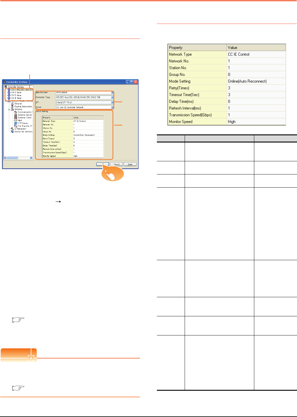
11 - 8 11. CC-Link IE CONTROLLER NETWORK CONNECTION
11.3 GOT side settings
11.3 GOT side settings
11.3.1 Setting communication
interface (Communication
settings)
Set the channel of connecting equipment.
1. Select [Common] [Controller Setting] from the
menu.
2. The Controller Setting window is displayed. Select the
channel to be used from the list menu.
3. Set the following items.
• Manufacturer: Mitsubishi
• Controller Type: Set according to the Controller
Type to be connected.
• I/F: Interface to be used
• Driver: CC-Link IE Controller Network
4. The detailed setting is displayed after Manufacturer,
Controller Type, I/F, and Driver are set.
Make the settings according to the usage
environment.
11.3.2 Communication detail settings
Click the [OK] button when settings are completed.
POINTPOINTPOINT
The settings of connecting equipment can be
confirmed in [I/F Communication Setting].
For details, refer to the following.
1.1.2 I/F communication setting
11.3.2 Communication detail settings
Make the settings according to the usage environment.
2.
3.
4.
Click!
Item Description Range
Network
Type*4
Set the network Type
(Default: CC IE Control)
• CC IE Control
• CC IE Control
extended mode
Network No. Set the network No.
(Default: 1) 1 to 239
Station No. Set the station No. of the GOT.
(Default: 1) 1 to 120
Mode Setting
Set the operation mode of the GOT.
(Default:
Online (auto. reconnection))
• Online
(auto.
reconnection)
• Offline
• Test station*1
• Self-loopback
test*1
• Internal self-
loopback test*1
• Line test*1
• H/W test*1
Retry
Set the number of retries to be
performed when a communication
timeout occurs.
When no response is received after
retries, a communication times out.
(Default: 3times)
0 to 5times
Timeout
Time
Set the time period for a
communication to time out.
(Default: 3sec)
3 to 90sec
Delay Time
Set the delay time for reducing the
load of the network/destination PLC.
(Default: 0ms)
0 to 300ms
Refresh
Interval
Set the number of refreshes to
secure the send/receive data in
station units during communication.
(Default: 1ms)
Valid when [Block data assurance
per station is available.] is checked
by the control station side network
parameters of the CC-Link IE
Controller Network.
1 to 1000ms
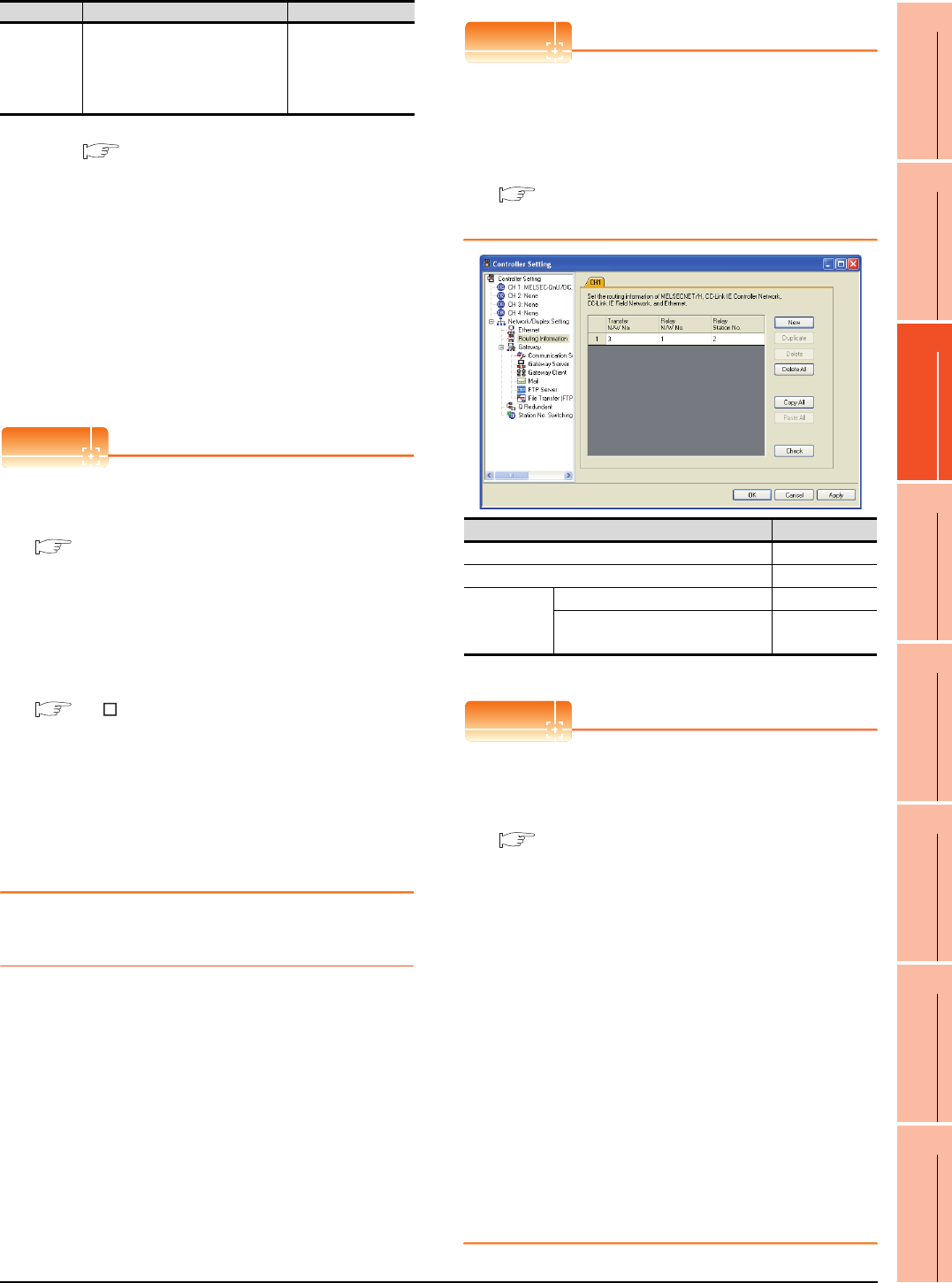
11. CC-Link IE CONTROLLER NETWORK CONNECTION
11.3 GOT side settings
11 - 9
9
MELSECNET/H
CONNECTION (PLC
TO PLC NETWORK)
10
MELSECNET/10
CONNECTION (PLC
TO PLC NETWORK)
11
CC-Link IE CONTROLLER
NETWORK
CONNECTION
12
CC-Link IE FIELD
NETWORK
CONNECTION
13
CC-Link CONNECTION
(INTELLIGENT DEVICE
STATION)
14
CC-Link
CONNECTION
(Via G4)
15
INVERTER
CONNECTION
16
SERVO AMPLIFIER
CONNECTION
*1 For details, refer to the following manual.
CC-Link IE Controller Network Reference Manual
*2 This range is effective when collecting a large amount of
data (such as logging and recipe function) on other than the
monitor screen.
However, the range may affect the sequence scan time
when connecting to Q00UJ/Q00U/Q01U/Q02UCPU or Q00J/
Q00/Q01CPU.
If you want to avoid the influence on the sequence scan time,
do not set [High].
(This setting hardly affects QCPUs other than the above.)
*3 Set this range if you want to avoid the influence on the
sequence scan time further than the [Normal] setting when
connecting to Q00UJ/Q00U/Q01U/Q02UCPU or Q00J/Q00/
Q01CPU.
However, the monitor speed may be reduced.
*4 When the CC-Link IE Controller Network is in the extended
mode, set to [CC IE Control extended mode]. The extended
mode can be used in GT Designer3 version 1.22Y or later.
POINTPOINTPOINT
(1) Switch setting example
For the switch setting example, refer to the
following.
11.4 PLC Side Setting
(2) Communication interface setting by Utility
The communication interface setting can be
changed on the Utility's [Communication Settings]
after writing [Communication Settings] of project
data.
For details on the Utility, refer to the following
manual.
GT User’s Manual
(3) Precedence in communication settings
When settings are made by GT Designer3 or the
Utility, the latest setting is effective.
(4) Network type
Be sure to set the same network types for the CPU
side and the GOT side. If the net work types of the
CPU side and the GOT side are different, an error
is displayed in the system alarm of the GOT side.
11.3.3 Routing parameter setting
Up to 64 [Transfer Network No.]s can be set.
However, the same transfer network number cannot be set
twice or more (multiple times).
Therefore, the one that can access to other station from the
request source host GOT is 64 kinds of [Transfer Network
No.]s.
POINTPOINTPOINT
Routing parameter setting
When communicating within the host network, routing
parameter setting is unnecessary.
For details of routing parameters, refer to the following
manual.
CC-Link IE Controller Network
Reference Manual
*1 Basic model QCPU and the QSCPU are not included.
POINTPOINTPOINT
(1) Routing parameter setting of relay station
Routing parameter setting is also necessary for
the relay station.
For the setting, refer to the following.
11.4 PLC Side Setting
(2) Parameter reflection function of MELSOFT Navigator
(a) The color of the cells for the items which are
reflected to GT Designer3 from MELSOFT
Navigator changes to green. Set items, which
are displayed in green cells, from the
MELSOFT Navigator.
(b) When the settings of Transfer network No.,
Relay network No. or Relay station No. are
reflected to the parameter from the MELSOFT
Navigator, those settings are added. Items set
in advance are not deleted.However, if the
target network No. overlaps, the item set in
advance is overwritten.
(c) The routing information is used manually by
the user when the data is created. Therefore,
after changing the network configuration by
MELSOFT Navigator, create a routing
information again. For details of the creation
of the routing information, refer to the
MELSOFT Navigator help.
Monitor
Speed
Set the monitor speed for the CC-
Link IE controller network.
This setting is not valid in all
systems.
(Default: High)
High*2/Normal/Low*3
Item Description Range
Item Range
Transfer Network No. 1 to 239
Relay Network No. 1 to 239
Relay Station
No.
Universal model QCPU 1 to 120
QCPU other than Universal model
QCPU*1 1 to 64
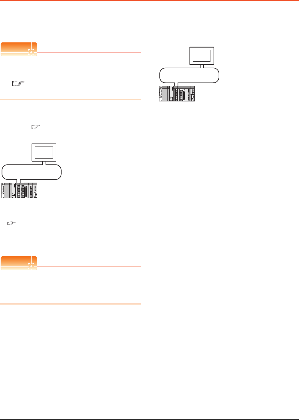
11 - 10 11. CC-Link IE CONTROLLER NETWORK CONNECTION
11.4 PLC Side Setting
11.4 PLC Side Setting
This section describes the settings of the GOT and CC-
Link IE controller network module in the following case of
system configuration.
POINTPOINTPOINT
CC-Link IE Controller Network module
For details of the CC-Link IE Controller Network
module, refer to the following manual.
CC-Link IE Controller Network Reference
Manual
System configuration1
(Network Type: CC IE Control)
*1 The CC-Link IE Controller Network module is mounted on
slot 0 of the base unit.
The start I/O No. of the CC-Link IE Controller Network
module is set at [0].
POINTPOINTPOINT
When connecting to Q170MCPU
When connected to Q170MCPU, the start I/O No. of
the CC-Link IE Controller Network module is set to
"70".
System configuration2
(Network Type: CC IE Control extended mode)
*1 The CC-Link IE Controller Network module is mounted on
slot 0 of the base unit.
The start I/O No. of the CC-Link IE Controller Network
module is set at [0].
<CC-Link IE Controller Network module> *1
(Use the default value for settings other than the following.)
Station No. : 1
Mode : Online
Network type : CC IE Control (Control station)
Network No. : 1
Total stations : 2
Network range assignment :
CC-Link IE Controller Network
<GOT>
(Use the default value for settings other
than the following.)
LB0000H to LB00FFH
LW00000H to LW000FFH
Network type : CC IE Control
Network No. : 1
Station No. : 2
Made Setting : Online (auto,reconnection)
Network range assignment :
Monitor Speed : High
LB0100H to LB01FFH
LW00100H to LW001FFH
■ GT Designer3 [Communication settings] of System
configuration1 (Network Type: CC IE Control)
■ [Network parameter] of GX Developer
<CC-Link IE Controller Network module> *1
(Use the default value for settings other than the following.)
Station No. : 1
Mode : Online
Network type : CC IE Control extended mode
(Control station)
Network No. : 1
Total stations : 2
Network range assignment :
CC-Link IE Controller Network
<GOT>
(Use the default value for settings other
than the following.)
LB0000H to LB00FFH
LW00000H to LW000FFH
Network type : CC IE Control extended mode
Network No. : 1
Station No. : 2
Made Setting : Online (auto,reconnection)
Network range assignment :
Monitor Speed : High
LB0100H to LB01FFH
LW00100H to LW001FFH
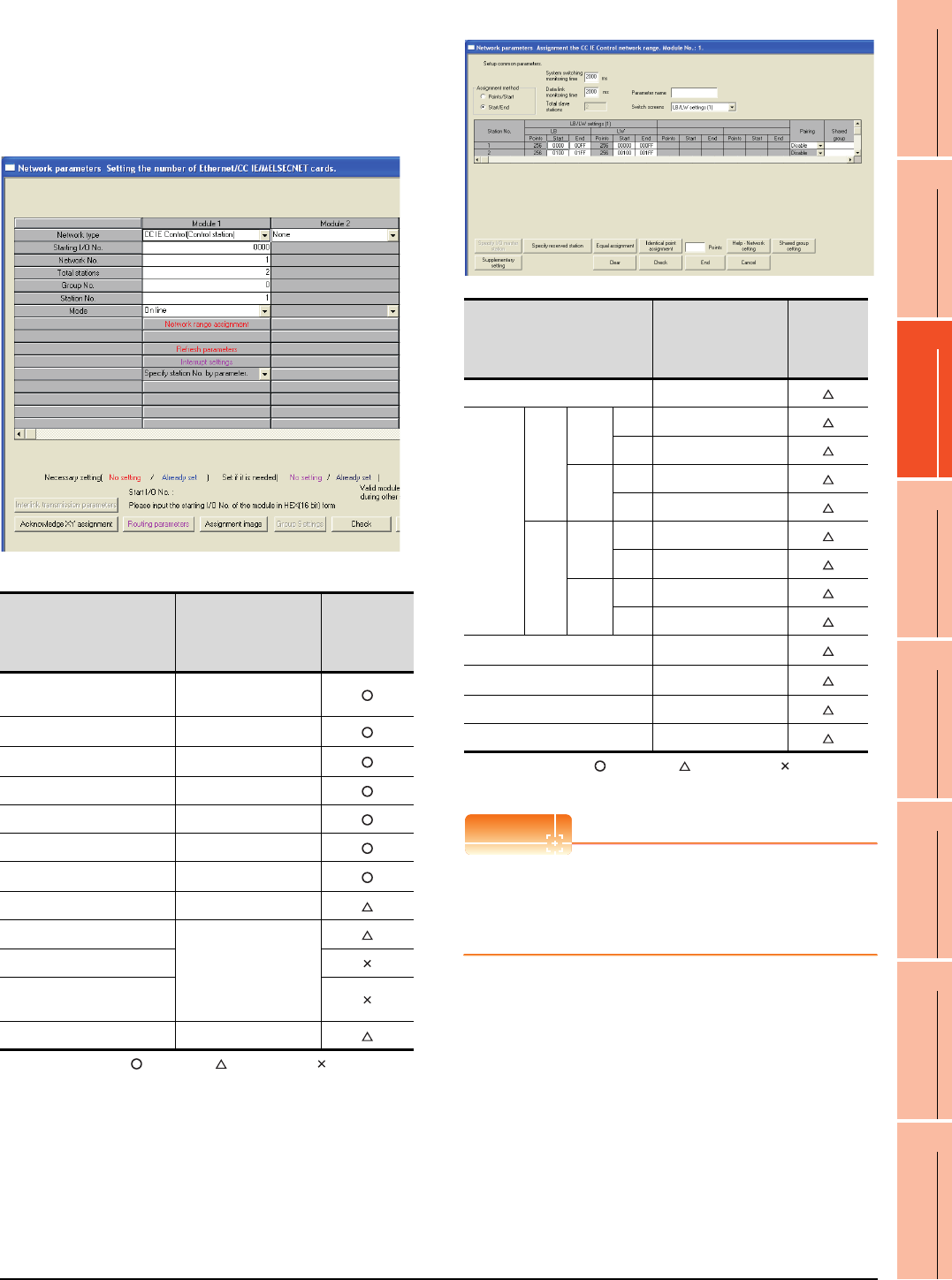
11. CC-Link IE CONTROLLER NETWORK CONNECTION
11.4 PLC Side Setting
11 - 11
9
MELSECNET/H
CONNECTION (PLC
TO PLC NETWORK)
10
MELSECNET/10
CONNECTION (PLC
TO PLC NETWORK)
11
CC-Link IE CONTROLLER
NETWORK
CONNECTION
12
CC-Link IE FIELD
NETWORK
CONNECTION
13
CC-Link CONNECTION
(INTELLIGENT DEVICE
STATION)
14
CC-Link
CONNECTION
(Via G4)
15
INVERTER
CONNECTION
16
SERVO AMPLIFIER
CONNECTION
Parameter settings (Connection to MELSEC-
Q, QS series) of System configuration1
(Network Type: CC IE Control)
(1) [Network parameter] of GX Developer
(a) Network parameter
: Necessary : As necessary : Not necessary
*1 When using Q170MCPU, set it according to the system
configuration.
*2 Specify the same network No. as that of the GOT.
*3 Set the same mode setting as that of the GOT.
(b) Network range assignment
: Necessary : As necessary : Not necessary
*1 Be sure to set it to perform the cyclic transmission.
POINTPOINTPOINT
When changing the network parameter
After writing the network parameter to the PLC CPU,
operate the PLC CPU ether turning OFF and then ON
or resetting.
Item Set value
Setting
necessity at
GOT
connection
Network type CC IE Control
(Control station) (fixed)
Starting I/O No.*1 0000H
Network No.*2 1
Total stations 2
Group No. 0 (fixed)
Station No. 1
Mode*3 Online
Network range assignment Refer to (b)
Refresh parameters
(Use default value)
Interrupt settings
Interlink transmission
parameters
Routing parameters Refer to (c)
Item Set value
Setting
necessity at
GOT
connection
Monitoring time 2000
LB/LW
setting(1)
*1
LB
Station
No.1
Start 0000H
End 00FFH
Station
No.2
Start 0100H
End 01FFH
LW
Station
No.1
Start 00000H
End 000FFH
Station
No.2
Start 00100H
End 001FFH
LX/LY setting*1 No setting
Specify I/O master station*1 No setting
Specify reserved station No setting
Supplementary setting (Use default value)
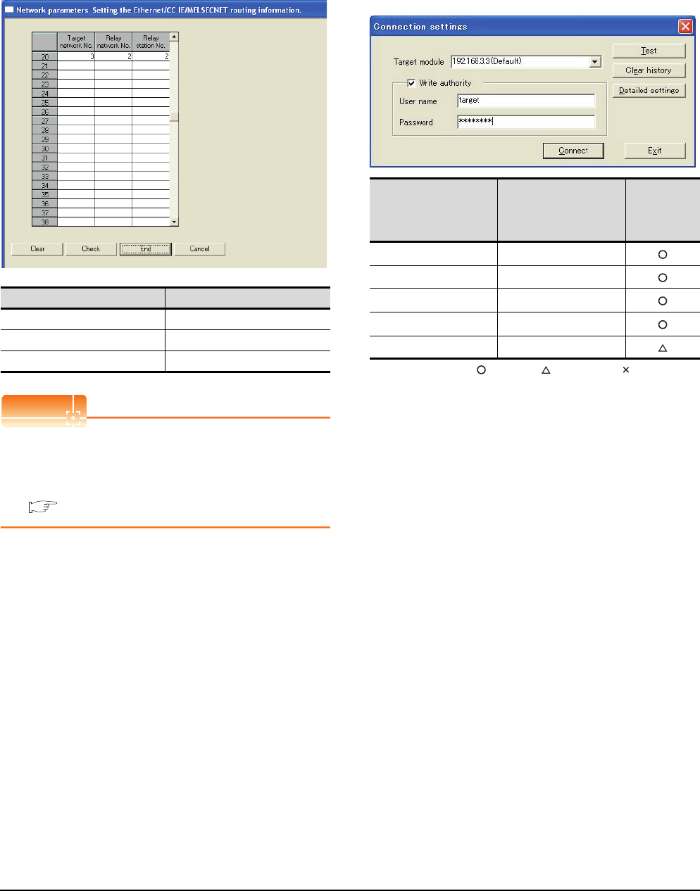
11 - 12 11. CC-Link IE CONTROLLER NETWORK CONNECTION
11.4 PLC Side Setting
(c) Routing parameter setting
Up to 64 [Transfer Network No.]s can be set.
However, the same transfer network number
cannot be set twice or more (multiple times).
Therefore, the one that can access to other station
from the request source host GOT is 64 kinds of
[Transfer Network No.]s.
POINTPOINTPOINT
Routing parameter setting of request source
Routing parameter setting is also necessary for the
request source GOT.
For the setting, refer to the following.
11.3.3 Routing parameter setting
Parameter setting (when connecting to C
Controller module)
Use SW3PVC-CCPU-E Ver.3.05F or later for the CC IE
Control utility.
(1) Connection settings between personal computer
and C controller module
: Necessary : As necessary : Not necessary
*1 If the IP address of the C Controller module has been
changed, input the changed IP address or host name.
*2 If the account of the C Controller module has been changed,
input the changed user name and password.
Item Range
Target network No. 1 to 239
Relay network No. 1 to 239
Relay station No. 1 to 120
Item Set value
Setting
necessity at
GOT
connection
Target module*1 192.168.3.3 (Default)
Write authority Mark the checkbox
User name*2 target
Password*2 password
Detailed settings -
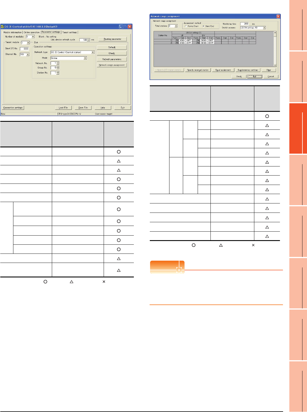
11. CC-Link IE CONTROLLER NETWORK CONNECTION
11.4 PLC Side Setting
11 - 13
9
MELSECNET/H
CONNECTION (PLC
TO PLC NETWORK)
10
MELSECNET/10
CONNECTION (PLC
TO PLC NETWORK)
11
CC-Link IE CONTROLLER
NETWORK
CONNECTION
12
CC-Link IE FIELD
NETWORK
CONNECTION
13
CC-Link CONNECTION
(INTELLIGENT DEVICE
STATION)
14
CC-Link
CONNECTION
(Via G4)
15
INVERTER
CONNECTION
16
SERVO AMPLIFIER
CONNECTION
(2) CC IE Control Utility's [Parameter Settings]
(a) Parameter settings
: Necessary : As necessary : Not necessary
*1 Set the same mode setting as that of the GOT.
*2 Specify the same network No. as that of the GOT.
(b) Network range assignment
: Necessary : As necessary : Not necessary
*1 Be sure to set it to perform the cyclic transmission.
POINTPOINTPOINT
When changing the network parameter
After writing the network parameter to the C Controller
module, either turn the C Controller module OFF and
then ON or reset it.
Item Set value
Setting
necessity at
GOT
connection
Number of modules 1
Link device refresh cycle (Use default value)
Routing parameter Refer to (c)
Target module 1
Start I/O No. 0000H
Channel No. 151
Operation settings
Network type CC IE Control
(Control station)
Mode*1 Online
Network No.*2 1
Group No. 0
Station No. 1
Refresh parameters (Use default value)
Network range
assignment Refer to (b)
Item Set value
Setting
necessity at
GOT
connection
Total stations 2
LB/LW
settings (1)
LB
Station
No.1
Start 0000H
End 00FFH
Station
No.2
Start 0100H
End 01FFH
LW
Station
No.1
Start 00000H
End 000FFH
Station
No.2
Start 00100H
End 001FFH
LX/LY settings*1 No setting
Monitoring time (Use default value)
Specify I/O master station*1 No setting
Specify reserved station No setting
Supplementary settings (Use default value)
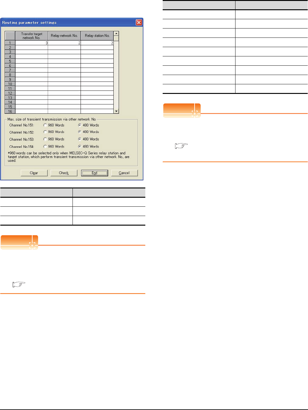
11 - 14 11. CC-Link IE CONTROLLER NETWORK CONNECTION
11.4 PLC Side Setting
(c) Routing parameter setting
Up to 64 [Transfer Network No.]s can be set.
However, the same transfer network number
cannot be set twice or more (multiple times).
Therefore, the one that can access to other station
from the request source host GOT is 64 kinds of
[Transfer Network No.]s.
POINTPOINTPOINT
Routing parameter setting of request source
Routing parameter setting is also necessary for the
request source GOT.
For the setting, refer to the following.
11.3.3 Routing parameter setting
GT Designer3 [Communication settings] of
System configuration1 (Network Type: CC IE
Control)
POINTPOINTPOINT
[Controller Setting] of GT Designer3
For the setting method of [Controller Setting] of GT
Designer3, refer to the following.
11.3.1 Setting communication interface
(Communication settings)
Item Range
Transfer target network No. 1 to 239
Relay network No. 1 to 239
Relay station No. 1 to 120
Item Set value
Network Type CC IE Control
Network No. 1: Network No.1
Station No. 2: Station No.2
Mode Setting Online (auto. reconnection)
Retry 3times (Use default value)
Timeout Time 3sec (Use default value)
Delay Time 0ms (Use default value)
Refresh Interval 1ms (Use default value)
Monitor Speed High (Use default value)
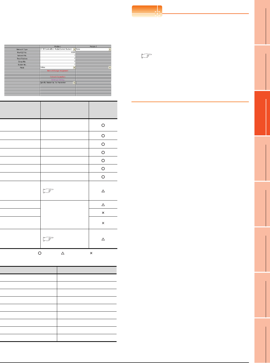
11. CC-Link IE CONTROLLER NETWORK CONNECTION
11.4 PLC Side Setting
11 - 15
9
MELSECNET/H
CONNECTION (PLC
TO PLC NETWORK)
10
MELSECNET/10
CONNECTION (PLC
TO PLC NETWORK)
11
CC-Link IE CONTROLLER
NETWORK
CONNECTION
12
CC-Link IE FIELD
NETWORK
CONNECTION
13
CC-Link CONNECTION
(INTELLIGENT DEVICE
STATION)
14
CC-Link
CONNECTION
(Via G4)
15
INVERTER
CONNECTION
16
SERVO AMPLIFIER
CONNECTION
Parameter settings (Connection to Universal
model QCPU) of System configuration2
(Network Type: Extended mode)
(1) [Network parameter] of GX Works2
(a) Network parameter
: Necessary : As necessary : Not necessary
(2) [Controller Setting] of GT Designer3
POINTPOINTPOINT
(1) Network type of the GOT side
When the network is in the extended mode, be
sure to set the network type of the GOT side to
[CC IE Control extended mode].
For [Controller Setting], of GT Designer3, refer to
the following.
11.3.1 Setting communication interface
(Communication settings)
(2) Network type of the PLC side
Only GX Works2 can set [CC IE Control extended
mode (control station)] or [CC IE Control extended
mode (ordinary station)]. The CPU which is
compatible with the extended mode is Universal
model QCPU only.
Item Set value
Setting necessity
at GOT
connection
Network Type CC IE Control Ext. Mode
(Control station) (fixed)
Start I/O No.*1 0000H
Network No.*2 1
Tot a l Sta t i o n s 2
Group No. 0 (Fixed)
Station No. 1
Mode*3 Online
Network Range
Assignment
Same as the following setting
[Network parameter]
of GX Developer
Refresh Parameters
(Use default value)
Interrupt Setting
Interlink transmission
parameters
Routing parameters
Same as the following setting
[Network parameter]
of GX Developer
Item Set value
Network type CC IE Control extended mode
Network No. 1: Network No.1
Station No. 2: Station No.2
Mode Online (auto. reconnection)
Retry 3times (Use default value)
Timeout Time 3sec (Use default value)
Delay Time 1ms (Use default value)
Refresh Interval High (Use default value)
Monitor Speed High (Use default value)
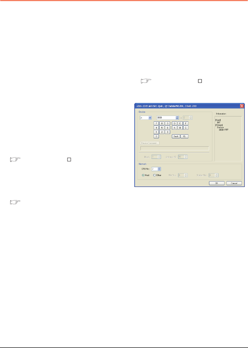
11 - 16 11. CC-Link IE CONTROLLER NETWORK CONNECTION
11.5 Precautions
11.5 Precautions
GOT startup in CC-Link IE Controller
Network connection
For the CC-Link IE Controller Network connection, the
data link is started approximately 13 seconds after the
GOT startup.
When a network error occurs in the system
alarm
In the CC-Link IE Controller Network connection, when
a network error occurs in the system alarm, the system
alarm display cannot be canceled even though the
causes are removed.
To cancel the system alarm display, restart the GOT.
Connection in the multiple CPU system
When the GOT is connected to multiple CPU system,
the following time is taken until when the PLC runs.
QCPU (Q mode), motion controller CPU (Q series): 10
seconds or more
MELDAS C70: 18 seconds or more
When the GOT starts before the PLC runs, a system
alarm occurs. Adjust the opening screen time in the
GOT setup so that no system alarm occurs.
GT Designer3 Version Screen Design
Manual
CC-Link IE Controller Network module
version
For version restrictions of the CC-Link IE Controller
Network module, refer to the following manual.
CC-Link IE Controller Network Reference
Manual
Connection to QSCPU
The GOT can only read device data and sequence
programs by the ladder monitor function in the QSCPU.
The GOT cannot write any data to the QSCPU.
Connection to Q170MCPU
Set [CPU No.] to "2" in the device setting to monitor the
device of the Motion CPU area (CPU No.2).
When the CPU No. is set to "0" or "1", the device on the
PLC CPU area (CPU No.1) is monitored.
When the CPU No. is set to the number other than "0"
to "2", a communication error occurs and the monitoring
cannot be executed.
For setting the CPU No., refer to the following manual.
GT Designer3 Version Screen Design
Manual
Example) Setting dialog box of the bit device
12
9
MELSECNET/H
CONNECTION (PLC
TO PLC NETWORK)
10
MELSECNET/10
CONNECTION (PLC
TO PLC NETWORK)
11
CC-Link IE CONTROLLER
NETWORK
CONNECTION
12
CC-Link IE FIELD
NETWORK
CONNECTION
13
CC-Link CONNECTION
(INTELLIGENT DEVICE
STATION)
14
CC-Link
CONNECTION
(Via G4)
15
INVERTER
CONNECTION
16
SERVO AMPLIFIER
CONNECTION
12 - 1
12.CC-Link IE FIELD
NETWORK CONNECTION
12.1 Connectable Model List . . . . . . . . . . . . . . . . . . . . . . . . . . . 12 - 2
12.2 System Configuration. . . . . . . . . . . . . . . . . . . . . . . . . . . . . 12 - 7
12.3 GOT side settings . . . . . . . . . . . . . . . . . . . . . . . . . . . . . . . 12 - 8
12.4 PLC Side Setting . . . . . . . . . . . . . . . . . . . . . . . . . . . . . . . 12 - 10
12.5 Precautions . . . . . . . . . . . . . . . . . . . . . . . . . . . . . . . . . . . 12 - 13
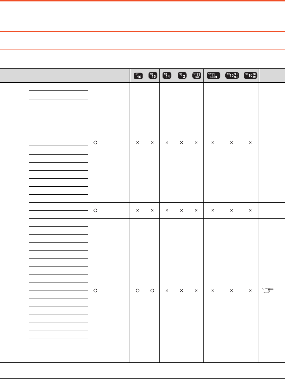
12 - 2 12. CC-Link IE FIELD NETWORK CONNECTION
12.1 Connectable Model List
12. CC-Link IE FIELD NETWORK
CONNECTION
12.1 Connectable Model List
12.1.1 PLC/Motion controller CPU
The following table shows the connectable models.
(Continued to next page)
Series Model name Clock
Communication
type
Refer to
MELSEC-Q
(Q mode)
Q00JCPU
- -
Q00CPU*1
Q01CPU*1
Q02CPU*1
Q02HCPU*1
Q06HCPU*1
Q12HCPU*1
Q25HCPU*1
Q02PHCPU
Q06PHCPU
Q12PHCPU
Q25PHCPU
Q12PRHCPU(Main base)
Q25PRHCPU(Main base)
Q12PRHCPU(Extension base)
- -
Q25PRHCPU(Extension base)
Q00UJCPU
CC-Link IE
FIELD
NETWORK
12.2
Q00UCPU
Q01UCPU
Q02UCPU
Q03UDCPU
Q04UDHCPU
Q06UDHCPU
Q10UDHCPU
Q13UDHCPU
Q20UDHCPU
Q26UDHCPU
Q03UDECPU
Q04UDEHCPU
Q06UDEHCPU
Q10UDEHCPU
Q13UDEHCPU
Q20UDEHCPU
Q26UDEHCPU
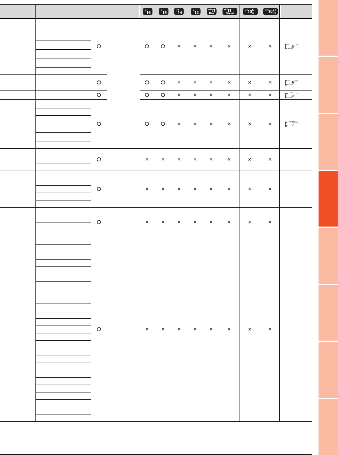
12. CC-Link IE FIELD NETWORK CONNECTION
12.1 Connectable Model List
12 - 3
9
MELSECNET/H
CONNECTION (PLC
TO PLC NETWORK)
10
MELSECNET/10
CONNECTION (PLC
TO PLC NETWORK)
11
CC-Link IE CONTROLLER
NETWORK
CONNECTION
12
CC-Link IE FIELD
NETWORK
CONNECTION
13
CC-Link CONNECTION
(INTELLIGENT DEVICE
STATION)
14
CC-Link
CONNECTION
(Via G4)
15
INVERTER
CONNECTION
16
SERVO AMPLIFIER
CONNECTION
(Continued to next page)
*1 Use a module with the upper five digits later than 12042.
*2 Use a module with the upper five digits later than 13012.
*3 Use a module with the upper five digits later than "13042". Use GX Developer of Version 8.98C or later.
Series Model name Clock
Communication
type Refer to
MELSEC-Q
(Q mode)
Q50UDEHCPU
CC-Link IE
FIELD
NETWORK
12.2
Q100UDEHCPU
Q03UDVCPU
Q04UDVCPU
Q06UDVCPU
Q13UDVCPU
Q26UDVCPU
C Controller
module
Q12DCCPU-V*1
12.2
Q24DHCCPU-V
MELSEC-QS QS001CPU*3 12.2
MELSEC-L
L02CPU*2
12.2
L26CPU
L26CPU-BT*2
L02CPU-P*2
L26CPU-PBT*2
L02SCPU
MELSEC-Q
(A mode)
Q02CPU-A
- -Q02HCPU-A
Q06HCPU-A
MELSEC-QnA
(QnACPU)
Q2ACPU
- -
Q2ACPU-S1
Q3ACPU
Q4ACPU
Q4ARCPU
MELSEC-QnA
(QnASCPU)
Q2ASCPU
- -
Q2ASCPU-S1
Q2ASHCPU
Q2ASHCPU-S1
MELSEC-A
(AnCPU)
A2UCPU
- -
A2UCPU-S1
A3UCPU
A4UCPU
A2ACPU
A2ACPUP21
A2ACPUR21
A2ACPU-S1
A2ACPUP21-S1
A2ACPUR21-S1
A3ACPU
A3ACPUP21
A3ACPUR21
A1NCPU
A1NCPUP21
A1NCPUR21
A2NCPU
A2NCPUP21
A2NCPUR21
A2NCPU-S1
A2NCPUP21-S1
A2NCPUR21-S1
A3NCPU
A3NCPUP21
A3NCPUR21
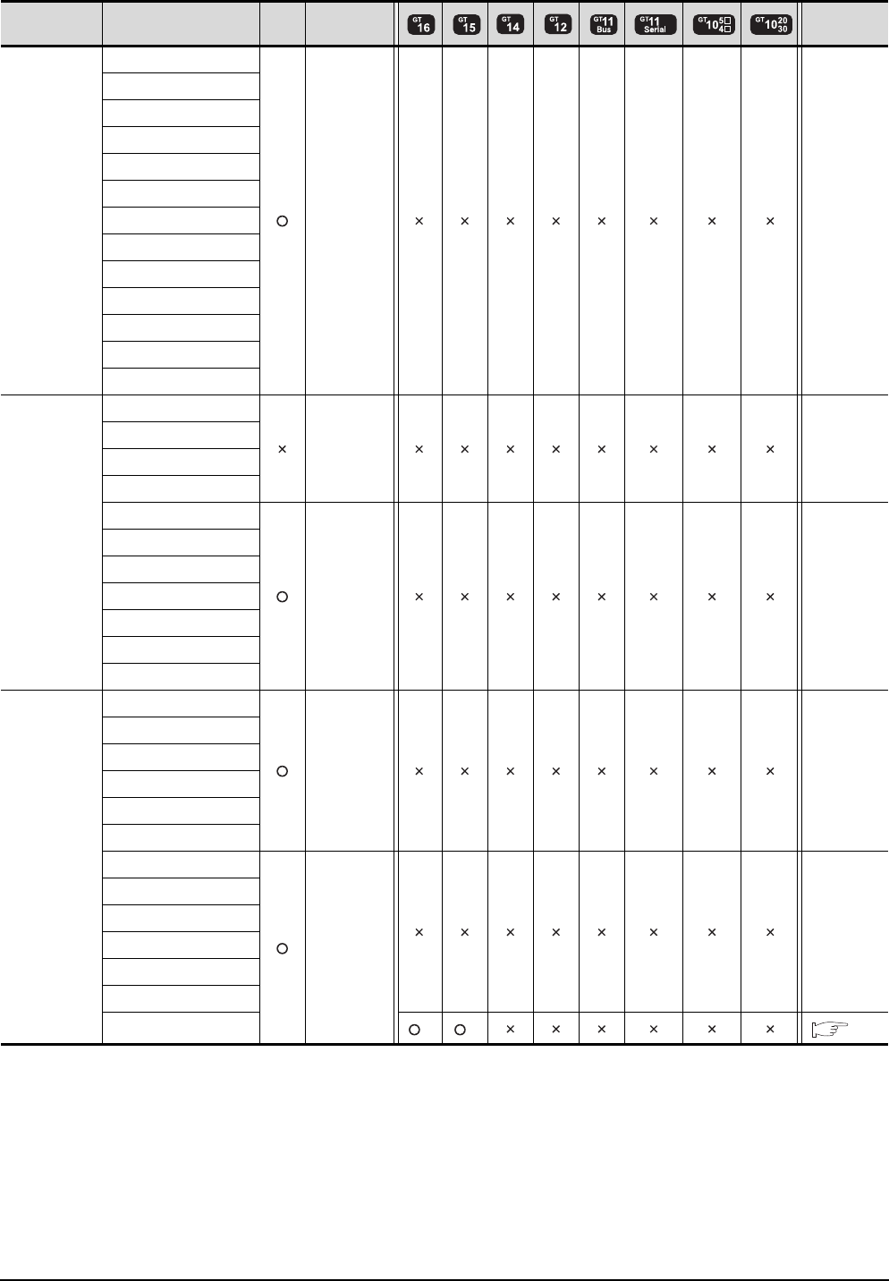
12 - 4 12. CC-Link IE FIELD NETWORK CONNECTION
12.1 Connectable Model List
(Continued to next page)
*1 Only the first step can be used on the extension base unit (Q52B/Q55B).
*2 For the PLC CPU area, use a module with the upper five digits later than 12012. Only the PLC CPU area can be monitored.
Series Model name Clock
Communication
type Refer to
MELSEC-A
(AnSCPU)
A2USCPU
- -
A2USCPU-S1
A2USHCPU-S1
A1SCPU
A1SCPUC24-R2
A1SHCPU
A2SCPU
A2SCPU-S1
A2SHCPU
A2SHCPU-S1
A1SJCPU
A1SJCPU-S3
A1SJHCPU
MELSEC-A
A0J2HCPU
- -
A0J2HCPUP21
A0J2HCPUR21
A0J2HCPU-DC24
A2CCPU
- -
A2CCPUP21
A2CCPUR21
A2CCPUC24
A2CCPUC24-PRF
A2CJCPU-S3
A1FXCPU
Motion
controller
CPU
(Q Series)
Q172CPU
- -
Q173CPU
Q172CPUN
Q173CPUN
Q172HCPU
Q173HCPU
Q172DCPU
CC-Link IE
FIELD
NETWORK
-
Q173DCPU
Q172DCPU-S1
Q173DCPU-S1
Q172DSCPU
Q173DSCPU
Q170MCPU*1 *2 *2 12.2
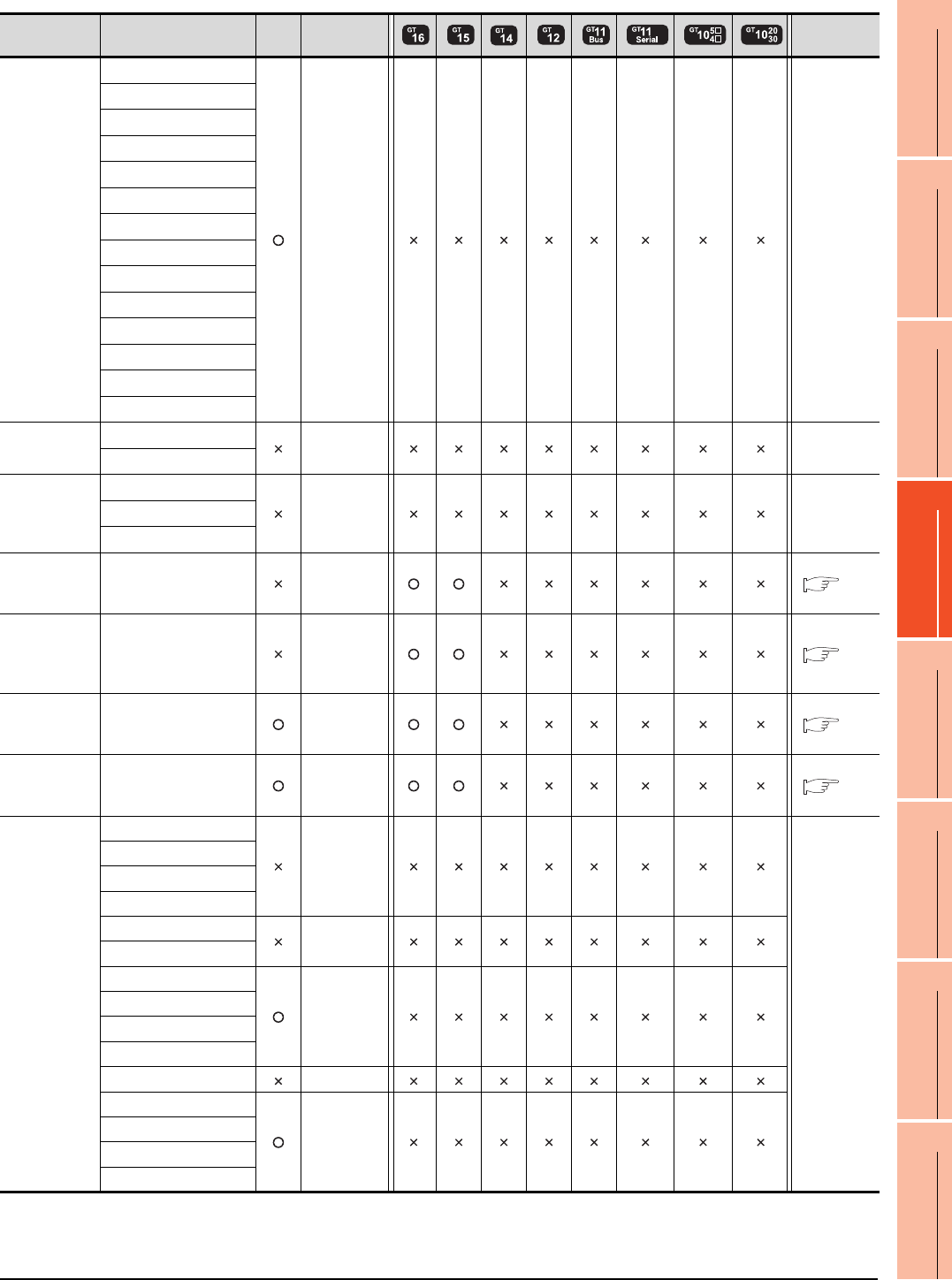
12. CC-Link IE FIELD NETWORK CONNECTION
12.1 Connectable Model List
12 - 5
9
MELSECNET/H
CONNECTION (PLC
TO PLC NETWORK)
10
MELSECNET/10
CONNECTION (PLC
TO PLC NETWORK)
11
CC-Link IE CONTROLLER
NETWORK
CONNECTION
12
CC-Link IE FIELD
NETWORK
CONNECTION
13
CC-Link CONNECTION
(INTELLIGENT DEVICE
STATION)
14
CC-Link
CONNECTION
(Via G4)
15
INVERTER
CONNECTION
16
SERVO AMPLIFIER
CONNECTION
Series Model name Clock
Communication
type Refer to
Motion
controller
CPU
(A Series)
A273UCPU
- -
A273UHCPU
A273UHCPU-S3
A373UCPU
A373UCPU-S3
A171SCPU
A171SCPU-S3
A171SCPU-S3N
A171SHCPU
A171SHCPUN
A172SHCPU
A172SHCPUN
A173UHCPU
A173UHCPU-S1
MELSEC-WS
WS0-CPU0
- -
WS0-CPU1
MELSECNET/H
Remote I/O
station
QJ72LP25-25
- -QJ72LP25G
QJ72BR15
CC-Link IE
Field Network
head module
LJ72GF15-T2
CC-Link IE
FIELD
NETWORK
12.2
CC-Link IE
Field Network
Ethernet
adapter module
NZ2GF-ETB
CC-Link IE
FIELD
NETWORK
12.2
CNC C70 Q173NCCPU
CC-Link IE
FIELD
NETWORK
12.2
Robot
controller
CRnQ-
700(Q172DRCPU)
CC-Link IE
FIELD
NETWORK
12.2
MELSEC-FX
FX0
-
-
FX0S
FX0N
FX1
FX2
-
FX2C
FX1S
-
FX1N
FX2N
FX1NC
FX2NC -
FX3G
-
FX3GC
FX3U
FX3UC

12 - 6 12. CC-Link IE FIELD NETWORK CONNECTION
12.1 Connectable Model List
12.1.2 CC-Link IE Field Network communication unit
CPU series CC-Link IE Field Network communication unit
MELSEC-Q(Universal model) QJ71GF11-T2, QD77GF16
MELSEC-L LJ71GF11-T2
MELSEC-QS QS0J71GF11-T2
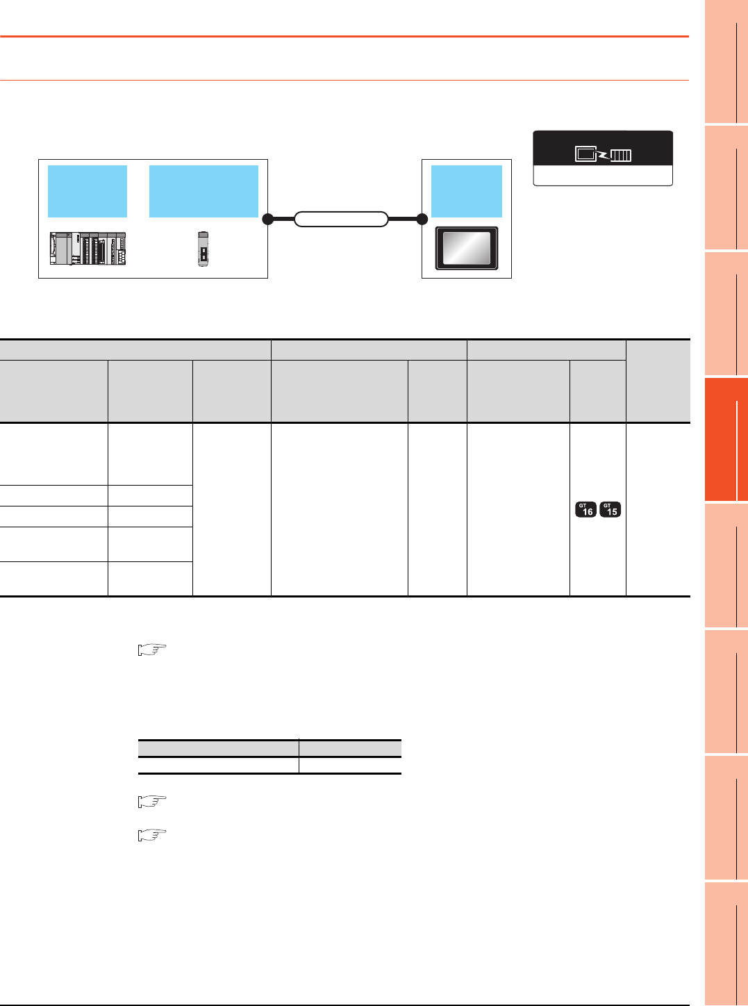
12. CC-Link IE FIELD NETWORK CONNECTION
12.2 System Configuration
12 - 7
9
MELSECNET/H
CONNECTION (PLC
TO PLC NETWORK)
10
MELSECNET/10
CONNECTION (PLC
TO PLC NETWORK)
11
CC-Link IE CONTROLLER
NETWORK
CONNECTION
12
CC-Link IE FIELD
NETWORK
CONNECTION
13
CC-Link CONNECTION
(INTELLIGENT DEVICE
STATION)
14
CC-Link
CONNECTION
(Via G4)
15
INVERTER
CONNECTION
16
SERVO AMPLIFIER
CONNECTION
12.2 System Configuration
12.2.1 Connecting to CC-Link IE Field Network communication unit
*1 The overall extension cable length and the length between stations vary depending on the connection method (line, star or ring),
the system configuration, etc.
For details, refer to the following manual.
CC-Link IE Field Network Master/Local Module User's Manual
*2 Use hubs that satisfy the following conditions.
• Compliance with the IEEE802.3 (1000BASE-T)
• Supporting the auto MDI/MDI-X function
• Supporting the auto-negotiation function
• Switching hub (A repeater hub is not available.)
Recommended switching hub (Mitsubishi electric products)
For details, refer to the following manual.
CC-Link IE Field Network Master/Local Module User's Manual
*3 When connecting to the QD77GF16, refer to the following manual.
MELSEC-Q QD77GF Simple Motion Module User's Manual
PLC CPU CC-Link IE
Field Network unit GOT
Connection cable
CC-Link IE Field Network
Communication driver
PLC Connection cable GOT
Number of
connectable
equipment
Model name
CC-Link IE Field
Network
communication
unit
Communicatio
n type Cable model*2 Max
distance*1 option device Model
MELSEC-Q
(Universal model)
Q170MCPU
C Controller module
QJ71GF11-T2
QD77GF16*3
CC-Link IE
Field Network
Ethernet cable that meets the
1000BASE-T standard:
Category 5e or higher,
(double-shielded, STP)
straight cable.
12100m GT15-J71GF13-T2 120 GOTs
MELSEC-QS QS0J71GF11-T2
MELSEC-L LJ71GF11-T2
CC-Link IE Field
Network head module -
Ethernet adapter
module -
Type Model name
Industrial switching hub NZ2EHG-T8
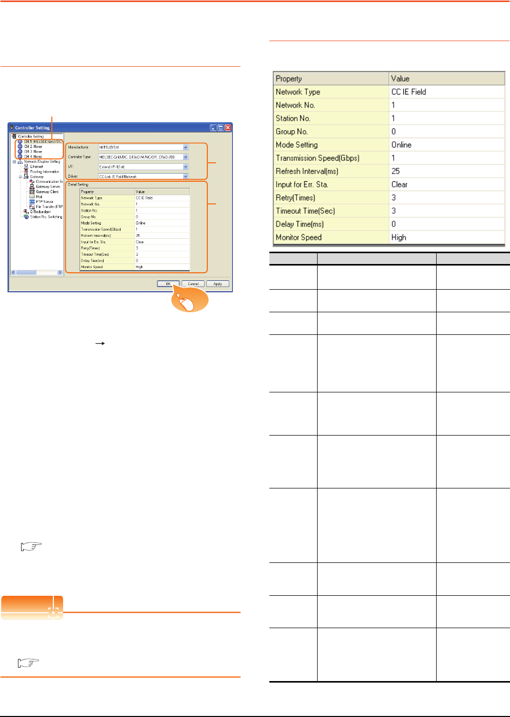
12 - 8 12. CC-Link IE FIELD NETWORK CONNECTION
12.3 GOT side settings
12.3 GOT side settings
12.3.1 Setting communication
interface (Communication
settings)
Set the channel of connecting equipment.
1. Select [Common] [Controller Setting] from the
menu.
2. The Controller Setting window is displayed. Select the
channel to be used from the list menu.
3. Set the following items.
• Manufacturer: Mitsubishi
• Controller Type: Set according to the Controller
Type to be connected.
• I/F: Interface to be used
• Driver: CC-Link IE Field Network
4. The detailed setting is displayed after Manufacturer,
Controller Type, I/F, and Driver are set.
Make the settings according to the usage
environment.
12.3.2 Communication detail settings
Click the [OK] button when settings are completed.
POINTPOINTPOINT
The settings of connecting equipment can be
confirmed in [I/F Communication Setting].
For details, refer to the following.
1.1.2 I/F communication setting
12.3.2 Communication detail settings
Make the settings according to the usage environment.
(Continued to next page)
2.
3.
4.
Click!
Item Description Range
Network
Type*4 Set the network Type • CC IE Field
Network No. Set the network No. of the GOT.
(Default: 1) 1 to 239
Station No. Set the station No. of the GOT.
(Default: 1) 1 to 120
Mode Setting
Set the operation mode of the GOT.
(Default:
Online (auto. reconnection))
• Online
• Offline
• H/W test*1
• Self-loopback
test*1
Refresh
Interval
Set the number of refreshes to
secure the send/receive data in
station units during communication.
(Default: 25ms)
1 to 1000ms
Input for Error
Station
Set the hold/clear of input from the
station where the data link is faulty
due to some reason such as turning
the power OFF.
(Default: Clear)
Clear/Hold
Retry
Set the number of retries to be
performed when a communication
timeout occurs.
When receiving no response after
retries, the communication times
out.
(Default: 3times)
0 to 5times
Timeout
Time
Set the time period for a
communication to time out.
(Default: 3sec)
3 to 90sec
Delay Time
Set the delay time for reducing the
load of the network/destination PLC.
(Default: 0ms)
0 to 300ms
Monitor
Speed
Set the monitor speed for the CC-
Link IE field network.
This setting is not valid in all
systems.
(Default: High)
High*2/Normal/Low*3
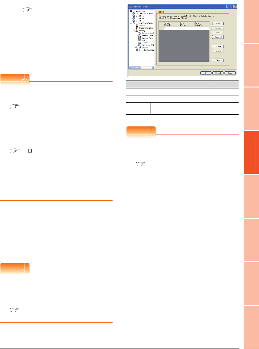
12. CC-Link IE FIELD NETWORK CONNECTION
12.3 GOT side settings
12 - 9
9
MELSECNET/H
CONNECTION (PLC
TO PLC NETWORK)
10
MELSECNET/10
CONNECTION (PLC
TO PLC NETWORK)
11
CC-Link IE CONTROLLER
NETWORK
CONNECTION
12
CC-Link IE FIELD
NETWORK
CONNECTION
13
CC-Link CONNECTION
(INTELLIGENT DEVICE
STATION)
14
CC-Link
CONNECTION
(Via G4)
15
INVERTER
CONNECTION
16
SERVO AMPLIFIER
CONNECTION
*1 For details, refer to the following manual.
CC-Link IE Field Network Master/Local Module
User's Manual
*2 This range is effective when collecting a large amount of
data (such as logging and recipe function) on other than the
monitor screen.
However, the range may affect the sequence scan time
when connecting to Q00UJ/Q00U/Q01U/Q02UCPU.
If you want to avoid the influence on the sequence scan time,
do not set [High].
(This setting hardly affects QCPUs other than the above.)
*3 Set this range if you want to avoid the influence on the
sequence scan time further than the [Normal] setting when
connecting to Q00UJ/Q00U/Q01U/Q02UCPU.
However, the monitor speed may be reduced.
POINTPOINTPOINT
(1) Switch setting example
For the switch setting example, refer to the
following.
12.4 PLC Side Setting
(2) Communication interface setting by Utility
The communication interface setting can be
changed on the Utility's [Communication Settings]
after writing [Communication Settings] of project
data.
For details on the Utility, refer to the following
manual.
GT User’s Manual
(3) Precedence in communication settings
When settings are made by GT Designer3 or the
Utility, the latest setting is effective.
(4) Network type
Be sure to set the same network types for the CPU
side and the GOT side. If the network types of the
CPU side and the GOT side are different, an error
is displayed in the system alarm of the GOT side.
12.3.3 Routing parameter setting
Up to 64 [Transfer Network No.]s can be set.
However, the same transfer network number cannot be set
twice or more (multiple times).
Therefore, the one that can access to other station from the
request source host GOT is 64 kinds of [Transfer Network
No.]s.
POINTPOINTPOINT
Routing parameter setting
When communicating within the host network, routing
parameter setting is unnecessary.
For details of routing parameters, refer to the following
manual.
CC-Link IE Field Network
Reference Manual
*1 Basic model QCPU and the QSCPU are not included.
POINTPOINTPOINT
(1) Routing parameter setting of relay station
Routing parameter setting is also necessary for
the relay station.
For the setting, refer to the following.
12.4 PLC Side Setting
(2) Parameter reflection function of MELSOFT Navigator
(a) The color of the cells for the items which are
reflected to GT Designer3 from MELSOFT
Navigator changes to green. Set items, which
are displayed in green cells, from the
MELSOFT Navigator.
(b) When the settings of Transfer network No.,
Relay network No. or Relay station No. are
reflected to the parameter from the MELSOFT
Navigator, those settings are added. Items set
in advance are not deleted. However, if the
target network No. overlaps, the item set in
advance is overwritten.
(c) The routing information is used manually by
the user when the data is created. Therefore,
after changing the network configuration by
MELSOFT Navigator, create a routing
information again. For details of the creation
of the routing information, refer to the
MELSOFT Navigator help.
Item Range
Transfer Network No. 1 to 239
Relay Network No. 1 to 239
Relay Station
No.
MELSEC-Q (Universal model)
Q170MCPU C Controller Module 0 to 120
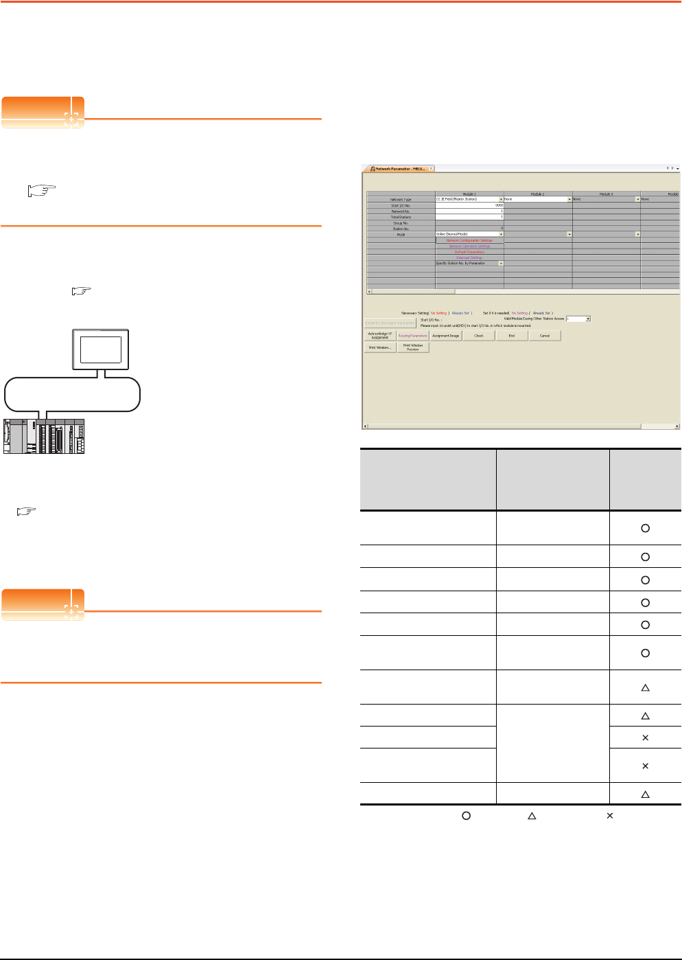
12 - 10 12. CC-Link IE FIELD NETWORK CONNECTION
12.4 PLC Side Setting
12.4 PLC Side Setting
This section describes the settings of the GOT and CC-
Link IE controller network module in the following case of
system configuration.
POINTPOINTPOINT
CC-Link IE Field Network Module
For details of the CC-Link IE Field Network module,
refer to the following manual.
CC-Link IE Field Network Master/Local Module
User's Manual
System configuration
(Network Type: CC IE Field)
*1 The CC-Link IE Field Network module is mounted on slot 0
of the base unit.
The start I/O No. of the CC-Link IE Field Network module is
set at [0].
POINTPOINTPOINT
When connecting to Q170MCPU
When connected to Q170MCPU, the start I/O No. of
the CC-Link IE Field Network module is set to "70".
Parameter settings (Connection to MELSEC-
Q, QS series) of System configuration
(Network Type: CC IE Field)
(1) Network parameter] of GX Works2
Use GX Works2 of Version 1.31H or later.
(a) Network parameter
: Necessary : As necessary : Not necessary
*1 When using Q170MCPU, set it according to the system
configuration.
*2 Specify the same network No. as that of the GOT.
*3 Set the same mode setting as that of the GOT.
<CC-Link IE Field Network module> *1
(Use the default value for settings other than the following.)
Station No. : 0 (fixed)
Mode : Online (normal)
Network type : CC IE Field (Master station)
Network No. : 1
Total stations : 1
Network Configuration Settings :
CC-Link IE Field Network
<GOT>
(Use the default value for settings other
than the following.)
RX/RY00H to FFH
RWW/RWr00H to FFH
Network type : CC IE Field
Network No. : 1
Station No. : 1
Mode Setting : Online
Network Configuration Settings :
Monitor Speed : High
RX/RY00 to FFH
RWW/RWr00 to FFH
■ GT Designer3 [Communication setting] of System
configuration1 (Network Type: CC IE Field)
■ [Network parameter] of GX Works2
Item Set value
Setting
necessity at
GOT
connection
Network type CC IE Field
(Master station) (fixed)
Starting I/O No.*1 0000H
Network No.*2 1
Total stations 1
Station No. 0 (fixed)
Mode*3 Online
(Normal mode)
Network Configuration
Settings Refer to (b)
Refresh parameters
(Use default value)
Interrupt settings
Interlink transmission
parameters
Routing parameters Refer to (c)
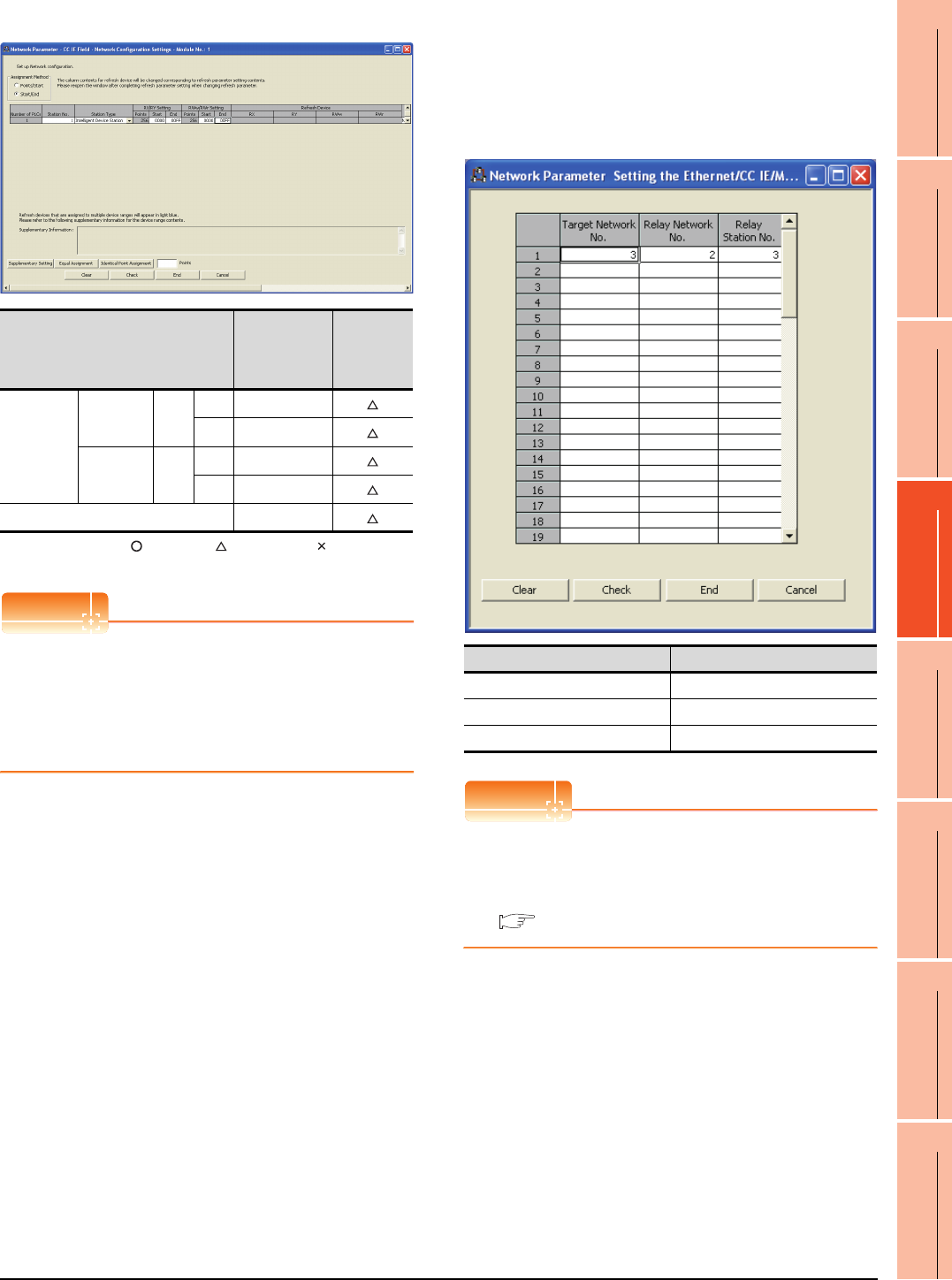
12. CC-Link IE FIELD NETWORK CONNECTION
12.4 PLC Side Setting
12 - 11
9
MELSECNET/H
CONNECTION (PLC
TO PLC NETWORK)
10
MELSECNET/10
CONNECTION (PLC
TO PLC NETWORK)
11
CC-Link IE CONTROLLER
NETWORK
CONNECTION
12
CC-Link IE FIELD
NETWORK
CONNECTION
13
CC-Link CONNECTION
(INTELLIGENT DEVICE
STATION)
14
CC-Link
CONNECTION
(Via G4)
15
INVERTER
CONNECTION
16
SERVO AMPLIFIER
CONNECTION
(b) Network Configuration Settings
: Necessary : As necessary : Not necessary
*1 Be sure to set it to perform the cyclic transmission.
POINTPOINTPOINT
(1) When changing the network parameter
After writing the network parameter to the PLC
CPU, operate the PLC CPU ether turning OFF and
then ON or resetting.
(2) GOT station type
Set the GOT as an intelligent device station.
(c) Routing parameter setting
Up to 64 [Transfer Network No.]s can be set.
However, the same transfer network number
cannot be set twice or more (multiple times).
Therefore, the one that can access to other station
from the request source host GOT is 64 kinds of
[Transfer Network No.]s.
POINTPOINTPOINT
Routing parameter setting of request source
Routing parameter setting is also necessary for the
request source GOT.
For the setting, refer to the following.
12.3.3 Routing parameter setting
Item Set value
Setting
necessity at
GOT
connection
Rx/RY,
RWw/RWr
setting(1)*1
Rx/RY
setting
Station
No.1
Start 0000H
End 00FFH
RWw/RWr
setting
Station
No.1
Start 00000H
End 000FFH
Reserved/Error Invalid Station No setting
Item Range
Transfer target network No. 1 to 239
Relay network No. 1 to 239
Relay station No. 0 to 120

12 - 12 12. CC-Link IE FIELD NETWORK CONNECTION
12.4 PLC Side Setting
GT Designer3 [Communication settings] of
System configuration (Network Type: CC IE
Field)
POINTPOINTPOINT
[Controller Setting] of GT Designer3
For the setting method of [Controller Setting] of GT
Designer3, refer to the following.
12.3.1 Setting communication interface
(Communication settings)
Item Set value
Network Type CC IE Field
Network No. 1: Network No.1
Station No. 1: Station No.1
Mode Setting Online
Retry 3times (Use default value)
Timeout Time 3sec (Use default value)
Delay Time 0ms (Use default value)
Refresh Interval 25ms (Use default value)
Monitor Speed High (Use default value)
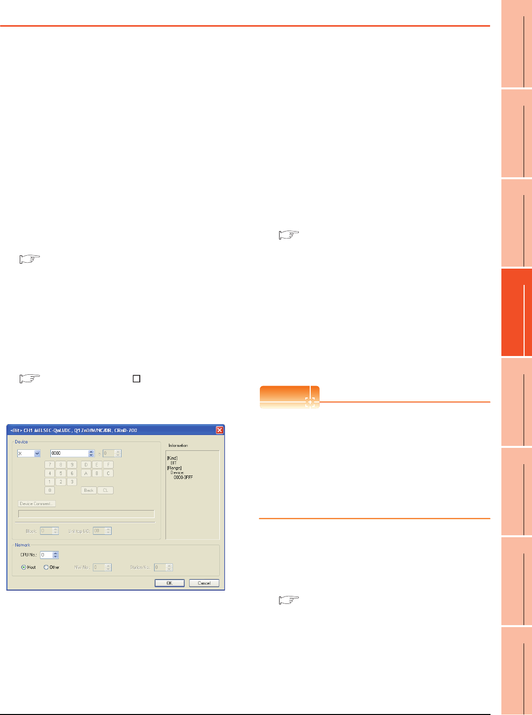
12. CC-Link IE FIELD NETWORK CONNECTION
12.5 Precautions
12 - 13
9
MELSECNET/H
CONNECTION (PLC
TO PLC NETWORK)
10
MELSECNET/10
CONNECTION (PLC
TO PLC NETWORK)
11
CC-Link IE CONTROLLER
NETWORK
CONNECTION
12
CC-Link IE FIELD
NETWORK
CONNECTION
13
CC-Link CONNECTION
(INTELLIGENT DEVICE
STATION)
14
CC-Link
CONNECTION
(Via G4)
15
INVERTER
CONNECTION
16
SERVO AMPLIFIER
CONNECTION
12.5 Precautions
GOT startup in CC-Link IE Field Network
connection
For the CC-Link IE Field Network connection, the data
link is started approximately 15 seconds after the GOT
startup.
When a network error occurs in the system
alarm
In the CC-Link IE Field Network connection, when a
network error occurs in the system alarm, the system
alarm display cannot be canceled even though the
causes are removed.
To cancel the system alarm display, restart the GOT.
CC-Link IE Field Network module version
For version restrictions of the CC-Link IE Field Network
module, refer to the following manual.
CC-Link IE Field Network Master/Local Module
User's Manual
Connection to Q170MCPU
The Motion CPU area (CPU No.2) cannot be
monitored.
Set the CPU No. to "0" or "1".
The device of the PLC CPU area (CPU No.1) is
monitored.
For setting the CPU No., refer to the following manual.
GT Designer3 Version Screen Design
Manual
Example) Setting dialog box of the bit device
Data link failure in other stations at GOT
startup
At GOT startup, the data link failure may occur in other
stations.
However, after the failure occurrence, the GOT
reconnects automatically and monitors the devices
properly.
To avoid such data link failure, start up the GOT 10
seconds earlier than the master station.
However, if the master station does not complete
startup when GOT starts monitoring (10 seconds after
the GOT startup), the communication timeout occurs in
the GOT side.
For details, refer to the following manual.
CC-Link IE Field Network Master/Local Module
User's Manual
Data link failure in all stations at GOT startup
or cable connection/disconnection
At GOT startup, the communication is broken
temporarily between PORT1 and PORT2 in the CC-
Link IE Field module which is installed on the GOT.
Thus, as the GOT or a station between the GOT and
the master station is reconnected, the data link failure
may occur on all stations.
POINTPOINTPOINT
GOT startup
GOT startup indicates the startups after the following
operations:
• Turning ON the GOT
• Resetting the GOT main unit
• Operating the utility
• Downloading the project including the
communication settings
• Downloading the OS
When the output is required to be held at the
data link failure
Set the GOT to hold the input from the data link faulty
stations in the communication setting. Set "Input for
Error Station" to "Hold".
12.3.2 Communication detail settings

12 - 14 12. CC-Link IE FIELD NETWORK CONNECTION
12.5 Precautions
13
9
MELSECNET/H
CONNECTION (PLC
TO PLC NETWORK)
10
MELSECNET/10
CONNECTION (PLC
TO PLC NETWORK)
11
CC-Link IE CONTROLLER
NETWORK
CONNECTION
12
CC-Link IE FIELD
NETWORK
CONNECTION
13
CC-Link CONNECTION
(INTELLIGENT DEVICE
STATION)
14
CC-Link
CONNECTION
(Via G4)
15
INVERTER
CONNECTION
16
SERVO AMPLIFIER
CONNECTION
13 - 1
13.CC-Link CONNECTION
(INTELLIGENT DEVICE STATION)
13.1 Connectable Model List . . . . . . . . . . . . . . . . . . . . . . . . . . . 13 - 2
13.2 System Configuration. . . . . . . . . . . . . . . . . . . . . . . . . . . . . 13 - 6
13.3 GOT Side Settings . . . . . . . . . . . . . . . . . . . . . . . . . . . . . . . 13 - 9
13.4 PLC Side Setting . . . . . . . . . . . . . . . . . . . . . . . . . . . . . . . 13 - 12
13.5 Precautions . . . . . . . . . . . . . . . . . . . . . . . . . . . . . . . . . . . 13 - 39
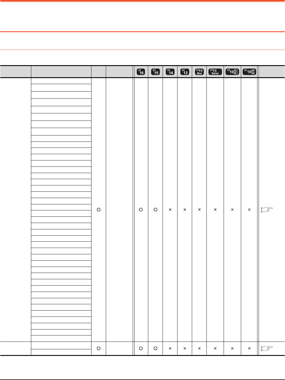
13 - 2 13. CC-Link CONNECTION (INTELLIGENT DEVICE STATION)
13.1 Connectable Model List
13. CC-Link CONNECTION
(INTELLIGENT DEVICE STATION)
13.1 Connectable Model List
13.1.1 PLC/Motion controller CPU
The following table shows the connectable models.
(Continued to next page)
*1 When in multiple CPU system configuration, use CPU function version B or later.
*2 Use a module with the upper five digits later than 12042.
Series Model name Clock
Communication
type Refer to
MELSEC-Q
(Q mode)
Q00JCPU
CC-Link(ID) 13.2
Q00CPU*1
Q01CPU*1
Q02CPU*1
Q02HCPU*1
Q06HCPU*1
Q12HCPU*1
Q25HCPU*1
Q02PHCPU
Q06PHCPU
Q12PHCPU
Q25PHCPU
Q12PRHCPU (Main base)
Q25PRHCPU (Main base)
Q12PRHCPU (Extension base)
Q25PRHCPU (Extension base)
Q00UJCPU
Q00UCPU
Q01UCPU
Q02UCPU
Q03UDCPU
Q04UDHCPU
Q06UDHCPU
Q10UDHCPU
Q13UDHCPU
Q20UDHCPU
Q26UDHCPU
Q03UDECPU
Q04UDEHCPU
Q06UDEHCPU
Q10UDEHCPU
Q13UDEHCPU
Q20UDEHCPU
Q26UDEHCPU
Q50UDEHCPU
Q100UDEHCPU
Q03UDVCPU
Q04UDVCPU
Q06UDVCPU
Q13UDVCPU
Q26UDVCPU
C Controller
module
Q12DCCPU-V*2
CC-Link(ID) 13.2
Q24DHCCPU-V

13. CC-Link CONNECTION (INTELLIGENT DEVICE STATION)
13.1 Connectable Model List
13 - 3
9
MELSECNET/H
CONNECTION (PLC
TO PLC NETWORK)
10
MELSECNET/10
CONNECTION (PLC
TO PLC NETWORK)
11
CC-Link IE CONTROLLER
NETWORK
CONNECTION
12
CC-Link IE FIELD
NETWORK
CONNECTION
13
CC-Link CONNECTION
(INTELLIGENT DEVICE
STATION)
14
CC-Link
CONNECTION
(Via G4)
15
INVERTER
CONNECTION
16
SERVO AMPLIFIER
CONNECTION
(Continued to next page)
Series Model name Clock Communicati
on type Refer to
MELSEC-QS QS001CPU - -
MELSEC-L
L02CPU
CC-Link(ID) 13.2.2
L26CPU
L26CPU-B
L02CPU-P
L26CPU-PBT
L02SCPU
MELSEC-Q
(A mode)
Q02CPU-A
CC-Link(ID) 13.2.1
Q02HCPU-A
Q06HCPU-A
MELSEC-QnA
(QnACPU)
Q2ACPU
CC-Link(ID) 13.2.1
Q2ACPU-S1
Q3ACPU
Q4ACPU
Q4ARCPU
MELSEC-QnA
(QnASCPU)
Q2ASCPU
CC-Link(ID) 13.2.1
Q2ASCPU-S1
Q2ASHCPU
Q2ASHCPU-S1
MELSEC-A
(AnCPU)
A2UCPU
CC-Link(ID) 13.2.1
A2UCPU-S1
A3UCPU
A4UCPU
A2ACPU
A2ACPUP21
A2ACPUR21
A2ACPU-S1
A2ACPUP21-S1
A2ACPUR21-S1
A3ACPU
A3ACPUP21
A3ACPUR21
A1NCPU
A1NCPUP21
A1NCPUR21
A2NCPU
A2NCPUP21
A2NCPUR21
A2NCPU-S1
A2NCPUP21-S1
A2NCPUR21-S1
A3NCPU
A3NCPUP21
A3NCPUR21
MELSEC-A
(AnSCPU)
A2USCPU
CC-Link(ID) 13.2.1
A2USCPU-S1
A2USHCPU-S1
A1SCPU
A1SCPUC24-R2
A1SHCPU
A2SCPU
A2SCPU-S1
A2SHCPU
A2SHCPU-S1
A1SJCPU
A1SJCPU-S3
A1SJHCPU
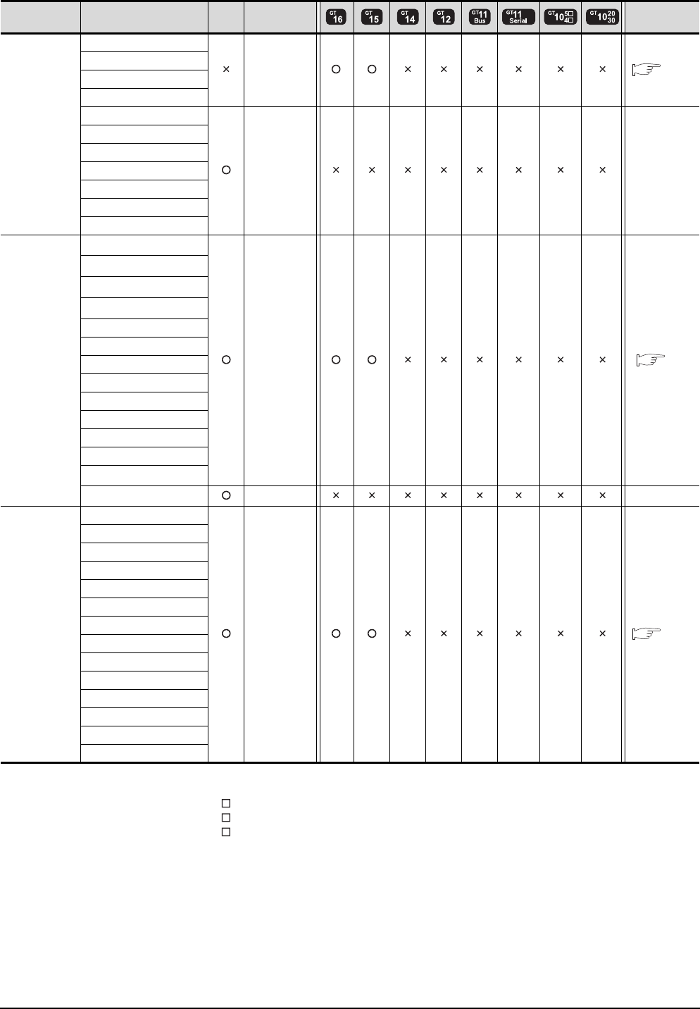
13 - 4 13. CC-Link CONNECTION (INTELLIGENT DEVICE STATION)
13.1 Connectable Model List
(Continued to next page)
*1 When using SV13, SV22, or SV43, use the motion controller CPU on which any of the following main OS version is installed.
• SW6RN-SV13Q : 00H or later
• SW6RN-SV22Q : 00H or later
• SW6RN-SV43Q : 00B or later
*2 Use main modules with the following product numbers.
• Q172CPU: Product number N******* or later
• Q173CPU: Product number M******* or later
*3 Only the first step can be used on the extension base unit (Q52B/Q55B).
Series Model name Clock
Communication
type Refer to
MELSEC-A
A0J2HCPU
CC-Link(ID) 13.2.1
A0J2HCPUP21
A0J2HCPUR21
A0J2HCPU-DC24
A2CCPU
- -
A2CCPUP21
A2CCPUR21
A2CCPUC24
A2CCPUC24-PRF
A2CJCPU-S3
A1FXCPU
Motion
controller
CPU
(Q Series)
Q172CPU*1*2
CC-Link(ID) 13.2
Q173CPU*1*2
Q172CPUN*1
Q173CPUN*1
Q172HCPU
Q173HCPU
Q172DCPU
Q173DCPU
Q172DCPU-S1
Q173DCPU-S1
Q172DSCPU
Q173DSCPU
Q170MCPU*3
MR-MQ100 - -
Motion
controller
CPU
(A Series)
A273UCPU
CC-Link(ID) 13.2.1
A273UHCPU
A273UHCPU-S3
A373UCPU
A373UCPU-S3
A171SCPU
A171SCPU-S3
A171SCPU-S3N
A171SHCPU
A171SHCPUN
A172SHCPU
A172SHCPUN
A173UHCPU
A173UHCPU-S1
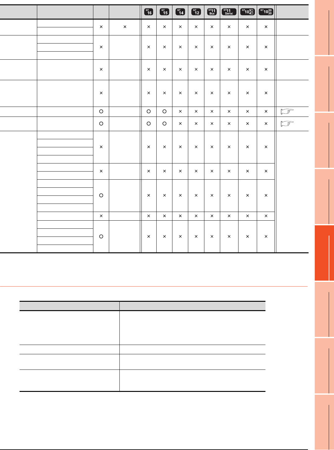
13. CC-Link CONNECTION (INTELLIGENT DEVICE STATION)
13.1 Connectable Model List
13 - 5
9
MELSECNET/H
CONNECTION (PLC
TO PLC NETWORK)
10
MELSECNET/10
CONNECTION (PLC
TO PLC NETWORK)
11
CC-Link IE CONTROLLER
NETWORK
CONNECTION
12
CC-Link IE FIELD
NETWORK
CONNECTION
13
CC-Link CONNECTION
(INTELLIGENT DEVICE
STATION)
14
CC-Link
CONNECTION
(Via G4)
15
INVERTER
CONNECTION
16
SERVO AMPLIFIER
CONNECTION
13.1.2 CC-Link module
*1 Transient communication can be performed to only CC-Link modules of function version B or later and software version J or later.
Series Model name Clock
Communication
type Refer to
MELSEC-WS
WS0-CPU0
-
WS0-CPU1
MELSECNET/H
Remote I/O
station
QJ72LP25-25
- -QJ72LP25G
QJ72BR15
CC-Link IE
Field Network
head module
LJ72GF15-T2 - -
CC-Link IE
Field Network
Ethernet
adapter module
NZ2GF-ETB - -
CNC C70 Q173NCCPU CC-Link(ID) 13.2
Robot
controller CRnQ-700 (Q172DRCPU) CC-Link(ID) 13.2
MELSEC-FX
FX0
-
-
FX0S
FX0N
FX1
FX2
-
FX2C
FX1S
-
FX1N
FX2N
FX1NC
FX2NC -
FX3G
-
FX3GC
FX3U
FX3UC
CPU series CC-Link module
MELSEC-Q (Q mode)
C Controller module
Motion controller CPU (Q Series)
CNC C70
Robot controller (CRnQ-700)
QJ61BT11
QJ61BT11N
MELSEC-L LJ61BT11
MELSEC-QnA AJ61QBT11
A1SJ61QBT11
MELSEC-Q (A mode)
MELSEC-A
Motion controller CPU (A Series)
AJ61BT11
A1SJ61BT11
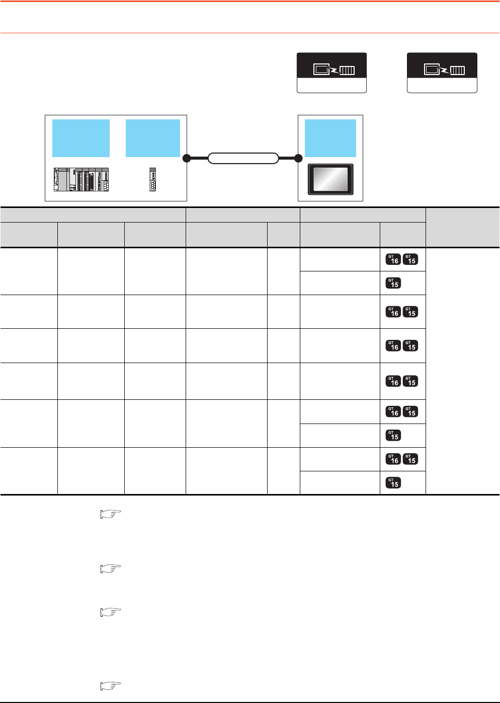
13 - 6 13. CC-Link CONNECTION (INTELLIGENT DEVICE STATION)
13.2 System Configuration
13.2 System Configuration
13.2.1 Connecting with CC-Link Ver.1 compatible
*1 For the system configuration of the CC-Link module, refer to the following manuals.
CC-Link System Master/Local Module User's Manual QJ61BT11N
Control & Communication Link System Master/Local Module Type AJ61QBT11/A1SJ61QBT11 User's Manual
Control & Communication Link System Master/Local Module Type AJ61BT11/A1SJ61BT11 User's Manual
MELSEC-L CC-Link System Master/Local Module User's Manual
*2 For the specifications and inquiries of the CC-Link dedicated cable, refer to the following.
CC-Link Partner Association's home page: http://www.cc-link.org/
*3 The maximum overall extension cable length and the length between stations vary depending on the cable type to be used and
the transmission speed.
For details, refer to the following manual.
CC-Link System Master/Local Module User's Manual QJ61BT11N
Control & Communication Link System Master/Local Module Type AJ61QBT11/A1SJ61QBT11 User's Manual
Control & Communication Link System Master/Local Module Type AJ61BT11/A1SJ61BT11 User's Manual
MELSEC-L CC-Link System Master/Local Module User's Manual
*4 Transient transmission can be performed to only CC-Link modules of function version B or later and software version J or later.
*5 Specify Ver.1 as the mode setting in the Communication Settings to use it.
For details of the settings, refer to the following the manual.
13.3.1 Setting communication interface (Communication settings)
CC-Link Ver2(ID)
Communication driver
(When MODEL GT15-J61BT13
CC-Link communication unit is used)
CC-Link
module
PLC GOT
Connection cable
CC-Link(ID)
(When MODEL GT15-75J61BT13-Z
CC-Link communication unit is used)
Communication driver
PLC Connection cable GOT Number of
connectable
equipment
Model name CC-Link module
*1
Communication
type Cable model
Max.
distance
Option device Model
MELSEC-Q QJ61BT11
QJ61BT11N CC-Link (Ver.1)
CC-Link dedicated
cable
*2
*3
GT15-J61BT13
*5
26 GOTs
GT15-75J61BT13-Z
C Controller
module
QJ61BT11
QJ61BT11N CC-Link(Ver.1)
CC-Link dedicated
cable
*2
*3 GT15-J61BT13
*5
MELSEC-L LJ61BT11 CC-Link(Ver.1)
CC-Link dedicated
cable
*2
*3 GT15-J61BT13
*5
MELSEC-L
(L26CPU-BT) - CC-Link(Ver.1)
CC-Link dedicated
cable
*2
*3 GT15-J61BT13
*5
MELSEC-QnA AJ61QBT11
A1SJ61QBT11*4 CC-Link (Ver.1)
CC-Link dedicated
cable
*2
*3
GT15-J61BT13
*5
GT15-75J61BT13-Z
MELSEC-A AJ61BT11
A1SJ61BT11*4 CC-Link (Ver.1)
CC-Link dedicated
cable
*2
*3
GT15-J61BT13
*5
GT15-75J61BT13-Z
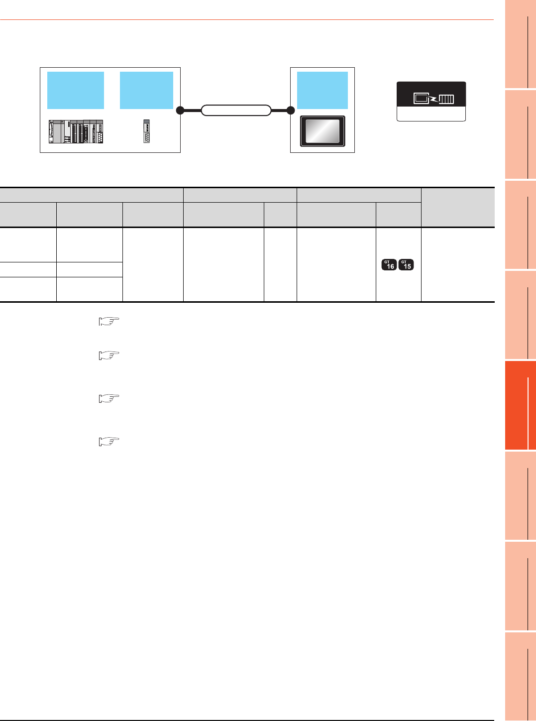
13. CC-Link CONNECTION (INTELLIGENT DEVICE STATION)
13.2 System Configuration
13 - 7
9
MELSECNET/H
CONNECTION (PLC
TO PLC NETWORK)
10
MELSECNET/10
CONNECTION (PLC
TO PLC NETWORK)
11
CC-Link IE CONTROLLER
NETWORK
CONNECTION
12
CC-Link IE FIELD
NETWORK
CONNECTION
13
CC-Link CONNECTION
(INTELLIGENT DEVICE
STATION)
14
CC-Link
CONNECTION
(Via G4)
15
INVERTER
CONNECTION
16
SERVO AMPLIFIER
CONNECTION
13.2.2 Connecting with CC-Link Ver.2 compatible
*1 For the system configuration of the CC-Link module, refer to the following manual.
CC-Link System Master/Local Module User's Manual QJ61BT11N
MELSEC-L CC-Link System Master/Local Module User's Manual
*2 For the specifications and inquiries of the CC-Link dedicated cable, refer to the following.
CC-Link Partner Association's home page: http://www.cc-link.org/
*3 The maximum overall extension cable length and the length between stations vary depending on the cable type to be used and
the transmission speed.
For details, refer to the following manual.
CC-Link System Master/Local Module User's Manual QJ61BT11N
MELSEC-L CC-Link System Master/Local Module User's Manual
*4 Specify Ver.2 as the mode setting in the Communication Settings to use it.
For details of the settings, refer to the following the manual.
13.3.1 Setting communication interface (Communication settings)
CC-Link
module
PLC GOT
Connection cable
CC-Link Ver2(ID)
Communication driver
(When MODEL GT15-J61BT13
CC-Link communication unit is used)
PLC Connection cable GOT Number of
connectable
equipment
Model name CC-Link module
*1
Communication
type Cable model
Max.
distance
Option device Model
MELSEC-Q
C Controller
module
QJ61BT11N
CC-Link (Ver.2)
CC-Link dedicated
cable
*2
*3 GT15-J61BT13
*4 26 GOTs
MELSEC-L LJ61BT11
MELSEC-L
(L26CPU-BT) -
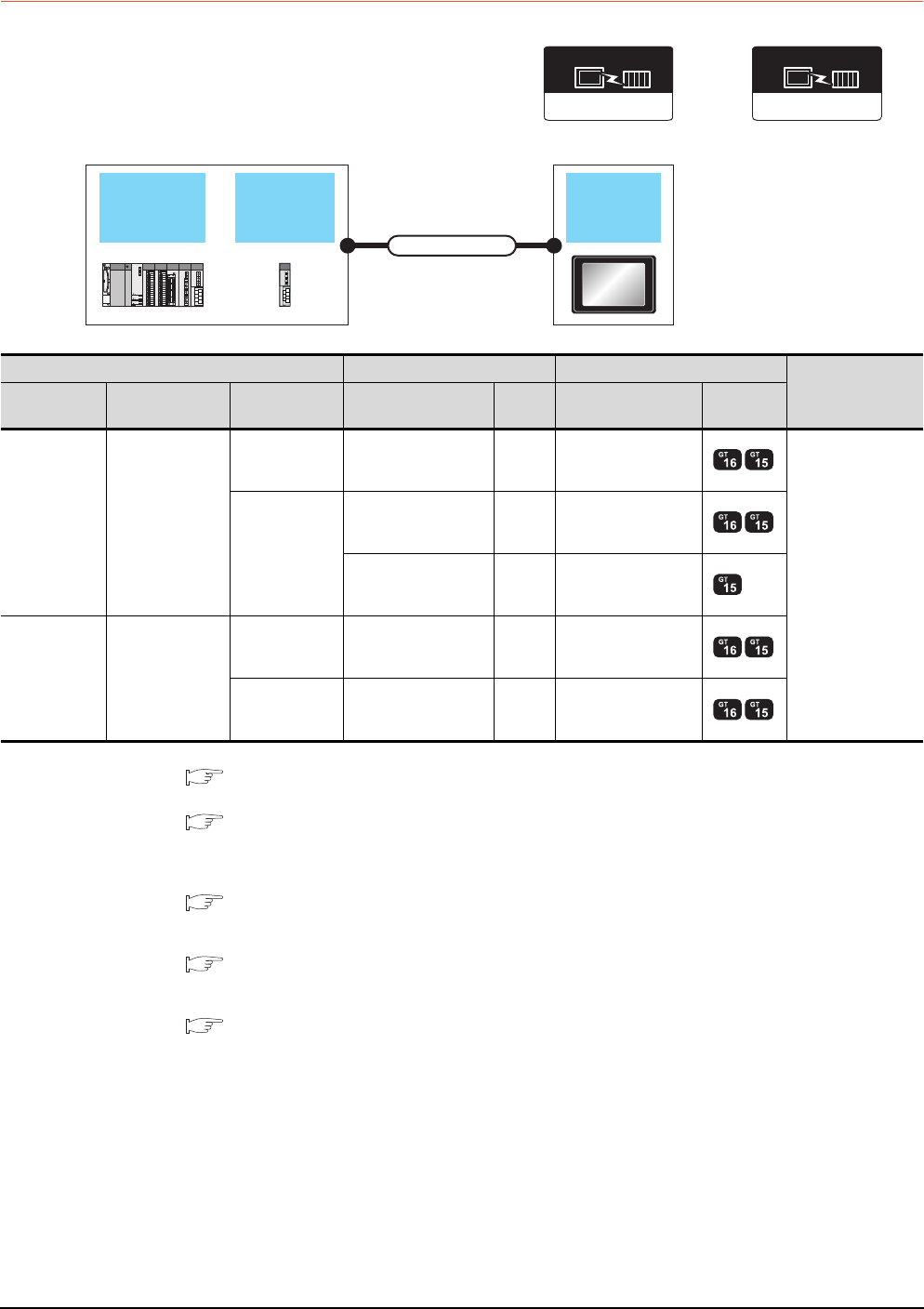
13 - 8 13. CC-Link CONNECTION (INTELLIGENT DEVICE STATION)
13.2 System Configuration
13.2.3 Connecting with CC-Link Ver.1/Ver.2 compatibles mixed
*1 For the system configuration of the CC-Link module, refer to the following manual.
CC-Link System Master/Local Module User's Manual QJ61BT11N
*2 For the specifications and inquiries of the CC-Link dedicated cable, refer to the following.
CC-Link Partner Association's home page: http://www.cc-link.org/
*3 The maximum overall extension cable length and the length between stations vary depending on the cable type to be used and
the transmission speed.
For details, refer to the following manual.
CC-Link System Master/Local Module User's Manual QJ61BT11N
*4 Specify Ver.2 as the mode setting in the Communication Settings to use it.
For details of the settings, refer to the following the manual.
13.3.1 Setting communication interface (Communication settings)
*5 Specify Ver.1 as the mode setting in the Communication Settings to use it.
For details of the settings, refer to the following the manual.
13.3.1 Setting communication interface (Communication settings)
CC-Link
module
QCPU GOT
Connection cable
CC-Link Ver2(ID)
Communication driver
(When MODEL GT15-J61BT13
CC-Link communication unit is used)
CC-Link(ID)
(When MODEL GT15-75J61BT13-Z
CC-Link communication unit is used)
Communication driver
PLC Connection cable GOT Number of
connectable
equipment
Model name CC-Link module
*1
Communication
type Cable model
Max.
distance
Option device Model
MELSEC-Q QJ61BT11N
CC-Link (Ver.2)
CC-Link dedicated
cable
*2
*3 GT15-J61BT13
*4
26 GOTs
CC-Link (Ver.1)
CC-Link dedicated
cable
*2
*3 GT15-J61BT13
*5
CC-Link dedicated
cable
*2
*3 GT15-75J61BT13-Z
C Controller
module QJ61BT11N
CC-Link (Ver.2)
CC-Link dedicated
cable
*2
*3 GT15-J61BT13
*4
CC-Link (Ver.1)
CC-Link dedicated
cable
*2
*3 GT15-J61BT13
*5
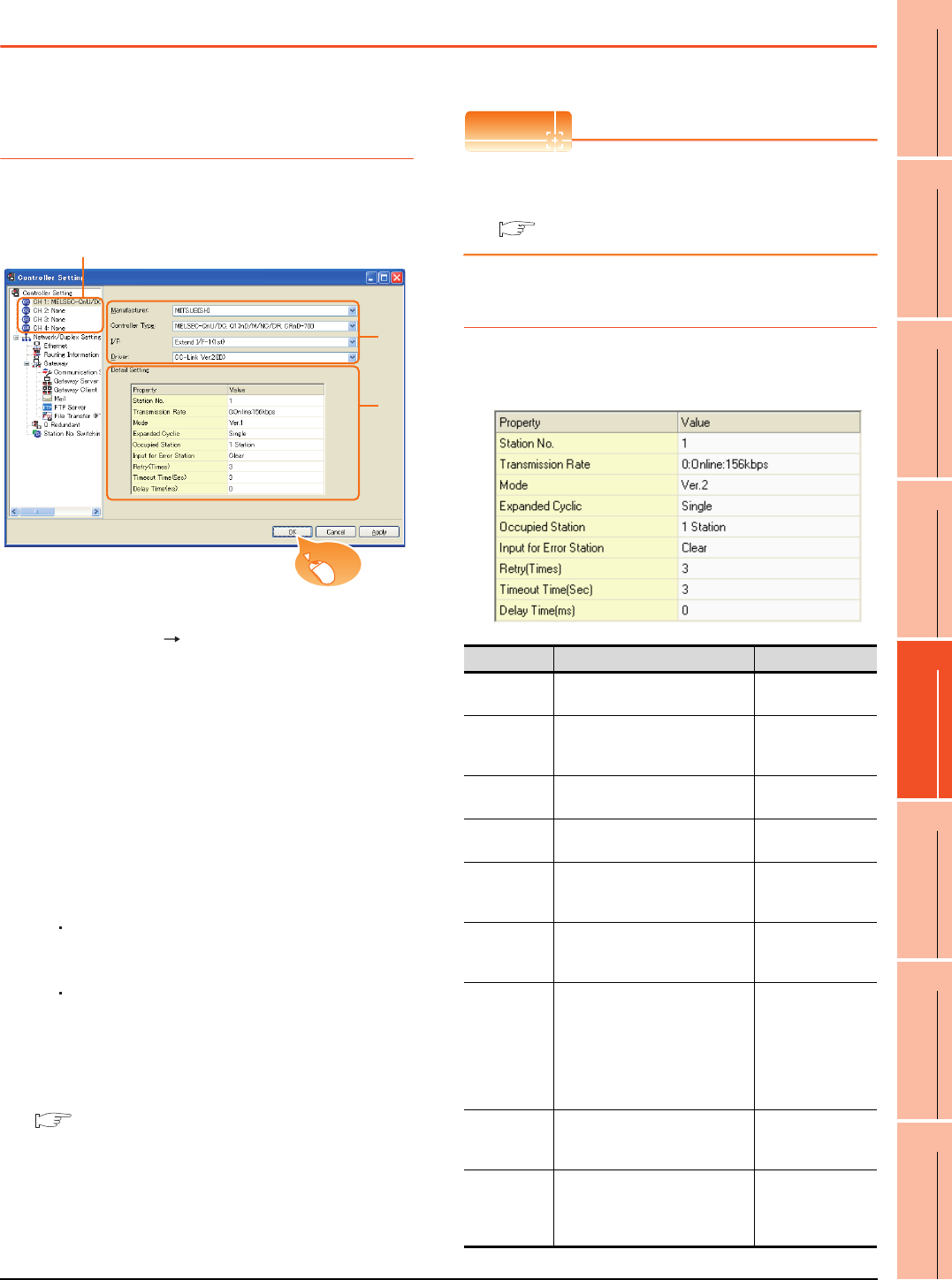
13. CC-Link CONNECTION (INTELLIGENT DEVICE STATION)
13.3 GOT Side Settings
13 - 9
9
MELSECNET/H
CONNECTION (PLC
TO PLC NETWORK)
10
MELSECNET/10
CONNECTION (PLC
TO PLC NETWORK)
11
CC-Link IE CONTROLLER
NETWORK
CONNECTION
12
CC-Link IE FIELD
NETWORK
CONNECTION
13
CC-Link CONNECTION
(INTELLIGENT DEVICE
STATION)
14
CC-Link
CONNECTION
(Via G4)
15
INVERTER
CONNECTION
16
SERVO AMPLIFIER
CONNECTION
13.3 GOT Side Settings
13.3.1 Setting communication
interface (Communication
settings)
Set the channel of the connected equipment.
1. Select [Common] [Controller Setting] from the
menu.
2. The Controller Setting window is displayed. Select the
channel to be used from the list menu.
3. Set the following items.
• Manufacturer: Mitsubishi
• Controller Type: Set according to the Controller
Type to be connected.
• I/F: Interface to be used
• Driver:
When MODEL GT15-J61BT13 CC-Link
communication unit is used
CC-Link Ver2 (ID)
When MODEL GT15-75J61BT13-Z CC-Link
communication unit is used
CC-Link (ID)
4. The detailed setting is displayed after Manufacturer,
Controller Type, I/F, and Driver are set.
Make the settings according to the usage
environment.
13.3.2 Communication detail settings
Click the [OK] button when settings are completed.
POINTPOINTPOINT
The settings of connecting equipment can be
confirmed in [I/F Communication Setting].
For details, refer to the following.
1.1.2 I/F communication setting
13.3.2 Communication detail settings
Make the settings according to the usage environment.
(1) CC-Link Ver.2 (ID)
2.
3.
4.
Click!
Item Description Range
Station No. Set the station No. of the GOT.
(Default: 1) 1 to 64
Transmission
Rate*1
Set the transmission speed and
the mode of the GOT.
(Default: 0)
0 to E
Mode Set the mode of CC-Link.
(Default: Ver.1)
Ver.1/Ver.2/
Additional/Offline
Expanded
Cyclic
Set the cyclic point expansion.
(Default: Single)
Single/Double/
Quadruple/Octuple
Occupied
Station
Set the number of stations
occupied by the GOT.
(Default: 1 Station)
1 Station/4 Stations
Input for Error
Station
Set Clear/Hold at an error
occurrence.
(Default: Clear)
Clear/Hold
Retry
Set the number of retries to be
performed when a communication
timeout occurs.
When no response is received
after retries, a communication
times out.
(Default: 3times)
0 to 5times
Timeout Time
Set the time period for a
communication to time out.
(Default: 3sec)
3 to 90sec
Delay Time
Set the delay time for reducing the
load of the network/destination
PLC.
(Default: 0ms)
0 to 300 (ms)

13 - 10 13. CC-Link CONNECTION (INTELLIGENT DEVICE STATION)
13.3 GOT Side Settings
*1 Transmission speed settings
The following lists the transmission speed settings of the CC-
Link communication.
For details of the hardware test, refer to the following
manual.
CC-Link System Master/Local Module User's
Manual for CC-Link module to be used
(2) CC-Link(ID)
POINTPOINTPOINT
(1) Communication interface setting by Utility
The communication interface setting can be
changed on the Utility's [Communication Settings]
after writing [Communication Settings] of project
data.
For details on the Utility, refer to the following
manual.
GT User's Manual
(2) Precedence in communication settings
When settings are made by GT Designer3 or the
Utility, the latest setting is effective.
Set value Description
0 Online: 156kbps
1 Online: 625kbps
2 Online: 2.5Mbps
3 Online: 5Mbps
4 Online: 10Mbps
A Hardware test: 156kbps
B Hardware test: 625kbps
C Hardware test: 2.5Mbps
D Hardware test: 5Mbps
E Hardware test: 10Mbps
Item Description Range
Retry
Set the number of retries to be
performed when a communication
timeout occurs.
When no response is received after
retries, a communication times out.
(Default: 3times)
0 to 5times
Timeout Time
Set the time period for a communication
to time out.
(Default: 3sec)
3 to 90sec
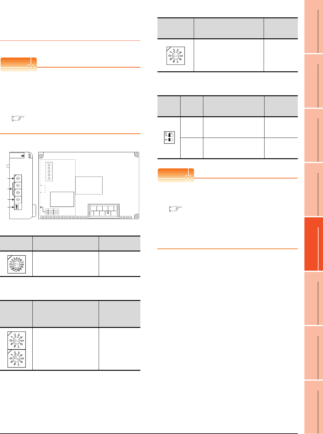
13. CC-Link CONNECTION (INTELLIGENT DEVICE STATION)
13.3 GOT Side Settings
13 - 11
9
MELSECNET/H
CONNECTION (PLC
TO PLC NETWORK)
10
MELSECNET/10
CONNECTION (PLC
TO PLC NETWORK)
11
CC-Link IE CONTROLLER
NETWORK
CONNECTION
12
CC-Link IE FIELD
NETWORK
CONNECTION
13
CC-Link CONNECTION
(INTELLIGENT DEVICE
STATION)
14
CC-Link
CONNECTION
(Via G4)
15
INVERTER
CONNECTION
16
SERVO AMPLIFIER
CONNECTION
13.3.3 Switch setting (Only when
MODEL GT15-75J61BT13-Z
CC-Link communication unit is
used)
POINTPOINTPOINT
Switch setting of the communication unit
When using the MODEL GT15-J61BT13 CC-Link
communication unit, the switch setting is not needed.
For details of each setting switch and LED, refer to the
following manual.
GT15 CC-Link communication unit User's
Manual
(1) Mode setting switch
(2) Station number setting switch
(3) Transmission baudrate setting switch
(4) Condition setting switches
POINTPOINTPOINT
(1) Switch setting example
For the switch setting example, refer to the
following.
13.4 PLC Side Setting
(2) When the switch setting is changed
When changing the switch setting after mounting
the MODEL GT15-75J61BT13-Z CC-Link
communication unit on the GOT, reset the GOT.
Mode setting
switch Description Set value
Select the online mode.
(Default: 0) 0 (fixed)
Station
number
setting
switch
Description Set value
Specify the station No. of the CC-
Link communication unit.
(Default: 01)
1 to 64
21
ON
4
3
2
1
0
F
E
D
C
B
A
9
8
7
6
5
0
9
8
7
6
5
4
3
2
1
0
9
8
7
6
5
4
3
2
1
0
9
8
7
6
5
4
3
2
1
(1) MODE
STATION NO.
BAUDRATE
SW
1
2
ON
HOLD
4
OFF
CLEAR
1
DA
1357
2468
DG NC NC
DB SLD (FG1) NC
10
1
L ERR.
RD
SD
L RUN
RUN
(4)
(3)
(2)
Left side Front side
GT15-75J61BT13-Z
Transmission
baudrate
setting switch
Description Set value
Specify the transmission speed.
(Default: 0)
0: 156kbps
1: 625kbps
2: 2.5Mbps
3: 5Mbps
4: 10Mbps
Condition
setting
switches
Setting
switch Description Set value
SW1
Specify input data status of
the data link error station.
(Default: OFF)
OFF: Cleared
ON: Held
SW2
Specify the number of stations
occupied.
(Default: OFF)
OFF: 1 station
ON: 4 stations
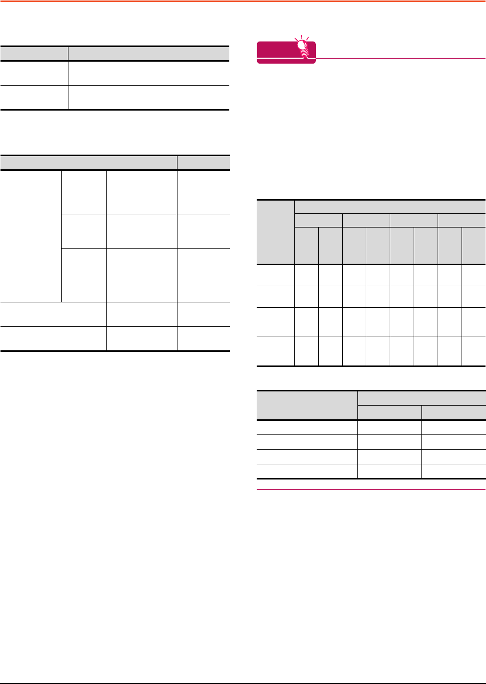
13 - 12 13. CC-Link CONNECTION (INTELLIGENT DEVICE STATION)
13.4 PLC Side Setting
13.4 PLC Side Setting
The GOT operates as the stations of which are shown
below in the CC-Link system.
The switch settings and parameter settings of the PLC side
(CC-Link module) are described in 13.4.1 to 13.4.7.
HINTHINTHINT
Number of stations occupied
The number of stations occupied is setting for
determining number of link device points (RX/RY/
RWw/RWr) used by the GOT.
To use multiple numbers of link device points in the
case of cyclic transmission between the GOT and CC-
Link module, set the number of stations occupied as
the exclusive station 4.
The number of link device points at the exclusive
station 1 and 4 is shown below.
CC-Link Ver.2
CC-Link Ver.1
Station data Description
Station type Intelligent device station, Ver.1 intelligent device
station or Ver.2 intelligent device station
Number of stations
occupied Station 1 or Station 4
Model name Refer to
CC-Link
module
(Q Series)
Connecting
with
Ver.1
compatible
QJ61BT11,
QJ61BT11N 13.4.1
Connecting
with Ver.2
compatible
QJ61BT11N 13.4.2
Connecting
with Ver.1/
Ver.2
compatibles
mixed
QJ61BT11N 13.4.3
CC-Link module
(QnA Series)
AJ61QBT11,
A1SJ61QBT11 13.4.6
CC-Link module
(A Series)
AJ61BT11,
A1SJ61BT11 13.4.7
Link
device
Expanded cyclic setting
Single Double Quadruple Octuple
Exclu
sive
statio
n 1
Exclu
sive
statio
n 4
Exclu
sive
statio
n 1
Exclu
sive
statio
n 4
Exclu
sive
statio
n 1
Exclu
sive
statio
n 4
Exclu
sive
statio
n 1
Exclu
sive
statio
n 4
Remote
input (RX)
32
points
128
points
32
points
224
points
64
points
448
points
128
points
896
points
Remote
output (RY)
32
points
128
points
32
points
224
points
64
points
448
points
128
points
896
points
Remote
register
(RWw)
4
points
16
points
8
points
32
points
16
points
64
points
32
points
128
points
Remote
register
(RWr)
4
points
16
points
8
points
32
points
16
points
64
points
32
points
128
points
Link device
Number of stations occupied
Exclusive station Exclusive station 4
Remote input (RX) 32 points 128 points
Remote output (RY) 32 points 128 points
Remote register (RWw) 4 points 16 points
Remote register (RWr) 4 points 16 points
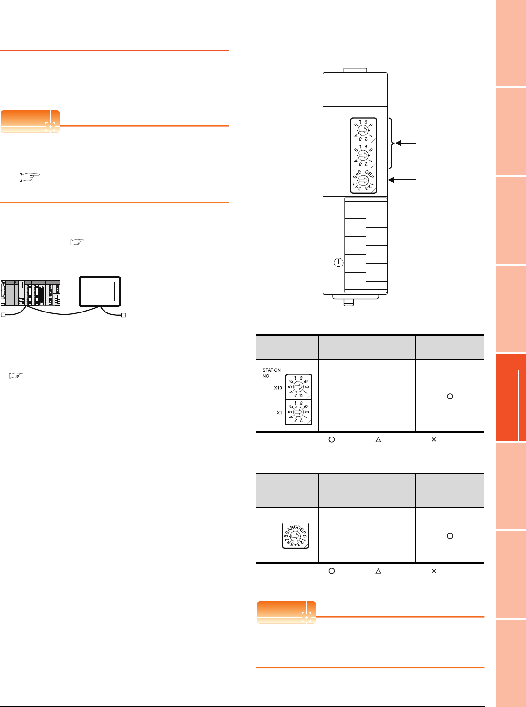
13. CC-Link CONNECTION (INTELLIGENT DEVICE STATION)
13.4 PLC Side Setting
13 - 13
9
MELSECNET/H
CONNECTION (PLC
TO PLC NETWORK)
10
MELSECNET/10
CONNECTION (PLC
TO PLC NETWORK)
11
CC-Link IE CONTROLLER
NETWORK
CONNECTION
12
CC-Link IE FIELD
NETWORK
CONNECTION
13
CC-Link CONNECTION
(INTELLIGENT DEVICE
STATION)
14
CC-Link
CONNECTION
(Via G4)
15
INVERTER
CONNECTION
16
SERVO AMPLIFIER
CONNECTION
13.4.1 Connecting to CC-Link module
(Q Series) with Ver.1
compatible
This section describes the settings of the GOT and the CC-
Link module (Q Series) with Ver.1 compatible in the
following system configuration.
POINTPOINTPOINT
CC-Link module (Q Series)
For details of the CC-Link module (Q Series), refer to
the following manual.
CC-Link System Master/Local Module User's
Manual QJ61BT11N
System configuration
*1 The CC-Link module is mounted on the base unit slot 0.
The Start I/O No. of the CC-Link module is set to "0"
Switch setting of CC-Link module (Q Series)
Set the station number setting switch, transmission
speed / mode setting switch.
(1) Station number setting switch
: Necessary : As necessary : Not necessary
(2) Transmission rate/mode setting switch
: Necessary : As necessary : Not necessary
*1 Specify the same transmission speed as that of the GOT.
POINTPOINTPOINT
When the switch setting is changed
Turn the PLC CPU OFF then ON again, or reset the
PLC CPU.
<CC-Link module> *1
Type : Master station
Station No. : Station No.0
Mode : Remote net (Ver.1 mode)
All connect count : 1
Transmission speed : 156kbps
<GOT>
(Use the default value for settings other
than the following.)
Station type : Intelligent device
station
Station No. : Station No.1
Number of
stations occupied : Exclusive station 1
Transmission speed : 156kbps
(Use the default value for the settings other than the following.)
■ [Controller Setting] of GT Designer3
■ Setting of the CC-Link communication unit
■ Switch setting of CC-Link module (Q Series)
■ [Network parameter] of GX Developer
Station number
setting switch Description Set value Setting necessity at
GOT connection
Station number
setting
(master station)
0 (fixed)
Transmission
rate/mode setting
switch
Description Set value Setting necessity at
GOT connection
Transmission
rate/
mode setting
(Online:
156kbps)*1
0
(1)
(2)
QJ61BT11, QJ61BT11N
0
5
0
5
0
8
1
2
7
6
5
4
3
STATION
NO.
X10
X1
MODE
QJ61BT11N
RUN
ERR.
SD
MST
L RUN
L ERR.
RD
S MST
NC
DA
DB
NC
SLD
DG
(FG)
C
4
MODE
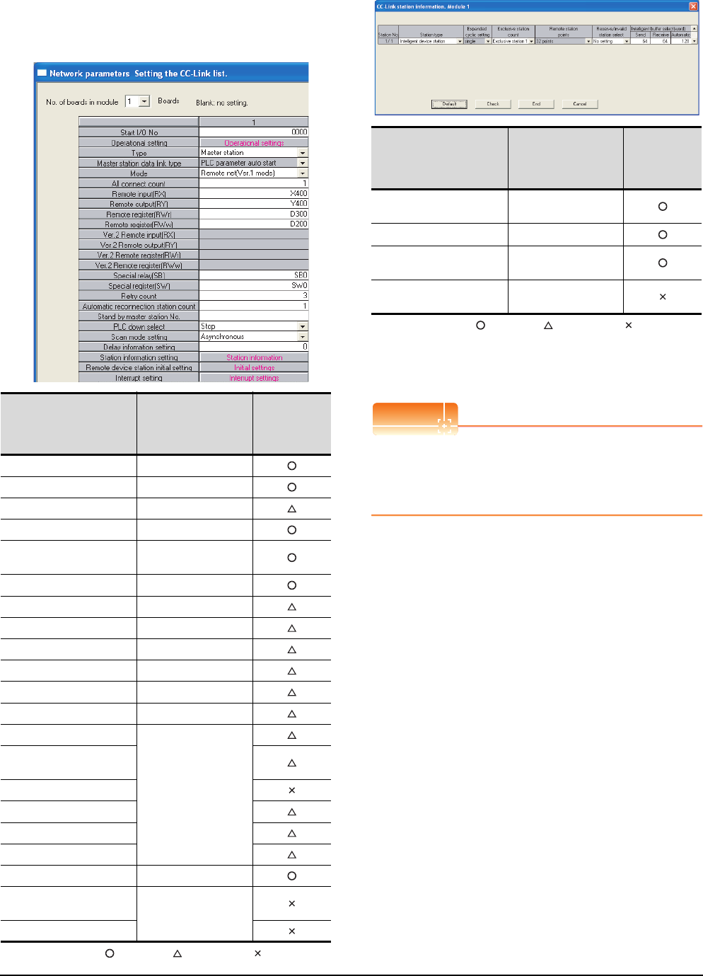
13 - 14 13. CC-Link CONNECTION (INTELLIGENT DEVICE STATION)
13.4 PLC Side Setting
Parameter setting (when connecting to
MELSEC-Q or QS series)
(1) [Network parameter] of GX Developer
(a) Network parameter
: Necessary : As necessary : Not necessary
(b) Station information setting
: Necessary : As necessary : Not necessary
*1 When the [Mode] of the CC-Link module is set at [Remote
net - (Ver. 1 mode)], [Remote station points] cannot be set.
*2 Set the same number of occupied stations as that on the
GOT.
POINTPOINTPOINT
When changing the network parameter
After writing the network parameter to the PLC CPU,
operate the PLC CPU ether turning OFF and then ON
or resetting.
Item Set value
Setting
necessity
at GOT
connection
No. of boards in module 1
Start I/O No. 0000H
Operation setting (Use default value)
Type Master station (fixed)
Mode Remote net
(Ver.1 mode)
All connect count 1
Remote input (RX) X400
Remote output (RY) Y400
Remote register (RWr) D300
Remote register (RWw) D200
Special relay (SB) SB0
Special register (SW) SW0
Retry count
(Use default value)
Automatic reconnection
station count
Stand by master station No.
PLC down select
Scan mode setting
Delay information setting
Station information setting Refer to (b).
Remote device station initial
settings (Use default value)
Interrupt setting
Item*1 Set value
Setting
necessity
at GOT
connection
Station type Intelligent device
station (fixed)
Exclusive station count*2 Exclusive station 1
Reserve/invalid station
select No setting
Intelligent buffer select
(word) (Use default value)
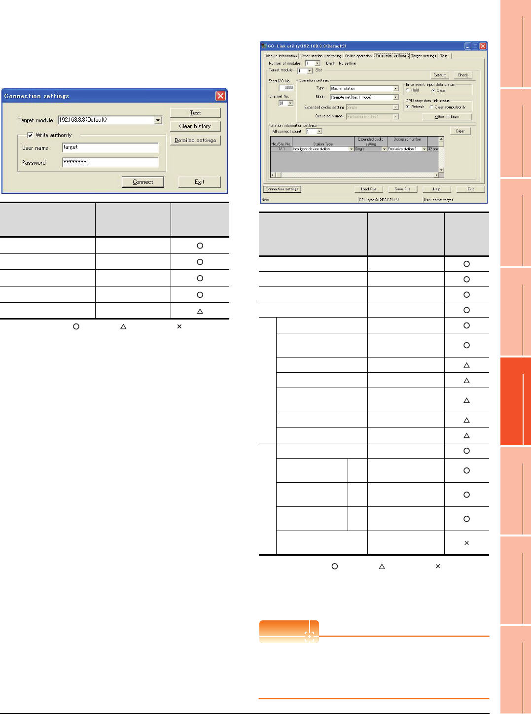
13. CC-Link CONNECTION (INTELLIGENT DEVICE STATION)
13.4 PLC Side Setting
13 - 15
9
MELSECNET/H
CONNECTION (PLC
TO PLC NETWORK)
10
MELSECNET/10
CONNECTION (PLC
TO PLC NETWORK)
11
CC-Link IE CONTROLLER
NETWORK
CONNECTION
12
CC-Link IE FIELD
NETWORK
CONNECTION
13
CC-Link CONNECTION
(INTELLIGENT DEVICE
STATION)
14
CC-Link
CONNECTION
(Via G4)
15
INVERTER
CONNECTION
16
SERVO AMPLIFIER
CONNECTION
Parameter setting (when connecting to C
Controller module)
Use SW3PVC-CCPU-E Ver.3.05F or later for the CC-
Link utility.
(1) Connection settings
: Necessary : As necessary : Not necessary
*1 If the IP address of the C Controller module has been
changed, input the changed IP address or host name.
*2 If the account of the C Controller module has been changed,
input the changed user name and password.
(2) CC-Link Utility's [Parameter Settings]
(a) Parameter settings
: Necessary : As necessary : Not necessary
*1 When the [Mode] of the CC-Link module is set at [Remote
net - (Ver. 1 mode)], [Remote station points] cannot be set.
*2 Set the same number of occupied stations as that on the
GOT.
POINTPOINTPOINT
When changing the network parameter
After writing the network parameter to the C Controller
module, either turn the C Controller module OFF and
then ON or reset it.
Item Set value
Setting
necessity at
GOT connection
Target module*1 192.168.3.3 (Default)
Write authority Mark the checkbox
User name*2 target
Password*2 password
Detailed settings -
Item*1 Set value
Setting
necessity at
GOT
connection
Number of modules 1
Target module 1
Start I/O No. 0000H
Channel No. (Use default value)
Operation settings
Type Master station (fixed)
Mode Remote net
(Ver.1 mode)
Expanded cyclic setting Single
Occupied number Exclusive station 1
Error event: input data
status Clear
CPU stop: data link status Refresh
Other settings (Use default value)
Station information settings
All connect count 1
Station Type Sta.
No.1
Intelligent device
station
Occupied number*2 Sta.
No.1 Exclusive station 1
Reserve/invalid
station select
Sta.
No.1 No setting
Intelligent buffer select
(word) (Use default value)
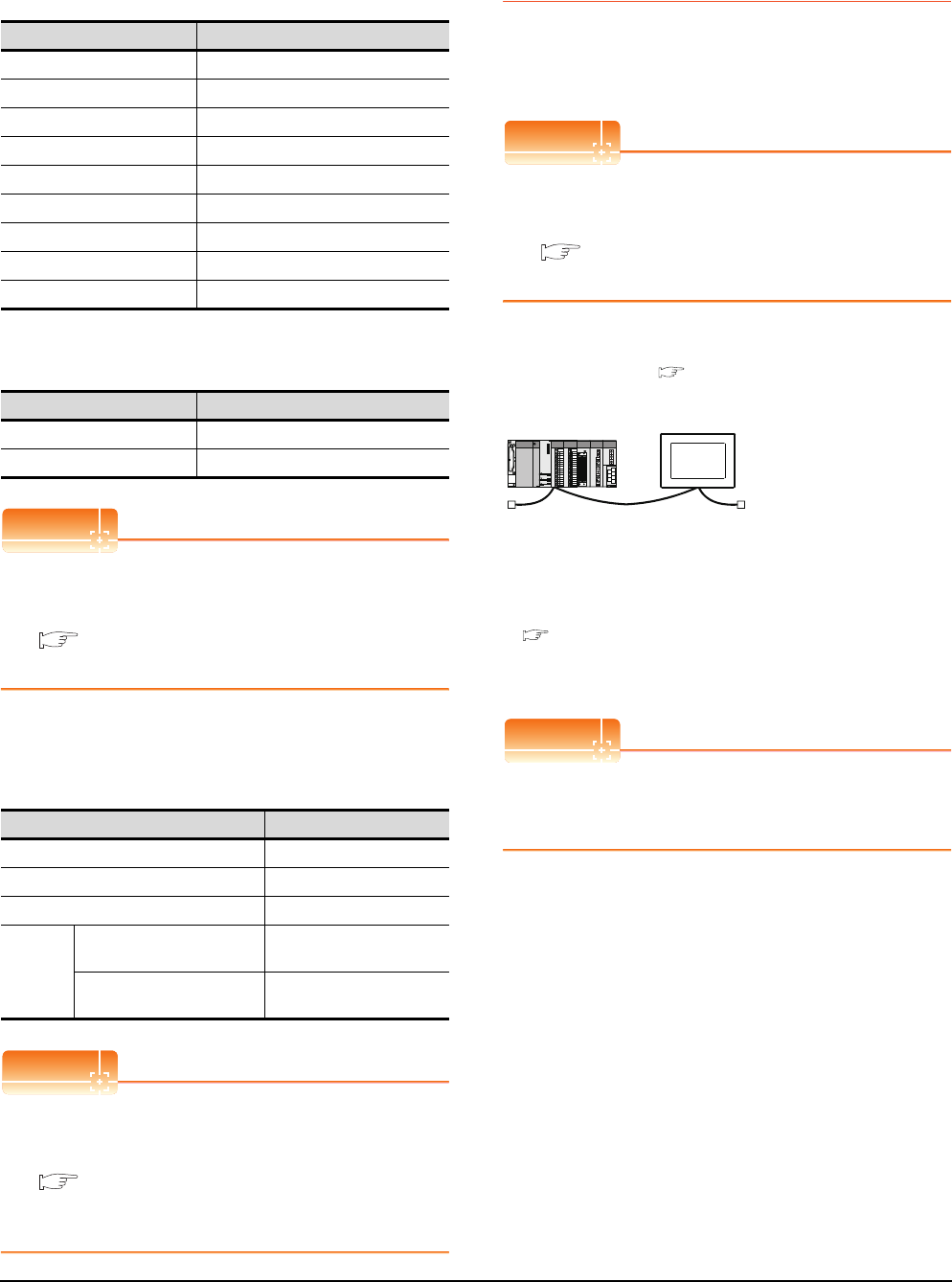
13 - 16 13. CC-Link CONNECTION (INTELLIGENT DEVICE STATION)
13.4 PLC Side Setting
[Controller Setting] of GT Designer3
(1) When MODEL GT15-J61BT13 CC-Link
communication unit is used
(2) When MODEL GT15-75J61BT13-Z CC-Link
communication unit is used
POINTPOINTPOINT
[Controller Setting] of GT Designer3
For the setting method of [Controller Setting] of GT
Designer3, refer to the following.
13.3.1 Setting communication interface
(Communication settings)
Setting of the CC-Link communication unit
(Only when MODEL GT15-75J61BT13-Z
CC-Link communication unit is used)
POINTPOINTPOINT
Setting of the CC-Link communication unit
For the setting method of the CC-Link communication
unit, refer to the following.
13.3.3 Switch setting (Only when MODEL
GT15-75J61BT13-Z CC-Link communication
unit is used)
13.4.2 Connecting to CC-Link
module (Q Series) with
Ver.2 compatible
This section describes the settings of the GOT and CC-
Link module (Q Series) in the following case of system
configuration.
POINTPOINTPOINT
CC-Link module (Q Series)
For details of the CC-Link module (Q Series), refer to
the following manual.
CC-Link System Master/Local Module User's
Manual QJ61BT11N
System configuration
*1 The CC-Link module is mounted on the base unit slot 0.
The Start I/O No. of the CC-Link module is set to "0"
POINTPOINTPOINT
When connecting to Q170MCPU
When connected to Q170MCPU, the start I/O No. of
the CC-Link module is set to "70".
Item Set value
Station No. 1: Station No.1
Transmission Rate 0: Online 156kbps
Mode Ver.1: Remote net (Ver.1 mode)
Expanded Cyclic Single (Use default value)
Number of stations occupied 1 Station
Input for Error Station 0: Clear
Retry 3times (Use default value)
Timeout Time 3sec (Use default value)
Delay Time 0ms (Use default value)
Item Set value (Use default value)
Retry 3times
Timeout Time 3sec
Item Set value
Mode setting switch 0: Online (fixed)
Station number setting switch 1: Station No.1
Transmission baudrate setting switch 0: 156kbps
Condition
setting
switches
SW1 (Input data status of the
data link error station) OFF: Cleared
SW2 (Number of occupied
stations) OFF: 1 station
<CC-Link module>
*1
Type : Master station
Station No. : Station No.0
Mode : Remote net (Ver.2 mode)
All connect count : 1
Transmission speed : 156kbps
<GOT>
(Use the default value for settings other
than the following.)
Station type : Intelligent device
station
Station No. : Station No.1
Expanded cyclic setting : Single
Number of
stations occupied : Exclusive station 1
Transmission speed : 156kbps
(Use the default value for the settings other than the following.)
■ [Communication settings] of GT Designer3
■ Switch setting of CC-Link module (Q Series)
■ [Network parameter] of GX Developer
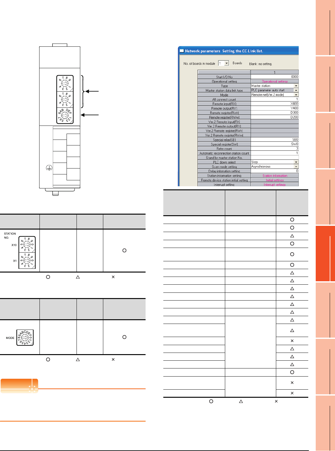
13. CC-Link CONNECTION (INTELLIGENT DEVICE STATION)
13.4 PLC Side Setting
13 - 17
9
MELSECNET/H
CONNECTION (PLC
TO PLC NETWORK)
10
MELSECNET/10
CONNECTION (PLC
TO PLC NETWORK)
11
CC-Link IE CONTROLLER
NETWORK
CONNECTION
12
CC-Link IE FIELD
NETWORK
CONNECTION
13
CC-Link CONNECTION
(INTELLIGENT DEVICE
STATION)
14
CC-Link
CONNECTION
(Via G4)
15
INVERTER
CONNECTION
16
SERVO AMPLIFIER
CONNECTION
Switch setting of CC-Link module (Q Series)
Set the station number setting switch, transmission
speed / mode setting switch.
(1) Station number setting switch
: Necessary : As necessary : Not necessary
(2) Transmission rate/mode setting switch
: Necessary : As necessary : Not necessary
*1 Specify the same transmission speed as that of the GOT.
POINTPOINTPOINT
When the switch setting has been changed
Turn the PLC CPU OFF then ON again, or reset the
PLC CPU.
Parameter setting (when connecting to
MELSEC-Q or QS series)
(1) [Network parameter] of GX Developer
(a) Network parameter
: Necessary : As necessary : Not necessary
*1 When using Q170MCPU, set it according to the system
configuration.
Station number
setting switch Description Set value Setting necessity
at GOT connection
Station number
setting
(master station)
0 (fixed)
Transmission
rate/mode setting
switch
Description Set value Setting necessity
at GOT connection
Transmission
rate/mode
setting
(Online:
156kbps)*1
0
(1)
(2)
QJ61BT11N
0
5
0
5
0
8
1
2
7
6
5
4
3
STATION
NO.
X10
X1
MODE
QJ61BT11N
RUN
ERR.
SD
MST
L RUN
L ERR.
RD
S MST
NC
DA
DB
NC
SLD
DG
(FG)
C
4
Item Set value
Setting
necessity at
GOT
connection
No. of boards in module 1
Start I/O No.*1 0000H
Operation setting (Use default value)
Type Master station
Mode Remote net
(Ver.2 mode)
All connect count 1
Remote input (RX) X400
Remote output (RY) Y400
Remote register (RWr) D300
Remote register (RWw) D200
Special relay (SB) SB0
Special register (SW) SW0
Retry count
(Use default value)
Automatic reconnection
station count
Stand by master station No.
PLC down select
Scan mode setting
Delay information setting
Station information setting Refer to (b)
Remote device station initial
setting (Use default value)
Interrupt setting
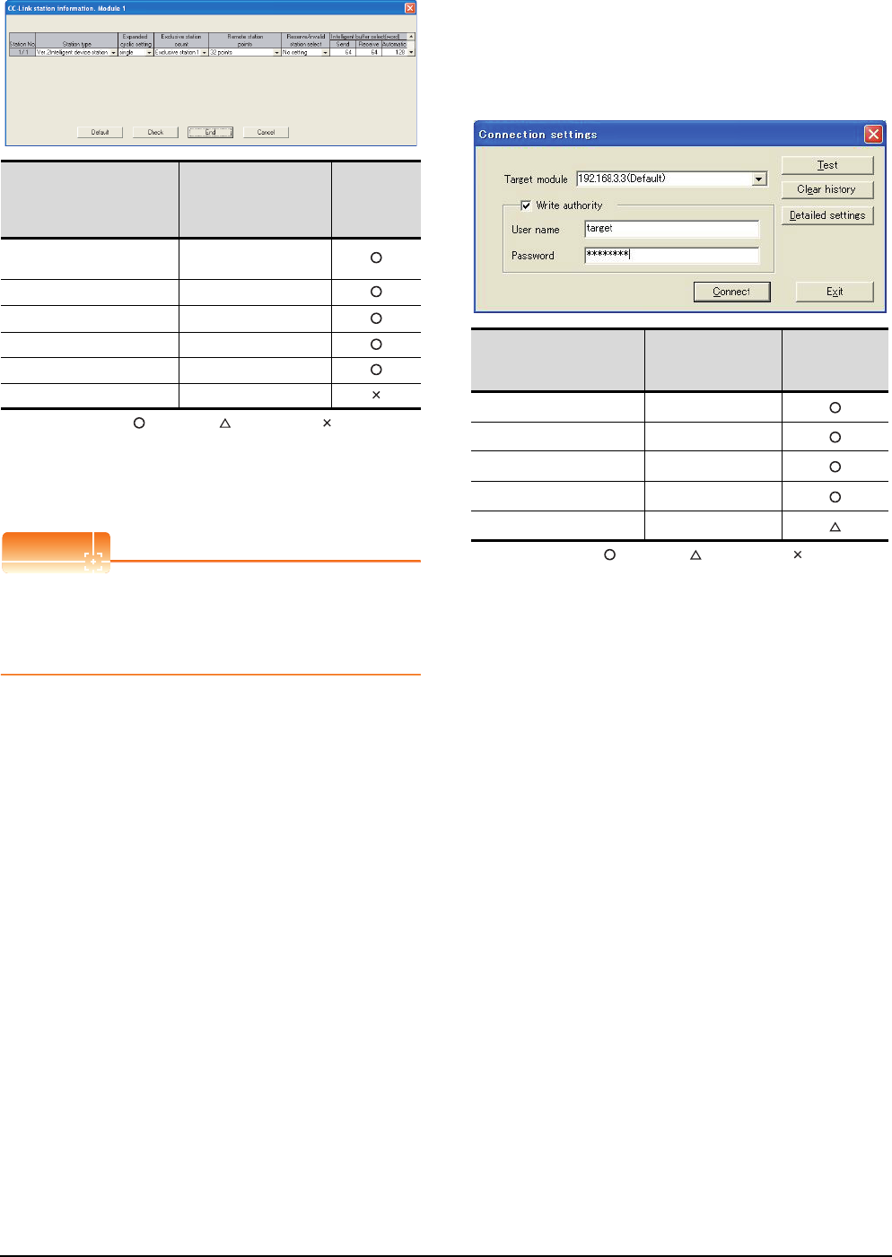
13 - 18 13. CC-Link CONNECTION (INTELLIGENT DEVICE STATION)
13.4 PLC Side Setting
(b) Station information setting
: Necessary : As necessary : Not necessary
*1 When the [Mode] of the CC-Link module is set at [Remote
net - (Ver. 2 mode)], [Remote station points] can be set.
[Remote station points] is a setting for the remote I/O station.
The default value (32 points) must be used on the GOT.
*2 Set the same setting as that of the GOT.
POINTPOINTPOINT
When changing the network parameter
After writing the network parameter to the PLC CPU,
operate the PLC CPU ether turning OFF and then ON
or resetting.
Parameter setting (when connecting to C
Controller module)
Use SW3PVC-CCPU-E Ver.3.05F or later for the CC-
Link utility.
(1) Connection settings
: Necessary : As necessary : Not necessary
*1 If the IP address of the C Controller module has been
changed, input the changed IP address or host name.
*2 If the account of the C Controller module has been changed,
input the changed user name and password.
Item*1 Set value
Setting
necessity at
GOT
connection
Station type Ver.2 intelligent device
station (fixed)
Expanded cyclic setting*2 Single
Exclusive station count*2 Exclusive station 1
Remote station points 32 points (fixed)
Reserve/invalid station select No setting
Intelligent buffer select (word) (Use default value)
Item Set value
Setting
necessity at
GOT connection
Target module*1 192.168.3.3 (Default)
Write authority Mark the checkbox
User name*2 target
Password*2 password
Detailed settings -
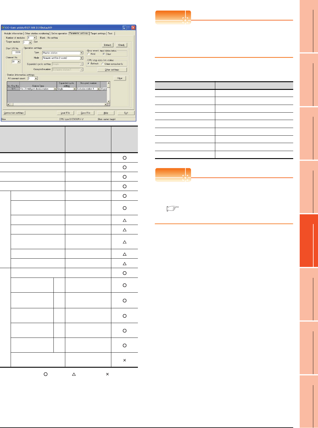
13. CC-Link CONNECTION (INTELLIGENT DEVICE STATION)
13.4 PLC Side Setting
13 - 19
9
MELSECNET/H
CONNECTION (PLC
TO PLC NETWORK)
10
MELSECNET/10
CONNECTION (PLC
TO PLC NETWORK)
11
CC-Link IE CONTROLLER
NETWORK
CONNECTION
12
CC-Link IE FIELD
NETWORK
CONNECTION
13
CC-Link CONNECTION
(INTELLIGENT DEVICE
STATION)
14
CC-Link
CONNECTION
(Via G4)
15
INVERTER
CONNECTION
16
SERVO AMPLIFIER
CONNECTION
(2) CC-Link Utility's [Parameter Settings]
(a) Parameter settings
: Necessary : As necessary : Not necessary
*1 When the [Mode] of the CC-Link module is set at [Remote
net - (Ver. 2 mode)], [Remote station points] can be set.
[Remote station points] is a setting for the remote I/O station.
The default value (32 points) must be used on the GOT.
*2 Set the same setting as that of the GOT.
POINTPOINTPOINT
When changing the network parameter
After writing the network parameter to the C Controller
module, either turn the C Controller module OFF and
then ON or reset it.
[Communication settings] of GT Designer3
POINTPOINTPOINT
[Controller Setting] of GT Designer3
For the setting method of [Controller Setting] of GT
Designer3, refer to the following.
13.3.1 Setting communication interface
(Communication settings)
Item*1 Set value
Setting
necessity at
GOT
connection
Number of modules 1
Target module 1
Start I/O No. 0000H
Channel No. (Use default value)
Operation settings
Type Master station
Mode Remote net
(Ver.2 mode)
Expanded cyclic setting Single
Occupied number Exclusive station 1
Error event: input data
status Clear
CPU stop: data link status Refresh
Other settings (Use default value)
Station information settings
All connect count 1
Station Type Sta.
No.1
Ver.2 intelligent device
station
Expanded cyclic
setting*2
Sta.
No.1 Single
Occupied number*2 Sta.
No.1 Exclusive station 1
Remote station points Sta.
No.1 32 points
Reserve/invalid
station select
Sta.
No.1 No setting
Intelligent buffer select
(word) (Use default value)
Item Set value
Station No. 1: Station No.1
Transmission Rate 0: Online 156kbps
Mode Ver.2: Remote net (Ver.2 mode)
Expanded Cyclic Single
Number of stations occupied 1 Station
Input for Error Station Clear
Retry 3times (Use default value)
Timeout Time 3sec (Use default value)
Delay Time 0ms (Use default value)
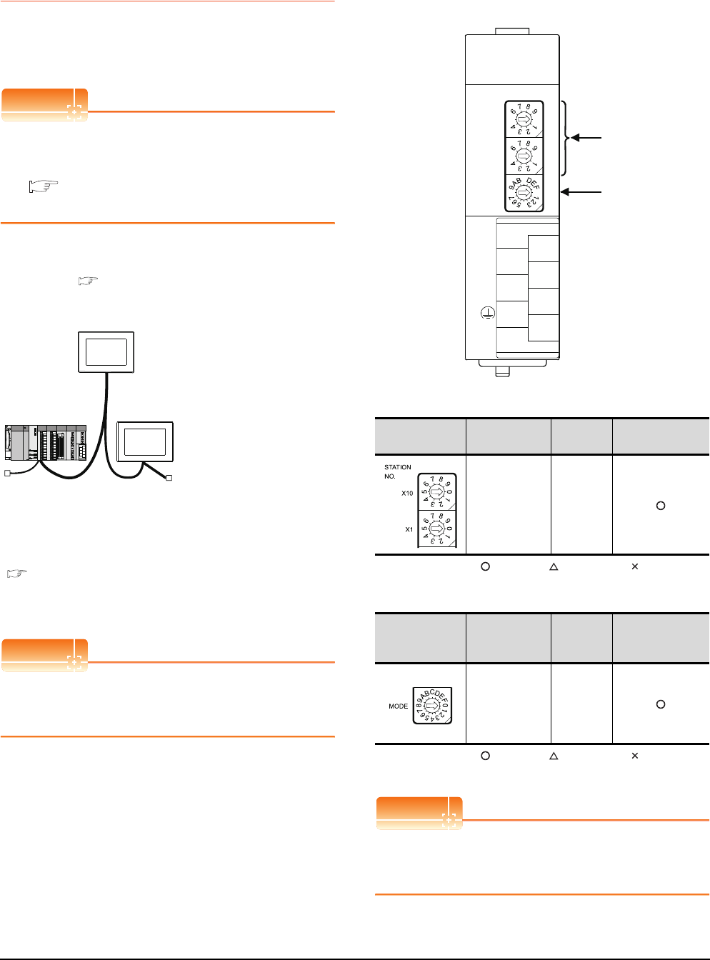
13 - 20 13. CC-Link CONNECTION (INTELLIGENT DEVICE STATION)
13.4 PLC Side Setting
13.4.3 Connecting to CC-Link module
(Q Series) with Ver.1/Ver.2
compatibles mixed
This section describes the setting of the GOT and CC-Link
module (Q Series) with Ver.1/Ver.2 compatibles mixed in
the following system configuration.
POINTPOINTPOINT
CC-Link module (Q Series)
For details of the CC-Link module (Q Series), refer to
the following manual.
CC-Link System Master/Local Module User's
Manual QJ61BT11N
System configuration
*1 The CC-Link module is mounted on the base unit slot 0.
The Start I/O No. of the CC-Link module is set to "0"
POINTPOINTPOINT
When connecting to Q170MCPU
When connected to Q170MCPU, the start I/O No. of
the CC-Link module is set to "70".
Switch setting of CC-Link module (Q Series)
Set the station number setting switch, transmission
speed / mode setting switch.
(1) Station number setting switch
: Necessary : As necessary : Not necessary
(2) Transmission rate/mode setting switch
: Necessary : As necessary : Not necessary
*1 Specify the same transmission speed as that of the GOT.
POINTPOINTPOINT
When the switch setting has been changed
Turn the PLC CPU OFF then ON again, or reset the
PLC CPU.
<CC-Link module>
*1
Type : Master station
Station No. : Station No. 0
Mode : Remote net (Ver.2 mode)
All connect count : 2
Transmission speed : 156kbps
<GOT (Ver.1 compatible)>
(Use default value for settings other than the following.)
Station type : Intelligent device
station
Station No. : Station No. 1
Number of stations
occupied Exclusive station 1:
:Transmission speed 156kbps
(Use default value for settings other than the following.)
<GOT (Ver.2 compatible)>
(Use default value for settings other
than the following.)
Station type : Intelligent device
station
Station No. : Station No. 2
Number of stations
occupied Exclusive station 1:
Expanded cyclic setting Single:
:Transmission speed 156kbps
■ [Controller Setting] of GT Designer3
■ Setting of the CC-Link communication unit
■ Switch setting of CC-Link module (Q Series)
■ [Network parameter] of GX Developer
Station number
setting switch Description Set value Setting necessity
at GOT connection
Station number
setting
(master station)
0 (fixed)
Transmission
rate/mode setting
switch
Description Set value Setting necessity
at GOT connection
Transmission
rate/
mode setting
(Online:
156kbps)*1
0
(1)
(2)
QJ61BT11N
0
5
0
5
0
8
1
2
7
6
5
4
3
STATION
NO.
X10
X1
MODE
QJ61BT11N
RUN
ERR.
SD
MST
L RUN
L ERR.
RD
S MST
NC
DA
DB
NC
SLD
DG
(FG)
C
4
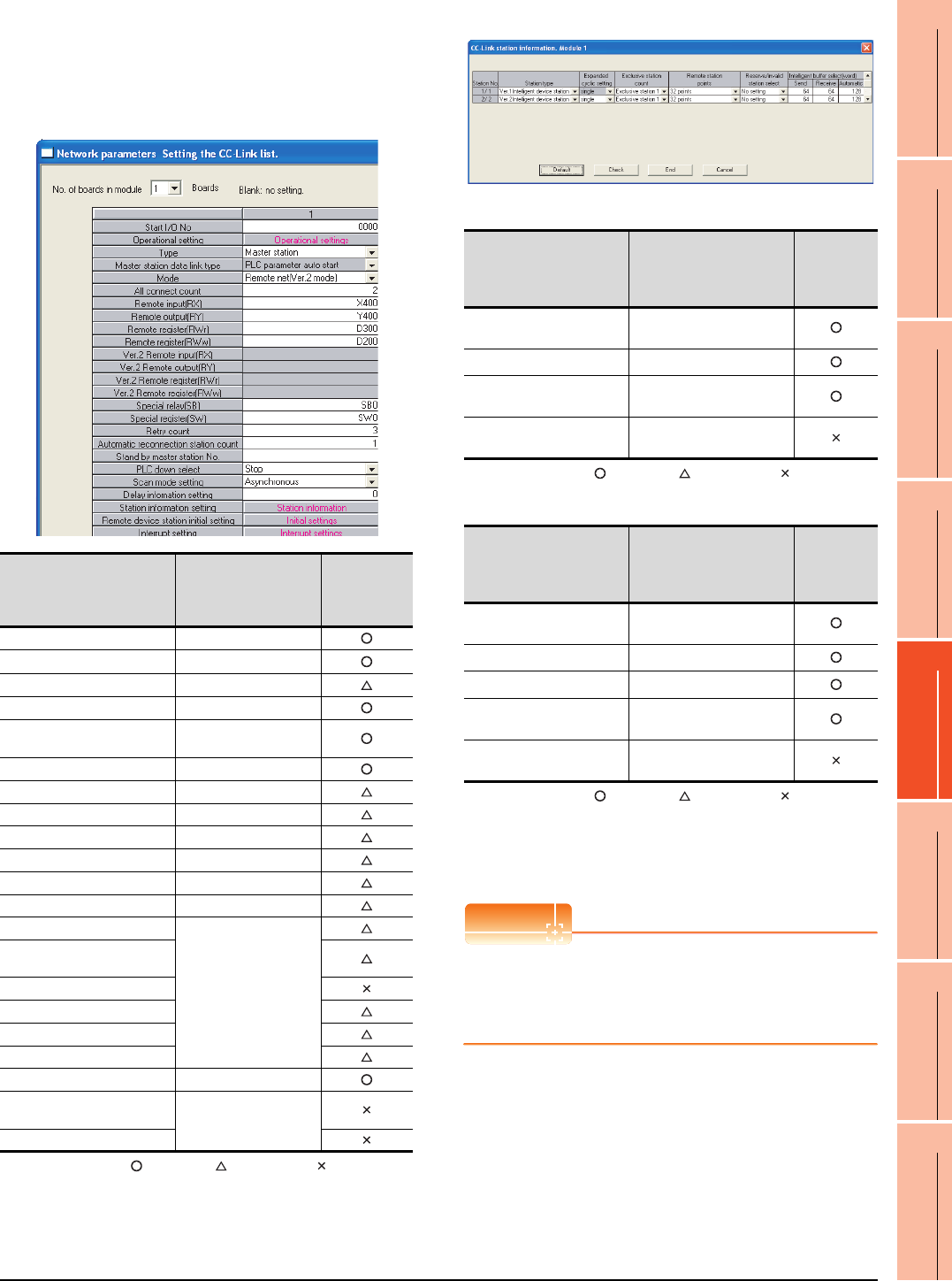
13. CC-Link CONNECTION (INTELLIGENT DEVICE STATION)
13.4 PLC Side Setting
13 - 21
9
MELSECNET/H
CONNECTION (PLC
TO PLC NETWORK)
10
MELSECNET/10
CONNECTION (PLC
TO PLC NETWORK)
11
CC-Link IE CONTROLLER
NETWORK
CONNECTION
12
CC-Link IE FIELD
NETWORK
CONNECTION
13
CC-Link CONNECTION
(INTELLIGENT DEVICE
STATION)
14
CC-Link
CONNECTION
(Via G4)
15
INVERTER
CONNECTION
16
SERVO AMPLIFIER
CONNECTION
Parameter setting (when connecting to
MELSEC-Q or QS series)
(1) [Network parameter] of GX Developer
(a) Network parameter
: Necessary : As necessary : Not necessary
*1 When using Q170MCPU, set it according to the system
configuration.
(b) Station information setting
• Station information setting of station No.1 (GOT)
: Necessary : As necessary : Not necessary
• Station information setting of station No.2 (GOT)
: Necessary : As necessary : Not necessary
*1 When the [Mode] of the CC-Link module is set at [Remote
net - (Ver. 2 mode)], [Remote station points] can be set.
[Remote station points] is a setting for the remote I/O station.
The default value (32 points) must be used on the GOT.
*2 Set the same setting as that of the GOT.
POINTPOINTPOINT
When changing the network parameter
After writing the network parameter to the PLC CPU,
operate the PLC CPU ether turning OFF and then ON
or resetting.
Item Set value
Setting
necessity at
GOT
connection
No. of boards in module 1
Start I/O No.*1 0000H
Operation setting (Use default value)
Type Master station (fixed)
Mode Remote net
(Ver.2 mode)
All connect count 2
Remote input (RX) X400
Remote output (RY) Y400
Remote register (RWr) D300
Remote register (RWw) D200
Special relay (SB) SB0
Special register (SW) SW0
Retry count
(Use default value)
Automatic reconnection
station count
Stand by master station No.
PLC down select
Scan mode setting
Delay information setting
Station information setting Refer to (b)
Remote device station initial
setting (Use default value)
Interrupt setting
Item*1 Set value
Setting
necessity at
GOT
connection
Station type Ver.1 intelligent
device station (fixed)
Exclusive station count*2 Exclusive station 1
Reserve/invalid station
select No setting
Intelligent buffer select
(word) (Use default value)
Item*1 Set value
Setting
necessity at
GOT
connection
Station type Ver.2 intelligent device
station (fixed)
Expanded cyclic setting*2 Single
Exclusive station count*2 Exclusive station 1
Reserve/invalid station
select No setting
Intelligent buffer select
(word) (Use default value)
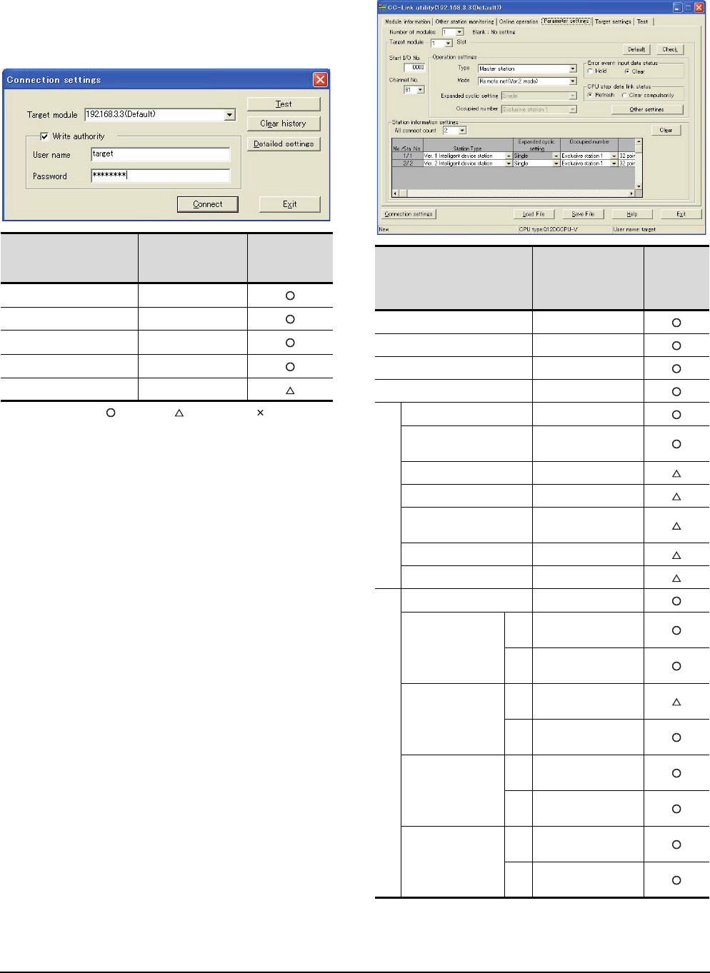
13 - 22 13. CC-Link CONNECTION (INTELLIGENT DEVICE STATION)
13.4 PLC Side Setting
Parameter setting (when connecting to C
Controller module)
Use SW3PVC-CCPU-E Ver.3.05F or later for the CC-
Link utility.
(1) Connection settings
: Necessary : As necessary : Not necessary
*1 If the IP address of the C Controller module has been
changed, input the changed IP address or host name.
*2 If the account of the C Controller module has been changed,
input the changed user name and password.
(2) CC-Link Utility's [Parameter Settings]
(a) Parameter settings
Item Set value
Setting
necessity at
GOT connection
Target module*1 192.168.3.3 (Default)
Write authority Mark the checkbox
User name*2 target
Password*2 password
Detailed settings -
Item*1 Set value
Setting
necessity at
GOT
connection
Number of modules 1
Target module 1
Start I/O No. 0000H
Channel No. (Use default value)
Operation settings
Type Master station
Mode Remote net
(Ver.2 mode)
Expanded cyclic setting Single
Occupied number Exclusive station 1
Error event: input data
status Clear
CPU stop: data link status Refresh
Other settings (Use default value)
Station information settings
All connect count 2
Station Type
Sta.
No.1
Ver.1 intelligent device
station
Sta.
No.2
Ver.2 intelligent device
station
Expanded cyclic
setting*2
Sta.
No.1 Single
Sta.
No.2 Single
Occupied number*2
Sta.
No.1 Exclusive station 1
Sta.
No.2 Exclusive station 1
Remote station points
Sta.
No.1 32 points
Sta.
No.2 32 points
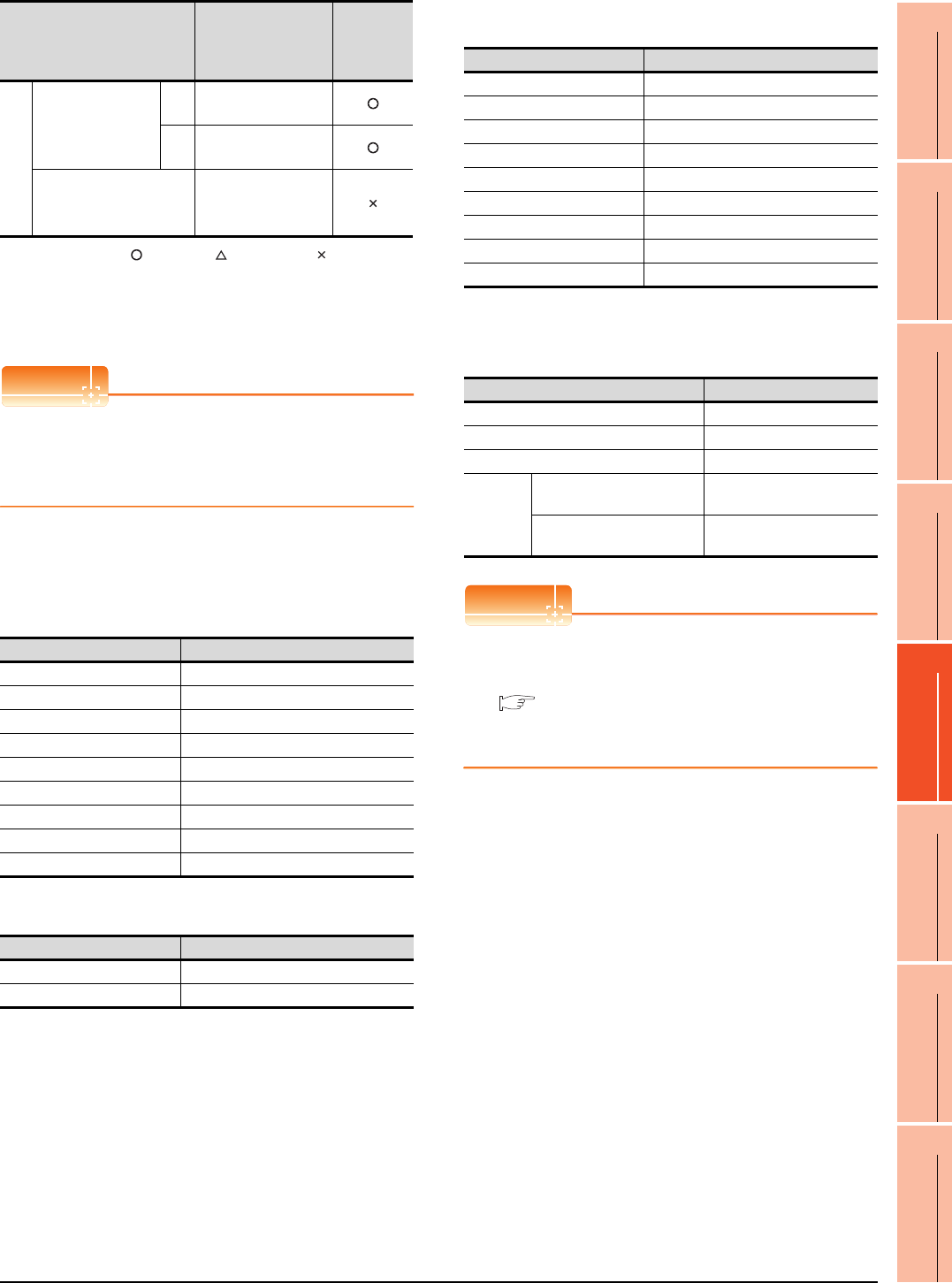
13. CC-Link CONNECTION (INTELLIGENT DEVICE STATION)
13.4 PLC Side Setting
13 - 23
9
MELSECNET/H
CONNECTION (PLC
TO PLC NETWORK)
10
MELSECNET/10
CONNECTION (PLC
TO PLC NETWORK)
11
CC-Link IE CONTROLLER
NETWORK
CONNECTION
12
CC-Link IE FIELD
NETWORK
CONNECTION
13
CC-Link CONNECTION
(INTELLIGENT DEVICE
STATION)
14
CC-Link
CONNECTION
(Via G4)
15
INVERTER
CONNECTION
16
SERVO AMPLIFIER
CONNECTION
: Necessary : As necessary : Not necessary
*1 When the [Mode] of the CC-Link module is set at [Remote
net - (Ver. 2 mode)], [Remote station points] can be set.
[Remote station points] is a setting for the remote I/O station.
The default value (32 points) must be used on the GOT.
*2 Set the same setting as that of the GOT.
POINTPOINTPOINT
When changing the network parameter
After writing the network parameter to the C Controller
module, either turn the C Controller module OFF and
then ON or reset it
[Controller Setting] of GT Designer3
(1) Communication Settings of station No.1 (GOT)
(a) When MODEL GT15-J61BT13 CC-Link
communication unit is used
(b) When MODEL GT15-75J61BT13-Z CC-Link
communication unit is used
(2) Communication Settings of station No.2 (GOT)
Setting of the CC-Link communication unit
(Only when MODEL GT15-75J61BT13-Z
CC-Link communication unit is used)
POINTPOINTPOINT
Setting of the CC-Link communication unit
For the setting method of the CC-Link communication
unit, refer to the following.
13.3.3 Switch setting (Only when MODEL
GT15-75J61BT13-Z CC-Link communication
unit is used)
Station information settings
Reserve/invalid
station select
Sta.
No.1 No setting
Sta.
No.2 No setting
Intelligent buffer select
(word) (Use default value)
Item Set value
Station No. 1: Station No.1
Transmission Rate 0: Online 156kbps
Mode Ver.1: Remote net (Ver.1 mode)
Expanded Cyclic Single (Use default value)
Number of stations occupied 1 Station
Input for Error Station 0: Clear
Retry 3times (Use default value)
Timeout Time 3sec (Use default value)
Delay Time 0ms (Use default value)
Item Set value (Use default value)
Retry 3times
Timeout Time 3sec
Item*1 Set value
Setting
necessity at
GOT
connection Item Set value (Use default value)
Station No. 2: Station No.2
Transmission Rate 0: Online 156kbps
Mode Ver.2: Remote net (Ver.2 mode)
Expanded Cyclic Single
Number of stations occupied 1 Station
Input for Error Station 0: Clear
Retry 3times (Use default value)
Timeout Time 3sec (Use default value)
Delay Time 0ms (Use default value)
Item Set value
Mode setting switch 0: Online (fixed)
Station number setting switch 1: Station No.1
Transmission baudrate setting switch 0: 156kbps
Condition
setting
switches
SW1 (Input data status of the
data link error station) OFF: Cleared
SW2 (Number of occupied
stations) OFF: 1 station
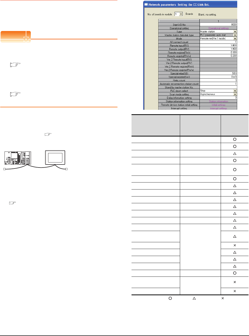
13 - 24 13. CC-Link CONNECTION (INTELLIGENT DEVICE STATION)
13.4 PLC Side Setting
13.4.4 Connecting to MELSEC-L
series with CC-Link Ver.1
compatible
This section describes the settings of the GOT and
MELSEC-L in the following case of the system
configuration.
POINTPOINTPOINT
(1) CC-Link module (L Series)
For details of the CC-Link module (L Series), refer
to the following manual.
MELSEC-L CC-Link System Master/Local
Module User's Manual
(2) CC-Link function built-in CPU
For details on the CC-Link function built-in CPU,
refer to the following manual.
MELSEC-L CC-Link System Master/Local
Module User's Manual
System configuration
(Example when using CC-Link module (L Series))
[Network parameter] of GX Developer
(1) Network parameter
: Necessary : As necessary : Not necessary
*1 Set the Start I/O No. of the CC-Link module according to the
system configuration.
<CC-Link module>
*1
Type : Master station
Station No. : Station No.0
Mode : Remote net (Ver.1 mode)
All connect count : 1
Transmission speed : 156kbps
<GOT>
(Use the default value for settings other
than the following.)
Station type : Intelligent device
station
Station No. : Station No.1
Expanded cyclic setting : Single
Number of
stations occupied : Exclusive station
Transmission speed : 156kbps
(Use the default value for the settings other than the following.)
■ [Controller Setting] of GT Designer3
■ [Network parameter] of GX Developer
Item Set value
Setting
necessity at
GOT
connection
No. of boards in module 1
Start I/O No.*1 0000H
Operation setting (Use default value)
Type Master station (fixed)
Mode Remote net
(Ver.1 mode)
All connect count 1
Remote input (RX) X400
Remote output (RY) Y400
Remote register (RWr) D300
Remote register (RWw) D200
Special relay (SB) SB0
Special register (SW) SW0
Retry count
(Use default value)
Automatic reconnection
station count
Stand by master station No.
PLC down select
Scan mode setting
Delay information setting
Station information setting Refer to (2)
Remote device station initial
setting (Use default value)
Interrupt setting
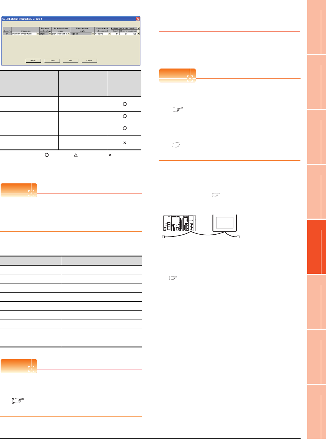
13. CC-Link CONNECTION (INTELLIGENT DEVICE STATION)
13.4 PLC Side Setting
13 - 25
9
MELSECNET/H
CONNECTION (PLC
TO PLC NETWORK)
10
MELSECNET/10
CONNECTION (PLC
TO PLC NETWORK)
11
CC-Link IE CONTROLLER
NETWORK
CONNECTION
12
CC-Link IE FIELD
NETWORK
CONNECTION
13
CC-Link CONNECTION
(INTELLIGENT DEVICE
STATION)
14
CC-Link
CONNECTION
(Via G4)
15
INVERTER
CONNECTION
16
SERVO AMPLIFIER
CONNECTION
(2) Station information setting
: Necessary : As necessary : Not necessary
*1 When the [Mode] of the CC-Link module is set at [Remote
net - (Ver. 1 mode)], [Remote station points] cannot be set.
*2 Set the same setting as that of the GOT.
POINTPOINTPOINT
When changing the network parameter
After writing the network parameter to the PLC CPU,
operate the PLC CPU ether turning OFF and then ON
or resetting.
[Controller Setting] of GT Designer3
POINTPOINTPOINT
[Controller Setting] of GT Designer3
For the setting method of [Controller Setting] of GT
Designer3, refer to the following.
13.3.1 Setting communication interface
(Communication settings)
13.4.5 Connecting to MELSEC-L
series with CC-Link Ver.2
compatible
This section describes the settings of the GOT and
MELSEC-L in the following case of the system
configuration.
POINTPOINTPOINT
(1) CC-Link module (L Series)
For details of the CC-Link module (L Series), refer
to the following manual.
MELSEC-L CC-Link System Master/Local
Module User's Manual
(2) CC-Link function built-in CPU
For details on the CC-Link function built-in CPU,
refer to the following manual.
MELSEC-L CC-Link System Master/Local
Module User's Manual
System configuration
(Example when using CC-Link module (L Series))
Item*1 Set value
Setting
necessity at
GOT
connection
Station type Intelligent
device station (fixed)
Exclusive station count*2 Exclusive station 1
Reserve/invalid station
select No setting
Intelligent buffer select
(word) (Use default value)
Item Set value
Station No. 1: Station No.1
Transmission Rate 0: Online 156kbps
Mode Ver.1: Remote net (Ver.1 mode)
Expanded Cyclic Single (Use default value)
Number of stations occupied 1 Station
Input for Error Station 0: Clear
Retry 3times (Use default value)
Timeout Time 3sec (Use default value)
Delay Time 0ms (Use default value)
<CC-Link module>
*1
Type : Master station
Station No. : Station No.0
Mode : Remote net (Ver.3 mode)
All connect count : 1
Transmission speed : 156kbps
<GOT>
(Use the default value for settings other
than the following.)
Station type : Intelligent device
station
Station No. : Station No.1
Expanded cyclic setting : Single
Number of
stations occupied : Exclusive station
Transmission speed : 156kbps
(Use the default value for the settings other than the following.)
■ [Controller Setting] of GT Designer3
■ [Network parameter] of GX Developer
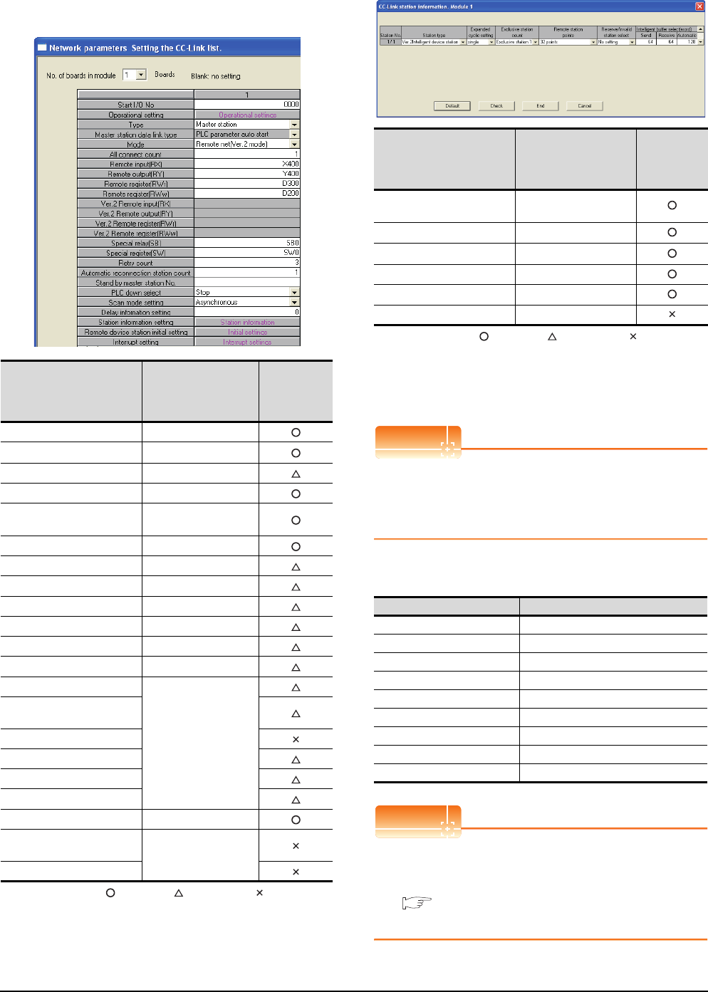
13 - 26 13. CC-Link CONNECTION (INTELLIGENT DEVICE STATION)
13.4 PLC Side Setting
[Network parameter] of GX Developer
(1) Network parameter
: Necessary : As necessary : Not necessary
*1 Set the Start I/O No. of the CC-Link module according to the
system configuration.
(2) Station information setting
: Necessary : As necessary : Not necessary
*1 When the [Mode] of the CC-Link module is set at [Remote
net - (Ver. 2 mode)], [Remote station points] can be set.
[Remote station points] is a setting for the remote I/O station.
The default value (32 points) must be used on the GOT.
*2 Set the same setting as that of the GOT.
POINTPOINTPOINT
When changing the network parameter
After writing the network parameter to the PLC CPU,
operate the PLC CPU either turning OFF and then ON
or resetting.
[Controller Setting] of GT Designer3
POINTPOINTPOINT
[Controller Setting] of GT Designer3
For the setting method of [Controller Setting] of GT
Designer3, refer to the following.
13.3.1 Setting communication interface
(Communication settings)
Item Set value
Setting
necessity at
GOT
connection
No. of boards in module 1
Start I/O No.*1 0000H
Operation setting (Use default value)
Type Master station (fixed)
Mode Remote net
(Ver.2 mode)
All connect count 1
Remote input (RX) X400
Remote output (RY) Y400
Remote register (RWr) D300
Remote register (RWw) D200
Special relay (SB) SB0
Special register (SW) SW0
Retry count
(Use default value)
Automatic reconnection
station count
Stand by master station No.
PLC down select
Scan mode setting
Delay information setting
Station information setting Refer to (2)
Remote device station initial
setting (Use default value)
Interrupt setting
Item*1 Set value
Setting
necessity at
GOT
connection
Station type Ver.2 intelligent device
station (fixed)
Expanded cyclic setting*2 Single
Exclusive station count*2 Exclusive station 1
Remote station points 32 points (fixed)
Reserve/invalid station select No setting
Intelligent buffer select (word) (Use default value)
Item Set value
Station No. 1: Station No.1
Transmission Rate 0: Online 156kbps
Mode Ver.2: Remote net (Ver.2 mode)
Expanded Cyclic Single
Number of stations occupied 1 Station
Input for Error Station 0: Clear
Retry 3times (Use default value)
Timeout Time 3sec (Use default value)
Delay Time 0ms (Use default value)
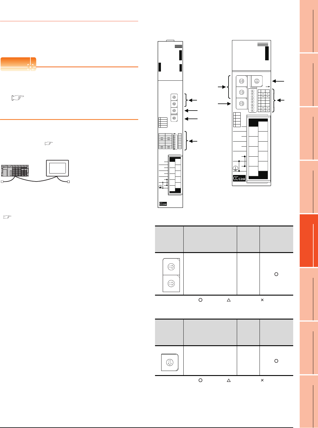
13. CC-Link CONNECTION (INTELLIGENT DEVICE STATION)
13.4 PLC Side Setting
13 - 27
9
MELSECNET/H
CONNECTION (PLC
TO PLC NETWORK)
10
MELSECNET/10
CONNECTION (PLC
TO PLC NETWORK)
11
CC-Link IE CONTROLLER
NETWORK
CONNECTION
12
CC-Link IE FIELD
NETWORK
CONNECTION
13
CC-Link CONNECTION
(INTELLIGENT DEVICE
STATION)
14
CC-Link
CONNECTION
(Via G4)
15
INVERTER
CONNECTION
16
SERVO AMPLIFIER
CONNECTION
13.4.6 Connecting to CC-Link module
(QnA Series)
This section describes the settings of the GOT and CC-
Link module (QnA Series) in the following case of system
configuration.
POINTPOINTPOINT
CC-Link module (QnA Series)
For details of the CC-Link module (QnA Series), refer
to the following manual.
Control & Communication Link System Master/
Local Module Type AJ61QBT11/A1SJ61QBT11
User's Manual
System configuration
*1 The CC-Link module is mounted on the base unit slot 0.
The Start I/O No. of the CC-Link module is set to "0"
Switch settings of CC-Link module (QnA
Series)
Set for each setting switch.
(1) Station number setting switch
: Necessary : As necessary : Not necessary
(2) Mode setting switch
: Necessary : As necessary : Not necessary
*1
<CC-Link module>
(Use the default value for settings other than the following.)
<GOT> (Use the default value for settings other
than the following.)
Station type : Intelligent device
station
Station No. : Station No.1
Number of stations occupied : Exclusive station 1
Transmission speed : 156kbps
Station type : Master station
Station No. : Station No.0
Mode setting : Remote net mode
All connect count : 1
Transmission speed : 156kbps
■ [Controller Setting] of GT Designer3
■ Setting of the CC-Link communication unit
■ Switch settings of CC-Link module (QnA Series)
■ Parameter setting
Station
number
setting
switch
Description Set value
Setting
necessity at
GOT
connection
Station number setting
(master station) 0 (fixed)
Mode setting
switch Description Set value
Setting
necessity at
GOT
connection
Mode setting
(Online: Remote net
mode)
0 (fixed)
A
J61QBT11
E
R
R
O
R
R
A
T
E
B
T
E
S
T
1
B RATE
0156K
1 625K
2 2. 5M
35M
4 10M
ON
MODE
0 : ONLINE (A. R. )
2 : OFFLINE
RUN
ERR.
MST
S MST
LOCAL
CPU R / W
SW
M / S
PRM
TIME
LINE
L RUN
L ERR.
OFF
S MSTM / L
HOLDCLEAR
3 / 41 / 2
SW
1
2
3
4
5
6
7
8
ON
10
8
6
4
2
9
7
5
3
1
NC
DA
NC
(FG)
SLD
NC
NC
NC
DB
DG
STAT IO N NO .
10
x
x
156K
625K
2. 5M
5M
10M
TEST
S0
S1
S2
SD
RD
0
1
9
8
7
6
5
4
3
2
0
1
9
8
7
6
5
4
3
2
0
1
9
8
7
6
5
4
3
2
C
D
B
A
9
8
7
6
5
4
3
2
1
0
F
E
1 : ONLINE (RIM )
2 / 31 / 4
AJ61QBT11
(2)
(4)
(1)
(3)
10
8
6
4
2
9
7
5
3
1
NC
DA
NC
(FG)
SLD
NC
NC
NC
DB
DG
A1SJ61QBT11
A1SJ61QBT11
12345678
O N
STATION NO. MODE
10
x
1
x
B RATE
0 156K
1 625K
2 2. 5M
35M
4 10M
1
2
3
4
5
6
7
8
M / L
CLR
1/2
S. M
HLD
3/4
SW OFF ON
RUN
ERR.
MST
S MST
LOCAL
CPU R / W
L RUN
L ERR.
SD
RD
SW
M / S
PRM
TIME
LINE
E
R
R
O
R
0
1
9
8
7
6
5
4
3
2
0
1
9
8
7
6
5
4
3
2
0
1
9
8
7
6
5
4
3
2
C
D
B
A
9
8
7
6
5
4
3
2
1
0
F
E
1/4 2/3
A1SJ61QBT11
(2)
(4)
(1)
(3)
10
x
1
x
0
1
9
8
7
6
5
4
3
2
0
1
9
8
7
6
5
4
3
2
MODE
C
D
B
A
9
8
7
6
5
4
3
2
1
0
F
E
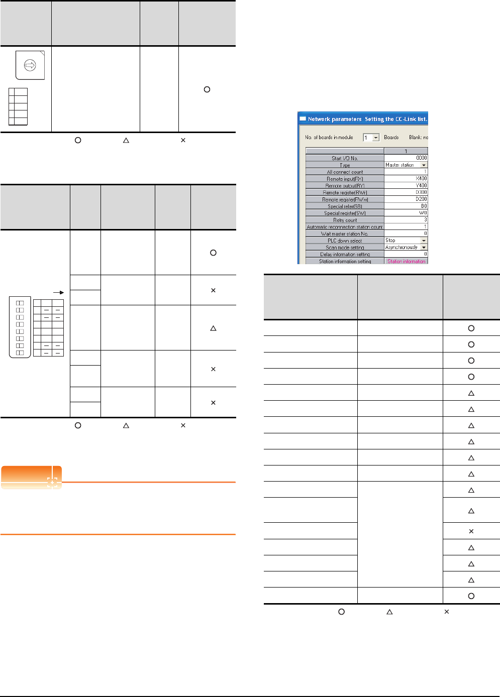
13 - 28 13. CC-Link CONNECTION (INTELLIGENT DEVICE STATION)
13.4 PLC Side Setting
(3) Transmission speed setting switch
: Necessary : As necessary : Not necessary
*1 Specify the same transmission speed as that of the GOT.
(4) Condition setting switches
: Necessary : As necessary : Not necessary
*2 Will be valid when the CC-Link module is the local station.
In the case of the master station, turn off it.
POINTPOINTPOINT
When the switch setting has been changed
Turn the PLC CPU OFF then ON again, or reset the
PLC CPU.
Parameter setting
There are two methods for the parameter setting:
perform the setting from [Network parameter] of GX
Developer and the sequence program.
Performing it from the [Network parameter] of the GX
Developer can be set only when the PLC CPU and the
CC-Link module use the function version B or later.
(1) Setting from [Network parameter] of GX Developer
(a) Network parameter
: Necessary : As necessary : Not necessary
Transmission
speed setting
switch
Description Set value
Setting
necessity at
GOT
connection
Transmission speed
setting (156kbps)*1 0
Condition setting
switches
Setting
switch Description Set
value
Setting
necessity at
GOT
connection
SW1
Station type
(Master
station/Local
station)
OFF
(fixed)
SW2
Not used OFF
(fixed)
SW3
SW4
Input data
status of the
data link error
station (clear)
OFF
SW5 Number of
stations
occupied*2
OFF
(fixed)
SW6
SW7
Not used OFF
(fixed)
SW8
B RATE
0 156K
1 625K
22. 5M
35M
410M
0
1
9
8
7
6
5
4
3
2
12345678
O N
1
2
3
4
5
6
7
8
M / L
CLR
1/2
S. M
HLD
3/4
SW OFF ON
1/4 2/3
Item Set value
Setting
necessity at
GOT
connection
No. of boards in module 1
Start I/O No. 0000H
Type Master station (fixed)
All connect count 1
Remote input (RX) X400
Remote output (RY) Y400
Remote register (RWr) D300
Remote register (RWw) D200
Special relay (SB) B0
Special register (SW) W0
Retry count
(Use default value)
Automatic reconnection
station count
Wait master station No.
PLC down select
Scan mode setting
Delay information setting
Station information setting Refer to (2)
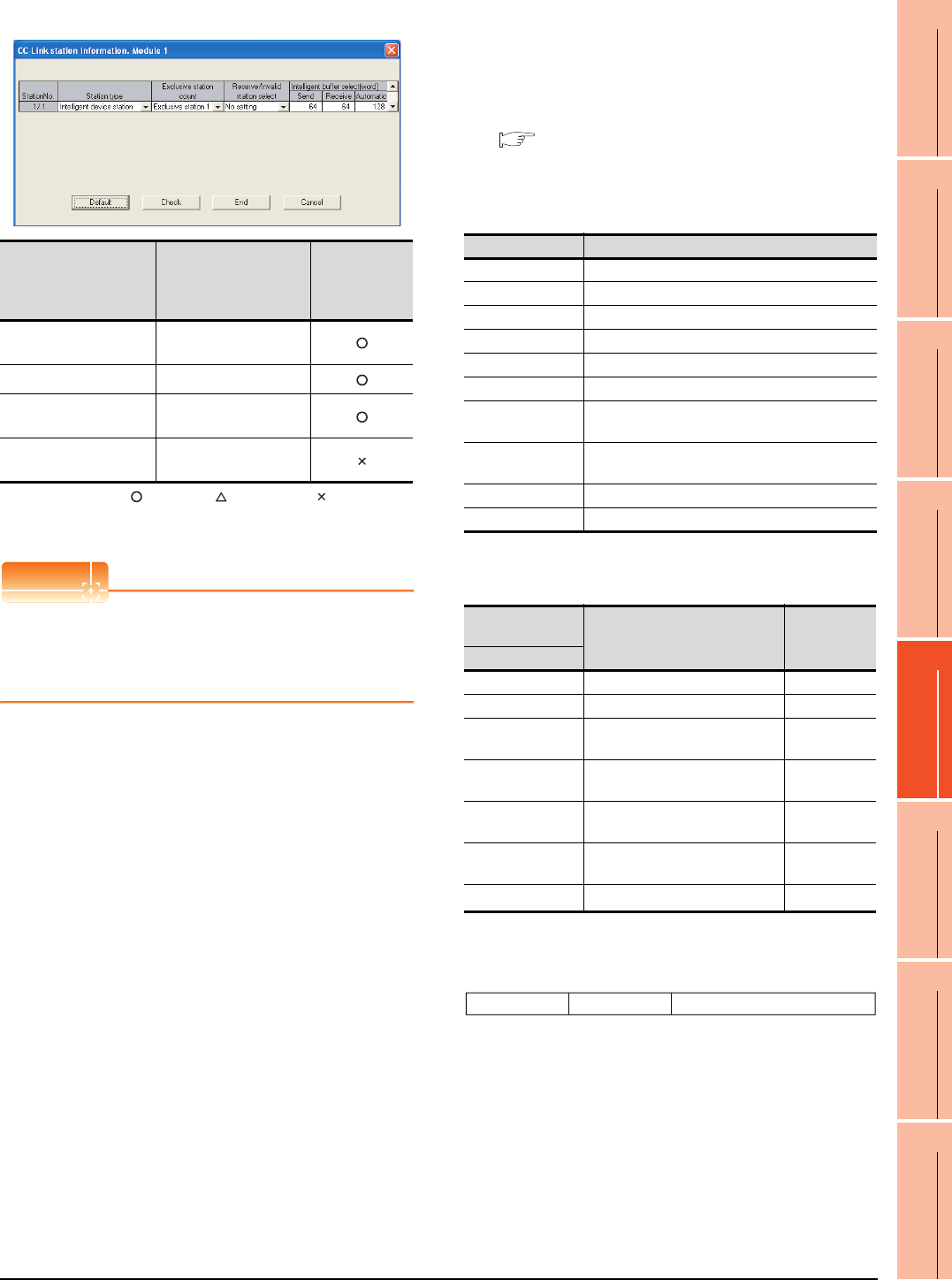
13. CC-Link CONNECTION (INTELLIGENT DEVICE STATION)
13.4 PLC Side Setting
13 - 29
9
MELSECNET/H
CONNECTION (PLC
TO PLC NETWORK)
10
MELSECNET/10
CONNECTION (PLC
TO PLC NETWORK)
11
CC-Link IE CONTROLLER
NETWORK
CONNECTION
12
CC-Link IE FIELD
NETWORK
CONNECTION
13
CC-Link CONNECTION
(INTELLIGENT DEVICE
STATION)
14
CC-Link
CONNECTION
(Via G4)
15
INVERTER
CONNECTION
16
SERVO AMPLIFIER
CONNECTION
(b) Station information setting
: Necessary : As necessary : Not necessary
*1 Specify the same number of occupied stations as that of the
GOT.
POINTPOINTPOINT
When changing the network parameter
After writing the network parameter to the PLC CPU,
operate the PLC CPU ether turning OFF and then ON
or resetting.
(2) Setting from sequence program
The parameter is written to the buffer memory, and the
data link is automatically started when PLC CPU status
changes from STOP to RUN.
(a) I/O signal of CC-Link module
Control & Communication Link System Master/
Local Module Type AJ61QBT11/A1SJ61QBT11
User's Manual
(b) Device used by user
(c) Buffer memory settings used in the present
example
*1 Details for the station data are shown below.
For 1) and 2), set the same station No. and number of station
occupied as those of the GOT.
For 3), the setting is fixed.
Item Set value
Setting
necessity at
GOT
connection
Station type Intelligent device station
(fixed)
Exclusive station count*1 Exclusive station 1
Reserve/invalid station
select No setting
Intelligent buffer select
(word) (Use default value)
Device Application
M100, M101 Flag for parameter setting
M102, M103 Flag for data link startup
D0 Number of connected modules
D1 Number of retry
D2 Automatic reconnection station count
D3 Operation specification in the case of CPU failure
D4 Reserved station specification (Station No. 1 to
Station No. 16)
D5 Error invalid station specification (Station No. 1 to
Station No. 16)
D6 Station data (first module)
D400 Error code in the case of data link startup failure
Buffer memory
address Item Set value
Decimal (Hex)
1(11 (1H) Number of connected modules 1 (1 module)
2(22 (2H) Number of retry 3 (3times)
3(33 (3H)Automatic reconnection station
count 1 (1 station)
6(66 (6H)Operation specification in the
case of CPU failure 0 (stop)
16(1016 (10H)Reserved station specification
(Station No. 1 to Station No. 16)
0 (No
specification)
20(1420 (14H)Error invalid station specification
(Station No. 1 to Station No. 16)
0 (No
specification)
32(2032 (20H)Station data (first module)*1 2101H
1) Station No. (Set the same station No. as that of the GOT)
01H to 40H: Station No. 1 to Station No. 64
2) Number of stations occupied (Set the number of station
occupied as that of the GOT)
1H: Exclusive station 1
2H: Exclusive station 2
3H: Exclusive station 3
4H: Exclusive station 4
3) Station type (2H: Set it to intelligent device station)
0H: Remote I/O station
1H: Remote device station
2H: Intelligent device station (Incl. local station)
3) 2) 1)
b15 b12 b11 b8 b7 to b0
to to
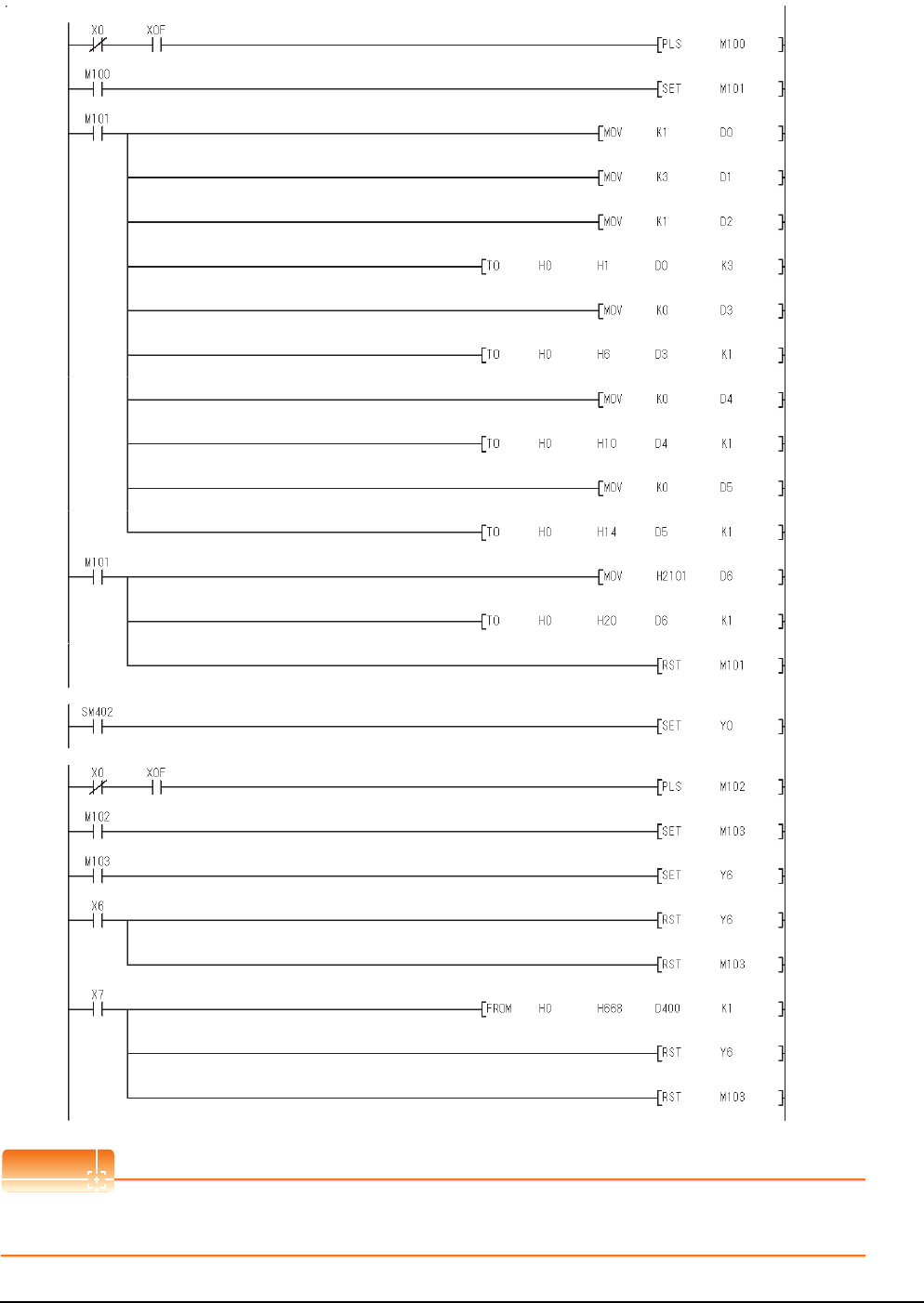
13 - 30 13. CC-Link CONNECTION (INTELLIGENT DEVICE STATION)
13.4 PLC Side Setting
(d) Example of sequence program
POINTPOINTPOINT
When changing the sequence program
After writing the sequence program to the PLC CPU, operate the PLC CPU ether turning OFF and then ON or resetting.
Data link
startup
normal
completion
(buffer memory)
Data link
startup
abnormal
completion
(buffer
memory)
Turn on only during 1 scan after RUN
Module
ready
Module error
Module
ready
Module error
Number of connected
modules (1 module)
Number of retry
(3 times)
Number of
automatic return
stations (1 station)
Reserved station
specification (No
specification)
Refresh insruction
Data link start up
request (buffer memory
address)
Error code reading
(SW0068)
Error invalid station
specification (No
specification)
Station data (Intelligent
device station, exclusive
station 1, station No.1)
Operation specification
in the case of CPU
failure (Stop)
Refresh insruction
Parameter setting
Data link with buffer memory parameter
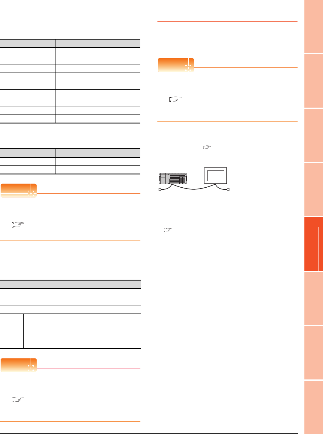
13. CC-Link CONNECTION (INTELLIGENT DEVICE STATION)
13.4 PLC Side Setting
13 - 31
9
MELSECNET/H
CONNECTION (PLC
TO PLC NETWORK)
10
MELSECNET/10
CONNECTION (PLC
TO PLC NETWORK)
11
CC-Link IE CONTROLLER
NETWORK
CONNECTION
12
CC-Link IE FIELD
NETWORK
CONNECTION
13
CC-Link CONNECTION
(INTELLIGENT DEVICE
STATION)
14
CC-Link
CONNECTION
(Via G4)
15
INVERTER
CONNECTION
16
SERVO AMPLIFIER
CONNECTION
[Controller Setting] of GT Designer3
(1) When MODEL GT15-J61BT13 CC-Link
communication unit is used
(2) When MODEL GT15-75J61BT13-Z CC-Link
communication unit is used
POINTPOINTPOINT
[Controller Setting] of GT Designer3
For the setting method of [Controller Setting] of GT
Designer3, refer to the following.
13.3.1 Setting communication interface
(Communication settings)
Setting of the CC-Link communication unit
(Only when MODEL GT15-75J61BT13-Z
CC-Link communication unit is used)
POINTPOINTPOINT
Setting of the CC-Link communication unit
For the setting method of the CC-Link communication
unit, refer to the following.
13.3.3 Switch setting (Only when MODEL
GT15-75J61BT13-Z CC-Link communication
unit is used)
13.4.7 Connecting to CC-Link module
(A Series)
This section describes the settings of the GOT and CC-
Link module (A Series) in the following case of system
configuration.
POINTPOINTPOINT
CC-Link module (A Series)
For details of the CC-Link module (A Series), refer to
the following manual.
Control & Communication Link System Master/
Local Module Type AJ61BT11/A1SJ61BT11
User's Manual
System configuration
*1 The CC-Link module is mounted on the base unit slot 0.
The Start I/O No. of the CC-Link module is set to "0"
Item Set value
Station No. 1: Station No.1
Transmission Rate 0: Online 156kbps
Mode Ver.1: Remote net (Ver.1 mode)
Expanded Cyclic Single (Use default value)
Number of stations occupied
1 Station
Input for Error Station 0: Clear
Retry 3times (Use default value)
Timeout Time 3sec (Use default value)
Delay Time 0ms (Use default value)
Item Set value (Use default value)
Retry 3times
Timeout Time 3sec
Item Set value
Mode setting switch 0: Online (fixed)
Station number setting switch 1: Station No.1
Transmission baudrate setting switch 0: 156kbps
Condition
setting
switches
SW1
(Input data status of the data
link error station)
OFF: Cleared
SW2 (Number of occupied
stations) OFF: 1 station
*1
<CC-Link module>
(Use the default value for settings other than the following.)
<GOT>
(Use the default value for settings other
than the following.)
Station type : Master station
All connect count : 1
Mode setting : Remote net mode
Station No. : Station No.0
Module mode : Intelligent mode
Transmission speed : 156kbps
Station type : Intelligent device
station
Station No. : Station No.1
Number of station occupied : Exclusive station 1
Transmission
speed
: 156kbps
■ [Controller Setting] of GT Designer3
■ Setting of the CC-Link communication unit
■ Settings of CC-Link module (A Series)
■ Sequence program
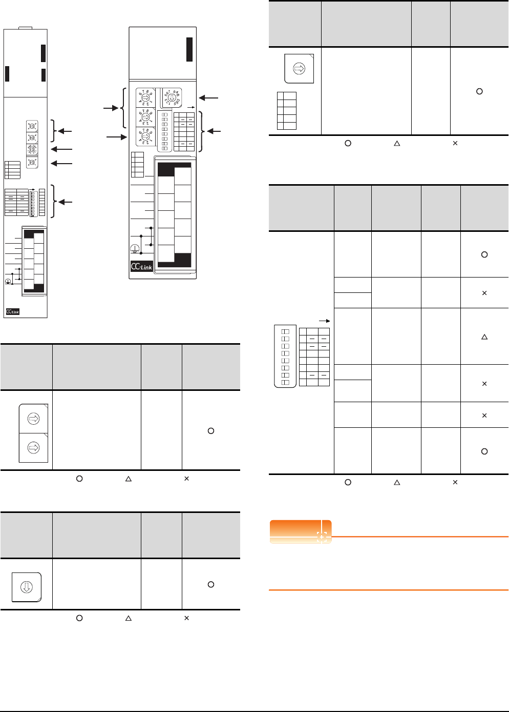
13 - 32 13. CC-Link CONNECTION (INTELLIGENT DEVICE STATION)
13.4 PLC Side Setting
Settings of CC-Link module (A Series)
Set for each setting switch.
(1) Station number setting switch
: Necessary : As necessary : Not necessary
(2) Mode setting switch
: Necessary : As necessary : Not necessary
(3) Transmission speed setting switch
: Necessary : As necessary : Not necessary
*1 Specify the same transmission speed as that of the GOT.
(4) Condition setting switches
: Necessary : As necessary : Not necessary
*2 Will be valid when the CC-Link module is a local station.
In the case of the master station, turn off it.
POINTPOINTPOINT
When the switch setting has been changed
Turn the PLC CPU OFF then ON again, or reset the
PLC CPU.
Station
number
setting switch
Description Set value
Setting
necessity at
GOT
connection
Station number setting
(master station) 0 (fixed)
Mode setting
switch Description Set value
Setting
necessity at
GOT
connection
Mode setting
(Online: Remote net
mode)
0 (fixed)
AJ61BT11
(2)
(4)
(1)
(3)
A1SJ61BT11
(2)
(4)
(1)
(3)
A
J61BT11
E
R
R
O
R
R
A
T
E
B
T
E
S
T
1
B RATE
0156K
1 625K
2 2. 5M
35M
4 10M
ON
MODE
0 : ONLINE (A. R. )
2 : OFFLINE
RUN
ERR.
MST
S MST
LOCAL
CPU R / W
SW
M / S
PRM
TIME
LINE
L RUN
L ERR.
OFF
S MSTM / L
HOLDCLEAR
3 / 41 / 2
SW
1
2
3
4
5
6
7
8
ON
10
8
6
4
2
9
7
5
3
1
NC
DA
NC
(FG)
SLD
NC
NC
NC
DB
DG
STATION NO.
10
x
x
156K
625K
2. 5M
5M
10M
TEST
S0
S1
S2
SD
RD
0
8
7
5
3
2
0
8
7
5
3
2
0
8
7
5
3
2
C
8
4
0
1 : ONLINE (RIM )
ISFM SFM
2 / 31 / 4
10
8
6
4
2
9
7
5
3
1
NC
DA
NC
(FG)
SLD
NC
NC
NC
DB
DG
A1SJ61BT11
A1SJ61BT11
12345678
O N
STATION NO. MODE
10
x
1
x
B RATE
0 156K
1 625K
2 2. 5M
35M
4 10M
1
2
3
4
5
6
7
8
M / L
CLR
1/2
S. M
HLD
3/4
SW OFF ON
RUN
ERR.
MST
S MST
LOCAL
CPU R / W
L RUN
L ERR.
SD
RD
SW
M / S
PRM
TIME
LINE
E
R
R
O
R
0
5
0
5
0
5
C
8
4
0
ISM SFM
1/4 2/3
10
x
1
x
0
1
9
8
7
6
5
4
3
2
0
1
9
8
7
6
5
4
3
2
STATION NO.
MODE
C
D
B
A
9
8
7
6
5
4
3
2
1
0
F
E
Transmission
speed setting
switch
Description Set value
Setting
necessity at
GOT
connection
Transmission speed
setting (156kbps)*1 0
Condition setting
switches
Setting
switch Description Set value
Setting
necessity at
GOT
connection
SW1
Station type
(Master
station/Local
station)
OFF
(fixed)
SW2
Not used OFF
(fixed)
SW3
SW4
Input data
status of the
data link
error station
(clear)
OFF
SW5 Number of
stations
occupied*2
OFF
(fixed)
SW6
SW7 Not used OFF
(fixed)
SW8
Module
mode
(Intelligent
mode)
OFF
(fixed)
B RATE
0 156K
1 625K
2 2. 5M
35M
4 10M
0
1
9
8
7
6
5
4
3
2
12345678
O N
1
2
3
4
5
6
7
8
M / L
CLR
1/2
S. M
HLD
3/4
SW OFF ON
ISM SFM
1/4 2/3

13. CC-Link CONNECTION (INTELLIGENT DEVICE STATION)
13.4 PLC Side Setting
13 - 33
9
MELSECNET/H
CONNECTION (PLC
TO PLC NETWORK)
10
MELSECNET/10
CONNECTION (PLC
TO PLC NETWORK)
11
CC-Link IE CONTROLLER
NETWORK
CONNECTION
12
CC-Link IE FIELD
NETWORK
CONNECTION
13
CC-Link CONNECTION
(INTELLIGENT DEVICE
STATION)
14
CC-Link
CONNECTION
(Via G4)
15
INVERTER
CONNECTION
16
SERVO AMPLIFIER
CONNECTION
Sequence program
The parameter setting and the sequence program of
the data link startup request is required.
(1) Programming condition (with CC-Link dedicated
instructions)
The program sets the network parameter and
automatic refresh parameter when PLC CPU status
changes from STOP to RUN, and automatically starts
the data link with CC-Link dedicated instructions.
(a) I/O signal of CC-Link module
Control & Communication Link System Master/
Local Module Type AJ61BT11/A1SJ61BT11
User's Manual
(b) Device used by user
Device Application
M0 RLPA instruction normal completion flag
M1 RLPA instruction error completion flag
M100 Network parameter setting flag
M101 Automatic refresh parameter setting flag
D0 Synchronous mode valid/invalid
D1 Number of connected modules
D2 Station data
D3 Send buffer size
D4 Receive buffer size
D5 Automatic update buffer size
D400 Error code in the case of error completion of
RLPA instruction
D100 to D103 Automatic refresh setting (RX)
D104 to D107 Automatic refresh setting (RY)
D108 to D111 Automatic refresh setting (RW)
D112 to D115 Automatic refresh setting (SB)
D116 to D119 Automatic refresh setting (SW)
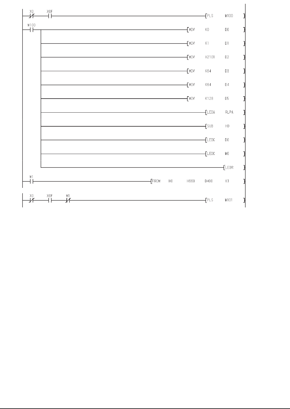
13 - 34 13. CC-Link CONNECTION (INTELLIGENT DEVICE STATION)
13.4 PLC Side Setting
(c) Example of sequence program (CC-Link dedicated instruction)
(Continued to next page)
* Setting of network parameter with dedicated RLPA instruction
* Setting of automatic refresh parameter with dedicated RRPA instruction
Module
ready
Module error
Module
ready
RLPA error
completion
Module
error
RLPA error completion
Synchronous mode
(Invalid)
Number of connected
modules (1 module)
Send buffer size
(64 words)
Receive buffer size
(64 words)
Automatic update buffer
size (128 words)
CC-Link module head
I/O No. (0000H)
Parameter storage
head device (D0)
Turning on during 1 scan
in the case of instruction
completion ON (M0)
Error code reading
(SW0068)
Dedicated
instruction (RLPA)
Station data (intelligent
device station, exclusive
station 1, station No.1)
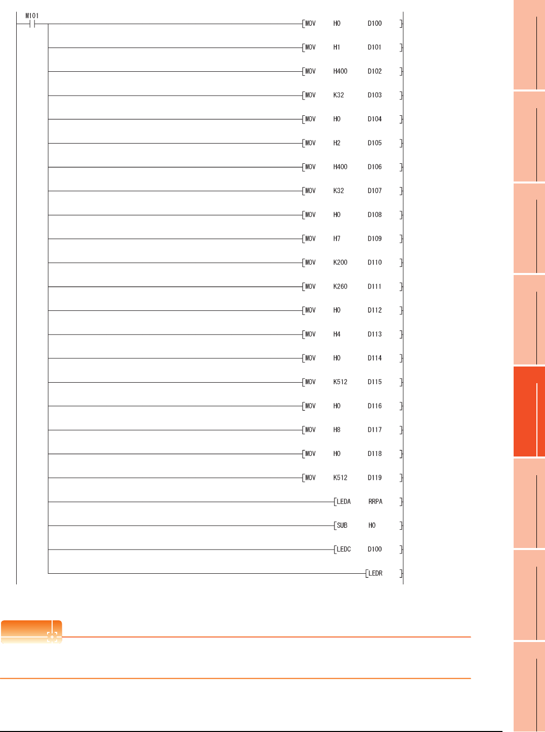
13. CC-Link CONNECTION (INTELLIGENT DEVICE STATION)
13.4 PLC Side Setting
13 - 35
9
MELSECNET/H
CONNECTION (PLC
TO PLC NETWORK)
10
MELSECNET/10
CONNECTION (PLC
TO PLC NETWORK)
11
CC-Link IE CONTROLLER
NETWORK
CONNECTION
12
CC-Link IE FIELD
NETWORK
CONNECTION
13
CC-Link CONNECTION
(INTELLIGENT DEVICE
STATION)
14
CC-Link
CONNECTION
(Via G4)
15
INVERTER
CONNECTION
16
SERVO AMPLIFIER
CONNECTION
POINT
POINT
POINT
When changing the sequence program
After writing the sequence program to the PLC CPU, operate the PLC CPU ether turning OFF and then ON or resetting.
Head No. of RX (RX0)
RY head number (RY0)
RX refresh destination (X)
No. of refresh points (32)
RX refresh destination
device head No. (400)
RY refresh destination (Y)
No. of refresh points (32)
RY refresh destination
device head No. (400)
RW head No. (RW0)
RW refresh destination (D)
RW refresh destination
device head No. (200)
SB head No. (SB0)
SB refresh destination (B)
No. of refresh points (512)
No. of refresh points (260)
SB refresh destination
device head number (0)
SW head number (SW0)
SW refresh destination (W)
No. of refresh points (512)
Dedicated instruction
(RRPA)
CC-Link module head
I/O No. (0000H)
Parameter storage head
device (D100)
SW refresh destination
device head No. (0)
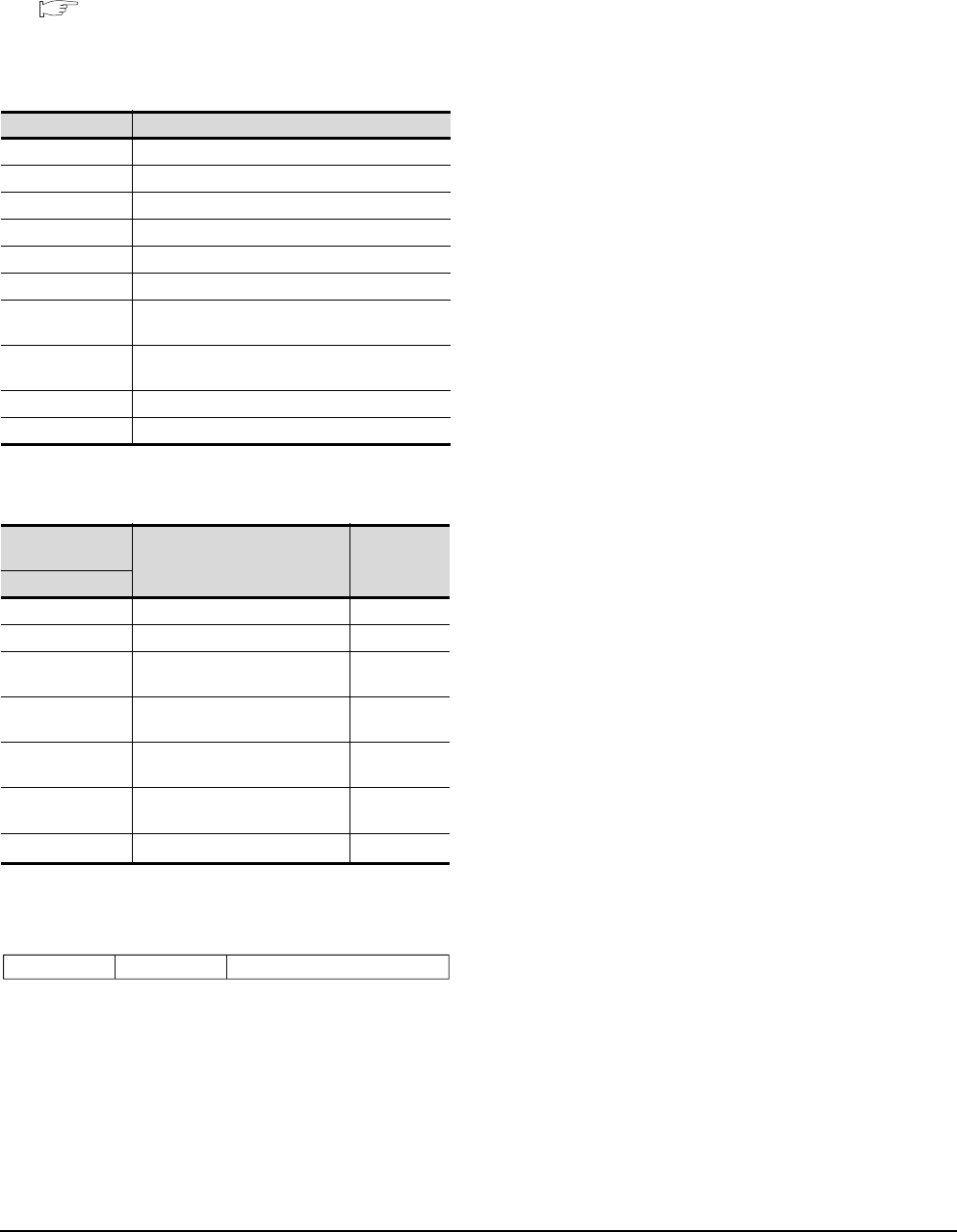
13 - 36 13. CC-Link CONNECTION (INTELLIGENT DEVICE STATION)
13.4 PLC Side Setting
(2) Program condition (for FROM/TO instruction)
This program writes parameters to the buffer memory
when PLC CPU status changes from STOP to RUN
and automatically starts the data link with FROM/TO
instruction.
(a) I/O signal of CC-Link module
Control & Communication Link System Master/
Local Module Type AJ61BT11/A1SJ61BT11
User's Manual
(b) Devices used by user
(c) Buffer memory settings used in the present
example
*1 Details for the station data are shown below.
For 1) and 2), set the same station No. and number of station
occupied settings as those of the GOT.
For 3), the setting is fixed.
Device Application
M100, M101 Flag for parameter setting
M102, M103 Flag for data link startup
D0 Number of connected modules
D1 Number of retry
D2 Automatic reconnection station count
D3 Operation specification in the case of CPU failure
D4 Reserved station specification (Station No. 1 to
Station No. 16)
D5 Error invalid station specification (Station No. 1 to
Station No. 16)
D6 Station data (first module)
D400 Error code in the case of data link startup failure
Buffer memory
address Item Set value
Decimal (Hex)
1 (1H) Number of connected modules 1 (1 module)
2 (2H) Number of retry 3 (3times)
3 (3H)Automatic reconnection station
count 1 (1 station)
6 (6H)Operation specification in the
case of CPU failure 0 (stop)
16 (10H)Reserved station specification
(Station No. 1 to Station No. 16)
0 (No
specification)
20 (14H)Error invalid station specification
(Station No. 1 to Station No. 16)
0 (No
specification)
32 (20H)Station data (first module)*1 2101H
1) Station No. (Set the same station No. as that of the GOT.)
01H to 40H: Station No. 1 to Station No. 64
2) Number of stations occupied (Set the same setting of the
number of station occupied as that of the GOT.)
1H: Exclusive station 1
2H: Exclusive station 2
3H: Exclusive station 3
4H: Exclusive station 4
3) Station type (2H: Set it to intelligent device station.)
0H: Remote I/O station
1H: Remote device station
2H: Intelligent device station (Incl. local station)
b15 b12to b11 b8to b7 to b0
3) 2) 1)
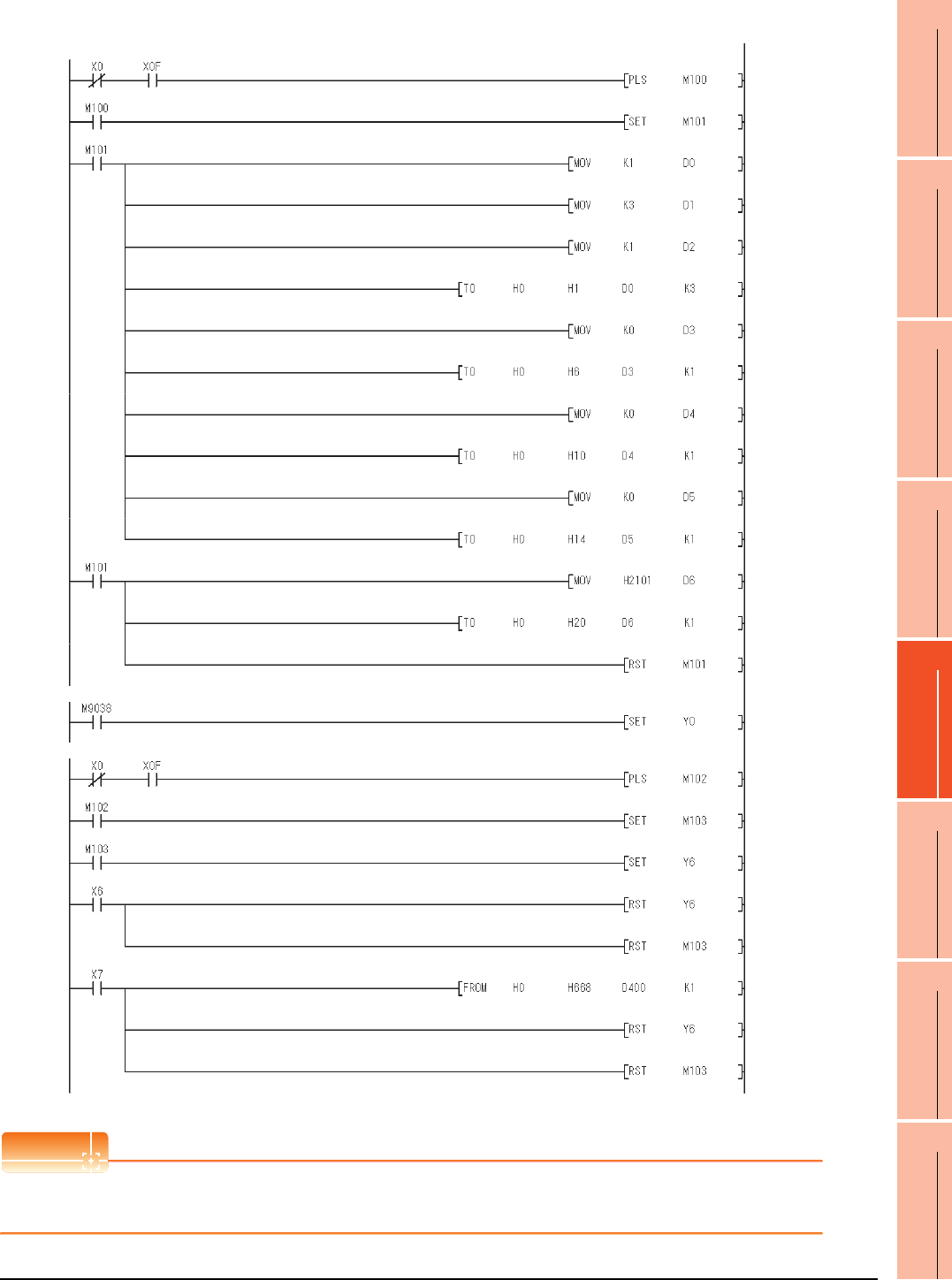
13. CC-Link CONNECTION (INTELLIGENT DEVICE STATION)
13.4 PLC Side Setting
13 - 37
9
MELSECNET/H
CONNECTION (PLC
TO PLC NETWORK)
10
MELSECNET/10
CONNECTION (PLC
TO PLC NETWORK)
11
CC-Link IE CONTROLLER
NETWORK
CONNECTION
12
CC-Link IE FIELD
NETWORK
CONNECTION
13
CC-Link CONNECTION
(INTELLIGENT DEVICE
STATION)
14
CC-Link
CONNECTION
(Via G4)
15
INVERTER
CONNECTION
16
SERVO AMPLIFIER
CONNECTION
(d) Example of sequence program (FROM/TO instruction)
POINTPOINTPOINT
When changing the sequence program
After writing the sequence program to the PLC CPU, operate the PLC CPU ether turning OFF and then ON or resetting.
Data link
startup
normal
completion
(buffer memory)
Data link
startup
abnormal
completion
(buffer
memory)
Turn on only during 1 scan after RUN
Module
ready
Module error
Module
ready
Module error
Number of connected
modules (1 module)
Number of retry (3 times)
Number of automatic
return stations (1 station)
Reserved station
specification
(No specification)
Refresh instruction
Data link startup request
(buffer memory address)
Error code reading
(SW0068)
Error invalid station
specification
(No specification)
Station data (Intelligent
device station, exclusive
station 1, station No. 1)
Operation specification in
the case of CPU failure
(Stop)
* Parameter setting
* Refresh instruction
* Data link with buffer memory parameters
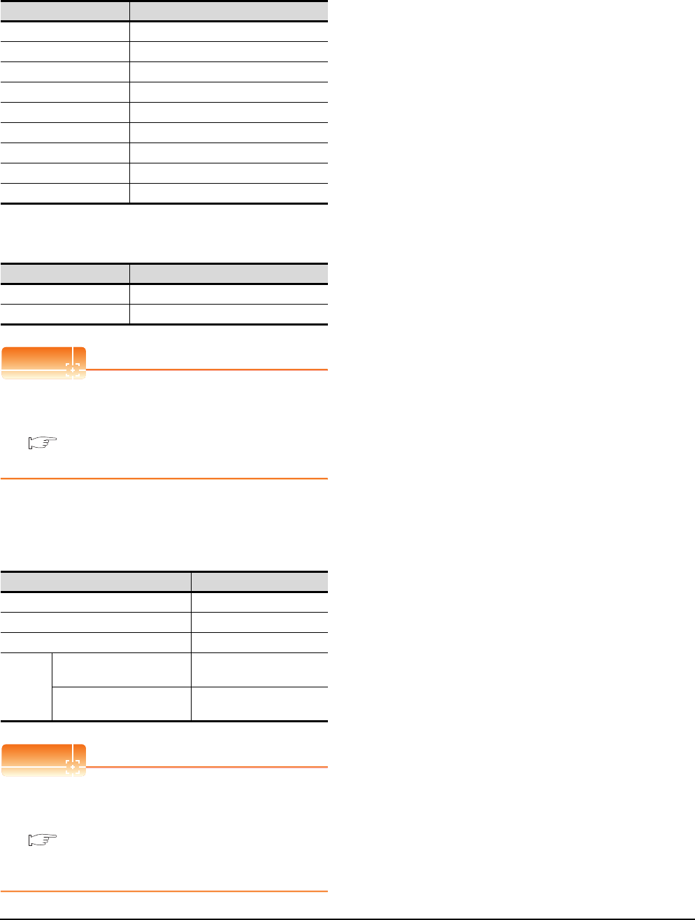
13 - 38 13. CC-Link CONNECTION (INTELLIGENT DEVICE STATION)
13.4 PLC Side Setting
[Controller Setting] of GT Designer3
(1) When MODEL GT15-J61BT13 CC-Link
communication unit is used
(2) When MODEL GT15-75J61BT13-Z CC-Link
communication unit is used
POINTPOINTPOINT
[Controller Setting] of GT Designer3
For the setting method of [Controller Setting] of GT
Designer3, refer to the following.
13.3.1 Setting communication interface
(Communication settings)
Setting of the CC-Link communication unit
(Only when MODEL GT15-75J61BT13-Z
CC-Link communication unit is used)
POINTPOINTPOINT
Setting of the CC-Link communication unit
For the setting method of the CC-Link communication
unit, refer to the following.
13.3.3 Switch setting (Only when MODEL
GT15-75J61BT13-Z CC-Link communication
unit is used)
Item Set value
Station No. 1: Station No.1
Transmission Rate 0: Online 156kbps
Mode Ver.1: Remote net (Ver.1 mode)
Expanded Cyclic Single (Use default value)
Number of stations occupied
1 Station
Input for Error Station 0: Clear
Retry 3times (Use default value)
Timeout Time 3sec (Use default value)
Delay Time 0ms (Use default value)
Item Set value (Use default value)
Retry 3times
Timeout Time 3sec
Item Set value
Mode setting switch 0: Online (fixed)
Station number setting switch 1: Station No.1
Transmission baudrate setting switch 0: 156kbps
Conditio
n setting
switches
SW1 (Input data status of the
data link error station) OFF: Cleared
SW2 (Number of occupied
stations) OFF: 1 station
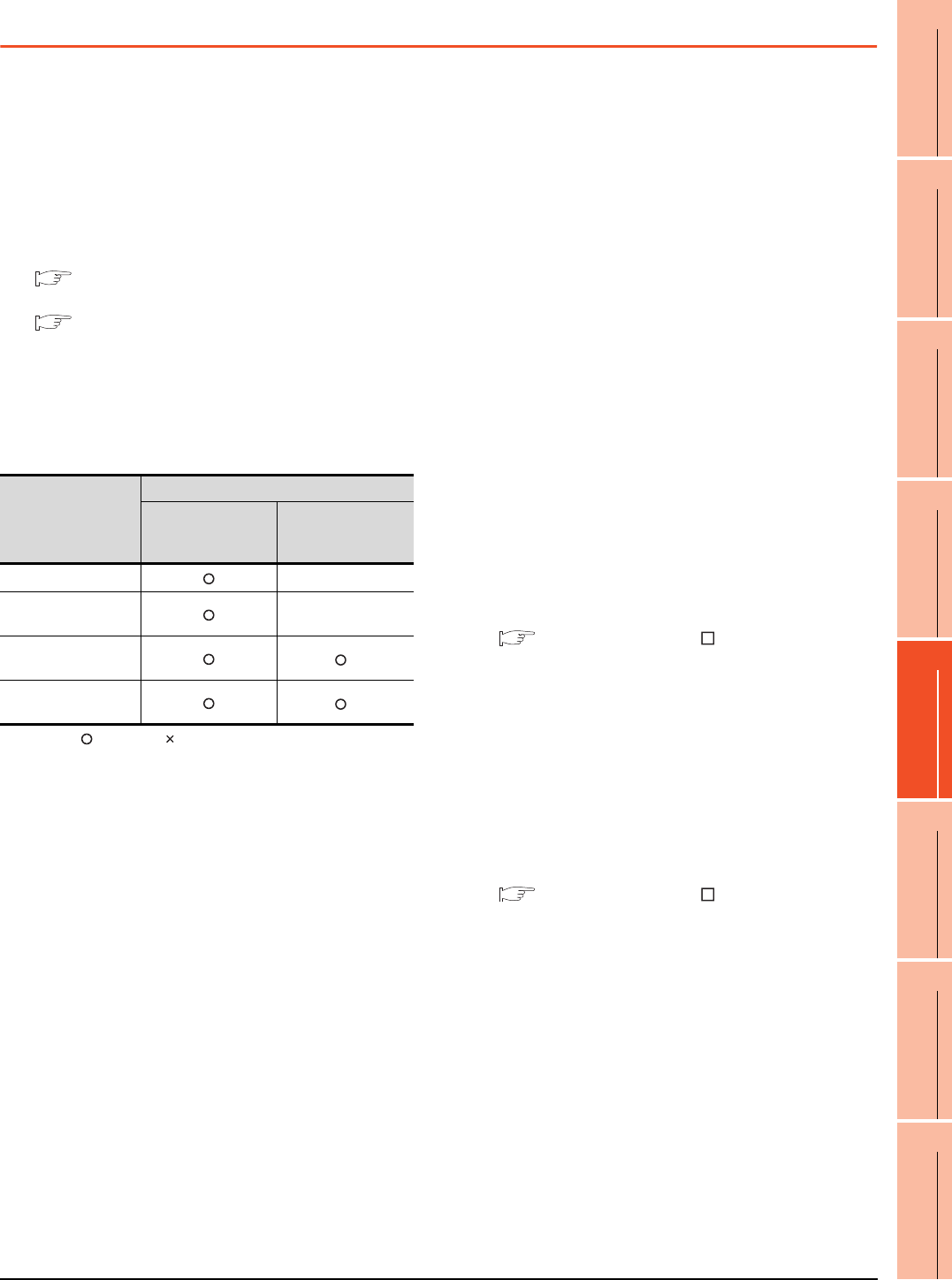
13. CC-Link CONNECTION (INTELLIGENT DEVICE STATION)
13.5 Precautions
13 - 39
9
MELSECNET/H
CONNECTION (PLC
TO PLC NETWORK)
10
MELSECNET/10
CONNECTION (PLC
TO PLC NETWORK)
11
CC-Link IE CONTROLLER
NETWORK
CONNECTION
12
CC-Link IE FIELD
NETWORK
CONNECTION
13
CC-Link CONNECTION
(INTELLIGENT DEVICE
STATION)
14
CC-Link
CONNECTION
(Via G4)
15
INVERTER
CONNECTION
16
SERVO AMPLIFIER
CONNECTION
13.5 Precautions
Using cyclic transmission
(1) I/O signal for master station
Do not turn on the reserved output signals in the output
signals (remote output: RY) to the GOT from the master
station.
When the reserved output signal is turned on, the PLC
system may be malfunctioned.
For the assignment of I/O signals in the GOT, refer to
the following manual.
MODEL GT15-J61BT13 CC-Link
communication unit User’s Manual
GT15 CC-Link communication unit User's
Manual
(2) Access range that can be monitored
The monitoring range of remote I/O (RX and RY) and
that of the remote registers (RWr and RWw) vary
according to the mode in the master station of the CC-
Link system.
: Applicable : N/A(All "0") -: N/A of system configuration
*1 Monitoring is applicable only when MODEL GT15-J61BT13
CC-Link communication unit is used.
(3) When GOT malfunctions, the cyclic output status
remains the same as before becoming faulty.
For transient transmission
(1) CC-Link module of target station
Mount the CC-Link module of function version B or later
and software version J or later to the PLC CPU when
performing the following CC-Link modules and
transient transmission.
Only cyclic transmission can be communicated with the
CC-Link module of function version A or before and
software version I or before.
• AJ61BT11
•A1SJ61BT11
•AJ61QBT11
•A1SJ61QBT11
(2) Access range that can be monitored
The GOT can access to the PLC CPU mounting the
master and local station of the CC-Link System.
It cannot access another network via the CC-Link
module.
GOT startup in the CC-Link connection
(intelligent device station)
For CC-Link connection (intelligent device station), the
data link is started approximately 10 seconds after the
GOT startup.
When a network error occurs in the system
alarm
In the CC-Link connection (intelligent device station),
when a network error occurs in the system alarm, the
system alarm display cannot be canceled even though
the causes are removed.
To cancel the system alarm display, restart the GOT.
Connection in the multiple CPU system
When the GOT is connected to multiple CPU system,
the following time is taken until when the PLC runs.
QCPU (Q mode), motion controller CPU (Q series): 10
seconds or more
MELDAS C70: 18 seconds or more
When the GOT starts before the PLC runs, a system
alarm occurs.Adjust the opening screen time in the
GOT setup so that no system alarm occurs.
GT Designer3 Version Screen Design
Manual
Connection to LCPU
LCPU may diagnose (check file system, execute
recovering process, etc.) the SD memory card when
turning on the power or when resetting. Therefore, it
takes time until the SD memory card becomes
available. When the GOT starts before the SD card
becomes available, a system alarm occurs. Adjust the
opening screen time in the GOT setup so that no
system alarm occurs.
GT Designer3 Version Screen Design
Manual
Connection to Q17nDCPU, Q170MCPU,
CNC C70, CRnQ-700
The Q17nDCPU, Q170MCPU, CNC C70 and CRnQ-
700 are applicable to the CC-Link network system Ver.2
only
For connecting to the CC-Link (ID) network system, set
the CC-Link (ID) network system to the CC-Link Ver.2
mode.
Mode of master station
Applicable of monitoring
Data for each station
compatible with
CC-Link ver.1
Data for each station
compatible with
CC-Link ver.2
Remote net mode -
Remote net ver.1
mode -
Remote net ver.2
mode
*1
Remote net additional
mode
*1
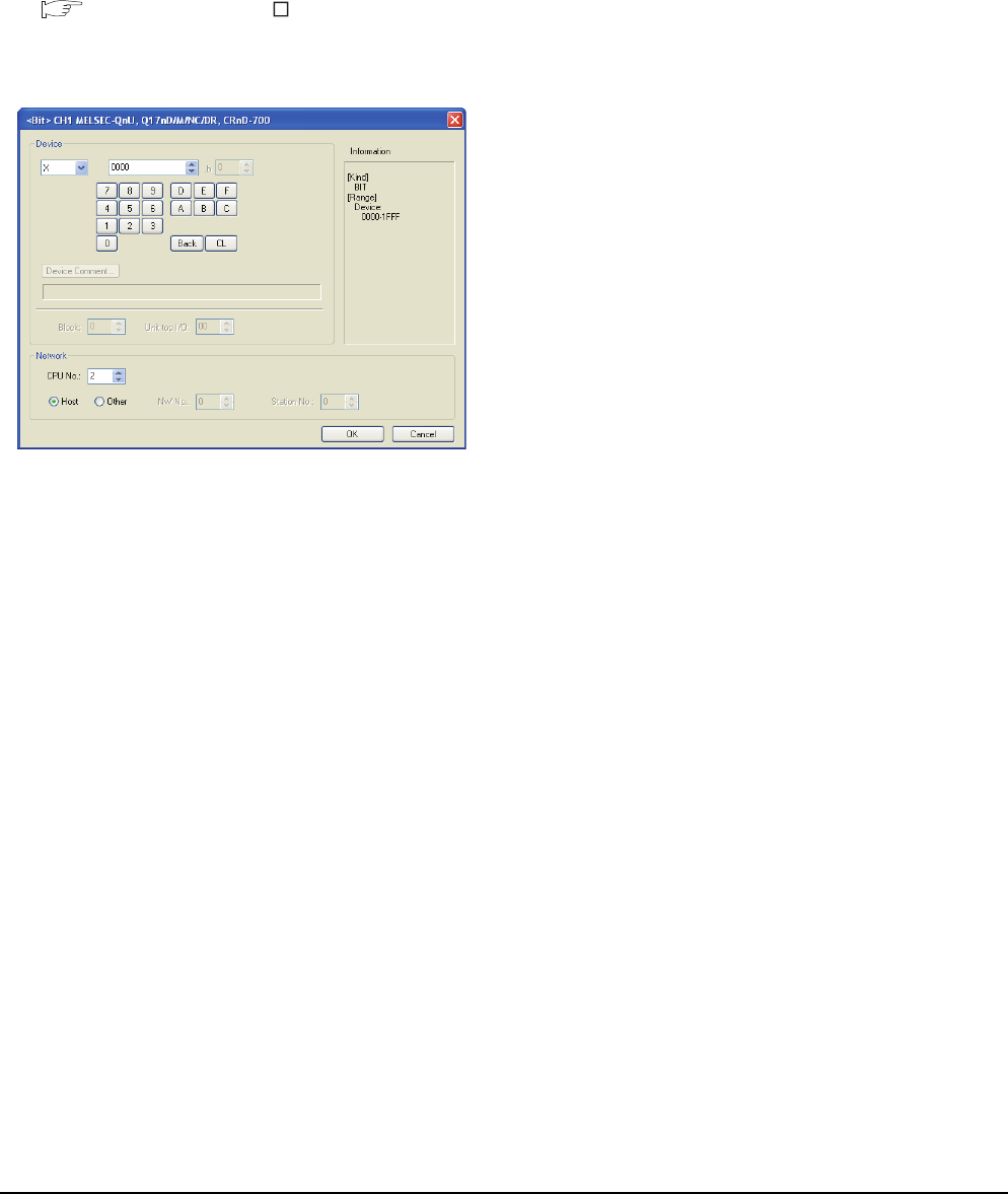
13 - 40 13. CC-Link CONNECTION (INTELLIGENT DEVICE STATION)
13.5 Precautions
Connection to Q170MCPU
Set [CPU No.] to "2" in the device setting to monitor the
device of the Motion CPU area (CPU No.2).
When the CPU No. is set to "0" or "1", the device on the
PLC CPU area (CPU No.1) is monitored.
When the CPU No. is set to the number other than "0"
to "2", a communication error occurs and the monitoring
cannot be executed.
For setting the CPU No., refer to the following manual.
GT Designer3 Version Screen Design
Manual
Example) Setting dialog box of the bit device
14
9
MELSECNET/H
CONNECTION (PLC
TO PLC NETWORK)
10
MELSECNET/10
CONNECTION (PLC
TO PLC NETWORK)
11
CC-Link IE CONTROLLER
NETWORK
CONNECTION
12
CC-Link IE FIELD
NETWORK
CONNECTION
13
CC-Link CONNECTION
(INTELLIGENT DEVICE
STATION)
14
CC-Link
CONNECTION
(Via G4)
15
INVERTER
CONNECTION
16
SERVO AMPLIFIER
CONNECTION
14 - 1
14.CC-Link CONNECTION (Via G4)
14.1 Connectable Model List . . . . . . . . . . . . . . . . . . . . . . . . . . . 14 - 2
14.2 System Configuration. . . . . . . . . . . . . . . . . . . . . . . . . . . . . 14 - 6
14.3 Connection Diagram . . . . . . . . . . . . . . . . . . . . . . . . . . . . . 14 - 8
14.4 GOT Side Settings . . . . . . . . . . . . . . . . . . . . . . . . . . . . . . . 14 - 9
14.5 PLC Side Settings . . . . . . . . . . . . . . . . . . . . . . . . . . . . . . .14 - 11
14.6 Precautions . . . . . . . . . . . . . . . . . . . . . . . . . . . . . . . . . . . 14 - 17
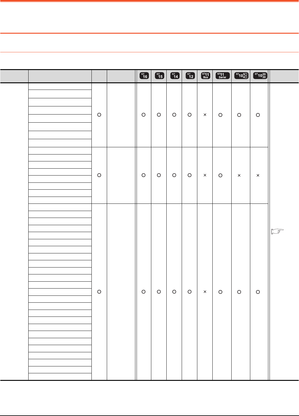
14 - 2 14. CC-Link CONNECTION (Via G4)
14.1 Connectable Model List
14. CC-Link CONNECTION (Via G4)
14.1 Connectable Model List
14.1.1 PLC/Motion controller CPU
The following table shows the connectable models.
(Continued to next page)
*1 When in multiple CPU system configuration, use CPU function version B or later.
*2 Only master station can be monitored in GT11 and GT10.
*3 For GT10, do not include in the multiple CPU system configuration.
Series Model name Clock
Communication
type Refer to
MELSEC-Q
(Q mode)
Q00JCPU
CC-Link
(G4)
*2 *2 *2
14.2.1
Q00CPU*1
Q01CPU*1
Q02CPU*1
Q02HCPU*1
Q06HCPU*1
Q12HCPU*1
Q25HCPU*1
Q02PHCPU
CC-Link
(G4)
*2 *3 *3
Q06HCPU
Q12PHCPU
Q25PHCPU
Q12PRHCPU (Main base)
Q25PRHCPU (Main base)
Q12PRHCPU (Extension base)
Q25PRHCPU (Extension base)
Q00UJCPU
CC-Link
(G4)
*2 *2 *2
Q00UCPU
Q01UCPU
Q02UCPU
Q03UDCPU
Q04UDHCPU
Q06UDHCPU
Q10UDHCPU
Q13UDHCPU
Q20UDHCPU
Q26UDHCPU
Q03UDECPU
Q04UDEHCPU
Q06UDEHCPU
Q10UDEHCPU
Q13UDEHCPU
Q20UDEHCPU
Q26UDEHCPU
Q50UDEHCPU
Q100UDEHCPU
Q03UDVCPU
Q04UDVCPU
Q06UDVCPU
Q13UDVCPU
Q26UDVCPU
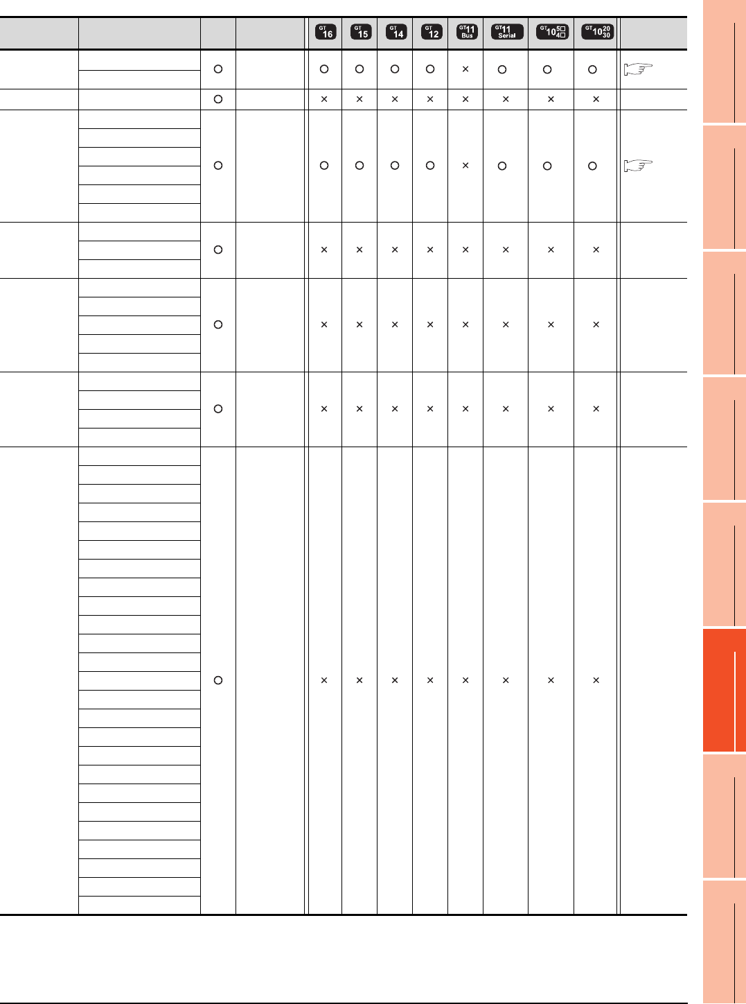
14. CC-Link CONNECTION (Via G4)
14.1 Connectable Model List
14 - 3
9
MELSECNET/H
CONNECTION (PLC
TO PLC NETWORK)
10
MELSECNET/10
CONNECTION (PLC
TO PLC NETWORK)
11
CC-Link IE CONTROLLER
NETWORK
CONNECTION
12
CC-Link IE FIELD
NETWORK
CONNECTION
13
CC-Link CONNECTION
(INTELLIGENT DEVICE
STATION)
14
CC-Link
CONNECTION
(Via G4)
15
INVERTER
CONNECTION
16
SERVO AMPLIFIER
CONNECTION
(Continued to next page)
*1 Only master station can be monitored in GT11 and GT10.
*2 Use only modules with the upper five digits of the serial No. later than 12042.
Series Model name Clock
Communication
type Refer to
C Controller
module
Q12DCCPU-V*2
CC-Link(G4) *1 *1 *1 14.2.1
Q24DHCCPU-V
MELSEC-QS QS001CPU - -
MELSEC-L
L02CPU
CC-Link(G4) *1 *1 *1 14.2.2
L26CPU
L26CPU-BT
L02CPU-P
L26CPU-PBT
L02SCPU
MELSEC-Q
(A mode)
Q02CPU-A
- -Q02HCPU-A
Q06HCPU-A
MELSEC-QnA
(QnACPU)
Q2ACPU
- -
Q2ACPU-S1
Q3ACPU
Q4ACPU
Q4ARCPU
MELSEC-QnA
(QnASCPU)
Q2ASCPU
- -
Q2ASCPU-S1
Q2ASHCPU
Q2ASHCPU-S1
MELSEC-A
(AnCPU)
A2UCPU
- -
A2UCPU-S1
A3UCPU
A4UCPU
A2ACPU
A2ACPUP21
A2ACPUR21
A2ACPU-S1
A2ACPUP21-S1
A2ACPUR21-S1
A3ACPU
A3ACPUP21
A3ACPUR21
A1NCPU
A1NCPUP21
A1NCPUR21
A2NCPU
A2NCPUP21
A2NCPUR21
A2NCPU-S1
A2NCPUP21-S1
A2NCPUR21-S1
A3NCPU
A3NCPUP21
A3NCPUR21
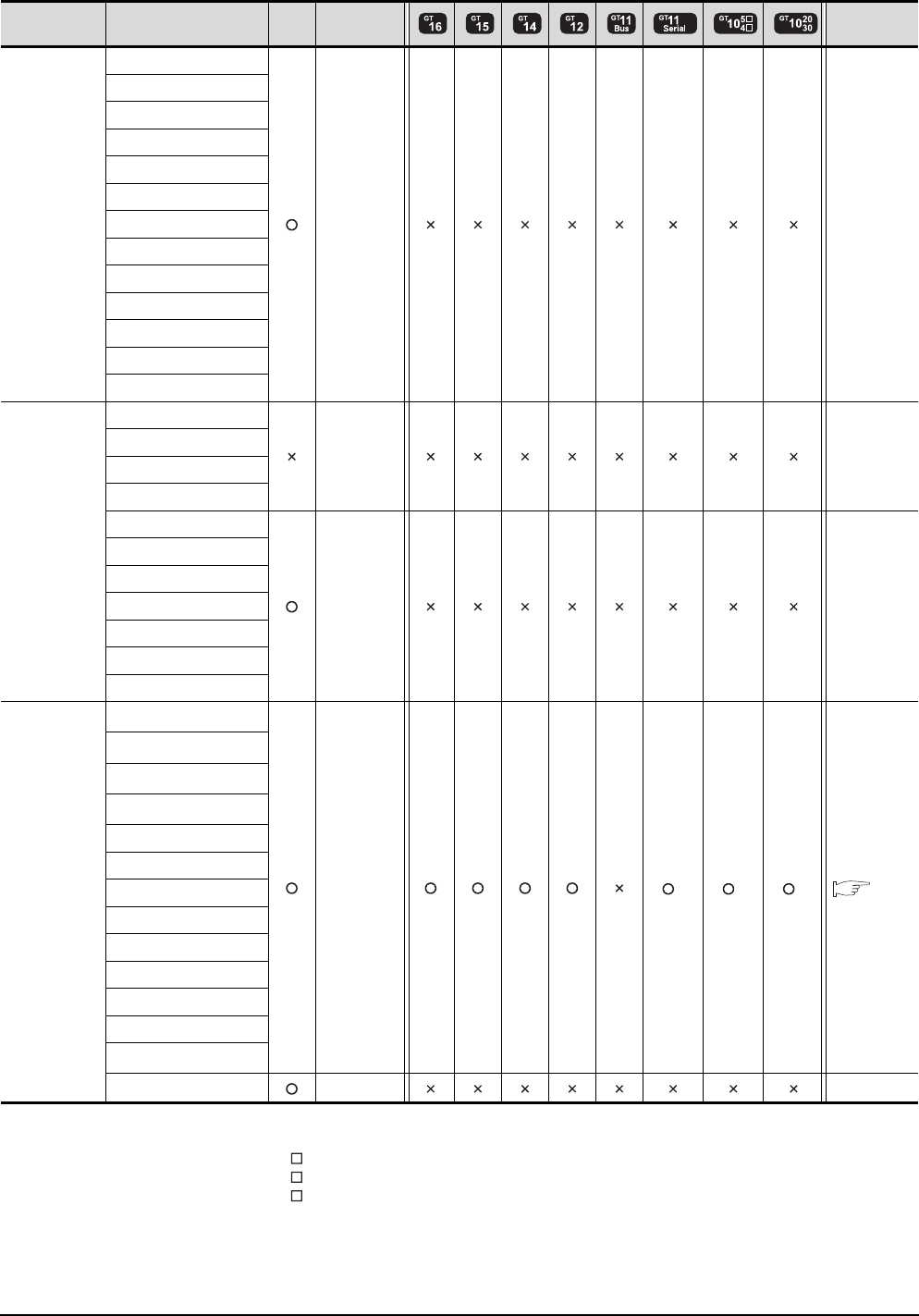
14 - 4 14. CC-Link CONNECTION (Via G4)
14.1 Connectable Model List
(Continued to next page)
*1 When using SV13, SV22, or SV43, use the motion controller CPU on which any of the following main OS version is installed.
• SW6RN-SV13Q : 00H or later
• SW6RN-SV22Q : 00H or later
• SW6RN-SV43Q : 00B or later
*2 Use main modules with the following product numbers.
• Q172CPU: Product number N******* or later
• Q173CPU: Product number M******* or later
*3 Only the first step can be used on the extension base unit (Q52B/Q55B).
*4 Only master station can be monitored in GT11 and GT10.
Series Model name Clock
Communication
type Refer to
MELSEC-A
(AnSCPU)
A2USCPU
- -
A2USCPU-S1
A2USHCPU-S1
A1SCPU
A1SCPUC24-R2
A1SHCPU
A2SCPU
A2SCPU-S1
A2SHCPU
A2SHCPU-S1
A1SJCPU
A1SJCPU-S3
A1SJHCPU
MELSEC-A
A0J2HCPU
- -
A0J2HCPUP21
A0J2HCPUR21
A0J2HCPU-DC24
A2CCPU
- -
A2CCPUP21
A2CCPUR21
A2CCPUC24
A2CCPUC24-PRF
A2CJCPU-S3
A1FXCPU
Motion
controller
CPU
(Q Series)
Q172CPU*1*2
CC-Link (G4) *4 *4 *4 14.2.1
Q173CPU*1*2
Q172CPUN*1
Q173CPUN*1
Q172HCPU
Q173HCPU
Q172DCPU
Q173DCPU
Q172DCPU-S1
Q173DCPU-S1
Q172DSCPU
Q173DSCPU
Q170MCPU*3
MR-MQ100 - -
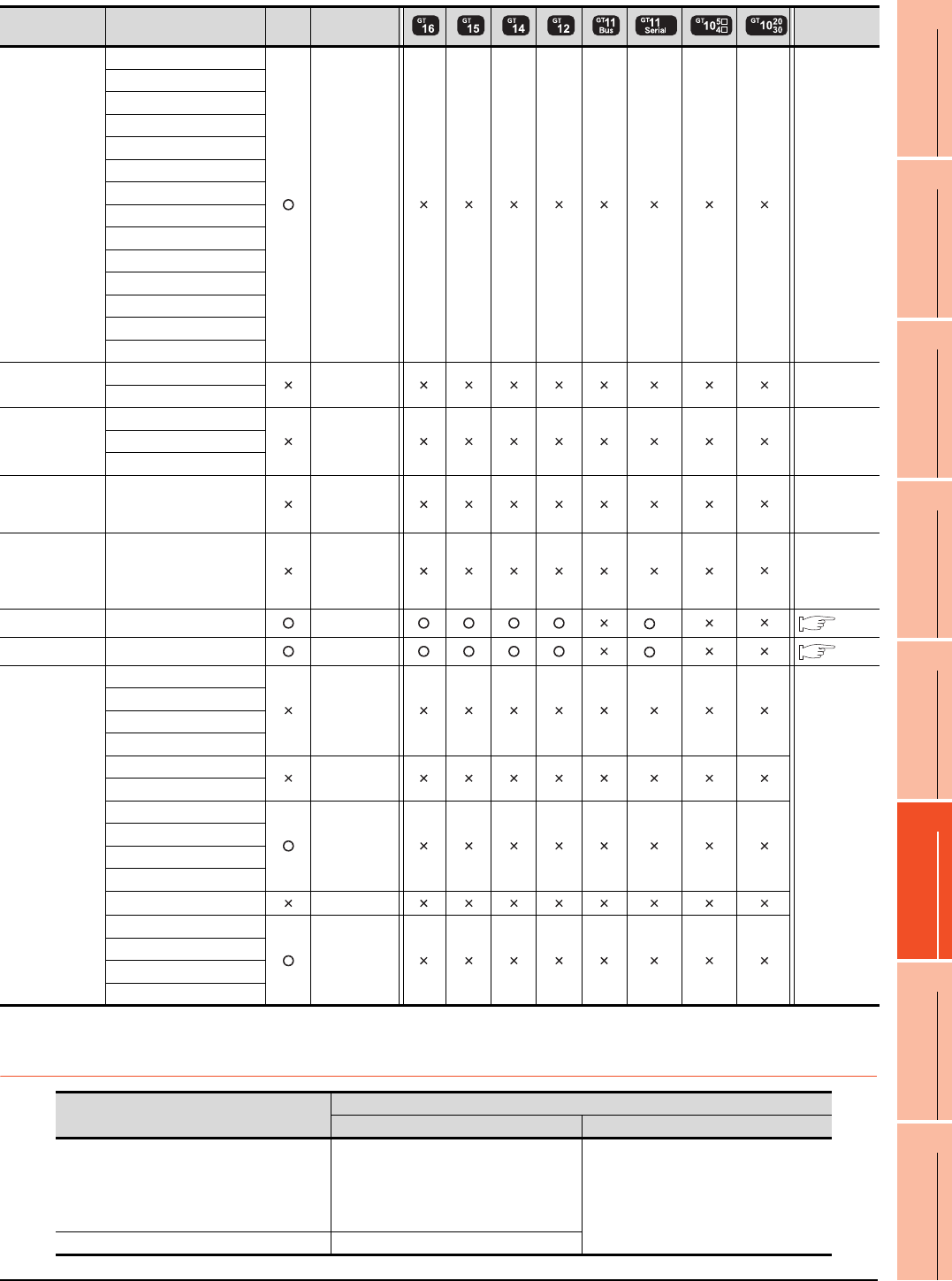
14. CC-Link CONNECTION (Via G4)
14.1 Connectable Model List
14 - 5
9
MELSECNET/H
CONNECTION (PLC
TO PLC NETWORK)
10
MELSECNET/10
CONNECTION (PLC
TO PLC NETWORK)
11
CC-Link IE CONTROLLER
NETWORK
CONNECTION
12
CC-Link IE FIELD
NETWORK
CONNECTION
13
CC-Link CONNECTION
(INTELLIGENT DEVICE
STATION)
14
CC-Link
CONNECTION
(Via G4)
15
INVERTER
CONNECTION
16
SERVO AMPLIFIER
CONNECTION
*1 Only master station can be monitored in GT11.
14.1.2 CC-Link module/peripheral module
Series Model name Clock
Communication
type Refer to
Motion
controller
CPU
(A Series)
A273UCPU
- -
A273UHCPU
A273UHCPU-S3
A373UCPU
A373UCPU-S3
A171SCPU
A171SCPU-S3
A171SCPU-S3N
A171SHCPU
A171SHCPUN
A172SHCPU
A172SHCPUN
A173UHCPU
A173UHCPU-S1
MELSEC-WS WS0-CPU0 - -
WS0-CPU1
MELSECNET/H
Remote I/O
station
QJ72LP25-25
- -QJ72LP25G
QJ72BR15
CC-Link IE
Field Network
head module
LJ72GF15-T2 - -
CC-Link IE
Field Network
Ethernet
adapter module
NZ2GF-ETB - -
CNC C70 Q173NCCPU CC-Link (G4) *1 14.2.1
Robot controller CRnQ-700 (Q172DRCPU) CC-Link (G4) *1 14.2.1
MELSEC-FX
FX0
-
-
FX0S
FX0N
FX1
FX2
-
FX2C
FX1S
-
FX1N
FX2N
FX1NC
FX2NC -
FX3G
-
FX3GC
FX3U
FX3UC
CPU series Model name
CC-Link module Peripheral module
MELSEC-Q (Q mode)
C Controller module
Motion controller CPU (Q Series)
CNC C70
Robot controller (CRnQ-700)
QJ61BT11
QJ61BT11N AJ65BT-G4-S3
AJ65BT-R2N
MELSEC-L LJ61BT11
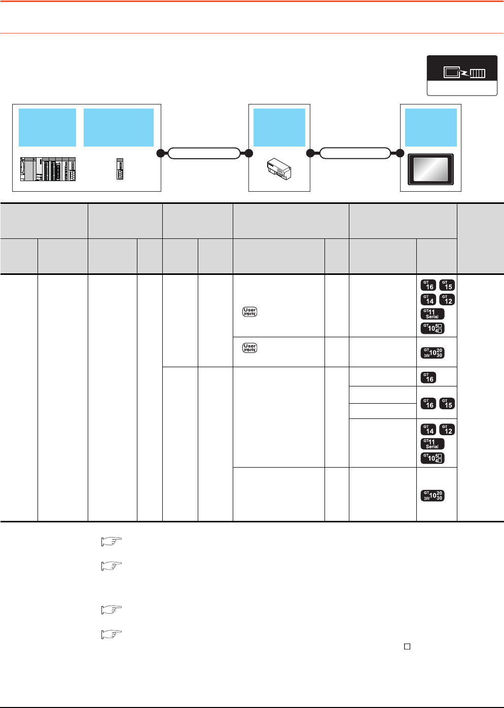
14 - 6 14. CC-Link CONNECTION (Via G4)
14.2 System Configuration
14.2 System Configuration
14.2.1 Connecting to QCPU (Q mode)
*1 For the system configuration of the CC-Link module, refer to the following manual.
CC-Link System Master/Local Module User's Manual QJ61BT11N
*2 For the specifications and inquiries of the CC-Link dedicated cable, refer to the following.
CC-Link Partner Association's home page: http://www.cc-link.org/
*3 The maximum overall extension cable length and the length between stations vary depending on the cable type to be used and
the transmission speed.
For details, refer to the following manual.
CC-Link System Master/Local Module User's Manual QJ61BT11N
*4 For the connection to GOT, refer to the connection diagram.
RS422 connection diagram 1)
*5 Connect it to the RS-232 interface (built into GOT). It cannot be mounted on GT1655 and GT155 .
CC-Link (G4)
Communication driver
CC-Link moduleQCPU
Peripheral
connection
module
Connection cable 1)
GOT
Connection cable 2)
PLC Connection cable 1)
Peripheral
connection
module
Connection cable 2) GOT
Number of
connectable
equipment
Model
name
CC-Link
module
*1
Cable
model
Max.
dista
nce
Model
name
Commu
nication
type
Cable model
Connection diagram
number
Max.
dista
nce
Option
device Model
MELSEC
-Q
C
Controlle
r module
QJ61BT11
QJ61BT11N
CC-Link
dedicated
cable
*2
*3
AJ65BT
-R2N RS-232
GT09-C30R2-9P
or
RS232 connection
diagram 1)
15m - (Built into GOT)
1 GOT for
1 peripheral
connection
module
RS232 connection
diagram 2)
15m - (Built into GOT)
AJ65BT
-G4-S3 RS-422
GT01-C30R4-25P(3m)
GT01-C100R4-25P(10m)
GT01-C200R4-25P(20m)
GT01-C300R4-25P(30m)
30m
GT16-C02R4-9S
GT15-RS2T4-9P*5
GT15-RS4-9S
- (Built into GOT)
GT10-C30R4-25P(3m)
GT10-C100R4-25P(10m)
GT10-C200R4-25P(20m)
GT10-C300R4-25P(30m)
*4
30m - (Built into GOT)
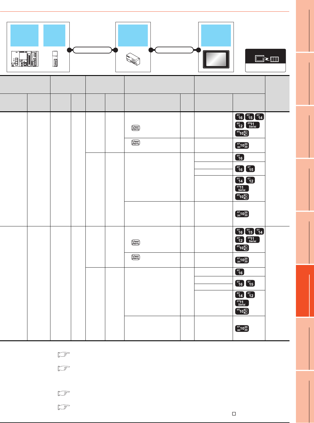
14. CC-Link CONNECTION (Via G4)
14.2 System Configuration
14 - 7
9
MELSECNET/H
CONNECTION (PLC
TO PLC NETWORK)
10
MELSECNET/10
CONNECTION (PLC
TO PLC NETWORK)
11
CC-Link IE CONTROLLER
NETWORK
CONNECTION
12
CC-Link IE FIELD
NETWORK
CONNECTION
13
CC-Link CONNECTION
(INTELLIGENT DEVICE
STATION)
14
CC-Link
CONNECTION
(Via G4)
15
INVERTER
CONNECTION
16
SERVO AMPLIFIER
CONNECTION
14.2.2 Connecting to LCPU
*1 For the system configuration of the CC-Link module, refer to the following manual.
MELSEC-L CC-Link System Master/Local Module User's Manual
*2 For the specifications and inquiries of the CC-Link dedicated cable, refer to the following.
CC-Link Partner Association's home page: http://www.cc-link.org/
*3 The maximum overall extension cable length and the length between stations vary depending on the cable type to be used and
the transmission speed.
For details, refer to the following manual.
MELSEC-L CC-Link System Master/Local Module User's Manual
*4 For the connection to GOT, refer to the connection diagram.
RS422 connection diagram 1)
*5 Connect it to the RS-232 interface (built into GOT). It cannot be mounted on GT1655 and GT155 .
PLC Connection
cable 1)
Peripheral
connection
module
Connection cable 2) GOT
Number of
connectable
equipment
Model name
CC-Link
module
*1
Cable
model
Max.
dista
nce
Model
name
Commu
nication
type
Cable model
Connection diagram number
Max.
dista
nce
Option
device Model
L02CPU
L26CPU
-BT
L02CPU-P
L26CPU-PBT
LJ61BT11
CC-Link
dedicated
cable
*2
*3
AJ65BT
-R2N RS-232
GT09-C30R2-9P
or
RS232 connection
diagram 1)
15m - (Built into GOT)
1 GOT for
1 peripheral
connection
module
RS232 connection
diagram 2)
15m - (Built into GOT)
AJ65BT
-G4-S3 RS-422
GT01-C30R4-25P(3m)
GT01-C100R4-25P(10m)
GT01-C200R4-25P(20m)
GT01-C300R4-25P(30m)
30m
GT16-C02R4-9S
GT15-RS2T4-9P*5
GT15-RS4-9S
- (Built into GOT)
GT10-C30R4-25P(3m)
GT10-C100R4-25P(10m)
GT10-C200R4-25P(20m)
GT10-C300R4-25P(30m)*4
30m - (Built into GOT)
L26CPU
-BT
L26CPU-PBT
-
CC-Link
dedicated
cable
*2
*3
AJ65BT
-R2N RS-232
GT09-C30R2-9P
or
RS232 connection
diagram 1)
15m - (Built into GOT)
1 GOT for
1 peripheral
connection
module
RS232 connection
diagram 2)
15m - (Built into GOT)
AJ65BT
-G4-S3 RS-422
GT01-C30R4-25P(3m)
GT01-C100R4-25P(10m)
GT01-C200R4-25P(20m)
GT01-C300R4-25P(30m)
30m
GT16-C02R4-9S
GT15-RS2T4-9P*5
GT15-RS4-9S
- (Built into GOT)
GT10-C30R4-25P(3m)
GT10-C100R4-25P(10m)
GT10-C200R4-25P(20m)
GT10-C300R4-25P(30m)*4
30m - (Built into GOT)
CC-Link (G4)
Communication driver
CC-Link
module
LCPU
Peripheral
connection
module
Connection cable 2)
GOT
Connection cable 2)
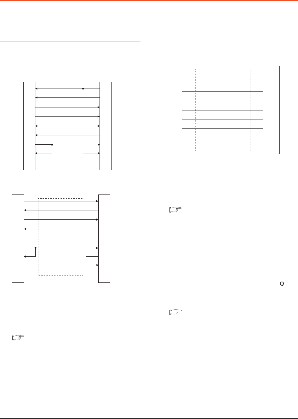
14 - 8 14. CC-Link CONNECTION (Via G4)
14.3 Connection Diagram
14.3 Connection Diagram
The following diagram shows the connection between the
GOT and the PLC.
14.3.1 RS-232 cable
Connection diagram
Precautions when preparing a cable
(1) Cable length
The length of the RS-232 cable must be 15m or less.
(2) GOT side connector
For the GOT side connector, refer to the following.
1.4.1 GOT connector specifications
14.3.2 RS-422 cable
Connection diagram
Precautions when preparing a cable
(1) Cable length
The length of the RS-422 cable must be 500m or less.
(2) GOT side connector
For the GOT side connector, refer to the following.
1.4.1 GOT connector specifications
Connecting terminating resistors
(1) GOT side
When connecting a PLC to the GOT, a terminating
resistor must be connected to the GOT.
(a) For GT16, GT15, GT12
Set the terminating resistor setting switch of the
GOT main unit to "Disable".
(b) For GT14, GT11, GT10
Set the terminating resistor selector to "330 ".
For the procedure to set the terminating resistor, refer
to the following.
1.4.3 Terminating resistors of GOT
RS232 connection diagram 1)
RS232 connection diagram 2)
GOT side
(D-Sub 9-pin)
1
2
3
4
5
6
7
8
9
PLC side
7
3
2
6
5
4
1
8
9
CD
RD(RXD)
SD(TXD)
ER(DTR)
SG
DR(DSR)
RS(RTS)
CS(CTS)
-
RS(RTS)
SD(TXD)
RD(RXD)
DR(DSR)
SG
ER(DTR)
CD
CS(CTS)
-
GOT side
(terminal block)
PLC side
2
3
6
4
5
1
7
8
9
SD
RD
ER
DR
SG
RS
CS
NC
NC
RD(RXD)
SD(TXD)
DR(DSR)
ER(DTR)
SG
CD
RS(RTS)
CS(CTS)
NC
RS422 connection diagram 1)
GOT side
(terminal block)
Untied wire color of
GT10-C□□□R4-25P
Brown
Red
Orange
Yellow
Green
Blue
Purple
Black
White
SDA
SDB
RDA
RDB
SG
RSA
RSB
CSA
CSB
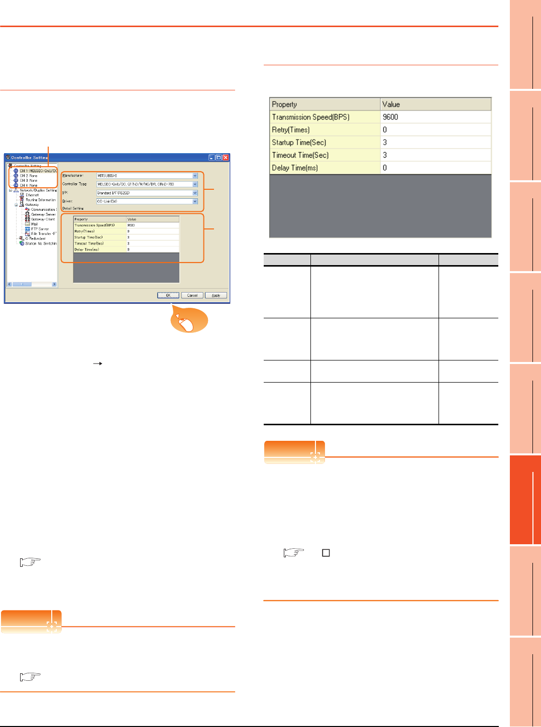
14. CC-Link CONNECTION (Via G4)
14.4 GOT Side Settings
14 - 9
9
MELSECNET/H
CONNECTION (PLC
TO PLC NETWORK)
10
MELSECNET/10
CONNECTION (PLC
TO PLC NETWORK)
11
CC-Link IE CONTROLLER
NETWORK
CONNECTION
12
CC-Link IE FIELD
NETWORK
CONNECTION
13
CC-Link CONNECTION
(INTELLIGENT DEVICE
STATION)
14
CC-Link
CONNECTION
(Via G4)
15
INVERTER
CONNECTION
16
SERVO AMPLIFIER
CONNECTION
14.4 GOT Side Settings
14.4.1 Setting communication
interface (Communication
settings)
Set the channel of the connected equipment.
1. Select [Common] [Controller Setting] from the
menu.
2. The Controller Setting window is displayed. Select the
channel to be used from the list menu.
3. Set the following items.
• Manufacturer: Mitsubishi
• Controller Type: Set according to the Controller
Type to be connected.
• I/F: Interface to be used
• Driver: CC-Link (G4)
4. The detailed setting is displayed after Manufacturer,
Controller Type, I/F, and Driver are set.
Make the settings according to the usage
environment.
14.4.2 Communication detail settings
Click the [OK] button when settings are completed.
POINTPOINTPOINT
The settings of connecting equipment can be
confirmed in [I/F Communication Setting].
For details, refer to the following:
1.1.2 I/F communication setting
14.4.2 Communication detail settings
Make the settings according to the usage environment.
POINTPOINTPOINT
(1) Communication interface setting by the Utility
The communication interface setting can be
changed on the Utility's [Communication Settings]
after writing [Communication Settings] of project
data.
For details on the Utility, refer to the following
manual.
GT User's Manual
(2) Precedence in communication settings
When settings are made by GT Designer3 or the
Utility, the latest setting is effective.
2.
3.
4.
Click!
Item Description Range
Transmission
Speed
Set this item when change the
transmission speed used for
communication with the connected
equipment.
(Default: 9600bps)
9600bps,
19200bps,
38400bps
57600bps
115200bps
Retry
Set the number of retries to be
performed when a communication
timeout occurs.
(Default: 0time)
0 to 5times
Timeout Time Set the time period for a communication
to time out.(Default: 3sec) 3 to 30sec
Delay time
Set this item to adjust the transmission
timing of the communication request
from the GOT.
(Default: 0ms)
0 to 300ms
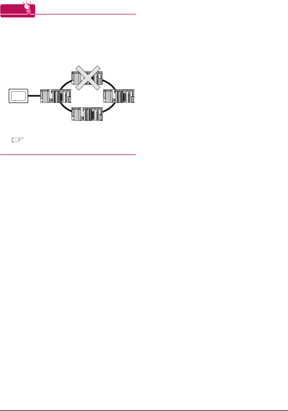
14 - 10 14. CC-Link CONNECTION (Via G4)
14.4 GOT Side Settings
HINTHINTHINT
Cutting the portion of multiple connection of the
controller
By setting GOT internal device, GOT can cut the
portion of multiple connection of the controller. For
example, faulty station that has communication
timeout can be cut from the system.
For details of the setting contents of GOT internal
device, refer to the following manual.
GT Designer3 Version Screen Design Manual
(Fundamentals)
Disconnect the
faulty station
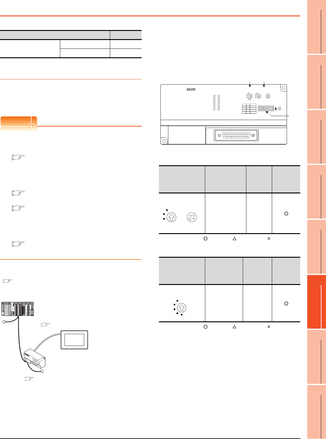
14. CC-Link CONNECTION (Via G4)
14.5 PLC Side Settings
14 - 11
9
MELSECNET/H
CONNECTION (PLC
TO PLC NETWORK)
10
MELSECNET/10
CONNECTION (PLC
TO PLC NETWORK)
11
CC-Link IE CONTROLLER
NETWORK
CONNECTION
12
CC-Link IE FIELD
NETWORK
CONNECTION
13
CC-Link CONNECTION
(INTELLIGENT DEVICE
STATION)
14
CC-Link
CONNECTION
(Via G4)
15
INVERTER
CONNECTION
16
SERVO AMPLIFIER
CONNECTION
14.5 PLC Side Settings
14.5.1 Connecting AJ65BT-G4-S3
This section describes the settings of the GOT and
peripheral connection module in the following case of the
system configuration.
POINTPOINTPOINT
(1) Peripheral connection module
For details of the peripheral connection module,
refer to the following manual.
Peripheral Connection Module Type AJ65BT-
G4-S3 User's Manual (detail volume)
(2) CC-Link module
For details of the CC-Link module, refer to the
following manual.
CC-Link System Master/Local Module User's
Manual QJ61BT11N
MELSEC-L CC-Link System Master/Local
Module User's Manual
(3) CC-Link function built-in CPU
For details on the CC-Link function built-in CPU,
refer to the following manual.
MELSEC-L CC-Link System Master/Local
Module User's Manual
System configuration
*1 The Start I/O No. of the CC-Link module is set to "0"
Switch setting of peripheral connection
module
Set the station number setting switch, data link
transmission speed setting switch, and operation
setting DIP switch.
(1) Station number setting switch
: Necessary : As necessary : Not necessary
(2) Data link transmission speed setting switch
: Necessary : As necessary : Not necessary
Model Reference
Peripheral connection
module
AJ65BT-G4-S3 14.5.1
AJ65BT-R2N 14.5.2
<CC-Link module>
*1
Station type
Station No.
Mode
All connect count
Transmission speed
<AJ65BT-G4-S3>
Station type
Station No.
Number of stations occupied
Transmission speed
<GOT>Setting example
Transmission speed: 9600bps
: Master station
: Station No. 0
: Remote net (Ver.1 mode)
: 1
: Intelligent device station
: Station No. 1
: Exclusive station 1
: 156kbps
: 156kbps
Setting example
Setting example
14.5.3 Switch setting of CC-Link module (Q series)
14.5.4 [Network parameter] of GX Developer
■ Switch setting of peripheral connection module
14.5.6 [Controller Setting] of GT Designer3
Station number setting
switch Description Set value
Setting
necessity at
GOT
connection
AJ65BT-G4-S3
station number
setting
1 to 64
Data link transmission
speed setting switch Description Set value
Setting
necessity at
GOT
connection
Data link
transmission
speed setting
0: 156kbps
1: 625kbps
2: 2.5Mbps
3: 5Mbps
4: 10Mbps
(2) (1)
(3)
B RATE STATION NO.
x10 x1
SW
18234567 ON
RESET
PW
RUN
L RUN
SD
RD
L ERR.
MITSUBISHI AJ65BT-G4-S3
RS-422
5
0
6
92
7
81
3
4
5
0
6
2
1
3
4
0
2
1
3
4
SW1 MODE
QnA
A
non-used
Q
SW6
OFF
OFF
ON
ON
OFF
OFF
ON
ON
STATION NO.
×10 ×1
5
0
6
92
7
81
3
4
5
0
6
2
1
3
4
B RATE
0
2
1
3
4
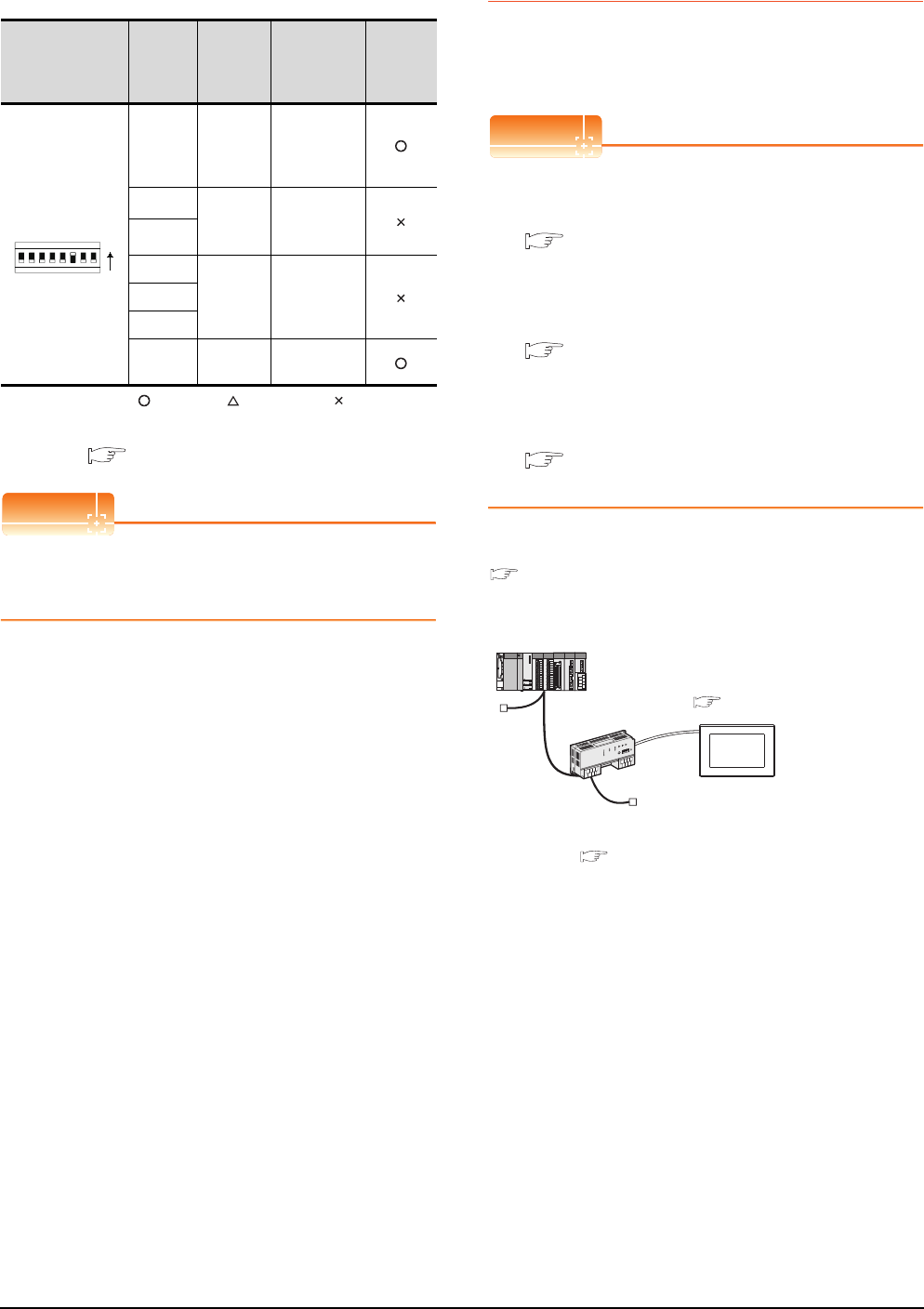
14 - 12 14. CC-Link CONNECTION (Via G4)
14.5 PLC Side Settings
(3) Operation setting DIP switch
: Necessary : As necessary : Not necessary
*1 The peripheral connection module operates with the baud
rate set in the GOT.
14.5.6 [Controller Setting] of GT Designer3
POINTPOINTPOINT
Operation mode of peripheral connection module
Be sure to set the "Q mode" as an operation mode of
the peripheral connection module.
14.5.2 Connecting AJ65BT-R2N
This section describes the settings of the GOT and
peripheral connection module in the following case of the
system configuration.
POINTPOINTPOINT
(1) Peripheral connection module
For details of the peripheral connection module,
refer to the following manual.
Peripheral Connection Module Type AJ65BT-
R2N User's Manual
(2) CC-Link module
For details of the CC-Link module, refer to the
following manual.
CC-Link System Master/Local Module User's
Manual QJ61BT11N
(3) CC-Link built-in CPU
For details on the CC-Link function built-in CPU,
refer to the following manual.
MELSEC-L CC-Link System Master/Local
Module User's Manual
System configuration
*1 The Start I/O No. of the CC-Link module is set to "0"
Operation setting
DIP switch
Setting
Switch Description Set value
Setting
necessity
at GOT
connection
SW1,
SW6
Operation
mode
SW1 = OFF
SW6 = ON
(fixed)
(Q mode)
SW2 Peripheral
transmissi
on speed*1
OFF (fixed)
SW3
SW4
Not used OFF (fixed)SW5
SW7
SW8 Test mode OFF (fixed)
(Online mode)
SW
18234567
ON
<CC-Link module>
*1
Station type
Station No.
Mode
All connect count
Transmission speed
: Master station
: Station No. 0
: Remote net (Ver.1 mode)
: 1
: 156kbps
<AJ65BT-R2N>
Station type
Station No.
Number of stations occupied
Transmission speed
: Intelligent device station
: Station No. 1
: Exclusive station 1
: 156kbps
<GOT>
Transmission speed: 9600bps
Setting example
Setting example
Setting example
14.5.3 Switch setting of CC-Link module (Q series)
14.5.4 [Network parameter] of GX Developer
■ Switch setting of peripheral connection module
14.5.6 [Controller Setting] of GT Designer3
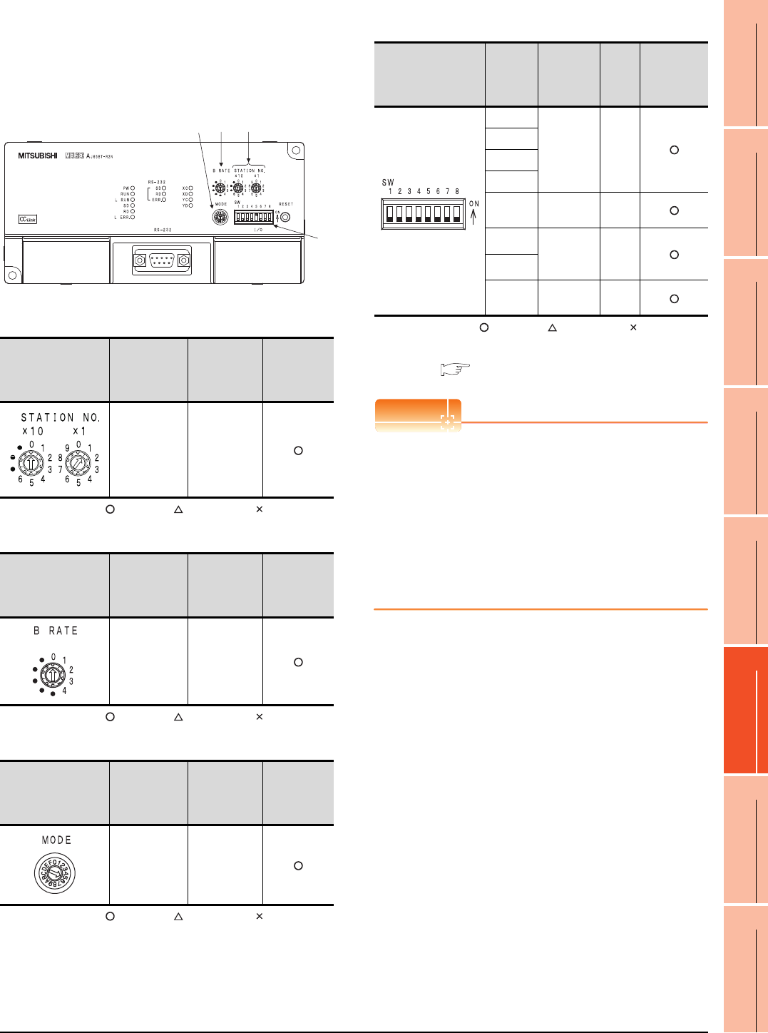
14. CC-Link CONNECTION (Via G4)
14.5 PLC Side Settings
14 - 13
9
MELSECNET/H
CONNECTION (PLC
TO PLC NETWORK)
10
MELSECNET/10
CONNECTION (PLC
TO PLC NETWORK)
11
CC-Link IE CONTROLLER
NETWORK
CONNECTION
12
CC-Link IE FIELD
NETWORK
CONNECTION
13
CC-Link CONNECTION
(INTELLIGENT DEVICE
STATION)
14
CC-Link
CONNECTION
(Via G4)
15
INVERTER
CONNECTION
16
SERVO AMPLIFIER
CONNECTION
Switch setting of peripheral connection
module
Set the station number setting switch, data link
transmission speed setting switch, and operation
setting DIP switch.
(1) Station number setting switch
: Necessary : As necessary : Not necessary
(2) Data link transmission speed setting switch
: Necessary : As necessary : Not necessary
(3) Mode setting switch
: Necessary : As necessary : Not necessary
(4) RS-232 transmission setting switch
: Necessary : As necessary : Not necessary
*1 The peripheral connection module operates with the baud
rate set in the GOT.
14.5.6 [Controller Setting] of GT Designer3
POINTPOINTPOINT
Precautions when setting peripheral connection
module
(1) mode setting switch
Be sure to set the Operation mode setting switch
to "5" (MELSOFT/connection mode).
(2) RS-232 transmission setting switch
Turn OFF SW1 through SW8 of the RS-232
transmission setting switch.
If any switch of SW1 through SW8 is ON, setting
error will occur (RUN LED turns off).
Station number setting
switch Description Set value
Setting
necessity at
GOT
connection
AJ65BT-R2N
station number
setting
1 to 64
Data link transmission
speed setting switch Description Set value
Setting
necessity at
GOT
connection
Data link
transmission
speed setting
0: 156kbps
1: 625kbps
2: 2.5Mbps
3: 5Mbps
4: 10Mbps
Mode setting switch Description Set value
Setting
necessity at
GOT
connection
Mode setting
5 (fixed)
(MELSOFT/
connection
mode)
(1)
2
4
(3) (2)
(4)
RS-232 transmission
setting switch
Setting
switch Description Set
value
Setting
necessity at
GOT
connection
SW1
Peripheral
transmission
speed*1
OFF
(fixed)
SW2
SW3
SW4
SW5 Data
bit length
OFF
(fixed)
SW6 Parity bit
length
OFF
(fixed)
SW7
SW8 Stop bit
length
OFF
(fixed)
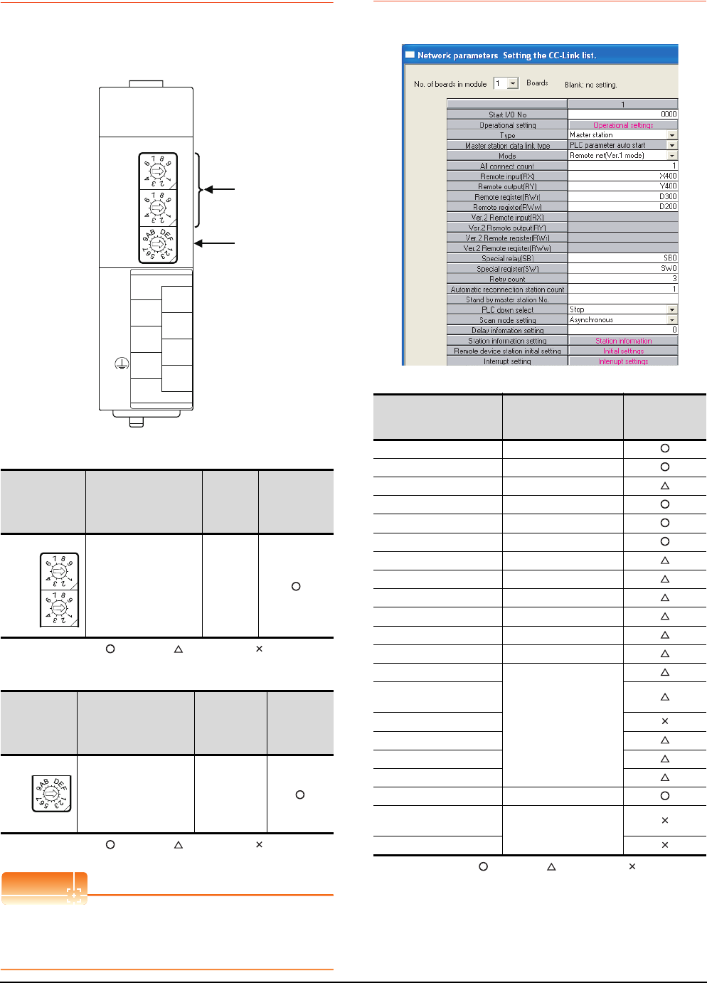
14 - 14 14. CC-Link CONNECTION (Via G4)
14.5 PLC Side Settings
14.5.3 Switch setting of CC-Link
module (Q series)
Set the station number setting switch, transmission speed /
mode setting switch.
(1) Station number setting switch
: Necessary : As necessary : Not necessary
(2) Transmission rate/mode setting switch
: Necessary : As necessary : Not necessary
POINTPOINTPOINT
When the switch setting has been changed
Turn the PLC CPU OFF then ON again, or reset the
PLC CPU.
14.5.4 [Network parameter] of GX
Developer
(1) Network parameter
: Necessary : As necessary : Not necessary
Station number
setting switch Description Set value
Setting
necessity
at GOT
connection
Station number setting
(master station) 0 (fixed)
Transmission
rate/
mode setting
switch
Description Set value
Setting
necessity
at GOT
connection
Transmission rate/mode
setting
0: 156kbps
1: 625kbps
2: 2.5Mbps
3: 5Mbps
4: 10Mbps
(1)
(2)
QJ61BT11, QJ61BT11N
0
5
0
5
0
8
1
2
7
6
5
4
3
STATION
NO.
X10
X1
MODE
QJ61BT11N
RUN
ERR.
SD
MST
L RUN
L ERR.
RD
S MST
NC
DA
DB
NC
SLD
DG
(FG)
C
4
0
5
0
5
STATION
NO.
X10
X1
0
8
MODE
C
4
Item Set value
Setting necessity
at GOT
connection
No. of boards in module 1
Start I/O No. 0000H
Operation setting (Use default value)
Type Master station (fixed)
Mode Remote net (Ver.1 mode)
All connect count 1
Remote input (RX) X400
Remote output (RY) Y400
Remote register (RWr) D300
Remote register (RWw) D200
Special relay (SB) SB0
Special register (SW) SW0
Retry count
(Use default value)
Automatic reconnection
station count
Stand by master station No.
PLC down select
Scan mode setting
Delay information setting
Station information setting Refer to (2)
Remote device station
initial setting (Use default value)
Interrupt setting
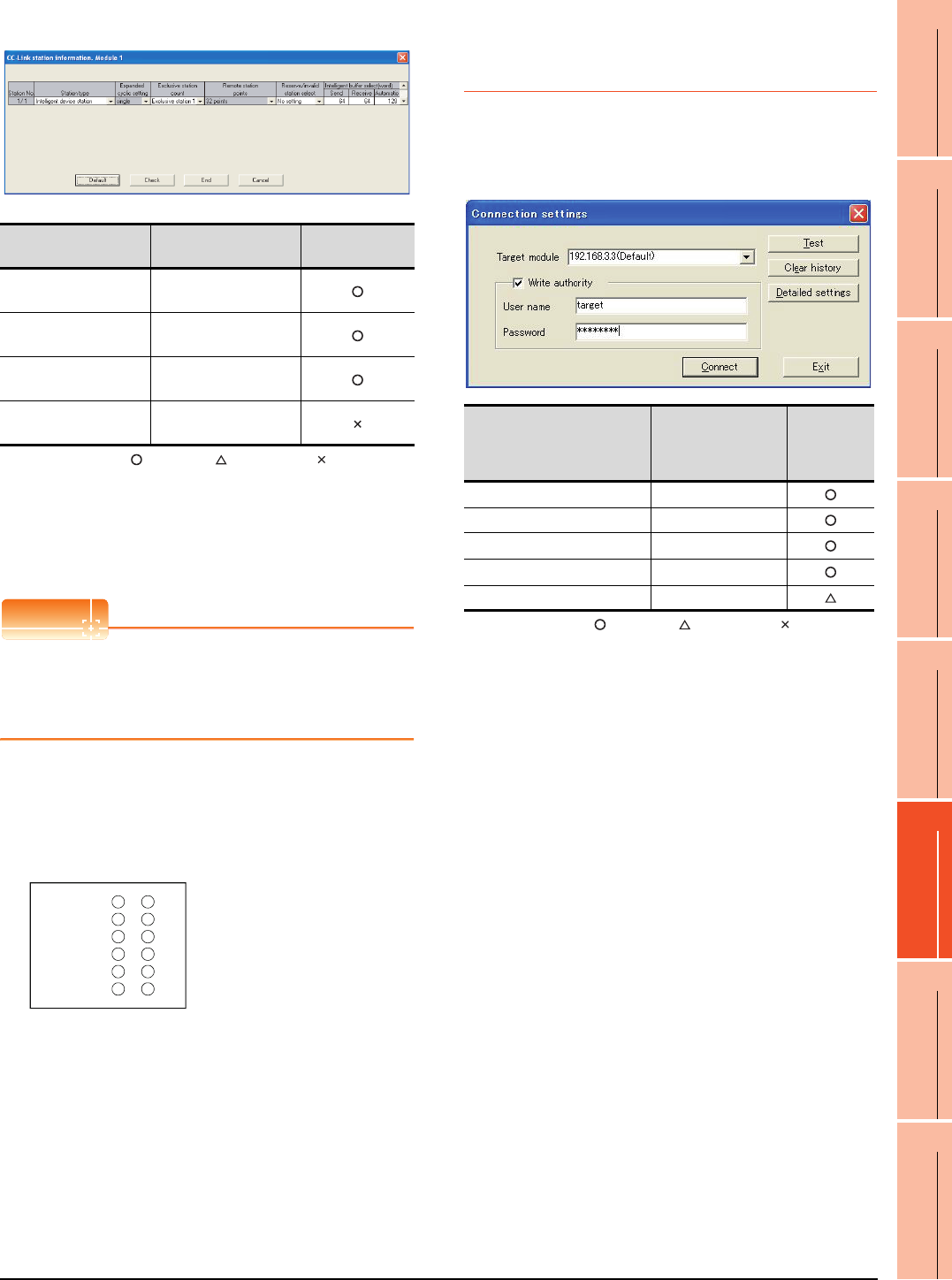
14. CC-Link CONNECTION (Via G4)
14.5 PLC Side Settings
14 - 15
9
MELSECNET/H
CONNECTION (PLC
TO PLC NETWORK)
10
MELSECNET/10
CONNECTION (PLC
TO PLC NETWORK)
11
CC-Link IE CONTROLLER
NETWORK
CONNECTION
12
CC-Link IE FIELD
NETWORK
CONNECTION
13
CC-Link CONNECTION
(INTELLIGENT DEVICE
STATION)
14
CC-Link
CONNECTION
(Via G4)
15
INVERTER
CONNECTION
16
SERVO AMPLIFIER
CONNECTION
(2) Station information setting
: Necessary : As necessary : Not necessary
*1 When the [Mode] of the CC-Link module is set at [Remote
net - (Ver. 2 mode)], [Remote station points] can be set.
[Remote station points] is a setting for the remote I/O station.
The default value (32 points) must be used on the GOT.
*2 When the [Mode] of the CC-Link module is set at [Remote
net - (Ver. 2 mode)] or [Remote net - Additional mode], set to
[Ver. 1 Intelligent device station].
POINTPOINTPOINT
When changing the network parameter
After writing the network parameter to the PLC CPU,
operate the PLC CPU ether turning OFF and then ON
or resetting.
(3) Completion confirmation
After initial communications of CC-Link are completed,
the L RUN LED of AJ65BT-G4-S3 turns on.
The GOT starts to monitor after the L-RUN LED of
AJ65BT-G4-S3 turns on.
It does not monitor while the L RUN LED turns off.
14.5.5 Parameter setting (when
connecting to C Controller
module)
Use SW3PVC-CCPU-E Ver.3.05F or later for the C
Controller module setting utility.
(1) Connection settings
: Necessary : As necessary : Not necessary
*1 If the IP address of the C Controller module has been
changed, input the changed IP address or host name.
*2 If the account of the C Controller module has been changed,
input the changed user name and password.
Item*1 Set value Setting necessity
at GOT connection
Station type*2 Intelligent device
station (fixed)
Number of stations
occupied Exclusive station 1 (fixed)
Reserve/invalid station
select No setting
Intelligent buffer select
(word) (Use default value)
PW
RUN
L RUN
SD
RD
L ERR.
Item Set value
Setting
necessity
at GOT
connection
Target module*1 192.168.3.3
Write authority Mark the checkbox
User name*2 target
Password*2 password
Detailed settings -
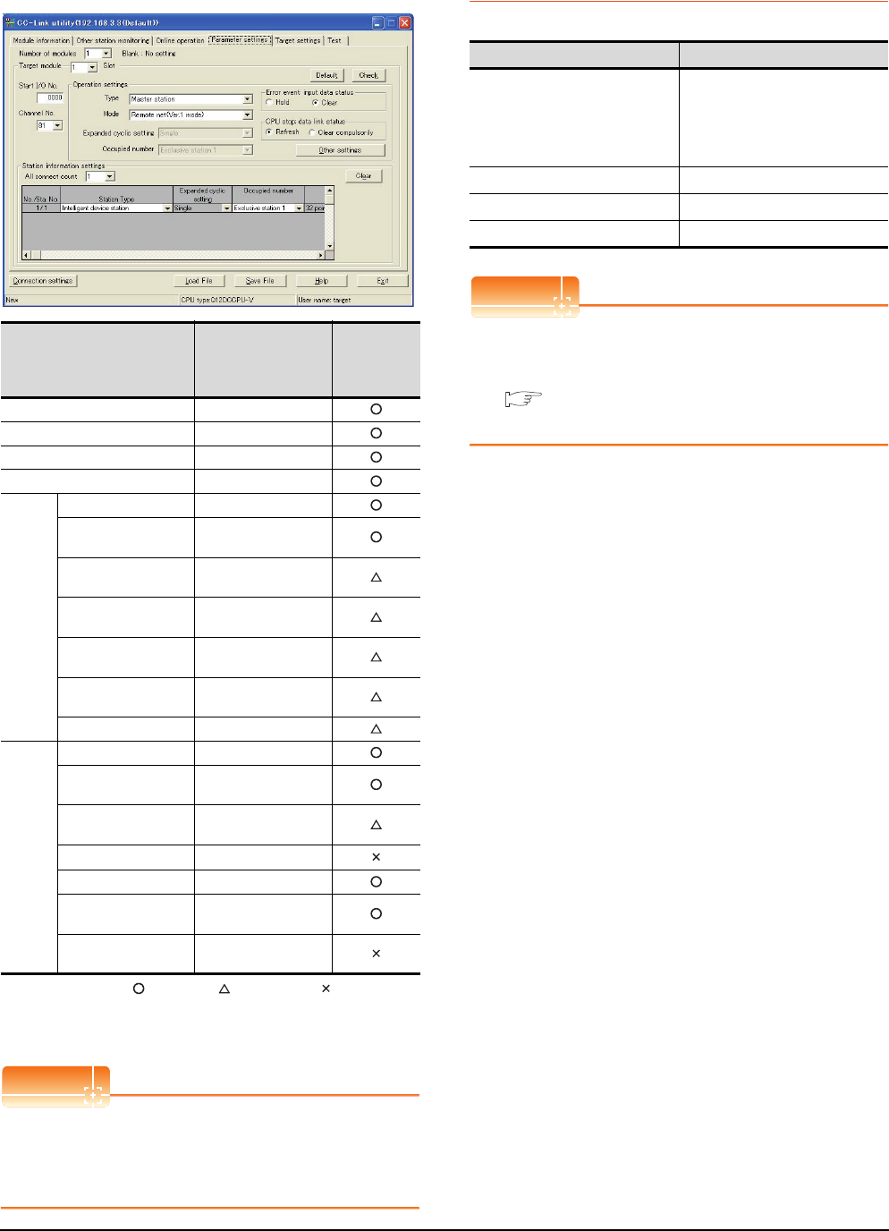
14 - 16 14. CC-Link CONNECTION (Via G4)
14.5 PLC Side Settings
(2) [Parameter Setting] of CC-Link utility
(a) Network parameter
: Necessary : As necessary : Not necessary
*1 If the CC-Link module [Mode] is [Remote net -Ver.1 mode],
[Remote station points] cannot be set.
*2 Set the same setting as that of the GOT.
POINTPOINTPOINT
When changing the network parameter
After writing the network parameter to the C Controller
module, either turn the C Controller module OFF and
then ON or reset it.
14.5.6 [Controller Setting] of GT
Designer3
POINTPOINTPOINT
[Controller Setting] of GT Designer3
For [Controller Setting], of GT Designer3, refer to the
following.
14.4.1 Setting communication interface
(Communication settings)
Item Set value
Setting
necessity
at GOT
connection
Number of modules 1
Target module 1
Start I/O No. 0000H
Channel No. (Use default value)
Operation
setting
type Master station(fixed)
Mode*1 Remote net
(Ver.1 mode)
Expanded cyclic
station Single(fixed)
Occupied number Exclusive station 1
(fixed)
Error event : input data
status Clear
CPU stop: data link
status Refresh
Other settings (Use default value)
Station
information
settings
All connect count 1
Station type Ver.1 Intelligent device
station(fixed)
Expanded cyclic
station Single
Occupied number*2 Exclusive station 1
Remote station points 32 points
Reserve/invalid station
select No setting
Intelligent buffer select
(word) (Use default value)
Item Set value
Transmission Speed
9600bps
19200bps
38400bps
57600bps
115200bps
Retry Count 0 to 5times
Timeout Time 3 to 30sec
Delay Time 0 to 300ms
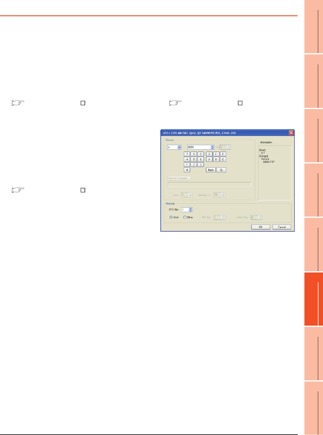
14. CC-Link CONNECTION (Via G4)
14.6 Precautions
14 - 17
9
MELSECNET/H
CONNECTION (PLC
TO PLC NETWORK)
10
MELSECNET/10
CONNECTION (PLC
TO PLC NETWORK)
11
CC-Link IE CONTROLLER
NETWORK
CONNECTION
12
CC-Link IE FIELD
NETWORK
CONNECTION
13
CC-Link CONNECTION
(INTELLIGENT DEVICE
STATION)
14
CC-Link
CONNECTION
(Via G4)
15
INVERTER
CONNECTION
16
SERVO AMPLIFIER
CONNECTION
14.6 Precautions
Connection in the multiple CPU system
When the GOT is connected to multiple CPU system,
the following time is taken until when the PLC runs.
QCPU (Q mode), motion controller CPU (Q series): 10
seconds or more
MELDAS C70: 18 seconds or more
When the GOT starts before the PLC runs, a system
alarm occurs.Adjust the opening screen time in the
GOT setup so that no system alarm occurs.
GT Designer3 Version Screen Design
Manual
Connection to LCPU
LCPU may diagnose (check file system, execute
recovering process, etc.) the SD memory card when
turning on the power or when resetting. Therefore, it
takes time until the SD memory card becomes
available. When the GOT starts before the SD card
becomes available, a system alarm occurs. Adjust the
opening screen time in the GOT setup so that no
system alarm occurs.
GT Designer3 Version Screen Design
Manual
Connection to Q17nDCPU, Q170MCPU,
CNC C70, CRnQ-700
The Q17nDCPU, Q170MCPU, CNC C70 and CRnQ-
700 are applicable to the CC-Link network system Ver.2
only.
For connecting to the CC-Link (Via G4) network
system, set the CC-Link (G4) network system to the
CC-Link Ver.2 mode.
Connection to Q170MCPU
Set [CPU No.] to "2" in the device setting to monitor the
device of the Motion CPU area (CPU No.2).
When the CPU No. is set to "0" or "1", the device on the
PLC CPU area (CPU No.1) is monitored.
When the CPU No. is set to the number other than "0"
to "2", a communication error occurs and the monitoring
cannot be executed.
For setting the CPU No., refer to the following manual.
GT Designer3 Version Screen Design
Manual
Example) Setting dialog box of the bit device

14 - 18 14. CC-Link CONNECTION (Via G4)
14.6 Precautions

MITSUBISHI FA DEVICE
CONNECTIONS
15. INVERTER CONNECTION . . . . . . . . . . . . . . . . . . . . . . . . 15 - 1
16. SERVO AMPLIFIER CONNECTION . . . . . . . . . . . . . . . . . 16 - 1
17. ROBOT CONTROLLER CONNECTION . . . . . . . . . . . . . . 17 - 1
18. CNC CONNECTION . . . . . . . . . . . . . . . . . . . . . . . . . . . . . 18 - 1

15
9
MELSECNET/H
CONNECTION (PLC
TO PLC NETWORK)
10
MELSECNET/10
CONNECTION (PLC
TO PLC NETWORK)
11
CC-Link IE CONTROLLER
NETWORK
CONNECTION
12
CC-Link IE FIELD
NETWORK
CONNECTION
13
CC-Link CONNECTION
(INTELLIGENT DEVICE
STATION)
14
CC-Link
CONNECTION
(Via G4)
15
INVERTER
CONNECTION
16
SERVO AMPLIFIER
CONNECTION
15 - 1
15.INVERTER CONNECTION
15.1 Connectable Model List . . . . . . . . . . . . . . . . . . . . . . . . . . . 15 - 2
15.2 System Configuration. . . . . . . . . . . . . . . . . . . . . . . . . . . . . 15 - 3
15.3 Connection Diagram . . . . . . . . . . . . . . . . . . . . . . . . . . . . 15 - 21
15.4 GOT Side Settings . . . . . . . . . . . . . . . . . . . . . . . . . . . . . . 15 - 29
15.5 FREQROL Series Inverter Side Settings . . . . . . . . . . . . . 15 - 31
15.6 Device Range that Can Be Set . . . . . . . . . . . . . . . . . . . . 15 - 44
15.7 Precautions . . . . . . . . . . . . . . . . . . . . . . . . . . . . . . . . . . . 15 - 47
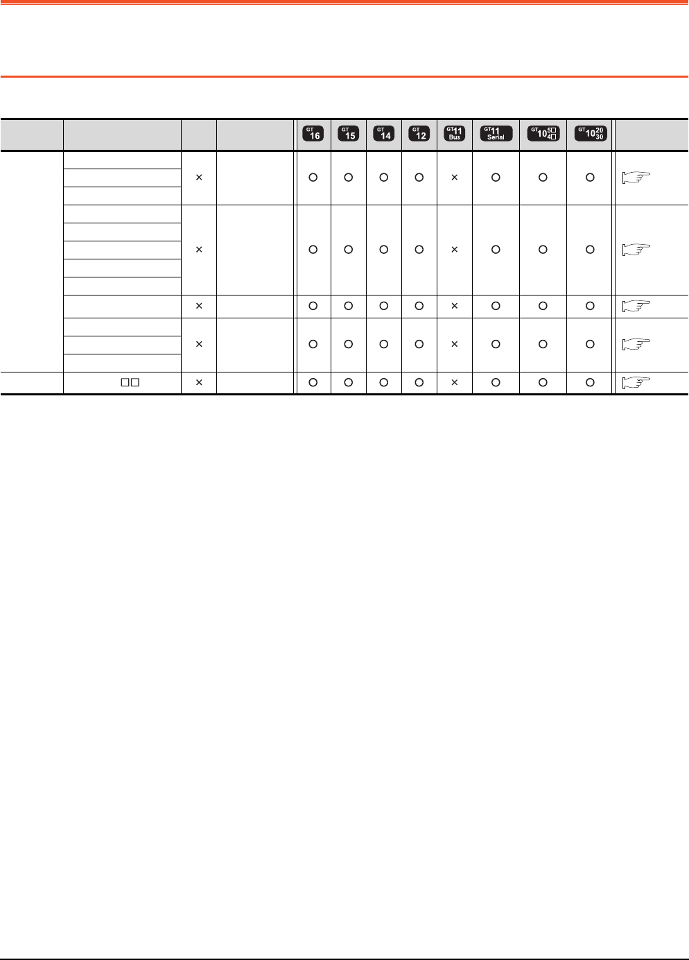
15 - 2 15. INVERTER CONNECTION
15.1 Connectable Model List
15. INVERTER CONNECTION
15.1 Connectable Model List
The following table shows the connectable models.
Series Model name Clock Communication
type Refer to
FREQROL
FREQROL-A500/A500L
RS-422 15.2.1
FREQROL-F500/F500L
FREQROL-V500/V500L
FREQROL-E500
RS-422 15.2.2
FREQROL-S500/S500E
FREQROL-F500J
FREQROL-D700
FREQROL-F700PJ
FREQROL-E700 RS-422 15.2.3
FREQROL-A700
RS-422 15.2.4
FREQROL-F700
FREQROL-F700P
MELIPM MD-CX522- K(-A0) RS-422 15.2.5
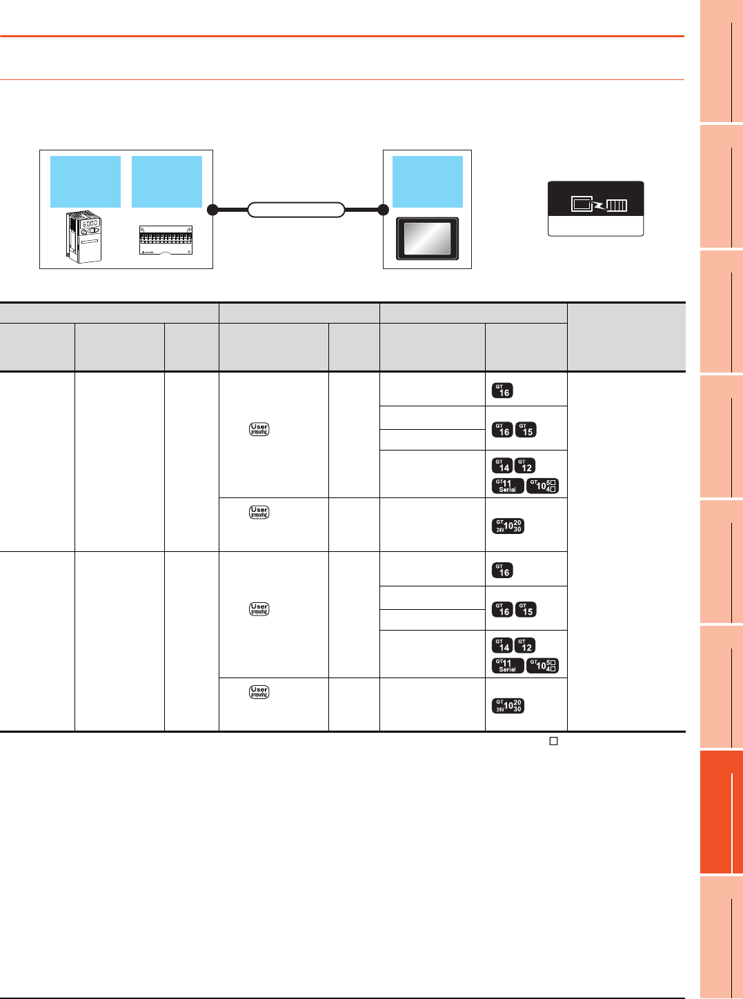
15. INVERTER CONNECTION
15.2 System Configuration
15 - 3
9
MELSECNET/H
CONNECTION (PLC
TO PLC NETWORK)
10
MELSECNET/10
CONNECTION (PLC
TO PLC NETWORK)
11
CC-Link IE CONTROLLER
NETWORK
CONNECTION
12
CC-Link IE FIELD
NETWORK
CONNECTION
13
CC-Link CONNECTION
(INTELLIGENT DEVICE
STATION)
14
CC-Link
CONNECTION
(Via G4)
15
INVERTER
CONNECTION
16
SERVO AMPLIFIER
CONNECTION
15.2 System Configuration
15.2.1 Connecting to FREQROL-A500/A500L/F500/F500L/V500/V500L
When connecting to one inverter
*1 Connect it to the RS-232 interface (built into GOT). It cannot be mounted on GT1655 and GT155 .
*2 Connect to the PU port of the inverter.
FREQROL 500/700
Communication driver
GOT
Connection cable
Computer link
option
Inverter
Inverter Connection cable GOT
Number of connectable
equipment
Model name Computer link
option
Communi
cation
type
Connection diagram
number
Max.
distance Option device Model
FREQROL-
A500/A500L
F500/F500L
V500/V500L
*2
-RS-422
RS422
connection diagram 1)
500m
GT16-C02R4-9S
(0.2m)
1 GOT for 1 inverter
GT15-RS2T4-9P*1
GT15-RS4-9S
- (Built into GOT)
RS422
connection diagram
10)
500m - (Built into GOT)
FREQROL-
A500/A500L
F500/F500L
V500/V500L
FR-A5NR RS-422
RS422
connection diagram 2)
500m
GT16-C02R4-9S
(0.2m)
GT15-RS2T4-9P*1
GT15-RS4-9S
- (Built into GOT)
RS422
connection diagram
11)
500m - (Built into GOT)

15 - 4 15. INVERTER CONNECTION
15.2 System Configuration
When connecting to multiple inverters (Max. 31) (Using the distributor)
*1 Connect it to the RS-232 interface (built into GOT). It cannot be mounted on GT1655 and GT155 .
*2 Connect to the PU port of the inverter.
*3 The distributor is a product manufactured by HACHIKO ELECTRIC CO., LTD. For details, contact HACHIKO ELECTRIC CO.,
LTD.
*4 For GT11 and GT10, the number of connectable inverters differs according to the hardware version.
For the procedure to check the hardware version, refer to the following manual.
GT11 User’s Manual
GT10 User’s Manual
GOTDistributor
Connection cable 2)Connection cable 1)Terminal cable
Connection cable 1)
Distributor
InverterInverter
Connection cable 1)
FREQROL 500/700
Communication driver
Inverter
Terminal cable
Connection
cable 1)
Distributor
*3
Connection cable
2) GOT
Max.
distance
Number of
connectable
equipment
Model name
Commun
ication
type
Connection
diagram number
Model
name
Connection
diagram number Option device Model
FREQROL-
A500/A500L
F500/F500L
V500/V500L
*2
RS-422
RS422
connection
diagram 9)
RS422
connection
diagram 3)
BMJ-8
(Recomm
ended)
RS422
connection
diagram 1)
GT16-C02R4-9S
(0.2m)
500m
31 inverters
for one
GOT*4
GT15-RS2T4-9P*1
GT15-RS4-9S
- (Built into GOT)
BMJ-8
(Recomm
ended)
RS422
connection
diagram 10) - (Built into GOT)
Model name Hardware version Number of connectable
Inverter
GT1155-QTBD
C or later 31
B or earlier 10
GT1155-QSBD
GT1150-QLBD
F or later 31
E or earlier 10
GT1055-QSBD
GT1050-QBBD
C or later 31
B or earlier 10

15. INVERTER CONNECTION
15.2 System Configuration
15 - 5
9
MELSECNET/H
CONNECTION (PLC
TO PLC NETWORK)
10
MELSECNET/10
CONNECTION (PLC
TO PLC NETWORK)
11
CC-Link IE CONTROLLER
NETWORK
CONNECTION
12
CC-Link IE FIELD
NETWORK
CONNECTION
13
CC-Link CONNECTION
(INTELLIGENT DEVICE
STATION)
14
CC-Link
CONNECTION
(Via G4)
15
INVERTER
CONNECTION
16
SERVO AMPLIFIER
CONNECTION
GT1045-QSBD
GT1040-QBBD A or later 31
GT1030-L D
GT1030-H D
B or later 31
A or earlier 10
GT1020-L D
E or later 31
D or earlier 10
Model name Hardware version Number of connectable
Inverter
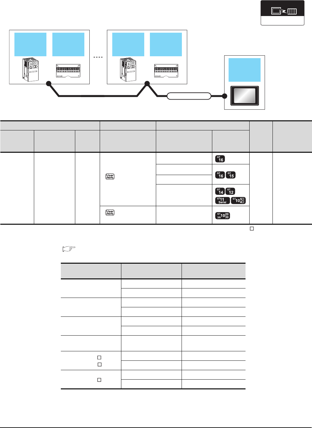
15 - 6 15. INVERTER CONNECTION
15.2 System Configuration
When connecting to multiple inverters (Max. 31) (Using the computer link option)
*1 Connect it to the RS-232 interface (built into GOT). It cannot be mounted on GT1655 and GT155 .
*2 For GT11 and GT10, the number of connectable inverters differs according to the hardware version.
For the procedure to check the hardware version, refer to the following manual.
GT11 User’s Manual
GT10 User’s Manual
FREQROL 500/700
Communication driver
Inverter
GOT
Connection cable
Computer
link
option
Inverter
Computer
link
option
Inverter Connection cable GOT
Max.
distance
Number of
connectable
equipment
Model name Computer link
option
Communi
cation
type
Connection diagram
number Option device Model
FREQROL-
A500/A500L
F500/F500L
V500/V500L
FR-A5NR RS-422
RS422 connection
diagram 4)
GT16-C02R4-9S(0.2m)
500m 31 inverters for
one GOT*2
GT15-RS2T4-9P*1
GT15-RS4-9S
- (Built into GOT)
RS422 connection
diagram 12)
- (Built into GOT)
Model name Hardware version Number of connectable
Inverter
GT1155-QTBD
C or later 31
B or earlier 10
GT1155-QSBD
GT1150-QLBD
F or later 31
E or earlier 10
GT1055-QSBD
GT1050-QBBD
C or later 31
B or earlier 10
GT1045-QSBD
GT1040-QBBD A or later 31
GT1030-L D
GT1030-H D
B or later 31
A or earlier 10
GT1020-L D
E or later 31
D or earlier 10
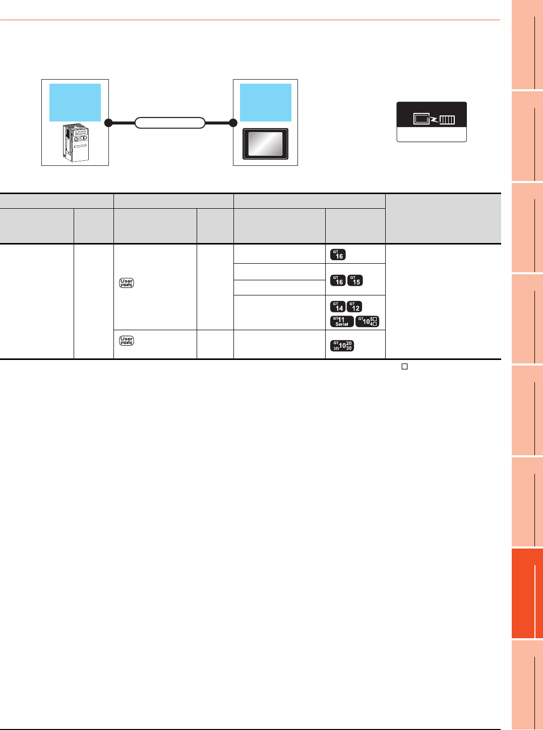
15. INVERTER CONNECTION
15.2 System Configuration
15 - 7
9
MELSECNET/H
CONNECTION (PLC
TO PLC NETWORK)
10
MELSECNET/10
CONNECTION (PLC
TO PLC NETWORK)
11
CC-Link IE CONTROLLER
NETWORK
CONNECTION
12
CC-Link IE FIELD
NETWORK
CONNECTION
13
CC-Link CONNECTION
(INTELLIGENT DEVICE
STATION)
14
CC-Link
CONNECTION
(Via G4)
15
INVERTER
CONNECTION
16
SERVO AMPLIFIER
CONNECTION
15.2.2 Connecting to FREQROL-E500/S500/S500E/F500J/D700/F700PJ
When connecting to one inverter
*1 Connect it to the RS-232 interface (built into GOT). It cannot be mounted on GT1655 and GT155 .
*2 Connect to the PU port of the inverter.
FREQROL 500/700
Communication driver
Inverter GOT
Connection cable
Inverter Connection cable GOT
Number of connectable equipment
Model name
Communi
cation
type
Connection diagram
number
Max.
distance Option device Model
FREQROL-
E500/S500/S500E
F500J/D700/F700PJ
*2
RS-422
RS422 connection
diagram 1)
500m
GT16-C02R4-9S(0.2m)
1 GOT for 1 inverter
GT15-RS2T4-9P*1
GT15-RS4-9S
- (Built into GOT)
RS422 connection
diagram 10)
500m - (Built into GOT)
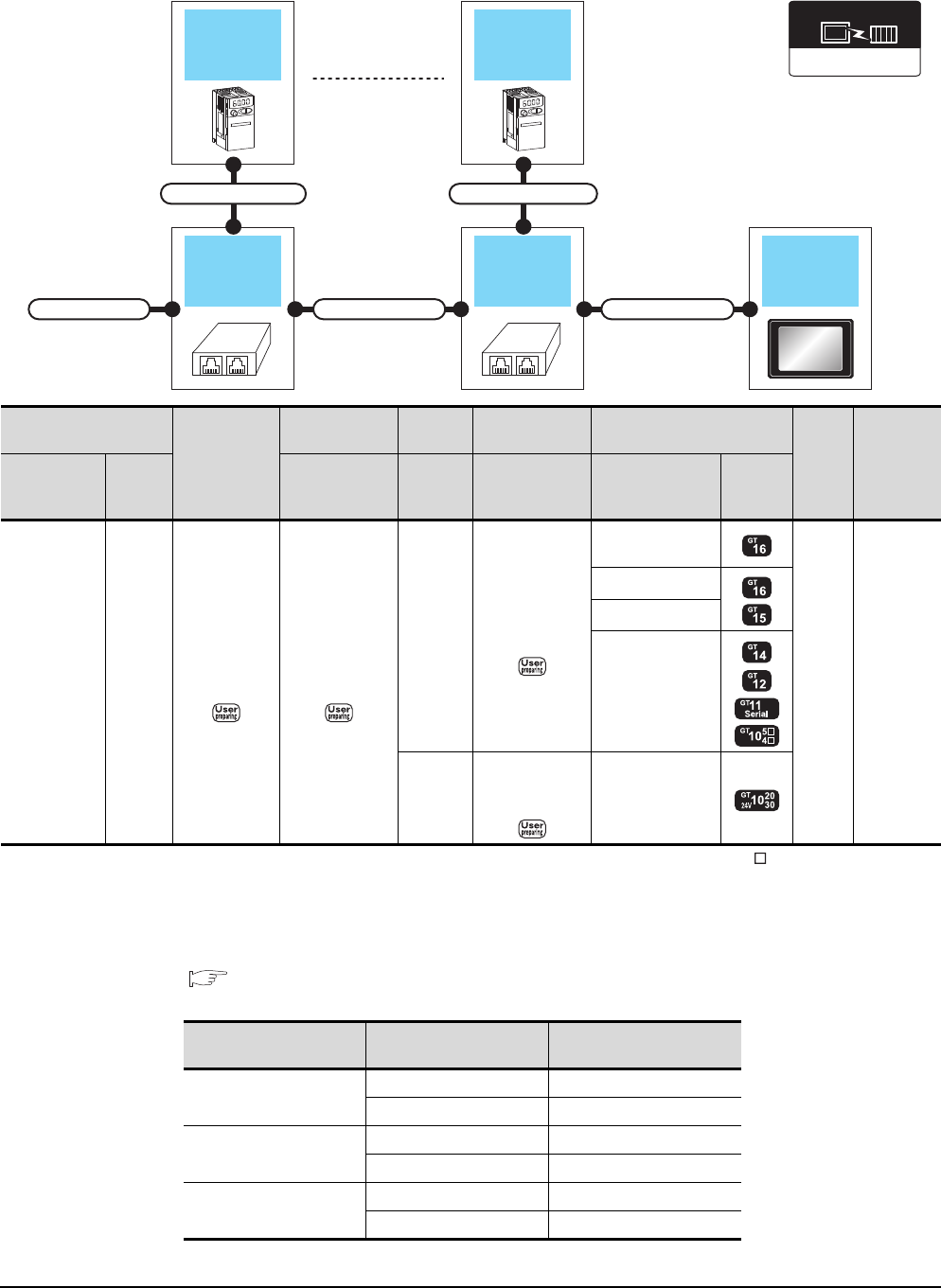
15 - 8 15. INVERTER CONNECTION
15.2 System Configuration
When connecting to multiple inverters (Max. 31) (Using the distributor)
*1 Connect it to the RS-232 interface (built into GOT). It cannot be mounted on GT1655 and GT155 .
*2 Connect to the PU port of the inverter.
*3 The distributor is a product manufactured by HACHIKO ELECTRIC CO., LTD. For details, contact HACHIKO ELECTRIC CO.,
LTD.
*4 For GT11 and GT10, the number of connectable inverters differs according to the hardware version.
For the procedure to check the hardware version, refer to the following manual.
GT11 User’s Manual
GT10 User’s Manual
GOTDistributor
Connection cable 2)
Connection cable 1)
Terminal cable
Connection cable 1)
Distributor
Inverter
Connection cable 1)
Inverter
FREQROL 500/700
Communication driver
Inverter
Terminal cable
Connection cable
1)
Distributor
*3
Connection cable
2) GOT
Max.
distance
Number of
connectable
equipment
Model name
Commu
nication
type
Connection
diagram number
Model
name
Connection
diagram number Option device Model
FREQROL-
E500/S500
S500E/F500J
D700
*2
RS-422
RS422
connection
diagram 9)
RS422
connection
diagram 3)
BMJ-8
(Recomm
ended)
RS422
connection
diagram 1)
GT16-C02R4-9S
(0.2m)
500m
31 inverters
for one
GOT*4
GT15-RS2T4-9P*1
GT15-RS4-9S
- (Built into GOT)
BMJ-8
(Recomm
ended)
RS422
connection
diagram 10) - (Built into GOT)
Model name Hardware version Number of connectable
Inverter
GT1155-QTBD
C or later 31
B or earlier 10
GT1155-QSBD
GT1150-QLBD
F or later 31
E or earlier 10
GT1055-QSBD
GT1050-QBBD
C or later 31
B or earlier 10

15. INVERTER CONNECTION
15.2 System Configuration
15 - 9
9
MELSECNET/H
CONNECTION (PLC
TO PLC NETWORK)
10
MELSECNET/10
CONNECTION (PLC
TO PLC NETWORK)
11
CC-Link IE CONTROLLER
NETWORK
CONNECTION
12
CC-Link IE FIELD
NETWORK
CONNECTION
13
CC-Link CONNECTION
(INTELLIGENT DEVICE
STATION)
14
CC-Link
CONNECTION
(Via G4)
15
INVERTER
CONNECTION
16
SERVO AMPLIFIER
CONNECTION
GT1045-QSBD
GT1040-QBBD A or later 31
GT1030-L D
GT1030-H D
B or later 31
A or earlier 10
GT1020-L D
E or later 31
D or earlier 10
Model name Hardware version Number of connectable
Inverter
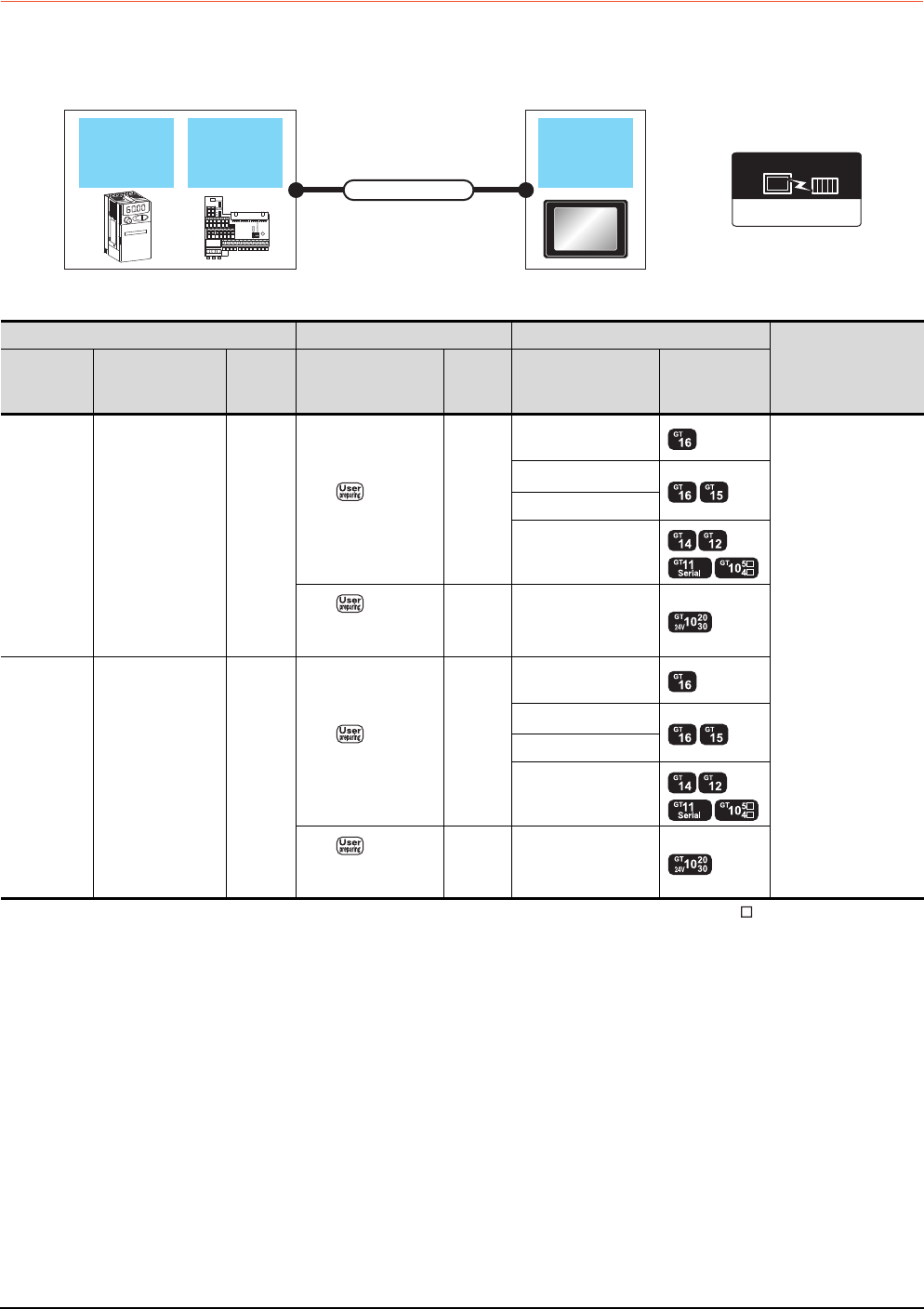
15 - 10 15. INVERTER CONNECTION
15.2 System Configuration
15.2.3 Connecting to FREQROL E700
When connecting to one inverter
*1 Connect it to the RS-232 interface (built into GOT). It cannot be mounted on GT1655 and GT155 .
*2 Connect to the PU port of the inverter.
*3 The control terminal option and the PU port cannot be used at the same time.
FREQROL 500/700
Communication driver
Control
terminal
option
GOT
Connection cable
Inverter
Inverter Connection cable GOT
Number of connectable
equipment
Model name Control terminal
option
Commun
ication
type
Connection diagram
number
Max.
distance Option device Model
FREQROL-
E700
*2
- RS-422
RS422
connection diagram 1)
500m
GT16-C02R4-9S
(0.2m)
1 GOT for 1 inverter
GT15-RS2T4-9P*1
GT15-RS4-9S
- (Built into GOT)
RS422
connection diagram
10)
500m - (Built into GOT)
FREQROL-
E700*3 FR-E7TR*3 RS-422
RS422
connection diagram 7)
500m
GT16-C02R4-9S
(0.2m)
GT15-RS2T4-9P*1
GT15-RS4-9S
- (Built into GOT)
RS422
connection diagram
15)
500m - (Built into GOT)

15. INVERTER CONNECTION
15.2 System Configuration
15 - 11
9
MELSECNET/H
CONNECTION (PLC
TO PLC NETWORK)
10
MELSECNET/10
CONNECTION (PLC
TO PLC NETWORK)
11
CC-Link IE CONTROLLER
NETWORK
CONNECTION
12
CC-Link IE FIELD
NETWORK
CONNECTION
13
CC-Link CONNECTION
(INTELLIGENT DEVICE
STATION)
14
CC-Link
CONNECTION
(Via G4)
15
INVERTER
CONNECTION
16
SERVO AMPLIFIER
CONNECTION
When connecting to multiple inverters (Max. 31) (Using the distributor)
*1 Connect it to the RS-232 interface (built into GOT). It cannot be mounted on GT1655 and GT155 .
*2 Connect to the PU port of the inverter.
*3 The distributor is a product manufactured by HACHIKO ELECTRIC CO., LTD. For details, contact HACHIKO ELECTRIC CO.,
LTD.
*4 For GT11 and GT10, the number of connectable inverters differs according to the hardware version.
For the procedure to check the hardware version, refer to the following manual.
GT11 User’s Manual
GT10 User’s Manual
GOTDistributor
Connection cable 2)Connection cable 1)
Terminal cable
Connection cable 1)
Distributor
Inverter
Connection cable 1)
Inverter
FREQROL 500/700
Communication driver
Inverter
Terminating
cable
Connection cable
1)
Distributor
*3
Connection cable
2) GOT
Max.
distance
Number of
connectable
equipment
Model name
Commun
ication
type
Connection
diagram number
Model
name
Connection
diagram number Option device Model
FREQROL-
E700
*2
RS-422
RS422
connection
diagram 9)
RS422
connection
diagram 3)
BMJ-8
(Recomm
ended)
RS422
connection
diagram 1)
GT16-C02R4-9S
(0.2m)
500m
31inverters
for one
GOT*4
GT15-RS2T4-9P*1
GT15-RS4-9S
- (Built into GOT)
BMJ-8
(Recomm
ended)
RS422
connection
diagram 10) - (Built into GOT)
Model name Hardware version Number of connectable
Inverter
GT1155-QTBD
C or later 31
B or earlier 10
GT1155-QSBD
GT1150-QLBD
F or later 31
E or earlier 10
GT1055-QSBD
GT1050-QBBD
C or later 31
B or earlier 10

15 - 12 15. INVERTER CONNECTION
15.2 System Configuration
GT1045-QSBD
GT1040-QBBD A or later 31
GT1030-L D
GT1030-H D
B or later 31
A or earlier 10
GT1020-L D
E or later 31
D or earlier 10
Model name Hardware version Number of connectable
Inverter
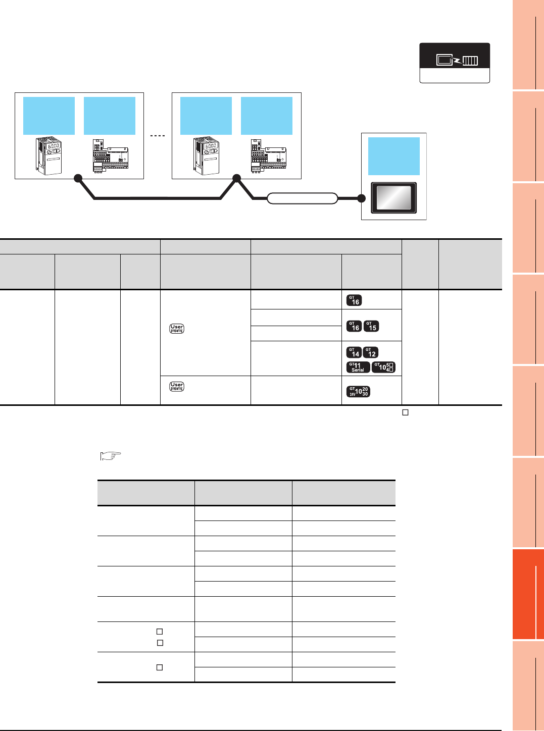
15. INVERTER CONNECTION
15.2 System Configuration
15 - 13
9
MELSECNET/H
CONNECTION (PLC
TO PLC NETWORK)
10
MELSECNET/10
CONNECTION (PLC
TO PLC NETWORK)
11
CC-Link IE CONTROLLER
NETWORK
CONNECTION
12
CC-Link IE FIELD
NETWORK
CONNECTION
13
CC-Link CONNECTION
(INTELLIGENT DEVICE
STATION)
14
CC-Link
CONNECTION
(Via G4)
15
INVERTER
CONNECTION
16
SERVO AMPLIFIER
CONNECTION
When connecting to multiple inverters (Max. 31) (Using the control terminal option)
*1 Connect it to the RS-232 interface (built into GOT). It cannot be mounted on GT1655 and GT155 .
*2 The control terminal option and the PU port cannot be used at the same time.
*3 For GT11 and GT10, the number of connectable inverters differs according to the hardware version.
For the procedure to check the hardware version, refer to the following manual.
GT11 User’s Manual
GT10 User’s Manual
FREQROL 500/700
Communication driver
Inverter
GOT
Connection cable
Inverter
Control
terminal
option
Control
terminal
option
Inverter Connection cable GOT
Max.
distance
Number of
connectable
equipment
Model name Control terminal
option
Communi
cation
type
Connection diagram
number Option device Model
FREQROL-
E700*2 FR-E7TR*2 RS-422
RS422 connection
diagram 8)
GT16-C02R4-9S(0.2m)
500m 31 inverters for
one GOT*3
GT15-RS2T4-9P*1
GT15-RS4-9S
- (Built into GOT)
RS422 connection
diagram 16)
- (Built into GOT)
Model name Hardware version Number of connectable
Inverter
GT1155-QTBD
C or later 31
B or earlier 10
GT1155-QSBD
GT1150-QLBD
F or later 31
E or earlier 10
GT1055-QSBD
GT1050-QBBD
C or later 31
B or earlier 10
GT1045-QSBD
GT1040-QBBD A or later 31
GT1030-L D
GT1030-H D
B or later 31
A or earlier 10
GT1020-L D
E or later 31
D or earlier 10
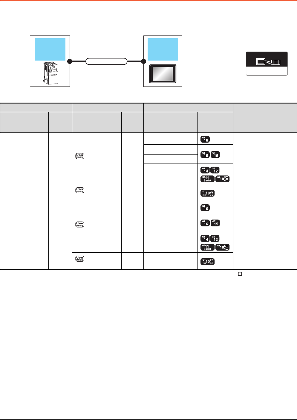
15 - 14 15. INVERTER CONNECTION
15.2 System Configuration
15.2.4 Connecting to FREQROL-A700/F700/700P
When connecting to one inverter
*1 Connect it to the RS-232 interface (built into GOT). It cannot be mounted on GT1655 and GT155 .
FREQROL 500/700
Communication driver
Inverter GOT
Connection cable
Inverter Connection cable GOT
Number of connectable
equipment
Model name
Communi
cation
type
Connection diagram
number
Max.
distance Option device Model
FREQROL-
A700/F700/F700P
(PU port)
RS-422
RS422 connection
diagram 1)
500m
GT16-C02R4-9S(0.2m)
1 GOT for 1 inverter
GT15-RS2T4-9P*1
GT15-RS4-9S
- (Built into GOT)
RS422 connection
diagram 10)
500m - (Built into GOT)
FREQROL-
A700/F700/F700P
(Built-in RS485
terminal block)
RS-422
RS422 connection
diagram 5)
500m
GT16-C02R4-9S(0.2m)
GT15-RS2T4-9P*1
GT15-RS4-9S
- (Built into GOT)
RS422 connection
diagram 13)
500m - (Built into GOT)
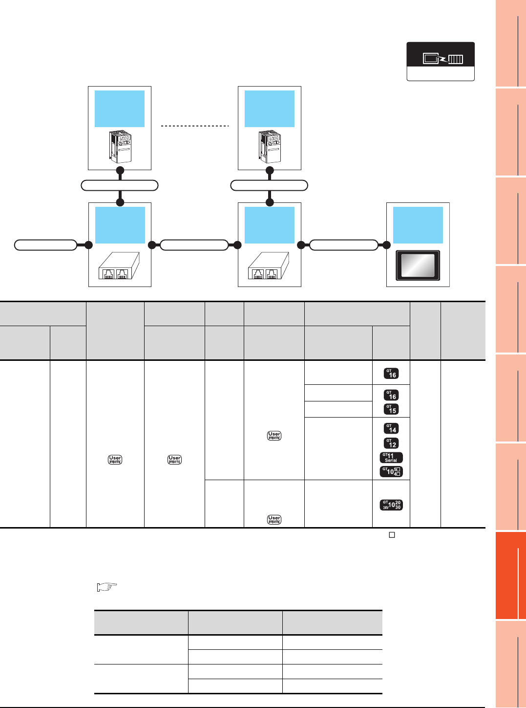
15. INVERTER CONNECTION
15.2 System Configuration
15 - 15
9
MELSECNET/H
CONNECTION (PLC
TO PLC NETWORK)
10
MELSECNET/10
CONNECTION (PLC
TO PLC NETWORK)
11
CC-Link IE CONTROLLER
NETWORK
CONNECTION
12
CC-Link IE FIELD
NETWORK
CONNECTION
13
CC-Link CONNECTION
(INTELLIGENT DEVICE
STATION)
14
CC-Link
CONNECTION
(Via G4)
15
INVERTER
CONNECTION
16
SERVO AMPLIFIER
CONNECTION
When connecting to multiple inverters (Max. 31) (Using the distributor)
*1 Connect it to the RS-232 interface (built into GOT). It cannot be mounted on GT1655 and GT155 .
*2 The distributor is a product manufactured by HACHIKO ELECTRIC CO., LTD. For details, contact HACHIKO ELECTRIC CO.,
LTD.
*3 For GT11 and GT10, the number of connectable inverters differs according to the hardware version.
For the procedure to check the hardware version, refer to the following manual.
GT11 User’s Manual
GT10 User’s Manual
FREQROL 500/700
Communication driver
GOTDistributor
Connection cable 2)Connection cable 1)
Terminal cable
Connection cable 1)
Distributor
Inverter
Connection cable 1)
Inverter
Inverter
Terminal cable
Connection cable
1)
Distributor
*2
Connection cable
2) GOT
Max.
distance
Number of
connectable
equipment
Model name
Commun
ication
type
Connection
diagram number
Model
name
Connection
diagram number Option device Model
FREQROL-
A700/F700
(PU port)
RS-422
RS422
connection
diagram 9)
RS422
connection
diagram 3)
BMJ-8
(Recomm
ended)
RS422
connection
diagram 1)
GT16-C02R4-9S
(0.2m)
500m
31 inverters
for one
GOT*3
GT15-RS2T4-9P*1
GT15-RS4-9S
- (Built into GOT)
BMJ-8
(Recomm
ended)
RS422
connection
diagram 10) - (Built into GOT)
Model name Hardware version Number of connectable
Inverter
GT1155-QTBD
C or later 31
B or earlier 10
GT1155-QSBD
GT1150-QLBD
F or later 31
E or earlier 10

15 - 16 15. INVERTER CONNECTION
15.2 System Configuration
GT1055-QSBD
GT1050-QBBD
C or later 31
B or earlier 10
GT1045-QSBD
GT1040-QBBD A or later 31
GT1030-L D
GT1030-H D
B or later 31
A or earlier 10
GT1020-L D
E or later 31
D or earlier 10
Model name Hardware version Number of connectable
Inverter
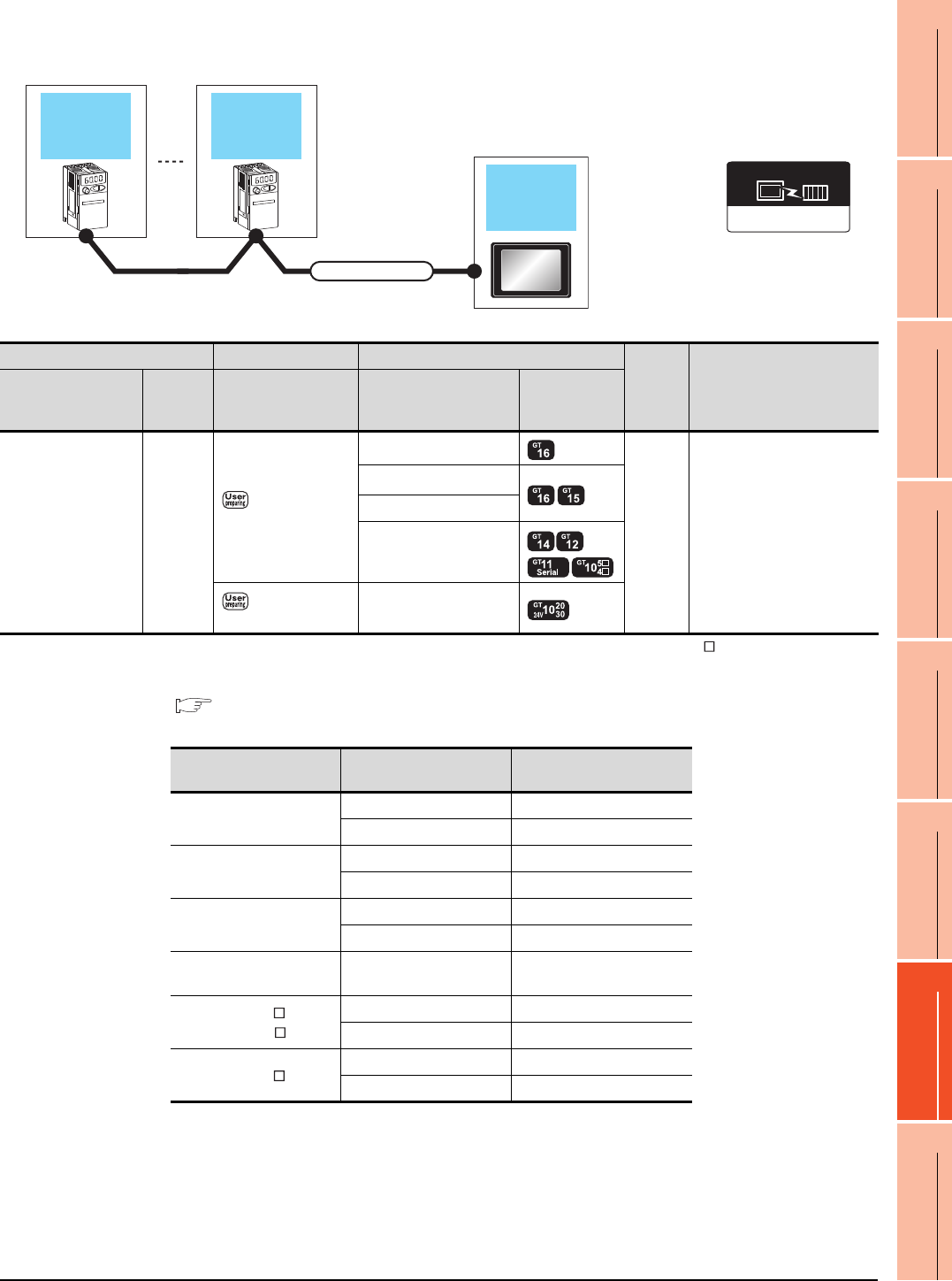
15. INVERTER CONNECTION
15.2 System Configuration
15 - 17
9
MELSECNET/H
CONNECTION (PLC
TO PLC NETWORK)
10
MELSECNET/10
CONNECTION (PLC
TO PLC NETWORK)
11
CC-Link IE CONTROLLER
NETWORK
CONNECTION
12
CC-Link IE FIELD
NETWORK
CONNECTION
13
CC-Link CONNECTION
(INTELLIGENT DEVICE
STATION)
14
CC-Link
CONNECTION
(Via G4)
15
INVERTER
CONNECTION
16
SERVO AMPLIFIER
CONNECTION
When connecting to multiple inverters (Max. 31) (Using the built-in RS485 terminal block)
*1 Connect it to the RS-232 interface (built into GOT). It cannot be mounted on GT1655 and GT155 .
*2 For GT11 and GT10, the number of connectable inverters differs according to the hardware version.
For the procedure to check the hardware version, refer to the following manual.
GT11 User’s Manual
GT10 User’s Manual
FREQROL 500/700
Communication driver
Inverter
GOT
Connection cable
Inverter
Inverter Connection cable GOT
Max.
distance
Number of connectable
equipment
Model name
Communi
cation
type
Connection diagram
number Option device Model
FREQROL-
A700/F700
(Built-in RS485
terminal block)
RS-422
RS422 connection
diagram 6)
GT16-C02R4-9S(0.2m)
500m 31 inverters for one GOT*2
GT15-RS2T4-9P*1
GT15-RS4-9S
- (Built into GOT)
RS422 connection
diagram 14)
- (Built into GOT)
Model name Hardware version Number of connectable
Inverter
GT1155-QTBD
C or later 31
B or earlier 10
GT1155-QSBD
GT1150-QLBD
F or later 31
E or earlier 10
GT1055-QSBD
GT1050-QBBD
C or later 31
B or earlier 10
GT1045-QSBD
GT1040-QBBD A or later 31
GT1030-L D
GT1030-H D
B or later 31
A or earlier 10
GT1020-L D
E or later 31
D or earlier 10
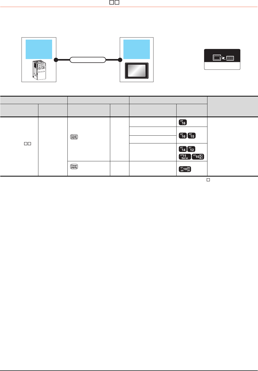
15 - 18 15. INVERTER CONNECTION
15.2 System Configuration
15.2.5 Connecting to MD-CX522- K(-A0)
When connecting to one inverter
*1 Connect it to the RS-232 interface (built into GOT). It cannot be mounted on GT1655 and GT155 .
*2 Connect to the PU port of the inverter.
FREQROL 500/700
Communication driver
Inverter GOT
Connection cable
Inverter Connection cable GOT
Number of connectable
Model name equipment
Model name Communication
type
Connection diagram
number
Max.
distance Option device Model
MD-CX522- K
(-A0)*2 RS-422
RS422 connection
diagram 1)
20m
GT16-C02R4-9S(0.2m)
1 GOT for 1 inverter
GT15-RS2T4-9P*1
GT15-RS4-9S
- (Built into GOT)
RS422 connection
diagram 10)
20m - (Built into GOT)
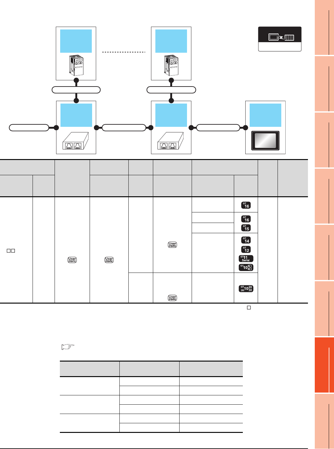
15. INVERTER CONNECTION
15.2 System Configuration
15 - 19
9
MELSECNET/H
CONNECTION (PLC
TO PLC NETWORK)
10
MELSECNET/10
CONNECTION (PLC
TO PLC NETWORK)
11
CC-Link IE CONTROLLER
NETWORK
CONNECTION
12
CC-Link IE FIELD
NETWORK
CONNECTION
13
CC-Link CONNECTION
(INTELLIGENT DEVICE
STATION)
14
CC-Link
CONNECTION
(Via G4)
15
INVERTER
CONNECTION
16
SERVO AMPLIFIER
CONNECTION
When connecting to multiple inverters (Max. 31) (Using the distributor)
*1 Connect it to the RS-232 interface (built into GOT). It cannot be mounted on GT1655 and GT155 .
*2 Connect to the PU port of the inverter.
*3 The distributor is a product manufactured by HACHIKO ELECTRIC CO., LTD. For details, contact HACHIKO ELECTRIC
CO.,LTD.
*4 For GT11 and GT10, the number of connectable inverters differs according to the hardware version.
For the procedure to check the hardware version, refer to the following manual.
GT11 User’s Manual
GT10 User’s Manual
GOTDistributor
Connection cable 2)Connection cable 1)
Terminal cable
Connection cable 1)
Distributor
Inverter
Connection cable 1)
Inverter
FREQROL 500/700
Communication driver
Inverter
Terminating
cable
Connection cable
1)
Distributor
*3
Connection cable
2) GOT
Max.
distance
Number of
connectable
Model name
equipment
Model name
Commu
nication
type
Connection
diagram number
Model
name
Connection
diagram number Option device Model
MD-CX522
-K(-A0)
*2
RS-422
RS422
connection
diagram 9)
RS422
connection
diagram 3)
BMJ-8
(Recomm
ended)
RS422
connection
diagram 1)
GT16-C02R4-9S
(0.2m)
20m
31 inverters
for one
GOT*4
GT15-RS2T4-9P*1
GT15-RS4-9S
- (Built into GOT)
BMJ-8
(Recomm
ended)
RS422
connection
diagram 10) - (Built into GOT)
Model name Hardware version Number of connectable
Inverter
GT1155-QTBD
C or later 31
B or earlier 10
GT1155-QSBD
GT1150-QLBD
F or later 31
E or earlier 10
GT1055-QSBD
GT1050-QBBD
C or later 31
B or earlier 10

15 - 20 15. INVERTER CONNECTION
15.2 System Configuration
GT1045-QSBD
GT1040-QBBD A or later 31
GT1030-L D
GT1030-H D
B or later 31
A or earlier 10
GT1020-L D
E or later 31
D or earlier 10
Model name Hardware version Number of connectable
Inverter
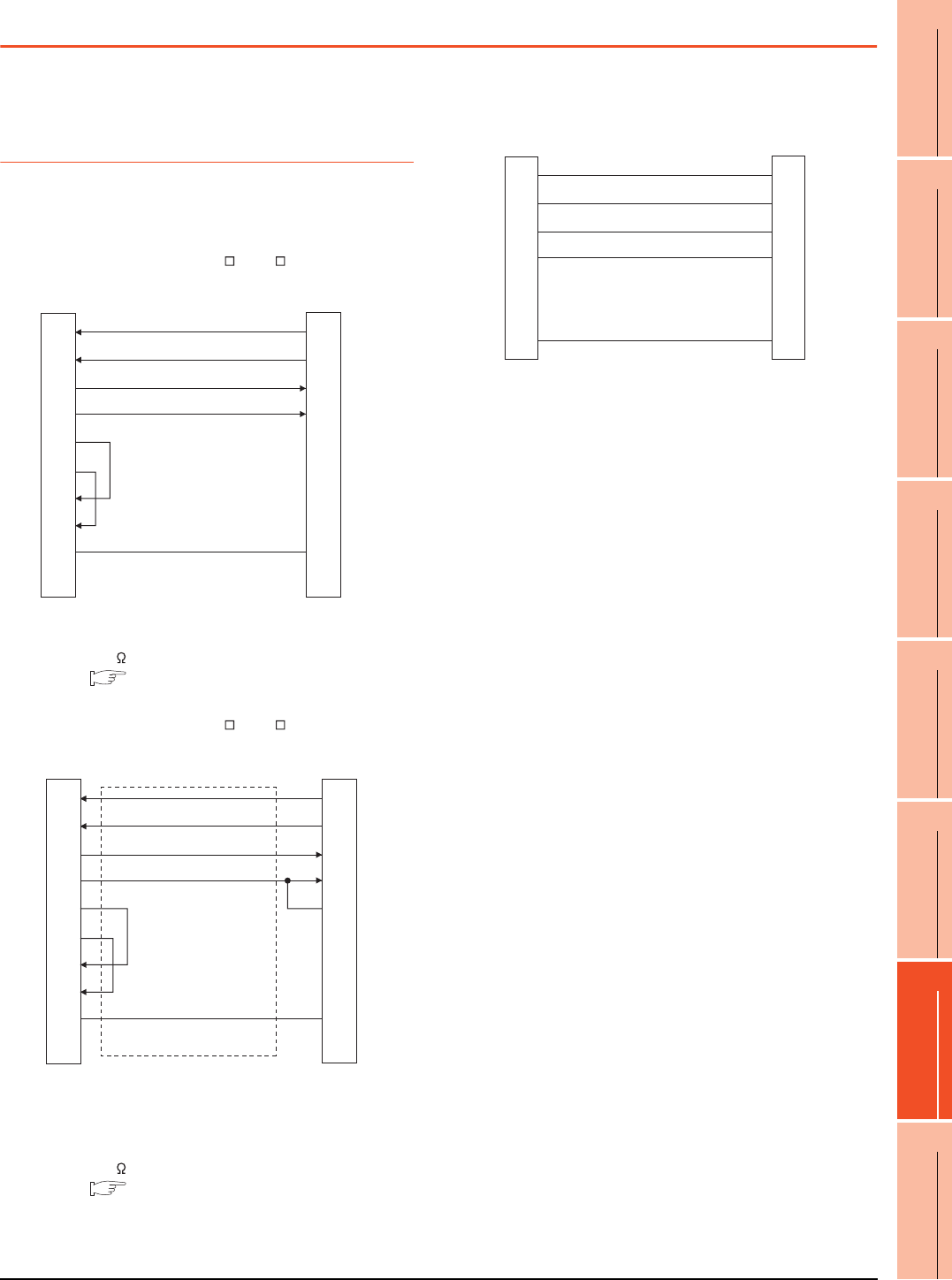
15. INVERTER CONNECTION
15.3 Connection Diagram
15 - 21
9
MELSECNET/H
CONNECTION (PLC
TO PLC NETWORK)
10
MELSECNET/10
CONNECTION (PLC
TO PLC NETWORK)
11
CC-Link IE CONTROLLER
NETWORK
CONNECTION
12
CC-Link IE FIELD
NETWORK
CONNECTION
13
CC-Link CONNECTION
(INTELLIGENT DEVICE
STATION)
14
CC-Link
CONNECTION
(Via G4)
15
INVERTER
CONNECTION
16
SERVO AMPLIFIER
CONNECTION
15.3 Connection Diagram
The following diagram shows the connection between the
GOT and the inverter.
15.3.1 RS-422 cable
Connection diagram
RS422 connection diagram 1)
(For GT16, GT15, GT14, GT12, GT11, GT105 , GT104 )
*1 For GT16, GT15 and GT12, set the terminating resistor to
"Disable".
For GT14, GT11 and GT10, set the terminating resistor to
"330 ".
1.4.3 Terminating resistors of GOT
RS422 connection diagram 2)
(For GT16, GT15, GT14, GT12, GT11, GT105 , GT104 )
*1 Connect a terminating resistor jumper to RDB and
RDR.The terminating resister jumper is packed together
with the FR-A5NR.
*2 For GT16, GT15 and GT12, set the terminating resistor to
"Disable".
For GT14, GT11 and GT10, set the terminating resistor to
"330 ".
1.4.3 Terminating resistors of GOT
GOT side*1
RDA
RDB
SDA
SDB
RSA
RSB
CSA
CSB
SG
FG
5
4
3
6
2
8
-
-
1
2
7
1
6
3
8
4
9
5
-
SDA
SDB
RDA
RDB
P5S
P5S
-
-
SG
Inverter or Distributor side
(Modular connector)
RDA
RDB
SDA
SDB
RSA
RSB
CSA
CSB
SG
FG
2
7
1
6
3
8
4
9
5
-
SDA
SDB
RDA
RDB
RDR
SG
FR-A5NR side
(terminal block)
*1
GOT side*2
RS422 connection diagram 3)
SDA
SDB
RDA
RDB
P5S
P5S
SG
5
4
3
6
2
8
1
5
4
3
6
2
8
1
SDA
SDB
RDA
RDB
P5S
P5S
SG
Inverter side or distributor side
(Modular connector)
Distributor side
(Modular connector)
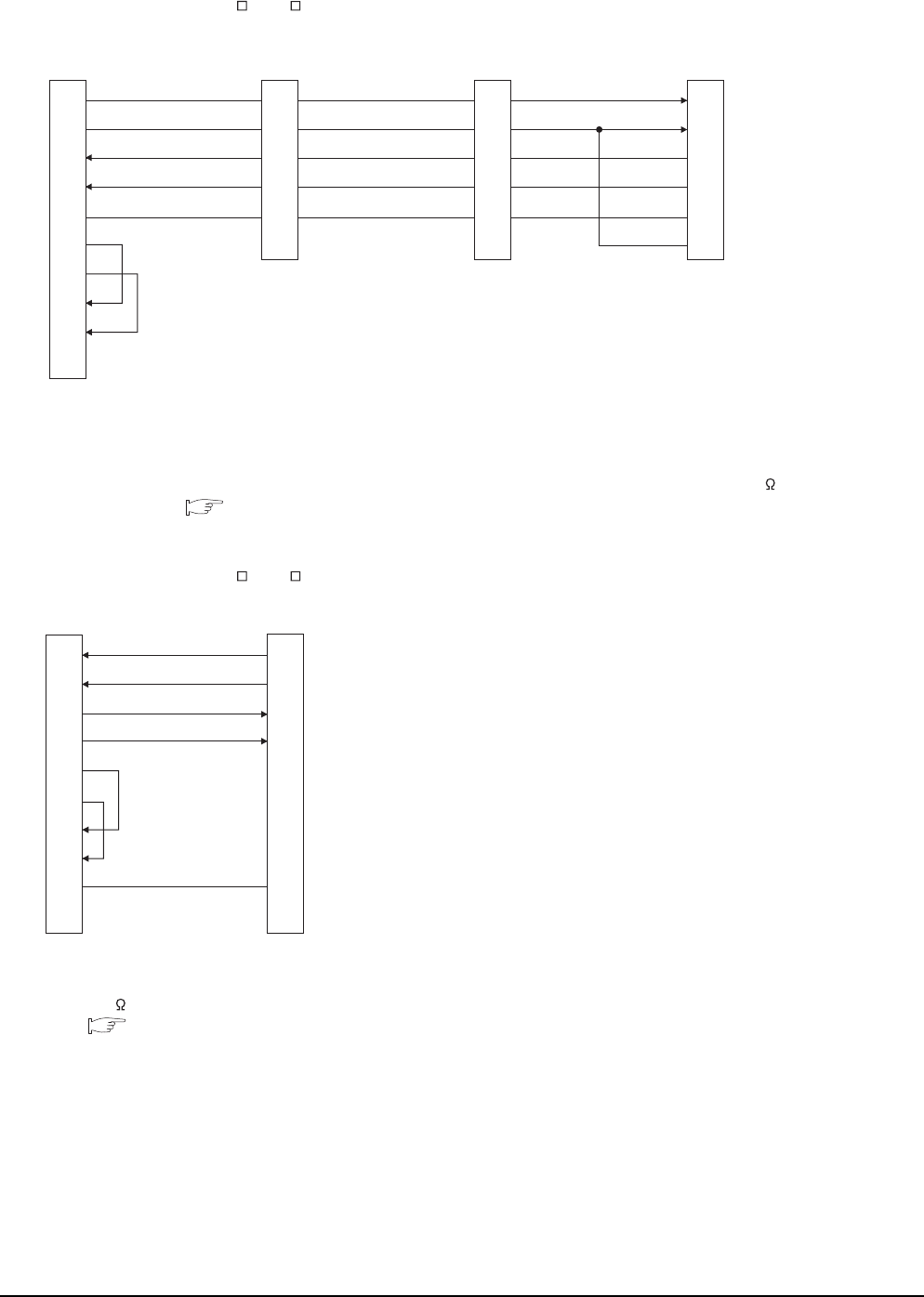
15 - 22 15. INVERTER CONNECTION
15.3 Connection Diagram
*1 Connect a terminating resistor jumper to RDB and RDR which are assigned in the FR-A5NR of the inverter located farthest from
the GOT.
The terminating resister jumper is packed together with the FR-A5NR.
*2 For GT16, GT15 and GT12, set the terminating resistor of GOT side, which will be a terminal, to "Enable".
For GT14, GT11 and GT10, set the terminating resistor of GOT side, which will be a terminal, to "330 ".
1.4.3 Terminating resistors of GOT
*1 For GT16, GT15 and GT12, set the terminating resistor to
"Disable".
For GT14, GT11 and GT10, set the terminating resistor to
"330 ".
1.4.3 Terminating resistors of GOT
*2 RDA2, RDB2, SDA2 and SDB2 terminals of the RS485
terminal block (built into the inverter) cannot be used.
RS422 connection diagram 4)
(For GT16, GT15, GT14, GT12, GT11, GT105 , GT104 )
RDA
RDB
SDA
SDB
SG
RDR
1
6
2
7
5
3
8
4
9
-
FR-A5NR side
(terminal block)
Station No.0
RDA
RDB
SDA
SDB
SG
RDR
FR-A5NR side
(terminal block)
Station No.1
RDA
RDB
SDA
SDB
SG
RDR
FR-A5NR side
(terminal block)
Station No.n
GOT side
*2
*1
SDA
SDB
RDA
RDB
SG
RSA
RSB
CSA
CSB
FG
RS422 connection diagram 5)
(For GT16, GT15, GT14, GT12, GT11, GT105 , GT104 )
GOT side*1
RDA
RDB
SDA
SDB
RSA
RSB
CSA
CSB
SG
FG
2
7
1
6
3
8
4
9
5
-
SDA1(TXD1+)
SDB1(TXD1-)
RDA1(RXD1+)
RDB1(RXD1-)
SG(GND)
Inverter side
RS485 terminal block
(built into the inverter)*2
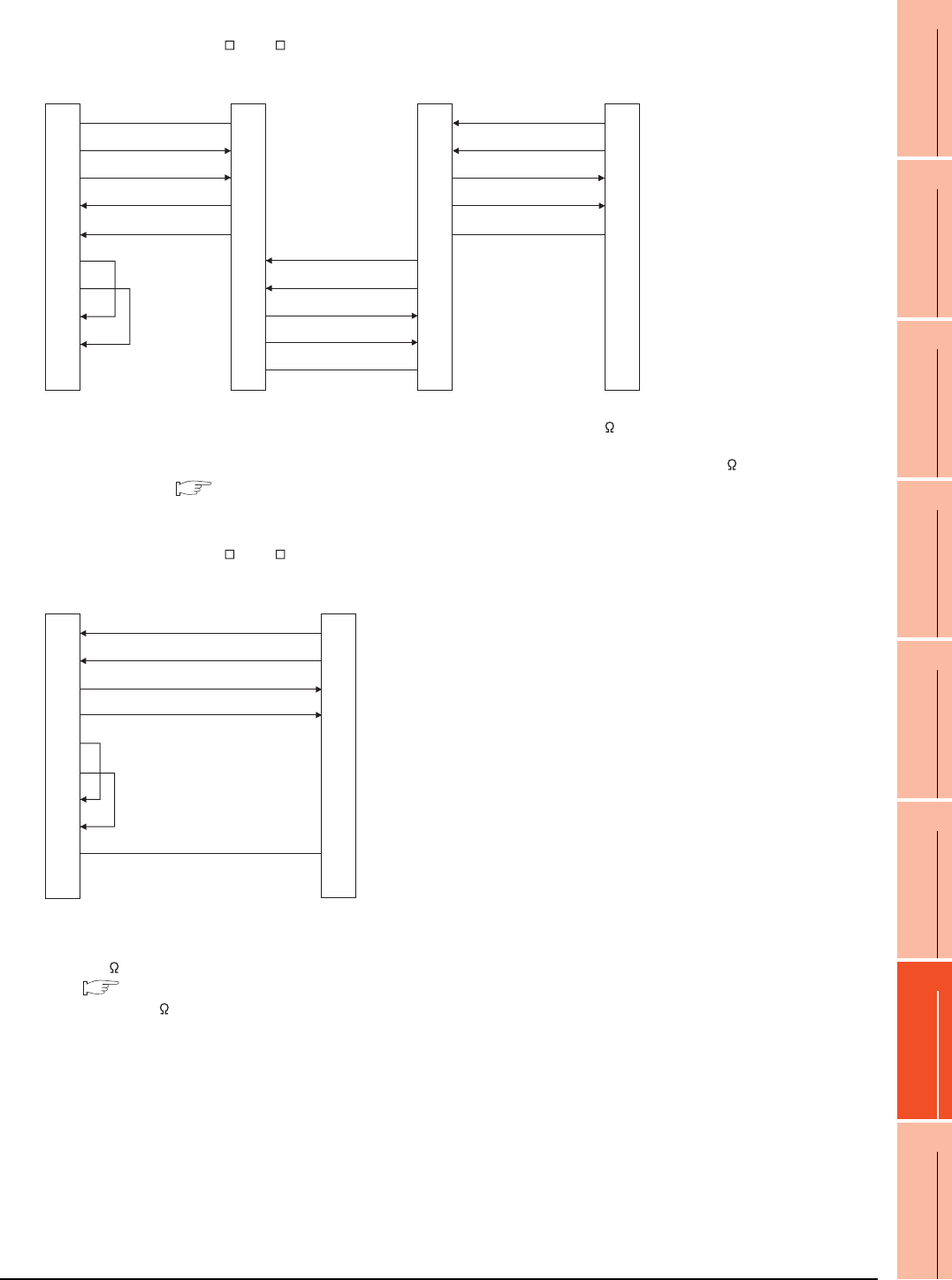
15. INVERTER CONNECTION
15.3 Connection Diagram
15 - 23
9
MELSECNET/H
CONNECTION (PLC
TO PLC NETWORK)
10
MELSECNET/10
CONNECTION (PLC
TO PLC NETWORK)
11
CC-Link IE CONTROLLER
NETWORK
CONNECTION
12
CC-Link IE FIELD
NETWORK
CONNECTION
13
CC-Link CONNECTION
(INTELLIGENT DEVICE
STATION)
14
CC-Link
CONNECTION
(Via G4)
15
INVERTER
CONNECTION
16
SERVO AMPLIFIER
CONNECTION
*1 Set the terminator switch built in the farthest inverter from the GOT to ON (100 ).
*2 For GT16, GT15 and GT12, set the terminating resistor of GOT side, which will be a terminal, to "Enable".
For GT14, GT11 and GT10, set the terminating resistor of GOT side, which will be a terminal, to "330 ".
1.4.3 Terminating resistors of GOT
*1 For GT16, GT15 and GT12, set the terminating resistor to
"Disable".
For GT14, GT11 and GT10, set the terminating resistor to
"330 ".
1.4.3 Terminating resistors of GOT
*2 Turn ON (100 ) the terminator switch for the FR-E7TR.
RS422 connection diagram 6)
(For GT16, GT15, GT14, GT12, GT11, GT105 , GT104 )
SG
SDB
SDA
RDB
RDA
RSA
RSB
CSA
CSB
SDA2
SDB2
RDA2
RDB2
GND
SDA1
SDB1
RDA1
RDB1
GND
GND
RDB1
RDA1
SDB1
SDA1
5
6
1
7
2
3
8
4
9
-
SDA2
SDB2
RDA2
RDB2
GND
SDA2
SDB2
RDA2
RDB2
GND
SDA1
SDB1
RDA1
RDB1
GND
GOT side*2
Built-in RS-485
terminal block
Station No.0
Built-in RS-485
terminal block
Station No.1
Built-in RS-485
terminal block*1
Station No.n
RS422 connection diagram 7)
(For GT16, GT15, GT14, GT12, GT11, GT105 , GT104 )
GOT side*1
RDA
RDB
SDA
SDB
RSA
RSB
CSA
CSB
SG
FG
2
7
1
6
3
8
4
9
5
-
SDA
SDB
RDA
RDB
SG
FR-E7TR side
(terminal block)*2
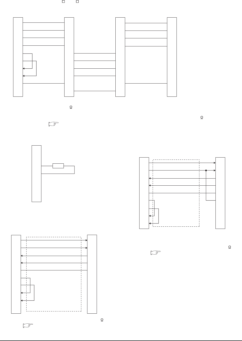
15 - 24 15. INVERTER CONNECTION
15.3 Connection Diagram
*1 Turn ON (100 ) the terminator switch for the most distant FR-E7TR from the GOT.
*2 For GT16, GT15 and GT12, set the terminating resistor of GOT side, which will be a terminal, to "Enable".
For GT14, GT11 and GT10, set the terminating resistor of GOT side, which will be a terminal, to "330 ".
1.4.3 Terminating resistors of GOT
*1 Set the terminating resistor of the GOT side to "330 ".
1.4.3 Terminating resistors of GOT
*1 Connect a terminating resistor jumper to RDB and RDR.
The terminating resister jumper is packed together with the
FR-A5NR.
*2 Set the terminating resistor of the GOT side to "330 ".
1.4.3 Terminating resistors of GOT
RS422 connection diagram 8)
(For GT16, GT15, GT14, GT12, GT11, GT105 , GT104 )
RDA
RDB
SDA
SDB
RSA
RSB
CSA
CSB
SG
FG
SDB
SDA
RDB
RDA
SG
SDA
SDB
RDA
RDB
SG
2
7
1
6
3
8
4
9
5
-
SDA
SDB
RDA
RDB
SG
SDB
SDA
RDB
RDA
SG
SDA
SDB
RDA
RDB
SDB
SDA
RDB
RDA
SG
SG
GOT side*2
FR-E7TR side
terminal block
Station No.0
FR-E7TR side
terminal block
Station No.1
FR-E7TR side
terminal block*1
Station No.2
RS422 connection diagram 9)
RS422 connection diagram 10)
(For GT1030, GT1020)
Distributor side
Terminating resistor
100Ω 1/2W
SDA
SDB
RDA
RDB
P5S
P5S
SG
5
4
3
6
2
8
1
GOT side*1
(terminal block)
SDA
SDB
RDA
RDB
SG
RSA
RSB
CSA
CSB
3
6
5
4
1
2
7
8
RDA
RDB
SDA
SDB
SG
P5S
SG
P5S
Inverter side or distributor side
(Modular connector)
RS422 connection diagram 11)
(For GT1030, GT1020)
GOT side
*2
(terminal block)
SDA
SDB
RDA
RDB
SG
RSA
RSB
CSA
CSB
RDA
RDB
SDA
SDB
SG
RDR
FR-A5NR side
(terminal block)
*1
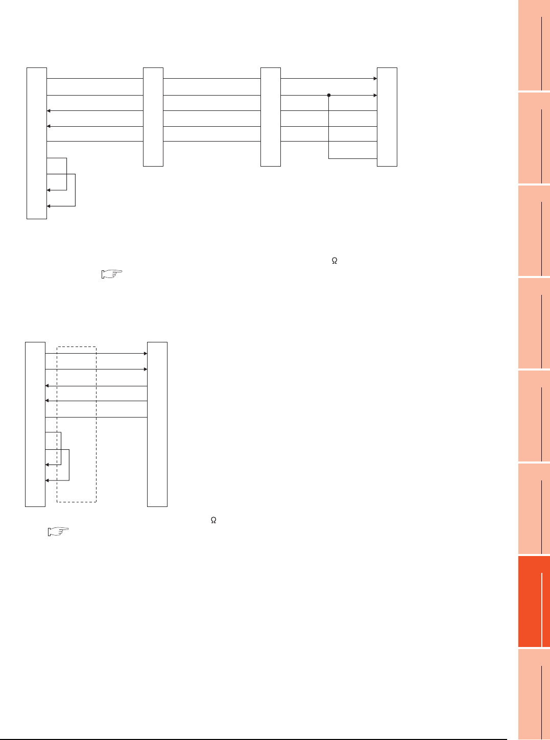
15. INVERTER CONNECTION
15.3 Connection Diagram
15 - 25
9
MELSECNET/H
CONNECTION (PLC
TO PLC NETWORK)
10
MELSECNET/10
CONNECTION (PLC
TO PLC NETWORK)
11
CC-Link IE CONTROLLER
NETWORK
CONNECTION
12
CC-Link IE FIELD
NETWORK
CONNECTION
13
CC-Link CONNECTION
(INTELLIGENT DEVICE
STATION)
14
CC-Link
CONNECTION
(Via G4)
15
INVERTER
CONNECTION
16
SERVO AMPLIFIER
CONNECTION
*1 Connect a terminating resistor jumper to RDB and RDR which are assigned in the FR-A5NR of the inverter located farthest from
the GOT.
The terminating resister jumper is packed together with the FR-A5NR.
*2 Set the terminating resistor of GOT side, which will be a terminal, to "330 ".
1.4.3 Terminating resistors of GOT
*1 Set the terminating resistor of the GOT side to "330 ".
1.4.3 Terminating resistors of GOT
RS422 connection diagram 12)
(For GT1030, GT1020)
RDA
RDB
SDA
SDB
SG
RDR
FR-A5NR side
(terminal block)
Station No.0
FR-A5NR side
(terminal block)
Station No.1
FR-A5NR side
(terminal block)
Station No.n
RDA
RDB
SDA
SDB
SG
RDR
RDA
RDB
SDA
SDB
SG
RDR
GOT side*2
(terminal block)
*1
SDA
SDB
RDA
RDB
SG
RSA
RSB
CSA
CSB
RS422 connection diagram 13)
(For GT1030, GT1020)
GOT side*1
(terminal block)
SDA
SDB
RDA
RDB
SG
RSA
RSB
CSA
CSB
RDA1(RXD1+)
RDB1(RXD1-)
SDA1(TXD1+)
SDB1(TXD1-)
SG(GND)
Inverter side
RS485 terminal block
(built into the inverter)
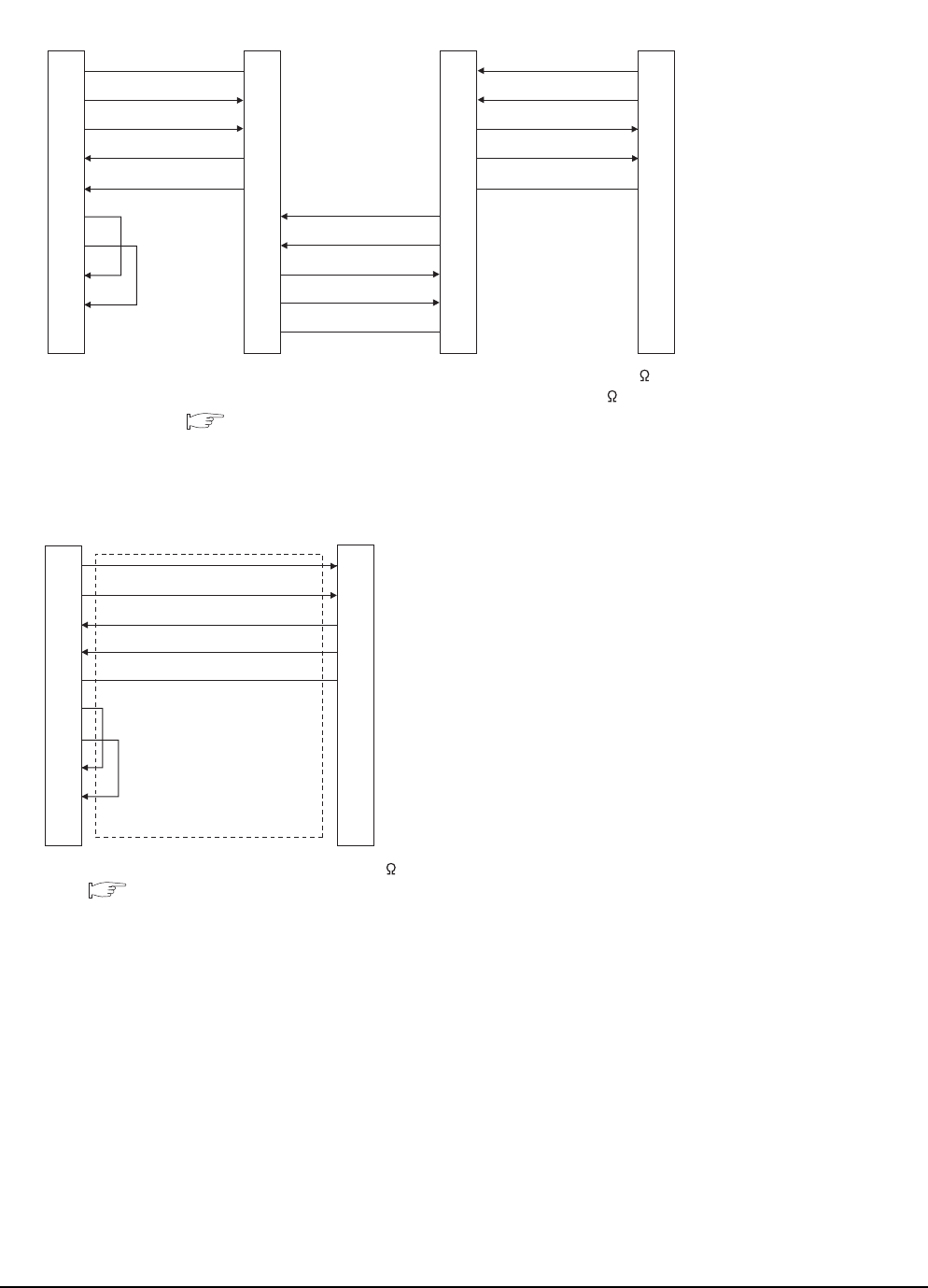
15 - 26 15. INVERTER CONNECTION
15.3 Connection Diagram
*1 Set the terminator switch built in the farthest inverter from the GOT to ON (100 ).
*2 Set the terminating resistor of GOT side, which will be a terminal, to "330 ".
1.4.3 Terminating resistors of GOT
*1 Set the terminating resistor of the GOT side to "330 ".
1.4.3 Terminating resistors of GOT
RS422 connection diagram 14)
(For GT1030, GT1020)
SG
SDB
SDA
RDB
RDA
RSA
RSB
CSA
CSB
SDA2
SDB2
RDA2
RDB2
GND
Built-in RS-485
terminal block
Station No.0
Built-in RS-485
terminal block
Station No.1
Built-in RS-485
terminal block*1
Station No.n
SDA2
SDB2
RDA2
RDB2
GND
GND
RDB1
RDA1
SDB1
SDA1
SDA1
SDB1
RDA1
RDB1
GND
SDA1
SDB1
RDA1
RDB1
GND
SDA2
SDB2
RDA2
RDB2
GND
GOT side
(terminal block)
RS422 connection diagram 15)
(For GT1030, GT1020)
SDA
SDB
RDA
RDB
SG
RSA
RSB
CSA
CSB
RDA
RDB
SDA
SDB
SG
FR-E7TR side
(terminal block)
GOT side*1
(terminal block)
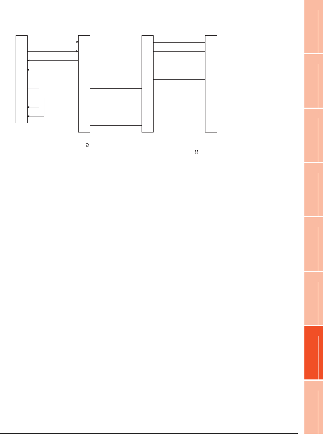
15. INVERTER CONNECTION
15.3 Connection Diagram
15 - 27
9
MELSECNET/H
CONNECTION (PLC
TO PLC NETWORK)
10
MELSECNET/10
CONNECTION (PLC
TO PLC NETWORK)
11
CC-Link IE CONTROLLER
NETWORK
CONNECTION
12
CC-Link IE FIELD
NETWORK
CONNECTION
13
CC-Link CONNECTION
(INTELLIGENT DEVICE
STATION)
14
CC-Link
CONNECTION
(Via G4)
15
INVERTER
CONNECTION
16
SERVO AMPLIFIER
CONNECTION
*1 Turn ON (100 ) the terminator switch for the most distant FR-E7TR from the GOT.
*2 Set the terminating resistor of GOT side, which will be a terminal, to "330 ".
RS422 connection diagram 16)
(For GT1030, GT1020)
SDA
SDB
RDA
RDB
SG
RSA
RSB
CSA
CSB
SDB
SDA
RDB
RDA
SG
FR-E7TR side
terminal block
Station No.0
FR-E7TR side
terminal block
Station No.1
FR-E7TR side
terminal block*1
Station No.2
RDA
RDB
SDA
SDB
SG
RDA
RDB
SDA
SDB
SG
SDB
SDA
RDB
RDA
SG
RDA
RDB
SDA
SDB
SG
SDB
SDA
RDB
RDA
SG
GOT side*2
(terminal block)
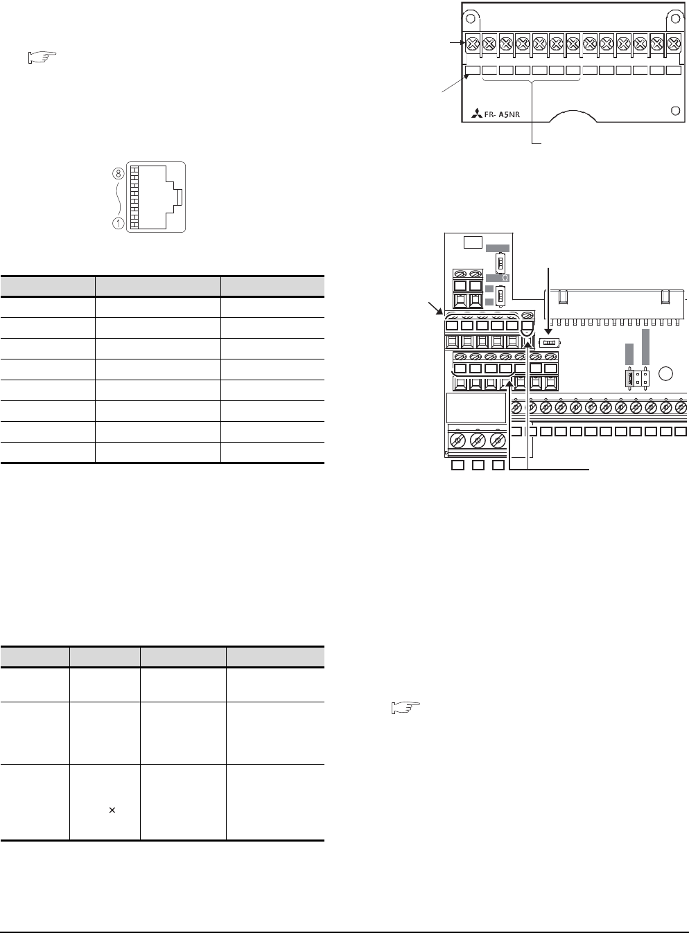
15 - 28 15. INVERTER CONNECTION
15.3 Connection Diagram
Precautions when preparing a cable
(1) Cable length
The length of the RS-422 cable must be 500m or less.
(2) GOT side connector
For the GOT side connector, refer to the following.
1.4.1 GOT connector specifications
(3) Inverter connector specifications
(a) Pin layout in the PU port
The contents inside ( ) indicate symbols described
in the inverter manual.
The pins number 2 and 8 (P5S) are connected to
the power supply for an operation panel or a
parameter unit.
Do not use them in RS-422 communication.
(b) Connector of cable between FREQROL Series
inverters
Use the commercial connectors and cables shown
in the table below or the comparable
products.(Refer to the manual for the inverter.)
(4) Terminal block layout in the FR-A5NR computer link
option
Attach this option to the A500 and F500 Series.
(5) Terminal block layout in the FR-E7TR control
terminal option
Mount the FR-E7TR to the E700 series.
Connecting terminating resistors
(1) GOT side
When connecting a PLC to the GOT, a terminating
resistor must be connected to the GOT.
(a) For GT16, GT15, GT12
Set the terminating resistor setting switch.
(b) For GT14, GT11, GT10
Set the terminating resistor selector switch.
For the procedure to set the terminating resistor, refer
to the following.
1.4.3 Terminating resistors of GOT
Pin No. Signal name Remark
1GND (SG)
2 (P5S) Not used
3RXD+ (RDA)
4TXD- (SDB)
5TXD+ (SDA)
6 RXD- (RDB)
7GND (SG)
8 (P5S) Not used
Name Model name Specifications Manufacturer
Connector 5-554720-3 RJ45 connector Tyco International,
Ltd
Modular
ceiling
rosette
(Distributor)
BMJ-8 -
HACHIKO
ELECTRIC
CO.,LTD.
TEL(03)-3806-9171
Cable SGLPEV
0.5mm 4P
Cable
conforming to
EIA568
(such as cable
10BASE-T)
MITSUBISHI
CABLE
INDUSTRIES, LTD.
When seen from the front of the inverte
r
(receptacle side)
Modular jack
SDBSDA RDA RDB RDR SG
ABC
Connected to the GOT
Terminal block
Screw size: M3
Terminal
symbol
O
N
OPENOPEN
100100
SOURCESOURCE
SINKSINK
V
II
SE
SDA SDB RDA RDB SG 2
SDA
SDB RDA RDB
SG 2
SDA SDB RDA RDB RUN FU
SDA SDB RDA RDB RUN
FU SE
10 4
RM RH
MRS RES
SD PC
STF STR
SD SD
ABC
FM RL
To the GOT or
the previous
inverter
Set the terminal 2/SG switch to the
right position (ON) to change the
terminal 2 to the terminal SG.
To the next inverter
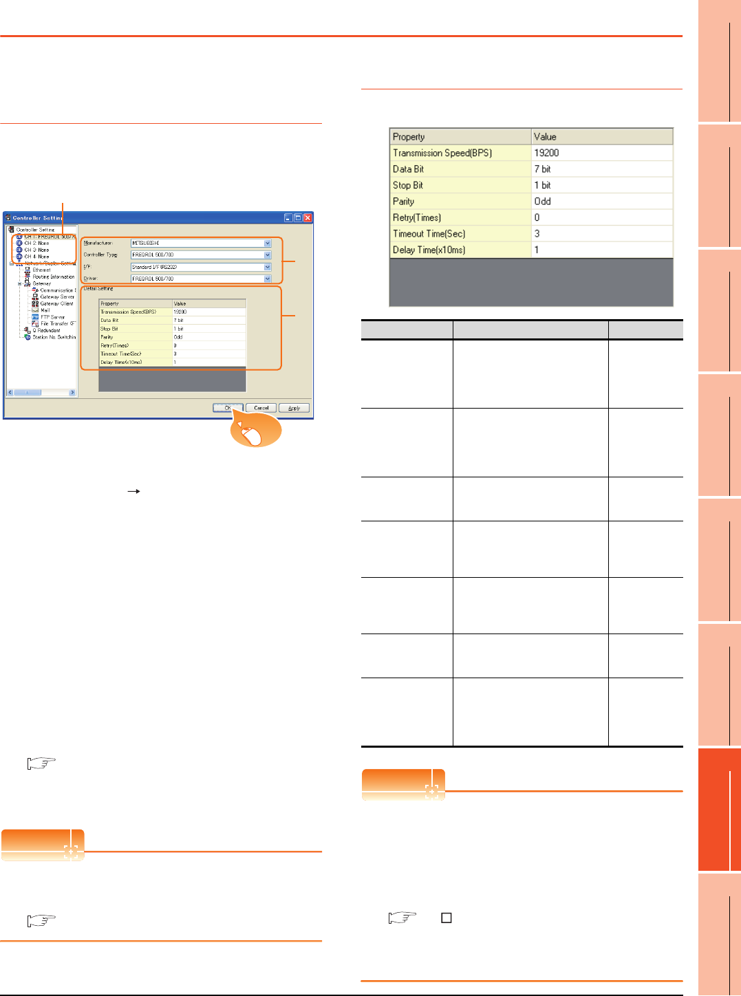
15. INVERTER CONNECTION
15.4 GOT Side Settings
15 - 29
9
MELSECNET/H
CONNECTION (PLC
TO PLC NETWORK)
10
MELSECNET/10
CONNECTION (PLC
TO PLC NETWORK)
11
CC-Link IE CONTROLLER
NETWORK
CONNECTION
12
CC-Link IE FIELD
NETWORK
CONNECTION
13
CC-Link CONNECTION
(INTELLIGENT DEVICE
STATION)
14
CC-Link
CONNECTION
(Via G4)
15
INVERTER
CONNECTION
16
SERVO AMPLIFIER
CONNECTION
15.4 GOT Side Settings
15.4.1 Setting communication
interface (Communication
settings)
Set the channel of the connected equipment.
1. Select [Common] [Controller Setting] from the
menu.
2. The Controller Setting window is displayed. Select the
channel to be used from the list menu.
3. Set the following items.
• Manufacturer: Mitsubishi
• Controller Type: Set according to the Controller
Type to be connected.
• I/F: Interface to be used
• Driver: FREQROL 500/700
4. The detailed setting is displayed after Manufacturer,
Controller Type, I/F, and Driver are set.
Make the settings according to the usage
environment.
15.4.2 Communication detail settings
Click the [OK] button when settings are completed.
POINTPOINTPOINT
The settings of connecting equipment can be
confirmed in [I/F Communication Setting].
For details, refer to the following.
1.1.2 I/F communication setting
15.4.2 Communication detail settings
Make the settings according to the usage environment.
POINTPOINTPOINT
(1) Communication interface setting by the Utility
The communication interface setting can be
changed on the Utility's [Communication Settings]
after writing [Communication Settings] of project
data.
For details on the Utility, refer to the following
manuals.
GT User's Manual
(2) Precedence in communication settings
When settings are made by GT Designer3 or the
Utility, the latest setting is effective.
2.
3.
4.
Click!
Item Description Range
Transmission
Speed
Set this item when change the
transmission speed used for
communication with the
connected equipment.
(Default: 19200bps)
9600bps,
19200bps,
38400bps,
57600bps,
115200bps
Data Bit
Set this item when change the
data length used for
communication with the
connected equipment.
(Default: 7bits)
7bits/8bits
Stop Bit
Specify the stop bit length for
communications.
(Default: 1bit)
1bit/2bits
Parity
Specify whether or not to perform
a parity check, and how it is
performed during communication.
(Default: Odd)
None
Even
Odd
Retry
Set the number of retries to be
performed when a communication
timeout occurs.
(Default: 0time)
0 to 5times
Timeout Time
Set the time period for a
communication to time out.
(Default: 3sec)
1 to 30sec
Delay Time
Set this item to adjust the
transmission timing of the
communication request from the
GOT.
(Default: 10ms)
0 to 300ms

15 - 30 15. INVERTER CONNECTION
15.4 GOT Side Settings
HINTHINTHINT
Cutting the portion of multiple connection of the
controller
By setting GOT internal device, GOT can cut the
portion of multiple connection of the controller. For
example, faulty station that has communication
timeout can be cut from the system.
For details of the setting contents of GOT internal
device, refer to the following manual.
GT Designer3 Version Screen Design Manual
(Fundamentals)
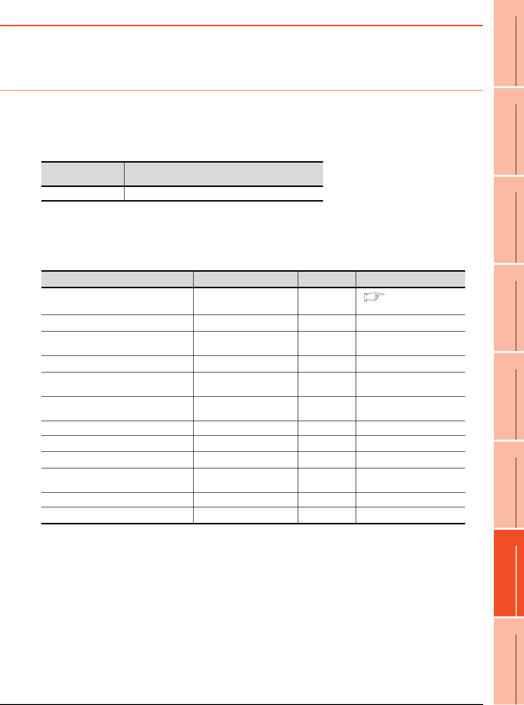
15. INVERTER CONNECTION
15.5 FREQROL Series Inverter Side Settings
15 - 31
9
MELSECNET/H
CONNECTION (PLC
TO PLC NETWORK)
10
MELSECNET/10
CONNECTION (PLC
TO PLC NETWORK)
11
CC-Link IE CONTROLLER
NETWORK
CONNECTION
12
CC-Link IE FIELD
NETWORK
CONNECTION
13
CC-Link CONNECTION
(INTELLIGENT DEVICE
STATION)
14
CC-Link
CONNECTION
(Via G4)
15
INVERTER
CONNECTION
16
SERVO AMPLIFIER
CONNECTION
15.5 FREQROL Series Inverter Side Settings
For details of the inverter, refer to the manual of each series.
15.5.1 Connecting FREQROL-S500, S500E, F500J series
Communication settings
Make the communication settings of the inverter.
Be sure to perform the inverter reset after updating each parameter.
(1) Communication port and corresponding parameters
(2) Communication settings of inverter
Set the following parameters using the PU (parameter unit). Set Pr.30 (Extended function selection) to 1 [With
display] before making the parameter settings.
Do not change these parameters, even though they can be monitored from the GOT. If they are changed,
communication with the GOT is disabled.
*1 Setting items are parameter names described in the manual of FREQROL-S500, S500E, and F500J series.
*2 Settings on the GOT can be changed.
When changing the settings on the GOT, be sure to change the parameters on the inverter to correspond with the GOT settings.
*3 Inverter default values (No need to change)
*4 When being monitored from the GOT, the parameter n1 through n7 correspond with Pr.331 through Pr.337, and the parameter
n10 through n12 correspond with Pr.340 through Pr.342.
Numbers in brackets show the parameter number when the parameter unit is in use.
*5 There is no Protocol selection setting on the inverter side.
GOT connection
destination Parameters corresponding to inverter
RS-485 port Pr.79, n1 to n7, n10 to n12
Setting item*1 Parameter No.*4 Set value Contents of setting
Communication station number n1 (331) 0 to 31 15.5.12 Station number
setting
Communication speed*2 n2 (332) 192*3 19200bps
Stop bit length*2 n3 (333) 10 Data length: 7bit
Stop bit length: 1bit
Parity check presence/absence*2 n4 (334) 1 Odd
Number of communication retries n5 (335) ---
(65535)
The inverter will not come to an
alarm stop.
Communication check time interval n6 (336) --- Communication check
suspension
Wait time setting n7 (337) 0 0ms
CRLF selection n11 (341) 1*3 With CR, without LF
Protocol selection*5 ―― ―
Operation mode selection Pr.79 0*3 External operation mode at
power on
Link start mode selection n10 (340) 1 Computer link operation
E2PROM write selection n12 (342) 0*3 Written to RAM and EEPROM

15 - 32 15. INVERTER CONNECTION
15.5 FREQROL Series Inverter Side Settings
15.5.2 Connecting FREQROL-E500 series
Communication settings
Make the communication settings of the inverter.
Be sure to perform the inverter reset after updating each parameter.
(1) Communication port and corresponding parameters
(2) Communication settings of inverter
Set the following parameters using the PU (parameter unit).
Do not change these parameters, even though they can be monitored from the GOT.If they are changed,
communication with the GOT is disabled.
*1 Setting items are parameter names described in the manual of FREQROL-E500 series.
*2 Settings on the GOT can be changed.
When changing the settings on the GOT, be sure to change the parameters on the inverter to correspond with the GOT settings.
*3 Inverter default values (No need to change)
*4 There is no Protocol selection setting on the inverter side.
*5 The setting is required for Frequency setting command selection.
GOT connection
destination Parameters corresponding to inverter
PU connector Pr.79, Pr.117 to Pr.124, Pr.146, Pr.342
Setting item*1 Parameter No. Set value Contents of setting
Communication station number Pr.117 0 to 31 15.5.12 Station number
setting
Communication speed*2 Pr.118 192*3 19200bps
Stop bit length*2 Pr.119 10 Data length: 7bit
Stop bit length: 1bit
Parity check presence/absence*2 Pr.120 1 Odd
Number of communication retries Pr.121 9999
(65535)
The inverter will not come to an
alarm stop.
Communication check time interval Pr.122 9999 Communication check
suspension
Wait time setting Pr.123 0 0ms
CRLF presence/ absence selection Pr.124 1*3 With CR, without LF
Protocol selection*4 ―― ―
Operation mode selection Pr.79 1*3 PU operation mode
Communication startup mode selection*4 ―― ―
E2PROM write selection Pr.342 0*3 Written to RAM and EEPROM
Frequency setting command selection*5 Pr.146 9999 Built-in frequency setting
potentiometer invalid

15. INVERTER CONNECTION
15.5 FREQROL Series Inverter Side Settings
15 - 33
9
MELSECNET/H
CONNECTION (PLC
TO PLC NETWORK)
10
MELSECNET/10
CONNECTION (PLC
TO PLC NETWORK)
11
CC-Link IE CONTROLLER
NETWORK
CONNECTION
12
CC-Link IE FIELD
NETWORK
CONNECTION
13
CC-Link CONNECTION
(INTELLIGENT DEVICE
STATION)
14
CC-Link
CONNECTION
(Via G4)
15
INVERTER
CONNECTION
16
SERVO AMPLIFIER
CONNECTION
15.5.3 Connecting FREQROL-F500, F500L series
Communication settings
Make the communication settings of the inverter.
Be sure to perform the inverter reset after updating each parameter.
(1) Communication port and corresponding parameters
(2) Communication settings of inverter
Set the following parameters using the PU (parameter unit). Set Pr.160 (user group read selection) to 0 [All
parameters can be accessed for reading and writing.] before making the parameter settings.
Do not change these parameters, even though they can be monitored from the GOT. If they are changed,
communication with the GOT is disabled.
*1 Setting items are parameter names described in the manual of FREQROL-F500 and F500L series.
*2 Settings on the GOT can be changed.
When changing the settings on the GOT, be sure to change the parameters on the inverter to correspond with the GOT settings.
*3 Inverter default values (No need to change)
*4 Since the value has been set as a default, no setting is required when connecting to the PU connector on the inverter side.
*5 There is no Protocol selection setting on the inverter side.
*6 The setting is required on the inverter side when FR-A5NR is used.
GOT connection destination Parameters corresponding to inverter
PU connector Pr.79, Pr.117 to Pr.124
FR-A5NR (Option unit) Pr.79, Pr.331 to Pr.337, Pr.340 to Pr.342
Setting item*1
Parameter No.
Set value Contents of setting
PU connector FR-A5NR
Communication station number Pr.117 Pr.331 0 to 31 15.5.12 Station number
setting
Communication speed*2 Pr.118 Pr.332 192*4 19200bps
Stop bit length/data length
Stop bit length*2 Pr.119 Pr.333 10 Data length: 7bit
Stop bit length: 1bit
Parity check presence/absence*2 Pr.120 Pr.334 1 Odd
Number of communication retries Pr.121 Pr.335 9999 The inverter will not come to an
alarm stop.
Communication check time interval Pr.122 Pr.336 9999 Communication check
suspension
Wait time setting Pr.123 Pr.337 0 0ms
CRLF presence/ absence selection Pr.124 Pr.341 1*3 With CR, without LF
Protocol selection*5 ―― ― ―
Operation mode selection Pr.79
PU
connector 1 PU operation mode
FR-A5NR 0*3 External operation mode at
power on
Link start mode selection*6 ―Pr.340 1 Computer link operation
E2PROM write selection*6 ―Pr.342 0*3 Written to RAM and EEPROM
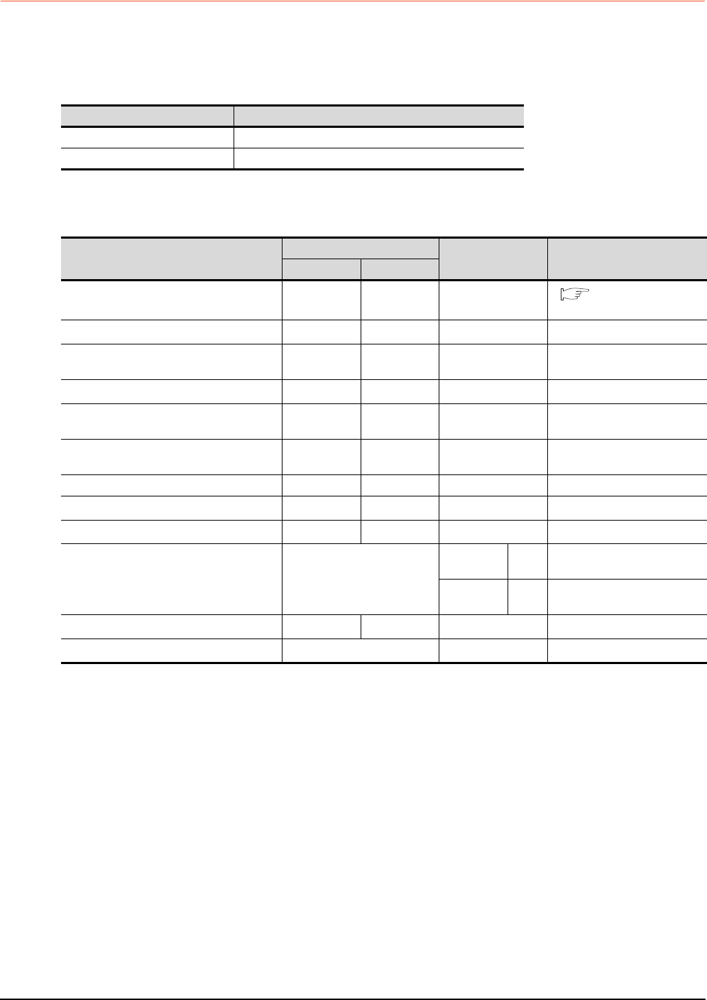
15 - 34 15. INVERTER CONNECTION
15.5 FREQROL Series Inverter Side Settings
15.5.4 Connecting FREQROL-A500, A500L series
Communication settings
Make the communication settings of the inverter.
Be sure to perform the inverter reset after updating each parameter.
(1) Communication port and corresponding parameters
(2) Communication settings of inverter
Set the following parameters using the PU (parameter unit). Do not change these parameters, even though they
can be monitored from the GOT. If they are changed, communication with the GOT is disabled.
*1 Setting items are parameter names described in the manual of FREQROL-A500 and A500L series.
*2 Settings on the GOT can be changed.
When changing the settings on the GOT, be sure to change the parameters on the inverter to correspond with the GOT settings.
*3 Inverter default values (No need to change)
*4 Since the value has been set as a default, no setting is required when connecting to the PU connector on the inverter side.
*5 There is no Protocol selection setting on the inverter side.
*6 The setting is required on the inverter side when FR-A5NR is used.
GOT connection destination Parameters corresponding to inverter
PU connector Pr.79, Pr.117 to Pr.124, Pr.342
FR-A5NR (Option unit) Pr.79, Pr.331 to Pr.337, Pr.340 to Pr.342
Setting item*1
Parameter No.
Set value Contents of setting
PU connector FR-A5NR
Communication station number Pr.117 Pr.331 0 to 31 15.5.12 Station number
setting
Communication speed*2 Pr.118 Pr.332 192*4 19200bps
Stop bit length*2 Pr.119 Pr.333 10 Data length: 7bit
Stop bit length: 1bit
Parity check presence/absence*2 Pr.120 Pr.334 1 Odd
Number of communication retries Pr.121 Pr.335 9999 The inverter will not come to an
alarm stop.
Communication check time interval Pr.122 Pr.336 9999 Communication check
suspension
Wait time setting Pr.123 Pr.337 0 0ms
CRLF presence/ absence selection Pr.124 Pr.341 1*3 With CR, without LF
Protocol selection*5 ―― ― ―
Operation mode selection Pr.79
PU
connector 1 PU operation mode
FR-A5NR 0*3 External operation mode at
power on
Link start mode selection*6 ―Pr.340 1 Computer link operation
E2PROM write selection Pr.342 0*3 Written to RAM and EEPROM
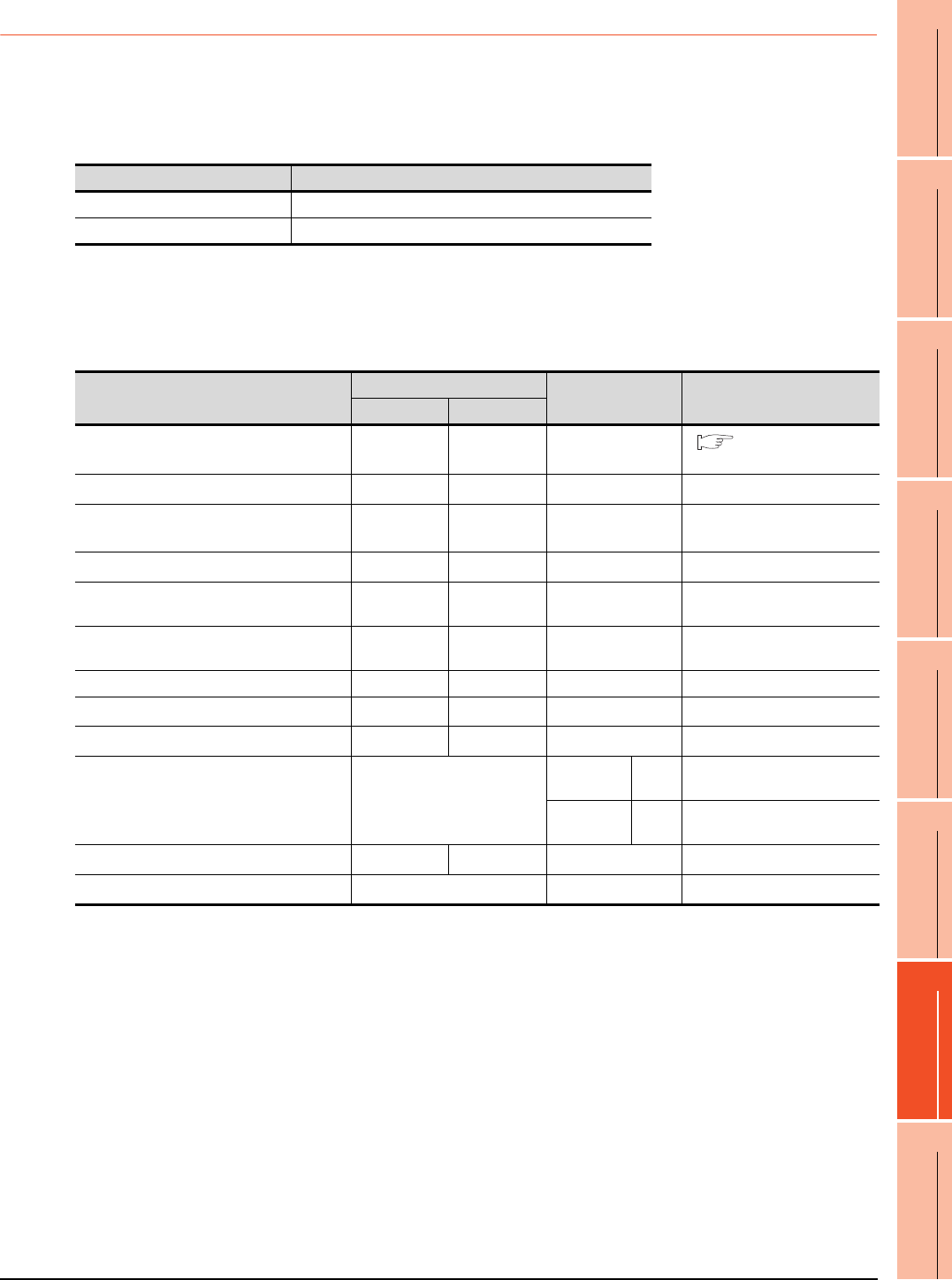
15. INVERTER CONNECTION
15.5 FREQROL Series Inverter Side Settings
15 - 35
9
MELSECNET/H
CONNECTION (PLC
TO PLC NETWORK)
10
MELSECNET/10
CONNECTION (PLC
TO PLC NETWORK)
11
CC-Link IE CONTROLLER
NETWORK
CONNECTION
12
CC-Link IE FIELD
NETWORK
CONNECTION
13
CC-Link CONNECTION
(INTELLIGENT DEVICE
STATION)
14
CC-Link
CONNECTION
(Via G4)
15
INVERTER
CONNECTION
16
SERVO AMPLIFIER
CONNECTION
15.5.5 Connecting FREQROL-V500, V500L series
Communication settings
Make the communication settings of the inverter.
Be sure to perform the inverter reset after updating each parameter.
(1) Communication port and corresponding parameters
(2) Communication settings of inverter
Set the following parameters using the PU (parameter unit). Set Pr.160 (Extended function display selection) to
1 [All parameters can be accessed for reading and writing.] before making the parameter settings.
Do not change these parameters, even though they can be monitored from the GOT. If they are changed,
communication with the GOT is disabled.
*1 Setting items are parameter names described in the manual of FREQROL-V500 and V500L series.
*2 Settings on the GOT can be changed.
When changing the settings on the GOT, be sure to change the parameters on the inverter to correspond with the GOT settings.
*3 Inverter default values (No need to change)
*4 Since the value has been set as a default, no setting is required when connecting to the PU connector on the inverter side.
*5 There is no Protocol selection setting on the inverter side.
*6 The setting is required on the inverter side when FR-A5NR is used.
GOT connection destination Parameters corresponding to inverter
PU connector Pr.79, Pr.117 to Pr.124, Pr.342
FR-A5NR (Option unit) Pr.79, Pr.331 to Pr.337, Pr.340 to Pr.342
Setting item*1
Parameter No.
Set value Contents of setting
PU connector FR-A5NR
Communication station number Pr.117 Pr.331 0 to 31 15.5.12 Station number
setting
Communication speed*2 Pr.118 Pr.332 192*4 19200bps
Stop bit length/data length
Stop bit length*2 Pr.119 Pr.333 10 Data length: 7bit
Stop bit length: 1bit
Parity check presence/absence*2 Pr.120 Pr.334 1 Odd
Number of communication retries Pr.121 Pr.335 9999 The inverter will not come to an
alarm stop.
Communication check time interval Pr.122 Pr.336 9999 Communication check
suspension
Wait time setting Pr.123 Pr.337 0 0ms
CRLF presence/ absence selection Pr.124 Pr.341 1*3 With CR, without LF
Protocol selection*5 ―― ― ―
Operation mode selection Pr.79
PU
connector 1 PU operation mode
FR-A5NR 0*3 External operation mode at
power on
Link start mode selection*6 ―Pr.340 1 Computer link operation
E2PROM write selection Pr.342 0*3 Written to RAM and EEPROM

15 - 36 15. INVERTER CONNECTION
15.5 FREQROL Series Inverter Side Settings
15.5.6 Connecting FREQROL-E700 series
Communication settings
Make the communication settings of the inverter.
Be sure to perform the inverter reset after updating each parameter.
(1) Communication port and corresponding parameters
(2) Communication settings of inverter
Set the following parameters using the PU (parameter unit).
Do not change these parameters, even though they can be monitored from the GOT. If they are changed,
communication with the GOT is disabled.
*1 Setting items are parameter names described in the manual of FREQROL-E700 series.
*2 Settings on the GOT can be changed.
When changing the settings on the GOT, be sure to change the parameters on the inverter to correspond with the GOT settings.
*3 Inverter default values (No need to change)
GOT connection
destination Parameters corresponding to inverter
PU connector
Pr.79, Pr.117 to Pr.124, Pr.340, Pr.342, Pr.549
FR-E7TR
(RS-485 terminal block)
Setting item*1 Parameter No. Set value Contents of setting
PU communication station number Pr.117 0 to 31 15.5.12 Station number
setting
PU communication speed*2 Pr.118 192*3 19200bps
PU communication stop bit length*2 Pr.119 10 Data length: 7bit
Stop bit length: 1bit
PU communication parity check*2 Pr.120 1 Odd
Number of PU communication retries Pr.121 9999 The inverter will not come to an
alarm stop.
PU communication check time interval Pr.122 9999 Communication check
suspension
PU communication wait time setting Pr.123 0 0ms
PU communication CR/LF selection Pr.124 1*3 With CR, without LF
Protocol selection Pr.549 0*3 Mitsubishi inverter protocol
Operation mode selection Pr.79 0*3 PU operation mode
Communication startup mode selection Pr.340 1 Network operation mode.
Communication EEPROM write selection Pr.342 0*3 Written to RAM and EEPROM
15. INVERTER CONNECTION
15.5 FREQROL Series Inverter Side Settings
15 - 37
9
MELSECNET/H
CONNECTION (PLC
TO PLC NETWORK)
10
MELSECNET/10
CONNECTION (PLC
TO PLC NETWORK)
11
CC-Link IE CONTROLLER
NETWORK
CONNECTION
12
CC-Link IE FIELD
NETWORK
CONNECTION
13
CC-Link CONNECTION
(INTELLIGENT DEVICE
STATION)
14
CC-Link
CONNECTION
(Via G4)
15
INVERTER
CONNECTION
16
SERVO AMPLIFIER
CONNECTION
15.5.7 Connecting FREQROL-D700 series
Communication settings
Make the communication settings of the inverter.
Be sure to perform the inverter reset after updating each parameter.
(1) Communication port and corresponding parameters
(2) Communication settings of inverter
Set the following parameters using the PU (parameter unit). Set Pr.160 (User group read selection) to 0 [The
simple mode and extended parameters can be displayed] before making the parameter settings.
Do not change these parameters, even though they can be monitored from the GOT. If they are changed,
communication with the GOT is disabled.
*1 Setting items are parameter names described in the manual of FREQROL-D700 series.
*2 Settings on the GOT can be changed.
When changing the settings on the GOT, be sure to change the parameters on the inverter to correspond with the GOT settings.
*3 Inverter default values (No need to change)
GOT connection
destination Parameters corresponding to inverter
PU connector Pr.79, Pr.117 to Pr.124, Pr.340, Pr.342, Pr.549
Setting item*1 Parameter No. Set value Contents of setting
PU communication station number Pr.117 0 to 31 15.5.12 Station number
setting
PU communication speed*2 Pr.118 192*3 19200bps
PU communication stop bit length*2 Pr.119 10 Data length: 7bit
Stop bit length: 1bit
PU communication parity check*2 Pr.120 1 Odd
Number of PU communication retries Pr.121 9999 The inverter will not come to an
alarm stop.
PU communication check time interval Pr.122 9999 Communication check
suspension
PU communication wait time setting Pr.123 0 0ms
PU communication CR/LF selection Pr.124 1*3 With CR, without LF
Protocol selection Pr.549 0*3 Mitsubishi inverter protocol
Operation mode selection Pr.79 0*3 PU operation mode
Communication startup mode selection Pr.340 1 Network operation mode.
Communication EEPROM write selection Pr.342 0*3 Written to RAM and EEPROM
15 - 38 15. INVERTER CONNECTION
15.5 FREQROL Series Inverter Side Settings
15.5.8 Connecting FREQROL-F700/700P series
Communication settings
Make the communication settings of the inverter.
Be sure to perform the inverter reset after updating each parameter.
(1) Communication port and corresponding parameters
(2) Communication settings of inverter
Set the following parameters using the PU (parameter unit). Set Pr.160 (User group read selection) to 0 [The
simple mode and extended parameters can be displayed] before making the parameter settings.
Do not change these parameters, even though they can be monitored from the GOT. If they are changed,
communication with the GOT is disabled.
*1 Setting items are parameter names described in the manual of FREQROL-F700 series.
*2 Settings on the GOT can be changed.
When changing the settings on the GOT, be sure to change the parameters on the inverter to correspond with the GOT settings.
*3 Inverter default values (No need to change)
*4 Since the value has been set as a default, no setting is required when connecting to the PU connector on the inverter side.
GOT connection
destination Parameters corresponding to inverter
PU connector Pr.79, Pr.117 to Pr.124, Pr.340, Pr.342
RS-485 terminal Pr.79, Pr.331 to Pr.337, Pr.340 to Pr.342, Pr.549
Setting item*1
Parameter No.
Set value Contents of setting
PU connector RS-485
PU communication station number/RS-485
communication station number Pr.117 Pr.331 0 to 31 15.5.12 Station number
setting
PU communication speed/RS-485
communication speed*2 Pr.118 Pr.332 192*4 19200bps
PU communication stop bit length/
RS-485 communication stop bit length*2 Pr.119 Pr.333 10 Data length: 7bit
Stop bit length: 1bit
PU communication parity check/
RS-485 communication parity check*2 Pr.120 Pr.334 1 Odd
Number of PU communication retries/
RS-485 communication retry count Pr.121 Pr.335 9999 The inverter will not come to an
alarm stop.
PU communication check time interval/
RS-485 communication check time interval Pr.122 Pr.336 9999*4 Communication check
suspension
PU communication waiting time setting/
RS-485 communication waiting time setting Pr.123 Pr.337 0 0ms
PU communication CR/LF selection/
RS-485 communication CR/LF selection Pr.124 Pr.341 1*3 With CR, without LF
Protocol selection ―Pr.549 0*3 Mitsubishi inverter protocol
Operation mode selection Pr.79
PU
connector 1 PU operation mode
RS-485 0*3 External operation mode at
power on
Communication startup mode selection Pr.340
PU
connector 0*3 Refer to Pr.79 settings.
RS-485 1 Network operation mode.
Communication EEPROM write selection Pr.342 0*3 Written to RAM and EEPROM

15. INVERTER CONNECTION
15.5 FREQROL Series Inverter Side Settings
15 - 39
9
MELSECNET/H
CONNECTION (PLC
TO PLC NETWORK)
10
MELSECNET/10
CONNECTION (PLC
TO PLC NETWORK)
11
CC-Link IE CONTROLLER
NETWORK
CONNECTION
12
CC-Link IE FIELD
NETWORK
CONNECTION
13
CC-Link CONNECTION
(INTELLIGENT DEVICE
STATION)
14
CC-Link
CONNECTION
(Via G4)
15
INVERTER
CONNECTION
16
SERVO AMPLIFIER
CONNECTION
HINTHINTHINT
Automatic setting with Pr.999 (FREQROL-F700P series only)
If Pr.999 is set as the following, the communication settings other than [PU communication station number] and
[Communication EEPROM write selection] can be automatically set in a batch to the default communication
settings of the GOT side.
*1 When monitoring the value of Pr.999, 9999 is always monitored.
Parameter No. Set value Description
Operation in parameter setting mode
Pr.999*1
10 GOT Initial settings (PU connector) [AUTO]→[GOT]→[1]Write
11 GOTInitial settings
(RS-485 terminal) -
15 - 40 15. INVERTER CONNECTION
15.5 FREQROL Series Inverter Side Settings
15.5.9 Connecting FREQROL-F700PJ series
Communication settings
Make the communication settings of the inverter.
Be sure to perform the inverter reset after updating each parameter.
(1) Communication port and corresponding parameters
(2) Communication settings of inverter
Set the following parameters using the PU (parameter unit). Set Pr.160 (User group read selection) to 0 [The
simple mode and extended parameters can be displayed] before making the parameter settings.
Do not change these parameters, even though they can be monitored from the GOT. If they are changed,
communication with the GOT is disabled.
*1 Setting items are parameter names described in the manual of FREQROL-F700 series.
*2 Settings on the GOT can be changed.
When changing the settings on the GOT, be sure to change the parameters on the inverter to correspond with the GOT settings.
*3 Inverter default values (No need to change)
HINTHINTHINT
Automatic setting with Pr.999
If Pr.999 is set as the following, the communication settings other than [PU communication station number] and
[Communication EEPROM write selection] can be automatically set in a batch to the default communication
settings of the GOT side.
*1 When monitoring the value of Pr.999, 9999 is always monitored.
GOT connection
destination Parameters corresponding to inverter
PU connector Pr.79, Pr.117 to Pr.124, Pr.340, Pr.342, Pr.549
Setting item*1 Parameter No. Set value Contents of setting
PU communication station number Pr.117 0 to 31 15.5.12 Station number
setting
PU communication speed*2 Pr.118 192*3 19200bps
PU communication stop bit length Pr.119 10 Data length: 7bit
Stop bit length: 1bit
PU communication parity check*2 Pr.120 1 Odd
Number of PU communication retries Pr.121 9999 The inverter will not come to an
alarm stop.
PU communication check time interval Pr.122 9999 Communication check
suspension
PU communication waiting time setting Pr.123 0 0ms
PU communication CR/LF selection Pr.124 1*3 With CR, without LF
Protocol selection Pr.549 0*3 Mitsubishi inverter protocol
Operation mode selection Pr.79 0*3 External operation mode at
power on
Communication startup mode selection Pr.340 1 Network operation mode.
Communication EEPROM write selection Pr.342 0*3 Written to RAM and EEPROM
Parameter No. Set value Description
Operation in parameter setting mode
Pr.999*1 10 GOT Initial settings (PU connector) [AUTO] [GOT] [1]Write
15. INVERTER CONNECTION
15.5 FREQROL Series Inverter Side Settings
15 - 41
9
MELSECNET/H
CONNECTION (PLC
TO PLC NETWORK)
10
MELSECNET/10
CONNECTION (PLC
TO PLC NETWORK)
11
CC-Link IE CONTROLLER
NETWORK
CONNECTION
12
CC-Link IE FIELD
NETWORK
CONNECTION
13
CC-Link CONNECTION
(INTELLIGENT DEVICE
STATION)
14
CC-Link
CONNECTION
(Via G4)
15
INVERTER
CONNECTION
16
SERVO AMPLIFIER
CONNECTION
15.5.10 Connecting FREQROL-A700 series
Communication settings
Make the communication settings of the inverter.
Be sure to perform the inverter reset after updating each parameter.
(1) Communication port and corresponding parameters
(2) Communication settings of inverter
Set the following parameters using the PU (parameter unit).
Do not change these parameters, even though they can be monitored from the GOT. If they are changed,
communication with the GOT is disabled.
*1 Setting items are parameter names described in the manual of FREQROL-A700 series.
*2 Settings on the GOT can be changed.
When changing the settings on the GOT, be sure to change the parameters on the inverter to correspond with the GOT settings.
*3 Inverter default values (No need to change)
*4 Since the value has been set as a default, no setting is required when connecting to the PU connector on the inverter side.
GOT connection
destination Parameters corresponding to inverter
PU connector Pr.79, Pr.117 to Pr.124, Pr.340, Pr.342
RS-485 terminal Pr.79, Pr.331 to Pr.337, Pr.340 to Pr.342, Pr.549
Setting item*1
Parameter No.
Set value Contents of setting
PU connector RS-485
PU communication station number/RS-485
communication station number Pr.117 Pr.331 0 to 31 15.5.12 Station number
setting
PU communication speed/RS-485
communication speed*2 Pr.118 Pr.332 192*4 19200bps
PU communication stop bit length/
RS-485 communication stop bit length*2 Pr.119 Pr.333 10 Data length: 7bit
Stop bit length: 1bit
PU communication parity check/
RS-485 communication parity check*2 Pr.120 Pr.334 1 Odd
Number of PU communication retries/
RS-485 communication retry count Pr.121 Pr.335 9999 The inverter will not come to an
alarm stop.
PU communication check time interval/
RS-485 communication check time interval Pr.122 Pr.336 9999*4 Communication check
suspension
PU communication waiting time setting/
RS-485 communication waiting time setting Pr.123 Pr.337 0 0ms
PU communication CR/LF selection/
RS-485 communication CR/LF selection Pr.124 Pr.341 1*3 With CR, without LF
Protocol selection ―Pr.549 0*3 Mitsubishi inverter protocol
Operation mode selection Pr.79
PU
connector 1 PU operation mode
RS-485 0*3 External operation mode at
power on
Communication startup mode selection Pr.340
PU
connector 0*3 Refer to Pr.79 settings.
RS-485 1 Network operation mode.
Communication EEPROM write selection Pr.342 0*3 Written to RAM and EEPROM
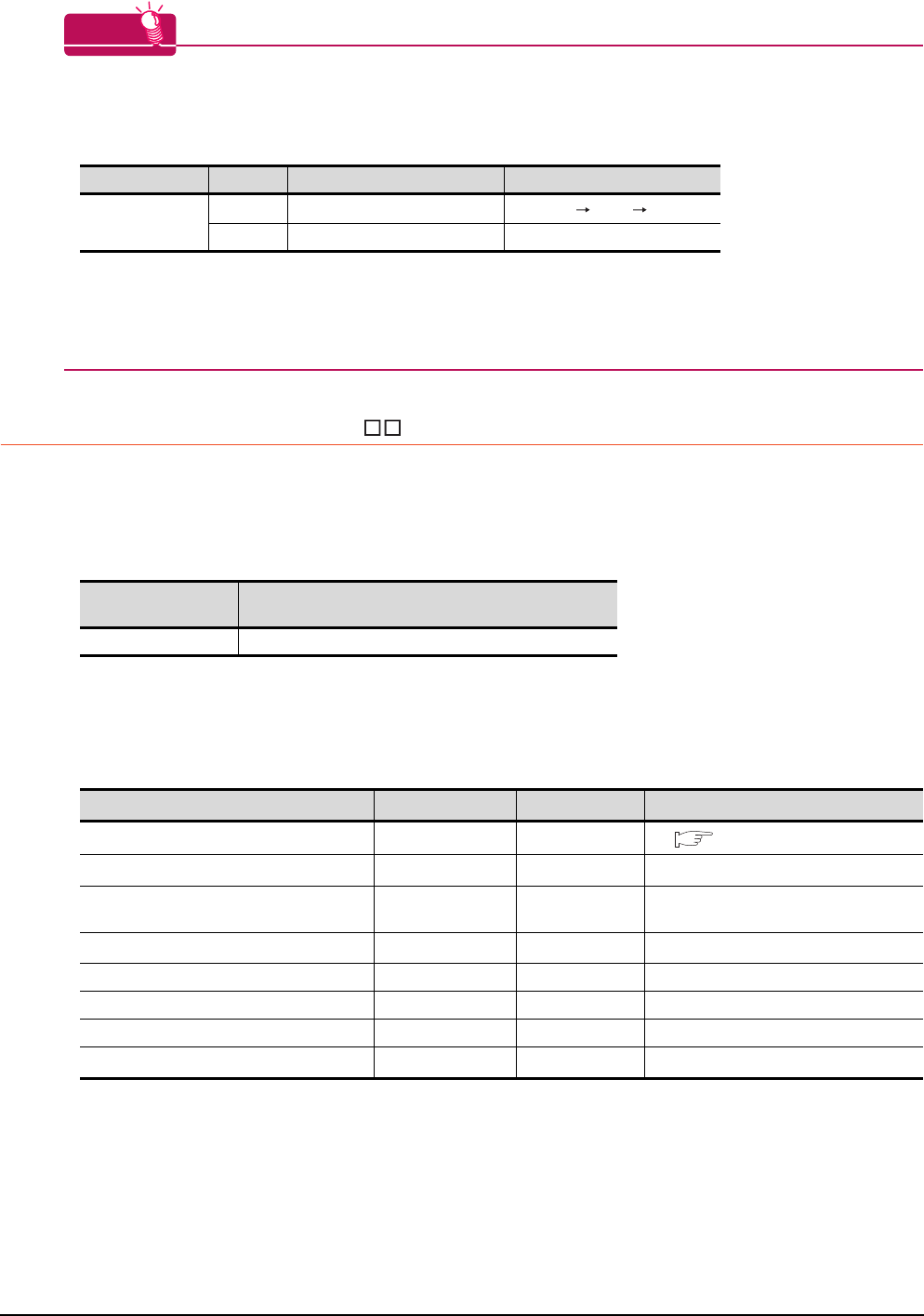
15 - 42 15. INVERTER CONNECTION
15.5 FREQROL Series Inverter Side Settings
HINTHINTHINT
(1) Automatic setting with Pr.999
If Pr.999 is set as the following, the communication settings other than [PU communication station number]
and [Communication EEPROM write selection] can be automatically set in a batch to the default
communication settings of the GOT side.
*1 When monitoring the value of Pr.999, 9999 is always monitored.
(2) Inverters available for automatic batch setting
Parameters are not automatically set in a batch depending on the SERIAL (production number) symbol of the
inverter to be used. For details, contact your local distributor.
15.5.11 Connecting MD-CX522- K(-A0)
Communication settings
Make the communication settings of the inverter.
Be sure to perform the inverter reset after updating each parameter.
(1) Communication port and corresponding parameters
(2) Communication settings of inverter
• Set the following parameters using the PU (parameter unit).
• After setting the parameters for the communication settings, reset the inverter.
• Do not change these parameters, even though they can be monitored from the GOT. If they are changed,
communication with the GOT is disabled.
*1 Setting items are parameter names described in the manual of MELIPM series.
*2 Settings on the GOT can be changed.
When changing the settings on the GOT, be sure to change the parameters on the inverter to correspond with the GOT settings.
*3 Inverter default values (No need to change)
Parameter No. Set value Description
Operation in parameter setting mode
Pr.999*1
10 GOT Initial settings (PU connector) [AUTO] [GOT] [1]Write
11 GOT Initial settings (RS-485) ―
GOT connection
destination Parameters corresponding to inverter
PU connector Pr.79, Pr.117 to Pr.124
Setting item*1 Parameter No. Set value Contents of setting
Communication station number Pr.117 0 to 31 15.5.12 Station number setting
Communication speed*2 Pr.118 192*3 19200bps
Stop bit length/data length*2 Pr.119 10 Data length: 7bit
Stop bit length: 1bit
Parity check presence/absence*2 Pr.120 1 Odd
Number of communication retries Pr.121 9999 The inverter will not come to an alarm stop.
Communication check time interval Pr.122 9999 Communication check suspension
Wait time setting Pr.123 0 0ms
CRLF presence/absence selection Pr.124 1*3 With CR, without LF
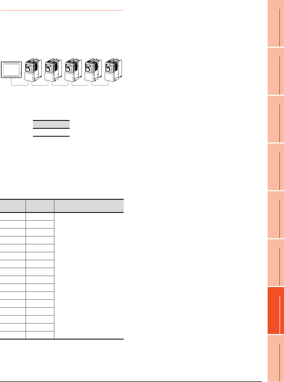
15. INVERTER CONNECTION
15.5 FREQROL Series Inverter Side Settings
15 - 43
9
MELSECNET/H
CONNECTION (PLC
TO PLC NETWORK)
10
MELSECNET/10
CONNECTION (PLC
TO PLC NETWORK)
11
CC-Link IE CONTROLLER
NETWORK
CONNECTION
12
CC-Link IE FIELD
NETWORK
CONNECTION
13
CC-Link CONNECTION
(INTELLIGENT DEVICE
STATION)
14
CC-Link
CONNECTION
(Via G4)
15
INVERTER
CONNECTION
16
SERVO AMPLIFIER
CONNECTION
15.5.12 Station number setting
Set each station number so that no station number
overlaps.
The station number can be set without regard to the cable
connection order. There is no problem even if station
numbers are not consecutive.
(1) Direct specification
When setting the device, specify the station number of
the inverter of which data is to be changed.
(2) Indirect specification
When setting the device, indirectly specify the station
number of the inverter of which data is to be changed
using the 16-bit GOT internal data register (GD10 to
GD25).
When specifying the station No. from 100 to 155 on GT
Designer3, the value of GD10 to GD25 compatible to
the station No. specification will be the station No. of
the inverter.
Specification range
0 to 31
Specification
station NO.
Compatible
device Setting range
100 GD10
0 to 31
For the setting other than the above,
error (dedicated device is out of range)
will occur.
101 GD11
102 GD12
103 GD13
104 GD14
105 GD15
106 GD16
107 GD17
108 GD18
109 GD19
110 GD20
111 GD21
112 GD22
113 GD23
114 GD24
115 GD25
GOT
Station
No.1
Station
No.0
Station
No.3
Station
No.21
Station
No.6
Examples of station number setting
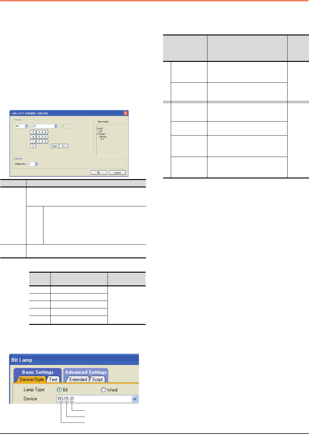
15 - 44 15. INVERTER CONNECTION
15.6 Device Range that Can Be Set
15.6 Device Range that Can Be Set
The device ranges of controller that can be used for GOT
are as follows.
Note that the device ranges in the following tables are the
maximum values that can be set in GT Designer3.
The device specifications of controllers may differ
depending on the models, even though belonging to the
same series.
Please make the setting according to the specifications of
the controller actually used.
When a non-existent device or a device number outside
the range is set, other objects with correct device settings
may not be monitored.
Setting item
*1 The following shows the relation between the inverter station
numbers and the GOT data register.
(1) Setting the device by inputting directly from the
keyboard
When setting the device by inputting directly from the
keyboard, set the items as follows.
Inverter (FREQROL 500/700 series)
*1 When creating the screen, designate only either of
programmed operation (PG) device or parameter (Pr)
device.
Do no designate both PG (PG0 to PG89) and Pr (Pr900 to
Pr905) devices.
*2 Only 16-bit (1-word) designation is possible.
*3 Only reading is possible.
*4 Precautions for PU operation mode
When the GOT is connected to the PU connector and the
operation mode is set to the PU operation mode, the multi-
speed operation (W3 to W7, SP121, SP122) cannot be used.
For using the multi-speed operation, follow either of the
operations as below.
• Connect the GOT to the RS-485 terminal and set the
operation mode to the NET operation mode (Computer
link operation mode), and then operate the inverter.
• Change the motor speed with the set frequency (SP109,
SP110), and then operate the inverter with the forward or
reverse rotation (WS1, WS2, SP121, SP122).
*5 Precautions for WS devices
Only writing is possible for WS devices.
More than one WS cannot turn on at once.
(Except the turned on WS device, the other WS devices turn
off.)
Bits of SP122 (word device) and SP121 (word device) are
assigned to WS0 to WS7 and WS8 to WS15 respectively.
When more than one WS turns on at once, convert the
values for the bit devices that are assigned to the word
device into values for the word device. Write the converted
values into SP122 or SP121.
• Setting High speed operation command (WS5), Middle
speed operation command (WS4), and Low speed
operation command (WS3)
When setting High speed operation command (WS5),
Middle speed operation command (WS4), and Low speed
operation command (WS3), write numerical values to
device SP122 as necessary.
As the following figure shows, each operation mode is
assigned to device SP122.
The following shows an example for Forward rotation
command (WS1) and Low speed operation command
(WS3).
Item Description
Device
Set the device name, device number, and bit number.
The bit number can be set only by specifying the bit of word
device.
Station
No.
Monitors the inverter of the specified station No.
0 to 31: To monitor the inverter of the specified
station No.
100 to 115: To specify the station No. of the inverter
to be monitored by the value of GOT data register
(GD).*1
Information Displays the device type and setting range which are
selected in [Device].
Station
No. GOT data register (GD) Setting range
100 GD10 0 to 31
(If setting a value
outside the
range above, a
device range
error occurs)
101 GD11
::
114 GD24
115 GD25
Station No.
Device number
Device name
Device name Setting range
Device
No.
represen
tation
Bit device
Inverter
status monitor
(RS)*3
RS0: 0 to RS15: 31
RS0: 100 to RS15: 115
Decimal
Run command
(WS)
*4*5
WS0: 0 to RS15: 31
WS0: 100 to RS15: 115
Word device
Alarm definition
(A)
*2*3
A0: 0 to A7: 31
A0: 100 to A7: 115
Decimal
Parameter (Pr)
*1*2
Pr0: 0 to Pr999: 31
Pr0: 100 to Pr999: 115
Programmed
operation
(PG)*1*2
PG0: 0 to PG89: 31
PG0: 100 to PG89: 115
Special
parameter
(SP)*2*4
SP108: 0 to SP127: 31
SP108: 100 to SP127: 115
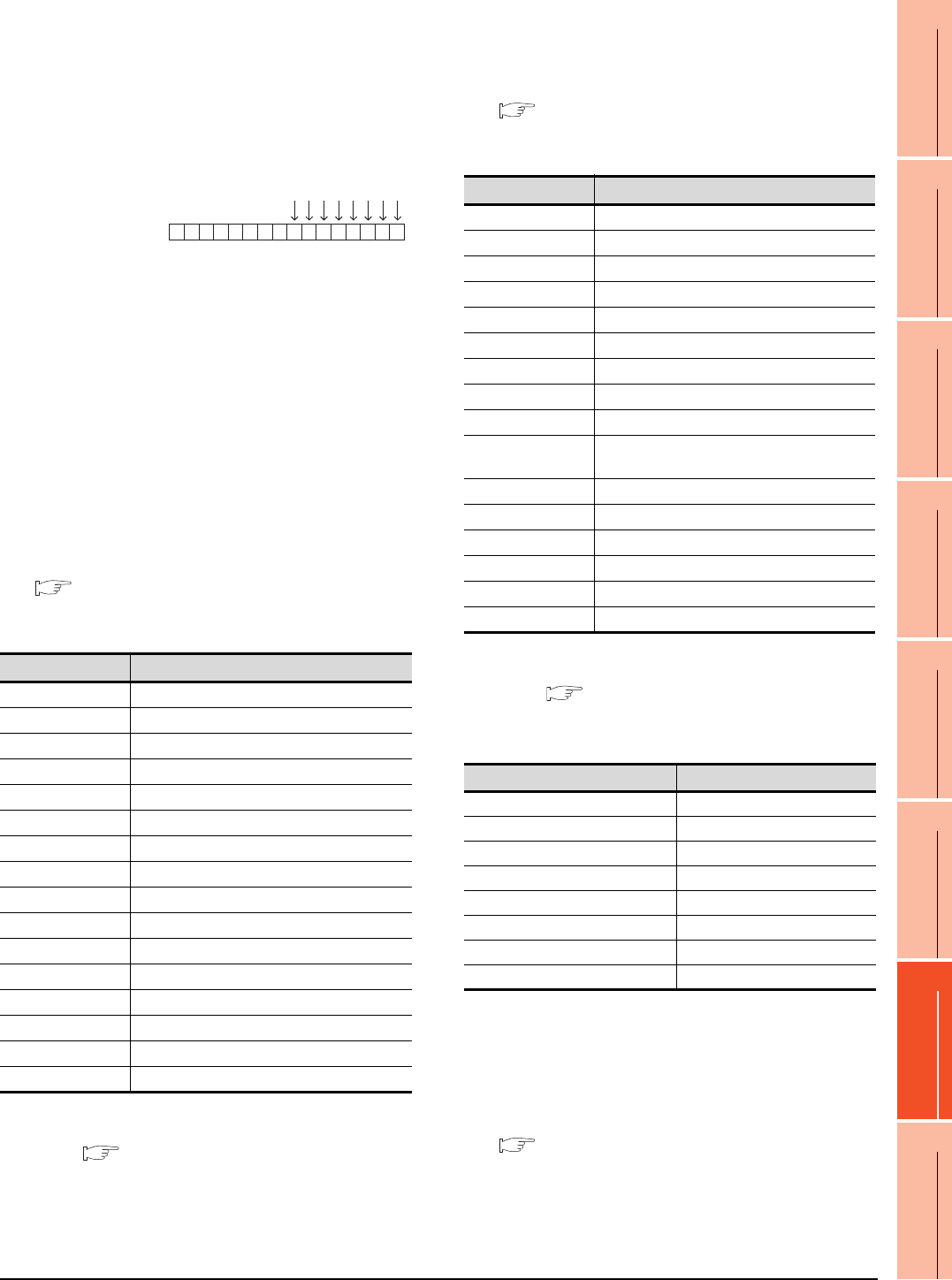
15. INVERTER CONNECTION
15.6 Device Range that Can Be Set
15 - 45
9
MELSECNET/H
CONNECTION (PLC
TO PLC NETWORK)
10
MELSECNET/10
CONNECTION (PLC
TO PLC NETWORK)
11
CC-Link IE CONTROLLER
NETWORK
CONNECTION
12
CC-Link IE FIELD
NETWORK
CONNECTION
13
CC-Link CONNECTION
(INTELLIGENT DEVICE
STATION)
14
CC-Link
CONNECTION
(Via G4)
15
INVERTER
CONNECTION
16
SERVO AMPLIFIER
CONNECTION
Write [1] to each bit corresponding to Forward rotation
command (WS1) and Low speed operation command
(WS3) of device SP122. The value will be 000AH in this
example. When writing the value to device SP122 actually,
convert 000AH to decimal number and write the value
[10].
When using a WS device, [Alternate] of a bit switch cannot
be used.
Use [Set], [Reset], and [Momentary] of a bit switch.
The following shows correspondences between virtual
inverter devices used in the GOT and data of the
inverter.
(1) Inverter status monitor
An example with FREQROL-A700 series is shown
below. For the setting items of other than the
FREQROL-A700 series, refer to the following manual.
User's Manual of the used inverter
(communication function (setting item and set
data))
*1 The description (function of input terminal) may be changed
by the parameter of the inverter side. Check the function of
the inverter used.
Inverter User's Manual (Application) Communication
operation and setting
(2) Run command
An example with FREQROL-A700 series is shown
below. For the setting items of other than the
FREQROL-A700 series, refer to the following manual.
User's Manual of the used inverter
(Communication function (Setting item and set
data))
*1 The data (function of input terminal) may be changed by the
parameter of the inverter side. Check the function of the
inverter used.
Inverter User's Manual (Application) Communication
operation and setting
(3) Alarm definition
*1 Only reading is possible for A0 to A7.
These devices cannot be used for a write object (numerical input etc.).
(4) Parameter
The numbers of virtual devices for inverter (parameter
(Pr)), used by GOT, correspond to the inverter
parameter numbers.
For the inverter parameters, refer to the following.
Manual of the inverter being used
Device name Description*1
RS0 Inverter running (RUN)
RS1 Forward rotation (STF)
RS2 Reverse rotation (STR)
RS3 Up to frequency (SU)
RS4 Overload (OL)
RS5 Instantaneous power failure (IPF)
RS6 Frequency detection (FU)
RS7 Fault (ABC1)
RS8 ABC2
RS9 -
RS10 -
RS11 -
RS12 -
RS13 -
RS14 -
RS15 Fault occurrence
Device SP122
b15 b7 b0
0000000000001010
WS7: Output stop(MRS)
WS6: Second function selection(RT)
WS5: High speed operation command(RH)
WS4: Middle speed operation command(RM)
WS3: Low speed operation command(RL)
WS2: Reverse rotation command(STR)
WS1: Forward rotation command(STF)
WS0: Current input selection(AU)
Device name Description*1
WS0 Current input selection (AU)
WS1 Forward rotation command (STF)
WS2 Reverse rotation command (STR)
WS3 Low speed operation command (RL)
WS4 Middle speed operation command (RM)
WS5 High speed operation command (RH)
WS6 Second function selection (RT)
WS7 Output stop (MRS)
WS8 Jog operation (JOG)
WS9 Selection of automatic restart after instantaneous
power failure (CS)
WS10 Start self-holding (STOP)
WS11 Reset (RES)
WS12 -
WS13 -
WS14 -
WS15 -
Device name*1 Description
A0 Second alarm in past
A1 Latest alarm
A2 Fourth alarm in past
A3 Third alarm in past
A4 Sixth alarm in past
A5 Fifth alarm in past
A6 Eighth alarm in past
A7 Seventh alarm in past
15 - 46 15. INVERTER CONNECTION
15.6 Device Range that Can Be Set
POINTPOINTPOINT
(1) Monitoring Pr.37
GOT cannot monitor the parameter (Pr.37) of
FREQROL-E500/S500(E)/F500J/D700/F700PJ/
E700.
(2) When setting "8888" or "9999" to inverter parameter (Pr)
"8888" and "9999" designate special function.
To set these numbers from GOT, designate a
number as shown below.
(3) Precautions for setting calibration parameter
(Pr900 to Pr905)
When setting a calibration parameter (Pr900 to
Pr905), it is necessary to set the value below for
extension second parameter (SP108), depending on
the device number to be used and the inverter model.
(5) Programmed operation
The devices below correspond to the parameters
(Pr.201 to Pr.230) of FREQROL-A500 series.
*1 To set the start time (PG10 to PG19, PG40 to PG49, PG70
to PG79), set hour or minute in the upper 8bits, and minute
or second in the lower 8bits.
Example) To set 13 hour 35 minute
(6) Special parameter
The numbers of the inverter’s virtual devices (SP) used
for the GOT correspond to instruction codes of the
inverter communication function.
For instruction details, and values to be read and
written, refer to the following,
Manual of the inverter used
*1 GOT cannot monitor SP109 to SP111 if the conditions below
are satisfied at the same time.
(Only FREQROL-E500/S500(E)/F500J/D700/F700PJ/E700
series)
•Pr37 0
• SP127 = 1
*2 Only reading is possible for SP111 to SP114.
These devices cannot be used for a write object (numerical
input etc.).
*3 Only writing is possible for SP124 and SP125.
These devices cannot be used for read object.
Set value of inverter side Value specified by GOT
8888 65520
9999 65535
Value to be set to extension
second parameter (SP108) Description
H00 Offset/gain
H01 Analog
H02 Analog value at terminal
Device name Description
PG0 to PG9 Program set 1 (running frequency)
PG10 to PG19*1 Program set 1 (time)
PG20 to PG29 Program set 1 (rotation direction)
PG30 to PG39 Program set 2 (running frequency)
PG40 to PG49*1 Program set 2 (time)
PG50 to PG59 Program set 2 (rotation direction)
PG60 to PG69 Program set 3 (running frequency)
PG70 to PG79*1 Program set 3 (time)
PG80 to PG89 Program set 3 (rotation direction)
Time to be set 13H 35M Remark
Convert "hour" and "minute"
into hexadecimal. H0D H23 HEX
Combine upper and lower 8-
bit values. Input H0D23 or 3363. -
Device
name Description
Instruction
code
Read Write
SP108 Second parameter changing 6CHECH
SP109*1 Set frequency (RAM) 6DHEDH
SP110*1 Set frequency (RAM, E2PROM) 6EHEEH
SP111*1*2 Output frequency 6FH-
SP112*2 Output current 70H-
SP113*2 Output voltage 71H-
SP114*2 Special monitor 72H-
SP115 Special monitor selection No. 73HF3H
SP116 Alarm definition all clear - F4H
Latest alarm, second alarm in past 74H-
SP117 Third alarm in past, fourth alarm in past 75H-
SP118 Fifth alarm in past, sixth alarm in past 76H-
SP119 Seventh alarm in past, eights alarm in
past 77H-
SP121 Inverter status monitor (extended) 79HF9H
Run command (extend)
SP122 Inverter status monitor 7AH-
Run command - FAH
SP123 Communication mode 7BHFBH
SP124*3 All parameter clear - FCH
SP125*3 Inverter reset - FDH
SP127 Link parameter extended setting 7FHFFH
15. INVERTER CONNECTION
15.7 Precautions
15 - 47
9
MELSECNET/H
CONNECTION (PLC
TO PLC NETWORK)
10
MELSECNET/10
CONNECTION (PLC
TO PLC NETWORK)
11
CC-Link IE CONTROLLER
NETWORK
CONNECTION
12
CC-Link IE FIELD
NETWORK
CONNECTION
13
CC-Link CONNECTION
(INTELLIGENT DEVICE
STATION)
14
CC-Link
CONNECTION
(Via G4)
15
INVERTER
CONNECTION
16
SERVO AMPLIFIER
CONNECTION
15.7 Precautions
Station No. of inverter system
Make sure to establish inverter system with No.0
station.
Number of inverter
Up to 31 inverters can be connected.
For GT11 and GT10, refer to the following manual for
the procedure to check the connectable inverter
depending on the version.
GT11 User's Manual, GT10 User's Manual
Parameter setting
(1) Communication parameter change
Do not make any change for each communication
parameter of the inverter side from GOT.
If changed, the communication to the inverter cannot
be made.
(2) When setting "8888" or "9999" to inverter parameter
(Pr)
"8888" and "9999" designate special function. When
specifying from the GOT, it will be as follows.
Screen switching devices, system
information devices
Make sure to use GD for screen switching devices and
system information devices when the GOT is
connected to only the inverter.
GOT clock control
Since the inverter does not have a clock function, the
settings of [time adjusting] or [time broad cast] by GOT
clock control will be disabled.
Model name Hardware version Number of connect-
able Inverter
GT1155-QTBD
C or later 31
B or earlier 10
GT1155-QSBD
GT1150-QLBD
F or later 31
E or earlier 10
GT1055-QSBD
GT1050-QBBD
C or later 31
B or earlier 10
GT1045-QSBD
GT1040-QBBD A or later 31
GT1030-L D
GT1030-H D
B or later 31
A or earlier 10
GT1020-L D
E or later 31
D or earlier 10
Set value of inverter side Value specified by GOT
8888 65520
9999 65535

15 - 48 15. INVERTER CONNECTION
15.7 Precautions
16
9
MELSECNET/H
CONNECTION (PLC
TO PLC NETWORK)
10
MELSECNET/10
CONNECTION (PLC
TO PLC NETWORK)
11
CC-Link IE CONTROLLER
NETWORK
CONNECTION
12
CC-Link IE FIELD
NETWORK
CONNECTION
13
CC-Link CONNECTION
(INTELLIGENT DEVICE
STATION)
14
CC-Link
CONNECTION
(Via G4)
15
INVERTER
CONNECTION
16
SERVO AMPLIFIER
CONNECTION
16 - 1
16.SERVO AMPLIFIER
CONNECTION
16.1 Connectable Model List . . . . . . . . . . . . . . . . . . . . . . . . . . . 16 - 2
16.2 System Configuration. . . . . . . . . . . . . . . . . . . . . . . . . . . . . 16 - 3
16.3 Connection Diagram . . . . . . . . . . . . . . . . . . . . . . . . . . . . . 16 - 8
16.4 GOT Side Settings . . . . . . . . . . . . . . . . . . . . . . . . . . . . . . 16 - 12
16.5 Setting on Servo Amplifier Side . . . . . . . . . . . . . . . . . . . . 16 - 14
16.6 Device Range that Can Be Set . . . . . . . . . . . . . . . . . . . . 16 - 17
16.7 Precautions . . . . . . . . . . . . . . . . . . . . . . . . . . . . . . . . . . . 16 - 45
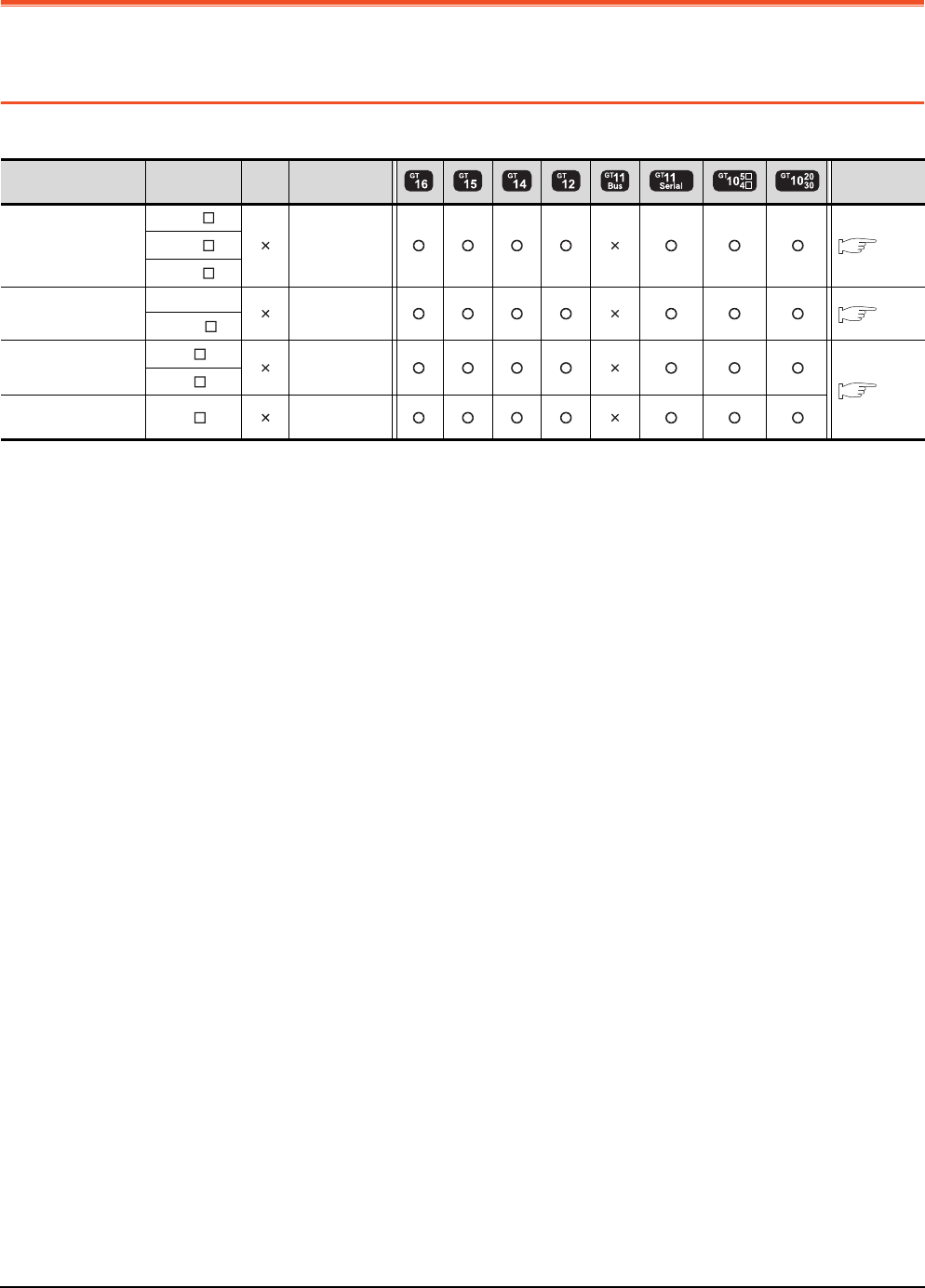
16 - 2 16. SERVO AMPLIFIER CONNECTION
16.1 Connectable Model List
16. SERVO AMPLIFIER CONNECTION
16.1 Connectable Model List
The following table shows the connectable models.
*1 For the RS-422 communication, use MELSERVO-J4 of software version A3 or a later version.
Series Model name Clock
Communication
type
Refer to
MELSERVO-J2-Super
MR-J2S- A
RS-232
RS-422 16.2.1
MR-J2S- CP
MR-J2S- CL
MELSERVO-J2M
MR-J2M-P8A RS-232
RS-422 16.2.2
MR-J2M- DU
MELSERVO-J3
MR-J3- A RS-232
RS-422
16.2.3
MR-J3- T
MELSERVO-J4*1 MR-J4- A RS-232
RS-422
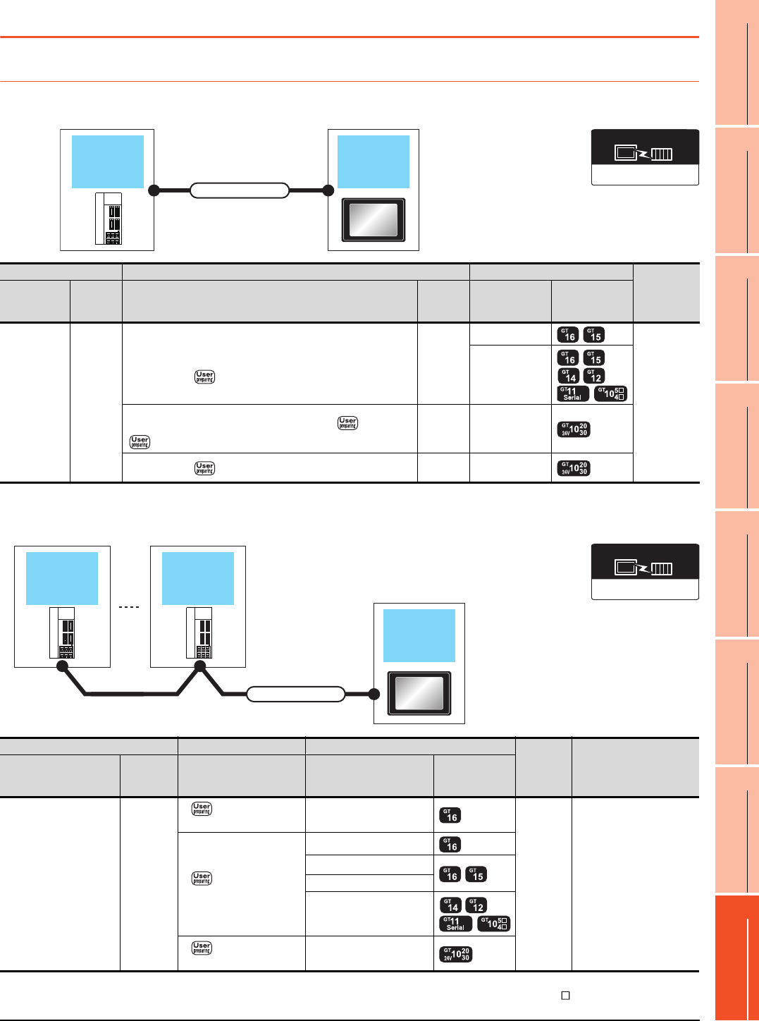
16. SERVO AMPLIFIER CONNECTION
16.2 System Configuration
16 - 3
9
MELSECNET/H
CONNECTION (PLC
TO PLC NETWORK)
10
MELSECNET/10
CONNECTION (PLC
TO PLC NETWORK)
11
CC-Link IE CONTROLLER
NETWORK
CONNECTION
12
CC-Link IE FIELD
NETWORK
CONNECTION
13
CC-Link CONNECTION
(INTELLIGENT DEVICE
STATION)
14
CC-Link
CONNECTION
(Via G4)
15
INVERTER
CONNECTION
16
SERVO AMPLIFIER
CONNECTION
16.2 System Configuration
16.2.1 Connecting to the MELSERVO-J2-Super Series
When connecting via RS-232 communication
*1 Connect the connector of the servo amplifier to CN3.
When connecting via RS-422 communication
*1 Connect the connector of the servo amplifier to CN3.
*2 Connect it to the RS-232 interface (built into GOT). It cannot be mounted on GT1655 and GT155 .
Servo
amplifier GOT
Connection cable
CHARGE
MITSUBISHI
Communication driver
MELSERVO-J4, J3, J2S/M
Servo amplifier Connection cable GOT Number of
connectable
equipment
Series name
Commun
ication
type
Cable model
Connection diagram number
Max.
distance Option device Model
MELSERVO-
J2-Super*1 RS-232
MR-CPCATCBL3M(3m)
or
RS232 connection diagram 1)
15m
GT15-RS2-9P
1 GOT for
1 servo
amplifier
-
(Built into GOT)
MR-CPCATCBL3M(3m)
or
RS232 connection diagram 1)
+RS232
connection diagram 2)
15m -
(Built into GOT)
RS232 connection diagram 3) 15m -
(Built into GOT)
GOT
Connection cable
Servo
amplifier
Servo
amplifier
CHARGE
MITSUBISHI
CHARGE
MITSUBISHI
Communication driver
MELSERVO-J4, J3, J2S/M
Servo amplifier Connection cable GOT
Max.
distance
Number of connectable
equipment
Series name
Communi
cation
type
Connection diagram
number Option device Model
MELSERVO-J2-Super
*1 RS-422
RS422 connection
diagram 1)
- (Built into GOT)
30m
Up to 32 axes for 1 GOT
(multi-drop
communication)
RS422 connection
diagram 2)
GT16-C02R4-9S(0.2m)
GT15-RS2T4-9P*2
GT15-RS4-9S
- (Built into GOT)
RS422 connection
diagram 7)
- (Built into GOT)
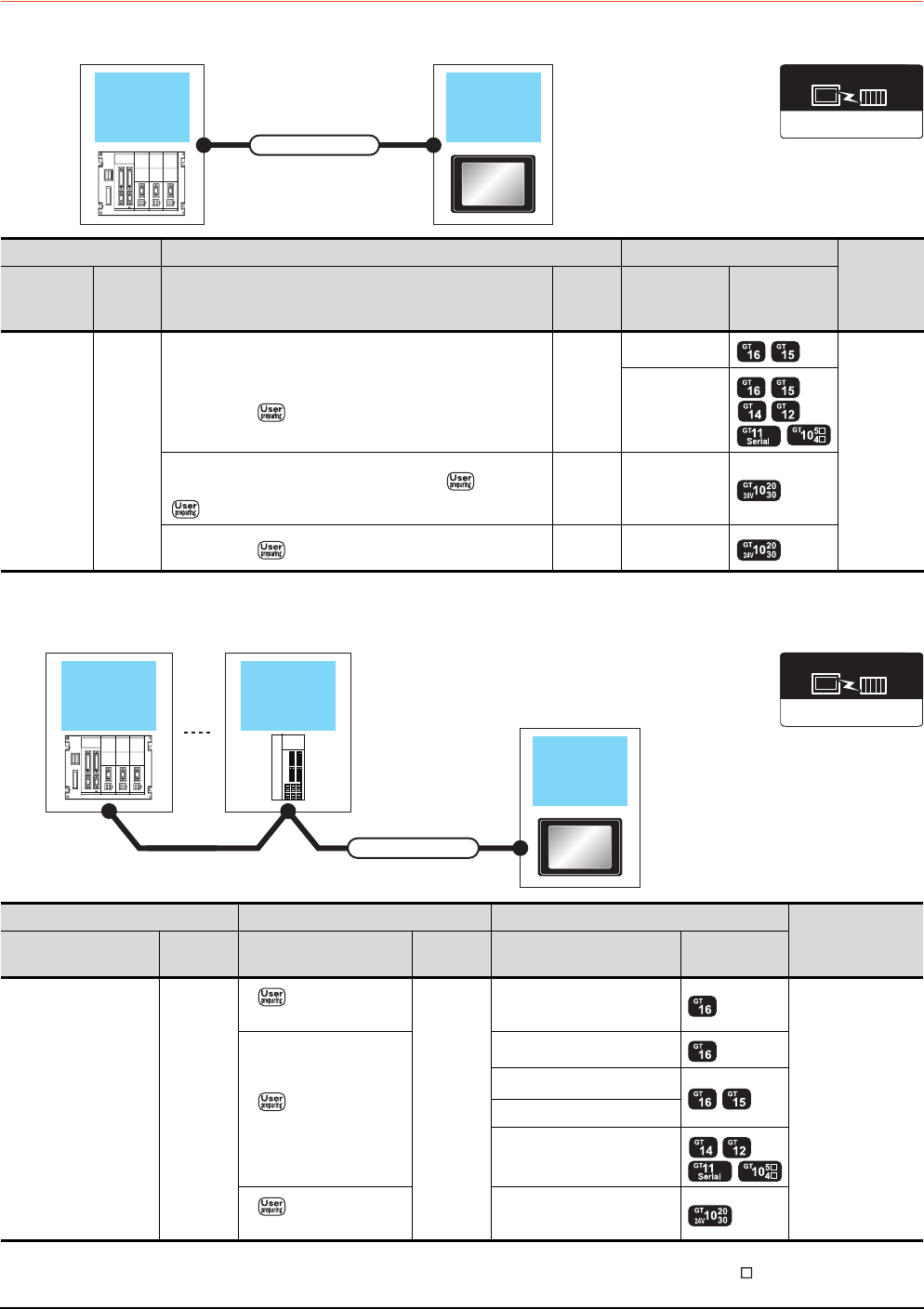
16 - 4 16. SERVO AMPLIFIER CONNECTION
16.2 System Configuration
16.2.2 Connecting to the MELSERVO-J2M Series
When connecting via RS-232 communication
*1 Connect the connector of the servo amplifier to CN3.
When connecting via RS-422 communication
*1 Connect the connector of the servo amplifier to CN3.
*2 Connect it to the RS-232 interface (built into GOT). It cannot be mounted on GT1655 and GT155 .
Servo
amplifier GOT
Connection cable
Communication driver
MELSERVO-J4, J3, J2S/M
Servo amplifier Connection cable GOT
Number of
connectable
equipment
Series name
Commun
ication
type
Cable model
Connection diagram number
Max.
distance Option device Model
MELSERVO
-J2M
*1
RS-232
MR-CPCATCBL3M(3m)
or
RS232 connection diagram 1)
15m
GT15-RS2-9P
1 GOT for
1 servo
amplifier
-
(Built into GOT)
MR-CPCATCBL3M(3m)
or
RS232 connection diagram 1)
+RS232
connection diagram 2)
15m -
(Built into GOT)
RS232 connection diagram 3) 15m -
(Built into GOT)
GOT
Connection cable
Servo
amplifier
Servo
amplifier
CHARGE
MITSUBISHI
Communication driver
MELSERVO-J4, J3, J2S/M
Servo amplifier Connection cable GOT Number of
connectable
equipment
Series name Communic
ation type
Connection diagram
number
Max.
distance Option device Model
MELSERVO-J2M
*1 RS-422
RS422 connection
diagram 1)
30m
- (Built into GOT)
0 to 31 stations
for 1 GOT
RS422 connection
diagram 2)
GT16-C02R4-9S(0.2m)
GT15-RS2T4-9P*2
GT15-RS4-9S
- (Built into GOT)
RS422 connection
diagram 7)
- (Built into GOT)
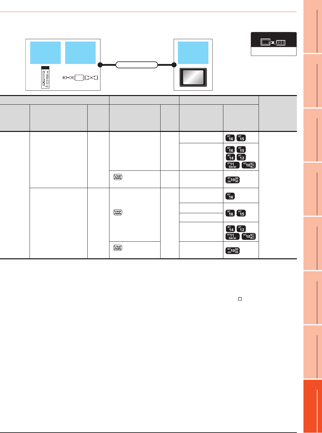
16. SERVO AMPLIFIER CONNECTION
16.2 System Configuration
16 - 5
9
MELSECNET/H
CONNECTION (PLC
TO PLC NETWORK)
10
MELSECNET/10
CONNECTION (PLC
TO PLC NETWORK)
11
CC-Link IE CONTROLLER
NETWORK
CONNECTION
12
CC-Link IE FIELD
NETWORK
CONNECTION
13
CC-Link CONNECTION
(INTELLIGENT DEVICE
STATION)
14
CC-Link
CONNECTION
(Via G4)
15
INVERTER
CONNECTION
16
SERVO AMPLIFIER
CONNECTION
16.2.3 Connecting to the MELSERVO-J4, J3 Series
When connecting to one servo amplifier
*1 Connect the connector of the servo amplifier to CN3.
*2 DSV-CABV is a product manufactured by Diatrend Corporation. For details, contact Diatrend Corporation.
*3 FA-T-RS40VS is a product manufactured by MITSUBISHI ELECTRIC ENGINEERING COMPANY LIMITED. For details, contact
MITSUBISHI ELECTRIC ENGINEERING COMPANY LIMITED.
The cables (RS-PCATCBL-0.5M(0.5m), RS-422SCBL-2M(2m)) are packed together.
Use the provided cables to connect devices.
*4 Connect it to the RS-232 interface (built into GOT). It cannot be mounted on GT1655 and GT155 .
RS-422/232
converter GOT
Connection cable
Servo
amplifier
Communication driver
MELSERVO-J4, J3, J2S/M
Servo amplifier Connection cable GOT
Number of
connectable
equipment
Series name
RS-422/232 interface
converter
RS-422/232 conversion
cable
Commun
ication
type
Cable model
Connection diagram
number
Max.
distance
Option device Model
MELSERVO-
J4*1, J3*1
DSV-CABV(1.5m)*2
or
FA-T-RS40VS*3
RS-232
-15m
GT15-RS2-9P
1 GOT for
1 servo amplifier
- (Built into GOT)
RS232 connection
diagram 2)
15m - (Built into GOT)
- RS-422
RS422 connection
diagram 3)
30m
GT16-C02R4-9S
(0.2m)
GT15-RS2T4-9P*4
GT15-RS4-9S
- (Built into GOT)
RS422 connection
diagram 8)
- (Built into GOT)
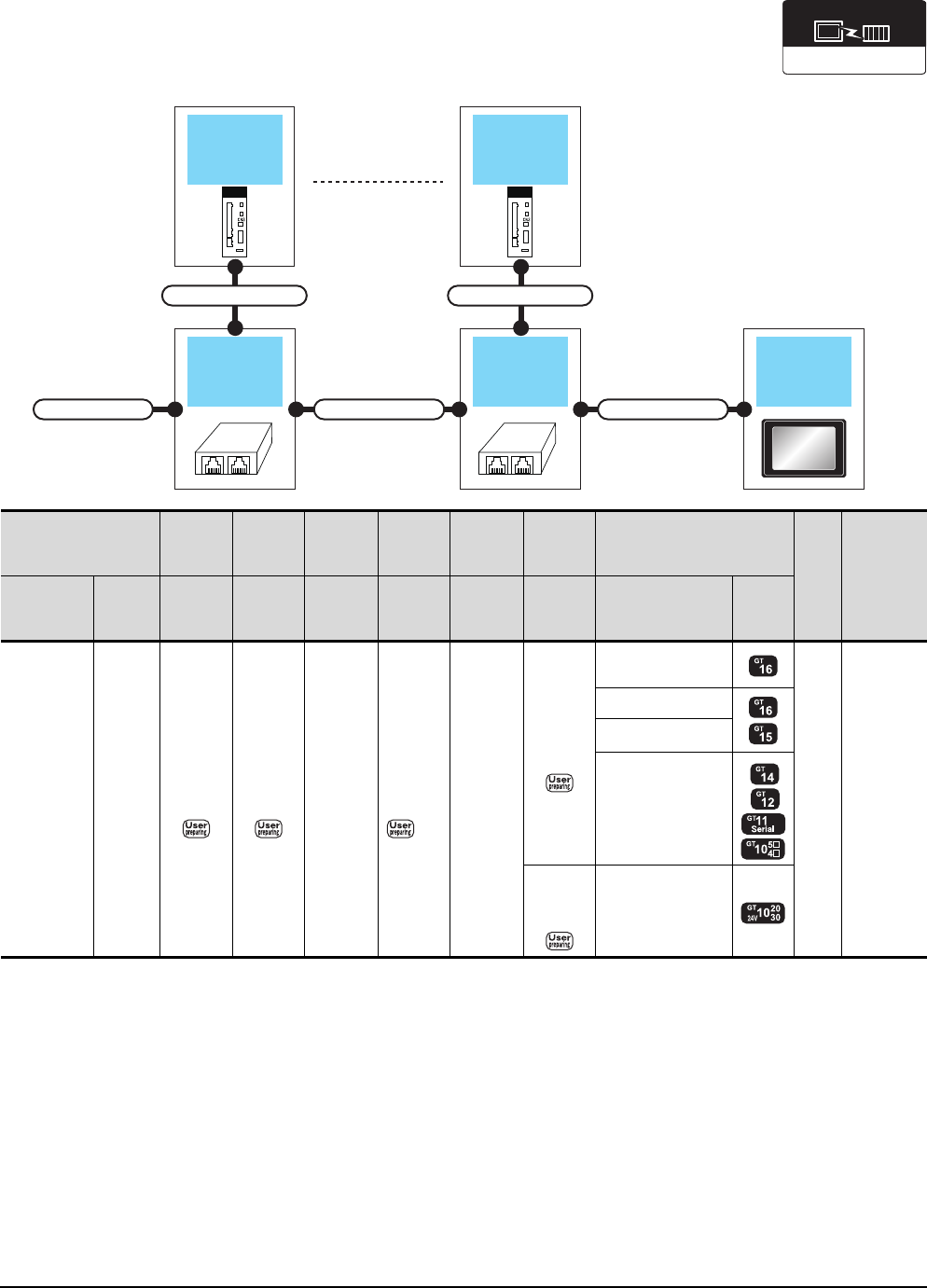
16 - 6 16. SERVO AMPLIFIER CONNECTION
16.2 System Configuration
When connecting to multiple servo amplifiers (RS-422 connection)
*1 Connect the connector of the servo amplifier to CN3.
*2 The distributor is a product manufactured by HACHIKO ELECTRIC CO., LTD. For details, contact HACHIKO ELECTRIC CO.,
LTD.
GOTDistributor
Connection cable 3)Connection cable 2)
Terminal cable
Connection cable 1)
Distributor
Connection cable 1)
Servo
amplifier
Servo
amplifier
Communication driver
MELSERVO-J4, J3, J2S/M
Servo amplifier
Terminating
cable
Connection
cable
1)
Distributor
*2
Connection
cable
2)
Distributor
*2
Connection
cable
3)
GOT
Max.
dista
nce
Number of
connectable
equipment
Series name
Commu
nication
type
Connection
diagram
number
Connection
diagram
number
Model
name
Connection
diagram
number
Model
name
Connection
diagram
number
Option device Model
MELSERVO-
J4*1, J3*1 RS-422
RS422
connection
diagram 6)
RS422
connection
diagram 5)
BMJ-8
(Recomm
ended)
RS422
connection
diagram 4)
BMJ-8
(Recomm
ended)
RS422
connection
diagram 3)
GT16-C02R4-9S
(0.2m)
30m
Up to 32
axes for
1 GOT
GT15-RS2T4-9P*1
GT15-RS4-9S
- (Built into GOT)
RS422
connection
diagram 8)
- (Built into GOT)
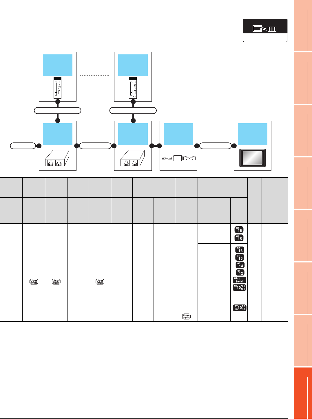
16. SERVO AMPLIFIER CONNECTION
16.2 System Configuration
16 - 7
9
MELSECNET/H
CONNECTION (PLC
TO PLC NETWORK)
10
MELSECNET/10
CONNECTION (PLC
TO PLC NETWORK)
11
CC-Link IE CONTROLLER
NETWORK
CONNECTION
12
CC-Link IE FIELD
NETWORK
CONNECTION
13
CC-Link CONNECTION
(INTELLIGENT DEVICE
STATION)
14
CC-Link
CONNECTION
(Via G4)
15
INVERTER
CONNECTION
16
SERVO AMPLIFIER
CONNECTION
When connecting to multiple servo amplifiers (RS-232 connection)
*1 Connect the connector of the servo amplifier to CN3.
*2 FA-T-RS40VS is a product manufactured by MITSUBISHI ELECTRIC ENGINEERING COMPANY LIMITED. For detail of this
product, contact MITSUBISHI ELECTRIC ENGINEERING COMPANY LIMITED.
The cables (RS-PCATCBL-0.5M(0.5m), RS-422SCBL-2M(2m)) are packed together.
Use the cables packed together to connect.
*3 The distributor is a product manufactured by HACHIKO ELECTRIC CO., LTD. For details, contact HACHIKO ELECTRIC CO.,
LTD.
GOTDistributor
Connection cable 2) Connection cable 3)
Terminal cable
Connection cable 1)
RS-422/232
converter
Distributor
Connection cable 1)
Servo
amplifier
Servo
amplifier
Communication driver
MELSERVO-J4, J3, J2S/M
Servo
amplifier
Terminating
cable
Connection
cable
1)
Distributor
*3
Connection
cable
2)
Distributor
*3
RS-422/232
interface converter*2
Connection
cable
3)
GOT
Max.
dista
nce
Number of
connectable
equipment
Series
name
Connecti
on
diagram
number
Connecti
on
diagram
number
Model
name
Connecti
on
diagram
number
Model
name
Model
name
Commun
ication
type
Connection
diagram
number
Option device Model
MELSER
VO-J4*1,
J3*1
RS422
connection
diagram 6)
RS422
connection
diagram 5)
BMJ-8
(Recom
mended)
RS422
connection
diagram 4)
BMJ-8
(Recom
mended)
FA-T-
RS40VS RS-232
-
GT15-RS2-9P
30m
Up to 32
axes for
1 GOT
-
(Built into GOT)
RS232
connection
diagram 2)
-
(Built into GOT)
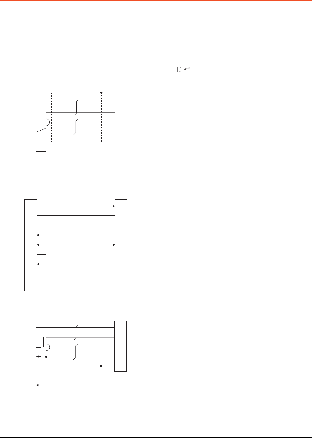
16 - 8 16. SERVO AMPLIFIER CONNECTION
16.3 Connection Diagram
16.3 Connection Diagram
The following diagram shows the connection between the
GOT and the servo amplifier.
16.3.1 RS-232 cable
Connection diagram
Precautions when preparing cable
(1) Cable length
The length of the cable RS-232 must be 15m or less.
(2) GOT side connector
For the GOT side connector, refer to the following.
1.4.1 GOT connector specifications
RS232 connection diagram 1)
RS232 connection diagram 2)
RS232 connection diagram 3)
Connector for interface unit's or
servo amplifier's CN3
1
3
9
2
5
7
8
6
4
GOT side
Plate
2
1
12
11
CD/NC*1
SD(TXD)
-
RD(RXD)
SG
RS(RTS)
CS(CTS)
DR(DSR)
ER(DTR)
FG
RXD
LG
TXD
LG
1
2
3
4
5
6
7
8
9
GOT side Connection cable side
3
2
1
4
5
6
7
8
9
SD(TXD)
RD(RXD)
ER(DTR)
DR(DSR)
SG
RS(RTS)
CS(CTS)
NC
NC
TXD
RXD
-
DTR
GND
DSR
RTS
CTS
-
Connector for interface unit's or
servo amplifier's CN3
1
2
3
4
5
6
7
8
9
GOT side
2
1
12
11
Plate
SD(TXD)
RD(RXD)
ER(DTR)
DR(DSR)
SG
RS(RTS)
CS(CTS)
NC
NC
RXD
LG
TXD
LG
FG
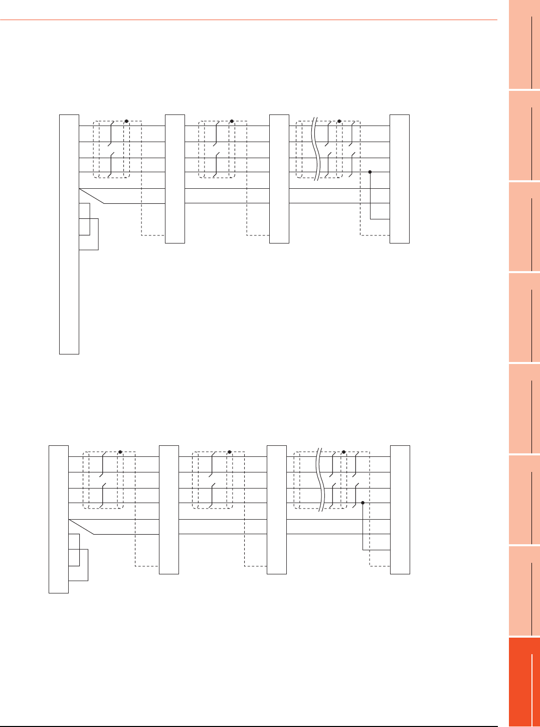
16. SERVO AMPLIFIER CONNECTION
16.3 Connection Diagram
16 - 9
9
MELSECNET/H
CONNECTION (PLC
TO PLC NETWORK)
10
MELSECNET/10
CONNECTION (PLC
TO PLC NETWORK)
11
CC-Link IE CONTROLLER
NETWORK
CONNECTION
12
CC-Link IE FIELD
NETWORK
CONNECTION
13
CC-Link CONNECTION
(INTELLIGENT DEVICE
STATION)
14
CC-Link
CONNECTION
(Via G4)
15
INVERTER
CONNECTION
16
SERVO AMPLIFIER
CONNECTION
16.3.2 RS-422 cable
Connection diagram
*1 At the last axis, connect TRE to RDN.
*1 At the last axis, connect TRE to RDN.
RS422 connection diagram 1)
GOT side
SDP
SDN
RDP
RDN
LG
LG
TRE
SD
Connector for
interface unit's
or
2nd axis servo
amplifier's CN3
SDP
SDN
RDP
RDN
LG
LG
TRE
SD
RDA1(RXD1+)
RDB1(RXD1-)
SDA1(TXD1+)
SDB1(TXD1-)
SG
RSA(RTS+)
RSB(RTS-)
CSA(CTS+)
CSB(CTS-)
SDA2(TXD2+)
SDB2(TXD2-)
RDA2(RXD2+)
RDB2(RXD2-)
NC
3
4
1
2
13
9
10
11
12
5
6
7
8
14
Shell
9
19
5
15
11
1
10
Plate
9
19
5
15
11
1
10
Plate
Connector for
interface unit's
or
1st axis servo
amplifier's CN3
Connector for
interface unit's
or
32nd axis (last axis)*1
servo amplifier's CN3
SDP
SDN
RDP
RDN
LG
LG
TRE
SD
9
19
5
15
11
1
10
Plate
RS422 connection diagram 2)
GOT side
SDP
SDN
RDP
RDN
LG
LG
TRE
SD
Connector for
interface unit's
or
2nd axis servo
amplifier's CN3
SDP
SDN
RDP
RDN
LG
LG
TRE
SD
RXD+(RDA)
RXD-(RDB)
TXD+(SDA)
TXD-(SDB)
SG(GND)
RTS+(RSA)
RTS-(RSB)
CTS+(CSA)
CTS-(CSB)
2
7
1
6
5
3
8
4
9
9
19
5
15
11
1
10
Plate
9
19
5
15
11
1
10
Plate
Connector for
interface unit's
or
1st axis servo
amplifier's CN3
Connector for
interface unit's
or
32nd axis (last axis)
servo amplifier's CN3 *1
SDP
SDN
RDP
RDN
LG
LG
TRE
SD
9
19
5
15
11
1
10
Plate
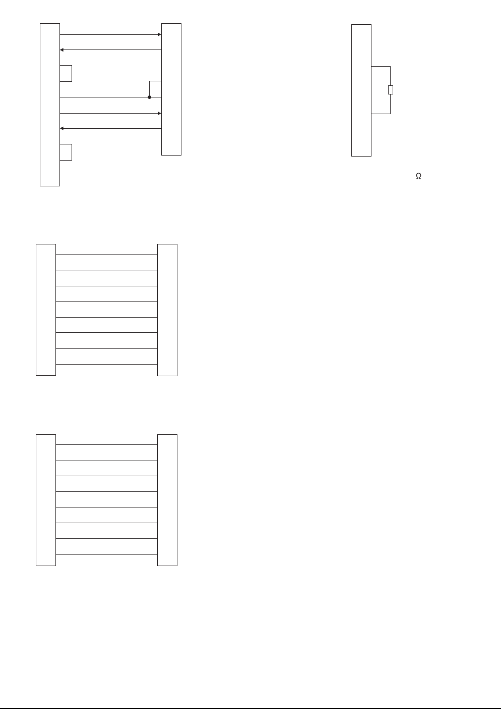
16 - 10 16. SERVO AMPLIFIER CONNECTION
16.3 Connection Diagram
RS422 connection diagram 3)
RS422 connection diagram 4)
RS422 connection diagram 5)
*1Make the wiring between the distributor and servo amplifier as short as
possible.
1
2
3
4
5
6
7
8
9
-
GOT side
Distributor side
(Modular connector)
3
5
2
7
1
6
4
8
SDA
RDA
RSA
CSA
SG
SDB
RDB
RSB
CSB
FG
RDP
SDP
P5D
LG
LG
RDN
SDN
NC
1
2
3
4
5
6
7
8
Distributor side
(Modular connector)
Distributor side
(Modular connector)
1
2
3
4
5
6
7
8
LG
P5D
RDP
SDN
SDP
RDN
LG
NC
LG
P5D
RDP
SDN
SDP
RDN
LG
NC
*1
1
2
3
4
5
6
7
8
Distributor side
(Modular connector)
Servo amplifier side
(Modular connector)
1
2
3
4
5
6
7
8
LG
P5D
RDP
SDN
SDP
RDN
LG
NC
LG
P5D
RDP
SDN
SDP
RDN
LG
NC
RS422 connection diagram 6)
*1 Perform terminal processing on the part between RDP (3-
pin) and RDN (6-pin) with a 150 resistor.
1
2
3
4
5
6
7
8
Distributor side
(Modular connector)
LG
P5D
RDP
SDN
SDP
RDN
LG
NC
*1
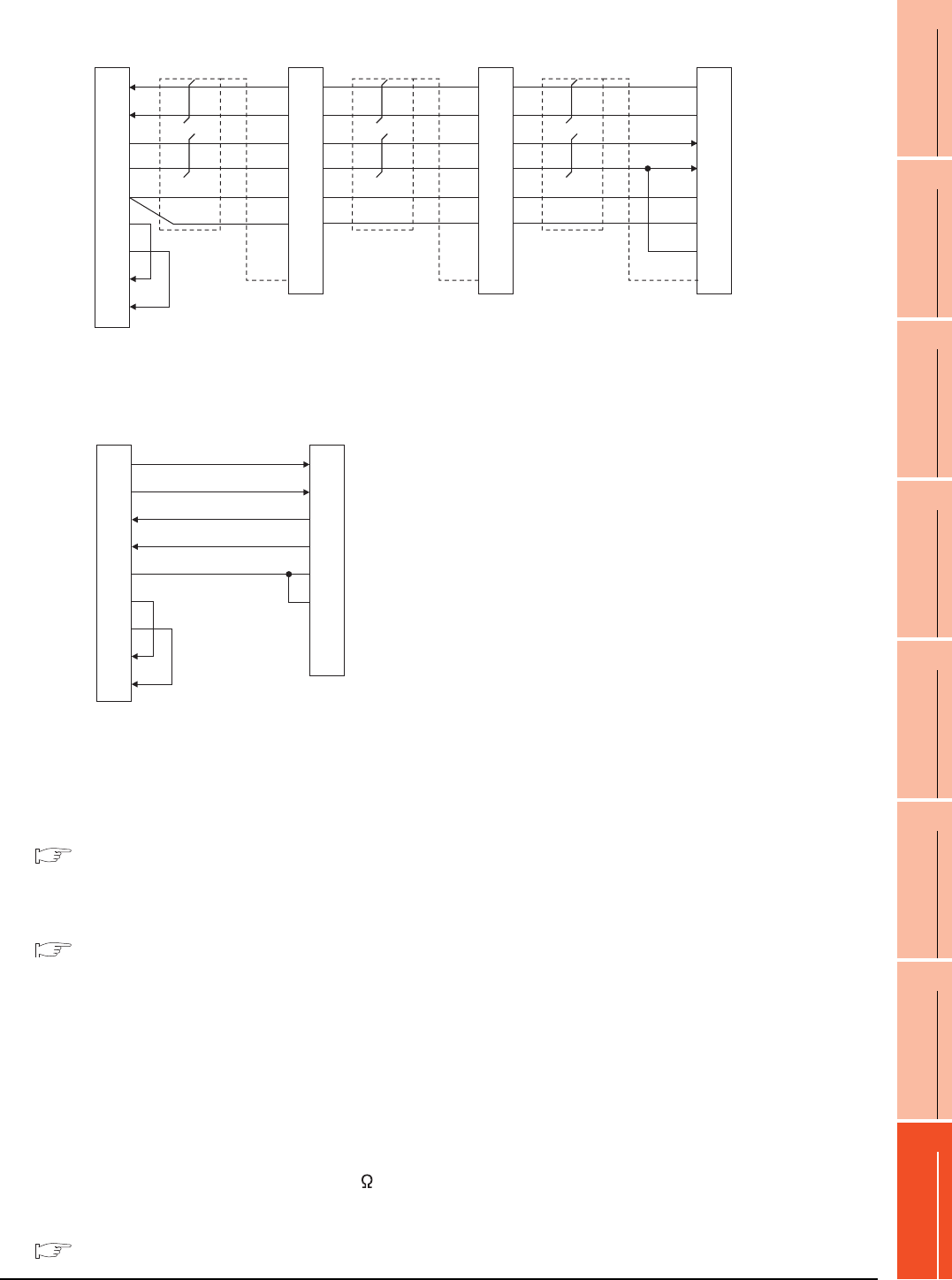
16. SERVO AMPLIFIER CONNECTION
16.3 Connection Diagram
16 - 11
9
MELSECNET/H
CONNECTION (PLC
TO PLC NETWORK)
10
MELSECNET/10
CONNECTION (PLC
TO PLC NETWORK)
11
CC-Link IE CONTROLLER
NETWORK
CONNECTION
12
CC-Link IE FIELD
NETWORK
CONNECTION
13
CC-Link CONNECTION
(INTELLIGENT DEVICE
STATION)
14
CC-Link
CONNECTION
(Via G4)
15
INVERTER
CONNECTION
16
SERVO AMPLIFIER
CONNECTION
*1 At the last axis, connect TRE to RDN.
Precautions when preparing cable
(1) Cable length
The length of the RS-422 cable must be 30m or less.
(2) GOT side connector
For the GOT side connector, refer to the following.
1.4.1 GOT connector specifications
(3) Servo amplifier connector
Use the connector compatible with the servo amplifier.
For details, refer to the following.
See the technical data of the servo amplifier to
be used.
Connecting terminating resistors
(1) GOT side
When connecting a servo amplifier to the GOT, a
terminating resistor must be connected to the GOT.
(a) For GT16, GT15, GT12
Set the terminating resistor setting switch of the
GOT main unit to "No".
(b) For GT14, GT11, GT10
Set the terminating resistor selector to "330 ".
For the procedure to set the terminating resistor, refer
to the following.
1.4.3 Terminating resistors of GOT
RS422 connection diagram 7)
GOT side Distributor Distributor
SDP
SDN
RDP
RDN
LG
LG
TRE
SDP
SDN
RDP
RDN
LG
LG
TRE
RXD+(RDA)
RXD-(RDB)
TXD+(SDA)
TXD-(SDB)
SG(GND)
RTS+(RSA)
RTS-(RSB)
CTS+(CSA)
CTS-(CSB)
3
4
1
2
5
6
7
8
9
9
19
5
15
11
1
10
Plate
9
19
5
15
11
1
10
Plate
Distributor
SDP
SDN
RDP
RDN
LG
LG
TRE
9
19
5
15
11
1
10
Plate
*1
RS422 connection diagram 8)
1
2
3
4
5
6
7
8
9
GOT side
Distributor side
(Modular connector)
3
6
5
4
1
7
2
8
TXD+(SDA)
TXD-(SDB)
RXD+(RDA)
RXD-(RDB)
SG
RTS+(RSA)
RTS-(RSB)
CTS+(CSA)
CTS-(CSB)
RDP
RDN
SDP
SDN
LG
LG
P5D
NC
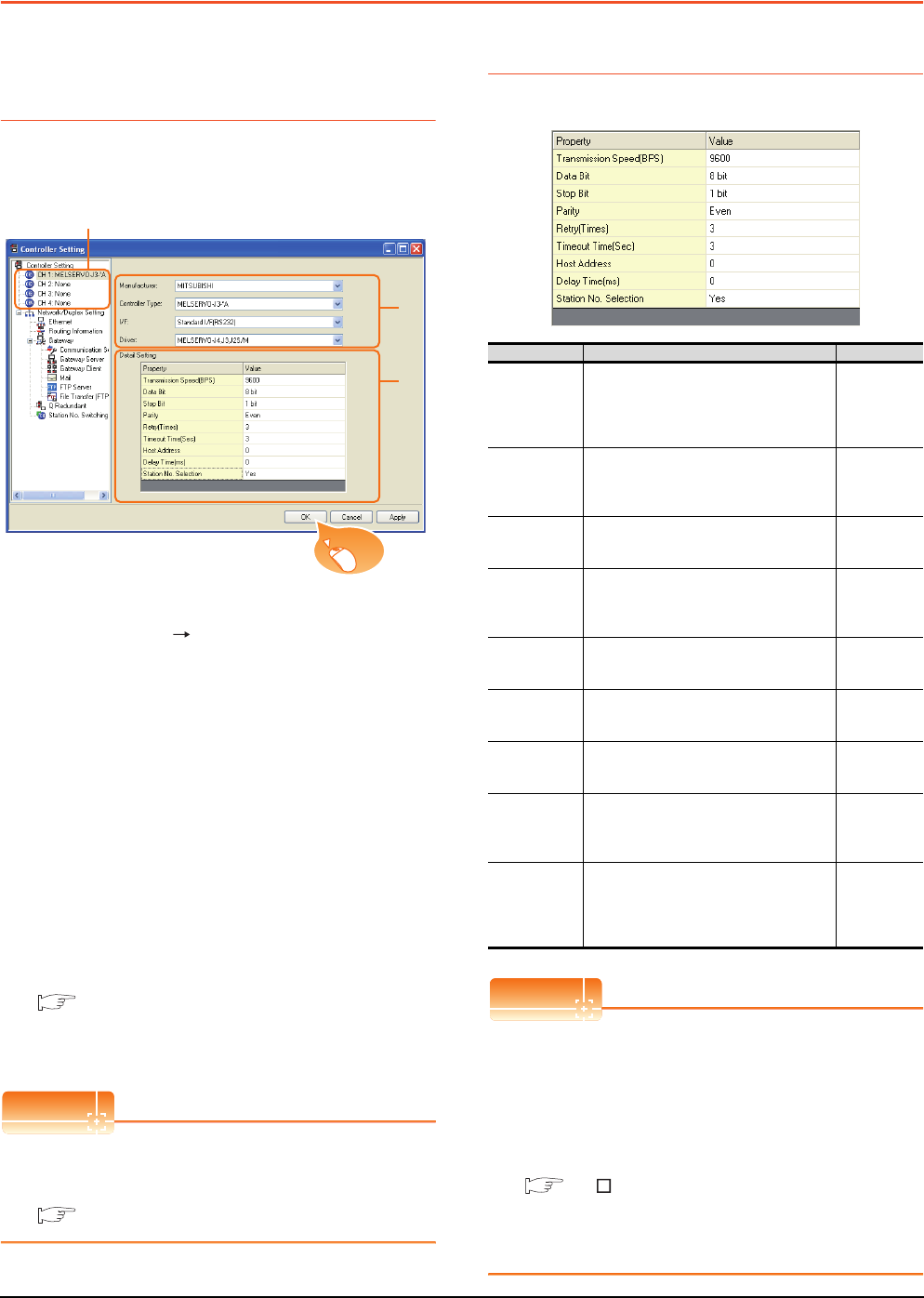
16 - 12 16. SERVO AMPLIFIER CONNECTION
16.4 GOT Side Settings
16.4 GOT Side Settings
16.4.1 Setting communication
interface (Communication
settings)
Set the channel of the connected equipment.
1. Select [Common] [Controller Setting] from the
menu.
2. The Controller Setting window is displayed. Select the
channel to be used from the list menu.
3. Set the following items.
• Manufacturer: Mitsubishi
• Controller Type: Set according to the Controller
Type to be connected.
• I/F: Interface to be used
• Driver: MELSERVO-J4, J3, J2S/M
4. The detailed setting is displayed after Manufacturer,
Controller Type, I/F, and Driver are set.
Make the settings according to the usage
environment.
16.4.2 Communication detail settings
Click the [OK] button when settings are completed.
POINTPOINTPOINT
The settings of connecting equipment can be
confirmed in [I/F Communication Setting].
For details, refer to the following.
1.1.2 I/F communication setting
16.4.2 Communication detail settings
Make the settings according to the usage environment.
POINTPOINTPOINT
(1) Communication interface setting by Utility
The communication interface setting can be
changed on the Utility's [Communication Settings]
after writing [Communication Settings] of project
data.
For details on the Utility, refer to the following
manual.
GT User's Manual
(2) Precedence in communication settings
When settings are made by GT Designer3 or the
Utility, the latest setting is effective.
2.
3.
4.
Click!
Item Description Range
Transmission
Speed
Set this item when change the
transmission speed used for
communication with the connected
equipment.
(Default: 9600bps)
9600bps,
19200bps,
38400bps,
57600bps
115200bps
Data Bit
Set this item when change the data length
used for communication with the
connected equipment.
(Default: 8bit)
8bit (fixed)
Stop Bit
Specify the stop bit length for
communications.
(Default: 1bit)
1bit (fixed)
Parity
Specify whether or not to perform a parity
check, and how it is performed during
communication.
(Default: Even)
Even (fixed)
Retry
Set the number of retries to be performed
when a communication timeout occurs.
(Default: 3times)
0 to 5times
Timeout Time
Set the time period for a communication to
time out.
(Default: 3sec)
3 to 30sec
Host Address
Specify the station number of the servo
amplifier in the system configuration.
(Default: 0)
0 to 31
Delay Time
Set this item to adjust the transmission
timing of the communication request from
the GOT.
(Default: 0ms)
0 to 300 (ms)
Station No.
Selection
Specify whether to use the station No.
during communication.
If [Yes] is selected, the station No. is fixed
to "0."
(Default: Yes)
Yes or N o

16. SERVO AMPLIFIER CONNECTION
16.4 GOT Side Settings
16 - 13
9
MELSECNET/H
CONNECTION (PLC
TO PLC NETWORK)
10
MELSECNET/10
CONNECTION (PLC
TO PLC NETWORK)
11
CC-Link IE CONTROLLER
NETWORK
CONNECTION
12
CC-Link IE FIELD
NETWORK
CONNECTION
13
CC-Link CONNECTION
(INTELLIGENT DEVICE
STATION)
14
CC-Link
CONNECTION
(Via G4)
15
INVERTER
CONNECTION
16
SERVO AMPLIFIER
CONNECTION
HINTHINTHINT
Cutting the portion of multiple connection of the
controller
By setting GOT internal device, GOT can cut the
portion of multiple connection of the controller. For
example, faulty station that has communication
timeout can be cut from the system.
For details of the setting contents of GOT internal
device, refer to the following manual.
GT Designer3 Version Screen Design Manual
(Fundamentals)
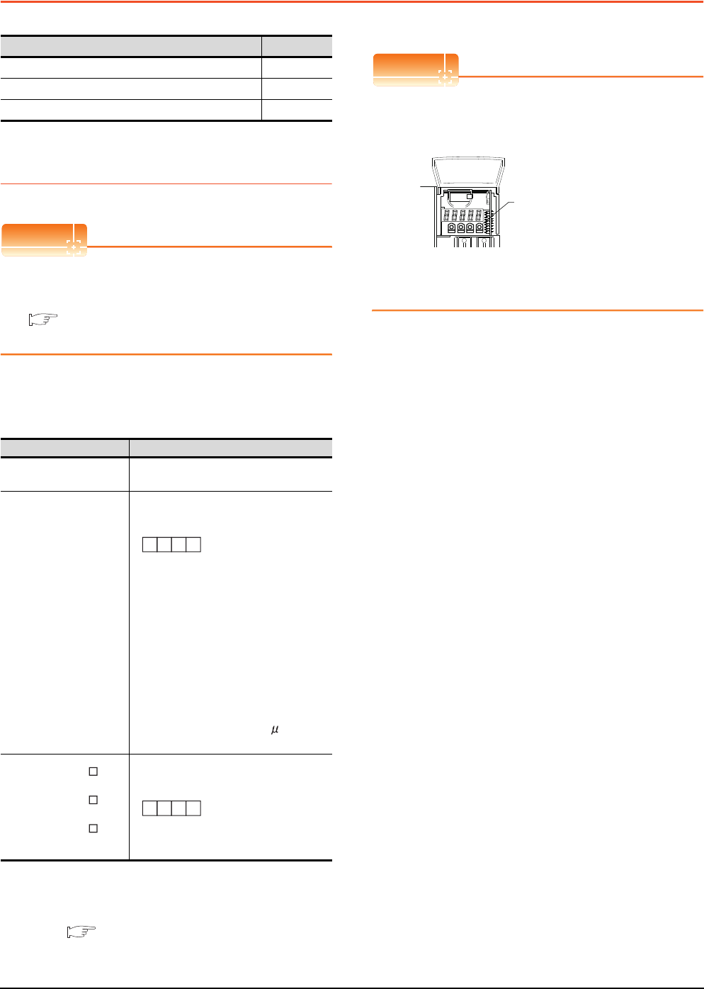
16 - 14 16. SERVO AMPLIFIER CONNECTION
16.5 Setting on Servo Amplifier Side
16.5 Setting on Servo Amplifier Side
16.5.1 Connecting to the
MELSERVO-J2-Super Series
POINTPOINTPOINT
MELSERVO-J2-Super Series
For details of the MELSERVO-J2-Super Series, refer
to the following manual.
See the technical manual for the MELSERVO-
J2-Super Series servo amplifiers.
Parameters of MELSERVO-J2-Super Series
Enter the parameters of the MELSERVO-J2-Super
Series.
*1 Avoid duplication of the station No. with any of the other
axes.
*2 Specify the same transmission speed as that of the GOT.
For the transmission speed setting on the GOT side, refer to
the following.
16.4.1 Setting communication interface
(Communication settings)
*3 To change the set value, enter "000E" to basic parameter
No. 19.
POINTPOINTPOINT
(1) Parameter setting
Set the parameter at the pushbutton switch
provided on the operation section of the servo
amplifier or setup software.
(2) When changing the parameter
Turn off then on the servo amplifier to be effective
the new parameter.
Model name Refer to
MELSERVO-J2-Super Series 16.5.1
MELSERVO-J2M Series 16.5.2
MELSERVO-J4, J3 Series 16.5.3
Item Set value
Basic parameter No. 15 Station number setting: 0 to 31
(Default: 0)*1
Basic parameter No. 16
Serial communication function selection
(Default: 0000)
(1) Serial communication baud rate
selection*2
0: 9600bps
1: 19200bps
2: 38400bps
3: 57600bps
(2) Serial communication I/F selection
0: RS-232
1: RS-422
(3) Communication response delay time
selection
0: Invalid
1: Valid (Response after 800 s or longer
delay)
In case of MR-J2S- :
Expansion parameter 2 No. 53
In case of MR-J2S- CP:
Expansion parameter 2 No. 57
In case of MR-J2S- CL:
Expansion parameter 2 No. 57
Function selection 8
(Default: 0000)*3
(1) Station No. selection for protocol
0: With station No.
1: Without station No.
0
(3) (2) (1)
Basic parameter No. 16
000
Expansion parameter 2 No. 53 or No. 57
(1)
MODE UP DOWN SET
Pushbutton switch
provided on the operation
section of the servo amplifier
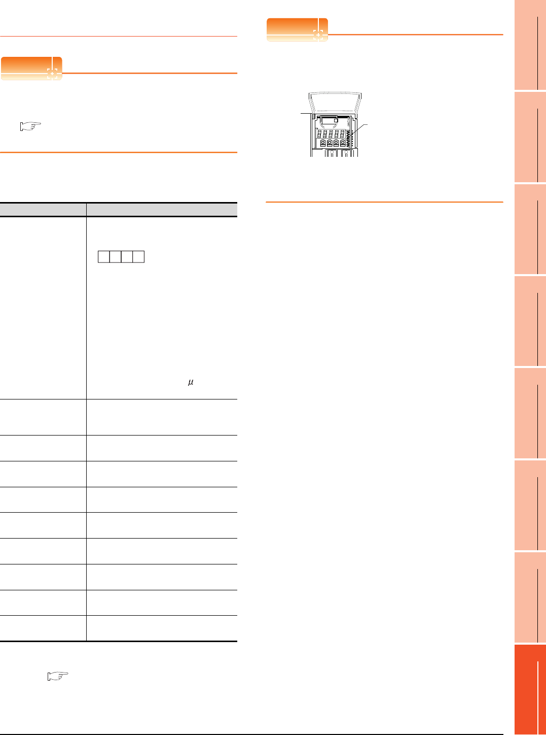
16. SERVO AMPLIFIER CONNECTION
16.5 Setting on Servo Amplifier Side
16 - 15
9
MELSECNET/H
CONNECTION (PLC
TO PLC NETWORK)
10
MELSECNET/10
CONNECTION (PLC
TO PLC NETWORK)
11
CC-Link IE CONTROLLER
NETWORK
CONNECTION
12
CC-Link IE FIELD
NETWORK
CONNECTION
13
CC-Link CONNECTION
(INTELLIGENT DEVICE
STATION)
14
CC-Link
CONNECTION
(Via G4)
15
INVERTER
CONNECTION
16
SERVO AMPLIFIER
CONNECTION
16.5.2 Connecting to the
MELSERVO-J2M Series
POINTPOINTPOINT
MELSERVO-J2M Series
For details of the MELSERVO-J2M Series, refer to the
following manual.
See the technical manual for the MELSERVO-
J2M Series servo amplifiers.
Parameter of MELSERVO-J2M Series
Enter the parameters of the MELSERVO-J2M Series.
*1 Specify the same transmission speed as that of the GOT.
For the transmission speed setting on the GOT side, refer to
the following.
16.4.1 Setting communication interface
(Communication settings)
*2 Avoid duplication of the station No. with any of the other
units.
POINTPOINTPOINT
(1) Parameter setting
Set the parameter at the pushbutton switch
provided on the operation section of the servo
amplifier or setup software.
(2) When changing the parameter
Turn off then on the servo amplifier to be effective
the new parameter.
Item Set value
Basic IFU parameter
No. 0
Serial communication function selection
(Default: 0000)
(1) Serial communication baud rate selection*1
0: 9600bps
1: 19200bps
2: 38400bps
3: 57600bps
(2) Serial communication I/F selection
0: RS-232
1: RS-422
(3) Communication response delay time
selection
0: Invalid
1: Valid (Response after 800 s or longer
delay)
Basic IFU parameter
No. 10
Interface unit serial communication station No.
selection:
0 to 31 (Default: 0) *2
Basic IFU parameter
No. 11
Slot 1 serial communication station No. selection:
0 to 31 (Default: 1) *2
Basic IFU parameter
No. 12
Slot 2 serial communication station No. selection:
0 to 31 (Default: 2) *2
Basic IFU parameter
No. 13
Slot 3 serial communication station No. selection:
0 to 31 (Default: 3) *2
Basic IFU parameter
No. 14
Slot 4 serial communication station No. selection:
0 to 31 (Default: 4) *2
Basic IFU parameter
No. 15
Slot 5 serial communication station No. selection:
0 to 31 (Default: 5) *2
Basic IFU parameter
No. 16
Slot 6 serial communication station No. selection:
0 to 31 (Default: 6) *2
Basic IFU parameter
No. 17
Slot 7 serial communication station No. selection:
0 to 31 (Default: 7) *2
Basic IFU parameter
No. 18
Slot 8 serial communication station No. selection:
0 to 31 (Default: 8) *2
Basic IFU parameter No. 0
0
(3) (2) (1)
MODE UP DOWN SET
Pushbutton switch
provided on the operation
section of the servo amplifier
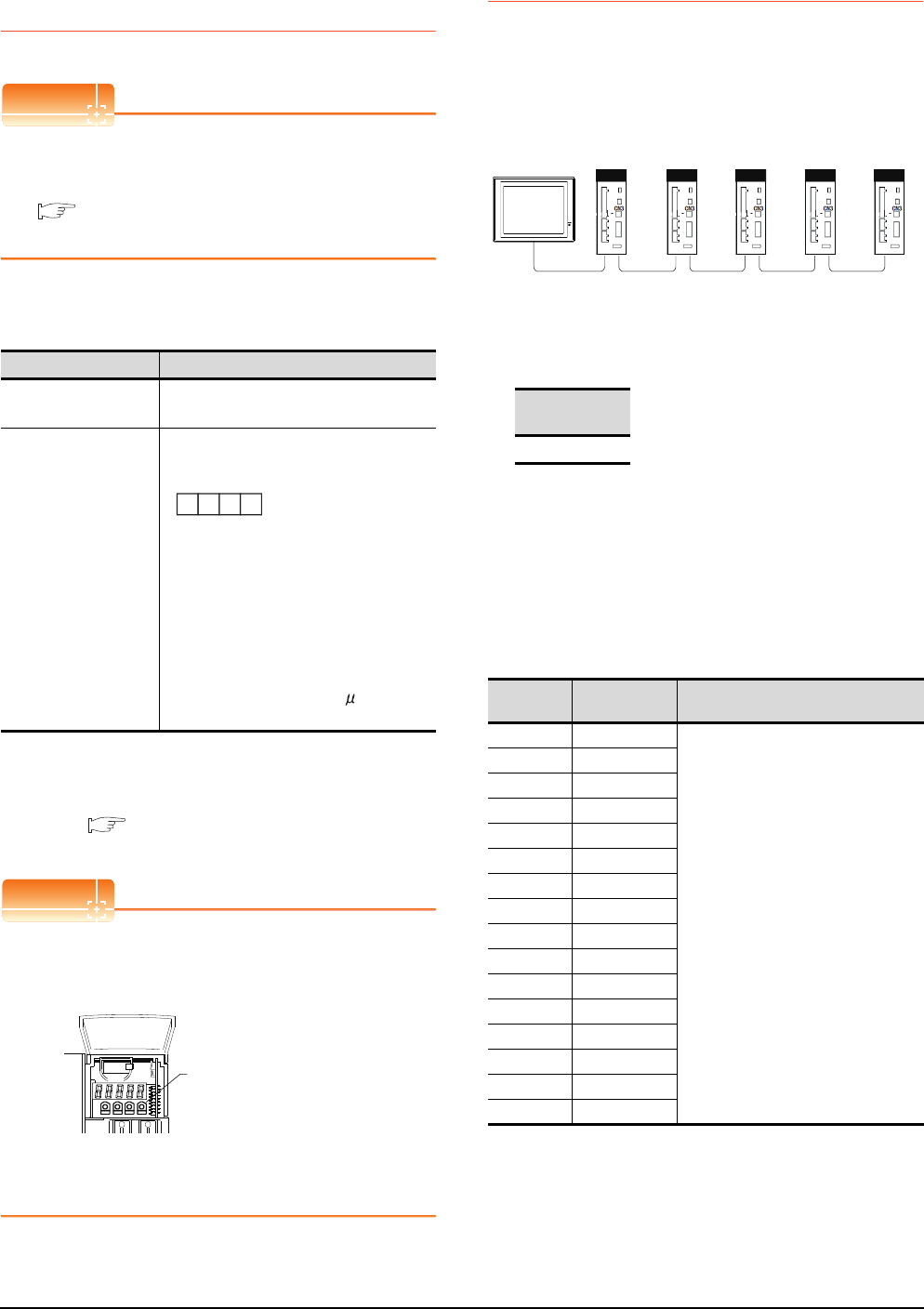
16 - 16 16. SERVO AMPLIFIER CONNECTION
16.5 Setting on Servo Amplifier Side
16.5.3 Connecting to the
MELSERVO-J4,J3 Series
POINTPOINTPOINT
MELSERVO-J4, J3 Series
For details of the MELSERVO-J4, J3 Series, refer to
the following manual.
See the technical manual for the MELSERVO-
J4, J3 Series servo amplifiers.
Parameters of MELSERVO-J4, J3 Series
Enter the parameters of the MELSERVO-J4, J3 Series.
*1 Avoid duplication of the station No. with any of the other
axes.
*2 Specify the same transmission speed as that of the GOT.
For the transmission speed setting on the GOT side, refer to
the following.
16.4.1 Setting communication interface
(Communication settings)
POINTPOINTPOINT
(1) Parameter setting
Set the parameter at the pushbutton switch
provided on the operation section of the servo
amplifier or setup software.
(2) When changing the parameter
Turn off then on the servo amplifier to be effective
the new parameter.
16.5.4 Station number setting
Set each station number so that no station number
overlaps.
The station number can be set without regard to the cable
connection order. There is no problem even if station
numbers are not consecutive.
(1) Direct specification
When setting the device, specify the station number of
the servo amplifier of which data is to be changed.
(2) Indirect specification
When setting the device, indirectly specify the station
number of the inverter of which data is to be changed
using the 16-bit GOT internal data register (GD10 to
GD25).
When specifying the station No. from 100 to 115 on GT
Designer3,the value of GD10 to GD25 compatible to
the station No.specification will be the station No.of the
servo amplifier.
(3) All station specification
Target station differs depending on write-in operation or
read-out operation.
• For write-in operation, all station will be a target.
• For read-out operation, only one station will be a
target.
Item Set value
Basic parameter
No. PC20
Station number setting: 0 to 31
(Default: 0)*1
Basic parameter
No. PC21
Serial communication function selection
(Default: 0000)
(1) Serial communication baud rate selection*2
0: 9600bps
1: 19200bps
2: 38400bps
3: 57600bps
4: 115200bps
(2) Communication response delay time
selection
0: Invalid
1: Valid (Response after 800 s or longer
delay)
(2) (1)
Basic parameter No. PC21
MODE UP DOWN SET
Pushbutton switch
provided on the operation
section of the servo amplifier
Specification
range
0 to 31
Specification
station NO.
Compatible
device Setting range
100 GD10
0 to 31
For the setting other than the above, a
communication timeout error will occur.
101 GD11
102 GD12
103 GD13
104 GD14
105 GD15
106 GD16
107 GD17
108 GD18
109 GD19
110 GD20
111 GD21
112 GD22
113 GD23
114 GD24
115 GD25
Station
NO.3
Station
NO.0
Station
NO.1
Station
NO.21
Station
NO. 6
Examples of station number setting
GOT
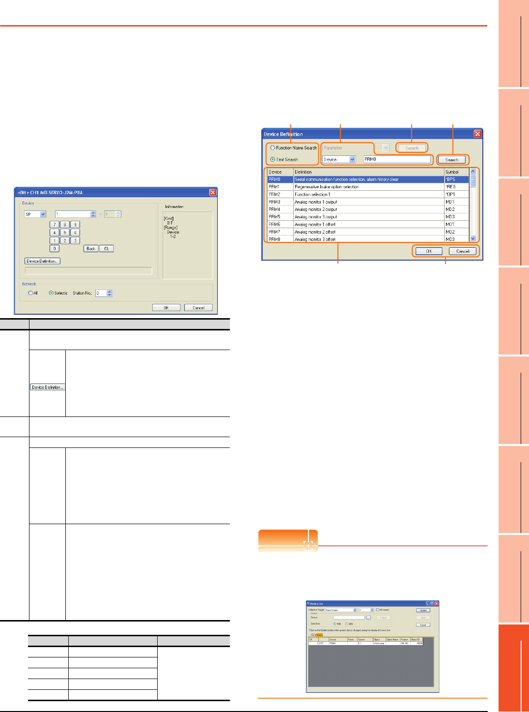
16. SERVO AMPLIFIER CONNECTION
16.6 Device Range that Can Be Set
16 - 17
9
MELSECNET/H
CONNECTION (PLC
TO PLC NETWORK)
10
MELSECNET/10
CONNECTION (PLC
TO PLC NETWORK)
11
CC-Link IE CONTROLLER
NETWORK
CONNECTION
12
CC-Link IE FIELD
NETWORK
CONNECTION
13
CC-Link CONNECTION
(INTELLIGENT DEVICE
STATION)
14
CC-Link
CONNECTION
(Via G4)
15
INVERTER
CONNECTION
16
SERVO AMPLIFIER
CONNECTION
16.6 Device Range that Can Be Set
The device ranges of controller that can be used for GOT
are as follows.
Note that the device ranges in the following tables are the
maximum values that can be set in GT Designer3.
The device specifications of controllers may differ
depending on the models, even though belonging to the
same series.
Please make the setting according to the specifications of
the controller actually used.
When a non-existent device or a device number outside
the range is set, other objects with correct device settings
may not be monitored.
(1) Servo amplifier
For details of *1, refer to the following.
(a) Device Definition dialog box
When setting a device on the Device dialog box and
click the [Device Definition...] button, the
correspondence between the GOT virtual device for a
servo amplifier and the definition of the servo amplifier
is displayed.
The device can be searched with the servo definition or
other items on this dialog box to set a device.
1. Select a key item for searching.
Function Name Search: Select this item when
searching a device with the function name.
Text Search: Select this item when searching a device
with the character string.
2. Select and input a key item for searching.
3. Click the [Search] button.
4. The items that matches to the specified condition are
displayed.
The display contents are as follows.
Device : The GOT virtual device for a servo
amplifier is displayed.
Definition : The definition of the servo amplifier is
displayed.
Symbol : The abbreviated name for the servo
amplifier is displayed.
5. Select a device to be set.
6. Clicking the [OK] button reflects the device selected
by step 4 to the Device dialog box.
POINTPOINTPOINT
When selecting [All] in the Network setting
The network No. 0 and Station No. FF are displayed on
Device List and when printing.
(Device List screen)
Item Description
Device
Set the device name, device number, and bit number.
The bit number can be set only when specifying the bit of word device.
Clicking the button displays the dialog box indicating
the correspondence between the GOT virtual device
for a servo amplifier and the definition of servo
amplifier.
If selecting an item on the displayed dialog box,
remember that the servo amplifier definition is
displayed in the text box below.
Informat
ion
Displays the device type and setting range which are selected in
[Device].
Network
Set the monitor target of the set device.
All
Select this item when writing data to all servo
amplifiers connected.
During a monitoring, the servo amplifier of Station
No. 0 is monitored.
When inputting data by Numerical Input, the data is
written to all servo amplifiers connected during
inputting; the servo amplifier of Station No. 0 is
monitored during other than inputting (displaying).
Selection
Select this item when monitoring the servo amplifier
of the Station No. specified.
After selecting, set station numbers of servo
amplifiers in the following range.
0 to 31:
The servo amplifier of the Station No. specified will
be monitored.
100 to 115:
Specify the Station No. of the servo amplifier to be
monitored with a GOT data register (GD).*1
Station No. GOT data register (GD) Setting range
100 GD10
0 to 31
(If setting a value out
of the range above, a
timeout error occurs.)
101 GD11
::
114 GD24
115 GD25
1. 2. 3.
6.
4. 5.
3.
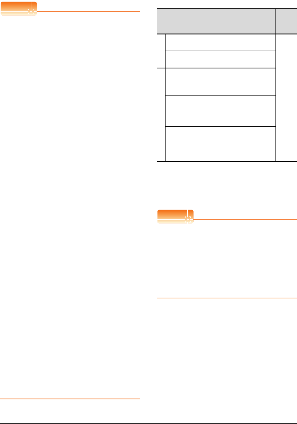
16 - 18 16. SERVO AMPLIFIER CONNECTION
16.6 Device Range that Can Be Set
POINTPOINTPOINT
Monitoring servo amplifier
Carefully read the manual of servo amplifier to be
connected and fully understand the operating
procedures before monitoring.
Before operation, check the parameter settings.
Improper settings may cause some machines to
perform unexpected operation.
The parameter settings must not be changed
excessively. Operation will be insatiable.
(1) Parameters with * in front of it's abbreviated name
For the parameter with * in front of it's abbreviated
name, powering off the servo amplifier after setting
then on makes the parameter valid.
(2) Data length for setting virtual devices for servo
amplifier
Set the following data length for setting devices.
• PRM, ST, AL, PA, PB, PC, PD, POS, SPD, ACT,
DCT, DWL, AUX
: 16bits or 32bits (depends on the data of servo
amplifier)
• DI, DO, TMI, TMO, TMD: 32bits
If the above data length was not set, data would
not be set to the servo amplifier correctly or the
GOT can not monitor normally.
(a) Monitoring
• When the 16-bit data is handled as 32-bit
data, the upper 16bits are displayed as 0.
• When the 32-bit data is handled as 16-bit
data, the lower 16bits only are displayed as
0.
(b) Writing
The GOT writes within the range of data
length set. Note that the servo amplifier
responds correctly while the written data is
invalid in the servo amplifier side when the
written data is outside the range of values
which can be set by the servo amplifier.
(3) Memory area for writing parameters
Parameters are written to RAM or E2PROM of
servo amplifier.
(a) When written to RAM
Remember that written parameters are
cleared when power supply to the servo
amplifier is turned off.
(b) When written to E2PROM
Written parameters are not cleared even
when power supply to the servo amplifier is
turned off.However, there are limits in the
number of writing to E2PROM.
If the data is frequently updated (more than
once in an hour), write the parameters to the
RAM.
For details, refer to the manual of the servo
amplifier used.
(2) MELSERVO-J2M-P8A
*1 Use PRM0 to PRM29 when writing parameters to the servo
amplifier RAM.
PRM1000 to PRM1029 are used when writing parameters to
E2PROM of the servo amplifier.
*2 The GOT cannot read or write data from/to consecutive
devices.
*3 Only reading is possible.
POINTPOINTPOINT
Precautions for SP, OM, and TMO devices
(1) For bit devices
Only writing is possible.
[Alternate] of a bit switch cannot be used.
Use [Set], [Reset], and [Momentary] of a bit
switch.
(2) For word devices
Only writing is possible.
Numerical input cannot be used.
When writing, use [Word Set] of a data set switch.
Device name*2 Setting range available
Device
No.
represent
ation
Bit device
Servo amplifier request
(SP) SP1 to SP2
Decimal
Operation mode selection
(OM) OM0 to OM4
Word device
Basic parameter
Expansion parameter
(PRM)*1
PRM0 to PRM29
PRM1000 to PRM1029
Status display (ST) ST0 to ST2
Alarm (AL)
AL0
AL11 to AL13
AL200 to AL205
AL210 to AL215
AL230 to AL235
External input (DI)*3 DI0 to DI2
External output (DO) DO0 to DO1
Forced output of signal pin
(for test operation)
(TMO)
TMO0
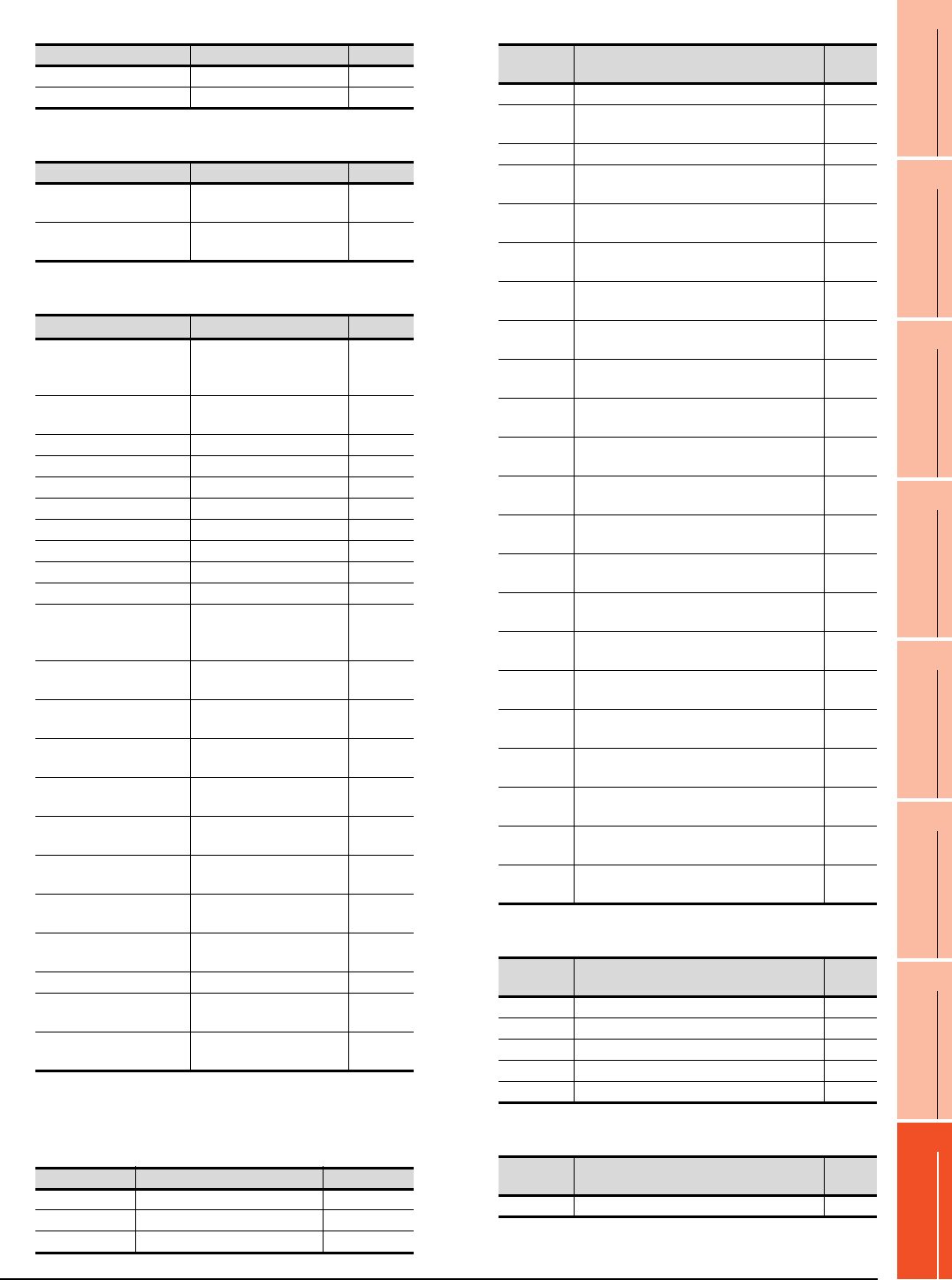
16. SERVO AMPLIFIER CONNECTION
16.6 Device Range that Can Be Set
16 - 19
9
MELSECNET/H
CONNECTION (PLC
TO PLC NETWORK)
10
MELSECNET/10
CONNECTION (PLC
TO PLC NETWORK)
11
CC-Link IE CONTROLLER
NETWORK
CONNECTION
12
CC-Link IE FIELD
NETWORK
CONNECTION
13
CC-Link CONNECTION
(INTELLIGENT DEVICE
STATION)
14
CC-Link
CONNECTION
(Via G4)
15
INVERTER
CONNECTION
16
SERVO AMPLIFIER
CONNECTION
(a) Servo amplifier request
(b) Operation mode selection
(c) Basic parameter/expansion parameter
*2 For the parameters prefixed by an asterisk (*), setting
becomes effective when the power is turned off once and
back on after setting the parameter data.
(d) Status display
(e) Alarm
(f) External I/O signal
(g) Forced output of signal pin (for test operation)
Device name Item Symbol
SP1 Current alarm clear ―
SP2 Alarm history clear ―
Device name Item Symbol
OM0 Normal mode
(not test operation mode) ―
OM4 Output signal (DO) forced
output ―
Device name Item Symbol*2
PRM0, PRM1000
Serial communication
function selection,
alarm history clear
*BPS
PRM1, PRM1001 Regenerative brake option
selection *REG
PRM2, PRM1002 Function selection 1 *OP1
PRM3, PRM1003 Analog monitor 1 output MD1
PRM4, PRM1004 Analog monitor 2 output MD2
PRM5, PRM1005 Analog monitor 3 output MD3
PRM6, PRM1006 Analog monitor 1 offset MO1
PRM7, PRM1007 Analog monitor 2 offset MO2
PRM8, PRM1008 Analog monitor 3 offset MO3
PRM9, PRM1009 Function selection 2 *OP2
PRM10, PRM1010
Interface unit serial
communication station No.
selection
*ISN
PRM11, PRM1011 Slot 1 serial communication
station No. selection *DSN1
PRM12, PRM1012 Slot 2 serial communication
station No. selection *DSM2
PRM13, PRM1013 Slot 3 serial communication
station No. selection *DSM3
PRM14, PRM1014 Slot 4 serial communication
station No. selection *DSN4
PRM15, PRM1015 Slot 5 serial communication
station No. selection *DSN5
PRM16, PRM1016 Slot 6 serial communication
station No. selection *DSN6
PRM17, PRM1017 Slot 7 serial communication
station No. selection *DSN7
PRM18, PRM1018 Slot 8 serial communication
station No. selection *DSN8
PRM19, PRM1019 Parameter write inhibit *BLK
PRM20, PRM1020 Serial communication
time-out selection SIC
PRM21 to PRM29
PRM1021 to PRM1029 For manufacturer setting ―
Device name Item Symbol
ST0 Regenerative load ratio ―
ST1 Bus voltage ―
ST2 Peak bus voltage ―
Device
name Item Symbol
AL0 Current alarm number ―
AL11 Servo status when alarm occurs
regenerative load factor ―
AL12 Servo status when alarm occurs bus voltage ―
AL13 Servo status when alarm occurs peak bus
voltage ―
AL200 Alarm number from alarm history
most recent alarm ―
AL201 Alarm number from alarm history
first alarm in past ―
AL202 Alarm number from alarm history
second alarm in past ―
AL203 Alarm number from alarm history
third alarm in past ―
AL204 Alarm number from alarm history
fourth alarm in past ―
AL205 Alarm number from alarm history
fifth alarm in past ―
AL210 Alarm occurrence time in alarm history
most recent alarm ―
AL211 Alarm occurrence time in alarm history
first alarm in past ―
AL212 Alarm occurrence time in alarm history
second alarm in past ―
AL213 Alarm occurrence time in alarm history
third alarm in past ―
AL214 Alarm occurrence time in alarm history
fourth alarm in past ―
AL215 Alarm occurrence time in alarm history
fifth alarm in past ―
AL230 Detailed alarm from alarm history
most recent alarm ―
AL231 Detailed alarm from alarm history
first alarm in past ―
AL232 Detailed alarm from alarm history
second alarm in past ―
AL233 Detailed alarm from alarm history
third alarm in past ―
AL234 Detailed alarm from alarm history
fourth alarm in past ―
AL235 Detailed alarm from alarm history
fifth alarm in past ―
Device
name Item Symbol
DI0 External input pin statuses CN1A/CN1B ―
DI1 External input pin statuses CN5 ―
DI2 External input pin statuses CN4A/CN4B ―
DO0 External output pin statuses CN1A/CN1B ―
DO1 External output pin statuses CN1A/CN1B ―
Device
name Item Symbol
TMO0 Forced output of signal pin ―
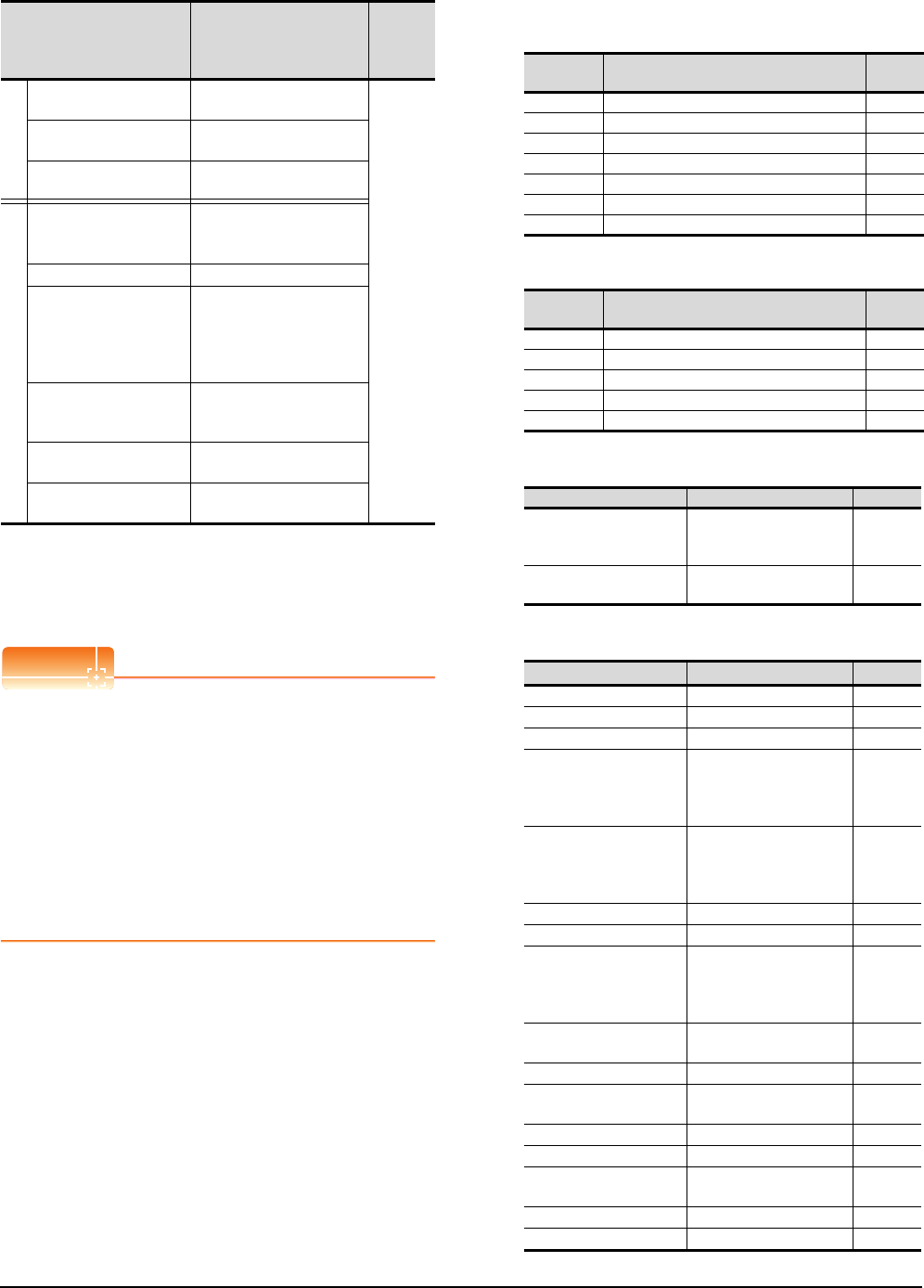
16 - 20 16. SERVO AMPLIFIER CONNECTION
16.6 Device Range that Can Be Set
(3) MELSERVO-J2M-*DU
*1 Use PRM0 to PRM84 when writing parameters to the servo
amplifier RAM.
PRM1000 to PRM1084 are used when writing parameters to
E2PROM of the servo amplifier.
*2 The GOT cannot read or write data from/to consecutive
devices.
POINTPOINTPOINT
Precautions for SP, OM, TMB, TMI, TMO, and TMD
devices
(1) For bit devices
Only writing is possible.
[Alternate] of a bit switch cannot be used.
Use [Set], [Reset], and [Momentary] of a bit
switch.
(2) For word devices
Only writing is possible.
Numerical input cannot be used.
When writing, use [Word Set] of a data set switch.
The following shows correspondences between virtual
devices for servo amplifier and data of the servo
amplifier used with the GOT.
(a) Servo amplifier request
(b) Operation mode selection
(c) Instruction demand (for test operation)
(d) Basic parameter/expansion parameter
(Continued to next page)
Device name*2 Setting range
Device
No.
represent
ation
Bit device
Servo amplifier request
(SP) SP0 to SP6
Decimal
Operation mode selection
(OM) OM0 to OM4
Instruction demand
(for test operation) (TMB) TMB0 to TMB1
Word device
Basic parameter
Expansion parameter
(PRM)*1
PRM0 to PRM84
PRM1000 to PRM1084
Status display (ST) ST0 to ST10
Alarm (AL)
AL0
AL11 to AL21
AL200 to AL205
AL210 to AL215
AL230 to AL235
Input signal for test
operation
(for test operation) (TMI)
TMI0
Forced output of signal pin
(for test operation) (TMO) TMO0
Set data
(for test operation) (TMD) TMD0 to TMD2
Device
name Item Symbol
SP0 Status display data clear ―
SP1 Current alarm clear ―
SP2 Alarm history clear ―
SP3 External input signal prohibited ―
SP4 External output signal prohibited ―
SP5 External input signal resumed ―
SP6 External output signal resumed ―
Device
name Item Symbol
OM0 Normal mode (not test operation mode) ―
OM1 JOG operation ―
OM2 Positioning operation ―
OM3 Motorless operation ―
OM4 Output signal (DO) forced output ―
Device name Item Symbol
TMB0
Clears acceleration/
deceleration time constant
(test mode)
―
TMB1 Temporary stop command
(test mode) ―
Device name Item Symbol*1
PRM0, PRM1000 For manufacturer setting ―
PRM1, PRM1001 Function selection 1 *OP1
PRM2, PRM1002 Auto tuning ATU
PRM3, PRM1003
CMX Electronic gear
numerator
(Command pulse multiplying
factor numerator)
CMX
PRM4, PRM1004
Electronic gear
denominator
(Command pulse multiplying
factor denominator)
CDV
PRM5, PRM1005 In-position range INP
PRM6, PRM1006 Position loop gain 1 PG1
PRM7, PRM1007
Position command
acceleration/deceleration
time constant
(position smoothing)
PST
PRM8 to PRM15,
PRM1008 to PRM1015 For manufacturer setting ―
PRM16, PRM1016 Alarm history clear *BPS
PRM17 to PRM18,
PRM1017 to PRM1018 For manufacturer setting ―
PRM19, PRM1019 DRU parameter block *BLK
PRM20, PRM1020 Function selection 2 *OP2
PRM21, PRM1021 Function selection 3
(Command pulse selection) *OP3
PRM22, PRM1022 Function selection 4 *OP4
PRM23, PRM1023 Feed forward gain FFC

16. SERVO AMPLIFIER CONNECTION
16.6 Device Range that Can Be Set
16 - 21
9
MELSECNET/H
CONNECTION (PLC
TO PLC NETWORK)
10
MELSECNET/10
CONNECTION (PLC
TO PLC NETWORK)
11
CC-Link IE CONTROLLER
NETWORK
CONNECTION
12
CC-Link IE FIELD
NETWORK
CONNECTION
13
CC-Link CONNECTION
(INTELLIGENT DEVICE
STATION)
14
CC-Link
CONNECTION
(Via G4)
15
INVERTER
CONNECTION
16
SERVO AMPLIFIER
CONNECTION
*1 For the parameters prefixed by an asterisk (*), setting
becomes effective when the power is turned off once and
back on after setting the parameter data.
(e) Status display
(f) Alarm
Device name Item Symbol*1
PRM24, PRM1024 Zero speed ZSP
PRM25 to PRM26,
PRM1025 to PRM1026 For manufacturer setting ―
PRM27, PRM1027 Encoder output pulses *ENR
PRM28, PRM1028 Internal torque limit 1 TL1
PRM29 to PRM32,
PRM1029 to PRM1032 For manufacturer setting ―
PRM33, PRM1033 Electromagnetic brake
sequence output MBR
PRM34, PRM1034
Ratio of load inertia moment
to servo motor inertia
moment
GD2
PRM35, PRM1035 Position loop gain 2 PG2
PRM36, PRM1036 Speed loop gain 1 VG1
PRM37, PRM1037 Speed loop gain 2 VG2
PRM38, PRM1038 Speed integral
compensation VIC
PRM39, PRM1039 Speed differential
compensation VDC
PRM40 to PRM41,
PRM1040 to PRM1041 For manufacturer setting ―
PRM42, PRM1042 Input signal selection 1 *DI1
PRM43 to PRM50,
PRM1043 to PRM1050 For manufacturer setting ―
PRM51, PRM1051 Function selection 6 *OP6
PRM52 to PRM53,
PRM1052 to PRM1053 For manufacturer setting ―
PRM54, PRM1054 Function selection 9 *OP9
PRM55, PRM1055 Function selection A *OPA
PRM56 to PRM57,
PRM1056 to PRM1057 For manufacturer setting ―
PRM58, PRM1058 Machine resonance
suppression filter 1 NH1
PRM59, PRM1059 Machine resonance
suppression filter 2 NH2
PRM60, PRM1060
Low-pass filter,
adaptive vibration
suppression control
LPF
PRM61, PRM1061
Ratio of load inertia moment
to servo motor inertia
moment 2
GD2B
PRM62, PRM1062 Position control gain 2
changing ratio PG2B
PRM63, PRM1063 Speed control gain 2
changing ratio VG2B
PRM64, PRM1064
Speed integral compensation
changing ratio
VICB
PRM65, PRM1065 Gain changing selection *CDP
PRM66, PRM1066 Gain changing condition CDS
PRM67, PRM1067 Gain changing time constant CDT
PRM68, PRM1068 For manufacturer setting ―
PRM69, PRM1069 Command pulse multiplying
factor numerator 2 CMX2
PRM70, PRM1070 Command pulse multiplying
factor numerator 3 CMX3
PRM71, PRM1071 Command pulse multiplying
factor numerator 4 CMX4
PRM72 to PRM75,
PRM1072 to PRM1075 For manufacturer setting ―
PRM76, PRM1076 Internal torque limit 2 TL2
PRM77 to PRM84,
PRM1077 to PRM1084 For manufacturer setting ―
Device name Item Symbol
ST0 Cumulative feedback pulses ―
ST1 Servo motor speed ―
ST2 Droop pulses ―
ST3 Cumulative command pulses ―
ST4 Command pulse frequency ―
ST5 Effective load ratio ―
ST6 Peak load ratio ―
ST7 Instantaneous torque ―
ST8 Within one-revolution position ―
ST9 ABS counter ―
ST10 Load inertia moment ratio ―
Device
name Item Symbol
AL0 Current alarm number ―
AL11 Servo status when alarm occurs cumulative
feedback pulses ―
AL12 Servo status when alarm occurs
servo motor speed ―
AL13 Servo status when alarm occurs droop
pulses ―
AL14 Servo status when alarm occurs cumulative
command pulses ―
AL15 Servo status when alarm occurs command
pulse frequency ―
AL16 Servo status when alarm occurs effective
load ratio ―
AL17 Servo status when alarm occurs peak load
ratio ―
AL18 Servo status when alarm occurs
instantaneous torque ―
AL19 Servo status when alarm occurs within one-
revolution position ―
AL20 Servo status when alarm occurs ABS
counter ―
AL21 Servo status when alarm occurs
load inertia moment ratio ―
AL200 Alarm number from alarm history
most recent alarm ―
AL201 Alarm number from alarm history
first alarm in past ―
AL202 Alarm number from alarm history
second alarm in past ―
AL203 Alarm number from alarm history
third alarm in past ―
AL204 Alarm number from alarm history
fourth alarm in past ―
AL205 Alarm number from alarm history
fifth alarm in past ―
AL210 Alarm occurrence time in alarm history
most recent alarm ―
AL211 Alarm occurrence time in alarm history
first alarm in past ―
AL212 Alarm occurrence time in alarm history
second alarm in past ―
AL213 Alarm occurrence time in alarm history
third alarm in past ―
AL214 Alarm occurrence time in alarm history
fourth alarm in past ―
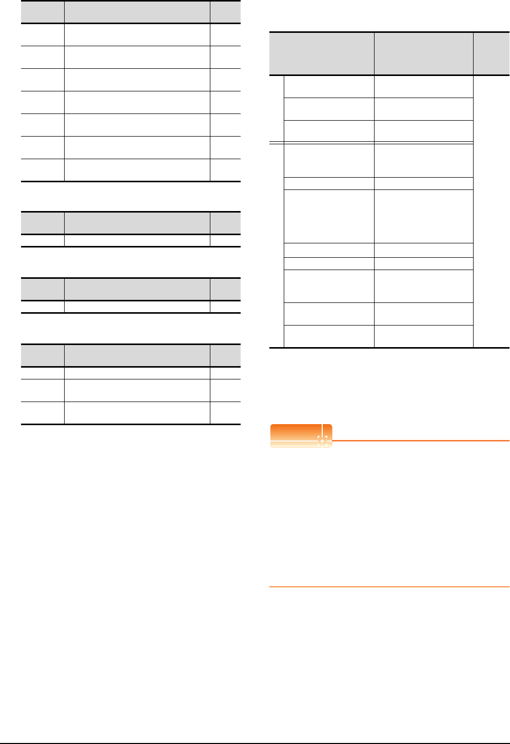
16 - 22 16. SERVO AMPLIFIER CONNECTION
16.6 Device Range that Can Be Set
(g) Input signal for test operation (for test operation)
(h) Forced output of signal pin (for test operation)
(i) Set data (for test operation)
(4) MELSERVO-J2S-*A
*1 Use PRM0 to PRM84 when writing parameters to the servo
amplifier RAM.
PRM1000 to PRM1084 are used when writing parameters to
E2PROM of the servo amplifier.
*2 The GOT cannot read or write data from/to consecutive
devices.
*3 Only reading is possible.
POINTPOINTPOINT
Precautions for SP, OM, TMB, TMI, TMO, and TMD
devices
(1) For bit devices
Only writing is possible.
[Alternate] of a bit switch cannot be used.
Use [Set], [Reset], and [Momentary] of a bit
switch.
(2) For word devices
Only writing is possible.
Numerical input cannot be used.
When writing, use [Word Set] of a data set switch.
AL215 Alarm occurrence time in alarm history
fifth alarm in past ―
AL230 Detailed alarm from alarm history
most recent alarm ―
AL231 Detailed alarm from alarm history
first alarm in past ―
AL232 Detailed alarm from alarm history
second alarm in past ―
AL233 Detailed alarm from alarm history
third alarm in past ―
AL234 Detailed alarm from alarm history
fourth alarm in past ―
AL235 Detailed alarm from alarm history
fifth alarm in past ―
Device
name Item Symbol
TMI0 Input signal for test operation ―
Device
name Item Symbol
TMO0 Forced output of signal pin ―
Device
name Item Symbol
TMD0 Writes the speed (test mode) ―
TMD1 Writes the acceleration/deceleration time
constant (test mode) ―
TMD2 Writes the moving distance in pulses (test
mode) ―
Device
name Item Symbol
Device name*2 Setting range
Device
No.
represent
ation
Bit device
Servo amplifier request
(SP) SP0 to SP6
Decimal
Operation mode selection
(OM) OM0 to OM4
Instruction demand
(for test operation) (TMB) TMB0 to TMB1
Word device
Basic parameter
/expansion parameter
(PRM)*1
PRM0 to PRM84
PRM1000 to PRM1084
Status display (ST) ST0 to ST14
Alarm (AL)
AL0 to AL1
AL11 to AL25
AL200 to AL205
AL210 to AL215
AL230 to AL235
External input (DI)*3 DI0
External output (DO) DO0
Input signal for test
operation
(for test operation) (TMI)
TMI0
Forced output of signal pin
(for test operation) (TMO) TMO0
Set data
(for test operation) (TMD) TMD0 to TMD2

16. SERVO AMPLIFIER CONNECTION
16.6 Device Range that Can Be Set
16 - 23
9
MELSECNET/H
CONNECTION (PLC
TO PLC NETWORK)
10
MELSECNET/10
CONNECTION (PLC
TO PLC NETWORK)
11
CC-Link IE CONTROLLER
NETWORK
CONNECTION
12
CC-Link IE FIELD
NETWORK
CONNECTION
13
CC-Link CONNECTION
(INTELLIGENT DEVICE
STATION)
14
CC-Link
CONNECTION
(Via G4)
15
INVERTER
CONNECTION
16
SERVO AMPLIFIER
CONNECTION
The following shows correspondences between virtual
devices for servo amplifier and data of the servo
amplifier used with the GOT.
(a) Servo amplifier request
(b) Operation mode selection
(c) Instruction demand (for test operation)
(d) Basic parameter/expansion parameter
(Continued to next page)
Device
name Item Symbol
SP0 Status display data clear ―
SP1 Current alarm clear ―
SP2 Alarm history clear ―
SP3 External input signal prohibited ―
SP4 External output signal prohibited ―
SP5 External input signal resumed ―
SP6 External output signal resumed ―
Device
name Item Symbol
OM0 Normal mode (not test operation mode) ―
OM1 JOG operation ―
OM2 Positioning operation ―
OM3 Motorless operation ―
OM4 Output signal (DO) forced output ―
Device name Item Symbol
TMB0 Clears acceleration/
deceleration time constant ―
TMB1 Temporary stop command ―
Device name Item Symbol*1
PRM0, PRM1000 Control mode, regenerative
brake option selection *STY
PRM1, PRM1001 Function selection 1 *OP1
PRM2, PRM1002 Auto tuning ATU
PRM3, PRM1003
Electronic gear numerator
(Command pulse multiplying
factor numerator)
CMX
PRM4, PRM1004
Electronic gear denominator
(Command pulse multiplying
factor denominator)
CDV
PRM5, PRM1005 In-position range INP
PRM6, PRM1006 Position loop gain 1 PG1
PRM7, PRM1007
Position command
acceleration/deceleration time
constant
PST
PRM8, PRM1008
Internal speed command1/limit1
SC1
PRM9, PRM1009
Internal speed command2/limit2
SC2
PRM10, PRM1010
Internal speed command3/limit3
SC3
PRM11, PRM1011 Acceleration time constant STA
PRM12, PRM1012 Deceleration time constant STB
PRM13, PRM1013 S-pattern acceleration/
deceleration time constant STC
PRM14, PRM1014 Torque command time constant TQC
PRM15, PRM1015 Station number setting *SNO
PRM16, PRM1016 Serial communication function
selection, alarm history clear *BPS
PRM17, PRM1017 Analog monitor output MOD
PRM18, PRM1018 Status display selection *DMD
PRM19, PRM1019 Parameter block *BLK
PRM20, PRM1020 Function selection 2 *OP2
PRM21, PRM1021 Function selection 3
(Command pulse selection) *OP3
PRM22, PRM1022 Function selection 4 *OP4
PRM23, PRM1023 Feed forward gain FFC
PRM24, PRM1024 Zero speed ZSP
PRM25, PRM1025
Analog speed command
maximum speed
/limit maximum speed
VCM
PRM26, PRM1026 Analog torque command
maximum output TLC
PRM27, PRM1027 Encoder output pulses *ENR
PRM28, PRM1028 Internal torque limit 1 TL1
PRM29, PRM1029 Analog speed command offset
/limit offset VCO
PRM30, PRM1030 Analog torque command offset
/limit offset TLO
PRM31,PRM1031 Analog monitor 1 offset MO1
PRM32, PRM1032 Analog monitor 2 offset MO2
PRM33, PRM1033 Electromagnetic brake
sequence output MBR
PRM34, PRM1034 Ratio of load inertia moment to
servo motor inertia moment GD2
PRM35, PRM1035 Position loop gain 2 PG2
PRM36, PRM1036 Speed loop gain 1 VG1
PRM37, PRM1037 Speed loop gain 2 VG2
PRM38, PRM1038 Speed integral compensation VIC
PRM39, PRM1039
Speed differential compensation
VDC
PRM40, PRM1040 For manufacturer setting ―
PRM41, PRM1041 Input signal automatic ON
selection *DIA
PRM42, PRM1042 Input signal selection 1 *DI1
PRM43, PRM1043
Input signal selection 2 (CN1B-5)
*DI2
PRM44, PRM1044
Input signal selection 3 (CN1B-14)
*DI3
PRM45, PRM1045
Input signal selection 4 (CN1A-8)
*DI4
PRM46, PRM1046
Input signal selection 5 (CN1B-7)
*DI5
PRM47, PRM1047
Input signal selection 6 (CN1B-8)
*DI6
PRM48, PRM1048
Input signal selection 7 (CN1B-9)
*DI7
PRM49, PRM1049 Output signal selection 1 *DO1
PRM50, PRM1050 For manufacturer setting ―
PRM51, PRM1051 Function selection 6 *OP6
PRM52, PRM1052 For manufacturer setting ―
PRM53, PRM1053 Function selection 8 *OP8
PRM54, PRM1054 Function selection 9 *OP9
PRM55, PRM1055 Function selection A *OPA
PRM56, PRM1056 Serial communication
time-out selection SIC
PRM57, PRM1057 For manufacturer setting ―
PRM58, PRM1058 Machine resonance
suppression filter 1 NH1
PRM59, PRM1059 Machine resonance
suppression filter 2 NH2
PRM60, PRM1060 Low-pass filter, adaptive
vibration suppression control LPF
PRM61, PRM1061 Ratio of load inertia moment
to servo motor inertia moment 2 GD2B
PRM62, PRM1062 Position control gain 2
changing ratio PG2B
PRM63, PRM1063 Speed control gain 2 changing
ratio VG2B
PRM64, PRM1064 Speed integral compensation
changing ratio VICB
PRM65, PRM1065 Gain changing selection *CDP
PRM66, PRM1066 Gain changing condition CDS
PRM67, PRM1067 Gain changing time constant CDT
PRM68, PRM1068 For manufacturer setting ―
PRM69, PRM1069 Command pulse multiplying
factor numerator 2 CMX2
Device name Item Symbol*1

16 - 24 16. SERVO AMPLIFIER CONNECTION
16.6 Device Range that Can Be Set
*1 For the parameters prefixed by an asterisk (*), setting
becomes effective when the power is turned off once and
back on after setting the parameter data.
(e) Status display
(f) Alarm (g) External I/O signal
(h) Input signal for test operation (for test operation)
(i) Forced output of signal pin (for test operation)
(j) Set data (for test operation)
Device name Item Symbol*1
PRM70, PRM1070
Command pulse multiplying
factor numerator 3
CMX3
PRM71, PRM1071
Command pulse multiplying
factor numerator 4
CMX4
PRM72, PRM1072
Internal speed command4/limit4
SC4
PRM73, PRM1073
Internal speed command5/limit5
SC5
PRM74, PRM1074
Internal speed command6/limit6
SC6
PRM75, PRM1075
Internal speed command7/limit7
SC7
PRM76, PRM1076 Internal torque limit 2 TL2
PRM77 to PRM84,
PRM1077 to PRM1084
For manufacturer setting ―
Device
name Item Symbol
ST0 Cumulative feedback pulses ―
ST1 servo motor speed ―
ST2 Droop pulses ―
ST3 Cumulative command pulses ―
ST4 Command pulse frequency ―
ST5 Analog speed command voltage/limit voltage ―
ST6 Analog torque command voltage/limit voltage ―
ST7 Regenerative load ratio ―
ST8 Effective load ratio ―
ST9 Peak load ratio ―
ST10 Instantaneous torque ―
ST11 Within one-revolution position ―
ST12 ABS counter ―
ST13 load inertia moment ratio ―
ST14 Bus voltage ―
Device
name Item Symbol
AL0 Current alarm number ―
AL1 Detailed data of current alarms ―
AL11 Servo status when alarm occurs cumulative
feedback pulses ―
AL12 Servo status when alarm occurs
servo motor speed ―
AL13 Servo status when alarm occurs droop pulses ―
AL14 Servo status when alarm occurs cumulative
command pulses ―
AL15 Servo status when alarm occurs command
pulse frequency ―
AL16 Servo status when alarm occurs analog
speed command voltage/limit voltage ―
AL17 Servo status when alarm occurs analog
torque command voltage/limit voltage ―
AL18
Servo status when alarm occurs regenerative
load ratio
―
AL19
Servo status when alarm occurs effective load
ratio
―
AL20
Servo status when alarm occurs peak load ratio
―
AL21 Servo status when alarm occurs
instantaneous torque ―
AL22 Servo status when alarm occurs within one-
revolution position ―
AL23 Servo status when alarm occurs ABS counter ―
AL24 Servo status when alarm occurs
load inertia moment ratio ―
AL25 Servo status when alarm occurs bus voltage ―
AL200 Alarm number from alarm history
most recent alarm ―
AL201 Alarm number from alarm history
first alarm in past ―
AL202 Alarm number from alarm history
second alarm in past ―
AL203 Alarm number from alarm history
third alarm in past ―
AL204 Alarm number from alarm history
fourth alarm in past ―
AL205 Alarm number from alarm history
fifth alarm in past ―
AL210 Alarm occurrence time in alarm history
most recent alarm ―
AL211 Alarm occurrence time in alarm history
first alarm in past ―
AL212 Alarm occurrence time in alarm history
second alarm in past ―
AL213 Alarm occurrence time in alarm history
third alarm in past ―
AL214 Alarm occurrence time in alarm history
fourth alarm in past ―
AL215 Alarm occurrence time in alarm history
fifth alarm in past ―
AL230 Detailed alarm from alarm history
most recent alarm ―
AL231 Detailed alarm from alarm history
first alarm in past ―
AL232 Detailed alarm from alarm history
second alarm in past ―
AL233 Detailed alarm from alarm history
third alarm in past ―
AL234 Detailed alarm from alarm history
fourth alarm in past ―
AL235 Detailed alarm from alarm history
fifth alarm in past ―
Device
name Item Symbol
DI0 External input pin statuses ―
DO0 External output pin statuses ―
Device
name Item Symbol
TMI0 Input signal status for test operation ―
Device
name Item Symbol
TMO0 Forced output status of signal pin ―
Device
name Item Symbol
TMD0 Writes the speed (test mode) ―
TMD1 Writes the acceleration/deceleration time
constant (test mode) ―
TMD2 Writes the moving distance in pulses (test
mode) ―
Device
name Item Symbol
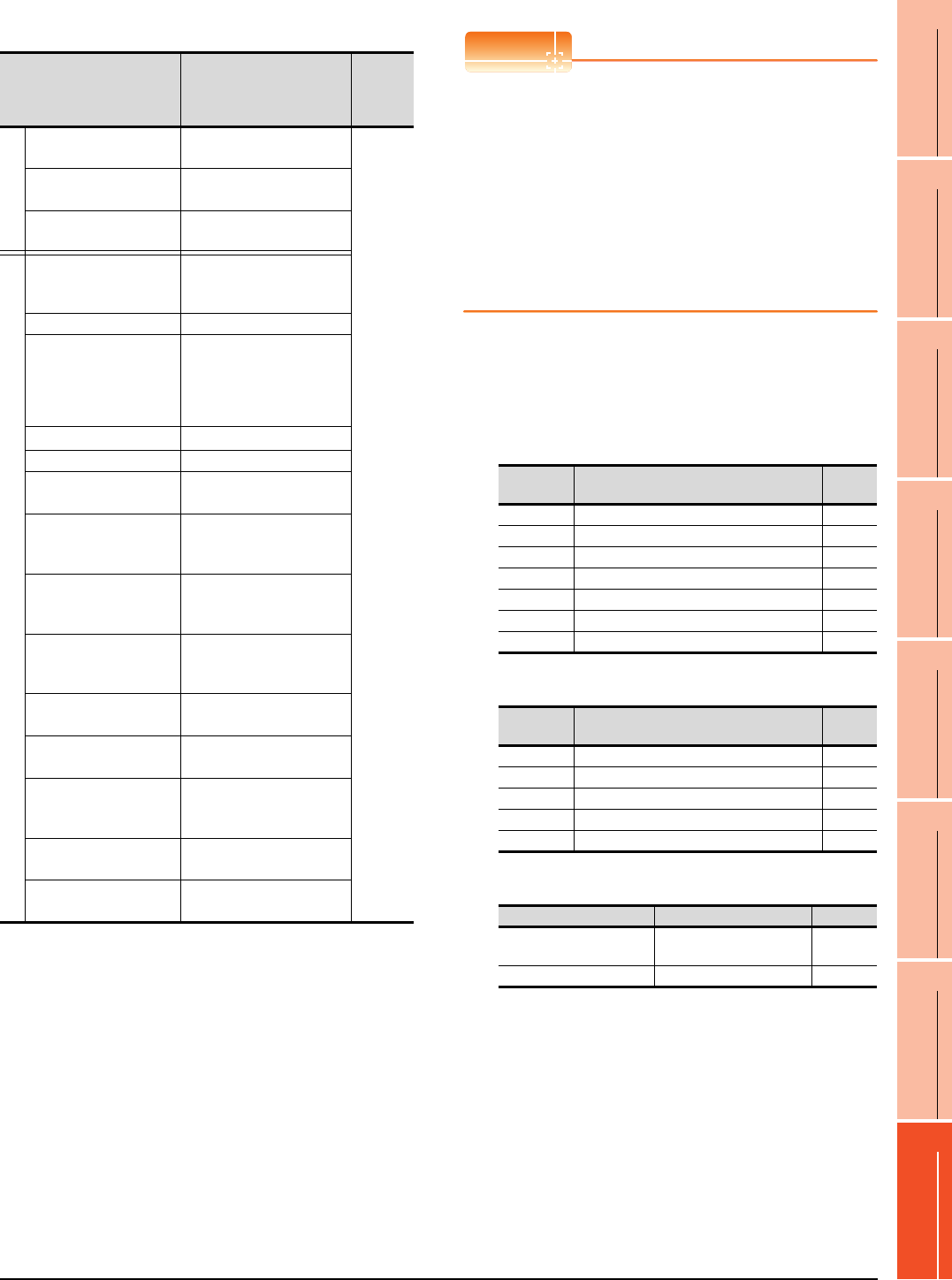
16. SERVO AMPLIFIER CONNECTION
16.6 Device Range that Can Be Set
16 - 25
9
MELSECNET/H
CONNECTION (PLC
TO PLC NETWORK)
10
MELSECNET/10
CONNECTION (PLC
TO PLC NETWORK)
11
CC-Link IE CONTROLLER
NETWORK
CONNECTION
12
CC-Link IE FIELD
NETWORK
CONNECTION
13
CC-Link CONNECTION
(INTELLIGENT DEVICE
STATION)
14
CC-Link
CONNECTION
(Via G4)
15
INVERTER
CONNECTION
16
SERVO AMPLIFIER
CONNECTION
(5) MELSERVO-J2S-*CP
*1 Use PRM0 to PRM90 when writing parameters to the servo
amplifier RAM.
PRM1000 to PRM1090 are used when writing parameters to
E2PROM of the servo amplifier.
*2 When writing to a point table, use the area of 1001 to 1031
(E2PROM area) of POS, SPD, ACT, DCT, DWL, or AUX.
If writing to the area of 1 to 31 (RAM area) of POS, SPD,
ACT, DCT, DWL, or AUX, the value is not reflected.
*3 The GOT cannot read or write data from/to consecutive
devices.
*4 Only reading is possible for DI0 to DI1.
POINTPOINTPOINT
Precautions for SP, OM, TMB, TMI, TMO, and TMD
devices
(1) For bit devices
Only writing is possible.
[Alternate] of a bit switch cannot be used.
Use [Set], [Reset], and [Momentary] of a bit
switch.
(2) For word devices
Only writing is possible.
Numerical input cannot be used.
When writing, use [Word Set] of a data set switch.
The following shows correspondences between virtual
devices for servo amplifier and data of the servo
amplifier used with the GOT.
(a) Servo amplifier request
(b) Operation mode selection
(c) Instruction demand (for test operation)
Device name*3 Setting range
Device
No.
represent
ation
Bit device
Servo amplifier request
(SP) SP0 to SP6
Decimal
Operation mode selection
(OM) OM0 to OM4
Instruction demand
(for test operation) (TMB) TMB0 to TMB1
Word device
Basic parameter
/expansion parameter
(PRM)*1
PRM0 to PRM90
PRM1000 to PRM1090
Status display (ST) ST0 to ST16
Alarm (AL)
AL0 to AL1
AL11 to AL27
AL200 to AL205
AL210 to AL215
AL230 to AL235
External input (DI)*4 DI0 to DI2
External output (DO) DO0 to DO1
Point table
(position) (POS)*2
POS1 to POS31
POS1001 to POS1031
Point table
Point table (speed)
(SPD)*2
SPD1 to SPD31
SPD1001 to SPD1031
Point table
(acceleration time
constant) (ACT)*2
ACT1 to ACT31
ACT1001 to ACT1031
Point table
(deceleration time
constant) (DCT)*2
DCT1 to DCT31
DCT1001 to DCT1031
Point table
(dwell) (DWL)*2
DWL1 to DWL31
DWL1001 to DWL1031
Point table
(auxiliary function) (AUX)*2
AUX1 to AUX31
AUX1001 to AUX1031
Input signal for test
operation
(for test operation) (TMI)
TMI0
Forced output of signal pin
(for test operation) (TMO) TMO0
Set data
(for test operation) (TMD) TMD0 to TMD2
Device
name Item Symbol
SP0 Status display data clear ―
SP1 Current alarm clear ―
SP2 Alarm history clear ―
SP3 External input signal prohibited ―
SP4 External output signal prohibited ―
SP5 External input signal resumed ―
SP6 External output signal resumed ―
Device
name Item Symbol
OM0 Normal mode (not test operation mode) ―
OM1 JOG operation ―
OM2 Positioning operation ―
OM3 Motorless operation ―
OM4 Output signal (DO) forced output ―
Device name Item Symbol
TMB0 Clears the acceleration/
deceleration time constant ―
TMB1 Temporary stop command ―

16 - 26 16. SERVO AMPLIFIER CONNECTION
16.6 Device Range that Can Be Set
(d) Basic parameter/expansion parameter
*1 For the parameters prefixed by an asterisk (*), setting
becomes effective when the power is turned off once and
back on after setting the parameter data.
(e) Status display
Device name Item Symbol*1
PRM0, PRM1000
Command system/
regenerative brake option
selection
*STY
PRM1, PRM1001 Feeding function selection *FTY
PRM2, PRM1002 Function selection 1 *OP1
PRM3, PRM1003 Auto tuning ATU
PRM4, PRM1004 Electronic gear numerator *CMX
PRM5, PRM1005 Electronic gear denominator *CDV
PRM6, PRM1006 In-position range INP
PRM7, PRM1007 Position loop gain 1 PG1
PRM8, PRM1008 Home position return type *ZTY
PRM9, PRM1009 Home position return speed ZRF
PRM10, PRM1010 Creep speed CRF
PRM11, PRM1011 Home position shift distance ZST
PRM12, PRM1012 Rough match output range CRP
PRM13, PRM1013 Jog speed JOG
PRM14, PRM1014 S-pattern acceleration/
deceleration time constant *STC
PRM15, PRM1015 Station number setting *SNO
PRM16, PRM1016
Serial communication function
selection,
alarm history clear
*BPS
PRM17, PRM1017 Analog monitor output MOD
PRM18, PRM1018 Status display selection *DMD
PRM19, PRM1019 Parameter block *BLK
PRM20, PRM1020 Function selection 2 *OP2
PRM21, PRM1021 For manufacturer setting ―
PRM22, PRM1022 Function selection 4 *OP4
PRM23, PRM1023 Serial communication time-out
selection SIC
PRM24, PRM1024 Feed forward gain FFC
PRM25, PRM1025 Override offset VCO
PRM26, PRM1026 Torque limit offset TLO
PRM27, PRM1027 Encoder output pulses *ENR
PRM28, PRM1028 Internal torque limit 1 TL1
PRM29, PRM1029 Internal torque limit 2 TL2
PRM30, PRM1030 Backlash compensation *BKC
PRM31,PRM1031 Analog monitor 1 offset MO1
PRM32, PRM1032 Analog monitor 2 offset MO2
PRM33, PRM1033 Electromagnetic brake
sequence output MBR
PRM34, PRM1034 Ration of load inertia moment
to servo motor inertia moment GD2
PRM35, PRM1035 Position control gain 2 PG2
PRM36, PRM1036 Speed control gain 1 VG1
PRM37, PRM1037 Position control gain 2 VG2
PRM38, PRM1038 Speed integral compensation VIC
PRM39, PRM1039 Speed differential
compensation VDC
PRM40 to PRM41,
PRM1040 to PRM1041 For manufacturer setting ―
PRM42, PRM1042 Home position return position
data *ZPS
PRM43, PRM1043 Moving distance after
proximity dog DCT
PRM44, PRM1044 Moving distance
after proximity dog ZTM
PRM45, PRM1045 Stopper type home position
return torque limit value ZTT
PRM46, PRM1046 Software limit + *LMP
PRM47, PRM1047
PRM48, PRM1048 Software limit - *LMN
PRM49, PRM1049
PRM50, PRM1050
Position range output address +
*LPP
PRM51, PRM1051
PRM52, PRM1052
Position range output address -
*LNP
PRM53, PRM1053
PRM54, PRM1054 For manufacturer setting ―
PRM55, PRM1055 Function selection 6 *OP6
PRM56, PRM1056 For manufacturer setting ―
PRM57, PRM1057 Function selection 8 *OP8
PRM58, PRM1058 Function selection 9 *OP9
PRM59, PRM1059 Function selection A *OPA
PRM60, PRM1060 For manufacturer setting ―
PRM61, PRM1061 Machine resonance
suppression filter 1 NH1
PRM62, PRM1062 Machine resonance
suppression filter 2 NH2
PRM63, PRM1063
Low-pass filter,
adaptive vibration suppression
control
LPF
PRM64, PRM1064
Ratio of load inertia moment
to servo motor inertia moment 2
GD2B
PRM65, PRM1065 Position control gain 2
changing ratio PG2B
PRM66, PRM1066 Speed control gain 2 changing
ratio VG2B
PRM67, PRM1067 Speed integral compensation
changing ratio VICB
PRM68, PRM1068 Gain changing selection *CDP
PRM69, PRM1069 Gain changing condition CDS
PRM70, PRM1070 Gain changing time constant CDT
PRM71 to PRM90,
PRM1071 to PRM1090 For manufacturer setting ―
Device name Item Symbol
ST0 Current position ―
ST1 Command position ―
ST2 Command remaining distance ―
ST3 Point table No. ―
ST4 Cumulative feedback pulses ―
ST5 Servo motor speed ―
ST6 Droop pulses ―
ST7 Override ―
ST8 Torque limit voltage ―
ST9 Regenerative load ratio ―
ST10 Effective load ratio ―
ST11 Peak load ratio ―
ST12 Instantaneous torque ―
ST13 Within one-revolution position ―
ST14 ABS counter ―
ST15 Load inertia moment ratio ―
ST16 Bus voltage ―
Device name Item Symbol*1

16. SERVO AMPLIFIER CONNECTION
16.6 Device Range that Can Be Set
16 - 27
9
MELSECNET/H
CONNECTION (PLC
TO PLC NETWORK)
10
MELSECNET/10
CONNECTION (PLC
TO PLC NETWORK)
11
CC-Link IE CONTROLLER
NETWORK
CONNECTION
12
CC-Link IE FIELD
NETWORK
CONNECTION
13
CC-Link CONNECTION
(INTELLIGENT DEVICE
STATION)
14
CC-Link
CONNECTION
(Via G4)
15
INVERTER
CONNECTION
16
SERVO AMPLIFIER
CONNECTION
(f) Alarm (g) External I/O signal
(h) Point table (position)
(i) Input signal for test operation (for test operation)
(j) Forced output of signal pin (for test operation)
(k) Set data (for test operation)
Device
name Item Symbol
AL0 Current alarm number ―
AL1 Detailed data of current alarms ―
AL11 Servo status when alarm occurs current position ―
AL12 Servo status when alarm occurs command
position ―
AL13 Servo status when alarm occurs command
remaining distance ―
AL14 Servo status when alarm occurs
point table No. ―
AL15 Servo status when alarm occurs
cumulative feedback pulses ―
AL16 Servo status when alarm occurs
servo motor speed ―
AL17
Servo status when alarm occurs droop pulses
―
AL18 Servo status when alarm occurs override ―
AL19 Servo status when alarm occurs torque limit
voltage ―
AL20 Servo status when alarm occurs regenerative
load ratio ―
AL21 Servo status when alarm occurs effective load
ratio ―
AL22 Servo status when alarm occurs peak load ratio ―
AL23 Servo status when alarm occurs instantaneous
torque ―
AL24 Servo status when alarm occurs within one-
revolution position ―
AL25
Servo status when alarm occurs ABS counter
―
AL26 Servo status when alarm occurs
Load inertia moment ratio ―
AL27 Servo status when alarm occurs bus voltage ―
AL200 Alarm number from alarm history
most recent alarm ―
AL201 Alarm number from alarm history
first alarm in past ―
AL202 Alarm number from alarm history
second alarm in past ―
AL203 Alarm number from alarm history
third alarm in past ―
AL204 Alarm number from alarm history
fourth alarm in past ―
AL205 Alarm number from alarm history
fifth alarm in past ―
AL210 Alarm occurrence time in alarm history
most recent alarm ―
AL211 Alarm occurrence time in alarm history
first alarm in past ―
AL212 Alarm occurrence time in alarm history
second alarm in past ―
AL213 Alarm occurrence time in alarm history
third alarm in past ―
AL214 Alarm occurrence time in alarm history
fourth alarm in past ―
AL215 Alarm occurrence time in alarm history
fifth alarm in past ―
AL230 Detailed alarm from alarm history
most recent alarm ―
AL231 Detailed alarm from alarm history
first alarm in past ―
AL232 Detailed alarm from alarm history
second alarm in past ―
AL233 Detailed alarm from alarm history
third alarm in past ―
AL234 Detailed alarm from alarm history
fourth alarm in past ―
AL235 Detailed alarm from alarm history
fifth alarm in past ―
Device
name Item Symbol
DI0 Input device statuses ―
DI1 External input pin statuses ―
DI2 Statuses of input devices switched on
through communication ―
DO0 Output device statuses ―
DO1 External output pin statuses ―
Device name Item Symbol
POS1 to POS31,
POS1001 to POS1031
Point table (position)
No. 1 to No. 31 ―
SPD1 to SPD31,
SPD1001 to SPD1031
Point table (speed)
No. 1 to No. 31 ―
ACT1 to ACT31,
ACT1001 to ACT1031
Point table
(acceleration time constant)
No. 1 to No. 31
―
DCT1 to DCT31,
DCT1001 to DCT1031
Point table
(deceleration time constant)
No. 1 to No. 31
―
DWL1 to DWL31,
DWL1001 to DWL1031
Point table
(dwell)
No. 1 to No. 31
―
AUX1 to AUX31,
AUX1001 to AUX1031
Point table
(auxiliary function)
No. 1 to No. 31
―
Device
name Item Symbol
TMI0 Input signal for test operation ―
Device
name Item Symbol
TMO0 Forced output of signal pin ―
Device
name Item Symbol
TMD0 Writes the speed (test mode) ―
TMD1 Writes the acceleration/deceleration time
constant (test mode) ―
TMD2 Writes the moving distance in pulses (test
mode) ―
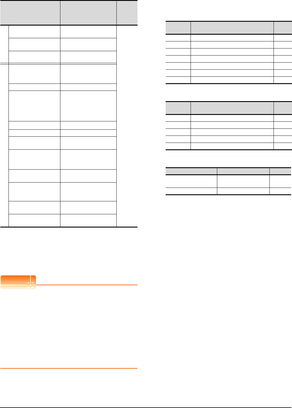
16 - 28 16. SERVO AMPLIFIER CONNECTION
16.6 Device Range that Can Be Set
(6) MELSERVO-J2S-*CL
*1 PRM0 to PRM90 are used when writing parameters to the
servo amplifier RAM.
PRM1000 to PRM1090 are used when writing parameters to
E2PROM of the servo amplifier.
*2 The GOT cannot read or write data from/to consecutive
devices.
*3 Use the integer number when writing parameters to Rx.
*4 Only reading is possible for DI0 to DI1.
POINTPOINTPOINT
Precautions for SP, OM, TMB, TMI, TMO, and TMD
devices
(1) For bit devices
Only writing is possible.
[Alternate] of a bit switch cannot be used.
Use [Set], [Reset], and [Momentary] of a bit
switch.
(2) For word devices
Only writing is possible.
Numerical input cannot be used.
When writing, use [Word Set] of a data set switch.
The following shows correspondences between virtual
devices for servo amplifier and data of the servo
amplifier used with the GOT.
(a) Servo amplifier request
(b) Operation mode selection
(c) Instruction demand (for test operation)
Device name*2 Setting range
Device
No.
represent
ation
Bit device
Servo amplifier request
(SP) SP0 to SP6
Decimal
Operation mode selection
(OM) OM0 to OM4
Instruction demand
(for test operation) (TMB) TMB0 to TMB1
Word device
Basic parameter
/expansion parameter
(PRM)*1
PRM0 to PRM90
PRM1000 to PRM1090
Status display (ST) ST0 to ST17
Alarm (AL)
AL0 to AL1
AL11 to AL28
AL200 to AL205
AL210 to AL215
AL230 to AL235
External input (DI)*4 DI0 to DI2
External output(DO) DO0 to DO1
Current position latch data
(LD) LD1
The value of the general-
purpose register (Rx)
(RR)*3
RR1 to RR4
RR1001 to RR1004
The value of the general-
purpose register (Dx) (RD) RD1 to RD4
Input signal for test
operation
(for test operation) (TMI)
TMI0
Forced output of signal pin
(for test operation) (TMO) TMO0
Set data
(for test operation) (TMD) TMD0 to TMD2
Device
name Item Symbol
SP0 Status display data clear ―
SP1 Current alarm clear ―
SP2 Alarm history clear ―
SP3 External input signal prohibited ―
SP4 External output signal prohibited ―
SP5 External input signal resumed ―
SP6 External output signal resumed ―
Device
name Item Symbol
OM0 Normal mode (not test operation mode) ―
OM1 JOG operation ―
OM2 Positioning operation ―
OM3 Motorless operation ―
OM4 Output signal (DO) forced output ―
Device name Item Symbol
TMB0 Clears the acceleration/
deceleration time constant ―
TMB1 Temporary stop command ―

16. SERVO AMPLIFIER CONNECTION
16.6 Device Range that Can Be Set
16 - 29
9
MELSECNET/H
CONNECTION (PLC
TO PLC NETWORK)
10
MELSECNET/10
CONNECTION (PLC
TO PLC NETWORK)
11
CC-Link IE CONTROLLER
NETWORK
CONNECTION
12
CC-Link IE FIELD
NETWORK
CONNECTION
13
CC-Link CONNECTION
(INTELLIGENT DEVICE
STATION)
14
CC-Link
CONNECTION
(Via G4)
15
INVERTER
CONNECTION
16
SERVO AMPLIFIER
CONNECTION
(d) Basic parameter/expansion parameter
*1 For the parameters prefixed by an asterisk (*), setting
becomes effective when the power is turned off once and
back on after setting the parameter data.
(e) Status display
Device name Item Symbol*1
PRM0, PRM1000
Command system/
regenerative brake option
selection
*STY
PRM1, PRM1001 Feeding function selection *FTY
PRM2, PRM1002 Function selection 1 *OP1
PRM3, PRM1003 Auto tuning ATU
PRM4, PRM1004 Electronic gear numerator *CMX
PRM5, PRM1005 Electronic gear denominator *CDV
PRM6, PRM1006 In-position range INP
PRM7, PRM1007 Position loop gain 1 PG1
PRM8, PRM1008 Home position return type *ZTY
PRM9, PRM1009 Home position return speed ZRF
PRM10, PRM1010 Creep speed CRF
PRM11, PRM1011 Home position shift distance ZST
PRM12, PRM1012 For manufacturer setting ―
PRM13, PRM1013 Jog speed JOG
PRM14, PRM1014 S-pattern acceleration/
deceleration time constant *STC
PRM15, PRM1015 Station number setting *SNO
PRM16, PRM1016
Serial communication function
selection,
alarm history clear
*BPS
PRM17, PRM1017 Analog monitor output MOD
PRM18, PRM1018 Status display selection *DMD
PRM19, PRM1019 Parameter block *BLK
PRM20, PRM1020 Function selection 2 *OP2
PRM21, PRM1021 For manufacturer setting ―
PRM22, PRM1022 Function selection 4 *OP4
PRM23, PRM1023 Serial communication time-out
selection SIC
PRM24, PRM1024 Feed forward gain FFC
PRM25, PRM1025 Override offset VCO
PRM26, PRM1026 Torque limit offset TLO
PRM27, PRM1027 Encoder output pulses *ENR
PRM28, PRM1028 Internal torque limit 1 TL1
PRM29, PRM1029 Internal torque limit 2 TL2
PRM30, PRM1030 Backlash compensation *BKC
PRM31,PRM1031 Analog monitor 1 offset MO1
PRM32, PRM1032 Analog monitor 2 offset MO2
PRM33, PRM1033 Electromagnetic brake
sequence output MBR
PRM34, PRM1034 Ration of load inertia moment
to servo motor inertia moment GD2
PRM35, PRM1035 Position control gain 2 PG2
PRM36, PRM1036 Speed control gain 2 VG1
PRM37, PRM1037 Speed control gain 2 VG2
PRM38, PRM1038 Speed integral compensation VIC
PRM39, PRM1039 Speed differential
compensation VDC
PRM40, PRM1040 JOG operation acceleration/
deceleration time constant JTC
PRM41, PRM1041
Home position return
operation acceleration/
deceleration time constant
ZTS
PRM42, PRM1042 Home position return position
data *ZPS
PRM43, PRM1043 Moving distance after
proximity dog DCT
PRM44, PRM1044 Stopper type home position
return stopper time ZTM
PRM45, PRM1045 Stopper type home position
return torque limit value ZTT
PRM46, PRM1046 Software limit+ *LMP
PRM47, PRM1047
PRM48, PRM1048 Software limit- *LMN
PRM49, PRM1049
PRM50, PRM1050 Position range output
address+ *LPP
PRM51, PRM1051
PRM52, PRM1052 Position range output address- *LNP
PRM53, PRM1053
PRM54, PRM1054 For manufacturer setting ―
PRM55, PRM1055 Function selection 6 *OP6
PRM56, PRM1056 For manufacturer setting ―
PRM57, PRM1057 Function selection 8 *OP8
PRM58, PRM1058 Function selection 9 *OP9
PRM59, PRM1059 Function selection A *OPA
PRM60, PRM1060 For manufacturer setting ―
PRM61, PRM1061 Machine resonance
suppression filter 1 NH1
PRM62, PRM1062 Machine resonance
suppression filter 2 NH2
PRM63, PRM1063
Low-pass filter,
adaptive vibration suppression
control
LPF
PRM64, PRM1064
Ratio of load inertia moment
to Servo motor inertia moment 2
GD2B
PRM65, PRM1065 Position control gain 2
changing ratio PG2B
PRM66, PRM1066 Speed control gain 2 changing
ratio VG2B
PRM67, PRM1067 Speed integral compensation
changing ratio VICB
PRM68, PRM1068 Gain changing selection *CDP
PRM69, PRM1069 Gain changing condition CDS
PRM70, PRM1070 Gain changing time constant CDT
PRM71 to PRM73,
PRM1071 to PRM1073 For manufacturer setting ―
PRM74, PRM1074 OUT1 output time selection OUT1
PRM75, PRM1075 OUT2 output time selection OUT2
PRM76, PRM1076 OUT3 output time selection OUT3
PRM77, PRM1077 Selected to program input
polarity selection 1 SYC1
PRM78 to PRM90,
PRM1078 to PRM1090 For manufacturer setting ―
Device name Item Symbol
ST0 Current position ―
ST1 Command position ―
ST2 Command remaining distance ―
ST3 Program Number ―
ST4 Step Number ―
ST5 Cumulative feedback pulses ―
ST6 Servo motor speed ―
ST7 Droop pulses ―
ST8 Override ―
ST9 Torque limit voltage ―
ST10 Regenerative load ratio ―
ST11 Effective load ratio ―
ST12 Peak load ratio ―
ST13 Instantaneous torque ―
ST14 Within one-revolution position ―
ST15 ABS counter ―
ST16 Load inertia moment ratio ―
ST17 Bus voltage ―
Device name Item Symbol*1

16 - 30 16. SERVO AMPLIFIER CONNECTION
16.6 Device Range that Can Be Set
(f) Alarm
(g) External I/O signal
(h) Current position latch data
(i) The value of the general-purpose register (Rx)
(j) The value of the general-purpose register (Dx)
(k) Input signal for test operation (for test operation)
(l) Forced output of signal pin (for test operation)
(m) Set data (for test operation)
Device
name Item Symbol
AL0 Current alarm number ―
AL1 Detailed data of current alarms ―
AL11 Servo status when alarm occurs Current
position ―
AL12 Servo status when alarm occurs Command
position ―
AL13 Servo status when alarm occurs Command
remaining distance ―
AL14 Servo status when alarm occurs Program
Number ―
AL15
Servo status when alarm occurs Step Number
―
AL16 Servo status when alarm occurs Cumulative
feedback pulses ―
AL17 Servo status when alarm occurs
Servo motor speed ―
AL18
Servo status when alarm occurs Droop pulses
―
AL19 Servo status when alarm occurs Override ―
AL20 Servo status when alarm occurs Torque limit
voltage ―
AL21 Servo status when alarm occurs
Regenerative load ratio ―
AL22 Servo status when alarm occurs Effective
load ratio ―
AL23 Servo status when alarm occurs Peak load
ratio ―
AL24 Servo status when alarm occurs
Instantaneous torque ―
AL25 Servo status when alarm occurs Within one-
revolution position ―
AL26
Servo status when alarm occurs ABS counter
―
AL27 Servo status when alarm occurs
Load inertia moment ratio ―
AL28 Servo status when alarm occurs Bus voltage ―
AL200 Alarm number from Alarm History
most recent alarm ―
AL201 Alarm number from Alarm History
first alarm in past ―
AL202 Alarm number from Alarm History
second alarm in past ―
AL203 Alarm number from Alarm History
third alarm in past ―
AL204 Alarm number from Alarm History
fourth alarm in past ―
AL205 Alarm number from Alarm History
fifth alarm in past ―
AL210 Alarm occurrence time in alarm history
most recent alarm ―
AL211 Alarm occurrence time in alarm history
first alarm in past ―
AL212 Alarm occurrence time in alarm history
second alarm in past ―
AL213 Alarm occurrence time in alarm history
third alarm in past ―
AL214 Alarm occurrence time in alarm history
fourth alarm in past ―
AL215 Alarm occurrence time in alarm history
fifth alarm in past ―
AL230 Detailed alarm from Alarm History
most recent alarm ―
AL231 Detailed alarm from Alarm History
first alarm in past ―
AL232 Detailed alarm from Alarm History
second alarm in past ―
AL233 Detailed alarm from Alarm History
third alarm in past ―
AL234 Detailed alarm from Alarm History
fourth alarm in past ―
AL235 Detailed alarm from Alarm History
fifth alarm in past ―
Device
name Item Symbol
DI0 Input device statuses ―
DI1 External input pin statuses ―
DI2 Statuses of input devices switched on
through communication ―
DO0 Output device statuses ―
DO1 External output pin statuses ―
Device
name Item Symbol
LD1 Current position latch data ―
Device name Item Symbol
RR1, RR1001 The value of the general-
purpose register (R1) ―
RR2, RR1002 The value of the general-
purpose register (R2) ―
RR3, RR1003 The value of the general-
purpose register (R3) ―
RR4, RR1004 The value of the general-
purpose register (R4) ―
Device name Item Symbol
RD1 The value of the general-
purpose register (D1) ―
RD2 The value of the general-
purpose register (D2) ―
RD3 The value of the general-
purpose register (D3) ―
RD4 The value of the general-
purpose register (D4) ―
Device name Item Symbol
TMI0 Input signal for test operation ―
Device name Item Symbol
TMO0 Forced output of signal pin ―
Device
name Item Symbol
TMD0 Writes the speed (test mode) ―
TMD1 Writes the acceleration/deceleration time
constant(test mode) ―
TMD2 Writes the moving distance in pulses(test
mode) ―
Device
name Item Symbol
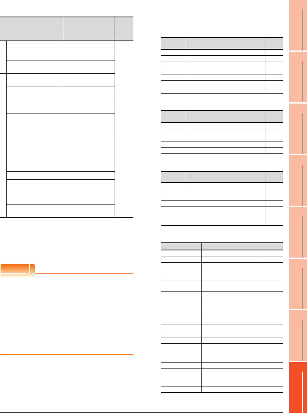
16. SERVO AMPLIFIER CONNECTION
16.6 Device Range that Can Be Set
16 - 31
9
MELSECNET/H
CONNECTION (PLC
TO PLC NETWORK)
10
MELSECNET/10
CONNECTION (PLC
TO PLC NETWORK)
11
CC-Link IE CONTROLLER
NETWORK
CONNECTION
12
CC-Link IE FIELD
NETWORK
CONNECTION
13
CC-Link CONNECTION
(INTELLIGENT DEVICE
STATION)
14
CC-Link
CONNECTION
(Via G4)
15
INVERTER
CONNECTION
16
SERVO AMPLIFIER
CONNECTION
(7) MELSERVO-J3-*A
*1 1 to 50 of PA, PB, PC, and PD are used when writing data to
the servo amplifier RAM.
1001 to 1050 of PA, PB, PC, and PD are used when writing
data to E2PROM of the servo amplifier.
*2 The GOT cannot read or write data from/to consecutive
devices.
*3 Only reading is possible.
*4 Only reading is possible for DI0 to DI1.
POINTPOINTPOINT
Precautions for SP, OM, TMB, TMI, TMO, and TMD
devices
(1) For bit devices
Only writing is possible.
[Alternate] of a bit switch cannot be used.
Use [Set], [Reset], and [Momentary] of a bit
switch.
(2) For word devices
Only writing is possible.
Numerical input cannot be used.
When writing, use [Word Set] of a data set switch.
The following shows correspondences between virtual
devices for servo amplifier and data of the servo
amplifier used with the GOT.
(a) Servo amplifier request
(b) Operation mode selection
(c) Instruction demand (for test operation)
(d) Basic parameter/expansion parameter
*1 For the parameters prefixed by an asterisk (*), setting
becomes effective when the power is turned off once and
back on after setting the parameter data.
Device name*2 Setting range
Device
No.
represen
tation
Bit device
Servo amplifier request (SP) SP0 to SP6
Decimal
Operation mode selection
(OM) OM0 to OM4
Instruction demand
(for test operation) (TMB) TMB1 to TMB6
Word device
Basic setting parameter
(PA)*1
PA1 to PA19
PA1001 to PA1019
Gain filter parameter
(PB)*1
PB1 to PB45
PB1001 to PB1045
Extension setting parameter
(PC)*1
PC1 to PC50
PC1001 to PC1050
I/O setting parameter (PD)*1 PD1 to PD30
PD1001 to PD1030
Status display (ST)*3 ST0 to ST14
Alarm (AL)*3
AL0 to AL1
AL11 to AL25
AL200 to AL205
AL210 to AL215
AL230 to AL235
External input (DI)*4 DI0 to DI2
External output (DO)*3 DO0 to DO1
Input signal for test operation
(for test operation) (TMI) TMI0
Forced output of signal pin
(for test operation) (TMO) TMO0
Set data
(for test operation) (TMD)
TMD0 to TMD1
TMD3
Device
name Item Symbol
SP0 Status display data clear ―
SP1 Current alarm clear ―
SP2 Alarm history clear ―
SP3 External input signal prohibited ―
SP4 External output signal prohibited ―
SP5 External input signal resumed ―
SP6 External output signal resumed ―
Device
name Item Symbol
OM0 Normal mode (not test operation mode) ―
OM1 JOG operation ―
OM2 Positioning operation ―
OM3 Motorless operation ―
OM4 Output signal (DO) forced output ―
Device
name Item Symbol
TMB1 Temporary stop command ―
TMB2 Test operation (positioning operation) start
command ―
TMB3 Forward rotation direction ―
TMB4 Reverse rotation direction ―
TMB5 Restart for remaining distance ―
TMB6 Remaining distance clear ―
Device name Item Symbol*1
PA1, PA1001 Control mode *STY
PA2, PA1002 Regenerative brake option *REG
PA3, PA1003 Absolute position detection
system *ABS
PA4, PA1004 Function selection A-1 *AOP1
PA5, PA1005 Number of command input
pulses per revolution *FBP
PA6, PA1006
Electronic gear numerator
(command pulse multiplying
factor numerator)
CMX
PA7, PA1007
Electronic gear denominator
(command pulse multiplying
factor denominator)
CDV
PA8, PA1008 Auto tuning mode ATU
PA9, PA1009 Auto tuning response RSP
PA10, PA1010 In-position range INP
PA11, PA1011 Forward torque limit TLP
PA12, PA1012 Reverses torque limit TLN
PA13, PA1013 Command pulse input form *PLSS
PA14, PA1014 Rotation direction selection *POL
PA15, PA1015 Encoder output pulses *ENR
PA16 to PA18,
PA1016 to PA1018 For manufacturer setting ―
PA19, PA1019 Parameter block *BLK

16 - 32 16. SERVO AMPLIFIER CONNECTION
16.6 Device Range that Can Be Set
(e) Gain filter parameter
*1 For the parameters prefixed by an asterisk (*), setting
becomes effective when the power is turned off once and
back on after setting the parameter data.
(f) Extension setting parameter
*1 For the parameters prefixed by an asterisk (*), setting
becomes effective when the power is turned off once and
back on after setting the parameter data.
Device name Item Symbol*1
PB1, PB1001 Adaptive tuning mode
(Adaptive filter II) FILT
PA2, PB1002
Vibration suppression control filter
tuning mode
(Advanced vibration suppression
control)
VRFT
PB3, PB1003
Position command acceleration/
deceleration time constant
(position smoothing)
PST
PB4, PB1004 Feed forward gain FFC
PB5, PB1005 For manufacturer setting ―
PB6, PB1006 Ratio of load inertia moment to
servo motor inertia moment GD2
PB7, PB1007 Model control gain PG1
PB8, PB1008 Position loop gain PG2
PB9, PB1009 Speed loop gain VG2
PB10, PB1010 Speed integral compensation VIC
PB11, PB1011 Speed differential compensation VDC
PB12, PB1012 For manufacturer setting ―
PB13, PB1013 Machine resonance suppression
filter 1 NH1
PB14, PB1014 Notch form selection 1 NHQ1
PB15, PB1015 Machine resonance suppression
filter 2 NH2
PB16, PB1016 Notch form selection 2 NHQ2
PB17, PB1017 For manufacturer setting ―
PB18, PB1018 Low-pass filter setting LPF
PB19, PB1019 Vibration suppression control
vibration frequency setting VRF1
PB20, PB1020 Vibration suppression control
resonance frequency setting VRF2
PB21 to PB22,
PB1021 to PB1022 For manufacturer setting ―
PB23, PB1023 Low-pass filter selection VFBF
PB24, PB1024 Slight vibration suppression
control selection *MVS
PB25, PB1025 Function selection B-1 *BOP1
PB26, PB1026 Gain changing selection *CDP
PB27, PB1027 Gain changing condition CDL
PB28, PB1028 Gain changing time constant CDT
PB29, PB1029
Ratio of load inertia moment to
servo motor inertia moment at
changing gain
GD2B
PB30, PB1030 Position loop gain at changing
gain PG2B
PB31, PB1031 Speed loop gain at changing gain VG2B
PB32, PB1032 Speed integral compensation at
changing gain VICB
PB33, PB1033
Vibration suppression control
vibration frequency setting for
changing gain
VRF1B
PB34, PB1034
Vibration suppression control
vibration resonance setting for
changing gain
VRF2B
PB35 to PB45,
PB1035 to PB1045 For manufacturer setting ―
Device name Item Symbol*1
PC1, PC1001 Acceleration time constant STA
PC2, PC1002 Deceleration time constant STB
PC3, PC1003 S-pattern acceleration/
deceleration time constant STC
PC4, PC1004 Torque command time constant TQC
PC5, PC1005 Internal speed command1/limit1 SC1
PC6, PC1006 Internal speed command2/limit2 SC2
PC7, PC1007 Internal speed command3/limit3 SC3
PC8, PC1008 Internal speed command4/limit4 SC4
PC9, PC1009 Internal speed command5/limit5 SC5
PC10, PC1010 Internal speed command6/limit6 SC6
PC11, PC1011 Internal speed command7/limit7 SC7
PC12, PC1012
Analog speed command
maximum speed
/limit maximum speed
VCM
PC13, PC1013 Analog torque command
maximum output TLC
PC14, PC1014 Analog monitor 1 output MOD1
PC15, PC1015 Analog monitor 2 output MOD2
PC16, PC1016 Electromagnetic brake
sequence output MBR
PC17, PC1017 Zero speed ZSP
PC18, PC1018 Alarm history clear *BPS
PC19, PC1019 Encoder output pulse selection *ENRS
PC20, PC1020 Station number setting *SNO
PC21, PC1021
Communication function selection
*SOP
PC22, PC1022 Function selection C-1 *COP1
PC23, PC1023 Function selection C-2 *COP2
PC24, PC1024 Function selection C-3 *COP3
PC25, PC1025 For manufacturer setting ―
PC26, PC1026 Function selection C-5 *COP5
PC27 to PC29,
PC1027 to PC1029 For manufacturer setting ―
PC30, PC1030 Acceleration time constant 2 STA2
PC31, PC1031 Deceleration time constant 2 STB2
PC32, PC1032 Command pulse multiplying
factor numerator 2 CMX2
PC33, PC1033 Command pulse multiplying
factor numerator 3 CMX3
PC34, PC1034 Command pulse multiplying
factor numerator 4 CMX4
PC35, PC1035 Internal torque limit 2 TL2
PC36, PC1036 Status display selection *DMD
PC37, PC1037 Analog speed command offset
/limit offset VCO
PC38, PC1038 Analog torque command offset
/limit offset TPO
PC39, PC1039 Analog monitor 1 offset MO1
PC40, PC1040 Analog monitor 2 offset MO2
PC41 to PC50,
PC1041 to PC1050 For manufacturer setting ―
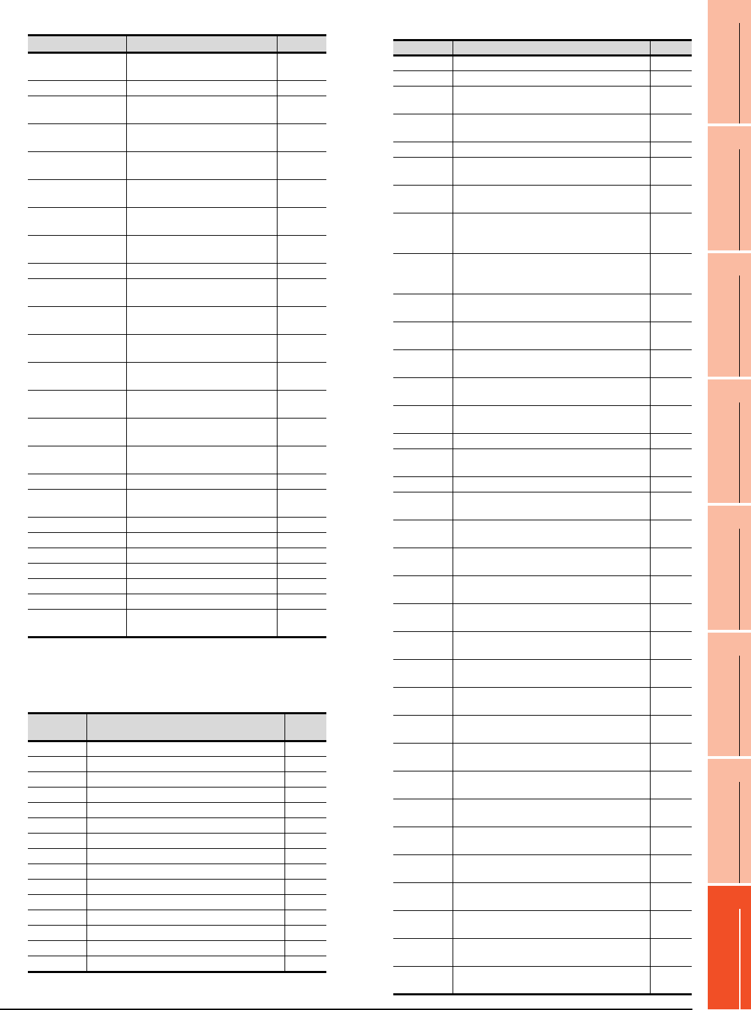
16. SERVO AMPLIFIER CONNECTION
16.6 Device Range that Can Be Set
16 - 33
9
MELSECNET/H
CONNECTION (PLC
TO PLC NETWORK)
10
MELSECNET/10
CONNECTION (PLC
TO PLC NETWORK)
11
CC-Link IE CONTROLLER
NETWORK
CONNECTION
12
CC-Link IE FIELD
NETWORK
CONNECTION
13
CC-Link CONNECTION
(INTELLIGENT DEVICE
STATION)
14
CC-Link
CONNECTION
(Via G4)
15
INVERTER
CONNECTION
16
SERVO AMPLIFIER
CONNECTION
(g) I/O setting parameter
*1 For the parameters prefixed by an asterisk (*), setting
becomes effective when the power is turned off once and
back on after setting the parameter data.
(h) Status display
(i) Alarm
Device name Item Symbol*1
PD1, PD1001 Input signal automatic ON
selection 1 *DIA1
PD2, PD1002 For manufacturer setting ―
PD3, PD1003 Input signal device selection 1
(CN1-15) *DI1
PD4, PD1004 Input signal device selection 2
(CN1-16) *DI2
PD5, PD1005 Input signal device selection 3
(CN1-17) *DI3
PD6, PD1006 Input signal device selection 4
(CN1-18) *DI4
PD7, PD1007 Input signal device selection 5
(CN1-19) *DI5
PD8, PD1008 Input signal device selection 6
(CN1-41) *DI6
PD9, PD1009 For manufacturer setting ―
PD10, D1010 Input signal device selection 8
(CN1-43) *DI8
PD11, PD1011 Input signal device selection 9
(CN1-44) *DI9
PD12, PD1012 Input signal device selection 10
(CN1-45) *DI10
PD13, PD1013 Output signal device selection 1
(CN1-22) *DO1
PD14, PD1014 Output signal device selection 2
(CN1-23) *DO2
PD15, PD1015 Output signal device selection 3
(CN1-24) *DO3
PD16, PD1016 Output signal device selection 4
(CN1-25) *DO4
PD17, PD1017 For manufacturer setting ―
PD18, PD1018 Output signal device selection 6
(CN1-49) *DO6
PD19, PD1019 Response level setting *DIF
PD20, 1020 Function selection D-1 *DOP1
PD21, PD1021 For manufacturer setting ―
PD22, PD1022 Function selection D-3 *DOP3
PD23, PD1023 For manufacturer setting ―
PD24, PD1024 Function selection D-5 *DOP5
PD25 to PD30,
PD1025 to PD1030 For manufacturer setting ―
Device
name Item Symbol
ST0 Cumulative feedback pulses ―
ST1 Servo motor speed ―
ST2 Droop pulses ―
ST3 Cumulative command pulses ―
ST4 Command pulse frequency ―
ST5 Analog speed command voltage/limit voltage ―
ST6
Analog torque command voltage/limit voltage
―
ST7 Regenerative load ratio ―
ST8 Effective load ratio ―
ST9 Peak load ratio ―
ST10 Instantaneous torque ―
ST11 Within one-revolution position ―
ST12 ABS counter ―
ST13 Load inertia moment ratio ―
ST14 Bus voltage ―
Device name
Item Symbol
AL0 Current alarm number ―
AL1 Detailed data of current alarms ―
AL11 Servo status when alarm occurs cumulative
feedback pulses ―
AL12 Servo status when alarm occurs
servo monitor speed ―
AL13
Servo status when alarm occurs droop pulses
―
AL14 Servo status when alarm occurs cumulative
command pulses ―
AL15 Servo status when alarm occurs command
pulse frequency ―
AL16
Servo status when alarm occurs analog
speed command voltage
/limit voltage
―
AL17
Servo status when alarm occurs
analog torque command voltage
/limit voltage
―
AL18 Servo status when alarm occurs
regenerative load ratio ―
AL19 Servo status when alarm occurs effective
load ratio ―
AL20 Servo status when alarm occurs peak load
ratio ―
AL21 Servo status when alarm occurs
instantaneous torque ―
AL22 Servo status when alarm occurs within one-
revolution position ―
AL23 Load inertia moment ratio ABS counter ―
AL24 Servo status when alarm occurs
load inertia moment ratio ―
AL25 Servo status when alarm occurs bus voltage ―
AL200 Alarm number from alarm history
most recent alarm ―
AL201 Alarm number from alarm history
first alarm in past ―
AL202 Alarm number from alarm history
second alarm in past ―
AL203 Alarm number from alarm history
third alarm in past ―
AL204 Alarm number from alarm history
fourth alarm in past ―
AL205 Alarm number from alarm history
fifth alarm in past ―
AL210 Alarm occurrence time in alarm history
most recent alarm ―
AL211 Alarm occurrence time in alarm history
first alarm in past ―
AL212 Alarm occurrence time in alarm history
second alarm in past ―
AL213 Alarm occurrence time in alarm history
third alarm in past ―
AL214 Alarm occurrence time in alarm history
fourth alarm in past ―
AL215 Alarm occurrence time in alarm history
fifth alarm in past ―
AL230 Detailed alarm from alarm history
most recent alarm ―
AL231 Detailed alarm from alarm history
first alarm in past ―
AL232 Detailed alarm from alarm history
second alarm in past ―
AL233 Detailed alarm from alarm history
third alarm in past ―
AL234 Detailed alarm from alarm history
fourth alarm in past ―
AL235 Detailed alarm from alarm history
fifth alarm in past ―

16 - 34 16. SERVO AMPLIFIER CONNECTION
16.6 Device Range that Can Be Set
(j) External input
(k) External output
(l) Input signal for test operation (for test operation)
(m) Forced output of signal pin (for test operation)
(n) Set data (for test operation)
Device
name Item Symbol
DI0 Input device statuses ―
DI1 External input pin statuses ―
DI2 Statuses of input devices switched on
through communication ―
Device name Item Symbol
DO0 Output device statuses ―
DO1 External output pin statuses ―
Device name Item Symbol
TMI0 Input signal for test operation ―
Device name Item Symbol
TMO0 Forced output of signal pin ―
Device name Item Symbol
TMD0 Writes the speed (test mode) ―
TMD1
Writes the acceleration/
deceleration time constant
(test mode)
―
TMD2 For manufacturer setting ―
TMD3 Writes the moving distance
(test mode) ―
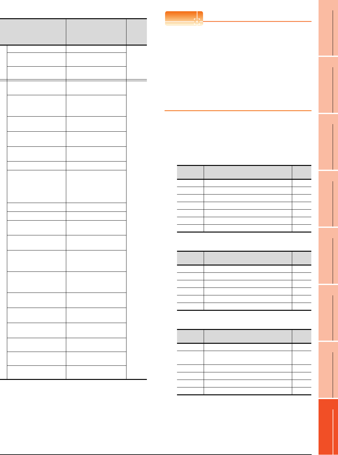
16. SERVO AMPLIFIER CONNECTION
16.6 Device Range that Can Be Set
16 - 35
9
MELSECNET/H
CONNECTION (PLC
TO PLC NETWORK)
10
MELSECNET/10
CONNECTION (PLC
TO PLC NETWORK)
11
CC-Link IE CONTROLLER
NETWORK
CONNECTION
12
CC-Link IE FIELD
NETWORK
CONNECTION
13
CC-Link CONNECTION
(INTELLIGENT DEVICE
STATION)
14
CC-Link
CONNECTION
(Via G4)
15
INVERTER
CONNECTION
16
SERVO AMPLIFIER
CONNECTION
(8) MELSERVO-J3-*T
*1 Use 1 to 50 of PA, PB, PC, PD, and PO when the GOT
writes data to RAM of the servo amplifier.
Use 1001 to 1050 of PA, PB, PC, PD, and PO when the GOT
write data to E2PROM of the servo amplifier.
*2 When the GOT writes data to point tables, use 1001 to 1255
of POS, SPD, ACT, DCT, DWL, AUX, and MCD (E2PROM
area).
*3 MCD cannot be used as a real number.
*4 Only reading is possible.
*5 The GOT cannot read or write data from/to consecutive
devices.
*6 Only reading is possible for DI0 to DI4.
POINTPOINTPOINT
Precautions for SP, OM, TMB, TMI, TMO, and TMD
devices
(1) For bit devices
Only writing is possible.
[Alternate] of a bit switch cannot be used.
Use [Set], [Reset], and [Momentary] of a bit
switch.
(2) For word devices
Only writing is possible.
Numerical input cannot be used.
When writing, use [Word Set] of a data set switch.
The following shows correspondences between virtual
devices for servo amplifier and data of the servo
amplifier used with the GOT.
(a) Servo amplifier request
(b) Operation mode selection
(c) Instruction demand (for test operation)
Device name*5 Setting range
Device
No.
represen
tation
Bit device
Servo amplifier request (SP) SP0 to SP6
Decimal
Operation mode selection
(OM) OM0 to OM5
Instruction demand
(for test operation) (TMB) TMB1 to TMB6
Word device
Basic setting parameter
(PA)*1
PA1 to PA19
PA1001 to PA1019
Decimal
Gain
filter parameter
(PB)*1
PB1 to PB45
PB1001 to PB1045
Extension setting
parameter (PC)*1
PC1 to PC50
PC1001 to PC1050
I/O setting parameter
(PD)*1
PD1 to PD30
PD1001 to PD1030
Option unit parameter
(PO)*1
PO1 to PO35
PO1001 to PO1035
Status display (ST)*4 ST0 to ST17
Alarm (AL)*4
AL0 to AL1
AL11 to AL28
AL200 to AL205
AL210 to AL215
AL230 to AL235
External input (DI)*6 DI0 to DI7
External output (DO)*4 DO0 to DO4
Point table
(position) (POS)*2
POS1 to POS255
POS1001 to POS1255
Point table
(speed) (SPD)*2
SPD1 to SPD255
SPD1001 to SPD1255
Point table
(acceleration time constant)
(ACT)*2
ACT1 to ACT255
ACT1001 to ACT1255
Point table
(deceleration time constant)
(DCT)*2
DCT1 to DCT255
DCT1001 to DCT1255
Point table
(dwell) (DWL)*2
DWL1 to DWL255
DWL1001 to DWL1255
Point table
(auxiliary function) (AUX)*2
AUX1 to AUX255
AUX1001 to AUX1255
Point table
(M code) (MCD)*2*3
MCD1 to MCD255
MCD1001 to MCD1255
Input signal for test operation
(for test operation) (TM0) TMI0 to TMI2
Forced output of signal pin
(for test operation) (TMO) TMO0 to TMO1
Set data
(for test operation) (TMD)
TMD0 to TMD1
TMD3
Device
name Item Symbol
SP0 Status display data clear ―
SP1 Current alarm clear ―
SP2 Alarm history clear ―
SP3 External input signal prohibited ―
SP4 External output signal prohibited ―
SP5 External input signal resumed ―
SP6 External output signal resumed ―
Device
name Item Symbol
OM0 Normal mode (not test operation mode) ―
OM1 JOG operation ―
OM2 Positioning operation ―
OM3 Motorless operation ―
OM4 Output signal (DO) forced output ―
OM5 One step sending ―
Device
name Item Symbol
TMB1 Temporary stop command ―
TMB2 Test operation (positioning operation) start
command ―
TMB3 Forward rotation direction ―
TMB4 Reverse rotation direction ―
TMB5 Restart for remaining distance ―
TMB6 Remaining distance clear ―

16 - 36 16. SERVO AMPLIFIER CONNECTION
16.6 Device Range that Can Be Set
(d) Basic setting parameter
*1 For the parameters prefixed by an asterisk (*), setting
becomes effective when the power is turned off once and
back on after setting the parameter data.
(e) Gain filter parameter
*1 For the parameters prefixed by an asterisk (*), setting
becomes effective when the power is turned off once and
back on after setting the parameter data.
(f) Extension setting parameter
(Continued to next page)
Device name Item Symbol*1
PA1, PA1001 Control mode *STY
PA2, PA1002 Regenerative brake option *REG
PA3, PA1003 Absolute position detection
system *ABS
PA4, PA1004 Function selection A-1 *AOP1
PA5, PA1005 Feeding function selection *FTY
PA6, PA1006 Electronic gear numerator *CMX
PA7, PA1007 Electronic gear denominator *CDV
PA8, PA1008 Auto tuning mode ATU
PA9, PA1009 Auto tuning response RSP
PA10, PA1010 In-position range INP
PA11, PA1011 Forward torque limit TLP
PA12, PA1012 Reverses torque limit TLN
PA13, PA1013 For manufacturer setting ―
PA14, PA1014 Rotation direction selection *POL
PA15, PA1015 Encoder output pulses *ENR
PA16 to PA18,
PA1016 to PA1018 For manufacturer setting ―
PA19, PA1019 Parameter block *BLK
Device name Item Symbol*1
PB1, PB1001 Adaptive tuning mode
(Adaptive filter II) FILT
PA2, PB1002
Vibration suppression control filter
tuning mode
(advanced vibration suppression
control)
VRFT
PB3, PB1003 For manufacturer setting ―
PB4, PB1004 Feed forward gain FFC
PB5, PB1005 For manufacturer setting ―
PB6, PB1006 Ratio of load inertia moment to
servo motor inertia moment GD2
PB7, PB1007 Model control gain PG1
PB8, PB1008 Position loop gain PG2
PB9, PB1009 Speed loop gain VG2
PB10, PB1010 Speed integral compensation VIC
PB11, PB1011 Speed differential compensation VDC
PB12, PB1012 For manufacturer setting ―
PB13, PB1013 Machine resonance suppression
filter 1 NH1
PB14, PB1014 Notch form selection 1 NHQ1
PB15, PB1015 Machine resonance suppression
filter 2 NH2
PB16, PB1016 Notch form selection 2 NHQ2
PB17, PB1017 For manufacturer setting ―
PB18, PB1018 Low-pass filter setting LPF
PB19, PB1019 Vibration suppression control
vibration frequency setting VRF1
PB20, PB1020 Vibration suppression control
resonance frequency setting VRF2
PB21 to PB22,
PB1021 to PB1022 For manufacturer setting ―
PB23, PB1023 Low-pass filter selection VFBF
PB24, PB1024 Slight vibration suppression
control selection *MVS
PB25, PB1025 For manufacturer setting ―
PB26, PB1026 Gain changing selection *CDP
PB27, PB1027 Gain changing condition CDL
PB28, PB1028 Gain changing time constant CDT
PB29, PB1029
Gain changing, Ratio of load
inertia moment to servo motor
inertia moment
GD2B
PB30, PB1030 Gain changing, Position loop gain PG2B
PB31, PB1031 Gain changing, Speed loop gain VG2B
PB32, PB1032 Gain changing, Speed integral
compensation VICB
PB33, PB1033
Gain changing, Vibration
suppression control vibration
frequency setting
VRF1B
PB34, PB1034
Gain changing, Vibration
suppression control resonance
frequency setting
VRF2B
PB35 to PB45,
PB1035 to PB1045 For manufacturer setting ―
Device name Item Symbol*1
PC1, PC1001 For manufacturer setting ―
PC2, PC1002 Home position return type *ZTY
PC3, PC1003 Direction of home position return *ZDIR
PC4, PC1004 Home position return speed ZRF
PC5, PC1005 Creep speed CRF
PC6, PC1006 Home position shift distance ZST
PC7, PC1007
Home position return position data
*ZPS
PC8, PC1008
Moving distance after proximity dog
DCT
PC9, PC1009 Hold time home position return
hold time ZTM
PC10, PC1010 Hold time home position return
torque limit value ZTT
PC11, PC1011 Rough match output range CRP
PC12, PC1012 Jog speed JOG
PC13, PC1013 S-pattern acceleration/
deceleration time constant *STC
PC14, PC1014 Backlash compensation *BKC
PC15, PC1015 For manufacturer setting ―
PC16, PC1016 Electromagnetic brake sequence
output MBR
PC17, PC1017 Zero speed ZSP
PC18, PC1018 Alarm history clear *BPS
PC19, PC1019 Encoder output pulse selection *ENRS
PC20, PC1020 Station number setting *SNO
PC21, PC1021
Communication function selection
*SOP
PC22, PC1022 Function selection C-1 *COP1
PC23, PC1023 For manufacturer setting ―
PC24, PC1024 Function selection C-3 *COP3
PC25, PC1025 For manufacturer setting ―
PC26, PC1026 Function selection C-5 *COP5
PC27, PC1027 For manufacturer setting ―
PC28, PC1028 Function selection C-7 *COP7
PC29 to PC30,
PC1029 to PC1030 For manufacturer setting ―
PC31, PC1031 Software limit + Low LMPL
PC32, PC1032 Software limit + High LMPH
PC33, PC1033 Software limit - Low LMNL
PC34, PC1034 Software limit - High LMNH
PC35, PC1035 Internal torque limit 2 TL2
PC36, PC1036 Status display selection *DMD
PC37, PC1037
Position range output address + Low
*LPPL
PC38, PC1038
Position range output address + High
*LPPH
PC39, PC1039
Position range output address - Low
*LNPL
Device name Item Symbol*1

16. SERVO AMPLIFIER CONNECTION
16.6 Device Range that Can Be Set
16 - 37
9
MELSECNET/H
CONNECTION (PLC
TO PLC NETWORK)
10
MELSECNET/10
CONNECTION (PLC
TO PLC NETWORK)
11
CC-Link IE CONTROLLER
NETWORK
CONNECTION
12
CC-Link IE FIELD
NETWORK
CONNECTION
13
CC-Link CONNECTION
(INTELLIGENT DEVICE
STATION)
14
CC-Link
CONNECTION
(Via G4)
15
INVERTER
CONNECTION
16
SERVO AMPLIFIER
CONNECTION
*1 For the parameters prefixed by an asterisk (*), setting
becomes effective when the power is turned off once and
back on after setting the parameter data.
(g) I/O setting parameter
*1 For the parameters prefixed by an asterisk (*), setting
becomes effective when the power is turned off once and
back on after setting the parameter data.
(h) Option unit parameter
(i) Status display
Device name Item Symbol*1
PC40, PC1040 Position range output address -
High *LNPH
PC41 to PC50,
PC1041 to PC1050 For manufacturer setting ―
Device name Item Symbol*1
PD1, PD1001 Input signal automatic ON
selection 1 *DIA1
PD2, PD1002 For manufacturer setting ―
PD3, PD1003 Input signal automatic ON
selection 3 *DIA3
PD4, PD1004 Input signal automatic ON
selection 4 *DIA4
PD5, PD1005 For manufacturer setting ―
PD6, PD1006 Input signal device selection 2
(CN6-2) *DI2
PD7, PD1007 Input signal device selection 3
(CN6-3) *DI3
PD8, PD1008 Input signal device selection 4
(CN6-4) *DI4
PD9, PD1009 Output signal device selection 1
(CN6-14) *DO1
PD10, D1010 Output signal device selection 2
(CN6-15) *DO2
PD11, PD1011 Output signal device selection 3
(CN6-16) *DD3
PD12 to PD15,
PD1012 to PD1015 For manufacturer setting ―
PD16, PD1016 Input polarity selection *DIAB
PD17 to PD18,
PD1017 to PD1018 For manufacturer setting ―
PD19, PD1019 Response level setting *DIF
PD20, 1020 Function selection D-1 *DOP1
PD21, PD1021 For manufacturer setting ―
PD22, PD1022 Function selection D-3 *DOP3
PD23, PD1023 For manufacturer setting ―
PD24, PD1024 Function selection D-5 *DOP5
PD25 to PD30,
PD1025 to PD1030 For manufacturer setting ―
Device name Item Symbol
PO1, PO1001 For manufacturer setting ―
PO2, PO1002
MR-J3-D01
Input signal device selection 1
(CN10-21, 26)
*ODI1
PO3, PO1003
MR-J3-D01
Input signal device selection 2
(CN10-27, 28)
*ODI2
PO4, PO1004
MR-J3-D01
Input signal device selection 3
(CN10-29, 30)
*ODI3
PO5, PO1005
MR-J3-D01
Input signal device selection 4
(CN10-31, 32)
*ODI4
PO6, PO1006
MR-J3-D01
Input signal device selection 5
(CN10-33, 34)
*ODI5
PO7, PO1007
MR-J3-D01
Input signal device selection 6
(CN10-35, 36)
*ODI6
PO8, PO1008
MR-J3-D01
Output signal device selection 1
(CN10-46, 47)
*ODO1
PO9, PO1009
MR-J3-D01
Output signal device selection 2
(CN10-48, 49)
*ODO2
PO10, PO1010 Function selection 0-1 *OOP1
PO11, PO1011 For manufacturer setting ―
PO12, PO1012 Function selection 0-3 *OOP3
PO13, PO1013 MR-J3-D01 Analog monitor 1
output MOD1
PO14, PO1014 MR-J3-D01 Analog monitor 2
output MOD2
PO15, PO1015 MR-J3-D01 Analog monitor 1
offset M01
PO16, PO1016 MR-J3-D01 Analog monitor 2
offset M02
PO17 to 20,
PO1017 to PO1020 For manufacturer setting ―
PO21, PO1021 MR-J3-D01
Override offset VCO
PO22, PO1022 MR-J3-D01
Analog torque limitation offset TLO
PO23 to 35,
PO1023 to PO1035 For manufacturer setting ―
Device
name Item Symbol
ST0 Current position ―
ST1 Command position ―
ST2 Command remaining distance ―
ST3 Point table No. ―
ST4 Cumulative feedback pulses ―
ST5 Servo monitor speed ―
ST6 Droop pulses ―
ST7 Override voltage ―
ST8 Override ―
ST9
Analog torque command voltage/limit voltage
―
ST10 Regenerative load ratio ―
ST11 Effective load ratio ―
ST12 Peak load ratio ―
ST13 Instantaneous torque ―
ST14 Within one-revolution position ―
ST15 ABS counter ―
ST16 load inertia moment ratio ―
ST17 Bus voltage ―
Device name Item Symbol

16 - 38 16. SERVO AMPLIFIER CONNECTION
16.6 Device Range that Can Be Set
(j) Alarm (k) External input
(l) External output
(m) Point table (position)
(n) Input signal for test operation (for test operation)
(o) Forced output of signal pin (for test operation)
(p) Set data (for test operation)
Device
name Item Symbol
AL0 Current alarm number ―
AL1 Detailed data of current alarms ―
AL11
Servo status when alarm occurs Current position
―
AL12
Servo status when alarm occurs Command position
―
AL13 Servo status when alarm occurs Command
remaining distance ―
AL14 Servo status when alarm occurs
Point table No. ―
AL15 Servo status when alarm occurs Cumulative
feedback pulses ―
AL16 Servo status when alarm occurs
Servo motor speed ―
AL17
Servo status when alarm occurs Droop pulses
―
AL18 Servo status when alarm occurs Override
voltage ―
AL19 Servo status when alarm occurs Override ―
AL20 Servo status when alarm occurs
Analog torque limit voltage ―
AL21 Servo status when alarm occurs
Regenerative load ratio ―
AL22 Servo status when alarm occurs Effective
load ratio ―
AL23
Servo status when alarm occurs Peak load ratio
―
AL24 Servo status when alarm occurs
Instantaneous torque ―
AL25 Servo status when alarm occurs Within one-
revolution position ―
AL26
Servo status when alarm occurs ABS counter
―
AL27 Servo status when alarm occurs
Load inertia moment ratio ―
AL28 Servo status when alarm occurs Bus voltage ―
AL200 Alarm number from alarm history,
Most recent alarm ―
AL201 Alarm number from alarm history
First alarm in past ―
AL202 Alarm number from alarm history
Second alarm in past ―
AL203 Alarm number from alarm history
Third alarm in past ―
AL204 Alarm number from alarm history
Fourth alarm in past ―
AL205 Alarm number from alarm history
Fifth alarm in past ―
AL210 Alarm occurrence time in alarm history
Most recent alarm ―
AL211 Alarm occurrence time in alarm history
First alarm in past ―
AL212 Alarm occurrence time in alarm history
Second alarm in past ―
AL213 Alarm occurrence time in alarm history
Third alarm in past ―
AL214 Alarm occurrence time in alarm history
Fourth alarm in past ―
AL215 Alarm occurrence time in alarm history
Fifth alarm in past ―
AL230 Detailed alarm from alarm history
Most recent alarm ―
AL231 Detailed alarm from alarm history
First alarm in past ―
AL232 Detailed alarm from alarm history
Second alarm in past ―
AL233 Detailed alarm from alarm history
Third alarm in past ―
AL234 Detailed alarm from alarm history
Fourth alarm in past ―
AL235 Detailed alarm from alarm history
Fifth alarm in past ―
Device
name Item Symbol
DI0 Input device statuses 1 ―
DI1 Input device statuses 2 ―
DI2 Input device statuses 3 ―
DI3 External input pin statuses 1 ―
DI4 External input pin statuses 2 ―
DI5 Statuses of input devices switched on
through communication 1 ―
DI6 Statuses of input devices switched on
through communication 2 ―
DI7 Statuses of input devices switched on
through communication 3 ―
Device
name Item Symbol
DO0 Output device statuses 1 ―
DO1 Output device statuses 2 ―
DO2 Output device statuses 3 ―
DO3 External output pin statuses 1 ―
DO4 External output pin statuses 2 ―
Device name Item Symbol
POS1 to POS255,
POS1001 to POS1255
Point table
(position) No.1 to 255 ―
SPD1 to SPD255,
SPD1001 to SPD1255
Point table
(speed) No.1 to 255 ―
ACT1 to ACT255,
ACT1001 to ACT1255
Point table
(acceleration time constant)
No.1 to 255
―
DCT1 to DCT255,
DCT1001 to DCT1255
Point table
(deceleration time constant)
No.1 to 255
―
DWL1 to DWL255,
DWL1001 to DWL1255
Point table
(dwell) (DWL) No.1 to 255 ―
AUX1 to AUX255,
AUX1001 to AUX1255
Point table
(auxiliary function) No.1 to 255 ―
MCD1 to MCD255,
MCD1001 to MCD1255
Point table
(M code) No.1 to 255 ―
Device
name Item Symbol
TMI0 Input signal for test operation 1 ―
TMI1 Input signal for test operation 2 ―
TMI2 Input signal for test operation 3 ―
Device
name Item Symbol
TMO0 Forced output from signal pin (CN6) ―
TMO1 Forced output from signal pin (CN10) ―
Device
name Item Symbol
TMD0 Writes the speed (test mode) ―
TMD1 Writes the acceleration/deceleration time
constant (test mode) ―
TMD3 Writes the moving distance (test mode) ―
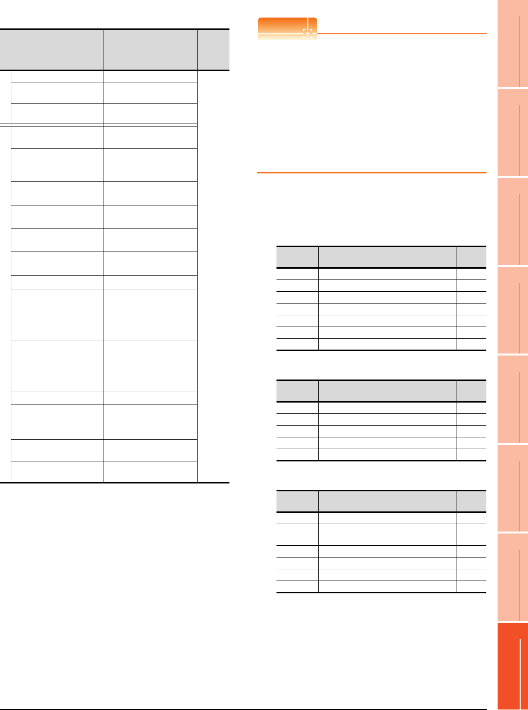
16. SERVO AMPLIFIER CONNECTION
16.6 Device Range that Can Be Set
16 - 39
9
MELSECNET/H
CONNECTION (PLC
TO PLC NETWORK)
10
MELSECNET/10
CONNECTION (PLC
TO PLC NETWORK)
11
CC-Link IE CONTROLLER
NETWORK
CONNECTION
12
CC-Link IE FIELD
NETWORK
CONNECTION
13
CC-Link CONNECTION
(INTELLIGENT DEVICE
STATION)
14
CC-Link
CONNECTION
(Via G4)
15
INVERTER
CONNECTION
16
SERVO AMPLIFIER
CONNECTION
(9) MELSERVO-J4-*A
*1 Use 1 to 80 of PA, PB, PC, PD, PE, and PF when the GOT
writes data to RAM of the servo amplifier.
Use 1001 to 1080 of PA, PB, PC, PD, PE, and PF when the
GOT write data to E2PROM of the servo amplifier.
*2 The GOT cannot read or write data from/to consecutive
devices.
*3 Only reading is possible.
*4 Only reading is possible for DI0 to DI1.
POINTPOINTPOINT
Precautions for SP, OM, TMB, TMI, TMO, and TMD
devices
(1) For bit devices
Only writing is possible.
[Alternate] of a bit switch cannot be used.
Use [Set], [Reset], and [Momentary] of a bit
switch.
(2) For word devices
Only writing is possible.
Numerical input cannot be used.
When writing, use [Word Set] of a data set switch.
The following shows correspondences between virtual
devices for servo amplifier and data of the servo
amplifier used with the GOT.
(a) Servo amplifier request
(b) Operation mode selection
(c) Instruction demand (for test operation)
Device name*2 Setting range
Device
No.
represen
tation
Bit device
Servo amplifier request (SP) SP0 to SP6
Decimal
Operation mode selection
(OM) OM0 to OM4
Instruction demand
(for test operation) (TMB) TMB1 to TMB6
Word device
Basic setting parameter
(PA)*1
PA1 to PA32
PA1001 to PA1032
Gain
filter parameter
(PB)*1
PB1 to PB64
PB1001 to PB1064
Extension setting
parameter (PC)*1
PC1 to PC80
PC1001 to PC1080
I/O setting parameter
(PD)*1
PD1 to PD48
PD1001 to PD1048
Extension setting 2
parameter (PE)*1
PE1 to PE64
PE1001 to PE1064
Extension setting 3
parameter (PF)*1
PF1 to PF48
PF1001 to PF1048
Status display (ST)*3 ST0 to ST41
Alarm (AL)*3
AL0 to AL1
AL11 to AL25
AL200 to AL205
AL210 to AL215
AL230 to AL235
Alarm (ALM)*3
ALM0 to ALM1
ALM11 to ALM52
ALM200 to ALM215
ALM220 to ALM235
ALM240 to ALM255
External input (DI)*4 DI0 to DI2
External output (DO)*3 DO0 to DO1
Input signal for test operation
(for test operation) (TM0) TMI0
Forced output of signal pin
(for test operation) (TMO) TMO0
Set data
(for test operation) (TMD)
TMD0 to TMD1
TMD3
Device
name Item Symbol
SP0 Status display data clear ―
SP1 Current alarm clear ―
SP2 Alarm history clear ―
SP3 External input signal prohibited ―
SP4 External output signal prohibited ―
SP5 External input signal resumed ―
SP6 External output signal resumed ―
Device
name Item Symbol
OM0 Normal mode (not test operation mode) ―
OM1 JOG operation ―
OM2 Positioning operation ―
OM3 Motorless operation ―
OM4 Output signal (DO) forced output ―
Device
name Item Symbol
TMB1 Temporary stop command ―
TMB2 Test operation (positioning operation) start
command ―
TMB3 Forward rotation direction ―
TMB4 Reverse rotation direction ―
TMB5 Restart for remaining distance ―
TMB6 Remaining distance clear ―

16 - 40 16. SERVO AMPLIFIER CONNECTION
16.6 Device Range that Can Be Set
(d) Basic setting parameter
*1 For the parameters prefixed by an asterisk (*), setting
becomes effective when the power is turned off once and
back on after setting the parameter data.
(e) Gain filter parameter
Device name Item Symbol*1
PA1, PA1001 Operation mode *STY
PA2, PA1002 Regenerative option *REG
PA3, PA1003 Absolute position detection
system *ABS
PA4, PA1004 Function selection A-1 *AOP1
PA5, PA1005 Number of command input
pulses per revolution *FBP
PA6, PA1006
Electronic gear numerator
(command pulse multiplication
numerator)
CMX
PA7, PA1007
Electronic gear denominator
(command pulse multiplication
denominator)
CDV
PA8, PA1008 Auto tuning mode ATU
PA9, PA1009 Auto tuning response RSP
PA10, PA1010 In-position range INP
PA11, PA1011 Forward rotation torque limit TLP
PA12, PA1012 Reverse rotation torque limit TLN
PA13, PA1013 Command pulse input form *PLSS
PA14, PA1014 Rotation direction selection *POL
PA15, PA1015 Encoder output pulses *ENR
PA16, PA1016 Encoder output pulses 2 *ENR2
PA17 to 18,
PA1017 to 1018 For manufacturer setting ―
PA19, PA1019 Parameter writing inhibit *BLK
PA20, PA1020 Tough drive setting *TDS
PA21, PA1021 Function selection A-3 *AOP3
PA22, PA1022 For manufacturer setting ―
PA23, PA1023 Drive recorder arbitrary alarm
trigger setting DRAT
PA24, PA1024 Function selection A-4 *AOP4
PA25, PA1025 One-touch tuning - Overshoot
permissible level OTHOV
PA26 to 32,
PA1026 to 1032 For manufacturer setting ―
Device name Item Symbol*1
PB1, PB1001 Adaptive tuning mode
(adaptive filter II) PB1
PB2, PB1002
Vibration suppression control
tuning mode (advanced vibration
suppression control II)
VRFT
PB3, PB1003
Position command acceleration/
deceleration time constant
(position smoothing)
PST
PB4, PB1004 Feed forward gain FFC
PB5, PB1005 For manufacturer setting ―
PB6, PB1006 Load to motor inertia ratio GD2
PB7, PB1007 Model loop gain PG1
PB8, PB1008 Position loop gain PG2
PB9, PB1009 Speed loop gain VG2
PB10, PB1010 Speed integral compensation VIC
PB11, PB1011 Speed differential compensation VDC
PB12, PB1012 Overshoot amount compensation OVA
PB13, PB1013 Machine resonance suppression
filter 1 NH1
PB14, PB1014 Notch shape selection 1 NHQ1
PB15, PB1015 Machine resonance suppression
filter 2 NH2
PB16, PB1016 Notch shape selection 2 NHQ2
PB17, PB1017 Shaft resonance suppression filter NHF
PB18, PB1018 Low-pass filter setting LPF
PB19, PB1019 Vibration suppression control 1
- Vibration frequency VRF11
PB20, PB1020 Vibration suppression control 1
- Resonance frequency VRF12
PB21, PB1021 Vibration suppression control 1
- Vibration frequency dumping VRF13
PB22, PB1022 Vibration suppression control 1
- Resonance frequency dumping VRF14
PB23, PB1023 Low-pass filter selection VFBF
PB24, PB1024 Slight vibration suppression
control *MVS
PB25, PB1025 Function selection B-1 *BOP1
PB26, PB1026 Gain switching function *CDP
PB27, PB1027 Gain switching condition CDL
PB28, PB1028 Gain switching time constant CDT
PB29, PB1029 Load to motor inertia ratio after
gain switching GD2B
PB30, PB1030 Position loop gain after gain
switching PG2B
PB31, PB1031 Speed loop gain after gain
switching VG2B
PB32, PB1032 Speed integral compensation
after gain switching VICB
PB33, PB1033
Vibration suppression control 1
- Vibration frequency after gain
switching
VRF1B
PB34, PB1034
Vibration suppression control 1
- Resonance frequency after gain
switching
VRF2B
PB35, PB1035
Vibration suppression control 1
- Resonance frequency dumping
after gain switching
VRF3B
PB36, PB1036
Vibration suppression control 1
- Resonance frequency dumping
after gain switching
VRF4B
PB37 to 44,
PB1037 to 1044 For manufacturer setting ―
PB45, PB1045 Command notch filter CNHF
PB46, PB1046 Machine resonance suppression
filter 3 NH3
PB47, PB1047 Notch shape selection 3 NHQ3
PB48, PB1048 Machine resonance suppression
filter 4 NH4
PB49, PB1049 Notch shape selection 4 NHQ4
PB50, PB1050 Machine resonance suppression
filter 5 NH5
PB51, PB1051 Notch shape selection 5 NHQ5
PB52, PB1052 Vibration suppression control 2
- Vibration frequency VRF21
PB53, PB1053 Vibration suppression control 2
- Resonance frequency VRF22
PB54, PB1054 Vibration suppression control 2
- Vibration frequency dumping VRF23
PB55, PB1055 Vibration suppression control 2
- Resonance frequency dumping VRF24
PB56, PB1056
Vibration suppression control 2
- Vibration frequency after gain
switching
VRF21B
PB57, PB1057
Vibration suppression control 2
- Resonance frequency after gain
switching
VRF22B
PB58, PB1058
Vibration suppression control 2
- Vibration frequency dumping
after gain switching
VRF23B
PB59, PB1059
Vibration suppression control 2
- Resonance frequency dumping
after gain switching
VRF24B
Device name Item Symbol*1

16. SERVO AMPLIFIER CONNECTION
16.6 Device Range that Can Be Set
16 - 41
9
MELSECNET/H
CONNECTION (PLC
TO PLC NETWORK)
10
MELSECNET/10
CONNECTION (PLC
TO PLC NETWORK)
11
CC-Link IE CONTROLLER
NETWORK
CONNECTION
12
CC-Link IE FIELD
NETWORK
CONNECTION
13
CC-Link CONNECTION
(INTELLIGENT DEVICE
STATION)
14
CC-Link
CONNECTION
(Via G4)
15
INVERTER
CONNECTION
16
SERVO AMPLIFIER
CONNECTION
*1 For the parameters prefixed by an asterisk (*), setting
becomes effective when the power is turned off once and
back on after setting the parameter data.
(f) Extension setting parameter
*1 For the parameters prefixed by an asterisk (*), setting
becomes effective when the power is turned off once and
back on after setting the parameter data.
(g) I/O setting parameter
*1 For the parameters prefixed by an asterisk (*), setting
becomes effective when the power is turned off once and
back on after setting the parameter data.
PB60, PB1060 Model loop gain after gain
switching PG1B
PB61 to 64,
PB1061 to 1064 For manufacturer setting ―
Device name Item Symbol*1
PC1, PC1001 Acceleration time constant STA
PC2, PC1002 Deceleration time constant STB
PC3, PC1003 S-pattern acceleration/
deceleration time constant STC
PC4, PC1004 Torque command time constant TQC
PC5, PC1005 Internal speed command 1 SC1
Internal speed limit 1
PC6, PC1006 Internal speed command 2 SC2
Internal speed limit 2
PC7, PC1007
Internal speed command 3
SC3
Internal speed limit 3
PC8, PC1008
Internal speed command 4
SC4
Internal speed limit 4
PC9, PC1009 Internal speed command 5 SC5
Internal speed limit 5
PC10, PC1010 Internal speed command 6 SC6
Internal speed limit 6
PC11, PC1011 Internal speed command 7 SC7
Internal speed limit 7
PC12, PC1012
Analog speed command -
Maximum speed VCM
Analog speed limit - Maximum
speed
PC13, PC1013 Analog torque command
maximum output TLC
PC14, PC1014 Analog monitor 1 output MOD1
PC15, PC1015 Analog monitor 2 output MOD2
PC16, PC1016 Electromagnetic brake sequence
output MBR
PC17, PC1017 Zero speed ZSP
PC18, PC1018 Alarm history clear *BPS
PC19, PC1019 Encoder output pulse selection *ENRS
PC20, PC1020 Station number setting *SNO
PC21, PC1021
Communication function selection
*SOP
PC22, PC1022 Function selection C-1 *COP1
PC23, PC1023 Function selection C-2 *COP2
PC24, PC1024 Function selection C-3 *COP3
PC25, PC1025 For manufacturer setting ―
PC26, PC1026 Function selection C-5 *COP5
PC27, PC1027 Function selection C-6 *COP6
PC28, PC1028 For manufacturer setting ―
PC29, PC1029 For manufacturer setting ―
PC30, PC1030 Acceleration time constant 2 STA2
PC31, PC1031 Deceleration time constant 2 STB2
PC32, PC1032 Command input pulse
multiplication numerator 2 CMX2
PC33, PC1033 Command input pulse
multiplication numerator 3 CMX3
PC34, PC1034 Command input pulse
multiplication numerator 4 CMX4
PC35, PC1035 Internal torque limit 2 TL2
PC36, PC1036
Status display selection
*DMD
PC37, PC1037
Analog speed command offset
VCO
Analog speed limit offset
Device name Item Symbol*1
PC38, PC1038
Analog torque command offset
TPO
Analog torque limit offset
PC39, PC1039
Analog monitor 1 offset
MO1
PC40, PC1040
Analog monitor 2 offset
MO2
PC41 to 42,
PC1041 to 1042
For manufacturer setting
―
PC43, PC1043
Error excessive alarm detection
level
ERZ
PC44 to 50,
PC1044 to 1050
For manufacturer setting
―
PC51, PC1051
Forced stop deceleration time
constant
RSBR
PC52, PC1052
For manufacturer setting
―
PC53, PC1053
For manufacturer setting
―
PC54, PC1054
Vertical axis freefall prevention
compensation amount
RSUP1
PC55 to PC59,
PC1055 to PC1059
For manufacturer setting
―
PC60, PC1060
Function selection C-D
*COPD
PC61 to PC80,
PC1061 to PC1080
For manufacturer setting
―
Device name Item Symbol*1
PD1, PD1001 Input signal automatic on
selection 1 *DIA1
PD2, PD1002 For manufacturer setting ―
PD3, PD1003 Input device selection 1L *DI1L
PD4, PD1004 Input device selection 1H *DI1H
PD5, PD1005 Input device selection 2L *DI2L
PD6, PD1006 Input device selection 2H *DI2H
PD7, PD1007 Input device selection 3L *DI3L
PD8, PD1008 Input device selection 3H *DI3H
PD9, PD1009 Input device selection 4L *DI4L
PD10, PD1010 Input device selection 4H *DI4H
PD11, PD1011 Input device selection 5L *DI5L
PD12, PD1012 Input device selection 5H *DI5H
PD13, PD1013 Input device selection 6L *DI6L
PD14, PD1014 Input device selection 6H *DI6H
PD15 to 16,
PD1015 to 1016 For manufacturer setting ―
PD17, PD1017 Input device selection 8L *DI8L
PD18, PD1018 Input device selection 8H *DI8H
PD19, PD1019 Input device selection 9L *DI9L
PD20, PD1020 Input device selection 9H *DI9H
PD21, PD1021 Input device selection 10L *DI10L
PD22, PD1022 Input device selection 10H *DI10H
PD23, PD1023 Output device selection 1 *DO1
PD24, PD1024 Output device selection 2 *DO2
PD25, PD1025 Output device selection 3 *DO3
PD26, PD1026 Output device selection 4 *DO4
PD27, PD1027 For manufacturer setting ―
PD28, PD1028 Output device selection 6 *DO6
PD29, PD1029 Input filter setting *DIF
PD30, PD1030 Function selection D-1 *DOP1
PD31, PD1031 For manufacturer setting ―
PD32, PD1032 Function selection D-3 *DOP3
PD33, PD1033 For manufacturer setting ―
PD34, PD1034 Function selection D-5 *DOP5
PD35 to 48,
PD1035 to 1048 For manufacturer setting ―
Device name Item Symbol*1

16 - 42 16. SERVO AMPLIFIER CONNECTION
16.6 Device Range that Can Be Set
(h) Extension setting 2 parameter
(i) Extension setting 3 parameter
(j) Status display
(k) Alarm (compatible with MELSERVO-J3-*A)
Device name Item Symbol
PE1 to 40,
PE1000 to 1040 For manufacturer setting ―
PE41, PE1041 Function selection E-3 EOP3
PE42 to 64,
PE1042 to 1064 For manufacturer setting ―
Device
name Item Symbol
PF1 to 8,
PF1001 to
1008
For manufacturer setting ―
PF9,
PF1009 Function selection F-5 *FOP5
PF10 to 14,
PF1010 to
1014
For manufacturer setting ―
PF15,
PF1015 Electronic dynamic brake operating time DBT
PF16 to 20,
PF1016 to
1020
For manufacturer setting ―
PF21,
PF1021 Drive recorder switching time setting DRT
PF22,
PF1022 For manufacturer setting ―
PF23,
PF1023
Vibration tough drive - Oscillation detection
level OSCL1
PF24,
PF1024 Vibration tough drive function selection OSCL2
PF25,
PF1025
Instantaneous power failure tough drive
- Detection time
CVAT
PF26 to 30,
PF1026 to
1030
For manufacturer setting ―
PF31,
PF1031
Machine diagnosis function - Friction
judgement speed FRIC
PF32 to 48,
PF1032 to
1048
For manufacturer setting ―
Device
name Item Symbol
ST0 Comulative feedback pulse ―
ST1 Servo motor speed ―
ST2
Droop pulse
―
ST3 Cumulative command pulse ―
ST4 Command pulse frequency ―
ST5 Analog speed command voltage/limit voltage ―
ST6 Analog torque command voltage/limit
voltage ―
ST7 Regenerative load ratio ―
ST8
Effetive load ratio
―
ST9 Peak load ratio ―
ST10 Instantaneous torque ―
ST11 Within one-revolution position(1 pulse unit) ―
ST12 ABS counter ―
ST13 Load inertia moment ratio ―
ST14
Bus voltage
―
ST15 to 31 For manufacturer setting ―
ST32 Internal temperature of encoder ―
ST33
Setting time
―
ST34 Oscillation detection frequency ―
ST35 Number of tough drives ―
ST36 to 39 For manufacturer setting ―
ST40 Unit power consumption 1
(incremwnt of 1 W) ―
ST41 Unit total power consumption 1
(incremwnt of 1 Wh) ―
Device
name Item Symbol
AL0 Current alarm number ―
AL1 Detailed data of current alarms ―
AL11 Servo status when alarm occurs Cumulative
feedback pulses ―
AL12 Servo status when alarm occurs Servo motor
speed ―
AL13 Servo status when alarm occurs Droop
pulses ―
AL14 Servo status when alarm occurs cumulative
command pulses ―
AL15 Servo status when alarm occurs command
pulse frequency ―
AL16 Servo status when alarm occurs analog
speed command voltage/limit voltage ―
AL17 Servo status when alarm occurs analog
torque command voltage/limit voltage ―
AL18 Servo status when alarm occurs regenerative
load ratio ―
AL19 Servo status when alarm occurs effective
load ratio ―
AL20 Servo status when alarm occurs peak load
ratio ―
AL21 Servo status when alarm occurs
Instantaneous torque ―
AL22 Servo states when alarm occurs Within
onerevolution position(1 pulse unit) ―
AL23 Servo status when alarm occurs ABS counter ―
AL24 Servo status when alarm occurs load inertia
moment ratio ―
AL25 Servo status when alarm occurs Bus voltage ―
AL200 Alarm number from Alarm History most
recent alarm ―
AL201 Alarm number from Alarm History first alarm
in past ―
AL202 Alarm number from Alarm History second
alarm in past ―
AL203 Alarm number from Alarm History third alarm
in past ―
AL204 Alarm number from Alarm History fourth
alarm in past ―
AL205 Alarm number from Alarm History fifth alarm
in past ―
AL210 Alarm occurrence time in alarm history most
recent alarm ―
AL211 Alarm occurrence time in alarm history first
alarm in past ―
AL212 Alarm occurrence time in alarm history
second alarm in past ―
AL213 Alarm occurrence time in alarm history third
alarm in past ―
AL214 Alarm occurrence time in alarm history fourth
alarm in past ―
AL215 Alarm occurrence time in alarm history fifth
alarm in past ―
AL230 Detailed alarm from Alarm History most
recent alarm ―
Device
name Item Symbol

16. SERVO AMPLIFIER CONNECTION
16.6 Device Range that Can Be Set
16 - 43
9
MELSECNET/H
CONNECTION (PLC
TO PLC NETWORK)
10
MELSECNET/10
CONNECTION (PLC
TO PLC NETWORK)
11
CC-Link IE CONTROLLER
NETWORK
CONNECTION
12
CC-Link IE FIELD
NETWORK
CONNECTION
13
CC-Link CONNECTION
(INTELLIGENT DEVICE
STATION)
14
CC-Link
CONNECTION
(Via G4)
15
INVERTER
CONNECTION
16
SERVO AMPLIFIER
CONNECTION
(l) Alarm (extended for MELSERVO-J4-*A)
AL231 Detailed alarm from Alarm History first alarm
in past ―
AL232 Detailed alarm from Alarm History second
alarm in past ―
AL233 Detailed alarm from Alarm History third alarm
in past ―
AL234 Detailed alarm from Alarm History fourth
alarm in past ―
AL235 Detailed alarm from Alarm History fifth alarm
in past ―
Device
name Item Symbol
ALM0 Current alarm number ―
ALM1 Detailed data of current alarms ―
ALM11 Servo status when alarm occurs Cumulative
feedback pulses ―
ALM12 Servo status when alarm occurs Servo motor
speed ―
ALM13 Servo status when alarm occurs Droop
pulses ―
ALM14 Servo status when alarm occurs cumulative
command pulses ―
ALM15 Servo status when alarm occurs command
pulse frequency ―
ALM16 Servo status when alarm occurs analog
speed command voltage/limit voltage ―
ALM17 Servo status when alarm occurs analog
torque command voltage/limit voltage ―
ALM18 Servo status when alarm occurs regenerative
load ratio ―
ALM19 Servo status when alarm occurs effective
load ratio ―
ALM20 Servo status when alarm occurs peak load
ratio ―
ALM21 Servo status when alarm occurs
Instantaneous torque ―
ALM22 Servo states when alarm occurs Within
onerevolution position(1 pulse unit) ―
ALM23 Servo status when alarm occurs ABS counter ―
ALM24 Servo status when alarm occurs load inertia
moment ratio ―
ALM25 Servo status when alarm occurs Bus voltage ―
ALM
26 to 42 For manufacturer setting ―
ALM43 Servo states when alarm occurs Internal
temperature of encoder ―
ALM44 Servo states when alarm occurs Setting time ―
ALM45 Servo states when alarm occurs Oscillation
detection frequency ―
ALM46 Servo states when alarm occurs Number of
tough drives ―
ALM
47 to 50 For manufacturer setting ―
ALM51 Servo states when alarm occurs Unit power
consumption 1 (incremwnt of 1 W) ―
ALM52 Servo states when alarm occurs Unit total
power consumption 1 (incremwnt of 1 Wh) ―
ALM200 Alarm number from Alarm History most
recent alarm ―
ALM201 Alarm number from Alarm History 1st alarm in
past ―
ALM202 Alarm number from Alarm History 2nd alarm
in past ―
ALM203 Alarm number from Alarm History 3rd alarm
in past ―
Device
name Item Symbol
ALM204 Alarm number from Alarm History 4th alarm
in past ―
ALM205 Alarm number from Alarm History 5th alarm
in past ―
ALM206 Alarm number from Alarm History 6th alarm
in past ―
ALM207 Alarm number from Alarm History 7th alarm
in past ―
ALM208 Alarm number from Alarm History 8th alarm
in past ―
ALM209 Alarm number from Alarm History 9th alarm
in past ―
ALM210 Alarm number from Alarm History 10th alarm
in past ―
ALM211 Alarm number from Alarm History 11th alarm
in past ―
ALM212 Alarm number from Alarm History 12th alarm
in past ―
ALM213 Alarm number from Alarm History 13th alarm
in past ―
ALM214 Alarm number from Alarm History 14th alarm
in past ―
ALM215 Alarm number from Alarm History 15th alarm
in past ―
ALM220 Alarm occurrence time in alarm history most
recent alarm ―
ALM221 Alarm occurrence time in alarm history 1st
alarm in past ―
ALM222 Alarm occurrence time in alarm history 2nd
alarm in past ―
ALM223 Alarm occurrence time in alarm history 3rd
alarm in past ―
ALM224 Alarm occurrence time in alarm history 4th
alarm in past ―
ALM225 Alarm occurrence time in alarm history 5th
alarm in past ―
ALM226 Alarm occurrence time in alarm history 6th
alarm in past ―
ALM227 Alarm occurrence time in alarm history 7th
alarm in past ―
ALM228 Alarm occurrence time in alarm history 8th
alarm in past ―
ALM229 Alarm occurrence time in alarm history 9th
alarm in past ―
ALM230 Alarm occurrence time in alarm history 10th
alarm in past ―
ALM231 Alarm occurrence time in alarm history 11th
alarm in past ―
ALM232 Alarm occurrence time in alarm history 12th
alarm in past ―
ALM233 Alarm occurrence time in alarm history 13th
alarm in past ―
ALM234 Alarm occurrence time in alarm history 14th
alarm in past ―
ALM235 Alarm occurrence time in alarm history 15th
alarm in past ―
ALM240 Detailed alarm from Alarm History most
recent alarm ―
ALM241 Detailed alarm from Alarm History 1st alarm
in past ―
ALM242 Detailed alarm from Alarm History 2nd alarm
in past ―
ALM243 Detailed alarm from Alarm History 3rd alarm
in past ―
ALM244 Detailed alarm from Alarm History 4th alarm
in past ―
ALM245 Detailed alarm from Alarm History 5th alarm
in past ―
Device
name Item Symbol

16 - 44 16. SERVO AMPLIFIER CONNECTION
16.6 Device Range that Can Be Set
(m) External input
(n) External output
(o) Input signal for test operation (for test operation)
(p) Forced output of signal pin (for test operation)
(q) Set data (for test operation)
ALM246 Detailed alarm from Alarm History 6th alarm
in past ―
ALM247 Detailed alarm from Alarm History 7th alarm
in past ―
ALM248 Detailed alarm from Alarm History 8th alarm
in past ―
ALM249 Detailed alarm from Alarm History 9th alarm
in past ―
ALM250 Detailed alarm from Alarm History 10th alarm
in past ―
ALM251 Detailed alarm from Alarm History 11th alarm
in past ―
ALM252 Detailed alarm from Alarm History 12th alarm
in past ―
ALM253 Detailed alarm from Alarm History 13th alarm
in past ―
ALM254 Detailed alarm from Alarm History 14th alarm
in past ―
ALM255 Detailed alarm from Alarm History 15th alarm
in past ―
Device name Item Symbol
DI0 Input device statuses ―
DI1 External input pin statuses ―
DI2
Statuses of input devices
switched on through
communication
―
Device
name Item Symbol
DO0 Output device statuses ―
DO1 External output pin statuses ―
Device
name Item Symbol
TMI0 Input signal for test operation ―
Device
name Item Symbol
TMO0 Forced output from signal pin ―
Device
name Item Symbol
TMD0 Writes the speed (test mode) ―
TMD1 Writes the acceleration/deceleration time
constant (test mode) ―
TMD2 For manufacturer setting ―
TMD3 Writes the moving distance (test mode) ―
Device
name Item Symbol

16. SERVO AMPLIFIER CONNECTION
16.7 Precautions
16 - 45
9
MELSECNET/H
CONNECTION (PLC
TO PLC NETWORK)
10
MELSECNET/10
CONNECTION (PLC
TO PLC NETWORK)
11
CC-Link IE CONTROLLER
NETWORK
CONNECTION
12
CC-Link IE FIELD
NETWORK
CONNECTION
13
CC-Link CONNECTION
(INTELLIGENT DEVICE
STATION)
14
CC-Link
CONNECTION
(Via G4)
15
INVERTER
CONNECTION
16
SERVO AMPLIFIER
CONNECTION
16.7 Precautions
Station number setting in the servo system
Make sure to establish servo system with the station
number set with the host address.
For details of host address setting, refer to the
following.
16.4.1 Setting communication interface
(Communication settings)
GOT clock function
Since the servo amplifier does not have a clock
function, the settings of [Adjust] or [Broadcast] by GOT
clock control will be disabled.
Servo amplifier/test operation using the GOT
During the servo amplifier/test operation, when the
communication between the GOT and the servo
amplifier is interrupted for 0.5[ms] or more, the servo
amplifier decelerates, stops, and then gets into the
servo lock status. During the servo amplifier/test
operation, continue the communication constantly by
monitoring the status display of the servo amplifier on
the GOT screen, etc.

16 - 46 16. SERVO AMPLIFIER CONNECTION
16.7 Precautions
17
17
ROBOT
CONTROLLER
CONNECTION
18
CNC CONNECTION
19
GOT MULTI-DROP
CONNECTION
20
MULTIPLE-GT14, GT12,
GT11, GT10
CONNECTION FUNCTION
21
MULTI-CHANNEL
FUNCTION
22
FA TRANSPARENT
FUNCTION
17 - 1
17.ROBOT CONTROLLER
CONNECTION
17.1 Connectable Model List . . . . . . . . . . . . . . . . . . . . . . . . . . . 17 - 2
17.2 System Configuration. . . . . . . . . . . . . . . . . . . . . . . . . . . . . 17 - 2
17.3 GOT Side Settings . . . . . . . . . . . . . . . . . . . . . . . . . . . . . . . 17 - 3
17.4 PLC Side Settings . . . . . . . . . . . . . . . . . . . . . . . . . . . . . . . 17 - 6
17.5 Device Range that Can Be Set . . . . . . . . . . . . . . . . . . . . . 17 - 8
17.6 Precautions . . . . . . . . . . . . . . . . . . . . . . . . . . . . . . . . . . . . 17 - 8
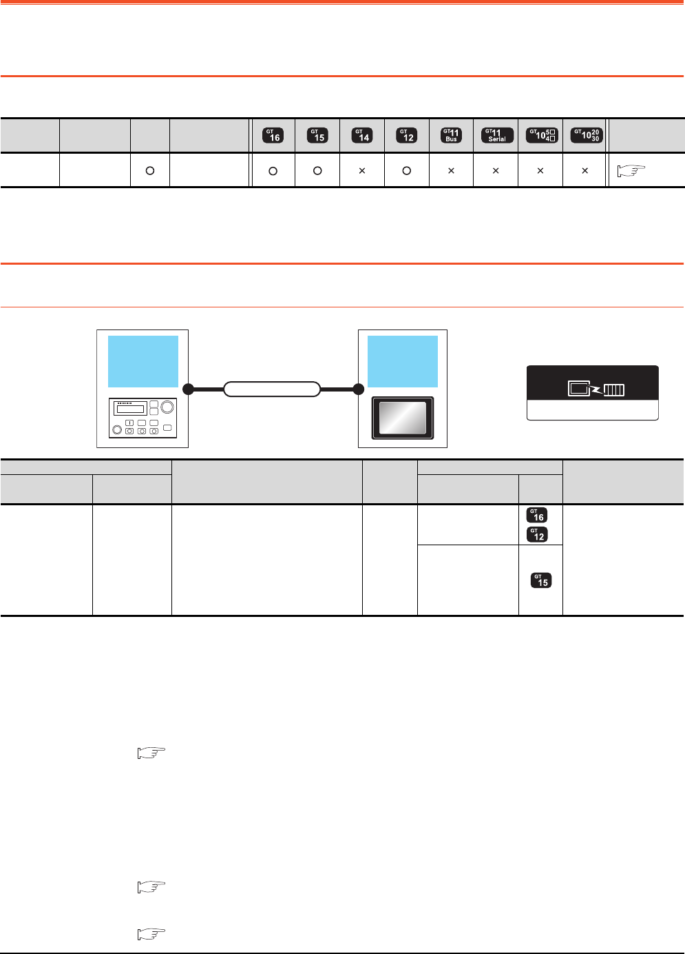
17 - 2 17. ROBOT CONTROLLER CONNECTION
17.1 Connectable Model List
17. ROBOT CONTROLLER CONNECTION
17.1 Connectable Model List
The following table shows the connectable models.
For details on the connection with CRnQ-700 (Q172DRCPU), refer to Mitsubishi Products (Chapter 5 to 13).
17.2 System Configuration
17.2.1 Connecting to robot controller (CRnD-700)
*1 The destination connected with the twisted pair cable varies with the configuration of the applicable Ethernet network system.
Connect to the Ethernet module, hub, transceiver or other system equipment corresponding to the applicable Ethernet network
system.
Use cables, connectors, and hubs that meet the IEEE802.3 10BASE-T/100BASE-TX standard.
*2 A straight cable is available.
When connecting QnUDE(H) and GOT directly with Ethernet cable, remember that the by cross cable is available.
*3 When connecting GT16 of the function version A to an equipment that meets the 10BASE (-T/2/5) standard, use the switching
hub and operate in a 10Mbps/100Mbps mixed environment.
For how to check the function version, refer to the following.
GT16 User's Manual (Hardware)
*4 A length between a hub and a node.
The maximum distance differs depending on the Ethernet device to be used.
The following shows the number of the connectable nodes when a repeater hub is used.
• 10BASE-T: Max. 4 nodes for a cascade connection (500m)
• 100BASE-TX: Max. 2 nodes for a cascade connection (205m)
When switching hubs are used, the cascade connection between the switching hubs has no logical limit for the number of
cascades.
For the limit, contact the switching hub manufacturer.
*5 For the system configuration of CRnD-700, refer to the following manual.
CRnD-700 SET UP MANUAL
*6 Select [CRnD-700] for [Controller Type] in [Ethernet] of GT Designer3.
For [Ethernet] of GT Designer3, refer to the following.
17.3.3 Ethernet setting
Series Model name Clock Communication
type Refer to
Robot
controller CRnD-700 Ethernet 17.2.1
Ethernet(MELSEC),Q17nNC,CRnD-700
Communication driver
Robot
controller GOT
Connection cable
Robot controller
Connection cable
*1*2
Maximum
segment
length*3
GOT Number of connectable
equipment
Model name Communication
type Option device Model
CRnD-700*5*6 Ethernet
Twisted pair cable
• 10BASE-T
Shielded twisted pair cable (STP) or
unshielded twisted pair cable (UTP):
Category 3, 4, and 5
• 100BASE-TX
Shielded twisted pair cable (STP):
Category 5 and 5e
100m
- (Built into GOT)
*3
1 GOT
GT15-J71E71-100
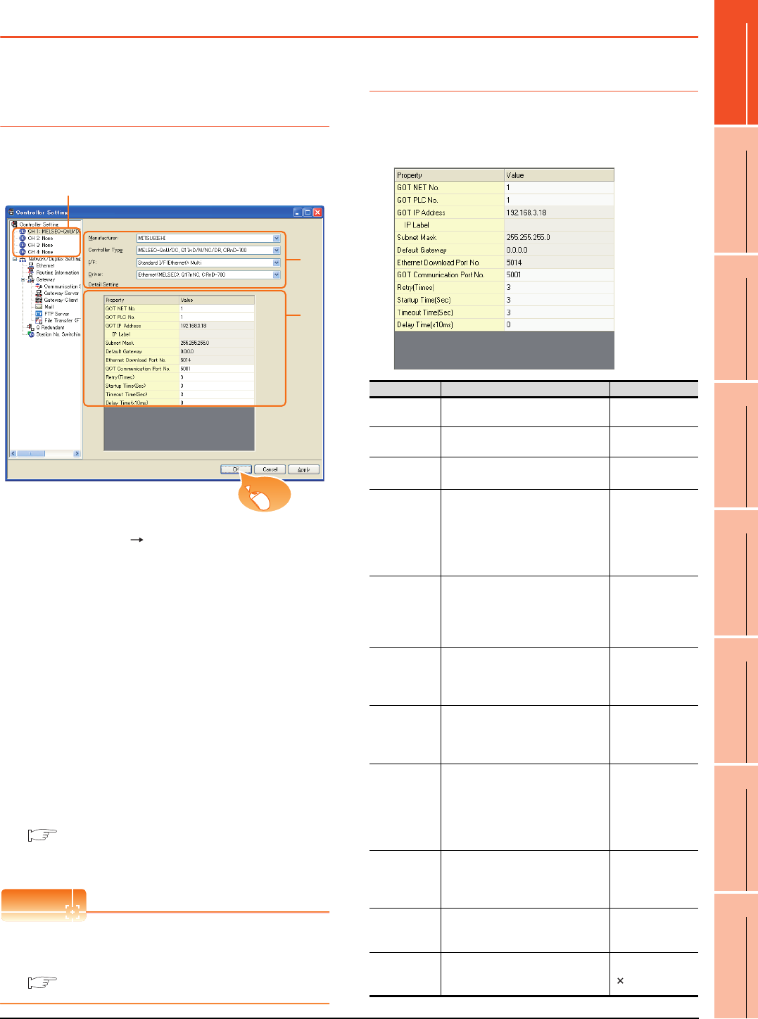
17. ROBOT CONTROLLER CONNECTION
17.3 GOT Side Settings
17 - 3
17
ROBOT
CONTROLLER
CONNECTION
18
CNC CONNECTION
19
GOT MULTI-DROP
CONNECTION
20
MULTIPLE-GT14, GT12,
GT11, GT10
CONNECTION FUNCTION
21
MULTI-CHANNEL
FUNCTION
22
FA TRANSPARENT
FUNCTION
17.3 GOT Side Settings
17.3.1 Setting communication
interface (Communication
settings)
Set the channel of the connected equipment.
1. Select [Common] [Controller Setting] from the
menu.
2. The Controller Setting window is displayed. Select the
channel to be used from the list menu.
3. Set the following items.
• Manufacturer: Mitsubishi
• Controller Type: Set according to the Controller
Type to be connected.
• I/F: Interface to be used
• Driver:
Ethernet (MELSEC), Q17nNC, CRnD-700
4. The detailed setting is displayed after Manufacturer,
Controller Type, I/F, and Driver are set.
Make the settings according to the usage
environment.
17.3.2 Communication detail settings
Click the [OK] button when settings are completed.
POINTPOINTPOINT
The settings of connecting equipment can be
confirmed in [I/F Communication Setting].
For details, refer to the following:
1.1.2 I/F communication setting
17.3.2 Communication detail settings
Make the settings according to the usage environment.
GT16
2.
3.
4.
Click!
Item Description Range
GOT NET No. Set the network No. of the GOT.
(Default: 1) 1 to 239
GOT PLC No. Set the station No. of the GOT.
(Default: 1) 1 to 64
GOT
IP Address*1
Set the IP address of the GOT.
(Default: 192.168.3.18)
0.0.0.0 to
255.255.255.255
Subnet Mask*1
Set the subnet mask for the sub
network.(Only for connection via
router)
If the sub network is not used, the
default value is set.
(Default: 255.255.255.0)
0.0.0.0 to
255.255.255.255
Default
Gateway*1
Set the router address of the default
gateway where the GOT is
connected.(Only for connection via
router)
(Default: 0.0.0.0)
0.0.0.0 to
255.255.255.255
Ethernet
Download Port
No.
*1
Set the GOT port No. for Ethernet
download.
(Default: 5014)
1024 to 5010 to
5014 to 65534
(Except for 5011, 5012,
5013 and 49153)
GOT
Communication
Port No.
Set the GOT port No. for the
connection with the Ethernet module.
(Default: 5001)
1024 to 5010 to
5014 to 65534
(Except for 5011, 5012,
5013 and 49153)
Retry
Set the number of retries to be
performed when a communication
timeout occurs.
When receiving no response after
retries, the communication times out.
(Default: 3times)
0 to 5times
Startup Time
Specify the time period from the GOT
startup until GOT starts the
communication with the PLC CPU.
(Default: 3sec)
3 to 255sec
Timeout Time
Set the time period for a
communication to time out.
(Default: 3sec)
3 to 90sec
Delay Time
Set the delay time for reducing the
load of the network/destination PLC.
(Default: 0ms)
0 to 10000
( 10ms)
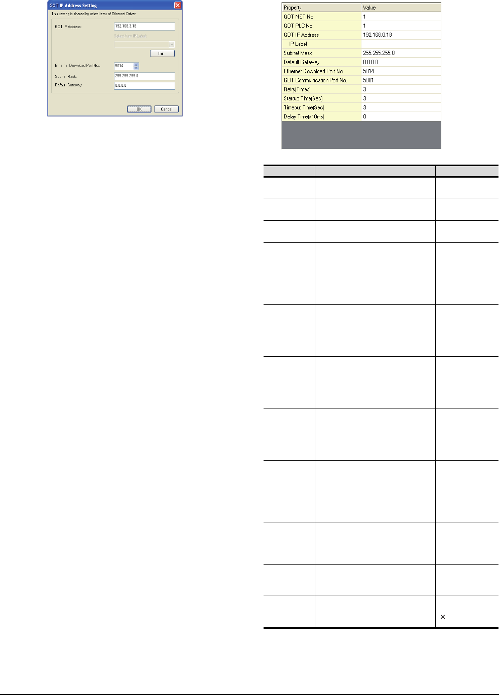
17 - 4 17. ROBOT CONTROLLER CONNECTION
17.3 GOT Side Settings
*1 Click the [Setting] button and perform the setting in the [GOT
IP Address Setting]
screen. GT15, GT12
Item Description Range
GOT NET No. Set the network No. of the GOT.
(Default: 1) 1 to 239
GOT PLC No. Set the station No. of the GOT.
(Default: 1) 1 to 64
GOT
IP Address
Set the IP address of the GOT.
(Default: 192.168.0.18)
0.0.0.0 to
255.255.255.255
Subnet Mask
Set the subnet mask for the sub
network. (Only for connection via
router)
If the sub network is not used, the
default value is set.
(Default: 255.255.255.0)
0.0.0.0 to
255.255.255.255
Default
Gateway
Set the router address of the default
gateway where the GOT is
connected. (Only for connection via
router)
(Default: 0.0.0.0)
0.0.0.0 to
255.255.255.255
Ethernet
Download Port
No.
Set the GOT port No. for Ethernet
download.
(Default: 5014)
1024 to 5010 to
5014 to 65534
(Except for 5011,
5012, 5013 and
49153)
GOT
Communication
Port No.
Set the GOT port No. for the
connection with the Ethernet module.
(Default: 5001)
1024 to 5010 to
5014 to 65534
(Except for 5011,
5012, 5013 and
49153)
Retry
Set the number of retries to be
performed when a communication
timeout occurs.
When receiving no response after
retries, the communication times out.
(Default: 3times)
0 to 5times
Startup Time
Specify the time period from the GOT
startup until GOT starts the
communication with the PLC CPU.
(Default: 3sec)
3 to 255sec
Timeout Time
*1
Set the time period for a
communication to time out.
(Default: 3sec)
3 to 90sec
Delay Time
Set the delay time for reducing the
load of the network/destination PLC.
(Default: 0ms)
0 to 10000
( 10ms)
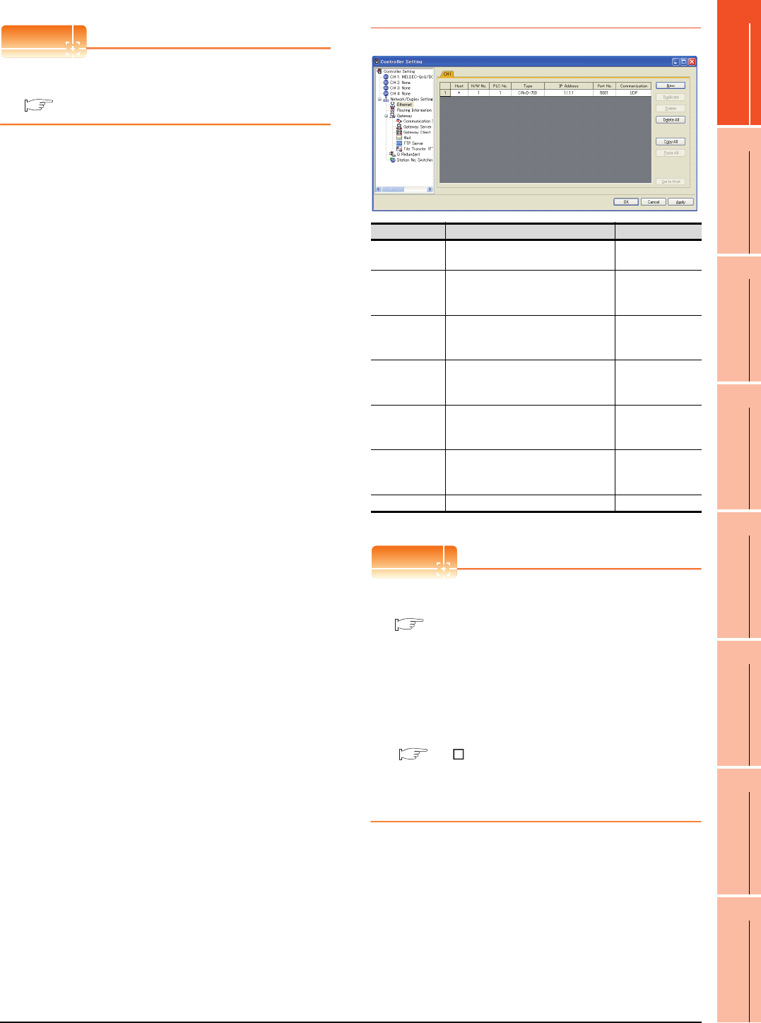
17. ROBOT CONTROLLER CONNECTION
17.3 GOT Side Settings
17 - 5
17
ROBOT
CONTROLLER
CONNECTION
18
CNC CONNECTION
19
GOT MULTI-DROP
CONNECTION
20
MULTIPLE-GT14, GT12,
GT11, GT10
CONNECTION FUNCTION
21
MULTI-CHANNEL
FUNCTION
22
FA TRANSPARENT
FUNCTION
POINTPOINTPOINT
Example of [Detail setting].
For examples of [Detail setting], refer to the following.
17.4 PLC Side Settings
17.3.3 Ethernet setting
*1 Select [CRnD-700] for [Controller Type].
POINTPOINTPOINT
(1) Example of [Ethernet]
For examples of [Ethernet], refer to the following.
17.4 PLC Side Settings
(2) Communication interface setting by Utility
The communication interface setting can be
changed on the Utility's [Communication Settings]
after writing [Communication Settings] of project
data.
For details on the Utility, refer to the following
manual.
GT User's Manual
(3) Precedence in communication settings
When settings are made by GT Designer3 or the
Utility, the latest setting is effective.
Item Description Range
Host The host is displayed. (The host is
indicated with an asterisk (*)) ―
N/W No.
Set the network No. of the connected
Ethernet module.
(Default: blank)
1 to 239
PLC No.
Set the station No. of the connected
Ethernet module.
(Default: blank)
1 to 64
Type*1
Set the type of the connected
Ethernet module.
CRnD-70(fixed)
CRnD-70(fixed)
IP address
Set the IP address of the connected
Ethernet module.
(Default: blank)
0.0.0.0 to
255.255.255.255
Port No.
Set the port No. of the connected
Ethernet module.
(Default: 5001)
1024 to 65534
Communication UDP (fixed) UDP (fixed)
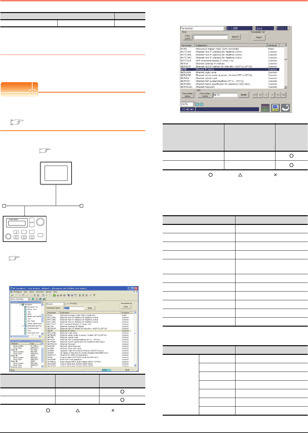
17 - 6 17. ROBOT CONTROLLER CONNECTION
17.4 PLC Side Settings
17.4 PLC Side Settings
17.4.1 Connecting to robot controller
(CRnD-700)
This section describes the settings of a GOT and a robot
controller in the following case of system configuration.
POINTPOINTPOINT
Robot controller (CRnD-700)
For details of the robot controller (CRnD-700), refer to
the following manual.
CRnD-700 SET UP MANUAL
System configuration
Parameter settings for CRnD-700
(1) For RT ToolBox2
: Necessary : As necessary : Not necessary
(2) For R32TB or R56TB
(For R56TB)
: Necessary : As necessary : Not necessary
[Controller Setting] and [Ethernet] of GT
Designer3
(1) Communication settings
(2) Ethernet setting
Model Reference
Robot controller CRnD-700 17.4.1
Item Set value Setting necessity at
GOT connection
NETIP 192.168.0.19
GOTPORT 5001
<GOT> (The settings other than the
following are set to the default)
2
Network No. : 1
PLC No. : 1
IP address : 192.168.0.18
Port No. : 5001
Communication format : UDP (fixed)
Network No. : 1
PLC No. : 2
IP address : 192.168.0.19
Port No. : 5001
Communication format : UDP(fixed)
<CRnD-700> (The settings other than the
following are set to the default)
■ Parameter settings for CRnD-700
■ [Controller Setting] and [Ethernet] of GT
Designer3
Item Set value
Setting
necessity at
GOT
connection
NETIP 192.168.0.19
GOTPORT 5001
Item Set value
GOT NET No. 1
GOT PLC No. 1
GOT IP Address 192.168.0.18
GOT Port No. (Communication) 5001
GOT Port No.
(Ethernet Download) 5014
Default Gateway 0.0.0.0
Subnet Mask 255.255.255.0
Retry 3times
Startup Time 3sec
Timeout Time 3sec
Delay Time 0ms
Item Set value
Ethernet setting
No.1
Host *
N/W No. 1
PLC No. 2
Type CRnD-700
IP address 192.168.0.19
Port No. 5001 (fixed)
Communication UDP (fixed)

17. ROBOT CONTROLLER CONNECTION
17.4 PLC Side Settings
17 - 7
17
ROBOT
CONTROLLER
CONNECTION
18
CNC CONNECTION
19
GOT MULTI-DROP
CONNECTION
20
MULTIPLE-GT14, GT12,
GT11, GT10
CONNECTION FUNCTION
21
MULTI-CHANNEL
FUNCTION
22
FA TRANSPARENT
FUNCTION
POINTPOINTPOINT
[Controller Setting] and [Ethernet] of GT Designer3
For [Controller Setting] and [Ethernet] of GT
Designer3, refer to the following.
17.3.1 Setting communication interface
(Communication settings)
Confirming communication state of CRnD-
700
(1) When using the Command Prompt of Windows®.
Execute a Ping command at the Command Prompt of
Windows®.
(a) When normal communication
C:\>Ping 192.168.0.19
Reply from 192.168.0.19: bytes=32 time<1ms
TTL=64
(b) When abnormal communication
C:\>Ping 192.168.0.19
Request timed out.
(2) When abnormal communication
At abnormal communication, check the followings and
execute the Ping command again.
• Cable connecting condition
• Parameter settings
• Operation state of the CRnD-700. (faulty or not)
• The IP address of the CRnD-700 specified for the
Ping command.

17 - 8 17. ROBOT CONTROLLER CONNECTION
17.5 Device Range that Can Be Set
17.5 Device Range that Can Be Set
For details on the device range that can be used on the
GOT, refer to the following.
2.1 MELSEC-QnU/DC, Q17nD/M/NC/DR,
CRnD-700
17.6 Precautions
When setting IP address
Do not use "0" and "255" at the end of an IP address.
(Numbers of *.*.*.0 and *.*.*.255 are used by the
system)
The GOT may not monitor the controller correctly with
the above numbers.
Consult with the administrator of the network before
setting an IP address to the GOT and controller.
When connecting to the multiple network
equipment (including GOT) in a segment
By increasing the network load, the transmission speed
between the GOT and PLC may be reduced.
The following actions may improve the communication
performance.
• Using a switching hub
• More high speed by 100BASE-TX (100Mbps)
• Reduction of the monitoring points on GOT
18
17
ROBOT
CONTROLLER
CONNECTION
18
CNC CONNECTION
19
GOT MULTI-DROP
CONNECTION
20
MULTIPLE-GT14, GT12,
GT11, GT10
CONNECTION FUNCTION
21
MULTI-CHANNEL
FUNCTION
22
FA TRANSPARENT
FUNCTION
18 - 1
18.CNC CONNECTION
18.1 Connectable Model List . . . . . . . . . . . . . . . . . . . . . . . . . . . 18 - 2
18.2 System Configuration. . . . . . . . . . . . . . . . . . . . . . . . . . . . . 18 - 3
18.3 Connection Diagram . . . . . . . . . . . . . . . . . . . . . . . . . . . . . 18 - 7
18.4 GOT Side Settings . . . . . . . . . . . . . . . . . . . . . . . . . . . . . . . 18 - 8
18.5 CNC Side Settings . . . . . . . . . . . . . . . . . . . . . . . . . . . . . . 18 - 16
18.6 Device Range that Can Be Set . . . . . . . . . . . . . . . . . . . . 18 - 23
18.7 Precautions . . . . . . . . . . . . . . . . . . . . . . . . . . . . . . . . . . . 18 - 23

18 - 2 18. CNC CONNECTION
18.1 Connectable Model List
18. CNC CONNECTION
18.1 Connectable Model List
The following table shows the connectable models.
*1 Use the NC system software version D0 or later.
*2 Includes the case on the MELSECNET/H network system in the NET/10 mode. The GOT cannot be connected to the remote I/O
network..
For the connection to CNC C70, refer to Mitsubishi Products (Chapter 5 to Chapter 13).
Series Model name Clock Communication
type Refer to
MELDAS
C6/C64
*1
FCA C6
FCA C64
RS-232
RS-422 18.2.1
MELSECNET/10*2 18.2.2
CC-Link(ID) 18.2.3
Ethernet 18.2.4
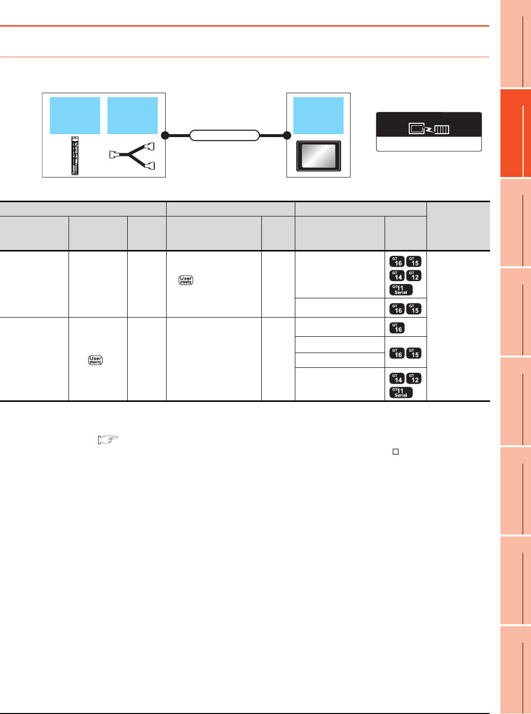
18. CNC CONNECTION
18.2 System Configuration
18 - 3
17
ROBOT
CONTROLLER
CONNECTION
18
CNC CONNECTION
19
GOT MULTI-DROP
CONNECTION
20
MULTIPLE-GT14, GT12,
GT11, GT10
CONNECTION FUNCTION
21
MULTI-CHANNEL
FUNCTION
22
FA TRANSPARENT
FUNCTION
18.2 System Configuration
18.2.1 Direct connection to CPU
*1 Connect the connector of the CNC side to TERMINAL.
*2 Connect the connector of the CNC side to SIO.
*3 To be prepared by the user, referring the following.
MELDAS C6/C64 CONNECTION AND MAINTENANCE MANUAL (BNP-B2255) F311 Cable Production Drawing
*4 Connect it to the RS-232 interface (built into GOT). It cannot be mounted on GT1655 and GT155 .
AJ71C24, MELDAS C6*
Communication driver
F311 cable
GOT
Connection cable
MELDAS
C6/C64
CNC Connection cable GOT
Number of
connectable
equipment
Model name F311 cable
Communi
cation
type
Cable model Max.
distance Option device Model
MELDAS C6/C64
*1 - RS-232 RS232 connection
diagram
15m
- (Built into GOT)
1 GOT for 1 PLC
GT15-RS2-9P
MELDAS C6/C64
*2
*3 RS-422
GT01-C30R4-25P(3m)
GT01-C100R4-25P(10m)
GT01-C200R4-25P(20m)
GT01-C300R4-25P(30m)
30.5m
GT16-C02R4-9S(0.2m)
GT15-RS2T4-9P*4
GT15-RS4-9S
- (Built into GOT)
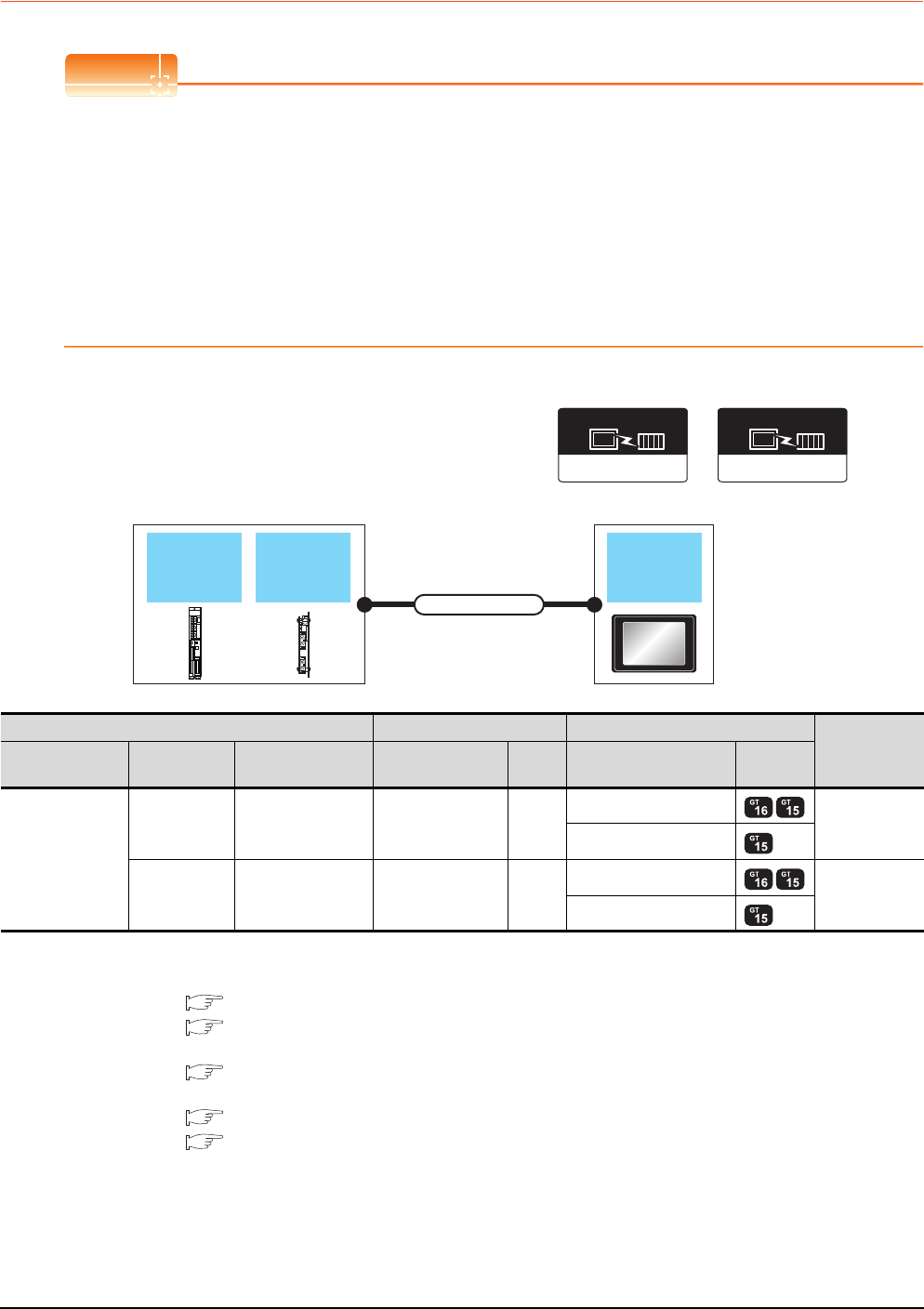
18 - 4 18. CNC CONNECTION
18.2 System Configuration
18.2.2 MELSECNET/10 connection (PLC to PLC network)
POINTPOINTPOINT
(1) Connectable network
MELSECNET/10 connection includes the case that MELSECNET/H is used in NET/10 mode.The GOT
cannot be connected to the remote I/O network.
Connect the GOT to the following network systems as an ordinary station.
• MELSECNET/10 network system (PLC to PLC network) optical loop system
• MELSECNET/10 network system (PLC to PLC network) coaxial bus system
(2) MELSECNET/H network module
When connecting the MELSECNET/H network module to the MELSECNET/10 network system, specify the
MELSECNET/10 Mode as a network type.
*1 The overall extension cable length and the length between stations vary depending on the cable type to be used and the total
number of stations.
For details, refer to the following manuals.
C6/C64/C64T CONNECTION AND MAINTENANCE MANUAL BNP-B2255
C6/C64/C64T NETWORK INSTRUCTION MANUAL BNP-B2373
*2 Specify the MELSECNET/10 Mode as the Communication Settings.For the setting, refer to the following.
18.4.1 Setting communication interface (Communication settings)
*3 For the coaxial cable and optical fiber cable, refer to the following manuals.
C6/C64/C64T CONNECTION AND MAINTENANCE MANUAL BNP-B2255
C6/C64/C64T NETWORK INSTRUCTION MANUAL BNP-B2373
MELSECNET/H
Communication driver
(When MELSECNET/H
communication unit is used)
MELSECNET/10
Communication driver
(When MELSECNET/10
communication unit is used)
Expansion
unit GOT
Connection cable
MELDAS
C6/C64
CNC Connection cable GOT Number of
connectable
equipment
Model name Expansion unit Communication type Cable model
Max.
distance
Option device Model
MELDAS C6/C64
FCU6-EX878 MELSECNET/10
(Coaxial bus system)
Coaxial cable
*3
*1
GT15-J71BR13*2
31 GOTs
GT15-75J71BR13-Z
FCU6-EX879 MELSECNET/10
(Optical loop system)
Optical fiber cable
*3
*1
GT15-J71LP23-25*2
63 GOTs
GT15-75J71LP23-Z
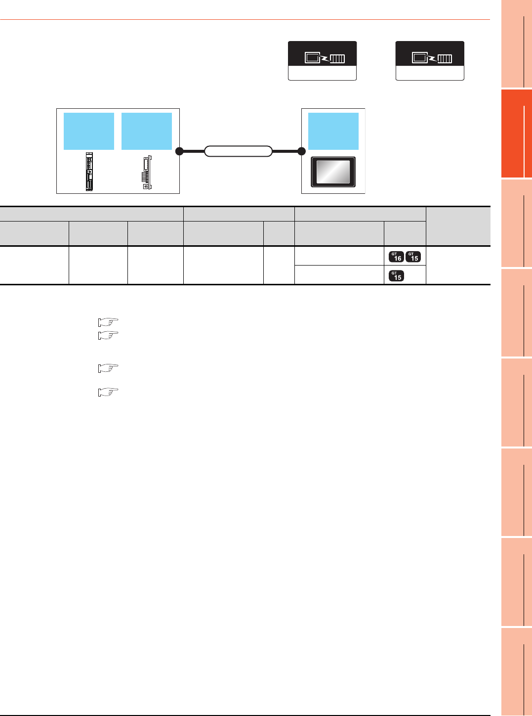
18. CNC CONNECTION
18.2 System Configuration
18 - 5
17
ROBOT
CONTROLLER
CONNECTION
18
CNC CONNECTION
19
GOT MULTI-DROP
CONNECTION
20
MULTIPLE-GT14, GT12,
GT11, GT10
CONNECTION FUNCTION
21
MULTI-CHANNEL
FUNCTION
22
FA TRANSPARENT
FUNCTION
18.2.3 CC-Link connection (intelligent device station)
*1 The overall extension cable length and the length between stations vary depending on the cable type to be used and the total
number of stations.
For details, refer to the following manuals.
C6/C64/C64T CONNECTION AND MAINTENANCE MANUAL BNP-B2255
C6/C64/C64T NETWORK INSTRUCTION MANUAL BNP-B2373
*2 Specify Ver.1 as the mode setting in the Communication Settings to use it.
For details of the settings, refer to the following the manual.
18.4.1 Setting communication interface (Communication settings)
*3 For the specifications and inquiries of the CC-Link dedicated cable, refer to the following.
CC-Link Partner Association's home page: http://www.cc-link.org/
CC-Link Ver2(ID)
Communication driver
(When MODEL GT15-J61BT13
CC-Link communication unit is used)
CC-Link(ID)
(When MODEL GT15-75J61BT13-Z
CC-Link communication unit is used)
Communication driver
Expansion
unit GOT
Connection cable
MELDAS
C6/C64
CNC Connection cable GOT Number of
connectable
equipment
Model name Expansion unit Communication
type Cable model
Max.
distance
Option device Model
MELDAS C6/C64 FUC6-HR865 CC-Link(ID)
CC-Link dedicated
cable
*3
*1
GT15-J61BT13*2
26 GOTs
GT15-75J61BT13-Z
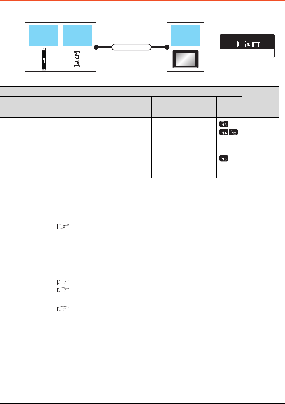
18 - 6 18. CNC CONNECTION
18.2 System Configuration
18.2.4 Ethernet connection
*1 The destination connected with the twisted pair cable varies with the configuration of the applicable Ethernet network system.
Connect to the Ethernet module, hub, transceiver or other system equipment corresponding to the applicable Ethernet network
system.
Use cables, connectors, and hubs that meet the IEEE802.3 10BASE-T/100BASE-TX standards.
A cross cable is available for connecting the GOT to the Ethernet module.
*2 When connecting GT16 of the function version A to an equipment that meets the 10BASE (-T/2/5) standard, use the switching
hub and operate in a 10Mbps/100Mbps mixed environment.
For how to check the function version, refer to the following.
GT16 User's Manual
*3 A length between a hub and a node.
The maximum distance differs depending on the Ethernet device to be used.
The following shows the number of the connectable nodes when a repeater hub is used.
• 10BASE-T: Max. 4 nodes for a cascade connection (500m)
• 100BASE-TX: Max. 2 nodes for a cascade connection (205m)
When switching hubs are used, the cascade connection between the switching hubs has no logical limit for the number of
cascades.
For the limit, contact the switching hub manufacturer.
*4 For the system configuration of the expansion unit, refer to the following manuals.
C6/C64/C64T CONNECTION AND MAINTENANCE MANUAL BNP-B2255
C6/C64/C64T NETWORK INSTRUCTION MANUAL BNP-B2373
*5 Select [AJ71QE71] for [Controller Type] in [Ethernet] of GT Designer3.
For [Ethernet] of GT Designer3, refer to the following.
18.4.3 Ethernet setting
Ethernet(MELSEC),Q17nNC,CRnD-700
Communication driver
Expansion
unit GOT
Connection cable
MELDAS
C6/C64
CNC Connection cable*1 GOT
Number of
connectable
equipment
Model name Expansion unit
Commun
ication
type
Cable model
Maximum
segment
length*3
Option device Model
MELDAS C6/C64 FUC6-EX875
*4*5 Ethernet
Twisted pair cable
• 10BASE-T
Shielded twisted pair cable
(STP) or unshielded twisted
pair cable (UTP): Category
3, 4, and 5
• 100BASE-TX
Shielded twisted pair cable
(STP):
Category 5 and 5e
100m
- (Built into GOT)
*2
128 GOTs
(recommended to
16 units or less)
GT15-J71E71-100
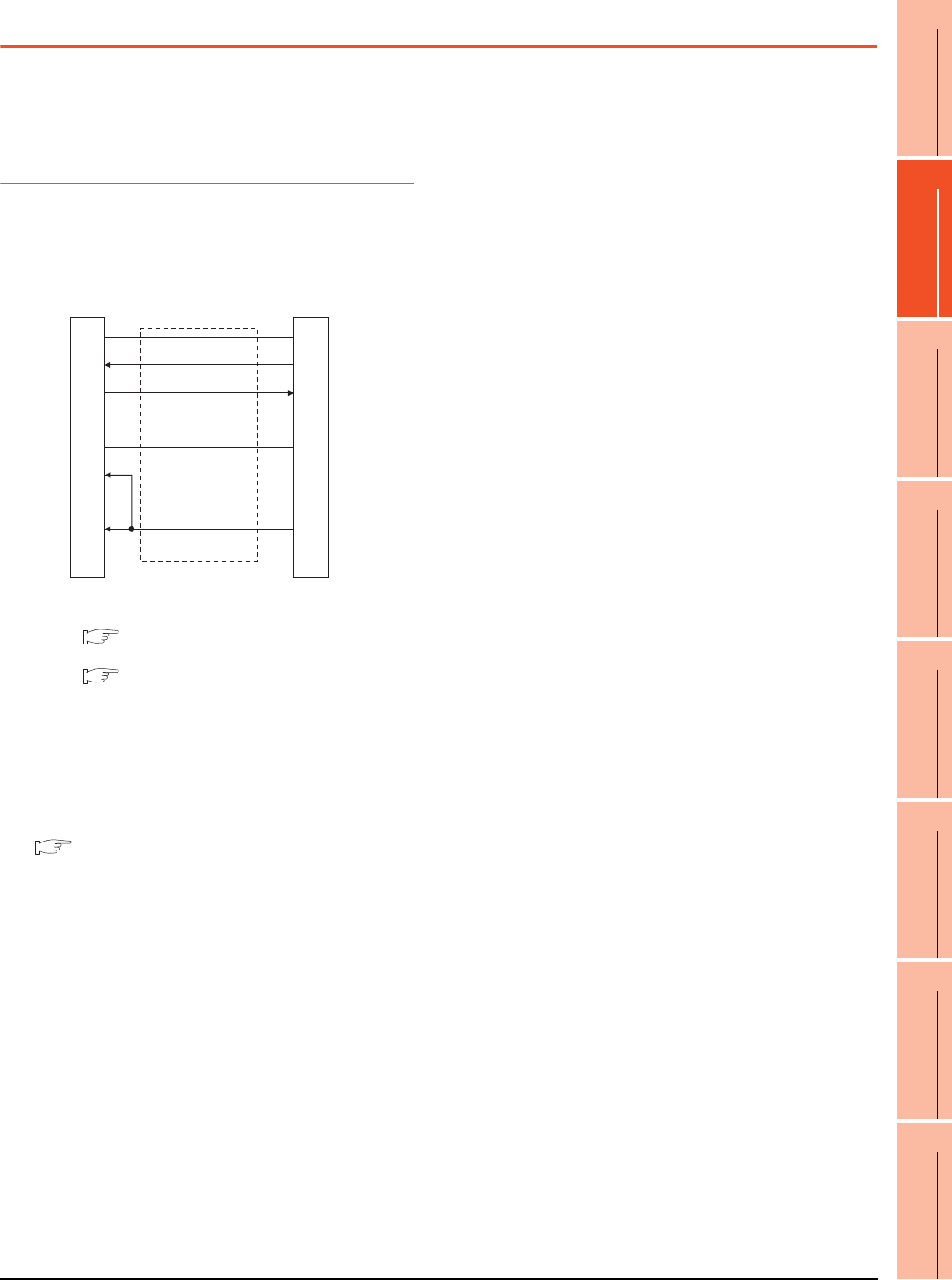
18. CNC CONNECTION
18.3 Connection Diagram
18 - 7
17
ROBOT
CONTROLLER
CONNECTION
18
CNC CONNECTION
19
GOT MULTI-DROP
CONNECTION
20
MULTIPLE-GT14, GT12,
GT11, GT10
CONNECTION FUNCTION
21
MULTI-CHANNEL
FUNCTION
22
FA TRANSPARENT
FUNCTION
18.3 Connection Diagram
The following diagram shows the connection between the
GOT and the CNC.
18.3.1 RS-232 cable
Connection diagram
*1 For details of the MELDAS C6/C64 side connection, refer to
the following manuals.
MELDAS C6/C64 CONNECTION AND
MAINTENANCE MANUAL BNP-B2255
MELDAS C6/C64 NETWORK MANUAL BNP-B2373
Precautions when preparing a cable
(1) Cable length
The length of the RS-232 cable must be 15m or less.
(2) GOT side connector
For the GOT side connector, refer to the following.
1.4.1 GOT connector specifications
RS232 connection diagram
MELDAS C6/C64 side*1
(20 pin half pitch)
CD
RD(RXD)
SD(TXD)
ER(DTR)
SG
DR(DSR)
RS(RTS)
CS(CTS)
-
GND
SD
RD
-
GND
-
-
ER(DTR)
-
1
2
3
4
5
6
7
8
9
1
6
16
-
11
-
-
18
-
GOT side
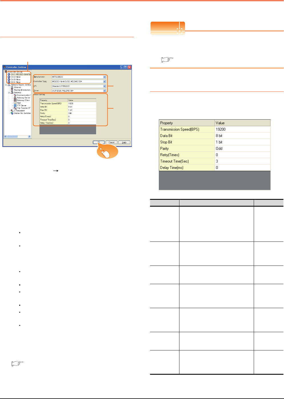
18 - 8 18. CNC CONNECTION
18.4 GOT Side Settings
18.4 GOT Side Settings
18.4.1 Setting communication
interface (Communication
settings)
Set the channel of the connected equipment.
1. Select [Common] [Controller Setting] from the
menu.
2. The Controller Setting window is displayed. Select the
channel to be used from the list menu.
3. Set the following items.
• Manufacturer: Mitsubishi
• Controller Type:
For GT16, GT15
MELSEC-QnA/Q/QS, MELDAS C6*
For GT14, GT11
MELSEC-QnA/Q, MELDAS C6*
• I/F: Interface to be used
• Driver:
For direct connection to CPU
AJ71QC24, MELDAS C6*
For ELSECNET/10 connection
MELSECNET/H
MELSECNET/10
For CC-Link (ID) connection
CC-Link Ver2 (ID)
CC-Link (ID)
For Ethernet connection
Ethernet (MELSEC), Q17nNC, CRnD-700
4. The detailed setting is displayed after Manufacturer,
Controller Type, I/F, and Driver are set.
Make the settings according to the usage
environment.
18.4.2 Communication detail settings
Click the [OK] button when settings are completed.
POINTPOINTPOINT
The settings of connecting equipment can be
confirmed in [I/F Communication Setting].
For details, refer to the following.
1.1.2 I/F communication setting
18.4.2 Communication detail settings
Make the settings according to the usage environment.
(1) AJ71QC24, MELDAS C6*
2.
3.
4.
Click!
Item Description Range
Transmission
Speed
Set this item when change the
transmission speed used for
communication with the connected
equipment.
(Default: 19200bps)
4800bps,
9600bps,
19200bps,
38400bps,
57600bps,
115200bps
Data Bit
Set this item when change the data
length used for communication with the
connected equipment.
(Default: 8bit)
8bit (fixed)
Stop Bit
Specify the stop bit length for
communications.
(Default: 1bit)
1bit (fixed)
Parity
Specify whether or not to perform a parity
check, and how it is performed during
communication.
(Default: Odd)
Odd (fixed)
Retry
Set the number of retries to be
performed when a communication
timeout occurs.
(Default: 0time)
0 to 5times
Timeout Time
Set the time period for a communication
to time out.
(Default: 3sec)
3 to 30sec
Delay Time
Set this item to adjust the transmission
timing of the communication request
from the GOT.
(Default: 0ms)
0 to 300ms
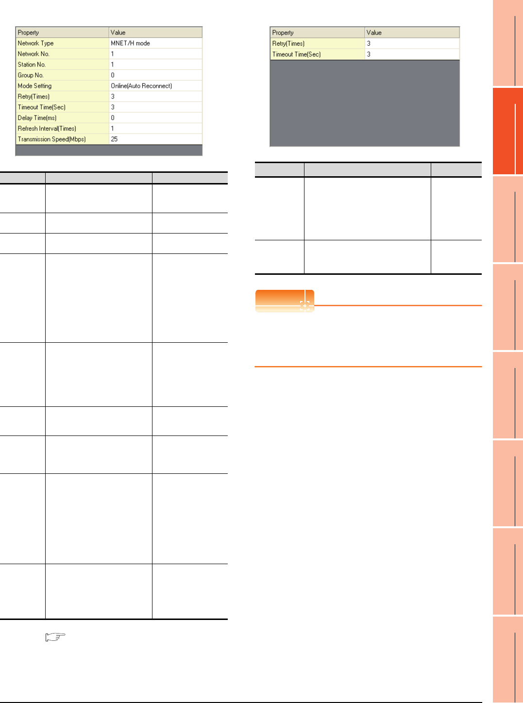
18. CNC CONNECTION
18.4 GOT Side Settings
18 - 9
17
ROBOT
CONTROLLER
CONNECTION
18
CNC CONNECTION
19
GOT MULTI-DROP
CONNECTION
20
MULTIPLE-GT14, GT12,
GT11, GT10
CONNECTION FUNCTION
21
MULTI-CHANNEL
FUNCTION
22
FA TRANSPARENT
FUNCTION
(2) MELSECNET/H
*1 For details, refer to the following manual.
Q corresponding MELSECNET/H Network System
Reference Manual (PLC to PLC network)
(3) MELSECNET/10
POINTPOINTPOINT
When MELSECNET/H communication unit is used
When connecting to the MELSECNET/10 network
using the MELSECNET/H communication unit,
specify [MELSECNET/10 mode] as [Network Type].
Item Description Range
Network Type Set the network type.
(Default: MNET/H mode)
• MNET/H mode
• MNET/10 mode
• MNET/H EXT mode
Network No. Set the network No.
(Default: 1) 1 to 239
Station No. Set the station No. of the GOT.
(Default: 1) 1 to 64
Mode Setting
Set the operation mode of the
GOT.
(Default:
Online (auto. reconnection))
• Online
(auto. reconnection)
• Offline
• Test between
slave station*1
• Self-loopback test*1
• Internal self-
loopback test*1
• H/W test*1
Retry
Set the number of retries to be
performed when a communication
timeout occurs.
When receiving no response after
retries, the communication times
out.
(Default: 3times)
0 to 5times
Timeout Time
Set the time period for a
communication to time out.
(Default: 3sec)
3 to 90sec
Delay Time
Set the delay time for reducing the
load of the network/destination
PLC.
(Default: 0ms)
0 to 300ms
Refresh
Interval
Set the number of refreshes to
secure the send/receive data in
station units during
communication.
(Default: 1time)
Valid when [Secured data send/
Secured data receive] is marked
by the control station side network
parameters of the MELSECNET/H
network system.
1 to 1000times
Transmission
Speed
Set the communication
transmission speed.
(Default: 25Mbps)
When specifying [MNET/10 mode]
as the network type, only 10Mbps
can be set applicable.
10Mbps/25Mbps
Item Description Range
Retry
Set the number of retries to be
performed when a communication
timeout occurs.
When receiving no response after
retries, the communication times out.
(Default: 3times)
0 to 5times
Timeout Time
Set the time period for a communication
to time out.
(Default: 3sec)
3 to 90sec
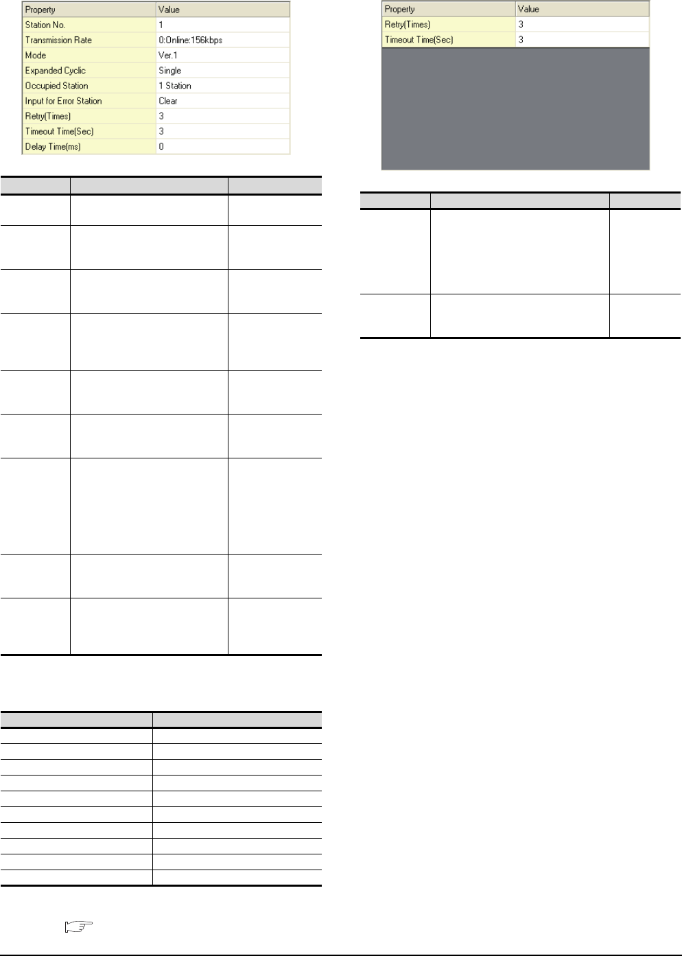
18 - 10 18. CNC CONNECTION
18.4 GOT Side Settings
(4) CC-Link Ver.2 (ID)
*1 Transmission speed settings
The following lists the transmission speed settings of the CC-
Link communication.
For details of the hardware test, refer to the following
manual.
CC-Link System Master/Local Module User's
Manual for CC-Link module to be used
(5) CC-Link(ID)
Item Description Range
Station No. Set the station No. of the GOT.
(Default: 1) 1 to 64
Transmission
Rate*1
Set the transmission speed and
the mode of the GOT.
(Default: 0)
0 to E
Mode Set the mode of CC-Link.
(Default: Ver.1)
Ver.1/Ver.2/
Additional/
Offline
Expanded
Cyclic
Set the cyclic point expansion.
(Default: Single)
Single/
Double/
Quadruple/
Octuple
Occupied
Station
Set the number of stations
occupied by the GOT.
(Default: 1 Station)
1 Station/4 Stations
Input for Error
Station
Set Clear/Hold at an error
occurrence.
(Default: Clear)
Clear/Hold
Retry
Set the number of retries to be
performed when a communication
timeout occurs.
When no response is received
after retries, a communication
times out.
(Default: 3times)
0 to 5times
Timeout Time
Set the time period for a
communication to time out.
(Default: 3sec)
3 to 90sec
Delay Time
Set the delay time for reducing the
load of the network/destination
PLC.
(Default: 0ms)
0 to 300ms
Set value Description
0 Online: 156kbps
1 Online: 625kbps
2 Online: 2.5Mbps
3 Online: 5Mbps
4 Online: 10Mbps
A Hardware test: 156kbps
B Hardware test: 625kbps
C Hardware test: 2.5Mbps
D Hardware test: 5Mbps
E Hardware test: 10Mbps
Item Description Range
Retry
Set the number of retries to be
performed when a communication
timeout occurs.
When receiving no response after
retries, the communication times out.
(Default: 3times)
0 to 5times
Timeout Time
Set the time period for a communication
to time out.
(Default: 3sec)
3 to 90sec
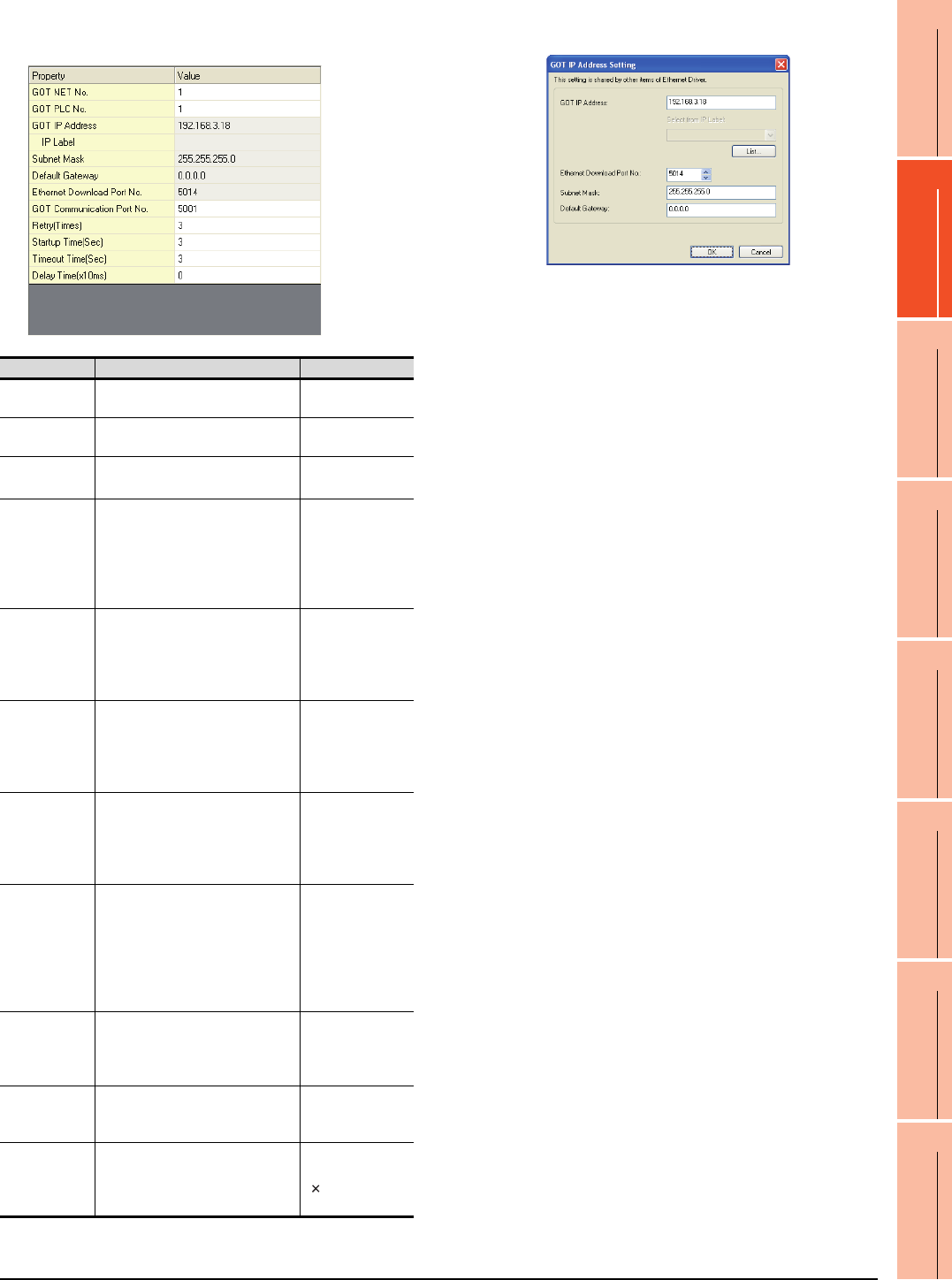
18. CNC CONNECTION
18.4 GOT Side Settings
18 - 11
17
ROBOT
CONTROLLER
CONNECTION
18
CNC CONNECTION
19
GOT MULTI-DROP
CONNECTION
20
MULTIPLE-GT14, GT12,
GT11, GT10
CONNECTION FUNCTION
21
MULTI-CHANNEL
FUNCTION
22
FA TRANSPARENT
FUNCTION
(6) Ethernet(MELSEC), Q17nNC, CRnD-700
(a) GT16, GT14
*1 Click the [Setting] button and perform the setting in the [GOT
IP Address Setting]
screen.
Item Description Range
GOT NET No. Set the network No. of the GOT.
(Default: 1) 1 to 239
GOT PLC No. Set the station No. of the GOT.
(Default: 1) 1 to 64
GOT
IP Address*1
Set the IP address of the GOT.
(Default: 192.168.3.18)
0.0.0.0 to
255.255.255.255
Subnet
Mask*1
Set the subnet mask for the sub
network.(Only for connection via
router)
If the sub network is not used, the
default value is set.
(Default: 255.255.255.0)
0.0.0.0 to
255.255.255.255
Default
Gateway
*1
Set the router address of the
default gateway where the GOT is
connected.(Only for connection via
router)
(Default: 0.0.0.0)
0.0.0.0 to
255.255.255.255
Ethernet
Download Port
No.*1
Set the GOT port No. for Ethernet
download.
(Default: 5014)
1024 to 5010,
5014 to 65534
(Except for 5011,
5012, 5013 and
49153)
GOT
Communication
Port No.
Set the GOT port No. for the
connection with the Ethernet
module.
(Default: 5001)
1024 to 5010 to
5014 to 65534
(Except for 5011,
5012, 5013 and
49153)
Retry
Set the number of retries to be
performed when a communication
timeout occurs.
When receiving no response after
retries, the communication times
out.
(Default: 3times)
0 to 5times
Startup Time
Specify the time period from the
GOT startup until GOT starts the
communication with the PLC CPU.
(Default: 3sec)
3 to 255sec
Timeout Time
Set the time period for a
communication to time out.
(Default: 3sec)
3 to 90sec
Delay Time
Set the delay time for reducing the
load of the network/destination
PLC.
(Default: 0ms)
0 to 10000
( 10ms)

18 - 12 18. CNC CONNECTION
18.4 GOT Side Settings
(b) GT15, GT12
POINTPOINTPOINT
(1) Communication interface setting by Utility
The communication interface setting can be
changed on the Utility's [Communication Settings]
after writing [Communication Settings] of project
data.
For details on the Utility, refer to the following
manual.
GT User's Manual
(2) Precedence in communication settings
When settings are made by GT Designer3 or the
Utility, the latest setting is effective.
Item Description Range
GOT NET No. Set the network No. of the GOT.
(Default: 1) 1 to 239
GOT PLC No. Set the station No. of the GOT.
(Default: 1) 1 to 64
GOT IP
Address
Set the IP address of the GOT.
(Default: 192.168.0.18)
0.0.0.0 to
255.255.255.255
Subnet Mask
Set the subnet mask for the sub
network.(Only for connection via
router)
If the sub network is not used, the
default value is set.
(Default: 255.255.255.0)
0.0.0.0 to
255.255.255.255
Default
Gateway
Set the router address of the
default gateway where the GOT is
connected.(Only for connection via
router)
(Default: 0.0.0.0)
0.0.0.0 to
255.255.255.255
Ethernet
Download Port
No.
Set the GOT port No. for Ethernet
download.
(Default: 5014)
1024 to 5010 to
5014 to 65534
(Except for 5011,
5012, 5013 and
49153)
GOT
Communication
Port No.
Set the GOT port No. for the
connection with the Ethernet
module.
(Default: 5001)
1024 to 5010 to
5014 to 65534
(Except for 5011,
5012, 5013 and
49153)
Retry
Set the number of retries to be
performed when a communication
timeout occurs.
When receiving no response after
retries, the communication times
out.
(Default: 3times)
0 to 5times
Startup Time
Specify the time period from the
GOT startup until GOT starts the
communication with the PLC CPU.
(Default: 3sec)
3 to 255sec
Timeout Time
Set the time period for a
communication to time out.
(Default: 3sec)
3 to 90sec
Delay Time
Set the delay time for reducing the
load of the network/destination
PLC.
(Default: 0ms)
0 to 10000
( 10ms)
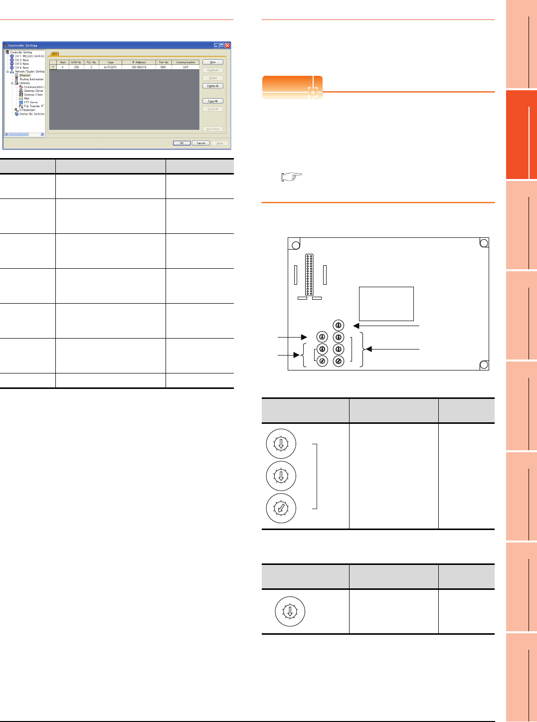
18. CNC CONNECTION
18.4 GOT Side Settings
18 - 13
17
ROBOT
CONTROLLER
CONNECTION
18
CNC CONNECTION
19
GOT MULTI-DROP
CONNECTION
20
MULTIPLE-GT14, GT12,
GT11, GT10
CONNECTION FUNCTION
21
MULTI-CHANNEL
FUNCTION
22
FA TRANSPARENT
FUNCTION
18.4.3 Ethernet setting
*1 For operating CNC monitor function, set N/W No. to "239".
18.4.4 Switch setting
Switch setting (GT15-75J71P23-Z, GT15-
75JBR13-Z)
POINTPOINTPOINT
Switch setting of the communication unit
When using the MELSECNET/H communication unit,
the switch setting is not needed.
For details of each setting switch and LED, refer to the
following manual.
GT15 MELSECNET/10 communication unit
User's Manual
(1) Network number setting switch
(2) Group number setting switch
*1 The GOT does not use the group number.
Specify "0".
Item Description Range
Host The host is displayed. (The host
is indicated with an asterisk (*)) ―
N/W No.
Set the network No. of the
connected Ethernet module.
(Default: blank)
Network No. of
CNC*1
PLC No.
Set the station No. of the
connected Ethernet module.
(Default: blank)
Station No. of CNC
Type
Set the type of the connected
Ethernet module.
(Default: QJ71E71)
AJ71QE71
IP Address
Set the IP address of the
connected Ethernet module.
(Default: blank)
IP address of CNC
Port No.
Set the port No. of the connected
Ethernet module.
(Default: 5001)
5001
Communication
UDP (fixed) UDP (fixed)
Network number setting
switch Description Set value
Set the network No. of the
MELSECNET/10
communication unit.
(Default: 001)
1 to 239
Group number setting
switch Description Set value
Set the group No. of the
MELSECNET/10
communication unit.
(Default: 0)
0: No group
setting
(fixed)*1
8
0
7
F
6
E
5
D
4
C
3
B
2
A
1
9
MODE
5
0
6
1
7
2
8
3
9
4
5
0
6
1
7
2
8
3
9
4
STATION
No.
X10
X1
5
0
6
1
7
2
8
3
9
4
5
0
6
1
7
2
8
3
9
4
NETWORK
No.
X10
5
0
6
1
7
2
8
3
9
4
X100
X1
5
0
6
1
7
2
8
3
9
4
GROUP No.
RUN
PC
DUAL
SW.E
M/S.E
PRM.E
CRC
OVER
AB.IF
TIME
DATA
UNDER
LOOP
SD
RD
POWER
D.LINK
T.PASS
GOT R/W
CRC
OVER
AB.IF
TIME
DATA
UNDER
LOOP
SD
RD
E
R
R
O
R
E
R
R
O
R
F.LOOP
R.LOOP
GT15-75J71LP23-Z, GT15-75J71BR13-Z
(4)
(2)
(1)
(3)
5
0
6
1
7
2
8
3
9
4
5
0
6
1
7
2
8
3
9
4
NETWORK
No.
X10
5
0
6
1
7
2
8
3
9
4
X100
X1
5
0
6
1
7
2
8
3
9
4
GROUP No.
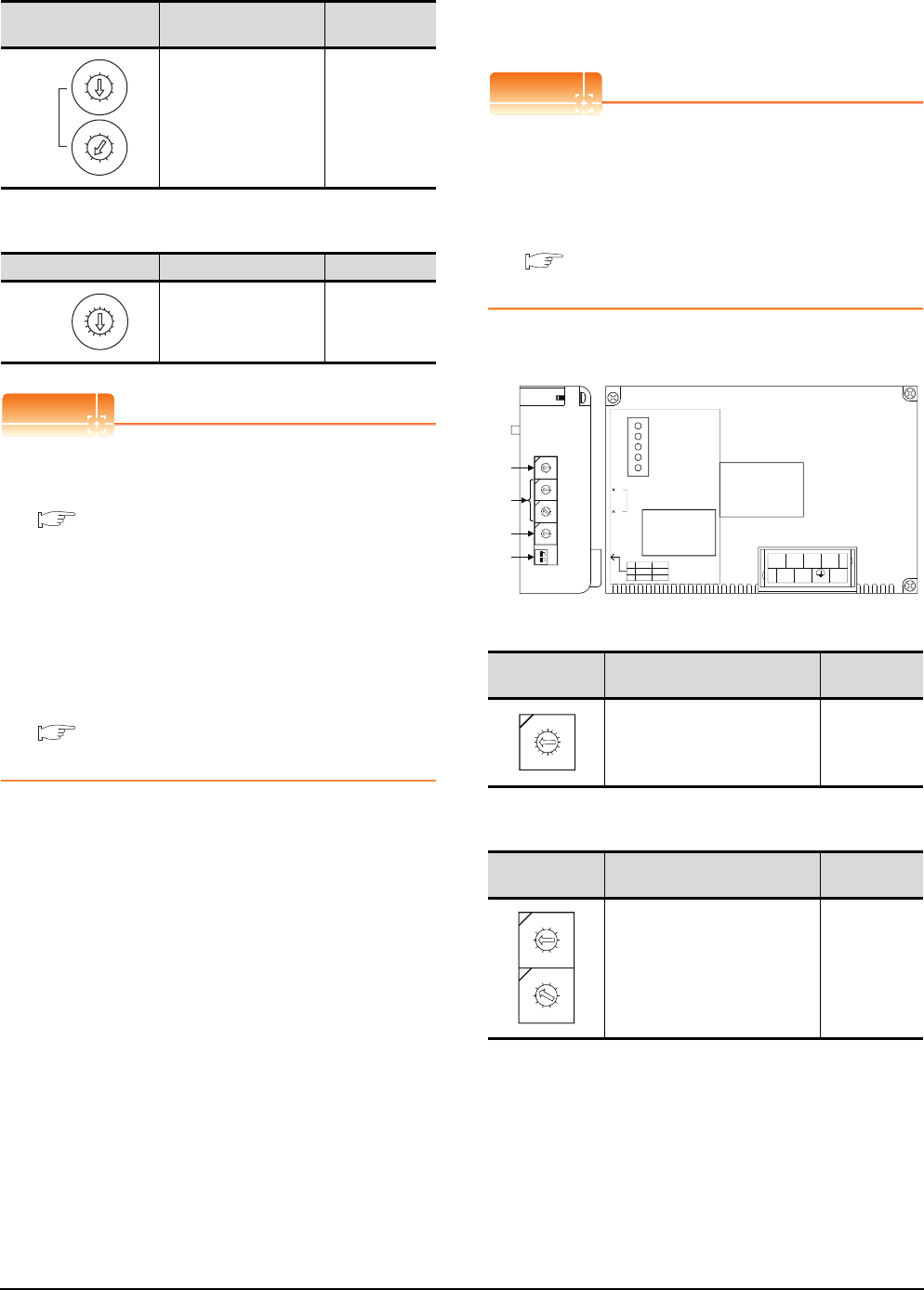
18 - 14 18. CNC CONNECTION
18.4 GOT Side Settings
(3) Station number setting switch
(4) Mode setting switch
POINTPOINTPOINT
(1) Switch setting example
For the switch setting example, refer to the
following.
18.5.1 MELSECNET/10 connection
(2) When the switch setting is changed
When changing the switch setting after mounting
the MELSECNET/10 communication unit to the
GOT, reset the GOT.
(3) Self check test
Select "3" to "9" as the mode setting switch to
provide a self check test of the MELSECNET/10
communication unit.
For details, refer to the following manual.
GT15 MELSECNET/10 communication unit
User's Manual
Switch setting (Only when MODEL GT15-
75J61BT13-Z CC-Link communication unit is
used)
POINTPOINTPOINT
Switch setting of the communication unit
When using the MODEL GT15-J61BT13 CC-Link
communication unit, the switch setting is not needed.
For details of each setting switch and LED, refer to the
following manual.
GT15 CC-Link communication unit User's
Manual
(1) Mode setting switch
(2) Station number setting switch
Station number setting
switch Description Set value
Set the station No. of the
MELSECNET/10
communication unit.
Set to not duplicate other
stations in the network.
(Default: 01)
1 to 64:
GT15-
75J71LP23-Z
1 to 32:
GT15-
75J71BR13-Z
Mode setting switch Description Set value
Online
(Default: 0) 0
5
0
6
1
7
2
8
3
9
4
5
0
6
1
7
2
8
3
9
4
STATION
No.
X10
X1
8
0
7
F
6
E
5
D
4
C
3
B
2
A
1
9
MODE
Mode setting
switch Description Set value
Select the online mode.
(Default: 0) 0 (fixed)
Station number
setting switch Description Set value
Specify the station No. of the
CC-Link communication unit.
(Default: 01)
1 to 64
21
ON
4
3
2
1
0
F
E
D
C
B
A
9
8
7
6
5
0
9
8
7
6
5
4
3
2
1
0
9
8
7
6
5
4
3
2
1
0
9
8
7
6
5
4
3
2
1
(1) MODE
STATION NO.
BAUDRATE
SW
1
2
ON
HOLD
4
OFF
CLEAR
1
DA
1357
2468
DG NC NC
DB SLD (FG1) NC
10
1
L ERR.
RD
SD
L RUN
RUN
(4)
(3)
(2)
Left side Front side
GT15-75J61BT13-Z
4
3
2
1
0
F
E
D
C
B
A
9
8
7
6
5
0
9
8
7
6
5
4
3
2
1
0
9
8
7
6
5
4
3
2
1
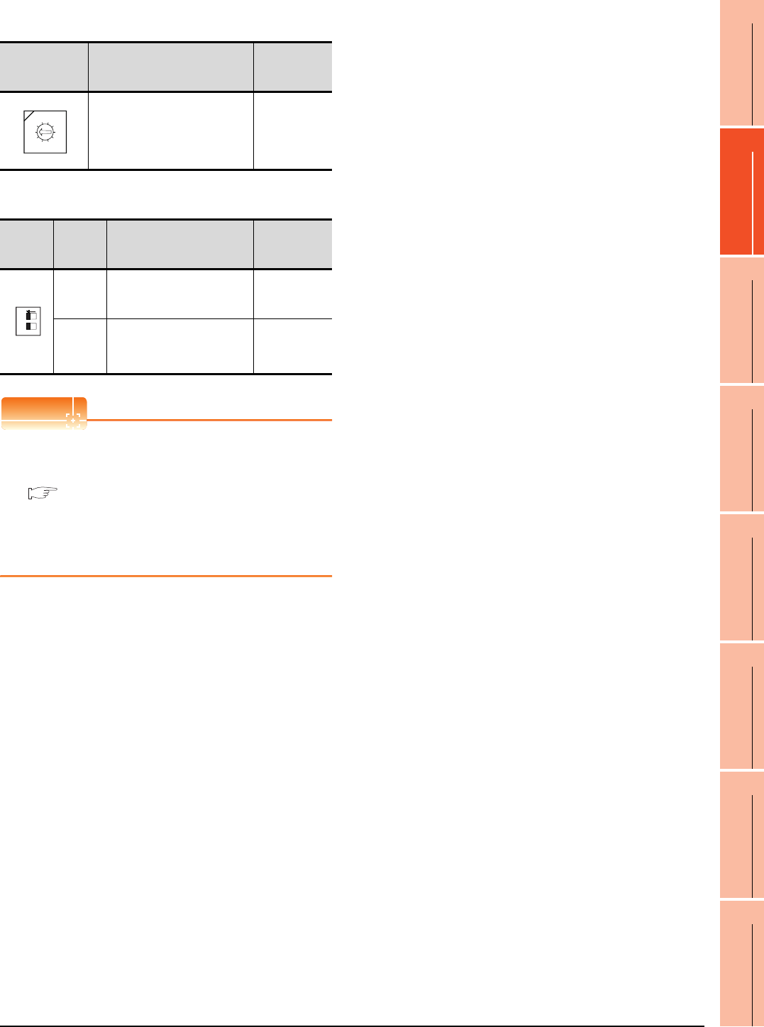
18. CNC CONNECTION
18.4 GOT Side Settings
18 - 15
17
ROBOT
CONTROLLER
CONNECTION
18
CNC CONNECTION
19
GOT MULTI-DROP
CONNECTION
20
MULTIPLE-GT14, GT12,
GT11, GT10
CONNECTION FUNCTION
21
MULTI-CHANNEL
FUNCTION
22
FA TRANSPARENT
FUNCTION
(3) Transmission baudrate setting switch
(4) Condition setting switches
POINTPOINTPOINT
(1) Switch setting example
For the switch setting example, refer to the
following.
18.5.2 CC-Link (ID) connection
(2) When the switch setting is changed
When changing the switch setting after mounting
the GT15-75J61BT13-Z type CC-Link
communication unit to the GOT, reset the GOT.
Transmission
baudrate setting
switch
Description Set value
Specify the transmission speed.
(Default: 0)
0: 156kbps
1: 625kbps
2: 2.5Mbps
3: 5Mbps
4: 10Mbps
Condition
setting
switches
Setting
switch Description Set value
SW1
Specify input data status of the
data link error station.
(Default: OFF)
OFF: Cleared
ON: Held
SW2
Specify the number of stations
occupied.
(Default: OFF)
OFF: 1 station
ON: 4 stations
0
9
8
7
6
5
4
3
2
1
21
ON
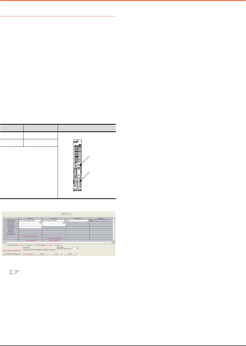
18 - 16 18. CNC CONNECTION
18.5 CNC Side Settings
18.5 CNC Side Settings
18.5.1 MELSECNET/10 connection
Parameter setting
Set parameters related to MELSECNET/10 with
MELSEC's peripheral devices in the same way as
parameter setting of MELSEC CPU, and write them on
CNC by Personal computer. However, in the case of
using the default parameters or not requiring separate
settings due to normal stations, it is not necessary to
set the network
(1) Control Station Parameter
If you wish to place the control station in CNC and set
the common parameters, set the network parameters
by peripheral device and write them on CNC. An
example of parameter setting by GPPW is as follows.
Set the first I/O No. as follows according to the
expansion slot to which the unit is inserted.
(a) Start I/O No.
(b) Example of GX Developer setting
For details of the parameter setting, refer to the
following.
C6/C64/C64T NETWORK INSTRUCTION
MANUAL BNP-B2373
(2) Normal Station Parameter
As for normal stations, it is not necessary to set
parameters unless separate settings are required.
The refresh parameters are set and written as required.
In this case, the parameter setting of the first I/O No. is
the same as in the case of the control station.
Slot Start I/O No.
EXT1 0200
EXT2 0280
EXT1
EXT2
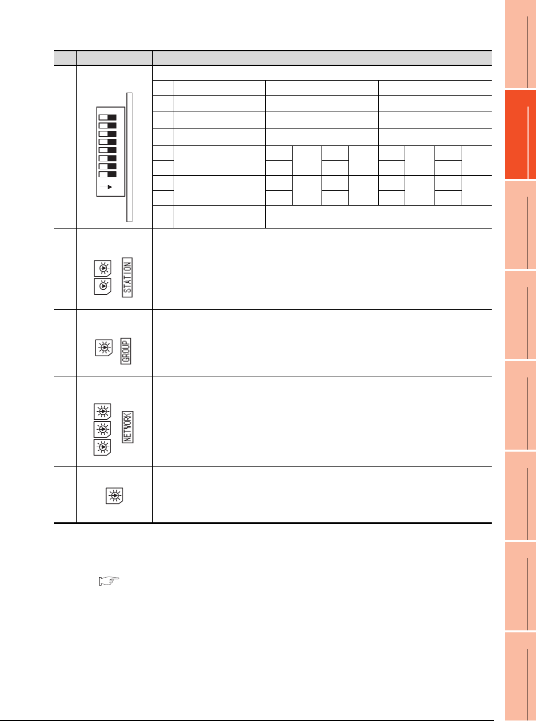
18. CNC CONNECTION
18.5 CNC Side Settings
18 - 17
17
ROBOT
CONTROLLER
CONNECTION
18
CNC CONNECTION
19
GOT MULTI-DROP
CONNECTION
20
MULTIPLE-GT14, GT12,
GT11, GT10
CONNECTION FUNCTION
21
MULTI-CHANNEL
FUNCTION
22
FA TRANSPARENT
FUNCTION
Expansion unit settings
(1) FCU6-EX879 (Optical fiber cable)
*1 Set the network type to the PLC to PLC network.
*2 Set as necessary.
*3 Set the station No. not to overlap with that of other units.
*4 Set the station type to the control station.
For details of the parameter setting, refer to the following.
C6/C64/C64T NETWORK INSTRUCTION MANUAL BNP-B2373
No. Switch name Settings
1)
Condition setting
switch
Set the operation condition.
SW Description OFF ON
1Network type*1 Inter-PC net (PC) Remote I/O net
2Station type*4 Normal station (N.ST) Control station (MNG)
3Used parameter*2 Common parameters (PRM) Default parameter (D.PRM)
4Number of stations*2
(Valid when SW3 is ON)
OFF 8
Station
ON 16
Station
OFF 32
Station
ON 64
Station
5OFFOFFONON
6B/W total points*2
(Valid when SW3 is ON)
OFF 2K
points
ON 4K
points
OFF 6K
points
ON 8K
points
7OFFOFFONON
8 Not used Always OFF
2)
Station number
setting switch
Station number setting*2*3
(Setting range)
01 to 64: Station number
Other than 01 to 64: Setting error
3)
Setting switch of
group number
Group number setting
Not used, fixed to 0
4)
Setting switch of
network number
Network number setting*2
(Setting range)
001 to 255: Network number
Other than 001 to 255: Setting error
5)
Mode setting switch Mode setting*2
0: Online
1: Cannot be used
2: Offline
3 to F: Test mode
1
8
7
6
5
4
3
2
ON
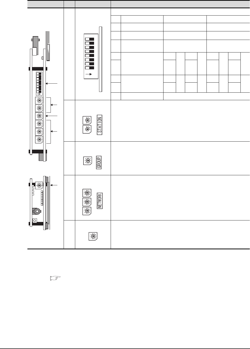
18 - 18 18. CNC CONNECTION
18.5 CNC Side Settings
(2) FCU6-EX878 (Coaxial cable)
*1 Set the network type to the PLC to PLC network.
*2 Set as necessary.
*3 Set the station No. not to overlap with that of other units.
*4 Set the station type to the control station.
For details of the parameter setting, refer to the following.
C6/C64/C64T NETWORK INSTRUCTION MANUAL BNP-B2373
Switch layout No. Switch name Settings
1)
Condition setting
switch
Set the operation condition.
SW Description OFF ON
1Network type*1 Inter-PC net (PC) Remote I/O net
2Station type*4 Normal station (N.ST) Control station (MNG)
3Used parameter*2 Common parameters
(PRM)
Default parameter
(D.PRM)
4
Number of stations*2
(Valid when SW3 is ON)
OFF 8
Sta
tio
n
ON 16
Sta
tio
n
OFF 32
Sta
tio
n
ON 64
Sta
tio
n
5OFFOFFONON
6B/W total points*2
(Valid when SW3 is ON)
OFF 2K
poi
nts
ON 4K
poi
nts
OFF 6K
poi
nts
ON 8K
poi
nts
7OFFOFFONON
8 Not used Always OFF
2)
Station number
setting switch
Station number setting*2*3
(Setting range)
01 to 64: Station number
Other than 01 to 64: Setting error
3)
Setting switch of
group number
Group number setting
Not used, fixed to 0
4)
Setting switch of
network number
Network number setting*2
(Setting range)
001 to 255: Network number
Other than 001 to 255: Setting error
5)
Mode setting switch Mode setting*2
0: Online
1: Cannot be used
2: Offline
3 to F: Test mode
1)
3)
5)
2)
4)
1
8
7
6
5
4
3
2
ON
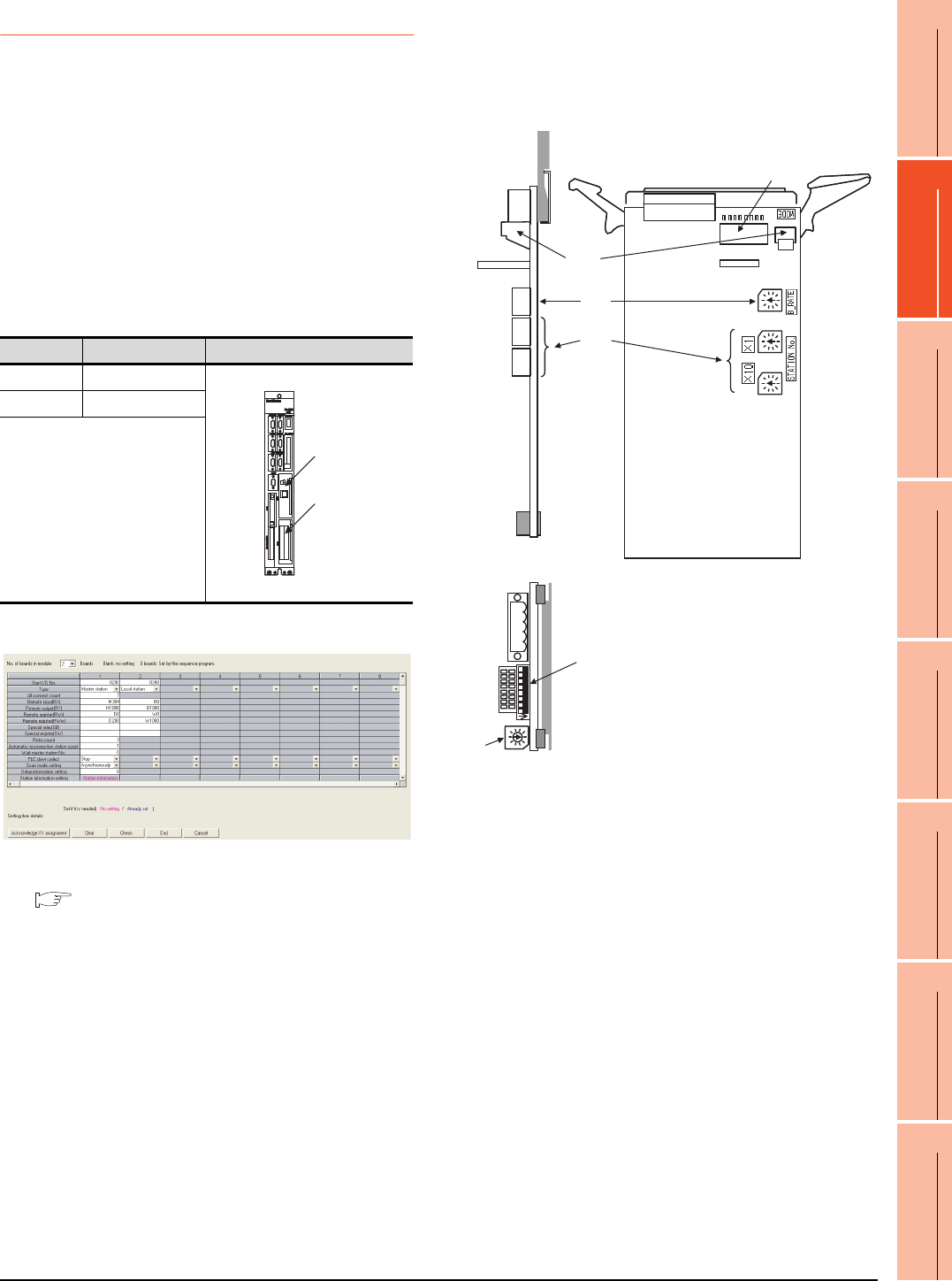
18. CNC CONNECTION
18.5 CNC Side Settings
18 - 19
17
ROBOT
CONTROLLER
CONNECTION
18
CNC CONNECTION
19
GOT MULTI-DROP
CONNECTION
20
MULTIPLE-GT14, GT12,
GT11, GT10
CONNECTION FUNCTION
21
MULTI-CHANNEL
FUNCTION
22
FA TRANSPARENT
FUNCTION
18.5.2 CC-Link (ID) connection
Parameter setting
Set parameters related to CC-Link connection with GX
Developer and write them to CNC by PLC. However, in
the case of using the local stations, it is not necessary
to set the network parameters.
(1) Master station parameter
It is necessary to set and write the network parameters
to CNC with GX Developer. The following shows an
example of parameter settings.Set the first I/O No. as
follows according to the expansion slot to which the unit
is inserted.
(a) Start I/O No.
(b) Example of GX Developer setting
For details of the parameter setting, refer to the
following.
C6/C64/C64T NETWORK INSTRUCTION
MANUAL BNP-B2373
Expansion unit settings
Make the communication settings by the setting switch
in the expansion unit (FCU6-HR865).
(1) Expansion unit
Slot Start I/O No.
EXT1 0200
EXT2 0280
EXT1
EXT2
4)
3)
2)
1)
1)
2)
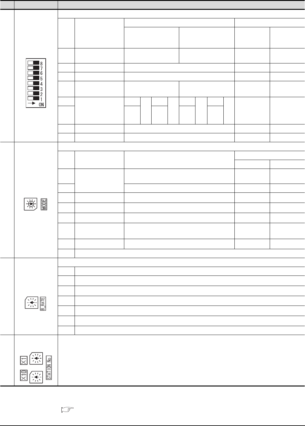
18 - 20 18. CNC CONNECTION
18.5 CNC Side Settings
(2) Contents of setting
*1 Set as necessary.
*2 Set the station No. not to overlap with that of other units.
For details of the parameter setting, refer to the following.
C6/C64/C64T NETWORK INSTRUCTION MANUAL BNP-B2373
No. Switch name Settings
1)
Condition setting
switch
Set the operation condition.
No. Description
Switch status Setting validity
OFF ON
Master station
(Standby
master station)
Local station
(Standby
master station)
SW1 Station type*1 Master station/local
station Standby master station (Valid) (Valid)
SW2 Not used Always OFF - -
SW3 Not used Always OFF - -
SW4 Data link error station
input data status*1 Clear Hold valid valid
SW4
Number of occupied
stations*1
OFF 1
Sta
tio
n
OFF 2
Sta
tio
n
ON 3
Sta
tion
ON 4
Sta
tio
n
Invalid valid
SW5 OFF ON ON OFF
SW7 Not used Always OFF - -
SW8 Not used Always OFF - -
2)
Mode setting switch
This switch sets the unit operation status.
No. Name Description
Settability
Master station Local station
0
Online*1
Automatic online return provided when data link is
enabled Yes Ye s
1 Link with remote I/O net mode Yes No
2Offline*1 Data link offline state Yes Yes
3Line test 1*1 Line test 1 in offline state Yes No
4Line test 2*1 Line test 2 in offline state Yes No
5Parameter confirmation
test*1 Checks the parameter details Yes No
6Hardware test*1 Test Expansion unit (FCU6-HR865) Yes Yes
7 to F Not usable
3)
Transmission speed
setting switch
This switch sets the unit transmission speed.
No. Description
0156Kbps*1
1625Kbps*1
22.5Mbps*1
35Mbps*1
410Mbps*1
5 to F Not usable
4)
Setting switch of
station No. This switch sets the unit station No.*1*2
(Setting range)
Master station: 00
Local station: 01 to 64
Standby master station: 01 to 64
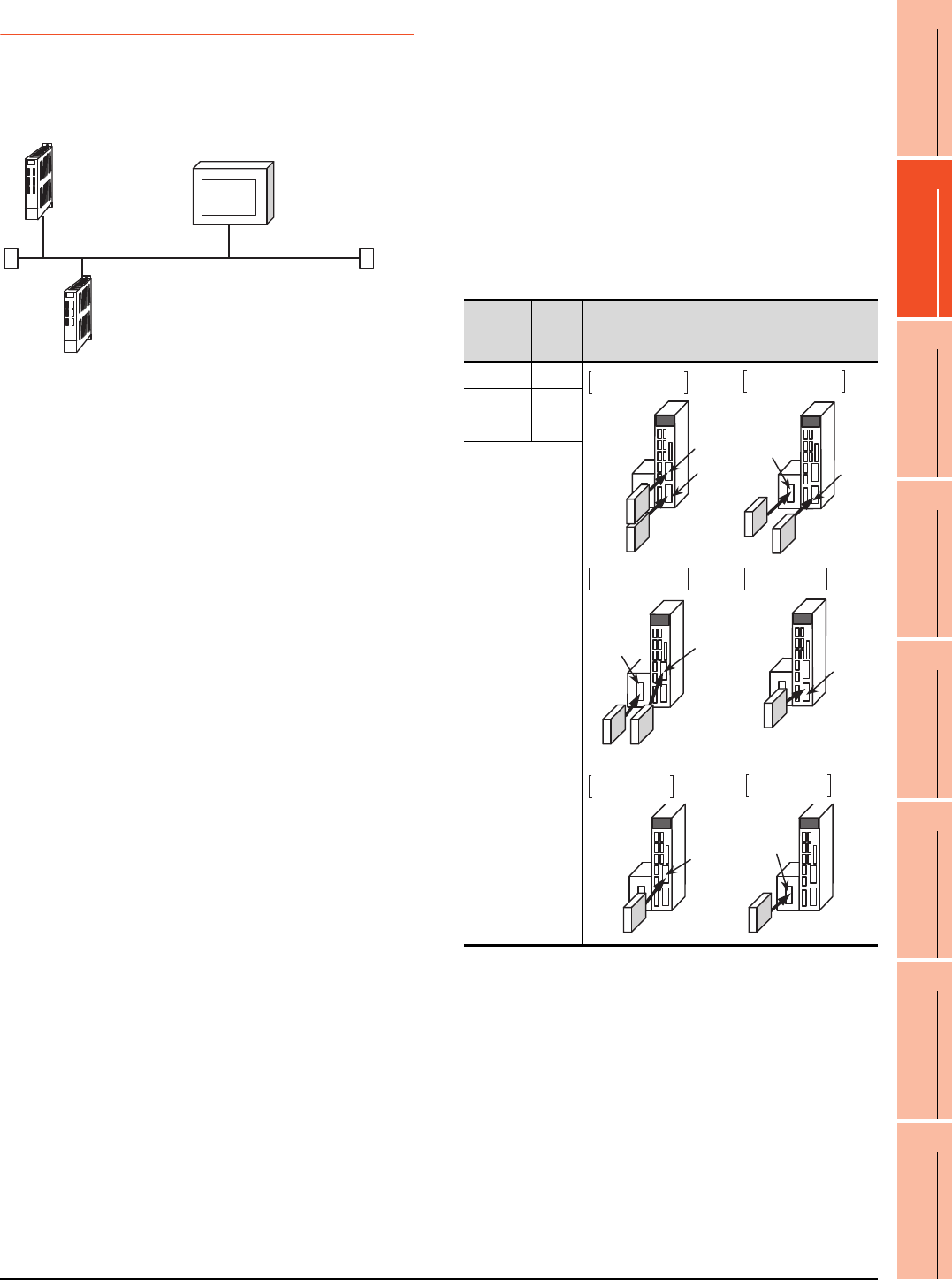
18. CNC CONNECTION
18.5 CNC Side Settings
18 - 21
17
ROBOT
CONTROLLER
CONNECTION
18
CNC CONNECTION
19
GOT MULTI-DROP
CONNECTION
20
MULTIPLE-GT14, GT12,
GT11, GT10
CONNECTION FUNCTION
21
MULTI-CHANNEL
FUNCTION
22
FA TRANSPARENT
FUNCTION
18.5.3 Ethernet connection
System configuration
The following shows the example of the system
configuration when using the CNC monitor function.
Parameter setting
Set parameters related to Ethernet with MELSEC’s
peripheral devices in the same way as parameter
setting of MELSEC CPU, and write them on CNC by
Personal computer.
(1) Network parameter setting
Set the network parameters by peripheral device and
write them on CNC. An example of parameter setting
by GPPW is as follows. Set the first I/O No. as follows
according to the expansion slot to which the unit is
inserted.
(a) Unit No.
Ethernet (192.168.1.xx)
<CNC-1>
[Communication with GOT]
N/W No. :239
PLC No. :2
IP address :192.168.1.2
<CNC-2>
N/W No. :239
PLC No. :3
IP address :192.168.1.3
<GOT>
N/W No. :1
PLC No. :1
IP address :192.168.1.1
Slot
position
Start
I/O
No.
Mounting position of extension unit
EXT1 0200
EXT2 0280
EXT3 0300
EXT2
EXT1
Unit2
Unit1
EXT3
EXT1
EXT2
EXT3
EXT1
When mounted
in EXT2 only
When mounted
in EXT3 only
EXT2
EXT3
When mounted
in EXT1 and EXT2
When mounted
in EXT1 and EXT3
When mounted
in EXT2 and EXT3
When mounted
in EXT1 only
Unit2
Unit2 Unit1
Unit1
Unit1
Unit1
Unit1
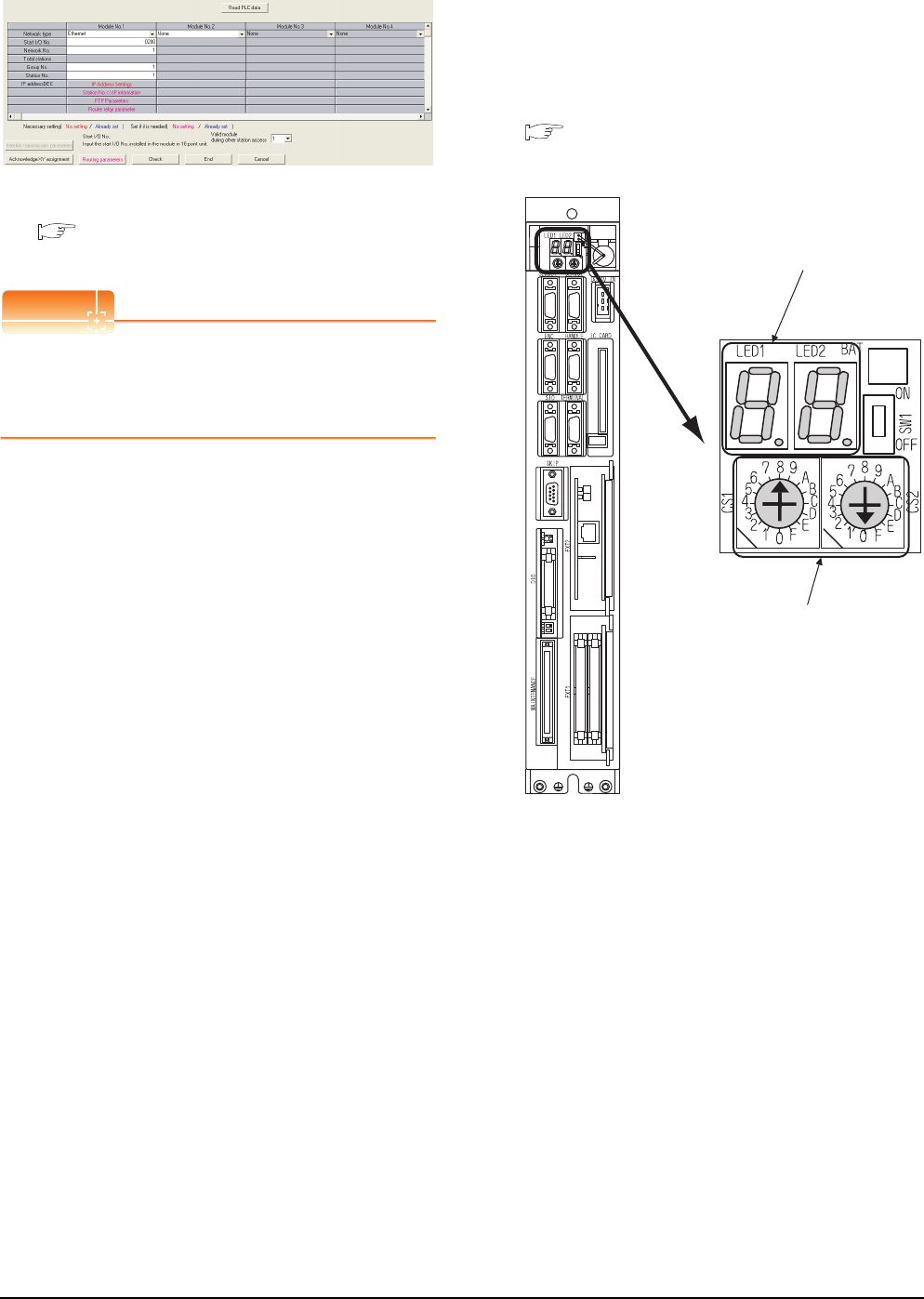
18 - 22 18. CNC CONNECTION
18.5 CNC Side Settings
(b) Example of GX Developer setting
For details of the parameter setting, refer to the
following.
C6/C64/C64T NETWORK INSTRUCTION
MANUAL BNP-B2373
POINTPOINTPOINT
IP address setting
IP address setting on GX Developer is invalid.
Set the IP address by the 7-segment LED and rotary
switch of the CNC side, referring to the next page.
(2) CNC side parameter setting
Confirm the CNC side parameter setting with the
settings of IP address, gateway address, subnet mask
and port No. by the 7-segment LED and rotary switch of
the CNC side.
For details of the parameter setting operation, refer to
the following.
C6/C64/C64T NETWORK INSTRUCTION
MANUAL BNP-B2373 IV Setting the Ethernet
IP Address
7-segment LED
Rotary switch

18. CNC CONNECTION
18.6 Device Range that Can Be Set
18 - 23
17
ROBOT
CONTROLLER
CONNECTION
18
CNC CONNECTION
19
GOT MULTI-DROP
CONNECTION
20
MULTIPLE-GT14, GT12,
GT11, GT10
CONNECTION FUNCTION
21
MULTI-CHANNEL
FUNCTION
22
FA TRANSPARENT
FUNCTION
18.6 Device Range that Can Be Set
For details of the device range that can be used on the GOT, refer to the following.
2.3 MELSEC-QnA/Q/QS, MELDAS C6 *
18.7 Precautions
18.7.1 Direct connection to CPU
Version of CNC
For MELDAS C6/C64, use NC system software version
D0 or later.
18.7.2 MELSECNET/10 connection
Network configuration
Use the MELSECNET/10 mode of MELSECNET/H
(PLC to PLC network) or MELSECNET/10 (PLC to PLC
network) to configure a network including the GOT.
(1) The following networks including the GOT cannot be
configured.
• MELSECNET/10 (Remote I/O network)
• MELSECNET/H (Remote I/O network)
(2) When configuring the network (MELSECNET/H
(PLC to PLC network) including the GOT, refer to the
following.
9. MELSECNET/H CONNECTION (PLC TO
PLC NETWORK)
Monitoring range
Only CNC of the same networks No. can be monitored
in GOT.
For details, refer to the following manual.
3.1 Access Range for Monitoring Stations on
Network Systems
Starting GOT with CNC connection
(MELSECNET/10 connection)
With the CNC connection (MESLSECNET/10
connection), the data link starts approximately 10
seconds after the GOT starts.
When a network error occurs in the system
alarm
When a system alarm regarding a network error occurs
with the CNC connection (MELSECNET/10
connection), the system alarm is kept displaying on the
GOT even though the error factor is removed.
To cancel the system alarm display, restart the GOT.
Version of CNC
For MELDAS C6/C64, use NC system software version
E0 or later.
18.7.3 CC-Link (ID) connection
Using cyclic transmission
(1) I/O signal for master station
Do not turn on the reserved output signals in the output
signals (remote output: RY) to the GOT from the master
station.
When the reserved output signal is turned on, the CNC
system may be malfunctioned.
For the assignment of I/O signals in the GOT, refer to
the following manual.
MODEL GT15-J61BT13 CC-Link
communication unit User's Manual
GT15 CC-Link communication unit User's
Manual
(2) CC-Link Mode
CNC is not compatible with CC-Link Ver.2.
(3) When GOT malfunctions
The cyclic output status remains the same as before
becoming faulty.
For transient transmission
(1) Access range that can be monitored
The GOT can access to the CNC mounting the master
and local station of the CC-Link System.
It cannot access another network via the CC-Link
module.
GOT startup in CNC connection (CC-Link
connection (intelligent device station))
In the CNC connection (CC-Link connection (intelligent
device station)), the data link is started approximately
10 seconds after the GOT startup.
When a network error occurs in the system
alarm
In the CNC connection (CC-Link connection (intelligent
device station)), when a network error occurs in the
system alarm, the system alarm message cannot be
canceled even though the causes are removed.
To cancel the system alarm display, restart the GOT.
Version of CNC
For MELDAS C6/C64, use NC system software version
D0 or later.
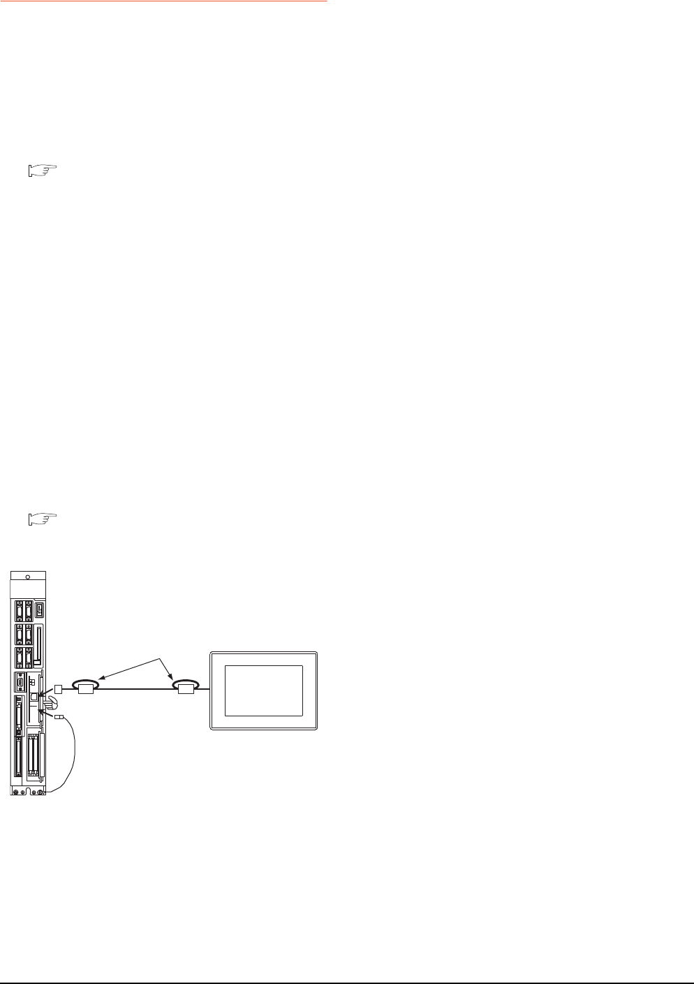
18 - 24 18. CNC CONNECTION
18.7 Precautions
18.7.4 Ethernet connection
Via network system
GOT with Ethernet communication cannot access the
CNCs in another network via the CNC (network
module, Ethernet module, etc.).
When connecting to multiple GOTs
When connecting two or more GOTs in the Ethernet
network, set each [PLC No.] to the GOT.
18.4.1 Setting communication interface
(Communication settings)
When connecting to the multiple network
equipment (including GOT) in a segment
By increasing the network load, the transmission speed
between the GOT and CNC may be reduced.
The following actions may improve the communication
performance.
• Using a switching hub
• More high speed by 100BASE-TX (100Mbps)
• Reduction of the monitoring points on GOT
Ethernet cable connection
Ethernet cable is so susceptible to noise that you
should wire power cables and electric supply cables
separately. And you need to attach a ferrite core
(attachment) on the control unit side.
For details of the Ethernet cable connection, refer to the
following
C6/C64/C64T NETWORK INSTRUCTION
MANUAL BNP-B2373 IX Connection Function
with GOT
Version of CNC
For MELDAS C6/C64, use NC system software version
D0 or later.
LED1
1 turn
Ferrite
core
Ferrite core
Ethernet
FG cable for Ethernet
GOT


19
17
ROBOT
CONTROLLER
CONNECTION
18
CNC CONNECTION
19
GOT MULTI-DROP
CONNECTION
20
MULTIPLE-GT14, GT12,
GT11, GT10
CONNECTION FUNCTION
21
MULTI-CHANNEL
FUNCTION
22
FA TRANSPARENT
FUNCTION
19 - 1
19.GOT MULTI-DROP
CONNECTION
19.1 CPU that can be Monitored . . . . . . . . . . . . . . . . . . . . . . . . 19 - 2
19.2 Connectable Model List . . . . . . . . . . . . . . . . . . . . . . . . . . . 19 - 3
19.3 System Configuration . . . . . . . . . . . . . . . . . . . . . . . . . . . . 19 - 14
19.4 Connection Diagram . . . . . . . . . . . . . . . . . . . . . . . . . . . . . 19 - 15
19.5 GOT Side Settings . . . . . . . . . . . . . . . . . . . . . . . . . . . . . . 19 - 23
19.6 Setting of Serial Multi-Drop Connection Unit . . . . . . . . . . 19 - 24
19.7 Setting of connection conversion adapter. . . . . . . . . . . . . 19 - 29
19.8 Precautions. . . . . . . . . . . . . . . . . . . . . . . . . . . . . . . . . . . . 19 - 30
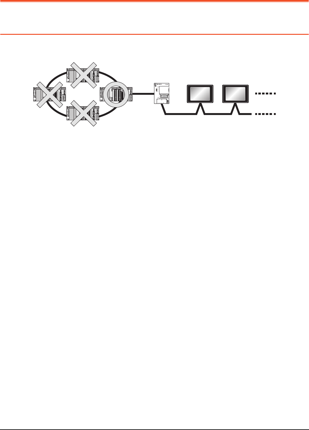
19 - 2 19. GOT MULTI-DROP CONNECTION
19.1 CPU that can be Monitored
19. GOT MULTI-DROP CONNECTION
19.1 CPU that can be Monitored
The GOT can monitor only a CPU to which a serial multi-drop connection unit (GT01-RS4-M) is connected directly.
Serial Multi-Drop Unit
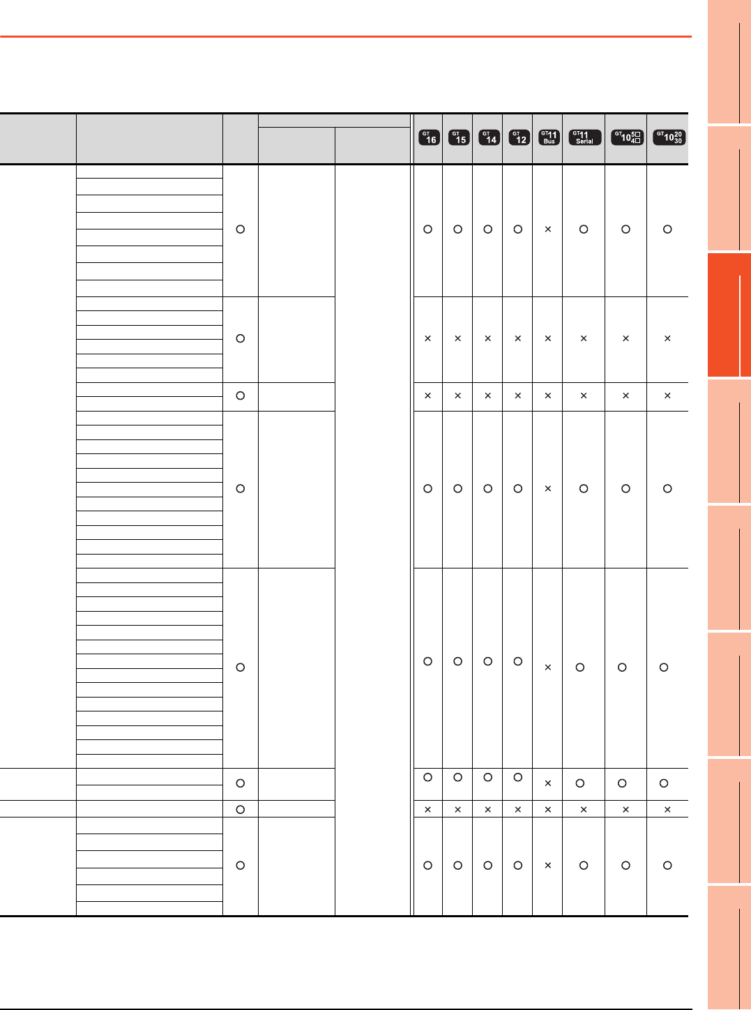
19. GOT MULTI-DROP CONNECTION
19.2 Connectable Model List
19 - 3
17
ROBOT
CONTROLLER
CONNECTION
18
CNC CONNECTION
19
GOT MULTI-DROP
CONNECTION
20
MULTIPLE-GT14, GT12,
GT11, GT10
CONNECTION FUNCTION
21
MULTI-CHANNEL
FUNCTION
22
FA TRANSPARENT
FUNCTION
19.2 Connectable Model List
Connecting the CPU to the Serial Multi-Drop Connection Unit (hereinafter referred to as "master
module") directly
The following table shows the connectable models.
(Continued to next page)
*1 When in multiple CPU system configuration, use CPU function version B or later.
*2 Access via the (RS-232) in the multiple CPU system.
*3 When connecting in direct CPU connection, the adapter L6ADP-R2 is required.
*4 Use a module with the upper five digits of the serial No. later than 12042.
*5 Ww and Wr devices cannot be monitored.
Series Model name Clock
Communication type
Between CPU
and master
module
Between
master module
and GOT
MELSEC-Q
(Q mode)*5
Q00JCPU
RS-232
RS-422
RS-485
Q00CPU*1
Q01CPU*1
Q02CPU*1
Q02HCPU*1
Q06HCPU*1
Q12HCPU*1
Q25HCPU*1
Q02PHCPU
RS-232
RS-422
Q06PHCPU
Q12PHCPU
Q25PHCPU
Q12PRHCPU (Main base)
Q25PRHCPU (Main base)
Q12PRHCPU (Extension base) -
Q25PRHCPU (Extension base)
Q00UJCPU
RS-232
RS-422
Q00UCPU
Q01UCPU
Q02UCPU
Q03UDCPU
Q04UDHCPU
Q06UDHCPU
Q10UDHCPU
Q13UDHCPU
Q20UDHCPU
Q26UDHCPU
Q03UDECPU
RS-232
*2 *2 *2 *2
*2 *2 *2
Q04UDEHCPU
Q06UDEHCPU
Q10UDEHCPU
Q13UDEHCPU
Q20UDEHCPU
Q26UDEHCPU
Q50UDEHCPU
Q100UDEHCPU
Q03UDVCPU
Q04UDVCPU
Q06UDVCPU
Q13UDVCPU
Q26UDVCPU
C Controller
module
Q12DCCPU-V*4
RS-232
*2 *2 *2 *2
*2 *2 *2
Q24DHCCPU-V
MELSEC-QS*5 QS001CPU -
MELSEC-L*5
L02CPU*3
RS-232
RS-422
L26CPU*3
L26CPU-BT*3
L02CPU-P*3
L26CPU-PBT*3
L02SCPU
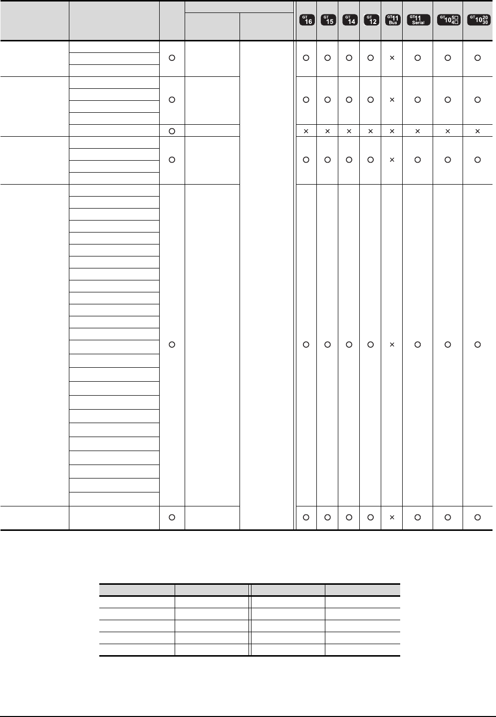
19 - 4 19. GOT MULTI-DROP CONNECTION
19.2 Connectable Model List
(Continued to next page)
*1 When monitoring AnNCPU or A2SCPU, only the following or later software version is used to write to the CPU.
• AnNCPU(S1) with link: Version L or later, AnNCPU(S1) without link: Version H or later
• A2SCPU: Version H or later
*2 GT10 can be connected to CPUs of the following HW versions or later.
*3 Ww and Wr devices cannot be monitored.
*4 SB, SW, Ww, Wr, ER, and BM devices cannot be monitored.
Series Model name Clock
Communication type
Between CPU
and master
module
Between
master module
and GOT
MELSEC-Q
(A mode)*3
Q02CPU-A
RS-232
RS-422
RS-485
Q02HCPU-A
Q06HCPU-A
MELSEC-QnA
(QnACPU)*2*3
Q2ACPU
RS-422
Q2ACPU-S1
Q3ACPU
Q4ACPU
Q4ARCPU RS-422
MELSEC-QnA
(QnASCPU)*2*3
Q2ASCPU
RS-422
Q2ASCPU-S1
Q2ASHCPU
Q2ASHCPU-S1
MELSEC-A
(AnCPU)*4
A2UCPU
RS-422
A2UCPU-S1
A3UCPU
A4UCPU
A2ACPU
A2ACPUP21
A2ACPUR21
A2ACPU-S1
A2ACPUP21-S1
A2ACPUR21-S1
A3ACPU
A3ACPUP21
A3ACPUR21
A1NCPU*1
A1NCPUP21*1
A1NCPUR21*1
A2NCPU*1
A2NCPUP21*1
A2NCPUR21*1
A2NCPU-S1*1
A2NCPUP21-S1*1
A2NCPUR21-S1*1
A3NCPU*1
A3NCPUP21*1
A3NCPUR21*1
MELSEC-A
(AnSCPU)*4 A2USCPU RS-422
PLC type HW/SW Version PLC type HW/SW Version
Q2ACPU DA Q2ASCPU AL
Q2ACPU-S1 DA Q2ASCPU-S1 AL
Q3ACPU DA Q2ASHCPU BL
Q4ACPU EA Q2ASHCPU-S1 BL
Q4ARCPU AL - -
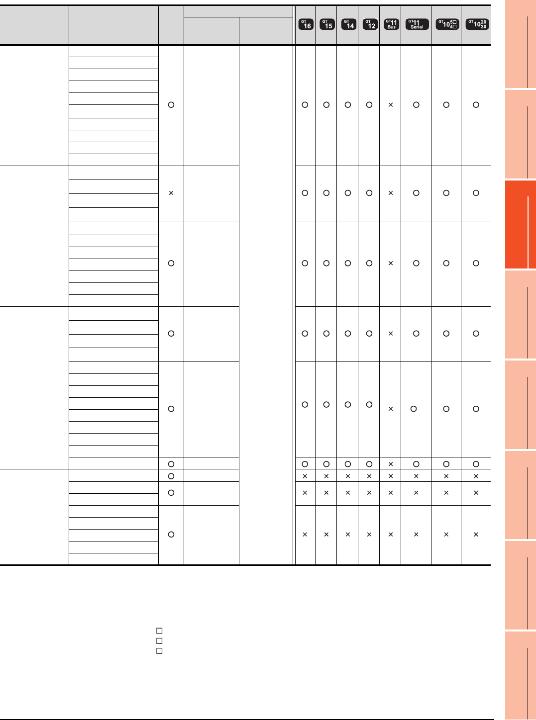
19. GOT MULTI-DROP CONNECTION
19.2 Connectable Model List
19 - 5
17
ROBOT
CONTROLLER
CONNECTION
18
CNC CONNECTION
19
GOT MULTI-DROP
CONNECTION
20
MULTIPLE-GT14, GT12,
GT11, GT10
CONNECTION FUNCTION
21
MULTI-CHANNEL
FUNCTION
22
FA TRANSPARENT
FUNCTION
(Continued to next page)
*1 When monitoring A0J2HCPU or A2CCPU, only the following or later software version is used to write to the CPU.
• A0J2HCPU (with/without link): Version E or later
• A0J2HCPU-DC24: Version B or later
• A2CCPU: Version H or later
*2 When using SV13, SV22, or SV43, use the motion controller CPU on which any of the following main OS version is installed.
• SW6RN-SV13Q : 00E or later
• SW6RN-SV22Q : 00E or later
• SW6RN-SV43Q : 00B or later
*3 Use main modules with the following product numbers.
• Q172CPU: Product number K******* or later
• Q173CPU: Product number J******* or later
*4 Access via the (RS-232) in the multiple CPU system.
*5 SB, SW, Ww, Wr, ER, and BM devices cannot be monitored.
Series Model name Clock
Communication type
Between CPU
and master
module
Between
master module
and GOT
MELSEC-A
(AnSCPU)*5
A2USCPU-S1
RS-422
RS-485
A2USHCPU-S1
A1SCPU
A1SCPUC24-R2
A1SHCPU
A2SCPU*1
A2SHCPU
A1SJCPU
A1SJCPU-S3
A1SJHCPU
MELSEC-A*5
A0J2HCPU*1
RS-422
A0J2HCPUP21*1
A0J2HCPUR21*1
A0J2HCPU-DC24*1
A2CCPU*1
RS-422
A2CCPUP21
A2CCPUR21
A2CCPUC24
A2CCPUC24-PRF
A2CJCPU-S3
A1FXCPU
Motion controller
CPU (Q Series)
Q172CPU*2*3
RS-232
RS-422
Q173CPU*2*3
Q172CPUN*2
Q173CPUN*2
Q172HCPU
RS-232
*4 *4 *4 *4
*4
Q173HCPU
Q172DCPU
Q173DCPU
Q172DCPU-S1
Q173DCPU-S1
Q172DSCPU
Q173DSCPU
Q170MCPU RS-232
Motion controller
CPU (A Series)*5
A273UCPU RS-422
A273UHCPU RS-422
A273UHCPU-S3
A373UCPU
RS-422
A373UCPU-S3
A171SCPU
A171SCPU-S3
A171SCPU-S3N
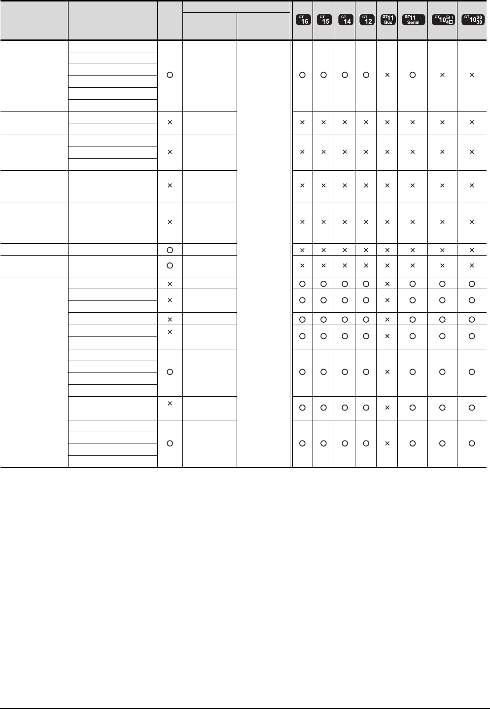
19 - 6 19. GOT MULTI-DROP CONNECTION
19.2 Connectable Model List
(Continued to next page)
*1 It is available by installing the real time clock function board or the EEPROM memory with the real time clock function.
*2 SB, SW, Ww, Wr, ER, and BM devices cannot be monitored.
Series Model name Clock
Communication type
Between CPU
and master
module
Between
master module
and GOT
Motion controller
CPU (A Series)*2
A171SHCPU
RS-422
RS-485
A171SHCPUN
A172SHCPU
A172SHCPUN
A173UHCPU
A173UHCPU-S1
MELSEC-WS WS0-CPU0 RS-232
WS0-CPU1
MELSECNET/H
remote I/O station
QJ72LP25-25
RS-232QJ72LP25G
QJ72BR15
CC-Link IE
Field Network
head module
LJ72GF15-T2 -
CC-Link IE
Field Network
Ethernet adapter
module
NZ2GF-ETB -
CNC C70 Q173NCCPU RS-232
Robot controller CRnQ-700
(Q172DRCPU) RS-232
MELSEC-FX
FX0RS-422
FX0S RS-422
FX0N
FX1RS-422
FX2
*1
RS-422
FX2C
FX1S
RS-232
RS-422
FX1N
FX2N
FX1NC
FX2NC
*1
RS-232
RS-422
FX3G
RS-232
RS-422
FX3GC
FX3U
FX3UC
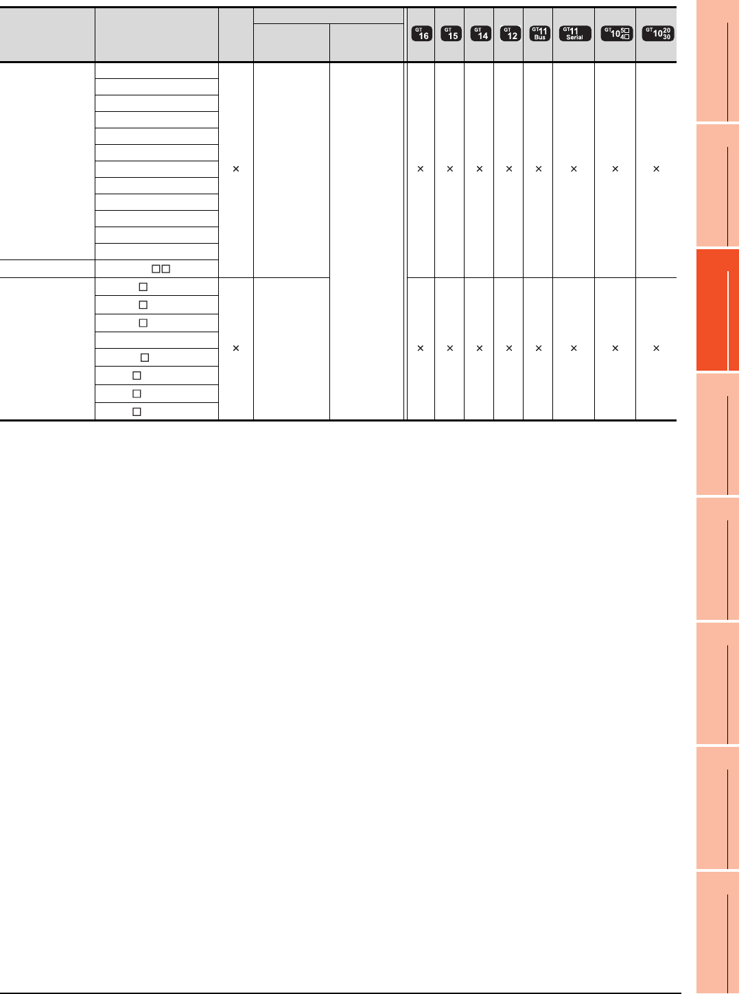
19. GOT MULTI-DROP CONNECTION
19.2 Connectable Model List
19 - 7
17
ROBOT
CONTROLLER
CONNECTION
18
CNC CONNECTION
19
GOT MULTI-DROP
CONNECTION
20
MULTIPLE-GT14, GT12,
GT11, GT10
CONNECTION FUNCTION
21
MULTI-CHANNEL
FUNCTION
22
FA TRANSPARENT
FUNCTION
Series Model name Clock
Communication type
Between CPU
and master
module
Between
master module
and GOT
FREQROL
FREQROL-A500/A500L
RS-422
RS-485
FREQROL-F500/F500L
FREQROL-V500/V500L
FREQROL-E500
FREQROL-S500/S500E
FREQROL-F500J
FREQROL-D700
FREQROL-F700PJ
FREQROL-E700
FREQROL-A700
FREQROL-F700
FREQROL-F700P
MELIPM MD-CX522- K(-A0)
MELSERVO
MR-J2S- A
RS-232
RS-422
MR-J2S- CP
MR-J2S- CL
MR-J2M-P8A
MR-J2M- DU
MR-J3- A
MR-J3- T
MR-J4- A
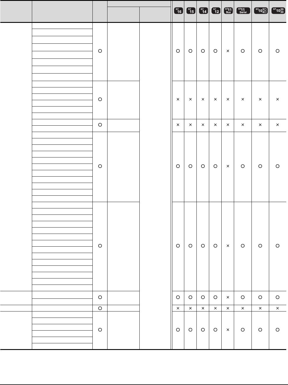
19 - 8 19. GOT MULTI-DROP CONNECTION
19.2 Connectable Model List
Connecting the CPU to the Serial Multi-Drop Connection Unit (hereinafter referred to as "master
module") in computer link connection
The following table shows the connectable models.
(Continued to next page)
*1 When in multiple CPU system configuration, use CPU function version B or later.
*2 Use a module with the upper five digits of the serial No. later than 12042.
*3 Ww and Wr devices cannot be monitored.
Series Model name Clock
Communication type
Between CPU
and master
module
Between
master module
and GOT
MELSEC-Q
(Q mode)*3
Q00JCPU
RS-232
RS-422
RS-485
Q00CPU*1
Q01CPU*1
Q02CPU*1
Q02HCPU*1
Q06HCPU*1
Q12HCPU*1
Q25HCPU*1
Q02PHCPU
RS-232
RS-422
Q06PHCPU
Q12PHCPU
Q25PHCPU
Q12PRHCPU (Main base)
Q25PRHCPU (Main base)
Q12PRHCPU (Extension base) -
Q25PRHCPU (Extension base)
Q00UJCPU
RS-232
RS-422
Q00UCPU
Q01UCPU
Q02UCPU
Q03UDCPU
Q04UDHCPU
Q06UDHCPU
Q10UDHCPU
Q13UDHCPU
Q20UDHCPU
Q26UDHCPU
Q03UDECPU
RS-232
RS-422
Q04UDEHCPU
Q06UDEHCPU
Q10UDEHCPU
Q13UDEHCPU
Q20UDEHCPU
Q26UDEHCPU
Q50UDEHCPU
Q100UDEHCPU
Q03UDVCPU
Q04UDVCPU
Q06UDVCPU
Q13UDVCPU
Q26UDVCPU
C Controller
module
Q12DCCPU-V*4
RS-232
Q24DHCCPU-V
MELSEC-QS QS001CPU -
MELSEC-L*3
L02CPU
RS-232
RS-422
L26CPU
L26CPU-BT
L02CPU-P
L26CPU-PBT
L02SCPU
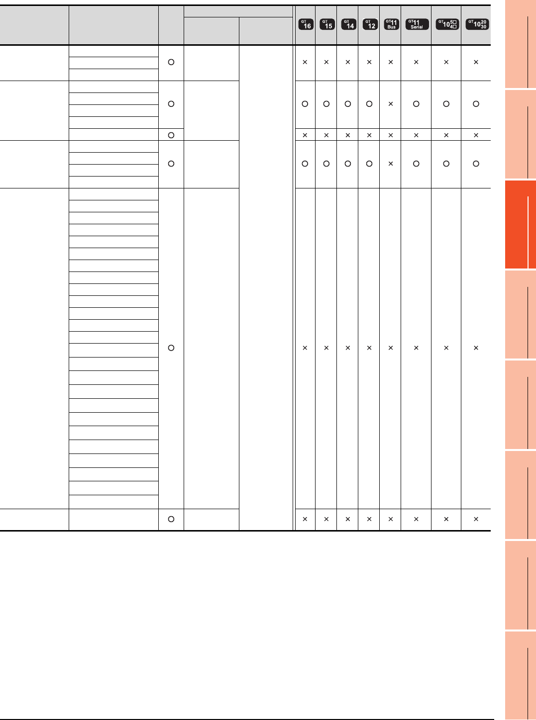
19. GOT MULTI-DROP CONNECTION
19.2 Connectable Model List
19 - 9
17
ROBOT
CONTROLLER
CONNECTION
18
CNC CONNECTION
19
GOT MULTI-DROP
CONNECTION
20
MULTIPLE-GT14, GT12,
GT11, GT10
CONNECTION FUNCTION
21
MULTI-CHANNEL
FUNCTION
22
FA TRANSPARENT
FUNCTION
(Continued to next page)
*1 Ww and Wr devices cannot be monitored.
Series Model name Clock
Communication type
Between CPU
and master
module
Between
master module
and GOT
MELSEC-Q
(A mode)*1
Q02CPU-A
RS-232
RS-422
RS-485
Q02HCPU-A
Q06HCPU-A
MELSEC-QnA
(QnACPU)*1
Q2ACPU
RS-232
RS-422
Q2ACPU-S1
Q3ACPU
Q4ACPU
Q4ARCPU
MELSEC-QnA
(QnASCPU)*1
Q2ASCPU
RS-232
RS-422
Q2ASCPU-S1
Q2ASHCPU
Q2ASHCPU-S1
MELSEC-A
(AnCPU)
A2UCPU
RS-232
RS-422
A2UCPU-S1
A3UCPU
A4UCPU
A2ACPU
A2ACPUP21
A2ACPUR21
A2ACPU-S1
A2ACPUP21-S1
A2ACPUR21-S1
A3ACPU
A3ACPUP21
A3ACPUR21
A1NCPU
A1NCPUP21
A1NCPUR21
A2NCPU
A2NCPUP21
A2NCPUR21
A2NCPU-S1
A2NCPUP21-S1
A2NCPUR21-S1
A3NCPU
A3NCPUP21
A3NCPUR21
MELSEC-A
(AnSCPU) A2USCPU RS-232
RS-422
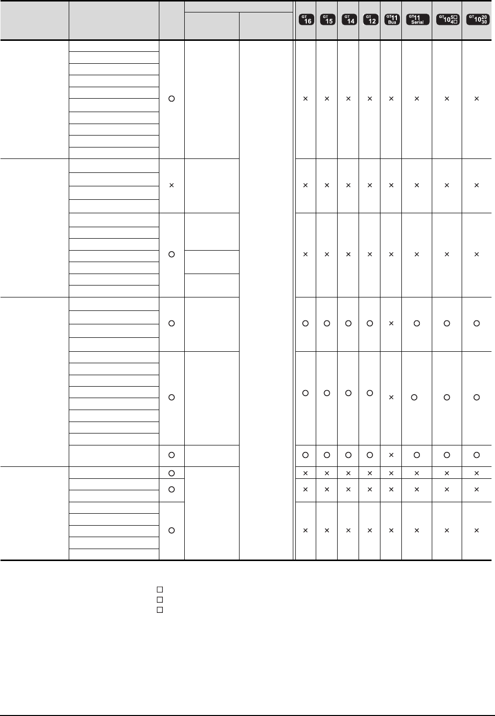
19 - 10 19. GOT MULTI-DROP CONNECTION
19.2 Connectable Model List
(Continued to next page)
*1 When using SV13, SV22, or SV43, use the motion controller CPU on which any of the following main OS version is installed.
• SW6RN-SV13Q : 00E or later
• SW6RN-SV22Q : 00E or later
• SW6RN-SV43Q : 00B or later
*2 Use main modules with the following product numbers.
• Q172CPU: Product number K******* or later
• Q173CPU: Product number J******* or later
*3 Access via the (RS-232) in the multiple CPU system.
Series Model name Clock
Communication type
Between CPU
and master
module
Between
master module
and GOT
MELSEC-A
(AnSCPU)
A2USCPU-S1
RS-232
RS-422
RS-485
A2USHCPU-S1
A1SCPU
A1SCPUC24-R2
A1SHCPU
A2SCPU
A2SHCPU
A1SJCPU
A1SJCPU-S3
A1SJHCPU
MELSEC-A
A0J2HCPU
RS-422
A0J2HCPUP21
A0J2HCPUR21
A0J2HCPU-DC24
A2CCPU
-
A2CCPUP21
A2CCPUR21
A2CCPUC24 RS-232
RS-422
A2CCPUC24-PRF
A2CJCPU-S3 -
A1FXCPU
Motion controller
CPU (Q Series)
Q172CPU*1*2
RS-232
RS-422
Q173CPU*1*2
Q172CPUN*1*2
Q173CPUN*1*2
Q172HCPU
RS-232
RS-422 *3 *3 *3 *3
*3
Q173HCPU
Q172DCPU
Q173DCPU
Q172DCPU-S1
Q173DCPU-S1
Q172DSCPU
Q173DSCPU
Q170MCPU RS-232
RS-422
Motion controller
CPU (A Series)
A273UCPU
RS-232
RS-422
A273UHCPU
A273UHCPU-S3
A373UCPU
A373UCPU-S3
A171SCPU
A171SCPU-S3
A171SCPU-S3N
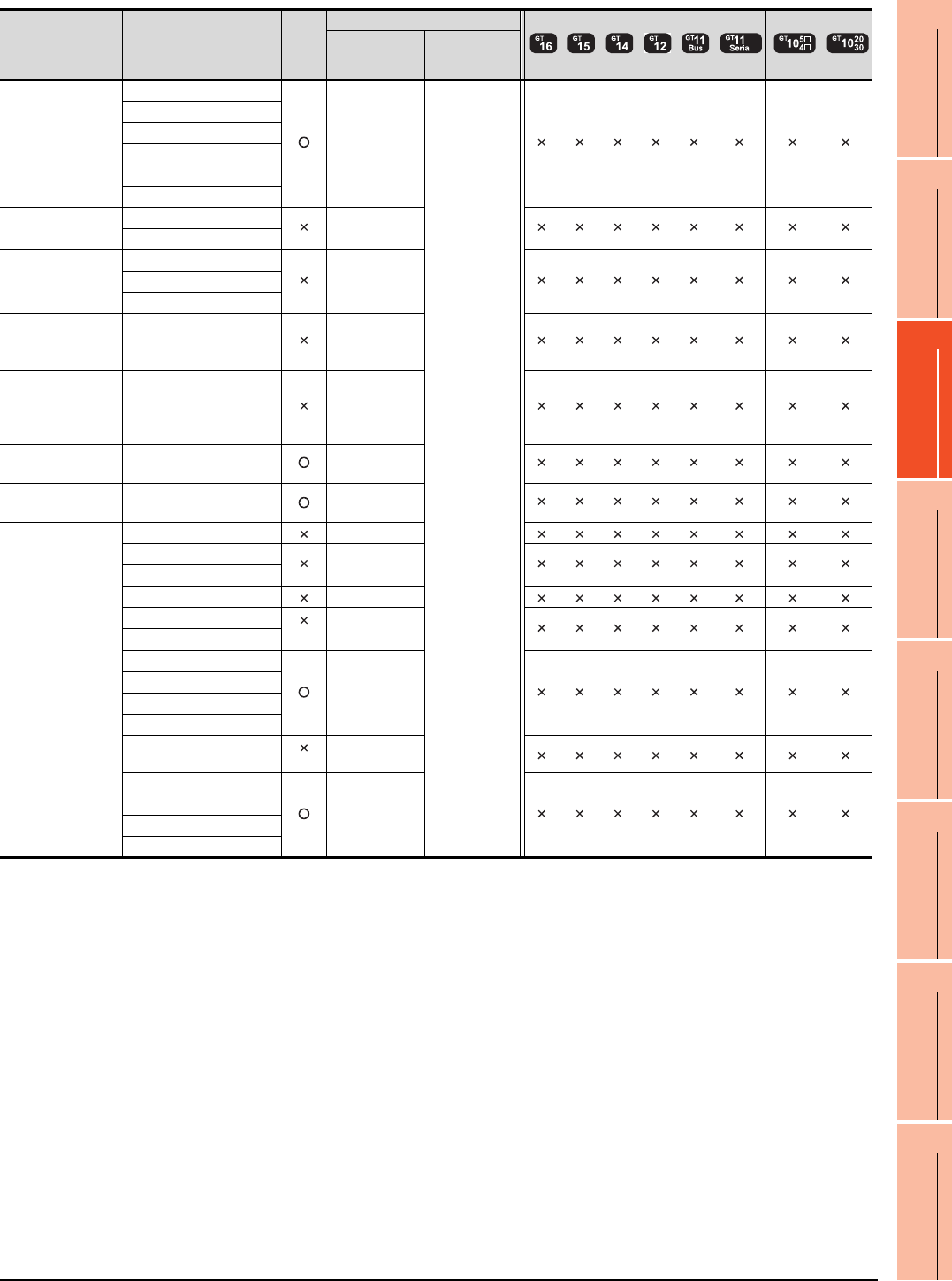
19. GOT MULTI-DROP CONNECTION
19.2 Connectable Model List
19 - 11
17
ROBOT
CONTROLLER
CONNECTION
18
CNC CONNECTION
19
GOT MULTI-DROP
CONNECTION
20
MULTIPLE-GT14, GT12,
GT11, GT10
CONNECTION FUNCTION
21
MULTI-CHANNEL
FUNCTION
22
FA TRANSPARENT
FUNCTION
(Continued to next page)
*1 It is available by installing the real time clock function board or the EEPROM memory with the real time clock function.
Series Model name Clock
Communication type
Between CPU
and master
module
Between
master module
and GOT
Motion controller
CPU (A Series)
A171SHCPU
RS-232
RS-422
RS-485
A171SHCPUN
A172SHCPU
A172SHCPUN
A173UHCPU
A173UHCPU-S1
MELSEC-WS WS0-CPU0 -
WS0-CPU1
MELSECNET/H
remote I/O station
QJ72LP25-25
RS-232
RS-422
QJ72LP25G
QJ72BR15
CC-Link IE
Field Network
head module
LJ72GF15-T2 -
CC-Link IE
Field Network
Ethernet adapter
module
NZ2GF-ETB -
CNC C70 Q173NCCPU RS-232
RS-422
Robot controller CRnQ-700
(Q172DRCPU) -
MELSEC-FX
FX0-
FX0S -
FX0N
FX1-
FX2
*1
-
FX2C
FX1S
-
FX1N
FX2N
FX1NC
FX2NC *1 -
FX3G
-
FX3GC
FX3U
FX3UC
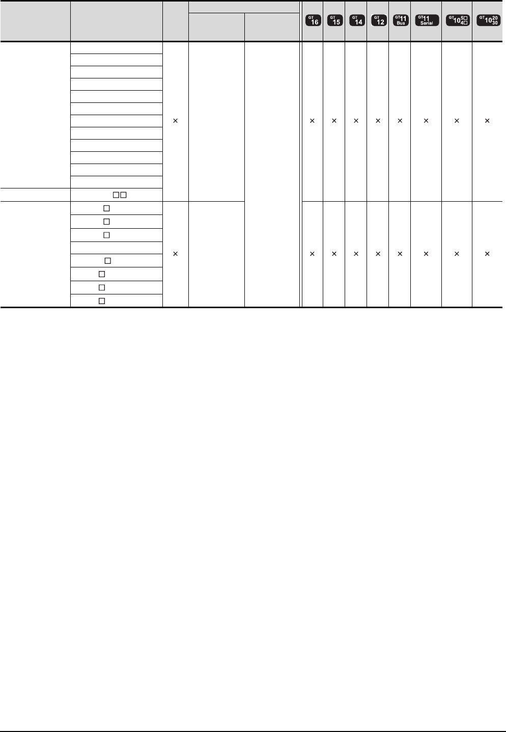
19 - 12 19. GOT MULTI-DROP CONNECTION
19.2 Connectable Model List
Series Model name Clock
Communication type
Between CPU
and master
module
Between
master module
and GOT
FREQROL
FREQROL-A500/A500L
RS-422
RS-485
FREQROL-F500/F500L
FREQROL-V500/V500L
FREQROL-E500
FREQROL-S500/S500E
FREQROL-F500J
FREQROL-D700
FREQROL-F700PJ
FREQROL-E700
FREQROL-A700
FREQROL-F700
FREQROL-F700P
MELIPM MD-CX522- K(-A0)
MELSERVO
MR-J2S- A
RS-232
RS-422
MR-J2S- CP
MR-J2S- CL
MR-J2M-P8A
MR-J2M- DU
MR-J3- A
MR-J3- T
MR-J4- A
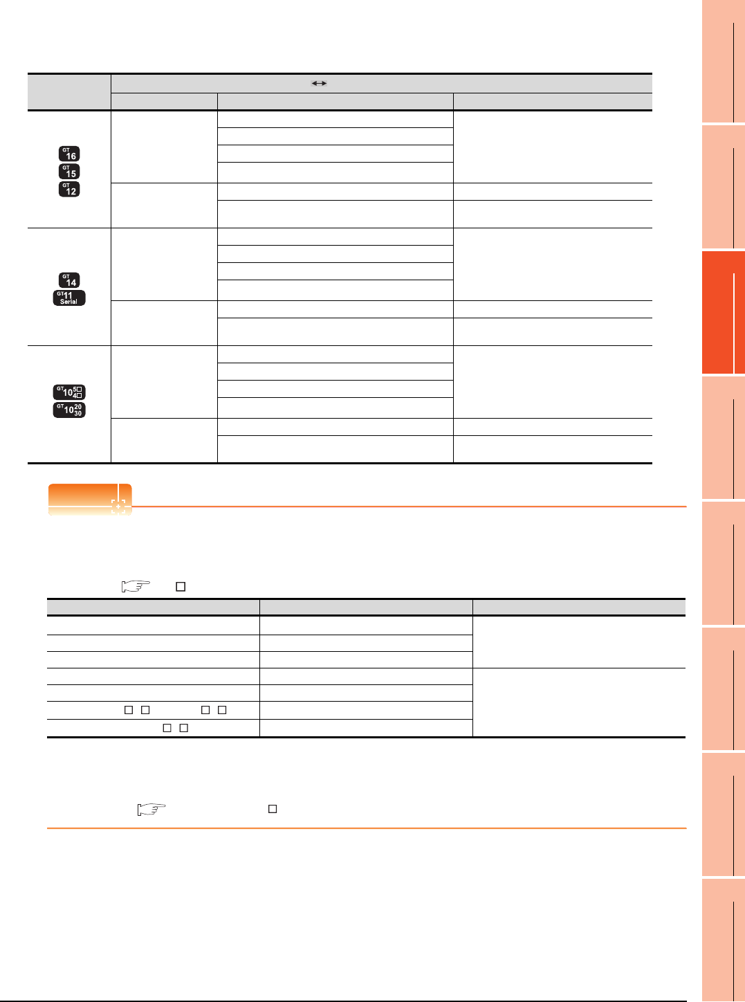
19. GOT MULTI-DROP CONNECTION
19.2 Connectable Model List
19 - 13
17
ROBOT
CONTROLLER
CONNECTION
18
CNC CONNECTION
19
GOT MULTI-DROP
CONNECTION
20
MULTIPLE-GT14, GT12,
GT11, GT10
CONNECTION FUNCTION
21
MULTI-CHANNEL
FUNCTION
22
FA TRANSPARENT
FUNCTION
[Controller Type] and [Communication driver] of GT Designer3
The following table shows the [Controller Type] and [Communication driver] of GT Designer3 for which the GOT
multi-drop connection is available.
POINTPOINTPOINT
GOT models support the GOT Multi-Drop Connection
The following GOT models support the GOT Multi-Drop Connection.
For the confirming method of hardware version, refer to the following.
GT User's Manual
*1 When connecting GT16/GT15 in multi-drop connection, the writing of the standard monitor OS and communication driver to the
GOT from GT Designer3 (Version 1.14Q or later), as well as the writing of the standard monitor OS and communication driver to
the serial multi-drop connection unit are required.
For details of the OS installation, refer to the following.
GT Designer3 Version Screen Design Manual (Fundamentals)
GOT type PLC Serial Multi-Drop Connection Unit
Connection type Type Serial Multi-Drop Connection driver
DIRECT
CONNECTION TO
CPU
COMPUTER LINK
CONNECTION
MELSEC-QnU/DC, Q17nD/M/NC/DR, CRnD-700
QnA/L/Q CPU
MELSEC-QnA/Q/QS, MELDAS C6*
MELSEC-Q(MULTI)/Q MOTION
MELSEC-L
DIRECT
CONNECTION TO
CPU
MELSEC-A MELSEC-A
MELSEC-FX MELSEC-FX
DIRECT
CONNECTION TO
CPU
COMPUTER LINK
CONNECTION
MELSEC-QnU/DC, Q17nD/M/NC/DR
QnA/L/Q CPU
MELSEC-QnA/Q, MELDAS C6*
MELSEC-Q(MULTI)/Q MOTION
MELSEC-L
DIRECT
CONNECTION TO
CPU
MELSEC-A MELSEC-A
MELSEC-FX MELSEC-FX
(RS-422)
DIRECT
CONNECTION TO
CPU
COMPUTER LINK
CONNECTION
MELSEC-QnU/DC
QnA/L/Q CPU
MELSEC-QnA/Q
MELSEC-Q(MULTI)
MELSEC-L
DIRECT
CONNECTION TO
CPU
MELSEC-A MELSEC-A
MELSEC-FX MELSEC-FX
GOT Hardware version Standard monitor OS
GT16, GT15*1, GT14 version A or later
-
GT1155-QTBD version C or later
GT1155-QSBD, GT1150-QLBD version F or later
GT1055-QSBD, GT1050-QBBD version C or later
Standard monitor OS[01.12.**]or later
GT1045-QSBD, GT1040-QBBD version A or later
GT1030-L D , GT1030-H D version B or later
GT1020-L D version E or later
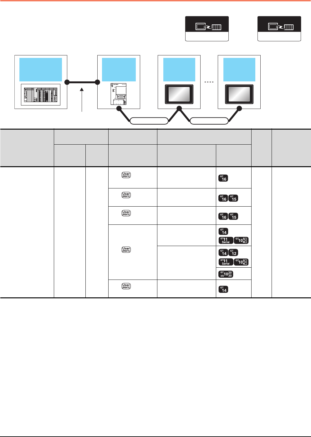
19 - 14 19. GOT MULTI-DROP CONNECTION
19.3 System Configuration
19.3 System Configuration
*1 Connect it to the RS-422/485 interface (built into GOT).
*2 The maximum distance from the PLC to the terminal GOT.
*3 When the number of connected GOTs is increased, the response performance decreases.
*4 Connect it to the RS-232 interface (built into GOT).
*5 Cannot be connected to products with input voltage 5V.
(Serial Multi-Drop Connection Unit)
Connection type
dependent
Communication driver
(GOT)
Multi-Drop (Slave)
Communication driver
Connection cable
GOT GOT
Serial multi
drop connection
unit
PLC
Varies according to the
connection type.
Connection cable
PLC
Serial Multi-Drop
Connection Unit Connection cable GOT
Max.
distance
Number of
connectable
equipment
Model
Commun
ication
type
Cable model Option device Model
For details of the system
configuration between
the Serial Multi-Drop
Connection Unit and
PLC, refer to the
corresponding section.
GT01-RS4-M RS-485
RS485
connection diagram 2)
FA-LTBGTR4CBL05 (0.5m)
FA-LTBGTR4CBL10 (1m)
FA-LTBGTR4CBL20 (2m)
500m*2
16 GOTs for
Serial Multi-Drop
Connection Unit*3
RS485
connection diagram 1)
GT15-RS4-9S
RS485
connection diagram 3)
GT15-RS4-TE
RS485
connection diagram 4)
GT10-9PT5S*1
- (Built into GOT)
*5
RS485
connection diagram 5) GT14-RS2T4-9P*4
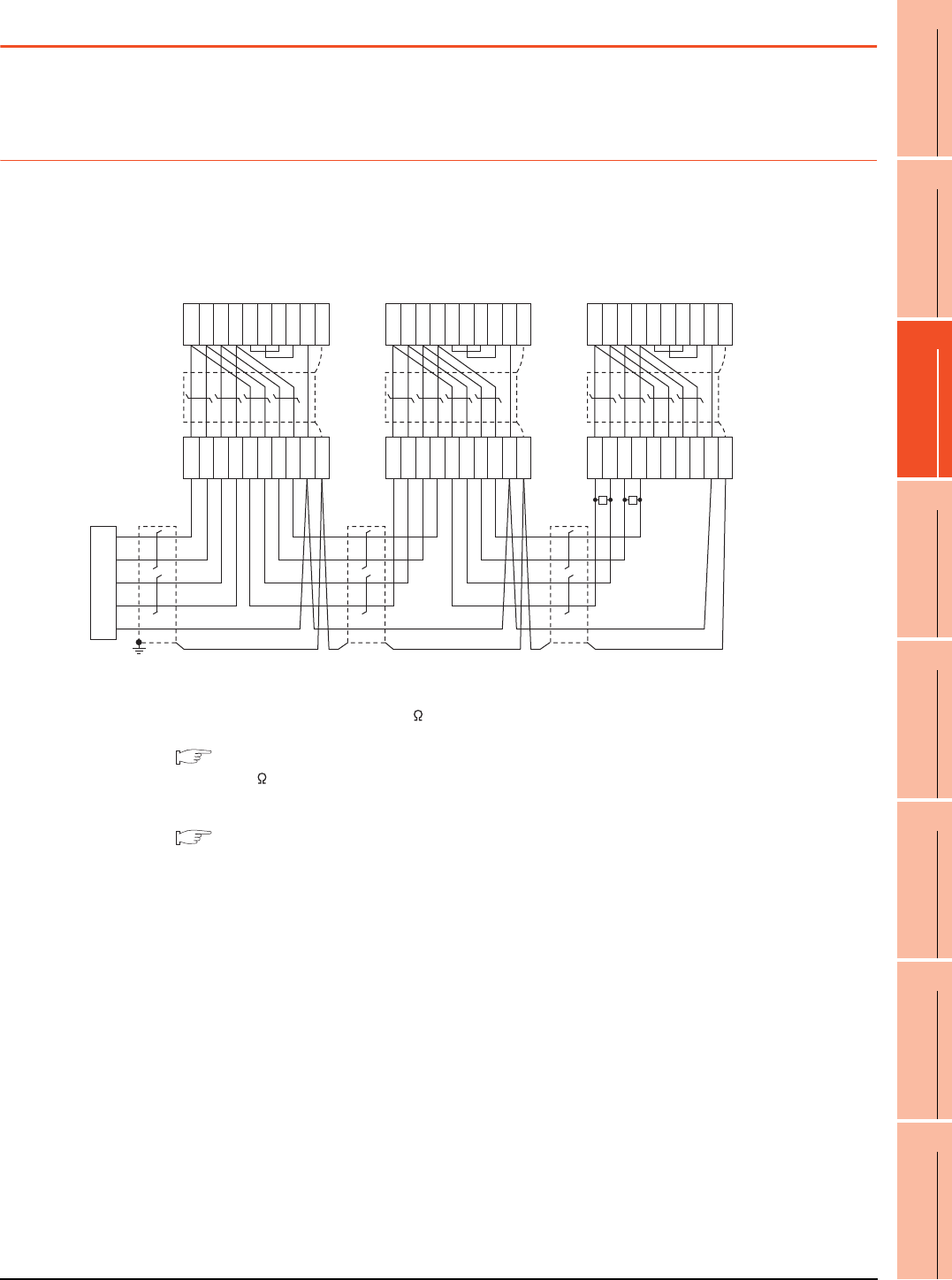
19. GOT MULTI-DROP CONNECTION
19.4 Connection Diagram
19 - 15
17
ROBOT
CONTROLLER
CONNECTION
18
CNC CONNECTION
19
GOT MULTI-DROP
CONNECTION
20
MULTIPLE-GT14, GT12,
GT11, GT10
CONNECTION FUNCTION
21
MULTI-CHANNEL
FUNCTION
22
FA TRANSPARENT
FUNCTION
19.4 Connection Diagram
The following diagram shows the cable connection between the serial multi-drop connection unit and the GOT.
19.4.1 RS-485 cable
Connection diagram
*1 Use the twisted pair cable for SDA/SDB and RDA/RDB.
*2 Set the terminating resistor selector to "330 ".
*3 Set the terminating resistor setting switch of the GOT main unit to "Disable".
1.4.3 Terminating resistors of GOT
*4 Connect a 330 terminating resistor to the GOT to be a terminal.
*5 Make sure to ground a cable shield line by applying Class D Grounding.
*6 For the cable for converting D-sub9 pin connector to terminal block, refer to the following.
Precautions when preparing a cable(2)
RS485 connection diagram 1)
Serial multi drop
connection unit
Terminal
block
GOT side (9 pin)
RDA
*1
RDB
*1
SDA
*1
SDB
*1
SG
SDA
SDB
RDA
RDB
SDA
SDB
RDA
RDB
SG
FG
SDA
SDB
RDA
RDB
RSA
RSB
CSA
CSB
SG
SHELL
1
6
2
7
3
8
4
9
5
*5
*3
GOT side (9 pin)
*3
GOT side (9 pin)
*3
*6
Terminal
block
*6
Terminal
block
*6
SDA
SDB
RDA
RDB
SDA
SDB
RDA
RDB
SG
FG
SDA
SDB
RDA
RDB
RSA
RSB
CSA
CSB
SG
SHELL
1
6
2
7
3
8
4
9
5
SDA
SDB
RDA
RDB
SDA
SDB
RDA
RDB
SG
FG
SDA
SDB
RDA
RDB
RSA
RSB
CSA
CSB
SG
SHELL
1
6
2
7
3
8
4
9
5
R
*4
R
*2
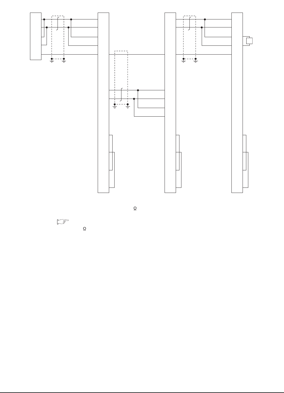
19 - 16 19. GOT MULTI-DROP CONNECTION
19.4 Connection Diagram
*1 Use the twisted pair cable for SDA/SDB.
*2 Set the terminating resistor selector to "110 ".
*3 Set the terminating resistor setting switch of the GOT main unit to "Disable".
1.4.3 Terminating resistors of GOT
*4 Connect a 110 terminating resistor to the GOT to be a terminal.
*5 Make sure to ground a cable shield line by applying Class D Grounding.
RS485 connection diagram 2)
(For 1 pair wiring)
CON side*3(20 pin) CON side*3(20 pin) CON side*3(20 pin)
Serial multi drop
connection unit
6
8
10
12
2
1
3
4
5
7
9
11
13
14
15
16
17
18
19
20
SDA*1
SDB*1
RDA
RDB
SG
SDA1(TXD1+)
SDB1(TXD1-)
RDA1(RXD1+)
RDB1(RXD1-)
SG
NC
NC
NC
SDA2(TXD2+)
SDB2(TXD2-)
RDA2(RXD2+)
RDB2(RXD2-)
NC
RSA(RTS+)
NC
RSB(RTS-)
NC
CSA(CTS+)
NC
CSB(CTS-)
*2
*5*5*5*5
5
7
9
11
2
1
3
4
6
8
10
12
13
14
15
16
17
18
19
20
SDA2(TXD2+)
SDB2(TXD2-)
RDA2(RXD2+)
RDB2(RXD2-)
SG
NC
NC
NC
SDA1(TXD1+)
SDB1(TXD1-)
RDA1(RXD1+)
RDB1(RXD1-)
NC
RSA(RTS+)
NC
RSB(RTS-)
NC
CSA(CTS+)
NC
CSB(CTS-)
*5
*5
6
8
10
12
2
1
3
4
5
7
9
11
13
14
15
16
17
18
19
20
SDA1(TXD1+)
SDB1(TXD1-)
RDA1(RXD1+)
RDB1(RXD1-)
SG
NC
NC
NC
SDA2(TXD2+)
SDB2(TXD2-)
RDA2(RXD2+)
RDB2(RXD2-)
NC
RSA(RTS+)
NC
RSB(RTS-)
NC
CSA(CTS+)
NC
CSB(CTS-)
*4
R
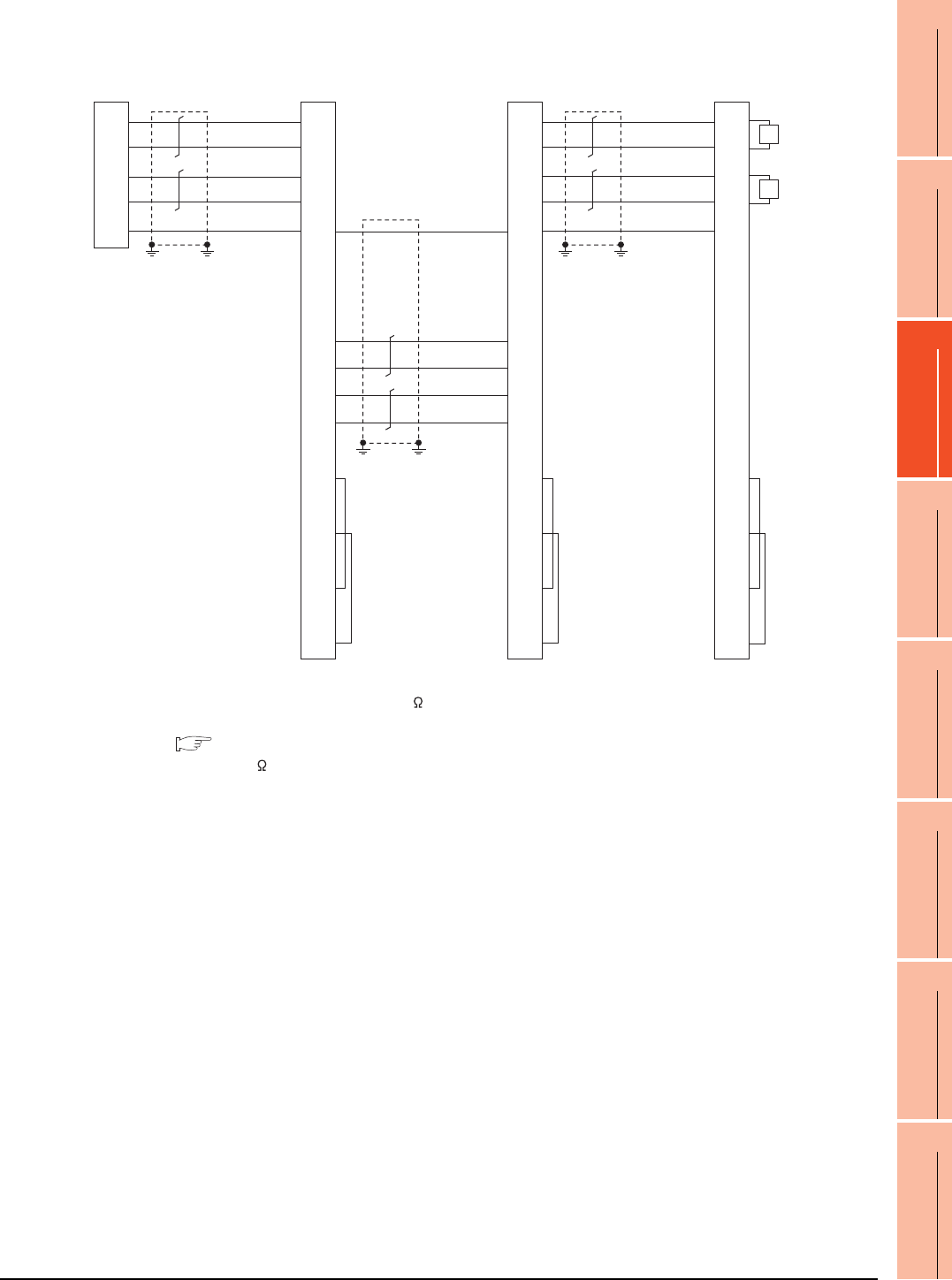
19. GOT MULTI-DROP CONNECTION
19.4 Connection Diagram
19 - 17
17
ROBOT
CONTROLLER
CONNECTION
18
CNC CONNECTION
19
GOT MULTI-DROP
CONNECTION
20
MULTIPLE-GT14, GT12,
GT11, GT10
CONNECTION FUNCTION
21
MULTI-CHANNEL
FUNCTION
22
FA TRANSPARENT
FUNCTION
*1 Use the twisted pair cable for SDA/SDB and RDA/RDB.
*2 Set the terminating resistor selector to "330 ".
*3 Set the terminating resistor setting switch of the GOT main unit to "Disable".
1.4.3 Terminating resistors of GOT
*4 Connect a 330 terminating resistor to the GOT to be a terminal.
*5 Make sure to ground a cable shield line by applying Class D Grounding.
RS485 connection diagram 2)
(For 2 pair wiring)
CON side*3(20pin) CON side*3(20pin) CON side*3(20pin)
Serial multi drop
connection unit
6
8
10
12
2
1
3
4
5
7
9
11
13
14
15
16
17
18
19
20
RDA*1
RDB*1
SDA*1
SDB*1
SG
SDA1(TXD1+)
SDB1(TXD1-)
RDA1(RXD1+)
RDB1(RXD1-)
SG
NC
NC
NC
SDA2(TXD2+)
SDB2(TXD2-)
RDA2(RXD2+)
RDB2(RXD2-)
NC
RSA(RTS+)
NC
RSB(RTS-)
NC
CSA(CTS+)
NC
CSB(CTS-)
*2
*5*5
5
7
9
11
2
1
3
4
6
8
10
12
13
14
15
16
17
18
19
20
SDA2(TXD2+)
SDB2(TXD2-)
RDA2(RXD2+)
RDB2(RXD2-)
SG
NC
NC
NC
SDA1(TXD1+)
SDB1(TXD1-)
RDA1(RXD1+)
RDB1(RXD1-)
NC
RSA(RTS+)
NC
RSB(RTS-)
NC
CSA(CTS+)
NC
CSB(CTS-)
*5*5
6
8
10
12
2
1
3
4
5
7
9
11
13
14
15
16
17
18
19
20
SDA1(TXD1+)
SDB1(TXD1-)
RDA1(RXD1+)
RDB1(RXD1-)
SG
NC
NC
NC
SDA2(TXD2+)
SDB2(TXD2-)
RDA2(RXD2+)
RDB2(RXD2-)
NC
RSA(RTS+)
NC
RSB(RTS-)
NC
CSA(CTS+)
NC
CSB(CTS-)
*5*5
*4
R
*4
R
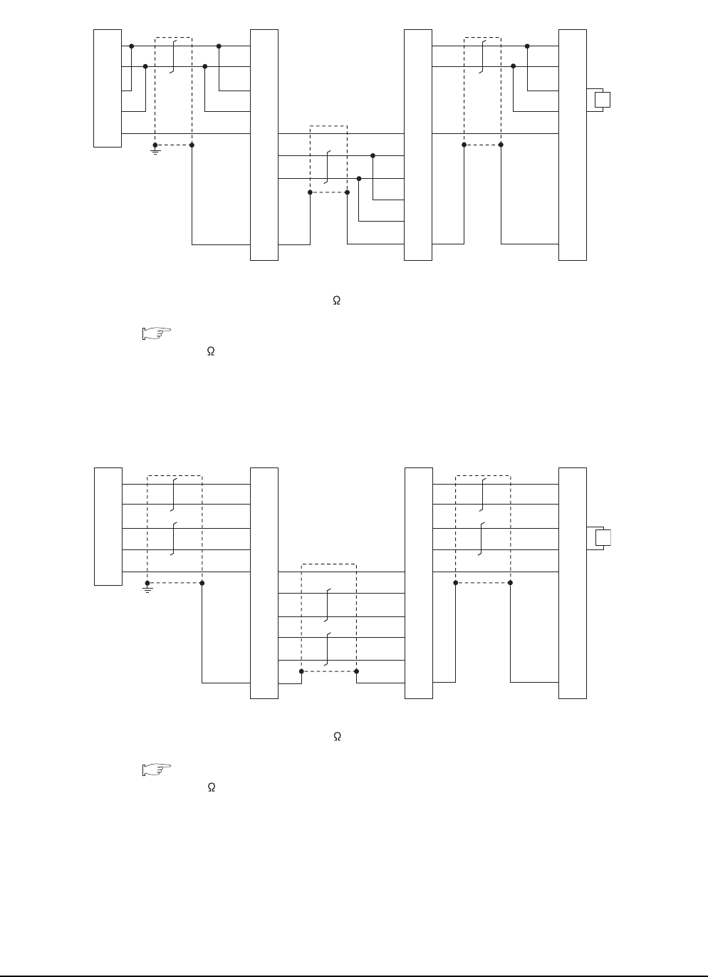
19 - 18 19. GOT MULTI-DROP CONNECTION
19.4 Connection Diagram
*1 Use the twisted pair cable for SDA/SDB.
*2 Set the terminating resistor selector to "110 ".
*3 Set the terminating resistor setting switch of the GOT main unit to "Disable".
1.4.3 Terminating resistors of GOT
*4 Connect a 110 terminating resistor to the GOT to be a terminal.
*5 Make sure to ground a cable shield line by applying Class D Grounding.
*1 Use the twisted pair cable for SDA/SDB, RDA/RDB.
*2 Set the terminating resistor selector to "330 ".
*3 Set the terminating resistor setting switch of the GOT main unit to "Disable".
1.4.3 Terminating resistors of GOT
*4 Connect a 330 terminating resistor to the GOT to be a terminal.
*5 Make sure to ground a cable shield line by applying Class D Grounding.
RS485 connection diagram 3)
(For 1 pair wiring)
GOT side
*3
GOT side
*3
GOT side
*3
Serial multi drop
connection unit
*2
1
2
3
4
9
5
6
7
8
10
SDA
*1
SDB
*1
RDA
RDB
SG
SDA1
SDB1
RDA1
RDB1
SG
SDA2
SDB2
RDA2
RDB2
FG
*5
5
6
7
8
9
1
2
3
4
10
SDA2
SDB2
RDA2
RDB2
SG
SDA1
SDB1
RDA1
RDB1
FG
1
2
3
4
9
5
6
7
8
10
SDA1
SDB1
RDA1
RDB1
SG
SDA2
SDB2
RDA2
RDB2
FG
*4
R
RS485 connection diagram 3)
(For 2 pair wiring)
1
2
3
4
9
5
6
7
8
10
RDA*1
RDB*1
SDA*1
SDB*1
SG
SDA1
SDB1
RDA1
RDB1
SG
SDA2
SDB2
RDA2
RDB2
FG
*5
5
6
7
8
9
1
2
3
4
10
SDA2
SDB2
RDA2
RDB2
SG
SDA1
SDB1
RDA1
RDB1
FG
1
2
3
4
9
5
6
7
8
10
SDA1
SDB1
RDA1
RDB1
SG
SDA2
SDB2
RDA2
RDB2
FG
*4
R
Serial multi drop
connection unit *2GOT side*3GOT side*3GOT side*3
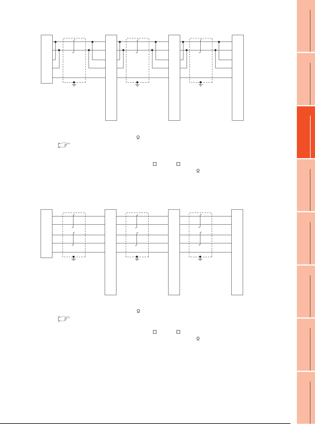
19. GOT MULTI-DROP CONNECTION
19.4 Connection Diagram
19 - 19
17
ROBOT
CONTROLLER
CONNECTION
18
CNC CONNECTION
19
GOT MULTI-DROP
CONNECTION
20
MULTIPLE-GT14, GT12,
GT11, GT10
CONNECTION FUNCTION
21
MULTI-CHANNEL
FUNCTION
22
FA TRANSPARENT
FUNCTION
*1 Set the terminating resistor selector to "OPEN".
*2 Set the terminating resistor selector to "110 ".
1.4.3 Terminating resistors of GOT
*3 Set the 1pair/2pair signal selection switch to "1pair" when using the connection conversion adapter.
In that case, transition wiring is not necessary between SDA and RDA or SDB and RDB.
*4 This is the connector pin No. of GT14, GT11, GT105 , or GT104 main unit.
*5 Make sure to ground a cable shield line by applying Class D Grounding (100 or less).
*1 Set the terminating resistor selector to "OPEN".
*2 Set the terminating resistor selector to "330 ".
1.4.3 Terminating resistors of GOT
*3 Set the 1pair/2pair signal selection switch to "2pair" when using the connection conversion adapter.
*4 This is the connector pin No. of GT14, GT11, GT105 , or GT104 main unit.
*5 Make sure to ground a cable shield line by applying Class D Grounding (100 or less).
RS485 connection diagram 4)
(For 1 pair wiring)
GOT side*1 *3GOT side*1 *3
Serial multi drop
connection unit
1
6
2
7
5
3
8
4
9
SDA
SDB
RDA
RDB
SG
SDA
SDB
RDA
RDB
SG
RSA
RSB
CSA
CSB
*2
*5
1
6
2
7
5
3
8
4
9
SDA
SDB
RDA
RDB
SG
RSA
RSB
CSA
CSB
*5
*4*4*4
GOT side*2 *3
1
6
2
7
5
3
8
4
9
SDA
SDB
RDA
RDB
SG
RSA
RSB
CSA
CSB
*5
*3
*3
*3
RS485 connection diagram 4)
(For 2 pair wiring)
GOT side
*1 *3
Serial multi drop
connection unit
1
6
2
7
5
3
8
4
9
RDA
RDB
SDA
SDB
SG
SDA
SDB
RDA
RDB
SG
RSA
RSB
CSA
CSB
*2
*5
GOT side
*1 *3
1
6
2
7
5
3
8
4
9
SDA
SDB
RDA
RDB
SG
RSA
RSB
CSA
CSB
*5
*4*4*4
GOT side
*2 *3
1
6
2
7
5
3
8
4
9
SDA
SDB
RDA
RDB
SG
RSA
RSB
CSA
CSB
*5
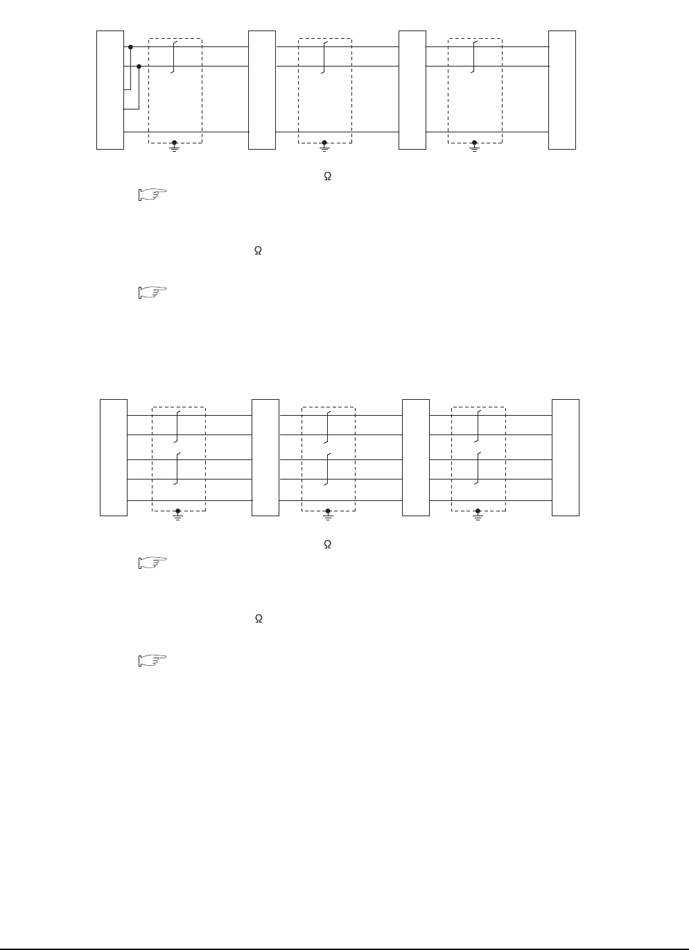
19 - 20 19. GOT MULTI-DROP CONNECTION
19.4 Connection Diagram
*1 Set the terminating resistor selector to "110 ".
19.6.3 Setting switches
*2 Set the 2-wire/4-wire terminating resistor setting switch of the RS-232/485 signal conversion adaptor as follows.
2-wire type/4-wire type: 2-wire type (1Pair)
• When GOT is a terminal
Terminating resistor: 110
• When GOT is not a terminal
Terminating resistor: OPEN
1.4.4 Setting the RS-232/485 signal conversion adaptor
*3 Make sure to ground a cable shield line by applying Class D Grounding (100 or less).
*1 Set the terminating resistor selector to "110 ".
19.6.3 Setting switches
*2 Set the 2-wire/4-wire terminating resistor setting switch of the RS-232/485 signal conversion adaptor as follows.
2-wire type/4-wire type: 4-wire type (2Pair)
• When GOT is a terminal
Terminating resistor: 330
• When GOT is not a terminal
Terminating resistor: OPEN
1.4.4 Setting the RS-232/485 signal conversion adaptor
*3 Make sure to ground a cable shield line by applying Class D Grounding (100 or less).
RS485 connection diagram 5)
(For 1 pair wiring)
GOT side
*2
GOT side
*2
GOT side
*2
Serial multi drop
connection unit
SDA
SDB
RDA
RDB
SG
SDA
SDB
RDA
RDB
SG
*1
*3
SDA
SDB
RDA
RDB
SG
*3
SDA
SDB
RDA
RDB
SG
*3
RS485 connection diagram 5)
(For 2 pair wiring)
GOT side*2
Serial multi drop
connection unit
SDA
SDB
RDA
RDB
SG
RDA
RDB
SDA
SDB
SG
*1
*3
GOT side*2
SDA
SDB
RDA
RDB
SG
*3
GOT side*2
SDA
SDB
RDA
RDB
SG
*3
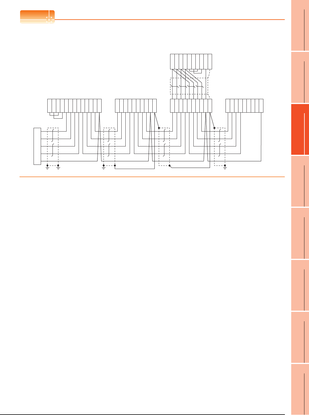
19. GOT MULTI-DROP CONNECTION
19.4 Connection Diagram
19 - 21
17
ROBOT
CONTROLLER
CONNECTION
18
CNC CONNECTION
19
GOT MULTI-DROP
CONNECTION
20
MULTIPLE-GT14, GT12,
GT11, GT10
CONNECTION FUNCTION
21
MULTI-CHANNEL
FUNCTION
22
FA TRANSPARENT
FUNCTION
POINTPOINTPOINT
Mixed wiring with various GOTs
The GOT multi-drop connection can be used with various GOTs mixed.
GT16
(FA-LTBGTR4CBL□□)
GT16, GT15
(GT15-RS4-TE)
GT11, GT10
(GT10-9PT5S)
GT16, GT15
(GT15-RS4-9S)
User-created
terminal block
RDA
RDB
SDA
SDB
SG
RSA
RSB
CSA
CSB
SDA1
SDB1
RDA1
RDB1
SDA2
SDB2
RDA2
RDB2
SG
RDB1
RDA1
SDB1
SDA1
RDB2
RDA2
SDB2
SDA2
SG
FG
SDA1
SDB1
RDA1
RDB1
SDA2
SDB2
RDA2
RDB2
SG
FG
RDB
RDA
SDB
SDA
RSA
RSB
CSA
CSB
SG
SDA
SDB
RDA
RDB
RSA
RSB
CSA
CSB
SG
SHELL
Example of mixed wiring with various GOTs
Serial multi drop
connection unit
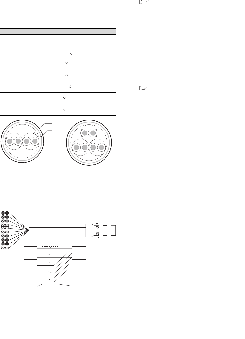
19 - 22 19. GOT MULTI-DROP CONNECTION
19.4 Connection Diagram
Precautions when preparing a cable
(1) Cable
Use a shielded twisted pair cable of 0.3mm2 or more as
a cable for GOT multi-drop connection.The following
shows recommended model names and manufacturers
of the cable to be used.
(2) Cable for converting D-sub9 pin connector to
terminal block
Create by yourself, referring to the following connection
diagram.
Make sure to connect the wiring branched on the GOT side
connector.
Use a shielded twisted pair cable of 0.2mm2 or more.
Use an applicable cable to D-sub connector.
Wiring should be the shortest distance.
(3) GOT side connector
For the GOT side connector, refer to the following.
1.4.1 GOT connector specifications
Connecting terminating resistors
When connecting a Serial Multi-Drop Connection Unit
to the GOT, a terminating resistor must be connected to
the GOT.
(a) For GT16, GT15, GT12
Set the terminating resistor setting switch.
(b) For GT14, GT11, GT10
Set the terminating resistor selector switch.
For the procedure to set the terminating resistor, refer
to the following.
1.4.3 Terminating resistors of GOT
Manufacturer Model Remark
Mitsubishi Cable
Industries,Ltd SPEV(SB)-0.5-2P Two-pair cable of
0.5mm2
Showa Electric Wire &
Cable Co.,Ltd
KMPEV-SB
CWS-178 0.5SQ 2P
Two-pair cable of
0.5mm2
Sumitomo Electric
Industries.,Ltd
DPEV SB 0.3 3P
Three-pair cable of
0.3mm2
DPEV SB 0.5 3P
Three-pair cable of
0.5mm2
The Furukawa Electric
Co.,Ltd D-KPEV-SB 0.5 3P
Three-pair cable of
0.5mm2
Fujikura Ltd.
IPEV-SB 2P 0.3 mm2Two-pair cable of
0.3mm2
IPEV-SB 2P 0.5 mm2Two-pair cable of
0.5mm2
Pair
Shield
Two-pair cable structural
drawing example
Three-pair cable structural
drawing example
Example of connection diagram for 2 pair wiring
SDA1
SDB1
RDA1
RDB1
SDA2
SDB2
RDA2
RDB2
SG
FG
SDA
SDB
RDA
RDB
SG
RSA
RSB
CSA
CSB
FG
1
6
2
7
5
3
8
4
9
Shell
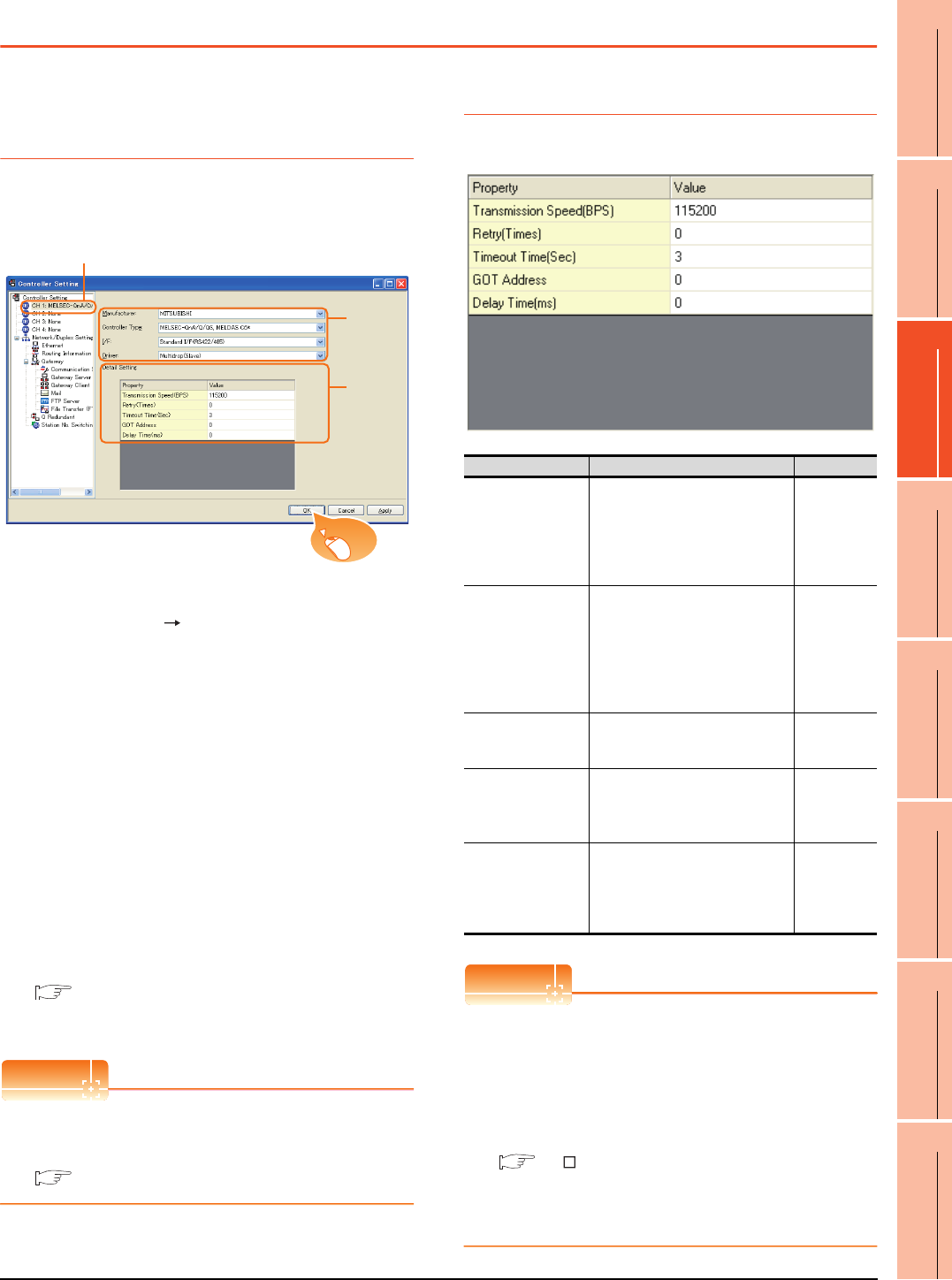
19. GOT MULTI-DROP CONNECTION
19.5 GOT Side Settings
19 - 23
17
ROBOT
CONTROLLER
CONNECTION
18
CNC CONNECTION
19
GOT MULTI-DROP
CONNECTION
20
MULTIPLE-GT14, GT12,
GT11, GT10
CONNECTION FUNCTION
21
MULTI-CHANNEL
FUNCTION
22
FA TRANSPARENT
FUNCTION
19.5 GOT Side Settings
19.5.1 Setting communication
interface (communication
settings)
Set the channel of connecting equipment.
1. Select [Common] [Controller Setting] from the
menu.
2. The Controller Setting window is displayed. Select the
channel to be used from the list menu.
3. Set the following items.
• Manufacturer: Set it according to the connected
equipment.
• Controller Type: Set it according to the connected
equipment.
• I/F: Interface to be used
• Driver: Multi-Drop (slave)
4. The detailed setting is displayed after Manufacturer,
Controller Type, I/F, and Driver are set.
Make the settings according to the usage
environment.
19.5.2 Communication detail settings
Click the [OK] button when settings are completed.
POINTPOINTPOINT
The settings of connecting equipment can be
confirmed in [I/F Communication Setting].
For details, refer to the following.
1.1.2 I/F communication setting
19.5.2 Communication detail settings
Make the settings according to the usage environment.
POINTPOINTPOINT
(1) Communication interface setting by Utility
The communication interface setting can be
changed on the Utility's [Communication Settings]
after writing [Communication Settings] of project
data.
For details on the Utility, refer to the following
manual.
GT User's Manual
(2) Precedence in communication settings
When settings are made by GT Designer3 or the
Utility, the latest setting is effective.
2.
3.
4.
Click!
Item Description Range
Transmission Speed
Set this item when change the
transmission speed used for
communication with the connected
equipment.
(Default: 115200bps)
4800bps,
9600bps,
19200bps,
38400bps,
57600bps,
115200bps
Retry
Set the number of retries to be
performed when a communication
timeout occurs.
When receiving no response after
retries, the communication times
out.
(Default: 0time)
0 to 5times
Timeout Time
Set the time period for a
communication to time out.
(Default: 3sec)
3 to 30sec
GOT Address
Specify the station number of the
host station in the system
configuration.
(Default: 0)
0 to 15
Delay Time
Set this item to adjust the
transmission timing of the
communication request from the
GOT.
(Default: 0ms)
0 to 300 ms
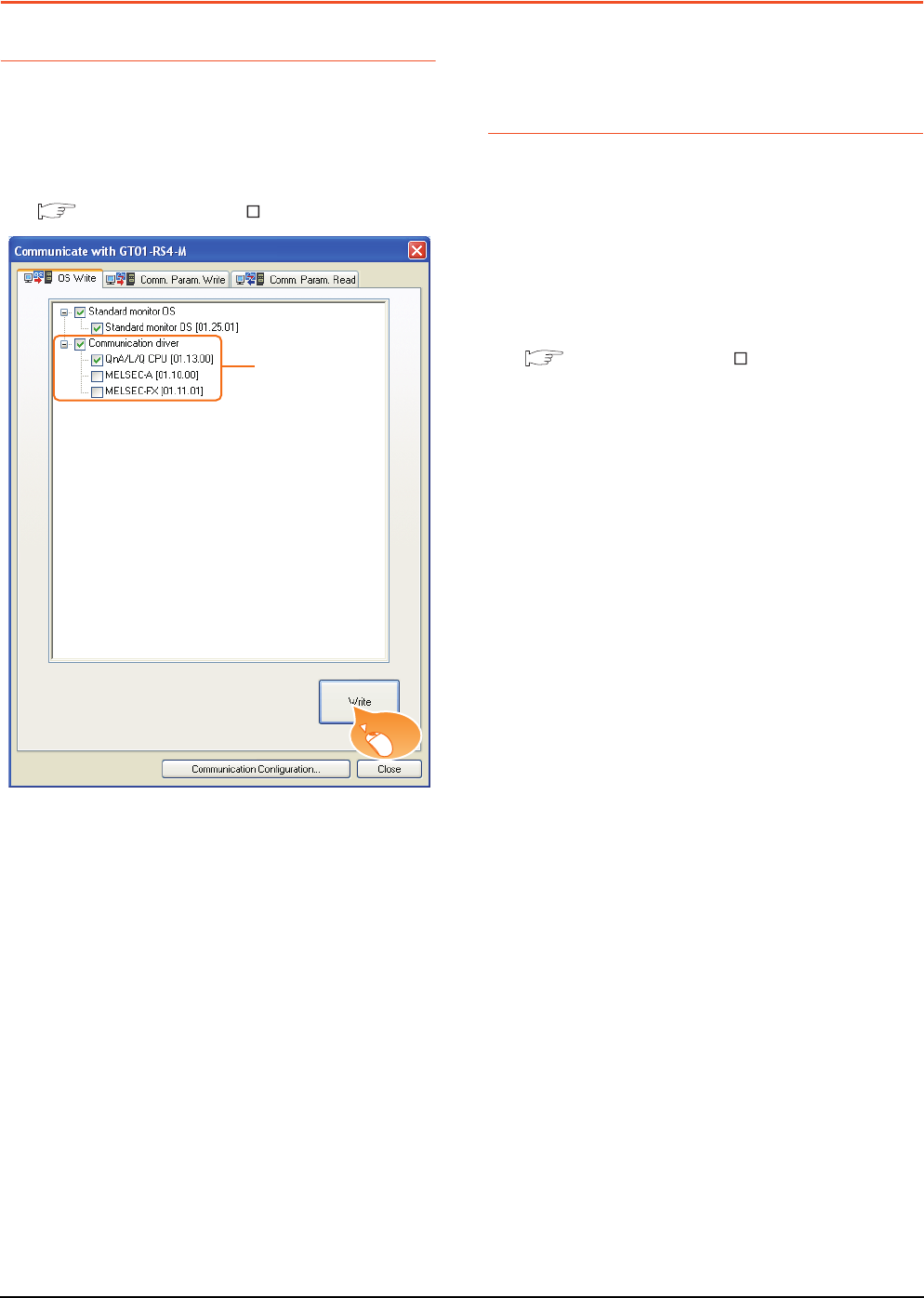
19 - 24 19. GOT MULTI-DROP CONNECTION
19.6 Setting of Serial Multi-Drop Connection Unit
19.6 Setting of Serial Multi-Drop Connection Unit
19.6.1 Write the OS
Write the standard monitor OS and communication
driver according to the desired connection type onto the
serial multi-drop connection unit.
For the OS writing methods, refer to the following
manual.
GT Designer3 Version Screen design manual
1. Check-mark a communication driver according to the
desired connection type and click the [Write] button.
19.6.2 Setting communication
interface (Communication
settings)
Make the Serial Multi-Drop Connection Unit interface
setting on [Communication with GT01-RS4-M] of GT
Designer 3.
For the communication interface driver, set the same
communication driver as the serial multi-drop
connection.
For details on [Communication with GT01-RS4-M] of
GT Designer3, refer to the manuals.
GT Designer3 Version Screen design manual
1.
Click!
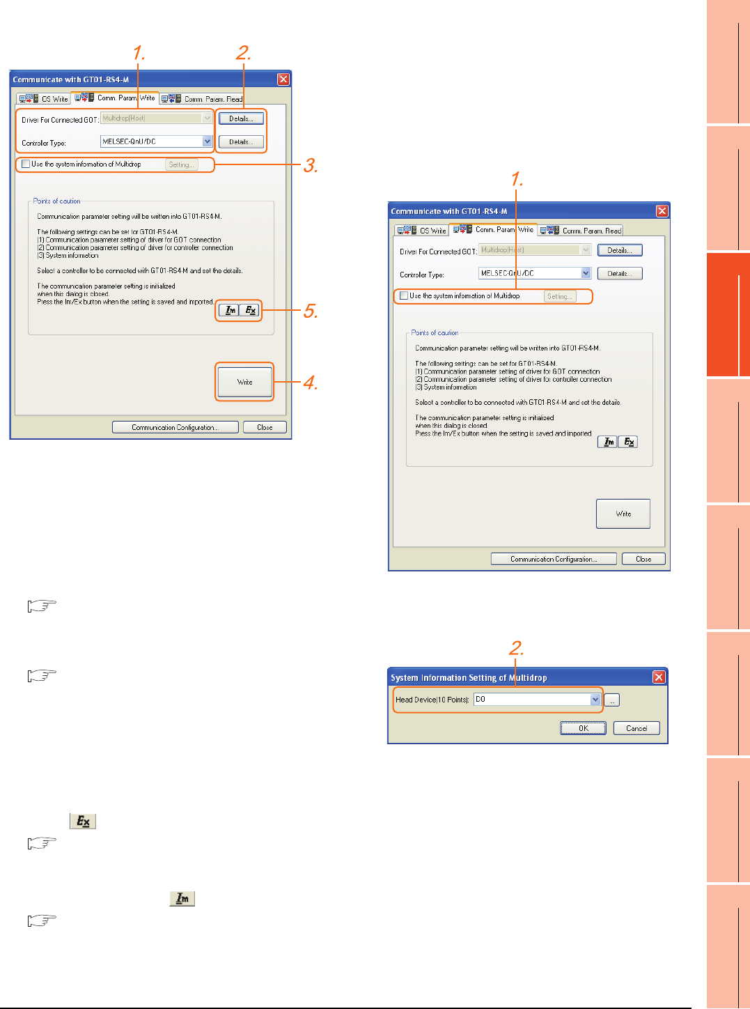
19. GOT MULTI-DROP CONNECTION
19.6 Setting of Serial Multi-Drop Connection Unit
19 - 25
17
ROBOT
CONTROLLER
CONNECTION
18
CNC CONNECTION
19
GOT MULTI-DROP
CONNECTION
20
MULTIPLE-GT14, GT12,
GT11, GT10
CONNECTION FUNCTION
21
MULTI-CHANNEL
FUNCTION
22
FA TRANSPARENT
FUNCTION
Controller setting
1. Set the following to the driver for the connected
equipment.
• Connection type dependent
The driver for connection with the GOT is fixed to the
following one.
• Multi-drop(Host)
2. Perform the detailed settings for the driver.
■ Communication detail settings
3. Set [Use the system information of Multidrop] as
necessary.
■ Setting the multi-drop system information
function
4. Click the [Write] button when settings are completed.
5. If the [Communication with GT01-RS4-M] dialog box
is closed, communication setting contents for GT01-
RS4-M does not remain.
• To maintain the communication setting contents,
click (export).
■ Exporting/Importing the communication
setting contents
• To use communication setting contents which are
saved previously, click (import).
■ Exporting/Importing the communication
setting contents
Setting the multi-drop system information
function
When checking the connection status of each GOT
which is connected to GT01-RS4-M on the PLC side,
set the multi-drop system information function.
The GOT connection status is stored in the PLC side
word device.
(1) Setting on the PLC side word device
1. Select [Use the system information of Multidrop] and
click the [Set] button. The following dialog window is
displayed.
2. Set the PLC side word device to [Head Device (10
Points)]. In this example, "D0" is set.
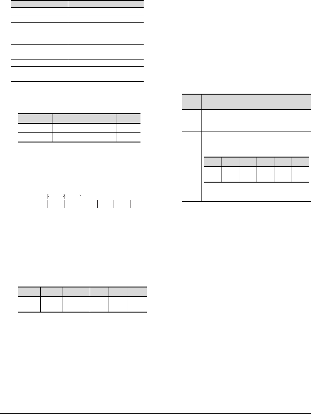
19 - 26 19. GOT MULTI-DROP CONNECTION
19.6 Setting of Serial Multi-Drop Connection Unit
(2) Assignment contents of the PLC side word device
The following table shows the device assignment
contents when setting [Head Device (10 Points)] to
"D0".
(3) Details on the word device assignment contents
(a) Control signal 1-1
< 10 second cycle flicker signal *1 >
By the repetition of turning ON/OFF every 5
seconds, the connection between GT01-RS4-M
and the PLC can be confirmed on the PLC side.
When no repetition of this ON/OFF is observed,
GT01-RS4-M is not connected to the PLC.
*1 When writing or clearing data on the program area from the
personal computer to the PLC using FA transparent function,
flicker of the signal as shown above may be temporarily
stopped.
(b) Station information notification signal *2
This signal notifies the status of the slave station
(GOT) which is connected to the master station
(GT01-RS4-M). Only the bit corresponding to the
number of connected slave station (GOT) is turned
ON and other bits are turned OFF.
• 1: Connected
• 0: Unconnected (Including communication error
status)
*2 When the communication between GT01-RS4-M and the
PLC becomes faulty, the station information notification
signal is not updated.
(c) Slave station control signal
This signal controls slave stations which are not
updated by the master station.
Usually, the master station accesses all stations
(up to 16 stations). In addition, if stations are
temporarily in communication error due to a power
disconnection or screen data transfer during the
steady operation, the automatic recovery of the
station is executed for one station per ten seconds.
Therefore, the automatic recovery may take
maximum 2 minutes and 30 seconds.
Using this control signal, the number of slave
stations to be monitored by the master station can
be reduced to the actual number of slave stations
to be used by a user. This makes the automatic
recovery processing smooth. If an error occurs in
only one station, the time for the station to recover
automatically can be reduced within 10 seconds.
When the bits are off and the master station and
the slave stations are in communication, the
communication with the corresponding slave
stations is disconnected if the above corresponding
bits are turned on.
Device Description
D0 (Head device+0) Control signal 1-1
D1(Head device+1) Station information notification signal
D2(Head device+2) (Reserve)
D3(Head device+3) (Reserve)
D4(Head device+4) (Reserve)
D5(Head device+5) Slave station control signal
D6(Head device+6) (Reserve)
D7(Head device+7) (Reserve)
D8(Head device+8) (Reserve)
D9(Head device+9) (Reserve)
Bit position Description
bit0 10 second cycle flicker signal
bit1 to 15 (Reserve)
bit15 bit14 .................. bit2 bit1 bit0
Station
No. 15
Station
No. 14 .................. Station
No. 2
Station
No. 1
Station
No. 0
OFF
ON
5sec 5sec
Device
value Action
0
The master station accesses all the slave stations
(station 0 to 15). When the multi-drop system
information is not used, the operation is the same.
Other
than 0
Turning on the bit corresponding to a station No.
disconnects the specified slave station from the
master station.
1...Connected
0...Unconnected
bit15 bit14 .......... bit2 bit1 bit0
Station
No. 15
Station
No. 14
..........
Station
No. 2
Station
No. 1
Station
No. 0
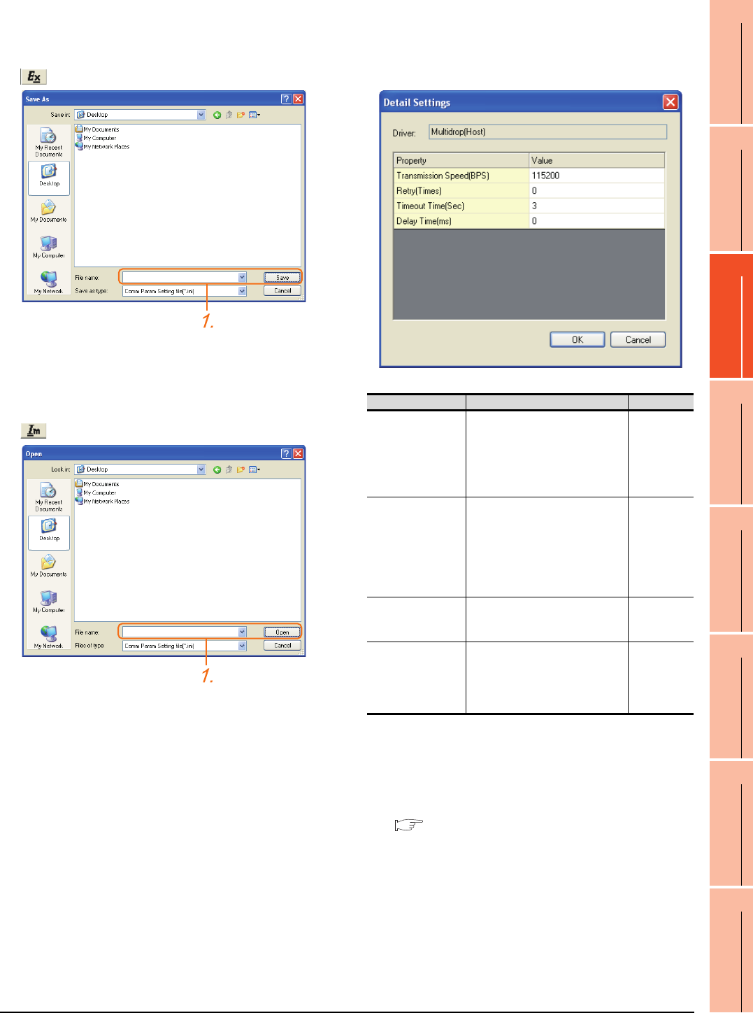
19. GOT MULTI-DROP CONNECTION
19.6 Setting of Serial Multi-Drop Connection Unit
19 - 27
17
ROBOT
CONTROLLER
CONNECTION
18
CNC CONNECTION
19
GOT MULTI-DROP
CONNECTION
20
MULTIPLE-GT14, GT12,
GT11, GT10
CONNECTION FUNCTION
21
MULTI-CHANNEL
FUNCTION
22
FA TRANSPARENT
FUNCTION
Exporting/Importing the communication
setting contents
(1) Export
1. After determining the storage location as necessary,
name the file and save it.
The file format is [*.ini] (fixed).
(2) Import
1. Enter the name of the file previously saved and open
the file.
The file format is [*.ini] (fixed).
Communication detail settings
Make the settings according to the usage environment.
(3) For the connection with GOT
(4) For the connected equipment
Set the communication detail settings of the driver for
controllers according to the connection type.
Refer to each chapter.
Item Description Range
Transmission Speed
Set this item when change the
transmission speed used for
communication with the connected
equipment.
(Default: 115200bps)
4800bps,
9600bps,
19200bps,
38400bps,
57600bps,
115200bps
Retry
Set the number of retries to be
performed when a communication
timeout occurs.
When receiving no response after
retries, the communication times
out.
(Default: 0time)
0 to 5times
Timeout Time
Set the time period for a
communication to time out.
(Default: 3sec)
3 to 30sec
Delay Time
Set this item to adjust the
transmission timing of the
communication request from the
GOT.
(Default: 0ms)
0 to 300 ms
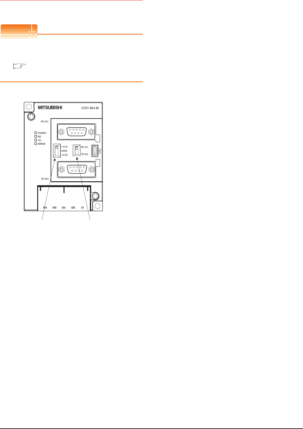
19 - 28 19. GOT MULTI-DROP CONNECTION
19.6 Setting of Serial Multi-Drop Connection Unit
19.6.3 Setting switches
Set the switches according to the connection type.
POINTPOINTPOINT
Serial Multi-Drop Connection Unit
For details on the Serial Multi-Drop Connection Unit,
refer to the following manual.
Serial Multi-Drop Connection Unit User’s
Manual
Terminating resistor
selector switch
PLC communication
selection switch
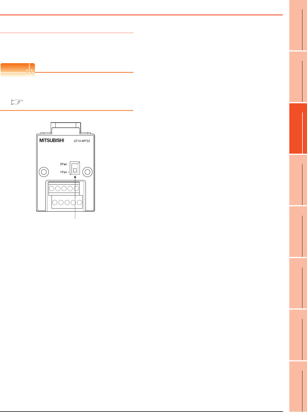
19. GOT MULTI-DROP CONNECTION
19.7 Setting of connection conversion adapter
19 - 29
17
ROBOT
CONTROLLER
CONNECTION
18
CNC CONNECTION
19
GOT MULTI-DROP
CONNECTION
20
MULTIPLE-GT14, GT12,
GT11, GT10
CONNECTION FUNCTION
21
MULTI-CHANNEL
FUNCTION
22
FA TRANSPARENT
FUNCTION
19.7 Setting of connection conversion adapter
19.7.1 Setting switches
Set the switches according to the connection type.
POINTPOINTPOINT
Connection conversion adapter
For details on the connection conversion adapter, refer
to the following manual.
Connection Conversion Adapter User’s manual
1pair / 2pair signal
selection switch
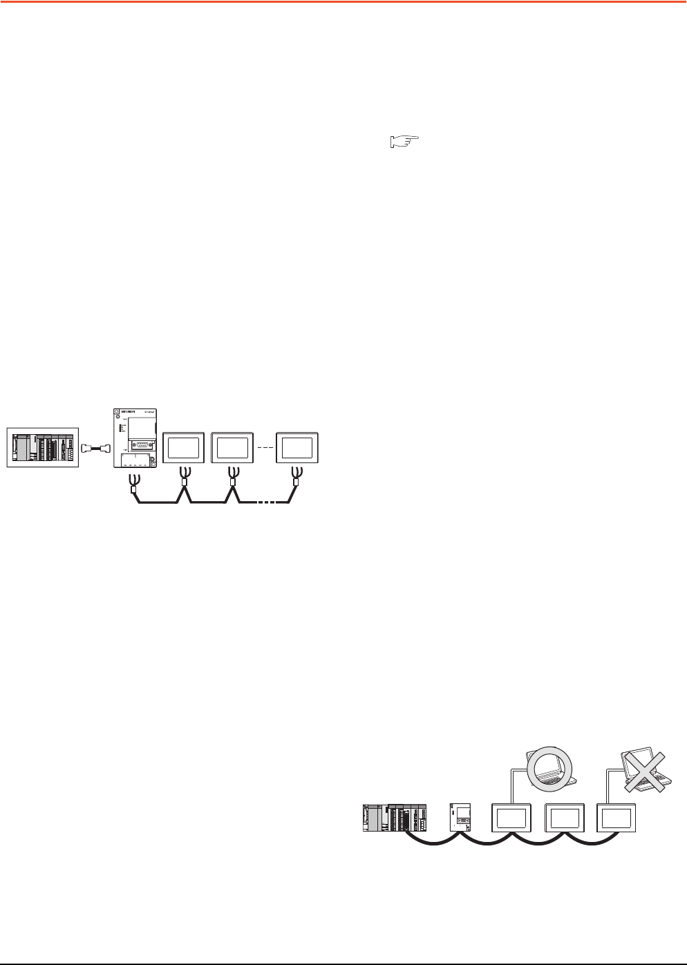
19 - 30 19. GOT MULTI-DROP CONNECTION
19.8 Precautions
19.8 Precautions
Connecting GT16 and GT15 in multi-drop
connection
(1) Standard monitor OS installation, Writing
Communication driver
When connecting GT16/GT15 in multi-drop connection,
the writing of the standard monitor OS and
communication driver to the GOT from GT Designer3
(Version 1.12N or later), as well as the writing of the
standard monitor OS and communication driver to the
serial multi-drop connection unit are required.
(2) Device specification
Network No. and station No. are not supported.
Station number setting on GOT
Set each station number so that no station number
overlaps.When the station No. is duplicated, the GOT
whose station No. is duplicated cannot be monitored
normally.
The station number can be set without regard to the
cable connection order.There is no problem even if
station numbers are not consecutive.
Extended/Option function of GOT
The extended/option functions of GOT shown below
are not available.
System monitor, Device monitor, Ladder monitor, A list
editor, FX list editor, Intelligent unit monitor, Network
monitor, Q motion monitor, Servo amplifier monitor,
CNC monitor, Backup/restore, CNC data I/O, SFC
monitor, Ladder editor, Log viewer, MELSEC-L
troubleshoot, Motion SFC, motion program (SV43)
editor, Motion program (SV43) I/O
System alarm (GT16, GT15, GT14, GT11)
The alarms of the serial multi-drop connection unit are
displayed on the system alarm.The alarms of the
connected PLC are not displayed.
Activating the serial multi-drop connection
unit
The master module detects a slave GOT, which is
connected, at the startup.It may take time to detect
again the slave station which is not detected at this
point.Activate the master module in the condition that a
communication can be made after the startup of the
slave GOT.
Using the multi-drop connection in the multi-
channel configuration
If a communication timeout error occurs when using the
multi-drop connection in the multi-channel
configuration, set the send delay time to the serial
multi-drop connection unit side.
■ Communication detail settings
Device update cycle
• When the number of connected slave GOTs and the
device points of each GOT increase, the device
update cycle on the screen may get slower. In such a
case, it is recommended to reduce the device points
of each GOT. (Please consider 250 points as a guide
of 1 GOT, and 750 points as a guide of the total
points.) In addition, when a timeout error occurs,
make the timeout time longer in the communication
settings of the slave GOT.
• When the device number is set randomly, the device
update cycle becomes slower compared to the case
that the device number is set consecutively.Therefore,
it is recommended to set the device number
consecutively.
• Depending on the device points or combination, it
may take time to switch the screen.At this time, the
device update cycle of other slave station is also
affected.
FA transparent function
FA transparent function is available for each GOT in the
GOT multi-drop connection system.
(1) Standard monitor OS installation, Writing
Communication driver
When using FA transparent function in GOT multi-drop
connection, the writing of the standard monitor OS and
communication driver to the GOT from GT Designer3
(Version 1.18U or later), as well as the writing of the
standard monitor OS and communication driver to the
serial multi-drop connection unit are required.
(2) Number of personal computers
Only one personal computer can be connected to the
multi-drop connection system.
(3) Monitor speed of GOT
The monitoring performance slows down according to
the number of monitoring GOTs. While using FA
transparent function, the monitoring performance of the
whole multi-drop system decreases. As a result,
timeout error may occur in GOTs in the system.
Station
No.3
Station
No.0
Station
No.15
The example of a Station No. setting
Only one personal computer
20
17
ROBOT
CONTROLLER
CONNECTION
18
CNC CONNECTION
19
GOT MULTI-DROP
CONNECTION
20
MULTIPLE-GT14, GT12,
GT11, GT10
CONNECTION FUNCTION
21
MULTI-CHANNEL
FUNCTION
22
FA TRANSPARENT
FUNCTION
20 - 1
20.MULTIPLE-GT14, GT12, GT11,
GT10 CONNECTION FUNCTION
20.1 Connectable Model List . . . . . . . . . . . . . . . . . . . . . . . . . . . 20 - 2
20.2 System Configuration. . . . . . . . . . . . . . . . . . . . . . . . . . . . . 20 - 2
20.3 Connection Diagram . . . . . . . . . . . . . . . . . . . . . . . . . . . . . 20 - 5
20.4 GOT Side Settings . . . . . . . . . . . . . . . . . . . . . . . . . . . . . . . 20 - 7
20.5 Precautions . . . . . . . . . . . . . . . . . . . . . . . . . . . . . . . . . . . .20 - 11
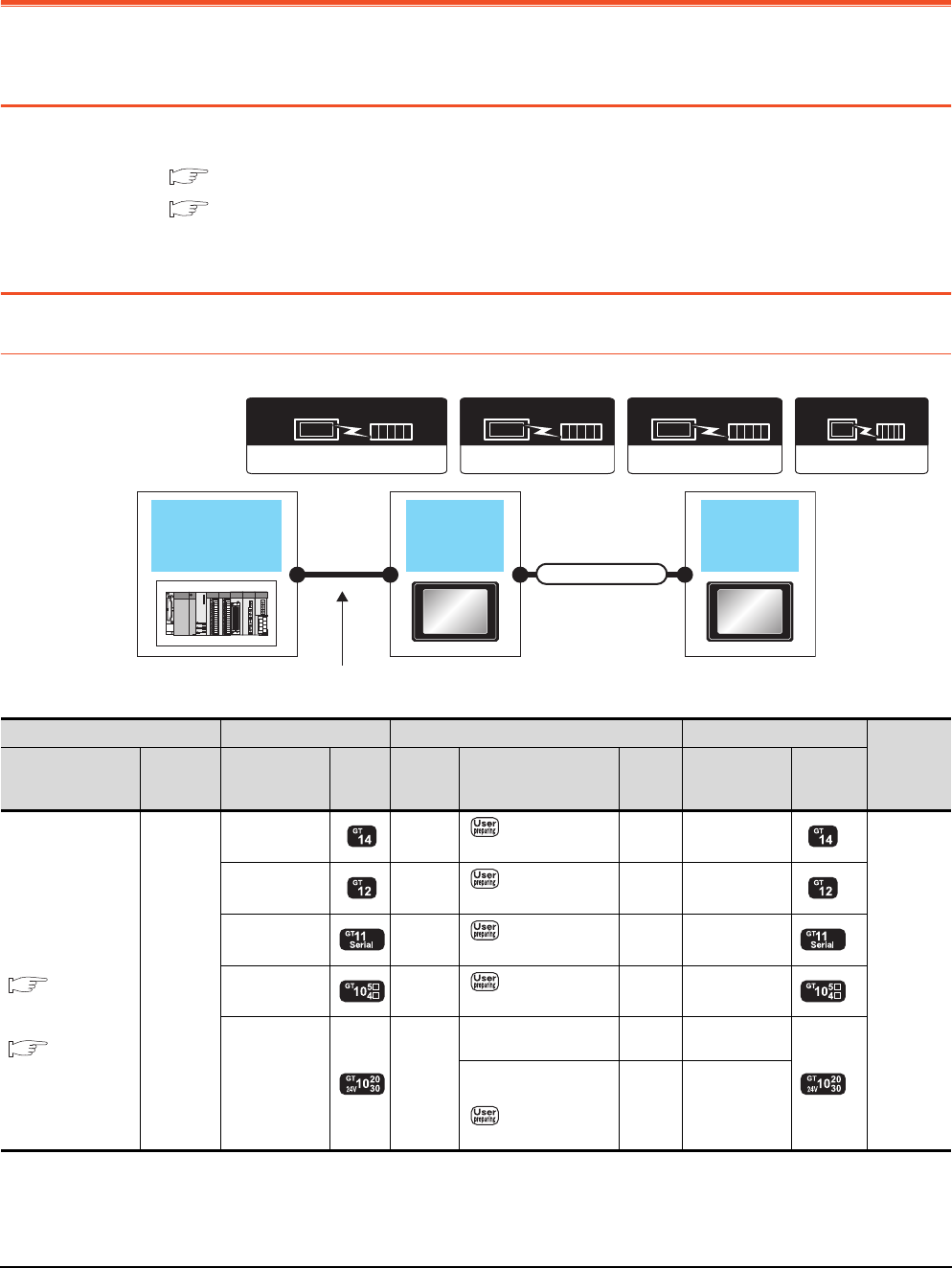
20 - 2 20. MULTIPLE-GT14, GT12, GT11, GT10 CONNECTION FUNCTION
20.1 Connectable Model List
20. MULTIPLE-GT14, GT12, GT11, GT10
CONNECTION FUNCTION
20.1 Connectable Model List
For details of connectable models, refer to the following.
6. DIRECT CONNECTION TO CPU
7. COMPUTER LINK CONNECTION
20.2 System Configuration
20.2.1 Connecting the GOT to PLC via RS-232 interface
(Continued to next page)
MELSEC-FX
Communication driver
Communication driver
MELSEC-A
( For GT10)
Communication driver
QnA/L/Q CPU
( For GT10)
Communication driver
( For GT16, GT15, GT14, GT12, GT11)
A/QnA/L/Q CPU,LJ71C24,QJ71C24
GOT
(1st)
GOT
(2nd)
PLC
Varies according to
the connection type.
Connection cable
PLC GOT (1st) *1 Connection cable GOT (2nd) *1
Number of
connectable
equipment
Connection type Communic
ation type Option device Model
Commu
nication
type
Cable model
Max.
distance
Option device Model
For the system
configuration
between a got and A
plc, refer to the
following.
DIRECT
CONNECTION TO
CPU
COMPUTER
LINK
CONNECTION*4
RS-232
-
(Built into GOT) RS-422 RS422 connection
diagram 1)
30m -
(Built into GOT)
2 GOTs
-
(Built into GOT) RS-422 RS422 connection
diagram 1)
30m -
(Built into GOT)
-
(Built into GOT) RS-422 RS422 connection
diagram 1)
30m -
(Built into GOT)
-
(Built into GOT) RS-422 RS422 connection
diagram 1)
30m -
(Built into GOT)
-
(Built into GOT) RS-232
GT10-C30R2-6P(3m)*3 3m -
(Built into GOT)
*2
GT10-C02H-6PT9P (0.2m)
+
RS232 connection
diagram 4)
15m -
(Built into GOT)
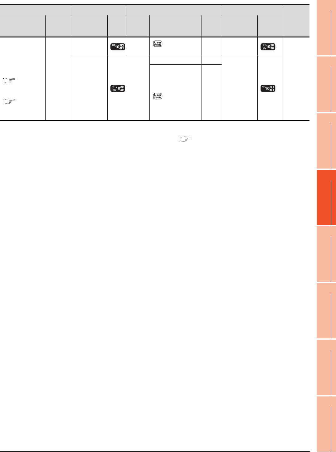
20. MULTIPLE-GT14, GT12, GT11, GT10 CONNECTION FUNCTION
20.2 System Configuration
20 - 3
17
ROBOT
CONTROLLER
CONNECTION
18
CNC CONNECTION
19
GOT MULTI-DROP
CONNECTION
20
MULTIPLE-GT14, GT12,
GT11, GT10
CONNECTION FUNCTION
21
MULTI-CHANNEL
FUNCTION
22
FA TRANSPARENT
FUNCTION
*1 When GT14, GT12, GT11 and GT10 are intermingled, the Multiple connection function is not supported.
*2 The 2nd GOT must be a RS-232 built-in product.
*3 For the connection to GOT, refer to the connection diagram.( RS232 connection diagram 2))
*4 When connected to the Computer link, the multiple connection function supports only QCPU (Q mode), LCPU.
*5 The 2nd GOT must be a GT10 (input power supply: 24V) RS-422 built-in product.
PLC GOT (1st) *1 Connection cable GOT (2nd) *1
Number of
connectable
equipment
Connection type Communic
ation type Option device Model
Commu
nication
type
Cable model
Max.
distance
Option device Model
For the system
configuration
between a got and A
plc, refer to the
following.
DIRECT
CONNECTION TO
CPU
COMPUTER
LINK
CONNECTION*4
RS-232
-
(Built into GOT) RS-422 RS422 connection
diagram 2)
30m -
(Built into GOT)
*5
2 GOTs
-
(Built into GOT) RS-232
GT01-C30R2-6P(3m) 3m
-
(Built into GOT)
GT10-C02H-6PT9P (0.2m)
+
RS232 connection
diagram 5)
15m
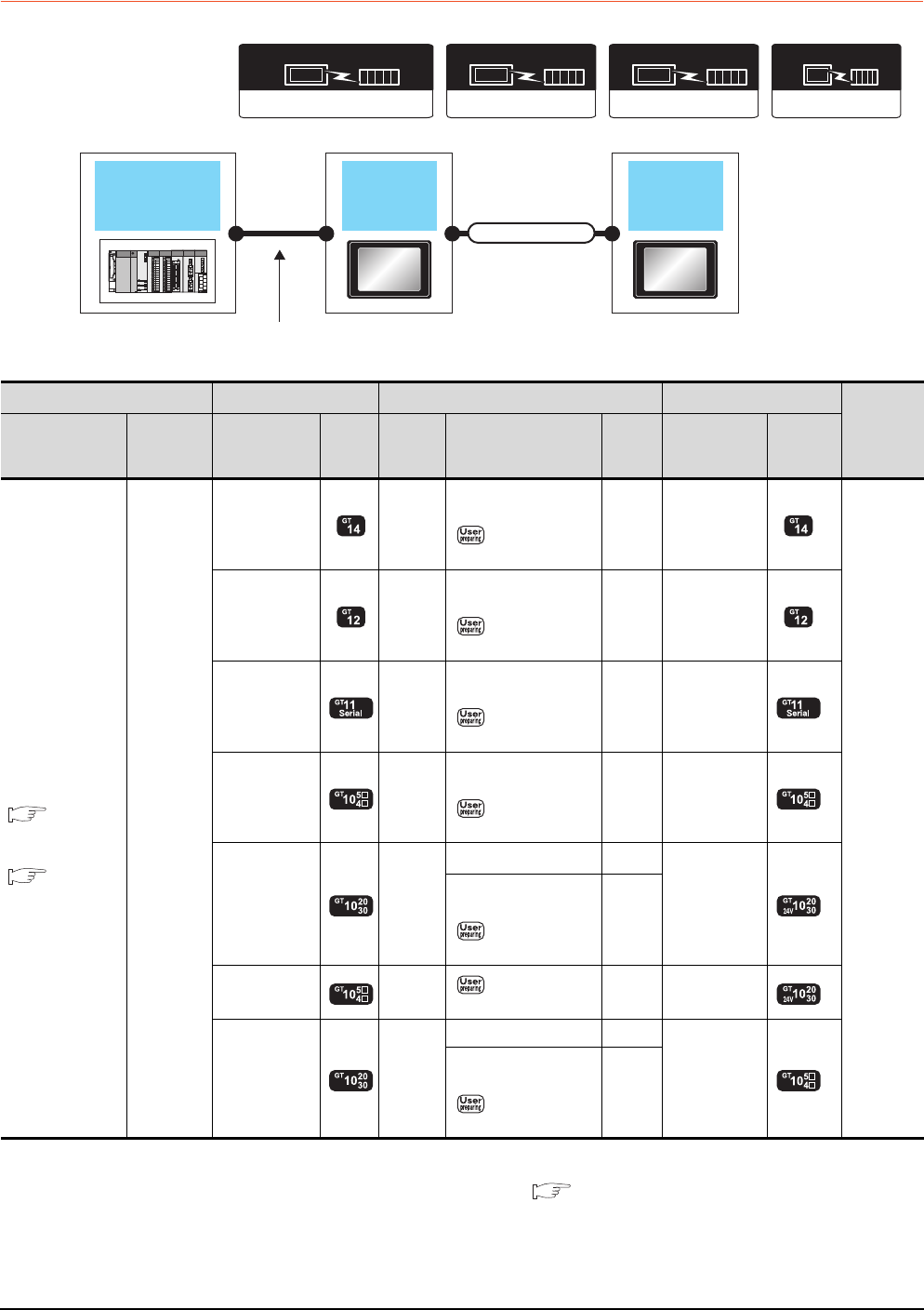
20 - 4 20. MULTIPLE-GT14, GT12, GT11, GT10 CONNECTION FUNCTION
20.2 System Configuration
20.2.2 Connecting the GOT to PLC via RS-422 interface
*1 When GT14, GT12, GT11 and GT10 are intermingled, the Multiple connection function is not supported.
*2 The 2nd GOT must be a GT10 (input power supply: 24V) RS-232 built-in product.
*3 For the connection to GOT, refer to the connection diagram.( RS232 connection diagram 2))
*4 When connected to the Computer link, the multiple connection function supports only QCPU (Q mode), LCPU.
MELSEC-FX
Communication driver
Communication driver
MELSEC-A
( For GT10)
GOT
(1st)
GOT
(2nd)
PLC
Varies according to
the connection type.
Connection cable
Communication driver
QnA/L/Q CPU
( For GT10)
( For GT14, GT12, GT11)
Communication driver
A/QnA/L/Q CPU,LJ71C24,QJ71C24
PLC GOT (1st) *1 Connection cable GOT (2nd) *1
Number of
connectable
equipment
Connection type Communica
tion type Option device Model
Commun
ication
type
Cable model
Max.
distance
Option device Model
For the system
configuration
between a got and
A plc, refer to the
following.
DIRECT
CONNECTION TO
CPU
COMPUTER LINK
CONNECTION*4
RS-422
-
(Built into GOT) RS-232
GT01-C30R2-9S(3m)
or
RS232 connection
diagram 1)
15m -
(Built into GOT)
2 GOTs
-
(Built into GOT) RS-232
GT01-C30R2-9S(3m)
or
RS232 connection
diagram 1)
15m -
(Built into GOT)
-
(Built into GOT) RS-232
GT01-C30R2-9S(3m)
or
RS232 connection
diagram 1)
15m -
(Built into GOT)
-
(Built into GOT) RS-232
GT01-C30R2-9S(3m)
or
RS232 connection
diagram 1)
15m -
(Built into GOT)
-
(Built into GOT) RS-232
GT10-C30R2-6P(3m) *3 3m
-
(Built into GOT)
*2
GT10-C02H-6PT9P (0.2m)
+
RS232 connection
diagram 4)
15m
-
(Built into GOT) RS-232 RS232 connection
diagram 3)
15m -
(Built into GOT)
*2
-
(Built into GOT) RS-232
GT01-C30R2-6P(3m) 3m
-
(Built into GOT)
GT10-C02H-6PT9P (0.2m)
+
RS232 connection
diagram 5)
15m
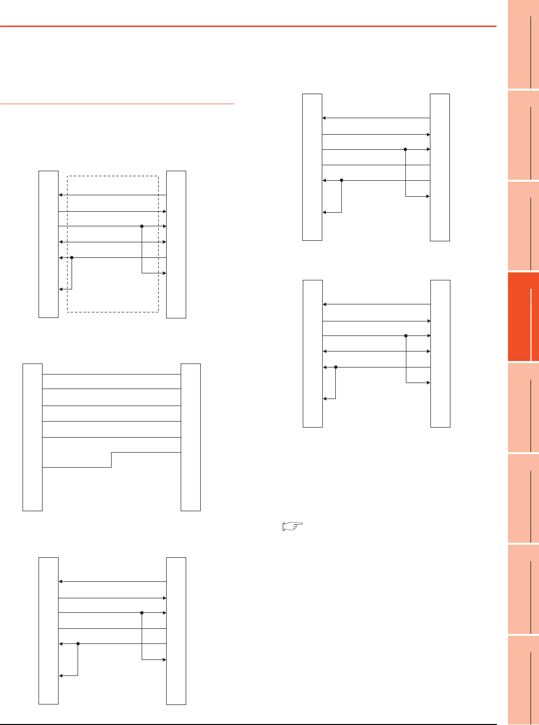
20. MULTIPLE-GT14, GT12, GT11, GT10 CONNECTION FUNCTION
20.3 Connection Diagram
20 - 5
17
ROBOT
CONTROLLER
CONNECTION
18
CNC CONNECTION
19
GOT MULTI-DROP
CONNECTION
20
MULTIPLE-GT14, GT12,
GT11, GT10
CONNECTION FUNCTION
21
MULTI-CHANNEL
FUNCTION
22
FA TRANSPARENT
FUNCTION
20.3 Connection Diagram
The following diagram shows the connection between the
GOT and the PLC.
20.3.1 RS-232 Cable
Connection diagram
Precautions when preparing a cable
(1) Cable length
The length of the RS-232 cable must be 15m or less.
(2) GOT side connector
For the GOT side connector, refer to the following.
1.4.1 GOT connector specifications
RS232 connection diagram 1)
RS232 connection diagram 2)
RS232 connection diagram 3)
GOT side GOT side
N.C.
RD(RXD)
SD(TXD)
ER(DTR)
SG
DR(DSR)
RS(RTS)
CS(CTS)
-
1
2
3
4
5
6
7
8
9
1
3
2
6
5
4
8
7
-
N.C.
SD(TXD)
RD(RXD)
DR(DSR)
SG
ER(DTR)
CS(CTS)
RS(RTS)
-
Second GOT side
(terminal block)
Brown
Red
Blue
Yellow
Green
Purple
Untied wire color
of GT10-C30R2-6P
SD
RD
ER
DR
SG
RS
CS
NC
NC
First GOT side
Second GOT side
(terminal block)
N.C.
RD(RXD)
SD(TXD)
ER(DTR)
SG
DR(DSR)
RS(RTS)
CS(CTS)
-
1
2
3
4
5
6
7
8
9
6
1
2
4
5
3
7
8
9
RS
SD(TXD)
RD(RXD)
DR(DSR)
SG
ER(DTR)
CS(CTS)
N.C.
N.C.
RS232 connection diagram 4)
RS232 connection diagram 5)
Second GOT side
(terminal block)
Cable (GT10-C02H-6PT9P)
D-Sub 9-pin
N.C.
RD (RXD)
SD (TXD)
ER (DTR)
SG
DR (DSR)
RS (RTS)
CS (CTS)
-
1
2
3
4
5
6
7
8
9
6
1
2
4
5
3
7
8
9
RS
SD (TXD)
RD (RXD)
DR (DSR)
SG
ER (DTR)
CS (CTS)
N.C.
N.C.
Cable (GT10-C02H-6PT9P)
D-Sub 9-pin side Second GOT side
N.C.
RD (RXD)
SD (TXD)
ER (DTR)
SG
DR (DSR)
RS (RTS)
CS (CTS)
-
1
2
3
4
5
6
7
8
9
1
3
2
6
5
4
8
7
-
N.C.
SD (TXD)
RD (RXD)
DR (DSR)
SG
ER (DTR)
CS (CTS)
RS (RTS)
-
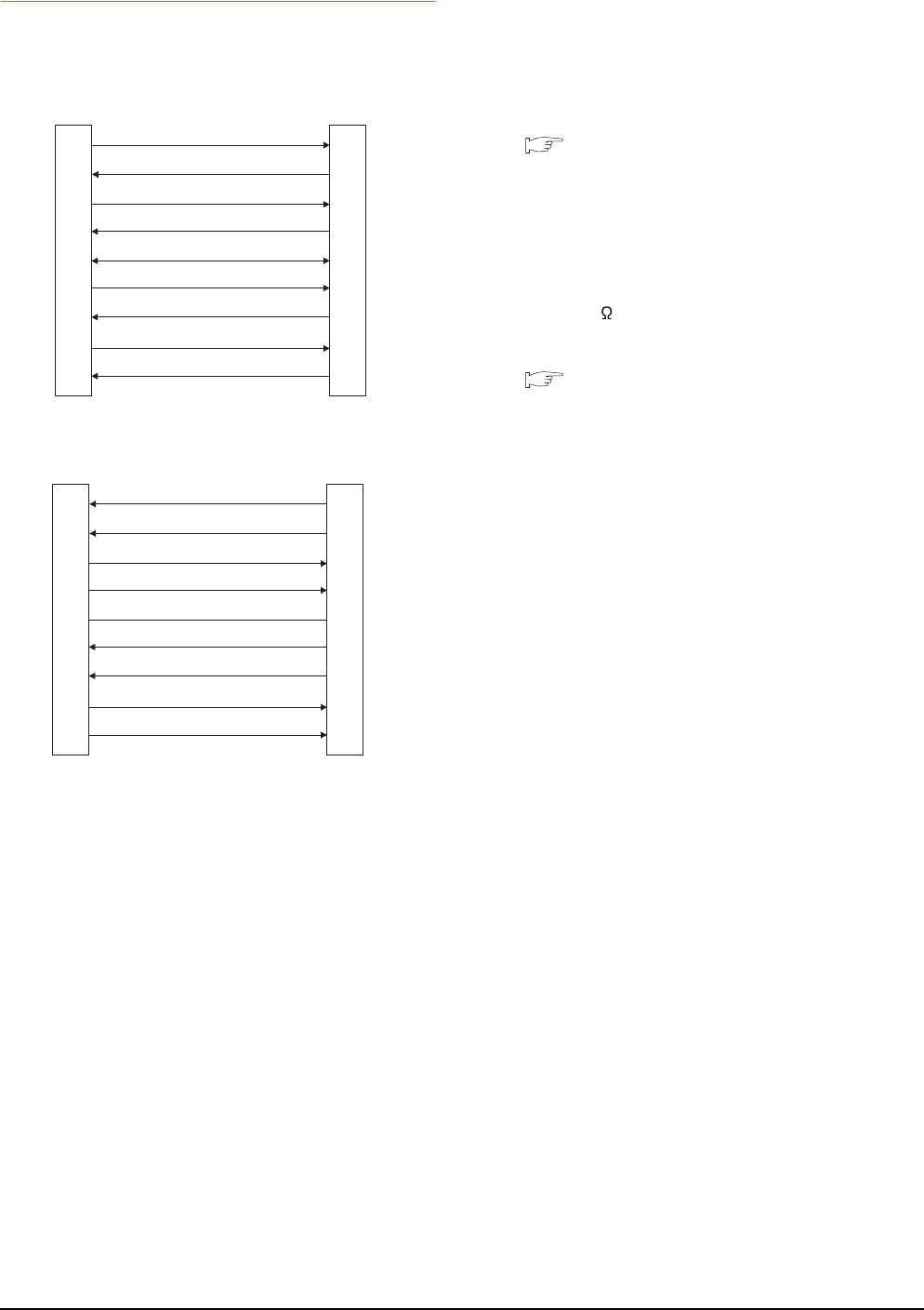
20 - 6 20. MULTIPLE-GT14, GT12, GT11, GT10 CONNECTION FUNCTION
20.3 Connection Diagram
20.3.2 RS-422 cable
Connection diagram
Precautions when preparing a cable
(1) Cable length
The length of the RS-422 cable must be 30m or less.
(2) GOT side connector
For the GOT side connector, refer to the following.
1.4.1 GOT connector specifications
Connecting terminating resistors
(1) GOT side
When connecting a PLC to the GOT, a terminating
resistor must be connected to the GOT.
Set the terminating resistor selector of the GOT main
unit to "300 ".
For the procedure to set the terminating resistor, refer
to the following.
1.4.3 Terminating resistors of GOT
RS422 connection diagram 1)
RS422 connection diagram 2)
GOT side
SDA
RDA
RSA
CSA
SG
SDB
RDB
RSB
CSB
2
1
4
3
5
7
6
9
8
1
2
3
4
5
6
7
8
9
GOT side
RDA
SDA
CSA
RSA
SG
RDB
SDB
CSB
RSB
First GOT side
RDA
RDB
SDA
SDB
SG
CSA
CSB
RSA
RSB
1
2
3
4
5
6
7
8
9
2
7
1
6
5
4
9
3
8
Second GOT side
(terminal block)
SDA
SDB
RDA
RDB
SG
RSA
RSB
CSA
CSB
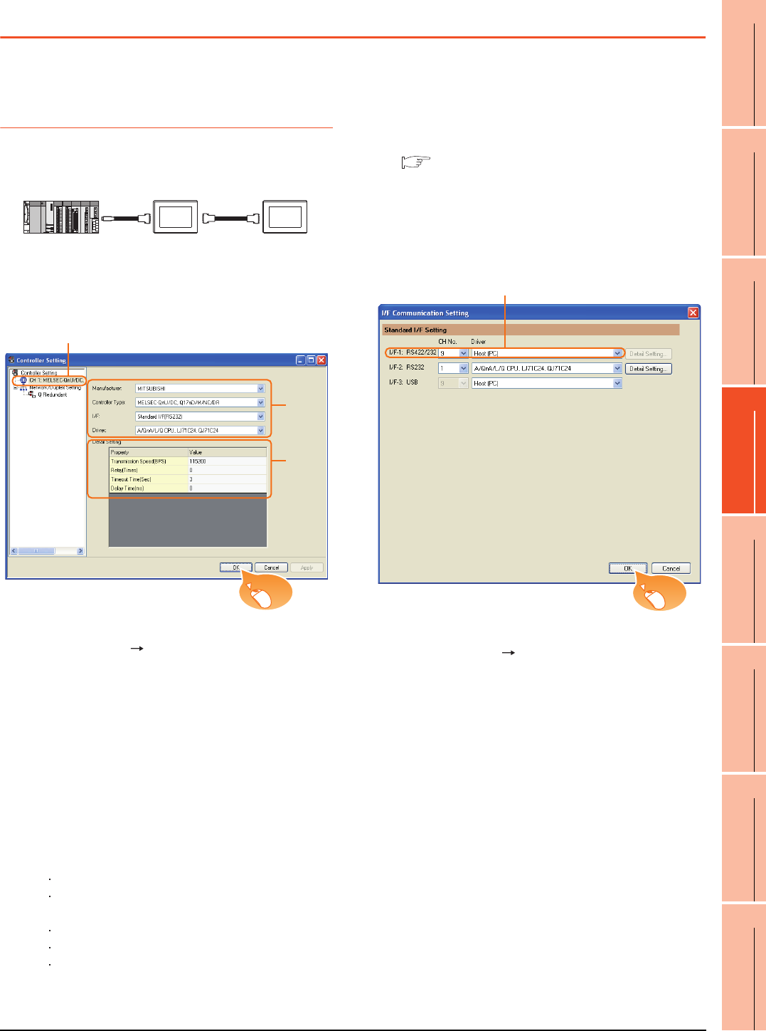
20. MULTIPLE-GT14, GT12, GT11, GT10 CONNECTION FUNCTION
20.4 GOT Side Settings
20 - 7
17
ROBOT
CONTROLLER
CONNECTION
18
CNC CONNECTION
19
GOT MULTI-DROP
CONNECTION
20
MULTIPLE-GT14, GT12,
GT11, GT10
CONNECTION FUNCTION
21
MULTI-CHANNEL
FUNCTION
22
FA TRANSPARENT
FUNCTION
20.4 GOT Side Settings
20.4.1 Setting communication
interface (Communication
settings)
This section explains with an example of the following
system configuration.
Setting for the first GOT
(1) Settings of communication interface connecting to
the PLC
1. Select [Common] [Controller Setting] from the
menu.
2. The Controller Setting window is displayed. Select the
channel to be used from the list menu.
3. Set the following items.
• Manufacturer: Mitsubishi
• Controller Type: Set according to the Controller
Type to be connected.
• I/F: Standard I/F (RS232)
• Driver: Set either of the following according to the
Controller Type to be connected.
For GT14, GT12, GT11
A/QnA/L/Q CPU, LJ71C24, QJ71C24
MELSEC-FX
For GT10
QnA/L/Q CPU
MELSEC-A
MELSEC-FX
4. The detailed setting is displayed after Manufacturer,
Controller Type, I/F, and Driver are set.
Make the settings according to the usage
environment.
20.4.2 Communication detail settings
Click the [OK] button when settings are completed.
(2) Settings of communication interface connecting to
the second GOT
1. Select [Common] [I/F Communication Setting] from
the menu.
2. The I/F Connection list window is displayed. Select
the following.
• I/F-1: RS422/232
CH No.: 9
Driver: Host (PC)
Click the [OK] button when settings are completed.
RS-422
cable
RS-232
cable
1st GOT 2nd GOT
GT11 GT11
2.
3.
4.
Click!
2.
Click!
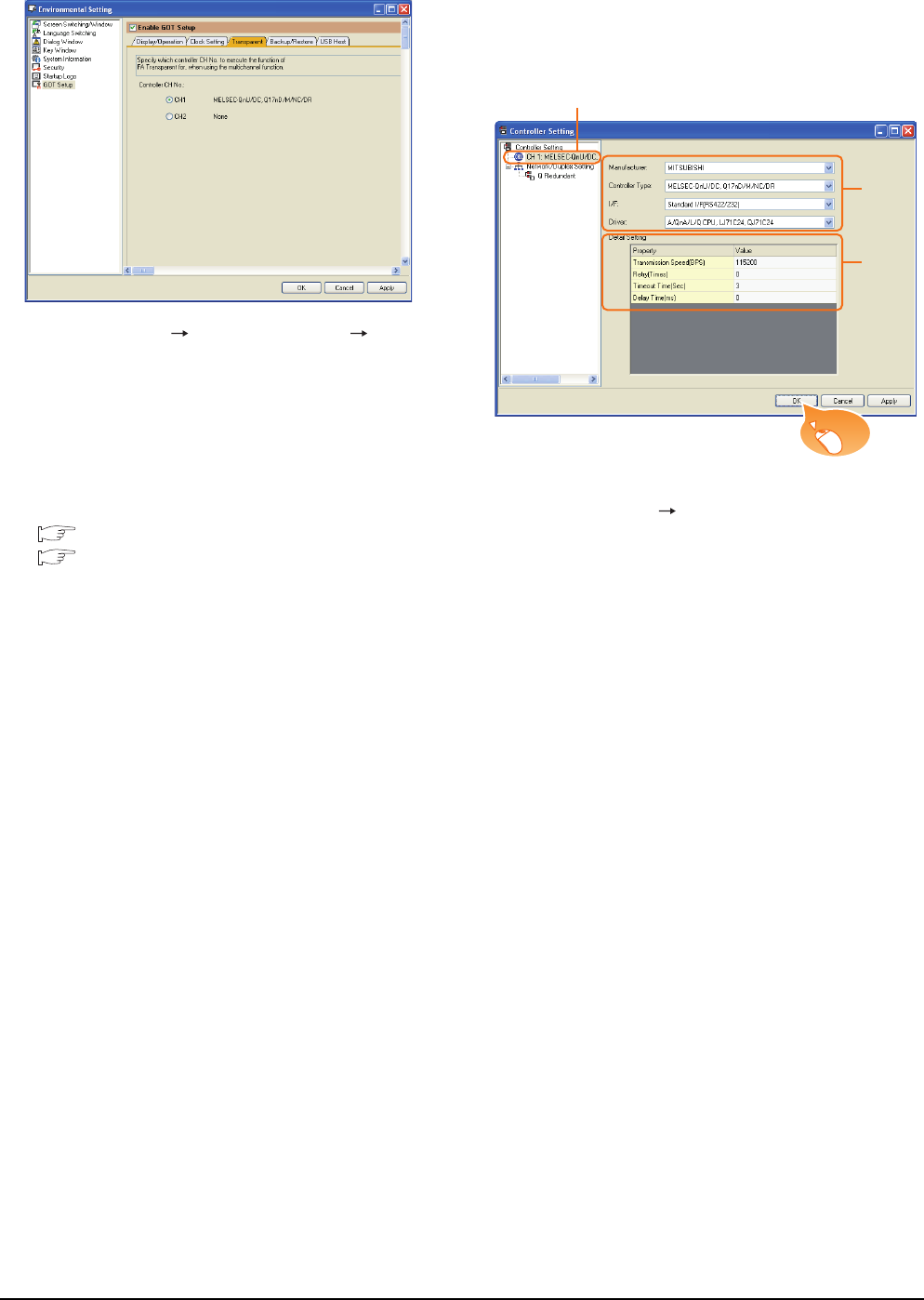
20 - 8 20. MULTIPLE-GT14, GT12, GT11, GT10 CONNECTION FUNCTION
20.4 GOT Side Settings
(3) [Transparent] setting (GT14 only)
1. Select [Common] [Environment Setup] [GOT
Setup], check [Enable GOT Setup], and select the
[Transparent] menu.
2. After [Controller CH No.] is displayed, check the
channel No. connected to the target PLC of multiple
GOTs.
For details of connectable models, refer to the
following.
6. DIRECT CONNECTION TO CPU
7. COMPUTER LINK CONNECTION
Click the [OK] button when settings are completed.
Setting for the second GOT
Set the communication interface connecting to the first
GOT.
1. Select [Common] [Controller Setting] from the
menu.
2. The Controller Setting window is displayed. Select
[CH1] from the list menu.
3. Set the following items.
• Manufacturer: Mitsubishi
• Controller Type: Set the same setting as the first
GOT (communication interface connecting to the
PLC)
• I/F: Standard I/F (RS422/232)
• Driver: Set the same setting as the first GOT
(communication interface connecting to the PLC)
4. The detailed setting is displayed after Manufacturer,
Controller Type, I/F, and Driver are set.
Set the same setting as the first GOT (communication
interface connecting to the PLC)
Click the [OK] button when settings are completed.
2.
3.
4.
Click!
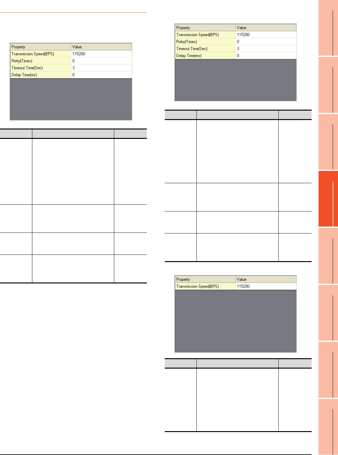
20. MULTIPLE-GT14, GT12, GT11, GT10 CONNECTION FUNCTION
20.4 GOT Side Settings
20 - 9
17
ROBOT
CONTROLLER
CONNECTION
18
CNC CONNECTION
19
GOT MULTI-DROP
CONNECTION
20
MULTIPLE-GT14, GT12,
GT11, GT10
CONNECTION FUNCTION
21
MULTI-CHANNEL
FUNCTION
22
FA TRANSPARENT
FUNCTION
20.4.2 Communication detail settings
Make the settings according to the usage environment.
(1) A/QnA/L/Q CPU, LJ71C24, QJ71C24
(2) MELSEC-FX
(a) For the GT14, GT12, GT11
(b) For GT10
Item Description Range
Transmission
Speed
Set this item when change the
transmission speed used for
communication with the connected
equipment.
(Default: 115200bps)
When the setting exceeds the limit of
the connected equipment,
communication is performed at the
fastest transmission speed supported
by the connected equipment.
9600bps,
19200bps,
38400bps,
57600bps,
115200bps
Retry
Set the number of retries to be
performed when a communication
timeout occurs.
(Default: 0time)
0 to 5times
Timeout Time
Set the time period for a communication
to time out.
(Default: 3sec)
3 to 30sec
Delay Time
Set this item to adjust the transmission
timing of the communication request
from the GOT.
(Default: 0ms)
0 to 300ms
Item Description Range
Transmission
Speed
Set this item when change the
transmission speed used for
communication with the connected
equipment.
(Default: 115200bps)
When the setting exceeds the limit of
the connected equipment,
communication is performed at the
fastest transmission speed supported
by the connected equipment.
9600bps,
19200bps,
38400bps,
57600bps,
115200bps
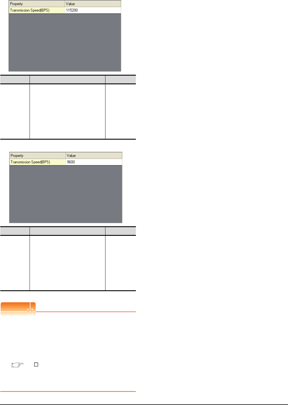
20 - 10 20. MULTIPLE-GT14, GT12, GT11, GT10 CONNECTION FUNCTION
20.4 GOT Side Settings
(3) QnA/L/Q CPU (GT10)
(4) MELSEC-A (GT10)
POINTPOINTPOINT
(1) Communication interface setting by the Utility
The communication interface setting can be
changed on the Utility's [Communication Settings]
after writing [Communication Settings] of project
data.
For details on the RS-422 conversion unit and the
GOT utility, refer to the following manual:
GT User's Manual
(2) Precedence in communication settings
When settings are made by GT Designer3 or the
Utility, the latest setting is effective.
Item Description Range
Transmission
Speed
Set this item when change the
transmission speed used for
communication with the connected
equipment.
(Default: 115200bps)
When the setting exceeds the limit of
the connected equipment,
communication is performed at the
fastest transmission speed supported
by the connected equipment.
9600bps,
19200bps,
38400bps,
57600bps,
115200bps
Item Description Range
Transmission
Speed
Set this item when change the
transmission speed used for
communication with the connected
equipment.
(Default: 9600bps)
When the setting exceeds the limit of
the connected equipment,
communication is performed at the
fastest transmission speed supported
by the connected equipment.
9600bps
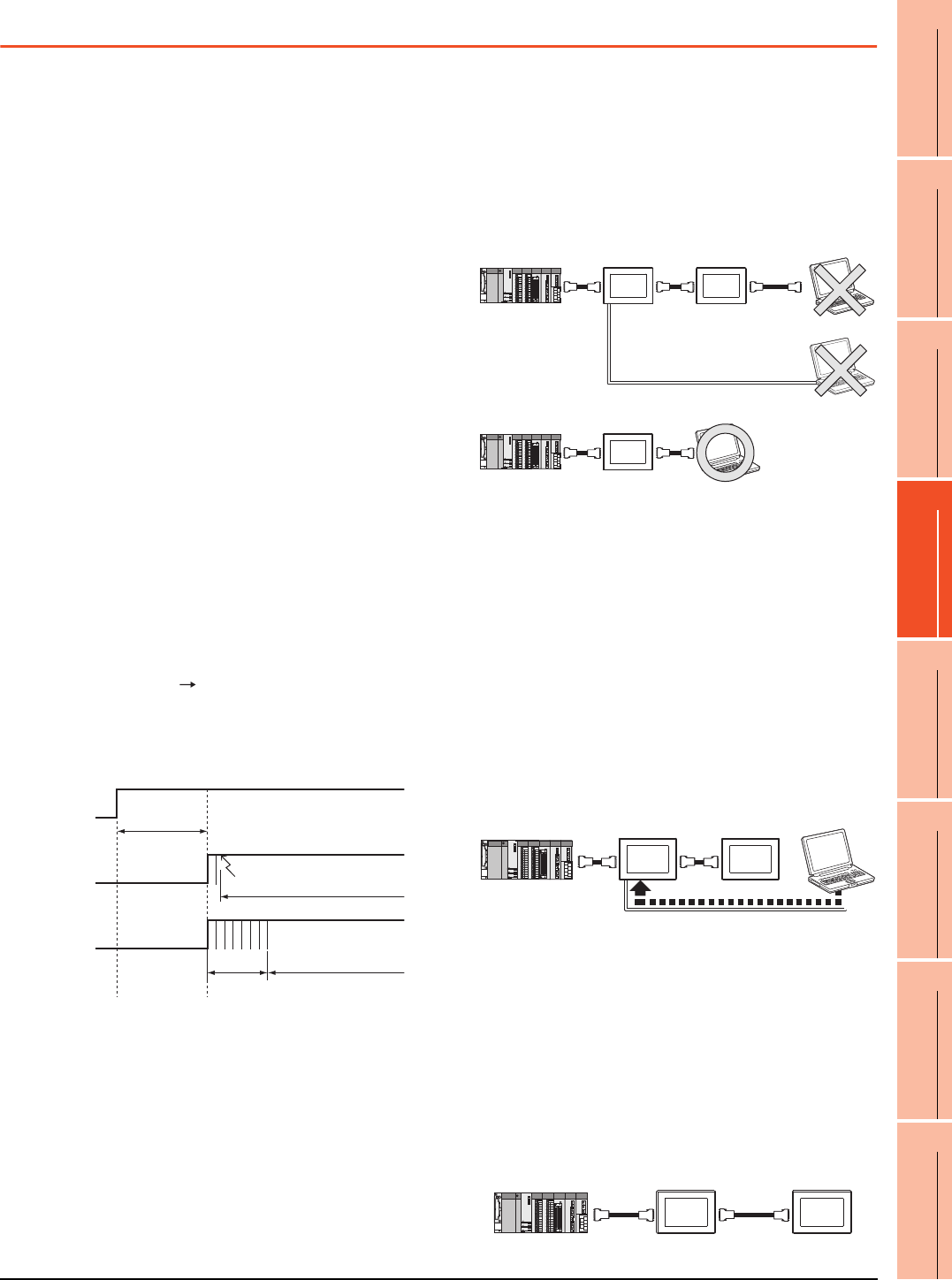
20. MULTIPLE-GT14, GT12, GT11, GT10 CONNECTION FUNCTION
20.5 Precautions
20 - 11
17
ROBOT
CONTROLLER
CONNECTION
18
CNC CONNECTION
19
GOT MULTI-DROP
CONNECTION
20
MULTIPLE-GT14, GT12,
GT11, GT10
CONNECTION FUNCTION
21
MULTI-CHANNEL
FUNCTION
22
FA TRANSPARENT
FUNCTION
20.5 Precautions
GOT's communication timing
(1) GOT's communication timing
Adjust the communication timing so that, after applying
the power to the system, the communication with the
connected device (MITSUBISHI PLC) is performed in
order starting from the first GOT (from the 1st GOT to
the 2nd, and so on).
When the communication is failed, retries are
performed. And if the predetermined time has elapsed,
a communication error occurs.
• If the first GOT is turned on after a while the second
GOT is turned on, because the communication start of
the second GOT is delayed, a communication error
may be detected at the second GOT.
• If the system power is turned on simultaneously and it
takes time to start the communication of the second
GOT, a communication error may be developed.
(2) Adjusting communication timing
(a) When powering up the system simultaneously
Using the utility or selecting [GOT Setup] -
[Opening Screen Time] from GT Designer3, set the
opening screen time adding a delay to each setting
for the GOTs.
During the opening process, communication with
the connected device does not start.
Example: Set value of [Opening Screen Time]
(Inside (): set value)
First module (5s) Second module (10s)
(b) When powering on devices individually
Turn on the connected device first, and then the
first GOT, the second GOT, and so on.
Using the FA transparent function
When multiple GOTs are connected, the FA transparent
function is not available even if the RS-232 interface or
USB interface is used for the connection.
(When connecting a personal computer to the first
GOT, the FA transparent function can be used.)
Monitoring stop condition for the GOT in the
multiple-GT11 connection
In the system where multiple GOTs are connected,
performing either of the following monitoring stop
operations on the preceding stage (the first GOT) also
stops monitoring of the GOT on the next stage (the
second GOT).
When the GOT on the preceding stage resumes
monitoring, the GOT on the next stage also resumes it.
• When project data or the OS is written/read by GT
Designer3*1
• When the GOT is set up*1
*1 A timeout error occurs in GX Developer.
When PLC power disconnection occurs in
the multiple-GOT connection
In the system where multiple GOTs are connected,
when the communication between the PLC and the first
GOT is stopped due to PLC power disconnection and a
disconnection of the communication cable between the
PLC and the first GOT, the GOT waits for timeout
against the communication request from the peripheral
devices (GX Developer, etc.), and recovery of
monitoring between the PLC and the GOT is delayed.
user screen
user screen
The title screen
is displayed.
Power supply (24V DC)
Power feeding to GOT
First GOT's
communication
Second GOT's
communication Retry
Communication of the
2nd GOT is enabled.
PC
PC
1st GOT 2nd GOT
RS-232
PC
1st GOT
USB
GT Designer3
1st GOT 2nd GOT
USB
The project data is being download.
Monitoring
stopped
Downloading
1st GOT 2nd GOT
MonitoringMonitoring

20 - 12 20. MULTIPLE-GT14, GT12, GT11, GT10 CONNECTION FUNCTION
20.5 Precautions


21
17
ROBOT
CONTROLLER
CONNECTION
18
CNC CONNECTION
19
GOT MULTI-DROP
CONNECTION
20
MULTIPLE-GT14, GT12,
GT11, GT10
CONNECTION FUNCTION
21
MULTI-CHANNEL
FUNCTION
22
FA TRANSPARENT
FUNCTION
21 - 1
21.MULTI-CHANNEL FUNCTION
21.1 What is Multi-channel Function? . . . . . . . . . . . . . . . . . . . . 21 - 2
21.2 System Configuration. . . . . . . . . . . . . . . . . . . . . . . . . . . . . 21 - 4
21.3 GOT Side Settings . . . . . . . . . . . . . . . . . . . . . . . . . . . . . . . 21 - 7
21.4 Precautions . . . . . . . . . . . . . . . . . . . . . . . . . . . . . . . . . . . 21 - 41
21.5 Multi-channel Function Check Sheet . . . . . . . . . . . . . . . . 21 - 42
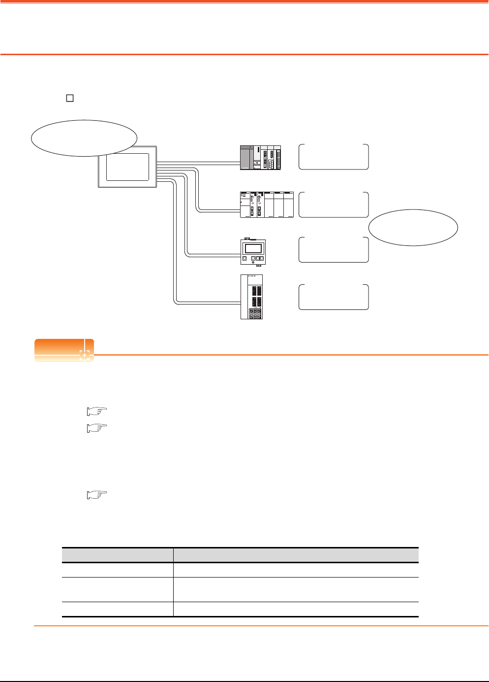
21 - 2 21. MULTI-CHANNEL FUNCTION
21.1 What is Multi-channel Function?
21. MULTI-CHANNEL FUNCTION
21.1 What is Multi-channel Function?
Multi-channel Function is a function to monitor up to four FA controllers (PLC CPU, temperature controller, inverter, etc.)
on one GOT by writing multiple communication drivers in the GOT.
(For GT155 , up to two controllers (two channels))
POINTPOINTPOINT
(1) Before using the multi-channel function
This manual describes the procedure to use the multi-channel function, based on the following system
configuration example.
21.2.1 Bus connection and serial connection
21.2.2 Ethernet multiple connection
(2) System configuration when the multi-channel function is used
The system configuration between GOT and the controllers is the same as that of when not using the multi-
channel function.
For the system configuration between GOT and the controllers, refer to the following.
Each chapter indicating the system configuration
(3) Precautions for hardware
To use the multi-channel function, an option function board is required for some GOTs.
The following table shows the required option function boards.
Channel No.1
Channel No.2
Channel No.3
Channel No.4
Installing multiple
communication drivers
Bus connection
OMRON PLC
connection
Temperature
controller
connection
Servo amplifier
connection
Monitoring the devices
of FA controllers
GOT Option function board
GT16, GT12 Not necessary
GT15 GT15-QFNB, GT15-QFNB16M, GT15-QFNB32M,
GT15-QFNB48M, GT15-MESB48M
GT14 Not necessary
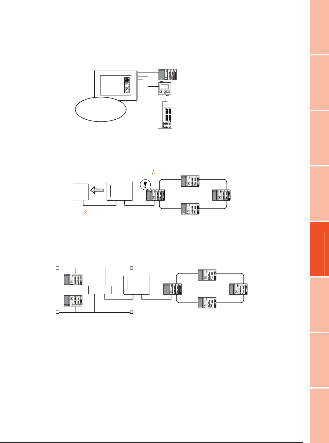
21. MULTI-CHANNEL FUNCTION
21.1 What is Multi-channel Function?
21 - 3
17
ROBOT
CONTROLLER
CONNECTION
18
CNC CONNECTION
19
GOT MULTI-DROP
CONNECTION
20
MULTIPLE-GT14, GT12,
GT11, GT10
CONNECTION FUNCTION
21
MULTI-CHANNEL
FUNCTION
22
FA TRANSPARENT
FUNCTION
Features of the multi-channel function
(1) With a single unit of GOT, the system consisting of PLC CPU, temperature controller, servo amplifier and
other controllers can be configured.
One GOT can monitor a PLC CPU, temperature controller and servo amplifier, etc. Therefore, the system
configuration, in which several controllers are mixed, can be easily established.
In addition, each system can be monitored on the GOT screen, and the unified management of the information
is possible.
(2) Controlling FXCPU/third party PLC, etc. through the network (MELSECNET/H, etc.)
It is possible to control FXCPU/third party PLC, etc. through the network (MELSECNET/H, etc.).
For example, it is possible to execute read/write of a device such as FXCPU when the condition is satisfied,
using the device of the PLC CPU on the network (MELSECNET/H, etc.) as the trigger for action.
(3) With one GOT, the Ethernet connection and the bus or network connection are available in combination.
(GT16 only)
One GOT can make the Ethernet connections and the bus or network connection. Therefore, the system
configuration, in which several networks are linked, can be established.
Also, the GOT can monitor multiple controllers on an Ethernet network.(Multi-channel Ethernet connection)
PLC
Temperatur
controller
Servo amplifier
PLC system
Temperature controller system
Servo amplifier system
Can monitor
different kinds
of controllers on
the same screen.
FXCPU
Condition is satisfied
Writing to a device
Hub
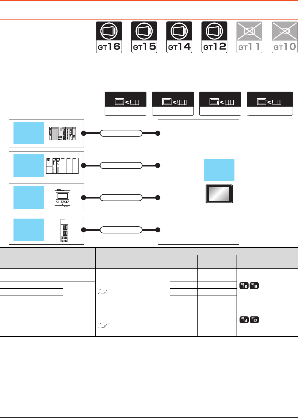
21 - 4 21. MULTI-CHANNEL FUNCTION
21.2 System Configuration
21.2 System Configuration
21.2.1 Bus connection and serial connection
One GOT can monitor a PLC CPU, temperature controller and servo amplifier, etc. Therefore, the system configuration,
in which several controllers are mixed, can be easily established.
In addition, each system can be monitored on the GOT screen, and the unified management of the information is
possible.
Communication driver
Bus(Q)
OMRON SYSMAC
Communication driver
OMRON THERMAC
/INPANEL NEO
Communication driver
Communication driver
MELSERVO-J3, J2S/M
Bus connection
(Channel No.1)
Direct CPU
connection
(Channel No.2)
Temperature
controller
connection
(Channel No.3)
Servo amplifier connection
(Channel No.4)
Connection cable
QCPU
Connection cable
Connection cable
Connection cable
OMRON
PLC
OMRON
temperature
controller
MELSERVO-
J2-Super
series
GOT
PLC Connection
type Connection cable
GOT Number of
connectable
equipment
Channel
No. Option device Model
MELSEC-Q Bus
connection
For the system configuration between
GOT and the controllers, refer to the
following.
Each chapter indicating the
system configuration
1 GT15-QBUS 4 connected
equipment for 1
GOT
(4 channels)
OMRON PLC
Direct CPU
connection
2 - (Built into GOT)
OMRON temperature controller 3 GT15-RS2-9P
MELSERVO-J2-Super 4 GT15-RS4-9S
OMRON PLC
Direct CPU
connection
For the system configuration between
GOT and the controllers, refer to the
following.
Each chapter indicating the
system configuration
1
- (Built into GOT)
2 connected
equipment for 1
GOT
(2 channels)
OMRON temperature controller 2

21. MULTI-CHANNEL FUNCTION
21.2 System Configuration
21 - 5
17
ROBOT
CONTROLLER
CONNECTION
18
CNC CONNECTION
19
GOT MULTI-DROP
CONNECTION
20
MULTIPLE-GT14, GT12,
GT11, GT10
CONNECTION FUNCTION
21
MULTI-CHANNEL
FUNCTION
22
FA TRANSPARENT
FUNCTION
POINTPOINTPOINT
Controllers that use Channels No.5 to 8
The following shows the drivers that can be set to Channels No. 5 to 8.
For the system configuration and connection condition with the controller, refer to the chapter of each controller.
*1 Only one channel can be assigned to one driver.
Channel No. Driver*1 Reference
5 to 7
Barcode Reader,
RFID Controller,
PC Remote Operation(Serial),
Printer (Serial)
GOT1000 Series Connection Manual (Microcomputer, MODBUS, Products, Peripherals)
FINGERPRINT AUTHENTICATION DEVICE CONNECTION
BAR CODE READER CONNECTION
PC REMOTE CONNECTION
PRINTER CONNECTION
RFID CONNECTION
8
Barcode Reader,
RFID Controller,
PC Remote Operation(Serial),
Fingerprint Authentication,
Printer (Serial)
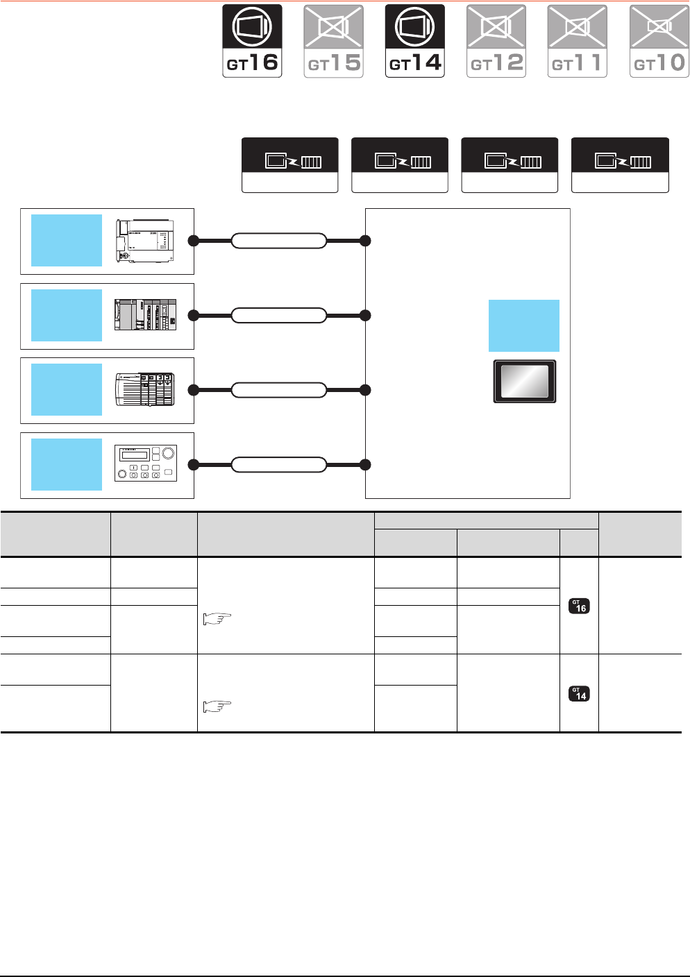
21 - 6 21. MULTI-CHANNEL FUNCTION
21.2 System Configuration
21.2.2 Ethernet multiple connection
One GOT can make several Ethernet connections and the bus or network connections. Therefore, the system
configuration, in which several networks are linked, can be established.
MELSECNET/H
Communication driver
MELSEC-FX
Communication driver
Ethernet/IP(AB)/
Gateway
Communication driver
Ethernet(MELSEC),
Q17nNC, CRnD-700
Communication driver
Direct CPU connection
(Channel No.1)
MELSECNET/H
connection
(Channel No.2)
Ethernet connection
(Channel No.3)
Ethernet connection
(Channel No.4)
Connection cable
Connection cable
Connection cable
Connection cable
GOT
FXCPU
ALLEN-
BRADLEY
PLC
Robot
controller
QCPU
PLC Connection type Connection cable
GOT Number of
connectable
equipment
Channel No. Option device Model
MELSEC-FX Direct CPU
connection For the system configuration between
GOT and the controllers, refer to the
following.
Each chapter indicating the
system configuration
1 GT15-RS2T4-9P
4 connected
equipment for 1
GOT
(4 channels)
QCPU MELSECNET/H 2 GT15-J71LP23-25
ALLEN-BRADLEY
PLC Ethernet 3- (Built into GOT)
Robot controller 4
ALLEN-BRADLEY
PLC
Ethernet
For the system configuration between
GOT and the controllers, refer to the
following.
Each chapter indicating the
system configuration
1
- (Built into GOT)
2 connected
equipment for 1
GOT
(2 channels)
OMRON PLC 2
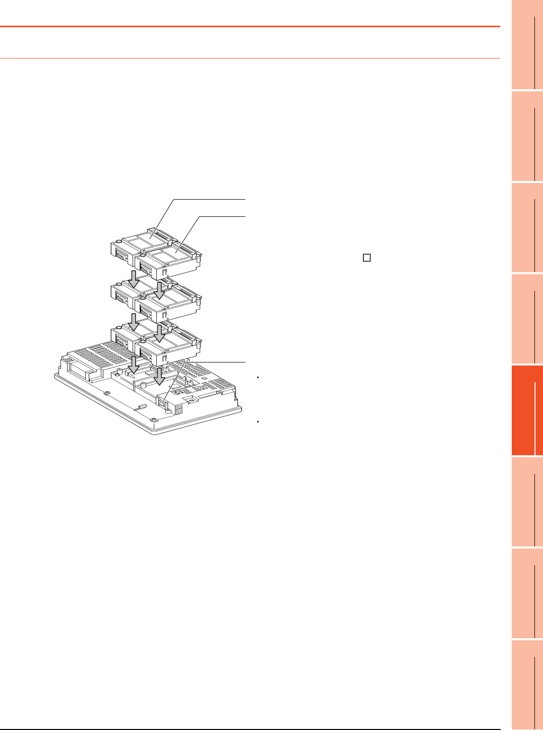
21. MULTI-CHANNEL FUNCTION
21.3 GOT Side Settings
21 - 7
17
ROBOT
CONTROLLER
CONNECTION
18
CNC CONNECTION
19
GOT MULTI-DROP
CONNECTION
20
MULTIPLE-GT14, GT12,
GT11, GT10
CONNECTION FUNCTION
21
MULTI-CHANNEL
FUNCTION
22
FA TRANSPARENT
FUNCTION
21.3 GOT Side Settings
21.3.1 Basics of interface selection
This section explains basic knowledge of the multi-channel function.
A general flow of operation from system selection for the multi-channel function to drawing is explained in 21.3.2 to
21.3.6.
It is recommended to refer to 21.3.2 to 21.3.6 when making necessary settings using the multi-channel function for the
first time.
Multi-channel function specifications
How the units are installed and the multi-channel function specifications are described below.
(1) Image drawing of unit installation
3rd stage
Extension interface 1
Extension interface 2
Standard interface
For GT16
The RS-232 interface, the USB interface,
the RS-422/485 interface, and the Ethernet interface
are built in as the standard interfaces.
For GT15
The RS-232 interface and the USB interface
are built in as the standard interfaces.
Extension interface allows the installation of a
communication unit up to the 3rd stage, respectively.
(For the GT1655, GT155 , only one extension
interface can be installed.)
A communication unit installed at the 4th or higher
stage cannot be used.
2nd stage
1st stage
(Example: In the case of the GT1575)

21 - 8 21. MULTI-CHANNEL FUNCTION
21.3 GOT Side Settings
(2) Specifications
*1 MELSECNET/H connection, MELSECNET/10 connection, CC-Link IE Controller Network connection, CC-Link connection
(intelligent device station)
*2 Ethernet connection, MODBUS®/TCP connection
*3 Gateway function, MES interface function, Ethernet download
*4 Fingerprint unit, barcode reader, RFID controller, personal computer (writing remote personal computer operation (serial), FA
transparent function, OS install, project data) or serial printer
*5 GT15-QBUS2, GT15-ABUS2, GT15-J71GP23-SX, GT15-J71LP23-25, GT15-J71BR13, GT15-J61BT13
Item
Specifications
Description
GT1695
GT1685
GT1675
GT1672
GT1665
GT1662
GT1655
GT1595
GT1585
GT157
GT156
GT155 GT14 GT12
Max.
number of
channels
4 channels 2 channels
GT16
• In bus connection and network connection (*1), only 1 channel can
be set for one GOT.
• For the Ethernet connection (*2), up to 4 channels can be set.
• When the Ethernet interface built in the GOT is used for connection
other than communication with a controller (*3), the connection is
not included in the count of the number of channels.
• The interface used for connecting to an external device (*4) is not
included in the count of the number of channels.
GT15
• For the bus connection, network connection (*1), and Ethernet
connection (*2), only 1 channel can be set for one GOT.
• When an Ethernet communication unit is used in other than
communications with a controller (*3), it is not included in the count
of the number of channels.
• The interface used for connecting to an external device (*4) is not
included in the count of the number of channels.
GT14
• The interface used for connecting to an external device (*4) is not
included in the count of the number of channels.
• For the Ethernet connection (*2), up to 2 channels can be set.
(GT1455-QTBDE and GT1450-QLBDE only)
• When the Ethernet interface built in the GOT is used for connection
other than communication with a controller (*3), the connection is
not included in the count of the number of channels.
(GT1455-QTBDE and GT1450-QLBDE only)
GT12
• For the Ethernet connection (*2), only 1 channel can be set for one
GOT.
• When an Ethernet communication unit is used in other than
communications with a controller (*3), it is not included in the count
of the number of channels.
• The interface used for connecting to an external device (*4) is not
included in the count of the number of channels.
Max.
installable
number of
modules
5353 -
• Multiple identical units can be installed only for serial communication
units.
• It is necessary to calculate the consumed current.
(( This section ■ Calculating consumed current)
• An RS-422 conversion unit is not included in the count of the
number of units.
(For GT1655, GT155 , the RS-422 conversion unit is not
applicable.)
Allowable
number of
stages
Max. 3
stages
(2 slots)
Max. 3
stages
(1 slot)
Max. 3
stages
(2 slot)
Max. 3
stages
(1 slot)
-
• A module that occupies 2 slots (*5, *6, *7) must be installed at the
first stage.
• For the video/RGB display, RGB output, and multimedia function,
install the unit indicated in *6 at the first stage and the other units at
the second or later stage.
• When a unit indicated in *7 is used, other extension units cannot be
installed.
• The CF card unit must be installed on the last stage, if used.

21. MULTI-CHANNEL FUNCTION
21.3 GOT Side Settings
21 - 9
17
ROBOT
CONTROLLER
CONNECTION
18
CNC CONNECTION
19
GOT MULTI-DROP
CONNECTION
20
MULTIPLE-GT14, GT12,
GT11, GT10
CONNECTION FUNCTION
21
MULTI-CHANNEL
FUNCTION
22
FA TRANSPARENT
FUNCTION
*6 GT16M-V4, GT15V-75V4, GT16M-R2, GT15V-75R1, GT16M-V4R1, GT15V-75V4R1, GT16M-ROUT, GT15V-75ROUT, GT16M-
MMR
*7 GT15-75QBUSL, GT15-75QBUS2L, GT15-75ABUSL, GT15-75ABUS2L, GT15-75J71LP23-Z,
GT15-75J71BR13-Z, GT15-75J61BT13-Z
Usable units differ depending on the GOT.
For units usable with each GOT, refer to the following manuals.
User's Manual of GOT used.
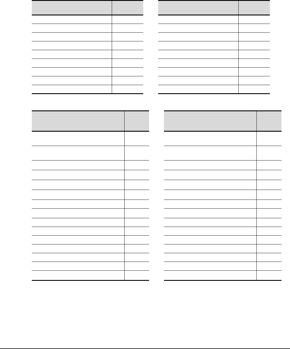
21 - 10 21. MULTI-CHANNEL FUNCTION
21.3 GOT Side Settings
Calculating consumed current
For using multiple extension units, a bar code reader, or a RFID controller, the total current for the extension units,
bar code reader, or RFID controller must be within the current that the GOT can supply.
For the current that the GOT can supply and the current for the extension units, bar code reader, or RFID controller,
refer to the below tables. For the current that the GOT can supply and the current for the extension units, bar code
reader, or RFID controller, refer to the below tables. Make sure that the total of consumed current is within the
capacity of the GOT.
(1) Current supply capacity of the GOT
(2) Current consumed by an extension unit/barcode reader/RFID controller
*1 Value used for calculating the current consumption of the multi-channel function.
For the specifications of the unit, refer to the manual included with the unit.
*2 When the GOT supplies power to a barcode reader or a RFID controller from the standard interface, add their consumed current.
(Maximum value is less than 0.3 A)
GOT type Capacity
(A) GOT type Capacity
(A)
GT1695M-X 2.4 GT1595-X 2.13
GT1685M-S 2.4 GT1585V-S 1.74
GT1675M-S 2.4 GT1585-S 1.74
GT1675M-V 2.4 GT1575V-S 2.2
GT1675-VN, GT1672-VN 2.4 GT1575-S 2.2
GT1665M-S 2.4 GT1575-V, GT1572-VN 2.2
GT1665M-V 2.4 GT1565-V, GT1562-VN 2.2
GT1662-VN 2.4 GT1555-V 1.3
GT1655-V 1.3 GT1555-Q, GT1550-Q 1.3
Module type
Consumed
current
(A)
Module type
Consumed
current
(A)
GT15-QBUS, GT15-QBUS2,
GT15-75QBUSL, GT15-75QBUS2L 0.275*1 GT15V-75V4 0.2*1
GT15-ABUS, GT15-ABUS2,
GT15-75ABUSL, GT15-75ABUS2L 0.12 GT16M-R2 0*1
GT15-RS2-9P 0.29 GT15V-75R1 0.2*1
GT15-RS4-9S 0.33 GT16M-V4R1 0.12*1
GT15-RS4-TE 0.3 GT15V-75V4R1 0.2*1
GT15-RS2T4-9P 0.098 GT16M-ROUT 0.11*1
GT15-J71E71-100 0.224 GT15V-75ROUT 0.11
GT15-J71GP23-SX 1.07 GT16M-MMR 0.27*1
GT15-J71GF13-T2 0.96 GT15-CFCD 0.07
GT15-J71LP23-25 0.56 GT15-CFEX-C08SET 0.15
GT15-J71BR13 0.77 GT15-SOUT 0.08
GT15-J61BT13 0.56 GT15-DIO 0.1
Bar code reader *2 GT15-DIOR 0.1
GT15-PRN 0.09 RFID controller *2
GT16M-V4 0.12*1 GT15-80FPA 0.22

21. MULTI-CHANNEL FUNCTION
21.3 GOT Side Settings
21 - 11
17
ROBOT
CONTROLLER
CONNECTION
18
CNC CONNECTION
19
GOT MULTI-DROP
CONNECTION
20
MULTIPLE-GT14, GT12,
GT11, GT10
CONNECTION FUNCTION
21
MULTI-CHANNEL
FUNCTION
22
FA TRANSPARENT
FUNCTION
(3) Calculation example
(a) When connecting the GT15-J71BR13, GT15-RS4-9S (3 units), GT15-J71E71-100 (for the gateway
function) and a bar code reader (0.12 A) to the GT1575-V
Since the calculated value is within the capacity of the GOT, they can be connected to the GOT.
(b) When connecting the GT15-J71BR13, GT15-RS4-9S (2 units), GT15-J71E71-100 (for the gateway
function) and a bar code reader (0.12 A) to the GT1585-S
Since the calculated value exceeds the capacity of the GOT, such configuration is not allowed.
Current supply capacity of GOT (A) Total consumed current (A)
2.2 0.77+0.33+0.33+0.33+0.224+0.12=2.104
Current supply capacity of GOT (A) Total consumed current (A)
1.74 0.77+0.33+0.33+0.224+0.12=1.774
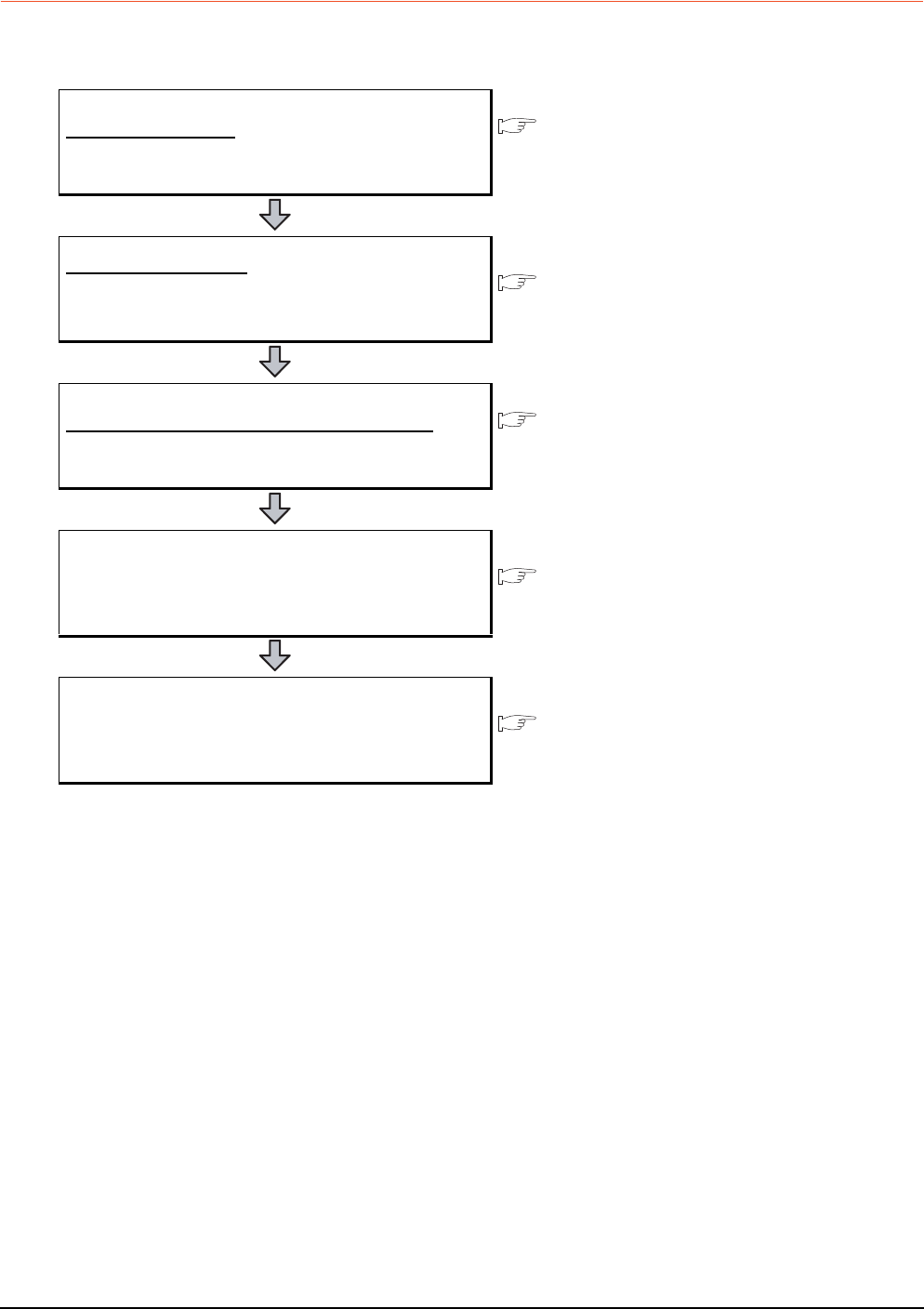
21 - 12 21. MULTI-CHANNEL FUNCTION
21.3 GOT Side Settings
21.3.2 General flow from system selection to drawing
System selection for using the multi-channel function is explained below.
Make selection and setting for the multi-channel function by following the order shown below.
System selection
Determine the connection type and the channel No. to be used.
21.3.3
Determining the connection type and channel No. (System
selection)
Interface selection
Determine the GOT side interface and communication units to
be used for the multichannel function.
21.3.4
Determining the GOT side interface (Interface selection)
Checking the unit installation position
Determine the communication unit installation position.
1.3.7
Installing a unit on another unit (Checking the unit installation
position)
Make settings for Communication Settings. 21.3.5
Setting for communication settings
Confirm items to know before starting drawing. 21.3.6
Items to be checked before starting drawing

21. MULTI-CHANNEL FUNCTION
21.3 GOT Side Settings
21 - 13
17
ROBOT
CONTROLLER
CONNECTION
18
CNC CONNECTION
19
GOT MULTI-DROP
CONNECTION
20
MULTIPLE-GT14, GT12,
GT11, GT10
CONNECTION FUNCTION
21
MULTI-CHANNEL
FUNCTION
22
FA TRANSPARENT
FUNCTION
21.3.3 Determining the connection type and channel No. (System selection)
Determining the connection type
(1) GT16
For GT16, the combinations of the bus or network connection, the Ethernet connection, and the serial
connection are available as shown in the following table.
(Continued to next page)
Connection type Reference
Bus/network connection
Bus connection 5. BUS CONNECTION
MELSECNET/H connection (PLC to PLC network) 9. MELSECNET/H CONNECTION (PLC TO PLC NETWORK)
MELSECNET/10 connection (PLC to PLC network) 10. MELSECNET/10 CONNECTION (PLC TO PLC NETWORK)
CC-Link IE Controller Network connection 11. CC-Link IE CONTROLLER NETWORK CONNECTION
CC-Link IE Field Network connection 12. CC-Link IE FIELD NETWORK CONNECTION
CC-Link connection (intelligent device station) 13. CC-Link CONNECTION (INTELLIGENT DEVICE STATION)
CNC connection(MELSECNET/10 connection (PLC to PLC
network)) 18.2.2 MELSECNET/10 connection (PLC to PLC network)
CNC connection(CC-Link connection (intelligent device station)) 18.2.3 CC-Link connection (intelligent device station)
Ethernet connection
Ethernet connection 8. ETHERNET CONNECTION
Robot controller connection 17. ROBOT CONTROLLER CONNECTION
CNC connection (Ethernet connection) 18.2.4 Ethernet connection
Third party PLC connection (Ethernet connection)
Non-Mitsubishi Products 1
• 4. CONNECTION TO OMRON PLC 4.3 Ethernet Connection
Non-Mitsubishi Products 2
• 6. CONNECTION TO YASKAWA PLC
6.3 Ethernet Connection
• 7. CONNECTION TO YOKOGAWA PLC
7.3 Ethernet Connection
• 10. CONNECTION TO ALLEN-BRADLEY PLC
10.3 Ethernet Connection
• 14. CONNECTION TO SIEMENS PLC
14.3 Ethernet Connection
Microcomputer connection (Ethernet) Microcomputer, MODBUS Products, Peripherals
• 3. MICROCOMPUTER CONNECTION (ETHERNET)
MODBUS®/TCP connection Microcomputer, MODBUS Products, Peripherals
• 5. MODBUS(R)/TCP CONNECTION

21 - 14 21. MULTI-CHANNEL FUNCTION
21.3 GOT Side Settings
Connection type Reference
Serial connection
Direct CPU connection 6. DIRECT CONNECTION TO CPU
Computer link connection 7. COMPUTER LINK CONNECTION
CC-Link connection (via G4) 14. CC-Link CONNECTION (Via G4)
Inverter connection 15. INVERTER CONNECTION
Servo amplifier connection 16. SERVO AMPLIFIER CONNECTION
CNC connection (serial connection) 18.2.1 Direct connection to CPU
GOT Multi- Drop Connection 19. GOT MULTI-DROP CONNECTION
Third party PLC connection (serial connection)
Non-Mitsubishi Products 1
• 4. CONNECTION TO OMRON PLC
4.2 Serial Connection
• 6. CONNECTION TO KEYENCE PLC
• 7. CONNECTION TO KOYO EI PLC
• 8. CONNECTION TO JTEKT PLC
• 9. CONNECTION TO SHARP PLC
• 12. CONNECTION TO TOSHIBA PLC
• 13. CONNECTION TO TOSHIBA MACHINE PLC
• 15. CONNECTION TO PANASONIC PLC
Non-Mitsubishi Products 2
• 2. CONNECTION TO HITACHI IES PLC
• 3. CONNECTION TO HITACHI PLC
• 4. CONNECTION TO FUJI FA PLC
• 6. CONNECTION TO YASKAWA PLC
6.2 Serial Connection
• 7. CONNECTION TO YOKOGAWA PLC
7.2 Serial Connection
• 10. CONNECTION TO ALLEN-BRADLEY PLC
10.2 Serial Connection
• 11. CONNECTION TO GE FANUC PLC
• 12. CONNECTION TO LS INDUSTRIAL SYSTEMS PLC
• 14. CONNECTION TO SIEMENS PLC
• 16. CONNECTION TO MURATEC CONTROLLER
Third party safety controller connection Non-Mitsubishi Products 2
• 13. CONNECTION TO SICK SAFETY CONTROLLER
Third party servo amplifier connection Non-Mitsubishi Products 1
• 14. CONNECTION TO PANASONIC SERVO AMPLIFIER
Third party robot controller connection
Non-Mitsubishi Products 1
• 2. CONNECTION TO IAI ROBOT CONTROLLER
Non-Mitsubishi Products 2
• 15. CONNECTION TO HIRATA CORPORATION HNC
CONTROLLER
Third party temperature controller connection
Non-Mitsubishi Products 1
• 3. CONNECTION TO AZBIL CONTROL EQUIPMENT
• 5. CONNECTION TO OMRON TEMPERATURE
CONTROLLER
• 10. CONNECTION TO SHINKO TECHNOS INDICATING
CONTROLLER
• 11. CONNECTION TO CHINO CONTROLLER
Non-Mitsubishi Products 2
• 5. CONNECTION TO FUJI SYS TEMPERATURE
CONTROLLER
• 8. CONNECTION TO YOKOGAWA TEMPERATURE
CONTROLLER
• 9. CONNECTION TO RKC TEMPERATURE CONTROLLER
Microcomputer Connection (Serial) Microcomputer, MODBUS Products, Peripherals
• 2. MICROCOMPUTER CONNECTION (SERIAL)
MODBUS®/RTU connection Microcomputer, MODBUS Products, Peripherals
• 4. MODBUS(R)/RTU CONNECTION
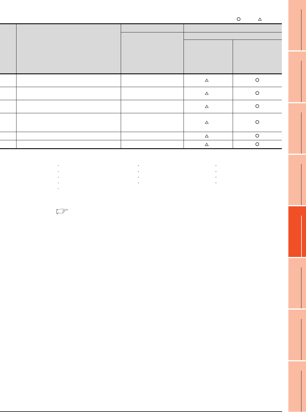
21. MULTI-CHANNEL FUNCTION
21.3 GOT Side Settings
21 - 15
17
ROBOT
CONTROLLER
CONNECTION
18
CNC CONNECTION
19
GOT MULTI-DROP
CONNECTION
20
MULTIPLE-GT14, GT12,
GT11, GT10
CONNECTION FUNCTION
21
MULTI-CHANNEL
FUNCTION
22
FA TRANSPARENT
FUNCTION
The following shows the applicable combinations of connection types, the number of channels, and restricted
functions.
: Allowed : Restricted
*1 When the functions below are used, the connectable number of channels may be restricted depending on the combination of the
functions to be used.
Fingerprint authentication Barcode function RFID function
Remote personal computer operation Video display function Multimedia function
Operation panel function External I/O function RGB display function
Report function Hard copy function(for printer output) Sound output function
Functions with the CF card unit or CF card extension unit
The video display function, multimedia function and RGB display function cannot be used together.
The CF card unit and the CF card extension unit cannot be used at the same time.
For details, refer to the following.
21.3.4 Determining the GOT side interface (Interface selection)
*2 For the FA transparent function via the RS-232 connection, the RS-232 interface built in the GOT is available only.
When the RS-232 interface built in the GOT is already used, the FA transparent function is not available.
Item Allowable combination of connection types
GOT to be used Functions that are restricted by the connection type*1
GT1695
GT1685
GT1675
GT1672
GT1665
GT1662
GT1655
FA transparent function
RS-232 USB
(a) • Bus/network connection: 1 channel
• Serial connection: 1 to 3 channels Max. 4 channels *2
(b) • Bus/network connection: 1 channel
• Ethernet connection: 1 to 3 channels Max. 4 channels *2
(c) • Ethernet connection: 1 to 3 channels
• Serial connection: 1 to 3 channels Max. 4 channels *2
(d)
• Bus/network connection: 1 channel
• Ethernet connection: 1 to 2 channels
• Serial connection: 1 to 2 channels
Max. 4 channels *2
(e) • Serial connection: 4 channels Max. 4 channels *2
(f) • Ethernet connection:: 4 channels Max. 4 channels *2

21 - 16 21. MULTI-CHANNEL FUNCTION
21.3 GOT Side Settings
(2) GT15
For GT15, the combinations of the bus, network, or Ethernet connection and the serial connection are available
as shown in the following table.
(Continued to next page)
Connection type Reference
Bus/network/Ethernet
connection
Bus connection 5. BUS CONNECTION
Ethernet connection 8. ETHERNET CONNECTION
MELSECNET/H connection (PLC to PLC network) 9. MELSECNET/H CONNECTION (PLC TO PLC NETWORK)
MELSECNET/10 connection (PLC to PLC network) 10. MELSECNET/10 CONNECTION (PLC TO PLC NETWORK)
CC-Link IE Controller Network connection 11. CC-Link IE CONTROLLER NETWORK CONNECTION
CC-Link IE Field Network connection 12. CC-Link IE FIELD NETWORK CONNECTION
CC-Link connection (intelligent device station) 13. CC-Link CONNECTION (INTELLIGENT DEVICE STATION)
Robot controller connection 17. ROBOT CONTROLLER CONNECTION
CNC connection(MELSECNET/10 connection (PLC to PLC
network)) 18.2.2 MELSECNET/10 connection (PLC to PLC network)
CNC connection(CC-Link connection (intelligent device station)) 18.2.3 CC-Link connection (intelligent device station)
CNC connection (Ethernet connection) 18.2.4 Ethernet connection
Third party PLC connection (Ethernet connection)
Non-Mitsubishi Products 1
• 4. CONNECTION TO OMRON PLC 3.3 Ethernet Connection
Non-Mitsubishi Products 2
• 6. CONNECTION TO YASKAWA PLC
6.3 Ethernet Connection
• 7. CONNECTION TO YOKOGAWA PLC
7.3 Ethernet Connection
• 10. CONNECTION TO ALLEN-BRADLEY PLC
10.3 Ethernet Connection
• 14. CONNECTION TO SIEMENS PLC
14.3 Ethernet Connection
Microcomputer connection (Ethernet) Microcomputer, MODBUS Products, Peripherals
• 3. MICROCOMPUTER CONNECTION (ETHERNET)
MODBUS®/TCP connection Microcomputer, MODBUS Products, Peripherals
• 5. MODBUS(R)/TCP CONNECTION

21. MULTI-CHANNEL FUNCTION
21.3 GOT Side Settings
21 - 17
17
ROBOT
CONTROLLER
CONNECTION
18
CNC CONNECTION
19
GOT MULTI-DROP
CONNECTION
20
MULTIPLE-GT14, GT12,
GT11, GT10
CONNECTION FUNCTION
21
MULTI-CHANNEL
FUNCTION
22
FA TRANSPARENT
FUNCTION
Connection type Reference
Serial connection
Direct CPU connection 6. DIRECT CONNECTION TO CPU
Computer link connection 7. COMPUTER LINK CONNECTION
CC-Link connection (via G4) 14. CC-Link CONNECTION (Via G4)
Inverter connection 15. INVERTER CONNECTION
Servo amplifier connection 16. SERVO AMPLIFIER CONNECTION
CNC connection (serial connection) 18.2.1 Direct connection to CPU
GOT Multi- Drop Connection 19. GOT MULTI-DROP CONNECTION
Third party PLC connection (serial connection)
Non-Mitsubishi Products 1
• 4. CONNECTION TO OMRON PLC
4.2 Serial Connection
• 6. CONNECTION TO KEYENCE PLC
• 7. CONNECTION TO KOYO EI PLC
• 8. CONNECTION TO JTEKT PLC
• 9. CONNECTION TO SHARP PLC
• 12. CONNECTION TO TOSHIBA PLC
• 13. CONNECTION TO TOSHIBA MACHINE PLC
• 15. CONNECTION TO PANASONIC EW PLC
Non-Mitsubishi Products 2
• 2. CONNECTION TO HITACHI IES PLC
• 3. CONNECTION TO HITACHI PLC
• 4. CONNECTION TO FUJI FA PLC
• 6. CONNECTION TO YASKAWA PLC
6.2 Serial Connection
• 7. CONNECTION TO YOKOGAWA PLC
7.2 Serial Connection
• 10. CONNECTION TO ALLEN-BRADLEY PLC
10.2 Serial Connection
• 11. CONNECTION TO GE FANUC PLC
• 12. CONNECTION TO LS INDUSTRIAL SYSTEMS PLC
• 14. CONNECTION TO SIEMENS PLC
• 16. CONNECTION TO MURATEC CONTROLLER
Third party safety controller connection Non-Mitsubishi Products 2
• 13. CONNECTION TO SICK SAFETY CONTROLLER
Third party servo amplifier connection Non-Mitsubishi Products 1
• 14. CONNECTION TO PANASONIC SERVO AMPLIFIER
Third party robot controller connection
Non-Mitsubishi Products 1
• 2. CONNECTION TO IAI ROBOT CONTROLLER
Non-Mitsubishi Products 2
• 15. CONNECTION TO HIRATA CORPORATION HNC
CONTROLLER
Third party temperature controller connection
Non-Mitsubishi Products 1
• 3. CONNECTION TO AZBIL CONTROL EQUIPMENT
• 5. CONNECTION TO OMRON TEMPERATURE
CONTROLLER
• 10. CONNECTION TO SHINKO TECHNOS INDICATING
CONTROLLER
• 11. CONNECTION TO CHINO CONTROLLER
Non-Mitsubishi Products 2
• 5. CONNECTION TO FUJI SYS TEMPERATURE
CONTROLLER
• 8. CONNECTION TO YOKOGAWA TEMPERATURE
CONTROLLER
• 9. CONNECTION TO RKC TEMPERATURE CONTROLLER
Microcomputer Connection (Serial) Microcomputer, MODBUS Products, Peripherals
• 2. MICROCOMPUTER CONNECTION (SERIAL)
MODBUS®/RTU connection Microcomputer, MODBUS Products, Peripherals
• 4. MODBUS(R)/RTU CONNECTION
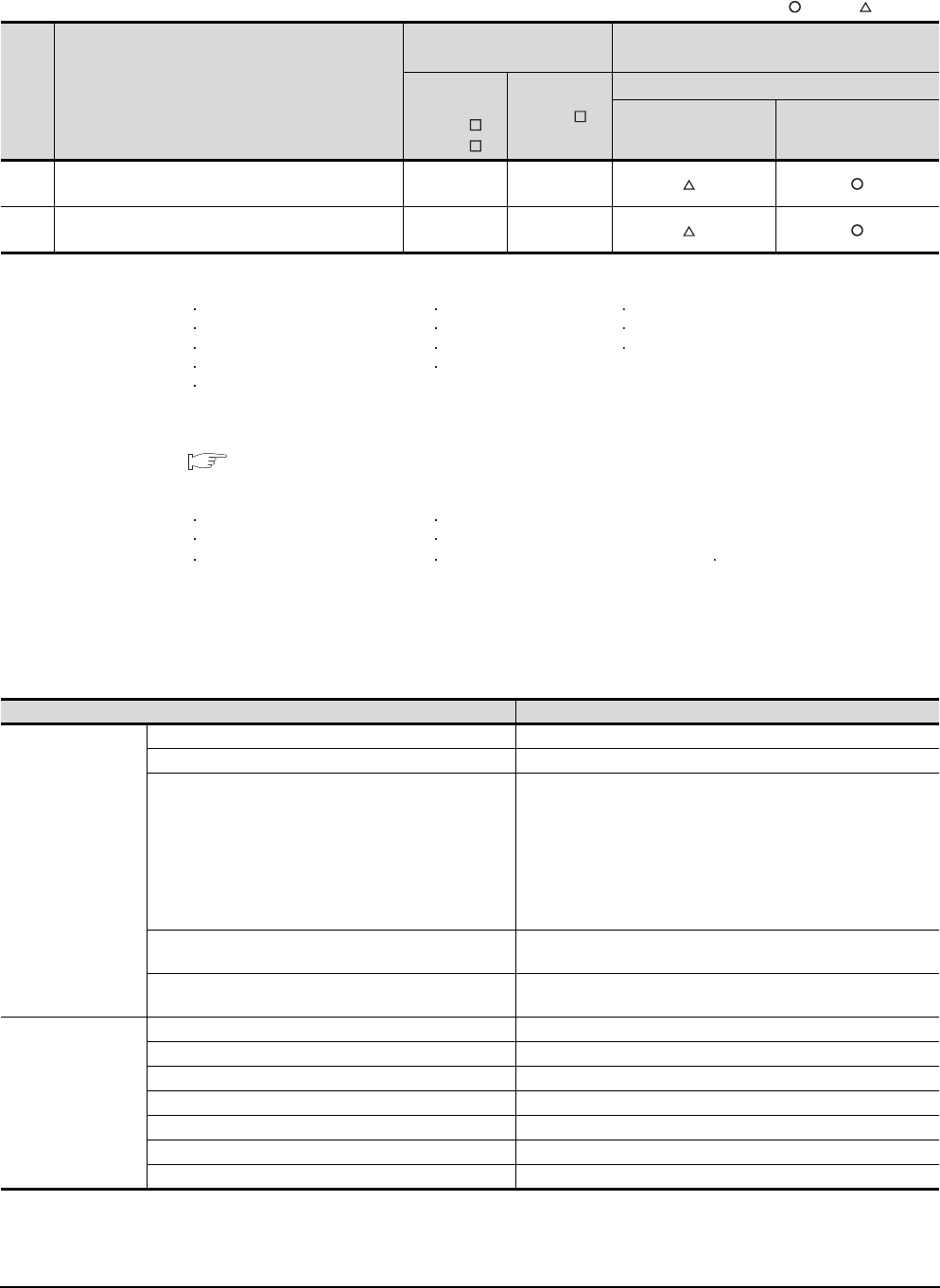
21 - 18 21. MULTI-CHANNEL FUNCTION
21.3 GOT Side Settings
The number of channels and the functions that can be used differ depending on the GOT to be used.
The table below shows the allowable combinations of connection types, the number of channels and restricted
functions.
: Allowed : Restricted
*1 When the functions below are used, the connectable number of channels may be restricted depending on the combination of the
functions to be used.
Fingerprint authentication Barcode function RFID function
Remote personal computer operation Video display function Operation panel function
External I/O function RGB display function Report function
Hard copy function(for printer output) Sound output function
Functions with the CF card unit or CF card extension unit
The video display function and RGB display function cannot be used together.
The CF card unit and the CF card extension unit cannot be used at the same time.
For details, refer to the following.
21.3.4 Determining the GOT side interface (Interface selection)
*2 When any of the connection methods below is used, Ethernet connection cannot be used although Ethernet download, gateway
function, MES interface function and file transfer function (FTP client) can be used.
Bus connection MELSECTNET/H connection
MELSECNET/10 connection CC-Link IE Controller Network connection
CC-Link connection MODBUS®/TCP connection CC-Link IE Field Network connection
*3 For the FA transparent function via the RS-232 connection, the RS-232 interface built in the GOT is available only.
When the RS-232 interface built in the GOT is already used, the FA transparent function is not available.
(3) GT14
For GT14, the combinations of the Ethernet connection and the serial connection are available as shown in the
following table.
(Continued to next page)
Item Allowable combination of connection types
GOT to be used Functions that are restricted by the connection
type*1*2
GT1595
GT1585
GT157
GT156
GT155
FA transparent function
RS-232 USB
(a) • Bus/network/Ethernet connection: 1 channel
• Serial connection: 1 to 3 channels
Max. 4
channels
Max. 2
channels
*3
(b) • Serial connection: 4 channels Max. 4
channels
Max. 2
channels
*3
Connection type Reference
Ethernet connection
Ethernet connection 8.ETHERNET CONNECTION
CNC connection (Ethernet connection) 18.2.4Ethernet connection
Third party PLC connection (Ethernet connection)
Non-Mitsubishi Products 1
• 3. CONNECTION TO OMRON PLC 3.3 Ethernet Connection
Non-Mitsubishi Products 2
• 6. CONNECTION TO YASKAWA PLC 6.3 Ethernet Connection
• 7. CONNECTION TO YOKOGAWA PLC 7.3 Ethernet Connection
• 10. CONNECTION TO ALLEN-BRADLEY PLC 10.3 Ethernet
Connection
• 14. CONNECTION TO SIEMENS PLC 14.3 Ethernet Connection
Microcomputer connection (Ethernet) Microcomputer, MODBUS Products, Peripherals
• 3. MICROCOMPUTER CONNECTION (ETHERNET)
MODBUS®/TCP connection Microcomputer, MODBUS Products, Peripherals
• 5. MODBUS(R)/TCP CONNECTION
Serial connection
Direct CPU connection 6.DIRECT CONNECTION TO CPU
Computer link connection 7.COMPUTER LINK CONNECTION
CC-Link connection (via G4) 14.CC-Link CONNECTION (Via G4)
Inverter connection 15.INVERTER CONNECTION
Servo amplifier connection 16.SERVO AMPLIFIER CONNECTION
CNC connection (serial connection) 18.2.1Direct connection to CPU
GOT Multi- Drop Connection 19.GOT MULTI-DROP CONNECTION
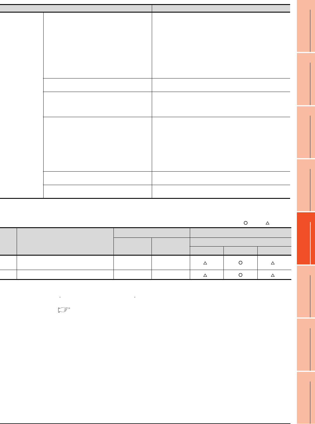
21. MULTI-CHANNEL FUNCTION
21.3 GOT Side Settings
21 - 19
17
ROBOT
CONTROLLER
CONNECTION
18
CNC CONNECTION
19
GOT MULTI-DROP
CONNECTION
20
MULTIPLE-GT14, GT12,
GT11, GT10
CONNECTION FUNCTION
21
MULTI-CHANNEL
FUNCTION
22
FA TRANSPARENT
FUNCTION
The number of channels and the functions that can be used differ depending on the GOT to be used. The table
below shows the allowable combinations of connection types, the number of channels and restricted functions.
: Allowed : Restricted
*1 When the functions below are used, the connectable number of channels may be restricted depending on the combination of the
functions to be used.
Barcode function RFID function
For details, refer to the following.
21.3.4 Determining the GOT side interface (Interface selection)
*2 For the FA transparent function via the RS-232 connection, the RS-232 interface built in the GOT is available only.
When the RS-232 interface built in the GOT is already used, the FA transparent function is not available.
*3 When a GOT and PLC are connected by Ethernet connection, connecting a GOT and a personal computer by Ethernet is not
allowed.
Connection type Reference
Serial connection
Third party PLC connection (serial connection)
Non-Mitsubishi Products 1
• 4. CONNECTION TO OMRON PLC 4.2 Serial Connection
• 6. CONNECTION TO KEYENCE PLC
• 12. CONNECTION TO TOSHIBA PLC
• 15. CONNECTION TO PANASONIC EW PLC
Non-Mitsubishi Products 2
• 6. CONNECTION TO YASKAWA PLC 6.2 Serial Connection
• 7. CONNECTION TO YOKOGAWA PLC 7.2 Serial Connection
• 10. CONNECTION TO ALLEN-BRADLEY PLC 11.2 Serial Connection
• 14. CONNECTION TO SIEMENS PLC
• 16. CONNECTION TO MURATEC CONTROLLER
Third party safety controller connection Non-Mitsubishi Products 2
• 13. CONNECTION TO SICK SAFETY CONTROLLER
Third party robot controller connection
Non-Mitsubishi Products 1
• 2. CONNECTION TO IAI ROBOT CONTROLLER
Non-Mitsubishi Products 2
• 15. CONNECTION TO HIRATA CORPORATION HNC CONTROLLER
Third party temperature controller connection
Non-Mitsubishi Products 1
• 3. CONNECTION TO AZBIL CONTROL EQUIPMENT
• 5. CONNECTION TO OMRON TEMPERATURE CONTROLLER
• 10. CONNECTION TO SHINKO TECHNOS INDICATING
CONTROLLER
• 11. CONNECTION TO CHINO CONTROLLER
Non-Mitsubishi Products 2
• 8. CONNECTION TO YOKOGAWA TEMPERATURE CONTROLLER
• 9. CONNECTION TO RKC TEMPERATURE CONTROLLER
Microcomputer connection (Serial) Microcomputer, MODBUS Products, Peripherals
• 2. MICROCOMPUTER CONNECTION (SERIAL)
MODBUS®/RTU connection Microcomputer, MODBUS Products, Peripherals
• 4. MODBUS(R)/RTU CONNECTION
Item Allowable combination of connection types
GOT to be used Functions that are restricted by the connection type*1
GT1455-QTBDE,
GT1450-QLBDE
GT1455-QTBD,
GT1450-QLBD
FA transparent function
RS-232 USB Ethernet
(a) • Ethernet connection: 1 to 2 channels
• Serial connection: 1 to 2 channels Max. 2 channels - *2 *3
(b) • Serial connection: 2 channels Max. 2 channels Max. 2 channels *2 *3

21 - 20 21. MULTI-CHANNEL FUNCTION
21.3 GOT Side Settings
(4) GT12
For GT12, the combinations of the Ethernet connection and the serial connection are available as shown in the
following table
Connection type Reference
Ethernet connection
Ethernet connection 8.ETHERNET CONNECTION
CNC connection (Ethernet connection) 18.2.4Ethernet connection
Third party PLC connection (Ethernet connection)
Non-Mitsubishi Products 1
• 4. CONNECTION TO OMRON PLC 4.3 Ethernet Connection
Non-Mitsubishi Products 2
• 6. CONNECTION TO YASKAWA PLC 6.3 Ethernet Connection
• 7. CONNECTION TO YOKOGAWA PLC 7.3 Ethernet Connection
• 10. CONNECTION TO ALLEN-BRADLEY PLC 10.3 Ethernet Connection
Microcomputer connection (Ethernet) Microcomputer, MODBUS Products, Peripherals
• 3. MICROCOMPUTER CONNECTION (ETHERNET)
MODBUS®/TCP connection Microcomputer, MODBUS Products, Peripherals
• 5. MODBUS(R)/TCP CONNECTION
Serial connection
Direct CPU connection 6.DIRECT CONNECTION TO CPU
Computer link connection 7.COMPUTER LINK CONNECTION
CC-Link connection (via G4) 14.CC-Link CONNECTION (Via G4)
Inverter connection 15.INVERTER CONNECTION
Servo amplifier connection 16.SERVO AMPLIFIER CONNECTION
CNC connection (serial connection) 18.2.1Direct connection to CPU
GOT Multi- Drop Connection 19.GOT MULTI-DROP CONNECTION
Third party PLC connection (serial connection)
Non-Mitsubishi Products 1
• 4. CONNECTION TO OMRON PLC 4.2 Serial Connection
• 6. CONNECTION TO KEYENCE PLC
• 7. CONNECTION TO KOYO EI PLC
• 8. CONNECTION TO JTEKT PLC
• 9. CONNECTION TO SHARP PLC
• 12. CONNECTION TO TOSHIBA PLC
• 13. CONNECTION TO TOSHIBA MACHINE PLC
• 15. CONNECTION TO PANASONIC PLC
Non-Mitsubishi Products 2
• 2. CONNECTION TO HITACHI IES PLC
• 3. CONNECTION TO HITACHI PLC
• 4. CONNECTION TO FUJI FA PLC
• 6. CONNECTION TO YASKAWA PLC 6.2 Serial Connection
• 7. CONNECTION TO YOKOGAWA PLC 7.2 Serial Connection
• 10. CONNECTION TO ALLEN-BRADLEY PLC 11.2 Serial Connection
• 11. CONNECTION TO GE FANUC PLC
• 12. CONNECTION TO LS INDUSTRIAL SYSTEMS PLC
• 14. CONNECTION TO SIEMENS PLC
Third party safety controller connection Non-Mitsubishi Products 2
• 13. CONNECTION TO SICK SAFETY CONTROLLER
Third party servo amplifier connection Non-Mitsubishi Products 1
• 14. CONNECTION TO PANASONIC SERVO AMPLIFIER
Third party robot controller connection
Non-Mitsubishi Products 1
• 2. CONNECTION TO IAI ROBOT CONTROLLER
Non-Mitsubishi Products 2
• 15. CONNECTION TO HIRATA CORPORATION HNC CONTROLLER
Third party temperature controller connection
Non-Mitsubishi Products 1
• 3. CONNECTION TO AZBIL CONTROL EQUIPMENT
• 5. CONNECTION TO OMRON TEMPERATURE CONTROLLER
• 10. CONNECTION TO SHINKO TECHNOS INDICATING CONTROLLER
• 11. CONNECTION TO CHINO CONTROLLER
Non-Mitsubishi Products 2
• 5. CONNECTION TO FUJI SYS TEMPERATURE CONTROLLER
• 8. CONNECTION TO YOKOGAWA TEMPERATURE CONTROLLER
• 9. CONNECTION TO RKC TEMPERATURE CONTROLLER
Microcomputer connection (Serial) Microcomputer, MODBUS Products, Peripherals
• 2. MICROCOMPUTER CONNECTION (SERIAL)
MODBUS®/RTU connection Microcomputer, MODBUS Products, Peripherals
• 4. MODBUS(R)/RTU CONNECTION

21. MULTI-CHANNEL FUNCTION
21.3 GOT Side Settings
21 - 21
17
ROBOT
CONTROLLER
CONNECTION
18
CNC CONNECTION
19
GOT MULTI-DROP
CONNECTION
20
MULTIPLE-GT14, GT12,
GT11, GT10
CONNECTION FUNCTION
21
MULTI-CHANNEL
FUNCTION
22
FA TRANSPARENT
FUNCTION
The number of channels and the functions that can be used differ depending on the GOT to be used.
The table below shows the allowable combinations of connection types, the number of channels and restricted
functions.
: Allowed : Restricted
*1 When the functions below are used, the connectable number of channels may be restricted depending on the combination of the
functions to be used.
Barcode function RFID function
For details, refer to the following.
21.3.4 Determining the GOT side interface (Interface selection)
*2 When any of the connection methods below is used, Ethernet connection cannot be used although Ethernet download and
gateway function can be used.
MODBUS®/TCP Connection
*3 For the FA transparent function via the RS-232 connection, the RS-232 interface built in the GOT is available only.
When the RS-232 interface built in the GOT is already used, the FA transparent function is not available.
Item Allowable combination of connection types
GOT to be used Functions that are restricted by the connection type*1*2
GT1275
GT1265
FA transparent function
RS-232 USB
(a) • Ethernet connection: 1 channel
• Serial connection: 1 channel Max. 2 channels *3
(b) • Serial connection: 2 channels Max. 2 channels *3
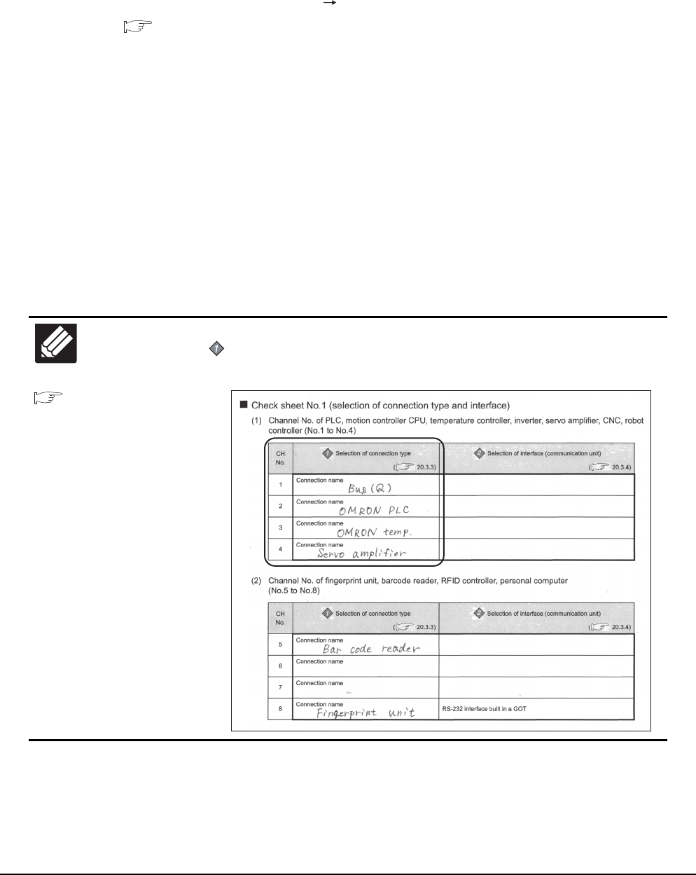
21 - 22 21. MULTI-CHANNEL FUNCTION
21.3 GOT Side Settings
Determining the channel No.
(1) Channel No. of PLC, motion controller, temperature controller, inverter, servo amplifier, CNC, robot
controller
After determining the connection type to be used, determine the channel Nos. (CH No. 1 to CH No. 4) to be
used for the respective connection types.
There are no special cautions to be attended to for determining channel Nos.
Set the channel No. by selecting [Common] [Controller Setting] from the menu.
1.1.1 Setting connected equipment (Channel setting)
(2) Channel No. of external devices (fingerprint unit, barcode reader, RFID controller, personal computer and
serial printer)
When connecting a fingerprint unit, barcode reader, RFID controller, personal computer or serial printer, select
the channel No. (No.5 to No.8) for each external device.
(a) Number of external devices that can be connected to the GOT
One fingerprint unit, barcode reader, RFID controller, personal computer or serial printer can be connected
to one GOT.
One driver must be set for one channel No. (No.5 to No.8) in the communication settings.
(b) Operator authentication (external authentication or fingerprint authentication)
When using the operator authentication (external authentication or fingerprint authentication), the RFID
controller is available for the channel No.8 only.
(c) External devices that requires the power supply from the GOT
When using the barcode reader or RFID controller that requires the power supply from the GOT, set the
channel No.8.
When the channel No.5 to No.7 is set, the GOT cannot supply the power.
21.5
Multi-channel Function
Check Sheet
Write down the following items selected in this section to the check sheet.
Selection of connection type
Write down the name of connection type to be used.
Write Check
Sheet
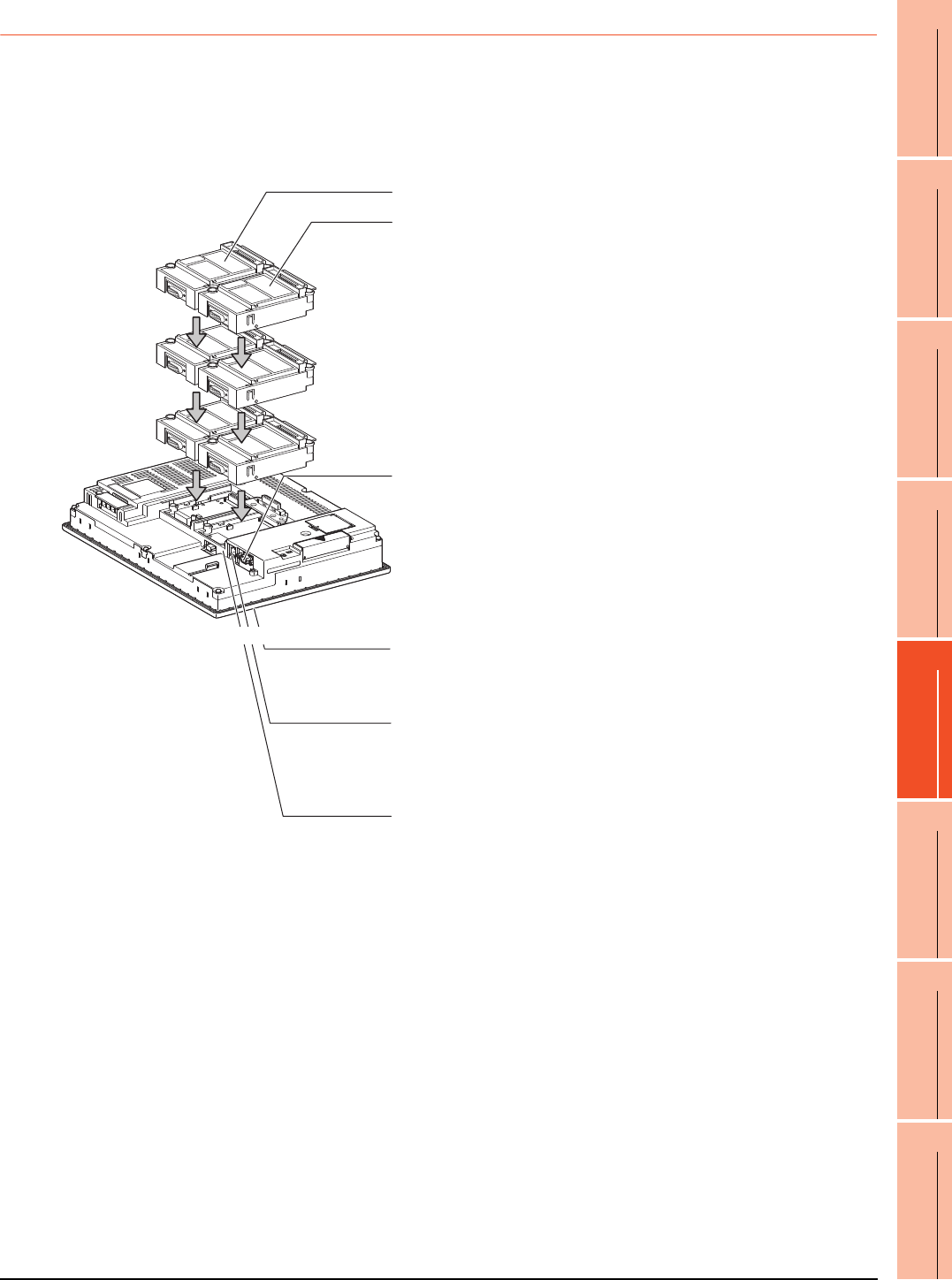
21. MULTI-CHANNEL FUNCTION
21.3 GOT Side Settings
21 - 23
17
ROBOT
CONTROLLER
CONNECTION
18
CNC CONNECTION
19
GOT MULTI-DROP
CONNECTION
20
MULTIPLE-GT14, GT12,
GT11, GT10
CONNECTION FUNCTION
21
MULTI-CHANNEL
FUNCTION
22
FA TRANSPARENT
FUNCTION
21.3.4 Determining the GOT side interface (Interface selection)
To use the multi-channel function, add interfaces to the GOT with the following methods if required.
(1) GT16
• Install communication units on the extension interfaces.
• Use communication units installed on the extension interfaces with the RS-232 interface, the RS422/485
interface, and/or the Ethernet interface built in the GOT.
3rd stage
Extension interface 1
Extension interface 2
Standard interface 1
(RS-232 interface built in the GOT)
Allows a controller to be connected via the serial
communication.
For RS-232 communications, connect RS-232 cable.
For RS-422 communications, attach an RS-422
conversion unit and connect RS-422 cable to it.
(For the GT1655, the RS-422 conversion unit is not applicable.)
Extension interface allows the installation
of a communication unit up to the 3rd stage,
respectively.
(For the GT1655, only one extension interface can
be installed.)
2nd stage
1st stage
Standard interface 2
(USB interface built in the GOT)
Not used for the multi-channel function.
Standard interface 4
(Ethernet interface built in the GOT)
Allows controllers to be connected via Ethernet.
Up to four channels can be set.
Standard interface 3
(RS-422/485 interface built in the GOT)
Allows a controller to be connected via the serial
communication.
(Example: In the case of the GT1685)
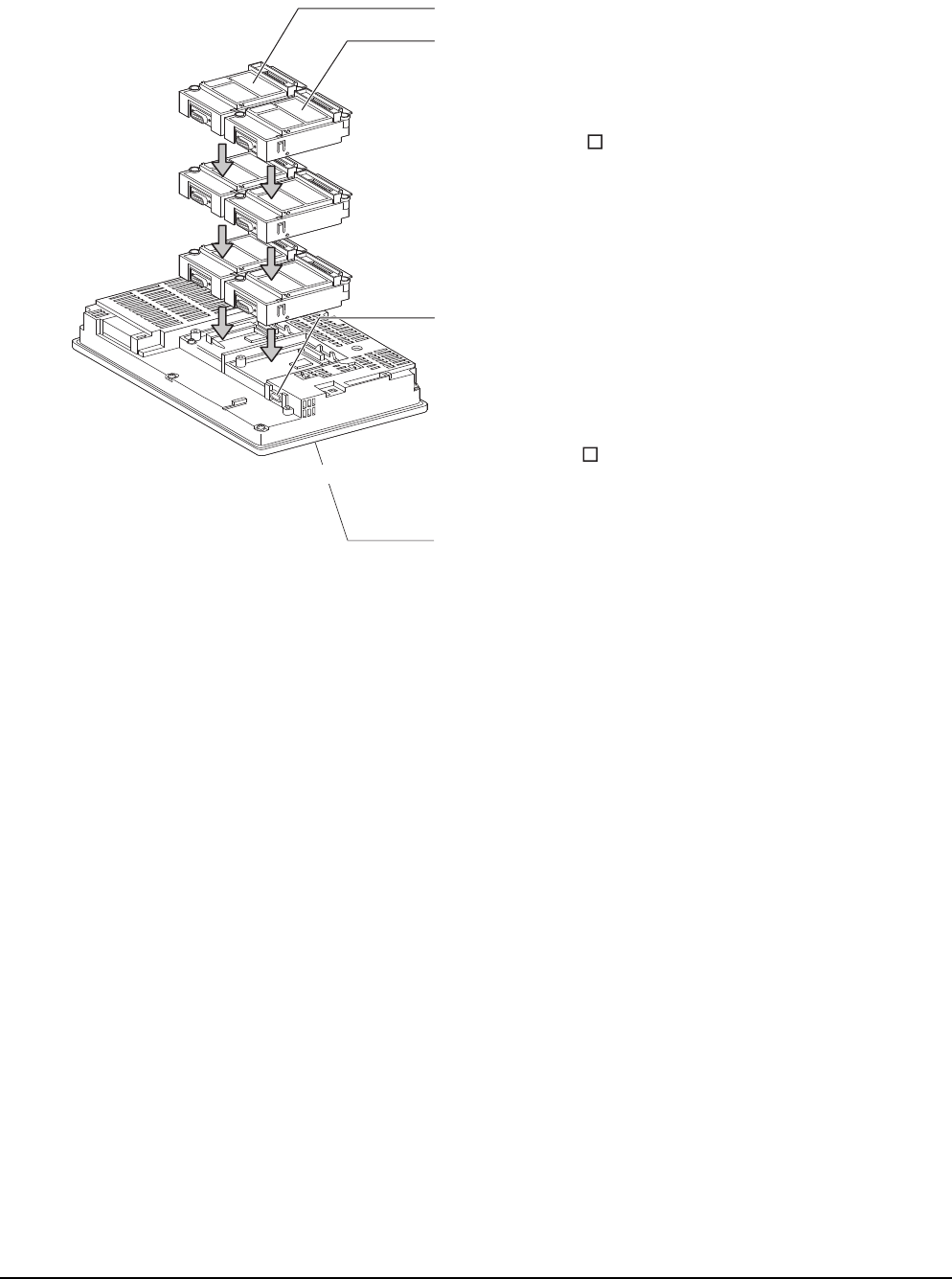
21 - 24 21. MULTI-CHANNEL FUNCTION
21.3 GOT Side Settings
(2) GT15
• Install communication units on the extension interfaces.
• Use communication units installed on the extension interfaces with the RS-232 interface built in the GOT.
3rd stage
Extension interface 1
Extension interface 2
Standard interface 1
(RS-232 interface built in the GOT)
Allows a controller to be connected via the serial communication.
For RS-232 communications, connect RS-232 cable.
For RS-422 communications, attach an RS-422
conversion unit and connect RS-422 cable to it.
(For the GT155 , the RS-422 conversion unit is not applicable.)
Extension interface allows the installation
of a communication unit up to the 3rd stage,
respectively.
(For the GT155 , only one extension interface can
be installed.)
A communication unit installed at the 4th
or higher stage cannot be used.
2nd stage
1st stage
Standard interface 2
(USB interface built in the GOT)
Not used for the multi-channel function.
(Example: In the case of the GT1575)
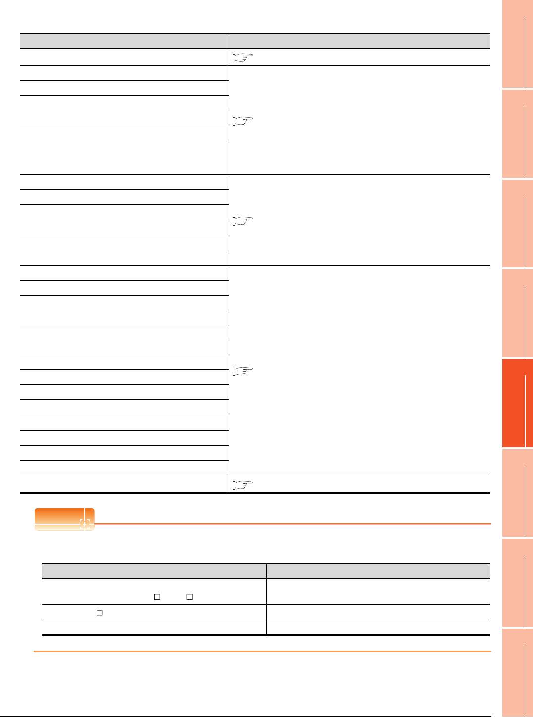
21. MULTI-CHANNEL FUNCTION
21.3 GOT Side Settings
21 - 25
17
ROBOT
CONTROLLER
CONNECTION
18
CNC CONNECTION
19
GOT MULTI-DROP
CONNECTION
20
MULTIPLE-GT14, GT12,
GT11, GT10
CONNECTION FUNCTION
21
MULTI-CHANNEL
FUNCTION
22
FA TRANSPARENT
FUNCTION
For the connection via the connection type selected in 21.3.3, select interfaces and communication units to be used.
Select the interfaces and communication units according to the connection type by referring to the following.
POINTPOINTPOINT
Number of units that can be installed to a GOT
The number of units that can be installed to extension interfaces differs depending on the GOT type.
Selected connection type Reference for required interface and communication unit
• Bus connection This section ■ GOT interface used for bus connection
• MELSECNET/H connection (PLC to PLC network)
This section ■ GOT interface used for network connection
• MELSECNET/10 connection (PLC to PLC network)
• CC-Link IE Controller Network connection
• CC-Link IE Field Network connection
• CC-Link connection (intelligent device station)
• CNC connection
(MELSECNET/10 connection (PLC to PLC network),
CC-Link connection (intelligent device station))
• Ethernet connection
This section ■ GOT interface used for Ethernet connection
• Third party PLC connection (Ethernet connection)
•MODBUS
®/TCP connection
• Robot controller connection
• CNC connection (Ethernet connection)
• Microcomputer connection (Ethernet)
• Direct CPU connection
This section ■ GOT interface used for serial connection
• Computer link connection
• CC-Link connection (via G4)
• Third party PLC connection (serial connection)
• Third party safety controller connection
• Third party servo amplifier connection
• Third party robot controller connection
• Third party temperature controller connection
• Microcomputer Connection (Serial)
• GOT Multi- Drop Connection
•MODBUS
®/RTU connection
• Inverter connection
• Servo amplifier connection
• CNC connection (serial connection)
• Other functions This section ■ Interfaces and option units used for other functions
GOT Number of units that can be installed
GT1695, GT1685, GT1675, GT1672, GT1665,
GT1662, GT1595, GT1585, GT157 , GT156 Up to 5 units can be installed (up to 4 communication units)
GT1655, GT155 Up to 3 units can be installed (up to 2 communication units)
GT12 -
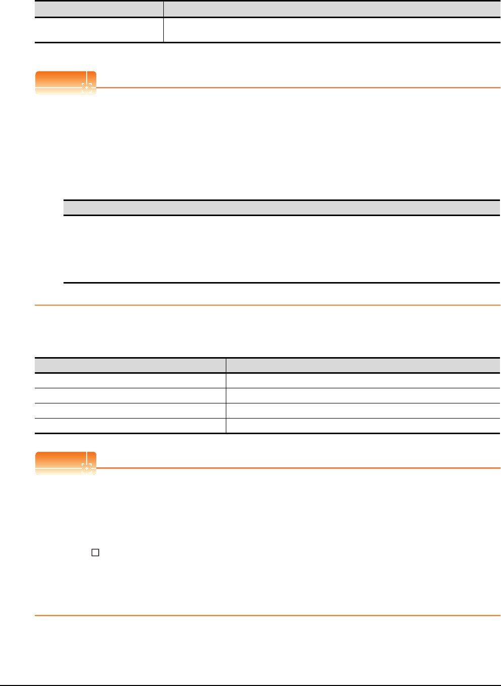
21 - 26 21. MULTI-CHANNEL FUNCTION
21.3 GOT Side Settings
GOT interface used for bus connection
For the bus connection, use the following communication units.
*1 To mount multiple units, the GT15-QBUS(2) or GT15-ABUS(2) is required.
POINTPOINTPOINT
(1) Bus connection units to be used
GT15-QBUS(2) and GT15-ABUS(2) can be used independent of the number of serial connection channels.
When using the multi-channel function for the first time, it is recommended to use GT15-QBUS(2) or GT15-
ABUS(2).
(2) Restrictions by bus connection unit installation
For the following functions, use the GT15-QBUS(2) or GT15-ABUS(2), regardless of the number of channels
used for the serial connection.
With the GT15-75QBUS(2)L or GT15-75ABUS(2)L, the following functions are not available.
*1 Since the GT16 has the Ethernet interface, the function is available regardless of the bus connection unit to be used.
GOT interface used for network connection
For the network connection, use the following communication units.
POINTPOINTPOINT
When using GT15-75J71LP23-Z, GT15-75J71BR13-Z, or GT15-75J61BT13-Z
(1) GT16
The GT15-75J71LP23-Z, GT15-75J71BR13-Z, and GT15-75J61BT13-Z are not applicable.
(2) GT15
No unit can be mounted on the GT15-75J71LP23-Z, GT15-75J71BR13-Z, or GT15-75J61BT13-Z. (For the
GT155 , the GT15-75J71LP23-Z, GT15- 75J71BR13-Z, and GT15-75J61BT13-Z are not applicable)
Therefore, the RS-232 interface built in the GOT is used for the serial connection.
Because of this, the functions using the RS-232 interface, including the barcode function, are not available.
The gateway function, the printer output, and others are also not available since no unit can be mounted on
the above models.
Interface Model*1
Bus connection unit GT15-75QBUS(2)L, GT15-75ABUS(2)L, GT15-QBUS(2),
GT15-ABUS(2)
Function
Remote personal computer operation(serial), Video display function, Multimedia function,
Operation panel function, External I/O function, RGB display function,
Report function (when using a PictBridge compatible printer),
Hard copy function (when using a PictBridge compatible printer),
Sound output function, Functions with the CF card unit or CF card extension unit,
Ethernet download*1, Gateway function*1, MES interface function*1
Interface Model
MELSECNET/H communication unit GT15-J71LP23-25, GT15-J71BR13
CC-Link IE Controller Network communication unit GT15-J71GP23-SX
CC-Link IE Field Network communication unit GT15-J71GF13-T2
CC-Link communication unit GT15-J61BT13

21. MULTI-CHANNEL FUNCTION
21.3 GOT Side Settings
21 - 27
17
ROBOT
CONTROLLER
CONNECTION
18
CNC CONNECTION
19
GOT MULTI-DROP
CONNECTION
20
MULTIPLE-GT14, GT12,
GT11, GT10
CONNECTION FUNCTION
21
MULTI-CHANNEL
FUNCTION
22
FA TRANSPARENT
FUNCTION
GOT interface used for Ethernet connection
For the Ethernet connection, use the following interface built in the GOT and communication unit.
(1) GT16
*1 Up to four channels can be used.
(2) GT15
(3) GT14
*1 Up to two channels can be used.
(4) GT12
POINTPOINTPOINT
When using Ethernet download, gateway function, or MES interface function
(1) GT16
The Ethernet download, the gateway function, and the MES interface function are available using the Ethernet
interface built in the GOT (one channel).
(2) GT15
For using Ethernet download, the gateway function and MES interface function, only one Ethernet
communication unit is required.
(3) GT14
The Ethernet download and the gateway function are available using the Ethernet interface built in the GOT
(one channel).
(4) GT12
The Ethernet download and the gateway function are available using the Ethernet interface built in the GOT
(one channel).
GOT interface used for serial connection
For the serial connection, provide interfaces equivalent to the number of channels by using the following interfaces
built in the GOT and communication units in combinations.
(1) GT16
*1 The operator authentication (external authentication or fingerprint authentication) or the FA transparent function (RS-232
communication) uses the RS-232 interface built in the GOT.
*2 For the RS-422 communication using the RS-232 interface built in the GOT, the RS-422 conversion unit is required.
(For GT 1655, the RS-422 conversion unit is not applicable.)
Interface Name
Interface built in GOT Ethernet interface*1
Interface Model
Ethernet communication unit GT15-J71E71-100
Interface Name
Interface built in GOT Ethernet interface*1
Interface Name
Interface built in GOT Ethernet interface
Interface Name/model
Interface built in GOT RS-232 interface*1*2, RS-422/485 interface
Serial communication module GT15-RS2-9P, GT15-RS4-9S, GT15-RS4-TE
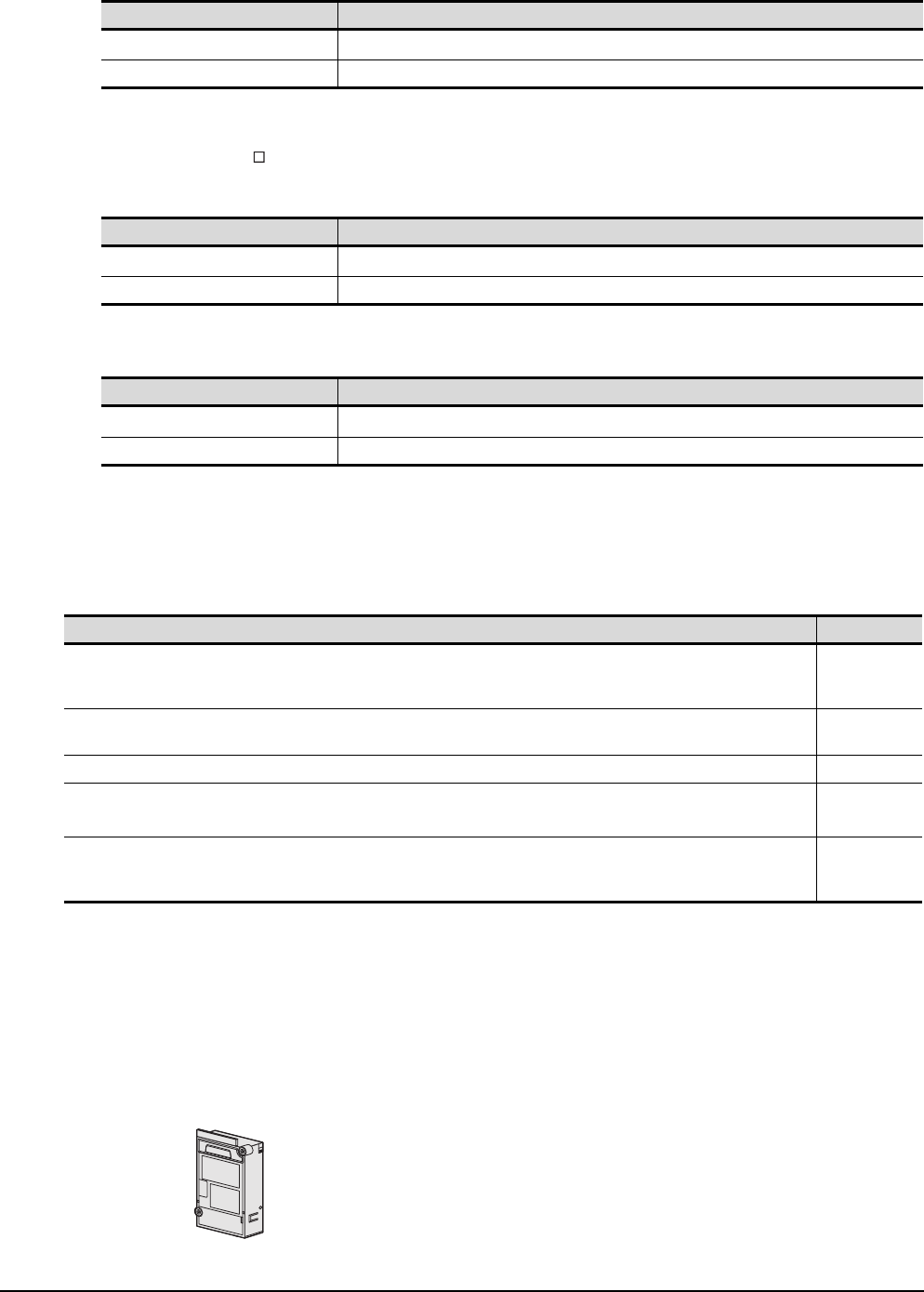
21 - 28 21. MULTI-CHANNEL FUNCTION
21.3 GOT Side Settings
(2) GT15
*1 The operator authentication (external authentication or fingerprint authentication) or the FA transparent function (RS-232
communication) uses the RS-232 interface built in the GOT.
*2 For the RS-422 communication using the RS-232 interface built in the GOT, the RS-422 conversion unit is required.
(For GT155 , the RS-422 conversion unit is not applicable.)
(3) GT14
*1 The FA transparent function (RS-232 communication) uses the RS-232 interface built in the GOT.
(4) GT12
*1 The FA transparent function (RS-232 communication) uses the RS-232 interface built in the GOT.
Interfaces and option units used for other functions
When the following functions are used in combinations, the number of available channels may vary according to the
combinations of units
*1 For GT16, the function is available regardless of the combinations of units because the GOT has the Ethernet interface.
For GT15, the function is not available when the Ethernet communication unit cannot be mounted because of the combination of
units.
Refer to the explanation below to check if the number of channels for the multi-channel function to be used is
restricted or not. If it is restricted, review the system configuration.
(1) Number of stages taken up by the individual functions (number of slots)
(a) Report function (when using a PictBridge compatible printer), hard copy function (when using a PictBridge
compatible printer), operation panel function, external I/O function and sound output function
Interface Name/model
Interface built in GOT RS-232 interface*1*2
Serial communication module GT15-RS2-9P, GT15-RS4-9S, GT15-RS4-TE
Interface Name/model
Interface built in GOT RS-232 interface*1, RS-422/485 interface
Serial communication module -
Interface Name/model
Interface built in GOT RS-232 interface*1, RS-422/485 interface
Serial communication module -
Function Reference
Report function (when using a PictBridge compatible printer), Hard copy function (when using a PictBridge compatible printer),
Operation panel function, External I/O function,
Sound output function
(1) (a)
Remote personal computer operation (serial), Video display function,
Multimedia function, RGB display function (1) (b)
Functions with the CF card unit or CF card extension unit (1) (c)
Remote personal computer operation(Ethernet), Ethernet download*1,
Gateway function*1, MES interface function*1 (1) (d)
Fingerprint authentication, Barcode function,
RFID function, Remote personal computer operation(serial),
Report function (when using the serial printer), Hard copy function (when using the serial printer)
(1) (e)
The printer unit, sound output unit, or external I/O unit is required depending on the
function to be used.
Each unit uses one stage (one slot) of an extension interface.
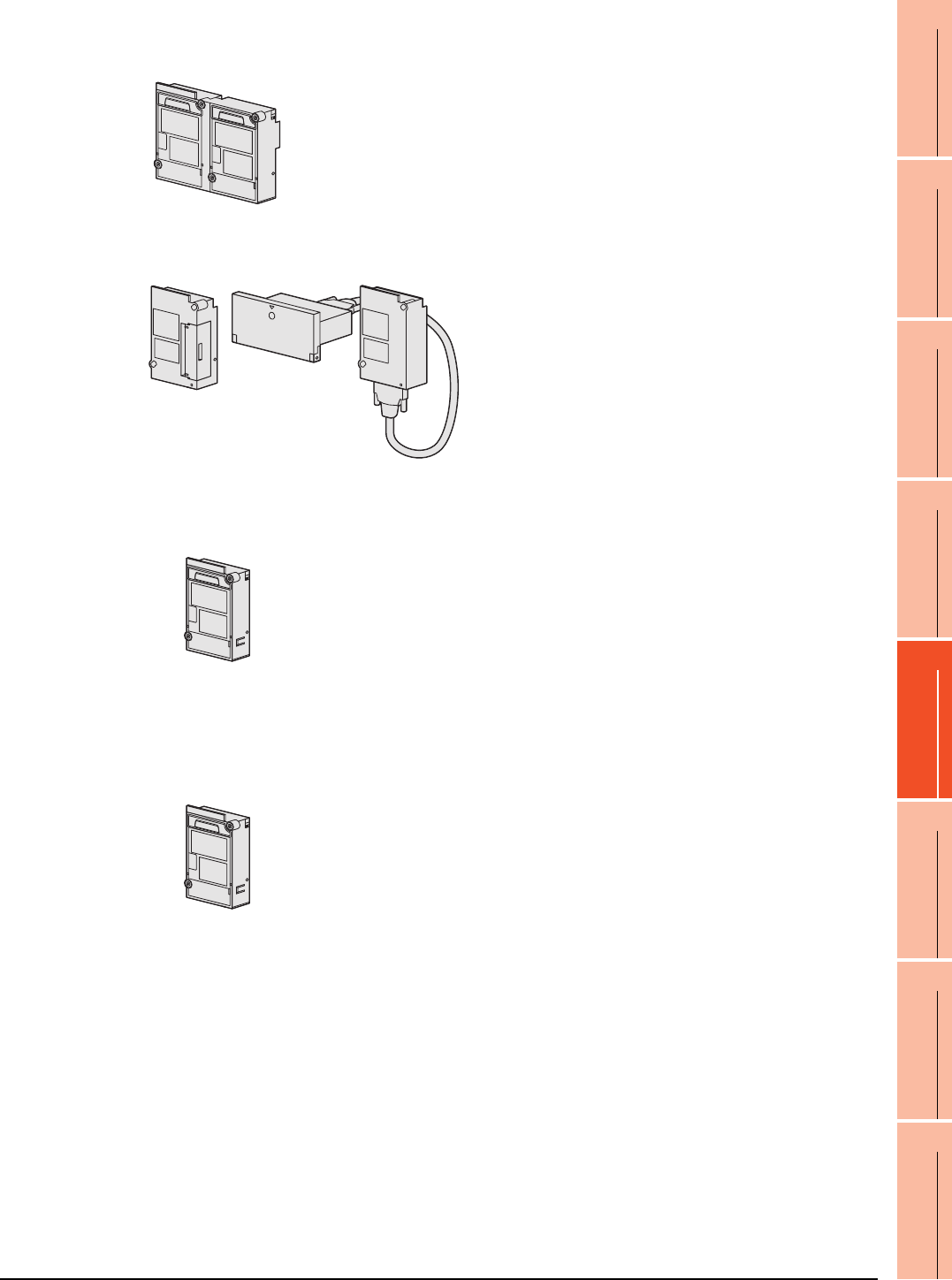
21. MULTI-CHANNEL FUNCTION
21.3 GOT Side Settings
21 - 29
17
ROBOT
CONTROLLER
CONNECTION
18
CNC CONNECTION
19
GOT MULTI-DROP
CONNECTION
20
MULTIPLE-GT14, GT12,
GT11, GT10
CONNECTION FUNCTION
21
MULTI-CHANNEL
FUNCTION
22
FA TRANSPARENT
FUNCTION
(b) Remote personal computer operation (serial), video display function, multimedia function and RGB display
function
(c) Functions with CF card unit or CF card extension unit
(d) Remote personal computer operation (Ethernet), Ethernet download, gateway and MES interface functions
(e) Fingerprint authentication, barcode function, RFID function, remote personal computer operation (serial),
report function (when using a serial printer) and hard copy function (when using a serial printer)
A video input unit, an RGB input unit, a video/RGB input unit, an RGB output unit or a
multimedia unit is required corresponding to the function to be used.
Each type of unit uses 1 stage (2 slots) of extension interface.
Only one piece of each type of unit can be installed on a GOT.
The CF card unit or CF card extension unit is required.
The CF card unit or CF card extension unit uses one stage
(one slot) of an extension interface.
•GT16
Use the interface built in the GOT.
The Ethernet communication unit is not applicable.
•GT15
An Ethernet communication unit is required.
An Ethernet communication unit uses 1 stage (1 slot) of extension interface.
If the GOT is already connected in the Ethernet connection, the Ethernet
communication unit installed in the GOT is used.
Use the interface built in the GOT or a serial communication unit.
A serial communication unit uses 1 stage (1 slot) of extension interface.
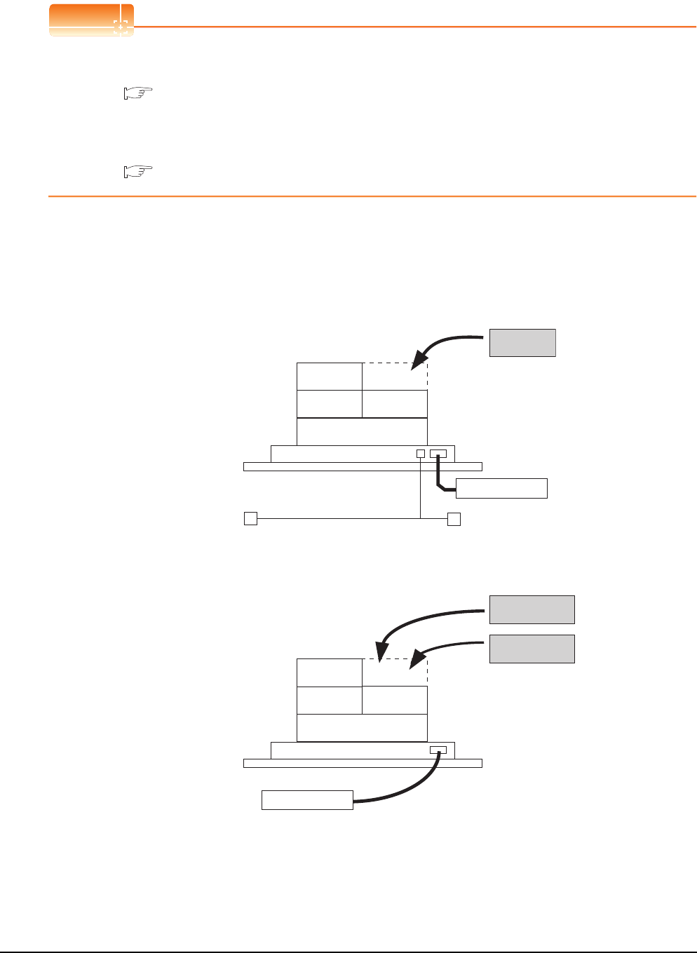
21 - 30 21. MULTI-CHANNEL FUNCTION
21.3 GOT Side Settings
(2) Combinations of units that affect the number of available channels
The following are examples of unit combinations that affect the number of available channels.
POINTPOINTPOINT
Installing a unit on another unit (Checking the unit installation position)
For details on the precautions for installing units on another unit, refer to the following.
1.3.7 Installing a unit on another unit (Checking the unit installation position)
For the installation method of each unit, refer to the User's Manual for the communication unit and option unit you
are using.
For the method for installing a unit on another unit, refer to the following.
User's Manual of GOT used.
Example 1) To add the printer output (when using a PictBridge compatible printer) and the Ethernet download in
a system using the bus connection (1 channel), serial connection (3 channels), and the barcode
function
(a) For GT16
Mount the printer unit at the third stage, and use the Ethernet interface built in the GOT. This enables both
the printer output of the report function and the Ethernet download.
(b) For GT15
Because units can be mounted up to the third stage for GT15, the printer output of the report function and
the Ethernet download cannot be used together.
Serial communication
unit
Serial communication
unit
Serial communication
unit
Printer unit
Barcode reader
Bus connection unit
Ethernet communication
unit
Printer unit
Barcode reader
Bus connection unit
Serial communication
unit
Serial communication
unit
Serial communication
unit
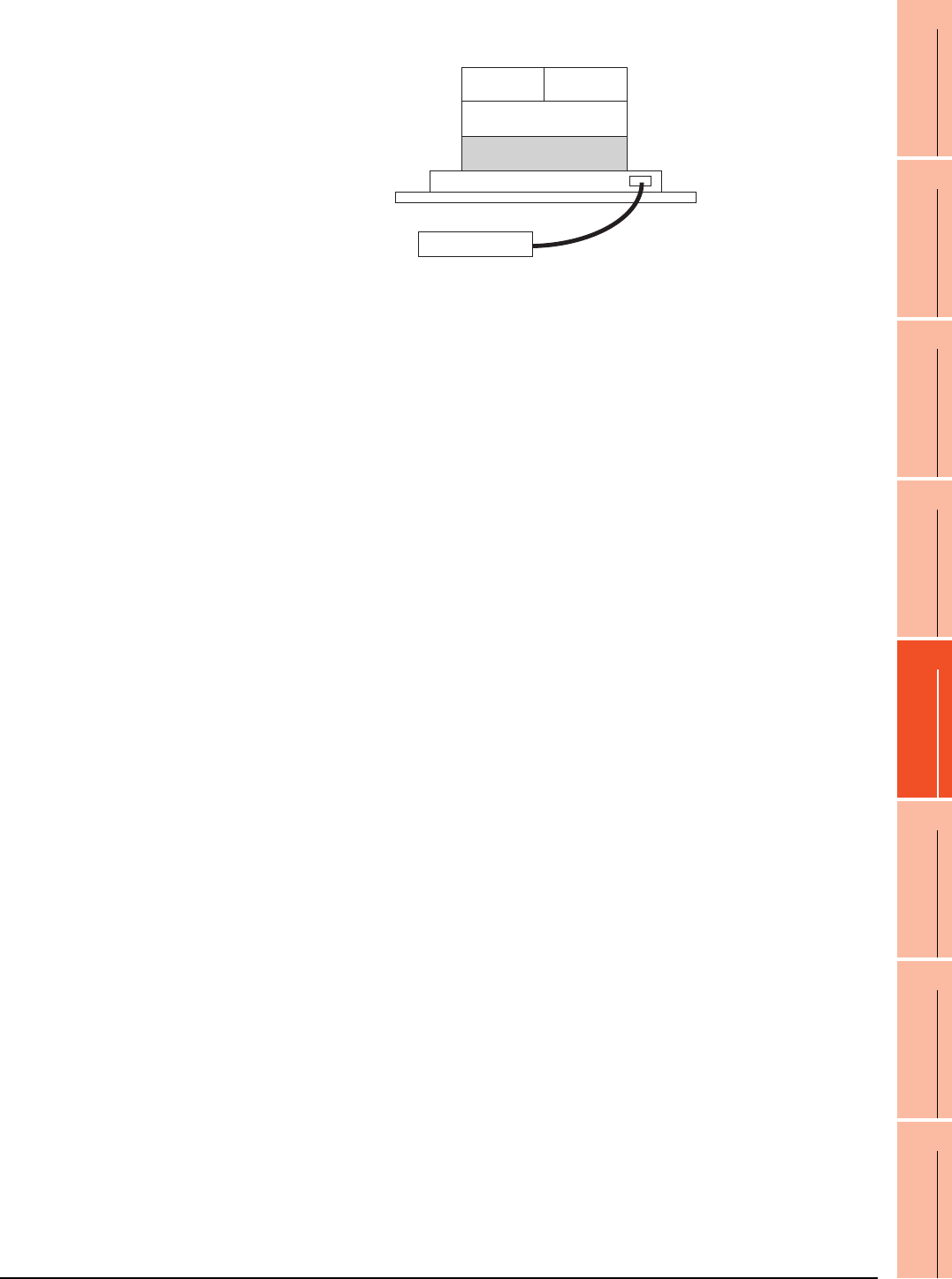
21. MULTI-CHANNEL FUNCTION
21.3 GOT Side Settings
21 - 31
17
ROBOT
CONTROLLER
CONNECTION
18
CNC CONNECTION
19
GOT MULTI-DROP
CONNECTION
20
MULTIPLE-GT14, GT12,
GT11, GT10
CONNECTION FUNCTION
21
MULTI-CHANNEL
FUNCTION
22
FA TRANSPARENT
FUNCTION
Example 2) To add the serial connection (1 channel) to the system using the bus connection (unit occupying 2
slots: 1 channel), the serial connection (2 channels), the video display, and the barcode function
Since there are no available areas left for installing a unit, serial connection can be used for up to 2
channels.
Video input unit
Barcode reader
Bus connection unit
Serial communication
unit
Serial communication
unit
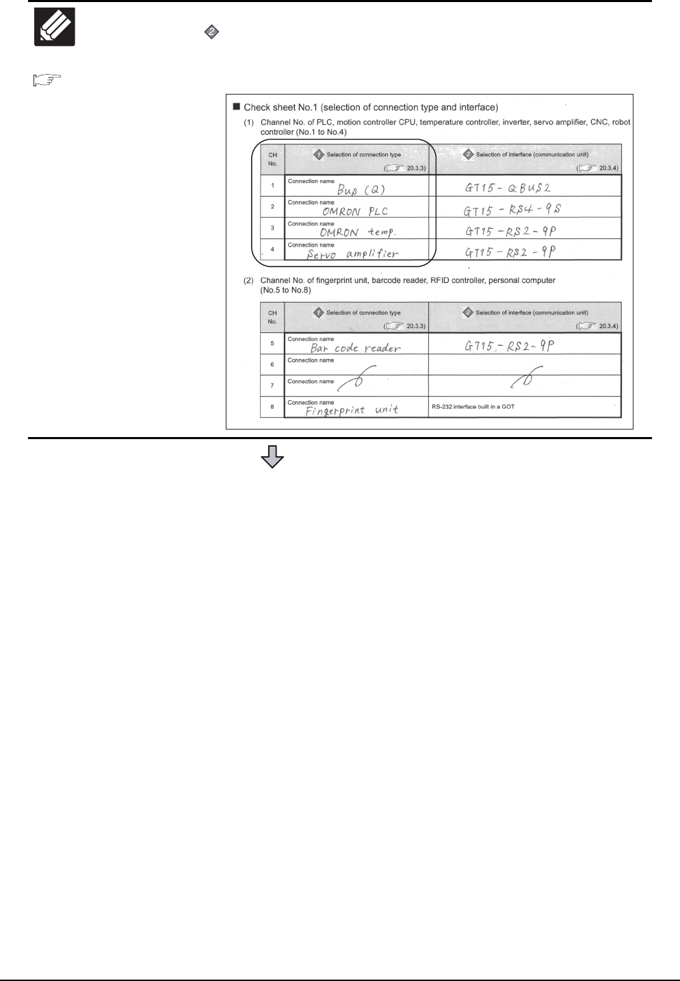
21 - 32 21. MULTI-CHANNEL FUNCTION
21.3 GOT Side Settings
21.5
Multi-channel Function
Check Sheet
Write down the following items selected in this section to the check sheet.
Selection of interface (communication unit)
Write down the name of interface and the model name of communication unit to be used
for each of the connection type.
(Continued to next page)
Write Check
Sheet
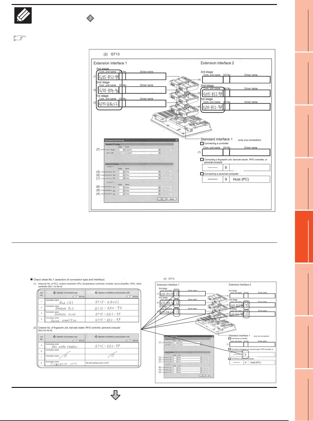
21. MULTI-CHANNEL FUNCTION
21.3 GOT Side Settings
21 - 33
17
ROBOT
CONTROLLER
CONNECTION
18
CNC CONNECTION
19
GOT MULTI-DROP
CONNECTION
20
MULTIPLE-GT14, GT12,
GT11, GT10
CONNECTION FUNCTION
21
MULTI-CHANNEL
FUNCTION
22
FA TRANSPARENT
FUNCTION
21.5
Multi-channel Function
Check Sheet
Write down the following items to the check sheet.
Attaching the communication unit
1. Write down the name of communication unit to be used for each of the
connection type.
* For the GT155 , setting is made only for Extension interface 1.
When GT15-QBUS2/ABUS2 is used, although GT15-RS2-9P is installed physically at the
2nd stage of extend interface 2, the GOT recognizes the position as the 1st stage.
Therefore, in the check sheet, the position should be entered as 1st stage.
2. After writing down the names of communication units, write down CH
No. to be assigned to respective units based on the entry in ■ Check
Sheet No. 1 (selection of connection type and interface).
(Continued to next page)
Write Check
Sheet
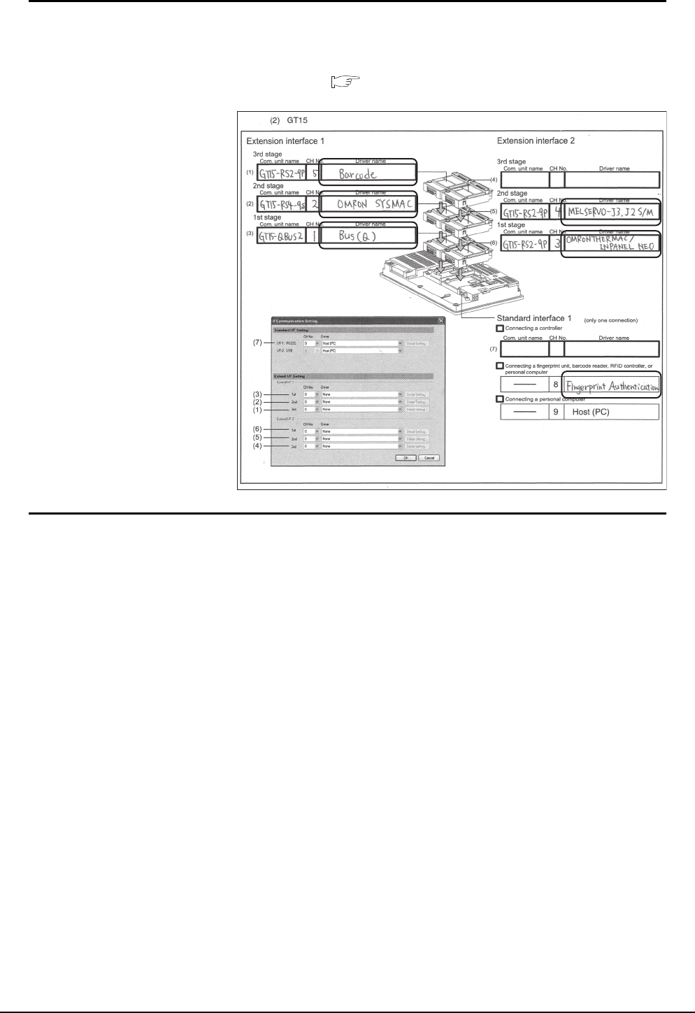
21 - 34 21. MULTI-CHANNEL FUNCTION
21.3 GOT Side Settings
3. After writing down CH No., write down the communication driver name
for each connection type. For the communication drivers used for the
respective connection types, refer to the following.
Chapters of each respective connection type
* For the GT155 , setting is made only for Extension interface 1.
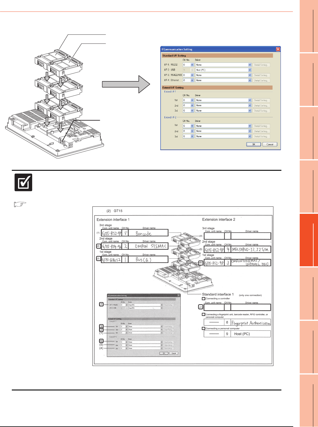
21. MULTI-CHANNEL FUNCTION
21.3 GOT Side Settings
21 - 35
17
ROBOT
CONTROLLER
CONNECTION
18
CNC CONNECTION
19
GOT MULTI-DROP
CONNECTION
20
MULTIPLE-GT14, GT12,
GT11, GT10
CONNECTION FUNCTION
21
MULTI-CHANNEL
FUNCTION
22
FA TRANSPARENT
FUNCTION
21.3.5 Setting for communication settings
Make communication settings based on the interface and the installation position of the respective communication units.
3rd stage
Extend interface 1
Extend interface 2
RS-232 interface
built in a GOT
2nd stage
1st stage
21.5
Multi-channel Function
Check Sheet
Make settings for Communication Settings by GT Designer3 referring to the check sheet
where the necessary information has been written.
The positions that the settings should be made on the communication settings screen are
specified on the check sheet by numbers (GT16: (1) to (9), GT15: (1) to (7)).
* For the GT155 , setting is made only for Extension interface 1.
This completes the setting for Communication Settings.
Create a screen with GT Designer3.
Check
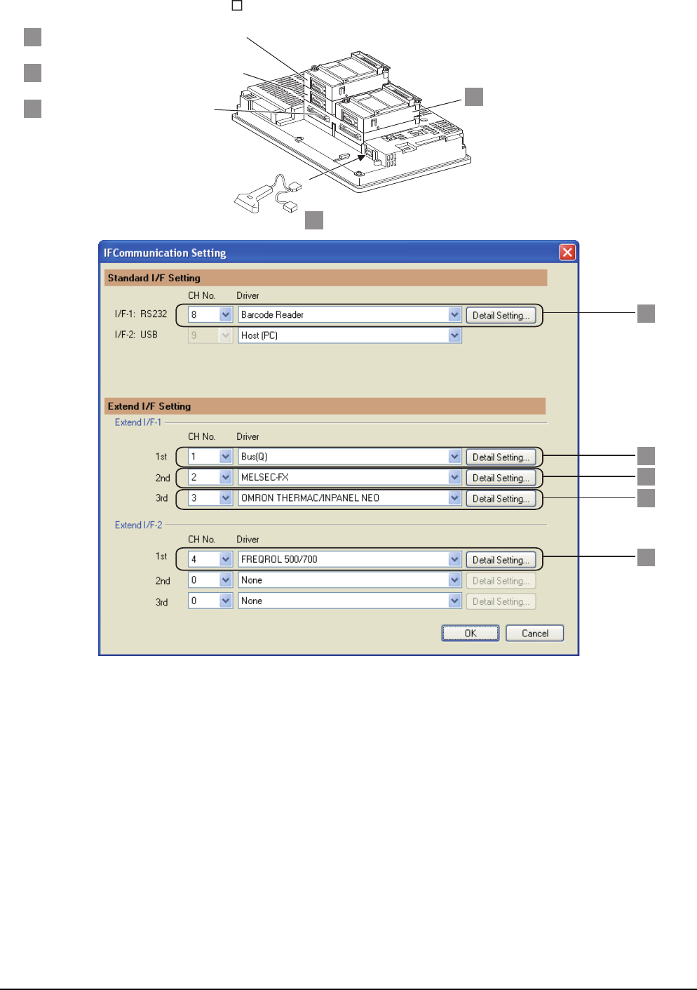
21 - 36 21. MULTI-CHANNEL FUNCTION
21.3 GOT Side Settings
Example: Setting example for "Bus connection (1 channel) + Serial connection (3 channels) + Bar code reader"
(In the case of the GT157 )
4
5
1
2
3
Serial communication unit (GT15-RS2-9P)
OMRON temperature controller connection
Serial communication unit (GT15-RS4-9P)
Inverter connection
Serial communication unit (GT15-RS2-9P)
FXCPU direction CPU connection
Bus connection unit (GT15-QBUS2)
QCPU bus connection
Bar code reader
5
4
1
2
3
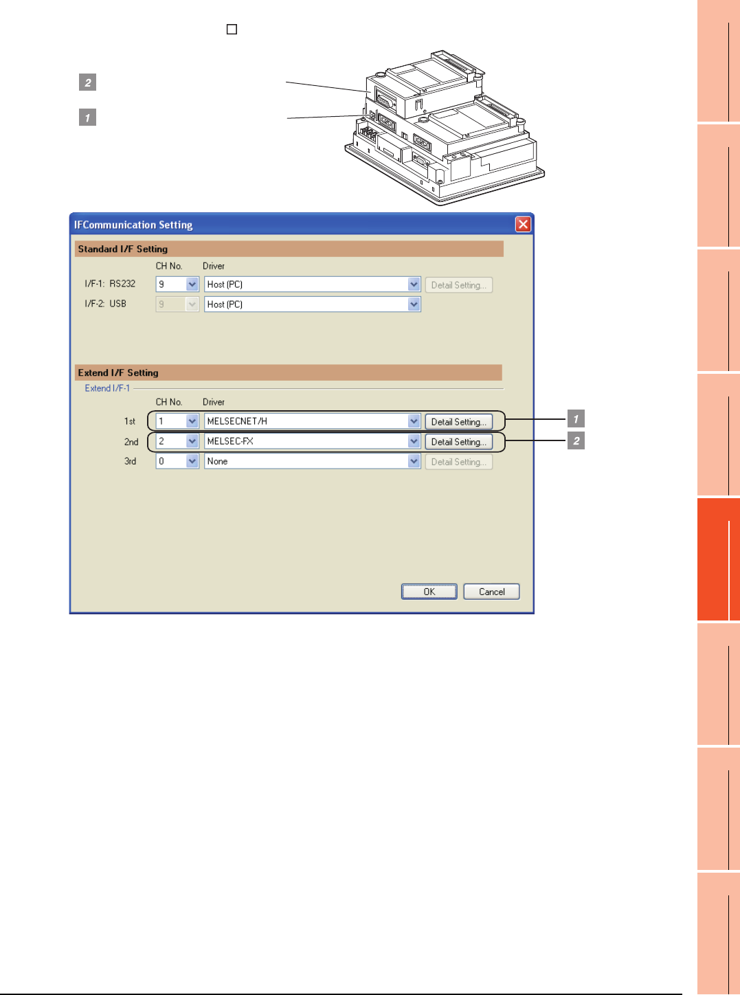
21. MULTI-CHANNEL FUNCTION
21.3 GOT Side Settings
21 - 37
17
ROBOT
CONTROLLER
CONNECTION
18
CNC CONNECTION
19
GOT MULTI-DROP
CONNECTION
20
MULTIPLE-GT14, GT12,
GT11, GT10
CONNECTION FUNCTION
21
MULTI-CHANNEL
FUNCTION
22
FA TRANSPARENT
FUNCTION
Example: Setting example for "MELSECNET/H connection (1 channel) + Serial connection (1 channel)"
(In the case of the GT155 )
MELSECNET/H communication unit
(GT15-J71LP23-25)
Serial communication unit (GT15-RS2-9P)
FXCPU direction CPU connection
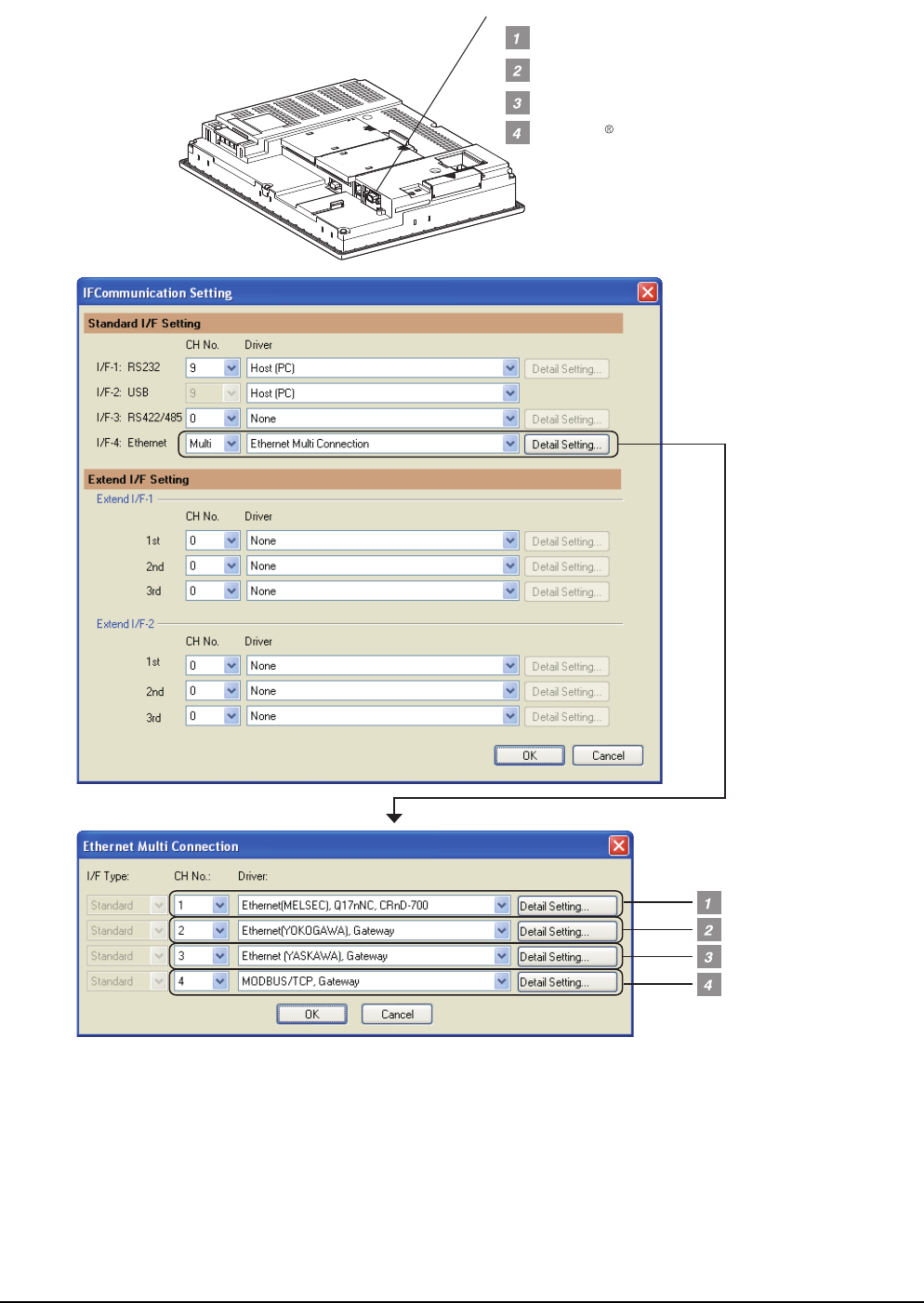
21 - 38 21. MULTI-CHANNEL FUNCTION
21.3 GOT Side Settings
Example: Setting example for Ethernet connection (4 channels) (In the case of the GT1685)
YASKAWA PLC Ethernet connection
MODBUS /TCP connection
YOKOGAWA PLC Ethernet connection
QCPU Ethernet connection
Ethernet interface built in the GOT
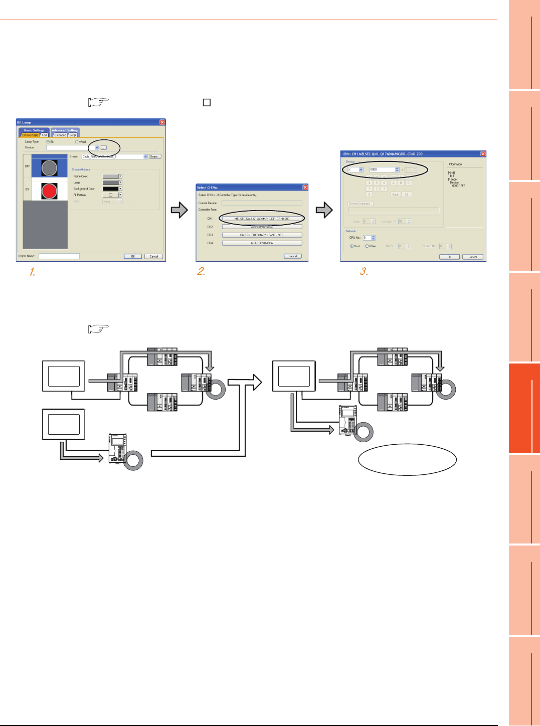
21. MULTI-CHANNEL FUNCTION
21.3 GOT Side Settings
21 - 39
17
ROBOT
CONTROLLER
CONNECTION
18
CNC CONNECTION
19
GOT MULTI-DROP
CONNECTION
20
MULTIPLE-GT14, GT12,
GT11, GT10
CONNECTION FUNCTION
21
MULTI-CHANNEL
FUNCTION
22
FA TRANSPARENT
FUNCTION
21.3.6 Items to be checked before starting drawing
The following describes that should be understood before starting drawing and the functions that should be set
beforehand when using the multi-channel function.
Device settings
It is necessary to set the device to be used together with the CH No.
GT Designer3 Version Screen Design Manual
Accessible range for monitoring
The accessible range for monitoring is not changed even when the multi-channel function is used.
3. ACCESS RANGE FOR MONITORING
Click the device setting button. Click the controller to be set. Set the device.
FXCPU
Accessible range
is not changed.
FXCPU
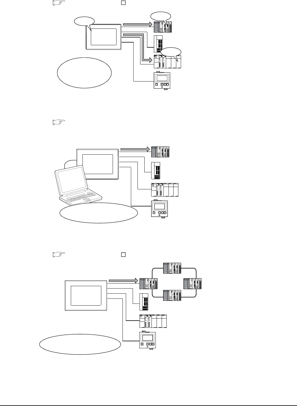
21 - 40 21. MULTI-CHANNEL FUNCTION
21.3 GOT Side Settings
Clock function
Set the controller for which adjust/broadcast should be executed by the CH No.
GT Designer3 Version Screen Design Manual
FA transparent function
Set the controller for which the FA transparent function should be executed by the CH No.
22.5.1 Setting communication interface
The set CH No. can be changed by the Utility.
To execute the FA transparent function for other CH No., change the CH No. using the Utility.
Station No. switching function
Set the controller for which the station No. switching function should be executed by the CH No.
GT Designer3 Version Screen Design Manual
CH No. 1
Mitsubishi PLC
CH No. 2
Servo amplifier
CH No. 3
OMRON PLC
CH No. 4
Temperature controlle
r
Broadcast is
executed for
CH No. 1 and
CH No. 3.
10:10
10:10
CHARGE
MITSUBISHI
10:10
FA transparent function is
executed for CH No. 1.
CHARGE
MITSUBISHI
CH No. 1
Mitsubishi PLC
CH No. 2
Servo amplifier
CH No. 3
OMRON PLC
CH No. 4
Temperature controller
Station No. switching is
executed for CH No. 1.
CHARGE
MITSUBISH I
CH No. 1
Mitsubishi PLC
CH No. 2
Servo amplifier
CH No. 3
OMRON PLC
CH No. 4
Temperature controller
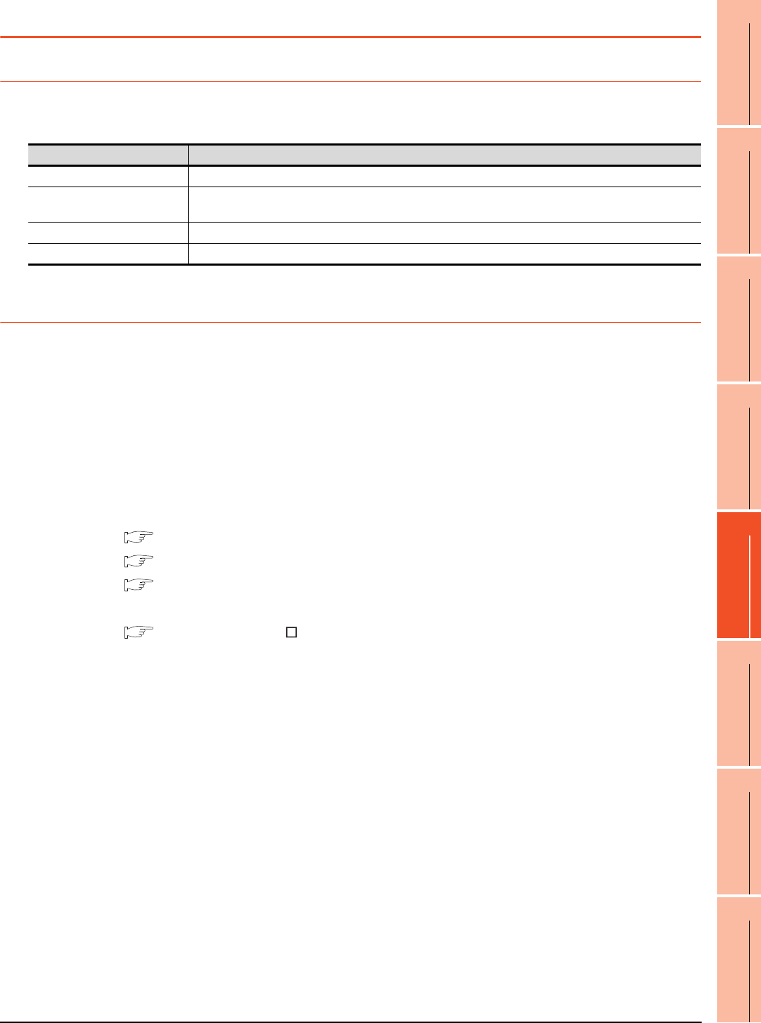
21. MULTI-CHANNEL FUNCTION
21.4 Precautions
21 - 41
17
ROBOT
CONTROLLER
CONNECTION
18
CNC CONNECTION
19
GOT MULTI-DROP
CONNECTION
20
MULTIPLE-GT14, GT12,
GT11, GT10
CONNECTION FUNCTION
21
MULTI-CHANNEL
FUNCTION
22
FA TRANSPARENT
FUNCTION
21.4 Precautions
21.4.1 Precautions for hardware
To use the multi-channel function, an option function board is required according to the GOT.
The following shows required option function boards according to the GOT.
21.4.2 Precautions for use
Occurrence of the same system alarm at different channels
When the advanced system alarm is used, if the system alarms with the same error code occur in different channels
the GOT treats the alarms as the same system alarm.
Therefore, if the system alarms with the same error code occur one by one, the time of later system alarm occurrence
is not reflected to the GOT.
Confirmation of the channel No. at which a system alarm occurred
When a system alarm occurred, confirm the channel No. where the alarm occurred, using the procedure indicated
below.
(1) Check by [System alarm display] of the utility.
GT16 User's Manual (Basic Utility)
GT15 User's Manual
GT14 User's Manual
(2) Monitor the internal devices of the GOT.
GT Designer3 Version Screen Design Manual
GOT Option function board
GT16 Not necessary
GT15 GT15-QFNB, GT15-QFNB16M, GT15-QFNB32M, GT15-QFNB48M
GT15-MESB48M
GT14 Not necessary
GT12 Not necessary
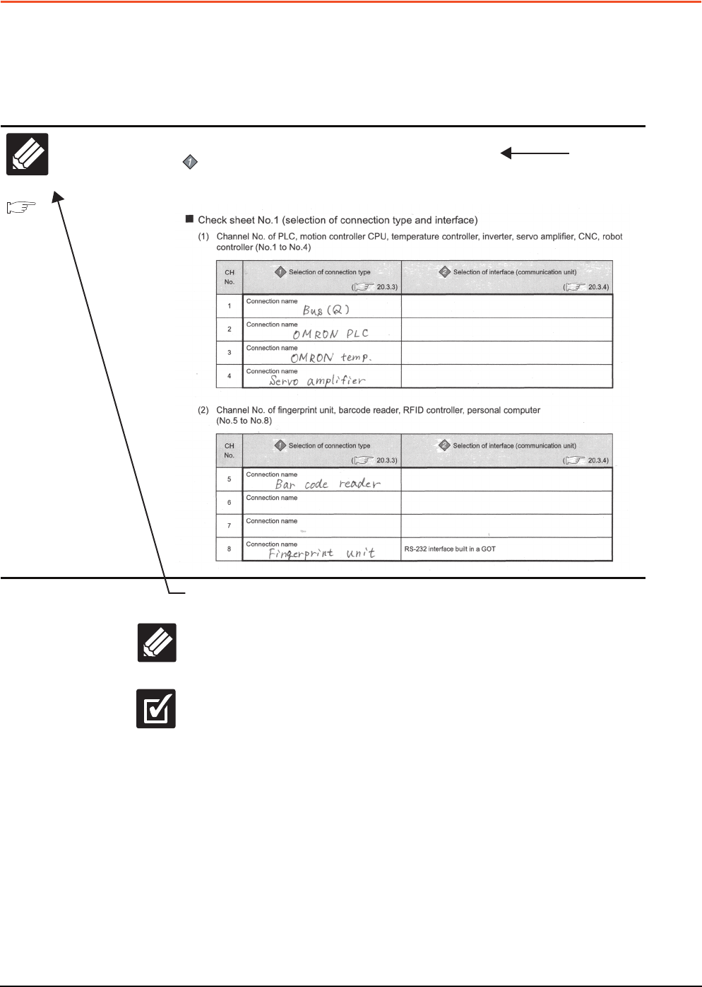
21 - 42 21. MULTI-CHANNEL FUNCTION
21.5 Multi-channel Function Check Sheet
21.5 Multi-channel Function Check Sheet
This section provides the check sheet to be used for Communication Settings when the multi-channel function is used.
Sections 21.3.3 to 21.3.5 contain explanations of the items to be checked on the check sheet.
Checking items explained in these sections using the check sheet on the following page allows you to complete the
setting for the multi-channel function.
Write Check
Sheet
The following symbols are used for each purpose.
Indicates parts where items and details are to be written.
Confirm the details and write them to the check sheet.
Indicates parts where written details are to be checked.
Confirm the details and perform the Communication Settings.
Check
Enter the selections having been made in the steps above to the check sheet.
Selection of connection type
Enter the name of connection type to be used.
Section 2.8.10
Multi-channel function
check sheet
Write Check
Sheet
Shows items and
contents to be written on
the check sheet.
Also describes an
example of the check
sheet.
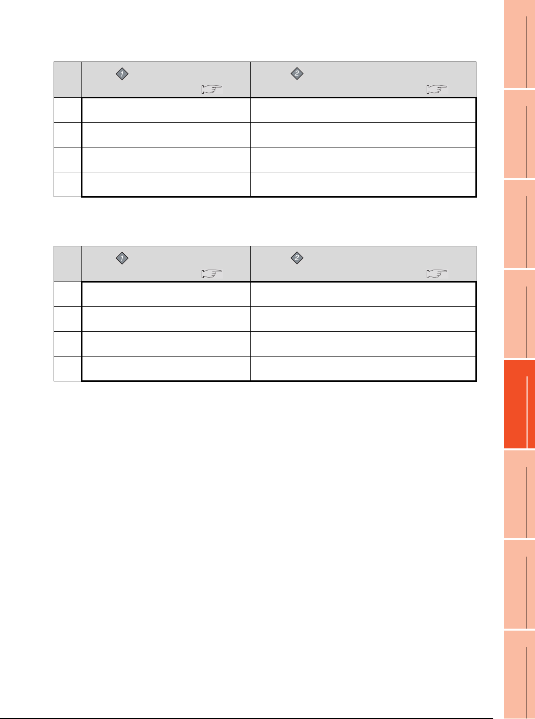
21. MULTI-CHANNEL FUNCTION
21.5 Multi-channel Function Check Sheet
21 - 43
17
ROBOT
CONTROLLER
CONNECTION
18
CNC CONNECTION
19
GOT MULTI-DROP
CONNECTION
20
MULTIPLE-GT14, GT12,
GT11, GT10
CONNECTION FUNCTION
21
MULTI-CHANNEL
FUNCTION
22
FA TRANSPARENT
FUNCTION
Check sheet No.1 (selection of connection type and interface)
(1) Channel No. of PLC, motion controller CPU, temperature controller, inverter, servo amplifier, CNC, robot
controller (No.1 to No.4)
(2) Channel No. of fingerprint unit, barcode reader, RFID controller, personal computer, serial printer
(No.5 to No.8)
CH
No.
Selection of connection type
( 21.3.3)
Selection of interface (communication unit)
( 21.3.4)
1Connection name
2Connection name
3Connection name
4Connection name
CH
No.
Selection of connection type
( 21.3.3)
Selection of interface (communication unit)
( 21.3.4)
5Connection name
6Connection name
7Connection name
8Connection name RS-232 interface built in a GOT
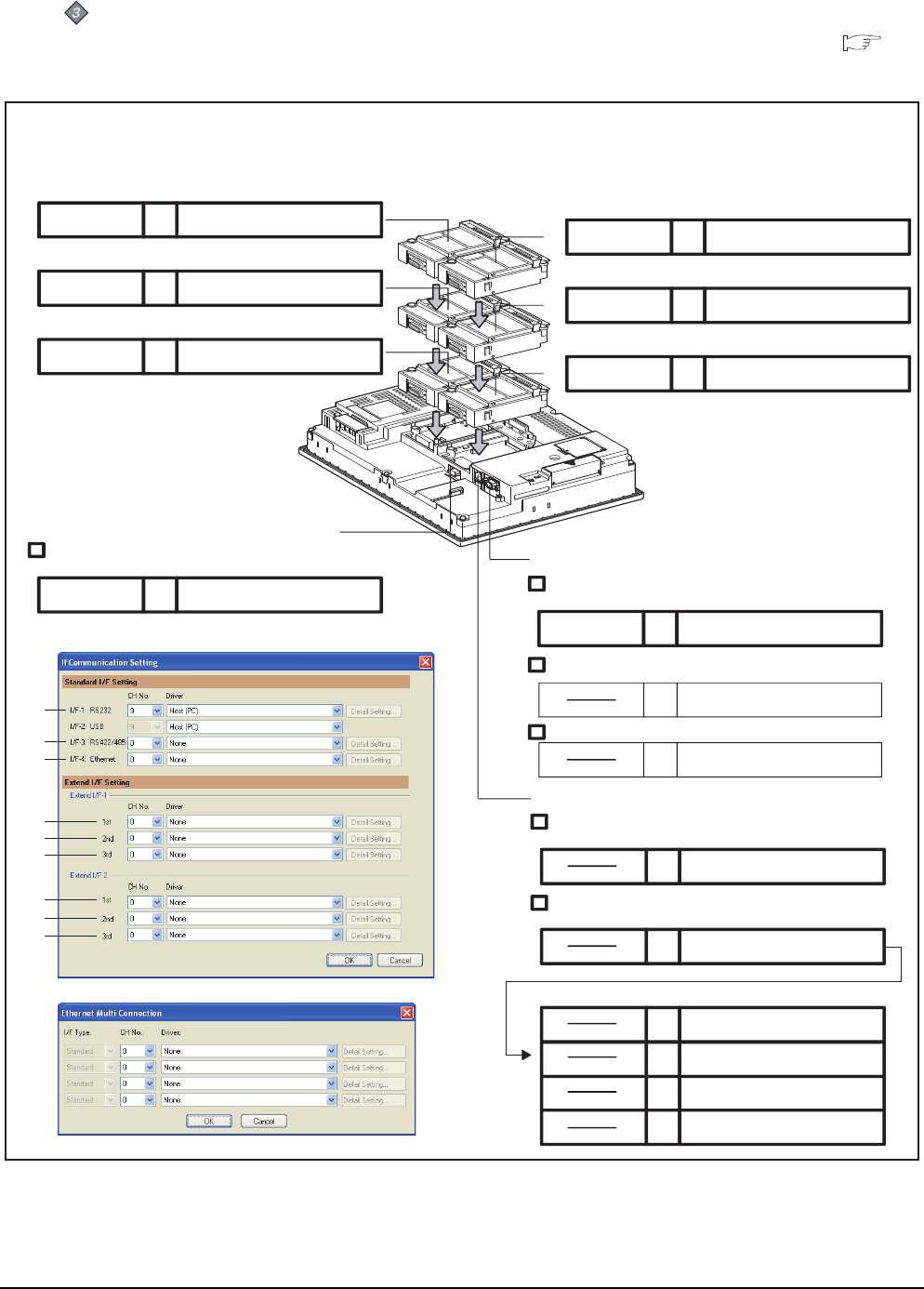
21 - 44 21. MULTI-CHANNEL FUNCTION
21.5 Multi-channel Function Check Sheet
Check sheet No. 2 (selection of GOT side interface)
Attaching the communication unit
( 1.3.7)
(1) GT16
(4)
(2)
Extension interface 1
1rd stage
2rd stage
3rd stage
Com. unit name CH No.
Com. unit name CH No.
Com. unit name CH No.
1rd stage
2rd stage
3rd stage
Com. unit name CH No. Driver name
Com. unit name CH No.
Com. unit name CH No.
Standard interface 1 (only one connection)
Connecting a controller
Com. unit name CH No. Driver name
Connecting a fingerprint unit, barcode reader, RFID controller, or
personal computer
Connecting a personal computer
9
8
Host (PC)
Driver name
Driver name
Driver name
Driver name
(1)
(3)
(5)
(6)
(7)
Standard interface 4 (only one connection)
Connecting a controller (Without multi-channel Ethernet connection)
Com. unit name CH No. Driver name
Connecting a controller (With multi-channel Ethernet connection)
(9)
Standard interface 3
(only one connection)
Connecting a controller
Com. unit name CH No. Driver name
(8)
Com. unit name CH No. Driver name
Multi-channel Ethernet connection
Multi
Com. unit name CH No. Driver name
(4)
(5)
(6)
(1)
(2)
(3)
(9)
(8)
(7)
Extension interface 2
Driver name
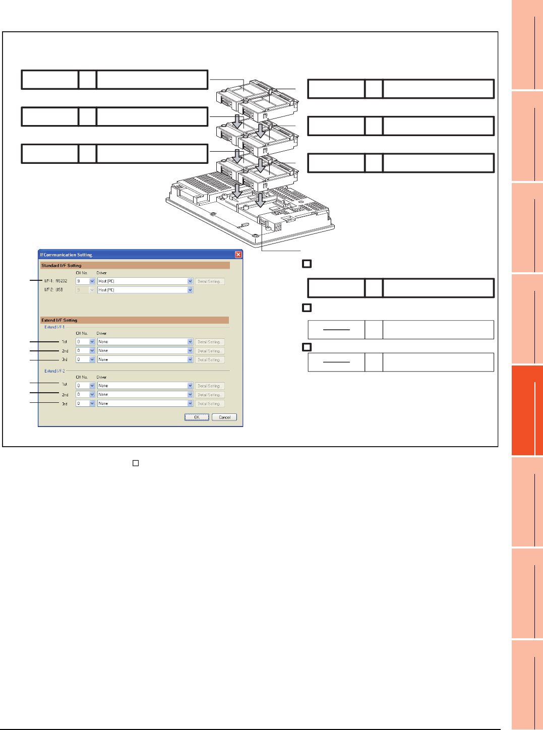
21. MULTI-CHANNEL FUNCTION
21.5 Multi-channel Function Check Sheet
21 - 45
17
ROBOT
CONTROLLER
CONNECTION
18
CNC CONNECTION
19
GOT MULTI-DROP
CONNECTION
20
MULTIPLE-GT14, GT12,
GT11, GT10
CONNECTION FUNCTION
21
MULTI-CHANNEL
FUNCTION
22
FA TRANSPARENT
FUNCTION
(2) GT15
* For the GT155 , setting is made only for Extension interface 1.
(7)
(4)
(2)
Extension interface 1 Extension interface 2
1st stage
2nd stage
3rd stage
Com. unit name CH No.
Com. unit name CH No.
Com. unit name CH No.
1st stage
2nd stage
3rd stage
Com. unit name CH No. Driver name
Com. unit name CH No.
Com. unit name CH No.
Standard interface 1
Connecting a controller
Com. unit name CH No. Driver name
Connecting a fingerprint unit, barcode reader, RFID controller, or
personal computer
Connecting a personal computer
9
8
Host (PC)
Driver name
Driver name
Driver name
Driver name
Driver name
(only one connection)
(3)
(2)
(1)
(6)
(5)
(4)
(1)
(3)
(5)
(6)
(7)

21 - 46 21. MULTI-CHANNEL FUNCTION
21.5 Multi-channel Function Check Sheet


22
17
ROBOT
CONTROLLER
CONNECTION
18
CNC CONNECTION
19
GOT MULTI-DROP
CONNECTION
20
MULTIPLE-GT14, GT12,
GT11, GT10
CONNECTION FUNCTION
21
MULTI-CHANNEL
FUNCTION
22
FA TRANSPARENT
FUNCTION
22 - 1
22.FA TRANSPARENT FUNCTION
22.1 FA Transparent Function . . . . . . . . . . . . . . . . . . . . . . . . . . 22 - 2
22.2 Compatible Software . . . . . . . . . . . . . . . . . . . . . . . . . . . . . 22 - 2
22.3 List of Models that Can Be Monitored . . . . . . . . . . . . . . . .22 - 11
22.4 System Configuration. . . . . . . . . . . . . . . . . . . . . . . . . . . . 22 - 26
22.5 GOT Side Settings . . . . . . . . . . . . . . . . . . . . . . . . . . . . . . 22 - 36
22.6 Personal Computer Side Setting . . . . . . . . . . . . . . . . . . . 22 - 39
22.7 Precautions . . . . . . . . . . . . . . . . . . . . . . . . . . . . . . . . . . . 22 - 67
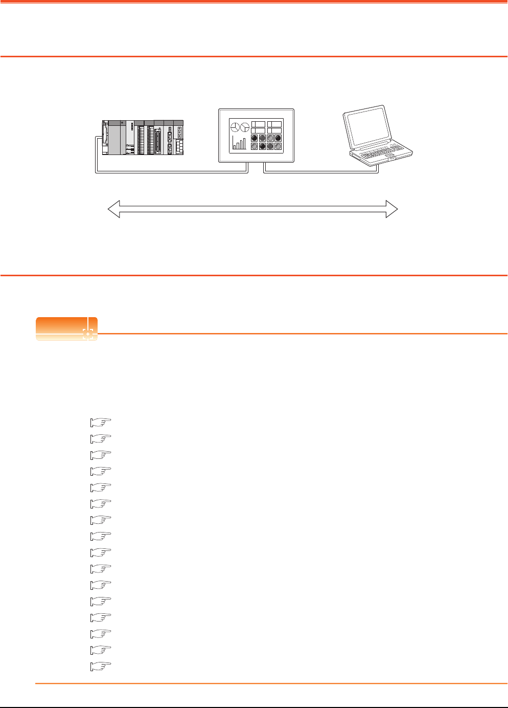
22 - 2 22. FA TRANSPARENT FUNCTION
22.1 FA Transparent Function
22. FA TRANSPARENT FUNCTION
22.1 FA Transparent Function
The FA transparent function allows the sequence programs of the Mitsubishi PLC to be read, written and monitored from
a personal computer connected via a GOT.
22.2 Compatible Software
The following shows the software compatible with the FA transparent function.
POINTPOINTPOINT
(1) The range accessible by software when FA transparent function is used
Use of the FA transparent function does not affect the range accessible by the software.
For details on accessible range, refer to the manual for the respective software.
(2) The software settings when using FA transparent function
For the software settings, refer to the following when using FA transparent function.
22.6.1 Accessing the PLC by the GX Developer, PX Developer, GX Configurator
22.6.2 Accessing by GX Works2
22.6.3 Accessing by GX LogViewer
22.6.4 Accessing PLC by GX Configurator-QP
22.6.5 Accessing by the MT Developer
22.6.6 Accessing by the MT Works2
22.6.7 Accessing the servo amplifier by the MR Configurator
22.6.8 Accessing the servo amplifier by the MR Configurator2
22.6.9 Accessing the inverter by the FR Configurator
22.6.10 Accessing PLC by FX Configurator-FP
22.6.11 Accessing by FX Configurator-EN
22.6.12 Accessing by RT ToolBox2
22.6.13 Accessing by NC Configurator
22.6.14 Accessing by MELSOFT Navigator
22.6.15 Accessing by LCPU Logging Configuration Tool
22.6.16 Accessing by Setting/ Monitoring tool for C Controller module
Sequence program can be read, written, monitored, etc.
Bus connection cable
RS-232/RS-422 cable
Ethernet connection cable
RS-232 cable
USB cable
Ethernet connection cable
A 1254
348B
A 1254
348B

22. FA TRANSPARENT FUNCTION
22.2 Compatible Software
22 - 3
17
ROBOT
CONTROLLER
CONNECTION
18
CNC CONNECTION
19
GOT MULTI-DROP
CONNECTION
20
MULTIPLE-GT14, GT12,
GT11, GT10
CONNECTION FUNCTION
21
MULTI-CHANNEL
FUNCTION
22
FA TRANSPARENT
FUNCTION
Connecting the GOT and personal computer with RS-232
(1) When connecting the GOT and PLC in bus connection
The following shows the software and the accessible PLC CPUs.
*1 GX Developer Version 8 or later is required to use the FA transparent function.
GX Developer Version 8.68W or later is required to use the FA transparent function when connecting the QnUDE(H)CPU to the
GOT.
*2 MT Developer (SW6RNC-GSVE) Version 00N or later is required to use the FA transparent function.
*3 MR Configurator (MRZJW3-SETUP221E) Version B1 or later is required to use the FA transparent function.
*4 PX Developer Version 1.09K or later is required to use the FA transparent function.
PX Developer Version 1.18U or later is required to use the FA transparent function when connecting the Q02PHCPU or
Q06PHCPU to the GOT.
*5 Use GX Developer Version 8.30G or later combined with the following GX Configurator version or later to use the FA transparent
function.
GX Configurator-AD : Version 2.03D or later, GX Configurator-DA : Version 2.04E or later
GX Configurator-SC : Version 2.10L or later, GX Configurator-CT : Version 1.23Z or later
GX Configurator-TI : Version 1.22Y or later, GX Configurator-TC : Version 1.21X or later
GX Configurator-AS : Version 1.20W or later, GX Configurator-FL : Version 1.21X or later
GX Configurator-PT : Version 1.20W or later
*6 RT ToolBox2 Version 1.1 or later is required to use the FA transparent function.
*7 GX Configurator-QP Version2.32J or later is required to use the FA transparent function.
*8 MT Works2 Version 1.00A or later is required to use the FA transparent function.
*9 MELSOFT Navigator Version 1.04E or later is required to use the FA transparent function.
*10 GX Works2 Version 1.03D or later is required to use the FA transparent function.
*11 MX Component Version 3.14Q or later is required to use the FA transparent function.
*12 Use MX Component Version 3.14Q or later for MX Sheet.
*13 Start MR Configurator2 with MT Developer2 Version 1.10L or later.
*14 MR Configurator2 Version 1.09K or later is required to use the FA transparent function.
*15 A motion controller is required between the GOT and PLC in bus connection.
*16 MX Component Version 4.00A or later is required to use the FA transparent function.
*17 MX Component Version 4.00A or later is required for MX Sheet to use the FA transparent function.
PLC CPU Software
QCPU (Q mode), C Controller module
MELSOFT Navigator*9
GX Developer*1
GX Works2*10
PX Developer*4
GX Configurator*5-AD/DA/SC/CT/TI/TC/AS/FL/PT
GX Configurator-QP*7
MX Component*11, MX Sheet*12
Q/QnA/ACPU,
motion controller CPU (A Series)
GX Developer*1
GX Works2*11
MX Component*11, MX Sheet*12
Motion controller CPU (Q Series)
MELSOFT Navigator*9
MT Developer*2
SW6RN-GSV13P, SW6RN-GSV22P, SW6RN-GSV43P,
SW6RN-GSV54P, SW6RN-DOSCP,
SW6RN-SNETP (for user API)
MR Configurator*3
MT Works2*8, MX Component*16, MX Sheet*17
Robot controller (CRnQ-700) RT ToolBox2*6
MELSERVO(MR-J3-B)*15 MR Configurator*3, MR Configurator2*13
MELSERVO(MR-J4-B)*15 MR Configurator2*14

22 - 4 22. FA TRANSPARENT FUNCTION
22.2 Compatible Software
(2) When connecting the GOT and PLC in direct CPU connection
The following shows the software and the accessible PLC CPUs.
*1 MR Configurator (MRZJW3-SETUP221E) Version B1 or later is required to use the FA transparent function.
*2 FR Configurator(FR-SW2-SETUP-WJ) Ver.1.02 or later is required to use the FA transparent function when connecting the A700/
F700 series to the GOT.
FR Configurator(FR-SW3-SETUP-WJ) Ver.2.00 or later is required to use the FA transparent function when connecting the E700
series to the GOT.
FR Configurator(FR-SW3-SETUP-WJ) Ver.3.10 or later is required to use the FA transparent function when connecting the F700
series to the GOT.
*3 PX Developer Version 1.09K or later is required to use the FA transparent function.
PX Developer Version 1.18U or later is required to use the FA transparent function when connecting the Q02PHCPU or
Q06PHCPU to the GOT.
*4 Use GX Developer Version 8.30G or later combined with the following GX Configurator version or later to use the FA transparent
function.
GX Configurator-AD : Version 2.03D pr later, GX Configurator-DA : Version 2.04E or later
GX Configurator-SC : Version 2.10L or later, GX Configurator-CT : Version 1.23Zor later
GX Configurator-TI : Version 1.22Y or later, GX Configurator-TC : Version 1.21X or later
GX Configurator-AS : Version 1.20W or later, GX Configurator-FL : Version 1.21X or later
GX Configurator-PT : Version 1.20W or later
*5 The RS-232/USB conversion adaptor (GT10-RS2TUSB-5S) is not applicable to FX-PCS/WIN.
*6 FX Configurator-FP Version 1.30 or later is required to use the FA transparent function.
*7 RT ToolBox2 Version 1.1 or later is required to use the FA transparent function.
*8 GX Configurator-QP Version2.32J or later is required to use the FA transparent function.
*9 MT Works2 Version 1.00A or later is required to use the FA transparent function.
*10 MELSOFT Navigator Version 1.04E or later is required to use the FA transparent function.
*11 GX Works2 Version 1.03D or later is required to use the FA transparent function.
*12 GX Developer Version 8.88S or later is required to use the FA transparent function.
*13 GX Works2 Version 1.11M or later is required to use the FA transparent function.
*14 The adapter (L6ADP-R2) is required.
*15 MELSOFT Navigator Version 1.07H or later is required to use the FA transparent function.
*16 MX Component Version 3.14Q or later is required to use the FA transparent function.
*17 Use MX Component Version 3.14Q or later for MX Sheet.
*18 Start MR Configurator2 with MT Developer2 Version 1.10L or later.
*19 FX Configurator-EN Version 1.10A or later is required to use the FA transparent function.
*20 LCPU Logging Configuration Tool Version 1.04E or later is required to use the FA transparent function.
*21 MR Configurator2 Version 1.09K or later is required to use the FA transparent function.
*22 A motion controller is required between the GOT and PLC in direct CPU connection.
*23 MX Component Version 4.00A or later is required to use the FA transparent function.
*24 MX Component Version 4.00A or later is required for MX Sheet to use the FA transparent function.
PLC CPU Software
QCPU (Q mode)
MELSOFT Navigator*10
GX Developer
GX Works2*11
PX Developer*3
GX Configurator*4-AD/DA/SC/CT/TI/TC/AS/FL/PT
GX Configurator-QP*8
MX Component*16, MX Sheet*17
LCPU*14
MELSOFT Navigator*15
GX Developer*12 GX Works2*13, GX Logviewer
MX Component*16, MX Sheet*17, LCPU Logging Configuration Tool*20
QCPU (A mode), QnA/ACPU GX Developer
MX Component*16, MX Sheet*17
FXCPU
MELSOFT Navigator*10
GX Developer
GX Works2*11
FX-PCS/WIN*5
FX Configurator-FP*6
FX Configurator-EN *19
MX Component*16, MX Sheet*17
Motion controller CPU (Q Series)
MELSOFT Navigator*10
MT Developer
SW6RN-GSV13P, SW6RN-GSV22P, SW6RN-GSV43P,
SW6RN-GSV54P, SW6RN-DOSCP, SW6RN-SNETP (for user API)
MT Works2*9
MR Configurator*1, MX Component*23, MX Sheet*24
Motion controller CPU (A Series)
GX Developer
SW3RN-GSV13P, SW3RN-GSV22P, SW3RN-GSV43P,
SW3RN-GSV51P
MX Component*16, MX Sheet*17
MELSERVO(MR-J3-B)*22 MR Configurator*1, MR Configurator2*18
MELSERVO(MR-J4-B)*22 MR Configurator2*21
FREQROL A700/F700/E700/D700 Series FR Configurator*2
Robot controller (CRnQ-700) RT ToolBox2*7

22. FA TRANSPARENT FUNCTION
22.2 Compatible Software
22 - 5
17
ROBOT
CONTROLLER
CONNECTION
18
CNC CONNECTION
19
GOT MULTI-DROP
CONNECTION
20
MULTIPLE-GT14, GT12,
GT11, GT10
CONNECTION FUNCTION
21
MULTI-CHANNEL
FUNCTION
22
FA TRANSPARENT
FUNCTION
(3) When connecting the GOT and PLC in computer link connection
The following shows the software and the accessible PLC CPUs.
*1 GX Developer Version 8.62Q or later is required to use the FA transparent function.
GX Developer Version 8.68W or later is required to use the FA transparent function when connecting the QnUDE(H)CPU to the
GOT.
*2 PX Developer Version 1.18U or later is required to use the FA transparent function.
*3 GX Configurator-QP Version2.32J or later is required to use the FA transparent function.
*4 MELSOFT Navigator Version 1.04E or later is required to use the FA transparent function.
*5 GX Works2 Version 1.03D or later is required to use the FA transparent function.
*6 GX Developer Version 8.88S or later is required to use the FA transparent function.
*7 GX Works2 Version 1.11M or later is required to use the FA transparent function.
*8 MELSOFT Navigator Version 1.07H or later is required to use the FA transparent function.
*9 MX Component Version 3.14Q or later is required to use the FA transparent function.
*10 Use MX Component Version 3.14Q or later for MX Sheet.
*11 LCPU Logging Configuration Tool Version 1.04E or later is required to use the FA transparent function.
*12 MX Component Version 4.00A or later is required to use the FA transparent function.
*13 MX Component Version 4.00A or later is required for MX Sheet to use the FA transparent function.
(4) When connecting the GOT and PLC in Ethernet communication
The following shows the software and the accessible PLC CPUs.
*1 Only QCPU can be connected.To connect to QnA/ACPU, connect via QCPU.
*2 GX Developer Version 8.78G or later is required to use the FA transparent function.
*3 MELSOFT Navigator Version 1.04E or later is required to use the FA transparent function.
*4 GX Works2 Version 1.10L or later is required to use the FA transparent function.
*5 MT Works2 Version 1.08J or later is required to use the FA transparent function.
*6 GX Developer Version 8.88S or later is required to use the FA transparent function.
*7 GX Works2 Version 1.11M or later is required to use the FA transparent function.
*8 MT Works2 Version 1.12N or later is required to connect with Q17nDCPU-S1.
*9 MELSOFT Navigator Version 1.07H or later is required to use the FA transparent function.
*10 MX Component Version 3.14Q or later is required to use the FA transparent function.
*11 Use MX Component Version 3.14Q or later for MX Sheet.
*12 LCPU Logging Configuration Tool Version 1.04E or later is required to use the FA transparent function.
*13 RT ToolBox2 Version 1.7 or later is required to use the FA transparent function.
*14 MR Configurator2 Version 1.09K or later is required to use the FA transparent function.
*15 A motion controller is required between the GOT and PLC in Ethernet connection.
*16 GX Works2 Version 1.98C or later is required to use the FA transparent function.
PLC CPU Software
QCPU (Q mode)
MELSOFT Navigator*4
GX Developer*1
GX Works2*5
PX Developer*2
GX Configurator-QP*3
MX Component*9, MX Sheet*10
LCPU
MELSOFT Navigator*8
GX Developer*6
GX Works2*7
GX LogViewer
MX Component*9, MX Sheet*10, LCPU Logging Configuration Tool*11
Motion controller CPU (Q Series) MX Component*12, MX Sheet*13
PLC CPU Software
QCPU (Q mode)*1, C Controller module
MELSOFT Navigator*3
GX Developer*2
GX Works2*4
MX Component*10, MX Sheet*11
LCPU
MELSOFT Navigator*9
GX Developer*6
GX Works2*7
GX LogViewer
MX Component*10, MX Sheet*11, LCPU Logging Configuration Tool*12
FXCPU GX Works2*16
QCPU (A mode), QnA/ACPU*1 GX Developer*2
MX Component*10, MX Sheet*11
Motion controller CPU (Q Series)
MELSOFT Navigator*3
SW6RN-GSV13P, SW6RN-GSV22P, SW6RN-GSV43P,
SW6RN-GSV54P, SW6RN-DOSCP, SW6RN-SNETP (for user API)
MT Works2*5*8
Robot controller (CRnQ-700, CRnD-700) RT ToolBox2*13
MELSERVO(MR-J3-B) *15 MR Configurator2
MELSERVO(MR-J4-B) *15 MR Configurator2*14

22 - 6 22. FA TRANSPARENT FUNCTION
22.2 Compatible Software
Connecting the GOT and personal computer with USB
(1) When connecting the GOT and PLC in bus connection
The following shows the software and the accessible PLC CPUs.
*1 GX Developer Version 8.22Y or later is required to use the FA transparent function.
GX Developer Version 8.68W or later is required to use the FA transparent function when connecting the QnUDE(H)CPU to the
GOT.
*2 MT Developer (SW6RNC-GSVE) Version 00N or later is required to use the FA transparent function.
*3 MR Configurator (MRZJW3-SETUP221E) Version B1 or later is required to use the FA transparent function.
*4 PX Developer Version 1.09K or later is required to use the FA transparent function.
PX Developer Version 1.18U or later is required to use the FA transparent function when connecting the Q02PHCPU or
Q06PHCPU to the GOT.
*5 Use GX Developer Version 8.30G or later combined with the following GX Configurator version or later to use the FA transparent
function.
GX Configurator-AD : Version 2.03D pr later, GX Configurator-DA : Version 2.04E or later
GX Configurator-SC : Version 2.10L or later, GX Configurator-CT : Version 1.23Zor later
GX Configurator-TI : Version 1.22Y or later, GX Configurator-TC : Version 1.21X or later
GX Configurator-AS : Version 1.20W or later, GX Configurator-FL : Version 1.21X or later
GX Configurator-PT : Version 1.20W or later
*6 RT ToolBox2 Version 1.1 or later is required to use the FA transparent function.
*7 GX Configurator-QP Version2.32J or later is required to use the FA transparent function.
*8 MT Works2 Version 1.00A or later is required to use the FA transparent function.
*9 MELSOFT Navigator Version 1.04E or later is required to use the FA transparent function.
*10 GX Works2 Version 1.03D or later is required to use the FA transparent function.
*11 NC Configurator Version A0 or later is required to use the FA transparent function.
*12 MX Component Version 3.14Q or later is required to use the FA transparent function.
*13 Use MX Component Version 3.14Q or later for MX Sheet.
*14 Start MR Configurator2 with MT Developer2 Version 1.10L or later.
*15 MR Configurator2 Version 1.09K or later is required to use the FA transparent function.
*16 A motion controller is required between the GOT and PLC in bus connection.
*17 MX Component Version 4.00A or later is required to use the FA transparent function.
*18 MX Component Version 4.00A or later is required for MX Sheet to use the FA transparent function.
*19 Setting/Monitoring tool for C Controller module Version 4.00A or later is required to use the FA transparent function.
PLC CPU Software
QCPU (Q mode), C Controller module
MELSOFT Navigator*9
GX Developer*1
GX Works2*10
PX Developer*4
GX Configurator*5-AD/DA/SC/CT/TI/TC/AS/FL/PT
GX Configurator-QP*7
MX Component*12, MX Sheet*13
Setting/Monitoring tool for C Controller module*19
QCPU (A mode), QnA/ACPU,
motion controller CPU (A Series)
GX Developer*1
MX Component*12, MX Sheet*13
Motion controller CPU (Q Series)
MELSOFT Navigator*9
MT Developer*2
SW6RN-GSV13P, SW6RN-GSV22P, SW6RN-GSV43P,
SW6RN-GSV54P, SW6RN-DOSCP, SW6RN-SNETP (for user API)
MR Configurator*3
MT Works2*8, MX Component*17, MX Sheet*18
CNC CPU(Q173NCCPU) NC Configurator*11
Robot controller (CRnQ-700) RT ToolBox2*6
MELSERVO(MR-J3-B)*16 MR Configurator*3, MR Configurator2*14
MELSERVO(MR-J4-B)*16 MR Configurator2*15

22. FA TRANSPARENT FUNCTION
22.2 Compatible Software
22 - 7
17
ROBOT
CONTROLLER
CONNECTION
18
CNC CONNECTION
19
GOT MULTI-DROP
CONNECTION
20
MULTIPLE-GT14, GT12,
GT11, GT10
CONNECTION FUNCTION
21
MULTI-CHANNEL
FUNCTION
22
FA TRANSPARENT
FUNCTION
(2) When connecting the GOT and PLC in direct CPU connection
The following shows the software and the accessible PLC CPUs.
*1 GX Developer Version 8.22Y or later is required to use the FA transparent function.
GX Developer Version 8.68W or later is required to use the FA transparent function when connecting the QnUDE(H)CPU to the
GOT.
*2 MT Developer (SW6RNC-GSVE) Version 00N or later is required to use the FA transparent function.
*3 MR Configurator (MRZJW3-SETUP221E) Version B1 or later is required to use the FA transparent function.
*4 FR Configurator(FR-SW2-SETUP-WJ) Ver.1.02 or later is required to use the FA transparent function when connecting the A700/
F700 series to the GOT.
FR Configurator(FR-SW3-SETUP-WJ) Ver.2.00 or later is required to use the FA transparent function when connecting the E700
series to the GOT.
FR Configurator(FR-SW3-SETUP-WJ) Ver.3.10 or later is required to use the FA transparent function when connecting the F700
series to the GOT.
*5 PX Developer Version 1.09K or later is required to use the FA transparent function.
PX Developer Version 1.18U or later is required to use the FA transparent function when connecting the Q02PHCPU or
Q06PHCPU to the GOT.
*6 Use GX Developer Version 8.30G or later combined with the following GX Configurator version or later to use the FA transparent
function.
GX Configurator-AD : Version 2.03D pr later, GX Configurator-DA : Version 2.04E or later
GX Configurator-SC : Version 2.10L or later, GX Configurator-CT : Version 1.23Zor later
GX Configurator-TI : Version 1.22Y or later, GX Configurator-TC : Version 1.21X or later
GX Configurator-AS : Version 1.20W or later, GX Configurator-FL : Version 1.21X or later
GX Configurator-PT : Version 1.20W or later
*7 FX Configurator-FP Version 1.30 or later is required to use the FA transparent function.
*8 RT ToolBox2 Version 1.1 or later is required to use the FA transparent function.
*9 GX Configurator-QP Version2.32J or later is required to use the FA transparent function.
*10 MT Works2 Version 1.00A or later is required to use the FA transparent function.
*11 MELSOFT Navigator Version 1.04E or later is required to use the FA transparent function.
*12 GX Works2 Version 1.03D or later is required to use the FA transparent function.
*13 GX Developer Version 8.88S or later is required to use the FA transparent function.
*14 GX Works2 Version 1.11M or later is required to use the FA transparent function.
*15 The adapter (L6ADP-R2) is required.
*16 MELSOFT Navigator Version 1.07H or later is required to use the FA transparent function.
*17 MX Component Version 3.14Q or later is required to use the FA transparent function.
*18 Use MX Component Version 3.14Q or later for MX Sheet.
*19 Start MR Configurator2 with MT Developer2 Version 1.10L or later.
*20 FX Configurator-EN Version 1.10A or later is required to use the FA transparent function.
*21 LCPU Logging Configuration Tool Version 1.04E or later is required to use the FA transparent function.
*22 MR Configurator2 Version 1.09K or later is required to use the FA transparent function.
*23 A motion controller is required between the GOT and PLC in direct CPU connection.
*24 MX Component Version 4.00A or later is required to use the FA transparent function.
*25 MX Component Version 4.00A or later is required for MX Sheet to use the FA transparent function.
PLC CPU Software
QCPU (Q mode)
MELSOFT Navigator*11
GX Developer*1
GX Works2*12
PX Developer*5
GX Configurator*6-AD/DA/SC/CT/TI/TC/AS/FL/PT
GX Configurator-QP*9
MX Component*17, MX Sheet*18
LCPU*15
MELSOFT Navigator*16
GX Developer*13
GX Works2*14
GX Logviewer
MX Component*17, MX Sheet*18, LCPU Logging Configuration Tool*21
QCPU (A mode), QnA/ACPU,
motion controller CPU (A Series)
GX Developer*1
MX Component*17, MX Sheet*18
FXCPU
MELSOFT Navigator*11
GX Developer*1
GX Works2*12
FX Configurator-FP*7
FX Configurator-EN *20
MX Component*17, MX Sheet*18
Motion controller CPU (Q Series)
MELSOFT Navigator*11
MT Developer*2
SW6RN-GSV13P, SW6RN-GSV22P, SW6RN-GSV43P,
SW6RN-GSV54P, SW6RN-DOSCP, SW6RN-SNETP (for user API)
MR Configurator*3
MT Works2*10, MX Component*24, MX Sheet*25
FREQROL A700/F700/E700/D700 Series FR Configurator*4
Robot controller (CRnQ-700) RT ToolBox2*8
MELSERVO(MR-J3-B)*23 MR Configurator*3, MR Configurator2*19
MELSERVO(MR-J4-B)*23 MR Configurator2*22

22 - 8 22. FA TRANSPARENT FUNCTION
22.2 Compatible Software
(3) When connecting the GOT and PLC in computer link connection
The following shows the software and the accessible PLC CPUs.
*1 GX Developer Version 8.62Q or later is required to use the FA transparent function.
GX Developer Version 8.68W or later is required to use the FA transparent function when connecting the QnUDE(H)CPU to the GOT.
*2 PX Developer Version 1.18U or later is required to use the FA transparent function.
*3 GX Configurator-QP Version2.32J or later is required to use the FA transparent function.
*4 MELSOFT Navigator Version 1.04E or later is required to use the FA transparent function.
*5 GX Works2 Version 1.03D or later is required to use the FA transparent function.
*6 GX Developer Version 8.88S or later is required to use the FA transparent function.
*7 GX Works2 Version 1.11M or later is required to use the FA transparent function.
*8 MELSOFT Navigator Version 1.07H or later is required to use the FA transparent function.
*9 MX Component Version 3.14Q or later is required to use the FA transparent function.
*10 Use MX Component Version 3.14Q or later for MX Sheet.
*11 LCPU Logging Configuration Tool Version 1.04E or later is required to use the FA transparent function.
*12 MX Component Version 4.00A or later is required to use the FA transparent function.
*13 MX Component Version 4.00A or later is required for MX Sheet to use the FA transparent function.
(4) When connecting the GOT and PLC in Ethernet communication
The following shows the software and the accessible PLC CPUs.
*1 Only QCPU can be connected.To connect to QnA/ACPU, connect via QCPU.
*2 GX Developer Version 8.78G or later is required to use the FA transparent function.
*3 MELSOFT Navigator Version 1.04E or later is required to use the FA transparent function.
*4 GX Works2 Version 1.10L or later is required to use the FA transparent function.
*5 MT Works2 Version 1.08J or later is required to use the FA transparent function.
*6 NC Configurator Version A1 or later is required to use the FA transparent function.
*7 GX Developer Version 8.88S or later is required to use the FA transparent function.
*8 GX Works2 Version 1.11M or later is required to use the FA transparent function.
*9 MT Works2 Version 1.12N or later is required to connect with Q17nDCPU-S1.
*10 MELSOFT Navigator Version 1.07H or later is required to use the FA transparent function.
*11 MX Component Version 3.14Q or later is required to use the FA transparent function.
*12 Use MX Component Version 3.14Q or later for MX Sheet.
*13 GX Works2 Version 1.34L or later is required to execute the FA transparent function with using CC-Link IE Field Network Ethernet
adapter (NZ2GF-ETB).
C controller module does not support CC-Link IE Field Network.
*14 LCPU Logging Configuration Tool Version 1.04E or later is required to use the FA transparent function.
*15 RT ToolBox2 Version 1.7 or later is required to use the FA transparent function.
*16 MR Configurator2 Version 1.09K or later is required to use the FA transparent function.
*17 A motion controller is required between the GOT and PLC in Ethernet connection.
*18 Setting/Monitoring tool for C Controller module Version 4.00A or later is required to use the FA transparent function.
*19 GX Works2 Version 1.98C or later is required to use the FA transparent function.
PLC CPU Software
QCPU (Q mode)
MELSOFT Navigator*4
GX Developer*1
GX Works2*5
PX Developer*2
GX Configurator-QP*3
MX Component*9, MX Sheet*10
LCPU
MELSOFT Navigator*8
GX Developer*6
GX Works2*7
GX LogViewer
MX Component*9, MX Sheet*10, LCPU Logging Configuration Tool*11
Motion controller CPU (Q Series) MX Component*12, MX Sheet*13
PLC CPU Software
QCPU (Q mode)*1, C Controller module
MELSOFT Navigator*3
GX Developer*2
GX Works2*4*13
MX Component*11, MX Sheet*12
Setting/Monitoring tool for C Controller module*18
LCPU
MELSOFT Navigator*10
GX Developer*7
GX Works2*8
GX LogViewer
MX Component*11, MX Sheet*12, LCPU Logging Configuration Tool*14
FXCPU GX Works2*19
QCPU (A mode), QnA/ACPU*1 GX Developer*2
MX Component*11, MX Sheet*12
Motion controller CPU (Q Series) MELSOFT Navigator*3
MT Works2*5*9
CNC CPU(Q173NCCPU) NC Configurator*6
Robot controller (CRnQ-700, CRnD-700) RT ToolBox2*15
MELSERVO(MR-J3-B) *17 MR Configurator2
MELSERVO(MR-J4-B) *17 MR Configurator2*16

22. FA TRANSPARENT FUNCTION
22.2 Compatible Software
22 - 9
17
ROBOT
CONTROLLER
CONNECTION
18
CNC CONNECTION
19
GOT MULTI-DROP
CONNECTION
20
MULTIPLE-GT14, GT12,
GT11, GT10
CONNECTION FUNCTION
21
MULTI-CHANNEL
FUNCTION
22
FA TRANSPARENT
FUNCTION
When connecting the GOT and PC with Ethernet
(1) When connecting the GOT and PLC in Bus connection
The following shows the software and the accessible PLC CPUs.
*1 GX Works2 Version 1.48A or later is required to use the FA transparent function.
*2 MX Component Version 3.15R or later is required to use the FA transparent function.
*3 MX Component Version 3.15R or later is required for MX Sheet to use the FA transparent function.
*4 Use MT Works2 Version 1.25B or later for MT Works2.
*5 A motion controller is required between the GOT and PLC in bus connection.
*6 Use MR Configurator2 Version 1.07H or later for MR Configurator2.
*7 Use MR Configurator2 Version 1.09K or later for MR Configurator2.
*8 Setting/Monitoring tool for C Controller module Version 4.00A or later is required to use the FA transparent function.
(2) When connecting the GOT and PLC in direct CPU connection
The following shows the software and the accessible PLC CPUs.
*1 GX Works2 Version 1.48A or later is required to use the FA transparent function.
*2 The adapter (L6ADP-R2) is required.
*3 MX Component Version 3.15R or later is required to use the FA transparent function.
*4 MX Component Version 3.15R or later is required for MX Sheet to use the FA transparent function.
*5 GX Works2 Version 1.73B or later is required for GX Works2 to use the FA transparent function.
*6 MT Works2 Version 1.25B or later is required for MT Works2 to use the FA transparent function.
*7 MR Configurator2 Version 1.07H or later is required for MR Configurator2 to use the FA transparent function.
*8 MR Configurator2 Version 1.09K or later is required to use the FA transparent function.
*9 A motion controller is required between the GOT and PLC in direct CPU connection.
(3) When connecting the GOT and PLC in computer link connection
The following shows the software and the accessible PLC CPUs.
*1 GX Works2 Version 1.48A or later is required to use the FA transparent function.
*2 MX Component Version 3.15R or later is required to use the FA transparent function.
*3 MX Component Version 3.15R or later is required for MX Sheet to use the FA transparent function.
Connecting the GOT and personal computer with Modem
(1) When connecting the GOT and PLC in bus connection
The following shows the software and the accessible PLC CPUs.
*1 GX Developer Version 8.78G or later is required to use the FA transparent function.
*2 GX Works2 Version 1.16S or later is required to use the FA transparent function.
(2) When connecting the GOT and PLC in direct CPU connection
The following shows the software and the accessible PLC CPUs.
*1 GX Developer Version 8.78G or later is required to use the FA transparent function.
*2 GX Works2 Version 1.16S or later is required to use the FA transparent function.
PLC CPU Software
QCPU (Q mode), C Controller module GX Works2 *1, MX Component *2, MX Sheet*3, Setting/Monitoring tool for C Controller
module*8
Motion controller CPU (Q series) MT Works2*4
MELSERVO(MR-J3-B) *5 MR Configurator2*6
MELSERVO(MR-J4-B) *5 MR Configurator2*7
PLC CPU Software
QCPU (Q mode) GX Works2 *1, MX Component *3, MX Sheet*4
LCPU*2 GX Works2 *1, MX Component *3, MX Sheet*4
FXCPU GX Works2*5
Motion controller CPU (Q series) MT Works2*6
MELSERVO(MR-J3-B)*9 MR Configurator2*7
MELSERVO(MR-J4-B)*9 MR Configurator2*8
PLC CPU Software
QCPU (Q mode) GX Works2 *1, MX Component *2, MX Sheet*3
LCPU*2 GX Works2 *1, MX Component *2, MX Sheet*3
PLC CPU Software
QCPU (Q mode) GX Developer*1
GX Works2 *2
PLC CPU Software
QCPU (Q mode) GX Developer*1
GX Works2 *2
FXCPU GX Developer*1

22 - 10 22. FA TRANSPARENT FUNCTION
22.2 Compatible Software
(3) When connecting the GOT and PLC in computer link connection
The following shows the software and the accessible PLC CPUs.
*1 GX Developer Version 8.78G or later is required to use the FA transparent function.
*2 GX Works2 Version 1.16S or later is required to use the FA transparent function.
(4) When connecting the GOT and PLC in Ethernet connection
The following shows the software and the accessible PLC CPUs.
*1 Use GX Developer of Version 8.78G or later.
*2 Use GX Works2 of Version 1.15R or later.
PLC CPU Software
QCPU (Q mode) GX Developer*1
GX Works2 *2
PLC CPU Software
QCPU (Q mode) GX Developer*1
GX Works2 *2
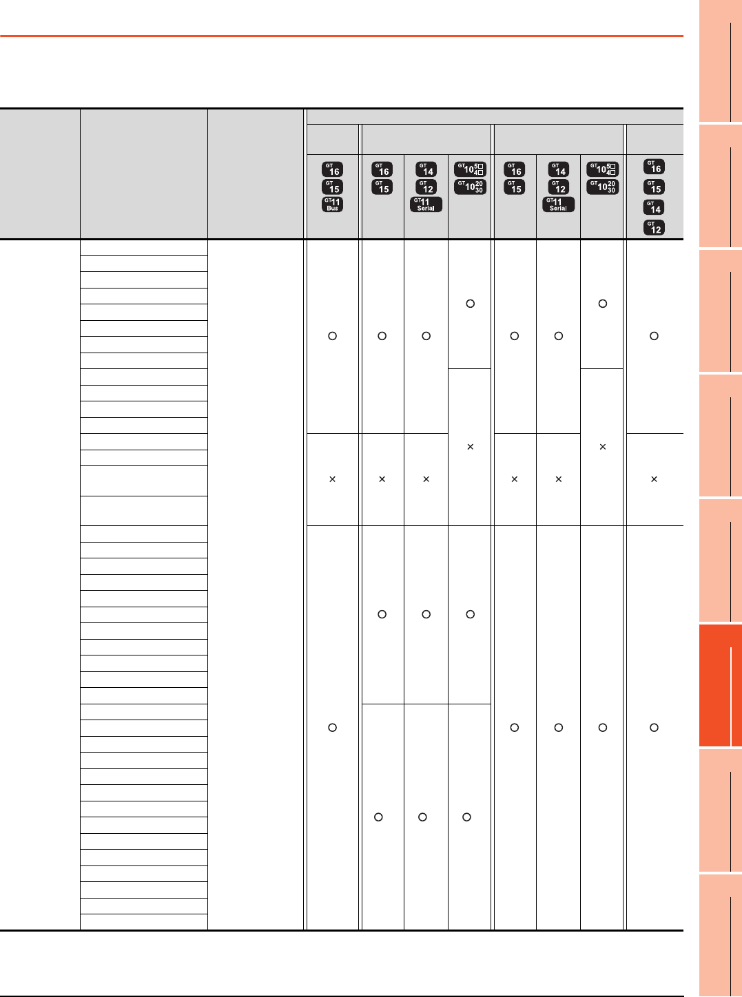
22. FA TRANSPARENT FUNCTION
22.3 List of Models that Can Be Monitored
22 - 11
17
ROBOT
CONTROLLER
CONNECTION
18
CNC CONNECTION
19
GOT MULTI-DROP
CONNECTION
20
MULTIPLE-GT14, GT12,
GT11, GT10
CONNECTION FUNCTION
21
MULTI-CHANNEL
FUNCTION
22
FA TRANSPARENT
FUNCTION
22.3 List of Models that Can Be Monitored
The following models support FA transparent function.
When connecting the GOT and personal computer with serial or USB
(Continued to next page)
*1 Use the serial port of QCPU in the multiple CPU system, since QnUEHCPU has no direct coupled I/F.
*2 GT14 models compatible with Ethernet connection are only GT1455-QTBDE and GT1450-QLBDE.
Series Model name Target software
Connection type
Bus
connection
Direct CPU connection Computer link connection Ethernet
connection
*2
MELSEC-Q
(Q mode)
Q00JCPU
GX Developer
GX Works2
GX Configurator
PX Developer
MX Component
MX Sheet
Q00CPU
Q01CPU
Q02CPU
Q02HCPU
Q06HCPU
Q12HCPU
Q25HCPU
Q02PHCPU
Q06PHCPU
Q12PHCPU
Q25PHCPU
Q12PRHCPU (Main base)
Q25PRHCPU (Main base)
Q12PRHCPU
(Extension base)
Q25PRHCPU
(Extension base)
Q00UJCPU
Q00UCPU
Q01UCPU
Q02UCPU
Q03UDCPU
Q04UDHCPU
Q06UDHCPU
Q10UDHCPU
Q13UDHCPU
Q20UDHCPU
Q26UDHCPU
Q03UDECPU
*1 *1 *1
Q04UDEHCPU
Q06UDEHCPU
Q10UDEHCPU
Q13UDEHCPU
Q20UDEHCPU
Q26UDEHCPU
Q50UDEHCPU
Q100UDEHCPU
Q03UDVCPU
Q04UDVCPU
Q06UDVCPU
Q13UDVCPU
Q26UDVCPU
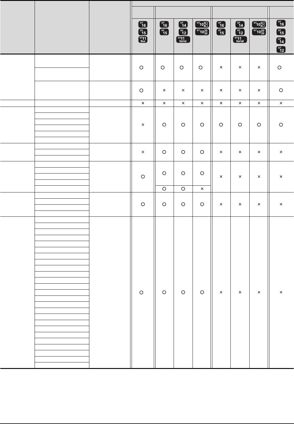
22 - 12 22. FA TRANSPARENT FUNCTION
22.3 List of Models that Can Be Monitored
*1 Use the serial port of QCPU in the multiple CPU system since Q12DCCPU-V1 and Q24DHCCPU-V have no direct coupled I/F.
*2 When using Q12DCCPU-V1 or Q24DHCCPU-V as the connected CPU, only MX Component can be used.
When accessing other CPUs relaying Q12DCCPU-V or Q24DHCCPU-V, GX Developer or GX Works2 can also be used.
*3 GT14 models compatible with Ethernet connection are only GT1455-QTBDE and GT1450-QLBDE.
*4 Do not execute the write during RUN in the bus connection.
*5 When the GOT and the personal computer are connected in the serial connection, Setting/Monitoring tool for C Controller module
is unavailable.
(Continued to next page)
Series Model name Target software
Connection type
Bus
connection
Direct CPU connection Computer link connection Ethernet
connection
*3
C Controller
module
Q12DCCPU-V GX Developer
GX Works2
MX Component
MX Sheet
*2 *1 *1 *1 *2
Q24DHCCPU-V
Q24DHCCPU-V
Setting/Monitoring
tool for C Controller
module*5
*2
MELSEC-QS QS001CPU -
MELSEC-L
L02CPU GX Developer
GX Works2
MX Component
MX Sheet
LCPU Logging
Configuration Tool
L26CPU
L26CPU-BT
L02CPU-P
L26CPU-PBT
L02SCPU
MELSEC-Q
(A mode)
Q02CPU-A GX Developer
MX Component
MX Sheet
Q02HCPU-A
Q06HCPU-A
MELSEC-QnA
(QnACPU)
Q2ACPU
GX Developer
MX Component
MX Sheet
Q2ACPU-S1
Q3ACPU
Q4ACPU
Q4ARCPU
MELSEC-QnA
(QnASCPU)
Q2ASCPU GX Developer
MX Component
MX Sheet
Q2ASCPU-S1
Q2ASHCPU
Q2ASHCPU-S1
MELSEC-A
(AnCPU)
A2UCPU
GX Developer
MX Component
MX Sheet
*4
A2UCPU-S1
A3UCPU
A4UCPU
A2ACPU
A2ACPUP21
A2ACPUR21
A2ACPU-S1
A2ACPUP21-S1
A2ACPUR21-S1
A3ACPU
A3ACPUP21
A3ACPUR21
A1NCPU
A1NCPUP21
A1NCPUR21
A2NCPU
A2NCPUP21
A2NCPUR21
A2NCPU-S1
A2NCPUP21-S1
A2NCPUR21-S1
A3NCPU
A3NCPUP21
A3NCPUR21

22. FA TRANSPARENT FUNCTION
22.3 List of Models that Can Be Monitored
22 - 13
17
ROBOT
CONTROLLER
CONNECTION
18
CNC CONNECTION
19
GOT MULTI-DROP
CONNECTION
20
MULTIPLE-GT14, GT12,
GT11, GT10
CONNECTION FUNCTION
21
MULTI-CHANNEL
FUNCTION
22
FA TRANSPARENT
FUNCTION
(Continued to next page)
*1 Use the serial port of QCPU in the multiple CPU system since only the USB port is available as the direct coupled I/F for Q172H/
Q173HCPU.
*2 Use the serial port of QCPU in the multiple CPU system since Q172H/Q173HCPU has no direct coupled I/F.
*3 GT14 models compatible with Ethernet connection are only GT1455-QTBDE and GT1450-QLBDE.
*4 Do not execute the write during RUN in the bus connection.
Series Model name Target software
Connection type
Bus
connection
Direct CPU connection Computer link connection Ethernet
connection
*3
MELSEC-A
(AnSCPU)
A2USCPU
GX Developer
MX Component
MX Sheet
A2USCPU-S1
A2USHCPU-S1
A1SCPU
A1SCPUC24-R2
A1SHCPU
A2SCPU*1
A2SCPU-S1
A2SHCPU
A2SHCPU-S1
A1SJCPU
A1SJCPU-S3
A1SJHCPU
MELSEC-A
A0J2HCPU
GX Developer
MX Component
MX Sheet
*4
A0J2HCPUP21
A0J2HCPUR21
A0J2HCPU-DC24
A2CCPU
GX Developer
MX Component
MX Sheet
A2CCPUP21
A2CCPUR21
A2CCPUC24
A2CCPUC24-PRF
A2CJCPU-S3
A1FXCPU
Motion
controller CPU
(Q Series)
Q172CPU
MT Developer
Q173CPU
Q172CPUN
Q173CPUN
Q172HCPU MT Developer
MR Configurator
*1 *1 *1
Q173HCPU
Q172DCPU
MT Works2 *2 *2 *2
Q173DCPU
Q172DCPU-S1
Q173DCPU-S1
Q172DSCPU
Q173DSCPU
Q170MCPU
MT Works2
GX Developer
GX Works2
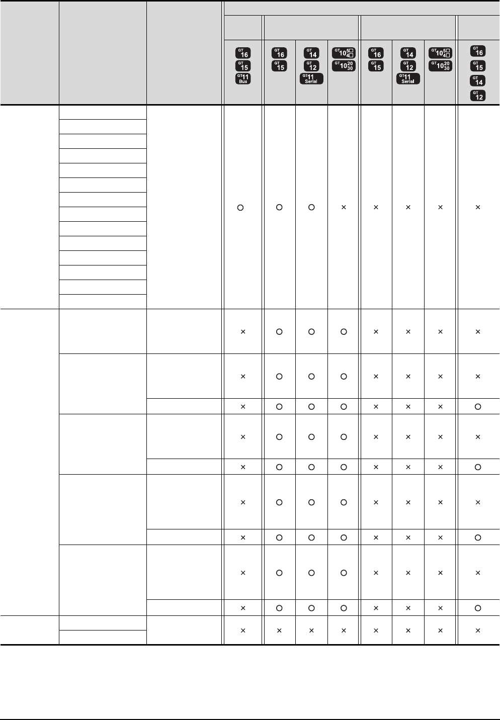
22 - 14 22. FA TRANSPARENT FUNCTION
22.3 List of Models that Can Be Monitored
(Continued to next page)
*1 GT14 models compatible with Ethernet connection are only GT1455-QTBDE and GT1450-QLBDE.
*2 Do not execute the write during RUN in the bus connection.
Series Model name Target software
Connection type
Bus
connection
Direct CPU connection Computer link connection Ethernet
connection
*1
Motion
controller CPU
(A Series)
A273UCPU
GX Developer
MX Component
MX Sheet
*2
A273UHCPU
A273UHCPU-S3
A373UCPU
A373UCPU-S3
A171SCPU
A171SCPU-S3
A171SCPU-S3N
A171SHCPU
A171SHCPUN
A172SHCPU
A172SHCPUN
A173UHCPU
A173UHCPU-S1
MELSEC-FX
FX0, FX0S, FX0N,
FX1, FX2, FX2C,
FX1S, FX1N, FX2N,
FX1NC, FX2NC
GX Developer
GX Works2
MX Component
MX Sheet
FX3G
GX Developer
FX Configurator-FP
MX Component
MX Sheet
GX Works2
FX3GC
GX Developer
FX Configurator-FP
MX Component
MX Sheet
GX Works2
FX3U
GX Developer
FX Configurator-FP
FX Configurator-EN
MX Component
MX Sheet
GX Works2
FX3UC
GX Developer
FX Configurator-FP
FX Configurator-EN
MX Component
MX Sheet
GX Works2
MELSEC-WS
WS0-CPU0
-
WS0-CPU1
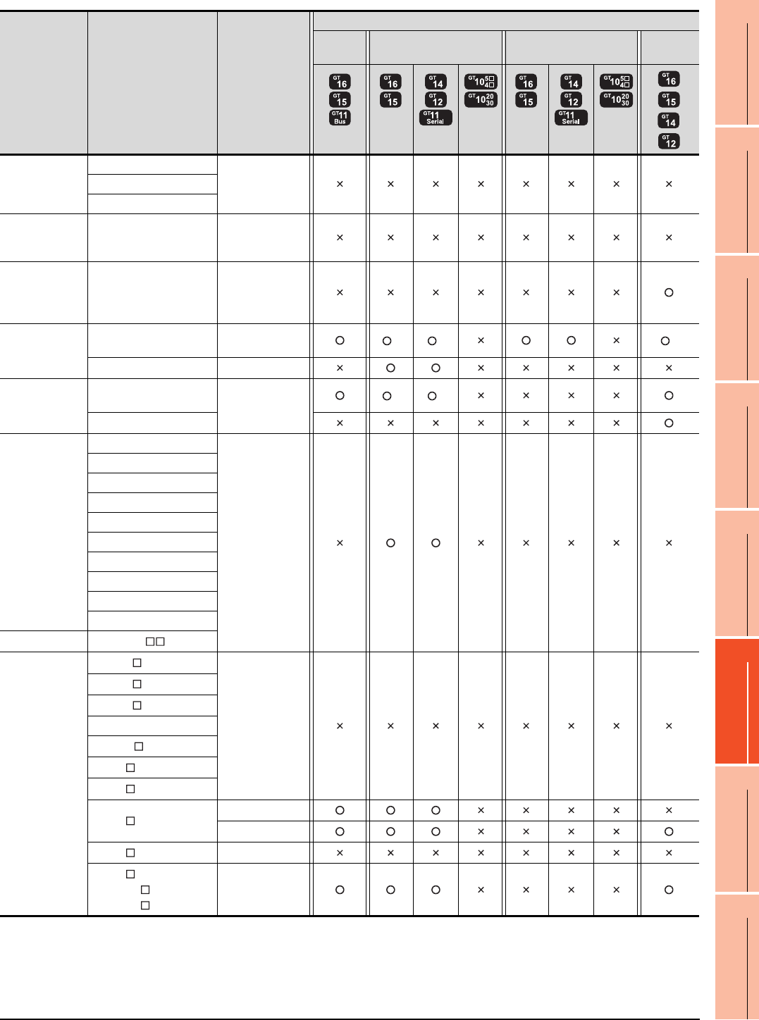
22. FA TRANSPARENT FUNCTION
22.3 List of Models that Can Be Monitored
22 - 15
17
ROBOT
CONTROLLER
CONNECTION
18
CNC CONNECTION
19
GOT MULTI-DROP
CONNECTION
20
MULTIPLE-GT14, GT12,
GT11, GT10
CONNECTION FUNCTION
21
MULTI-CHANNEL
FUNCTION
22
FA TRANSPARENT
FUNCTION
*1 Use the serial port of QCPU in the multiple CPU system since Q173NCCPU has no direct coupled I/F.
*2 Connect to the DISPLAY I/F of Q173NCCPU.
GX Developer accesses the PLC CPU which configures the multiple CPU system.
*3 Use the serial port of QCPU in the multiple CPU system, since CRnQ-700 has no direct coupled I/F.
*4 GT14 models compatible with Ethernet connection are only GT1455-QTBDE and GT1450-QLBDE.
Series Model name Target software
Connection type
Bus
connection
Direct CPU connection Computer link connection Ethernet
connection
*4
MELSECNET/H
Remote I/O
station
QJ72LP25-25
-QJ72LP25G
QJ72BR15
CC-Link IE
Field Network
head module
LJ72GF15-T2 -
CC-Link IE
Field Network
Ethernet adapter
module
NZ2GF-ETB GX Works2
CNC
CNC C70
(Q173NCCPU)
GX Developer
NC Configurator
*1 *1 *2
MELDAS C6/C64 GX Developer
Robot
controller
CRnQ-700
(Q172DRCPU) RT ToolBox2
*3 *3
CRnD-700
FREQROL
FREQROL-A500/A500L
FR Configurator
FREQROL-F500/F500L
FREQROL-V500/V500L
FREQROL-E500
FREQROL-S500/S500E
FREQROL-F500J
FREQROL-D700
FREQROL-E700
FREQROL-A700
FREQROL-F700
MELIPM MD-CX522- K(-A0)
MELSERVO
MR-J2S- A
-
MR-J2S- CP
MR-J2S- CL
MR-J2M-P8A
MR-J2M- DU
MR-J3- A
MR-J3- T
MR-J3- B
MR Configurator
MR Configurator2
MR-J4- A -
MR-J4- B
MR-J4W2- B
MR-J4W3- B
MR Configurator2
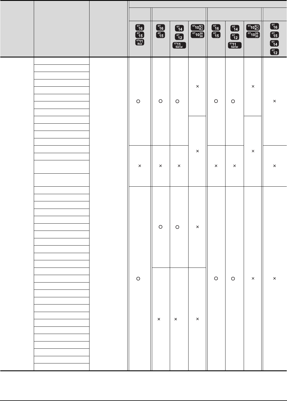
22 - 16 22. FA TRANSPARENT FUNCTION
22.3 List of Models that Can Be Monitored
When connecting the GOT and PC with Ethernet
(Continued to next page)
*1 Use the serial port of QCPU in the multiple CPU system, since QnUDEHCPU has no direct coupled I/F.
*2 GT14 models compatible with Ethernet connection are only GT1455-QTBDE and GT1450-QLBDE.
*3 GT11 is not supported.
Series Model name Target software
Connection type
Bus
connection
Direct CPU connection Computer link connection Ethernet
connection
*2 *2
*2
MELSEC-Q
(Q mode)
Q00JCPU
GX Works2
MX Component
MX Sheet
*3 *3*3
Q00CPU
Q01CPU
Q02CPU
Q02HCPU
Q06HCPU
Q12HCPU
Q25HCPU
Q02PHCPU
Q06PHCPU
Q12PHCPU
Q25PHCPU
Q12PRHCPU (Main base)
Q25PRHCPU (Main base)
Q12PRHCPU
(Extension base)
Q25PRHCPU
(Extension base)
Q00UJCPU
*3
*3
*3
Q00UCPU
Q01UCPU
Q02UCPU
Q03UDCPU
Q04UDHCPU
Q06UDHCPU
Q10UDHCPU
Q13UDHCPU
Q20UDHCPU
Q26UDHCPU
Q03UDECPU
*1*1*3
Q04UDEHCPU
Q06UDEHCPU
Q10UDEHCPU
Q13UDEHCPU
Q20UDEHCPU
Q26UDEHCPU
Q50UDEHCPU
Q100UDEHCPU
Q03UDVCPU
Q04UDVCPU
Q06UDVCPU
Q13UDVCPU
Q26UDVCPU
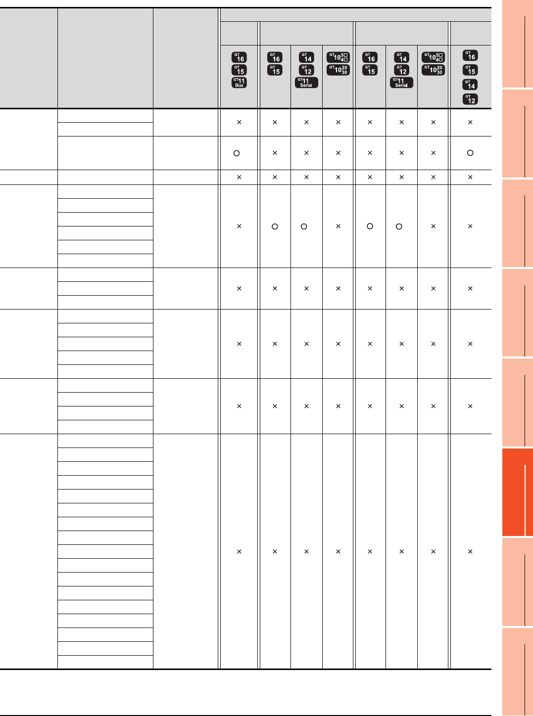
22. FA TRANSPARENT FUNCTION
22.3 List of Models that Can Be Monitored
22 - 17
17
ROBOT
CONTROLLER
CONNECTION
18
CNC CONNECTION
19
GOT MULTI-DROP
CONNECTION
20
MULTIPLE-GT14, GT12,
GT11, GT10
CONNECTION FUNCTION
21
MULTI-CHANNEL
FUNCTION
22
FA TRANSPARENT
FUNCTION
(Continued to next page)
*1 GT14 models compatible with Ethernet connection are only GT1455-QTBDE and GT1450-QLBDE.
*2 GT11 is not supported.
Series Model name Target software
Connection type
Bus
connection
Direct CPU connection Computer link connection Ethernet
connection
*1
C controller
module
Q12DCCPU-V
-
Q24DHCCPU-V
Q24DHCCPU-V
Setting/Monitoring
tool for C
Controller module
*2
MELSEC-QS QS001CPU -
MELSEC-L
L02CPU
GX Works2
MX Component
MX Sheet
*2 *2
L26CPU
L26CPU-BT
L02CPU-P
L26CPU-PBT
L02SCPU
MELSEC-Q
(A mode)
Q02CPU-A
-Q02HCPU-A
Q06HCPU-A
MELSEC-QnA
(QnACPU)
Q2ACPU
-
Q2ACPU-S1
Q3ACPU
Q4ACPU
Q4ARCPU
MELSEC-QnA
(QnASCPU)
Q2ASCPU
-
Q2ASCPU-S1
Q2ASHCPU
Q2ASHCPU-S1
MELSEC-A
(AnCPU)
A2UCPU
-
A2UCPU-S1
A3UCPU
A4UCPU
A2ACPU
A2ACPUP21
A2ACPUR21
A2ACPU-S1
A2ACPUP21-S1
A2ACPUR21-S1
A3ACPU
A3ACPUP21
A3ACPUR21
A1NCPU
A1NCPUP21
A1NCPUR21
A2NCPU
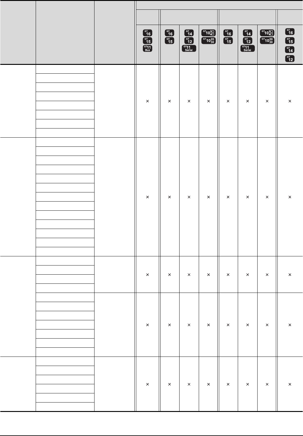
22 - 18 22. FA TRANSPARENT FUNCTION
22.3 List of Models that Can Be Monitored
(Continued to next page)
*1 GT14 models compatible with Ethernet connection are only GT1455-QTBDE and GT1450-QLBDE.
Series Model name Target software
Connection type
Bus
connection
Direct CPU connection Computer link connection Ethernet
connection
*1
MELSEC-A
(AnCPU)
A2NCPUP21
-
A2NCPUR21
A2NCPU-S1
A2NCPUP21-S1
A2NCPUR21-S1
A3NCPU
A3NCPUP21
A3NCPUR21
MELSEC-A
(AnSCPU)
A2USCPU
-
A2USCPU-S1
A2USHCPU-S1
A1SCPU
A1SCPUC24-R2
A1SHCPU
A2SCPU
A2SCPU-S1
A2SHCPU
A2SHCPU-S1
A1SJCPU
A1SJCPU-S3
A1SJHCPU
MELSEC-A
A0J2HCPU
-
A0J2HCPUP21
A0J2HCPUR21
A0J2HCPU-DC24
A2CCPU
-
A2CCPUP21
A2CCPUR21
A2CCPUC24
A2CCPUC24-PRF
A2CJCPU-S3
A1FXCPU
Motion
controller CPU
(Q Series)
Q172CPU
-
Q173CPU
Q172CPUN
Q173CPUN
Q172HCPU
Q173HCPU

22. FA TRANSPARENT FUNCTION
22.3 List of Models that Can Be Monitored
22 - 19
17
ROBOT
CONTROLLER
CONNECTION
18
CNC CONNECTION
19
GOT MULTI-DROP
CONNECTION
20
MULTIPLE-GT14, GT12,
GT11, GT10
CONNECTION FUNCTION
21
MULTI-CHANNEL
FUNCTION
22
FA TRANSPARENT
FUNCTION
(Continued to next page)
*1 GT14 models compatible with Ethernet connection are only GT1455-QTBDE and GT1450-QLBDE.
*2 GT11 is not supported.
*3 Use the serial port of QCPU in the multiple CPU system since Q172D/Q173DCPU has no direct coupled I/F.
Series Model name Target software
Connection type
Bus
connection
Direct CPU connection Computer link connection Ethernet
connection
*1
Motion
controller CPU
(Q Series)
Q172DCPU
MT Works2 *2 *3 *2*3
Q173DCPU
Q172DCPU-S1
Q173DCPU-S1
Q172DSCPU
Q173DSCPU
Q170MCPU
MT Works2
GX Developer
GX Works2
*2 *2
Motion
controller CPU
(A Series)
A273UCPU
-
A273UHCPU
A273UHCPU-S3
A373UCPU
A373UCPU-S3
A171SCPU
A171SCPU-S3
A171SCPU-S3N
A171SHCPU
A171SHCPUN
A172SHCPU
A172SHCPUN
A173UHCPU
A173UHCPU-S1
MELSEC-FX
FX0
GX Works2 *2
FX0S
FX0N
FX1
FX2
FX2C
FX1S
FX1N
FX2N
FX1NC
FX2NC
FX3G
FX3GC
FX3U
FX3UC
MELSEC-WS
WS0-CPU0
-
WS0-CPU1
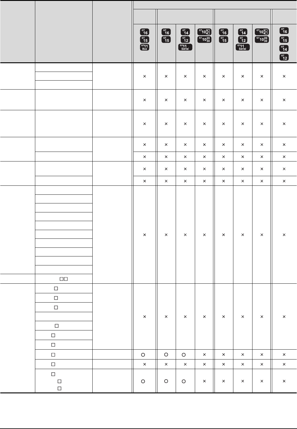
22 - 20 22. FA TRANSPARENT FUNCTION
22.3 List of Models that Can Be Monitored
*1 GT14 models compatible with Ethernet connection are only GT1455-QTBDE and GT1450-QLBDE.
*2 GT11 is not supported.
*3 A motion controller is required between the GOT and PLC in bus connection.
*4 A motion controller is required between the GOT and PLC in direct CPU connection.
Series Model name Target software
Connection type
Bus
connection
Direct CPU connection Computer link connection Ethernet
connection
*1
MELSECNET/H
Remote I/O
station
QJ72LP25-25
-QJ72LP25G
QJ72BR15
CC-Link IE
Field Network
head module
LJ72GF15-T2 -
CC-Link IE
Field Network
Ethernet
adapter module
NZ2GF-ETB -
CNC
CNC C70
(Q173NCCPU) -
MELDAS C6/C64
Robot controller
CRnQ-700
(Q172DRCPU) -
CRnD-700
FREQROL
FREQROL-A500/A500L
-
FREQROL-F500/F500L
FREQROL-V500/V500L
FREQROL-E500
FREQROL-S500/S500E
FREQROL-F500J
FREQROL-D700
FREQROL-E700
FREQROL-A700
FREQROL-F700
MELIPM MD-CX522- K(-A0)
MELSERVO
MR-J2S- A
-
MR-J2S- CP
MR-J2S- CL
MR-J2M-P8A
MR-J2M- DU
MR-J3- A
MR-J3- T
MR-J3- B*3*4 MR Configurator2 *2 *2
MR-J4- A -
MR-J4- B*3*4
MR-J4W2- B*3*4
MR-J4W3- B*3*4
MR Configurator2 *2 *2
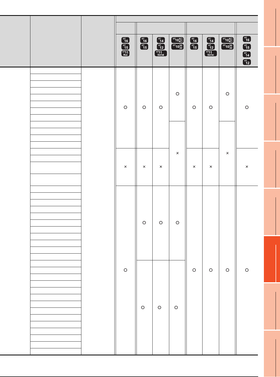
22. FA TRANSPARENT FUNCTION
22.3 List of Models that Can Be Monitored
22 - 21
17
ROBOT
CONTROLLER
CONNECTION
18
CNC CONNECTION
19
GOT MULTI-DROP
CONNECTION
20
MULTIPLE-GT14, GT12,
GT11, GT10
CONNECTION FUNCTION
21
MULTI-CHANNEL
FUNCTION
22
FA TRANSPARENT
FUNCTION
When connecting the GOT and personal computer with modem
(Continued to next page)
*1 Use the serial port of QCPU in the multiple CPU system, since QnUEHCPU has no direct coupled I/F.
*2 GT14 models compatible with Ethernet connection are only GT1455-QTBDE and GT1450-QLBDE.
Series Model name Target software
Connection type
Bus
connection
Direct CPU connection Computer link connection Ethernet
connection
*2
MELSEC-Q
(Q mode)
Q00JCPU
GX Developer
GX Works2
Q00CPU
Q01CPU
Q02CPU
Q02HCPU
Q06HCPU
Q12HCPU
Q25HCPU
Q02PHCPU
Q06PHCPU
Q12PHCPU
Q25PHCPU
Q12PRHCPU (Main base)
Q25PRHCPU (Main base)
Q12PRHCPU
(Extension base)
Q25PRHCPU
(Extension base)
Q00UJCPU
Q00UCPU
Q01UCPU
Q02UCPU
Q03UDCPU
Q04UDHCPU
Q06UDHCPU
Q10UDHCPU
Q13UDHCPU
Q20UDHCPU
Q26UDHCPU
Q03UDECPU
*1 *1 *1
Q04UDEHCPU
Q06UDEHCPU
Q10UDEHCPU
Q13UDEHCPU
Q20UDEHCPU
Q26UDEHCPU
Q50UDEHCPU
Q100UDEHCPU
Q03UDVCPU
Q04UDVCPU
Q06UDVCPU
Q13UDVCPU
Q26UDVCPU
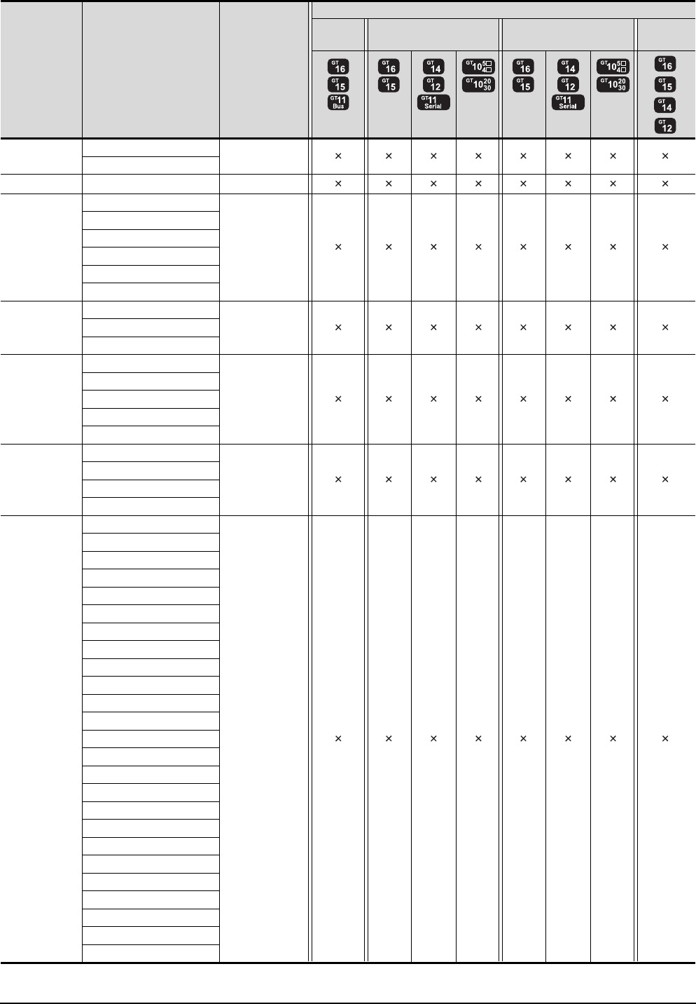
22 - 22 22. FA TRANSPARENT FUNCTION
22.3 List of Models that Can Be Monitored
(Continued to next page)
*1 GT14 models compatible with Ethernet connection are only GT1455-QTBDE and GT1450-QLBDE.
Series Model name Target software
Connection type
Bus
connection
Direct CPU connection Computer link connection Ethernet
connection
*1
C Controller
module
Q12DCCPU-V -
Q24DHCCPU-V
MELSEC-QS QS001CPU -
MELSEC-L
L02CPU
-
L26CPU
L26CPU-BT
L02CPU-P
L26CPU-PBT
L02SCPU
MELSEC-Q
(A mode)
Q02CPU-A
-Q02HCPU-A
Q06HCPU-A
MELSEC-QnA
(QnACPU)
Q2ACPU
-
Q2ACPU-S1
Q3ACPU
Q4ACPU
Q4ARCPU
MELSEC-QnA
(QnASCPU)
Q2ASCPU
-
Q2ASCPU-S1
Q2ASHCPU
Q2ASHCPU-S1
MELSEC-A
(AnCPU)
A2UCPU
-
A2UCPU-S1
A3UCPU
A4UCPU
A2ACPU
A2ACPUP21
A2ACPUR21
A2ACPU-S1
A2ACPUP21-S1
A2ACPUR21-S1
A3ACPU
A3ACPUP21
A3ACPUR21
A1NCPU
A1NCPUP21
A1NCPUR21
A2NCPU
A2NCPUP21
A2NCPUR21
A2NCPU-S1
A2NCPUP21-S1
A2NCPUR21-S1
A3NCPU
A3NCPUP21
A3NCPUR21
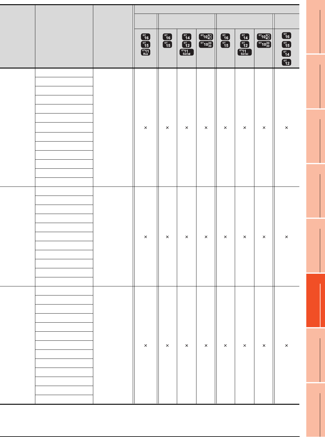
22. FA TRANSPARENT FUNCTION
22.3 List of Models that Can Be Monitored
22 - 23
17
ROBOT
CONTROLLER
CONNECTION
18
CNC CONNECTION
19
GOT MULTI-DROP
CONNECTION
20
MULTIPLE-GT14, GT12,
GT11, GT10
CONNECTION FUNCTION
21
MULTI-CHANNEL
FUNCTION
22
FA TRANSPARENT
FUNCTION
(Continued to next page)
*1 GT14 models compatible with Ethernet connection are only GT1455-QTBDE and GT1450-QLBDE.
Series Model name Target software
Connection type
Bus
connection
Direct CPU connection Computer link connection Ethernet
connection
*1
MELSEC-A
(AnSCPU)
A2USCPU
-
A2USCPU-S1
A2USHCPU-S1
A1SCPU
A1SCPUC24-R2
A1SHCPU
A2SCPU*1
A2SCPU-S1
A2SHCPU
A2SHCPU-S1
A1SJCPU
A1SJCPU-S3
A1SJHCPU
MELSEC-A
A0J2HCPU
-
A0J2HCPUP21
A0J2HCPUR21
A0J2HCPU-DC24
A2CCPU
A2CCPUP21
A2CCPUR21
A2CCPUC24
A2CCPUC24-PRF
A2CJCPU-S3
A1FXCPU
Motion
controller CPU
(Q Series)
Q172CPU
-
Q173CPU
Q172CPUN
Q173CPUN
Q172HCPU
Q173HCPU
Q172DCPU
Q173DCPU
Q172DCPU-S1
Q173DCPU-S1
Q172DSCPU
Q173DSCPU
Q170MCPU
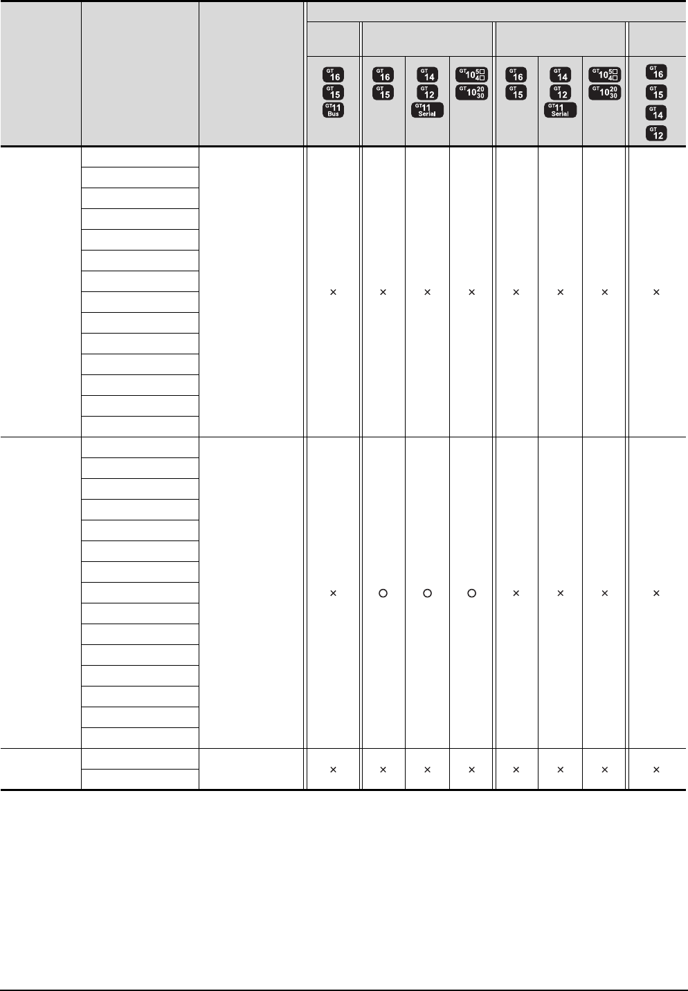
22 - 24 22. FA TRANSPARENT FUNCTION
22.3 List of Models that Can Be Monitored
(Continued to next page)
*1 GT14 models compatible with Ethernet connection are only GT1455-QTBDE and GT1450-QLBDE.
Series Model name Target software
Connection type
Bus
connection
Direct CPU connection Computer link connection Ethernet
connection
*1
Motion
controller CPU
(A Series)
A273UCPU
-
A273UHCPU
A273UHCPU-S3
A373UCPU
A373UCPU-S3
A171SCPU
A171SCPU-S3
A171SCPU-S3N
A171SHCPU
A171SHCPUN
A172SHCPU
A172SHCPUN
A173UHCPU
A173UHCPU-S1
MELSEC-FX
FX0
GX Developer
FX0S
FX0N
FX1
FX2
FX2C
FX1S
FX1N
FX2N
FX1NC
FX2NC
FX3G
FX3GC
FX3U
FX3UC
MELSEC-WS
WS0-CPU0
-
WS0-CPU1
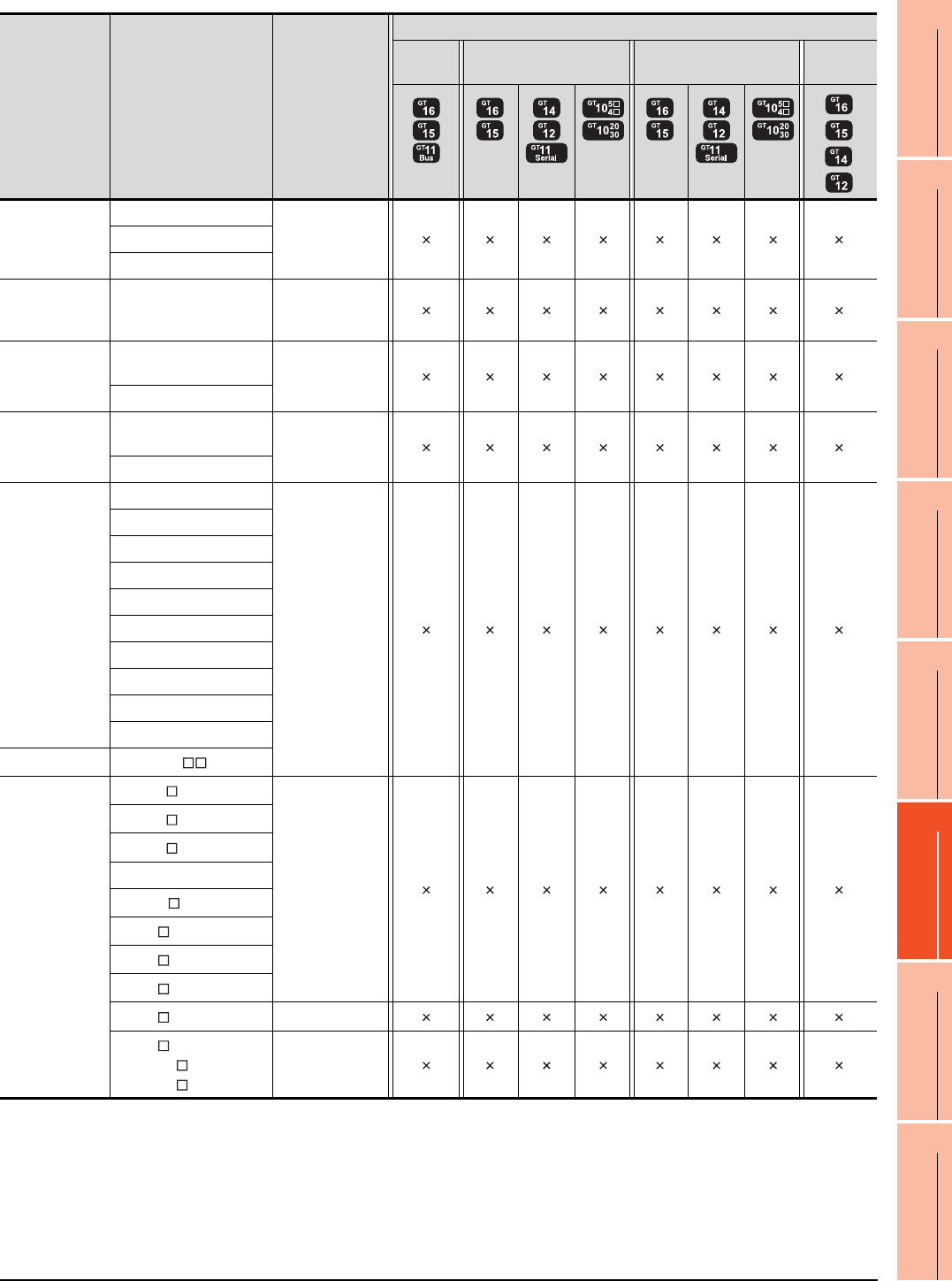
22. FA TRANSPARENT FUNCTION
22.3 List of Models that Can Be Monitored
22 - 25
17
ROBOT
CONTROLLER
CONNECTION
18
CNC CONNECTION
19
GOT MULTI-DROP
CONNECTION
20
MULTIPLE-GT14, GT12,
GT11, GT10
CONNECTION FUNCTION
21
MULTI-CHANNEL
FUNCTION
22
FA TRANSPARENT
FUNCTION
*1 GT14 models compatible with Ethernet connection are only GT1455-QTBDE and GT1450-QLBDE.
Series Model name Target software
Connection type
Bus
connection
Direct CPU connection Computer link connection Ethernet
connection
*1
MELSECNET/H
Remote I/O
station
QJ72LP25-25
-QJ72LP25G
QJ72BR15
CC-Link IE
Field Network
head module
LJ72GF15-T2 -
CNC
CNC C70
(Q173NCCPU) -
MELDAS C6/C64
Robot
controller
CRnQ-700
(Q172DRCPU) -
CRnD-700
FREQROL
FREQROL-A500/A500L
-
FREQROL-F500/F500L
FREQROL-V500/V500L
FREQROL-E500
FREQROL-S500/S500E
FREQROL-F500J
FREQROL-D700
FREQROL-E700
FREQROL-A700
FREQROL-F700
MELIPM MD-CX522- K(-A0)
MELSERVO
MR-J2S- A
-
MR-J2S- CP
MR-J2S- CL
MR-J2M-P8A
MR-J2M- DU
MR-J3- A
MR-J3- T
MR-J3- B
MR-J4- A -
MR-J4- B
MR-J4W2- B
MR-J4W3- B
-
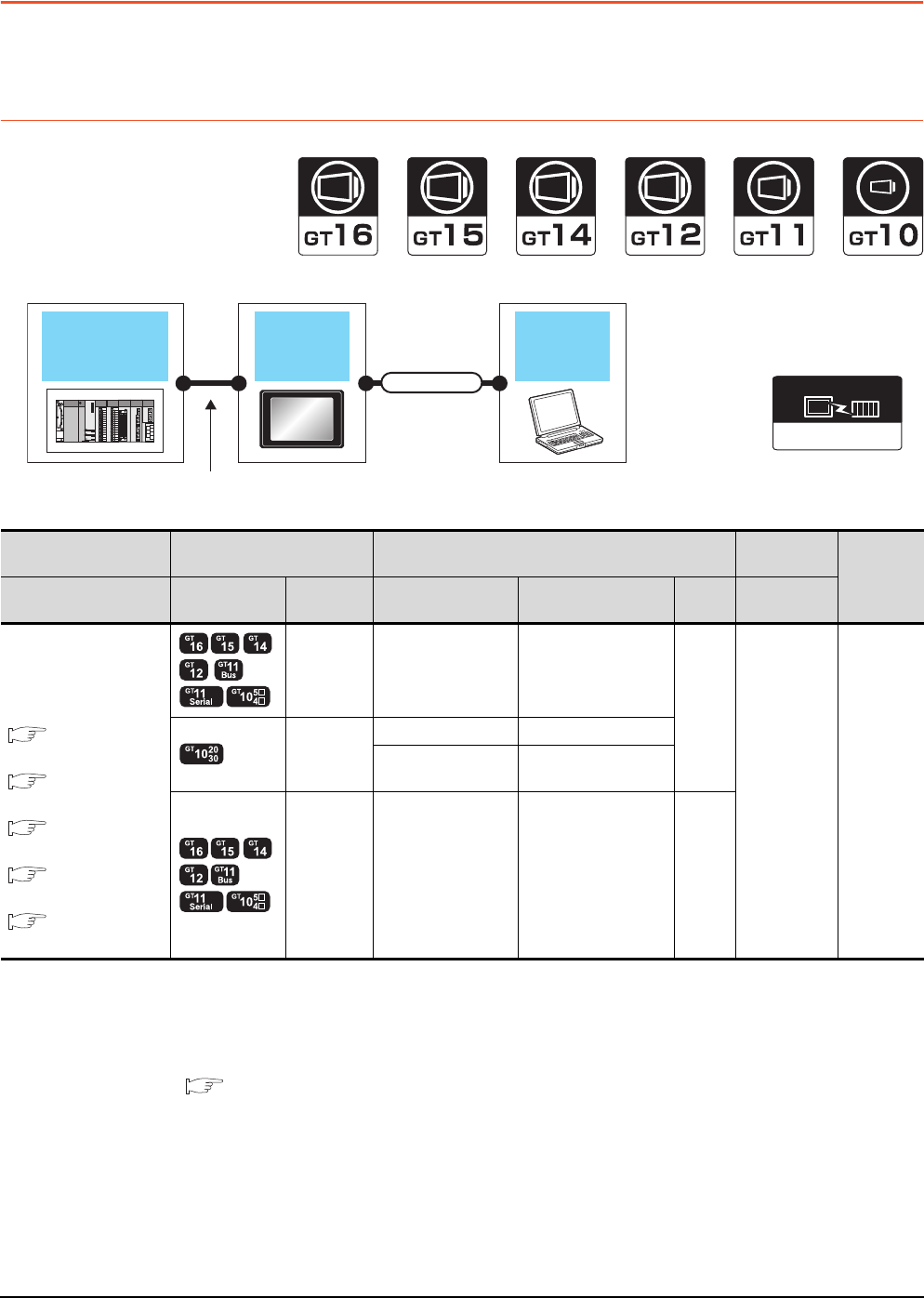
22 - 26 22. FA TRANSPARENT FUNCTION
22.4 System Configuration
22.4 System Configuration
22.4.1 GX Developer, GX Works2, GX LogViewer, MX Component, MX Sheet,
LCPU Logging Configuration Tool, Setting/Monitoring tool for C Controller
module
When connecting the GOT and personal computer with serial or USB
*1 Applicable to the QCPU only
*2 GT10, LCPU Logging Configuration Tool are not applicable to the bus connection.
*3 GT11 and GT10 are not applicable to the Ethernet connection.
*4 The use of RS-232/USB conversion adaptor requires an installation of the dedicated communication driver onto personal
computer.
For details, refer to the following manual.
RS-232/USB Conversion adaptor User's Manual
*5 GX LogViewer, MX Component, MX Sheet, LCPU Logging Configuration Tool and Setting/Monitoring tool for C Controller module
are not supported.
*6 Not applicable to Setting/Monitoring tool for C Controller module.
GOT PC
PLC
Varies according to
the connection type.
Connection cable
Connection type
dependant
Communication driver
PLC GOT Connection cable Personal
computer Number of
connectable
equipment
Connection type Model Interface RS-232/USB
conversion adaptor Cable model
Max.
distance
Software
For the system
configuration between the
GOT and PLC, refer to the
following.
BUS
CONNECTION*2
DIRECT
CONNECTION TO CPU*6
COMPUTER LINK
CONNECTION*1*6
ETHERNET
CONNECTION*3
GOT MULTI-DROP
CONNECTION*5
RS-232 - GT01-C30R2-9S(3m)
3m
GX Developer
GX Works2
GX LogViewer
MX Component
MX Sheet
LCPU Logging
Configuration
Too l
Setting/
Monitoring tool
for C Controller
module
1 personal
computer
for 1 GOT
RS-232
- GT01-C30R2-6P(3m)
GT10-RS2TUSB-5S
*4
GT09-C30USB-5P(3m)
GT09-C20USB-5P(2m)
USB - GT09-C30USB-5P(3m)
GT09-C20USB-5P(2m) 3m
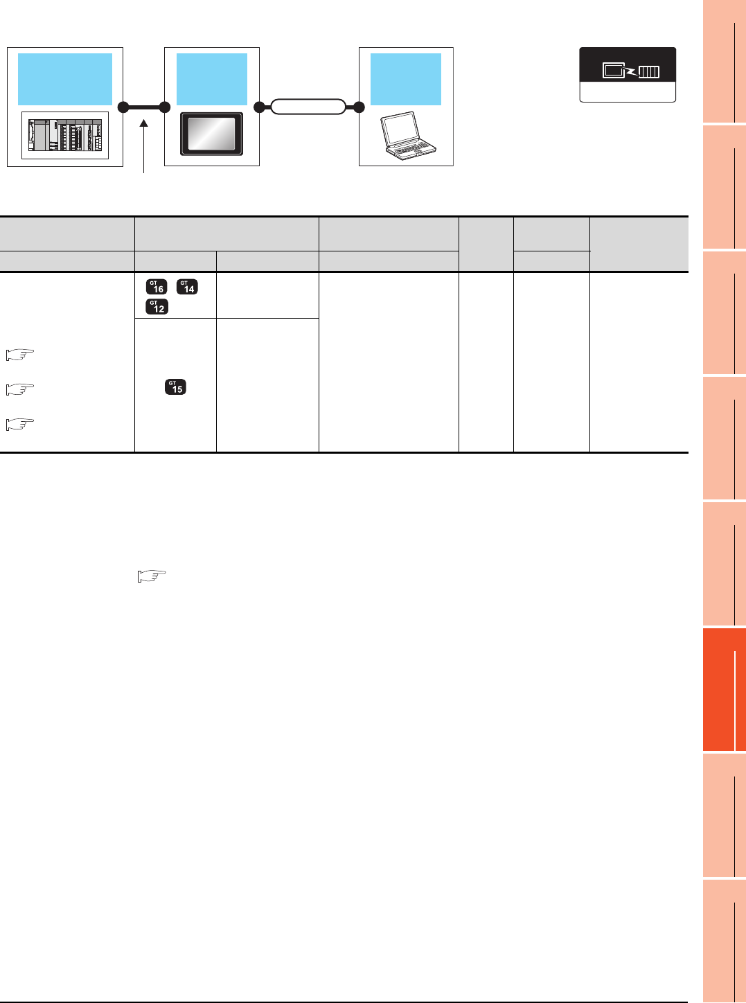
22. FA TRANSPARENT FUNCTION
22.4 System Configuration
22 - 27
17
ROBOT
CONTROLLER
CONNECTION
18
CNC CONNECTION
19
GOT MULTI-DROP
CONNECTION
20
MULTIPLE-GT14, GT12,
GT11, GT10
CONNECTION FUNCTION
21
MULTI-CHANNEL
FUNCTION
22
FA TRANSPARENT
FUNCTION
When connecting the GOT and PC with Ethernet (For GT16, GT15, GT14, GT12)
*1 The destination connected with the twisted pair cable varies with the configuration of the applicable Ethernet network system.
Connect to the Ethernet module, hub, transceiver, or other system equipment corresponding to the applicable Ethernet network
system.
Use cables, connectors, and hubs that meet the IEEE802.3 10BASE-T/100BASE-TX standards.
A cross cable is available for connecting the GOT to the Ethernet module.
*2 When connecting GT16 of the function version A to an equipment that meets the 10BASE (-T/2/5) standard, use the switching
hub and operate in a 10Mbps/100Mbps mixed environment.
For how to check the function version, refer to the following.
GT16 User's Manual
*3 A length between a hub and a node.
The maximum distance differs depending on the Ethernet device to be used.
The following shows the number of the connectable nodes when a repeater hub is used.
• 10BASE-T: Max. 4 nodes for a cascade connection (500m)
• 100BASE-TX: Max. 2 nodes for a cascade connection (205m)
When switching hubs are used, the cascade connection between the switching hubs has no logical limit for the number of
cascades.
For the limit, contact the switching hub manufacturer.
*4 LCPU is not applicable to the bus connection.
*5 GT14 models compatible with Ethernet connection are only GT1455-QTBDE and GT1450-QLBDE.
*6 Not applicable to Setting/Monitoring tool for C Controller module.
Connection type
dependant
Communication driver
GOT PC
PLC
Varies according to
the connection type.
Connection cable
PLC GOT Connection cable*1 Maximum
segment
length*3
Personal
computer
Number of
connectable
equipment
Connection type Model Interface Cable model Software
For the system configuration
between
the GOT and PLC, refer to
the following.
BUS
CONNECTION*4
DIRECT
CONNECTION TO CPU*6
COMPUTER LINK
CONNECTION*6
*2 *5
- (Built into GOT) Twisted pair cable
• 10BASE-T
Shielded twisted pair cable
(STP) or unshielded
twisted pair cable (UTP):
Category 3, 4, and 5
• 100BASE-TX
Shielded twisted pair cable
(STP):
Category 5 and 5e
100m
GX Works2
Setting/
Monitoring tool
for C Controller
module
1 personal
computer
for 1 GOT
GT15-J71E71-100
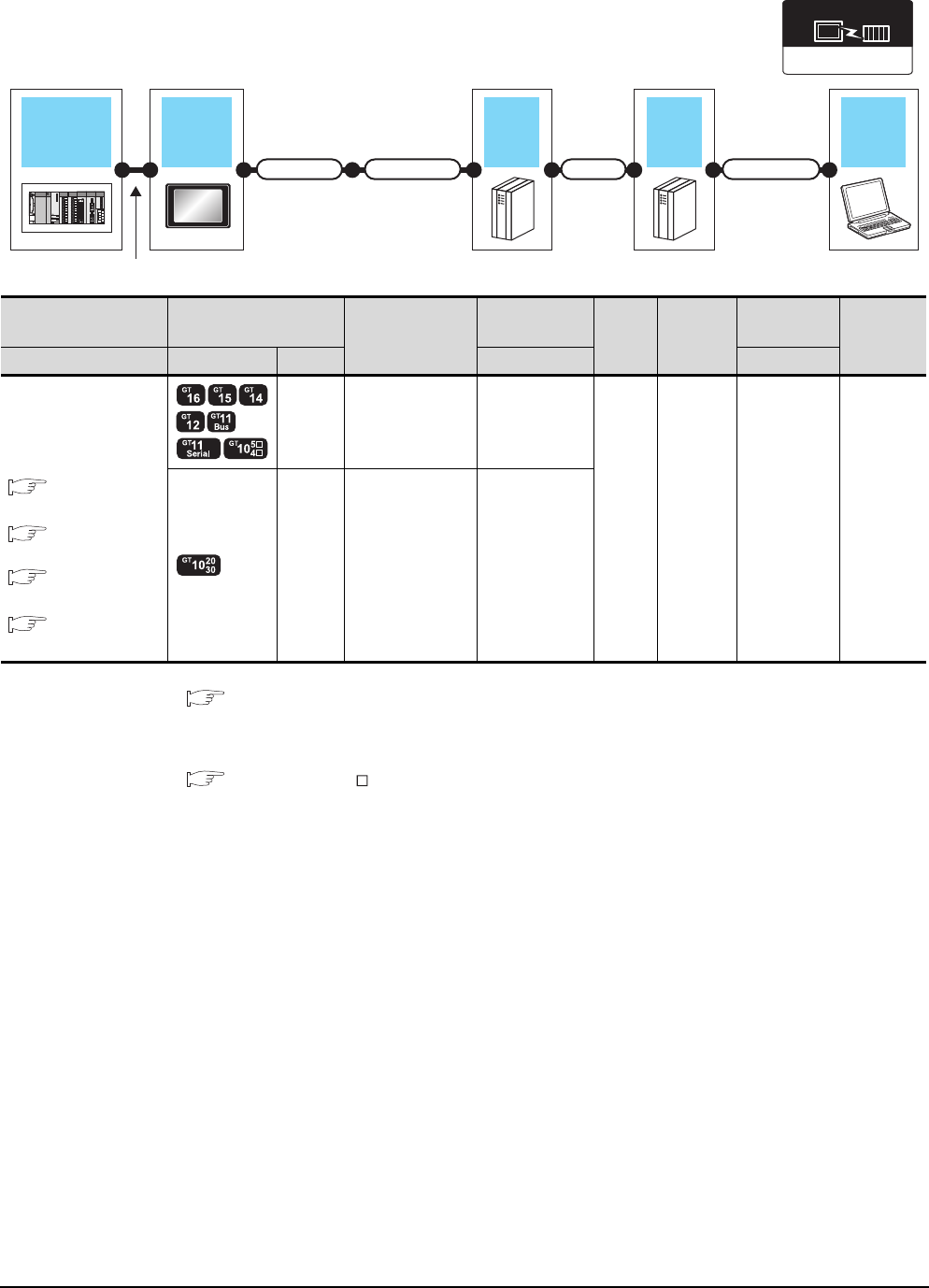
22 - 28 22. FA TRANSPARENT FUNCTION
22.4 System Configuration
When connecting the GOT and personal computer with modem
*1 For connectable modems, system equipment and connection cables, refer to the following Technical News.
List of valid devices applicable for GOT1000 series (T10-0039)
*2 GT10 is not applicable to the bus connection.
*3 Installation of the GOT modem connection tool to the personal computer is required to connect the GOT to a modem.
For details, refer to the following manual.
GT Designer3 Version Screen Design Manual
*4 GT11 and GT10 are not applicable to the Ethernet connection.
Connection type
dependant
Communication driver
GOT
Modem
PLC
Varies according to the connection type.
Connection cable
Adapter cable Connection cablePhone line
PC
Modem
PLC GOT
Adapter cable
Connection cable
Modem Phone line
Personal
computer*3
Number of
connectable
equipment
Connection type Model Interface Cable model Software
For the system
configuration between the
GOT and PLC, refer to the
following.
BUS
CONNECTION*2
DIRECT
CONNECTION TO CPU
COMPUTER LINK
CONNECTION*1
ETHERNET
CONNECTION*4
RS-232
(Built
into
GOT)
-*1
*1 Public line GX Developer
GX Works2
1 personal
computer
for 1 GOT
RS-232 GT10-C02H-6PT9P
(0.2m) *1
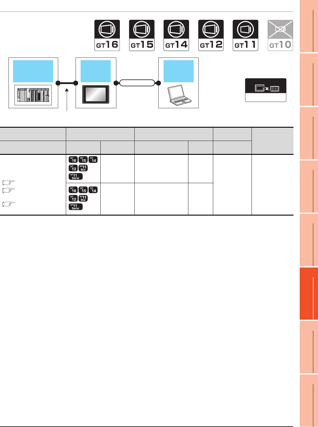
22. FA TRANSPARENT FUNCTION
22.4 System Configuration
22 - 29
17
ROBOT
CONTROLLER
CONNECTION
18
CNC CONNECTION
19
GOT MULTI-DROP
CONNECTION
20
MULTIPLE-GT14, GT12,
GT11, GT10
CONNECTION FUNCTION
21
MULTI-CHANNEL
FUNCTION
22
FA TRANSPARENT
FUNCTION
22.4.2 PX Developer, GX Configurator
GOT PC
PLC
Varies according to
the connection type.
Connection cable
Connection type
dependant
Communication driver
PLC GOT Connection cable Personal
computer Number of
connectable
equipment
Connection type Model Interface Cable model Max.
distance Software
For the system configuration
between the GOT and PLC, refer
to the following.
BUS CONNECTION
DIRECT CONNECTION
TO CPU
COMPUTER LINK
CONNECTION
RS-232 GT01-C30R2-9S(3m) 3m
PX Developer
GX Configurator
1 personal
computer for 1 GOT
USB GT09-C30USB-5P(3m)
GT09-C20USB-5P(2m) 3m
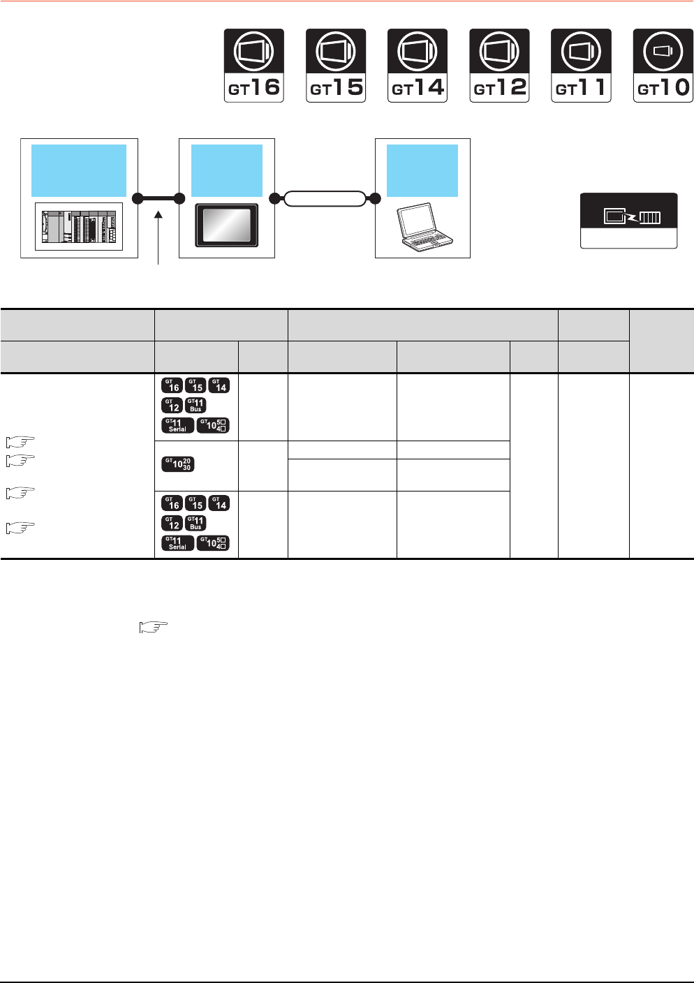
22 - 30 22. FA TRANSPARENT FUNCTION
22.4 System Configuration
22.4.3 MT Developer, MT Works2
When connecting the GOT and personal computer with serial or USB
*1 GT10 is not applicable to the bus connection.
*2 GT11 and GT10 are not applicable to the Ethernet connection.
*3 The use of RS-232/USB conversion adaptor requires an installation of the dedicated communication driver onto personal
computer.
RS-232/USB Conversion adaptor USER'S MANUAL
*4 GX LogViewer, MX Component and MX Sheet are not supported.
Connection type
dependant
Communication driver
GOT PC
QCPU +
Motion controller CPU
(Q series)
Connection cable
Varies according to
the connection type.
PLC GOT Connection cable Personal
computer Number of
connectable
equipment
Connection type Model Interface RS-232/USB
conversion adaptor Cable model Max.
distance Software
For the system configuration
between the GOT and PLC, refer
to the following.
BUS CONNECTION*1
DIRECT CONNECTION
TO CPU
ETHERNET
CONNECTION*2
GOT MULTI-DROP
CONNECTION*4
RS-232 - GT01-C30R2-9S(3m)
3m
MT Developer
MT Works2
1 personal
computer
for 1 GOT
RS-232
- GT01-C30R2-6P(3m)
GT10-RS2TUSB-5S*3 GT09-C30USB-5P(3m)
GT09-C20USB-5P(2m)
USB - GT09-C30USB-5P(3m)
GT09-C20USB-5P(2m)
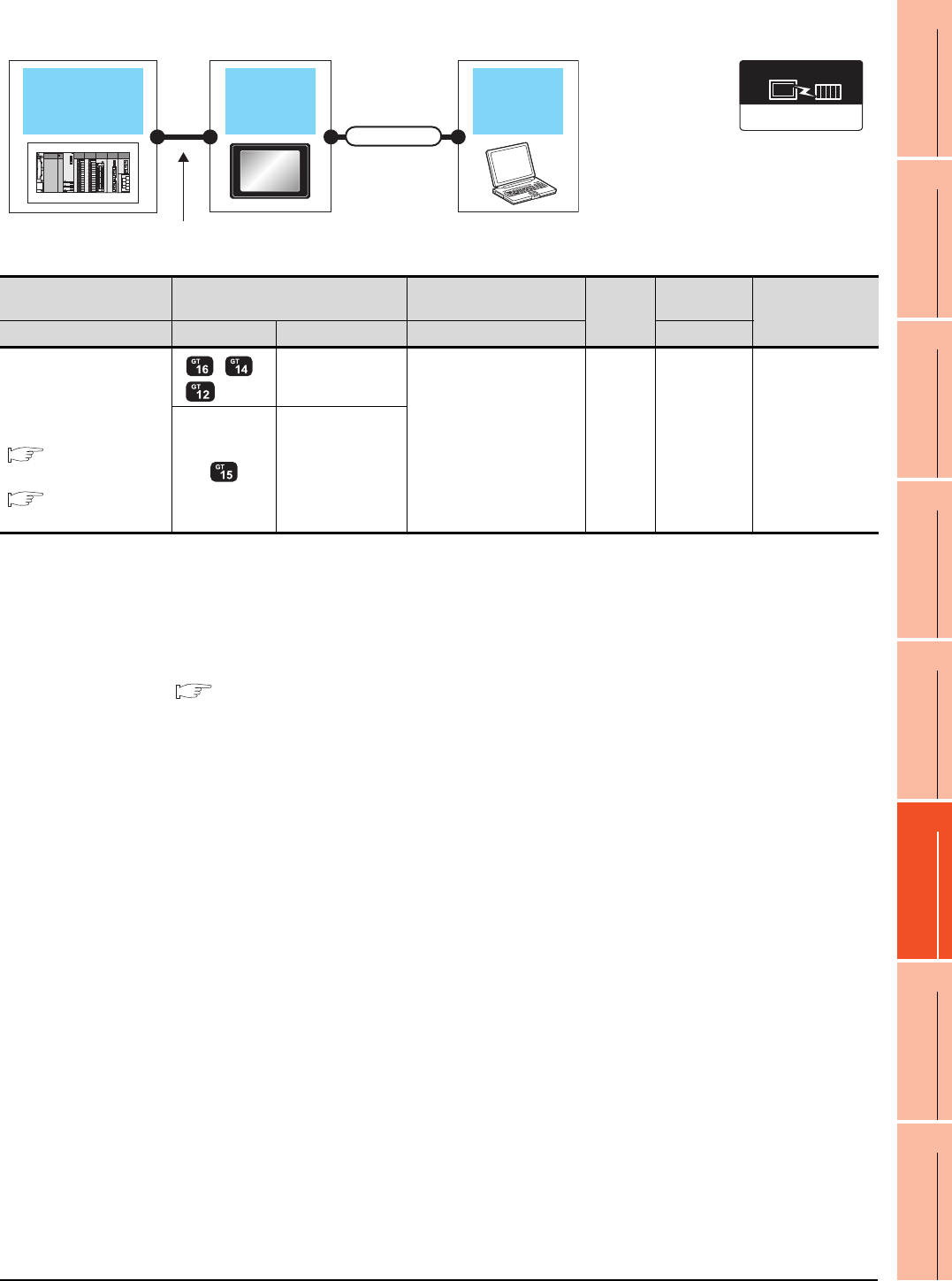
22. FA TRANSPARENT FUNCTION
22.4 System Configuration
22 - 31
17
ROBOT
CONTROLLER
CONNECTION
18
CNC CONNECTION
19
GOT MULTI-DROP
CONNECTION
20
MULTIPLE-GT14, GT12,
GT11, GT10
CONNECTION FUNCTION
21
MULTI-CHANNEL
FUNCTION
22
FA TRANSPARENT
FUNCTION
When connecting the GOT and PC with Ethernet (For GT16, GT15, GT14, GT12)
*1 The destination connected with the twisted pair cable varies with the configuration of the applicable Ethernet network system.
Connect to the Ethernet module, hub, transceiver, or other system equipment corresponding to the applicable Ethernet network
system.
Use cables, connectors, and hubs that meet the IEEE802.3 10BASE-T/100BASE-TX standards.
A cross cable is available for connecting the GOT to the Ethernet module.
*2 When connecting GT16 of the function version A to an equipment that meets the 10BASE (-T/2/5) standard, use the switching
hub and operate in a 10Mbps/100Mbps mixed environment.
For how to check the function version, refer to the following.
GT16 User's Manual
*3 A length between a hub and a node.
The maximum distance differs depending on the Ethernet device to be used.
The following shows the number of the connectable nodes when a repeater hub is used.
• 10BASE-T: Max. 4 nodes for a cascade connection (500m)
• 100BASE-TX: Max. 2 nodes for a cascade connection (205m)
When switching hubs are used, the cascade connection between the switching hubs has no logical limit for the number of
cascades.
For the limit, contact the switching hub manufacturer.
*4 LCPU is not applicable to the bus connection.
*5 GT14 models compatible with Ethernet connection are only GT1455-QTBDE and GT1450-QLBDE.
Connection type
dependant
Communication driver
GOT PC
PLC
Varies according to
the connection type.
Connection cable
PLC GOT Connection cable*1 Maximum
segment
length*3
Personal
computer
Number of
connectable
equipment
Connection type Model Interface Cable model Software
For the system configuration
between
the GOT and PLC, refer to
the following.
BUS
CONNECTION*4
DIRECT
CONNECTION TO CPU
*2 *5
- (Built into GOT)
Twisted pair cable
• 10BASE-T
Shielded twisted pair cable
(STP) or unshielded
twisted pair cable (UTP):
Category 3, 4, and 5
• 100BASE-TX
Shielded twisted pair cable
(STP):
Category 5 and 5e
100m MT Works2
1 personal
computer
for 1 GOT
GT15-J71E71-100
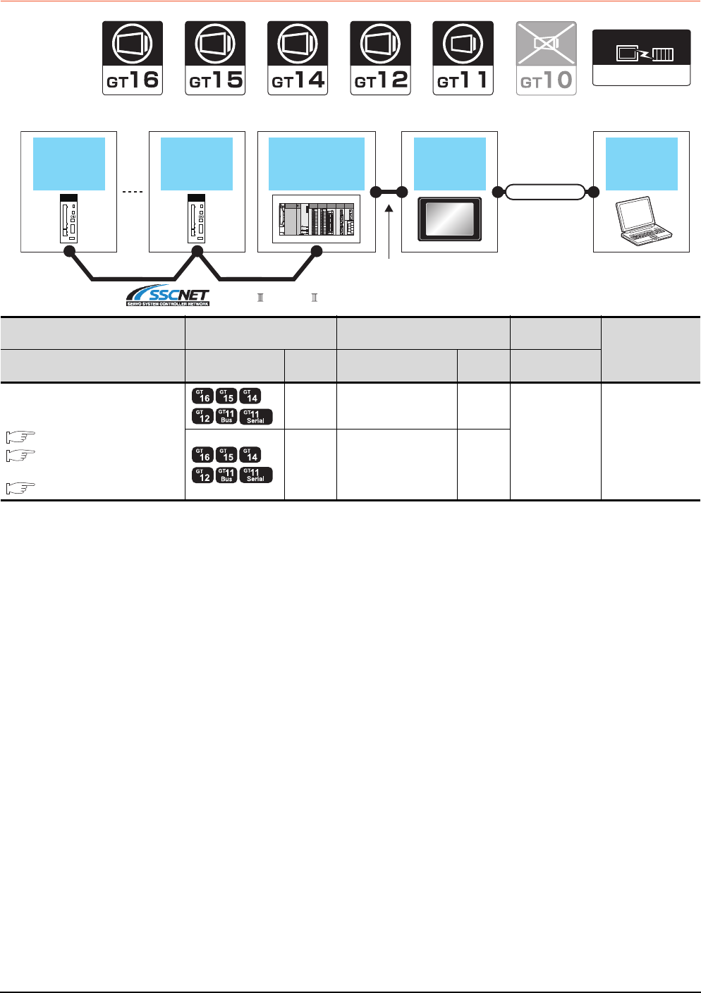
22 - 32 22. FA TRANSPARENT FUNCTION
22.4 System Configuration
22.4.4 MR Configurator, MR Configurator2
When connecting the GOT and personal computer with serial or USB
*1 Only MR Configurator2 is compatible with the Ethernet connection.
Connection type
dependant
Communication driver
Connection type
dependant
Communication driver
GOT
Servo
amplifier
Servo
amplifier
QCPU +
Motion controller
CPU (Q series)
PC
Connection cable
Varies according to
the connection type.
SSCNET , SSCNET /H
PLC GOT Connection cable Personal
computer Number of
connectable
equipment
Connection type Model Interface Cable model Max.
distance Software
For the system configuration between
the GOT and PLC, refer to the following.
BUS CONNECTION
DIRECT CONNECTION TO
CPU
ETHERNET CONNECTION*1
RS-232 GT01-C30R2-9S(3m) 3m
MR Configurator
MR Configurator2
1 personal
computer for 1 GOT
USB GT09-C30USB-5P(3m)
GT09-C20USB-5P(2m) 3m
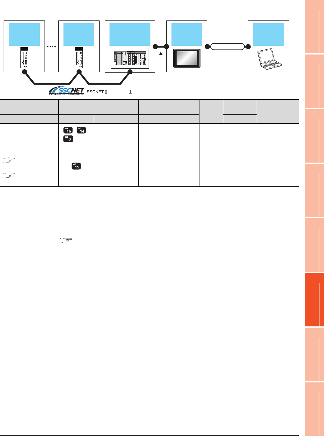
22. FA TRANSPARENT FUNCTION
22.4 System Configuration
22 - 33
17
ROBOT
CONTROLLER
CONNECTION
18
CNC CONNECTION
19
GOT MULTI-DROP
CONNECTION
20
MULTIPLE-GT14, GT12,
GT11, GT10
CONNECTION FUNCTION
21
MULTI-CHANNEL
FUNCTION
22
FA TRANSPARENT
FUNCTION
When connecting the GOT and PC with Ethernet (For GT16, GT15, GT14, GT12)
*1 The destination connected with the twisted pair cable varies with the configuration of the applicable Ethernet network system.
Connect to the Ethernet module, hub, transceiver, or other system equipment corresponding to the applicable Ethernet network
system.
Use cables, connectors, and hubs that meet the IEEE802.3 10BASE-T/100BASE-TX standards.
A cross cable is available for connecting the GOT to the Ethernet module.
*2 When connecting GT16 of the function version A to an equipment that meets the 10BASE (-T/2/5) standard, use the switching
hub and operate in a 10Mbps/100Mbps mixed environment.
For how to check the function version, refer to the following.
GT16 User's Manual
*3 A length between a hub and a node.
The maximum distance differs depending on the Ethernet device to be used.
The following shows the number of the connectable nodes when a repeater hub is used.
• 10BASE-T: Max. 4 nodes for a cascade connection (500m)
• 100BASE-TX: Max. 2 nodes for a cascade connection (205m)
When switching hubs are used, the cascade connection between the switching hubs has no logical limit for the number of
cascades.
For the limit, contact the switching hub manufacturer.
*4 LCPU is not applicable to the bus connection.
*5 GT14 models compatible with Ethernet connection are only GT1455-QTBDE and GT1450-QLBDE.
GOT
Servo
amplifier
Servo
amplifier
QCPU +
Motion controller
CPU (Q series)
PC
Connection cable
Varies according to
the connection type.
, SSCNET /H
PLC GOT Connection cable*1 Maximum
segment
length*3
Personal
computer
Number of
connectable
equipment
Connection type Model Interface Cable model Software
For the system configuration
between
the GOT and PLC, refer to
the following.
BUS
CONNECTION*4
DIRECT
CONNECTION TO CPU
*2 *5
- (Built into GOT)
Twisted pair cable
• 10BASE-T
Shielded twisted pair cable
(STP) or unshielded
twisted pair cable (UTP):
Category 3, 4, and 5
• 100BASE-TX
Shielded twisted pair cable
(STP):
Category 5 and 5e
100m MR
Configurator2
1 personal
computer
for 1 GOT
GT15-J71E71-100
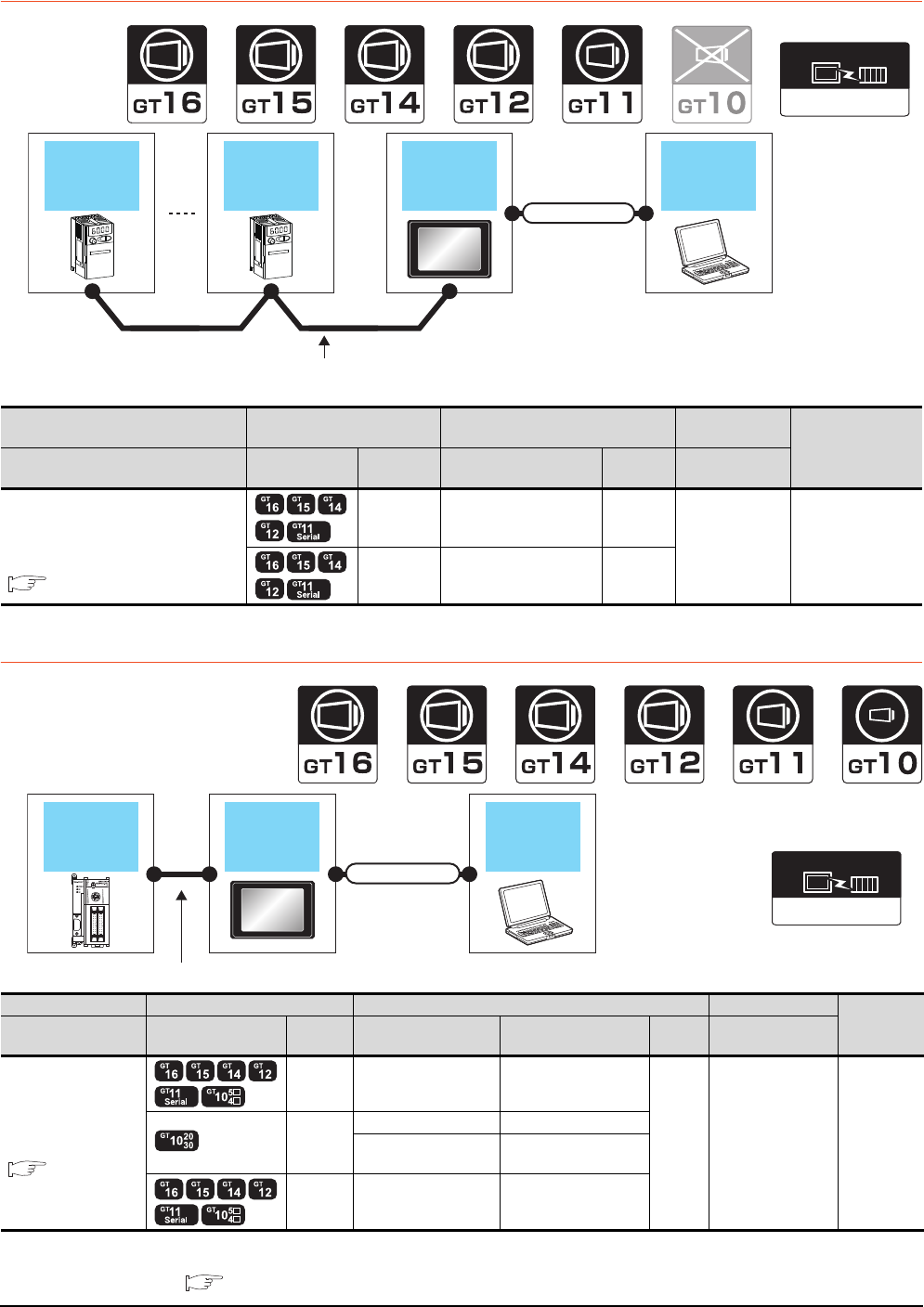
22 - 34 22. FA TRANSPARENT FUNCTION
22.4 System Configuration
22.4.5 FR Configurator
22.4.6 FX Configurator-FP, FX Configurator-EN
*1 The use of RS-232/USB conversion adaptor requires an installation of the dedicated communication driver onto personal
computer.
RS-232/USB Conversion adaptor User's Manual
Inverter GOT
Varies according to
the connection type.
Inverter PC
Connection cable
FREQROL 500/700
Communication driver
Inverter GOT Connection cable Personal
computer Number of
connectable
equipment
Connection type Model Interface Cable model Max.
distance Software
For details on the system configuration
between GOT and Mitsubishi inverter,
refer to the following.
INVERTER CONNECTION
RS-232 GT01-C30R2-9S(3m) 3m
FR Configurator 1 personal
computer for 1 GOT
USB GT09-C30USB-5P(3m)
GT09-C20USB-5P(2m) 3m
GOT PC
PLC
Varies according to the connection type.
Connection cable
MELSEC-FX
Communication driver
PLC GOT Connection cable Personal computer Number of
connectable
equipment
Connection type Model Interface RS-232/USB
conversion adaptor Cable model
Max.
distance
Software
For the system
configuration between
the GOT and PLC,
refer to the following.
DIRECT
CONNECTION TO
CPU
RS-232 - GT01-C30R2-9S(3m)
3m FX Configurator-FP,
FX Configurator-EN
1 personal
computer
for 1 GOT
RS-232
- GT01-C30R2-6P(3m)
GT10-RS2TUSB-5S*1 GT09-C30USB-5P(3m)
GT09-C20USB-5P(2m)
USB - GT09-C30USB-5P(3m)
GT09-C20USB-5P(2m)
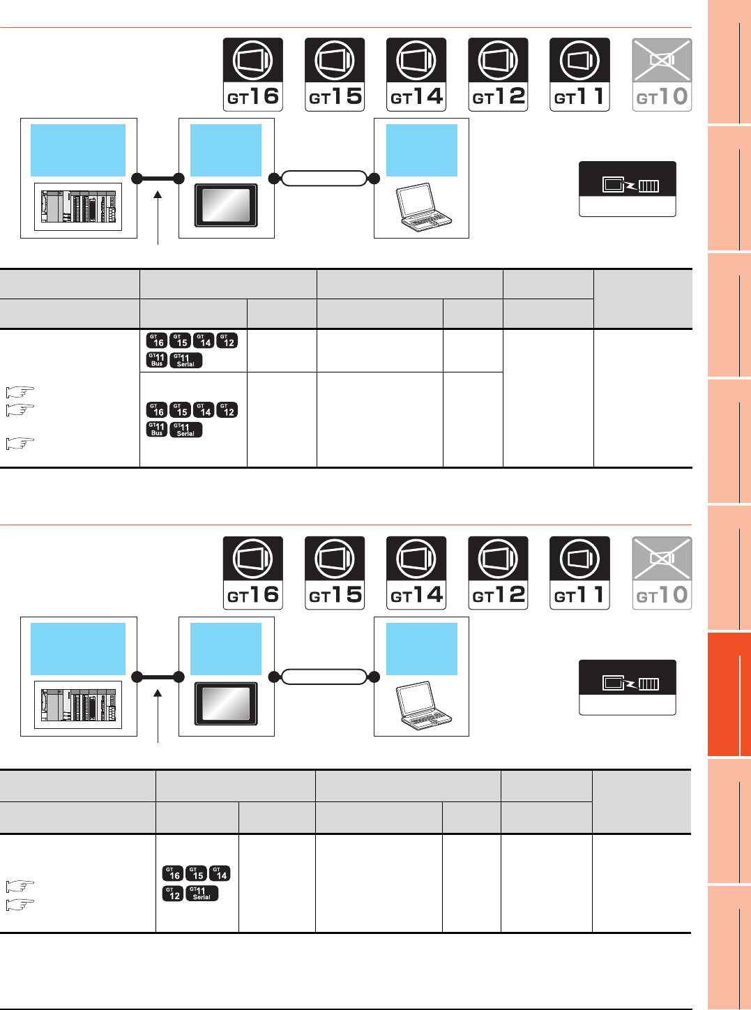
22. FA TRANSPARENT FUNCTION
22.4 System Configuration
22 - 35
17
ROBOT
CONTROLLER
CONNECTION
18
CNC CONNECTION
19
GOT MULTI-DROP
CONNECTION
20
MULTIPLE-GT14, GT12,
GT11, GT10
CONNECTION FUNCTION
21
MULTI-CHANNEL
FUNCTION
22
FA TRANSPARENT
FUNCTION
22.4.7 RT ToolBox2
*1 CRnD-700 is not applicable to the bus connection, the direct CPU connection.
22.4.8 NC Configurator
*1 GT11 is not applicable to the Ethernet connection.
GOT PC
Connection cable
CRnQ-700
Varies according to the connection type.
Connection type
dependant
Communication driver
PLC GOT Connection cable Personal
computer Number of
connectable
equipment
Connection type Model Interface Cable model Max.
distance Software
For the system configuration
between the GOT and PLC,
refer to the following.
BUS CONNECTION*1
DIRECT
CONNECTION TO CPU*1
ETHERNET
CONNECTION
RS-232 GT01-C30R2-9S(3m) 3m
RT ToolBox2 1 personal
computer for 1 GOT
USB GT09-C30USB-5P(3m)
GT09-C20USB-5P(2m) 3m
GOT PC
Connection cable
Q173NCCPU
Varies according to the connection type.
Connection type
dependant
Communication driver
PLC GOT Connection cable Personal
computer Number of
connectable
equipment
Connection type Model Interface Cable model Max.
distance Software
For the system configuration
between the GOT and PLC, refer
to the following.
BUS CONNECTION
ETHERNET
CONNECTION*1
USB GT09-C30USB-5P(3m)
GT09-C20USB-5P(2m) 3m NC Configurator 1 personal
computer for 1 GOT
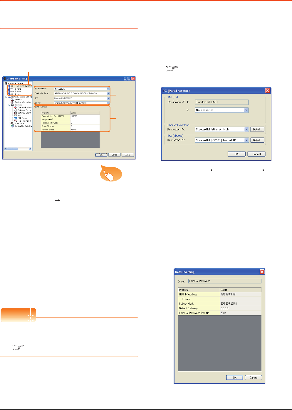
22 - 36 22. FA TRANSPARENT FUNCTION
22.5 GOT Side Settings
22.5 GOT Side Settings
22.5.1 Setting communication
interface
Controller setting
Set the channel of the connected equipment.
1. Select [Common] [Controller Setting] from the
menu.
2. The Controller Setting window is displayed. Select the
channel to be used from the list menu.
3. Set Manufacturer, Controller Type, I/F, and Driver
according to the connected equipment to be used.
4. The detailed setting is displayed after Manufacturer,
Controller Type, I/F, and Driver are set.
Make the settings according to the usage
environment.
Click the [OK] button when settings are completed.
POINTPOINTPOINT
The settings of connecting equipment can be
confirmed in [I/F Communication Setting].
For details, refer to the following.
1.1.2 I/F communication setting
Communication setting with personal
computer
Set the communication setting between the GOT and the
personal computer.
For details of the setting contents, refer to the following
manual.
Screen Design Manual (Fundamentals)
7.1.2 Interface setting of the GOT
Example: For GT16
1. Select [Common] [Peripheral Setting] [PC(Data
Transfer) ]from the menu.
2. The [PC (Data Transfer)] is displayed. Set the
interface of the GOT to be used in the communication
with the personal computer.
(a) Host (PC) setting
When communicating the GOT and the personal
computer in the direct connection, set the interface
of the GOT to be used in the communication with
the personal computer.
(b) Ethernet download setting
When communicating the GOT via Ethernet, set
the interface of the GOT to be used in the
communication with the personal computer.
2.
3.
4.
Click!
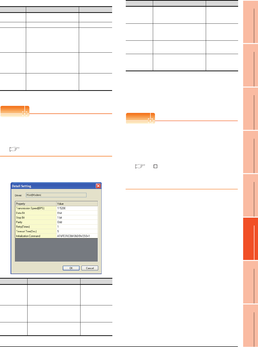
22. FA TRANSPARENT FUNCTION
22.5 GOT Side Settings
22 - 37
17
ROBOT
CONTROLLER
CONNECTION
18
CNC CONNECTION
19
GOT MULTI-DROP
CONNECTION
20
MULTIPLE-GT14, GT12,
GT11, GT10
CONNECTION FUNCTION
21
MULTI-CHANNEL
FUNCTION
22
FA TRANSPARENT
FUNCTION
*1 Click the [Setting] button and perform the setting in the [GOT
IP Address Setting] screen.
POINTPOINTPOINT
Setting the FA transparent function of GX Works2
When connecting the GOT and the personal computer
in Ethernet connection, set the GOT IP address and
the Ethernet download port No. to the same as the
contents of PLC side I/F detailed setting of GOT.
22.6.2 Accessing by GX Works2
(c) Host (modem) setting
When communicating the GOT via modem, set the
interface of the GOT to be used in the
communication with the modem.
*1 The maximum number of characters of the AT command
differs according to the specification of the modem. When
the maximum number of characters of the AT command
which can be used in the modem is less than 255, set the
initialization command according to the specification of the
modem.
3. Click the [OK] button when settings are completed.
POINTPOINTPOINT
(1) Communication interface setting by Utility
The communication interface setting can be
changed on the Utility's [Communication Settings]
after downloading [Communication Settings] of
project data.
For details on the Utility, refer to the following
manual.
GT User's Manual
(2) Precedence in communication settings
When settings are made by GT Designer3 or the
Utility, the latest setting is effective.
Item Description Range
GOT
IP Address
Set the IP address of the GOT.
(Default: 192.168.3.18)
0.0.0.0 to
255.255.255.255
IP Label Set the IP Label of detail setting. -
Subnet Mask*1
Set the subnet mask for the sub
network. (Only for connection via
router)
If the sub network is not used,
the default value is set.
(Default: 255.255.255.0)
0.0.0.0 to
255.255.255.255
Default
Gateway*1
Set the router address of the
default gateway where the GOT
is connected. (Only for
connection via router)
(Default: 0.0.0.0)
0.0.0.0 to
255.255.255.255
Ethernet
Download Port
No.*1
Set the GOT port No. for
Ethernet download.
(Default: 5014)
1024 to 5010,
5014 to 65534
(Except for 5011, 5012,
5013, 49153)
Item Description Range
Transmission
Speed
Set this item when change the
transmission speed used for
communication with the connected
equipment.
(Default: 115200)
9600bps,
19200bps,
38400bps,
57600bps,
115200bps
Data Bit
Set this item when change the data
length used for communication with
the connected equipment.
(Default: 8bit)
7bits/8bits
Stop Bit
Specify the stop bit length for
communications.
(Default: 1bit)
1bit/2bits
Parity
Specify whether or not to perform a
parity check, and how it is performed
during communication.
(Default: Odd)
None
Even
Odd
Retry
Set the number of retries to be
performed when a communication
timeout occurs.
(Default: 1time)
1time
Timeout Time
Set the time period for a
communication to time out.
(Default: 5sec)
5sec
Initialization
Command*1
Set the AT command to initialize the
modem.
(Default:
AT&FE0%C0&K0&D0W2S0=1)
Up to 255 one-byte
alphanumeric
characters
Item Description Range
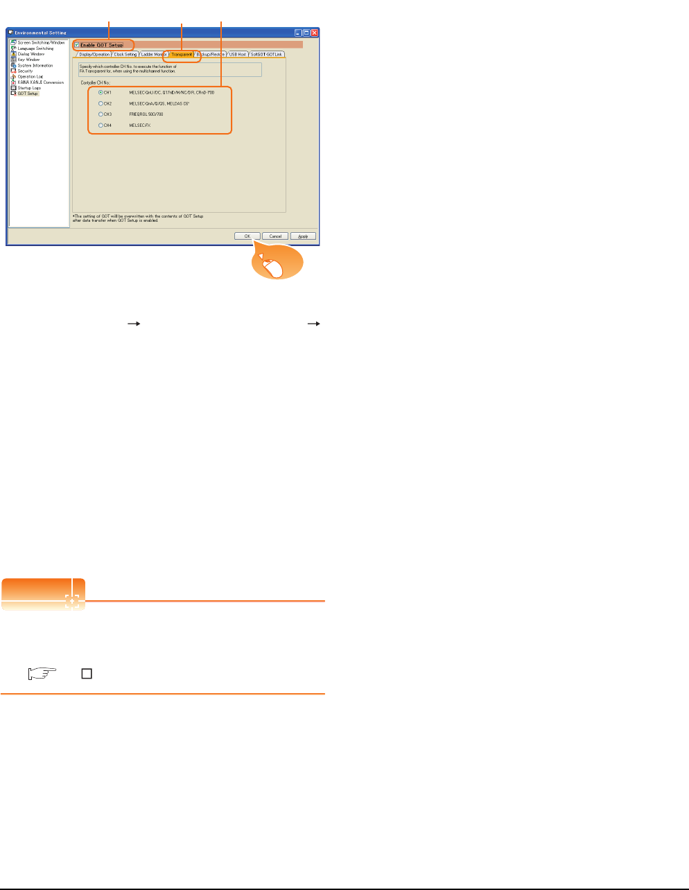
22 - 38 22. FA TRANSPARENT FUNCTION
22.5 GOT Side Settings
GOT Setup
When using the multi-channel function (only GT16,
GT15, GT14, GT12), specify the channel No. on which
FA transparent function is executed.
1. Select [Common] [GOT Environmental Setting]
[GOT Setup] from the menu.
2. Check [Enable GOT Setup].
3. Select the [Transparent] tab.
4. As necessary, check one of [CH1] to [CH4]. (Default:
CH1)
< GT16,GT15 >
[CH1], [CH2], [CH3], [CH4]
< GT14,GT12 >
[CH1], [CH2]
Click the [OK] button when settings are completed.
POINTPOINTPOINT
Transparent setting on the utility screen
Transparent setting can be performed by the GOT.
For details of the operating, refer to the following.
GT User's Manual
2. 3. 4.
Click!
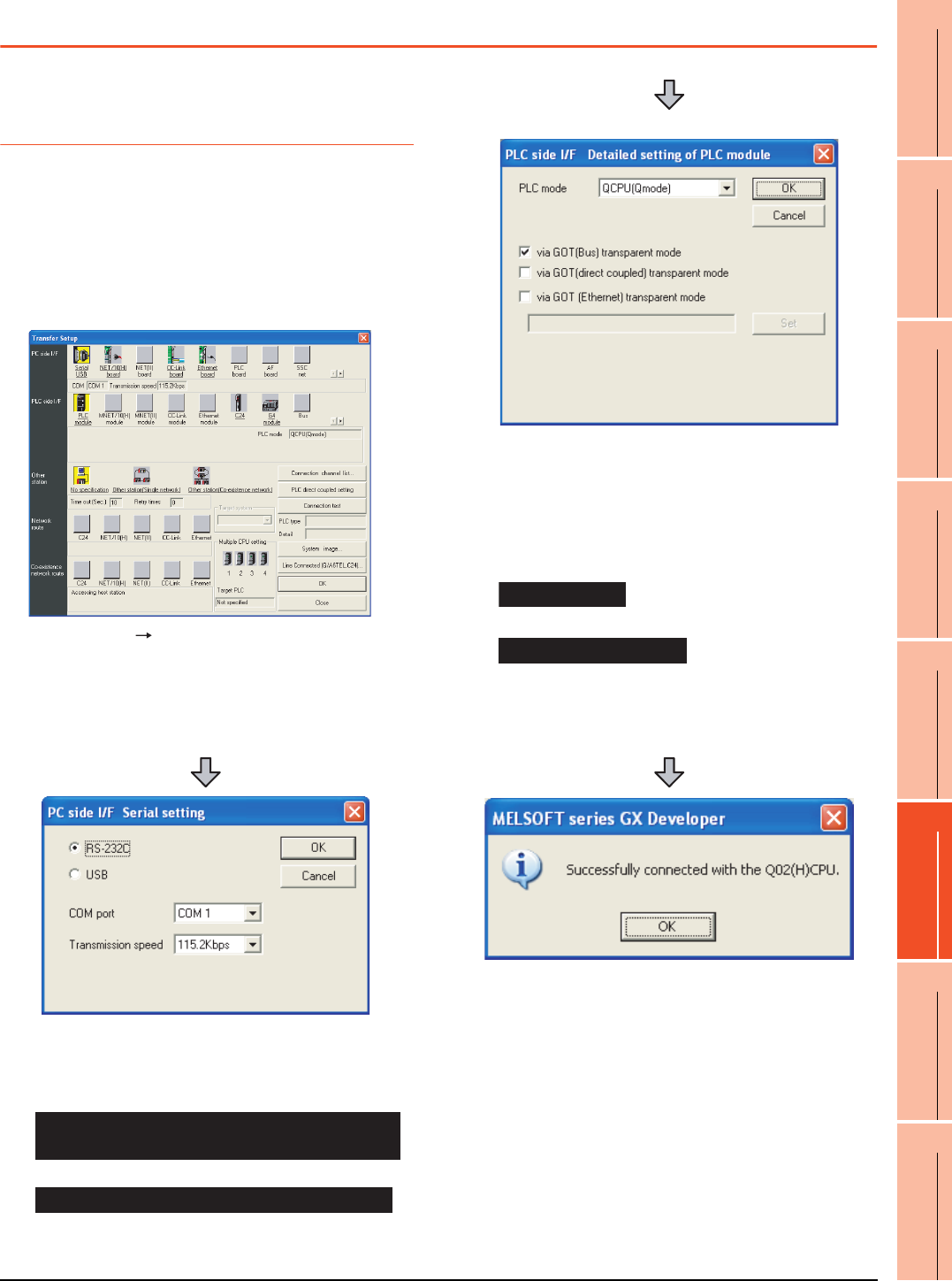
22. FA TRANSPARENT FUNCTION
22.6 Personal Computer Side Setting
22 - 39
17
ROBOT
CONTROLLER
CONNECTION
18
CNC CONNECTION
19
GOT MULTI-DROP
CONNECTION
20
MULTIPLE-GT14, GT12,
GT11, GT10
CONNECTION FUNCTION
21
MULTI-CHANNEL
FUNCTION
22
FA TRANSPARENT
FUNCTION
22.6 Personal Computer Side Setting
22.6.1 Accessing the PLC by the GX
Developer, PX Developer,
GX Configurator
The setting method for the FA transparent function of GX
Developer is used as an example.
GX Configurator is an add-on software of GX Developer.
(Except for GX Configurator-QP)
Connecting the GOT and PLC in bus
connection or direct CPU connection
(when connecting to QCPU (Q mode))
1. Click [Online] [Transfer Setup] in GX Developer.
2. The [Transfer Setup] is displayed.
3. Set the [Transfer Setup]:
PC side I/F : Serial USB (COM)
PLC side I/F : PLC module
Other station : No specification
4. Double-click [Serial] of the PC side I/F to display [PC
side I/F Serial setting].
5. Check-mark either of the following in [PC side I/F
Serial setting].
Mark the [RS-232C] checkbox.
Mark the [USB] checkbox.
When connecting the GOT to PC via modem
When connecting the GOT and PC with serial
When connecting the GOT and PC with USB
(For bus connection)
6. Double-click [PLC module] of the PLC side I/F to
display [PLC side I/F Detailed setting of PLC module].
7. Check-mark either of the following in [PLC side I/F
Detailed setting of PLC module].
[via GOT(Bus) transparent mode]
*1
[via GOT (direct coupled) transparent mode]
*1 This is operation required in the case of using GX Developer
of which version is 8.22Y and above.
8. The screen returns to [Transfer Setup]. Click
[Connection Test] to check if GX Developer has been
connected to the QCPU (Q mode).
Bus connection
Direct CPU connection
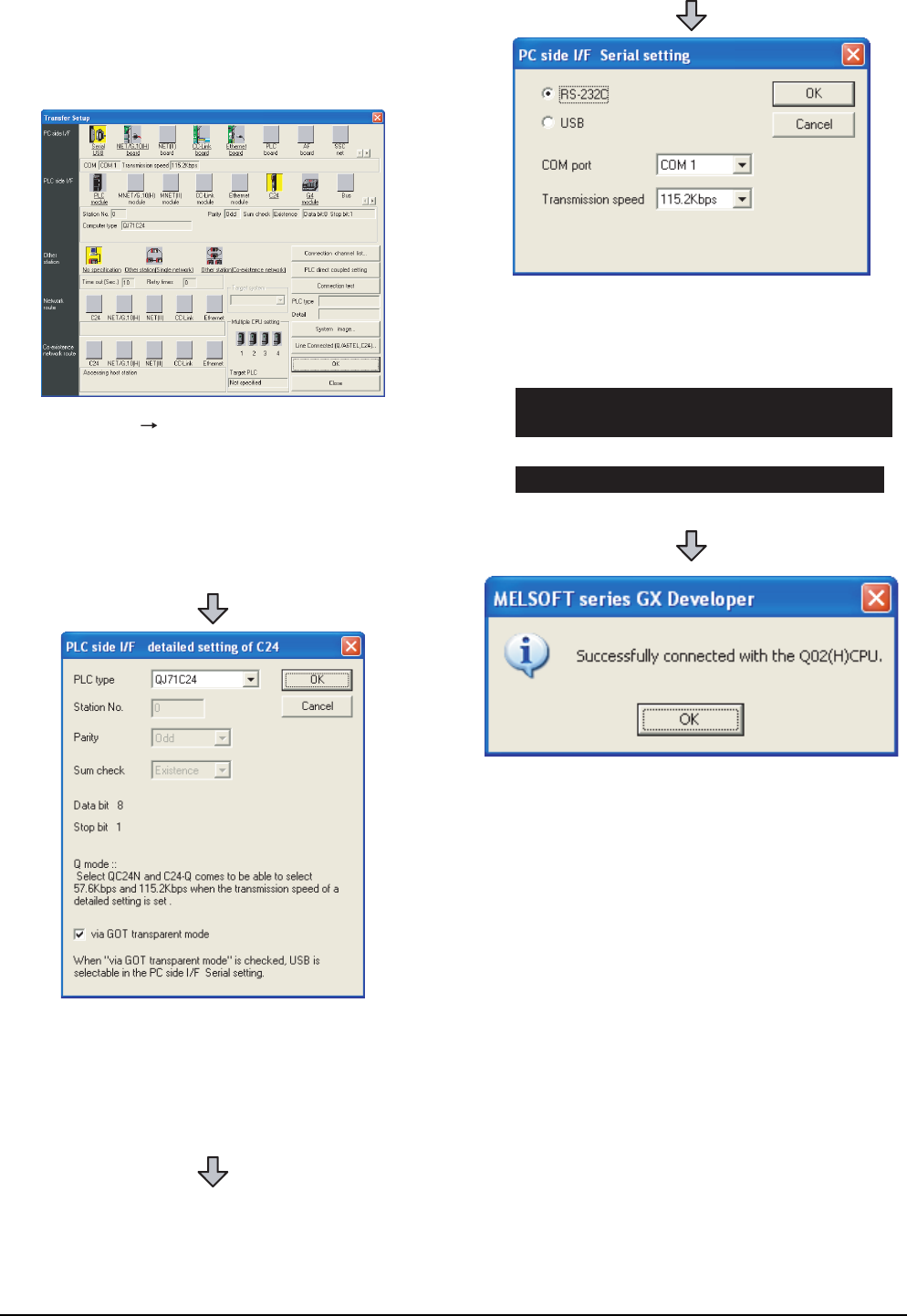
22 - 40 22. FA TRANSPARENT FUNCTION
22.6 Personal Computer Side Setting
Connecting the GOT and PLC in computer link
connection(when connected to the QJ71C24(N))
(GX Configurator is not supported.)
1. Click [Online] [Transfer Setup] in GX Developer.
2. The [Transfer Setup] is displayed.
3. Set the [Transfer Setup]:
PC side I/F : Serial
PLC side I/F : C24
Other station : No specification
4. Return to [Transfer Setup] and double-click [C24] of
the PLC side I/F to display [PLC side I/F detailed
setting of C24].
5. Check [via GOT transparent mode] for [PLC side I/F
detailed setting of C24].
6. Double-click [Serial] of the PC side I/F to display [PC
side I/F Serial setting].
7. Check-mark either of the following in [PC side I/F
Serial setting].
Mark the [RS-232C] checkbox.
Mark the [USB] checkbox.
8. The screen returns to [Transfer Setup]. Click
[Connection Test] to check if GX Developer has been
connected to the QCPU (Q mode).
When connecting the GOT to PC via modem
When connecting the GOT and PC with serial
When connecting the GOT and PC with USB
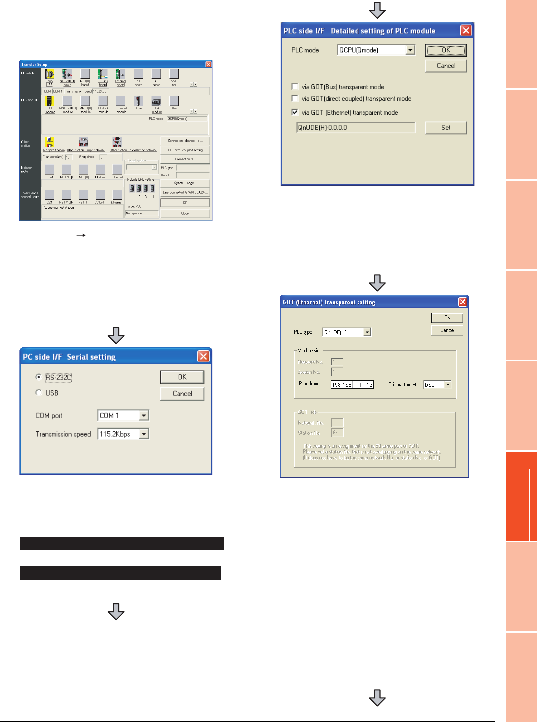
22. FA TRANSPARENT FUNCTION
22.6 Personal Computer Side Setting
22 - 41
17
ROBOT
CONTROLLER
CONNECTION
18
CNC CONNECTION
19
GOT MULTI-DROP
CONNECTION
20
MULTIPLE-GT14, GT12,
GT11, GT10
CONNECTION FUNCTION
21
MULTI-CHANNEL
FUNCTION
22
FA TRANSPARENT
FUNCTION
When connecting the GOT and PLC in
Ethernet communication
(when connecting to QCPU (Q mode))
1. Click [Online] [Transfer Setup] in GX Developer.
2. The [Transfer Setup] is displayed.
3. Set the [Transfer Setup]:
PC side I/F : Serial USB (COM)
PLC side I/F : PLC module
Other station : No specification
4. Double-click [Serial] of the PC side I/F to display [PC
side I/F Serial setting].
5. Check-mark either of the following in [PC side I/F
Serial setting].
Mark the [RS-232C] checkbox.
Mark the [USB] checkbox.
When connecting the GOT and PC with serial
When connecting the GOT and PC with USB
6. Double-click [PLC module] of the PLC side I/F to
display [PLC side I/F Detailed setting of PLC module].
7. On the [PLC side I/F Detailed setting of PLC module],
mark the [via GOT(Ethernet) transparent mode]
checkbox and click [Set].
8. By clicking [Set], the [GOT (Ethernet) transparent
setting] is displayed.
Here, set the built-in Ethernet port QCPU or Ethernet
module, which is firstly connected via a GOT.
9. Set [QnUDE(H)] or [QJ71E71] for [Type name].
When connecting the Q173NCCPU, set [QJ71E71].
10.Specify the number for [Network No.] and [Station
No.] same as the number assigned to the Ethernet
module.
When [QnUDE(H)] is set for [Type name], the setting
is not required.
11. Specify the IP address for [IP address] same as the
IP address assigned to the built-in Ethernet port
QCPU or Ethernet module.
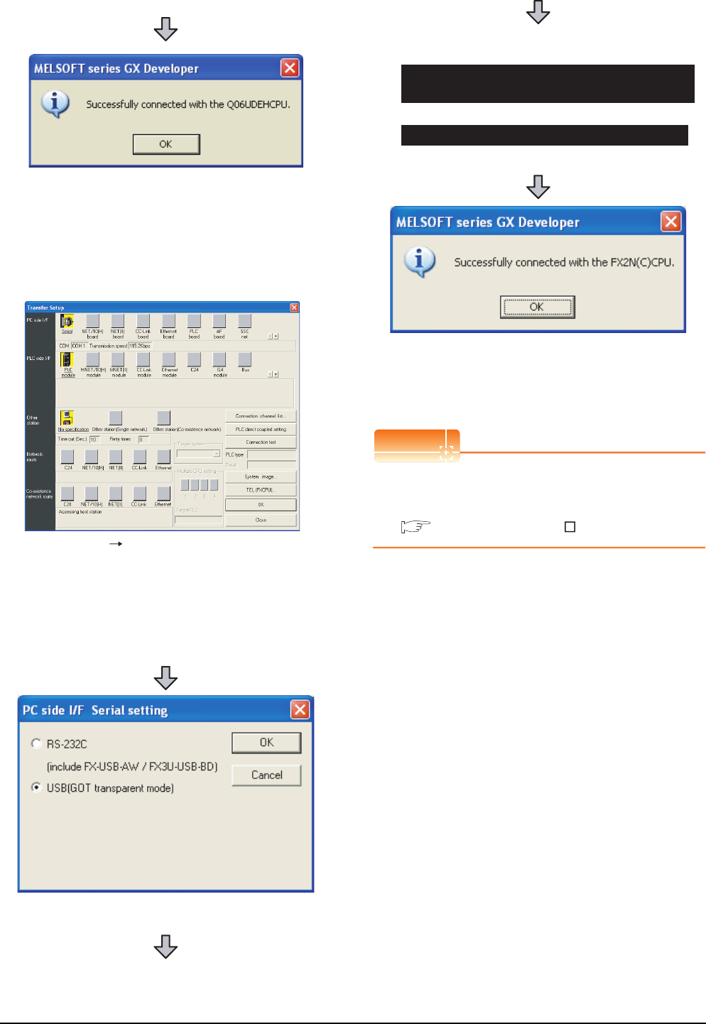
22 - 42 22. FA TRANSPARENT FUNCTION
22.6 Personal Computer Side Setting
Connecting the GOT and PLC in direct CPU
connection (when connecting to FXCPU)
POINTPOINTPOINT
How to operate GX Developer
For the GX Developer operation method, refer to the
following manual.
GX Developer Version Operating Manual
12.The screen returns to [Transfer Setup]. Click
[Connection Test] to check if GX Developer has been
connected to the QCPU (Q mode).
1. Click [Online] [Transfer Setup] in GX Developer.
2. The [Transfer Setup] is displayed.
3. Set the [Transfer Setup]:
PC side I/F : Serial
PLC side I/F : PLC module
Other station : No specification
4. Double-click [Serial] of the PC side I/F to display [PC
side I/F Serial setting].
5. Check-mark either of the following in [PC side I/F
Serial setting].
Mark the [RS-232C] checkbox.
Mark the [USB] checkbox.
6. The screen returns to the [Transfer Setup]. Click the
[Connection Test] to check if GX Developer has been
connected to the FXCPU.
When connecting the GOT to PC via modem
When connecting the GOT and PC with serial
When connecting the GOT and PC with USB
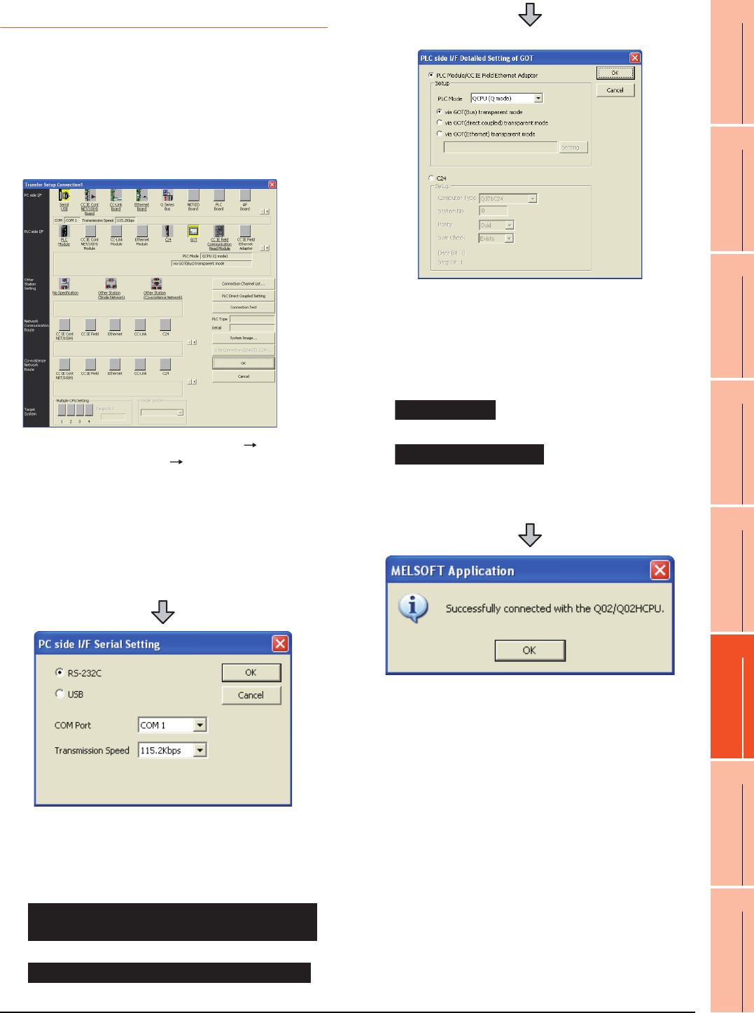
22. FA TRANSPARENT FUNCTION
22.6 Personal Computer Side Setting
22 - 43
17
ROBOT
CONTROLLER
CONNECTION
18
CNC CONNECTION
19
GOT MULTI-DROP
CONNECTION
20
MULTIPLE-GT14, GT12,
GT11, GT10
CONNECTION FUNCTION
21
MULTI-CHANNEL
FUNCTION
22
FA TRANSPARENT
FUNCTION
22.6.2 Accessing by GX Works2
The following shows the procedure to set the FA
transparent function of GX Works2.
When connecting the GOT and personal
computer with serial or USB
(1) Connecting the GOT and PLC in bus connection or
direct CPU connection (when connecting to QCPU
(Q mode))
1. Click the Connection Destination view
[Connection Destination] [(Connection target data
name)] in the Navigation window of GX Works2.
2. The [Transfer Setup Connection1] is displayed.
3. Set the [Transfer Setup Connection1]:
PC side I/F : Serial USB
PLC side I/F : GOT
Other Station Setting : No Specification:
4. Double-click [Serial USB] of the PC side I/F to display
[PC side I/F Serial Setting].
5. Check-mark either of the following in [PC side I/F
Serial Setting].
Mark the [RS-232C] checkbox.
Mark the [USB] checkbox.
When connecting the GOT to PC via modem
When connecting the GOT and PC with serial
When connecting the GOT and PC with USB
(For bus connection)
6. Double-click [GOT] of the PLC side I/F to display
[PLC side I/F Detailed Setting of GOT].
7. Check-mark either of the following in [PLC side I/F
Detailed Setting of GOT].
[via GOT(Bus) transparent mode]
Mark the [via GOT(direct coupled) transparent mode]
checkbox.
8. The screen returns to [Transfer Setup Connection1].
Click [Connection Test] to check if GX Works2 has
been connected to the QCPU (Q mode).
Bus connection
Direct CPU connection
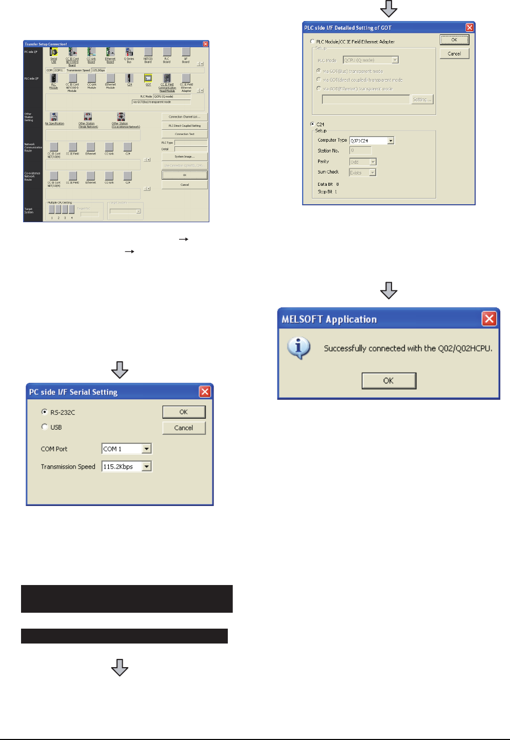
22 - 44 22. FA TRANSPARENT FUNCTION
22.6 Personal Computer Side Setting
(2) Connecting the GOT and PLC in computer link
connection (when connecting to QJ71C24 (N))
1. Click the Connection Destination view
[Connection Destination] [(Connection target data
name)] in the Navigation window of GX Works2.
2. The [Transfer Setup Connection1] is displayed.
3. Set the [Transfer Setup Connection1]:
PC side I/F : Serial USB
PLC side I/F : GOT
Other Station Setting : No Specification
4. Double-click [Serial USB] of the PC side I/F to display
[PC side I/F Serial Setting].
5. Check-mark either of the following in [PC side I/F
Serial Setting].
Mark the [RS-232C] checkbox.
Mark the [USB] checkbox.
When connecting the GOT to PC via modem
When connecting the GOT and PC with serial
When connecting the GOT and PC with USB
6. Double-click [GOT] of the PLC side I/F to display
[PLC side I/F Detailed Setting of GOT].
7. Check-mark [C24] in [PLC side I/F Detailed Setting of
GOT].
8. The screen returns to [Transfer Setup Connection1].
Click [Connection Test] to check if GX Works2 has
been connected to the QCPU (Q mode).
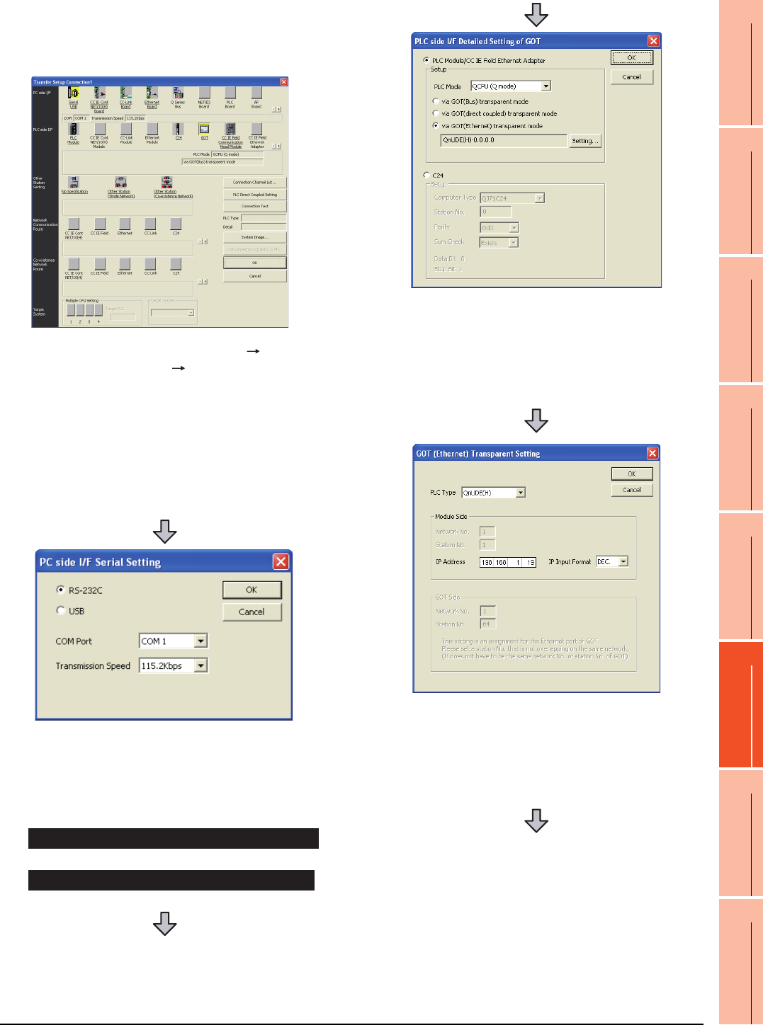
22. FA TRANSPARENT FUNCTION
22.6 Personal Computer Side Setting
22 - 45
17
ROBOT
CONTROLLER
CONNECTION
18
CNC CONNECTION
19
GOT MULTI-DROP
CONNECTION
20
MULTIPLE-GT14, GT12,
GT11, GT10
CONNECTION FUNCTION
21
MULTI-CHANNEL
FUNCTION
22
FA TRANSPARENT
FUNCTION
(3) Connecting the GOT and PLC in Ethernet
connection
(a) Connecting to QCPU (Q mode)
1. Click the Connection Destination view
[Connection Destination] [(Connection target data
name)] in the Navigation window of GX Works2.
2. The [Transfer Setup Connection1] is displayed.
3. Set the [Transfer Setup Connection1]:
PC side I/F : Serial USB
PLC side I/F : GOT
Other Station Setting : No Specification
4. Double-click [Serial USB] of the PC side I/F to display
[PC side I/F Serial Setting].
5. Check-mark either of the following in [PC side I/F
Serial Setting].
Mark the [RS-232C] checkbox.
Mark the [USB] checkbox.
When connecting the GOT and PC with serial
When connecting the GOT and PC with USB
6. Double-click [GOT] of the PLC side I/F to display
[PLC side I/F Detailed Setting of GOT].
7. On the [PLC side I/F Detailed Setting of GOT], mark
the [via GOT(Ethernet) transparent mode] checkbox
and click [Setting...].
8. By clicking [Set], the [GOT (Ethernet) Transparent
Setting] is displayed.
Here, set the built-in Ethernet port QCPU or Ethernet
module, which is firstly connected via a GOT.
9. Set [QnUDE(H)] or [QJ71E71] for [PLC Type].
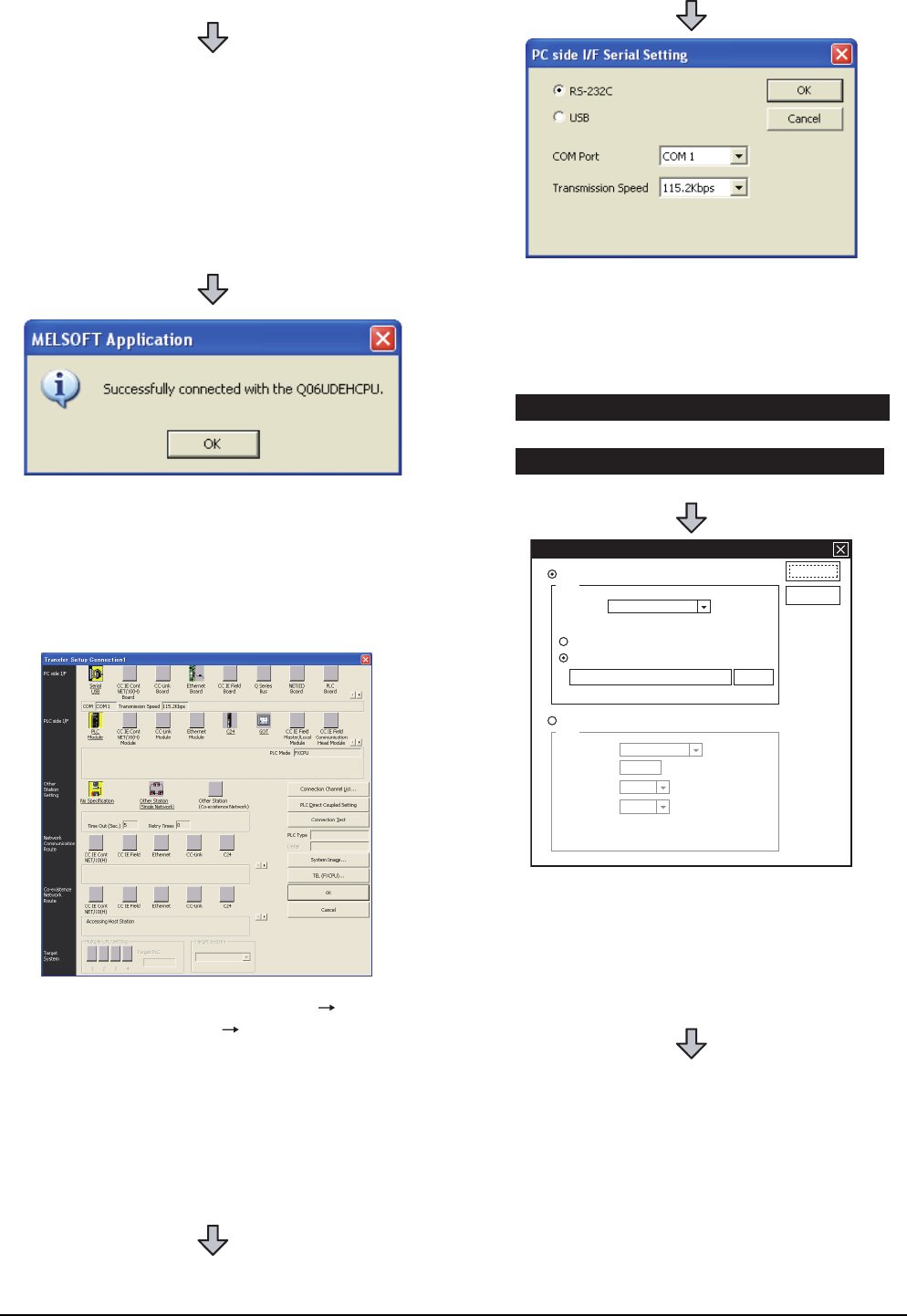
22 - 46 22. FA TRANSPARENT FUNCTION
22.6 Personal Computer Side Setting
(b) Connecting to FXCPU
10.Specify the number for [Network No.] and [Station
No.] same as the number assigned to the Ethernet
module.
When [QnUDE(H)] is set for [PLC type], the setting is
not required.
11. Specify the IP address for [IP Address] same as the
IP address assigned to the built-in Ethernet port
QCPU or Ethernet module.
12.The screen returns to [Transfer Setup Connection1].
Click [Connection Test] to check if GX Works2 has
been connected to the QCPU (Q mode).
1. Click the Connection Destination view
[Connection Destination] [(Connection target data
name)] in the Navigation window of GX Works2.
2. The [Transfer Setup Connection1] is displayed.
3. Set the [Transfer Setup Connection1]:
PC side I/F : Serial USB
PLC side I/F : GOT
Other Station Setting : No Specification
4. Double-click [Serial USB] of the PC side I/F to display
[PC side I/F Serial Setting].
5. Check-mark either of the following in [PC side I/F
Serial Setting].
Mark the [RS-232C] checkbox.
Mark the [USB] checkbox.
6. Double-click [GOT] of the PLC side I/F to display
[PLC side I/F Detailed Setting of GOT].
7. On the [PLC side I/F Detailed Setting of GOT], mark
the [via GOT(Ethernet) transparent mode] checkbox
and click [Setting...].
When connecting the GOT and PC with serial
When connecting the GOT and PC with USB
PLC side I/F Detailed Setting of GOT
PLC Module/CC IE Field Ethernet Adapter
Setup
Setup
PLC Mode
via GOT(direct coupled) transparent mode
via GOT(Ethernet) transparent mode
Computer Type
Station No.
Parity
Sum Check
Data Bit 8
Stop Bit 1
FX3U-ENET-ADP-0.0.0.0.
Setting...
OK
Cancel
FXCPU
C24
QJ71C24
0
Odd
Exists
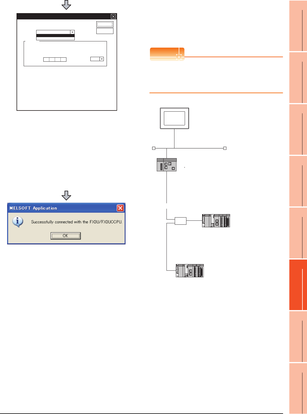
22. FA TRANSPARENT FUNCTION
22.6 Personal Computer Side Setting
22 - 47
17
ROBOT
CONTROLLER
CONNECTION
18
CNC CONNECTION
19
GOT MULTI-DROP
CONNECTION
20
MULTIPLE-GT14, GT12,
GT11, GT10
CONNECTION FUNCTION
21
MULTI-CHANNEL
FUNCTION
22
FA TRANSPARENT
FUNCTION
(4) Connecting the GOT and Ethernet adapter (NZ2GF-
ETB) in Ethernet connection, and connecting it to a
PLC in the CC-Link IE Field Network.
This section describes the settings of the GX Works2 in
the following case of system configuration.
POINTPOINTPOINT
Version of GX Works2
GX Works2 Version 1.34L or later is required to
execute the FA transparent function with using
Ethernet adapter (NZ2GF-ETB).
8. By clicking [Set], the [GOT (Ethernet) transparent
setting] is displayed.
Here, set the [FX3U-ENET-ADP] or [Ethernet
Module], which is connected via a GOT.
9. Set [FX3U-ENET-ADP] or [Ethernet Module] for [PLC
Type].
10.Specify the IP address for [IP address] same as the
IP address assigned to the [FX3U-ENET-ADP] or
[Ethernet Module].
11. The screen returns to [Transfer Setup]. Click
[Connection Test] to check if GX Developer has been
connected to the FXCPU.
GOT(Ethernet) Transparent Setting
Module Side
IP Address
IP Input Format
0000
PLC Type
OK
Cancel
FX3U-ENET-ADP
Ethernet Module
DEC.
FX3U-ENET-ADP
Network No. :3
PC No. :1
IP address :192.168.3.18
Port No. :5001
Communication
format
:UDP (fixed)
Ethernet
CC-Link IE Field Network
HUB
<Ethernet adapter module>
(Use default value for settings other than the following.)
Ethernet setting
IP address
CC-Link IE Field Network setting
Network No.
Station No.
:192.168.3.30
:1
:1
<CC-Link IE Field Network Master/Local module>
(Use default value for settings other than the following.)
Network Type
Network No.
PC No.
Total Stations
: CC IE Field (Master station)
: 1
: 0
: 2
<CC-Link IE Field Network Master/Local module>
(Use default value for settings other than the following.)
Network Type
Network No.
PC No.
: CC IE Field (Local station)
: 1
: 2
<GOT>
(Use default value for settings other than the following.)
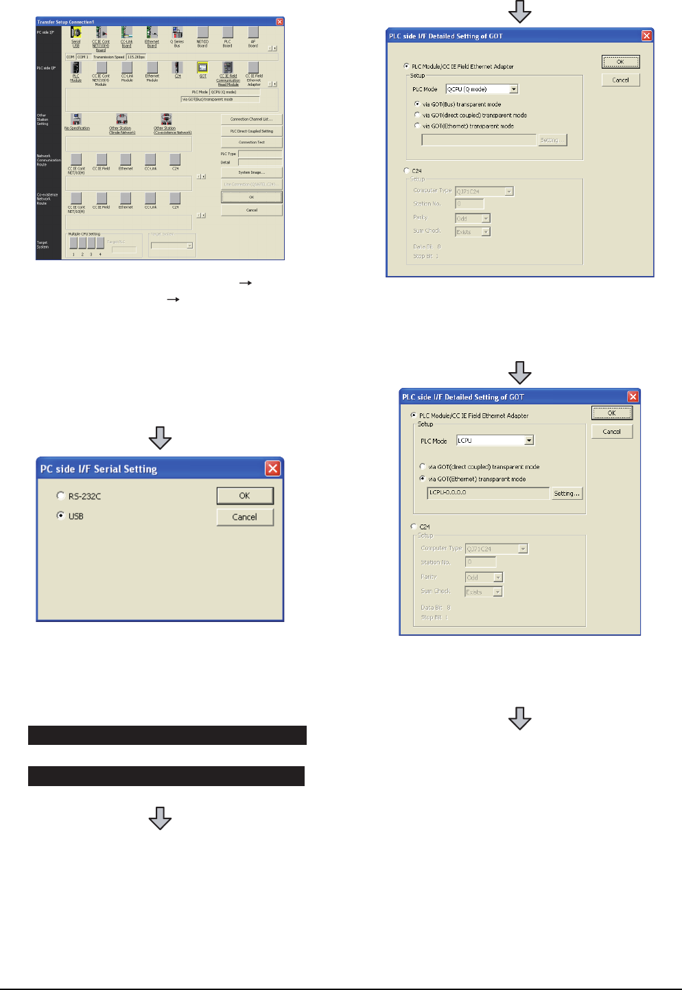
22 - 48 22. FA TRANSPARENT FUNCTION
22.6 Personal Computer Side Setting
1. Click the Connection Destination view
[Connection Destination] [(Connection target data
name)] in the Navigation window of GX Works2.
2. The [Transfer Setup Connection1] is displayed.
3. Set the [Transfer Setup Connection1].
PC side I/F : Serial USB
PLC side I/F : GOT
4. Double-click [Serial USB] of the PC side I/F to display
[PC side I/F Serial Setting].
5. Check-mark either of the following in [PC side I/F
Serial Setting].
Mark the [RS-232C] checkbox.
Mark the [USB] checkbox.
When connecting the GOT and PC with serial
When connecting the GOT and PC with USB
6. Double-click [GOT] of the PLC side I/F to display
[PLC side I/F Detailed Setting of GOT].
7. Set the [CPU mode] to [LCPU].
8. On the[PLC side I/F Detailed Setting of GOT], mark
the [via GOT(Ethernet) transparent mode] checkbox
and click [Setting...].
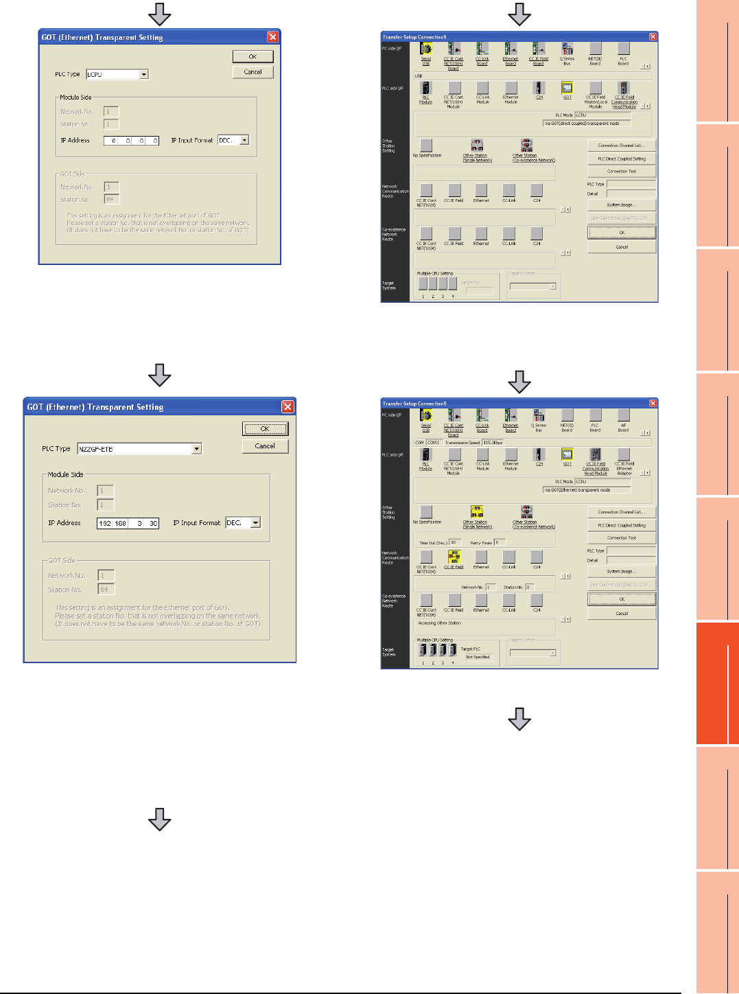
22. FA TRANSPARENT FUNCTION
22.6 Personal Computer Side Setting
22 - 49
17
ROBOT
CONTROLLER
CONNECTION
18
CNC CONNECTION
19
GOT MULTI-DROP
CONNECTION
20
MULTIPLE-GT14, GT12,
GT11, GT10
CONNECTION FUNCTION
21
MULTI-CHANNEL
FUNCTION
22
FA TRANSPARENT
FUNCTION
9. [GOT (Ethernet) Transparent Setting] is displayed.
Here, set the Ethernet module, which is firstly
connected via a GOT.
10.Set [NZ2GF-ETB] for [PLC Type].
11. Set the same number to [IP address] as the number
assigned to NZ2GF-ETB, and click [OK].
In the system configuration example, the setting is as
follows.
[IP address]: 192 168 3 30
12.Return to [PLC side I/F Detailed Setting of GOT], and
click [OK].
13.The [Transfer Setup Connection1] is displayed.
14.Click [Other station (Single network)].
15.Double-click [CC IE Field].
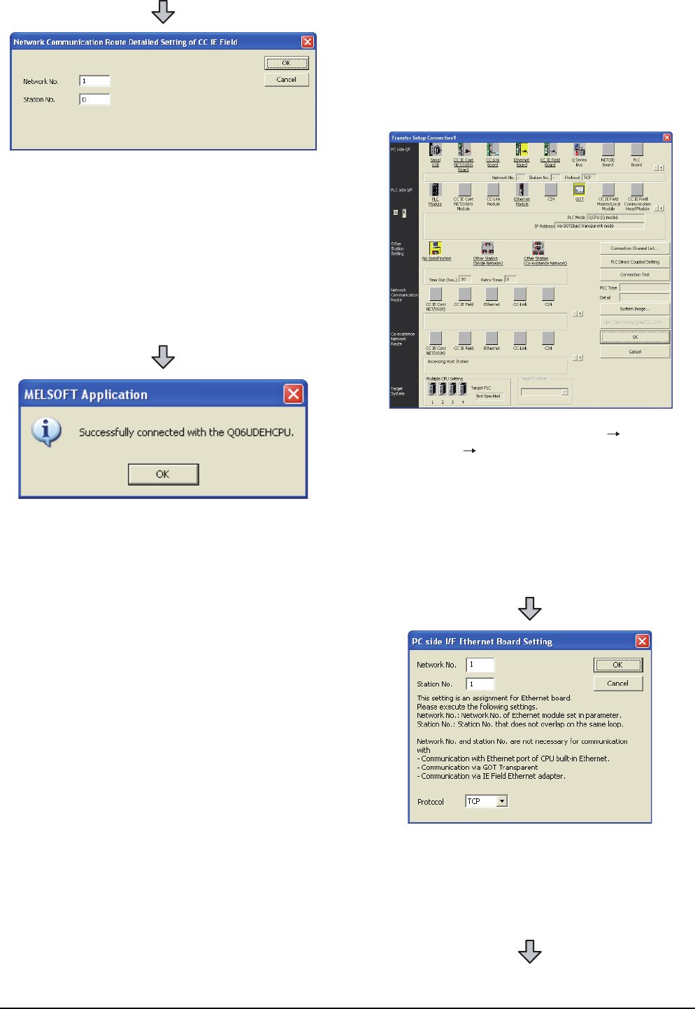
22 - 50 22. FA TRANSPARENT FUNCTION
22.6 Personal Computer Side Setting
When connecting the GOT and personal
computer in Ethernet connection (GT16,
GT15 and GT14 only)
(1) Connecting the GOT and PLC in bus connection or
direct CPU connection (when connecting to QCPU
(Q mode))
16.Network Communication Route Detailed Setting of
CC IE Field is displayed.
17.Set [Network No.] and [Station No.] assigned to CPU,
and click [OK].
When connecting to CC-Link IE Field Network
Master/Local module of the system configuration
example, the setting is as follows.
[Network No.] :1
[Station No.] :0
18.The screen returns to [Transfer Setup]. Click
[Connection Test] to check if GX Developer has been
connected to the QCPU (Q mode).
1. Click the Connection Destination view [Connection
Destination] [(Connection target data name)] in the
Navigation window of GX Works2.
2. The [Transfer Setup] is displayed.
3. Set the [Transfer Setup]:
PC side I/F :Ethernet Board
PLC side I/F :GOT
Other Station Setting : No specification
4. Double-click [Ethernet Board] of the PC side I/F to
display [PC side I/F Ethernet Board Setting].
5. Set the protocol to TCP. Network No. and Station No.
are not required to be changed (default) because they
are not used.
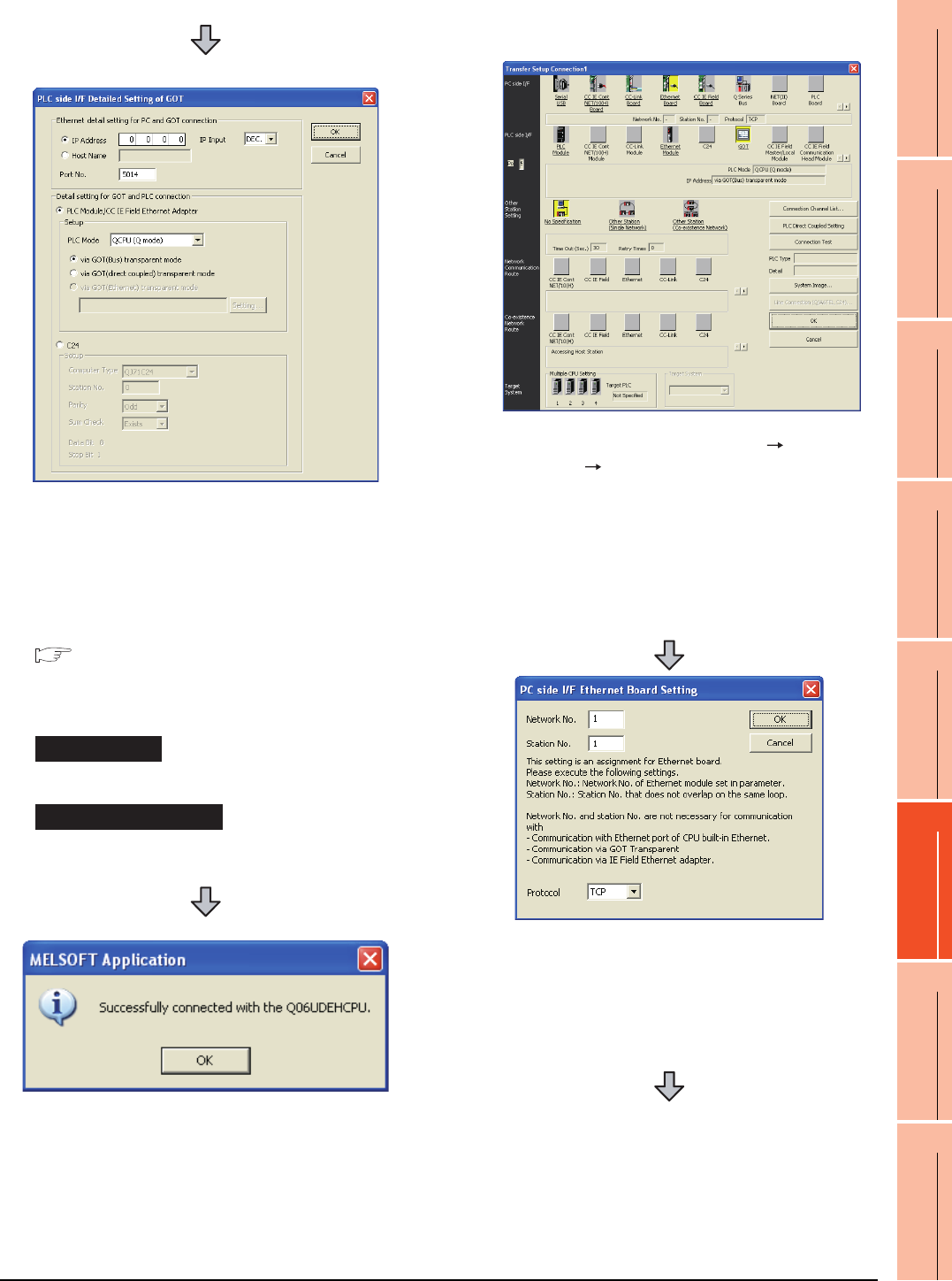
22. FA TRANSPARENT FUNCTION
22.6 Personal Computer Side Setting
22 - 51
17
ROBOT
CONTROLLER
CONNECTION
18
CNC CONNECTION
19
GOT MULTI-DROP
CONNECTION
20
MULTIPLE-GT14, GT12,
GT11, GT10
CONNECTION FUNCTION
21
MULTI-CHANNEL
FUNCTION
22
FA TRANSPARENT
FUNCTION
(2) Connecting the GOT and PLC in computer link
connection (when connecting to QJ71C24 (N))
(For bus connection)
6. Double-click [GOT] of the PLC side I/F to display
[PLC side I/F Detailed Setting of GOT].
7. Set the IP address and port No. in [Ethernet detail
setting for PC and GOT connection].
Set the IP address and port No. to the same as the
Ethernet download setting.
22.5.1 (b) Ethernet download setting
8. Check either of the followings in [Detail setting for
GOT and PLC connection].
[via GOT(Bus) transparent mode]
Mark the [via GOT(direct coupled) transparent mode]
checkbox.
9. The screen returns to [Transfer Setup]. Click
[Connection Test] to check if GX Developer has been
connected to the QCPU (Q mode).
Bus connection
Direct CPU connection
1. Click the Connection Destination view [Connection
Destination] [(Connection target data name)] in the
Navigation window of GX Works2.
2. The [Transfer Setup] is displayed.
3. Set the [Transfer Setup]:
PC side I/F : Ethernet Board
PLC side I/F : GOT
Other Station Setting : No specification
4. Double-click [Ethernet Board] of the PC side I/F to
display [PC side I/F Ethernet Board Setting].
5. Set the protocol to TCP. Network No. and Station No.
are not required to be changed (default) because they
are not used.
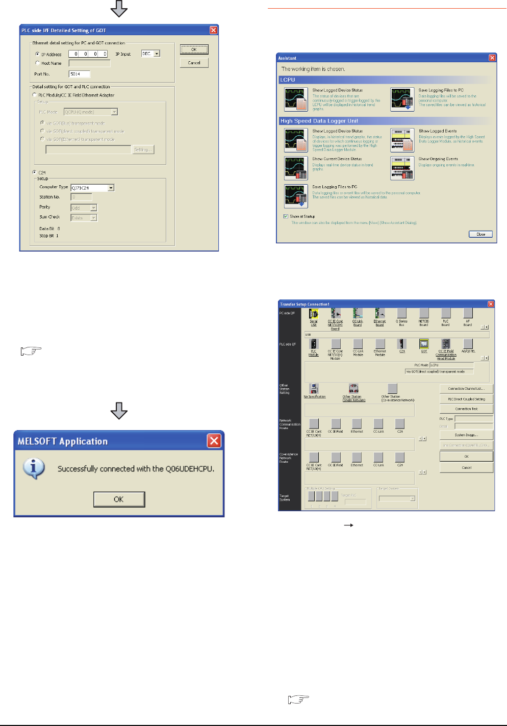
22 - 52 22. FA TRANSPARENT FUNCTION
22.6 Personal Computer Side Setting
22.6.3 Accessing by GX LogViewer
The following shows the procedure to set the FA
transparent function of GX LogViewer.
6. Double-click [GOT] of the PLC side I/F to display
[PLC side I/F Detailed Setting of GOT].
7. Set the IP address and port No. in [Ethernet detail
setting for PC and GOT connection].
Set the IP address and port No. to the same as the
Ethernet download setting.
22.5.1 (b) Ethernet download setting
8. Check [C24] in [Detail setting for GOT and PLC
connection].
9. The screen returns to [Transfer Setup]. Click
[Connection Test] to check if GX Works2 has been
connected to the QCPU (Q mode).
1. Click [Show Assistant Dialog] for [View] on GX
LogViewer.
2. The [Assistant] dialog box is displayed.
3. Click [LCPU] [Show Logged Device Status] in the
[Assistant] dialog box.
4. The [Transfer Setup Connection 1] dialog box is
displayed.
5. Set the [Transfer Setup Connection 1]:
PC side I/F : Serial USB
PLC side I/F : GOT
Other Station Setting : (Select from the system
configuration)
6. For [PC side I/F Serial Setting] and [PLC side I/F
Detailed Setting of GOT] of [Transfer Setup], refer to
the following.
22.6.2 Accessing by GX Works2
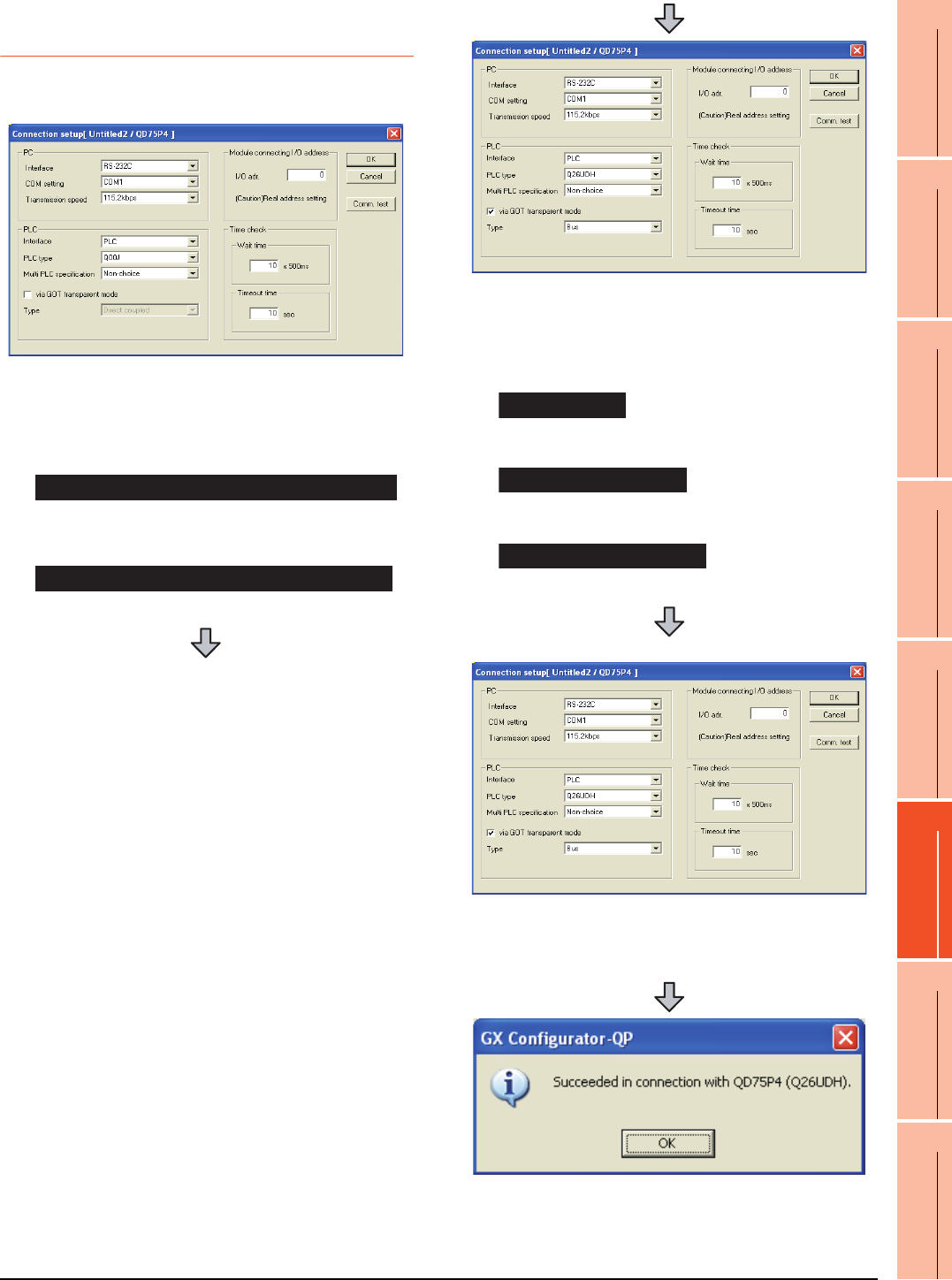
22. FA TRANSPARENT FUNCTION
22.6 Personal Computer Side Setting
22 - 53
17
ROBOT
CONTROLLER
CONNECTION
18
CNC CONNECTION
19
GOT MULTI-DROP
CONNECTION
20
MULTIPLE-GT14, GT12,
GT11, GT10
CONNECTION FUNCTION
21
MULTI-CHANNEL
FUNCTION
22
FA TRANSPARENT
FUNCTION
22.6.4 Accessing PLC by
GX Configurator-QP
The following shows the procedure to set the FA
transparent function of GX Configurator-QP.
1. Click [Connection setup] for [Online] on GX
Configurator-QP.
2. The [Connection setup] is displayed.
3. Set the [PC side] in [Connection setup].
Interface: (RS-232C)
COM setting: COM1 to COM10
Transmission speed: 9.6kbps to 115.2kbps
Interface: USB
When connecting the GOT and PC with serial
When connecting the GOT and PC with USB
4. Set the [PLC side] in [Connection setup].
PLC type: Q series PLC type
Multi PLC specification: None/No.1 to 4
Direct CPU connection, mark the [via GOT
transparent mode] checkbox.
Interface: PLC
Type: Bus
Interface: PLC
Type: Direct coupled
Interface: C24
(For bus connection only)
5. Set the [Module connecting I/O address] in
[Connection setup].
Specify the actual IP address of the module.
6. The screen returns to the [Connection setup]. Click
the [Connection Test] to check if GX Developer has
been connected to the QD75***(QnCPU).
Bus connection
Direct CPU connection
Computer link connection
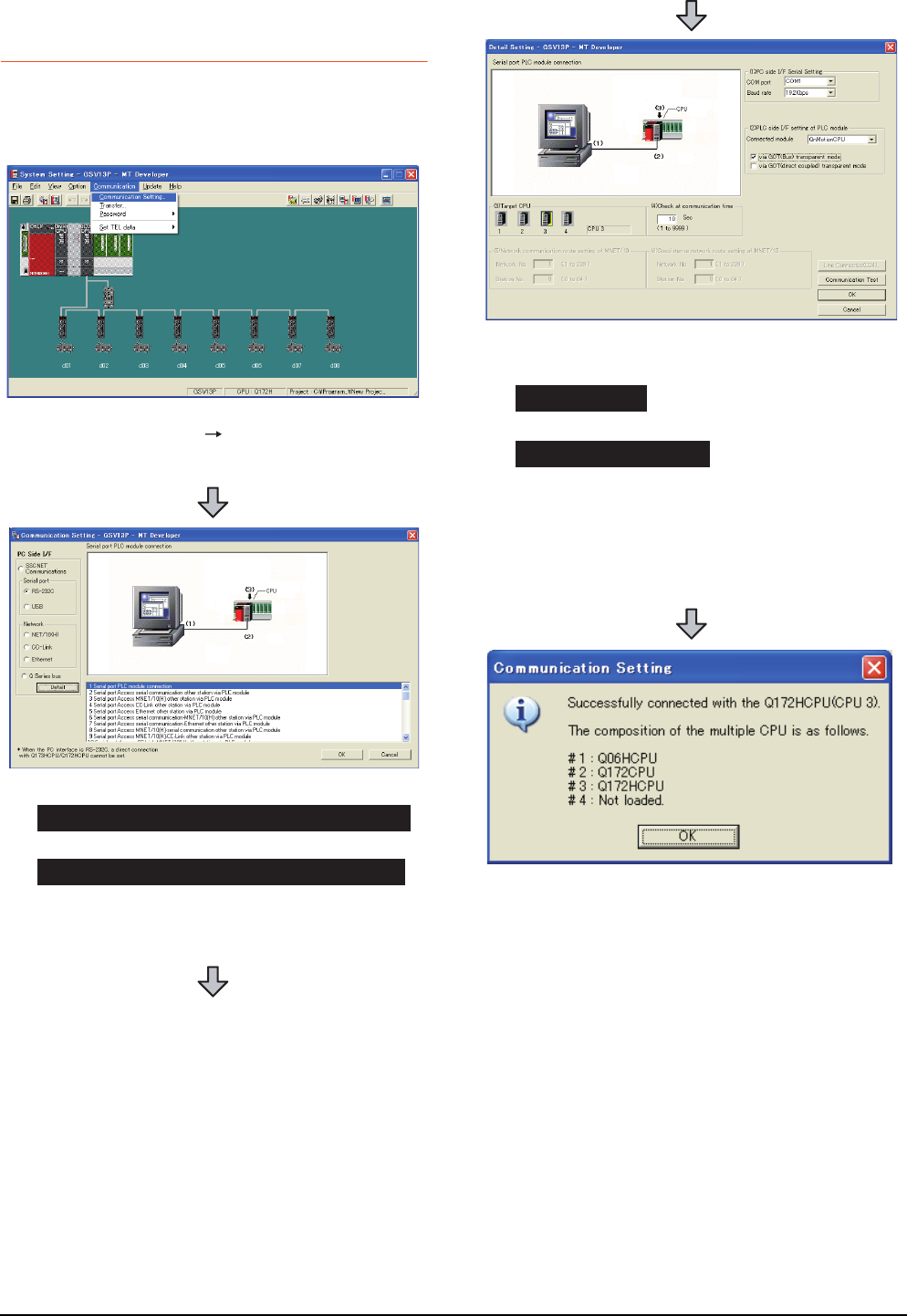
22 - 54 22. FA TRANSPARENT FUNCTION
22.6 Personal Computer Side Setting
22.6.5 Accessing by the MT
Developer
This section explains the procedure to set the FA
transparent function of MT Developer with an example of
connecting to motion controller CPU (Q series).
1. Click [Communication] [Communication Setting] in
MT Developer.
2. Check-mark either of the following in [Serial port].
Mark the [RS-232C] checkbox.
Mark the [USB] checkbox.
3. Click [Detail].
When connecting the GOT and PC with serial
When connecting the GOT and PC with USB
4. Check-mark either of the following in [PLC side I/F
setting of PLC module].
[via GOT(Bus) transparent mode]
[via GOT(direct coupled) transparent mode]
5. As necessary, select a CPU that is targeted by using
the transparent function in [CPU].
6. Click [Connection Test].
7. Confirm that the personal computer is connected to
the motion controller CPU (Q series).
Bus connection
Direct CPU connection
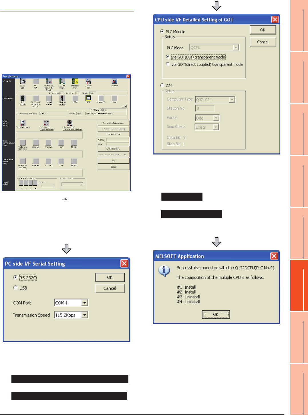
22. FA TRANSPARENT FUNCTION
22.6 Personal Computer Side Setting
22 - 55
17
ROBOT
CONTROLLER
CONNECTION
18
CNC CONNECTION
19
GOT MULTI-DROP
CONNECTION
20
MULTIPLE-GT14, GT12,
GT11, GT10
CONNECTION FUNCTION
21
MULTI-CHANNEL
FUNCTION
22
FA TRANSPARENT
FUNCTION
22.6.6 Accessing by the MT Works2
This section explains the procedure to set the FA
transparent function of MT Works2 with an example of
connecting to motion controller CPU (Q series).
When connecting the GOT and personal
computer with serial or USB
(1) Connecting the GOT and PLC in bus connection or
direct CPU connection
1. Click [Transfer setup] [Online].
2. The [Transfer setup] is displayed.
3. Set the [Transfer setup]:
PC side I/F : Serial USB
CPU side I/F : GOT
Other Station Setting : No specification
4. Double-click [Serial] of the PLC side I/F to display [PC
side I/F Serial setting].
5. Check-mark either of the following in [PC side I/F
Serial setting].
Mark the [RS-232C] checkbox.
Mark the [USB] checkbox.
When connecting the GOT and PC with serial
When connecting the GOT and PC with USB
6. Double-click [GOT] of the CPU side I/F to display
[CPU side I/F Detailed Setting of GOT].
7. Check-mark either of the following in [CPU side I/F
Detailed Setting of GOT].
Mark the [via GOT(Bus) transparent mode] checkbox.
Mark the [via GOT (direct coupled) transparent mode]
checkbox.
8. The screen returns to [Transfer setup]. Click
[Connection Test] to check if MT Works2 has been
connected to the motion controller (Q mode).
Bus connection
Direct CPU connection
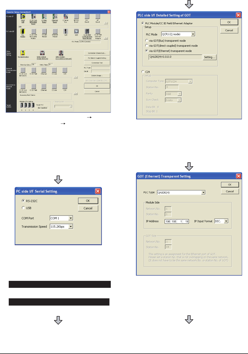
22 - 56 22. FA TRANSPARENT FUNCTION
22.6 Personal Computer Side Setting
(2) When connecting the GOT and PLC in Ethernet
communication
1. Click the Connection Destination view
[Connection Destination] [(Connection target data
name)] in the Navigation window of MT Works2.
2. The [Transfer Setup] is displayed.
3. Set the [Transfer Setup]:
PC side I/F : Serial USB
PLC side I/F : GOT
Other Station Setting : No Specification:
4. Double-click [Serial USB] of the PC side I/F to display
[PC side I/F Serial Setting].
5. Check-mark either of the following in [PC side I/F
Serial Setting].
Mark the [RS-232C] checkbox.
Mark the [USB] checkbox.
When connecting the GOT and PC with serial
When connecting the GOT and PC with USB
6. Double-click [GOT] of the PLC side I/F to display
[PLC side I/F Detailed Setting of GOT].
7. PLC side I/F Detailed Setting of GOT
Mark the [via GOT(Ethernet) transparent mode]
checkbox and click [Set].
8. By clicking [Set], the [GOT (Ethernet) Transparent
Setting] is displayed.
Here, set the built-in Ethernet port QCPU or Ethernet
module, which is firstly connected via a GOT.
9. Set [QnUDE(H)] or [QJ71E71] for [Type name].
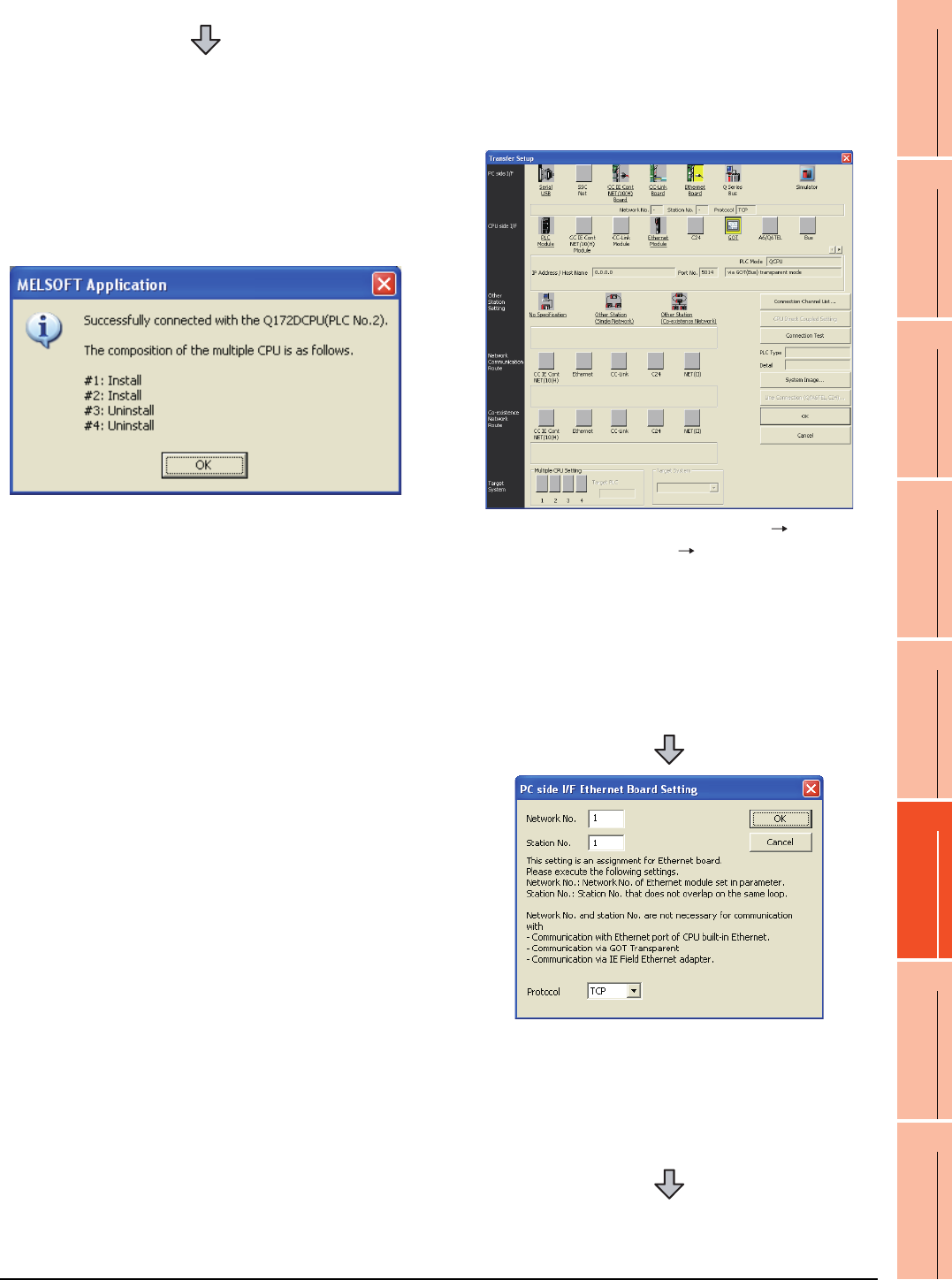
22. FA TRANSPARENT FUNCTION
22.6 Personal Computer Side Setting
22 - 57
17
ROBOT
CONTROLLER
CONNECTION
18
CNC CONNECTION
19
GOT MULTI-DROP
CONNECTION
20
MULTIPLE-GT14, GT12,
GT11, GT10
CONNECTION FUNCTION
21
MULTI-CHANNEL
FUNCTION
22
FA TRANSPARENT
FUNCTION
When connecting the GOT and personal
computer in Ethernet connection (GT16,
GT15 and GT14 only)
(1) Connecting the GOT and PLC in bus connection or
direct CPU connection
10.Specify the number for [Network No.] and [Station
No.] same as the number assigned to the Ethernet
module.
When [QnUDE(H)] is set for [Type name], the setting
is not required.
11. Specify the IP address for [IP address] same as the
IP address assigned to the built-in Ethernet port
QCPU or Ethernet module.
12.The screen returns to [Transfer setup]. Click
[Connection Test] to check if GX Developer has been
connected to the motion controller (Q mode).
1. Click the Connection Destination view
[Connection Destination] [(Connection target data
name)] in the Navigation window of MT Works2.
2. The [Transfer Setup] is displayed.
3. Set the [Transfer Setup]:
PC side I/F : Ethernet Board
PLC side I/F : GOT
Other Station Setting : No Specification:
4. Double-click [Ethernet Board] of the PC side I/F to
display [PC side I/F Ethernet Board Setting].
5. Set the protocol to TCP. Network No. and Station No.
are not required to be changed (default) because they
are not used.
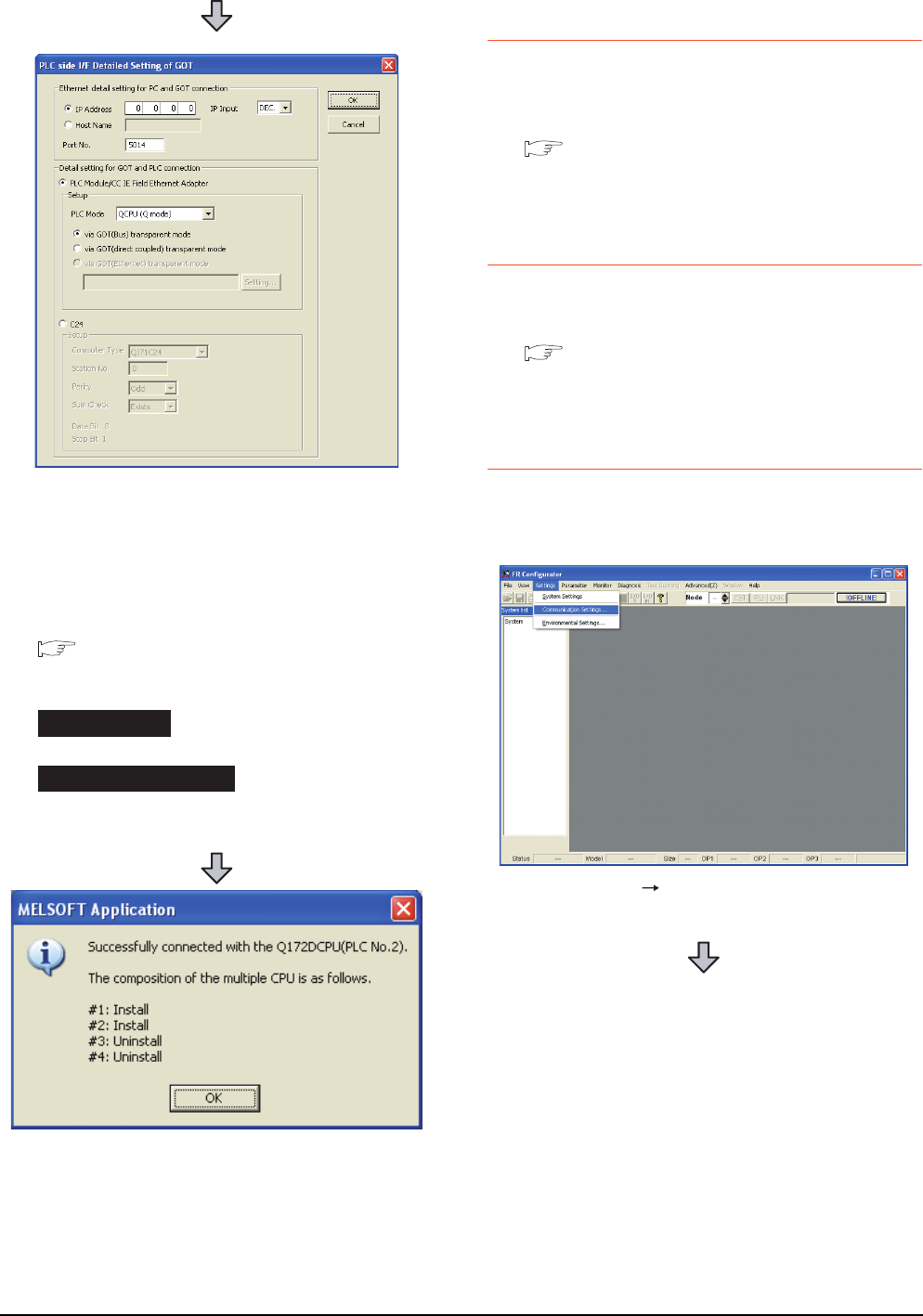
22 - 58 22. FA TRANSPARENT FUNCTION
22.6 Personal Computer Side Setting
22.6.7 Accessing the servo amplifier
by the MR Configurator
Make the FA transparent settings with the of MT
Developer.
For details, refer to the following:
22.6.5 Accessing by the MT Developer
22.6.8 Accessing the servo amplifier
by the MR Configurator2
Make the FA transparent settings with the of MT Works2.
For details, refer to the following:
22.6.6 Accessing by the MT Works2
22.6.9 Accessing the inverter by the
FR Configurator
This section explains the setting method of the FA
transparent function of FR Configurator with an example of
connecting to FREQROL A700/F700 series.
(For bus connection)
6. Double-click [GOT] of the PLC side I/F to display
[PLC side I/F Detailed Setting of GOT].
7. Set the IP address and port No. in [Ethernet detail
setting for PC and GOT connection].
Set the IP address and port No. to the same as the
Ethernet download setting.
22.5.1 (b) Ethernet download setting
8. Check either of the followings in [Detail setting for
GOT and PLC connection].
[via GOT(Bus) transparent mode]
Mark the [via GOT(direct coupled) transparent mode]
checkbox.
9. The screen returns to [Transfer Setup]. Click
[Connection Test] to check if GX Developer has been
connected to the Motion controller (Q mode).
Bus connection
Direct CPU connection
1. Click [Settings] [Communication Settings...] in FR
Configurator.
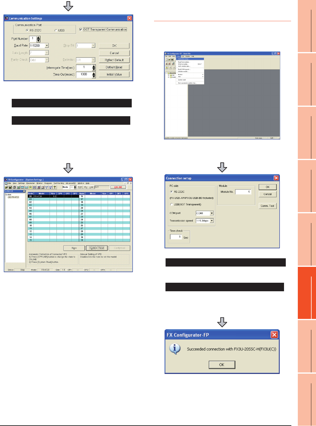
22. FA TRANSPARENT FUNCTION
22.6 Personal Computer Side Setting
22 - 59
17
ROBOT
CONTROLLER
CONNECTION
18
CNC CONNECTION
19
GOT MULTI-DROP
CONNECTION
20
MULTIPLE-GT14, GT12,
GT11, GT10
CONNECTION FUNCTION
21
MULTI-CHANNEL
FUNCTION
22
FA TRANSPARENT
FUNCTION
22.6.10 Accessing PLC by FX
Configurator-FP
This section explains the procedure to set the FA
transparent function of FX Configurator-FP with an
example of connecting to FXCPU.
2. Check-mark either of the following in [Communication
Port].
Mark the [RS-232C] checkbox.
Mark the [USB] checkbox.
3. Click the [GOT Transparent Communication].
4. Click the [OK].
5. Click [OFFLINE] to make it [ONLINE].
6. Click the [System Read], then check if GOT has been
connected to FREQROL A700/F700 series normally.
When connecting the GOT and PC with serial
When connecting the GOT and PC with USB
1. Click [Connection setup] for [Online] on FX
Configurator-FP.
2. Check-mark either of the following in [PC side].
Mark the [RS-232 (FX-USB-AW/FX3U-USB-BD
Included)] checkbox.
Mark the [USB(GOT Transparent)] checkbox.
3. Click [Comm. Test].
4. After the communication test is completed, check that
the GOT is correctly connected to the FXCPU.
When connecting the GOT and PC with serial
When connecting the GOT and PC with USB
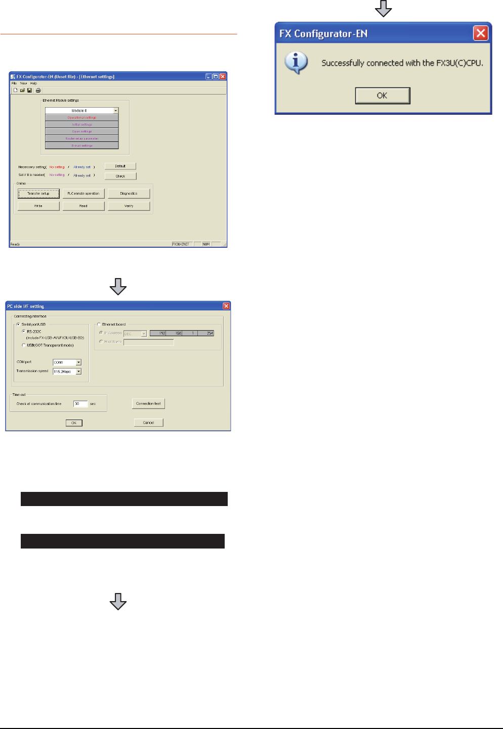
22 - 60 22. FA TRANSPARENT FUNCTION
22.6 Personal Computer Side Setting
22.6.11 Accessing by FX Configurator-
EN
This section explains the procedure to set the FA
transparent function of the FX Configurator-EN.
1. Click [Transfer setup] on the FX Configurator-EN.
2. Mark the [Serial port/USB] checkbox in [Connecting
interface].
3. Check-mark either of the following in [Serial port/
USB] of [Connecting interface].
Mark the [RS-232C (include FX-USB-AW/FX3U-USB-
BD)] checkbox.
Mark the [USB (GOT Transparent mode)] checkbox.
4. Click [Connection test]
When connecting the GOT and PC with serial
When connecting the GOT and PC with USB
5. After the communication test is completed, check that
the GOT is correctly connected to the FXCPU.
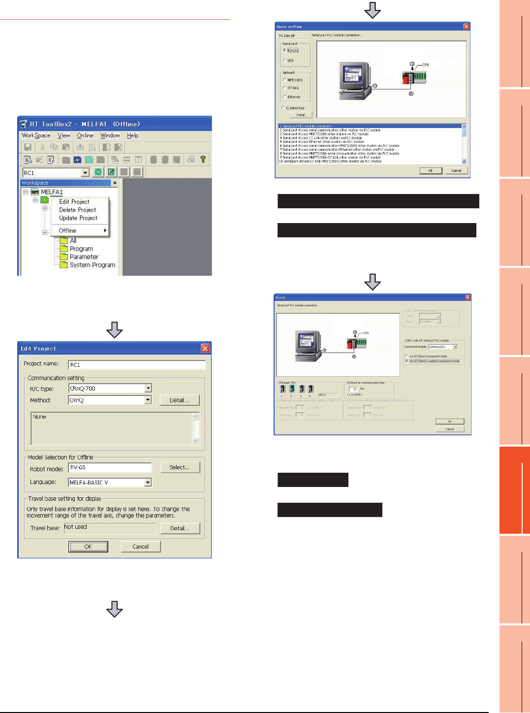
22. FA TRANSPARENT FUNCTION
22.6 Personal Computer Side Setting
22 - 61
17
ROBOT
CONTROLLER
CONNECTION
18
CNC CONNECTION
19
GOT MULTI-DROP
CONNECTION
20
MULTIPLE-GT14, GT12,
GT11, GT10
CONNECTION FUNCTION
21
MULTI-CHANNEL
FUNCTION
22
FA TRANSPARENT
FUNCTION
22.6.12 Accessing by RT ToolBox2
This section explains the procedure to set the FA
transparent function of RT ToolBox2 with an example of
connecting to CRnQ-700.
Connecting the GOT and Controller in bus
connection or direct CPU connection (CRnQ-
700)
1. Right-click a project name to be a target on the
project tree of RT ToolBox2.
Click [Edit Project].
2. Set [Method] to [CRnC].
3. Click [Detail].
4. Check-mark either of the following in [Serial port].
Mark the [RS-232C] checkbox.
Mark the [USB] checkbox.
5. Click [Detail].
6. Check-mark either of the following in [PLC side I/F
setting of PLC module].
[via GOT(Bus) transparent mode]
[via GOT(direct coupled) transparent mode]
7. As necessary, select a CPU that is targeted in [CPU].
When connecting the GOT and PC with serial
When connecting the GOT and PC with USB
Bus connection
Direct CPU connection
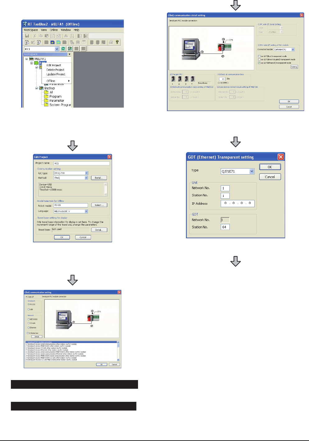
22 - 62 22. FA TRANSPARENT FUNCTION
22.6 Personal Computer Side Setting
Connecting the GOT and Controller in
Ethernet connection
1. Right-click a project name to be a target on the
project tree of RT ToolBox2.
Click [Edit Project].
2. Set [Method] to [CRnQ].
3. Click [Detail].
4. Check-mark either of the following in [Serial port].
Mark the [RS-232] checkbox.
Mark the [USB] checkbox.
5. Click [Detail].
When connecting the GOT and PC with serial
When connecting the GOT and PC with USB
6. On the [PLC side I/F setting of PLC module], mark the
[via GOT (Ethernet) transparent mode] checkbox and
click [Set].
7. Set [QJ71E71] for [Type].
8. Specify the number assigned to the Ethernet module
for [Network No.], [Station No.] and [IP Address] in
"Module side".
9. Specify the number assigned to the GOT for [Network
No.], [Station No.] and [IP Address] in "GOT side".
10.As necessary, select a CPU that is targeted in [CPU].
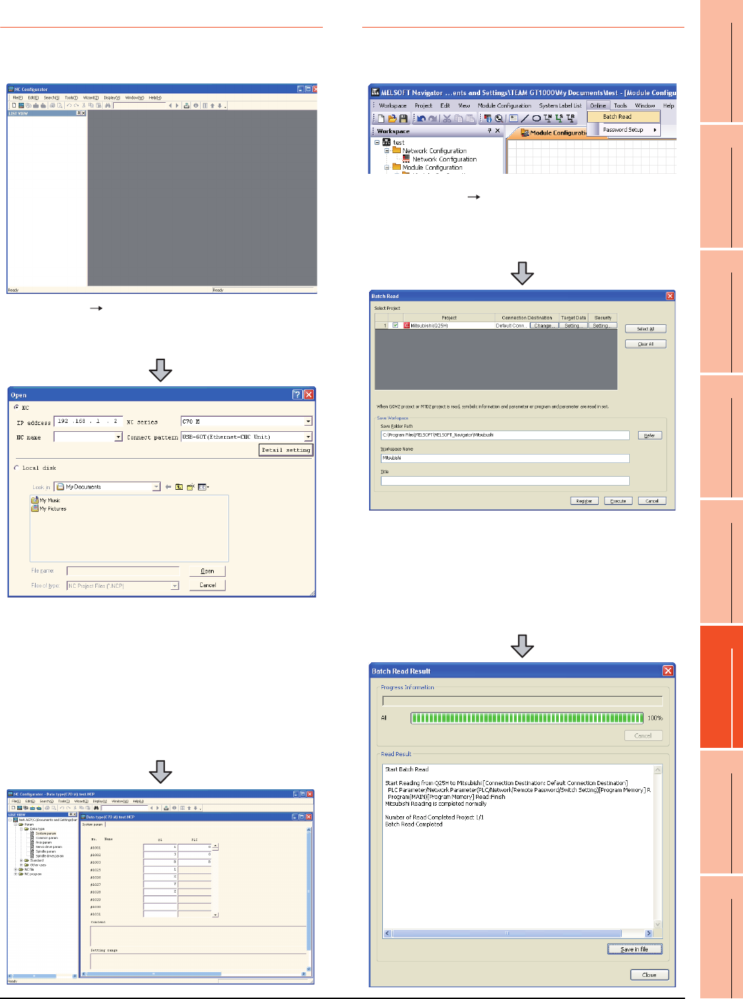
22. FA TRANSPARENT FUNCTION
22.6 Personal Computer Side Setting
22 - 63
17
ROBOT
CONTROLLER
CONNECTION
18
CNC CONNECTION
19
GOT MULTI-DROP
CONNECTION
20
MULTIPLE-GT14, GT12,
GT11, GT10
CONNECTION FUNCTION
21
MULTI-CHANNEL
FUNCTION
22
FA TRANSPARENT
FUNCTION
22.6.13 Accessing by NC Configurator
The following shows the procedure to set the FA
transparent function of NC Configurator.
22.6.14 Accessing by MELSOFT Navigator
This section explains the procedure to set the FA transparent
function of the MELSOFT Navigator.
1. Click [File] [Open].
2. The [Open] is displayed.
3. Select [NC] on the upper left of the screen, and set
the following:
NC series : C70 M or C70 L
Connect pattern : Set the pattern according to the
connect pattern.
IP address : Set as necessary.
4. By clicking [Open], data is read from CNC and
displayed.
1. Click [Online] [Batch Read] in MELSOFT
Navigator.
2. The [Batch Read] is displayed.
3. Select the projects to be read from [Select Project],
and set the storage destination of the workspace in
[Save Workspace].
4. Click [Execute] to read and display the specified
project.
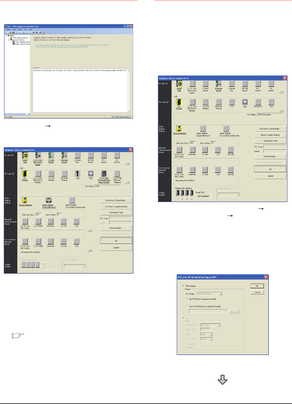
22 - 64 22. FA TRANSPARENT FUNCTION
22.6 Personal Computer Side Setting
22.6.15 Accessing by LCPU Logging
Configuration Tool
The following shows the procedure to set the FA
transparent function of LCPU Logging Configuration Tool .
22.6.16 Accessing by Setting/ Monitoring
tool for C Controller module
The following shows the procedure to set the FA
transparent function of Setting/Monitoring tool for C
Controller module with the C Controller module
(Q24DHCCPU-V) connected.
When connecting the GOT and personal
computer with USB
(1) When connecting the GOT and PLC in bus
connection
1. Click [Online] [Transfer Setup...].
2. The [Transfer Setup] is displayed.
3. Set the [Transfer Setup]:
PC side I/F : Serial USB
PLC side I/F : GOT
Other Station Setting : No specification
4. Set [PC side I/F Serial Setting] and [PLC side I/F
Detailed Setting of GOT] in [Transfer Setup]. For
details, refer to the following.
22.6.2 Accessing by GX Works2
1. Click the Connection Destination view
[Connection Destination] [(Connection target
data name)] in the Navigation window of MT Setting/
Monitoring tool for C Controller module.
2. The [Transfer Setup] is displayed.
3. Set the [Transfer Setup]:
PLC side I/F : GOT
Other station : No specification
4. Double-click [GOT] of the CPU side I/F to display
[CPU side I/F Detailed Setting of GOT].
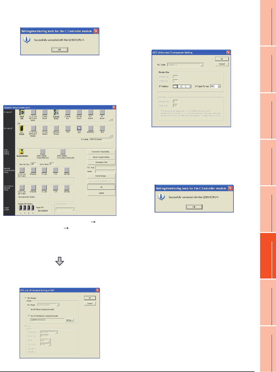
22. FA TRANSPARENT FUNCTION
22.6 Personal Computer Side Setting
22 - 65
17
ROBOT
CONTROLLER
CONNECTION
18
CNC CONNECTION
19
GOT MULTI-DROP
CONNECTION
20
MULTIPLE-GT14, GT12,
GT11, GT10
CONNECTION FUNCTION
21
MULTI-CHANNEL
FUNCTION
22
FA TRANSPARENT
FUNCTION
(2) When connecting the GOT and PLC in Ethernet
communication
5. Mark the [via GOT(Bus) transparent mode]
checkbox on the [CPU side I/F Detailed Setting of
GOT] screen.
6. The screen returns to [Transfer Setup]. Click
[Connection Test] to check if Setting/Monitoring tool
for C Controller module has been connected to the
motion controller (Q mode).
1. Click the Connection Destination view
[Connection Destination] [(Connection target
data name)] in the Navigation window of MT Setting/
Monitoring tool for C Controller module.
2. The [Transfer Setup] is displayed.
3. Set the [Transfer Setup]:
PLC side I/F : GOT
Other station : No specification
4. Double-click [GOT] of the CPU side I/F to display
[CPU side I/F Detailed Setting of GOT].
5. Mark the [via GOT(Ethernet) transparent mode]
checkbox on the [CPU side I/F Detailed Setting of
GOT] screen.
6. By clicking [Set], the [GOT (Ethernet) Transparent
Setting] is displayed.
Here, set the C Controller module (Q24DHCCPU-
V), which is firstly connected via a GOT.
7. Specify the IP address for [IP address] same as the
IP address assigned to the C Controller module
(Q24DHCCPU-V).
8. The screen returns to [Transfer Setup]. Click
[Connection Test] to check if Setting/Monitoring tool
for C Controller module has been connected to the
C Controller module (Q24DHCCPU-V).
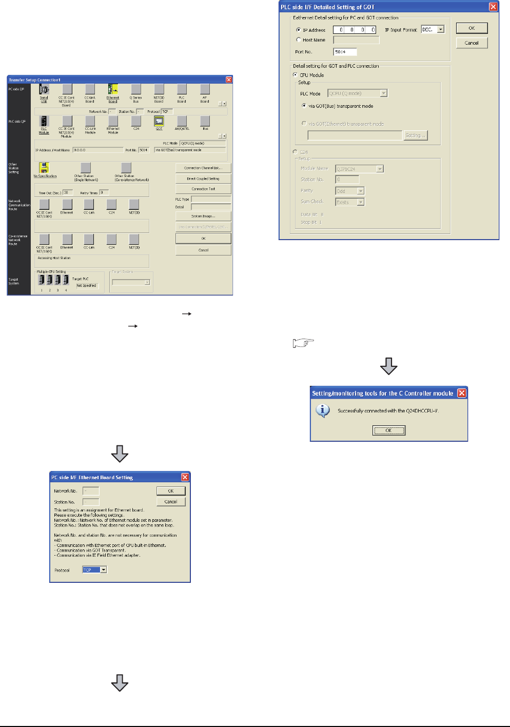
22 - 66 22. FA TRANSPARENT FUNCTION
22.6 Personal Computer Side Setting
When connecting the GOT and personal
computer in Ethernet connection (GT16,
GT15, and GT14 only)
(1) When connecting the GOT and PLC in bus
connection
1. Click the Connection Destination view
[Connection Destination] [(Connection target
data name)] in the Navigation window of MT Setting/
Monitoring tool for C Controller module.
2. The [Transfer Setup] is displayed.
3. Set the [Transfer Setup]:
PC side I/F : Ethernet Board
PLC side I/F : GOT
Other station : No specification
4. Double-click [Ethernet Board] of the PC side I/F to
display [PC side I/F Ethernet Board Setting].
5. Set the protocol to TCP. Network No. and Station
No. are not required to be changed (default)
because they are not used.
6. Double-click [GOT] of the PLC side I/F to display
[PLC side I/F Detailed Setting of GOT].
7. Set the IP address and port No. in [Ethernet detail
setting for PC and GOT connection].
Set the IP address and port No. to the same as the
Ethernet download setting.
22.5.1 (b) Ethernet download setting
8. The screen returns to [Transfer Setup]. Click
[Connection Test] to check if Setting/Monitoring tool
for C Controller module has been connected to the
motion controller (Q mode).
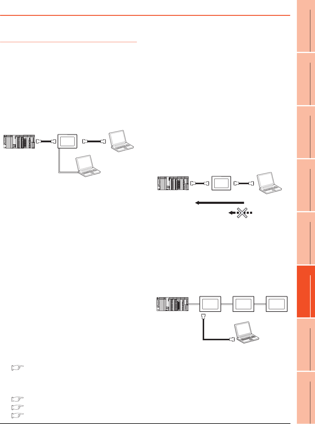
22. FA TRANSPARENT FUNCTION
22.7 Precautions
22 - 67
17
ROBOT
CONTROLLER
CONNECTION
18
CNC CONNECTION
19
GOT MULTI-DROP
CONNECTION
20
MULTIPLE-GT14, GT12,
GT11, GT10
CONNECTION FUNCTION
21
MULTI-CHANNEL
FUNCTION
22
FA TRANSPARENT
FUNCTION
22.7 Precautions
22.7.1 Precautions common to each
software
GOT interface required to use the FA
transparent function
Connect the personal computer, to which GX
Developer or any other relevant software has been
installed, to the RS-232 interface or USB interface of
the GOT.
When performing the FA transparent function, use
either RS-232 interface or USB interface of the GOT.
Using both of them to perform the FA transparent
function concurrently is not allowed.
Conditions for suspending the FA transparent
function
The FA transparent function is also suspended when
any of the following operations, which stop the GOT
monitor, is performed.
Note that the FA transparent function will not be
stopped while using the optional function such as the
Utility display or ladder monitor function.
• When project data is written/read, or when the OS is
written by GT Designer3*1
• When the GOT is set up*1
• When no communication request (online monitor,
etc.) has been issued from GX Developer for 45
minutes
*1 A timeout error occurs in GX Developer.
When GOT monitoring is faulty
The FA transparent function cannot be used in case
that the GOT monitoring is faulty due to PLC CPU
errors or faulty communication between the PLC CPU
and GOT.
When GOT monitoring is faulty, check the following.
(1) Whether the PLC CPU operates normally
Refer to the User's Manual of the PLC CPU you
use.
(2) Whether the PLC CPU and GOT are connected
normally
5. BUS CONNECTION
6. DIRECT CONNECTION TO CPU
7. COMPUTER LINK CONNECTION
When monitoring the PLC CPU from a
personal computer
When monitoring the PLC CPU from a personal
computer, the GOT and personal computer refresh the
display slower.
Software available for the FA transparent
function
When multiple kinds of software are activated on one
personal computer, only one of them is available for
communications using the FA transparent function.
Do not concurrently perform any communications using
the FA transparent function.
(Offline operation with each software is available)
Also, do not perform communications with the GOT
(e.g. downloading project data) from GT Designer3
during execution of communications using the FA
transparent function.
When the FA transparent function is used in
a bus connection
(1) When multiple GOTs are bus-connected
When multiple GOTs are bus-connected, the FA
transparent function can be used on each GOT.
However, note that the monitoring performance of each
GOT slows down as the number of monitoring GOTs
and personal computers increases.
RS-232
USB
GT Designer3
GX Developer and so on
Online operation
Communication with GOT
PC
RS-232
cable
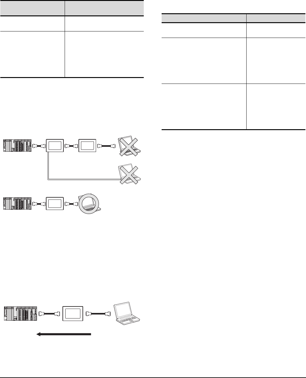
22 - 68 22. FA TRANSPARENT FUNCTION
22.7 Precautions
(2) When the FA transparent function is used in a bus
connection
When the FA transparent function is used in a bus
connection, the following GX Developer functions or
GX Works2 functions cannot be executed.
The message [The executed function is not supported.
Please check the manual and other documentation.] is
displayed on GX Developer or GX Works2.
When using together with the Multiple-GT11,
GT10 connection function
When multiple GOTs are connected, the FA transparent
function is not available even if the RS-232 interface or
USB interface is used for the connection.
When PLC power disconnection occurs with
the FA transparent function being used
While the FA transparent function is being used, if the
communication between the PLC and the GOT is
stopped due to PLC power disconnection or a
disconnection of the communication cable between the
PLC and the GOT, the GOT waits for timeout against
the communication request from the peripheral devices
(GX Developer, etc.), and it takes a few minutes to
recover the monitoring between the PLC and the GOT.
When the FA transparent function is used in
an Ethernet connection
(1) GX Developer function or GX Works2 function
When the FA transparent function is used in an
Ethernet connection, the following GX Developer
functions or GX Works2 functions cannot be executed.
The message [The executed function is not supported.
Please check the manual and other documentation.] is
displayed on GX Developer or GX Works2.
(2) GOT station monitoring function
When the FA transparent function is used in an
Ethernet connection, GOT station monitoring function
cannot be operated.
Therefore, in the cases of [no connection target], [PLC
power OFF], etc., the monitoring of the GOT delays for
the timeout time.
Unsupported GX Developer
functions Remark
• Remote Reset
• Remote system reset ―
• Remote RUN
• Remote STOP
• Remote PAUSE
• Remote STEP-RUN
• Remote latch clear
• Write clock data
• Clear malfunction log
Inexecutable only when specify all
stations/groups has been performed.
PC
PC
1st GOT 2nd GOT
RS-232
PC
1st GOT
USB
GX Developer and so on
Online operation
Monitoring
Unsupported GX Developer functions Remark
• Remote Reset
• Remote system reset ―
• Remote RUN
• Remote STOP
• Remote PAUSE
• Remote STEP-RUN
• Remote latch clear
• Write clock data
• Clear malfunction log
Inexecutable only when
specify all stations/groups
has been performed.
• Remote password function
• MELSECNET diagnostics
• CC IE Control diagnostics
• CC IE Field diagnostics
• Ethernet diagnostics
(PING test/loopback test with
the Ethernet module (Q series))
―
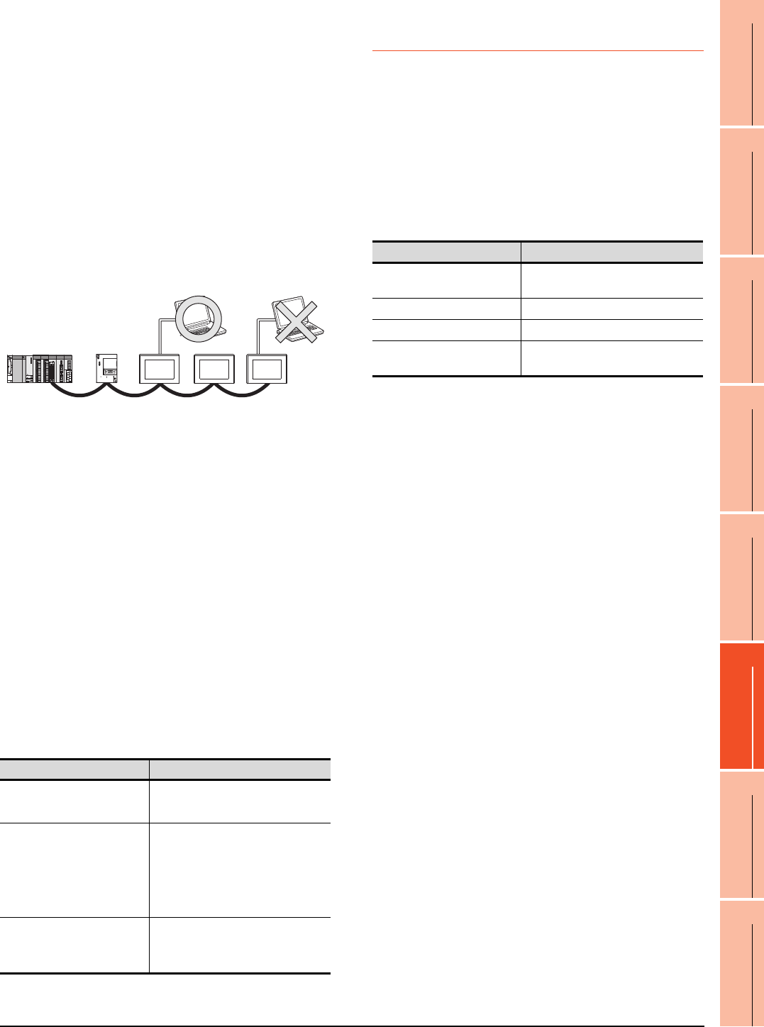
22. FA TRANSPARENT FUNCTION
22.7 Precautions
22 - 69
17
ROBOT
CONTROLLER
CONNECTION
18
CNC CONNECTION
19
GOT MULTI-DROP
CONNECTION
20
MULTIPLE-GT14, GT12,
GT11, GT10
CONNECTION FUNCTION
21
MULTI-CHANNEL
FUNCTION
22
FA TRANSPARENT
FUNCTION
When connecting the GOT multi-drop
connection
FA transparent function is available for each GOT in the
GOT multi-drop connection system.
(1) Standard monitor OS installation, Communication
driver writing
When using FA transparent function in GOT multi-drop
connection, the writing of the standard monitor OS and
communication driver to the GOT from GT Designer3
(Version 1.18U or later), as well as the writing of the
standard monitor OS and communication driver to the
serial multi-drop connection unit are required.
(2) Number of personal computers
Only one personal computer can be connected to the
multi-drop connection system.
(3) Monitor speed of GOT
The monitoring performance slows down according to
the number of monitoring GOTs. While using FA
transparent function, the monitoring performance of the
whole multi-drop system decreases. As a result,
timeout error may occur in GOTs in the system.
When connecting the GOT and personal
computer with modem connection
When using the FA transparent function with a modem,
the communication settings of compatible software,
modem connection tool, modem and GOT must be set
correctly to communicate with the GOT. If not correctly
set, the communication cannot be performed.
When connecting the GOT and personal
computer with serial or USB
When the operations shown below are executed, the
operation is executed in the PLC. However, the display
on the GOT may stop temporarily or the display of
timeout may appear on GX Works2.
*1 The remote operations only of when the connection type
between the GOT and CPU is the direct CPU connection or
computer link connection are applied.
22.7.2 When using GX Developer,
GX Woks2
When connecting to QCPU (A mode)
When connecting to QCPU (A mode), set the PLC type
to "A4UCPU" or "QCPU (A mode)" on GX Developer.
When connecting the GOT and PC with RS-
232
The [Transmission speed] setting in [PC side I/F Serial
setting] in GX Developer or GX Works2 must be within
the range supported by the connected CPU.
When [monitor conditions] have been set on
GX Developer, GX Works2
(1) Monitoring performance of the GOT is temporarily
suspended.
(2) The GOT cannot respond to the touch switch operation
and numerical/ascii inputs.
(3) Writing to PLC results in a system alarm occurrence
and displays the message, "315 Device writing error.
Correct device.".
(4) While setting the monitor conditions, do not perform
any operation which makes the GOT restart (e.g.
downloading project data, changing utility data).
Doing so may display a system alarm, "402
Communication timeout. Confirm communication
pathway or modules." when the GOT restarts.
When the monitor conditions setting for the PLC CPU
has not been cancelled, reconnect GX Developer, GX
Works2 to cancel the setting.(An error may be output
when the monitor conditions setting is cancelled.)
(5) When the time check of GX Developer, GX Works2 is
set to 30 seconds or more in the monitor condition
settings, the message "402 Communication timeout.
Confirm communication pathway or modules." may
appear.
Set the time check time of GX Developer, GX Works2
to 30 seconds or less.
When exiting GX Developer, GX Works2
For 45 seconds after GX Developer, GX Works2 has
been exited, the GOT continues monitoring at the same
speed as when the FA transparent function is working.
Operation*1 Remark
• Remote Reset
Applied for the following operations
specifying the currently selected
station.
• Remote RUN
• Remote STOP
• Remote PAUSE
• Remote STEP-RUN
• Remote Reset
• Remote latch clear
• Write clock data
Applied for the following operations
specifying all the station.
• CC IE Control diagnostics
(Link startup/stop)
• CC IE Field diagnostics
(Link startup/stop)
―
Only one personal computer
CPU connected Transmission speed
QCPU, FXCPU 9600bps, 19200bps, 38400bps,
57600bps, 115200bps
QnACPU 9600bps, 19200bps, 38400bps
ACPU 9600, 19200bps
Motion controller CPU
(A series) 9600bps

22 - 70 22. FA TRANSPARENT FUNCTION
22.7 Precautions
When performing [Read to PLC], [Write to
PLC] and other file operations on GX
Developer, GX Works2
If any of the following GOT functions is executed during
the file operation such as [Read to PLC] or [Write to
PLC], an error may occur on the GOT, GX Developer,
or GX Works2.
In this case, take the following corrective action:
• File reading in the ladder monitor function for
MELSEC-Q
• Read/write of values of the file register specified for
the recipe function
• Reading TC monitor set value in the system monitor
function
*1 The numerical indicates the system alarm No.
• Reading the special module monitor CPU
Malfunction log
• Backup/restore
• SFC monitor file reading
Error messages
on GOT
Corrective
action on GOT
side
Error messages
on GX Developer
and GX Works2
Corrective
action on GX
Developer and
GX Works2
The file is not
found.
With no file
operation being
executed on
GX Developer
or GX Works2,
re-execute the
file reading.
File access
failure.
Please retry.
With no file
reading being
executed in the
ladder monitor
function for
MELSEC-Q,
re-execute the
file operation.
Error messages
on GOT
Corrective
action on GOT
side
Error messages
on GX Developer
and GX Works2
Corrective
action on GX
Developer and
GX Works2
358 PLC file
access failure.
Confirm PLC
drive.*1
With no file
operation on
GX Developer
or GX Works2,
turn ON the
trigger device
for the recipe
function again.
File access
failure.
Please retry.
Execute the
file access
operation
again with the
recipe in-
process signal
in GOT system
information
OFF.
PLC file system
error. Unable to
communicate
with PLC.
Error messages
on GOT
Corrective
action on GOT
side
Error messages
on GX Developer
and GX Works2
Corrective
action on GX
Developer and
GX Works2
No message is
displayed.
(The TC set
value space is
blank.)
With no file
operation being
executed on
GX Developer
or GX Works2,
re-execute the
TC monitor.
File access
failure.
Please retry.
With no TC set
value being
read, re-
execute the file
operation.
Error messages
on GOT
Corrective
action on GOT
side
Error messages
on GX Developer
and GX Works2
Corrective
action on GX
Developer and
GX Works2
Communication
error
With no file
operation being
executed on
GX Developer
or GX Works2,
re-execute the
CPU
malfunction log
reading.
File access
failure.
Please retry.
With no special
module
monitor
malfunction log
being read,
execute the file
operation.
Error messages
on GOT
Corrective
action on GOT
side
Error messages
on GX Developer
and GX Works2
Corrective
action on GX
Developer and
GX Works2
Backup
With no file
operation being
executed on
GX Developer
or GX Works2,
re-execute the
backup.
―
With no
backup being
executed,
execute the file
operation.
Restore
With no file
operation being
executed on
GX Developer
or GX Works2,
re-execute the
restore.
―
With no restore
being
executed,
execute the file
operation.
Error messages
on GOT
Corrective
action on GOT
side
Error messages
on GX Developer
and GX Works2
Corrective
action on GX
Developer and
GX Works2
―
With no file
operation being
executed on
GX Developer
or GX Works2,
re-execute the
file reading.
―
With no special
module
monitor CPU
malfunction log
being read,
execute the file
operation.
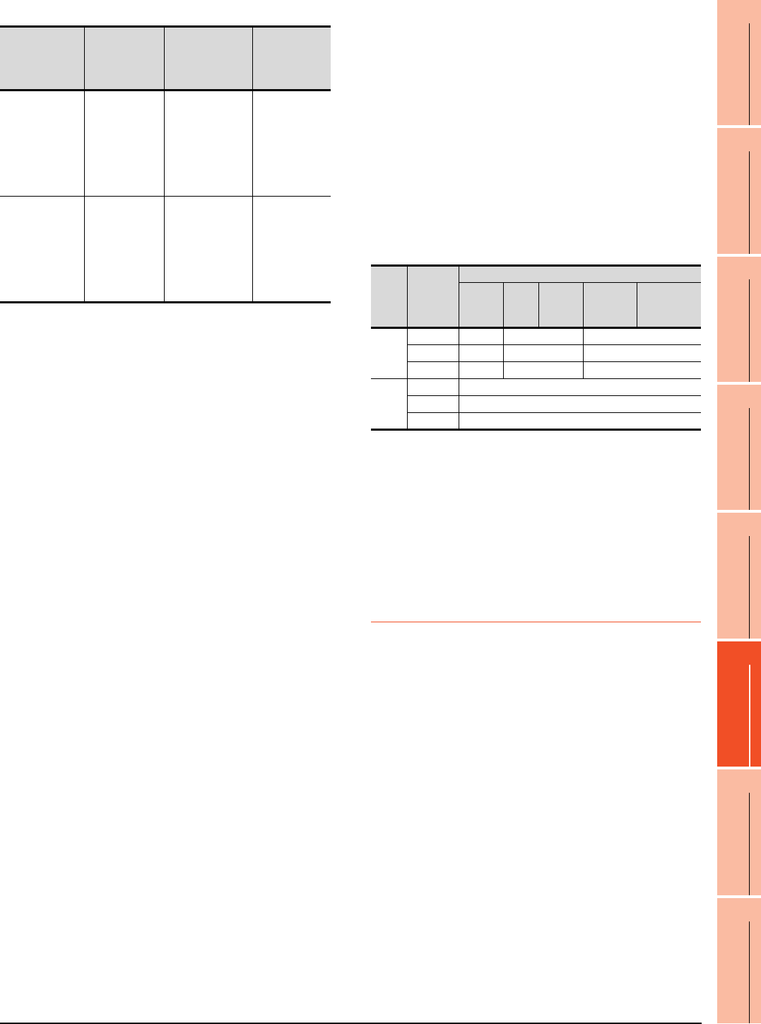
22. FA TRANSPARENT FUNCTION
22.7 Precautions
22 - 71
17
ROBOT
CONTROLLER
CONNECTION
18
CNC CONNECTION
19
GOT MULTI-DROP
CONNECTION
20
MULTIPLE-GT14, GT12,
GT11, GT10
CONNECTION FUNCTION
21
MULTI-CHANNEL
FUNCTION
22
FA TRANSPARENT
FUNCTION
• Reading/Writing files of ladder edit
When PLC write is failed while using the FA
transparent function
The execution of PLC write using the FA transparent
function may be failed due to some reason such as
cable disconnection.
When this occurs, re-execute the PLC write from the
same personal computer, or reset the PLC CPU.
Restrictions on GX Developer during backup/
restore execution
(1) When reading/writing data from/to a PLC, monitoring a
PLC, and others are executed with GX Developer or
GX Works2 with the FA transparent function during the
backup/restore execution with the GOT, the backup/
restore is stopped.
Check that reading/writing data from/to the PLC,
monitoring the PLC, and others are not executed with
GX Developer or GX Works2 with the FA transparent
function. Execute the backup/restore with the GOT
again.
(2) When the backup/restore is executed with the GOT
while reading/writing data from/to a PLC, monitoring a
PLC, and others are executed with GX Developer or
GX Works2 with the FA transparent function, errors
occur on GX Developer or GX Works2.
The backup/restore with the GOT is correctly executed.
When connecting the GOT and personal
computer with modem connection
(1) Timeout time settings
When the FA transparent function is used with a
modem, it takes time for the initial communication with
PLC and GX Works2 or GX Developer and a timeout
may occur. In that case, set a longer time for the initial
communication timeout time for the GOT modem
connection tool.
(2) Communication settings
When the FA transparent function is used via modem,
the communication setting differs depending on the
connection target of the GOT.
Set as follows.
*1 Communication settings of GX Works2/GX Developer are
set automatically, and setting is not required.
When connecting the ACPU and motion
controller CPU (A series) in bus connection
Do not execute write during RUN with GX Developer.
An error may occur in the PLC due to the write during
RUN, what may stop the PLC.
22.7.3 When using MT Developer,
MT Works2
When exiting MT Developer, MT Works2
For 45 seconds after GX Developer, MT Works2 has
been exited, the GOT continues monitoring at the same
speed as when the FA transparent function is working.
When PLC write is failed while using the FA
transparent function
The execution of PLC write using the FA transparent
function may be failed due to some reasons such as
cable disconnection.
When this occurs, re-execute the PLC write from the
same personal computer, or reset the motion controller
CPU.
When a cable disconnection has occurred
When the cable between the GOT and the motion CPU
is disconnected, it takes time until a timeout error
occurs in MT Developer.
Error messages
on GOT
Corrective
action on GOT
side
Error messages
on GX Developer
and GX Works2
Corrective
action on GX
Developer and
GX Works2
Read
With no file
operation being
executed on
GX Developer
or GX Works2,
re-execute the
file reading.
―
With no file
reading being
executed on
ladder edit,
execute the file
operation.
Write
With no file
operation being
executed on
GX Developer
or GX Works2,
re-execute the
file writing.
―
With no file
writing being
executed on
ladder edit,
execute the file
operation. Tar g et
of the
GOT
Setting
item
Setting target
GT
Designer3
GX
Works2
*1
GX
Developer
*1
GOT modem
connection
tool
Communication
settings of the
GOT
FXCPU
Data length
8bits 7bits 8bits
Parity None Even None
Stop bit 1bit 1bit 1bit
QCPU
Data length
8bits
Parity Odd
Stop bit 1bit

22 - 72 22. FA TRANSPARENT FUNCTION
22.7 Precautions
22.7.4 When using MR Configurator,
MR Configurator2
Unavailable functions and restrictions
For the use via the motion controller, there are
unavailable functions and restrictions.
For details on the restrictions, refer to the help screen
of MR Configurator.
Monitor speed of GOT
Since the FA transparent function is used via the
motion CPU, the monitor speed of GOT is slow.
22.7.5 When using FR Configurator
GOT monitoring when using FA transparent
function
When FA transparent function is used, GOT suspends
monitoring on channels supporting FA transparent
function.
POINTPOINTPOINT
Cancelling the suspended GOT monitoring
immediately
To cancel the suspended (45 seconds) GOT
monitoring immediately after FA transparent is
executed, input "1" to device GS457.Then GOT
resumes monitoring.
If FA transparent is resumed even if "1" is already input
to device GS457, an error will occur on FR
Configurator.
For the details of the device, refer to the following
manual.
GT Designer3 Version Screen Design
Manual
When using the oscilloscope function
specified sampling
Since the monitoring of the inverter data may be not
performed at the specified sampling intervals
depending on the settings of oscilloscope function,
adjust the communication setting, a sampling interval,
etc.
PU mode operation command source
selection
On the setting of PU mode operation command source
selection (Pr:551) of the inverter, specify the terminal
(1:RS-485 terminals, 2:PU connected) connected to
GOT.

Index-1
INDEX
INDEX
[A]
ABBREVIATIONS AND GENERIC TERMS ........ A-24
ACCESS RANGE FOR MONITORING ................. 3-1
AnCPU type
Bus connection .................................................. 5-9
CC-Link connection (intelligent device station)
......................................................................... 13-6
Computer link connection ................................ 7-13
Direct connection to CPU................................... 6-9
Ethernet connection ........................................... 8-7
MELSECNET/10 connection (PLC to PLC network)
................................................................. 10-7,10-8
AnSCPU type
Bus connection ................................................ 5-12
CC-Link connection (intelligent device station)
......................................................................... 13-6
Computer link connection ................................ 7-14
Direct connection to CPU................................... 6-9
Ethernet connection ........................................... 8-7
MELSECNET/10 connection (PLC to PLC network)
................................................................. 10-7,10-8
[B]
Built-in Ethernet port QCPU ................................ 8-11
Bus connection ...................................................... 5-1
[C]
C Controller module
Bus connection .................................................. 5-5
CC-Link connection (intelligent device station)
................................................................. 13-6,13-7
CC-Link connection (via G4)............................ 14-6
CC-Link IE Controller Network connection ...... 11-7
Computer link connection .................................. 7-7
Direct connection to CPU................................... 6-6
Ethernet connection ......................................... 8-11
MELSECNET/10 connection (PLC to PLC network)
................................................................. 10-7,10-8
MELSECNET/H connection (PLC to PLC network)
........................................................................... 9-7
CC-Link connection (intelligent device station).... 13-1
CC-Link connection (via G4) ............................... 14-1
CC-Link IE Controller Network connection .......... 11-1
CC-Link IE Field Network connection.................. 12-1
CNC C70
Bus connection .................................................. 5-5
CC-Link connection (intelligent device station)
................................................................. 13-6,13-7
CC-Link connection (via G4)............................ 14-6
CC-Link IE Controller Network connection ...... 11-7
Computer link connection .................................. 7-7
Direct connection to CPU................................... 6-6
Ethernet connection ......................................... 8-12
MELSECNET/10 connection (PLC to PLC network)
................................................................. 10-7,10-8
MELSECNET/H connection (PLC to PLC network)
........................................................................... 9-7
CNC connection
CC-Link connection (intelligent device station)
......................................................................... 18-5
Direct connection to CPU................................. 18-3
Ethernet connection ......................................... 18-6
MELSECNET/10 connection (PLC to PLC network)
......................................................................... 18-4
CNC side settings .............................................. 18-16
Coaxial cable ....................................................... 1-29
Communication module ....................................... 1-17
Computer link connection ...................................... 7-1
Connectable Model List
Bus connection................................................... 5-2
CC-Link connection (intelligent device station)
......................................................................... 13-2
CC-Link connection (via G4) ............................ 14-2
CC-Link IE Controller Network connection....... 11-2
CC-Link IE Field Network connection .............. 12-2
CNC connection ............................................... 18-2
Computer link connection................................... 7-2
Direct connection to CPU................................... 6-2
Ethernet connection ........................................... 8-2
GOT MULTI-DROP CONNECTION................. 19-2
INVERTER CONNECTION.............................. 15-2
MELSECNET/10 connection (PLC to PLC network)
......................................................................... 10-2
MELSECNET/H connection (PLC to PLC network)
........................................................................... 9-2
Multiple-GT14,GT12,GT11,GT10 connection
function............................................................. 20-2
ROBOT CONTROLLER CONNECTION.......... 17-2
Servo amplifier connection............................... 16-2
Connection Diagram
CC-Link connection (via G4) ............................ 14-8
CNC connection ............................................... 18-7
Computer link connection................................. 7-15
Direct connection to CPU................................. 6-22
GOT MULTI-DROP CONNECTION............... 19-15
INVERTER CONNECTION............................ 15-21
Multiple-GT14,GT12,GT11,GT10 connection
function............................................................. 20-5
Servo amplifier connection............................... 16-8
Connector conversion adapter............................. 1-18
Controller Type ...................................................... 1-6
Conversion cables ............................................... 1-18
[D]
DEVICE RANGE THAT CAN BE SET................... 2-1
Device Range that Can Be Set
CNC connection ............................................. 18-23
INVERTER CONNECTION............................ 15-44
ROBOT CONTROLLER CONNECTION.......... 17-8
Servo amplifier connection............................. 16-17
Direct connection to CPU ...................................... 6-1

Index-2
[E]
Ethernet connection............................................... 8-1
[F]
FA transparent function ............................... 22-1,22-2
FXCPU
Direct connection to CPU................................. 6-10
Ethernet connection ........................................... 8-9
[G]
GOT connector specifications ............................. 1-26
GOT MULTI-DROP CONNECTION .................... 19-1
GOT Side Settings
Bus connection................................................. 5-30
CC-Link connection (intelligent device station)
......................................................................... 13-9
CC-Link connection (via G4) ............................ 14-9
CC-Link IE Controller Network connection....... 11-8
CC-Link IE Field Network connection .............. 12-8
CNC connection ............................................... 18-8
Computer link connection................................. 7-19
Direct connection to CPU................................. 6-25
Ethernet connection ......................................... 8-15
FA transparent function.................................. 22-36
GOT MULTI-DROP CONNECTION............... 19-23
INVERTER CONNECTION............................ 15-29
MELSECNET/10 connection (PLC to PLC network)
......................................................................... 10-9
MELSECNET/H connection (PLC to PLC network)
........................................................................... 9-9
MULTI-CHANNEL FUNCTION ........................ 21-7
Multiple-GT14,GT12,GT11,GT10 connection
function ............................................................ 20-7
ROBOT CONTROLLER CONNECTION.......... 17-3
Servo amplifier connection............................. 16-12
[H]
HOW TO MONITOR REDUNTANT SYSTEM ....... 4-1
[I]
I/F .......................................................................... 1-8
I/F communication setting.................................... 1-12
Inverter
FREQROL A500/A500L/F500/F500L/V500/V500L
......................................................................... 15-3
FREQROL A700/F700/F700P........................ 15-14
FREQROL E500/S500/S500E/F500J/D700/
F700PJ............................................................. 15-7
FREQROL E700 ............................................ 15-10
INVERTER CONNECTION ................................. 15-1
Inverter Side Settings ........................................ 15-31
[L]
LCPU
CC-Link connection.......................................... 14-7
Computer link connection................................... 7-8
Direct connection to CPU................................... 6-7
List of Models that Can Be Monitored ............... 22-11
[M]
MELSECNET/10 connection (PLC to PLC network)
............................................................................. 10-1
MELSECNET/H connection (PLC to PLC network)
............................................................................... 9-1
Motion controller CPU (A series)
Bus connection......................................... 5-19,5-24
CC-Link connection (intelligent device station)
......................................................................... 13-6
Computer link connection......................... 7-13,7-14
Direct connection to CPU ................................... 6-9
Ethernet connection ........................................... 8-7
MELSECNET/10 connection (PLC to PLC network)
................................................................. 10-7,10-8
Motion controller CPU (Q series)
Bus connection................................................... 5-5
CC-Link connection (intelligent device station)
......................................................................... 13-7
CC-Link connection (via G4) ............................ 14-6
CC-Link IE Controller Network connection....... 11-7
Computer link connection................................... 7-7
Direct connection to CPU ........................... 6-6,6-20
Ethernet connection ........................................... 8-7
MELSECNET/10 connection (PLC to PLC network)
................................................................. 10-7,10-8
MELSECNET/H connection (PLC to PLC network)
........................................................................... 9-7
MULTI-CHANNEL FUNCTION ............................ 21-1
Multi-channel Function Check Sheet ................. 21-42
Multiple-GT14,GT12,GT11,GT10 connection function
............................................................................. 20-1
[O]
Option unit ........................................................... 1-18
[P]
Personal Computer Side Setting ....................... 22-39
PLC Side Setting
CC-Link connection (intelligent device station)
....................................................................... 13-12
CC-Link IE Controller Network connection..... 11-10
CC-Link IE Field Network connection............. 12-10
Computer link connection................................. 7-22
Ethernet connection ......................................... 8-20
MELSECNET/10 connection (PLC to PLC network)
....................................................................... 10-12
MELSECNET/H connection (PLC to PLC network)
......................................................................... 9-11
ROBOT CONTROLLER CONNECTION.......... 17-6
PLC Side Settings
CC-Link connection (via G4) .......................... 14-11
Precautions
Bus connection................................................. 5-34
CC-Link connection (intelligent device station)
....................................................................... 13-39
CC-Link connection (via G4) .......................... 14-17
CC-Link IE Controller Network connection..... 11-16
CC-Link IE Field Network connection............. 12-13
CNC connection ............................................. 18-23

Index-3
INDEX
Computer link connection ................................ 7-29
Direct connection to CPU................................. 6-28
Ethernet connection ......................................... 8-49
FA transparent function.................................. 22-67
GOT MULTI-DROP CONNECTION............... 19-30
INVERTER CONNECTION............................ 15-47
MELSECNET/10 connection (PLC to PLC network)
....................................................................... 10-26
MELSECNET/H connection (PLC to PLC network)
......................................................................... 9-16
MULTI-CHANNEL FUNCTION ...................... 21-41
Multiple-GT14,GT12,GT11,GT10 connection
function .......................................................... 20-11
ROBOT CONTROLLER CONNECTION ......... 17-8
Servo amplifier connection............................. 16-45
PREPARATORY PROCEDURES FOR
MONITORING ....................................................... 1-1
[Q]
QCPU(A mode)
CC-Link connection (intelligent device station)
......................................................................... 13-6
Computer link connection .................................. 7-9
Direct connection to CPU................................... 6-6
Ethernet connection ........................................... 8-7
MELSECNET/10 connection (PLC to PLC network)
................................................................. 10-7,10-8
QCPU(Q mode)
Bus connection .................................................. 5-5
CC-Link connection (intelligent device station)
................................................................. 13-6,13-7
CC-Link connection (via G4)............................ 14-6
CC-Link IE Controller Network connection ...... 11-7
CC-Link IE Field Network connection .............. 12-7
Computer link connection .................................. 7-7
Direct connection to CPU................................... 6-6
Ethernet connection ................................... 8-7,8-11
MELSECNET/10 connection (PLC to PLC network)
................................................................. 10-7,10-8
MELSECNET/H connection (PLC to PLC network)
........................................................................... 9-7
QnACPU type
Bus connection .................................................. 5-9
CC-Link connection (intelligent device station)
......................................................................... 13-6
Computer link connection ................................ 7-10
Direct connection to CPU................................... 6-8
Ethernet connection ........................................... 8-7
MELSECNET/10 connection (PLC to PLC network)
................................................................. 10-7,10-8
QnASCPU type
Bus connection ................................................ 5-12
CC-Link connection (intelligent device station)
......................................................................... 13-6
Computer link connection ................................ 7-11
Direct connection to CPU................................... 6-8
Ethernet connection ........................................... 8-7
MELSECNET/10 connection (PLC to PLC network)
................................................................. 10-7,10-8
QSCPU
CC-Link IE Controller Network connection....... 11-7
Ethernet connection ........................................... 8-7
MELSECNET/10 connection (PLC to PLC network)
................................................................. 10-7,10-8
MELSECNET/H connection (PLC to PLC network)
........................................................................... 9-7
[R]
Remote I/O station of MELSECNET/H network system
Computer link connection................................... 7-7
Direct connection to CPU................................... 6-6
Ethernet connection ........................................... 8-7
ROBOT CONTROLLER
Bus connection................................................... 5-5
CC-Link connection (intelligent device station)
................................................................. 13-6,13-7
CC-Link connection (via G4) ............................ 14-6
CC-Link IE Controller Network connection....... 11-7
Computer link connection................................... 7-7
Direct connection to CPU................................... 6-6
Ethernet connection ........................................... 8-7
MELSECNET/10 connection (PLC to PLC network)
................................................................. 10-7,10-8
MELSECNET/H connection (PLC to PLC network)
........................................................................... 9-7
ROBOT CONTROLLER CONNECTION ............. 17-1
[S]
Serial Multi-Drop Connection Unit ....................... 1-18
Servo amplifier
MELSERVO-J2M Series .................................. 16-4
MELSERVO-J2-Super Series .......................... 16-3
MELSERVO-J3 Series ..................................... 16-5
Servo amplifier connection .................................. 16-1
Setting connected equipment ................................ 1-4
Setting of connection conversion adapter.......... 19-29
Setting of Serial Multi-Drop Connection Unit ..... 19-24
Setting on Servo Amplifier Side ......................... 16-14
Station number setting
INVERTER CONNECTION............................ 15-43
MELSERVO connection................................. 16-16
System Configuration
Bus connection................................................... 5-5
CC-Link connection (intelligent device station)
......................................................................... 13-6
CC-Link connection (via G4) ............................ 14-6
CC-Link IE Controller Network connection....... 11-7
CC-Link IE Field Network connection .............. 12-7
CNC connection ............................................... 18-3
Computer link connection................................... 7-7
Direct connection to CPU................................... 6-6
Ethernet connection ........................................... 8-7
FA transparent function.................................. 22-26
GOT MULTI-DROP CONNECTION............... 19-14
INVERTER CONNECTION.............................. 15-3
MELSECNET/10 connection (PLC to PLC network)
......................................................................... 10-7
MELSECNET/H connection (PLC to PLC network)
........................................................................... 9-7

Index-4
MULTI-CHANNEL FUNCTION ........................ 21-4
Multiple-GT14,GT12,GT11,GT10 connection
function ............................................................ 20-2
ROBOT CONTROLLER CONNECTION.......... 17-2
Servo amplifier connection............................... 16-3
[T]
Terminating resistors of GOT .............................. 1-30
[W]
What is Multi-channel Function? ......................... 21-2

REVISIONS - 1
REVISIONS
* The manual number is given on the bottom left of the back cover.
Print Date * Manual Number Revision
Oct., 2009 SH(NA)-080898ENG-A First edition: Compatible with GT Works3 (ELE) Version1.01B
Nov., 2009 SH(NA)-080898ENG-B B edition: Compatible with GT Works3 (ELE) Version1.05F
• Compatible with iQ Works
Jan.,2010 SH(NA)-080898ENG-C C edition: Compatible with GT Works3 (ELE) Version1.10L
• MELSEC-L compatible, MELSEC-FX (MELSEC-FX buffer memory compatible), FA transparent (GX Works2
compatible, NC Configurator compatible), GT10 motion controller CPU (Q series) connection compatible
May,2010 SH(NA)-080898ENG-D D edition: Compatible with GT Works3 (ELE) Version1.14Q
• Q50UDEH/Q100UDEH compatible, Q172DCPU-S1/Q173DCPU-S1 compatible, LJ72GF15-T2 compatible
• GT16/GT15 GOT multi-drop connection compatible
Jun., 2010 SH(NA)-080898ENG-E E edition: Compatible with GT Works3 (ELE) Version1.17T
• GT1675-VN, GT1672-VN, and GT1662-VN are added.
• Q12DCCPU-V compatible, MELSEC-WS compatible, FA transparent (MX Component, MX Sheet and GX
LogViewer compatible)
Oct., 2010 SH(NA)-080898ENG-F F edition: Compatible with GT Works3 (ELE) Version1.19V
• Compatible with CC-Link IE Field Network Ethernet adapter module
• FA transparent in GOT multi-drop connection compatible
• Station monitoring function (Inverter connection) compatible
• FA transparent (MR Configurator2 compatible)
Jan., 2011 SH(NA)-080898ENG-G G edition: Compatible with GT Works3 (ELE) Version1.23Z
• CC IE Control extended mode compatible
• Inverter connection with 31 modules, device range expansion compatible
• FA transparent in LCPU Logging Configuration Tool compatible
• FA transparent in Ethernet connection between GOT and personal computer compatible
Apr., 2011 SH(NA)-080898ENG-H H edition: Compatible with GT Works3 (ELE) Version1.28E
• GT1655-V is added.
Jul., 2011 SH(NA)-080898ENG-I I edition: Compatible with GT Works3 (ELE) Version1.31H
• CC-Link IE Field Network compatible
• Communication setting storage and error information notification in GOT multi-drop connection compatible
• FA transparent (MX Component) in Ethernet connection between personal computer and GOT compatible
• Device range expansion (D and W of QCPU and X, Y, Ww, and Wr of LCPU) compatible
• Communication setting format 2 compatible
Oct., 2011 SH(NA)-080898ENG-J J edition: Compatible with GT Works3 (ELE) Version1.37P
• GT14, GT12 are added.
• Station shutoff function (Inverter connection) compatible
• CC-Link IE Field Network compatible model (QS001CPU) are added.
• Note about Ethernet connection (FXCPU) are added.
Jan., 2012 SH(NA)-080898ENG-K K edition: Compatible with GT Works3 (ELE) Version1.40S
• "I/F Communication Setting" is compatible with "5V power supply".
• CC-Link IE field extended device of QSCPU compatible
• Station shutoff function for the network connection via PLC CPU compatible
• Station number setting function compatible (multi-drop system information function expanded)
• FA transparent in Ethernet connection between GOT and personal computer compatible (FXCPU, motion CPU,
MELSERVO)
• RS-232/485 signal conversion adaptor is added.
•FX
3U-ENET-ADP is added.
Apr., 2012 SH(NA)-080898ENG-L L edition: Compatible with GT Works3 (ELE) Version1.45X
•FX
3GC compatible
• Q172DSCPU/Q173DSCPU compatible
Jun., 2012 SH(NA)-080898ENG-M M edition: Compatible with GT Works3 (ELE) Version1.54G
• Ethernet connection; Timeout time setting range is extended.
• MELSERVO-J4 series compatible
• Ping test at the GT14 main unit compatible
Sep., 2012 SH(NA)-080898ENG-N N edition: Compatible with GT Works3 (ELE) Version1.58L
• Device G compatible

REVISIONS - 2
* The manual number is given on the bottom left of the back cover.
© 2009 MITSUBISHI ELECTRIC CORPORATION
Print Date * Manual Number Revision
Nov., 2012 SH(NA)-080898ENG-O Compatible with GT Works3 (ELE) Version1.63R
• SAFETY PRECAUTIONS is changed.
• C Controller module (Q24DHCCPU-V) compatible
• Inverter connection (MELIPM series) compatible
• FA transparent function (MX Component 4.00A) compatible
Feb., 2013 SH(NA)-080898ENG-P Compatible with GT Works3 (ELE) Version1.67V
• High-speed QnU (QnUDVCPU) compatible
• MELSEC-L models (L26CPU/L02SCPU, LJ71E71-100) are added.
• FA transparent function (Setting/Monitoring tool for C Controller module) compatible
• FA transparent function (FXCPU) compatible
This manual confers no industrial property rights or any rights of any other kind, nor does it confer any patent licenses.
Mitsubishi Electric Corporation cannot be held responsible for any problems involving industrial property rights which may occur as a result
of using the contents noted in this manual.

WARRANTY
Please confirm the following product warranty details before using this product.
1. Gratis Warranty Term and Gratis Warranty Range
If any faults or defects (hereinafter "Failure") found to be the responsibility of Mitsubishi occurs during use of the product within the
gratis warranty term, the product shall be repaired at no cost via the sales representative or Mitsubishi Service Company.
However, if repairs are required onsite at domestic or overseas location, expenses to send an engineer will be solely at the
customer's discretion. Mitsubishi shall not be held responsible for any re-commissioning, maintenance, or testing on-site that
involves replacement of the failed module.
[Gratis Warranty Term]
The gratis warranty term of the product shall be for thirty-six (36) months after the date of purchase or delivery to a designated
place.
Note that after manufacture and shipment from Mitsubishi, the maximum distribution period shall be six (6) months, and the
longest gratis warranty term after manufacturing shall be forty-two (42) months. The gratis warranty term of repair parts shall not
exceed the gratis warranty term before repairs.
[Gratis Warranty Range]
(1) The customer shall be responsible for the primary failure diagnosis unless otherwise specified.
If requested by the customer, Mitsubishi Electric Corporation or its representative firm may carry out the primary failure
diagnosis at the customer’s expence.
The primary failure diagnosis will, however, be free of charge should the cause of failure be attributable to Mitsubishi Electric
Corporation.
(2) The range shall be limited to normal use within the usage state, usage methods and usage environment, etc., which follow
the conditions and precautions, etc., given in the instruction manual, user's manual and caution labels on the product.
(3) Even within the gratis warranty term, repairs shall be charged for in the following cases.
1. Failure occurring from inappropriate storage or handling, carelessness or negligence by the user. Failure caused by the
user's hardware or software design.
2. Failure caused by unapproved modifications, etc., to the product by the user.
3. When the Mitsubishi product is assembled into a user's device, Failure that could have been avoided if functions or
structures, judged as necessary in the legal safety measures the user's device is subject to or as necessary by industry
standards, had been provided.
4. Failure that could have been avoided if consumable parts designated in the instruction manual had been correctly
serviced or replaced.
5. Replacing consumable parts such as the battery, backlight and fuses.
6. Failure caused by external irresistible forces such as fires or abnormal voltages, and Failure caused by force majeure
such as earthquakes, lightning, wind and water damage.
7. Failure caused by reasons unpredictable by scientific technology standards at time of shipment from Mitsubishi.
8. Any other failure found not to be the responsibility of Mitsubishi or that admitted not to be so by the user.
2. Onerous repair term after discontinuation of production
(1) Mitsubishi shall accept onerous product repairs for seven (7) years after production of the product is discontinued.
Discontinuation of production shall be notified with Mitsubishi Technical Bulletins, etc.
(2) Product supply (including repair parts) is not available after production is discontinued.
3. Overseas service
Overseas, repairs shall be accepted by Mitsubishi's local overseas FA Center. Note that the repair conditions at each FA Center
may differ.
4. Exclusion of loss in opportunity and secondary loss from warranty liability
Regardless of the gratis warranty term, Mitsubishi shall not be liable for compensation to damages caused by any cause found not
to be the responsibility of Mitsubishi, loss in opportunity, lost profits incurred to the user by Failures of Mitsubishi products, special
damages and secondary damages whether foreseeable or not, compensation for accidents, and compensation for damages to
products other than Mitsubishi products, replacement by the user, maintenance of on-site equipment, start-up test run and other
tasks.
5. Changes in product specifications
The specifications given in the catalogs, manuals or technical documents are subject to change without prior notice.
6. Product application
(1) In using the Mitsubishi graphic operation terminal, the usage conditions shall be that the application will not lead to a major
accident even if any problem or fault should occur in the graphic operation terminal device, and that backup and fail-safe
functions are systematically provided outside of the device for any problem or fault.
(2) The Mitsubishi graphic operation terminal has been designed and manufactured for applications in general industries, etc.
Thus, applications in which the public could be affected such as in nuclear power plants and other power plants operated by
respective power companies, and applications in which a special quality assurance system is required, such as for Railway
companies or Public service purposes shall be excluded from the graphic operation terminal applications.
In addition, applications in which human life or property that could be greatly affected, such as in aircraft, medical applications,
incineration and fuel devices, manned transportation equipment for recreation and amusement, and safety devices, shall also
be excluded from the graphic operation terminal range of applications.
However, in certain cases, some applications may be possible, providing the user consults the local Mitsubishi representative
outlining the special requirements of the project, and providing that all parties concerned agree to the special circumstances,
solely at our discretion.
In some of three cases, however, Mitsubishi Electric Corporation may consider the possibility of an application, provided that
the customer notifies Mitsubishi Electric Corporation of the intention, the application is clearly defined and any special quality is
not required.

SH(NA)-080898ENG-P
GOT is a registered trademark of Mitsubishi Electric Corporation.
Microsoft, Windows, Windows NT, Windows Server, Windows Vista, and Windows 7 are registered trademarks or trademarks
of Microsoft Corporation in the United States and other countries.
Adobe and Adobe Reader are registered trademarks of Adobe Systems Incorporated.
Pentium and Celeron are a registered trademarks of Intel Corporation in the United States and other countries.
Ethernet is a trademark of Xerox Corporation in the United States.
MODBUS is a trademark of Schneider Electric SA.
VNC is a registered trademark of RealVNC Ltd. in the United States and other countries.
Other company and product names herein are either trademarks or registered trademarks of their respective owners.

Connection Manual
(Mitsubishi Products)
Series
MODEL
MODEL
CODE
SW1-GTD3-U(CON1)-ELE
1D7MC9
SH(NA)-080898ENG-P(1302)MEE
for GT Works3 (ELE)
Specifications subject to change without notice.
Printed in Japan, February 2013.
When exported from Japan, this manual does not require application to the
Ministry of Economy, Trade and Industry for service transaction permission.
HEAD OFFICE : TOKYO BUILDING, 2-7-3 MARUNOUCHI, CHIYODA-KU, TOKYO 100-8310, JAPAN
NAGOYA WORKS : 1-14 , YADA-MINAMI 5-CHOME , HIGASHI-KU, NAGOYA , JAPAN
HEADQUARTERS
EUROPEMITSUBISHI ELECTRIC EUROPE B.V.
German Branch
Gothaer Straße 8
D-40880 Ratingen
Phone: +49 (0)2102 / 486-0
Fax: +49 (0)2102 / 486-1120
CZECH REP.MITSUBISHIELECTRIC EUROPEB.V.-org.sl.
Czech Branch
Radlická 751/113e
CZ-158 00 Praha 5
Phone: +420 - 251 551 470
Fax: +420 - 251-551-471
FRANCEMITSUBISHI ELECTRIC EUROPE B.V.
French Branch
25, Boulevard des Bouvets
F-92741 Nanterre Cedex
Phone: +33 (0)1 / 55 68 55 68
Fax: +33 (0)1 / 55 68 57 57
IRELANDMITSUBISHI ELECTRIC EUROPE B.V.
Irish Branch
Westgate Business Park, Ballymount
IRL-Dublin 24
Phone: +353 (0)1 4198800
Fax: +353 (0)1 4198890
ITALYMITSUBISHI ELECTRIC EUROPE B.V.
Italian Branch
Viale Colleoni 7
I-20864 Agrate Brianza (MB)
Phone: +39 039 / 60 53 1
Fax: +39 039 / 60 53 312
POLANDMITSUBISHI ELECTRIC EUROPE B.V.
Polish Branch
Krakowska 50
PL-32-083 Balice
Phone: +48 (0)12 / 630 47 00
Fax: +48 (0)12 / 630 47 01
RUSSIAMITSUBISHI ELECTRIC EUROPE B.V.
Russian Branch
52, bld. 3 Kosmodamianskaya nab 8 floor
RU-115054 Мoscow
Phone: +7 495 721-2070
Fax: +7 495 721-2071
SPAINMITSUBISHI ELECTRIC EUROPE B.V.
Spanish Branch
Carretera de Rubí 76-80
E-08190 Sant Cugat del Vallés (Barcelona)
Phone: 902 131121 // +34 935653131
Fax: +34 935891579
UKMITSUBISHI ELECTRIC EUROPE B.V.
UK Branch
Travellers Lane
UK-Hatfield, Herts. AL10 8XB
Phone: +44 (0)1707 / 28 87 80
Fax: +44 (0)1707 / 27 86 95
JAPAN
MITSUBISHI ELECTRIC CORPORATION
Tokyo Building 2-7-3
Marunouchi, Chiyoda-ku
Tokyo 100-8310
Phone: +81 (3) 3218-2111
Fax: +81 (3) 3218-2185
USAMITSUBISHI ELECTRIC AUTOMATION, Inc.
500 Corporate Woods Parkway
Vernon Hills, IL 60061
Phone: +1 (847) 478-2100
Fax: +1 (847) 478-0328
EUROPEAN REPRESENTATIVES
AUSTRIAGEVA
Wiener Straße 89
AT-2500 Baden
Phone: +43 (0)2252 / 85 55 20
Fax: +43 (0)2252 / 488 60
BELARUSTECHNIKON
Oktyabrskaya 19, Off. 705
BY-220030 Minsk
Phone: +375 (0)17 / 210 46 26
Fax: +375 (0)17 / 210 46 26
BELGIUMESCO DRIVES
Culliganlaan 3
BE-1831 Diegem
Phone: +32 (0)2 / 717 64 60
Fax: +32 (0)2 / 717 64 61
BELGIUMKONING & HARTMAN B.V.
Woluwelaan 31
BE-1800 Vilvoorde
Phone: +32 (0)2 / 257 02 40
Fax: +32 (0)2 / 257 02 49
BOSNIA AND HERZEGOVINAINEA RBT d.o.o.
Stegne 11
SI-1000 Ljubljana
Phone: +386 (0)1/ 513 8116
Fax: +386 (0)1/ 513 8170
BULGARIAAKHNATON
4, Andrei Ljapchev Blvd., PO Box 21
BG-1756 Sofia
Phone: +359 (0)2 / 817 6000
Fax: +359 (0)2 / 97 44 06 1
CROATIAINEA CR
Losinjska 4 a
HR-10000 Zagreb
Phone: +385 (0)1 / 36 940 - 01/ -02/ -03
Fax: +385 (0)1 / 36 940 - 03
CZECH REPUBLICAutoCont C.S. S.R.O.
Kafkova 1853/3
CZ-702 00 Ostrava 2
Phone: +420 595 691 150
Fax: +420 595 691 199
DENMARKBeijer Electronics A/S
Lykkegardsvej 17
DK-4000 Roskilde
Phone: +45 (0)46/ 75 76 66
Fax: +45 (0)46 / 75 56 26
ESTONIABeijer Electronics Eesti OÜ
Pärnu mnt.160i
EE-11317 Tallinn
Phone: +372 (0)6 / 51 81 40
Fax: +372 (0)6 / 51 81 49
FINLANDBeijer Electronics OY
Vanha Nurmijärventie 62
FIN-01670 Vantaa
Phone: +358 (0)207 / 463 500
Fax: +358 (0)207 / 463 501
FINLANDPROVENDOR OY
Teljänkatu 8 A3
FIN-28130 Pori
Phone: +358 (0) 2 / 522 3300
Fax: +358 (0) 2 / 522 3322
GREECEUTECO A.B.E.E.
5, Mavrogenous Str.
GR-18542 Piraeus
Phone: +30 211 / 1206 900
Fax: +30 211 / 1206 999
HUNGARYMELTRADE Ltd.
Fertő utca 14.
HU-1107 Budapest
Phone: +36 (0)1 / 431-9726
Fax: +36 (0)1 / 431-9727
LATVIABeijer Electronics SIA
Ritausmas iela 23
LV-1058 Riga
Phone: +371 (0)784 / 2280
Fax: +371 (0)784 / 2281
LITHUANIABeijer Electronics UAB
Goštautu g. 3
LT-48324 Kaunas
Phone: +370 37 262707
Fax: +370 37 455605
EUROPEAN REPRESENTATIVES
MALTAALFATRADE Ltd.
99, Paola Hill
Malta-Paola PLA 1702
Phone: +356 (0)21 / 697 816
Fax: +356 (0)21 / 697 817
MOLDOVAINTEHSIS SRL
bld. Traian 23/1
MD-2060 Kishinev
Phone: +373 (0)22 / 66 4242
Fax: +373 (0)22 / 66 4280
NETHERLANDSHIFLEX AUTOM. B.V.
Wolweverstraat 22
NL-2984 CD Ridderkerk
Phone: +31 (0)180 / 46 60 04
Fax: +31 (0)180 / 44 23 55
NETHERLANDSKONING & HARTMAN B.V.
Haarlerbergweg 21-23
NL-1101 CH Amsterdam
Phone: +31 (0)20 / 587 76 00
Fax: +31 (0)20 / 587 76 05
NORWAYBeijer Electronics AS
Postboks 487
NO-3002 Drammen
Phone: +47 (0)32 / 24 30 00
Fax: +47 (0)32 / 84 85 77
PORTUGALFonseca S.A.
R. João Francisco do Casal 87/89
PT- 3801-997 Aveiro, Esgueira
Phone: +351 (0)234 / 303 900
Fax: +351 (0)234 / 303 910
ROMANIASirius Trading & Services srl
Aleea Lacul Morii Nr. 3
RO-060841 Bucuresti, Sector 6
Phone: +40 (0)21 / 430 40 06
Fax: +40 (0)21 / 430 40 02
SERBIAINEA SR
Izletnicka 10
SER-113000 Smederevo
Phone: +381 (0)26 / 615 401
Fax: +381 (0)26 / 615 401
SLOVAKIASIMAP s.r.o.
Jána Derku 1671
SK-911 01 Trencín
Phone: +421 (0)32 743 04 72
Fax: +421 (0)32 743 75 20
SLOVENIAINEA RBT d.o.o.
Stegne 11
SI-1000 Ljubljana
Phone: +386 (0)1 / 513 8116
Fax: +386 (0)1 / 513 8170
SWEDENBeijer Electronics Automation AB
Box 426
SE-20124 Malmö
Phone: +46 (0)40 / 35 86 00
Fax: +46 (0)40 / 93 23 01
SWITZERLANDOMNI RAY AG
Im Schörli 5
CH-8600 Dübendorf
Phone: +41 (0)44 / 802 28 80
Fax: +41 (0)44 / 802 28 28
TURKEY
Fabrika Otomasyonu Merkezi
Şerifali Mahallesi Nutuk Sokak No:5
İ
Phone: +90 (0)216 526 39 90
Fax: +90 (0)216 526 39 95
UKRAINECSC AUTOMATION Ltd.
4-B, M. Raskovoyi St.
UA-02660 Kiev
Phone: +380 (0)44 / 494 33 55
Fax: +380 (0)44 / 494-33-66
EURASIAN REPRESENTATIVES
KAZAKHSTANTOO Kazpromavtomatika
Ul. Zhambyla 28
KAZ-100017 Karaganda
Phone: +7 7212 / 50 10 00
Fax: +7 7212 / 50 11 50
MIDDLE EAST REPRESENTATIVES
EGYPTI.C. SYSTEMS Ltd.
23 Al-Saad-Al-Alee St.
EG-Sarayat, Maadi, Cairo
Phone: +20 (0) 2 / 235 98 548
Fax: +20 (0) 2 / 235 96 625
ISRAELILAN & GAVISH Ltd.
24 Shenkar St., Kiryat Arie
IL-49001 Petah-Tiqva
Phone: +972 (0)3 / 922 18 24
Fax: +972 (0)3 / 924 0761
ISRAELGIRIT CELADON Ltd.
12 H'aomanut Street
IL-42505 Netanya
Phone: +972 (0)9 / 863 39 80
Fax: +972 (0)9 / 885 24 30
LEBANON
CEG LIBAN
Cebaco Center/Block A Autostrade DORA
Lebanon-Beirut
Phone: +961 (0)1 / 240 445
Fax: +961 (0)1 / 240 193
AFRICAN REPRESENTATIVE
SOUTH AFRICAADROIT TECHNOLOGIES
20 Waterford Office Park 189 Witkoppen Road
ZA-Fourways
Phone: + 27 (0)11 / 658 8100
Fax: + 27 (0)11 / 658 8101
Mitsubishi Electric Europe B.V. /// FA - European Business Group /// Gothaer Straße 8 /// D-40880 Ratingen /// Germany
Tel.: +49(0)2102-4860 /// Fax: +49(0)2102-4861120/// info@mitsubishi-automation.com /// www.mitsubishi-automation.com
MITSUBISHI ELECTRIC
