Mitsubishi Electronics Motion Controllers Q172Dcpu Users Manual Programming (COMMON) [type Q173D/Q172D]
Q172DCPU to the manual 8477e028-1172-4702-b959-a2406df8790f
2015-02-09
: Mitsubishi-Electronics Mitsubishi-Electronics-Motion-Controllers-Q172Dcpu-Users-Manual-556712 mitsubishi-electronics-motion-controllers-q172dcpu-users-manual-556712 mitsubishi-electronics pdf
Open the PDF directly: View PDF ![]() .
.
Page Count: 174 [warning: Documents this large are best viewed by clicking the View PDF Link!]
- SAFETY PRECAUTIONS
- REVISIONS
- INTRODUCTION
- CONTENTS
- About Manuals
- 1. OVERVIEW
- 2. MULTIPLE CPU SYSTEM
- 3. COMMON PARAMETERS
- 4. AUXILIARY AND APPLIED FUNCTIONS
- 4.1 Limit Switch Output Function
- 4.2 Absolute Position System
- 4.3 High-Speed Reading of Specified Data
- 4.4 ROM Operation Function
- 4.5 Security Function
- 4.6 All clear function
- 4.7 Communication via Network
- 4.8 Monitor Function of the Main Cycle
- 4.9 Servo Parameter Reading Function
- 4.10 Optional Data Monitor Function
- 4.11 Connect/Disconnect Function
- 4.12 Remote operation
- APPENDICES
- WARRANTY

Motion Controllers
Programming Manual
Common
Q173DCPU
Q172DCPU
MITSUBISHI ELECTRIC
MITSUBISHI ELECTRIC
01 01 2008
B(NA)-0300134
Version A
INDUSTRIAL AUTOMATION
A - 1
SAFETY PRECAUTIONS
(Please read these instructions before using this equipment.)
Before using this product, please read this manual and the relevant manuals introduced in this manual
carefully and pay full attention to safety to handle the product correctly.
These precautions apply only to this product. Refer to the Q173DCPU/Q172DCPU Users manual for a
description of the Motion controller safety precautions.
In this manual, the safety instructions are ranked as "DANGER" and "CAUTION".
DANGER
Indicates that incorrect handling may cause hazardous
conditions, resulting in death or severe injury.
CAUTION
Indicates that incorrect handling may cause hazardous
conditions, resulting in medium or slight personal injury or
physical damage.
Depending on circumstances, procedures indicated by CAUTION may also be linked to serious
results.
In any case, it is important to follow the directions for usage.
Please save this manual to make it accessible when required and always forward it to the end user.
A - 2
For Safe Operations
1. Prevention of electric shocks
DANGER
Never open the front case or terminal covers while the power is ON or the unit is running, as this
may lead to electric shocks.
Never run the unit with the front case or terminal cover removed. The high voltage terminal and
charged sections will be exposed and may lead to electric shocks.
Never open the front case or terminal cover at times other than wiring work or periodic
inspections even if the power is OFF. The insides of the Motion controller and servo amplifier are
charged and may lead to electric shocks.
Completely turn off the externally supplied power used in the system before mounting or removing the
module, performing wiring work, or inspections. Failing to do so may lead to electric shocks.
When performing wiring work or inspections, turn the power OFF, wait at least ten minutes, and
then check the voltage with a tester, etc.. Failing to do so may lead to electric shocks.
Be sure to ground the Motion controller, servo amplifier and servomotor. (Ground resistance :
100 or less) Do not ground commonly with other devices.
The wiring work and inspections must be done by a qualified technician.
Wire the units after installing the Motion controller, servo amplifier and servomotor. Failing to do
so may lead to electric shocks or damage.
Never operate the switches with wet hands, as this may lead to electric shocks.
Do not damage, apply excessive stress, place heavy things on or sandwich the cables, as this
may lead to electric shocks.
Do not touch the Motion controller, servo amplifier or servomotor terminal blocks while the power
is ON, as this may lead to electric shocks.
Do not touch the built-in power supply, built-in grounding or signal wires of the Motion controller
and servo amplifier, as this may lead to electric shocks.
2. For fire prevention
CAUTION
Install the Motion controller, servo amplifier, servomotor and regenerative resistor on
incombustible. Installing them directly or close to combustibles will lead to fire.
If a fault occurs in the Motion controller or servo amplifier, shut the power OFF at the servo
amplifier’s power source. If a large current continues to flow, fire may occur.
When using a regenerative resistor, shut the power OFF with an error signal. The regenerative
resistor may abnormally overheat due to a fault in the regenerative transistor, etc., and may lead
to fire.
Always take heat measures such as flame proofing for the inside of the control panel where the
servo amplifier or regenerative resistor is installed and for the wires used. Failing to do so may
lead to fire.
Do not damage, apply excessive stress, place heavy things on or sandwich the cables, as this may
lead to fire.
A - 3
3. For injury prevention
CAUTION
Do not apply a voltage other than that specified in the instruction manual on any terminal.
Doing so may lead to destruction or damage.
Do not mistake the terminal connections, as this may lead to destruction or damage.
Do not mistake the polarity ( + / - ), as this may lead to destruction or damage.
Do not touch the heat radiating fins of controller or servo amplifier, regenerative resistor and
servomotor, etc., while the power is ON and for a short time after the power is turned OFF. In this
timing, these parts become very hot and may lead to burns.
Always turn the power OFF before touching the servomotor shaft or coupled machines, as these
parts may lead to injuries.
Do not go near the machine during test operations or during operations such as teaching.
Doing so may lead to injuries.
4. Various precautions
Strictly observe the following precautions.
Mistaken handling of the unit may lead to faults, injuries or electric shocks.
(1) System structure
CAUTION
Always install a leakage breaker on the Motion controller and servo amplifier power source.
If installation of an electromagnetic contactor for power shut off during an error, etc., is specified in
the instruction manual for the servo amplifier, etc., always install the electromagnetic contactor.
Install the emergency stop circuit externally so that the operation can be stopped immediately and
the power shut off.
Use the Motion controller, servo amplifier, servomotor and regenerative resistor with the correct
combinations listed in the instruction manual. Other combinations may lead to fire or faults.
Use the CPU module, base unit and motion module with the correct combinations listed in the
instruction manual. Other combinations may lead to faults.
If safety standards (ex., robot safety rules, etc.,) apply to the system using the Motion controller,
servo amplifier and servomotor, make sure that the safety standards are satisfied.
Construct a safety circuit externally of the Motion controller or servo amplifier if the abnormal
operation of the Motion controller or servo amplifier differ from the safety directive operation in the
system.
In systems where coasting of the servomotor will be a problem during the forced stop, emergency
stop, servo OFF or power supply OFF, use dynamic brakes.
Make sure that the system considers the coasting amount even when using dynamic brakes.
In systems where perpendicular shaft dropping may be a problem during the forced stop,
emergency stop, servo OFF or power supply OFF, use both dynamic brakes and electromagnetic
brakes.
A - 4
CAUTION
The dynamic brakes must be used only on errors that cause the forced stop, emergency stop, or
servo OFF. These brakes must not be used for normal braking.
The brakes (electromagnetic brakes) assembled into the servomotor are for holding applications,
and must not be used for normal braking.
The system must have a mechanical allowance so that the machine itself can stop even if the
stroke limits switch is passed through at the max. speed.
Use wires and cables that have a wire diameter, heat resistance and bending resistance
compatible with the system.
Use wires and cables within the length of the range described in the instruction manual.
The ratings and characteristics of the parts (other than Motion controller, servo amplifier and
servomotor) used in a system must be compatible with the Motion controller, servo amplifier and
servomotor.
Install a cover on the shaft so that the rotary parts of the servomotor are not touched during
operation.
There may be some cases where holding by the electromagnetic brakes is not possible due to the
life or mechanical structure (when the ball screw and servomotor are connected with a timing belt,
etc.). Install a stopping device to ensure safety on the machine side.
(2) Parameter settings and programming
CAUTION
Set the parameter values to those that are compatible with the Motion controller, servo amplifier,
servomotor and regenerative resistor model and the system application. The protective functions
may not function if the settings are incorrect.
The regenerative resistor model and capacity parameters must be set to values that conform to
the operation mode, servo amplifier and servo power supply module. The protective functions
may not function if the settings are incorrect.
Set the mechanical brake output and dynamic brake output validity parameters to values that are
compatible with the system application. The protective functions may not function if the settings
are incorrect.
Set the stroke limit input validity parameter to a value that is compatible with the system
application. The protective functions may not function if the setting is incorrect.
Set the servomotor encoder type (increment, absolute position type, etc.) parameter to a value
that is compatible with the system application. The protective functions may not function if the
setting is incorrect.
Set the servomotor capacity and type (standard, low-inertia, flat, etc.) parameter to values that
are compatible with the system application. The protective functions may not function if the
settings are incorrect.
Set the servo amplifier capacity and type parameters to values that are compatible with the
system application. The protective functions may not function if the settings are incorrect.
A - 5
CAUTION
Use the program commands for the program with the conditions specified in the instruction
manual.
Set the sequence function program capacity setting, device capacity, latch validity range, I/O
assignment setting, and validity of continuous operation during error detection to values that are
compatible with the system application. The protective functions may not function if the settings
are incorrect.
Some devices used in the program have fixed applications, so use these with the conditions
specified in the instruction manual.
The input devices and data registers assigned to the link will hold the data previous to when
communication is terminated by an error, etc. Thus, an error correspondence interlock program
specified in the instruction manual must be used.
Use the interlock program specified in the intelligent function module's instruction manual for the
program corresponding to the intelligent function module.
(3) Transportation and installation
CAUTION
Transport the product with the correct method according to the mass.
Use the servomotor suspension bolts only for the transportation of the servomotor. Do not
transport the servomotor with machine installed on it.
Do not stack products past the limit.
When transporting the Motion controller or servo amplifier, never hold the connected wires or
cables.
When transporting the servomotor, never hold the cables, shaft or detector.
When transporting the Motion controller or servo amplifier, never hold the front case as it may fall
off.
When transporting, installing or removing the Motion controller or servo amplifier, never hold the
edges.
Install the unit according to the instruction manual in a place where the mass can be withstood.
Do not get on or place heavy objects on the product.
Always observe the installation direction.
Keep the designated clearance between the Motion controller or servo amplifier and control panel
inner surface or the Motion controller and servo amplifier, Motion controller or servo amplifier and
other devices.
Do not install or operate Motion controller, servo amplifiers or servomotors that are damaged or
that have missing parts.
Do not block the intake/outtake ports of the Motion controller, servo amplifier and servomotor with
cooling fan.
Do not allow conductive matter such as screw or cutting chips or combustible matter such as oil
enter the Motion controller, servo amplifier or servomotor.
A - 6
CAUTION
The Motion controller, servo amplifier and servomotor are precision machines, so do not drop or
apply strong impacts on them.
Securely fix the Motion controller, servo amplifier and servomotor to the machine according to
the instruction manual. If the fixing is insufficient, these may come off during operation.
Always install the servomotor with reduction gears in the designated direction. Failing to do so
may lead to oil leaks.
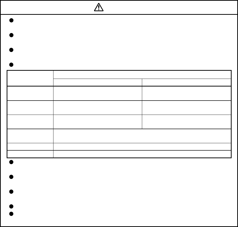
Store and use the unit in the following environmental conditions.
Conditions
Environment
Motion controller/Servo amplifier Servomotor
Ambient
temperature According to each instruction manual. 0°C to +40°C (With no freezing)
(32°F to +104°F)
Ambient humidity According to each instruction manual. 80% RH or less
(With no dew condensation)
Storage
temperature According to each instruction manual. -20°C to +65°C
(-4°F to +149°F)
Atmosphere Indoors (where not subject to direct sunlight).
No corrosive gases, flammable gases, oil mist or dust must exist
Altitude 1000m (3280.84ft.) or less above sea level
Vibration According to each instruction manual
When coupling with the synchronous encoder or servomotor shaft end, do not apply impact such
as by hitting with a hammer. Doing so may lead to detector damage.
Do not apply a load larger than the tolerable load onto the synchronous encoder and servomotor
shaft. Doing so may lead to shaft breakage.
When not using the module for a long time, disconnect the power line from the Motion controller
or servo amplifier.
Place the Motion controller and servo amplifier in static electricity preventing vinyl bags and store.
When storing for a long time, please contact with our sales representative.
Also, execute a trial operation.
A - 7
(4) Wiring
CAUTION
Correctly and securely wire the wires. Reconfirm the connections for mistakes and the terminal
screws for tightness after wiring. Failing to do so may lead to run away of the servomotor.
After wiring, install the protective covers such as the terminal covers to the original positions.
Do not install a phase advancing capacitor, surge absorber or radio noise filter (option FR-BIF)
on the output side of the servo amplifier.
Correctly connect the output side (terminal U, V, W). Incorrect connections will lead the
servomotor to operate abnormally.
Do not connect a commercial power supply to the servomotor, as this may lead to trouble.
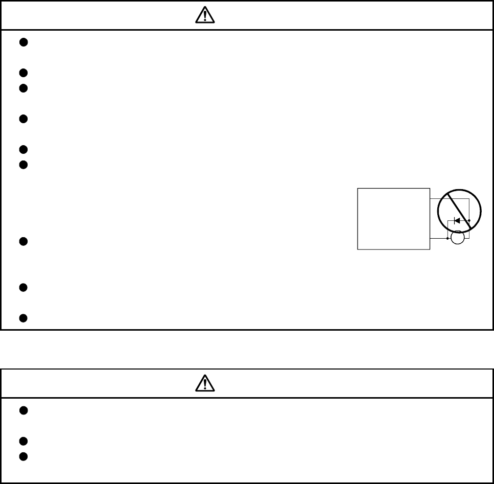
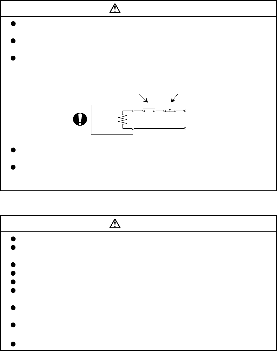
Do not mistake the direction of the surge absorbing diode
installed on the DC relay for the control signal output of brake
signals, etc. Incorrect installation may lead to signals not being
output when trouble occurs or the protective functions not
functioning.
Do not connect or disconnect the connection cables between
each unit, the encoder cable or PLC expansion cable while the
power is ON.
Servo amplifier
VIN
(24VDC)
Control output
signal RA
Securely tighten the cable connector fixing screws and fixing mechanisms. Insufficient fixing may
lead to the cables combing off during operation.
Do not bundle the power line or cables.
(5) Trial operation and adjustment
CAUTION
Confirm and adjust the program and each parameter before operation. Unpredictable
movements may occur depending on the machine.
Extreme adjustments and changes may lead to unstable operation, so never make them.
When using the absolute position system function, on starting up, and when the Motion
controller or absolute value motor has been replaced, always perform a home position return.
A - 8
(6) Usage methods
CAUTION
Immediately turn OFF the power if smoke, abnormal sounds or odors are emitted from the Motion
controller, servo amplifier or servomotor.
Always execute a test operation before starting actual operations after the program or
parameters have been changed or after maintenance and inspection.
Do not attempt to disassemble and repair the units excluding a qualified technician whom our
company recognized.
Do not make any modifications to the unit.
Keep the effect or electromagnetic obstacles to a minimum by installing a noise filter or by using
wire shields, etc. Electromagnetic obstacles may affect the electronic devices used near the
Motion controller or servo amplifier.
When using the CE Mark-compliant equipment, refer to the "EMC Installation Guidelines" (data
number IB(NA)-67339) for the Motion controllers and refer to the corresponding EMC guideline
information for the servo amplifiers, inverters and other equipment.
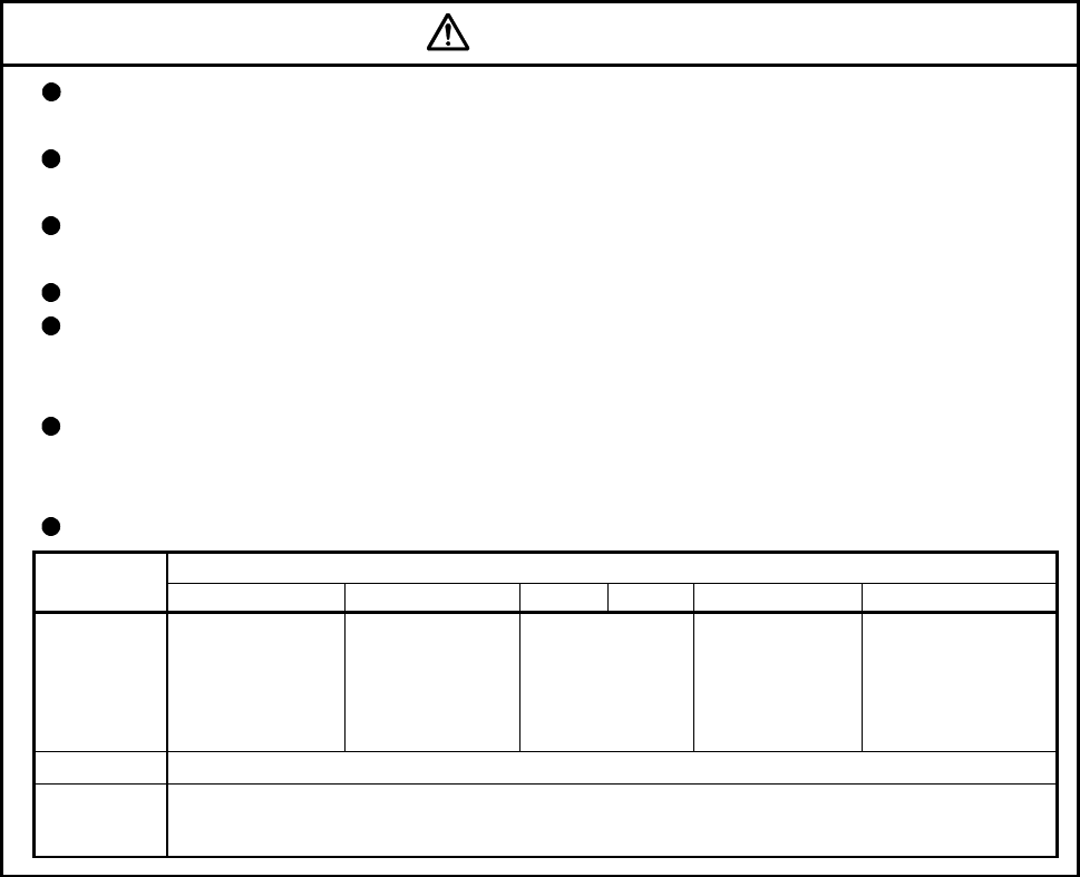
Use the units with the following conditions.
Conditions
Item
Q61P-A1 Q61P-A2 Q61P Q62P Q63P Q64P
+10% +10% +10% +30% +10%
100 to 120VAC -15% 200 to 240VAC -15% 100 to 240VAC -15% 24VDC -35% 100 to 120VAC -15% /
+10%
200 to 240VAC -15%
Input power
(85 to 132VAC) (170 to 264VAC) (85 to 264VAC) (15.6 to 31.2VDC) (85 to 132VAC/
170 to 264VAC)
Input frequency 50/60Hz ±5%
Tolerable
momentary
power failure
20ms or less
A - 9
(7) Corrective actions for errors
CAUTION
If an error occurs in the self diagnosis of the Motion controller or servo amplifier, confirm the
check details according to the instruction manual, and restore the operation.
If a dangerous state is predicted in case of a power failure or product failure, use a servomotor
with electromagnetic brakes or install a brake mechanism externally.
Use a double circuit construction so that the electromagnetic brake operation circuit can be
operated by emergency stop signals set externally.
Electro-
magnetic
brakes
Servomotor
24VDC
RA1 EMG
Shut off with servo ON signal OFF,
alarm, electromagnetic brake signal.
Shut off with the
emergency stop
signal(EMG).
If an error occurs, remove the cause, secure the safety and then resume operation after alarm
release.
The unit may suddenly resume operation after a power failure is restored, so do not go near the
machine. (Design the machine so that personal safety can be ensured even if the machine
restarts suddenly.)
(8) Maintenance, inspection and part replacement
CAUTION
Perform the daily and periodic inspections according to the instruction manual.
Perform maintenance and inspection after backing up the program and parameters for the Motion
controller and servo amplifier.
Do not place fingers or hands in the clearance when opening or closing any opening.
Periodically replace consumable parts such as batteries according to the instruction manual.
Do not touch the lead sections such as ICs or the connector contacts.
Before touching the module, always touch grounded metal, etc. to discharge static electricity from
human body. Failure to do so may cause the module to fail or malfunction.
Do not directly touch the module's conductive parts and electronic components.
Touching them could cause an operation failure or give damage to the module.
Do not place the Motion controller or servo amplifier on metal that may cause a power leakage
or wood, plastic or vinyl that may cause static electricity buildup.
Do not perform a megger test (insulation resistance measurement) during inspection.
A - 10
CAUTION
When replacing the Motion controller or servo amplifier, always set the new module settings
correctly.
When the Motion controller or absolute value motor has been replaced, carry out a home position
return operation using one of the following methods, otherwise position displacement could occur.
1) After writing the servo data to the Motion controller using programming software, switch on the
power again, then perform a home position return operation.
2) Using the backup function of the programming software, load the data backed up before
replacement.
After maintenance and inspections are completed, confirm that the position detection of the
absolute position detector function is correct.
Do not drop or impact the battery installed to the module.
Doing so may damage the battery, causing battery liquid to leak in the battery. Do not use the
dropped or impacted battery, but dispose of it.
Do not short circuit, charge, overheat, incinerate or disassemble the batteries.
The electrolytic capacitor will generate gas during a fault, so do not place your face near the
Motion controller or servo amplifier.
The electrolytic capacitor and fan will deteriorate. Periodically replace these to prevent secondary
damage from faults. Replacements can be made by our sales representative.
(9) About processing of waste
When you discard Motion controller, servo amplifier, a battery (primary battery) and other option articles,
please follow the law of each country (area).
CAUTION
This product is not designed or manufactured to be used in equipment or systems in situations
that can affect or endanger human life.
When considering this product for operation in special applications such as machinery or systems
used in passenger transportation, medical, aerospace, atomic power, electric power, or
submarine repeating applications, please contact your nearest Mitsubishi sales representative.
Although this product was manufactured under conditions of strict quality control, you are strongly
advised to install safety devices to forestall serious accidents when it is used in facilities where a
breakdown in the product is likely to cause a serious accident.
(10) General cautions
CAUTION
All drawings provided in the instruction manual show the state with the covers and safety
partitions removed to explain detailed sections. When operating the product, always return the
covers and partitions to the designated positions, and operate according to the instruction manual.

A - 11
REVISIONS
The manual number is given on the bottom left of the back cover.
Print Date Manual Number Revision
Jan., 2008 IB(NA)-0300134-A First edition
Japanese Manual Number IB(NA)-0300126
This manual confers no industrial property rights or any rights of any other kind, nor does it confer any patent
licenses. Mitsubishi Electric Corporation cannot be held responsible for any problems involving industrial property
rights which may occur as a result of using the contents noted in this manual.
© 2008 MITSUBISHI ELECTRIC CORPORATION

A - 12
INTRODUCTION
Thank you for choosing the Mitsubishi Motion controller Q173DCPU/Q172DCPU.
Before using the equipment, please read this manual carefully to develop full familiarity with the functions
and performance of the Motion controller you have purchased, so as to ensure correct use.
CONTENTS
Safety Precautions .................................................................................................................................. A- 1
Revisions................................................................................................................................................. A-11
Contents.................................................................................................................................................. A-12
About Manuals ........................................................................................................................................ A-14
1. OVERVIEW 1- 1 to 1-20
1.1 Overview ........................................................................................................................................... 1- 1
1.2 Features ............................................................................................................................................ 1- 3
1.2.1 Features of Motion CPU ................................................................................................................... 1- 3
1.2.2 Basic specifications of Q173DCPU/Q172DCPU ............................................................................. 1- 5
1.3 Hardware Configuration .................................................................................................................... 1- 8
1.3.1 Motion system configuration ............................................................................................................. 1- 8
1.3.2 Q173DCPU System overall configuration ........................................................................................ 1-10
1.3.3 Q172DCPU System overall configuration ........................................................................................ 1-12
1.3.4 Software packages............................................................................................................................ 1-14
1.3.5 Restrictions on motion systems ........................................................................................................ 1-17
2. MULTIPLE CPU SYSTEM 2- 1 to 2-32
2.1 Multiple CPU System ........................................................................................................................ 2- 1
2.1.1 Overview............................................................................................................................................ 2- 1
2.1.2 Installation position of CPU module.................................................................................................. 2- 2
2.1.3 Precautions for using I/O modules and intelligent function modules............................................... 2- 3
2.1.4 Modules subject to installation restrictions ....................................................................................... 2- 4
2.1.5 How to reset the Multiple CPU system............................................................................................. 2- 5
2.1.6 Operation for CPU module stop error............................................................................................... 2- 6
2.2 Starting Up the Multiple CPU System............................................................................................... 2- 9
2.2.1 Startup Flow of the Multiple CPU System ........................................................................................ 2- 9
2.3 Communication between the PLC CPU and the Motion CPU in the Multiple CPU System ............. 2-11
2.3.1 CPU shared Memory......................................................................................................................... 2-11
2.3.2 Multiple CPU high speed transmission............................................................................................. 2-14
2.3.3 Multiple CPU high speed refresh function........................................................................................ 2-25
2.3.4 Clock synchronization between Multiple CPU ................................................................................. 2-29
2.3.5 Multiple CPU synchronous startup ................................................................................................... 2-30
2.3.6 Control Instruction from PLC CPU to Motion CPU .......................................................................... 2-31
3. COMMON PARAMETERS 3- 1 to 3-22
3.1 System Settings ................................................................................................................................ 3- 1
3.1.1 System data settings......................................................................................................................... 3- 2
3.1.2 Common system parameters ........................................................................................................... 3- 4

A - 13
3.1.3 Individual parameters........................................................................................................................ 3-10
3.2 I/O number assignment..................................................................................................................... 3-15
3.2.1 I/O number assignment of each module .......................................................................................... 3-15
3.2.2 I/O number of each CPU modules ................................................................................................... 3-17
3.2.3 I/O number setting............................................................................................................................. 3-18
3.3 Servo Parameters ............................................................................................................................. 3-19
4. AUXILIARY AND APPLIED FUNCTIONS 4- 1 to 4-44
4.1 Limit Switch Output Function ............................................................................................................ 4- 1
4.1.1 Operations ......................................................................................................................................... 4- 1
4.1.2 Limit output setting data.................................................................................................................... 4- 4
4.2 Absolute Position System ................................................................................................................. 4- 8
4.2.1 Current value control......................................................................................................................... 4-10
4.3 High-Speed Reading of Specified Data ............................................................................................ 4-11
4.4 ROM Operation Function .................................................................................................................. 4-12
4.4.1 Specifications of 7-segment LED/Switches...................................................................................... 4-12
4.4.2 Outline of ROM operation ................................................................................................................. 4-14
4.4.3 Operating procedure of the ROM operation function....................................................................... 4-19
4.5 Security Function .............................................................................................................................. 4-21
4.5.1 Password registration/change .......................................................................................................... 4-21
4.5.2 Password delete................................................................................................................................ 4-23
4.5.3 Password check ................................................................................................................................ 4-24
4.5.4 Password save .................................................................................................................................. 4-25
4.6 All clear function................................................................................................................................ 4-26
4.7 Communication via Network ............................................................................................................. 4-27
4.7.1 Specifications of the communications via network........................................................................... 4-27
4.7.2 Access range of the communications via network........................................................................... 4-28
4.8 Monitor Function of the Main Cycle .................................................................................................. 4-33
4.9 Servo Parameter Reading Function.................................................................................................. 4-34
4.10 Optional Data Monitor Function ...................................................................................................... 4-35
4.11 Connect/Disconnect Function ......................................................................................................... 4-36
4.12 Remote operation ........................................................................................................................... 4-41
4.12.1 Remote RUN/STOP........................................................................................................................ 4-41
4.12.2 Remote latch clear .......................................................................................................................... 4-43
APPENDICES APP- 1 to APP-35
APPENDIX 1 Special relays/Special registers................................................................................... APP- 1
APPENDIX 1.1 Special relays ..............................................................................................................APP- 1
APPENDIX 1.2 Special registers .....................................................................................................APP- 5
APPENDIX 1.3 Replacement of special relays/special registers ........................................................APP-11
APPENDIX 2 System Setting Errors.................................................................................................. APP-13
APPENDIX 3 Self-diagnosis error code............................................................................................. APP-15
APPENDIX 4 Differences Between Q173DCPU/Q172DCPU and Q173HCPU/Q172HCPU ............ APP-26
APPENDIX 4.1 Differences Between Q173DCPU/Q172DCPU and Q173HCPU/Q172HCPU .........APP-26
APPENDIX 4.2 Comparison of devices................................................................................................APP-28
APPENDIX 4.3 Differences of each mode ...........................................................................................APP-35

A - 14
About Manuals
The following manuals are also related to this product.
In necessary, order them by quoting the details in the tables below.
Related Manuals
(1) Motion controller
Manual Name Manual Number
(Model Code)
Q173DCPU/Q172DCPU Motion controller User's Manual
This manual explains specifications of the Motion CPU modules, Q172DLX Servo external signal interface
module, Q172DEX Synchronous encoder interface module, Q173DPX Manual pulse generator interface
module, Power supply modules, Servo amplifiers, SSCNET cables, Synchronous encoder cables and
others.
(Optional)
IB-0300133
(1XB927)
Q173DCPU/Q172DCPU Motion controller (SV13/SV22) Programming Manual (Motion SFC)
This manual explains the functions, programming, debugging, error lists and others for Motion SFC.
(Optional)
IB-0300135
(1XB929)
Q173DCPU/Q172DCPU Motion controller (SV13/SV22) Programming Manual (REAL MODE)
This manual explains the servo parameters, positioning instructions, device lists, error lists and others.
(Optional)
IB-0300136
(1XB930)
Q173DCPU/Q172DCPU Motion controller (SV22) Programming Manual (VIRTUAL MODE)
This manual explains the dedicated instructions to use the synchronous control by virtual main shaft,
mechanical system program create mechanical module, servo parameters, positioning instructions, device
lists, error lists and others.
(Optional)
IB-0300137
(1XB931)

A - 15
(2) PLC
Manual Name Manual Number
(Model Code)
QCPU User's Manual (Hardware Design, Maintenance and Inspection)
This manual explains the specifications of the QCPU modules, power supply modules, base modules,
extension cables, memory card battery and others.
(Optional)
SH-080483ENG
(13JR73)
QCPU User's Manual (Function Explanation, Program Fundamentals)
This manual explains the functions, programming methods and devices and others to create programs
with the QCPU.
(Optional)
SH-080484ENG
(13JR74)
QCPU User's Manual (Multiple CPU System)
This manual explains the functions, programming methods and cautions and others to construct the
Multiple CPU system with the QCPU.
(Optional)
SH-080485ENG
(13JR75)
QCPU (Q Mode)/QnACPU Programming Manual (Common Instructions)
This manual explains how to use the sequence instructions, basic instructions, application instructions and
micro computer program.
(Optional)
SH-080039
(13JF58)
QCPU (Q Mode)/QnACPU Programming Manual (PID Control Instructions)
This manual explains the dedicated instructions used to exercise PID control.
(Optional)
SH-080040
(13JF59)
QCPU (Q Mode)/QnACPU Programming Manual (SFC)
This manual explains the system configuration, performance specifications, functions, programming,
debugging, error codes and others of MELSAP3.
(Optional)
SH-080041
(13JF60)
I/O Module Type Building Block User's Manual
This manual explains the specifications of the I/O modules, connector, connector/terminal block
conversion modules and others.
(Optional)
SH-080042
(13JL99)
(3) Servo amplifier
Manual Name Manual Number
(Model Code)
MR-J3- B Servo amplifier Instruction Manual
This manual explains the I/O signals, parts names, parameters, start-up procedure and others for
MR-J3- B Servo amplifier.
(Optional)
SH-030051
(1CW202)
Fully Closed Loop Control MR-J3- B-RJ006 Servo amplifier Instruction Manual
This manual explains the I/O signals, parts names, parameters, start-up procedure and others for Fully
Closed Loop Control MR-J3- B-RJ006 Servo amplifier.
(Optional)
SH-030056
(1CW304)

A - 16
MEMO
1 - 1
1
1 OVERVIEW
1. OVERVIEW
1.1 Overview
This programming manual describes the common items of each operating system
software, such as the Multiple CPU system of the operating system software packages
"SW8DNC-SV Q" for Motion CPU module (Q173DCPU/Q172DCPU).
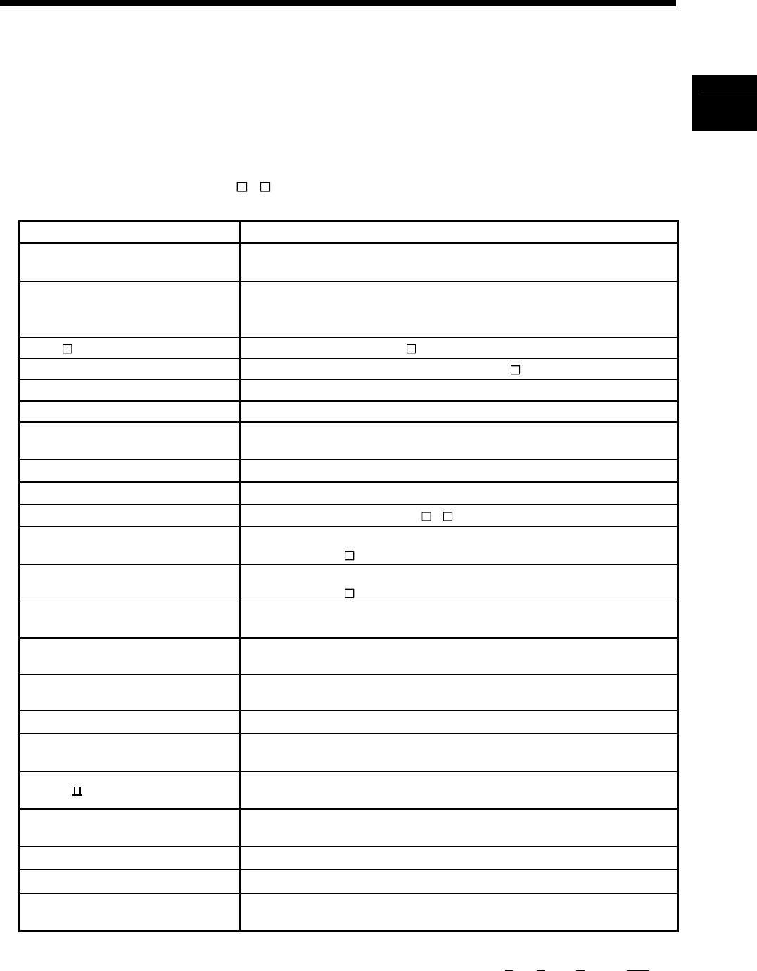
In this manual, the following abbreviations are used.
Generic term/Abbreviation Description
Q173DCPU/Q172DCPU or
Motion CPU (module) Q173DCPU/Q172DCPU Motion CPU module
Q172DLX/Q172DEX/Q173DPX or
Motion module
Q172DLX Servo external signals interface module/
Q172DEX Serial Synchronous encoder interface module(Note-1)/
Q173DPX Manual pulse generator interface module
MR-J3- B Servo amplifier model MR-J3- B
AMP or Servo amplifier General name for "Servo amplifier model MR-J3- B"
QCPU, PLC CPU or PLC CPU module QnUD(H)CPU
Multiple CPU system or Motion system Abbreviation for "Multiple PLC system of the Q series"
CPUn Abbreviation for "CPU No.n (n= 1 to 4) of the CPU module for the Multiple CPU
system"
Self CPU Motion CPU being programmed by the currently open MT Developer project
Programming software package General name for MT Developer/GX Developer/MR Configurator
Operating system software General name for "SW8DNC-SV Q"
SV13 Operating system software for conveyor assembly use (Motion SFC) :
SW8DNC -SV13Q
SV22 Operating system software for automatic machinery use (Motion SFC) :
SW8DNC -SV22Q
MT Developer Abbreviation for "Motion controller programming software
MT Developer2 (Version 1.00A or later)"
GX Developer Abbreviation for "MELSEC PLC programming software package
GX Developer (Version 8.48A or later)"
MR Configurator Abbreviation for "Servo setup software package
MR Configurator (Version C0 or later)"
Manual pulse generator or MR-HDP01 Abbreviation for "Manual pulse generator (MR-HDP01)"
Serial absolute synchronous encoder
or Q170ENC Abbreviation for "Serial absolute synchronous encoder (Q170ENC)"
SSCNET (Note-2) High speed synchronous network between Motion controller and servo
amplifier
Absolute position system General name for "system using the servomotor and servo amplifier for
absolute position"
Battery holder unit Battery holder unit (Q170DBATC)
External battery General name for "Q170DBATC" and "Q6BAT"
Intelligent function module Abbreviation for "MELSECNET/H module/Ethernet module/CC-Link module/
Serial communication module"
(Note-1) : Q172DEX can be used in SV22.
(Note-2) : SSCNET: Servo System Controller NETwork

1 - 2
1 OVERVIEW
REMARK
For information about the each module, design method for program and parameter,
refer to the following manuals relevant to each module.
Item Reference Manual
Motion CPU module/Motion unit Q173DCPU/Q172DCPU User’s Manual
PLC CPU, peripheral devices for PLC program design, I/O
modules and intelligent function module Manual relevant to each module
Operation method for MT Developer Help of each software
• Design method for Motion SFC program
• Design method for Motion SFC parameter
• Motion dedicated PLC instruction
Q173DCPU/Q172DCPU Motion controller (SV13/SV22)
Programming Manual (Motion SFC)
SV13/SV22 • Design method for positioning control
program in the real mode
• Design method for positioning control
parameter
Q173DCPU/Q172DCPU Motion controller (SV13/SV22)
Programming Manual (REAL MODE)
SV22
(Virtual mode)
• Design method for mechanical system
program
Q173DCPU/Q172DCPU Motion controller (SV22)
Programming Manual (VIRTUAL MODE)

1 - 3
1 OVERVIEW
1.2 Features
The Motion CPU and Multiple CPU system have the following features.
1.2.1 Features of Motion CPU
(1) Q series PLC Multiple CPU system
(a) Load distribution of processing can be performed by controlling the
complicated servo control with Motion CPU and the machine control or
information control with PLC CPU. Therefore, the flexible system
configuration can be realized.
(b) The Motion CPU and PLC CPU are selected flexibly, and the Multiple CPU
system up to 4 CPU modules can be realized.
The Motion CPU module for the number of axis to be used can be selected.
Q173DCPU : Up to 32 axes
Q172DCPU : Up to 8 axes
The PLC CPU module for the program capacity to be used can be selected.
(One or more PLC CPU is necessary with the Multiple CPU system.)
Q03UDCPU : 30k steps
Q04UDHCPU : 40k steps
Q06UDHCPU : 60k steps
(c) The device data access of the Motion CPU and the Motion SFC program
start can be executed from PLC CPU by the Motion dedicated PLC
instruction.
(2) High speed operation processing
(a) The minimum operation cycle of the Motion CPU is made 0.44[ms], and it
correspond with high frequency operation.
(b) High speed PLC control is possible by the universal model QCPU.
(For LD instruction)
Q03UDCPU : 20[ns]
Q04UDHCPU : 9.5[ns]
Q06UDHCPU : 9.5[ns]

1 - 4
1 OVERVIEW
(3) Connection between the Motion controller and servo amplifier with
high speed synchronous network by SSCNET
(a) High speed synchronous network by SSCNET connect between the
Motion controller and servo amplifier, and batch control the charge of servo
parameter, servo monitor and test operation, etc.
It is also realised reduce the number of wires.
(b) The maximum distance between the Motion CPU and servo amplifier, servo
amplifier and servo amplifier of the SSCNET cable on the same bus was
set to 50(164.04)[m(ft.)], and the flexibility improved at the Motion system
design.
(4) The operating system software package for your application needs
By installing the operating system software for applications in the internal flash
memory of the Motion CPU, the Motion controller suitable for the machine can be
realized.
And, it also can correspond with the function improvement of the software
package.
(a) Conveyor assembly use (SV13)
Offer liner interpolation, circular interpolation, helical interpolation, constant-
speed control, speed control, fixed-pitch feed and etc. by the dedicated
servo instruction. Ideal for use in conveyors and assembly machines.
(b) Automatic machinery use (SV22)
Provides synchronous control and offers electronic cam control by
mechanical support language. Ideal for use in automatic machinery.
1 - 5
1 OVERVIEW
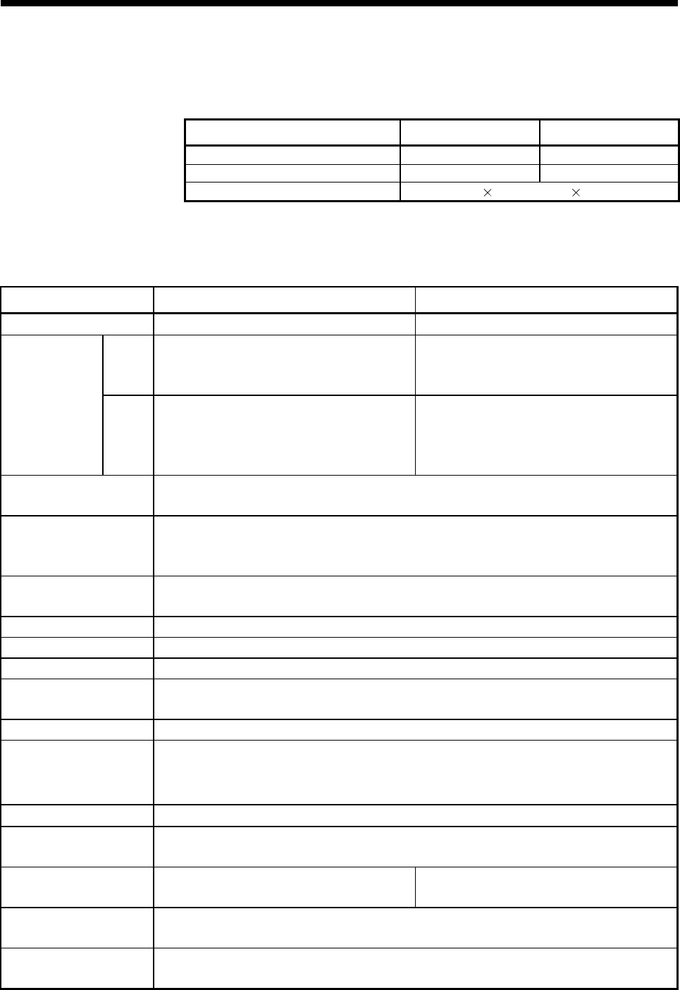
1.2.2 Basic specifications of Q173DCPU/Q172DCPU
(1) Module specifications
Item Q173DCPU Q172DCPU
Internal current consumption (5VDC) [A] 1.25 1.14
Mass [kg] 0.33 0.33
Exterior dimensions [mm(inch)] 98 (3.85)(H) 27.4 (1.08)(W) 119.3 (4.69)(D)
(2) SV13/SV22 Motion control specifications/performance
specifications
(a) Motion control specifications
Item Q173DCPU Q172DCPU
Number of control axes Up to 32 axes Up to 8 axes
SV13
0.44ms/ 1 to 6 axes
0.88ms/ 7 to 18 axes
1.77ms/19 to 32 axes
0.44ms/ 1 to 6 axes
0.88ms/ 7 to 8 axes
Operation cycle
(default)
SV22
0.44ms/ 1 to 4 axes
0.88ms/ 5 to 12 axes
1.77ms/13 to 28 axes
3.55ms/29 to 32 axes
0.44ms/ 1 to 4 axes
0.88ms/ 5 to 8 axes
Interpolation functions Linear interpolation (Up to 4 axes), Circular interpolation (2 axes),
Helical interpolation (3 axes)
Control modes
PTP(Point to Point) control, Speed control, Speed-position control, Fixed-pitch feed,
Constant speed control, Position follow-up control, Speed control with fixed position stop,
Speed switching control, High-speed oscillation control, Synchronous control (SV22)
Acceleration/
deceleration control
Automatic trapezoidal acceleration/deceleration,
S-curve acceleration/deceleration
Compensation Backlash compensation, Electronic gear, Phase compensation (SV22)
Programming language Motion SFC, Dedicated instruction, Mechanical support language (SV22)
Servo program capacity 14k steps
Number of positioning
points
3200 points
(Positioning data can be designated indirectly)
Peripheral I/F Via PLC CPU (USB/RS-232)
Home position return
function
Proximity dog type (2 types), Count type (3 types), Data set type (2 types), Dog cradle type,
Stopper type (2 types), Limit switch combined type
(Home position return re-try function provided, home position shift function provided)
JOG operation function Provided
Manual pulse generator
operation function Possible to connect 3 modules
Synchronous encoder
operation function Possible to connect 12 modules Possible to connect 8 modules
M-code function M-code output function provided
M-code completion wait function provided
Limit switch output
function
Number of output points 32 points
Watch data: Motion control data/Word device

1 - 6
1 OVERVIEW
Motion control specifications (continued)
Item Q173DCPU Q172DCPU
Absolute position system Made compatible by setting battery to servo amplifier.
(Possible to select the absolute data method or incremental method for each axis)
Number of SSCNET
systems (Note-1) 2 systems 1 system
Q172DLX : 4 modules usable Q172DLX : 1 module usable
Q172DEX : 6 modules usable Q172DEX : 4 modules usable
Motion related interface
module
Q173DPX : 4 modules usable (Note-2) Q173DPX : 3 modules usable (Note-2)
(Note-1) : The servo amplifiers for SSCNET cannot be used.
(Note-2) : When using the incremental synchronous encoder (SV22 use), you can use above number of modules.
When connecting the manual pulse generator, you can use only 1 module.
1 - 7
1 OVERVIEW
(b) Motion SFC Performance Specifications
Item Q173DCPU/Q172DCPU
Code total
(Motion SFC chart + Operation control
+ Transition)
543k bytes
Motion SFC program capacity
Text total
(Operation control + Transition) 484k bytes
Number of Motion SFC programs 256 (No.0 to 255)
Motion SFC chart size/program Up to 64k bytes (Included Motion SFC chart comments)
Number of Motion SFC steps/program Up to 4094 steps
Number of selective branches/branch 255
Number of parallel branches/branch 255
Motion SFC program
Parallel branch nesting Up to 4 levels
Number of operation control programs 4096 with F(Once execution type) and FS(Scan execution type)
combined. (F/FS0 to F/FS4095)
Number of transition programs 4096(G0 to G4095)
Code size/program Up to approx. 64k bytes (32766 steps)
Number of blocks(line)/program Up to 8192 blocks (in the case of 4 steps(min)/blocks)
Number of characters/block Up to 128 (comment included)
Number of operand/block Up to 64 (operand: constants, word device, bit devices)
( ) nesting/block Up to 32 levels
Operation control program Calculation expression/bit conditional expression
Operation control program
(F/FS)
/
Transition program
(G)
Descriptive
expression Transition program Calculation expression/bit conditional expression/
comparison conditional expression
Number of multi execute programs Up to 256
Number of multi active steps Up to 256 steps/all programs
Normal task Execute in main cycle of Motion CPU
Fixed cycle Execute in fixed cycle
(0.88ms, 1.77ms, 3.55ms, 7.11ms, 14.2ms)
External
interrupt
Execute when input ON is set among interrupt module QI60
(16 points).
Event task
(Execution
can be
masked.) PLC interrupt Execute with interrupt instruction (D(P).GINT) from PLC CPU.
Execute specification Executed
task
NMI task Execute when input ON is set among interrupt module QI60
(16 points).
Internal relays (M) 8192 points
Link relays (B) 8192 points
Annunciators (F) 2048 points
Special relays (SM) 2256 points
Data registers (D) 8192 points
Link registers (W) 8192 points
Special registers (SD) 2256 points
Motion registers (#) 8736 points
Coasting timers (FT) 1 point (888µs)
Number of devices
(Device In the Motion CPU
only)
(Included the positioning
dedicated device)
Multiple CPU area devices (U \G) Up to 14336 points usable (Note)
(Note): Usable number of points changes according to the system settings.
1 - 8
1 OVERVIEW
1.3 Hardware Configuration
This section describes the Q173DCPU/Q172DCPU system configuration, precautions
on use of system, and configured equipments.
1.3.1 Motion system configuration
This section describes the equipment configuration, configuration with peripheral
devices and system configuration in the Q173DCPU/Q172DCPU system.
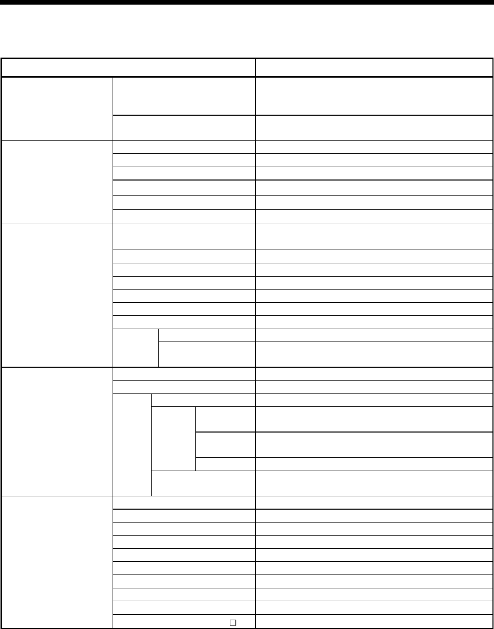
(1) Equipment configuration in Q173DCPU/Q172DCPU system
MITSUBISHI
LITHI UM BATT ERY
It is possible to select the best according to the system.
Power supply module/
QnUD(H)CPU/ I/O module/
Intelligent function module
of the Q series
Motion CPU module
(Q173DCPU/Q172DCPU)
Main base unit
(Q38DB, Q312DB)
Extension cable
(QC B)
Extension of the Q series module
Motion module
(Q172DLX, Q172DEX, Q173DPX)
SSCNET cable
(MR-J3BUS M(-A/-B))
Battery
(Q6BAT)
Servo amplifier
(MR-J3- B)
Motion module
(Q172DLX, Q173DPX)
Power supply module/
I/O module/Intelligent function
module of the Q series
Q6 B extension base unit
(Q63B, Q65B, Q68B, Q612B)
(Note-1) : Be sure to install the Battery (Q6BAT) to the Battery holder unit (Q170DBATC).
It is packed together with Q173DCPU/Q172DCPU.
Battery holder unit
(Q170DBATC)
(Note-1)
Forced stop input cable
(Q170DEMICBL M)
(Note-2)
(Note-1)
(Note-2) : Q172DEX cannot be used in the extension base unit.
Mount it to the main base unit.
1 - 9
1 OVERVIEW
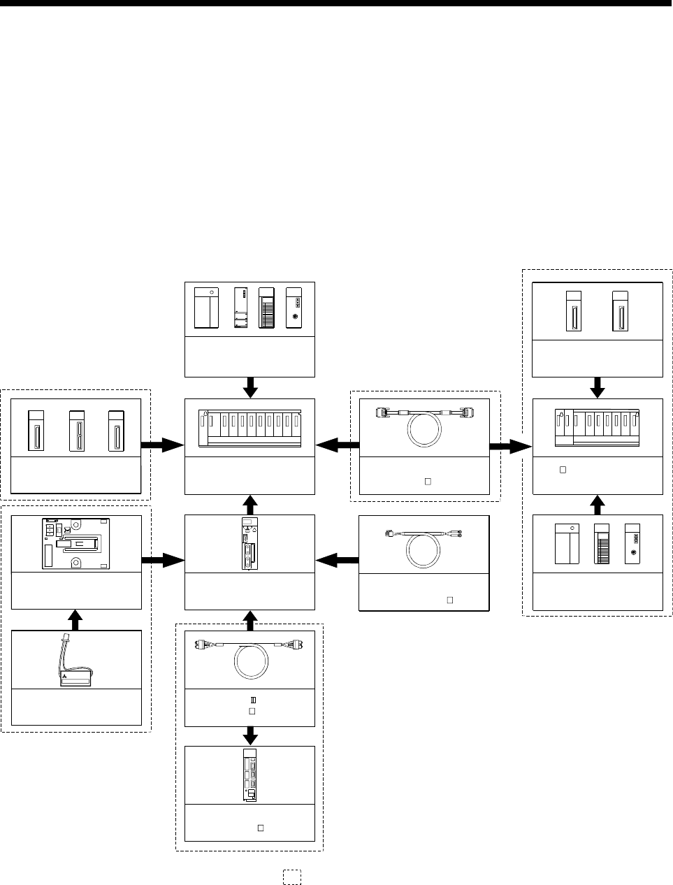
(2) Peripheral device configuration for the Q173DCPU/Q172DCPU
The following (a)(b) can be used.
(a) USB configuration
PLC CPU module
(QnUD(H)CPU)
USB cable
(b) RS-232 configuration
PLC CPU module
(QnUD(H)CPU)
RS-232 communication cable
(QC30R2)
Personal computer
MI
TSUB
ISHI
MI
TSUB
ISHI
Personal computer
1 - 10
1 OVERVIEW
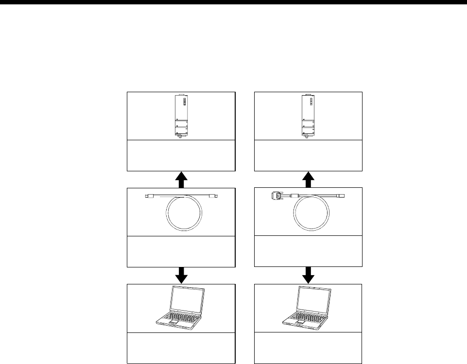
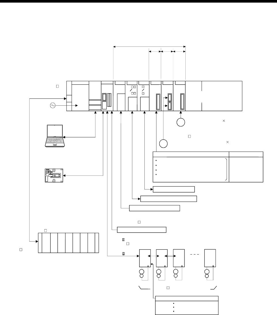
1.3.2 Q173DCPU System overall configuration
Manual pulse generator 3/module
PLC CPU/
Motion CPU
100/200VAC
Q173D
CPU
(Q3 DB) QnUD(H)
CPU
d16
d1
MR-J3- B model Servo amplifier,
Up to 32 axes (Up to 16 axes/system)
Personal Computer
IBM PC/AT
d1
Motion CPU control module
USB/RS-232
Q61P
Main base unit
I/O module/
Intelligent function module
E
M
E
M
E
M
E
M
SSCNET cable
(MR-J3BUS M(-A/-B)) SSCNET (CN1)
SSCNET (CN2)
Battery holder unit
Q170DBATC
d16
External input signals of servo amplifier
Upper stroke limit
Proximity dog
Lower stroke limit
Extension cable
(QC B)
Power supply
module
(Q6 B)
UP to 7 extensions
Extension base unit
QI60 QX
Interrupt signals (16 points)
Analogue input/output
QY
Q6 AD
Q6 DA
Input/output (Up to 256 points)
Manual pulse
generator
interface module
Synchronous
encoder
interface module
Servo external
signals
interface module
(Up to 1 module)
Q172D
EX
(MR-HDP01)
P
Serial absolute synchronous encoder 2/module
(Up to 6 modules) (Q170ENC)
E
Serial absolute synchronous encoder cable
(Q170ENCCBL M)
Q172D
LX
Q173D
PX
External input signals
FLS
8 axes/module
Number of Inputs
(Up to 4 modules)
RLS
STOP
DOG/CHANGE : Proximity dog/
Speed-position switching
: Stop signal
: Lower stroke limit
: Upper stroke limit
EMI forced stop input (24VDC)
Forced stop input cable
(Q170DEMICBL M)

1 - 11
1 OVERVIEW
CAUTION
Construct a safety circuit externally of the Motion controller or servo amplifier if the abnormal
operation of the Motion controller or servo amplifier differ from the safety directive operation in
the system.
The ratings and characteristics of the parts (other than Motion controller, servo amplifier and
servomotor) used in a system must be compatible with the Motion controller, servo amplifier and
servomotor.
Set the parameter values to those that are compatible with the Motion controller, servo amplifier,
servomotor and regenerative resistor model and the system application. The protective functions
may not function if the settings are incorrect.
1 - 12
1 OVERVIEW
1.3.3 Q172DCPU System overall configuration
d2
d1
MR-J3- B model Servo amplifier,
Up to 8 axes
d3
E
M
E
M
E
M
E
M
SSCNET cable
(MR-J3BUS M(-A/-B))
SSCNET (CN1) d8
External input signals of servo amplifier
Upper stroke limit
Proximity dog
Lower stroke limit
PLC CPU/
Motion CPU
100/200VAC
Q172D
CPU
(Q3 DB) QnUD(H)
CPU
Personal Computer
IBM PC/AT
Motion CPU control module
USB/RS-232
Q61P
Main base unit
I/O module /
Intelligent function module
Extension cable
(QC B)
Power supply
module
(Q6 B)
UP to 7 extensions
Extension base unit
QI60 QX
Interrupt signals (16 points)
Analogue input/output
QY
Q6 AD
Q6 DA
Input/output (Up to 256 points)
Manual pulse
generator
interface module
Synchronous
encoder
interface module
Servo external
signals
interface module
(Up to 1 module)
Q172D
EX
(MR-HDP01)
PManual pulse generator 3/module
(Up to 6 modules)
(Q170ENC)
ESerial absolute synchronous encoder 2/module
Serial absolute synchronous encoder cable
(Q170ENCCBL M)
Q172D
LX
Q173D
PX
External input signals
FLS
8 axes/module
Number of Inputs
(Up to 4 modules)
RLS
STOP
DOG/CHANGE : Proximity dog/
Speed-position switching
: Stop signal
: Lower stroke limit
: Upper stroke limit
Battery holder unit
Q170DBATC
EMI forced stop input (24VDC)
Forced stop input cable
(Q170DEMICBL M)

1 - 13
1 OVERVIEW
CAUTION
Construct a safety circuit externally of the Motion controller or servo amplifier if the abnormal
operation of the Motion controller or servo amplifier differ from the safety directive operation in
the system.
The ratings and characteristics of the parts (other than Motion controller, servo amplifier and
servomotor) used in a system must be compatible with the Motion controller, servo amplifier and
servomotor.
Set the parameter values to those that are compatible with the Motion controller, servo amplifier,
servomotor and regenerative resistor model and the system application. The protective functions
may not function if the settings are incorrect.
1 - 14
1 OVERVIEW
1.3.4 Software packages
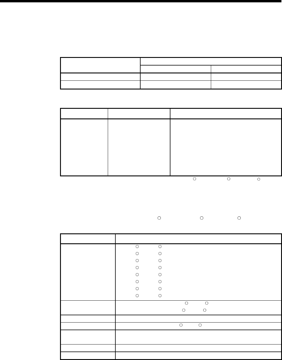
(1) Software packages
(a) Operating system software
Software package
Application Q173DCPU Q172DCPU
For conveyor assembly SV13 SW8DNC-SV13QB SW8DNC-SV13QD
For automatic machinery SV22 SW8DNC-SV22QA SW8DNC-SV22QC
(b) Motion controller programming software
Part name Model name Details
MT Developer2 SW1DNC-MTW2-E
(1 CD-ROM disk)
Conveyor Assembly Software
Automatic Machinery Software
Cam Data Creation Software
Digital Oscilloscope Software
Communication System Software
Document Print Software
Operation Manual (Help)
Installation manual (PDF)
(Note) : Operating environment to use MT Developer is Windows R Vista/WindowsR XP/WindowsR 2000
English version only.
(2) Operating environment of personal computer
Operating environment is shown below.
IBM PC/AT with which WindowsR Vista/WindowsR XP/WindowsR2000 English
version operates normally.
Item Operating environment
OS
MicrosoftR WindowsR Vista Home Basic
MicrosoftR WindowsR Vista Home Premium
MicrosoftR WindowsR Vista Business
MicrosoftR WindowsR Vista Ultimate
MicrosoftR WindowsR Vista Enterprise
MicrosoftR WindowsR XP Professional (Service Pack 2 or later)
MicrosoftR WindowsR XP Home Edition (Service Pack 2 or later)
MicrosoftR WindowsR 2000 Professional (Service Pack 4 or later)
CPU Desktop PC: Recommended Intel R Celeron R Processor 2.8GHz or more
Laptop PC: Recommended Intel R Pentium R Processor M 1.7GHz or more
Memory capacity Recommended 512MB or more
Video card Card compatible with Microsoft R DirectXR 9.0c or later
Available hard disk
capacity
Installation: HD 1GB or more
Operation: Virtual memory 50MB or more
Disk drive CD-ROM disk drive
Display Resolution 1024×768 pixels or higher
(Note-1) : Microsoft, Windows and DirectX are either registered trademarks or trademarks of Microsoft
Corporation in the United States and/or other countries.
(Note-2) : Intel, Celeron and Pentium are trademarks of Intel Corporation in the U.S. and other countries.
1 - 15
1 OVERVIEW
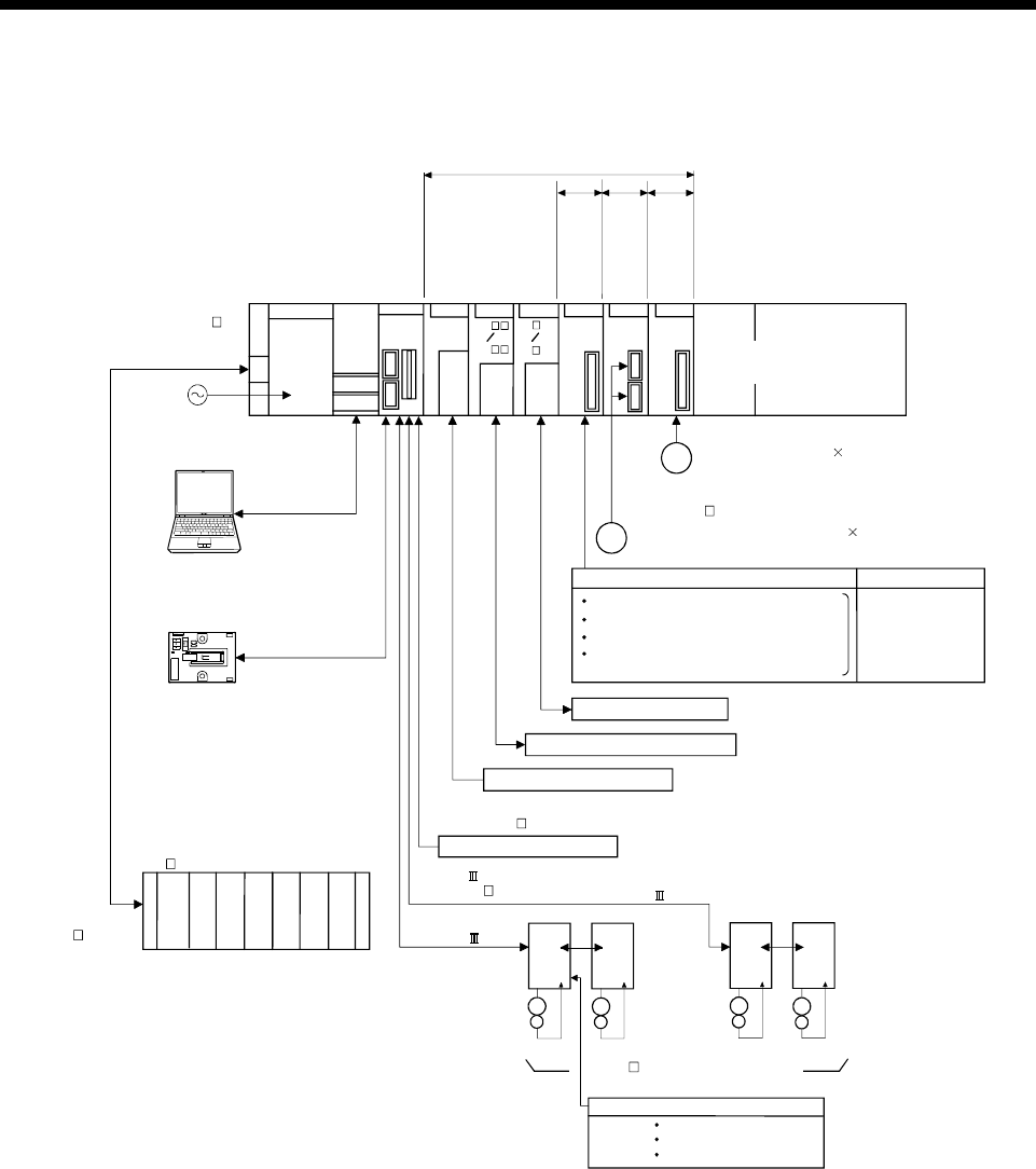
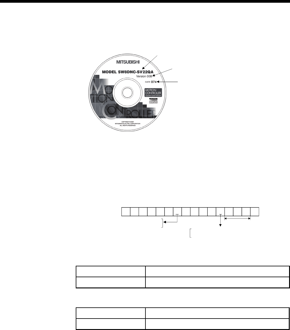
(3) Operating system type/version
(a) Confirmation method in the operating system (CD)
2) OS software version
1)
2)
3)
3) Serial number
1) OS software type
Example) When using Q173DCPU, SV22 and version 00A.
1) SW8DNC-SV22QA
2) 00A
(b) Confirmation method in MT Debeloper
The operating system(OS) type/version of connected CPU is displayed on
the installation screen of MT Developer.
SV 2 2 QAVER3
(OS software)
A or B : Q173DCPU
C or D : Q172DCPU
00 A
OS version
3: Motion SFC compatibility
. : Motion SFC not compatibility
(4) Relevant software packages
(a) PLC software package
Model name Software package
GX Developer SW8D5C-GPPW-E
(b) Servo set up software package
Model name Software package
MR Configurator MRZJW3-SETUP221E
1 - 16
1 OVERVIEW
POINTS
(1) When the operation of Windows is not unclear in the operation of this software,
refer to the manual of Windows or guide-book from the other supplier.
(2) The following functions cannot be used when the computer is running under
WindowsR Vista, WindowsR XP or WindowsR 2000.
This product may not perform properly, when these functions are used.
< WindowsR Vista/WindowsR XP>
• Activating the application with WindowsR compatibility mode
• Fast user switching
• Remote desktop
• Large size
• x64 Edition (64 bit WindowsR)
< WindowsR 2000>
• Large fonts

1 - 17
1 OVERVIEW
1.3.5 Restrictions on motion systems
(1) Combination of Multiple CPU system
(a) Motion CPU module cannot be used as standalone module.
Be sure to install the universal model PLC CPU module (Q03UDCPU/
Q04UDHCPU/Q06UDHCPU) to CPU No.1.
For Universal model PLC CPU module, "Multiple CPU high speed
taransmission function" must be set in the Multiple CPU settings.
(b) Only Multiple CPU high speed main base unit (Q38DB/Q312DB) can be
used.
(c) The combination of Q173DCPU/Q172DCPU and Q173HCPU(-T)/
Q172HCPU(-T)/Q173CPUN(-T)/Q172CPUN(-T) cannot be used.
(d) Up to four modules of PLC CPU modules (Q03UDCPU/Q04UDHCPU/
Q06UDHCPU/Motion CPU modules can be installed from the CPU slot (the
slot on the right side of power supply module) to slot 2 of the main base unit.
CPU modules called as CPU No.1 to CPU No.4 from the left sequentially.
There is no restriction on the installation order of CPU No.2 to No.4.
For CPU module except CPU No.1, an empty slot can be reserved for
addition of CPU module. An empty slot can be set between CPU modules.
However, the mounting condition when combining with the High
performance PLC CPU module/Process CPU module/PC CPU module/C
controller module is different depending on the specification of CPU
modules, refer to the Manuals of each CPU modules.
(e) It takes about 10 seconds to startup (state that can be controlled) of Motion
CPU. Make a Multiple CPU synchronous startup setting suitable for the
system.
(f) Execute the automatic refresh of the Motion CPU modules and PLC CPU
modules (Q03UDCPU/Q04UDHCPU/Q06UDHCPU) by using the automatic
refresh of Multiple CPU high speed transmission area setting.
When the High performance PLC CPU module/Process CPU module/PC
CPU module/C controller module is mounted in the combination of Multiple
CPU system, the Motion CPU module cannot be execute the automatic
refresh with these modules.
(g) Use the Motion dedicated PLC instructions that starts by "D(P).". The Motion
dedicated PLC instructions that starts by "S(P)." cannot be used. When the
High performance PLC CPU module/Process CPU module/PC CPU
module/C controller module is mounted in the combination of Multiple CPU
system, the Motion dedicated PLC instruction from these modules cannot be
executed.

1 - 18
1 OVERVIEW
(2) Motion modules
(a) Installation position of Q172DEX(Note-1) is only the main base unit.
It cannot be used on the extension base unit.
(b) Q172DLX/Q173DPX can be installed on any of the main base unit/
extension base unit.
(c) Q172DLX/Q172DEX(Note-1)/Q173DPX cannot be installed in CPU slot and I/O
slot 0 to 2 of the main base unit. Wrong installation might damage the main
base unit.
(d) Q172EX(-S1/-S2/-S3)/Q172LX/Q173PX(-S1) for Q173HCPU(-T)/
Q172HCPU(-T)/Q173CPUN(-T)/Q172CPUN(-T)/Q173CPU/Q172CPU
cannot be used.
(e) Be sure to use the Motion CPU as the control CPU of Motion modules
(Q172DLX, Q172DEX(Note-1), Q173DPX, etc.) for Motion CPU. They will not
operate correctly if PLC CPU is set and installed as the control CPU by
mistake. Motion CPU is treated as a 32-point intelligent module by PLC
CPU of other CPU.
(Note-1) : Q172DEX can be used in SV22. It cannot be used in SV13.

1 - 19
1 OVERVIEW
(3) Other restrictions
(a) Motion CPU module cannot be set as the control CPU of intelligent function
module (except some modules) or Graphic Operation Terminal(GOT).
(b) Be sure to use the external battery.
(c) There are following methods to execute the forced stop input.
• Use a EMI terminal of Motion CPU module
• Use a device set in the forced stop input setting of system setting
(d) Forced stop input for EMI terminal of Motion CPU module cannot be
invalidated by the parameter.
When the device set in the forced stop input setting is used without use of
EMI terminal of Motion CPU module, apply 24VDC voltage on EMI terminal
and invalidate the forced stop input of EMI terminal.
(e) Be sure to use the cable for forced stop input (sold separately). The forced
stop cannot be released without using it.
(f) When the operation cycle is 0.4[ms], set the system setting as the axis select
switch of servo amplifier "0 to 7".
If the axis select switch of servo amplifier "8 to F" is set, the servo amplifiers
are not recognized.
(g) It is impossible to mount the main base unit by DIN rail when using the
Motion CPU module.
Doing so could result in vibration that may cause erroneous operation.
(h) The module name displayed by "System monitor" - "Product information list"
of GX Developer is different depending on the function version of Motion
modules (Q172DLX, Q172DEX, Q173DPX).
(Note): Even if the function version "C" is displayed, it does not correspond
to the online module change.
Model display
Module name Function version "B" Function version "C"
Q172DLX Q172LX Q172DLX
Q172DEX MOTION-UNIT Q172DEX
Q173DPX MOTION-UNIT Q173DPX

1 - 20
1 OVERVIEW
MEMO

2 - 1
2 MULTIPLE CPU SYSTEM
2
2. MULTIPLE CPU SYSTEM
2.1 Multiple CPU System
2.1.1 Overview
(1) What is Multiple CPU system ?
A Multiple CPU system is a system in which more than one PLC CPU module
and Motion CPU module (up to 4 modules) are mounted on several main base
unit in order to control the I/O modules and intelligent function modules.
Each Motion CPU controls the servo amplifiers connected by SSCNET cable.
(2) System configuration based on load distribution
(a) By distributing such tasks as servo control, machine control and information
control among multiple processors, the flexible system configuration can be
realized.
(b) You can increase the number of control axes by using a multiple Motion
CPU modules.
It is possible to control up to 96 axes by using the three CPU modules
(Q173DCPU).
(c) By distributing the high-load processing performed on a single PLC CPU
over several CPU modules, it is possible to reduce the overall system PLC
scan time.
(3) Communication between CPUs in the Multiple CPU system
(a) Since device data of other CPUs can be automatically read by the automatic
refresh function, the self CPU can also use them as those of self CPU.
(Note): When the High performance PLC CPU module/Process CPU
module/PC CPU module/C controller module is mounted in the
combination of Multiple CPU system, the Motion dedicated PLC
instruction from these modules cannot be executed.
(b) Motion dedicated PLC instructions can be used to access device data from
the PLC CPU to Motion CPU and start Motion SFC program.
2 - 2
2 MULTIPLE CPU SYSTEM
2.1.2 Installation position of CPU module
Up to four PLC CPUs and Motion CPUs can be installed from the CPU slot (the right
side slot of the power supply module) to slots 2 of the main base unit.
The Motion CPU module cannot be installed in the CPU slot.
The PLC CPU module must be installed in the CPU slot (CPU No.1) in the Multiple
CPU system.
There is no restriction on the installation order for CPU modules (CPU No.2 to 4).
(Note): Refer to the manual for each CPU module when the High performance PLC
CPU module, Process CPU module, PC CPU module and C controller module
is mounted in the combination of Multiple CPU.
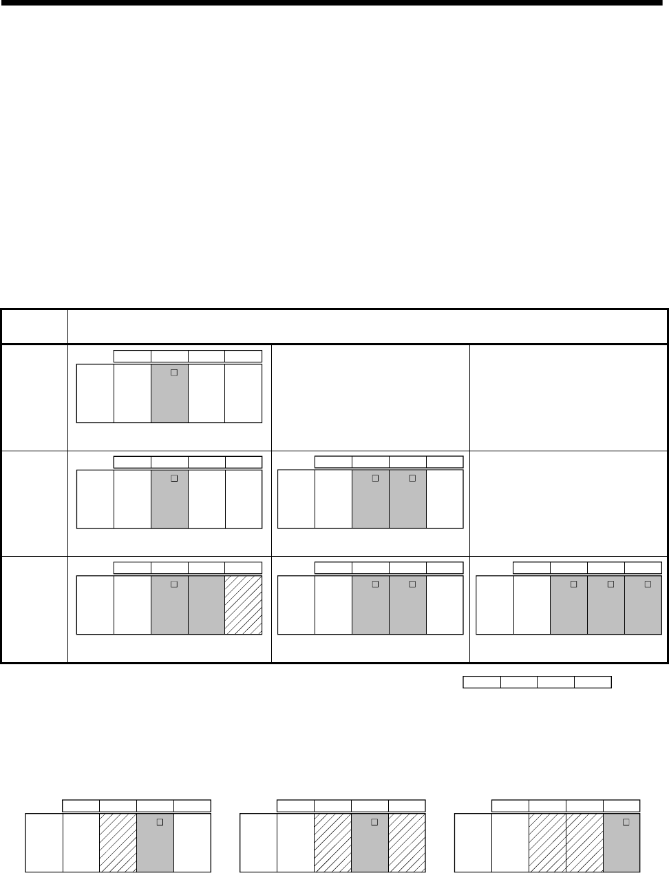
Table 2.1 Example for CPU module installation
Number of
CPUs Installation position of CPU module
2
QnUD(H)
CPU
CPU 0 1 2
Power
supply
Q17 D
CPU
CPU
No.2
CPU
No.1
CPU
No.3
CPU
No.4
—— ——
3
QnUD(H)
CPU
CPU 0 1 2
Power
supply
Q17 D
CPU
CPU
No.2
CPU
No.1
CPU
No.3
CPU
No.4
QnUD(H)
CPU
QnUD(H)
CPU
CPU 0 1 2
Power
supply
Q17 D
CPU
CPU
No.2
CPU
No.1
CPU
No.3
CPU
No.4
Q17 D
CPU
——
4
QnUD(H)
CPU
CPU 0 1 2
Power
supply
Q17 D
CPU
CPU
No.2
CPU
No.1
CPU
No.3
CPU
No.4
QnUD(H)
CPU
CPU
empty
Q17 D
CPU
QnUD(H)
CPU
CPU 0 1 2
Power
supply
Q17 D
CPU
CPU
No.2
CPU
No.1
CPU
No.3
CPU
No.4
QnUD(H)
CPU
Q17 D
CPU
Q17 D
CPU
QnUD(H)
CPU
CPU 0 1 2
Power
supply
Q17 D
CPU
CPU
No.2
CPU
No.1
CPU
No.3
CPU
No.4
CPU012: Slot numbe
r
An empty slot can be reserved for future addition of a CPU module.
Set the number of CPU modules including empty slots in the Multiple CPU setting, and
set the type of the slots to be emptied to "PLC (Empty)" in the CPU setting.
Q17 D
CPU
Q17 D
CPU
QnUD(H)
CPU
CPU 0 1 2
Power
supply
CPU
No.2
CPU
No.1
CPU
No.3
CPU
No.4
(Example 2)
Q17 D
CPU
QnUD(H)
CPU
CPU 0 1 2
Power
supply
CPU
No.2
CPU
No.1
CPU
No.3
CPU
No.4
(Example 1)
QnUD(H)
CPU
CPU 0 1 2
Power
supply
CPU
No.2
CPU
No.1
CPU
No.3
CPU
No.4
(Example 3)
CPU
empty
CPU
empty
CPU
empty
CPU
empty
CPU
empty
2 - 3
2 MULTIPLE CPU SYSTEM
2.1.3 Precautions for using I/O modules and intelligent function modules
(1) Modules controllable by the Motion CPU
Modules controllable by the Motion CPU are shown below.
• Motion modules (Q172DLX, Q172DEX, Q173DPX)
• I/O modules (QX , QY , QH , QX Y)
• Analogue modules (Q6 AD , Q6 AD- , Q6 DA , Q6 DA- )
• Interrupt module (QI60)
(2) Compatibility with the Multiple CPU system
The intelligent function modules of function version "B" or later support the
Multiple CPU system. Be sure to use the PLC CPU as a control CPU because of
the intelligent function modules cannot be controlled by the Motion CPU.
(3) Access range from non-controlled CPU
(a) The Motion CPU can access only the modules controlled by the self CPU. It
cannot access the modules controlled by other CPUs.
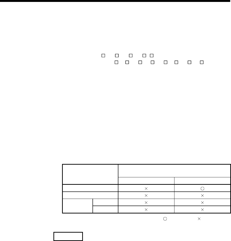
(b) Access range from non-controlled PLC CPU for the modules controlled by
the Motion CPU are shown below.
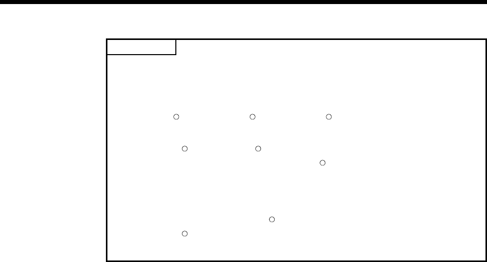
Table 2.2 Access range to non-controlled module
I/O setting outside of the group
(Set by PLC CPU)
Access target
Disabled (Not checked) Enabled (Checked)
Input (X)
Output (Y)
Read
Buffer
memory Write
: Accessible : Inaccessible
REMARK
• The function version of an intelligent function module can be checked on the rated
plate of the intelligent function module or in the GX Developer's system monitor
product information list.
• Refer to the "Q173DCPU/Q172DCPU User's Manual" for the model name which
can be controlled by the Motion CPU.
2 - 4
2 MULTIPLE CPU SYSTEM
2.1.4 Modules subject to installation restrictions
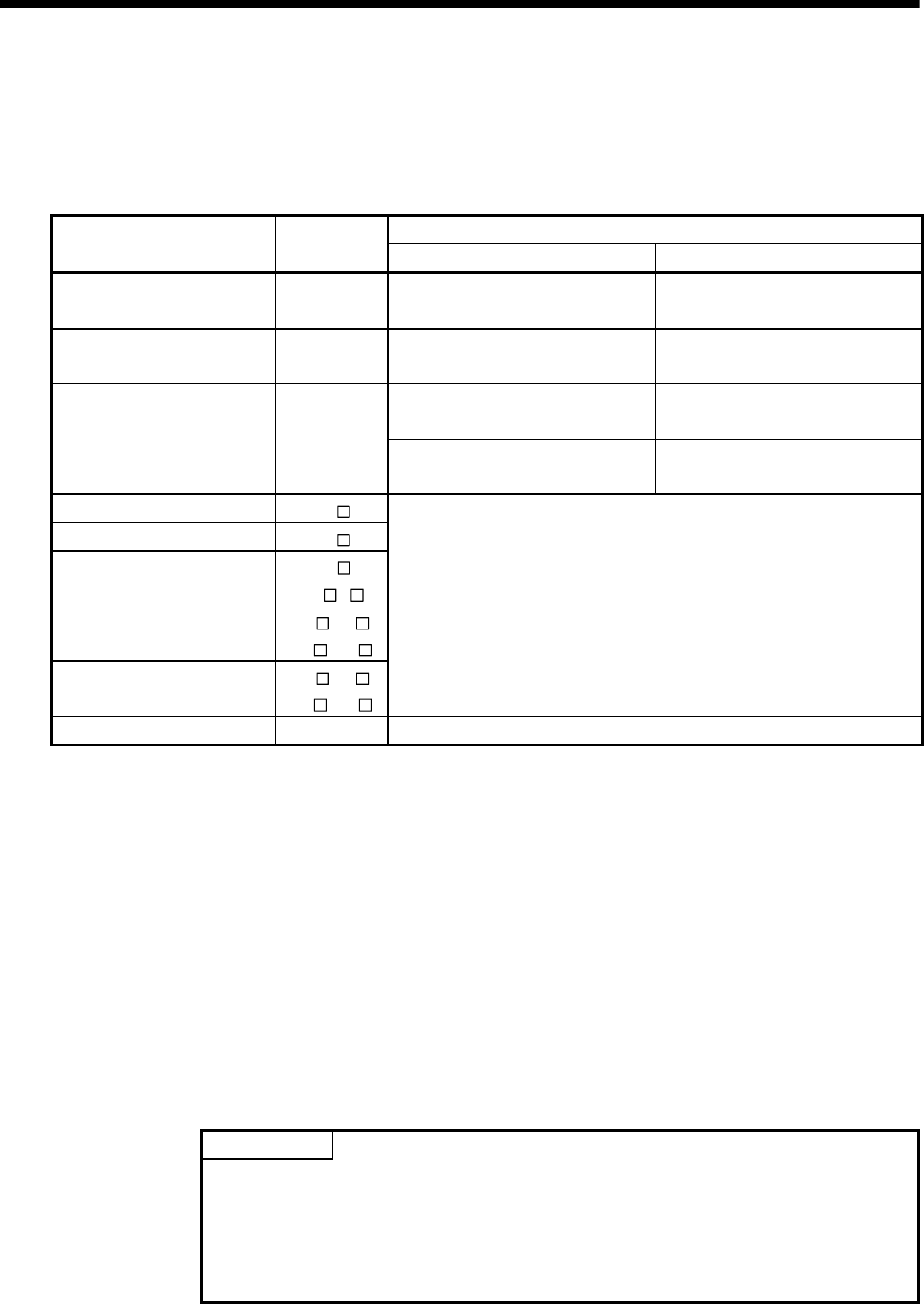
(1) Modules subject to install restrictions for the Motion CPU are sown below. Use
within the restrictions listed below.
Maximum installable modules per CPU
Description Model name Q173DCPU Q172DCPU
Servo external signals
interface module Q172DLX 4 modules 1 module
Serial absolute synchronous
interface module
Q172DEX
(Note-2) 6 modules 4 modules
4 modules (Note-2)
(Incremental serial encoder use)
3 modules (Note-2)
(Incremental serial encoder use)
Manual pulse generator
interface module
Q173DPX
(Note-1) 1 module
(Manual pulse generator only use)
1 module
(Manual pulse generator only use)
Input module QX
Output module QY
Input/output
composite module
QH
QX Y
Analogue input module Q6 AD
Q6 AD-
Analogue output module Q6 DA
Q6 DA-
Total 256 points
Interrupt module QI60 1 module
(Note-1) : When the Manual pulse generator and the serial encoder are used at the same time with the SV22, the
Q173DPX installed in the slot of the smallest number is used for manual pulse generator input.
(Note-2) : SV22 only.
(2) A total of eight base units including one main base unit and seven extension base
units can be used. However, the usable slots (number of modules) are limited to
64 per system including empty slots. If a module is installed in slot 65 or
subsequent slot, an error (SP. UNIT LAY ERROR) will occur. Make sure all
modules are installed in slots 1 to 64. (Even when the total number of slots
provided by the main base unit and extension base units exceeds 65 (such as
when six 12-slot base units are used), an error does not occur as long as the
modules are installed within slots 1 to 64.)
POINT
(1) Q172DLX/Q172DEX/Q173DPX cannot be installed in CPU slot and I/O slot 0
to 2 of the main base unit. Wrong installation might damage the main base
unit.
(2) Q172DEX can be installed in the main base unit only. It cannot be used in the
extension base unit.

2 - 5
2 MULTIPLE CPU SYSTEM
2.1.5 How to reset the Multiple CPU system
The entire Multiple CPU system can be reset by resetting CPU No.1.
The CPU modules of No.2 to No.4, I/O modules and intelligent function modules will be
reset when PLC CPU No.1 is reset.
If a stop error occurs in any of the CPUs on the Multiple CPU system, either reset CPU
No.1 or restart the Multiple CPU system (power supply ON OFF ON) for
recovery.
(Recovery is not allowed by resetting the error-stopped CPU modules other than CPU
No.1.)
POINT
(1) It is not possible to reset the CPU modules of No.2 to No.4 individually in the
Multiple CPU system.
If an attempt to reset any of those PLC CPU modules during operation of the
Multiple CPU system, a "MULTI CPU DOWN (error code: 7000)" error will
occur for the other CPUs, and the entire Multiple CPU system will be halted.
However, depending on the timing in which any of PLC CPU modules other
than No.1 has been reset, an error other than the "MULTI CPU DOWN" may
halt the other PLC CPUs/Motion CPUs.
(2) A "MULTI CPU DOWN (error code: 7000)" error will occur regardless of the
operation mode(All stop by stop error of CPU "n"/continue) set at the "Multiple
CPU setting" screen when any of PLC CPU modules of No.2 to No.4 is reset.
(Refer to Section 2.1.6.)
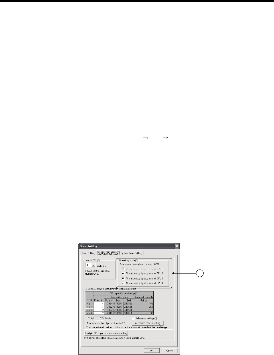
2 - 6
2 MULTIPLE CPU SYSTEM
2.1.6 Operation for CPU module stop error
The entire system will behaves differently depending whether a stop error occurs in
CPU No.1 or any of CPU No.2 to No.4 in the Multiple CPU system.
(1) When a stop error occurs at CPU No.1
(a) A "MULTI CPU DOWN (error code: 7000)" error occurs at the other CPUs
and the Multiple CPU system will be halted when a stop error occurs at the
PLC CPU No.1. (Note-1)
(b) The following procedure to restore the system is shown below.
1) Confirm the error cause with the PLC diagnostics on GX Developer.
2) Remove the error cause.
3) Either reset the PLC CPU No.1 or restart the power to the Multiple CPU
system (power ON OFF ON).
All CPUs on the entire Multiple CPU system will be reset and the system will
be restored when PLC CPU No. 1 is reset or the Multiple CPU system is
reapplied.
(2) When a stop error occurs at CPU other than No.1
Whether the entire system is halted or not is determined by the Multiple CPU
setting's "Operating Mode" setting when a stop error occurs in a PLC CPU
module/Motion CPU module other than CPU No.1.
The default is set for all CPUs to be stopped with a stop error.
When you do not want to stop all CPUs at occurrence of a stop error in a PLC
CPU module/Motion CPU module, remove the check mark that corresponds to
the CPU No. so that its error will not stop all CPUs. (See arrow A.)
A
(a) When a stop error occurs in the CPU module for which "All station stop by
stop error of CPU 'n' " has been set, a "MULTI CPU DOWN (error code:
7000)" error occurs for the other PLC CPU module/Motion CPU modules
and the Multiple CPU system will be halted. (Note-1)
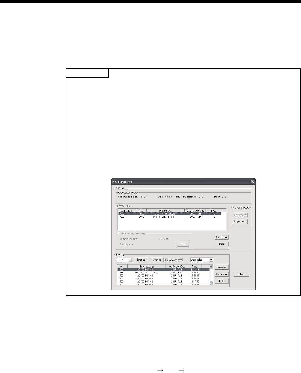
2 - 7
2 MULTIPLE CPU SYSTEM
(b) When a stop error occurs in the CPU module for which " All station stop by
stop error of CPU 'n' " has not been set, a "MULTI EXE. ERROR (error
code: 7010)" error occurs in all other CPUs but operations will continue.
POINT
(Note-1) : When a stop error occurs, a "MULTI CPU DOWN (error code : 7000)"
stop error will occur at the CPU on which the error was detected.
Depending on the timing of error detection, a "MULTI CPU DOWN" error
may be detected in a CPU of "MULTI CPU DOWN" status, not the first
CPU on which a stop error occurs.
Because of this, CPU No. different from the one of initial error CPU may
be stored in the error data's common information category.
To restore the system, remove the error cause on the CPU that is
stopped by an error other than "MULTI CPU DOWN".
In the screen below, the cause of the CPU No.2 error that did not cause
the "MULTI CPU DOWN" error is to be removed.
(c) Observe the following procedures to restore the system.
1) Confirm the error-detected CPU No. and error cause with the PLC
diagnostics on GX Developer.
2) If the error code occurred in Motion CPU 10000 to 10999, confirm the
error cause with Motion CPU error batch monitor of MT Developer.
3) Remove the error cause.
4) Either reset the PLC CPU No.1 or restart the power to the Multiple CPU
system (power ON OFF ON).
All CPUs on the entire Multiple CPU system will be reset and the system will
be restored when PLC CPU No.1 is reset or the power to the Multiple CPU
system is reapplied.

2 - 8
2 MULTIPLE CPU SYSTEM
(3) Operation at a Motion CPU error
Operations at a Motion CPU error are shown below.
Category Type of error Operation Remark
System setting error Does not operate from the
beginning (does not run).
• All actual output PY points turn OFF.
No effect on other CPUs.
WDT error Varies depending on the error.
Self-diagnosis error Stops at a CPU DOWN error.
• All actual output PY points turn OFF.
Other CPUs may also stop depending on
the parameter setting.
Operation
disable errors
Other CPU DOWN error
Operation corresponding to
STOP (M2000 OFF). Depends on
the "Operation mode upon CPU
stop error" setting.
• All actual output PY points turn OFF.
Self-diagnosis error Operation continues when the
continuous error occurred.
Motion SFC error
Minor error
Major error
Servo error
Operation
continuous
enable errors
Servo program setting
error
Processing stops for each
program or axis instead of the
Motion CPU stopping all the
processing.
• Only the applicable program stops (the
program may continue depending on the
type of error).
• Actual output PY retains output.
• No effect on other CPUs.
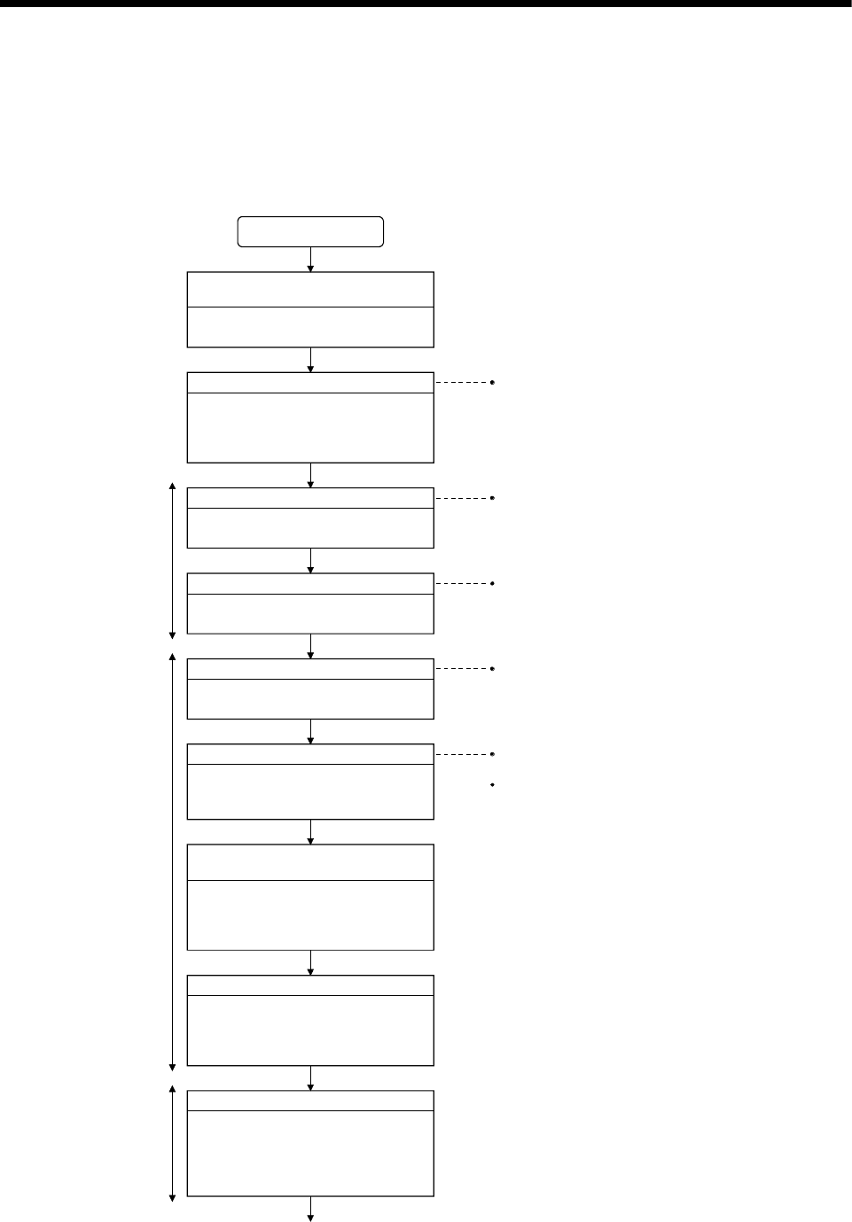
2 - 9
2 MULTIPLE CPU SYSTEM
2.2 Starting Up the Multiple CPU System
This section describes a standard procedure to start up the Multiple CPU system.
2.2.1 Startup Flow of the Multiple CPU System
Refer to the "QCPU User's Manual" (Function
Explanation/Program Fundamentals)".
Install the selected module on the main
base unit and extension base unit.
Definition of functions with Multiple CPU
system
Control and function executed in each
CPU module are defined.
START
Application and assignment of device
When automatic refresh of the CPU
shared memory is performed, the
number of refresh points is continuously
obtained.
Selection of module
Select the module to achieve the
function with the Multiple CPU system.
Installation of module
Start-up GX Developer
(Ver. 8.48A or later).
Start-up of GX Developer
Create the parameter such as Multiple
CPU setting and control CPU setting,
and the PLC program.
Creation of parameters, etc.
Connection of PC to the PLC CPU
module of CPU No. 1
Connect the PC that started
GX Developer to the PLC CPU module
of CPU No. 1 with the RS-232 cable/
USB cable.
Multiple CPU system power ON
Turn ON the power of Multiple CPU
system in the following state of PLC
CPU module of CPU No.1.
RUN/STOP/RESET switch : STOP
Refer to Section 2.3
Refer to the "Q173DCPU/Q172DCPU User's
Manual"
Refer to the "Q173DCPU/Q172DCPU User's
Manual"
Refer to the GX Developer Manual.
Create the parameters for CPU No. 1 to 4 and
PLC programs.
PLC CPU
Motion CPU
PLC CPU
Write parameter and PLC program in
the PLC CPU of CPU No. 1.
For PLC CPU other than CPU No. 1,
select the applicable PLC CPU by
specifying the connection.
Write of parameter and program
PLC CPU
1)
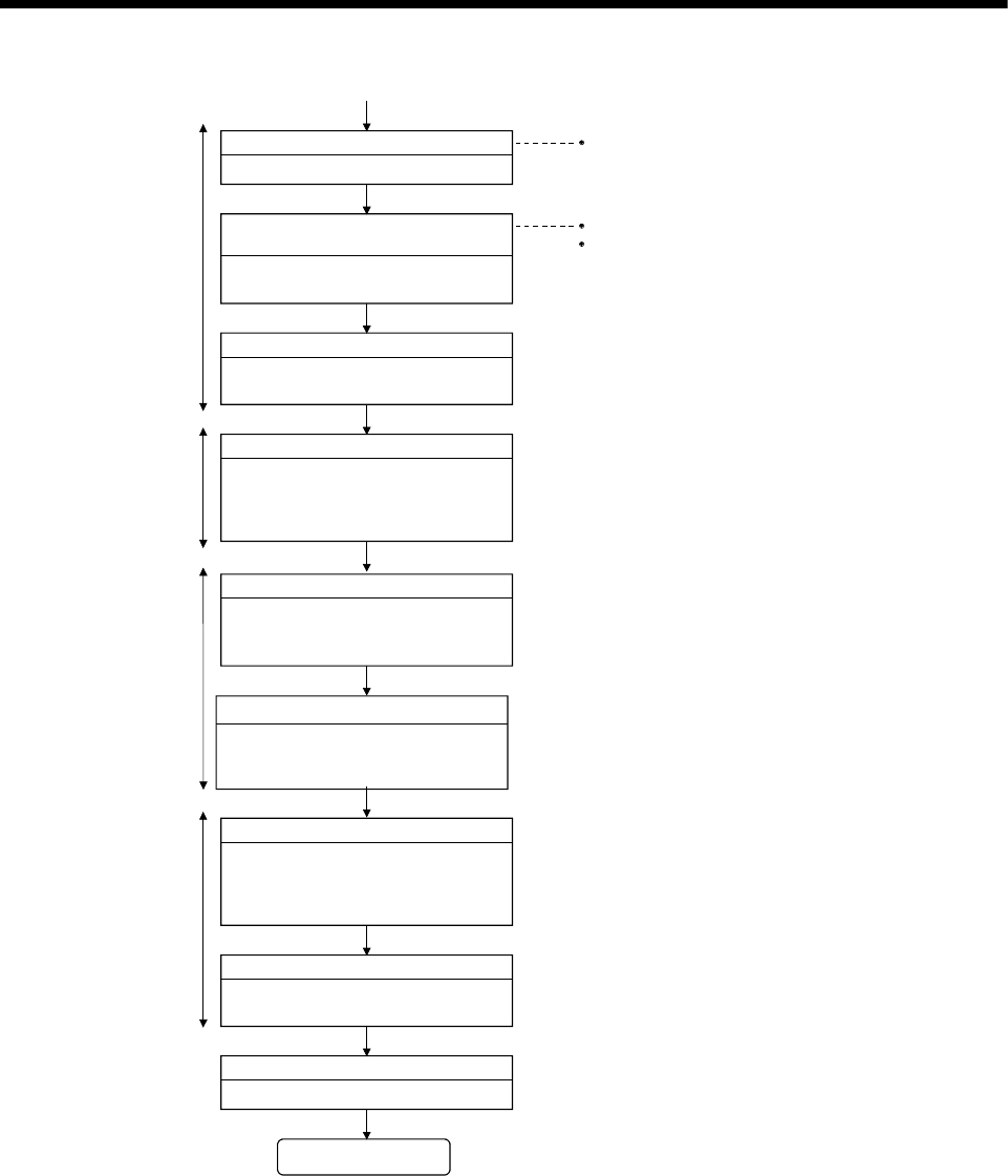
2 - 10
2 MULTIPLE CPU SYSTEM
Refer to the Programming Manual of each
operatin
g
s
y
stem software for details of pro
g
ram.
1)
Refer to Section 3.1 for system settings.
Start-up MT Developer.
Start-up of MT Developer Refer to the help for operation of MT Developer.
Creation of system settings and
program, etc.
Create the system settings, servo data
and Motion SFC program.
Write the system settings, servo data
and Motion SFC program.
Write to the Motion CPU
Reset PLC CPU module of CPU No.1
Set RUN/STOP/RESET switch of PLC
CPU module in CPU No.1 to RESET
to reset the entire system.
Status check in all CPU modules
Check if all CPUs of the Multiple CPU
system are RUN status/error by
resetting the CPU module of CPU No. 1.
Check and correction of errors
An error is checked with the PC
diagnosis function of GX Developer and
Motion CPU error batch monitor of
MT Developer for correction.
Debug of each CPU module
Multiple CPU system is debugged for
each PLC CPU/Motion CPU.
Actual operation
Check in the automatic operation.
END
PLC CPU
Set RUN/STOP/RESET switch of PLC
CPU modules and RUN/STOP switch of
Motion CPU modules in CPU No.1 to 4
to RUN.
Switch setting for all CPUs
PLC CPU
Motion CPU
PLC CPU
Motion CPU
Motion CPU
(Note) : Installation of the operating system software is required to the Motion CPU module before start of
the Multiple CPU system.
Refer to Chapter 5 of the "Q173DCPU/Q172DCPU User's Manual" for installation of the Motion
CPU operating system software.
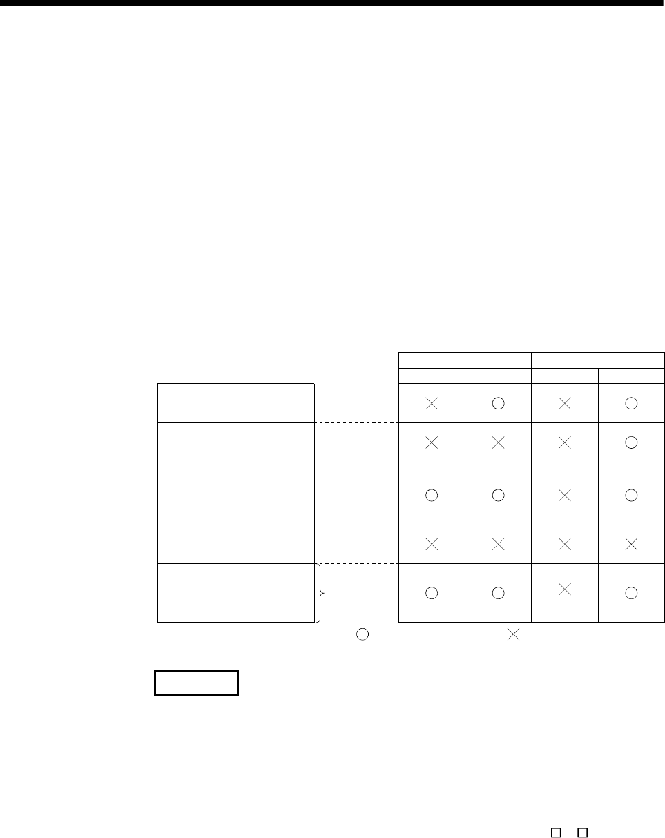
2 - 11
2 MULTIPLE CPU SYSTEM
2.3 Communication between the PLC CPU and the Motion CPU in the Multiple CPU System
2.3.1 CPU shared Memory
(1) Structure of CPU shared memory
The CPU shared memory is memory provided for each CPU module by which
data is written or read between CPU modules of a Multiple CPU system.
The CPU shared memory consists of four areas.
• Self CPU operation information area
• System area
• User setting area
• Multiple CPU high speed transmission area
The CPU shared memory configuration and the availability of the communication
from the self CPU using the CPU shared memory by program are shown below.
Multiple CPU
high speed
bus
(Note-2)
0
511
2047
512
2048
4095
4096
9999
10000
up to
24335
(0H)
(1FFH)
(7FFH)
(200H)
(800H)
(FFFH)
(1000H)
(270FH)
(2710H)
(5F0FH)
Self CPU operation
information area
System area
CPU shared memory
User setting area
to
to
to
to
to
to
to
to
to
to
Multiple CPU high speed
transmission area
(Variable size in 0 to
14k[points]: 1k words in unit)
Write Read Write Read
(Note-2) (Note-2)
(Note-2) (Note-2)
(Note-1)
(Note-3) (Note-3)(Note-3)
Unusable
Self CPU Other CPU
: Communication allowed : Communication not allowed
REMARK
(Note-1) : Use the MULTW instruction to write to the user setting area of the self
CPU in the Motion CPU.
Use the S. TO instruction to write to the user setting area of the self CPU
in the PLC CPU.
(Note-2) : Use the MULTR instruction to read the shared memory of self CPU and
other CPU in the Motion CPU.
Use the FROM instruction/Multiple CPU area device (U \G ) to read the
shared memory of the Motion CPU from the PLC CPU.
(Note-3) : Refer to Section 2.3.2(1) for the access method of Multiple CPU high
speed transmission area.

2 - 12
2 MULTIPLE CPU SYSTEM
(a) Self CPU operation information area (0H to 1FFH)
1) The following information of self CPU is stored as the Multiple CPU
system
Table 2.3 Table of self CPU operation information areas
CPU shared
memory
address
Name Detail Description (Note) Corresponding
special register
0H Information availability
Information availability
flag
The area to confirm if information is stored in the self CPU's
operation information area (1H to 1FH) or not.
• 0: Information not stored in the self CPU's operation information
area.
• 1: Information stored in the self CPU's operation information
area.
—
1H Diagnostic error Diagnostic error number An error No. identified during diagnosis is stored in BIN. SD0
2H
The year and month that the error number was stored in the CPU
shared memory's 1H address is stored with two digits of the BCD
code.
SD1
3H
The date and time that the error number was stored in the CPU
shared memory's 1H address is stored with two digits of the BCD
code.
SD2
4H
Time the diagnostic error
occurred
Time the diagnostic error
occurred
The minutes and seconds that the error number was stored in the
CPU shared memory's 1H address is stored with two digits of the
BCD code.
SD3
5H Error information
identification code
Error information
identification code
Stores an identification code to determine what error information
has been stored in the common error information and individual
error information.
SD4
6H to 10H Common error information Common error information The common information corresponding to the error number
identified during diagnosis is stored. SD5 to SD15
11H to 1BH Individual error
information
Individual error
information
The individual information corresponding to the error number
identified during diagnostic is stored. SD16 to SD26
1CH Empty — Cannot be used —
1DH Switch status CPU switch status Stores the CPU module switch status. SD200
1EH Empty — Cannot be used —
1FH CPU operation status CPU operation status Stores the CPU module's operation status. SD203
(Note) : Refer to the corresponding special register for details.
2) The self CPU operation information area is refreshed every time the
applicable register has been changed in the main cycle.
3) Other PLC CPU can use FROM instruction to read data from the self
CPU operation information area.
However, because there is a delay in data updating, use the read data
for monitoring purposes only.
(b) System area
The area used by the operating systems (OS) of the PLC CPU/Motion CPU.
(c) User setting area
The area for communication between CPU modules in the Multiple CPU
system by MULTR/MULTW instruction of Motion CPU.
(PLC CPU use FROM/S.TO instruction or Multiple CPU area devices to
communicate between CPU modules.)
Refer to the Programming Manual of operating system software for
MULTR/MULTW instruction.
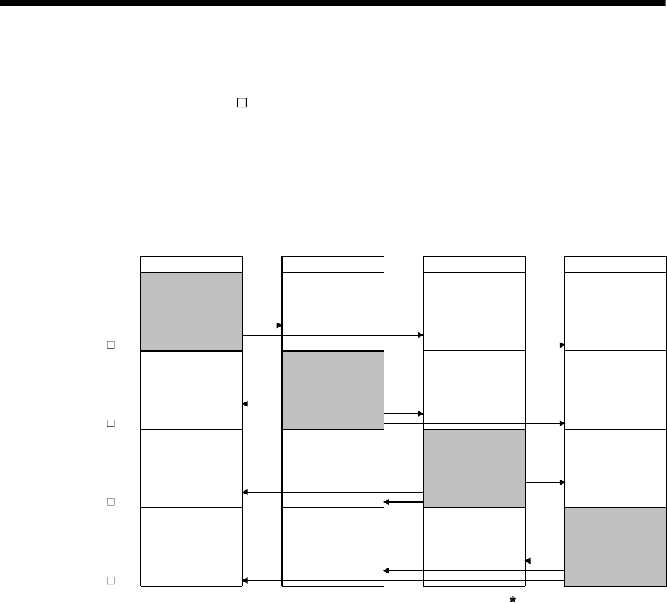
2 - 13
2 MULTIPLE CPU SYSTEM
(d) Multiple CPU high speed transmission area
The area corresponding to the Multiple CPU high speed main base unit
(Q3 DB) and Multiple CPU high speed transmission that uses the drive
system controllers including QnUD(H)CPU and Motion CPU.
The image chart of Multiple CPU high speed transmission area is shown
below.
Refer to Section 2.3.2(1) for access to the Multiple CPU high speed
transmission area of self CPU and other CPU.
CPU No.1
Multiple CPU high
speed transmission
area
(Reception)
CPU No.1
Multiple CPU high
speed transmission
area
(Reception)
CPU No.2
to
(Note-1)
U3E0\G
U3E0\G10000
to
(Note-1)
U3E1\G
U3E1\G10000
to
(Note-1)
U3E2\G
U3E2\G10000
to
(Note-1)
U3E3\G
U3E3\G10000 CPU No.4
Multiple CPU high
speed transmission
area
(Reception)
CPU No.3
Multiple CPU high
speed transmission
area
(Reception)
CPU No.2
Multiple CPU high
speed transmission
area
(Reception)
CPU No.1
CPU No.2
Multiple CPU high
speed transmission
area
(Reception)
CPU No.3 CPU No.4
CPU No.1
Multiple CPU high
speed transmission
area
(Transmission)
(Note-2)
CPU No.2
Multiple CPU high
speed transmission
area
(Transmission)
(Note-2)
CPU No.3
Multiple CPU high
speed transmission
area
(Transmission)
(Note-2)
CPU No.4
Multiple CPU high
speed transmission
area
(Transmission)
(Note-2)
CPU No.1
Multiple CPU high
speed transmission
area
(Reception)
CPU No.4
Multiple CPU high
speed transmission
area
(Reception)
CPU No.3
Multiple CPU high
speed transmission
area
(Reception)
CPU No.4
Multiple CPU high
speed transmission
area
(Reception)
CPU No.3
Multiple CPU high
speed transmission
area
(Reception)
CPU No.2
Multiple CPU high
speed transmission
area
(Reception)
(Note-1) : The final device is "10000+(A 1024-B-1)".
A : Data transmission size of each CPU (1k words in unit)
B : Size used in the automatic refresh of each CPU.
Refer to Section "2.3.2 Multiple CPU high speed transmission"
for the size setting of A and B.
(Note-2) : Transmission area to write/read in the self CPU.
Reception area from the other CPU can be read only.
It is updated ever
y
0.88ms.
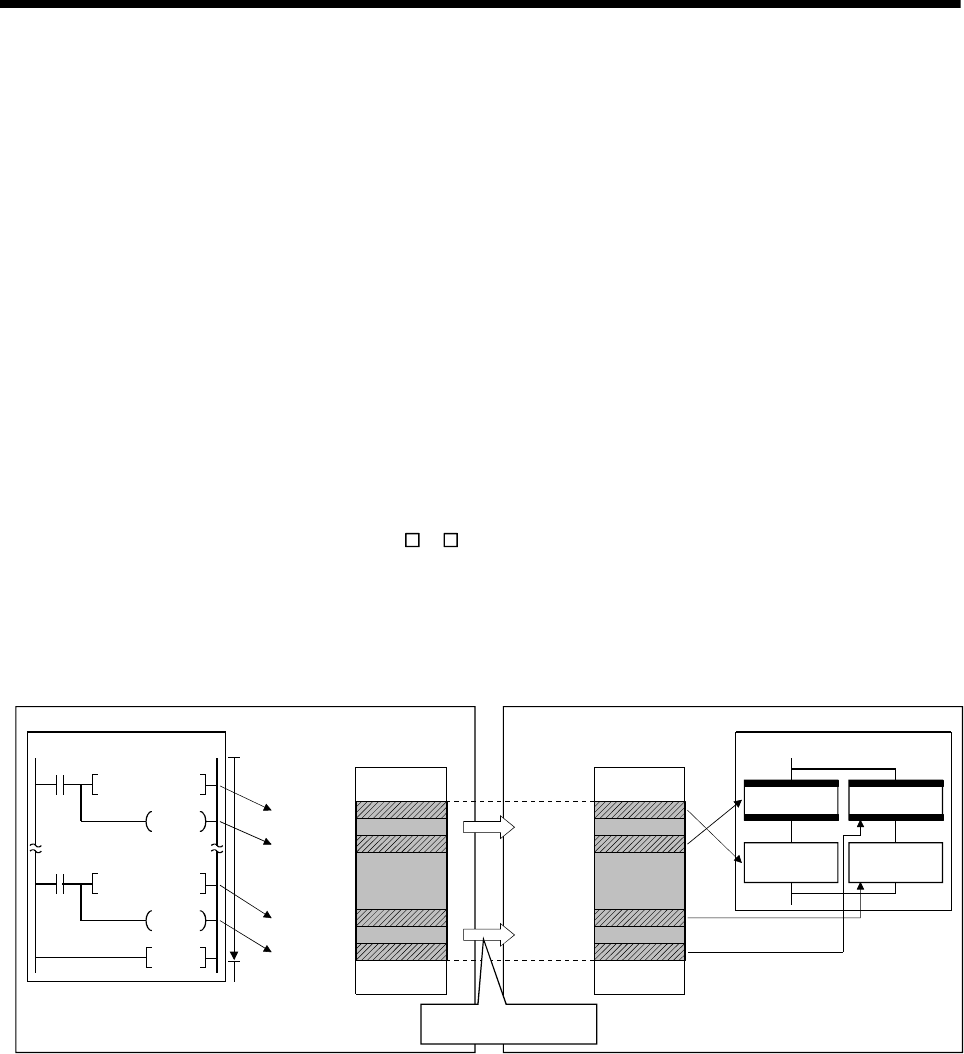
2 - 14
2 MULTIPLE CPU SYSTEM
2.3.2 Multiple CPU high speed transmission
(1) Multiple CPU high speed transmission
Multiple CPU high speed transmission is a function for fixed cycle data
transmission between Multiple CPUs (Multiple CPU high speed transmission
cycle is 0.88ms.).
Secure data transmission is possible without effecting the PLC CPU scan time or
Motion CPU main cycle because the data transmission and execution of PLC
program and Motion SFC program can be executed with parallel processing.
High speed response between multiple CPUs is realized by synchronizing the
Multiple CPU high speed transmission cycle with Motion CPU operation cycle.
The following methods of data transmission exist between Multiple CPUs for
Multiple CPU high speed transmission.
• Multiple CPU area device method
Directly set the Multiple CPU high speed transmission area by Multiple CPU
area device (U \G ) in the program.
• Automatic refresh method
Refresh the internal devices of each CPU by automatic refresh via "Multiple
CPU high speed transmission area".
(a) Multiple CPU area device method
CPU shared memory
(User setting area (Note-1))
SM400
U3E0\
G10110.5
MOV W1
U3E0\
G10100
SM400
2)
U3E0\G10000
U3E0\G10010
U3E0\G10100
U3E0\G10110
U3E0\G10000
U3E0\G10010
U3E0\G10100
U3E0\G10110
5)
1)
4)
U3E0\
G10010.1
MOV W0
U3E0\
G10000
END
CPU No.1 (PLC CPU) CPU No.2 (Motion CPU)
CPU shared memory
(User setting area (Note-1))
PLC program Motion SFC program
3)
6)
G0
U3E0\G10010.1
F0
W0=U3E0\G10010
G1
U3E0\G10110.5
F1
W1=U3E0\G10110
CPU No.1
transmitting
data
CPU No.1
transmitting
data
Multiple CPU high speed
transmission in 0.88ms cycle
1), 4) : Write data in the user setting area (Note-1) by the instruction that uses the Multiple CPU area device.
3), 6) : Read data from the user setting area (Note-1) by the instruction that uses the Multiple CPU area device.
2), 5) : Transmit the contents of user setting area (Note-1) to the other CPU with by Multiple CPU high speed transmission in 0.88ms cycle.
Note-1: The area composed in the Multiple CPU high speed transmission area.
(Refer to Section "(3) Memory configuration of Multiple CPU high speed transmission area".)
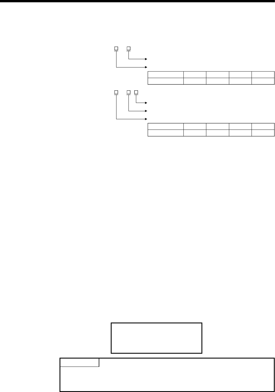
2 - 15
2 MULTIPLE CPU SYSTEM
1) Access to Multiple CPU high speed transmission area
a) Description of Multiple CPU area device
: U \ G
CPU shared memory address (decimal) (10000 to up to 24335)
CPU shared memory address (decimal) (10000 to up to 24335)
First I/O number of CPU module
Bit specification (0 to F : Hexadecimal)
: U \ G .
Bit device
CPU No.
First I/O number 3E0(H)
CPU No.1
3E1(H)
CPU No.2
3E2(H)
CPU No.3
3E3(H)
CPU No.4
First I/O number CPU module
CPU No.
First I/O number 3E0(H)
CPU No.1
3E1(H)
CPU No.2
3E2(H)
CPU No.3
3E3(H)
CPU No.4
Word device
(Example)
• Multiple CPU high speed transmission memory address of CPU No. 2:
10002
U3E1\G10002
• Bit 14 of CPU No. 3 Multiple CPU high speed transmission memory
address 10200
U3E2\G10200.E
b) Example of access in the program
<Motion SFC program>
• Store K12345678 to the Multiple CPU high speed transmission
memory 10200,10201 of self CPU (CPU No.2).
U3E1\G10200L = K12345678
• Turn on bit 12 of the Multiple CPU high speed transmission
memory 10301 of self CPU (CPU No.3)
SET U3E2\G10301.C
<Servo program>
• Program which executes the positioning for Axis 1 to position set
in the Multiple CPU high speed transmission memory 10400,
10401 of CPU No.1 at the speed set in the 10402, 10403 of CPU
No.1, and uses bit 1 of CPU No.1 Multiple CPU high speed
transmission memory 10404 of CPU No.1 as a cancel signal.
ABS-1
Axis 1, U3E0\G10400
Speed U3E0\G10402
Cancel U3E0\G10404.1
POINT
This method can be used to access only the Multiple CPU high speed transmission
area of CPU shared memory. It cannot be used to access the CPU shared memory
(0 to 4095).
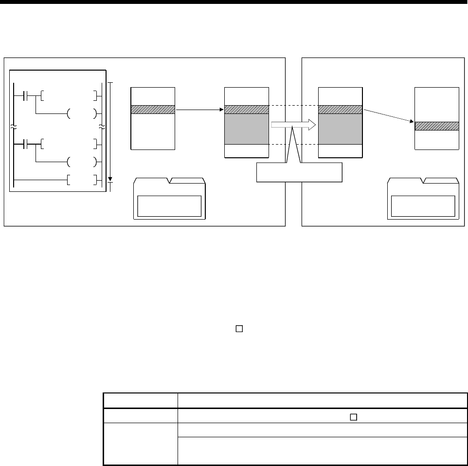
2 - 16
2 MULTIPLE CPU SYSTEM
(b) Example of using automatic refresh method
INC
SM400
SM400
PLC program
CPU No.1 (PLC CPU)
CPU shared memory
(Automatic refresh area (Note-1))
D0
Y0
INC D1
Y0
END
D0
1)
2) 3)
CPU No.2 (Motion CPU)
CPU No.1
transmitting
data D2000
Device memory
CPU shared memory
(Automatic refresh area (Note-1))
Parameter
Device memory
Refresh at the
timing of END
processing
Refresh at the
timing of Motion
CPU main cycle
CPU No.1 to CPU No.2
Transmit D0
CPU No.1 to CPU No.2
Receive D2000
CPU No.1
transmitting
data
Multiple CPU high speed
transmission in 0.88ms cycle
Parameter
1) Transmit the content of D0 to the automatic refresh area (Note-1) at the time of END processing by parameter setting.
2) Transmit the content of automatic refresh area (Note-1) to the other CPU by Multiple CPU high speed transmission at 0.88ms cycle.
3) Read the content of automatic refresh area (Note-1) at the time of Motion CPU main cycle and transmit it to D2000 by parameter setting.
.Note-1: The area composed in the Multiple CPU high speed transmission area.
(Refer to Section "(3) Memory configuration of Multiple CPU high speed transmission area".)
(2) System configuration
Multiple CPU high speed transmission can be used only between CPU modules
for the Multiple CPU high speed transmission installed in the Multiple CPU high
speed main base unit (Q3 DB).
The system configuration specification is shown in Table 2.4.
Table 2.4 System configuration to use Multiple CPU high speed
transmission
Object Restrictions
Base unit Multiple CPU high speed main base unit (Q3 DB) is used.
QnUD(H)CPU is used for CPU No. 1.
CPU module Q173DCPU/Q172DCPU and QnUD(H)CPU are used for CPU No. 2 to
CPU No. 4
"MULTI EXE. ERROR (error code: 7011) will occur if the power supply of Multiple
CPU system is turned on without matching the system configuration shown in
Table 2.4.
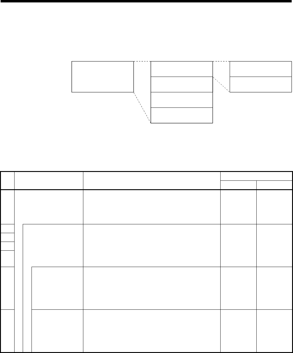
2 - 17
2 MULTIPLE CPU SYSTEM
(3) Memory configuration of Multiple CPU high speed transmission
area
Memory configuration of Multiple CPU high speed transmission area is shown
below.
User setting area
Multiple CPU high speed
transmission area
[Variable in 0 to
14k[points] (Note-1)]Automatic refresh area
7)
6)
CPU No.1 send area
3)
2)
4)
5)
1)
(Note-1): Multiple CPU high speed transmission area;
14k[points]: Maximum value when constituted with two CPUs
13k[points]: Maximum value when constituted with three CPUs
12k[points]: Maximum value when constituted with four CPUs
CPU No.2 send area
CPU No.3 send area
CPU No.4 send area
Table 2.5 Description of area
Size
No. Name Description Setting range Setting unit
1) Multiple CPU high speed
transmission area
• Area for data transmission between each CPU module
in the Multiple CPU system.
• The area up to 14k [points] is divided between each
CPU module that constitutes the Multiple CPU system.
0 to 14k 1k
2)
3)
4)
5)
CPU No. n send area
(n=1 to 4)
• Area to store the send data of the each CPU module.
• Sends the data stored in the send area of self CPU to
the other CPUs.
• Other CPU send area stores the data received from
the other CPUs.
0 to 14k 1k
6) User setting area
• Area for data communication with other CPUs using
the Multiple CPU area device.
• Can be accessed by the user program using the
Multiple CPU area device.
• Refer to Section 2.3.2 (1) for details of this area.
0 to 14k 2
7) Automatic refresh
area
• Area for communicating device data with other CPUs
by the communication using the automatic refresh.
• Access by user program is disabled.
• Refer to Section "(4)(b) Automatic refresh setting" for
details of this area.
0 to 14k 2
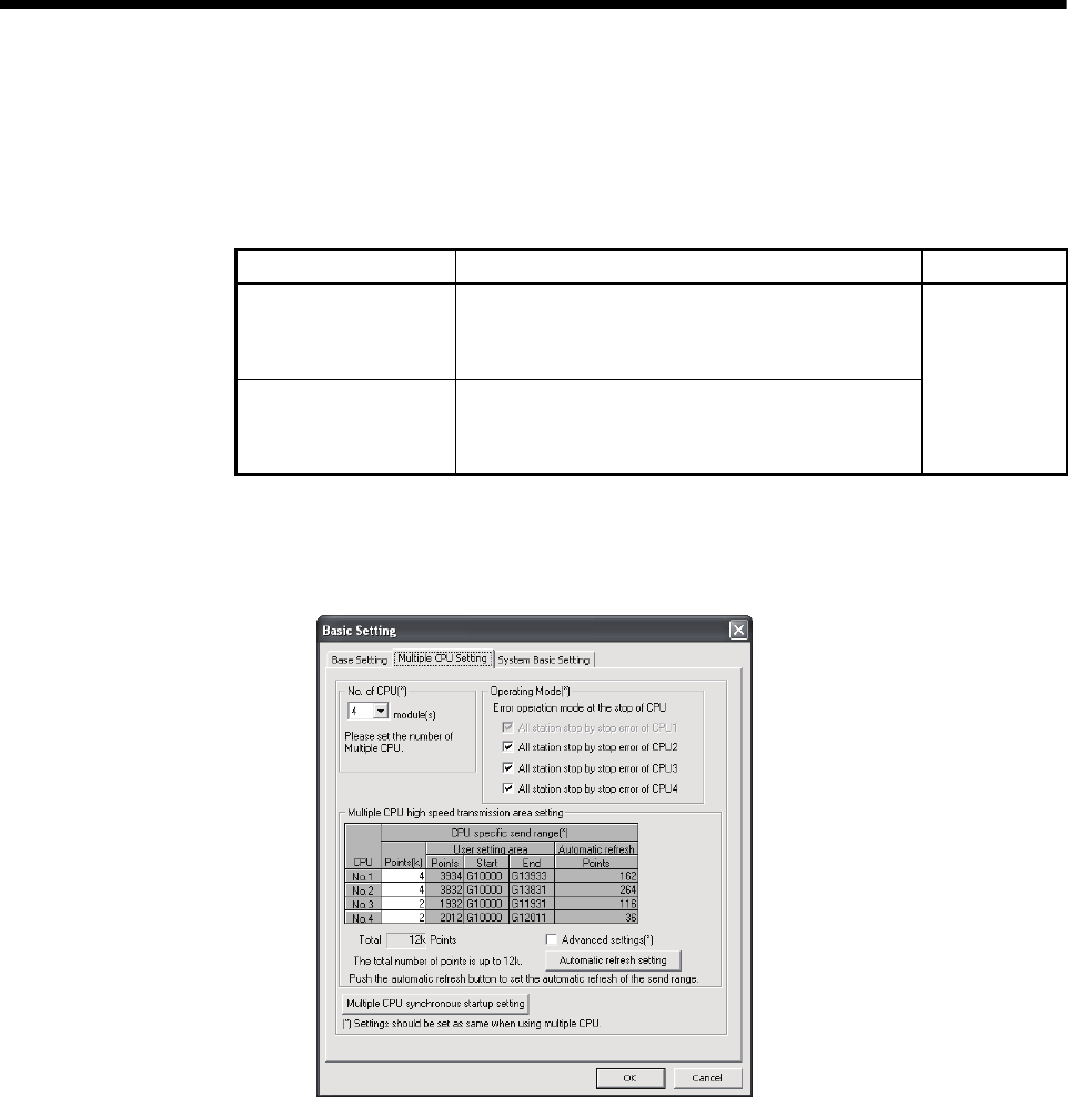
2 - 18
2 MULTIPLE CPU SYSTEM
(4) Parameter setting
The parameter setting list for use with the Multiple CPU high speed transmission
is shown in Table 2.6.
Table 2.6 Multiple CPU high speed transmission parameter list
Name Description Target CPU
Multiple CPU high
speed transmission
area setting
Set the size of the Multiple CPU high speed
transmission area allocated in each CPU module
which composes the Multiple CPU system.
Automatic refresh
setting
Set the range to execute the data transmission by
the automatic refresh function among the user area
in the Multiple CPU high speed transmission area.
All CPUs
(a) Multiple CPU high speed transmission area setting
Multiple CPU high speed transmission area setting screen and setting range
are shown below.

2 - 19
2 MULTIPLE CPU SYSTEM
Table 2.7 Parameter setting items of Multiple CPU high speed transmission area setting
Item Setting description Setting/display value Restriction Consistency
check
CPU CPU No. corresponding to displayed parameters. CPU No.1 to No.4 — —
Set the number of points of data that each CPU
module sends.
Default value assigned to each CPU is shown
below.
Default value of CPU specific
send range [points]
Number of
CPUs CPU
No.1
CPU
No.2
CPU
No.3
CPU
No.4
2 7k 7k — —
3 7k 3k 3k —
4 3k 3k 3k 3k
CPU specific
send range
Range: 0 to 14k [points]
Unit: 1k [point]
(Points: Word in units)
• Set the total of all CPUs to be
the following points or lower.
When constituted with two
CPUs: 14k [points]
When constituted with three
CPUs: 13k [points]
When constituted with four
CPUs: 12k [points]
Provided
Automatic
refresh
Number of points used in the automatic refresh
function is displayed.
Number of points that is set by the "automatic
refresh setting" is displayed.
Range: 0 to 14336 [points]
Unit: 2 [points]
Do not exceed the CPU
specific send range [points]. —
User setting
area
Area size specified directly by program is
displayed.
The value where the "number of points set in the
automatic refresh" is subtracted from the "CPU
specific send range setting" is displayed.
Range: 0 to 14336 [points]
Unit: 2 [points] — —
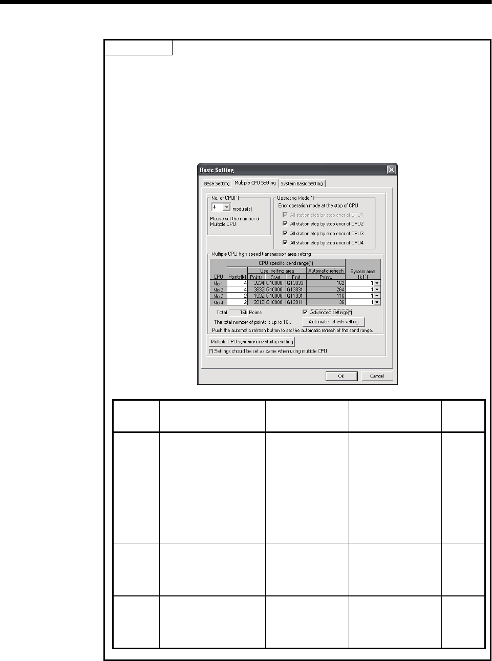
2 - 20
2 MULTIPLE CPU SYSTEM
POINT
Selecting "Advanced setting" enables the ability to change the number of points
from 1k to 2k in the system area used for Motion dedicated PLC instructions.
Changing the number of points in the system area to 2k increases the number of
Motion dedicated PLC instructions that can be executed concurrently in a scan.
The screen where "Advanced setting" is selected is shown below.
Refer to the "Q173DCPU/Q172DCPU Motion controller (SV13/SV22) Programming
Manual (Motion SFC) " for the Motion dedicated PLC instruction.
Item Setting description Setting/display value
(Points: Word in units) Restriction
Data size
consistency
check
CPU specific
send range
Set the number of points of data
that each CPU module sends.
Range: 0 to 14k [points]
Unit: 1k [points]
• Set the total of all CPUs to
be the following points or
lower.
When constituted with two
CPUs: 14k [points]
When constituted with
three CPUs: 13k [points]
When constituted with four
CPUs: 12k [points]
Provided
System area
Set the number of points for a
system area to be assigned for
each CPU module.
(Default value of system area
size is 1k [point].)
Range: 1k/2k [points] — Provided
Total
Display the total of number of
points of the self CPU send area
and the system area that are
assigned to the each CPU
module.
Range: 1 to 16k [points]
Unit: 1k [points]
Set the total of all CPUs to
16.0k points or lower. —
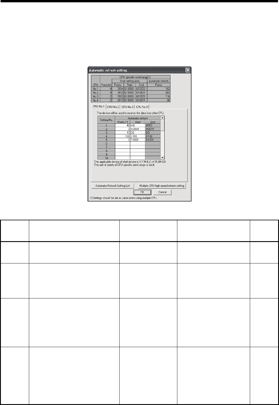
2 - 21
2 MULTIPLE CPU SYSTEM
(b) Automatic refresh setting
Setting for use of the automatic refresh function in the Multiple CPU high
speed transmission area.
Up to 32 setting ranges can be set for each CPU module.
Automatic refresh setting screen and setting range are shown below.
Table 2.8 Parameter setting items of automatic refresh setting
Item Setting description Setting range Restriction
Data size
consistency
check
CPU
selection
Select the CPU module for editing of the
CPU specific send range setting. CPU No.1 to No.4
• CPU No. which exceeds the
number of CPU modules cannot
be selected.
—
Setting No.
The setting No. for transmission of each
CPU module is displayed. Automatic
refresh is executed between devices set to
the same setting No. for all CPUs that
constitute the Multiple CPU system.
1 to 32 — —
Points Set the number of points for data
communication.
Range: 2 to 14336 [points]
Unit: 2 [points]
• Setting which exceeds the
number of points of the self CPU
send area allocated to the each
CPU module (CPU specific send
range) cannot be set.
• Bit device can be specified in
units of 32 points (2 words) only.
Provided
Start
Specifies the device which performs the
data communication (automatic refresh).
Specifies the device sent by the self CPU
when the "Send source CPU selection" is
the self CPU, and specifies the device
received by the self CPU when the CPU
specific send range setting is the other
CPU.
Usable device ( X, Y, M, B,
D, W, #, SM, SD)
Note) Set "blank" when
automatic refresh is
not executed.
• Bit device can be specified in
units of 16 points (1 word) only.
• Device number cannot be
duplicated.
None
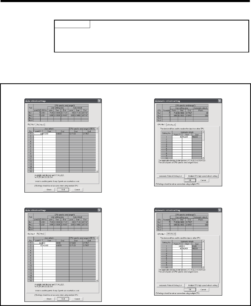
2 - 22
2 MULTIPLE CPU SYSTEM
POINT
The processing performance of automatic refresh improves when devices are
transmitted in 2 word sets. Therefore, it is recommended to set the start device as 2
word unit by inputting an even device number.
1) Operation example of automatic refresh
a) Parameter setting
The example of setting automatic refresh is shown below.
• CPU No.1 (PLC CPU) (GX Developer)
Set the device transmitted to CPU No.2.
• CPU No.2 (Motion CPU) (MT Developer)
Set the device received from CPU No.1.
Set the device received from CPU No.2.
Set the device transmitted to CPU No.1.
(Note) : The operation example of automatic refresh is shown on the next page.
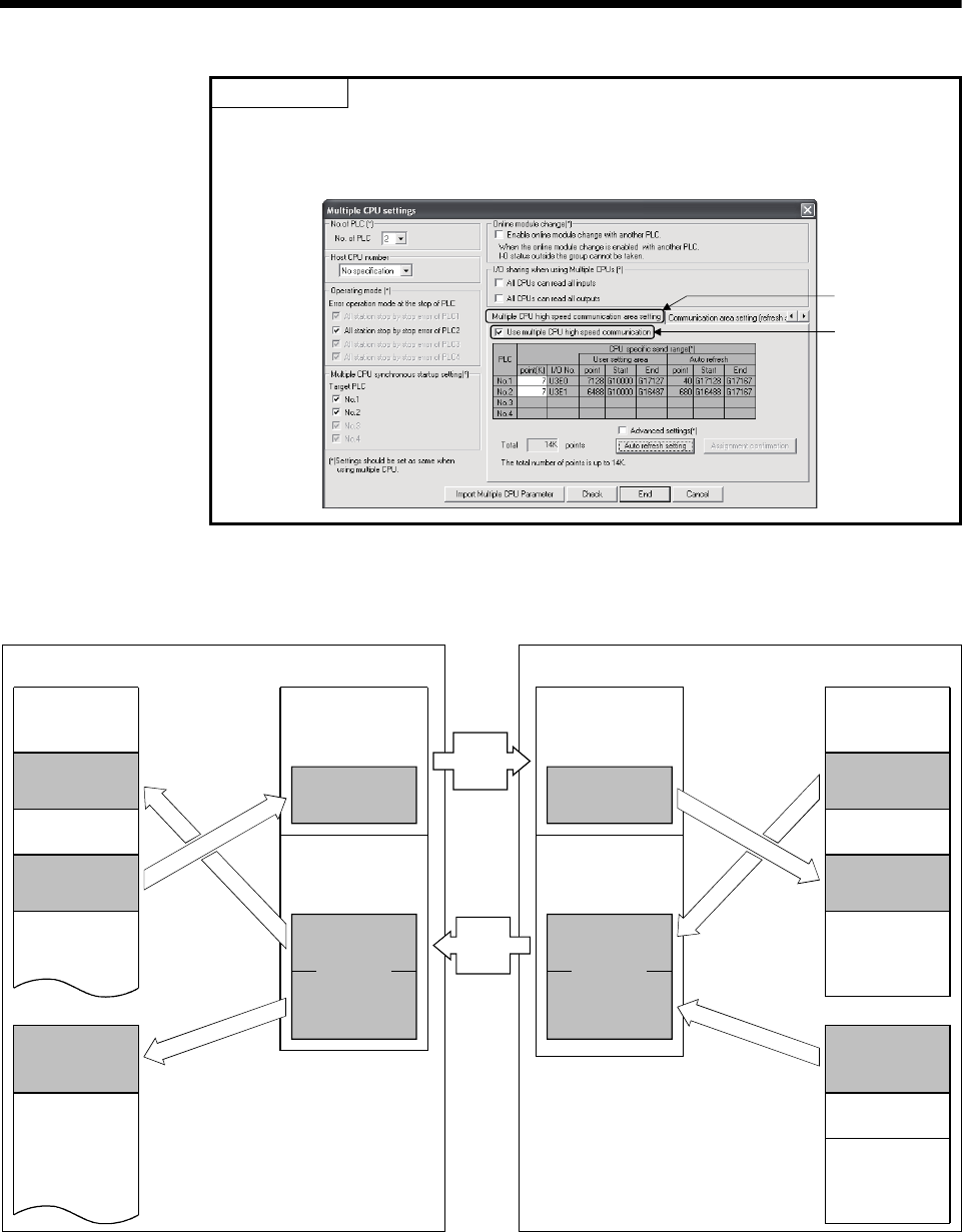
2 - 23
2 MULTIPLE CPU SYSTEM
POINT
Set the following operation for automatic refresh setting using GX Developer.
1) Select tab "Multiple CPU high speed communication area setting".
2) Set "Use Multiple CPU high speed communication ".
1)
2)
b) Operation example
The example of operating automatic refresh is shown below.
U3E1\G10000
Internal relay
Data register
PLC CPU (CPU No.1) Motion CPU (CPU No.2)
Internal relay
Data register
Axis status
Axis command
signal
Axis monitor
device
Control change
register
M3200
M3839
M0
M2399
M2400
M3039
M3040
M3199
M3840
M8191
D0
D639
D640
D703
D704
D8191
M3200
M3839
M0
M2399
M2400
M3039
M3040
M3199
M3840
D0
D639
D640
Automatic
refresh area
Automatic
refresh area
Automatic
refresh area
Automatic
refresh area
U3E0\G10000
U3E1\G10000
U3E0\G10000
Multiple CPU high speed
transmission area
Multiple CPU high speed
transmission area
Main cycle
Main cycle
Main cycle
END processing
END processing
END processing
CPU No.1
transmitting data
CPU No.2
receiving data
CPU No.1
receiving data
CPU No.2
transmitting data
Transfer
in 0.88ms
cycle
Transfer
in 0.88ms
cycle
(c) Data size consistency check
Whether the Multiple CPU setting parameters are the same for all CPUs or
not is automatically checked. A "PARAMETER ERROR (error code: 3012,
3015) " will occur if they do not match.

2 - 24
2 MULTIPLE CPU SYSTEM
(5) Precautions
(a) Assurance of data sent between CPUs
Due to the timing of data sent from the self CPU and automatic refresh in
any of the other CPUs, old data and new data may become mixed (data
separation).
The following shows the methods for avoiding data separation at
communications by automatic refresh.
1) Data consistency for 32 bit data
Transfer data with automatic refresh method is in units of 32 bits. Since
automatic refresh is set in units of 32 bits, 32-bit data does not separate.
• For word data
2 words data can be prevented from separating by using an even
number to set the first number of each device in automatic refresh
setting.
2) Data consistency for data exceeding 32 bits
In automatic refresh method, data is read in descending order of the
setting number in automatic refresh setting parameter.
Transfer data separation can be avoided by using a transfer number
lower than the transfer data as an interlock device.
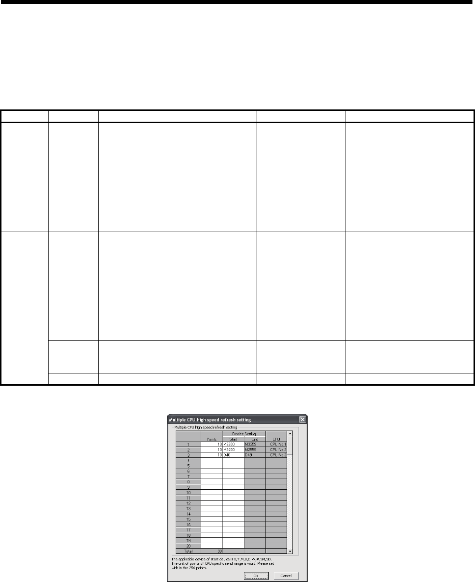
2 - 25
2 MULTIPLE CPU SYSTEM
2.3.3 Multiple CPU high speed refresh function
This function is used to update the data between internal devices of Motion CPU and
the Multiple CPU high speed transmission area. This occurs every operation cycle as
defined in the device setting of automatic refresh in the self CPU.
Classification Item Description Setting/display value Restriction
Setting No. Setting No. which executes high speed
refresh is displayed.
1 to 128
(Up to 128)
Display
CPU
CPU No. set in the automatic refresh setting
is automatically displayed by setting devices.
Self CPU : Refresh from the internal device
of Motion CPU to Multiple CPU
high speed transmission area.
Other CPU : Refresh form the Multiple CPU
high speed transmission area to
internal device of Motion CPU.
CPU No. 1 to No.4
Device
setting
Set the device No. of Motion CPU to execute
the high speed refreshes.
Usable device : D, W, #,
SD, M, X, Y, B, SM
• The start device number must be a
multiple of 16 for the bit device.
• Do not set a device not setting also
set in the automatic refresh.
• No. of "start device + number of
points" cannot exceed setting
range of each setting No. in
automatic refresh setting.
• Do not overlap the device No.
between setting No..
Points
Set the number of points to refresh data of
each data in word unit.
(Note) Refresh is not executed when not set.
Range: 2 to 256 [points]
Unit: 2 points (Note-1)
• Sets the total of all CPUs to 256
points or lower.
User setting
Refresh cycle Operation cycle (fixed) — —
(Note-1) : Point in word unit.
(1) Application example of Multiple CPU high speed refresh function
Multiple CPU high speed refresh function is used as in the following applications.
1) Read the data such as the real current value and synchronous encoder
current value with PLC CPU at high speed.
2) Exchange the FIN waiting signal at high speed.
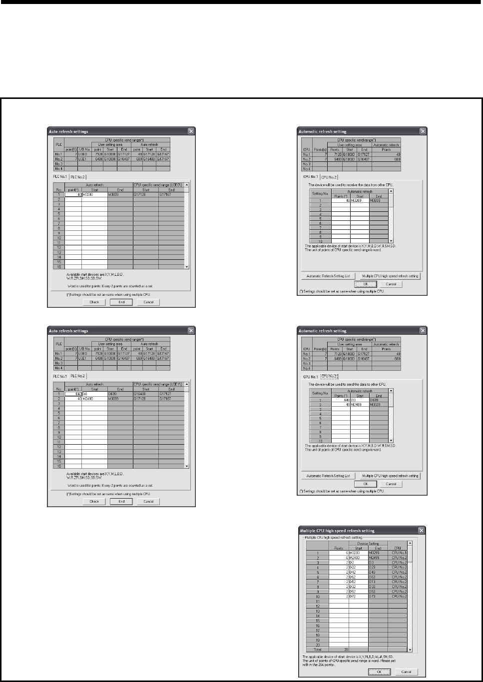
2 - 26
2 MULTIPLE CPU SYSTEM
(2) Operation example of Multiple CPU high speed refresh function
(a) Parameter setting
The automatic refresh setting of Multiple CPU high speed refresh is shown
below.
• CPU No.1 (PLC CPU) (GX Developer)
Set the device transmitted to CPU No.2.
• CPU No.2 (Motion CPU) (MT Developer)
Set the device received from CPU No.1.
Set the device received from CPU No.2.
Set the device transmitted to CPU No.1.
Set the device to executed the Multiple CPU high speed refresh.
(Note) : The operating example of Multiple CPU high speed refresh function is shown
in "(b) Operation example".
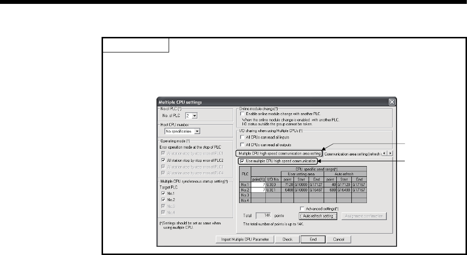
2 - 27
2 MULTIPLE CPU SYSTEM
POINT
Set the following operation for automatic refresh setting using GX Developer.
1) Select tab "Multiple CPU high speed communication area setting".
2) Set "Use Multiple CPU high speed communication ".
1)
2)
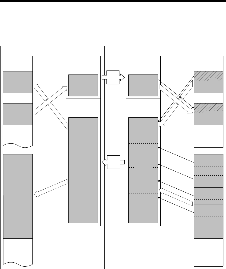
2 - 28
2 MULTIPLE CPU SYSTEM
(b) Operation example
The example of operating Multiple CPU high speed refresh function is
shown below.
U3E1\G10000
U3E0\G10000
D640
Motion CPU (CPU No.2)
Control change
register
D0
D639
PLC CPU (CPU No.1)
Internal relay
Multiple CPU high speed
transmission area Internal relay
Multiple CPU high speed
transmission area
Data register Data register
M3200
M3839
M0
M2399
M2400
M3039
M3040
M3199
M3840
Automatic
refresh area
Automatic
refresh area
CPU No.1
transmitting data
CPU No.2
receiving data
U3E1\G10000
U3E0\G10000
CPU No.1
receiving data
CPU No.2
transmitting data
Automatic
refresh area
Automatic
refresh area
M3200
M3839
M0
M2399
M2400
M3039
M3040
M3199
M3840
D640
D0
D639
M2495
M2496
M3295
M3296
M8191
Axis command
signal
D8191
D704
D703
D80
D60
D40
D20
D19
D79
D59
D39
D2,D3
D12,D13
D62,D63
D72, D73
D42,D43
D52,D53
D22,D23
D32,D33
Operation cycle
Operation cycle
Operation cycle
Operation cycle
Main cycle
Main cycle
Main cycle
Operation cycle
END processing
END processing
END processing
3 axis monitor
device
4 axis monitor
device
1 axis monitor
device
2 axis monitor
device
5 to 32 axis
monitor
device
Transfer
in 0.88ms
cycle
Transfer
in 0.88ms
cycle
Operation
cycle
Axis
status
• Axis 1 to 4 status information (M2400 to M2495) is transferred to the
automatic refresh area one every operation cycle of the Motion CPU.
• Axis 1 to axis 4 command signals are received from the automatic refresh
area one every operation cycle of the Motion CPU.
• Real current values of Axis 1 to axis 4 and M-code is updated by setting
D0 to D639 of the Motion CPU to the automatic refresh area.
• Every 0.88ms, data in the automatic refresh area of all CPUs are
transferred allowing each CPU to update its data upon its next
independent operation cycle.

2 - 29
2 MULTIPLE CPU SYSTEM
2.3.4 Clock synchronization between Multiple CPU
The clock of each CPU is synchronized with the clock of CPU No. 1.
The clock data used for synchronization in a Multiple CPU system can be edited.
(1) Setting of clock data
Set the clock of CPU No.1. The Motion CPU module operates automatically by
the clock of CPU No.1.
POINT
The clock data of CPU No.1 is automatically set even if the clocks of CPU No. 2 to
4 are set independently.
(2) Synchronization of clock data
All clocks are synchronized with CPU No.1 immediately after turning
ON/resetting power and every 1-second interval thereafter.
(3) Information of clock
The clock data that CPU No. 1 transmits is year, month, day, day of week, hour,
minute and second.
(4) Error
Since CPU No.1 sets the clock data at 1-second intervals, an error of up to 1
second may occur to the clock of CPU No.2 to 4.
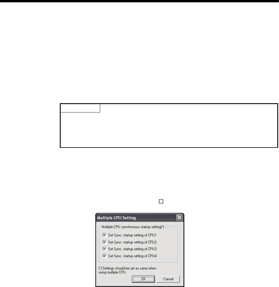
2 - 30
2 MULTIPLE CPU SYSTEM
2.3.5 Multiple CPU synchronous startup
Multiple CPU synchronous startup function synchronizes the startups of CPU No.1 to
CPU No.4. (It takes about ten seconds to startup for Motion CPU.)
Since this function monitors the startup of each CPU module, when other CPU is
accessed by a user program, an interlock program which checks the CPU module
startup is unnecessary.
With the Multiple CPU synchronous startup function, the startup is synchronized with
the slowest CPU module to startup; therefore, the system startup may be slow.
POINT
Multiple CPU synchronous startup function is for accessing each CPU module in a
Multiple CPU system without needing an interlock.
This function is not for starting an operation simultaneously among CPU modules
after startup.
(1) Multiple CPU synchronous startup setting
To use the Multiple CPU synchronous startup function, check No.1 to No.4 of
target CPU in Multiple CPU settings in system setting of MT Developer. (Set it in
the Multiple CPU setting of PLC parameter setting of GX Developer for
QnUD(H)CPU.)
"Set Sync. startup setting of CPU " is set for No.1 to 4 at default.
Set the same Multiple CPU synchronous startup for all CPUs that constitute the
Multiple CPU system.
The self-diagnosis error "PARAMETER ERROR (error code: 3015)" will occur if
all CPU modules that constitute the Multiple CPU system do not have the same
setting.
When this function is not used (each CPU startup without synchronization),
startup of each CPU module can be confirmed by using special relays SM220 to
SM223 (CPU No.1 to 4 READY complete flag).
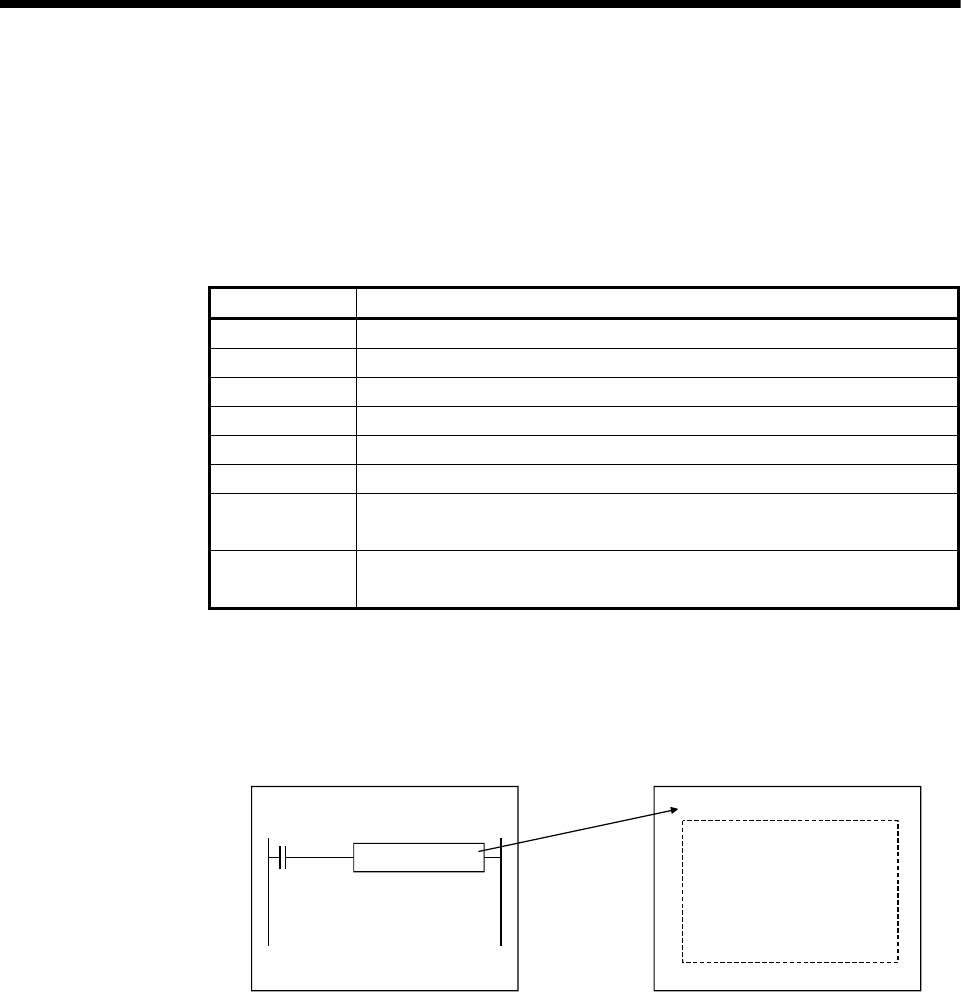
2 - 31
2 MULTIPLE CPU SYSTEM
2.3.6 Control Instruction from PLC CPU to Motion CPU
Control can be instructed from the PLC CPU to the Motion CPU using the Motion
dedicated PLC instructions listed in the table below.
Refer to the "Q173DCPU/Q172DCPU Motion controller (SV13/SV22) Programming
Manual (Motion SFC)" for the details of each instruction.
(Control may not be instructed from one Motion CPU to another Motion CPU.)
Instruction name Description
D(P).SFCS Start request of the Motion SFC program (Program No. may be specified.)
D(P).SVST Start request of the specified servo program
D(P).CHGA Current value change request of the specified axis
D(P).CHGV Speed change request of the specified axis
D(P).CHGT Torque control value change request of the specified axis
D(P).GINT Execute request of an event task to the other CPU (Motion CPU)
D(P).DDWR Write device data of the self CPU (PLC CPU) to the device of other CPU
(Motion CPU)
D(P).DDRD Read device data of other CPU (Motion CPU) to the device of self CPU
(PLC CPU)
For example, by using the D(P).SFCS instruction of Motion dedicated PLC instruction,
the Motion SFC of the Motion CPU can be started from the PLC CPU.
<Example>
PLC CPU Motion CPU
Motion SFC
D(P). SFCS instruction
Start request

2 - 32
2 MULTIPLE CPU SYSTEM
MEMO

3 - 1
3 COMMON PARAMETERS
3
3. COMMON PARAMETERS
3.1 System Settings
In the Multiple CPU system, the common system parameters and individual
parameters are set for each CPU and written to each CPU.
(1) The base settings, Multiple CPU settings and Motion slot settings are set in the
common system parameter setting.
(2) The system basic setting, self CPU installation position setting, servo
amplifier setting, high-speed read setting and optional data monitor setting are set
in the individual parameter setting.
(3) The data setting and correction can be performed in dialog form using MT
Developer.

3 - 2
3 COMMON PARAMETERS
3.1.1 System data settings
The table below lists the system data items to be set.
Item Setting range Initial value Remark
Main base 8/12 slots Main base: 8 slots
Base setting Extension base None/2/3/5/8/10/12 slots None
Set the number of slots in the main
base or extension base.
No. of CPU 2/3/4 modules 2 modules Set the total number of Multiple
CPUs including PLC CPU(s).
Error operation mode at the
stop of CPU
Stop/do not stop all CPUs upon an
error in CPU No. 1 to 4.
(The setting range varies depending
on the number of Multiple CPUs.)
Stop all CPUs upon error
in CPU Nos. 1 to 4
Set whether or not to stop the entire
system when a CPU stop error
occurs in each CPU.
CPU
specific
send range
0 to 14k points Varies depending on the
number of CPUs.
System
area 1 to 2k points 1
Multiple CPU
high speed
transmission
area setting Automatic
refresh
setting
Point : 2 to 14336 points
Start : Set target device for
automatic refresh.
None
Refer to Section 2.3.2.
Multiple CPU
setting
Multiple CPU synchronous
startup setting
Set/do not set CPU No. 1 to 4 as the
synchronized startup.
(The setting range varies depending
on the number of Multiple CPUs.)
Set CPU No. 1 to 4 as
the synchronized startup. Refer to Section 2.3.5.
Module arrangement Within the main base and extension
base slots None
Install the modules controlled by the
self CPU in the main base and/or
extension base(s).
Common
system
parameters
Motion slot
setting
Individual module Varies depending on the module. Varies depending on the
module.
Set detailed items for each module
controlled by the self CPU.
Operation cycle 0.4ms/0.8ms/1.7ms/3.5ms/7.1 ms/
14.2ms/Auto Auto Set the operation cycle of motion
control.
Operation at STOP to RUN
M2000 is turned on by switching
from STOP to RUN./M2000 is
turned on by switching from STOP
to RUN and setting 1 in the set
register.
M2000 is turned on by
switching from STOP to
RUN.
Set the condition in which the PLC
ready flag (M2000) turns on.
Forced stop (Note-1) None/X(PX) (0 to 1FFF)/
M (0 to 8191) None
Set the bit device to use forced stop
in the program.
However, the forced stop input by
EMI terminal of Motion CPU module
cannot be invalidated using
parameter setting.
System basic
setting
Latch range
M (0 to 8191)/B (0 to 1FFF)/
F (0 to 2047)/D (0 to 8191)/
W (0 to 1FFF)
None Set the latch range of device
memory.
Individual
parameters
Self CPU installation position setting
Set self CPU/other CPU/CPU
(empty) for slots 0/1/2. (The setting
range varies depending on the
number of Multiple CPUs installed.)
None Set the installation position of the
self CPU in the main base.

3 - 3
3 COMMON PARAMETERS
Item Setting range Initial value Remark
Q173DCPU: Up to 2 systems, 32
axes
Q172DCPU: Up to 1 system, 8 axes
None Set the model name, axis No. and
other details for the servo amplifiers.
External signal input setting
Amplifier input invalid/Amplifier input
valid
Amplifier input invalid
Amplifier setting
Input filter setting
None/0.8ms/1.7ms/2.6ms/3.5ms 3.5ms
—
High-speed data read setting One Q172DEX/Q173DPX module
and one input module. None Set the high-speed read data.
Refer to Section 4.3.
Individual
parameters
Optional data monitor setting
Set 1 to 3 for each axis.
Q173DCPU: Up to 32 axes
Q172DCPU: Up to 8 axes
None Set the optional data monitor.
Refer to Section 4.10.
(Note-1) : The forced stop can also be executed by the EMI forced stop terminal of Motion CPU module or forced stop terminal of
servo amplifier besides the forced stop input setting.
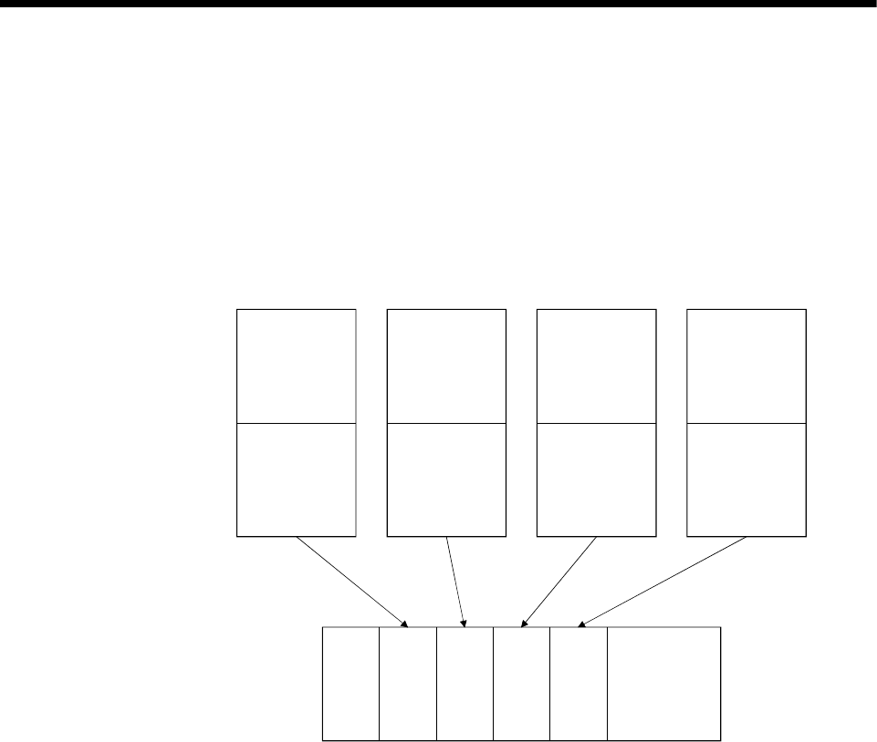
3 - 4
3 COMMON PARAMETERS
3.1.2 Common system parameters
(1) Parameters for operating the Multiple CPU system
In the Multiple CPU system, the common system parameters and individual
parameter for each CPU are set and written into each CPU. Regarding the
Motion CPU, the items in System Settings related to the entire Multiple CPU
system must be identical to the parameter settings in the PLC CPU.
Parameter write
PLC CPU
parameters
Power supply
QnUD(H)
CPU
Q173D
CPU
QnUD(H)
CPU
Q172D
CPU
Individual
parameter
Common system
parameters
Individual
parameter
Common system
parameters
Individual
parameter
Common system
parameters
Individual
parameter
Common system
parameters
PLC CPU
parameters
Motion CPU
parameters
Motion CPU
parameters

3 - 5
3 COMMON PARAMETERS
(2) Parameters common throughout the Multiple CPU system
In the Motion CPU, during initialization the parameters in the table below are
verified against the parameters in the PLC CPU of CPU No. 1. Unmatched
parameters generate a PARAMETER ERROR (error code: 3012, 3015), so the
parameters show below must be set identically between Motion CPUs and the
PLC CPU of CPU No.1. (If the system settings are changed in a Motion CPU, it is
necessary to reset. Therefore, the parameters are checked only during
initialization.)
The parameter No. of unmatched parameter is set in the error individual
information (SD16) by this error occurrence.
PLC CPUs can use the parameters of the other CPUs via "Multiple CPU
parameter utilization" of GX Developer. Since Motion CPUs don't have this
function, however, the common parameters must be set for each Motion CPU.
Table of Parameters cross-Multiple CPU system
Type of parameter
Name in Motion CPU Name in PLC CPU Verification item Parameter
number Remark
No. of CPU No. of PLC Number of CPUs 0E00H
Operating mode Operating mode Operation mode for CPU
stop error 0E01H
CPU specific
send range
CPU specific
send range
Points of CPU specific
send range E008H Refer to Section 2.3.2.
System area System area System area size E008H
Refer to Section 2.3.2.
This parameter can be
set when "Advanced
setting" is selected.
Multiple CPU
high speed
transmission
area setting
Automatic
refresh setting
Multiple CPU
high speed
transmission
area setting
Automatic
refresh setting
Points of automatic
refresh E009H
Refer to Section 2.3.2.
(Automatic refresh using
Multiple CPU high speed
transmission area)
Multiple
CPU setting
Multiple CPU synchronous
startup setting
Multiple
CPU
settings
Multiple CPU synchronous
startup setting
Synchronize Multiple CPU
startup or not E00BH Refer to Section 2.3.5.
Motion slot setting Detailed settings Control PLC Control CPU No. 0406H
Verify module only set in
the system settings in the
Motion CPU side.
Total number of bases
Base No.
Base setting
I/O
assignment
Basic setting Slots Base Number of base
slots
0401H
Not verified if base
settings are omitted in
the PLC CPU side.
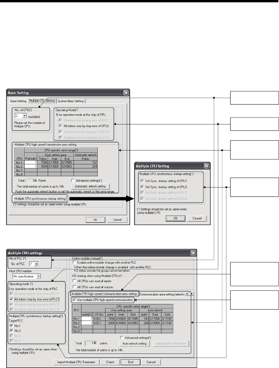
3 - 6
3 COMMON PARAMETERS
(a) Multiple CPU settings
Set the following items identically in Multiple CPU Settings (Motion CPU) in
MT Developer and in Multiple CPU Settings (PLC CPU) in GX Developer.
• Number of CPU modules (Included CPU empty slots)
• Operation mode when a CPU stop error occurred
• Multiple CPU high speed transmission area setting (Must be set the same
for all CPUs)
• Multiple CPU synchronous startup setting
Multiple CPU
synchronous startup
setting
Number of CPU
modules
Error operation mode
at the stop of CPU
Multiple CPU Settings (Motion CPU) in MT Developer
Multiple PLC Setting (PLC CPU setting) in GX Developer
Multiple CPU high
speed transmission
area setting
Select tab "Multiple
CPU high speed
communication area
setting"
Set "Use multiple
CPU high speed
communication".
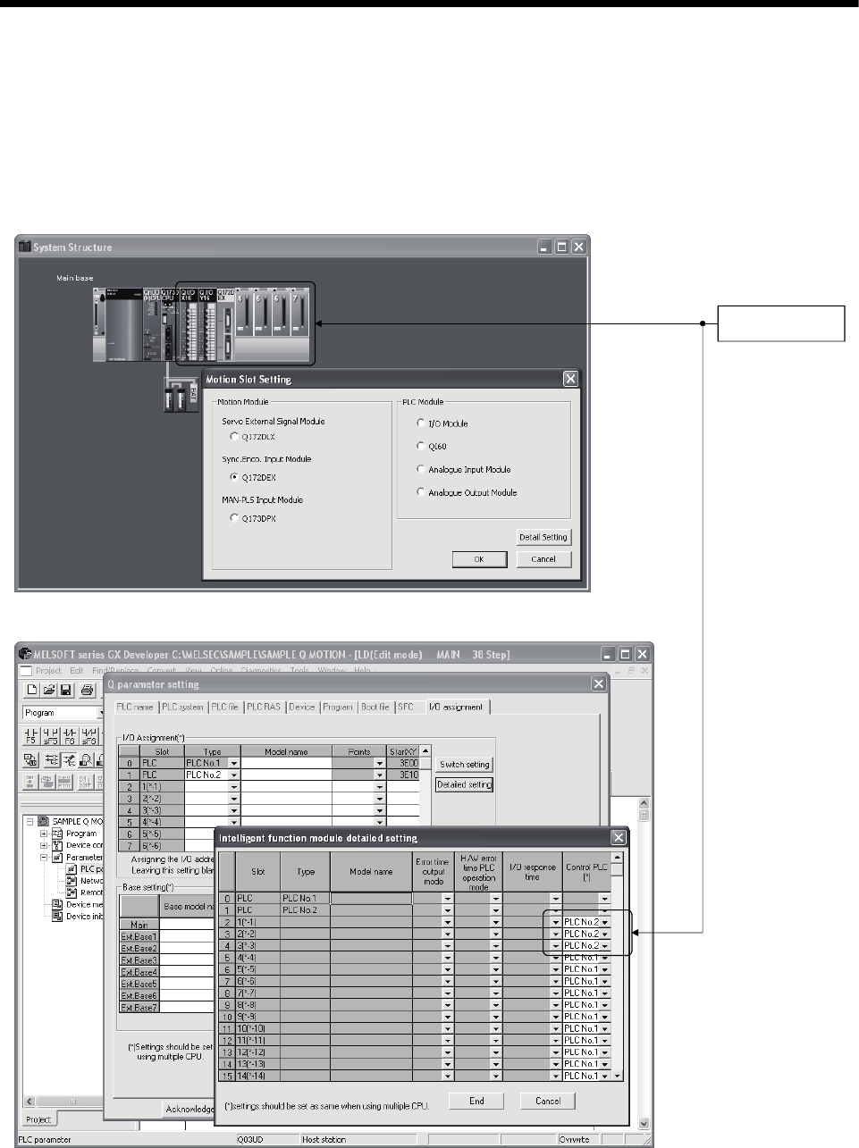
3 - 7
3 COMMON PARAMETERS
(b) Motion slot settings
Set the modules controlled by the self CPU by the Motion Slot Settings
(Motion CPU) in MT Developer. In GX Developer, set the slot for Motion
CPU control as the CPU number of Motion CPU in I/O Assignment Settings
(PLC CPU).
Motion Slot Setting (Motion CPU) in MT Developer
(Note): Motion slot setting items are different depending on the operating system software.
I/O Assignment Setting (PLC CPU setting) in GX Developer
Control CPU No.
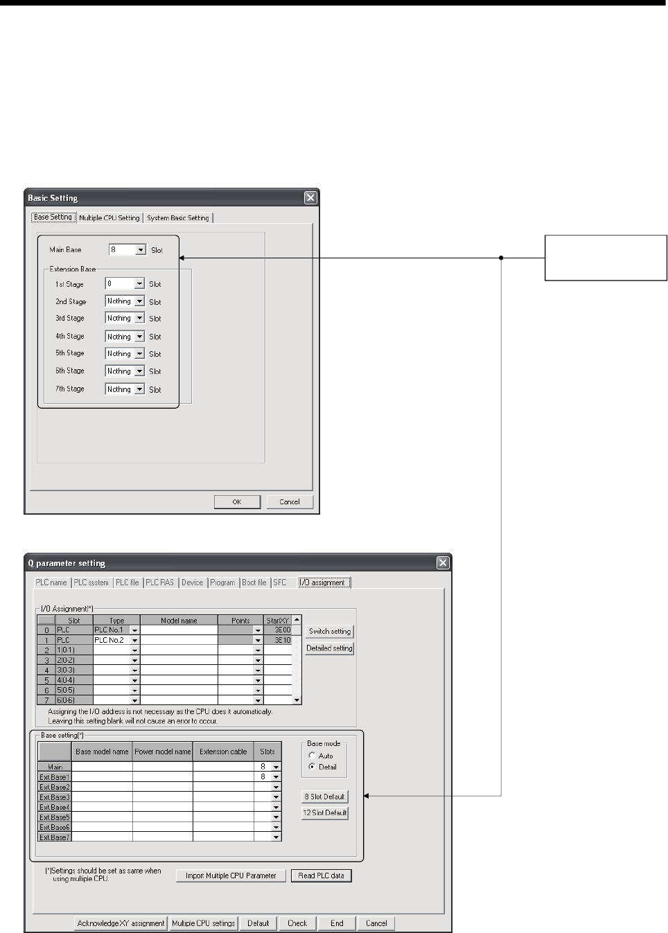
3 - 8
3 COMMON PARAMETERS
(c) Base settings
Set the total number of bases and number of slots in each base identically
between Base Settings (Motion CPU) in MT Developer and I/O Assignment
Settings (PLC CPU) in GX Developer. In GX Developer, the detailed
settings may be omitted by setting the base mode "Automatic".
I/O Assignment Settings (PLC CPU setting) in GX Developer
Base Settings (Motion CPU) in MT Developer
(Note) : Only the Motion CPU
may be set without
setting the PLC CPU.
Total number of bases
and number of slots in
each base
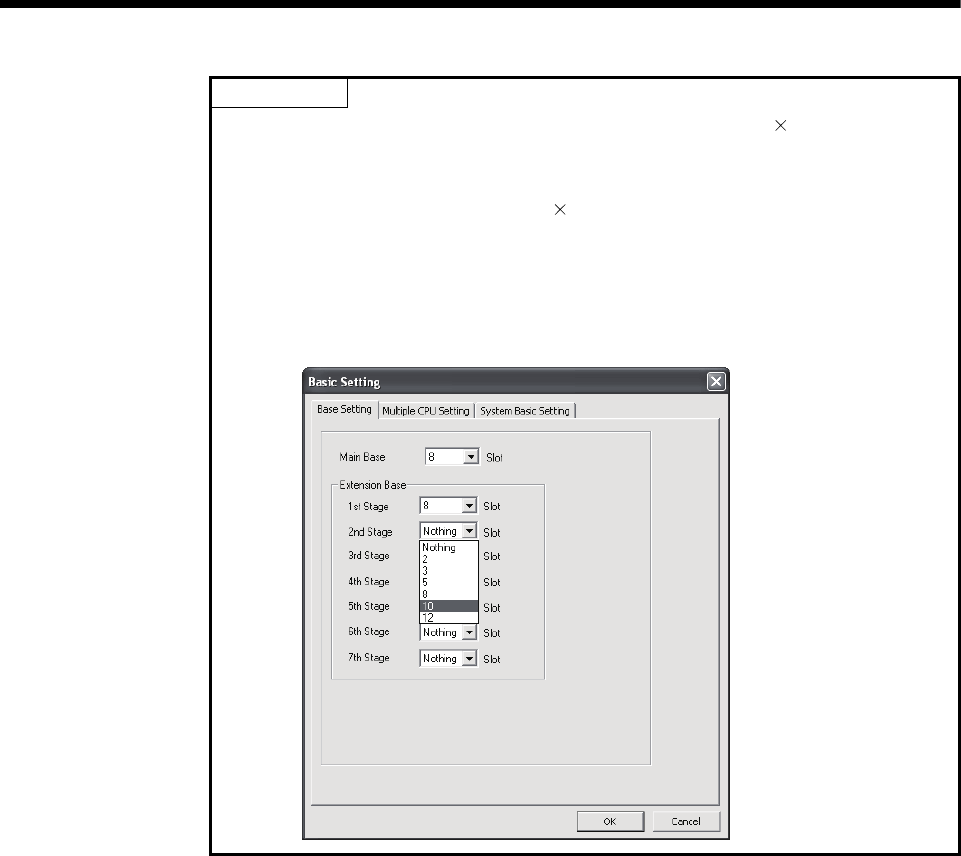
3 - 9
3 COMMON PARAMETERS
POINT
GOT is recognized as an intelligent function modules "16 points 10 slots" on the
base (number of extension bases and slot No. are set in the GOT parameter.) for
bus connection with GOT.
Set the one extension base (16 points 10 slots) for connection with GOT, then set
"10 slots" as number of extension bases for connection with GOT in the system
setting (base setting).
<Example>
When the "2nd stage" of extension base is set as connection with GOT.
(Set "10" slot as "2nd stage" of extension base in the base setting.)
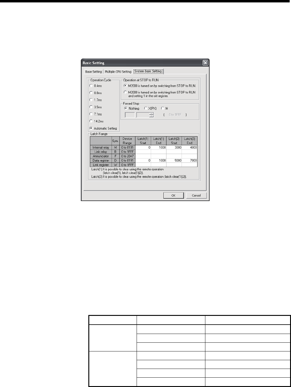
3 - 10
3 COMMON PARAMETERS
3.1.3 Individual parameters
(1) System basic setting
The following explains each item to be set in system basic setting.
(a) Operation cycle
1) Set the of motion operation cycle (cycles at which a position command is
computed and sent to the servo amplifier).
The setting range is 0.4ms/0.8ms/1.7ms/3.5ms/7.1ms/14.2ms/Automatic
setting. The actual operation cycle corresponding to 0.4ms is 0.444...ms.
Similarly, 0.8ms corresponds to 0.888…ms, 1.7ms to 1.777...ms, 3.5ms
to 3.555...ms, 7.1ms to 7.111...ms, and 14.2ms to 14.222…ms,
respectively.
2) The default value is "Automatic Setting". When "Automatic Setting" is
selected, the operation cycle is set according to the table below based
on the number of axes for servo amplifier set in the System Settings.
Operating system Number of axes Operation cycle setting
1 to 6 axes 0.4 ms
7 to 18 axes 0.8 ms
SV13
19 to 32 axes 1.7 ms
1 to 4 axes 0.4 ms
5 to 12 axes 0.8 ms
13 to 28 axes 1.7 ms
SV22
29 to 32 axes 3.5 ms

3 - 11
3 COMMON PARAMETERS
3) If the duration of motion operation has exceeded the operation cycle, the
operation cycle over flag (M2054) turns ON. Even when "Automatic
setting" is selected, the duration of motion operation may exceed the
operation cycle depending on the control conditions. The actual duration
of motion operation (unit:μs) is stored in SD522, and the current setting
of operation cycle (unit:μs) is stored in SD523. Monitor these special
registers and adjust the set value of operation cycle so that the actual
duration of motion operation will not exceed the set operation cycle. (A
WDT or other error may occur in the Motion CPU.)
(b) Operation at STOP to RUN
Set the condition in which the "PLC ready" flag (M2000) turns ON. Select
any one of the followings.
1) M2000 is turned on by switching from STOP to RUN.
Condition in which the M2000 turns from OFF to ON
• Change the RUN/STOP switch from STOP to RUN.
• Turn ON the power supply with the RUN/STOP switch set to RUN.
Condition in which the M2000 turns from ON to OFF
• Change the RUN/STOP switch from RUN to STOP.
2) M2000 is turned on by switching from STOP to RUN and setting 1 in the
set register.
(M2000 turns ON when the switch is set to RUN and 1 is set in the
setting register.)
Condition in which the M2000 turns from OFF to ON
• With the RUN/STOP switch set to RUN, set 1 in the setting register
for "PLC ready" flag (D704). (The Motion CPU detects a change from
0 to 1 in the lowest bit in the D704).
Condition in which the M2000 turns from ON to OFF
• With the RUN/STOP switch set to RUN, set 0 in the setting register
for "PLC ready" flag (D704). (The Motion CPU detects a change from
1 to 0 in the lowest bit in the D704).
• Change the RUN/STOP switch from RUN to STOP.
(c) Forced stop
Set the bit device used for executing a forced stop in which all servo-
amplifier axes are stopped immediately in the program.
Either X (PX) or M can be specified. No default value has been set. The set
bit device is designated as contact B and performs the following control in
response to ON/OFF of the device.
• Bit device is turned OFF …Forced stop input is ON (forced stop)
• Bit device is turned ON …..Forced stop input is OFF (forced stop is
released.)
The forced stop input by EMI terminal of Motion CPU module cannot be
invalidated using parameter setting.

3 - 12
3 COMMON PARAMETERS
(d) Latch range
Set the following latching ranges for M, B, F, D and W, respectively.
• Latch (1) : It is possible clear using the remote operation (Latch clear(1),
Latch clear (1)(2)).
• Latch (2) : It is possible clear using the remote operation (Latch clear
(1)(2)).
(2) Individual module settings
The setting items for each module are shown below.
Setting items for each module
Number of usable modules
Module name Item Setting range Initial value Q173DCPU Q172DCPU
External signal setting Set the number of axes for which
the 8 axes input is used. Unused
DOG Valid on leading edge/
Valid on trailing edge
Valid on
leading edge
Q172DLX
Servo external
signals input
module I/O response time
(Operation mode)
0.4/0.6/1 ms
(DOG/CHANGE response time) 0.4 ms
4 1
Synchronous encoder
setting Used/Unused Unused
Synchronous encoder
selection Q170ENC/MR-HENC Q170ENC
I/O response time
(Operation mode)
0.4/0.6/1 ms
(TREN response time) 0.4 ms
Q172DEX
Synchronous
encoder input
module
High-speed data read
setting Used/Unused Unused
6 (SV22) 4 (SV22)
Manual pulse generator
setting
(SV13)
Used only Used
Manual pulse generator/
Synchronous encoder
setting
(SV22)
Used/Unused P
Used
I/O response time
(Operation mode)
0.4/0.6/1 ms
(TREN response time) 0.4 ms
Q173DPX
Manual pulse
generator input
module
High-speed data read
setting Used/Unused Unused
1 (SV13)
4 (SV22)
1 (SV13)
3 (SV22)
QI60 Interrupt
module Input response time 0.1/0.2/0.4/0.6/1 ms 0.2 ms 1 1
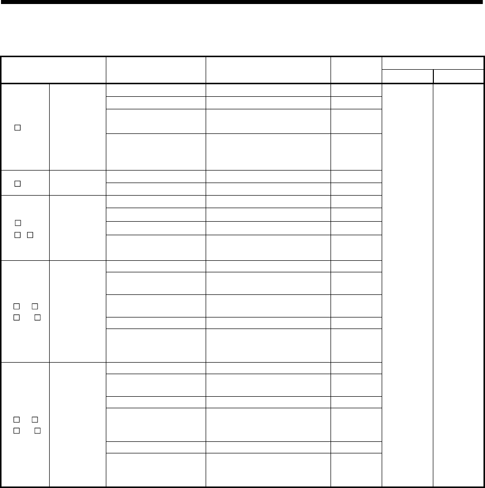
3 - 13
3 COMMON PARAMETERS
Setting items for each module (Continued)
Number of usable modules
Module name Item Setting range Initial value
Q173DCPU Q172DCPU
First I/O No. 00 to FF0 (in units of 16 points) 0
Point 0/16/32/64/128/256 16
High-speed data read
setting Used/Unused Unused
QX Input module
I/O response time
(setting for high-speed input
module in parentheses)
1/5/10/20/70 ms
(0.1/0.2/0.4/0.6/1 ms)
10 ms
(0.2 ms)
First I/O No. 00 to FF0 (in units of 16 points) 0
QY Output module
Point 0/16/32/64/128/256 16
First I/O No. 00 to FF0 (in units of 16 points) 0
Point 0/16/32/64/128/256 16
I/O response time 1/5/10/20/70 ms 10 ms
QH /
QX Y
Input/Output
composite
module High-speed data read
setting Used/Unused Unused
First I/O No. 00 to FF0 (in units of 16 points) 0
Input range 4 to 20mA/0 to 20mA/1 to 5V/0 to
5V/-10 to 10V/0 to 10V/User range 4 to 20mA
Temperature drift
compensation Used/None Used
Resolution mode Normal/High Normal
Q6 AD /
Q6 AD-
Analogue input
module
Operation mode Normal (A/D conversion)/Offset
gain setting
Normal
(A/D
conversion)
First I/O No. 00 to FF0 (in units of 16 points) 0
Output range 4 to 20mA/0 to 20mA/1 to 5V/0 to
5V/-10 to 10V/User range 4 to 20mA
HOLD/CLEAR function CLEAR only CLEAR
Output mode Normal (Asynchronous)/
Synchronous output
Normal
(Asyn-
chronous)
Resolution mode Normal/High Normal
Q6 DA /
Q6 DA-
Analogue
output module
Operation mode Normal (D/A conversion)/
Offset gain setting
Normal
(D/A
conversion)
Total 256
points or less
Total 256
points or less

3 - 14
3 COMMON PARAMETERS
(3) External signal input
Servo external signal (Upper stroke limit/Lower stroke limit/Stop signal/Proximity
dog) can be selected for every axis from the following two methods.
(a) Q172DLX Servo external signals interface module use
Set the servo external signals interface module, and set axis No. as the
"External signal setting" in the system setting.
(b) Servo amplifier input device use (MR-J3-B use only)
Set "Amplifier input valid" as the external signal input setting in the "Amplifier
setting" of system setting.
There are following restrictions to use.
• Count type home position return cannot be used.
• Speed/position switching control cannot be executed.
• Stop signal (STOP) cannot be used.
The correspondence of external signal and input device is shown below.
External signals Input device (CN3) (Note)
Upper stroke limit (FLS) DI1
Lower stroke limit (RLS) DI2
Proximity dog (DOG) DI3
(Note): Refer to the "MR-J3-B Servo Amplifier Instruction Manual" for pin configurations.
Set the external signal setting in the "Input Filter Setting".

3 - 15
3 COMMON PARAMETERS
3.2 I/O number assignment
In the Multiple CPU system, I/O numbers are used for interactive transmission
between the Motion CPU and I/O modules and intelligent function modules, or
between PLC CPU and Motion CPU.
3.2.1 I/O number assignment of each module
The Multiple CPU system is different from the Single CPU system in the position (slot) of
I/O number "0H" for PLC CPU.
However, I/O number of control module can be assigned independently for each CPU for
Motion CPU.
(1) Position of I/O number "0H"
(a) The number of slots set with the Multiple CPU settings are occupied by the
PLC CPU/Motion CPU on the Multiple CPU system.
(b) I/O modules and intelligent function modules are installed from the right of the
slots occupied by PLC CPU/Motion CPU.
(c) I/O number of Motion CPU control module can be assigned independently for
each CPU.
The I/O number of PLC CPU control module for an I/O module or intelligent
function module mounted to the next slot to those occupied by CPU modules
is set as "0H" and consecutive numbers are then allocated sequentially to the
right.
(d) Notation of I/O number
• Receiving of ON/OFF data by Motion CPU is deemed input (PX), while
outputting of ON/OFF data from Motion CPU is deemed output (PY).
• I/O number is expressed in hexadecimal.
REMARK
1) If the number of CPU modules installed on the main base unit is less than the
number set at the "Multiple CPU setting", set the open slot(s) to "PLC (Empty)".
Refer to Section 2.1.2 for the "PLC (Empty)" setting.
2) The I/O numbers for the Multiple CPU system can be confirmed with the system
monitor of GX Developer.
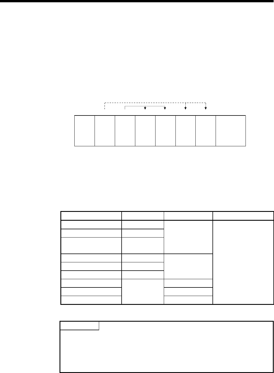
3 - 16
3 COMMON PARAMETERS
(2) I/O number assignment of Motion CPU control module
Mitsubishi recommends that I/O No. assignment be set as common consecutive
No. throughout all CPUs.
However, the I/O number of the input modules, output modules and input/output
composite modules controlled with the Motion CPU can also be set regardless as
the I/O number of PLC CPU.
(I/O number of the Motion CPU control modules is indicated as PX/PY.)
I/O number of the Motion CPU control modules cannot be assigned by I/O
assignment settings of PLC CPU.
CPU No. 2
control
module
PX0 to PX1F
(X0 to X1F)
Q173D
CPU
Q03UD
CPU
Power supply
module
X40 to X5F
123450
I/O assignment
Y60 to Y7F
CPU No. 1 CPU No. 2 CPU No. 2
control
module
CPU No. 1
control
module
CPU No. 1
control
module
QX41
PY20 to PX3F
(Y20 to Y3F)
QY41 QX41 QY41
(3) Setting of the Motion CPU control modules by the PLC CPU
Follow the table below when Motion CPU control modules are set in I/O
Assignment Settings of the PLC CPU. (The PLC CPU handles the Q172DLX,
Q172DEX and Q173DPX as intelligent function modules having 32 occupied
points.) Type and number of points may be left unset.
Module name Type Number of points Remarks
Input module Input
Output module Output
Input/Output composite
module Composite I/O
Selected according
to the module.
Analogue input module Analogue input
Analogue output module Analogue output
Interrupt module (QI60) Interrupt
16 points
Q172DLX 32 points
Q172DEX 32 points
Q173DPX
Intelligent
32 points
• For the control CPU,
set the CPU that
corresponds to the
Motion CPU (required).
• Type and number of
points may be left
unset.
POINT
(1) Set the I/O device of the Motion CPU within the range from PX/PY000 to
PX/PYFFF. Set the number of real I/O points within 256 points. (I/O No. may
not be consecutive.)
(2) As for the Motion CPU, the Q172DLX, Q172DEX, Q173DPX and QI60 are not
included in the number of real I/O points.

3 - 17
3 COMMON PARAMETERS
3.2.2 I/O number of each CPU modules
In the Multiple CPU system, I/O numbers are assigned to each CPU module to specify
installed CPU modules.
The I/O number for each CPU module is fixed to the corresponding slot and cannot be
changed.
The I/O number allocated to each CPU module in the Multiple CPU system is shown
below.
CPU module
installation position CPU slot Slot 0 Slot 1 Slot 2
First I/O number 3E00H 3E10H 3E20H 3E30H
The I/O number of PLC CPU/Motion CPU are used in the following cases.
• When writing data to the CPU shared memory of self CPU using the S. TO
instruction.
• When reading data from the CPU shared memory of other CPU using the FROM
instruction.
• When reading data from the CPU shared memory of other CPU using an intelligent
function module device (U \G )
• When reading device data directly from the Motion CPU from the PLC CPU using the
"D(P).DDRD" instruction.
• When writing device data directly to the Motion CPU from the PLC CPU using the
"D(P).DDWR" instruction.
Refer to Section 2.3.6 or the "Q173DCPU/Q172DCPU Motion controller (SV13/SV22)
Programming Manual (Motion SFC)" for the Motion dedicated PLC instruction.
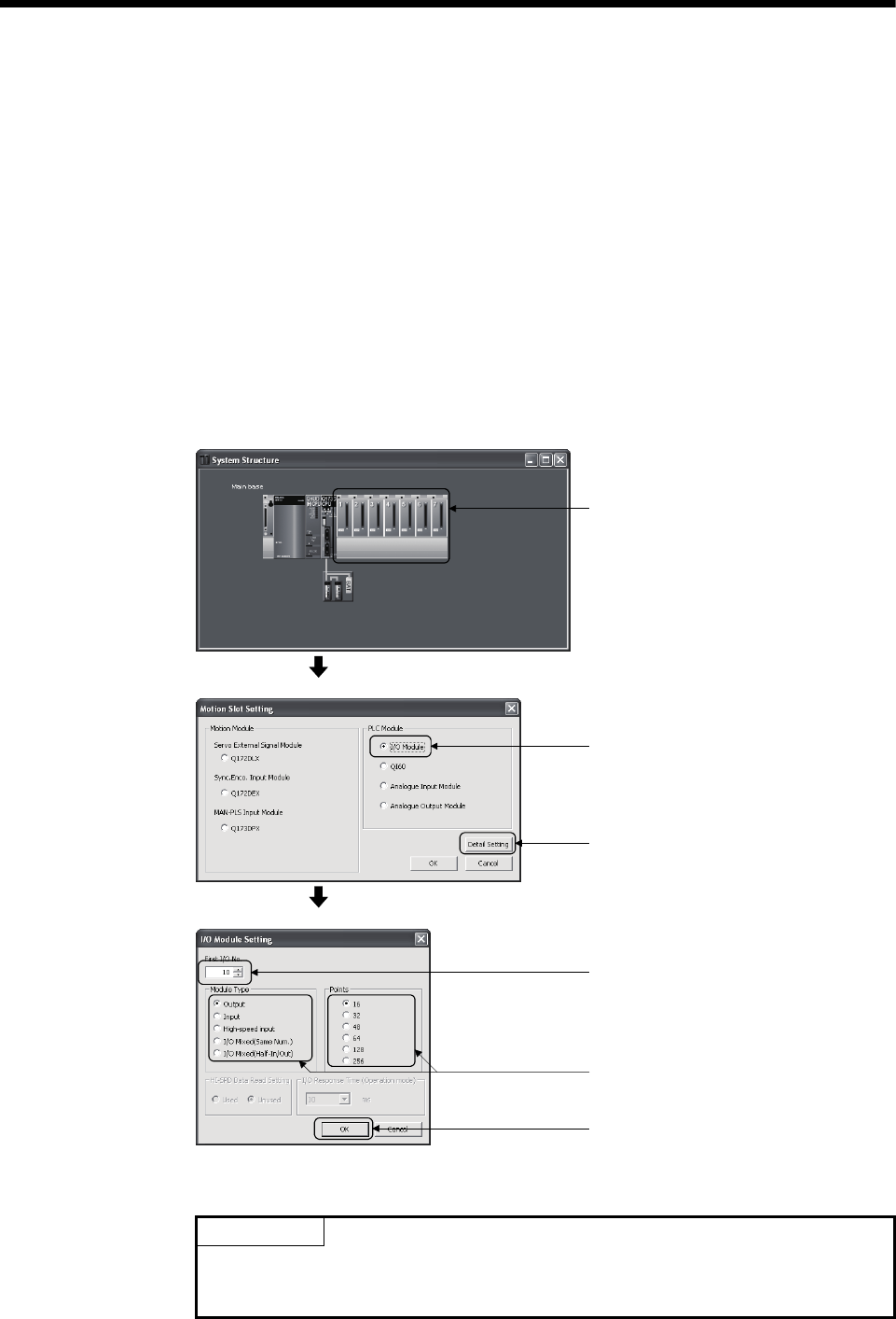
3 - 18
3 COMMON PARAMETERS
3.2.3 I/O number setting
Set the modules installed in the each slot of the main base or extension base and
assign the control CPU of applicable slot as the self CPU in the system setting for
Motion CPU.
The following modules must be set the I/O No..
• Input module • Output module • Input/Output composite module
• Analogue input module • Analogue output module
Refer to the help of MT Developer for the detailed operating procedure on the system
settings screen.
Set the I/O No. of modules controlled with the Motion CPU module set in the system
structure screen of MT Developer. The setting procedure of I/O No. is shown below.
(Example) For set the output module
1) Double-click the slot position, display
the Motion Slot Settings screen.
<System Structure>
2) Select the I/O module.
5) Select applicable module type
and number of points for
the I/O module to be used.
3) Click [Detail Setting].
4) Set the first I/O No.
(PX No., PY No.).
6) Click [OK].
<Motion Slot Settings>
<I/O Module Settings>
(Note): Display of system setting and motion slot setting are different depending on the operating system
software.
POINT
I/O No.s cannot be assigned automatically, unlike a PLC CPU for which I/O No. are
assigned automatically if such setting is omitted in the Motion CPU. In the Motion
CPU, be sure to set the first I/O No. in System Settings for each module used.
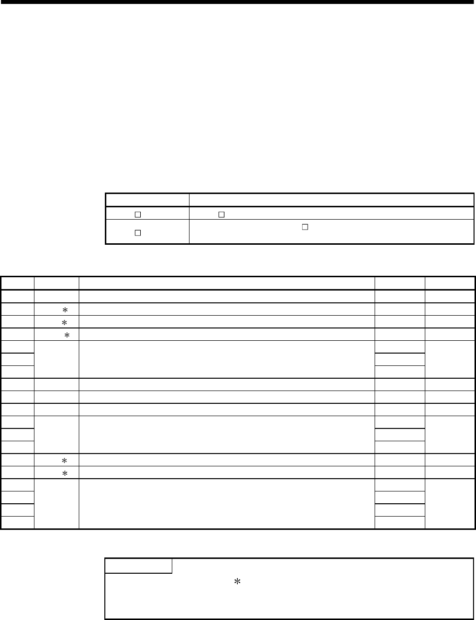
3 - 19
3 COMMON PARAMETERS
3.3 Servo Parameters
The servo parameters control the data fixed by the specifications of the servo amplifier
and servomotor controlled in the parameter set for each axis and the control of the
servomotor.
The servo parameters are set by the Setup software (MR Configurator).
Refer to the "Servo amplifier Instruction Manual" for details of the servo parameters.
Refer to the help for handling of MR Configurator.
Instruction Manual list is shown below.
Servo amplifier type Instruction manual name
MR-J3- B MR-J3- B Servo Amplifier Instruction Manual (SH-030051)
MR-J3- B-RJ006 Fully closed loop control MR-J3- B-RJ006 Servo Amplifier Instruction Manual
(SH-030056)
(1) Basic setting parameters
No. Symbol Name Initial value Unit
PA01 — For manufacturer setting 0000h —
PA02 REG Regenerative brake option 0000h —
PA03 ABS Absolute position detection system 0000h —
PA04 AOP1 Function selection A-1 0000h —
PA05 0
PA06 1
PA07
— For manufacturer setting
1
—
PA08 ATU Auto tuning mode 0001h —
PA09 RSP Auto tuning response 12 —
PA10 INP In-position range 100 PLS
PA11 1000.0
PA12 1000.0
PA13
— For manufacturer setting
0000h
—
PA14 POL Rotation direction selection 0 —
PA15 ENR Encoder output pulse 4000 PLS/rev
PA16 0
PA17 0000h
PA18 0000h
PA19
— For manufacturer setting
000Bh
—
POINTS
(1) When the items marked " " in the above table has changed, make the Multiple
CPU system reset or power supply OFF to ON. And, once turn OFF the servo
amplifier power supply and then turn ON it again.
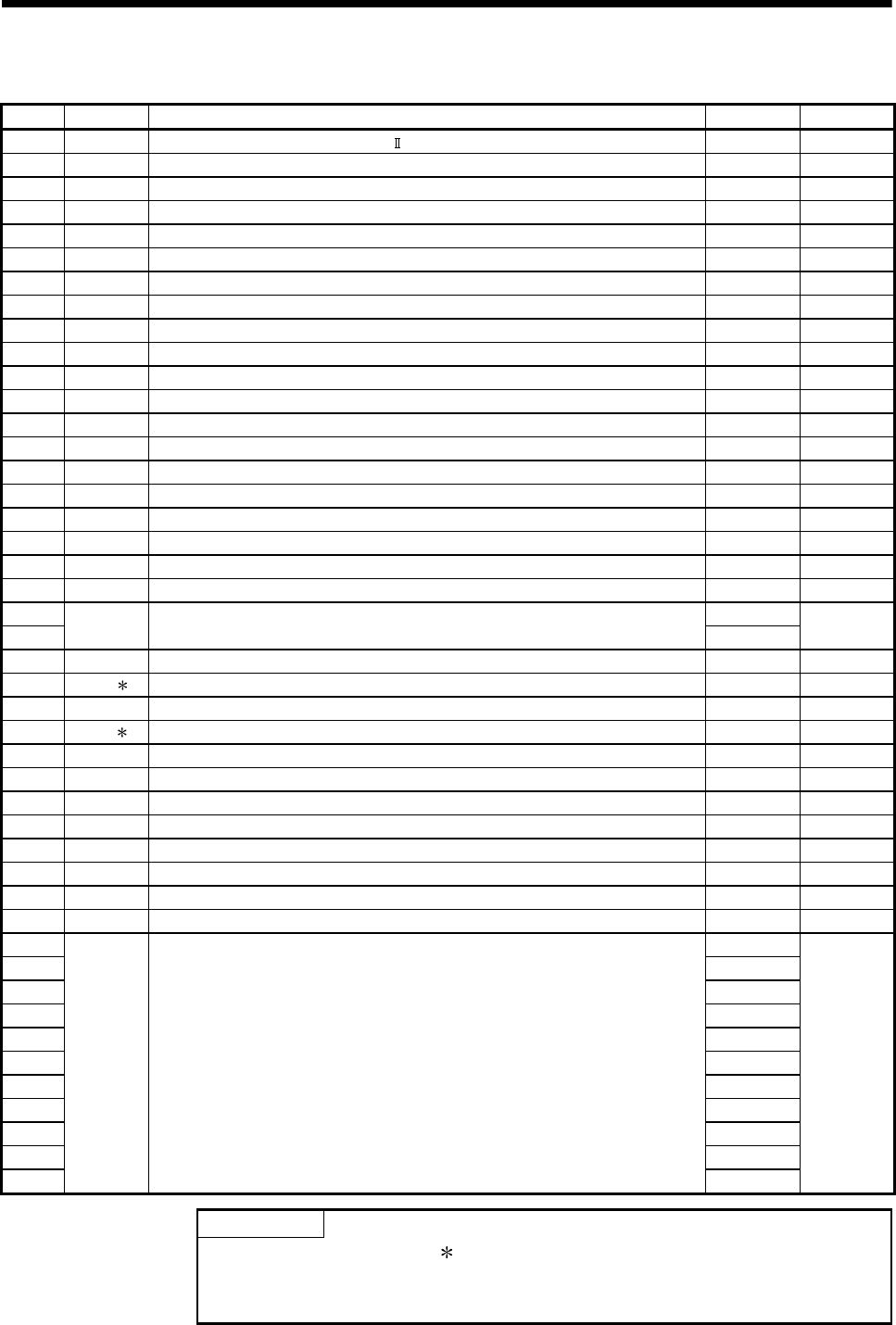
3 - 20
3 COMMON PARAMETERS
(2) Gain/filter parameters
No. Symbol Name Initial value Unit
PB01 FILT Adaptive tuning mode (Adaptive filter ) 0000h —
PB02 VRFT Vibration suppression control tuning mode (Advanced vibration suppression control) 0000h —
PB03 — For manufacturer setting 0 —
PB04 FFC Feed forward gain 0 %
PB05 — For manufacturer setting 500 —
PB06 GD2 Ratio of load inertia moment to servomotor inertia moment 7.0 times
PB07 PG1 Model loop gain 24 rad/s
PB08 PG2 Position loop gain 37 rad/s
PB09 VG2 Speed loop gain 823 rad/s
PB10 VIC Speed integral compensation 33.7 ms
PB11 VDC Speed differential compensation 980 —
PB12 — For manufacturer setting 0 —
PB13 NH1 Machine resonance suppression filter 1 4500 Hz
PB14 NHQ1 Notch shape selection 1 0000h —
PB15 NH2 Machine resonance suppression filter 2 4500 Hz
PB16 NHQ2 Notch shape selection 2 0000h —
PB17 — Automatic setting parameter — —
PB18 LPF Low pass filter setting 3141 rad/s
PB19 VRF1 Vibration suppression control - vibration frequency setting 100.0 Hz
PB20 VRF2 Vibration suppression control - resonance frequency setting 100.0 Hz
PB21 0.00
PB22 — For manufacturer setting 0.00 —
PB23 VFBF Low pass filter selection 0000h —
PB24 MVS Slight vibration suppression control selection 0000h —
PB25 — For manufacturer setting 0000h —
PB26 CDP Gain changing selection 0000h —
PB27 CDL Gain changing condition 10 —
PB28 CDT Gain changing time constant 1 ms
PB29 GD2B Gain changing - ratio of load inertia moment to servo motor inertia moment 7.0 times
PB30 PG2B Gain changing - position loop gain 37 rad/s
PB31 VG2B Gain changing - speed loop gain 823 rad/s
PB32 VICB Gain changing - speed integral compensation 33.7 ms
PB33 VRF1B Gain changing - vibration suppression control - vibration frequency setting 100.0 Hz
PB34 VRF2B Gain changing - vibration suppression control - resonance frequency setting 100.0 Hz
PB35 0.00
PB36 0.00
PB37 100
PB38 0.0
PB39 0.0
PB40 0.0
PB41 1125
PB42 1125
PB43 0004h
PB44 0.0
PB45
— For manufacturer setting
0000h
—
POINTS
(1) When the items marked " " in the above table has changed, make the Multiple
CPU system reset or power supply OFF to ON. And, once turn OFF the servo
amplifier power supply and then turn ON it again.
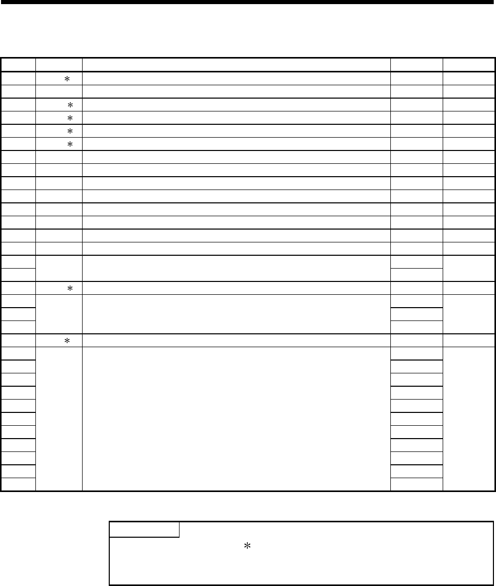
3 - 21
3 COMMON PARAMETERS
(3) Extension setting parameters
No. Symbol Name Initial value Unit
PC01 ERZ Error excessive alarm level 3 rev
PC02 MBR Electromagnetic brake sequence output 0 ms
PC03 ENRS Encoder output pulse selection 0000h —
PC04 COP1 Function selection C-1 0000h —
PC05 COP2 Function selection C-2 0000h —
PC06 COP3 Function selection C-3 0000h —
PC07 ZSP Zero speed 50 r/min
PC08 — For manufacturer setting 0 —
PC09 MOD1 Analog monitor 1 output 0000h —
PC10 MOD2 Analog monitor 2 output 0001h —
PC11 MO1 Analog monitor 1 offset 0 mV
PC12 MO2 Analog monitor 2 offset 0 mV
PC13 MOSDL Analog monitor feedback position output standard data Low 0 PLS
PC14 MOSDH Analog monitor feedback position output standard data High 0 10000PLS
PC15 0
PC16 — For manufacturer setting 0000h —
PC17 COP4 Function selection C-4 0000h —
PC18 0000h
PC19 0000h
PC20
— For manufacturer setting
0000h
—
PC21 BPS Alarm history clear 0000h —
PC22 0000h
PC23 0000h
PC24 0000h
PC25 0000h
PC26 0000h
PC27 0000h
PC28 0000h
PC29 0000h
PC30 0000h
PC31 0000h
PC32
— For manufacturer setting
0000h
—
POINTS
(1) When the items marked " " in the above table has changed, make the Multiple
CPU system reset or power supply OFF to ON. And, once turn OFF the servo
amplifier power supply and then turn ON it again.
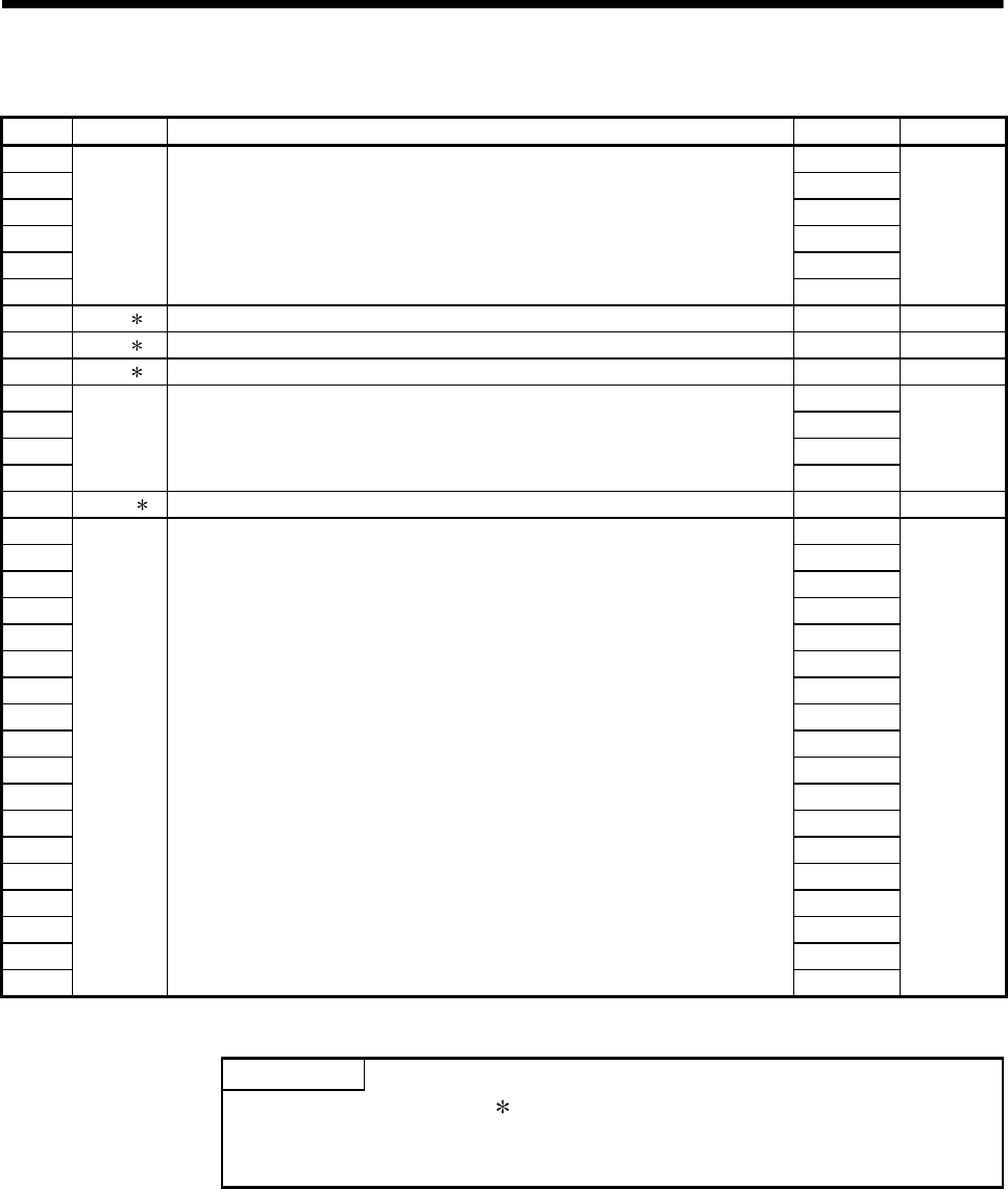
3 - 22
3 COMMON PARAMETERS
(4) I/O Setting Parameters
No. Symbol Name Initial value Unit
PD01 0000h
PD02 0000h
PD03 0000h
PD04 0000h
PD05 0000h
PD06
— For manufacturer setting
0000h
—
PD07 DO1 Output signal device selection 1 (CN3-13) 0005h —
PD08 DO2 Output signal device selection 2 (CN3-9) 0004h —
PD09 DO3 Output signal device selection 3 (CN3-15) 0003h —
PD10 0000h
PD11 0004h
PD12 0000h
PD13
— For manufacturer setting
0000h
—
PD14 DOP3 Function Selection D-3 0000h —
PD15 0000h
PD16 0000h
PD17 0000h
PD18 0000h
PD19 0000h
PD20 0000h
PD21 0000h
PD22 0000h
PD23 0000h
PD24 0000h
PD25 0000h
PD26 0000h
PD27 0000h
PD28 0000h
PD29 0000h
PD30 0000h
PD31 0000h
PD32
— For manufacturer setting
0000h
—
POINTS
(1) When the items marked " " in the above table has changed, make the Multiple
CPU system reset or power supply OFF to ON. And, once turn OFF the servo
amplifier power supply and then turn ON it again.
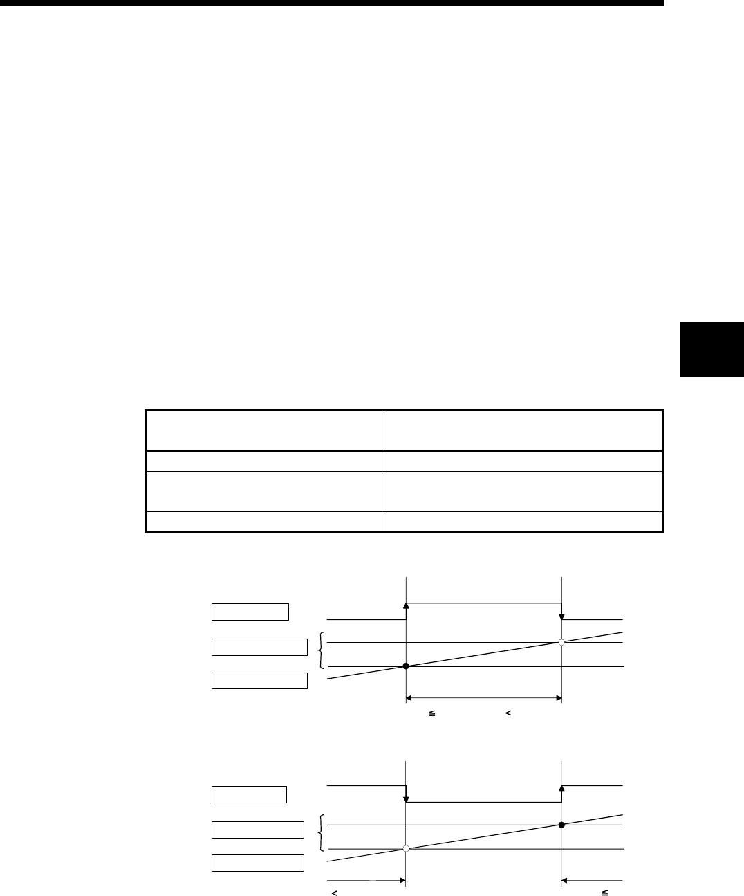
4 - 1
4 AUXILIARY AND APPLIED FUNCTIONS
4
4. AUXILIARY AND APPLIED FUNCTIONS
4.1 Limit Switch Output Function
This function is used to output the ON/OFF signal corresponding to the data range of
the watch data set per output device.
Motion control data or optional word data can be used as watch data. (Refer to Section
"4.1.2 Limit output setting data" for details.) A maximum output device for 32 points can
be set regardless of the number of axes.
4.1.1 Operations
(1) ON output to an output device is made while the watch data value is in the ON
output region set with (ON Value) and (OFF Value) in this function.
(a) (ON Value), (OFF Value) and watch data value are handled as signed data.
ON output region where an ON output is made to the output device is
governed by the magnitude relationship between (ON Value) and (OFF
Value) as indicated below.
Relationship between (ON Value) and
(OFF Value) ON output region
(ON Value) < (OFF Value) (ON Value) <= (watch data value) < (OFF Value)
(ON Value) > (OFF Value) (ON Value) <= (watch data value)
(Watch data value) < (OFF Value)
(ON Value) = (OFF Value) Output OFF in whole region
1) (ON Value) < (OFF Value)
Output device
ON region setting
Watch data value
OFF
OFF Value
ON Value
ON
OFF
(ON Value) (Watch data value) (OFF Value)
2) (ON Value) > (OFF Value)
ON Value
Output device
ON region setting
Watch data value
OFF Value
ON
OFF
(Watch data value) (OFF Value) (ON Value) (Watch data value)
ON
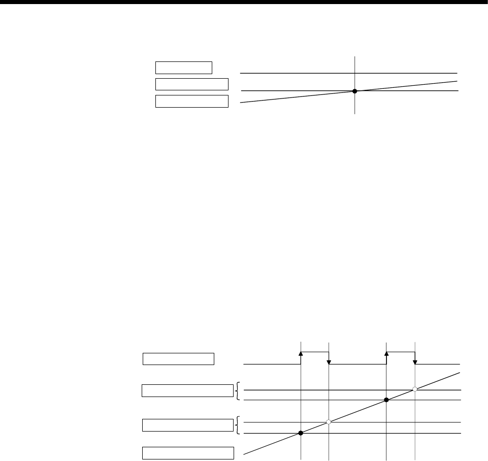
4 - 2
4 AUXILIARY AND APPLIED FUNCTIONS
3) (ON Value) = (OFF Value)
Output device
ON region setting
Watch data value
ON Value OFF Value
OFF in whole region
(b) The limit switch outputs are controlled based on the each watch data during
the PCPU ready status (SM500: ON) by the PLC ready flag (M2000) from
OFF to ON.
When the PCPU ready flag (SM500) turns OFF by turning the PLC ready flag
(M2000) from ON to OFF, all points turn OFF. When (ON Value) and (OFF
Value) are specified with word devices, the word device contents are input to
the internal area when the PLC ready flag (M2000) turns from OFF to ON.
After that, the word device contents are input per motion operation cycle, and
limit switch outputs are controlled.
(c) Multiple outputs (Up to 32 points) can be also set to one watch data. In each
setting, the output device may be the same.
If multiple ON region settings have been made to the same output device, the
logical add of the output results in the regions is output.
ON region setting No.1
Output device
Watch data value
OFF
OFF Value
ON Value
ON
OFF
ON region setting No.2 OFF Value
ON Value
ON
(2) Output enable/disable bit can be set and executed enable/disable of the limit
switch outputs point-by-point.
Limit switch output control is executed when the output enable/disable bit is ON,
and the output is OFF when it is OFF.
If there is no setting, the outputs are always enabled.
(3) Forced output bit can be set and turned the forcibly output of the limit switch
outputs point-by-point ON.
The output is ON when the forced output bit is ON. Priority is given to control of
this setting over off (disable) of the "output enable/disable bit".
If there is no setting, no forced outputs are not always made.
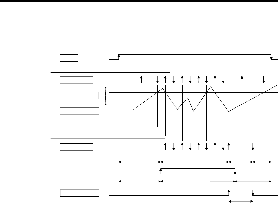
4 - 3
4 AUXILIARY AND APPLIED FUNCTIONS
(4) When the multiple watch data, ON region, output enable/disable bit and forced
output bit are set to the same output device, the logical add of output results of the
settings is output.
ON
Enable/disable bit
Output device
Watch data value
ON region setting
Output device
Output OFF Output OFF
Output ON
(Forced output)
Output control based on
ON Value and OFF Value
2) With output enable/disable bit/forced output settings
1) Without output enable/disable bit/forced output settings
SM500
OFF Value
ON Value
Forced output bit
Output OFF
Output control based on
ON Value and OFF Value Output OFF
Output ON
(Forced output)
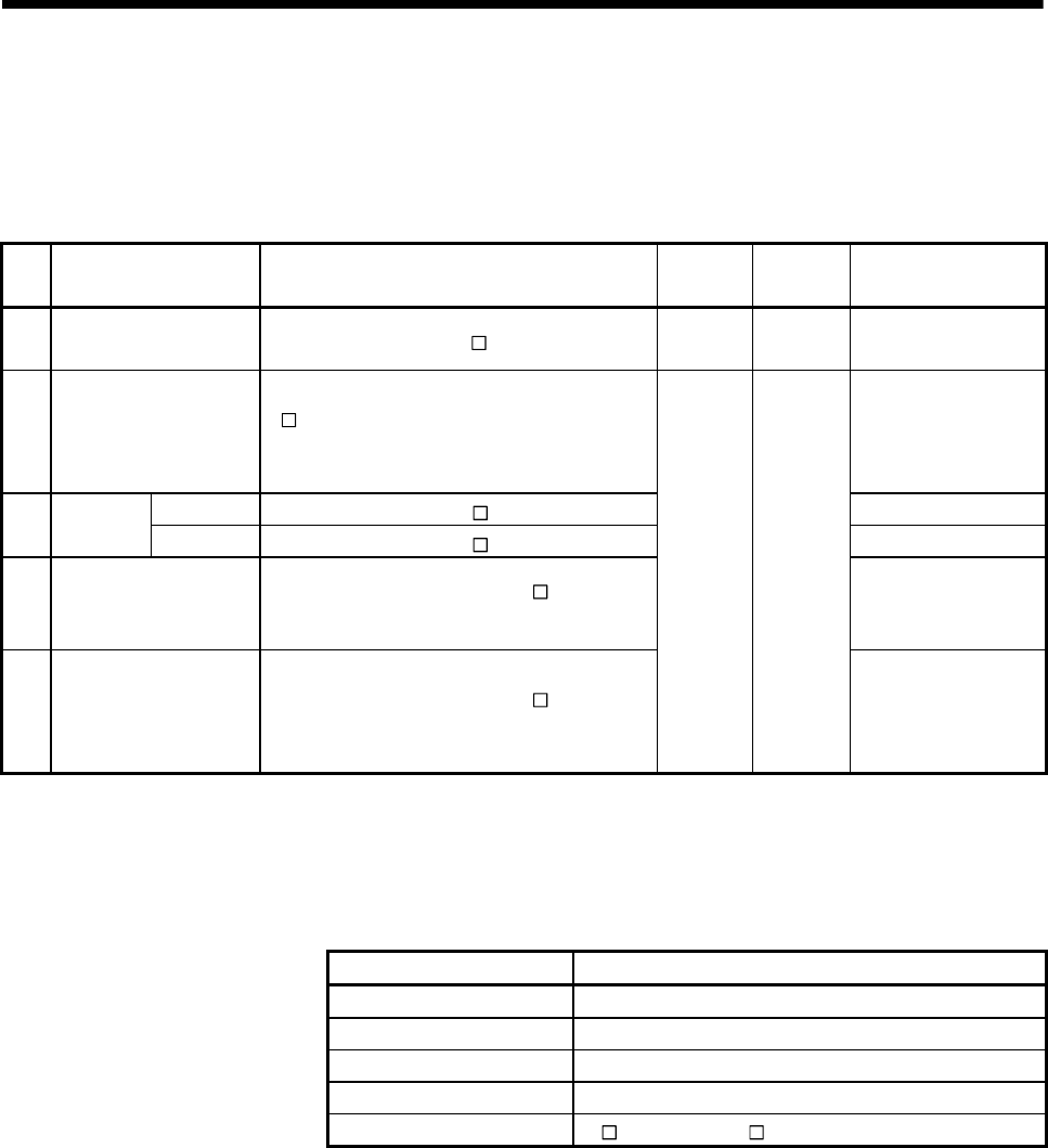
4 - 4
4 AUXILIARY AND APPLIED FUNCTIONS
4.1.2 Limit output setting data
Limit output data list are shown below.
Up to 32 points of output devices can be set.
(The following items of No.1 to No.5 are set together as one point.)
No. Item Setting range Fetch
cycle
Refresh
cycle Remarks
1 Output device Bit device (X, Y, M, B, U \G) —
Operation
cycle
2 Watch data
Motion control data/ word device (D, W, #,
U\G, absolute address)
(16-bit integer type/32-bit integer type/
64-bit floating-point type)
ON Value Word device (D, W, #, U \G)/constant (K, H)
3 ON region
setting OFF Value Word device (D, W, #, U \G)/constant (K, H)
4 Output enable/disable
bit
Bit device (X, Y, M, B, F, SM, U \G)/ none
(default)
ON : Enable
OFF : Disable
None : Always enable
5 Forced output bit Bit device (X, Y, M, B, F, SM, U \G)/ none
(default)
Operation
cycle —
None : No forced
outputs are
always made
(OFF status)
(1) Output device
(a) Set the bit device which outputs the ON/OFF signal toward the preset watch
data.
(b) As the output device, the following devices can be used.
Item Device No. setting range
Input relay (Note-1) X0 to X1FFF
Output relay (Note-2) Y0 to Y1FFF
Internal relay (Note-3) M0 to M8191
Link relay B0 to B1FFF
Multiple CPU area device U\G10000.0 to U \G (10000+p-1).F (Note-4), (Note-5)
(Note-1) : PX is write-disabled and it cannot be used as the output device.
For X, only the free No. of the input card non-loading can be used.
(Note-2) : The real output device range (PY) is also included.
(Note-3) : M2001 to M2032 cannot be used to the output device.
Be careful because it affect a positioning operation, when the positioning
dedicated devices are set.
(Note-4) : "p" indicates the user setting area points of the Multiple CPU high speed
transmission area for the each CPU.
(Note-5) : Only device of the self CPU can be used.
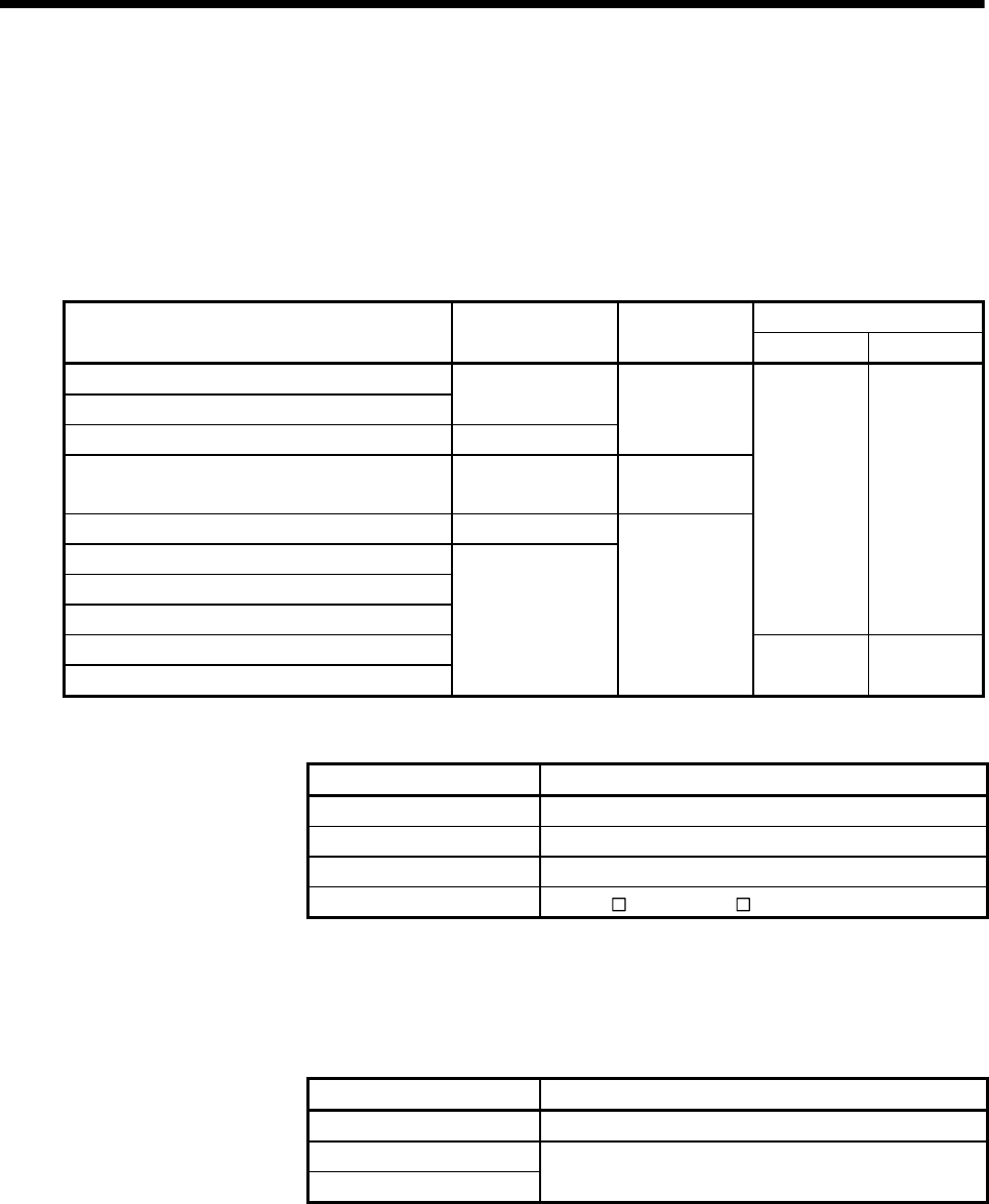
4 - 5
4 AUXILIARY AND APPLIED FUNCTIONS
(2) Watch data
(a) This data is used to perform the limit switch output function. This data is
comparison data to output the ON/OFF signal. The output device is
ON/OFF-controlled according to the ON region setting.
(b) As the watch data, motion control data or optional word device data can be
used.
1) Motion control data
Axis No. setting range
Item Unit Data type
Q173DCPU Q172DCPU
Feed current value
Real current value Position command
Deviation counter value PLS
32-bit
integer type
Motor current 0.1% 16-bit
integer type
Motor speed 0.1r/min
Cam shaft within-one-revolution current value
Feed current value (Virtual)
After-differential current value (Virtual)
1 to 32 1 to 8
After-differential encoder current value
Encoder current value
PLS
32-bit
integer type
1 to 12 1 to 8
2) Word device data
Item Device No. setting range
Data register D0 to D8191
Link register W0 to W1FFF
Motion register #0 to #7999
Multiple CPU area device U\G10000 to U \G (10000+p-1) (Note-1)
(Note-1) : "p" indicates the user setting area points of the Multiple CPU high speed
transmission area for the each CPU.
3) When the optional device data is set, the following data type is set as the
data type to be compared.
Data type Remarks
16-bit integer type
32-bit integer type
64-bit floating-point type Set the device No. as an even No..
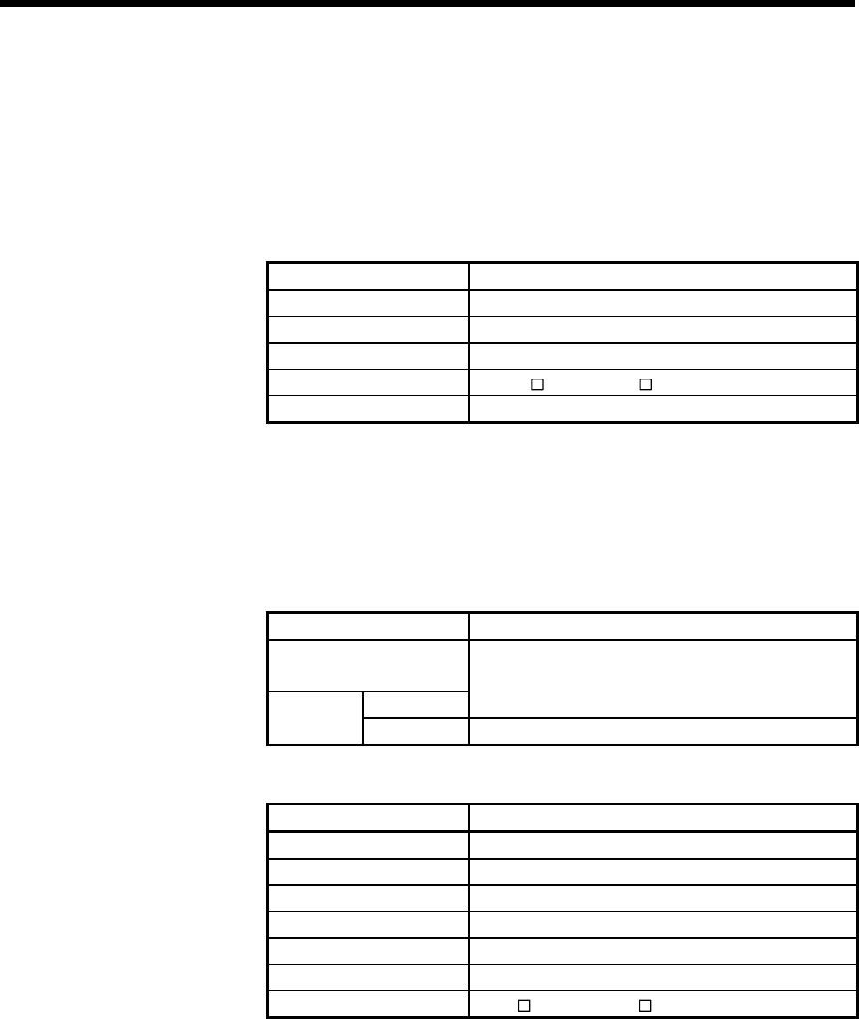
4 - 6
4 AUXILIARY AND APPLIED FUNCTIONS
(3) ON region setting
(a) The data range which makes the output device turn ON/OFF toward the
watch data.
(b) The following devices can be used as the ON Value and OFF Value of the
data range.
The data type of device/constant to be set is the same as the type of watch
data.
Item Device No. setting range
Data register D0 to D8191
Link register W0 to W1FFF
Motion register #0 to #7999
Multiple CPU area device U\G10000 to U \G (10000+p-1) (Note-1)
Constant Hn/Kn
(Note-1) : "p" indicates the user setting area points of the Multiple CPU high speed
transmission area for the each CPU.
(4) Output enable/disable bit
(a) Set the status of output enable/disable bit when the limit switch output is
forbidden during operation.
1) The following control is exercised.
Output enable/disable bit Control description
Without setting
(always enable)
ON (enable)
Limit switch output is turned ON/OFF based on the ON
region setting (ON Value, OFF Value).
With setting OFF (disable) Limit switch output is turned OFF.
(b) Usable devices
Item Device No. setting range
Input relay (Note-1) X0 to X1FFF
Output relay (Note-2) Y0 to Y1FFF
Internal relay M0 to M8191
Link relay B0 to B1FFF
Annunciator F0 to F2047
Special relay SM0 to SM1999
Multiple CPU area device U\G10000.0 to U \G (10000+p-1).F (Note-3)
(Note-1) : The real input range(PX) is included.
(Note-2) : The real input range(PY) is included.
(Note-3) : "p" indicates the user setting area points of the Multiple CPU high speed
transmission area for the each CPU.
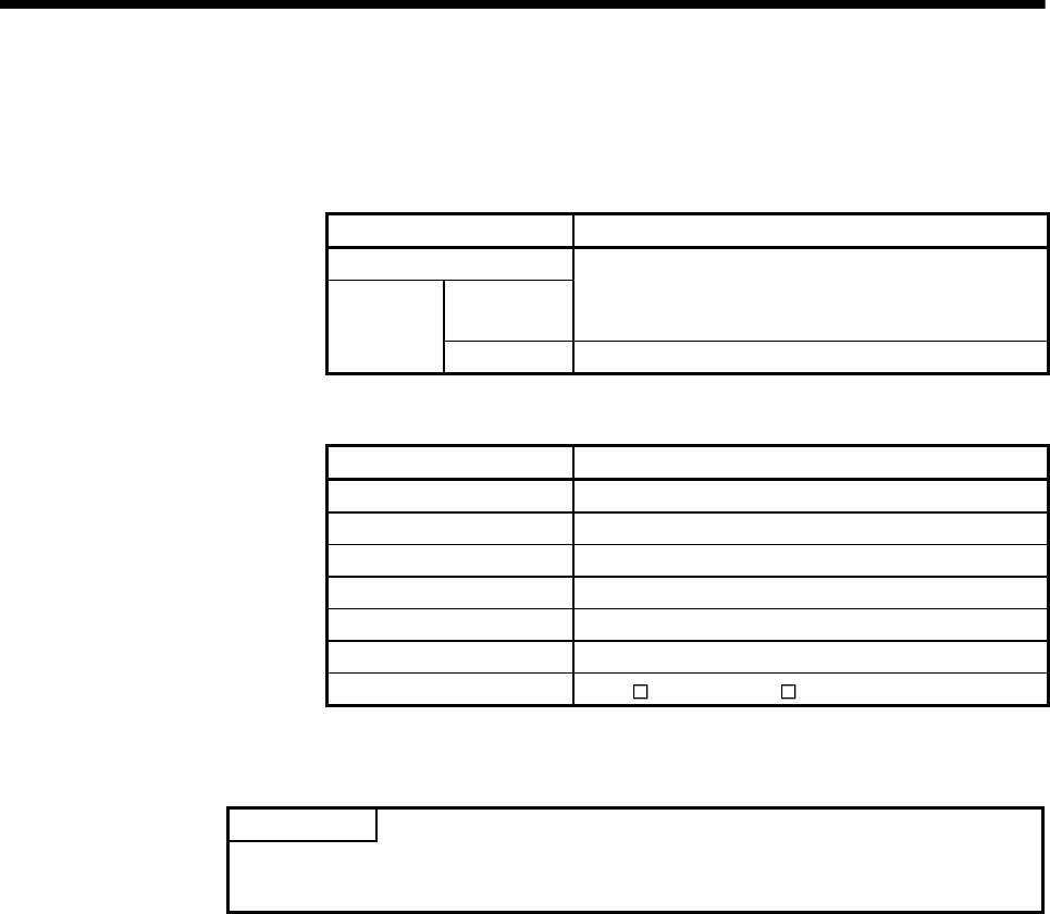
4 - 7
4 AUXILIARY AND APPLIED FUNCTIONS
(5) Forced output bit
(a) Set the "forced output bit" when you want to forcibly provide the limit switch
outputs during operation.
1) The following control is exercised.
Output enable/disable bit Control description
Without setting
OFF
Limit switch outputs are turned ON/OFF on the basis of
the "output enable/disable bit" and ON region setting
(ON Value, OFF Value).
With setting
ON Limit switch outputs are turned ON.
(b) Usable devices
Item Device No. setting range
Input relay X0 to X1FFF
Output relay Y0 to Y1FFF
Internal relay M0 to M8191
Link relay B0 to B1FFF
Annunciator F0 to F2047
Special relay SM0 to SM1999
Multiple CPU area device U\G10000.0 to U \G (10000+p-1).F (Note-1)
(Note-1) : "p" indicates the user setting area points of the Multiple CPU high speed
transmission area for the each CPU.
POINT
Refer to Chapter 2 for the user setting area points of the Multiple CPU high speed
transmission area.
4 - 8
4 AUXILIARY AND APPLIED FUNCTIONS
4.2 Absolute Position System
The positioning control for absolute position system can be performed using the
absolute-position-compatible servomotors and servo amplifiers.
If the machine position is set at the system starting, home position return is not
necessary because the absolute position is detected at the power on.
The machine position is set with the home position return using the Motion SFC
program or MT Developer.
(1) Conditions of the absolute position system start
Perform a home position return after machine adjustment at the absolute position
system start.
(2) In the absolute positioning system, the absolute position may be lost in the
following cases:
Set the absolute position with a home position return.
(a) The battery unit is removed or replaced.
(b) The battery error of the servo amplifier occurs. (It is detected at the servo
amplifier power on).
(c) The machine system is disturbed by a shock.
(d) The cable between servo amplifier and encoder is removed, or the servo
amplifier or encoder is replaced.
(3) The current value history can be monitored using of the "System setting mode-
allowable travel during power off" or "Monitor mode" using a MT Developer.
(Refer to the help of MT Developer to be used "Allowable travel during power off"
and "Monitor mode".)
CAUTION
After removing or replacing the battery unit, correctly install the new unit and set the absolute
position.
After a servo battery error occurs, eliminate the cause of the error and ensure operation is safe
before setting the absolute position.
After the mechanical system is disturbed by a shock, make the necessary checks and repairs,
and ensure operation is safe before setting the absolute position.

4 - 9
4 AUXILIARY AND APPLIED FUNCTIONS
POINT
(1) The address setting range of absolute position system is 2147483648 to
2147483647.
It is not possible to restore position commands that exceed this limit, or current
values after a power interruption.
Correspond by the [degree] setting for an infinite feed operation.
(2) Even when the current value address is changed by a current value change
instruction, the restored data for the current value after a power interruption is
the value based on the status prior to execution of the current value change
instruction.
(3) When home position return has not been completed (home position return
request is ON), restoration of the current value after a power interruption is not
possible.
4 - 10
4 AUXILIARY AND APPLIED FUNCTIONS
4.2.1 Current value control
The current value when using the ABS encoder is controlled by following functions.
(1) The validity of an encoder data during operation is checked.
(a) Checks that the amount of change of the encoder in a 3.5[ms] is within 180
degrees at the motor axis. (An error is displayed at the abnormal.)
(b) Checks that adjustment of the encoder data and feed-back positions
controlled with the servo amplifier. (An error is displayed at the abnormal.)
(2) The following values can be monitored by the current value history monitor of
MT Developer.
Monitor conditions Monitor value
Multiple CPU system power ON/OFF
Home position return completion
Encoder current value,
Servo command value,
Monitor current value
(a) Current value history monitor
Month/day/hour/minute
The time such as at the completion of home position return and servo
amplifier power supply ON/OFF is indicated.
In order to indicate the time correctly, turn on SM801 (clock data read
request) in the Motion SFC program after setting the clock data of
special register.
(b) Encoder current value
When using the MR-J3- B, the multiple revolution data and within-one-
revolution data read from the encoder is indicated.
(Note) : For the encoder current value in the home position data area, the
encoder current value when the motor is within the in-position range
at the completion of home position return is displayed (not encoder
value of home position).
(c) Servo command value
The command value issued to the servo amplifier is indicated.
(d) Monitor current value
The current value controlled in the Motion CPU is indicated.
(Note) : A value near the feed current value is indicated. However, because
the monitor current value and feed current value are different data, it
is not abnormal even if a different value is indicated.
(e) Alarms
When an error for current value restoration occurs at the servo amplifier
power on, an error code is indicated.
(3) By setting of the "Allowable travel during power off", if the encoder data changes
exceeding the setting range during power-off, it checks at servo amplifier power-
on. (An error is displayed at the abnormal.)
"Allowable travel during power off" cannot be set for the Linear servo amplifier.
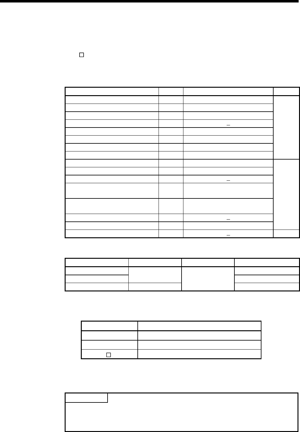
4 - 11
4 AUXILIARY AND APPLIED FUNCTIONS
4.3 High-Speed Reading of Specified Data
This function is used to store the specified positioning data in the specified device (D,
W, U \G). The signal from input module controlled in the Motion CPU is used as a
trigger.
It can be set in the system setting of MT Developer.
(1) Positioning data that can be set
Setting data Word No. Unit Remarks
Position command (Feed current value) 2 10-1[µm], 10-5[inch], 10-5[degree], [PLS]
Actual current value 2 10-1[µm], 10-5[inch], 10-5[degree], [PLS]
Position droop (Deviation counter value) 2 [PLS]
M-code 1
Torque limit value 1 [%]
Motor current 1 [%]
Motor speed 2 [r/min]
Servo command value 2 [PLS]
Virtual servomotor feed current value 2 [PLS]
Synchronous encoder current value 2 [PLS]
Virtual servo M-code 1
Current value after main shaft differential
gear 2 [PLS]
Current value within one revolution of
cam axis 2 [PLS]
Execute cam No. 1
Execute stroke amount 2 10-1[µm], 10-5[inch] [PLS]
Valid in
SV22
virtual
mode only
Optional address (Fixed to 4 bytes) 2
(2) Modules and signals to be used
Input module Signal Read timing Number of settable points
Q172DEX 2
Q173DPX TREN 3
PLC input module(Note) PX device
0.8[ms]
8
(Note) : Only one PLC input module can be used.
(3) Usable devices
Word devices Usable devices
D 0 to 8191
W 0 to 1FFF
U\G 10000 to (10000 + p-1) (Note-1), (Note-2)
(Note-1): "p" indicates the user setting area points of the Multiple CPU high speed
transmission area for the each CPU.
(Note-2): Only device of the self CPU can be used.
POINT
(1) Set an even number as device setting in the two word data.
(2) Refer to Chapter 2 for the user setting area points of the Multiple CPU high
speed transmission area.
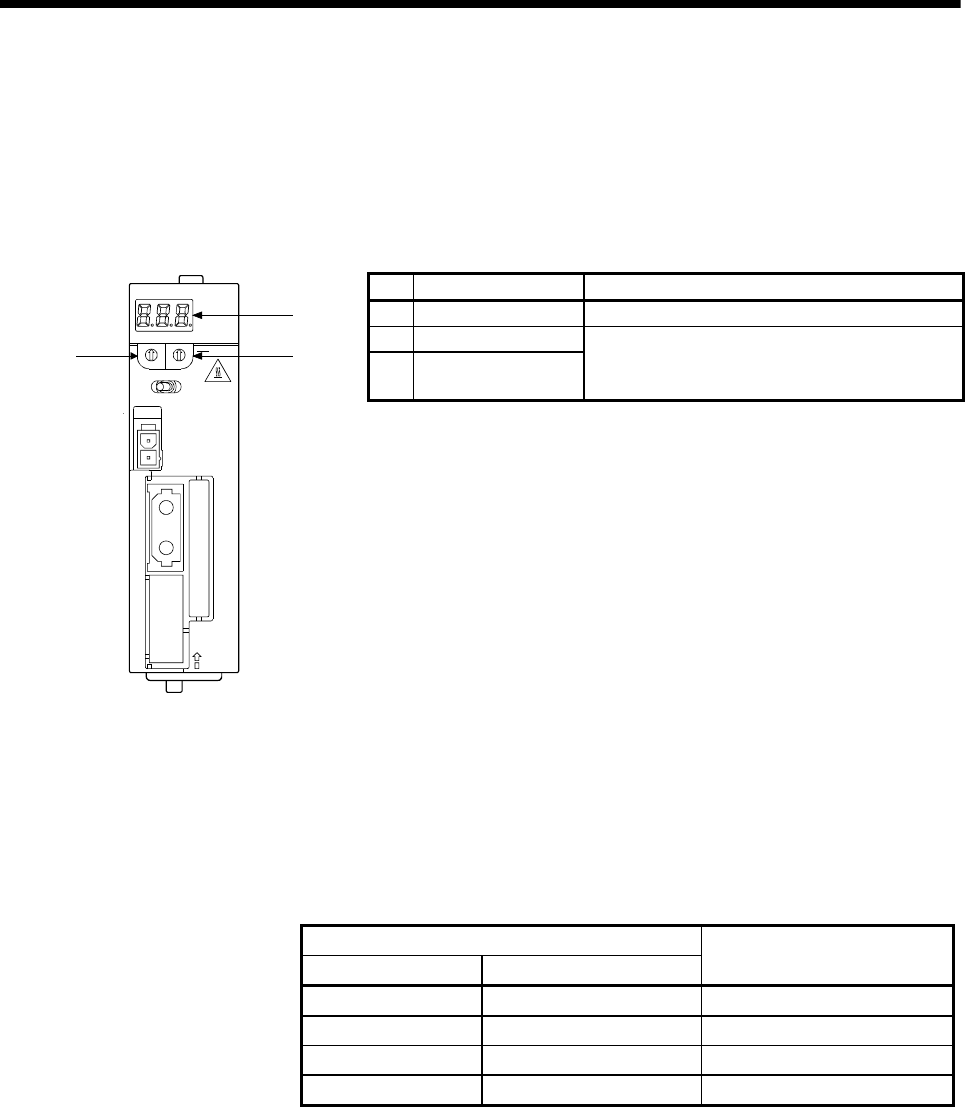
4 - 12
4 AUXILIARY AND APPLIED FUNCTIONS
4.4 ROM Operation Function
This function is used to operate based on the data in the FLASH ROM built-in Motion
CPU module that the user programs and parameters have been stored.
4.4.1 Specifications of 7-segment LED/Switches
No. Items Functions
1) 7-segment LED • Indicate the operation state and error information.
2) Rotary switch 1 (SW1)
3) Rotary switch 2 (SW2)
• Set the operation mode (Normal mode, Installation
mode and mode operated by ROM, etc.)
• Each switch setting is 0 to F.
STOP RUN
0
8
C
4
1
2
3
5
6
7
9
A
B
D
E
F
0
8
C
4
1
2
3
5
6
7
9
A
B
D
E
F
Q172DCPU
CN1
1
CAUTI ON
2
SW
BAT
FRONT
EMI
1)
3)2)
(1) Operation mode
"Operation mode" of the Motion CPU is set by the rotary switch setting of Motion
CPU module at the power supply ON of the Multiple CPU system.
The rotary switch setting, operation mode and operation mode overview are
shown below.
(a) Rotary switch setting and operation mode
Rotary switch setting (Note-1)
SW1 SW2
Operation mode
A Any setting (Except C) Installation mode
0 0 Mode operated by RAM
0 6 Mode operated by ROM
Any setting C SRAM clear (Note-2)
(Note-1) : Do not set except the above setting.
(Note-2) : The programs, parameters, absolute position data, and latch data in the
SRAM built-in Motion CPU module are cleared.
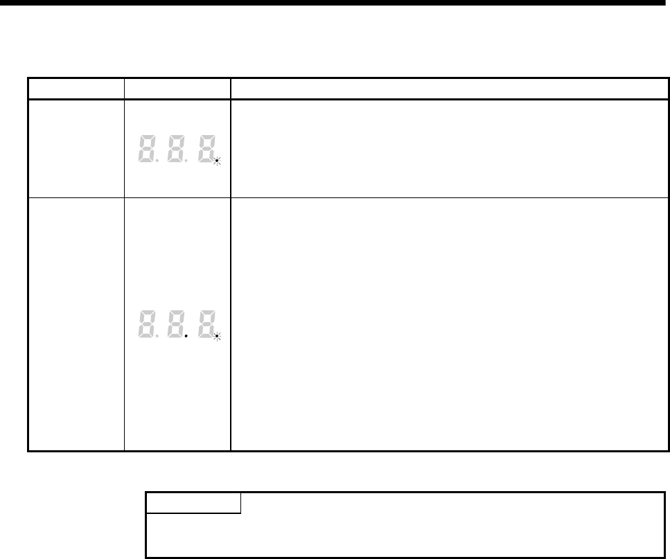
4 - 13
4 AUXILIARY AND APPLIED FUNCTIONS
(b) Operation mode overview
Operation mode 7-segment LED Operation overview
Mode operated
by RAM
• " . " remains flashing in the first digit of 7-segment LED.
• It operates based on the user programs and parameters stored in the SRAM
built-in Motion CPU module.
• The user programs and parameters for the ROM operation can be written to
the FLASH ROM built-in Motion CPU module.
Mode operated
by ROM
• " . " remains flashing in the first digit and steady " . " display in the second
digit of 7-segment LED.
• Operation starts after the user programs and parameters stored in the FLASH
ROM built-in Motion CPU module are read to the SRAM built-in Motion CPU
module at power supply on or reset of the Multiple CPU system.
If the ROM writing is not executed, even if the user programs and parameters
are changed using the MT Developer during mode operated by ROM,
operation starts with the contents of the FLASH ROM at next power supply on
or reset.
Also, If the ROM writing is not executed, even if the auto tuning data are
reflected on the servo parameter of Motion CPU by operation in the auto-tuning
setting, operation starts with the contents of the FLASH ROM at next power
supply on or reset.
POINT
Do not change the rotary switch setting during operation.
Be sure to turn OFF the power supply before the rotary switch setting change.
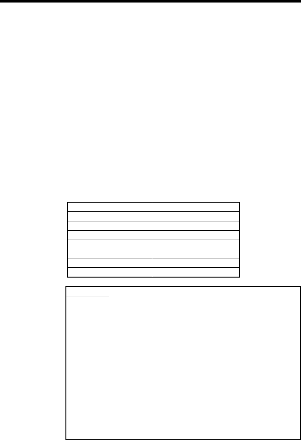
4 - 14
4 AUXILIARY AND APPLIED FUNCTIONS
4.4.2 Outline of ROM operation
When the ROM writing is requested to the Motion CPU module using the MT
Developer, the programs and parameters stored in the SRAM built-in Motion CPU
module are batch-written to the FLASH ROM, after the data of FLASH ROM built-in
Motion CPU are erased.
When the Motion CPU starts in the "Mode operated by ROM", a normal operation
starts, after the data written in the FLASH ROM is read to the SRAM.
The programs and parameters created by the MT Developer must be written
beforehand to the FLASH ROM built-in Motion CPU module at the ROM operation.
The following methods for ROM writing are shown below.
• Write the programs and parameters written in the SRAM built-in Motion CPU module
to the FLASH ROM built-in Motion CPU module.
• Write the programs and parameters of the MT Developer to the SRAM built-in Motion
CPU module, and then write them to the FLASH ROM built-in Motion CPU module.
The data batch written to the FLASH ROM built-in Motion CPU module by ROM writing
are shown below. Backup data except the followings (current position of servomotor in
absolute position system, home position and latch device.) cannot be written to the
FLASH ROM.
SV13 SV22
System setting data
Each parameter for servo control
Servo program
Motion SFC parameter
Motion SFC program
— Mechanical system program
— Cam data
POINT
(1) "Backup • load" operation of the MT Developer targets the SRAM built-in
Motion CPU module. (The FLASH ROM built-in Motion CPU module is not
targeted.)
Set to "Mode operated by ROM" after ROM writing to execute the ROM
operation after "Backup • load" operation at the Motion CPU module
exchange.
(2) The FLASH ROM built-in Motion CPU module serves as a life in 100000 times
writing. Make the ROM writing within 100000 times. If it passes over a life,
"writing error" will occur, replace the Motion CPU module.
(3) The online change of Motion SFC program executes the Motion SFC program
performed the online change from the next scanning at the mode operated by
ROM. Operation starts with the contents of the Motion SFC program written in
the FLASH ROM built-in Motion CPU module at next power supply on or reset.
(4) It needs to meet the following conditions for the ROM writing.
(a) PLC ready flag (M2000) OFF
(b) Not installation mode
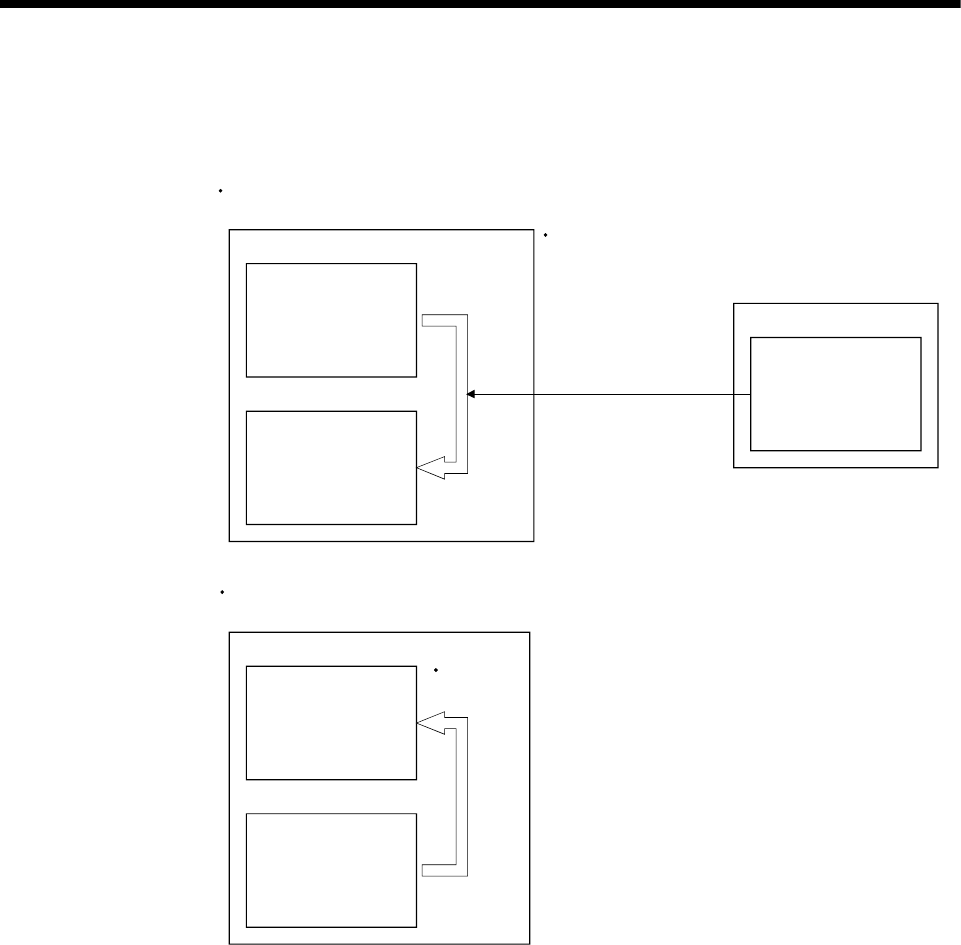
4 - 15
4 AUXILIARY AND APPLIED FUNCTIONS
(1) Write the programs and parameters written in the SRAM built-in Motion CPU
module to the FLASH ROM built-in Motion CPU module for the ROM operation.
Motion CPU module
Programs
Parameters, etc.
<ROM writing>
MT Developer
Mode operated by RAM/Mode operated by ROM
Programs
Parameters, etc.
SRAM
FLASH ROM
1) ROM writing request Programs
Parameters, etc.
Motion CPU module
<ROM operation>
Mode operated by RAM/Mode operated by ROM
SRAM
FLASH ROM
Programs
Parameters, etc.
Programs
Parameters, etc.
Read at
starting
2) ROM writing
IBM PC/AT
Be sure to write the programs and parameters beforehand
to the SRAM built-in Motion CPU module at the ROM
operation.
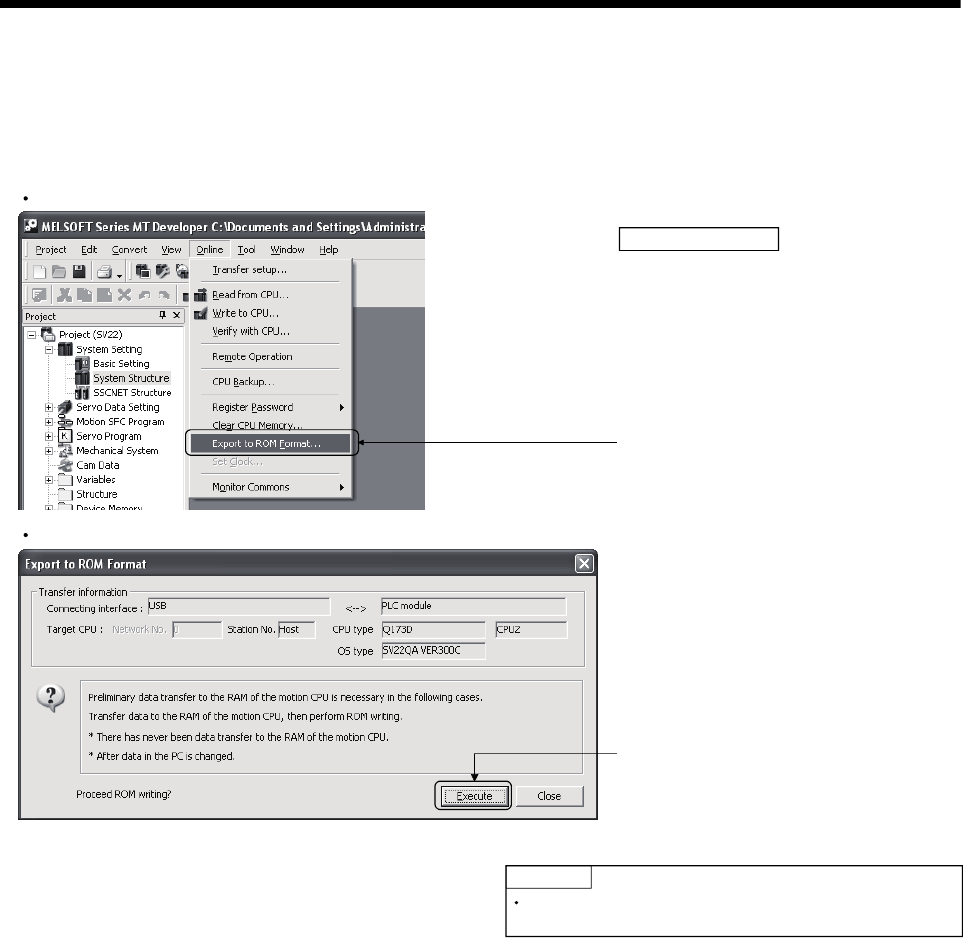
4 - 16
4 AUXILIARY AND APPLIED FUNCTIONS
<Operating procedure for ROM writing> Write the data of SRAM built-in Motion CPU module to the ROM.
The operating procedure for ROM writing using the MT Developer is shown below.
Main Frame screen
1) Select menu "Online" -"Export to ROM
Format" to display "Export to ROM Format"
screen.
POINT
Export to ROM Format screen
Operating procedure
Be sure to write the all data beforehand to SRAM built-in
Motion CPU module at the ROM writing.
2) Select "Execute" button.
ROM writing is executed to FLASH ROM
built-in Motion CPU module.
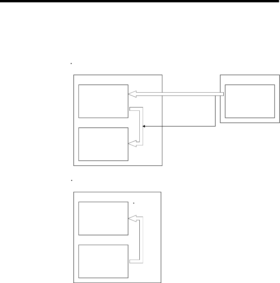
4 - 17
4 AUXILIARY AND APPLIED FUNCTIONS
(2) Write the programs and parameters of the MT Developer to the SRAM built-in
Motion CPU module, and then write them to the FLASH ROM built-in Motion CPU
module for the ROM operation.
Motion CPU module
Programs
Parameters, etc.
<Data writing + ROM writing>
Mode operated by RAM/Mode operated by ROM
Programs
Parameters, etc.
SRAM
FLASH ROM
Motion CPU module
<ROM operation>
Mode operated by RAM/Mode operated by ROM
SRAM
FLASH ROM
Programs
Parameters, etc.
Programs
Parameters, etc.
Read at
starting
3) ROM writing
1) Write data
(ROM writing request)
2) ROM writing request
after write data
MT Developer
Programs
Parameters, etc.
IBM PC/AT
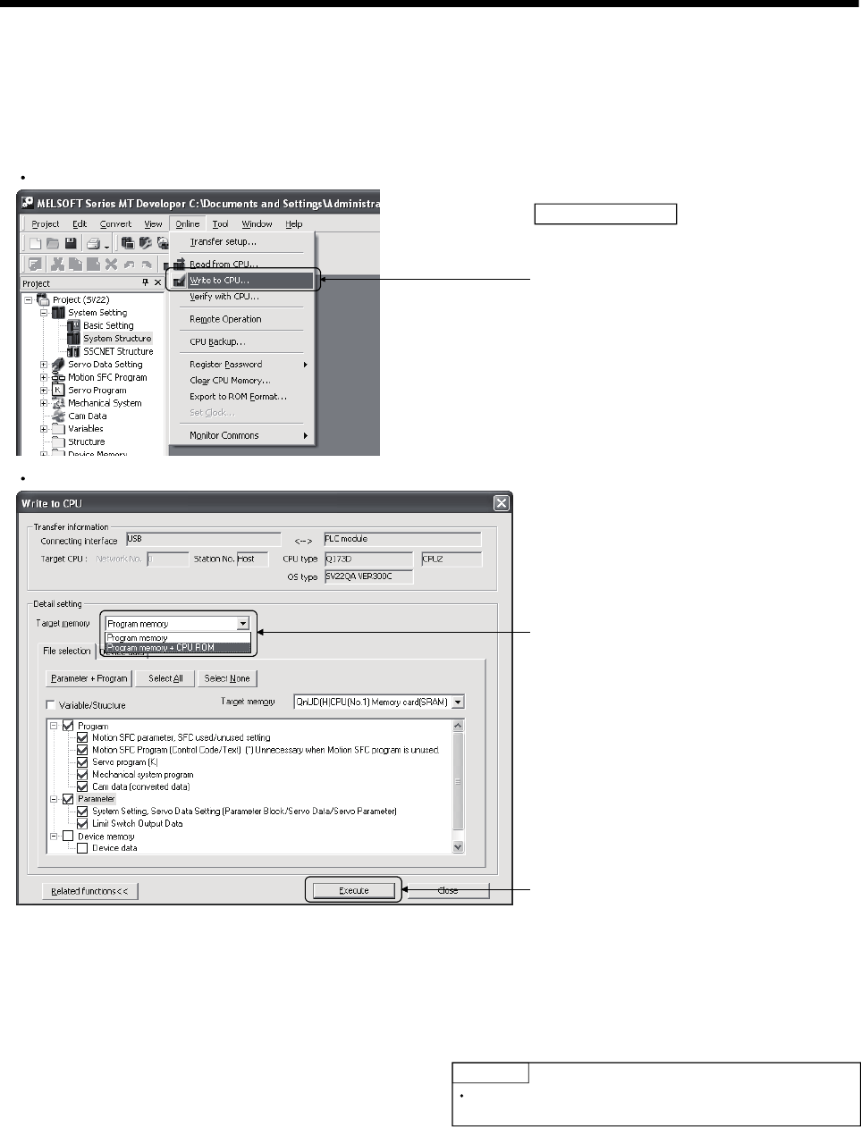
4 - 18
4 AUXILIARY AND APPLIED FUNCTIONS
<Operating procedure for ROM writing> Write the data of MT Developer to the ROM.
The operating procedure for ROM writing using the MT Developer is shown below.
POINT
Be sure to write the all data beforehand to SRAM built-in
Motion CPU module at the ROM writing.
2) Check data of MT Developer written in the
Motion CPU.
3) Select "Program memory + CPU ROM" in
target memory.
(Note): Mechanical system program and cam data
(converted data) cannot be displayed when
using OS type "SW8DNC-SV13".
Main Frame screen
1) Select menu "Online" -"Write to CPU" to
display "Write to CPU" screen.
Write to CPU screen
Operating procedure
4) Select "Execute" button.
SRAM data built in Motion CPU module is written
to ROM after writing data of MT developer to
SRAM built-in Motion CPU module.
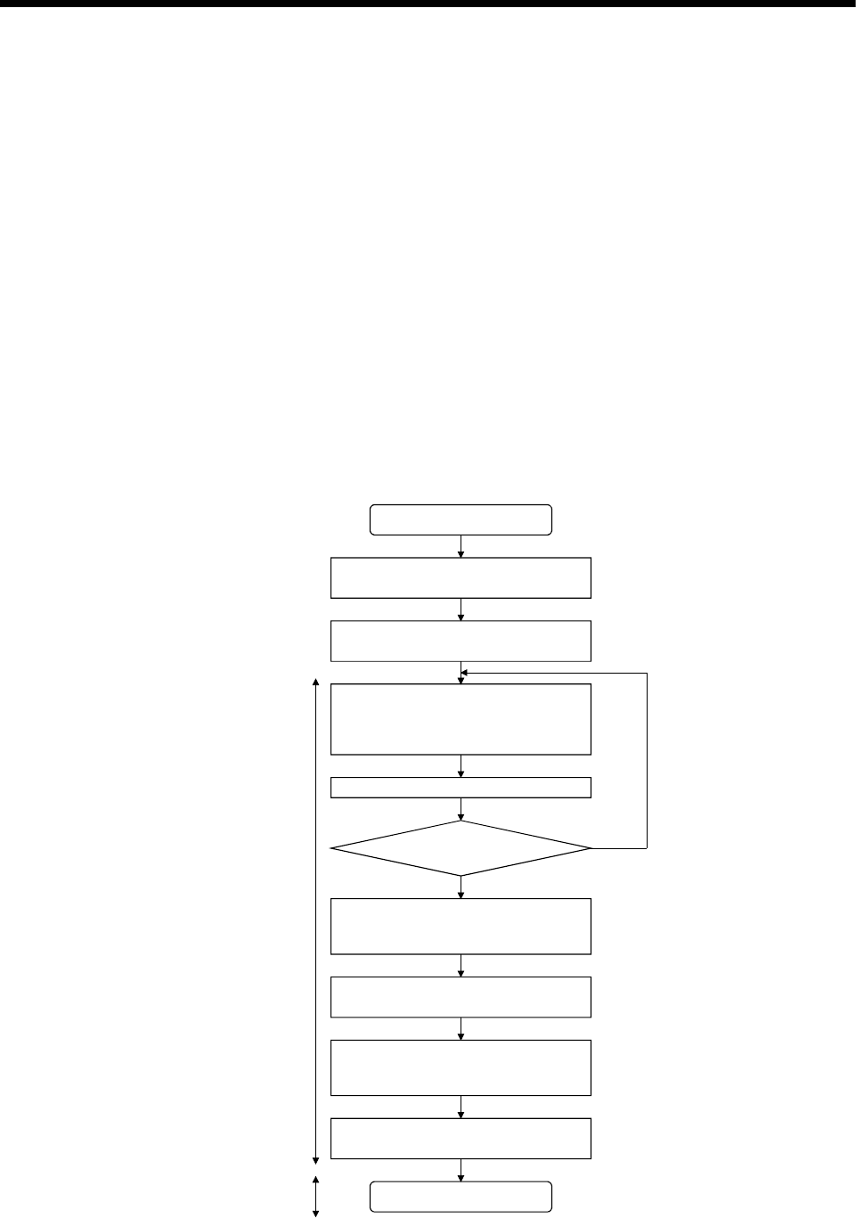
4 - 19
4 AUXILIARY AND APPLIED FUNCTIONS
4.4.3 Operating procedure of the ROM operation function
The outline procedure of ROM operation function is shown below.
1) Turn on or reset the power supply of Multiple CPU system in the "Mode operated
by RAM".
2) Create the system setting, programs and parameters using the MT Developer, and
execute a trial run and adjustment.
3) Write the system setting, programs and parameters of SRAM built-in Motion CPU
module to the FLASH ROM built-in Motion CPU module by the ROM writing
request using the MT Developer.
4) By starting the Motion CPU in the "Mode operated by ROM", a normal operation
starts after the system setting, programs and parameters written in the FLASH
ROM built-in Motion CPU module are read to the SRAM built-in Motion CPU
module.
(1) ROM operation procedure
The ROM operation procedure is shown below.
Set the "Mode operated by RAM" by setting
the rotary switch 1 (SW1) and 2 (SW2) to "0".
Turn ON the power supply of Multiple CPU
system.
Create or correct the system setting,
parameters and programs using the MT
Developer, and write them to the Motion
CPU module.
Execute the trial run and adjustment.
Is the operation normal ?
Execute the "ROM writing" of the programs
and parameters in a lump using the MT
Developer.
Turn OFF the power supply of Multiple CPU
system.
Set the "Mode operated by ROM" by setting
the rotary switch 1 (SW1) to "0" and rotary
switch 2 (SW2) to "6".
Turn ON the power supply of Multiple CPU
system.
ROM operation start
Preparation for ROM operation
NO
YES
Mode operated
by RAM
(ROM writing)
Mode operated
by ROM
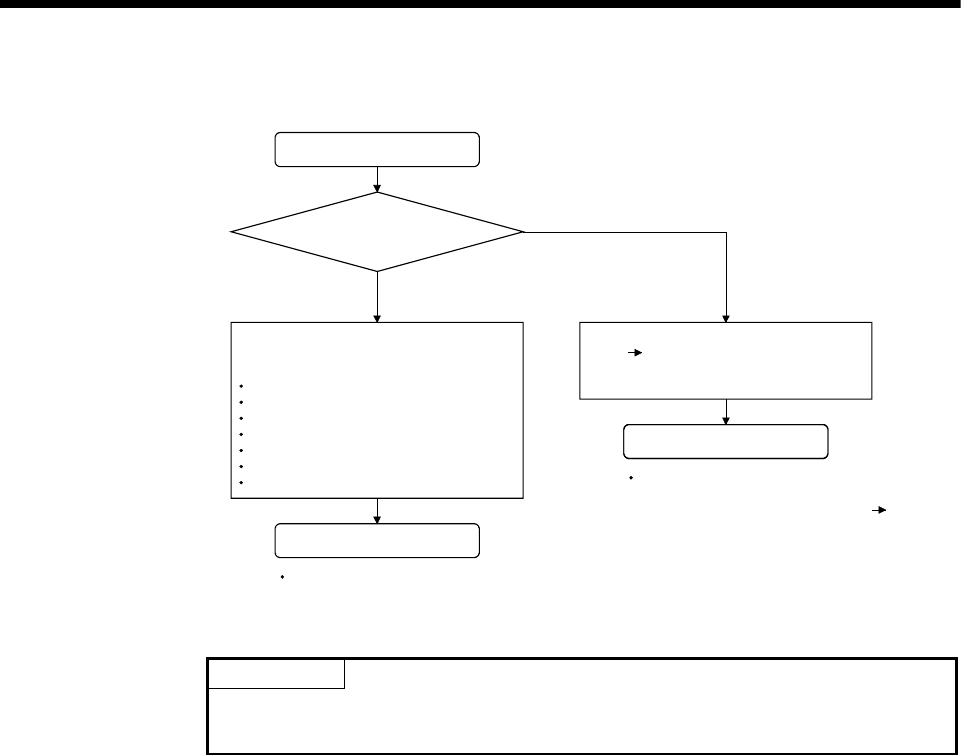
4 - 20
4 AUXILIARY AND APPLIED FUNCTIONS
(2) Operation at the "Mode operated by ROM"
NO
YES
Mode operated by ROM start
Is the data write
to the FLASH ROM built-in
Motion CPU module ?
Normal operation start
Read the followings of the FLASH ROM
built-in Motion CPU module to the SRAM
built-in Motion CPU module.
System setting data
Parameter for servo control
Servo program
Motion SFC parameter
Motion SFC program
Mechanical system program (SV22)
Cam data (SV22)
(Data (programs, parameters and absolute
position data) is not written to the FLASH
ROM built-in Motion CPU module.)
The system setting error (" AL" flashes 3
times steady "L01" display) in the 7-
segment LED at the front side of Motion
CPU module.
After that, it is same operation at the
RAM operation.
After that, it cannot be operated because of
stop state.
Retry the operation for "ROM writing"
"Mode operated by ROM" after confirm the
contents for programs and parameters of the
SRAM built-in Motion CPU module.
Wait the restart of Multiple
CPU system.
POINT
(1) Change the operation mode using the rotary switch of Motion CPU module.
(2) Confirm the operation mode by the 7-segment LED of Motion CPU module.
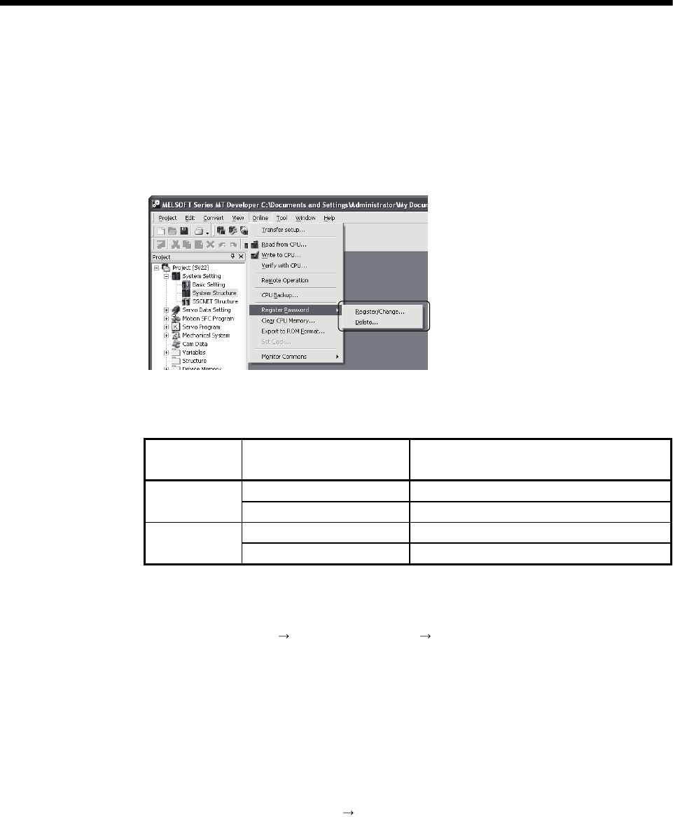
4 - 21
4 AUXILIARY AND APPLIED FUNCTIONS
4.5 Security Function
This function is used to protect the user data of Motion CPU by registering a password.
The illegal reading or writing of the user data are prevented by setting a password.
Registered password can be changed and deleted.
[Register/Change Password] or [Delete Password] screen is used to register/
change/delete a password. Select from a menu bar to display these screen.
The user data protected in this function are shown below.
"Write Protection" or "Read/Write Protection" can be set every user data.
Operating
system software User data Protected contents
Motion SFC program Motion SFC programs (Control code, text)
SV13/SV22 Servo program Servo programs and program allocation
Mechanical system program Mechanical system programs
SV22 Cam data Cam data
4.5.1 Password registration/change
Select menu [Online] [Register Password] [Register/Change] to register/change a
password.
(1) Procedure for password registration
(a) Enter initial registration password in password column, and select
registration condition (Write Protection, Read/Write Protection). It leaves in
blank for the user data that does not register a password.
(b) Click on [Execute] button to register a password in the Motion CPU.
(c) Select menu [Project] [Save] to save a password after registration in a
project.
Refer to Section 4.5.4 for password save.
(2) Procedure for password change
(a) Status of password registered in the Motion CPU are displayed.
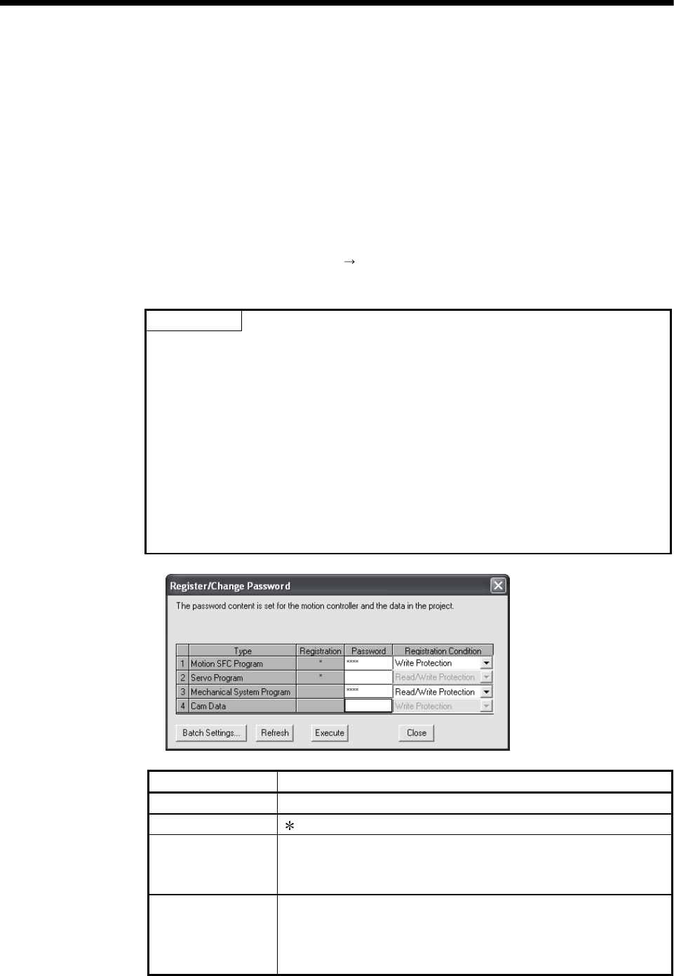
4 - 22
4 AUXILIARY AND APPLIED FUNCTIONS
(b) Enter new password in password column, and select registration condition
(Write Protection, Read/Write Protection). It leaves in blank for the user data
that does not change a password.
(c) Click on [Execute] button to display [Check Password] screen for old
password confirmation. Click on [Execute] button after old password input.
New password will be registered in the Motion CPU by success of old
password check.
When the new password is the same as old password (change for only
registration condition), [Check Password] screen is not displayed.
(d) Select menu [Project] [Save] to save a password after change in a project.
Refer to Section 4.5.4 for password save.
POINT
(1) If an user has forgotten a registration password, clear a password of Motion
CPU by the all clear function. However, the all password data and user data
are cleared by the all clear function. Re-write the user data to the Motion CPU.
(Refer to Section 4.6 for details.)
(2) ROM operation can be executed by user data registered a password.
The password setting is also included in the ROM writing/reading data.
(3) The password data is not save in a project without password save.
Therefore, be sure to save a password.
(4) If an operation stops by reset or power OFF of the Multiple CPU system while
a password registration/change, the user data may not be registered.
Register/change a password again to restore the user data.
Items Details
Type Type of user data
Registration " " is displayed when a password is registered in the Motion CPU.
Password
Enter initial registration/change password.
Alphanumeric character (ASCII) of 6 or less
Match case (Not full-size character)
Registration condition
A registration condition set in the Motion CPU is displayed.
• Write Protection
• Read/Write Protection
New registration condition can be selected by password input.
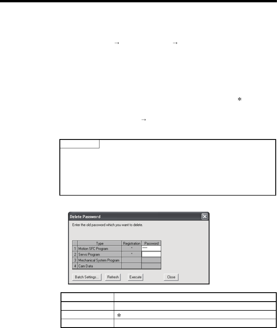
4 - 23
4 AUXILIARY AND APPLIED FUNCTIONS
4.5.2 Password delete
Select menu [Online] [Register Password] [Delete] to delete a password.
(1) Procedure for password delete
(a) Status of password registered in the Motion CPU are displayed.
(b) Enter old password and click on [Execute] button to delete password. It
leaves in blank for the user data that does not delete a password.
(c) A password will be deleted by success of password check. (" " displayed in
registration column disappears.)
(d) Select menu [Project] [Save] to save a password after delete in a project.
Refer to Section 4.5.4 for password save.
POINT
(1) The password data is not save in a project without password save.
Therefore, be sure to save a password.
(2) If an operation stops by reset or power OFF of the Multiple CPU system while
delete of password, the data may not be deleted. Delete a password again to
restore the user data.
Items Details
Type Type of user data
Registration " " is displayed when a password is registered in the Motion CPU.
Password Enter old password.
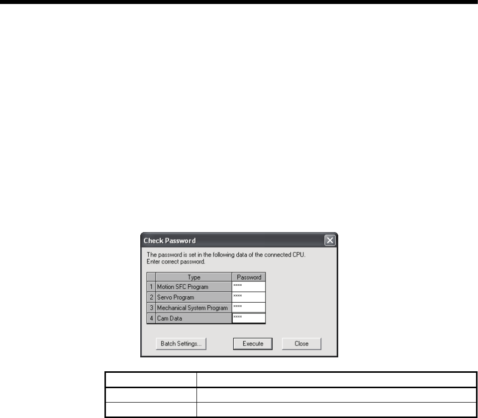
4 - 24
4 AUXILIARY AND APPLIED FUNCTIONS
4.5.3 Password check
When operating the user data that sets password, the check password screen is
displayed automatically.
(1) Procedure for password check
(a) Enter old password in password column, and click on [Execute] button.
(b) Protection by the password temporarily released by success of password
check. After that it can be operated the user data.
(c) A password is memorized until MT Developer ends. (Since protection by
password is automatically released temporarily at the user data operation, a
check password screen is not displayed.)
Items Details
Type Type of user data
Password Enter old password.

4 - 25
4 AUXILIARY AND APPLIED FUNCTIONS
4.5.4 Password save
Registered/changed/deleted password or password read with user data from "Read
from CPU" screen displayed by menu [Online] [Read from CPU] can be saved in a
project data.
A password saved in a project data can be registered with user data, when the user
data are written in the Motion CPU that does not set password from "Write to CPU"
screen displayed by menu [Online] [Write to CPU].
Select menu [Project] [Save] to save the updated password data in a project.
(1) Status of password data for each operation
Operation Status of password data
Read When a password is set in the call source Motion CPU, the password contents
are called and the password data in a project are updated.
Write When a password data is set in a project, if a password is not set in the write
designation Motion CPU, the password contents are also written.
Verification Password data in a project are not updated.
ROM writing Password contents registered in the write designation Motion CPU are written in
ROM.
Online change Password contents of write designation Motion CPU are not updated.
Backup It is saved in backup data including also the password contents registered in the
call source Motion CPU. The password data in a project is not updated.
Load Password contents in backup data are written in the write designation Motion
CPU.
Register/change
password
New password contents are written in the write designation Motion CPU.
Password data in a project is also updated to new password contents.
Delete password A password is deleted from the write designation Motion CPU.
A password is deleted also from the password data in a project.
Project diversion The password data in diverting source project is not diverted.
POINT
(1) The password data is not save in a project without project save.
(2) Save a project after delete of password to delete the password data in a
project. Or, create a project without password data by creating new project
and diverting user data from a project with password data.
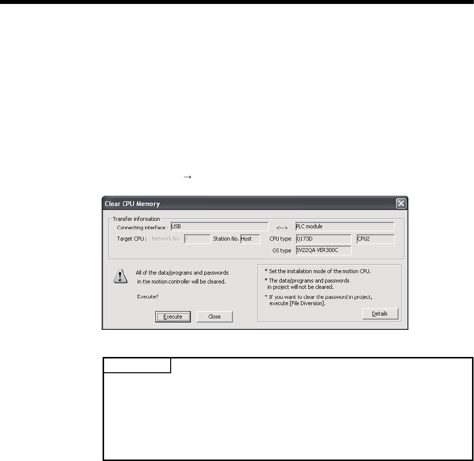
4 - 26
4 AUXILIARY AND APPLIED FUNCTIONS
4.6 All clear function
This function is used to clear the all user data, password setting, backup area and user
data area of FLASH ROM in the Motion CPU module.
(1) Procedure for clear all
(a) Set the Motion CPU module to installation mode (Set a rotary switch 1
(SW1) to "A".)
(b) Select [Execute] button of "Clear CPU Memory" screen displayed by menu
[Online] [Clear CPU Memory]".
POINT
(1) Set the Motion CPU module to installation mode to clear all.
Be sure to set a rotary switch after power supply OFF.
(2) The user data area of FLASH ROM built-in Motion CPU module is also
cleared.
(3) All user data and password setting are cleared at the "Clear all".
It is recommended to be backup them in advance using MT Developer.

4 - 27
4 AUXILIARY AND APPLIED FUNCTIONS
4.7 Communication via Network
The communication between the personal computer and the Motion CPU is possible
via Q series Network module (MELSECNET/10(H), Ethernet, CC-Link and etc.) in the
Motion CPU (Q173DCPU/Q172DCPU).
Refer to the PLC manuals for the specifications of each network modules of
MELSECNET/10(H), Ethernet, CC-Link and Serial communication, the handling
method.
4.7.1 Specifications of the communications via network
(1) Communications via network enables using MT Developer in the Motion CPU.
(2) Access range of the communications via network of the Motion CPU is an access
range equivalent to QnUD(H)CPU. (Refer to Section "4.7.2 Access range of the
communications via network".)
(3) By setting the routing parameter to the control CPU of the network module and the
CPU which connected the peripheral devices in the network by
MELSECNET/10(H) and Ethernet, it is possible to relay to 8 network points and
communicate.
(4) Because the Motion CPU cannot become the control CPU of the network module,
there is not setting item of the network module and network parameter.
However, when connecting with the CPU on the other network from the peripheral
device which connected the Motion CPU, it needs to the setting of the routing
parameter.
(5) It can operate by remote control the monitor or program editing of the Motion CPU
via the intranet using the Ethernet module.
Power supply
Personal Computer
Intranet
Personal Computer
QnUD(H)
CPU
Q173D/
Q172D
CPU
Power supply
QnUD(H)
CPU
Q173D/
Q172D
CPU
Ethernet Ethernet
Ethernet Ethernet
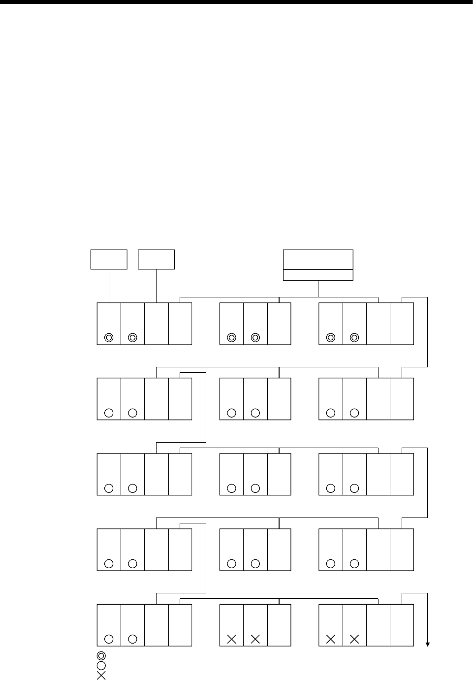
4 - 28
4 AUXILIARY AND APPLIED FUNCTIONS
4.7.2 Access range of the communications via network
(1) Network configuration via the MELSECNET/10(H) or the Ethernet
(a) It can access the other CPU via the network from the programming software
packages (GX Developer, MT Developer, etc.) of the personal computer
connected with the CPU or serial communication module in USB/RS-232.
(b) It can access the other CPU via the network from the programming software
packages in the personal computer by connecting the personal computer
equipped with Ethernet to MELSECNET/10(H) or Ethernet board to the
Ethernet to MELSECNET/10(H) or Ethernet.
(c) The access range of above (1) and (2) can be accessed to 8 network points
by setting the routing parameter to the control CPU of the network module
and the CPU which connected the personal computer.
RS-232USB/
RS-232
: Communication is possible
: Communication is possible (Setting of the routing parameter is necessary.)
: Communication is impossible
C24
MNET
Ether
: Serial communication module
: MELSECNET/10(H)
: Ethernet
<Example>
Network No.1
Personal computer
Q173D
CPU
C24 MNET
or
Ether
QnUD(H)
CPU
Personal
computer
MNET board or Ether
Personal
computer
Network
No.2
Q173D
CPU
MNET
or
Ether
QnUD(H)
CPU
Q173D
CPU
MNET
or
Ether
QnUD(H)
CPU
MNET
or
Ether
Q173D
CPU
MNET
or
Ether
QnUD(H)
CPU
MNET
or
Ether
Q173D
CPU
MNET
or
Ether
QnUD(H)
CPU
Q173D
CPU
MNET
or
Ether
QnUD(H)
CPU
MNET
or
Ether
Network No.3
Q173D
CPU
MNET
or
Ether
QnUD(H)
CPU
MNET
or
Ether
Q173D
CPU
MNET
or
Ether
QnUD(H)
CPU
Q173D
CPU
MNET
or
Ether
QnUD(H)
CPU
MNET
or
Ether
Q173D
CPU
MNET
or
Ether
QnUD(H)
CPU
MNET
or
Ether
Q173D
CPU
MNET
or
Ether
QnUD(H)
CPU
Q173D
CPU
MNET
or
Ether
QnUD(H)
CPU
MNET
or
Ether
Q173D
CPU
MNET
or
Ether
QnUD(H)
CPU
MNET
or
Ether
Q173D
CPU
MNET
or
Ether
QnUD(H)
CPU
Q173D
CPU
MNET
or
Ether
QnUD(H)
CPU
MNET
or
Ether
Network
No.6
Network
No.10
Network No.5
Network No.7
Network No.9
Network No.4
Network No.8
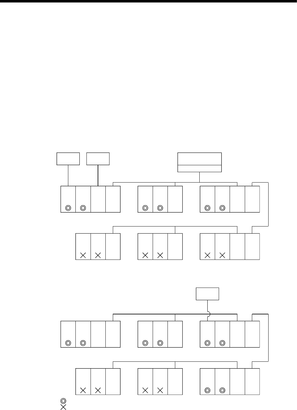
4 - 29
4 AUXILIARY AND APPLIED FUNCTIONS
(2) Network configuration via the CC-Link
(a) It can access the other CPU via the CC-link from the programming software
packages (GX Developer, MT Developer, etc.) of the personal computer
connected with the CPU or serial communication module in USB/RS-232.
(b) It can access the other CPU via the CC-Link from the programming software
packages in the personal computer by connecting the personal computer
equipped with CC-Link board to the CC-Link.
(c) The access range of above (1) is only the CPU on the CC-Link which a
system connects it to, and it can select a CC-Link network to connect by
specifying the I/O No. of the CC-Link module.
(d) The access range of above (2) is only the CPU of the connected the CC-
Link.
RS-232USB/
RS-232
C24 : Serial communication module
<Example 1>
Network No.1
Personal computer
Q173D
CPU
C24 CC-Link
QnUD(H)
CPU
Personal
computer
CC-Link board
Personal
computer
Network
No.2
Q173D
CPU
QnUD(H)
CPU
Q173D
CPU
QnUD(H)
CPU
Network No.3
: Communication is possible
: Communication is impossible
CC-Link CC-Link CC-Link
<Example 2>
Network No.1
Q173D
CPU
C24 CC-Link
QnUD(H)
CPU
Network
No.2
Q173D
CPU
QnUD(H)
CPU
Q173D
CPU
QnUD(H)
CPU
Network No.3
CC-Link CC-Link CC-Link
Q173D
CPU
CC-Link
QnUD(H)
CPU
Q173D
CPU
CC-Link
QnUD(H)
CPU
Q173D
CPU
QnUD(H)
CPU
CC-Link CC-Link
Q173D
CPU
QnUD(H)
CPU
CC-Link CC-LinkQ173D
CPU
CC-LinkQnUD(H)
CPU
Q173D
CPU
CC-LinkQnUD(H)
CPU
USB/
RS-232
Personal
computer
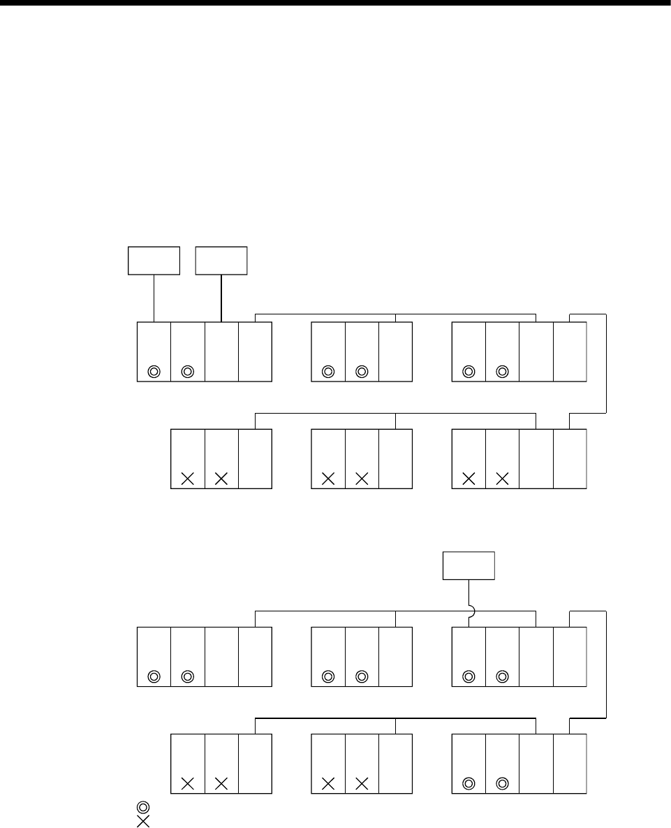
4 - 30
4 AUXILIARY AND APPLIED FUNCTIONS
(3) Network configuration via the RS-422/485
(a) It can access the other CPU via the RS-422/485 from the programming
software packages (GX Developer, MT Developer, etc.) of the personal
computer connected with the CPU or serial communication module in
USB/RS-232.
(b) The access range of above (1) is only the CPU on the RS-422/485 which a
system connects it to, and it can select RS-422/485 network to connect by
specifying the I/O No. of the C24 module.
RS-232USB/
RS-232
C24 : Serial communication module
<Example 1>
RS-422/485
Q173D
CPU
C24
QnUD(H)
CPU
Personal
computer
Personal
computer
RS-422/485
Q173D
CPU
QnUD(H)
CPU
Q173D
CPU
QnUD(H)
CPU
: Communication is possible
: Communication is impossible
<Example 2>
Q173D
CPU
C24
QnUD(H)
CPU
Q173D
CPU
QnUD(H)
CPU
Q173D
CPU
QnUD(H)
CPU
Q173D
CPU
QnUD(H)
CPU
Q173D
CPU
QnUD(H)
CPU
Q173D
CPU
QnUD(H)
CPU
Q173D
CPU
QnUD(H)
CPU
Q173D
CPU
QnUD(H)
CPU
Q173D
CPU
QnUD(H)
CPU
USB/
RS-232
Personal
computer
C24 C24 C24 C24
C24 C24 C24 C24
RS-422/485
C24 C24 C24 C24
C24 C24 C24 C24
RS-422/485
RS-422/485
RS-422/485
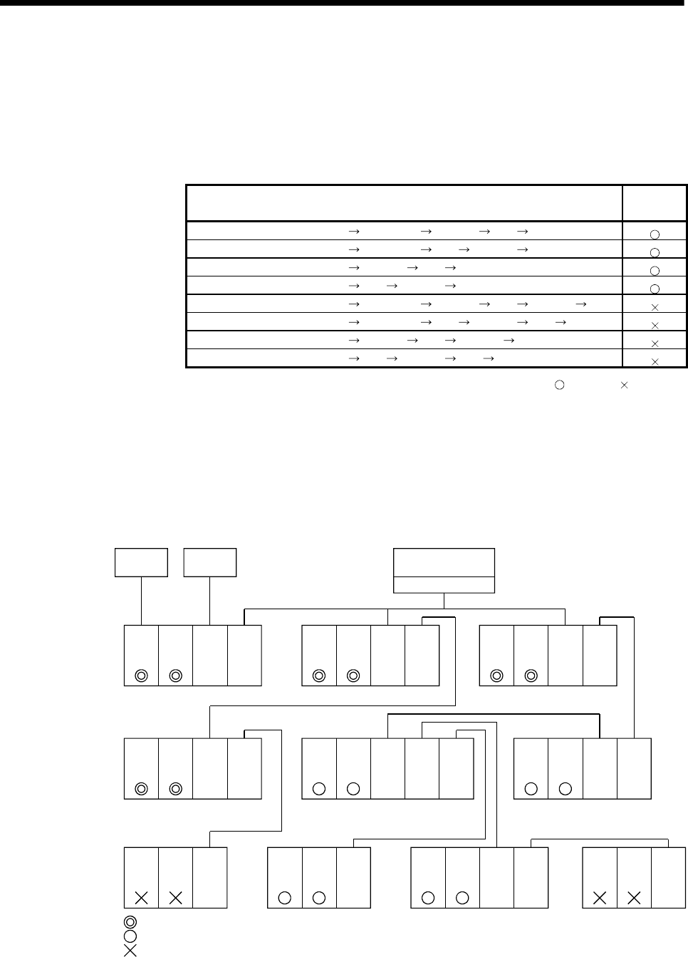
4 - 31
4 AUXILIARY AND APPLIED FUNCTIONS
(4) Network configuration which MELSECNET/10(H), Ethernet, CC-
Link, RS-422/485 were mixed
(a) When the MELSECNET/10(H) or Ethernet is defined as "Network" and CC-
Link or RS-422/485 is defined as "Link", combination of whether to be able
to access from the programming software packages (GX Developer,
MT Developer, etc.) is shown below.
Network communications Usable/
unusable
Programming software package CPU (C24) Network Link CPU
Programming software package CPU (C24) Link Network CPU
Programming software package Network Link CPU
Programming software package Link Network CPU
Programming software package CPU (C24) Network Link Network CPU
Programming software package CPU (C24) Link Network Link CPU
Programming software package Network Link Network CPU
Programming software package Link Network Link CPU
: Usable : Unusable
(b) It can be accessed to 8 network points by setting the routing parameter in
the "Network".
(c) Because routing cannot access, it can access only the connected network.
The connected network can be selected by specifying the I/O No. of the
module.
RS-232USB/
RS-232
C24
MNET
Ether
: Serial communication module
: MELSECNET/10(H)
: Ethernet
<Example 1>
Network No.1
Personal computer
Q173D
CPU
C24 MNET
or
Ether
QnUD(H)
CPU
Personal
computer
MNET board or Ether
Personal
computer
Network
No.2
Q173D
CPU
MNET
or
Ether
QnUD(H)
CPU
Q173D
CPU
MNET
or
Ether
QnUD(H)
CPU
MNET
or
Ether
Q173D
CPU
MNET
or
Ether
QnUD(H)
CPU
C24 Q173D
CPU
MNET
or
Ether
QnUD(H)
CPU
Q173D
CPU
MNET
or
Ether
QnUD(H)
CPU
MNET
or
Ether
Network No.3
Q173D
CPU
MNET
or
Ether
QnUD(H)
CPU
CC-Link
Q173D
CPU
CC-LinkQnUD(H)
CPU
Network No.5
C24
CC-Link CC-Link
: Communication is possible
: Communication is possible (Setting of the routing parameter is necessary.)
: Communication is impossible
Q173D
CPU
MNET
or
Ether
QnUD(H)
CPU
Q173D
CPU
MNET
or
Ether
QnUD(H)
CPU
RS-422/485
RS-422/485
Network No.4
RS-422/485
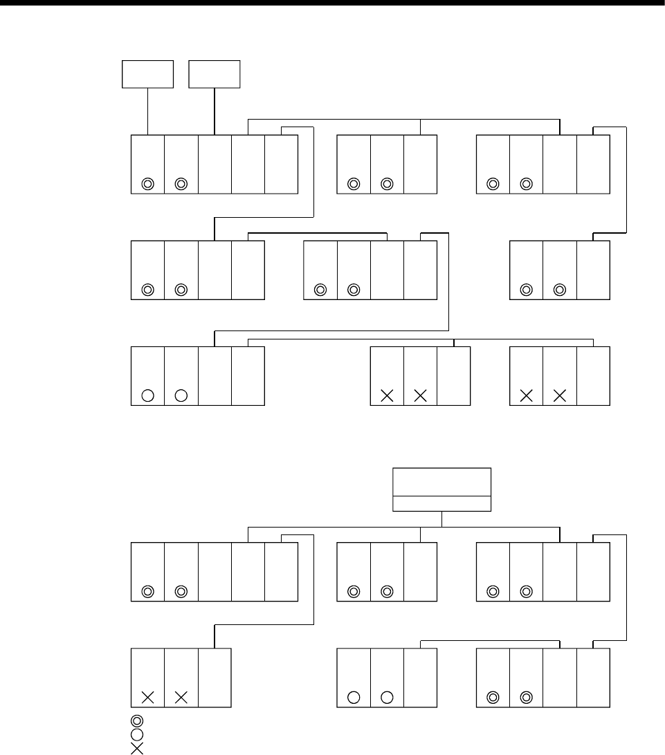
4 - 32
4 AUXILIARY AND APPLIED FUNCTIONS
RS-232USB/
RS-232
C24
MNET
Ether
: Serial communication module
: MELSECNET/10(H)
: Ethernet
<Example 2>
RS-422/485
Q173D
CPU
C24 CC-LinkQnUD(H)
CPU
Personal
computer
Personal
computer
Network
No.1
Q173D
CPU
CC-LinkQnUD(H)
CPU
Q173D
CPU
MNET
or
Ether
QnUD(H)
CPU
CC-Link
Q173D
CPU
MNET
or
Ether
QnUD(H)
CPU
CC-Link Q173D
CPU
MNET
or
Ether
QnUD(H)
CPU
Q173D
CPU
QnUD(H)
CPU
MNET
or
Ether
RS-422/485
Q173D
CPU
MNET
or
Ether
QnUD(H)
CPU
Q173D
CPU
C24
QnUD(H)
CPU
RS-422/485
Network No.2
CC-Link
MNET
or
Ether
Q173D
CPU
C24
QnUD(H)
CPU
C24
Network No.3
<Example 3>
RS-422/485
Personal computer
Q173D
CPU
C24 CC-LinkQnUD(H)
CPU
CC-Link board
Network
No.1
Q173D
CPU
CC-LinkQnUD(H)
CPU
Q173D
CPU
MNET
or
Ether
QnUD(H)
CPU
CC-Link
Q173D
CPU
MNET
or
Ether
QnUD(H)
CPU
Q173D
CPU
QnUD(H)
CPU
MNET
or
Ether
RS-422/485
Network No.2
CC-Link
: Communication is possible
: Communication is possible (Setting of the routing parameter is necessary.)
: Communication is impossible
Q173D
CPU
CC-Link
QnUD(H)
CPU
MNET
or
Ether

4 - 33
4 AUXILIARY AND APPLIED FUNCTIONS
4.8 Monitor Function of the Main Cycle
(1) Information for main cycle of the Motion CPU (process cycle executed at free time
except for motion control) is stored to the special register.
(2) Since the automatic refresh of CPU shared memory and normal task of Motion
SFC program are executed in the main cycle, make it reference for process time,
etc. to program.
(3) There are following methods to shorten a main cycle.
(a) Lengthen an operation cycle setting.
(b) Reduce the number of event task programs to execute in the Motion SFC
program.
(c) Reduce the number of normal task programs to execute simultaneously in
the Motion SFC program.
(d) Reduce the number of automatic refresh points of CPU shared memory.
(4) When a main cycle is lengthened (more than 1.0[s]), a WDT error may occur in
the Motion CPU.
(5) Details of main cycle monitor register is shown below.
No. Name Meaning Details
SD520 Scan time Current scan time
(1ms units)
• Current scan time is stored in the unit 1[ms].
• Setting range (0 to 65535[ms])
SD521 Maximum scan time Maximum scan time
(1ms units)
• Maximum main cycle is stored in the unit 1[ms].
• Setting range (0 to 65535[ms])

4 - 34
4 AUXILIARY AND APPLIED FUNCTIONS
4.9 Servo Parameter Reading Function
(1) When the servo parameters are changed, the Motion CPU will be automatically
read the servo parameters and reflected them to the servo parameter storage
area in the Motion CPU. Therefore, an operation to read servo parameters is
unnecessary in the following cases.
(a) The parameters are changed by auto tuning.
(b) The parameters are changed by connecting directly MR Configurator to the
servo amplifier.
POINT
If the power supply of Multiple CPU system is turned off/reset or the power supply
of servo amplifier is turned off immediately after change, it may not be reflected.
(2) After executing the servo parameter reading function, when it needs to reflect the
servo parameters changed to the MT Developer, read the servo parameters from
the Motion CPU and save data.
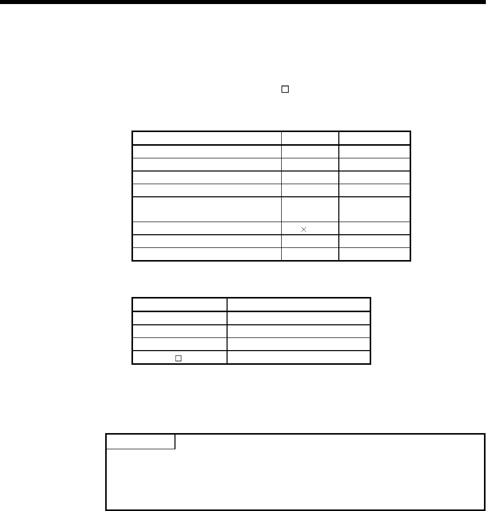
4 - 35
4 AUXILIARY AND APPLIED FUNCTIONS
4.10 Optional Data Monitor Function
This function is used to store the data (refer to following table) up to three points per
axis to the specified devices (D, W, #, U \G) and monitor them.
It can be set by the system setting of MT Developer.
(1) Data that can be set
Data type Unit Number of words
Effective load ratio [%] 1
Regenerative load ratio [%] 1
Peak load ratio [%] 1
Position feed back [PLS] 2
Absolute position encoder within one-
revolution position [PLS] 2
Load inertia ratio [ 0.1] 1
Position loop gain 1 [rad/s] 1
Bus voltage [V] 1
(2) Devices that can be set
Word device Device that can be set
D 0 to 8191
W 0 to 1FFF
# 0 to 7999
U\G 10000 to (10000+p-1) (Note-1), (Note-2)
(Note-1): "p" indicates the user setting area points of the Multiple CPU high speed transmission area
for the each CPU.
(Note-2): Only device of the self CPU can be used.
POINT
(1) The updating cycle of data is every operation cycle.
(2) Set an even number as device setting in the two word data.
(3) Refer to Chapter 2 for the user setting area points of the Multiple CPU high
speed transmission area.
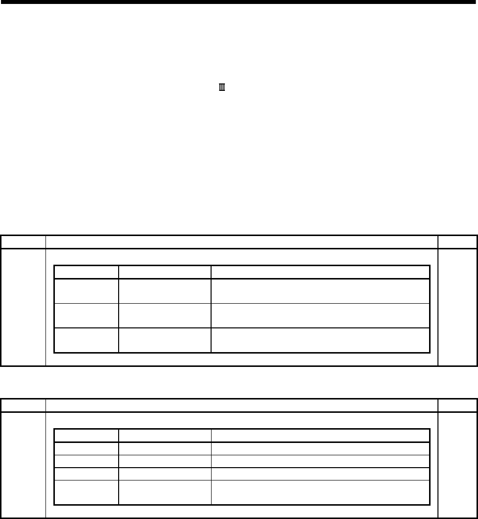
4 - 36
4 AUXILIARY AND APPLIED FUNCTIONS
4.11 Connect/Disconnect Function
This function is used to temporarily suspend SSCNET communication while servo
amplifiers and/or SSCNET cables after Axis 1 are exchanged with the power supply
ON in a Multiple CPU system.
SD803 is required for connect/disconnect and SD508 stores the command status for
"accept waiting" or "execute waiting" during this process. If a servo amplifier was
previously removed using the connect/disconnect function, it must be used again to
reconnect the servo amplifier. This function is only required when there is a desire to
maintain communication to all axes in front of the one being removed.
No connect/disconnect processing is required if the power supply to Axis 1 is
shutdown.
(1) Connect/disconnect status devices
Device No. Overview Set by
The execute status for a connect/disconnect is stored.
Monitoring value Status Contents
0
Connect/disconnect
command accept waiting
Connect command or disconnect command is in the status
that can be accepted
-1
Connect/disconnect
execute waiting
SD508 is waiting for connect/disconnect execute command
after accepting a connect command or disconnect command.
-2
While
connecting/disconnecting Connect/disconnect is in process.
SD508
System
(2) Connect/disconnect command devices
Device No. Overview Set by
The connect/disconnect command is set.
Setting value Command Contents
0 None This value is set if there is no command.
1 to 32 Disconnect command Set axis No. "1 to 32" to be disconnected.
-10 Connect command Set to connect axis while disconnecting.
-2
Connect/disconnect
execute command
Connect/disconnect processing is executed by setting this
value in the status of a connect/disconnect execute waiting.
SD803
User

4 - 37
4 AUXILIARY AND APPLIED FUNCTIONS
POINT
(1) After completion of SSCNET communication disconnect processing, be sure to
check the LED display of the servo amplifier for "AA" before turning OFF its
the power supply.
(2) When a "1 to 32 : Disconnect command" and/or "-10 : Connect command"
are set to the "Connect/disconnect command device (SD803)", the status of
the SD508 changes to the "-1: Connect/disconnect waiting" state. In order to
complete connect/disconnect processing, "-2 : Connect/disconnect execute
command" must be set to SD803 to execute the prior connect/disconnect
command.
(3) When "1 to 32 : Disconnect command" is set to axis not disconnect, the
connect/disconnect status device (SD508) returns "0" without entering the
status of "-1 : Connect/disconnect execute waiting".
(4) Operation failure may occur in some axes if the power supply of servo
amplifiers connected after them on the SSCNET system is turned OFF. Be
sure to use the disconnect function before turning OFF the power supply of
any servo amplifiers connected after an amplifier whose power remains on.
(3) Procedure for connect/disconnect function to exchange the servo amplifier or
SSCNET cable is shown below.
(a) Operation procedure to disconnect
1) Set the axis No. to disconnect in SD803. (Setting value: 1 to 32)
2) Check that "-1: Disconnect execute waiting" is set in SD508.
(Disconnect execute waiting)
3) Set "-2: Disconnect execute command" in SD803.
4) Check that "0: Disconnect command accept waiting" is set in SD508.
(Completion of disconnection)
5) Turn OFF the power supply of servo amplifier after checking its LED
display for "AA" and then disconnect.
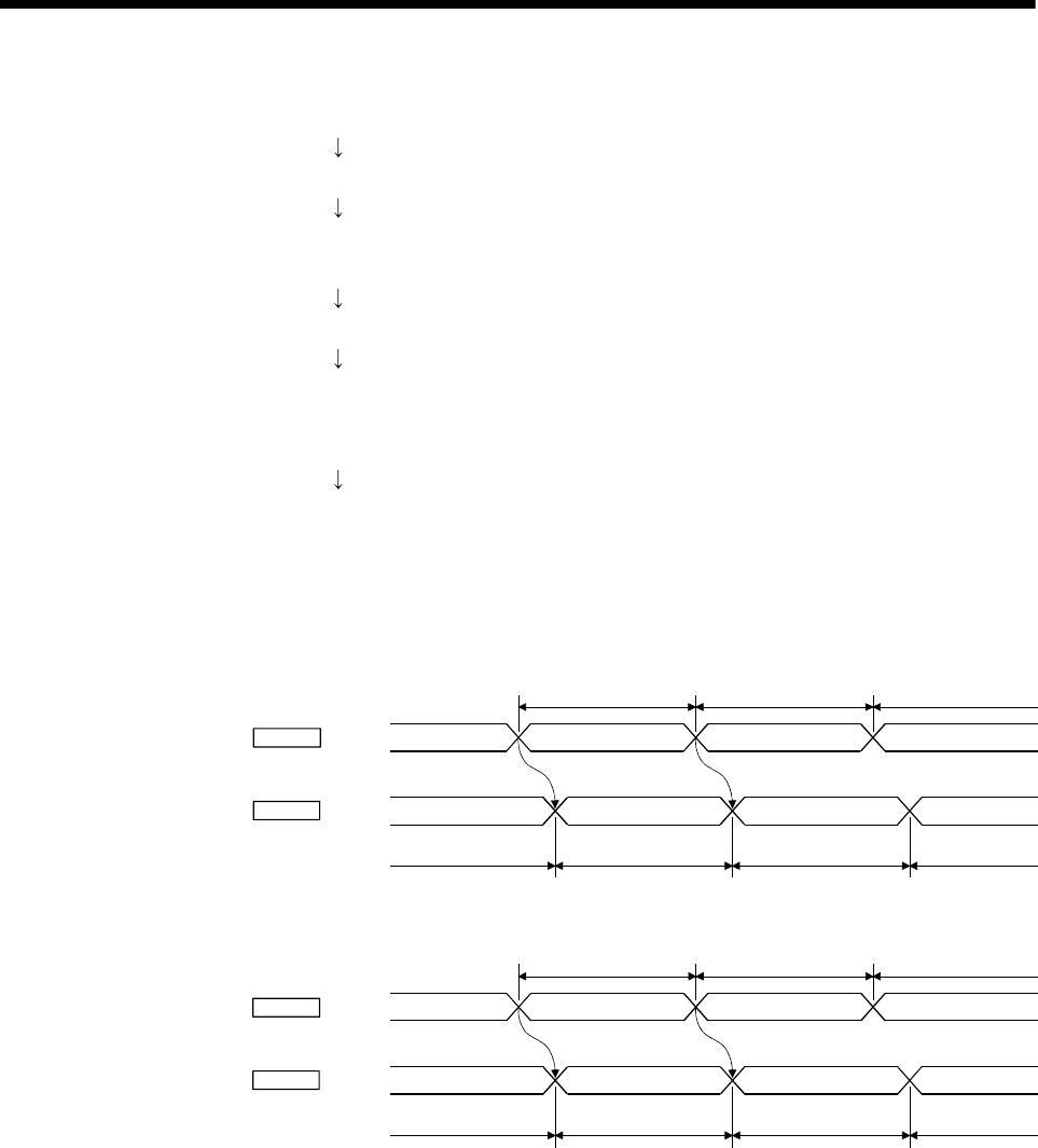
4 - 38
4 AUXILIARY AND APPLIED FUNCTIONS
(b) Operation procedure to connect
1) Turn ON the power supply of the servo amplifier.
2) Set "-10: Connect command" in SD803.
3) Check that "-1: Connect execute waiting" is set in SD508.
(Connect execute waiting)
4) Set "-2: Connect execute command" in SD803.
5) Check that SD508 is "0: Connect command accept waiting" is set in
SD508.
(Completion of connection)
6) Resume operation of servo amplifier after verifying the servo ready
status (M2415+20n) is ON.
(4) Flow for device value at connect/disconnect operation is shown below.
(a) Disconnect operation
SD803
0SD508 -1 -2 0
1 to 32 -2
0 0
Command
Monitor
Disconnect command
accept waiting
Disconnect command
(Axis No. of servo amplifier
to disconnect)
Disconnect execute
waiting
Disconnect execute
command
Disconnect
processing execute
Completion of
disconnection
Disconnect
command clear
(b) Connect operation
SD803
0SD508 -1 -2 0
-10 -2
0 0
Command
Monitor
Connect command
accept waiting
Connect command
Connect execute waiting
Connect execute command
Connect processing execute
Completion of
connection
Connect command clear
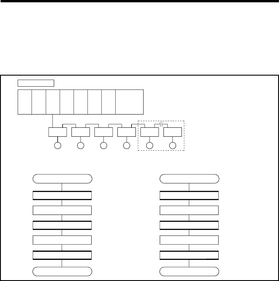
4 - 39
4 AUXILIARY AND APPLIED FUNCTIONS
<Program example>
(1) Self CPU program which connects/disconnects servo amplifiers from Axis 5 on
Disconnect procedure: Turn OFF the power supply of servo amplifier after
checking its LED display for "AA".
Connect procedure: Resume operation of servo amplifier after verifying
that the servo ready (M2415+20n) is ON.
Disconnect processing Connect processing
(a) Motion SFC program
Disconnect operation Connect operation
[G10]
[F10]
[G20]
[F20]
[G30]
[G10]
[F10]
[G20]
[F20]
[G30]
SD508==0
SD803=5
SD508==-1
SD803=-2
SD508==0
END
SD508==0
SD803=-10
SD508==-1
SD803=-2
SD508==0
END
Check the disconnect
command accept status.
Set "5" (Disconnect from
Axis 5 on) as disconnect
command in SD803.
Disconnect execute waiting
Set "-2" as disconnect
execute command in
SD803.
Check the completion of
disconnect processing.
Check the connect
command accept status.
Set "-10" as connect
command in SD803.
Connect execute waiting
Set "-2" as connect
execute command in
SD803.
Check the completion of
connect processing.
Q61P QnUD(H)
CPU
Q172D
CPU
QY40 QY40 Q172D
LX
QY40
System configuration
Axis 1
AMP
M
Axis 2
AMP
M
Axis 3
AMP
M
Axis 4
AMP
M
Axis 5
AMP
M
Axis 8
AMP
M
Disconnection (From Axis 5 on)
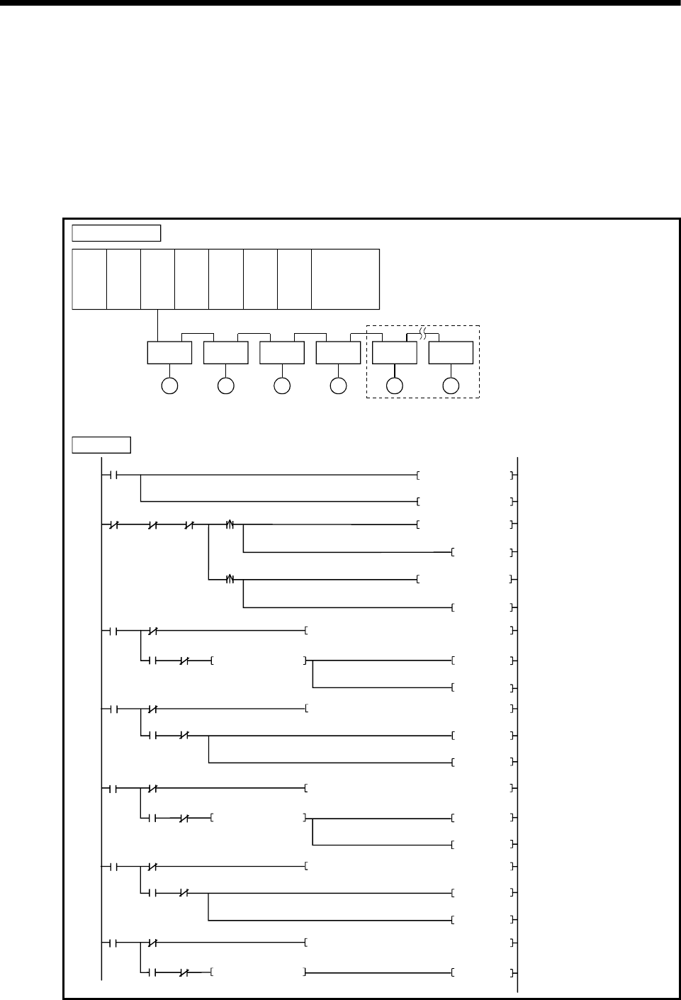
4 - 40
4 AUXILIARY AND APPLIED FUNCTIONS
(2) PLC CPU program which connects/disconnects servo amplifiers from Axis 5 on
which is connected to the Motion CPU (CPU No.2).
Disconnect procedure: Turn X0 OFF to ON, and then turn OFF the power
supply of servo amplifier after checking the LED
display "AA" of servo amplifier.
Connect procedure: Turn X1 OFF to ON, and then resume operation of
servo amplifier after checking the servo ready
(M2415+20n) of servo amplifier.
0
SM400
DP.DDRD H3E1 D100 M10
SD508D50
K-2 D104
MOV
18
K1 D51
MOV
5
M101
M100 M102 X0
K5 D102MOV
M100
SET
K-10 D102MOV
D100 K0=
M10 M11
39
M100
SET
X1
M10
M100
M12
M101
M12 M13
DP.DDWR H3E1 SD803 M12
D102D50
M100
RST
SET
M101
RST
M102SET
DP.DDRD H3E1 D100 M10
SD508
D50
57
D100 K-1
=
M10 M11
78
M10
M102
M12
M103
M12 M13
DP.DDWR H3E1 SD803 M12
D104
D50
M102
RST
M103
SET
M103
RST
M104SET
DP.DDRD H3E1 D100 M10
SD508
D50
96
D100 K0=
M10 M11
M10
M104
M104RST
M101
Set "-2" as disconnect execute
command in D104.
Set "-10" as connect command
in D102.
Read the data of SD508 for Multiple
CPU system (CPU No.2) by turning
M102 ON, and store it to data area
(D100) of self CPU.
Write the data of SD803 for Multiple
CPU system (CPU No.2) to D102 by
turning M101 ON.
(Disconnect command/Connect
command)
Read the data of SD508 for Multiple
CPU system (CPU No.2) by turning
M100 ON, and store it to data area
(D100) of self CPU.
Write the data of SD803 for Multiple
CPU system (CPU No.2) to D104 by
turning M103 ON.
(Disconnect execute command)
Read the data of SD508 for Multiple
CPU system (CPU No.2) by turning
M104 ON, and store it to data area
(D100) of self CPU.
Q61P QnUD(H)
CPU
Q172D
CPU
QY40 QY40 Q172D
LX
QY40
System configuration
Axis 1
AMP
M
Axis 2
AMP
M
Axis 3
AMP
M
Axis 4
AMP
M
Axis 5
AMP
M
Axis 8
AMP
M
Disconnection (From Axis 5 on)
PLC program
Set "5" (Disconnect afrom Axis 5 on)
as disconnect command in D102.
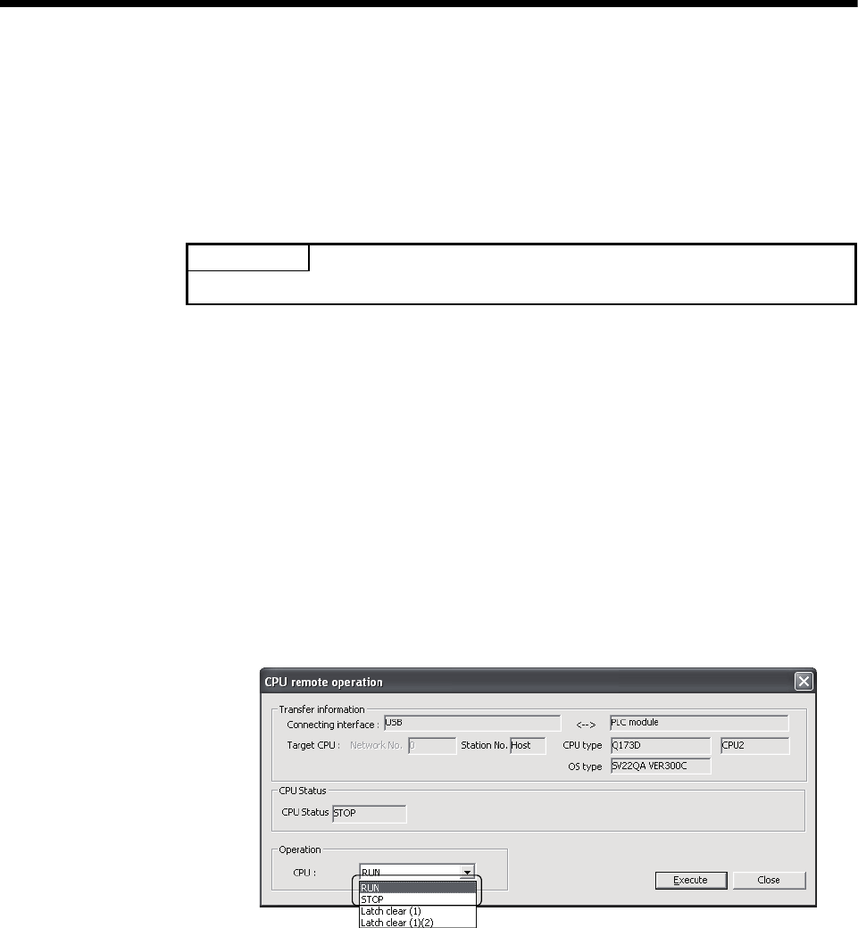
4 - 41
4 AUXILIARY AND APPLIED FUNCTIONS
4.12 Remote operation
This function is used to control the following operation of Motion CPU using
MT Developer.
• Remote RUN/STOP
• Remote latch clear
POINT
Latch clear can be executed only using the remote control of MT Developer.
4.12.1 Remote RUN/STOP
The PLC ready flag (M2000) is turned ON/OFF by MT Developer with RUN/STOP
switch of Motion CPU module set to RUN.
(1) Operation procedure
(a) Remote RUN
Select [RUN] on "CPU remote operation" screen displayed by menu [Online]
– [Remote Operation], and click [Execute] button.
(b) Remote STOP
Select [STOP] on "CPU remote operation" screen displayed by menu
[Online] – [Remote Operation], and click [Execute] button.
4 - 42
4 AUXILIARY AND APPLIED FUNCTIONS
POINT
(1) Remote RUN cannot be executed if RUN/STOP switch sets to STOP.
Operation after remote operation by RUN/STOP switch is shown below.
Position of RUN/STOP switch
RUN STOP
Execute remote RUN RUN STOP
Remote operation Execute remote STOP STOP STOP
(2) The following parameters are read by turning on the PLC ready flag (M2000).
• Fixed parameter
• Parameter block
• Home position return data
• JOG operation data
• Servo parameter
• Mechanical system program (SV22)
• Motion SFC parameter
• Limit switch parameter
REMARK
The PLC ready flag (M2000) can also be turned ON/OFF (PCPU READY complete
flag (SM500) ON/OFF) in the following methods.
• RUN/STOP switch change
• PLC ready flag (M2000) ON/OFF
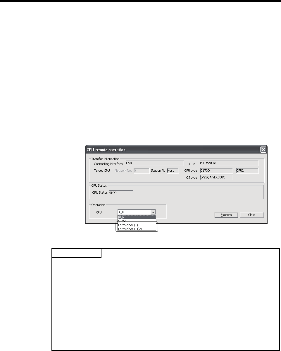
4 - 43
4 AUXILIARY AND APPLIED FUNCTIONS
4.12.2 Remote latch clear
Device data of Motion CPU that latched are cleared by MT Developer at PLC
ready flag (M2000) OFF (PCPU READY complete flag (SM500) OFF).
Operation for remote latch clear is combined with remote RUN/STOP.
(1) Operation procedure
(a) Turn OFF the PLC ready flag (M2000) (PCPU READY complete flag
(SM500) OFF) by remote STOP.
(b) Select [Latch clear (1)] or [Latch clear (1)(2)] on "CPU remote operation"
screen displayed by menu [Online] – [Remote Operation], and click
[Execute] button.
(Note): Execute remote RUN to turn ON the PLC ready flag (M2000) after
remote latch clear.
POINT
(1) Remote latch clear cannot be operated while the PLC ready flag (M2000) is ON
(PCPU READY complete flag (SM500) is ON) or test mode.
(2) The following latch area are cleared in the remote latch clear operation.
• Latch clear (1) : Clear the range set in latch area (1)
• Latch clear (1)(2) : Clear the range set in latch area (1) and (2)
(3) The user area (#0 to #7999) of motion device are also cleared by executing remote
latch clear.
(4) All of the user device not latched are cleared by the remote latch clear operation of
latch area (1) and (2).
(5) Set the range of latch area (1) and (2) in the system basic setting of system setting.
(Refer to Section 3.1.3.)

4 - 44
4 AUXILIARY AND APPLIED FUNCTIONS
MEMO

APP - 1
A
PPENDICES
APP.
APPENDICES
APPENDIX 1 Special relays/Special registers
APPENDIX 1.1 Special relays
Special relays are internal relays whose applications are fixed in the Motion CPU. For
this reason, they cannot be used in the same way as the normal internal relays by the
Motion SFC programs.
However, they can be turned ON/OFF as needed in order to control the Motion CPU.
The headings in the table that follows have the following meanings.
Item Explanation
No. • Indicates the device No. of the special relay.
Name • Indicates the name of the special relay.
Meaning • Indicates the nature of the special relay.
Details • Indicates detailed information about the nature of the special relay.
Set by
(When set)
• Indicates whether the relay is set by the system or user, and, if it is set by system, when
setting is performed.
<Set by>
S: Set by system (Motion CPU)
U: Set by user (Motion SFC program or test operation using MT Developer)
S/U: Set by both system (Motion CPU) and user
<When set> Indicated only if setting is done by system (Motion CPU).
Main process: Set during each main processing (free time processing of the CPU)
Initial process: Set only during initial processing (when power supply is turned ON, or
when executed the reset)
Status change : Set only when there is a change in status
Error : Set when error is occurred.
Request : Set only when there is a user request (Special relay, etc.)
Operation cycle : Set during each operation cycle of the Motion CPU.

APP - 2
A
PPENDICES
Table 1.1 Special relay list
No. Name Meaning Details Set by
(When set) Remark
SM0 Diagnostic error OFF : No error
ON : Error
• Turn ON if an error occurs as a result of diagnosis.
• Remains ON even if the condition is restored to normal
thereafter.
• Turn ON by ON to OFF of the Motion error detection flag
(M2039) for except the stop error after confirming the error
content.
SM1 Self-diagnostic error
OFF : No self-diagnostic error
ON : Self-diagnostic error
• Turn ON if an error occurs as a result of self-diagnosis.
• Remains ON even if the condition is restored to normal
thereafter.
• Turn ON by ON to OFF of the Motion error detection flag
(M2039) for except the stop error after confirming the error
content.
SM51 Battery low latch OFF : Normal
ON : Battery low
• Turn ON if the voltage of external battery reduces to less than
2.5[V].
• Remains ON even if the condition is restored to normal
thereafter.
SM52 Battery low OFF : Normal
ON : Battery low
• Turn on when the voltage of the external battery reduces to
less than 2.5[V].
• Turn OFF when the voltage of external battery returns to
normal.
• Turn ON if an instantaneous power failure of within 20[ms]
occurs during use of the AC power supply module.
Reset when the power supply is switched OFF, then ON.
SM53 AC/DC DOWN
detection
OFF : AC/DC DOWN
not detected
ON : AC/DC DOWN
detected
• Turn ON if an instantaneous power failure of within 10[ms]
occurs during use of the AC power supply module.
Reset when the power supply is switched OFF, then ON.
SM58 Battery low warning
latch
OFF : Normal
ON : Battery low
• Turn ON if the voltage of external battery reduces to less than
2.7[V].
• Remains ON even if the condition is restored to normal
thereafter.
SM59 Battery low warning OFF : Normal
ON : Battery low
• Turn on when the voltage of the external battery reduces to
less than 2.7[V].
• Turn OFF when the voltage of external battery returns to
normal.
SM60 Fuse blown detection OFF : Normal
ON : Module with blown fuse
• Turn ON if there is at least one output module whose fuse
has blown.
• Remains ON even if the condition is restored to normal
thereafter.
S (Occur an error)
SM211 Clock data error OFF : No error
ON : Error
• Turn ON if an error occurs in clock data (SD210 to SD213)
value, and turn OFF if no error is detected. S (Request)
SM220
(Note-1) CPU No.1 READY
complete
OFF : CPU No.1 READY
incompletion
ON : CPU No.1 READY
completion
• Turn ON if CPU No. 1 which uses Multiple CPU high speed
bus can be operated between Multiple CPU.
SM221
(Note-1)
CPU No.2 READY
complete
OFF : CPU No.2 READY
incompletion
ON : CPU No.2 READY
completion
• Turn ON if CPU No. 2 which uses Multiple CPU high speed
bus can be operated between Multiple CPU.
SM222
(Note-1)
CPU No.3 READY
complete
OFF : CPU No.3 READY
incompletion
ON : CPU No.3 READY
completion
• Turn ON if CPU No. 3 which uses Multiple CPU high speed
bus can be operated between Multiple CPU.
SM223
(Note-1)
CPU No.4 READY
complete
OFF : CPU No.4 READY
incompletion
ON : CPU No.4 READY
completion
• Turn ON if CPU No. 4 which uses Multiple CPU high speed
bus can be operated between Multiple CPU.
SM240 No.1 CPU resetting OFF : CPU No.1 reset cancel
ON : CPU No.1 resetting • Goes OFF when reset of the CPU No.1 is cancelled.
SM241 No.2 CPU resetting OFF : CPU No.2 reset cancel
ON : CPU No.2 resetting • Goes OFF when reset of the CPU No.2 is cancelled.
SM242 No.3 CPU resetting OFF : CPU No.3 reset cancel
ON : CPU No.3 resetting • Goes OFF when reset of the CPU No.3 is cancelled.
S (Change status)

APP - 3
A
PPENDICES
Table 1.1 Special relay list (Continued)
No. Name Meaning Details Set by
(When set) Remark
SM243 No.4 CPU resetting OFF : CPU No.4 reset cancel
ON : CPU No.4 resetting • Goes OFF when reset of the CPU No.4 is cancelled.
SM244 No.1 CPU error
OFF : CPU No.1 normal
ON : CPU No.1 during stop
error
• Goes OFF when the CPU No.1 is normal. (Including a
continuation error)
• Comes ON when the CPU No.1 is during stop error. (Note-2)
SM245 No.2 CPU error
OFF : CPU No.2 normal
ON : CPU No.2 during stop
error
• Goes OFF when the CPU No.2 is normal. (Including a
continuation error)
• Comes ON when the CPU No.2 is during stop error. (Note-2)
SM246 No.3 CPU error
OFF : CPU No.3 normal
ON : CPU No.4 during stop
error
• Goes OFF when the CPU No.3 is normal. (Including a
continuation error)
• Comes ON when the CPU No.3 is during stop error. (Note-2)
SM247 No.4 CPU error
OFF : CPU No.4 normal
ON : CPU No.4 during stop
error
• Goes OFF when the CPU No.4 is normal. (Including a
continuation error)
• Comes ON when the CPU No.4 is during stop error. (Note-2)
S (Change status)
SM400 Always ON ON
OFF • Normally is ON.
SM401 Always OFF ON
OFF • Normally is OFF.
S (Main processing)
SM500 PCPU READY
complete
ON : PCPU READY
completion
OFF : PCPU READY
incompletion
• When the PLC ready flag (M2000) turn OFF to ON, the
fixed parameters, servo parameters and limit switch output
data, etc., are checked, and if no error is detected, this flag
turns ON.
• Turn OFF with PLC ready flag (M2000) OFF.
SM501 Test mode ON ON : TEST mode ON
OFF : Except TEST mode
• Judge whether TEST mode ON or not using MT Developer.
• If the TEST mode is not established by TEST mode request
using MT Developer, the TEST mode request error flag
(SM510) turns ON.
S (Request)
SM502 External forced stop
input
ON : Forced stop OFF
OFF : Forced stop ON • Confirm forced stop ON/OFF. S (Operation cycle)
SM503 Digital oscilloscope
executing
ON : Digital oscilloscope is
stop
OFF : Digital oscilloscope is
executing
• Confirm the execution of digital oscilloscope using MT
Developer. S (Change status)
SM510 TEST mode request
error
ON : Abnormal
OFF : Normal
• Turn ON if the TEST mode is not established by TEST mode
request using MT Developer.
• When this relay is ON, the error content is stored in the
TEST mode request error register (SD510, SD511).
SM512 Motion CPU WDT
error
ON : Abnormal
OFF : Normal
• Turn ON when a "watchdog timer error" is detected by the
Motion CPU self-diagnosis function.
When the Motion CPU detects a WDT error, it executes an
immediate stop without deceleration of the operating axes.
• The error cause is stored in the "Motion CPU WDT error
cause (SD512)".
SM513
Manual pulse
generator axis setting
error
ON : At least one D714 to
D719 setting is
abnormal.
OFF : All D714 to D719
settings are normal.
• Judge whether normal/abnormal of the register for manual
pulse generator axis setting register (D714 to D719).
• When this relay is ON, the error content is stored in the
manual pulse generator axis setting error register (SD513
to SD515).
SM516 Servo program
setting error
ON : Abnormal
OFF : Normal
• Judge whether normal/abnormal of the positioning data of
servo program(K) specified with the Motion SFC program,
and if error is detected this flag turns ON.
• The content of a servo program setting error is stored at
SD516, SD517.
SM526 Over heat warning
latch
OFF : Normal
ON : Abnormal
• Turn ON when the temperature of Motion CPU module
becomes specified value 85[°C] (185[°F]) or more.
Remains ON even if normal status is restored.
SM527 Over heat warning OFF : Normal
ON : Abnormal
• Turn ON when the temperature of Motion CPU module
becomes specified value 85[°C] (185[°F]) or more.
Turn OFF when the temperature of Motion CPU module
returns to normal.
S (Occur an error)

APP - 4
A
PPENDICES
Table 1.1 Special relay list (Continued)
No. Name Meaning Details Set by
(When set) Remark
SM528 No.1 CPU MULTR
complete
OFF to ON :
CPU No.1 read completion
• Turn ON when the data read from CPU No.1 is normal by
MULTR instruction.
SM529 No.2 CPU MULTR
complete
OFF to ON :
CPU No.2 read completion
• Turn ON when the data read from CPU No.2 is normal by
MULTR instruction.
SM530 No.3 CPU MULTR
complete
OFF to ON :
CPU No.3 read completion
• Turn ON when the data read from CPU No.3 is normal by
MULTR instruction.
SM531 No.4 CPU MULTR
complete
OFF to ON :
CPU No.4 read completion
• Turn ON when the data read from CPU No.4 is normal by
MULTR instruction.
S (Read completion)
SM801 Clock data read
request
OFF : Ignored
ON : Read request
• When this relay is ON, clock data is read to SD210 to
SD213 as BCD values. U
(Note-1) : It is used for interlock condition of Multiple CPU high speed bus dedicated instruction when a synchronous system
set in Multiple CPU synchronous startup setting of system setting.
(Note-2) : The CPU No.1 is reset after the factor of the stop error is removed to cancel a stop error → Resetting is cancelled.

APP - 5
A
PPENDICES
APPENDIX 1.2 Special registers
Special registers are internal registers whose applications are fixed in the
Motion CPU. For this reason, it is not possible to use these registers in Motion
SFC programs in the same way that normal registers are used.
However, data can be written as needed in order to control the Motion CPU.
Data stored in the special registers are stored as BIN values if no special
designation has been made to the contrary.
The headings in the table that follows have the following meanings.
Item Explanation
Number • Indicates the No. of the special register.
Name • Indicates the name of the special register.
Meaning • Indicates the nature of the special register.
Details • Indicates detailed information about the nature of the special register.
Set by
(When set)
• Indicates whether the register is set by the system or user, and, if it is set by system,
when setting is performed.
<Set by>
S: Set by system (Motion CPU)
U: Set by user (Motion SFC program or test operation using MT Developer)
S/U: Set by both system (Motion CPU) and user
<When set> Indicated only if setting is done by system (Motion CPU).
Main process: Set during each main processing (free time processing of the CPU)
Initial process: Set only during initial processing (when power supply is turned ON, or
when executed the reset)
Status change : Set only when there is a change in status
Error : Set when error is occurred.
Request : Set only when there is a user request (Special relay, etc.)
Operation cycle : Set during each operation cycle of the Motion CPU.
APP - 6
A
PPENDICES
Table 1.2 Special register list
No. Name Meaning Details Set by
(When set) Remark
SD0 Diagnostic errors
Diagnostic error
code
• Error codes for errors found by diagnosis are stored as BIN data.
• Refer to "APPENDIX 3" for details of the error code.
• After confirm the error content, except the stop error, it is possible to clear by
ON to OFF of the Motion error detection flag (M2039).
• Clear SD0 to SD26 by ON to OFF of the Motion error detection flag (M2039)
for except the stop error after confirming the error content.
SD1
• The year (last two digits) and month that SD0 data was updated is stored as
BCD 2-digit code.
Example : January 2006
H0601
B15 B7 B0B8to to
Month(1 to 12)Year(0 to 99)
SD2
• The day and hour that SD0 data was updated is stored as BCD 2-digit code.
Example : 25st, 10 a.m
H2510
B15 B7 B0B8to to
Day(1 to 31) Hour(0 to 23)
SD3
Clock time for
diagnostic error
occurrence
Clock time for
diagnostic error
occurrence
• The minute and second that SD0 data was updated is stored as BCD 2-digit
code.
Second(0 to 59)
B15 B7 B0B8to to Example : 35min., 48 sec.
H3548
Minute(0 to 59)
SD4 Error information
categories
Error information
category code
• Category codes which help indicate what type of information is being stored in
the error common information areas (SD5 to SD15) and error individual
information areas (SD16 to SD26) are stored. The category code for judging
the error information type is stored.
Individual information
category codes
Common information
category codes
B15 B7B8to to B0
• The common information category codes store the following codes.
0: No error
1: Module No./CPU No./Base No.
• The individual information category codes store the following codes.
0: No error
5: Parameter No.
13:Parameter No./CPU No.
SD5
SD6
SD7
SD8
SD9
SD10
SD11
SD12
SD13
• Common information corresponding to the diagnostic error (SD0) is stored.
• The error common information type can be judged by SD4 (common
information category code).
1: Module No./CPU No./Base No.
• For the Multiple CPU system, Module No. or CPU No. is stored
depending on the error that occurred.
(Refer to corresponding error code for which No. has been stored.)
CPU No.1: 1, CPU No.2: 2, CPU No.3: 3, CPU No.4: 4
SD14 No. Meaning
SD5 Module No./CPU No./Base No.
SD6 I/O No.
SD7
to
SD15
Empty
SD15
Error common
information
Error common
information
S (Occur an error)
APP - 7
A
PPENDICES
Table 1.2 Special register list (Continued)
No. Name Meaning Details Set by
(When set) Remark
SD16
SD17
SD18
SD19
• Individual information corresponding to the diagnostic error (SD0) is stored.
• The error individual information type can be judged by SD4 (individual
information category code).
5: Parameter No.
SD20 No. Meaning
SD21 SD16 Parameter No.
SD22
SD23
SD24
SD17
to
SD26
Empty
SD25 0401H :Base setting
0406H :Motion slot setting
0E00H :Multiple CPU setting (Number of Multiple CPU's)
0E01H :Multiple CPU setting (Operation mode/Multiple CPU
synchronous startup)
E008H :Multiple CPU high speed transmission area setting
(CPU specific send range setting/ (System area))
E009H/E00AH :Multiple CPU high speed transmission area setting
(Automatic refresh setting)
E00BH :Synchronous setting
13: Parameter No./CPU No.
No. Meaning
SD16 Parameter No.
SD17 CPU No.(1 to 4)
SD18
to
SD26
Empty
SD26
Error individual
information
Error individual
information
SD53 AC/DC DOWN
counter No.
Number of times
for AC/DC DOWN
• Every time the input voltage fails to or below 85[%] (AC power)/65[%] (DC
power) the rating during calculation of the Motion CPU module, the value is
incremented by 1 and stored in BIN code.
SD60 Fuse blown No. Module No. with
blown fuse • The lowest station I/O No. of the module with the blown fuse is stored.
S (Occur an error)
• The CPU switch status is stored in the following format.
B15 B12 B11 B8 B7 B4 B3 B0
1)2)
Not used
1) CPU switch status 0: RUN
1: STOP
2) Memory card switch Always OFF
SD200 Status of switch Status of CPU
switch
• The CPU operating status is stored as indicated in the following figure.
B15 B12B11 B8 B7 B4 B3 B0
1
)
2
)
1) Operating status of CPU 0: RUN
2: STOP
2) STOP cause
(Note) Priority is earliest first
0: RUN/STOP switch
4: Error
SD203 Operating status
of CPU
Operating status
of CPU
S (Main processing)
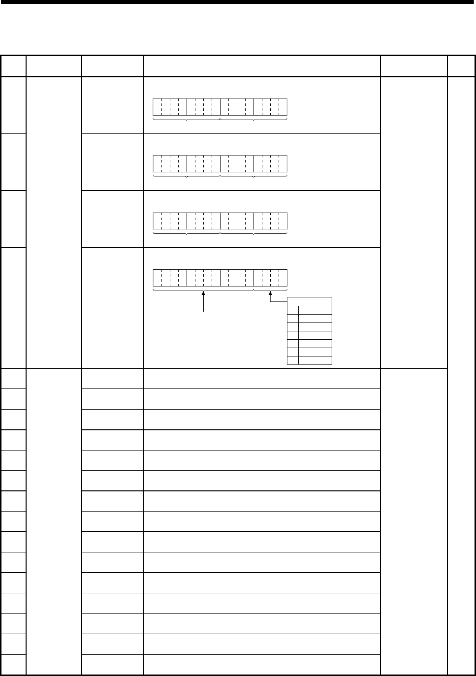
APP - 8
A
PPENDICES
Table 1.2 Special register list (Continued)
No. Name Meaning Details Set by
(When set) Remark
SD210 Clock data
(Year, Month)
• The year (last two digits) and month are stored as BCD code.
B15 B12
to B11 B8
to B7 B4
to B3 B0
to
Year Month
Example : July, 2006
H0607
SD211 Clock data
(Day, Hour)
• The day and hour are stored as BCD code.
B15 B12to B11 B8to B7 B4to B3 B0to
Day Hour
Example : 31st, 10 a.m.
H3110
SD212 Clock data
(Minute, Second)
• The minutes and seconds are stored as BCD code.
Example : 35 min., 48 sec.
H3548
B15 B12to B11 B8to B7 B4to B3 B0to
Minute Second
SD213
Clock data
Clock data
(Day of week)
• The day of week is stored as BCD code.
B15 B12to B11 B8to B7 B4to B3 B0to
Always set to "0".
Day of week
0
1
2
3
4
5
6
Sunday
Monday
Tuesday
Wednesday
Thursday
Friday
Saturday
Example : Friday
H0005
S/U (Request)
SD290 Number of points
assigned for X • Stores the number of points currently set for X devices.
SD291 Number of points
assigned for Y • Stores the number of points currently set for Y devices.
SD292 Number of points
assigned for M • Stores the number of points currently set for M devices.
SD293 Number of points
assigned for L • Stores the number of points currently set for L devices.
SD294 Number of points
assigned for B • Stores the number of points currently set for B devices.
SD295 Number of points
assigned for F • Stores the number of points currently set for F devices.
SD296 Number of points
assigned for SB • Stores the number of points currently set for SB devices.
SD297 Number of points
assigned for V • Stores the number of points currently set for V devices.
SD298 Number of points
assigned for S • Stores the number of points currently set for S devices.
SD299 Number of points
assigned for T • Stores the number of points currently set for T devices.
SD300 Number of points
assigned for ST • Stores the number of points currently set for ST devices.
SD301 Number of points
assigned for C • Stores the number of points currently set for C devices.
SD302 Number of points
assigned for D • Stores the number of points currently set for D devices.
SD303 Number of points
assigned for W • Stores the number of points currently set for W devices.
SD304
Device
assignment
Number of points
assigned for SW • Stores the number of points currently set for SW devices.
S (Initial processing)
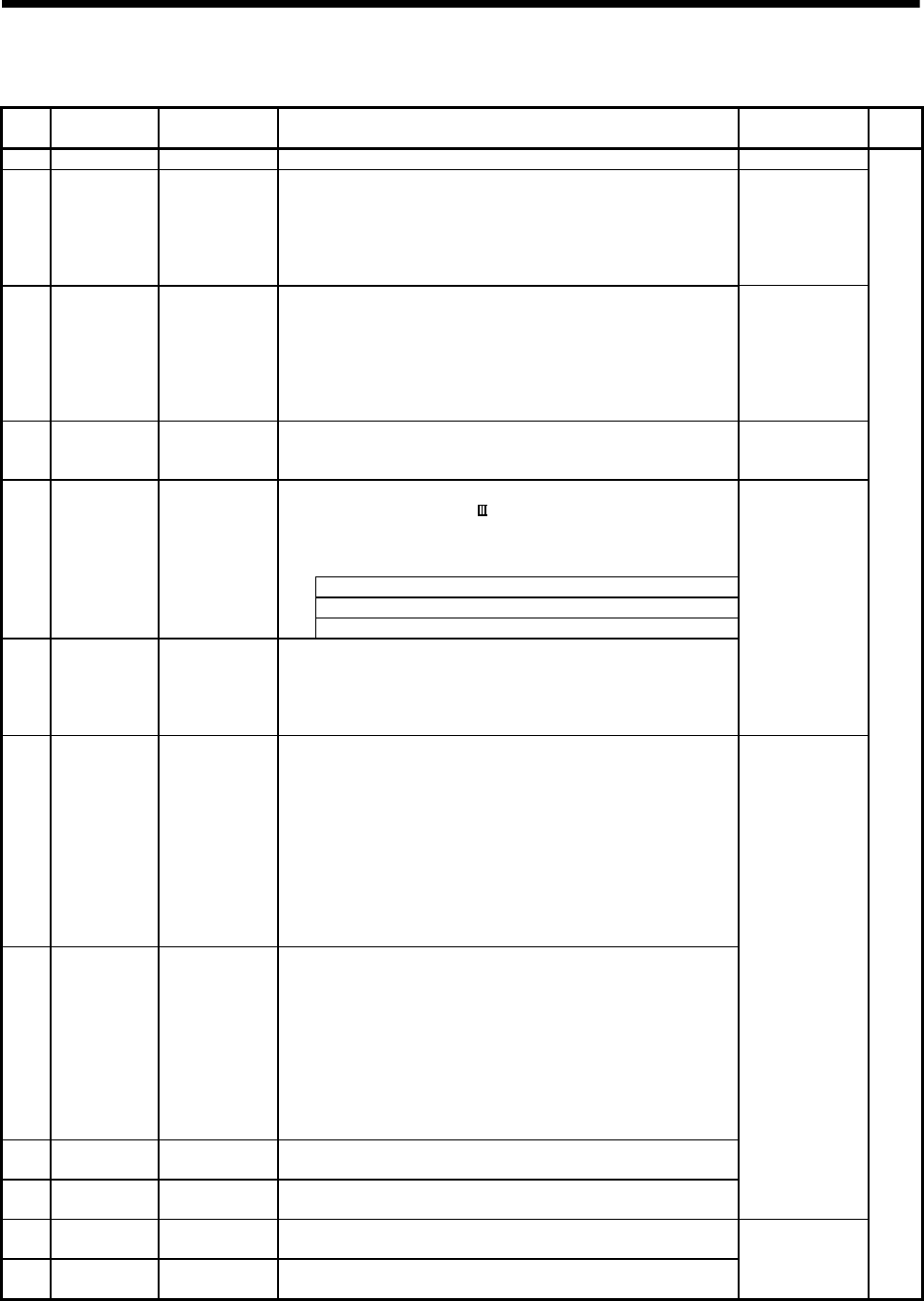
APP - 9
A
PPENDICES
Table 1.2 Special register list (Continued)
No. Name Meaning Details Set by
(When set) Remark
SD395 Multiple CPU No. Multiple CPU No. • CPU No. of the self CPU is stored. S (Initial processing)
SD500
SD501
Real mode axis
information
register
Real mode axis
information register
• The information (Real mode axis: 0/Except real mode axis: 1) used as a real
mode axis at the time of switching from real mode to virtual mode is stored.
SD500 : b0 to b15 (Axis 1 to 16)
SD501 : b0 to b15 (Axis 17 to 32)
• The real mode axis information does not change at the time of switching from
virtual mode to real mode
S (At virtual mode
transition)
SD502
SD503
Servo amplifier
loading
information
Servo amplifier
loading information
• The loading status (loading: 1/non-loading: 0) of the servo amplifier checked
in initial process, and stored as the bit data.
SD502 : b0 to b15 (Axis 1 to 16)
SD503 : b0 to b15 (Axis 17 to 32)
• The axis which turned from non-loading to loading status after power-on is
handled as loaded. (However, the axis which turned from loading to non-
loading status remains as loaded.)
S (Initial processing)
SD504
SD505
SD506
Real mode/virtual
mode switching
error information
Real mode /virtual
mode switching
error code
• When a mode switching error occurs in real-to-virtual or virtual-to-real
mode switching, or a mode continuation error occurs in the virtual mode, its
error information is stored.
S (Occur an error)
• This signal is used to temporarily suspend SSCNET communication while
servo amplifiers and/or SSCNET cables after Axis 1 are exchanged with the
power supply ON in a Multiple CPU system.
SD508 stores the command status for "accept waiting" or "execute waiting"
during this process.
0 : Connect/disconnect command accept waiting
-1 : Connect/disconnect execute waiting
SD508
Connect/
Disconnect
(Status)
Connect/
disconnect of
SSCNET
-2 Connect/disconnect executing
SD510
SD511
Test mode
request error
It is operating in
requirement error
occurrence of the
test mode, axis
information
• Each axis is stopping: 0/Operating: 1, information is stored as a bit data.
SD510 : b0 to b15 (Axis 1 to Axis 16)
SD511 : b0 to b15 (Axis 17 to Axis 32)
S (Main processing)
SD512 Motion CPU
WDT error cause
Error meaning of
WDT error occurs
• The following error codes are stored in SD512.
1: S/W fault 1
2: Operation cycle over
3: Q bus WDT error
4: WDT error
201 to 215: Q bus H/W fault
250 to 253: Servo amplifier interface H/W fault
300: S/W fault 3
301: 15 CPSTART instructions of 8 or more points were started
simultaneously.
303: S/W fault 4
SD513
SD514
SD515
Manual pulse
generator axis
setting error
Manual pulse
generator axis
setting error
information
• Contents of the manual pulse generator axis setting error is stored when the
manual pulse generator axis setting error flag (SM513) turn on.
(Normal: 0/Setting error: 1)
SD513 : The manual pulse generator axis setting error is stored in b0 to b2
(P1 to P3).
The smoothing magnification setting is stored in b3 to b5 (P1 to P3).
SD514 : One pulse input magnification setting error is stored in b0 to b15
(axis 1 to axis 16).
SD515 : One pulse input magnification setting error is stored in b0 to b15
(axis 17 to axis 32).
SD516 Error program
No.
Error program No.
of servo program
• When the servo program setting error flag (SM516) turns on, the erroneous
servo program No. will be stored.
SD517 Error item
information
Error code of servo
program
• When the servo program setting error flag (SM516) turns on, the error code
corresponding to the erroneous setting item will be stored.
S (Occur an error)
SD520 Scan time Scan time
(1ms units)
• Main cycle is stored in the unit 1ms.
Setting range (0 to 65535[ms])
SD521 Maximum scan
time
Maximum scan
time (1ms units)
• The maximum value of the main cycle is stored in the unit 1ms.
Setting range (0 to 65535[ms])
S (Main processing)

APP - 10
A
PPENDICES
Table 1.2 Special register list (Continued)
No. Name Meaning Details Set by
(When set) Remark
SD522 Motion operation
cycle
Motion operation
cycle • The time required for motion operation cycle is stored in the [µs] unit. S (Operation cycle)
SD523
Operation cycle
of the Motion
CPU setting
Operation cycle
of the Motion CPU
setting
• The setting operation cycle is stored in the [µs] unit. S (Initial processing)
• This signal is used to temporarily suspend SSCNET communication while
servo amplifiers and/or SSCNET cables after Axis 1 are exchanged with the
power supply ON in a Multiple CPU system.
SD803 is required for connect/disconnect during this process.
1 to 32 : Disconnect command
-10 : Connect command
SD803
Connect/
Disconnect
(Command)
Connect/
disconnect of
SSCNET
-2 : Connect/disconnect execute command
U

APP - 11
A
PPENDICES
APPENDIX 1.3 Replacement of special relays/special registers
When a project for Q173HCPU(-T)/Q172HCPU(-T)/Q173CPUN(-T)/Q172CPUN(-T)/
Q173CPU/Q172CPU is converted into a project for Q173DCPU/Q172DCPU using the
"Project management - File diversion" in MT Developer, special relays (M9000 to
M9255) and special registers (D9000 to D9255) are automatically converted into new
special relays (SM2000 to SM2255) and special registers (SD2000 to SD2255)
respectively.
However, in order to maintain the same functionality the user must manually convert
them to the special relays and special registers shown in Table 1.3 and Table 1.4
below for Q173DCPU/Q172DCPU.
Table 1.3 Replacement of special relays
Device No.
Special relays for
Q173HCPU(-T)/Q172HCPU(-T)/
Q173CPUN(-T)/Q172CPUN(-T)
Q173CPU/Q172CPU
Automatically
converted to
special relays
Special relays for
Q173DCPU/
Q172DCPU
Name Remark
M9000 SM2000 SM60 Fuse blown detection
M9005 SM2005 SM53 AC/DC DOWN detection
M9006 SM2006 SM52 Battery low
M9007 SM2007 SM51 Battery low latch
M9008 SM2008 SM1 Self-diagnostic error
M9010 SM2010 SM0 Diagnostic error
M9025 — — Clock data set request
M9026 SM2026 SM211 Clock data error
M9028 SM2028 SM801 Clock data read request
M9036 SM2036 SM400 Always ON
M9037 SM2037 SM401 Always OFF
M9060 SM2060 — Diagnostic error reset Use M2039 for error
reset operation.
M9073 SM2073 SM512 Motion CPU WDT error
M9074 SM2074 SM500 PCPU READY complete
M9075 SM2075 SM501 Test mode ON
M9076 SM2076 SM502 External forced stop input
M9077 SM2077 SM513 Manual pulse generator axis setting error
M9078 SM2078 SM510 TEST mode request error
M9079 SM2079 SM516 Servo program setting error
M9216 SM2216 SM528 No.1 CPU MULTR complete
M9217 SM2217 SM529 No.2 CPU MULTR complete
M9218 SM2218 SM530 No.3 CPU MULTR complete
M9219 SM2219 SM531 No.4 CPU MULTR complete
M9240 SM2240 SM240 No.1 CPU resetting
M9241 SM2241 SM241 No.2 CPU resetting
M9242 SM2242 SM242 No.3 CPU resetting
M9243 SM2243 SM243 No.4 CPU resetting
M9244 SM2244 SM244 No.1 CPU error
M9245 SM2245 SM245 No.2 CPU error
M9246 SM2246 SM246 No.3 CPU error
M9247 SM2247 SM247 No.4 CPU error

APP - 12
A
PPENDICES
Table 1.4 Replacement of special registers
Device No.
Special relays for
Q173HCPU(-T)/Q172HCPU(-T)/
Q173CPUN(-T)/Q172CPUN(-T)
Q173CPU/Q172CPU
Automatically
converted to
special relays
Special relays for
Q173DCPU/
Q172DCPU
Name Remark
D9000 SD2000 SD60 Fuse blown No.
D9005 SD2005 SD53 AC/DC DOWN counter No.
D9008 SD2008 SD0 Diagnostic errors
D9010 SD2010 SD1
Clock time for diagnostic error occurrence
(Year, month)
D9011 SD2011 SD2
Clock time for diagnostic error occurrence
(Day, hour)
D9012 SD2012 SD3
Clock time for diagnostic error occurrence
(Minute, second)
D9013 SD2013 SD4 Error information categories
D9014 SD2014 SD5 Error common information
D9015 SD2015 SD203 Operating status of CPU
D9017 SD2017 SD520 Scan time
D9019 SD2019 SD521 Maximum scan time
D9025 SD2025 SD210 Clock data (Year, month)
D9026 SD2026 SD211 Clock data (Day, hour)
D9027 SD2027 SD212 Clock data (Minute, second)
D9028 SD2028 SD213 Clock data (Day of week)
D9060 SD2060 — Diagnostic error reset error No. Use M2039 for error
reset operation.
D9061 SD2061 SD395 Multiple CPU No.
D9112 SD2112 SD508 Connect/Disconnect (Status)
D9182 SD2182 SD510
D9183 SD2183 SD511
Test mode request error
D9184 SD2184 SD512 Motion CPU WDT error cause
D9185 SD2185 SD513
D9186 SD2186 SD514
D9187 SD2187 SD515
Manual pulse generator axis setting error
D9188 SD2188 SD522 Motion operation cycle
D9189 SD2189 SD516 Error program No.
D9190 SD2190 SD517 Error item information
D9191 SD2191 SD502
D9192 SD2192 SD503
Servo amplifier loading information
D9193 SD2193 SD504
D9194 SD2194 SD505
D9195 SD2195 SD506
Real mode/virtual mode switching error
information
D9196 SD2196 — PC link communication error codes
Q173DCPU/
Q172DCPU does not
support PC link
communication.
D9197 SD2197 SD523 Operation cycle of the Motion CPU setting
D9200 SD2200 SD200 State of switch
D9201 SD2201 — State of LED
Use 7-segment LED
in Q173DCPU/
Q172DCPU.
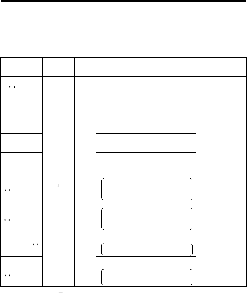
APP - 13
A
PPENDICES
APPENDIX 2 System Setting Errors
Motion CPUs generate a system configuration error under the following conditions.
Table 2.1 System Setting Errors
Error name 7-segment LED
(Note-1)
Error code
(Note-2)
Error cause Check
timing
Operation at
error
occurrence
LAY ERROR
(SL )
• The slot set in system settings is vacant or a different
module is installed.
AXIS No. MULTIDEF
• The axis No. setting overlaps in the system settings.
• The axis No. (function select switch) setting of servo
amplifier overlaps in the same SSCNET system.
AMP No. SETTING • Not a single axis is set in system settings.
SYS.SET DATA ERR
• System setting data is not written.
• System setting data is written without relative check.
Or it is written at the state of error occurrence.
AXIS No. ERROR • System setting data is not written.
I/O POINTS OVER • The number of actual I/O points set in system
settings exceeds 256.
ROM ERROR1 • Type of the operating system software of data written
to ROM is different.
ROM ERROR2 • Data is not written to ROM.
ROM ERROR3
()
• Data size of ROM is abnormal.
• Execute the ROM writing again.
• Check the adjustment for the version of Motion
CPU, MT Developer and operating system
software.
ROM ERROR4
()
• Data of ROM is abnormal.
• Execute the ROM writing again.
• Check the adjustment for the version of Motion
CPU, MT Developer and operating system
software.
CAN'T USE SL ( )
• The motion modules that cannot be used are
installed.
• Use the Motion modules (Q172DLX, Q173DPX,
Q172DEX).
UNIT SET ERR
()
"AL" flashes
3- times
"L01" display
10014
(Note-3)
• The system setting data that set the motion modules
that cannot be used are written.
• Use the MT Developer of version corresponding
to the Motion modules (Q172DLX, Q173DPX,
Q172DEX).
Power
supply ON/
Reset
Cannot be
started.
(Motion CPU
system
setting error)
(Note-1) : "" AL" flashes 3-times "L01" display"" (Repetition) Error code is not displayed.
(Note-2) : Error code stored in self-diagnostic error (SD0)
(Note-3) : When the error code 10014 occurs, the system setting error flag (M2041) turns ON and the error name is displayed on the error
list monitor of MT Developer.

APP - 14
A
PPENDICES
MEMO
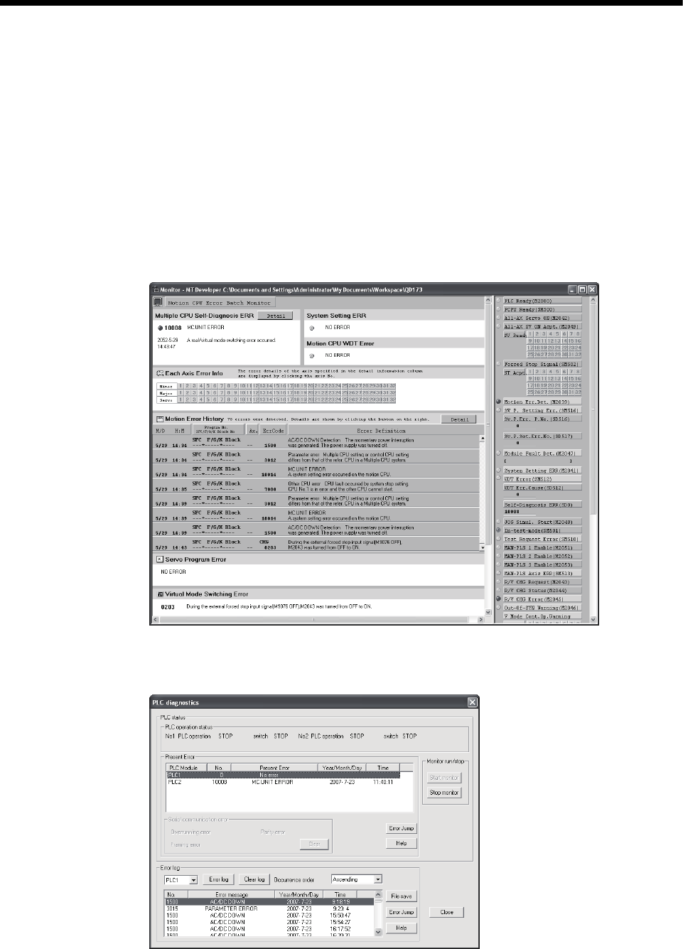
APP - 15
A
PPENDICES
APPENDIX 3 Self-diagnosis error code
Multiple CPU related errors are stored in the CPU shared memory "self CPU operation
information area (1H to 1CH)" of each module and self diagnostic error information
(SD0 to SD26) of the special register (SD) as the self diagnostic errors.
Error codes (1000 to 9999) of Multiple CPU related errors are common to each CPU
module.
The error code (10000 to 10999) is stored as required at Motion CPU-specific error
occurrence.
Confirm the error codes and contents by "Motion error history" on Motion CPU error
batch monitor of MT Developer and remove the error cause if an error occurs.
Confirm operation status and error occurrence of each CPU used in the Multiple CPU
system by PLC diagnosis of GX Developer.
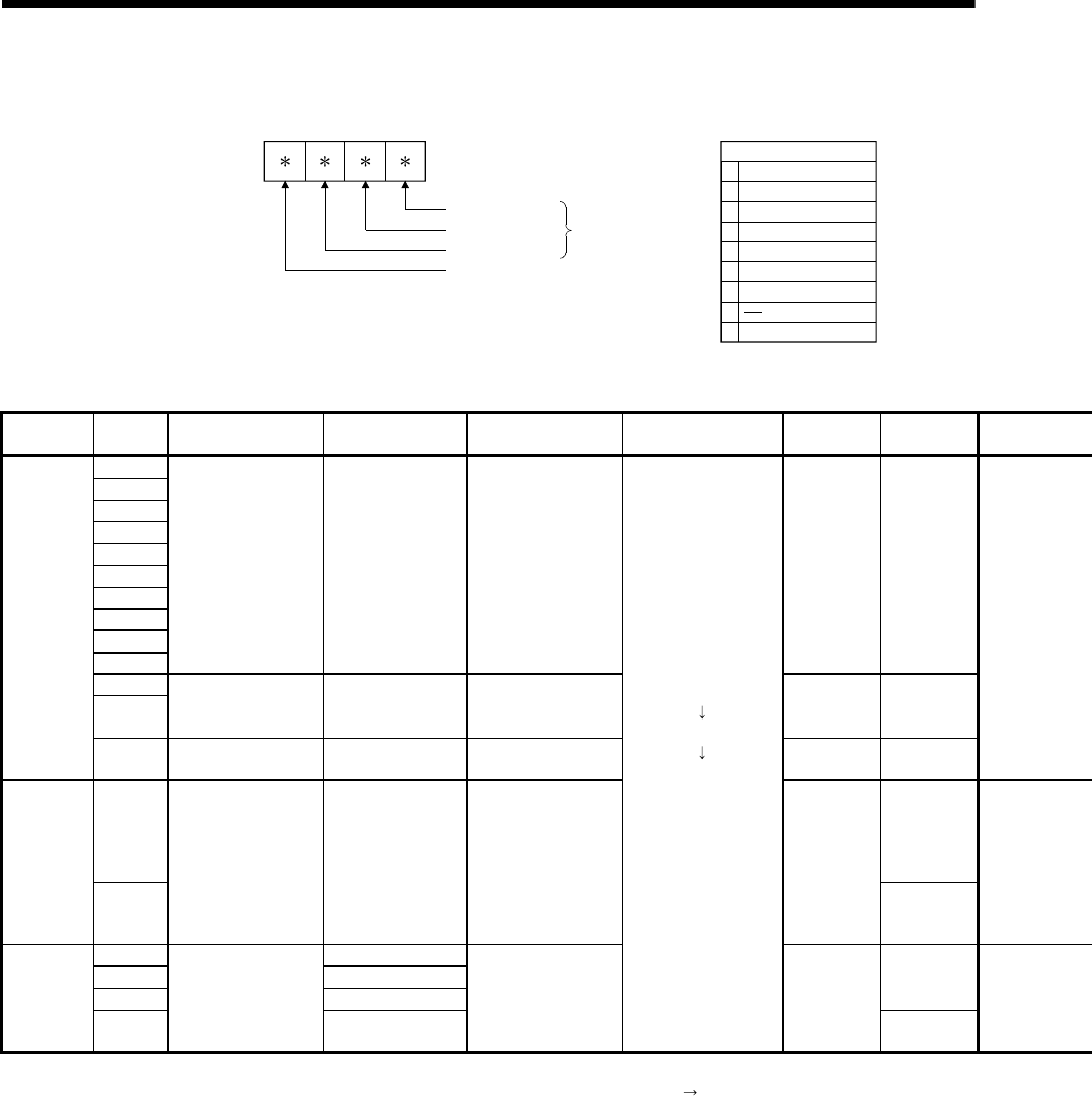
APP - 16
A
PPENDICES
(1) Multiple CPU related errors which occurs in Motion CPU
Each digit of error code has been described as follows.
Digit
Thousands digit
Tens digit
Hundreds digit
Details code
:
:
:
Major division
1
2
3
4
5
6
7
8
9
Internal hardware
Redundant system
Program
Watch timer
Multiple CPU
Outside diagnosis
Handling
Parameter
Thousands digit : Major division (Cause)
Table 3.1 Multiple CPU related errors which occurs in Motion CPU (1000 to 9999)
Item Error code
(SD0) Error message Common information
(SD5 to SD15)
Individual Information
(SD16 to SD26) 7-segment LED display CPU operation
status
Diagnostic
timing
1000
1001
1002
1003
1004
1005
1006
1007
1008
1009
MAIN CPU DOWN — — Stop Always
1105
1150 RAM ERROR — — Stop At power ON/
At reset
CPU hard
error
1300 FUSE BREAK OFF Module No. — Stop (Note-3) Always
1401 At power ON/
At reset
Module hard
error
1403
SP. UNIT DOWN Module No. — Stop
Always
1413 —
1414 Module No.
1415 Base No.
(Note-2)
Always
Base
1416
CONTROL-BUS. ERR.
CPU No. (Note-1)
—
"AL" flashes 3 times
Steady "A1" display
4 digits error code is
displayed in two flashes
of 2 digits each.
Stop
At power ON/
At reset
(Note-1) : CPU No. is stored in slot No. of common information classification.
(Note-2) : Base No. stored in "common information classification code" of "error information classification code" "0 : Main base, 1 to 7 : Number of extension bases.
(Note-3) : CPU operation status at error occurrence can be set in the parameters. (LED display varies in conjunction with operation.)

APP - 17
A
PPENDICES
Error code
(SD0) Error contents and cause Corrective action
1000
1001
1002
1003
1004
1005
1006
1007
1008
1009
Runaway or failure of CPU module.
(1) Malfunctioning due to noise or other reason
(2) Hardware fault
1105 The CPU shared memory in the CPU module is faulty.
1150 The memory of the CPU module in the Multiple CPU high speed
transmission area is faulty.
(1) Take noise reduction measures.
(2) Reset the CPU module and RUN it again. If the same error is
displayed again, this suggests a CPU module hardware fault.
Explain the error symptom and get advice from our sales
representative.
1300 There is an output module with a blown fuse. Check FUSE. LED of the output modules and replace the module whose
LED is lit.
1401 There was no response from the Motion module/intelligent function
module in the initial processing.
Set the Motion module/intelligent function module used in the Motion CPU
in the system setting.
This suggests a Motion module, intelligent function module, CPU module
and/or base unit is expecting a hardware fault.
Explain the error symptom and get advice from our sales representative.
1403
(1) An error is detected at the intelligent function module.
(2) The I/O module (including intelligent function module) is nearly
removed or completely removed/mounted during running.
The CPU module, base unit and/or the intelligent function module that
was accessed is experiencing a hardware fault.
Explain the error symptom and get advice from our sales representative.
1413
1414
An error is detected on the system bus.
1415 Fault of the main or extension base unit was detected.
1416 System bus fault was detected at power-on or reset.
Reset the CPU module and RUN it again. If the same error is displayed
again, the intelligent function module, CPU module or base unit is faulty.
Explain the error symptom and get advice from our sales representative.

APP - 18
A
PPENDICES
Table 3.1 Multiple CPU related errors which occurs in Motion CPU (1000 to 9999)
(Continued)
Item Error code
(SD0) Error message Common information
(SD5 to SD15)
Individual Information
(SD16 to SD26) 7-segment LED display CPU operation
status
Diagnostic
timing
1430 —
1431
1432
At power ON/
At reset
1433
1434
Multiple CPU
high speed
bus
1435
MULTI-C.BUS ERR.
CPU No.
—
"AL" flashes 3 times
Steady "A1" display
4 digits error code is
displayed in two flashes
of 2 digits each.
Stop
Always
Power supply 1500 AC/DC DOWN — — None Continue Always
Steady "BT1"
Battery 1600 BATTERY ERROR Drive name —
Steady "BT2"
Continue Always
2100
2107
Module No.
2124 —
2125
2140
SP. UNIT LAY ERR.
Handling the
intelligent
function
module/
Multiple CPU
module
2150 SP. UNIT VER. ERR.
Module No.
—
"AL" flashes 3 times
Steady "A1" display
4 digits error code is
displayed in two flashes
of 2 digits each.
Stop At power ON/
At reset

APP - 19
A
PPENDICES
Error code
(SD0) Error contents and cause Corrective action
1430 The error of self CPU is detected in the Multiple CPU high speed bus.
Reset the CPU module and RUN it again. If the same error is displayed
again, this suggests a CPU module hardware fault.
Explain the error symptom and get advice from our sales representative.
1431 The communication error with other CPU is detected in the Multiple
CPU high speed bus.
(1) Take noise reduction measures.
(2) Check the main base unit mounting status of the CPU module.
(3) Reset the CPU module and RUN it again. If the same error is
displayed again, this suggests a CPU module or base unit hardware
fault.
Explain the error symptom and get advice from our sales
representative.
1432 The communication time out with other CPU is detected in the
Multiple CPU high speed bus.
Reset the CPU module and RUN it again. If the same error is displayed
again, this suggests a CPU module hardware fault.
Explain the error symptom and get advice from our sales representative.
1433
1434
1435
The communication error with other CPU is detected in the Multiple
CPU high speed bus.
(1) Take noise reduction measures.
(2) Check the main base unit mounting status of the CPU module.
(3) Reset the CPU module and RUN it again. If the same error is displayed
again, this suggests a CPU module or base unit hardware fault.
Explain the error symptom and get advice from our sales
representative.
1500 A momentary power supply interruption has occurred.
The power supply went off. Check the power supply.
1600
(1) The battery voltage in the CPU module has dropped below
stipulated level.
(2) The battery holder unit that install the battery is not mounted to the
CPU module.
(1) Change the battery.
(2) Mount the battery holder unit that installs the battery.
2100 In the I/O assignment setting of PLC CPU, the intelligent function
module was allocated to an I/O module or vice versa.
Make the PLC parameter's I/O assignment setting again so it is consistent
with the actual status of the intelligent function module and the CPU
module.
2107 The first I/O No. set in the system settings is overlapped with the one
for another module.
Make the I/O No. setting again so it is consistent with the actual status of
the modules.
2124 (1) A module is mounted on the 65th or higher slot.
(2) The extension base unit set to "None" is mounted.
(1) Remove the module mounted on the 65th or later slot.
(2) Remove the extension base unit set to "None".
2125 (1) A module which the CPU cannot recognise has been mounted.
(2) There was no response form the intelligent function module.
(1) Install an usable module.
(2) The intelligent function module is experiencing a hardware fault.
Explain the error symptom and get advice from our sales
representative.
2140
The motion modules (Q172DLX, Q172DEX, Q173DPX, Q172LX,
Q172EX (-S1/-S2/-S3), Q173PX (-S1)) are installed in CPU slot or
I/O 0 to 2 slot.
Remove the Motion modules installed CPU slot or I/O 0 to 2 slot.
2150
In a Multiple CPU system, the control CPU of intelligent function
module incompatible with the Multiple CPU system is set to other than
CPU No.1.
(1) Change to the intelligent function module (function version B or later)
compatible with the Multiple CPU system.
(2) Change the control CPU of intelligent function module incompatible with
the Multiple CPU system to CPU No.1.

APP - 20
A
PPENDICES
Table 3.1 Multiple CPU related errors which occurs in Motion CPU (1000 to 9999)
(Continued)
Item Error code
(SD0) Error message Common information
(SD5 to SD15)
Individual Information
(SD16 to SD26) 7-segment LED display CPU operation
status
Diagnostic
timing
3001
3012
At power ON/
At reset/
STOP RUN
3013
Parameter No.
Parameter
3015
PARAMETER ERROR —
Parameter No./
CPU No.
Stop
At power ON/
At reset
Always
7000 CPU No.
(Note-1) (Note-4)
7002
MULTI CPU DOWN
CPU No.
(Note-1)
— Stop
At power
supply ON/
at reset
7010 CPU No.
(Note-1)
7011 —
7013
MULTI EXE. ERROR
CPU No.
— Stop
At power
supply ON/
at reset
7020 MULTI CPU ERROR CPU No.
(Note-1) — Continue Always
7030
7031
CPU No.
Multiple CPU
7035
CPU LAY. ERROR
Module No.
—
"AL" flashes 3 times
Steady "A1" display
4 digits error code is
displayed in two flashes
of 2 digits each.
Stop
At power
supply ON/
at reset
(Note-1) : CPU No. is stored in slot No. of common information classification.
(Note-4) : Because a stop error or CPU No. except CPU No. that it was reset becomes MULTI CPU DOWN simultaneously, a stop error or CPU No. except CPU
No. that it was reset may store in the classification of common error information depending on timing.

APP - 21
A
PPENDICES
Error code
(SD0) Error contents and cause Corrective action
3001 The parameter settings are corrupted.
(1) Check the parameter item corresponding the numerical value
(parameter No.), and correct it.
(2) Rewrite corrected parameters to the CPU module, reload or reset the
Multiple CPU system power supply.
(3) If the same error occurs, it is thought to be a hardware error.
Explain the error symptom and get advice from our sales
representative.
3012
Multiple CPU setting of Multiple CPU setting parameter or control
CPU setting of system setting differs from that of the reference CPU
settings.
Match the Multiple CPU setting of Multiple CPU setting parameter or control
CPU setting of system setting with that of the reference CPU (CPU No.1)
settings.
3013
Multiple CPU automatic refresh setting is any of the following.
(1) When a bit device is specified as a refresh device, a number other
than a multiple of 16 is specified for the refresh start device.
(2) The device specified is other than the one that may be specified.
(3) The number of send points is an odd number.
(4) The total number of send points is greater than the maximum
number of refresh points.
Check the following in the Multiple CPU automatic refresh setting and make
correction.
(1) When specifying the bit device, specify a multiple of 16 for the refresh
start device.
(2) Specify the device that may be specified for the refresh device.
(3) Set the number of send points to an even number.
(4) Set the total number of send points is within the range of the maximum
number of refresh points.
3015
(1) "Use multiple CPU high speed transmission " is not set in the
Multiple CPU setting of Universal module QCPU.
(2) In a Multiple CPU system, the CPU verified is different from the
one set in the parameter setting.
(1) Set "Use multiple CPU high speed transmission " in the Universal
module QCPU.
(2) Check the parameter item corresponding to the numerical value
(parameter No./CPU No.) and parameter of target CPU, and correct
them.
In the operating mode of a Multiple CPU system, a CPU error
occurred at the CPU where "All station stop by stop error of CPU"
was selected.
7000 In a Multiple CPU system, CPU No.1 resulted in stop error at power-
on and the other CPU cannot start. (This error occurred at CPU No.2
to 4)
Check the error of the CPU resulting in CPU module fault, and remove the
errors.
7002 There is no response from the target CPU module in a Multiple CPU
system during initial communication.
Reset the CPU module and RUN it again. If the same error is displayed
again, this suggests the hardware fault of any of the CPU modules.
Explain the error symptom and get advice from our sales representative.
7010 In a Multiple CPU system, a faulty CPU module was mounted. Replace the faulty CPU module.
Either of the following settings was made in a Multiple CPU system.
(1) Multiple CPU automatic refresh setting was made for the
inapplicable CPU module.
(2) "I/O sharing when using multiple CPUs" setting was made for the
inapplicable CPU module.
(1) Correct the Multiple CPU automatic refresh setting.
(2) Correct the "I/O sharing when using multiple CPUs" setting.
7011 The system configuration for using the Multiple CPU high speed
transmission function is not met.
(1) The QnUD(H)CPU is not used for the CPU No.1.
(2) The Multiple CPU high speed main base unit (Q3 DB) is not
used.
Change to the system configuration to meet the conditions for using the
Multiple CPU high speed transmission function.
7013
(1) CPU module which cannot be mounted in OnCPU(H)CPU is
mounted. (The module may break down.)
(2) Q173HCPU,Q172HCPU,Q173CPUN,Q172CPUN is mounted.
Remove Q173HCPU,Q172HCPU,Q173CPUN,Q172CPUN.
7020
In the operating mode of a Multiple CPU system, an error occurred in
the CPU where "system stop" was not selected. (The CPU module
where no error occurred was used to detect an error.)
Check the error of the CPU resulting in CPU module fault, and remove the
error.
7030
An assignment error occurred in the CPU-mountable slot (CPU slot,
I/O slot 0 to 2) in excess of the number of CPU slot (with in the range
of CPU number setting parameter).
7031 An assignment error occurred in the CPU slot (within the range of the
CPU number setting parameter).
(1) Set the same value to the number of CPU modules specified in the
Multiple CPU setting of the PLC parameter and the number of mounted
CPU modules (including CPU (empty)).
(2) Make the same as the state of the installation of CPU module set in the
system setting.
7035 The CPU module has been mounted on the inapplicable slot. Mount the CPU module on the applicable slot.
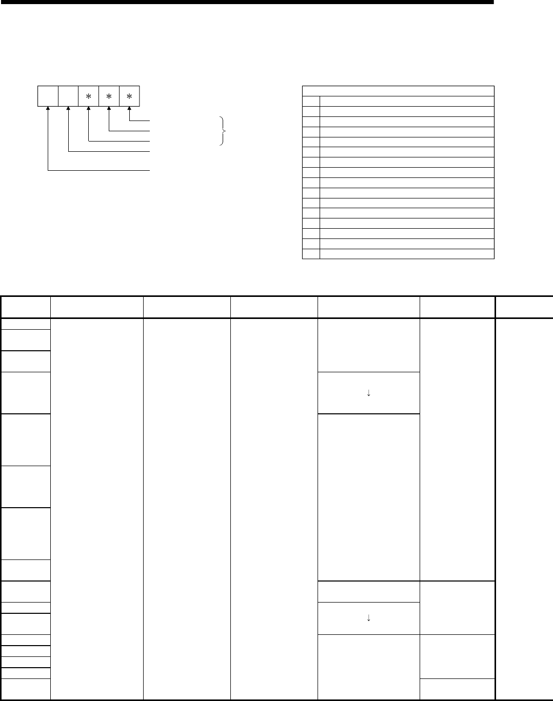
APP - 22
A
PPENDICES
(2) Motion CPU-specific errors
Each digit of error code has been described as follows.
Refer to programming manuals for error details.
Digit
Thousands digit
Tens digit
Hundreds digit
Details code
:
:
:
Details code
10
Ten thousands digit : Except PLC CPU
: Positioning CPU division
(0 : Motion CPU)
003
004
005
006
007
008
009
010
011
014
016
020
021
022
023
030
Minor/major error
Mode switching error (SV22)
Servo error
Servo program setting error (SV13/SV22)
Manual pulse generator axis setting error
WDT error
System setting error
Motion slot fault
Motion SFC control error (F/FS)
Motion CPU internal bus error
TEST mode request error
Minor/major error (Virtual servomoter axis)(SV22)
Minor/major error (Synchronous encoder axis)(SV22)
Motion SFC control error (G)
Motion SFC control error (K or others (Not F/FS, G))
Motion SFC control error (Motion SFC chart)
Table 3.2 Motion CPU-specific errors (10000 to 10999)
Error code
(SD0) Error messages Common information
(SD5 to SD15)
Individual information
(SD16 to SD26) 7-segment LED display CPU status operation
10003
10004
10005
None
10006
"AL" flashes 3 times
Steady "S01" display
10007
10008
10009
10010
None
Continue
10011 Steady ". . . " display
10014
10016
"AL" flashes 3 times
Steady "L01" display
Stop
10020
10021
10022
10023
Continue
10030
MC.UNIT ERROR — —
None
Stop

APP - 23
A
PPENDICES
Error code
(SD0) Error contents and cause Corrective action
10003 Minor/major errors had occurred.
10004 Minor/major errors had occurred in virtual servomotor axis.
(SV22)
10005 Minor/major errors had occurred in synchronous encoder axis.
(SV22)
Check the Motion error history of MT Developer and the minor/major error
codes of minor/major error code of minor/major error code storage device,
and remove the error cause.
Refer to the error codes for error details of minor/major errors.
10006 The servo errors had occurred in the servo amplifier connected to
the Motion CPU.
Check the Motion error history of MT Developer and the servo error codes
of servo error code storage device, and remove the error cause of servo
amplifier.
Refer to the servo error code for details of servo errors.
10007 Servo program setting error occurred.
Check the Motion error history of MT Developer and the servo program
setting error storage device (error program No., error item information),
and remove the error cause.
Refer to the servo program setting error codes for details of servo program
setting errors.
10008 Real mode/virtual mode switching error occurred. (SV22)
Check the Motion error history of MT Developer and the real mode/virtual
mode switching error storage device, and remove the error cause.
Refer to the real mode/virtual mode switching error codes for details of real
mode/virtual mode switching errors.
10009 Manual pulse generator axis setting error occurred.
Check the Motion error history of MT Developer and the manual pulse
generator axis setting error storage device, and remove the error cause.
Refer to the manual pulse generator axis setting error codes for details of
manual pulse generator axis setting errors.
10010 Test mode request error occurred. Check the Motion error history of MT Developer and the test mode request
error storage device, and remove the error cause.
10011 WDT error occurred at Motion CPU. Check the Motion error history of MT Developer and the Motion CPU WDT
error factors, and remove the error cause.
10014 System setting error occurred at Motion CPU.
10016 Motion slot fault occurred at Motion CPU.
Check the error message on error monitor screen of MT Developer, and
remove the error cause. And then, turn on the power supply again or reset
the Multiple CPU system.
10020
10021
10022
10023
Motion SFC error occurred at Motion SFC program.
Check the Motion error history of MT Developer, and remove the error
cause.
Refer to the Motion SFC error code for details of errors.
10030 Motion CPU internal bus error occurred. Motion CPU module hardware fault.
Explain the error symptom and get advice from our sales representative.
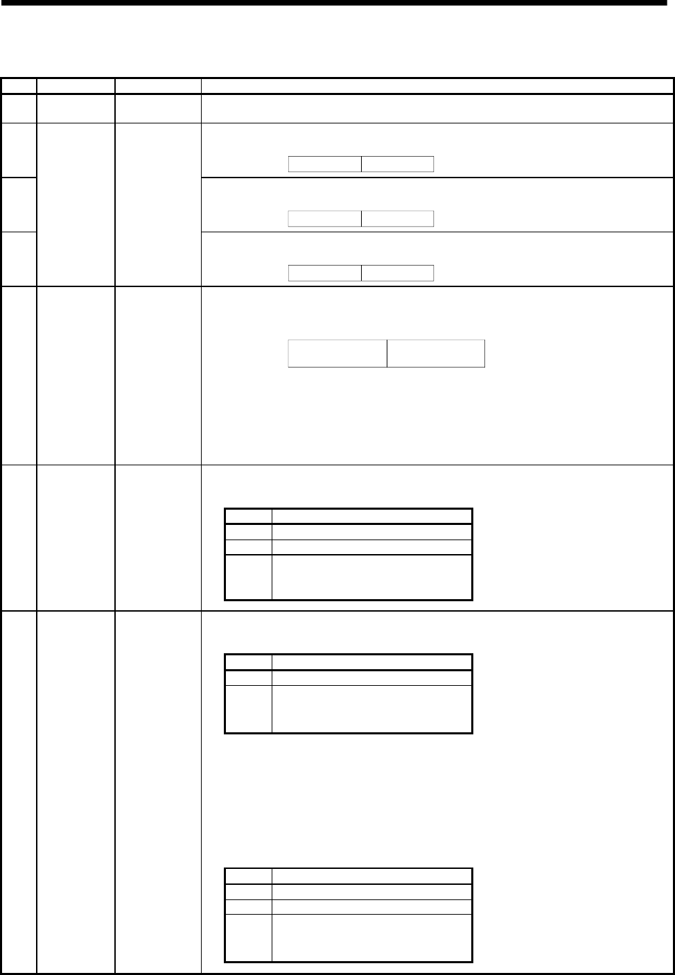
APP - 24
A
PPENDICES
(3) Self-diagnostic error information
No. Name Meaning Details
SD0 Diagnostic errors
Diagnostic error
code • Error codes for errors found by diagnosis are stored as BIN data.
SD1
• The year (last two digits) and month that SD0 data was updated is stored as BCD 2-digit code.
Example : January 2006
H0601
B15 B7 B0B8to to
Month(1 to 12)Year(0 to 99)
SD2
• The day and hour that SD0 data was updated is stored as BCD 2-digit code.
Example : 25st, 10 a.m
H2510
B15 B7 B0B8to to
Day(1 to 31) Hour(0 to 23)
SD3
Clock time for
diagnostic error
occurrence
Clock time for
diagnostic error
occurrence
• The minute and second that SD0 data was updated is stored as BCD 2-digit code.
Second(0 to 59)
B15 B7 B0B8to to Example : 35min., 48 sec.
H3548
Minute(0 to 59)
SD4 Error information
categories
Error information
category code
• Category codes which help indicate what type of information is being stored in the error common information
areas (SD5 to SD15) and error individual information areas (SD16 to SD26) are stored. The category code for
judging the error information type is stored.
Individual information
category codes
Common information
category codes
B15 B7B8to to B0
• The common information category codes store the following codes.
0: No error
1: Module No./CPU No./Base No.
• The individual information category codes store the following codes.
0: No error
5: Parameter No.
13:Parameter No./CPU No.
• Common information corresponding to the diagnostic error (SD0) is stored.
• The error common information type can be judged by SD4(common information category code).
1: Module No./CPU No./Base No.
No. Meaning
SD5 Module No./CPU No./Base No.
SD6 I/O No.
SD7
to
SD15
Empty
SD5
to
SD15
Error common
information
Error common
information
• Individual information corresponding to the diagnostic error (SD0) is stored.
• The error individual information type can be judged by SD4(individual information category code).
5: Parameter No.
No. Meaning
SD16 Parameter No.
SD17
to
SD26
Empty
0401H :Base setting
0406H :Motion slot setting
0E00H :Multiple CPU setting (Number of Multiple CPU's)
0E01H :Multiple CPU setting (Operation mode/ Multiple CPU synchronous startup)
E008H :Multiple CPU high speed transmission area setting
(CPU specific send range setting / (System area))
E009H/E00AH : Multiple CPU high speed transmission area setting(Automatic refresh setting)
E00BH :Synchronous setting
13: Parameter No./CPU No.
No. Meaning
SD16 Parameter No.
SD17 CPU No.(1 to 4)
SD18
to
SD26
Empty
SD16
to
SD26
Error individual
information
Error individual
information

APP - 25
A
PPENDICES
(4) Release of Multiple CPU related error
The release operation of errors that continues operation for CPU can be
executed.
Release the errors in the following procedure.
1) Remove the error cause.
2) Turn off the Motion error detection flag (M2039).
The special relays, special registers and 7-segment LED for the errors are returned to
the status before error occurs after release of errors.
If the same error is displayed again after release of errors, an error is set again, and
the Motion error detection flag (M2039) turns on.
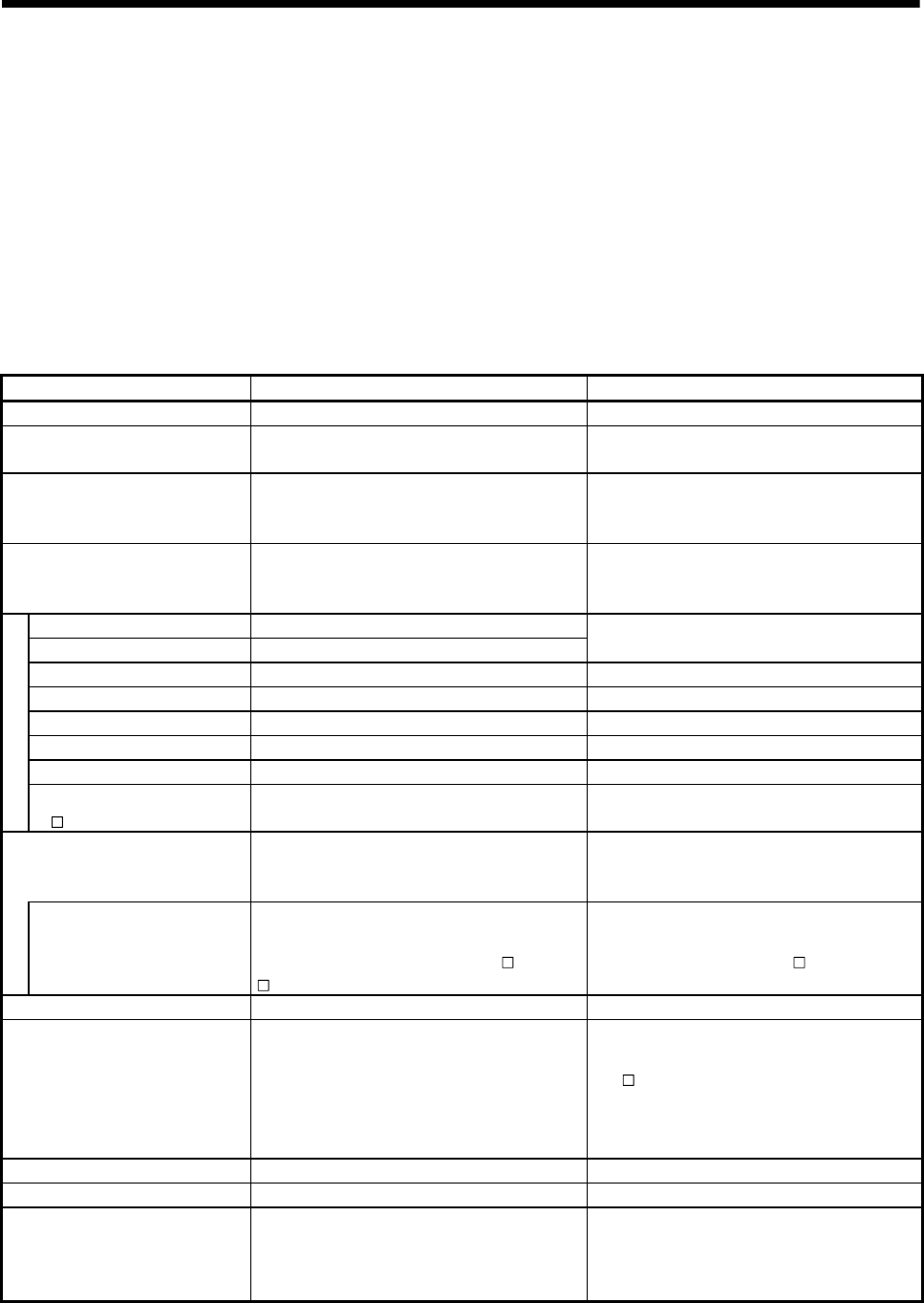
APP - 26
A
PPENDICES
APPENDIX 4 Differences Between Q173DCPU/Q172DCPU and Q173HCPU/Q172HCPU
APPENDIX 4.1 Differences Between Q173DCPU/Q172DCPU and Q173HCPU/Q172HCPU
Common differences to each mode are shown in Table 4.1.
Refer to "APPENDIX 4.3 Differences of each mode" for characteristic differences to
each mode.
And, refer to "APPENDIX 4.2 Comparison of devices " for detailed differences of
devices.
Table 4.1 Differences Between Q173DCPU/Q172DCPU and Q173HCPU/Q172HCPU
Item Q173DCPU/Q172DCPU Q173HCPU/Q172HCPU
Peripheral I/F Via PLC CPU (USB/RS-232) USB/SSCNET
External battery Demand Add Q6BAT at continuous power failure for 1
month or more.
Forced stop input
• Use EMI terminal of Motion CPU module.
• Use device set by forced stop input setting in
the system setting.
• Use device set by forced stop input setting in
the system setting.
Multiple CPU high speed
transmission memory for data
transfer between CPU modules
Included —
Internal relays (M) 8192 points
Latch relays (L) None (Latch for M is possible by latch setting) Total 8192 points
Special relays (M) — 256 points
Special relays (SM) 2256 points —
Special registers (D) — 256 points
Special registers (SD) 2256 points —
Motion registers (#) 8736 points 8192 points
Device
Multiple CPU area devices
(U \G) Up to 14336 points —
Motion dedicated PLC instructions
D(P).DDRD, D(P).DDWR, D(P).SFCS,
D(P).SVST, D(P).CHGT, D(P).CHGV,
D(P).CHGA, D(P).GINT
S(P).DDRD, S(P).DDWR, S(P).SFCS,
S(P).SVST, S(P).CHGT, S(P).CHGV,
S(P).CHGA, S(P).GINT
Interlock condition
Multiple instructions are executable continuously
without interlock condition by the self CPU high
speed interrupt accept flag from CPU .
:CPU No.
Interlock condition by the to self CPU high speed
interrupt accept flag from CPU is necessary.
Motion modules Q172DLX, Q172DEX, Q173DPX Q172LX, Q172EX, Q173PX
System setting
• QnUD(H)CPU is set as CPU No. 1.
• Only Multiple CPU high speed main base unit
(Q38DB/Q312DB) can be used as main base
unit.
• Motion modules cannot be installed to I/O 0 to 2
slot.
• QnUD(H)CPU is set to CPU No. 1.
• Q3 B can be used as a main base unit.
• Motion modules can be mounted to I/O 0 to 2
slot.
Latch clear Remote operation L.CLR switch
RUN/STOP Remote operation, RUN/STOP switch RUN/STOP switch
ROM operation
• ROM writing is executed with mode operated
by RAM/ mode operated by ROM.
• ROM writing can be executed for the data of
MT Developer.
Rom writing is executed with installation mode/
mode written in ROM.
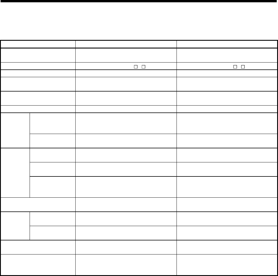
APP - 27
A
PPENDICES
Table 4.1 Differences Between Q173DCPU/Q172DCPU and Q173HCPU/Q172HCPU
(Continued)
Item Q173DCPU/Q172DCPU Q173HCPU/Q172HCPU
Medium of operating system
software CD-ROM (1 disk) FD (2 disks)
Model of operating system software SW8DNC-SV Q SW6RN-SV Q
CPU module No.1 QnUD(H)CPU Qn(H)CPU
Installation orders CPU No.2 or later No restriction Install Motion CPU module on the right-hand side
of PLC CPU module.
Combination of Motion CPU
modules Q173DCPU/Q172DCPU only Combination with
Q173CPUN(-T)/Q172CPUN(-T).
CPU empty slot Settable between CPU modules Not settable between CPU modules
Multiple CPU high
speed transmission
area
Provided None
CPU shared
memory Access by Multiple
CPU shared memory Possible Impossible
Memory Multiple CPU high speed transmission area in
CPU shared memory Automatic refresh area in CPU shared memory
Automatic refresh
setting 32 range possible 4 range possible
Automatic
refresh Multiple CPU high
speed refresh
function
Provided None
LED display 7-segment LED display Each LED of MODE, RUN, ERR, M.RUN, BAT
and BOOT
Latch (1) It is possible to clear with latch clear(1) and latch
clear (1)(2) of remote latch clear.
Range which can be cleared with the latch clear
key.
Latch range
setting Latch (2) It is possible to clear with lath clear(1)(2) of
remote latch clear.
Range which cannot be cleared with the latch
clear key.
All clear function Execute with installation mode Turn off the PLC ready flag (M2000) and test
mode ON flag (M9075) to execute all clear.
Release of Multiple CPU related
error Turn off M2039.
Store the error code to be released in the special
register D9060 and turn off to on the special relay
M9060.

APP - 28
A
PPENDICES
APPENDIX 4.2 Comparison of devices
(1) Motion registers
(a) Monitor devices
Table 4.2 Motion registers (Monitor devices) list
Device No.
Q173DCPU/Q172DCPU Q173HCPU/Q172HCPU Name Remark
#8000 to #8019 #8064 to #8067 Axis 1 monitor device
#8020 to #8039 #8068 to #8071 Axis 2 monitor device
#8040 to #8059 #8072 to #8075 Axis 3 monitor device
#8060 to #8079 #8076 to #8079 Axis 4 monitor device
#8080 to #8099 #8080 to #8083 Axis 5 monitor device
#8100 to #8119 #8084 to #8087 Axis 6 monitor device
#8120 to #8139 #8088 to #8091 Axis 7 monitor device
#8140 to #8159 #8092 to #8095 Axis 8 monitor device
#8160 to #8179 #8096 to #8099 Axis 9 monitor device
#8180 to #8199 #8100 to #8103 Axis 10 monitor device
#8200 to #8219 #8104 to #8107 Axis 11 monitor device
#8220 to #8239 #8108 to #8111 Axis 12 monitor device
#8240 to #8259 #8112 to #8115 Axis 13 monitor device
#8260 to #8279 #8116 to #8119 Axis 14 monitor device
#8280 to #8299 #8120 to #8123 Axis 15 monitor device
#8300 to #8319 #8124 to #8127 Axis 16 monitor device
#8320 to #8339 #8128 to #8131 Axis 17 monitor device
#8340 to #8359 #8132 to #8135 Axis 18 monitor device
#8360 to #8379 #8136 to #8139 Axis 19 monitor device
#8380 to #8399 #8140 to #8143 Axis 20 monitor device
#8400 to #8419 #8144 to #8147 Axis 21 monitor device
#8420 to #8439 #8148 to #8151 Axis 22 monitor device
#8440 to #8459 #8152 to #8155 Axis 23 monitor device
#8460 to #8479 #8156 to #8159 Axis 24 monitor device
#8480 to #8499 #8160 to #8163 Axis 25 monitor device
#8500 to #8519 #8164 to #8167 Axis 26 monitor device
#8520 to #8539 #8168 to #8171 Axis 27 monitor device
#8540 to #8559 #8172 to #8175 Axis 28 monitor device
#8560 to #8579 #8176 to #8179 Axis 29 monitor device
#8580 to #8599 #8180 to #8183 Axis 30 monitor device
#8600 to #8619 #8184 to #8187 Axis 31 monitor device
#8620 to #8639 #8188 to #8191 Axis 32 monitor device

APP - 29
A
PPENDICES
Table 4.3 Monitor devices list
Device No.
Q173DCPU/Q172DCPU Q173HCPU/Q172HCPU
Name Remark
#8000 + 20n #8064 + 4n Servo amplifier type
#8001 + 20n #8065 + 4n Motor current
#8002 + 20n
#8003 + 20n
#8066 + 4n
#8067 + 4n Motor speed
#8004 + 20n
#8005 + 20n — Command speed
#8006 + 20n
#8007 + 20n — Home position return re-travel value
New device in
Q173DCPU/Q172DCPU
(Note-1) : "n" in the above device No. indicates the numerical value which correspond to axis No.
(b) Motion error history
Table 4.4 Motion registers (Motion error history) list
Device No.
Q173DCPU/Q172DCPU Q173HCPU/Q172HCPU
Name Remark
#8640 to #8651 #8000 to #8007 Seventh error information in past
(Oldest error information)
#8652 to #8663 #8008 to #8015 Sixth error information in past
#8664 to #8675 #8016 to #8023 Fifth error information in past
#8676 to #8687 #8024 to #8031 Fourth error information in past
#8688 to #8699 #8032 to #8039 Third error information in past
#8700 to #8711 #8040 to #8047 Second error information in past
#8712 to #8723 #8048 to #8055 First error information in past
#8724 to #8735 #8056 to #8063 Latest error information
Table 4.5 Motion error history list
Device No.
Q173DCPU/Q172DCPU Q173HCPU/Q172HCPU Name Remark
#8640 + 12n #8000 + 8n Error Motion SFC program No.
#8641 + 12n #8001 + 8n Error type
#8642 + 12n #8002 + 8n Error program No.
#8643 + 12n #8003 + 8n Error block No./Motion SFC list/Line No./Axis No.
#8644 + 12n #8004 + 8n Error code
#8645 + 12n #8005 + 8n Error occurrence time (Year/month
#8646 + 12n #8006 + 8n Error occurrence time (Day/hour)
#8647 + 12n #8007 + 8n Error occurrence time (Minute/second)
#8648 + 12n — Error setting data information
#8649 + 12n — Unusable
#8650 + 12n
#8651 + 12n — Error setting data
New device in
Q173DCPU/Q172DCPU
(Note-1) : "n" in the above device No. indicates the numerical value which correspond to axis No.

APP - 30
A
PPENDICES
(2) Special relays
Table 4.6 Special relay list
Device No.
Q173DCPU/Q172DCPU Q173HCPU/Q172HCPU Name Remark
SM60 M9000/M2320 Fuse blown detection
SM53 M9005/M2321 AC/DC DOWN detection
SM52 M9006/M2322 Battery low
SM51 M9007/M2323 Battery low latch
SM1 M9008/M2324 Self-diagnostic error
SM0 M9010/M2325 Diagnostic error
— M9025/M3136 Clock data set request
SM211 M9026/M2338 Clock data error
SM801 M9028/M3137 Clock data read request
SM400 M9036/M2326 Always ON
SM401 M9037/M2327 Always OFF
— M9060/M3138 Diagnostic error reset Use M2039 for error reset
operation.
SM512 M9073/M2329 Motion CPU WDT error
SM500 M9074/M2330 PCPU READY complete
SM501 M9075/M2331 Test mode ON
SM502 M9076/M2332 External forced stop input
SM513 M9077/M2333 Manual pulse generator axis setting error
SM510 M9078/M2334 TEST mode request error
SM516 M9079/M2335 Servo program setting error
SM528 M9216/M2345 No.1 CPU MULTR complete
SM529 M9217/M2346 No.2 CPU MULTR complete
SM530 M9218/M2347 No.3 CPU MULTR complete
SM531 M9219/M2348 No.4 CPU MULTR complete
SM240 M9240/M2336 No.1 CPU resetting
SM241 M9241/M2337 No.2 CPU resetting
SM242 M9242/M2338 No.3 CPU resetting
SM243 M9243/M2339 No.4 CPU resetting
SM244 M9244/M2340 No.1 CPU error
SM245 M9245/M2341 No.2 CPU error
SM246 M9246/M2342 No.3 CPU error
SM247 M9247/M2343 No.4 CPU error
SM58 — Battery low warning latch
SM59 — Battery low warning
SM220 — CPU No.1 READY complete
SM221 — CPU No.2 READY complete
SM222 — CPU No.3 READY complete
SM223 — CPU No.4 READY complete
SM503 — Digital oscilloscope executing
SM526 — Over heat warning latch
SM527 — Over heat warning
New device in
Q173DCPU/Q172DCPU

APP - 31
A
PPENDICES
(3) Special registers
Table 4.7 Special registers list
Device No.
Q173DCPU/Q172DCPU Q173HCPU/Q172HCPU Name Remark
SD60 D9000 Fuse blown No.
SD53 D9005 AC/DC DOWN counter No.
SD0 D9008 Diagnostic errors
SD1 D9010
Clock time for diagnostic error occurrence
(Year, month)
SD2 D9011
Clock time for diagnostic error occurrence
(Day, hour)
SD3 D9012
Clock time for diagnostic error occurrence
(Minute, second)
SD4 D9013 Error information categories
SD5 D9014
SD6 —
SD7 —
SD8 —
SD9 —
SD10 —
SD11 —
SD12 —
SD13 —
SD14 —
SD15 —
Error common information
SD16 —
SD17 —
SD18 —
SD19 —
SD20 —
SD21 —
SD22 —
SD23 —
SD24 —
SD25 —
New device in
Q173DCPU/Q172DCPU
SD26 —
Error individual information
SD203 D9015 Operating status of CPU
SD520 D9017 Scan time
SD521 D9019 Maximum scan time
SD210 D9025 Clock data (Year, month)
SD211 D9026 Clock data (Day, hour)
SD212 D9027 Clock data (Minute, second)
SD213 D9028 Clock data (Day of week)
— D9060 Diagnostic error reset error No. Use M2039 for error reset
operation.
SD395 D9061 Multiple CPU No.
SD508 D9112 Connect/Disconnect (Status)
SD803 — Connect/Disconnect (Command)
New device in
Q173DCPU/Q172DCPU
SD510 D9182
SD511 D9183
Test mode request error

APP - 32
A
PPENDICES
Table 4.7 Special registers list (Continued)
Device No.
Q173DCPU/Q172DCPU Q173HCPU/Q172HCPU
Name Remark
SD512 D9184 Motion CPU WDT error cause
SD513 D9185
SD514 D9186
SD515 D9187
Manual pulse generator axis setting error
SD522 D9188 Motion operation cycle
SD516 D9189 Error program No.
SD517 D9190 Error item information
SD502 D9191
SD503 D9192
Servo amplifier loading information
SD504 D9193
SD505 D9194
SD506 D9195
Real mode/virtual mode switching error information
— D9196 PC link communication error codes
Q173DCPU/Q172DCPU
does not support PC link
communication.
SD523 D9197 Operation cycle of the Motion CPU setting
SD200 D9200 State of switch
— D9201 State of LED Use 7-segment LED in
Q173DCPU/Q172DCPU.
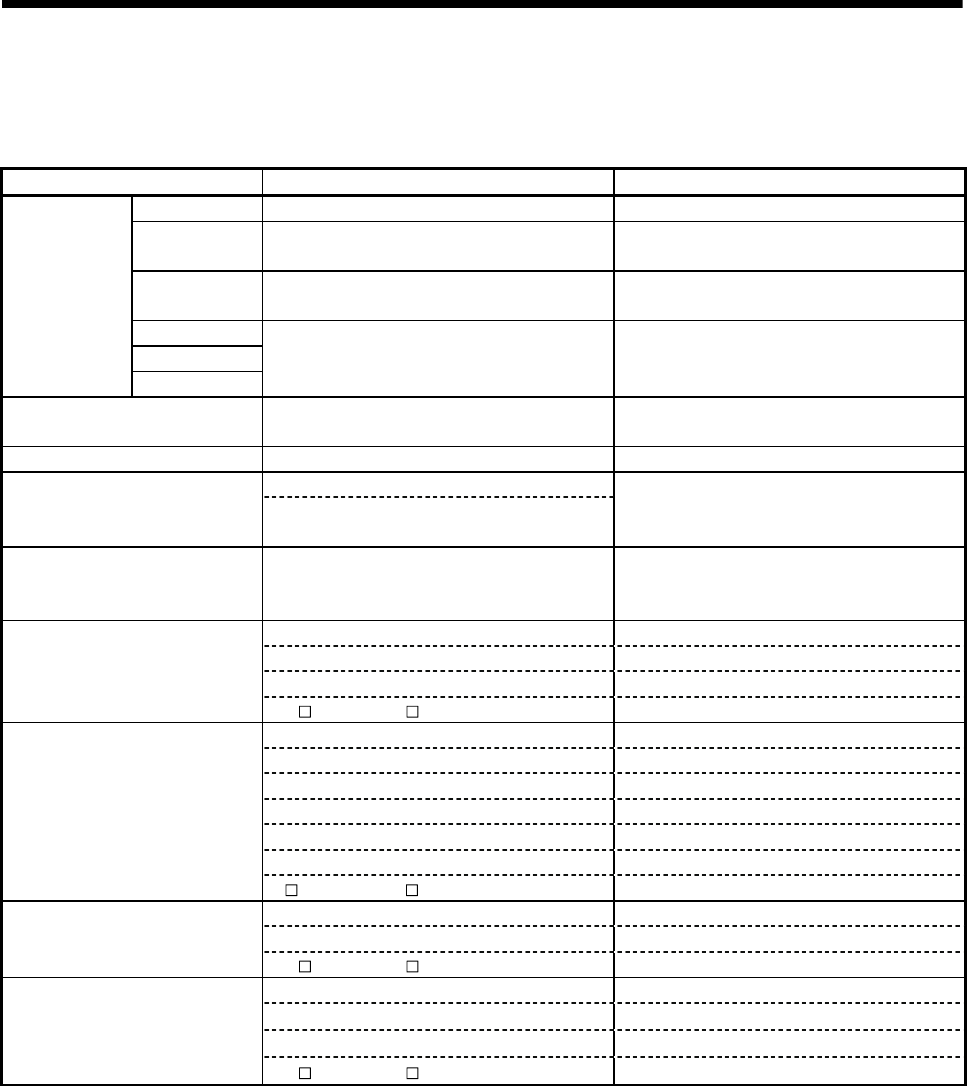
APP - 33
A
PPENDICES
(4) Other devices
Table 4.8 Other devices list
Item Q173DCPU/Q172DCPU Q173HCPU/Q172HCPU
M2320 to M2399 Unusable Special relay allocated devices (Status)
M2400 to M3039 Device area of 9 axes or more is usable as user
devices in Q172DCPU.
Device area of 9 axes or more is unusable as
user devices in Q172HCPU.
M3136 to M3199 Unusable Special relay allocated devices
(Command signal)
M3200 to M3839
D0 to D639
Internal relays/
Data registers
D640 to D703
Device area of 9 axes or more is usable as user
devices in Q172DCPU.
Device area of 9 axes or more is unusable in
Q172HCPU.
Personal computer link
communication error flag — M2034
PCPU READY complete SM500 D759
D9 + 20n (Data shortened to 1 word) (Note-1)
Home position return re-travel value #8006 + 20n, #8007 + 20n
(Referring at monitoring) (Note-1)
D9 + 20n (Note-1)
Travel value change registers
Optional device
(Set for D16 + 20n, D17 + 20n are also usable.)
(Note-1)
D16 + 20n, D17 + 20n (Note-1)
D0 to D8191 D800 to D8191
W0 to W1FFF W0 to W1FFF
#0 to #7999 #0 to #7999
Indirect setting devices
(Word devices)
U\G10000 to U \G(10000 + p – 1) (Note-2) —
X0 to X1FFF X0 to X1FFFF
Y0 to Y1FFF Y0 to Y1FFF
M0 to M8191 M/L0 to M/L8191
— M9000 to M9255
B0 to B1FFF B0 to B1FFF
F0 to F2047 F0 to F2047
Indirect setting devices
(Bit devices)
U\G10000.0 to U \G(10000 + p – 1).F (Note-2) —
D0 to D8191 D800 to D3069, D3080 to D8191
W0 to W1FFF W0 to W1FFF
High-speed reading function
settable devices U\G10000 to U \G(10000 + p – 1) (Note-2) —
D0 to D8191 D0 to D8191
W0 to W1FFF W0 to W1FFF
#0 to #7999 #0 to #7999
Optional data monitor function
settable devices
U\G10000 to U \G(10000 + p – 1) (Note-2) —
(Note-1) : "n" in the above device No. indicates the numerical value which correspond to axis No.
(Note-2) : "p" indicates the user setting area points of Multiple CPU high speed transmission area in each CPU.
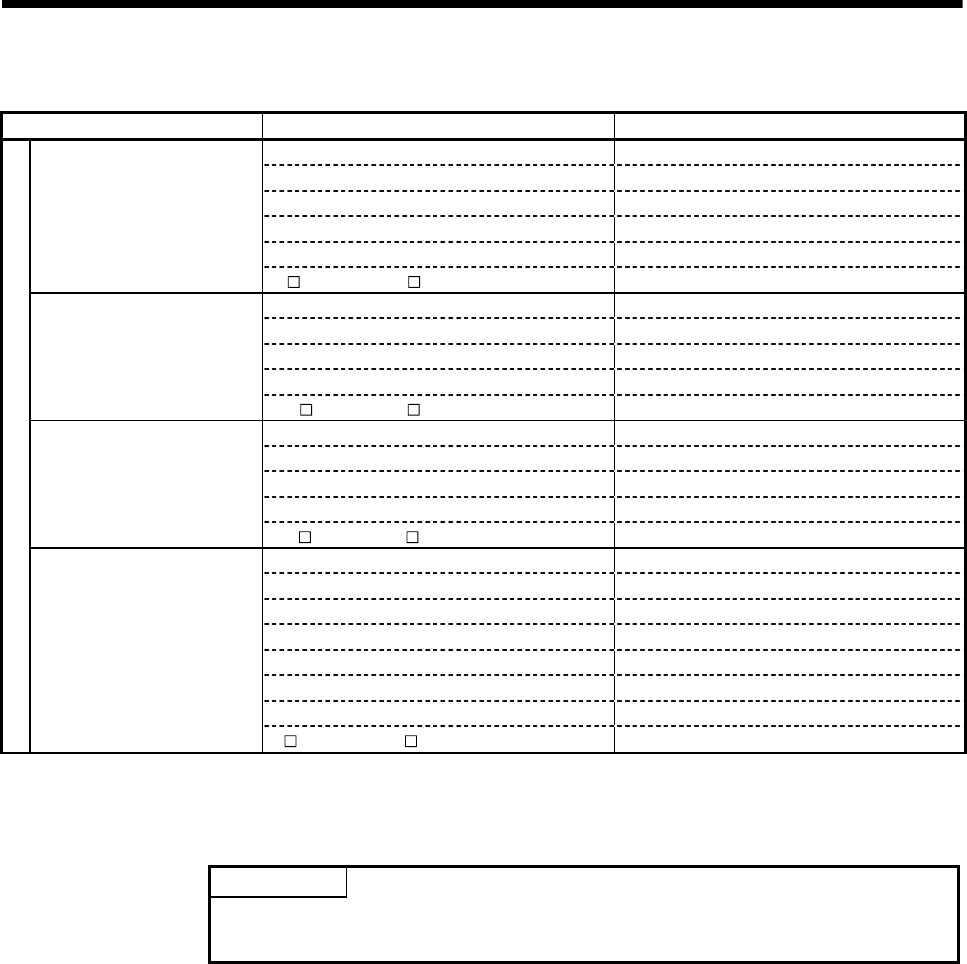
APP - 34
A
PPENDICES
Table 4.8 Other devices list (Continued)
Item Q173DCPU/Q172DCPU Q173HCPU/Q172HCPU
X0 to X1FFF X0 to X1FFF
Y0 to Y1FFF Y0 to Y1FFF
M0 to M8191 M0 to M8191
— L0 to L8191
B0 to B1FFF B0 to B1FFF
Output device
U\G10000.0 to U \G(10000 + p –1).F (Note-2) —
D0 to D8191 D0 to D8191
W0 to W1FFF W0 to W1FFF
#0 to #7999 #0 to #8191
Absolute value address Absolute value address
Watch data
U\G10000 to U \G(10000 + p –1) (Note-2) —
D0 to D8191 D0 to D8191
W0 to W1FFF W0 to W1FFF
#0 to #7999 #0 to #8191
Constant (Hn/Kn) (Note-3) Constant (Hn/Kn)
(Note-3)
ON region setting
U\G10000 to U \G(10000 + p – 1) (Note-2) —
X0 to X1FFF X0 to X1FFF
Y0 to Y1FFF Y0 to Y1FFF
M0 to M8191 M0 to M8191
— L0 to L8191
B0 to B1FFF B0 to B1FFF
F0 to F2047 F0 to F2047
SM0 to SM1999 M9000 to M9255
Limit switch output data
Output enable/disable bit
Forced output bit
U\G10000.0 to U \G(10000 + p – 1).F (Note-2) —
(Note-2) : "p" indicates the user setting area points of Multiple CPU high speed transmission area in each CPU.
(Note-3) : Setting range varies depending on the setting units.
POINT
Refer to Chapter 2 for number of user setting area points of Multiple CPU high
speed transmission area.
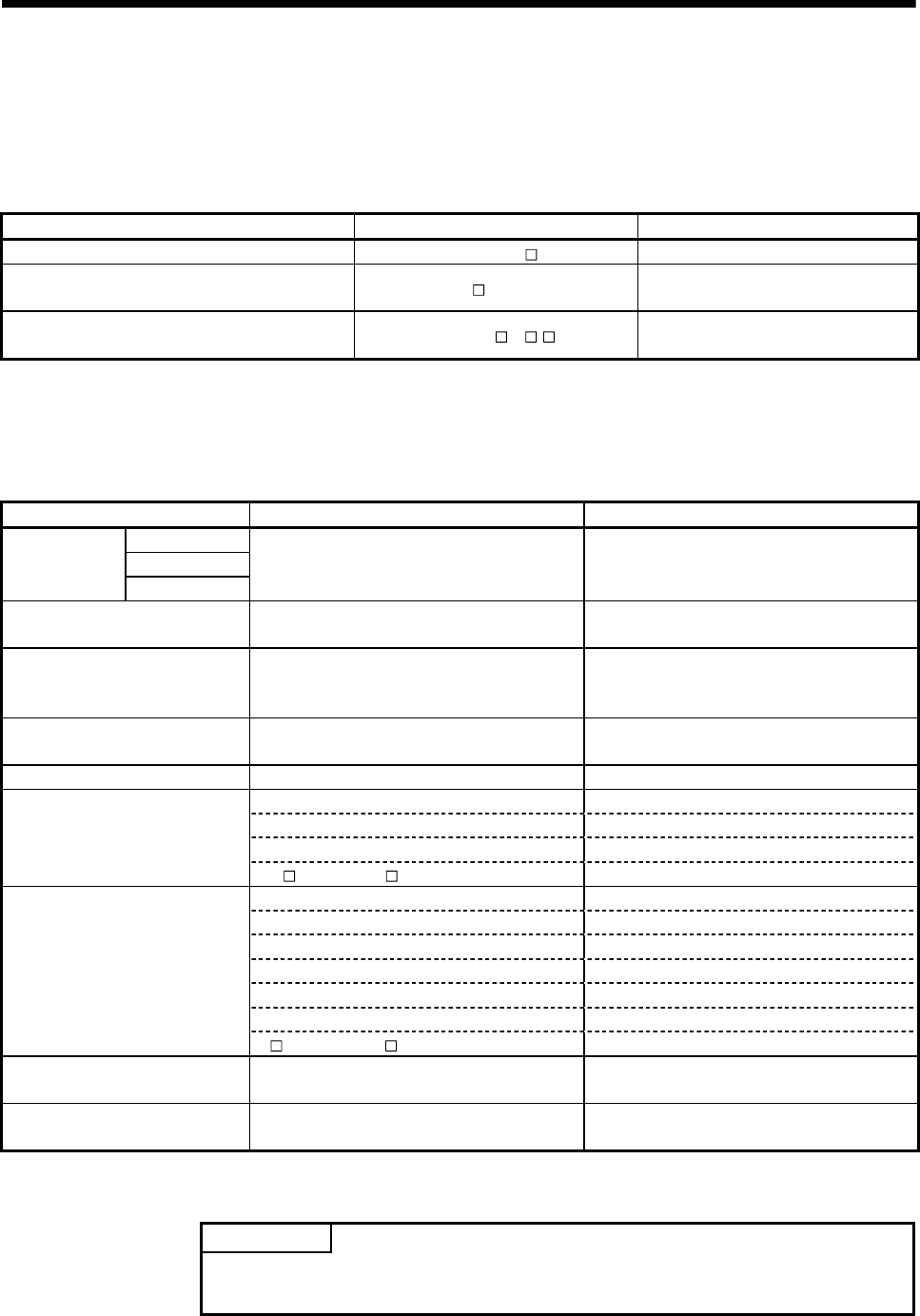
APP - 35
A
PPENDICES
APPENDIX 4.3 Differences of each mode
(1) Motion SFC
Table 4.9 Differences in Motion SFC mode
Item Q173DCPU/Q172DCPU Q173HCPU/Q172HCPU
Motion SFC program executing flag X, Y, M, B, U \G —
Operation control/transition control usable device
(Word device) D, W, U \G, SD, #, FT D, W, Special D, #, FT
Operation control/transition control usable device
(Bit device) X, PX, Y, PY, M, U \G ., B, F, SM X, PX, Y, PY, M, L, B, F, Special M
(2) Virtual mode
Table 4.10 Differences in Virtual mode
Item Q173DCPU/Q172DCPU Q173HCPU/Q172HCPU
M4640 to M4687
M5440 to M5487
Internal relay/
Data register D1120 to D1239
Device area of 9 axes or more is usable as user
devices in the Q172DCPU.
Device area of 9 axes or more is unusable in the
Q172HCPU.
Clutch status Optional device
(Set for M2160 to M2223 are also usable.) M2160 to M2223
Cam axis command signals
(Cam/ball screw switching
command)
Optional device
(Set for M5488 to M5519 are also usable.) M5488 to M5519
Smoothing clutch complete signals Optional device
(Set for M5520 to M5583 are also usable.) M5520 to M5583
Real mode axis information register SD500, SD501 D790, D791
D0 to D8191 D800 to D3069, D3080 to D8191
W0 to W1FFF W0 to W1FFF
#0 to #7999 —
Indirect setting devices of
mechanical system program
(Word device) U\G10000 to U \G(10000 + p –1 ) (Note-1) —
X0 to X1FFF X0 to X1FFF
Y0 to Y1FFF Y0 to Y1FFF
M0 to M8191 M/L0 to M/L8191
— M9000 to M9255
B0 to B1FFF B0 to B1FFF
F0 to F2047 F0 to F2047
Indirect setting devices of
mechanical system program
(Bit device)
U\G10000.0 to U \G(10000 + p –1 ).F (Note-1) —
Speed change ratio of speed
change gear
Upper limit value : 0 to 65535
Lower limit value : 0 to 65535
Upper limit value : 1 to 10000
Lower limit value : 1 to 10000
Permissible droop pulse value of
output module 1 to 1073741824 [PLS] 1 to 65535[∗100PLS]
(Note-1) : "p" indicates user setting area points of Multiple CPU high speed transmission area in each CPU.
POINT
Refer to Chapter 2 for number of user setting area points of Multiple CPU high
speed transmission area.

WARRANTY
Please confirm the following product warranty details before using this product.
1. Gratis Warranty Term and Gratis Warranty Range
If any faults or defects (hereinafter "Failure") found to be the responsibility of Mitsubishi occurs during use of the
product within the gratis warranty term, the product shall be repaired at no cost via the sales representative or
Mitsubishi Service Company.
However, if repairs are required onsite at domestic or overseas location, expenses to send an engineer will be solely
at the customer's discretion. Mitsubishi shall not be held responsible for any re-commissioning, maintenance, or
testing on-site that involves replacement of the failed module.
[Gratis Warranty Term]
Note that an installation period of less than one year after installation in your company or your customer’s premises
or a period of less than 18 months (counted from the date of production) after shipment from our company,
whichever is shorter, is selected.
[Gratis Warranty Range]
(1) Diagnosis of failure
As a general rule, diagnosis of failure is done on site by the customer.
However, Mitsubishi or Mitsubishi service network can perform this service for an agreed upon fee upon the
customer’s request.
There will be no charges if the cause of the breakdown is found to be the fault of Mitsubishi.
(2) Breakdown repairs
There will be a charge for breakdown repairs, exchange replacements and on site visits for the following four
conditions, otherwise there will be a charge.
1) Breakdowns due to improper storage, handling, careless accident, software or hardware design by the
customer
2) Breakdowns due to modifications of the product without the consent of the manufacturer
3) Breakdowns resulting from using the product outside the specified specifications of the product
4) Breakdowns that are outside the terms of warranty
Since the above services are limited to Japan, diagnosis of failures, etc. are not performed abroad.
If you desire the after service abroad, please register with Mitsubishi. For details, consult us in advance.
2. Exclusion of Loss in Opportunity and Secondary Loss from Warranty Liability
Mitsubishi will not be held liable for damage caused by factors found not to be the cause of Mitsubishi; opportunity
loss or lost profits caused by faults in the Mitsubishi products; damage, secondary damage, accident compensation
caused by special factors unpredictable by Mitsubishi; damages to products other than Mitsubishi products; and to
other duties.
3. Onerous Repair Term after Discontinuation of Production
Mitsubishi shall accept onerous product repairs for seven years after production of the product is discontinued.
4. Delivery Term
In regard to the standard product, Mitsubishi shall deliver the standard product without application settings or
adjustments to the customer and Mitsubishi is not liable for on site adjustment or test run of the product.
5. Precautions for Choosing the Products
(1) These products have been manufactured as a general-purpose part for general industries, and have not been
designed or manufactured to be incorporated in a device or system used in purposes related to human life.
(2) Before using the products for special purposes such as nuclear power, electric power, aerospace, medicine,
passenger movement vehicles or under water relays, contact Mitsubishi.
(3) These products have been manufactured under strict quality control. However, when installing the product where
major accidents or losses could occur if the product fails, install appropriate backup or failsafe functions in the
system.
(4) When exporting any of the products or related technologies described in this catalogue, you must obtain an
export license if it is subject to Japanese Export Control Law.

IB(NA)-0300134-A(0801)MEE
MODEL
MODEL
CODE
Q173D-P-COM-E
1XB928
IB(NA)-0300134-A(0801)MEE When exported from Japan, this manual does not require application to the
Ministry of Economy, Trade and Industry for service transaction permission.
Specifications subject to change without notice.
MOTION CONTROLLER Qseries
Programming Manual (COMMON)
(Q173DCPU/Q172DCPU)
HEAD OFFICE : TOKYO BUILDING, 2-7-3 MARUNOUCHI, CHIYODA-KU, TOKYO 100-8310, JAPAN

HEADQUARTERS
EUROPEMITSUBISHI ELECTRIC EUROPE B.V.
German Branch
Gothaer Straße 8
D-40880 Ratingen
Phone: +49 (0)2102 / 486-0
Fax: +49 (0)2102 / 486-1120
CZECH REPUBLICMITSUBISHI ELECTRIC EUROPE B.V.
Czech Branch
Avenir Business Park, Radlická 714/113a
CZ-158 00 Praha 5
Phone: +420 (0)251 551 470
Fax: +420 (0)251-551-471
FRANCEMITSUBISHI ELECTRIC EUROPE B.V.
French Branch
25, Boulevard des Bouvets
F-92741 Nanterre Cedex
Phone: +33 (0)1 / 55 68 55 68
Fax: +33 (0)1 / 55 68 57 57
IRELANDMITSUBISHI ELECTRIC EUROPE B.V.
Irish Branch
Westgate Business Park, Ballymount
IRL-Dublin 24
Phone: +353 (0)1 4198800
Fax: +353 (0)1 4198890
ITALYMITSUBISHI ELECTRIC EUROPE B.V.
Italian Branch
Viale Colleoni 7
I-20041 Agrate Brianza (MI)
Phone: +39 039 / 60 53 1
Fax: +39 039 / 60 53 312
SPAINMITSUBISHI ELECTRIC EUROPE B.V.
Spanish Branch
Carretera de Rubí 76-80
E-08190 Sant Cugat del Vallés (Barcelona)
Phone: 902 131121 // +34 935653131
Fax: +34 935891579
UKMITSUBISHI ELECTRIC EUROPE B.V.
UK Branch
Travellers Lane
UK-Hatfield, Herts. AL10 8XB
Phone: +44 (0)1707 / 27 61 00
Fax: +44 (0)1707 / 27 86 95
JAPAN
MITSUBISHI ELECTRIC CORPORATION
Office Tower “Z” 14 F
8-12,1 chome, Harumi Chuo-Ku
Tokyo 104-6212
Phone: +81 3 622 160 60
Fax: +81 3 622 160 75
USAMITSUBISHI ELECTRIC AUTOMATION, Inc.
500 Corporate Woods Parkway
Vernon Hills, IL 60061
Phone: +1 847 478 21 00
Fax: +1 847 478 22 53
EUROPEAN REPRESENTATIVES
AUSTRIAGEVA
Wiener Straße 89
AT-2500 Baden
Phone: +43 (0)2252 / 85 55 20
Fax: +43 (0)2252 / 488 60
BELARUSTEHNIKON
Oktyabrskaya 16/5, Off. 703-711
BY-220030 Minsk
Phone: +375 (0)17 / 210 46 26
Fax: +375 (0)17 / 210 46 26
BELGIUMKoning & Hartman b.v.
Woluwelaan 31
BE-1800 Vilvoorde
Phone: +32 (0)2 / 257 02 40
Fax: +32 (0)2 / 257 02 49
BOSNIA AND HERZEGOVINAINEA BH d.o.o.
Aleja Lipa 56
BA-71000 Sarajevo
Phone: +387 (0)33 / 921 164
Fax: +387 (0)33/ 524 539
BULGARIAAKHNATON
4 Andrej Ljapchev Blvd. Pb 21
BG-1756 Sofia
Phone: +359 (0)2 / 817 6004
Fax: +359 (0)2 / 97 44 06 1
CROATIAINEA CR d.o.o.
Losinjska 4 a
HR-10000 Zagreb
Phone: +385 (0)1 / 36 940 - 01/ -02/ -03
Fax: +385 (0)1 / 36 940 - 03
CZECH REPUBLICAutoCont C.S. s.r.o.
Technologická 374/6
CZ-708 00 Ostrava-Pustkovec
Phone: +420 595 691 150
Fax: +420 595 691 199
CZECH REPUBLICB:TECH A.S.
U Borové 69
CZ-58001 Havlíčkův Brod
Phone: +420 (0)569 777 777
Fax: +420 (0)569-777 778
DENMARKBeijer Electronics A/S
Lykkegårdsvej 17, 1.
DK-4000 Roskilde
Phone: +45 (0)46/ 75 76 66
Fax: +45 (0)46 / 75 56 26
ESTONIABeijer Electronics Eesti OÜ
Pärnu mnt.160i
EE-11317 Tallinn
Phone: +372 (0)6 / 51 81 40
Fax: +372 (0)6 / 51 81 49
FINLANDBeijer Electronics OY
Jaakonkatu 2
FIN-01620 Vantaa
Phone: +358 (0)207 / 463 500
Fax: +358 (0)207 / 463 501
GREECEUTECO A.B.E.E.
5, Mavrogenous Str.
GR-18542 Piraeus
Phone: +30 211 / 1206 900
Fax: +30 211 / 1206 999
HUNGARYMELTRADE Ltd.
Fertő utca 14.
HU-1107 Budapest
Phone: +36 (0)1 / 431-9726
Fax: +36 (0)1 / 431-9727
LATVIABeijer Electronics SIA
Vestienas iela 2
LV-1035 Riga
Phone: +371 (0)784 / 2280
Fax: +371 (0)784 / 2281
LITHUANIABeijer Electronics UAB
Savanoriu Pr. 187
LT-02300 Vilnius
Phone: +370 (0)5 / 232 3101
Fax: +370 (0)5 / 232 2980
EUROPEAN REPRESENTATIVES
MALTAALFATRADE Ltd.
99, Paola Hill
Malta- Paola PLA 1702
Phone: +356 (0)21 / 697 816
Fax: +356 (0)21 / 697 817
MOLDOVAINTEHSIS srl
bld. Traian 23/1
MD-2060 Kishinev
Phone: +373 (0)22 / 66 4242
Fax: +373 (0)22 / 66 4280
NETHERLANDSKoning & Hartman b.v.
Haarlerbergweg 21-23
NL-1101 CH Amsterdam
Phone: +31 (0)20 / 587 76 00
Fax: +31 (0)20 / 587 76 05
NORWAYBeijer Electronics AS
Postboks 487
NO-3002 Drammen
Phone: +47 (0)32 / 24 30 00
Fax: +47 (0)32 / 84 85 77
POLANDMPL Technology Sp. z o.o.
Ul. Krakowska 50
PL-32-083 Balice
Phone: +48 (0)12 / 630 47 00
Fax: +48 (0)12 / 630 47 01
ROMANIASirius Trading & Services srl
Aleea Lacul Morii Nr. 3
RO-060841 Bucuresti, Sector 6
Phone: +40 (0)21 / 430 40 06
Fax: +40 (0)21 / 430 40 02
SERBIACraft Con. & Engineering d.o.o.
Bulevar Svetog Cara Konstantina 80-86
SER-18106 Nis
Phone:+381 (0)18 / 292-24-4/5
Fax: +381 (0)18 / 292-24-4/5
SERBIAINEA SR d.o.o.
Izletnicka 10
SER-113000 Smederevo
Phone: +381 (0)26 / 617 163
Fax: +381 (0)26 / 617 163
SLOVAKIAAutoCont Control s.r.o.
Radlinského 47
SK-02601 Dolny Kubin
Phone: +421 (0)43 / 5868210
Fax: +421 (0)43 / 5868210
SLOVAKIACS MTrade Slovensko, s.r.o.
Vajanskeho 58
SK-92101 Piestany
Phone: +421 (0)33 / 7742 760
Fax: +421 (0)33 / 7735 144
SLOVENIAINEA d.o.o.
Stegne 11
SI-1000 Ljubljana
Phone: +386 (0)1 / 513 8100
Fax: +386 (0)1 / 513 8170
SWEDENBeijer Electronics AB
Box 426
SE-20124 Malmö
Phone: +46 (0)40 / 35 86 00
Fax: +46 (0)40 / 35 86 02
SWITZERLANDEconotec AG
Hinterdorfstr. 12
CH-8309 Nürensdorf
Phone: +41 (0)44 / 838 48 11
Fax: +41 (0)44 / 838 48 12
TURKEYGTS
Darülaceze Cad. No. 43 KAT. 2
TR-34384 Okmeydanı-Istanbul
Phone: +90 (0)212 / 320 1640
Fax: +90 (0)212 / 320 1649
UKRAINECSC Automation Ltd.
4-B, M. Raskovoyi St.
UA-02660 Kiev
Phone: +380 (0)44 / 494 33 55
Fax: +380 (0)44 / 494-33-66
EURASIAN REPRESENTATIVES
KAZAKHSTANKazpromautomatics Ltd.
Mustafina Str. 7/2
KAZ-470046 Karaganda
Phone: +7 7212 / 50 11 50
Fax: +7 7212 / 50 11 50
MIDDLE EAST REPRESENTATIVES
ISRAELILAN & GAVISH Ltd.
24 Shenkar St., Kiryat Arie
IL-49001 Petah-Tiqva
Phone: +972 (0)3 / 922 18 24
Fax: +972 (0)3 / 924 0761
ISRAELTEXEL ELECTRONICS Ltd.
2 Ha´umanut, P.O.B. 6272
IL-42160 Netanya
Phone: +972 (0)9 / 863 39 80
Fax: +972 (0)9 / 885 24 30
LEBANONCEG INTERNATIONAL
Cebaco Center/Block A Autostrade DORA
Lebanon - Beirut
Phone: +961 (0)1 / 240 430
Fax: +961 (0)1 / 240 438
AFRICAN REPRESENTATIVE
SOUTH AFRICACBI Ltd.
Private Bag 2016
ZA-1600 Isando
Phone: + 27 (0)11 / 928 2000
Fax: + 27 (0)11 / 392 2354
MITSUBISHI
ELECTRIC
FACTORY AUTOMATION
Mitsubishi Electric Europe B.V. /// FA - European Business Group /// Gothaer Straße 8 /// D-40880 Ratingen /// Germany
Tel.: +49(0)2102-4860 /// Fax: +49(0)2102-4861120/// info@mitsubishi-automation.com /// www.mitsubishi-automation.com
MITSUBISHI ELECTRIC
