Mitsubishi Electronics Mr 385R St A Users Manual 385R_420R_455R_A_A(NZ)
MR-455R-ST-A to the manual 17d8547b-961a-4b3c-9076-ac9af41c3c8f
2015-02-09
: Mitsubishi-Electronics Mitsubishi-Electronics-Mr-385R-St-A-Users-Manual-557142 mitsubishi-electronics-mr-385r-st-a-users-manual-557142 mitsubishi-electronics pdf
Open the PDF directly: View PDF ![]() .
.
Page Count: 32

MITSUBISHI 2005
HOME REFRIGERATORS
SERVICE MANUAL
Models MR-385R-W-A
MR-385R-ST-A
MR-420R-W-A
MR-420R-ST-A
MR-455R-W-A
MR-455R-ST-A
CONTENTS
NO.SM-RE-0502
1. SPECIFICATIONS....................................................
2. OUTLINES AND DIMENSIONS..................................
3. WIRING DIAGRAM....................................................
4. REFRIGERANT CIRCUIT...........................................
5. NAME OF THE PARTS...........................................
6. TROUBLE SHOOTING..............................................
6.1 TROUBLE CRITERION OF MAIN PARTS.......
6.2 HOW TO CHECK P.C.BOARDS......................
6.3 TEST POINT DIAGRAM OF
MAIN CONTROL BOARD..............................
6.4 MULFUNCTION DISPLAY AND CHECKING
POINT...........................................................
6.5 IMPORTANCE DETAIL OF FAULT ANALYSIS.
7. DISASSEMBLY INSTRUCTIONS.................................
8. PARTS LIST...............................................................
1
7
10
11
13
14
14
16
17
18
19
20
23
MR-385R-W-A(NZ)
MR-385R-ST-A(NZ)
MR-420R-W-A(NZ)
MR-420R-ST-A(NZ)
MR-455R-W-A(NZ)
MR-455R-ST-A(NZ)
A……......Australia
A(NZ) .....New Zealand

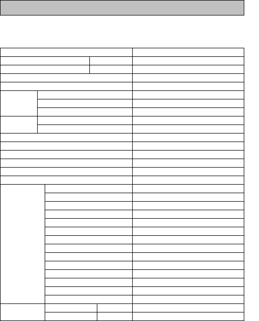
1.1 SPECIFICATION
MR-385R-A
MR-385R-A(NZ)
Power supply 230/240V 50Hz
Total capacity (Gross (AS)) L
Dimensions (HXWXD) mm. 1591 x 685 x 700
Cabinet Acrylic resin coated steel
Food liner ABS resin
Cabinet Foamed cyclopenthane
Freezer door Foamed cyclopenthane
Refrigerator door Foamed cyclopenthane
Cooling system Freezer Forced air convection
Refrigerator Surround cooling,multi air flow,front air flow
Evaporator Fin and tube type
Condenser Concealed type
Defrost system Automatic (Heater defrost)
Drain Automatic (drainage)
Temperature control system Automatic control
Refrigerator room light 240V 15W (E12)
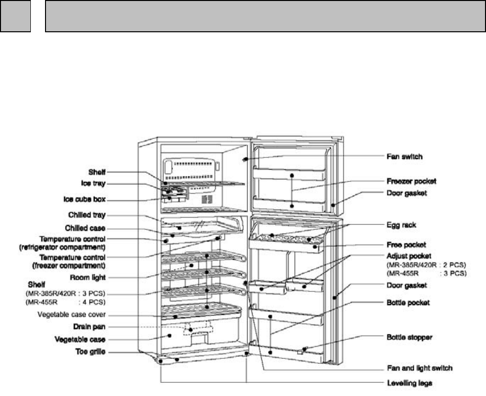
Ice tray 1 pc.
Ice box 1 pc.
Freezer pocket 2 pcs.
Slide chilled case 1 pc.
Crystal shelf (F) 1 pc.
Crystal shelf (R) 3 pcs.
Free pocket 1 pc.
Egg rack 2 pcs.
Adjust pocket 2 pcs.
Bottle pocket 2 pcs.
Vegetable case 1 pc.
Tray V 1 pc.
Drain pan 1 pc.
Bottle stopper 1 pc.
Weight Unit kg 65
Shipping kg 72
- 1 -
Insulation
Accessories
385 (F : 130 R : 255)
1 SPECIFICATION
MR-420R-A
MR-420R-A(NZ)
Power supply 230/240V 50Hz
Total capacity (Gross (AS)) L
Dimensions (HXWXD) mm. 1696 x 685 x 700
Cabinet Acrylic resin coated steel
Food liner ABS resin
Cabinet Foamed cyclopenthane
Freezer door Foamed cyclopenthane
Refrigerator door Foamed cyclopenthane
Cooling system Freezer Forced air convection
Refrigerator Surround cooling,multi air flow,front air flow
Evaporator Fin and tube type
Condenser Concealed type
Defrost system Automatic (Heater defrost)
Drain Automatic (drainage)
Temperature control system Automatic control
Refrigerator room light 240V 15W (E12)
Ice tray 1 pc.
Ice box 1 pc.
Freezer pocket 2 pcs.
Slide chilled case 1 pc.
Crystal shelf (F) 1 pc.
Crystal shelf (R) 3 pcs.
Free pocket 1 pc.
Egg rack 2 pcs.
Adjust pocket 2 pcs.
Bottle pocket 2 pcs.
Vegetable case 1 pc.
Tray V 1 pc.
Drain pan 1 pc.
Bottle stopper 1 pc.
Weight Unit kg 69
Shipping kg 73
- 2 -
Insulation
Accessories
420 (F : 130 R : 290)

MR-455R-A
MR-455R-A(NZ)
Power supply 230/240V 50Hz
Total capacity (Gross (AS)) L
Dimensions (HXWXD) mm. 1806 x 685 x 700
Cabinet Acrylic resin coated steel
Food liner ABS resin
Cabinet Foamed cyclopenthane
Freezer door Foamed cyclopenthane
Refrigerator door Foamed cyclopenthane
Cooling system Freezer Forced air convection
Refrigerator Surround cooling,multi air flow,front air flow
Evaporator Fin and tube type
Condenser Concealed type
Defrost system Automatic (Heater defrost)
Drain Automatic (drainage)
Temperature control system Automatic control
Refrigerator room light 240V 15W (E12)
Ice tray 2 pcs.
Ice box 1 pc.
Freezer pocket 2 pcs.
Slide chilled case 1 pc.
Crystal shelf (F) 1 pc.
Crystal shelf (R) 4 pcs.
Free pocket 1 pc.
Egg rack 2 pcs.
Adjust pocket 3 pcs.
Bottle pocket 2 pcs.
Vegetable case 1 pc.
Tray V 1 pc.
Drain pan 1 pc.
Bottle stopper 1 pc.
Weight Unit kg 73
Shipping kg 79
- 3 -
Insulation
Accessories
454 (F : 130 R : 324)

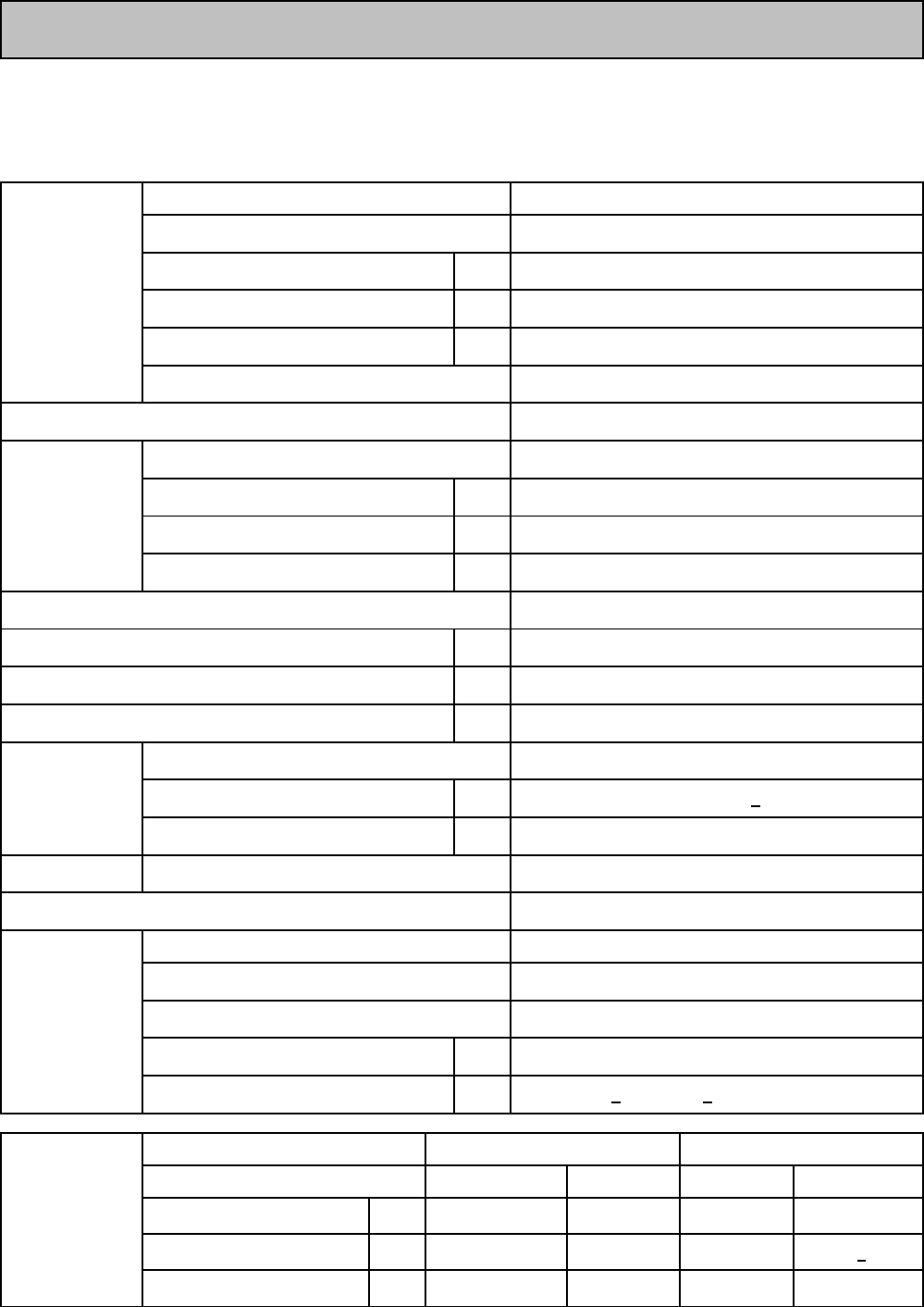
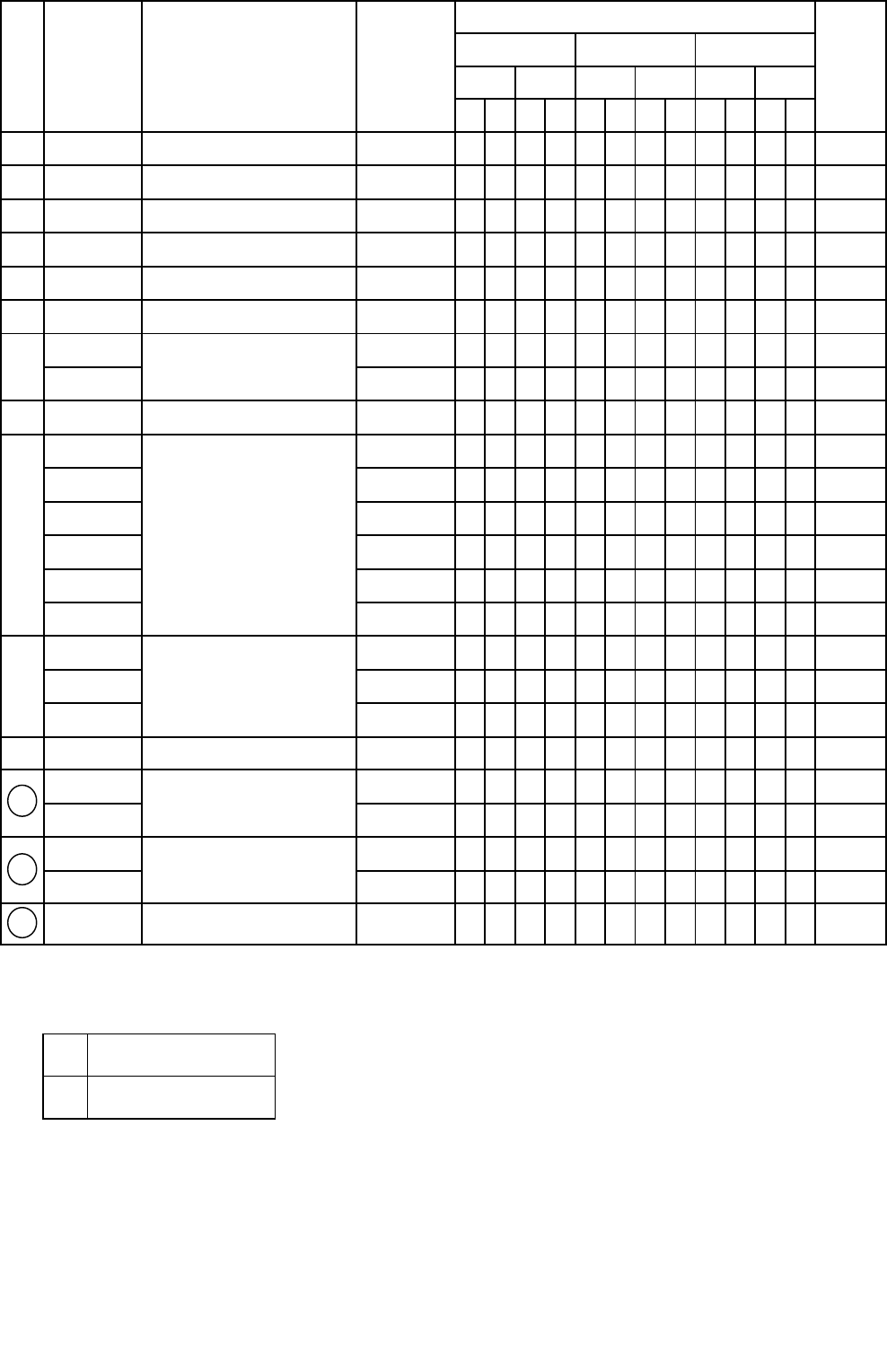
1.2 ELECTRICAL PARTS SPECIFICATION
MR-385R-A
MR-385R-A(NZ)
Model
Power supply
Compressor Rated input W
Starting current A
Running current A
Winding resistance (T : 20 oC)
PTC RELAY
Model
Motor protector Ambient temperature oC
Time Sec.
Current A
Running capacitor
Capillary tube mm.
Dehydrant Molecular sieve g
Refrigerant HFC. 134a g
Defrosting control Defrosting timer
Defrost finish oC
Thermal fuse oC
Heater Defrost heater
Deodorition
Model
Type
Number of poles
Input W
Revolution r.p.m
Model Freezer Refrigerator (MM1-6177)
Dial position ON OFF OPEN SHUT
Warmer oC-13.7 -19.0 - 3.5
Normal oC-16.9 -22.9 MAX 5.0 -1.0 + 1.5
Colder oC-20.4 -27.5 - -12.5
Fan motor
Temperature control
- 4 -
DG57C96RAW5
106/108(220/240V 50Hz)
7.38/8.01(220/240V 50Hz)
0.57/0.55(220/240V 50Hz)
18.2 Ω(Main) / 17.7 Ω(Aux)
PTH7M330MD2
5TM181NHBYY
Less than 10.2/12 (220/240V 50Hz)
2520 + 200 / 2580+200 (220/240V 50Hz)
2p
25
16 MAX
5.4
4µF 400VAC
Single phase
∅ 1.8 X ∅ 0.7 X 2350
10
384 Ω(240V 150W)
Filter
220/240V 50Hz
UDVH15MA1H
145
Control board
Thermister 14 + 1.5
73

MR-420R-A
MR-420R-A(NZ)
Model
Power supply
Compressor Rated input W
Starting current A
Running current A
Winding resistance (T : 20 oC)
PTC RELAY
Model
Motor protector Ambient temperature oC
Time Sec.
Current A
Running capacitor
Capillary tube mm.
Dehydrant Molecular sieve g
Refrigerant HFC. 134a g
Defrosting control Defrosting timer
Defrost finish oC
Thermal fuse oC
Heater Defrost heater
Deodorition
Model
Type
Number of poles
Input W
Revolution r.p.m
Model Freezer Refrigerator (MM1-6177)
Dial position ON OFF OPEN SHUT
Warmer oC-13.7 -19.0 - 3.5
Normal oC-16.9 -22.9 MAX 5.0 -1.0 + 1.5
Colder oC-20.4 -27.5 - -12.5
Fan motor
Temperature control
- 5 -
DG66C11RAW5
117/118(220/240V 50Hz)
8.05/8.83(220/240V 50Hz)
0.71/0.66(220/240V 50Hz)
15.4 Ω(Main) / 17.7 Ω(Aux)
PTH7M330MD2
5TM205NHBYY
Less than 10.2/12 (220/240V 50Hz)
2520 + 200 / 2580+200 (220/240V 50Hz)
2p
25
16 MAX
6.0
4µF 400VAC
Single phase
∅ 1.8 X ∅ 0.7 X 2350
10
384 Ω(240V 150W)
Filter
220/240V 50Hz
UDVH15MA1H
145
Control board
Thermister 14 + 1.5
73
MR-455R-A
MR-455R-A(NZ)
Model
Power supply
Compressor Rated input W
Starting current A
Running current A
Winding resistance (T : 20 oC)
PTC RELAY
Model
Motor protector Ambient temperature oC
Time Sec.
Current A
Running capacitor
Capillary tube mm.
Dehydrant Molecular sieve g
Refrigerant HFC. 134a g
Defrosting control Defrosting timer
Defrost finish oC
Thermal fuse oC
Heater Defrost heater
Deodorition
Model
Type
Number of poles
Input W
Revolution r.p.m
Model Freezer Refrigerator (MM1-6177)
Dial position ON OFF OPEN SHUT
Warmer oC-13.7 -19.0 - 3.5
Normal oC-16.9 -22.9 MAX 5.0 -1.0 + 1.5
Colder oC-20.4 -27.5 - -12.5
Temperature control
- 6 -
Less than 10.2/12 (220/240V 50Hz)
2520 + 200 / 2580+200 (220/240V 50Hz)
DD66C13RAW5
127/131(220/240V 50Hz)
8.3/9.1(220/240V 50Hz)
Fan motor
UDVH15MA1H
Single phase
2p
4µF 400VAC
0.63/0.61(220/240V 50Hz)
12 Ω(Main) / 28.7 Ω(Aux)
Filter
∅ 1.8 X ∅ 0.7 X 2350
10
145
Control board
384 Ω(240V, 150W)
220/240V 50Hz
Thermister 14 + 1.5
73
25
16 MAX
6.0
PTH7M330MD2
5TM205NHBYY
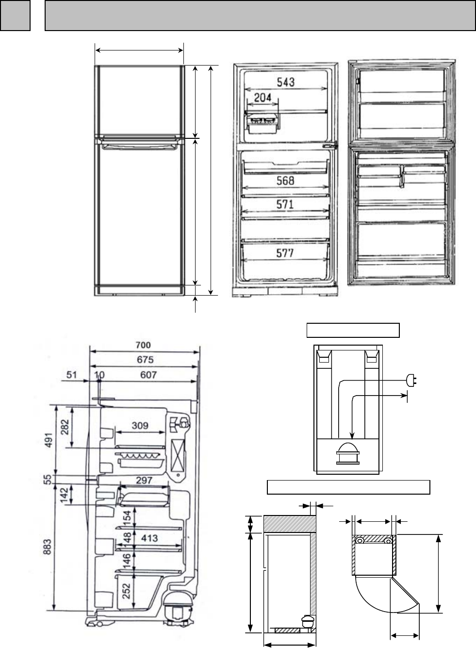
Unit : mm
MR-385R-A
MR-385R-A(NZ)
- 7 -
2 OUTLINES AND DIMENSIONS
20
685
20
1334
454
40
100
1591
700
REQUIRED SPACE FOR INSTALLATION
1950
PLUG CORD LENGTH
568
685
81591
942
73

Unit : mm
MR-420R-A
MR-420R-A(NZ)
- 8 -
PLUG CORD LENGTH
REQUIRED SPACE FOR INSTALLATION
20685
20
1334
454
40
100
1696
700
1950
568
685
81696
1047
73

Unit : mm
MR-455R-A
MR-455R-A(NZ)
- 9 -
PLUG CORD LENGTH
REQUIRED SPACE FOR INSTALLATION
20685
20
1334
454
40
100
1806
700
1950
568
685
81806
1157
73

(SKELETON WIRING DIAGRAM)
MR-385R-A
MR-385R-A(NZ)
MR-420R-A
MR-420R-A(NZ)
MR-455R-A
MR-455R-A(NZ)
(ACTUAL WIRING DIAGRAM)
3 WIRING DIAGRAM
- 10 -

MR-385R-A MR-420R-A
MR-385R-A(NZ) MR-420R-A(NZ)
- 11 -
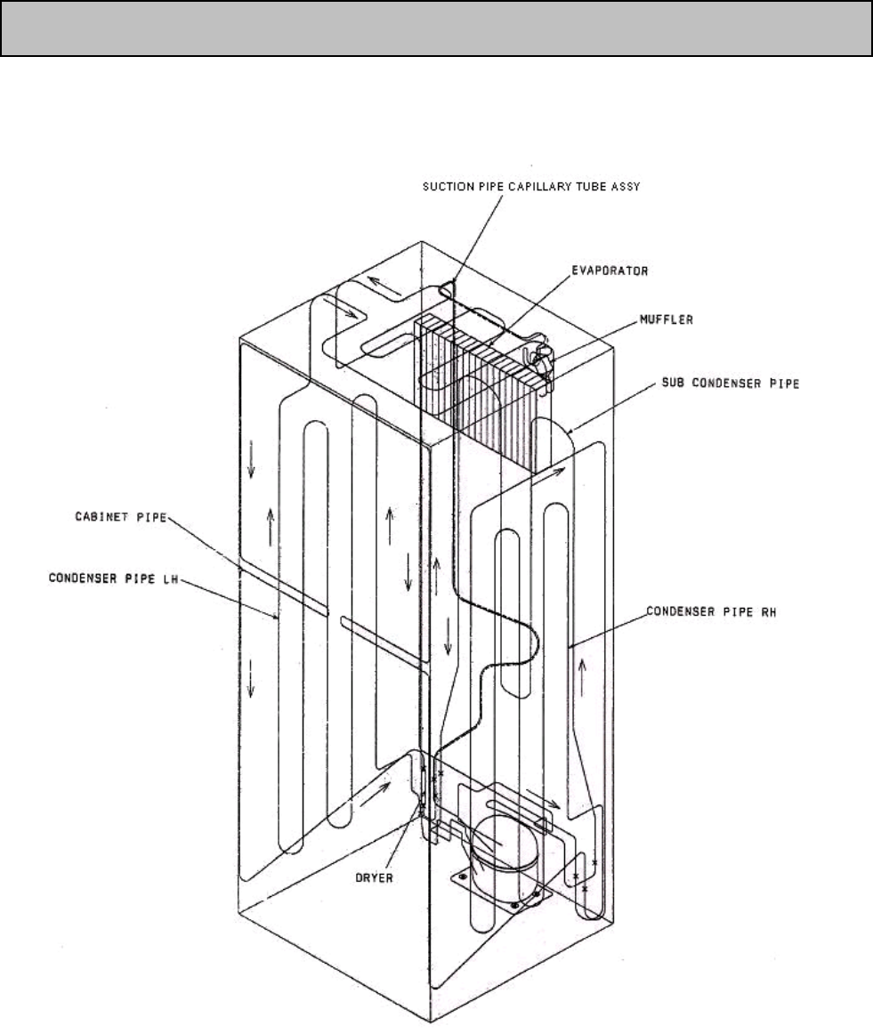
4 REFRIGERANT CIRCUIT
MR-455R-A
MR-455R-A(NZ)
- 12 -
MR-385R-A
MR-385R-A(NZ)
MR-420R-A
MR-420R-A(NZ)
MR-455R-A
MR-455R-A(NZ)
- 13 -
5 NAME OF PARTS

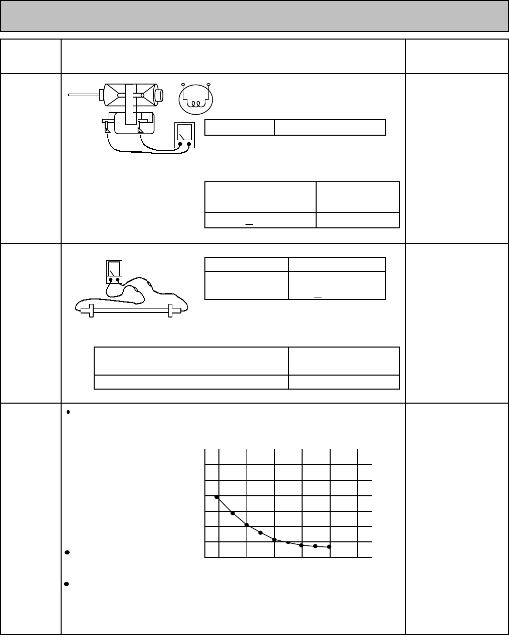
6.1 TROUBLE CRITERION OF MAIN PARTS
MR-385R-A MR-420R-A MR-455R-A
MR-385R-A(NZ) MR-420R-A(NZ) MR-455R-A(NZ)
Compressor
Measure the resistance with a tester.
(Ambient temperature:Room temperature 15oC ~ 25oC)
In the control
panel of the
Measure the resistance with a tester. refrigerator
compartment
Model
Measure the resistance with a tester.(Ambient temperature:Room temperature 15oC ~ 25oC)
PTC RELAY
PTH7M330MD2
Measure the resistance with a tester.
(Ambient temperature:Room temperature 15oC ~ 25oC)
Normal abnormal(faulty)
As PTC Relay has been heated while refrigerator is running be sure
to measure the resistance after the thermistor has got cool enough.
6 TROUBLE SHOOTING
69 + 9o C
120 + 5o C
400VAC
Run capacitor
Opened (∞Ω )
W
Rated input
Compressor in
Opened (∞Ω )
69 + 9o C
Motor
protector
120 + 5o C
- 14 -
33 Ω (Approx.)
Connected
Point
Model
Normal abnormal(faulty)
Less than 1Ω
Opened (∞Ω ) or Short (0Ω)
rear side of
the frame
Starting current
Running current A
chamber at the
Compressor in
the machine
chamber at the
rear side of
the machine
the machine
chamber at the
Components/
Part Name
Model
Parts Mounted
Position
Check Method and Criterion
DG57C96RAW5
MR-420R,455RMR-385R
DG66C11RAW5
the frame
Compressor in
rear side of
the frame
Abnormal
(faulty)
Close
Open
Normal
Main wiring
Auxilliary wiring 17.7 Ω (Approx.)
5TM181NHBYY 5TM205NHBYY
abnormal(faulty)
A
Opened(∞ Ω )
RU
Short (0Ω)
7.38/8.01(220/240V 50Hz)
0.57/0.55(220/240V 50Hz)
Normal
MR-385R MR-420R,455R
18.2 Ω (Approx.)
17.7 Ω (Approx.)
15.4 Ω (Approx.)
117/118(220/240V 50Hz)
8.05/8.83(220/240V 50Hz)
0.71/0.66(220/240V 50Hz)
106/108(220/240V 50Hz)
Short (0Ω )
MR-420R,455RMR-385R
Rated input
Auxilialy
wiring
Main
wiring
5
6
3
2
5
6
2
3
Fan grill of the
freezer compartment.
Measure the resistance with a tester.
(Ambient temperature:Room temperature 15oC ~ 25oC)
In the drip tray under
the evaporator of the
freezer compartment
Measure the resistance with a tester.
(Ambient temperature:Room temperature 15oC ~ 25oC)
Resistance measured under Defrost thermistors
the ambient temperature from Thermistor resistance radiator
-50: to +50: (kΩ)against temperature of the freezer
compartment.
1. 200" to 500k" F-thermistor, control
............normal panel of the refrigerator
2. Out of the above range compartment.
............abnormal
Thermistor Check Procedure
Thermistor resistance will vary
with the change of temperature. (oC)
Take the temperature around the thermistor, Temperature
and then measure resistance using a tester.
The relation of resistance and temperature is as shown on the above graph.
- 15 -
Short (0Ω)
Rated input 150 W
operation method Power ON after defrosting
(14 + 1.5oC or more)
10
Thermistor
30
Opened ( ∞ Ω )
Defrost
Heater
Abnormal (faulty)Normal
384Ω (Approx.)
-20 -10 0 20
abnormal(faulty)
Refrigerator
fan motor
560+ 10% ( Ω )
UDVH15MA1H
Model
Normal
Check Method and Criterion Parts Mounted Position
Components/
Part Name
5
10
15
20
25
30
Resistance
6.2 HOW TO CHECK P.C BOARDS
MR-385R-A MR-420R-A MR-455R-A
MR-385R-A(NZ) MR-420R-A(NZ) MR-455R-A(NZ)
(1) Precautions
Unplug unit before checking
If the controller P.C. board box is opened with the refrigerator inside
cooled, dew will form on the control board, causing trouble such as
poor insulation.
The following cares must be taken when servicing.
1. Be sure to unplug the power cord before servicing.
2. Wipe away droplets on the control board box with dry cloth,
and dry it up before setting a new controller P.C board.
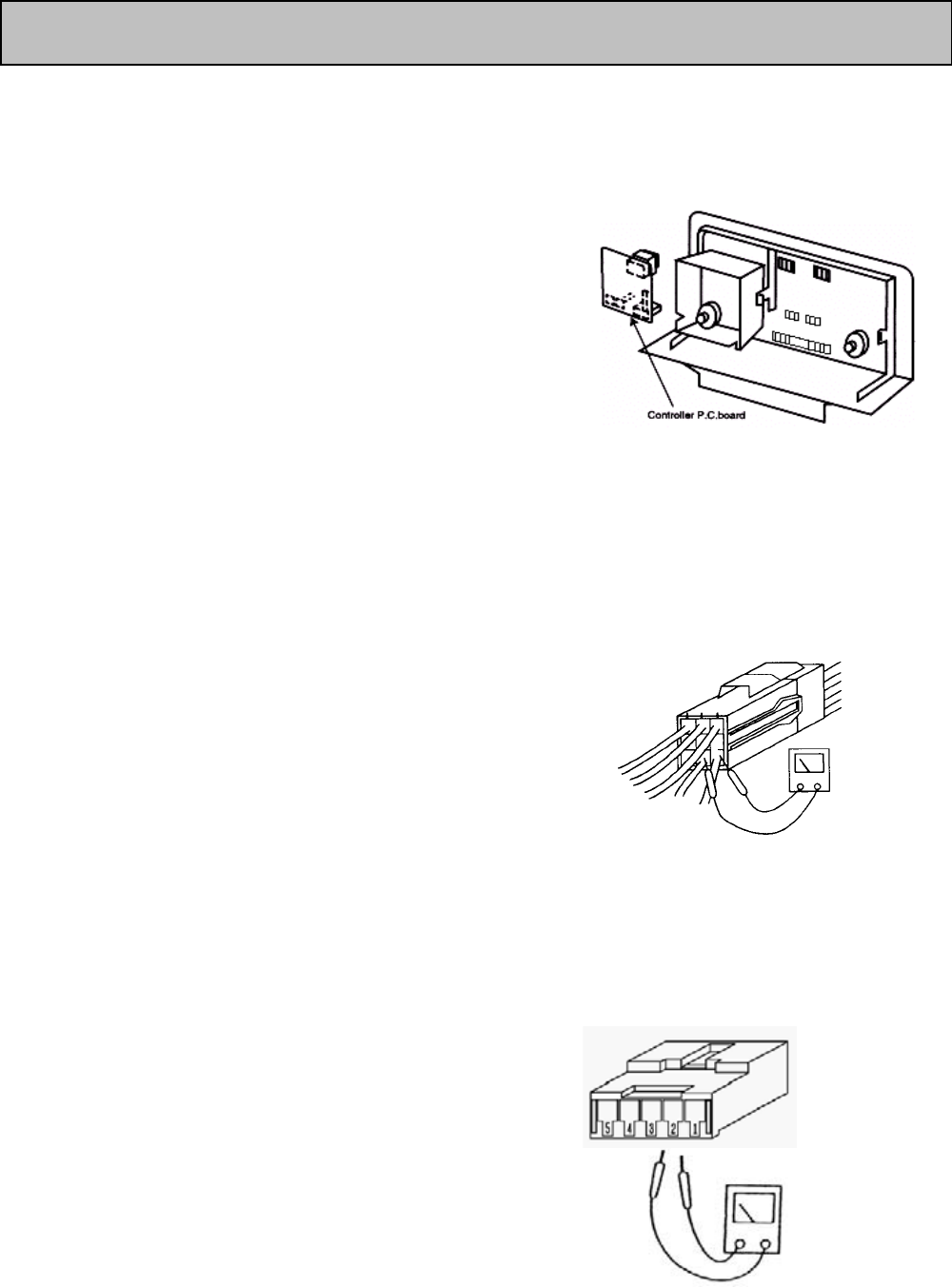
(2) How to check the controller P.C board and vicinity.
The control board box can be checked without opening the box.
Measure the voltage and resistance using 8 connectors outside
the box. How to check with connectors
1. Check for 230/240V output during power on. POWER ON
Make the pin No.7,9 of the 9 pins white connector as a common pin,
and measure the voltage between the common pin and
another pin.
Make sure that 230/240V is output
Note: The room light always has 230/240V.
2. Check for "thermistor" output during power on.
5 pins white connector
Make the pin No.1 of the 5 pin white connector as a
common pin, and measure the voltage between the common
pin and another pin.
Make sure that 2-3 VDC is output.
POWER OFF
3.Check for weak current wiring during power off
5 pins white connector
Remove the connector, and measure the resistance across
-No.1 pin and No.2 pin to confirm the continuity for DEF
thermistor.
-No.1 pin and No.3 pin to confirm the continuity for the
Freezer thermistor.
- 16 -

6.3 TEST POINT DIAGRAM OF MAIN CONTROL BOARD
MR-385R-A MR-420R-A MR-455R-A
MR-385R-A(NZ) MR-420R-A(NZ) MR-455R-A(NZ)
- 17 -

6.4 Malfunction Display and Checking points.
6.4.1 ) Malfunction display will use LED for show self-check
6.4.2 ) Fucntion display
6.4.3 ) Repairing and check point
* A the case below , if the analysis result has malfunction over 2 points and will express in the list has more importance.
Function display Cause Analysis result Check point Corrective Priority Repairing
2. Check the resistance of thermistor Change part
2. Check the resistance of thermistor Change part
2. Check the resistance of defrost heater Change part
3. Check the resistance of temp. fuse Change part
Caution
1. Before plug in the AC power , Be ensure the comp had been off more than 20 min.
Improve in contact
Improve in contact
1. Check connector of control PCB CN1 ,
relay connector temp. fuse
3
2
1
Improve in contact
LED display self - check
Malfunction display
Lighting mode
1 time
2 times
3 times Defrost unfinished
with in 2 hours
Fault trouble of defrost thermistor
Fault trouble of freezer thermistor
Fault trouble of defrost heater
Open circuit or short
circuit case
Open circuit or short
circuit case
- 18 -
2. The consider short circuit or open circuit of thermistor , resistance of open circuit is ∞ Ω , resistance of short circuit is 0Ω
1. Check connector of control PCB CN5 , relay
connector 6 pin
1. Check connector of control PCB CN5 ,
relay connector 2 pin
ON
OFF
5 Sec.
Cycle
2 times1 time
Cycle Cycle Cycle
5 Sec. 5 Sec. 5 Sec.
1 time
1 time1 time 2 times
2 times 2 times

6.5 Importance detail of fault analysis
6.5.1 Flow chart of self - check
1) Self - check monitor circuit
For show the fault condition of refrigerator and clarify point. Therefore, self - check monitor control is provided
that are able to monitor No. of blinking condition with electric circuit and electric part . Before disconnect power plug please
confirm LED self - check .
"CONTROL PANEL"
LED show shelf - check
Caution
1. As the part list below couldn't analysis by self - check , then
please check by reference to trouble shooting page.
- Dilapidation of door switch ,refrigerator room and freezer room.
- Dilapidation of compressor and fan motor .
2. If have malfunction when supply the power . Compressor and
fan motor will not operate 20 minutes.
2) Interval of self check analysis
- Troubles of thermistor : will check always.
- Trouble of defrost heater : will just analyse during defrost display only.
(The period checking will analyse the defrost circuit after connect the plug 2 hours )
- 19 -
Refrigerator plug
connect?
Connect power plug
Self - check
Mal Function Display
(No .of blinking)
No change on display Normal operation
Check the fault point as
malfunction list
Disconnect power plug
Repair the macfunction cause
Connect power plug
No
Yes
Yes
No

MR-385R-A MR-420R-A MR-455R-A
MR-385R-A(NZ) MR-420R-A(NZ) MR-455R-A(NZ)
Unplug the power cord before prepairing and servicing
1. Remove parts insider the Freezer room
(1) Photo 1st Remove Crystal shelf Freezer,
Fan Grille
(2) Photo 2nd Remove scews for closing Lead cover F,
Remove 2 Rivets From Fan grille
(3) Photo 3rd Cut binder, remove poly bag, Take off
connector lead wire.
Fan motor
(4) Photo 4th Remove Fan motor after remove fan and
remove screw out of fan motor base.
Defrost thermal fuse and Freezer thermistor
(5) Photo 4th Remove fan grille out of bell mouth, remove
the connector and plug to take out the thermal fuse and
thermistor freezer.
Defrost heater and Drip tray
(6)
out of base after remove heater cover plate and drip tray
Caution on assembly
(7) 1. Insert the fan into the base of fan motor's shaft, check
if the fan rotates with your finger.
2. When inserted drip tray to effect to slacken the lead
wire of defrost heater in order to prevent water from
entering the glass tube.
3. Attach defrost thermistor with muffler and lighten the
binder.
- 20 -
PHOTO
DISASSEMBLY INSTRUCTIONS
Photo 5th Lift up evaporator and remove the defrost heater
Ice corner tray assy, Ice tray, Ice box
7
OPERATION PROCEDURE
Photo 1
Photo 5
Photo 2
Photo 3
Photo 4
Crystal shelf F
Ice box Ice corner tray assy
Ice tray
Screw
Lead cover F
Rivets
Binder
Bag
Connector lead wire
Fan motor
Fan grille
Evaporator
Defrost heater
Def thermistor
Heater cover
Drip tray
Screw
Bell mouth
Thermal fuse

2. Remove parts inside the refrigerator
(1) Remove chilled case door and slide chilled case ,
remove crystal shelf of refrigerator room , remove the
control panel
(Photo 6)
(2) Remove lamp cover R
(Photo 6)
(3) Remove screw and rivet , pull the control panel with
to right refrigerator wall.
(Photo 6)
(4) Pick the aluminium tape and sealing tape, remove
PC Board
(Photo 7)
(5) Remove duct R assy, damper thermo is installed
within it.
(Photo 7)
Remove the screw of damper thermo
Caution on assembly
1. Be sure to use new sealing materials and tape for
assembly.
- 21 -
OPERATION PROCEDURE PHOTO
2. Attach the sealing material of refcon assy and attach
the aluminium tape everytimes for protective moisture.
Photo 6
Photo 7
Rivets
Thermo dial R
Lamp cover R Screws
Control panel Thermo dial F
Aluminium tape
Duct R assy
Sealing tape
PC Board

3. Removing the compressor
(1) Detach the drain pan.
Compressor
(2) Collect gas from the charge pipe on the high pressure side.
(3) After collecting gas, cut the charge pipe on the low pressure side.
(4) Detach the welded section of the discharge pipe and suction pipe
(5) Replace the compressor and the dryer at a time. (The dryer should be the one packed with the compressor.)
CAUTION ON ASSEMBLY
After replacement check cooling operation and check the weld for gas leaking.
Fig<MR-385R,420R,455R>
OPERATING PROCEDURE
- 22 -
Suction pipe
w
Binder
Dr
y
er
Discharge pipe
(High pressure side)
U Washer
Char
g
e
p
i
p
e
: This mark shows welding point.
w
w
w
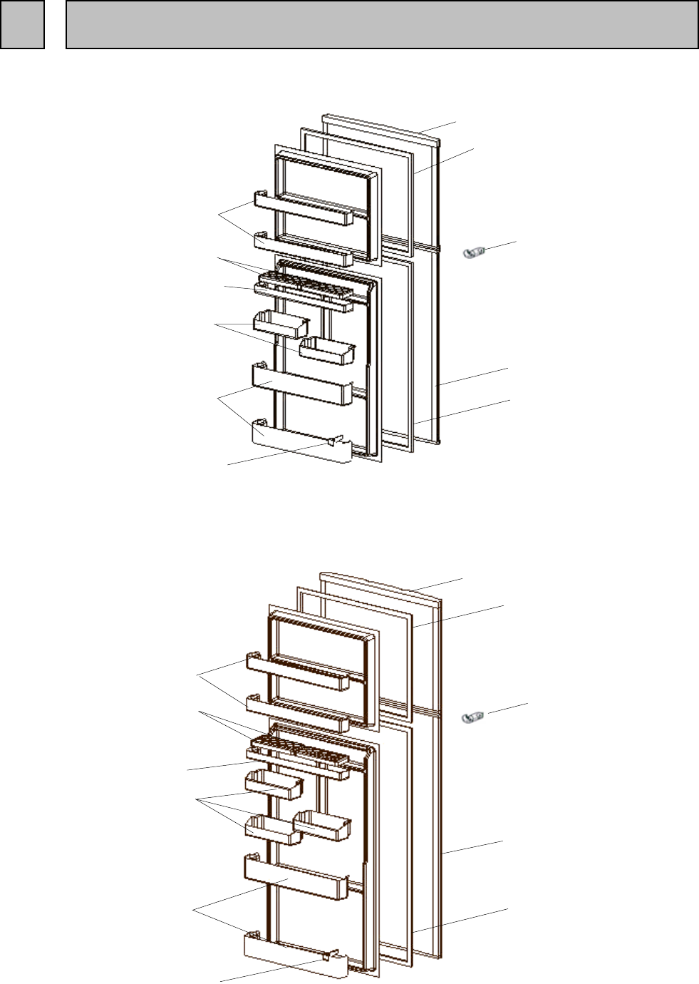
DOOR, BODY PARTS
MR-385R-A
MR-385R-A(NZ)
MR-420R-A
MR-420R-A(NZ)
MR-455R-A
MR-455R-A(NZ)
- 23 -
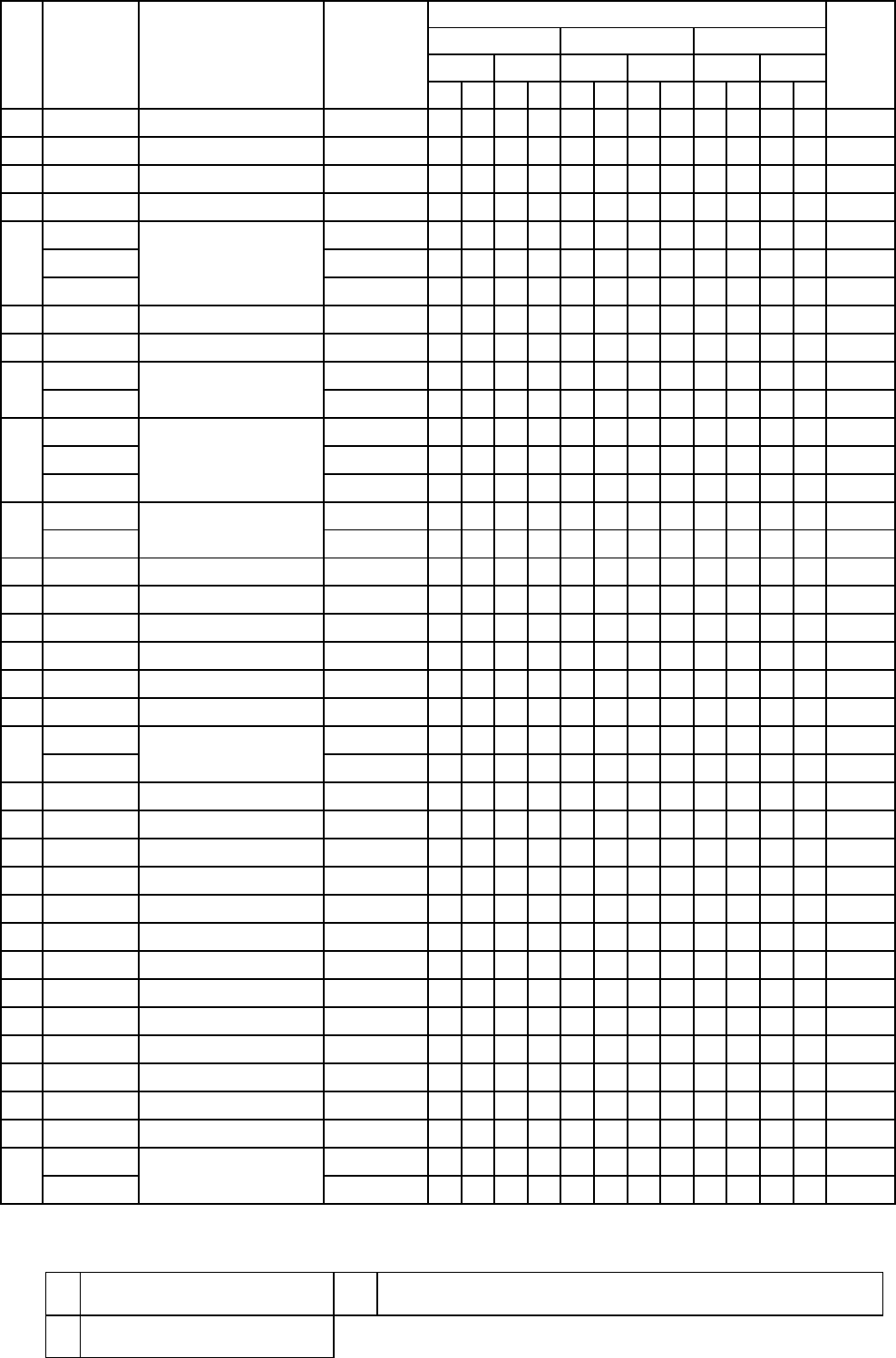
8 PARTS LIST
1
2
3
4
5
6
10
9
11
7
8
1
2
4
510
9
11
8
7
6
3
WSTWSTWSTWSTWSTWST
1 KIEJ62131 FREEZER POCKET 222222222222
2 KIE401115 EGG RACK 222222222222
3 KIEJ62118 FREE POCKET 111111111111
4 KIEJ62159 ADJUST POCKET 222222223333
5 KIEJ62124 BOTTLE POCKET 222222222222
6 KIEH88143 BOTTLE STOPPER 111111111111
KIEJ81001 111111
KIEJ82001 111111
8 KIEH79111 MAGNET GASKET ASSY (F) 111111111111
KIEJ81000 1 1
KIEJ82000 1 1
KIEJ83000 1 1
KIEJ84000 1 1
KIEJ85000 1 1
KIEJ86000 1 1
KIEH79110 1111
KIEH82110 1111
KIEH85110 1111
11 KIEG05741 CATCHER 111111111111
KIEJ81011 111111
KIEJ82011 111111
KIEJ81010 111111
KIEJ82010 111111
14 KIEJ79031 BADGE ASSY 111111111111
RECOMMEND PART NO. 7, 8, 9, 10
ABBREVIATION
ENCIRCLED PART NUMBER ARE NOT SHOWN IN THE FIGURES.
- 24 -
HANDLE COVER R
HANDLE BODY
12
13
7 DOOR F
9
10
DOOR R
MAGNET GASKET ASSY (R)
PART NO. PART NAMENO. 385R
A A(NZ) PRICESPEC
Q'TY/UNIT
420R 455R
A A(NZ) A A(NZ)
F
R
FREEZER ROOM
REFRIGERATOR ROOM

ACCESSORY PARTS
MR-385R-A
MR-385R-A(NZ)
MR-420R-A
MR-420R-A(NZ)
MR-455R-A
MR-455R-A(NZ)
- 25 -
1
2
3
4
5
6
7
17
18
22
23
25
9
8
10
11
12
13
30
22
31
27
26
14
15
19
20
21
24
29
28
1
2
3
4
6
7
8
10
12
13
14
15
29 30
31
28
22
27
26
25
24
23
22
21
20
19
18
17
11
9
5
16
16
WSTWSTWSTWSTWSTWST
1 KIEH79662 BELL MOUTH 111111111111
2 KIEJ81473 LAMP COVER (F) 111111111111
3 KIEH79663 FAN GRILLE 111111111111
4 KIEH79450 ICE CORNER ASSY 111111111111
KIEH79665 1111
KIEH82665 1111
KIEH85665 1111
6 KIEH79411 SLIDE CHILLED CASE 111111111111
7 KIEJ81850 CONTROL PANEL 111111111111
KIEH79305 11111111
KIEHK4305 1111
KIEH79853 1111
KIEH82853 1111
KIEH85853 1111
KIEJ62470 1111
KIEJ65470 11111111
11 KIEH79420 CRYSTAL SHELF (R) 333333334444
12 KIEJ81468 TRAY V 111111111111
13 KIEJ62405 VEGETABLE CASE 111111111111
14 KIEH79435 DRAIN PAN 111111111111
15 KIE805794 CASTER SET 222222222222
16 KIEH79326 LEAD COVER F 111111111111
KIEJ81705 1 1 1 1 1
KIEJ82705 111111
18 KIEJ81701 HINGE ASSY (UPPER) 111111111111
19 KIEH79431 CRYSTAL SHELF (F) 111111111111
20 KIEH79440 ICE TRAY 111111111111
21 KIEH79467 ICE BOX 111111111111
22 KIEB66746 STOPPER HINGE 222222222222
23 KIEE94703 HINGE ASSY (MIDDLE) 111111111111
24 KIEJ62418 CHILLED CASE DOOR 111111111111
25 KIEH79416 TRAY C 111111111111
26 KIEH79315 THERMO DIAL (F) 111111111111
27 KIEH79474 VITAMIN GUARD 111111111111
28 KIEE94702 HINGE ASSY (LOWER) 111111111111
29 KIEH79795 CASTER ASSY 222222222222
30 KIEC02460 ADJUST BOLT 222222222222
KIEJ81730 1 1 1 1 1
KIEJ82730 111111
RECOMMEND PART NO. 2, 3, 4, 5, 6, 11, 13, 19, 20, 21, 24, 25
ABBREVIATION
KICK PLATE31
8
9
10
17 HINGE COVER
455R
A A(NZ) A A(NZ) A A(NZ)
- 26 -
NO. PART NAMEPART NO.
5
SPEC
Q'TY/UNIT
PRICE
385R 420R
DUCT R ASSY
THERMO DIAL (R)
CONTROL PANEL (SUB)
LAMP COVER (R)
F
RREFRIGERATOR ROOM
FREEZER ROOM VBETWEEN REFRIGERATOR ROOM AND VEGETABLE ROOM

ELECTRICIAL PARTS AND UNIT PARTS
MR-385R-A
MR-385R-A(NZ)
MR-420R-A
MR-420R-A(NZ)
MR-455R-A
MR-455R-A(NZ)
- 27 -
1
2
4
3
5
6
9
7
10
8
11
13
12
14
15
16
15
17
18
20
19
27
21
22
23
24
26
25
28
30
29
31

WSTWSTWSTWSTWSTWST
1 KIEH79336 THERMAL FUSE ( DEF ) 111111111111
2 KIEH85995 EVAPORATOR 111111111111
3 KIEH79537 HEATER ROOF 111111111111
4 KIEHM2392 DEFROST HEATER ASSY 240V, 150W NOT
DEODORIZER 111111111111
5 KIEB66397 HEATER COVER 111111111111
6 KIE402360 LAMP E17 240V I5W 111111111111
7 KIEH79538 DRIP TRAY 111111111111
8 KIEH79301 DAMPER THERMO MM1-6177 111111111111
KIEJ81277 DG57C96RAW5 1111
KIEJ82277 DG66C11RAW5 11111111
10 KIE902735 U WASHER 333333333333
11 KIEE76797 RUBBER MOUNT 444444444444
12 KIEH79312 THERMISTOR (DEF) 111111111111
13 KIEH79378 THERMISTOR (F) 111111111111
14 KIEH79323 MOTOR ATTACH 111111111111
15 KIE401329 FAN MOTOR BUSH 222222222222
16 KIEC02320 FAN MOTOR UDVH15MA1H 111111111111
17 KIECD4362 FAN SWITCH 111111111111
18 KIEHD2386 LAMP SOCKET(R) 111111111111
19 KIEG01321 FAN 111111111111
20 KIEA53346 RUNNING CAPACITOR 4µF, 400VAC 111111111111
21 KIEJ81339 REFCON ASSY 111111111111
22 KIEH82336 THERMAL FUSE 111111111111
23 KIEH79363 LAMP SWITCH ( R ) 111111111111
24 KIEJ81354 PLUG CORD ASSY 111111111111
25 KIEJ81807 CONNECTOR BOX 111111111111
26 KIEAA1980 DRYER 4AXH-9,10GR 111111111111
27 KIEG05341 PROTECTOR COVER 111111111111
KIEJ62340 5TM181NHBYY 1111
KIEJ83340 5TM205NHBYY 11111111
29 KIEE76330 PTC RELAY PTH7MM330MD2 111111111111
30 KIEH61399 FILTER 111111111111
31 KIEHJ3311 THERMITOR (A.T.) 111111111111
RECOMMEND PART NO. 1, 6, 9, 10, 13, 14, 22, 23, 27, 29, 30
ABBREVIATION
- 28 -
NO. PART NO. PRICESPEC
28 MOTOR PROTECTOR
Q'TY/UNIT
A A(NZ)
420R 455R
A A(NZ)
9 COMPRESSOR
A A(NZ)
PART NAME 385R
F
R
FREEZER ROOM
REFRIGERATOR ROOM
DEF DEFROST

PACKING PART
MR-385R-A MR-385R-A(NZ)
MR-420R-A MR-420R-A(NZ)
MR-455R-A MR-455R-A(NZ)
- 29 -
NO STEP ON
123
L
R
1
C.F.B BOX ASSY
8
C.F.B TOP COVER
5
SIDE CUSHION ASSY
4
PACKING COVER
7
C.F.B PALLET
6
BOTTOM CUSHION
3
TOP CUSHION MID
2
TOP CUSHION
REFRIGERATOR

WSTWSTWSTWSTWSTWST
KIEJ81970 1
KIEJ82970 1
KIEJ83970 1
KIEJ84970 1
KIEJ85970 1
KIEJ86970 1
KIEJL4970 1
KIEJL5970 1
KIEJL6970 1
KIEJL7970 1
KIEJL8970 1
KIEJL9970 1
2 KIEJ81979 TOP CUSHION 111111111111
3 KIEH79972 TOP CUSHION MID 111111111111
4 KIEG55973 PACKING COVER 111111111111
5 KIEJ81971 SIDE CUSHION ASSY 111111111111
6 KIEH79978 BOTTOM CUSHION 111111111111
7 KIEH79974 C.F.B PALLET 111111111111
8 KIEH79975 C.F.B TOP COVER 111111111111
A(NZ)
1
A A(NZ) A A(NZ)
SPEC
Q'TY/UNIT
- 30 -
PRICE
C.F.B BOX ASSY
NO. PART NO. PART NAME 385R 420R 455R
A

MITSUBISHI ELECTRIC CORPORATATION
HEAD OFFICE : MITSUBISHI DENKI BLDG., MARUNOUCHI,TOKYO 100. TELEX : J24532 CABLE MELCO TOKYO
Distributed by
BLACK DIAMOND TECHNOLOGIES LIMITED (BDT)
Wellington Office (Head Office) Auckland Office Christchurch Office
1 Parliament Street Unit1, 4 Walls Road Suite 2, Level 1
PO Box 30-772 Penrose 37 Manderville Street
Lower Hutt Auckland PO Box 12-726 Chistchurch PO Box 1604
Ph : (04) 560 9100 Ph: (09) 526 9340 Ph : (03) 341 7052
Fax : (04) 560 9133 Fax : (09) 526 9369 Fax : (03) 341 7054
