Mitsubishi 1CW940 Servo Motor Instruction Manual User To The 0f6c6c20 368e 46cc 8b62 Db841420da26
User Manual: Mitsubishi 1CW940 to the manual
Open the PDF directly: View PDF ![]() .
.
Page Count: 456 [warning: Documents this large are best viewed by clicking the View PDF Link!]
- Safety Instructions
- About processing of waste
- COMPLIANCE WITH EC DIRECTIVES
- CONFORMANCE WITH UL/C-UL STANDARD
- CONTENTS
- 1. INTRODUCTION
- 2. INSTALLATION
- 3. CONNECTORS USED FOR SERVO MOTOR WIRING
- 4. INSPECTION
- 5. SPECIFICATIONS
- 6. CHARACTERISTICS
- 7. OUTLINE DIMENSION DRAWINGS
- 7.1 Servo motors
- 7.1.1 HC-MF HC-KF series
- 7.1.2 HA-FF series
- 7.1.3 HC-SF HC-SFS series
- 7.1.4 HC-RF HC-RFS series
- 7.1.5 HC-UF 2000r/min HC-UFS 2000r/min series
- 7.1.6 HC-UF 3000r/min series
- 7.1.7 HC-UF3000r/min, HC-UFS3000r/min series with IP65-compliant connectors
- 7.1.8 HA-LH series
- 7.1.9 HC-AQ series
- 7.1.10 HA-LF series
- 7.1.11 HC-MFS HC-KFS series
- 7.1.12 HC-UFS 3000r/min series
- 7.1.13 HA-LFS series
- 7.1.14 HC-LFS series
- 7.2 Servo motors (in inches)
- 7.2.1 HC-MF HC-KF series
- 7.2.2 HA-FF series
- 7.2.3 HC-SF HC-SFS series
- 7.2.4 HC-RF HC-RFS series
- 7.2.5 HC-UF 2000r/min HC-UFS 2000r/min series
- 7.2.6 HC-UF 3000r/min series
- 7.2.7 HC-UF3000r/min, HC-UFS3000r/min series with IP65-compliant connectors
- 7.2.8 HA-LH series
- 7.2.9 HC-AQ series
- 7.2.10 HA-LF series
- 7.2.11 HC-MFS HC-KFS series
- 7.2.12 HC-UFS 3000r/min series
- 7.2.13 HA-LFS series
- 7.2.14 HC-LFS series
- 7.3 Connector
- 7.1 Servo motors
- 8. CALCULATION METHODS FOR DESIGNING
- 8.1 Specification symbol list
- 8.2 Position resolution and electronic gear setting
- 8.3 Speed and command pulse frequency
- 8.4 Stopping characteristics
- 8.5 Capacity selection
- 8.6 Load torque equations
- 8.7 Expression for calculating the electromagnetic brake workload
- 8.8 Load inertia moment equations
- 8.9 Precautions for zeroing
- 8.10 Selection example
- APPENDIX
- REVISIONS

L
Servo Motor Instruction Manual
SH (NA) 3181-L (0805) MEE Printed in Japan Specifications subject to change without notice.
This Instruction Manual uses recycled paper.
MODEL
MODEL
CODE 1CW940
MOTOR INSTRUCTION
General-Purpose AC Servo
MODEL
Servo Motor
INSTRUCTION MANUAL
L
HEAD OFFICE : TOKYO BLDG MARUNOUCHI TOKYO 100-8310
A - 1
Safety Instructions
(Always read these instructions before using the equipment.)
Do not attempt to install, operate, maintain or inspect the servo amplifier and servo motor until you have read
through this Instruction Manual, MELSERVO Servo Amplifier Installation Guide/Instruction Manual and
appended documents carefully and can use the equipment correctly. Do not use the servo amplifier and servo
motor until you have a full knowledge of the equipment, safety information and instructions.
In this Instruction Manual, the safety instruction levels are classified into "WARNING" and "CAUTION".
WARNING Indicates that incorrect handling may cause hazardous conditions,
resulting in death or severe injury.
CAUTION Indicates that incorrect handling may cause hazardous conditions,
resulting in medium or slight injury to personnel or may cause physical
damage.
Note that the CAUTION level may lead to a serious consequence according to conditions. Please follow the
instructions of both levels because they are important to personnel safety.
What must not be done and what must be done are indicated by the following diagrammatic symbols.
: Indicates what must not be done. For example, "No Fire" is indicated by .
: Indicates what must be done. For example, grounding is indicated by .
In this Instruction Manual, instructions at a lower level than the above, instructions for other functions, and so
on are classified into "POINT".
After reading this installation guide, always keep it accessible to the operator.
A - 2
1. To prevent electric shock, note the following
WARNING
Before wiring or inspection, turn off the power and wait for 15 minutes or more until the charge lamp turns
off. Then, confirm that the voltage between P and N is safe with a voltage tester and others. Otherwise,
an electric shock may occur. In addition, always confirm from the front of the servo amplifier, whether the
charge lamp is off or not.
Connect the servo amplifier and servo motor to ground.
Any person who is involved in wiring and inspection should be fully competent to do the work.
Do not attempt to wire the servo amplifier and servo motor until they have been installed. Otherwise, you
may get an electric shock.
Operate the switches with dry hand to prevent an electric shock.
The cables should not be damaged, stressed loaded, or pinched. Otherwise, you may get an electric
shock.
During power-on or operation, do not open the front cover of the servo amplifier. You may get an electric
shock.
Do not operate the servo amplifier with the front cover removed. High-voltage terminals and charging area
are exposed and you may get an electric shock.
Except for wiring or periodic inspection, do not remove the front cover of the servo amplifier even if the
power is off. The servo amplifier is charged and you may get an electric shock.
2. To prevent fire, note the following.
CAUTION
Install the servo amplifier, servo motor and regenerative resistor on incombustible material. Installing them
directly or close to combustibles will lead to a fire.
Always connect a magnetic contactor (MC) between the main circuit power supply and L1, L2, and L3 of
the servo amplifier, and configure the wiring to be able to shut down the power supply on the side of the
servo amplifier’s power supply. If a magnetic contactor (MC) is not connected, continuous flow of a large
current may cause a fire when the servo amplifier malfunctions.
When a regenerative resistor is used, use an alarm signal to switch main power off. Otherwise, a
regenerative transistor fault or the like may overheat the regenerative resistor, causing a fire.
3. To prevent injury, note the follow
CAUTION
Only the voltage specified in the Instruction Manual should be applied to each terminal, Otherwise, a
burst, damage, etc. may occur.
Connect the terminals correctly to prevent a burst, damage, etc.
Ensure that polarity ( , ) is correct. Otherwise, a burst, damage, etc. may occur.
Take safety measures, e.g. provide covers, to prevent accidental contact of hands and parts (cables, etc.)
with the servo amplifier heat sink, regenerative resistor, servo motor, etc. since they may be hot while
power is on or for some time after power-off. Their temperatures may be high and you may get burnt or a
parts may damaged.
During operation, never touch the rotating parts of the servo motor. Doing so can cause injury.
A - 3
4. Additional instructions
The following instructions should also be fully noted. Incorrect handling may cause a fault, injury, electric
shock, etc.
(1) Transportation and installation
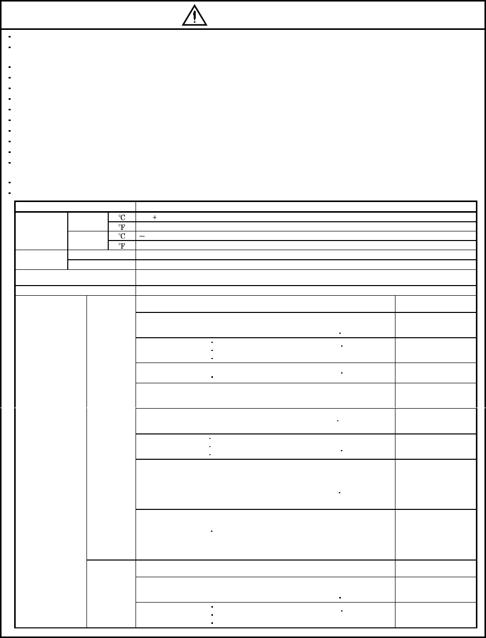
CAUTION
Transport the products correctly according to their weights.
Use the eye-bolt of the servo motor to only transport the servo motor and do not use it to transport in the
condition to have installed a servo motor on the machine.
Stacking in excess of the specified number of products is not allowed.
Do not carry the servo motor by the cables, shaft or encoder.
Do not hold the front cover to transport the servo amplifier. The servo amplifier may drop.
Install the servo amplifier in a load-bearing place in accordance with the Instruction Manual.
Do not climb or stand on servo equipment. Do not put heavy objects on equipment.
The servo motor must be installed in the specified direction.
Leave specified clearances between the servo amplifier and control enclosure walls or other equipment.
Do not install or operate the servo motor which has been damaged or has any parts missing.
Do not block the intake/exhaust port of the servo motor which has a cooling fan.
Provide adequate protection to prevent screws and other conductive matter, oil and other combustible matter
from entering the servo amplifier and servo motor.
Do not drop or strike servo motor. Isolate from all impact loads.
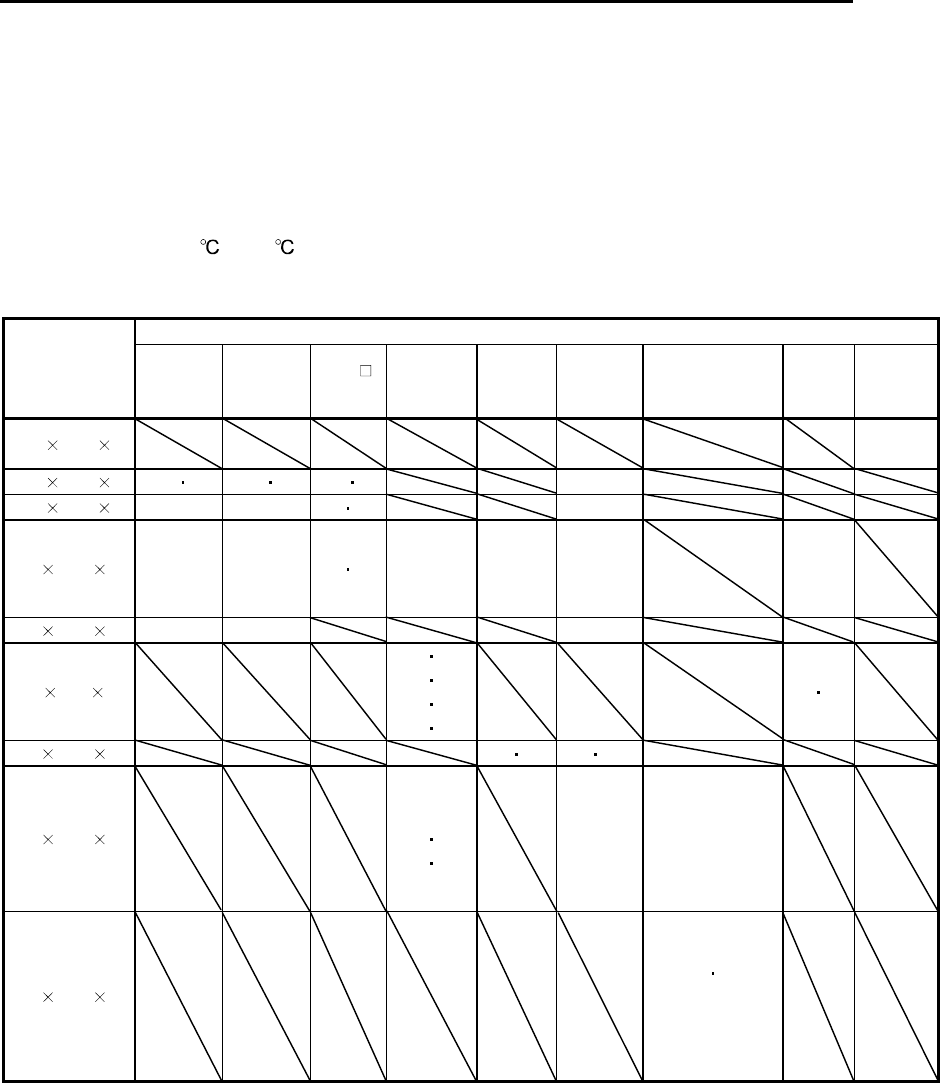
When you keep or use it, please fulfill the following environmental conditions.
Environment Conditions
[] 0 to 40 (non-freezing)
In
Operation [] 32 to 104 (non-freezing)
[ ] 15 to 70 (non-freezing)
Ambient
temperature In Storage [] 5 to 158 (non-freezing)
In Operation 80%RH or less (non-condensing)
Ambient
humidity In Storage 90%RH or less (non-condensing)
Ambience Indoors (no direct sunlight)
Free from corrosive gas, flammable gas, oil mist, dust and dirt
Altitude Max. 1000m (3280 ft) above sea level
HC-KFS series
HC-MFS series HC-UFS13 to 73 X,Y:49
HC-SFS81
HC-SFS52 to 152
HC-SFS53 to 153
HC-SFS524 to 1524
HC-RFS series
HC-UFS72 152
X,Y:24.5
HC-SFS121 201
HC-SFS202 352
HC-SFS203 353
HC-SFS2024 3524
HC-UFS202 to 502
X:24.5
Y:49
HC-SFS301
HC-SFS502 702 HC-SFS5024 7024 X:24.5
Y:29.4
HC-AQ series
HC-KF series
HC-MF series
HA-FF series
HC-UF13 to 73 X,Y:19.6
HC-SF81
HC-SF52 to 152
HC-SF53 to 153
HC-RF series
HC-UF72 152
HC-LFS52 to 152
X:9.8
Y:24.5
HC-SF121 201
HC-SF202 352
HC-SF203 353
HC-UF202 to 502
HC-LFS202 302
X:19.6
Y:49
HA-LFS601 to 12K1
HA-LFS701M to 15K1M
HA-LFS502 to 22K2
HA-LFS6014 to 12K14
HA-LFS701M4 to 15K1M4
HA-LFS11K24 to 22K24
HA-LH11K2 to 22K2
HC-SF301
HC-SF502 702
X:11.7
Y:29.4
[m/s2]
HA-LFS15K1 to 37K1
HA-LFS22K1M to 37K1M
HA-LFS30K2 37K2
HA-LFS15K14 to 37K14
HA-LFS22K1M4 to 50K1M4
HA-LFS30K24 to 55K24
HA-LF series X,Y:9.8
HC-KFS series
HC-MFS series HC-UFS13 to 73 X,Y:161
HC-SFS81
HC-SFS52 to 152
HC-SFS53 to 153
HC-SFS524 to 1524
HC-RFS series
HC-UFS72 152
X,Y:80
(Note) Vibration
[ft/s2]
HC-SFS121 201
HC-SFS202 352
HC-SFS203 353
HC-SFS2024 3524
HC-UFS202 to 502
X:80
Y:161
A - 4
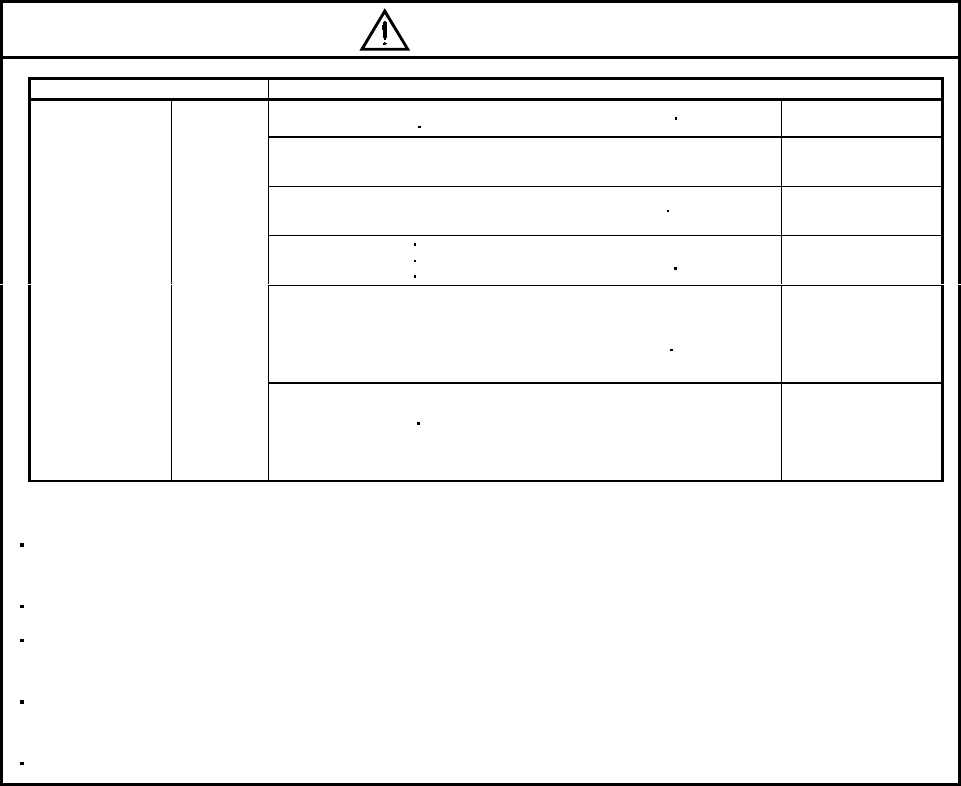
CAUTION
Environment Conditions
HC-SFS301
HC-SFS502 702 HC-SFS5024 7024 X:80
Y:96
HC-AQ series
HC-KF series
HC-MF series
HA-FF series
HC-UF13 to 73 X,Y:64
HC-SF81
HC-SF52 to 152
HC-SF53 to 153
HC-RF series
HC-UF72 152
HC-LFS52 to 152
X:32
Y:80
HC-SF121 201
HC-SF202 352
HC-SF203 353
HC-UF202 to 502
HC-LFS202 302
X:64
Y:161
HA-LFS601 to 12K1
HA-LFS701M to 15K1M
HA-LFS502 to 22K2
HA-LFS6014 to 12K14
HA-LFS701M4 to 15K1M4
HA-LFS11K24 to 22K24
HA-LH11K2 to 22K2
HC-SF301
HC-SF502 702
X:38.4
Y:96.5
(Note) Vibration [ft/s2]
HA-LFS15K1 to 37K1
HA-LFS22K1M to 37K1M
HA-LFS30K2 37K2
HA-LFS15K14 to 37K14
HA-LFS22K1M4 to 50K1M4
HA-LFS30K24 to 55K24
HA-LF series X,Y:32
Note. Except the servo motor with reduction gear.
Securely attach the servo motor to the machine. If attach insecurely, the servo motor may come off during
operation.
The servo motor with reduction gear must be installed in the specified direction to prevent oil leakage.
Take safety measures, e.g. provide covers, to prevent accidental access to the rotating parts of the servo
motor during operation.
Never hit the servo motor or shaft, especially when coupling the servo motor to the machine. The encoder
may become faulty.
Do not subject the servo motor shaft to more than the permissible load. Otherwise, the shaft may break.
A - 5
(2) Wiring
CAUTION
Wire the equipment correctly and securely. Otherwise, the servo motor may operate unexpectedly.
Do not install a power capacitor, surge absorber or radio noise filter (FR-BIF option) between the servo
motor and servo amplifier.
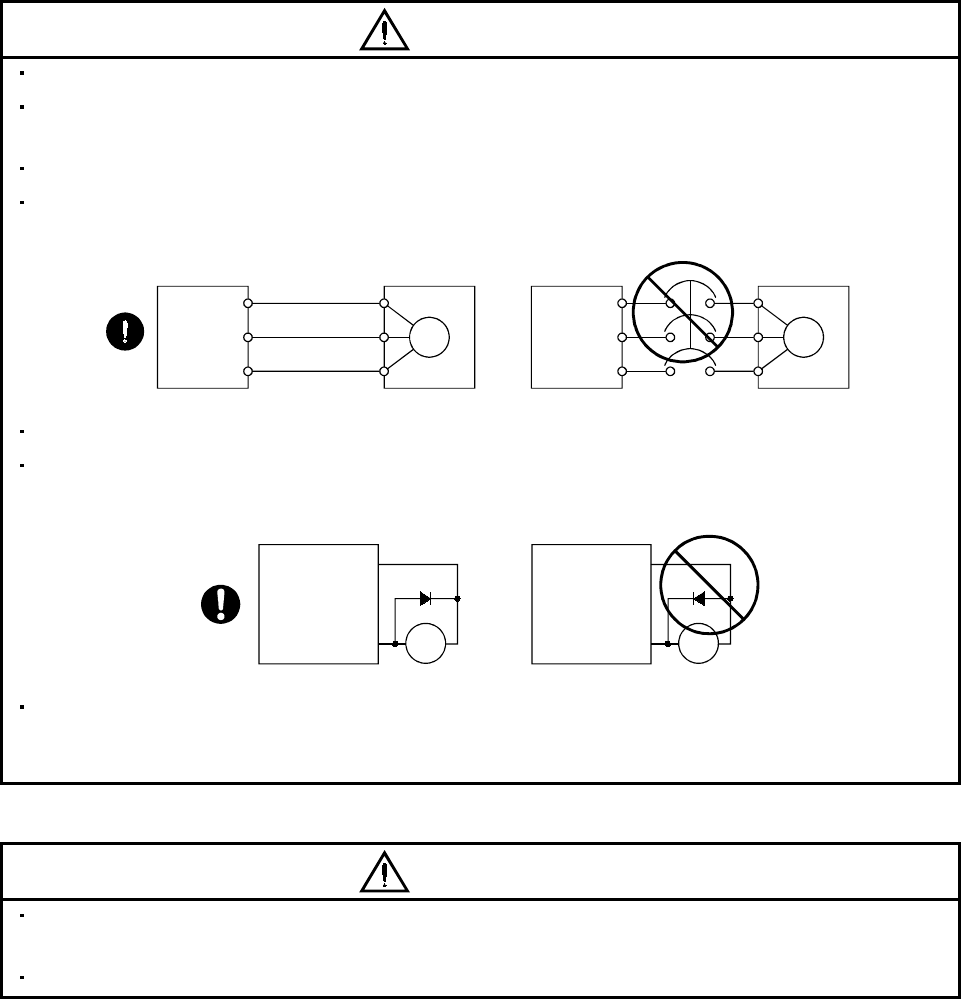
Connect the output terminals (U, V, W) correctly. Otherwise, the servo motor will operate improperly.
Connect the servo motor power terminal (U, V, W) to the servo motor power input terminal (U, V, W)
directly. Do not let a magnetic contactor, etc. intervene.
U
Servo motor
M
V
W
U
V
W
U
M
V
W
U
V
W
Servo amplifier Servo motorServo amplifier
Do not connect AC power directly to the servo motor. Otherwise, a fault may occur.
The surge absorbing diode installed on the DC output signal of the servo amplifier relay must be wired in
the specified direction. Otherwise, the forced stop and other protective circuits may not operate.
VIN
(24VDC)
Servo amplifier
RA
Control
output
signal
VIN
(24VDC)
Servo amplifier
RA
Control
output
signal
When the cable is not tightened enough to the terminal block (connector), the cable or terminal block
(connector) may generate heat because of the poor contact. Be sure to tighten the cable with specified
torque.
(3) Test run adjustment
CAUTION
Before operation, check the parameter settings. Improper settings may cause some machines to perform
unexpected operation.
The parameter settings must not be changed excessively. Operation will be insatiable.
A - 6
(4) Usage
CAUTION
Provide an external emergency stop circuit to ensure that operation can be stopped and power switched
off immediately.
Any person who is involved in disassembly and repair should be fully competent to do the work.
The STOP key of the parameter unit is only valid for test run. Provide an emergency stop key
independently of the STOP key. (MELSERVO-H series only)
Before resetting an alarm, make sure that the run signal into the servo amplifier is off to prevent an
accident. A sudden restart is made if an alarm is reset with the run signal on.
Do not modify the equipment.
Use a noise filter, etc. to minimize the influence of electromagnetic interference, which may be caused by
electronic equipment used near the servo amplifier.
Burning or breaking a servo amplifier may cause a toxic gas. Do not burn or break a servo amplifier.
Use the servo amplifier with the specified servo motor.
The electromagnetic brake on the servo motor is designed to hold the servo motor shaft and should not
be used for ordinary braking.
For such reasons as service life and mechanical structure (e.g. where a ball screw and the servo motor
are coupled via a timing belt), the electromagnetic brake may not hold the servo motor shaft. To ensure
safety, install a stopper on the machine side.
(5) Corrective actions
CAUTION
When it is assumed that a hazardous condition may take place at the occur due to a power failure or a
product fault, use a servo motor with electromagnetic brake or an external brake mechanism for the
purpose of prevention.
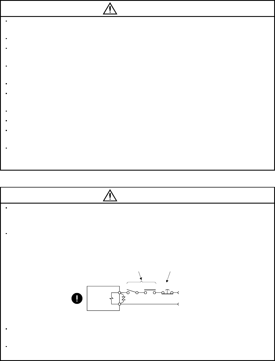
Configure the electromagnetic brake circuit so that it is activated not only by the servo amplifier signals
but also by an external emergency (forced) stop signal.
Contacts must be open when
servo-on signal is off, when an
alarm (trouble) is present and when
an electromagnetic brake signal.
Electromagnetic brake
Circuit must be
opened during
emergency (force) stop.
SON RA EMG(EM1)
24VDC
Servo motor
When any alarm has occurred, eliminate its cause, ensure safety, and deactivate the alarm before
restarting operation.
When power is restored after an instantaneous power failure, keep away from the machine because the
machine may be restarted suddenly (design the machine so that it is secured against hazard if restarted).
A - 7
(6) Maintenance, inspection and parts replacement
CAUTION
With age, the electrolytic capacitor of the servo amplifier will deteriorate. To prevent a secondary accident
due to a fault, it is recommended to replace the electrolytic capacitor every 10 years when used in general
environment.
Please consult our sales representative.
(7) Storage
CAUTION
Note the following points when storing the servo motor for an extended period of time (guideline: three or
more months).
Always store the servo motor indoors in a clean and dry place.
If it is stored in a dusty or damp place, make adequate provision, e.g. cover the whole product.
If the insulation resistance of the winding decreases, reexamine the storage method.
Though the servo motor is rust-proofed before shipment using paint or rust prevention oil, rust may be
produced depending on the storage conditions or storage period.
If the servo motor is to be stored for longer than six months, apply rust prevention oil again especially to
the machined surfaces of the shaft, etc.
Before using the product after storage for an extended period of time, hand-turn the motor output shaft to
confirm that nothing is wrong with the servo motor. (When the servo motor is equipped with a brake,
make the above check after releasing the brake with the brake power supply.)
When the equipment has been stored for an extended period of time, consult Mitsubishi.
(8) General instruction
CAUTION
To illustrate details, the equipment in the diagrams of this Instruction Manual may have been drawn
without covers and safety guards. When the equipment is operated, the covers and safety guards must
be installed as specified. Operation must be performed in accordance with this Instruction Manual.
A - 8
About processing of waste
When you discard servo amplifier, a battery (primary battery), and other option articles, please follow the law of
each country (area).
FOR MAXIMUM SAFETY
These products have been manufactured as a general-purpose part for general industries, and have not
been designed or manufactured to be incorporated in a device or system used in purposes related to
human life.
Before using the products for special purposes such as nuclear power, electric power, aerospace,
medicine, passenger movement vehicles or under water relays, contact Mitsubishi.
These products have been manufactured under strict quality control. However, when installing the product
where major accidents or losses could occur if the product fails, install appropriate backup or failsafe
functions in the system.
EEP-ROM life
The number of write times to the EEP-ROM, which stores parameter settings, etc., is limited to 100,000. If
the total number of the following operations exceeds 100,000, the servo amplifier and/or converter unit may
fail when the EEP-ROM reaches the end of its useful life.
Write to the EEP-ROM due to parameter setting changes
Write to the EEP-ROM due to device changes
Precautions for Choosing the Products
Mitsubishi will not be held liable for damage caused by factors found not to be the cause of Mitsubishi;
machine damage or lost profits caused by faults in the Mitsubishi products; damage, secondary damage,
accident compensation caused by special factors unpredictable by Mitsubishi; damages to products other
than Mitsubishi products; and to other duties.
COMPLIANCE WITH EC DIRECTIVES
1. WHAT ARE EC DIRECTIVES?
The EC Directives were issued to standardize the regulations of the EU countries and ensure smooth
distribution of safety-guaranteed products. In the EU countries, the Machinery Directive (effective in
January, 1995), EMC Directive (effective in January, 1996) and Low Voltage Directive (effective in
January, 1997) of the EC Directives require that products to be sold should meet their fundamental safety
requirements and carry the CE marks (CE marking). CE marking applies to machines and equipment
into which servo amplifiers have been installed.
The servo amplifiers do not function independently but are designed for use with machines and
equipment.
Therefore, the CE marking does not apply to the servo amplifiers but applies to the machines and
equipment into which the servo amplifiers are installed.
This servo amplifier conforms to the standards related to the Low Voltage Directive to facilitate CE
marking on machines and equipment into which the servo amplifiers will be installed. To ensure ease of
compliance with the EMC Directive, Mitsubishi Electric prepared the "EMC INSTALLATION
GUIDELINES" (IB(NA)67310) which provides servo amplifier installation, control box making and other
procedures. Please contact your sales representative.
A - 9
2. PRECAUTIONS FOR COMPLIANCE
Use the servo motor compatible with the EN Standard.
Unless otherwise specified, the handling, performance, specifications and others of the EN Standard-
compatible models are the same as those of the standard models.
To comply with the EN Standard, also observe the following items strictly.
(1) Wiring
(a) Use a fixed terminal block to connect the power supply lead of the servo motor to the servo
amplifier. Do not connect cables directly.
Terminal block
(b) Use the servo motor side power connector which complies with the EN Standard.
The EN Standard-compliant power connector sets are available from us as options.
Power Connector Set Model Servo Motor Model
MR-PWCNF HC-FF C(B)-UE
MR-PWCNS1 HC-SF81(B)
HC-SF52(B) to 152(B)
HC-SF53(B) to 153(B)
HC-RF103(B) to 203(B)
HC-UF72(B) 152(B)
HC-SFS81(B)
HC-SFS52(B) to 152(B)
HC-SFS53(B) to 153(B)
HC-SFS524(B) to 1524(B)
HC-RFS103(B) to 203(B)
HC-UFS72(B) 152(B)
HC-LFS52(B) to 152(B)
MR-PWCNS2 HC-SF121(B) to 301(B)
HC-SF202(B) to 502(B)
HC-SF203(B) 353(B)
HC-RF353(B) 503(B)
HC-UF202(B) to 502(B)
HC-SFS121(B) to 301(B)
HC-SFS202(B) to 502(B)
HC-SFS203(B) 353(B)
HC-SFS2024(B) to 5024(B)
HC-RFS353(B) 503(B)
HC-UFS202(B) to 502(B)
HA-LFS502
HC-LFS202(B) 302(B)
MR-PWCNS3 HC-SF702(B) HC-SFS702(B)
HC-SFS7024(B)
HA-LFS702
(2) Installation
The flange of the machine mounted with the HC-MF(HC-MF-UE)/HC-KF(HC-KF-UE)/HC-AQ/HC-
MFS/HC-KFS must be connected to the earth ( ).
(3) Performing EMC tests
When EMC tests are run on a machine/device into which the servo motor has been installed, it must
conform to the electromagnetic compatibility (immunity/emission) standards after it has satisfied the
operating environment/electrical equipment specifications.
For the other EMC directive guidelines on the servo motor, refer to the EMC Installation Guidelines
(IB(NA)67310).
A - 10
CONFORMANCE WITH UL/C-UL STANDARD
Use the UL/C-UL Standard-compliant model of servo motor.
Unless otherwise specified, the handling, performance, specifications, etc. of the UL/C-UL Standard-
compliant models are the same as those of the standard models.
The servo motor is compliant with the UL/C-UL standard when it is mounted on the flanges made of
aluminum whose sizes are indicated in the following table.
The rated torque of the servo motor under the UL/C-UL standard indicates the continuous permissible
torque value that can be generated when it is mounted on the flange specified in this table and used in
the environment of 0 to 40 ambient temperature. Therefore, to conform to the UL/C-UL standard,
mount the servo motor on a flange with a heat radiating effect equivalent to that of this flange.
Servo Motor
Flange Size
[mm] HC-KF(-UE)
HC-KFS
HC-MF(-UE)
HC-MFS
HA-FF C
-UE
(Note 2)
HC-SF
HC-SFS
HC-RF
HC-RFS
HC-UF
HC-UFS
HA-LF
HA-LFS HC-LFS HC-AQ
150 150 3 0135 to
0335
150 150 6 053 13 053 13 053 13 13
250 250 623 23 2333 23
250 250 12 43 43 43 63
81
52 to 152
53 to 153
524 to 1524
103 to 203 43 52 to 152
300 300 12 (Note 1) 73 73 73
300 300 20
121 201
202 352
203 353
2024 3524
202 302
550 550 30 353 503 72 152
650 650 35
301
502 702
5024 7024
202 to 502
601 to 12K1
701M to 15K1M
502 to 22K2
6014 to 12K14
701M4 to 15K1M4
11K24 to 22K24
950 950 35
15K1 to 37K1
22K1M to 37K1M
30K2 37K2
15K14 to 37K14
22K1M4 to
50K1M4
30K24 to 55K24
Note 1. 73 is not available for the HC-KF(-UE) series.
2. 524 to 7024 are not available for the HC-SF series.
1
CONTENTS
1. INTRODUCTION 1 - 1 to 1 -16
1.1 Servo motor features .............................................................................................................................. 1 - 1
1.2 Model name make-up............................................................................................................................. 1 - 2
1.3 Parts identification................................................................................................................................ 1 -15
2. INSTALLATION 2 - 1 to 2 -14
2.1 Environmental conditions...................................................................................................................... 2 - 2
2.2 Installation orientation.......................................................................................................................... 2 - 4
2.3 Load remove precautions....................................................................................................................... 2 - 4
2.4 Permissible load for the shaft................................................................................................................ 2 - 5
2.4.1 Without reduction gear ................................................................................................................... 2 - 5
2.4.2 With reduction gear......................................................................................................................... 2 - 7
2.5 Protection from oil and water............................................................................................................... 2 -11
2.6 Cooling fan..............................................................................................................................................2 -13
2.7 Cable ....................................................................................................................................................... 2 -13
3. CONNECTORS USED FOR SERVO MOTOR WIRING 3 - 1 to 3 -20
3.1 Makeups .................................................................................................................................................. 3 - 1
3.1.1 HC-KF(-UE) HC-MF(-UE) HA-FF HC-UF3000r/min series ................................................ 3 - 1
3.1.2 HA-FF C-UE series........................................................................................................................ 3 - 1
3.1.3 HC-SF(S) HC-RF(S) HC-UF(S)2000r/min, HA-LH HA-LF HA-LFS HC-LFS series..... 3 - 7
3.1.4 HC-AQ series................................................................................................................................... 3 -15
3.1.5 HC-KFS HC-MFS HC-UFS3000r/min series .......................................................................... 3 -15
3.1.6 HC-UF3000r/min series (Compliance with IP65) ....................................................................... 3 -16
3.2 IP65, EN Standard-compliant options ................................................................................................ 3 -17
3.3 Signal arrangement of encoder connectors ......................................................................................... 3 -19
4. INSPECTION 4 - 1 to 4 - 2
5. SPECIFICATIONS 5 - 1 to 5 -50
5.1 Standard specifications.......................................................................................................................... 5 - 1
5.2 Torque characteristics........................................................................................................................... 5 -23
5.3 Servo motors with reduction gears ......................................................................................................5 -41
5.4 Servo motors with special shafts.......................................................................................................... 5 -47
5.4.1 Keyway............................................................................................................................................. 5 -47
5.4.2 D cut................................................................................................................................................. 5 -49
5.4.3 Straight (HC-AQ)............................................................................................................................ 5 -49
6. CHARACTERISTICS 6 - 1 to 6 - 6
6.1 Electromagnetic brake characteristics ................................................................................................. 6 - 1
6.2 Vibration rank......................................................................................................................................... 6 - 5
6.3 Machine accuracies................................................................................................................................. 6 - 6

2
7. OUTLINE DIMENSION DRAWINGS 7 - 1 to 7 -306
7.1 Servo motors............................................................................................................................................ 7 - 1
7.1.1 HC-MF HC-KF series....................................................................................................................7 - 1
7.1.2 HA-FF series ................................................................................................................................... 7 -23
7.1.3 HC-SF HC-SFS series .................................................................................................................. 7 -50
7.1.4 HC-RF HC-RFS series ................................................................................................................. 7 -90
7.1.5 HC-UF 2000r/min HC-UFS 2000r/min series ........................................................................... 7 -97
7.1.6 HC-UF 3000r/min series .............................................................................................................. 7 -100
7.1.7 HC-UF3000r/min, HC-UFS3000r/min series with IP65-compliant connectors..................... 7 -103
7.1.8 HA-LH series.................................................................................................................................7 -106
7.1.9 HC-AQ series.................................................................................................................................7 -108
7.1.10 HA-LF series ............................................................................................................................... 7 -109
7.1.11 HC-MFS HC-KFS series .......................................................................................................... 7 -113
7.1.12 HC-UFS 3000r/min series..........................................................................................................7 -132
7.1.13 HA-LFS series............................................................................................................................. 7 -135
7.1.14 HC-LFS series............................................................................................................................. 7 -144
7.2 Servo motors (in inches)......................................................................................................................7 -149
7.2.1 HC-MF HC-KF series................................................................................................................. 7 -149
7.2.2 HA-FF series .................................................................................................................................7 -171
7.2.3 HC-SF HC-SFS series ................................................................................................................7 -198
7.2.4 HC-RF HC-RFS series ............................................................................................................... 7 -238
7.2.5 HC-UF 2000r/min HC-UFS 2000r/min series ......................................................................... 7 -245
7.2.6 HC-UF 3000r/min series .............................................................................................................. 7 -248
7.2.7 HC-UF3000r/min, HC-UFS3000r/min series with IP65-compliant connectors..................... 7 -251
7.2.8 HA-LH series.................................................................................................................................7 -254
7.2.9 HC-AQ series.................................................................................................................................7 -256
7.2.10 HA-LF series ............................................................................................................................... 7 -257
7.2.11 HC-MFS HC-KFS series .......................................................................................................... 7 -261
7.2.12 HC-UFS 3000r/min series..........................................................................................................7 -280
7.2.13 HA-LFS series............................................................................................................................. 7 -283
7.2.14 HC-LFS series............................................................................................................................. 7 -292
7.3 Connector..............................................................................................................................................7 -297
8. CALCULATION METHODS FOR DESIGNING 8 - 1 to 8 -14
8.1 Specification symbol list......................................................................................................................... 8 - 1
8.2 Position resolution and electronic gear setting ................................................................................... 8 - 2
8.3 Speed and command pulse frequency................................................................................................... 8 - 3
8.4 Stopping characteristics......................................................................................................................... 8 - 4
8.5 Capacity selection................................................................................................................................... 8 - 5
8.6 Load torque equations............................................................................................................................ 8 - 8
8.7 Expression for calculating the electromagnetic brake workload ....................................................... 8 - 8
8.8 Load inertia moment equations ............................................................................................................ 8 - 9
8.9 Precautions for zeroing ......................................................................................................................... 8 -10
8.10 Selection example ................................................................................................................................ 8 -11

3
APPENDIX App.- 1 to App.- 3
App. 1 Servo motor ID codes................................................................................................................... App.- 1
App. 2 Change of connector sets to the RoHS compatible products ................................................... App.- 3

4
MEMO
1 - 1
1. INTRODUCTION
1. INTRODUCTION
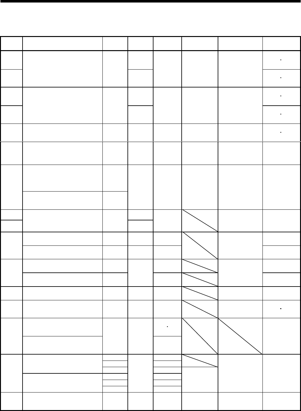
1.1 Servo motor features
Servo
Moto
r
Series
Features
(Points Different from Conventional
Products)
Rated
Speed
[r/min]
Positionin
g
Resolution
[p
ulses/rev
]
Capacity
[kW]
Interchan
g
eable
Servo Motor
Series
Compliance with
Overseas Standards
Environmental
Resistance
HC-KF 8192 (Note1 2) IP44
HC-KFS
Low inertia, small capacity 4 to 5
times greater in inertia moment than
HC-MF(S).
Equipped with absolute position
detector as standard
3000
131072
0.05 to 0.4 HC-MF
HC-ME
HC-MH
EN Standard
UL/C-UL Standard
(Standard model is
compliant) (Note1 2) IP55
HC-MF 8192 (Note1 2) IP44
HC-MFS
Ultra low inertia, small capacity
1.2 times higher in power rate than
HA-ME
Equipped with absolute position
detector as standard
3000
131072
0.05 to 0.75 HA-ME
HA-MH
EN Standard
UL/C-UL Standard
(Standard model is
compliant) (Note1 2) IP55
HA-FF Low inertia, small capacity
Equipped with absolute position
detector as standard 8192 3000 0.05 to 0.6 HA-FE
HA-FH
EN Standard
UL/C-UL Standard
(HA-FF-UE is
compliant)
(Note1 2) IP44
HC-SF
Middle inertia, middle capacity
1.5 times higher in power rate than
HA-SE
Equipped with absolute position
detector as standard
1000
2000
3000 16384 0.5 to 7 HA-SE
HA-SH
EN Standard
UL/C-UL
(Standard model is
compliant)
IP65
Three-phase, 200VAC-compatible
Middle inertia, middle capacity 1.5
times higher in power rate than HA-
SE
Equipped with absolute position
detector as standard
1000
2000
3000
HC-SFS
Three-phase, 400VAC-compatible
Middle inertia, middle capacity
Equipped with absolute position
detector as standard
2000
131072 0.5 to 7 HA-SE
HA-SH
EN Standard
UL/C-UL
(Standard model is
compliant)
IP65
HC-RF 16384
HC-RFS
Ultra low inertia, middle capacity
About 3 times higher in power rate
than HA-LH
Equipped with absolute position
detector as standard
3000
131072
1 to 5
EN Standard
UL/C-UL Standard
(Standard model is
compliant)
IP65
Flat type, small capacity
Equipped with absolute position
detector as standard 3000 8192 0.1 to 0.75 (Note1) IP65
HC-UF Flat type, middle capacity
Equipped with absolute position
detector as standard 2000 16384 0.75 to 5
EN Standard
UL/C-UL Standard
(Standard model is
compliant) IP65
Flat type small capacity
Equipped with absolute position
detector as standard 3000 0.1 to 0.75 (Note1) IP65
HC-UFS Flat type middle capacity
Equipped with absolute position
detector as standard 2000
131072
0.75 to 5
EN Standard
UL/C-UL Standard
(Standard model is
compliant) IP65
HA-LH Low inertia, large capacity 2000 16384 11 to 22 EN Standard
(HA-LH-EC is
compliant) JP44
HC-AQ 24VDC-compatible,
compact size, small capacity 3000 8192 0.01 to 0.03
EN Standard,
UL/C-UL Standard
(Standard model is
compliant)
(Note1 2) IP55
Three-phase, 200VAC-compatible,
low inertia, large capacity
Equipped with absolute position
detector as standard
30 37
HA-LF Three-phase, 400VAC-compatible,
low inertia, large capacity
Equipped with absolute position
detector as standard
2000 16384
30 to 55
IP44
1000 6 to 37
1500 7 to 37
Three-phase, 200VAC-compatible,
low inertia, middle large capacity
Equipped with absolute position
detector as standard 2000 5 to 37
1000 6 to 37
1500 7 to 50
HA-LFS Three-phase, 400VAC-compatible,
low inertia, large capacity
Equipped with absolute position
detector as standard 2000
131072
11 to 55
HA-LH
EN Standard,
UL/C-UL Standard
(Standard model is
compliant)
IP44
HC-LFS Low inertia, middle capacity
Equipped with absolute position
detector as standard 2000 131072 0.5 to 3 HA-LH
EN Standard,
UL/C-UL Standard
(Standard model is
compliant)
IP65
Note 1. Except connector section.
2. Except for the shaft-through portion.
1 - 2
1. INTRODUCTION
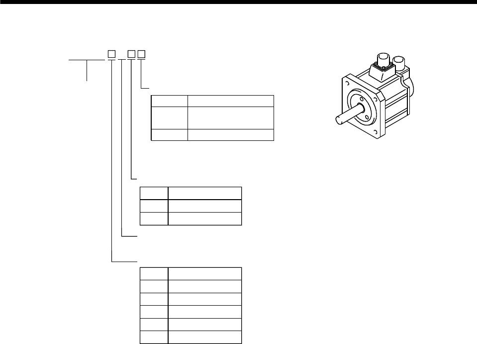
1.2 Model name make-up
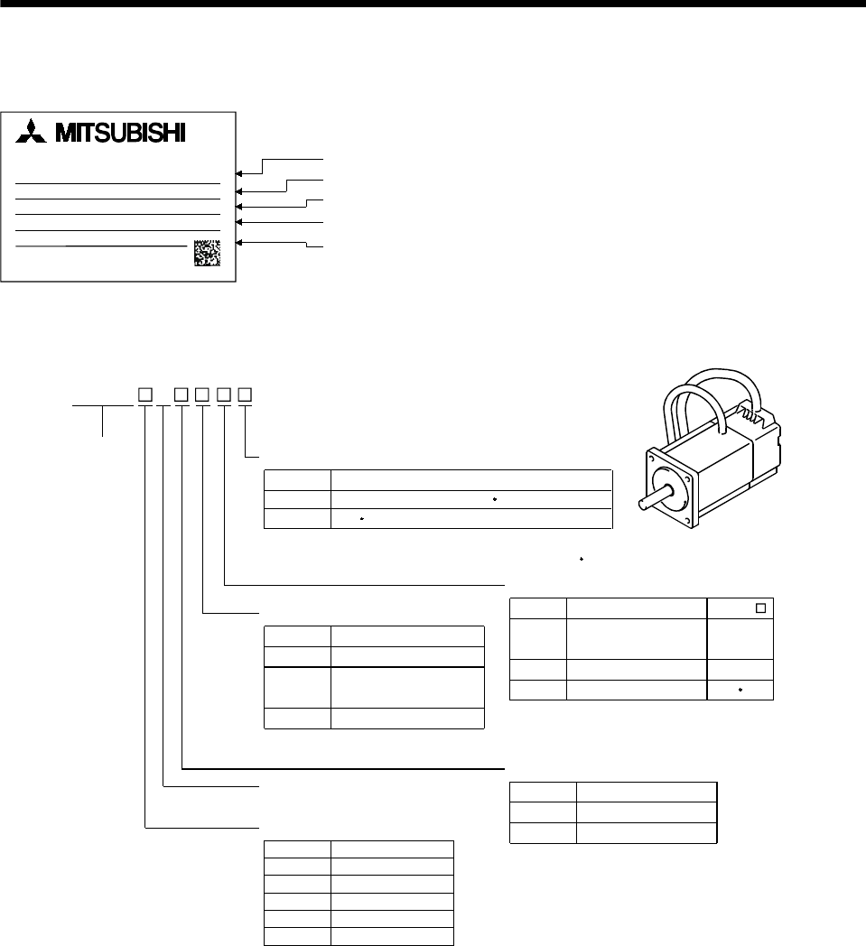
(1) Rating plate
AC SERVO MOTOR
HC-SF502G1H
INPUT 3AC 133V 26A
MITSUBISHI ELECTRIC CORPORATION
MADE IN JAPAN
2000r/min IP65CI.F 102kg
SER.No. AS958300202X
OUTPUT 5kW IEC60034-1 '99
Model
Input power
Rated output
Rated speed, Protection structure,
Insulation class, Mass
Serial number
(2) Model
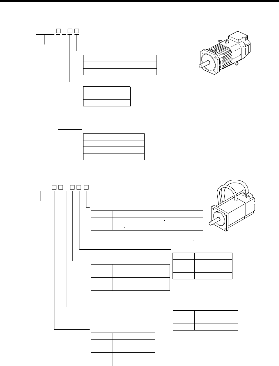
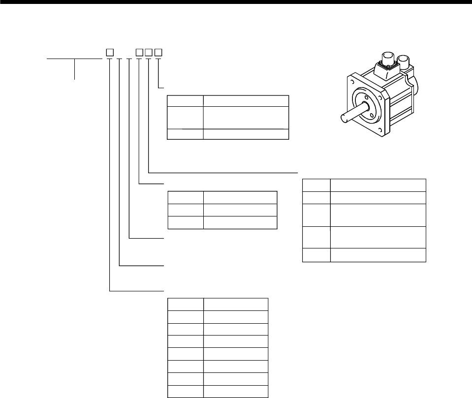
(a) HC-MF series (ultra low inertia, small capacity)
3
Symbol
Rated Output [kW]
-UE
Symbol
Shaft type
(Note) K
(Note) D
Symbol
G1
Symbol
1
2
0.05
0.1
0.2
05
Series name
Appearance
Compliance with Standard
Specifications
None
(Note) Standard model (EN UL/C-UL Standard)
EN UL/C-UL Standard
Shaft Shape
D-cut shaft
Note. The special shaft applies to the standard
servo motor and servo motor with
electromagnetic brake.
Reduction gear
Reduction Gear
None Without
For general
industrial machine
For precision application
Electromagnetic brake
Electromagnetic Brake
Without
With
Rated speed
3000 [r/min]
Rated output
None
Standard
(Straight shaft)
With keyway (With key)
HC-MF
53 13
053 to 73
23 to 73
G2
Symbol
B
None
40.4
70.75
HC-MF
Note. The standard models produced in and after
February, 2001 are compatible with the EN UL/C-UL Standard.
1 - 3
1. INTRODUCTION
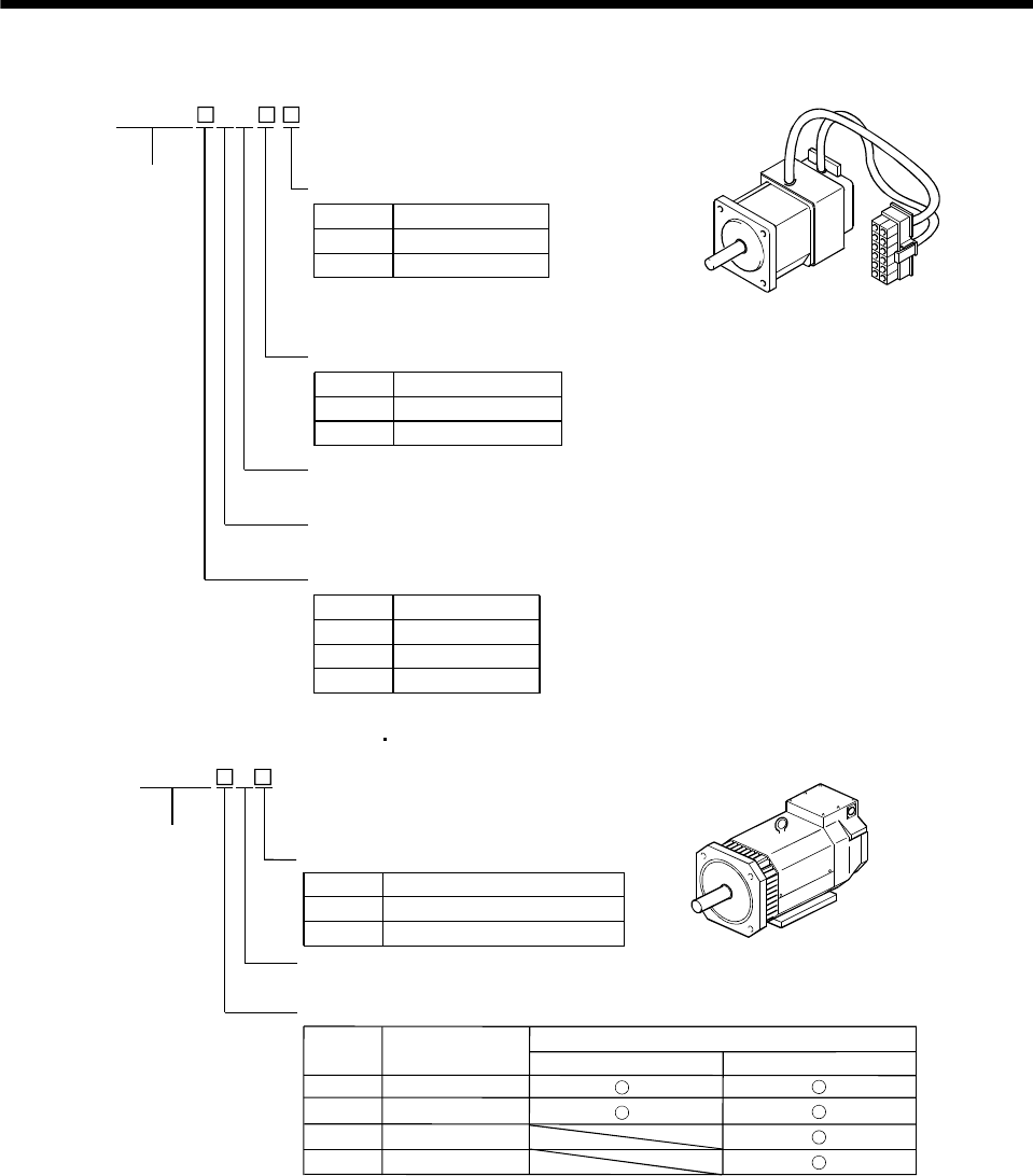
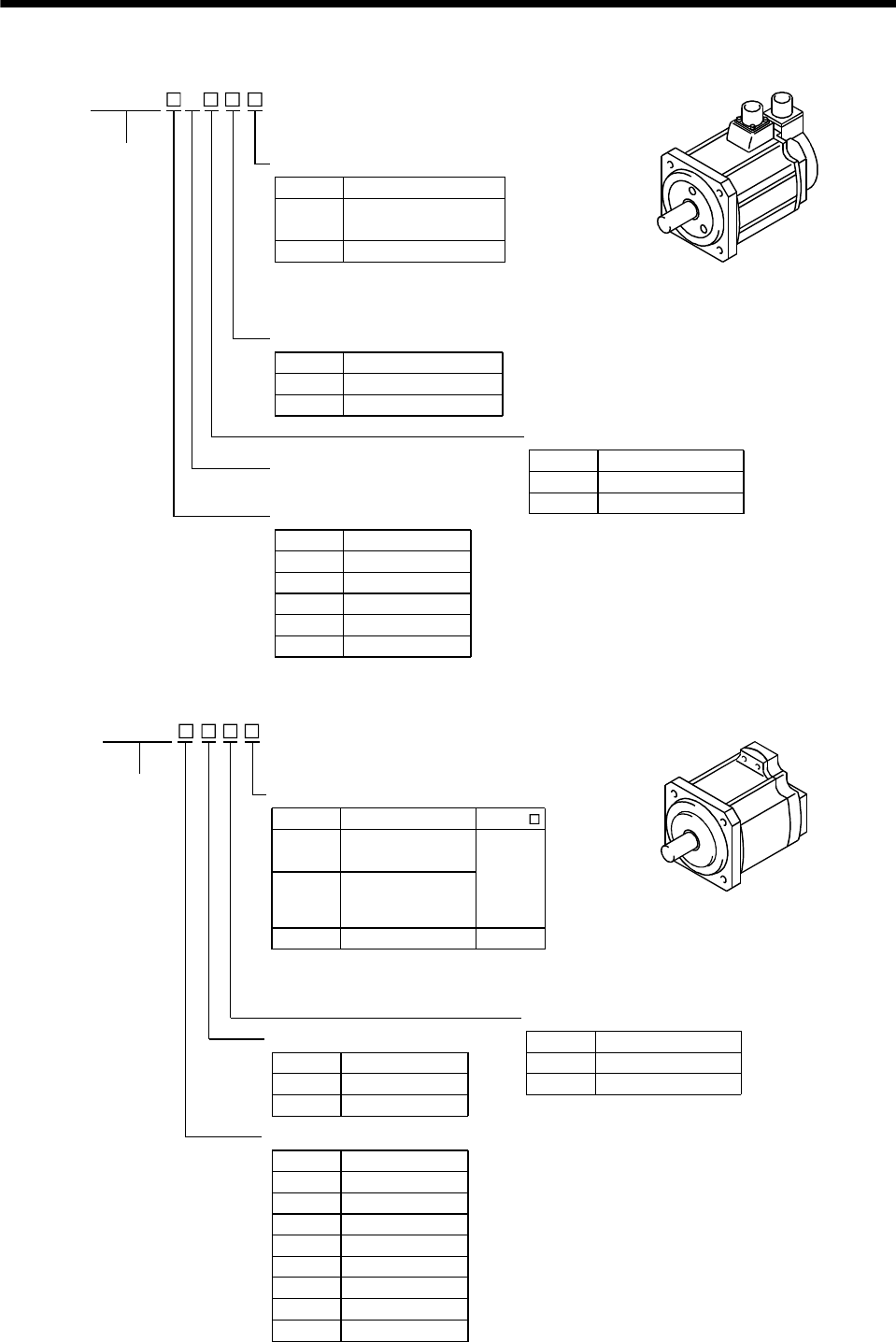
(b) HA-FF series (low inertia, small capacity)
Symbol
Rated Output [kW]
-UE
Symbol
Shaft type
(Note2) D
Symbol
G1
Symbol
1
2
0.05
0.1
0.2
05
Series name Compliance with Standard
Specifications
None
Standard model (Japan)
EN UL/C-UL Standard
Shaft Shape
D-cut shaft
Reduction gear
Reduction Gear
None Without
For general
industrial machine
For precision application
Electromagnetic brake
Electromagnetic Brake
Without
With
Rated speed
3000 [r/min]
Rated output
None
HA-FF
053 13
053 to 63
G2
Symbol
B
None
(Note1) Standard
Note 1. The Standard shafts of the HA-FF23 to
63 are with keys and those of the other
models are straight shafts.
2. The special shaft applies to the standard
servo motor and servo motor with
electromagnetic brake.
Appearance
Rated Output [kW]Symbol
4
6
0.3
0.4
0.6
3
Input power supply form
Standard model
Lead
Symbol
C
None
EN UL/C-UL Standard-
compliant model
Cannon connector
3 HA-FF
1 - 4
1. INTRODUCTION
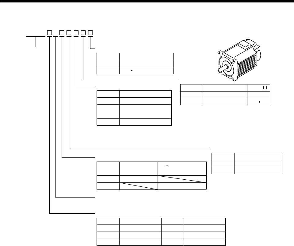
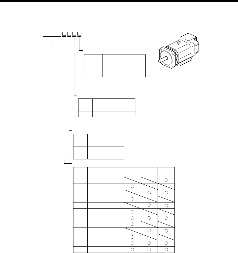
(c) HC-SF series (middle inertia, middle capacity)
Rated Output [kW]
Symbol
G1
Symbol
8
10
0.5
0.85
1
5
Series name
Reduction gear
None Without
Electromagnetic brake
Electromagnetic Brake
Without
With
Rated speed
Rated output
Appearance
Symbol
B
None
1000 [r/min]
(Note) Reduction Gear
Note. Not provided for 1000r/min and
3000r/min series.
Symbol
Shaft type
None
Shaft Shape
With keyway (With key)
Standard
(Straight shaft)
(Note) K
For general
industrial machine
(flange type)
For general
industrial machine
(leg type)
G1H
For precision applicationG2
Symbol
2
3
1000
2000
3000
1
2000 [r/min] 3000 [r/min]
15
20
1.2
1.5
2
12
30
35
3
3.5
50 5
70 7
HC-SF
Note. The special shaft applies to the standard
servo motor and servo motor with
electromagnetic brake.
Speed [r/min]
1 - 5
1. INTRODUCTION
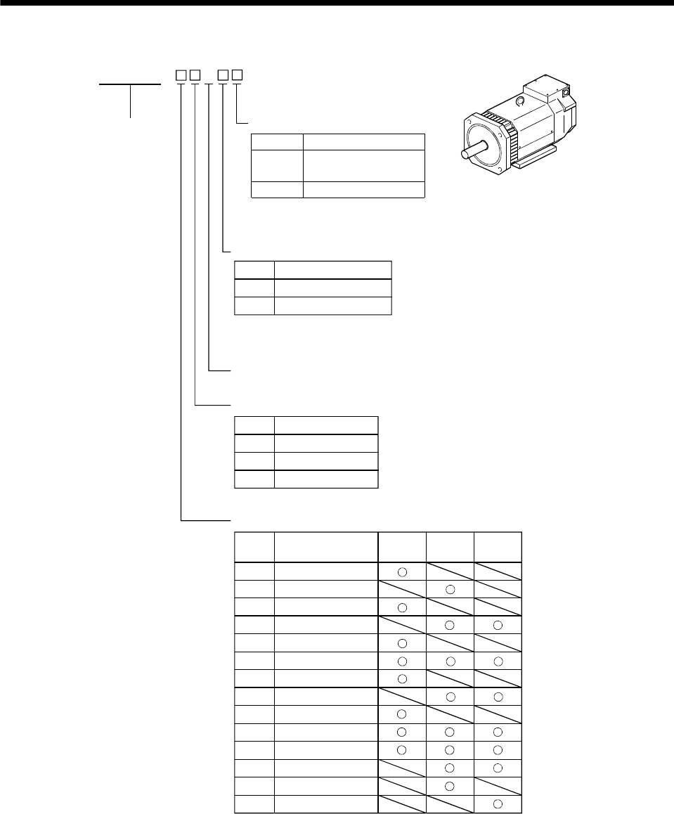
(d) HC-RF series (ultra low inertia, middle capacity)
Rated Output [kW]
Symbol
Symbol
20
1
15 1.5
2
10
Series name
Appearance
Reduction gear
Reduction Gear
None Without
For precision application
Electromagnetic brake
Electromagnetic Brake
Without
With
Rated speed
3000 [r/min]
Rated output
Symbol
Shaft type
(Note) K
None
Shaft Shape
Standard
(Straight shaft)
With keyway (With key)
G2
Symbol
B
None
35 3.5
50 5
3 HC-RF
Note. The special shaft applies to the
standard servo motor and servo
motor with electromagnetic brake.
(e) HC-UF series (flat type, small and middle capacity)
HC-UF
Series name
Appearance
Rated Output [kW]
Symbol
Shaft type
(Note) K
(Note) D
Symbol
2
4
0.1
0.2
0.4
1
None
Shaft Shape
D-cut shaft
Electromagnetic brake
Electromagnetic Brake
Without
With
Rated speed
Rated output
Standard
(Straight shaft)
With keyway
(HC-UF23 to 73: With key)
HC-UF
13
13 to 43
72 to 202
Symbol
B
None
Speed [r/min]Symbol
3
2000
3000
2
20
0.75
2
7
1.5
15
3.5
35
550
Note. The special shaft applies to the standard
servo motor and servo motor with
electromagnetic brake.
1 - 6
1. INTRODUCTION
(f) HA-LH series (low inertia, large capacity)
HA-LH
Series name
Appearance
Compliant Standard
Encoder
Rated speed
2000[r/min]
Rated Output [kW]Symbol
15K
22K
11
15
22
11K
Rated output
Symbol
None
Specifications
Standard model (in Japan)
EN Standard
-EC
Symbol
None
Encoder
Incremental
Absolute
-Y
2
(g) HC-KF series (low inertia, small capacity)
3000[r/min]
20.2
0.44
Appearance
Compliance with Standard
Symbol Specifications
None (Note) Standard model (EN UL/C-UL Standard)
-UE
Shaft type
Symbol Shaft Shape
None
(Note) K With keyway
Symbol Reduction Gear
None Without
G1 For general industrial machine
G2 For precision application
Electromagnetic brake
Symbol Electromagnetic Brake
None Without
BWith
Rated speed
Rated output
Symbol Rated Output [kW]
EN UL/C-UL Standard
Standard
(Straight shaft)
Reduction gear
Series name
HC-KF 3
05 0.05
0.11
Note. The standard models produced in and after
February, 2001 are compatible with the EN UL/C-UL Standard.
Note. The special shaft applies
to the standard servo motor
and servo motor with
electromagnetic brake.
1 - 7
1. INTRODUCTION
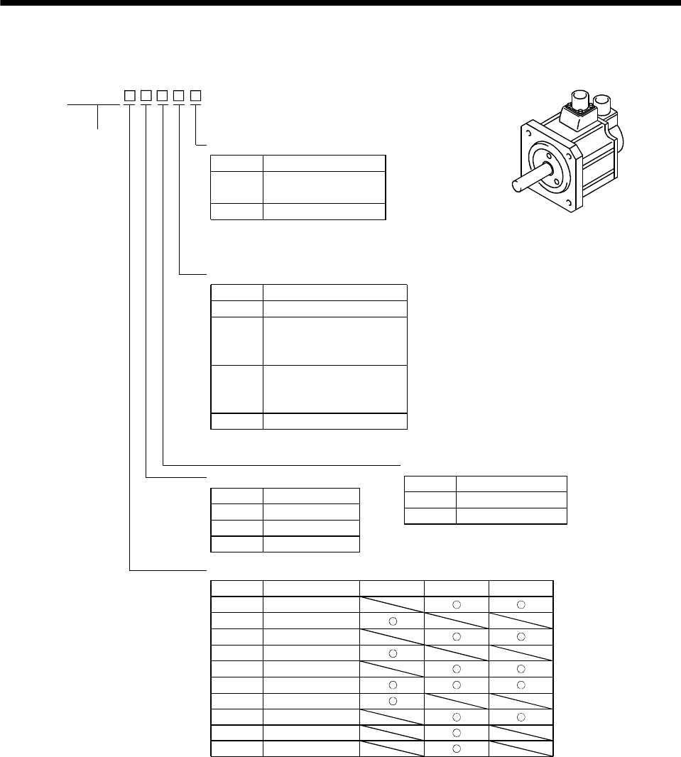
(h) HC-AQ series (24VDC-compatible, compact size, small capacity)
HC-AQ
Rated Output [kW]Symbol
03
0.01
02 0.02
0.03
01
Series name
Appearance
Rated speed
3000 [r/min]
Rated output
Symbol
Shaft type
Shaft Shape
Electromagnetic brake
Electromagnetic Brake
Without
With
Symbol
B
None
(Note) D D-cut shaft
(Note) S Straight shaft
Power supply voltage
24VDC
35
Note. The special shaft applies to
the standard servo motor and
servo motor with electromagnetic brake.
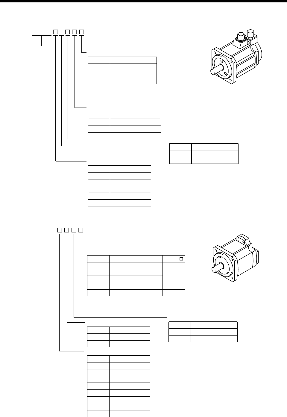
(i) HA-LF series (Three-phase, 200 400VAC-compatible, low inertia, large capacity)
Three-phase 200 to 230VAC
HA-LF
Rated Output [kW]
Symbol
45K
30
37K 37
45
30K
Series name
Appearance
Rated speed
2000 [r/min]
Rated output
Power supply specification
55K 55
2
Power Supply VoltageSymbol
4
None
Three-phase 380 to 480VAC
Power supply specifications
Three-phase 200 to 230VAC Three-phase 380 to 480VAC
1 - 8
1. INTRODUCTION
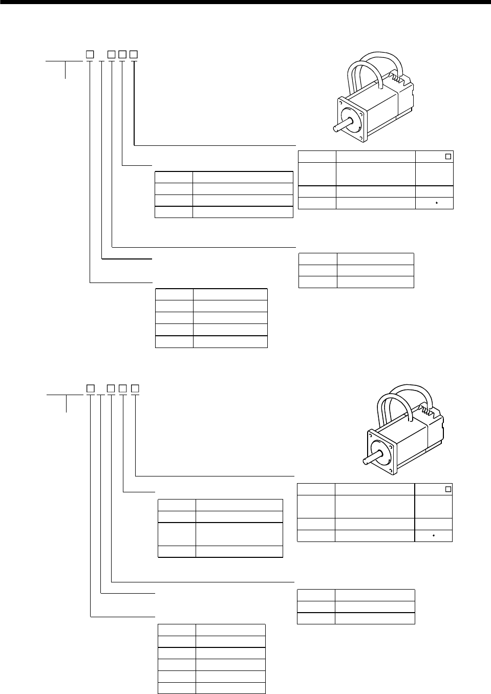
(j) HC-KFS series (low inertia, small capacity, high resolution)
3000[r/min]
05 0.05
0.11
Appearance
Shaft type
Symbol Reduction Gear
None Without
G1 For general industrial machine
G2 For precision application
Electromagnetic brake
Symbol Electromagnetic Brake
None Without
BWith
Rated speed
Rated output
Symbol Rated Output [kW]
Reduction gear
3
Series name
HC-KFS
20.2
0.44
Symbol
(Note) K
(Note) D
None
Shaft Shape
D-cut shaft
Standard
(Straight shaft)
With keyway (With key)
HC-KFS
053 13
053 to 73
23 to 73
Note. The special shaft applies to the standard
servo motor and servo motor with
electromagnetic brake.
(k) HC-MFS series (ultra low inertia, small capacity, high resolution)
3
Rated Output [kW]
Symbol
Shaft type
(Note) K
(Note) D
Symbol
G1
Symbol
1
2
0.05
0.1
0.2
05
Series name
Appearance
None
Shaft Shape
D-cut shaft
Note. The special shaft applies to the standard
servo motor and servo motor with
electromagnetic brake.
Reduction gear
Reduction Gear
None Without
For general
industrial machine
For precision application
Electromagnetic brake
Electromagnetic Brake
Without
With
Rated speed
3000 [r/min]
Rated output
Standard
(Straight shaft)
With keyway (With key)
HC-MFS
53 13
053 to 73
23 to 73
G2
Symbol
B
None
40.4
70.75
HC-MFS
1 - 9
1. INTRODUCTION
(l) HC-SFS series (middle inertia, middle capacity, high resolution)
1) 200VAC-compatible
Rated Output [kW]
Symbol
G1
Symbol
8
10
0.5
0.85
1
5
Series name
Reduction gear
None Without
Electromagnetic brake
Electromagnetic Brake
Without
With
Rated speed
Rated output
Appearance
Symbol
B
None
1000 [r/min]
Reduction Gear
Note. Not provided for 1000r/min and
3000r/min series.
Speed [r/min]
Symbol
Shaft type
None
Shaft Shape
With keyway (Without key)
Note. The special shaft applies to the
standard servo motor and servo
motor with electromagnetic brake.
Standard
(Straight shaft)
(Note) K
(Note) For general
industrial machine
(flange type)
(Note) For general
industrial machine
(leg type)
G1H
(Note) For precision application
G2
Symbol
2
3
1000
2000
3000
1
2000 [r/min] 3000 [r/min]
15
20
1.2
1.5
2
12
30
35
3
3.5
HC-SFS
50 5
70 7
1 - 10
1. INTRODUCTION
2) 400VAC-compatible
HC-SFS 2 4
Series name Shaft type
Symbol Shaft Shape
None Standard
(Straight shaft)
With keyway (Without key)
(Note) K
Symbol Electromagnetic brake
None
B
Without
With
Power supply voltage
Three-phase 380 to 480 VAC
5 0.5
10 1
Rated speed
2000 [r/min]
Electromagnetic brake
Rated output
Symbol Rated output [kW]
Reductiongear
None
Symbol Reductiongear
Without
G1
G2
G1H
For general industrial machine
(flange type)
For general industrial machine
(leg type)
For precision application
Appearance
15 1.5
20 2
35 3.5
50 5
70 7
Note. The special shaft applies to the
standard servo motor and servo
motor with electromagnetic brake.
1 - 11
1. INTRODUCTION
(m) HC-RFS series (ultra low inertia, middle capacity, high resolution)
Rated Output [kW]
Symbol
Symbol
20
1
15 1.5
2
10
Series name
Appearance
Reduction gear
Reduction Gear
None Without
For precision application
Electromagnetic brake
Electromagnetic Brake
Without
With
Rated speed
3000 [r/min]
Rated output
Symbol
Shaft type
(Note) K
None
Shaft Shape
Note. The special shaft applies to the
standard servo motor and servo
motor with electromagnetic brake.
Standard
(Straight shaft)
With keyway (Without key)
G2
Symbol
B
None
35 3.5
50 5
3 HC-RFS
(n) HC-UFS series (flat type small and middle capacity, high resolution)
HC-UFS
Series name
Appearance
Rated Output [kW]
Symbol
Shaft type
(Note) K
(Note) D
Symbol
2
4
0.1
0.2
0.4
1
None
Shaft Shape
D-cut shaft
Note. The special shaft applies to the standard
servo motor and servo motor with
electromagnetic brake.
Electromagnetic brake
Electromagnetic Brake
Without
With
Rated speed
Rated output
Standard
(Straight shaft)
With keyway
HC-UFS 23 to 73 are
provided with keys.
HC-UFS
13
13 to 43
72 to 202
Symbol
B
None
Speed [r/min]Symbol
3
2000
3000
2
20
0.75
2
7
1.5
15
3.535
550
1 - 12
1. INTRODUCTION
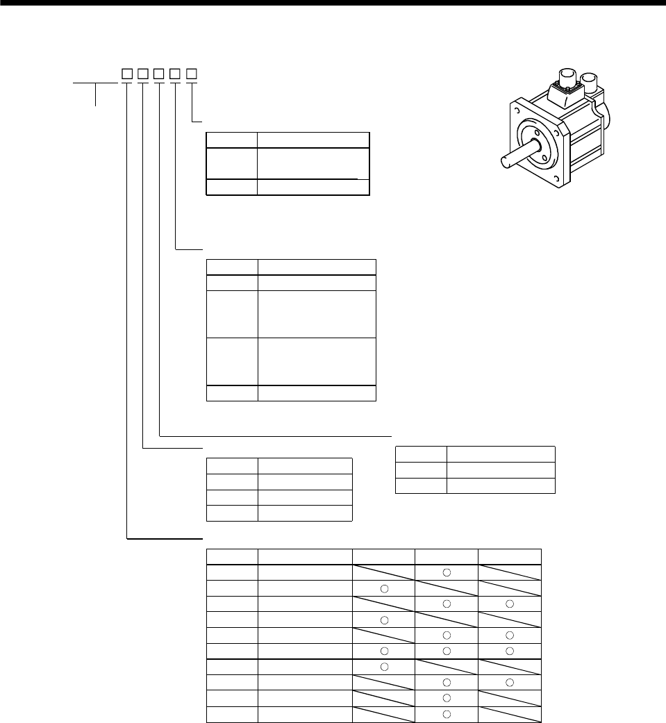
(o) HA-LFS series (low inertia, middle large capacity, high resolution)
1) 200VAC-compatible
(Note)B
11000
1M 1500
22000
HA-LFS
Rated speed
Series name
Symbol Speed [r/min]
Appearance
50 5
1000
[r/min]
1500
[r/min]
2000
[r/min]
60 6
70 7
80 8
11K 11
12K 12
15K 15
20K 20
22K 22
25K 25
30K 30
37K 37
Symbol Rated Output [kW]
Rated output
Electromagnetic brake
Note Without
For precision application
Symbol Electromagnetic brake
Note. Refer to Table 6.1 for the servo motor
compatible with the electromagnetic brake.
Symbol
Shaft type
(Note) K
None
Shaft Shape
Note. The special shaft applies to the
standard servo motor and servo
motor with electromagnetic brake.
Standard
(Straight shaft)
With keyway (Without key)
1 - 13
1. INTRODUCTION
2) 400VAC-compatible
80 8
11K 11
12K 12
15K 15
20K 20
22K 22
25K 25
30K 30
37K 37
45K 45
50K 50
55K 55
Series name
Electromagnetic brake
HA-LFS 4
Electromagnetic brake
Symbol
Note Without
(Note)B For precision application
Note. Refer to Table 6.1 for the servo motor
compatible with the electromagnetic brake.
Power supply voltage
Three-phase 380 to 480 VAC
11000
1M 1500
22000
Rated speed
Symbol Speed [r/min]
1500
[r/min]
2000
[r/min]
Symbol Rated Output [kW]
Rated output
Appearance
Symbol
Shaft type
(Note) K
None
Shaft Shape
Note. The special shaft applies to the
standard servo motor and servo
motor with electromagnetic brake.
Standard
(Straight shaft)
With keyway (Without key)
1000
[r/min]
60 6
70 7
1 - 14
1. INTRODUCTION
(p) HC-LFS series (low inertia, middle capacity, high resolution)
50.5
10 1
15 1.5
20 2
30 3
HC-LFS 2
Series name
Electromagnetic brake
Symbol
Rated speed
2000 [r/min]
Rated output
Symbol
Electromagnetic Brake
Rated Output [kW]
None Without
With
B
Appearance
Symbol
Shaft type
(Note) K
None
Shaft Shape
Note. The special shaft applies to the
standard servo motor and servo
motor with electromagnetic brake.
Standard
(Straight shaft)
With keyway (Without key)
1 - 15
1. INTRODUCTION
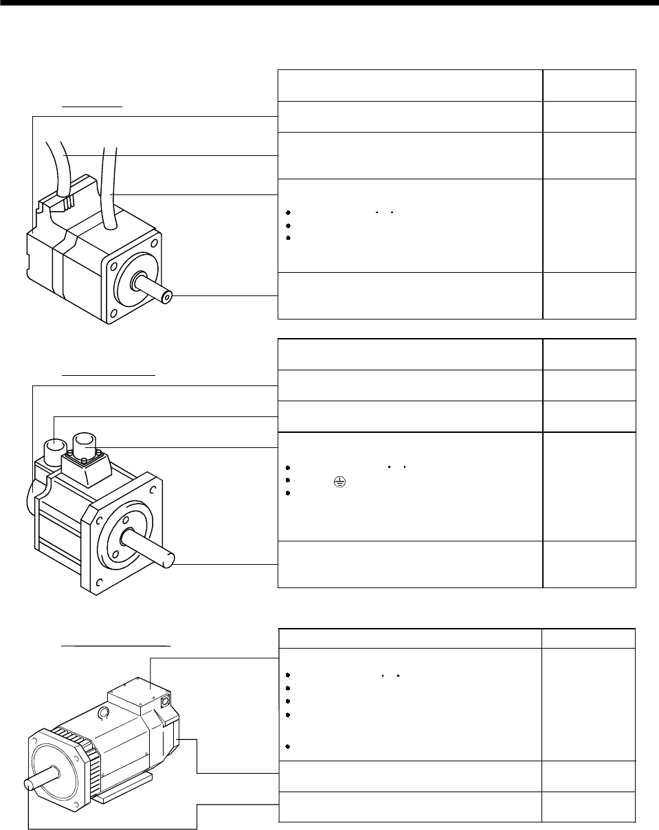
1.3 Parts identification
Terminal box
Power leads (U V W)
Cooling fan leads
Ground terminal
Brake lead
(for motor with electromagnetic brake)
Terminal box type
Lead type Name/Application Reference
Encoder Section 5.1
Encoder cable
with encoder connector Section 3.2
Chapter 7
Servo motor shaft
Connector type
Encoder connector
Power cable
Power lead (U V W)
Earth lead
Brake lead
(for motor with electromagnetic brake)
Chapter 2
Section 5.4
Name/Application Reference
Encoder Section 5.1
Section 3.2
Chapter 7
Servo motor shaft Chapter 2
Section 5.4
Power connector
Power supply (U V W)
Earth ( )
Brake (for motor with electromagnetic brake)
Some motors with electromagnetic brakes
have brake connectors separately.
Name/Application Reference
Encoder
Encoder connector
Section 5.1
Section 3.2
Servo motor shaft Chapter 2
Chapter 7

1 - 16
1. INTRODUCTION
MEMO
2 - 1
2. INSTALLATION
2. INSTALLATION
CAUTION
Stacking in excess of the limited number of products is not allowed.
Install the equipment on incombustible material. Installing them directly or close to
combustibles will lead to a fire.
Install the equipment in a load-bearing place in accordance with this Instruction
Manual.
Do not get on or put heavy load on the equipment to prevent injury.
Use the equipment within the specified environmental condition range.
Do not subject the servo motor to drop impact or shock loads as they are precision
equipment.
Do not install or operate a faulty servo amplifier.
Do not hold the cable, shaft or encoder to carry the servo motor. Otherwise, a fault
or injury may occur.
The lifting eyebolts of the servo motor may only be used to transport the servo
motor. They must not be used to transport the servo motor when it is mounted on a
machine.
The servo motor with reduction gear must be installed in the specified direction.
Otherwise, it can leak oil, leading to a fire or fault.
Securely fix the servo motor to the machine. If fixed insecurely, the servo motor will
come off during operation, leading to injury.
When coupling the shaft end of the servo motor, do not subject the shaft end to
impact, such as hammering. The encoder may become faulty.
When coupling a load to the servo motor, do not use a rigid coupling. Doing so can
cause the shaft to break.
Take safety measures, e.g. provide covers, to prevent accidental access to the
rotating parts of the servo motor during operation.
Do not subject the servo motor shaft to more than the permissible load. Otherwise,
the shaft may break, leading to injury.
When the product has been stored for an extended period of time, consult
Mitsubishi.
When treating the servo motor, be careful about the edged parts such as the
corners of the servo motor.
2 - 2
2. INSTALLATION
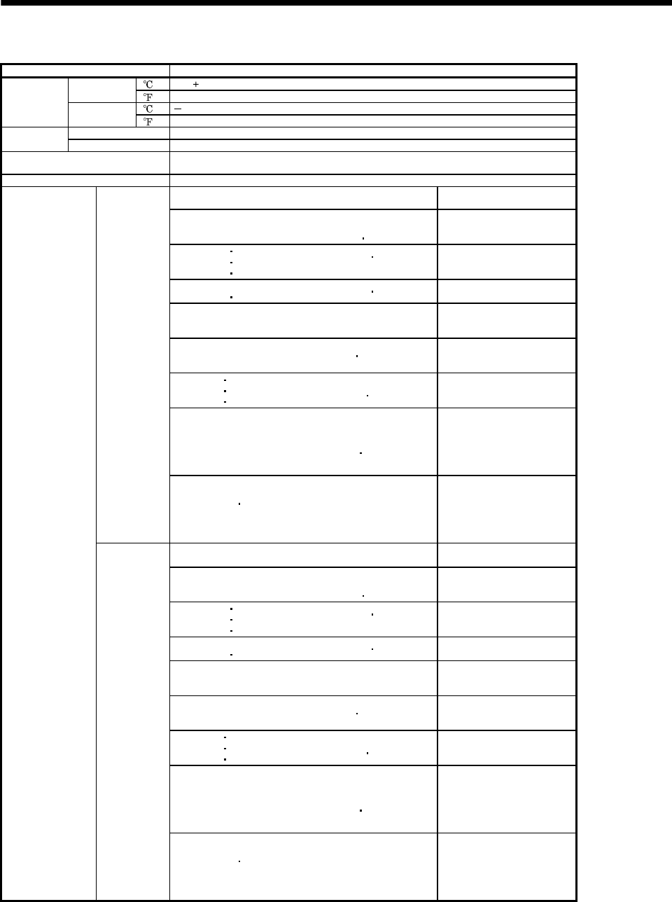
2.1 Environmental conditions
Environment Conditions
[]0 to 40 (non-freezing)
In Operation [] 32 to 104 (non-freezing)
[ ] 15 to 70 (non-freezing)
Ambient
temperature In Storage [] 5 to 158 (non-freezing)
In Operation 80%RH or less (non-condensing)
Ambient
humidity In Storage 90%RH or less (non-condensing)
Ambience Indoors (no direct sunlight)
Free from corrosive gas, flammable gas, oil mist, dust and dirt
Altitude Max. 1000m (3280 ft) above sea level
HC-KFS series
HC-MFS series HC-UFS13 to 73 X,Y:49
HC-SFS81
HC-SFS52 to 152
HC-SFS53 to 153
HC-SFS524 to 1524
HC-RFS series
HC-UFS72 152
X,Y:24.5
HC-SFS121 201
HC-SFS202 352
HC-SFS203 353
HC-SFS2024 3524
HC-UFS202 to 502
X:24.5
Y:49
HC-SFS301
HC-SFS502 702 HC-SFS5024 7024 X:24.5
Y:29.4
HC-AQ series
HC-KF series
HC-MF series
HA-FF series
HC-UF13 to 73 X,Y:19.6
HC-SF81
HC-SF52 to 152
HC-SF53 to 153
HC-RF series
HC-UF72 152
HC-LFS52 to152
X:9.8
Y:24.5
HC-SF121 201
HC-SF202 352
HC-SF203 353
HC-UF202 to 502
HC-LFS202 302
X:19.6
Y:49
HA-LFS601 to12K1
HA-LFS701M to 15K1M
HA-LFS502 to 22K2
HA-LFS6014 to 12K14
HA-LFS701M4 to 15K1M4
HA-LFS11K24 to 22K24
HA-LH11K2 to 22K2
HC-SF301
HC-SF502 702
X:11.7
Y:29.4
[m/s2]
HA-LFS15K1 to 37K1
HA-LFS22K1M to 37K1M
HA-LFS30K2 37K2
HA-LFS15K14 to 37K14
HA-LFS22K1M4 to 50K1M4
HA-LFS30K24 to 55K24
HA-LF series X,Y:9.8
HC-KFS series
HC-MFS series HC-UFS13 to 73 X,Y:161
HC-SFS81
HC-SFS52 to 152
HC-SFS53 to 153
HC-SFS524 to 1524
HC-RFS series
HC-UFS72 152
X,Y:80
HC-SFS121 201
HC-SFS202 352
HC-SFS203 353
HC-SFS2024 3524
HC-UFS202 to 502
X:80
Y:161
HC-SFS301
HC-SFS502 702 HC-SFS5024 7024 X:80
Y:96
HC-AQ series
HC-KF series
HC-MF series
HA-FF series
HC-UF13 to 73 X,Y:64
HC-SF81
HC-SF52 to 152
HC-SF53 to 153
HC-RF series
HC-UF72 152
HC-LFS52 to152
X:32
Y:80
HC-SF121 201
HC-SF202 352
HC-SF203 353
HC-UF202 to 502
HC-LFS202 302
X:64
Y:161
HA-LFS601 to12K1
HA-LFS701M to 15K1M
HA-LFS502 to 22K2
HA-LFS6014 to 12K14
HA-LFS701M4 to 15K1M4
HA-LFS11K24 to 22K24
HA-LH11K2 to 22K2
HC-SF301
HC-SF502 702
X:38.4
Y:96.5
(Note) Vibration
[ft/s2]
HA-LFS15K1 to 37K1
HA-LFS22K1M to 37K1M
HA-LFS30K2 37K2
HA-LFS15K14 to 37K14
HA-LFS22K1M4 to 50K1M4
HA-LFS30K24 to 55K24
HA-LF series X,Y:32
Note. Except the servo motor with reduction gear.
2 - 3
2. INSTALLATION
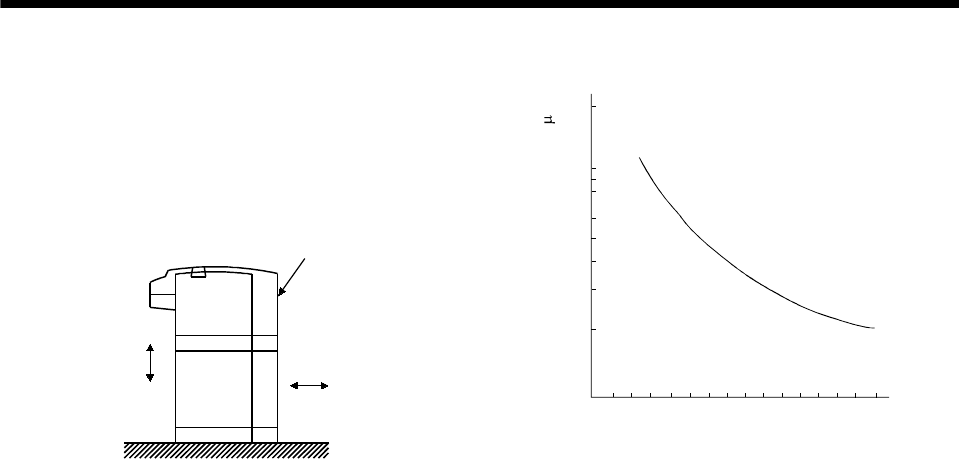
Vibration occurs in the directions shown below.
The values were measured at the portion which
indicates the maximum value (normally the bracket
opposite to load side). When the servo motor is at
a
stop, the bearings are likely to fret and vibration
should therefore be suppressed to about half of the
permissible value.
Servo moto
r
Vibration
XY
Graph of vibration servo amplitude vs. speed
Speed [r/min]
500 1000 15002000 250030003500
200
100
80
60
50
40
30
20
Vibration amplitude (both amplitudes) [ m]
2 - 4
2. INSTALLATION
2.2 Installation orientation
The following table lists directions of installation.
Servo Motor Series Direction of Installation Remarks
HC-KF
HA-FF
HC-RF
HC-KFS
HC-SFS
HC-UFS
HC-MF
HC-SF
HC-UF
HC-MFS
HC-RFS
HC-LFS
HC-AQ
For installation in the horizontal direction, it is recommended to set the
connector section downward.
HA-LH
HA-LFS (Flange type)
May be installed in any
direction.
HA-LF
HA-LFS (Flange leg type)
Horizontal direction with
the legs downward. Use either the legs or flange for installation.
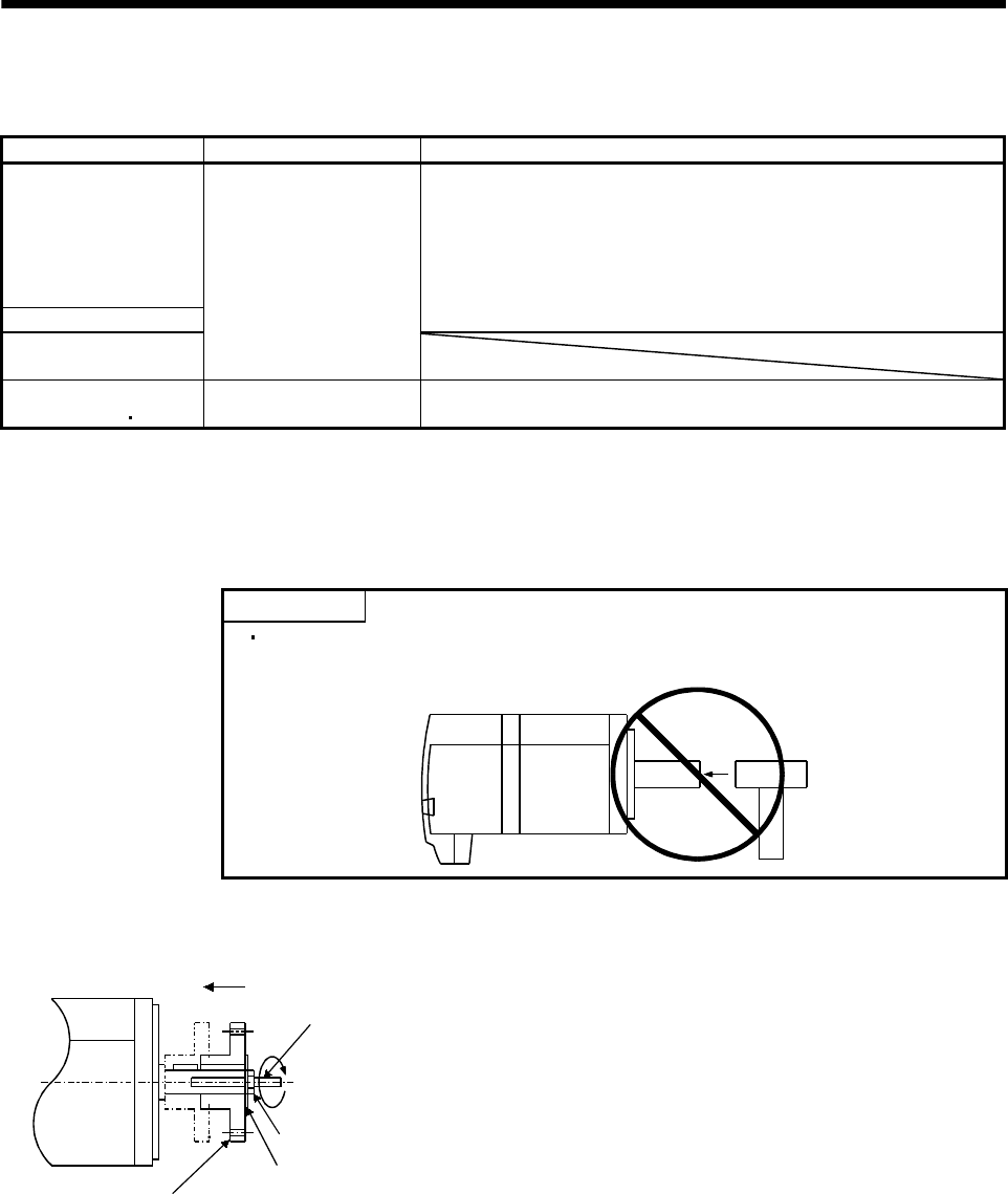
When the servo motor with electromagnetic brake is installed with the shaft end at top, the brake plate
may generate sliding sound but it is not a fault. Refer to section 5.3 for the installation orientation of the
servo motor with reduction gear.
2.3 Load remove precautions
POINT
During assembling, the shaft end must not be hammered. Doing so can
cause the encoder to fail.
(1) When mounting a pulley to the servo motor shaft provided with a keyway, use the screw hole in the
shaft end. To fit the pulley, first insert a double-end stud into the screw hole of the shaft, put a washer
against the end face of the coupling, and insert and tighten a nut to force the pulley in.
Servo motor
Double-end stud
Nut
Washer
Pulley
(2) For the servo motor shaft with a keyway, use the screw hole in the shaft end. For the shaft without a
keyway, use a friction coupling or the like.
(3) When removing the pulley, use a pulley remover to protect the shaft from impact.
(4) To ensure safety, fit a protective cover or the like on the rotary area, such as the pulley, mounted to
the shaft.
(5) When a threaded shaft end part is needed to mount a pulley on the shaft, please contact us.
(6) The orientation of the encoder on the servo motor cannot be changed.
(7) For installation of the servo motor, use spring washers, etc. and fully tighten the bolts so that they do
not become loose due to vibration.
(8) For the HC-AQ series, use spring washers and apply Screw Lock to mount the servo motor. In
addition, use Helisert screws when the flange for mouthing the servo motor is made of aluminum.
2 - 5
2. INSTALLATION
2.4 Permissible load for the shaft
POINT
Do not use a rigid coupling as it may apply excessive bending load to the
shaft, leading to shaft breakage.
(1) Use a flexible coupling and make sure that the misalignment of the shaft is less than the permissible
radial load.
(2) When using a pulley, sprocket or timing belt, select a diameter that will fit into the permissible radial
load.
(3) Excess of the permissible load can cause the bearing life to reduce and the shaft to break.
(4) The load indicated in this section is static load in a single direction and does not include eccentric load.
Make eccentric load as small as possible. Not doing so can cause the servo motor to be damaged.
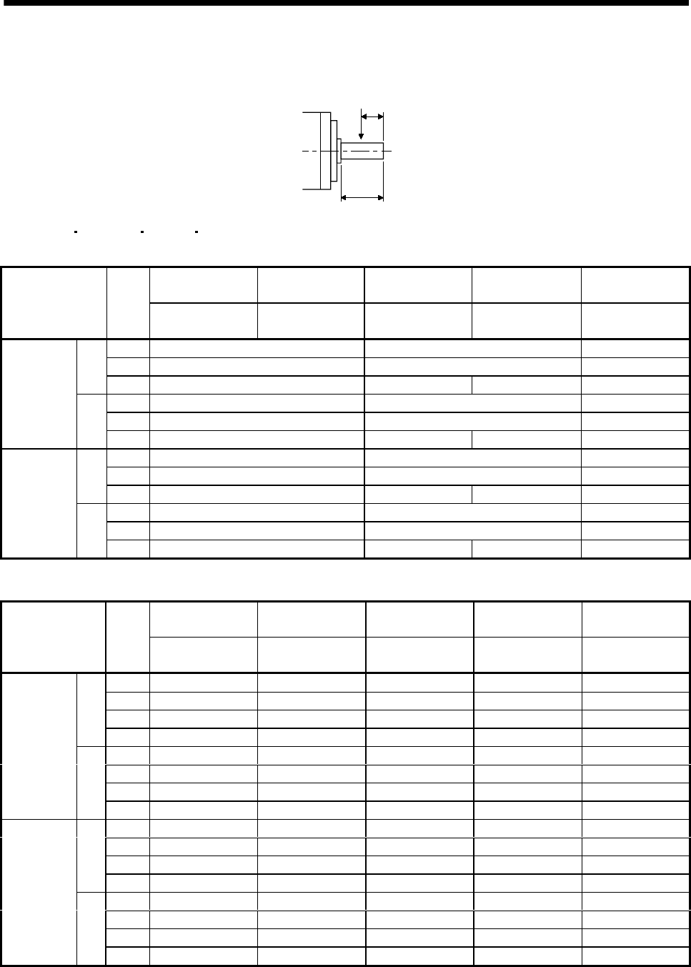
2.4.1 Without reduction gear
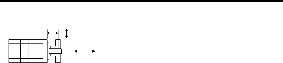
L (Note 1) Permissible Radial Load
(Note 2)
Permissible Thrust Load
(Note 2)
Servo Motor
[mm] [in] [N] [lb] [N] [lb]
053 / 13 25 0.98 88 20 59 13
23 / 43 30 1.18 245 55 98 22
HC-KF
HC-KFS 73 (Note 3) 40 1.57 392 88 147 33
053 / 13 25 0.98 88 20 59 13
23 / 43 30 1.18 245 55 98 22
HC-MF
HC-MFS 73 40 1.57 392 88 147 33
053 30 1.18 108 24 98 22
13 30 1.18 118 27 98 22
23 / 33 30 1.18 176 40 147 33
HA-FF
43 / 63 40 1.57 323 73 284 64
81 55 2.17 980 220 490 110
121 to 301 79 3.11 2058 463 980 220
52 (4) to 152 (4) (Note4) 55 2.17 980 220 490 110
202 (4) / 702 (4) (Note4) 79 3.11 2058 463 980 220
53 to 153 55 2.17 980 220 490 110
HC-SF
HC-SFS
203 / 353 79 3.11 2058 463 980 220
52 to 152 55 2.17 980 220 490 110
HC-LFS 202/302 79 3.11 2058 463 980 220
103 to 203 45 1.77 686 154 196 44
HC-RF
HC-RFS 353 / 503 63 2.48 980 220 392 88
72 / 152 55 2.17 637 143 490 110
202 65 2.56 882 198 784 176
352 / 502 65 2.56 1176 264 784 176
13 25 0.98 88 20 59 13
23 / 43 30 1.18 245 55 98 22
HC-UF
HC-UFS
73 40 1.57 392 88 147 33
11K2 85 3.35 2450 551 980 220
HA-LH 15K2 / 22K2 110 4.33 2940 661 980 220
0135 16 0.63 34 8 14 3
0235 16 0.63 44 10 14 3HC-AQ
0335 16 0.63 49 11 14 3
30K2(4) 37K2(4) 140 5.51 3234 727 1470 330
HA-LF 45K24 /55K24 140 5.51 4900 1102 1960 441
502/702/601(4)/701M(4)/11K2(4) 85 3.35 2450 551 980 153
801(4) 12K1(4) 11K1M(4)
15K1M(4) 15K2(4) 22K2(4) 110 4.33 2940 661 980 153
15K1(4) 20K1(4) 22K1M(4)
30K1M(4) 30K2(4) 37K2(4)
140 5.51 3234 727 1470 330
25K1(4) 30K1(4) 37K1M(4)
45K1M4 45K24•55K24 140 5.51 4900 1102 1960 441
HA-LFS
37K1(4) 50K1M4 170 6.69 6370 1432 1960 441
2 - 6
2. INSTALLATION
Note 1. For the symbols in the table, refer to the following diagram.
Radial load
Thrust load
L
L: Distance from flange mounting surface to load center
2. Do not subject the shaft to load greater than this value. The values in the table assume that the loads work singly.
3. 73 is not available for the HC-KF series.
4. 524 to 7024 are not available for the HC-SF series.
2 - 7
2. INSTALLATION
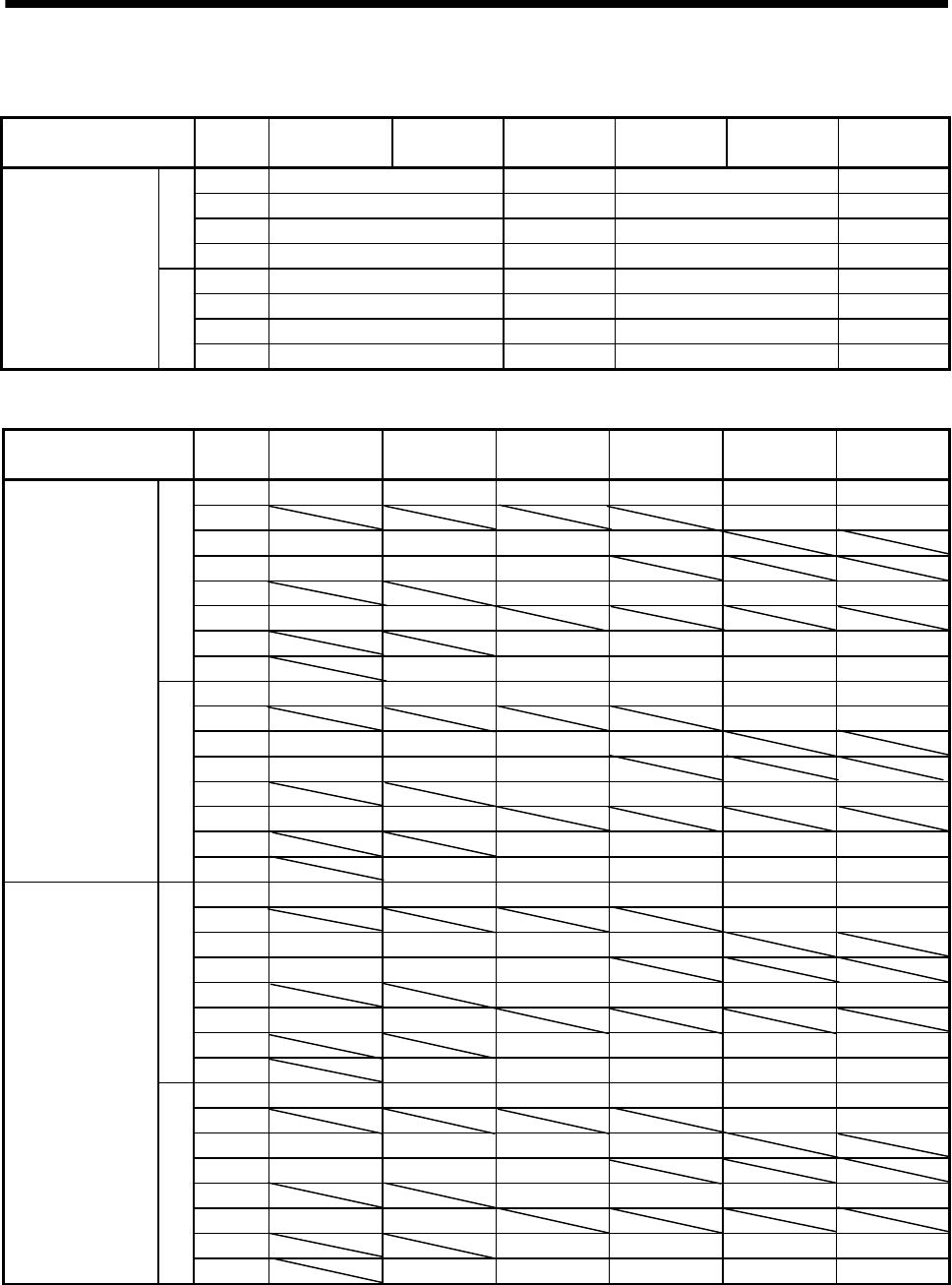
2.4.2 With reduction gear
The permissible radial loads in the table are the values at the center of the reduction gear output shaft.
Q/ 2
Q
(1) HC-MF HC-MFS HC-KF HC-KFS series
(a) General industrial machine-compliant
HC-MF053(B)G1
HC-MFS053(B)G1
HC-MF13(B)G1
HC-MFS13(B)G1
HC-MF23(B)G1
HC-MFS23(B)G1
HC-MF43(B)G1
HC-MFS43(B)G1
HC-MF73(B)G1
HC-MFS73(B)G1
Item Gear
ratio HC-KF053(B)G1
HC-KFS053(B)G1
HC-KF13(B)G1
HC-KFS13(B)G1
HC-KF23(B)G1
HC-KFS23(B)G1
HC-KF43(B)G1
HC-KFS43(B)G1 HC-KFS73(B)G1
1/5 150 330 430
1/12 240 710 620[N]
1/20 370 780 760 970
1/5 34 74 97
1/12 54 160 139
Permissible
Radial Load
[lb]
1/20 83 175 171 218
1/5 200 350 430
1/12 320 720 620[N]
1/20 450 780 760 960
1/5 45 79 97
1/12 72 162 139
Permissible
Thrust Load
[lb]
1/20 101 175 171 216
(b) Precision application-compliant
HC-MF053(B)G2
HC-MFS053(B)G2
HC-MF13(B)G2
HC-MFS13(B)G2
HC-MF23(B)G2
HC-MFS23(B)G2
HC-MF43(B)G2
HC-MFS43(B)G2
HC-MF73(B)G2
HC-MFS73(B)G2
Item Gear
ratio HC-KF053(B)G2
HC-KFS053(B)G2
HC-KF13(B)G2
HC-KFS13(B)G2
HC-KF23(B)G2
HC-KFS23(B)G2
HC-KF43(B)G2
HC-KFS43(B)G2 HC-KFS73(B)G2
1/5 160 160 160 340 390
1/9 200 200 420 480 600
1/20 260 540 610 790 1040
[N]
1/29 290 610 700 900 1190
1/53636367688
1/9 45 45 94 108 135
1/20 58 121 137 178 234
Permissible
Radial Load
[lb]
1/29 65 137 157 202 268
1/5 220 220 220 370 390
1/9 270 270 450 490 600
1/20 400 660 640 790 1140
[N]
1/29 450 750 830 1010 1290
1/54949498387
1/9 61 61 101 110 135
1/20 90 148 144 178 256
Permissible
Thrust Load
[lb]
1/29 101 167 187 227 290
2 - 8
2. INSTALLATION
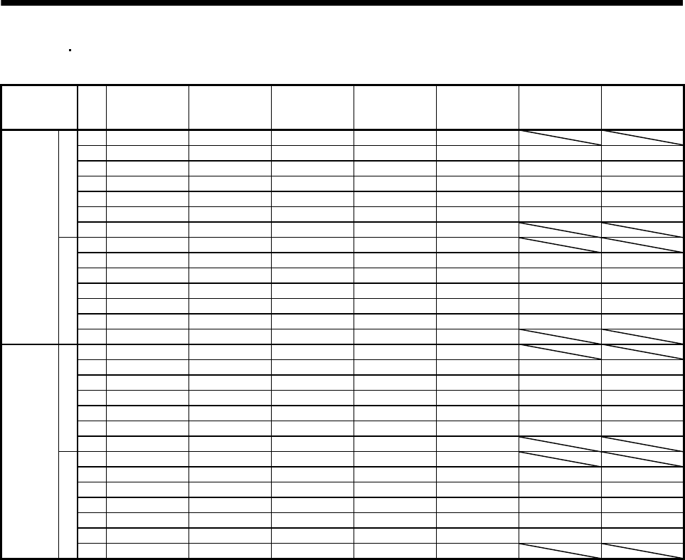
(2) HA-FF series
(a) General industrial machine-compliant
Item Gear
ratio HA-FF053(B)G1 HA-FF13(B)G1 HA-FF23(B)G1 HA-FF33(B)G1 HA-FF43(B)G1 HA-FF63(B)G1
1/5 588 686 686 980
1/10 588 686 686 1470
1/20 588 1176 1568 1764
[N]
1/30 686 1225 1764 2156
1/5 132 154 154 220
1/10 132 154 154 330
1/20 132 264 353 397
Permissible Radial
Load
[lb]
1/30 154 275 397 485
(b) Precision application-compliant
Item Gear
ratio HA-FF053(B)G2 HA-FF13(B)G2 HA-FF23(B)G2 HA-FF33(B)G2 HA-FF43(B)G2 HA-FF63(B)G2
1/5 69 69 98 216 216 588
1/9 735 735
1/10 88 127 265 265
1/15 137 216 392
1/20 980 980 1274 1274
1/25 392 784
1/29 1078 1470 1470 1470
[N]
1/45 1274 1666 1666 1666 3430
1/51515224949132
1/9 165 165
1/10 20 29 60 60
1/15 31 49 88
1/20 220 220 286 286
1/25 88 176
1/29 242 330 330 330
Permissible Radial
Load
[lb]
1/45 286 375 375 375 771
1/5 59 59 147 265 265 784
1/9 980 980
1/10 78 167 343 343
1/15 88 216 363
1/20 1372 1372 2254 2254
1/25 314 412
1/29 1764 2548 2548 2548
[N]
1/45 1960 3234 3234 3234 5390
1/51313336060176
1/9 220 220
1/10 16 38 77 77
1/15 20 49 82
1/20 308 308 507 507
1/25 71 93
1/29 397 573 573 573
Permissible Thrust
Load
[lb]
1/45 441 727 727 727 1212
2 - 9
2. INSTALLATION
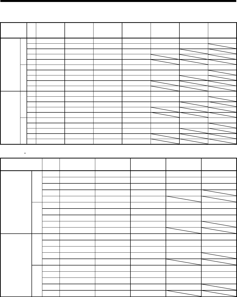
(3) HC-SF HC-SFS (2000r/min) series
(a) General industrial machine-compliant
Item Gear
ratio
HC-SF52(B)G1
HC-SFS52(B)G1
HC-SFS524(B)G1
HC-SF102(B)G1
HC-SFS102(B)G1
HC-SFS1024(B)G1
HC-SF152(B)G1
HC-SFS152(B)G1
HC-SFS1524(B)G1
HC-SF202(B)G1
HC-SFS202(B)G1
HC-SFS2024(B)G1
HC-SF352(B)G1
HC-SFS352(B)G1
HC-SFS3524(B)G1
HC-SF502(B)G1
HC-SFS502(B)G1
HC-SFS5024(B)G1
HC-SF702(B)G1
HC-SFS702(B)G1
HC-SFS7024(B)G1
1/6 2058 2842 2842 2842 3332
1/11 2391 3273 3273 3273 3871 5488 7526
1/17 2832 3646 3646 3646 4420 6468 8683
1/29 3273 4410 5135 7291 7291 13426 13426
1/35 5253 5253 6047 8555 8555 16072 16072
1/43 5253 6047 8555 8555 11662 16072 22540
[N]
1/59 5880 9741 9741 9741 13132
1/6 463 639 639 639 749
1/11 538 728 728 728 870 1234 1952
1/17 637 820 820 820 994 1454 1952
1/29 728 991 1154 1639 1639 3018 3018
1/35 1181 1181 1359 1923 1923 3613 3613
1/43 1181 1359 1923 1923 2622 3613 5067
Permissible
Radial Load
[lb]
1/59 1322 2190 2190 2190 2952
1/6 1470 2352 2352 2352 3920
1/11 1470 2764 2764 2764 3920 6292 8085
1/17 1470 2940 2940 2940 3920 6860 9673
1/29 1470 2940 3920 6860 6860 13720 13720
1/35 2940 2940 3920 6860 6860 13720 13720
1/43 2940 3920 6860 6860 9800 13720 19600
[N]
1/59 2940 6860 6860 6860 9800
1/6 330 529 529 529 881
1/11 330 621 621 621 881 1415 1818
1/17 330 661 661 661 881 1542 2175
1/29 330 661 881 1542 1542 3084 3084
1/35 661 661 881 1542 1542 3084 3084
1/43 661 881 1542 1542 2203 3084 4406
Permissible
Thrust
Load
[lb]
1/59 661 1542 1542 1542 2203
2 - 10
2. INSTALLATION
(b) Precision application-compliant
Item Gear
ratio
HC-SF52(B)G2
HC-SFS52(B)G2
HC-SFS524(B)G2
HC-SF102(B)G2
HC-SFS102(B)G2
HC-SFS1024(B)G2
HC-SF152(B)G2
HC-SFS152(B)G2
HC-SFS1524(B)G2
HC-SF202(B)G2
HC-SFS202(B)G2
HC-SFS2024(B)G2
HC-SF352(B)G2
HC-SFS352(B)G2
HC-SFS3524(B)G2
HC-SF502(B)G2
HC-SFS502(B)G2
HC-SFS5024(B)G2
HC-SF702(B)G2
HC-SFS702(B)G2
HC-SFS7024(B)G2
1/5 833 833 833 1666 3822 3822 3822
1/9 980 980 1960 1960 4704 4704
1/20 1274 2646 2646 6076 6076
1/29 2940 2940 6860 6860
[N]
1/45 3430 8036 8036 8036
1/5 187 187 187 375 859 859 859
1/9 220 220 441 441 1058 1058
1/20 286 595 595 1366 1366
1/29 661 661 1542 1542
Permissible
Radial Load
[lb]
1/45 771 1807 1807 1807
1/5 1176 1176 1176 2156 5488 5488 5488
1/9 1568 1568 2646 2646 7252 7252
1/20 2254 3724 3724 9506 9506
1/29 4704 4704 11760 11760
[N]
1/45 5390 14700 14700 14700
1/5 264 264 264 485 1234 1234 1234
1/9 353 353 595 595 1630 1630
1/20 507 837 837 2137 2137
1/29 1058 1058 2644 2644
Permissible
Thrust
Load
[lb]
1/45 1212 3305 3305 3305
(4) HC-RF HC-RFS series
Item Gear
ratio
HC-RF103(B)G2
HC-RFS103(B)G2
HC-RF153(B)G2
HC-RFS153(B)G2
HC-RF203(B)G2
HC-RFS203(B)G2
HC-RF353(B)G2
HC-RFS353(B)G2
HC-RF503(B)G2
HC-RFS503(B)G2
1/5 833 833 833 1666 3822
1/9 980 1960 1960 4704 4704
1/20 2646 2646 2646 6076 6076
1/29 2940 2940 6860 6860
[N]
1/45 3430 8036 8036
1/5 187 187 187 375 859
1/9 220 441 441 1058 1058
1/20 595 595 595 1366 1366
1/29 661 661 1542 1542
Permissible
Radial Load
[lb]
1/45 771 1806 1806
1/5 1176 1176 1176 2156 5488
1/9 1568 2646 2646 7252 7252
1/20 3724 3724 3724 9506 9506
1/29 4704 4704 11760 11760
[N]
1/45 5390 14700 14700
1/5 264 264 264 485 1234
1/9 353 595 595 1630 1630
1/20 837 837 837 2137 2137
1/29 1058 1058 2644 2644
Permissible
Thrust Load
[lb]
1/45 1212 3305 3305
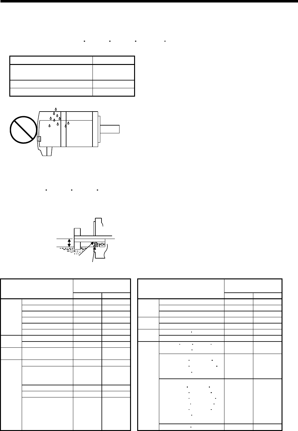
2 - 11
2. INSTALLATION
2.5 Protection from oil and water
(1) Next, the servo motor is not waterproof (IP44). Do not subject the servo motor to oil and water.
Especially for the HC-MF HC-KF HC-AQ HC-KFS HC-MFS and HA-FF series, do not subject the
shaft-through portion to oil.
Servo Motor Series Protection
HC-KF/HC-MF
HA-LF/HA-FF/HA-LFS IP44
HC-AQ/HC-KFS/HC-MFS IP55
HA-LH JP44
Oil or water
Servo motor
(2) When the gear box is mounted horizontally, the oil level in the gear box should always be lower than
the oil seal lip on the servo motor shaft. If it is higher than the oil seal lip, oil will enter the servo
motor, leading to a fault.
The HC-MF HC-KF HC-AQ HC-MFS and HC-KFS series servo motor is not equipped with an oil
seal and cannot be used with the gear box as described above. Oil should be shut off on the gear box
side.
In a special specification article with an oil seal is available. Please contact Mitsubishi.
Servo motor
V ring
Gear
Lip
Height above oil level h
Height above Oil Level h Height above Oil Level h
Servo Motor
[mm] [in]
Servo Motor
[mm] [in]
81 20 0.79 053/13 8 0.32
121 to 301 25 0.98 23/33 12 0.47
52(4) to 152(4) (Note)20 0.79
HA-FF
43/63 14 0.55
202(4) to 702(4) (Note) 25 0.98 11K2 30 0.18
53 to 153 20 0.79 HA-LH 15K2/22K2 40 1.58
HC-SF
HC-SFS
203/353 25 0.98 30K2(4) 37K2(4) 45 1.77
52 to 152 20 0.79 HA-LF 45K24/55K24 48 1.89
HC-LFS 202/302 25 0.98 502 702 601(4)
701M(4) 11K2(4) 34 1.34
HC-RF
HC-RFS 103 to 503 20 0.79
72/152 20 0.79
15K1(4) 20K1(4)
22K1M(4) 30K1M(4)
30K2(4) 37K2(4)
45 1.77
202 to 502 25 0.98
13 12 0.47
23/43 14 0.55
801(4) 12K1(4)
25K1(4) 30K1(4)
11K1M(4) 15K1M(4)
37K1M(4) 45K1M4
15K2(4) 22K2(4)
45K24 55K24
48 1.89
HC-UF
HC-UFS
73 20 0.79
HA-LFS
37K1(4) 50K1M4 55 2.17
Note. 524 to 7024 are not available for the HC-SF series.
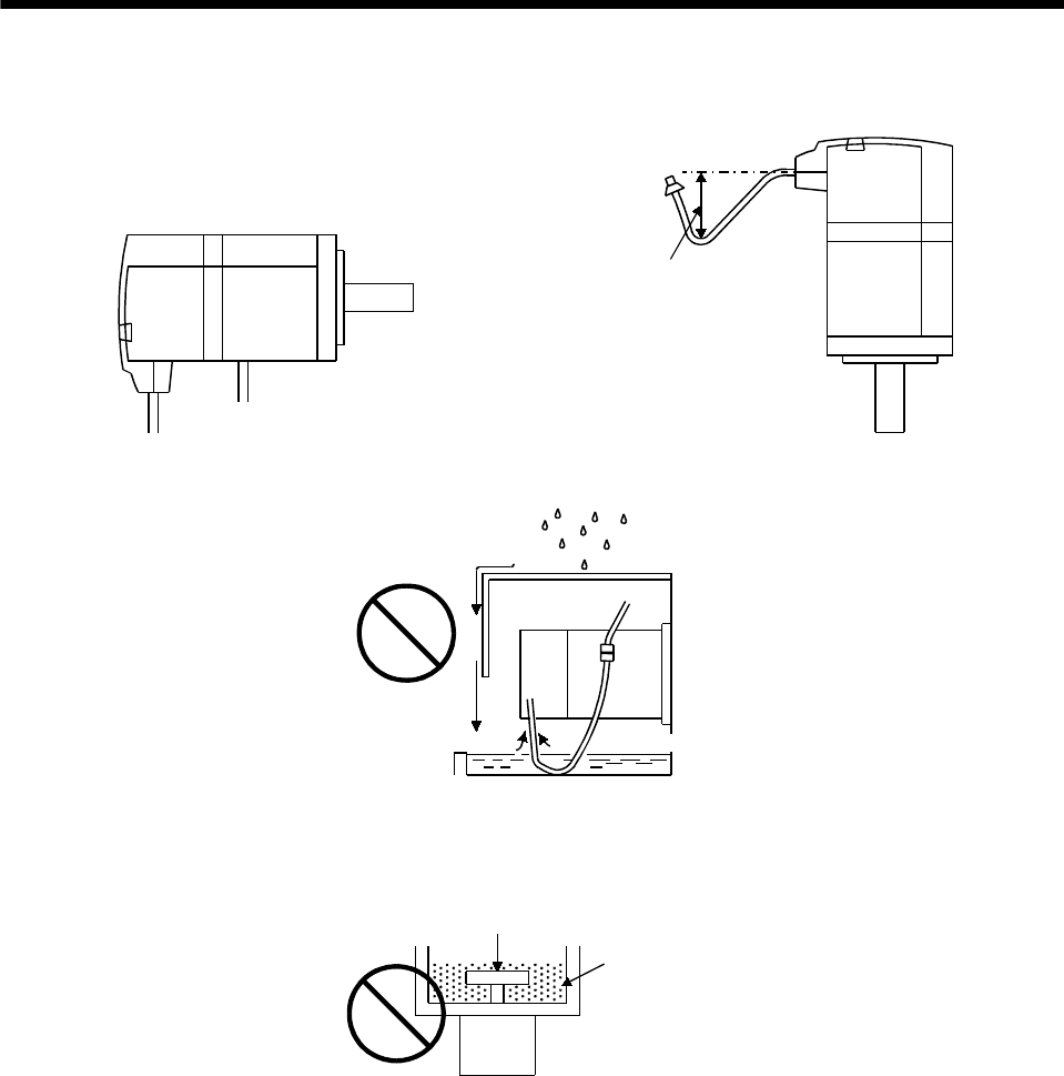
2 - 12
2. INSTALLATION
(3) When installing the servo motor horizontally, face the power cable and encoder cable downward. When
installing the servo motor vertically or obliquely, provide a trap for the cable.
Cable trap
(4) Do not use the servo motor with its cable soaked in oil or water. (Figure on the right)
Cover
<Incorrect> Capillary phenomenon
Oil/water pool
Servo
motor
(5) When the servo motor is to be installed with the shaft end at top, provide measures so that it is not
exposed to oil and water entering from the machine side, gear box, etc.
Gear
Lubricating oil
Servo motor
(6) If the servo motor is exposed to oil such as coolant, the sealant, packing, cable and others may be
affected depending on the oil type.
(7) In the environment where the servo motor is exposed to oil mist, oil, water, grease and/or like, the
servo motor of the standard specifications may not be usable. Contact us.
(8) In the case of the servo motor with oil seal, the oil seal may sound during operation. It poses no
problems in function.
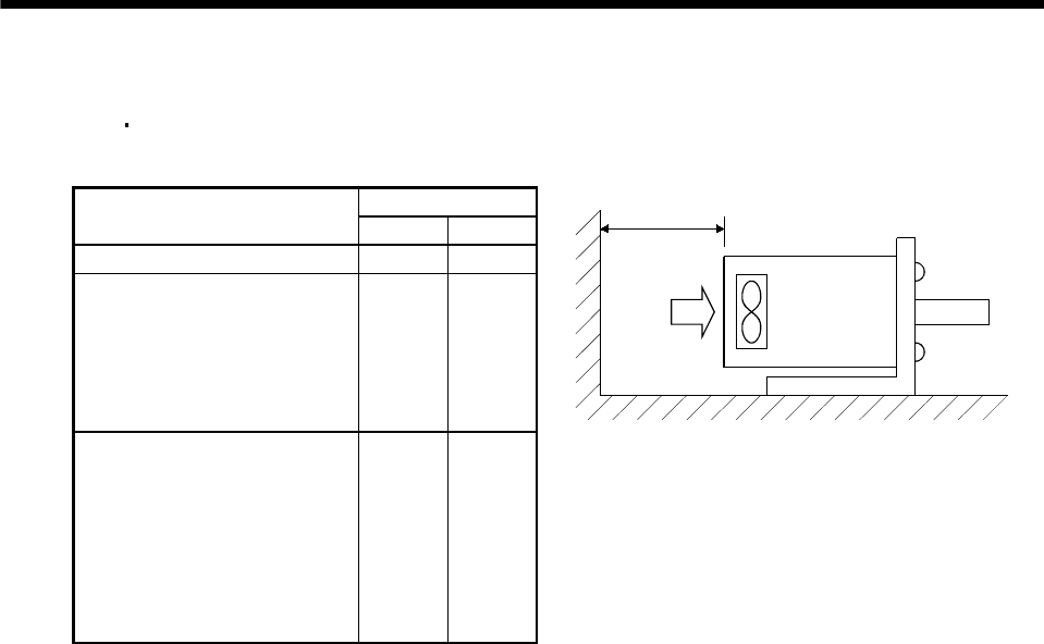
2 - 13
2. INSTALLATION
2.6 Cooling fan
The HA-LH HA-LF and HA-LFS servo motors have a cooling fan. Leave the following distance between
the servo motor's suction face and the wall.
Distance L
Servo Motor Series [mm] [in]
HA-LH series 50 1.97
HA-LFS601 to 12K1
HA-LFS701M to 15K1M
HA-LFS11K2 to 22K2
HA-LFS6014 to 12K14
HA-LFS701M4 to 15K1M4
HA-LFS11K24 to 22K24
100 3.94
HA-LF30K2/37K2
HA-LF30K24 to 55K24
HA-LFS15K1 to 37K1
HA-LFS22K1M to 37K1M
HA-LFS30K2/37K2
HA-LFS15K14 to 37K14
HA-LFS22K1M4 to 50K1M4
HA-LFS30K24 to 55K24
150 5.91
L or longer
Wind
Servo motor
Cooling fan
2.7 Cable
The power supply and encoder cables routed from the servo motor should be fixed to the servo motor to
keep them unmovable. Otherwise, cable breaks may occur. In addition, do not modify the connectors,
terminals and others at the ends of the cables.

2 - 14
2. INSTALLATION
MEMO
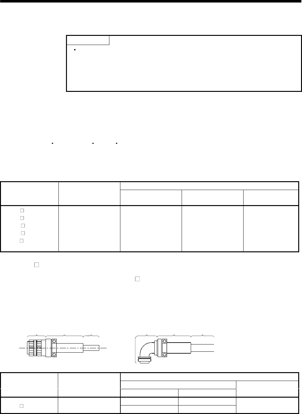
3 - 1
3. CONNECTORS USED FOR SERVO MOTOR WIRING
3. CONNECTORS USED FOR SERVO MOTOR WIRING
POINT
Protective structure indicated for cables and connecters is for a cable or
connector alone. When the cables and connectors are used to connect the
servo amplifier and servo motor, and if protective structures of the servo
amplifier and servo motor are lower than that of the cable and connector,
specifications of the servo amplifier and servo motor apply.
3.1 Makeups
This section gives connector makeups on an operating environment basis. Use the models of the
manufacturers given or equivalent.
3.1.1 HC-KF(-UE) HC-MF(-UE) HA-FF HC-UF3000r/min series
Use round crimping terminals (1.25-4) for connection of the power supply and electromagnetic brake. For
connection of the encoder, use the connector indicated in this section or equivalent. This connector may be
used with the EN Standard and UL/C-UL Standard but is not waterproof.
Cable Side Connector
Servo Motor
Connector Supplied for
Servo Motor
(Tyco Electronics)
Housing
(Tyco Electronics)
Connector Pin
(Tyco Electronics)
Cable Clamp
(Toa Electric Industry)
HC-KF (B)
HC-KF (B)-UE
HC-MF (B)
HC-MF (B) -UE
HA-FF (B)
HC-UF13 to 73(B)
1-172169-9 1-172161-9 170359-1
170363-1 (loose piece) MTI-0002
3.1.2 HA-FF C-UE series
If used with a waterproof connector, the HA-FF C(B)-UE does not improve in ingress protection (IP54).
(1) Non-waterproof, UL/C-UL Standard-compliant
(a) When using cabtyre cables
1) For connection of power supply
1) Plug
2) Cable
clamp Cable 1) Plug
2) Cable
clamp Cable
Cable Side Connector
1) Plug (DDK)
Servo Motor Connector Supplied for
Servo Motor Type Model
2) Cable clamp
(DDK)
Straight D/MS3106B14S-2S
HA-FF C(B) -UE CE05-2A14S-2PD-B Angle D/MS3108B14S-2S D/MS3057-6A
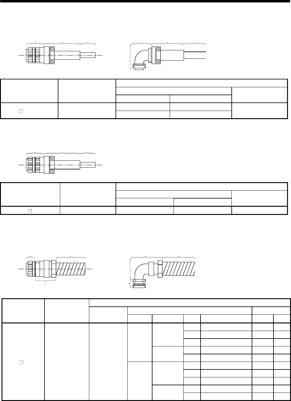
3 - 2
3. CONNECTORS USED FOR SERVO MOTOR WIRING
2) For connection of encoder
1) Plug
2) Cable
clamp Cable 1) Plug
2) Cable
clamp Cable
Cable Side Connector
1) Plug (DDK)Servo Motor Connector Supplied for
Servo Motor Type Model
2) Cable clamp
(DDK)
Straight D/MS3106B20-29S
HA-FF C(B) -UE MS3102A20-29P Angle D/MS3108B20-29S D/MS3057-12A
3) For connection of brake
1) Plug
2) Cable
clamp Cable
Cable Side Connector
Plug (DDK)
Servo Motor Connector Supplied for
Servo Motor Type Model
2) Cable clamp
(DDK)
HA-FF CB-UE MS3102A10SL-4P Straight D/MS3106A10SL-4S D/MS3057-4A
(b) When using flexible conduits
1) For connection of power supply
1) Plug Conduit
1) Plug
2) Connector for
conduit Conduit
2) Connector for conduit
Cable Side Connector
2) Cable Connector Conduit
Servo Motor Connector Supplied
for Servo Motor 1) Plug
(DDK) Type Manufacturer Size Model Model ID
1/4 RCC-102RL-MS14F VF-02 8.3
3/8 RCC-103RL-MS14F VF-03 10.6
Nippon flex
1/2 RCC-104RL-MS14F VF-04 14.0
10 MSA-10-14 FCV10 10.0
Straight
Daiwa
Dengyo 12 MSA-12-14 FCV12 12.3
1/4 RCC-302RL-MS14F VF-02 8.3
3/8 RCC-303RL-MS14F VF-03 10.6
Nippon flex
1/2 RCC-304RL-MS14F VF-04 14.0
10 MAA-10-14 FCV10 10.0
HA-FF C(B) -UE CE05-2A14S-2PD-B D/MS3106A14S-
2S(D190)
Angle
Daiwa
Dengyo 12 MAA-12-14 FCV12 12.3
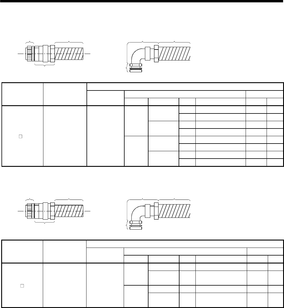
3 - 3
3. CONNECTORS USED FOR SERVO MOTOR WIRING
2) For connection of encoder
1) Plug Conduit
1) Plug
2) Connector for
conduit Conduit
2) Connector for conduit
Cable Side Connector
2) Cable Connector Conduit
Servo Motor Connector Supplied
for Servo Motor 1) Plug
(DDK) Type Manufacturer Size Model Model ID
1/2 RCC-104RL-MS20F VF-04 14.0
Nippon flex 3/4 RCC-106RL-MS20F VF-06 19.0
16 MSA-16-20 FCV16 15.8
Straight Daiwa
Dengyo 22 MSA-22-20 FCV22 20.8
1/2 RCC-304RL-MS20F VF-04 14.0
Nippon flex 3/4 RCC-306RL-MS20F VF-06 19.0
16 MAA-16-20 FCV16 15.8
HA-FF C(B) -UE MS3102A20-29P D/MS3106A20-
29S(D190)
Angle Daiwa
Dengyo 22 MAA-22-20 FCV22 20.8
3) For connection of brake
1) Plug Conduit
1) Plug
2) Connector for
conduit Conduit
2) Connector for conduit
Cable Side Connector
2) Cable Connector Conduit
Servo Motor Connector Supplied
for Servo Motor 1) Plug
(DDK) Type Manufacturer Size Model Model ID
Nippon flex 1/4 RCC-102RL-MS10F VF-02 8.3
Straight Daiwa
Dengyo 10 MSA-10-10 FCV10 10.0
Nippon flex 1/4 RCC-302RL-MS10F VF-02 8.3
HA-FF CB-UE MS3102A10SL-4P D/MS3106A10SL-
4S(D190)
Angle Daiwa
Dengyo 10 MAA-10-10 FCV10 10.0
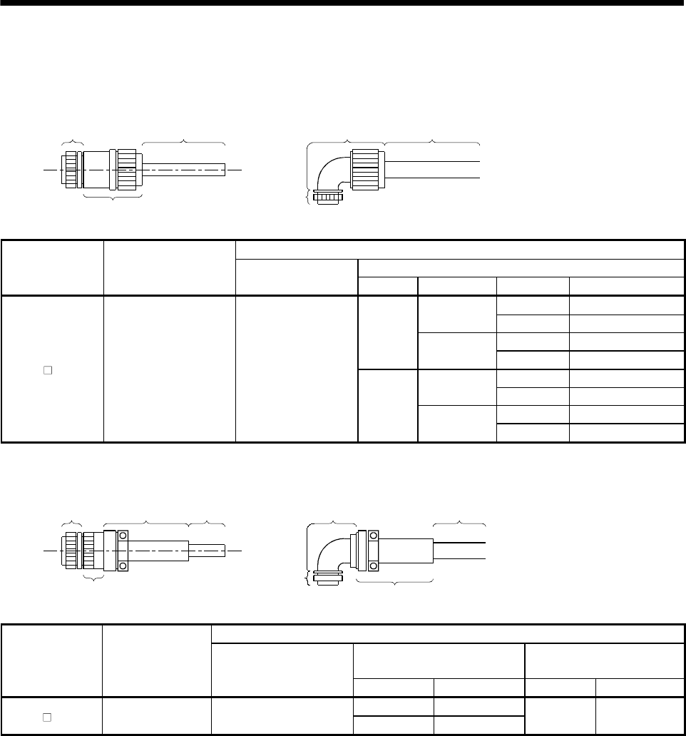
3 - 4
3. CONNECTORS USED FOR SERVO MOTOR WIRING
(2) EN Standard, UL/C-UL Standard-compliant
(a) When using cabtyre cables
1) For connection of power supply
1) Plug Cable
1) Plug
Cable
2) Connector for
cable
2) Connector for cable
Cable Side Connector
2) Connector for CableServo Motor Connector Supplied for
Servo Motor 1) Plug
(DDK) Type Manufacturer Cable OD Model
4 to 8 ACS-08RL-MS14F
Nippon flex 8 to 12 ACS-12RL-MS14F
5 to 8.3 YSO14-5 to 8
Straight
Daiwa Dengyo 8.3 to 11.3 YSO14-9 to 11
4 to 8 ACA-08RL-MS14F
Nippon flex 8 to 12 ACA-12RL-MS14F
5 to 8.3 YLO14-5 to 8
HA-FF C(B) -UE CE05-2A14S-2PD-B CE05-6A14S-2SD-D
Angle
Daiwa Dengyo 8.3 to 11.3 YLO14-9 to 11
2) For connection of encoder
1) Plug
3) Cable
clamp Cable 2) Back shell
3) Cable clamp
Cable
2) Back shell
1) Plug
Cable Side Connector
2) Back Shell
(DDK)
3) Cable Clamp
(DDK)
Servo Motor Connector Supplied
for Servo Motor 1) Plug
(DDK) Type Model Cable OD Model
Straight CE02-20BS-S-D
HA-FF C(B) -UE MS3102A20-29P D/MS3106A20-29S(D190) Angle CE-20BA-S-D 6.8 to 10 CE3057-12A-3-D
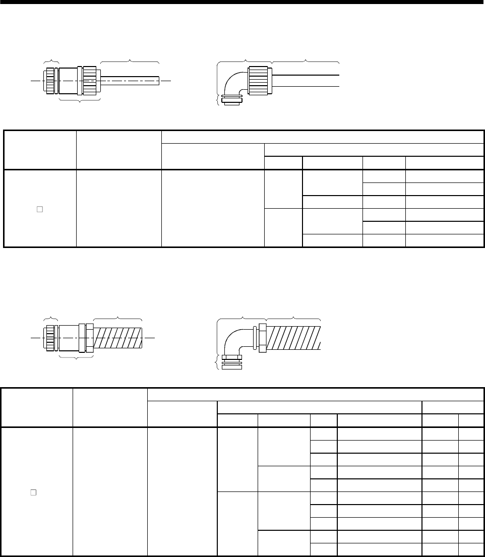
3 - 5
3. CONNECTORS USED FOR SERVO MOTOR WIRING
3) For connection of brake
1) Plug Cable
1) Plug
Cable
2) Connector for cable
2) Connector for cable
Cable Side Connector
2) Cable Connector
Servo Motor Connector Supplied for
Servo Motor 1) Plug
(DDK) Type Manufacturer Cable OD Model
4 to 8 ACS-08RL-MS10F
Nippon flex 8 to 12 ACS-12RL-MS10F
Straight
Daiwa Dengyo 5 to 8.3 YS010-5 to 8
4 to 8 ACA-08RL-MS10F
Nippon flex 8 to 12 ACA-12RL-MS10F
HA-FF CB-UE MS3102A10SL-4P D/MS3106A10SL-4S(D190)
Angle
Daiwa Dengyo 5 to 8.3 YL010-5 to 8
(b) When using flexible conduits
1) For connection of power supply
1) Plug Conduit
1) Plug
2) Connector fo
r
conduit Conduit
2) Connector for conduit
Cable Side Connector
2) Cable Connector Conduit
Servo Motor Connector Supplied
for Servo Motor 1) Plug
(DDK) Type Manufacturer Size Model Model ID
1/4 RCC-102RL-MS14F VF-02 8.3
3/8 RCC-103RL-MS14F VF-03 10.6
Nippon flex
1/2 RCC-104RL-MS14F VF-04 14.0
10 MSA-10-14 FCV10 10.0
Straight
Daiwa
Dengyo 12 MSA-12-14 FCV12 12.3
1/4 RCC-302RL-MS14F VF-02 8.3
3/8 RCC-303RL-MS14F VF-03 10.6
Nippon flex
1/2 RCC-304RL-MS14F VF-04 14.0
10 MAA-10-14 FCV10 10.0
HA-FF C(B) -UE CE05-2A14S-2PD-B CE05-6A14S-
2SD-D
Angle
Daiwa
Dengyo 12 MAA-12-14 FCV12 12.3
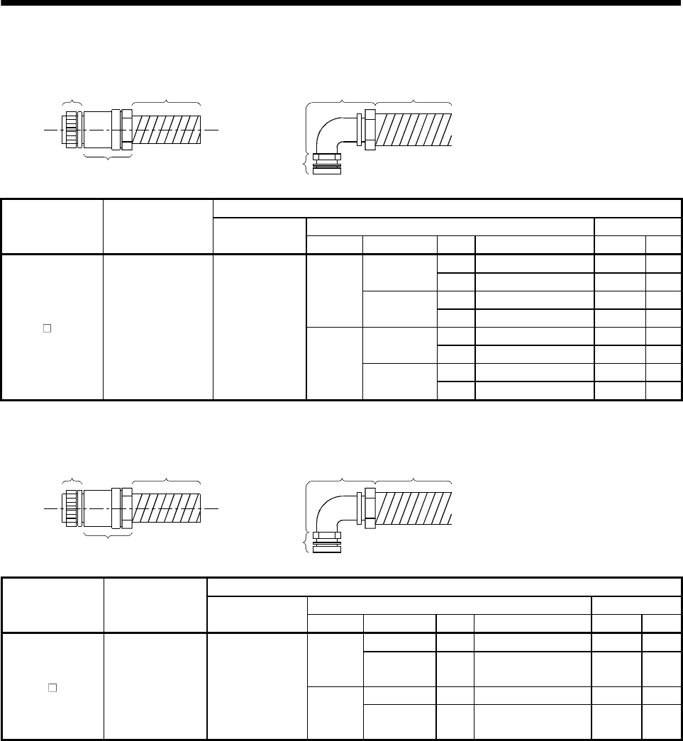
3 - 6
3. CONNECTORS USED FOR SERVO MOTOR WIRING
2) For connection of encoder
1) Plug Conduit
1) Plug
2) Connector for
conduit Conduit
2) Connector for conduit
Cable Side Connector
2) Cable Connector ConduitServo Motor Connector Supplied
for Servo Motor 1) Plug
(DDK) Type Manufacturer Size Model Model ID
1/2 RCC-104RL-MS20F VF-04 14.0
Nippon flex 3/4 RCC-106RL-MS20F VF-06 19.0
16 MSA-16-20 FCV16 15.8
Straight Daiwa
Dengyo 22 MSA-22-20 FCV22 20.8
1/2 RCC-304RL-MS20F VF-04 14.0
Nippon flex 3/4 RCC-306RL-MS20F VF-06 19.0
16 MAA-16-20 FCV16 15.8
HA-FF C(B) -UE MS3102A20-29P D/MS3106A20-
29S(D190)
Angle Daiwa
Dengyo 22 MAA-22-20 FCV22 20.8
3) For connection of brake
1) Plug Conduit
1) Plug
2) Connector for
conduit Conduit
2) Connector for conduit
Cable Side Connector
2) Cable Connector ConduitServo Motor Connector Supplied
for Servo Motor 1) Plug
(DDK) Type Manufacturer Size Model Model ID
Nippon flex 1/4 RCC-102RL-MS10F VF-02 8.3
Straight Daiwa
Dengyo 10 MSA-10-10 FCV10 10.0
Nippon flex 1/4 RCC-302RL-MS10F VF-02 8.3
HA-FF CB-UE MS3102A10SL-4P D/MS3106A10SL-
4S(D190)
Angle Daiwa
Dengyo 10 MAA-10-10 FCV10 10.0
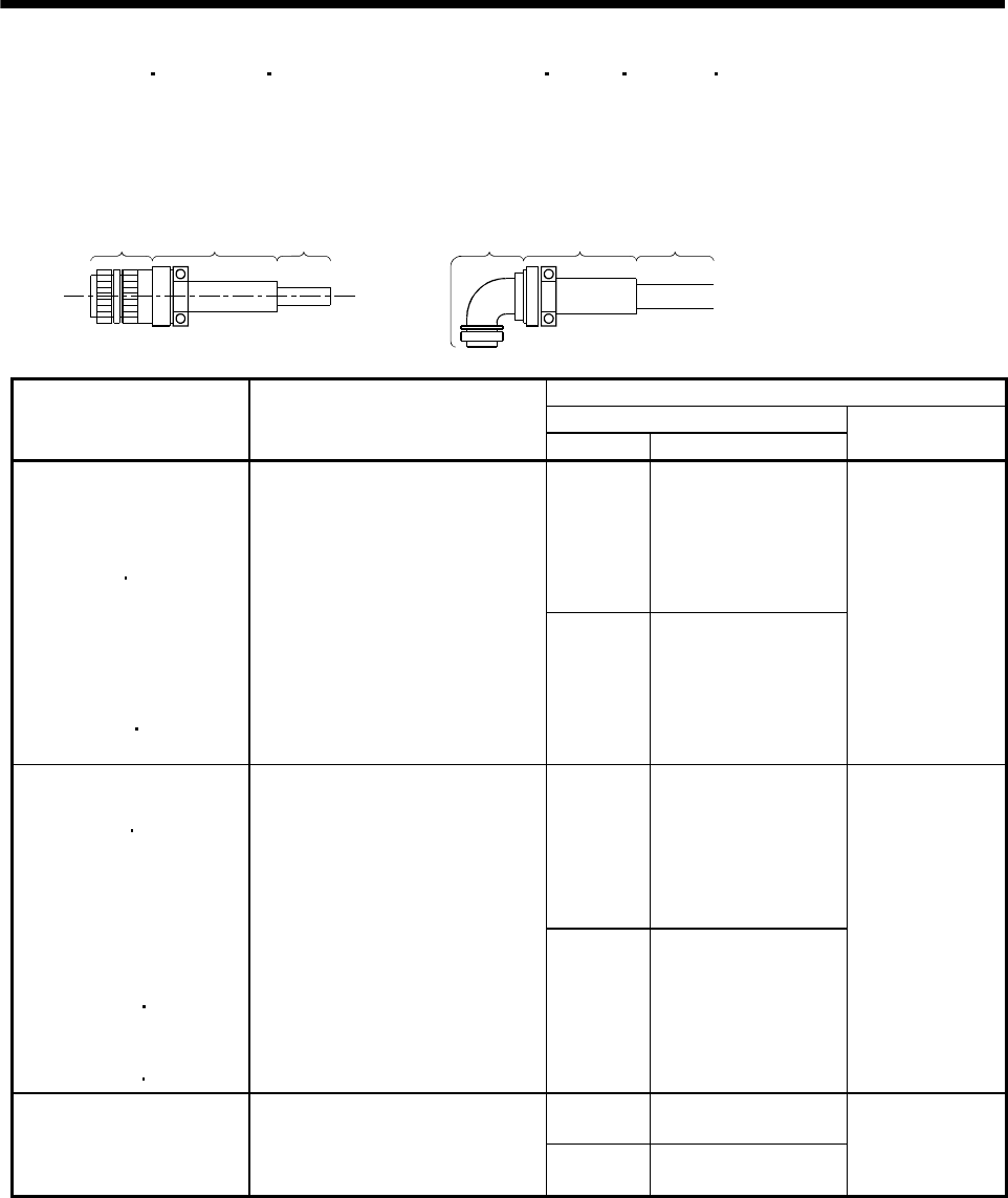
3 - 7
3. CONNECTORS USED FOR SERVO MOTOR WIRING
3.1.3 HC-SF(S) HC-RF(S) HC-UF(S)2000r/min, HA-LH HA-LF HA-LFS HC-LFS series
(1) Non-waterproof, UL/C-UL Standard-compliant
(a) When using cabtyre cables
1) For connection of power supply
1) Plug
2) Cable
clamp Cable 1) Plug
2) Cable
clamp Cable
Cable Side Connector
1) Plug (DDK)
Servo Motor Connector Supplied for Servo Motor
Type Model
2) Cable clamp
(DDK)
Straight D/MS3106B22-23S
HC-SF81(B)
HC-SF52(B) to 152(B)
HC-SF53(B) to 153(B)
HC-RF103(B) to 203(B)
HC-UF72(B) 152(B)
HC-SFS81(B)
HC-SFS52(B) to 152(B)
HC-SFS53(B) to 153(B)
HC-SFS524(B) to 1524(B)
HC-RFS103(B) to 203(B)
HC-UFS72(B) 152(B)
HC-LFS52(B) to 152(B)
CE05-2A22-23PD-B
Angle D/MS3108B22-23S
D/MS3057-12A
Straight D/MS3106B24-10S
HC-SF121(B) to 301(B)
HC-SF202(B) to 502(B)
HC-SF203(B) 353(B)
HC-RF353(B) to 503(B)
HC-UF202(B) to 502(B)
HC-SFS121(B) to 301(B)
HC-SFS202(B) to 502(B)
HC-SFS203(B) to 353(B)
HC-SFS2024(B) to 5024(B)
HC-RFS353(B) 503(B)
HC-UFS202(B) to 502(B)
HA-LFS502
HC-LFS202(B) 302(B)
CE05-2A24-10PD-B
Angle D/MS3108B24-10S
D/MS3057-16A
Straight D/MS3106B32-17S
HC-SF702(B)
HC-SFS702(B)
HC-SFS7024(B)
HA-LFS702
CE05-2A32-17PD-B
Angle D/MS3108B32-17S
D/MS3057-20A
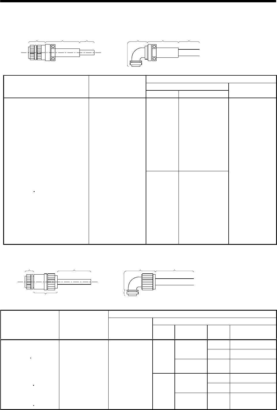
3 - 8
3. CONNECTORS USED FOR SERVO MOTOR WIRING
2) For connection of encoder
1) Plug
2) Cable
clamp Cable 1) Plug
2) Cable
clamp Cable
Cable Side Connector
1) Plug (DDK)Servo Motor Connector Supplied for
Servo Motor Type Model
2) Cable clamp
(DDK)
Straight D/MS3106B20-29S
HC-SF81(B) to 301(B)
HC-SF52(B) to 702(B)
HC-SF53(B) to 353(B)
HC-RF103(B) to 503(B)
HC-UF72(B) to 502(B)
HC-SFS81(B) to 301(B)
HC-SFS52(B) to 702(B)
HC-SFS53(B) to 353(B)
HC-SFS524(B) to 7024(B)
HC-RFS103(B) to 503(B)
HC-UFS72(B) to 502(B)
HA-LH11K2 to 22K2
HA-LF30K24 to 55K24
HA-LF30K2 37K2
HA-LFS601 to 37K1
HA-LFS701M to 37K1M
HA-LFS502 to 37K2
HA-LFS6014 to 37K14
HA-LFS701M4 to 50K1M4
HA-LFS11K24 to 55K24
HC-LFS52(B) to 302(B)
MS3102A20-29P
Angle D/MS3108B20-29S
D/MS3057-12A
3) For connection of brake
1) Plug Cable
1) Plug
Cable
2) Connector for cable
2) Connector for cable
Cable Side Connector
2) Connector for Cable
Servo Motor Connector Supplied
for Servo Motor 1) Plug
(DDK) Type Manufacturer Cable
OD Model
4 to 8 ACS-08RL-MS10F
Nippon flex 8 to 12 ACS-12RL-MS10F
Straight
Daiwa
Dengyo 5 to 8.3 YSO10-5 to 8
4 to 8 ACA-08RL-MS10F
Nippon flex 8 to 12 ACA-12RL-MS10F
HC-SF121B to 301B
HC-SF202B to 702B
HC-SF203B 353B
HC-UF202B to 502B
HC-SFS121B to 301B
HC-SFS202B to 702B
HC-SFS203B 353B
HC-SFS2024B to 7024B
HC-UFS202B to 502B
HC-LFS202B 302B
MS3102A10SL-4P D/MS3106A10SL-
4S (D190)
Angle
Daiwa
Dengyo 5 to 8.3 YLO10-5 to 8
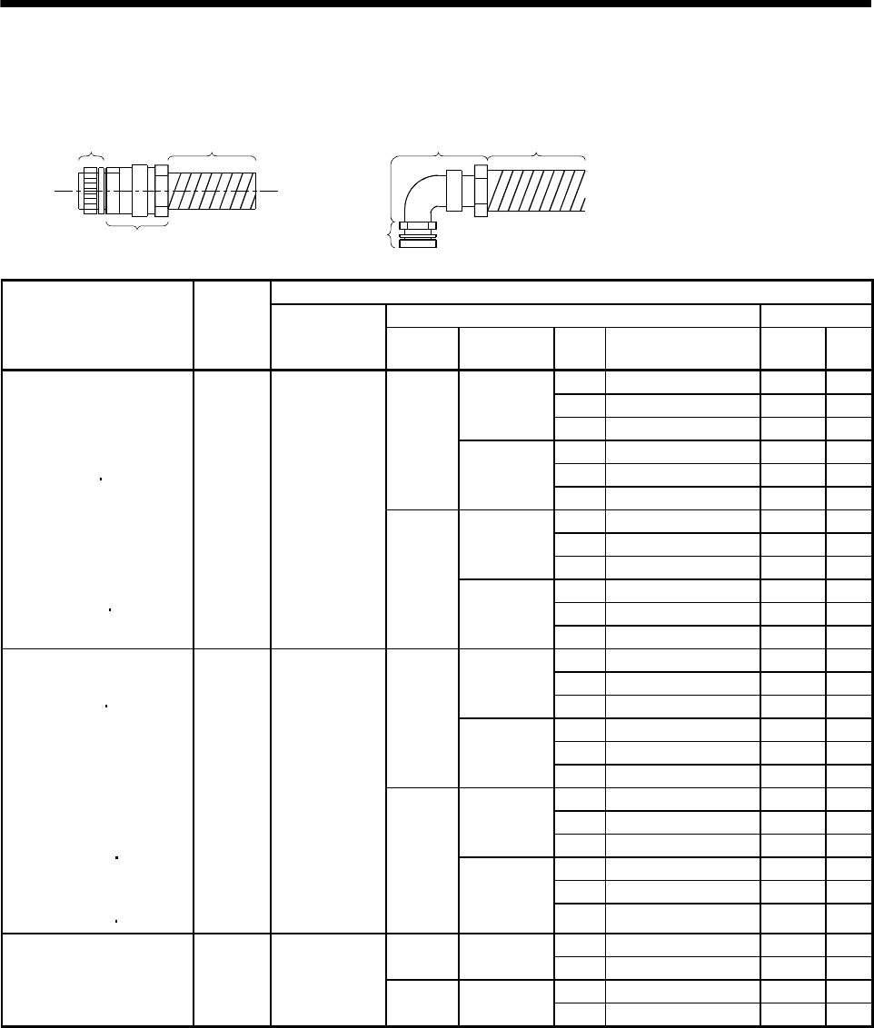
3 - 9
3. CONNECTORS USED FOR SERVO MOTOR WIRING
(b) When using flexible conduits
1) For connection of power supply
1) Plug Conduit
1) Plug
2) Connector for
conduit Conduit
2) Connector for conduit
Cable Side Connector
2) Connector for conduit Conduit
Servo Motor
Connector
Supplied
for Servo
Motor
1) Plug
(DDK) Type Manufacturer Size Model Model ID
1/2 RCC-104RL-MS22F VF-04 14.0
3/4 RCC-106RL-MS22F VF-06 19.0Nippon flex
1 RCC-108RL-MS22F VF-08 24.4
16 MSA-16-22 FCV16 15.8
22 MSA-22-22 FCV22 20.8
Straight
Daiwa
Dengyo 28 MSA-28-22 FCV28 26.4
1/2 RCC-304RL-MS22F VF-04 14.0
3/4 RCC-306RL-MS22F VF-06 19.0Nippon flex
1 RCC-308RL-MS22F VF-08 24.4
16 MAA-16-22 FCV16 15.8
22 MAA-22-22 FCV22 20.8
HC-SF81(B)
HC-SF52(B) to 152(B)
HC-SF53(B) to 153(B)
HC-RF103(B) to 203(B)
HC-UF72(B) 152(B)
HC-SFS81(B)
HC-SFS52(B) to 152(B)
HC-SFS53(B) to 153(B)
HC-SFS524(B) to 1524(B)
HC-RFS103(B) to 203(B)
HC-UFS72(B) 152(B)
HC-LFS52(B) to 152(B)
CE05-
2A22-
23PD-B
D/MS3106A22-
23S(D190)
Angle
Daiwa
Dengyo 28 MAA-28-22 FCV28 26.4
1/2 RCC-104RL-MS24F VF-04 14.0
3/4 RCC-106RL-MS24F VF-06 19.0
Nippon flex
1 RCC-108RL-MS24F VF-08 24.4
16 MSA-16-24 FCV16 15.8
22 MSA-22-24 FCV22 20.8
Straight
Daiwa
Dengyo 28 MSA-28-24 FCV28 26.4
1/2 RCC-304RL-MS24F VF-04 14.0
3/4 RCC-306RL-MS24F VF-06 19.0Nippon flex
1 RCC-308RL-MS24F VF-08 24.4
16 MAA-16-24 FCV16 15.8
22 MAA-22-24 FCV22 20.8
HC-SF121(B) to 301(B)
HC-SF202(B) to 502(B)
HC-SF203(B) 352(B)
HC-RF353(B) to 503(B)
HC-UF202(B) to 502(B)
HC-SFS121(B) to 301(B)
HC-SFS202(B) to 502(B)
HC-SFS203(B) to 353(B)
HC-SFS2024(B) to 5024(B)
HC-RFS353(B) 503(B)
HC-UFS202(B) to 502(B)
HA-LFS502
HC-LFS202(B) 302(B)
CE05-
2A24-
10PD-B
D/MS3106A24-
10S(D190)
Angle
Daiwa
Dengyo 28 MAA-28-24 FCV28 26.4
3/4 RCC-106RL-MS32F VF-06 19.0
Straight Nippon flex 1 RCC-108RL-MS32F VF-08 24.4
3/4 RCC-306RL-MS32F VF-06 19.0
HC-SF702(B)
HC-SFS702(B)
HC-SFS7024(B)
HA-LFS702
CE05-
2A32-
17PD-B
D/MS3106A32-
17S(D190) Angle Daiwa
Dengyo 1 RCC-308RL-MS32F VF-08 24.4
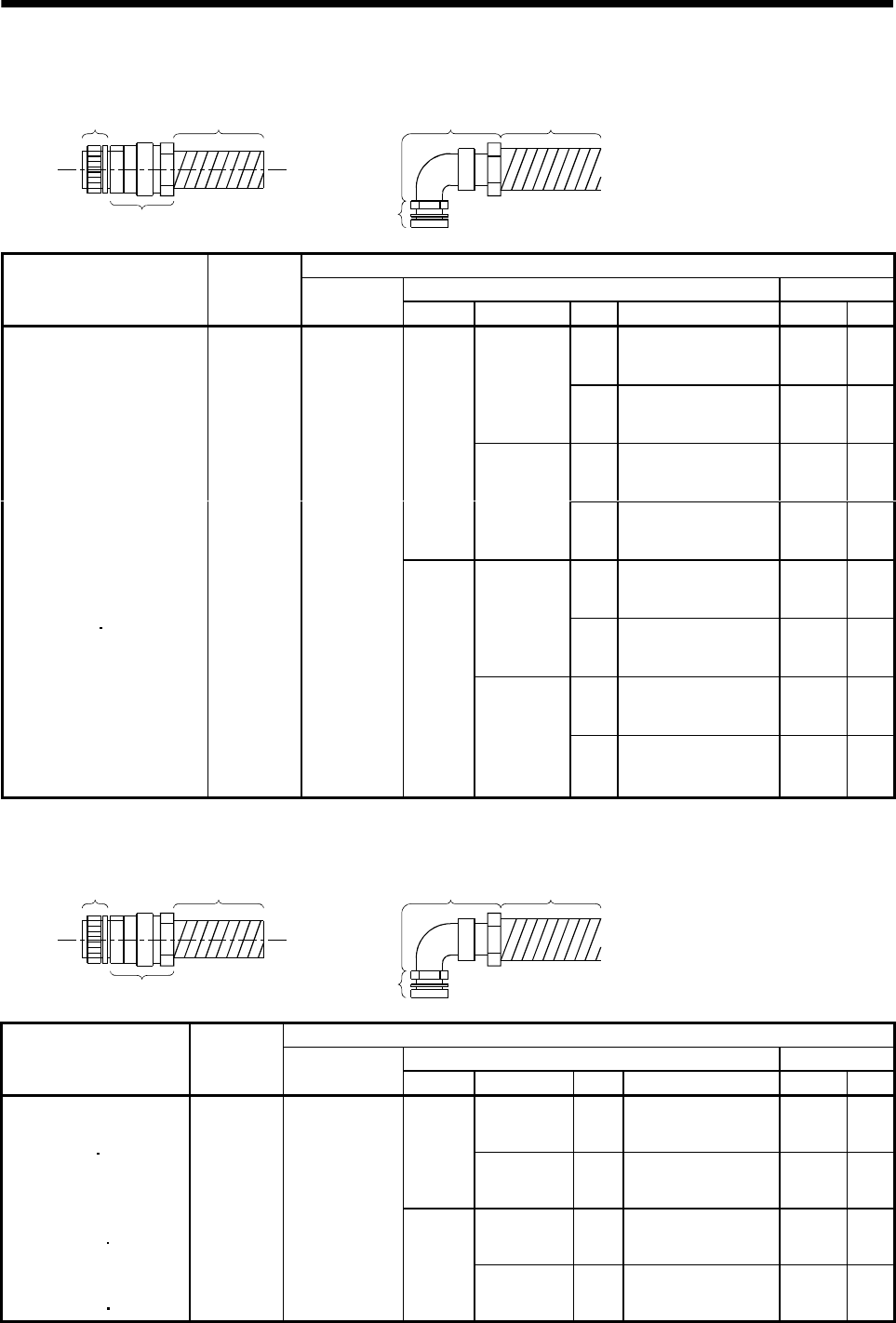
3 - 10
3. CONNECTORS USED FOR SERVO MOTOR WIRING
2) For connection of encoder
1) Plug Conduit
1) Plug
2) Connector for
conduit Conduit
2) Connector for conduit
Cable Side Connector
2) Connector for conduit ConduitServo Motor
Connector
Supplied for
Servo Motor
1) Plug
(DDK) Type Manufacturer Size Model Model ID
1/2 RCC-104RL-MS20F VF-04 14.0
Nippon flex
3/4 RCC-106RL-MS20F VF-06 19.0
16 MSA-16-20 FCV16 15.8
Straight
Daiwa
Dengyo
22 MSA-22-20 FCV22 20.8
1/2 RCC-304RL-MS20F VF-04 14.0
Nippon flex
3/4 RCC-306RL-MS20F VF-06 19.0
16 MAA-16-20 FCV16 15.8
HC-SF81(B) to 301(B)
HC-SF52(B) to 702(B)
HC-SF53(B) to 353(B)
HC-RF103(B) to 503(B)
HC-UF72(B) to 502(B)
HC-SFS81(B) to 301(B)
HC-SFS52(B) to 702(B)
HC-SFS53(B) to 353(B)
HC-SFS5024(B) to 7024(B)
HC-RFS103(B) to 503(B)
HC-UFS72(B) to 502(B)
HA-LH11K2 to 22K2
HA-LF30K24 to 55K24
HA-LF30K2 37K2
HA-LFS601 to 37K1
HA-LFS701M to 37K1M
HA-LFS502 to 37K2
HA-LFS6014 to 37K14
HA-LFS701M4 to 50K1M4
HA-LFS11K24 to 55K24
HC-LFS52(B) to 302(B)
MS3102A20-
29P
D/MS3106A20-
29S(D190)
Angle
Daiwa
Dengyo
22 MAA-22-20 FCV22 20.8
3) For connection of brake
1) Plug Conduit
1) Plug
2) Connector for
conduit Conduit
2) Connector for conduit
Cable Side Connector
2) Connector for conduit ConduitServo Motor
Connector
Supplied for
Servo Motor
1) Plug
(DDK) Type Manufacturer Size Model Model ID
Nippon flex 1/4 RCC-102RL-MS10F VF-02 8.3
Straight
Daiwa
Dengyo 10 MSA-10-10 FCV10 10
Nippon flex 1/4 RCC-302RL-MS10F VF-02 8.3
HC-SF121B to 301B
HC-SF202B to 702B
HC-SF203B 353B
HC-UF202B to 502B
HC-SFS121B to 301B
HC-SFS202B to 702B
HC-SFS203B 353B
HC-SFS2024B to 7024B
HC-UFS202B to 502B
HC-LFS202B 302B
MS3102A
10SL-4P
D/MS3106A10SL-
4S(D190)
Angle
Daiwa
Dengyo 10 MAA-10-10 FCV10 10
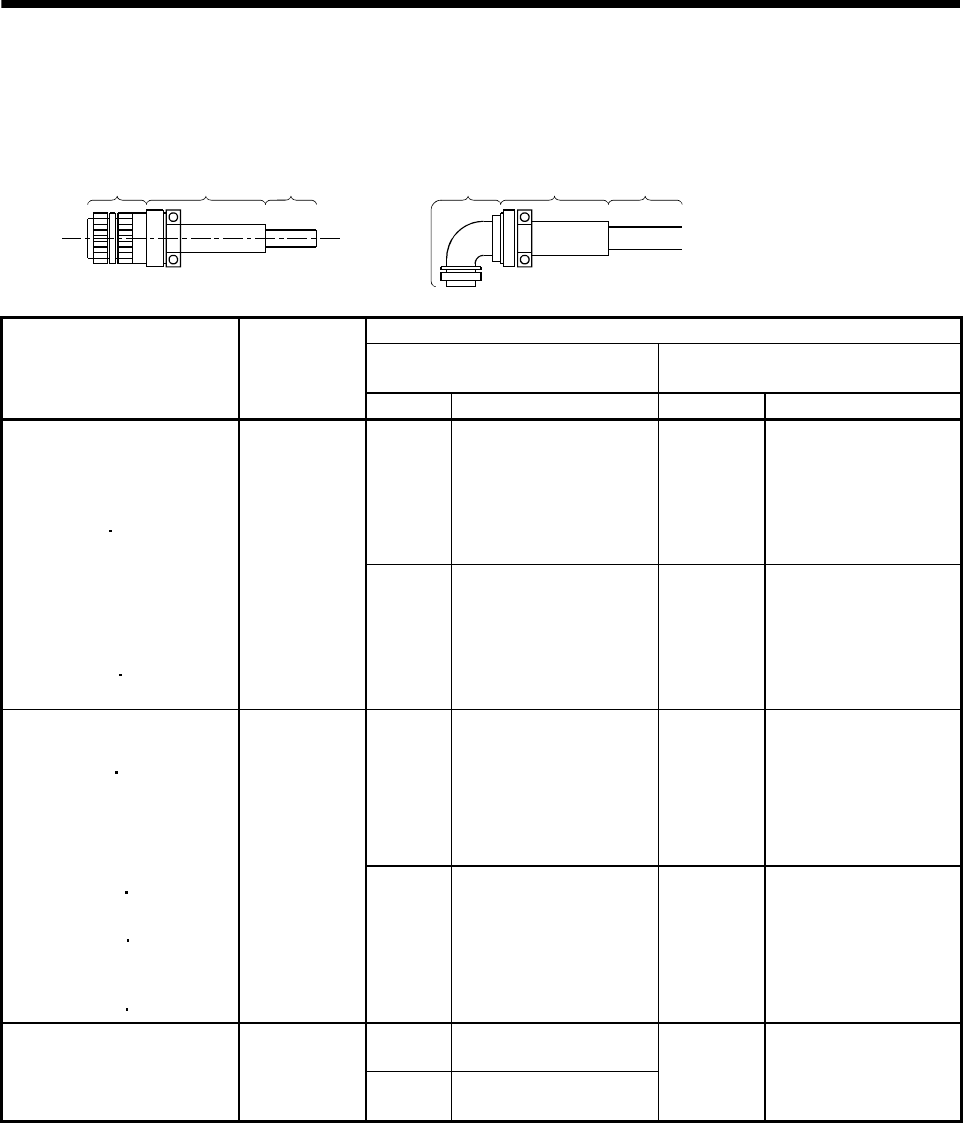
3 - 11
3. CONNECTORS USED FOR SERVO MOTOR WIRING
(2) Waterproof (IP65), EN Standard, UL/C-UL Standard-compliant
(a) When using cabtyre cables
1) For connection of power supply
1) Plug
2) Cable
clamp Cable 1) Plug
2) Cable
clamp Cable
Cable Side Connector
1) Plug (DDK) 2) Cable clamp
(DDK)
Servo Motor
Connector
Supplied for
Servo Motor Type Model Cable OD Model
Straight CE05-6A22-23SD-D-BSS 9.5 to 13 CE3057-12A-2-D
HC-SF81(B)
HC-SF52(B) to 152(B)
HC-SF53(B) to 153(B)
HC-RF103(B) to 203(B)
HC-UF72(B) 152(B)
HC-SFS81(B)
HC-SFS52(B) to 152(B)
HC-SFS53(B) to 153(B)
HC-SFS524(B) to 1524(B)
HC-RFS103(B) to 203(B)
HC-UFS72(B) 152(B)
HC-LFS52(B) to 152(B)
CE05-2A22-
23PD-B
Angle CE05-8A22-23SD-D-BAS 12.5 to 16 CE3057-12A-1-D
Straight CE05-6A24-10SD-D-BSS 13 to 15.5 CE3057-16A-2-D
HC-SF121(B) to 301(B)
HC-SF202(B) to 502(B)
HC-SF203(B) 353(B)
HC-RF353(B) to 503(B)
HC-UF202(B) to 502(B)
HC-SFS121(B) to 301(B)
HC-SFS202(B) to 502(B)
HC-SFS203(B) 353(B)
HC-SFS2024(B) to 5024(B)
HC-RFS353(B) 503(B)
HC-UFS202(B) to 502(B)
HA-LFS502
HC-LFS202(B) 302(B)
CE05-2A24-
10PD-B
Angle CE05-8A24-10SD-D-BAS 15 to 19.1 CE3057-16A-1-D
Straight CE05-6A32-17SD-D-BSS
HC-SF702(B)
HC-SFS702(B)
HC-SFS7024(B)
HA-LFS702
CE05-2A32-
17PD-B Angle CE05-8A32-17SD-D-BAS
22 to 23.8 CE3057-20A-1-D
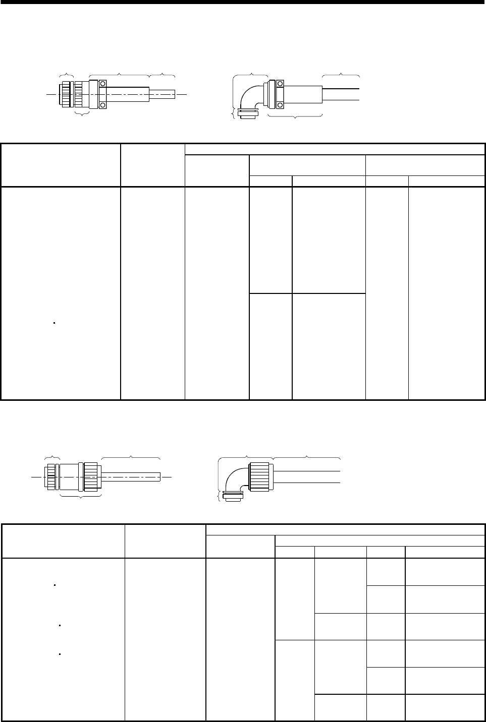
3 - 12
3. CONNECTORS USED FOR SERVO MOTOR WIRING
2) For connection of encoder
1) Plug
3) Cable
clamp Cable 2) Back shell
3) Cable clamp
Cable
2) Back shell
1) Plug
Cable Side Connector
2) Back shell 3) Cable clamp
(DDK)
Servo Motor
Connector
Supplied for
Servo Motor
1) Plug
(DDK) Type Model Cable OD Model
Straight CE02-20BS-S-D
HC-SF81(B) to 301(B)
HC-SF52(B) to 702(B)
HC-SF53(B) to 353(B)
HC-RF103(B) to 503(B)
HC-UF72(B) to 502(B)
HC-SFS81(B) to 301(B)
HC-SFS52(B) to 702(B)
HC-SFS53(B) to 353(B)
HC-SFS524(B) to 7024(B)
HC-RFS103(B) to 502(B)
HC-UFS72(B) to 502(B)
HA-LH11K2 to 22K2
HA-LF30K24 to 55K24
HA-LF30K2 37K2
HA-LFS601 to 37K1
HA-LFS701M to 37K1M
HA-LFS502 to 37K2
HA-LFS6014 to 37K14
HA-LFS701M4 to 50K1M4
HA-LFS11K24 to 55K24
HC-LFS52(B) to 302(B)
MS3102A20-29P D/MS3106A20-
29S(D190)
Angle CE-20BA-S-D
6.8 to 10 CE3057-12A-3-D
3) For connection of brake
1) Plug Cable
1) Plug
Cable
2) Connector for
cable
2) Connector for cable
Cable Side Connector
2) Connector for Cable
Servo Motor Connector Supplied
for Servo Motor 1) Plug
(DDK) Type Manufacturer Cable OD Model
4 to 8 ACS-08RL-MS10F
Nippon flex
8 to 12 ACS-12RL-MS10F
Straight
Daiwa
Dengyo 5 to 8.3 YSO-10-5 to 8
4 to 8 ACA-08RL-MS10F
Nippon flex
8 to 12 ACA-12RL-MS10F
HC-SF121B to 301B
HC-SF202B to 702B
HC-SF203B 353B
HC-UF202B to 502B
HC-SFS121B to 301B
HC-SFS202B to 702B
HC-SFS203B 353B
HC-SFS2024B to 7024B
HC-UFS202B to 502B
HC-LFS202B 302B
HA-LFS601B to 801B
HA-LFS701MB to 15K1MB
HA-LFS11K2B to 22K2B
HA-LFS6014B to 8014B
HA-LFS701M4B to 15K1M4B
HA-LFS11K24B to 22K24B
MS3102A10SL-4P D/MS3106A10SL-
4S(D190)
Angle
Daiwa
Dengyo 5 to 8.3 YLO-10-5 to 8
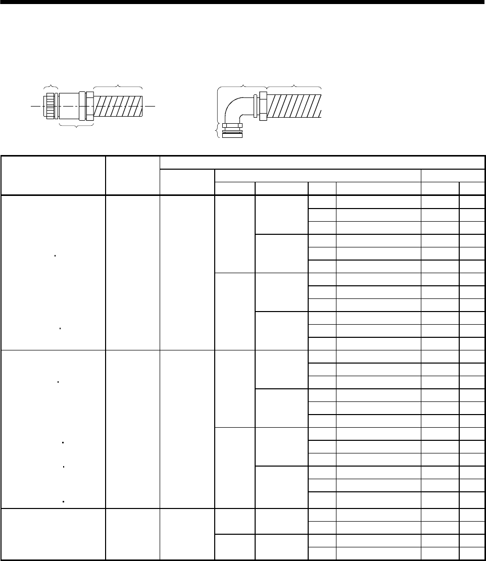
3 - 13
3. CONNECTORS USED FOR SERVO MOTOR WIRING
(b) When using flexible conduits
1) For connection of power supply
1) Plug Conduit
1) Plug
2) Connector fo
r
conduit Conduit
2) Connector for conduit
Cable Side Connector
2) Connector for conduit Conduit
Servo Motor
Connector
Supplied for
Servo Motor
1) Plug
(DDK) Type Manufacturer Size Model Model ID
1/2 RCC-104RL-MS22F VF-04 14.0
3/4 RCC-106RL-MS22F VF-06 19.0
Nippon flex
1 RCC-108RL-MS22F VF-08 24.4
16 MSA-16-22 FCV16 15.8
22 MSA-22-22 FCV22 20.8
Straight
Daiwa
Dengyo 28 MSA-28-22 FCV28 26.4
1/2 RCC-304RL-MS22F VF-04 14.0
3/4 RCC-306RL-MS22F VF-06 19.0
Nippon flex
1 RCC-308RL-MS22F VF-08 24.4
16 MAA-16-22 FCV16 15.8
22 MAA-22-22 FCV22 20.8
HC-SF81(B)
HC-SF52(B) to 152(B)
HC-SF53(B) to 153(B)
HC-RF103(B) to 203(B)
HC-UF72(B) 152(B)
HC-SFS81(B)
HC-SFS52(B) to 152(B)
HC-SFS53(B) to 153(B)
HC-SFS524(B) to 1524(B)
HC-RFS103(B) to 203(B)
HC-UFS72(B) 152(B)
HC-LFS52(B) to 152(B)
CE05-2A22-
23PD-B
CE05-6A22-
23SD-D
Angle
Daiwa
Dengyo 28 MAA-28-22 FCV28 26.4
1/2 RCC-104RL-MS24F VF-04 14.0
3/4 RCC-106RL-MS24F VF-06 19.0Nippon flex
1 RCC-108RL-MS24F VF-08 24.4
16 MSA-16-24 FCV16 15.8
22 MSA-22-24 FCV22 20.8
Straight
Daiwa
Dengyo 28 MSA-28-24 FCV28 26.4
1/2 RCC-304RL-MS24F VF-04 14.0
3/4 RCC-306RL-MS24F VF-06 19.0
Nippon flex
1 RCC-308RL-MS24F VF-08 24.4
16 MAA-16-24 FCV16 15.8
22 MAA-22-24 FCV22 20.8
HC-SF121(B) to 301(B)
HC-SF202(B) to 502(B)
HC-SF203(B) 353(B)
HC-RF353(B) to 503(B)
HC-UF202(B) to 502(B)
HC-SFS121(B) to 301(B)
HC-SFS202(B) to 502(B)
HC-SFS203(B) 353(B)
HC-SFS2024(B) to 5024(B)
HC-RFS353(B) 503(B)
HC-UFS202(B) to 502(B)
HA-LFS502
HC-LFS202(B) 302(B)
CE05-2A24-
10PD-B
CE05-6A24-
10SD-D
Angle
Daiwa
Dengyo 28 MAA-28-24 FCV28 26.4
3/4 RCC-106RL-MS32F VF-06 19.0
Straight Nippon flex 1 RCC-108RL-MS32F VF-08 24.4
3/4 RCC-306RL-MS32F VF-06 19.0
HC-SF702(B)
HC-SFS702(B)
HC-SFS7024(B)
HA-LFS702
CE05-2A32-
17PD-B
CE05-6A32-
17SD-D Angle Nippon flex 1 RCC-308RL-MS32F VF-08 24.4
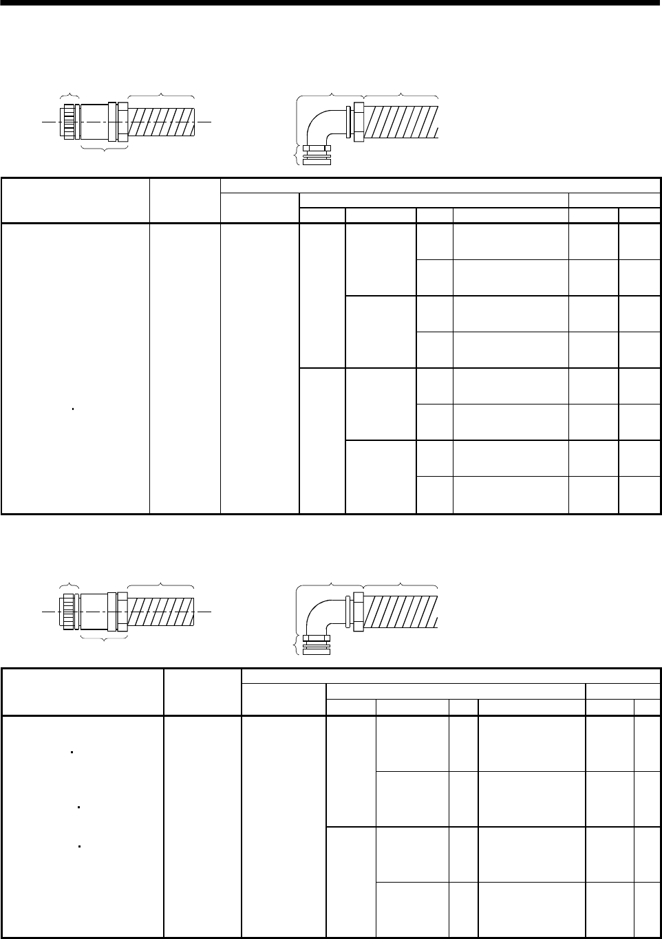
3 - 14
3. CONNECTORS USED FOR SERVO MOTOR WIRING
2) For connection of encoder
1) Plug Conduit
1) Plug
2) Connector for
conduit Conduit
2) Connector for conduit
Cable Side Connector
2) Connector for conduit ConduitServo Motor
Connector
Supplied for
Servo Motor
1) Plug
(DDK) Type Manufacturer Size Model Model ID
1/2 RCC-104RL-MS20F VF-04 14.0
Nippon flex
3/4 RCC-106RL-MS20F VF-06 19.0
16 MSA-16-20 FCV16 15.8
Straight
Daiwa
Dengyo 22 MSA-22-20 FCV22 20.8
1/2 RCC-304RL-MS20F VF-04 14.0
Nippon flex
3/4 RCC-306RL-MS20F VF-06 19.0
16 MAA-16-20 FCV16 15.8
HC-SF81(B) to 301(B)
HC-SF52(B) to 702(B)
HC-SF53(B) to 353(B)
HC-RF103(B) to 503(B)
HC-UF72(B) to 502(B)
HC-SFS81(B) to 301(B)
HC-SFS52(B) to 702(B)
HC-SFS53(B) to 353(B)
HC-SFS524(B) to 7024(B)
HC-RFS103(B) to 503(B)
HC-UFS72(B) to 502(B)
HA-LH11K2 to 22K2
HA-LF30K24 to 55K24
HA-LF30K2 37K2
HA-LFS601 to 37K1
HA-LFS701M to 37K1M
HA-LFS502 to 37K2
HA-LFS6014 to 37K14
HA-LFS701M4 to 50K1M4
HA-LFS11K24 to 55K24
HC-LFS52(B) to 302 (B)
MS3102A20-
29P
D/MS3106A20-
29S(D190)
Angle
Daiwa
Dengyo 22 MAA-22-20 FCV22 20.8
3) For connection of brake
1) Plug Conduit
1) Plug
2) Connector for
conduit Conduit
2) Connector for conduit
Cable Side Connector
2) Connector for conduit ConduitServo Motor
Connector
Supplied for
Servo Motor
1) Plug
(DDK) Type Manufacturer Size Model Model ID
Nippon flex 1/4 RCC-102RL-MS10F VF-02 8.3
Straight
Daiwa
Dengyo 10 MSA-10-10 FCV10 10
Nippon flex 1/4 RCC-302RL-MS10F VF-02 8.3
HC-SF121B to 301B
HC-SF202B to 702B
HC-SF203B 353B
HC-UF202B to 502B
HC-SFS121B to 301B
HC-SFS202B to 702B
HC-SFS203B 353B
HC-SFS2024B to 7024B
HC-UFS202B to 502B
HC-LFS202B 302B
HA-LFS601B to 801B
HA-LFS701MB to 15K1MB
HA-LFS11K2B to 22K2B
HA-LFS6014B to 8014B
HA-LFS701M4B to 15K1M4B
HA-LFS11K24B to 22K24B
MS3102A10SL-
4P
D/MS3106A10SL-
4S(D190)
Angle
Daiwa
Dengyo 10 MAA-10-10 FCV10 10
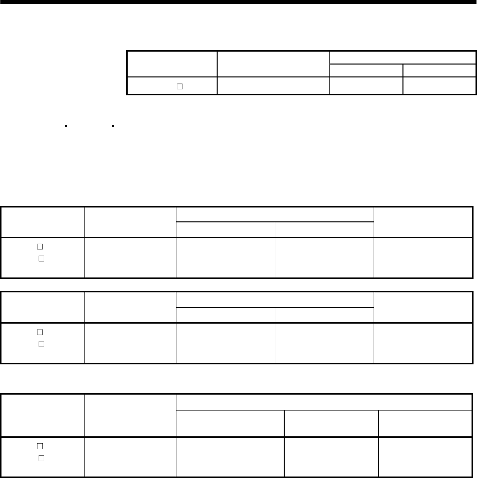
3 - 15
3. CONNECTORS USED FOR SERVO MOTOR WIRING
3.1.4 HC-AQ series
Cable Side Connector (Molex)
Servo Motor Servo Motor Side Connector
(Molex) Plug Terminal
HC-AQ (B) (Note) 5557-12R-210 5559-12P-210 5558
Note. Terminal: 5556
3.1.5 HC-KFS HC-MFS HC-UFS3000r/min series
Use the connectors indicated in this section or equivalent for connection of the power supply,
electromagnetic brake and encoder. These connectors may be used for the EN Standard and UL/C-UL
Standard but are not waterproof.
(1) For connection of power supply and brake
Cable Side Connector
Servo Motor Connector Supplied for
Servo Motor (Molex) Plug (Molex) Terminal (Molex) Manual crimping tool
HC-KFS
HC-MFS
HC-UFS13 to 73
5557-04R-210 5559-04P-210 5558PBT3L 57022-5300
Cable Side Connector
Servo Motor Connector Supplied for
Servo Motor (Molex) Plug (Molex) Terminal (Molex)
Manual crimping tool
HC-KFS B
HC-MFS B
HC-UFS13 to 73B
5557-06R-210 5559-06P-210 5558PBT3L 57022-5300
(2) For connection of encoder
Cable Side Connector
Servo Motor
Connector Supplied for
Servo Motor
(Tyco Electronics) Housing (Tyco Electronics) Connector pin
(Tyco Electronics)
Cable clamp
(Toa Electric Industry)
HC-KFS (B)
HC-MFS (B)
HC-UFS13 to 73(B)
1-172169-9 1-172161-9 170359-1
170363-1 (loose piece) MTI-0002
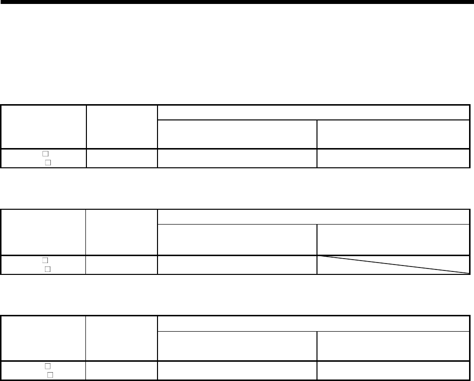
3 - 16
3. CONNECTORS USED FOR SERVO MOTOR WIRING
3.1.6 HC-UF3000r/min series (Compliance with IP65)
Use the connectors indicated in this section or equivalent for connection of the power supply,
electromagnetic brake and encoder. These connectors are waterproof.
(1) For connection of power
Cable Side Connector
Servo Motor
Connector
Supplied for
Servo Motor
(Hirose Electric) Plug (Hirose Electric) Cable clamp (Hirose Electric)
HC-UF (B)-S1
HC-UFS (B)-S1 RM15WTP-4P RM15WTJA-4S (Note) RM15WTP-CP(8)
Note. The numeral within the parentheses indicates the applicable cable diameter. It depends on the used cable diameter.
(2) For connection of encoder
Cable Side Connector
Servo Motor
Connector
Supplied for
Servo Motor
(Hirose Electric) Plug (With cable clamp) (Hirose Electric) Cable clamp (Hirose Electric)
HC-UF (B)-S1
HC-UFS (B)-S1 RM15WTP-10P (Note) RM15WTJA-10S-(7)
Note. The numeral within the parentheses indicates the applicable cable diameter. It depends on the used cable diameter.
(3) For connection of brake
Cable Side Connector
Servo Motor
Connector
Supplied for
Servo Motor
(Hirose Electric) Plug (Hirose Electric) Cable clamp (Hirose Electric)
HC-UF B-S1
HC-UFS B-S1 RM15WTP-4P RM15WTJA-4S (Note) RM15WTP-CP(6)
Note. The numeral within the parentheses indicates the applicable cable diameter. It depends on the used cable diameter.
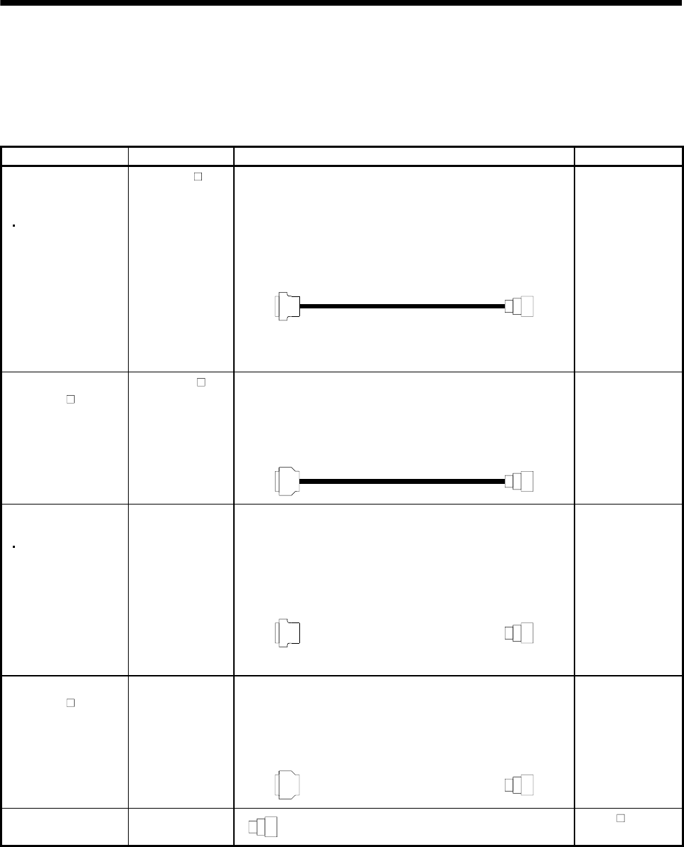
3 - 17
3. CONNECTORS USED FOR SERVO MOTOR WIRING
3.2 IP65, EN Standard-compliant options
The following options are available to satisfy the IP65 ingress protection and EN Standard.
To comply with the EN Standard, the power supply connector used must be any of these options or
equivalent.
Product Model Description Servo Motor
Servo amplifier side connector
(3M or equivalent)
Connector: 10120-3000PE
Shell kit: 10320-52F0-008
Encoder side connector
(DDK)
Plug: D/MS3106A20-29S(D190)
Cable clamp: CE3057-12A-3-D
Back shell: CE02-20BS-S-D
IP65-compliant
encoder cable
(For MR-J2 series
MR-J2-Super Series)
MR-ENCBL M-H HC-SF series
HC-RF series
HC-UF2000r/min
series
HA-LF-UE series
HA-FF-UE series
HC-SFS series
HC-RFS series
HC-UFS2000r/min
series
HA-LFS series
HC-LFS series
Servo amplifier side connector
(Honda Tsushin Kogyo)
Connector: PCR-S20FS
Case: PCR-LS20LA1
Encoder side connector
(DDK)
Plug: D/MS3106A20-29S(D190)
Cable clamp: CE3057-12A-3-D
Back shell: CE02-20BS-S-D
Encoder cable
(For MR-H- N series)
MR-EN1CBL M-H HC-SF series
HC-RF series
HC-UF2000r/min
series
HA-LF-UE series
Servo amplifier side connector
(3M or equivalent)
Connector: 10120-3000PE
Shell kit: 10320-52F0-008
Encoder side connector
(DDK)
Plug: D/MS3106A20-29S(D190)
Cable clamp: CE3057-12A-3-D
Back shell: CE02-20BS-S-D
Encoder connector set
(For MR-J2 series
MR-J2-Super Series)
MR-ENCNS HC-SF series
HC-RF series
HC-UF2000r/min
series
HC-SFS series
HC-RFS series
HC-UFS2000r/min
series
HA-LFS series
HC-LFS series
Servo amplifier side connector
(Honda Tsushin Kogyo)
Connector: PCR-S20FS
Case: PCR-LS20LA1
Encoder side connector
(DDK)
Plug: D/MS3106A20-29S(D190)
Cable clamp: CE3057-12A-3-D
Back shell: CE02-20BS-S-D
Encoder connector set
(For MR-H- N series)
MR-EN1CNS HC-SF series
HC-RF series
HC-UF2000r/min
series
HA-LF series
EN Standard-compliant
power connector set
MR-PWCNF Plug: CE05-6A14S-2SD-D (DDK)
Cable connector: YSO14-9 to 11 (Daiwa Dengyo)
HA-FF C-UE
series

3 - 18
3. CONNECTORS USED FOR SERVO MOTOR WIRING
Product Model Description Servo Motor
IP65/EN
Standard-compliant
power connector set
MR-PWCNS1 Plug: CE05-6A22-23SD-D-BSS
Cable clamp: CE3057-12A-2-D
(DDK)
HC-SF81(B)
HC-SF52(B) to 152(B)
HC-SF53(B) to 153(B)
HC-RF103(B) to 203(B)
HC-UF72(B) 152(B)
HC-SFS81(B)
HC-SFS52(B) to 152(B)
HC-SFS53(B) to 153(B)
HC-SFS524(B) to 1524(B)
HC-RFS103(B) to 203(B)
HC-UFS72(B) 152(B)
HC-LFS52(B) to 152(B)
IP65/EN
Standard-compliant
power connector set
MR-PWCNS2 Plug: CE05-6A24-10SD-D-BSS
Cable clamp: CE3057-16A-2-D
(DDK)
HC-SF121(B) to 301(B)
HC-SF202(B) to 502(B)
HC-SF203(B) 353(B)
HC-RF353(B) 503(B)
HC-UF202(B) to 502(B)
HC-SFS121(B) to 301(B)
HC-SFS202(B) to 502(B)
HC-SFS203(B) 353(B)
HC-SFS2024(B) to 5024(B)
HC-RFS353(B) 503(B)
HC-UFS202(B) to 502(B)
HA-LFS502
HC-LFS202(B) 302(B)
Power connector set MR-PWCNS3 Plug:CE05-6A32-17SD-D-BSS
Cable clamp: CE3057-20A-1-D
(DDK)
HC-SF702(B)
HC-SFS702(B)
HC-SFS7024(B)
HA-LFS702
IP65/EN
Standard-compliant
brake connector set
MR-BKCN (Note) Plug: D/MS3106A10SL-4S(D190) (DDK)
Cable connector: YSO10-5 to 8 (Daiwa
Dengyo)
HA-FF CB-UE
HC-SF121B to 301B
HC-SF202B to 702B
HC-SF203B 353B
HC-UF202B 502B
HC-SFS121B to 301B
HC-SFS202B to 702B
HC-SFS203B 353B
HC-SFS2024B to 7024B
HC-RFS353B 503B
HC-UFS202B to 502B
HC-LFS202B 302B
Note. If it is used with the HA-FF C-UE, the servo motor does not improve in ingress protection (IP54).
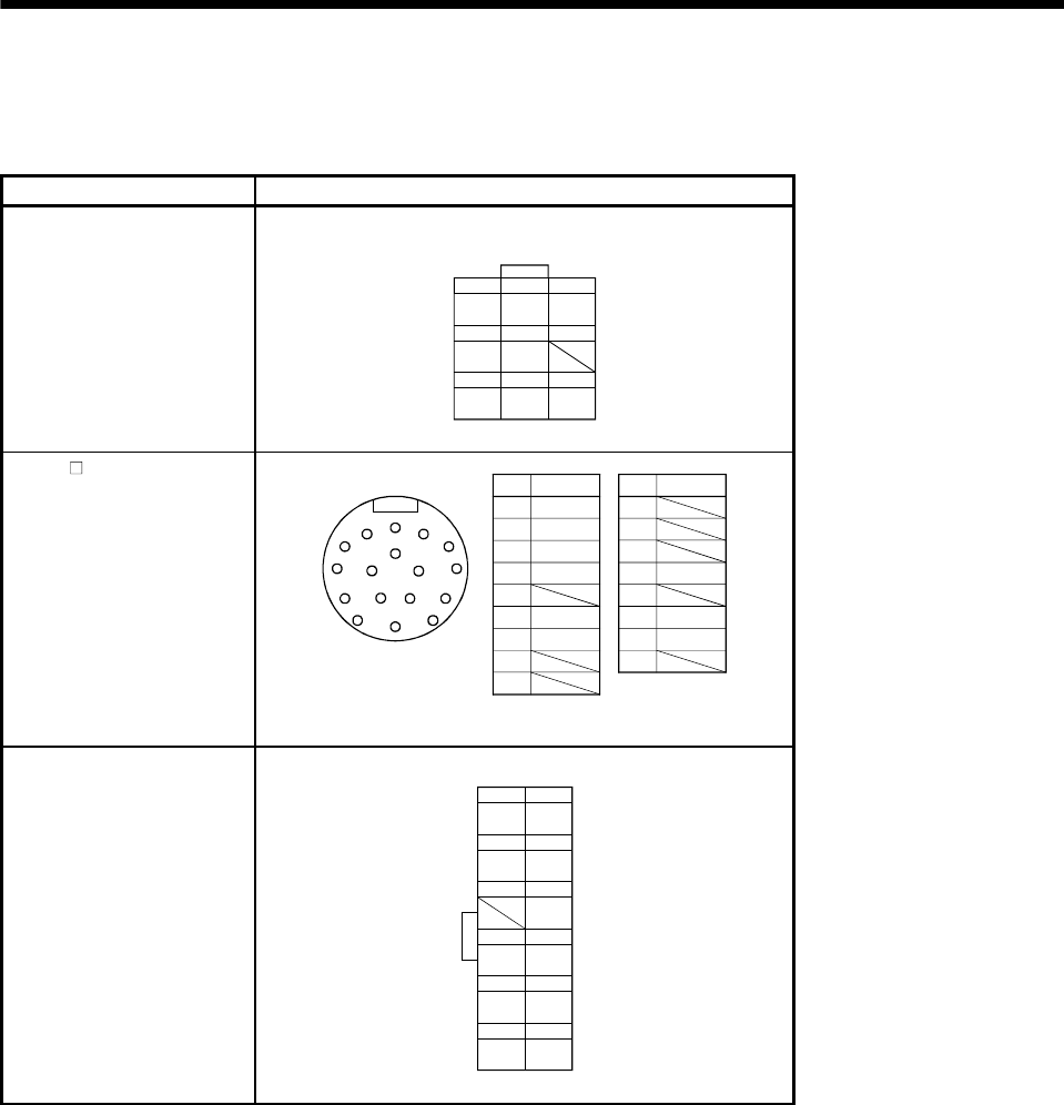
3 - 19
3. CONNECTORS USED FOR SERVO MOTOR WIRING
3.3 Signal arrangement of encoder connectors
The encoder connector of each servo motor has the following signal arrangement. The connectors shown
are as seen from the pin side.
Servo Motor Series Signal Arrangement
HC-KF(-UE) series
HC-MF(-UE) series
HA-FF series
HC-UF3000r/min series
HC-KFS series
HC-MFS series
HC-UFS3000r/min series
Encoder connectors
1-172169-9 (AMP)
123
456
789
MR MRR BAT
MD MDR
P5 LG SHD
HA-FF C-UE series
HC-SF series
HC-RF series
HC-UF2000r/min series
HA-LH series
HA-LF series
HC-SFS series
HC-RFS series
HC-UFS2000r/min series
HA-LFS series
HC-LFS series
ABC
D
E
F
G
H
J
K
LM
Pin Signal
A
B
CMR
DMRR
E
FBAT
GLG
H
J
Pin Signal
K
L
M
NSHD
P
RLG
SP5
T
Encoder connectors
RS
TP
NMDR
MD
HC-AQ series
12 6
11 5
10 4
MRR MR
LG P5
SHD
93
82
71
WU
VE
B1 B2
Motor connecto
r

3 - 20
3. CONNECTORS USED FOR SERVO MOTOR WIRING
MEMO
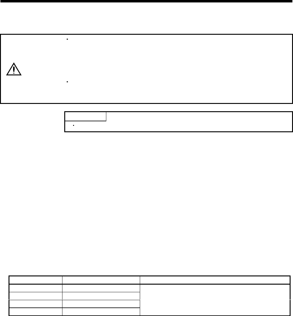
4 - 1
4. INSPECTION
4. INSPECTION
WARNING
Before starting maintenance and/or inspection, turn off the power and wait for 15
minutes or more until the charge lamp turns off. Then, confirm that the voltage
between P and N is safe with a voltage tester and others. Otherwise, an electric
shock may occur. In addition, always confirm from the front of the servo amplifier
whether the charge lamp is off or not.
Any person who is involved in inspection should be fully competent to do the work.
Otherwise, you may get an electric shock. For repair and parts replacement,
contact your safes representative.
POINT
Do not disassemble and/or repair the equipment on customer side.
(1) Inspection
It is recommended to make the following checks periodically.
(a) Check the servo motor bearings, brake section, etc. for unusual noise.
(b) Check the cables and the like for scratches and cracks. Especially when the junction cable is
movable, perform periodic inspection according to operating conditions.
(c) Check the servo motor shaft and coupling for misalignment.
(d) Check the power supply connector and encoder connector tightening screws for looseness.
(2) Life
The following parts must be changed periodically as listed below. If any part is found faulty, it must be
changed immediately even when it has not yet reached the end of its life, which depends on the
operating method and environmental conditions. For parts replacement, please contact your sales
representative.
Part Name Guideline of Life Remarks
Bearings 20,000 to 30,000 hours
Encoder 20,000 to 30,000 hours
Oil seal 5,000 hours
Cooling fan 20,000 hours
The Guideline of Life field gives the reference time. If any fault
is found before this time is reached, the part must be changed.
(a) Bearings
When the servo motor is run at rated speed under rated load, change the bearings in 20,000 to
30,000 hours as a guideline. This differs on the operating conditions. The bearings must also be
changed if unusual noise or vibration is found during inspection.
(b) Oil seal
Must be changed in 5,000 hours of operation at rated speed as a guideline. These parts must also
be changed if oil leakage, etc. is found during inspection.

4 - 2
4. INSPECTION
MEMO
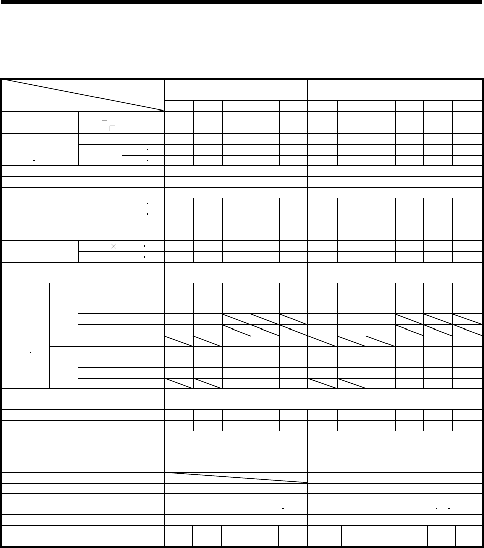
5 - 1
5. SPECIFICATIONS
5. SPECIFICATIONS
5.1 Standard specifications
HC-MF Series
(ultra low inertia, small capacity)
HA-FF Series
(low inertia, small capacity)
Servo Motor
Item 053 13 23 43 73 053 13 23 33 43 63
MR-H AN/BN/ACN/TN 20 20 40 60 100 10 10 20 40 40 60
Applicable servo
amplifier MR-J2- A/B/C 10102040701010204040 60
Rated output [kW] 0.05 0.1 0.2 0.4 0.75 0.05 0.1 0.2 0.3 0.4 0.6
[N m] 0.16 0.32 0.64 1.3 2.4 0.16 0.32 0.64 0.95 1.3 1.9
Continuous
running duty
(Note 1 11)
Rated
torque [oz in] 22.7 45.3 90.7 184 340 22.7 45.3 90.7 135 184 269
Rated speed (Note 1) [r/min] 3000 3000
Maximum speed [r/min] 4500 4000
Instantaneous permissible speed [r/min] 5175 4600
[N m] 0.48 0.95 1.9 3.8 7.2 0.48 0.95 1.9 2.9 3.8 5.7
Maximum torque [oz in] 68.0 135 269 538 1020 68.0 135 269 411 538 808
Power rate at continuous rated torque
[kW/s] 13.47 34.13 46.02 116.55 94.43 4.0 10.2 11.7 18.1 17.2 30.1
J[10 4kg m2] 0.019 0.03 0.088 0.143 0.6 0.063 0.095 0.35 0.50 0.98 1.2
Inertia moment
(Note 3) WK2[oz in2] 0.104 0.16 0.48 0.78 3.28 0.344 0.52 1.91 2.73 5.36 6.56
Recommended ratio of load inertia moment to
servo motor shaft inertia moment (Note 2) 30 times or less 10 times or less
Servo amplifier's
built-in regenerative
resistor
(Note 5) (Note 5) (Note 5) 4275 1726 (Note 5) (Note 5) (Note 5) 1500 750 600
MR-RB013(10W) (Note 5) (Note 5) 2071 1363 370
MR-RB033(30W) (Note 5) (Note 5) (Note 5) 4088 1109
MR-H
series
MR-RB32(300W) (Note 5) (Note 5) (Note 5) (Note 5) 3983 3046
Servo amplifier' built-in
regenerative resistor (Note 5) (Note 5) (Note 5) 1010 400 (Note 5) (Note 5) (Note 5) 320 150 120
MR-RB032(30W) (Note 5) (Note 5) (Note 5) 3000 600 (Note 5) (Note 5) (Note 5) 950 450 360
Regenerative
brake duty
[times/min]
(Note 4 15)
MR-J2
series
MR-RB12(100W) (Note 5) (Note 5) 2400 (Note 5) 3200 1500 1200
Power supply capacity Refer to "Power supply equipment capacity and generated loss of servo amplifiers"
in Servo Amplifier Instruction Manual.
Rated current [A] 0.85 0.85 1.5 2.8 5.1 0.6 1.1 1.3 1.9 2.5 3.6
Maximum current [A] 2.6 2.6 5 9 18 1.8 3.3 3.9 5.7 7.5 10.8
Speed/position detector
Encoder common to absolute
position and incremental detection
systems (Resolution per servo motor
1 rotation : 8192 pulse/rev)
Encoder common to absolute position and
incremental detection systems (Resolution
per servo motor 1 rotation: 8192 pulse/rev)
Accessories V ring
Insulation class Class B Class B
Structure Totally-enclosed, self-cooled
(protection type: IP44 (Note 6 12))
Totally-enclosed, self-cooled
(protection type: IP44 (Note 8 912))
Environmental conditions (Note 7) Refer to section 2.1 Refer to section 2.1
[kg] 0.4 0.53 0.99 1.45 3.0 1.3 1.5 2.3 2.6 4.2 4.8
Mass (Note 3) [lb] 0.88 1.17 2.18 3.20 6.61 2.87 3.31 5.07 5.73 9.26 10.6
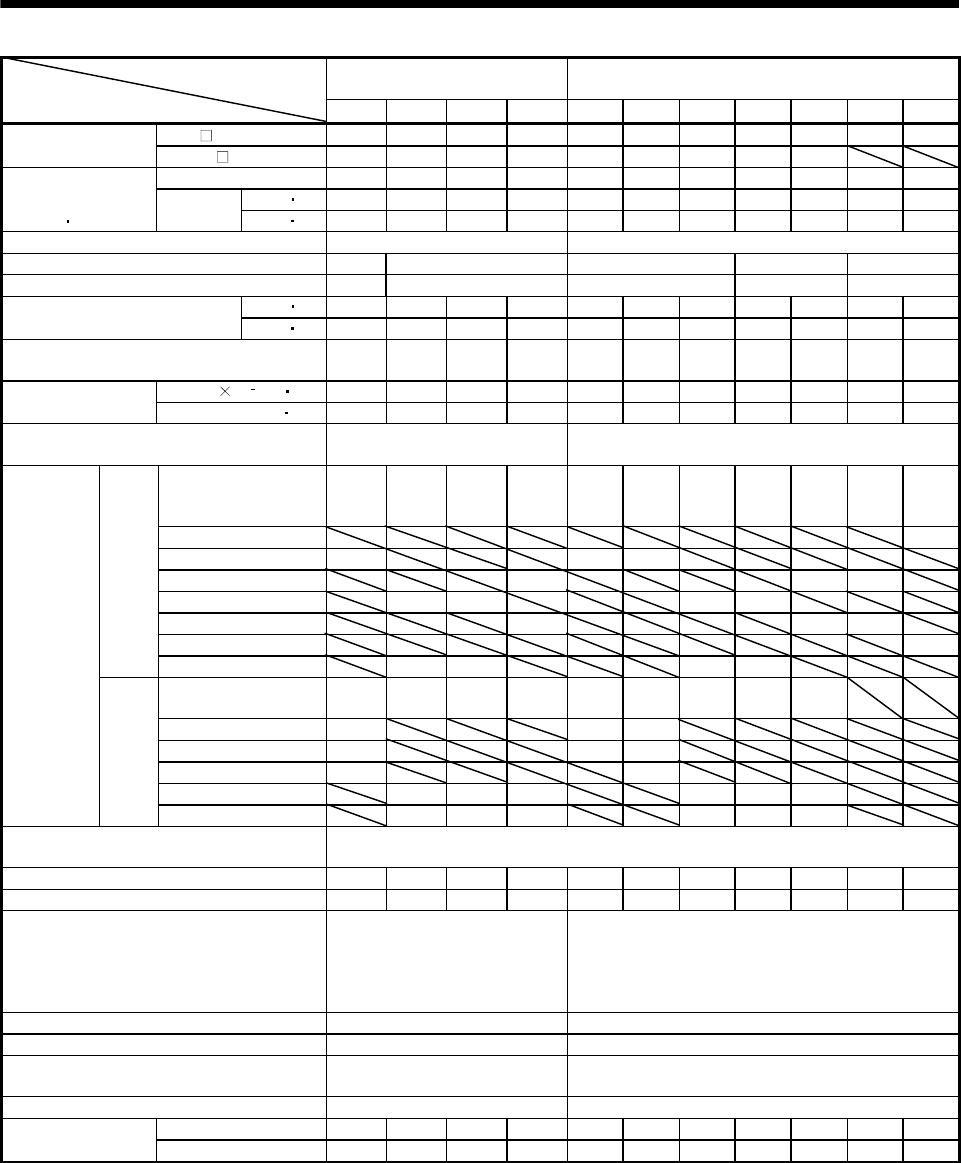
5 - 2
5. SPECIFICATIONS
HC-SF 1000r/min Series
(middle inertia, middle capacity)
HC-SF 2000r/min Series
(middle inertia, middle capacity)
Servo Motor
Item 81 121 201 301 52 102 152 202 352 502 702
MR-H AN/BN/ACN/TN 100 200 200 350 60 100 200 200 350 500 700
Applicable servo
amplifier MR-J2- A/B/C 100 200 200 350 60 100 200 200 350
Rated output [kW] 0.85 1.2 2.0 3.0 0.5 1.0 1.5 2.0 3.5 5.0 7.0
[N m] 8.12 11.5 19.1 28.6 2.39 4.78 7.16 9.55 16.7 23.9 33.4
Continuous
running duty
(Note 1 11)
Rated
torque [oz in] 1151 1630 2707 4053 339 677 1015 1353 2367 3387 4733
Rated speed (Note 1) [r/min] 1000 2000
Maximum speed [r/min] 1500 1200 3000 2500 2000
Instantaneous permissible speed [r/min] 1725 1380 3450 2875 2300
[N m] 24.4 34.4 57.3 85.9 7.16 14.4 21.6 28.5 50.1 71.6 100.0
Maximum torque [oz in] 3458 4875 8120 12173 1015 2041 3061 4039 7100 10146 14171
Power rate at continuous rated torque
[kW/s] 32.9 30.9 44.5 81.3 8.7 16.7 25.6 21.5 34.1 56.5 69.7
J[10 4kg m2] 20.0 42.5 82 101 6.6 13.7 20.0 42.5 82.0 101 160Inertia moment
(Note 3) WK2[oz in2] 109 232 448 552 36.1 74.9 109 232 448 552 875
Recommended ratio of load inertia moment to
servo motor shaft inertia moment (Note 2) 15 times or less 15 times or less
Servo amplifier's
built-in regenerative
resistor
440 335 174 141 207 170 179 84 43 39 32
MR-RB31(300W) 57
MR-RB32(300W) 1649 1241 638
MR-RB30(300W) 326 100 90
MR-RB34(300W) 774 401 412 193
MR-RB50(500W) 543 167 150
MR-RB51(500W) 95
MR-H
series
MR-RB54(500W) 1290 669 687 322
Servo amplifier' built-in
regenerative resistor 140 240 100 84 56 54 136 64 31
MR-RB032(30W) 220 165 80
MR-RB12(100W) 740 560 270
MR-RB32(300W) 2220 810
MR-RB30(300W) 730 330 250 408 192 95
Regenerative
brake duty
[times/min]
(Note 4)
MR-J2
series
MR-RB50(500W) 1216 550 430 680 320 158
Power supply capacity Refer to "Power supply equipment capacity and generated loss of servo amplifiers"
in Servo Amplifier Instruction Manual.
Rated current [A] 5.1 7.1 9.6 16 3.2 6 9 11 17 26 35
Maximum current [A] 15.3 21.3 28.8 48 9.6 18 27 33 51 84 105
Speed/position detector
Encoder common to absolute
position and incremental
detection systems (Resolution per
servo motor 1 rotation: 16384
pulse/rev)
Encoder common to absolute position and
incremental detection systems (Resolution per
servo motor 1 rotation: 16384 pulse/rev)
Accessories Oil seal Oil seal
Insulation class Class F Class F
Structure Totally-enclosed, self-cooled
(protection type: IP65)
Totally-enclosed, self-cooled
(protection type: IP65(Note 12))
Environmental conditions (Note 7) Refer to section 2.1 Refer to section 2.1
[kg] 9.0 12 19 23 5.0 7.0 9.0 12.0 19.0 23 32
Mass (Note 3) [lb] 19.8 26.5 41.9 50.7 11.0 15.4 19.8 26.5 41.9 50.7 70.5
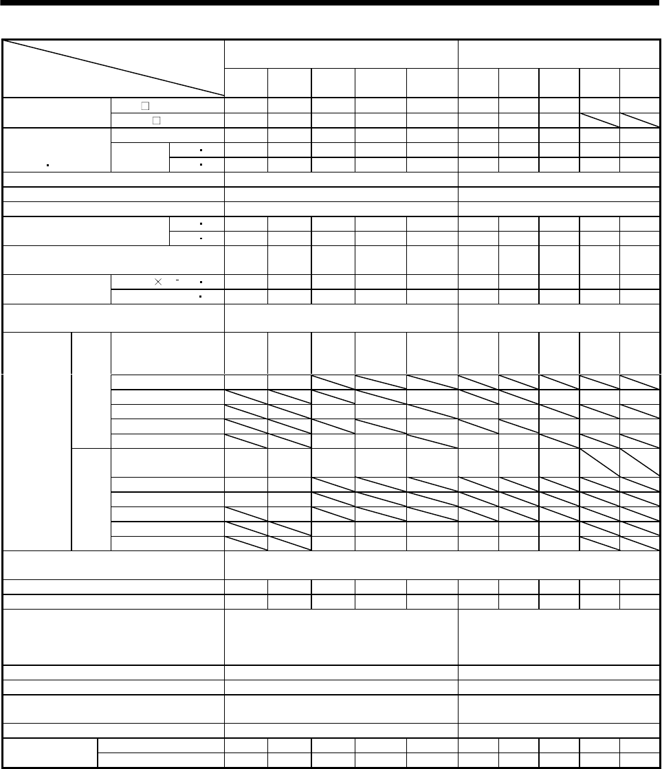
5 - 3
5. SPECIFICATIONS
HC-SF 3000r/min Series
(middle inertia, middle capacity)
HC-RF Series
(ultra low inertia, middle capacity)
Servo Motor
Item 53 103 153 203
(Note 13)
353
(Note 13) 103 153 203 353 503
MR-H AN/BN/ACN/TN 60 100 200 200 350 200 200 350 500 500
Applicable servo
amplifier MR-J2- A/B/C 60 100 200 200 350 200 200 350
Rated output [kW] 0.5 1.0 1.5 2.0 3.5 1.0 1.5 2.0 3.5 5.0
[N m] 1.59 3.18 4.78 6.37 11.1 3.18 4.78 6.37 11.1 15.9
Continuous
running duty
(Note 1 11)
Rated
torque [oz in] 225 451 677 903 1573 451 677 903 1573 2253
Rated speed (Note 1) [r/min] 3000 3000
Maximum speed [r/min] 3000 4500
Instantaneous permissible speed [r/min] 3450 5175
[N m] 4.77 9.55 14.3 19.1 33.4 7.95 11.9 15.9 27.9 39.7
Maximum torque [oz in] 676 1353 2026 2707 4733 1127 1686 2253 3954 5626
Power rate at continuous rated torque
[kW/s] 3.8 7.4 11.4 9.5 15.1 67.4 120 176 150 211
J[10 4kg m2] 6.6 13.7 20.0 42.5 82.0 1.5 1.9 2.3 8.6 12.0
Inertia moment
(Note 3) WK2[oz in2] 36.1 74.9 109.3 232.4 448.3 8.2 10.4 12.6 47.0 65.6
Recommended ratio of load inertia moment
to servo motor shaft inertia moment (Note 2) 15 times or less 5 times or less
Servo amplifier's
built-in regenerative
resistor
92 71 79 37 19 1056 834 689 174 125
MR-RB32(300W) 552 267
MR-RB30(300W) 45 1589 401 288
MR-RB34(300W) 183 86 2437 1924
MR-RB50(500W) 74 2648 669 479
MR-H
series
MR-RB54(500W) 305 143 4061 3206
Servo amplifier' built-in
regenerative resistor 25 24 82 24 14 1090 860 710
MR-RB032(30W) 73 36
MR-RB12(100W) 250 120
MR-RB32(300W) 360
MR-RB30(300W) 250 70 42 3270 2580 2130
Regenerative
brake duty
[times/min]
(Note 4)
MR-J2
series
MR-RB50(500W) 410 110 70 5450 4300 3550
Power supply capacity Refer to "Power supply equipment capacity and generated loss of servo amplifiers"
in Servo Amplifier Instruction Manual.
Rated current [A] 3.2 5.3 8.6 10.4 16.4 6.1 8.8 14 23 28
Maximum current [A] 9.6 15.9 25.8 31.2 49.2 18.4 23.4 37 58 70
Speed/position detector
Encoder common to absolute position and
incremental detection systems (Resolution
per servo motor 1 rotation: 16384 pulse/rev)
Encoder common to absolute position
and incremental detection systems
(Resolution per servo motor 1
rotation: 16384 pulse/rev)
Accessories Oil seal Oil seal
Insulation class Class F Class F
Structure Totally-enclosed, self-cooled
(protection type: IP65)
Totally-enclosed, self-cooled
(protection type: IP65(Note 12))
Environmental conditions (Note 7) Refer to section 2.1 Refer to section 2.1
[kg] 5.0 7.0 9.0 12 19 3.9 5.0 6.2 12.0 17.0
Mass (Note 3) [lb] 11.0 15.4 19.8 26.5 41.9 8.6 11.0 13.7 26.5 37.5
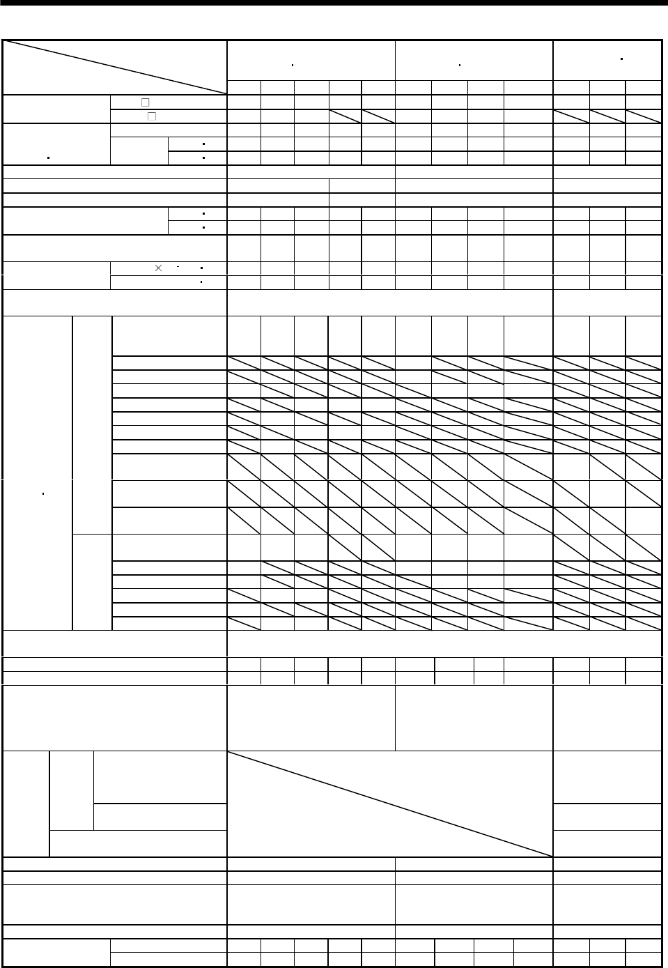
5 - 4
5. SPECIFICATIONS
HC-UF 2000r/min Series
(flat type middle capacity)
HC-UF 3000r/min Series
(flat type small capacity)
HA-LH Series
(low inertia large
capacity)
Servo Motor
Item 72 152 202 352 502 13 23 43 73(Note 13) 11K2 15K2 22K2
MR-H AN/BN/ACN/TN 100 200 350 500 500 10 40 60 100 11K 15K 22K
Applicable servo
amplifier MR-J2 A/B/C 70 200 350 10 20 40 70
Rated output [kW] 0.75 1.5 2.0 3.5 5.0 0.1 0.2 0.4 0.75 11 15 22
[N m] 3.58 7.16 9.55 16.7 23.9 0.32 0.64 1.3 2.4 52.5 71.6 105
Continuous
running duty
(Note 1 11)
Rated
torque [oz in] 507 1015 1353 2367 3387 45 91 184 340 7435 10139 14869
Rated speed (Note 1) [r/min] 2000 3000 2000
Maximum speed [r/min] 3000 2500 4500 2000
Instantaneous permissible speed [r/min] 3450 2875 5175 2300
[N m] 10.7 21.6 28.5 50.1 71.6 0.95 1.9 3.8 7.2 158 215 263
Maximum torque [oz in] 1516 3061 4039 7100 10146 135 269 538 1020 22375 30447 37244
Power rate at continuous rated torque
[kW/s] 12.3 23.2 23.9 36.5 49.6 15.5 19.2 47.7 9.76 235 177 278
J[10
4
kg m2]10.4 22.1 38.2 76.5 115 0.066 0.241 0.365 5.90 118 290 395
Inertia moment
(Note 3) WK2[oz in2]56.9 120.8 208.9 418.3 628.8 0.4 1.3 2.0 32.3 642.4 1585.6 2159.6
Recommended ratio of load inertia moment
to servo motor shaft inertia moment (Note 2) 15 times or less 10 times or less
Servo amplifier's
built-in regenerative
resistor
211 161 93 44 31 (Note5) 2530 1669 165 85
(Note10)
70
(Note10)
55
(Note10)
MR-RB013(10W) 2241
MR-RB033(30W) (Note5)
MR-RB32(300W) 791 (Note5) (Note5) 619
MR-RB30(300W) 215 102 72
MR-RB34(300W) 372
MR-RB50(500W) 358 169 119
MR-RB54(500W) 620
MR-RB65(800W) 130
(Note14)
MR-RB66(1300W) 100
(Note14)
MR-H
Series
MR-RB67(1300W) 80
(Note14)
Servo amplifier' built-in
regenerative resistor 53 124 68 (Note5) (Note5) 410 41
MR-RB032(30W) 79 (Note5) (Note5) 1230 62
MR-RB12(100W) 264 (Note5) 4100 206
MR-RB30(300W) 372 203
MR-RB32(300W) 791 618
Regenerative
brake duty
[times/min]
(Note 4 15)
MR-J2
Series
MR-RB50(500W) 620 338
Power supply capacity Refer to "Power supply equipment capacity and generated loss of servo amplifiers" in
Servo Amplifier Instruction Manual.
Rated current [A] 5.4 9.7 14 23 28 0.76 1.5 2.8 4.3 68 87 126
Maximum current [A] 16.2 29.1 42 69 84 2.5 4.95 9.24 12.9 204 261 315
Speed/position detector
Encoder common to absolute
position and incremental
detection systems (Resolution
per servo motor 1 rotation:
16384 pulse/rev)
Encoder common to absolute
position and incremental
detection systems (Resolution
per servo motor 1 rotation:
8192 pulse/rev)
Incremental encoder
(Resolution per servo
motor 1 rotation:
16384 pulse/rev)
Voltage, frequency
One-phase 200 to
220VAC 50Hz, One-
phase 200 to
230VAC 60Hz
Power
supply
Power consumption [W] 42 (50Hz)
54 (60Hz)
Cooling
fan
Rated current [A] 0.21 (50Hz)
0.25 (60Hz)
Accessories Oil seal Oil seal Oil seal
Insulation class Class F Class B Class F
Structure Totally-enclosed, self-cooled
(protection type: IP65)
Totally-enclosed, self-cooled
(protection type: IP65(Note9))
Totally-enclosed,
force-cooling
(protection type: JP44)
Environmental conditions (Note 7) Refer to section 2.1 Refer to section 2.1 Refer to section 2.1
[kg] 8.0 11.0 16.0 20.0 24.0 0.8 1.5 1.7 5.0 70 108 135
Mass (Note 3) [lb] 17.6 24.3 35.3 44.1 52.9 1.8 3.3 3.7 11.0 154.3 238.1 297.6
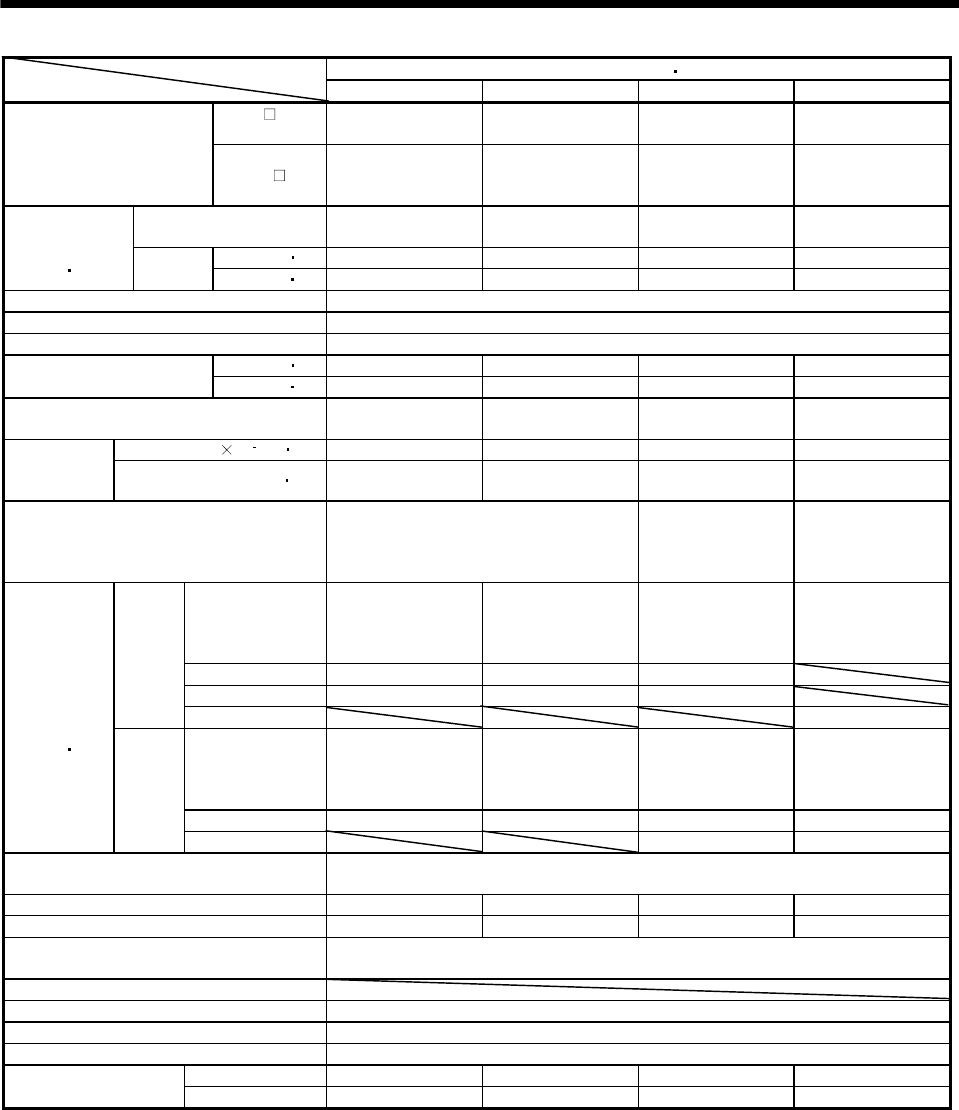
5 - 5
5. SPECIFICATIONS
HC-KF Series (low inertia small capacity)
Servo Motor
Item 053 13 23 43
MR-H AN/
BN/ACN/TN 10 10 20 40
Applicable servo amplifier
MR-J2-
10A-A16
10B-A16
10C-A16
10A-A15
10B-A15
10C-A15
20A-A15
20B-A15
20C-A15
40A-A15
40B-A15
40C-A15
Rated
output [kW] 0.05 0.1 0.2 0.4
[N m] 0.16 0.32 0.64 1.3
Continuous
running duty
(Note 1 11) Rated
torque [oz in] 22.7 45.3 90.7 184
Rated speed (Note 1) [r/min] 3000
Maximum speed [r/min] 4500
Instantaneous permissible speed [r/min] 5175
[N m] 0.48 0.95 1.9 3.8
Maximum torque [oz in] 68.0 135 269 538
Power rate at continuous rated torque
[kW/s] 4.78 12.1 15.8 36.7
J[10 4kg m2] 0.053 0.084 0.260 0.460Inertia
moment
(Note 3) WK2[oz in2] 0.29 0.459 1.422 2.515
Recommended ratio of load inertia
moment to servo motor shaft inertia
moment
(Note 2)
15 times or less 24 times or less 22 times or less
Servo amplifier's
built-in
regenerative
resistor
(Note 5) (Note 5) (Note 5) 900
MR-RB013(10W) 3580 2210 350
MR-RB033(30W) (Note 5) (Note 5) 1050
MR-H
series
MR-RB32(300W) (Note 5)
Servo amplifier's
built-in
regenerative
resistor
(Note 5) (Note 5) (Note 5) 220
MR-RB032(30W) (Note 5) (Note 5) (Note 5) 660
Regenerative
brake duty
[times/min]
(Note 4 15)
MR-J2
series
MR-RB12(100W) (Note 5) 2200
Power supply capacity Refer to "Power supply equipment capacity and generated loss of servo amplifiers"
in Servo Amplifier Instruction Manual.
Rated current [A] 0.83 0.71 1.1 2.3
Maximum current [A] 2.5 2.2 3.4 6.9
Speed/position detector Encoder common to absolute position and incremental detection systems
(Resolution per servo motor 1 rotation: 8192 pulses/rev)
Accessory
Insulation class Class B
Structure Totally-enclosed, self-cooled (protection type: IP44 (Note 6))
Environmental conditions (Note 7) Refer to section 2.1
[kg] 0.40 0.53 0.99 1.45
Mass [lb] 0.882 1.168 2.18 3.20
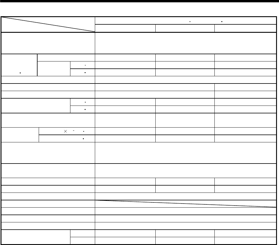
5 - 6
5. SPECIFICATIONS
HC-AQ Series (24VDC-compatible compact size small capacity)
Servo Motor
Item 0135 0235 0335
Applicable servo amplifier
MR-J2-03A5
MR-J2-03B5
MR-J2-03C5
Rated output [kW] 0.01 0.02 0.03
[N m] 0.0318 0.0637 0.0955
Continuous
running duty
(Note 1 11) Rated torque [oz in] 4.503 9.021 13.524
Rated speed (Note 1) [r/min] 3000
Maximum speed [r/min] 5000 4500
Instantaneous permissible speed [r/min] 5750 5175
[N m] 0.0955 0.191 0.287
Maximum torque [oz in] 13.524 27.048 40.643
Power rate at continuous rated torque
[kW/s] 2.0 5.6 9.7
J[10 4kg m2] 0.0050 0.0072 0.0094
Inertia moment
(Note 3) WK2[oz in2] 0.027 0.039 0.051
Recommended ratio of load inertia
moment to servo motor shaft inertia
moment (Note 2)
30 times or less
Power supply capacity Refer to "Power supply equipment capacity and generated loss of servo amplifiers"
in Servo Amplifier Instruction Manual.
Rated current [A] 2.4 2.4 2.3
Maximum current [A] 7.7 7.7 7.4
Speed/position detector Incremental encoder (Resolution per servo motor 1 rotation: 8192 pulses/rev)
Accessory
Insulation class Class B
Structure Totally-enclosed, self-cooled (protection type: IP55 (Note 6))
Environmental conditions (Note 7) Refer to section 2.1
[kg] 0.19 0.22 0.25
Mass (Note 3) [lb] 0.419 0.485 0.551
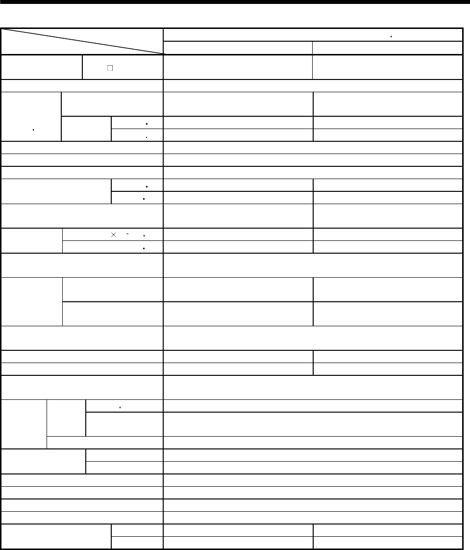
5 - 7
5. SPECIFICATIONS
HA-LF Series (three-phase, 200VAC-compatible, low inertia large capacity)Servo Motor
Item 30K2 37K2
Applicable servo
amplifier MR-H AN/BN 30K 37K
Compatible converter unit MR-HP30KA
Rated
output [kW] 30 37
[N m] 143 177
Continuous
running duty
(Note 1 11) Rated
torque [oz in] 20250.6 25065.4
Rated speed (Note 1) [r/min] 2000
Maximum speed [r/min] 2000
Instantaneous permissible speed [r/min] 2300
[N m] 358 442
Maximum torque [oz in2] 50697.2 62592.6
Power rate at continuous rated torque
[kW/s] 373 480
J[10 4kg m2] 550 650
Inertia
moment WK2[oz in2] 3007.1 3553.8
Recommended ratio of load inertia moment
to servo motor shaft inertia moment 10 times or less
MR-RB139 (1300W) 58 49
Regenerative
brake duty
[times/min]
(Note 4)
MR-RB137 (3900W)
(3 units are required.) 174 147
Power supply capacity Refer to “Power supply equipment capacity and generated loss of servo amplifiers” in
Servo Amplifier Instruction Manual.
Rated current [A] 166 204
Maximum current [A] 415 510
Speed/position detector Encoder common to absolute position and incremental detection systems
(Resolution per servo motor 1 rotation: 16384 pulse/rev)
Voltage frequency Three-phase 200 to 220VAC 50Hz, Three-phase 200 to 230VAC 60Hz
Power
supply Power
consumption [W] 45(50Hz)/63(60Hz)
Cooling
fan
Rated current [A] 0.32(50Hz)/0.35(60Hz)
Maximum rated 125VAC/DC, 3A or 250VAC/DC, 2A
Thermal protector Minimum rated 6VAC/DC, 0.15A
Accessories Oil seal
Insulation class Class F
Structure Totally-enclosed force-cooled (protection type: IP44)
Environmental conditions (Note 7) Refer to section 2.1
[kg] 160 180
Mass (Note 3) [lb] 352.7 396.8
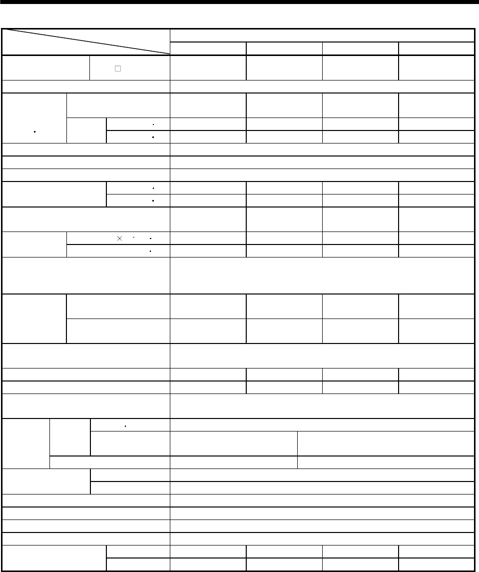
5 - 8
5. SPECIFICATIONS
HA-LF Series (three-phase, 400VAC-compatible, low Inertia, large capacity)
Servo Motor
Item 30K24 37K24 45K24 55K24
Applicable servo
amplifier MR-H AN4/BN4 30K 37K 45K 55K
Compatible converter unit MR-HP55KA4
Rated
output [kW] 30 37 45 55
[N m] 143 177 215 263
Continuous
running duty
(Note 1 11) Rated
torque [oz in] 20250.6 25065.4 30446.6 37244.0
Rated speed (Note 1) [r/min] 2000
Maximum speed [r/min] 2000
Instantaneous permissible speed [r/min] 2300
[N m] 358 442 537 657
Maximum torque [oz in] 50697.2 62592.6 76045.8 930392
Power rate at continuous rated torque
[kW/s] 373 480 427 526
J[10 4kg m2] 550 650 1080 1310
Inertia moment
(Note 3) WK2[oz in2] 3007.095 3553.84 5904.84 7162.354
Recommended ratio of load inertia moment
to servo motor shaft inertia moment
(Note 2)
10 times or less
MR-RB136-4 (1300W) 58 49 30 24
Regenerative
brake duty
[times/min]
(Note 4)
MR-RB138-4 (3900W)
(3 units are required.) 174 147 89 73
Power supply capacity Refer to "Power supply equipment capacity and generated loss of servo
amplifiers" in Servo Amplifier Instruction Manual.
Rated current [A] 83 102 131 143
Maximum current [A] 208 255 328 358
Speed/position detector Encoder common to absolute position and incremental detection systems
(Resolution per servo motor 1 rotation: 16384 pulses/rev)
Voltage frequency Three-phase 380 to 460VAC 50/60Hz
Power
supply Power
consumption [W] 65(50Hz)/85(60Hz) 110(50Hz)/150(60Hz)
Cooling fan
Rated current [A] 0.12(50Hz)/0.14(60Hz) 0.20(50Hz)/0.22(60Hz)
Maximum rated 125VAC/DC, 3A or 250VAC/DC, 2A
Thermal protector Minimum rated 6VAC/DC, 0.15A
Accessories Oil seal
Insulation class Class F
Structure Totally-enclosed, force-cooled (protection type: IP44)
Environmental conditions (Note 7) Refer to section 2.1
[kg] 160 180 230 250
Mass (Note 3) [lb] 352.739 396.832 507.063 551.155
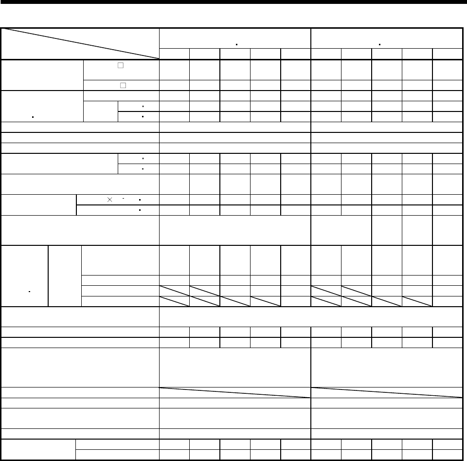
5 - 9
5. SPECIFICATIONS
HC-MFS Series
(ultra low inertia small capacity)
HC-KFS Series
(low inertia small capacity)
Servo Motor
Item 053 13 23 43 73 053 13 23 43 73
MR-J2S- A/B/CP/
CL 10 10 20 40 70 10 10 20 40 70
Applicable servo
amplifier/drive unit MR-J2M- DU 10 10 20 40 70 10 10 20 40 70
Rated output [kW] 0.05 0.1 0.2 0.4 0.75 0.05 0.1 0.2 0.4 0.75
[N m] 0.16 0.32 0.64 1.3 2.4 0.16 0.32 0.64 1.3 2.4
Continuous
running duty
(Note 1 11)
Rated
torque [oz in] 22.7 45.3 90.7 184 340 22.7 45.3 90.7 184 340
Rated speed (Note 1) [r/min] 3000 3000
Maximum speed [r/min] 4500 4500
Instantaneous permissible speed [r/min] 5175 5175
[N m] 0.48 0.95 1.9 3.8 7.2 0.48 0.95 1.9 3.8 7.2
Maximum torque [oz in] 68.0 135 269 538 1020 68.0 135 269 538 1020
Power rate at continuous rated torque
[kW/s] 13.47 34.13 46.02 116.55 94.43 4.78 12.1 15.8 36.7 37.7
J[10 4kg m2] 0.019 0.03 0.088 0.143 0.6 0.053 0.084 0.260 0.460 1.51
Inertia moment
(Note 3) WK2[oz in2] 0.104 0.16 0.48 0.78 3.28 0.29 0.459 1.422 2.515 8.26
Recommended ratio of load inertia moment to
servo motor shaft inertia moment (Note 2) 30 times or less 15 times or
less
24
times
or less
22
times
or less
15
times
or less
Servo amplifier's
built-in regenerative
resistor
(Note 5) (Note 5) (Note 5) 1010 400 (Note 5) (Note 5) (Note 5) 220 190
MR-RB032(30W) (Note 5) (Note 5) (Note 5) 3000 600 (Note 5) (Note 5) (Note 5) 660 280
MR-RB12(100W) (Note 5) (Note5) 2400 (Note 5) 2200 940
Regenerative
brake duty
[times/min]
(Note 4 15)
MR-J2S
series
MR-RB32(300W) (Note5) 2800
Power supply capacity Refer to "Power supply equipment capacity and generated loss of servo amplifiers"
in Servo Amplifier Instruction Manual.
Rated current [A] 0.85 0.85 1.5 2.8 5.1 0.83 0.71 1.1 2.3 5.8
Maximum current [A] 2.6 2.6 5 9 18 2.5 2.2 3.4 6.9 18.6
Speed/position detector
Encoder common to absolute position
and incremental detection systems
(Resolution per servo motor 1 rotation :
131072 pulse/rev)
Encoder common to absolute position
and incremental detection systems
(Resolution per servo motor 1 rotation :
131072 pulse/rev)
Accessories
Insulation class Class B Class B
Structure Totally-enclosed, self-cooled
(protection type: IP55 (Note 6,12))
Totally-enclosed, self-cooled
(protection type: IP55 (Note 6,12))
Environmental conditions (Note 7) Refer to section 2.1 Refer to section 2.1
[kg] 0.4 0.53 0.99 1.45 3.0 0.40 0.53 0.99 1.45 3.0
Mass (Note 3) [lb] 0.88 1.17 2.18 3.20 6.61 0.882 1.168 2.18 3.20 6.61
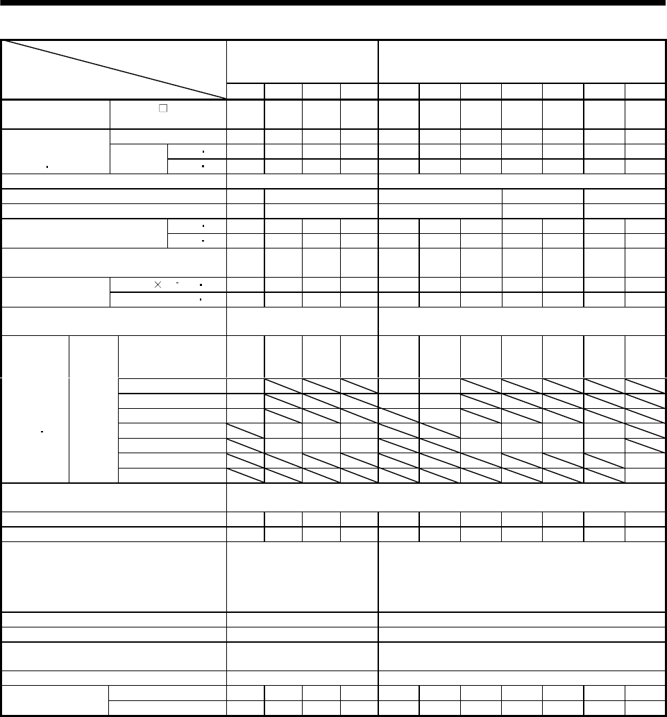
5 - 10
5. SPECIFICATIONS
HC-SFS1000r/min Series
(200V-compatible, middle
inertia, middle capacity)
HC-SFS 2000r/min Series
(200V-compatible, middle inertia, middle capacity)
Servo Motor
Item 81 121 201 301 52 102 152 202 352 502 702
Applicable servo
amplifier/drive unit
MR-J2S- A/B/CP/
CL 100 200 200 350 60 100 200 200 350 500 700
Rated output [kW] 0.85 1.2 2.0 3.0 0.5 1.0 1.5 2.0 3.5 5.0 7.0
[N m] 8.12 11.5 19.1 28.6 2.39 4.78 7.16 9.55 16.7 23.9 33.4
Continuous
running duty
(Note 1 11)
Rated
torque [oz in] 1151 1630 2707 4053 339 677 1015 1353 2367 3387 4733
Rated speed (Note 1) [r/min] 1000 2000
Maximum speed [r/min] 1500 1200 3000 2500 2000
Instantaneous permissible speed [r/min] 1725 1380 3450 2875 2300
[N m] 24.4 34.4 57.3 85.9 7.16 14.4 21.6 28.5 50.1 71.6 100.0
Maximum torque [oz in] 3458 4875 8120 12173 1015 2041 3061 4039 7100 10146 14171
Power rate at continuous rated torque
[kW/s] 32.9 30.9 44.5 81.3 8.7 16.7 25.6 21.5 34.1 56.5 69.7
J[10 4kg m2] 20.0 42.5 82 101 6.6 13.7 20.0 42.5 82.0 101 160Inertia moment
(Note 3) WK2[oz in2] 109 232 448 552 36.1 74.9 109 232 448 552 875
Recommended ratio of load inertia moment to
servo motor shaft inertia moment (Note 2) 15 times or less 15 times or less
Servo amplifier's
built-in regenerative
resistor
140 240 100 84 56 54 136 64 31 39 32
MR-RB032(30W) 220 165 80
MR-RB12(100W) 740 560 270
MR-RB32(300W) 2220 810
MR-RB30(300W) 730 330 250 408 192 95 90
MR-RB50(500W) 1216 550 430 680 320 158 150
MR-RB31(300W) 57
Regenerative
brake duty
[times/min]
(Note 4 15)
MR-J2S
series
MR-RB51(500W) 95
Power supply capacity Refer to "Power supply equipment capacity and generated loss of servo amplifiers"
in Servo Amplifier Instruction Manual.
Rated current [A] 5.1 7.1 9.6 16 3.2 6 9 11 17 26 35
Maximum current [A] 15.3 21.3 28.8 48 9.6 18 27 33 51 84 105
Speed/position detector
Encoder common to absolute
position and incremental
detection systems (Resolution
per servo motor 1 rotation:
131072 pulse/rev)
Encoder common to absolute position and incremental
detection systems (Resolution per servo motor 1
rotation: 131072 pulse/rev)
Accessories Oil seal Oil seal
Insulation class Class F Class F
Structure Totally-enclosed, self-cooled
(protection type: IP65)
Totally-enclosed, self-cooled
(protection type: IP65(Note 12))
Environmental conditions (Note 7) Refer to section 2.1 Refer to section 2.1
[kg] 9.0 12 19 23 5.0 7.0 9.0 12.0 19.0 23 32
Mass (Note 3) [lb] 19.8 26.5 41.9 50.7 11.0 15.4 19.8 26.5 41.9 50.7 70.5
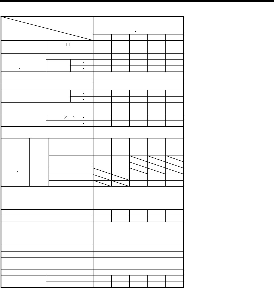
5 - 11
5. SPECIFICATIONS
HC-SFS 3000r/min Series
(200V-compatible,
middle inertia middle capacity)
Servo Motor
Item 53 103 153 203 353
Applicable servo
amplifier
MR-J2S- A/B/CP/
CL 60 100 200 200 350
Rated output [kW] 0.5 1.0 1.5 2.0 3.5
[N m] 1.59 3.18 4.78 6.37 11.1
Continuous
running duty
(Note 1 11)
Rated
torque [oz in] 225 451 677 903 1573
Rated speed (Note 1) [r/min] 3000
Maximum speed [r/min] 3000
Instantaneous permissible speed [r/min] 3450
[N m] 4.77 9.55 14.3 19.1 33.4
Maximum torque [oz in] 676 1353 2026 2707 4733
Power rate at continuous rated torque
[kW/s] 3.8 7.4 11.4 9.5 15.1
J[10 4kg m2]6.6 13.7 20.0 42.5 82.0
Inertia moment
(Note 3) WK2[oz in2] 36.1 74.9 109.3 232.4 448.3
Recommended ratio of load inertia moment
to servo motor shaft inertia moment (Note 2) 15 times or less
Servo amplifier's
built-in regenerative
resistor
25 24 82 24 14
MR-RB032(30W) 73 36
MR-RB12(100W) 250 120
MR-RB32(300W) 360
MR-RB30(300W) 250 70 42
Regenerative
brake duty
[times/min]
(Note 4 15)
MR-J2S
series
MR-RB50(500W) 410 110 70
Power supply capacity
Refer to "Power supply equipment
capacity and generated loss of servo
amplifiers" in Servo Amplifier
Instruction Manual.
Rated current [A] 3.2 5.3 8.6 10.4 16.4
Maximum current [A] 9.6 15.9 25.8 31.2 49.2
Speed/position detector
Encoder common to absolute position
and incremental detection systems
(Resolution per servo motor 1 rotation :
131072 pulse/rev)
Accessories Oil seal
Insulation class Class F
Structure Totally-enclosed, self-cooled
(protection type: IP65)
Environmental conditions (Note 7) Refer to section 2.1
[kg] 5.0 7.0 9.0 12 19
Mass (Note 3) [lb] 11.0 15.4 19.8 26.5 41.9
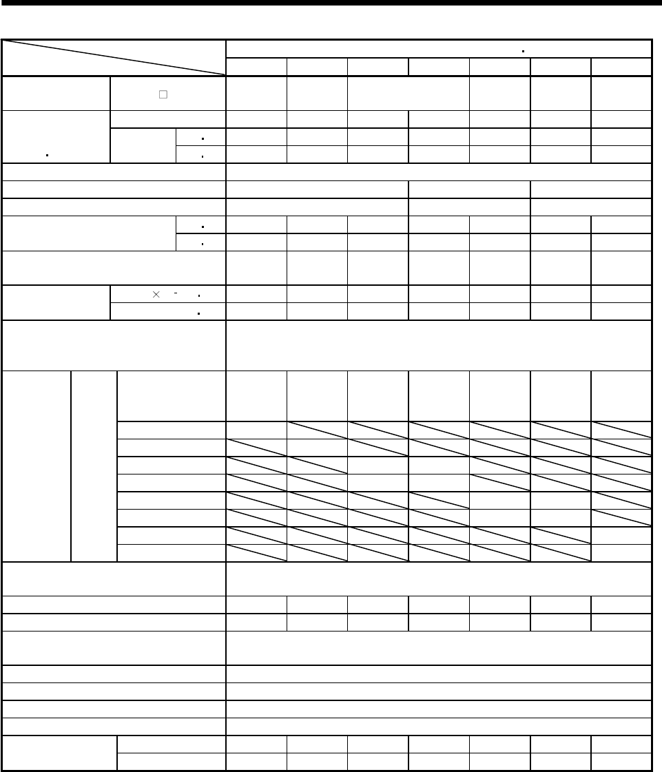
5 - 12
5. SPECIFICATIONS
HC-SFS Series(400VAC-compatible, middle inertia middle capacity)
Servo Motor
Item 524 1024 1524 2024 3524 5024 7024
Applicable servo
amplifier MR-J2S- A4 60 100 200 350 500 700
Rated output [kW] 0.5 1.0 1.5 2.0 3.5 5.0 7.0
[N m] 2.39 4.78 7.16 9.55 16.7 23.9 33.4
Continuous
running duty
(Note 1 11)
Rated
torque [oz in] 338.5 676.9 1013.9 1352.4 2364.9 3384.5 4729.9
Rated speed (Note 1) [r/min] 2000
Maximum speed [r/min] 3000 2500 2000
Instantaneous permissible speed [r/min] 3450 2875 2300
[N m] 7.16 14.4 21.6 28.5 50.1 71.6 100.0
Maximum torque [oz in] 1013.9 2039.2 3058.8 4036 7094.8 10139.4 14161.2
Power rate at continuous rated torque
[kW/s] 8.7 16.7 25.6 21.5 34.1 56.5 69.7
J [ 10 4kg m2] 6.6 13.7 20.0 42.5 82.0 101 160
Inertia moment
(Note 3) WK2 [oz in2] 36.1 74.9 109.3 232.4 448.3 552.2 874.8
Recommended ratio of load inertia
moment to servo motor shaft inertia
moment (Note2)
15 times or less
Servo amplifier’s
built-in regenerative
resistor
56 54 136 64 31 39 32
MR-RB1L-4(100W) 560
MR-RB3M-4(300W) 810
MR-RB3H-4(300W) 408 192
MR-RB5H-4(500W) 680 320
MR-RB3G-4(300W) 95 90
MR-RB5G-4(500W) 158 150
MR-RB34-4(300W) 57
Regenerative
brake duty
[times/min]
(Note 4)
MR-J2S
Series
MR-RB54-4(500W) 95
Power supply capacity Refer to “Power supply equipment capacity and generated loss of servo
amplifiers” in Servo Amplifier Instruction Manual.
Rated current [A] 1.5 2.8 4.4 5.4 8.6 14 17
Maximum current [A] 4.5 8.4 13.2 16.2 25.8 42 51
Speed/position detector Encoder common to absolute position and incremental detection systems
(Resolution per servo motor 1 rotation: 131072 pulse/rev)
Accessories Oil seal
Insulation class Class F
Structure Totally-enclosed, self-cooled(protection type: IP65 (Note 12))
Environmental conditions (Note 7) Refer to section 2.1
[kg] 5.0 7.0 9.0 12.0 19.0 23 32
Mass (Note 3) [lb] 11 15.4 19.8 26.5 41.9 50.7 70.5
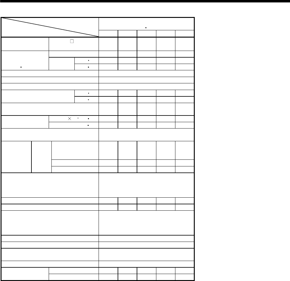
5 - 13
5. SPECIFICATIONS
HC-RFS Series
(ultra low inertia middle capacity)
Servo Motor
Item 103 153 203 353 503
Applicable servo
amplifier
MR-J2S- A/B/CP/
CL 200 200 350 500 500
Rated output [kW] 1.0 1.5 2.0 3.5 5.0
[N m] 3.18 4.78 6.37 11.1 15.9
Continuous
running duty
(Note 1 11)
Rated
torque [oz in] 450 677 902 1572 2252
Rated speed (Note 1) [r/min] 3000
Maximum speed [r/min] 4500
Instantaneous permissible speed [r/min] 5175
[N m] 7.95 11.9 15.9 27.9 39.7
Maximum torque [oz in] 1126 1686 2253 3954 5626
Power rate at continuous rated torque
[kW/s] 67.4 120 176 150 211
J[10 4kg m2]1.5 1.9 2.3 8.6 12.0
Inertia moment
(Note 3) WK2[oz in2] 8.2 10.4 12.6 47.0 65.6
Recommended ratio of load inertia moment
to servo motor shaft inertia moment (Note 2) 5 times or less
Servo amplifier's
built-in regenerative
resistor
1090 860 710 174 125
MR-RB30(300W) 3270 2580 2130 401 288
Regenerative
brake duty
[times/min]
(Note 4)
MR-J2S
series
MR-RB50(500W) 5450 4300 3550 669 479
Power supply capacity
Refer to "Power supply equipment
capacity and generated loss of servo
amplifiers" in Servo Amplifier
Instruction Manual.
Rated current [A] 6.1 8.8 14 23 28
Maximum current [A] 18.4 23.4 37 58 70
Speed/position detector
Encoder common to absolute position
and incremental detection systems
(Resolution per servo motor 1 rotation:
131072 pulse/rev)
Accessories Oil seal
Insulation class Class F
Structure Totally-enclosed, self-cooled
(protection type: IP65 (Note 12))
Environmental conditions (Note 7) Refer to section 2.1
[kg] 3.9 5.0 6.2 12.0 17.0
Mass (Note 3) [lb] 8.6 11.0 13.7 26.5 37.5
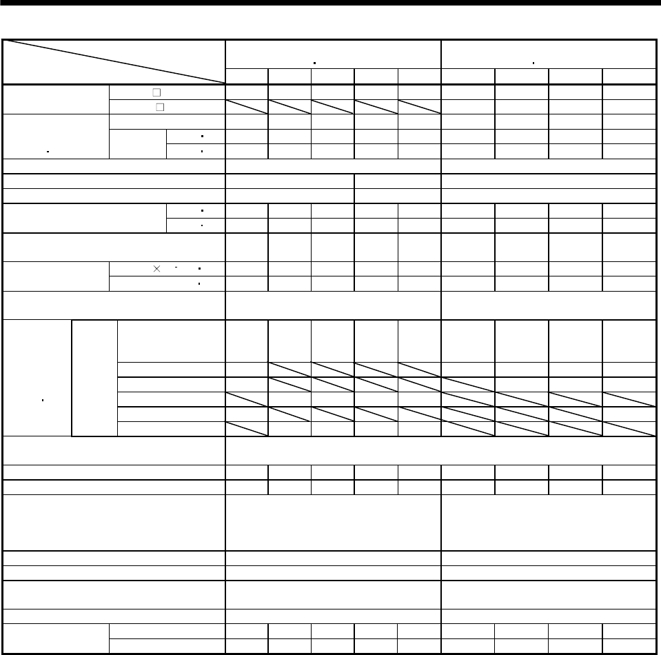
5 - 14
5. SPECIFICATIONS
HC-UFS 2000r/min Series
(flat type middle capacity)
HC-UFS 3000r/min Series
(flat type small capacity)
Servo Motor
Item 72 152 202 352 502 13 23 43 73
MR-J2S A/B/CP/CL 70 200 350 500 500 10 20 40 70
Applicable servo
amplifier/drive unit MR-J2M DU 10 20 40 70
Rated output [kW] 0.75 1.5 2.0 3.5 5.0 0.1 0.2 0.4 0.75
[N m] 3.58 7.16 9.55 16.7 23.9 0.32 0.64 1.3 2.4
Continuous
running duty
(Note 1 11)
Rated
torque [oz in] 507 1015 1353 2367 3387 45 91 184 340
Rated speed (Note 1) [r/min] 2000 3000
Maximum speed [r/min] 3000 2500 4500
Instantaneous permissible speed [r/min] 3450 2875 5175
[N m] 10.7 21.6 28.5 50.1 71.6 0.95 1.9 3.8 7.2
Maximum torque [oz in] 1516 3061 4039 7100 10146 135 269 538 1020
Power rate at continuous rated torque
[kW/s] 12.3 23.2 23.9 36.5 49.6 15.5 19.2 47.7 9.76
J[10 4kg m2]10.4 22.1 38.2 76.5 115 0.066 0.241 0.365 5.90
Inertia moment
(Note 3) WK2[oz in2]56.9 120.8 208.9 418.3 628.8 0.4 1.3 2.0 32.3
Recommended ratio of load inertia moment
to servo motor shaft inertia moment (Note 2) 15 times or less 15 times or less
Servo amplifier's
built-in regenerative
resistor
53 124 68 44 31 (Note5) (Note5) 410 41
MR-RB032(30W) 79 (Note5) (Note5) 1230 62
MR-RB12(100W) 264 (Note5) 4100 206
MR-RB30(300W) 372 203 102 72
MR-RB32(300W) 791 618
Regenerative
brake duty
[times/min]
(Note 4 15)
MR-J2S
Series
MR-RB50(500W) 620 338 169 119
Power supply capacity Refer to "Power supply equipment capacity and generated loss of servo amplifiers"
in Servo Amplifier Instruction Manual.
Rated current [A] 5.4 9.7 14 23 28 0.76 1.5 2.8 4.3
Maximum current [A] 16.2 29.1 42 69 84 2.5 4.95 9.24 12.9
Speed/position detector
Encoder common to absolute position and
incremental detection systems (Resolution
per servo motor 1 rotation : 131072
pulse/rev)
Encoder common to absolute position and
incremental detection systems (Resolution
per servo motor 1 rotation : 131072
pulse/rev)
Accessories Oil seal Oil seal
Insulation class Class F Class B
Structure Totally-enclosed, self-cooled
(protection type: IP65)
Totally-enclosed, self-cooled
(protection type: IP65(Note9))
Environmental conditions (Note 7) Refer to section 2.1 Refer to section 2.1
[kg] 8.0 11.0 16.0 20.0 24.0 0.8 1.5 1.7 5.0
Mass (Note 3) [lb] 17.6 24.3 35.3 44.1 52.9 1.8 3.3 3.7 11.0
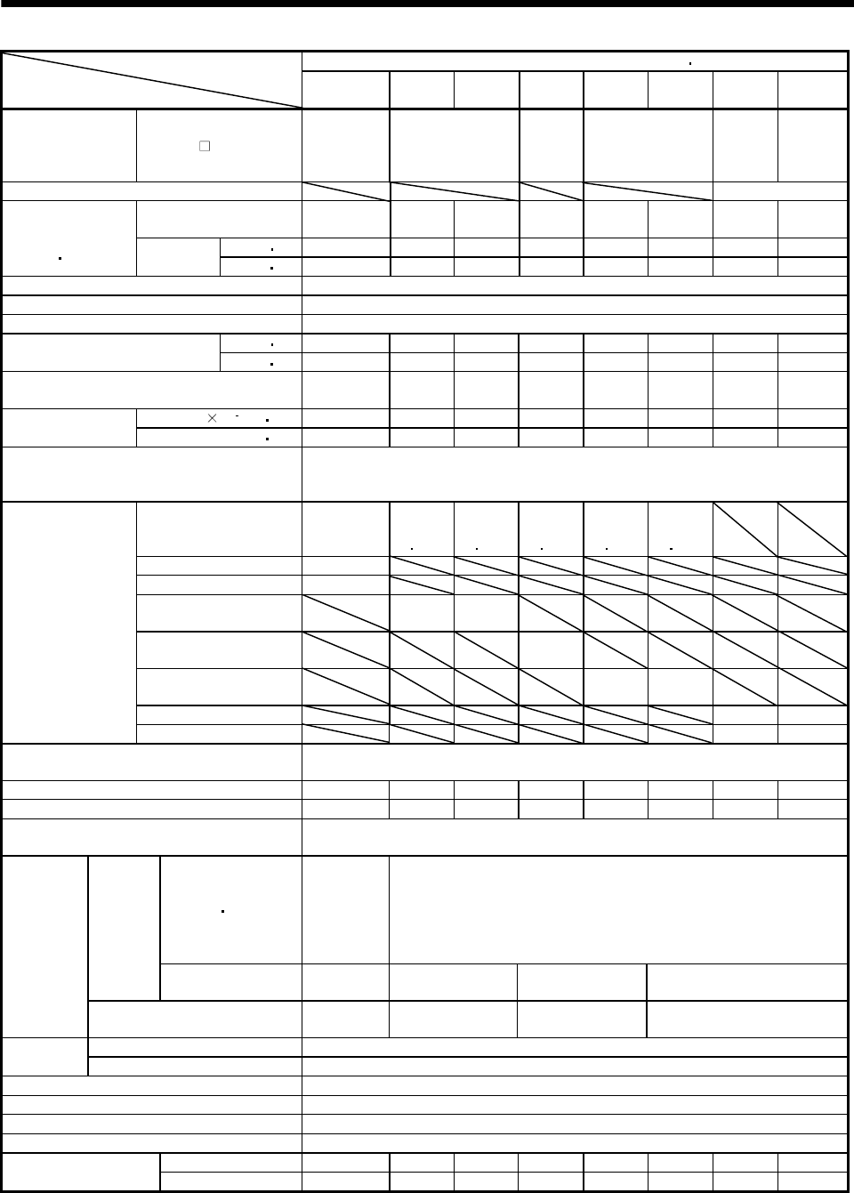
5 - 15
5. SPECIFICATIONS
HA-LFS 1000r/min Series (200VAC-compatible, low inertia middle large capacity)Servo Motor
Item 601
(Note 13) 801 12K1 15K1 20K1 25K1 30K1 37K1
Applicable servo
amplifier MR-J2S- A/B
700A-U058
700B-U058
700CP-U058
700CL-U058
11KA
11KB
15KA
15KB
22KA
22KB
30KA
30KB
37KA-
U039
37KB-
U039
Compatible converter unit MR-HP30KA
Rated output [kW] 6 8 12 15 20 25 30 37
(75% ED)
[N m] 57.3 76.4 115 143 191 239 286 353
Continuous
running duty
(Note 1 11) Rated
torque [oz in] 8114 10819 16285 20251 27048 33845 40501 49989
Rated speed (Note 1) [r/min] 1000
Maximum speed [r/min] 1200
Instantaneous permissible speed [r/min] 1380
[N m] 172 229 344 415 477 597 716 883
Maximum torque [oz in] 24357 32429 48715 58769 67549 84542 101394 125044
Power rate at continuous rated torque
[kW/s] 313 265 445 373 561 528 626 668
J[10 4kg m2] 105 220 295 550 650 1080 1310 1870
Inertia moment
(Note 3) WK2[oz in2] 574.1 1202.8 1612.9 3007.1 3553.8 5904.8 7162.4 10224.1
Recommended ratio of load inertia moment
to servo motor shaft inertia moment
(Note 2)
10 times or less
Servo amplifier’s
built-in regenerative
resistor
158
354
(Note 10
14)
264
(Note 10
14)
230
(Note 10
14)
195
(Note 10
14)
117
(Note 10
14)
MR-RB31(300W) 278
MR-RB51(500W) 464
MR-RB65(800W) 354
(Note 14)
264
(Note 14)
MR-RB66(1300W) 230
(Note 14)
MR-RB67(1300W) 195
(Note 14)
117
(Note 14)
MR-RB139(1300W) 97 68
Regenerative
brake duty
[times/min]
(Note 4)
MR-RB137(3900W) 290 203
Power supply capacity Refer to “Power supply equipment capacity and generated loss of servo
amplifiers” in Servo Amplifier Instruction Manual.
Rated current [A] 34 42 61 83 118 118 154 188
Maximum current [A] 102 126 183 249 295 295 385 470
Speed/position detector Encoder common to absolute position and incremental detection systems
(Resolution per servo motor 1 rotation: 131072 pulse/rev)
Voltage frequency
Three-phase
200 to 220
VAC 50Hz,
One-phase
200 to 230
VAC 60Hz
Three-phase 200 to 230VAC 50Hz/60Hz
Power
supply
Power
consumption [W] 42(50Hz)/
54(60Hz)
62(50Hz)/
76(60Hz)
65(50Hz)/
85(60Hz)
120(50Hz)/
175(60Hz)
Cooling fan
Rated current [A] 0.21(50Hz)/
0.25(60Hz)
0.18(50Hz)/
0.17(60Hz)
0.20(50Hz)/
0.22(60Hz)
0.65(50Hz)/
0.80(60Hz)
Maximum rated 125VAC/DC, 3A or 250VAC/DC, 2A
Thermal
protector Minimum rated 6VAC/DC, 0.15A
Accessories Oil seal
Insulation class Class F
Structure Totally-enclosed, force-cooled (protection type: IP44)
Environmental conditions (Note 7) Refer to section 2.1
[kg] 55 95 115 160 180 230 250 335
Mass (Note 3) [lb] 121.3 209.4 253.5 352.7 396.8 507.1 551.6 738.5
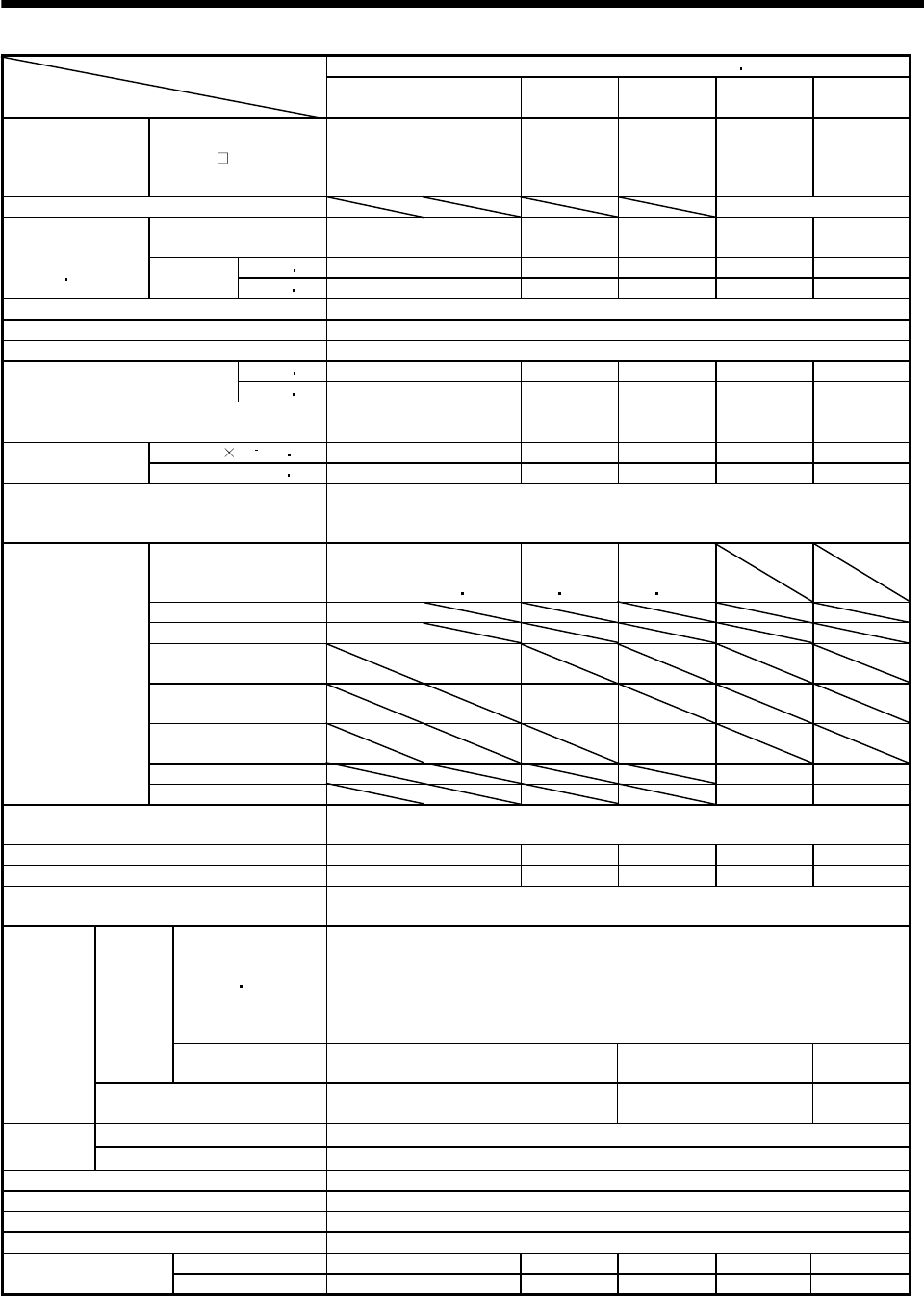
5 - 16
5. SPECIFICATIONS
HA-LFS 1500r/min Series (200VAC-compatible, low inertia middle large capacity)Servo Motor
Item
701M
(Note 13) 11K1M 15K1M 22K1M 30K1M 37K1M
Applicable servo
amplifier MR-J2S-
700A-U058
700B-U058
700CP-U059
700CL-U059
11KA
11KB
15KA
15KB
22KA
22KB
30KA
30KB
37KA-U042
37KB-U042
Compatible converter unit MR-HP30KA
Rated output [kW] 7 11 15 22 30 37
(75% ED)
[N m] 44.6 70.0 95.5 140 191 236
Continuous
running duty
(Note 1 11) Rated
torque [oz in] 6315.9 9912.9 13524 19825.7 27047.9 33420.5
Rated speed (Note 1) [r/min] 1500
Maximum speed [r/min] 2000
Instantaneous permissible speed [r/min] 2300
[N m] 134 210 286 350 477 589
Maximum torque [oz in] 18976 29738.6 40501.1 49564.3 67549.1 83409.6
Power rate at continuous rated torque
[kW/s] 189 223 309 357 561 514
J[10 4kg m2] 105 220 295 550 650 1080
Inertia moment
(Note 3) WK2[oz in2] 574.1 1202.8 1612.9 3007.1 3553.8 5904.8
Recommended ratio if load inertia moment
to servo motor shaft inertia moment
(Note 2)
10 times or less
Servo amplifier’s
built-in regenerative
resistor
70
158
(Note 10
14)
191
(Note 10
14)
102
(Note 10
14)
MR-RB31(300W) 124
MR-RB51(500W) 206
MR-RB65(800W) 158
(Note 14)
MR-RB66(1300W) 191
(Note 14)
MR-RB67(1300W) 102
(Note 14)
MR-RB139(1300W) 87 52
Regenerative
brake duty
[times/min]
(Note 4)
MR-RB137(3900W) 260 156
Power supply capacity Refer to “Power supply equipment capacity and generated loss of servo
amplifiers” in Servo Amplifier Instruction Manual.
Rated current [A] 37 65 87 126 174 202
Maximum current [A] 111 195 261 315 435 505
Speed/position detector Encoder common to absolute position and incremental detection systems
(Resolution per servo motor 1 rotation: 131072 pulse/rev)
Voltage frequency
One-phase
200 to 220
VAC 50Hz,
One-phase
200 to 230
VAC 60Hz
Three-phase 200 to 230VAC 50Hz/60Hz
Power
supply
Power
consumption [W] 42(50Hz)/
54(60Hz)
62(50Hz)/
76(60Hz)
65(50Hz)/
85(60Hz)
120(50Hz)/
175(60Hz)
cooling fan
Rated current [A] 0.21(50Hz)/
0.25(60Hz)
0.18(50Hz)/
0.17(60Hz)
0.20(50Hz)/
0.22(60Hz)
0.65(50Hz)/
0.80(60Hz)
Maximum rated 125VAC/DC, 3A or 250VAC/DC, 2A
Thermal
protector Minimum rated 6VAC/DC, 0.15A
Accessories Oil seal
Insulation class Class F
Structure Totally-enclosed, force-cooled (protection type: IP44)
Environmental conditions (Note 7) Refer to section 2.1
[kg] 55 95 115 160 180 230
Mass (Note 3) [lb] 121.3 209.4 253.5 352.7 396.8 507.1
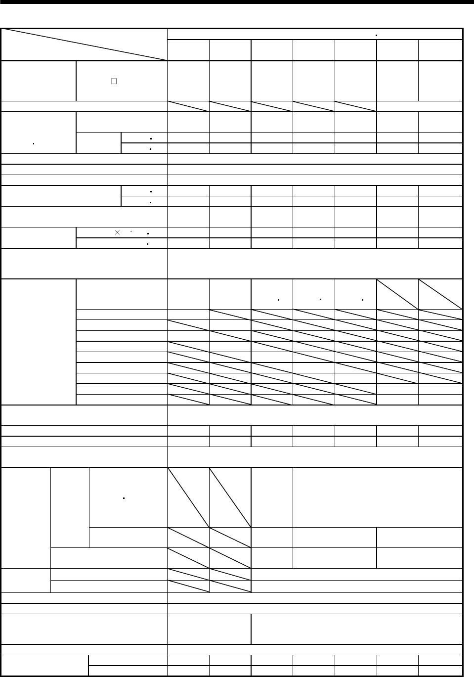
5 - 17
5. SPECIFICATIONS
HA-LFS 2000r/min Series (200VAC-compatible, low inertia middle large capacity)Servo Motor
Item
502
(Note 13)
702
(Note 13) 11K2 15K2 22K2 30K2 37K2
Applicable servo
amplifier MR-J2S-
500A
500B
500CP
500CL
700A
700B
700CP
700CL
11KA
11KB
15KA
15KB
22KA
22KB
30KA
30KB
37KA
37KB
Compatible converter unit MR-HP30KA
Rated output [kW] 5.0 7.0 11 15 22 30 37
(75% ED)
[N m] 23.9 33.4 52.5 71.6 105 143 177
Continuous
running duty
(Note 1 11) Rated
torque [oz in] 3384.5 4729.9 7434.6 10139.4 14869.3 20250.6 25065.4
Rated speed (Note 1) [r/min] 2000
Maximum speed [r/min] 2000
Instantaneous permissible speed [r/min] 2300
[N m] 71.6 100 158 215 263 358 442
Maximum torque [oz in] 10139.4 14161.2 22374.7 30446.6 37244 50697.2 62592.6
Power rate at continuous rated torque
[kW/s] 77.2 118 263 233 374 373 480
J[10 4kg m2] 74.0 94.2 105 220 295 550 650
Inertia moment
(Note 3) WK2[oz in2] 404.6 515 574.1 1202.8 1612.9 3007.1 3553.8
Recommended ratio of load inertia moment
to servo motor shaft inertia moment
(Note 2)
10 times or less
Servo amplifier’s
built-in regenerative
resistor
50 50 186
(Note 10 14)
144
(Note 10 14)
107
(Note 10 14)
MR-RB30(300W) 120
MR-RB31(300W) 95
MR-RB50(500W) 200
MR-RB51(500W) 160
MR-RB65(800W) 186(Note 14)
MR-RB66(1300W) 144(Note 14)
MR-RB67(1300W) 107(Note 14)
MR-RB139(1300W) 58 49
Regenerative
brake duty
[times/min]
(Note 4)
MR-RB137(3900W) 174 147
Power supply capacity Refer to “Power supply equipment capacity and generated loss of servo
amplifiers” in Servo Amplifier Instruction Manual.
Rated current [A] 25 34 63 77 112 166 204
Maximum current [A] 75 102 189 231 280 415 510
Speed/position detector Encoder common to absolute position and incremental detection systems
(Resolution per servo motor 1 rotation: 131072 pulse/rev)
Voltage frequency
One-phase
200 to 220
VAC 50Hz,
One-phase
200 to 230
VAC 60Hz
Three-phase 200 to 230VAC 50Hz/60Hz
Power
supply
Power
consumption [W] 42(50Hz)/
54(60Hz)
62(50Hz)/
76(60Hz)
65(50Hz)/
85(60Hz)
Cooling fan
Rated current [A] 0.21(50Hz)/
0.25(60Hz)
0.18(50Hz)/
0.17(60Hz)
0.20(50Hz)/
0.22(60Hz)
Maximum rated 125VAC/DC, 3A or 250VAC/DC, 2A
Thermal
protector Minimum rated 6VAC/DC, 0.15A
Accessories Oil seal
Insulation class Class F
Structure
Totally-enclosed,
self-cooled
(protection: IP65)
Totally-enclosed, force-cooled (protection: IP44)
Environmental conditions (Note 7) Refer to section 2.1
[kg] 28 35 55 95 115 160 180
Mass (Note 3) [lb] 61.7 77.2 121.3 209.4 253.5 352.7 396.8
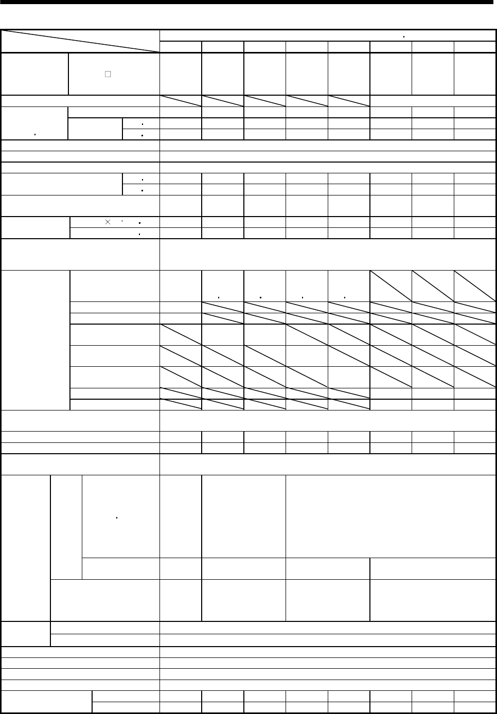
5 - 18
5. SPECIFICATIONS
HA-LFS 1000r/min Series (400VAC-compatible, low inertia large capacity)Servo Motor
Item 6014 8014 12K14 15K14 20K14 25K14 30K14 37K14
Applicable
servo
amplifier
MR-J2S-
700A4-
U071
700B4-
U071
11KA4
11KB4
11KA4
11KB4
15KA4
15KB4
22KA4
22KB4
30KA4
30KB4
30KA4
30KB4
37KA4
37KB4
Compatible converter unit MR-HP55KA4
Rated output [kW] 6 8 12 15 20 25 30 37
[N m] 57.3 76.4 115 143 191 239 286 353
Continuous
running duty
(Note 1 11)
Rated
torque [oz in] 8114.4 10819.1 16285.4 20250.56 27047.95 33845.34 40501.11 49989.14
Rated speed (Note 1) [r/min] 1000
Maximum speed [r/min] 1200
Instantaneous permissible speed [r/min] 1380
[N m] 172 229 344 415 477 597 716 883
Maximum torque [oz in] 24357.3 32429.21 48714.63 58769.1 67549.06 84542.54 101394.4 125043.65
Power rate at continuous rated torque
[kW/s] 313 265 445 373 561 528 626 668
J[10 4kg m2] 105 220 295 550 650 1080 1310 1870
Inertia moment
(Note 3) WK2[oz in2] 574.1 1202.8 1612.9 3007.1 3553.8 5904.8 7162.4 10224.1
Recommended ratio of load inertia
moment to servo motor shaft inertia
moment (Note 2)
10 times or less
Servo amplifier's
supplied regenerative
resistor
158
354
(Note 10
14)
264
(Note 10
14)
230
(Note 10
14)
195
(Note 10
14)
MR-RB34-4(300W) 278
MR-RB54-4(500W) 464
MR-RB6B-4(800W) 354
(Note 14)
264
(Note 14)
MR-RB60-4(1300W) 230
(Note 14)
MR-RB6K-4(1300W) 195
(Note 14)
MR-RB136-4(1300W) 118 97 68
Regenerative
brake duty
[times/min]
(Note 4)
MR-RB138-4(3900W) 354 290 203
Power supply capacity Refer to “Power supply equipment capacity and generated loss of servo amplifiers” in
Servo Amplifier Instruction Manual.
Rated current [A] 17 20 30 40 55 70 77 95
Maximum current [A] 51 63 93 126 148 175 193 235
Speed/position detector Encoder common to absolute position and incremental detection systems
(Resolution per servo motor 1 rotation: 131072 pulse/rev)
Voltage frequency
One-phase
200 to
220VAC/
50Hz,
One-phase
200 to
230VAC/
60Hz
Three-phase 380 to
440VAC 50Hz
Three-phase 380 to
480VAC 60Hz
Three-phase 380 to 460VAC 50Hz
Three-phase 380 to 480VAC 60Hz
Power
supply
Power
consumption [W] 42 (50Hz)/
54 (60Hz)
62 (50Hz)/
76 (60Hz)
65 (50Hz)/
85 (60Hz)
110 (50Hz)/
150 (60Hz)
Cooling fan
Rated current [A]
0.21
(50Hz)/
0.25
(60Hz)
0.14 (50Hz)/
0.11 (60Hz)
0.12 (50Hz)/
0.14 (60Hz)
0.20 (50Hz)/
0.22 (60Hz)
Maximum rated 125VAC/DC, 3A or 250VAC/DC, 2A
Thermal
protector Minimum rated 6VAC/DC, 0.15A
Accessories Oil seal
Insulation class Class F
Structure Totally-enclosed, force-cooled (protection: IP44)
Environmental conditions (Note 7) Refer to section 2.1
[kg] 55 95 115 160 180 230 250 335
Mass (Note 3) [lb] 121.3 209.4 209.43 352.7 396.8 507 551.2 738.5
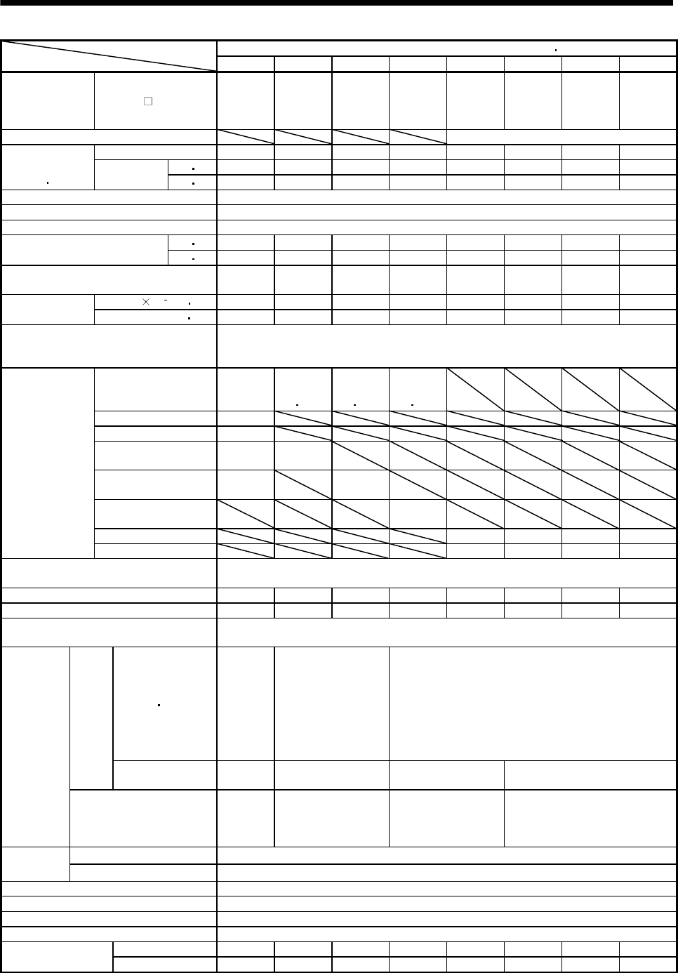
5 - 19
5. SPECIFICATIONS
HA-LFS 1500r/min Series (400VAC-compatible, low inertia large capacity)Servo Motor
Item 701M4 11K1M4 15K1M4 22K1M4 30K1M4 37K1M4 45K1M4 50K1M4
Applicable servo
amplifier MR-J2S-
700A4-
U073
700B4-
U073
11KA4
11KB4
15KA4
15KB4
22KA4
22KB4
30KA4
30KB4
37KA4
37KB4
45KA4
45KB4
55KA4
55KB4
Compatible converter unit MR-HP55KA4
Rated output[kW]7 11152230374550
[N m] 44.6 70.0 95.5 140 191 236 286 318
Continuous
running duty
(Note 1 11)
Rated
torque [oz in] 6315.9 9912.86 13523.97 19825.72 27047.95 33420.5 40501.11 45032.71
Rated speed (Note 1) [r/min] 1500
Maximum speed [r/min] 2000
Instantaneous permissible speed [r/min] 2300
[N m] 134 210 286 350 477 589 716 796
Maximum torque [oz in] 18976 29738.6 40501.1 49564.3 67549.1 83409.6 101394.3 112723.4
Power rate at continuous rated torque
[kW/s] 189 223 309 357 561 514 626 542
J[10 4kg m2] 105 220 295 550 650 1080 1310 1870
Inertia moment
(Note 3) WK2[oz in2] 574.1 1202.8 1612.9 3007.1 3553.8 5904.8 7162.4 10224.1
Recommended ratio of load inertia
moment to servo motor shaft inertia
moment (Note 2)
10 times or less
Servo amplifier's
supplied regenerative
resistor
70
158
(Note 10
14)
191
(Note 10
14)
102
(Note 10
14)
MR-RB34-4(300W) 124
MR-RB54-4(500W) 206
MR-RB6B-4(800W) 124 158
(Note 14)
MR-RB60-4(1300W) 206 191
(Note 14)
MR-RB6K-4(1300W) 102
(Note 14)
MR-RB136-4(1300W) 87 52 43 30
Regenerative
brake duty
[times/min]
(Note 4)
MR-RB138-4(3900W) 260 156 129 90
Power supply capacity Refer to “Power supply equipment capacity and generated loss of servo amplifiers” in
Servo Amplifier Instruction Manual.
Rated current [A] 18 31 41 63 87 101 128 143
Maximum current [A] 54 99 132 158 218 253 320 358
Speed/position detector Encoder common to absolute position and incremental detection systems
(Resolution per servo motor 1 rotation: 131072 pulse/rev)
Voltage frequency
One-phase
200 to
220VAC/
50Hz,
One-phase
200 to
230VAC/
60Hz
Three-phase 380 to
440VAC 50Hz
Three-phase 380 to
480VAC 60Hz
Three-phase 380 to 460VAC 50Hz
Three-phase 380 to 480VAC 60Hz
Power
supply
Power
consumption [W] 42 (50Hz)/
54 (60Hz)
62 (50Hz)/
76 (60Hz)
65 (50Hz)/
85 (60Hz)
110 (50Hz)/
150 (60Hz)
Cooling fan
Rated current [A]
0.21
(50Hz)/
0.25
(60Hz)
0.14 (50Hz)/
0.11 (60Hz)
0.12 (50Hz)/
0.14 (60Hz)
0.20 (50Hz)/
0.22 (60Hz)
Maximum rated 125VAC/DC, 3A or 250VAC/DC, 2A
Thermal
protector Minimum rated 6VAC/DC, 0.15A
Accessories Oil seal
Insulation class Class F
Structure Totally-enclosed, force-cooled (protection: IP44)
Environmental conditions (Note 7) Refer to section 2.1
[kg] 55 95 115 160 180 230 250 335
Mass (Note 3) [lb] 121.3 209.4 253.5 352.7 396.8 507.1 551.2 738.5
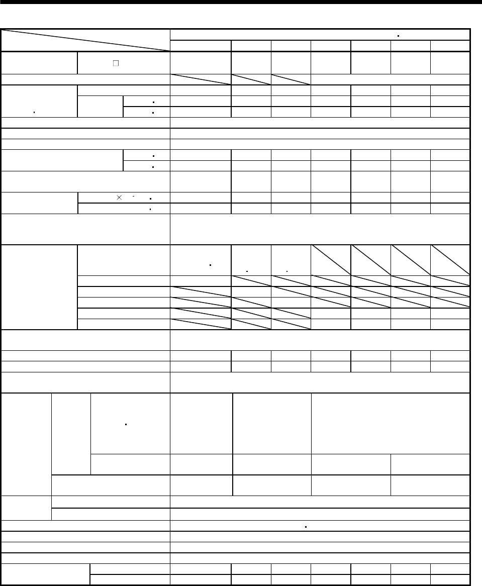
5 - 20
5. SPECIFICATIONS
HA-LFS 2000r/min Series (400VAC-compatible, low inertia large capacity)Servo Motor
Item 11K24 15K24 22K24 30K24 37K24 45K24 55K24
Applicable servo
amplifier MR-J2S- A4/B4 11K 15K 22K 30K 37K 45K 55K
Compatible converter unit MR-HP55KA4
Rated output [kW] 11 15 22 30 37 45 55
[N m] 52.5 71.6 105 143 177 215 263
Continuous
running duty
(Note 1 11)
Rated
torque [oz in] 7434.6 10139.4 14869.3 20250.6 25065.4 30446.6 37244
Rated speed (Note 1) [r/min] 2000
Maximum speed [r/min] 2000
Instantaneous permissible speed [r/min] 2300
[N m] 158 215 263 358 442 537 657
Maximum torque [oz in] 22374.7 30446.6 37244 506972 62592.6 76045.8 93039.3
Power rate at continuous rated torque
[kW/s] 263 233 374 373 480 427 526
J[10 4kg m2] 105 220 295 550 650 1080 1310
Inertia moment
(Note 3) WK2[oz in2] 574.1 1202.8 1612.9 3007.1 3553.8 5904.8 7162.4
Recommended ratio of load inertia moment
to servo motor shaft inertia moment
(Note 2)
10 times or less
Servo amplifier's
supplied regenerative
resistor
186
(Note 10 14)
144
(Note 10
14)
107
(Note 10
14)
MR-RB6B-4(800W) 186 (Note14)
MR-RB60-4(1300W) 144(Note 14)
MR-RB6K-4(1300W) 107(Note 14)
MR-RB136-4(1300W) 58 49 30 24
Regenerative
brake duty
[times/min]
(Note 4)
MR-RB138-4(3900W) 174 147 89 73
Power supply capacity Refer to “Power supply equipment capacity and generated loss of servo
amplifiers” in Servo Amplifier Instruction Manual.
Rated current [A] 32 40 57 83 102 131 143
Maximum current [A] 96 120 171 208 255 328 358
Speed/position detector Encoder common to absolute position and incremental detection systems
(Resolution per servo motor 1 rotation: 131072 pulse/rev)
Voltage frequency
One-phase 200
to
220VAC/50Hz,
One-phase 200
to
230VAC/60Hz
Three-phase 380 to
440VAC 50Hz
Three-phase 380 to
480VAC 60Hz
Three-phase 380 to 460VAC 50Hz
Three-phase 380 to 480VAC 60Hz
Power
supply
Power
consumption [W] 42 (50Hz)/
54 (60 Hz)
62 (50Hz)/
76 (60Hz)
65 (50Hz)/
85 (60Hz)
110 (50Hz)/
150 (60Hz)
Cooling fan
Rated current [A] 0.21 (50Hz)/
0.25 (60 Hz)
0.14 (50Hz)/
0.11 (60Hz)
0.12 (50Hz)/
0.14 (60Hz)
0.20 (50Hz)/
0.22 (60Hz)
Maximum rated 125VAC/DC, 3A or 250VAC/DC, 2A
Thermal
protector Minimum rated 6VAC/DC, 0.15A
Accessories Absolute Encoder, oil seal
Insulation class Class F
Structure Totally-enclosed, force-cooled (protection: IP44)
Environmental conditions (Note 7) Refer to section 2.1
[kg] 55 95 115 160 180 230 250
Mass (Note 3) [lb] 121.3 209.4 253.5 352.7 396.8 507.1 551.2
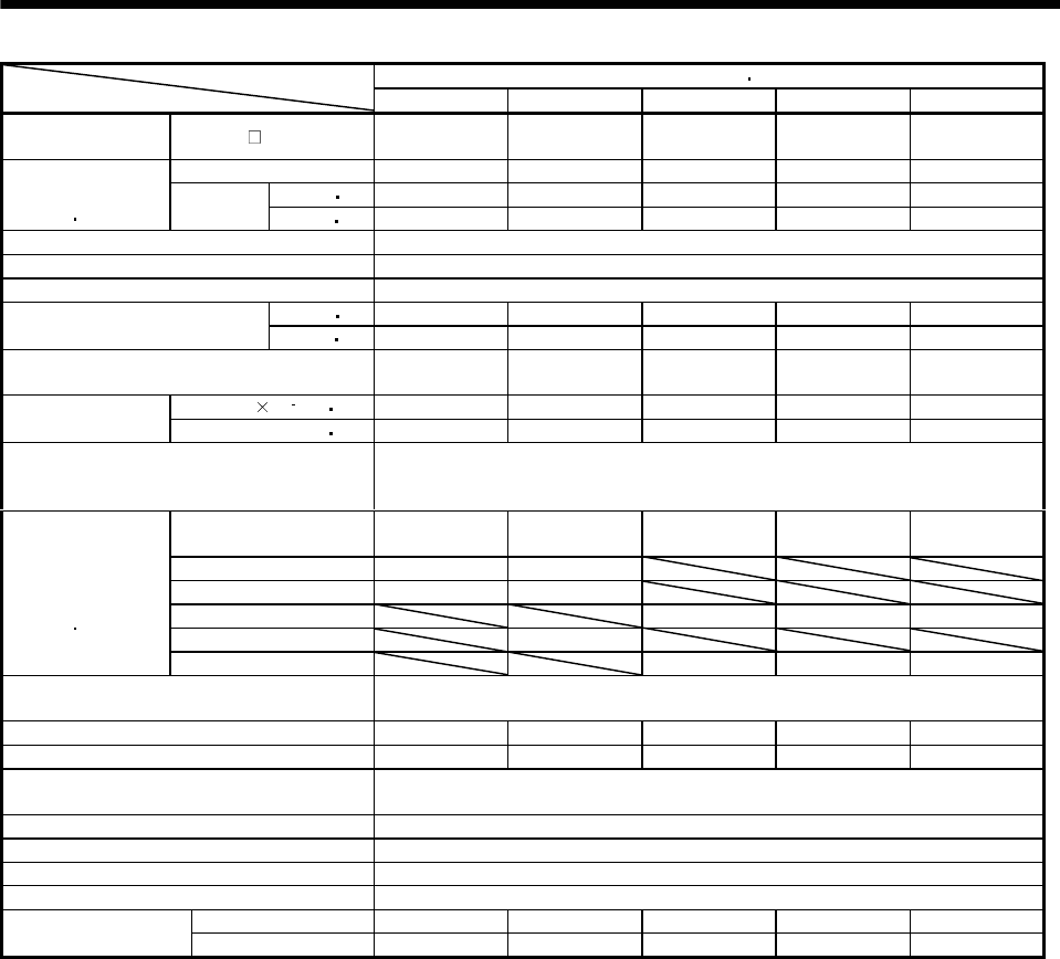
5 - 21
5. SPECIFICATIONS
HC-LFS Series (low inertia middle capacity)Servo Motor
Item 52 102 152 202 302
Applicable servo
amplifier MR-J2S- A/B/CP/CL 60 100 200 350 500
Rated output [kW] 0.5 1.0 1.5 2.0 3.0
[N m] 2.39 4.78 7.16 9.55 14.3
Continuous
running duty
(Note 1 11)
Rated
torque [oz in] 338.5 676.9 1013.9 1352.4 2025.1
Rated speed (Note 1) [r/min] 2000
Maximum speed [r/min] 3000
Instantaneous permissible speed [r/min] 3450
[N m] 7.16 14.4 21.6 28.5 42.9
Maximum torque [oz in] 1013.9 2039.2 3058.8 4036 6075.2
Power rate at continuous rated torque
[kW/s] 17.9 49.7 80.1 41.5 56.8
J[10 4kg m2] 3.2 4.6 6.4 22 36
Inertia moment
(Note 3) WK2[oz in2] 17.5 25.2 35 120.3 196.8
Recommended ratio of load inertia moment
to servo motor shaft inertia moment
(Note 2)
10 times or less
Servo amplifier’ built-in
regenerative resistor 115 160 425 120 70
MR-RB032(30W) 340 235
MR-RB12(100W) 1150 800
MR-RB30(300W) 1270 370 215
MR-RB32(300W) 2410
Regenerative
brake duty
[times/min]
(Note 4 15)
MR-RB50(500W) 2120 615 355
Power supply capacity Refer to “Power supply equipment capacity and generated loss of servo
amplifiers” in Servo Amplifier Instruction Manual.
Rated current [A] 3.2 5.9 9.9 14 23
Maximum current [A] 9.6 18 30 42 69
Speed/position detector Encoder common to absolute position and incremental detection systems
(Resolution per servo motor 1 rotation: 131072 pulse/rev)
Accessories Oil seal
Insulation class Class F
Structure Totally-enclosed, self-cooled (protection type: IP65)
Environmental conditions (Note 7) Refer to section 2.1
[kg] 6.5 8.0 10.0 21 28
Mass (Note 3) [lb] 14.33 17.6 22 46.3 61.7
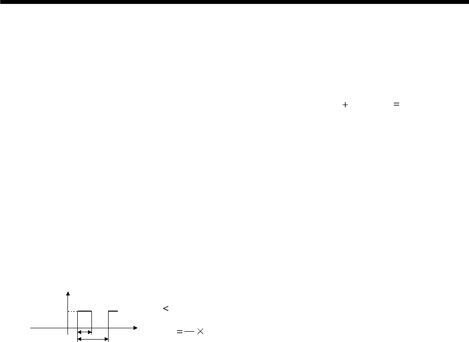
5 - 22
5. SPECIFICATIONS
Note 1.When the power supply voltage drops, we cannot guarantee the output and rated speed.
2.If the load inertia moment ratio exceeds the indicated value, please consult us.
3.This ratio is the load inertia moment ratio to the inertia moment of the servo motor. If the load inertia moment ratio exceeds the
indicated value, please consult us. When the servo motor is equipped with reduction gear or electromagnetic brake, refer to the
corresponding outline dimension drawing. For the EN Standard- and UL/C-UL Standard-compliant models, please consult us.
4.The regenerative brake duty indicated is the permissible duty when the servo motor running without load at the rated speed is
decelerated to a stop. When a load is connected, the value in the table is multiplied by 1/(m 1), where m load inertia
moment/motor inertia moment. At the speed higher than the rated, the permissible number of times is in inverse proportion to
the square of (running speed/rated speed). When the running speed varies frequently or when the regenerative mode continues
as in vertical feed, calculate regenerative heat generated during operation. Provisions must be made to keep this generated heat
below the permissible value.
5.If the effective torque is within the rated torque range, there are no restrictions on the regenerative duty.
6.Except for the shaft-through portion and connector end.
7.In the environment where the servo motor is exposed to oil mist, oil and/or water, the servo motor of the standard specifications
may not be usable. Contact us.
8.IP54 for the EN Standard-compliant model.
9.Except the connector section.
10.Values for use of the supplied regenerative brake unit (regenerative resistor) are indicated in the case of the 11k to 22kW servo
amplifiers. Values for use of the supplied regenerative brake unit (regenerative resistor).
11.80%ED at low noise.
80%ED: Indicates the condition in which operation time at read torque accounts for 80% and the other no-load time accounts for
20% in a single operation cycle.
Torque
100% tb
tc time
tb 60 sec. (continuous operation time)
%ED tc
tb 100
12.When the servo motor is provided with the reduction gear, the protection type of the reduction gear section is IP44.
13.Consult us since they may not be connected depending on the production period of the servo amplifier.
14.Value applicable when the regenerative option is cooled by a cooling fan.
15.The regenerative brake duty of the 600W or less servo amplifier may vary under the influence of the power supply voltage
because of the large ratio of the energy for charging the electrolytic capacitor in the servo amplifier.

5 - 23
5. SPECIFICATIONS
5.2 Torque characteristics
POINT
For machines which produce unbalance torque, e.g. vertical lift
applications, it is recommended to use the servo motor so that the
unbalance torque will be within 70% of the rated torque.
The torque characteristics without notes assume that the power supply is
three-phase 200VAC.
(1) HC-MF series
POINT
The continuous broken line in the graph assumes that the servo motor is
used with the servo amplifier of single-phase 100VAC power supply
specifications.
1000 2000 3000 40004500
Continuous running
region
Speed [r/min]
Torque [N m]
0
0.2
0.4
0.6
[HC-MF053]
Short-duration
running region
1000 2000 3000 40004500
Speed [r/min]
Torque [N m]
0
0.25
0.5
1.0
[HC-MF13]
0.75
Speed [r/min]
Torque [N m]
0
0.5
1.0
2.0
[HC-MF23]
1.5
1000 2000 3000 40004500
Continuous running
region
Short-duration
running region
Continuous running
region
Short-duration
running region
1000 2000 3000 40004500
Speed [r/min]
0
1.0
2.0
4.0
[HC-MF43]
3.0
Torque [N m]
Speed [r/min]
1000 2000 3000 40004500
Torque [N m]
0
2.0
4.0
8.0
[HC-MF73]
6.0
Continuous running
region
Short-duration
running region
Continuous running
region
Short-duration
running region
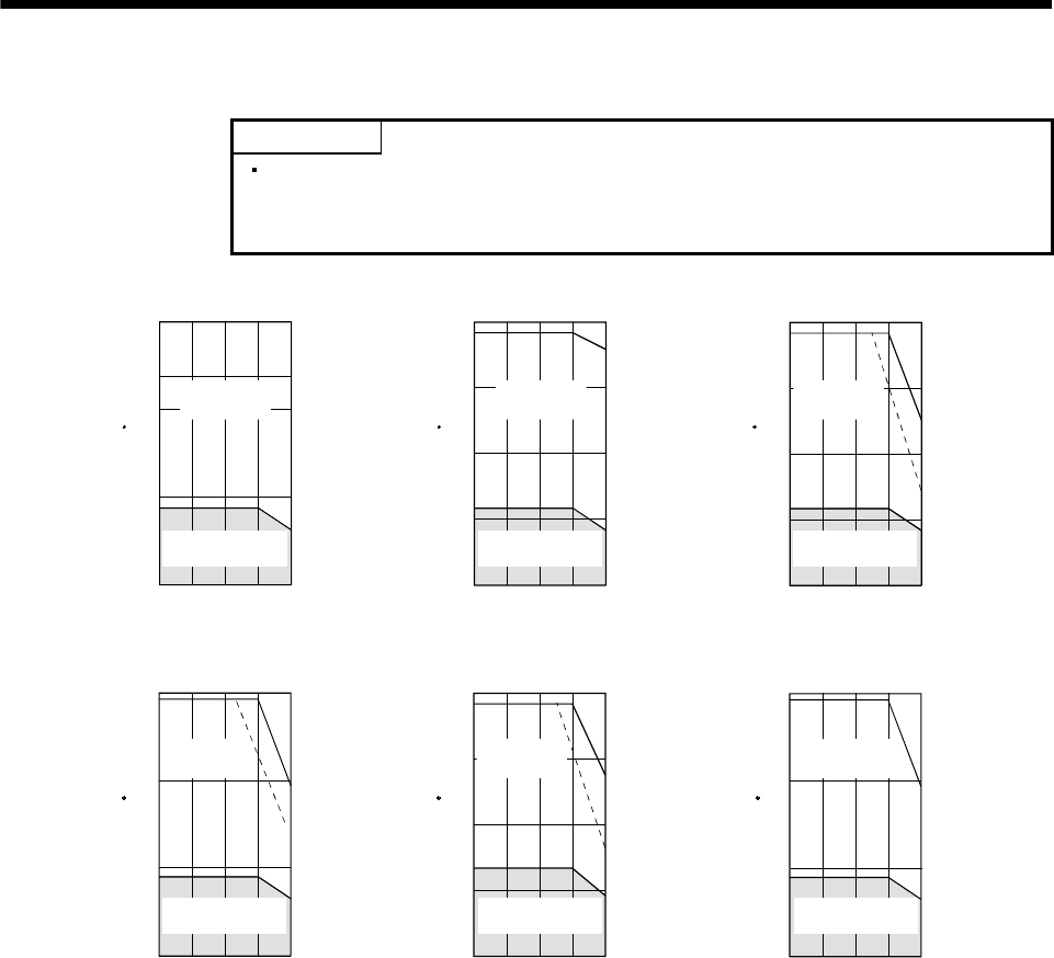
5 - 24
5. SPECIFICATIONS
(2) HA-FF series
POINT
The continuous broken line in the graph assumes that the servo motor is
used with the servo amplifier of single-phase 100VAC power supply
specifications.
1000 2000 3000
Torque [N m]
0
0.5
1.0
2.0
[HA-FF23]
1.5
4000
S
p
eed
[
r/min
]
Torque [N m]
0
0.2
0.4
0.6
[HA-FF053]
1000 2000 3000 4000
Speed [r/min]
3000
Torque [N m]
0
0.25
0.5
1.0
[HA-FF13]
0.75
1000 2000 4000
Speed [r/min]
Continuous running
region
Short-duration
running region
Continuous running
region
Short-duration
running region
Continuous running
region
Short-duration
running region
1000 2000 3000 4000
Speed [r/min]
Torque [N m]
0
1.0
2.0
3.0
[HA-FF33]
4000
0
1.0
2.0
4.0
[HA-FF43]
3.0
Torque [N m]
1000 2000 3000
Speed [r/min]
40001000 2000 3000
Speed [r/min]
Torque [N m]
0
2.0
4.0
6.0
[HA-FF63]
Continuous running
region
Short-duration
running region
Continuous running
region
Short-duration
running region
Continuous running
region
Short-duration
running region
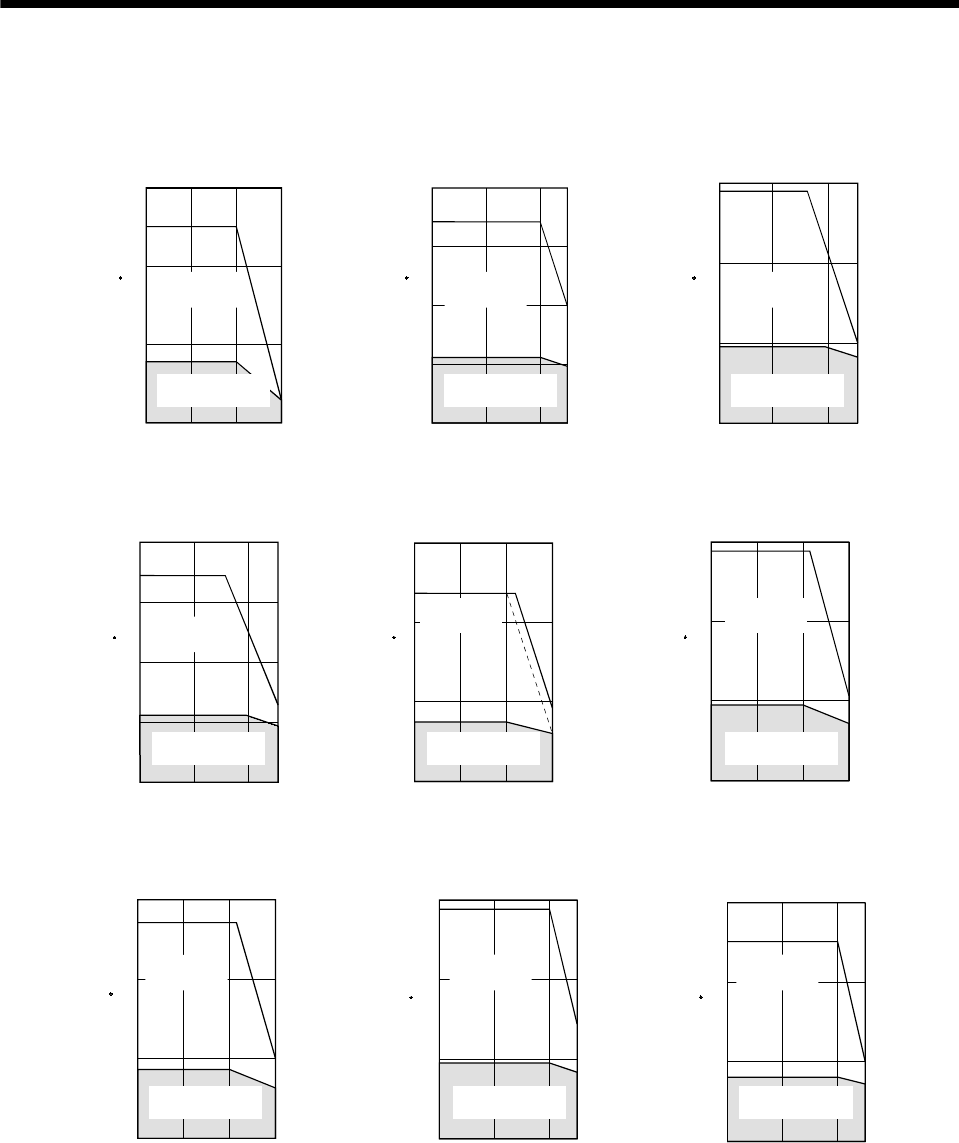
5 - 25
5. SPECIFICATIONS
(3) HC-SF/HC-SFS series
(a) 200VAC-compatible
Torque [N m]
10
20
40
[HC-SF121] (Note 1)
[HC-SFS121] (Note 1)
0
Speed [r/min]
500 1000
30
Torque [N m]
20
40
60
[HC-SF201] (Note 1)
[HC-SFS201] (Note 1)
0
Speed [r/min]
500 1000
Torque [N m]
10
20
30
[HC-SF81] (Note 1)
[HC-SFS81] (Note 1)
0500 1000 1500
Speed [r/min]
1200 1200
Continuous running
region
Short-duration
running region
Continuous running
region
Short-duration
running region
Continuous running
region
Short-duration
running region
Torque [N m]
25
50
100
[HC-SF301] (Note 1)
[HC-SFS301] (Note 1)
0
Speed [r/min]
500 1000
75
1200
5
10
15
[HC-SF102] (Note 1)
[HC-SFS102] (Note 1)
0
Speed [r/min]
1000 2000 3000
Torque [N m]
Torque [N m]
3
6
9
[HC-SF52] (Note 1, 2)
[HC-SFS52] (Note 1, 2)
01000 2000 3000
Speed [r/min]
Continuous running
region
Short-duration
running region
Continuous running
region
Short-duration
running region
Continuous running
region
Short-duration
running region
8
16
24
[HC-SF152] (Note 1)
[HC-SFS152] (Note 1)
0
Speed [r/min]
1000 2000 3000
Torque [N m]
Torque [N m]
10
20
30
[HC-SF202] (Note 1)
[HC-SFS202] (Note 1)
0
Speed [r/min]
1000 2000
[HC-SF352] (Note 1)
[HC-SFS352] (Note 1)
Torque [N m]
20
40
60
0
Speed [r/min]
1000 20002500 2500
Continuous running
region
Short-duration
running region
Continuous running
region
Short-duration
running region
Continuous running
region
Short-duration
running region
Note 1. The continuous line assumes that the servo amplifier's main circuit power supply is 3-phase 200VAC.
2. The broken line assumes that the servo amplifier's main circuit power supply is 1-phase 230VAC.
Note that only the area different from 3-phase 200VAC is indicated by the broken line.
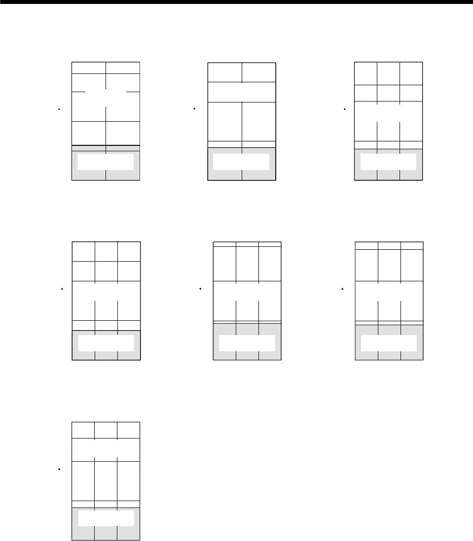
5 - 26
5. SPECIFICATIONS
20
60
80
[HC-SF502]
[HC-SFS502]
0
Speed [r/min]
1000 2000
40
Torque [N m]
Torque [N m]
40
80
120
[HC-SF702]
[HC-SFS702]
0
Speed [r/min]
1000 2000
Torque [N m]
2
4
6
[HC-SF53]
[HC-SFS53]
01000 2000 3000
Speed [r/min]
Continuous running
region
Short-duration
running region
Continuous running
region
Short-duration
running region
Continuous running
region
Short-duration
running region
Torque [N m]
4
8
12
[HC-SF103]
[HC-SFS103]
01000 2000 3000
Speed [r/min]
Torque [N m]
5
10
15
[HC-SF153]
[HC-SFS153]
01000 2000 3000
Speed [r/min]
Torque [N m]
7
14
21
[HC-SF203]
[HC-SFS203]
01000 2000 3000
Speed [r/min]
Continuous running
region
Short-duration
running region
Continuous running
region
Short-duration
running region
Continuous running
region
Short-duration
running region
Torque [N m]
13
26
39
[HC-SF353]
[HC-SFS353]
01000 2000 3000
Speed [r/min]
Continuous running
region
Short-duration
running region
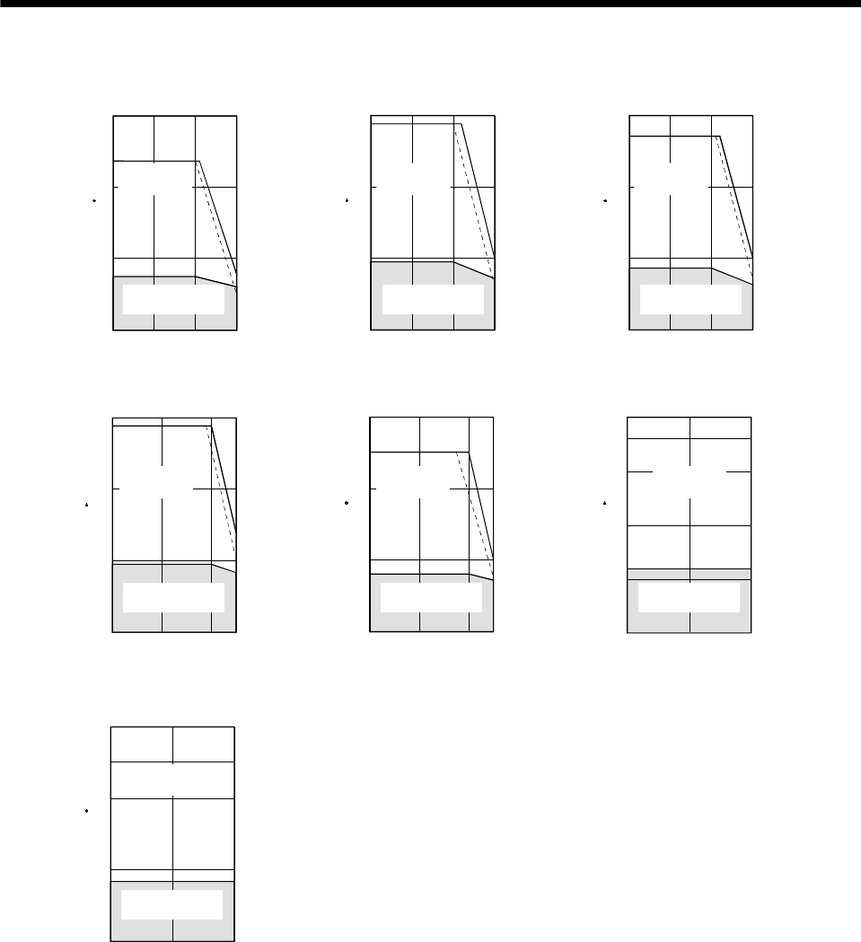
5 - 27
5. SPECIFICATIONS
(b) 400VAC-compatible
5
10
15
[HC-SFS1024] (Note 1, 2)
0
Speed [r/min]
1000 2000 3000
Torque [N m]
Torque [N m]
3
6
9
[HC-SFS524] (Note 1, 2)
01000 2000 3000
Speed [r/min]
8
16
24
[HC-SFS1524] (Note 1, 2)
0
Speed [r/min]
1000 2000 3000
Torque [N m]
Continuous running
region
Short-duration
running region
Continuous running
region
Short-duration
running region
Continuous running
region
Short-duration
running region
[HC-SFS3524] (Note 1, 2)
Torque [N m]
20
40
60
0
Speed [r/min]
1000 2000
20
60
80
[HC-SFS5024] (Note 1)
0
Speed [r/min]
1000 2000
40
Torque [N m]
2500
Torque [N m]
10
20
30
[HC-SFS2024] (Note 1, 2)
0
Speed [r/min]
1000 2000 2500
Continuous running
region
Short-duration
running region
Continuous running
region
Short-duration
running region
Continuous running
region
Short-duration
running region
Torque [N m]
40
80
120
[HC-SFS7024] (Note 1)
0
Speed [r/min]
1000 2000
Continuous running
region
Short-duration
running region
Note 1. The continuous line assumes that the servo amplifier's main circuit power supply is 3-phase 400VAC.
2. The broken line assumes that the servo amplifier's main circuit power supply is 3-phase 380VAC.
Note that only the area different from 3-phase 400VAC is indicated by the broken line.
5 - 28
5. SPECIFICATIONS
(4) HC-RF/HC-RFS series
1000 2000 3000 4000
Speed [r/min]
Torque [N m]
0
3
6
9
[HC-RF103]
[HC-RFS103]
1000 2000 3000 4000
Speed [r/min]
Torque [N m]
0
5
10
15
[HC-RF153]
[HC-RFS153]
Speed [r/min]
Torque [N m]
0
6
12
18
[HC-RF203]
[HC-RFS203]
1000 2000 3000 4000
4500 4500 4500
Continuous running
region
Short-duration
running region Short-duration
running region
Continuous running
region
Short-duration
running region
Continuous running
region
[HC-RF353]
[HC-RFS353]
Speed [r/min]
Torque [N m]
0
15
30
45
[HC-RF503]
[HC-RFS503]
1000 2000 3000 4000
1000 2000 3000 4000
Speed [r/min]
Torque [N m]
0
3
6
9
4500 4500
Continuous running
region
Short-duration
running region
Continuous running
region
Short-duration
running region
5 - 29
5. SPECIFICATIONS
(5) HC-UF/HC-UFS series
POINT
The continuous broken line in the graph assumes that the servo motor is
used with the servo amplifier of single-phase 100VAC power supply
specifications.
Torque [N m]
4
8
12
[HC-UF72]
[HC-UFS72]
01000 2000 3000
Speed [r/min]
Torque [N m]
8
16
24
[HC-UF152]
[HC-UFS152]
01000 2000 3000
Speed [r/min]
Torque [N m]
10
20
30
[HC-UF202]
[HC-UFS202]
01000 2000 3000
Speed [r/min]
Continuous running
region
Short-duration
running region
Continuous running
region
Short-duration
running region
Continuous running
region
Short-duration
running region
500 100015002000
Speed [r/min]
Torque [N m]
0
20
40
60
[HC-UF352]
[HC-UFS352]
2500 500 100015002000
Speed [r/min]
Torque [N m]
0
20
40
80
[HC-UF502]
[HC-UFS502]
2500
60
Continuous running
region
Short-duration
running region
Continuous running
region
Short-duration
running region
1000 2000 3000 40004500
Speed [r/min]
Torque [N m]
0
0.25
0.5
1.0
[HC-UF13]
0.75
Continuous running
region
Short-duration
running region
Speed [r/min]
Torque [N m]
0
0.5
1.0
2.0
[HC-UF23]
1.5
1000 2000 3000 40004500
Continuous running
region
Short-duration
running region
1000 2000 3000 40004500
Speed [r/min]
0
1.0
2.0
4.0
[HC-UF43]
3.0
Torque [N m]
Continuous running
region
Short-duration
running region
Speed [r/min]
Torque [N m]
0
2
4
8
[HC-UF73]
6
1000 2000 3000 40004500
Continuous running
region
Short-duration
running region
5 - 30
5. SPECIFICATIONS
1000 2000 3000 40004500
Speed [r/min]
Torque [N m]
0.25
0.5
1.0
[HC-UFS13]
0.75
Speed [r/min]
Torque [N m]
0
0.5
1.0
2.0
[HC-UFS23]
1.5
1000 2000 3000 40004500 1000 2000 3000 4000450
0
Speed [r/min]
0
1.0
2.0
4.0
[HC-UFS43]
3.0
Torque [N m]
0
Continuous running
region
Short-duration
running region
Continuous running
region
Short-duration
running region
Continuous running
region
Short-duration
running region
Speed [r/min]
Torque [N m]
0
2.0
4.0
8.0
[HC-UFS73]
6.0
1000 2000 3000 40004500
Continuous running
region
Short-duration
running region
(6) HA-LH series
Torque [N m]
50
200
[HA-LH11K2]
0
Speed [r/min]
1000 2000
100
150
Torque [N m]
100
250
[HA-LH15K2]
0
Speed [r/min]
1000 2000
200
Torque [N m]
100
300
[HA-LH22K2]
0
Speed [r/min]
1000 2000
200
Continuous running
region
Short-duration
running region
Continuous running
region
Short-duration
running region
Continuous running
region
Short-duration
running region
5 - 31
5. SPECIFICATIONS
(7) HC-KF series
1000 2000 3000 40004500
0
0.2
0.4
0.6
[HC-KF053]
1000 2000 3000 40004500
0
0.25
0.5
1.0
0.75
[HC-KF13] [HC-KF23]
Torque [N m]
Torque [N m]
S
p
eed
[
r/min
]
S
p
eed
[
r/min
]
S
p
eed
[
r/min
]
Torque [N m]
0
0.5
1.0
2.0
1.5
1000 2000 3000 40004500
Continuous running
region
Short-duration
running region
Continuous running
region
Short-duration
running region
Continuous running
region
Short-duration
running region
[HC-KF43]
1000 2000 3000 40004500
Speed [r/min]
0
1.0
2.0
4.0
3.0
Torque [N m]
Continuous running
region
Short-duration
running region
(8) HC-AQ series
1000 2000 3000 4000
0
0.025
0.05
0.1
5000
0.075
[HC-AQ0135] (Note)
Speed [r/min]
1000 2000 3000 4000
0
0.05
0.1
0.2
5000
0.15
[HC-AQ0235] (Note)
Speed [r/min]
[HC-AQ0335] (Note)
Torque [N m]
1000 2000 3000 4000
0
0.1
0.3
4500
0.2
Speed [r/min]
Torque [N m]
Torque [N m]
Continuous running
region
Short-duration
running region
Continuous running
region
Short-duration
running region
Continuous running
region
Short-duration
running region
Note. Assumes that the servo amplifier main circuit power supply is 24 VDC.
5 - 32
5. SPECIFICATIONS
(9) HA-LF series
(a) 200VAC-compatible
Torque [N m]
0
Speed [r/min]
[HA-LF30K2]
100
400
1000 2000
300
200
Torque [N m]
0
Speed [r/min]
[HA-LF37K2]
200
600
1000 2000
400
Continuous running
region
Short-duration
running region
Continuous running
region
Short-duration
running region
(b) 400VAC-compatible
Torque [N m]
[HA-LF30K24] (Note)
0
Speed [r/min]
100
400
1000 2000
300
200
Torque [N m]
0
Speed [r/min]
[HA-LF37K24] (Note)
200
600
1000 2000
400
Torque [N m]
0
Speed [r/min]
[HA-LF45K24] (Note)
200
600
1000 2000
400
Continuous running
region
Short-duration
running region
Continuous running
region
Short-duration
running region
Continuous running
region
Short-duration
running region
Torque [N m]
0
Speed [r/min]
[HA-LF55K24] (Note)
200
800
1000 2000
600
400
Continuous running
region
Short-duration
running region
Note. Assumes that the servo amplifier main circuit power supply is three-phase 400 VAC.
5 - 33
5. SPECIFICATIONS
(10) HA-LFS series
(a) 200VAC-compatible
Speed [r/min]
Torque [N m]
Speed [r/min]
Torque [N m]
Speed [r/min]
Torque [N m]
500 1000 1200
0
100
200
300
400
[HA-LFS12K1]
Continuous running
region
Short-duration
running region
500
0
180
[HA-LFS601]
120
60
10001200 500
0
300
[HA-LFS801]
200
100
1000 1200
Continuous running
region
Short-duration
running region
Continuous running
region
Short-duration
running region
Speed [r/min]
Torque [N m]
Speed [r/min]
Torque [N m]
Speed [r/min]
Torque [N m]
500
0
450
[HA-LFS15K1]
300
150
10001200 500
0
600
[HA-LFS20K1]
400
200
10001200 500 10001200
0
200
400
600
800
[HA-LFS25K1]
Continuous running
region
Short-duration
running region
Continuous running
region
Short-duration
running region
Continuous running
region
Short-duration
running region
Speed [r/min]
Torque [N m]
Speed [r/min]
Torque [N m]
Speed [r/min]
Torque [N m]
500 10001200
0
200
400
600
800
[HA-LFS30K1]
500
0
900
[HA-LFS37K1]
600
300
10001200 500
0
150
[HA-LFS701M]
100
50
1000 2000
1500
Continuous running
region
Short-duration
running region
Continuous running
region
Short-duration
running region
Continuous running
region
Short-duration
running region
Speed [r/min]
Torque [N m]
Speed [r/min]
Torque [N m]
Speed [r/min]
Torque [N m]
500
0
240
[HA-LFS11K1M]
160
80
1500 20001000 500
0
300
[HA-LFS15K1M]
200
100
1500 2000
1000 500 1000 2000
0
100
200
300
400
[HA-LFS22K1M]
1500
Continuous running
region
Short-duration
running region
Continuous running
region
Short-duration
running region
Continuous running
region
Short-duration
running region
5 - 34
5. SPECIFICATIONS
Speed [r/min]
Torque [N m]
Speed [r/min]
Torque [N m]
Speed [r/min]
Torque [N m]
500
0
600
[HA-LFS30K1M]
400
200
1500 20001000 500
0
600
[HA-LFS37K1M]
400
200
1500 20001000 1000 2000
0
20
40
60
80
[HA-LFS502]
Continuous running
region
Short-duration
running region
Continuous running
region
Short-duration
running region
Continuous running
region
Short-duration
running region
Speed [r/min]
Torque [N m]
0
120
[HA-LFS702]
80
40
20001000
Speed [r/min]
Torque [N m]
1000
0
200
[HA-LFS11K2]
2000
150
100
50
Speed [r/min]
Torque [N m]
1000
0
240
[HA-LFS15K2]
2000
180
120
60
Continuous running
region
Short-duration
running region
Continuous running
region
Short-duration
running region
Continuous running
region
Short-duration
running region
Speed [r/min]
Torque [N m]
1000
0
300
[HA-LFS22K2]
2000
200
100
Continuous running
region
Short-duration
running region
Speed [r/min]
Torque [N m]
Speed [r/min]
Torque [N m]
1000
0
400
[HA-LFS30K2]
2000
300
200
100
1000
0
600
[HA-LFS37K2]
2000
400
200
Continuous running
region
Short-duration
running region
Continuous running
region
Short-duration
running region
5 - 35
5. SPECIFICATIONS
(b) 400VAC-compatible (Note 1)
180
[HA-LFS6014 (B)] (Note 1, 2)
Speed [r/min]
Torque [N m]
0
120
60
500 12001000
Continuous running
region
Short-duration
running region
300
[HA-LFS8014 (B)] (Note 1, 2)
Speed [r/min]
Torque [N m]
0
200
100
500 12001000
Continuous running
region
Short-duration
running region
400
[HA-LFS12K14 (B)] (Note 1, 2)
Speed [r/min]
Torque [N m]
0
300
200
500 12001000
Continuous running
region
Short-duration
running region
100
450
[HA-LFS15K14] (Note 1, 2)
Speed [r/min]
Torque [N m]
0
300
150
500 12001000
Continuous running
region
Short-duration
running region
600
[HA-LFS20K14] (Note 1, 2)
Speed [r/min]
Torque [N m]
0
400
200
500 12001000
Continuous running
region
Short-duration
running region
800
[HA-LFS25K14] (Note 1, 2)
Speed [r/min]
Torque [N m]
0
600
400
500 12001000
Continuous running
region
Short-duration
running region
200
800
[HA-LFS30K14] (Note 1, 2)
Speed [r/min]
Torque [N m]
0
600
200
500 12001000
400
Continuous running
region
Short-duration
running region
900
[HA-LFS37K14] (Note 1)
Speed [r/min]
Torque [N m]
0
600
300
500 12001000
Continuous running
region
Short-duration
running region
150
[HA-LFS701M4 (B)] (Note 1, 2)
Speed [r/min]
Torque [N m]
0
100
50
500 20001000
Continuous running
region
Short-duration
running region
1500
5 - 36
5. SPECIFICATIONS
500 1500 20001000
Speed [r/min]
Torque [N m]
0
240
[HA-LFS11K1M4] (Note 1, 2)
160
80
Continuous running
region
Short-duration
running region
Speed [r/min]
Torque [N m]
0
300
[HA-LFS15K1M4] (Note 1, 2)
200
100
500 1500 20001000
Continuous running
region
Short-duration
running region
Speed [r/min]
Torque [N m]
0
400
[HA-LFS22K1M4] (Note 1, 2)
300
200
100
500 1500 20001000
Continuous running
region
Short-duration
running region
600
[HA-LFS30K1M4] (Note 1, 2)
Speed [r/min]
Torque [N m]
0
400
200
500 1500 20001000
Continuous running
region
Short-duration
running region
600
[HA-LFS37K1M4] (Note 1, 2)
Speed [r/min]
Torque [N m]
0
400
200
500 1500 20001000
Continuous running
region
Short-duration
running region
Speed [r/min]
Torque [N m]
0
800
[HA-LFS45K1M4] (Note 1, 2)
400
200
600
500 1500 20001000
Continuous running
region
Short-duration
running region
Speed [r/min]
Torque [N m]
0
900
[HA-LFS50K1M4] (Note 1, 2)
600
300
500 1500 20001000
Continuous running
region
Short-duration
running region
Speed [r/min]
Torque [N m]
0
200
[HA-LFS11K24] (Note 1)
150
100
50
20001000
Continuous running
region
Short-duration
running region
Speed [r/min]
Torque [N m]
1000
0
240
[HA-LFS15K24] (Note 1, 2)
2000
180
120
60
Continuous running
region
Short-duration
running region
5 - 37
5. SPECIFICATIONS
Speed [r/min]
Torque [N m]
1000
0
300
[HA-LFS22K24] (Note 1)
2000
200
100
Continuous running
region
Short-duration
running region
Speed [r/min]
Torque [N m]
1000
0
[HA-LFS30K24] (Note 1)
2000
200
100
400
300
Continuous running
region
Short-duration
running region
Speed [r/min]
Torque [N m]
1000
0
600
[HA-LFS37K24] (Note 1)
2000
400
200
Continuous running
region
Short-duration
running region
Speed [r/min]
Torque [N m]
1000
0
600
[HA-LFS45K24] (Note 1)
2000
400
200
Continuous running
region
Short-duration
running region
Speed [r/min]
Torque [N m]
1000
0
800
[HA-LFS55K24] (Note 1)
2000
400
200
600
Continuous running
region
Short-duration
running region
Note 1. The continuous line assumes that the servo amplifier's main circuit power supply is 3-phase 400VAC.
2. The broken line assumes that the servo amplifier's main circuit power supply is 1-phase 230VAC.
Note that only the area different from 3-phase 200VAC is indicated by the broken line.
5 - 38
5. SPECIFICATIONS
(11) HC-MFS series
POINT
The continuous broken line in the graph assumes that the servo motor is
used with the servo amplifier of single-phase 100VAC power supply
specifications.
Speed [r/min]
Torque [N m]
Speed [r/min]
Torque [N m]
Speed [r/min]
Torque [N m]
1000 2000 3000 40004500
0
0.6
[HC-MFS053]
0.4
0.2
1000 2000 3000 40004500
0
0.25
0.5
0.75
1.0
[HC-MFS13]
1000 2000 3000 4000 4500
0
0.5
1.0
1.5
2.0
[HC-MFS23]
Continuous running
region
Short-duration
running region
Continuous running
region
Short-duration
running region
Continuous running
region
Short-duration
running region
Speed [r/min]
Torque [N m]
Speed [r/min]
Torque [N m]
1000 2000 3000 40004500
0
1.0
2.0
3.0
4.0
[HC-MFS43]
1000 2000 3000 40004500
0
2.0
4.0
6.0
8.0
[HC-MFS73]
Continuous running
region
Short-duration
running region
Continuous running
region
Short-duration
running region
5 - 39
5. SPECIFICATIONS
(12) HC-KFS series
POINT
The continuous broken line in the graph assumes that the servo motor is
used with the servo amplifier of single-phase 100VAC power supply
specifications.
Speed [r/min]
Torque [N m]
Speed [r/min]
Torque [N m]
Speed [r/min]
Torque [N m]
1000 2000 3000 4000 4500
0
0.6
[HC-KFS053]
0.4
0.2
1000 2000 3000 4000 4500
0
0.25
0.5
0.75
1.0
[HC-KFS13]
1000 2000 3000 40004500
0
0.5
1.0
1.5
2.0
[HC-KFS23]
Continuous running
region
Short-duration
running region
Continuous running
region
Short-duration
running region
Continuous running
region
Short-duration
running region
Speed [r/min]
Torque [N m]
Speed [r/min]
Torque [N m]
1000 2000 3000 40004500
0
1.0
2.0
3.0
4.0
[HC-KFS43]
1000 2000 3000 40004500
0
2.0
4.0
6.0
8.0
[HC-KFS73]
Continuous running
region
Short-duration
running region
Continuous running
region
Short-duration
running region
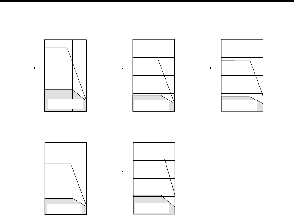
5 - 40
5. SPECIFICATIONS
(13) HC-LFS series
Speed [r/min]
Torque [N m]
Speed [r/min]
Torque [N m]
Speed [r/min]
Torque [N m]
1000
0
8
[HC-LFS52]
6
2
2000 3000
4
1000
0
20
[HC-LFS102]
15
5
2000 3000
10
1000
0
32
[HC-LFS152]
24
8
2000 3000
16
Continuous running
region
Short-duration
running region
Continuous running
region
Short-duration
running region
Continuous running
region
Short-duration
running region
Speed [r/min]
Torque [N m]
Speed [r/min]
Torque [N m]
1000
[HC-LFS302]
2000 3000
0
56
42
14
28
1000
0
40
[HC-LFS202]
30
10
2000 3000
20
Continuous running
region
Short-duration
running region
Continuous running
region
Short-duration
running region
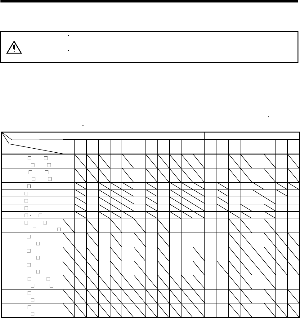
5 - 41
5. SPECIFICATIONS
5.3 Servo motors with reduction gears
CAUTION
The servo motor with reduction gear must be installed in the specified direction.
Otherwise , it can leak oil, leading to a fire or fault.
For the servo motor with reduction gear, transport it in the same status as in the
installation method. Tipping it over can cause oil leakage.
Servo motors are available with reduction gears designed for: general industrial machines and precision
applications.
Servo motors with electromagnetic brakes are also available.
(1) Manufacturing range of servo motor with reduction gear
Servo motors with reduction gears that may be manufactured are indicated by symbols (G1 G1H, G2)
in the following table. G1 G1H and G2 are symbols appended to the servo motor models.
For General Industrial Machines For Precision Applications
Reduction Gear Series
Reduction ratio
Servo Motor
(Note)
1/5 1/6
(Note)
1/10 1/11
(Note)
1/12 1/17
(Note)
1/20 1/29
(Note)
1/30 1/35 1/43 1/59 1/5 1/9 1/10 1/15 1/20 1/25 1/29 1/45
HC-KF053 to 43
HC-KFS053 to 73 G1 G1 G1 G2 G2 G2 G2
HC-MF053 to 73
HC-MFS053 to 73 G1 G1 G1 G2 G2 G2 G2
HA-FF053 G1 G1 G1 G1 G2 G2 G2 G2
HA-FF13 G1 G1 G1 G1 G2 G2 G2 G2 G2
HA-FF23 G1 G1 G1 G1 G2 G2 G2 G2 G2 G2
HA-FF33 G1 G1 G1 G1 G2 G2 G2 G2 G2
HA-FF43 63 G1 G1 G1 G1 G2 G2 G2 G2 G2
HC-SF52 to 202
HC-SFS52(4) to 202(4)
G1
G1H
G1
G1H
G1
G1H
G1
G1H
G1
G1H
G1
G1H
G1
G1H G2 G2 G2 G2 G2
HC-SF352
HC-SFS352(4)
G1
G1H
G1
G1H
G1
G1H
G1
G1H
G1
G1H
G1
G1H
G1
G1H G2 G2 G2
HC-SF502
HC-SFS502(4)
G1
G1H
G1
G1H
G1
G1H
G1
G1H
G1
G1H G2 G2
HC-SF702
HC-SFS702(4)
G1
G1H
G1
G1H
G1
G1H
G1
G1H
G1
G1H G2
HC-RF103 to 203
HC-RFS103 to 203 G2 G2 G2 G2 G2
HC-RF353
HC-RFS353 G2 G2 G2 G2
HC-RF503
HC-RFS503 G2 G2 G2
Note. Reduction ratios for general industrial machines are nominal values. For actual reduction ratios, refer to (2) and (3) in this section.
For those without (Note), the nominal value is equal to the actual reduction ratio.
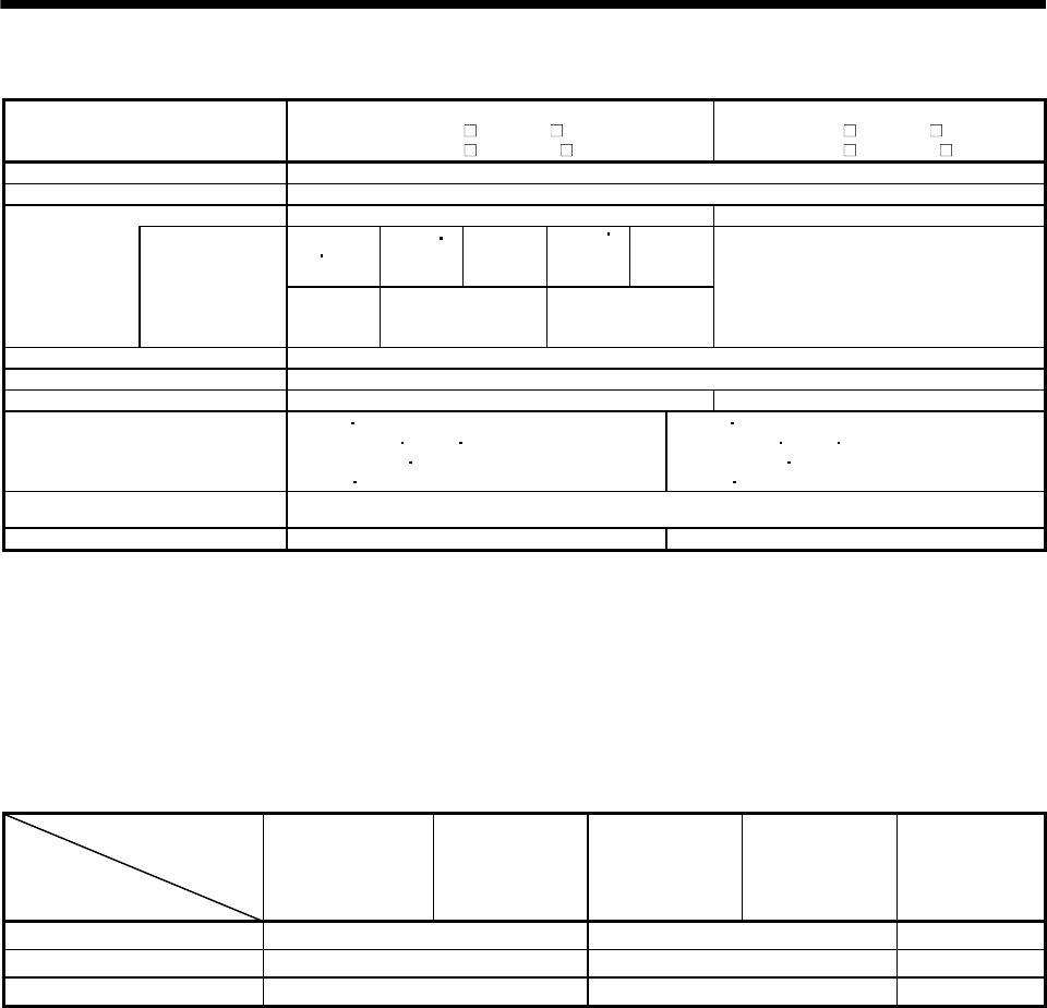
5 - 42
5. SPECIFICATIONS
(2) HC-MF/HC-KF/HC-MFS/HC-KFS series
Reduction Gear Series
For General Industrial Machines
(HC-KF G1/HC-MF G1)
(HC-KFS G1/HC-MFS G1)
For Precision Applications
(HC-KF G2/HC-MF G2)
(HC-KFS G2/HC-MFS G2)
Mounting method Flange mounting
Mounting direction In any directions
(Note 2) Grease lubrication (Already packed) (Note 2) Grease lubrication (Already packed)
50 100W
200W
400W
1/12, 1/20
750W
1/12
200W
400W
1/5
750W
1/5, 1/20
Lubrication
method Packed with Mobilplex
46
Mobil Oil
Molynoc AP2
NIPPON OIL
CORPORATION
Mobil Grease SP
Mobil Oil
LOR#101BV Oil Center Research
Output shaft rotating direction Same as the servo motor output shaft direction.
With electromagnetic brake Available
Backlash 60 minutes or less at reduction gear output shaft 3 minutes or less at reduction gear output shaft
(Note 1) Permissible load inertia
moment ratio (when converting into
the servo motor shaft)
HC-KF HC-KFS
When 50W 100W 750W used: 5 times or less
When 200W 400W used: 7 times or less
HC-MF HC-MFS:25 times or less
HC-KF HC-KFS
When 50W 100W 750W used: 5 times or less
When 200W 400W used: 7 times or less
HC-MF HC-MFS: 25 times or less
Permissible speed
(at servo motor shaft) 4500 r/min
Reduction gear efficiency (Note 3) 45 to 75% 60 to 80%
Note 1. If the above indicated value is exceeded, please consult us.
2. Maintenance-free.
3. The reduction gear efficiency differs depending on the reduction ratio.
Also, it changes depending on the use conditions such as the output torque, speed and rotation, temperature, etc. The
numerical value in the table is a typical value in the rated torque, rated speed and rotation and typical temperature, and not a
guaranteed value.
The actual reduction ratios of the servo motors with reduction gears designed for general industrial
machines are as listed below.
Servo Motor
Nominal
Reduction Ratio
HC-KF053(B)G1
HC-MF053(B)G1
HC-KFS053(B)G1
HC-MFS053(B)G1
HC-KF13(B)G1
HC-MF13(B)G1
HC-KFS13(B)G1
HC-MFS13(B)G1
HC-KF23(B)G1
HC-MF23(B)G1
HC-KFS23(B)G1
HC-MFS23(B)G1
HC-KF43(B)G1
HC-MF43(B)G1
HC-KFS43(B)G1
HC-MFS43(B)G1
HC-KFS73(B)G1
HC-MF73(B)G1
HC-MFS73(B)G1
1/5 9/44 19/96 1/5
1/12 49/576 25/288 525/6048
1/20 25/484 253/5000 625/12544
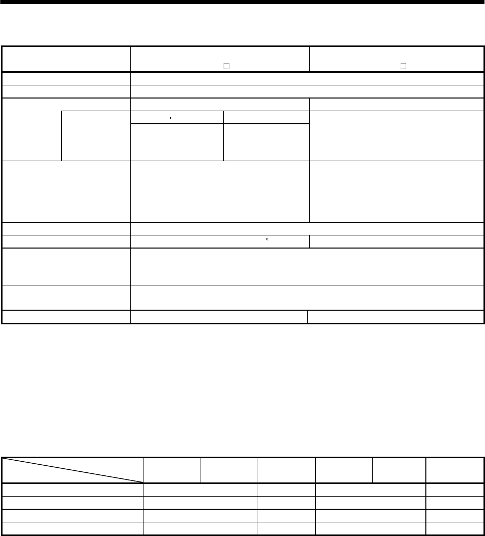
5 - 43
5. SPECIFICATIONS
(3) HA-FF series
Reduction Gear Series For General Industrial Machines
(HA-FF G1)
For Precision Applications
(HA-FF G2)
Mounting method Flange mounting
Mounting direction In any directions
(Note 3) Grease lubrication (Already packed) (Note 3) Grease lubrication (Already packed)
50 100W 200 to 600W
Lubrication
method Packed with
SUMICO
LUBRICANT
MOLY PS GREASE
No.2
PYRONOC
UNIVERSAL No.000
NIPPON PETRQLEUM
LOR#101BV
Oil Center Research
Output shaft rotating direction
Servo motor shaft and reduction gear output
shaft rotate in the same direction. For the
HA-FF053G1 1/30 and HA-FF3G1 1/30, how-
ever, the servo motor shaft and reduction gear
output shaft rotate in the opposite directions.
Servo motor shaft and reduction gear
output-shaft rotate in the same direction.
With electromagnetic brake Available
Backlash (Note 1) 40 minutes to 1.5 Within 3 minutes
(Note 2) Permissible load inertia
moment ratio (when converting
into the servo motor shaft)
5 times or less
Permissible speed
(at servo motor shaft) 3000 r/min
Reduction gear efficiency (Note 4) 73 to 85% 80 to 90%
Note 1. The above values are typical values and not guaranteed values.
2. If the above indicated value is exceeded, please consult us.
3. Maintenance-free.
4. The reduction gear efficiency differs depending on the reduction ratio.
Also, it changes depending on the use conditions such as the output torque, speed and rotation, temperature, etc. The
numerical value in the table is a typical value in the rated torque, rated speed and rotation and typical temperature, and not a
guaranteed value.
The actual reduction ratios of the servo motors with reduction gears designed for general industrial
machines are as listed below.
Servo Motor
Nominal Reduction Ratio HA-FF053G1 HA-FF13G1 HA-FF23G1 HA-FF33G1 HA-FF43G1 HA-FF63G1
1/5 9/44 57/280 19/94 10/49
1/10 3/29 39/400 39/376 243/2401
1/20 99/1972 51/980 72/1363 153/2891
1/30 144/4205 1/30 11/329 27/784
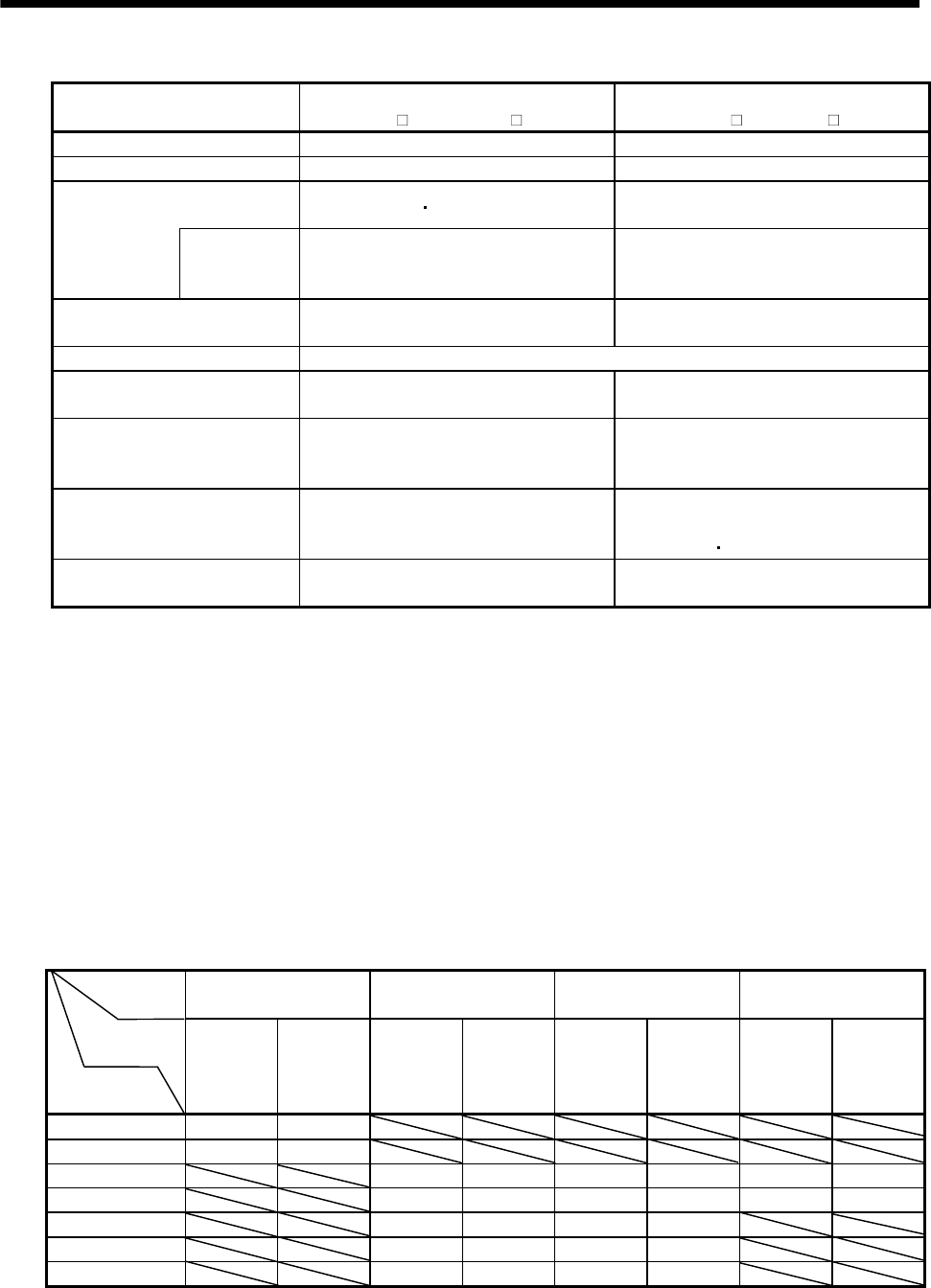
5 - 44
5. SPECIFICATIONS
(4) HC-SF/HC-SFS series
Reduction Gear Series For General Industrial Machines
(HC-SF G1(H)/HC-SFS G1(H))
For Precision Applications
(HC-SF G2/ HC-SFS G2)
Mounting method As in (a) in this section Flange mounting
Mounting direction As in (a) in this section In any directions
As in (a) (b) in this section (Note 4) Grease lubrication
(Already packed)
Lubrication
method (Note 2)
Recommended
products
As in (b) in this section LOR#101BV
Oil Center Research
Output shaft rotating direction Opposite direction to the servo motor
shaft Same direction as the servo motor shaft
With electromagnetic brake Available
Backlash 40 minutes to 2*at reduction gear output
shaft (Note 1)
3 minutes or less at reduction gear output
shaft
(Note 3) Permissible load inertia
moment ratio (when converting
into the servo motor shaft)
4 times or less 5 times or less
Permissible speed
(at servo motor shaft) 2000 r/min
0.5 to 1.5kW:3000 r/min
2 to 3.5kW:2500 r/min
57kW:2000 r/min
Reduction gear efficiency
(Note 5) 85 to 94% 80 to 90%
Note 1. The above values are typical values and not guaranteed values.
2. For grease lubrication, the reduction gear is already grease-packed.
3. If the above indicated value is exceeded, please consult us.
4. Maintenance-free.
5. The reduction gear efficiency differs depending on the reduction ratio.
Also, it changes depending on the use conditions such as the output torque, speed and rotation, temperature, etc. The
numerical value in the table is a typical value in the rated torque, rated speed and rotation and typical temperature, and
not a guaranteed value.
(a) Lubrication of reduction gears for general industrial machines
Oil lubrication cannot be used in applications where the servo motor will move. Specify grease
lubrication.
For grease lubrication, the reduction gear is already grease-packed.
For oil lubrication, pack the reduction gear with oil on the customer side.
Mounting
Direction Shaft in Any Direction Shaft Horizontal Shaft Downward Shaft Upward
Reduction
gear model
Reduction gear
frame No.
CNHM
(leg type)
CNVM
(flange type)
CHHM
(leg type)
CHVM
(flange type
)
CVHM
(leg type)
CVVM
(flange type
)
CWHM
(leg type)
CWVM
(flange type
)
4105 Grease Grease
4115 Grease Grease
4135 (Note) Oil (Note) Oil (Note) Oil (Note) Oil Grease Grease
4165 (Note) Oil (Note) Oil (Note) Oil (Note) Oil Grease Grease
4175 Oil Oil Oil Oil
4185 Oil Oil Oil Oil
4195 Oil Oil Oil Oil
Note. Grease-lubricated type is also available optionally.
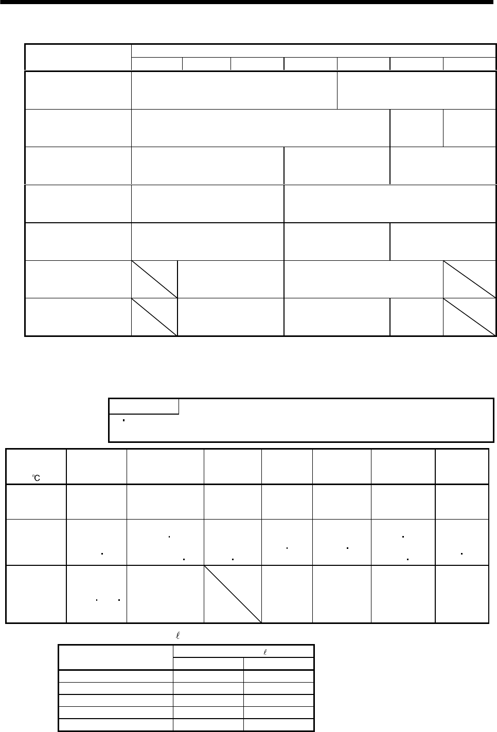
5 - 45
5. SPECIFICATIONS
The reduction gear frame numbers are as follows.
Reduction Ratio
Servo Motor 1/6 1/11 1/17 1/29 1/35 1/43 1/59
HC-SF52(B)G1 (H)
HC-SFS52(B)G1 (H)
HC-SFS524(B)G1 (H)
4105 4115
HC-SF102(B)G1 (H)
HC-SFS102(B)G1 (H)
HC-SFS1024(B)G1 (H)
4115 4135 4165
HC-SF152(B)G1 (H)
HC-SFS152(B)G1 (H)
HC-SFS1524(B)G1 (H)
4115 4135 4165
HC-SF202(B)G1 (H)
HC-SFS202(B)G1 (H)
HC-SFS2024(B)G1 (H)
4115 4165
HC-SF352(B)G1 (H)
HC-SFS352(B)G1 (H)
HC-SFS3524(B)G1 (H)
4135 4165 4175
HC-SF502(B)G1 (H)
HC-SFS502(B)G1 (H)
HC-SFS5024(B)G1 (H)
4165 4185
HC-SF702(B)G1 (H)
HC-SFS702(B)G1 (H)
HC-SFS7024(B)G1 (H)
4175 4185 4195
(b) Recommended lubricants
1) Grease
Albania Grease/Shell OIL
2) Lubricating oil
POINT
Since the oil-lubricated models are shipped without oil, make sure to fill oil up
to the upper red line of the oil gauge before operation.
Ambient
Temperature COSMO OIL NIPPON OIL
CORPORATION
IDEMITSU
KOSAN CO.,
LTD
Shell OIL ESSO OIL
GENERAL OIL Mobil OIL Japan
Energy
-10 to 5 COSMO
GEAR SE68
BONNOC M68
DIAMOND GEAR
LUBE SP68
DAPHNE
SUPER
GEAR OIL 68
Omala Oils
68
SPARTAN
EP68
Mobilgear 626
(ISO VG68)
JOMO
Reductus 68
0 to 35 COSMO
GEAR
SE100 150
BONNOC
M100 150
DIAMOND GEAR
LUBE SP100 150
DAPHNE
SUPER
GEAR OIL
100 150
Omala Oils
100 150
SPARTAN
EP100 150
Mobilgear
627 629
(ISO
VG100 150)
JOMO
Reductus
100 150
30 to 50 COSMO
GEAR
SE200 320
460
BONNOC
M200 to 460
DIAMOND GEAR
LUBE
SP220 to 460
Omala Oils
200 to 460
SPARTAN
EP220 to 460
Mobilgear 630
to 634
(ISO VG220 to
460)
JOMO
Reductus
200 to 460
Lubricating oil fill amount ( )
Fill amount [ ]
Reduction gear frame No. Horizontal type Vertical type
4135 0.7 1.1
4165 1.4 1.0
4175 1.9 1.9
4185 2.5 2.0
4195 4.0 2.7
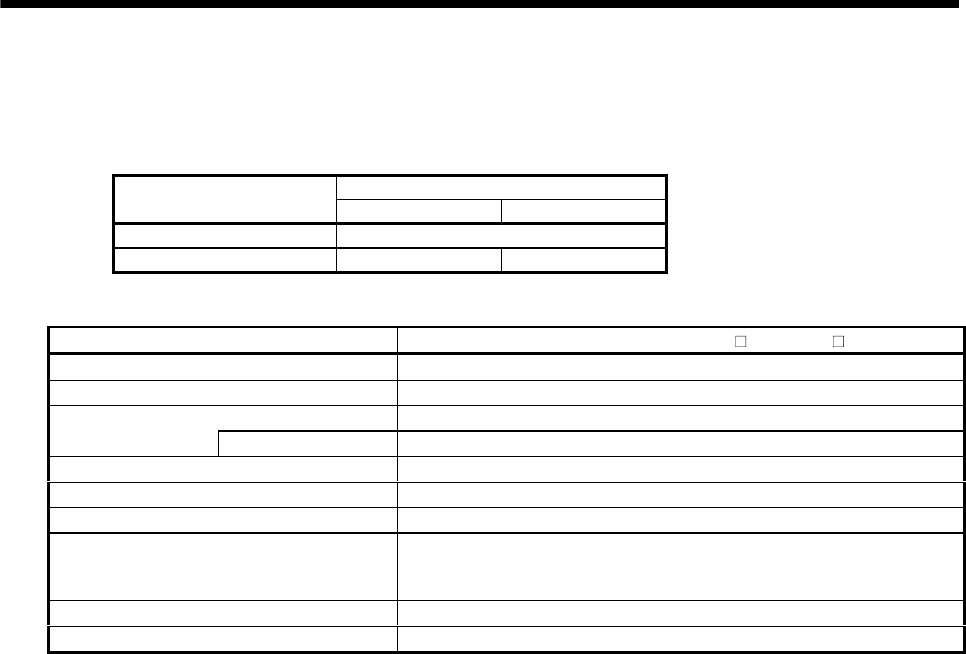
5 - 46
5. SPECIFICATIONS
(c) Changing intervals of lubricant for general industrial machines
1) Grease
Maintenance-free. (Limited to the case where the grease-lubricated type is standard.)
2) Lubricant
Operation hours per day
Changing intervals Less than 10 hours 10 to 24 hours
First time 500 hours
Second time and later Half year 2500 hours
(5) HC-RF/HC-RFS series
Reduction Gear Series For Precision Applications (HC-RF G2/HC-RFS G2)
Mounting method Flange mounting
Mounting direction In any directions
(Note 2) Grease lubrication (Already packed)
Lubrication method Packed with LOR#101BV Oil Center Research
Output shaft rotating direction Same direction as the servo motor shaft
With electromagnetic brake Available
Backlash Within 3 minutes at reduction gear output shaft
(Note 1) Permissible load inertia moment
ratio (when converting into the servo motor
shaft)
5 times or less
Permissible speed (at servo motor shaft) 4000 r/min
Reduction gear efficiency (Note 3) 80 to 90%
Note 1. If the above indicated value is exceeded, please consult us.
2. Maintenance-free.
3. The reduction gear efficiency differs depending on the reduction ratio.
Also, it changes depending on the use conditions such as the output torque, speed and rotation, temperature, etc. The
numerical value in the table is a typical value in the rated torque, rated speed and rotation and typical temperature, and
not a guaranteed value.
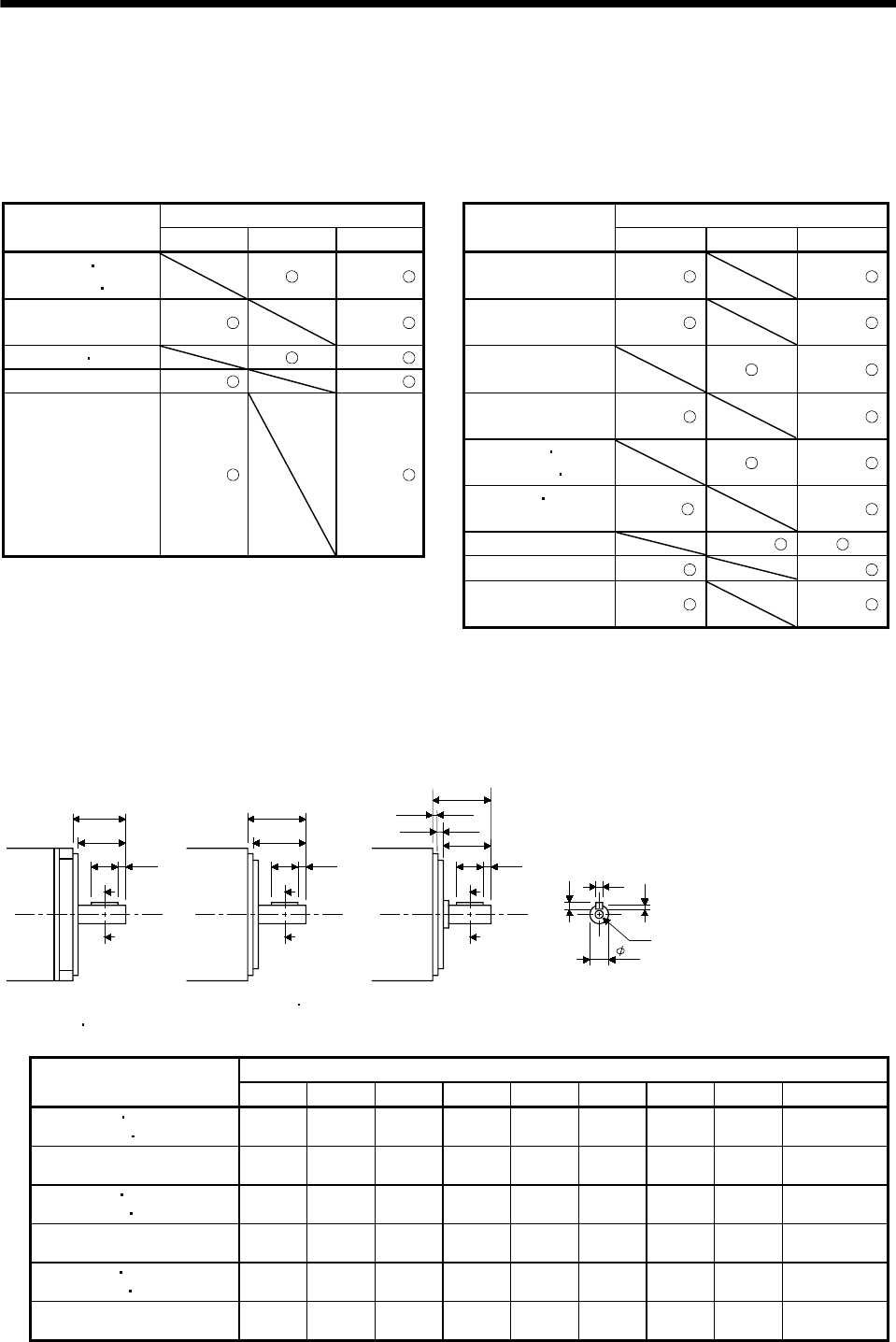
5 - 47
5. SPECIFICATIONS
5.4 Servo motors with special shafts
The standard shaft of the servo motor is straight without a keyway. Shafts with keyway and D cut are
also available. Except for the servo motor with reduction gear.
These shafts are not appropriate for applications where the servo motor is started and stopped frequently.
Use a friction coupling or the like with such keys since we cannot guarantee such trouble as broken shafts
due to loose keys.
Shaft Shape Shaft Shape
Servo Motor Model Keyway D cut Straight Servo Motor Model Keyway D cut Straight
HC-MF053 13
HC-MFS053 13 (Note 4) HC-RF103 to 503
HC-RFS103 to 503 (Note 2) (Note 4)
HC-MF23 to 73
HC-MFS23 to 73 (Note 1) (Note 4) HC-UF72 to 502
HC-UFS72 to 502 (Note 2) (Note 4)
HA-FF053 13 (Note 4)
HA-FF23 to 63 (Note 3) (Note 4)
HC-UF13
HC-UFS13 (Note 4)
HC-UF23 to 73
HC-UFS23 to 73 (Note 1) (Note 4)
HC-KF053 13
HC-KFS053 13 (Note 4)
HC-KF23 43
HC-KFS23 to 73 (Note 1) (Note 4)
HC-SF81 to 301
HC-SF52 to 702
HC-SF53 to 353
HC-SFS81 to 301
HC-SFS52 to 702
HC-SFS53 to 353
HC-SFS524 to 7024
(Note 2) (Note 4)
HC-AQ0135 to 0335 (Note 4)
HC-LFS (Note 2) (Note 4)
HA-LA
HA-LFS (Note 2) (Note 4)
Note 1. With a key.
2. Without a key.
3. Standard with a key. For shape, refer to chapter 7.
4. This is a standard. For shape, refer to chapter 7.
5.4.1 Keyway
(1) With key
R
Q
QL
QK
A
A
HC-MF(S)23K to 73K
HC-KF23K 43K
HC-KFS23K to 73K
R
HC-UF(S)23K 43K
QL
QK
A
A
Q
H
W
U
S
Y
Section A-A
R
HC-UF(S) 73K
QL
QK
A
A
3.5
2.5
Q
[Unit: mm]
([Unit: in])
Variable Dimensions
Servo Motor Model S R Q W QK QL U H Y
HC-MF23K 43K
HC-MFS23K 43K
14h6
(14)
30
(1.18)
27
(1.06)
5
(0.20)
20
(0.79)
3
(0.12)
3
(0.12)
5
(0.20)
M4 Depth 15
(0.59)
HC-MF73K
HC-MFS73K
19h6
(19)
40
(1.57)
37
(1.46)
6
(0.24)
25
(0.98)
5
(0.20)
3.5
(0.14)
6
(0.24)
M5 Depth 20
(0.79)
HC-UF23K 43K
HC-UFS23K 43K
14h6
(14)
30
(1.18)
23.5
(0.93)
5
(0.20)
20
(0.79)
3
(0.12)
3
(0.12)
5
(0.20)
M4 Depth 15
(0.59)
HC-UF73K
HC-UFS73K
19h6
(19)
40
(1.57)
32.5
(1.28)
6
(0.24)
25
(0.98)
5
(0.20)
3.5
(0.14)
6
(0.24)
M5 Depth 20
(0.79)
HC-KF23K 43K
HC-KFS23K 43K
14h6
(14)
30
(1.18)
27
(1.06)
5
(0.20)
20
(0.79)
3
(0.12)
3
(0.12)
5
(0.20)
M4 Depth 15
(0.59)
HC-KFS73K 19h6
(19)
40
(1.57)
37
(1.46)
6
(0.24)
25
(0.98)
5
(0.20)
3.5
(0.14)
6
(0.24)
M5 Depth 20
(0.79)
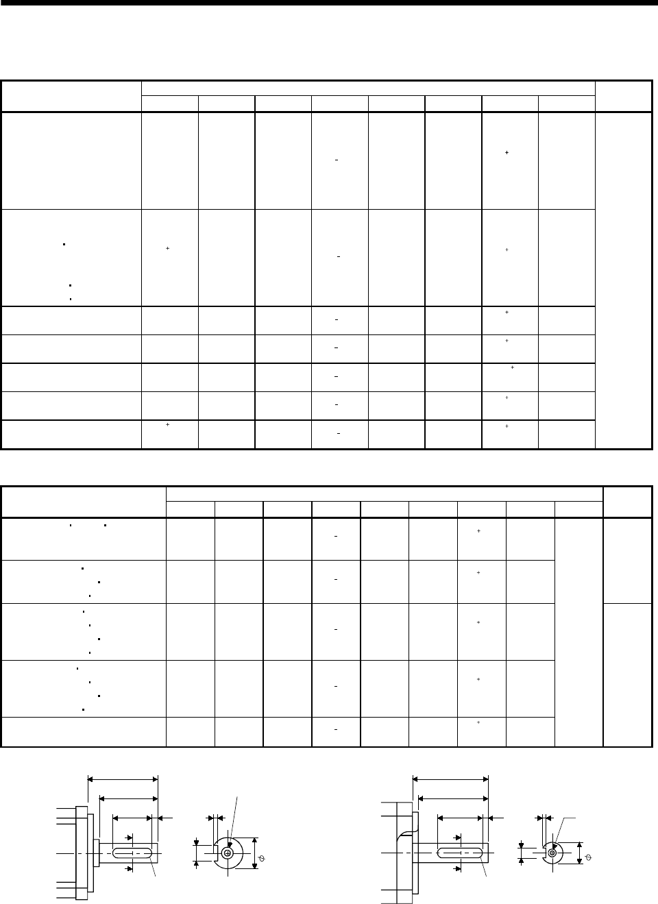
5 - 48
5. SPECIFICATIONS
(2) Without key
[Unit: mm]
([Unit: in])
Variable Dimensions
Servo Motor Model S R Q W QK QL U r Drawing
HC-SF81K
HC-SF52K to 152K
HC-SF53K to 153K
HC-SFS81K
HC-SFS52(4)K to 152(4)K
HC-SFS53K to 153K
HC-LFS52K to 152K
24h6
(0.94)
55
(2.17)
50
(1.97)
80
0.036
(0.31)
36
(1.42)
5
(0.20)
40.2
0
(0.16)
4
(0.16)
HC-SF121K to 301K
HC-SF202K to 702K
HC-SF203K 353K
HC-SFS121K to 301K
HC-SFS202(4)K to 702(4)K
HC-SFS203K 353K
HC-LFS202K 302K
35 0.010
0
(1.38)
79
(3.11)
75
(2.95)
10 0
0.036
(0.39)
55
(2.17)
5
(0.20)
50.2
0
(0.20)
5
(0.20)
HC-RF103K to 203K
HC-RFS103K to 203K
24h6
(0.94)
45
(1.79)
40
(1.57)
80
0.036
(0.31)
25
(0.98)
5
(0.20)
40.2
0
(0.16)
4
(0.16)
HC-RF353K to 503K
HC-RFS353K to 503K
28h6
(1.10)
63
(2.48)
58
(2.28)
80
0.036
(0.31)
45
(1.77)
3
(0.12)
40.2
0
(0.16)
4
(0.16)
HC-UF72K
HC-UFS72K
22h6
(0.87)
55
(2.17)
50
(1.97)
60
0.036
(0.24)
42
(1.65)
3
(0.12)
3.5 0.1
0
(0.14)
3
(0.12)
HC-UF152K
HC-UFS152K
28h6
(1.10)
55
(2.17)
50
(1.97)
80
0.036
(0.31)
40
(1.58)
5
(0.20)
40.2
0
(0.16)
4
(0.16)
HC-UF202K to 502K
HC-UFS202K to 502K
35 0.010
0
(1.38)
65
(2.56)
60
(2.36)
10 0
0.036
(0.39)
50
(1.97)
5
(0.20)
50.2
0
(0.20)
5
(0.20)
A
[Unit: mm]
([Unit: in])
Variable Dimensions
Servo Motor Model S R Q W QK QL U r Y Drawing
HA-LFS502K 702K 11K2(4)K
HA-LFS601(4)K
HA-LFS701M(4)K
42h6
(1.65)
85
(3.35)
80
(3.15)
12 0
0.04
(0.47)
70
(2.76)
5
(0.20)
50.2
0
(0.20)
6
(0.24)
HA-LFS801(4)K 12K1(4)K
HA-LFS11K1M(4)K 15K1M(4)K
HA-LFS15K2(4)K 22K2(4)K
55m6
(2.17)
110
(4.33)
100
(3.94)
16 0
0.04
(0.63)
90
(3.54)
5
(0.20)
60.2
0
(0.24)
8
(0.31)
A
HA-LF30K2(4)K 37K2(4)K
HA-LFS15K1(4)K 20K1(4)K
HA-LFS22K1M(4)K 30K1M(4)K
HA-LFS30K2(4)K 37K2(4)K
60m6
(2.36)
140
(5.51)
140
(5.51)
18 0
0.04
(0.71)
128
(5.04)
6
(0.24)
70.2
0
(0.28)
9
(0.35)
HA-LF45K24K 55K24K
HA-LFS25K1(4)K 30K1(4)K
HA-LFS37K1M(4)K 45K1M4K
HA-LFS45K24K 55K24K
65m6
(2.56)
140
(5.51)
140
(5.51)
18 0
0.04
(0.71)
128
(5.04)
6
(0.24)
70.2
0
(0.28)
9
(0.35)
HA-LFS37K1(4)K
HA-LFS50K1M4K
80m6
(3.15)
170
(6.69)
170
(6.69)
22 0
0.04
(0.87)
147
(5.79)
11
(0.43)
90.2
0
(0.35)
11
(0.43)
Same as
the
straight
shaft of
the
standard
motor. B
QK
A
Q
R
A
QL U
W
r
M8 threads
Depth 20 (0.79)
Section A-A
S
QK
A
Q
R
A
QL U
W
r
Y
Section A-A
S
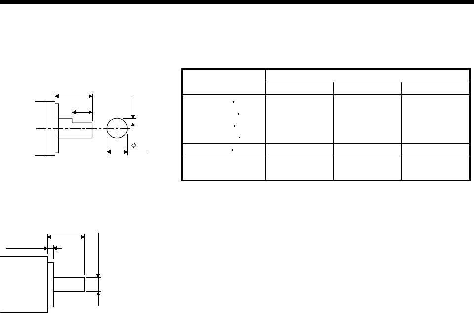
5 - 49
5. SPECIFICATIONS
5.4.2 D cut
[Unit: mm]
([Unit: in])
Variable Dimensions
Servo Motor Model RQKS
HC-KF053D 13D
HC-KFS053D 13D
HC-MF053D 13D
HC-MFS053D 13D
25(0.98) 20.5(0.81) 8h(0.32)
HA-FF053D 13D 30(1.178) 25.5(1.00) 8h(0.32)
R
S
QK
1(0.039)
HC-UF13D
HC-UFS13D 25(0.98) 17.5(0.69) 8h(0.32)
5.4.3 Straight (HC-AQ)
16 (0.63)
2.5 (0.098)
6h6 (0.236)
[Unit: mm
]
([Unit: in])

5 - 50
5. SPECIFICATIONS
MEMO
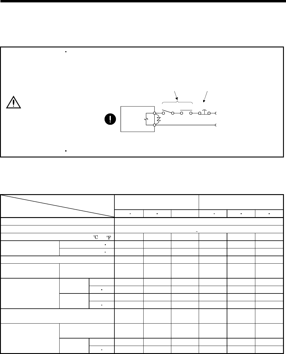
6 - 1
6. CHARACTERISTICS
6. CHARACTERISTICS
6.1 Electromagnetic brake characteristics
CAUTION
Configure the electromagnetic brake circuit so that it is activated not only by the
servo amplifier signals but also by an external emergency (forced) stop signal.
Contacts must be open when
servo-on signal is off, when an
alarm (trouble) is present and when
an electromagnetic brake signal.
Electromagnetic brake
Circuit must be
opened during
emergency (force) stop.
SON RA EMG(EM1)
24VDC
Servo motor
The electromagnetic brake is designed to hold a load. Do not use it for braking.
The characteristics of the electromagnetic brake provided for the servo motor with electromagnetic
brake are indicated below:
Table 6.1 Electromagnetic Brake Characteristics
HC-MF Series
HC-MFS Series HA-FF Series
Servo Motor
Item 053B 13B 23B 43B 73B 053B 13B 23B 33B 43B 63B
Type (Note 1) Spring-loaded safety brake
Rated voltage (Note 4) 24V 0
10% DC
Power consumption [W]20 (68 ) 6.3 7.9 9 7 7.4 11
[N m] 0.32 1.3 2.4 0.39 1.18 2.3
Brake static friction
torque [oz in] 45.3 184.2 340 55.3 167 326
Release delay time (Note 2) [s] 0.03 0.03 0.03 0.03 0.03 0.03
Braking delay time [s]
(Note 2) DC off 0.01 0.02 0.03 0.01 0.03 0.03
[J] 5.6 22.0 64.0 3.9 18.0 46.0
Per braking [oz in] 793.6 3117.6 9069.3 552.7 2550.7 6518.6
[J] 56 220 640 39 180 460
Permissible braking work
Per hour [oz in] 7936 31176 90693 5527 25507 65186
Brake looseness at servo motor shaft [degrees]
(Note 5) 0.19 to 2.5 0.12 to 1.2 0.1 to 0.9 0.3 to 3.5 0.2 to 2.0 0.2 to 1.3
Number of braking
cycles [times] 20000 20000 20000 30000 30000 30000
[J] 4 15 32 4 18 47
Brake life (Note 3) Work per
braking [oz in] 567 2126 4535 567 2551 6660
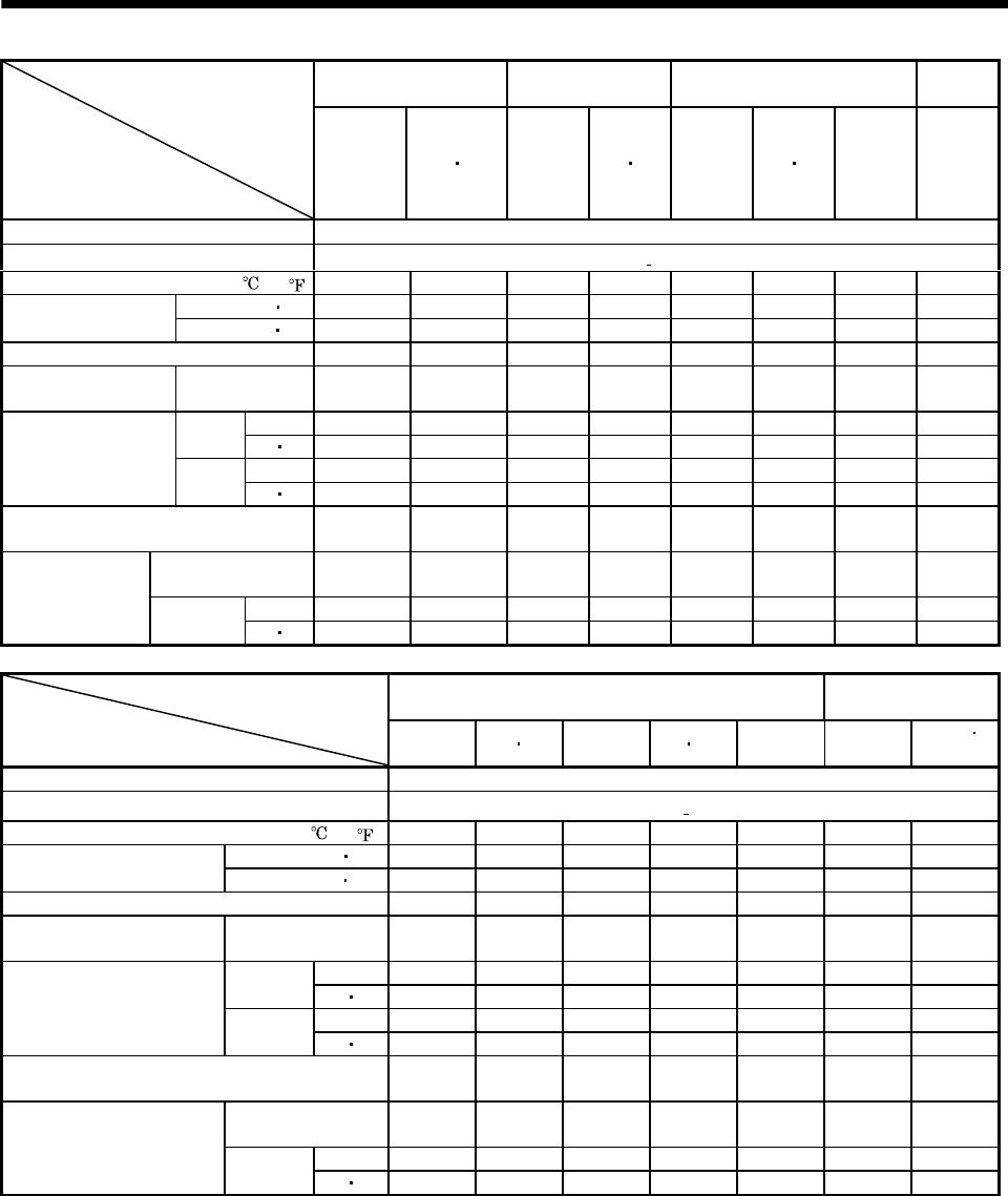
6 - 2
6. CHARACTERISTICS
HC-SF Series
HC-SFS Series
HC-RF Series
HC-RFS Series
HC-KF Series
HC-KFS Series
HC-AQ
Series
Servo Motor
Item
81B
52B to 152B
53B to 153B
524B to 1524B
(Note 7)
121B to 301B
202B to 702B
203B 353B
2024B to 7024B
(Note 7)
103B to
203B 353B 503B 053B
13B 23B 43B (Note 6)
73B
0135B to
0335B
Type (Note 1) Spring-loaded safety brake
Rated voltage (Note 4) 24V 0
10% DC
Power consumption [W]20 (68 ) 19 34 19 23 6.3 7.9 9 4.8
[N m] 8.3 43.1 6.8 16.7 0.32 1.3 2.4 0.098
Brake static friction
torque [oz in] 1176 6103 964 2367 45 6108 340 13.878
Release delay time (Note 2) [s] 0.04 0.1 0.03 0.04 0.03 0.1 0.03 0.02
Braking delay time [s]
(Note 2) DC off 0.03 0.03 0.03 0.03 0.01 0.02 0.03 0.01
[J] 400 4500 400 400 5.6 22.0 64.0 4.6
Per
braking [oz in] 56683.3 637687.1 56683.3 56683.3 793.6 3117.6 9069.3 63.882
[J] 4000 45000 4000 4000 56 220 640 46
Permissible braking
work Per
hour [oz in] 566833 6376871 566833 566833 7936 31176 90693 638.821
Brake looseness at servo motor shaft
(Note 5) [degrees] 0.2 to 0.6 0.2 to 0.6 0.2 to 0.6 0.2 to 0.6 0.19 to
2.5
0.12 to
1.2 0.1 to 0.9 0.1 to 2.5
Number of braking
cycles [times] 20000 20000 20000 20000 20000 20000 20000 20000
[J] 200 1000 200 200 4 15 32 1
Brake life (Note 3) Work per
braking [oz in] 28342 141708 28342 28342 567 2124.18 4535 141.612
HC-UF Series
HC-UFS Series HC-LFS Series
Servo Motor
Item 13B 23B 43B 73B 72B 152B 202B to
502B
52B to
152B
202B
302B
Type (Note 1) Spring-loaded safety brake
Rated voltage (Note 4) 24V 0
10% DC
Power consumption [W]20 (68 )6.37.91019341934
[N m] 0.32 1.3 2.4 8.3 43.1 8.3 43.1
Brake static friction torque [oz in] 45 184 340 1175 6103 1175 6103
Release delay time (Note 2) [s] 0.03 0.03 0.03 0.04 0.1 0.04 0.1
Braking delay time [s]
(Note 2) DC off 0.010.020.030.030.030.030.03
[J] 5.6 22 64 400 4500 400 4500
Per
braking [oz in] 793.6 3117.6 9069.3 56683.3 637687.1 56683.3 637687.1
[J] 56 220 640 4000 45000 4000 45000
Permissible braking work
Per hour [oz in] 7936 31176 90693 566833 6376871 566833 6376871
Brake looseness at servo motor shaft [degrees]
(Note 5) 0.19 to 2.5 0.12 to 1.2 0.1 to 0.9 0.2 to 0.6 0.2 to 0.6 0.2 to 0.6 0.2 to 0.6
Number of braking
cycles [times] 20000 20000 20000 20000 20000 20000 20000
[J] 4 15 32 200 1000 200 1000
Brake life (Note 3) Work per
braking [oz in] 567 2126 4535 28342 141708 28342 141708
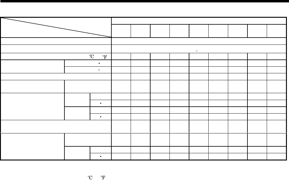
6 - 3
6. CHARACTERISTICS
HA-LFS Series (200/400VAC-compatible)
Servo Motor
Item
601B
6014B
801B
8014B
12K1B
12K14B
701MB
701M4B
11K1MB
11K1M4B
15K1MB
15K1M4B
11K2B
11K24B
15K2B
15K24B
22K2B
22K24B
Type (Note 1) Spring-loaded safety brake
Rated voltage (Note 4) 24V 0
10% DC
Power consumption [W]20 (68 )304646304646304646
[N m] 82 160.5 160.5 82 160.5 160.5 82 160.5 160.5
Brake static friction torque [oz in] 11612 22729 22729 11612 22729 22729 11612 22729 22729
Release delay time (Note 2) [s] 0.25 0.30 0.30 0.25 0.30 0.30 0.25 0.30 0.30
Braking delay time [s]
(Note 2) DC off 0.04 0.04 0.04 0.04 0.04 0.04 0.04 0.04 0.04
[J] 3000 5000 5000 3000 5000 5000 3000 5000 5000
Per
braking [oz in] 424837 708061 708061 424837 708061 708061 424837 708061 708061
[J] 30000 50000 50000 30000 50000 50000 30000 50000 50000
Permissible braking work
Per hour [oz in] 4248369 7080614 7080614 4248369 7080614 7080614 4248369 7080614 7080614
Brake looseness at servo motor shaft [degrees]
(Note 5) to 0.8 to 0.8 to 0.8 to 0.8 to 0.8 to 0.8 to 0.8 to 0.8 to 0.8
Number of braking
cycles [times] 20000 20000 20000 20000 20000 20000 20000 20000 20000
[J] 1000 3000 3000 1000 3000 3000 1000 3000 3000
Brake life (Note 3) Work per
braking [oz in] 141612 424837 424837 1416212 424837 424837 141612 424837 424837
Note 1. There is no manual release mechanism. When it is necessary to hand-turn the servo motor shaft for machine centering, etc.,
use a separate 24VDC power supply to release the brake electrically.
2. The value for initial ON gap at 20 (68 ).
3. The brake gap will increase as the brake lining wears, but the gap is not adjustable. The brake life indicated is the number of
braking cycles after which adjustment will be required.
4. 24VDC of the internal power output for interface (VDD) cannot be used. Always use a separate power supply.
5. The above values are typical initial values and not guaranteed values.
6. 73B is not available for the HC-KF.
7. 524B to 7024B are not available for the HC-SF.
(1) Sound generation
Though the brake lining may rattle during operation, it poses no functional problem.
If braking sound occurs, it may be improved by setting the machine resonance suppression filter or
adaptive vibration suppression control in the servo amplifier parameters. For details, refer to the
servo amplifier instruction manual.
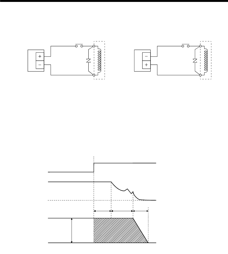
6 - 4
6. CHARACTERISTICS
(2) Electromagnetic brake power supply
24VDC of the internal power output for interface (VDD) cannot be used. Prepare the following power
supply for use with the electromagnetic brake only.
VAR
B1
B2
24VDC powe
r
supply for
electromagnetic brake
or
B1
B2
VAR
24VDC power
supply for
electromagnetic brake
Electromagnetic
Electromagnetic
RA RA
The surge absorber (VAR) must be installed across B1-B2. For the selection of the surge absorber,
refer to OPTIONS AND AUXILIARY EQUIPMENT of the Servo Amplifier Instruction Manual.
The electromagnetic brake terminals (B1, B2) have no polarity.
(3) Coasting distance
At an emergency stop, the servo motor will decelerate to a stop in the pattern shown in the following
diagram. Here, the maximum coasting distance (during fast feed), Lmax, will be the area shown with
the diagonal line in the figure and can be calculated approximately with Equation 6.1. The effect of the
load torque is greater near the stopping area. When the load torque is large, the servo motor will stop
faster than the value obtained in the equation.
Emergency stop
Brake current
Machine speed
V0
t1t2t3
(4) Others
A leakage magnetic flux will occur at the shaft end of the servo motor equipped with electromagnetic
brake. Note that chips, screws and other magnetic substances are attracted.
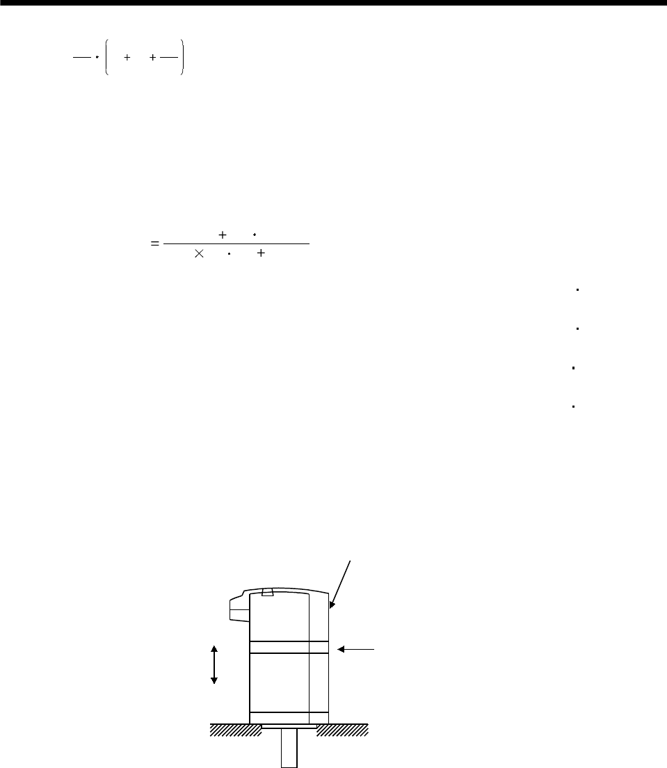
6 - 5
6. CHARACTERISTICS
L max =60
Vo t1 t2 2
t3 ................................................................................................... (6.1)
Where,
L max : Maximum coasting distance [mm]
Vo: Machine's fast feed speed [mm/min]
t1: Delay time of control section [s]
t2: Braking delay time of brake (Note) [s]
t3:Braking time [s]
9.55 104(TL 0.8TB)
(JL JL)No
t3
JL: Load inertia moment converted into equivalent [kg cm2]
value on servo motor shaft
JM : Servo motor inertia moment [kg cm2]
No : Servo motor speed during fast feed [r/min]
TL: Load torque converted into equivalent [N m]
value on servo motor shaft
TB: Brake static friction torque (Note) [N m]
Note. t2 and TB are the values noted in Table 6.1 Characteristics. JL is the machine's inertia moment at the servo motor shaft.
6.2 Vibration rank
The vibration rank of the servo motor is V-10 at the rated speed. Measure vibration in the following
position with the servo motor installed as shown below.
Top
Bottom
Servo motor
Measuring position
Servo Motor Vibration
Measuring Conditions
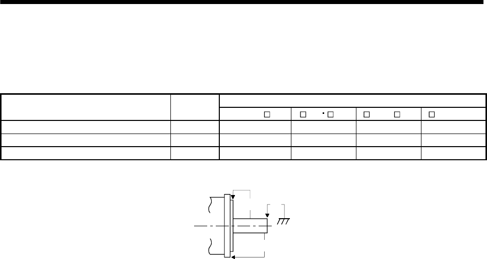
6 - 6
6. CHARACTERISTICS
6.3 Machine accuracies
The following table indicates the machine accuracies of the servo motor around the output shaft and
mounting. (except the optional products)
Flange Size
Accuracy [mm] Measuring
Position Less than 100 100 130 176 to 250 280 or more
Runout of flange surface to output shaft a) 0.05 0.06 0.08 0.08
Runout of fitting OD of flange surface b) 0.04 0.04 0.06 0.08
Runout of output shaft end c) 0.02 0.02 0.03 0.03
Reference diagram
a)
b) c)
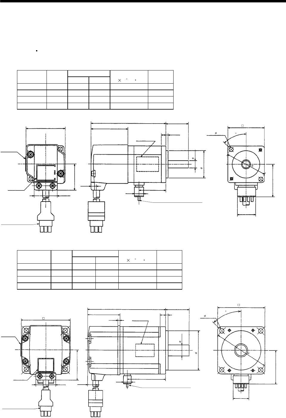
7 - 1
7. OUTLINE DIMENSION DRAWINGS
7. OUTLINE DIMENSION DRAWINGS
7.1 Servo motors
7.1.1 HC-MF HC-KF series
(1) Standard (without electromagnetic brake, without reduction gear)
Variable Dimensions
Model Output
[W] LKL
Inertia Moment
J[ 10 4kg m2]
Mass
[kg]
HC-MF053 50 81.5 29.5 0.019 0.40
HC-MF13 100 96.5 44.5 0.03 0.53
HC-KF053 50 81.5 29.5 0.053 0.40
HC-KF13 100 96.5 44.5 0.084 0.53
Power supply lead 4-AWG19 0.3m
(With end-insulated round
crimping terminal 1.25-4)
Red: Phase U
White: Phase V
Black: Phase W
Green/yellow: Earth
Top
Bottom
Motor plate
(Opposite side)
Encoder cable 0.3m
With connector 1-172169-9
(AMP)
Motor plate
25.2
25
30h7
2.5
5
20
2- 4.5
45
40
40.5
L
28.7
6.8
42
Top
Bottom
35.7
KL
9.9
8h6
BC12031*
(BC12034*)
Caution plate
Top
Bottom
46
(Note)[Unit: mm]
Note: The dimensions without tolerances are reference dimensions.
Variable Dimensions
Model Output
[W] LKL
Inertia Moment
J[ 10 4kg m2]
Mass
[kg]
HC-MF23 200 99.5 49.1 0.088 0.99
HC-MF43 400 124.5 72.1 0.143 1.45
HC-KF23 200 99.5 49.1 0.260 0.99
HC-KF43 400 124.5 72.1 0.460 1.45
Encoder cable 0.3m
With connector 1-172169-9
(AMP)
Power supply lead 4-AWG19 0.3m
Red: Phase U
White: Phase V
Black: Phase W
Green/yellow: Earth
60
45
4- 5.8
Motor plate
(Opposite side)
30
14h6
Motor plate
Bottom
Top Bottom
Top
62
L
41
2.7
Bottom
Top
10.6
50h7
(With end-insulated round crimping terminal 1.25-4)
20
38.4
70
42.8
9.9 KL
BC12032*
73
Caution plate
25.2
(BC12035*)
(Note)[Unit: mm]
Note: The dimensions without tolerances are reference dimensions.
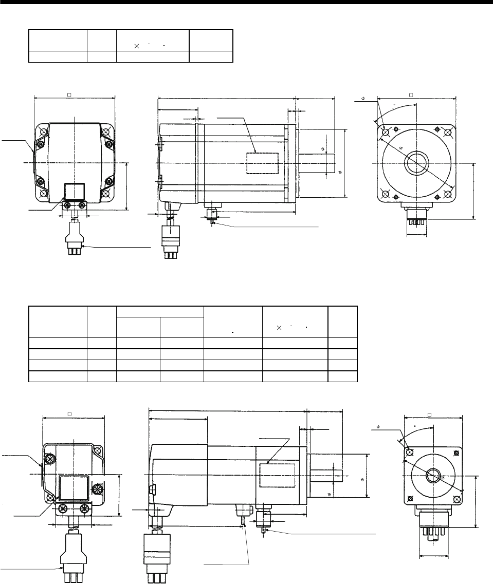
7 - 2
7. OUTLINE DIMENSION DRAWINGS
Model Output
[W]
Inertia Moment
J[ 10 4kg m2]
Mass
[kg]
HC-MF73 750 0.6 3
48.7
Encoder cable 0.3m
With connector 1-172169-9
(AMP)
Power supply lead 4-AWG19 0.3m
Red: Phase U
White: Phase V
Black: Phase W
Green/yellow: Earth
90
80
4- 6.6
Motor plate
(Opposite side)
142
83
40
19h6
70h7
58.1
20
86.7
(With end-insulated round crimping terminal 1.25-4)
Top
Bottom
Top
Bottom
25.2
82
39
2.7
Top
9.9
11
Motor plate
Bottom
BC12033*
Caution plate
(Note)[Unit: mm]
45
Note: The dimensions without tolerances are reference dimensions.
(2) With electromagnetic brake
Variable Dimensions
Model Output
[W] LKL
Brake static
friction torque
[N m]
Inertia Moment
J[ 10 4kg m2]
Mass
[kg]
HC-MF053B 50 109.5 29.5 0.32 0.022 0.75
HC-MF13B 100 124.5 44.5 0.32 0.032 0.89
HC-KF053B 50 109.5 29.5 0.32 0.056 0.75
HC-KF13B 100 124.5 44.5 0.32 0.087 0.89
Motor plate
(Opposite side)
Top
Bottom
Power supply lead 4-AWG19 0.3m
Red: Phase U
White: Phase V
Black: Phase W
Green/yellow: Earth
40
2- 4.5
KL
9.9
6.8
42
Brake lead
2-0.3 0.3m
(With end-insulated round
crimping terminal 1.25-4)
35.7
20
8h6
30h7
52.5
25L
40.5
65.5
Motor plate
Top
Bottom
Top
Bottom
25.2
28.7
2
Encoder cable 0.3m
With connector 1-172169-9
(AMP)
Caution plate
(With end-insulated round crimping terminal 1.25-4)
(BC12039*)
BC12036*
46
(Note)[Unit: mm]
45
Note: The dimensions without tolerances are reference dimensions.
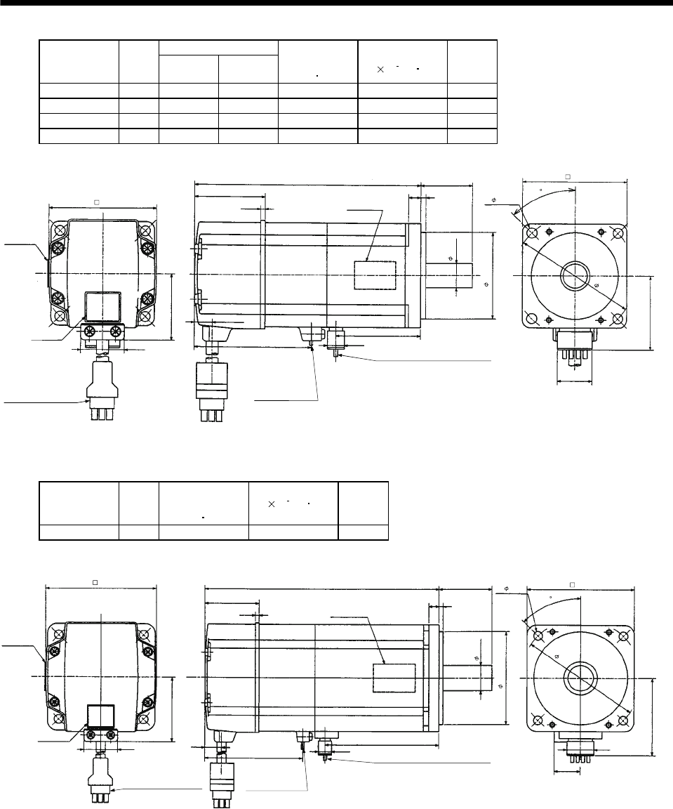
7 - 3
7. OUTLINE DIMENSION DRAWINGS
Variable Dimensions
Model Output
[W] LKL
Brake static
friction torque
[N m]
Inertia Moment
J[ 10 4kg m2]
Mass
[kg]
HC-MF23B 200 131.5 49.1 1.3 0.136 1.6
HC-MF43B 400 156.5 72.1 1.3 0.191 2.1
HC-KF23B 200 131.5 49.1 1.3 0.310 1.6
HC-KF43B 400 156.5 72.1 1.3 0.510 2.1
Brake lead
2-0.32 0.3m
(With end-insulated round
crimping terminal 1.25-4)
Power supply lead 4-AWG19 0.3m
Red: Phase U
White: Phase V
Black: Phase W
Green/yellow: Earth
Encoder cable 0.3m
With connector 1-172169-9
(AMP)
62
25.2
33.4
68 9.9
KL
41
2.7
L30
73
Motor plate
(Opposite side)
Top
Bottom
50h7
60
70
42.8
4- 5.8
10.6
Top
Bottom
Top
Bottom
BC12037*
20
14h6
(With end-insulated round crimping terminal 1.25-4)
Motor plate
Caution plate
(BC12039*)
(Note)[Unit: mm]
45
Note: The dimensions without tolerances are reference dimensions.
Model Output
[W]
Brake static
friction torque
[N m]
Inertia Moment
J[ 10 4kg m2]Mass
[kg]
HC-MF73B 750 2.4 0.725 4.0
Encoder cable 0.3m
With connector 1-172169-9
(AMP)
Brake lead
2-0.3 0.3m
(With end-insulated round
crimping terminal 1.25-4)
2
Power supply lead
4-AWG19 0.3m
Red: Phase U
White: Phase V
Black: Phase W
Green/yellow: Earth
Motor plate
(Opposite side)
Motor plate
82
Top
Bottom
Top
Bottom
25.2
48.7
177.5
39
2.7
11
72
86.7
9.9
(With end-insulated round crimping terminal 1.25-4)
BC12038*
40
38
80
Caution plate
Top
Bottom
19.5
58.1
20
19h6
70h7
4- 6.6
90
(Note)[Unit: mm]
45
Note: The dimensions without tolerances are reference dimensions.
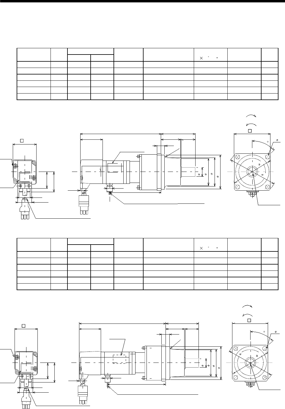
7 - 4
7. OUTLINE DIMENSION DRAWINGS
(3) With reduction gear for general industrial machine
The outer frame of the reduction gear is a material surface such as casting. Its actual dimensions may
be 1 to 3mm larger than the drawing dimensions. Design the machine side with allowances.
(a) Without electromagnetic brake
Variable Dimensions
Model Output
[W] LKL
Reduction
Gear Model
Reduction Ratio
(Actual Reduction Ratio)
Inertia Moment
J[ 10 4kg m2]Backlash Mass
[kg]
HC-MF053G1 50 126 74 K6505 1/5(9/44) 0.055 60min. max. 1.4
HC-MF053G1 50 144 92 K6512 1/12(49/576) 0.077 60min. max. 1.8
HC-MF053G1 50 144 92 K6520 1/20(25/484) 0.059 60min. max. 1.8
HC-KF053G1 50 126 74 K6505 1/5(9/44) 0.090 60min. max. 1.4
HC-KF053G1 50 144 92 K6512 1/12(49/576) 0.112 60min. max. 1.8
HC-KF053G1 50 144 92 K6520 1/20(25/484) 0.094 60min. max. 1.8
BC12066A
(BC12086A)
L60.5
25
34.5
6.58
40.5
9.9
28.7
25.2
35.7
20
6.8
(R4)
Motor
plate
Caution
plate
Encoder cable 0.3m
With connector 1-172169-9 (AMP)
Power supply lead 4-AWG19 0.3m
(Opposite side)
(With end-insulated round crimping terminal 1.25-4)
Red: Phase U
White: Phase V
Black: Phase W
Green/yellow: Earth
"Rotation direction"
For forward rotation command
For reverse rotation command
M4 threads,
depth 8
16h6
48
( 50)
60h7
75
88
4- 7
65
Motor plate
Top
Bottom Top
Bottom
45
42
KL
(Note)[Unit: mm]
Note: The dimensions without tolerances are reference dimensions.
Bottom
Top
Variable Dimensions
Model Output
[W] LKL
Reduction
Gear Model
Reduction Ratio
(Actual Reduction Ratio)
Inertia Moment
J[ 10 4kg m2]Backlash Mass
[kg]
HC-MF13G1 100 141 89 K6505 1/5(9/44) 0.067 60min. max. 1.5
HC-MF13G1 100 159 107 K6512 1/12(49/576) 0.089 60min. max. 1.9
HC-MF13G1 100 159 107 K6520 1/20(25/484) 0.071 60min. max. 1.9
HC-KF13G1 100 141 89 K6505 1/5(9/44) 0.121 60min. max. 1.5
HC-KF13G1 100 159 107 K6512 1/12(49/576) 0.143 60min. max. 1.9
HC-KF13G1 100 159 107 K6520 1/20(25/484) 0.125 60min. max. 1.9
BC12067A
(BC12087A)
28.7
25.2
25
34.5
40.5
6.8
86.5
9.9
KL
35.7
20
60.5
L
(R4)
Motor
plate
Caution
plate
Top
Bottom
Encoder cable 0.3m
With connector 1-172169-9 (AMP)
Power supply lead 4-AWG19 0.3m
(With end-insulated round crimping terminal 1.25-4)
Red: Phase U
White: Phase V
Black: Phase W
Green/yellow: Earth
Motor plate
(Opposite side)
Top
Bottom
"Rotation direction"
For forward rotation command
For reverse rotation command
M4 threads,
depth 8
16h6
48
( 50)
60h7
75
88
4- 7
65
45
42
(Note)[Unit: mm]
Note: The dimensions without tolerances are reference dimensions.
Bottom
Top
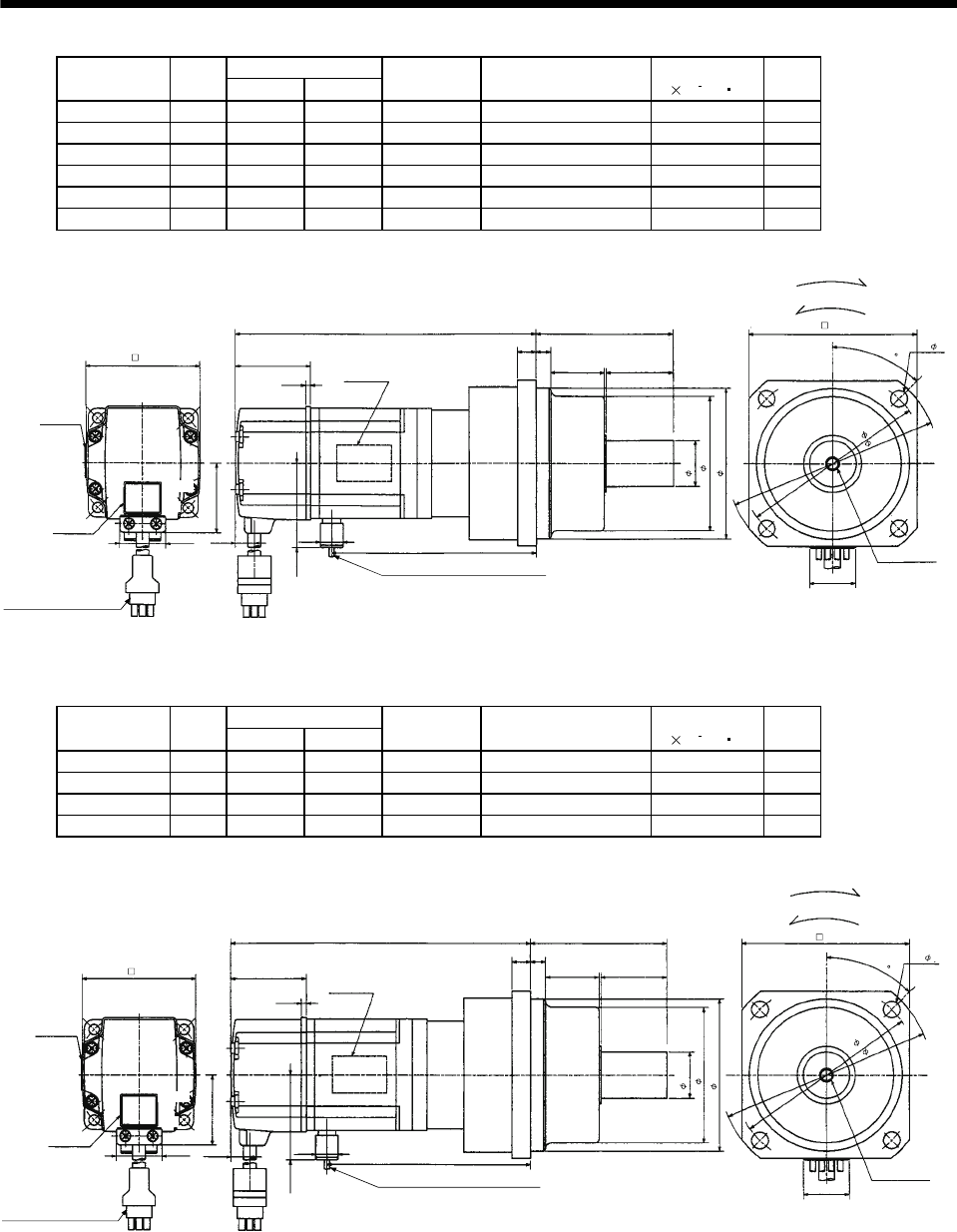
7 - 5
7. OUTLINE DIMENSION DRAWINGS
Variable Dimensions
Model Output
[W] LKL
Reduction
Gear Model
Reduction Ratio
(Actual Reduction Ratio)
Inertia Moment
J[ 10 4kg m2]
Mass
[kg]
HC-MF23G1 200 153 102.6 K9005 1/5(19/96) 0.249 3.3
HC-MF23G1 200 173 122.6 K9012 1/12(25/288) 0.293 3.9
HC-MF23G1 200 173 122.6 K9020 1/20(253/5000) 0.266 3.9
HC-KF23G1 200 153 102.6 K9005 1/5(19/96) 0.420 3.3
HC-KF23G1 200 173 122.6 K9012 1/12(25/288) 0.470 3.9
HC-KF23G1 200 173 122.6 K9020 1/20(253/5000) 0.440 3.9
38.4
25.2
L
35
8
10
Top
Bottom
30
74
M6 threads,
depth12
"Rotation
direction"
For forward rotation command
For reverse rotation command
Encoder cable 0.3m
With connector 1-172169-9
(AMP)
Power supply lead 4-AWG19 0.3m
(With end-insulated round crimping terminal 1.25-4)
Red: Phase U
White: Phase V
Black: Phase W
Green/yellow: Earth
Top
Bottom
Motor plate
(Opposite side)
Motor plate
62 41
10.6
Caution plate
25h6
73
82h7
2.7
KL
42.8
9.9
100
4- 9
BC12068*
(BC12088*)
20
90
Top
Bottom
114
(Note)[Unit: mm]
45
Note: The dimensions without tolerances are reference dimensions.
Variable Dimensions
Model Output
[W] LKL
Reduction
Gear Model
Reduction Ratio
(Actual Reduction Ratio)
Inertia Moment
J[ 10 4kg m2]
Mass
[kg]
HC-MF43G1 400 178 125.6 K9005 1/5(19/96) 0.296 3.8
HC-MF43G1 400 198 145.6 K9012 1/12(25/288) 0.339 4.4
HC-KF43G1 400 178 125.6 K9005 1/5(19/96) 0.610 3.8
HC-KF43G1 400 198 145.6 K9012 1/12(25/288) 0.660 4.4
Motor plate
38.4
25.2
4- 9
Top
Bottom
BC12069*
M6 threads,
depth12
Encoder cable 0.3m
With connector 1-172169-9
(AMP)
Power supply lead 4-AWG19 0.3m
(With end-insulated round crimping terminal 1.25-4)
Red: Phase U
White: Phase V
Black: Phase W
Green/yellow: Earth
10.6
Top
Bottom
Top
Bottom
Motor plate
(Opposite side)
Caution plate
62 41
2.7
"Rotation
direction"
For forward rotation command
For reverse rotation command
KL
74
30 35
10 8
100
114
90
20
(BC12089*)
9.9
L
42.8
82h7
73
25h6
(Note)[Unit: mm]
45
Note: The dimensions without tolerances are reference dimensions.
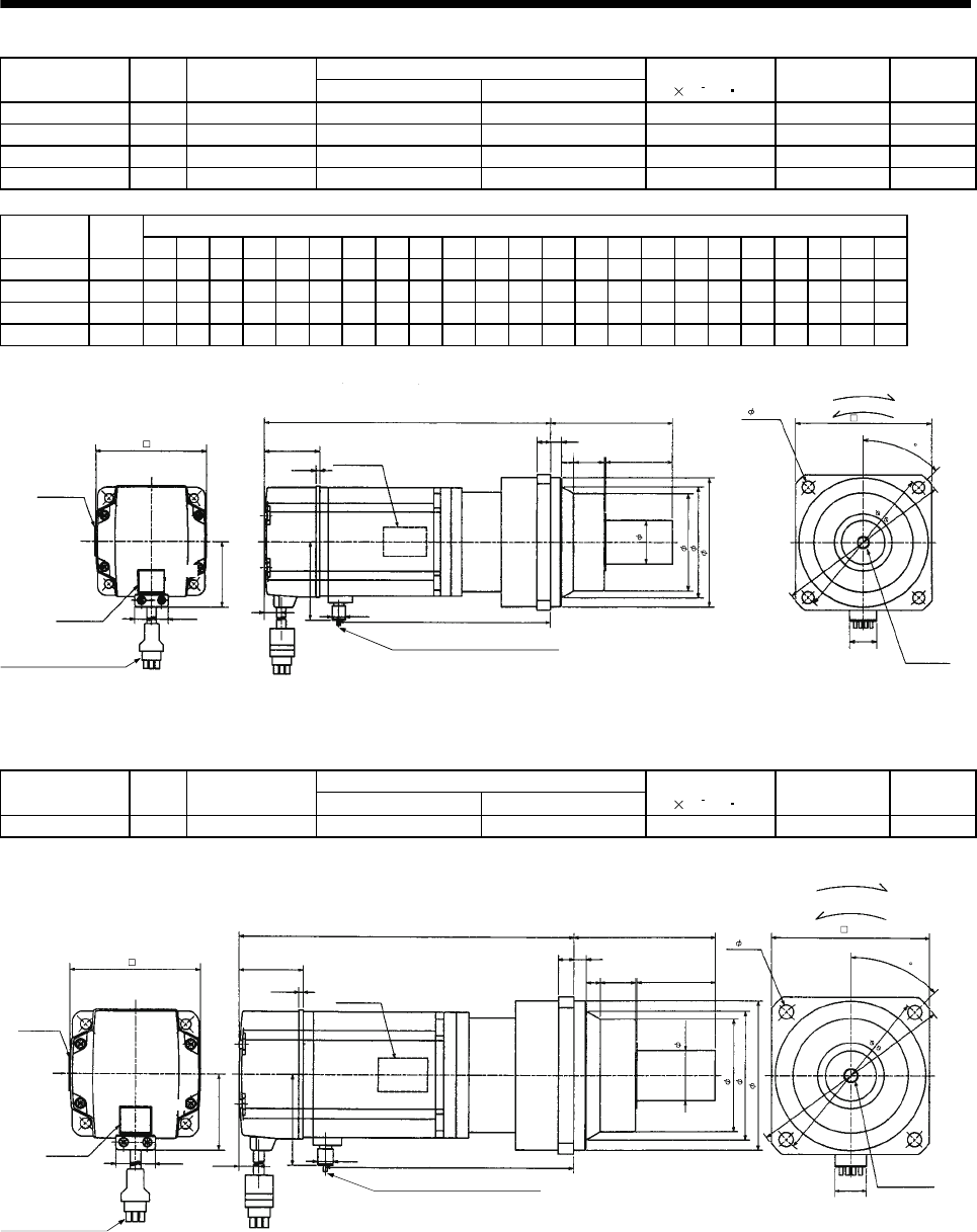
7 - 6
7. OUTLINE DIMENSION DRAWINGS
Reduction Ratio
Model Output
[W]
Reduction Gear
Model Normal Reduction ratio Actual Reduction Ratio
Inertia Moment
J[ 10 4kg m2]Backlash Mass
[kg]
HC-MF43G1 400 K10020 1/20 253/5000 0.653 60min. max. 5.5
HC-MF73G1 750 K10005 1/5 1/5 1.02 60min. max. 6.2
HC-MF73G1 750 K10012 1/12 525/6048 1.686 60min. max. 7.3
HC-MF73G1 750 K12020 1/20 625/12544 1.75 60min. max. 10.1
Variable Dimensions
Model Output
[W] D LH LK LT H LA LB LC LD LE LF LG LM LN LP L LR KL LZ Q S P R
HC-MF43G1 400 62 38.4 41 10.6 42.8 115 95 132 100 10 73 10 13 16 86 201.5 90 149.1 9 50 32M816
HC-MF73G1 750 82 48.7 39 11 58.1 115 95 132 100 10 73 10 13 16 86 207 90 151.7 9 50 32M816
HC-MF73G1 750 82 48.7 39 11 58.1 115 95 132 100 10 73 10 13 16 86 229 90 173.7 9 50 32M816
HC-MF73G1 750 82 48.7 39 11 58.1 140 115 162 120 12 90 15 13 20 104 242 106 186.7 14 60 40 M10 20
LD
4- LZ
Top
Bottom
BC12070*
P threads,
depth R
"Rotation direction" For forward rotation command
For reverse rotation command
Power supply lead 4-AWG19 0.3m
(With end-insulated round crimping terminal 1.25-4)
Encoder cable 0.3m
With connector 1-172169-9
(AMP)
Red: Phase U
White: Phase V
Black: Phase W
Green/yellow: Earth
LH
25.2
D
Top
Bottom
Top
Bottom
Motor plate
(Opposite side)
Motor plate
LK
KL
LR
LT
H
9.9
2.7
LG LE
LM LM Q
Sh6
LF
LP
LBh7
20
Caution plate
L
LC
LA
(Note)[Unit: mm]
45
Note: The dimensions without tolerances are reference dimensions.
Reduction Ratio
Model Output
[W]
Reduction Gear
Model Normal Reduction ratio Actual Reduction Ratio
Inertia Moment
J[ 10 4kg m2]Backlash Mass
[kg]
HC-KF43G1 400 K10020 1/20 253/5000 0.970 60min. max. 5.5
38.4
25.2
201.5
16
10
10
13
90
M8 threads,
depth 16
62
50
"Rotation direction" For forward rotation command
For reverse rotation command
Power supply lead 4-AWG19 0.3m
(With end-insulated round crimping terminal 1.25-4)
Encoder cable 0.3m
With connector 1-172169-9
(AMP)
Red: Phase U
White: Phase V
Black: Phase W
Green/yellow: Earth
Motor plate
(Opposite side)
Motor plate
Caution plate
Top
Bottom
Top
Bottom
41
2.7
10.6
42.8
9.9 149.1
95h7
86
73
32h6
4- 9
100
Top
Bottom
BC12090*
20
115
132
(Note)[Unit: mm]
45
Note: The dimensions without tolerances are reference dimensions.
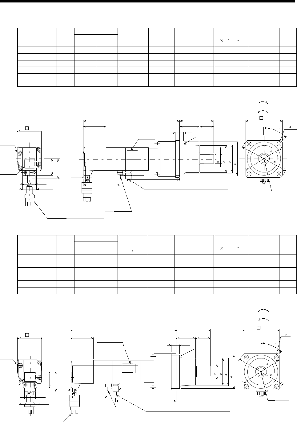
7 - 7
7. OUTLINE DIMENSION DRAWINGS
(b) With electromagnetic brake
Variable Dimensions
Model Output
[W] LKL
Brake static
friction torque
[N m]
Reduction
Gear Model
Reduction Ratio
(Actual Reduction
Ratio)
Inertia Moment
J[ 10 4kg m2]Backlash Mass
[kg]
HC-MF053BG1 50 154 74 0.32 K6505 1/5(9/44) 0.058 60min. max. 1.8
HC-MF053BG1 50 172 92 0.32 K6512 1/12(49/576) 0.080 60min. max. 2.2
HC-MF053BG1 50 172 92 0.32 K6520 1/20(25/484) 0.062 60min. max. 2.2
HC-KF053BG1 50 154 74 0.32 K6505 1/5(9/44) 0.093 60min. max. 1.8
HC-KF053BG1 50 172 92 0.32 K6512 1/12(49/576) 0.115 60min. max. 2.2
HC-KF053BG1 50 172 92 0.32 K6520 1/20(25/484) 0.097 60min. max. 2.2
BC12071A
(BC12091A)
60.5L
25
34.5
6.5
8
40.5
KL
28.7
25.2
35.7
20
6.8
65.5
9.9
(R4)
Motor
plate
Caution
plate
Top
Bottom
Encoder cable 0.3m
With connector 1-172169-9 (AMP)
(Opposite side)
Motor plate
Brake lead
2-0.3 0.3m
(With end-insulated
round crimping terminal 1.25-4)
Power supply lead 4-AWG19 0.3m
(With end-insulated round crimping terminal 1.25-4)
Red: Phase U
White: Phase V
Black: Phase W
Green/yellow: Earth
M4 threads,
depth 8
"Rotation direction"
For forward rotation command
For reverse rotation command
45
65
42
(Note)[Unit: mm]
Note: The dimensions without tolerances are reference dimensions.
2
Top
Bottom
16h6
48
( 50)
60h7
75
88
4- 7
Bottom
Top
Variable Dimensions
Model Output
[W] LKL
Brake static
friction torque
[N m]
Reduction
Gear Model
Reduction Ratio
(Actual Reduction
Ratio)
Inertia Moment
J[ 10 4kg m2]Backlash Mass
[kg]
HC-MF13BG1 100 169 89 0.32 K6505 1/5(9/44) 0.069 60min. max. 1.9
HC-MF13BG1 100 187 107 0.32 K6512 1/12(49/576) 0.091 60min. max. 2.3
HC-MF13BG1 100 187 107 0.32 K6520 1/20(25/484) 0.073 60min. max. 2.3
HC-KF13BG1 100 169 89 0.32 K6505 1/5(9/44) 0.124 60min. max. 1.9
HC-KF13BG1 100 187 107 0.32 K6512 1/12(49/576) 0.146 60min. max. 2.3
HC-KF13BG1 100 187 107 0.32 K6520 1/20(25/484) 0.128 60min. max. 2.3
BC12072A
(BC12092A)
28.7
35.7
25.2
20
40.5
L
86.5
60.5
25
34.5
(R4)
6.8 9.9
KL
65.5
Motor
plate
Caution
plate
Top
Bottom
Encoder cable 0.3m
With connector 1-172169-9 (AMP)
Power supply lead 4-AWG19
(With end-insulated round crimping terminal 1.25-4)
Red: Phase U
White: Phase V
Black: Phase W
Green/yellow: Earth
(Opposite side)
Motor plate
"Rotation direction"
For forward rotation command
For reverse rotation command
M4 threads,
depth 8
65
Top
Bottom
Brake lead
2-0.3 0.3m
(With end-insulated
round crimping terminal 1.25-4)
42
(Note)[Unit: mm]
Note: The dimensions without tolerances are reference dimensions.
2
16h6
48
( 50)
60h7
45
75
88
4- 7
Top
Bottom
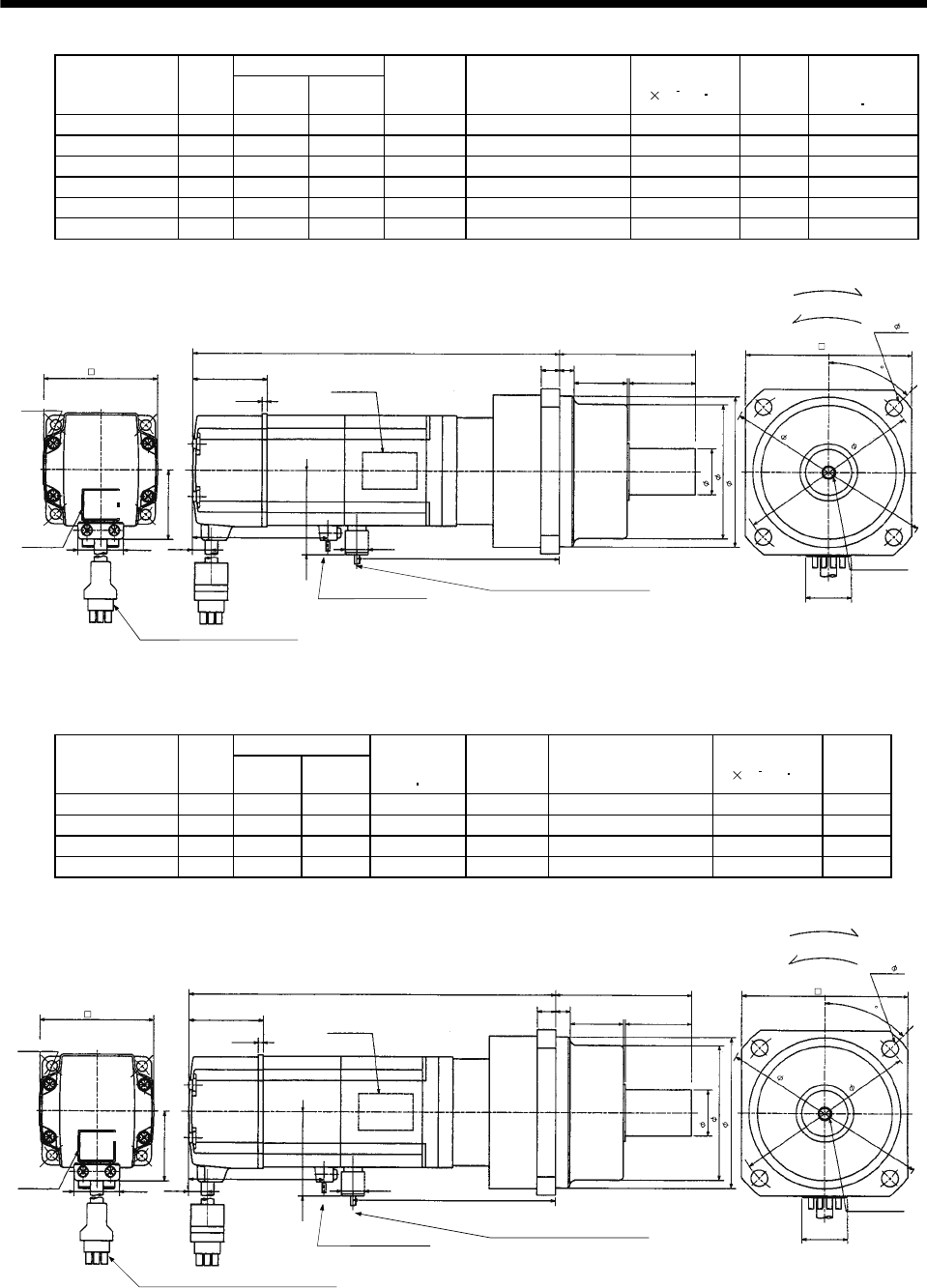
7 - 8
7. OUTLINE DIMENSION DRAWINGS
Variable Dimensions
Model Output
[W] LKL
Reduction
Gear Model
Reduction Ratio
(Actual Reduction Ratio)
Inertia Moment
J[ 10 4kg m2]
Mass
[kg]
Brake static
friction torque
[N m]
HC-MF23BG1 200 185 102.6 K9005 1/5(19/96) 0.289 3.9 1.3
HC-MF23BG1 200 205 122.6 K9012 1/12(25/288) 0.333 4.5 1.3
HC-MF23BG1 200 205 122.6 K9020 1/20(253/5000) 0.306 4.5 1.3
HC-KF23BG1 200 185 102.6 K9005 1/5(19/96) 0.470 3.9 1.3
HC-KF23BG1 200 205 122.6 K9012 1/12(25/288) 0.520 4.5 1.3
HC-KF23BG1 200 205 122.6 K9020 1/20(253/5000) 0.490 4.5 1.3
Motor plate
(Opposite side)
L
35
8
10
Top
Bottom
30
74
M6 threads,
depth 12
Encoder cable 0.3m
With connector 1-172169-9
(AMP)
Brake lead 2-0.3 0.3m
(With end-insulated round
crimping terminal 1.25-4)
2Power supply lead 4-AWG19 0.3m
(With end-insulated round crimping terminal 1.25-4)
Red: Phase U
White: Phase V
Black: Phase W
Green/yellow: Earth
25h6
BC12073*
73
82h7
(BC120793*)
Top
Bottom
Top
Bottom
62
Caution plate 25.2
38.4
10.6
41
9.9
42.8
KL
90
4- 9
100
114
"Rotation direction"
For forward rotation command
For reverse rotation command
20
2.7
68
(Note)[Unit: mm]
45
Motor plate
Note: The dimensions without tolerances are reference dimensions.
Variable Dimensions
Model Output
[W] LKL
Brake static
friction torque
[N m]
Reduction
Gear Model
Reduction Ratio
(Actual Reduction Ratio)
Inertia Moment
J[ 10 4kg m2]
Mass
[kg]
HC-MF43BG1 400 210 125.6 1.3 K9005 1/5(19/96) 0.344 4.4
HC-MF43BG1 400 230 145.6 1.3 K9012 1/12(25/288) 0.388 5.0
HC-KF43BG1 400 210 125.6 1.3 K9005 1/5(19/96) 0.660 4.4
HC-KF43BG1 400 230 145.6 1.3 K9012 1/12(25/288) 0.710 5.0
Motor plate
(Opposite side)
Top
Bottom
M6 threads,
depth 12
"Rotation direction"
For forward rotation command
For reverse rotation command
90
4- 9
(BC12094*)
BC12074*
35
810
30
74
L
62
25h6
73
82h7
20
Power supply lead 4-AWG19 0.3m
(With end-insulated round crimping terminal 1.25-4)
Red: Phase U
White: Phase V
Black: Phase W
Green/yellow: Earth
Brake lead 2-0.3 0.3m
(With end-insulated round
crimping terminal 1.25-4)
2
Encoder cable 0.3m
With connector 1-172169-9
(AMP)
Caution plate
Top
Bottom
Top
Bottom
25.2
38.4
10.6
41
2.7
42.8
9.9
KL
68
100
114
(Note)[Unit: mm]
45
Motor plate
Note: The dimensions without tolerances are reference dimensions.
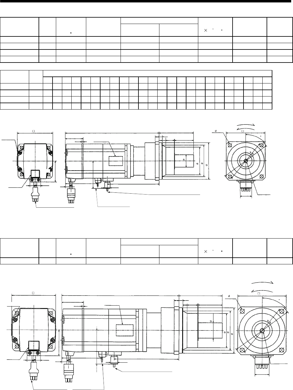
7 - 9
7. OUTLINE DIMENSION DRAWINGS
Reduction Ratio
Model Output
[W]
Brake static
friction torque
[N m]
Reduction
Gear Model Normal
Reduction ratio
Actual
Reduction Ratio
Inertia Moment
J[ 10 4kg m2]Backlash Mass
[kg]
HC-MF43BG1 400 1.3 K10020 1/20 253/5000 0.700 60min. max. 6.1
HC-MF73BG1 750 2.4 K10005 1/5 1/5 1.145 60min. max. 7.2
HC-MF73BG1 750 2.4 K10012 1/12 525/6048 1.811 60min. max. 8.3
HC-MF73BG1 750 2.4 K12020 1/20 625/12544 1.875 60min. max. 11.1
Variable Dimensions
Model Output
[W] D LH LK LT LX H LA LB LC LD LE LF LG LM LN LP L LR KL LZ Q S P R
HC-MF43BG1 400 62 38.4 41 10.6 68 42.8 115 95 132 100 10 73 10 13 16 86 233.5 90 149.1 95032M816
HC-MF73BG1 750 82 48.7 39 11 72 58.1 115 95 132 100 10 73 10 13 16 86 242.5 90 151.7 95032M816
HC-MF73BG1 750 82 48.7 39 11 72 58.1 115 95 132 100 10 73 10 13 16 86 264.5 90 173.7 95032M816
HC-MF73BG1 750 82 48.7 39 11 72 58.1 140 115 162 120 12 90 15 13 20 104 277.5 106 186.7 14 60 40 M10 20
Motor plate
(Opposite side) LN
LE
LG
Top
Bottom
LM
LR
P threads,
depth R
Q
Sh6
"Rotation direction" For forward rotation command
For reverse rotation command
Brake lead 2-0.3 0.3m
(With end-insulated round
crimping terminal 1.25-4)
Encoder cable 0.3m
With connector 1-172169-9
(AMP)
Power supply lead 4-AWG19 0.3m
(With end-insulated round crimping terminal 1.25-4)
2Red: Phase U
White: Phase V
Black: Phase W
Green/yellow: Earth
4- LZ LD
LC
LA
20
LF
LBh7
LP
Top
Bottom
Motor plate
Caution plate
D
LK
2.7
L
25.2
LH
LT LX
H
9.9
KL
Top
Bottom
BC12075*
(Note)[Unit: mm]
45
Note: The dimensions without tolerances are reference dimensions.
Reduction Ratio
Model Output
[W]
Brake static
friction torque
[N m]
Reduction
Gear Model Normal
Reduction ratio
Actual
Reduction Ratio
Inertia Moment
J[ 10 4kg m2]Backlash Mass
[kg]
HC-KF43BG1 400 1.3 K10020 1/20 253/5000 1.02 60min. max. 6.1
Motor plate
(Opposite side) 16
10
10
Top
Bottom
13
90
8 threads,
depth 16
50
"Rotation direction"
For forward rotation command
For reverse rotation command
Brake lead 2-0.3 0.3m
(With end-insulated round
crimping terminal 1.25-4)
Encoder cable 0.3m
With connector 1-172169-9
(AMP)
Power supply lead 4-AWG19 0.3m
(With end-insulated round crimping terminal 1.25-4)
2
Red: Phase U
White: Phase V
Black: Phase W
Green/yellow: Earth
4- 9
20
Top
Bottom
100
Top
Bottom
41
2.7
233.5
Caution plate 25.2
38.4
62
10.6
68
42.8
9.9
149.1
73
86
95h7
BC12095*
32h6
132
115
(Note)[Unit: mm]
45
Motor plate
Note: The dimensions without tolerances are reference dimensions.
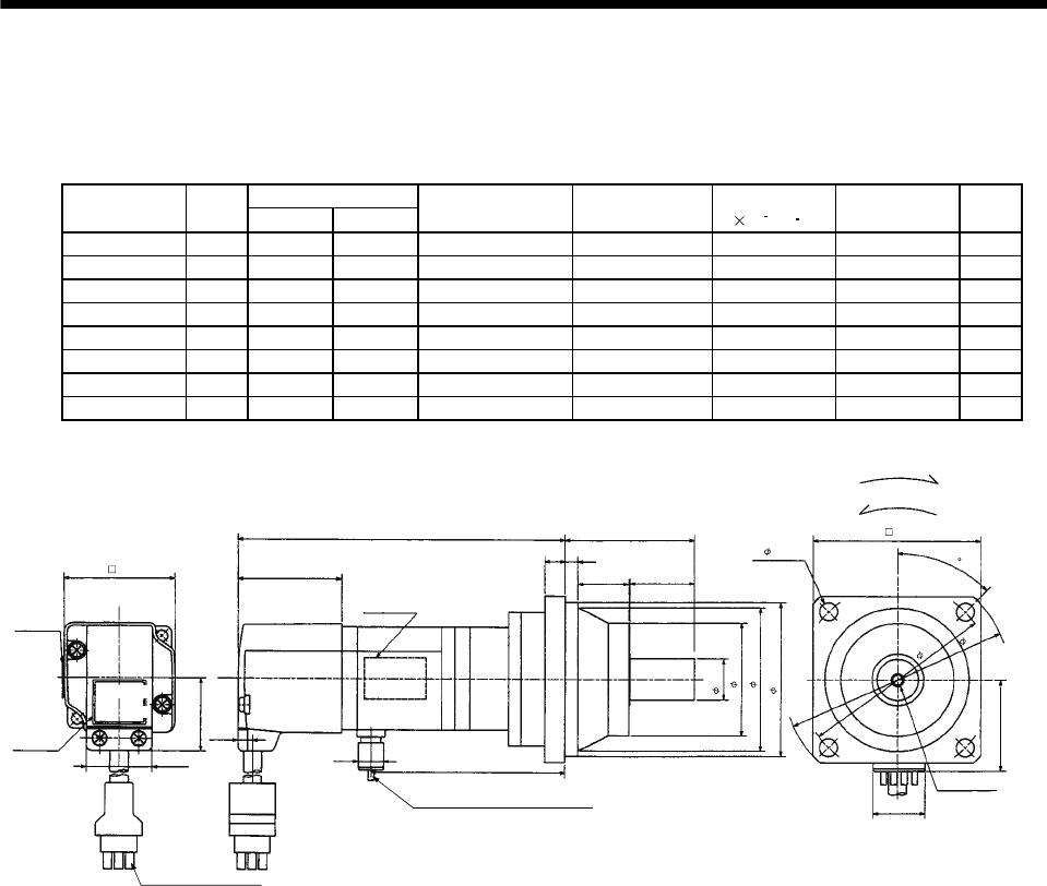
7 - 10
7. OUTLINE DIMENSION DRAWINGS
(4) With reduction gear for precision application
The outer frame of the reduction gear is a material surface such as casting. Its actual dimensions may
be 1 to 3mm larger than the drawing dimensions. Design the machine side with allowances.
(a) Without electromagnetic brake
Variable Dimensions
Model Output
[W] LKL
Reduction Gear
Model Reduction Ratio Inertia Moment
J[ 10 4kg m2]Backlash Mass
[kg]
HC-MF053G2 50 130 78 BK1-05B-A5MEKA 1/5 0.067 3 min. max. 1.4
HC-MF053G2 50 146 94 BK1-09B-A5MEKA 1/9 0.060 3 min. max. 1.7
HC-MF053G2 50 146 94 BK1-20B-A5MEKA 1/20 0.069 3 min. max. 1.8
HC-MF053G2 50 146 94 BK1-29B-A5MEKA 1/29 0.057 3 min. max. 1.8
HC-KF053G2 50 130 78 BK1-05B-A5MEKA 1/5 0.101 3 min. max. 1.4
HC-KF053G2 50 146 94 BK1-09B-A5MEKA 1/9 0.095 3 min. max. 1.7
HC-KF053G2 50 146 94 BK1-20B-A5MEKA 1/20 0.104 3 min. max. 1.8
HC-KF053G2 50 146 94 BK1-29B-A5MEKA 1/29 0.092 3 min. max. 1.8
Motor plate
(Opposite side)
28.7
25.2
L
25
86
Top
Bottom
23
55
M4 threads,
depth 8
"Rotation direction"
For forward rotation command
For reverse rotation command
Power supply lead 4-AWG19 0.3m
(With end-insulated round crimping terminal 1.25-4)
Encoder cable 0.3m
With connector 172169-9
(AMP)
Red: Phase U
White: Phase V
Black: Phase W
Green/yellow: Earth
Top
Bottom
70
4- 6.6
16h6
80
48
60
65h7
95
BC12076*
(BC12096*)
Motor plate
Caution plate
42 40.5
6.8
KL
9.9
20
35.7
(Note)[Unit: mm]
Top
Bottom
45
Note: The dimensions without tolerances are reference dimensions.
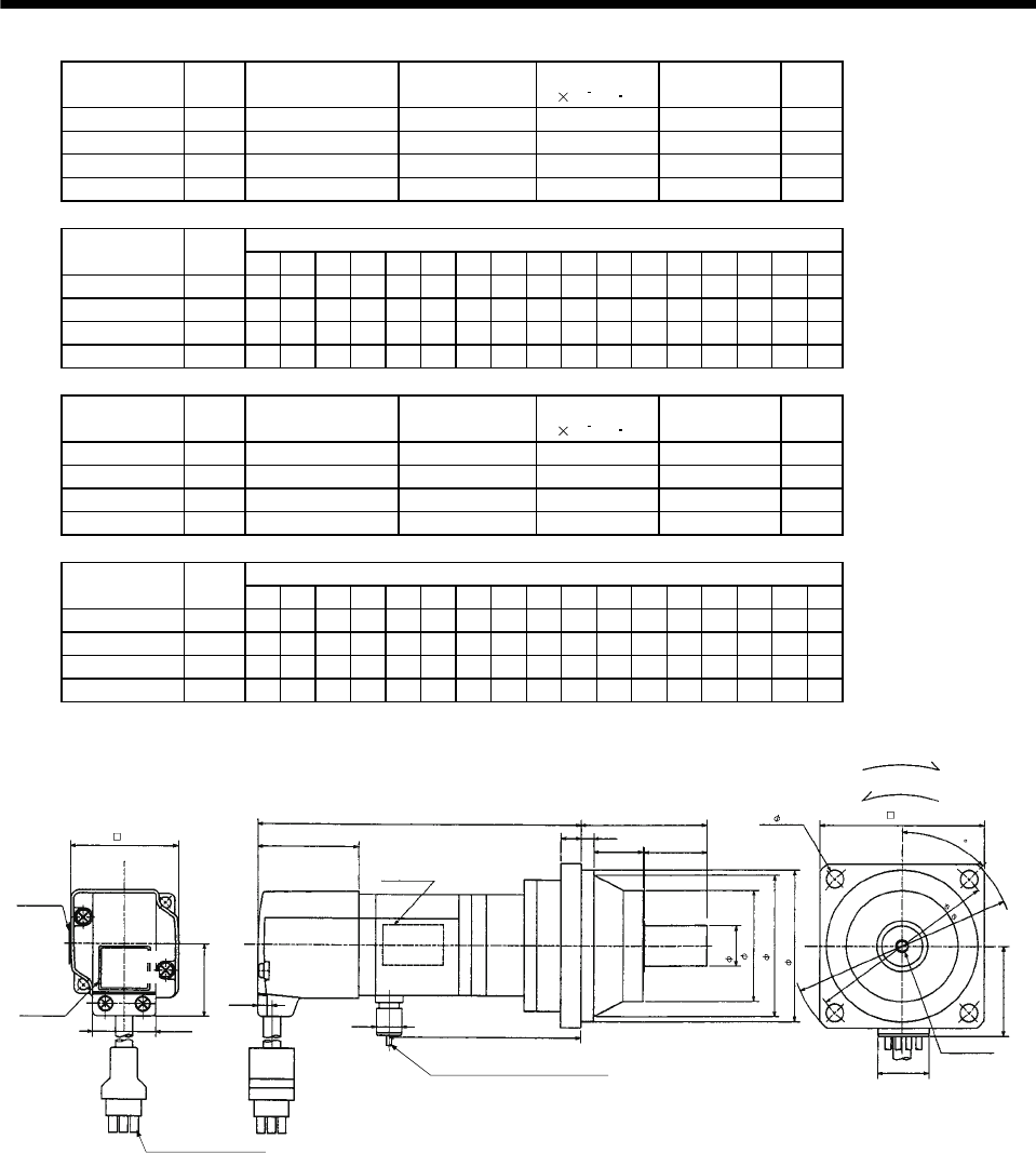
7 - 11
7. OUTLINE DIMENSION DRAWINGS
Model Output
[W]
Reduction Gear
Model Reduction Ratio Inertia Moment
J[ 10 4kg m2]Backlash Mass
[kg]
HC-MF13G2 100 BK1-05B-01MEKA 1/5 0.078 3 min. max. 1.5
HC-MF13G2 100 BK1-09B-01MEKA 1/9 0.072 3 min. max. 1.8
HC-MF13G2 100 BK2-20B-01MEKA 1/20 0.122 3 min. max. 3.0
HC-MF13G2 100 BK2-29B-01MEKA 1/29 0.096 3 min. max. 3.0
Variable Dimensions
Model Output
[W] LA LB LC LD LE LF LG LH LK L LR KL LZ Q S P R
HC-MF13G2 100 80 65 95 70 6 48 8 60 23 145 55 93 6.6 25 16 M4 8
HC-MF13G2 100 80 65 95 70 6 48 8 60 23 161 55 109 6.6 25 16 M4 8
HC-MF13G2 100 100 80 115 85 6 65 10 74 33 167 75 115 6.6 35 20 M5 10
HC-MF13G2 100 100 80 115 85 6 65 10 74 33 167 75 115 6.6 35 20 M5 10
Model Output
[W]
Reduction Gear
Model Reduction Ratio Inertia Moment
J[ 10 4kg m2]Backlash Mass
[kg]
HC-KF13G2 100 BK1-05B-01MEKA 1/5 0.132 3 min. max. 1.5
HC-KF13G2 100 BK1-09B-01MEKA 1/9 0.126 3 min. max. 1.8
HC-KF13G2 100 BK2-20B-01MEKA 1/20 0.176 3 min. max. 3.0
HC-KF13G2 100 BK2-29B-01MEKA 1/29 0.150 3 min. max. 3.0
Variable Dimensions
Model Output
[W] LA LB LC LD LE LF LG LH LK L LR KL LZ Q S P R
HC-KF13G2 100 80 65 95 70 6 48 8 60 23 145 55 93 6.6 25 16 M4 8
HC-KF13G2 100 80 65 95 70 6 48 8 60 23 161 55 109 6.6 25 16 M4 8
HC-KF13G2 100 100 80 115 85 6 65 10 74 33 167 75 115 6.6 35 20 M5 10
HC-KF13G2 100 100 80 115 85 6 65 10 74 33 167 75 115 6.6 35 20 M5 10
Motor plate
(Opposite side)
28.7
25.2 9.9
LELG
LF
LH
LD
4- LZ
Top
Bottom
LBh7
LK
P threads,
depth R
Q
Sh6
"Rotation direction"
For forward rotation command
For reverse rotation command
Encoder cable 0.3m
With connector 1-172169-9
(AMP)
Power supply lead 4-AWG19 0.3m
(With end-insulated round crimping terminal 1.25-4)
LR
Red: Phase U
White: Phase V
Black: Phase W
Green/yellow: Earth
Motor plate
Caution plate
42 40.5
6.8
KL
20
LC
Top
Bottom
Top
Bottom
L
BC12077*
(BC12097*)
35.7
LA
(Note)[Unit: mm]
45
Note: The dimensions without tolerances are reference dimensions.
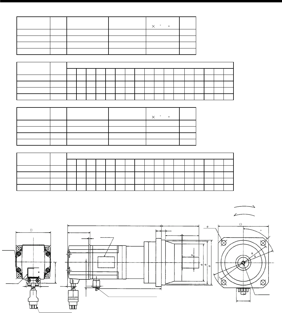
7 - 12
7. OUTLINE DIMENSION DRAWINGS
Model Output
[W]
Reduction Gear
Model Reduction Ratio Inertia Moment
J[ 10 4kg m2]
Mass
[kg]
HC-MF23G2 200 BK1-05B-02MEKA 1/5 0.191 2.1
HC-MF23G2 200 BK2-09B-02MEKA 1/9 0.208 3.5
HC-MF23G2 200 BK3-20B-02MEKA 1/20 0.357 5.0
HC-MF23G2 200 BK3-29B-02MEKA 1/29 0.276 5.0
Variable Dimensions
Model Output
[W] LA LB LC LD LE LF LG LH LK L LR KL LZ Q S P R
HC-MF23G2 200 80 65 95 70 6 48 8 60 23 157 55 106.6 6.6 25 16 M4 8
HC-MF23G2 200 100 80 115 85 6 65 10 74 33 175 75 124.6 6.6 35 20 M5 10
HC-MF23G2 200 115 95 135 100 8 75 10 85 35 180 85 129.6 94025M612
HC-MF23G2 200 115 95 135 100 8 75 10 85 35 180 85 129.6 94025M612
Model Output
[W]
Reduction Gear
Model Reduction Ratio Inertia Moment
J[ 10 4kg m2]
Mass
[kg]
HC-KF23G2 200 BK1-05B-02MEKA 1/5 0.360 2.1
HC-KF23G2 200 BK2-09B-02MEKA 1/9 0.380 3.5
HC-KF23G2 200 BK3-20B-02MEKA 1/20 0.530 5.0
HC-KF23G2 200 BK3-29B-02MEKA 1/29 0.450 5.0
Variable Dimensions
Model Output
[W] LA LB LC LD LE LF LG LH LK L LR KL LZ Q S P R
HC-KF23G2 200 80 65 95 70 6 48 8 60 23 157 55 106.6 6.6 25 16 M4 8
HC-KF23G2 200 100 80 115 85 6 65 10 74 33 175 75 124.6 6.6 35 20 M5 10
HC-KF23G2 200 115 95 135 100 8 75 10 85 35 180 85 129.6 94025M612
HC-KF23G2 200 115 95 135 100 8 75 10 85 35 180 85 129.6 94025M612
38.4
25.2
LELG
LD
Top
Bottom
LK
LR
P threads,
depth R
Q
LA
LC
"Rotation direction" For forward rotation command
For reverse rotation command
Power supply lead 4-AWG19 0.3m
Encoder cable 0.3m
With connector 1-172169-9
(AMP)
Red: Phase U
White: Phase V
Black: Phase W
Green/yellow: Earth
(With end-insulated round crimping terminal 1.25-4)
Motor plate
(Opposite side)
Top
Bottom
L
Sh6
LF
LH
LBh7
10.6 9.9
42.8
KL
62
Motor plate
Caution plate
Top
Bottom
41
2.7
4- LZ
BC12078*
(BC12098*)
20
(Note)[Unit: mm]
45
Note: The dimensions without tolerances are reference dimensions.
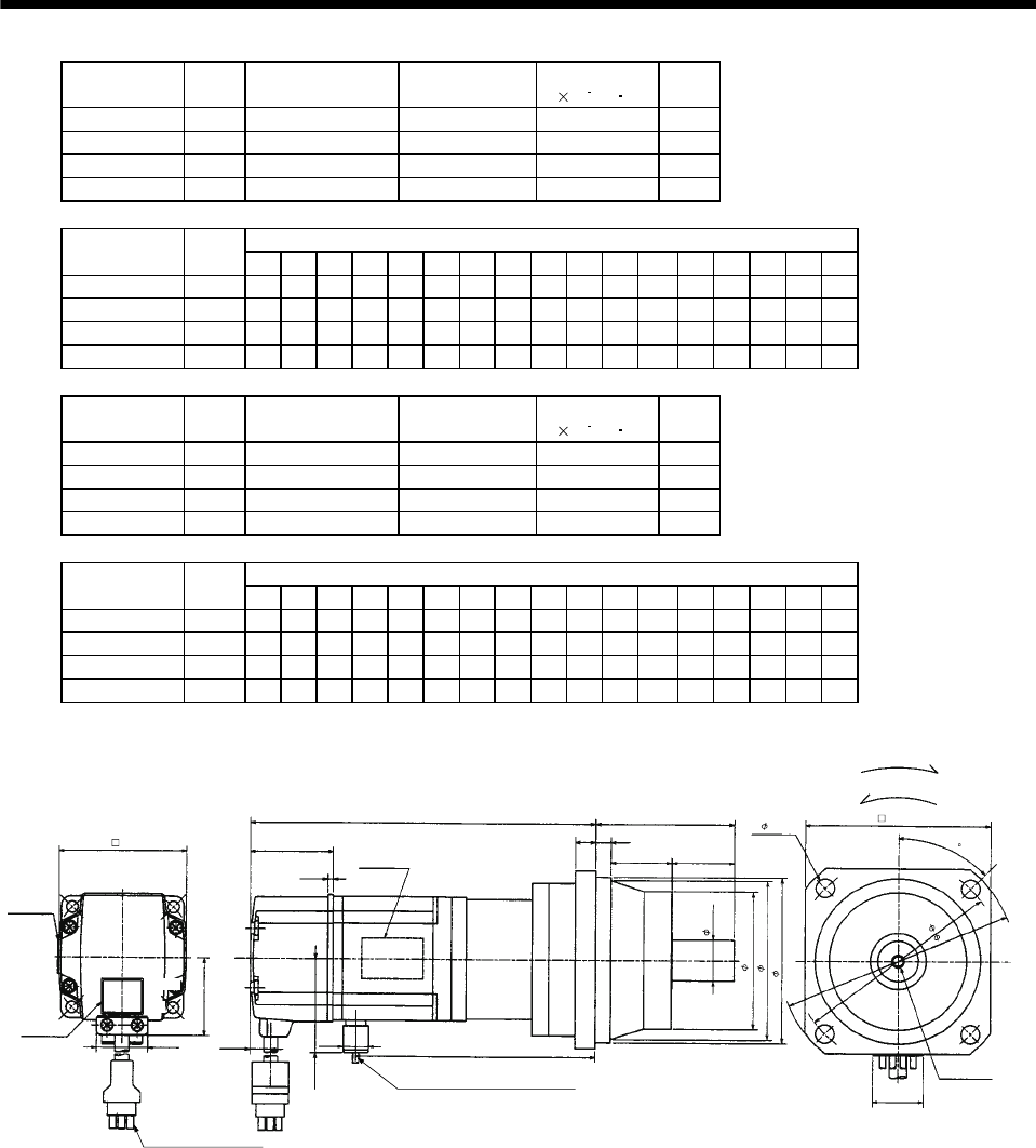
7 - 13
7. OUTLINE DIMENSION DRAWINGS
Model Output
[W]
Reduction Gear
Model Reduction Ratio Inertia Moment
J[ 10 4kg m2]
Mass
[kg]
HC-MF43G2 400 BK2-05B-04MEKA 1/5 0.295 3.7
HC-MF43G2 400 BK3-09B-04MEKA 1/9 0.323 5.3
HC-MF43G2 400 BK4-20B-04MEKA 1/20 0.426 7.5
HC-MF43G2 400 BK4-29B-04MEKA 1/29 0.338 7.5
Variable Dimensions
Model Output
[W] LA LB LC LD LE LF LG LH LK L LR KL LZ Q S P R
HC-MF43G2 400 100 80 115 85 6 65 10 74 33 184 75 131.6 6.6 35 20 M5 10
HC-MF43G2 400 115 95 135 100 8 75 10 85 35 205 85 152.6 94025M612
HC-MF43G2 400 135 110 155 115 8 90 12 100 40 211 100 158.6 11 50 32 M8 16
HC-MF43G2 400 135 110 155 115 8 90 12 100 40 211 100 158.6 11 50 32 M8 16
Model Output
[W]
Reduction Gear
Model Reduction Ratio Inertia Moment
J[ 10 4kg m2]
Mass
[kg]
HC-KF43G2 400 BK2-05B-04MEKA 1/5 0.610 3.7
HC-KF43G2 400 BK3-09B-04MEKA 1/9 0.640 5.3
HC-KF43G2 400 BK4-20B-04MEKA 1/20 0.740 7.5
HC-KF43G2 400 BK4-29B-04MEKA 1/29 0.660 7.5
Variable Dimensions
Model Output
[W] LA LB LC LD LE LF LG LH LK L LR KL LZ Q S P R
HC-KF43G2 400 100 80 115 85 6 65 10 74 33 184 75 131.6 6.6 35 20 M5 10
HC-KF43G2 400 115 95 135 100 8 75 10 85 35 205 85 152.6 94025M612
HC-KF43G2 400 135 110 155 115 8 90 12 100 40 211 100 158.6 11 50 32 M8 16
HC-KF43G2 400 135 110 155 115 8 90 12 100 40 211 100 158.6 11 50 32 M8 16
Motor plate
(Opposite side)
38.4
25.2
LE
LG
LD
4- LZ
Top
Bottom
LK
LR
P threads,
depth R
Q
Sh6
LA
LC
"Rotation direction"
For forward rotation command
For reverse rotation command
Power supply lead 4-AWG19 0.3m
(With end-insulated round crimping terminal 1.25-4)
Encoder cable 0.3m
With connector 1-172169-9
(AMP)
Red: Phase U
White: Phase V
Black: Phase W
Green/yellow: Earth
Motor plate
Caution plate
LF
LH
LBh7
62
Top
Bottom
Top
Bottom
41
2.7
L
10.6
42.8
9.9
KL
20
BC12079
(BC12099*)
(Note)[Unit: mm]
45
Note: The dimensions without tolerances are reference dimensions.
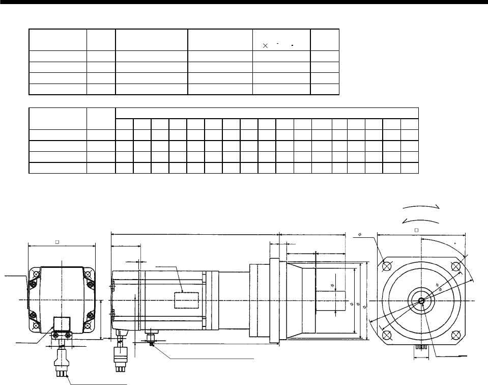
7 - 14
7. OUTLINE DIMENSION DRAWINGS
Model Output
[W]
Reduction Gear
Model Reduction Ratio Inertia Moment
J[ 10 4kg m2]
Mass
[kg]
HC-MF73G2 750 BK3-05B-08MEKA 1/5 0.973 6.3
HC-MF73G2 750 BK4-09B-08MEKA 1/9 0.980 8.6
HC-MF73G2 750 BK5-20B-08MEKA 1/20 1.016 12.0
HC-MF73G2 750 BK5-29B-08MEKA 1/29 0.910 12.0
Variable Dimensions
Model Output
[W] LA LB LC LD LE LF LG LH LK L LR KL LZ Q S P R
HC-MF73G2 750 115 95 135 100 8 75 10 85 35 212 85 156.7 9 40 25M612
HC-MF73G2 750 135 110 155 115 8 90 12 100 40 248 100 184.7 11 50 32 M8 16
HC-MF73G2 750 150 125 175 130 10 105 15 115 43 248 115 192.7 14 60 40 M10 20
HC-MF73G2 750 150 125 175 130 10 105 15 115 43 248 115 192.7 14 60 40 M10 20
Motor plate
(Opposite side)
KL
LE
LG
LF
LH
LD
4- LZ
Top
Bottom
LBh7
LK
LR
P threads,
depth R
Q
Sh6
"Rotation direction" For forward rotation command
For reverse rotation command
Power supply lead 4-AWG19 0.3m
Encoder cable 0.3m
With connector 1-172169-9
(AMP)
Red: Phase U
White: Phase V
Black: Phase W
Green/yellow: Earth
Motor plate
Caution plate
Top
Bottom
Top
Bottom
82 39
2.7
25.2
48.7
(With end-insulated round crimping terminal 1.25-4)
20
11 9.9
58.1
BC12080*
L
LA
LC
(Note)[Unit: mm]
45
Note: The dimensions without tolerances are reference dimensions.
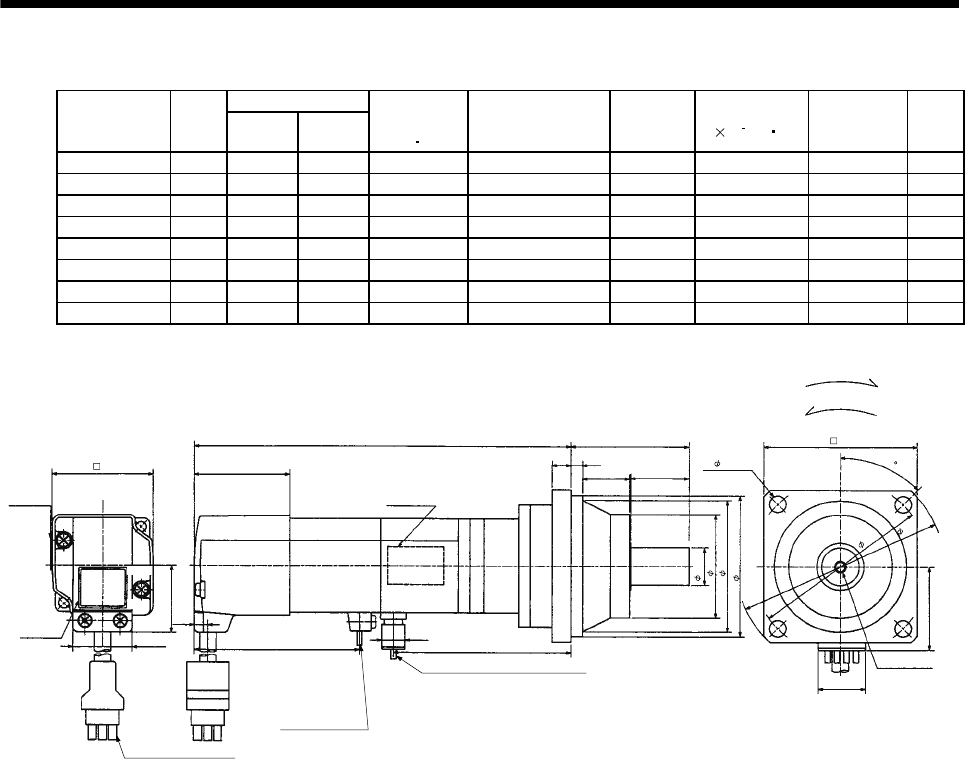
7 - 15
7. OUTLINE DIMENSION DRAWINGS
(b) With electromagnetic brake
Variable Dimensions
Model Output
[W] LKL
Brake static
friction torque
[N m]
Reduction Gear
Model
Reduction
Ratio
Inertia Moment
J[ 10 4kg m2]Backlash Mass
[kg]
HC-MF053BG2 50 158 78 0.32 BK1-05B-A5MEKA 1/5 0.070 3 min. max. 1.8
HC-MF053BG2 50 174 94 0.32 BK1-09B-A5MEKA 1/9 0.063 3 min. max. 2.1
HC-MF053BG2 50 174 94 0.32 BK1-20B-A5MEKA 1/20 0.072 3 min. max. 2.2
HC-MF053BG2 50 174 94 0.32 BK1-29B-A5MEKA 1/29 0.060 3 min. max. 2.2
HC-KF053BG2 50 158 78 0.32 BK1-05B-A5MEKA 1/5 0.104 3 min. max. 1.8
HC-KF053BG2 50 174 94 0.32 BK1-09B-A5MEKA 1/9 0.098 3 min. max. 2.1
HC-KF053BG2 50 174 94 0.32 BK1-20B-A5MEKA 1/20 0.107 3 min. max. 2.2
HC-KF053BG2 50 174 94 0.32 BK1-29B-A5MEKA 1/29 0.095 3 min. max. 2.2
Motor plate
(Opposite side)
25
86
Top
Bottom
23
55
"Rotation direction"
For forward rotation command
For reverse rotation command
Power supply lead 4-AWG19 0.3m
(With end-insulated round crimping terminal 1.25-4)
Encoder cable 0.3m
With connector 172169-9
(AMP)
Brake lead
2-0.3 0.3m
(With end-insulated round
crimping terminal 1.25-4)
Blue: B1,B2
2
Red: Phase U
White: Phase V
Black: Phase W
Green/yellow: Earth
Motor plate
48
60
65h7
16h6
M4 threads,
depth 8
35.7
20
70
4- 6.6
L
40.5
Caution plate 25.2
28.7
42
Top
Bottom
Top
Bottom
65.5 9.9
KL
(BC12100*)
BC12081*
6.8
95
80
(Note)[Unit: mm]
45
Note: The dimensions without tolerances are reference dimensions.
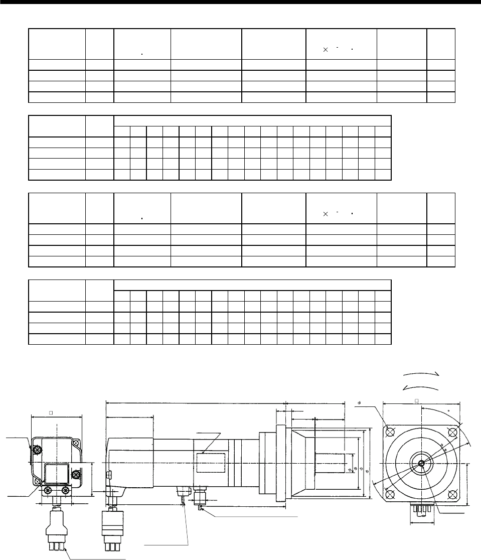
7 - 16
7. OUTLINE DIMENSION DRAWINGS
Model Output
[W]
Brake static
friction torque
[N m]
Reduction Gear
Model Reduction Ratio Inertia Moment
J[ 10 4kg m2]Backlash Mass
[kg]
HC-MF13BG2 100 0.32 BK1-05B-01MEKA 1/5 0.080 3 min. max. 1.9
HC-MF13BG2 100 0.32 BK1-09B-01MEKA 1/9 0.074 3 min. max. 2.2
HC-MF13BG2 100 0.32 BK2-20B-01MEKA 1/20 0.124 3 min. max. 3.4
HC-MF13BG2 100 0.32 BK2-29B-01MEKA 1/29 0.098 3 min. max. 3.4
Variable Dimensions
Model Output
[W] LA LB LC LD LE LF LG LH LK L LR KL LZ Q S P R
HC-MF13BG2 100 80 65 95 70 6 48 8 60 23 173 55 93 6.6 25 16 M4 8
HC-MF13BG2 100 80 65 95 70 6 48 8 60 23 189 55 109 6.6 25 16 M4 8
HC-MF13BG2 100 100 80 115 85 6 65 10 74 33 195 75 115 6.6 35 20 M5 10
HC-MF13BG2 100 100 80 115 85 6 65 10 74 33 195 75 115 6.6 35 20 M5 10
Model Output
[W]
Brake static
friction torque
[N m]
Reduction Gear
Model Reduction Ratio Inertia Moment
J[ 10 4kg m2]Backlash Mass
[kg]
HC-KF13BG2 100 0.32 BK1-05B-01MEKA 1/5 0.135 3 min. max. 1.9
HC-KF13BG2 100 0.32 BK1-09B-01MEKA 1/9 0.129 3 min. max. 2.2
HC-KF13BG2 100 0.32 BK2-20B-01MEKA 1/20 0.179 3 min. max. 3.4
HC-KF13BG2 100 0.32 BK2-29B-01MEKA 1/29 0.153 3 min. max. 3.4
Variable Dimensions
Model Output
[W] LA LB LC LD LE LF LG LH LK L LR KL LZ Q S P R
HC-KF13BG2 100 80 65 95 70 6 48 8 60 23 173 55 93 6.6 25 16 M4 8
HC-KF13BG2 100 80 65 95 70 6 48 8 60 23 189 55 109 6.6 25 16 M4 8
HC-KF13BG2 100 100 80 115 85 6 65 10 74 33 195 75 115 6.6 35 20 M5 10
HC-KF13BG2 100 100 80 115 85 6 65 10 74 33 195 75 115 6.6 35 20 M5 10
Motor plate
(Opposite side)
L
LELG
Top
Bottom
LK
LR
P threads,
depth R
Q
"Rotation direction"
For forward rotation command
For reverse rotation command
Power supply lead 4-AWG19 0.3m
(With end-insulated round crimping terminal 1.25-4)
Brake lead
2-0.3 0.3m
(With end-insulated round
crimping terminal 1.25-4)
2
Encoder cable 0.3m
With connector 1-172169-9
(AMP)
Red: Phase U
White: Phase V
Black: Phase W
Green/yellow: Earth
Sh6
LF
LH
LBh7
LD
4- LZ
20
40.5
42
Motor plate
Caution plate
25.2
28.7
65.5
6.8
KL
(BC12101*)
BC12082*
35.7
Top
Bottom
Top
Bottom
LA
LC
(Note)[Unit: mm]
45
Note: The dimensions without tolerances are reference dimensions.
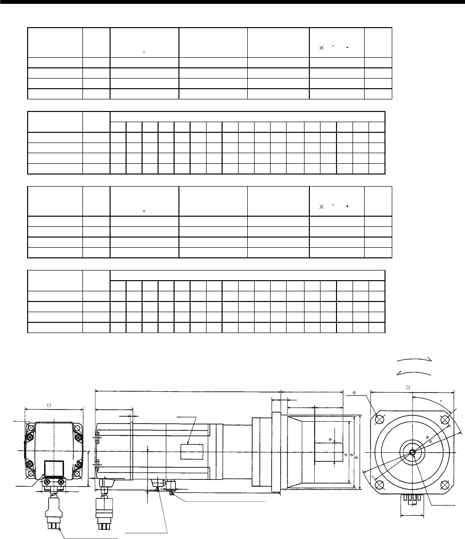
7 - 17
7. OUTLINE DIMENSION DRAWINGS
Model Output
[W]
Brake static
friction torque
[N m]
Reduction Gear
Model Reduction Ratio Inertia Moment
J[ 10 4kg m2]
Mass
[kg]
HC-MF23BG2 200 1.3 BK1-05B-02MEKA 1/5 0.239 2.7
HC-MF23BG2 200 1.3 BK2-09B-02MEKA 1/9 0.256 4.1
HC-MF23BG2 200 1.3 BK3-20B-02MEKA 1/20 0.405 5.6
HC-MF23BG2 200 1.3 BK3-29B-02MEKA 1/29 0.324 5.6
Variable Dimensions
Model Output
[W] LA LB LC LD LE LF LG LH LK L LR KL LZ Q S P R
HC-MF23BG2 200 80 65 95 70 6 48 8 60 23 189 55 106.6 6.6 25 16 M4 8
HC-MF23BG2 200 100 80 115 85 6 65 10 74 33 207 75 124.6 6.6 35 20 M5 10
HC-MF23BG2 200 115 95 135 100 8 75 10 85 35 212 85 129.6 94025M612
HC-MF23BG2 200 115 95 135 100 8 75 10 85 35 212 85 129.6 94025M612
Model Output
[W]
Brake static
friction torque
[N m]
Reduction Gear
Model Reduction Ratio Inertia Moment
J[ 10 4kg m2]
Mass
[kg]
HC-KF23BG2 200 1.3 BK1-05B-02MEKA 1/5 0.410 2.7
HC-KF23BG2 200 1.3 BK2-09B-02MEKA 1/9 0.430 4.1
HC-KF23BG2 200 1.3 BK3-20B-02MEKA 1/20 0.580 5.6
HC-KF23BG2 200 1.3 BK3-29B-02MEKA 1/29 0.500 5.6
Variable Dimensions
Model Output
[W] LA LB LC LD LE LF LG LH LK L LR KL LZ Q S P R
HC-KF23BG2 200 80 65 95 70 6 48 8 60 23 189 55 106.6 6.6 25 16 M4 8
HC-KF23BG2 200 100 80 115 85 6 65 10 74 33 207 75 124.6 6.6 35 20 M5 10
HC-KF23BG2 200 115 95 135 100 8 75 10 85 35 212 85 129.6 94025M612
HC-KF23BG2 200 115 95 135 100 8 75 10 85 35 212 85 129.6 94025M612
Motor plate
(Opposite side)
L
LELG
Top
Bottom
LK
LR
P threads,
depth R
Q
"Rotation direction"
For forward rotation command
For reverse rotation command
Power supply lead 4-AWG19 0.3m
(With end-insulated round crimping terminal 1.25-4)
Brake lead
2-0.3 0.3m
(With end-insulated round
crimping terminal 1.25-4)
2
Encoder cable 0.3m
With connector 1-172169-9
(AMP)
Red: Phase U
White: Phase V
Black: Phase W
Green/yellow: Earth
Top
Bottom
Sh6
LF
LH
LBh7
LC
LA
20
4- LZ
LD
Top
Bottom
Motor plate
Caution plate
2.52 68
38.4
10.6
42.8
9.9 KL
62
BC12083*
(BC12102*)
41
2.7
(Note)[Unit: mm]
45
Note: The dimensions without tolerances are reference dimensions.
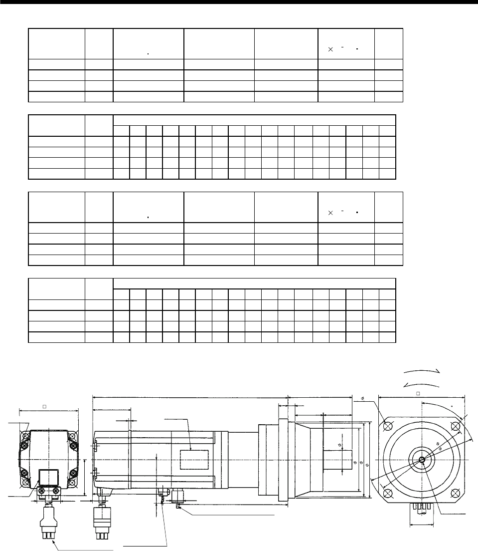
7 - 18
7. OUTLINE DIMENSION DRAWINGS
Model Output
[W]
Brake static
friction torque
[N m]
Reduction Gear
Model Reduction Ratio Inertia Moment
J[ 10 4kg m2]
Mass
[kg]
HC-MF43BG2 400 1.3 BK2-05B-04MEKA 1/5 0.344 4.3
HC-MF43BG2 400 1.3 BK3-09B-04MEKA 1/9 0.372 5.9
HC-MF43BG2 400 1.3 BK4-20B-04MEKA 1/20 0.475 8.1
HC-MF43BG2 400 1.3 BK4-29B-04MEKA 1/29 0.386 8.1
Variable Dimensions
Model Output
[W] LA LB LC LD LE LF LG LH LK L LR KL LZ Q S P R
HC-MF43BG2 400 100 80 115 85 6 65 10 74 33 216 75 131.6 6.6 35 20 M5 10
HC-MF43BG2 400 115 95 135 100 8 75 10 85 35 237 85 152.6 94025M612
HC-MF43BG2 400 135 110 155 115 8 90 12 100 40 243 100 158.6 11 50 32 M8 16
HC-MF43BG2 400 135 110 155 115 8 90 12 100 40 243 100 158.6 11 50 32 M8 16
Model Output
[W]
Brake static
friction torque
[N m]
Reduction Gear
Model Reduction Ratio Inertia Moment
J[ 10 4kg m2]
Mass
[kg]
HC-KF43BG2 400 1.3 BK2-05B-04MEKA 1/5 0.660 4.3
HC-KF43BG2 400 1.3 BK3-09B-04MEKA 1/9 0.690 5.9
HC-KF43BG2 400 1.3 BK4-20B-04MEKA 1/20 0.790 8.1
HC-KF43BG2 400 1.3 BK4-29B-04MEKA 1/29 0.710 8.1
Variable Dimensions
Model Output
[W] LA LB LC LD LE LF LG LH LK L LR KL LZ Q S P R
HC-KF43BG2 400 100 80 115 85 6 65 10 74 33 216 75 131.6 6.6 35 20 M5 10
HC-KF43BG2 400 115 95 135 100 8 75 10 85 35 237 85 152.6 94025M612
HC-KF43BG2 400 135 110 155 115 8 90 12 100 40 243 100 158.6 11 50 32 M8 16
HC-KF43BG2 400 135 110 155 115 8 90 12 100 40 243 100 158.6 11 50 32 M8 16
LE
LG
LK LR
Q
With connector 1-172169-9
(AMP)
Bottom
Top
Power supply lead 4-AWG19 0.3m
(With end-insulated round crimping terminal 1.25-4)
Red: Phase U
White: Phase V
Black: Phase W
Green/yellow: Earth
Encoder cable 0.3m
P threads,
depth R
For forward rotation command
"Rotation direction"
For reverse rotation command
Brake lead
2-0.3 0.3m
(With end-insulated round
crimping terminal 1.25-4)
2
Sh6
LF
LH
LBh7
LC
LA
4- LZ LD
(BC12103*)
BC12084*
20
Bottom
Top
Caution plate
LK
62 41
2.7
Motor plate
(Opposite side)
Bottom
Top
KL
9.9
68
25.2
38.4
10.6
42.8
(Note)[Unit: mm]
45
Motor plate
Note: The dimensions without tolerances are reference dimensions.
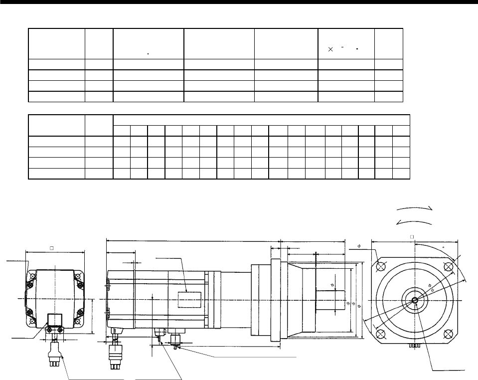
7 - 19
7. OUTLINE DIMENSION DRAWINGS
Model Output
[W]
Brake static
friction torque
[N m]
Reduction Gear
Model Reduction Ratio Inertia Moment
J[ 10 4kg m2]
Mass
[kg]
HC-MF73BG2 750 2.4 BK3-05B-08MEKA 1/5 1.098 7.3
HC-MF73BG2 750 2.4 BK4-09B-08MEKA 1/9 1.105 9.6
HC-MF73BG2 750 2.4 BK5-20B-08MEKA 1/20 1.141 13.0
HC-MF73BG2 750 2.4 BK5-29B-08MEKA 1/29 1.035 13.0
Variable Dimensions
Model Output
[W] LA LB LC LD LE LF LG LH LK L LR KL LZ Q S P R
HC-MF73BG2 750 115 95 135 100 8 75 10 85 35 247.5 85 156.7 94025M612
HC-MF73BG2 750 135 110 155 115 8 90 12 100 40 275.5 100 184.7 11 50 32 M8 16
HC-MF73BG2 750 150 125 175 130 10 105 15 115 43 283.5 115 192.7 14 60 40 M10 20
HC-MF73BG2 750 150 125 175 130 10 105 15 115 43 283.5 115 192.7 14 60 40 M10 20
Motor plate
(Opposite side)
LELG 4- LZ
Top
Bottom
LK
LR
Q
"Rotation direction"
For forward rotation command
For reverse rotation command
Power supply lead 4-AWG19 0.3m
(With end-insulated round crimping terminal 1.25-4)
Brake lead
2-0.3 0.3m
(With end-insulated round
crimping terminal 1.25-4)
2
Encoder cable 0.3m
With connector 1-172169-9
(AMP)
Red: Phase U
White: Phase V
Black: Phase W
Green/yellow: Earth
P threads,
depth R
Sh6
LF
LH
LBh7
L
Motor plate
82
Caution plate 25.2
48.7
Top
Bottom
Top
Bottom
39
2.7
11
72
9.9 KL
LD
BC12085*
58.1
LA
LC
(Note)[Unit: mm]
45
Note: The dimensions without tolerances are reference dimensions.
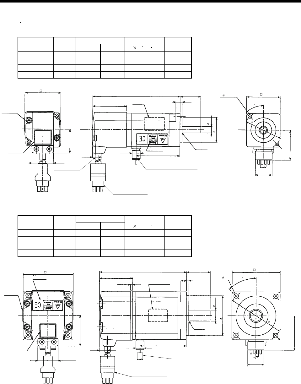
7 - 20
7. OUTLINE DIMENSION DRAWINGS
(5) EN UL/C-UL Standard-compliant models
(a) Standard (without electromagnetic brake, without reduction gear)
Variable Dimensions
Model Output
[W] LKL
Inertia Moment
J[ 10 4kg m2]
Mass
[kg]
HC-MF053-UE 50 89.5 37.5 0.019 0.5
HC-MF13-UE 100 104.5 52.5 0.03 0.6
HC-KF053-UE 50 89.5 37.5 0.054 0.5
HC-KF13-UE 100 104.5 52.5 0.085 0.6
Motor plate
Caution plate
Bottom
Top
Bottom
Top
25.2
28.7
42
Encoder cable
0.3m
Encoder cable 0.3m
With connector 1-172169-9
(AMP)
Power supply lead 4-AWG19 0.3m
(With end-insulated round crimping terminal 1.25-4)
Red: Phase U
White: Phase V
Black: Phase W
Green/yellow: Earth
Motor plate
(Opposite side)
Bottom
Top
Bottom
Top
40.5
L25
52.5
KL
TUV plate
8h6
30h7
V-10A
2- 4.5 40
35.7
20
BC07328A
9.9
6.8
V ring
(Note)[Unit: mm]
45
46
Note: The dimensions without tolerances are reference dimensions.
Variable Dimensions
Model Output
[W] LKL
Inertia Moment
J[ 10 4kg m2]
Mass
[kg]
HC-MF23-UE 200 108.5 58 0.09 1.2
HC-MF43-UE 400 133.5 81 0.14 1.7
HC-KF23-UE 200 108.5 58 0.270 1.2
HC-KF43-UE 400 133.5 81 0.470 1.7
62
Motor plate
Caution plate
25.2
38.4
plate
Bottom
Top
Bottom
Top
Bottom
Top
10.6 9.9
41
2.7
L30
37
Motor plate
(Opposite side)
Bottom
Top
KL
V ring
V-16A
Encoder cable 0.3m
With connector 1-172169-9
(AMP)
Power supply lead 4-AWG19 0.3m
(With end-insulated round crimping terminal 1.25-4)
Red: Phase U
White: Phase V
Black: Phase W
Green/yellow: Earth
20
BC07329A
42.8
70
4- 5.8
30
14h6
50h7
TUV
(Note)[Unit: mm]
45
Note: The dimensions without tolerances are reference dimensions.
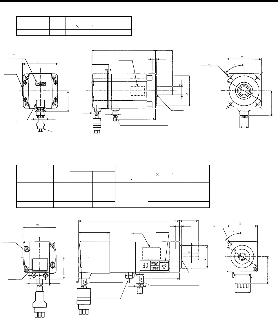
7 - 21
7. OUTLINE DIMENSION DRAWINGS
Model Output
[W]
Inertia Moment
J[ 10 4kg m2]
Mass
[kg]
HC-MF73-UE 750 0.675 3.1
Encoder cable 0.3m
With connector 1-172169-9
(AMP)
Motor plate
(Opposite side)
Motor plate
Caution plate 25.2
48.7
TUV plate
82
Bottom
Top
Bottom
Top
150
39
2.7
Bottom
Top
11 9.9
95
40
38
19h6
70h7
Power supply lead 4-AWG19 0.3m
(With end-insulated round crimping terminal 1.25-4)
Red: Phase U
White: Phase V
Black: Phase W
Green/yellow: Earth
V ring
V-25A
4- 6.6
80
90
58.5
20
BC07330A
(Note)[Unit: mm]
45
Note: The dimensions without tolerances are reference dimensions.
(b) With electromagnetic brake
Variable Dimensions
Model Output
[W] LKL
Brake static
friction torque
[N m]
Inertia Moment
J[ 10 4kg m2]Mass
[kg]
HC-MF053B-UE 50 117.5 37.5 0.022 0.9
HC-MF13B-UE 100 132.5 52.5 0.032 1
HC-KF053B-UE 50 117.5 37.5 0.057 0.9
HC-KF13B-UE 100 132.5 52.5
0.32
0.088 1
42
Motor plate
(Opposite side)
40.5
L25
2.55
TUV plate
Encoder cable 0.3m
With connector 1-172169-9
(AMP)
Brake lead
2-0.32 0.3m
(With end-insulated round
crimping terminal 1.25-4)
Power supply lead 4-AWG19 0.3m
(With end-insulated round crimping terminal 1.25-4)
Red: Phase U
White: Phase V
Black: Phase W
Green/yellow: Earth
B1,B2
KL
Motor plate
Caution plate
25.2
28.7
Top
Bottom
Top
Bottom
6.8
30h7
8h6
V-10A
V ring
40
2- 4.5
20
35.7
BC07369A
Top
Bottom
Top
Bottom
46
(Note)[Unit: mm]
45
Note: The dimensions without tolerances are reference dimensions.
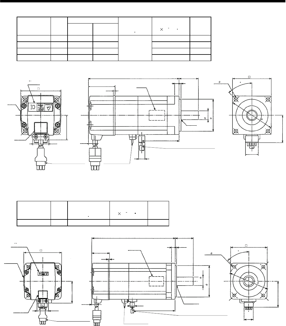
7 - 22
7. OUTLINE DIMENSION DRAWINGS
Variable Dimensions
Model Output
[W] LKL
Brake static
friction torque
[N m]
Inertia Moment
J[ 10 4kg m2]
Mass
[kg]
HC-MF23B-UE 200 140.5 58 0.136 1.7
HC-MF43B-UE 400 165.5 81 0.191 2.2
HC-KF23B-UE 200 140.5 58 0.320 1.7
HC-KF43B-UE 400 165.5 81
1.3
0.520 2.2
Encoder cable 0.3m
With connector 1-172169-9
(AMP)
Brake lead
2-0.3 0.3m
(With end-insulated round
crimping terminal 1.25-4)
B1,B2
Power supply lead 4-AWG19 0.3m
(With end-insulated round crimping terminal 1.25-4)
Red: Phase U
White: Phase V
Black: Phase W
Green/yellow: Earth
Motor plate
(Opposite side)
Bottom
Top
Motor plate
Caution plate
Top
Bottom
Bottom
Top
Top
Bottom
25.2
38.4
TUV plate
10.6
41
2.7
L30
37
95
9.9
14h6
50h7
V-16A
60
4- 5.8
42.8
20
BC07354A
V ring
62
70
(Note)[Unit: mm]
2
45
Note: The dimensions without tolerances are reference dimensions.
Model Output
[W]
Brake static
friction torque
[N m]
Inertia Moment
J[ 10 4kg m2]
Mass
[kg]
HC-MF73B-UE 750 2.4 0.75 4.2
Encoder cable 0.3m
With connector 1-172169-9
(AMP)
Brake lead
2-0.3 0.3m
(With end-insulated round
crimping terminal 1.25-4)
B1,B2
Power supply lead 4-AWG19 0.3m
(With end-insulated round crimping terminal 1.25-4)
Red: Phase U
White: Phase V
Black: Phase W
Green/yellow: Earth
BC07606
A
20
58.1
90
4- 6.6
80
40
38
19h6
70h7
95
9.9 V-25A
Bottom
Top
Motor plate
Caution plate 25.2
48.7
plateTUV
Bottom
Top
Bottom
Top
39
2.7
Motor plate
(Opposite side)
185.5
11 V ring
82
2
(Note)[Unit: mm]
45
Note: The dimensions without tolerances are reference dimensions.
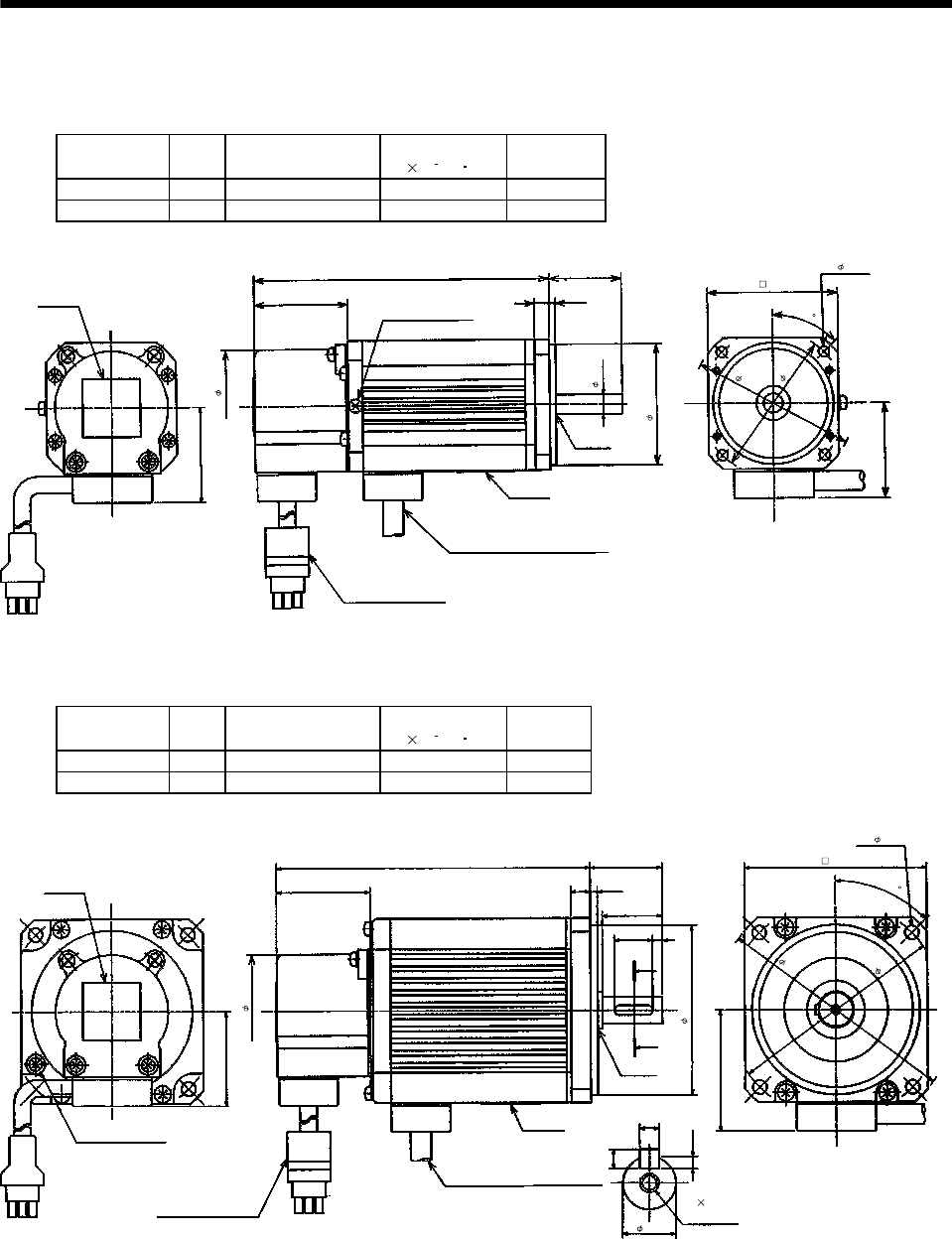
7 - 23
7. OUTLINE DIMENSION DRAWINGS
7.1.2 HA-FF series
(1) Standard (without electromagnetic brake, without reduction gear)
Model Output
[W]
Variable Dimensions
L
Inertia Moment
J[ 10 4kg m2]
Mass
[kg]
HA-FF053 50 106 0.063 1.3
HA-FF13 100 123 0.10 1.5
(Note)[Unit: mm]
Motor plate
39 2.5
6
8h6
54
4- 4.5
Bottom
Z694731
*
50h7
30
Bottom
Top
39
Caution plate
L
Earth terminal M3 screw
(Opposite side)
V ring
39
47
Top
Power supply cable
VCTF 3-1.25 0.5m
(With end-insulated round crimping terminal 1.25-4)
Encoder cable 0.3m
With connector 172169-9
(AMP)
2
Red: Phase U
White: Phase V
Black: Phase W
60
68
45
Note: The dimensions without tolerances are reference dimensions.
Model Output
[W]
Variable Dimensions
L
Inertia Moment
J[ 10 4kg m2]
Mass
[kg]
HA-FF23 200 130.5 0.35 2.3
HA-FF33 300 148 0.5 2.6
Motor plate
39 3
8
76
4- 5.5
(Note)[Unit: mm]
Bottom
Z694732
*
70h7
30
Bottom
Top
39
Caution plate
L
V ring
50
47
Earth terminal M3 screw
A
A
16 4
25
M4 0.7 threads,
depth 15
4
Section AA
2.5
4
100
90
11h6
Power supply cable
VCTF 3-1.25 0.5m
(With end-insulated round crimping
terminal 1.25-4)
2
Encoder cable 0.3m
With connector 172169-9
(AMP)
Top
Red: Phase U
White: Phase V
Black: Phase W
45
Note: The dimensions without tolerances are reference dimensions.
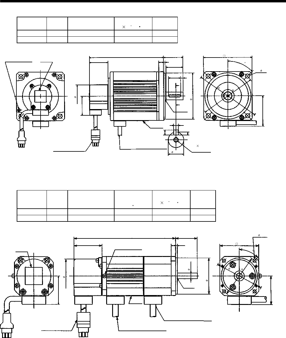
7 - 24
7. OUTLINE DIMENSION DRAWINGS
Model Output
[W]
Variable Dimensions
L
Inertia Moment
J[ 10 4kg m2]
Mass
[kg]
HA-FF43 400 154.5 0.98 4.2
HA-FF63 600 169.5 1.2 4.8
Motor plate
39 3
10
100
4- 9
(Note)[Unit: mm]
Z694733
*
95h7
40
39
L
V ring
62
47
Caution plate
A
A
5
35
5
Section AA
3
5
16h6
25
135
Bottom
Top
M5 0.8 threads,
depth 20
Power supply cable
VCTF 3-1.25 0.5m
(With end-insulated round
crimping terminal 1.25-4)
2
Red: Phase U
White: Phase V
Black: Phase W
Encoder cable 0.3m
With connector 172169-9
(AMP)
Earth terminal M3 screw
Bottom
Top
115
45
Note: The dimensions without tolerances are reference dimensions.
(2) Without electromagnetic brake
Model Output
[W]
Variable Dimensions
L
Brake static
friction torque
[N m]
Inertia Moment
J[ 10 4kg m2]
Mass
[kg]
HA-FF053B 50 141 0.39 0.08 1.6
HA-FF13B 100 158 0.39 0.11 1.8
Motor plate
39 2.56
8h6
54
4- 4.5
(Note)[Unit: mm]
Top
Bottom
Z694734
*
50h7
30
Bottom
Top
39
Caution plate
L
Earth terminal M3 screw
(Opposite side)
V ring
39
47
60
68
Power supply cable
VCTF 3-1.25 0.5m
(With end-insulated round
crimping terminal 1.25-4)
2
Red: Phase U
White: Phase V
Black: Phase W
Encoder cable 0.3m
With connector 172169-9
(AMP)
Brake lead
VCTF 2-0.5 0.5m
(With end-insulated round crimping terminal 1.25-4)
2
45
Note: The dimensions without tolerances are reference dimensions.
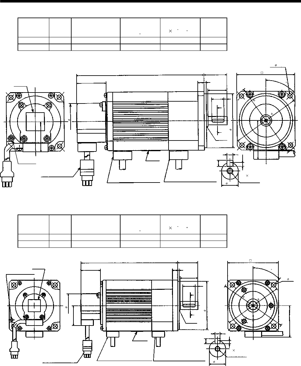
7 - 25
7. OUTLINE DIMENSION DRAWINGS
Model Output
[W]
Variable Dimensions
L
Brake static
friction torque
[N m]
Inertia Moment
J[ 10 4kg m2]
Mass
[kg]
HA-FF23B 200 168 1.2 0.48 2.9
HA-FF33B 300 185.5 1.2 0.63 3.2
Motor plate
39 38
76
4- 5.5
(Note)[Unit: mm]
Top
Bottom
Note: The dimensions without tolerances are reference dimensions. Z694735*
70h7
30
Bottom
Top
39
Caution plate
L
V ring
50
47
A
A
4
25
4
Section AA
2.5
4
11h6
16
100
Earth terminal
M3 screw
M4 0.7 threads,
depth 15
Power supply cable
VCTF 3-1.25 0.5m
(With end-insulated round
crimping terminal 1.25-4)
2
Red: Phase U
White: Phase V
Black: Phase W
Encoder cable 0.3m
With connector 172169-9
(AMP)
Brake lead
VCTF 2-0.5 0.5m
(With end-insulated round
crimping terminal 1.25-4)
2
90
45
Model Output
[W]
Variable Dimensions
L
Brake static
friction torque
[N m]
Inertia Moment
J[ 10 4kg m2]
Mass
[kg]
HA-FF43B 400 191.5 2.3 1.33 5.0
HA-FF63B 600 206.5 2.3 1.55 5.6
Motor plate
39 3
10
100
4- 9
(Note)[Unit: mm]
Note: The dimensions without tolerances are reference dimensions. Z694736
*
95h7
40
Bottom
Top
39
Caution plate
L
V ring
62
47
Earth terminal M3 screw
A
A
5
35
M5 0.8 threads,
depth 20
5
Section AA
3
5
16h6
25
Power supply cable
VCTF 3-1.25 0.5m
(With end-insulated round
crimping terminal 1.25-4)
2
Red :Phase U
White :Phase V
Black :Phase W
Encoder cable 0.3m
With connector 172169-9
(AMP)
Brake lead
VCTF 2-0.5 0.5m
(With end-insulated round
crimping terminal 1.25-4)
2
Top
Bottom
115
135
45
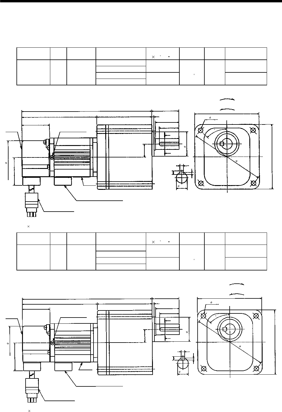
7 - 26
7. OUTLINE DIMENSION DRAWINGS
(3) With reduction gear for general industrial machine
The outer frame of the reduction gear is a material surface such as casting. Its actual dimensions may
be 1 to 3mm larger than the drawing dimensions. Design the machine side with allowances.
(a) Without electromagnetic brake
Model Output
[W]
Reduction
Gear Model
Reduction Ratio
(Actual Reduction Ratio)
Inertia Moment
J[ 10 4kg m2]Backlash Mass
[kg]
Output Shaft
Rotation Direction
1/5(9/44)
1/10(3/29) 0.068 Same as that of
motor shaft
1/20(99/1972)
HA-FF053G1 50 GR-S-10
1/30(144/4205) 0.063
40min. to
1.5 2.5 Opposite to that of
motor shaft
39
3
33
90
4- 6.5 (Note2)
Top
Bottom
Note: 1. The dimensions without tolerances are reference dimensions.
2. Four M6 90 through bolts are provided.
Z694764*
34
BottomTop
39
Caution plate
183
90
47
A
A
5
Section AA
3
5
15h6
106
Earth terminal M3 screw
(Opposite side)
77
27.5
38
18
104
(Note1)[Unit: mm]
"Rotation direction"
For forward rotation command
For reverse rotation command
Power supply cable VCTF 3-1.25 0.5m
(With end-insulated round crimping terminal 1.25-4)
Red: Phase U
White: Phase V
Black: Phase W
Encoder cable 0.3m
With connector 172169-9
(AMP)
2
45
Model Output
[W]
Reduction
Gear Model
Reduction Ratio
(Actual Reduction Ratio)
Inertia Moment
J[ 10 4kg m2]Backlash Mass
[kg]
Output Shaft
Rotation Direction
1/5(9/44)
1/10(3/29) 0.10 Same as that of
motor shaft
1/20(99/1972)
HA-FF13G1 100 GR-S-10
1/30(144/4205) 0.095
40min. to
1.5 2.7 Opposite to that of
motor shaft
Caution plate
Motor plate
39
3
33
90
4- 6.5 (Note2)
Top
Bottom
Z694765*
34
2
Bottom
Top
39
200
90
47
A
A
5
Section AA
3
5
15h6
123
Earth terminal M3 screw
(Opposite side)
77
27.5
38
18
104
(Note1)[Unit: mm]
"Rotation direction"
For forward rotation command
For reverse rotation command
Power supply cable
VCTF 3-1.25 0.5m
(With end-insulated round crimping terminal 1.25-4)
Red: Phase U
White: Phase V
Black: Phase W
Encoder cable 0.3m
With connector 172169-9
(AMP)
Note: 1. The dimensions without tolerances are reference dimensions.
2. Four M6 90 through bolts are provided.
45
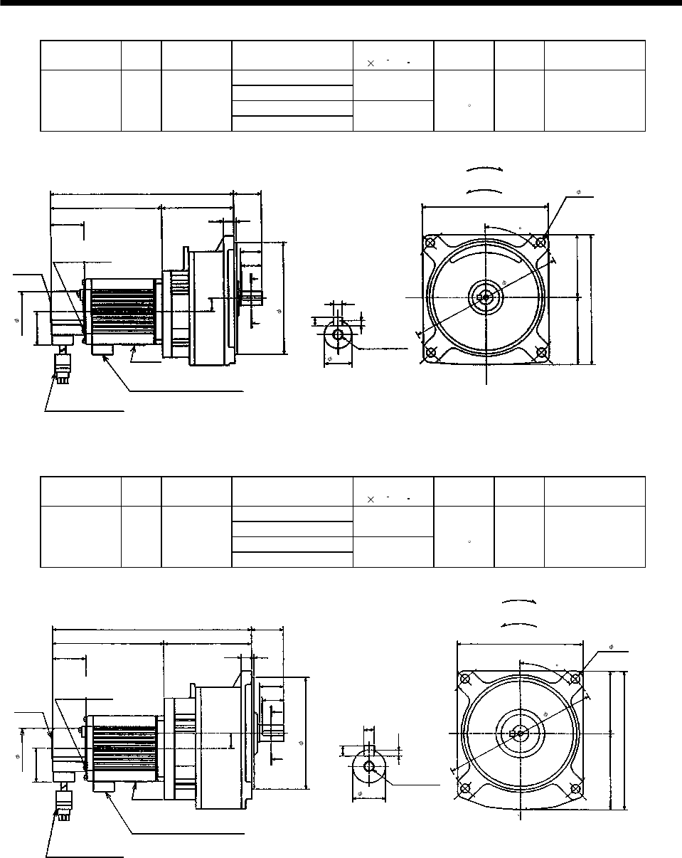
7 - 27
7. OUTLINE DIMENSION DRAWINGS
Model Output
[W]
Reduction
Gear Model
Reduction Ratio
(Actual Reduction Ratio)
Inertia Moment
J[ 10 4kg m2]Backlash Mass
[kg]
Output Shaft
Rotation Direction
1/5(57/280)
1/10(39/400) 0.373
1/20(51/980)
HA-FF23G1 200 GR-S-20
1/30(1/30) 0.37
40min. to
1.5 5.0 Same as that of
motor shaft
Motor plate
39 3
25
145
4- 10
Top
Bottom
Z694766
*
130js7
39
Caution plate
214.5
150
A
A
5
Section AA
3
5
16h6
130.5
32.5
24
12
15
47
84
77.5 72.5
180
(Note)[Unit: mm]
"Rotation direction"
For forward rotation command
For reverse rotation command
M6 threads,
depth 10
Bottom
Top
Power supply cable VCTF 3-1.25 0.5m
(With end-insulated round crimping terminal 1.25-4)
Red: Phase U
White: Phase V
Black: Phase W
Encoder cable 0.3m
With connector 172169-9
(AMP)
Earth terminal M3 screw
(Opposite side)
2
45
Note: The dimensions without tolerances are reference dimensions.
Model Output
[W]
Reduction
Gear Model
Reduction Ratio
(Actual Reduction Ratio)
Inertia Moment
J[ 10 4kg m2]Backlash Mass
[kg]
Output Shaft
Rotation Direction
1/5(19/94)
1/10(39/376) 0.545
1/20(72/1363)
HA-FF33G1 300 GR-S-30
1/30(11/329) 0.538
40min. to
1.5 6.5 Same as that of
motor shaft
Motor plate
39 3
25
145 4- 10
Top
Bottom
Z694767*
130js7
BottomTop
39
Caution plate
250
160
A
A
6
Section AA
3.5
6
19h6
148
37.5
28
12
18
47
102
M6 threads,
depth 10
87.5 72.5
(Note)[Unit: mm]
"Rotation direction"
For forward rotation command
For reverse rotation command
Power supply cable VCTF 3-1.25 0.5m
(With end-insulated round crimping terminal 1.25-4)
Red: Phase U
White: Phase V
Black: Phase W
Encoder cable 0.3m
With connector 172169-9
(AMP)
2
Earth terminal M3 screw
(Opposite side)
180
45
Note: The dimensions without tolerances are reference dimensions.
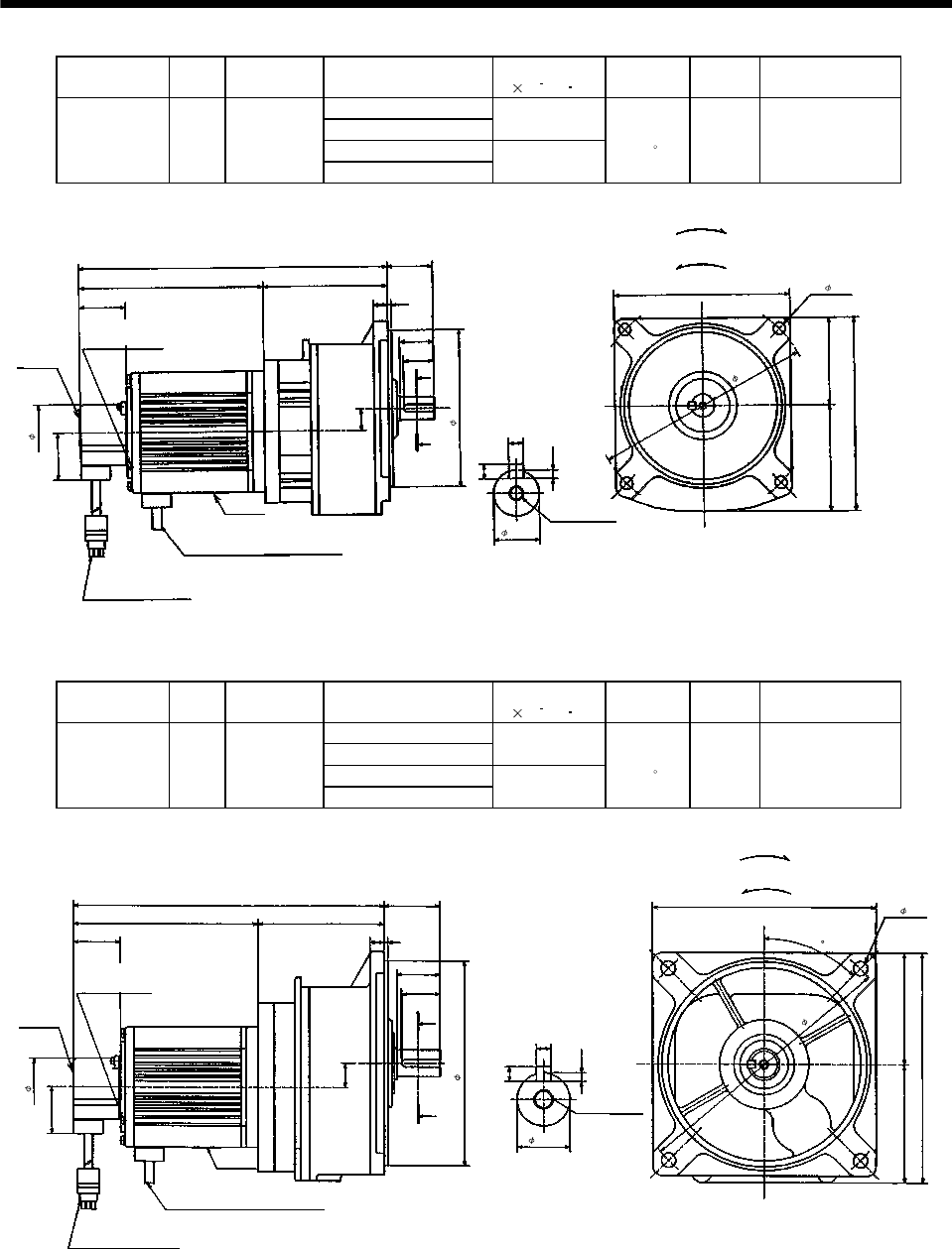
7 - 28
7. OUTLINE DIMENSION DRAWINGS
Model Output
[W]
Reduction
Gear Model
Reduction Ratio
(Actual Reduction Ratio)
Inertia Moment
J[ 10 4kg m2]Backlash Mass
[kg]
Output Shaft
Rotation Direction
1/5(19/94)
1/10(39/376) 1.02
1/20(72/1363)
HA-FF43G1 400 GR-S-40
1/30(11/329) 1.01
40min. to
1.5 8.0 Same as that of
motor shaft
Motor plate
39 3
25
145 4- 10
Top
Bottom
Z694768
*
130js7
Bottom
Top
39
Caution plate
258.5
160
A
A
6
Section AA
3.5
6
19h6
154.5
37.5
28
12
18
47
104
M6 threads,
depth 10
87.5 72.5
180
(Note)[Unit: mm]
"Rotation direction"
For forward rotation command
For reverse rotation command
2
Power supply cable VCTF 3-1.25 0.5m
(With end-insulated round crimping terminal 1.25-4)
Red: Phase U
White: Phase V
Black: Phase W
Encoder cable 0.3m
With connector 172169-9
(AMP)
Earth terminal M3 screw
(Opposite side)
Note: The dimensions without tolerances are reference dimensions.
Model Output
[W]
Reduction
Gear Model
Reduction Ratio
(Actual Reduction Ratio)
Inertia Moment
J[ 10 4kg m2]Backlash Mass
[kg]
Output Shaft
Rotation Direction
1/5(10/49)
1/10(243/2401) 1.34
1/20(153/2891)
HA-FF63G1 600 GR-S-60
1/30(27/784) 1.32
40min. to
1.5 13.0 Same as that of
motor shaft
39 3
32
185
225
Top
Bottom
Z694769
*
170js7
39
Caution plate
274.5
192.5
A
A
6
Section AA
3.5
6
22h6
169.5
46.5
36
12
20
47
105
M8 threads,
depth 12
100 92.5
4- 12
(Note)[Unit: mm]
"Rotation direction"
For forward rotation command
For reverse rotation command
Motor plate
Bottom
Top
2
Power supply cable VCTF 3-1.25 0.5m
(With end-insulated round crimping terminal 1.25-4)
Red: Phase U
White: Phase V
Black: Phase W
Encoder cable 0.3m
With connector 172169-9
(AMP)
Earth terminal M3 screw
(Opposite side)
45
Note: The dimensions without tolerances are reference dimensions.
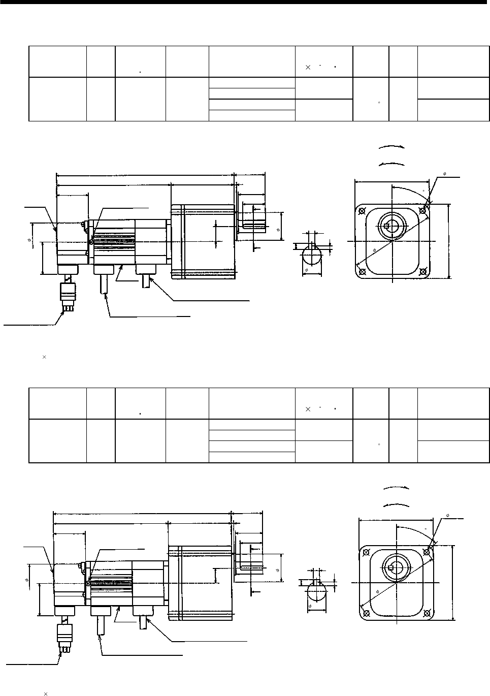
7 - 29
7. OUTLINE DIMENSION DRAWINGS
(b) With electromagnetic brake
Model Output
[W]
Brake static
friction torque
[N m]
Reduction
Gear Model
Reduction Ratio
(Actual Reduction Ratio)
Inertia Moment
J[ 10 4kg m2]Backlash
Mass
[kg]
Output Shaft
Rotation Direction
1/5(9/44)
1/10(3/29) 0.085 Same as that of
motor shaft
1/20(99/1972)
HA-FF053BG1 50 0.39 GR-S-10
1/30(144/4205) 0.080
40min.
to 1.5 2.8 Opposite to that of
motor shaft
Motor plate
39
3
141 90
4- 6.5 (Note2)
Top
Bottom
Z694770*
34
38
Bottom
39
Caution plate
218
90
47
Earth terminal M3 screw
(Opposite side)
A
A
33
5
Section AA
3
5
15h6
27.5
Brake cable
VCTF 2-0.5 0.5m
(With end-insulated round crimping terminal 1.25-4)
2
77
18
104
(Note1)[Unit: mm]
"Rotation direction"
For forward rotation command
For reverse rotation command
Top
Power supply cable VCTF 3-1.25 0.5m
(With end-insulated round crimping terminal 1.25-4)
Red: Phase U
White: Phase V
Black: Phase W
Encoder cable 0.3m
With connector 172169-9
(AMP)
Note: 1. The dimensions without tolerances are reference dimensions.
2. Four M6 90 through bolts are provided.
2
45
Model Output
[W]
Brake static
friction torque
[N m]
Reduction
Gear Model
Reduction Ratio
(Actual Reduction Ratio)
Inertia Moment
J[ 10 4kg m2]Backlash
Mass
[kg]
Output Shaft
Rotation Direction
1/5(9/44)
1/10(3/29) 0.115 Same as that of
motor shaft
1/20(99/1972)
HA-FF13BG1 100 0.39 GR-S-10
1/30(144/4205) 0.11
40min.
to 1.5 3.0 Opposite to that of
motor shaft
Note: 1. The dimensions without tolerances are reference dimensions.
2. Four M6 90 through bolts are provided.
39
3
158 90 4- 6.5 (Note2)
Top
Bottom
Z694771*
34
38
39
Caution plate
235
90
47
Earth terminal M3 screw
(Opposite side)
A
A
33
5
Section AA
3
5
15h6
27.5
2
77
18
104
(Note1)[Unit: mm]
"Rotation direction"
For forward rotation command
For reverse rotation command
Encoder cable 0.3m
With connector 172169-9
(AMP)
Power supply cable VCTF 3-1.25 0.5m
(With end-insulated round crimping terminal 1.25-4)
Red: Phase U
White: Phase V
Black: Phase W
Brake cable
VCTF 2-0.5 0.5m
(With end-insulated round crimping terminal 1.25-4)
2
Motor plate
Bottom
Top
45
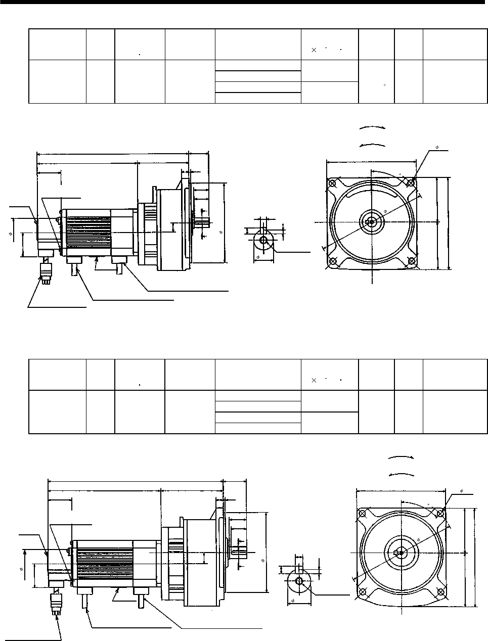
7 - 30
7. OUTLINE DIMENSION DRAWINGS
Model Output
[W]
Brake static
friction torque
[N m]
Reduction
Gear Model
Reduction Ratio
(Actual Reduction Ratio)
Inertia Moment
J[ 10 4kg m2]Backlash
Mass
[kg]
Output Shaft
Rotation Direction
1/5(57/280)
1/10(39/400) 0.503
1/20(51/980)
HA-FF23BG1 200 1.20 GR-S-20
1/30(1/30) 0.500
40min.
to 1.5 5.6 Same as that of
motor shaft
Motor plate
39 3
25
145
Top
Bottom
130js7
Power supply cable
VCTF 3-1.25 0.5m
(With end-insulated round crimping terminal 1.25-4)
2
Bottom
Top
39
Caution plate
252
150
A
A
5
Section AA
3
5
168
32.5
24
12
15
47
84
77.5 72.5
180
Brake lead
VCTF 2-0.5 0.5m
(With end-insulated round crimping terminal 1.25-4)
2
(Note)[Unit: mm]
"Rotation direction"
For forward rotation command
For reverse rotation command
M6 threads,
depth 10
Red: Phase U
White: Phase V
Black: Phase W
Encoder cable 0.3m
With connector 172169-9
(AMP)
Earth terminal M3 screw
(Opposite side)
Z694772*
16h6
4- 10
45
Note: The dimensions without tolerances are reference dimensions.
Model Output
[W]
Brake static
friction torque
[N m]
Reduction
Gear Model
Reduction Ratio
(Actual Reduction Ratio)
Inertia Moment
J[ 10 4kg m2]Backlash
Mass
[kg]
Output Shaft
Rotation Direction
1/5(19/94)
1/10(39/376) 0.678
1/20(72/1363)
HA-FF33BG1 300 1.20 GR-S-30
1/30(11/329) 0.670
40min.
to 1.5˚7.2 Same as that of
motor shaft
39 3
28
145 4- 10
Red: Phase U
White: Phase V
Black: Phase W
Top
Bottom
Z694773*
130js7
39
Caution plate
287.5
160
A
A
6
Section AA
3.5
6
19h6
185.5
37.5
25
12
18
47
102
M6 threads,
depth 10
87.5 72.5
180
(Note)[Unit: mm]
"Rotation direction"
For forward rotation command
For reverse rotation command
Brake lead
VCTF 2-0.5 0.5m
(With end-insulated round crimping terminal 1.25-4)
2
Motor plate
Bottom
Top
Power supply cable
VCTF 3-1.25 0.5m
(With end-insulated round crimping terminal 1.25-4)
2
Encoder cable 0.3m
With connector 172169-9
(AMP)
Earth terminal M3 screw
(Opposite side)
45
Note: The dimensions without tolerances are reference dimensions.
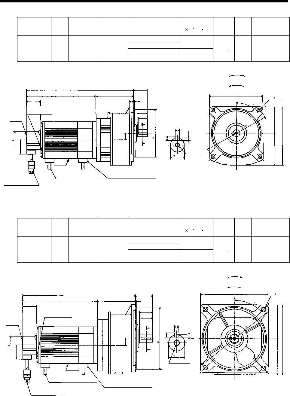
7 - 31
7. OUTLINE DIMENSION DRAWINGS
Model Output
[W]
Brake static
friction torque
[N m]
Reduction
Gear Model
Reduction Ratio
(Actual Reduction Ratio)
Inertia Moment
J[ 10 4kg m2]Backlash
Mass
[kg]
Output Shaft
Rotation Direction
1/5(19/94)
1/10(39/376) 1.37
1/20(72/1363)
HA-FF43BG1 400 2.30 GR-S-40
1/30(11/329) 1.36
40min.
to 1.5 8.9 Same as that of
motor shaft
39 3
28
145
4- 10
Red: Phase U
White: Phase V
Black: Phase W
Top
Bottom
Z694774*
130js7
39
Caution plate
295.5
160
A
A
6
Section AA
3.5
6
191.5
37.5
25
12
18
47
104
M6 threads,
depth 10
87.5 72.5
180
2
(Note)[Unit: mm]
"Rotation direction"
For forward rotation command
For reverse rotation command
Brake lead
VCTF 2-0.5 0.5m
(With end-insulated round crimping terminal 1.25-4)
Motor plate
BottomTop
Power supply cable
VCTF 3-1.25 0.5m
(With end-insulated round crimping terminal 1.25-4)
2
Encoder cable 0.3m
With connector 172169-9
(AMP)
Earth terminal M3 screw
(Opposite side)
19h6
45
Note: The dimensions without tolerances are reference dimensions.
Model Output
[W]
Brake static
friction torque
[N m]
Reduction
Gear Model
Reduction Ratio
(Actual Reduction Ratio)
Inertia Moment
J[ 10 4kg m2]Backlash
Mass
[kg]
Output Shaft
Rotation Direction
1/5(10/49)
1/10(243/2401) 1.69
1/20(153/2891)
HA-FF63BG1 600 2.30 GR-S-60
1/30(27/784) 1.67
40min.
to 1.5 13.9 Same as that of
motor shaft
39
3
36
185 4- 12
Top
Bottom
Z694775*
170js7
Power supply cable
VCTF 3-1.25 0.5m
(With end-insulated round
crimping terminal 1.25-4)
2
39
Caution plate
311.5
192.5
A
A6
3.5
6
22h6
206.5
Earth terminal M3 screw
(Opposite side)
46.5
32
12
20
47
105
100 92.5
225
2
Brake lead
VCTF 2-0.5 0.5m
(With end-insulated round crimping terminal 1.25-4)
Motor plate
BottomTop
Encoder cable 0.3m
With connector 172169-9
(AMP)
Red: Phase U
White: Phase V
Black: Phase W
Section AA
M8 threads,depth 12
(Note)[Unit: mm]
"Rotation direction"
For forward rotation command
For reverse rotation command
45
Note: The dimensions without tolerances are reference dimensions.
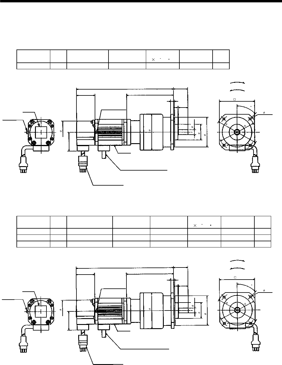
7 - 32
7. OUTLINE DIMENSION DRAWINGS
(4) With reduction gear for precision application
The outer frame of the reduction gear is a material surface such as casting. Its actual dimensions may
be 1 to 3mm larger than the drawing dimensions. Design the machine side with allowances.
(a) Without electromagnetic brake
Model Output
[W]
Reduction Gear
Model Reduction Ratio Inertia Moment
J[ 10 4kg m2]Backlash Mass
[kg]
HA-FF053G2 50 BM2-05B-A5MES 1/5 0.11 3 min. max. 2.3
Motor plate
39
6
99
4- 4.5
30
Bottom
Top
39
Caution Plate
205
Earth terminal
M3 screw
(Opposite side)
47
Earth terminal M3
2
920
78
75
(Note)[Unit: mm]
"Rotation direction"
For forward rotation command
For reverse rotation command
Power supply cable
VCTF 3-1.25 0.5m
(With end-insulated round crimping terminal 1.25-4)
2
Red: Phase U
White: Phase V
Black: Phase W
Encoder cable 0.3m
With connector 172169-9
(AMP)
Bottom
Top
10h6
74
Z694850*
33
62h7
89
45
Note: The dimensions without tolerances are reference dimensions.
Model Output
[W] Variable dimensions L Reduction Gear
Model Reduction Ratio Inertia Moment
J[ 10 4kg m2]Backlash Mass
[kg]
HA-FF053G2 50 205 BM2-10B-A5MES 1/10 0.108 3 min. max. 2.3
HA-FF053G2 50 205 BM2-15B-A5MES 1/15 0.105 3 min. max. 2.3
HA-FF13G2 100 205 BM2-05B-01MES 1/5 0.143 3 min. max. 2.5
Motor plate
39
6
99
74
4- 4.5
Z694805*
62h7
30
BottomTop
39
Caution plate
L
Earth terminal
M3 screw
(Opposite side)
47
Earth terminal M3
2
920
33
78
89
75
(Note)[Unit: mm]
"Rotation direction"
For forward rotation command
For reverse rotation command
Power supply cable
VCTF 3-1.25 0.5m
(With end-insulated round crimping terminal 1.25-4)
2
Red: Phase U
White: Phase V
Black: Phase W
Encoder cable 0.3m
With connector 172169-9
(AMP)
Top
Bottom
10h6
45
Note: The dimensions without tolerances are reference dimensions.
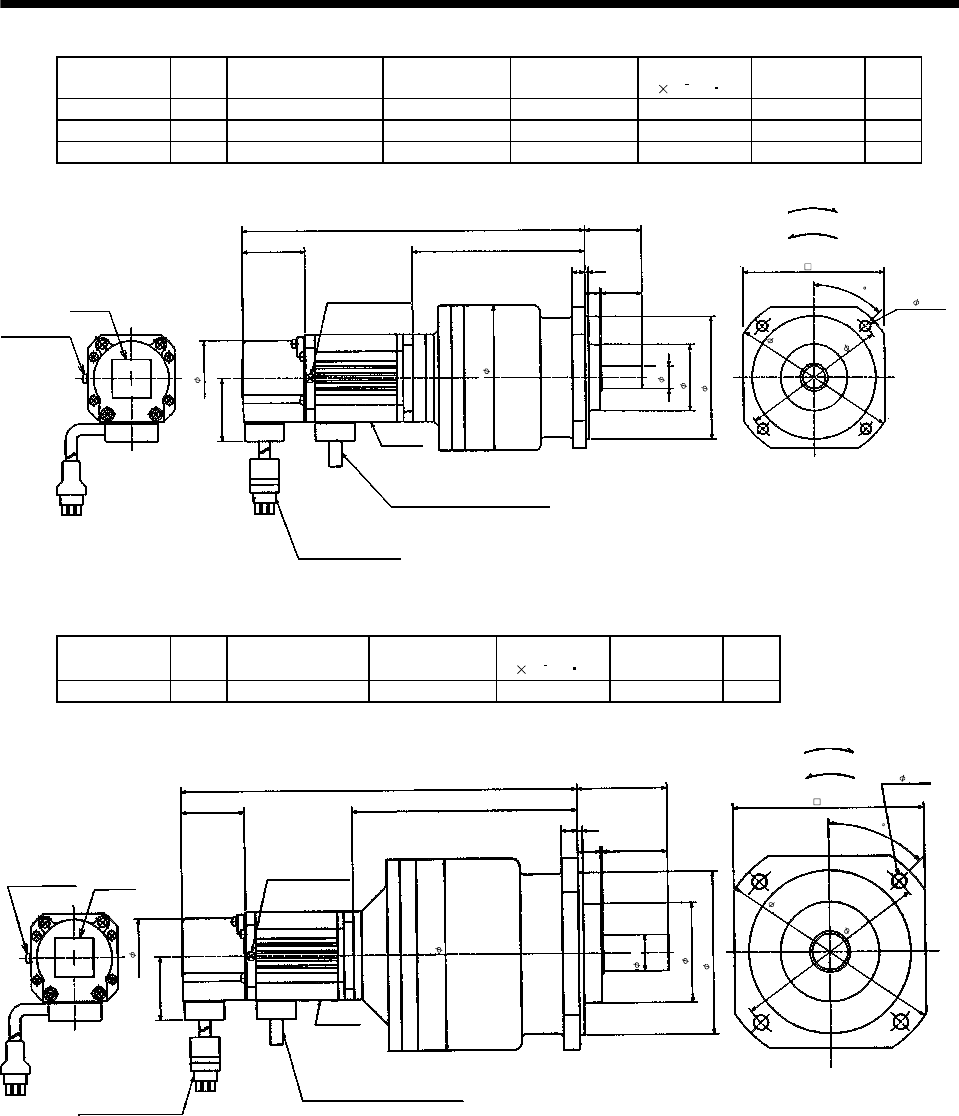
7 - 33
7. OUTLINE DIMENSION DRAWINGS
Model Output
[W] Variable dimensions L Reduction Gear
Model Reduction Ratio Inertia Moment
J[ 10 4kg m2]Backlash Mass
[kg]
HA-FF053G2 50 213 BM3-25B-A5MES 1/25 0.110 3min. max. 2.8
HA-FF13G2 100 230 BM3-10B-01MES 1/10 0.165 3min. max. 3.0
HA-FF13G2 100 230 BM3-15B-01MES 1/15 0.155 3min. max. 3.0
Motor plate
39
8
107
87
4- 5.5
Z694806*
35
Bottom
Top
39
Caution plate
L
Earth terminal
M3 screw
(Opposite side)
47
Earth terminal M3
2
925
87
90
(Note)[Unit: mm]
"Rotation direction"
For forward rotation command
For reverse rotation command
Power supply cable
VCTF 3-1.25 0.5m
(With end-insulated round crimping terminal 1.25-4)
2
Red: Phase U
White: Phase V
Black: Phase W
Encoder cable 0.3m
With connector 172169-9
(AMP)
Top
Bottom
14h6
41
76h7
102
45
Note: The dimensions without tolerances are reference dimensions.
Model Output
[W]
Reduction Gear
Model Reduction Ratio Inertia Moment
J[ 10 4kg m2]Backlash Mass
[kg]
HA-FF13G2 100 BM4-25B-01MES 1/25 0.29 3min. max. 5.0
Motor plate
39
10
139 118
4- 6.6
Z694807*
100h7
55
Bottom
Top
39
Caution plate
262
Earth terminal
M3 screw
(Opposite side)
Earth terminal M3
3
14 40
61
118
122
140
(Note)[Unit: mm]
"Rotation direction"
For forward rotation command
For reverse rotation command
Power supply cable
VCTF 3-1.25 0.5m
(With end-insulated round crimping terminal 1.25-4)
2
Red: Phase U
White: Phase V
Black: Phase W
Encoder cable 0.3m
With connector 172169-9
(AMP)
Top
Bottom
22h6
47
45
Note: The dimensions without tolerances are reference dimensions.
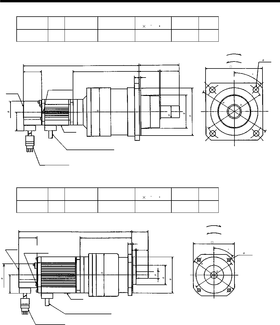
7 - 34
7. OUTLINE DIMENSION DRAWINGS
Model Output
[W]
Reduction Gear
Model Reduction Ratio Inertia Moment
J[ 10 4kg m2]Backlash Mass
[kg]
HA-FF13G2 100 BL1-45B-
01MES 1/45 0.293 3min. max. 6.0
Motor plate
39
10
151
25h6
120
4- 12
Top
Bottom
Z694737*
100h7
85
Bottom
Top
39
Caution plate
274
Earth terminal
M3 screw
(Opposite side)
47
3
40
70
102
43
130
155
(Note)[Unit: mm]
"Rotation direction"
For forward rotation command
For reverse rotation command
Power supply cable
VCTF 3-1.25 0.5m
(With end-insulated round crimping terminal 1.25-4)
2
Red: Phase U
White: Phase V
Black: Phase W
Encoder cable 0.3m
With connector 172169-9
(AMP)
45
Note: The dimensions without tolerances are reference dimensions.
Model Output
[W]
Reduction Gear
Model Reduction Ratio Inertia Moment
J[ 10 4kg m2]Backlash Mass
[kg]
HA-FF23G2 200 BM3-05B-
02MES 1/5 0.425 3min. max. 3.8
Motor plate
39
8
109
14h6
87
4- 5.5
Top
Bottom
Z694808*
76h7
35
Bottom
Top
39
Caution plate
239.5
Earth terminal M3 screw
(Opposite side)
47
2
925
41
87
90
(Note)[Unit: mm]
"Rotation direction"
For forward rotation command
For reverse rotation command
Power supply cable
VCTF 3-1.25 0.5m
(With end-insulated round crimping terminal 1.25-4)
2
Red: Phase U
White: Phase V
Black: Phase W
Encoder cable 0.3m
With connector 172169-9
(AMP)
102
45
Note: The dimensions without tolerances are reference dimensions.
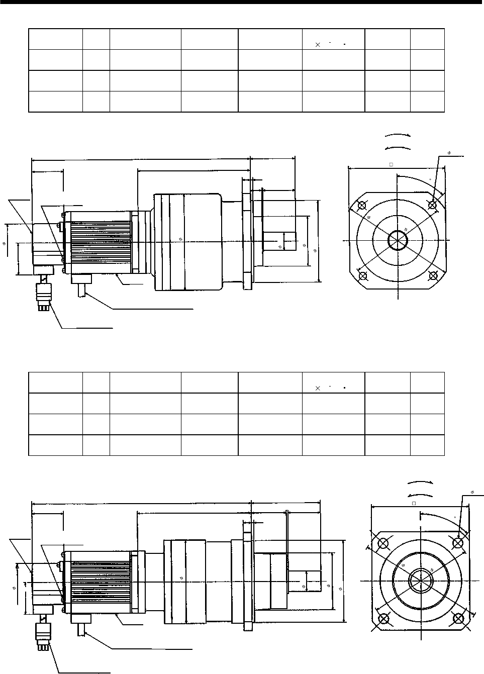
7 - 35
7. OUTLINE DIMENSION DRAWINGS
Model Output
[W]
Variable dimensions
L
Reduction Gear
Model Reduction Ratio Inertia Moment
J[ 10 4kg m2]Backlash Mass
[kg]
HA-FF23G2 200 269.5 BM4-10B-
02MES 1/10 0.645 3min. max. 5.8
HA-FF23G2 200 269.5 BM4-15B-
02MES 1/15 0.618 3min. max. 5.8
HA-FF33G2 300 287 BM4-10B-
03MES 1/10 0.795 3min. max. 6.1
Motor plate
39
10
139
22h6
118
4- 6.6
Top
Bottom
100h7
55
Bottom
Top
39
Caution plate
L
Earth terminal M3 screw
(Opposite side)
47
3
14 40
61
118
122
140
(Note)[Unit: mm]
"Rotation direction"
For forward rotation command
For reverse rotation command
Power supply cable
VCTF 3-1.25 0.5m
(With end-insulated round crimping terminal 1.25-4)
2
Red: Phase U
White: Phase V
Black: Phase W
Encoder cable 0.3m
With connector 172169-9
(AMP) Z694809*
45
Note: The dimensions without tolerances are reference dimensions.
Model Output
[W]
Variable dimensions
L
Reduction Gear
Model Reduction Ratio Inertia Moment
J[ 10 4kg m2]Backlash Mass
[kg]
HA-FF23G2 200 278 BL1-20B-
02MES 1/20 0.730 3min. max. 6.8
HA-FF23G2 200 278 BL1-29B-
02MES 1/29 0.633 3min. max. 6.8
HA-FF33G2 300 295 BL1-20B-
03MES 1/20 0.880 3min. max. 7.1
39
10
147
25h6
120
4- 12
Bottom
Z694738*
100h7
85
39
Caution plate
L
Earth terminal M3 screw
(Opposite side)
47
3
40
70
102
43
130
155
(Note)[Unit: mm]
"Rotation direction"
For forward rotation command
For reverse rotation command
Motor plate
Bottom
Top
Power supply cable
VCTF 3-1.25 0.5m
(With end-insulated round crimping terminal 1.25-4)
2
Red: Phase U
White: Phase V
Black: Phase W
Encoder cable 0.3m
With connector 172169-9
(AMP)
Top
45
Note: The dimensions without tolerances are reference dimensions.
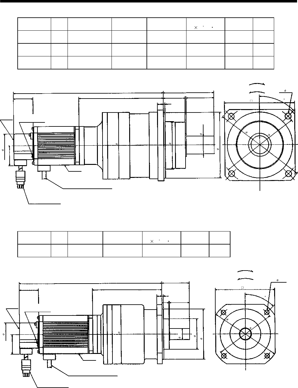
7 - 36
7. OUTLINE DIMENSION DRAWINGS
Model Output
[W]
Variable dimensions
L
Reduction Gear
Model Reduction Ratio Inertia Moment
J[ 10 4kg m2]Backlash Mass
[kg]
HA-FF23G2 200 299 BL2-45B-
02MES 1/45 0.763 3min. max. 12.3
HA-FF33G2 300 316 BL2-29B-
03MES 1/29 1.535 3min. max. 12.6
HA-FF33G2 300 316 BL2-45B-
03MES 1/45 0.913 3min. max. 12.6
Motor plate
39
12
168
35h6
140
4- 12
Top
Bottom
Z694739*
130h7
100
BottomTop
39
Caution
plate
47
3
55
94
132
43
L
185
160
(Note)[Unit: mm]
"Rotation direction"
For forward rotation command
For reverse rotation command
Power supply cable
VCTF 3-1.25 0.5m
(With end-insulated round crimping terminal 1.25-4)
2
Red: Phase U
White: Phase V
Black: Phase W
Encoder cable 0.3m
With connector 172169-9
(AMP)
Earth terminal M3 screw
(Opposite side)
45
Note: The dimensions without tolerances are reference dimensions.
Model Output
[W]
Reduction Gear
Model Reduction Ratio Inertia Moment
J[ 10 4kg m2]Backlash Mass
[kg]
HA-FF33G2 300 BM4-05B-
03MES 1/5 0.818 3min. max. 6.1
Motor plate
39
10
139
22h6
118
4- 6.6
Top
Bottom
Z694810*
100h7
55
BottomTop
39
Caution plate
287
47
3
14 40
61
118
122
140
(Note)[Unit: mm]
"Rotation direction"
For forward rotation command
For reverse rotation command
Earth terminal M3 screw
(Opposite side)
Power supply cable
VCTF 3-1.25 0.5m
(With end-insulated round crimping terminal 1.25-4)
2
Red: Phase U
White: Phase V
Black: Phase W
Encoder cable 0.3m
With connector 172169-9
(AMP)
45
Note: The dimensions without tolerances are reference dimensions.
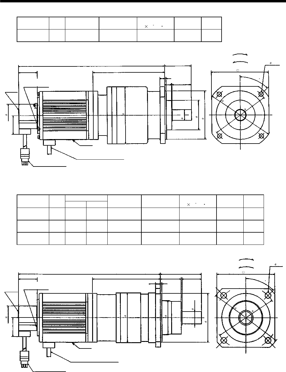
7 - 37
7. OUTLINE DIMENSION DRAWINGS
Model Output
[W]
Reduction Gear
Model Reduction Ratio Inertia Moment
J[ 10 4kg m2]Backlash Mass
[kg]
HA-FF43G2 400 BM4-05B-
04MES 1/5 1.293 3min. max. 7.7
Motor plate
39
10
149
22h6
118
4- 6.6
(Note)[Unit: mm]
Red: Phase U
White: Phase V
Black: Phase W
Top
Bottom
Z694811*
55
Bottom
Top
39
Caution plate
303.5
Earth terminal M3 screw
(Opposite side)
47
"Rotation direction" For forward rotation command
For reverse rotation command
3
14 40
61
118
122
Power supply cable
VCTF 3-1.25 0.5m
(With end-insulated round crimping terminal 1.25-4)
2
Encoder cable 0.3m
With connector 172169-9
(AMP)
100h7
140
45
Note: The dimensions without tolerances are reference dimensions.
Variable Dimensions
Model Output
[W] LH
Reduction Gear
Model Reduction Ratio Inertia Moment
J[ 10 4kg m2]Backlash Mass
[kg]
HA-FF43G2 400 295.5 141 BL1-09B-
04MES 1/9 1.193 3min. max. 8.2
HA-FF63G2 600 300.5 131 BL1-05B-
06MES 1/5 1.283 3min. max 8.8
HA-FF63G2 600 310.5 141 BL1-09B-
06MES 1/9 1.418 3min. max 8.8
Motor plate
39
10
H
25h6
120
4- 12
Top
Bottom
Z694740*
100h7
85
Bottom
Top
39
Caution plate
L
Earth terminal M3 screw
(Opposite side)
47
3
40
70
102
43
130
155
(Note)[Unit: mm]
"Rotation direction" For forward rotation command
For reverse rotation command
Power supply cable
VCTF 3-1.25 0.5m
(With end-insulated round crimping terminal 1.25-4)
2
Red: Phase U
White: Phase V
Black: Phase W
Encoder cable 0.3m
With connector 172169-9
(AMP)
45
Note: The dimensions without tolerances are reference dimensions.
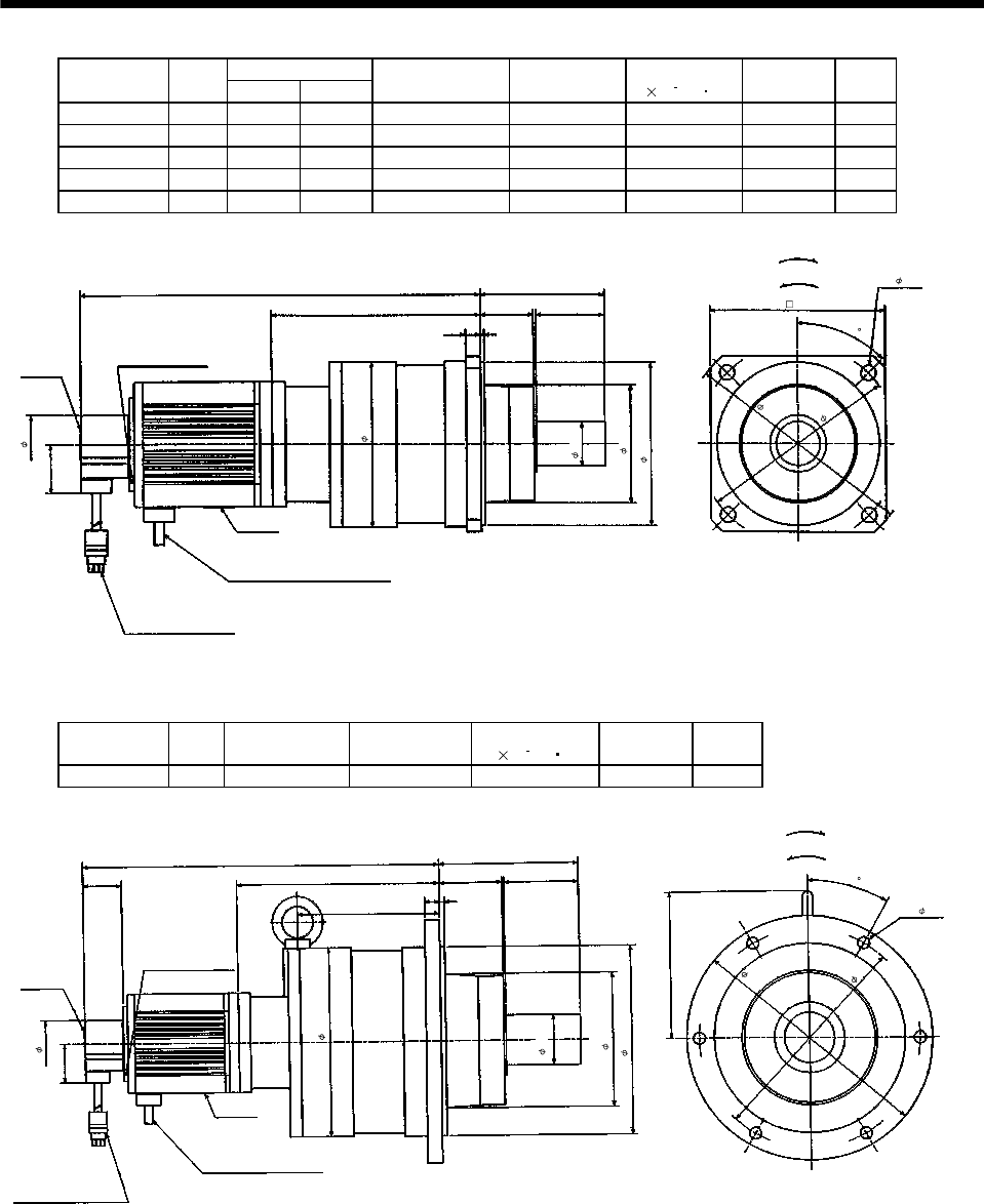
7 - 38
7. OUTLINE DIMENSION DRAWINGS
Variable Dimensions
Model Output
[W] LH
Reduction Gear
Model Reduction Ratio Inertia Moment
J[ 10 4kg m2]Backlash Mass
[kg]
HA-FF43G2 400 323.5 169 BL2-20B-04MES 1/20 2.378 3min. max 14.2
HA-FF43G2 400 323.5 169 BL2-29B-04MES 1/29 2.010 3min. max 14.2
HA-FF43G2 400 333.5 179 BL2-45B-04MES 1/45 1.388 3min. max 14.2
HA-FF63G2 600 338.5 169 BL2-20B-06MES 1/20 2.603 3min. max 14.8
HA-FF63G2 600 338.5 169 BL2-29B-06MES 1/29 2.235 3min. max 14.8
Motor plate
Encoder cable 0.3m
With connector 172169-9
(AMP)
12
H
35h6
140
4- 12
Top
Bottom
130h7
100
BottomTop
39
Caution plate
Earth terminal M3 screw
(Opposite side)
47
3
55
94
132
43
L
185
160
Z694741*
(Note)[Unit: mm]
"Rotation direction" For forward rotation command
For reverse rotation command
Power supply cable
VCTF 3-1.25 0.5m
(With end-insulated round crimping terminal 1.25-4)
2
Red: Phase U
White: Phase V
Black: Phase W
45
Note: The dimensions without tolerances are reference dimensions.
Model Output
[W]
Reduction Gear
Model Reduction Ratio Inertia Moment
J[ 10 4kg m2]Backlash Mass
[kg]
HA-FF63G2 600 BL3-45B-06MES 1/45 3.13 3min. max. 29.8
140
39
117.5
47
3
70.5
2
01
115
39
6375
Earth terminal
M3 screw
(Opposite side)
Bottom
Top
Motor plate
Bottom
Top
155
Z694742A
6- 12
Power supply cable
VCTF 3-1.25 0.5m
(With end-insulated round
crimping terminal 1.25-4)
2
Red: Phase U
White: Phase V
Black: Phase W
Encoder cable 0.3m
With connector 172169-9
(AMP)
(Note)[Unit: mm]
"Rotation direction" For forward rotation command
For reverse rotation command
Caution plate
190
135
197h7
50h5
245
220
30
Note: The dimensions without tolerances are reference dimensions.
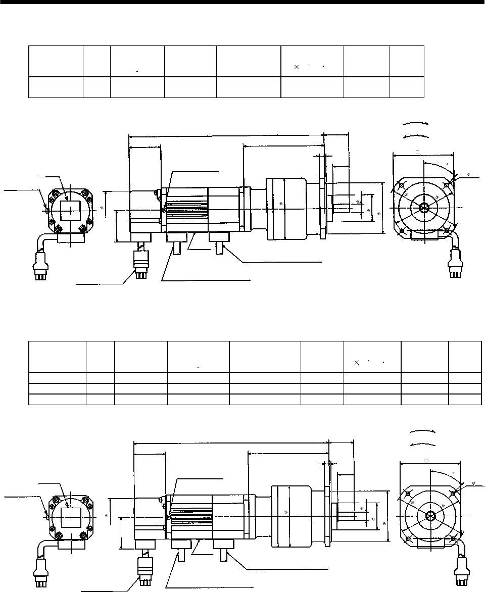
7 - 39
7. OUTLINE DIMENSION DRAWINGS
(b) With electromagnetic brake
Model Output
[W]
Brake static
friction torque
[N m]
Reduction
Gear Model Reduction Ratio Inertia Moment
J[ 10 4kg m2]Backlash Mass
[kg]
HA-FF053BG2 50 0.39 BM2-05B-
A5MES 1/5 0.128 3min. max. 2.6
30
89
10h6
4- 4.5
78
39
62h7
33
75
99
20
Bottom
Top
‰º
Top
Caution plate
62
240
Earth terminal M3
Bottom
74
39
47
Z694851*
Earth terminal M3 screw
(Opposite side)
"Rotation direction"
For forward rotation command
For reverse rotation command
(Note)[Unit: mm]
Brake lead
VCTF 2-0.52 0.5m
(With end-insulated round crimping terminal 1.25-4)
Motor plate
Power supply cable
VCTF 3-1.252 0.5m
(With end-insulated round crimping terminal 1.25-4)
Red: Phase U
White: Phase V
Black: Phase W
Encoder cable 0.3m
With connector 172169-9
(AMP)
45
Note: The dimensions without tolerances are reference dimensions.
Model Output
[W]
Variable
dimensions L
Brake static
friction torque
[N m]
Reduction Gear
Model
Reduction
Ratio
Inertia Moment
J[ 10 4kg m2]Backlash Mass
[kg]
HA-FF053BG2 50 240 0.39 BM2-05B-A5MES 1/10 0.125 3 min. max. 2.6
HA-FF053BG2 50 240 0.39 BM2-15B-A5MES 1/15 0.123 3 min. max. 2.6
HA-FF13BG2 100 257 0.39 BM2-05B-01MES 1/5 0.160 3 min. max. 2.8
30
89
10h6
4- 4.5
78
39
62h7
33
75
99
20
Bottom
Top
Motor plate
Top
Caution plate
62
L
Earth terminal M3
Bottom
74
39
47
Z694812*
Red: Phase U
White: Phase V
Black: Phase W
"Rotation direction" For forward rotation command
For reverse rotation command
(Note)[Unit: mm]
Earth terminal M3 screw
(Opposite side)
Brake lead
VCTF 2-0.52 0.5m
(With end-insulated round crimping terminal 1.25-4)
Power supply cable
VCTF 3-1.252 0.5m
(With end-insulated round crimping terminal 1.25-4)
Encoder cable 0.3m
With connector 172169-9
(AMP)
45
Note: The dimensions without tolerances are reference dimensions.
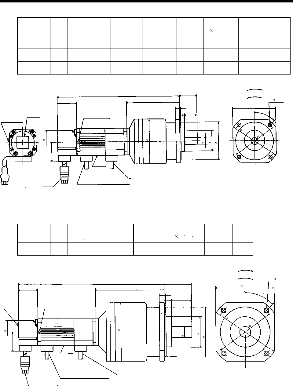
7 - 40
7. OUTLINE DIMENSION DRAWINGS
Model Output
[W]
Variable dimensions
L
Brake static
friction torque
[N m]
Reduction Gear
Model
Reduction
Ratio
Inertia Moment
J[ 10 4kg m2]Backlash Mass
[kg]
HA-FF053BG2 50 248 0.39 BM3-25B-
A5MES 1/25 0.120 3 min. max. 3.2
HA-FF13BG2 100 265 0.39 BM3-10B-
01MES 1/10 0.183 3 min. max. 3.4
HA-FF13BG2 100 265 0.39 BM3-15B-
01MES 1/15 0.173 3 min. max. 3.4
35
14 h6
4- 5.5
39
76h7
41
87
107
25
Motor plate
Top
Caution plate
82
L
Earth terminal M3
Bottom
87
39
47
Z694813*
9
Red: Phase U
White: Phase V
Black: Phase W
2
"Rotation direction" For forward rotation command
For reverse rotation command
(Note)[Unit: mm]
2
Brake lead
VCTF 2-0.5 0.5m
(With end-insulated round crimping terminal 1.25-4)
Bottom
Top
Power supply cable
VCTF 3-1.25 0.5m
(With end-insulated round crimping terminal 1.25-4)
Encoder cable 0.3m
With connector 172169-9
(AMP)
Earth terminal M3 screw
(Opposite side)
102
90
45
Note: The dimensions without tolerances are reference dimensions.
Model Output
[W]
Brake static
friction torque
[N m]
Reduction Gear
Model Reduction Ratio Inertia Moment
J[ 10 4kg m2]Backlash Mass
[kg]
HA-FF13BG2 100 0.39 BM4-25B-
01MES 1/25 0.308 3 min. max. 5.3
55
140
22h6
4- 6.6
122
39
100h7
61
118
139
40
Bottom
Top
Motor plate
Caution plate
103
297
Bottom
118
39
47
Z694814*
14
Top
"Rotation direction"
For forward rotation command
For reverse rotation command
(Note)[Unit: mm]
Earth terminal M3 screw
(Opposite side)
2
Brake lead
VCTF 2-0.5 0.5m
(With end-insulated round crimping terminal 1.25-4)
2
Power supply cable
VCTF 3-1.25 0.5m
(With end-insulated round
crimping terminal 1.25-4)
Red: Phase U
White: Phase V
Black: Phase W
Encoder cable 0.3m
With connector 172169-9
(AMP)
45
Note: The dimensions without tolerances are reference dimensions.
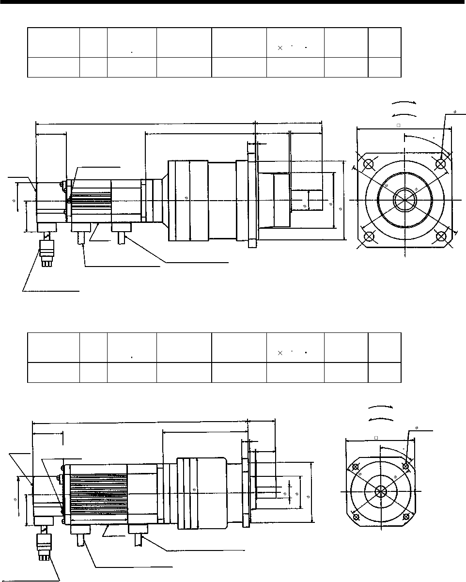
7 - 41
7. OUTLINE DIMENSION DRAWINGS
Model Output
[W]
Brake static
friction torque
[N m]
Reduction Gear
Model Reduction Ratio Inertia Moment
J[ 10 4kg m2]Backlash Mass
[kg]
HA-FF13BG2 100 0.39 BL1-45B-
01MES 1/45 0.298 3 min. max. 6.3
85
155
4- 12
130
39
100h7
70
102
151
40
Earth terminal M3 screw
(Opposite side)
Bottom
Top
Motor plate
ã
Caution plate
43
3
Encoder cable 0.3m
With connector 172169-9
(AMP)
308.5
Bottom
120
39
Z694792*
10
Top
Red: Phase U
White: Phase V
Black: Phase W
"Rotation direction"
For forward rotation command
For reverse rotation command
(Note)[Unit: mm]
2
Brake lead
VCTF 2-0.5 0.5m
(With end-insulated round crimping terminal 1.25-4)
2
Power supply cable
VCTF 3-1.25 0.5m
(With end-insulated round
crimping terminal 1.25-4)
47
25h6
45
Note: The dimensions without tolerances are reference dimensions.
Model Output
[W]
Brake static
friction torque
[N m]
Reduction Gear
Model Reduction Ratio Inertia Moment
J[ 10 4kg m2]Backlash Mass
[kg]
HA-FF23BG2 200 1.2 BM3-05B-
02MES 1/5 0.558 3 min. max. 4.4
35
102
14h 6
4- 5.5
90
39
76h7
41
87
109
25
Earth terminal M3 screw
(Opposite side)
BottomTop
Motor plate
Caution plate
82
277
Bottom
87
39
47
Z694815*
9
Top
Red: Phase U
White: Phase V
Black: Phase W
"Rotation direction"
For forward rotation command
For reverse rotation command
(Note)[Unit: mm]
2
Brake lead
VCTF 2-0.5 0.5m
(With end-insulated round crimping terminal 1.25-4)
2
Power supply cable
VCTF 3-1.25 0.5m
(With end-insulated round crimping terminal 1.25-4)
Encoder cable 0.3m
W
ith connector 172169-9
(AMP)
45
Note: The dimensions without tolerances are reference dimensions.
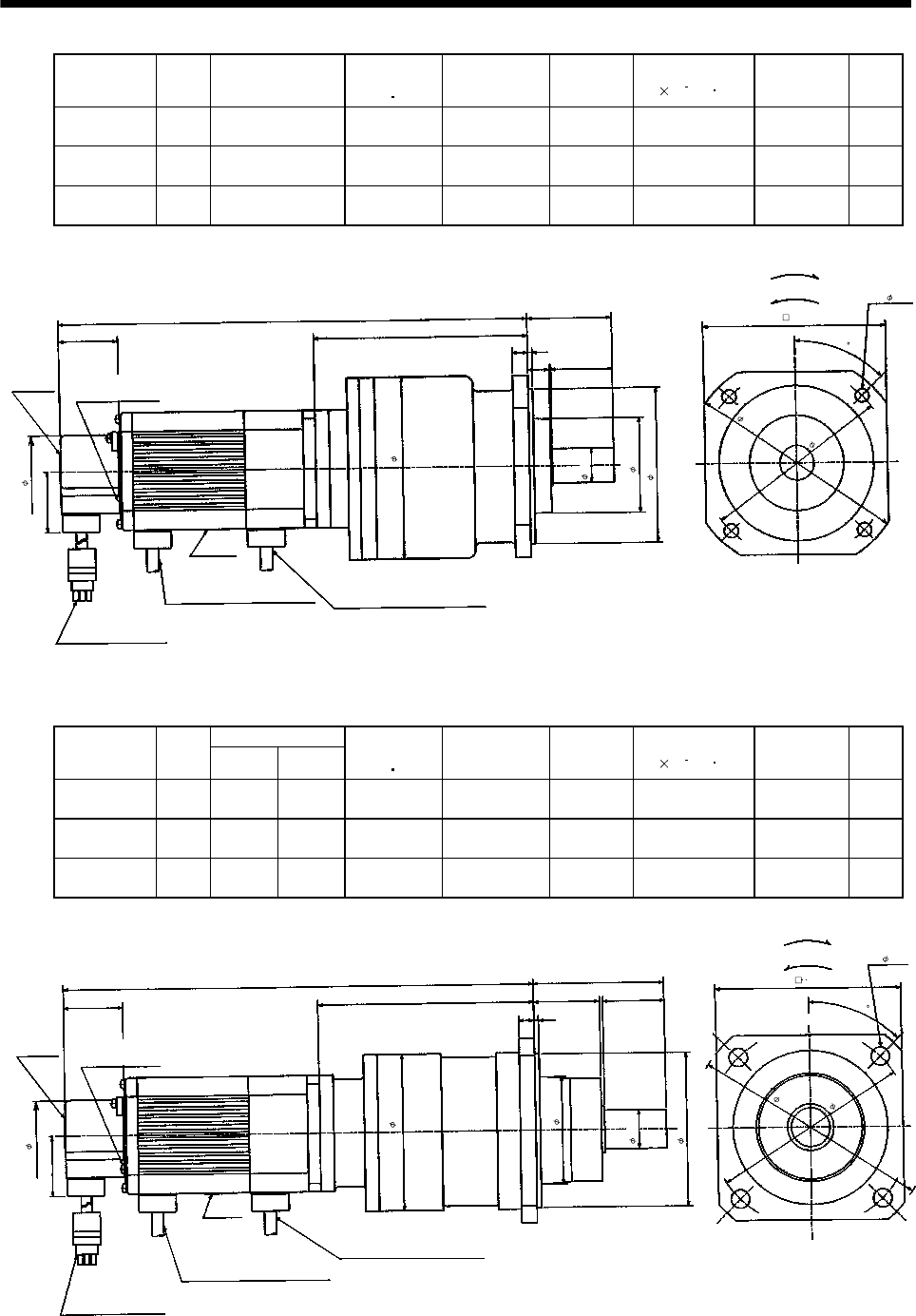
7 - 42
7. OUTLINE DIMENSION DRAWINGS
Model Output
[W]
Variable dimensions
L
Brake static
friction torque
[N m]
Reduction Gear
Model
Reduction
Ratio
Inertia Moment
J[ 10 4kg m2]Backlash Mass
[kg]
HA-FF23BG2 200 307 1.2 BM4-10B-
02MES 1/10 0.778 3 min. max. 6.4
HA-FF23BG2 200 307 1.2 BM4-15B-
02MES 1/15 0.75 3 min. max. 6.4
HA-FF33BG2 300 324.5 1.2 BM4-10B-
03MES 1/10 0.928 3 min. max. 6.7
55
140
22h6
4- 6.6
122
39
100h7
61
118
139
40
Earth terminal M3 screw
(Opposite side)
Bottom
Top
Motor plate
Caution plate
103
L
Bottom
39
47
Z694816*
14
Top
"Rotation direction"
For forward rotation command
(Note)[Unit: mm]
For reverse rotation command
2
Power supply cable
VCTF 3-1.25 0.5m
(With end-insulated round
crimping terminal 1.25-4)
Red: Phase U
White: Phase V
Black: Phase W
Encoder cable 0.3m
With connector 172169-9
(AMP)
2
Brake lead
VCTF 2-0.5 0.5m
(With end-insulated round crimping terminal 1.25-4)
118
45
Note: The dimensions without tolerances are reference dimensions.
Variable dimensions
Model Output
[W] LH
Brake static
friction torque
[N m]
Reduction Gear
Model
Reduction
Ratio
Inertia Moment
J[ 10 4kg m2]Backlash Mass
[kg]
HA-FF23BG2 200 311.5 144 1.2 BL1-20B-
02MES 1/20 0.885 3 min. max. 7.4
HA-FF23BG2 200 314.5 147 1.2 BL1-29B-
02MES 1/29 0.765 3 min. max. 7.4
HA-FF33BG2 300 329.5 144 1.2 BL1-20B-
03MES 1/20 1.013 3 min. max. 7.7
85
155
25h6
4- 12
130
39
100h7
70
102
H
40
Earth terminal M3 screw
(Opposite side)
Bottom
Top
Motor plate
Caution plate
103
L
Bottom
120
39
47
Z694793*
43
Top
Red: Phase U
White: Phase V
Black: Phase W
2
"Rotation direction"
For forward rotation command
(Note)[Unit: mm]
For reverse rotation command
2
Brake lead
VCTF 2-0.5 0.5m
(With end-insulated round crimping terminal 1.25-4)
Power supply cable
VCTF 3-1.25 0.5m
(With end-insulated round
crimping terminal 1.25-4)
Encoder cable 0.3m
With connector 172169-9
(AMP)
45
Note: The dimensions without tolerances are reference dimensions.
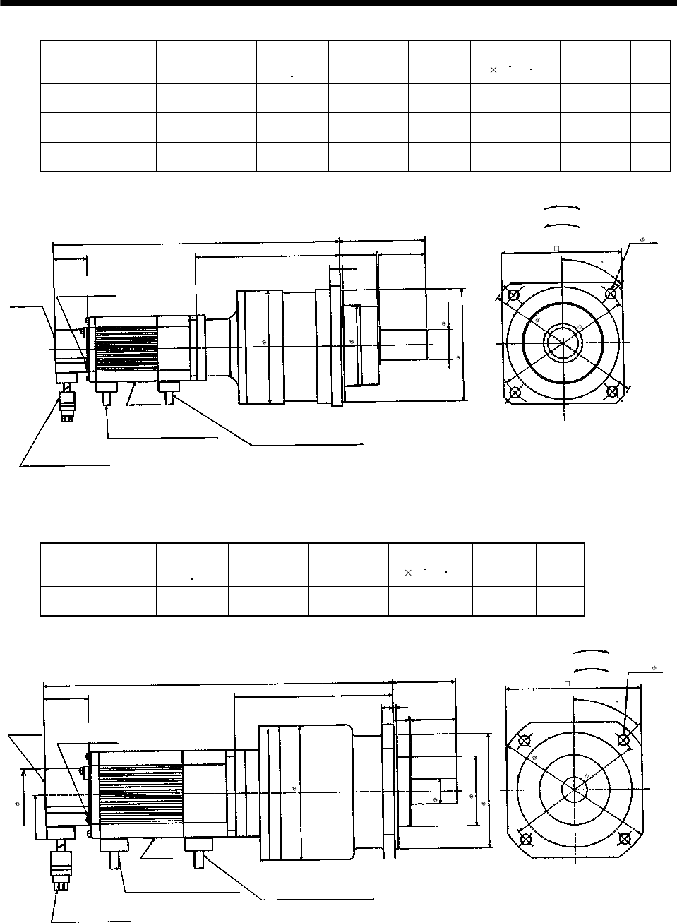
7 - 43
7. OUTLINE DIMENSION DRAWINGS
Model Output
[W]
Variable dimensions
L
Brake static
friction torque
[N m]
Reduction Gear
Model
Reduction
Ratio
Inertia Moment
J[ 10 4kg m2]Backlash Mass
[kg]
HA-FF23BG2 200 336 1.2 BL2-45B-
02MES 1/45 0.895 3 min. max. 12.9
HA-FF33BG2 300 353.5 1.2 BL2-29B-
03MES 1/29 1.668 3 min. max. 13.2
HA-FF33BG2 300 363.5 1.2 BL2-45B-
03MES 1/45 1.045 3 min. max. 13.2
100
185
35h6
4- 12
160
39
130h7
94
132
168
3
Earth terminal M3 screw
(Opposite side)
Bottom
Top
Motor plate
Caution plate
4355
L
Bottom
140
Z694794*
12
Top
Power supply cable
VCTF 3-1.25 0.5m
"Rotation direction"
For forward rotation command
(Note)[Unit: mm]
For reverse rotation command
2
Brake lead
VCTF 2-0.5 0.5m
(With end-insulated round crimping terminal 1.25-4)
Encoder cable 0.3m
With connector 172169-9
(AMP)
(With end-insulated round
crimping terminal 1.25-4)
Red: Phase U
White: Phase V
Black: Phase W
2
45
Note: The dimensions without tolerances are reference dimensions.
Model Output
[W]
Brake static
friction torque
[N m]
Reduction Gear
Model Reduction Ratio Inertia Moment
J[ 10 4kg m2]Backlash Mass
[kg]
HA-FF33BG2 300 1.2 BM4-05B-
03MES 1/5 0.95 3 min. max. 6.7
55
140
22h6
4- 6.6
122
39
100h7
61
118
139
40
Bottom
Top
Motor plate
Caution plate
103
Encoder cable 0.3m
With connector 172169-9
(AMP)
324.5
Bottom
118
39
47
Z694817*
14
Top
"Rotation direction"
For forward rotation command
(Note)[Unit: mm]
For reverse rotation command
2
Brake lead
VCTF 2-0.5 0.5m
(With end-insulated round crimping terminal 1.25-4)
Power supply cable
VCTF 3-1.25 0.5m
2
Earth terminal M3 screw
(Opposite side)
(With end-insulated round
crimping terminal 1.25-4)
Red: Phase U
White: Phase V
Black: Phase W
45
Note: The dimensions without tolerances are reference dimensions.
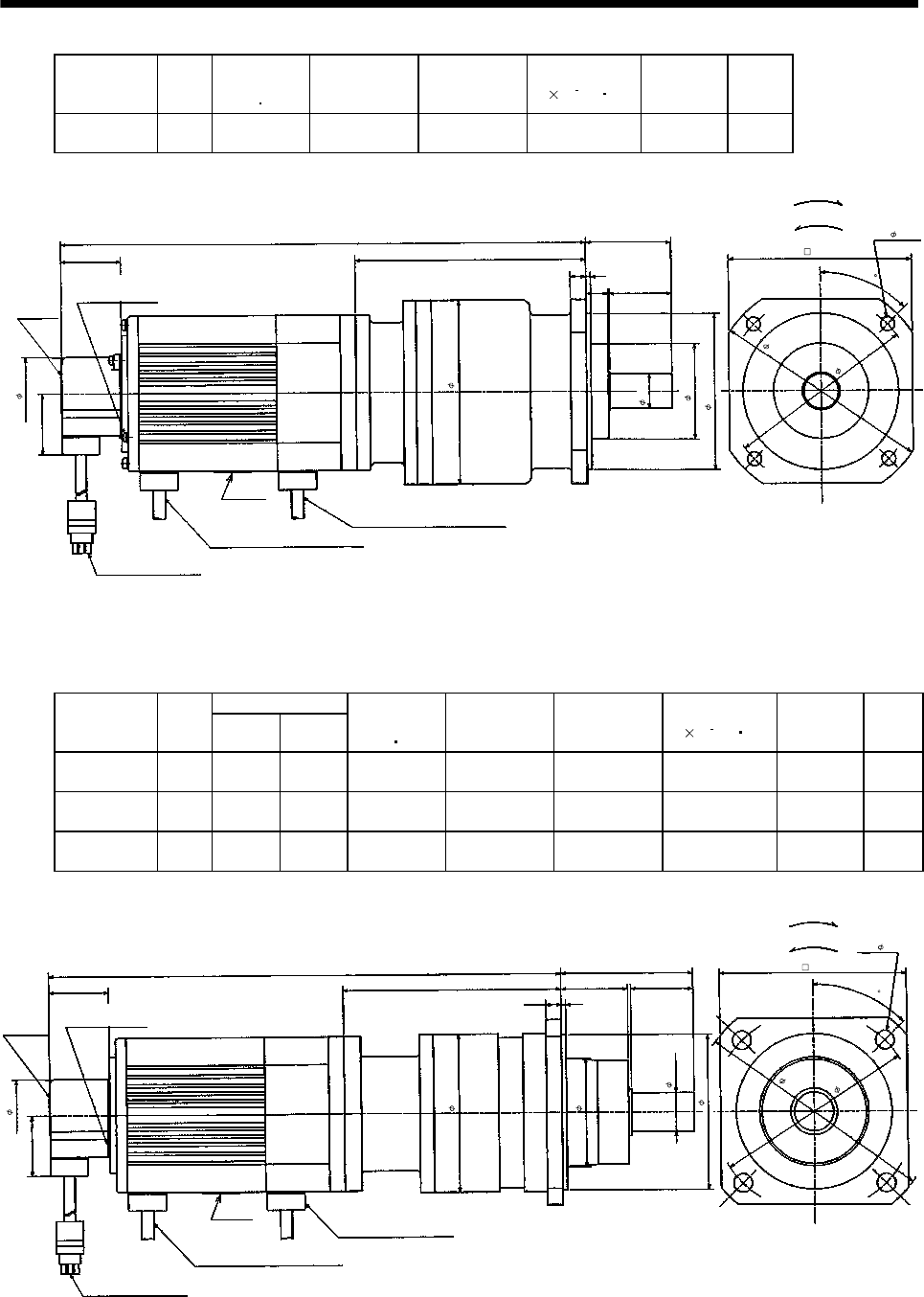
7 - 44
7. OUTLINE DIMENSION DRAWINGS
Model Output
[W]
Brake static
friction torque
[N m]
Reduction Gear
Model Reduction Ratio Inertia Moment
J[ 10 4kg m2]Backlash Mass
[kg]
HA-FF43BG2 400 2.3 BM4-05B-
04MES 1/5 1.643 3 min. max. 8.5
55
140
22h6
4- 6.6
122
39
100h7
61
118
149
40
Earth terminal M3 screw
(Opposite side)
BottomTop
Motor plate
Caution plate
103
Encoder cable 0.3m
With connector 172169-9
(AMP)
340.5
Bottom
118
39
47
Z694818*
14
Top
Red: Phase U
White: Phase V
Black: Phase W
"Rotation direction"
For forward rotation command
(Note)[Unit: mm]
For reverse rotation command
2
Brake lead
VCTF 2-0.5 0.5m
(With end-insulated round crimping terminal 1.25-4)
Power supply cable
VCTF 3-1.25 0.5m
(With end-insulated round crimping terminal 1.25-4)
2
45
Note: The dimensions without tolerances are reference dimensions.
Variable dimensions
Model Output
[W] LH
Brake static
friction torque
[N m]
Reduction Gear
Model Reduction Ratio Inertia Moment
J[ 10 4kg m2]Backlash Mass
[kg]
HA-FF43BG2 400 332.5 141 2.3 BL1-09B-
04MES 1/9 1.543 3 min. max. 9.0
HA-FF63BG2 600 337.5 131 2.3 BL1-05B-
06MES 1/5 1.858 3 min. max. 9.6
HA-FF63BG2 600 347.5 141 2.3 BL1-09B-
06MES 1/9 1.768 3 min. max. 9.6
85
155
25h6
4- 12
130
39
100h7
70
102
H
40
Earth terminal M3 screw
(Opposite side)
Bottom
Top
Motor plate
Caution
plate
103
Encoder cable 0.3m
With connector 172169-9
(AMP)
L
Bottom
120
39
47
Z694795*
Top
43
Red: Phase U
White: Phase V
Black: Phase W
2
"Rotation direction"
For forward rotation command
(Note)[Unit: mm]
For reverse rotation command
2
Brake lead
VCTF 2-0.5 0.5m
(With end-insulated round crimping terminal 1.25-4)
Power supply cable
VCTF 3-1.25 0.5m
(With end-insulated round crimping terminal 1.25-4)
45
Note: The dimensions without tolerances are reference dimensions.
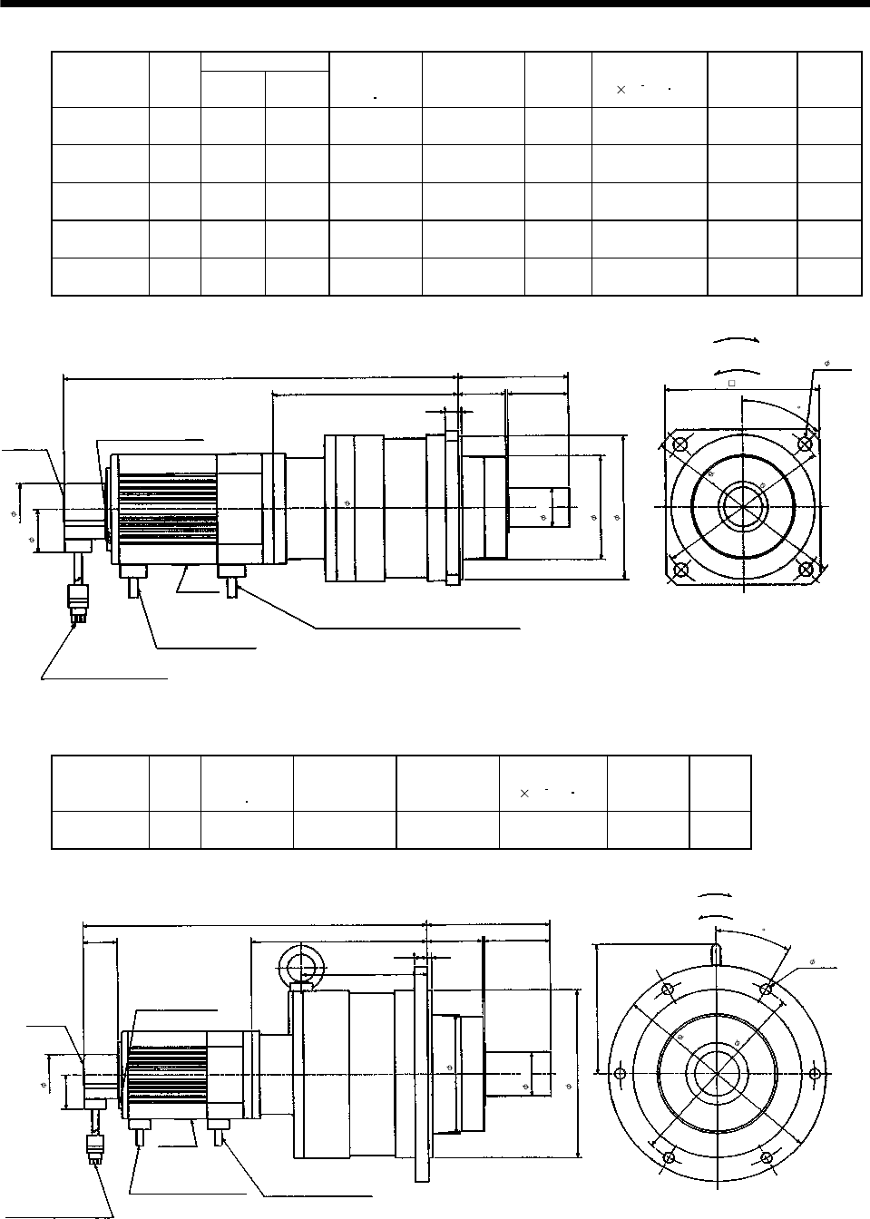
7 - 45
7. OUTLINE DIMENSION DRAWINGS
Variable dimensions
Model Output
[W] LH
Brake static
friction torque
[N m]
Reduction Gear
Model
Reduction
Ratio
Inertia Moment
J[ 10 4kg m2]Backlash Mass
[kg]
HA-FF43BG2 400 360.5 169 2.3 BL2-20B-
04MES 1/20 2.623 3 min. max. 15
HA-FF43BG2 400 360.5 169 2.3 BL2-29B-
04MES 1/29 2.36 3 min. max. 15
HA-FF43BG2 400 370.5 179 2.3 BL2-45B-
04MES 1/45 1.738 3 min. max. 15
HA-FF63BG2 600 375.5 169 2.3 BL2-20B-
06MES 1/20 2.953 3 min. max. 15.6
HA-FF63BG2 600 375.5 169 2.3 BL2-29B-
06MES 1/29 2.585 3 min. max. 15.6
3.94
7
.28
4- 0.47
H
2.
17
0.470.12
L
5.51
Z694796*
1.69
Bottom
Top
Bottom
Top
Motor plate
Encoder cable 11.8in
With connector 172169-9
(AMP)
Red: Phase U
White: Phase V
Black: Phase W
Power supply cable
VCTF 0.05 196.9in
(With end-insulated round
crimping terminal 0.05-4)
2
Brake lead
VCTF 0.02 19.7in
(With end-insulated round crimping terminal 0.05-4)
2
(Note)[Unit:in]
For forward
rotation command
For reverse
rotation command
Earth terminal M3 screw
(Opposite side)
Caution plate
"Rotation direction"
1.85
1.54
5.20
3.70
5.12
6
.30
45
1.38
Note: The dimensions without tolerances are reference dimensions.
Model Output
[W]
Brake static
friction torque
[N m]
Reduction Gear
Model Reduction Ratio Inertia Moment
J[ 10 4kg m2]Backlash Mass
[kg]
HA-FF63BG2 600 2.3 BM3-45B-
06MES 1/45 3.475 3 min. max. 33.7
140
245
50h6
6- 12
220
39
190h7
11
7
.5
135
201
75
Earth terminal M3 screw
(Opposite side)
Bottom
Top
Motor plate
Caution plate
155
Encoder cable 0.3m
With connector 172169-9
(AMP)
407.5
Bottom
39
Z694797A
Top
63
115
2
"Rotation direction"
For forward rotation command
(Note)[Unit: mm]
For reverse rotation command
2
Brake lead
VCTF 2-0.5 0.5m
(With end-insulated round crimping terminal 1.25-4)
Power supply cable
VCTF 3-1.25 0.5m
47
(With end-insulated round
crimping terminal 1.25-4)
Red: Phase U
White: Phase V
Black: Phase W
30
Note: The dimensions without tolerances are reference dimensions.
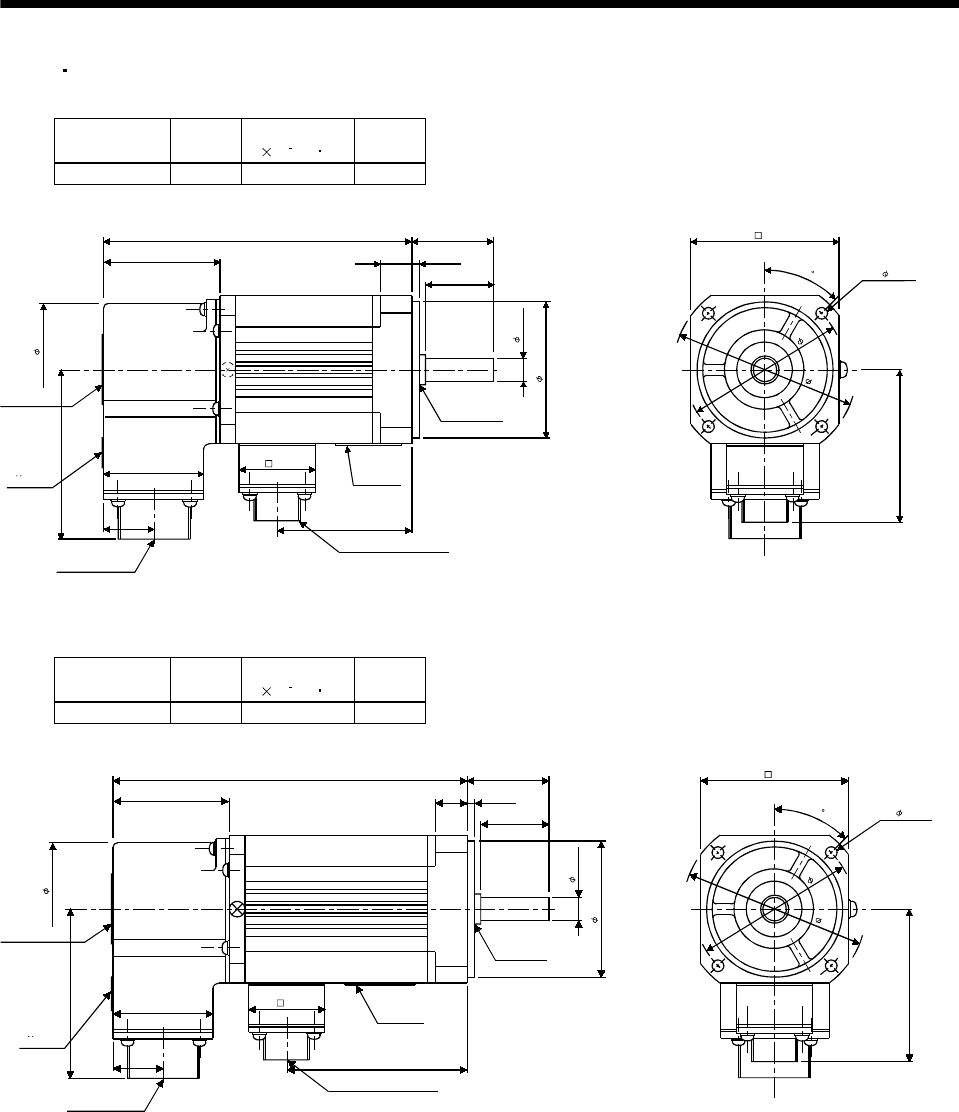
7 - 46
7. OUTLINE DIMENSION DRAWINGS
(5) EN UL/C-UL Standard-Compliant model
(a) Standard (without electromagnetic brake, without reduction gear)
Model Output
[W]
Inertia Moment
J[ 10 4kg m2]
Mass
[kg]
HA-FF053C-UE 50 0.063 1.8
(Note)[Unit: mm]
TUV plate
Caution plate
74
Bottom
Top
Bottom
Top 41
20 49.5
Motor plate
Top Bottom
Oil seal
GM10204B
120 30
12 2.5
25
46
Power supply connector
CE05-2A14S-2PD-B
4- 4.5
45
69
Encoder connector
MS3102A20-29P
32
54
47
8h6
50h7
60
68
Note: The dimensions without tolerances are reference dimensions.
BC07316A
Model Output
[W]
Inertia Moment
J[ 10 4kg m2]
Mass
[kg]
HA-FF13C-UE 100 0.10 2
(Note)[Unit: mm]
Caution plate
TUV plate
Bottom
Top
Bottom
Top
Encoder connector
MS3102A20-29P
46
137
Oil seal
S10207B
Motor plate
Top Bottom
Power supply connector
CE05-2A14S-2PD-B
45
69
54
4- 4.5
60
68
30
12 2.5
25
8h6
50h7
74
47
41
20 66.5
32
Note: The dimensions without tolerances are reference dimensions.
BC07331A
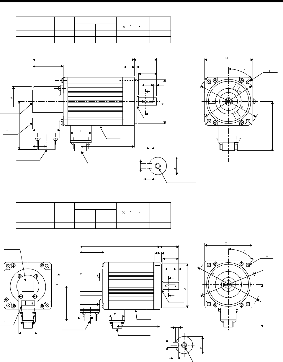
7 - 47
7. OUTLINE DIMENSION DRAWINGS
Variable Dimensions
Model Output
[W] LKL
Inertia Moment
J[ 10 4kg m2]
Mass
[kg]
HA-FF23C-UE 200 145 71.5 0.35 2.6
HA-FF33C-UE 300 162 89 0.50 2.9
(Note)[Unit: mm]
46
L
Caution plate
TUV plate
Encoder connector
MS3102A20-29P
Bottom
Top
Bottom
Top
Motor plate
KL 2.5
4
4
M4 threads, depth 15
Oil seal
S15307B
A
A
16 4
70h7
Top Bottom
45
79
Power supply connector
CE05-2A14S-2PD-B
Section AA
11h6
90
100
4- 5.5
76
74
47
41
20
32
30
14 3
25
Note: The dimensions without tolerances are reference dimensions. BC07332A
Variable Dimensions
Model Output
[W] LKL
Inertia Moment
J[ 10 4kg m2]
Mass
[kg]
HA-FF43C-UE 400 169 93 0.98 4.7
HA-FF63C-UE 600 184 108 1.2 5.3
(Note)[Unit: mm]
Caution plate
TUV plate
44
L40
16 3
35
25 5
A
A
Oil seal
S17308B
Motor plate
Encoder connector
MS3102A20-29P Power supply connector
CE05-2A14S-2PD-B
KL
BottomTop
M5 threads, depth 20
Section AA
3
5
5
95h7
45
100
91
47
16h6
4- 9
115
135
EC
Top
Bottom
Top
Bottom
74
47
41
20 32
Note: The dimensions without tolerances are reference dimensions.
BC07314B
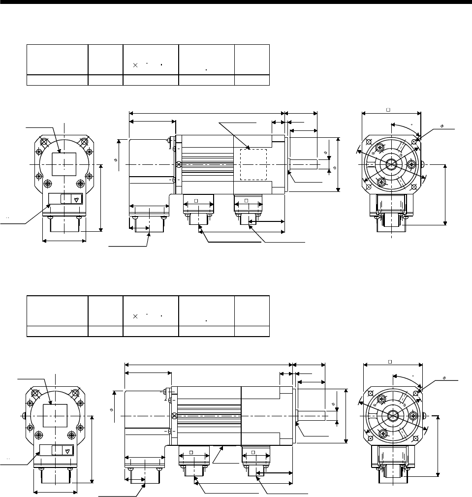
7 - 48
7. OUTLINE DIMENSION DRAWINGS
(b) With electromagnetic brake
Model Output
[W]
Inertia Moment
J[ 10 4kg m2]
Brake static
friction torque
[N m]
Mass
[kg]
HA-FF053CB-UE 50 0.08 0.39 2.1
(Note)[Unit: mm]
Caution plate
TUV plate
Bottom
Top
CE
44
47
41
Encoder connector
MS3102A20-29P
20
155 30
Motor plate
(Opposite side)
BottomTop
12 2.5
25
Oil seal
GM10204B
8h6
50h7
84
Power supply connector
CE05-2A14S-2PD-B
Brake connector
MS3102A10SL-4P
35.5
45
67
60
68
4- 4.5
54
32
74
47
28
Bottom
Top
Note: The dimensions without tolerances are reference dimensions.
BC08269A
Model Output
[W]
Inertia Moment
J[ 10 4kg m2]
Brake static
friction torque
[N m]
Mass
[kg]
HA-FF13CB-UE 100 0.11 0.39 2.3
(Note)[Unit: mm]
Caution plate
TUV plate
Bottom
Top
CE
44 Encoder connector
MS3102A20-29P
172
Oil seal
S10207B
Power supply connector
CE05-2A14S-2PD-B
Brake connector
MS3102A10SL-4P
45
Motor plate
Bottom
Top
Bottom
Top
47
74
47
41
20 101
35.5
32 28
30
12 2.5
25
8h6
50h7
67
60
68
4- 4.5
54
Note: The dimensions without tolerances are reference dimensions. BC07372A
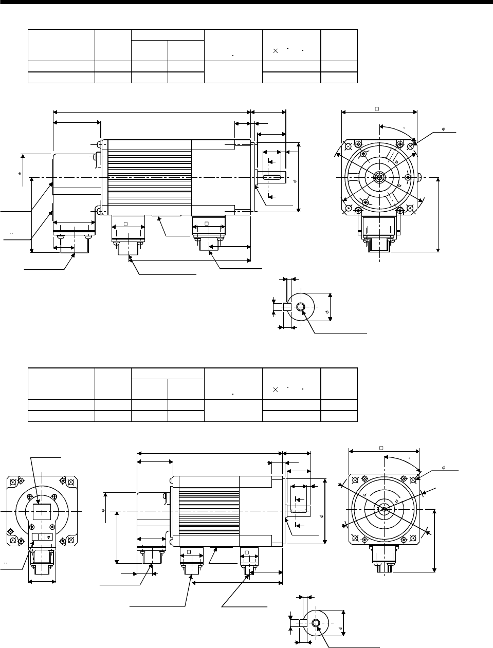
7 - 49
7. OUTLINE DIMENSION DRAWINGS
Variable Dimensions
Model Output
[W] LKL
Brake static
friction torque
[N m]
Inertia Moment
J[ 10 4kg m2]
Mass
[kg]
HA-FF23CB-UE 200 182 109 0.48 3.5
HA-FF33CB-UE 300 200 127 1.2 0.63 3.8
(Note)[Unit: mm]
Section AA
Caution plate
TUV plate
Encoder connector
MS3102A20-29P
Motor plate
Power supply connector
CE05-2A14S-2PD-B
Brake connector
MS3102A10SL-4P
30
L
14 3
25
A
A
16 4
70h7
Oil seal
S15307B
38.5
2.5
4
4
M4 threads, depth 15
KL
45
79
Bottom
Top
32
11h6
4- 5.5
76
90
100
74
41
20
46
47
28
Note: The dimensions without tolerances are reference dimensions. BC07357B
Variable Dimensions
Model Output
[W] LKL
Brake static
friction torque
[N m]
Inertia Moment
J[ 10 4kg m2]
Mass
[kg]
HA-FF43CB-UE 400 206 130 1.33 5.8
HA-FF63CB-UE 600 221 145 2.3 1.55 6.4
(Note)[Unit: mm]
Section AA
Caution plate
TUV plate
CE
41
20
44 Encoder connector
MS3102A20-29P
Power supply connector
CE05-2A14S-2PD-B
Motor plate
Brake connector
MS3102A10SL-4P
KL
42.5
Top Bottom
A
A
L
Oil seal
S17308B
16h6
3
5
5
M5 threads, depth 20
45
91
28
32
100
4- 9
115
135
Bottom
Top
Bottom
Top
47
74
47
40
16 3
35
95h7
5
25
Note: The dimensions without tolerances are reference dimensions. BC07333A
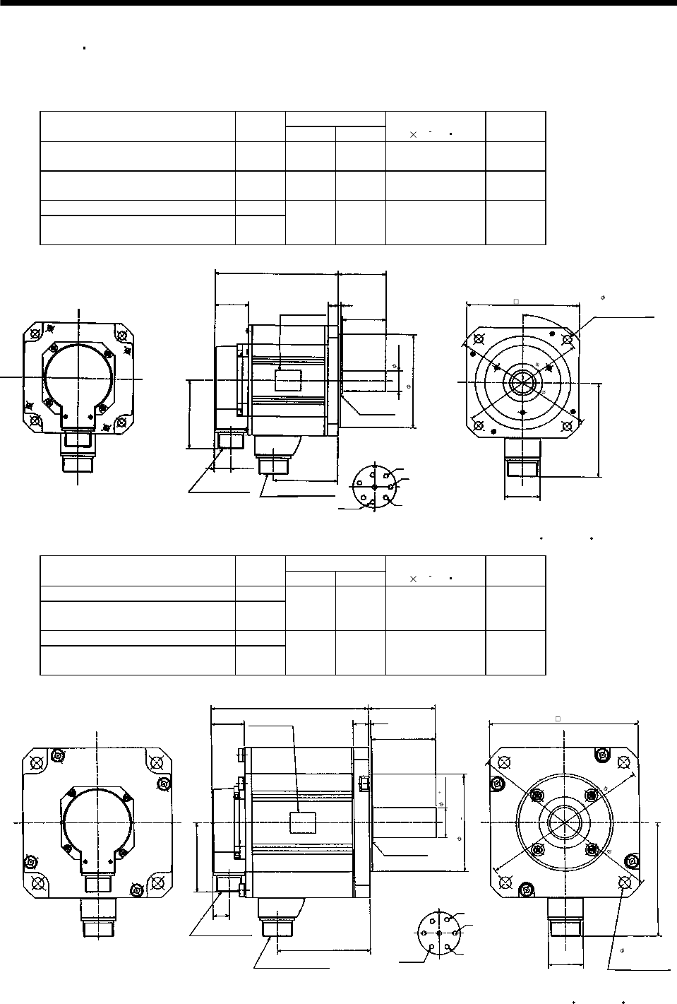
7 - 50
7. OUTLINE DIMENSION DRAWINGS
7.1.3 HC-SF HC-SFS series
If the above indicated value is exceeded, please consult us.
(1) Standard (without electromagnetic brake, without reduction gear)
Variable dimensions
Model Output
[kW] LKL
Inertia Moment
J[ 10 4kg m2]
Mass
[kg]
HC-SF52
HC-SF53
HC-SFS52
HC-SFS53 HC-SFS524 0.5 120 51.5 6.6 5.0
HC-SF102
HC-SF103
HC-SFS102
HC-SFS103 HC-SFS1024 1.0 145 76.5 13.7 7.0
HC-SF81 HC-SFS81 0.85
HC-SF152
HC-SF153
HC-SFS152
HC-SFS153 HC-SFS1524 1.5 170 101.5 20 9.0
KL
19.5
W
V
U
A
B
C
D
E
F
G
H
S30457B
MS3102A20-29P CE05-2A22-23P
81.5
39.5
L55
12 3
50
110h7
41
111
45°
Bottom
Top
Encoder connector Power supply connector
Oil seal
Motor flange direction
Earth
Power supply connector layout
CE05-2A22-23P
(Note)[Unit: mm]
Motor plate
(Opposite side)
Bottom
Top
130 4- 9 mounting hole
Use hexagon socket
head cap screw.
24h6
(BC11651* BC11757* BC11768*)
Z694854*
145
165
Note: The dimensions without tolerances are reference dimensions.
Variable dimensions
Model Output
[kW] LH
Inertia Moment
J[ 10 4kg m2]
Mass
[kg]
HC-SF121 HC-SFS121 1.2
HC-SF202
HC-SF203
HC-SFS202
HC-SFS203 HC-SFS2024 2.0 145 68.5 42.5 12.0
HC-SF201 HC-SFS201 2.0
HC-SF352
HC-SF353
HC-SFS352
HC-SFS353 HC-SFS3524 3.5 187 110.5 82.0 19.0
W
V
U
A
B
C
D
E
F
G
KL
19.5
81.5
39.5
L79
18 3
75
46
142
S40608B
MS3102A20-29P
CE05-2A24-10P
Encoder connector
Power supply connector
Oil seal
Motor flange direction
Power supply connector layout
CE05-2A24-10P
Motor plate
(Opposite side)
Bottom
Top
Earth
Bottom
Top
(Note)[Unit: mm
]
0.025
0
0
0.010
Z695393A*
4- 13.5 mounting hol
e
Use hexagon socket
head cap screw.
176
35
114.3
(BC11769* BC11652* BC11758*)
200
230
Note: The dimensions without tolerances are reference dimensions.
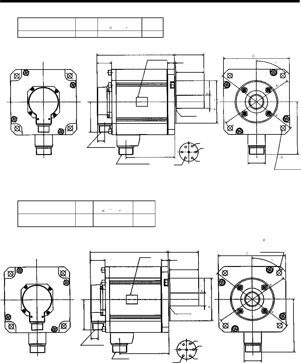
7 - 51
7. OUTLINE DIMENSION DRAWINGS
Model Output
[kW]
Inertia Moment
J[ 10-4kg m2]
Mass
[kg]
HC-SF301 HC-SFS301 3.0 101 23
W
V
U
A
B
C
D
E
F
G
131.5
19.5
81.5
39.5
208
18 3
75
46
142
S40608B
MS3102A20-29P
CE05-2A24-10P
Encoder connector
Power supply connector
Oil seal
Motor flange direction
Power supply connector layout
CE05-2A24-10P
Motor plate
(Opposite side)
Bottom
Top
4- 13.5 mounting
hole Use hexagon
socket head cap
screw.
Earth
Bottom
Top
(Note)[Unit: mm]
79
0
0.010
0.025
0
35
114.3
176
(BC11769*)
BC10628*
200
230
45
Note: The dimensions without tolerances are reference dimensions.
Model Output
[kW]
Inertia Moment
J[ 10 4kg m2]
Mass
[kg]
HC-SF502 HC-SFS502
HC-SFS5024 5.0 101 23
142
46
(Note)[Unit: mm]
Power supply connector layout
CE05-2A24-10P
A
B
C
D
E
FG
U
V
W
Power supply connector
CE05-2A24-10P
Encoder connector
MS3102A20-29P
Motor plate
(Opposite side)
208
39.5 18 3
75
79
S40608B
Oil seal
Top
Bottom
81.5
19.5
Top
Bottom
0
0.010
0.025
0
Earth
131.5
BC10626A
Motor flange direction
176
4- 13.5 mounting
hole Use hexagon
socket head cap
screw.
35
114.3
200
230
(BC11743*)
45
Note: The dimensions without tolerances are reference dimensions.
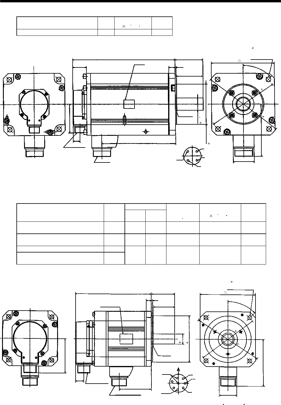
7 - 52
7. OUTLINE DIMENSION DRAWINGS
Model Output
[kW]
Inertia Moment
J[ 10 4kg m2]
Mass
[kg]
HC-SF702 HC-SFS702 HC-SFS7024 7.0 160 32
45°
58
(Note)[Unit: mm]
Power supply connector layout
CE05-2A32-17P
A
B
C
D
U
V
W
Power supply connector
CE05-2A32-17P
Encoder connector
MS3102A20-29P
Motor plate
(Opposite side)
292
39.5 18 3
75
79
S40608B
Oil seal
Top
Bottom
81.5
19.5
Top
Bottom
0
0.010
0.025
0
Earth
210.5 Motor flange direction
150
35
114.3
4- 13.5 mounting
hole Use hexagon
socket head cap
screw.
176
BC10856*
200
230
(BC11744*)
Note: The dimensions without tolerances are reference dimensions.
(2) With electromagnetic brake
Variable dimensions
Model Output
[kW] LKL
Brake static
friction torque
[N m]
Inertia Moment
J[ 10 4kg m2]
Mass
[kg]
HC-SF52B
HC-SF53B
HC-SFS52B
HC-SFS53B HC-SFS524B 0.5 153 51.5 8.5 8.3 7.5
HC-SF102B
HC-SF103B
HC-SFS102B
HC-SFS103B HC-SFS1024B 1.0 178 76.5 8.5 15.4 9.5
HC-SF81B HC-SFS81B 0.85
HC-SF152B
HC-SF153B
HC-SFS152B
HC-SFS153B HC-SFS1524B 1.5 203 101.5 8.5 21.7 11.5
KL
19.5
W
V
U
A
B
C
D
E
F
G
H
81.5
L55
12 3
50
41
111
45°
MS3102A20-29P
CE05-2A22-23P
Bottom
Top
Encoder connector
Power supply connector
Motor flange direction
Earth
Power supply connector layout
CE05-2A22-23P
(Note)[Unit: mm]
Motor plate
(Opposite side)
Brake
Oil seal
S30457B
130
4- 9 mounting hole
Use hexagon socket
head cap screw.
Z695005
(BC11653* BC11762* BC11775*
)
110h7
24h6
145
165
Note: The dimensions without tolerances are reference dimensions.
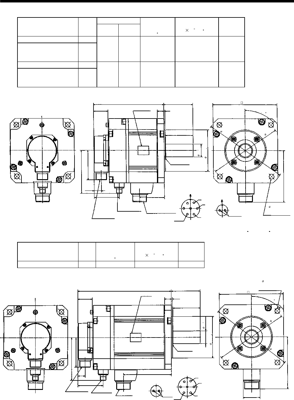
7 - 53
7. OUTLINE DIMENSION DRAWINGS
Variable dimensions
Model Output
[kW] LKL
Brake static
friction torque
[N m]
Inertia Moment
J[ 10 4kg m2]
Mass
[kg]
HC-SF121B HC-SFS121B 1.2
HC-SF202B
HC-SF203B
HC-SFS202B
HC-SFS203B
HC-SFS2024B
2.0 193 68.5 43.1 52.5 18.0
HC-SF201B HC-SFS201B 2.0
HC-SF352B
HC-SF353B
HC-SFS352B
HC-SFS353B
HC-SFS3524B
3.5 235 110.5 43.1 92.0 25.0
KL
19.5
81.5
39.5
L79
18 3
75
142
117
69
0.010
0
Bottom
Top
Power supply connector
CE05-2A24-10P
(Note)[Unit: mm]
Motor plate
(Opposite side)
MS3102A20-29P
Encoder connector
Brake connector
MS3102A10SL-4P
S40608B
Oil seal
Bottom
Top
W
V
U
A
B
C
D
E
F
GAB
Motor flange direction
Earth
Power supply connector layout
CE05-2A24-10P
Brake connector layout
MS3102A10SL-4P
Motor flange direction
Brake
Z695319D
4- 13.5 mounting hole
Use hexagon socket
head cap screw.
176
35
114.3 0.025
0
(BC11654* BC11763* BC11776*)
200
230
45
Note: The dimensions without tolerances are reference dimensions.
Model Output
[kW]
Brake static
friction torque
[N m]
Inertia Moment
J[ 10 4kg m2]
Mass
[kg]
HC-SF301B HC-SFS301B 3.0 43.1 111 29.0
0.025
0.010
Encoder connector
MS3102A20-29P
Motor plate
(Opposite side)
131.5
19.5
W
V
U
A
B
C
D
E
FG
Power supply
connector layout
CE05-2A24-10P
Motor flange direction
Oil seal
S40608B
81.5
39.5
256 79
18 3
75
142
Bottom
Top
Bottom
Top
Brake connector
MS3102A10SL-4P
117
69
Brake connector
layout
MS3102A10SL-4P
AB
Motor flange direction
Brake
(Note)[Unit: mm]
46
Earth
0
0
Power supply
connector
CE05-2A24-10P
35
114.3
4- 13.5 mounting hole
Use hexagon socket
head cap screw.
176
BC10823*
(BC11776*)
200
230
45
Note: The dimensions without tolerances are reference dimensions.

7 - 54
7. OUTLINE DIMENSION DRAWINGS
Model Output
[kW]
Brake static
friction torque
[N m]
Inertia Moment
J[ 10 4kg m2]
Mass
[kg]
HC-SF502B HC-SFS502B
HC-SFS5024B 5.0 43.1 111 29.0
0.025
0
0.010
0
Encoder connector
MS3102A20-29P
Motor plate
(Opposite side)
131.5
19.5
Earth
W
V
U
A
B
C
D
E
FG
Power supply connector layout
CE05-2A24-10P
Motor flange direction
Oil seal
S40608B
Power supply connector
CE05-2A24-10P
81.5
39.5
256 79
18 3
75
142
Bottom
Top
Bottom
Top
Brake connector
MS3102A10SL-4P
117
69
(Note)[Unit:mm]
46
Brake connector
layout
MS3102A10SL-4P
Brake
AB
Motor flange direction
176
4- 13.5 mounting hol
e
Use hexagon socket
head cap screw.
35
114.3
200
230
BC10627A
(
BC11750*
)
45
Note: The dimensions without tolerances are reference dimensions.
Model Output
[kW]
Brake static
friction torque
[N m]
Inertia Moment
J[ 10 4kg m2]
Mass
[kg]
HC-SF702B HC-SFS702B
HC-SFS7024B 7.0 43.1 170 38.0
0.025
0
0.010
0
Encoder connector
MS3102A20-29P
Motor plate
(Opposite side)
210.5
19.5
Earth
W
V
U
A
B
C
D
G
Power supply connector
layout
C
E
05
-2A
3
2-17P
Motor flange direction
Oil seal
S40608B
Power supply connector
CE05-2A32-17P
39.5
340 79
18 3
Bottom
Top
Bottom
Top
Brake connector
MS3102A10SL-4P
69
(Note)[Unit:mm]
58
Brake connector
layout
MS3102A10SL-4P
Brake
AB
150
Motor flange direction
117
75
81.5
35
114.3
176
BC10857*
4- 13.5 mounting hole
Use hexagon socket
head cap screw.
200
230
(BC11751*)
45
Note: The dimensions without tolerances are reference dimensions.
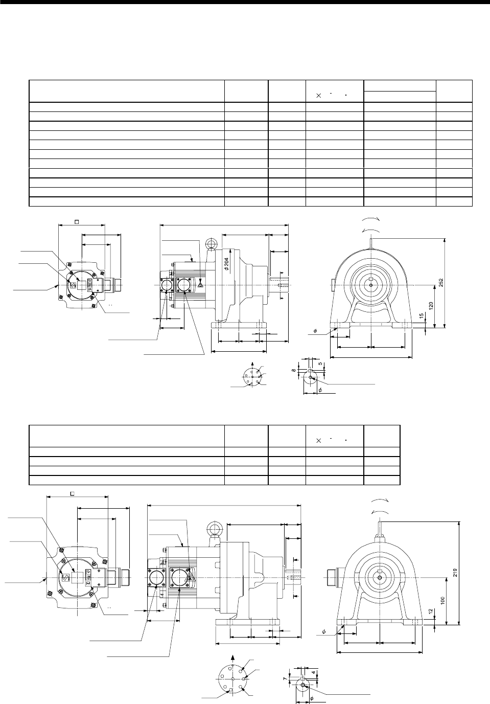
7 - 55
7. OUTLINE DIMENSION DRAWINGS
(3) With reduction gear for general industrial machine (leg type)
The outer frame of the reduction gear is a material surface such as casting. Its actual dimensions may
be 1 to 3mm larger than the drawing dimensions. Design the machine side with allowances.
(a) Without electromagnetic brake
Variable Dimensions
Model Output
[kW]
Reduction
Ratio
Inertia Moment
J[ 10
4
kg m2]L
Mass
[kg]
HC-SF52G1H HC-SFS52G1H HC-SFS524G1H 0.5 1/35 7.5 338 28
HC-SF52G1H HC-SFS52G1H HC-SFS524G1H 0.5 1/43 7.45 338 28
HC-SF52G1H HC-SFS52G1H HC-SFS524G1H 0.5 1/59 7.43 338 28
HC-SF102G1H HC-SFS102G1H HC-SFS1024G1H 1.0 1/6 16.8 363 30
HC-SF102G1H HC-SFS102G1H HC-SFS1024G1H 1.0 1/11 15.3 363 30
HC-SF102G1H HC-SFS102G1H HC-SFS1024G1H 1.0 1/17 14.9 363 30
HC-SF102G1H HC-SFS102G1H HC-SFS1024G1H 1.0 1/29 14.6 363 30
HC-SF102G1H HC-SFS102G1H HC-SFS1024G1H 1.0 1/35 14.6 363 30
HC-SF152G1H HC-SFS152G1H HC-SFS1524G1H 1.5 1/6 23.1 388 32
HC-SF152G1H HC-SFS152G1H HC-SFS1524G1H 1.5 1/11 21.5 388 32
HC-SF152G1H HC-SFS152G1H HC-SFS1524G1H 1.5 1/17 21.2 388 32
81.5
111
A
B
C
D
E
F
G
H
Z695739A
BC11798A BC26016A
10
Encoder connector
V
U
CE05-2A22-23P
MS3102A20-29P
W
Caution plate
(Note 2)
Motor plate
(Opposite side)
4- 14
130
Caution plate
Caution plate
Logo plate
(Side view of motor only)
Section AA
Power supply connector layout
Top
Bottom
Top
Bottom
TopBottom
For forward rotation command
"Rotation direction"
For reverse rotation command
TopBottom
Earth
CE05-2A22-23P
M8 screw, depth 20
Motor flange direction
TUV plate
(Note 2)
38h6
Power supply connector
(Note 1)[Unit: mm]
9595
230
55
131
L
8257.5 57.5
155
20
19.5
68.5
A
A
55
50
Note 1. The dimensions without tolerances are reference dimensions.
2. This caution plate is attached to the 400V class motors only, not to the 200V class.
Model Output
[kW]
Reduction
Ratio
Inertia Moment
J[ 10
4
kg m2]
Mass
[kg]
HC-SF52G1H HC-SFS52G1H HC-SFS524G1H 0.5 1/6 7.33 21
HC-SF52G1H HC-SFS52G1H HC-SFS524G1H 0.5 1/11 6.95 21
HC-SF52G1H HC-SFS52G1H HC-SFS524G1H 0.5 1/17 6.85 21
HC-SF52G1H HC-SFS52G1H HC-SFS524G1H 0.5 1/29 6.78 21
A
A
Z695738*
BC11797C BC26180B
A
B
C
D
E
F
G
H
325
121 35
40
75 75
180
8
19.5
68.5
32
15
604545
135
81.5
111
Encoder connector
Power supply connector
V
U
CE05-2A22-23P
MS3102A20-29P
W
Motor plate
Caution plate
(Opposite side)
28h6
130
Caution plate
Caution plate
(Note 2)
Logo plate
(Note 2)
Side view of motor only
4- 11
Section AA
Power supply connector layout
Top
Bottom
Top
Bottom
TopBottom
For forward rotation command
"Rotation direction"
For reverse rotation command
Top
Bottom
Earth
CE05-2A22-23P
M8 screw, depth 20
Motor flange direction
TUV plate
(Note 1)[Unit: mm]
Note 1. The dimensions without tolerances are reference dimensions.
2. This caution plate is attached to the 400V class motors only, not to the 200V class.
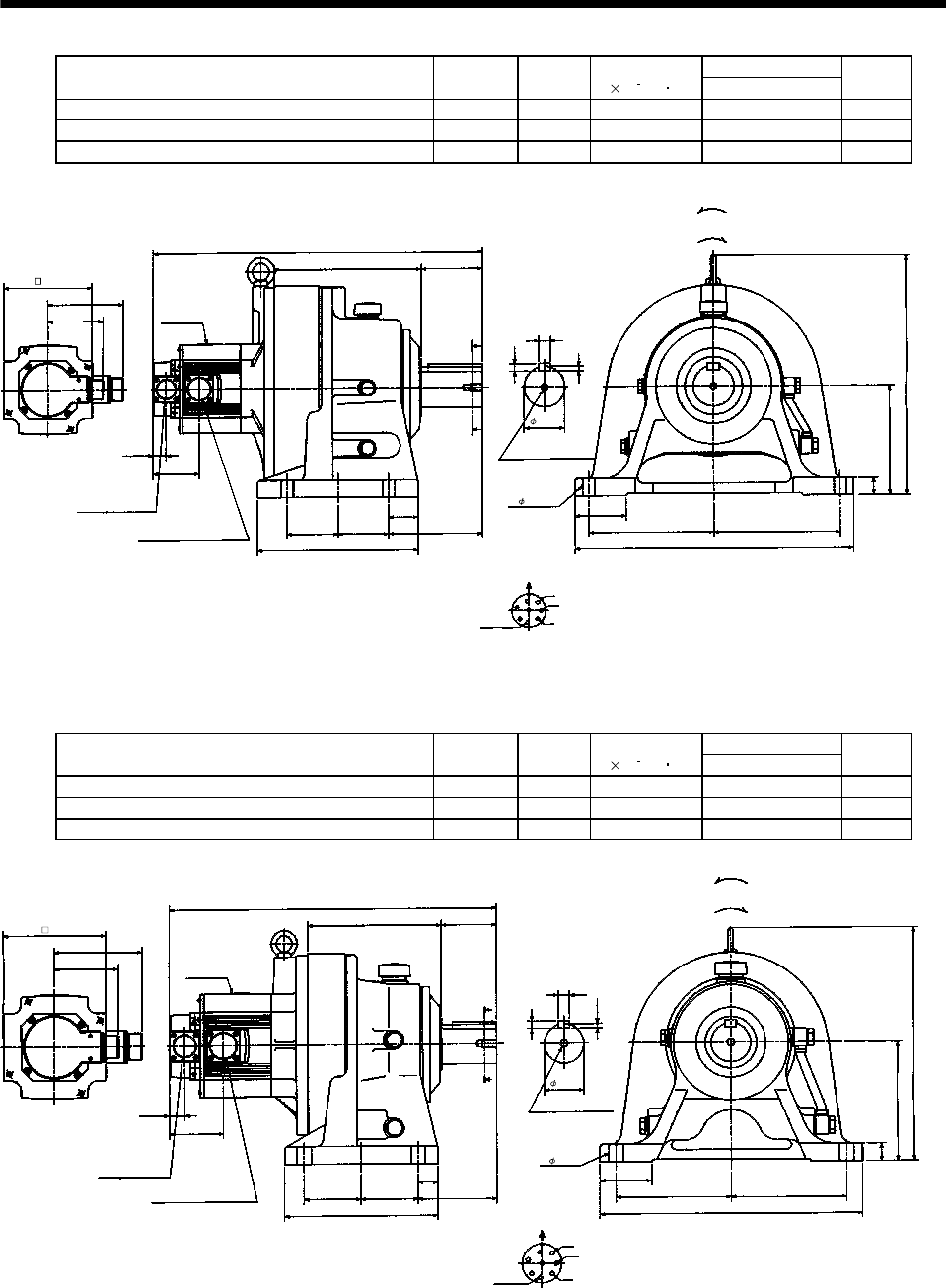
7 - 56
7. OUTLINE DIMENSION DRAWINGS
Variable Dimensions
Model Output
[kW]
Reduction
Ratio
Inertia Moment
J[ 10 4kg m2]L
Mass
[kg]
HC-SF102G1H HC-SFS102G1H HC-SFS1024G1H 1.0 1/59 19.48 488 90
HC-SF152G1H HC-SFS152G1H HC-SFS1524G1H 1.5 1/43 25.8 513 92
HC-SF152G1H HC-SFS152G1H HC-SFS1524G1H 1.5 1/59 25.73 513 92
W
V
U
A
F
G
HB
EC
D
L
111
352
81.5
19.5
68.5
218 90
A
A
75 75 139
44
238
18
11
7
160
25
185
185
75
410
MS3102A20-29P
CE05-2A22-23P
Bottom Top
Encoder connector
Power supply connector
Motor flange direction
Earth
Power supply connector layout
CE05-2A22-23P
(Note)[Unit: mm]
Motor plate
[Side view of motor only]
Section A-A
"Rotation direction"
For reverse
rotation command
For forward
rotation command
M10 threads, depth 18
Z695741*
(BC11800*)
130
60h6
4- 18
Note: The dimensions without tolerances are reference dimensions.
Variable Dimensions
Model Output
[kW]
Reduction
Ratio
Inertia Moment
J[ 10 4kg m2]L
Mass
[kg]
HC-SF102G1H HC-SFS102G1H HC-SFS1024G1H 1.0 1/43 15.65 416 51
HC-SF152G1H HC-SFS152G1H HC-SFS1524G1H 1.5 1/29 22.08 441 53
HC-SF152G1H HC-SFS152G1H HC-SFS1524G1H 1.5 1/35 22.03 441 53
W
V
U
A
F
G
H
B
E
C
D
L
111
295
81.5
19.5
68.5
170 70
A
A
72.5 72.5 100
25
195
14
9
5.5
150
22
145145
65
330
MS3102A20-29P
CE05-2A22-23P
Bottom Top
Encoder connector
Power supply connector
Motor flange direction
Earth
Power supply connector layout
CE05-2A22-23P
(Note)[Unit: mm]
Motor plate
[Side view of motor only] Section A-A
M10 threads, depth 18
"Rotation direction"
For reverse
rotation command
For forward
rotation command
50h6
4- 11
Z695740*
(BC11799*)
130
Note: The dimensions without tolerances are reference dimensions.
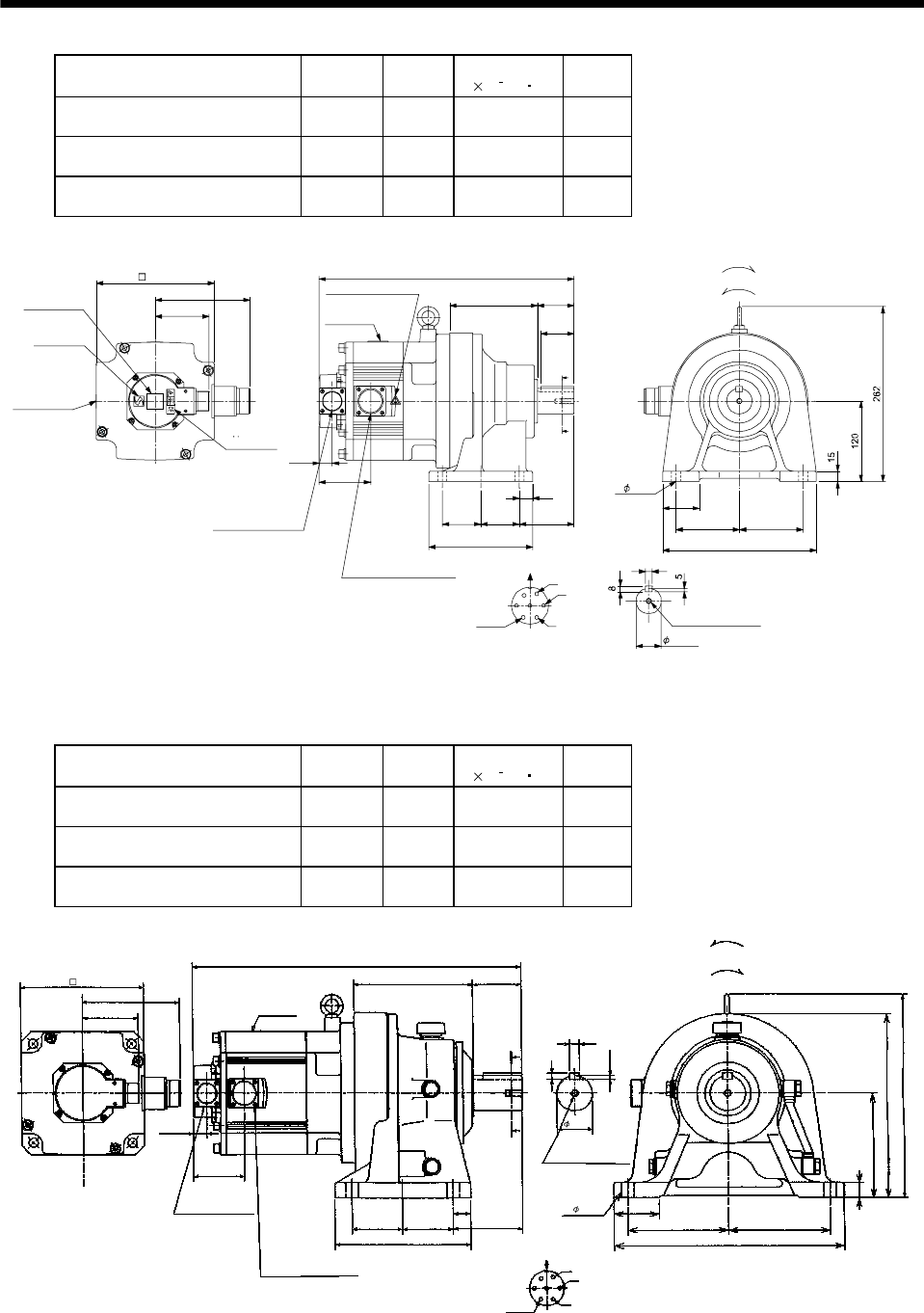
7 - 57
7. OUTLINE DIMENSION DRAWINGS
Model Output
[kW]
Reduction
Ratio
Inertia Moment
J[ 10 4kg m2]
Mass
[kg]
HC-SF202G1H HC-SFS202G1H
HC-SFS2024G1H 2.0 1/6 45.6 35
HC-SF202G1H HC-SFS202G1H
HC-SFS2024G1H 2.0 1/11 44.1 35
HC-SF202G1H HC-SFS202G1H
HC-SFS2024G1H 2.0 1/17 43.7 35
55
131
8257.557.5
155
20
A
A
50
9595
230
55
81.5
142
76.5
A
B
C
D
E
FG
10
Z695802B
BC11801A BC26335B
19.5
381
Encoder connector
Power supply connector
V
U
CE05-2A24-10P
MS3102A20-29P
W
Motor plate
Caution plate
Caution plate (Note 2)
(Opposite side)
38h6
176
Caution plate
Logo plate
(Note 2)
Side view of motor only
4- 14
Section AA
Power supply connector layout
Top
Bottom
Top
Bottom
TopBottom
For forward rotation command
"Rotation direction"
For reverse rotation command
Top
Bottom
Earth
CE05-2A24-10P
M8 screw, depth 20
Motor flange direction
TUV plate
(Note 1)[Unit: mm]
Note 1. The dimensions without tolerances are reference dimensions.
2. This caution plate is attached to the 400V class motors only, not to the 200V class.
Model Output
[kW]
Reduction
Ratio
Inertia Moment
J[ 10 4kg m2]
Mass
[kg]
HC-SF352G1H HC-SFS352G1H
HC-SFS3524G1H 3.5 1/6 90.1 60
HC-SF352G1H HC-SFS352G1H
HC-SFS3524 G1H 3.5 1/11 86.2 60
HC-SF352G1H HC-SFS352G1H
HC-SFS3524 G1H 3.5 1/17 85.0 60
142
473
170 70
81.5
A
A
19.5
76.5
292
5.5
265
150
65
145 145
330
9
14
U
V
W
CD BE
A
G
F
100
25
72.572.5
195
22
MS3102A20-29P
CE05-2A24-10P
Bottom Top
Encoder connector
Power supply connector Motor flange direction
Earth
Power supply connector layout
CE05-2A24-10P
(Note)[Unit: mm]
Motor plate
[Side view of motor only]
"Rotation direction"
For reverse
rotation command
For forward
rotation command
Section A-A
M10 threads, depth 18
50h6
4- 18
176
Z695803A
(BC11803*)
Note: The dimensions without tolerances are reference dimensions.
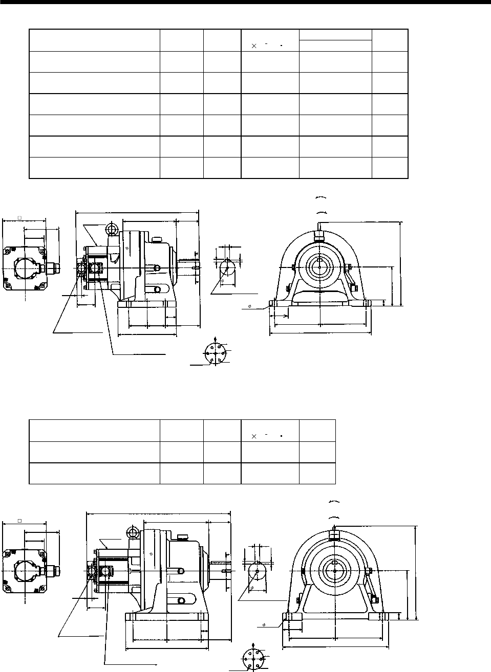
7 - 58
7. OUTLINE DIMENSION DRAWINGS
Variable Dimensions
Model Output
[kW]
Reduction
Ratio
Inertia Moment
J[ 10 4kg m2]L
Mass
[kg]
HC-SF202G1H HC-SFS202G1H
HC-SFS2024G1H 2.0 1/29 48.9 498 91
HC-SF202G1H HC-SFS202G1H
HC-SFS2024G1H 2.0 1/35 48.6 498 91
HC-SF202G1H HC-SFS202G1H
HC-SFS2024G1H 2.0 1/43 48.4 498 91
HC-SF202G1H HC-SFS202G1H
HC-SFS2024G1H 2.0 1/59 48.3 498 91
HC-SF352G1H HC-SFS352G1H
HC-SFS3524G1H 3.5 1/29 88.4 540 98
HC-SF352G1H HC-SFS352G1H
HC-SFS3524G1H 3.5 1/35 88.1 540 98
142
L
218 90
81.5
A
A
19. 5
76.5
341
7
160
25
75
185 185
410
11
18
U
V
W
C
DBE
A
G
F
139
44
7575
238
MS3102A20-29P
CE05-2A24-10P
Bottom Top
Encoder connector
Power supply connector
Motor flange direction
Earth
Power supply connector layout
CE05-2A24-10P
(Note)[Unit: mm]
[Side view of motor only]
"Rotation direction"
For reverse
rotation command
For forward
rotation command
Section A-A
M10 threads, depth 18
Motor plate
Z695804A
(BC11802*)
176
60h6
4- 18
300
Note: The dimensions without tolerances are reference dimensions.
Model Output
[kW]
Reduction
Ratio
Inertia Moment
J[ 10 4kg m2]
Mass
[kg]
HC-SF352G1H HC-SFS352G1H
HC-SFS3524G1H 3.5 1/43 106.5 139
HC-SF352G1H HC-SFS352G1H
HC-SFS3524G1H 3.5 1/59 105.9 139
142
584
262 90
81.5
A
A
19. 5
76.5
381
7.5
200
30
80
190 190
430
12
20
U
V
W
CD B
E
A
G
F
125
30
137.5137.5
335
MS3102A20-29P
CE05-2A24-10P
Bottom Top
Encoder connector
Power supply connector
Motor flange direction
Earth
Power supply connector layout
CE05-2A24-10P
(Note)[Unit: mm]
Motor plate
[Side view of motor only]
"Rotation direction"
For reverse
rotation command
For forward
rotation command
Section A-A
M12 threads, depth 24
70h6
4- 22
176
Z695805A
(BC11804*)
340
Note: The dimensions without tolerances are reference dimensions.
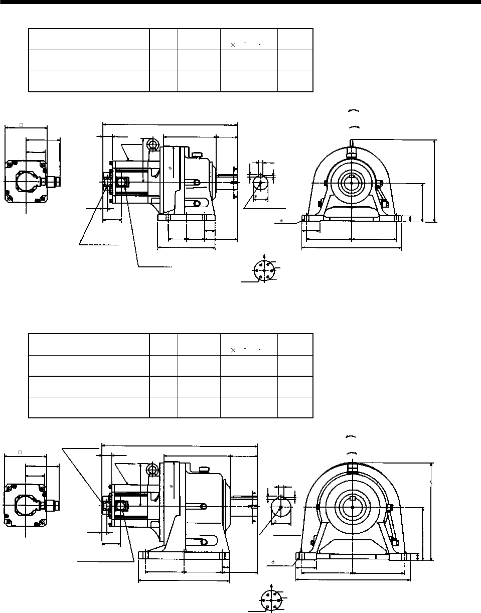
7 - 59
7. OUTLINE DIMENSION DRAWINGS
Model Output
[kW]
Reduction
Ratio
Inertia Moment
J[ 10 4kg m2]
Mass
[kg]
HC-SF502G1H HC-SFS502G1H
HC-SFS5024G1H 5.0 1/11 113.4 102
HC-SF502G1H HC-SFS502G1H
HC-SFS5024G1H 5.0 1/17 109.4 102
Power supply connector layout
CE05-2A24-10P
142
561
218 90
81.5
A
A
Motor plate
19.5
76.5
341
For reverse
rotation command
For forward
rotation command
"Rotation direction"
7
160
(Note)[Unit: mm]
25
75
185 185
410
11
18
Motor flange direction
U
V
W
C
DB
E
A
G
F
Earth
Section A-A
139
44
75
75
238
M10 threads, depth 18
Encoder connector
MS3102A20-29P
Power supply connector
CE05-2A24-10P
39.5
181
[Side view of motor only]
Bottom Top
BC10751*
176
4- 18
300
60h6
(BC11805*)
Note: The dimensions without tolerances are reference dimensions.
Model Output
[kW]
Reduction
Ratio
Inertia Moment
J[ 10 4kg m2]
Mass
[kg]
HC-SF502G1H HC-SFS502G1H
HC-SFS5024G1H 5.0 1/29 138.5 171
HC-SF502G1H HC-SFS502G1H
HC-SFS5024G1H 5.0 1/35 138.0 171
HC-SF502G1H HC-SFS502G1H
HC-SFS5024G1H 5.0 1/43 137.0 171
Power supply connector layout
CE05-2A24-10P
142
645
279 110
81.5
A
A
Motor plate
19.5
76.5
405
9
220
30
85
210 210
470
14
Motor flange direction
22
U
V
W
C
DB
E
A
G
F
Earth
Section A-A
145
30
160
160
380
M12 threads, depth 24
Encoder connector
MS3102A20-29P
Power supply connector
CE05-2A24-10P
39.5
176
For reverse
rotation command
For forward
rotation command
"Rotation direction"
(Note)[Unit: mm]
[Side view of motor only]
Bottom Top
80h6
4- 22
176
BC10752*
370
(BC11806*)
Note: The dimensions without tolerances are reference dimensions.
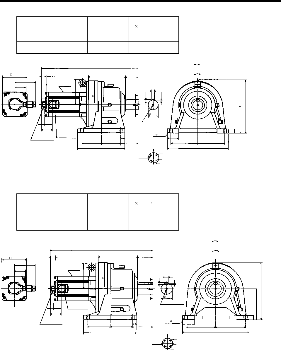
7 - 60
7. OUTLINE DIMENSION DRAWINGS
Model Output
[kW]
Reduction
Ratio
Inertia Moment
J[ 10 4kg m2]
Mass
[kg]
HC-SF702G1H HC-SFS702G1H
HC-SFS7024G1H 7.0 1/11 198.8 138
HC-SF702G1H HC-SFS702G1H
HC-SFS7024G1H 7.0 1/17 190.0 138
Power supply connector layout
CE05-2A32-17P
150
689
262 90
81.5
A
A
Motor plate
19.5
81.5
381
7.5
200
30
80
190 190
430
12
Motor flange direction
20
U
V
W
C
D
B
A
Earth
Section A-A
125
30
137.5
137.5
335
M12 threads, depth 24
Encoder connector
MS3102A20-29P
Power supply
connector
CE05-2A32-17P
181
39.5
For reverse
rotation command
For forward
rotation command
"Rotation direction"
(Note)[Unit: mm]
[Side view of motor only]
Bottom Top
BC10753*
176
70h6
4- 22
340
(BC11807*)
Note: The dimensions without tolerances are reference dimensions.
Model Output
[kW]
Reduction
Ratio
Inertia Moment
J[ 10 4kg m2]
Mass
[kg]
HC-SF702G1H HC-SFS702G1H
HC-SFS7024G1H 7.0 1/29 197.5 180
HC-SF702G1H HC-SFS702G1H
HC-SFS7024G1H 7.0 1/35 197.0 180
Power supply connector layout
CE05-2A32-17P
150
729
279 110
81.5
A
A
Motor plate
19.5
81.5
405
9
220
30
85
210 210
470
14
Motor flange direction
22
U
V
W
C
D
B
A
Earth
Section A-A
145
30
160
160
380
M12 threads, depth 24
Encoder connector
MS3102A20-29P
Power supply
connector
CE05-2A
32-17P
39.5
176
For reverse
rotation command
For forward
rotation command
"Rotation direction"
(Note)[Unit: mm]
[Side view of motor only]
Bottom Top
370
80h6
4- 22
176
BC10754*
(BC11808*)
Note: The dimensions without tolerances are reference dimensions.
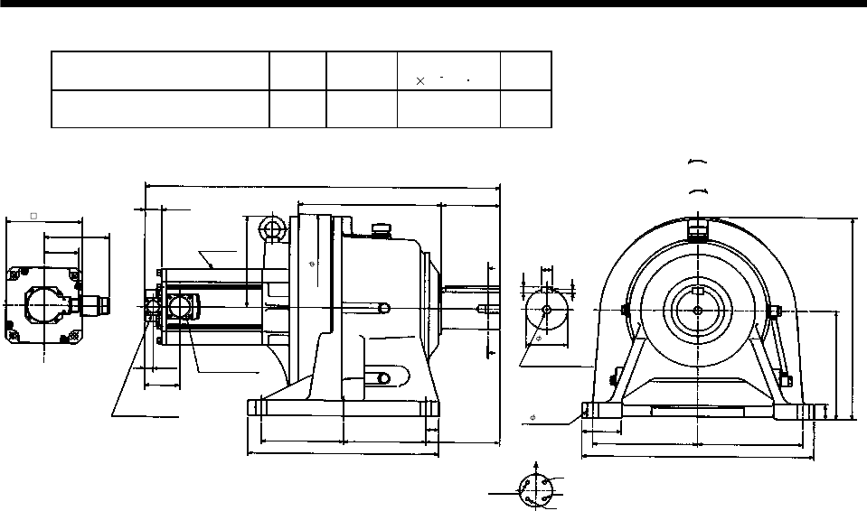
7 - 61
7. OUTLINE DIMENSION DRAWINGS
Model Output
[kW]
Reduction
Ratio
Inertia Moment
J[ 10 4kg m2]
Mass
[kg]
HC-SF702G1H HC-SFS702G1H
HC-SFS7024G1H 7.0 1/43 256.8 261
Power supply connector layout
CE05-2A32-17P
150
820
330 135
81.5
A
A
Motor plate
19.5
81.5
465
9
250
35
90
240 240
530
14
Motor flange direction
25
U
V
W
C
D
B
A
Earth
Section A-A
170
30
190
190
440
M20 threads, depth 34
Encoder connector
MS3102A20-29P
Power supply
connector
CE05-2A
32-17P
39.5
210
For reverse
rotation command
For forward
rotation command
"Rotation direction"
(Note)[Unit: mm]
[Side view of motor only]
Bottom Top
BC10755*
176
95h6
4- 26
430
(BC11809*)
Note: The dimensions without tolerances are reference dimensions.
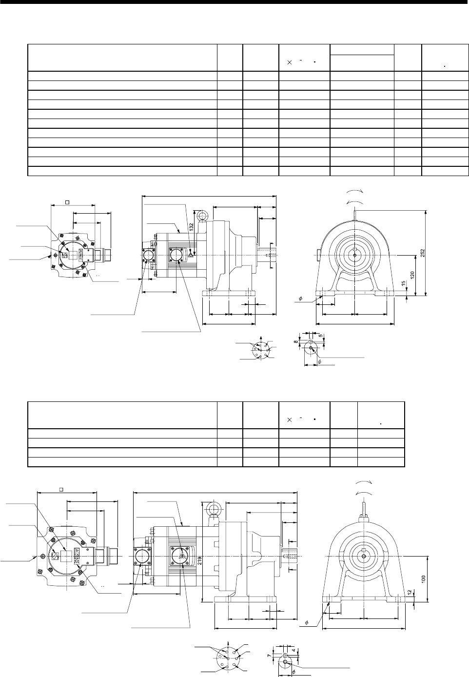
7 - 62
7. OUTLINE DIMENSION DRAWINGS
(b) With electromagnetic brake
Variable Dimensions
Model Output
[kW]
Reduction
Ratio
Inertia Moment
J[ 10 4kg m2]L
Mass
[kg]
Brake static
friction torque
[N m]
HC-SF52BG1H HC-SFS52BG1H HC-SFS524BG1H 0.5 1/35 9.2 371 33 8.3
HC-SF52BG1H HC-SFS52BG1H HC-SFS524BG1H 0.5 1/43 9.15 371 33 8.3
HC-SF52BG1H HC-SFS52BG1H HC-SFS524BG1H 0.5 1/59 9.13 371 33 8.3
HC-SF102BG1H HC-SFS102BG1H HC-SFS1024BG1H 1.0 1/6 18.5 396 35 8.3
HC-SF102BG1H HC-SFS102BG1H HC-SFS1024BG1H 1.0 1/11 17.0 396 35 8.3
HC-SF102BG1H HC-SFS102BG1H HC-SFS1024BG1H 1.0 1/17 16.6 396 35 8.3
HC-SF102BG1H HC-SFS102BG1H HC-SFS1024BG1H 1.0 1/29 16.3 396 35 8.3
HC-SF102BG1H HC-SFS102BG1H HC-SFS1024BG1H 1.0 1/35 16.3 396 35 8.3
HC-SF152BG1H HC-SFS152BG1H HC-SFS1524BG1H 1.5 1/6 24.8 421 37 8.3
HC-SF152BG1H HC-SFS152BG1H HC-SFS1524BG1H 1.5 1/11 23.2 421 37 8.3
HC-SF152BG1H HC-SFS152BG1H HC-SFS1524BG1H 1.5 1/17 22.9 421 37 8.3
A
B
C
D
E
F
G
H
Z695747A
BC11824B BC26421A
10
81.5
111
101.5
19.5
9595
230
55131
57.5 57.5 82
155
20
A
A
55
L
50
Encoder connector
Power supply connector
V
U
CE05-2A22-23P
MS3102A20-29P
W
Motor plate
Caution plate
Caution plate (Note 2)
(Opposite side)
38h6
130
Caution plate
Logo plate
(Note 2)
Side view of motor only
4- 14
Section AA
Power supply connector layout
TopBottom
Top
Bottom
Top
Bottom
Top
Botto
For forward rotation command
"Rotation direction"
For reverse rotation command
Earth
Brake
CE05-2A22-23P
M8 screw, depth 20
Motor flange direction
TUV plate
(Note 1)[Unit: mm]
Note 1. The dimensions without tolerances are reference dimensions.
2. This caution plate is attached to the 400V class motors only, not to the 200V class.
Model Output
[kW]
Reduction
Ratio
Inertia Moment
J[ 10 4kg m2]
Mass
[kg]
Brake static
friction torque
[N m]
HC-SF52BG1H HC-SFS52BG1H HC-SFS524BG1H 0.5 1/6 9.03 23 8.3
HC-SF52BG1H HC-SFS52BG1H HC-SFS524BG1H 0.5 1/11 8.65 23 8.3
HC-SF52BG1H HC-SFS52BG1H HC-SFS524BG1H 0.5 1/17 8.55 23 8.3
HC-SF52BG1H HC-SFS52BG1H HC-SFS524BG1H 0.5 1/29 8.48 23 8.3
135
45 45
15
60
121
110
35
40
180
8
A
A
A
B
C
D
E
F
G
H
101.5
358
111
81.5
75 75
19.5
Z695746A
BC11823C BC29416A
32
Encoder connector
Power supply connector
V
U
CE05-2A22-23P
MS3102A20-29P
W
Motor plate
Caution plate
Caution plate
(Note 2)
(Opposite side)
28h6
130
Caution plate
Logo plate
(Note 2)
Side view of motor only
4- 11
Section AA
Power supply connector layout
Top
Bottom
TopBottom Top
Bottom
TopBottom
For forward rotation command
"Rotation direction" For reverse rotation command
Earth
Brake
CE05-2A22-23P
M8 screw, depth 20
Motor flange direction
TUV plate
(Note 1)[Unit: mm]
Note 1. The dimensions without tolerances are reference dimensions.
2. This caution plate is attached to the 400V class motors only, not to the 200V class.
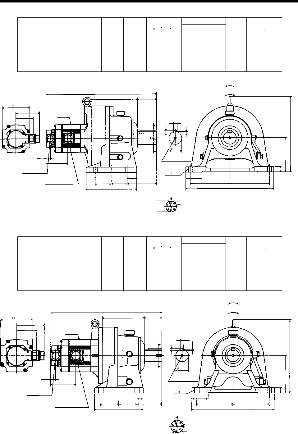
7 - 63
7. OUTLINE DIMENSION DRAWINGS
Variable Dimensions
Model Output
[kW]
Reduction
Ratio
Inertia Moment
J[ 10 4kg m2]L
Mass
[kg]
Brake static
friction torque
[N m]
HC-SF102BG1H HC-SFS102BG1H
HC-SFS1024BG1H 1.0 1/59 21.18 521 92 8.3
HC-SF152BG1H HC-SFS152BG1H
HC-SFS1524BG1H 1.5 1/43 27.5 546 94 8.3
HC-SF152BG1H HC-SFS152BG1H
HC-SFS1524BG1H 1.5 1/59 27.43 546 94 8.3
19.5
W
V
U
L
90218
A
FG
H
B
EC
D
111
81.5
101.5
A
A
238
75 75
44
139
18
11
7
410
185
25
75
160
352
185
MS3102A20-29P
CE05-2A22-23P
Bottom Top
Encoder connector
Power supply connector
Motor flange direction
Earth
Power supply connector layout
CE05-2A22-23P
(Note)[Unit: mm]
Motor plate
[Side view of motor only]
"Rotation direction"
For reverse
rotation command
For forward
rotation command
Brake
Section A-A
M10 threads, depth 18
130
60h6
4- 18
Z695749A
(BC11826*)
Note: The dimensions without tolerances are reference dimensions.
Variable Dimensions
Model Output
[kW]
Reduction
Ratio
Inertia Moment
J[ 10 4kg m2]L
Mass
[kg]
Brake static
friction torque
[N m]
HC-SF102BG1H HC-SFS102BG1H
HC-SFS1024BG1H 1.0 1/43 17.35 449 53 8.3
HC-SF152BG1H HC-SFS152BG1H
HC-SFS1524BG1H 1.5 1/29 23.78 474 55 8.3
HC-SF152BG1H HC-SFS152BG1H
HC-SFS1524BG1H 1.5 1/35 23.73 474 55 8.3
19.5
W
V
U
L
70170
A
FG
HB
E
C
D
111
81.5
101.5
A
A
195
72.5
25
100
14
9
5.5
330
145
22
65
150
295
72.5 145
MS3102A20-29P
CE05-2A22-23P
Bottom Top
Encoder connector
Power supply connector
Motor flange direction
Earth
Power supply connector layout
CE05-2A22-23P
(Note)[Unit: mm]
Motor plate
[Side view of motor only]
"Rotation direction"
For reverse
rotation command
For forward
rotation command
Brake
Section A-A
M10 threads, depth 18
(BC11825*)
Z695748A
130
50h6
4- 11
Note: The dimensions without tolerances are reference dimensions.
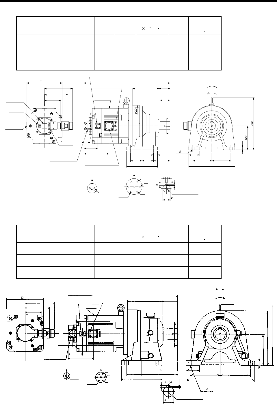
7 - 64
7. OUTLINE DIMENSION DRAWINGS
Model Output
[kW]
Reduction
Ratio
Inertia Moment
J[ 10 4kg m2]
Mass
[kg]
Brake static
friction torque
[N m]
HC-SF202BG1H HC-SFS202BG1H
HC-SFS2024BG1H 2.0 1/6 55.6 41 43.1
HC-SF202BG1H HC-SFS202BG1H
HC-SFS2024BG1H 2.01/1154.14143.1
HC-SF202BG1H HC-SFS202BG1H
HC-SFS2024BG1H 2.01/1753.74143.1
Z695852A
BC11827B BC29626A
10
9595
230
55
131
8257.557.5
155
20
A
A
55
429
81.5
117
142
A
B
C
D
E
F
G
BA
69
124.5
19.5
50
Encoder connector
Power supply connector
V
U
CE05-2A24-10P
MS3102A20-29P
W
Motor plate
Caution plate
Caution plate (Note 2)
(Opposite side)
38h6
176
Caution plate
Logo plate
(Note 2)
Side view of motor only 4- 14
Section AA
Power supply connector layout
Top
Bottom
TopBottom
Top
Bottom
Top
Bottom
For forward rotation command
"Rotation direction"
For reverse rotation command
Earth
Brake
CE05-2A24-10P
M8 screw, depth 20
Motor flange direction
Motor flange direction
Brake connector
CM3102A10SL-4P
TUV plate
Brake connector layout
MS3102A10SL-4P
(Note 1)[Unit: mm]
Note 1. The dimensions without tolerances are reference dimensions.
2. This caution plate is attached to the 400V class motors only, not to the 200V class.
Model Output
[kW]
Reduction
Ratio
Inertia Moment
J[ 10 4kg m2]
Mass
[kg]
Brake static
friction torque
[N m]
HC-SF352BG1H HC-SFS352BG1H
HC-SFS3524BG1H 3.5 1/6 100.1 66 43.1
HC-SF352BG1H HC-SFS352BG1H
HC-SFS3524BG1H 3.51/1196.26643.1
HC-SF352BG1H HC-SFS352BG1H
HC-SFS3524BG1H 3.51/1795.06643.1
19.5
W
V
U
521
170
A
FG
B
EC
D
142
117
69
A
A
124.5
72.5
195
14
9
5.5
65
22
25
150
265
145
81.5
AB
70
145
330
72.5 100
292
MS3102A20-29P
CE05-2A24-10P
Bottom Top
Encoder connector
Power supply connector
Motor flange direction
Earth
Power supply connector layout
CE05-2A24-10P
(Note)[Unit: mm]
Motor plate
[Side view of motor only]
"Rotation direction"
For reverse
rotation command
For forward
rotation command
Brake connector
MS3102A10SL-4P
Brake connector layout
MS3102A10SL-4P
Brake
Motor flange direction
Section A-A
M10 threads, depth 18
Z695853A
(BC11829*)
176
4- 18
50h6
Note: The dimensions without tolerances are reference dimensions.
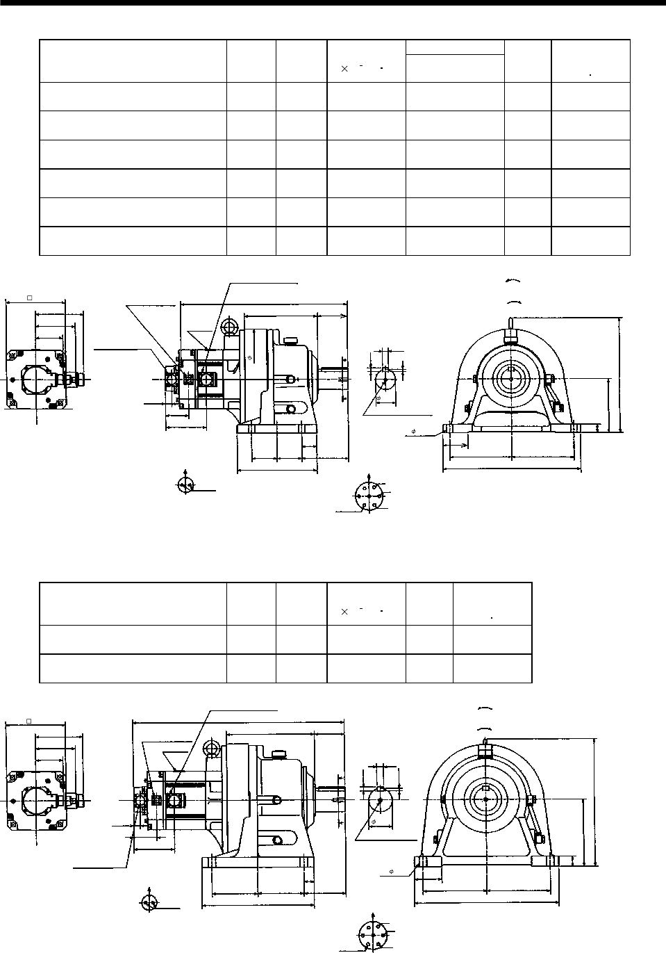
7 - 65
7. OUTLINE DIMENSION DRAWINGS
Variable Dimensions
Model Output
[kW]
Reduction
Ratio
Inertia Moment
J[ 10 4kg m2]L
Mass
[kg]
Brake static
friction torque
[N m]
HC-SF202BG1H HC-SFS202BG1H
HC-SFS2024BG1H 2.0 1/29 58.9 546 97 43.1
HC-SF202BG1H HC-SFS202BG1H
HC-SFS2024BG1H 2.0 1/35 58.6 546 97 43.1
HC-SF202BG1H HC-SFS202BG1H
HC-SFS2024BG1H 2.0 1/43 58.4 546 97 43.1
HC-SF202BG1H HC-SFS202BG1H
HC-SFS2024BG1H 2.0 1/59 58.3 546 97 43.1
HC-SF352BG1H HC-SFS352BG1H
HC-SFS3524BG1H 3.5 1/29 98.4 588 104 43.1
HC-SF352BG1H HC-SFS352BG1H
HC-SFS3524BG1H 3.5 1/35 98.1 588 104 43.1
19.5
W
V
U
L
218
A
FG
B
E
C
D
142
117
69
A
A
124.5
238
11
7
75
25
44
160
185
81.5
AB
410
139
18
341
90
185
75 75
MS3102A20-29P
CE05-2A24-10P
Bottom Top
Encoder connector
Power supply connector
Motor flange direction
Earth
Power supply connector layout
CE05-2A24-10P
(Note)[Unit: mm]
Motor plate
[Side view of motor only]
"Rotation direction"
For reverse
rotation command
For forward
rotation command
Brake connector
MS3102A10SL-4P
Brake connector layout
MS3102A10SL-4P
Brake
Motor flange direction
Section A-A
M10 threads, depth 18
4- 18
60h6
176
Z695854A
(BC11828*)
300
Note: The dimensions without tolerances are reference dimensions.
Model Output
[kW]
Reduction
Ratio
Inertia Moment
J[ 10 4kg m2]
Mass
[kg]
Brake static
friction torque
[N m]
HC-SF352BG1H HC-SFS352BG1H
HC-SFS3524BG1H 3.5 1/43 116.5 145 43.1
HC-SF352BG1H HC-SFS352BG1H
HC-SFS3524BG1H 3.5 1/59 115.9 145 43.1
19.5
W
V
U
632
262
A
FG
BE
C
D
142
117
69 A
A
124.5
335
12
7.5
80
30
30
200
190
81.5
AB430
125
20
381
90
190
137.5 137.5
Section A-A
M12 threads, depth 24
MS3102A20-29P
CE05-2A24-10P
Bottom Top
Encoder connector
Power supply connector
Motor flange direction
Earth
Power supply connector layout
CE05-2A24-10P
(Note)[Unit: mm]
Motor plate
[Side view of motor only]
"Rotation direction"
For reverse
rotation command
For forward
rotation command
Brake connector
MS3102A10SL-4P
Brake connector layout
MS3102A10SL-4P
Brake
Motor flange direction
Z695855A
(BC11830*)
176
4- 22
70h6
Note: The dimensions without tolerances are reference dimensions.
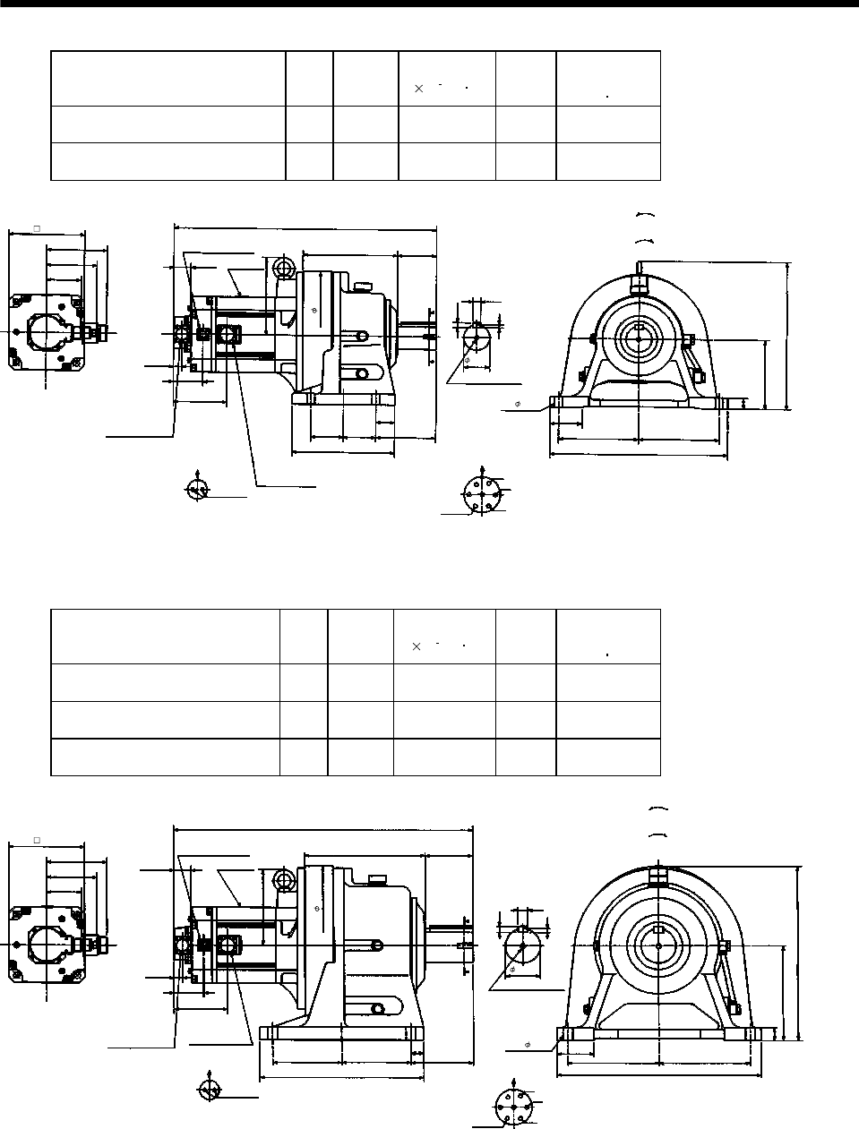
7 - 66
7. OUTLINE DIMENSION DRAWINGS
Model Output
[kW]
Reduction
Ratio
Inertia Moment
J[ 10 4kg m2]
Mass
[kg]
Brake static
friction torque
[N m]
HC-SFS502BG1H HC-SFS502BG1H
HC-SFS5024BG1H 5.0 1/11 123.4 108 43.1
HC-SFS502BG1H HC-SFS502BG1H
HC-SFS5024BG1H 5.0 1/17 119.4 108 43.1
Power supply connector layout
CE05-2A24-10P
142
609
218 90
117
A
A
Motor plate
19.5
69
341
7
160
25
75
185 185
410
11
Motor flange direction
18
U
V
W
CD B
E
A
G
F
Earth
Section A-A
139
44
75
75
238
M10 threads, depth 18
Encoder connector
MS3102A20-29P
Power supply connector
CE05-2A24-10P
39.5
181
81.5
Brake connector layout
MS3102A10SL-4P
Motor flange direction
B
A
Brake
124.5
Brake connector
MS3102A10SL-4P
Bottom Top
[Side view of motor only]
(Note)[Unit: mm]
"Rotation direction"
For reverse
rotation command
For forward
rotation command
4- 18
60h6
176
BC11028*
300
(BC11831*)
Note: The dimensions without tolerances are reference dimensions.
Model Output
[kW]
Reduction
Ratio
Inertia Moment
J[ 10 4kg m2]
Mass
[kg]
Brake static
friction torque
[N m]
HC-SF502BG1H HC-SFS502BG1H
HC-SFS5024BG1H 5.0 1/29 148.5 177 43.1
HC-SF502BG1H HC-SFS502BG1H
HC-SFS5024BG1H 5.0 1/35 148.0 177 43.1
HC-SF502BG1H HC-SFS502BG1H
HC-SFS5024BG1H 5.0 1/43 147.0 177 43.1
142
693
279 110
117
A
A
Motor plate
19.5
69
405
9
220
30
85
210 210
470
14
22
Power supply connector layout
CE05-2A24-10P
Motor flange direction
U
V
W
C
DB
E
A
G
F
Earth
Section A-A
145
30
160160
380
M12 threads, depth 24
Encoder connector
MS3102A20-29P
Power supply
connector
CE05-2A24-10P
39.5
176
81.5
Brake connector layout
MS3102A10SL-4P
Motor flange direction
B
ABrake
124.5
Brake connector
MS3102A10SL-4P
Bottom Top
(Note)[Unit: mm]
"Rotation direction"
For reverse
rotation command
For forward
rotation command
[Side view of motor only]
370
80h6
BC11029*
176
4- 22
(BC11832*)
Note: The dimensions without tolerances are reference dimensions.
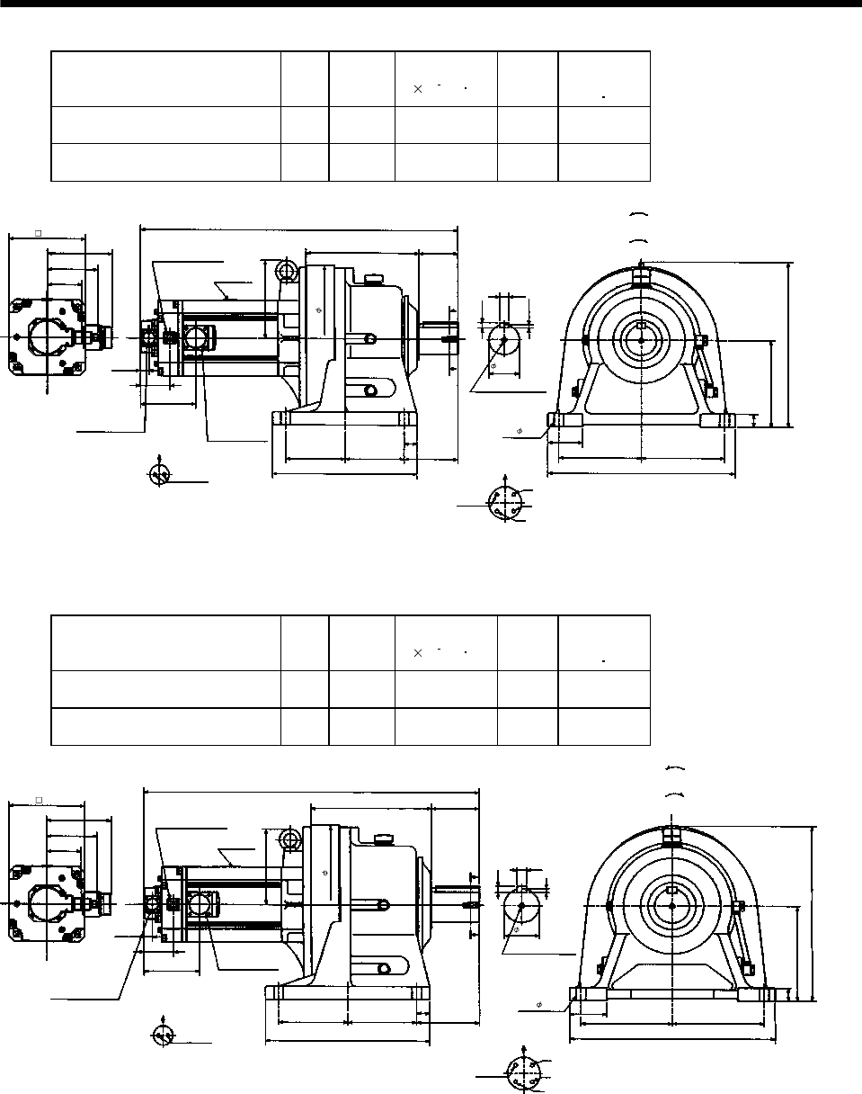
7 - 67
7. OUTLINE DIMENSION DRAWINGS
Model Output
[kW]
Reduction
Ratio
Inertia Moment
J[ 10 4kg m2]
Mass
[kg]
Brake static
friction torque
[N m]
HC-SF702BG1H HC-SFS702BG1H
HC-SFS7024BG1H 7.0 1/11 208.8 144 43.1
HC-SF702BG1H HC-SFS702BG1H
HC-SFS7024BG1H 7.0 1/17 200.0 144 43.1
Power supply connector layout
CE05-2A32-17P
150
737
262 90
117
A
A
Motor plate
19.5
69
381
7.5
200
30
80
190 190
430
12
Motor flange direction
20
U
V
W
C
D
B
A
Earth
Section A-A
125
30
137.5
137.5
335
M12 threads, depth 24
Encoder connector
MS3102A20-29P
Power supply
connector
CE05-2A32-17P
181
81.5
Brake connector layout
MS3102A10SL-4P
Motor flange direction
B
A
Brake
129.5
Brake connector
MS3102A10SL-4P
Bottom Top
(Note)[Unit: mm]
"Rotation direction"
For reverse
rotation command
For forward
rotation command
[Side view of motor only]
176
BC11030*
70h6
340
4- 22
(BC11833*)
Note: The dimensions without tolerances are reference dimensions.
Model Output
[kW]
Reduction
Ratio
Inertia Moment
J[ 10 4kg m2]
Mass
[kg]
Brake static
friction torque
[N m]
HC-SF702BG1H HC-SFS702BG1H
HC-SFS7024BG1H 7.0 1/29 207.5 186 43.1
HC-SF702BG1H HC-SFS702BG1H
HC-SFS7024BG1H 7.0 1/35 207.0 186 43.1
Power supply connector layout
CE05-2A32-17P
150
777
279 110
117
A
A
Motor plate
19.5
69
405
9
220
30
85
210 210
470
14
Motor flange direction
22
U
V
W
C
D
B
A
Earth
Section A-A
145
30
160160
380
M12 threads, depth 24
Encoder connector
MS3102A20-29P
Power supply
connector
CE05-2A
32-17P
176
81.5
Brake connector layout
MS3102A10SL-4P
Motor flange direction
B
A
Brake
129.5
Brake connector
MS3102A10SL-4P
Bottom Top
(Note)[Unit: mm
]
"Rotation direction"
For reverse
rotation command
For forward
rotation command
[Side view of motor only]
370
80h6
4- 22
BC11031*
176
(BC11834*)
Note: The dimensions without tolerances are reference dimensions.
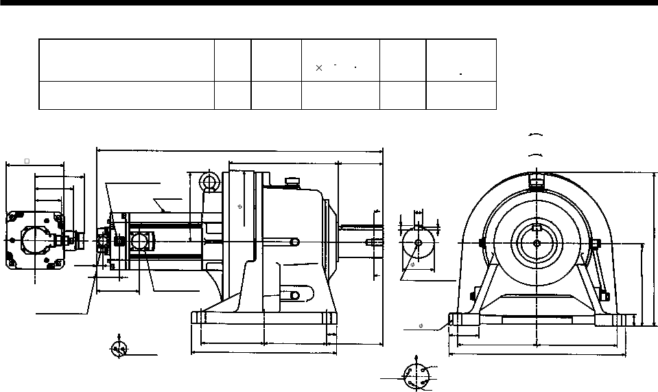
7 - 68
7. OUTLINE DIMENSION DRAWINGS
Model Output
[kW]
Reduction
Ratio
Inertia Moment
J[ 10 4kg m2]
Mass
[kg]
Brake static
friction torque
[N m]
HC-SF702BG1H HC-SFS702BG1H
HC-SFS7024BG1H 7.0 1/43 266.8 267 43.1
150
868
330 135
117
A
A
Motor plate
19.5
69
465
9
250
35
90
240 240
530
14
25
Power supply connector layout
CE05-2A32-17P
Motor flange direction
U
V
W
C
D
B
A
Earth
Section A-A
170
30
190
190
440
M20 threads, depth 34
Encoder connector
MS3102A20-29P
Power supply
connector
CE05-2A
32-17P
210
81.5
Brake connector layout
MS3102A10SL-4P
Motor flange direction
B
A
Brake
129.5
Brake connector
MS3102A10SL-4P
Bottom Top
(Note)[Unit: mm]
"Rotation direction"
For reverse
rotation command
For forward
rotation command
[Side view of motor only]
176
BC11032*
95h6
4- 26
430
(BC11835*)
Note: The dimensions without tolerances are reference dimensions.
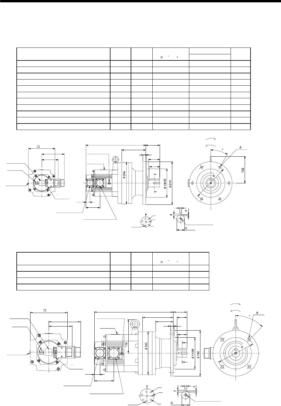
7 - 69
7. OUTLINE DIMENSION DRAWINGS
(4) With reduction gear for general industrial machine (flange type)
The outer frame of the reduction gear is a material surface such as casting. Its actual dimensions may
be 1 to 3mm larger than the drawing dimensions. Design the machine side with allowances.
(a) Without electromagnetic brake
Variable Dimensions
Model Output
[kW]
Reduction
Ratio
Inertia Moment
J[ 10 4kg m2]L
Mass
[kg]
HC-SF52G1 HC-SFS52G1 HC-SFS524G1 0.5 1/35 7.5 269 27
HC-SF52G1 HC-SFS52G1 HC-SFS524G1 0.5 1/43 7.45 269 27
HC-SF52G1 HC-SFS52G1 HC-SFS524G1 0.5 1/59 7.43 269 27
HC-SF102G1 HC-SFS102G1 HC-SFS1024G1 1.0 1/6 16.8 294 29
HC-SF102G1 HC-SFS102G1 HC-SFS1024G1 1.0 1/11 15.3 294 29
HC-SF102G1 HC-SFS102G1 HC-SFS1024G1 1.0 1/17 14.9 294 29
HC-SF102G1 HC-SFS102G1 HC-SFS1024G1 1.0 1/29 14.6 294 29
HC-SF102G1 HC-SFS102G1 HC-SFS1024G1 1.0 1/35 14.6 294 29
HC-SF152G1 HC-SFS152G1 HC-SFS1524G1 1.5 1/6 23.1 319 31
HC-SF152G1 HC-SFS152G1 HC-SFS1524G1 1.5 1/11 21.5 319 31
HC-SF152G1 HC-SFS152G1 HC-SFS1524G1 1.5 1/17 21.2 319 31
81.5
111
A
B
C
D
E
FG
H
Z695743*
BC11811B BC29695A
10
A
A
55
4
13
117
50
19.5
68.5
69L
Encoder connector
Power supply connector V
U
CE05-2A22-23P
MS3102A20-29P
W
Motor plate
Caution plate
Caution plate
(Note 2)
(Opposite side)
38h6
130
Caution plate
Logo plate
(Note 2)
Side view of motor only
6- 11
Section AA
Power supply connector layout
Top
Bottom
Top
Bottom
Top
Bottom
TopBottom
For forward rotation command
"Rotation direction"
For reverse rotation command
Earth
CE05-2A22-23P
M8 screw, depth 20
Motor flange direction
TUV plate
180
30
(Note 1)[Unit: mm]
Note 1. The dimensions without tolerances are reference dimensions.
2. This caution plate is attached to the 400V class motors only, not to the 200V class.
Model Output
[kW]
Reduction
Ratio
Inertia Moment
J[ 10 4kg m2]
Mass
[kg]
HC-SF52G1 HC-SFS52G1 HC-SFS524G1 0.5 1/6 7.33 18.5
HC-SF52G1 HC-SFS52G1 HC-SFS524G1 0.5 1/11 6.95 18.5
HC-SF52G1 HC-SFS52G1 HC-SFS524G1 0.5 1/17 6.85 18.5
HC-SF52G1 HC-SFS52G1 HC-SFS524G1 0.5 1/29 6.78 18.5
111
81.5
19.5
68.5
62
108
277 48
93
35
8
A
A
Z695742*
BC11810B BC26736A
A
B
C
D
E
FG
H
32
Encoder connector
Power supply connector V
U
CE05-2A22-23P
MS3102A20-29P
W
Motor plate
Caution plate Caution plate (Note 2)
(Opposite side)
28h6
130
Caution plate
Logo plate
(Note 2)
Side view of motor only
4- 11
Section AA
Power supply connector layout
Top
Bottom
TopBottom
Top
Bottom
Top
Bottom
For forward rotation command
"Rotation direction"
For reverse rotation command
Earth
CE05-2A22-23P
M8 screw, depth 20
Motor flange direction
TUV plate
45
134
(Note 1)[Unit: mm]
Note 1. The dimensions without tolerances are reference dimensions.
2. This caution plate is attached to the 400V class motors only, not to the 200V class.
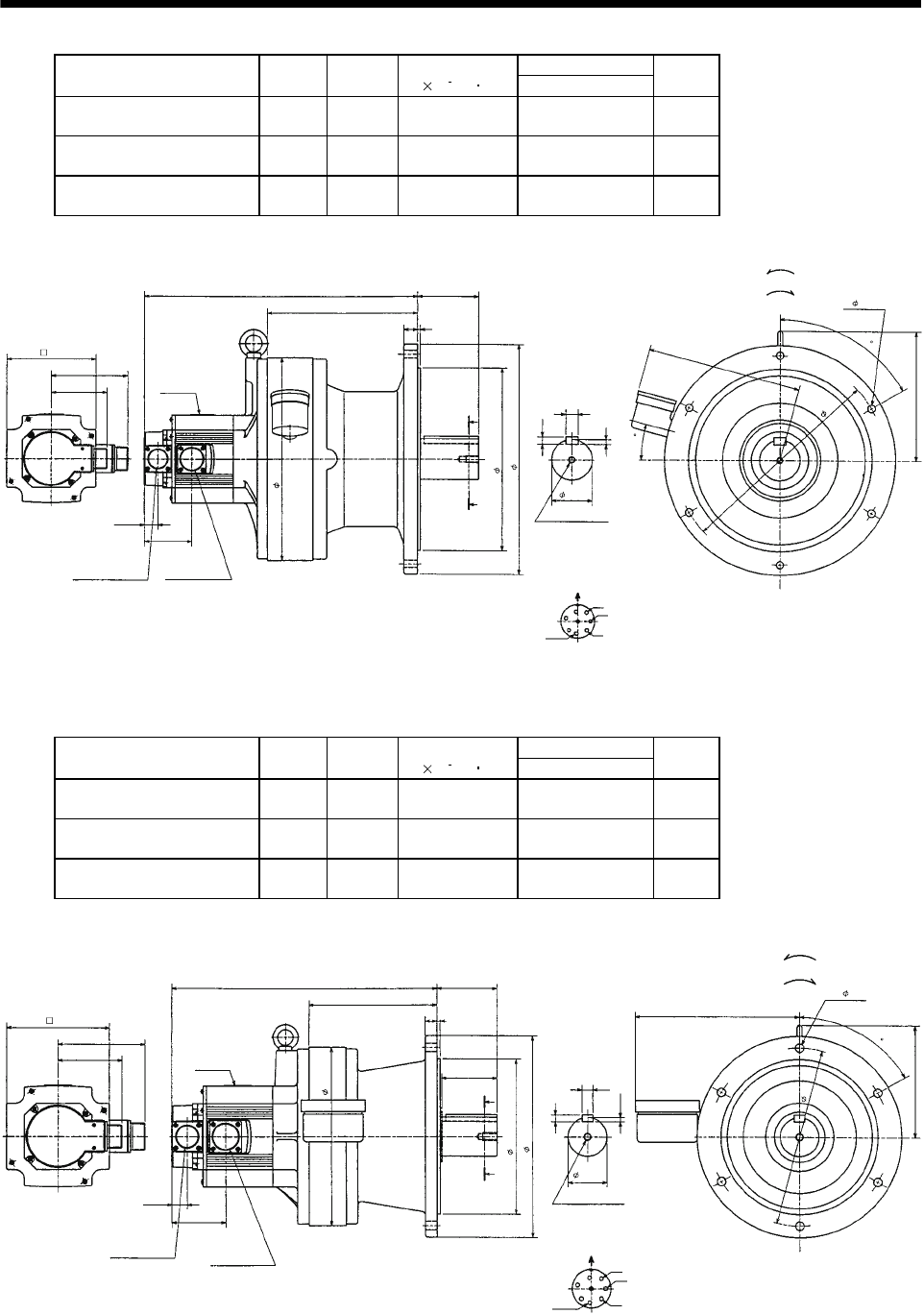
7 - 70
7. OUTLINE DIMENSION DRAWINGS
Variable Dimensions
Model Output
[kW]
Reduction
Ratio
Inertia Moment
J[ 10 4kg m2]L
Mass
[kg]
HC-SF102G1 HC-SFS102G1
HC-SFS1024G1 1.0 1/59 19.5 399 83
HC-SF152G1 HC-SFS152G1
HC-SFS1524G1 1.5 1/43 25.8 424 85
HC-SF152G1 HC-SFS152G1
HC-SFS1524G1 1.5 1/59 25.7 424 85
6- 11
310
MS3102A20-29P
CE05-2A22-23P
Bottom Top
Encoder connector Power supply
connector
Motor flange direction
Earth
Power supply connector layout
CE05-2A22-23P
(Note)[Unit: mm]
Motor plate
[Side view of motor only]
"Rotation direction"
For reverse rotation command
For forward rotation command
Section A-A
M10 threads, depth 18
(BC11813*)
Z695745*
270f8
340
60h6
300
130
111
81.5
19.5
68.5
L
219
89
4
20
A
A
18
11
7
228
192
60
15
U
V
W
A
B
C
D
E
H
FG
Note: The dimensions without tolerances are reference dimensions.
Variable Dimensions
Model Output
[kW]
Reduction
Ratio
Inertia Moment
J[ 10 4kg m2]L
Mass
[kg]
HC-SF102G1 HC-SFS102G1
HC-SFS1024G1 1.0 1/43 15.7 340 48
HC-SF152G1 HC-SFS152G1
HC-SFS1524G1 1.5 1/29 22.1 365 50
HC-SF152G1 HC-SFS152G1
HC-SFS1524G1 1.5 1/35 22.0 365 50
MS3102A20-29P
CE05-2A22-23P
Bottom Top
Encoder connector Power supply
connector
Motor flange direction
Earth
Power supply connector layout
CE05-2A22-23P
(Note)[Unit: mm]
Motor plate
[Side view of motor only]
"Rotation direction"
For reverse rotation command
For forward rotation command
Section A-A
M10 threads, depth 18
230
6- 11
200f8
260
50h6
Z695744*
(BC11812*)
230
130
60
111
81.5
L
164
76
15 4
70
A
A
14
9
5.5
209
145
19.5
68.5
U
V
W
A
B
C
D
E
H
FG
Note: The dimensions without tolerances are reference dimensions.
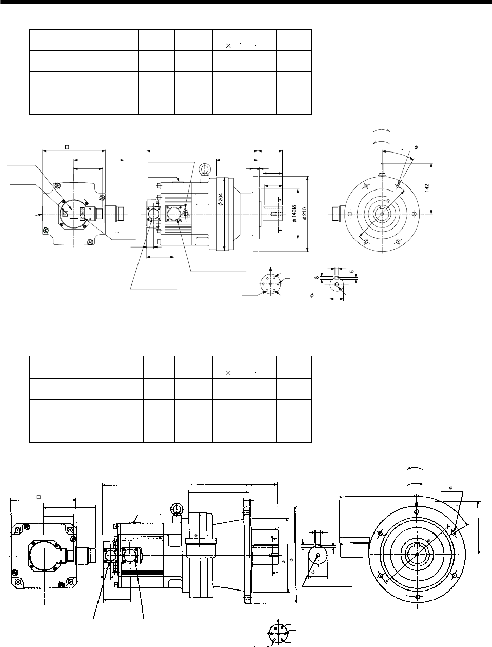
7 - 71
7. OUTLINE DIMENSION DRAWINGS
Model Output
[kW]
Reduction
Ratio
Inertia Moment
J[ 10 4kg m2]
Mass
[kg]
HC-SF202G1 HC-SFS202G1
HC-SFS2024G1 2.0 1/6 45.6 34
HC-SF202G1 HC-SFS202G1
HC-SFS2024G1 2.0 1/11 44.1 34
HC-SF202G1 HC-SFS202G1
HC-SFS2024G1 2.0 1/17 43.7 34
13 455
117
69
312
81.5
142
76.5
A
B
C
D
E
FG
10
Z695806A
BC11814B BC30689*
A
A
50
19.5
Encoder connector
Power supply connector
V
U
CE05-2A24-10P
MS3102A20-29P W
Motor plate
Caution plate Caution plate (Note 2)
(Opposite side)
38h6
176
Caution plate
Logo plate
(Note 2)
Side view of motor only
6- 11
Section AA
Power supply connector layout
Top
Bottom
Top
Bottom
Top
Bottom
Top
Bottom
For forward rotation command
"Rotation direction"
For reverse rotation command
Earth
CE05-2A24-10P
M8 screw, depth 20
Motor flange direction
TUV plate
30
180
(Note 1)[Unit: mm]
Note 1. The dimensions without tolerances are reference dimensions.
2. This caution plate is attached to the 400V class motors only, not to the 200V class.
Model Output
[kW]
Reduction
Ratio
Inertia Moment
J[ 10 4kg m2]
Mass
[kg]
HC-SF352G1 HC-SFS352G1
HC-SFS3524G1 3.5 1/6 90.1 57
HC-SF352G1 HC-SFS352G1
HC-SFS3524G1 3.5 1/11 86.2 57
HC-SF352G1 HC-SFS352G1
HC-SFS3524G1 3.5 1/17 85.0 57
142
397 76
70
81.5
A
A
76.5
142
5.5
60
9
209
U
V
W
CD B
E
A
G
F
164
415
19.5
14
MS3102A20-29P CE05-2A24-10P
Bottom Top
Encoder connector Power supply connector
Motor flange direction
Earth
Power supply connector layout
CE05-2A24-10P
(Note)[Unit: mm]
Motor plate
[Side view of motor only]
"Rotation direction"
For reverse
rotation command
For forward
rotation command
Section A-A
M10 threads, depth 18
176
230
200f8
260
50h6
6- 11
230
(BC11816*)
Z695807A
Note: The dimensions without tolerances are reference dimensions.
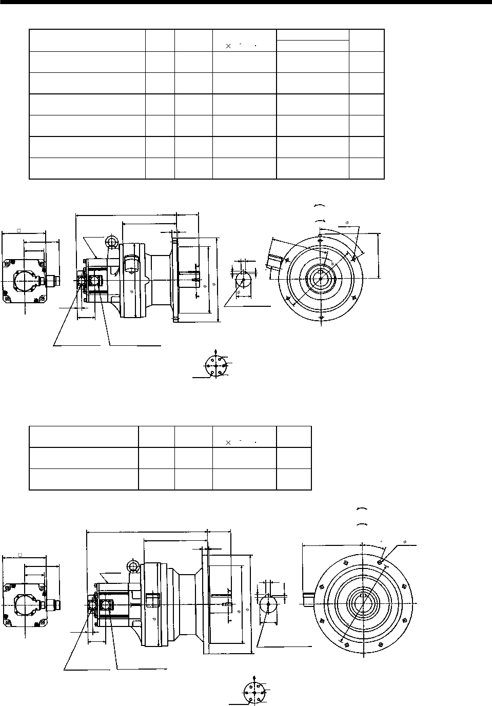
7 - 72
7. OUTLINE DIMENSION DRAWINGS
Variable Dimensions
Model Output
[kW]
Reduction
Ratio
Inertia Moment
J[ 10 4kg m2]L
Mass
[kg]
HC-SF202G1 HC-SFS202G1
HC-SFS2024G1 2.0 1/29 48.9 409 84
HC-SF202G1 HC-SFS202G1
HC-SFS2024G1 2.0 1/35 48.6 409 84
HC-SF202G1 HC-SFS202G1
HC-SFS2024G1 2.0 1/43 48.4 409 84
HC-SF202G1 HC-SFS202G1
HC-SFS2024G1 2.0 1/59 48.3 409 84
HC-SF352G1 HC-SFS352G1
HC-SFS3524G1 3.5 1/29 88.4 451 91
HC-SF352G1 HC-SFS352G1
HC-SFS3524G1 3.5 1/35 88.1 451 91
142
L89
4
81.5
A
A
76.5
181
7
60
11
18
U
V
W
CD B
E
A
G
F
219
4
20
19. 5
228
15
Section A-A
M10 threads, depth 18
MS3102A20-29P CE05-2A24-10P
Bottom Top
Encoder connector Power supply connector
Motor flange direction
Earth
Power supply connector layout
CE05-2A24-10P
(Note)[Unit: mm]
Motor plate
[Side view of motor only]
"Rotation direction"
For reverse
rotation command
For forward
rotation command
310
6- 11
60h6
270f8
340
300
176
Z695808A
(BC11815*)
Note: The dimensions without tolerances are reference dimensions.
Model Output
[kW]
Reduction
Ratio
Inertia Moment
J[ 10 4kg m2]
Mass
[kg]
HC-SF352G1 HC-SFS352G1
HC-SFS3524G1 3.5 1/43 106.5 133
HC-SF352G1 HC-SFS352G1
HC-SFS3524G1 3.5 1/59 105.9 133
142
94
81.5
A
A
76.5
12
22.5
7.5
20
U
V
W
CDBE
A
G
F
70h 6
490
5
22
19. 5
243
258
MS3102A20-29P CE05-2A24-10P
Bottom Top
Encoder connector Power supply connector
Motor flange direction
Earth
Power supply connector layout
CE05-2A24-10P
(Note)[Unit: mm]
Motor plate
[Side view of motor only]
"Rotation direction"
For reverse
rotation command
For forward
rotation command
1-M12 threads, depth 24
Section A-A
176
8- 14
360
316f8
400
340
Z695809A
(BC11817*)
Note: The dimensions without tolerances are reference dimensions.

7 - 73
7. OUTLINE DIMENSION DRAWINGS
Model Output
[kW]
Reduction
Ratio
Inertia Moment
J[ 10 4kg m2]
Mass
[kg]
HC-SF502G1 HC-SFS502G1
HC-SFS5024G1 5.0 1/11 113.4 95
HC-SF502G1 HC-SFS502G1
HC-SFS5024G1 5.0 1/17 109.4 95
Power supply connector layout
CE05-2A24-10P
142
472
219
89
A
A
Motor plate
19.5
181
7
60
11
Motor flange direction
18
U
V
W
C
DB
E
A
G
F
Earth
Section A-A
M10 threads, depth 18
Encoder connector
MS3102A20-29P
Power supply connector
CE05-2A24-10P
39.5
181
81.5
76.5
20 4
85
228
15
Bottom Top
[Side view of motor only]
(Note)[Unit: mm
]
"Rotation direction"
For reverse
rotation command
For forward
rotation command
300
270f8
340
60h6
6- 11
310
BC10756*
176
(BC11818*)
Note: The dimensions without tolerances are reference dimensions.
Model Output
[kW]
Reduction
Ratio
Inertia Moment
J[ 10 4kg m2]
Mass
[kg]
HC-SF502G1 HC-SFS502G1
HC-SFS5024G1 5.0 1/29 138.5 162
HC-SF502G1 HC-SFS502G1
HC-SFS5024G1 5.0 1/35 138.0 162
HC-SF502G1 HC-SFS502G1
HC-SFS5024G1 5.0 1/43 137.0 162
Power supply connector layout
CE05-2A24-10P
142
535
279
110
A
A
Motor plate
19.5
9
22.5
14
Motor flange direction
22
U
V
W
C
DB
E
A
G
F
Earth
Section A-A
1-M12 threads, depth 24
Encoder connector
MS3102A20-29P
Power supply connector
CE05-2A24-10P
39.5
176
81.5
76.5
22 5
105
258
Bottom Top
[Side view of motor only]
(Note)[Unit: mm
]
"Rotation direction"
For reverse
rotation command
For forward
rotation command
176
370
345f8
430
80h6
8- 18
390
BC10757*
(BC11819*)
Note: The dimensions without tolerances are reference dimensions.
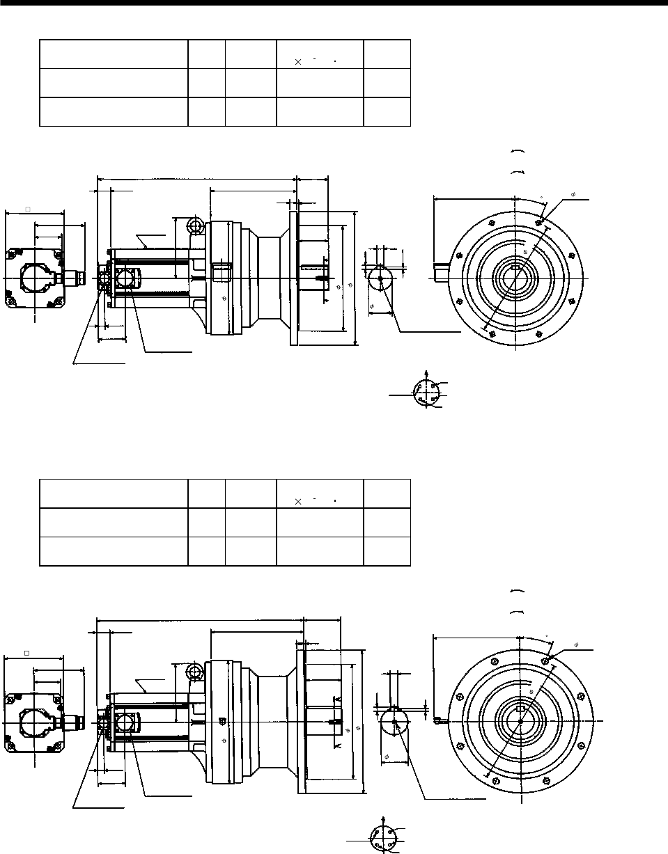
7 - 74
7. OUTLINE DIMENSION DRAWINGS
Model Output
[kW]
Reduction
Ratio
Inertia Moment
J[ 10 4kg m2]
Mass
[kg]
HC-SF702G1 HC-SFS702G1
HC-SFS7024G1 7.0 1/11 198.8 146
HC-SF702G1 HC-SFS702G1
HC-SFS7024G1 7.0 1/17 190.0 146
Power supply connector layout
CE05-2A32-17P
150
595
258
94
A
A
Motor plate
19.5
7.5
22.5
12
Motor flange direction
20
U
V
W
C
D
B
A
Earth
Section A-A 1-M12 threads, depth 24
Encoder connector
MS3102A20-29P
Power supply connector
CE05-2A32-17P
39.5
181
81.5
81.5
22 5
89
243
Bottom Top
[Side view of motor only]
(Note)[Unit: mm
]
"Rotation direction"
For reverse
rotation command
For forward
rotation command
BC10758*
176
70h6
8- 14
360
340
316f8
400
(BC11820*)
Note: The dimensions without tolerances are reference dimensions.
Model Output
[kW]
Reduction
Ratio
Inertia Moment
J[ 10 4kg m2]
Mass
[kg]
HC-SF702G1 HC-SFS702G1
HC-SFS7024G1 7.0 1/29 197.5 171
HC-SF702G1 HC-SFS702G1
HC-SFS7024G1 7.0 1/35 197.0 171
150
619
279
110
A
A
Motor plate
19.5
9
22.5
14
22
Power supply connector layout
CE05-2A32-17P
Motor flange direction
U
V
W
C
D
B
A
Earth
Section A-A
1-M12 threads, depth 24
Encoder connector
MS3102A20-29P
Power supply
connector
CE05-2A32-17P
39.5
176
81.5
81.5
22 5
105
258
Bottom Top
[Side view of motor only]
(Note)[Unit: mm]
"Rotation direction"
For reverse
rotation command
For forward
rotation command
370
345f8
430
80h6
8- 18
BC10759*
176
390
(BC11821*)
Note: The dimensions without tolerances are reference dimensions.

7 - 75
7. OUTLINE DIMENSION DRAWINGS
Model Output
[kW]
Reduction
Ratio
Inertia Moment
J[ 10 4kg m2]
Mass
[kg]
HC-SF702G1 HC-SFS702G1
HC-SFS7024G1 7.0 1/43 256.8 240
150
675
320
145
A
A
Motor plate
19.5
9
14
25
Power supply connector layout
CE05-2A32-17P
Motor flange direction
U
V
W
C
D
B
A
Earth
Section A-A
1-M20 threads, depth 34
Encoder connector
MS3102A20-29P
Power supply
connector
CE05-2A32-17P
39.5
210
81.5
81.5
30 6
135
285
15
Bottom Top
[Side view of motor only]
(Note)[Unit: mm
]
"Rotation direction"
For reverse
rotation command
For forward
rotation command
BC10760*
176
95h6
12- 18
450
400f8
490
430
(BC11822*)Note: The dimensions without tolerances are reference dimensions.
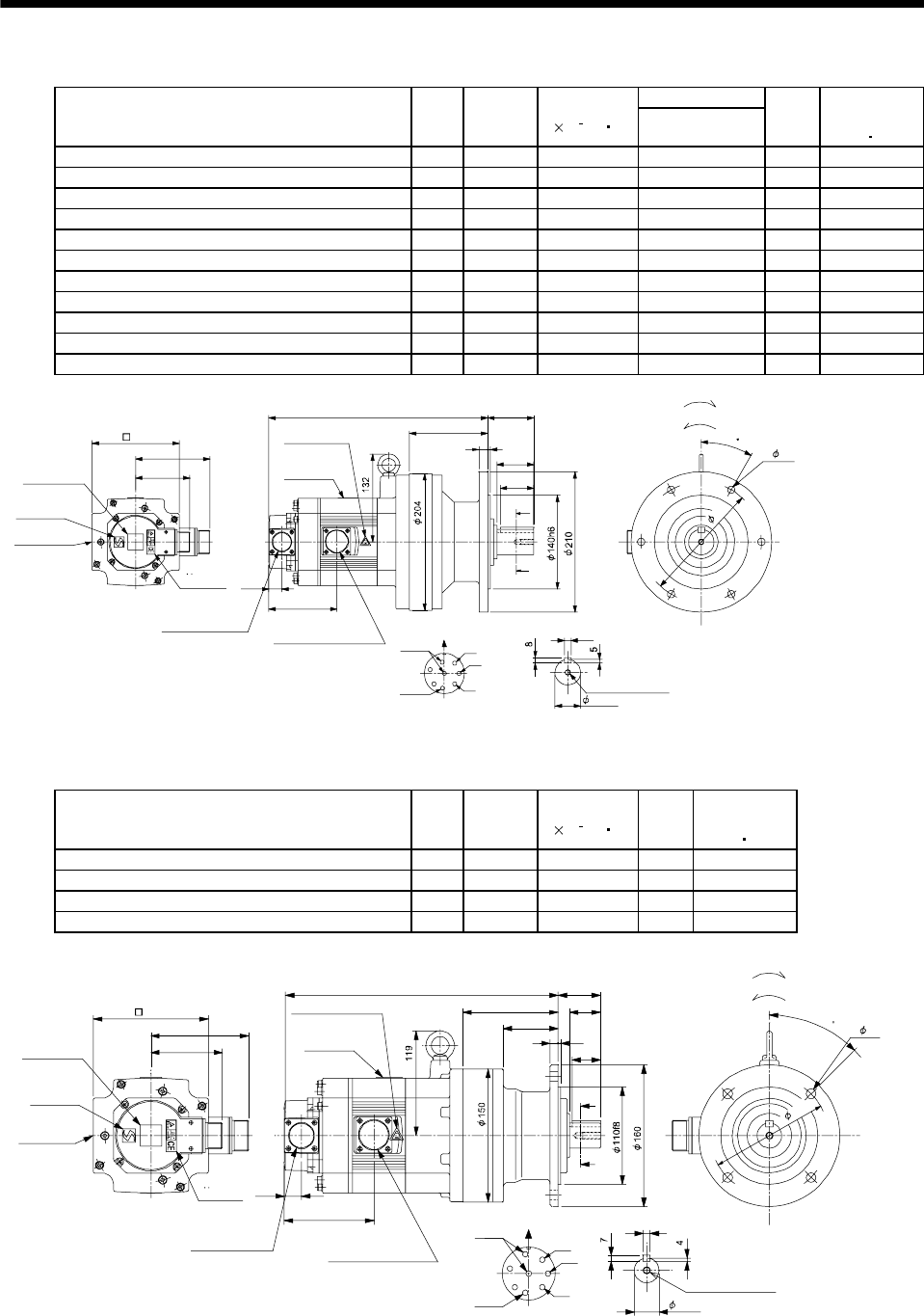
7 - 76
7. OUTLINE DIMENSION DRAWINGS
(b) With electromagnetic brake
Variable Dimensions
Model Output
[kW]
Reduction
Ratio
Inertia Moment
J[ 10 4kg m2]L
Mass
[kg]
Brake static
friction torque
[N m]
HC-SF52BG1 HC-SFS52BG1 HC-SFS524BG1 0.5 1/35 9.2 302 32.5 8.3
HC-SF52BG1 HC-SFS52BG1 HC-SFS524BG1 0.5 1/43 9.15 302 32.5 8.3
HC-SF52BG1 HC-SFS52BG1 HC-SFS524BG1 0.5 1/59 9.13 302 32.5 8.3
HC-SF102BG1 HC-SFS102BG1 HC-SFS1024BG1 1.0 1/6 18.5 327 34.5 8.3
HC-SF102BG1 HC-SFS102BG1 HC-SFS1024BG1 1.0 1/11 17.0 327 34.5 8.3
HC-SF102BG1 HC-SFS102BG1 HC-SFS1024BG1 1.0 1/17 16.6 327 34.5 8.3
HC-SF102BG1 HC-SFS102BG1 HC-SFS1024BG1 1.0 1/29 16.3 327 34.5 8.3
HC-SF102BG1 HC-SFS102BG1 HC-SFS1024BG1 1.0 1/35 16.28 327 34.5 8.3
HC-SF152BG1 HC-SFS152BG1 HC-SFS1524BG1 1.5 1/6 24.8 352 36.5 8.3
HC-SF152BG1 HC-SFS152BG1 HC-SFS1524BG1 1.5 1/11 23.2 352 36.5 8.3
HC-SF152BG1 HC-SFS152BG1 HC-SFS1524BG1 1.5 1/17 22.9 352 36.5 8.3
A
B
C
D
E
FG
H
A
A
81.5
111 55
69
L
413
117
101.5
10
19.5
50
Z695751*
BC11837B BC26058A
Encoder connector
Power supply connector
V
U
CE05-2A22-23P
MS3102A20-29P
W
Motor plate
Caution plate
Caution plate
(Note 2)
(Opposite side)
38h6
130
Caution plate
Logo plate
(Note 2)
Side view of motor only
6- 11
Section AA
Power supply connector layout
Top
Bottom
TopBottom
Top
Bottom
TopBottom
For forward rotation command
"Rotation direction"
For reverse rotation command
Earth
Brake
CE05-2A22-23P
M8 screw, depth 20
Motor flange direction
TUV plate
30
180
(Note 1)[Unit: mm]
Note 1. The dimensions without tolerances are reference dimensions.
2. This caution plate is attached to the 400V class motors only, not to the 200V class.
Model Output
[kW]
Reduction
Ratio
Inertia Moment
J[ 10 4kg m2]
Mass
[kg]
Brake static
friction torque
[N m]
HC-SF52BG1 HC-SFS52BG1 HC-SFS524BG1 0.5 1/6 9.03 20.5 8.3
HC-SF52BG1 HC-SFS52BG1 HC-SFS524BG1 0.5 1/11 8.65 20.5 8.3
HC-SF52BG1 HC-SFS52BG1 HC-SFS524BG1 0.5 1/17 8.55 20.5 8.3
HC-SF52BG1 HC-SFS52BG1 HC-SFS524BG1 0.5 1/29 8.48 20.5 8.3
Z695750*
BC11836C BC26183C
81.5
111
310 48
A
A
32
39
62
108 35
8
101.5
19.5
A
B
C
D
E
FG
H
Encoder connector
Power supply connector V
U
CE05-2A22-23P
MS3102A20-29P
W
Motor plate
Caution plate
Caution plate (Note 2)
(Opposite side)
28h6
130
Caution plate
Logo plate
(Note 2)
Side view of motor only
4- 11
Section AA
Power supply connector layout
Top
Bottom
TopBottom
To
Bottom
TopBottom
For forward rotation command
"Rotation direction"
For reverse rotation command
Earth
Brake
CE05-2A22-23P
M8 screw, depth 20
Motor flange direction
TUV plate
45
134
(Note 1)[Unit: mm]
Note 1. The dimensions without tolerances are reference dimensions.
2. This caution plate is attached to the 400V class motors only, not to the 200V class.
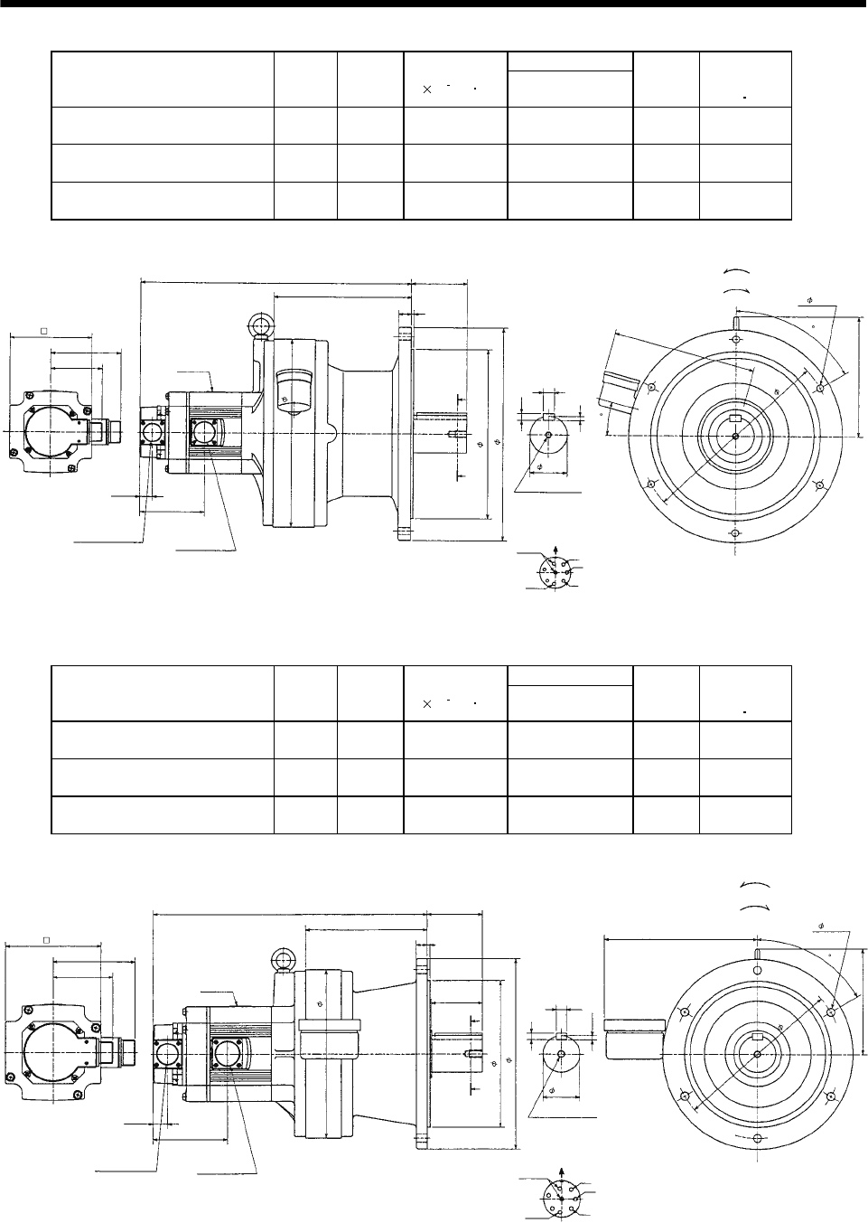
7 - 77
7. OUTLINE DIMENSION DRAWINGS
Variable Dimensions
Model Output
[kW]
Reduction
Ratio
Inertia Moment
J[ 10 4kg m2]L
Mass
[kg]
Brake static
friction torque
[N m]
HC-SF102BG1 HC-SFS102BG1
HC-SFS1024BG1 1.0 1/59 21.2 432 85 8.3
HC-SF152BG1 HC-SFS152BG1
HC-SFS1524BG1 1.5 1/43 27.5 457 87 8.3
HC-SF152BG1 HC-SFS152BG1
HC-SFS1524BG1 1.5 1/59 27.4 457 87 8.3
270f8
60h6
MS3102A20-29P
CE05-2A22-23P
Bottom Top
Encoder connector
Power supply connector
Motor flange direction
Earth
Power supply connector layout
CE05-2A22-23P
(Note)[Unit: mm]
Motor plate
[Side view of motor only]
"Rotation direction"
For reverse rotation command
For forward rotation command
Brake
Section A-A
M10 threads, depth 18
340
300
(BC11839*)
Z695753*
6- 11
310
19.5
101.5
81.5
111
130
L89
219
4
20
A
A
18
7
11
60
228
192
AV
U
15
B
C
D
E
FG
HW
Note: The dimensions without tolerances are reference dimensions.
Variable Dimensions
Model Output
[kW]
Reduction
Ratio
Inertia Moment
J[ 10 4kg m2]L
Mass
[kg]
Brake static
friction torque
[N m]
HC-SF102BG1 HC-SFS102BG1
HC-SFS1024BG1 1.0 1/43 17.4 373 50 8.3
HC-SF152BG1 HC-SFS152BG1
HC-SFS1524BG1 1.5 1/29 23.8 398 52 8.3
HC-SF152BG1 HC-SFS152BG1
HC-SFS1524BG1 1.5 1/35 23.7 398 52 8.3
(Note)[Unit: mm]
"Rotation direction"
For reverse rotation command
For forward rotation command
6- 11
Motor flange direction
Earth
Power supply connector layout
CE05-2A22-23P
Brake
Section A-A
M10 threads, depth 18
(BC11838*)
50h6
Z695752*
200f8
260
MS3102A20-29P
CE05-2A22-23P
Bottom Top
Encoder connector
Power supply connector
Motor plate
[Side view of motor only]
230
130
111
81.5
19.5
101.5
L76
164
15 4
70
A
A
9
14
5.5
209
60
145
230
U
V
W
A
B
C
D
E
FG
H
Note: The dimensions without tolerances are reference dimensions.
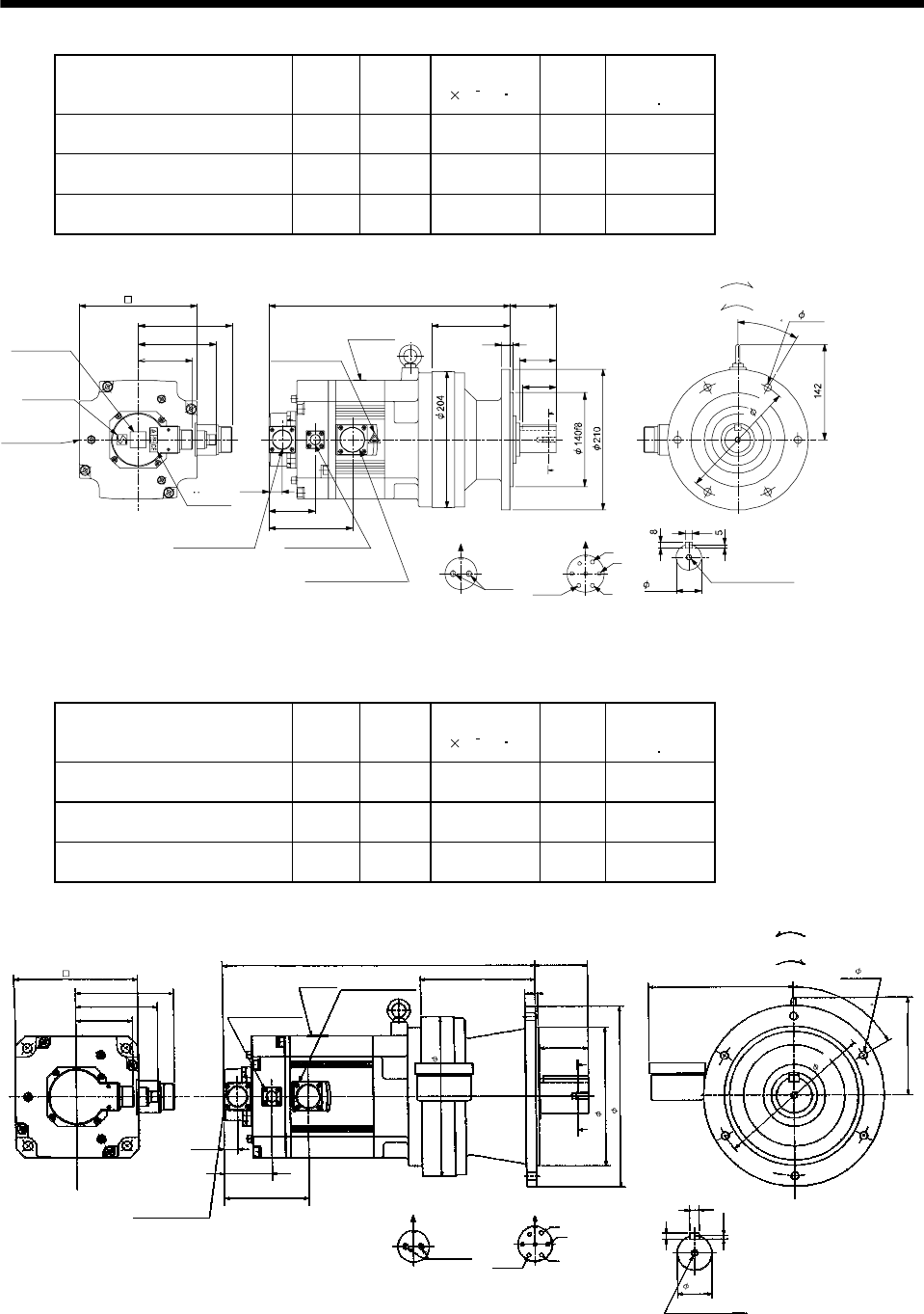
7 - 78
7. OUTLINE DIMENSION DRAWINGS
Model Output
[kW]
Reduction
Ratio
Inertia Moment
J[ 10 4kg m2]
Mass
[kg]
Brake static
friction torque
[N m]
HC-SF202BG1 HC-SFS202BG1
HC-SFS2024BG1 2.0 1/6 55.6 40 43.1
HC-SF202BG1 HC-SFS202BG1
HC-SFS2024BG1 2.0 1/11 54.1 40 43.1
HC-SF202BG1 HC-SFS202BG1
HC-SFS2024BG1 2.0 1/17 53.7 40 43.1
Z695856A
BC11840B BC29441A
81.5
117
142
A
B
C
D
E
FG
BA
10
19.5
69
124.5
13 4
55
117
69360
A
A
50
Encoder connector
Power supply connector
V
U
CE05-2A24-10P
MS3102A20-29P
W
Motor plate
Caution plate Caution plate
(Note 2)
(Opposite side)
38h6
176
Caution plate
Logo plate
(Note 2)
Side view of motor only
6- 11
Section AA
Power supply connector layout
Top
Bottom
TopBottom
Top
Bottom
TopBotto
For forward rotation command
"Rotation direction"
For reverse rotation command
Earth
Brake
CE05-2A24-10P
M8 screw, depth 20
Motor flange direction
Motor flange direction
Brake connector layout
MS3102A10SL-4P
Brake connector
MS3102A10SL-4P
TUV plate
180
30
(Note 1)[Unit: mm]
Note 1. The dimensions without tolerances are reference dimensions.
2. This caution plate is attached to the 400V class motors only, not to the 200V class.
Model Output
[kW]
Reduction
Ratio
Inertia Moment
J[ 10 4kg m2]
Mass
[kg]
Brake static
friction torque
[N m]
HC-SF352BG1 HC-SFS352BG1
HC-SFS3524BG1 3.5 1/6 100.1 63 43.1
HC-SF352BG1 HC-SFS352BG1
HC-SFS3524BG1 3.5 1/11 96.2 63 43.1
HC-SF352BG1 HC-SFS352BG1
HC-SFS3524BG1 3.5 1/17 95.0 63 43.1
142
445 76
70
81.5
A
A
69
142
5.5
9
14
U
V
W
CDBE
A
G
F
164
200f8
4
15
19.5
124.5
117
AB
209
MS3102A20-29P
CE05-2A24-10P
Bottom Top
Encoder connector
Power supply connector
Motor flange direction
Earth
Power supply connector layout
CE05-2A24-10P
(Note)[Unit: mm]
Motor plate
[Side view of motor only]
"Rotation direction"
For reverse
rotation command
For forward
rotation command
Motor flange direction
Brake connector
MS3102A10SL-4P
Brake connector layout
MS3102A10SL-4P
Brake
Section A-A
M10 threads, depth 18
Z695857A
(BC11842*)
260
230
50h6
6- 11
60
176
230
Note: The dimensions without tolerances are reference dimensions.
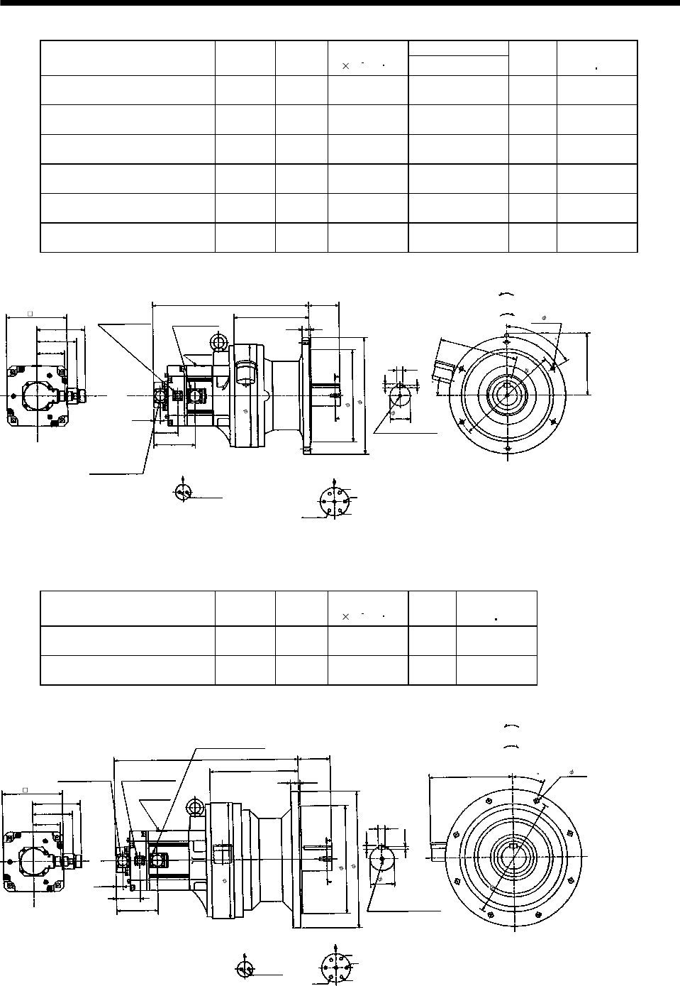
7 - 79
7. OUTLINE DIMENSION DRAWINGS
Variable Dimensions
Model Output
[kW]
Reduction
Ratio
Inertia Moment
J[ 10 4kg m2]L
Mass
[kg]
Brake static
friction torque
[N m]
HC-SF202BG1 HC-SFS202BG1
HC-SFS2024BG1 2.0 1/29 58.9 457 90 43.1
HC-SF202BG1 HC-SFS202BG1
HC-SFS2024BG1 2.0 1/35 58.6 457 90 43.1
HC-SF202BG1 HC-SFS202BG1
HC-SFS2024BG1 2.0 1/43 58.4 457 90 43.1
HC-SF202BG1 HC-SFS202BG1
HC-SFS2024BG1 2.0 1/59 58.3 457 90 43.1
HC-SF352BG1 HC-SFS352BG1
HC-SFS3524BG1 3.5 1/29 98.4 499 97 43.1
HC-SF352BG1 HC-SFS352BG1
HC-SFS3524BG1 3.5 1/35 98.1 499 97 43.1
142
L89
4
81.5
A
A
69
181
7
60
11
18
U
V
W
CD B
E
A
G
F
219
4
20
19. 5
228
15
124.5
117
AB
MS3102A20-29P
CE05-2A24-10P
Bottom Top
Encoder connector
Power supply connector
Motor flange direction
Earth
Power supply connector layout
CE05-2A24-10P
(Note)[Unit: mm]
Motor plate
[Side view of motor only]
"Rotation direction"
For reverse
rotation command
For forward
rotation command
Motor flange direction
Brake connector
MS3102A10SL-4P
Brake connector layout
MS3102A10SL-4P
Brake
Section A-A
M10 threads, depth 18
300
270f8
340
60h6
6- 11
3
1
0
176
Z695858A
(BC11841*)
Note: The dimensions without tolerances are reference dimensions.
Model Output
[kW]
Reduction
Ratio
Inertia Moment
J[ 10 4kg m2]
Mass
[kg]
Brake static
friction torque
[N m]
HC-SF352BG1 HC-SFS352BG1
HC-SFS3524BG1 3.5 1/43 116.5 139 43.1
HC-SF352BG1 HC-SFS352BG1
HC-SFS3524BG1 3.5 1/59 115.9 139 43.1
142
538 94
5
81.5
A
A
69
7.5
22.5
12
20
U
V
W
CD B
E
A
G
F
258
22
19.5
124.5
117
AB
243
Section A-A
1-M12 threads, depth 24
MS3102A20-29P
CE05-2A24-10P
Bottom Top
Encoder connector
Power supply connector
Motor flange direction
Earth
Power supply connector layout
CE05-2A24-10P
(Note)[Unit: mm]
Motor plate
[Side view of motor only]
"Rotation direction"
For reverse
rotation command
For forward
rotation command
Motor flange direction
Brake connector
MS3102A10SL-4P
Brake connector layout
MS3102A10SL-4P
Brake
Z695859A
(BC11843*)
8- 14
360
316f8
400
340
176
Note: The dimensions without tolerances are reference dimensions.
70h 6
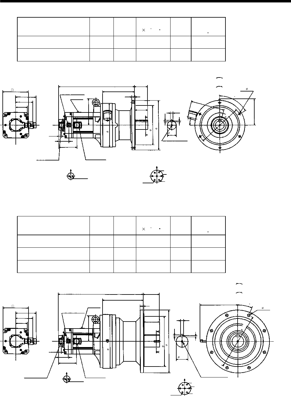
7 - 80
7. OUTLINE DIMENSION DRAWINGS
Model Output
[kW]
Reduction
Ratio
Inertia Moment
J[ 10 4kg m2]
Mass
[kg]
Brake static
friction torque
[N m]
HC-SF502BG1 HC-SFS502BG1
HC-SFS5024BG1 5.0 1/11 123.4 101 43.1
HC-SF502BG1 HC-SFS502BG1
HC-SFS5024BG1 5.0 1/17 119.4 101 43.1
Power supply connector layout
CE05-2A24-10P
142
520
219
89
117
A
A
Motor plate
19.5
69
181
7
11
Motor flange direction
18
U
V
W
C
DBE
A
G
F
Earth
Section A-A
M10 threads, depth 18
Encoder connector
MS3102A20-29P
Power supply connector
CE05-2A24-10P
181
81.5
Brake connector layout
MS3102A10SL-4P
Motor flange direction
B
ABrake
124.5
Brake connector
MS3102A10SL-4P
20 4
85
228
15
Bottom Top
[Side view of motor only]
(Note)[Unit: mm]
"Rotation direction"
For reverse
rotation command
For forward
rotation command
BC11033*
310
6- 11
60h6
340
270f8
300
176
60
(BC11844*)
Note: The dimensions without tolerances are reference dimensions.
Model Output
[kW]
Reduction
Ratio
Inertia Moment
J[ 10 4kg m2]
Mass
[kg]
Brake static
friction torque
[N m]
HC-SF502BG1 HC-SFS502BG1
HC-SFS5024BG1 5.0 1/29 148.5 168 43.1
HC-SF502BG1 HC-SFS502BG1
HC-SFS5024BG1 5.0 1/35 148.0 168 43.1
HC-SF502BG1 HC-SFS502BG1
HC-SFS5024BG1 5.0 1/43 147.0 168 43.1
142
583
279
110
117
A
A
Motor plate
19.5
69
9
14
22
Power supply connector layout
CE05-2A24-10P
Motor flange direction
U
V
W
C
DBE
A
G
F
Earth
Section A-A
1-M12 threads, depth 24
Encoder connector
MS3102A20-29P
Power supply connector
CE05-2A24-10P
176
81.5
Brake connector layout
MS3102A10SL-4P
Motor flange direction
B
A
Brake
124.5
Brake connector
MS3102A10SL-4P
22 5
105
345f8
22.5
258
176
Bottom Top
[Side view of motor only]
(Note)[Unit: mm
]
"Rotation direction"
For reverse
rotation command
For forward
rotation command
BC11034*
80h6
8- 18
390
370
430
(BC11845*)
Note: The dimensions without tolerances are reference dimensions.
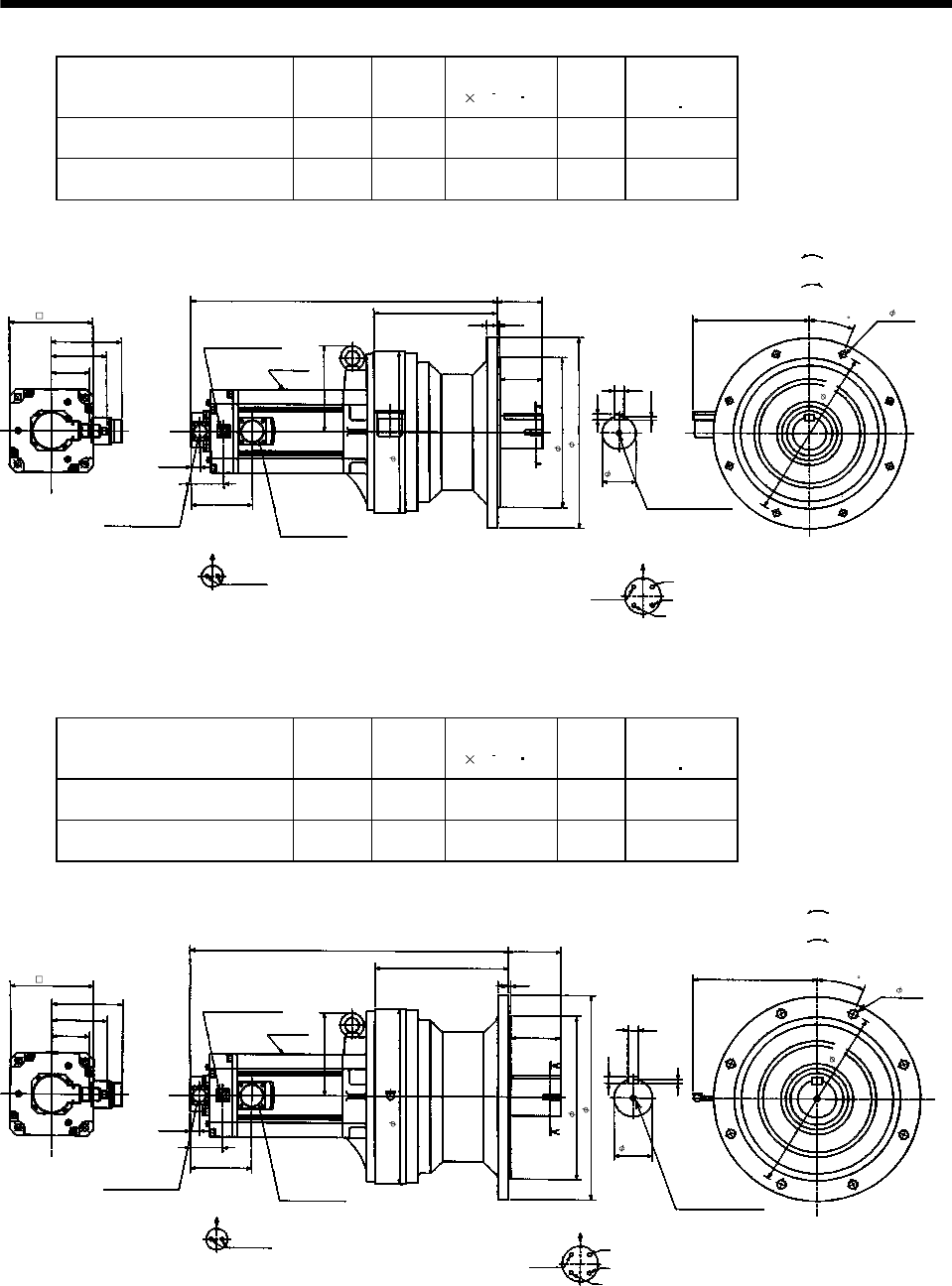
7 - 81
7. OUTLINE DIMENSION DRAWINGS
Model Output
[kW]
Reduction
Ratio
Inertia Moment
J[ 10 4kg m2]
Mass
[kg]
Brake static
friction torque
[N m]
HC-SF702BG1 HC-SFS702BG1
HC-SFS7024BG1 7.0 1/11 208.8 152 43.1
HC-SF702BG1 HC-SFS702BG1
HC-SFS7024BG1 7.0 1/17 200.0 152 43.1
150
643
258
94
117
A
A
Motor plate
19.5
69
7.5
12
20
Power supply connector layout
CE05-2A32-17P
Motor flange direction
U
V
W
C
D
B
A
Earth
Section A-A 1-M12 threads, depth 24
Encoder connector
MS3102A20-29P Power supply connector
CE05-2A32-17P
181
81.5
Brake connector layout
MS3102A10SL-4P
Motor flange direction
B
ABrake
129.5
Brake connector
MS3102A10SL-4P
22 5
89
22.5
243
Bottom Top
[Side view of motor only]
(Note)[Unit: mm]
"Rotation direction"
For reverse
rotation command
For forward
rotation command
340
316f8
400
70h6
8- 14
360
BC11035*
176
(BC11846*)
Note: The dimensions without tolerances are reference dimensions.
Model Output
[kW]
Reduction
Ratio
Inertia Moment
J[ 10 4kg m2]
Mass
[kg]
Brake static
friction torque
[N m]
HC-SF702BG1 HC-SFS702BG1
HC-SFS7024BG1 7.0 1/29 207.5 177 43.1
HC-SF702BG1 HC-SFS702BG1
HC-SFS7024BG1 7.0 1/35 207.0 177 43.1
667
279
110
117
A
A
Motor plate
19.5
69
9
14
22
Power supply connector layout
CE05-2A32-17P
Motor flange direction
U
V
W
C
D
B
A
Earth
Section A-A
1-M12 threads, depth 24
Encoder connector
MS3102A20-29P
Power supply
connector
CE05-2A32-17P
176
81.5
Brake connector layout
MS3102A10SL-4P
Motor flange direction
B
ABrake
129.5
Brake connector
MS3102A10SL-4P
22 5
105
22.5
150
258
Bottom Top
[Side view of motor only]
(Note)[Unit: mm
]
"Rotation direction"
For reverse
rotation command
For forward
rotation command
BC11036*
176
80h6
8- 18
390
345f8
430
370
(BC11847*)
Note: The dimensions without tolerances are reference dimensions.
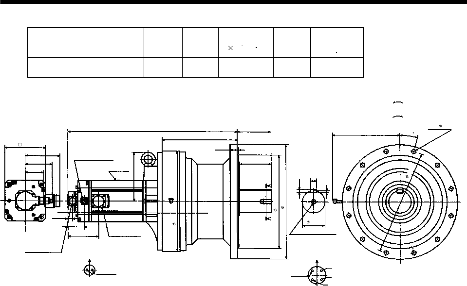
7 - 82
7. OUTLINE DIMENSION DRAWINGS
Model Output
[kW]
Reduction
Ratio
Inertia Moment
J[ 10 4kg m2]
Mass
[kg]
Brake static
friction torque
[N m]
HC-SF702BG1 HC-SFS702BG1
HC-SFS7024BG1 7.0 1/43 266.8 246 43.1
Power supply connector layout
CE05-2A32-17P
150
723
320
145
117
A
A
Motor plate
19.5
69
9
14
Motor flange direction
25
U
V
W
C
D
B
A
Earth
Section A-A
1-M20 threads, depth34
Encoder connector
MS3102A20-29P
Power supply
connector
CE05-2A32-17P
210
81.5
Brake connector layout
MS3102A10SL-4P
Motor flange direction
B
A
Brake
129.5
Brake connector
MS3102A10SL-4P
30 6
135
15
285
Bottom Top
(Note)[Unit: mm]
"Rotation direction"
For reverse
rotation command
For forward
rotation command
430
400f8
490
95h6
12- 18
450
BC11037*
176
(BC11848*)Note: The dimensions without tolerances are reference dimensions.
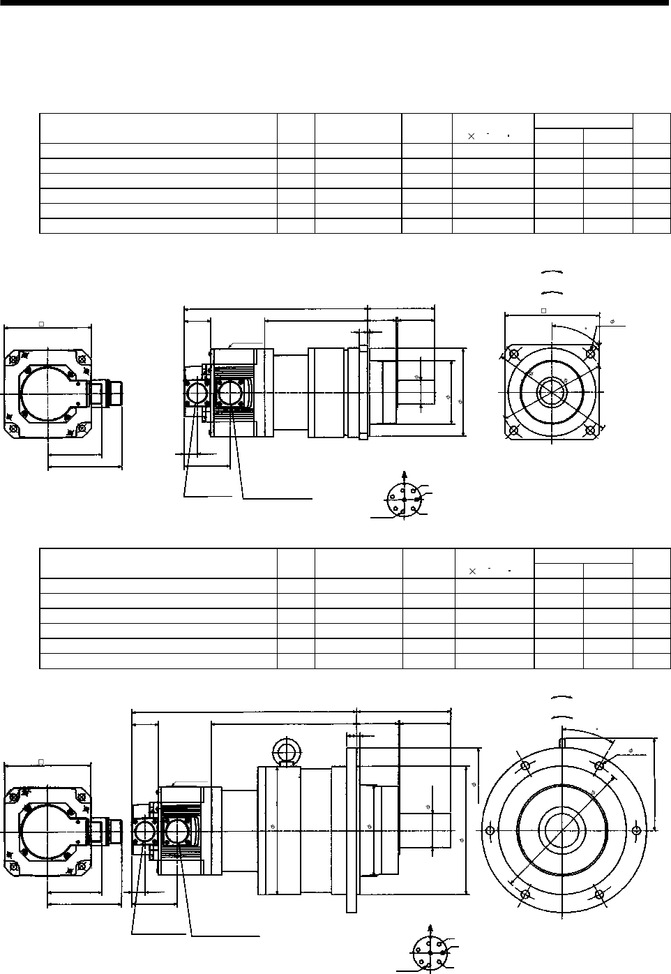
7 - 83
7. OUTLINE DIMENSION DRAWINGS
(5) With reduction gear for precision application
The outer frame of the reduction gear is a material surface such as casting. Its actual dimensions may
be 1 to 3mm larger than the drawing dimensions. Design the machine side with allowances.
(a) Without electromagnetic brake
Variable Dimensions
Model Output
[kW]
Reduction Gear
Model
Reduction
Ratio
Inertia Moment
J[ 10 4kg m2]LH
Mass
[kg]
HC-SF52G2 HC-SFS52G2 HC-SFS524G2 0.5 BL2-05B-05MEH 1/5 7.9 276 156 13
HC-SF52G2 HC-SFS52G2 HC-SFS524G2 0.5 BL2-09B-05MEH 1/9 7.55 288 168 13
HC-SF52G2 HC-SFS52G2 HC-SFS524G2 0.5 BL2-20B-05MEH 1/20 8.03 309 189 15
HC-SF102G2 HC-SFS102G2 HC-SFS1024G2 1.0 BL2-05B-10MEH 1/5 15.0 301 156 15
HC-SF102G2 HC-SFS102G2 HC-SFS1024G2 1.0 BL2-09B-10MEH 1/9 14.6 313 168 15
HC-SF152G2 HC-SFS152G2 HC-SFS1524G2 1.5 BL2-05B-15MEH 1/5 21.2 326 156 17
19.5
W
V
U
L
55
100
A
F
G
H
B
E
C
D
111
81.5
68.5
39.5 H43
12 3
94
MS3102A20-29P CE05-2A22-23P
Bottom Top
Encoder connector Power supply connector
Motor flange direction
Earth
Power supply connector layout
CE05-2A22-23P
(Note)[Unit: mm]
Motor plate
[Side view of motor only]
"Rotation direction"
For reverse
rotation command
For forward
rotation command
45
130 4- 12
185
160
140
130h7
35h6
Z695320*
(BC11849*)
Note: The dimensions without tolerances are reference dimensions.
Variable Dimensions
Model Output
[kW]
Reduction Gear
Model
Reduction
Ratio
Inertia Moment
J[ 10 4kg m2]LH
Mass
[kg]
HC-SF52G2 HC-SFS52G2 HC-SFS524G2 0.5 BL3-29B-05MEH 1/29 9.4 337 217 30
HC-SF52G2 HC-SFS52G2 HC-SFS524G2 0.5 BL3-45B-05MEH 1/45 8.43 343 223 30
HC-SF102G2 HC-SFS102G2 HC-SFS1024G2 1.0 BL3-20B-10MEH 1/20 18.4 362 217 32
HC-SF102G2 HC-SFS102G2 HC-SFS1024G2 1.0 BL3-29B-10MEH 1/29 16.5 362 217 32
HC-SF152G2 HC-SFS152G2 HC-SFS1524G2 1.5 BL3-09B-15MEH 1/9 24.7 379 209 34
HC-SF152G2 HC-SFS152G2 HC-SFS1524G2 1.5 BL3-20B-15MEH 1/20 24.6 387 217 34
19.5
W
V
U
L
75
140
A
FG
H
B
E
C
D
111
81.5
68.5
39.5 H63
15 5
137
30
MS3102A20-29P CE05-2A22-23P
Bottom Top
Encoder connector Power supply connector Motor flange direction
Earth
Power supply connector layout
CE05-2A22-23P
(Note)[Unit: mm]
Motor plate
[Side view of motor only]
"Rotation direction"
For reverse
rotation command
For forward
rotation command
Z695321A
(BC11850*)
190h7
50h6
245
135
190
130
6- 12
220
Note: The dimensions without tolerances are reference dimensions.
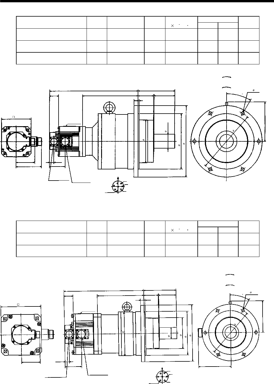
7 - 84
7. OUTLINE DIMENSION DRAWINGS
Variable Dimensions
Model Output
[kW]
Reduction Gear
Model
Reduction
Ratio
Inertia Moment
J[ 10 4kg m2]LH
Mass
[kg]
HC-SF102G2 HC-SFS102G2
HC-SFS1024G2 1.0 BL4-45B-10MEH 1/45 20.3 389 244 52
HC-SF152G2 HC-SFS152G2
HC-SFS1524G2 1.5 BL4-29B-15MEH 1/29 30.3 411 241 54
HC-SF152G2 HC-SFS152G2
HC-SFS1524G2 1.5 BL4-45B-15MEH 1/45 26.5 414 244 54
19.5
W
V
U
L
90
160
A
FG
H
B
E
C
D
111
81.5
68.5
39.5 H68
18 5
171
30
Encoder
connector
MS3102A20-29P Power supply connector
CE05-2A22-23P
Power supply connector layout
CE05-2A22-23P
Motor plate
Earth
Motor flange direction
(Note)[Unit: mm]
Bottom Top
(Side view of motor only)
"Rotation direction"
For reverse
rotation command
For forward
rotation command
(BC11851*)
Z695322*
130
6- 14
280
240h7
310
60h6
186
Note: The dimensions without tolerances are reference dimensions.
Variable Dimensions
Model Output
[kW]
Reduction Gear
Model
Reduction
Ratio
Inertia Moment
J[ 10 4kg m2]LH
Mass
[kg]
HC-SF202G2 HC-SFS202G2
HC-SFS2024G2 2.0 BL3-05B-20MEH 1/5 49.6 348 203 30
HC-SF202G2 HC-SFS202G2
HC-SFS2024G2 2.0 BL3-09B-20MEH 1/9 47.2 375 230 37
140
5
81.5 19.5
137
30
U
V
W
CD B
E
A
G
F
75
15
76.5
63
L
H
39.5
142
Encoder connector
MS3102A20-29P
Power supply connector
CE05-2A24-10P
Power supply connector layout
CE05-2A24-10P
Motor plate
Motor flange direction
(Note)[Unit: mm]
Bottom Top
(Side view of motor only)
"Rotation direction"
For reverse
rotation command
For forward
rotation command
Earth
135
190h7
245
190
176
6- 12
220
Z695637A
(BC11852*)
50h6
Note: The dimensions without tolerances are reference dimensions.
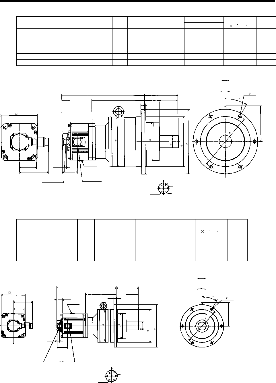
7 - 85
7. OUTLINE DIMENSION DRAWINGS
Variable Dimensions
Model Output
[kW]
Reduction Gear
Model
Reduction
Ratio LH
Inertia Moment
J[ 10 4kg m2]
Mass
[kg]
HC-SF202G2 HC-SFS202G2 HC-SFS2024G2 2.0 BL4-20B-20MEH 1/20 407 262 59.6 57
HC-SF202G2 HC-SFS202G2 HC-SFS2024G2 2.0 BL4-29B-20MEH 1/29 407 262 52.8 57
HC-SF202G2 HC-SFS202G2 HC-SFS2024G2 2.0 BL4-45B-20MEH 1/45 410 265 49.1 57
HC-SF352G2 HC-SFS352G2 HC-SFS3524G2 3.5 BL4-05B-35MEH 1/5 410 223 99.4 54
HC-SF352G2 HC-SFS352G2 HC-SFS3524G2 3.5 BL4-09B-35MEH 1/9 442 255 91.5 64
HC-SF352G2 HC-SFS352G2 HC-SFS3524G2 3.5 BL4-20B-35MEH 1/20 449 262 99.1 64
160
5
81.5 19.5
171
30
U
V
W
C
DB
E
A
G
F
90
18
76.5
68
L
H
39.5
142
Encoder connector
MS3102A20-29P
Power supply connector
CE05-2A24-10P
Power supply connector layout
CE05-2A24-10P
Motor plate
Earth
Motor flange direction
(Note)[Unit: mm]
Bottom Top
(Side view of motor only)
"Rotation direction"
For reverse
rotation command
For forward
rotation command
Z695638A
(BC11853*)
176
6- 14
280
240h7
310
186
240
60h6
Note: The dimensions without tolerances are reference dimensions.
Variable
Dimensions
Model Output
[kW]
Reduction Gear
Model
Reduction
Ratio LH
Inertia Moment
J[ 10 4kg m2]
Mass
[kg]
HC-SF502G2 HC-SFS502G2
HC-SFS5024G2 5.0 BL4-05B-50MEH 1/5 431 223 118.4 58
HC-SF502G2 HC-SFS502G2
HC-SFS5024G2 5.0 BL4-09B-50MEH 1/9 463 255 110.5 68
Power supply connector layout
CE05-2A24-10P
142
L
H
160
Motor plate
19.5
171
Motor flange direction
U
V
W
C
DBE
A
G
F
Earth
Encoder connector
MS3102A20-29P
Power supply connector
CE05-2A24-10P
81.5
76.5
18 5
90
39.5
30
Bottom Top
(Side view of motor only)
(Note)[Unit: mm]
"Rotation direction"
For reverse
rotation command
For forward
rotation command
240
186
60h6
240h7
310
6- 14
280
BC11067*
176
(********)
Note: The dimensions without tolerances are reference dimensions.
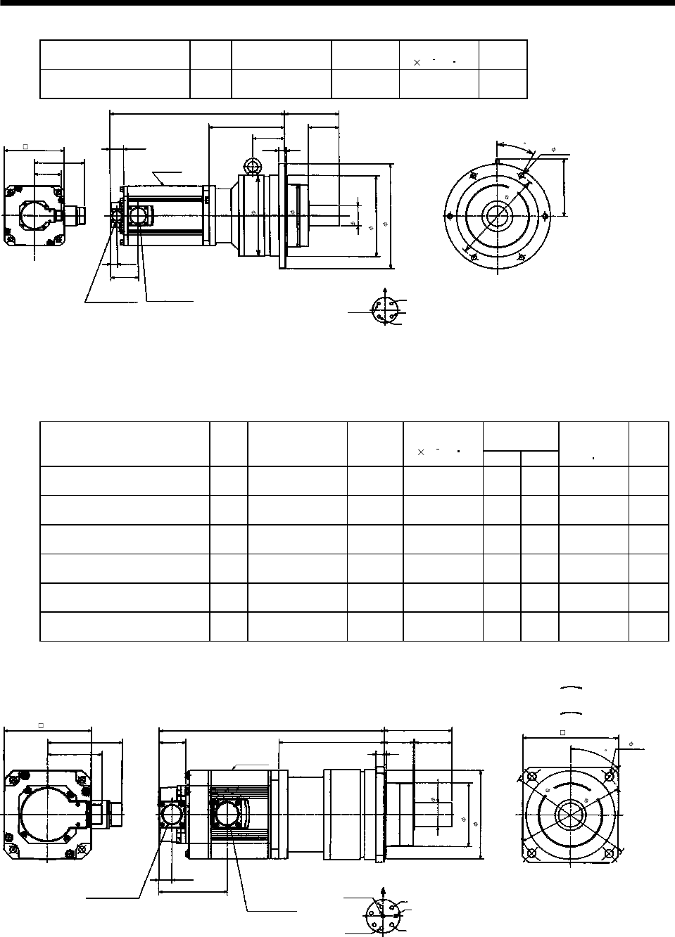
7 - 86
7. OUTLINE DIMENSION DRAWINGS
Model Output
[kW]
Reduction Gear
Model
Reduction
Ratio
Inertia Moment
J[ 10 4kg m2]
Mass
[kg]
HC-SF702G2 HC-SFS702G2
HC-SFS7024G2 7.0 BL4-05B-70MEH 1/5 177.4 67
Power supply connector layout
CE05-2A32-17P
150
515
223
160
Motor plate
19.5
171
(Note)[Unit: mm]
Motor flange direction
U
V
W
C
D
B
A
Earth
Encoder connector
MS3102A20-29P
Power supply connector
CE05-2A32-17P
81.5
81.5
18 5
90
39.5
30
94
Bottom Top
(Side view of motor only)
BC11068*
176 6- 14
280
60h6
240h7
310
240
186
(********)
Note: The dimensions without tolerances are reference dimensions.
(b) With electromagnetic brake
Variable
Dimensions
Model Output
[kW]
Reduction Gear
Model
Reduction
Ratio
Inertia Moment
J[ 10 4kg m2]LH
Brake static
friction torque
[N m]
Mass
[kg]
HC-SF52BG2 HC-SFS52BG2
HC-SFS524BG2 0.5 BL2-05B-05MEH 1/5 9.6 309 156 8.5 15
HC-SF52BG2 HC-SFS52BG2
HC-SFS524BG2 0.5 BL2-09B-05MEH 1/9 9.25 321 168 8.5 15
HC-SF52BG2 HC-SFS52BG2
HC-SFS524BG2 0.5 BL2-20B-05MEH 1/20 9.73 342 189 8.5 17
HC-SF102BG2 HC-SFS102BG2
HC-SFS1024BG2 1.0 BL2-05B-10MEH 1/5 16.7 334 156 8.5 17
HC-SF102BG2 HC-SFS102BG2
HC-SFS1024BG2 1.0 BL2-09B-10MEH 1/9 16.3 346 168 8.5 17
HC-SF152BG2 HC-SFS152BG2
HC-SFS1524BG2 1.5 BL2-05B-15MEH 1/5 22.9 359 156 8.5 19
L
39.5
19.5
101.5
H4355
100
45
W
V
U
A
FG
HB
E
C
D
111
81.5 12 3
Encoder connector
MS3102A20-29P Power supply connector
CE05-2A22-23P
Power supply connector layout
CE05-2A22-23P
Motor plate
Earth
Motor flange direction
(Note)[Unit: mm]
Bottom Top
(Side view of motor only)
"Rotation direction"
For reverse
rotation command
For forward
rotation command
Brake
35h6
94
130h7
4- 12
160
130
140
(BC11856*)
Z695323*
185
Note: The dimensions without tolerances are reference dimensions.
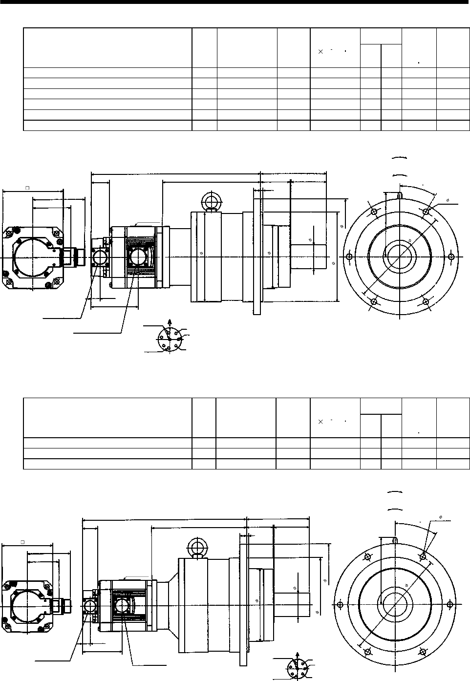
7 - 87
7. OUTLINE DIMENSION DRAWINGS
Variable
Dimensions
Model Output
[kW]
Reduction Gear
Model
Reduction
Ratio
Inertia Moment
J[ 10
4
kg m2]LH
Brake
static
friction
torque
[N m]
Mass
[kg]
HC-SF52BG2 HC-SFS52BG2 HC-SFS524BG2 0.5 BL3-29B-05MEH 1/29 11.1 370 217 8.5 32
HC-SF52BG2 HC-SFS52BG2 HC-SFS524BG2 0.5 BL3-45B-05MEH 1/45 10.1 376 223 8.5 32
HC-SF102BG2 HC-SFS102BG2 HC-SFS1024BG2 1.0 BL3-20B-10MEH 1/20 20.1 395 217 8.5 34
HC-SF102BG2 HC-SFS102BG2 HC-SFS1024BG2 1.0 BL3-29B-10MEH 1/29 18.2 395 217 8.5 34
HC-SF152BG2 HC-SFS152BG2 HC-SFS1524BG2 1.5 BL3-09B-15MEH 1/9 26.4 412 209 8.5 36
HC-SF152BG2 HC-SFS152BG2 HC-SFS1524BG2 1.5 BL3-20B-15MEH 1/20 26.3 420 217 8.5 36
W
V
U
A
FG
HB
E
C
D
L
39.5
140
63 75
111
81.5
15 5
H
19.5
101.5
137
30
Encoder connector
MS3102A20-29P
Power supply connector
CE05-2A22-23P
Power supply connector layout
CE05-2A22-23P
Motor plate
Earth
Motor flange direction
(Note)[Unit: mm]
Bottom Top
(Side view of motor only)
"Rotation direction"
For reverse
rotation command
For forward
rotation command
Brake
(BC11857*)
Z695324*
130
190
135
50h6
190h7
245
220
6- 12
Note: The dimensions without tolerances are reference dimensions.
Variable
Dimensions
Model Output
[kW]
Reduction Gear
Model
Reduction
Ratio
Inertia Moment
J[ 10
4
kg m2]LH
Brake
static
friction
torque
[N m]
Mass
[kg]
HC-SF102BG2 HC-SFS102BG2 HC-SFS1024BG2 1.0 BL4-45B-10MEH 1/45 22.0 422 244 8.5 54
HC-SF152BG2 HC-SFS152BG2 HC-SFS1524BG2 1.5 BL4-29B-15MEH 1/29 32.0 444 241 8.5 56
HC-SF152BG2 HC-SFS152BG2 HC-SFS1524BG2 1.5 BL4-45B-15MEH 1/45 28.2 447 244 8.5 56
W
V
U
A
FG
HB
E
C
D
L
39.5
160
68 90
111
81.5
18 5
H
19.5
101.5
171
30
Encoder connector
MS3102A20-29P Power supply connector
CE05-2A22-23P
Power supply connector layout
CE05-2A22-23P
Motor plate
Earth
Motor flange direction
(Note)[Unit: mm]
Bottom Top
(Side view of motor only)
"Rotation direction"
For reverse
rotation command
For forward
rotation command
Brake
60h6
240h7
310
186
280
6- 14
(BC11858*)
Z695325*
130
Note: The dimensions without tolerances are reference dimensions.
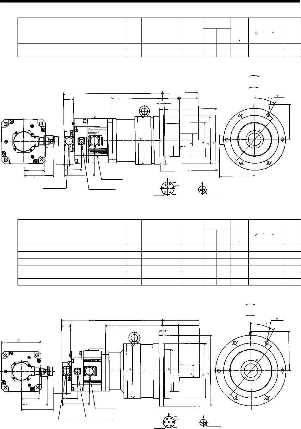
7 - 88
7. OUTLINE DIMENSION DRAWINGS
Variable
Dimensions
Model Output
[kW]
Reduction Gear
Model
Reduction
Ratio LH
Brake
static
friction
torque
[N m]
Inertia Moment
J[ 10
4
kg m2]
Mass
[kg]
HC-SF202BG2 HC-SFS202BG2 HC-SFS2024BG2 2.0 BL3-05B-20MEH 1/5 396 203 43.1 59.6 36
HC-SF202BG2 HC-SFS202BG2 HC-SFS2024BG2 2.0 BL3-09B-20MEH 1/9 423 230 43.1 57.2 43
140
5
81.5
19.5
137
30
U
V
W
C
DBE
A
G
F
75
15
69
63
L
H
39.5
142
124.5
AB
117
Encoder connector
MS3102A20-29P
Power supply connector
CE05-2A24-10P
Power supply connector layout
CE05-2A24-10P
Earth
Brake connector
MS3102A10SL-4P
Motor flange direction
Brake
Brake connector layout
MS3102A10SL-4P
Motor flange direction
Motor plate
(Note)[Unit: mm]
(Side view of motor only)
"Rotation direction"
For reverse
rotation command
For forward
rotation command
Z695640A
(BC11859*)
6- 12
220
190
135
190h7
245
50h6
Note: The dimensions without tolerances are reference dimensions.
Variable
Dimensions
Model Output
[kW]
Reduction Gear
Model
Reduction
Ratio LH
Brake
static
friction
torque
[N m]
Inertia Moment
J[ 10
4
kg m2]
Mass
[kg]
HC-SF202BG2 HC-SFS202BG2 HC-SFS2024BG2 2.0 BL4-20B-20MEH 1/20 455 262 43.1 69.6 63
HC-SF202BG2 HC-SFS202BG2 HC-SFS2024BG2 2.0 BL4-29B-20MEH 1/29 455 262 43.1 62.8 63
HC-SF202BG2 HC-SFS202BG2 HC-SFS2024BG2 2.0 BL4-45B-20MEH 1/45 458 265 43.1 59.1 63
HC-SF352BG2 HC-SFS352BG2 HC-SFS3524BG2 3.5 BL4-05B-35MEH 1/5 458 223 43.1 109.4 60
HC-SF352BG2 HC-SFS352BG2 HC-SFS3524BG2 3.5 BL4-09B-35MEH 1/9 490 255 43.1 101.5 70
HC-SF352BG2 HC-SFS352BG2 HC-SFS3524BG2 3.5 BL4-20B-35MEH 1/20 497 262 43.1 109.1 70
160
5
81.5
19.5
171
30
U
V
W
C
DB
E
A
G
F
90
18
124.5
68
L
H
39.5
69
117
142
AB
Encoder connector
MS3102A20-29P
Power supply connector
CE05-2A24-10P
Power supply connector layout
CE05-2A24-10P
Earth
Brake connector
MS3102A10SL-4P
Motor flange direction
Brake
Brake connector layout
MS3102A10SL-4P
Motor flange direction
Motor plate
(Note)[Unit: mm]
(Side view of motor only)
"Rotation direction"
For reverse
rotation command
For forward
rotation command
Bottom Top
240
240h7
310
186
6- 14
280
Z695641A
(BC11860*)
176
60h6
Note: The dimensions without tolerances are reference dimensions.
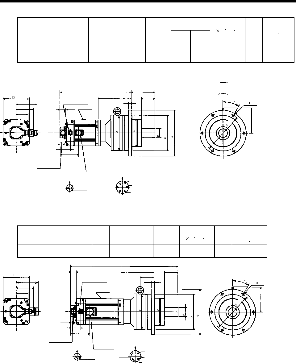
7 - 89
7. OUTLINE DIMENSION DRAWINGS
Variable
Dimensions
Model Output
[kW]
Reduction Gear
Model
Reduction
Ratio LH
Inertia Moment
J[ 10 4kg m2]
Mass
[kg]
Brake static
friction torque
[N m]
HC-SF502BG2 HC-SFS502BG2
HC-SFS5024BG2 5.0 BL4-05B-50MEH 1/5 479 223 128.4 64 43.1
HC-SF502BG2 HC-SFS502BG2
HC-SFS5024BG2 5.0 BL4-09B-50MEH 1/9 511 255 120.5 74 43.1
Power supply connector layout
CE05-2A24-10P
142
L
H
160
117 Motor plate
19.5
69
171
Motor flange direction
U
V
W
C
DB
E
A
G
F
Earth
Encoder connector
MS3102A20-29P Power supply connector
CE05-2A24-10P
81.5
Brake connector layout
MS3102A10SL-4P
Motor flange direction
B
ABrake
124.5
Brake connector
MS3102A10SL-4P 18 5
90
39.5
30
(Side view of motor only)
(Note)[Unit: mm]
"Rotation direction"
For reverse
rotation command
For forward
rotation command
Bottom Top
BC11069*
176
240
186
60h6
240h7
310
6- 14
280
(********)
Note: The dimensions without tolerances are reference dimensions.
Model Output
[kW]
Reduction Gear
Model
Reduction
Ratio
Inertia Moment
J[ 10 4kg m2]
Mass
[kg]
Brake static
friction torque
[N m]
HC-SF702BG2 HC-SFS702BG2
HC-SFS7024BG2 7.0 BL4-05B-70MEH 1/5 187.4 73 43.1
Power supply connector layout
CE05-2A32-17P
150
563
223
160
117
Motor plate
19.5
69
171
Motor flange direction
U
V
W
C
D
B
A
Earth
Encoder connector
MS3102A20-29P Power supply
connector
CE05-2A32-17P
81.5
Brake connector layout
MS3102A10SL-4P
Motor flange direction
B
A
Brake
129.5
Brake connector
MS3102A10SL-4P 18 5
90
39.5
30
94
(Side view of motor only)
(Note)[Unit: mm]
Bottom Top
240
186
60h6
240h7
310
280
6- 14
BC11070*
176
(********)
Note: The dimensions without tolerances are reference dimensions.
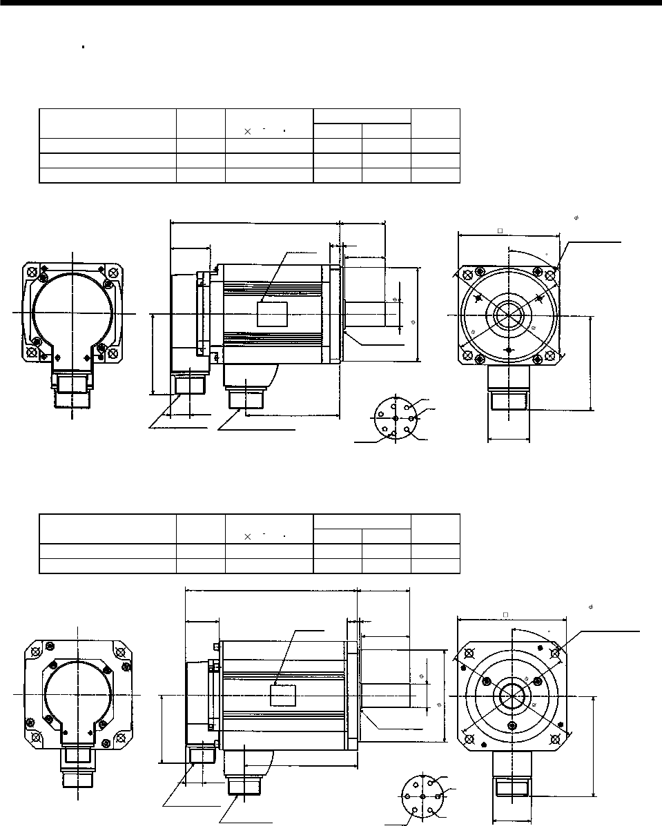
7 - 90
7. OUTLINE DIMENSION DRAWINGS
7.1.4 HC-RF HC-RFS series
If the above indicated value is exceeded, please consult us.
(1) Standard (without electromagnetic brake, without reduction gear)
Variable Dimensions
Model Output
[kW]
Inertia Moment
J[ 10 4kg m2]LKL
Mass
[kg]
HC-RF103 HC-RFS103 1.0 1.5 147 71 3.9
HC-RF153 HC-RFS153 1.5 1.9 172 96 5.0
HC-RF203 HC-RFS203 2.0 2.3 197 121 6.2
41
96
45
81.5
19.5
MS3102A20-29P CE05-2A22-23P W
V
U
A
F
G
HB
E
C
D
KL
L
39.5 10 3
40
S30457B
24h6
45
Bottom
Top
Encoder connector Power supply connector
Oil seal
Motor flange direction
Earth
Power supply connector layout
CE05-2A22-23P
(Note)[Unit: mm]
Use hexagon socket
head cap screw.
Motor plate
(Opposite side)
Bottom
Top
95h7
115
135
100
4- 9 mounting hole
Z694853*
(BC11697*)
Note: The dimensions without tolerances are reference dimensions.
Variable Dimensions
Model Output
[kW]
Inertia Moment
J[ 10 4kg m2]LKL
Mass
[kg]
HC-RF353 HC-RFS353 3.5 8.6 217 148 12
HC-RF503 HC-RFS503 5.0 12.0 274 205 17
(Note)[Unit: mm]
58
Motor plate
Earth
V
U
W
DC
B
A
G
F
E
120
Power supply connector layout
CE05-2A24-10P
Motor flange direction
3
63
12
39.5
28h6
Top
Bottom
L
(Opposite side)
Oil seal
S30457B
Bottom
Top
81.5
19.5
46
KL
Power supply connector
CE05-2A24-10P
Encoder connector
MS3102A20-29P
110h7
165
145
4- 9 mounting hole
Use hexagon socket
head cap screw.
130
Z695780*
45
(BC11698*)
Note: The dimensions without tolerances are reference dimensions.
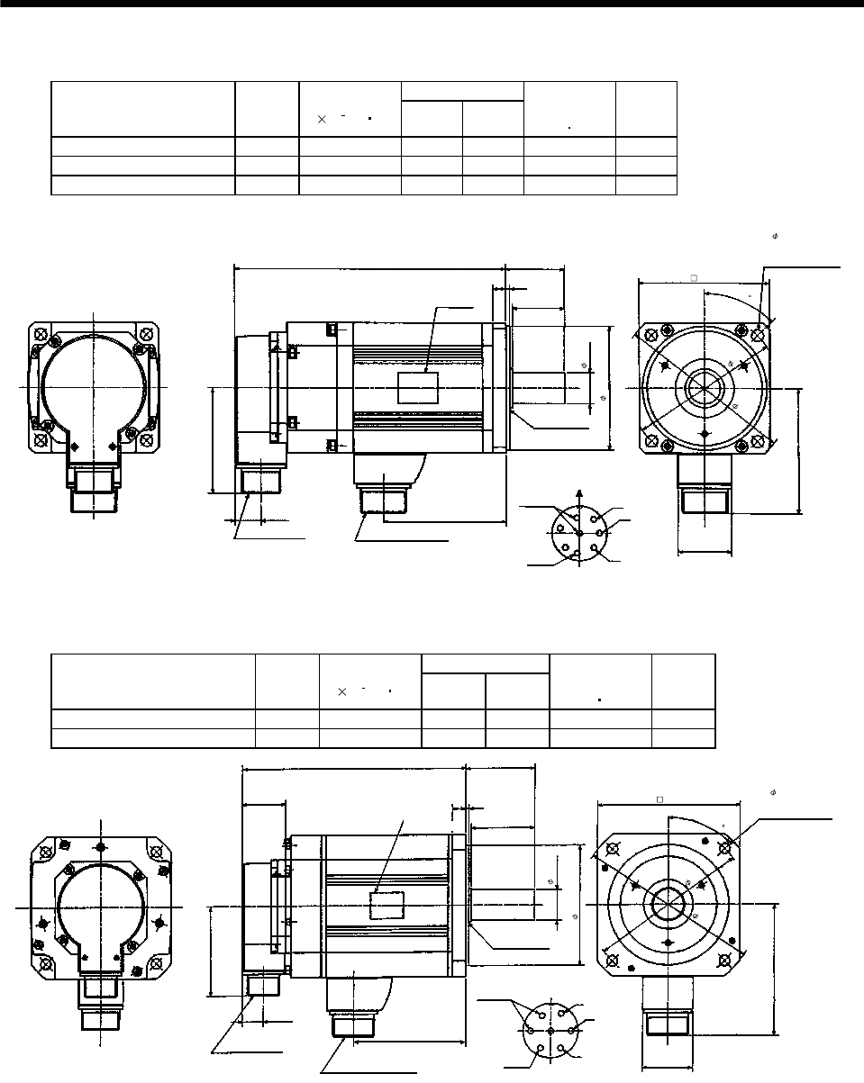
7 - 91
7. OUTLINE DIMENSION DRAWINGS
(2) With electromagnetic brake
Variable Dimensions
Model Output
[kW]
Inertia Moment
J[ 10 4kg m2]LKL
Brake static
friction torque
[N m]
Mass
[kg]
HC-RF103B HC-RFS103B 1.0 1.85 185 71 7 6.0
HC-RF153B HC-RFS153B 1.5 2.25 210 96 7 7.0
HC-RF203B HC-RFS203B 2.0 2.65 235 121 7 8.3
Bottom
KL
19.5
W
V
U
MS3102A20-29P CE05-2A22-23P
81.5
S30457B
L45
10 3
40
A
F
G
HB
E
C
D41
96
45
Bottom
Top
Encoder connector Power supply connector
Oil seal
Motor flange direction
Earth
Power supply connector layout
CE05-2A22-23P
(Note)[Unit: mm]
(Use hexagon socket
head cap screw.)
Motor plate
(Opposite side)
Top
Brake
100
4- 9 mounting hole
115
135
24h6
95h7
Z695165*
(BC11699*)
Note: The dimensions without tolerances are reference dimensions.
Variable Dimensions
Model Output
[kW]
Inertia Moment
J[ 10 4kg m2]LKL
Brake static
friction torque
[N m]
Mass
[kg]
HC-RF353B HC-RFS353B 3.5 11.8 254 148 16.7 15
HC-RF503B HC-RFS503B 5.0 15.5 311 205 16.7 21
Encoder connector
Power supply connector
19.5
Earth
W
V
U
A
B
C
D
E
FG
Power supply connector layout
CE05-2A24-10P
Motor flange direction
MS3102A20-29P
CE05-2A24-10P
81.5
L63
12 3
58
46
120
Bottom
(Note)[Unit: mm]
Bottom
39.5
S30457B
Brake
KL
Oil seal
Top
Top
Motor plate
(Opposite side)
130 4- 9 mounting hole
Use hexagon socke
t
head cap screw.
145
165
Z695563A
28h6
110h7
45
(BC11700*)
Note: The dimensions without tolerances are reference dimensions.

7 - 92
7. OUTLINE DIMENSION DRAWINGS
(3) With reduction gear for precision application
The outer frame of the reduction gear is a material surface such as casting. Its actual dimensions may
be 1 to 3mm larger than the drawing dimensions. Design the machine side with allowances.
(a) Without electromagnetic brake
Variable Dimensions
Model Output
[kW]
Reduction Gear
Model
Reduction
Ratio
Inertia Moment
J[ 10 4kg m2]LH
Mass
[kg]
HC-RF103G2 HC-RFS103G2 1.0 BL2-05B-10MEKD 1/5 4.95 301 154 11.9
HC-RF103G2 HC-RFS103G2 1.0 BL2-09B-10MEKD 1/9 4.6 313 166 11.9
HC-RF153G2 HC-RFS153G2 1.5 BL2-05B-15MEKD 1/5 5.35 326 154 13
HC-RF203G2 HC-RFS203G2 2.0 BL2-05B-20MEKD 1/5 5.75 351 154 14.2
L
39.5
100
19.5
76
81.5
96
H
12 3
43 55
W
V
U
A
FG
H
B
E
C
D
35h6
140
Z695327A
Encoder connector
MS3102A20-29P
Power supply connector
CE05-2A22-23P
Power supply connector layout
CE05-2A22-23P
Earth
Motor flange direction
(Note)[Unit: mm]
Bottom Top
(Side view of motor only)
"Rotation direction"
For reverse
rotation command
For forward
rotation command
Motor plate
94
130h7
132
185
160
4- 12
100
45
Note: The dimensions without tolerances are reference dimensions.
Variable Dimensions
Model Output
[kW]
Reduction Gear
Model
Reduction
Ratio
Inertia Moment
J[ 10 4kg m2]LHLI
Mass
[kg]
HC-RF103G2 HC-RFS103G2 1.0 BL3-20B-10MEKD 1/20 8.35 354 207 105 28.9
HC-RF103G2 HC-RFS103G2 1.0 BL3-29B-10MEKD 1/29 6.45 354 207 105 28.9
HC-RF103G2 HC-RFS103G2 1.0 BL3-45B-10MEKD 1/45 5.48 364 217 115 28.9
HC-RF153G2 HC-RFS153G2 1.5 BL3-09B-15MEKD 1/9 6.68 375 203 101 30
HC-RF153G2 HC-RFS153G2 1.5 BL3-20B-15MEKD 1/20 8.75 379 207 105 30
HC-RF153G2 HC-RFS153G2 1.5 BL3-29B-15MEKD 1/29 6.85 379 207 105 30
HC-RF203G2 HC-RFS203G2 2.0 BL3-09B-20MEKD 1/9 7.08 400 203 101 31.2
HC-RF203G2 HC-RFS203G2 2.0 BL3-20B-20MEKD 1/20 9.15 404 207 105 31.2
W
V
U
A
FG
HB
E
C
D
L
39.5
140
63 75
96
81.5
15 5
H
19.5
76
30
LI
Encoder connector
MS3102A20-29P
Power supply connector
CE05-2A22-23P
Power supply connector layout
CE05-2A22-23P
Earth
Motor flange direction
(Note)[Unit: mm]
Bottom Top
(Side view of motor only)
"Rotation direction"
For reverse
rotation command
For forward
rotation command
Motor plate
190
135
50h6
190h7
245
220
136.5
6- 12
Z695328*
100
Note: The dimensions without tolerances are reference dimensions.
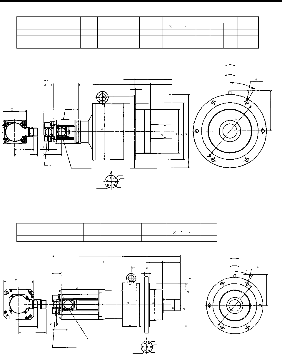
7 - 93
7. OUTLINE DIMENSION DRAWINGS
Variable Dimensions
Model Output
[kW]
Reduction Gear
Model
Reduction
Ratio
Inertia Moment
J[ 10 4kg m2]LHLI
Mass
[kg]
HC-RF153G2 HC-RFS153G2 1.5 BL4-45B-15MEKD 1/45 8.55 410 238 136 50
HC-RF203G2 HC-RFS203G2 2.0 BL4-29B-20MEKD 1/29 12.7 425 228 126 51.2
HC-RF203G2 HC-RFS203G2 2.0 BL4-45B-20MEKD 1/45 8.98 435 238 136 51.2
W
V
U
A
FG
H
B
E
C
D
L
39.5
160
68 90
96
81.5
18 5
H
19.5
76
30
LI
171
Encoder connector
MS3102A20-29P Power supply connector
CE05-2A22-23P
Power supply connector layout
CE05-2A22-23P
Earth
Motor flange direction
(Note)[Unit: mm]
Bottom Top
(Side view of motor only)
"Rotation direction"
For reverse
rotation command
For forward
rotation command
Motor plate
100
240
186
240h7
310
60h6
6- 14
280
Z695329*
(BC11865*)
Note: The dimensions without tolerances are reference dimensions.
Model Output
[kW]
Reduction Gear
Model
Reduction
Ratio
Inertia Moment
J[ 10 4kg m2]
Mass
[kg]
HC-RF353G2 HC-RFS353G2 3.5 BL3-05B-35MEKD 1/5 18.8 30
Earth W
V
U
Motor flange direction
A
FG
B
EC
D
Encoder connector
MS3102A20-29P
Power supply connector
CE05-2A24-10P
Bottom Top
418
39.5
63
140
75
81.5
120
15 5
201
Motor plate
19.5
69.5
245
For reverse
rotation command
For forward
rotation command
"Rotation direction"
136.5
30
74
(Note)[Unit: mm]
Power supply connector layout
CE05-2A24-10P
(Side view of motor only)
(********)
130
190
50h6
190h7
135
6- 12
220
Z695990A
Note: The dimensions without tolerances are reference dimensions.
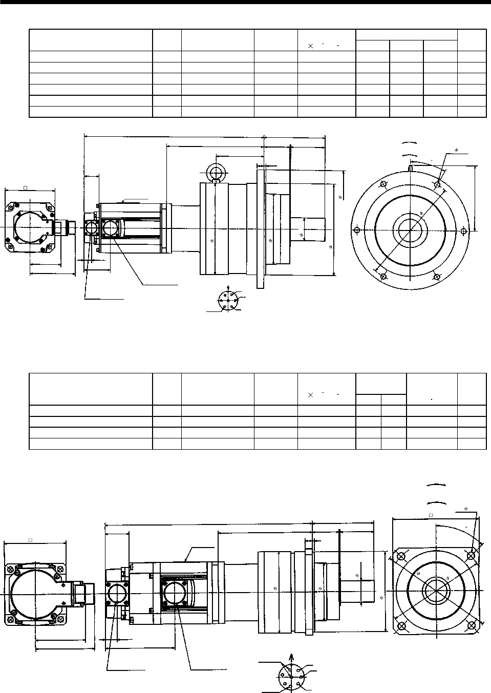
7 - 94
7. OUTLINE DIMENSION DRAWINGS
Variable Dimensions
Model Output
[kW]
Reduction Gear
Model
Reduction
Ratio
Inertia Moment
J[ 10 4kg m2]LHLI
Mass
[kg]
HC-RF353G2 HC-RFS353G2 3.5 BL4-09B-35MEKD 1/9 21.1 470 253 126 57
HC-RF353G2 HC-RFS353G2 3.5 BL4-20B-35MEKD 1/20 28.8 470 253 126 57
HC-RF353G2 HC-RFS353G2 3.5 BL4-29B-35MEKD 1/29 22.0 470 253 126 57
HC-RF503G2 HC-RFS503G2 5.0 BL4-05B-50MEKD 1/5 32.4 495 221 94 52
HC-RF503G2 HC-RFS503G2 5.0 BL4-09B-50MEKD 1/9 24.5 527 253 126 62
HC-RF503G2 HC-RFS503G2 5.0 BL4-20B-50MEKD 1/20 32.2 527 253 126 62
Earth W
V
U
Motor flange direction
A
FG
BEC
D
Encoder connector
MS3102A20-29P
Power supply connector
CE05-2A24-10P
Bottom Top
L
39.5
68
160
90
81.5
120
18 5
H
Motor plate
19.5
69.5
171
LI
(Note)[Unit: mm]
For reverse
rotation command
For forward
rotation command
"Rotation direction"
Power supply connector layout
CE05-2A24-10P
(Side view of motor only)
240
186
240h7
60h6
310
6- 14
280
(********)
130
30
Z695992
A
Note: The dimensions without tolerances are reference dimensions.
(b) With electromagnetic brake
Variable
Dimensions
Model Output
[kW]
Reduction Gear
Model
Reduction
Ratio
Inertia Moment
J[ 10 4kg m2]LH
Brake static
friction torque
[N m]
Mass
[kg]
HC-RF103BG2 HC-RFS103BG2 1.0 BL2-05B-10MEKD 1/5 5.3 339 154 7 14
HC-RF103BG2 HC-RFS103BG2 1.0 BL2-09B-10MEKD 1/9 4.95 351 166 7 14
HC-RF153BG2 HC-RFS153BG2 1.5 BL2-05B-15MEKD 1/5 5.7 364 154 7 15.1
HC-RF203BG2 HC-RFS203BG2 2.0 BL2-05B-20MEKD 1/5 6.1 389 154 7 16.3
L
39.5
100
19.5
113.5
81.5
96
H
12 3
43 55
130h7
W
V
U
A
FG
HB
E
C
D
Encoder connector
MS3102A20-29P
Power supply connector
CE05-2A22-23P
Power supply connector layout
CE05-2A22-23P
Earth
Motor flange direction
(Note)[Unit: mm]
Bottom Top
(Side view of motor only)
"Rotation direction"
For reverse
rotation command
For forward
rotation command
(Opposite side)
Motor plate
Brake
100
140
4- 12
185
160
35h6
94
132
Z695330*
(BC11868*)
45
Note: The dimensions without tolerances are reference dimensions.
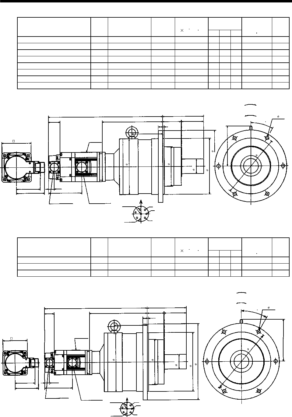
7 - 95
7. OUTLINE DIMENSION DRAWINGS
Variable
Dimensions
Model Output
[kW]
Reduction Gear
Model
Reduction
Ratio
Inertia Moment
J[ 10 4kg m2]LHLI
Brake static
friction torque
[N m]
Mass
[kg]
HC-RF103BG2 HC-RFS103BG2 1.0 BL3-20B-10MEKD 1/20 8.7 392 207 105 7 31
HC-RF103BG2 HC-RFS103BG2 1.0 BL3-29B-10MEKD 1/29 6.8 392 207 105 7 31
HC-RF103BG2 HC-RFS103BG2 1.0 BL3-45B-10MEKD 1/45 5.83 402 217 115 7 31
HC-RF153BG2 HC-RFS153BG2 1.5 BL3-09B-15MEKD 1/9 7.03 413 203 101 7 32.1
HC-RF153BG2 HC-RFS153BG2 1.5 BL3-20B-15MEKD 1/20 9.1 417 207 105 7 32.1
HC-RF153BG2 HC-RFS153BG2 1.5 BL3-29B-15MEKD 1/29 7.2 417 207 105 7 32.1
HC-RF203BG2 HC-RFS203BG2 2.0 BL3-09B-20MEKD 1/9 7.43 438 203 101 7 33.3
HC-RF203BG2 HC-RFS203BG2 2.0 BL3-20B-20MEKD 1/20 9.5 442 207 105 7 33.3
W
V
U
A
FG
HB
E
C
D
L
39.5 63
140
75
81.5
96
15 5
H
19.5
113.5
136.5
30
LI
Encoder connector
MS3102A20-29P
Power supply connector
CE05-2A22-23P
Power supply connector layout
CE05-2A22-23P
Earth
Motor flange direction
(Note)[Unit: mm]
Bottom Top
(Side view of motor only)
"Rotation direction"
For reverse
rotation command
For forward
rotation command
Motor plate
Brake
100
6- 12
220
245
190h7
50h6
135
190
Z695331*
(BC11869*)
Note: The dimensions without tolerances are reference dimensions.
Variable
Dimensions
Model Output
[kW]
Reduction Gear
Model
Reduction
Ratio
Inertia Moment
J[ 10 4kg m2]LHLI
Brake static
friction torque
[N m]
Mass
[kg]
HC-RF153BG2 HC-RFS153BG2 1.5 BL4-45B-15MEKD 1/45 8.9 448 238 136 7 52.1
HC-RF203BG2 HC-RFS203BG2 2.0 BL4-29B-20MEKD 1/29 13.1 463 228 126 7 53.3
HC-RF203BG2 HC-RFS203BG2 2.0 BL4-45B-20MEKD 1/45 9.3 473 238 136 7 53.3
W
V
U
A
FG
HB
E
C
D
L
39.5 68
160
90
81.5
96
18 5
H
19.5
113.5
171
30
LI
Encoder connector
MS3102A20-29P Power supply connector
CE05-2A22-23P
Power supply connector layout
CE05-2A22-23P
Earth
Motor flange direction
(Note)[Unit: mm]
Bottom Top
(Side view of motor only)
"Rotation direction"
For reverse
rotation command
For forward
rotation command
Motor plate
Brake
60h6
240h7
310
240
186
6- 14
280
100
Z695332*
(BC11870*)
Note: The dimensions without tolerances are reference dimensions.
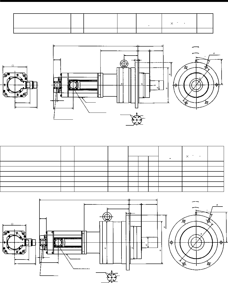
7 - 96
7. OUTLINE DIMENSION DRAWINGS
Model Output
[kW]
Reduction Gear
Model
Reduction
Ratio
Brake static
friction torque
[N m]
Inertia Moment
J[ 10 4kg m2]
Mass
[kg]
HC-RF353BG2 HC-RFS353BG2 3.5 BL3-05B-35MEKD 1/5 16.7 20.8 33
Earth W
V
U
Power supply connector layout
CE05-2A24-10P
Motor flange direction
A
FG
B
EC
D
Encoder connector
MS3102A20-29P
Power supply connector
CE05-2A24-10P
Bottom Top
455
39.5
63
140
75
81.5
120
(Side view of motor only)
15 5
201
Motor plate
19.5
106
For reverse
rotation command
For forward
rotation command
"Rotation direction"
136.5
30
74
Brake
(Note)[Unit: mm]
130
6- 12
220
135
190
190h7
50h6
245
Z695991A
(********)
Note: The dimensions without tolerances are reference dimensions.
Variable
Dimensions
Model Output
[kW]
Reduction Gear
Model
Reduction
Ratio LHLI
Brake static
friction torque
[N m]
Inertia Moment
J[ 10 4kg m2]
Mass
[kg]
HC-RF353BG2 HC-RFS353BG2 3.5 BL4-09B-35MEKD 1/9 507 253 126 16.7 23.1 60
HC-RF353BG2 HC-RFS353BG2 3.5 BL4-20B-35MEKD 1/20 507 253 126 16.7 30.8 60
HC-RF353BG2 HC-RFS353BG2 3.5 BL4-29B-35MEKD 1/29 507 253 126 16.7 22.0 60
HC-RF503BG2 HC-RFS503BG2 5.0 BL4-05B-50MEKD 1/5 532 221 94 16.7 34.4 56
HC-RF503BG2 HC-RFS503BG2 5.0 BL4-09B-50MEKD 1/9 564 253 126 16.7 26.5 66
HC-RF503BG2 HC-RFS503BG2 5.0 BL4-20B-50MEKD 1/20 564 253 126 16.7 34.2 66
Earth W
V
U
Motor flange direction
A
FG
B
EC
D
Encoder connector
MS3102A20-29P
Power supply connector
CE05-2A24-10P
Bottom Top
L
39.5
68
160
90
81.5
120
18 5
H
Motor plate
19.5
106
171
30
LI
Brake
(Note)[Unit: mm]
For forward
rotation command
For reverse
rotation command
"Rotation direction"
(Side view of motor only)
Power supply connector layout
CE05-2A24-10P
60h6
240h7
186
240
310
280
6- 14
(********)
130
Z695993A
Note: The dimensions without tolerances are reference dimensions.
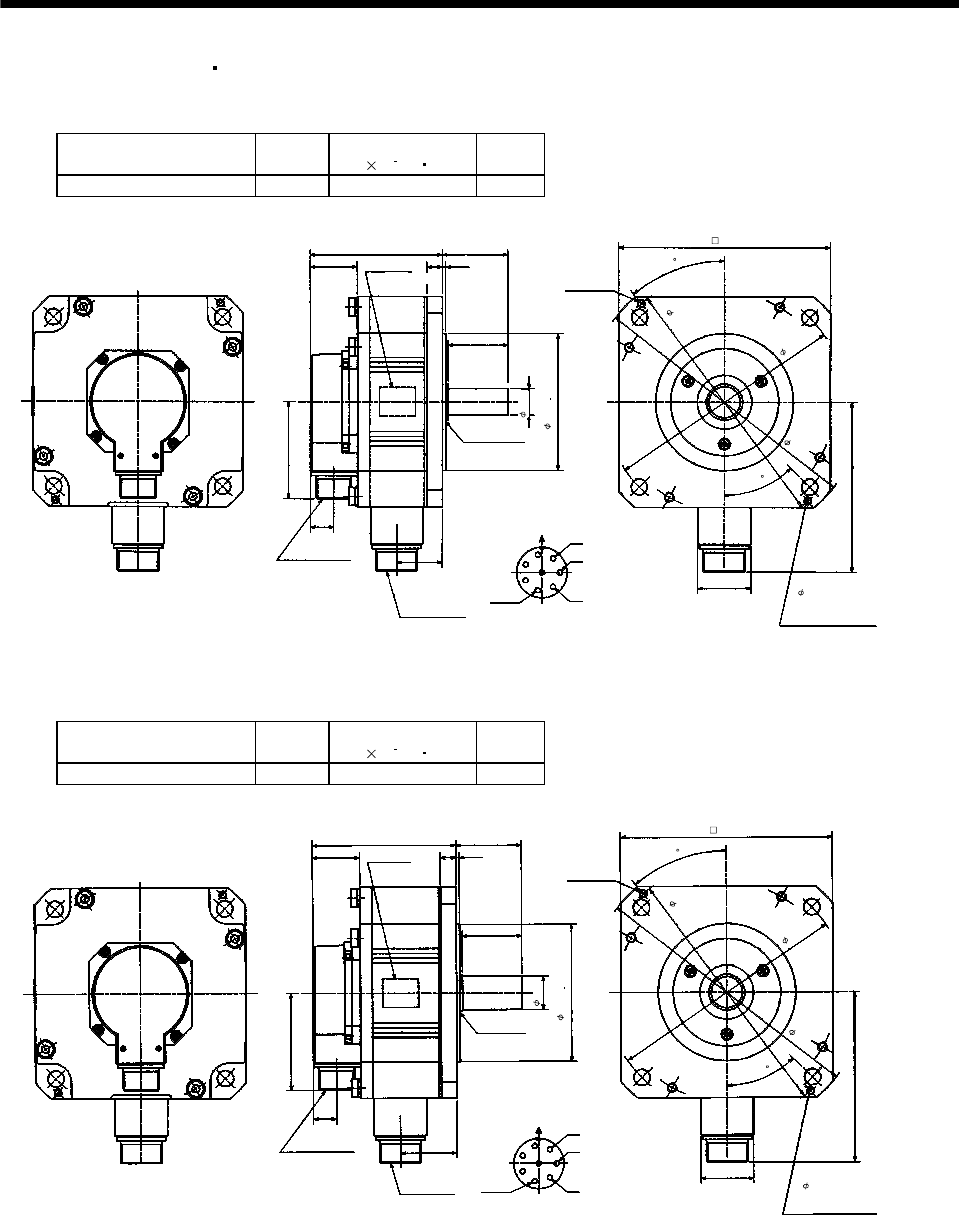
7 - 97
7. OUTLINE DIMENSION DRAWINGS
7.1.5 HC-UF 2000r/min HC-UFS 2000r/min series
(1) Standard (without electromagnetic brake)
Model Output
[kW]
Inertia Moment
J[ 10 4kg m2]
Mass
[kg]
HC-UF72 HC-UFS72 0.75 10.4 8
Top
Encoder connector
MS3102A20-29P
Power supply
connector
CE05-2A22-23P
Motor flange direction
Power supply connector layout
CE05-2A22-23P
A
B
C
D
E
FG
U
V
W
Earth
Oil seal
S30457B
2-M6 screw
40
45
39.5
55
13 3
Bottom
Top
19.5
81.5
144
(Note)[Unit: mm]
44
H
38
110.5
50
0
0.025
Bottom
Motor plate
(Opposite side)
22h6
114.3
230
200
215
4- 13.5 mounting hole
Use hexagon socket
head cap screw.
176
Z695911*
(BC11711*)
Note: The dimensions without tolerances are reference dimensions.
Model Output
[kW]
Inertia Moment
J[ 10 4kg m2]
Mass
[kg]
HC-UF152 HC-UFS152 1.5 22.1 11
Top
Bottom
Encoder connector
MS3102A20-29P
Power supply
connector
CE05-2A22-23P
Motor flange direction
Power supply connector layout
CE05-2A22-23P
A
B
C
D
E
F
G
U
V
W
Earth
Oil seal
S30457B
Motor plate
(Opposite side) 2-M6 screw
40
45
39.5
55
13 3
Bottom
Top
19.5
81.5
144
(Note)[Unit: mm]
44
H
47.5
120
50
114.3 0
0.025
28h6
230
215
200
176
4- 13.5 mounting hole
Use hexagon socket
head cap screw.
Z695912A
(BC11712*)
Note: The dimensions without tolerances are reference dimensions.
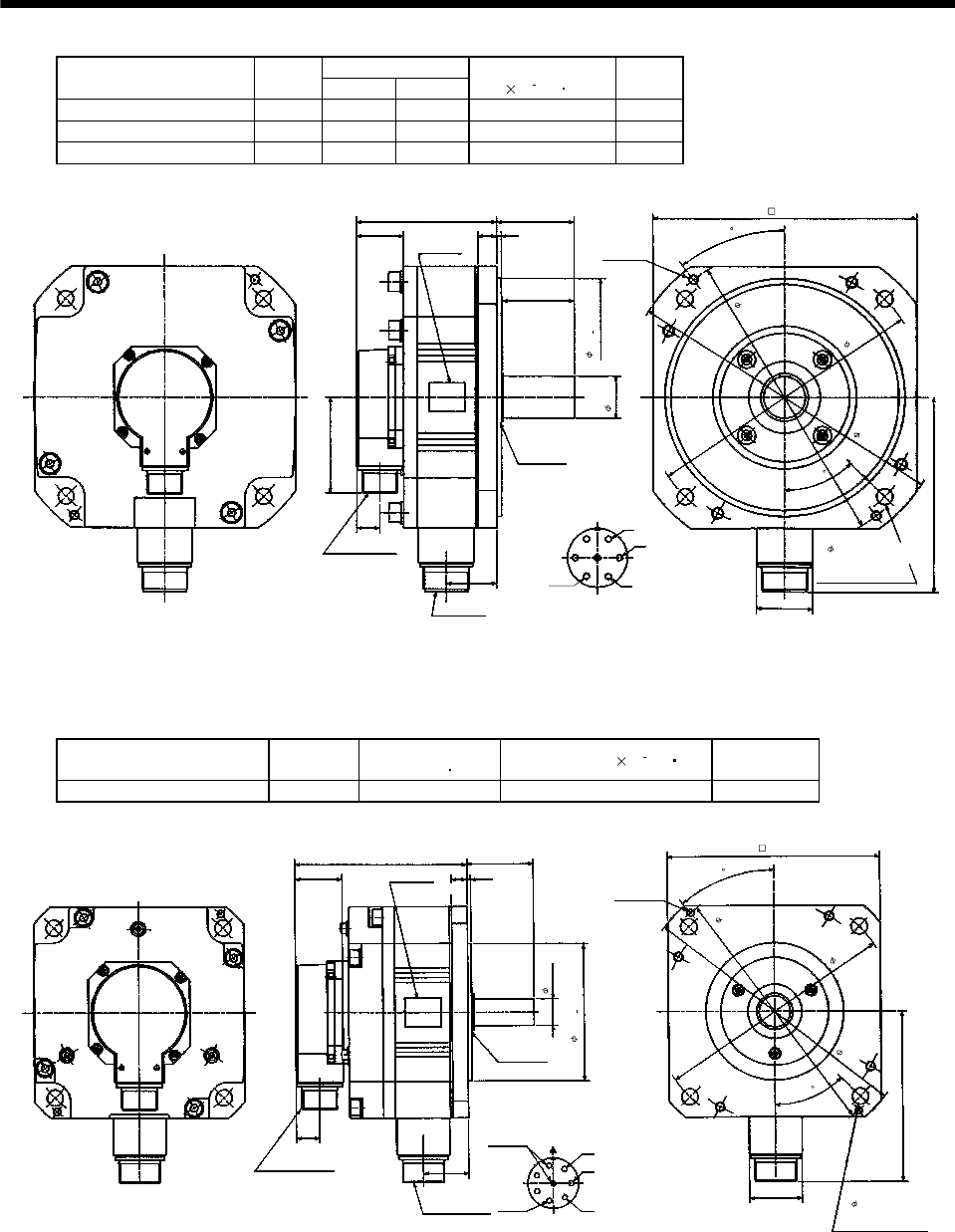
7 - 98
7. OUTLINE DIMENSION DRAWINGS
Variable Dimensions
Model Output
[kW] LKL
Inertia Moment
J[ 10 4kg m2]
Mass
[kg]
HC-UF202 HC-UFS202 2.0 118 42.5 38.2 16
HC-UF352 HC-UFS352 3.5 142 66.5 76.5 20
HC-UF502 HC-UFS502 5.0 166 90.5 115 24
Earth
Top
Bottom
Encoder connector
MS3102A20-29P
Power supply connector
CE05-2A24-10P
Motor flange direction
Power supply connector layout
CE05-2A24-10P
A
B
C
D
E
FG
U
V
W
Oil seal
S40608B
2-M8 screw
37.5
45
39.5
65
16 4
Bottom
Top
19.5
81.5
164
(Note)[Unit: mm]
47
KL
L
60
0
0.046
200
35h6
270
235
250
220
4- 13.5 mounting hole
Use hexagon socket
head cap screw.
Z695914*
Motor plate
(Opposite side)
(BC11713* BC12764*)
Note: The dimensions without tolerances are reference dimensions.
(2) With electromagnetic brake
Model Output [kW] Brake static friction
torque [N m] Inertia Moment J[ 10 4kg m2] Mass [kg]
HC-UF72B HC-UFS72B 0.75 8.5 12.4 10
Top
Bottom
Encoder connector
MS3102A20-29P
Power supply
connector
CE05-2A22-23P
Motor flange direction
Power supply connector layout
CE05-2A22-23P
A
B
C
D
E
FG
U
V
W
Earth
Oil seal
S30457B
Motor plate
2-M6 screw
40
45
39.5
55
13 3
Bottom
Top
19.5
144
(Note)[Unit: mm]
44
H
38
144
Brake
0
0.025
(Opposite side)
4- 13.5 mounting hole
Use hexagon socket
head cap screw.
230
200
215
176
22h6
114.3
Z695981A
(BC11714*)
Note: The dimensions without tolerances are reference dimensions.
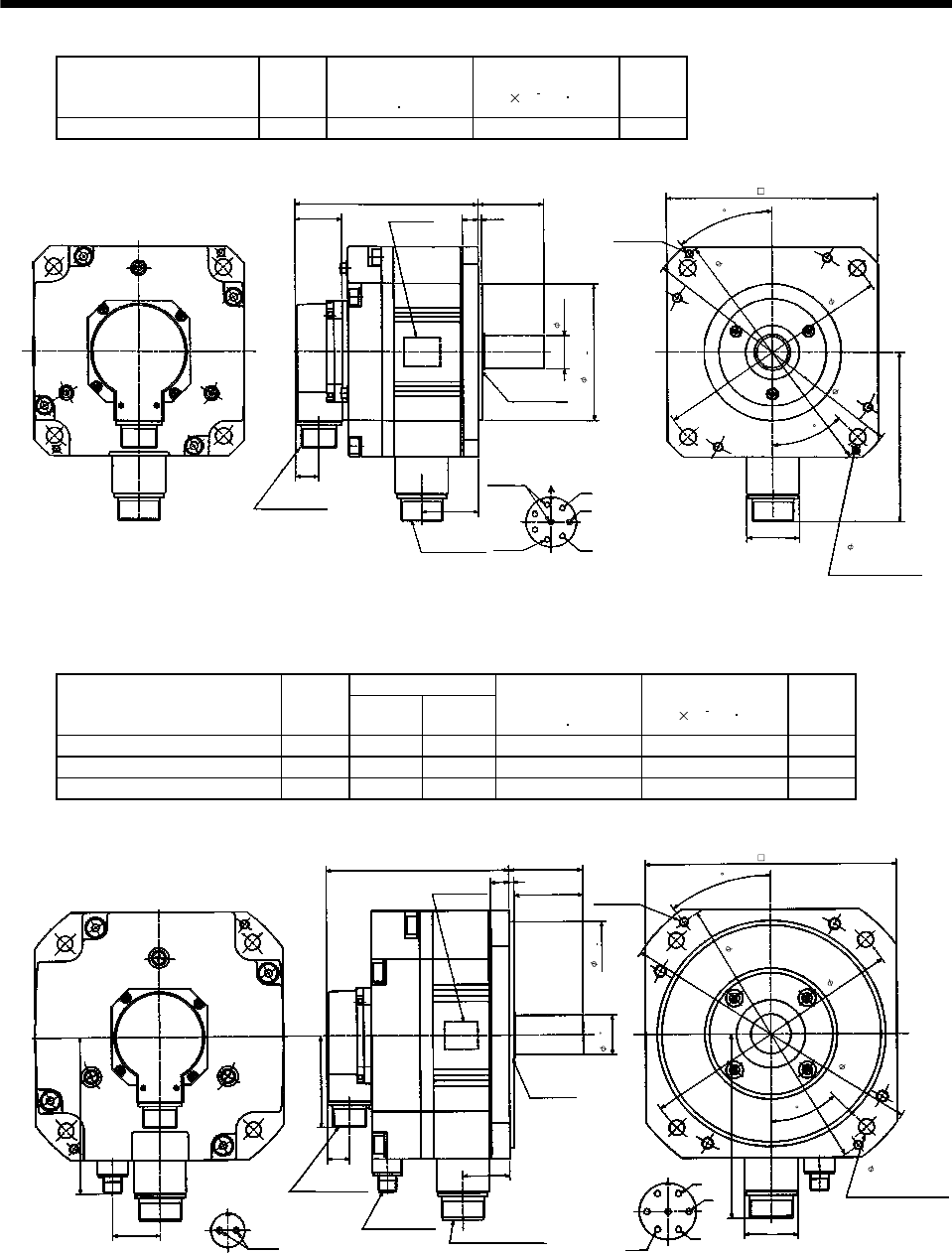
7 - 99
7. OUTLINE DIMENSION DRAWINGS
Model Output
[kW]
Brake static
friction torque
[N m]
Inertia Moment
J[ 10 4kg m2]
Mass
[kg]
HC-UF152B HC-UFS152B 1.5 8.5 24.1 13
0
0.025
Top
Bottom
Encoder connector
MS3102A20-29P
Power supply
connector
CE05-2A22-23P
Motor flange direction
Power supply connector layout
CE05-2A22-23P
A
B
C
D
E
FG
U
V
W
Earth
Oil seal
S30457B
Motor plate
(Opposite side) 2-M6 screw
40
45
39.5
55
13 3
Bottom
Top
19.5
144
(Note)[Unit: mm]
44
H
47.5
153.5
28h6
Brake
114.3
4- 13.5 mounting hole
Use hexagon socket
head cap screw.
230
200
215
176
Z695982B
(BC11715*)
Note: The dimensions without tolerances are reference dimensions.
Variable Dimensions
Model Output
[kW] LKL
Brake static
friction torque
[N m]
Inertia Moment
J[ 10 4kg m2]
Mass
[kg]
HC-UF202B HC-UFS202B 2.0 161 42.5 43.1 46.8 22
HC-UF352B HC-UFS352B 3.5 185 66.5 43.1 85.1 26
HC-UF502B HC-UFS502B 5.0 209 90.5 43.1 123.6 30
Top
Bottom
42
Motor flange direction
Brake connector layout
MS3102A10SL-4P
Brake
AB
Encoder connector
MS3102A20-29P
Brake connector
H/MS3102A10SL-4P Power supply connector
CE05-2A24-10P
KL Motor flange direction
Power supply connector layout
CE05-2A24-10P
A
B
C
D
E
FG
U
V
W
Earth
Oil seal
S40608B
Motor plate
(Opposite side)
2-M8 screw
37.5
45
65
60
16 4
L
Bottom
Top
19.5
81.5
164
139
(Note)[Unit: mm
]
47
0
0.046
0.010
0
35
200
235
250
270
4- 13.5 mounting hole
Use hexagon socket
head cap screw.
220
BC10647A
(BC12760* BC12766*)
Note: The dimensions without tolerances are reference dimensions.

7 - 100
7. OUTLINE DIMENSION DRAWINGS
7.1.6 HC-UF 3000r/min series
(1) Standard (without electromagnetic brake)
Model Output
[W]
Inertia Moment
J[ 10 4kg m2]
Mass
[kg]
HC-UF13 100 0.066 0.8
(Note)[Unit: mm]
Bottom
Top
Motor plate
(Opposite side)
26.9
70
Power supply lead 4-AWG19 0.3m
(With end-insulated round crimping terminal 1.25-4)
Red: Phase U
White: Phase V
Black: Phase W
Green/yellow: Earth
Encoder cable 0.3m
With connector 1-172169-9
(AMP)
25
56
3
50h7
40
8h6
70
Oil seal
S10207
33
9.9
Bottom
Top
Bottom
Top
Bottom
Top
60
4- 5.8
20
40
42.8
BC11740A
Motor plate TUV plate
Caution plate
R5
45
Note: The dimensions without tolerances are reference dimensions.
Variable Dimensions
Model Output
[W] LKL
Inertia Moment
J[ 10 4kg m2]
Mass
[kg]
HC-UF23 200 77 43.8 0.241 1.5
HC-UF43 400 92 58.8 0.365 1.7
50
26.9
L30
86.5
(Note)[Unit: mm]
Top
Bottom
Top
Bottom
Top
Bottom
BC11513A
Motor plate
(Opposite side)
Encoder cable 0.3m Power supply lead 4-AWG19 0.3m
With connector 1-172169-9
(AMP)
(With end-insulated round crimping terminal 1.25-4)
Red: Phase U
White: Phase V
Black: Phase W
Green/yellow: Earth
Oil seal
SC15307
14h6
3
90
80
4- 6.6
Motor plate
TUV plate
9.9
KL
56
55
70h7
45
R7
Note: The dimensions without tolerances are reference dimensions.
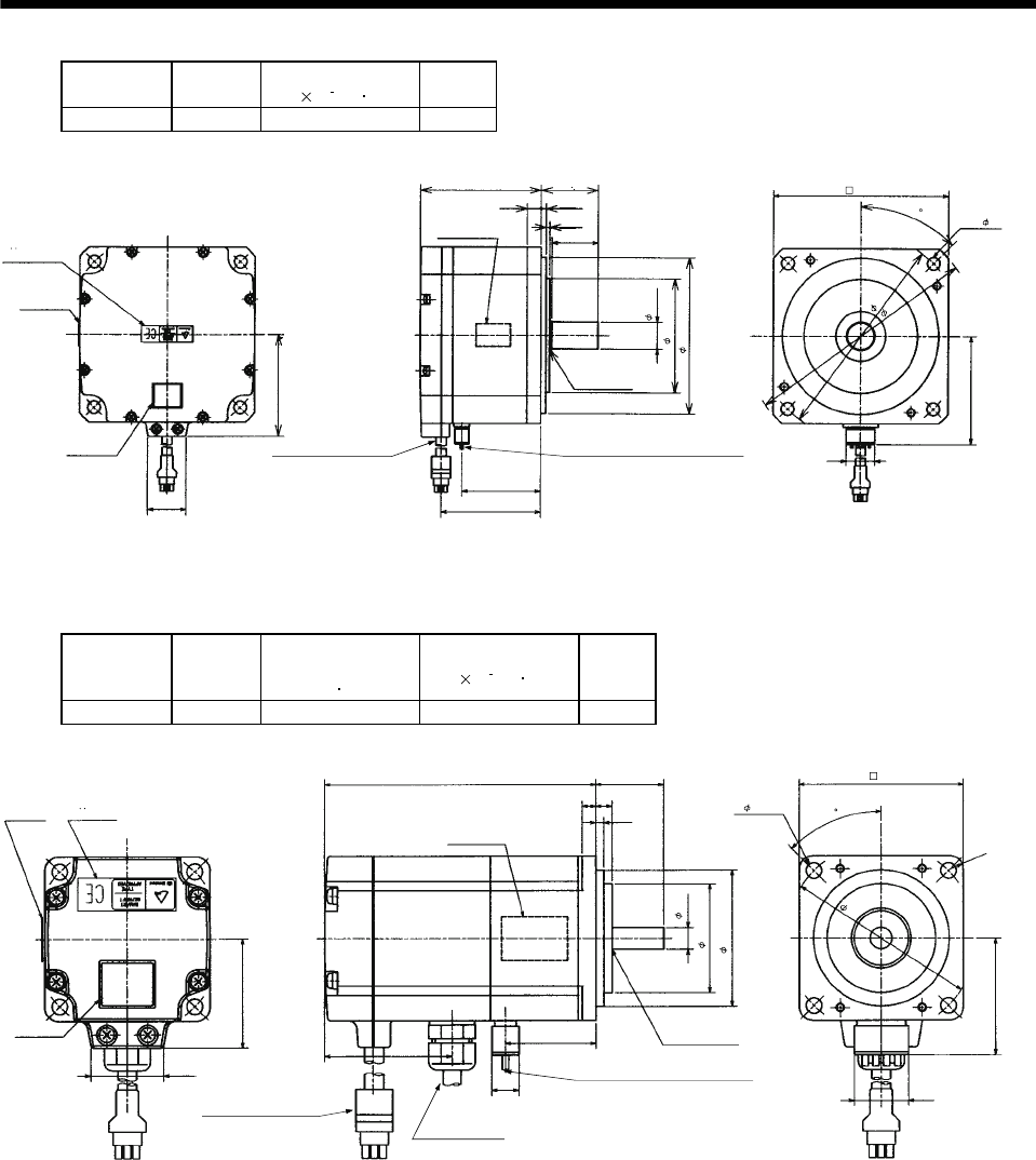
7 - 101
7. OUTLINE DIMENSION DRAWINGS
Model Output
[W]
Inertia Moment
J[ 10 4kg m2]
Mass
[kg]
HC-UF73 750 5.9 5.0
BC11357A
26.9
72
85 40
2.5
10
45
3.5
32.5
20
76
55.5
70
(Note)[Unit: mm]
Oil seal
SC20357
Encoder cable 0.3m
With connector 1-172169-9
(AMP)
Power supply lead 4-AWG19 0.3m
Motor plate
(Opposite side)
Bottom
Top
(With end-insulated round crimping terminal 1.25-4)
Red: Phase U
White: Phase V
Black: Phase W
Green/yellow: Earth
Motor plate
80
110h7
19h6
123
145
165
4- 9
TUV plate
Caution
plate
Bottom
Top
Bottom
Top
Note: The dimensions without tolerances are reference dimensions.
(2) With electromagnetic brake
Model Output
(W)
Brake static
friction torque
[N m]
Inertia Moment
J[ 10 4kg m2]
Mass
[kg]
HC-UF13B 100 0.32 0.074 1.2
42.8
(Note)[Unit: mm]
BC11767
A
Motor plate
(Opposite side)
Encoder cable 0.3m
Power supply lead 4-AWG19 0.3m
26.9
40
With connector 1-172169-9
(AMP)
(With end-insulated round crimping terminal 1.25-4)
Red: Phase U
White: Phase V
Black: Phase W
Green/yellow: Earth
Oil seal
SC10207
100 25
3
5
Bottom
Top
45
R5
6
Brake cable
Cabtyre cable 2-0.75 0.3m
(With end-insulated round crimping terminal 1.25-4)
2
40
50h7
8h6
4- 5.8
60
70
20
TUV plate
Motor plate
Caution
plate
Bottom
Top
Bottom
Top
Bottom
Top
46.7
33
9.9
Note: The dimensions without tolerances are reference dimensions.
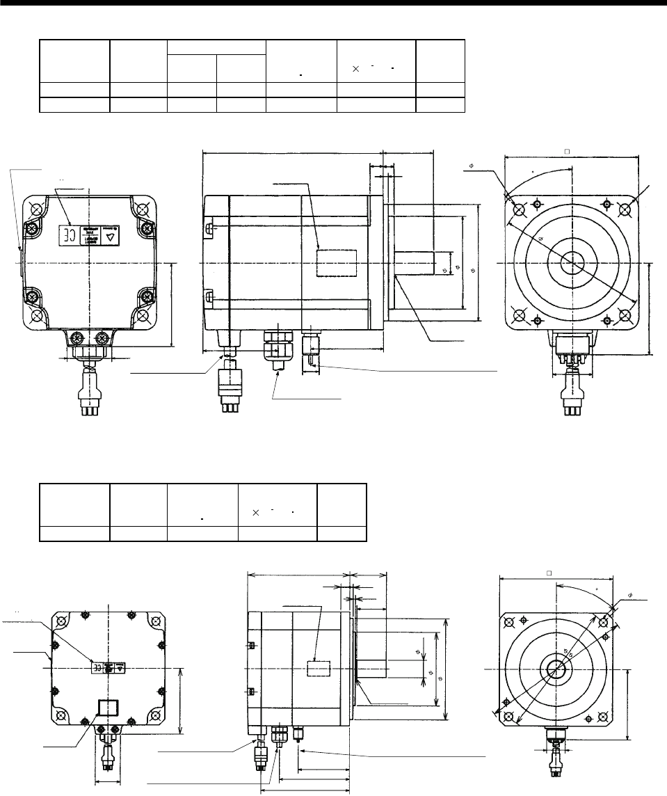
7 - 102
7. OUTLINE DIMENSION DRAWINGS
Variable Dimensions
Model Output
[W] LKL
Brake static
friction torque
[N m]
Inertia Moment
J [ 10 4kg m2]
Mass
[kg]
HC-UF23B 200 111 43.8 1.3 0.323 2.2
HC-UF43B 400 126 58.8 1.3 0.447 2.4
(Note)[Unit: mm]
BC11515A
Motor plate
(Opposite side)
Encoder cable 0.3m Power supply lead 4-AWG19 0.3m
26.9
50
With connector 1-172169-9
(AMP)
(With end-insulated round crimping terminal 1.25-4)
Red: Phase U
White: Phase V
Black: Phase W
Green/yellow: Earth
Oil seal
SC15307
L30
3
8
Bottom
Top
45
R7
6.5
Brake cable
2
TUV plate
Motor plate
Bottom
Top
47.2 KL
14h6
56
70h7
4- 6.6
80
90
55
24
Bottom
Top
Cabtyre cable 2-0.75 0.3m
(With end-insulated round
crimping terminal 1.25-4)
Note: The dimensions without tolerances are reference dimensions.
Model Output
[W]
Brake static
friction torque
[N m]
Inertia Moment
J[ 10 4kg m2]
Mass
[kg]
HC-UF73B 750 2.4 6.1 6.2
111
26.9
145
45
10
BC11358A
72
40
32.5
3.5
2.5
165
76
20
55.5
76
96
Oil seal
SC20357
Encoder cable 0.3m
With connector 1-172169-9
(AMP)
Brake cable
Power supply lead 4-AWG19 0.3m
(Note)[Unit: mm]
Motor plate
(Opposite side)
(With end-insulated round crimping terminal 1.25-4)
Red: Phase U
White: Phase V
Black: Phase W
Green/yellow: Earth
Bottom
Top
Motor plate
Caution
plate
TUV plate
19h6
110h7
80
123
4 -9
Bottom
Bottom
Top
Bottom
Top
Top
2
Note: The dimensions without tolerances are reference dimensions.
Cabtyre cable 2-0.75 0.3m
(With end-insulated round crimping terminal 1.25-4)
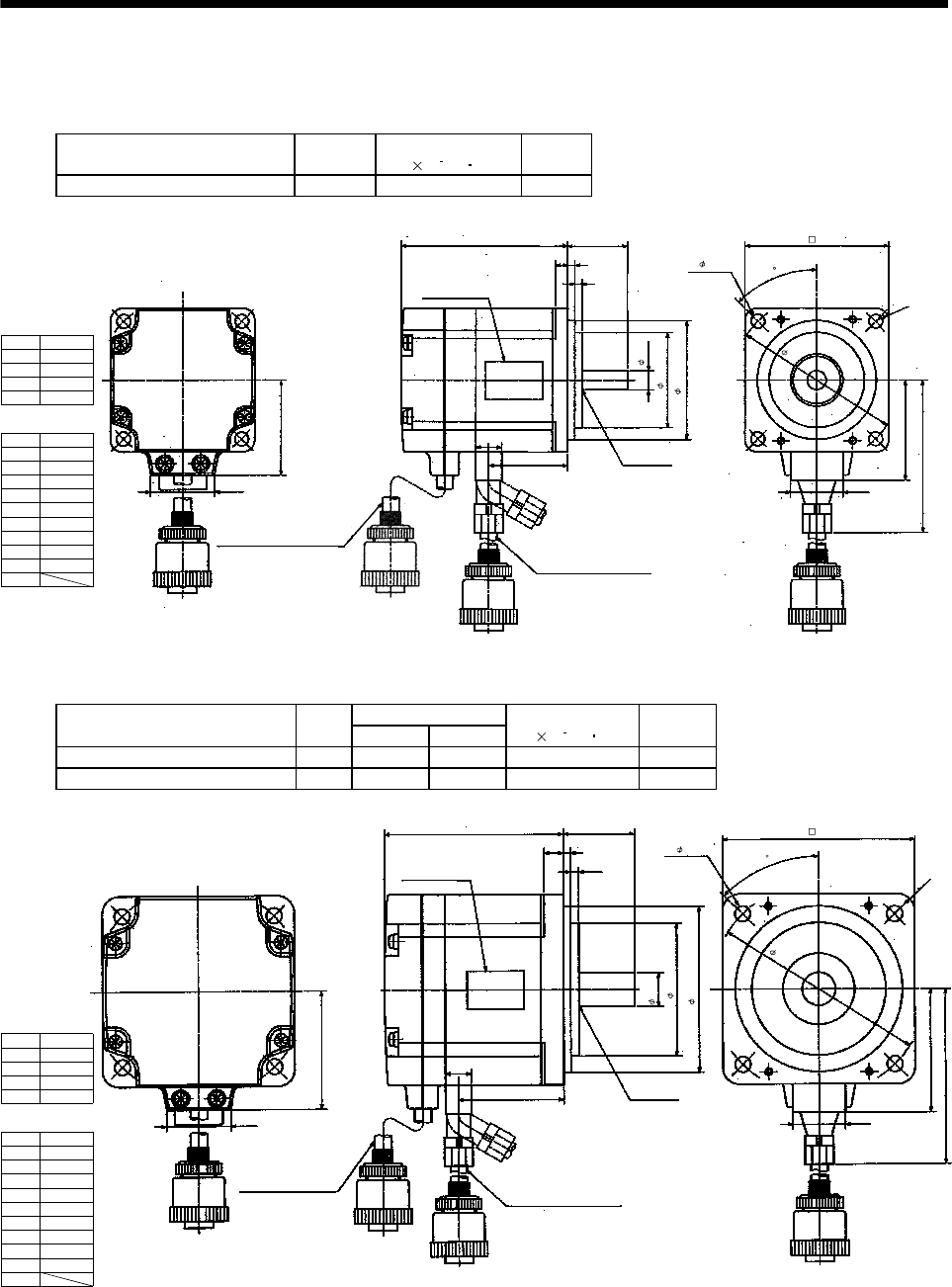
7 - 103
7. OUTLINE DIMENSION DRAWINGS
7.1.7 HC-UF3000r/min, HC-UFS3000r/min series with IP65-compliant connectors
(1) Without electromagnetic brake
Model Output
[W]
Inertia Moment
J[ 10 4kg m2]
Mass
[kg]
HC-UF13-S1 HC-UFS13-S1 100 0.066 0.8
40
26.9
70
70
45
5
BC11292A
25
3
3
14
33
50
87
24
1
2
3
4
1
2
3
4
5
6
7
8
9
10
MR
MRR
BAT
MD
MDR
R5
(Note)[Unit: mm]
Power supply
connector pin
connection list
Pin No. Application
Phase U
Phase V
Phase W
Earth
Encoder connector
pin connection list
Pin No. Application
Bottom
Top
Oil seal
S10207
Encoder cable 0.3m
Power supply cable 0.3m
Motor plate
(Opposite side)
With connector RM15WTP-10P,
cord clamp RM15WTP-CP7
(Hirose Electric) With connector RM15WTP-4P,
cord clamp RM15WTP-CP8
(Hirose Electric)
CNT
P5
LG
SD
8h6
40
50h7
4- 5.8
60
Note: The dimensions without tolerances are reference dimensions.
Variable Dimensions
Model Output
[W] LKL
Inertia Moment
J[ 10 4kg m2]
Mass
[kg]
HC-UF23-S1 HC-UFS23-S1 200 75 44 0.241 1.5
HC-UF43-S1 HC-UFS43-S1 400 90 59 0.365 1.7
50
26.9
L
45
8
BC11293A
30
3
3.5
14
KL
R7
60
97
24
1
2
3
4
Power supply
connector pin
connection list
Pin No. Application
Phase U
Phase V
Phase W
Earth
Encoder connector
pin connection list
(Note)[Unit: mm]
Bottom
Top
Oil seal
S15307
Encoder cable 0.3m
Power supply cable 0.3m
Motor plate
(Opposite side)
With connector
RM15WTP-10P,
cord clamp
RM15WTP-CP7
(Hirose Electric)
With connector RM15WTP-4P,
cord clamp RM15WTP-CP8
(Hirose Electric)
1
2
3
4
5
6
7
8
9
10
MR
MRR
BAT
MD
MDR
Pin No. Application
CNT
P5
LG
SD
56
70h7
14h6
4- 6.6
80
90
Note: The dimensions without tolerances are reference dimensions.
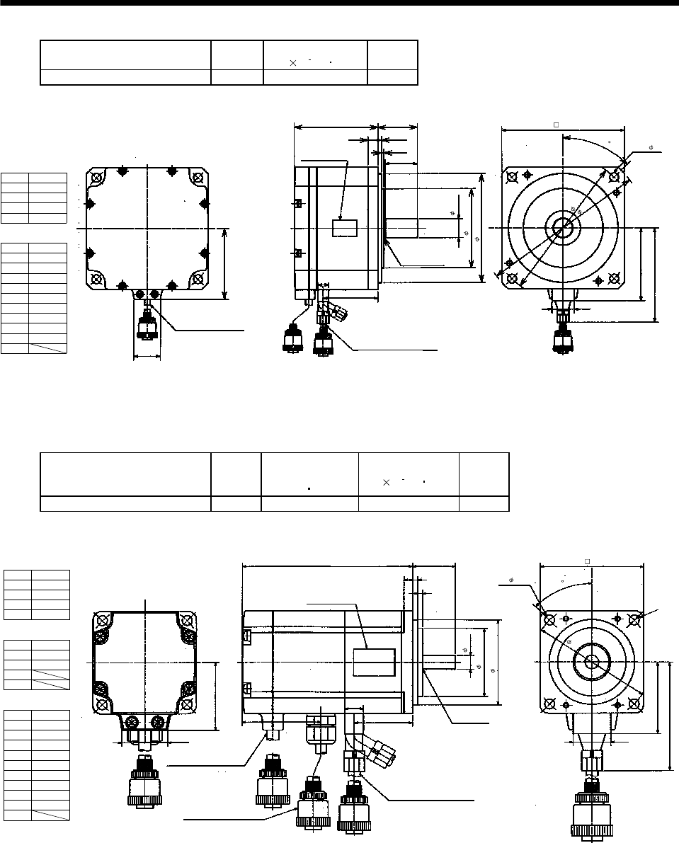
7 - 104
7. OUTLINE DIMENSION DRAWINGS
Model Output
[W]
Inertia Moment
J[ 10 4kg m2]
Mass
[kg]
HC-UF73-S1 HC-UFS73-S1 750 5.9 5.0
72
26.9
85
45
10
BC11359A
40
3.5
32.5
81.5
118.5
24
14
55.5
2.5
(Note)[Unit: mm]
Bottom
Top
Oil seal
S20357
Encoder cable 0.3m
Power supply cable 0.3m
Motor plate
(Opposite side)
With connector RM15WTP-10P,
cord clamp RM15WTP-CP7
(Hirose Electric) With connector RM15WTP-4P,
cord clamp RM15WTP-CP8
(Hirose Electric)
1
2
3
4
1
2
3
4
5
6
7
8
9
10
MR
MRR
BAT
MD
MDR
Power supply
connector pin
connection list
Pin No. Application
Phase U
Phase V
Phase W
Earth
Encoder connector
pin connection list
Pin No. Application
CNT
P5
LG
SD
19h6
80
110h7
4- 9
123
145
165
Note: The dimensions without tolerances are reference dimensions.
(2) With electromagnetic brake
Model Output
[W]
Brake static
friction torque
[N m]
Inertia Moment
J[ 10 4kg m2]
Mass
[kg]
HC-UF13B-S1 HC-UFS13B-S1 100 0.32 0.074 1.2
40
26.9
100
45
5
BC11295A
25
3
3
R5
50
87
24
14
33
46.5
(Note)[Unit: mm]
Bottom
Top
Oil seal
S10207
Encoder cable 0.3m
Brake cable 0.3m
Power supply cable 0.3m
Power supply
connector pin
connection list
1
2
3
4
Pin No. Application
B1
B2
Encoder connector
pin connection list
Brake connector pin
connection list
1
2
3
4
Pin No. Application
Phase U
Phase V
Phase W
Earth
Motor plate
(Opposite side)
With connector
RM15WTP-10P,
cord clamp RM15WTP-CP7
(Hirose Electric)
With connector RM15WTP-4P,
cord clamp RM15WTP-CP6
(Hirose Electric)
With connector RM15WTP-4P,
cord clamp RM15WTP-CP8
(Hirose Electric)
1
2
3
4
5
6
7
8
9
10
MR
MRR
BAT
MD
MDR
Pin No. Application
CNT
P5
LG
SD
50h7
40
8h6
80
4- 5.8
70
Note: The dimensions without tolerances are reference dimensions.
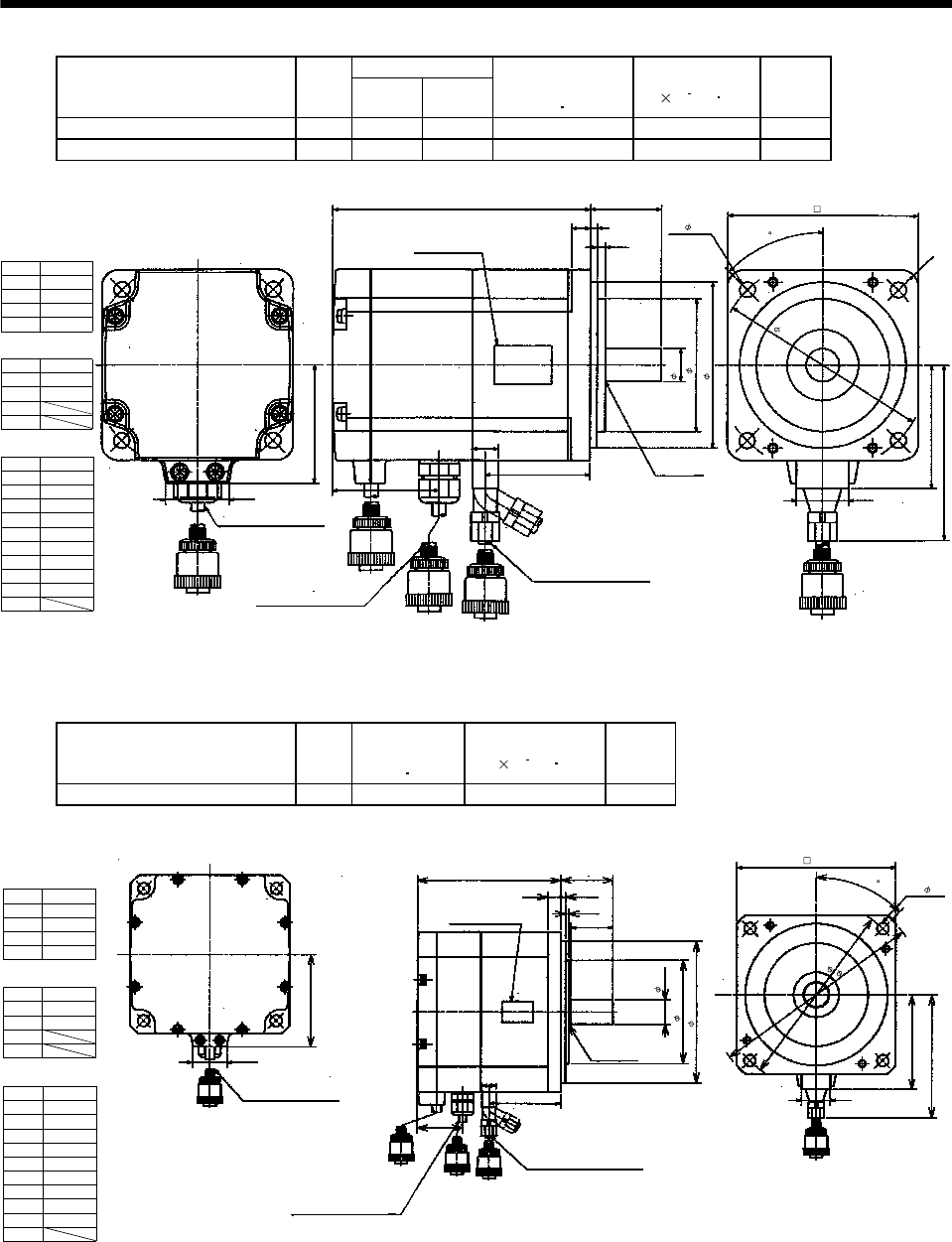
7 - 105
7. OUTLINE DIMENSION DRAWINGS
Variable Dimensions
Model Output
[W] LKL
Brake static
friction torque
[N m]
Inertia Moment
J[ 10 4kg m2]
Mass
[kg]
HC-UF23B-S1 HC-UFS23B-S1 200 109 44 1.3 0.323 2.2
HC-UF43B-S1 HC-UFS43B-S1 400 124 59 1.3 0.447 2.4
50
26.9
L
45
8
BC11296A
30
3
3.5
R7
60
97
24
14
KL
45.3
Power supply
connector pin
connection list
1
2
3
4
Pin No. Application
B1
B2
Encoder connector
pin connection list
Brake connector pin
connection list
1
2
3
4
Pin No. Application
Phase U
Phase V
Phase W
Earth
(Note)[Unit: mm]
Bottom
Top
Oil seal
S15307
Encoder cable 0.3m
Brake cable 0.3m
Power supply cable 0.3m
Motor plate
(Opposite side)
With connector
RM15WTP-10P,
cord clamp
RM15WTP-CP7
(Hirose Electric)
With connector RM15WTP-4P,
cord clamp RM15WTP-CP6
(Hirose Electric)
With connector RM15WTP-4P,
cord clamp RM15WTP-CP8
(Hirose Electric)
1
2
3
4
5
6
7
8
9
10
MR
MRR
BAT
MD
MDR
Pin No. Application
CNT
P5
LG
SD
14h6
56
70h7
4- 6.6
80
90
Note: The dimensions without tolerances are reference dimensions.
Model Output
[W]
Brake static
friction torque
[N m]
Inertia Moment
J[ 10 4kg m2]
Mass
[kg]
HC-UF73B-S1 HC-UFS73B-S1 750 2.4 6.1 6.2
111
45
10
BC11360A
40
3.5
32.5
81.5
118.5
24
145
14
55.5
35
2.5
165
(Note)[Unit: mm]
Bottom
Top
Oil seal
S20357
Brake cable 0.3m
Power supply cable 0.3m
Motor plate
(Opposite side)
Motor plate
(Opposite side)
40
26.9
72
Encoder cable 0.3m
With connector RM15WTP-10P,
cord clamp RM15WTP-CP7
(Hirose Electric)
With connector RM15WTP-4P,
cord clamp RM15WTP-CP6
(Hirose Electric)
With connector RM15WTP-4P,
cord clamp RM15WTP-CP8
(Hirose Electric)
Power supply
connector pin
connection list
1
2
3
4
Pin No. Application
B1
B2
Encoder connector
pin connection list
Brake connector pin
connection list
1
2
3
4
Pin No. Application
Phase U
Phase V
Phase W
Earth
1
2
3
4
5
6
7
8
9
10
MR
MRR
BAT
MD
MDR
Pin No. Application
CNT
P5
LG
SD
10h7
80
19h6
123
4- 9
Note: The dimensions without tolerances are reference dimensions.
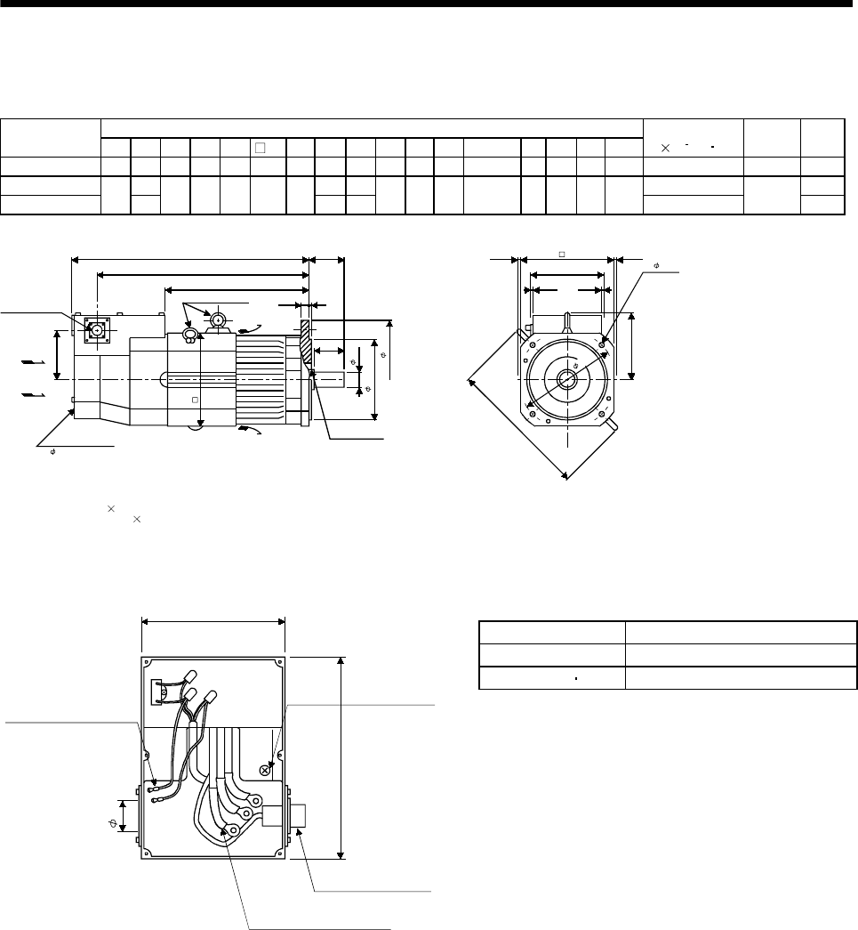
7 - 106
7. OUTLINE DIMENSION DRAWINGS
7.1.8 HA-LH series
(1) Standard (without electromagnetic brake)
Variable Dimensions
Model F L LA LB LC LD LG LT KL KH IE IF Hanger E LR Q S
Inertia Moment
J[ 10 4kg m2]Oil Seal Mass
[kg]
HA-LH11K2(-Y) 208 529 215 180 250 204 20 316 478 102 152 317 M10 3 85 80 42h6 118 S45629B 21
HA-LH15K2(-Y) 578 362 527 290 17
HA-LH22K2(-Y) 254 643 265 230 300 250 25 430 592 117 180 376 M12 5 110 100 55m6 395 S608295 30
Note: 1. The dimensions without tolerances are reference dimensions.
2. When using the motor without the hangers, plug the screw holes with the following bolts:
HA-LH11K2: M10 15mm max.
HA-LH15K2, 22K2: M12 18mm max.
(Note1)[Unit: mm]
5
77
IF
IE
164
5
Encoder connector
MS3102A20-29P
Oil seal
ELG
LR
KH
L
KL
LT
Q
Cooling fan
Hangers in 3 places
Exhaust air
Suction air
(Note2)
1 200V 50/60Hz
LC
LBh7
S
F
LD
4- 14.5
LA
Terminal Box of HA-LH11K2 to 22K2
Power Connection Screw Size
Servo Motor Power Connection Screw Size
HA-LH11K2 8-6
HA-LH15K2 22K2 14-6
146
209
Ground terminal
M6 screw
3 power leads (U, V, W)
with round crimping terminals
Encoder cable
MS3102A20-29P
Cooling fan leads
(BU,BV)
Round crimping
terminal 1.25-4
(Note)[Unit: mm]
44
Note: The dimensions without tolerances are reference dimensions.
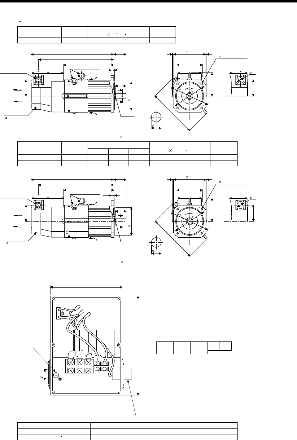
7 - 107
7. OUTLINE DIMENSION DRAWINGS
(2) EN UL/C-UL Standard-Compliant model
Model Output
[kW]
Inertia Moment
J[ 10
4
kg m2]
Mass
[kg]
HA-LH11K2-EC 11 118 70
Note: 1. The dimensions without tolerances are reference dimensions.
2. When usin
g
the motor with han
g
ers removed
,
p
lu
g
screw holes with bolts M10 15 or less.
4- 14.5 mounting hole
Use hexagon socket
head cap screw.
164
77
102
317
152
(Note1)[Unit: mm]
Encoder connector
MS3102A20-29P
Oil seal
S45629B
320
85
102
529
478
316
A
A
80
Cooling fan
Hangers in 3 places
Exhaust air
Suction air
(M10)
(Note2)
208
1 200V 50/60Hz
180h7
Section AA
42h6
44
215
250
204
Variable Dimensions
Model Output
[kW] LKLLT
Inertia Moment
J[ 10
4
kg m2]
Mass
[kg]
HA-LH15K2-EC 15 578 527 362 290 108
HA-LH22K2-EC 22 643 592 430 1160 135
S60829B
525
110
117
L
KL
LT
254
A
A
100
Note: 1. The dimensions without tolerances are reference dimensions.
2. When usin
g
the motor with han
g
ers removed
,
p
lu
g
screw holes with bolts M12 18 or less.
Encoder connector
MS3102A20-29P
Oil seal
Cooling fan
Hangers in 3 places
Exhaust air
Suction air
(M12)
(Note2)
1 200V 50/60Hz
230h7
Section AA
55m6
164
77
117
376
180
Use hexagon socket
head cap screw.
(Note1)[Unit: mm]
250
44
4- 14.5 mounting hole
265
300
Terminal Box of HA-LH11K2-EC to 22K2-EC
146
Terminal box
BU BV
UVW
Terminal block signal arrangemen
t
(Note)[Unit: mm]
Protective Earth (PE)
M6 screw
Encoder connector
MS3102A20-29P
209
UVWBU BV
44
Note: The dimensions without tolerances are reference dimensions.
Model Power Connection Screw Size Fan Connection Screw Size
HA-LH11K2-EC M6 M4
HA-LH15K2-EC 22K2-EC M8 M4
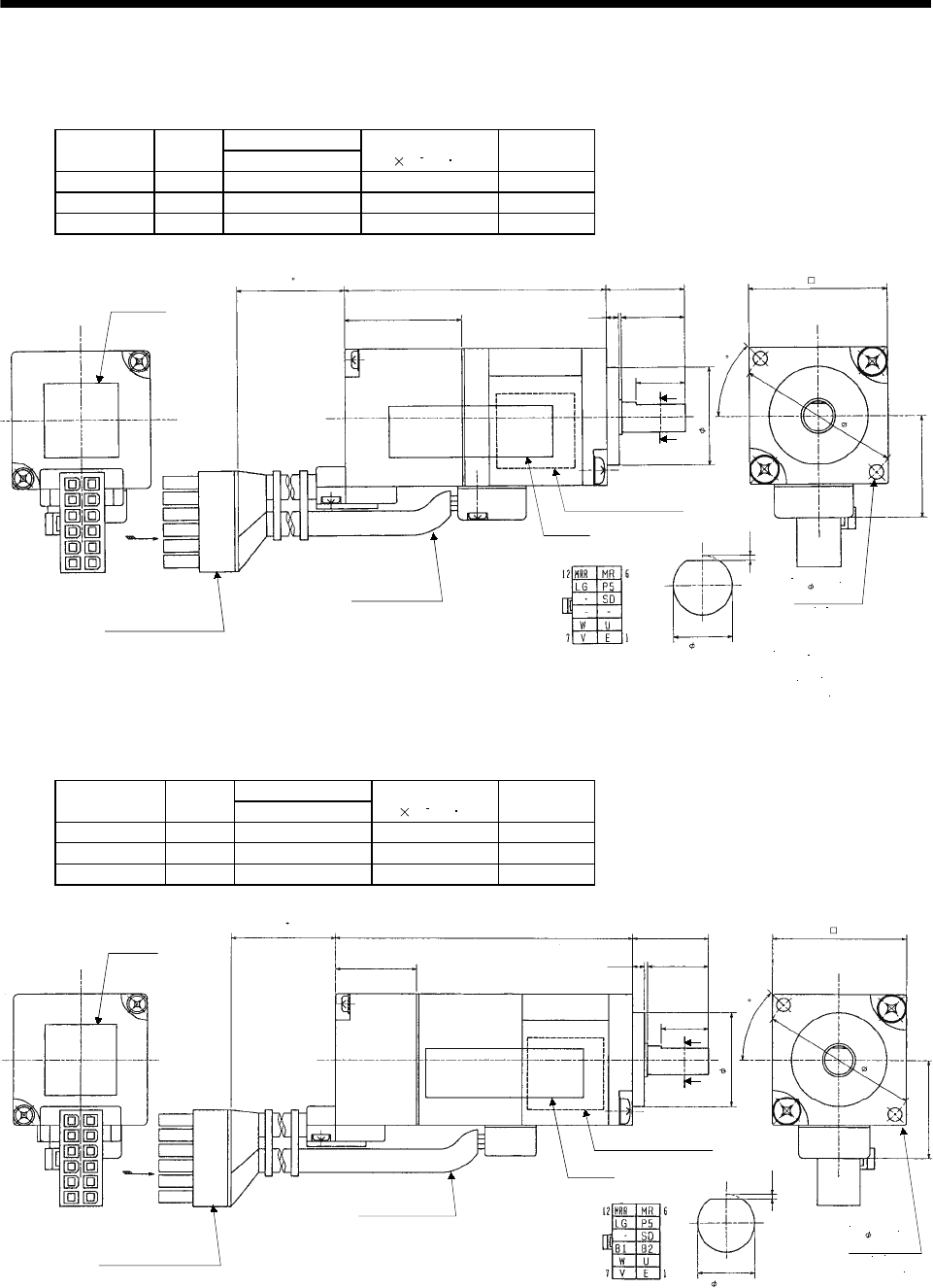
7 - 108
7. OUTLINE DIMENSION DRAWINGS
7.1.9 HC-AQ series
(1) Standard (without electromagnetic brake)
Variable Dimensions
Model Output
[W] L
Inertia Moment
J[ 10 4kg m2]
Mass
[kg]
HC-AQ0135D 10 54 0.0050 0.19
HC-AQ0235D 20 61 0.0072 0.22
HC-AQ0335D 30 68 0.0094 0.25
BC11340D
16
0.5
21
A
A
132.5
10
L
24
Connector 5557-12R-210
(Molex) UL94V-0
Power supply lead/
brake lead
U: Red
V: White
W: Black
Earth: Green
B1, B2 Arrow C Section A-A
200 20
0
Caution plate
Bottom
Top
Arrow C CE plate
Motor plate (Opposite side)
2- 2.9
mounting hole
20h7
33
45
Bottom
Bottom
Top
Top
28
(Note)[Unit: mm]
Note: The dimensions without tolerances are reference dimensions.
6h6
(2) With electromagnetic brake
Variable Dimensions
Model Output
[W] L
Inertia Moment
J[ 10 4kg m2]
Mass
[kg]
HC-AQ0135BD 10 81 0.0091 0.29
HC-AQ0235BD 20 88 0.0113 0.32
HC-AQ0335BD 30 95 0.0135 0.35
BC11343C
16
0.5
21
A
A
132.5
10
L
24
Arrow C Section A-A
Connector 5557-12R-210
(Molex) UL94V-0
2- 2.9
mounting hole
33
28
Power supply lead/
brake lead
U: Red
V: White
W: Black
Earth: Green
B1, B2
45
20h7
CE plate
Motor plate (Opposite side)
Bottom
Bottom
TopTop
200 20
0
Bottom
Top
Arrow C
Caution plate
6h6
(Note)[Unit: mm]
Note: The dimensions without tolerances are reference dimensions.
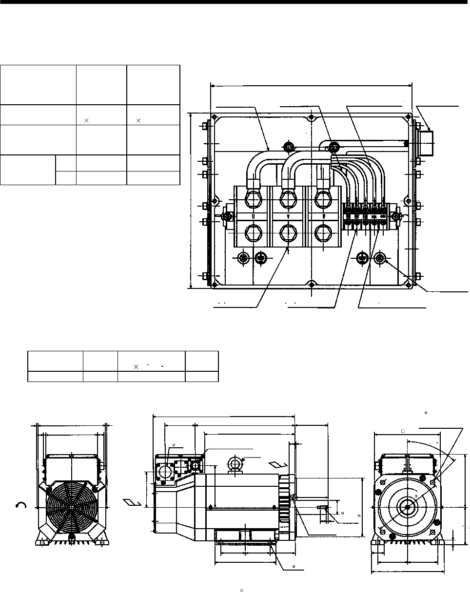
7 - 109
7. OUTLINE DIMENSION DRAWINGS
7.1.10 HA-LF series
Terminal box detail diagram
Motor Model
HA-LF30K2
HA-LF37K2
HA-LF30K24
HA-LF37K24
HA-LF45K24
HA-LF55K24
Motor power supply
lead size
8mm2(AWG8)
2 parallel
22mm2(AWG4)
2 parallel
Motor power supply
terminal block screw
size
M8 M10
LA 220 266
Terminal box
dimensions
(mm) LB 210 230
LA
LB
BG71994C
Motor power supply
lead
Encoder connector
MS3102A20-29P
(Note)[Unit: mm]
Motor power supply
terminal block
(U V W)
Cooling fan terminal block
(BU BV BW) M4 screw
Thermal protector terminal block
(OHS1 OHS2) M4 screw
Earth terminal
M6 screw
Cooling fan lead
0.9SQ or equivalent AWG#
Thermal protector lead
0.5SQ or equivalent AWG#
Note: The dimensions without tolerances are reference dimensions.
Model Output
[kW]
Inertia Moment
J[ 10 4kg m2]
Mass
[kg]
HA-LF30K24 30 550 160
66286
220
11 27
152
605
128 426 140
140
179
105 105
260
108
4- 15
25 5
386
25 8
45
230
20
55
127
310
127
160 0
0.5
BC10833
(Note1)[Unit: mm]
Cooling fan
rotation direction Suction air
Encoder connector
MS3102A20-29P
Hanger
(Note2) Exhaust air
Oil seal
S659013B
M12 screw
4- 19
Use hexagon socket
head cap screw.
Note: 1. The dimensions without tolerances are reference dimensions.
2. When the motor is used without the hanger, plug the threaded hole with a bolt of M16 20mm or less.
51
60m6
250h7
300
280
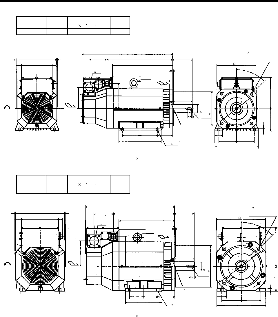
7 - 110
7. OUTLINE DIMENSION DRAWINGS
Model Output
[kW]
Inertia Moment
J[ 10 4kg m2]
Mass
[kg]
HA-LF37K24 37 650 180
66286
22011 27
152
650
128 471 140
140
179
127 127
304
108
25 5
431
25 8
45
230
20
55
127
310
127
160 0
0.5
BC10788C
(Note1)[Unit: mm
]
Cooling fan
rotation
direction Suction air
Encoder connector
MS3102A20-29P
Hanger
(Note2) Exhaust air
Oil seal
S659013B
M12 screw
4- 19
Use hexagon socket
head cap screw.
Note: 1. The dimensions without tolerances are reference dimensions.
2. When the motor is used without the han
g
er
,
p
lu
g
the threaded hole with a bolt of M16 20mm or less.
51
4- 15
60m6
250h7
280
300
Model Output
[kW]
Inertia Moment
J[ 10 4kg m2]
Mass
[kg]
HA-LF45K24 45 1080 230
66352
26611 27
184
640
138 439 140
140
216
101.5 101.5
262
121
25 5
399
30 9
45
280
22
70
139.5
349
139.5
180 0
0.5
BC11107A
(Note1)[Unit: mm]
Cooling fan
rotation
direction Suction air
Encoder connector
MS3102A20-29P
Hanger
(Note2)
Exhaust air
Oil seal
S709513B
M16 screw
4- 19
Use hexagon socket
head cap screw.
Note:1. The dimensions without tolerances are reference dimensions.
2. When the motor is used without the han
g
er
,
p
lu
g
the threaded hole with a bolt of M16 20mm or less.
63
4- 19
65m6
300h7
350
350

7 - 111
7. OUTLINE DIMENSION DRAWINGS
Model Output
[kW]
Inertia Moment
J[ 10 4kg m2]
Mass
[kg]
HA-LF55K24 55 1310 250
66352
26611 27
184
685
138 484 140
140
216
120.5 120.5
300
121
4- 19
25 5
444
30 9
45
280
22
70
139.5
349
139.5
180 0
0.5
BC10522F
(Note1)[Unit: mm]
Cooling fan
rotation
direction
Suction air
Encoder connector
MS3102A20-29P
Hanger
(Note2) Exhaust air
Oil seal
S709513B
M16 screw
Note: 1. The dimensions without tolerances are reference dimensions.
2. When the motor is used without the han
g
er,
p
lu
g
the threaded hole with a bolt of M16 20mm or less.
63
65m6
300h7
350
4- 19
Use hexagon socket
head cap screw.
350
Model Output
[kW]
Inertia Moment
J[ 10 4kg m2]
Mass
[kg]
HA-LF30K2 30 550 160
BC12180*
Note: 1. The dimensions without tolerances are reference dimensions.
2. When the motor is used without the han
g
er
,
p
lu
g
the threaded hole with a bolt of M16 20mm or less.
66
286
266 27
Cooling fan
rotation
direction Suction air
160
615
138 421
140
140
192
105 105
260
108
25 5
381
25 8
Encoder connector
MS3102A20-29P Hanger
(Note2)
Exhaust air
Oil seal
S659013B
M12 screw
63
60m6
250h7
4- 15
45
260
20
127
310
127
160 0
0.5
4- 19
Use hexagon socket
head cap screw.
300
280
350
11
(Note1)[Unit: mm]
55
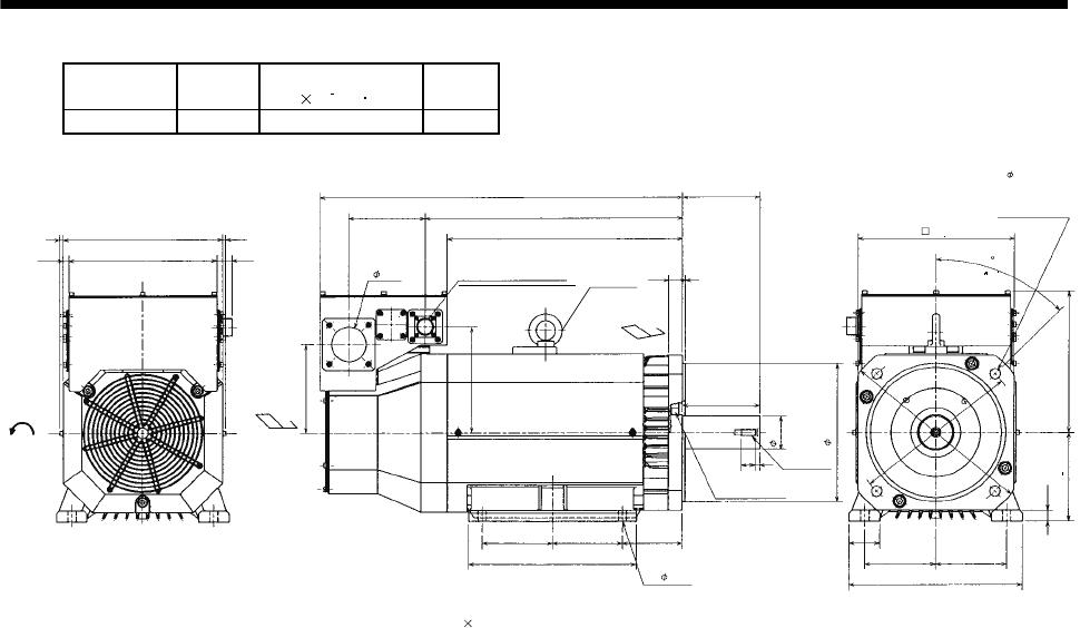
7 - 112
7. OUTLINE DIMENSION DRAWINGS
Model Output
[kW]
Inertia Moment
J[ 10 4kg m2]
Mass
[kg]
HA-LF37K2 37 650 180
Cooling fan
rotation
direction
Suction
air
Encoder connector
MS3102A20-29P Hanger
(Note2)
Exhaust air
Oil seal
S659013B
M12 screw
Use hexagon
socket head cap
screw
Note: 1. The dimensions without tolerances are reference dimensions.
2. When the motor is used without the hanger, plug the threaded hole with a bolt of M16 20 mm or less.
286
66
266
11 27
660
466
138
426
140
5
25
63
140
127 127
304
108
4- 15
250h7
60m6
8
25
127 127
310
55
20
260
45
280
300
350
192
160
BC12181*
(Note1)[Unit: mm]
160 0
0.5
4- 19
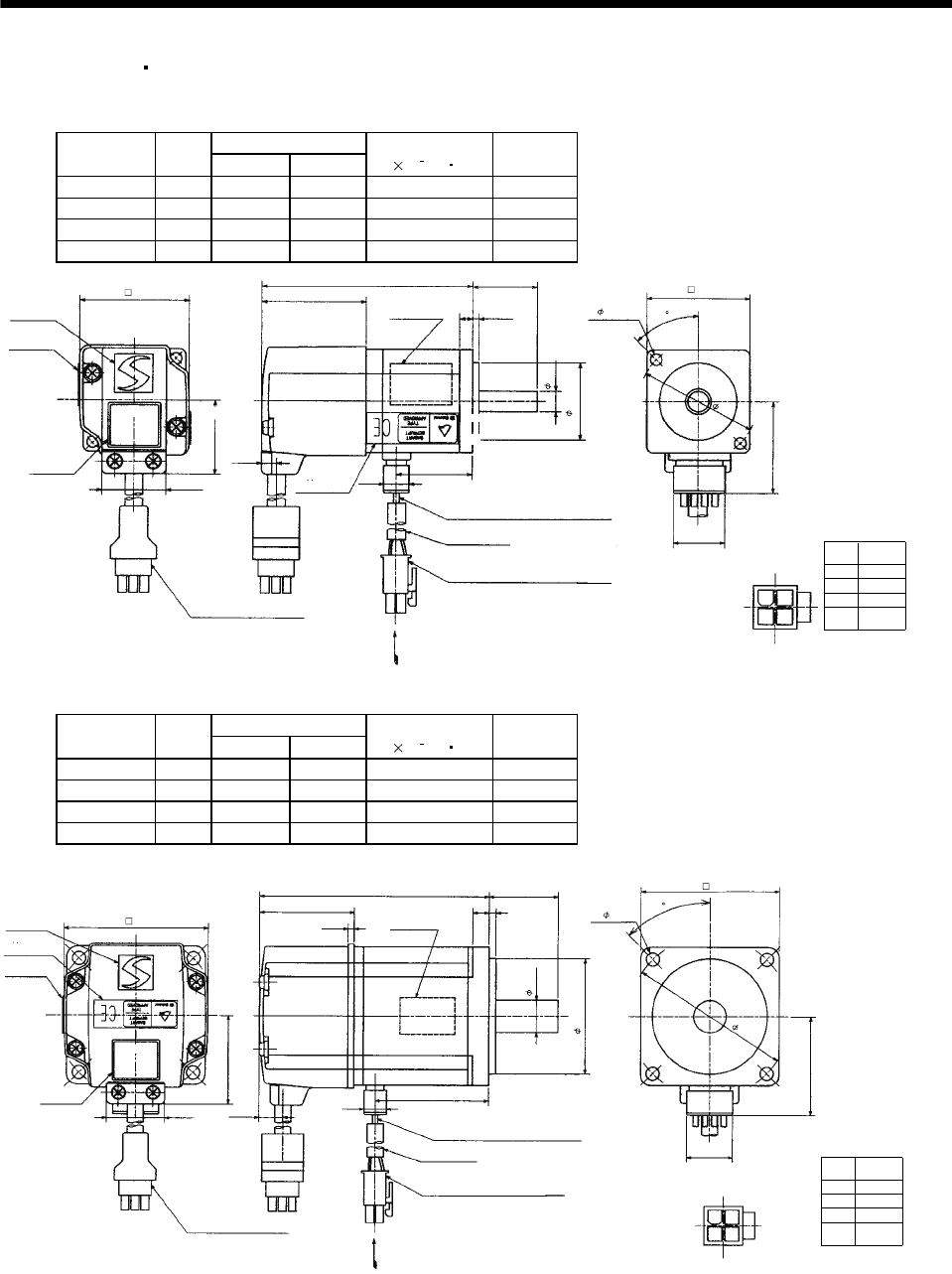
7 - 113
7. OUTLINE DIMENSION DRAWINGS
7.1.11 HC-MFS HC-KFS series
(1) Standard (without electromagnetic brake, without reduction gear)
Variable Dimensions
Model Output
[W] LKL
Inertia Moment
J[ 10 4kg m2]
Mass
[kg]
HC-MFS053 50 81.5 29.5 0.019 0.40
HC-MFS13 100 96.5 44.5 0.03 0.53
HC-KFS053 50 81.5 29.5 0.053 0.40
HC-KFS13 100 96.5 44.5 0.084 0.53
Power supply
connector pin
connection list
1
2
3
4
Pin No. Application
Phase U
Phase V
Phase W
Earth
(Note)[Unit: mm]
BC11873*
(BC11879*)
20
5557-04R-210 (Receptacle)
5556PBTL (Female terminal)
With connector 1-172169-9
(AMP)
Arrow A
45
35.7
Bottom
Top
Protective tube
Motor plate
(Opposite side)
30h7
46
40
8h6
Logo plate
Power supply connector (Molex)
Encoder cable 0.3m
Motor plate
Caution plate
Bottom
Top
Top
KL
25
2.5
5
L
40.5
6.8
9.9
25.2
42
28.7
2- 4.5
Power supply lead 4-AWG19 0.3m
TUV plate
Arrow A
Bottom
Top
Top
Bottom Bottom
Note: The dimensions without tolerances are reference dimensions.
1
2
3
4
Variable Dimensions
Model Output
[W] LKL
Inertia Moment
J[ 10 4kg m2]
Mass
[kg]
HC-MFS23 200 99.5 49.1 0.088 0.99
HC-MFS43 400 124.5 72.1 0.143 1.45
HC-KFS23 200 99.5 49.1 0.42 0.99
HC-KFS43 400 124.5 72.1 0.67 1.45
Power supply
connector pin
connection list
1
2
3
4
Pin No. Application
Phase U
Phase V
Phase W
Earth
(Note)[Unit: mm]
BC11874*
(BC11880*)
20
5557-04R-210 (Receptacle)
5556PBTL (Female terminal)
With connector 1-172169-9
(AMP)
Arrow A
45
42.8
Bottom
Top
Protective tube
Motor plate
(Opposite side)
50h7
70
60
14h6
Logo plate
Power supply connector (Molex)
Encoder cable 0.3m
Motor plate
Caution plate
Bottom
Top
KL
30
3
7
L
41
10.6 9.9
25.2
62
38.4
4- 5.8
Power supply lead 4-AWG19 0.3m
TUV plate
Arrow A
Top
Bottom
Top
Bottom
2.7
1
2
3
4
Note: The dimensions without tolerances are reference dimensions.
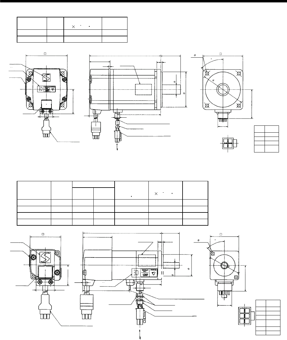
7 - 114
7. OUTLINE DIMENSION DRAWINGS
Model Output
[W]
Inertia Moment
J[ 10 4kg m2]
Mass
[kg]
HC-MFS73 750 0.6 3
HC-KFS73 750 1.51 3
Power supply
connector pin
connection list
1
2
3
4
Pin No. Application
Phase U
Phase V
Phase W
Earth
(Note)[Unit: mm]
BC11875*
20
5557-04R-210 (Receptacle)
5556PBTL (Female terminal)
With connector 1-172169-9
(AMP)
Arrow A
45
58.1
Bottom
Top
Protective tube
Motor plate
(Opposite side)
70h7
90
80
19h6
Logo plate
Power supply connector (Molex)
Encoder cable 0.3m
Motor plate
Caution plate
Bottom
Top
86.7
40
38
142
39
11 9.9
25.2
82
48.7
4- 6.6
Power supply lead 4-AWG19 0.3m
TUV plate
Arrow A
Top
Bottom
Top
Bottom
2.7
1
2
3
4
(BC12580*)
Note: The dimensions without tolerances are reference dimensions.
(2) With electromagnetic brake
Variable Dimensions
Model Output
[W] LKL
Brake static
friction torque
[N m]
Inertia Moment
J[ 10 4kg m2]
Mass
[kg]
HC-MFS053B 50 109.5 29.5 0.32 0.022 0.75
HC-MFS13B 100 124.5 44.5 0.32 0.032 0.89
HC-KFS053B 50 109.5 29.5 0.32 0.056 0.75
HC-KFS13B 100 124.5 44.5 0.32 0.087 0.89
Power supply
connector pin
connection list
1
2
3
4
Pin No. Application
Phase U
Phase V
Phase W
Earth
5
6
B1
B2
(Note)[Unit: mm]
BC11881*
(BC11887*)
20
5557-06R-210 (Receptacle)
5556PBTL (Female terminal)
Arrow A
45
35.7
Bottom
Top
Protective tube
Motor plate
(Opposite side)
30h7
46
40
8h6
Logo plate
Power supply connector (Molex)
Encoder cable 0.3m
Motor plate
Caution plate
Bottom
Top
Top
KL
25
2.55
L
40.5
6.8
9.9
25.2
42
28.7
2- 4.5
Power supply lead 4-AWG19 0.3m
TUV plate
Arrow A
Bottom
Top
Top
Brake lead
2-0.3 0.3m
2
Banding band
1
2
4
5
36
65.5
With connector 1-172169-9
(AMP)
Bottom Bottom
Note: The dimensions without tolerances are reference dimensions.
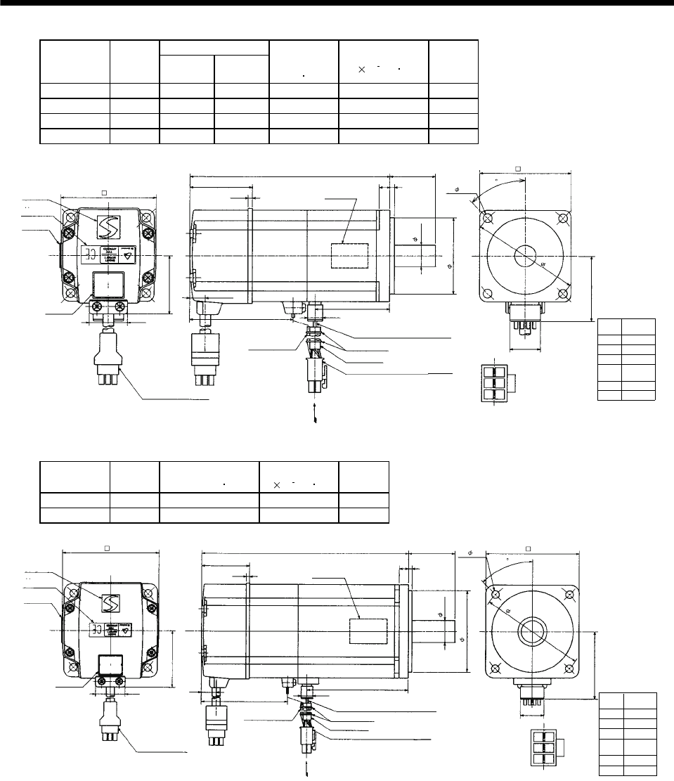
7 - 115
7. OUTLINE DIMENSION DRAWINGS
Variable Dimensions
Model Output
[W] LKL
Brake static
friction torque
[N m]
Inertia Moment
J[ 10 4kg m2]
Mass
[kg]
HC-MFS23B 200 131.5 49.1 1.3 0.136 1.6
HC-MFS43B 400 156.5 72.1 1.3 0.191 2.1
HC-KFS23B 200 131.5 49.1 1.3 0.310 1.6
HC-KFS43B 400 156.5 72.1 1.3 0.510 2.1
Power supply
connector pin
connection list
1
2
3
4
Pin No. Application
Phase U
Phase V
Phase W
Earth
5
6
B1
B2
(Note)[Unit: mm]
BC11882*
(BC11888*)
20
5557-06R-210 (Receptacle)
5556PBTL (Female terminal)
With connector 1-172169-9
(AMP) Arrow A
45
42.8
Bottom
Top
Protective tube
Motor plate
(Opposite side)
50h7
70
60
14h6
Logo plate
Power supply connector (Molex)
Encoder cable 0.3m
Motor plate
Caution plate
Bottom
Top
KL
30
3
7
L
41
10.6
9.9
25.2
62
38.4
4- 5.8
Power supply lead 4-AWG19 0.3m
TUV plate
Arrow A
Top
Bottom
Top
Bottom
2.7
68
Brake lead
2-0.3 0.3m
2
1
2
4
5
36
Note: The dimensions without tolerances are reference dimensions.
Banding band
Model Output
[W]
Brake static friction
torque [N m]
Inertia Moment
J[ 10 4kg m2]
Mass
[kg]
HC-MFS73B 750 2.4 0.725 4.0
HC-KFS73B 750 2.4 1.635 4.0
5557-06R-210 (Receptacle)
5556PBTL (Female terminal)
Power supply
connector pin
connection list
1
2
3
4
Pin No. Application
Phase U
Phase V
Phase W
Earth
5
6
B1
B2
(Note)[Unit: mm]
BC11883*
20
With connector 1-172169-9
(AMP)
Arrow A
45
58.1
Bottom
Top
Protective tube
Motor plate
(Opposite side)
70h7
90
80
19h6
Logo plate
Power supply connector (Molex)
Encoder cable 0.3m
Motor plate
Caution plate
Bottom
Top
86.7
40
38
177.5
39
11 9.9
25.2
82
48.7
4- 6.6
Power supply lead 4-AWG19 0.3m
TUV plate
Arrow A
Top
Bottom
Top
Bottom
2.7
72
Brake lead
2-0.3 0.3m
2
1
2
4
5
36
(BC12581*)
Note: The dimensions without tolerances are reference dimensions.
Banding band
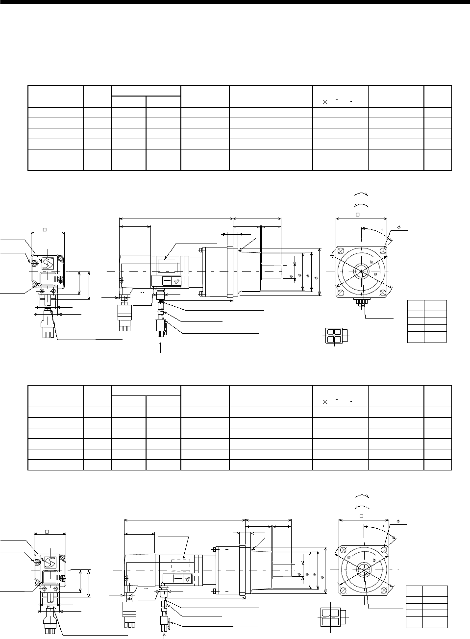
7 - 116
7. OUTLINE DIMENSION DRAWINGS
(3) With reduction gear for general industrial machine
The outer frame of the reduction gear is a material surface such as casting. Its actual dimensions may
be 1 to 3mm larger than the drawing dimensions. Design the machine side with allowances.
(a) Without electromagnetic brake
Variable Dimensions
Model Output
[W] LKL
Reduction
Gear Model
Reduction Ratio
(Actual Reduction Ratio)
Inertia Moment
J[ 10 4kg m2]Backlash Mass
[kg]
HC-MFS053G1 50 126 74 K6505 1/5(9/44) 0.055 60min. max. 1.4
HC-MFS053G1 50 144 92 K6512 1/12(49/576) 0.077 60min. max. 1.8
HC-MFS053G1 50 144 92 K6520 1/20(25/484) 0.059 60min. max. 1.8
HC-KFS053G1 50 126 74 K6505 1/5(9/44) 0.090 60min. max. 1.4
HC-KFS053G1 50 144 92 K6512 1/12(49/576) 0.112 60min. max. 1.8
HC-KFS053G1 50 144 92 K6520 1/20(25/484) 0.094 60min. max. 1.8
L60.5
25
34.5
6.5
8
40.5
KL
9.9
28.7
25.2
35.7
20
6.8
TUV Rheinland
BAUART
GEPRUFT
TYPE
APPROVED CE
4
3
1
2
(R4)
Logo plate
Motor plate
Caution
plate
Encoder cable 0.3m
connector 1-172169-9 (AMP)
Arrow A
Power supply lead 4-AWG19 0.3m
Protective tube
Power supply connector (Molex)
5557-04R-210 (Receptacle)
5556PBT (Female terminal)
Arrow A
Motor plate
(Opposite side)
M4 threads,
depth 8
88
45
75
65
60h7
16h6
48
4- 7
( 50)
42
Bottom
Top
For reverse rotation command
For forward rotation command
"Rotation direction"
Bottom
Top
Bottom
Top
TUV
plate
(Note)[Unit: mm]
Note: The dimensions without tolerances are reference dimensions.
Power supply
connector pin
connection list
1
2
3
4
Pin No. Application
Phase U
Phase V
Phase W
Earth
BC11896A
(BC11924A)
Bottom
Top
Top
Bottom
Variable Dimensions
Model Output
[W] LKL
Reduction
Gear Model
Reduction Ratio
(Actual Reduction Ratio)
Inertia Moment
J[ 10 4kg m2]Backlash Mass
[kg]
HC-MFS13G1 100 141 89 K6505 1/5(9/44) 0.067 60min. max. 1.5
HC-MFS13G1 100 159 107 K6512 1/12(49/576) 0.089 60min. max. 1.9
HC-MFS13G1 100 159 107 K6520 1/20(25/484) 0.071 60min. max. 1.9
HC-KFS13G1 100 141 89 K6505 1/5(9/44) 0.121 60min. max. 1.5
HC-KFS13G1 100 159 107 K6512 1/12(49/576) 0.143 60min. max. 1.9
HC-KFS13G1 100 159 107 K6520 1/20(25/484) 0.125 60min. max. 1.9
28.7
25.2
L
25
34.5
TUV Rheinland
BAUART
GEPRUFT
TYPE
APPROVED CE
40.5
6.8
86.5
9.9
KL
35.7
20
42
13
60.5
(R4)
Logo plate
Motor plate
Caution
plate
Encoder cable 0.3m
connector 1-172169-9 (AMP) Arrow A
Power supply lead 4-AWG19 0.3m
Protective tube
Power supply connector (Molex)
5557-04R-210 (Receptacle)
5556PBT (Female terminal)
Bottom
Top Bottom
Top
42 Motor plate
(Opposite side)
TUV
plate
Arrow A
60h7
16h6
48
( 50)
M4 threads,
depth 8
88
45
75
65
4- 7
For reverse rotation command
For forward rotation command
"Rotation direction"
Bottom
Top
(Note)[Unit: mm]
Note: The dimensions without tolerances are reference dimensions.
Power supply
connector pin
connection list
1
2
3
4
Pin No. Application
Phase U
Phase V
Phase W
Earth
BC11925A
(BC11897A)
Bottom
Top
Bottom
Top
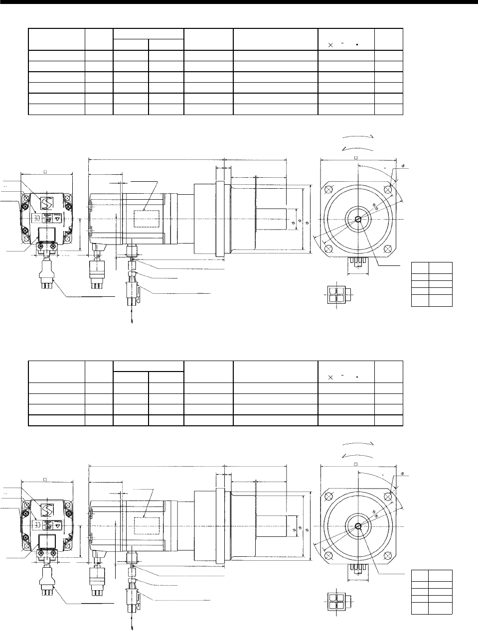
7 - 117
7. OUTLINE DIMENSION DRAWINGS
Variable Dimensions
Model Output
[W] LKL
Reduction
Gear Model
Reduction Ratio
(Actual Reduction Ratio)
Inertia Moment
J[ 10 4kg m2]
Mass
[kg]
HC-MFS23G1 200 153 102.6 K9005 1/5(19/96) 0.249 3.3
HC-MFS23G1 200 173 122.6 K9012 1/12(25/288) 0.293 3.9
HC-MFS23G1 200 173 122.6 K9020 1/20(253/5000) 0.266 3.9
HC-KFS23G1 200 153 102.6 K9005 1/5(19/96) 0.420 3.3
HC-KFS23G1 200 173 122.6 K9012 1/12(25/288) 0.470 3.9
HC-KFS23G1 200 173 122.6 K9020 1/20(253/5000) 0.440 3.9
Power supply
connector pin
connection list
1
2
3
4
Pin No. Application
Phase U
Phase V
Phase W
Earth
(Note)[Unit: mm]
BC11898*
(BC11926*)
20
5557-04R-210 (Receptacle)
5556PBTL (Female terminal)
With connector 1-172169-9
(AMP)
Arrow A
45
Protective tube
Motor plate
(Opposite side)
90
25h6
Logo plate
Power supply connector (Molex)
Encoder cable 0.3m
Motor plate
Caution
plate
Bottom
Top
Bottom
Top
KL
74
8
10
L
10.6
25.2
62
38.4
Power supply lead 4-AWG19 0.3m
Arrow A
Bottom
TUV plate
Bottom
Top
Top
42.8
9.9
2.7
41 30 35
73
82h7
1
2
3
4
For reverse rotation command
For forward rotation command
"Rotation direction"
114
100
4- 9
M6 threads,
depth 12
Note: The dimensions without tolerances are reference dimensions.
Variable Dimensions
Model Output
[W] LKL
Reduction
Gear Model
Reduction Ratio
(Actual Reduction Ratio)
Inertia Moment
J[ 10 4kg m2]
Mass
[kg]
HC-MFS43G1 400 178 125.6 K9005 1/5(19/96) 0.296 3.8
HC-MFS43G1 400 198 145.6 K9012 1/12(25/288) 0.339 4.4
HC-KFS43G1 400 178 125.6 K9005 1/5(19/96) 0.610 3.8
HC-KFS43G1 400 198 145.6 K9012 1/12(25/288) 0.660 4.4
Power supply
connector pin
connection list
1
2
3
4
Pin No. Application
Phase U
Phase V
Phase W
Earth
(Note)[Unit: mm]
BC11899*
(BC11927*)
20
5557-04R-210 (Receptacle)
5556PBTL (Female terminal)
With connector 1-172169-9
(AMP)
Arrow A
45
Protective tube
Motor plate
(Opposite side)
90
25h6
Logo plate
Power supply connector (Molex)
Encoder cable 0.3m
Motor plate
Caution
plate
Bottom
Top
Bottom
Top
KL
74
810
L
10.6
25.2
62
38.4
Power supply lead 4-AWG19 0.3m
Arrow A
Bottom
TUV plate
Bottom
Top
Top
42.8
9.9
2.7
41 30 35
73
82h7
1
2
3
4
For reverse rotation command
For forward rotation command
"Rotation direction"
114
100
4- 9
M6 threads,
depth 12
Note: The dimensions without tolerances are reference dimensions.
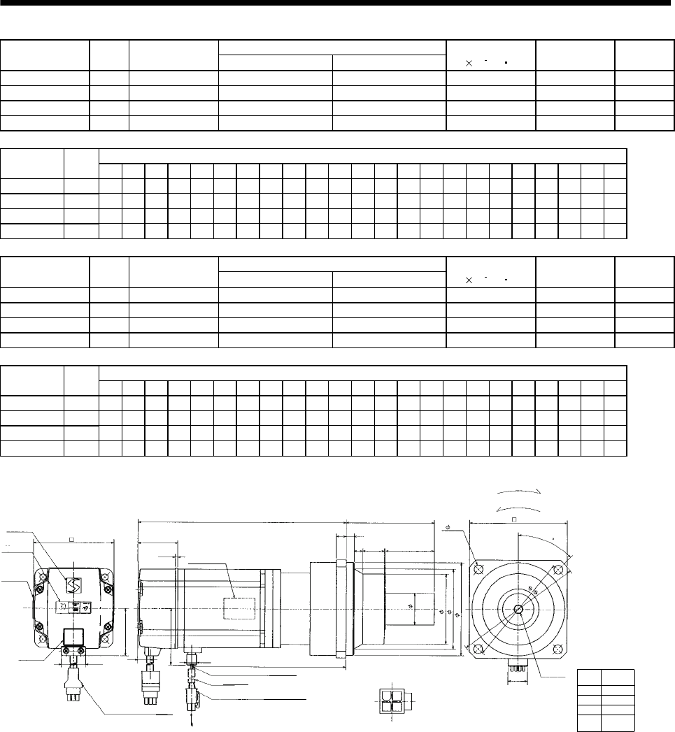
7 - 118
7. OUTLINE DIMENSION DRAWINGS
Reduction Ratio
Model Output
[W]
Reduction Gear
Model Normal Reduction ratio Actual Reduction Ratio
Inertia Moment
J[ 10 4kg m2]Backlash Mass
[kg]
HC-MFS43G1 400 K10020 1/20 253/5000 0.653 60min. max. 5.5
HC-MFS73G1 750 K10005 1/5 1/5 1.02 60min. max. 6.2
HC-MFS73G1 750 K10012 1/12 525/6048 1.686 60min. max. 7.3
HC-MFS73G1 750 K12020 1/20 625/12544 1.75 60min. max. 10.1
Variable Dimensions
Model Output
[W] D LH LK LT H LA LB LC LD LE LF LG LM LN LP L LR KL LZ Q S P R
HC-MFS43G1 400 62 38.4 41 10.6 42.8 115 95 132 100 10 73 10 13 16 86 201.5 90 149.1 9 50 32M816
HC-MFS73G1 750 82 48.7 39 11 58.1 115 95 132 100 10 73 10 13 16 86 207 90 151.7 9 50 32M816
HC-MFS73G1 750 82 48.7 39 11 58.1 115 95 132 100 10 73 10 13 16 86 229 90 173.7 9 50 32M816
HC-MFS73G1 750 82 48.7 39 11 58.1 140 115 162 120 12 90 15 13 20 104 242 106 186.7 14 60 40 M10 20
Reduction Ratio
Model Output
[W]
Reduction Gear
Model Normal Reduction ratio Actual Reduction Ratio
Inertia Moment
J[ 10 4kg m2]Backlash Mass
[kg]
HC-KFS43G1 400 K10020 1/20 253/5000 0.970 60min. max. 5.5
HC-KFS73G1 750 K10005 1/5 1/5 1.930 60min. max. 6.2
HC-KFS73G1 750 K10012 1/12 525/6048 2.596 60min. max. 7.3
HC-KFS73G1 750 K12020 1/20 625/12544 2.660 60min. max. 10.1
Variable Dimensions
Model Output
[W] D LH LK LT H LA LB LC LD LE LF LG LM LN LP L LR KL LZ Q S P R
HC-KFS43G1 400 62 38.4 41 10.6 42.8 115 95 132 100 10 73 10 13 16 86 201.5 90 149.1 9 50 32M816
HC-KFS73G1 750 82 48.7 39 11 58.1 115 95 132 100 10 73 10 13 16 86 207 90 151.7 9 50 32M816
HC-KFS73G1 750 82 48.7 39 11 58.1 115 95 132 100 10 73 10 13 16 86 229 90 173.7 9 50 32M816
HC-KFS73G1 750 82 48.7 39 11 58.1 140 115 162 120 12 90 15 13 20 104 242 106 186.7 14 60 40 M10 20
Power supply
connector pin
connection list
1
2
3
4
Pin No. Application
Phase U
Phase V
Phase W
Earth
(Note)[Unit: mm]
BC11900*
20
5557-04R-210 (Receptacle)
5556PBTL (Female terminal)
With connector 1-172169-9
(AMP) Arrow A
45
Protective tube
Motor plate
(Opposite side)
LD
Sh6
Logo plate
Power supply connector (Molex)
Encoder cable 0.3m
Motor plate
Caution
plate
Bottom
Top
Bottom
Top
KL
LR
L
LT
25.2
D
Power supply lead 4-AWG19 0.3m
Arrow
A
TUV plate
Bottom
Top
9.9
2.7
LK
LG
LF
1
2
3
4
For reverse rotation command
For forward rotation command
"Rotation direction"
LC
LA
4- LZ
P threads,
depth R
Bottom
Top
LH
H
LE
LM LN Q
LP
LBh7
(********)
Note: The dimensions without tolerances are reference dimensions.
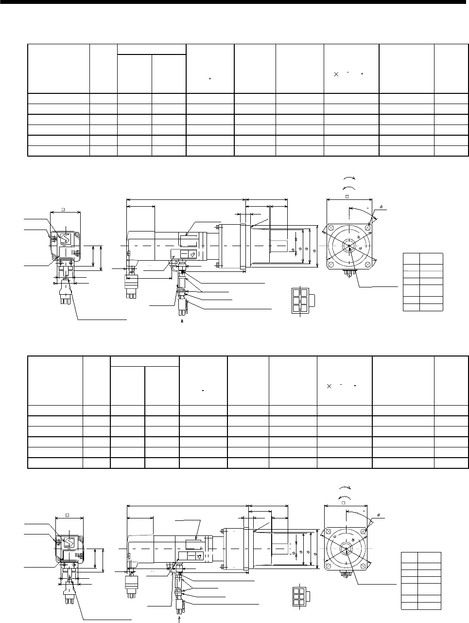
7 - 119
7. OUTLINE DIMENSION DRAWINGS
(b) With electromagnetic brake
Variable Dimensions
Model Output
[W] LKL
Brake static
friction torque
[N m]
Reduction
Gear Model
Reduction
Ratio
(Actual
Reduction
Ratio)
Inertia Moment
J[ 10 4kg m2]Backlash Mass
[kg]
HC-MFS053BG1 50 154 74 0.32 K6505 1/5(9/44) 0.058 60min. max. 1.8
HC-MFS053BG1 50 172 92 0.32 K6512 1/12(49/576) 0.080 60min. max. 2.2
HC-MFS053BG1 50 172 92 0.32 K6520 1/20(25/484) 0.062 60min. max. 2.2
HC-KFS053BG1 50 154 74 0.32 K6505 1/5(9/44) 0.093 60min. max. 1.8
HC-KFS053BG1 50 172 92 0.32 K6512 1/12(49/576) 0.115 60min. max. 2.2
HC-KFS053BG1 50 172 92 0.32 K6520 1/20(25/484) 0.097 60min. max. 2.2
60.5
L
2534.5
6.5
8
40.5
KL
28.7
25.2
35.7
20
TUV
Rheinland
BAUART
GEPR UFT
TYPE
APPR OVED CE
6.8
65.5
9.9
5
41
2
6
3
(R4)
Bottom
Top
Logo plate
Caution plate
42
Bottom
Top
Motor plate
TUV plate
Brake lead
2-0.3 0.3m
2
With connector 1-172169-9
(AMP)
Encoder cable 0.3m
5557-06R-210 (Receptacle)
5556PBT (Female terminal)
Protective tube
Power supply connector (Molex)
Arrow
A
Power supply lead 4-AWG19 0.3m
Motor plate
(Opposite side)
Bottom
Top
Arrow A
48
60h7
16h6
( 50)
Power supply
connector pin
connection list
1
2
3
4
Pin No. Application
Phase U
Phase V
Phase W
Earth
5
6
B1
B2
BC11901A
(BC11929A)
M4 threads, depth 8
65
88
75
45
4- 7
For reverse rotation command
For forward rotation command
"Rotation direction"
(Note)[Unit: mm]
Note: The dimensions without tolerances are reference dimensions.
Top
Bottom
Bottom
Top
Banding band
Variable Dimensions
Model Output
[W] LKL
Brake static
friction torque
[N m]
Reduction
Gear Model
Reduction
Ratio
(Actual
Reduction
Ratio)
Inertia Moment
J[ 10 4kg m2]Backlash Mass
[kg]
HC-MFS13BG1 100 169 89 0.32 K6505 1/5(9/44) 0.069 60min. max. 1.9
HC-MFS13BG1 100 187 107 0.32 K6512 1/12(49/576) 0.091 60min. max. 2.3
HC-MFS13BG1 100 187 107 0.32 K6520 1/20(25/484) 0.073 60min. max. 2.3
HC-KFS13BG1 100 169 89 0.32 K6505 1/5(9/44) 0.124 60min. max. 1.9
HC-KFS13BG1 100 187 107 0.32 K6512 1/12(49/576) 0.146 60min. max. 2.3
HC-KFS13BG1 100 187 107 0.32 K6520 1/20(25/484) 0.128 60min. max. 2.3
28.7
25.2
L
25
34.5
60.5
TUV
Rhein land
BAUA RT
GEPRUFT
TYPE
APPR OVED CE
40.5
6.8
86.5
9.9
KL
35.7
20
65.5
5
41
263
(R4)
Logo plate
Caution plate
42
Bottom
Top
Motor plate
With connector 1-172169-9
(AMP)
Encoder cable 0.3m
Bottom
Top
TUV plate
Brake lead
2-0.3 0.3m
25557-06R-210 (Receptacle)
5556PBT (Female terminal)
Protective tube
Power supply connector (Molex)
Power supply lead 4-AWG19 0.3m
Motor plate
(Opposite side)
Bottom
Top
48
60h7
16h6
( 50)
For reverse rotation command
For forward rotation command
"Rotation direction"
65
88
75
45
4- 7
M4 threads, depth 8
Arrow A
Arrow
A
Power supply
connector pin
connection list
1
2
3
4
Pin No. Application
Phase U
Phase V
Phase W
Earth
5
6
B1
B2
BC11902A
(BC11930A)
(Note)[Unit: mm]
Note: The dimensions without tolerances are reference dimensions.
Bottom
Top
Top
Bottom
Banding band
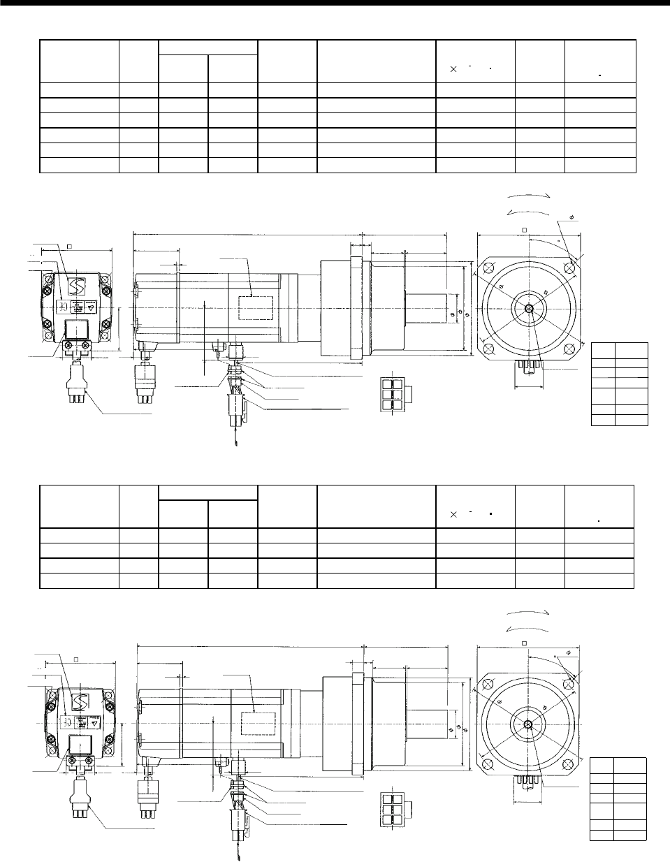
7 - 120
7. OUTLINE DIMENSION DRAWINGS
Variable Dimensions
Model Output
[W] LKL
Reduction
Gear Model
Reduction Ratio
(Actual Reduction Ratio)
Inertia Moment
J[ 10 4kg m2]
Mass
[kg]
Brake static
friction torque
[N m]
HC-MFS23BG1 200 185 102.6 K9005 1/5(19/96) 0.289 3.9 1.3
HC-MFS23BG1 200 205 122.6 K9012 1/12(25/288) 0.333 4.5 1.3
HC-MFS23BG1 200 205 122.6 K9020 1/20(253/5000) 0.306 4.5 1.3
HC-KFS23BG1 200 185 102.6 K9005 1/5(19/96) 0.470 3.9 1.3
HC-KFS23BG1 200 205 122.6 K9012 1/12(25/288) 0.520 4.5 1.3
HC-KFS23BG1 200 205 122.6 K9020 1/20(253/5000) 0.490 4.5 1.3
Power supply
connector pin
connection list
1
2
3
4
Pin No. Application
Phase U
Phase V
Phase W
Earth
5
6
B1
B2
BC11903*
(BC11931*)
(Note)[Unit: mm]
20
5557-06R-210 (Receptacle)
5556PBTL (Female terminal)
With connector 1-172169-9
(AMP) Arrow A
45
Protective tube
Motor plate
(Opposite side)
90
Logo plate
Power supply connector (Molex)
Encoder cable 0.3m
Motor plate
Caution
plate
Top
Bottom
Top
74
L
10.6
25.2
62
Arrow
A
9.9
41
10
1
2
4
5
For reverse rotation command
For forward rotation command
"Rotation direction"
114
100
4- 9
M6 threads,
depth 12
38.4
8
30 35
73
82h7
25h6
Bottom
Top
68
Power supply lead 4-AWG19 0.3m
Brake lead
2-0.3 0.3m
2
36
KL
2.7
42.8
Bottom
Top
TUV plate
Bottom
Note: The dimensions without tolerances are reference dimensions.
Banding band
Variable Dimensions
Model Output
[W] LKL
Reduction
Gear Model
Reduction Ratio
(Actual Reduction Ratio)
Inertia Moment
J[ 10 4kg m2]
Mass
[kg]
Brake static
friction torque
[N m]
HC-MFS43BG1 400 210 125.6 K9005 1/5(19/96) 0.344 4.4 1.3
HC-MFS43BG1 400 230 145.6 K9012 1/12(25/288) 0.388 5.0 1.3
HC-KFS43BG1 400 210 125.6 K9005 1/5(19/96) 0.660 4.4 1.3
HC-KFS43BG1 400 230 145.6 K9012 1/12(25/288) 0.710 5.0 1.3
Power supply
connector pin
connection list
1
2
3
4
Pin No. Application
Phase U
Phase V
Phase W
Earth
5
6
B1
B2
BC11904*
(BC11932*)
(Note)[Unit: mm]
20
5557-06R-210 (Receptacle)
5556PBTL (Female terminal)
With connector 1-172169-9
(AMP) Arrow A
45
Protective tube
Motor plate
(Opposite side)
90
Logo plate
Power supply connector (Molex)
Encoder cable 0.3m
Caution
plate
Top
Bottom
Top
74
L
10.6
25.2
62
Arrow
A
9.9
41 10
1
2
4
5
For reverse rotation command
For forward rotation command
"Rotation direction"
114
100
4- 9
M6 threads,
depth 12
38.4
8
30 35
73
82h7
25h6
Bottom
Top
68
Power supply lead 4-AWG19 0.3m
Brake lead
2-0.3 0.3m
2
36
KL
2.7
42.8
Bottom
Top
Motor plate
TUV plate
Bottom
Note: The dimensions without tolerances are reference dimensions.
Banding band
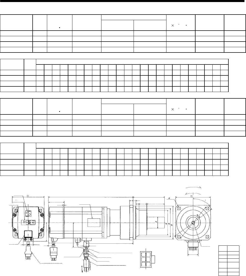
7 - 121
7. OUTLINE DIMENSION DRAWINGS
Reduction Ratio
Model Output
[W]
Brake static
friction torque
[N m]
Reduction
Gear Model Normal
Reduction ratio
Actual
Reduction Ratio
Inertia Moment
J[ 10 4kg m2]Backlash Mass
[kg]
HC-MFS43BG1 400 1.3 K10020 1/20 253/5000 0.700 60min. max. 6.1
HC-MFS73BG1 750 2.4 K10005 1/5 1/5 1.145 60min. max. 7.2
HC-MFS73BG1 750 2.4 K10012 1/12 525/6048 1.811 60min. max. 8.3
HC-MFS73BG1 750 2.4 K12020 1/20 625/12544 1.875 60min. max. 11.1
Variable Dimensions
Model Output
[W] D LH LK LT LX H LA LB LC LD LE LF LG LM LN LP L LR KL LZ Q S P R
HC-MFS43BG1 400 62 38.4 41 10.6 68 42.8 115 95 132 100 10 73 10 13 16 86 233.5 90 149.1 95032M816
HC-MFS73BG1 750 82 48.7 39 11 72 58.1 115 95 132 100 10 73 10 13 16 86 242.5 90 151.7 95032M816
HC-MFS73BG1 750 82 48.7 39 11 72 58.1 115 95 132 100 10 73 10 13 16 86 264.5 90 173.7 95032M816
HC-MFS73BG1 750 82 48.7 39 11 72 58.1 140 115 162 120 12 90 15 13 20 104 277.5 106 186.7 14 60 40 M10 20
Reduction Ratio
Model Output
[W]
Brake static
friction torque
[N m]
Reduction
Gear Model Normal
Reduction ratio
Actual
Reduction Ratio
Inertia Moment
J[ 10 4kg m2]Backlash Mass
[kg]
HC-KFS43BG1 400 1.3 K10020 1/20 253/5000 1.02 60min. max. 6.1
HC-KFS73BG1 750 2.4 K10005 1/5 1/5 2.055 60min. max. 7.2
HC-KFS73BG1 750 2.4 K10012 1/12 525/6048 2.721 60min. max. 8.3
HC-KFS73BG1 750 2.4 K12020 1/20 625/12544 2.785 60min. max. 11.1
Variable Dimensions
Model Output
[W] D LH LK LT LX H LA LB LC LD LE LF LG LM LN LP L LR KL LZ Q S P R
HC-KFS43BG1 400 62 38.4 41 10.6 68 42.8 115 95 132 100 10 73 10 13 16 86 233.5 90 149.1 95032M816
HC-KFS73BG1 750 82 48.7 39 11 72 58.1 115 95 132 100 10 73 10 13 16 86 242.5 90 151.7 95032M816
HC-KFS73BG1 750 82 48.7 39 11 72 58.1 115 95 132 100 10 73 10 13 16 86 264.5 90 173.7 95032M816
HC-KFS73BG1 750 82 48.7 39 11 72 58.1 140 115 162 120 12 90 15 13 20 104 277.5 106 186.7 14 60 40 M10 20
Power supply
connector pin
connection list
1
2
3
4
Pin No. Application
Phase U
Phase V
Phase W
Earth
5
6
B1
B2
BC11905*
(Note)[Unit: mm]
20
5557-06R-210 (Receptacle)
5556PBTL (Female terminal)
With connector 1-172169-9
(AMP)
Arrow A
45
Protective tube
Motor plate
(Opposite side)
Logo plate
Power supply connector (Molex)
Encoder cable 0.3m
Caution
plate
Top
Bottom
Top
LR
L
LT
25.2
D
Arrow
A
TUV plate
9.9
41 LG
1
2
4
5
For reverse rotation command
For forward rotation command
"Rotation direction"
LA
LC
4- LZ
P threads,
depth R
LH
LE
LN Q
LF
LBh7
Sh6
Bottom
Top
LX
Power supply lead 4-AWG19 0.3m
Brake lead
2-0.3 0.3m
2
36
KL
2.7
H
Bottom
Top
LM
LP
(********)
Motor plate
Bottom
LD
Note: The dimensions without tolerances are reference dimensions.
Banding band
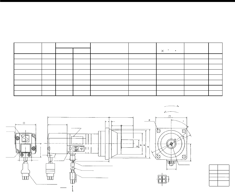
7 - 122
7. OUTLINE DIMENSION DRAWINGS
(4) With reduction gear for precision application
The outer frame of the reduction gear is a material surface such as casting. Its actual dimensions may
be 1 to 3mm larger than the drawing dimensions. Design the machine side with allowances.
(a) Without electromagnetic brake
Variable Dimensions
Model Output
[W] LKL
Reduction Gear Model Reduction Ratio Inertia Moment
J[ 10 4kg m2]Backlash Mass
[kg]
HC-MFS053G2 50 130 78 BK1-05B-A5MEKA 1/5 0.067 3 min. max. 1.4
HC-MFS053G2 50 146 94 BK1-09B-A5MEKA 1/9 0.060 3 min. max. 1.7
HC-MFS053G2 50 146 94 BK1-20B-A5MEKA 1/20 0.069 3 min. max. 1.8
HC-MFS053G2 50 146 94 BK1-29B-A5MEKA 1/29 0.057 3 min. max. 1.8
HC-KFS053G2 50 130 78 BK1-05B-A5MEKA 1/5 0.101 3 min. max. 1.4
HC-KFS053G2 50 146 94 BK1-09B-A5MEKA 1/9 0.095 3 min. max. 1.7
HC-KFS053G2 50 146 94 BK1-20B-A5MEKA 1/20 0.104 3 min. max. 1.8
HC-KFS053G2 50 146 94 BK1-29B-A5MEKA 1/29 0.092 3 min. max. 1.8
Power supply
connector pin
connection list
1
2
3
4
Pin No. Application
Phase U
Phase V
Phase W
Earth
(Note)[Unit: mm]
BC11906*
(BC11916*)
Logo plate
Motor plate
With connector 1-172169-9
(AMP)
Encoder cable 0.3m
Motor plate
(Opposite side)
8
60.5
L
40.5
6.5
28 25
6.8
9.9 KL
25.2
Top
28.7
Bottom
Top
TUV plate
Caution plate
Top
42
For reverse rotation command
For forward rotation command
Rotation direction
70
80
M4 threads, depth 8
16h6
48
65h7
20
13
24
Arrow A
4 - 6.6
Top
Bottom
95
35.7
45
5557-04R-210 (Receptacle)
5556PBTL (Female terminal)
Power supply connector (Molex)
Protective tube
Power supply lead 4-AWG19 0.3m
Arrow A
60
Bottom Bottom Bottom
Top
Note: The dimensions without tolerances are reference dimensions.
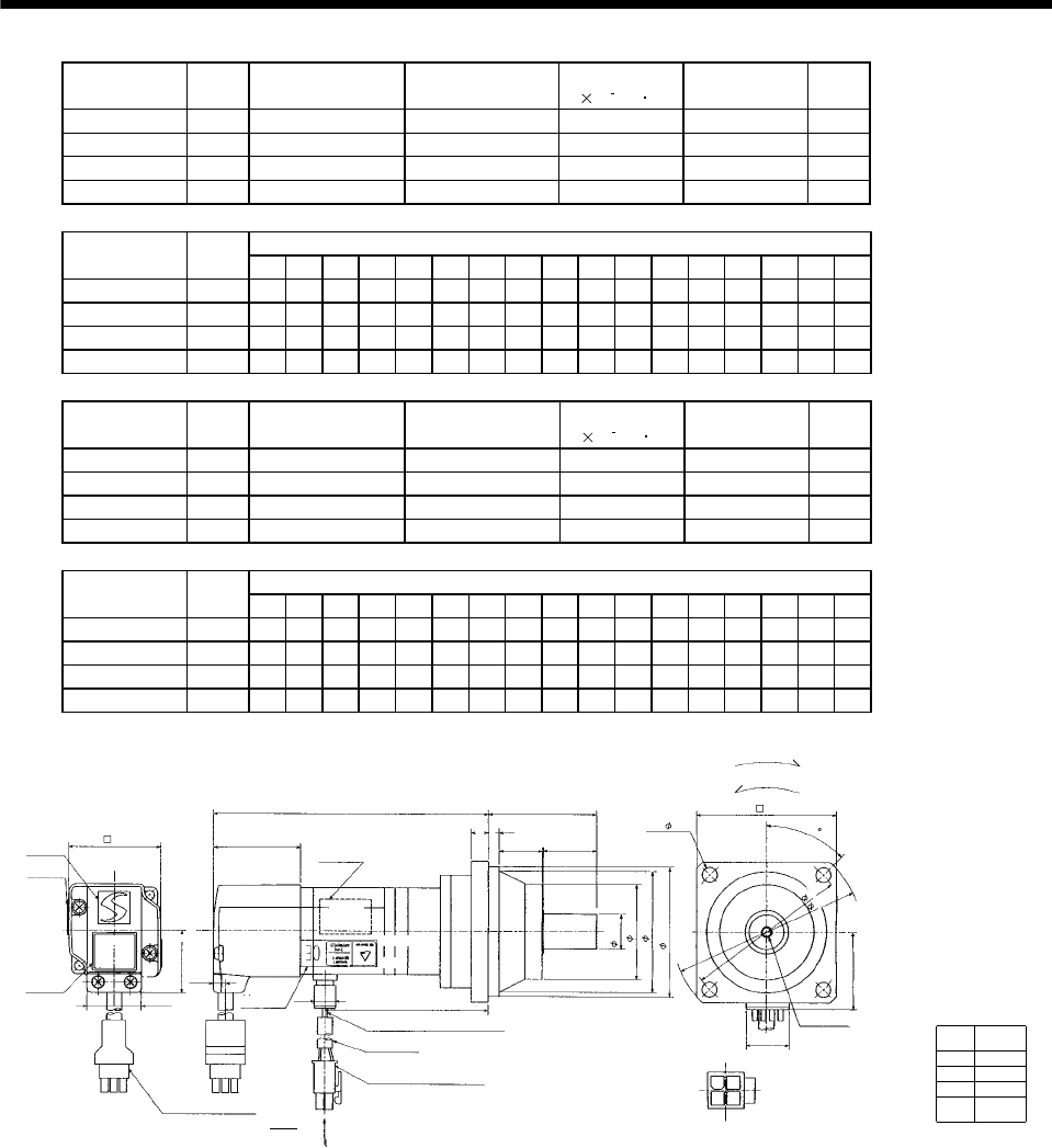
7 - 123
7. OUTLINE DIMENSION DRAWINGS
Model Output
[W]
Reduction Gear
Model Reduction Ratio Inertia Moment
J[ 10 4kg m2]Backlash Mass
[kg]
HC-MFS13G2 100 BK1-05B-01MEKA 1/5 0.078 3 min. max. 1.5
HC-MFS13G2 100 BK1-09B-01MEKA 1/9 0.072 3 min. max. 1.8
HC-MFS13G2 100 BK2-20B-01MEKA 1/20 0.122 3 min. max. 3.0
HC-MFS13G2 100 BK2-29B-01MEKA 1/29 0.096 3 min. max. 3.0
Variable Dimensions
Model Output
[W] LA LB LC LD LE LF LG LH LK L LR KL LZ Q S P R
HC-MFS13G2 100 80 65 95 70 6 48 8 60 23 145 55 93 6.6 25 16 M4 8
HC-MFS13G2 100 80 65 95 70 6 48 8 60 23 161 55 109 6.6 25 16 M4 8
HC-MFS13G2 100 100 80 115 85 6 65 10 74 33 167 75 115 6.6 35 20 M5 10
HC-MFS13G2 100 100 80 115 85 6 65 10 74 33 167 75 115 6.6 35 20 M5 10
Model Output
[W]
Reduction Gear
Model Reduction Ratio Inertia Moment
J[ 10 4kg m2]Backlash Mass
[kg]
HC-KFS13G2 100 BK1-05B-01MEKA 1/5 0.132 3 min. max. 1.5
HC-KFS13G2 100 BK1-09B-01MEKA 1/9 0.126 3 min. max. 1.8
HC-KFS13G2 100 BK2-20B-01MEKA 1/20 0.176 3 min. max. 3.0
HC-KFS13G2 100 BK2-29B-01MEKA 1/29 0.150 3 min. max. 3.0
Variable Dimensions
Model Output
[W] LA LB LC LD LE LF LG LH LK L LR KL LZ Q S P R
HC-KFS13G2 100 80 65 95 70 6 48 8 60 23 145 55 93 6.6 25 16 M4 8
HC-KFS13G2 100 80 65 95 70 6 48 8 60 23 161 55 109 6.6 25 16 M4 8
HC-KFS13G2 100 100 80 115 85 6 65 10 74 33 167 75 115 6.6 35 20 M5 10
HC-KFS13G2 100 100 80 115 85 6 65 10 74 33 167 75 115 6.6 35 20 M5 10
Power supply
connector pin
connection list
1
2
3
4
Pin No. Application
Phase U
Phase V
Phase W
Earth
(Note)[Unit: mm]
BC11907*
(BC11917*)
Logo plate
Motor plate
With connector 1-172169-9
(AMP)
Encoder cable 0.3m
Motor plate
(Opposite side)
LG
LR
L
40.5
LE
LK Q
6.8
9.9 KL
25.2
Top
28.7
Bottom
Top
TUV plate
Caution plate
Top
42
For reverse rotation command
For forward rotation command
Rotation direction
LD
P threads, depth R
Sh6
LF
LBh7
20
13
24
Arrow A
4 - LZ
Top
35.7
5557-04R-210 (Receptacle)
5556PBTL (Female terminal)
Power supply connector (Molex)
Protective tube
Power supply lead 4-AWG19 0.3m
Arrow A
LH
45
Bottom Bottom
Top
Bottom
Bottom
LC
LA
Note: The dimensions without tolerances are reference dimensions.
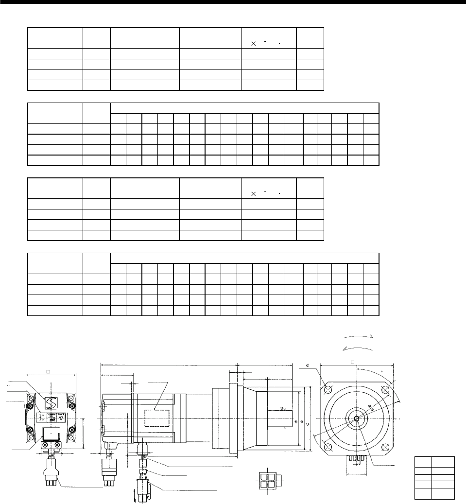
7 - 124
7. OUTLINE DIMENSION DRAWINGS
Model Output
[W]
Reduction Gear
Model Reduction Ratio Inertia Moment
J[ 10 4kg m2]
Mass
[kg]
HC-MFS23G2 200 BK1-05B-02MEKA 1/5 0.191 2.1
HC-MFS23G2 200 BK2-09B-02MEKA 1/9 0.208 3.5
HC-MFS23G2 200 BK3-20B-02MEKA 1/20 0.357 5.0
HC-MFS23G2 200 BK3-29B-02MEKA 1/29 0.276 5.0
Variable Dimensions
Model Output
[W] LA LB LC LD LE LF LG LH LK L LR KL LZ Q S P R
HC-MFS23G2 200 80 65 95 70 6 48 8 60 23 157 55 106.6 6.6 25 16 M4 8
HC-MFS23G2 200 100 80 115 85 6 65 10 74 33 175 75 124.6 6.6 35 20 M5 10
HC-MFS23G2 200 115 95 135 100 8 75 10 85 35 180 85 129.6 94025M612
HC-MFS23G2 200 115 95 135 100 8 75 10 85 35 180 85 129.6 94025M612
Model Output
[W]
Reduction Gear
Model Reduction Ratio Inertia Moment
J[ 10 4kg m2]
Mass
[kg]
HC-KFS23G2 200 BK1-05B-02MEKA 1/5 0.360 2.1
HC-KFS23G2 200 BK2-09B-02MEKA 1/9 0.380 3.5
HC-KFS23G2 200 BK3-20B-02MEKA 1/20 0.530 5.0
HC-KFS23G2 200 BK3-29B-02MEKA 1/29 0.450 5.0
Variable Dimensions
Model Output
[W] LA LB LC LD LE LF LG LH LK L LR KL LZ Q S P R
HC-KFS23G2 200 80 65 95 70 6 48 8 60 23 157 55 106.6 6.6 25 16 M4 8
HC-KFS23G2 200 100 80 115 85 6 65 10 74 33 175 75 124.6 6.6 35 20 M5 10
HC-KFS23G2 200 115 95 135 100 8 75 10 85 35 180 85 129.6 94025M612
HC-KFS23G2 200 115 95 135 100 8 75 10 85 35 180 85 129.6 94025M612
Power supply
connector pin
connection list
1
2
3
4
Pin No. Application
Phase U
Phase V
Phase W
Earth
(Note)[Unit: mm]
BC11908*
(BC11918*)
Logo plate
Motor plate
With connector 1-172169-9
(AMP)
Encoder cable 0.3m
Motor plate
(Opposite side)
LG
LR
L
41 LE
LK Q
10.6 9.9 KL
25.2
38.4
Bottom
Top
TUV plate
Caution plate
Top
62
For reverse rotation command
For forward rotation command
Rotation direction
LD
LA
P threads, depth R
Sh6
LF
LBh7
20
13
24
Arrow A
4 - LZ
Top
Bottom
LC
42.8
5557-04R-210 (Receptacle)
5556PBTL (Female terminal)
Power supply connector (Molex)
Protective tube
Power supply lead 4-AWG19 0.3m
LH
2.7
Arrow A
Bottom
Bottom
Top
45
Note: The dimensions without tolerances are reference dimensions.
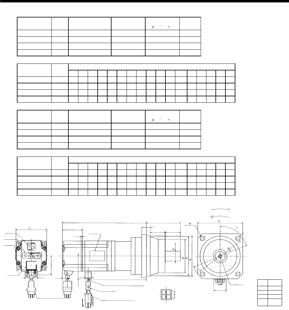
7 - 125
7. OUTLINE DIMENSION DRAWINGS
Model Output
[W]
Reduction Gear
Model Reduction Ratio Inertia Moment
J[ 10 4kg m2]
Mass
[kg]
HC-MFS43G2 400 BK2-05B-04MEKA 1/5 0.295 3.7
HC-MFS43G2 400 BK3-09B-04MEKA 1/9 0.323 5.3
HC-MFS43G2 400 BK4-20B-04MEKA 1/20 0.426 7.5
HC-MFS43G2 400 BK4-29B-04MEKA 1/29 0.338 7.5
Variable Dimensions
Model Output
[W] LA LB LC LD LE LF LG LH LK L LR KL LZ Q S P R
HC-MFS43G2 400 100 80 115 85 6 65 10 74 33 184 75 131.6 6.6 35 20 M5 10
HC-MFS43G2 400 115 95 135 100 8 75 10 85 35 205 85 152.6 94025M612
HC-MFS43G2 400 135 110 155 115 8 90 12 100 40 211 100 158.6 11 50 32 M8 16
HC-MFS43G2 400 135 110 155 115 8 90 12 100 40 211 100 158.6 11 50 32 M8 16
Model Output
[W]
Reduction Gear
Model Reduction Ratio Inertia Moment
J[ 10 4kg m2]
Mass
[kg]
HC-KFS43G2 400 BK2-05B-04MEKA 1/5 0.610 3.7
HC-KFS43G2 400 BK3-09B-04MEKA 1/9 0.640 5.3
HC-KFS43G2 400 BK4-20B-04MEKA 1/20 0.740 7.5
HC-KFS43G2 400 BK4-29B-04MEKA 1/29 0.660 7.5
Variable Dimensions
Model Output
[W] LA LB LC LD LE LF LG LH LK L LR KL LZ Q S P R
HC-KFS43G2 400 100 80 115 85 6 65 10 74 33 184 75 131.6 6.6 35 20 M5 10
HC-KFS43G2 400 115 95 135 100 8 75 10 85 35 205 85 152.6 94025M612
HC-KFS43G2 400 135 110 155 115 8 90 12 100 40 211 100 158.6 11 50 32 M8 16
HC-KFS43G2 400 135 110 155 115 8 90 12 100 40 211 100 158.6 11 50 32 M8 16
Power supply
connector pin
connection list
1
2
3
4
Pin No. Application
Phase U
Phase V
Phase W
Earth
(Note)[Unit: mm]
BC11909*
(BC11919*)
Logo plate
Motor plate
With connector 1-172169-9
(AMP)
Encoder cable 0.3m
Motor plate
(Opposite side)
LG
LR
L
41 LE
LK Q
10.6 9.9 KL
25.2
38.4
Bottom
Top
TUV plate
Caution plate
Top
62
For reverse rotation command
For forward rotation command
Rotation direction
LD
LA
P threads, depth R
Sh6
LF
LBh7
20
13
24
Arrow A
4 - LZ
Top
Bottom
LC
42.8
5557-04R-210 (Receptacle)
5556PBTL (Female terminal)
Power supply connector (Molex)
Protective tube
Power supply lead 4-AWG19 0.3m
LH
2.7
Arrow A
Bottom
Bottom
Top
45
Note: The dimensions without tolerances are reference dimensions.
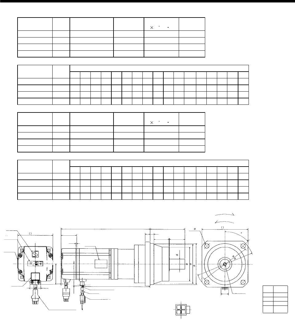
7 - 126
7. OUTLINE DIMENSION DRAWINGS
Model Output
[W]
Reduction Gear
Model
Reduction
Ratio
Inertia Moment
J[ 10 4kg m2]
Mass
[kg]
HC-MFS73G2 750 BK3-05B-08MEKA 1/5 0.973 6.3
HC-MFS73G2 750 BK4-09B-08MEKA 1/9 0.980 8.6
HC-MFS73G2 750 BK5-20B-08MEKA 1/20 1.016 12.0
HC-MFS73G2 750 BK5-29B-08MEKA 1/29 0.910 12.0
Variable Dimensions
Model Output
[W] LA LB LC LD LE LF LG LH LK L LR KL LZ Q S P R
HC-MFS73G2 750 115 95 135 100 8 75 10 85 35 212 85 156.7 94025M612
HC-MFS73G2 750 135 110 155 115 8 90 12 100 40 240 100 184.7 11 50 32 M8 16
HC-MFS73G2 750 150 125 175 130 10 105 15 115 43 248 115 192.7 14 60 40 M10 20
HC-MFS73G2 750 150 125 175 130 10 105 15 115 43 248 115 192.7 14 60 40 M10 20
Model Output
[W]
Reduction Gear
Model
Reduction
Ratio
Inertia Moment
J[ 10 4kg m2]
Mass
[kg]
HC-KFS73G2 750 BK3-05B-08MEKA 1/5 1.883 6.3
HC-KFS73G2 750 BK4-09B-08MEKA 1/9 1.890 8.6
HC-KFS73G2 750 BK5-20B-08MEKA 1/20 1.926 12.0
HC-KFS73G2 750 BK5-29B-08MEKA 1/29 1.820 12.0
Variable Dimensions
Model Output
[W] LA LB LC LD LE LF LG LH LK L LR KL LZ Q S P R
HC-KFS73G2 750 115 95 135 100 8 75 10 85 35 212 85 156.7 94025M612
HC-KFS73G2 750 135 110 155 115 8 90 12 100 40 240 100 184.7 11 50 32 M8 16
HC-KFS73G2 750 150 125 175 130 10 105 15 115 43 248 115 192.7 14 60 40 M10 20
HC-KFS73G2 750 150 125 175 130 10 105 15 115 43 248 115 192.7 14 60 40 M10 20
Power supply
connector pin
connection list
1
2
3
4
Pin No. Application
Phase U
Phase V
Phase W
Earth
(Note)[Unit: mm]
BC11910*
Logo plate
Motor plate
With connector 1-172169-9
(AMP)
Encoder cable 0.3m
Motor plate
(Opposite side)
LG
LR
L
39 LE
LK Q
11 9.9 KL
25.2
Top
48.7
Bottom
Top
TUV plate
Caution plate
82
For reverse rotation command
For forward rotation command
Rotation direction
LD
LA
P threads, depth R
Sh6
LF
LBh7
20
13
24
Arrow A
4 - LZ
Top
Bottom
LC
58.1
5557-04R-210 (Receptacle)
5556PBTL (Female terminal)
Power supply connector (Molex)
Protective tube
Power supply lead 4-AWG19 0.3m
LH
2.7
Arrow A
Bottom
Top
Bottom
(********)
45
Note: The dimensions without tolerances are reference dimensions.
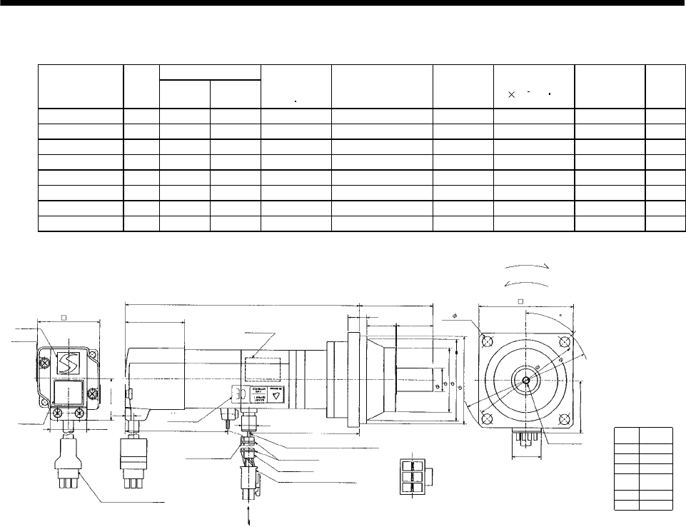
7 - 127
7. OUTLINE DIMENSION DRAWINGS
(b) With electromagnetic brake
Variable Dimensions
Model Output
[W] LKL
Brake static
friction torque
[N m]
Reduction Gear Model Reduction
Ratio
Inertia Moment
J[ 10 4kg m2]Backlash Mass
[kg]
HC-MFS053BG2 50 158 78 0.32 BK1-05B-A5MEKA 1/5 0.070 3 min. max. 1.8
HC-MFS053BG2 50 174 94 0.32 BK1-09B-A5MEKA 1/9 0.063 3 min. max. 2.1
HC-MFS053BG2 50 174 94 0.32 BK1-20B-A5MEKA 1/20 0.072 3 min. max. 2.2
HC-MFS053BG2 50 174 94 0.32 BK1-29B-A5MEKA 1/29 0.060 3 min. max. 2.2
HC-KFS053BG2 50 158 78 0.32 BK1-05B-A5MEKA 1/5 0.104 3 min. max. 1.8
HC-KFS053BG2 50 174 94 0.32 BK1-09B-A5MEKA 1/9 0.098 3 min. max. 2.1
HC-KFS053BG2 50 174 94 0.32 BK1-20B-A5MEKA 1/20 0.107 3 min. max. 2.2
HC-KFS053BG2 50 174 94 0.32 BK1-29B-A5MEKA 1/29 0.095 3 min. max. 2.2
(Note)[Unit: mm]
Logo plate
Motor plate
With connector 1-172169-9
(AMP)
Encoder cable 0.3m
Motor plate
(Opposite side)
8
55
L
40.5 6
23 25
65.5 9.9
KL
25.2
Top
28.7
Bottom
Top
TUV plate
Caution plate
42
For reverse rotation command
For forward rotation command
Rotation direction
70
80
M4 threads, depth 8
16h6
48
55h7
20
14
25
4 - 6.6
Top
Bottom
5557-06R-210 (Receptacle)
5556PBTL (Female terminal)
Power supply connector (Molex)
Protective tube
Power supply lead 4-AWG19 0.3m
60
Arrow A
35.7
36
Arrow A
BC11911*
(BC11920*)
Break lead
2-0.3 0.3m
2
Power supply
connector pin
connection list
1
2
3
4
Pin No. Application
Phase U
Phase V
Phase W
Earth
5
6
B1
B2
6.8
Bottom
Top
45
Bottom
95
Note: The dimensions without tolerances are reference dimensions.
Banding band
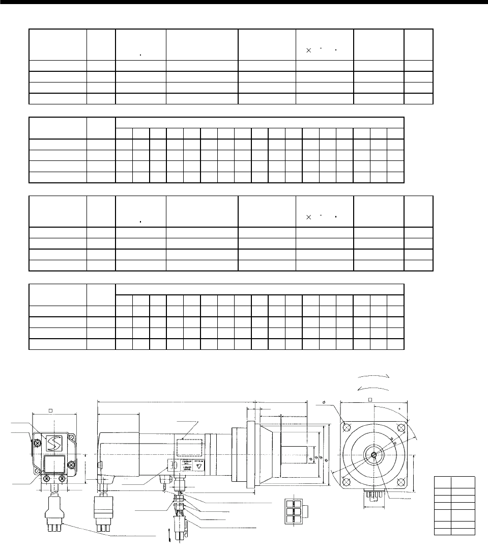
7 - 128
7. OUTLINE DIMENSION DRAWINGS
Model Output
[W]
Brake static
friction torque
[N m]
Reduction Gear
Model Reduction Ratio Inertia Moment
J[ 10 4kg m2]Backlash Mass
[kg]
HC-MFS13BG2 100 0.32 BK1-05B-01MEKA 1/5 0.080 3 min. max. 1.9
HC-MFS13BG2 100 0.32 BK1-09B-01MEKA 1/9 0.074 3 min. max. 2.2
HC-MFS13BG2 100 0.32 BK2-20B-01MEKA 1/20 0.124 3 min. max. 3.4
HC-MFS13BG2 100 0.32 BK2-29B-01MEKA 1/29 0.098 3 min. max. 3.4
Variable Dimensions
Model Output
[W] LA LB LC LD LE LF LG LH LK L LR KL LZ Q S P R
HC-MFS13BG2 100 80 65 95 70 6 48 8 60 23 173 55 93 6.6 25 16 M4 8
HC-MFS13BG2 100 80 65 95 70 6 48 8 60 23 189 55 109 6.6 25 16 M4 8
HC-MFS13BG2 100 100 80 115 85 6 65 10 74 33 195 75 115 6.6 35 20 M5 10
HC-MFS13BG2 100 100 80 115 85 6 65 10 74 33 195 75 115 6.6 35 20 M5 10
Model Output
[W]
Brake static
friction torque
[N m]
Reduction Gear
Model Reduction Ratio Inertia Moment
J[ 10 4kg m2]Backlash Mass
[kg]
HC-KFS13BG2 100 0.32 BK1-05B-01MEKA 1/5 0.135 3 min. max. 1.9
HC-KFS13BG2 100 0.32 BK1-09B-01MEKA 1/9 0.129 3 min. max. 2.2
HC-KFS13BG2 100 0.32 BK2-20B-01MEKA 1/20 0.179 3 min. max. 3.4
HC-KFS13BG2 100 0.32 BK2-29B-01MEKA 1/29 0.153 3 min. max. 3.4
Variable Dimensions
Model Output
[W] LA LB LC LD LE LF LG LH LK L LR KL LZ Q S P R
HC-KFS13BG2 100 80 65 95 70 6 48 8 60 23 173 55 93 6.6 25 16 M4 8
HC-KFS13BG2 100 80 65 95 70 6 48 8 60 23 189 55 109 6.6 25 16 M4 8
HC-KFS13BG2 100 100 80 115 85 6 65 10 74 33 195 75 115 6.6 35 20 M5 10
HC-KFS13BG2 100 100 80 115 85 6 65 10 74 33 195 75 115 6.6 35 20 M5 10
(Note)[Unit: mm]
BC11912*
Logo plate
Motor plate
Encoder cable 0.3m
Motor plate
(Opposite side)
LG
LR
L
40.5
LE
LK Q
65.5 9.9
KL
25.2
Top
28.7
Bottom
Top
TUV plate
Caution plate
Top
42
For reverse rotation command
For forward rotation command
Rotation direction
LD
P threads, depth R
Sh6
LF
LBh7
20
14
25
4 - LZ
Top
Bottom
LC
5557-06R-210 (Receptacle)
5556PBTL (Female terminal)
Power supply connector (Molex)
Protective tube
Power supply lead 4-AWG19 0.3m
LH
Arrow A
35.7
36
Arrow A
(BC11921*)
Break lead
2-0.3 0.3m
2
6.8
With connector
1-172169-9 (AMP)
LA
Power supply
connector pin
connection list
1
2
3
4
Pin No. Application
Phase U
Phase V
Phase W
Earth
5
6
B1
B2
45
Bottom Bottom
Note: The dimensions without tolerances are reference dimensions.
Banding band
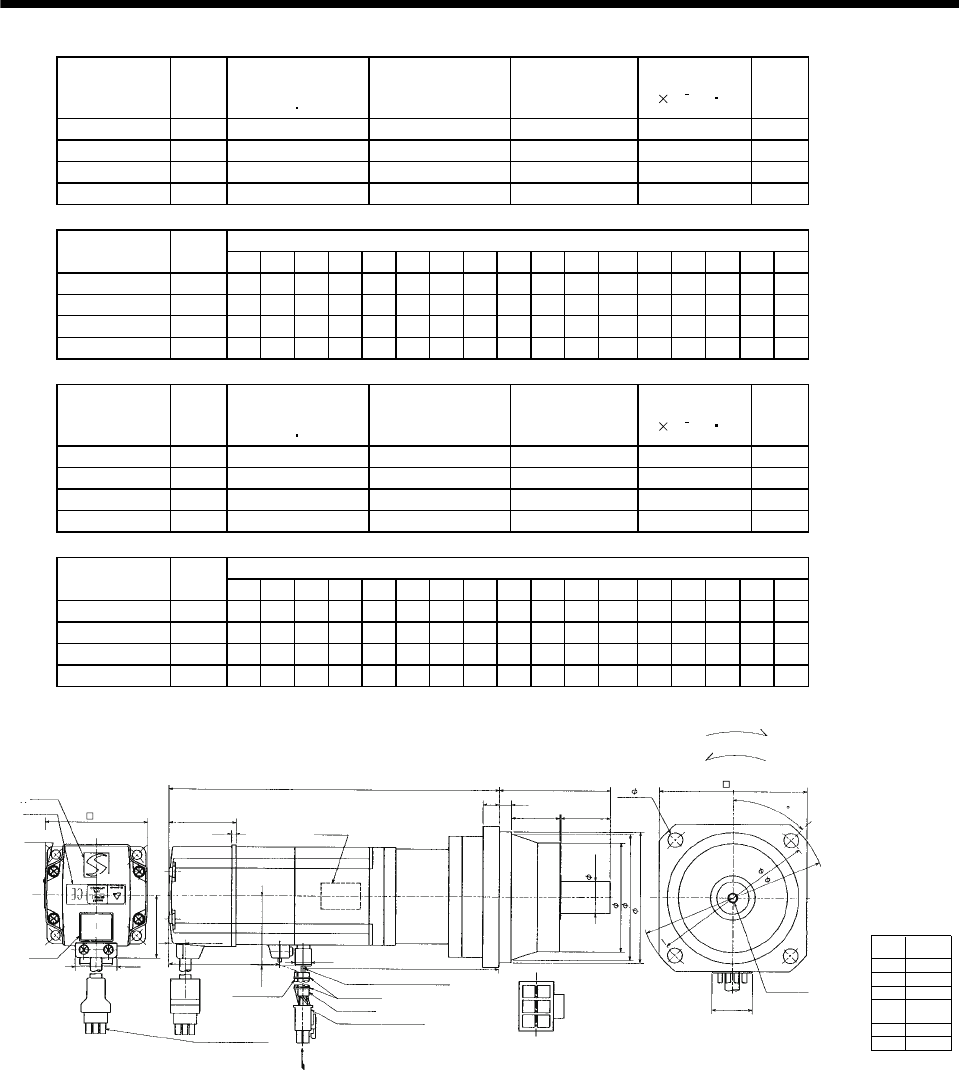
7 - 129
7. OUTLINE DIMENSION DRAWINGS
Model Output
[W]
Brake static
friction torque
[N m]
Reduction Gear
Model Reduction Ratio Inertia Moment
J[ 10 4kg m2]
Mass
[kg]
HC-MFS23BG2 200 1.3 BK1-05B-02MEKA 1/5 0.239 2.7
HC-MFS23BG2 200 1.3 BK2-09B-02MEKA 1/9 0.256 4.1
HC-MFS23BG2 200 1.3 BK3-20B-02MEKA 1/20 0.405 5.6
HC-MFS23BG2 200 1.3 BK3-29B-02MEKA 1/29 0.324 5.6
Variable Dimensions
Model Output
[W] LA LB LC LD LE LF LG LH LK L LR KL LZ Q S P R
HC-MFS23BG2 200 80 65 95 70 6 48 8 60 23 189 55 106.6 6.6 25 16 M4 8
HC-MFS23BG2 200 100 80 115 85 6 65 10 74 33 207 75 124.6 6.6 35 20 M5 10
HC-MFS23BG2 200 115 95 135 100 8 75 10 85 35 212 85 129.6 94025M612
HC-MFS23BG2 200 115 95 135 100 8 75 10 85 35 212 85 129.6 94025M612
Model Output
[W]
Brake static
friction torque
[N m]
Reduction Gear
Model Reduction Ratio Inertia Moment
J[ 10 4kg m2]
Mass
[kg]
HC-KFS23BG2 200 1.3 BK1-05B-02MEKA 1/5 0.410 2.7
HC-KFS23BG2 200 1.3 BK2-09B-02MEKA 1/9 0.430 4.1
HC-KFS23BG2 200 1.3 BK3-20B-02MEKA 1/20 0.580 5.6
HC-KFS23BG2 200 1.3 BK3-29B-02MEKA 1/29 0.500 5.6
Variable Dimensions
Model Output
[W] LA LB LC LD LE LF LG LH LK L LR KL LZ Q S P R
HC-KFS23BG2 200 80 65 95 70 6 48 8 60 23 189 55 106.6 6.6 25 16 M4 8
HC-KFS23BG2 200 100 80 115 85 6 65 10 74 33 207 75 124.6 6.6 35 20 M5 10
HC-KFS23BG2 200 115 95 135 100 8 75 10 85 35 212 85 129.6 94025M612
HC-KFS23BG2 200 115 95 135 100 8 75 10 85 35 212 85 129.6 94025M612
(Note)[Unit: mm]
BC11913*
Logo plate
Encoder cable 0.3m
Motor plate
(Opposite side)
LG
LR
L
41
LE
LK Q
68 9.9 KL
25.2
Top
38.4
Bottom
Top
TUV plate
Caution plate
62
For reverse rotation command
For forward rotation command
Rotation direction
LD
P threads, depth R
Sh6
LF
LBh7
20
14
25
4 - LZ
Top
Bottom
LC
5557-06R-210 (Receptacle)
5556PBTL (Female terminal)
Power supply connector (Molex)
Protective tube
Power supply lead 4-AWG19 0.3m
LH
Arrow A
36
Arrow A
(BC11922*)
Break lead
2-0.3 0.3m
2
10.6
With connector
1-172169-9
(AMP)
LA
42.8
Power supply
connector pin
connection list
1
2
3
4
Pin No. Application
Phase U
Phase V
Phase W
Earth
5
6
B1
B2
2.7
45
Bottom
Bottom
Top
Motor plate
Note: The dimensions without tolerances are reference dimensions.
Banding band

7 - 130
7. OUTLINE DIMENSION DRAWINGS
Model Output
[W]
Brake static
friction torque
[N m]
Reduction Gear Model Reduction Ratio Inertia Moment
J[ 10 4kg m2]
Mass
[kg]
HC-MFS43BG2 400 1.3 BK2-05B-04MEKA 1/5 0.344 4.3
HC-MFS43BG2 400 1.3 BK3-09B-04MEKA 1/9 0.372 5.9
HC-MFS43BG2 400 1.3 BK4-20B-04MEKA 1/20 0.475 8.1
HC-MFS43BG2 400 1.3 BK4-29B-04MEKA 1/29 0.386 8.1
Variable Dimensions
Model Output
[W] LA LB LC LD LE LF LG LH LK L LR KL LZ Q S P R
HC-MFS43BG2 400 100 80 115 85 6 65 10 74 33 216 75 131.6 6.6 35 20 M5 10
HC-MFS43BG2 400 115 95 135 100 8 75 10 85 35 237 85 152.6 94025M612
HC-MFS43BG2 400 135 110 155 115 8 90 12 100 40 243 100 158.6 11 50 32 M8 16
HC-MFS43BG2 400 135 110 155 115 8 90 12 100 40 243 100 158.6 11 50 32 M8 16
Model Output
[W]
Brake static
friction torque
[N m]
Reduction Gear Model Reduction Ratio Inertia Moment
J[ 10 4kg m2]
Mass
[kg]
HC-KFS43BG2 400 1.3 BK2-05B-04MEKA 1/5 0.660 4.3
HC-KFS43BG2 400 1.3 BK3-09B-04MEKA 1/9 0.690 5.9
HC-KFS43BG2 400 1.3 BK4-20B-04MEKA 1/20 0.790 8.1
HC-KFS43BG2 400 1.3 BK4-29B-04MEKA 1/29 0.710 8.1
Variable Dimensions
Model Output
[W] LA LB LC LD LE LF LG LH LK L LR KL LZ Q S P R
HC-KFS43BG2 400 100 80 115 85 6 65 10 74 33 216 75 131.6 6.6 35 20 M5 10
HC-KFS43BG2 400 115 95 135 100 8 75 10 85 35 237 85 152.6 94025M612
HC-KFS43BG2 400 135 110 155 115 8 90 12 100 40 243 100 158.6 11 50 32 M8 16
HC-KFS43BG2 400 135 110 155 115 8 90 12 100 40 243 100 158.6 11 50 32 M8 16
Power supply
connector pin
connection list
1
2
3
4
Pin No. Application
Phase U
Phase V
Phase W
Earth
BC11914*
(BC11923)*
5
6
B1
B2
(Note)[Unit: mm]
Logo plate
With connector 1-172169-9
(AMP)
Encoder cable 0.3m
Motor plate
(Opposite side)
LG
LRL
41
LE
LK Q
68
9.9 KL
25.2
38.4
Bottom
Top
TUV plate
Caution plate
Top
For reverse rotation command
For forward rotation command
Rotation direction
LD
LA
P threads, depth R
Sh6
LF
LBh7
20
14
25
Arrow A
4 - LZ
Top
Bottom
LC
42.8
5557-06R-210 (Receptacle)
5556PBTL (Female terminal)
Power supply connector (Molex)
Protective tube
Power supply lead 4-AWG19 0.3m
LH
2.7
Arrow A
62
Bottom
Break cable
VCTF 2-0.3 0.3m
2
36
10.6
45
Top
Bottom
Motor plate
Note: The dimensions without tolerances are reference dimensions.
Banding band
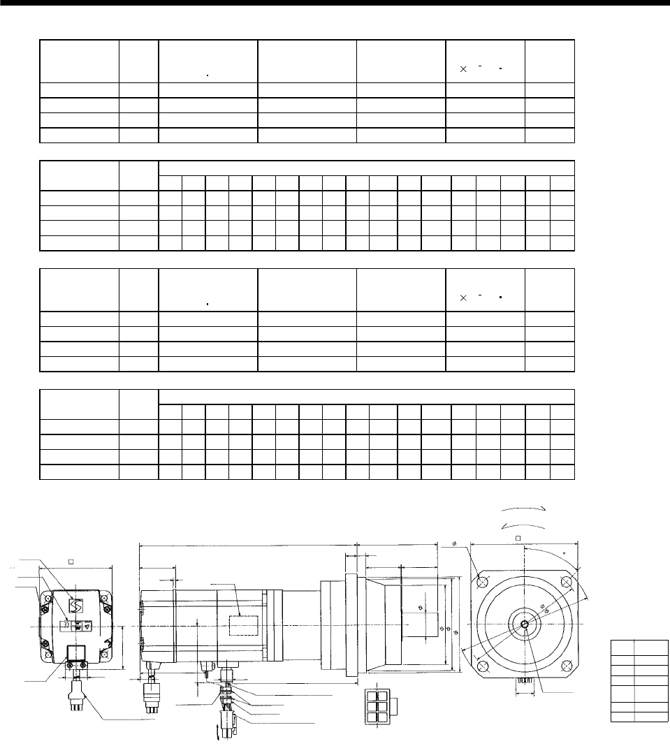
7 - 131
7. OUTLINE DIMENSION DRAWINGS
Model Output
[W]
Brake static
friction torque
[N m]
Reduction Gear
Model Reduction Ratio Inertia Moment
J[ 10 4kg m2]
Mass
[kg]
HC-MFS73BG2 750 2.4 BK3-05B-08MEKA 1/5 1.098 7.3
HC-MFS73BG2 750 2.4 BK4-09B-08MEKA 1/9 1.105 9.6
HC-MFS73BG2 750 2.4 BK5-20B-08MEKA 1/20 1.141 13.0
HC-MFS73BG2 750 2.4 BK5-29B-08MEKA 1/29 1.035 13.0
Variable Dimensions
Model Output
[W] LA LB LC LD LE LF LG LH LK L LR KL LZ Q S P R
HC-MFS73BG2 750 115 95 135 100 8 75 10 85 35 247.5 85 156.7 94025M612
HC-MFS73BG2 750 135 110 155 115 8 90 12 100 40 275.5 100 184.7 11 50 32 M8 16
HC-MFS73BG2 750 150 125 175 130 10 105 15 115 43 283.5 115 192.7 14 60 40 M10 20
HC-MFS73BG2 750 150 125 175 130 10 105 15 115 43 283.5 115 192.7 14 60 40 M10 20
Model Output
[W]
Brake static
friction torque
[N m]
Reduction Gear
Model Reduction Ratio Inertia Moment
J[ 10 4kg m2]
Mass
[kg]
HC-KFS73BG2 750 2.4 BK3-05B-08MEKA 1/5 2.008 7.3
HC-KFS73BG2 750 2.4 BK4-09B-08MEKA 1/9 2.015 9.6
HC-KFS73BG2 750 2.4 BK5-20B-08MEKA 1/20 2.051 13.0
HC-KFS73BG2 750 2.4 BK5-29B-08MEKA 1/29 1.945 13.0
Variable Dimensions
Model Output
[W] LA LB LC LD LE LF LG LH LK L LR KL LZ Q S P R
HC-KFS73BG2 750 115 95 135 100 8 75 10 85 35 247.5 85 156.7 94025M612
HC-KFS73BG2 750 135 110 155 115 8 90 12 100 40 275.5 100 184.7 11 50 32 M8 16
HC-KFS73BG2 750 150 125 175 130 10 105 15 115 43 283.5 115 192.7 14 60 40 M10 20
HC-KFS73BG2 750 150 125 175 130 10 105 15 115 43 283.5 115 192.7 14 60 40 M10 20
Power supply
connector pin
connection list
1
2
3
4
Pin No. Application
Phase U
Phase V
Phase W
Earth
BC11915*
5
6
B1
B2
(Note)[Unit: mm]
Logo plate
Motor plate
With connector 1-172169-9
(AMP)
Encoder cable 0.3m
Motor plate
(Opposite side)
LG
LRL
39
LE
LK Q
72 9.9 KL
25.2
Top
48.7
Bottom
Top
TUV plate
Caution plate
Top
For reverse rotation command
For forward rotation command
Rotation direction
LD
LA
P threads, depth R
Sh6
LF
LBh7
20
14
25
Arrow A
4 - LZ
Top
Bottom
LC
58.1
5557-06R-210 (Receptacle)
5556PBTL (Female terminal)
Power supply connector (Molex)
Protective tube
Power supply lead 4-AWG19 0.3m
LH
2.7
Arrow A
82
Bottom
Break cable
VCTF 2-0.3 0.3m
2
36
Bottom
45
Note: The dimensions without tolerances are reference dimensions.
(********)
Banding band
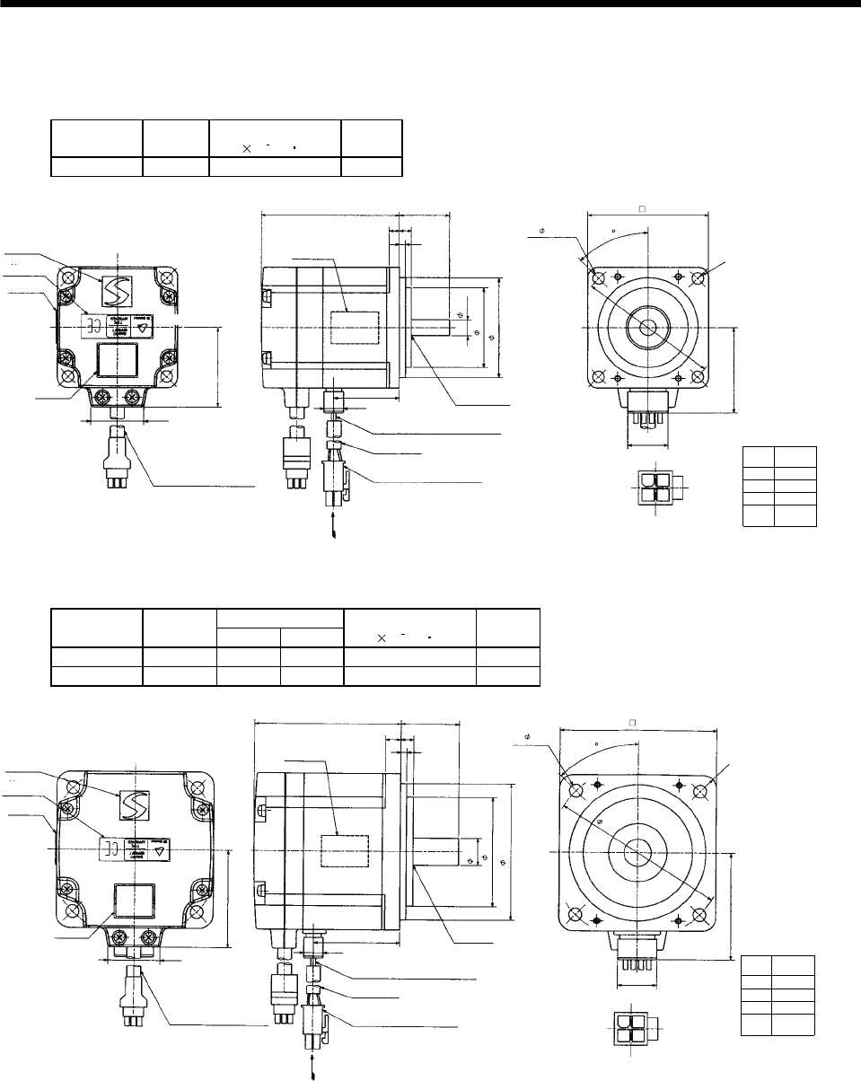
7 - 132
7. OUTLINE DIMENSION DRAWINGS
7.1.12 HC-UFS 3000r/min series
(1) Standard (without electromagnetic brake)
Model Output
[W]
Inertia Moment
J[ 10 4kg m2]
Mass
[kg]
HC-UFS13 100 0.066 0.8
Power supply
connector pin
connection list
1
2
3
4
Pin No. Application
Phase U
Phase V
Phase W
Earth
(Note)[Unit: mm]
BC11876*
20
5557-04R-210 (Receptacle)
5556PBTL (Female terminal)
With connector 1-172169-9
(AMP)
Arrow A
42.8
Bottom
Top
Protective tube
Motor plate
(Opposite side)
50h7
60
8h6
Logo plate
Power supply connector (Molex)
Encoder cable 0.3m
Motor plate
Caution plate
Bottom
Top Bottom
Top
25
3
5
70
9.9
33
26.9
40
4- 5.8
Power supply lead 4-AWG19 0.3m
TUV plate
Arrow A
Top
1
24
3
6
40
Oil seal
SC10207
R5
45
Bottom
Note: The dimensions without tolerances are reference dimensions.
Variable Dimensions
Model Output
[W] LKL
Inertia Moment
J[ 10 4kg m2]
Mass
[kg]
HC-UFS23 200 77 43.8 0.241 1.5
HC-UFS43 400 92 58.8 0.365 1.7
Power supply
connector pin
connection list
1
2
3
4
Pin No. Application
Phase U
Phase V
Phase W
Earth
(Note)[Unit: mm]
BC11877*
20
5557-04R-210 (Receptacle)
5556PBTL (Female terminal)
With connector 1-172169-9
(AMP)
Arrow A
55
Bottom
Top
Protective tube
Motor plate
(Opposite side)
70h7
90
80
14h6
Logo plate
Power supply connector (Molex)
Encoder cable 0.3m
Motor plate
Caution plate
Bottom
Top
Bottom
Top
KL
30
3
8
L
9.9
26.9
50
4- 6.6
Power supply lead 4-AWG19 0.3m
TUV plate
Arrow A
Top
Bottom
1
24
3
6.5
56
Oil seal
SC15307
R7
45
Note: The dimensions without tolerances are reference dimensions.
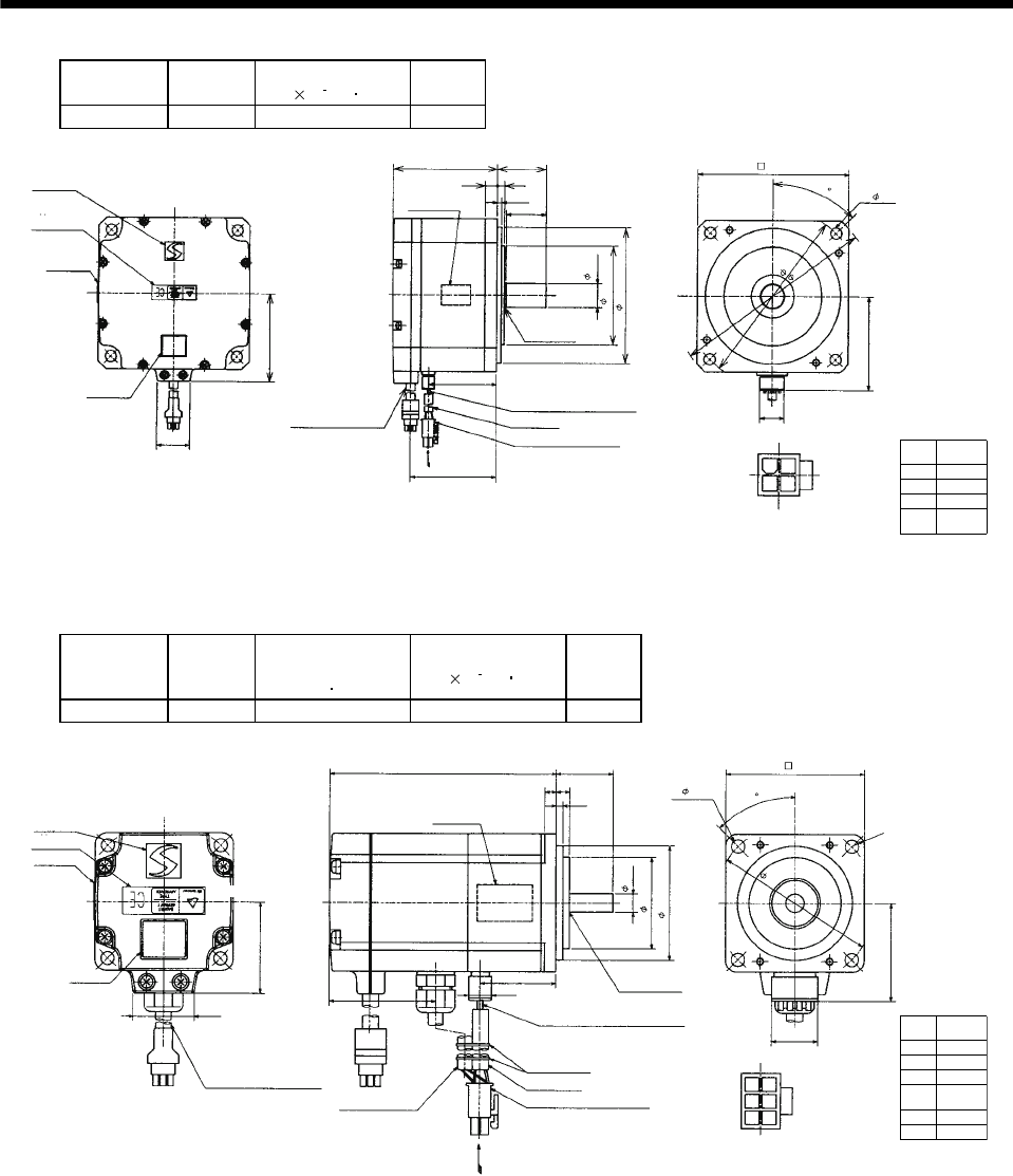
7 - 133
7. OUTLINE DIMENSION DRAWINGS
Model Output
[W]
Inertia Moment
J[ 10 4kg m2]
Mass
[kg]
HC-UFS73 750 5.9 5.0
Power supply
connector pin
connection list
1
2
3
4
Pin No. Application
Phase U
Phase V
Phase W
Earth
(Note)[Unit: mm]
BC11878*
20
5557-04R-210 (Receptacle)
5556PBTL (Female terminal)
With connector
1-172169-9 (AMP)
Arrow A
76
Bottom
Top
Protective tube
Motor plate
(Opposite side)
11h7
165
123
19h6
Logo plate
Power supply connector (Molex)
Encoder cable 0.3m
Motor plate
Caution plate
Bottom
Top
Bottom
Top
40
3.5
10
85
55.5
26.9
72
4- 9
Power supply lead 4-AWG19 0.3m
TUV plate
Arrow A
Top
Bottom
1
24
3
6
80
Oil seal
SC20357
32.5
145
70
45
Note: The dimensions without tolerances are reference dimensions.
(2) With electromagnetic brake
Model Output
[W]
Brake static
friction torque
[N m]
Inertia Moment
J[ 10 4kg m2]
Mass
[kg]
HC-UFS13B 100 0.32 0.074 1.2
Power supply
connector pin
connection list
1
2
3
4
Pin No. Application
Phase U
Phase V
Phase W
Earth
(Note)[Unit: mm]
BC11884*
20
5557-06R-210 (Receptacle)
5556PBTL (Female terminal)
With connector
1-172169-9 (AMP)
Arrow A
42.8
Bottom
Top
Protective tube
Motor plate
(Opposite side)
50h7
60
8h6
Logo plate
Power supply connector (Molex)
Encoder cable 0.3m
Motor plate
Caution plate
Bottom
Top Bottom
Top
46.7
25
3
5
100
9.9
26.9
40
4- 5.8
Power supply lead 4-AWG19 0.3m
TUV plate
Arrow A
Top
1
25
4
6
40
Oil seal
SC10207
33
70
Bottom
Break cable
VCTF 2-0.3 0.3m
236
R5
5
6
B1
B2
45
Note: The dimensions without tolerances are reference dimensions.
Banding band
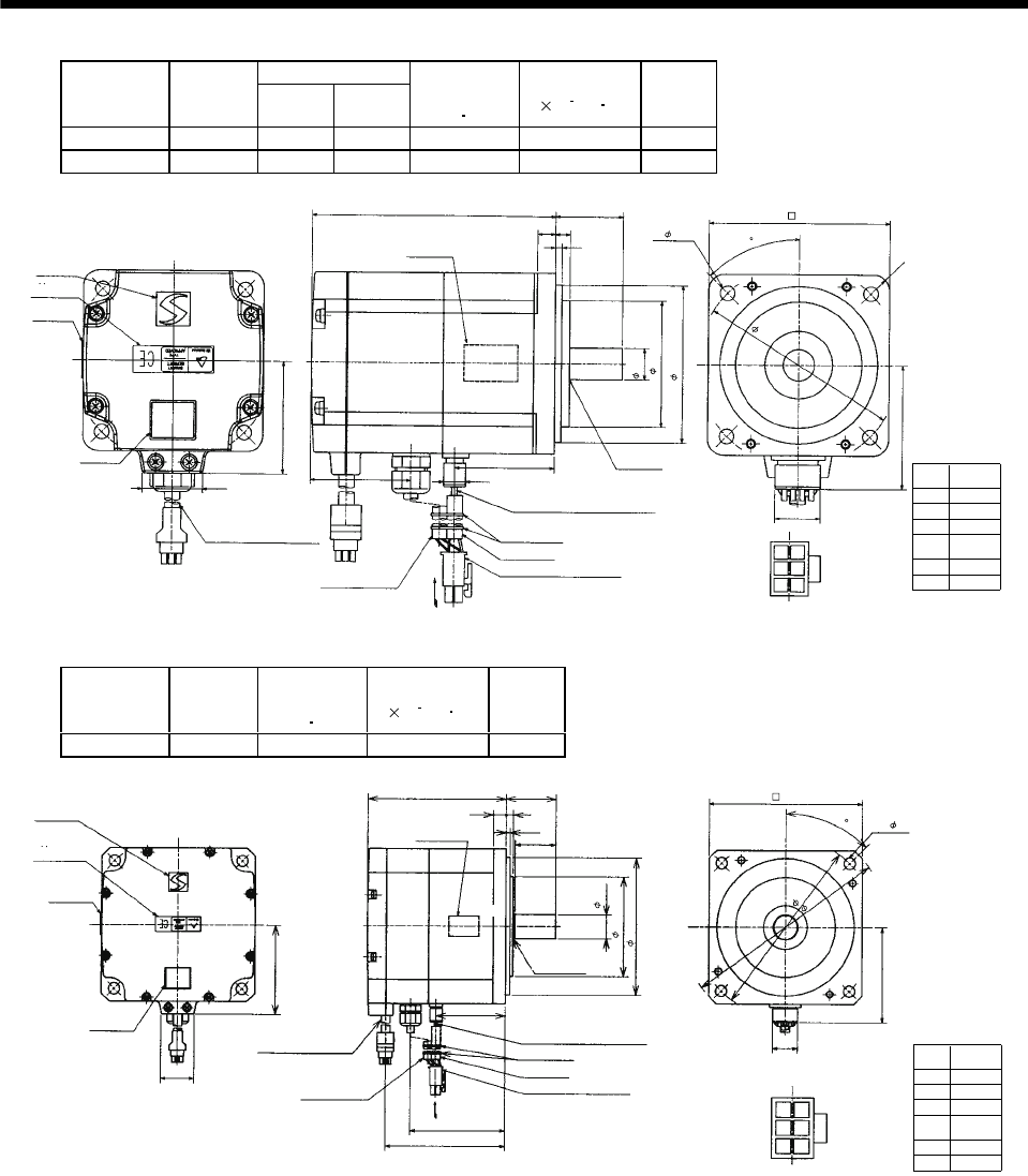
7 - 134
7. OUTLINE DIMENSION DRAWINGS
Variable Dimensions
Model Output
[W] LKL
Brake static
friction torque
[N m]
Inertia Moment
J[ 10 4kg m2]
Mass
[kg]
HC-UFS23B 200 111 43.8 1.3 0.323 2.2
HC-UFS43B 400 126 58.8 1.3 0.447 2.4
Power supply
connector pin
connection list
1
2
3
4
Pin No. Application
Phase U
Phase V
Phase W
Earth
(Note)[Unit: mm]
BC11885*
20
5557-06R-210 (Receptacle)
5556PBTL (Female terminal)
With connector
1-172169-9 (AMP)
Arrow A
55
Bottom
Top
Protective tube
Motor plate
(Opposite side)
70h7
80
14h6
Logo plate
Power supply connector (Molex)
Encoder cable 0.3m
Motor plate
Caution plate
Bottom
Top
Bottom
Top
47.2
30
3
8
L
9.9
26.9
50
4- 6.6
Power supply lead 4-AWG19 0.3m
TUV plate
Arrow
A
Top
1
25
4
6.5
56
Oil seal
SC15307
KL
90
Bottom
Break cable
VCTF 2-0.3 0.3m
236
R7
5
6
B1
B2
45
Note: The dimensions without tolerances are reference dimensions.
Banding band
Model Output
[W]
Brake static
friction torque
[N m]
Inertia Moment
J[ 10 4kg m2]
Mass
[kg]
HC-UFS73B 750 2.4 6.1 6.2
Power supply
connector pin
connection list
1
2
3
4
Pin No. Application
Phase U
Phase V
Phase W
Earth
(Note)[Unit: mm]
BC11886*
20
5557-06R-210 (Receptacle)
5556PBTL (Female terminal)
With connector
1-172169-9 (AMP)
Arrow A
76
Top
Protective tube
Motor plate
(Opposite side)
10h7
123
19h6
Logo plate
Power supply connector (Molex)
Encoder cable 0.3m
Motor plate
Caution plate
Bottom
Top
Bottom
Top
40
3.5
10
111
76
26.9
72
4- 9
Power supply lead 4-AWG19 0.3m
TUV plate
Arrow A
Top
1
25
4
6
80
Oil seal
SC20357
145
Bottom
Break cable
VCTF 2-0.3 0.3m
2
36 5
6
B1
B2
96
55.5
32.5
165
45
Bottom
Note: The dimensions without tolerances are reference dimensions.
Banding band
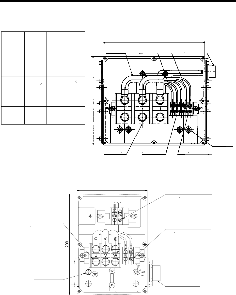
7 - 135
7. OUTLINE DIMENSION DRAWINGS
7.1.13 HA-LFS series
Terminal box detail diagram
Motor Model
HA-LFS15K1
HA-LFS20K1
HA-LFS22K1M
HA-LFS15K14
HA-LFS20K14
HA-LFS22K1M4
HA-LFS30K1M4
HA-LFS30K24
HA-LFS37K24
HA-LFS25K1 to 37K1
HA-LFS30K1M 37K1M
HA-LFS30K2 37K2
HA-LFS25K14 to 37K14
HA-LFS37K1M4
to 50K1M4
HA-LFS45K24 55K24
Motor power
supply lead size
8mm2
(AWG8)
2 parallel
22mm2(AWG4)
2 parallel
Motor power
supply terminal
block screw size
M8 M10
LA 220 266
Terminal box
dimensions
(mm) LB 210 230
(Note)[Unit: mm]
Cooling fan terminal block
(BU BV BW) M4 screw
BG71994C
LA
Motor power
supply lead
Cooling fan lead
0.9SQ or equivalent AWG#
Thermal protector lead
0.5SQ or equivalent AWG#
Encoder connector
MS3102A20-29P
Earth terminal
M6 screw
Thermal protector terminal block
(OHS1 OHS2) M4 screw
Motor power supply
terminal block (U V W)
LB
Note: The dimensions without tolerances are reference dimensions.
HA-LFS 601 701M 11K2 6014 701M4 11K24 terminal box detail diagram
(Note)[Unit: mm]
BG72707C
146 Thermal sensor terminal
(OHS1 OHS2) M4 screw
Cooling fan terminal block
(BU BV) M4 screw
Encoder connector
MS3102A20-29P
Earth terminal
M6 screw
Motor power supply
terminal block
(U V W) M6 screw
Note. The dimensions without tolerances are reference dimensions.
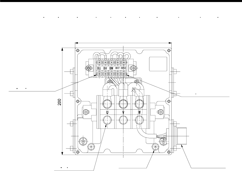
7 - 136
7. OUTLINE DIMENSION DRAWINGS
HA-LFS 801 12K1 11K1M 15K1M 15K2 22K2 8014 12K14 11K1M4 15K1M4 15K24 22K24
terminal box detail diagram
(Note)[Unit: mm]
180
BG72706
Thermal sensor terminal
(OHS1 OHS2) M4 screw
Cooling fan terminal block
(BU BV BW) M4 screw
Encoder connector
MS3102A20-29P
Earth terminal
M6 screw
Motor power supply
terminal block
(U V W) M8 screw
Note. The dimensions without tolerances are reference dimensions.
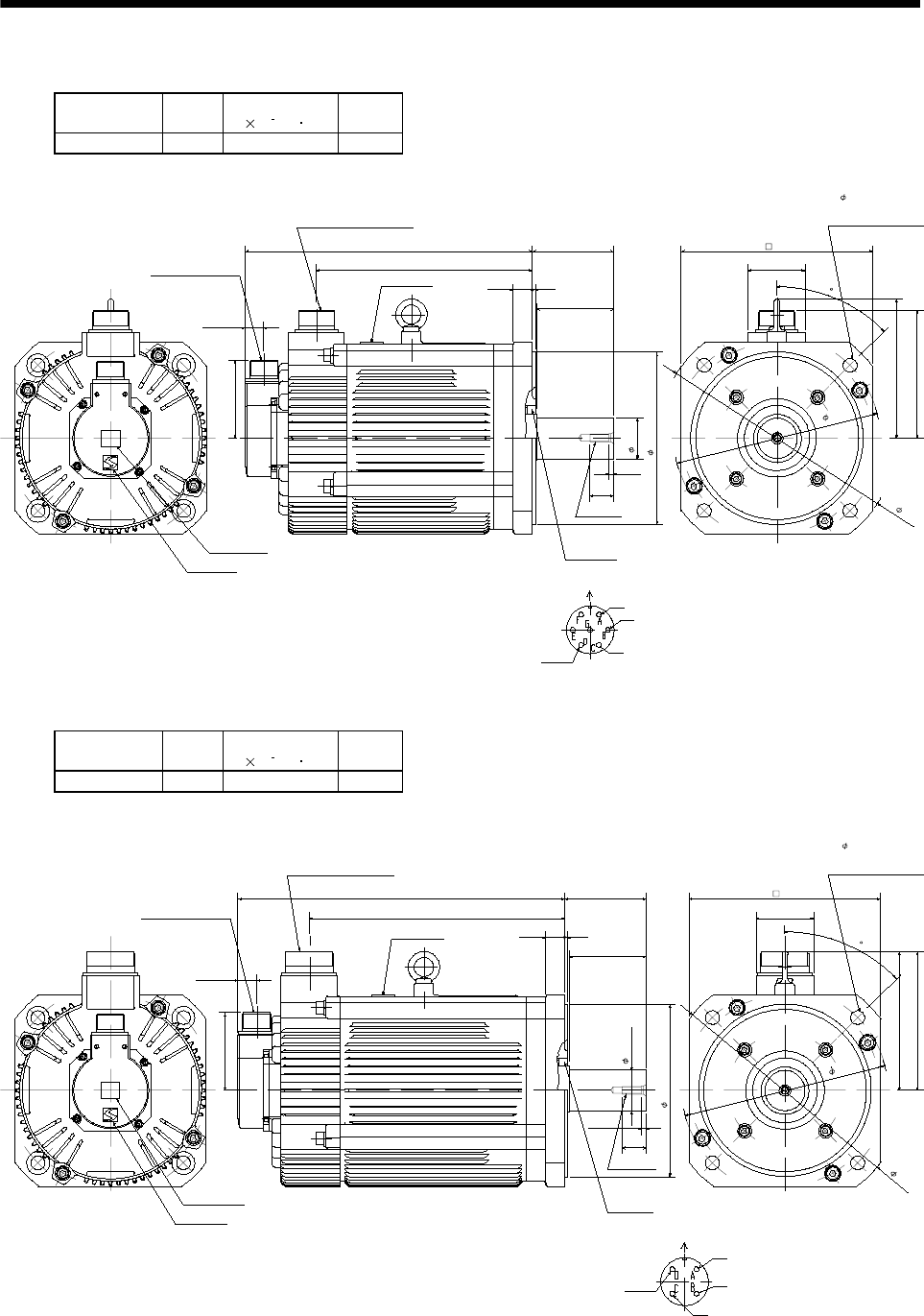
7 - 137
7. OUTLINE DIMENSION DRAWINGS
(1) Standard (Without electromagnetic brake, without reduction gear)
Model Output
[kW]
Inertia Moment
J[ 10 4kg m2]
Mass
[kg]
HA-LFS502 5 74.0 28
Caution plate
Logo plate
Top
Bottom
81.5
Encoder connector
MS3102A20-29P
300
19.5
225
80
320
85
Motor plate
Top Bottom
Power supply connector
CE05-2A24-10P
Oil seal
S50689B
180h7
42h6
25
5.2
M8 screw
Motor flange direction
Power supply connector layout
CE05-2A24-10P
Earth
W
V
U
200
45
Use hexagon socket
head cap screw.
4- 14.5
250
215
146
60
134
BC12835A
Note: The dimensions without tolerances are reference dimensions.
(Note)[Unit: mm]
Model Output
[kW]
Inertia Moment
J[ 10 4kg m2]
Mass
[kg]
HA-LFS702 7 94.2 35
Caution plate
Logo plate
Top
Bottom
81.5
Encoder connector
MS3102A20-29P
19.5
342
267
80
320
85
Motor plate
Top Bottom
Power supply connector
CE05-2A32-17P
Oil seal
S50689B
180h7
42h6
25
5.2
M8 screw
Motor flange direction
Power supply connector layout
CE05-2A32-17P
Earth
W
V
U
200
45
Use hexagon socket
head cap screw.
4- 14.5
250
215
146
60
146
BC12836A
Note: The dimensions without tolerances are reference dimensions.
(Note)[Unit: mm]
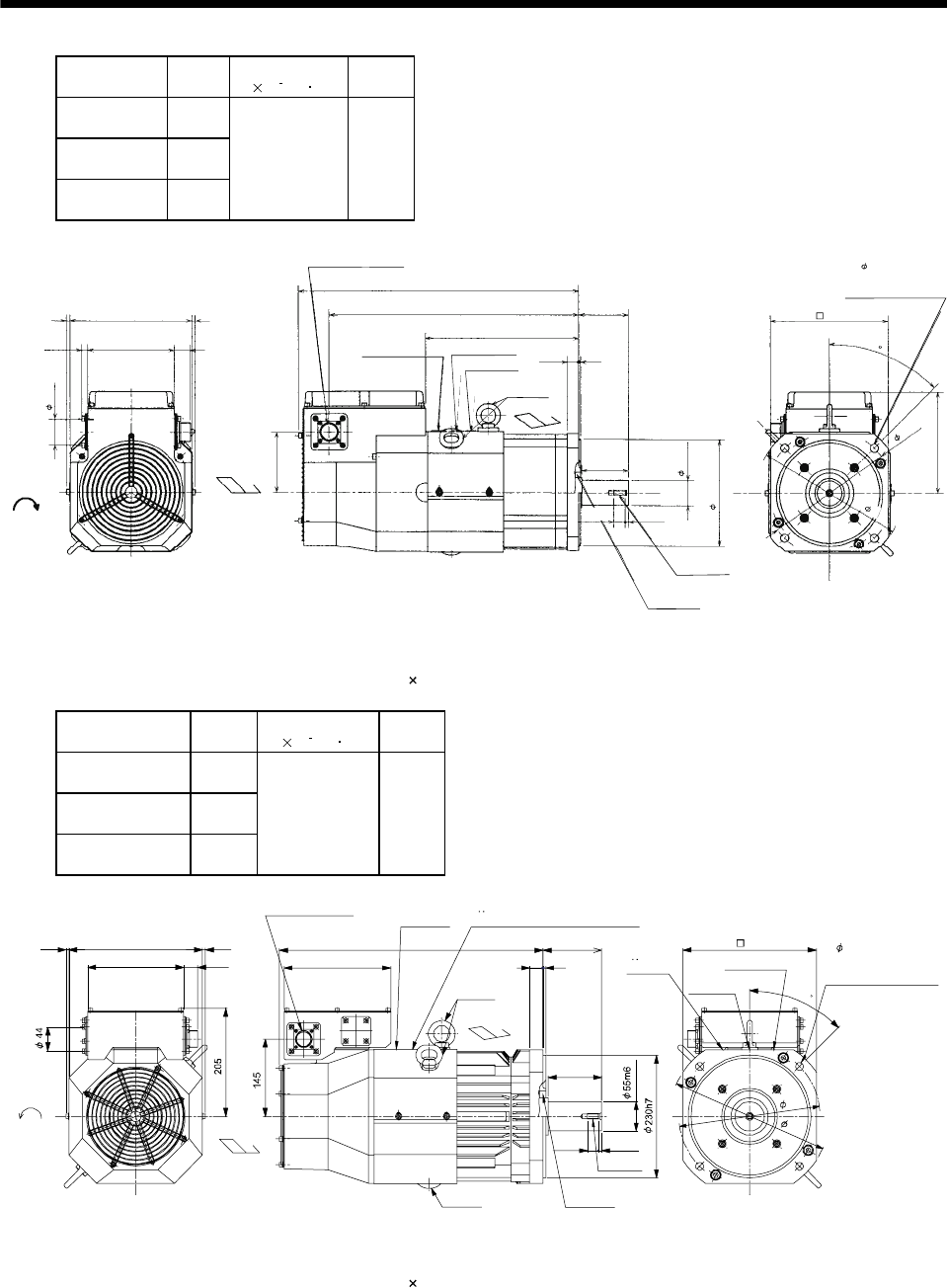
7 - 138
7. OUTLINE DIMENSION DRAWINGS
Model Output
[kW]
Inertia Moment
J[ 10 4kg m2]
Mass
[kg]
HA-LFS601
HA-LFS6014 6
HA-LFS701M
HA-LFS701M4 7
HA-LFS11K2
HA-LFS11K24 11
105 55
Cooling fan
rotation
direction
Suction air
66206
146 27
102
11
44
Encoder connector
MS3102A20-29P
Hanger
(Note 2)
Exhaust air
480
262
85
3
20
426
Motor plate Caution plate
Logo plate
Top
Bottom
Top
Bottom
Top
Oil seal
S50689B
180h7
42h6
80
19.8 5.2
M8 screw
200
45
Use hexagon socket
head cap screw.
4- 14.5
250
215
171
(Note 1)[Unit: mm]
BC12837A, BC12582*, BC12967A
Note 1. The dimensions without tolerances are reference dimensions.
2. When the motor is used without the hanger, plug the threaded hole with a bolt of M12 20 mm or less.
Model Output
[kW]
Inertia Moment
J[ 10 4kg m2]
Mass
[kg]
HA-LFS801
HA-LFS8014 8
HA-LFS11K1M
HA-LFS11K1M4 11
HA-LFS15K2
HA-LFS15K24 15
220 95
BC12804C, BC12964C, BC12969C
BC25028D, BC25670B, BC29888B
27
250
180
6 6 110
100
525
6.6
20.4
495
200
Encoder connector
MS3102A20-29P Motor plate
Caution plate
Logo plate
Hanger
(Note 2)
Hanger
(Note 2)
250
Suction air
Exhaust air
M10 screw
Oil seal
S709513B
Cooling fan
rotation
direction
TUV plate
TUV plate, Logo plate, Caution plate
45
265
300
4- 14.5 mounting hole
Use hexagon socket head
cap screw.
TopBottom
Top
Bottom
(Note 1)[Unit: mm]
Note 1. The dimensions without tolerances are reference dimensions.
2. When the motor is used without the hanger, plug the threaded hole with a bolt of M12 20 mm or less.
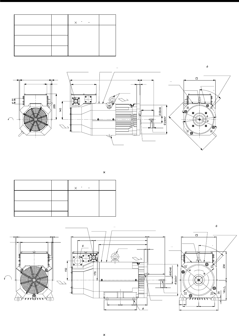
7 - 139
7. OUTLINE DIMENSION DRAWINGS
Model Output
[kW]
Inertia Moment
J[ 10 4kg m2]
Mass
[kg]
HA-LFS12K1
HA-LFS12K14 12
HA-LFS15K1M
HA-LFS15K1M4 15
HA-LFS22K2
HA-LFS22K24 22
295 115
555
100
110
5
25
6.6
20.4
66 250
27180 200
BC12970C, BC13039C, BC13158B
BC25300D, BC25349B, BC33032*
(Note 1)[Unit: mm]
Encoder connector
MS3102A20-29P
Motor plate
Caution plate
Logo plate
Hanger
(Note 2)
Hanger
(Note 2)
250
Suction air
Exhaust air
M10 screw
Oil seal
S709513B
Cooling fan
rotation
d
irection
TUV plate
TUV plate, Logo plate, Caution plate
45
265
300
376
4- 14.5 mounting hole
Use hexagon socket
head cap screw.
Top Bottom
Top
Bottom
Note 1. The dimensions without tolerances are reference dimensions.
2. When the motor is used without the hanger, plug the threaded hole with a bolt of M12 20 mm or less.
Model Output
[kW]
Inertia Moment
J[ 10 4kg m2]
Mass
[kg]
HA-LFS15K1
HA-LFS15K14 15
HA-LFS22K1M
HA-LFS22K1M4 22
HA-LFS30K24 30
550 160
6 6286
2722011 128 426
386
605 140
260
105 105 108
25 5
140
825
55 127 127
310
BC12966A, BC13040A
(BC13233B, BC13235*)
Encoder connector
MS3102A20-29P Motor plate
4- 15
Caution plate
Logo plate
51 Hanger
(Note 2)
280
Suction
air
Exhaust air
M12 screw
Oil seal
S709513B
Cooling fan
rotation
direction
TUV plate
TUV plate, Logo plate, Caution plate
45
300
350
4- 19
Use hexagon socket
head cap screw.
Top
Bottom
Top
Bottom
(Note 1)[Unit: mm]
Note 1. The dimensions without tolerances are reference dimensions.
2. When the motor is used without the hanger, plug the threaded hole with a bolt of M16 20 mm or less.
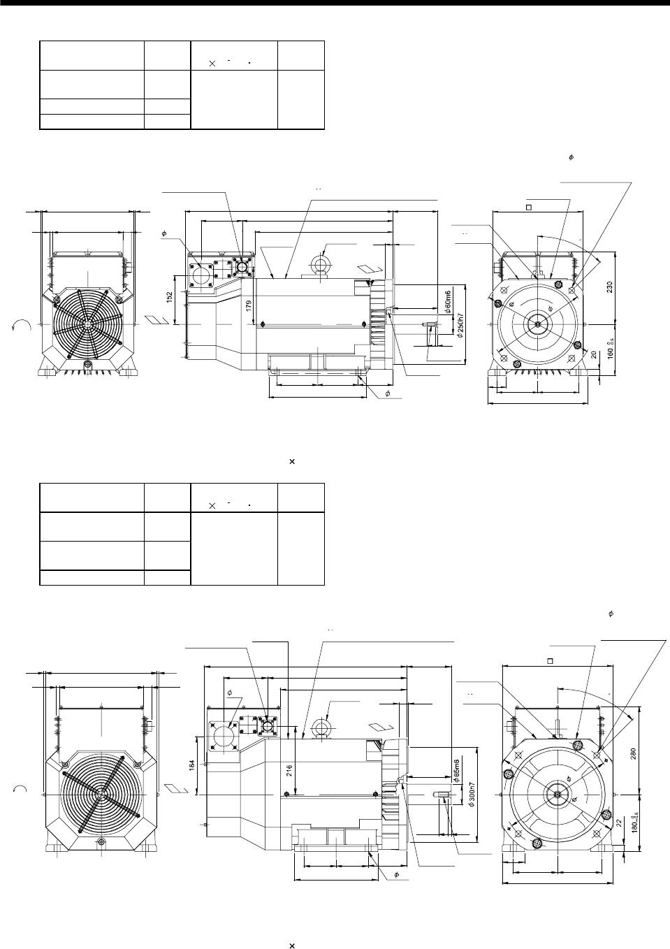
7 - 140
7. OUTLINE DIMENSION DRAWINGS
Model Output
[kW]
Inertia Moment
J[ 10 4kg m2]
Mass
[kg]
HA-LFS20K1
HA-LFS20K14 20
HA-LFS30K1M4 30
HA-LFS37K24 37
650 180
27220
11
62866 650
471
128
431
140
127 127 108
304
140
825
55 127 127
310
525
BC12972A
(BC13389B, BC13994*)
Encoder connector
MS3102A20-29P
Motor plate
4- 15
Caution plate
Logo plate
Hanger
(Note 2)
280
Suction air
Exhaust air
M12 screw
Oil seal
S659013B
Cooling fan
rotation
d
irection
TUV plate
TUV plate, Logo plate, Caution plate
45
350
300
4- 19
Use hexagon socket
head cap screw.
Top
Bottom
Top
Bottom
51
(Note 1)[Unit: mm]
Note 1. The dimensions without tolerances are reference dimensions.
2. When the motor is used without the hanger, plug the threaded hole with a bolt of M16 20 mm or less.
Model Output
[kW]
Inertia Moment
J[ 10 4kg m2]
Mass
[kg]
HA-LFS25K1
HA-LFS25K14 25
HA-LFS37K1M
HA-LFS37K1M4 37
HA-LFS45K24 45
1080 230
66 352
11 266 27
138
399
439
640 140
25 5
140
262
101.5 101.5 121
930
139.5139.5
70
349
BC12508*, BC12973A
(BC13391B, BC13390*)
Encoder connector
MS3102A20-29P
Motor plate
4- 19
Caution plate
Logo plate
Hanger
(Note 2)
350
Suction
air
Exhaust air
M16 screw
Oil seal
S709513B
Cooling fan
rotation
d
irection
TUV plate
TUV plate, Logo plate, Caution plate
45
350
400
4- 19
Use hexagon socket
head cap screw.
Top
Bottom
Top
Bottom
63
(Note 1)[Unit: mm]
Note 1. The dimensions without tolerances are reference dimensions.
2. When the motor is used without the hanger, plug the threaded hole with a bolt of M16 20 mm or less.
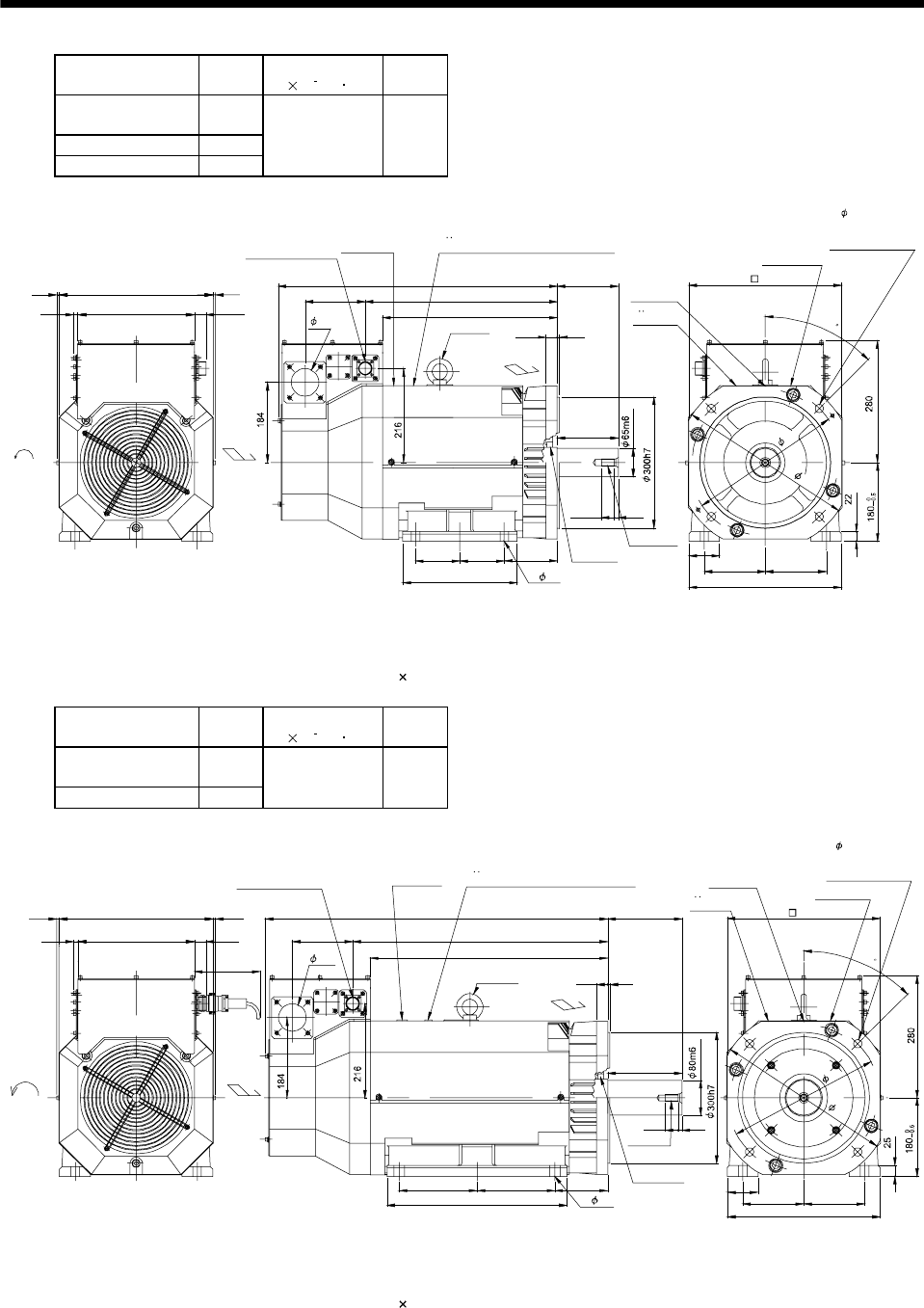
7 - 141
7. OUTLINE DIMENSION DRAWINGS
Model Output
[kW]
Inertia Moment
J[ 10 4kg m2]
Mass
[kg]
HA-LFS30K1
HA-LFS30K14 30
HA-LFS45K1M4 45
HA-LFS55K24 55
1310 250
66 352
11 266 27
138
444
484
685 140
25 5
140
300
120.5 120.5 121
9
30
139.5139.5
70
349
BC11371B
(BC13393B, BC13392*, BC13232*)
Encoder connector
MS3102A20-29P
Motor plate
4- 19
Caution plate
Logo plate
Hanger
(Note 2)
350
Suction
air
Exhaust air
M16 screw
Oil seal
S709513B
Cooling fan
rotation
d
irection
TUV plate
TUV plate, Logo plate, Caution plate
45
350
400
4- 19
Use hexagon socket
head cap screw.
Top
Bottom
Top
Bottom
63
(Note 1)[Unit: mm]
Note 1. The dimensions without tolerances are reference dimensions.
2. When the motor is used without the hanger, plug the threaded hole with a bolt of M16 20 mm or less.
Model Output
[kW]
Inertia Moment
J[ 10 4kg m2]
Mass
[kg]
HA-LFS37K1
HA-LFS37K14 37
HA-LFS50K1M4 50
1870 335
6 352 6
11 266 27
(150)
138 584
544
785
178 178
412
121
25 5
170
170
9
30
70
139.5 139.5
349
BC12221*
(BC13395B)
Encoder connector
MS3102A20-29P
Motor plate
4- 24
Caution plate
Logo plate
Hanger
(Note 2)
350
Suction
air
Exhaust air
M16 screw
Oil seal
S8511013B
Cooling fan
rotation
d
irection
TUV plate
TUV plate, Logo plate, Caution plate
45
350
400
4- 19
Use hexagon socket
head cap screw.
Top
Bottom
Top
Bottom
63
(Note 1)[Unit: mm]
Note 1. The dimensions without tolerances are reference dimensions.
2. When the motor is used without the hanger, plug the threaded hole with a bolt of M16 20 mm or less.
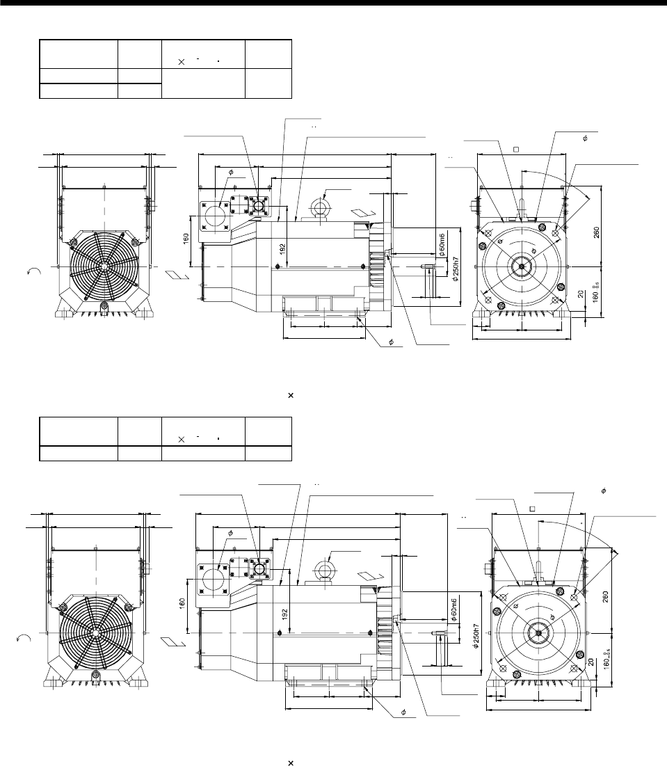
7 - 142
7. OUTLINE DIMENSION DRAWINGS
Model Output
[kW]
Inertia Moment
J[ 10 4kg m2]
Mass
[kg]
HA-LFS30K1M 30
HA-LFS37K2 37 650 180
66 286
2726611 138 466
426
660
25 5
304
127 127 108
310
127 127
55
25 8
140
140
BC25299A
Encoder connector
MS3102A20-29P
Motor plate
4- 15
Caution plate
Logo plate
Hanger
(Note 2)
280
Suction
air
Exhaust air
M12 screw
Oil seal
S659013B
Cooling fan
rotation
direction
TUV plate
TUV plate, Logo plate, Caution plate
45
300
350
4- 19
Use hexagon socket
head cap screw.
Top
Bottom
Top
Bottom
63
(Note 1)[Unit: mm]
Note 1. The dimensions without tolerances are reference dimensions.
2. When the motor is used without the hanger, plug the threaded hole with a bolt of M16 20 mm or less.
Model Output
[kW]
Inertia Moment
J[ 10 4kg m2]
Mass
[kg]
HA-LFS30K2 30 550 160
66 286
2726611 138 421
381
615
25 5
260
105 105 108
310
127 127
55
25 8
140
140
BC12971C
Encoder connector
MS3102A20-29P
Motor plate
4- 15
Caution plate
Logo plate
Hanger
(Note 2)
280
Suction
air
Exhaust air
M12 screw
Oil seal
S659013B
Cooling fan
rotation
d
irection
TUV plate
TUV plate, Logo plate, Caution plate
45
300
350
4- 19
Use hexagon socket
head cap screw.
Top
Bottom
Top
Bottom
63
(Note 1)[Unit: mm]
Note 1. The dimensions without tolerances are reference dimensions.
2. When the motor is used without the hanger, plug the threaded hole with a bolt of M16 20 mm or less.
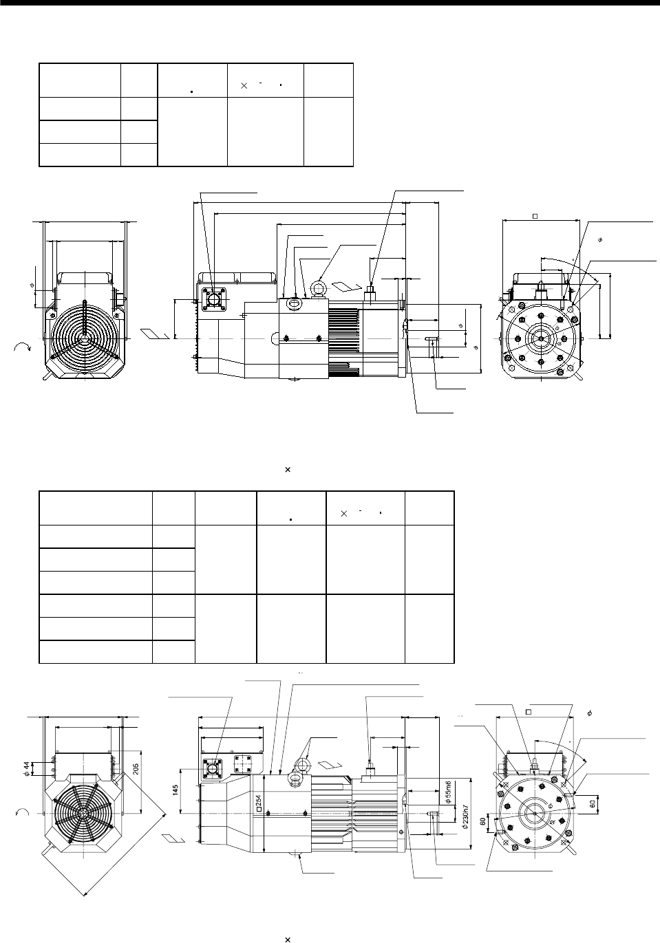
7 - 143
7. OUTLINE DIMENSION DRAWINGS
(2) With electromagnetic brake
Model Output
[kW]
Brake static
friction torque
[N m]
Inertia Moment
J[ 10
4
kg m2]
Mass
[kg]
HA-LFS601B
HA-LFS6014B 6
HA-LFS701MB
HA-LFS701M4B 7
HA-LFS11K2B
HA-LFS11K24B 11
82 113 70
102
334
498
171
11
(19.8) 5.2
80
85
320
550
146 27
206 66
93
142
55
Cooling fan
rotation
direction
Suction air
Encoder connector
MS3102A20-29P
Motor plate
Caution plate
Logo plate
Hanger
(Note 2)
M8 screw
Oil seal
S45629B
42h6
45
Use hexagon socket
head cap screw.
4- 14.5
215
Top
Bottom
Top
Bottom
44
180h7
Brake connector
H/MS3102A10SL-4P
250
200 M10 screw, depth20
BC13443*
(BC25146*)
Exhaust air
(Note 1)[Unit: mm]
Note 1. The dimensions without tolerances are reference dimensions.
2. When the motor is used without the hanger, plug the threaded hole with a bolt of M10 20 mm or less.
Model Output
[kW]
Variable
dimensions
L
Brake static
friction torque
[N m]
Inertia Moment
J[ 10
4
kg m2]
Mass
[kg]
HA-LFS801B
HA-LFS8014B 8
HA-LFS11K1MB
HA-LFS11K1M4B 11
HA-LFS15K2B
HA-LFS15K24B 15
610 160.5 293 126.0
HA-LFS12K1B
HA-LFS12K14B
12
HA-LFS15K1MB
HA-LFS15K1M4B 15
HA-LFS22K2B
HA-LFS22K24B 22
670 160.5 369 146.0
BC13444B, BC25697A, BC25700B
BC25746A, BC25767A, BC25865B
BC25985B, BC33030*, BC33034*
L
M12 screw, depth22
M12 screw, depth22
111.5
110
100
5
25
6.6
20.4
6 6
180 27
250
376
200
209
Encoder connector
MS3102A20-29P
Brake connector
MS3102A10SL-4P
Motor plate
Caution plateLogo plate
Hanger
(Note 2)
Hanger
(Note 2)
250
Suction air
Exhaust air
M10 screw
Oil seal
S60829B
Cooling fan
rotation
d
irection
TUV plate
TUV plate, Logo plate, Caution plate
45
265
300
4- 14.5 mounting hole
Use hexagon socket
head cap screw.
Top
Bottom
Top
Bottom
(Note 1)[Unit: mm]
Note 1. The dimensions without tolerances are reference dimensions.
2. When the motor is used without the hanger, plug the threaded hole with a bolt of M12 20 mm or less.
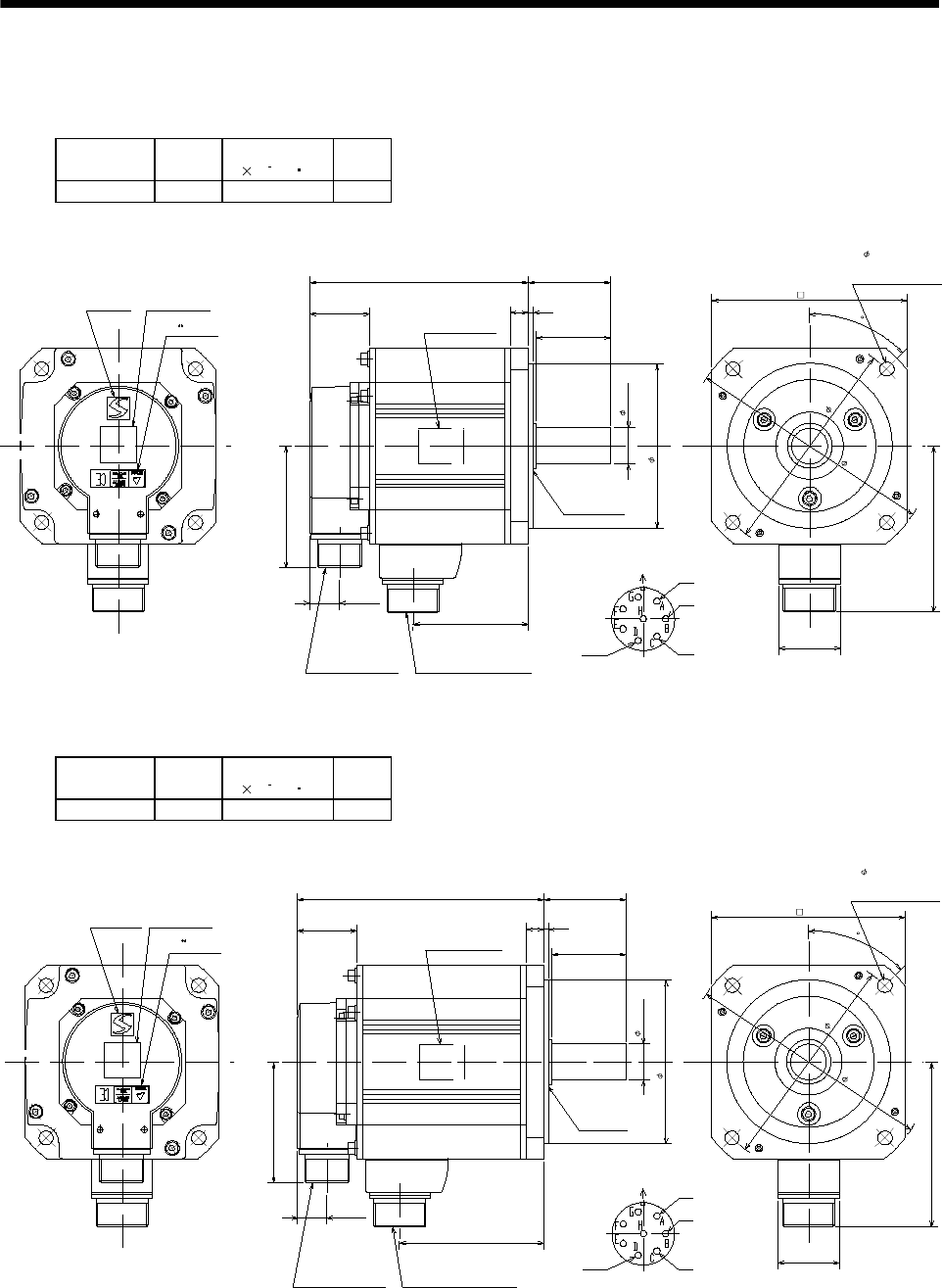
7 - 144
7. OUTLINE DIMENSION DRAWINGS
7.1.14 HC-LFS series
(1) Standard (without electromagnetic brake)
Model Output
[kW]
Inertia Moment
J[ 10 4kg m2]
Mass
[kg]
HC-LFS52 0.5 3.2 6.5
Caution plateLogo plate
Top
Bottom
TUV plate
Top
Bottom
Top
Bottom
145.5
39.5
50
3
12
55
Motor plate
(Opposite side)
Oil seal
S30457B
110h7
24h6
Motor flange direction
Power supply connector layout
CE05-2A22-23P
Earth W
V
U
81.5
Encoder connector
MS3102A20-29P
19.5
77
Power supply connector
CE05-2A22-23P
130
45
Use hexagon socket
head cap screw.
4- 9
165
145
41
111
BC12908*
Note: The dimensions without tolerances are reference dimensions.
Top
Bottom
(Note)[Unit: mm]
Model Output
[kW]
Inertia Moment
J[ 10 4kg m2]
Mass
[kg]
HC-LFS102 1.0 4.6 8
Caution plateLogo plate
Top
Bottom
Top
Bottom
Top
Bottom
165.5
39.5
50
312
55
Motor plate
(Opposite side)
Oil seal
S30457B
24h6
Motor flange direction
Power supply connector layout
CE05-2A22-23P
Earth W
V
U
81.5
Encoder connector
MS3102A20-29P
19.5
97
Power supply connector
CE05-2A22-23P
45
41
111
BC12909*
Note: The dimensions without tolerances are reference dimensions.
Top
Bottom
TUV plate
165
145
Use hexagon socket
head cap screw.
4- 9
110h7
130
(Note)[Unit: mm]
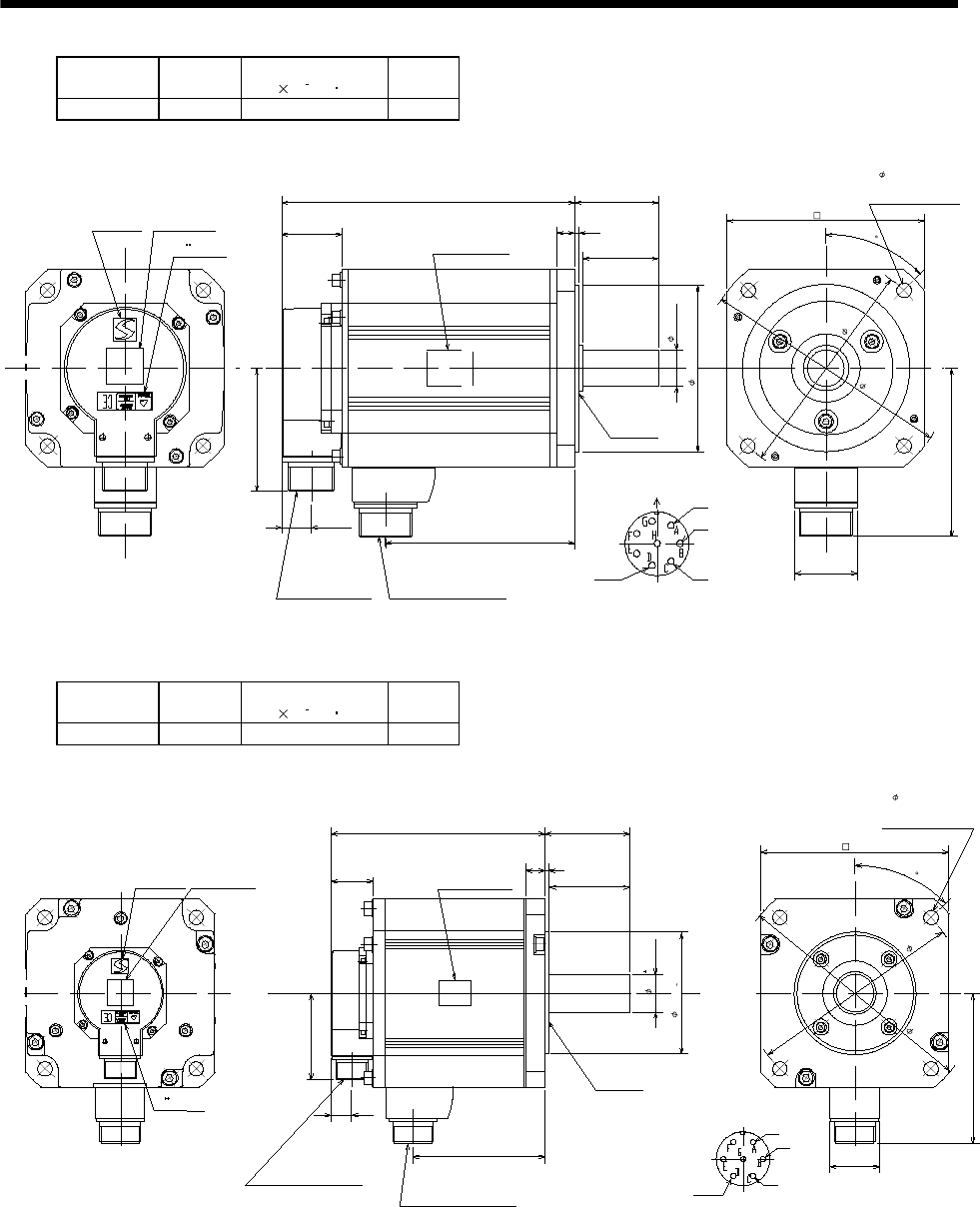
7 - 145
7. OUTLINE DIMENSION DRAWINGS
Model Output
[kW]
Inertia Moment
J[ 10 4kg m2]
Mass
[kg]
HC-LFS152 1.5 6.4 10
Caution plateLogo plate
Top
Bottom
Top
Bottom
Top
Bottom
193
39.5
50
312
55
Motor plate
(Opposite side)
Oil seal
S30457B
24h6
Motor flange direction
Power supply connector layout
CE05-2A22-23P
Earth W
V
U
81.5
Encoder connector
MS3102A20-29P
19.5
124.5
Power supply connector
CE05-2A22-23P
45
41
111
BC12910A
Note: The dimensions without tolerances are reference dimensions.
Top
Bottom
TUV plate
165
145
Use hexagon socket
head cap screw.
4- 9
130
110h7
(Note)[Unit: mm]
Model Output
[kW]
Inertia Moment
J[ 10 4kg m2]
Mass
[kg]
HC-LFS202 2.0 22 21
Caution plateLogo plate
Top
Bottom
Top
Bottom
Top
Bottom
200
39.5 75
318
79
Motor plate
(Opposite side)
Oil seal
S40608B
Motor flange direction
Power supply connector layout
CE05-2A24-10P
Earth
W
V
U
81.5
Encoder connector
MS3102A20-29P
19.5
123.5
Power supply connector
CE05-2A24-10P
45
46
142
BC13035*
Note: The dimensions without tolerances are reference dimensions.
Top
Bottom
TUV plate
230
200
Use hexagon socket
head cap screw.
4- 13.5
114.3 0
0.025
176
(Note)[Unit: mm]
35 0.010
0
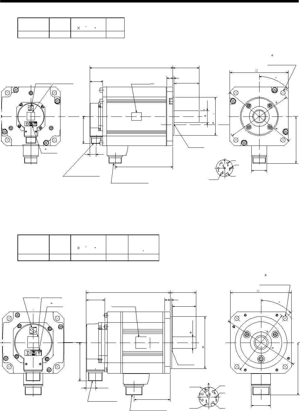
7 - 146
7. OUTLINE DIMENSION DRAWINGS
Model Output
[kW]
Inertia Moment
J[ 10 4kg m2]
Mass
[kg]
HC-LFS302 3.0 36 28
Caution plateLogo plate
Top
Bottom
Top
Bottom
Top
Bottom
250
39.5 75
318
79
Motor plate
(Opposite side)
Oil seal
S40608B
Motor flange direction
Power supply connector layout
CE05-2A24-10P
Earth
W
V
U
81.5
Encoder connector
MS3102A20-29P
19.5
173.5
Power supply connector
CE05-2A24-10P
45
46
142
BC13036*
Note: The dimensions without tolerances are reference dimensions.
Top
Bottom
TUV plate
230
200
Use hexagon socket
head cap screw.
4- 13.5
176
(Note)[Unit: mm]
114.3 0
0.025
35 0.010
0
(2) With electromagnetic brake
Model Output
[kW]
Inertia Moment
J[ 10 4kg m2]
Mass
[kg]
Brake static
friction torque
[N m]
HC-LFS52B 0.5 5.2 9 8.3
Caution plate
Logo plate
Top
Bottom
Top
Bottom
Top
Bottom
TUV plate
178.5
39.5
50
312
55
Motor plate
(Opposite side)
Oil seal
S30457B
81.5
Encoder connector
MS3102A20-29P
19.5
77
Power supply connector
CE05-2A22-23P
Top
Bottom
Motor flange direction
Power supply connector layout
CE05-2A22-23P
Earth W
V
U
Brake
45
41
111
165
145
Use hexagon socket
head cap screw.
4- 9
130
BC12984*
Note: The dimensions without tolerances are reference dimensions.
24h6
110h7
(Note)[Unit: mm]
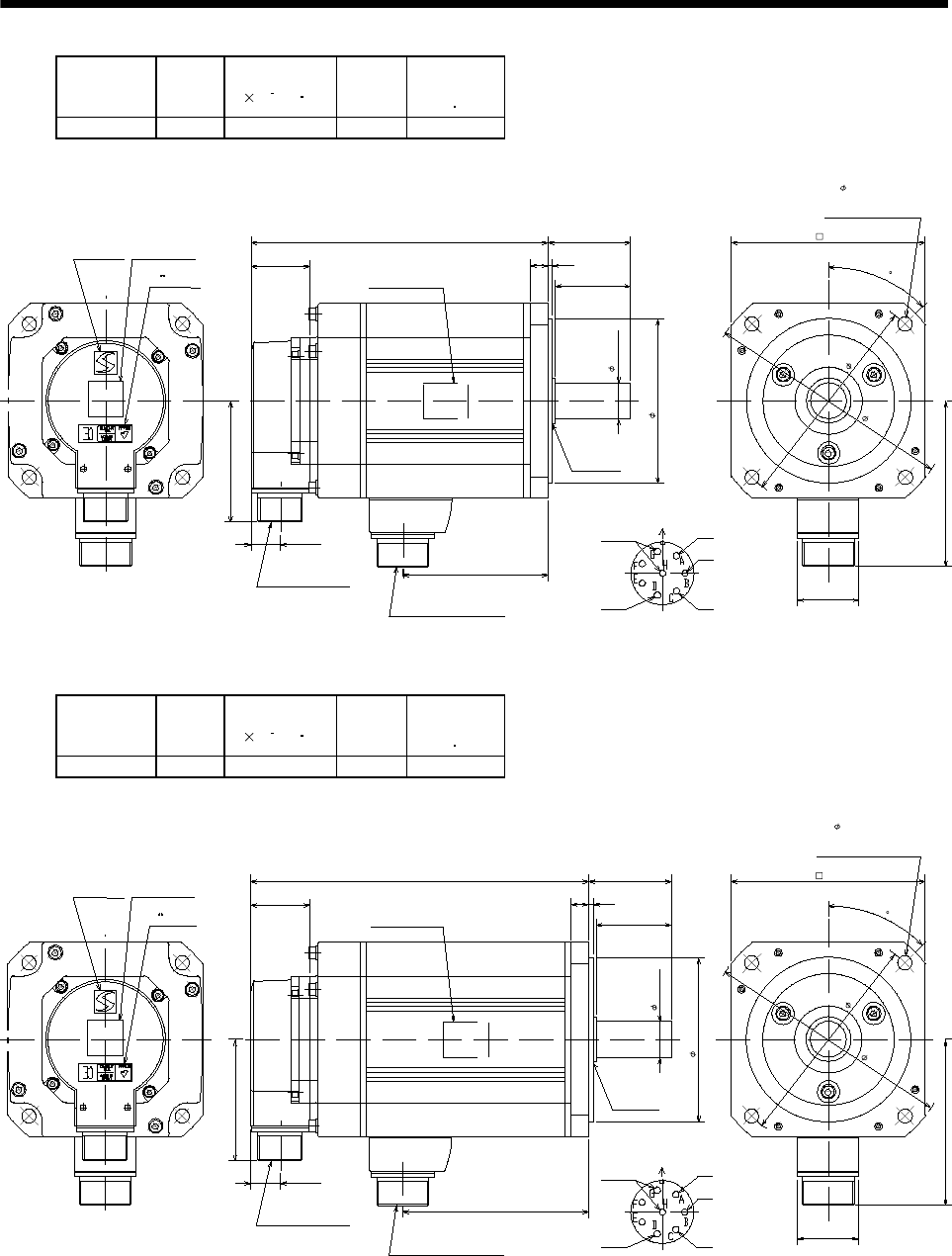
7 - 147
7. OUTLINE DIMENSION DRAWINGS
Model Output
[kW]
Inertia Moment
J[ 10 4kg m2]
Mass
[kg]
Brake static
friction torque
[N m]
HC-LFS102B 1.0 6.6 10.5 8.3
Caution plateLogo plate
Top
Bottom
Top
Bottom
Top
Bottom
TUV plate
198.5
39.5
50
312
55
Motor plate
(Opposite side)
Oil seal
S30457B
81.5
Encoder connector
MS3102A20-29P
19.5
97
Power supply connector
CE05-2A22-23P
24h6
110h7
Top
Bottom
Motor flange direction
Power supply connector layout
CE05-2A22-23P
Earth W
V
U
Brake
45
41
111
165
145
Use hexagon socket
head cap screw.
4- 9
130
BC12985*
Note: The dimensions without tolerances are reference dimensions.
(Note)[Unit: mm]
Model Output
[kW]
Inertia Moment
J[ 10 4kg m2]
Mass
[kg]
Brake static
friction torque
[N m]
HC-LFS152B 1.5 8.4 12.5 8.3
Caution plate
Logo plate
Top
Bottom
Top
Bottom
Top
Bottom
226
39.5
50
3
12
55
Motor plate
(Opposite side)
Oil seal
S30457B
24h6
Motor flange direction
Power supply connector layout
CE05-2A22-23P
Earth W
V
U
81.5
Encoder connector
MS3102A20-29P
19.5
124.5
Power supply connector
CE05-2A22-23P
45
41
111
BC12986*
Note: The dimensions without tolerances are reference dimensions.
Top
Bottom
TUV plate
165
145
Use hexagon socket
head cap screw.
4- 9
Brake
130
110h7
(Note)[Unit: mm]
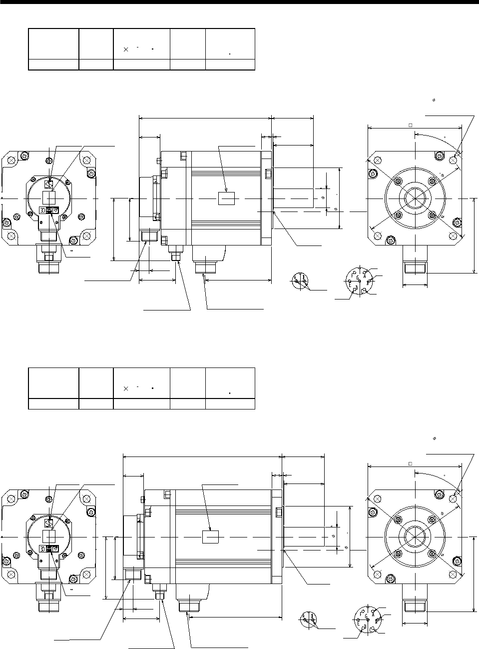
7 - 148
7. OUTLINE DIMENSION DRAWINGS
Model Output
[kW]
Inertia Moment
J[ 10 4kg m2]
Mass
[kg]
Brake static
friction torque
[N m]
HC-LFS202B 2.0 32 27 43.1
Caution plateLogo plate
Top
Bottom
Top
Bottom
Top
Bottom
248
39.5
75
318
79
Motor plate
(Opposite side)
Oil seal
S40608B
Motor flange direction
Power supply connector layout
CE05-2A24-10P
Earth
W
V
U
81.5
Encoder connector
MS3102A20-29P
19.5
123.5
Power supply connector
CE05-2A24-10P
45
46
142
BC13037A
Note: The dimensions without tolerances are reference dimensions.
Top
Bottom
TUV plate
230
200
Use hexagon socket
head cap screw.
4- 13.5
Brake
176
Brake connector
MS3102A10SL-4P
69
117
Motor flange direction
Brake connector layout
MS3102A10SL-4P
(Note)[Unit: mm]
114.3 0
0.25
35 0.01 0
0
Model Output
[kW]
Inertia Moment
J[ 10 4kg m2]
Mass
[kg]
Brake static
friction torque
[N m]
HC-LFS302B 3.0 46 34 43.1
Caution plateLogo plate
Top
Bottom
Top
Bottom
Top
Bottom
298
39.5
75
318
79
Motor plate
(Opposite side)
Oil seal
S40608B
Motor flange direction
Power supply connector layout
CE05-2A24-10P
Earth
W
V
U
81.5
Encoder connector
MS3102A20-29P
19.5
173.5
Power supply connector
CE05-2A24-10P
45
46
142
BC13038A
Note: The dimensions without tolerances are reference dimensions.
Top
Bottom
TUV plate
230
200
Use hexagon socket
head cap screw.
4- 13.5
Brake
176
Brake connector
MS3102A10SL-4P
69
117
Motor flange direction
Brake connector layout
MS3102A10SL-4P
(Note)[Unit: mm]
114.3 0
0.025
35 0.010
0
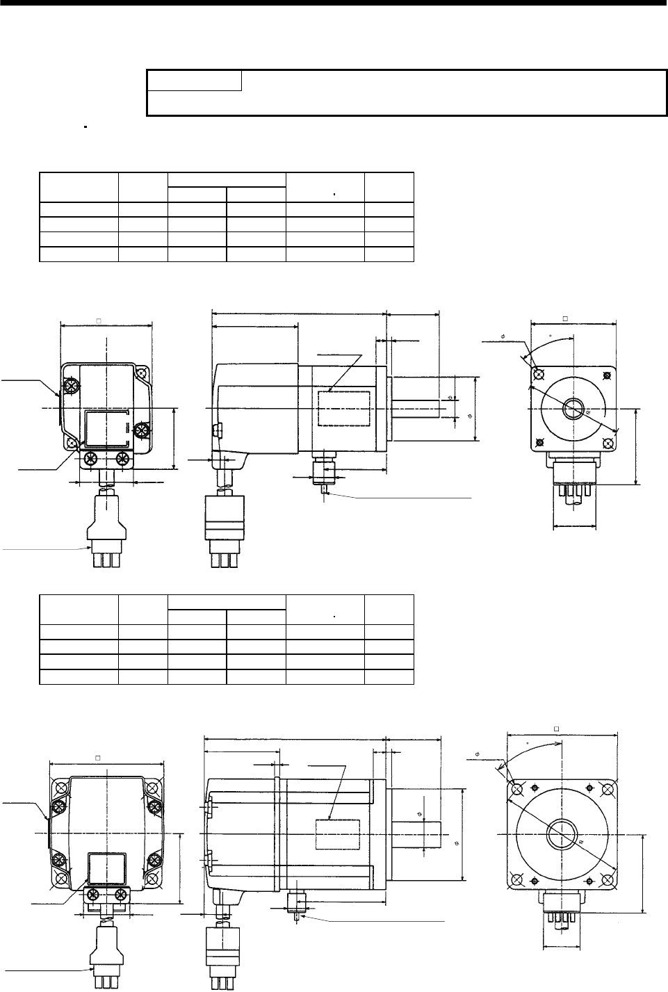
7 - 149
7. OUTLINE DIMENSION DRAWINGS
7.2 Servo motors (in inches)
POINT
The values in yards/pounds are reference values.
7.2.1 HC-MF HC-KF series
(1) Standard (without electromagnetic brake, without reduction gear)
Variable Dimensions [in]
Model Output
[W] LKL
Inertia Moment
WK2[oz in2]
Mass
[lb]
HC-MF053 50 3.21 1.16 0.10 0.9
HC-MF13 100 3.80 0.18 0.16 1.2
HC-KF053 50 3.21 0.12 0.29 0.9
HC-KF13 100 3.80 1.75 0.46 1.2
Power supply lead 4-AWG19 11.8in
(With end-insulated round
crimping terminal 1.25-4)
Red: Phase U
White: Phase V
Black: Phase W
Green/yellow: Earth
Top
Bottom
Motor plate
(Opposite side)
Encoder cable 11.8in
With connector 1-172169-9
(AMP)
Motor plate
0.984
0.098
0.197
0.787
L
Top
Bottom
1.406
KL
0.390
1.575
2- 0.177
0.315
1.181
BC12031*
(BC12034*)
Caution plate
Top
Bottom
1.594
1.654
0.268
0.992
1.130
1.811
[Unit: in]
45
Variable Dimensions [in]
Model Output
[W] LKL
Inertia Moment
WK2[oz in2]
Mass
[lb]
HC-MF23 200 3.92 1.93 0.48 2.2
HC-MF43 400 4.90 0.06 0.78 3.2
HC-KF23 200 3.92 1.93 1.422 2.2
HC-KF43 400 4.90 0.06 2.515 3.2
Encoder cable 11.8in
With connector 1-172169-9
(AMP)
Power supply lead 4-AWG19 11.8in
Red: Phase U
White: Phase V
Black: Phase W
Green/yellow: Earth
Motor plate
(Opposite side)
1.181
Motor plate
Bottom
Top Bottom
Top
L
Bottom
Top
(With end-insulated round crimping terminal 1.25-4)
0.787
1.685
0.390 KL
2.362
0.551
4- 0.228
1.969
BC12032*
0.276 0.118
Caution plate
(BC12035*)
1.614
2.441 0.106
0.417
0.992
1.512
2.756
[Unit: in]
45
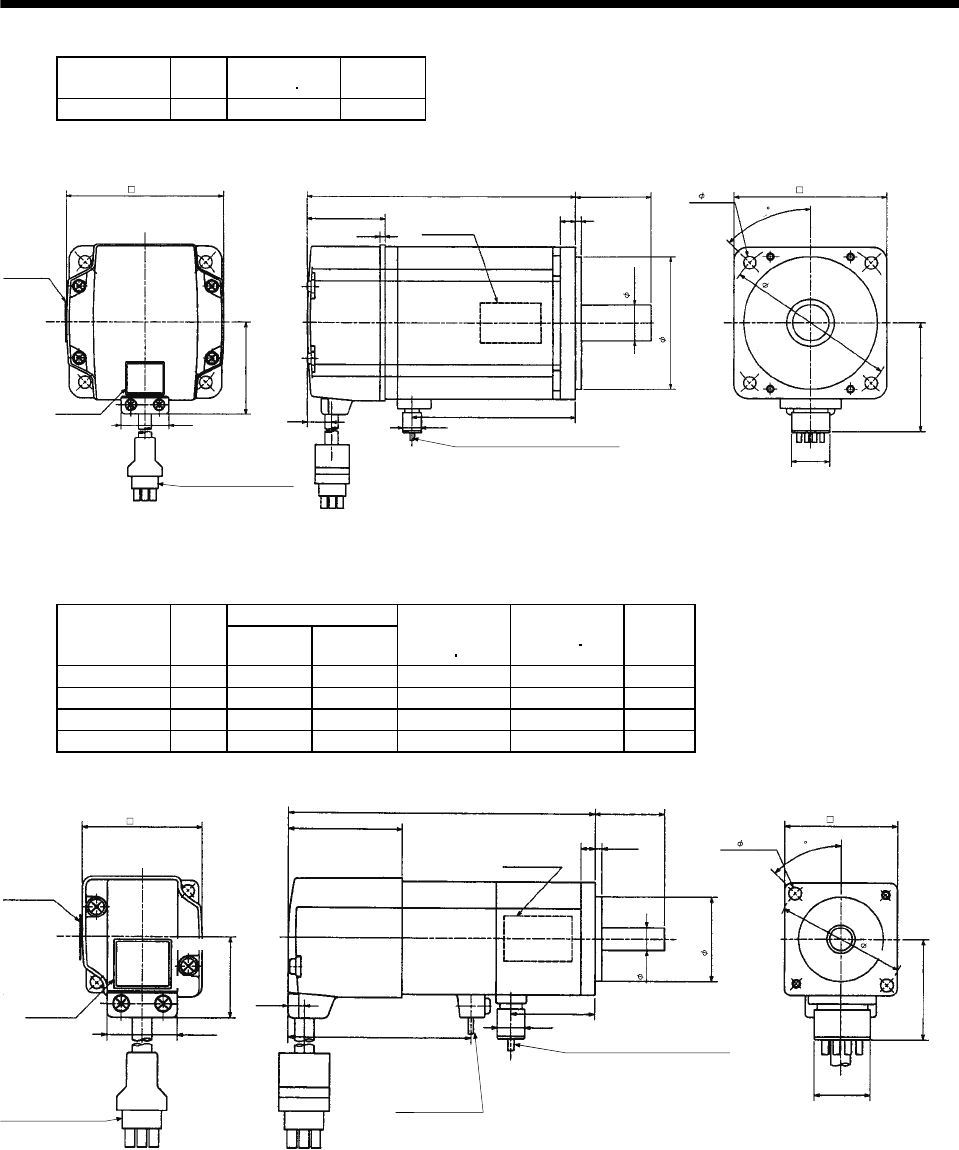
7 - 150
7. OUTLINE DIMENSION DRAWINGS
Model Output
[W]
Inertia Moment
WK2[oz in2]
Mass
[lb]
HC-MF73 750 3.28 6.6
Encoder cable 11.8in
With connector 1-172169-9
(AMP)
Power supply lead 4-AWG19 11.8in
Red: Phase U
White: Phase V
Black: Phase W
Green/
y
ellow: Earth
Motor plate
(Opposite side)
5.591
0.315 0.118
1.575
2.287
0.787
3.413
(With end-insulated round crimping terminal 1.25-4)
Top
Bottom
Top
Bottom
Top
0.390
0.748
Motor plate
2.756
Bottom
3.150
4- 0.260
3.543
BC12033*
Caution plate
1.535
3.228
0.106
0.992
1.917
0.433
[Unit: in]
45
(2) With electromagnetic brake
Variable Dimensions [in]
Model Output
[W] LKL
Brake static
friction torque
[oz in]
Inertia Moment
WK2[oz in2]
Mass
[lb]
HC-MF053B 50 4.31 1.16 45.32 0.12 1.7
HC-MF13B 100 4.90 1.75 45.32 0.18 2.0
HC-KF053B 50 4.31 1.16 45.32 0.31 1.7
HC-KF13B 100 4.90 1.75 45.32 0.48 2.0
Motor plate
(Opposite side)
Top
Bottom
Power supply lead
4-AWG19 11.8in
Red: Phase U
White: Phase V
Black: Phase W
Green/yellow: Earth
KL
0.390
Brake lead
2-0.3 11.8in
(With end-insulated round
crim
p
in
g
terminal 1.25-4
)
1.406
0.787
0.197 0.098
0.984L
2.579
Motor plate
Top
Bottom
Top
Bottom
2
Encoder cable 11.8in
With connector 1-172169-9
(AMP)
Caution plate
(With end-insulated round crimping terminal 1.25-4)
2- 0.177
1.575
1.181
0.315
(BC12039*)
BC12036*
1.594
1.654
0.268
0.992
1.130
1.811
[Unit: in]
45
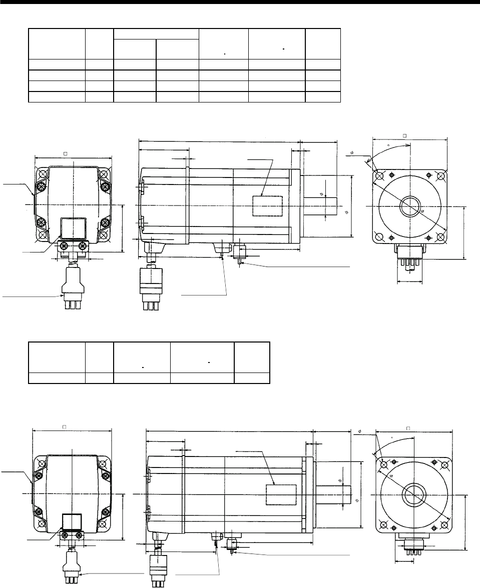
7 - 151
7. OUTLINE DIMENSION DRAWINGS
Variable Dimensions [in]
Model Output
[W] LKL
Brake static
friction torque
[oz in]
Inertia Moment
WK2[oz in2]
Mass
[lb]
HC-MF23B 200 5.18 1.93 184 0.74 3.5
HC-MF43B 400 6.16 2.84 184 1.04 4.6
HC-KF23B 200 5.18 1.93 184 1.694 3.5
HC-KF43B 400 6.16 2.84 184 2.788 4.6
Brake lead
2-0.32 11.8in
(With end-insulated round
crim
p
in
g
terminal 1.25-4
)
Power supply lead 4-AWG19 11.8in
Red: Phase U
White: Phase V
Black: Phase W
Green/yellow: Earth
Encoder cable 11.8in
With connector 1-172169-9
(AMP)
2.677 0.390
KL
L 1.181
0.276 0.118
Motor plate
(Opposite side)
Top
Bottom
1.969
2.362
45
1.685
4- 0.228
Top
Bottom
Bottom
BC12037*
0.787
0.551
(With end-insulated round crimping terminal 1.25-4)
Motor plate
Caution plate
(BC12039*)
1.614
2.441 0.106
0.417
0.992
1.512
2.756
[Unit: in]
Top
Model Output
[W]
Brake static
friction torque
[oz in]
Inertia Moment
WK2[oz in2]
Mass
[lb]
HC-MF73B 750 340 3.96 8.8
Encoder cable 11.8in
With connector 1-172169-9
(AMP)
Brake lead
2-0.3 11.8in
(With end-insulated round
crim
p
in
g
terminal 1.25-4
)
2
Power supply lead
4-AWG19 11.8in
Red: Phase U
White: Phase V
Black: Phase W
Green/yellow: Earth
Motor plate
(Opposite side)
Motor plate
Top
Bottom
Top
Bottom
6.988
2.835
3.413
0.390
(With end-insulated round crimping terminal 1.25-4)
BC12038*
1.575
0.118
0.315
Caution plate
Top
Bottom
3.150
0.768
2.287
0.787
0.748
2.756
4- 0.260
1.535
3.228
0.106
0.992
1.917
0.433
3.543
[Unit: in]
45
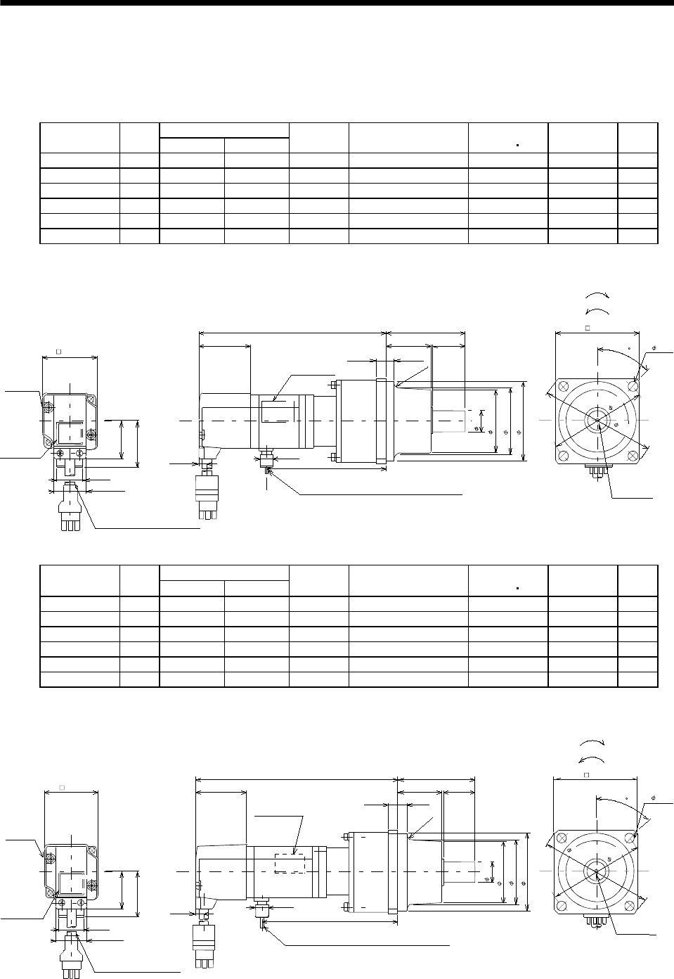
7 - 152
7. OUTLINE DIMENSION DRAWINGS
(3) With reduction gear for general industrial machine
The outer frame of the reduction gear is a material surface such as casting. Its actual dimensions may
be 0.039 to 0.118 in larger than the drawing dimensions. Design the machine side with allowances.
(a) Without electromagnetic brake
Variable Dimensions [in]
Model Output
[W] LKL
Reduction
Gear Model
Reduction Ratio
(Actual Reduction Ratio)
Inertia Moment
WK2[oz in2]Backlash Mass
[lb]
HC-MF053G1 50 4.96 2.91 K6505 1/5(9/44) 0.30 60min. max. 3.1
HC-MF053G1 50 5.669 3.62 K6512 1/12(49/576) 0.42 60min. max. 4.0
HC-MF053G1 50 5.669 3.62 K6520 1/20(25/484) 0.32 60min. max. 4.0
HC-KF053G1 50 4.96 2.91 K6505 1/5(9/44) 0.49 60min. max. 3.1
HC-KF053G1 50 5.669 3.62 K6512 1/12(49/576) 0.61 60min. max. 4.0
HC-KF053G1 50 5.669 3.62 K6520 1/20(25/484) 0.51 60min. max. 4.0
4- 0.276
Power supply lead 4-AWG19 11.8in
(With end-insulated round crimping terminal 1.25-4)
Red: Phase U
White: Phase V
Black: Phase W
Green/yellow: Earth
BC12066A
(BC12086A)
Motor plate
Caution plate
Bottom
Top
1.654
0.787
1.130
With connector 1-172169-9
(
AMP
)
Motor plate
(Opposite side)
0.390
KL
0.315 0.256
2.382
Bottom
Top
1.594
0.268
"Rotation direction"
For forward rotation command
For reverse rotation command
M4 threads,
depth 0.315
L
0.984
0.630
1.890
( 1.969)
2.559
1.358
2.953
3.465
45
Encoder cable 11.8in
1.406
0.992
2.362
(R4)
[Unit: in]
Bottom
Top
Variable Dimensions [in]
Model Output
[W] LKL
Reduction
Gear Model
Reduction Ratio
(Actual Reduction Ratio)
Inertia Moment
WK2[oz in2]Backlash Mass
[lb]
HC-MF13G1 100 5.551 3.5 K6505 1/5(9/44) 0.36 60min. max. 3.3
HC-MF13G1 100 6.26 4.21 K6512 1/12(49/576) 0.48 60min. max. 4.2
HC-MF13G1 100 6.26 4.21 K6520 1/20(25/484) 0.38 60min. max. 4.2
HC-KF13G1 100 5.551 3.5 K6505 1/5(9/44) 0.66 60min. max. 3.3
HC-KF13G1 100 6.26 4.21 K6512 1/12(49/576) 0.78 60min. max. 4.2
HC-KF13G1 100 6.26 4.21 K6520 1/20(25/484) 0.68 60min. max. 4.2
Power supply lead 4-AWG19 11.8in
(With end-insulated round crimping terminal 1.25-4)
Red: Phase U
White: Phase V
Black: Phase W
Green/
y
ellow: Earth
BC12067A
(BC12087A)
4- 0.276
Motor plate
Caution plate
Bottom
Top
1.654
0.787
1.130
With connector 1-172169-9
(AMP)
Motor plate
(Opposite side)
0.390
KL
0.315 0.256
2.382
Bottom
Top
1.594
0.268
"Rotation direction"
For forward rotation command
For reverse rotation command
M4 threads,
depth 0.315
L
0.984
1.890
2.559
1.358
2.953
3.465
45
Encoder cable 11.8in
1.406
0.992
2.362
(R4)
[Unit: in]
Bottom
Top
0.630
( 1.969)
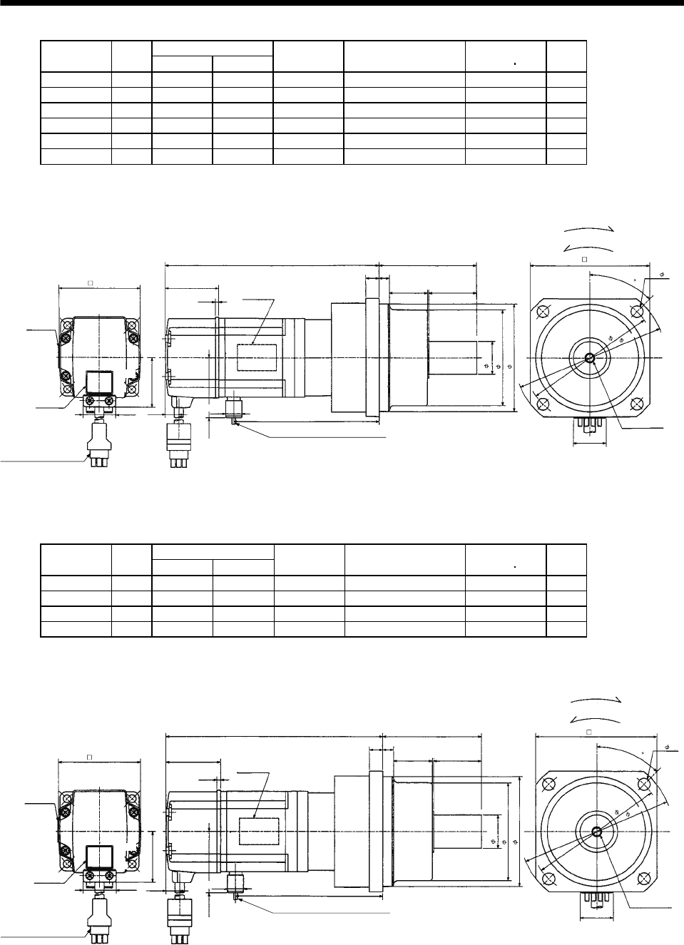
7 - 153
7. OUTLINE DIMENSION DRAWINGS
Variable Dimensions [in]
Model Output
[W] LKL
Reduction
Gear Model
Reduction Ratio
(Actual Reduction Ratio)
Inertia Moment
WK2[oz in2]
Mass
[lb]
HC-MF23G1 200 6.02 4.04 K9005 1/5(19/96) 1.36 7.3
HC-MF23G1 200 6.81 4.83 K9012 1/12(25/288) 1.60 8.6
HC-MF23G1 200 6.81 4.83 K9020 1/20(253/5000) 1.45 8.6
HC-KF23G1 200 6.02 4.04 K9005 1/5(19/96) 2.296 7.3
HC-KF23G1 200 6.81 4.83 K9012 1/12(25/288) 2.569 8.6
HC-KF23G1 200 6.81 4.83 K9020 1/20(253/5000) 2.406 8.6
L
Top
Bottom
M6 threads,
depth0.472
"Rotation direction"
For forward rotation command
For reverse rotation command
Encoder cable 11.8in
Power supply lead 4-AWG19 11.8in
(With end-insulated round crimping terminal 1.25-4)
Red: Phase U
White: Phase V
Black: Phase W
Green/
y
ellow: Earth
Top
Bottom
Motor plate
(Opposite side)
Motor plate
Caution plate
KL
4- 0.354
BC12068*
(BC12088*)
0.787
3.543
Top
Bottom
1.614
2.441
0.106
0.417
0.992
1.512
1.685
0.390
0.394 0.315
2.913
1.378
0.984
2.874
3.228
1.181
3.937
4.488
[Unit: in]
45
With connector 1-172169-9
(AMP)
Variable Dimensions [in]
Model Output
[W] LKL
Reduction
Gear Model
Reduction Ratio
(Actual Reduction Ratio)
Inertia Moment
WK2[oz in2]
Mass
[lb]
HC-MF43G1 400 7.01 4.95 K9005 1/5(19/96) 1.62 8.4
HC-MF43G1 400 7.80 5.73 K9012 1/12(25/288) 1.85 9.7
HC-KF43G1 400 7.01 4.95 K9005 1/5(19/96) 3.335 8.4
HC-KF43G1 400 7.80 5.73 K9012 1/12(25/288) 3.609 9.7
Motor plate
Top
Bottom
BC12069*
Encoder cable 11.8in
With connector 1-172169-9
(AMP)
Power supply lead 4-AWG19 11.8in
(With end-insulated round crimping terminal 1.25-4)
Red: Phase U
White: Phase V
Black: Phase W
Green/
y
ellow: Earth
Top
Bottom
Top
Bottom
Motor plate
(Opposite side)
Caution plate
"Rotation
direction"
For forward rotation command
For reverse rotation command
KL
(BC12089*)
L
1.614
2.441
0.106
0.417
0.992
1.512
1.685
0.390
0.394 0.315
2.913
1.378
0.984
2.874
3.228
1.181
M6 threads,
depth0.472
4- 0.354
0.787
3.543
3.937
4.488
[Unit: in]
45
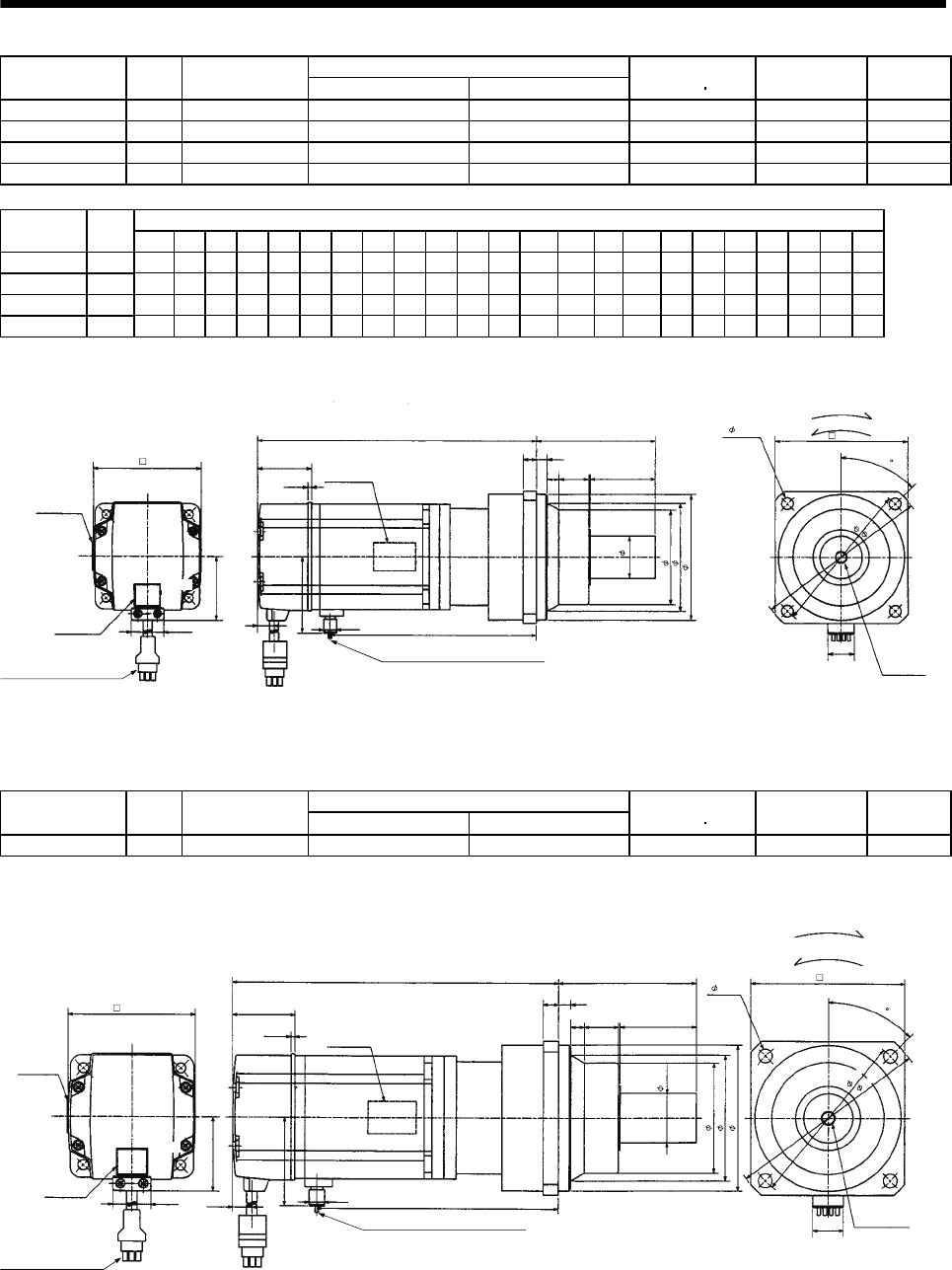
7 - 154
7. OUTLINE DIMENSION DRAWINGS
Reduction Ratio
Model Output
[W]
Reduction Gear
Model Normal Reduction ratio Actual Reduction Ratio
Inertia Moment
WK2[oz in2]Backlash Mass
[lb]
HC-MF43G1 400 K10020 1/20 253/5000 3.57 60min. max. 12.13
HC-MF73G1 750 K10005 1/5 1/5 5.58 60min. max. 13.67
HC-MF73G1 750 K10012 1/12 525/6048 9.22 60min. max. 16.09
HC-MF73G1 750 K12020 1/20 625/12544 9.57 60min. max. 22.27
Variable Dimensions [in]
Model Output
[W] D LH LK LT H LA LB LC LD LE LF LG LM LN LP L LR KL LZ Q S P R
HC-MF43G1 400 2.362 1.50 1.61 0.42 1.69 4.53 3.74 5.20 3.94 0.39 2.87 0.39 0.512 0.63 3.39 7.933 3.54 5.87 0.35 1.97 1.26 M8 0.63
HC-MF73G1 750 3.15 1.89 1.54 0.43 2.29 4.53 3.74 5.20 3.94 0.39 2.87 0.39 0.512 0.63 3.39 8.15 3.54 5.97 0.35 1.97 1.26 M8 0.63
HC-MF73G1 750 3.15 1.89 1.54 0.43 2.29 4.53 3.74 5.20 3.94 0.39 2.87 0.39 0.512 0.63 3.39 9.016 3.54 6.84 0.35 1.97 1.26 M8 0.63
HC-MF73G1 750 3.15 1.89 1.54 0.43 2.29 5.51 4.53 6.38 4.72 0.47 3.54 0.59 0.512 0.787 4.09 9.528 4.17 7.35 0.55 2.36 1.57 M10 0.79
LD
4- LZ
Top
Bottom
BC12070*
P threads,
depth R
LC
"Rotation direction" For forward rotation command
For reverse rotation command
Power supply lead 4-AWG19 11.8in
(With end-insulated round crimping terminal 1.25-4)
Encoder cable 11.8in
With connector 1-172169-9
(AMP)
Red: Phase U
White: Phase V
Black: Phase W
Green/yellow: Earth
LH
0.992
D
Top
Bottom
Top
Bottom
Motor plate
(Opposite side)
Motor plate
LK
KL
LR
LT
H
0.390
0.106
LG LE
LM LM Q
Sh6
LF
LP
LBh7
0.787
LA
Caution plate
L
[Unit: in]
45
Reduction Ratio
Model Output
[W]
Reduction Gear
Model Normal Reduction ratio Actual Reduction Ratio
Inertia Moment
WK2[oz in2]Backlash Mass
[lb]
HC-KF43G1 400 K10020 1/20 253/5000 5.303 60min. max. 12.13
7.933
0.630
0.394
3.543
P threads,
depth 0.630
1.969
"Rotation direction" For forward rotation command
For reverse rotation command
Power supply lead 4-AWG19 11.8in
(With end-insulated round crimping terminal 1.25-4)
Encoder cable 11.8in
With connector 1-172169-9
(AMP)
Red: Phase U
White: Phase V
Black: Phase W
Green/yellow: Earth
Motor plate
(Opposite side)
Motor plate
Caution plate
Top
Bottom
Top
Bottom
5.870
3.740
3.386
2.874
1.260
4- 0.354
3.937
Top
Bottom
BC12090*
0.787
1.614
2.441
0.106
0.417
0.992
1.512
1.685
0.390
0.394
4.528
5.197
[Unit: in]
0.512
45
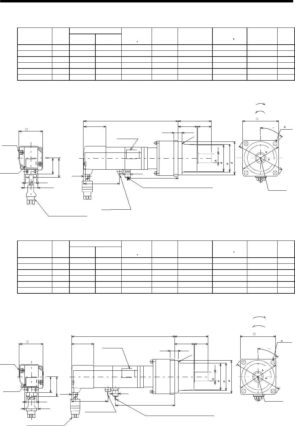
7 - 155
7. OUTLINE DIMENSION DRAWINGS
(b) With electromagnetic brake
Variable Dimensions [in]
Model Output
[W] LKL
Brake static
friction torque
[oz in]
Reduction
Gear Model
Reduction Ratio
(Actual
Reduction Ratio)
Inertia Moment
WK2[oz in2]Backlash Mass
[lb]
HC-MF053BG1 50 6.06 2.91 45 K6505 1/5(9/44) 0.32 60min. max. 4.0
HC-MF053BG1 50 6.77 3.62 45 K6512 1/12(49/576) 0.44 60min. max. 4.9
HC-MF053BG1 50 6.77 3.62 45 K6520 1/20(25/484) 0.34 60min. max. 4.9
HC-KF053BG1 50 6.02 2.91 45 K6505 1/5(9/44) 0.51 60min. max. 4.0
HC-KF053BG1 50 6.77 3.62 45 K6512 1/12(49/576) 0.63 60min. max. 4.9
HC-KF053BG1 50 6.77 3.62 45 K6520 1/20(25/484) 0.53 60min. max. 4.9
Power supply lead 4-AWG19 11.8in
(With end-insulated round crimping terminal 1.25-4)
Red: Phase U
White: Phase V
Black: Phase W
Green/yellow: Earth
BC12071A
(BC12091A)
4- 0.276
Motor plate
Caution plate
Bottom
Top
1.654
0.787
1.130
With connector 1-172169-9
(
AMP
)
Motor plate
(Opposite side)
2.579
KL
0.315 0.256
2.382
Bottom
Top
1.594
0.268
"Rotation direction"
For forward rotation command
For reverse rotation command
M4 threads,
depth 0.315
L
0.984
1.890
2.559
1.358
2.953
3.465
45
Encoder cable 11.8in
1.406
0.992
2.362
(R4)
0.390
Brake lead
2-0.3 11.8in
2
(With end-insulated round crimping terminal 1.25-4)
[Unit: in]
Bottom
Top
( 1.969)
0.630
Variable Dimensions [in]
Model Output
[W] LKL
Brake static
friction torque
[oz in]
Reduction
Gear Model
Reduction Ratio
(Actual
Reduction Ratio)
Inertia Moment
WK2[oz in2]Backlash Mass
[lb]
HC-MF13BG1 100 6.65 3.43 45 K6505 1/5(9/44) 0.38 60min. max. 4.2
HC-MF13BG1 100 7.36 4.21 45 K6512 1/12(49/576) 0.50 60min. max. 5.1
HC-MF13BG1 100 7.36 4.21 45 K6520 1/20(25/484) 0.40 60min. max. 5.1
HC-KF13BG1 100 6.65 3.43 45 K6505 1/5(9/44) 0.68 60min. max. 4.2
HC-KF13BG1 100 7.36 4.21 45 K6512 1/12(49/576) 0.80 60min. max. 5.1
HC-KF13BG1 100 7.36 4.21 45 K6520 1/20(25/484) 0.7 60min. max. 5.1
Power supply lead 4-AWG19 11.8in
Red: Phase U
White: Phase V
Black: Phase W
Green/
y
ellow: Earth
(With end-insulated round crimping terminal 1.25-4)
BC12072A
(BC12092A)
Motor plate
(Opposite side)
L
Top
Bottom
"Rotation direction"
For forward rotation command
For reverse rotation command
Encoder cable 11.8in
With connector 1-172169-9
(AMP)
Brake lead
2-0.3 11.8in
2
(With end-insulated round crimping
terminal 1.25-4)
Caution plate
Top
Bottom
0.390
2.579
KL
1.594
1.654
0.268
0.787
1.130
0.315 0.256
2.382
0.984
0.630
1.890
2.362
1.358
M4 threads,
depth 0.315
4- 10.276
2.559
2.953
3.465
[Unit: in]
45
Motor plate
1.406
0.992
(R4)
Bottom
Top
( 1.969)
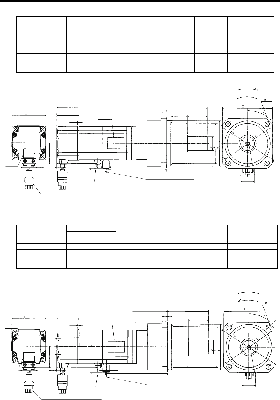
7 - 156
7. OUTLINE DIMENSION DRAWINGS
Variable Dimensions [in]
Model Output
[W] LKL
Reduction
Gear Model
Reduction Ratio
(Actual Reduction Ratio)
Inertia Moment
WK2[oz in2]
Mass
[lb]
Brake static
friction torque
[oz in]
HC-MF23BG1 200 6.65 4.04 K9005 1/5(19/96) 1.58 8.6 184
HC-MF23BG1 200 7.36 4.23 K9012 1/12(25/288) 1.82 9.9 184
HC-MF23BG1 200 7.36 4.23 K9020 1/20(253/5000) 1.67 9.9 184
HC-KF23BG1 200 6.65 4.04 K9005 1/5(19/96) 2.569 8.6 184
HC-KF23BG1 200 7.36 4.23 K9012 1/12(25/288) 2.843 9.9 184
HC-KF23BG1 200 7.36 4.23 K9020 1/20(253/5000) 2.679 9.9 184
Motor plate
(Opposite side)
L
Top
Bottom
Encoder cable 11.8in
With connector 1-172169-9
(
AMP
)
Brake lead 2-0.3 11.8in
(With end-insulated round
crimping terminal 1.25-4)
2Power supply lead 4-AWG19 11.8in
(With end-insulated round crimping terminal 1.25-4)
Red: Phase U
White: Phase V
Black: Phase W
Green/yellow: Earth
BC12073*
(BC120793*)
Top
Bottom
Top
Bottom
Caution plate 0.390 KL
"Rotation direction"
For forward rotation command
For reverse rotation command
2.677
1.614
2.441
0.106
0.417
0.992
1.512
1.685
0.394 0.315
2.913
1.378
0.984
2.874
3.228
1.181
M6 threads, depth
0.472
4- 0.354
0.787
3.543
3.937
4.488
[Unit: in]
45
Motor plate
Variable Dimensions [in]
Model Output
[W] LKL
Brake static
friction torque
[oz in]
Reduction
Gear Model
Reduction Ratio
(Actual Reduction Ratio)
Inertia Moment
WK2[oz in2]
Mass
[lb]
HC-MF43BG1 400 8.27 4.95 184 K9005 1/5(19/96) 1.88 9.7
HC-MF43BG1 400 9.06 5.73 184 K9012 1/12(25/288) 2.12 11.0
HC-KF43BG1 400 8.27 4.95 184 K9005 1/5(19/96) 3.609 9.7
HC-KF43BG1 400 9.06 5.73 184 K9012 1/12(25/288) 3.882 11.0
Motor plate
(Opposite side)
Top
Bottom
"Rotation direction"
For forward rotation command
For reverse rotation command
(BC12094*)
BC12074*
L
Power supply lead 4-AWG19 11.8in
(With end-insulated round crimping terminal 1.25-4)
Red: Phase U
White: Phase V
Black: Phase W
Green/yellow: Earth
Brake lead 2-0.3 11.8in
(With end-insulated round
crimping terminal 1.25-4)
2
Encoder cable 11.8in
With connector 1-172169-9
(
AMP
)
Caution plate
Top
Bottom
Top
Bottom
KL
2.677
1.614
2.441
0.106
0.417
0.992
1.512
0.394 0.315
2.913
1.378
0.984
2.874
3.228
1.181
M6 threads,
depth
0.472
4- 0.354
0.787
3.543
3.937
4.488
1.685
0.390
[Unit: in]
45
Motor plate
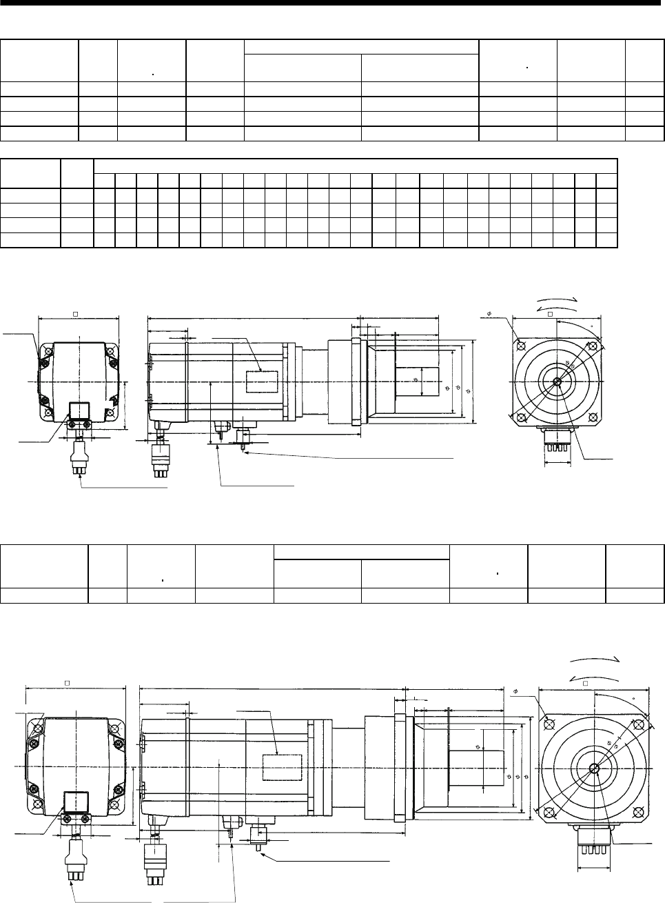
7 - 157
7. OUTLINE DIMENSION DRAWINGS
Reduction Ratio
Model Output
[W]
Brake static
friction torque
[oz in]
Reduction
Gear Model Normal Reduction ratio Actual Reduction Ratio
Inertia Moment
WK2[oz in2]Backlash Mass
[lb]
HC-MF43BG1 400 184 K10020 1/20 253/5000 3.83 60min. max. 13.4
HC-MF73BG1 750 340 K10005 1/5 1/5 6.26 60min. max. 15.9
HC-MF73BG1 750 340 K10012 1/12 525/6048 9.90 60min. max. 18.3
HC-MF73BG1 750 340 K12020 1/20 625/12544 10.25 60min. max. 25.8
Variable Dimensions [in]
Model Output
[W] D LH LK LT LX H LA LB LC LD LE LF LG LM LN LP L LR KL LZ Q S P R
HC-MF43BG1 400 2.44 1.51 1.64 0.14 2.68 1.69 4.53 3.74 5.20 3.94 0.39 2.87 0.39 0.512 0.63 3.39 9.19 3.54 5.87 0.35 1.97 1.26 M8 0.63
HC-MF73BG1 750 3.23 1.92 1.54 0.43 2.84 1.69 4.53 3.74 5.20 3.94 0.39 2.87 0.39 0.512 0.63 3.39 9.55 3.54 5.92 0.35 1.97 1.26 M8 0.63
HC-MF73BG1 750 3.23 1.92 1.54 0.43 2.84 1.69 4.53 3.74 5.20 3.94 0.39 2.87 0.39 0.512 0.63 3.39 10.41 3.54 6.84 0.35 1.97 1.26 M8 0.63
HC-MF73BG1 750 3.23 1.92 1.54 0.43 2.84 1.69 5.51 4.53 6.38 4.72 0.47 3.54 0.59 0.512 0.787 4.09 10.93 4.17 7.35 0.55 2.36 1.57 M10 0.79
Motor plate
(Opposite side) LN
LE
LG
Top
Bottom
LM
LR
P threads,
depth R
Q
Sh6
"Rotation direction" For forward rotation command
For reverse rotation command
Brake lead 2-0.3 11.8in
(With end-insulated round
crimping terminal 1.25-4)
Encoder cable 11.8in
With connector 1-172169-9
(AMP)
Power supply lead 4-AWG19 11.8in
(With end-insulated round crimping terminal 1.25-4)
2Red: Phase U
White: Phase V
Black: Phase W
Green/yellow: Earth
4- LZ LD
LC
LA
0.787
LF
LBh7
LP
Top
Bottom
Motor plate
Caution plate
D
LK
0.106
L
0.992
LH
LT LX
H
0.390
KL
Top
Bottom
BC12075*
[Unit: in]
45
Reduction Ratio
Model Output
[W]
Brake static
friction torque
[oz in]
Reduction
Gear Model Normal
Reduction ratio
Actual
Reduction Ratio
Inertia Moment
WK2[oz in2]Backlash Mass
[lb]
HC-KF43BG1 400 184 K10020 1/20 253/5000 5.577 60min. max. 13.4
Motor plate
(Opposite side)
Top
Bottom
8 threads,
depth 0.630
"Rotation direction"
For forward rotation command
For reverse rotation command
(With end-insulated round
crim
p
in
g
terminal 1.25-4
)
Encoder cable 11.8in
With connector 1-172169-9
(
AMP
)
Power supply lead 4-AWG19 11.8in
(With end-insulated round crimping terminal 1.25-4)
Brake lead 2-0.3 11.8in
2
Red: Phase U
White: Phase V
Black: Phase W
Green/yellow: Earth
4- 0.354
0.787
Bottom
3.937
Top
Bottom
9.193
Caution plate 2.677 5.870
BC12095*
1.614
2.441
0.106
0.417
0.992
1.512
1.685
0.390
0.394
3.543
1.969
2.874
3.386
3.740
0.394
0.630
0.512
4.528
[Unit: in]
5.197
Top
1.260
45
Motor plate
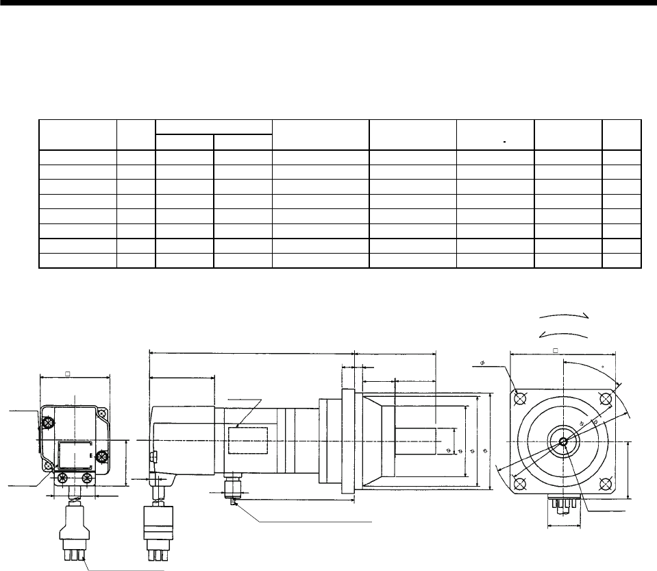
7 - 158
7. OUTLINE DIMENSION DRAWINGS
(4) With reduction gear for precision application
The outer frame of the reduction gear is a material surface such as casting. Its actual dimensions may
be 0.039 to 0.118 in larger than the drawing dimensions. Design the machine side with allowances.
(a) Without electromagnetic brake
Variable Dimensions [in]
Model Output
[W] LKL
Reduction Gear
Model Reduction Ratio Inertia Moment
WK2[oz in2]Backlash Mass
[lb]
HC-MF053G2 50 5.12 3.07 BK1-05B-A5MEKA 1/5 0.36 3 min. max. 3.1
HC-MF053G2 50 5.75 3.70 BK1-09B-A5MEKA 1/9 0.33 3 min. max. 3.7
HC-MF053G2 50 5.75 3.70 BK1-20B-A5MEKA 1/20 0.38 3 min. max. 4.0
HC-MF053G2 50 5.75 3.70 BK1-29B-A5MEKA 1/29 0.31 3 min. max. 4.0
HC-KF053G2 50 5.12 3.07 BK1-05B-A5MEKA 1/5 0.55 3 min. max. 3.1
HC-KF053G2 50 5.75 3.70 BK1-09B-A5MEKA 1/9 0.52 3 min. max. 3.7
HC-KF053G2 50 5.75 3.70 BK1-20B-A5MEKA 1/20 0.57 3 min. max. 4.0
HC-KF053G2 50 5.75 3.70 BK1-29B-A5MEKA 1/29 0.50 3 min. max. 4.0
Motor plate
(Opposite side)
L
Top
Bottom
M4 threads,
depth 0.315
"Rotation direction"
For forward rotation command
For reverse rotation command
Power supply lead 4-AWG19 0.3m11.8in
(With end-insulated round crimping terminal 1.25-4)
Encoder cable 11.8in
With connector 172169-9
(
AMP
)
Red: Phase U
White: Phase V
Black: Phase W
Green/yellow: Earth
Top
Bottom
2.756
4- 0.260
BC12076*
(BC12096*)
Motor plate
Caution plate
KL
0.390
0.787
1.594
1.654
0.268
0.992
1.130
0.315 0.256
2.382
0.984
0.630
1.890
2.362
0.906
2.559
3.150
3.740
[Unit: in]
1.406
Top
Bottom
45
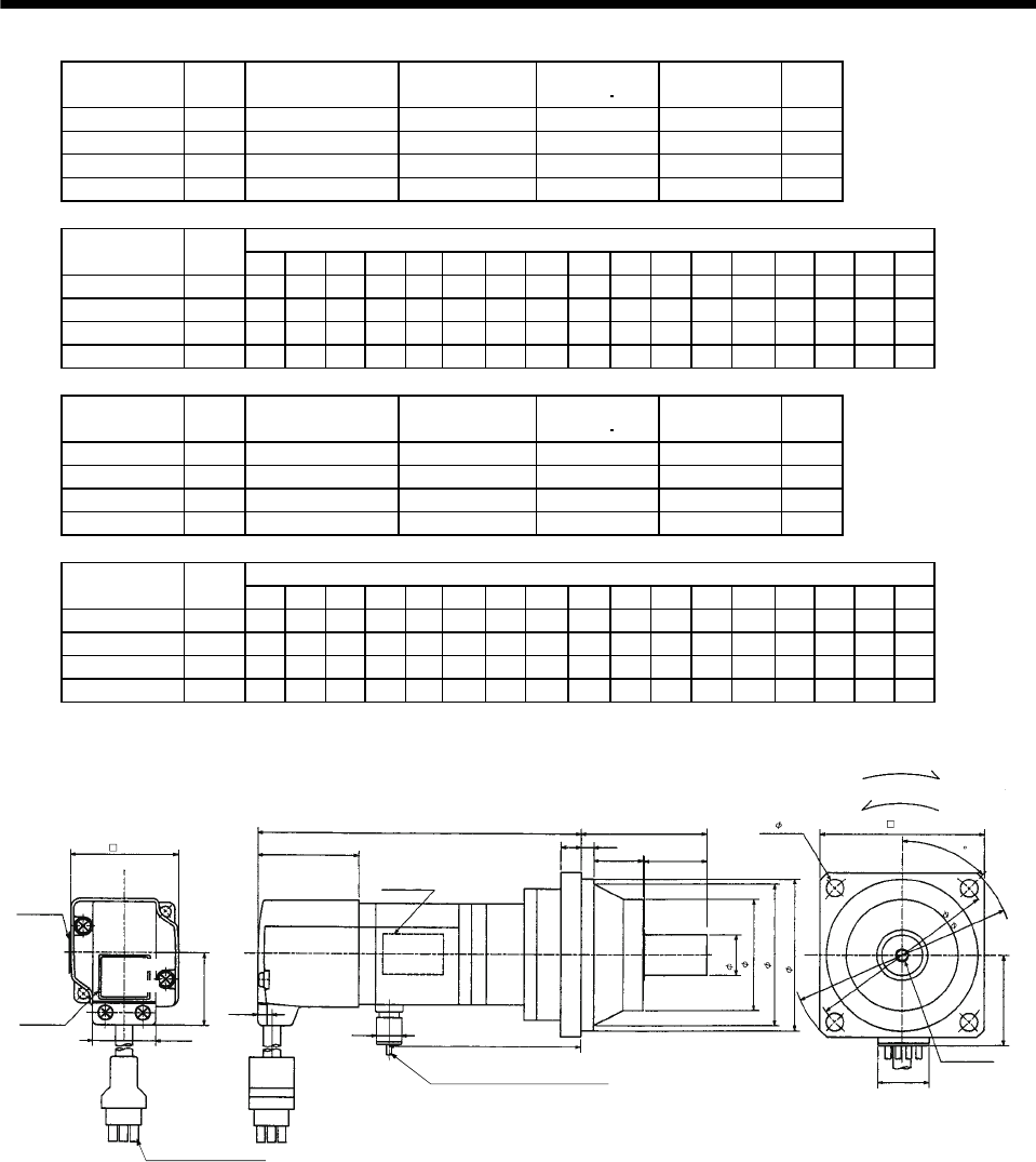
7 - 159
7. OUTLINE DIMENSION DRAWINGS
Model Output
[W]
Reduction Gear
Model Reduction Ratio Inertia Moment
WK2[oz in2]Backlash Mass
[lb]
HC-MF13G2 100 BK1-05B-01MEKA 1/5 0.43 3 min. max. 3.3
HC-MF13G2 100 BK1-09B-01MEKA 1/9 0.39 3 min. max. 4.0
HC-MF13G2 100 BK2-20B-01MEKA 1/20 0.66 3 min. max. 6.6
HC-MF13G2 100 BK2-29B-01MEKA 1/29 0.52 3 min. max. 6.6
Variable Dimensions [in]
Model Output
[W] LA LB LC LD LE LF LG LH LK L LR KL LZ Q S P R
HC-MF13G2 100 3.15 2.56 3.74 2.76 0.24 1.89 0.31 2.362 0.906 5.71 2.17 3.66 0.26 0.98 0.63 M4 0.31
HC-MF13G2 100 3.15 2.56 3.74 2.76 0.24 1.89 0.31 2.362 0.906 6.34 2.17 4.29 0.26 0.98 0.63 M4 0.31
HC-MF13G2 100 3.94 3.15 4.53 3.35 0.24 2.559 0.39 2.913 1.299 6.57 2.95 4.53 0.26 1.38 0.79 M5 0.39
HC-MF13G2 100 3.94 3.15 4.53 3.35 0.24 2.559 0.39 2.913 1.299 6.57 2.95 4.53 0.26 1.38 0.79 M5 0.39
Model Output
[W]
Reduction Gear
Model Reduction Ratio Inertia Moment
WK2[oz in2]Backlash Mass
[lb]
HC-KF13G2 100 BK1-05B-01MEKA 1/5 0.72 3 min. max. 3.3
HC-KF13G2 100 BK1-09B-01MEKA 1/9 0.69 3 min. max. 4.0
HC-KF13G2 100 BK2-20B-01MEKA 1/20 0.96 3 min. max. 6.6
HC-KF13G2 100 BK2-29B-01MEKA 1/29 0.82 3 min. max. 6.6
Variable Dimensions [in]
Model Output
[W] LA LB LC LD LE LF LG LH LK L LR KL LZ Q S P R
HC-KF13G2 100 3.15 2.56 3.74 2.76 0.24 1.89 0.31 2.362 0.906 5.71 2.17 3.66 0.26 0.98 0.63 M4 0.31
HC-KF13G2 100 3.15 2.56 3.74 2.76 0.24 1.89 0.31 2.362 0.906 6.34 2.17 4.29 0.26 0.98 0.63 M4 0.31
HC-KF13G2 100 3.94 3.15 4.53 3.35 0.24 2.559 0.39 2.913 1.299 6.57 2.95 4.53 0.26 1.38 0.79 M5 0.39
HC-KF13G2 100 3.94 3.15 4.53 3.35 0.24 2.559 0.39 2.913 1.299 6.57 2.95 4.53 0.26 1.38 0.79 M5 0.39
Motor plate
(Opposite side)
0.390
LELG
LF
LH
LD
4- LZ
Top
Bottom
LBh7
LK
P threads,
depth R
Q
Sh6
"Rotation direction"
For forward rotation command
For reverse rotation command
Encoder cable 11.8in
With connector 1-172169-9
(
AMP
)
Power supply lead 4-AWG19 118in
(With end-insulated round crimping terminal 1.25-4)
LR
Red: Phase U
White: Phase V
Black: Phase W
Green/yellow: Earth
Motor plate
Caution plate
KL
0.787
LA
LC
Top
Bottom
Top
Bottom
L
BC12077*
(BC12097*)
1.406
1.594
1.654
0.268
0.992
1.130
[Unit: in]
45
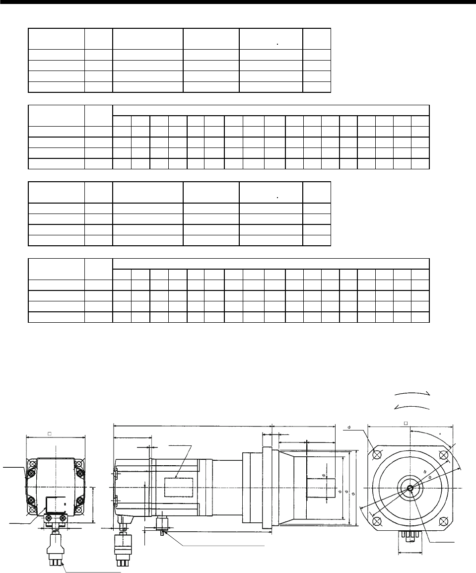
7 - 160
7. OUTLINE DIMENSION DRAWINGS
Model Output
[W]
Reduction Gear
Model Reduction Ratio Inertia Moment
WK2[oz in2]
Mass
[lb]
HC-MF23G2 200 BK1-05B-02MEKA 1/5 1.04 4.6
HC-MF23G2 200 BK2-09B-02MEKA 1/9 1.14 7.7
HC-MF23G2 200 BK3-20B-02MEKA 1/20 1.95 11.0
HC-MF23G2 200 BK3-29B-02MEKA 1/29 1.51 11.0
Variable Dimensions [in]
Model Output
[W] LA LB LC LD LE LF LG LH LK L LR KL LZ Q S P R
HC-MF23G2 200 3.15 2.56 3.74 2.76 0.24 1.89 0.31 2.362 0.906 6.18 2.17 4.20 0.26 0.98 0.63 M4 0.31
HC-MF23G2 200 3.94 3.15 4.53 3.35 0.24 2.559 0.39 2.913 1.299 6.89 2.95 4.91 0.26 1.38 0.79 M5 0.39
HC-MF23G2 200 4.53 3.74 5.31 3.94 0.31 2.953 0.39 3.346 1.378 7.09 3.35 5.10 0.35 1.57 0.98 M6 0.47
HC-MF23G2 200 4.53 3.74 5.31 3.94 0.31 2.953 0.39 3.346 1.378 7.09 3.35 5.10 0.35 1.57 0.98 M6 0.47
Model Output
[W]
Reduction Gear
Model Reduction Ratio Inertia Moment
WK2[oz in2]
Mass
[lb]
HC-KF23G2 200 BK1-05B-02MEKA 1/5 1.968 4.6
HC-KF23G2 200 BK2-09B-02MEKA 1/9 2.078 7.7
HC-KF23G2 200 BK3-20B-02MEKA 1/20 2.898 11.0
HC-KF23G2 200 BK3-29B-02MEKA 1/29 2.460 11.0
Variable Dimensions [in]
Model Output
[W] LA LB LC LD LE LF LG LH LK L LR KL LZ Q S P R
HC-KF23G2 200 3.15 2.56 3.74 2.76 0.24 1.89 0.31 2.362 0.906 6.18 2.17 4.20 0.26 0.98 0.63 M4 0.31
HC-KF23G2 200 3.94 3.15 4.53 3.35 0.24 2.559 0.39 2.913 1.299 6.89 2.95 4.91 0.26 1.38 0.79 M5 0.39
HC-KF23G2 200 4.53 3.74 5.31 3.94 0.31 2.953 0.39 3.346 1.378 7.09 3.35 5.10 0.35 1.57 0.98 M6 0.47
HC-KF23G2 200 4.53 3.74 5.31 3.94 0.31 2.953 0.39 3.346 1.378 7.09 3.35 5.10 0.35 1.57 0.98 M6 0.47
LELG
LD
Top
Bottom
LK
LR
P threads,
depth R
Q
LA
LC
"Rotation direction" For forward rotation command
For reverse rotation command
Power supply lead 4-AWG19 11.8in
Encoder cable 11.8in
With connector 1-172169-9
(
AMP
)
Red: Phase U
White: Phase V
Black: Phase W
Green/yellow: Earth
(With end-insulated round crimping terminal 1.25-4)
Motor plate
(Opposite side)
Top
Bottom
L
Sh6
LF
LH
LBh7
KL
Motor plate
Caution plate
Top
Bottom
4- LZ
BC12078*
(BC12098*)
0.787
1.614
2.441
0.106
0.417
0.992
1.512
1.685
0.390
[Unit: in]
45
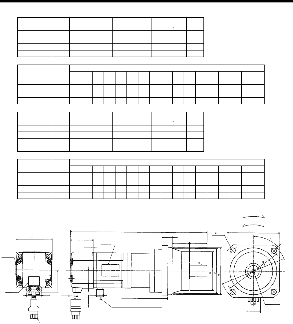
7 - 161
7. OUTLINE DIMENSION DRAWINGS
Model Output
[W]
Reduction Gear
Model Reduction Ratio Inertia Moment
WK2[oz in2]
Mass
[lb]
HC-MF43G2 400 BK2-05B-04MEKA 1/5 1.61 8.2
HC-MF43G2 400 BK3-09B-04MEKA 1/9 1.77 11.7
HC-MF43G2 400 BK4-20B-04MEKA 1/20 2.33 16.5
HC-MF43G2 400 BK4-29B-04MEKA 1/29 1.85 16.5
Variable Dimensions [in]
Model Output
[W] LA LB LC LD LE LF LG LH LK L LR KL LZ Q S P R
HC-MF43G2 400 3.94 3.15 4.53 3.35 0.24 2.56 0.39 2.91 1.3 7.24 2.95 5.18 0.26 1.38 0.79 M5 0.39
HC-MF43G2 400 4.53 3.74 5.32 3.94 0.31 2.95 0.39 3.35 1.38 8.07 3.35 6.01 0.35 1.58 0.98 M6 0.47
HC-MF43G2 400 5.32 3.94 6.10 4.53 0.31 3.54 0.47 3.94 1.58 8.31 3.94 6.24 0.43 1.97 1.26 M8 0.63
HC-MF43G2 400 5.32 4.33 6.10 4.53 0.31 3.54 0.47 3.94 1.58 8.31 3.94 6.24 0.43 1.97 1.26 M8 0.63
Model Output
[W]
Reduction Gear
Model Reduction Ratio Inertia Moment
WK2[oz in2]
Mass
[lb]
HC-KF43G2 400 BK2-05B-04MEKA 1/5 3.335 8.2
HC-KF43G2 400 BK3-09B-04MEKA 1/9 3.499 11.7
HC-KF43G2 400 BK4-20B-04MEKA 1/20 4.046 16.5
HC-KF43G2 400 BK4-29B-04MEKA 1/29 3.609 16.5
Variable Dimensions [in]
Model Output
[W] LA LB LC LD LE LF LG LH LK L LR KL LZ Q S P R
HC-KF43G2 400 3.94 3.15 4.53 3.35 0.24 2.56 0.39 2.91 1.3 7.24 2.95 5.18 0.26 1.38 0.79 M5 0.39
HC-KF43G2 400 4.53 3.74 5.32 3.94 0.31 2.95 0.39 3.35 1.38 8.07 3.35 6.01 0.35 1.58 0.98 M6 0.47
HC-KF43G2 400 5.32 3.94 6.10 4.53 0.31 3.54 0.47 3.94 1.58 8.31 3.94 6.24 0.43 1.97 1.26 M8 0.63
HC-KF43G2 400 5.32 4.33 6.10 4.53 0.31 3.54 0.47 3.94 1.58 8.31 3.94 6.24 0.43 1.97 1.26 M8 0.63
Motor plate
(Opposite side)
LE
LG
LD
4- LZ
Top
Bottom
LK
LR
P threads,
depth R
Q
Sh6
LA
LC
"Rotation direction"
For forward rotation command
For reverse rotation command
Power supply lead 4-AWG19 11.8in
(With end-insulated round crimping terminal 1.25-4)
Encoder cable 11.8in
With connector 1-172169-9
(
AMP
)
Red: Phase U
White: Phase V
Black: Phase W
Green/yellow: Earth
Motor plate
Caution plate
LF
LH
LBh7
Top
Bottom
Top
Bottom
L
KL
0.787
(BC12099*)
1.614
2.441
0.106
0.417
0.992
1.512
1.685
0.390
BC12079*
[Unit: in]
45
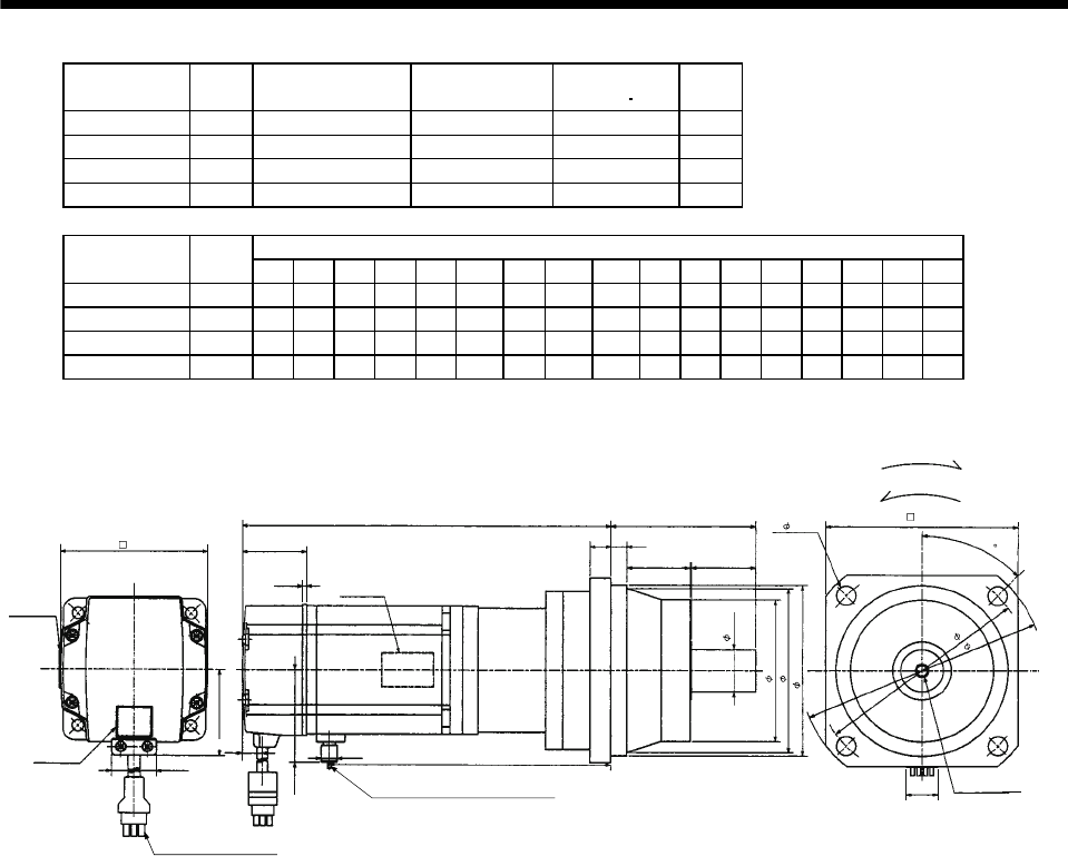
7 - 162
7. OUTLINE DIMENSION DRAWINGS
Model Output
[W]
Reduction Gear
Model Reduction Ratio Inertia Moment
WK2[oz in2]
Mass
[lb]
HC-MF73G2 750 BK3-05B-08MEKA 1/5 5.32 13.89
HC-MF73G2 750 BK4-09B-08MEKA 1/9 5.36 18.96
HC-MF73G2 750 BK5-20B-08MEKA 1/20 5.55 26.46
HC-MF73G2 750 BK5-29B-08MEKA 1/29 4.97 26.46
Variable Dimensions [in]
Model Output
[W] LA LB LC LD LE LF LG LH LK L LR KL LZ Q S P R
HC-MF73G2 750 4.53 3.74 5.31 3.94 0.31 2.953 0.39 3.346 1.378 8.35 3.35 6.17 0.35 1.57 0.98 M6 0.47
HC-MF73G2 750 5.31 4.33 6.10 4.53 0.31 3.543 0.47 3.937 1.575 9.76 3.94 7.27 0.43 1.97 1.26 M8 0.63
HC-MF73G2 750 5.91 4.92 6.89 5.12 0.39 4.134 0.59 4.528 1.693 9.76 4.53 7.59 0.55 2.36 1.57 M10 0.79
HC-MF73G2 750 5.91 4.92 6.89 5.12 0.39 4.134 0.59 4.528 1.693 9.76 4.53 7.59 0.55 2.36 1.57 M10 0.79
Motor plate
(Opposite side)
KL
LE
LG
LF
LH
LD
4- LZ
Top
Bottom
LBh7
LK
LR
P threads,
depth R
Q
Sh6
LA
LC
"Rotation direction" For forward rotation command
For reverse rotation command
Power supply lead 4-AWG19 11.8in
Encoder cable 11.8in
With connector 1-172169-9
(AMP)
Red: Phase U
White: Phase V
Black: Phase W
Green/yellow: Earth
Motor plate
Caution plate
Top
Bottom
Top
Bottom
(With end-insulated round crimping terminal 1.25-4)
0.787
BC12080*
L
1.535
3.228
0.106
0.992
1.917
0.433 0.390
2.287
[Unit: in]
45
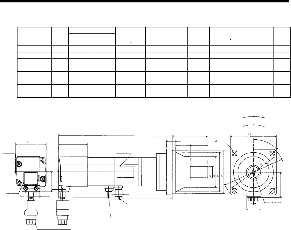
7 - 163
7. OUTLINE DIMENSION DRAWINGS
(b) With electromagnetic brake
Variable Dimensions [in]
Model Output
[W] LKL
Brake static
friction torque
[oz in]
Reduction Gear
Model
Reduction
Ratio
Inertia Moment
WK2[oz in2]Backlash Mass
[lb]
HC-MF053BG2 50 6.22 3.07 45 BK1-05B-A5MEKA 1/5 0.38 3 min. max. 4.0
HC-MF053BG2 50 6.85 3.70 45 BK1-09B-A5MEKA 1/9 0.34 3 min. max. 4.6
HC-MF053BG2 50 6.85 3.70 45 BK1-20B-A5MEKA 1/20 0.39 3 min. max. 4.9
HC-MF053BG2 50 6.85 3.70 45 BK1-29B-A5MEKA 1/29 0.33 3 min. max. 4.9
HC-KF053BG2 50 6.22 3.07 45 BK1-05B-A5MEKA 1/5 0.57 3 min. max. 4.0
HC-KF053BG2 50 6.85 3.70 45 BK1-09B-A5MEKA 1/9 0.54 3 min. max. 4.6
HC-KF053BG2 50 6.85 3.70 45 BK1-20B-A5MEKA 1/20 0.59 3 min. max. 4.9
HC-KF053BG2 50 6.85 3.70 45 BK1-29B-A5MEKA 1/29 0.52 3 min. max. 4.9
Motor plate
(Opposite side)
Top
Bottom
"Rotation direction"
For forward rotation command
For reverse rotation command
Power supply lead 4-AWG19 11.8in
(With end-insulated round crimping terminal 1.25-4)
Encoder cable 11.8in
With connector 172169-9
(
AMP
)
Brake lead
2-0.3 11.8in
(With end-insulated round
crimping terminal 1.25-4)
Blue: B1,B2
2
Red: Phase U
White: Phase V
Black: Phase W
Green/yellow: Earth
Motor plate
L
Caution plate
Top
Bottom
Top
Bottom
2.579 0.390
KL
(BC12100*)
BC12081*
1.594
1.654
0.268
0.992
1.130
0.315 0.256
2.382
0.984
1.102
0.630
1.890
2.362
2.559
M4 threads,
depth
0.315
2.756
0.787
1.406
3.150
3.740
4- 0.260
[Unit: in]
45
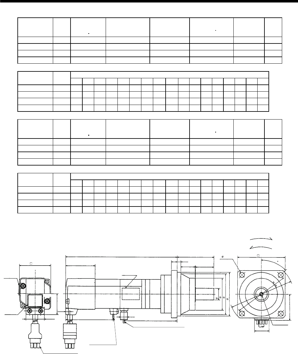
7 - 164
7. OUTLINE DIMENSION DRAWINGS
Model Output
[W]
Brake static
friction torque
[oz in]
Reduction Gear
Model Reduction Ratio Inertia Moment
WK2[oz in2]Backlash Mass
[lb]
HC-MF13BG2 100 45 BK1-05B-01MEKA 1/5 0.44 3 min. max. 4.2
HC-MF13BG2 100 45 BK1-09B-01MEKA 1/9 0.40 3 min. max. 4.9
HC-MF13BG2 100 45 BK2-20B-01MEKA 1/20 0.68 3 min. max. 7.5
HC-MF13BG2 100 45 BK2-29B-01MEKA 1/29 0.53 3 min. max. 7.5
Variable Dimensions [in]
Model Output
[W] LA LB LC LD LE LF LG LH LK L LR KL LZ Q S P R
HC-MF13BG2 100 3.15 2.56 3.74 2.76 0.24 1.89 0.31 2.362 0.906 6.81 2.17 3.66 0.26 0.98 0.63 M4 0.31
HC-MF13BG2 100 3.15 2.56 3.74 2.76 0.24 1.89 0.31 2.362 0.906 7.44 2.17 4.29 0.26 0.98 0.63 M4 0.31
HC-MF13BG2 100 3.94 3.15 4.53 3.35 0.24 2.559 0.39 2.913 1.299 7.68 2.95 4.53 0.26 1.38 0.79 M5 0.39
HC-MF13BG2 100 3.94 3.15 4.53 3.35 0.24 2.559 0.39 2.913 1.299 7.68 2.95 4.53 0.26 1.38 0.79 M5 0.39
Model Output
[W]
Brake static
friction torque
[oz in]
Reduction Gear
Model Reduction Ratio Inertia Moment
WK2[oz in2]Backlash Mass
[lb]
HC-KF13BG2 100 45 BK1-05B-01MEKA 1/5 0.74 3 min. max. 4.2
HC-KF13BG2 100 45 BK1-09B-01MEKA 1/9 0.71 3 min. max. 4.9
HC-KF13BG2 100 45 BK2-20B-01MEKA 1/20 0.98 3 min. max. 7.5
HC-KF13BG2 100 45 BK2-29B-01MEKA 1/29 0.84 3 min. max. 7.5
Variable Dimensions [in]
Model Output
[W] LA LB LC LD LE LF LG LH LK L LR KL LZ Q S P R
HC-KF13BG2 100 3.15 2.56 3.74 2.76 0.24 1.89 0.31 2.362 0.906 6.81 2.17 3.66 0.26 0.98 0.63 M4 0.31
HC-KF13BG2 100 3.15 2.56 3.74 2.76 0.24 1.89 0.31 2.362 0.906 7.44 2.17 4.29 0.26 0.98 0.63 M4 0.31
HC-KF13BG2 100 3.94 3.15 4.53 3.35 0.24 2.559 0.39 2.913 1.299 7.68 2.95 4.53 0.26 1.38 0.79 M5 0.39
HC-KF13BG2 100 3.94 3.15 4.53 3.35 0.24 2.559 0.39 2.913 1.299 7.68 2.95 4.53 0.26 1.38 0.79 M5 0.39
Motor plate
(Opposite side)
L
LELG
Top
Bottom
LK
LR
P threads,
depth R
Q
"Rotation direction"
For forward rotation command
For reverse rotation command
Power supply lead 4-AWG19 11.8in
(With end-insulated round crimping terminal 1.25-4)
Brake lead
2-0.3 11.8in
(With end-insulated round
crimping terminal 1.25-4)
2
Encoder cable 11.8in
With connector 1-172169-9
(
AMP
)
Red: Phase U
White: Phase V
Black: Phase W
Green/yellow: Earth
Sh6
LF
LH
LBh7
LD
LA
LC
4- LZ
0.787
Motor plate
Caution plate
2.579 KL
(BC12101*)
BC12082*
1.406
Top
Bottom
Top
Bottom
1.594
1.654
0.268
0.992
1.130
[Unit: in]
45
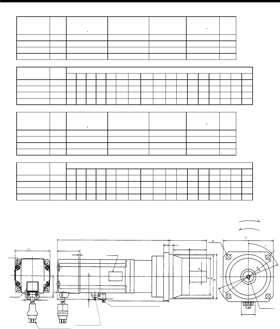
7 - 165
7. OUTLINE DIMENSION DRAWINGS
Model Output
[W]
Brake static
friction torque
[oz in]
Reduction Gear
Model Reduction Ratio Inertia Moment
WK2[oz in2]
Mass
[lb]
HC-MF23BG2 200 184 BK1-05B-02MEKA 1/5 1.31 6.0
HC-MF23BG2 200 184 BK2-09B-02MEKA 1/9 1.40 9.0
HC-MF23BG2 200 184 BK3-20B-02MEKA 1/20 2.21 12.3
HC-MF23BG2 200 184 BK3-29B-02MEKA 1/29 1.77 12.3
Variable Dimensions [in]
Model Output
[W] LA LB LC LD LE LF LG LH LK L LR KL LZ Q S P R
HC-MF23BG2 200 3.15 2.56 3.74 2.76 0.24 1.89 0.31 2.362 0.906 7.44 2.17 4.20 0.26 0.98 0.63 M4 0.31
HC-MF23BG2 200 3.94 3.15 4.53 3.35 0.24 2.559 0.39 2.913 1.299 8.15 2.95 4.91 0.26 1.38 0.79 M5 0.39
HC-MF23BG2 200 4.53 3.74 5.31 3.94 0.31 2.953 0.39 3.346 1.378 8.35 3.35 5.10 0.35 1.57 0.98 M6 0.47
HC-MF23BG2 200 4.53 3.74 5.31 3.94 0.31 2.953 0.39 3.346 1.378 8.35 3.35 5.10 0.35 1.57 0.98 M6 0.47
Model Output
[W]
Brake static
friction torque
[oz in]
Reduction Gear
Model Reduction Ratio Inertia Moment
WK2[oz in2]
Mass
[lb]
HC-KF23BG2 200 184 BK1-05B-02MEKA 1/5 2.242 6.0
HC-KF23BG2 200 184 BK2-09B-02MEKA 1/9 2.351 9.0
HC-KF23BG2 200 184 BK3-20B-02MEKA 1/20 3.171 12.3
HC-KF23BG2 200 184 BK3-29B-02MEKA 1/29 2.734 12.3
Variable Dimensions [in]
Model Output
[W] LA LB LC LD LE LF LG LH LK L LR KL LZ Q S P R
HC-KF23BG2 200 3.15 2.56 3.74 2.76 0.24 1.89 0.31 2.362 0.906 7.44 2.17 4.20 0.26 0.98 0.63 M4 0.31
HC-KF23BG2 200 3.94 3.15 4.53 3.35 0.24 2.559 0.39 2.913 1.299 8.15 2.95 4.91 0.26 1.38 0.79 M5 0.39
HC-KF23BG2 200 4.53 3.74 5.31 3.94 0.31 2.953 0.39 3.346 1.378 8.35 3.35 5.10 0.35 1.57 0.98 M6 0.47
HC-KF23BG2 200 4.53 3.74 5.31 3.94 0.31 2.953 0.39 3.346 1.378 8.35 3.35 5.10 0.35 1.57 0.98 M6 0.47
Motor plate
(Opposite side)
L
LELG
Top
Bottom
LK
LR
P threads,
depth R
Q
"Rotation direction"
For forward rotation command
For reverse rotation command
Power supply lead 4-AWG19 11.8in
(With end-insulated round crimping terminal 1.25-4)
Brake lead
2-0.3 11.8in
(With end-insulated round
crimping terminal 1.25-4)
2
Encoder cable 11.8in
With connector 1-172169-9
(
AMP
)
Red: Phase U
White: Phase V
Black: Phase W
Green/yellow: Earth
Top
Bottom
Sh6
LF
LH
LBh7
LC
LA
0.787
4- LZ
LD
Top
Bottom
Motor plate
Caution plate 2.677 KL
BC12083*
(BC12102*)
1.614
2.441
0.106
0.417
0.992
1.512
1.685
0.390
[Unit: in]
45
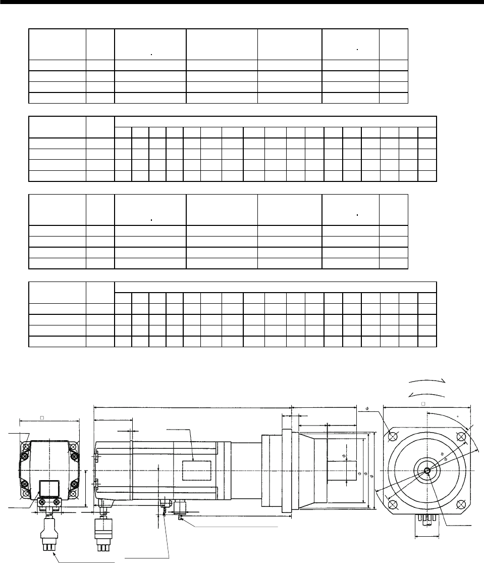
7 - 166
7. OUTLINE DIMENSION DRAWINGS
Model Output
[W]
Brake static
friction torque
[oz in]
Reduction Gear
Model Reduction Ratio Inertia Moment
WK2[oz in2]
Mass
[lb]
HC-MF43BG2 400 184 BK2-05B-04MEKA 1/5 1.88 9.5
HC-MF43BG2 400 184 BK3-09B-04MEKA 1/9 2.03 13.0
HC-MF43BG2 400 184 BK4-20B-04MEKA 1/20 2.59 17.9
HC-MF43BG2 400 184 BK4-29B-04MEKA 1/29 2.11 17.9
Variable Dimensions [in]
Model Output
[W] LA LB LC LD LE LF LG LH LK L LR KL LZ Q S P R
HC-MF43BG2 400 3.94 3.15 4.53 3.35 0.24 2.559 0.39 2.913 1.299 8.50 2.95 5.18 0.26 1.38 0.79 M5 0.39
HC-MF43BG2 400 4.53 3.74 5.31 3.94 0.31 2.953 0.39 3.346 1.378 9.33 3.35 6.01 0.35 1.57 0.98 M6 0.47
HC-MF43BG2 400 5.31 4.33 6.10 4.53 0.31 3.543 0.47 3.937 1.575 9.57 3.94 6.24 0.43 1.97 1.26 M8 0.63
HC-MF43BG2 400 5.31 4.33 6.10 4.53 0.31 3.543 0.47 3.937 1.575 9.57 3.94 6.24 0.43 1.97 1.26 M8 0.63
Model Output
[W]
Brake static
friction torque
[oz in]
Reduction Gear
Model Reduction Ratio Inertia Moment
WK2[oz in2]
Mass
[lb]
HC-KF43BG2 400 184 BK2-05B-04MEKA 1/5 3.609 9.5
HC-KF43BG2 400 184 BK3-09B-04MEKA 1/9 3.773 13.0
HC-KF43BG2 400 184 BK4-20B-04MEKA 1/20 4.319 17.9
HC-KF43BG2 400 184 BK4-29B-04MEKA 1/29 3.882 17.9
Variable Dimensions [in]
Model Output
[W] LA LB LC LD LE LF LG LH LK L LR KL LZ Q S P R
HC-KF43BG2 400 3.94 3.15 4.53 3.35 0.24 2.559 0.39 2.913 1.299 8.50 2.95 5.18 0.26 1.38 0.79 M5 0.39
HC-KF43BG2 400 4.53 3.74 5.31 3.94 0.31 2.953 0.39 3.346 1.378 9.33 3.35 6.01 0.35 1.57 0.98 M6 0.47
HC-KF43BG2 400 5.31 4.33 6.10 4.53 0.31 3.543 0.47 3.937 1.575 9.57 3.94 6.24 0.43 1.97 1.26 M8 0.63
HC-KF43BG2 400 5.31 4.33 6.10 4.53 0.31 3.543 0.47 3.937 1.575 9.57 3.94 6.24 0.43 1.97 1.26 M8 0.63
LE
LG
LK LR
Q
With connector 1-172169-9
(AMP)
Bottom
Top
Power supply lead 4-AWG19 11.8in
(With end-insulated round crimping terminal 1.25-4)
Red: Phase U
White: Phase V
Black: Phase W
Green/yellow: Earth
Encoder cable 11.8in
P threads,
depth R
For forward rotation command
"Rotation direction"
For reverse rotation command
Brake lead
2-0.3 11.8in
(With end-insulated round
crim
p
in
g
terminal 1.25-4
)
2
Sh6
LF
LH
LBh7
LC
LA
4- LZ LD
(BC12103*)
BC12084*
0.787
Bottom
Top
Caution plate
LK
Motor plate
(Opposite side)
Bottom
Top
KL
2.677
1.614
2.441
0.106
0.417
0.992
1.512
1.685
0.390
[Unit: in]
45
Motor plate
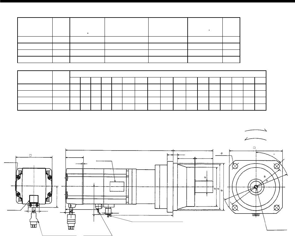
7 - 167
7. OUTLINE DIMENSION DRAWINGS
Model Output
[W]
Brake static
friction torque
[oz in]
Reduction Gear
Model Reduction Ratio Inertia Moment
WK2[oz in2]
Mass
[lb]
HC-MF73BG2 750 340 BK3-05B-08MEKA 1/5 6.00 16.1
HC-MF73BG2 750 340 BK4-09B-08MEKA 1/9 6.04 21.2
HC-MF73BG2 750 340 BK5-20B-08MEKA 1/20 6.24 28.7
HC-MF73BG2 750 340 BK5-29B-08MEKA 1/29 5.66 28.7
Variable Dimensions [in]
Model Output
[W] LA LB LC LD LE LF LG LH LK L LR KL LZ Q S P R
HC-MF73BG2 750 4.53 3.74 5.31 3.94 0.31 2.953 0.39 3.346 1.378 9.74 3.35 6.17 0.35 1.57 0.98 M6 0.47
HC-MF73BG2 750 5.31 4.33 6.10 4.53 0.31 3.543 0.47 3.937 1.575 10.85 3.94 7.27 0.43 1.97 1.26 M8 0.63
HC-MF73BG2 750 5.91 4.92 6.89 5.12 0.39 4.134 0.59 4.528 1.693 11.16 4.53 7.59 0.55 2.36 1.57 M10 0.79
HC-MF73BG2 750 5.91 4.92 6.89 5.12 0.39 4.134 0.59 4.528 1.693 11.16 4.53 7.59 0.55 2.36 1.57 M10 0.79
Motor plate
(Opposite side)
LELG 4- LZ
Top
Bottom
LK
LR
Q
"Rotation direction"
For forward rotation command
For reverse rotation command
Power supply lead 4-AWG19 11.8in
(With end-insulated round crimping terminal 1.25-4)
Brake lead
2-0.3 11.8in
(With end-insulated round
crim
p
in
g
terminal 1.25-4
)
2
Encoder cable 11.8in
With connector 1-172169-9
(AMP)
Red: Phase U
White: Phase V
Black: Phase W
Green/yellow: Earth
P threads,
depth R
Sh6
LF
LH
LBh7
L
Motor plate
Caution plate
Top
Bottom
Top
Bottom
LC
LA
2.835
KL
LD
BC12085*
1.535
3.228
0.106
0.992
1.917
0.433 0.390
2.287
[Unit: in]
45
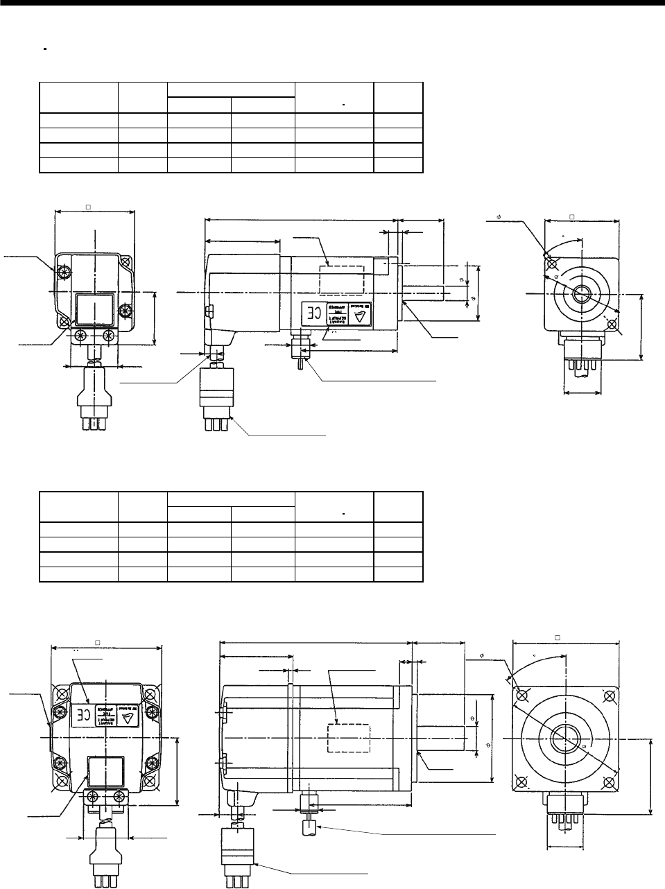
7 - 168
7. OUTLINE DIMENSION DRAWINGS
(5) EN UL/C-UL Standard-compliant models
(a) Standard (without electromagnetic brake, without reduction gear)
Variable Dimensions [in]
Model Output
[W] LKL
Inertia Moment
WK2[oz in2]
Mass
[lb]
HC-MF053-UE 50 3.52 1.48 0.10 1.1
HC-MF13-UE 100 4.11 2.07 0.16 1.3
HC-KF053-UE 50 3.52 1.48 0.30 1.1
HC-KF13-UE 100 4.11 2.07 0.47 1.3
Motor plate
Caution plate
Bottom
Top
Bottom
Top
Encoder cable
11.8in
Encoder cable 11.8in
With connector 1-172169-9
(AMP)
Power supply lead 4-AWG19 11.8in
(With end-insulated round crimping terminal 1.25-4)
Red: Phase U
White: Phase V
Black: Phase W
Green/yellow: Earth
Motor plate
(Opposite side)
Bottom
Top
Bottom
Top
L0.984
0.197 0.098
KL
TUV plate
1.181
V-10A
2- 0.177 1.575
1.406
0.787
BC07328A
0.390
V ring
1.594
1.654
0.268
0.992
1.130
0.315
1.811
[Unit: in]
45
Variable Dimensions [in]
Model Output
[W] LKL
Inertia Moment
WK2[oz in2]
Mass
[lb]
HC-MF23-UE 200 4.27 2.28 0.49 2.6
HC-MF43-UE 400 5.26 3.19 0.77 3.7
HC-KF23-UE 200 4.27 2.28 1.476 2.6
HC-KF43-UE 400 5.26 3.19 2.569 3.7
Motor plate
Caution plate
plate
Bottom
Top
Bottom
Top
Bottom
Top
0.390
L1.181
0.118
0.276
Motor plate
(Opposite side)
Bottom
Top
KL
V ring
V-16A
Encoder cable 11.8in
With connector 1-172169-9
(
AMP
)
Power supply lead 4-AWG19 11.8in
(With end-insulated round crimping terminal 1.25-4)
Red: Phase U
White: Phase V
Black: Phase W
Green/yellow: Earth
0.787
BC07329A
1.685
4- 0.228
2.362
0.551
1.969
TUV 1.614
2.441
0.106
0.417
0.992
1.512
2.756
[Unit: in]
45
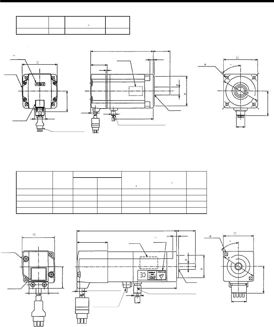
7 - 169
7. OUTLINE DIMENSION DRAWINGS
Model Output
[W]
Inertia Moment
WK2[oz in2]
Mass
[lb]
HC-MF73-UE 750 3.69 6.8
Encoder cable 11.8in
With connector 1-172169-9
(AMP)
Motor plate
(Opposite side)
Motor plate
Caution plate 0.992
1.917
TUV plate
3.228
Bottom
Top
Bottom
Top
5.905
1.535
0.106
Bottom
Top
0.433 0.390
3.740
1.575
0.118
0.315
0.748
2.756
Power supply lead 4-AWG19 11.8in
(With end-insulated round crimping terminal 1.25-4)
Red: Phase U
White: Phase V
Black: Phase W
Green/yellow: Earth
V ring
V-25A
4- 0.260
3.150
2.303
0.787
BC07330A
3.543
[Unit: in]
45
(b) With electromagnetic brake
Variable Dimensions [in]
Model Output
[W] LKL
Brake static
friction torque
[oz in]
Inertia Moment
WK2[oz in2]
Mass
[lb]
HC-MF053B-UE 50 4.63 1.48 45 0.12 2.0
HC-MF13B-UE 100 5.22 2.08 45 0.18 2.2
HC-KF053B-UE 50 4.63 1.48 45 0.31 2.0
HC-KF13B-UE 100 5.22 2.08 45 0.48 2.2
Motor plate
(Opposite side)
L
TUV plate
Encoder cable 11.8in
With connector 1-172169-9
(AMP)
Brake lead
2-0.32 11.8in
(With end-insulated round
crimping terminal 1.25-4)
Power supply lead 4-AWG19 11.8in
(With end-insulated round crimping terminal 1.25-4)
Red: Phase U
White: Phase V
Black: Phase W
Green/yellow: Earth
B1,B2
KL
Motor plate
Caution plate
Top
Bottom
Top
Bottom
V-10A
V ring
BC07369A
Top
Bottom
Top
Bottom
1.594
1.654
0.268
0.992
1.130
0.984
0.197 0.098
1.181
0.315
1.575
1.406
0.787
1.811
[Unit: in]
2- 0.177
45
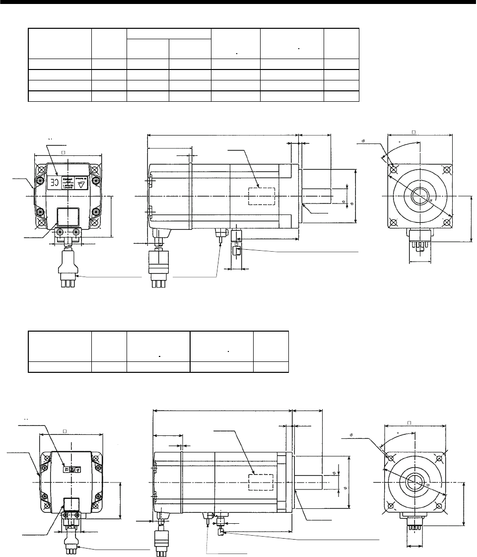
7 - 170
7. OUTLINE DIMENSION DRAWINGS
Variable Dimensions [in]
Model Output
[W] LKL
Brake static
friction torque
[oz in]
Inertia Moment
WK2[oz in2]
Mass
[lb]
HC-MF23B-UE 200 5.53 2.28 184 0.47 3.7
HC-MF43B-UE 400 6.52 3.19 184 1.04 4.9
HC-KF23B-UE 200 5.53 2.28 184 1.749 3.7
HC-KF43B-UE 400 6.52 3.19 184 2.843 4.9
Encoder cable 11.8in
With connector 1-172169-9
(AMP)
Brake lead
2-0.3 11.8in
(With end-insulated round
crimping terminal 1.25-4)
B1
,
B2
Power supply lead 4-AWG19 11.8in
(With end-insulated round crimping terminal 1.25-4)
Red: Phase U
White: Phase V
Black: Phase W
Green/yellow: Earth
Motor plate
(Opposite side)
Bottom
Top
Motor plate
Caution plate
Top
Bottom
Bottom
Top
Top
Bottom
TUV plate
L
KL
0.390
V-16A
BC07354A
V ring
1.614
2.441 0.106
0.417
0.992
1.512
1.181
0.118
0.276 4- 0.228
0.551
1.969
0.787
1.685
2.362
2.756
[Unit: in]
2
45
Model Output
[W]
Brake static
friction torque
[oz in]
Inertia Moment
WK2[oz in2]
Mass
[lb]
HC-MF73B-UE 750 340 4.10 9.3
Encoder cable 11.8in
With connector 1-172169-9
(AMP)
Brake lead
2-0.32 11.8in
(With end-insulated round
crimping terminal 1.25-4)
B1,B2
Power supply lead 4-AWG19 11.8in
(With end-insulated round crimping terminal 1.25-4)
Red: Phase U
White: Phase V
Black: Phase W
Green/yellow: Earth
BC07606
A
45
V-25A
Bottom
Top
Motor plate
Caution plate
plateTUV
Bottom
Top
Bottom
Top
Motor plate
(Opposite side)
7.303
V ring
0.992
1.917
3.228 1.535
0.106
0.433 0.390
3.740
1.575
0.118
0.315
0.748
2.756
4- 0.260
3.150
2.287
0.787
3.543
[Unit: in]
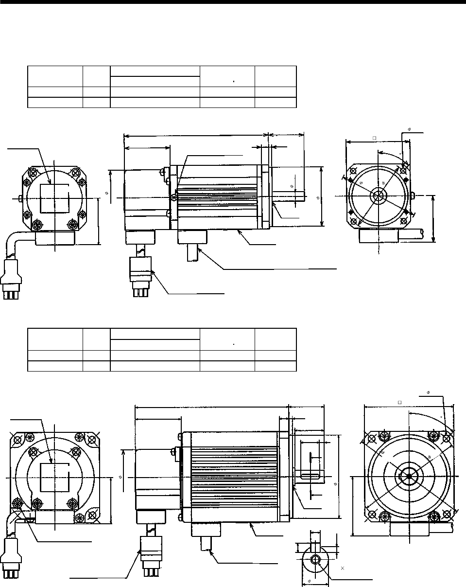
7 - 171
7. OUTLINE DIMENSION DRAWINGS
7.2.2 HA-FF series
(1) Standard (without electromagnetic brake, without reduction gear)
Variable Dimensions [in]
Model Output
[W] L
Inertia Moment
WK2[oz in2]
Mass
[lb]
HA-FF053 50 4.17 0.34 2.9
HA-FF13 100 4.84 0.55 3.3
Power supply cable
VCTF 0.05 19.7in
(With end-insulated round crimping terminal 0.05-4)
1.535 0.10.24
1.18
2
1.54
Caution plate
L
V ring
1.54
Earth terminal M3 screw
(Opposite side)
Bottom
Top
Red: Phase U
White: Phase V
Black: Phase W
[Unit: in]
Encoder cable 11.8in
With connector 172169-9
(AMP)
Bottom
Top
Motor plate
Z694731*
1.85
1.97
0.31
2.36
2.68
4- 0.18
2.13
45
Variable Dimensions [in]
Model Output
[W] L
Inertia Moment
WK2[oz in2]
Mass
[lb]
HA-FF23 200 5.138 1.91 5.1
HA-FF33 300 5.83 2.73 5.7
1.535 0.120.31
1.18
1.54
L
1.97
Earth terminal, M3 screw
A
A
0.63 0.16
0.98
0.16
Section AA
0.10
0.16
Power supply cable
VCTF 0.05 19.7in
(With end-insulated round
crimping terminal 0.05-4)
2
Caution plate
V ring
Bottom
Top
Red: Phase U
White: Phase V
Black: Phase W
[Unit: in]
Encoder cable 11.8in
With connector 172169-9
(AMP)
Bottom
Top
Motor plate
Z694732*
M4 0.7 threads,
depth 0.59
2.99
4- 0.22
3.54
3.94
2.76
0.43
1.85
45
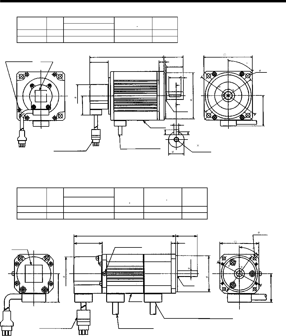
7 - 172
7. OUTLINE DIMENSION DRAWINGS
Variable Dimensions [in]
Model Output
[W] L
Inertia Moment
WK2[oz in2]
Mass
[lb]
HA-FF43 400 6.08 5.36 9.3
HA-FF63 600 6.67 6.56 10.6
Motor plate
1.535 0.12
0.39
[Unit: in]
1.57
1.54
L
V ring
2.44
Caution plate
A
A
0.20
1.38
0.20
Section AA
0.12
0.20
0.984
Bottom
Top
Power supply cable
VCTF 3-0.05 19.7in
(With end-insulated round
crimping terminal 0.05-4)
2
Red: Phase U
White: Phase V
Black: Phase W
Encoder cable 11.8in
With connector 172169-9
(AMP)
Earth terminal M3 screw
Top
4- 0.35
4.53
5.31
3.94
3.74
0.63
1.85
M5 0.8 threads,
depth 0.79
Z694733*
45
Bottom
(2) With electromagnetic brake
Variable Dimensions [in]
Model Output
[W] L
Brake static
friction torque
[oz in]
Inertia Moment
WK2[oz in2]
Mass
[lb]
HA-FF053B 50 5.551 55 0.44 3.5
HA-FF13B 100 6.22 55 0.60 4.0
Motor plate
1.535 0.10
0.24
[Unit: in]
Top
Bottom
1.18
Bottom
Top
1.54
Caution plate
L
Earth terminal M3 screw
(Opposite side)
V ring
1.54
Power supply cable
VCTF 3-0.05 19.7in
(With end-insulated round
crimping terminal 0.05-4)
2
Red: Phase U
White: Phase V
Black: Phase W
Encoder cable 118in
With connector 172169-9
(AMP)
Brake lead
VCTF 2-0.02 11.8in
(With end-insulated round crimping terminal 0.05-4)
2
1.85
0.31
1.97
4- 0.18
2.36
2.68
2.13
Z694734*
45
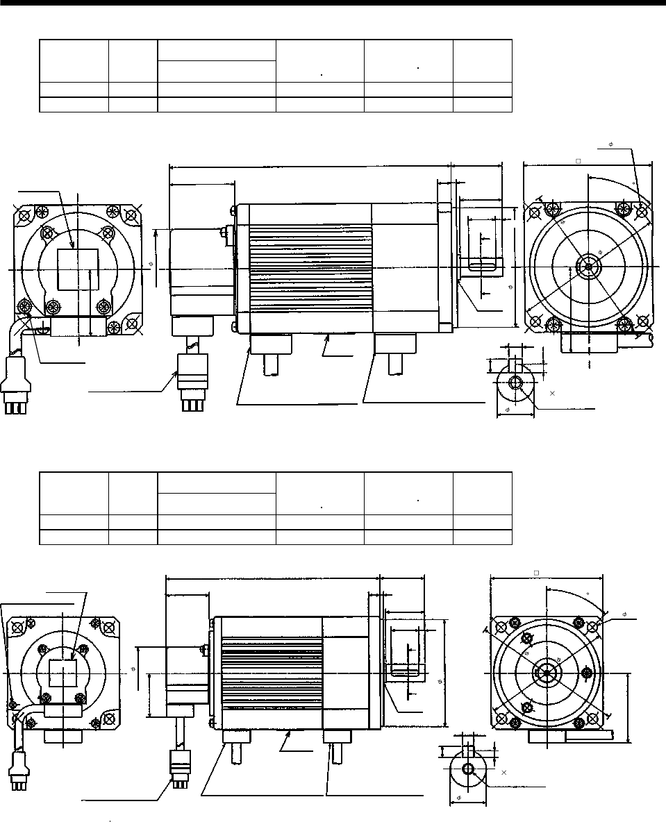
7 - 173
7. OUTLINE DIMENSION DRAWINGS
Variable Dimensions [in]
Model Output
[W] L
Brake static
friction torque
[oz in]
Inertia Moment
WK2[oz in2]
Mass
[lb]
HA-FF23B 200 6.614 170 2.62 6.4
HA-FF33B 300 7.303 170 3.44 7.1
Motor plate
1.535 0.12
0.31
[Unit: in]
Top
Bottom
1.18
Bottom
Top
1.54
Caution plate
L
V ring
1.97
A
A
0.98
0.16
Section AA
0.10
0.16
0.63
Earth terminal
M3 screw
M4 0.7 threads,
depth 0.59
Power supply cable
VCTF 3-0.05 1.97in
(With end-insulated round
crimping terminal 0.05-4)
2
Red: Phase U
White: Phase V
Black: Phase W
Encoder cable 11.8in
With connector 172169-9
(AMP)
Brake lead
VCTF 2-0.02 19.7in
(With end-insulated round
crimping terminal 0.05-4)
2
Z694735*
2.99
4- 0.22
3.54
3.94
0.43
2.76
1.85
45
0.16
Variable Dimensions [in]
Model Output
[W] L
Brake static
friction torque
[oz in]
Inertia Moment
WK2[oz in2]
Mass
[lb]
HA-FF43B 400 7.54 326 7.27 11.0
HA-FF63B 600 8.13 326 8.48 12.3
Motor plate
1.535 0.12
0.39
[Unit: in]
Top
1.57
Bottom
Top
1.54
Caution plate
L
V ring
2.44
Earth terminal M3 screw
A
A
0.20
1.38
M5 0.8 threads,
depth 0.79
0.20
Section AA
0.12
0.20
0.984
Power supply cable
VCTF 3-0.05 19.7in
(With end-insulated round
crimping terminal 0.05-4)
2
Red: Phase U
White: Phase V
Black: Phase W
Encoder cable 11.8in
With connector 172169-9
(AMP)
Brake lead
VCTF 2-0.02 19.7in
(With end-insulated round
crimping terminal 0.05-4)
2
1.85
3.74
0.63
3.94
4- 0.35
4.53
5.31
Z694736
*
45
Bottom
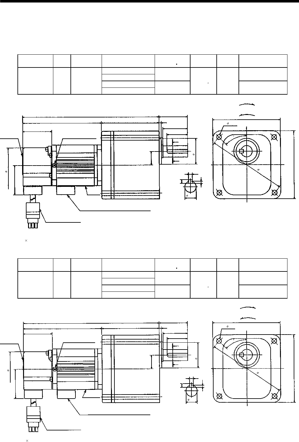
7 - 174
7. OUTLINE DIMENSION DRAWINGS
(3) With reduction gear for general industrial machine
The outer frame of the reduction gear is a material surface such as casting. Its actual dimensions may
be 0.039 to 0.118 in larger than the drawing dimensions. Design the machine side with allowances.
(a) Without electromagnetic brake
Model Output
[W]
Reduction
Gear Model
Reduction Ratio
(Actual Reduction Ratio)
Inertia Moment
WK2[oz in2]Backlash Mass
[lb]
Output Shaft Rotation
Direction
1/5(9/44)
1/10(3/29) 0.369 Same as that of motor
shaft
1/20(99/1972)
HA-FF053G1 50 GR-S-10
1/30(144/4205) 0.342
40min.
to 1.5 5.5 Opposite to that of
motor shaft
Motor plate
1.54
0.12
1.3
3.54
Top
Bottom
BottomTop
1.54
Caution plate
7.20
3.54
A
A
0.2
Section AA
0.12
0.2
4.173
Earth terminal M3 screw
(Opposite side)
3.031
0.11
1.5
0.71
[Unit: in]
"Rotation direction"
For forward rotation command
For reverse rotation command
Power supply cable VCTF 3-0.05 19.7in
(With end-insulated round crimping terminal 0.05-4)
Red: Phase U
White: Phase V
Black: Phase W
Encoder cable 11.8in
With connector 172169-9
(AMP)
2
Z694764*
4.09
4- 0.26 (Note)
0.59
Note: Four M6 90 throu
g
h bolts are
p
rovided.
1.85
1.34
45
Model Output
[W]
Reduction
Gear Model
Reduction Ratio
(Actual Reduction Ratio)
Inertia Moment
WK2[oz in2]Backlash Mass
[lb]
Output Shaft Rotation
Direction
1/5(9/44)
1/10(3/29) 0.547 Same as that of motor
shaft
1/20(99/1972)
HA-FF13G1 100 GR-S-10
1/30(144/4205) 0.519
40min.
to 1.5 6.0 Opposite to that of
motor shaft
Motor plate
1.54
0.12
1.3
3.54
Top
Bottom
2
Bottom
Top
1.54
Caution plate
7.87
3.54
A
A
0.2
Section AA
0.12
0.2
4.843
Earth terminal M3 screw
(Opposite side)
3.031
0.11
1.5
0.71
[Unit: in]
"Rotation direction"
For forward rotation command
For reverse rotation command
Power supply cable
VCTF 3-0.05 19.7in
(With end-insulated round crimping terminal 0.05-4)
Red: Phase U
White: Phase V
Black: Phase W
Encoder cable 11.8in
With connector 172169-9
(AMP)
Note: Four M6 90 throu
g
h bolts are
p
rovided.
1.85
Z694765*
1.34
0.59
4.09
4- 0.26 (Note)
45
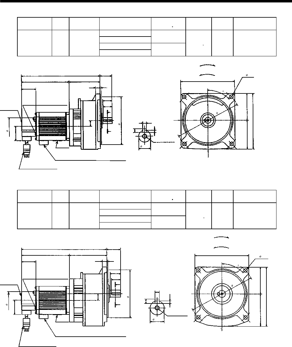
7 - 175
7. OUTLINE DIMENSION DRAWINGS
Model Output
[W]
Reduction
Gear Model
Reduction Ratio
(Actual Reduction Ratio)
Inertia Moment
WK2[oz in2]Backlash Mass
[lb]
Output Shaft Rotation
Direction
1/5(57/280)
1/10(39/400) 2.039
1/20(51/980)
HA-FF23G1 200 GR-S-20
1/30(1/30) 2.023
40min.
to 1.5 11 Same as that of
motor shaft
Motor plate
1.54 0.12
0.98
5.71
Top
Bottom
1.54
Caution plate
8.445
5.91
A
A
0.2
Section AA
0.12
0.2
5.138
1.28
0.94
0.47
0.59
3.307
3.05 2.85
[Unit: in]
"Rotation direction"
For forward rotation command
For reverse rotation command
M6 threads,
depth 0.39
Earth terminal M3 screw
(Opposite side)
Bottom
Top
Power supply cable VCTF 3-0.05 19.7in
(With end-insulated round crimping terminal 0.05-4)
Red: Phase U
White: Phase V
Black: Phase W
Encoder cable 11.8in
With connector 172169-9
(AMP)
2
Z694766*
1.85
5.12
0.63
7.09
4- 0.39
45
Model Output
[W]
Reduction
Gear Model
Reduction Ratio
(Actual Reduction Ratio)
Inertia Moment
WK2[oz in2]Backlash Mass
[lb]
Output Shaft Rotation
Direction
1/5(19/94)
1/10(39/376) 2.980
1/20(72/1363)
HA-FF33G1 300 GR-S-30
1/30(11/329) 2.939
40min.
to 1.5 14.3 Same as that of
motor shaft
Motor plate
1.54 0.12
0.98
5.71
Top
Bottom
BottomTop
1.54
Caution plate
9.84
6.3
A
A
0.24
Section AA
0.14
0.24
5.827
1.48
1.1
0.47
0.71
4.016
M6 threads,
depth 0.39
3.49 2.85
[Unit: in]
"Rotation direction"
For forward rotation command
For reverse rotation command
Earth terminal M3 screw
(Opposite side)
Power supply cable VCTF 3-0.05 19.7in
(With end-insulated round crimping terminal 0.05-4)
Red: Phase U
White: Phase V
Black: Phase W
Encoder cable 11.8in
With connector 172169-9
(AMP)
2
Z694767*
1.85
5.12
0.75
7.09
4- 0.39
45
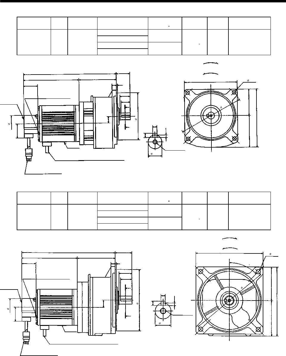
7 - 176
7. OUTLINE DIMENSION DRAWINGS
Model Output
[W]
Reduction
Gear Model
Reduction Ratio
(Actual Reduction Ratio)
Inertia Moment
WK2[oz in2]Backlash Mass
[lb]
Output Shaft
Rotation Direction
1/5(19/94)
1/10(39/376) 5.577
1/20(72/1363)
HA-FF43G1 400 GR-S-40
1/30(11/329) 5.536
40min.
to 1.5 17.6 Same as that of
motor shaft
Motor plate
1.54 0.12
0.98
5.71
Top
Bottom
Bottom
Top
1.54
Caution plate
10.177
6.3
A
A
0.24
Section AA
0.14
0.24
6.083
Earth terminal M3 screw
(Opposite side)
1.48
1.1
0.47
0.71
4.094
M6 threads,
depth 0.39
3.49 2.85
[Unit: in]
"Rotation direction"
For forward rotation command
For reverse rotation command
2
Power supply cable VCTF 3-0.05 19.7in
(With end-insulated round crimping terminal 0.05-4)
Red: Phase U
White: Phase V
Black: Phase W
Encoder cable 11.8in
With connector 172169-9
(AMP) Z694768*
0.75
1.85
5.12
4- 0.39
7.09
Model Output
[W]
Reduction
Gear Model
Reduction Ratio
(Actual Reduction Ratio)
Inertia Moment
WK2[oz in2]Backlash Mass
[lb]
Output Shaft
Rotation Direction
1/5(10/49)
1/10(243/2401) 7.326
1/20(153/2891)
HA-FF63G1 600 GR-S-60
1/30(27/784) 7.217
40min.
to 1.5 28.7 Same as that of
motor shaft
1.54 0.12
1.26
7.28
Top
Bottom
1.54
Caution plate
10.81
7.58
A
A
0.24
Section AA
0.14
0.24
6.673
Earth terminal M3 screw
(Opposite side)
1.83
1.42
0.47
0.79
4.134
M8 threads,
depth 0.47
3.94 3.64
[Unit: in]
"Rotation direction"
For forward rotation command
For reverse rotation command
Motor plate
Bottom
Top
2
Power supply cable VCTF 3-0.05 19.7in
(With end-insulated round crimping terminal 0.05-4)
Red: Phase U
White: Phase V
Black: Phase W
Encoder cable 11.8in
With connector 172169-9
(AMP) Z694769*
1.85
6.69
0.87
4- 0.47
8.86
45
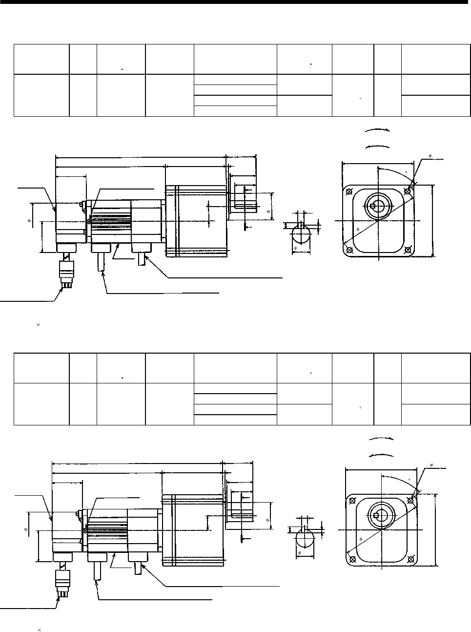
7 - 177
7. OUTLINE DIMENSION DRAWINGS
(b) With electromagnetic brake
Model Output
[W]
Brake static
friction torque
[oz in]
Reduction
Gear Model
Reduction Ratio
(Actual Reduction Ratio)
Inertia Moment
WK2[oz in2]Backlash Mass
[lb]
Output Shaft Rotation
Direction
1/5(9/44)
1/10(3/29) 0.465 Same as that of
motor shaft
1/20(99/1972)
HA-FF053BG1 50 55 GR-S-10
1/30(144/4205) 0.437
40min.
to 1.5 6.2 Opposite to that of
motor shaft
Motor plate
1.54
0.12
5.551 3.54
Top
Bottom
1.5
Bottom
1.54
Caution plate
8.583
3.54
Earth terminal M3 screw
(Opposite side)
A
A
1.3
0.2
Section AA
0.12
0.2
0.11
Brake cable
VCTF 2-0.02 19.7in
(With end-insulated round crimping terminal 0.05-4)
2
3.031
0.71
[Unit: in]
"Rotation direction"
For forward rotation command
For reverse rotation command
Top
Power supply cable VCTF 3-0.05 19.7in
(With end-insulated round crimping terminal 0.05-4)
Red: Phase U
White: Phase V
Black: Phase W
Encoder cable 11.8in
With connector 172169-9
(AMP)
2
Z694770*
Note: Four M6 90 throu
g
h bolts are
p
rovided.
1.85
1.34
0.59
4- 0.26 (Note
)
4.09
45
Model Output
[W]
Brake static
friction torque
[oz in]
Reduction
Gear Model
Reduction Ratio
(Actual Reduction Ratio)
Inertia Moment
WK2[oz in2]Backlash Mass
[lb]
Output Shaft Rotation
Direction
1/5(9/44)
1/10(3/29) 0.629 Same as that of
motor shaft
1/20(99/1972)
HA-FF13BG1 100 55 GR-S-10
1/30(144/4205) 0.601
40min.
to 1.5 6.6 Opposite to that of
motor shaft
1.54
0.12
6.22 3.54
Top
Bottom
1.5
1.54
Caution plate
9.252
3.54
Earth terminal M3 screw
(Opposite side)
A
A
1.3
0.2
Section AA
0.12
0.2
0.11
2
3.031
0.71
[Unit: in]
"Rotation direction"
For forward rotation command
For reverse rotation command
Encoder cable 11.8in
With connector 172169-9
(AMP)
Power supply cable VCTF 3-0.05 19.7in
(With end-insulated round crimping terminal 0.05-4)
Red: Phase U
White: Phase V
Black: Phase W
Brake cable
VCTF 2-0.02 19.7in
(With end-insulated round crimping terminal 0.05-4)
2
Motor plate
Bottom
Top
1.85
1.34
0.59
4- 0.26 (Note
)
4.09
Note: Four M6 90 throu
g
h bolts are
p
rovided.
Z694771*
45
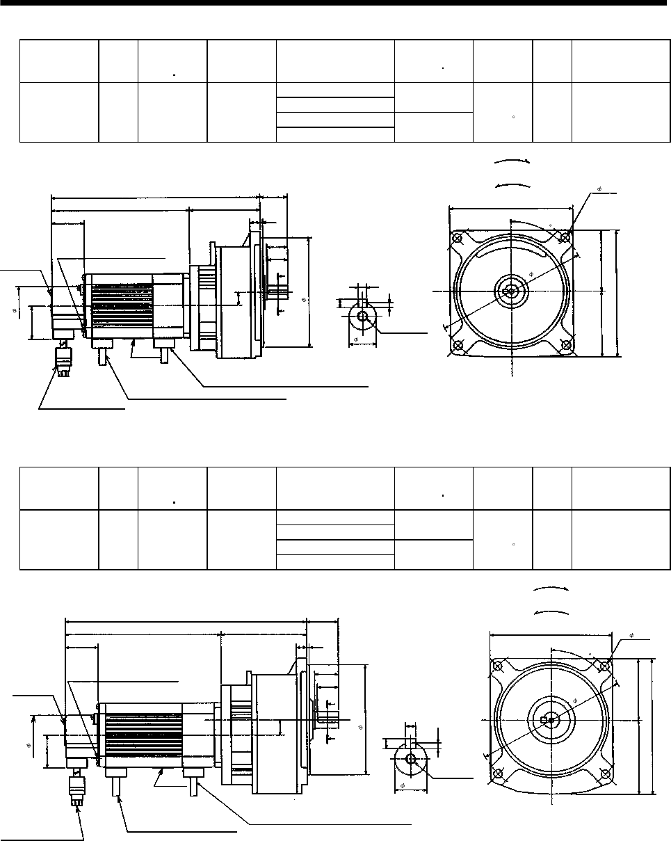
7 - 178
7. OUTLINE DIMENSION DRAWINGS
Model Output
[W]
Brake static
friction torque
[oz in]
Reduction
Gear Model
Reduction Ratio
(Actual Reduction Ratio)
Inertia Moment
WK2[oz in2]Backlash Mass
[lb]
Output Shaft Rotation
Direction
1/5(57/280)
1/10(39/400) 2.75
1/20(51/980)
HA-FF23BG1 200 170 GR-S-20
1/30(1/30) 2.734
40min.
to 1.5 12.3 Same as that of
motor shaft
Motor plate
1.54 0.12
0.98
5.71
Top
Bottom
Power supply cable
VCTF 3-0.05 19.7in
(With end-insulated round crimping terminal 0.05-4)
2
Bottom
Top
1.54
Caution plate
9.921
5.91
A
A
0.2
Section AA
0.12
0.2
6.614
Earth terminal M3 screw
(Opposite side)
1.28
0.94
0.47
0.59
3.307
3.05 2.85
Brake lead
VCTF 2-0.02 19.7in
(With end-insulated round crimping terminal 0.05-4)
2
[Unit: in]
"Rotation direction"
For forward rotation command
For reverse rotation command
M6 threads,
depth 0.39
Red: Phase U
White: Phase V
Black: Phase W
Encoder cable 11.8in
With connector 172169-9
(AMP)
Z694772*
1.85
5.12
4- 0.39
7.09
0.63
45
Model Output
[W]
Brake static
friction torque
[oz in]
Reduction
Gear Model
Reduction Ratio
(Actual Reduction Ratio)
Inertia Moment
WK2[oz in2]Backlash Mass
[lb]
Output Shaft Rotation
Direction
1/5(19/94)
1/10(39/376) 3.707
1/20(72/1363)
HA-FF33BG1 300 170 GR-S-30
1/30(11/329) 3.663
40min.
to 1.5 15.9 Same as that of
motor shaft
1.54 0.12
1.1
5.71
Red: Phase U
White: Phase V
Black: Phase W
Top
Bottom
1.54
Caution plate
11.319
6.3
A
A
0.24
Section AA
0.14
0.24
7.303
Earth terminal M3 screw
(Opposite side)
1.48
0.98
0.47
0.71
1.85
4.016
M6 threads,
depth 0.39
3.49 2.85
[Unit: in]
"Rotation direction"
For forward rotation command
For reverse rotation command
Brake lead
VCTF 2-0.02 19.7in
(With end-insulated round crimping terminal 0.05-4)
2
Motor plate
Bottom
Top
Power supply cable
VCTF 3-0.05 19.7in
(With end-insulated round crimping
terminal 0.05-4)
2
Encoder cable 11.8in
With connector 172169-9
(AMP)
5.12
0.75
4- 0.39
7.09
Z694773*
45
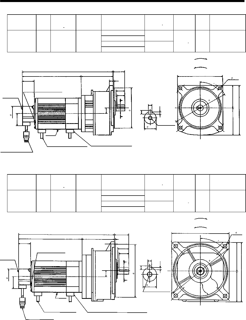
7 - 179
7. OUTLINE DIMENSION DRAWINGS
Model Output
[W]
Brake static
friction torque
[oz in]
Reduction
Gear Model
Reduction Ratio
(Actual Reduction Ratio)
Inertia Moment
WK2[oz in2]Backlash Mass
[lb]
Output Shaft Rotation
Direction
1/5(19/94)
1/10(39/376) 7.490
1/20(72/1363)
HA-FF43BG1 400 326 GR-S-40
1/30(11/329) 7.449
40min.
to 1.5 19.6 Same as that of
motor shaft
1.54 0.12
1.1
5.71
Red: Phase U
White: Phase V
Black: Phase W
Top
Bottom
1.54
Caution plate
11.63
6.3
A
A
0.24
Section AA
0.14
0.24
7.539
Earth terminal M3 screw
(Opposite side)
1.48
0.98
0.47
0.71
4.094
M6 threads,
depth 0.39
3.49 2.85
2
[Unit: in]
"Rotation direction"
For forward rotation command
For reverse rotation command
Brake lead
VCTF 2-0.02 19.7in
(With end-insulated round crimping terminal 0.05-4)
Motor plate
BottomTop
Power supply cable
VCTF 3-0.05 19.7in
(With end-insulated round crimping terminal 0.05-4)
2
Encoder cable 11.8in
With connector 172169-9
(AMP)
1.85
5.12
0.75
4- 0.39
7.09
Z694774*
45
Model Output
[W]
Brake static
friction torque
[oz in]
Reduction
Gear Model
Reduction Ratio
(Actual Reduction Ratio)
Inertia Moment
WK2[oz in2]Backlash Mass
[lb]
Output Shaft
Rotation Direction
1/5(10/49)
1/10(243/2401) 9.240
1/20(153/2891)
HA-FF63BG1 600 326 GR-S-60
1/30(27/784) 9.131
40min.
to 1.5 30.6 Same as that of
motor shaft
Caution plate
1.54
0.12
1.42
7.28
Top
Bottom
Power supply cable
VCTF 3-0.05 19.7in
(With end-insulated round
crimping terminal 0.05-4)
2
1.54
12.264
7.58
A
A0.24
0.14
0.24
8.13
Earth terminal M3 screw
(Opposite side)
1.83
1.26
0.47
0.79
4.134
3.94 3.64
2
Brake lead
VCTF 2-0.02 19.7in
(With end-insulated round crimping terminal 0.05-4)
Motor plate
BottomTop
Encoder cable 11.8in
With connector 172169-9
(
AMP
)
Red: Phase U
White: Phase V
Black: Phase W
Section AA
M6 threads, depth 0.47
[Unit: in]
"Rotation direction"
For forward rotation command
For reverse rotation command
1.85
6.69
0.87
4- 0.47
8.86
Z694775
*
45
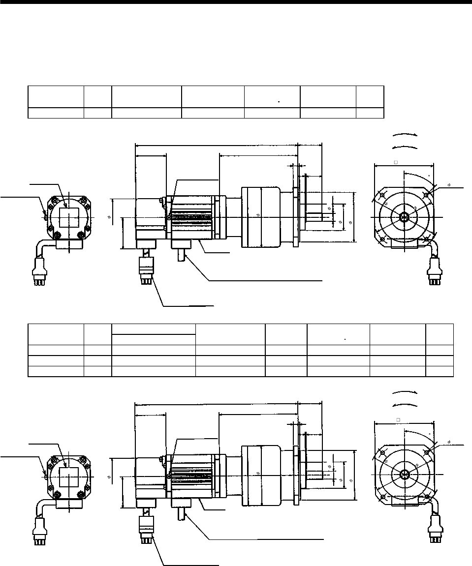
7 - 180
7. OUTLINE DIMENSION DRAWINGS
(4) With reduction gear for precision application
The outer frame of the reduction gear is a material surface such as casting. Its actual dimensions may
be 0.039 to 0.118 in larger than the drawing dimensions. Design the machine side with allowances.
(a) Without electromagnetic brake
Model Output
[W]
Reduction Gear
Model Reduction Ratio Inertia Moment
WK2[oz in2]Backlash Mass
[lb]
HA-FF053G2 50 BM2-05B-A5MES 1/5 0.60 3 min. max. 5.1
Motor plate
1.54
0.24
3.898
Top
1.18
Bottom
Top
1.54
Caution Plate
8.07
Earth terminal M3 screw
(Opposite side)
Earth terminal M3
0.08
0.350.79
[Unit: in]
"Rotation direction"
For forward rotation command
For reverse rotation command
Power supply cable
VCTF 3-0.05 19.7in
(With end-insulated round crimping terminal 0.05-4)
2
Red: Phase U
White: Phase V
Black: Phase W
Encoder cable 11.8in
With connector 172169-9
(AMP)
1.85
1.30
2.44
2.95
3.50
3.07
4- 0.18
2.91
Z694850*
45
Bottom
0.39
Variable Dimensions [in]
Model Output
[W] L
Reduction Gear
Model
Reduction
Ratio
Inertia Moment
WK2[oz in2]Backlash Mass
[lb]
HA-FF053G2 50 8.07 BM2-10B-A5MES 1/10 0.59 3 min. max. 5.1
HA-FF053G2 50 8.07 BM2-15B-A5MES 1/15 0.57 3 min. max. 5.1
HA-FF13G2 100 8.74 BM2-05B-01MES 1/5 0.78 3 min. max. 5.5
Motor plate
1.54
0.24
3.898
Top
1.18
BottomTop
1.54
Caution plate
L
Earth terminal M3 screw
(Opposite side)
Earth terminal M3
0.08
0.350.79
[Unit: in]
"Rotation direction"
For forward rotation command
For reverse rotation command
Power supply cable
VCTF 3-0.05 19.7in
(With end-insulated round crimping terminal 0.05-4)
2
Red: Phase U
White: Phase V
Black: Phase W
Encoder cable 11.8in
With connector 172169-9
(AMP) Z694805*
2.91
4- 0.18
3.07
3.50
2.44
1.30
2.95
1.85
45
Bottom
0.39
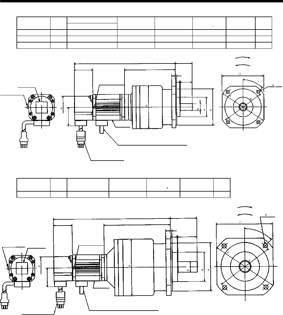
7 - 181
7. OUTLINE DIMENSION DRAWINGS
Variable Dimensions [in]
Model Output
[W] L
Reduction Gear
Model Reduction Ratio Inertia Moment
WK2[oz in2]Backlash Mass
[lb]
HA-FF053G2 50 8.39 BM3-25B-A5MES 1/25 0.601 3min. max. 6.2
HA-FF13G2 100 9.06 BM3-10B-01MES 1/10 0.90 3min. max. 6.6
HA-FF13G2 100 9.06 BM3-15B-01MES 1/15 0.85 3min. max. 6.6
Motor plate
1.54
0.31
4.213
Top
1.38
Bottom
Top
1.54
Caution plate
L
Earth terminal M3 screw
(Opposite side)
Earth terminal M3
0.08
0.350.98
[Unit: in]
"Rotation direction"
For forward rotation command
For reverse rotation command
Power supply cable
VCTF 3-0.05 19.7in
(With end-insulated round crimping terminal 0.05-4)
2
Red: Phase U
White: Phase V
Black: Phase W
Encoder cable 11.8in
With connector 172169-9
(AMP)
1.85
3.425
1.61
2.99
3.54
4.02
4- 0.22
3.43
Z694806*
45
Bottom
0.551
Model Output
[W]
Reduction Gear
Model Reduction Ratio Inertia Moment
WK2[oz in2]Backlash Mass
[lb]
HA-FF13G2 100 BM4-25B-01MES 1/25 1.59 3min. max. 11.0
Motor plate
1.54
0.39
5.472
Top
2.17
Bottom
Top
1.54
Caution plate
10.31
Earth terminal M3 screw
(Opposite side)
Earth terminal M3
0.12
0.55 1.57
4.65
[Unit: in]
"Rotation direction"
For forward rotation command
For reverse rotation command
Power supply cable
VCTF 3-0.05 19.7in
(With end-insulated round crimping terminal 0.05-4)
2
Red: Phase U
White: Phase V
Black: Phase W
Encoder cable 11.8in
With connector 172169-9
(AMP)
1.85
2.40
3.94
5.51
4.80
4- 0.26
4.65
Z694807*
45
Bottom
0.866
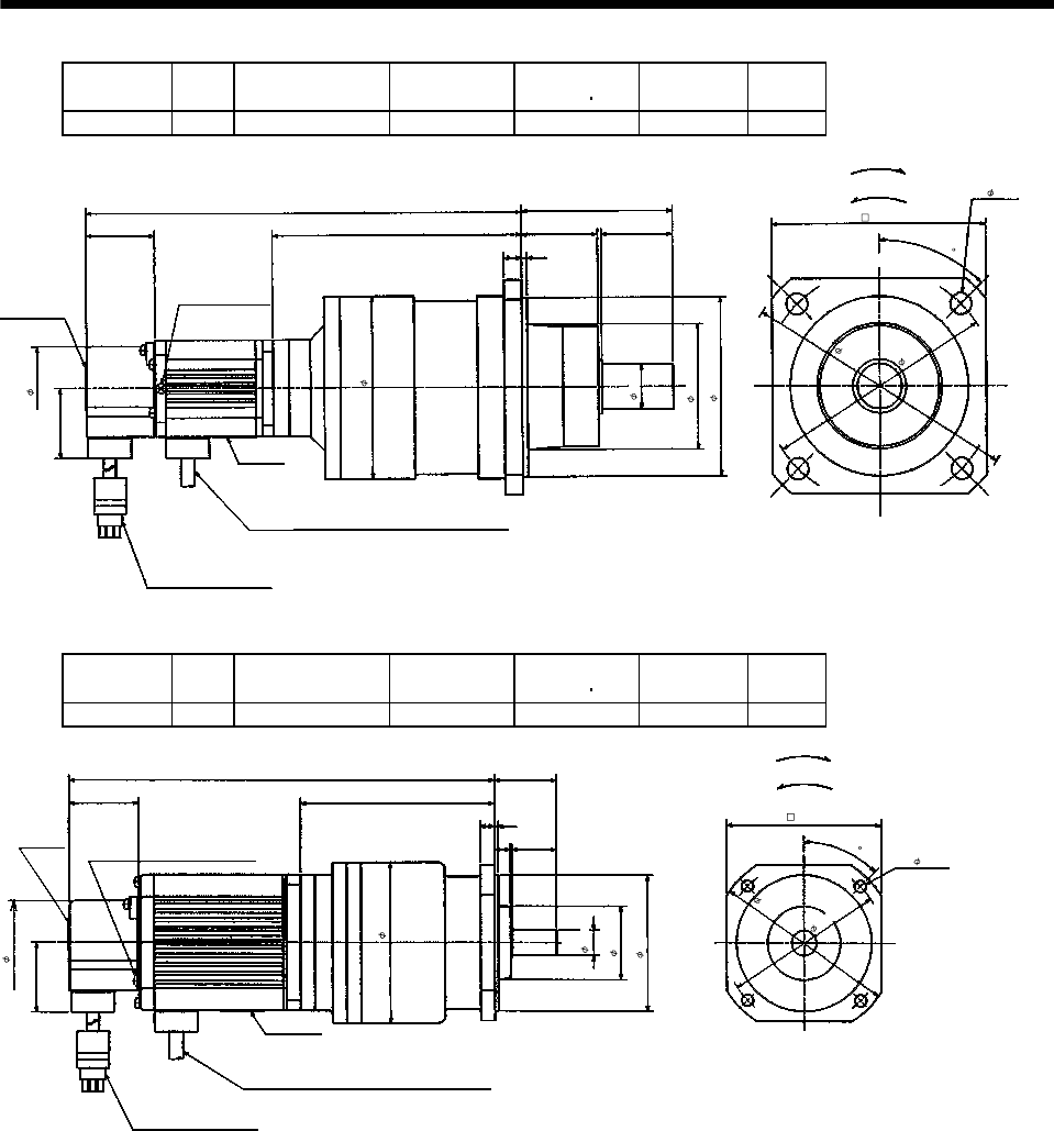
7 - 182
7. OUTLINE DIMENSION DRAWINGS
Model Output
[W]
Reduction Gear
Model Reduction Ratio Inertia Moment
WK2[oz in2]Backlash Mass
[lb]
HA-FF13G2 100 BL1-45B-01MES 1/45 1.60 3min. max. 13.2
Motor plate
1.54
0.39
5.945
Top
Bottom
3.35
Bottom
Top
1.54
Caution plate
10.79
Earth terminal M3 screw
(Opposite side)
0.12
1.57
1.69
[Unit: in]
"Rotation direction"
For forward rotation command
For reverse rotation command
Power supply cable
VCTF 3-0.05 19.7in
(With end-insulated round crimping terminal 0.05-4)
2
Red: Phase U
White: Phase V
Black: Phase W
Encoder cable 11.8in
With connector 172169-9
(AMP) Z694737*
4.72
4- 0.47
5.12
6.10
3.94
2.76
1.85
4.016
45
0.98
Model Output
[W]
Reduction Gear
Model Reduction Ratio Inertia Moment
WK2[oz in2]Backlash Mass
[lb]
HA-FF23G2 200 BM3-05B-02MES 1/5 2.32 3min. max. 8.4
Motor plate
1.54
0.31
4.291
Top
Bottom
1.38
Bottom
Top
1.54
Caution plate
9.429
Earth terminal M3 screw
(Opposite side)
0.08
0.35 0.98
[Unit: in]
"Rotation direction"
For forward rotation command
For reverse rotation command
Power supply cable
VCTF 3-0.05 19.7in
(With end-insulated round crimping terminal 0.05-4)
2
Red: Phase U
White: Phase V
Black: Phase W
Encoder cable 11.8in
With connector 172169-9
(AMP) Z694808*
3.43
4- 0.22
3.54
4.02
1.61
2.99
0.551
3.425
1.85
45
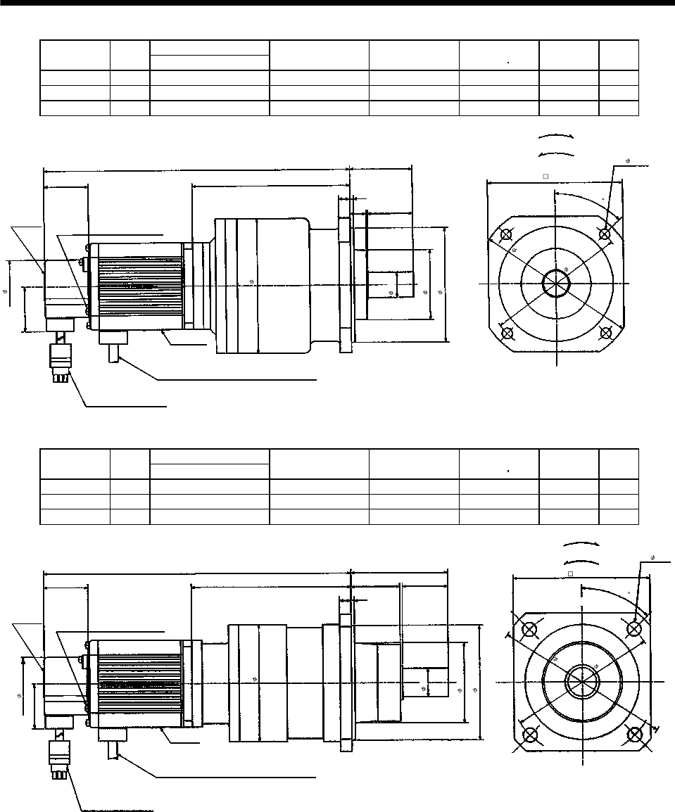
7 - 183
7. OUTLINE DIMENSION DRAWINGS
Variable Dimensions [in]
Model Output
[W] L
Reduction Gear
Model Reduction Ratio Inertia Moment
WK2[oz in2]Backlash Mass
[lb]
HA-FF23G2 200 10.61 BM4-10B-02MES 1/10 3.53 3min. max. 12.8
HA-FF23G2 200 10.61 BM4-15B-02MES 1/15 3.38 3min. max. 12.8
HA-FF33G2 300 11.30 BM4-10B-03MES 1/10 4.35 3min. max. 13.4
Motor plate
1.54
0.39
5.472
Top
Bottom
2.17
Bottom
Top
1.54
Caution plate
L
Earth terminal M3 screw
(Opposite side)
0.12
0.55 1.57
[Unit: in]
"Rotation direction"
For forward rotation command
For reverse rotation command
Power supply cable
VCTF 3-0.05 19.7 in
(With end-insulated round crimping terminal 0.05-4)
2
Red: Phase U
White: Phase V
Black: Phase W
Encoder cable 11.8in
With connector 172169-9
(AMP)
1.85
4.65
2.40
3.94
5.51
4.80
4- 0.26
4.65
Z694809*
45
0.866
Variable Dimensions [in]
Model Output
[W] L
Reduction Gear
Model Reduction Ratio Inertia Moment
WK2[oz in2]Backlash Mass
[lb]
HA-FF23G2 200 10.94 BL1-20B-02MES 1/20 3.99 3min. max. 15.0
HA-FF23G2 200 10.94 BL1-29B-02MES 1/29 3.46 3min. max. 15.0
HA-FF33G2 300 11.61 BL1-20B-03MES 1/20 4.81 3min. max. 15.7
1.54
0.39
5.787
Top
Bottom
3.35
1.54
Caution plate
L
Earth terminal M3 screw
(Opposite side)
0.12
1.57
1.69
[Unit: in]
"Rotation direction"
For forward rotation command
For reverse rotation command
Motor plate
Bottom
Top
Power supply cable
VCTF 3-0.05 19.7in
(With end-insulated round crimping terminal 0.05-4)
2
Red: Phase U
White: Phase V
Black: Phase W
Encoder cable 11.8in
With connector 172169-9
(AMP) Z694738*
4.72
4- 0.47
6.10
5.12
2.76
3.94
4.016
1.85
45
0.98

7 - 184
7. OUTLINE DIMENSION DRAWINGS
Variable Dimensions [in]
Model Output
[W] L
Reduction Gear
Model
Reduction
Ratio
Inertia Moment
WK2[oz in2]Backlash Mass
[lb]
HA-FF23G2 200 11.77 BL2-45B-02MES 1/45 4.17 3min. max. 27.1
HA-FF33G2 300 12.44 BL2-29B-03MES 1/29 83.9 3min. max. 27.8
HA-FF33G2 300 12.44 BL2-45B-03MES 1/45 4.99 3min. max. 27.8
Motor plate
1.54
0.47
6.614
Top
Bottom
3.94
BottomTop
1.54
Caution
plate
0.12
2.17
1.69
L
[Unit: in]
"Rotation direction"
For forward rotation command
For reverse rotation command
Power supply cable
VCTF 3-0.05 19.7in
(With end-insulated round crimping terminal 0.05-4)
2
Red: Phase U
White: Phase V
Black: Phase W
Encoder cable 11.8in
With connector 172169-9
(AMP)
Earth terminal M3 screw
(Opposite side)
1.85
5.20
3.70
1.38
5.12
7.28
6.30
4- 0.47
5.51
Z694739*
45
Model Output
[W]
Reduction Gear
Model
Reduction
Ratio
Inertia Moment
WK2[oz in2]Backlash Mass
[lb]
HA-FF33G2 300 BM4-05B-03MES 1/5 4.47 3min. max. 13.4
Motor plate
1.54
0.39
5.472
Top
Bottom
2.17
BottomTop
1.54
Caution plate
11.30
0.12
0.55 1.57
[Unit: in]
"Rotation direction"
For forward rotation command
For reverse rotation command
Earth terminal M3 screw
(Opposite side)
Power supply cable
VCTF 3-0.05 19.7in
(With end-insulated round crimping terminal 0.05-4)
2
Red: Phase U
White: Phase V
Black: Phase W
Encoder cable 11.8in
With connector 172169-9
(AMP) Z694810*
4.65
4- 0.26
4.80
5.51
2.40
4.65
3.94
1.85
45
0.866
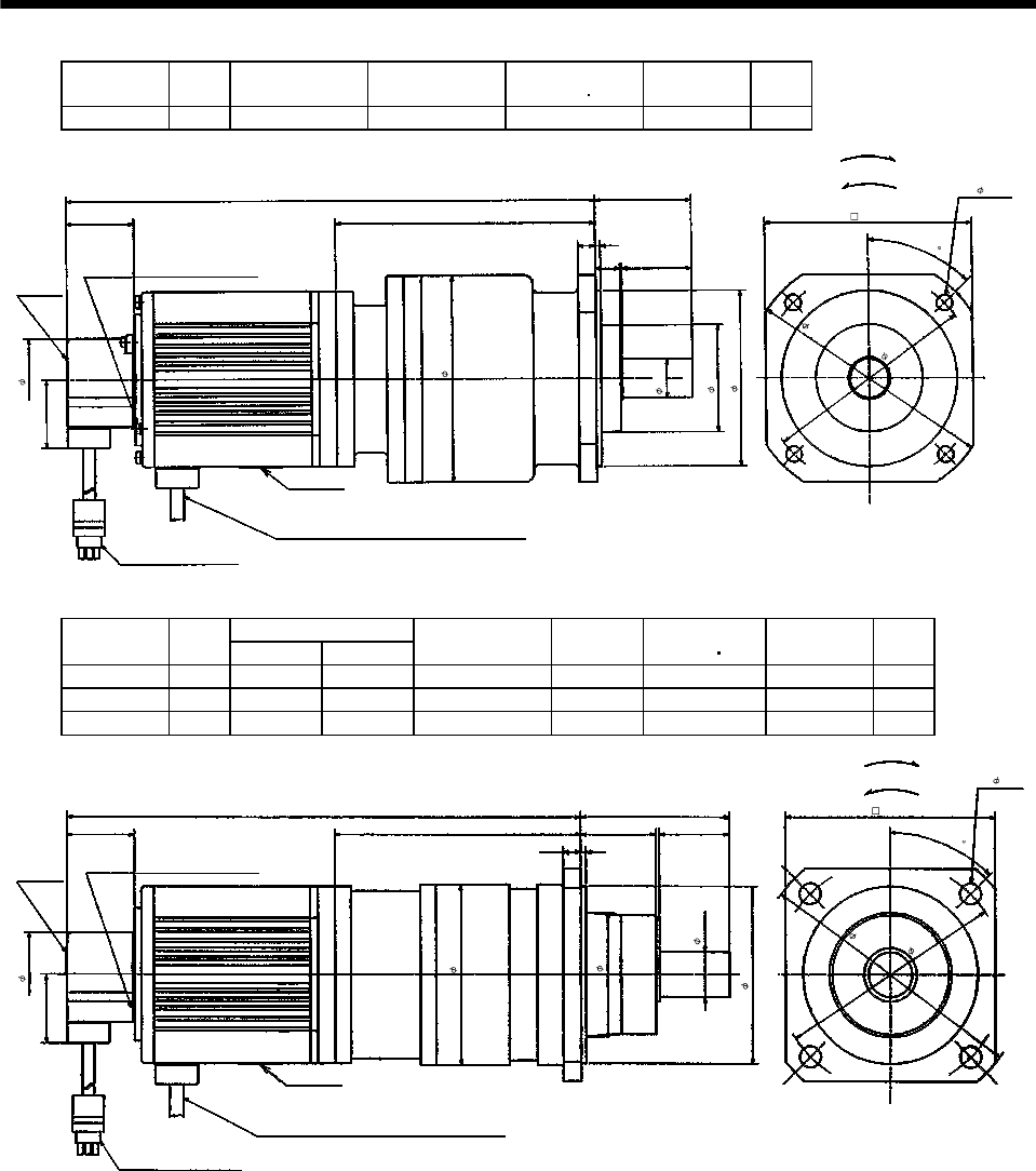
7 - 185
7. OUTLINE DIMENSION DRAWINGS
Model Output
[W]
Reduction Gear
Model Reduction Ratio Inertia Moment
WK2[oz in2]Backlash Mass
[lb]
HA-FF43G2 400 BM4-05B-04MES 1/5 7.07 3min. max. 17.0
Motor plate
1.54
0.39
5.866
[Unit: in]
Red: Phase U
White: Phase V
Black: Phase W
Top
Bottom
2.17
Bottom
Top
1.54
Caution plate
11.949
Earth terminal M3 screw
(Opposite side)
"Rotation direction" For forward rotation command
For reverse rotation command
0.12
0.55 1.57
Power supply cable
VCTF 3-0.05 19.7in
(With end-insulated round crimping terminal 0.05-4)
2
Encoder cable 11.8in
With connector 172169-9
(AMP)
1.85
4.65
3.94
2.40
4.80
5.51
4.65
4- 0.26
Z694811*
45
0.866
Variable Dimensions [in]
Model Output
[W] LH
Reduction Gear
Model
Reduction
Ratio
Inertia Moment
WK2[oz in2]Backlash Mass
[lb]
HA-FF43G2 400 11.63 5.557 BL1-09B-04MES 1/9 6.52 3min. max. 18.1
HA-FF63G2 600 11.83 5.157 BL1-05B-06MES 1/5 7.01 3min. max. 19.4
HA-FF63G2 600 12.22 5.557 BL1-09B-06MES 1/9 7.75 3min. max. 19.4
Caution plate
Motor plate
1.54
0.39
H
Top
Bottom
3.35
Bottom
Top
1.54
L
Earth terminal M3 screw
(Opposite side)
0.12
1.571.69
[Unit: in]
"Rotation direction" For forward rotation command
For reverse rotation command
Power supply cable
VCTF 3-0.05 19.7in
(With end-insulated round crimping terminal 0.05-4)
2
Red: Phase U
White: Phase V
Black: Phase W
Encoder cable 11.8in
With connector 172169-9
(AMP) Z694740*
4.72
4- 0.47
5.12
6.10
3.94
0.98
2.76
4.016
1.85
45
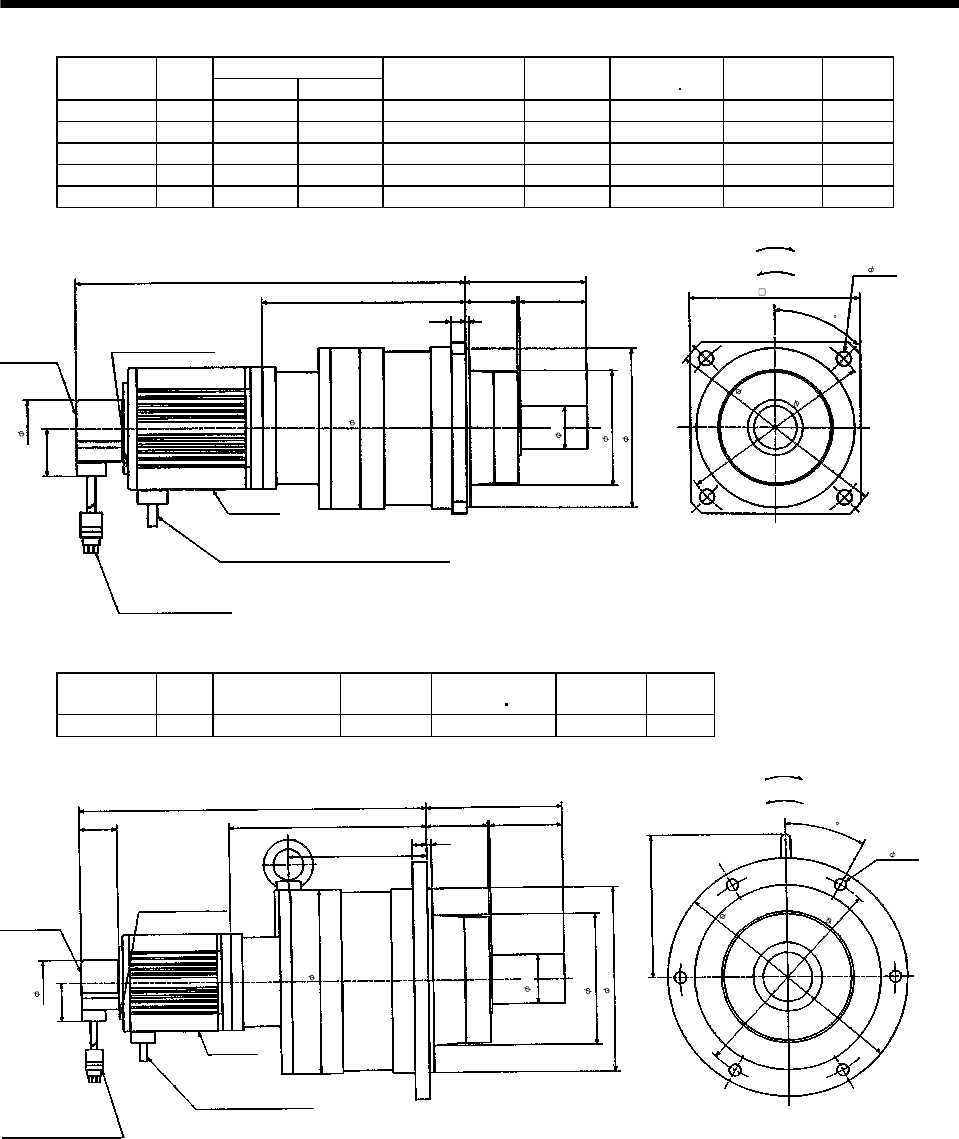
7 - 186
7. OUTLINE DIMENSION DRAWINGS
Variable Dimensions [in]
Model Output
[W] LH
Reduction Gear
Model
Reduction
Ratio
Inertia Moment
WK2[oz in2]Backlash Mass
[lb]
HA-FF43G2 400 12.74 6.654 BL2-20B-04MES 1/20 13.00 3min. max 31.3
HA-FF43G2 400 12.74 6.654 BL2-29B-04MES 1/29 10.99 3min. max 31.3
HA-FF43G2 400 13.13 7.047 BL2-45B-04MES 1/45 7.59 3min. max 31.3
HA-FF63G2 600 13.33 6.654 BL2-20B-06MES 1/20 14.23 3min. max 32.6
HA-FF63G2 600 13.33 6.654 BL2-29B-06MES 1/29 12.22 3min. max 32.6
Motor plate
Encoder cable 11.8in
With connector 172169-9
(AMP)
0.47
H
Top
Bottom
3.94
BottomTop
1.54
Caution plate
Earth terminal M3 screw
(Opposite side)
0.12
2.17
1.69
L
[Unit: in]
"Rotation direction" For forward rotation command
For reverse rotation command
Power supply cable
VCTF 3-0.05 196.9in
(With end-insulated round crimping terminal 0.05-4)
2
Red: Phase U
White: Phase V
Black: Phase W
1.85
5.20
3.70
5.12
7.28
6.30
4- 0.47
5.51
Z694741*
45
1.38
Model Output
[W]
Reduction Gear
Model
Reduction
Ratio
Inertia Moment
WK2[oz in2]Backlash Mass
[lb]
HA-FF63G2 600 BL3-45B-06MES 1/45 17.11 3min. max. 65.7
5.51
1.54
4.626
14.587
7.91
4.528
1.54 2.95
Earth terminal M3 screw
(Opposite side)
Bottom
Top
Motor plate
Bottom
Top
0.59 0.2
Z694742A
Power supply cable
VCTF 3-0.05 196.9in
(With end-insulated round
crimping terminal 0.05-4)
2
Red: Phase U
White: Phase V
Black: Phase W
Encoder cable 11.8in
With connector 172169-9
(AMP)
[Unit: in]
"Rotation direction" For forward rotation command
For reverse rotation command
Caution plate
2.48
6- 0.47
8.66
9.65
7.48
5.31
7.48
1.85
30
1.97
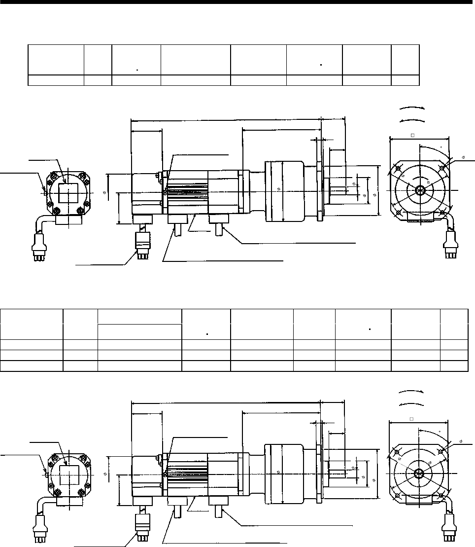
7 - 187
7. OUTLINE DIMENSION DRAWINGS
(b) With electromagnetic brake
Model Output
[W]
Brake static
friction torque
[oz in]
Reduction Gear
Model Reduction Ratio Inertia Moment
WK2[oz in2]Backlash Mass
[lb]
HA-FF053BG2 50 55 BM2-05B-A5MES 1/5 0.70 3min. max. 5.7
1.18
4- 0.18
1.54
2.44
1.30
2.95
3.898
0.79
Bottom
Top
‰º
Top
Caution plate
0.24 0.08
9.45
Earth terminal M3
2.91
1.54
1.85
Z694851*
2
2
Earth terminal M3 screw
(Opposite side)
"Rotation direction" For forward rotation command
For reverse rotation command
[Unit: in]
Brake lead
VCTF 2-0.02 19.7in
(With end-insulated round crimping terminal 0.05-4)
Motor plate
Power supply cable
VCTF 3-0.05 19.7in
(With end-insulated round crimping terminal 0.05-4)
Red: Phase U
White: Phase V
Black: Phase W
Encoder cable 11.8in
With connector 172169-9
(AMP)
3.50
3.07
0.39
45
Bottom
Variable Dimensions [in]
Model Output
[W] L
Brake static
friction torque
[oz in]
Reduction Gear
Model
Reduction
Ratio
Inertia Moment
WK2[oz in2]Backlash Mass
[lb]
HA-FF053BG2 50 9.45 55 BM2-05B-A5MES 1/10 0.68 3 min. max. 5.7
HA-FF053BG2 50 9.45 55 BM2-15B-A5MES 1/15 0.67 3 min. max. 5.7
HA-FF13BG2 100 10.118 55 BM2-05B-01MES 1/5 0.87 3 min. max. 6.2
1.18
3.50
4- 0.18
3.07
1.54
2.44
1.30
2.95
3.898
0.79
Bottom
Top
Motor plate
Top
Caution plate
0.24 0.08
L
Earth terminal M3
2.91
1.54
1.85
Z694812*
Red: Phase U
White: Phase V
Black: Phase W
2
2
"Rotation direction" For forward rotation command
For reverse rotation command[Unit: in]
Earth terminal M3 screw
(Opposite side)
Brake lead
VCTF 2-0.02 19.7in
(With end-insulated round crimping terminal 0.05-4)
Power supply cable
VCTF 3-0.05 19.7in
(With end-insulated round crimping terminal 0.05in-4)
Encoder cable 11.8in
With connector 172169-9
(AMP)
0.39
45
Bottom
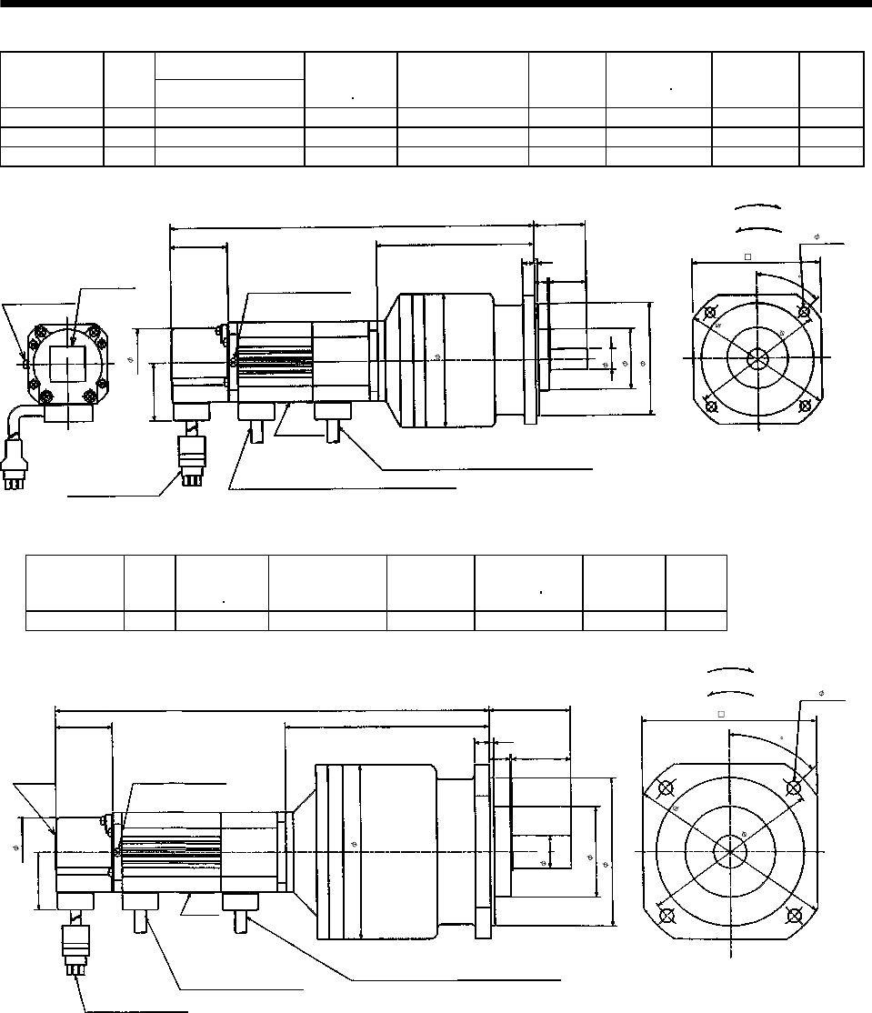
7 - 188
7. OUTLINE DIMENSION DRAWINGS
Variable Dimensions [in]
Model Output
[W] L
Brake static
friction torque
[oz in]
Reduction Gear
Model
Reduction
Ratio
Inertia Moment
WK2[oz in2]Backlash Mass
[lb]
HA-FF053BG2 50 9.764 55 BM3-25B-A5MES 1/25 0.66 3 min. max. 7.1
HA-FF13BG2 100 10.433 55 BM3-10B-01MES 1/10 1.00 3 min. max. 7.5
HA-FF13BG2 100 10.433 55 BM3-15B-01MES 1/15 0.95 3 min. max. 7.5
1.38
4.02
3.54
1.54
2.99
1.61
3.425
4.
213
0.98
Motor plate
Top
Caution plate
0.31 0.08
L
Earth terminal M3
3.43
1.54
1.85
Z694813*
0.35
Red: Phase U
White: Phase V
Black: Phase W
2
"Rotation direction" For forward rotation command
For reverse rotation command
[Unit: in]
2
Brake lead
VCTF 2-0.02 19.7in
(With end-insulated round crimping terminal 0.05-4)
Bottom
Top
Power supply cable
VCTF 3-0.05 19.7in
(With end-insulated round crimping terminal 0.05-4)
Encoder cable 11.8in
With connector 172169-9
(AMP)
Earth terminal M3 screw
(Opposite side)
4- 0.22
0.551
45
Bottom
Model Output
[W]
Brake static
friction torque
[oz in]
Reduction Gear
Model
Reduction
Ratio
Inertia Moment
WK2[oz in2]Backlash Mass
[lb]
HA-FF13BG2 100 55 BM4-25B-01MES 1/25 1.68 3 min. max. 11.7
2.17
5.51
4- 0.26
4.80
1.54
3.94
2.40
4.65
5.472
1.57
Bottom
Top
Motor plate
Caution plate
0.39 0.12
11.693
Bottom
4.65
1.54
1.85
Z694814*
0.55
Top
"Rotation direction"
For forward rotation command
For reverse rotation command
[Unit: in]
Earth terminal M3 screw
(Opposite side)
2
Brake lead
VCTF 2-0.02 19.7in
(With end-insulated round crimping terminal 0.05-4)
2
Power supply cable
VCTF 3-0.05 19.7in
(With end-insulated round
crimping terminal 0.05-4)
Red: Phase U
White: Phase V
Black: Phase W
Encoder cable 11.8in
With connector 172169-9
(AMP)
45
0.866
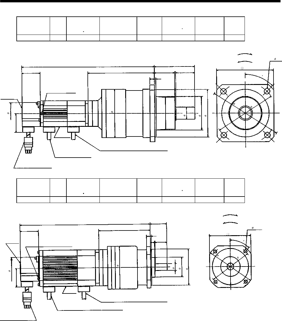
7 - 189
7. OUTLINE DIMENSION DRAWINGS
Model Output
[W]
Brake static
friction torque
[oz in]
Reduction Gear
Model
Reduction
Ratio
Inertia Moment
WK2[oz in2]Backlash Mass
[lb]
HA-FF13BG2 100 55 BL1-45B-01MES 1/45 1.63 3 min. max. 13.9
3.35
6.10
0.98
4- 0.47
5.12
1.54
3.94
2.76
4.016
5.945 1.57
Earth terminal M3 screw
(Opposite side)
Bottom
Top
Motor plate
ã
Caution plate
1.69
0.12
Encoder cable 11.8in
With connector 172169-9
(AMP)
12.15
Bottom
4.72
1.54
1.85
Z694792*
0.39
Top
Red: Phase U
White: Phase V
Black: Phase W
"Rotation direction"
For forward rotation command
For reverse rotation command
[Unit: in]
2
Brake lead
VCTF 2-0.02 19.7in
(With end-insulated round crimping terminal 0.05-4)
2
Power supply cable
VCTF 3-0.05 19.7in
(With end-insulated round
crimping terminal 0.05-4)
45
Model Output
[W]
Brake static
friction torque
[oz in]
Reduction Gear
Model
Reduction
Ratio
Inertia Moment
WK2[oz in2]Backlash Mass
[lb]
HA-FF23BG2 200 170 BM3-05B-02MES 1/5 3.05 3 min. max. 9.7
1.38
4.02
4- 0.22
3.54
1.54
2.99
1.61
4.291
0.98
Earth terminal M3 screw
(Opposite side)
BottomTop
Motor plate
Caution plate
0.31 0.08
10.91
Bottom
3.43
1.54
1.85
Z694815*
0.35
Top
Red: Phase U
White: Phase V
Black: Phase W
"Rotation direction"
For forward rotation command
For reverse rotation command
[Unit: in]
2
Brake lead
VCTF 2-0.02 19.7in
(With end-insulated round crimping terminal 0.05-4)
2
Power supply cable
VCTF 3-0.05 19.7in
(With end-insulated round crimping terminal 0.05-4)
Encoder cable 11.8in
With connector 172169-9
(AMP)
0.551
3.425
45
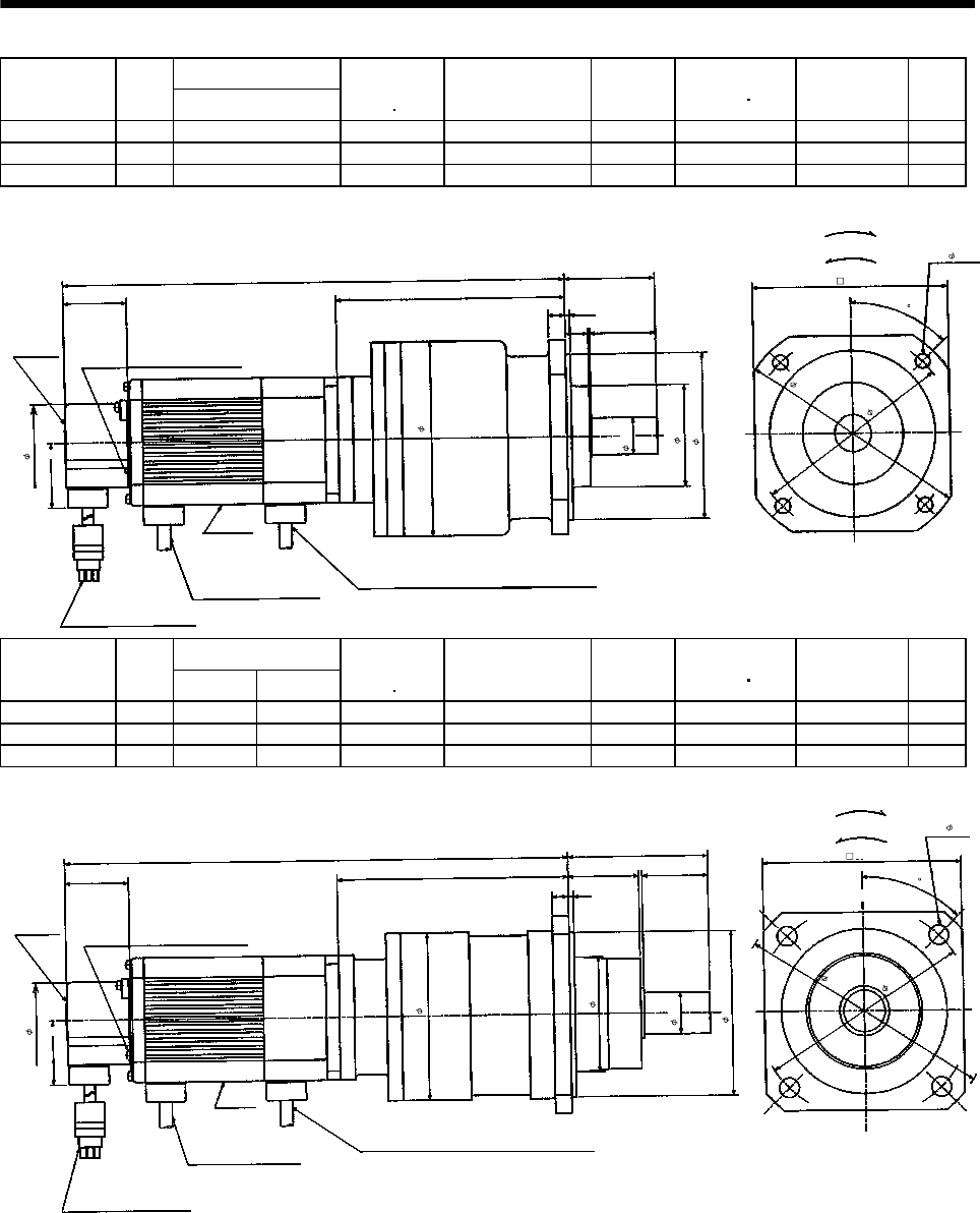
7 - 190
7. OUTLINE DIMENSION DRAWINGS
Variable Dimensions [in]
Model Output
[W] L
Brake static
friction torque
[oz in]
Reduction Gear
Model
Reduction
Ratio
Inertia Moment
WK2[oz in2]Backlash Mass
[lb]
HA-FF23BG2 200 12.087 170 BM4-10B-02MES 1/10 4.25 3 min. max. 14.1
HA-FF23BG2 200 12.087 170 BM4-15B-02MES 1/15 4.10 3 min. max. 14.1
HA-FF33BG2 300 12.78 170 BM4-10B-03MES 1/10 5.07 3 min. max. 14.8
2.17
5.51
4- 0.26
4.80
1.54
3.94
2.40
4.65
5.472
1.57
Earth terminal M3 screw
(Opposite side)
BottomTop
Motor plate
Caution plate
0.39 0.12
L
Bottom
4.65
1.54
1.85
Z694816*
0.55
"Rotation direction"
For forward rotation command
[Unit: in]
For reverse rotation command
2
Power supply cable
VCTF 3-0.05 19.7in
(With end-insulated round
crimping terminal 0.05-4)
Red: Phase U
White: Phase V
Black: Phase W
Encoder cable 11.8in
With connector 172169-9
(AMP)
2
Brake lead
VCTF 2-0.02 19.7in
(With end-insulated round crimping terminal 0.05-4)
Top
45
0.866
Variable Dimensions [in]
Model Output
[W] LH
Brake static
friction torque
[oz in]
Reduction Gear
Model
Reduction
Ratio
Inertia Moment
WK2[oz in2]Backlash Mass
[lb]
HA-FF23BG2 200 12.26 5.669 170 BL1-20B-02MES 1/20 4.84 3 min. max. 16.3
HA-FF23BG2 200 12.38 5.787 170 BL1-29B-02MES 1/29 4.18 3 min. max. 16.3
HA-FF33BG2 300 12.97 5.669 170 BL1-20B-03MES 1/20 5.54 3 min. max. 17.0
3.35
6.10
4- 0.47
5.12
1.54
3.94
2.76
4.016
H
1.57
Earth terminal M3 screw
(Opposite side)
Bottom
Top
Motor plate
Caution plate
0.39 0.12
L
Bottom
4.72
1.54
1.85
Z694793*
1.69
Red: Phase U
White: Phase V
Black: Phase W
2
"Rotation direction"
For forward rotation command
[Unit: in]
For reverse rotation command
2
Brake lead
VCTF 2-0.02 19.7in
(With end-insulated round crimping terminal 0.05-4)
Power supply cable
VCTF 3-0.05 19.7in
(With end-insulated round
crimping terminal 0.05-4)
Encoder cable 11.8in
With connector 172169-9
(AMP)
Top
45
0.98
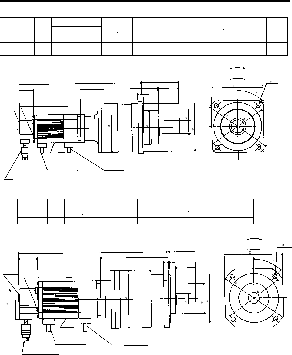
7 - 191
7. OUTLINE DIMENSION DRAWINGS
Variable Dimensions [in]
Model Output
[W] L
Brake static
friction torque
[oz in]
Reduction Gear
Model
Reduction
Ratio
Inertia Moment
WK2[oz in2]Backlash Mass
[lb]
HA-FF23BG2 200 13.23 170 BL2-45B-02MES 1/45 4.89 3 min. max. 28.4
HA-FF33BG2 300 13.92 170 BL2-29B-03MES 1/29 9.12 3 min. max. 29.1
HA-FF33BG2 300 14.31 170 BL2-45B-03MES 1/45 5.71 3 min. max. 29.1
3.94
7.2
8
1.38
4- 0.47
[Unit: in]
For forward
rotation command
For reverse
rotation command
6.3
0
1.54
5.1
2
3
.70
5.20
6.
614
0.
12
Earth terminal M3 screw
(Opposite side)
Motor plate
Caution plate
1.692.17
Encoder cable 11.8in
With connector 172169-9
(AMP)
L
Bottom
5.51
Z694794*
0.47
Top
Red: Phase U
White: Phase V
Black: Phase W
Power supply cable
VCTF 0.05 19.7in
(With end-insulated round
crimping terminal 0.05-4)
2
Brake lead
VCTF 0.02 19.7in
(With end-insulated round
crimping terminal 0.05-4)
2
Bottom
Top
"Rotation direction"
45
Model Output
[W]
Brake static
friction torque
[oz in]
Reduction Gear
Model
Reduction
Ratio
Inertia Moment
WK2[oz in2]Backlash Mass
[lb]
HA-FF33BG2 300 170 BM4-05B-03MES 1/5 5.19 3 min. max. 14.8
2.17
5.
51
0.866
4- 0.26
4.8
0
1.54
3.
94
2
.40
4.65
5.
472
1.
57
0.390.12
12.78
Bottom
4.65
1.
54
1.85
Z694817*
0.55
Top
Bottom
Top
Motor plate
Red: Phase U
White: Phase V
Black: Phase W
Power supply cable
VCTF 0.05 19.7in
(With end-insulated round
crimping terminal 0.05-4)
2
Encoder cable 11.8in
With connector 172169-9
(AMP)
Brake lead
VCTF 0.02 19.7in
(With end-insulated round
crimping terminal 0.05-4)
2
[Unit: in]
For forward
rotation command
For reverse
rotation command
Earth terminal M3 screw
(Opposite side)
Caution plate
"Rotation direction"
45
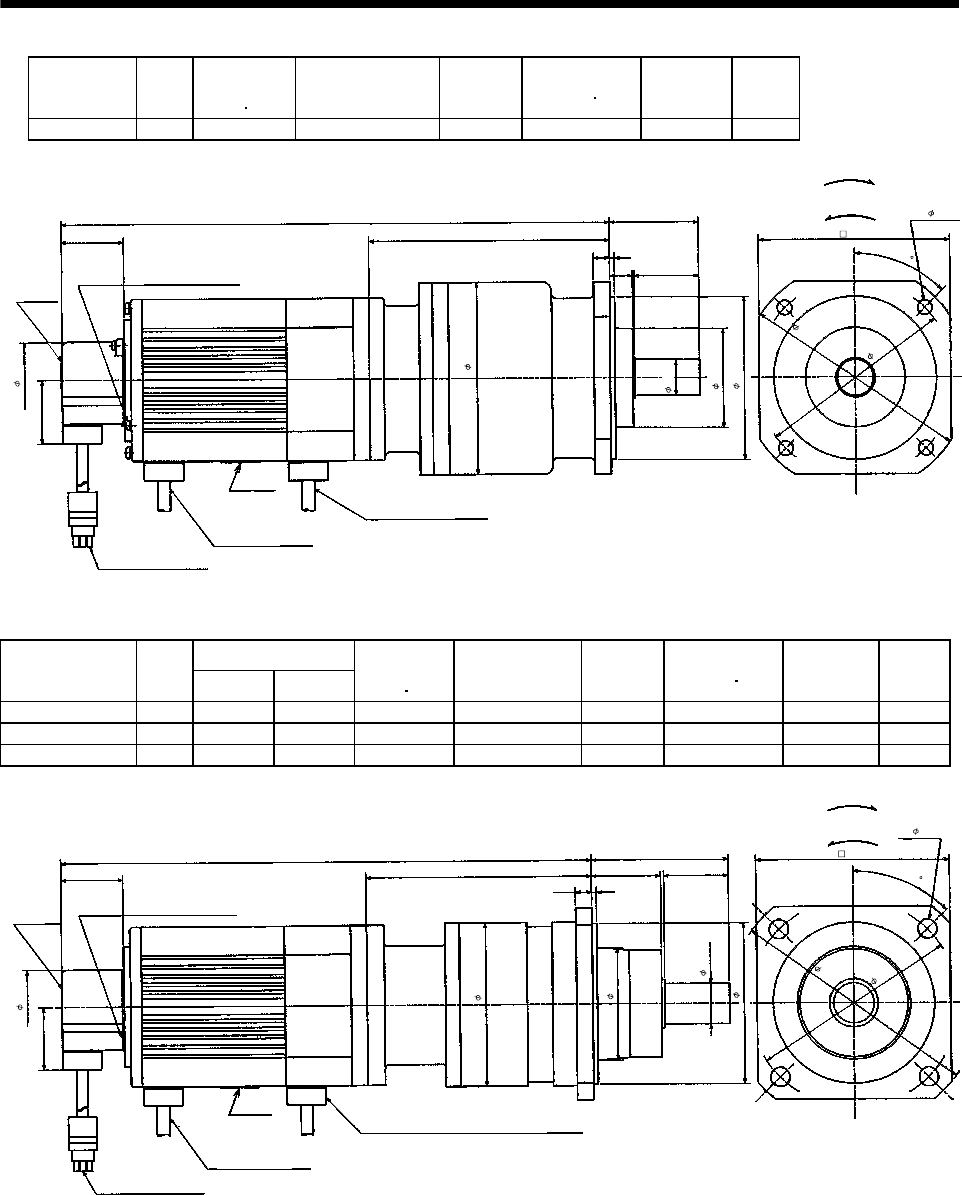
7 - 192
7. OUTLINE DIMENSION DRAWINGS
Model Output
[W]
Brake static
friction torque
[oz in]
Reduction Gear
Model
Reduction
Ratio
Inertia Moment
WK2[oz in2]Backlash Mass
[lb]
HA-FF43BG2 400 326 BM4-05B-04MES 1/5 8.98 3 min. max. 18.7
2.17
5.
51
4- 0.26
4.
80
1.54
3.
94
2
.40
4.65
5.
866
1.
57
0.390.12
13.41
4.65
1.
54
1.85
Z694818*
0.55
Bottom
Top
Bottom
Top
Motor plate
Encoder cable 11.8in
With connector 172169-9
(AMP) Red: Phase U
White: Phase V
Black: Phase W
Power supply cable
VCTF 0.05 19.7in
(With end-insulated round
crimping terminal 0.05-4)
2
Brake lead
VCTF 0.02 19.7in
(With end-insulated round
crimping terminal 0.05-4)
2
[Unit: in]
For forward
rotation command
For reverse
rotation command
Earth terminal M3 screw
(Opposite side)
Caution plate
"Rotation direction"
45
0.866
Variable Dimensions [in]
Model Output
[W] LH
Brake static
friction torque
[oz in]
Reduction Gear
Model
Reduction
Ratio
Inertia Moment
WK2[oz in2]Backlash Mass
[lb]
HA-FF43BG2 400 13.09 5.551 326 BL1-09B-04MES 1/9 8.43 3 min. max. 19.8
HA-FF63BG2 600 13.29 5.157 326 BL1-05B-06MES 1/5 10.16 3 min. max. 21.2
HA-FF63BG2 600 13.68 5.551 326 BL1-09B-06MES 1/9 9.66 3 min. max. 21.2
3.35
6.1
0
0.98
4- 0.47
5.1
2
1.54
3.
94
2.76
4.016
H
1.
57
0.390.12
L 4.72
1.
54
1.85
Z694795*
1.69
Bottom
Top
Bottom
Top
Motor plate
Red: Phase U
White: Phase V
Black: Phase W
Power supply cable
VCTF 0.05 19.7in
(With end-insulated round
crimping terminal 0.05-4)
2
Encoder cable 11.8in
With connector 172169-9
(AMP)
Brake lead
VCTF 0.02 19.7in
(With end-insulated round crimping terminal 0.05-4)
2
[Unit: in]
For forward
rotation command
For reverse
rotation command
Earth terminal M3 screw
(Opposite side)
Caution plate
"Rotation direction"
45
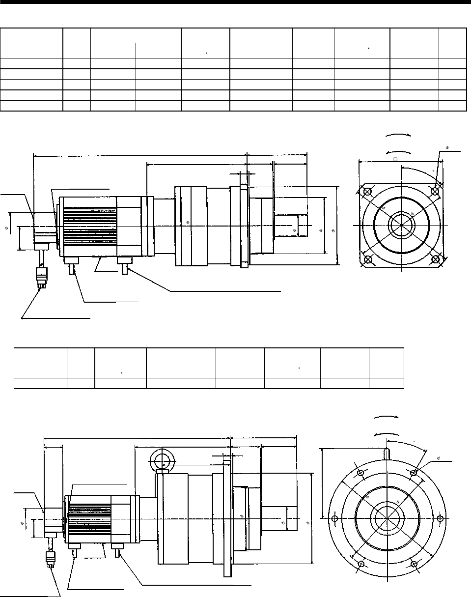
7 - 193
7. OUTLINE DIMENSION DRAWINGS
Variable Dimensions [in]
Model Output
[W] LH
Brake static
friction torque
[oz in]
Reduction Gear
Model
Reduction
Ratio
Inertia Moment
WK2[oz in2]Backlash Mass
[lb]
HA-FF43BG2 400 360.5 6.654 326 BL2-20B-04MES 1/20 14.91 3 min. max. 33.1
HA-FF43BG2 400 360.5 6.654 326 BL2-29B-04MES 1/29 12.90 3 min. max. 33.1
HA-FF43BG2 400 370.5 7.047 326 BL2-45B-04MES 1/45 9.50 3 min. max. 33.1
HA-FF63BG2 600 375.5 6.654 326 BL2-20B-06MES 1/20 16.14 3 min. max. 34.4
HA-FF63BG2 600 375.5 6.654 326 BL2-29B-06MES 1/29 14.13 3 min. max. 34.4
3.94 4- 0.47
5.
12
3
.70
5.20
H
2.
17
0.470.12
L
5.51
1.
54
1.85
Z694796*
1.69
Bottom
Top
Bottom
Top
Motor plate
Encoder cable 11.8in
With connector 172169-9
(AMP)
Red: Phase U
White: Phase V
Black: Phase W
Power supply cable
VCTF 0.05 196.9in
(With end-insulated round
crimping terminal 0.05-4)
2
Brake lead
VCTF 0.02 19.7in
(With end-insulated round crimping terminal 0.05-4)
2
[Unit: in]
For forward
rotation command
For reverse
rotation command
Earth terminal M3 screw
(Opposite side)
Caution plate
"Rotation direction"
45
1.38
6.30
7.28
Model Output
[W]
Brake static
friction torque
[oz in]
Reduction Gear
Model
Reduction
Ratio
Inertia Moment
WK2[oz in2]Backlash Mass
[lb]
HA-FF63BG2 600 326 BM3-45B-06MES 1/45 19.00 3 min. max. 74.3
5.51
9.
65
6- 0.47
8.66
1.54
7.4
8
4.
626
5
.31
7.
91
2.
95
0.590.2
16.04
1.
54
1.85
Z694797A
2.48
4.528
Bottom
Top
BottomTop
Motor plate
Encoder cable 11.8in
With connector 172169-9
(AMP) Red: Phase U
White: Phase V
Black: Phase W
Power supply cable
VCTF 0.05 196.9in
(With end-insulated round
crimping terminal 0.05-4)
2Brake lead
VCTF 0.02 19.7in
(With end-insulated round crimping terminal 0.05-4)
2
[Unit: in]
For forward
rotation command
For reverse
rotation command
Earth terminal M3 screw
(Opposite side)
Caution plate
"Rotation direction"
30
1.97
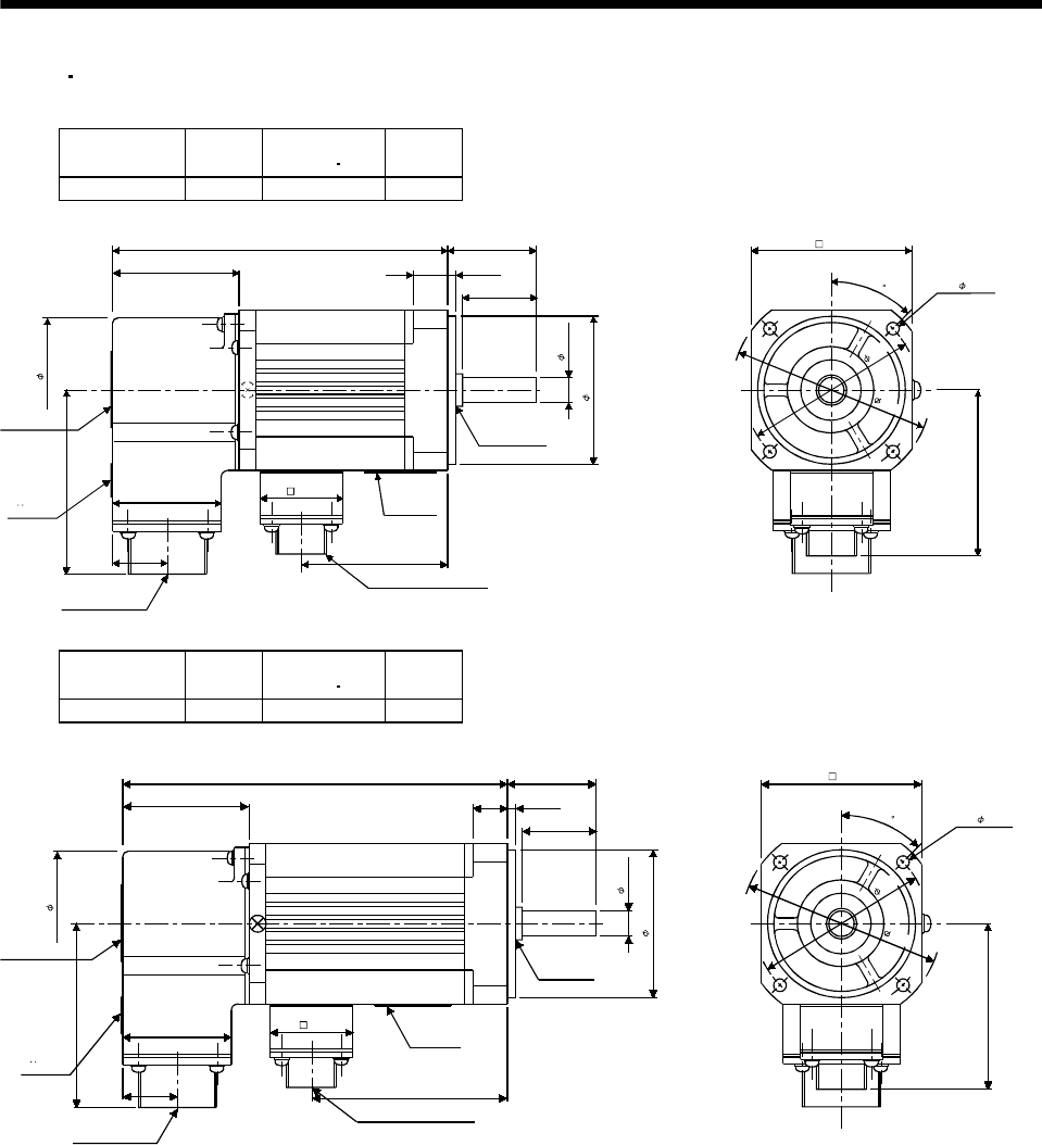
7 - 194
7. OUTLINE DIMENSION DRAWINGS
(5) EN UL/C-UL Standard-Compliant model
(a) Standard (without electromagnetic brake, without reduction gear)
Model Output
[W]
Inertia Moment
WK2[oz in2]
Mass
[lb]
HA-FF053C-UE 50 0.342 4.0
[Unit: in]
TUV plate
Caution plate
1.85
2.91
Bottom
Top
Bottom
Top 1.61
0.79
1.26
1.95
Motor plate
Top Bottom
Oil seal
GM10204B
4.72 1.18
0.42 0.1
0.98
0.31
1.97
1.81
Power supply connector
CE05-2A14S-2PD-B
4- 0.18
2.13
2.72
Encoder connector
MS3102A20-29P
2.36
2.68
45
BC07316A
Model Output
[W]
Inertia Moment
WK2[oz in2]
Mass
[lb]
HA-FF13C-UE 100 0.519 4.4
[Unit: in]
Caution plate
TUV plate
1.85
2.91
Bottom
Top
Bottom
Top
1.61
0.79
Encoder connector
MS3102A20-29P
1.81 0.47 0.1
5.39
0.98
1.18
0.31
1.97
Oil seal
S10207B
Motor plate
Top Bottom
2.62
Power supply connector
CE05-2A14S-2PD-B
1.26
4- 0.18
2.13
2.72
2.36
2.68
45
BC07331A
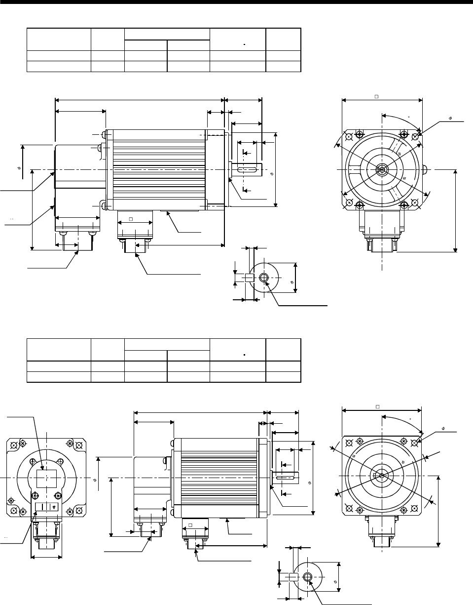
7 - 195
7. OUTLINE DIMENSION DRAWINGS
Variable Dimensions [in]
Model Output
[W] LKL
Inertia Moment
WK2[oz in2]
Mass
[lb]
HA-FF23C-UE 200 5.71 2.82 1.91 5.7
HA-FF33C-UE 300 6.38 3.50 2.73 6.4
[Unit: in]
1.85
1.81
L1.18
0.98
0.120.55
Caution plate
TUV plate
Encoder connector
MS3102A20-29P
0.79
1.61
1.26
Bottom
Top
Bottom
Top
Motor plate
KL 0.10
0.16
0.16
M4 threads, depth 0.59
0.43
Oil seal
S15307B
A
A
0.63 0.16
2.76
Top Bottom
4- 0.22
2.99
3.11
Power supply connector
CE05-2A14S-2PD-B
Section AA
3.54
3.94
2.91
45
BC07332A
Variable Dimensions [in]
Model Output
[W] LKL
Inertia Moment
WK2[oz in2]
Mass
[lb]
HA-FF43C-UE 400 6.65 3.66 5.33 10.4
HA-FF63C-UE 600 7.24 4.25 6.56 11.7
[Unit: in]
Caution plate
TUV plate
Bottom
Top
Bottom
Top
1.732
1.85
2.91
L1.57
0.63 0.12
1.38
0.98 0.20
A
A
Oil seal
S17308B
Motor plate
1.26
0.79
1.61
Encoder connector
MS3102A20-29P Power supply connector
CE05-2A14S-2PD-B
KL
BottomTop
M5 threads, depth 0.79
Section AA
0.12
0.20
0.20
0.63
3.74
4- 0.35
3.94
3.58
1.85
EC
4.53
5.31
45
BC07314B
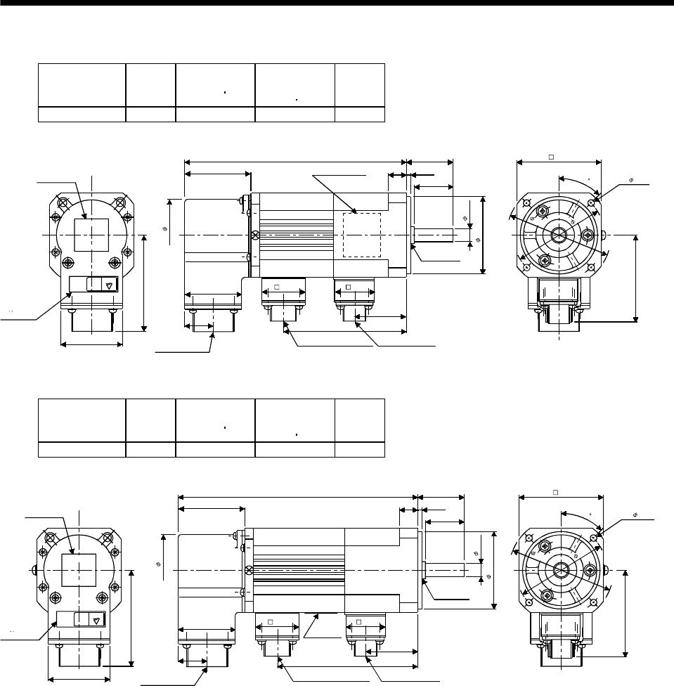
7 - 196
7. OUTLINE DIMENSION DRAWINGS
(b) With electromagnetic brake
Model Output
[W]
Inertia Moment
WK2[oz in2]
Brake static
friction torque
[oz in]
Mass
[lb]
HA-FF053CB-UE 50 0.437 55 4.6
[Unit: in]
Caution plate
TUV plate
Top
Bottom
Top
CE
2.91
1.73
1.85
1.85
1.61
Encoder connector
MS3102A20-29P
0.79
6.10 1.18
Motor plate
(Opposite side)
BottomTop
0.47 0.1
0.98
Oil seal
GM10204B
0.31
1.97
3.31
Power supply connector
CE05-2A14S-2PD-B
Brake connector
MS3102A10SL-4P
1.26
1.40
4- 0.18
2.13
2.64
2.68
2.36
1.10
Bottom
45
BC08269A
Model Output
[W]
Inertia Moment
WK2[oz in2]
Brake static
friction torque
[oz in]
Mass
[lb]
HA-FF13CB-UE 100 0.615 55 5.1
[Unit: in]
Caution plate
TUV plate
Top
CE
2.91
1.73
1.85
1.85
1.61
Encoder connector
MS3102A20-29P
0.79
6.77 1.18
0.43 0.1
0.98
Oil seal
S10207B
0.31
1.97
3.98
Power supply connector
CE05-2A14S-2PD-B
Brake connector
MS3102A10SL-4P
1.26
1.40
4- 0.18
2.13
2.64
Motor plate
Bottom
Top
BottomTop
2.68
2.36
1.10
Bottom
45
BC07372A
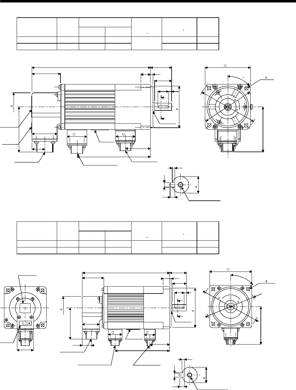
7 - 197
7. OUTLINE DIMENSION DRAWINGS
Variable Dimensions [in]
Model Output
[W] LKL
Brake static
friction torque
[oz in]
Inertia Moment
WK2[oz in2]
Mass
[lb]
HA-FF23CB-UE 200 7.17 4.29 2.64 7.7
HA-FF33CB-UE 300 7.87 5.0 170 3.46 8.4
[Unit: in]
Section AA
Caution plate
TUV plate
Encoder connector
MS3102A20-29P
0.79
2.91
1.61
1.81
1.85
1.26 1.10
Motor plate
Power supply connector
CE05-2A14S-2PD-B
Brake connector
MS3102A10SL-4P
1.18L
0.55 0.12
0.98
A
A
0.63 0.16
2.76
Oil seal
S15307B
1.52
0.10
0.16
0.16
0.43
M4 threads, depth 0.59
KL
4- 0.22
2.99
3.11
BottomTop
3.54
3.94
45
BC07357B
Variable Dimensions [in]
Model Output
[W] LKL
Brake static
friction torque
[oz in]
Inertia Moment
WK2[oz in2]
Mass
[lb]
HA-FF43CB-UE 400 8.11 5.12 7.24 12.8
HA-FF63CB-UE 600 8.70 5.71 326 8.47 14.1
[Unit: in]
Section AA
Caution plate
(English)
TUV plate
CE
1.85
2.91
1.61
0.79
1.732 Encoder connector
MS3102A20-29P
Power supply connector
CE05-2A14S-2PD-B (D17)
Motor plate
Brake connector
MS3102A10SL-4P
KL
1.26 1.10
3.74
1.67
0.98
1.38
Top Bottom
A
A
0.20
0.63 0.12
1.57L
1.85
Oil seal
S17308B
0.63
0.12
0.20
0.20
M5 threads, depth 0.79
4- 0.35
3.94
3.58
4.53
5.31
Bottom
Top
Bottom
Top
45
BC07333A
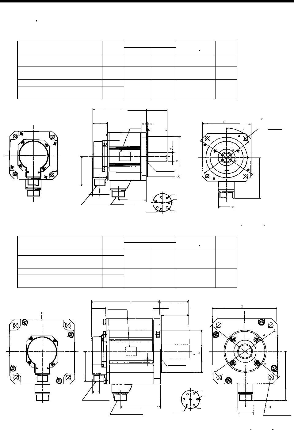
7 - 198
7. OUTLINE DIMENSION DRAWINGS
7.2.3 HC-SF HC-SFS series
(1) Standard (without electromagnetic brake, without reduction gear)
Variable Dimensions [in]
Model Output
[kW] LKL
Inertia Moment
WK2[oz in2]
Mass
[lb]
HC-SF52
HC-SF53
HC-SFS52
HC-SFS53 HC-SFS524 0.5 4.72 2.03 36.22 11.0
HC-SF102
HC-SF103
HC-SFS102
HC-SFS103 HC-SFS1024 1.0 5.71 3.02 74.90 15.4
HC-SF81 HC-SFS81 0.85
HC-SF152
HC-SF153
HC-SFS152
HC-SFS153 HC-SFS1524 1.5 6.69 4.00 109.08 19.8
KL
0.77
W
V
U
A
B
C
D
E
FG
H
S30457B
MS3102A20-29P CE05-2A22-23P
3.21
1.56
L2.165
0.47 0.12
1.97
0.95
4.33
1.61
4.37
6.50
5.71
5.12
Z694854*
Bottom
Top
Encoder connector Power supply connector
Oil seal
Motor flange direction
Earth
Power supply connector layout
CE05-2A22-23P
Use hexagon socket
head cap screw.
[Unit: in]
4- 0.35 mounting hole
Motor plate
(Opposite side)
Bottom
Top
(BC11651* BC11757* BC11768*)
45
Variable Dimensions [in]
Model Output
[kW] LKL
Inertia Moment
WK2[oz in2]
Mass
[lb]
HC-SF121 HC-SFS121 1.2
HC-SF202
HC-SF203
HC-SFS202
HC-SFS203 HC-SFS2024 2.0 5.71 2.70 232.37 26.5
HC-SF201 HC-SFS201 2.0
HC-SF352
HC-SF353
HC-SFS352
HC-SFS353 HC-SFS3524 3.5 7.36 4.35 448.33 41.9
W
V
U
A
B
C
D
E
F
G
KL
0.77
3.21
1.56
L3.11
0.71 0.12
2.95
1.81
5.59
6.93
9.06
7.87
Z695393A
S40608B
MS3102A20-29P
CE05-2A24-10P
Encoder connector
Power supply connector
Oil seal
Motor flange direction
Power supply connector layout
CE05-2A24-10P
Motor plate
(Opposite side)
Bottom
Top
4- 0.53 mounting hole
Use hexagon socket
head cap screw.
Earth
Bottom
Top
[Unit: in]
4.5
1.378
(BC11769* BC11652* BC11758*)
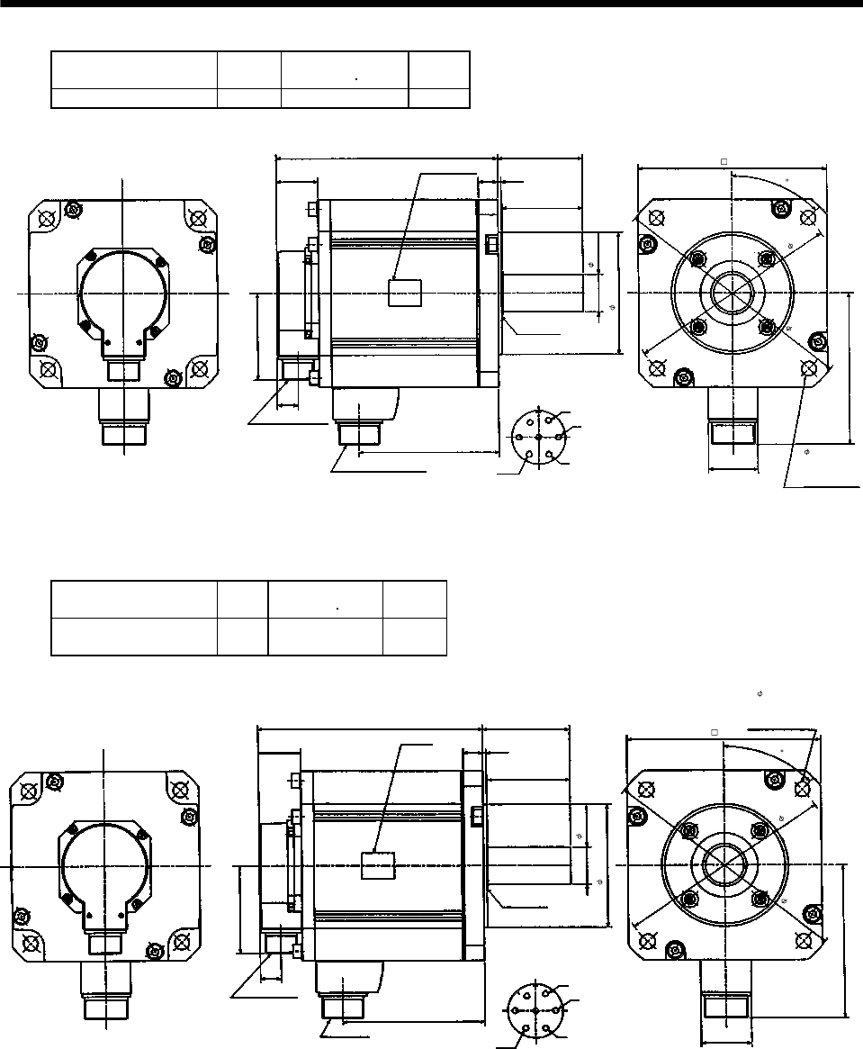
7 - 199
7. OUTLINE DIMENSION DRAWINGS
Model Output
[kW]
Inertia Moment
WK2[oz in2]
Mass
[lb]
HC-SF301 HC-SFS301 3.0 552.212 50.7
W
V
U
A
B
C
D
E
F
G
5.157
0.77
3.21
1.56
8.189
0.71 0.12
2.95
1.81
5.59
6.93
9.06
7.87
S40608B
MS3102A20-29P
CE05-2A24-10P
Encoder connector
Power supply connector
Oil seal
Motor flange direction
Power supply connector layout
CE05-2A24-10P
Motor plate
(Opposite side)
Bottom
Top
4- 0.53 mounting
hole Use hexagon
socket head cap
screw.
Earth
Bottom
Top
[Unit: in]
BC10628*
(BC11769*)
3.11
1.378
4.5
45
Model Output
[kW]
Inertia Moment
WK2[oz in2]
Mass
[lb]
HC-SF502 HC-SFS502
HC-SFS5024 5.0 552.212 50.7
6.93
7.87
4- 0.53 mounting
hole Use hexagon
socket head cap
screw.
5.591
9.06
1.811
[Unit: in]
Power supply connector layout
CE05-2A24-10P
A
B
C
D
E
FG
U
V
W
Power supply connector
CE05-2A24-10P
Encoder connector
MS3102A20-29P
Motor plate
(Opposite side)
8.189
1.56 0.71 0.12
2.95
3.11
S40608B
Oil seal
Top
Bottom
3.21
0.77
Top
Bottom
1.378
4.5
Earth
5.177
BC10626A
Motor flange direction
45
(BC11743*)
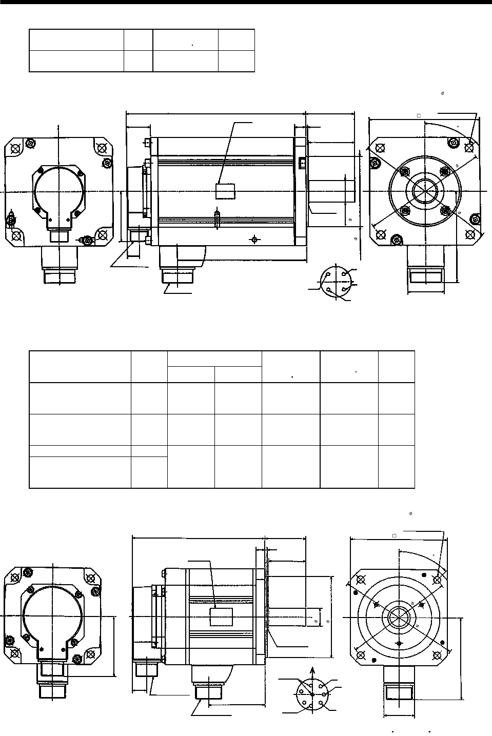
7 - 200
7. OUTLINE DIMENSION DRAWINGS
Model Output
[kW]
Inertia Moment
WK2[oz in2]
Mass
[lb]
HC-SF702 HC-SFS702
HC-SFS7024 7.0 874.791 70.5
6.93
7.87
4- 0.53 mounting
hole Use hexagon
socket head cap
screw.
9.06
2.283
[Unit: in]
Power supply connector layout
CE05-2A32-17P
A
B
C
D
U
V
W
Power supply connector
CE05-2A32-17P
Encoder connector
MS3102A20-29P
Motor plate
(Opposite side)
11.496
1.56 0.71 0.12
2.95
3.11
S40608B
Oil seal
Top
Bottom
3.21
0.77
Top
Bottom
1.378
4.5
Earth
8.287
BC10856*
Motor flange direction
5.906
45
(BC11744*)
(2) With electromagnetic brake
Variable Dimensions [in]
Model Output
[kW] LKL
Brake static
friction torque
[oz in]
Inertia Moment
WK2[oz in2]
Mass
[lb]
HC-SF52B
HC-SF53B
HC-SFS52B
HC-SFS53B
HC-SFS524B
0.5 6.02 2.03 1204 45.52 16.535
HC-SF102B
HC-SF103B
HC-SFS102B
HC-SFS103B
HC-SFS1024B
1.0 7.01 3.02 1204 84.20 20.944
HC-SF81B HC-SFS81B 0.85
HC-SF152B
HC-SF153B
HC-SFS152B
HC-SFS153B
HC-SFS1524B
1.5 7.99 4.00 1204 118.37 25.353
KL
0.77
W
V
U
A
B
C
D
E
F
G
H
MS3102A20-29P
CE05-2A22-23P
3.21
L2.165
0.47 0.12
1.97
0.95
4.33
1.61
4.37
5.12
6.50
5.71
Z695005
Encoder connector
Power supply connector
Oil seal
S30457B
Motor flange direction
Power supply connector layout
CE05-2A22-23P
Use hexagon socket
head cap screw.
4- 0.35 mounting hole
Motor plate
(Opposite side)
Bottom
Top
Earth
[Unit: in]
Brake
45
(BC11653* BC11762* BC11775*)
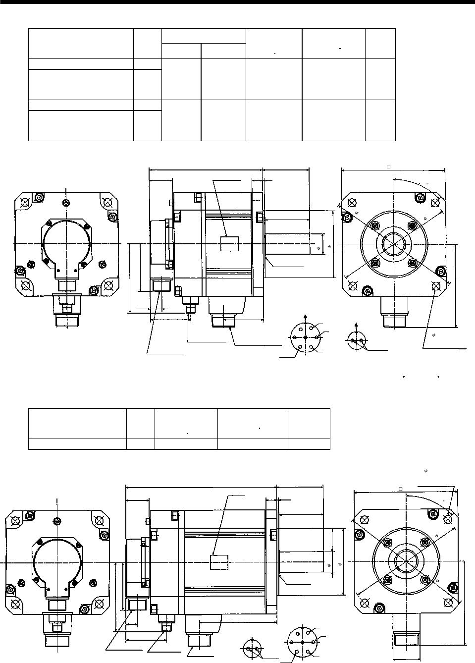
7 - 201
7. OUTLINE DIMENSION DRAWINGS
Variable Dimensions [in]
Model Output
[kW] LKL
Brake static
friction torque
[oz in]
Inertia Moment
WK2[oz in2]
Mass
[lb]
HC-SF121B HC-SFS 121B 1.2
HC-SF202B
HC-SF203B
HC-SFS 202B
HC-SFS 203B
HC-SFS 2024B
2.0 7.60 2.70 6103 287.04 39.683
HC-SF201B HC-SFS 201B 2.0
HC-SF352B
HC-SF353B
HC-SFS 352B
HC-SFS 353B
HC-SFS3524B
3.5 9.25 4.35 6103 503.01 55.115
KL
0.77
3.21
1.56
L3.11
0.71 0.12
2.95
5.59
6.93
9.06
7.87
4.61
2.72
4.5
1.38
Z695319D
4- 0.53 mounting hole
Use hexagon socket
head cap screw.
Bottom
Top
Power supply connector
CE05-2A24-10P
[Unit: in]
Motor plate
(Opposite side)
MS3102A20-29P
Encoder connector
Brake connector
MS3102A10SL-4P
S40608B
Oil seal
Bottom
Top
W
V
U
A
B
C
D
E
F
GAB
Motor flange direction
Earth
Power supply connector layout
CE05-2A24-10P
Brake connector layout
MS3102A10SL-4P
Motor flange direction
Brake
(BC11654* BC11763* BC11776*)
45
Model Output
[kW]
Brake static
friction torque
[oz in]
Inertia Moment
WK2[oz in2]
Mass
[lb]
HC-SF301B HC-SFS301B 3.0 6103 606.886 63.9
4.5
1.38
Encoder connector
MS3102A20-29P
Motor plate
(Opposite side)
5.177
0.77
W
V
U
A
B
C
D
E
FG
Power supply
connector layout
CE05-2A24-10P
Motor flange direction
Oil seal
S40608B
3.21
1.56
10.079 3.11
0.71 0.12
2.95
5.591
6.93
4- 0.53 mounting hole
Use hexagon socket
head cap screw.
Bottom
Top
Bottom
Top
Brake connector
MS3102A10SL-4P
9.06
7.87
4.61
2.72
Brake connector
layout
MS3102A10SL-4P
AB
Motor flange direction
Brake
[Unit: in]
1.811
Earth
Power supply
connector
CE05-2A24-10P
BC10823*
(BC11776*)
45
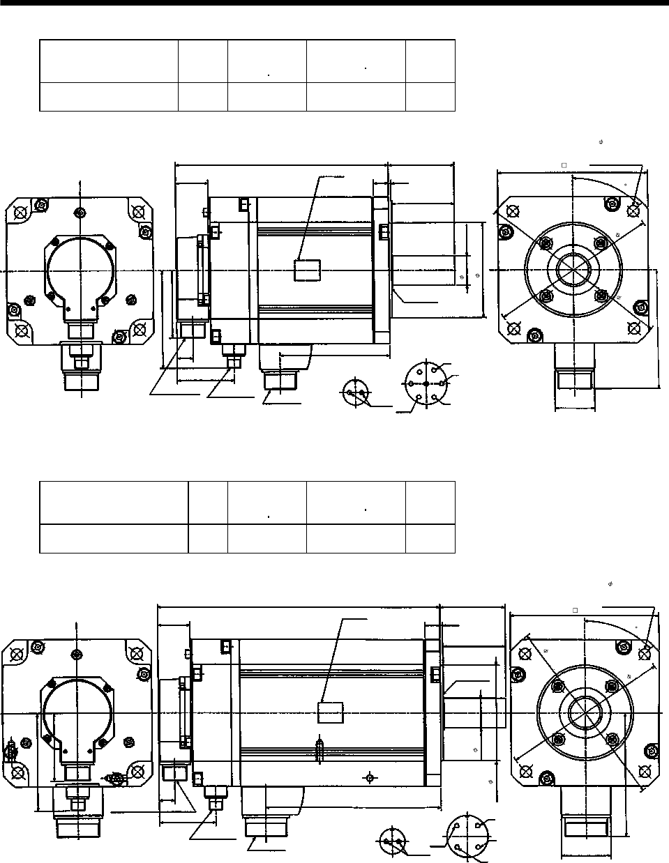
7 - 202
7. OUTLINE DIMENSION DRAWINGS
Model Output
[kW]
Brake static
friction torque
[oz in]
Inertia Moment
WK2[oz in2]
Mass
[lb]
HC-SF502B HC-SFS502B
HC-SFS5024B 5.0 6103 606.886 63.9
4.5
1.38
Encoder connector
MS3102A20-29P
Motor plate
(Opposite side)
5.177
0.77
Earth
W
V
U
A
B
C
D
E
FG
Power supply connector layout
CE05-2A24-10P
Motor flange direction
Oil seal
S40608B
Power supply connector
CE05-2A24-10P
3.21
1.56
10.079 3.11
0.71 0.12
2.95
5.591
6.93
4- 0.53 mounting hole
Use hexagon socket
head cap screw.
Bottom
Top
Bottom
Top
Brake connector
MS3102A10SL-4P
9.06
7.87
4.61
2.72
[Unit: in]
BC10627A
1.811
Brake connector
layout
MS3102A10SL-4P
Brake
AB
Motor flange direction
45
(
BC11750*
)
Model Output
[kW]
Brake static
friction torque
[oz in]
Inertia Moment
WK2[oz in2]
Mass
[lb]
HC-SF702B HC-SFS702B
HC-SFS7024B 7.0 6103 929.466 83.8
4.5
1.38
Encoder connector
MS3102A20-29P
Motor plate
(Opposite side)
8.287
0.77
Earth
W
V
U
A
B
C
D
G
Power supply connector
layout
C
E
05
-2A
3
2-17P
Motor flange direction
Oil seal
S40608B
Power supply connector
CE05-2A32-17P
1.56
13.386 3.11
0.71 0.12
6.93
4- 0.53 mounting hol
e
Use hexagon socket
head cap screw.
Bottom
Top
Bottom
Top
Brake connector
MS3102A10SL-4P
9.06
7.87
2.72
[Unit: in]
BC10857*
2.283
Brake connector
layout
MS3102A10SL-4P
Brake
AB
5.906
Motor flange direction
4.61
2.95
3.21
45
(BC11751*)
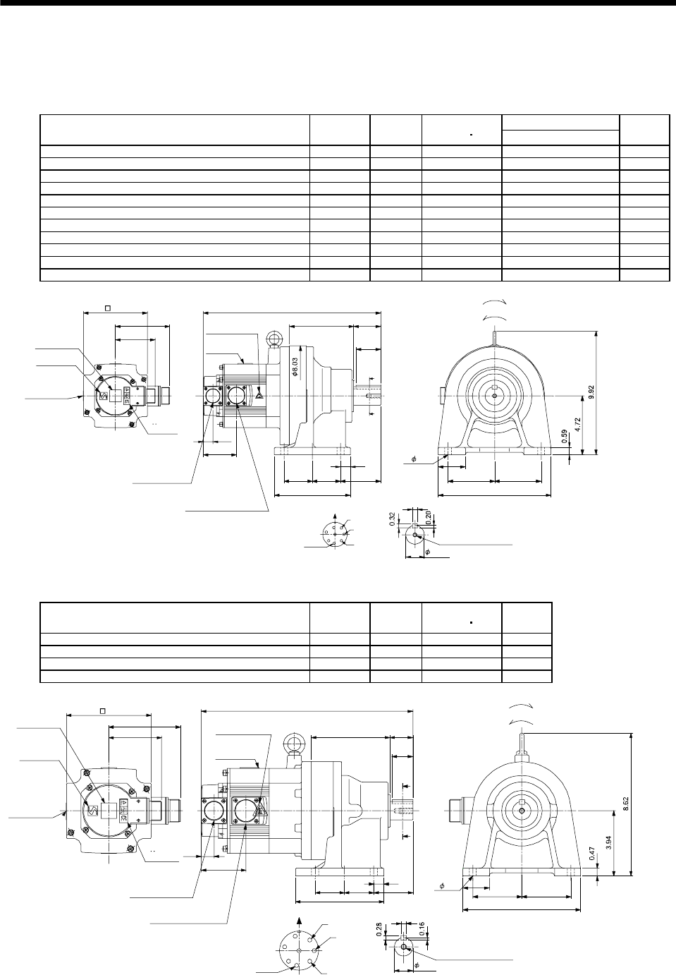
7 - 203
7. OUTLINE DIMENSION DRAWINGS
(3) With reduction gear for general industrial machine (leg type)
The outer frame of the reduction gear is a material surface such as casting. Its actual dimensions may
be 0.039 to 0.118 in larger than the drawing dimensions. Design the machine side with allowances.
(a) Without electromagnetic brake
Variable Dimensions [in]
Model Output
[kW]
Reduction
Ratio
Inertia Moment
WK2[oz in2]L
Mass
[lb]
HC-SF52G1H HC-SFS52G1H HC-SFS524G1H 0.5 1/35 41.01 13.31 61.7
HC-SF52G1H HC-SFS52G1H HC-SFS524G1H 0.5 1/43 40.73 13.31 61.7
HC-SF52G1H HC-SFS52G1H HC-SFS524G1H 0.5 1/59 40.60 13.31 61.7
HC-SF102G1H HC-SFS102G1H HC-SFS1024G1H 1.0 1/6 91.85 14.30 66.1
HC-SF102G1H HC-SFS102G1H HC-SFS1024G1H 1.0 1/11 83.7 14.30 66.1
HC-SF102G1H HC-SFS102G1H HC-SFS1024G1H 1.0 1/17 81.47 14.30 66.1
HC-SF102G1H HC-SFS102G1H HC-SFS1024G1H 1.0 1/29 79.83 14.30 66.1
HC-SF102G1H HC-SFS102G1H HC-SFS1024G1H 1.0 1/35 79.8 14.30 66.1
HC-SF152G1H HC-SFS152G1H HC-SFS1524G1H 1.5 1/6 126.3 15.28 70.5
HC-SF152G1H HC-SFS152G1H HC-SFS1524G1H 1.5 1/11 117.55 15.28 70.5
HC-SF152G1H HC-SFS152G1H HC-SFS1524G1H 1.5 1/17 115.9 15.28 70.5
3.21
4.37
A
B
C
D
E
FG
H
Z695739A
BC11798A BC26016A
0.39
3.743.74
9.06
2.17
5.16
L
3.232.26 2.26
6.10
0.79
0.77
2.70
A
A
2.17
1.97
Encoder connector
Power supply connector
V
U
CE05-2A22-23P
MS3102A20-29P
W
Motor plate
Caution plate
5.12
Logo plate
Side view of motor only
4- 0.55
Section AA
Power supply connector layout
Top
Bottom
Top
Bottom
TopBottom
TopBottom
For forward rotation command
"Rotation direction"
For reverse rotation command
Earth
CE05-2A22-23P
M8 screw, depth 0.79
Motor flange direction
TUV plate
Caution plate
(Note 2)
(Opposite side)
1.50
Caution plate
(Note 2)
(Note 1)[Unit: in]
Note 1. The dimensions without tolerances are reference dimensions.
2. This caution plate is attached to the 400V class motors only, not to the 200V class.
Model Output
[kW]
Reduction
Ratio
Inertia Moment
WK2[oz in2]
Mass
[lb]
HC-SF52G1H HC-SFS52G1H HC-SFS524G1H 0.5 1/6 40.05 46.3
HC-SF52G1H HC-SFS52G1H HC-SFS524G1H 0.5 1/11 38.00 46.3
HC-SF52G1H HC-SFS52G1H HC-SFS524G1H 0.5 1/17 37.45 46.3
HC-SF52G1H HC-SFS52G1H HC-SFS524G1H 0.5 1/29 37.04 46.3
A
A
Z695738*
BC11797C BC26180B
A
B
C
D
E
F
G
H
12.8
4.76 1.38
1.58
2.95 2.95
7.09
0.32
0.77
2.70
1.26
0.59
2.361.771.77
5.32
3.21
4.37
Encoder connector
Power supply connector
V
U
CE05-2A22-23P
MS3102A20-29P
W
Motor plate
Caution plate
Caution plate
(Note 2)
1.10
5.12
Logo plate
Side view of motor only
4- 0.43
Section AA
Power supply connector layout
Top
Bottom
Top
Bottom
Top
Bottom
TopBottom
For forward rotation command
"Rotation direction"
For reverse rotation command
Earth
CE05-2A22-23P
M8 screw, depth 0.79
Motor flange direction
TUV plate
Caution plate
(Note 2)
(Opposite side)
(Note 1)[Unit: in]
Note 1. The dimensions without tolerances are reference dimensions.
2. This caution plate is attached to the 400V class motors only, not to the 200V class.
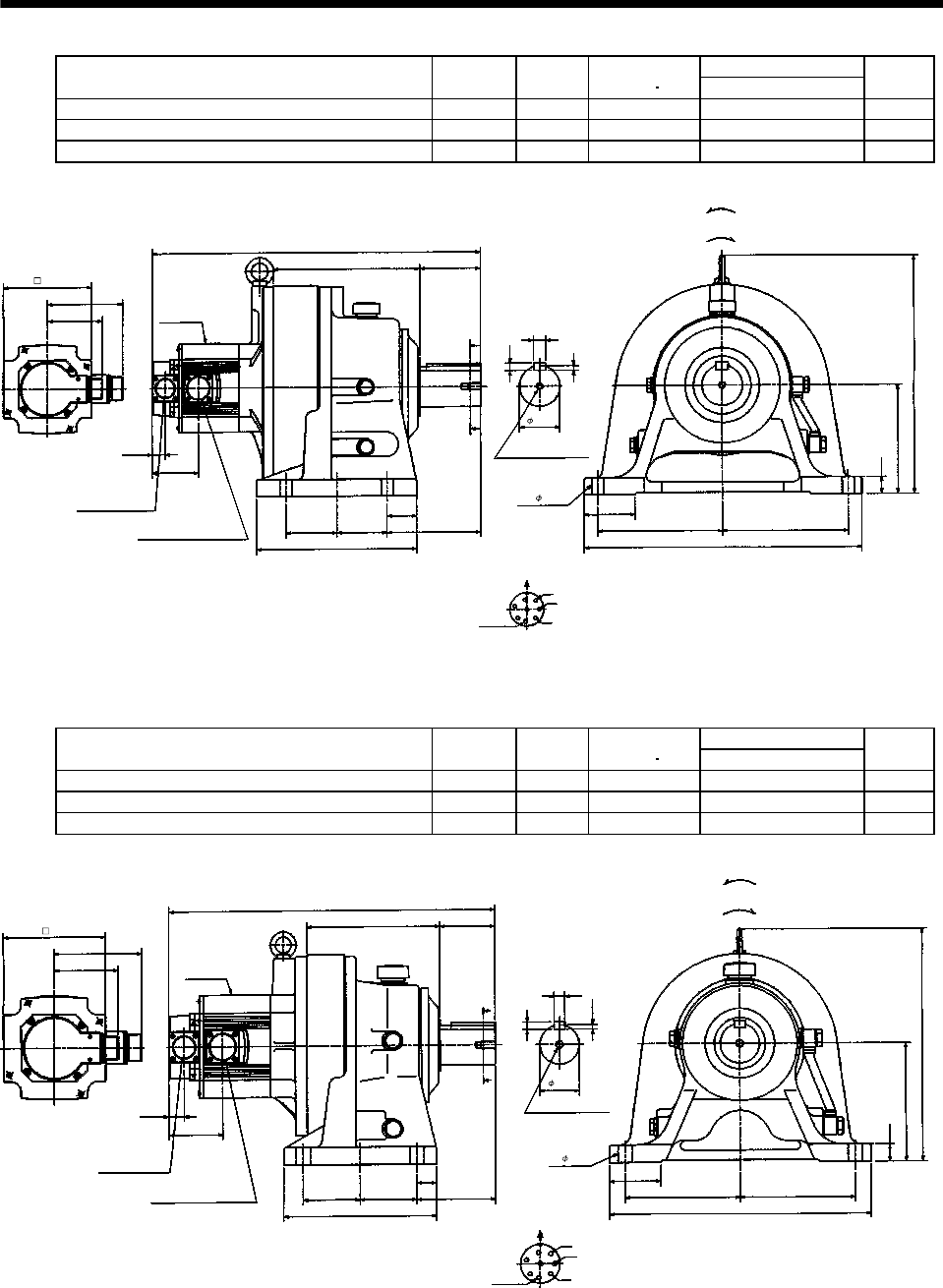
7 - 204
7. OUTLINE DIMENSION DRAWINGS
Variable Dimensions [in]
Model Output
[kW]
Reduction
Ratio
Inertia Moment
WK2[oz in2]L
Mass
[lb]
HC-SF102G1H HC-SFS102G1H HC-SFS1024G1H 1.0 1/59 106.51 19.21 198.4
HC-SF152G1H HC-SFS152G1H HC-SFS1524G1H 1.5 1/43 141.06 20.20 202.8
HC-SF152G1H HC-SFS152G1H HC-SFS1524G1H 1.5 1/59 140.68 20.20 202.8
W
V
U
A
F
G
HB
EC
D
L
4.37
5.12
13.86
3.21
0.77
2.70
8.58 3.54
A
A
2.95 2.95 5.47
1.73
9.37
0.71
0.43
0.28
2.36
6.30
0.98
7.28
7.28
2.95
16.14
4- 0.71
MS3102A20-29P
CE05-2A22-23P
Bottom Top
Encoder connector
Power supply connector
Motor flange direction
Earth
Power supply connector layout
CE05-2A22-23P
[Unit: in]
Motor plate
[Side view of motor only]
Section A-A
"Rotation direction"
For reverse
rotation command
For forward
rotation command
M10 threads, depth 0.71
Z695741*
(
BC11800*
)
Variable Dimensions [in]
Model Output
[kW]
Reduction
Ratio
Inertia Moment
WK2[oz in2]L
Mass
[lb]
HC-SF102G1H HC-SFS102G1H HC-SFS1024G1H 1.0 1/43 85.57 16.38 112.4
HC-SF152G1H HC-SFS152G1H HC-SFS1524G1H 1.5 1/29 120.72 17.36 116.8
HC-SF152G1H HC-SFS152G1H HC-SFS1524G1H 1.5 1/35 120.45 17.36 116.8
W
V
U
A
F
G
H
B
E
C
D
L
4.37
5.12
11.61
3.21
0.77
2.70
6.69 2.76
A
A
2.85 2.85 3.94
0.98
7.68
0.55
0.35
0.22
1.97
5.91
0.87
5.715.71
2.56
12.99
4- 0.43
MS3102A20-29P
CE05-2A22-23P
Bottom Top
Encoder connector
Power supply connector
Motor flange direction
Earth
Power supply connector layout
CE05-2A22-23P
[Unit: in]
Motor plate
[Side view of motor only] Section A-A
M10 threads, depth 0.71
"Rotation direction"
For reverse
rotation command
For forward
rotation command
Z695740*
(BC11799*)
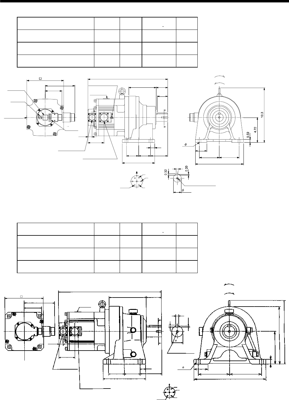
7 - 205
7. OUTLINE DIMENSION DRAWINGS
Model Output
[kW]
Reduction
Ratio
Inertia Moment
WK2[oz in2]
Mass
[lb]
HC-SF202G1H HC-SFS202G1H
HC-SFS2024G1H 2.0 1/6 249.32 77.2
HC-SF202G1H HC-SFS202G1H
HC-SFS2024G1H 2.0 1/11 241.11 77.2
HC-SF202G1H HC-SFS202G1H
HC-SFS2024G1H 2.0 1/17 238.93 77.2
2.175.16
3.232.262.26
6.10
0.79
A
A
1.97
3.743.74
9.06
2.17
W
V
U
3.21
5.59
3.01
A
B
C
D
E
FG
0.39
Z695802B
BC11801A BC26335B
0.77
15.0
Encoder connector
Power supply connector
CE05-2A24-10P
MS3102A20-29P
Motor plate
Caution plate
Caution plate
(Note 2)
1.50
6.93
Logo plate
Side view of motor only 4- 0.55
Caution plate (Note 2)
(Opposite side)
Section AA
Power supply connector layout
Top
Bottom
Top
Bottom
TopBottom
TopBottom
For forward rotation command
"Rotation direction" For reverse rotation command
Earth
CE05-2A24-10P
M8 screw, depth 0.79
Motor flange direction
TUV plate
(Note 1)[Unit: in]
Note 1. The dimensions without tolerances are reference dimensions.
2. This caution plate is attached to the 400V class motors only, not to the 200V class.
Model Output
[kW]
Reduction
Ratio
Inertia Moment
WK2[oz in2]
Mass
[lb]
HC-SF352G1H HC-SFS352G1H
HC-SFS3524G1H 3.5 1/6 492.62 132.3
HC-SF352G1H HC-SFS352G1H
HC-SFS3524G1H 3.5 1/11 471.21 132.3
HC-SF352G1H HC-SFS352G1H
HC-SFS3524G1H 3.5 1/17 464.73 132.3
5.59
18.62
6.60 2.76
1.97
6.93
3.21
A
A
0.77
3.01
11.50
0.22
10.43
Z695803A
5.91
2.56
5.71 5.71
12.99
4- 0.71
0.35
0.55
U
V
W
CD BE
A
G
F
3.94
0.98
2.852.85
7.68
0.87
MS3102A20-29P
CE05-2A24-10P
Bottom Top
Encoder connector
Power supply connector Motor flange direction
Earth
Power supply connector layout
CE05-2A24-10P
[Unit: in]
Motor plate
[Side view of motor only]
"Rotation direction"
For reverse
rotation command
For forward
rotation command
Section A-A
M10 threads, depth 0.71
(BC11803*)
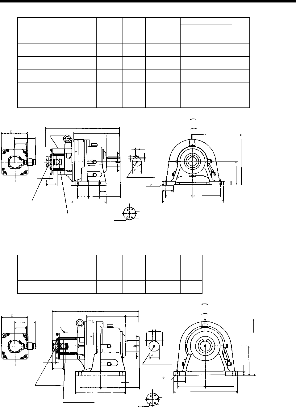
7 - 206
7. OUTLINE DIMENSION DRAWINGS
Variable Dimensions [in]
Model Output
[kW]
Reduction
Ratio
Inertia Moment
WK2[oz in2]L
Mass
[lb]
HC-SF202G1H HC-SFS202G1H
HC-SFS2024G1H 2.0 1/29 267.36 19.61 200.6
HC-SF202G1H HC-SFS202G1H
HC-SFS2024G1H 2.0 1/35 265.72 19.61 200.6
HC-SF202G1H HC-SFS202G1H
HC-SFS2024G1H 2.0 1/43 264.62 19.61 200.6
HC-SF202G1H HC-SFS202G1H
HC-SFS2024G1H 2.0 1/59 464.08 19.61 200.6
HC-SF352G1H HC-SFS352G1H
HC-SFS3524G1H 3.5 1/29 483.32 21.26 216.1
HC-SF352G1H HC-SFS352G1H
HC-SFS3524G1H 3.5 1/35 481.68 21.26 216.1
5.59
L
8.58 3.54
2.36
6.93
3.21
A
A
0.77
3.01
13.43
0.28
6.30
Z695804A
0.98
2.95
7.28 7.28
16.14
4- 0.71
0.43
0.71
U
V
W
C
DBE
A
G
F
5.47
1.73
2.952.95
9.37
11.81
MS3102A20-29P
CE05-2A24-10P
Bottom Top
Encoder connector
Power supply connector
Motor flange direction
Earth
Power supply connector layout
CE05-2A24-10P
[Unit: in]
[Side view of motor only]
"Rotation direction"
For reverse
rotation command
For forward
rotation command
Section A-A
M10 threads, depth 0.71
Motor plate
(BC11802*)
Model Output
[kW]
Reduction
Ratio
Inertia Moment
WK2[oz in2]
Mass
[lb]
HC-SF352G1H HC-SFS352G1H
HC-SFS3524G1H 3.5 1/43 582.28 306.4
HC-SF352G1H HC-SFS352G1H
HC-SFS3524G1H 3.5 1/59 579.0 306.4
5.59
22.99
10.32 3.54
2.76
6.93
3.21
A
A
0.77
3.01
15.0
0.30
7.87
Z695805A
1.18
3.15
7.48 7.48
16.93
4- 0.87
0.47
0.79
U
V
W
CD B
E
A
G
F
0.92
1.18
5.415.41
13.19
13.39
MS3102A20-29P
CE05-2A24-10P
Bottom Top
Encoder connector
Power supply connector
Motor flange direction
Earth
Power supply connector layout
CE05-2A24-10P
[Unit: in]
Motor plate
[Side view of motor only]
"Rotation direction"
For reverse
rotation command
For forward
rotation command
Section A-A
M12 threads, depth 0.95
(BC11804*)
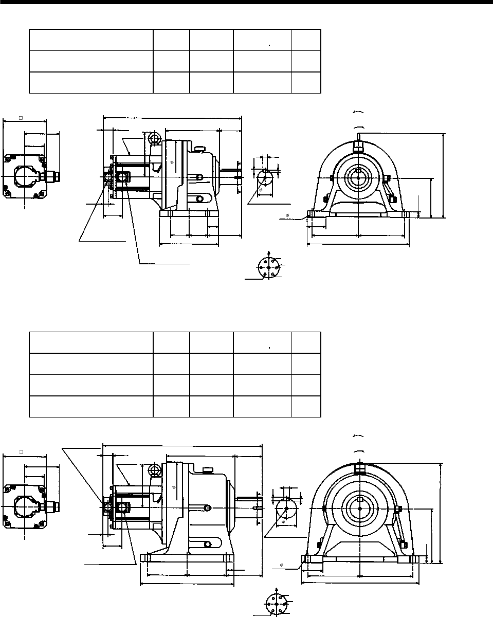
7 - 207
7. OUTLINE DIMENSION DRAWINGS
Model Output
[kW]
Reduction
Ratio
Inertia Moment
WK2[oz in2]
Mass
[lb]
HC-SF502G1H HC-SFS502G1H
HC-SFS5024G1H 5.0 1/11 620.01 225
HC-SF502G1H HC-SFS502G1H
HC-SFS5024G1H 5.0 1/17 598.14 225
Power supply connector layout
CE05-2A24-10P
5.59
22.09
8.58 3.54
2.36
3.21
A
A
Motor plate
0.77
3.01
13.43
0.28
6.30
BC10751*
0.98
2.95
7.28 7.28
16.14
4- 0.71
0.43
Motor flange direction
0.71
U
V
W
C
DB
E
A
G
F
Earth
Section A-A
5.47
1.73
2.95
2.95
9.37
M10 threads, depth 0.71
11.81
Encoder connector
MS3102A20-29P
Power supply connector
CE05-2A24-10P
1.56
7.13
6.93
Bottom Top
[Side view of motor only]
[Unit: in]
"Rotation direction"
For reverse
rotation command
For forward
rotation command
(BC11805*)
Model Output
[kW]
Reduction
Ratio
Inertia Moment
WK2[oz in2]
Mass
[lb]
HC-SF502G1H HC-SFS502G1H
HC-SFS5024G1H 5.0 1/29 757.24 377
HC-SF502G1H HC-SFS502G1H
HC-SFS5024G1H 5.0 1/35 754.51 377
HC-SF502G1H HC-SFS502G1H
HC-SFS5024G1H 5.0 1/43 749.04 377
Power supply connector layout
CE05-2A24-10P
5.59
25.39
10.98 4.33
3.15
3.21
A
A
Motor plate
0.77
3.01
15.95
0.35
8.66
BC10752*
1.18
3.35
8.27 8.27
18.50
4- 0.87
0.55
Motor flange direction
0.87
U
V
W
C
DB
E
A
G
F
Earth
Section A-A
5.71
1.18
6.30
6.30
14.96
14.57
Encoder connector
MS3102A20-29P
Power supply connector
CE05-2A24-10P
1.56
6.93
6.93
Bottom Top
[Side view of motor only]
[Unit: in]
"Rotation direction"
For reverse
rotation command
For forward
rotation command
M12 threads,
depth 0.95
(BC11806*)
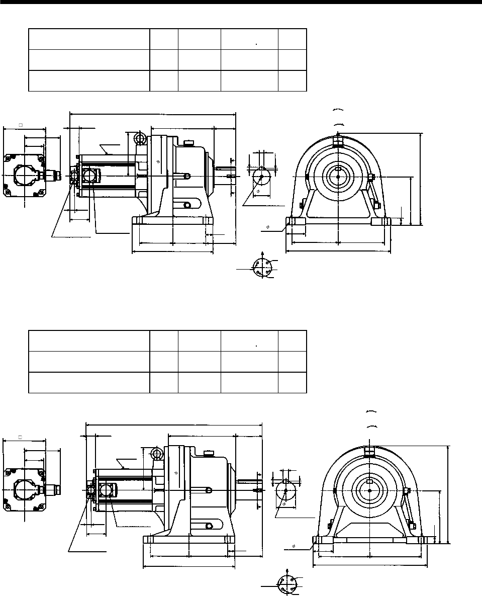
7 - 208
7. OUTLINE DIMENSION DRAWINGS
Model Output
[kW]
Reduction
Ratio
Inertia Moment
WK2[oz in2]
Mass
[lb]
HC-SF702G1H HC-SFS702G1H
HC-SFS7024G1H 7.0 1/11 1086.93 304
HC-SF702G1H HC-SFS702G1H
HC-SFS7024G1H 7.0 1/17 1038.82 304
Power supply connector layout
CE05-2A32-17P
5.91
27.13
10.32 3.54
2.76
3.21
A
A
Motor plate
0.77
3.21
15
0.30
7.87
BC10753*
1.18
3.15
7.48 7.48
16.93
4- 0.87
0.47
Motor flange direction
0.79
U
V
W
C
D
B
A
Earth
Section A-A
4.92
1.18
5.41
5.41
13.19
Encoder connector
MS3102A20-29P
Power supply
connector
CE05-2A32-17P
7.13
1.56
6.93
Bottom Top
[Side view of motor only]
[Unit: in]
"Rotation direction"
For reverse
rotation command
For forward
rotation command
M12 threads, depth 0.95
13.39
(BC11807*)
Model Output
[kW]
Reduction
Ratio
Inertia Moment
WK2[oz in2]
Mass
[lb]
HC-SF702G1H HC-SFS702G1H
HC-SFS7024G1H 7.0 1/29 1079.82 397
HC-SF702G1H HC-SFS702G1H
HC-SFS7024G1H 7.0 1/35 1077.09 397
Power supply connector layout
CE05-2A32-17P
5.91
28.70
10.98 4.33
3.15
3.21
A
A
Motor plate
0.77
3.21
15.95
0.35
8.66
BC10754*
1.18
3.35
8.27 8.27
18.50
4- 0.87
0.55
Motor flange direction
0.87
U
V
W
C
D
B
A
Earth
Section A-A
5.71
1.18
6.30
6.30
14.96
14.57
Encoder connector
MS3102A20-29P
1.56
6.93
6.93
Bottom Top
[Side view of motor only]
[Unit: in]
"Rotation direction"
For reverse
rotation command
For forward
rotation command
M12 threads,
depth 0.95
Power supply
connector
CE05-2A32-17P
(BC11808*)
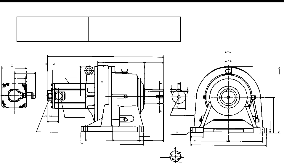
7 - 209
7. OUTLINE DIMENSION DRAWINGS
Model Output
[kW]
Reduction
Ratio
Inertia Moment
WK2[oz in2]
Mass
[lb]
HC-SF702G1H HC-SFS702G1H
HC-SFS7024G1H 7.0 1/43 1404.04 575
Power supply connector layout
CE05-2A32-17P
5.91
32.28
12.99 5.32
3.74
3.21
A
A
Motor plate
0.77
3.21
18.31
0.35
9.84
BC10755*
1.38
3.54
9.45 9.45
20.87
4- 1.62
0.55
Motor flange direction
0.98
U
V
W
C
D
B
A
Earth
Section A-A
6.69
1.18
7.48
7.48
17.32
16.93
Encoder connector
MS3102A20-29P
1.56
8.27
6.93
Bottom Top
[Side view of motor only]
[Unit: in]
"Rotation direction"
For reverse
rotation command
For forward
rotation command
M20 threads,
depth 1.34
Power supply
connector
CE05-2A32-17P
(BC11809*)
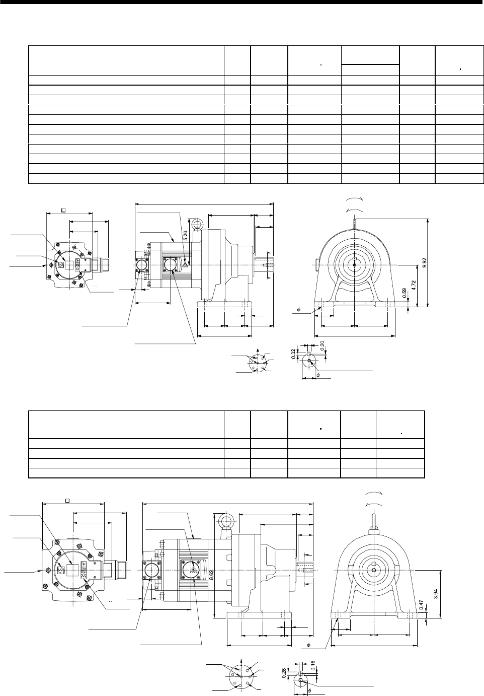
7 - 210
7. OUTLINE DIMENSION DRAWINGS
(b) With electromagnetic brake
Variable
Dimensions [in]
Model Output
[kW]
Reduction
Ratio
Inertia Moment
WK2[oz in2]L
Mass
[lb]
Brake static
friction torque
[oz in]
HC-SF52BG1H HC-SFS52BG1H HC-SFS524BG1H 0.5 1/35 50.3 14.61 72.8 1175
HC-SF52BG1H HC-SFS52BG1H HC-SFS524BG1H 0.5 1/43 50.03 14.61 72.8 1175
HC-SF52BG1H HC-SFS52BG1H HC-SFS524BG1H 0.5 1/59 49.89 14.61 72.8 1175
HC-SF102BG1H HC-SFS102BG1H HC-SFS1024BG1H 1.0 1/6 101.15 15.59 77.2 1175
HC-SF102BG1H HC-SFS102BG1H HC-SFS1024BG1H 1.0 1/11 92.9 15.59 77.2 1175
HC-SF102BG1H HC-SFS102BG1H HC-SFS1024BG1H 1.0 1/17 90.76 15.59 77.2 1175
HC-SF102BG1H HC-SFS102BG1H HC-SFS1024BG1H 1.0 1/29 89.12 15.59 77.2 1175
HC-SF102BG1H HC-SFS102BG1H HC-SFS1024BG1H 1.0 1/35 89.1 15.59 77.2 1175
HC-SF152BG1H HC-SFS152BG1H HC-SFS1524BG1H 1.5 1/6 135.6 16.58 81.6 1175
HC-SF152BG1H HC-SFS152BG1H HC-SFS1524BG1H 1.5 1/11 126.85 16.58 81.6 1175
HC-SF152BG1H HC-SFS152BG1H HC-SFS1524BG1H 1.5 1/17 125.2 16.58 81.6 1175
A
B
C
D
E
F
G
H
Z695747A
BC11824B BC26421A
0.39
3.21
4.37
4.0
0.77
3.743.74
9.06
2.17
5.16
2.26 2.26 3.23
6.10
0.79
A
A
2.17
L
1.97
Encoder connector
Power supply connector
V
U
CE05-2A22-23P
MS3102A20-29P
W
Motor plate
Caution plate
Caution plate (Note 2)
(Opposite side)
1.50
5.12
Caution plate
Logo plate
(Note 2)
Side view of motor only
4- 0.55
Section AA
Power supply connector layout
TopBottom
Top
Bottom
Top
Bottom
Top
Bottom
For forward rotation command
"Rotation direction"
For reverse rotation command
Earth
Brake
CE05-2A22-23P
M8 screw, depth 0.79
Motor flange direction
TUV plate
(Note 1)[Unit: in]
Note 1. The dimensions without tolerances are reference dimensions.
2. This caution plate is attached to the 400V class motors only, not to the 200V class.
Model Output
[kW]
Reduction
Ratio
Inertia Moment
WK2[oz in2]
Mass
[lb]
Brake static
friction torque
[oz in]
HC-SF52BG1H HC-SFS52BG1H HC-SFS524BG1H 0.5 1/6 49.34 50.7 1175
HC-SF52BG1H HC-SFS52BG1H HC-SFS524BG1H 0.5 1/11 47.29 50.7 1175
HC-SF52BG1H HC-SFS52BG1H HC-SFS524BG1H 0.5 1/17 46.75 50.7 1175
HC-SF52BG1H HC-SFS52BG1H HC-SFS524BG1H 0.5 1/29 46.34 50.7 1175
5.32
1.77 1.77
0.59
2.36
4.76
4.33
1.38
1.58
7.09
0.32
A
A
A
B
C
D
E
F
G
H
4.0
14.1
4.37
3.21
2.95 2.95
0.77
Z695746A
BC11823C BC29416A
1.26
Encoder connector
Power supply connector
V
U
CE05-2A22-23P
MS3102A20-29P
W
Motor plate
Caution plate
Caution plate
(Note 2)
(Opposite side)
1.10
5.12
Caution plate
Logo plate
(Note 2)
Side view of motor only
4- 0.43
Section AA
Power supply connector layout
Top
Bottom
TopBottom Top
Bottom
TopBottom
For forward rotation command
"Rotation direction"
For reverse rotation command
Earth
Brake
CE05-2A22-23P
M8 screw, depth 0.79
Motor flange direction
TUV plate
(Note 1)[Unit: in]
Note 1. The dimensions without tolerances are reference dimensions.
2. This caution plate is attached to the 400V class motors only, not to the 200V class.
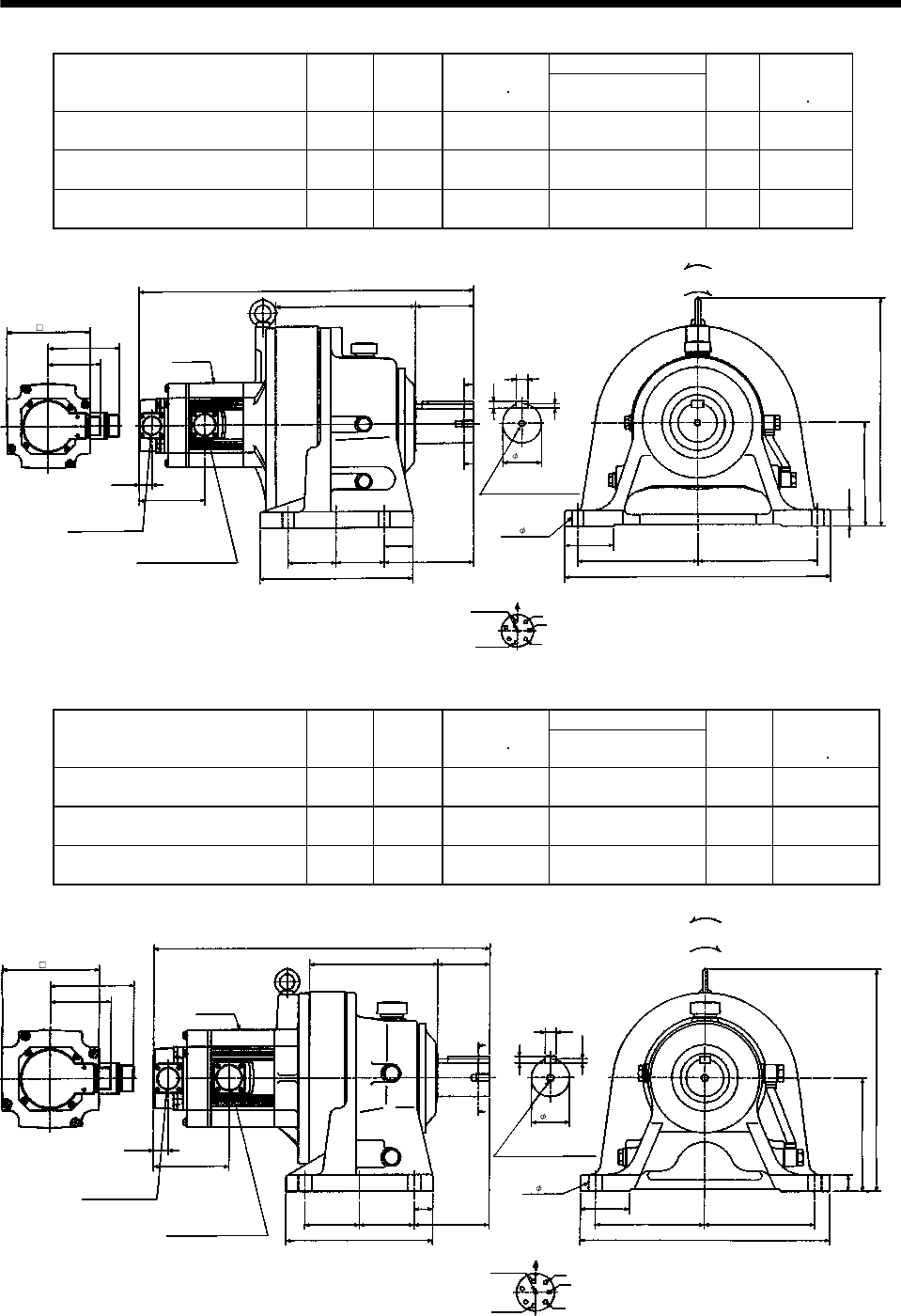
7 - 211
7. OUTLINE DIMENSION DRAWINGS
Variable Dimensions [in]
Model Output
[kW]
Reduction
Ratio
Inertia Moment
WK2[oz in2]L
Mass
[lb]
Brake static
friction torque
[oz in]
HC-SF102BG1H HC-SFS102BG1H
HC-SFS1024BG1H 1.0 1/59 115.80 20.51 202.8 1175
HC-SF152BG1H HC-SFS152BG1H
HC-SFS1524BG1H 1.5 1/43 150.36 21.50 207.2 1175
HC-SF152BG1H HC-SFS152BG1H
HC-SFS1524BG1H 1.5 1/59 149.97 21.50 207.2 1175
0.77
W
V
U
L
3.548.58
A
FG
H
B
EC
D
5.12
4.37
3.21
4.0
A
A
9.37
2.95 2.95
1.73
5.47
4- 0.71
16.14
7.28
0.98
2.95
6.30
13.86
7.28
Z695749A
MS3102A20-29P
CE05-2A22-23P
Bottom Top
Encoder connector
Power supply connector
Motor flange direction
Earth
Power supply connector layout
CE05-2A22-23P
[Unit: in]
Motor plate
[Side view of motor only]
"Rotation direction"
For reverse
rotation command
For forward
rotation command
Brake
2.36
0.71
0.43
0.28
Section A-A
M10 threads, depth 0.71
(BC11826*)
Variable Dimensions [in]
Model Output
[kW]
Reduction
Ratio
Inertia Moment
WK2[oz in2]L
Mass
[lb]
Brake static
friction torque
[oz in]
HC-SF102BG1H HC-SFS102BG1H
HC-SFS1024BG1H 1.0 1/43 94.86 17.68 116.8 1175
HC-SF152BG1H HC-SFS152BG1H
HC-SFS1524BG1H 1.5 1/29 130.02 18.66 121.3 1175
HC-SF152BG1H HC-SFS152BG1H
HC-SFS1524BG1H 1.5 1/35 129.74 18.66 121.3 1175
0.77
W
V
U
L
2.766.69
A
FG
HB
E
C
D
5.12
4.37
3.21
4.0
A
A
7.68
2.85
0.98
3.94
1.97
4- 0.43
0.55
0.35
0.22
12.99
5.71
0.87
2.56
5.91
11.61
2.85 5.71
Z695748A
MS3102A20-29P
CE05-2A22-23P
Bottom Top
Encoder connector
Power supply connector
Motor flange direction
Earth
Power supply connector layout
CE05-2A22-23P
[Unit: in]
Motor plate
[Side view of motor only]
"Rotation direction"
For reverse
rotation command
For forward
rotation command
Brake
Section A-A
M10 threads, depth 0.71
(BC11825*)
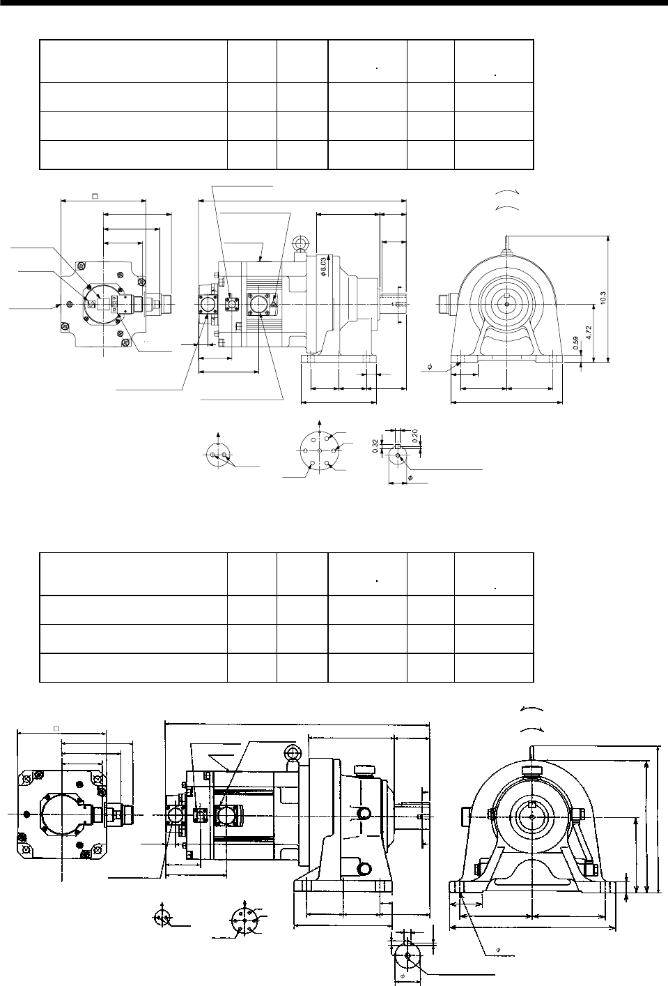
7 - 212
7. OUTLINE DIMENSION DRAWINGS
Model Output
[kW]
Reduction
Ratio
Inertia Moment
WK2[oz in2]
Mass
[lb]
Brake static
friction torque
[oz in]
HC-SF202BG1H HC-SFS202BG1H
HC-SFS2024BG1H 2.0 1/6 303.99 90.4 6103
HC-SF202BG1H HC-SFS202BG1H
HC-SFS2024BG1H 2.0 1/11 295.79 90.4 6103
HC-SF202BG1H HC-SFS202BG1H
HC-SFS2024BG1H 2.0 1/17 293.60 90.4 6103
Z695852A
BC11827B BC29626A
0.39
3.743.74
9.06
2.17
5.16
3.232.262.26
6.10
0.79
A
A
2.17
16.9
3.21
4.61
5.59
A
B
C
D
E
F
G
BA
2.72
4.90
0.77
1.97
Encoder connector
Power supply connector
V
U
CE05-2A24-10P
MS3102A20-29P
W
Motor plate
Caution plate
Caution plate (Note 2)
(Opposite side)
1.50
6.93
Caution plate
Logo plate
(Note 2)
Side view of motor only 4- 0.55
Section AA
Power supply connector layout
Top
Bottom
TopBottom
Top
Bottom
Top
Bottom
For forward rotation command
"Rotation direction"
For reverse rotation command
Earth
Brake
CE05-2A24-10P
M8 screw, depth 0.79
Motor flange direction
Motor flange direction
Brake connector
CM3102A10SL-4P
TUV plate
Brake connector layout
MS3102A10SL-4P
(Note 1)[Unit: in]
Note 1. The dimensions without tolerances are reference dimensions.
2. This caution plate is attached to the 400V class motors only, not to the 200V class.
Model Output
[kW]
Reduction
Ratio
Inertia Moment
WK2[oz in2]
Mass
[lb]
Brake static
friction torque
[oz in]
HC-SF352BG1H HC-SFS352BG1H
HC-SFS3524BG1H 3.5 1/6 547.29 145.5 6103
HC-SF352BG1H HC-SFS352BG1H
HC-SFS3524BG1H 3.5 1/11 525.97 145.5 6103
HC-SF352BG1H HC-SFS352BG1H
HC-SFS3524BG1H 3.5 1/17 519.41 145.5 6103
Z695853A
0.77
W
V
U
20.51
6.69
A
FG
B
EC
D
6.93
5.59
4.61
2.72
A
A
4.90
2.85
7.68
1.97
0.55
0.35
0.22
2.56
0.87
5.91
10.43
5.71
3.21
AB
2.76
4- 0.71
5.71
12.99
2.85 3.94
11.50
MS3102A20-29P
CE05-2A24-10P
Bottom Top
Encoder connector
Power supply connector
Motor flange direction
Earth
Power supply connector layout
CE05-2A24-10P
[Unit: in]
Motor plate
[Side view of motor only]
"Rotation direction"
For reverse
rotation command
For forward
rotation command
Brake connector
MS3102A10SL-4P
Brake connector layout
MS3102A10SL-4P
Brake
Motor flange direction
Section A-A
M10 threads, depth 0.71
0.98
(BC11829*)
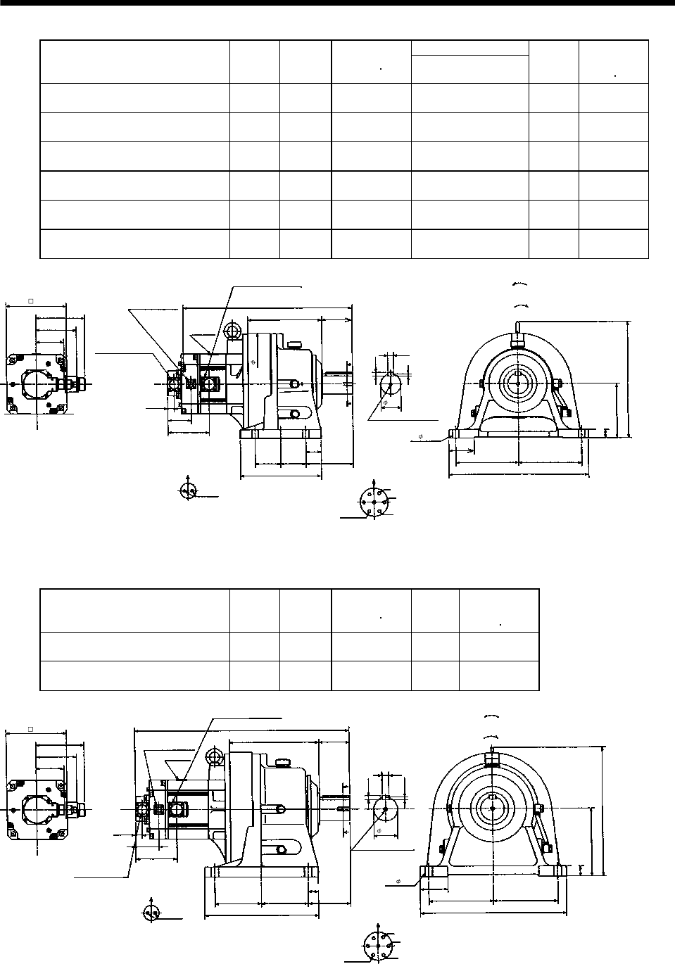
7 - 213
7. OUTLINE DIMENSION DRAWINGS
Variable Dimensions [in]
Model Output
[kW]
Reduction
Ratio
Inertia Moment
WK2[oz in2]L
Mass
[lb]
Brake static
friction torque
[oz in]
HC-SF202BG1H HC-SFS202BG1H
HC-SFS2024BG1H 2.0 1/29 322.03 21.50 213.8 6103
HC-SF202BG1H HC-SFS202BG1H
HC-SFS2024BG1H 2.0 1/35 320.39 21.50 213.8 6103
HC-SF202BG1H HC-SFS202BG1H
HC-SFS2024BG1H 2.0 1/43 319.30 21.50 213.8 6103
HC-SF202BG1H HC-SFS202BG1H
HC-SFS2024BG1H 2.0 1/59 318.75 21.50 213.8 6103
HC-SF352BG1H HC-SFS352BG1H
HC-SFS3524BG1H 3.5 1/29 538.8 23.15 229.3 6103
HC-SF352BG1H HC-SFS352BG1H
HC-SFS3524BG1H 3.5 1/35 536.36 23.15 229.3 6103
Z695854A
0.77
W
V
U
L
8.58
A
FG
B
EC
D
6.93
5.59
4.61
2.72
A
A
4.90
9.37
2.36
0.43
0.28
2.95
1.73
6.30
7.28
3.21
AB
16.14
5.47
0.71
13.43
3.54
4- 0.71
7.28
2.95 2.95
11.81
MS3102A20-29P
CE05-2A24-10P
Bottom Top
Encoder connector
Power supply connector
Motor flange direction
Earth
Power supply connector layout
CE05-2A24-10P
[Unit: in]
Motor plate
[Side view of motor only]
"Rotation direction"
For reverse
rotation command
For forward
rotation command
Brake connector
MS3102A10SL-4P
Brake connector layout
MS3102A10SL-4P
Brake
Motor flange direction
Section A-A
M10 threads, depth 0.71
0.98
(BC11828*)
Model Output
[kW]
Reduction
Ratio
Inertia Moment
WK2[oz in2]
Mass
[lb]
Brake static
friction torque
[oz in]
HC-SF352BG1H HC-SFS352BG1H
HC-SFS3524BG1H 3.5 1/43 636.96 319.7 6103
HC-SF352BG1H HC-SFS352BG1H
HC-SFS3524BG1H 3.5 1/59 633.68 319.7 6103
Z695855A
0.77
W
V
U
24.88
10.32
A
FG
B
E
C
D
6.93
5.59
4.61
2.72 A
A
4.90
13.19
2.76
0.47
0.30
3.15
7.87
7.48
3.21
AB16.93
4.92
0.79
15.0
3.54
4- 0.87
7.48
5.41 5.41
Section A-A
M12 threads, depth 0.95
MS3102A20-29P
CE05-2A24-10P
Bottom Top
Encoder connector
Power supply connector
Motor flange direction
Earth
Power supply connector layout
CE05-2A24-10P
[Unit: in]
Motor plate
[Side view of motor only]
"Rotation direction"
For reverse
rotation command
For forward
rotation command
Brake connector
MS3102A10SL-4P
Brake connector layout
MS3102A10SL-4P
Brake
Motor flange direction
1.18
1.18
(BC11830*)
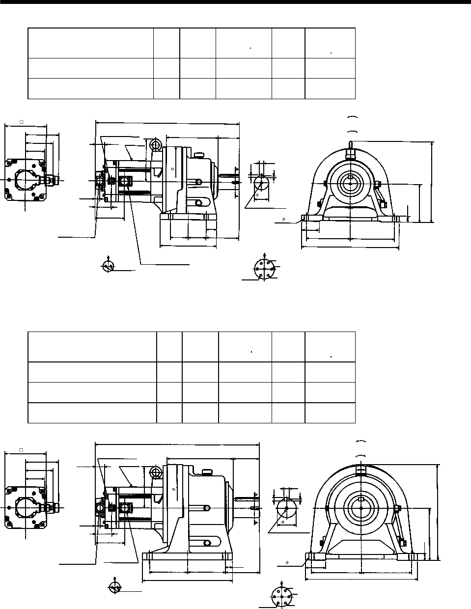
7 - 214
7. OUTLINE DIMENSION DRAWINGS
Model Output
[kW]
Reduction
Ratio
Inertia Moment
WK2[oz in2]
Mass
[lb]
Brake static
friction torque
[oz in]
HC-SF502BG1H HC-SFS502BG1H
HC-SFS5024BG1H 5.0 1/11 674.68 238.1 6103
HC-SF502BG1H HC-SFS502BG1H
HC-SFS5024BG1H 5.0 1/17 652.81 238.1 6103
Power supply connector layout
CE05-2A24-10P
5.59
23.98
8.58 3.54
2.36
4.61
A
A
Motor plate
0.77
2.72
13.43
0.28
6.30
BC11028*
0.98
2.95
7.28 7.28
16.14
4- 0.71
0.43
Motor flange direction
0.71
U
V
W
C
DB
E
A
G
F
Earth
Section A-A
5.47
1.73
2.95
2.95
9.37
M10 threads, depth 0.71
11.81
Encoder connector
MS3102A20-29P
Power supply connector
CE05-2A24-10P
1.56
7.13
3.21
Brake connector layout
MS3102A10SL-4P
Motor flange direction
B
A
Brake
4.90
Brake connector
MS3102A10SL-4P
6.93
Bottom Top
[Side view of motor only]
[Unit: in]
"Rotation direction"
For reverse
rotation command
For forward
rotation command
(BC11831*)
Model Output
[kW]
Reduction
Ratio
Inertia Moment
WK2[oz in2]
Mass
[lb]
Brake static
friction torque
[oz in]
HC-SF502BG1H HC-SFS502BG1H
HC-SFS5024BG1H 5.0 1/29 811.92 390.2 6103
HC-SF502BG1H HC-SFS502BG1H
HC-SFS5024BG1H 5.0 1/35 809.18 390.2 6103
HC-SF502BG1H HC-SFS502BG1H
HC-SFS5024BG1H 5.0 1/43 803.71 390.2 6103
5.59
27.28
10.98 4.33
3.15
4.61
A
A
Motor plate
0.77
2.72
15.95
0.35
8.66
BC11029*
1.18
3.35
8.27 8.27
18.50
4- 0.87
0.55
0.87
Power supply connector layout
CE05-2A24-10P
Motor flange direction
U
V
W
C
DB
E
A
G
F
Earth
Section A-A
5.71
1.18
6.306.30
14.96
M12 threads, depth 0.95
14.57
Encoder connector
MS3102A20-29P
Power supply
connector
CE05-2A24-10P
1.56
6.93
3.21
Brake connector layout
MS3102A10SL-4P
Motor flange direction
B
A
Brake
4.90
Brake connector
MS3102A10SL-4P
6.93
Bottom Top
[Side view of motor only]
[Unit: in]
"Rotation direction"
For reverse
rotation command
For forward
rotation command
(BC11832*)
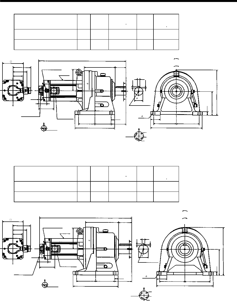
7 - 215
7. OUTLINE DIMENSION DRAWINGS
Model Output
[kW]
Reduction
Ratio
Inertia Moment
WK2[oz in2]
Mass
[lb]
Brake static
friction torque
[oz in]
HC-SF702BG1H HC-SFS702BG1H
HC-SFS7024BG1H 7.0 1/11 1141.60 317.5 6103
HC-SF702BG1H HC-SFS702BG1H
HC-SFS7024BG1H 7.0 1/17 1093.49 317.5 6103
Power supply connector layout
CE05-2A32-17P
5.91
29.02
10.32 3.54
2.76
4.61
A
A
Motor plate
0.77
2.72
15
0.30
7.87
BC11030*
1.18
3.15
7.48 7.48
16.93
4- 0.87
0.47
Motor flange direction
0.79
U
V
W
C
D
B
A
Earth
Section A-A
4.92
1.18
5.41
5.41
13.19
M12 threads, depth 0.95
13.39
Encoder connector
MS3102A20-29P
Power supply
connector
CE05-2A32-17P
7.13
3.21
Brake connector layout
MS3102A10SL-4P
Motor flange direction
B
A
Brake
5.10
Brake connector
MS3102A10SL-4P
6.93
Bottom Top
[Side view of motor only]
[Unit: in]
"Rotation direction"
For reverse
rotation command
For forward
rotation command
(BC11833*)
Model Output
[kW]
Reduction
Ratio
Inertia Moment
WK2[oz in2]
Mass
[lb]
Brake static
friction torque
[oz in]
HC-SF702BG1H HC-SFS702BG1H
HC-SFS7024BG1H 7.0 1/29 1134.50 410.1 6103
HC-SF702BG1H HC-SFS702BG1H
HC-SFS7024BG1H 7.0 1/35 1131.76 410.1 6103
Power supply connector layout
CE05-2A32-17P
5.91
30.59
10.98 4.33
3.15
4.61
A
A
Motor plate
0.77
2.72
15.95
0.35
8.66
BC11031*
1.18
3.35
8.27 8.27
18.50
4- 0.87
0.55
Motor flange direction
0.87
U
V
W
C
D
B
A
Earth
Section A-A
5.71
1.18
6.306.30
14.96
M12 threads, depth 0.95
14.57
Encoder connector
MS3102A20-29P
6.93
3.21
Brake connector layout
MS3102A10SL-4P
Motor flange direction
B
A
Brake
5.10
Brake connector
MS3102A10SL-4P
6.93
Bottom Top
[Side view of motor only]
[Unit: in]
"Rotation direction"
For reverse
rotation command
For forward
rotation command
Power supply
connector
CE05-2A32-17P
(BC11834*)

7 - 216
7. OUTLINE DIMENSION DRAWINGS
Model Output
[kW]
Reduction
Ratio
Inertia Moment
WK2[oz in2]
Mass
[lb]
Brake static
friction torque
[oz in]
HC-SF702BG1H HC-SFS702BG1H
HC-SFS7024BG1H 7.0 1/43 1458.71 588.6 6103
5.91
34.17
12.99 5.32
3.74
4.61
A
A
Motor plate
0.77
2.72
18.31
0.35
9.84
BC11032*
1.38
3.54
9.45 9.45
20.87
4- 1.02
0.55
0.98
Power supply connector layout
CE05-2A32-17P
Motor flange direction
U
V
W
C
D
B
A
Earth
Section A-A
6.69
1.18
7.48
7.48
17.32
M20 threads, depth 1.34
16.93
Encoder connector
MS3102A20-29P
8.27
3.21
Brake connector layout
MS3102A10SL-4P
Motor flange direction
B
ABrake
5.10
Brake connector
MS3102A10SL-4P
6.93
Bottom Top
[Side view of motor only]
[Unit: in]
"Rotation direction"
For reverse
rotation command
For forward
rotation command
Power supply
connector
CE05-2A32-17P
(BC11835*)
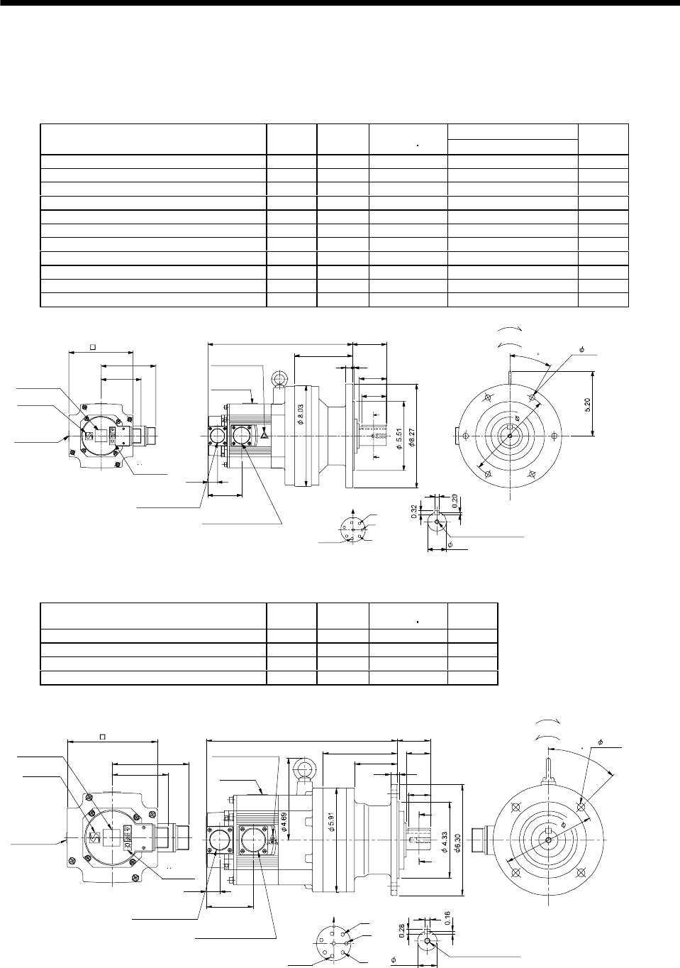
7 - 217
7. OUTLINE DIMENSION DRAWINGS
(4) With reduction gear for general industrial machine (flange type)
The outer frame of the reduction gear is a material surface such as casting. Its actual dimensions may
be 0.039 to 0.118 in larger than the drawing dimensions. Design the machine side with allowances.
(a) Without electromagnetic brake
Variable Dimensions [in]
Model Output
[kW]
Reduction
Ratio
Inertia Moment
WK2[oz in2]L
Mass
[lb]
HC-SF52G1 HC-SFS52G1 HC-SFS524G1 0.5 1/35 41.01 10.59 59.5
HC-SF52G1 HC-SFS52G1 HC-SFS524G1 0.5 1/43 40.73 10.59 59.5
HC-SF52G1 HC-SFS52G1 HC-SFS524G1 0.5 1/59 40.60 10.59 59.5
HC-SF102G1 HC-SFS102G1 HC-SFS1024G1 1.0 1/6 91.85 11.58 63.9
HC-SF102G1 HC-SFS102G1 HC-SFS1024G1 1.0 1/11 83.7 11.58 63.9
HC-SF102G1 HC-SFS102G1 HC-SFS1024G1 1.0 1/17 81.47 11.58 63.9
HC-SF102G1 HC-SFS102G1 HC-SFS1024G1 1.0 1/29 79.83 11.58 63.9
HC-SF102G1 HC-SFS102G1 HC-SFS1024G1 1.0 1/35 79.8 11.58 63.9
HC-SF152G1 HC-SFS152G1 HC-SFS1524G1 1.5 1/6 126.3 12.56 68.3
HC-SF152G1 HC-SFS152G1 HC-SFS1524G1 1.5 1/11 117.55 12.56 68.3
HC-SF152G1 HC-SFS152G1 HC-SFS1524G1 1.5 1/17 115.9 12.56 68.3
3.21
4.37
A
B
C
D
E
FG
H
Z695743*
BC11811B BC29695A
0.39
A
A
2.17
0.16
0.51
4.61
1.97
0.77
2.70
2.72L
Encoder connector
Power supply connector V
U
CE05-2A22-23P
MS3102A20-29P
W
Motor plate
Caution plate
Caution plate
(Note 2)
(Opposite side)
1.50
5.12
Caution plate
Logo plate
(Note 2)
Side view of motor only
6- 0.43
Section AA
Power supply connector layout
Top
Bottom
Top
Bottom
Top
Bottom
TopBottom
For forward rotation command
"Rotation direction"
For reverse rotation command
Earth
CE05-2A22-23P
M8 screw, depth 0.79
Motor flange direction
TUV plate
7.09
30
(Note 1)[Unit: in]
Note 1. The dimensions without tolerances are reference dimensions.
2. This caution plate is attached to the 400V class motors only, not to the 200V class.
Model Output
[kW]
Reduction
Ratio
Inertia Moment
WK2[oz in2]
Mass
[lb]
HC-SF52G1 HC-SFS52G1 HC-SFS524G1 0.5 1/6 40.05 40.8
HC-SF52G1 HC-SFS52G1 HC-SFS524G1 0.5 1/11 38.00 40.8
HC-SF52G1 HC-SFS52G1 HC-SFS524G1 0.5 1/17 37.45 40.8
HC-SF52G1 HC-SFS52G1 HC-SFS524G1 0.5 1/29 37.04 40.8
4.37
3.21
0.77
2.70
2.44
4.25
10.9 1.89
0.35 0.12
1.38
0.32
A
A
Z695742*
BC11810B BC26736A
A
B
C
D
E
FG
H
1.26
Encoder connector
Power supply connector V
U
CE05-2A22-23P
MS3102A20-29P
W
Motor plate
Caution plate Caution plate (Note 2)
(Opposite side)
1.10
5.12
Caution plate
Logo plate
(Note 2)
Side view of motor only
4- 0.43
Section AA
Power supply connector layout
Top
Bottom
TopBottom
Top
Bottom
Top
Bottom
For forward rotation command
"Rotation direction"
For reverse rotation command
Earth
CE05-2A22-23P
M8 screw, depth 0.79
Motor flange direction
TUV plate
45
5.28
(Note 1)[Unit: in]
Note 1. The dimensions without tolerances are reference dimensions.
2. This caution plate is attached to the 400V class motors only, not to the 200V class.
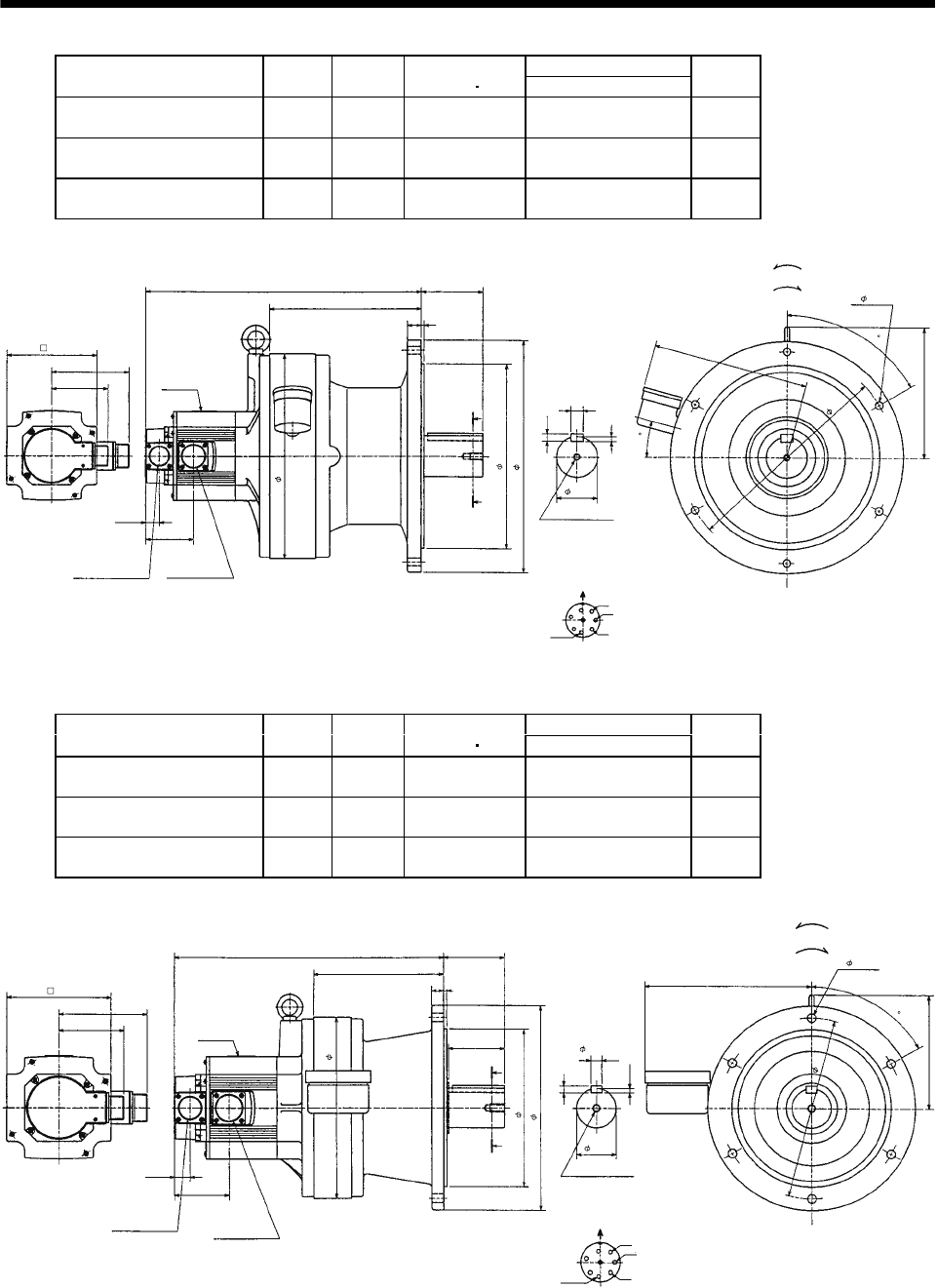
7 - 218
7. OUTLINE DIMENSION DRAWINGS
Variable Dimensions [in]
Model Output
[kW]
Reduction
Ratio
Inertia Moment
WK2[oz in2]L
Mass
[lb]
HC-SF102G1 HC-SFS102G1
HC-SFS1024G1 1.0 1/59 106.48 13.35 183.0
HC-SF152G1 HC-SFS152G1
HC-SFS1524G1 1.5 1/43 141.06 16.69 187.4
HC-SF152G1 HC-SFS152G1
HC-SFS1524G1 1.5 1/59 140.65 16.69 187.4
4.37
5.12
7.56
3.21
0.77
2.70
8.62
3.50
0.71
0.43
2.36
0.79 0.16
11.8
10.63
13.39
0.28
6- 0.43
8.98
60
Z695745*
MS3102A20-29P
CE05-2A22-23P
Bottom Top
Encoder connector Power supply
connector
Motor flange direction
Earth
Power supply connector layout
CE05-2A22-23P
[Unit: in]
Motor plate
[Side view of motor only]
"Rotation direction"
For reverse rotation command
For forward rotation command
Section A-A
M10 threads, depth 0.71
12.21
(BC11813*)
15
U
V
W
A
C
B
D
E
FG
L
A
A
H
Variable Dimensions [in]
Model Output
[kW]
Reduction
Ratio
Inertia Moment
WK2[oz in2]L
Mass
[lb]
HC-SF102G1 HC-SFS102G1
HC-SFS1024G1 1.0 1/43 85.57 13.39 105.8
HC-SF152G1 HC-SFS152G1
HC-SFS1524G1 1.5 1/29 120.69 14.37 110.2
HC-SF152G1 HC-SFS152G1
HC-SFS1524G1 1.5 1/35 120.42 14.37 110.2
4.37
5.12
5.71
3.21
0.77
2.70
6.46
2.99
0.55
0.35
1.97
0.56 0.16
9.06
7.87
2.76
10.24
0.22
9.06
6- 0.43
8.23
60
Z695744*
MS3102A20-29P
CE05-2A22-23P
Bottom Top
Encoder connector Power supply
connector
Motor flange direction
Earth
Power supply connector layout
CE05-2A22-23P
[Unit: in]
Motor plate
[Side view of motor only]
"Rotation direction"
For reverse rotation command
For forward rotation command
Section A-A
M10 threads, depth 0.71
(BC11812*)
L
A
A
U
V
W
A
C
D
E
FG
HB
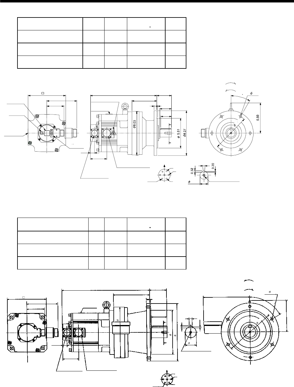
7 - 219
7. OUTLINE DIMENSION DRAWINGS
Model Output
[kW]
Reduction
Ratio
Inertia Moment
WK2[oz in2]
Mass
[lb]
HC-SF202G1 HC-SFS202G1
HC-SFS2024G1 2.0 1/6 249.32 75.0
HC-SF202G1 HC-SFS202G1
HC-SFS2024G1 2.0 1/11 241.11 75.0
HC-SF202G1 HC-SFS202G1
HC-SFS2024G1 2.0 1/17 238.93 75.0
0.51 0.16
2.17
4.61
2.72
12.3
3.21
5.59
3.01
A
B
C
D
E
FG
0.39
Z695806A
BC11814B BC30689*
A
A
1.97
0.77
Encoder connector
Power supply connector
V
U
CE05-2A24-10P
MS3102A20-29P W
Motor plate
Caution plate Caution plate (Note 2)
(Opposite side)
1.50
6.93
Caution plate
Logo plate
(Note 2)
Side view of motor only
6- 0.43
Section AA
Power supply connector layout
Top
Bottom
TopBottom
Top
Bottom
Top
Bottom
For forward rotation command
"Rotation direction"
For reverse rotation command
Earth
CE05-2A24-10P
M8 screw, depth 0.79
Motor flange direction
TUV plate
30
7.09
(Note 1)[Unit: in]
Note 1. The dimensions without tolerances are reference dimensions.
2. This caution plate is attached to the 400V class motors only, not to the 200V class.
Model Output
[kW]
Reduction
Ratio
Inertia Moment
WK2[oz in2]
Mass
[lb]
HC-SF352G1 HC-SFS352G1
HC-SFS3524G1 3.5 1/6 492.62 125.7
HC-SF352G1 HC-SFS352G1
HC-SFS3524G1 3.5 1/11 471.29 125.7
HC-SF352G1 HC-SFS352G1
HC-SFS3524G1 3.5 1/17 464.73 125.7
5.59
15.63 2.99
2.76
6.93
3.21
A
A
3.01
5.59
0.22
Z695807A
1.97
0.35
8.23
U
V
W
CD B
E
A
G
F
6.46
9.06
7.87
10.24
0.16
0.59
0.77
6- 0.43
0.55
MS3102A20-29P CE05-2A24-10P
Bottom Top
Encoder connector Power supply connector
Motor flange direction
Earth
Power supply connector layout
CE05-2A24-10P
[Unit: in]
Motor plate
[Side view of motor only]
"Rotation direction"
For reverse
rotation command
For forward
rotation command
Section A-A
M10 threads, depth 0.71
9.06
(BC11816*)
60
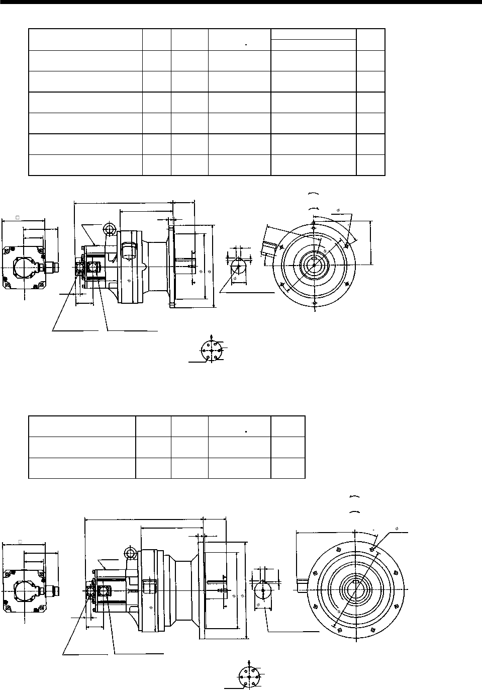
7 - 220
7. OUTLINE DIMENSION DRAWINGS
Variable Dimensions [in]
Model Output
[kW]
Reduction
Ratio
Inertia Moment
WK2[oz in2]L
Mass
[lb]
HC-SF202G1 HC-SFS202G1
HC-SFS2024G1 2.0 1/29 267.36 16.10 185.2
HC-SF202G1 HC-SFS202G1
HC-SFS2024G1 2.0 1/35 265.72 16.10 185.2
HC-SF202G1 HC-SFS202G1
HC-SFS2024G1 2.0 1/43 264.62 16.10 185.2
HC-SF202G1 HC-SFS202G1
HC-SFS2024G1 2.0 1/59 264.08 16.10 185.2
HC-SF352G1 HC-SFS352G1
HC-SFS3524G1 3.5 1/29 483.32 17.76 200.6
HC-SF352G1 HC-SFS352G1
HC-SFS3524G1 3.5 1/35 481.68 17.76 200.6
5.59
L3.50
0.16
6.93
3.21
A
A
3.01
7.13
0.28
Z695808A
2.36
0.43
0.71
U
V
W
CD B
E
A
G
F
8.62
11.81
10.63
13.39
4
0.79
0.77
6- 0.43
8.98
Section A-A
M10 threads, depth 0.71
MS3102A20-29P CE05-2A24-10P
Bottom Top
Encoder connector Power supply connector
Motor flange direction
Earth
Power supply connector layout
CE05-2A24-10P
[Unit: in]
Motor plate
[Side view of motor only]
"Rotation direction"
For reverse
rotation command
For forward
rotation command
12.21
(BC11815*)
60
15
Model Output
[kW]
Reduction
Ratio
Inertia Moment
WK2[oz in2]
Mass
[lb]
HC-SF352G1 HC-SFS352G1
HC-SFS3524G1 3.5 1/43 582.28 293.2
HC-SF352G1 HC-SFS352G1
HC-SFS3524G1 3.5 1/59 579.0 293.2
5.59
3.70
6.93
3.21
A
A
3.01
0.47
Z695809A
22.5
0.30
0.79
U
V
W
CDBE
A
G
F
19.29
13.39
12.44
15.75
0.20
0.87
0.77
8- 0.55
9.57
10.16
MS3102A20-29P CE05-2A24-10P
Bottom Top
Encoder connector Power supply connector
Motor flange direction
Earth
Power supply connector layout
CE05-2A24-10P
[Unit: in]
Motor plate
[Side view of motor only]
"Rotation direction"
For reverse
rotation command
For forward
rotation command
1-M12 threads, depth 0.95
Section A-A
14.17
2.76
(BC11817*)
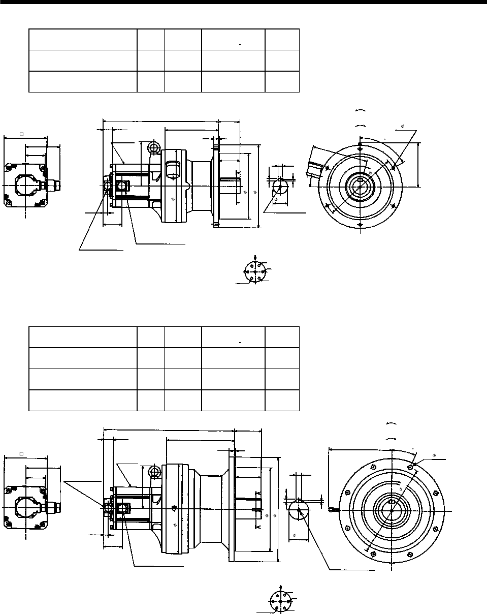
7 - 221
7. OUTLINE DIMENSION DRAWINGS
Model Output
[kW]
Reduction
Ratio
Inertia Moment
WK2[oz in2]
Mass
[lb]
HC-SF502G1 HC-SFS502G1
HC-SFS5024G1 5.0 1/11 620.01 209.4
HC-SF502G1 HC-SFS502G1
HC-SFS5024G1 5.0 1/17 598.14 209.4
Power supply connector layout
CE05-2A24-10P
5.59
18.58
8.62
3.50
2.36
A
A
Motor plate
0.77
7.13
0.28
BC10756*
60
6- 0.43
0.43
Motor flange direction
0.71
U
V
W
C
DB
E
A
G
F
Earth
Section A-A
M10 threads, depth 0.71
Encoder connector
MS3102A20-29P
Power supply connector
CE05-2A24-10P
1.56
7.13
3.21
3.01
0.79 0.16
3.35
10.63
13.39
8.98
12.21
15
6.93
Bottom Top
[Side view of motor only]
[Unit: in]
"Rotation direction"
For reverse
rotation command
For forward
rotation command
11.81
(BC11818*)
Model Output
[kW]
Reduction
Ratio
Inertia Moment
WK2[oz in2]
Mass
[lb]
HC-SF502G1 HC-SFS502G1
HC-SFS5024G1 5.0 1/29 757.24 357.1
HC-SF502G1 HC-SFS502G1
HC-SFS5024G1 5.0 1/35 754.51 357.1
HC-SF502G1 HC-SFS502G1
HC-SFS5024G1 5.0 1/43 749.04 357.1
Power supply connector layout
CE05-2A24-10P
5.59
21.06
10.94
4.33
3.15
A
A
Motor plate
0.77
0.35
BC10757*
22.5
8- 0.71
0.55
Motor flange direction
0.87
U
V
W
C
DB
E
A
G
F
Earth
Section A-A
14.57
Encoder connector
MS3102A20-29P
Power supply connector
CE05-2A24-10P
1.56
6.93
3.21
3.01
0.87 0.20
4.13
13.58
16.93
10.16
15.35
6.93
Bottom Top
[Side view of motor only]
[Unit: in]
"Rotation direction"
For reverse
rotation command
For forward
rotation command
1-M12 threads,
depth 0.95
(BC11819*)
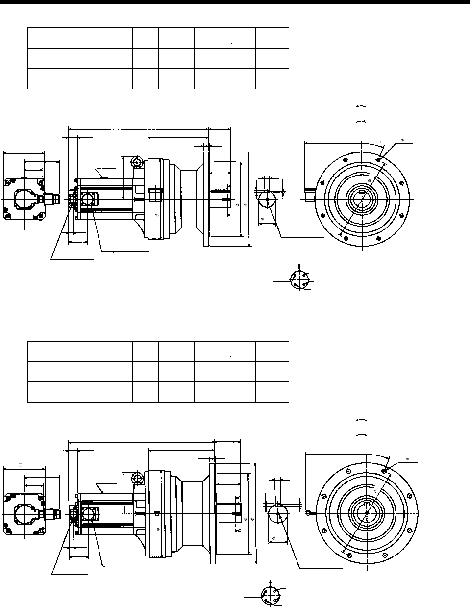
7 - 222
7. OUTLINE DIMENSION DRAWINGS
Model Output
[kW]
Reduction
Ratio
Inertia Moment
WK2[oz in2]
Mass
[lb]
HC-SF702G1 HC-SFS702G1
HC-SFS7024G1 7.0 1/11 1086.93 321.9
HC-SF702G1 HC-SFS702G1
HC-SFS7024G1 7.0 1/17 1038.82 321.9
Power supply connector layout
CE05-2A32-17P
5.91
23.43
10.16
3.70
2.76
A
A
Motor plate
0.77
0.30
BC10758*
22.5
8- 0.55
0.47
Motor flange direction
0.79
U
V
W
C
D
B
A
Earth
Section A-A
13.39
Encoder connector
MS3102A20-29P
Power supply connector
CE05-2A32-17P
1.56
7.13
3.21
3.21
0.87 0.20
3.50
12.44
15.75
9.57
14.17
6.93
Bottom Top
[Side view of motor only]
[Unit: in]
"Rotation direction"
For reverse
rotation command
For forward
rotation command
1-M12 threads,
depth 0.95
(BC11820*)
Model Output
[kW]
Reduction
Ratio
Inertia Moment
WK2[oz in2])
Mass
[lb]
HC-SF702G1 HC-SFS702G1
HC-SFS7024G1 7.0 1/29 1079.82 377.0
HC-SF702G1 HC-SFS702G1
HC-SFS7024G1 7.0 1/35 1077.09 377.0
5.91
24.37
10.98
4.33
3.15
A
A
Motor plate
0.77
0.35
BC10759*
8- 0.71
0.55
0.87
Power supply connector layout
CE05-2A32-17P
Motor flange direction
U
V
W
C
D
B
A
Earth
Section A-A
14.57
Encoder connector
MS3102A20-29P
Power supply
connector
CE05-2A32-17P
1.56
6.93
3.21
3.21
0.87 0.20
4.13
13.58
16.93
10.16
15.35
6.93
Bottom Top
[Side view of motor only]
[Unit: in]
"Rotation direction"
For reverse
rotation command
For forward
rotation command
1-M12 threads,
depth 0.95
(BC11821*)
22.5
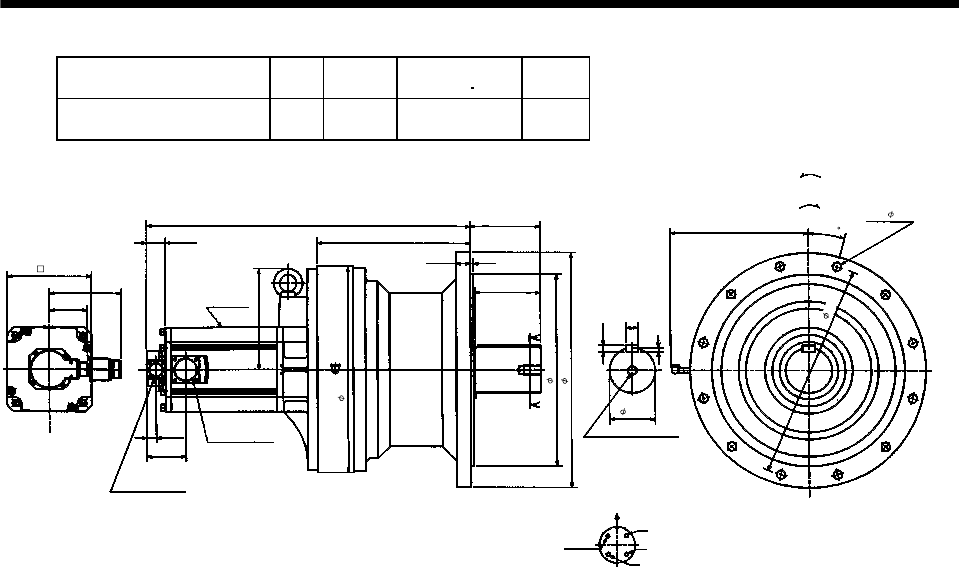
7 - 223
7. OUTLINE DIMENSION DRAWINGS
Model Output
[kW]
Reduction
Ratio
Inertia Moment
WK2[oz in2]
Mass
[lb]
HC-SF702G1 HC-SFS702G1
HC-SFS7024G1 7.0 1/43 1404.04 529.1
5.91
26.58
12.6
5.71
3.74
A
A
Motor plate
0.77
0.35
BC10760*
12- 0.71
0.55
0.98
Power supply connector layout
CE05-2A32-17P
Motor flange direction
U
V
W
C
D
B
A
Earth
Section A-A
16.93
Encoder connector
MS3102A20-29P
1.56
8.27
3.21
3.21
1.18 0.24
5.32
15.75
19.29
11.22
15
17.72
6.93
Bottom Top
[Side view of motor only]
[Unit: in]
"Rotation direction"
For reverse
rotation command
For forward
rotation command
1-M20 threads, depth 1.34
Power supply
connector
CE05-2A32-17P
(BC11822*)
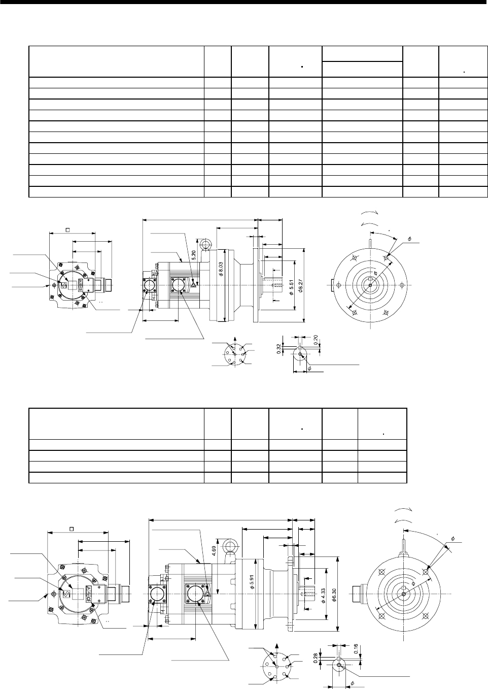
7 - 224
7. OUTLINE DIMENSION DRAWINGS
(b) With electromagnetic brake
Variable Dimensions [in]
Model Output
[kW]
Reduction
Ratio
Inertia Moment
WK2[oz in2]L
Mass
[lb]
Brake static
friction torque
[oz in]
HC-SF52BG1 HC-SFS52BG1 HC-SFS524BG1 0.5 1/35 50.3 11.89 71.7 1175
HC-SF52BG1 HC-SFS52BG1 HC-SFS524BG1 0.5 1/43 50.03 11.89 71.7 1175
HC-SF52BG1 HC-SFS52BG1 HC-SFS524BG1 0.5 1/59 49.89 11.89 71.7 1175
HC-SF102BG1 HC-SFS102BG1 HC-SFS1024BG1 1.0 1/6 101.15 12.87 76.1 1175
HC-SF102BG1 HC-SFS102BG1 HC-SFS1024BG1 1.0 1/11 92.9 12.87 76.1 1175
HC-SF102BG1 HC-SFS102BG1 HC-SFS1024BG1 1.0 1/17 90.76 12.87 76.1 1175
HC-SF102BG1 HC-SFS102BG1 HC-SFS1024BG1 1.0 1/29 89.12 12.87 76.1 1175
HC-SF102BG1 HC-SFS102BG1 HC-SFS1024BG1 1.0 1/35 89.1 12.87 76.1 1175
HC-SF152BG1 HC-SFS152BG1 HC-SFS1524BG1 1.5 1/6 135.6 13.86 80.5 1175
HC-SF152BG1 HC-SFS152BG1 HC-SFS1524BG1 1.5 1/11 126.85 13.86 80.5 1175
HC-SF152BG1 HC-SFS152BG1 HC-SFS1524BG1 1.5 1/17 125.2 13.86 80.5 1175
A
B
C
D
E
FG
H
A
A
3.21
4.37 2.17
2.72
L
0.16
0.51
4.61
4.0
0.39
0.77
1.97
Z695751*
BC11837B BC26058A
Encoder connector
Power supply connector
V
U
CE05-2A22-23P
MS3102A20-29P
W
Motor plate
Caution plate
Caution plate
(Note 2)
(Opposite side)
1.50
5.12
Caution plate
Logo plate
(Note 2)
Side view of motor only
6- 0.43
Section AA
Power supply connector layout
Top
Bottom
TopBottom
Top
Bottom
TopBottom
For forward rotation command
"Rotation direction"
For reverse rotation command
Earth
Brake
CE05-2A22-23P
M8 screw, depth 0.79
Motor flange direction
TUV plate
30
7.09
(Note 1)[Unit: in]
Note 1. The dimensions without tolerances are reference dimensions.
2. This caution plate is attached to the 400V class motors only, not to the 200V class.
Model Output
[kW]
Reduction
Ratio
Inertia Moment
WK2[oz in2]
Mass
[lb]
Brake static
friction torque
[oz in]
HC-SF52BG1 HC-SFS52BG1 HC-SFS524BG1 0.5 1/6 49.34 45.2 1175
HC-SF52BG1 HC-SFS52BG1 HC-SFS524BG1 0.5 1/11 47.29 45.2 1175
HC-SF52BG1 HC-SFS52BG1 HC-SFS524BG1 0.5 1/17 46.75 45.2 1175
HC-SF52BG1 HC-SFS52BG1 HC-SFS524BG1 0.5 1/29 46.34 45.2 1175
Z695750*
BC11836C BC26183C
3.21
4.32
12.2 1.87
A
A
1.26
0.12
0.35
2.44
4.25 1.38
0.32
4.0
0.77
A
B
C
D
E
FG
H
Encoder connector
Power supply connector V
U
CE05-2A22-23P
MS3102A20-29P
W
Motor plate
Caution plate
Caution plate (Note 2)
(Opposite side)
1.10
5.12
Caution plate
Logo plate
(Note 2)
Side view of motor only
4- 0.43
Section AA
Power supply connector layout
Top
Bottom
Top
Bottom
Top
Bottom
Top
Bottom
For forward rotation command
"Rotation direction"
For reverse rotation command
Earth
Brake
CE05-2A22-23P
M8 screw, depth 0.79
Motor flange direction
TUV plate
45
5.28
(Note 1)[Unit: in]
Note 1. The dimensions without tolerances are reference dimensions.
2. This caution plate is attached to the 400V class motors only, not to the 200V class.
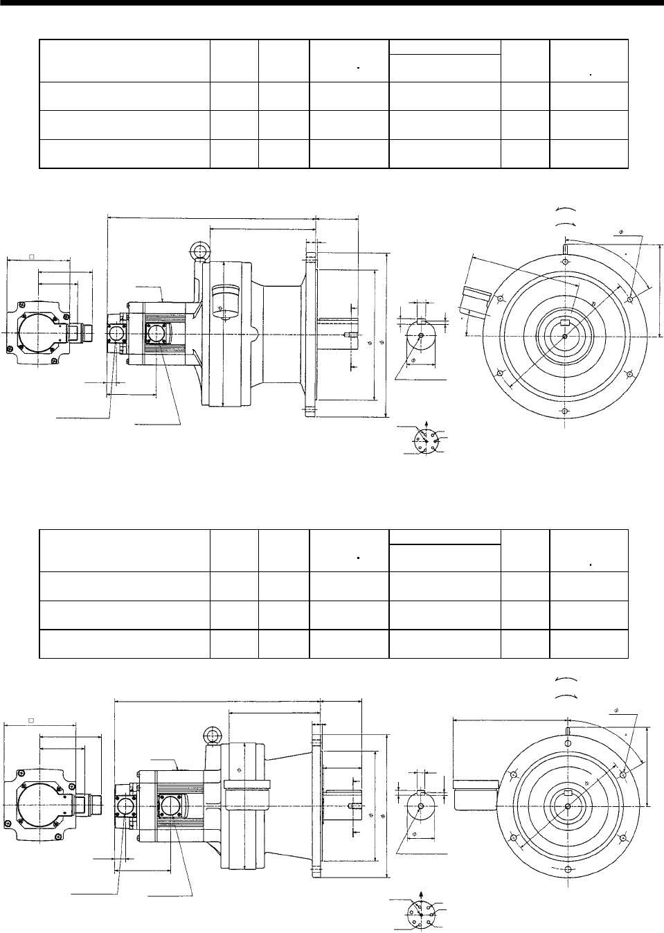
7 - 225
7. OUTLINE DIMENSION DRAWINGS
Variable Dimensions [in]
Model Output
[kW]
Reduction
Ratio
Inertia Moment
WK2[oz in2]L
Mass
[lb]
Brake static
friction torque
[oz in]
HC-SF102BG1 HC-SFS102BG1
HC-SFS1024BG1 1.0 1/59 115.77 17.01 187.4 1175
HC-SF152BG1 HC-SFS152BG1
HC-SFS1524BG1 1.5 1/43 150.36 17.99 191.8 1175
HC-SF152BG1 HC-SFS152BG1
HC-SFS1524BG1 1.5 1/59 149.95 17.99 191.8 1175
4.37
5.12
7.56
3.21
0.77
4.0
8.62
3.50
0.71
0.43
0.28
2.36
0.16
0.79
11.8
6- 0.43
8.98
10.63
13.39
60
Z695753*
MS3102A20-29P
CE05-2A22-23P
Bottom Top
Encoder connector
Power supply
connector
Motor flange direction
Earth
Power supply connector layout
CE05-2A22-23P
[Unit: in]
Motor plate
[Side view of motor only]
"Rotation direction"
For reverse rotation command
For forward rotation command
Brake
Section A-A
M10 threads, depth 0.71
12.21
(BC11839*)
15
L
A
A
U
V
W
A
B
C
H
D
E
FG
Variable Dimensions [in]
Model Output
[kW]
Reduction
Ratio
Inertia Moment
WK2[oz in2]L
Mass
[lb]
Brake static
friction torque
[oz in]
HC-SF102BG1 HC-SFS102BG1
HC-SFS1024BG1 1.0 1/43 94.86 14.69 110.2 1175
HC-SF152BG1 HC-SFS152BG1
HC-SFS1524BG1 1.5 1/29 129.99 15.67 114.6 1175
HC-SF152BG1 HC-SFS152BG1
HC-SFS1524BG1 1.5 1/35 129.72 15.67 114.6 1175
4.37
5.12
5.71
3.21
0.77
4.0
6.46
2.99
0.55
0.35
0.22
1.97
0.16
0.59
9.06
6- 0.43
8.23
7.87
10.24
60
2.76
Z695752*
MS3102A20-29P
CE05-2A22-23P
Bottom Top
Encoder connector Power supply
connector
Motor flange direction
Earth
Power supply connector layout
CE05-2A22-23P
[Unit: in]
Motor plate
[Side view of motor only]
"Rotation direction"
For reverse rotation command
For forward rotation command
Brake
Section A-A
M10 threads, depth 0.71
(BC11838*)
9.06
L
A
A
U
V
W
A
B
C
G
D
E
F
H
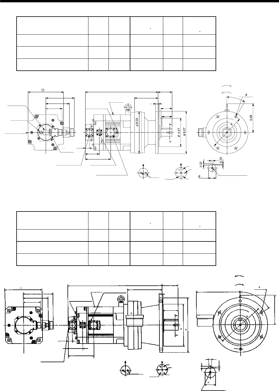
7 - 226
7. OUTLINE DIMENSION DRAWINGS
Model Output
[kW]
Reduction
Ratio
Inertia Moment
WK2[oz in2]
Mass
[lb]
Brake static
friction torque
[oz in]
HC-SF202BG1 HC-SFS202BG1
HC-SFS2024BG1 2.0 1/6 303.99 88.2 6103
HC-SF202BG1 HC-SFS202BG1
HC-SFS2024BG1 2.0 1/11 295.79 88.2 6103
HC-SF202BG1 HC-SFS202BG1
HC-SFS2024BG1 2.0 1/17 293.60 88.2 6103
Z695856A
BC11840B BC29441A
3.21
4.61
5.59
A
B
C
D
E
FG
BA
0.39
0.77
2.72
4.90
0.51 0.16
2.17
4.61
2.7214.2
A
A
1.97
Encoder connector
Power supply connector
V
U
CE05-2A24-10P
MS3102A20-29P
W
Motor plate
Caution plate Caution plate
(Note 2)
(Opposite side)
1.50
6.93
Caution plate
Logo plate
(Note 2)
Side view of motor only
6- 0.43
Section AA
Power supply connector layout
Top
Bottom
TopBottom
Top
Bottom
TopBottom
For forward rotation command
"Rotation direction"
For reverse rotation command
Earth
Brake
CE05-2A24-10P
M8 screw, depth 0.79
Motor flange direction
Motor flange direction
Brake connector layout
MS3102A10SL-4P
Brake connector
MS3102A10SL-4P
TUV plate
7.09
30
(Note 1)[Unit: in]
Note 1. The dimensions without tolerances are reference dimensions.
2. This caution plate is attached to the 400V class motors only, not to the 200V class.
Model Output
[kW]
Reduction
Ratio
Inertia Moment
WK2[oz in2]
Mass
[lb]
Brake static
friction torque
[oz in]
HC-SF352BG1 HC-SFS352BG1
HC-SFS3524BG1 3.5 1/6 547.29 138.9 6103
HC-SF352BG1 HC-SFS352BG1
HC-SFS3524BG1 3.5 1/11 525.97 138.9 6103
HC-SF352BG1 HC-SFS352BG1
HC-SFS3524BG1 3.5 1/17 519.41 138.9 6103
5.59
17.52 2.99
2.76
6.93
3.21
A
A
2.72
5.59
0.22
Z695857A
1.97
0.35
0.55
U
V
W
CDBE
A
G
F
6.46
9.06
7.87
10.24
0.16
0.59
0.77
6- 0.43
4.90
4.61
AB
8.23
MS3102A20-29P
CE05-2A24-10P
Bottom Top
Encoder connector
Power supply connector
Motor flange direction
Earth
Power supply connector layout
CE05-2A24-10P
[Unit: in]
Motor plate
[Side view of motor only]
"Rotation direction"
For reverse
rotation command
For forward
rotation command
Motor flange direction
Brake connector
MS3102A10SL-4P
Brake connector layout
MS3102A10SL-4P
Brake
Section A-A
M10 threads, depth 0.71
9.06
(BC11842*)
60
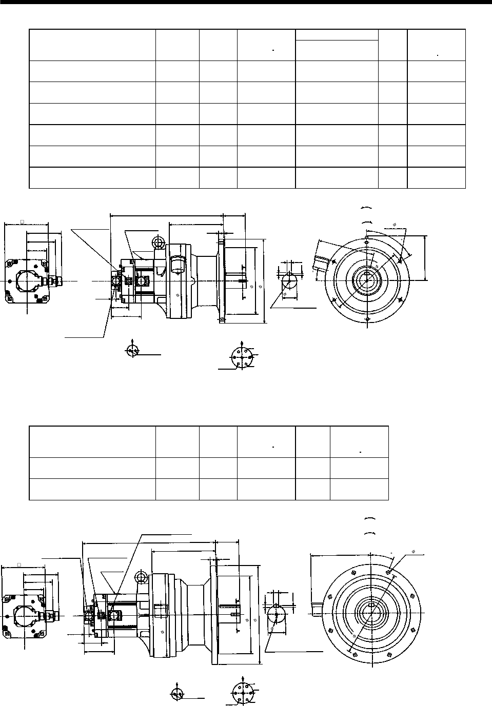
7 - 227
7. OUTLINE DIMENSION DRAWINGS
Variable Dimensions [in]
Model Output
[kW]
Reduction
Ratio
Inertia Moment
WK2[oz in2]L
Mass
[lb]
Brake static
friction torque
[oz in]
HC-SF202BG1 HC-SFS202BG1
HC-SFS2024BG1 2.0 1/29 322.03 17.99 198.4 6103
HC-SF202BG1 HC-SFS202BG1
HC-SFS2024BG1 2.0 1/35 320.39 17.99 198.4 6103
HC-SF202BG1 HC-SFS202BG1
HC-SFS2024BG1 2.0 1/43 319.30 17.99 198.4 6103
HC-SF202BG1 HC-SFS202BG1
HC-SFS2024BG1 2.0 1/59 318.75 17.99 198.4 6103
HC-SF352BG1 HC-SFS352BG1
HC-SFS3524BG1 3.5 1/29 538.0 19.65 213.8 6103
HC-SF352BG1 HC-SFS352BG1
HC-SFS3524BG1 3.5 1/35 536.36 19.65 213.8 6103
5.59
L3.50
0.16
6.93
3.20
A
A
2.72
7.13
0.28
Z695858A
60
2.36
0.43
0.71
U
V
W
CD B
E
A
G
F
8.62
10.63
13.39
4
0.79
0.77
6- 0.43
8.98
15
4.90
4.61
AB
MS3102A20-29P
CE05-2A24-10P
Bottom Top
Encoder connector
Power supply connector
Motor flange direction
Earth
Power supply connector layout
CE05-2A24-10P
[Unit: in]
Motor plate
[Side view of motor only]
"Rotation direction"
For reverse
rotation command
For forward
rotation command
Motor flange direction
Brake connector
MS3102A10SL-4P
Brake connector layout
MS3102A10SL-4P
Brake
Section A-A
M10 threads, depth 0.71
12.21
(BC11841*)
11.81
Model Output
[kW]
Reduction
Ratio
Inertia Moment
WK2[oz in2]
Mass
[lb]
Brake static
friction torque
[oz in]
HC-SF352BG1 HC-SFS352BG1
HC-SFS3524BG1 3.5 1/43 636.96 306.4 6103
HC-SF352BG1 HC-SFS352BG1
HC-SFS3524BG1 3.5 1/59 633.68 306.4 6103
5.59
21.18 3.70
0.20
6.93
3.21
A
A
2.72
0.30
Z695859A
22.5
2.76
0.47
0.79
U
V
W
CD B
E
A
G
F
10.16
13.39
12.44
15.75
0.87
0.77
8- 0.55
4.90
4.61
AB
9.57
Section A-A
MS3102A20-29P
CE05-2A24-10P
Bottom Top
Encoder connector
Power supply connector
Motor flange direction
Earth
Power supply connector layout
CE05-2A24-10P
[Unit: in]
Motor plate
[Side view of motor only]
"Rotation direction"
For reverse
rotation command
For forward
rotation command
Motor flange direction
Brake connector
MS3102A10SL-4P
Brake connector layout
MS3102A10SL-4P
Brake
14.17
1-M12 threads, depth 0.95
(BC11843*)
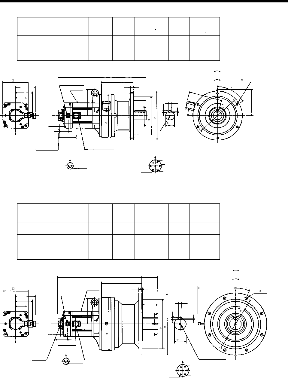
7 - 228
7. OUTLINE DIMENSION DRAWINGS
Model Output
[kW]
Reduction
Ratio
Inertia Moment
WK2[oz in2]
Mass
[lb]
Brake static
friction torque
[oz in]
HC-SF502BG1 HC-SFS502BG1
HC-SFS5024BG1 5.0 1/11 674.68 222.7 6103
HC-SF502BG1 HC-SFS502BG1
HC-SFS5024BG1 5.0 1/17 652.81 222.7 6103
Power supply connector layout
CE05-2A24-10P
5.59
20.47
8.62
3.50
2.36
4.61
A
A
Motor plate
0.77
2.72
7.13
0.28
BC11033*
60
6- 0.43
0.43
Motor flange direction
0.71
U
V
W
C
DB
E
A
G
F
Earth
Section A-A
M10 threads, depth 0.71
11.81
Encoder connector
MS3102A20-29P
Power supply connector
CE05-2A24-10P
7.13
3.20
Brake connector layout
MS3102A10SL-4P
Motor flange direction
B
ABrake
4.90
Brake connector
MS3102A10SL-4P 0.79 0.16
3.35
10.63
13.39
8.98
12.21
6.93
Bottom Top
[Side view of motor only]
[Unit: in]
"Rotation direction"
For reverse
rotation command
For forward
rotation command
15
(BC11844*)
Model Output
[kW]
Reduction
Ratio
Inertia Moment
WK2[oz in2]
Mass
[lb]
Brake static
friction torque
[oz in]
HC-SF502BG1 HC-SFS502BG1
HC-SFS5024BG1 5.0 1/29 811.92 370.4 6103
HC-SF502BG1 HC-SFS502BG1
HC-SFS5024BG1 5.0 1/35 809.18 370.4 6103
HC-SF502BG1 HC-SFS502BG1
HC-SFS5024BG1 5.0 1/43 803.71 370.4 6103
5.59
22.95
10.98
4.33
3.15
4.61
A
A
Motor plate
0.77
2.72
0.35
BC11034*
8- 0.71
0.55
0.87
Power supply connector layout
CE05-2A24-10P
Motor flange direction
U
V
W
C
DBE
A
G
F
Earth
Section A-A
14.57
Encoder connector
MS3102A20-29P
Power supply connector
CE05-2A24-10P
6.93
3.20
Brake connector layout
MS3102A10SL-4P
Motor flange direction
B
ABrake
4.90
Brake connector
MS3102A10SL-4P
0.87 0.20
4.13
13.58
16.93
10.16
15.35
6.93
Bottom Top
[Side view of motor only]
[Unit: in]
"Rotation direction"
For reverse
rotation command
For forward
rotation command
1-M12 threads,
depth 0.95
(BC11845*)
22.5

7 - 229
7. OUTLINE DIMENSION DRAWINGS
Model Output
[kW]
Reduction
Ratio
Inertia Moment
WK2[oz in2]
Mass
[lb]
Brake static
friction torque
[oz in]
HC-SF702BG1 HC-SFS702BG1
HC-SFS7024BG1 7.0 1/11 1141.60 335.1 6103
HC-SF702BG1 HC-SFS702BG1
HC-SFS7024BG1 7.0 1/17 1093.49 335.1 6103
5.91
25.32
10.16
3.70
2.76
4.61
A
A
0.77
2.72
0.30
BC11035*
8- 0.55
0.47
0.79
Motor flange direction
U
V
W
C
D
B
A
13.39
7.13
3.21
BA
5.10
0.87 0.20
3.50
12.44
15.75
9.57
14.17
Motor plate
Power supply connector layout
CE05-2A32-17P
Earth
Section A-A
Encoder connector
MS3102A20-29P
Power supply
connector
CE05-2A32-17P
Brake connector layout
MS3102A10SL-4P
Motor flange direction
Brake
Brake connector
MS3102A10SL-4P
6.93
Bottom Top
[Side view of motor only]
[Unit: in]
"Rotation direction"
For reverse
rotation command
For forward
rotation command
1-M12 threads,
depth 0.95
22.5°
(BC11846*)
Model Output
[kW]
Reduction
Ratio
Inertia Moment
WK2[oz in2]
Mass
[lb]
Brake static
friction torque
[oz in]
HC-SF702BG1 HC-SFS702BG1
HC-SFS7024BG1 7.0 1/29 1134.50 390.2 6103
HC-SF702BG1 HC-SFS702BG1
HC-SFS7024BG1 7.0 1/35 1131.76 390.2 6103
26.26
10.98
4.33
3.15
4.61
A
A
Motor plate
0.77
2.72
0.35
BC11036*
8- 0.71
0.55
0.87
Power supply connector layout
CE05-2A32-17P
Motor flange direction
U
V
W
C
D
B
A
Earth
Section A-A
14.57
Encoder connector
MS3102A20-29P
Power supply
connector
CE05-2A32-17P
6.93
3.21
Brake connector layout
MS3102A10SL-4P
Motor flange direction
B
ABrake
5.10
Brake connector
MS3102A10SL-4P
0.87 0.20
4.13
13.58
16.93
22.5
5.91
10.16
15.35
6.93
Bottom Top
[Side view of motor only]
[Unit: in]
"Rotation direction"
For reverse
rotation command
For forward
rotation command
1-M12 threads,
depth 0.95
(BC11847*)
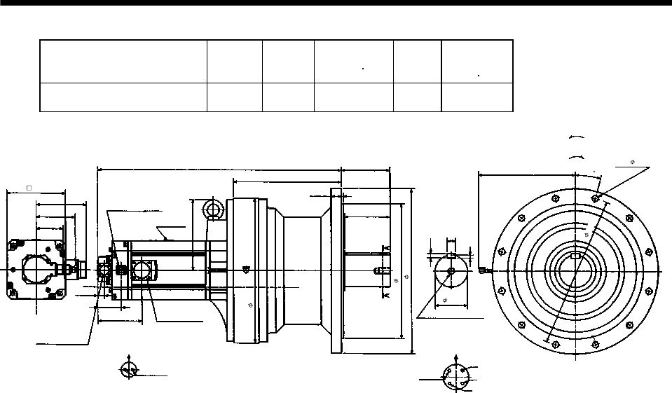
7 - 230
7. OUTLINE DIMENSION DRAWINGS
Model Output
[kW]
Reduction
Ratio
Inertia Moment
WK2[oz in2]
Mass
[lb]
Brake static
friction torque
[oz in]
HC-SF702BG1 HC-SFS702BG1
HC-SFS7024BG1 7.0 1/43 1458.71 542.3 6103
Power supply connector layout
CE05-2A32-17P
5.91
28.47
12.6
5.71
3.74
4.61
A
A
Motor plate
0.77
2.72
0.35
BC11037*
12- 0.71
0.55
Motor flange direction
0.98
U
V
W
C
D
B
A
Earth
Section A-A
16.93
8.27
3.21
Brake connector layout
MS3102A10SL-4P
Motor flange direction
B
ABrake
5.10
Brake connector
MS3102A10SL-4P
1.18 0.24
5.32
15.75
19.29
15
11.22
17.72
Encoder connector
MS3102A20-29P
Power supply
connector
CE05-2A32-17P
6.93
Bottom Top
[Unit: in]
"Rotation direction"
For reverse
rotation command
For forward
rotation command
1-M20 threads, depth1.34
(BC11848*)
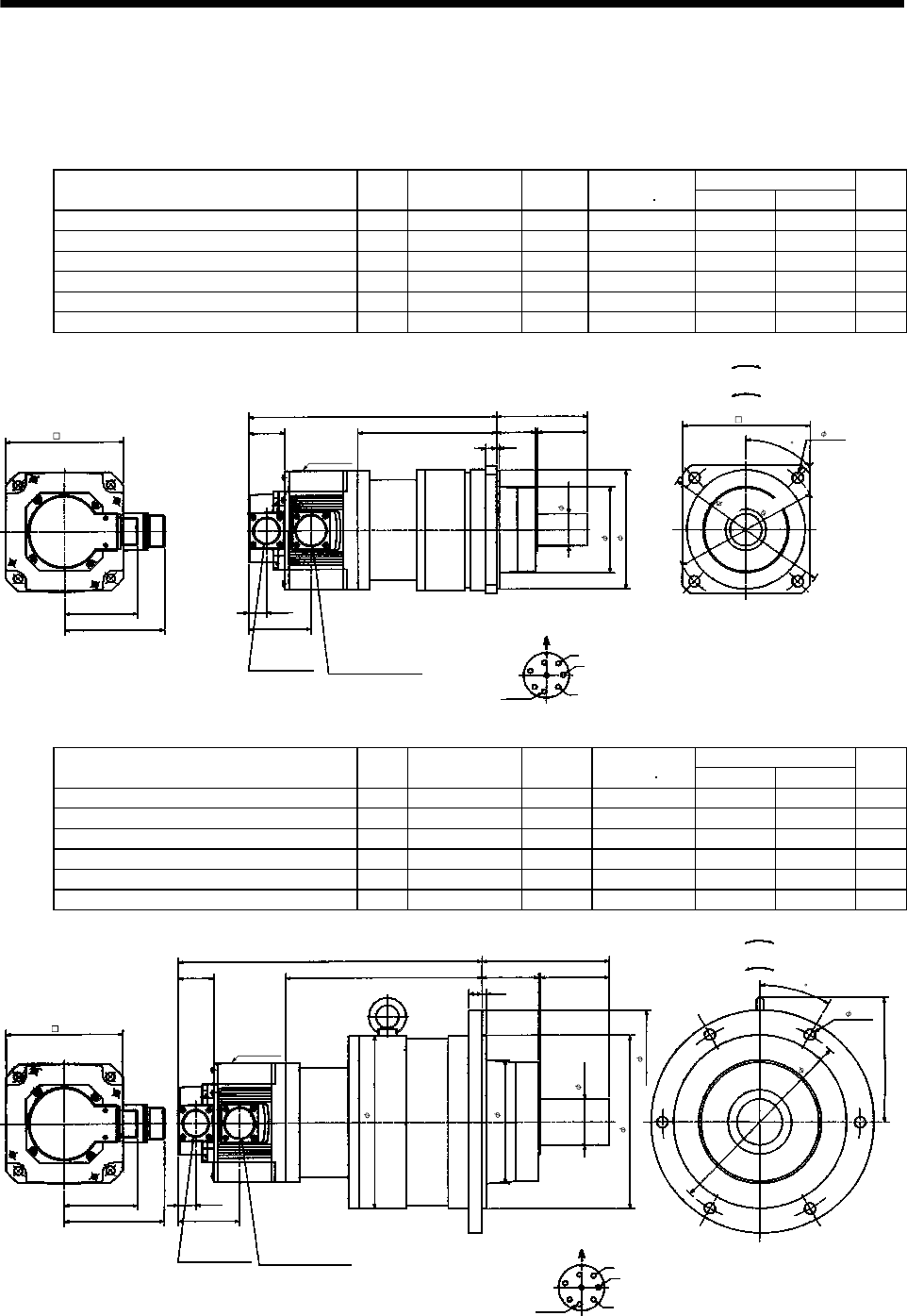
7 - 231
7. OUTLINE DIMENSION DRAWINGS
(5) With reduction gear for precision application
The outer frame of the reduction gear is a material surface such as casting. Its actual dimensions may
be 0.039 to 0.118 in larger than the drawing dimensions. Design the machine side with allowances.
(a) Without electromagnetic brake
Variable Dimensions [in]
Model Output
[kW]
Reduction Gear
Model
Reduction
Ratio
Inertia Moment
WK2[oz in2]LH
Mass
[lb]
HC-SF52G2 HC-SFS52G2 HC-SFS524G2 0.5 BL2-05B-05MEH 1/5 43.19 10.87 6.14 28.7
HC-SF52G2 HC-SFS52G2 HC-SFS524G2 0.5 BL2-09B-05MEH 1/9 41.28 11.34 6.61 28.7
HC-SF52G2 HC-SFS52G2 HC-SFS524G2 0.5 BL2-20B-05MEH 1/20 43.88 12.17 7.44 33.1
HC-SF102G2 HC-SFS102G2 HC-SFS1024G2 1.0 BL2-05B-10MEH 1/5 81.88 11.85 6.14 33.1
HC-SF102G2 HC-SFS102G2 HC-SFS1024G2 1.0 BL2-09B-10MEH 1/9 79.96 12.32 6.61 33.1
HC-SF152G2 HC-SFS152G2 HC-SFS1524G2 1.5 BL2-05B-15MEH 1/5 116.05 12.84 6.14 37.5
0.77
W
V
U
L
2.17
3.94
A
F
G
H
B
E
C
D
5.12
4.37
3.21
2.70
1.56 H1.69
0.47 0.12
1.38
3.70
5.12
4- 0.47
5.51
Z695320*
MS3102A20-29P CE05-2A22-23P
Bottom Top
Encoder connector Power supply connector
Motor flange direction
Earth
Power supply connector layout
CE05-2A22-23P
[Unit: in]
Motor plate
[Side view of motor only]
"Rotation direction"
For reverse
rotation command
For forward
rotation command
6.30
7.28
(BC11849*)
45
Variable Dimensions [in]
Model Output
[kW]
Reduction Gear
Model
Reduction
Ratio
Inertia Moment
WK2[oz in2]LH
Mass
[lb]
HC-SF52G2 HC-SFS52G2 HC-SFS524G2 0.5 BL3-29B-05MEH 1/29 51.39 13.27 8.54 66.1
HC-SF52G2 HC-SFS52G2 HC-SFS524G2 0.5 BL3-45B-05MEH 1/45 46.06 13.50 8.78 66.1
HC-SF102G2 HC-SFS102G2 HC-SFS1024G2 1.0 BL3-20B-10MEH 1/20 100.46 14.25 8.54 70.5
HC-SF102G2 HC-SFS102G2 HC-SFS1024G2 1.0 BL3-29B-10MEH 1/29 90.08 14.25 8.54 70.5
HC-SF152G2 HC-SFS152G2 HC-SFS1524G2 1.5 BL3-09B-15MEH 1/9 134.77 14.92 8.23 75.0
HC-SF152G2 HC-SFS152G2 HC-SFS1524G2 1.5 BL3-20B-15MEH 1/20 134.64 15.24 8.54 75.0
0.77
W
V
U
L
2.95
5.51
A
FG
H
B
E
C
D
5.12
4.37
3.21
2.70
1.56 H2.48
0.59 0.20
1.97
7.48
9.65
6- 0.47
5.32
8.66
5.39
7.48
Z695321A
MS3102A20-29P CE05-2A22-23P
Bottom Top
Encoder connector Power supply connector Motor flange direction
Earth
Power supply connector layout
CE05-2A22-23P
[Unit: in]
Motor plate
[Side view of motor only]
"Rotation direction"
For reverse
rotation command
For forward
rotation command
(BC11850*)
30

7 - 232
7. OUTLINE DIMENSION DRAWINGS
Variable Dimensions [in]
Model Output
[kW]
Reduction Gear
Model
Reduction
Ratio
Inertia Moment
WK2[oz in2]LH
Mass
[lb]
HC-SF102G2 HC-SFS102G2
HC-SFS1024G2 1.0 BL4-45B-10MEH 1/45 110.85 15.32 9.61 114.6
HC-SF152G2 HC-SFS152G2
HC-SFS1524G2 1.5 BL4-29B-15MEH 1/29 165.53 16.18 9.49 119.0
HC-SF152G2 HC-SFS152G2
HC-SFS1524G2 1.5 BL4-45B-15MEH 1/45 145.02 16.30 9.61 119.0
0.77
W
V
U
L
3.54
6.30
A
FG
H
B
E
C
D
5.12
4.37
3.21
2.70
1.56 H2.68
0.71 0.20
2.36
9.45
12.21
6- 0.55
7.32
6.73
11.02
Z695322*
Encoder
connector
MS3102A20-29P Power supply connector
CE05-2A22-23P
Power supply connector layout
CE05-2A22-23P
Motor plate
Earth
Motor flange direction
[Unit: in]
Bottom Top
(Side view of motor only)
"Rotation direction"
For reverse
rotation command
For forward
rotation command
(BC11851*)
30
Variable Dimensions [in]
Model Output
[kW]
Reduction Gear
Model
Reduction
Ratio
Inertia Moment
WK2[oz in2]LH
Mass
[lb]
HC-SF202G2 HC-SFS202G2
HC-SFS2024G2 2.0 BL3-05B-20MEH 1/5 271.19 13.70 7.99 66.1
HC-SF202G2 HC-SFS202G2
HC-SFS2024G2 2.0 BL3-09B-20MEH 1/9 258.06 14.76 9.06 81.6
5.51
0.20
6.93
3.20 0.77
5.39
Z695637A
U
V
W
CDB
E
A
G
F
7.48
7.48
9.65
2.95
0.59
6- 0.47
3.01
5.32
2.48
L
H
1.56
5.59
Encoder connector
MS3102A20-29P
Power supply connector
CE05-2A24-10P
Power supply connector layout
CE05-2A24-10P
Motor plate
Motor flange direction
[Unit: in]
Bottom Top
(Side view of motor only)
"Rotation direction"
For reverse
rotation command
For forward
rotation command
Earth
1.97
8.66
(BC11852*)
30
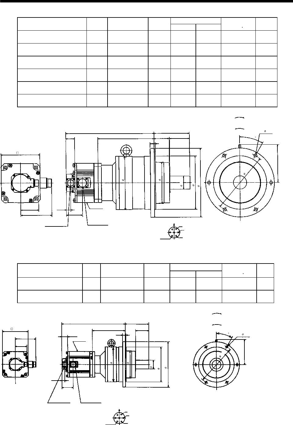
7 - 233
7. OUTLINE DIMENSION DRAWINGS
Variable Dimensions [in]
Model Output
[kW]
Reduction Gear
Model
Reduction
Ratio LH
Inertia Moment
WK2[oz in2]
Mass
[lb]
HC-SF202G2 HC-SFS202G2
HC-SFS2024G2 2.0 BL4-20B-20MEH 1/20 10.32 326.0 16.02 125.7
HC-SF202G2 HC-SFS202G2
HC-SFS2024G2 2.0 BL4-29B-20MEH 1/29 10.32 288.82 16.02 125.7
HC-SF202G2 HC-SFS202G2
HC-SFS2024G2 2.0 BL4-45B-20MEH 1/45 10.43 268.32 16.14 125.7
HC-SF352G2 HC-SFS352G2
HC-SFS3524G2 3.5 BL4-05B-35MEH 1/5 8.78 543.33 16.14 119.0
HC-SF352G2 HC-SFS352G2
HC-SFS3524G2 3.5 BL4-09B-35MEH 1/9 10.04 500.14 17.40 141.1
HC-SF352G2 HC-SFS352G2
HC-SFS3524G2 3.5 BL4-20B-35MEH 1/20 10.32 541.96 17.68 141.1
6.30
0.20
6.93
3.21 0.77
6.73
11.02
Z695638A
U
V
W
C
DB
E
A
G
F
9.45
9.45
12.21
3.54
0.71
6- 0.55
3.01
7.32
2.68
L
H
1.56
5.59
Encoder connector
MS3102A20-29P
Power supply connector
CE05-2A24-10P
Power supply connector layout
CE05-2A24-10P
Motor plate
Earth
Motor flange direction
[Unit: in]
Bottom Top
(Side view of motor only)
"Rotation direction"
For reverse
rotation command
For forward
rotation command
2.36
(BC11853*)
30
Variable Dimensions [in]
Model Output
[kW]
Reduction Gear
Model
Reduction
Ratio LH
Inertia Moment
WK2[oz in2]
Mass
[lb]
HC-SF502G2 HC-SFS502G2
HC-SFS5024G2 5.0 BL4-05B-50MEH 1/5 16.97 10.04 647.35 127.9
HC-SF502G2 HC-SFS502G2
HC-SFS5024G2 5.0 BL4-09B-50MEH 1/9 18.23 8.78 604.15 149.9
5.59
L
H
6.30
0.77
6.73
BC11067*
6- 0.55
9.45
3.21
3.01
0.71 0.20
3.54
9.45
12.21
1.56
7.32
2.36
11.02
6.93
Encoder connector
MS3102A20-29P
Power supply connector
CE05-2A24-10P
Motor plate
U
V
W
C
DB
E
A
G
F
Power supply connector layout
CE05-2A24-10P
Earth
Motor flange direction
Bottom Top
(Side view of motor only)
[Unit: in]
"Rotation direction"
For reverse
rotation command
For forward
rotation command
30
(********)
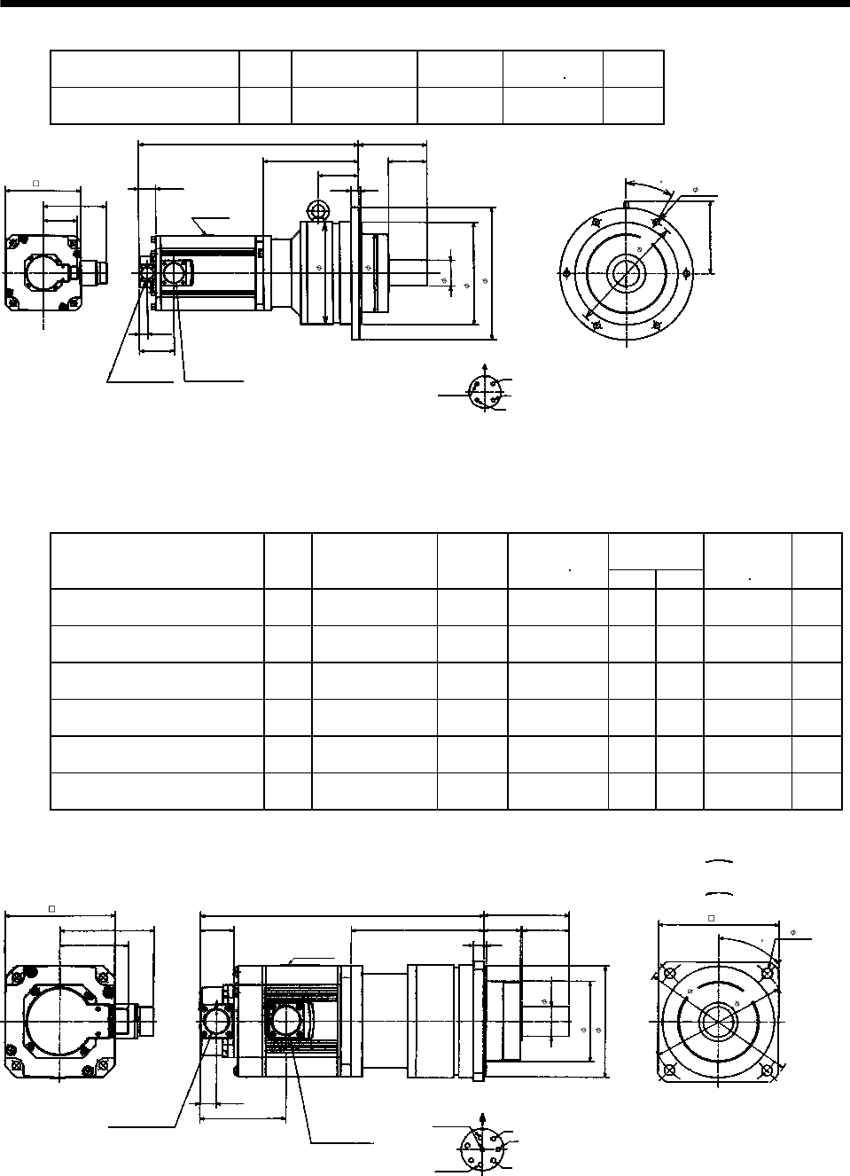
7 - 234
7. OUTLINE DIMENSION DRAWINGS
Model Output
[kW]
Reduction Gear
Model
Reduction
Ratio
Inertia Moment
WK2[oz in2]
Mass
[lb]
HC-SF702G2 HC-SFS702G2
HC-SFS7024G2 7.0 BL4-05B-70MEH 1/5 969.93 147.7
5.91
20.28
8.78
6.30
0.77
6.73
BC11068*
6- 0.55
U
V
W
C
D
B
A
9.45
3.21
3.21
0.71 0.20
3.54
9.45
12.21
1.56
7.32
3.36
3.70
11.02
6.93
Encoder connector
MS3102A20-29P
Power supply connector
CE05-2A32-17P
Motor plate
Power supply connector layout
CE05-2A32-17P
Earth
Motor flange direction
Bottom Top
(Side view of motor only)
[Unit: in]
(********)
30
(b) With electromagnetic brake
Variable
Dimensions [in]
Model Output
[kW]
Reduction Gear
Model
Reduction
Ratio
Inertia Moment
WK2[oz in2]LH
Brake static
friction torque
[oz in]
Mass
[lb]
HC-SF52BG2 HC-SFS52BG2
HC-SFS524BG2 0.5 BL2-05B-05MEH 1/5 52.49 12.17 6.14 1204 33.1
HC-SF52BG2 HC-SFS52BG2
HC-SFS524BG2 0.5 BL2-09B-05MEH 1/9 50.57 12.64 6.61 1204 33.1
HC-SF52BG2 HC-SFS52BG2
HC-SFS524BG2 0.5 BL2-20B-05MEH 1/20 53.17 13.47 7.44 1204 37.5
HC-SF102BG2 HC-SFS102BG2
HC-SFS1024BG2 1.0 BL2-05B-10MEH 1/5 91.17 13.15 6.14 1204 37.5
HC-SF102BG2 HC-SFS102BG2
HC-SFS1024BG2 1.0 BL2-09B-10MEH 1/9 89.26 13.62 6.61 1204 37.5
HC-SF152BG2 HC-SFS152BG2
HC-SFS1524BG2 1.5 BL2-05B-15MEH 1/5 125.34 14.13 6.14 1204 41.9
L
1.56
5.12
0.77
4.0
H 1.69 2.17
3.94
1.38
3.70
4- 0.47
45
W
V
U
A
FG
HB
E
C
D
5.12
4.37
3.21 0.47 0.12
7.28
6.30
5.51
Z695323*
Encoder connector
MS3102A20-29P Power supply connector
CE05-2A22-23P
Power supply connector layout
CE05-2A22-23P
Motor plate
Earth
Motor flange direction
[Unit: in]
Bottom Top
(Side view of motor only)
"Rotation direction"
For reverse
rotation command
For forward
rotation command
Brake
(BC11856*)
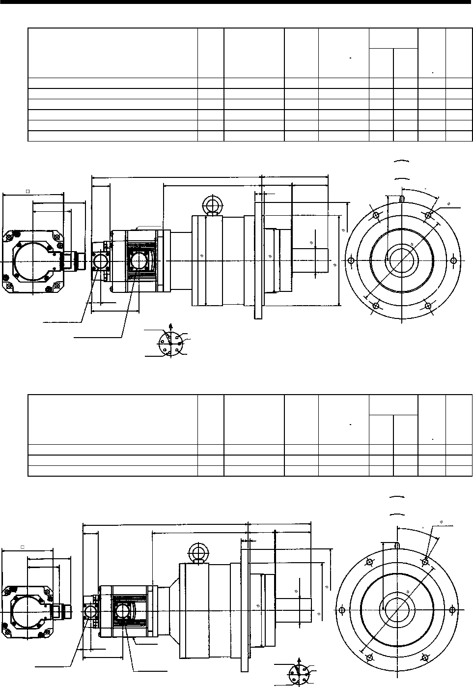
7 - 235
7. OUTLINE DIMENSION DRAWINGS
Variable
Dimensions [in]
Model Output
[kW]
Reduction Gear
Model
Reduction
Ratio
Inertia Moment
WK2[oz in2]LH
Brake
static
friction
torque
[oz in]
Mass
[lb]
HC-SF52BG2 HC-SFS52BG2 HC-SFS524BG2 0.5 BL3-29B-05MEH 1/29 60.69 14.57 8.54 1204 70.5
HC-SF52BG2 HC-SFS52BG2 HC-SFS524BG2 0.5 BL3-45B-05MEH 1/45 55.36 14.80 8.78 1204 70.5
HC-SF102BG2 HC-SFS102BG2 HC-SFS1024BG2 1.0 BL3-20B-10MEH 1/20 109.76 15.55 8.54 1204 75.0
HC-SF102BG2 HC-SFS102BG2 HC-SFS1024BG2 1.0 BL3-29B-10MEH 1/29 99.37 15.55 8.54 1204 75.0
HC-SF152BG2 HC-SFS152BG2 HC-SFS1524BG2 1.5 BL3-09B-15MEH 1/9 144.07 16.22 8.23 1204 79.4
HC-SF152BG2 HC-SFS152BG2 HC-SFS1524BG2 1.5 BL3-20B-15MEH 1/20 143.93 16.54 8.54 1204 79.4
W
V
U
A
FG
HB
E
C
D
L
1.56
5.51
2.48 2.95
8.66
6- 0.47
5.12
4.37
3.21
0.59 0.20
H
0.77
4.0
7.48
5.32
1.97
9.65
5.39
7.48
Z695324*
Encoder connector
MS3102A20-29P
Power supply connector
CE05-2A22-23P
Power supply connector layout
CE05-2A22-23P
Motor plate
Earth
Motor flange direction
[Unit: in]
Bottom Top
(Side view of motor only)
"Rotation direction"
For reverse
rotation command
For forward
rotation command
Brake
(BC11857*)
30
Variable
Dimensions [in]
Model Output
[kW]
Reduction Gear
Model
Reduction
Ratio
Inertia Moment
WK2[oz in2]LH
Brake
static
friction
torque
[oz in]
Mass
[lb]
HC-SF102BG2 HC-SFS102BG2 HC-SFS1024BG2 1.0 BL4-45B-10MEH 1/45 120.15 16.61 9.61 1204 114.6
HC-SF152BG2 HC-SFS152BG2 HC-SFS1524BG2 1.5 BL4-29B-15MEH 1/29 174.82 17.48 9.49 1204 123.5
HC-SF152BG2 HC-SFS152BG2 HC-SFS1524BG2 1.5 BL4-45B-15MEH 1/45 154.32 17.60 9.61 1204 123.5
W
V
U
A
FG
HB
E
C
D
L
1.56
6.30
2.68 3.54
11.02
6- 0.55
5.12
4.37
3.21
0.71 0.20
H
0.77
4.0
7.32
2.36
9.45
12.21
6.73
Z695325*
Encoder connector
MS3102A20-29P Power supply connector
CE05-2A22-23P
Power supply connector layout
CE05-2A22-23P
Motor plate
Earth
Motor flange direction
[Unit: in]
Bottom Top
(Side view of motor only)
"Rotation direction"
For reverse
rotation command
For forward
rotation command
Brake
(BC11858*)
30

7 - 236
7. OUTLINE DIMENSION DRAWINGS
Variable Dimensions [in]
Model Output
[kW]
Reduction Gear
Model
Reduction
Ratio LH
Brake static
friction torque
[oz in]
Inertia Moment
WK2[oz in2]
Mass
[lb]
HC-SF202BG2 HC-SFS202BG2
HC-SFS2024BG2 2.0 BL3-05B-20MEH 1/5 15.59 7.99 6103 325.86 79.4
HC-SF202BG2 HC-SFS202BG2
HC-SFS2024BG2 2.0 BL3-09B-20MEH 1/9 16.65 9.06 6103 312.74 94.8
5.51
0.20
3.20
0.77
5.39
Z695640A
U
V
W
C
DBE
A
G
F
7.48
7.48
9.65
2.95
0.59
6- 0.47
2.72
5.32
2.48
L
H
1.56
5.59
4.90
AB
4.61
Encoder connector
MS3102A20-29P
Power supply connector
CE05-2A24-10P
Power supply connector layout
CE05-2A24-10P
Earth
Brake connector
MS3102A10SL-4P
Motor flange direction
Brake
Brake connector layout
MS3102A10SL-4P
Motor flange direction
Motor plate
[Unit: in]
(Side view of motor only)
"Rotation direction"
For reverse
rotation command
For forward
rotation command
8.66
1.97
(BC11859*)
30
Variable Dimensions [in]
Model Output
[kW]
Reduction Gear
Model
Reduction
Ratio LH
Brake static
friction torque
[oz in]
Inertia Moment
WK2[oz in2]
Mass
[lb]
HC-SF202BG2 HC-SFS202BG2
HC-SFS2024BG2 2.0 BL4-20B-20MEH 1/20 17.91 10.32 6103 380.67 138.9
HC-SF202BG2 HC-SFS202BG2
HC-SFS2024BG2 2.0 BL4-29B-20MEH 1/29 17.91 10.32 6103 343.49 138.9
HC-SF202BG2 HC-SFS202BG2
HC-SFS2024BG2 2.0 BL4-45B-20MEH 1/45 18.03 10.43 6103 322.99 138.9
HC-SF352BG2 HC-SFS352BG2
HC-SFS3524BG2 3.5 BL4-05B-35MEH 1/5 18.03 8.78 6103 598.0 132.3
HC-SF352BG2 HC-SFS352BG2
HC-SFS3524BG2 3.5 BL4-09B-35MEH 1/9 19.29 10.04 6103 554.81 154.3
HC-SF352BG2 HC-SFS352BG2
HC-SFS3524BG2 3.5 BL4-20B-35MEH 1/20 19.57 10.32 6103 596.64 154.3
6.30
0.20
6.93
3.21
0.77
6.73
11.02
Z695641A
U
V
W
C
DB
E
A
G
F
7.32
9.45
12.21
3.54
0.71
6- 0.55
4.90
2.68
L
H
1.56
9.45
2.72
4.61
5.59
AB
Encoder connector
MS3102A20-29P
Power supply connector
CE05-2A24-10P
Power supply connector layout
CE05-2A24-10P
Earth
Brake connector
MS3102A10SL-4P
Motor flange direction
Brake
Brake connector layout
MS3102A10SL-4P
Motor flange direction
Motor plate
[Unit: in]
(Side view of motor only)
"Rotation direction"
For reverse
rotation command
For forward
rotation command
Bottom Top
2.36
(BC11860*)
30
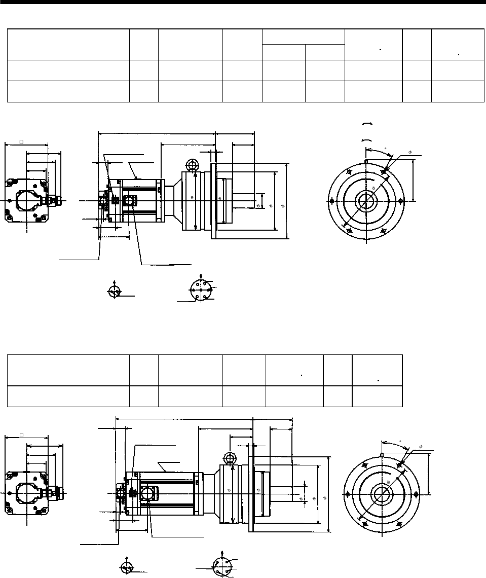
7 - 237
7. OUTLINE DIMENSION DRAWINGS
Variable Dimensions [in]
Model Output
[kW]
Reduction Gear
Model
Reduction
Ratio LH
Inertia Moment
WK2[oz in2]
Mass
[lb]
Brake static
friction torque
[oz in]
HC-SF502BG2 HC-SFS502BG2
HC-SFS5024BG2 5.0 BL4-05B-50MEH 1/5 18.86 8.78 702.02 141.1 6103
HC-SF502BG2 HC-SFS502BG2
HC-SFS5024BG2 5.0 BL4-09B-50MEH 1/9 20.12 10.04 658.83 163.1 6103
5.59
L
H
6.30
6.93
4.61
0.77
2.72
6.73
BC11069*
6- 0.55
U
V
W
C
DB
E
A
G
F
9.45
3.21
4.90
0.71 0.20
3.54
9.45
12.21
1.56
7.32
3.36
30
11.02
AB
Encoder connector
MS3102A20-29P Power supply connector
CE05-2A24-10P
Power supply connector layout
CE05-2A24-10P
Earth
Brake connector
MS3102A10SL-4P
Motor flange direction
Brake
Brake connector layout
MS3102A10SL-4P
Motor flange direction
Motor plate
[Unit: in]
(Side view of motor only)
"Rotation direction"
For reverse
rotation command
For forward
rotation command
Bottom Top
(********)
Model Output
[kW]
Reduction Gear
Model
Reduction
Ratio
Inertia Moment
WK2[oz in2]
Mass
[lb]
Brake static
friction torque
[oz in]
HC-SF702BG2 HC-SFS702BG2
HC-SFS7024BG2 7.0 BL4-05B-70MEH 1/5 1024.60 160.9 6103
5.91
22.17
8.78
6.30
6.93
4.61
0.77
2.72
6.73
BC11070*
6- 0.55
U
V
W
C
D
B
A
9.45
3.21
B
A
5.10
0.71 0.20
3.54
9.45
12.21
1.56
7.32
3.36
3.70
11.02
Encoder connector
MS3102A20-29P
Power supply connector
CE05-2A32-17P
Power supply connector layout
CE05-2A32-17P
Earth
Brake connector
MS3102A10SL-4P
Motor flange direction
Brake
Brake connector layout
MS3102A10SL-4P
Motor flange direction
Motor plate
[Unit: in]
(Side view of motor only)
Bottom Top
(********)
30
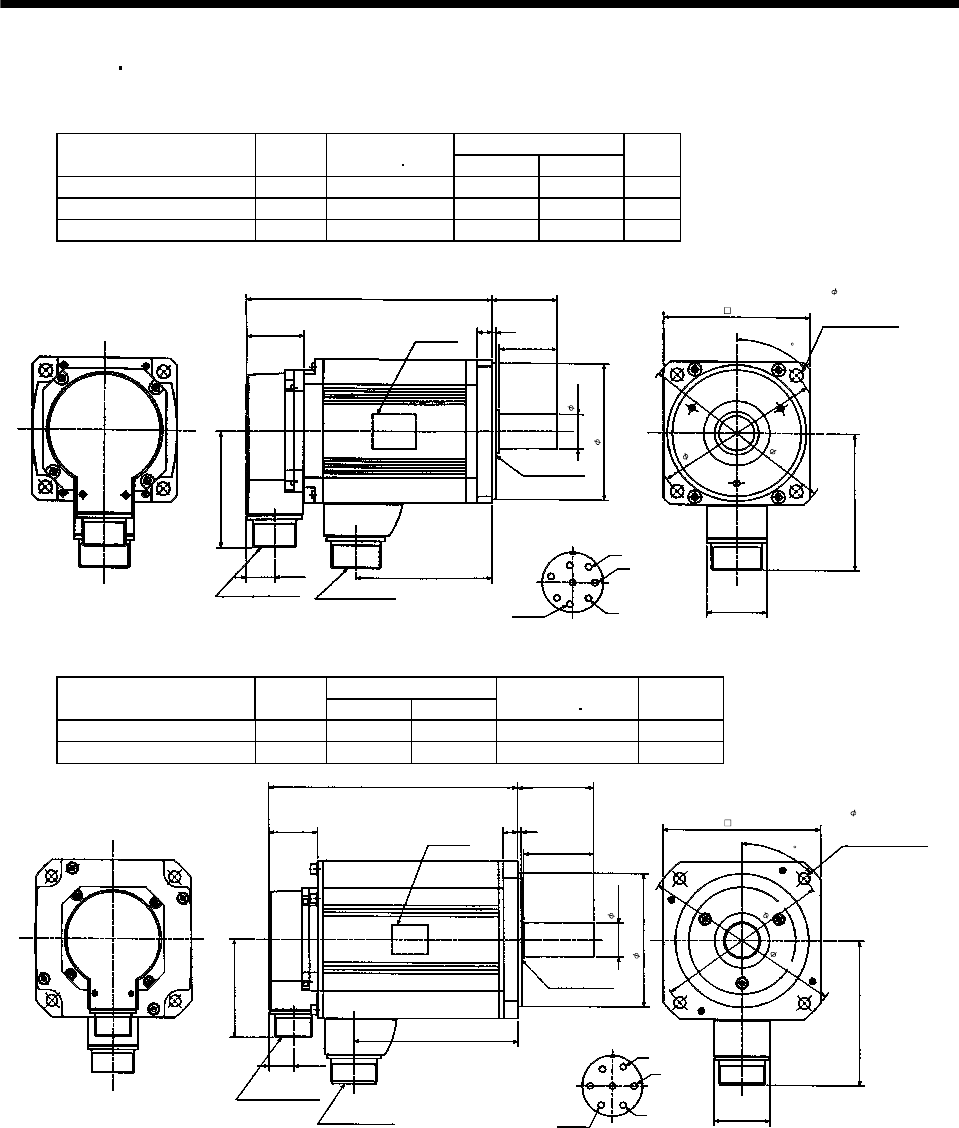
7 - 238
7. OUTLINE DIMENSION DRAWINGS
7.2.4 HC-RF HC-RFS series
(1) Standard (without electromagnetic brake, without reduction gear)
Variable Dimensions [in]
Model Output
[kW]
Inertia Moment
WK2[oz in2]LKL
Mass
[lb]
HC-RF103 HC-RFS103 1.0 8.20 5.79 2.80 8.6
HC-RF153 HC-RFS153 1.5 10.39 6.77 3.78 11.0
HC-RF203 HC-RFS203 2.0 12.58 7.76 4.76 13.7
1.61
3.78
4.53
5.32
3.21
0.77
MS3102A20-29P CE05-2A22-23P W
V
U
A
F
G
HB
E
C
D
KL
L
1.56 0.39 0.12
1.58
S30457B
0.95
3.74
1.77
(BC11697*
)
Bottom
Top
Encoder connector Power supply connector
Oil seal
Motor flange direction
Earth
Power supply connector layout
CE05-2A22-23P
[Unit: in]
Use hexagon socket
head cap screw.
Motor plate
(Opposite side)
Bottom
Top
Z694853*
3.94
4- 0.35 mounting hole
45
Variable Dimensions [in]
Model Output
[kW] LKL
Inertia Moment
WK2[oz in2]
Mass
[lb]
HC-RF353 HC-RFS353 3.5 8.543 5.827 47.02 26.5
HC-RF503 HC-RFS503 5.0 10.787 8.071 65.609 37.5
[Unit: in]
2.283
Motor plate
V
U
W
DC
B
A
G
F
E
4.724
Power supply connector layout
CE05-2A24-10P
0.12
2.48
0.47
1.56
1.102
Top
Bottom
L
(Opposite side)
Bottom
Top
3.21
0.77
5.118
1.811
KL
MS3102A20-29P
Encoder connector
CE05-2A24-10P
Power supply connector
S30457B
Oil seal
Motor flange direction
Earth
Use hexagon socket
head cap screw.
4- 0.354 mounting hol
e
Z695780*
4.331
5.709
6.496
45
(BC11698*)
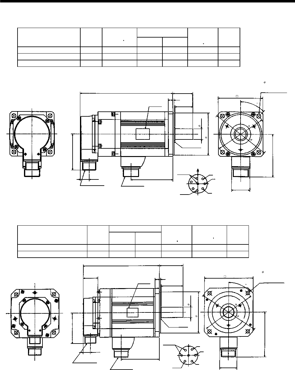
7 - 239
7. OUTLINE DIMENSION DRAWINGS
(2) With electromagnetic brake
Variable Dimensions [in]
Model Output
[kW]
Inertia Moment
WK2[oz in2]LKL
Brake static
friction torque
[oz in]
Mass
[lb]
HC-RF103B HC-RFS103B 1.0 10.12 7.28 2.80 991 13.2
HC-RF153B HC-RFS153B 1.5 12.30 8.27 3.78 991 15.4
HC-RF203B HC-RFS203B 2.0 14.49 9.25 4.76 991 18.3
KL
0.77
W
V
U
MS3102A20-29P CE05-2A22-23P
3.21
S30457B
L1.77
0.39 0.12
1.58
A
F
G
HB
E
C
D1.61
3.78
Bottom
Top
Encoder connector Power supply connector
Oil seal
Motor flange direction
Earth
Power supply connector layout
CE05-2A22-23P
[Unit: in]
Use hexagon socket
head cap screw.
4- 0.35 mounting hole
Motor plate
(Opposite side)
Bottom
Top
Brake
Z695165*
3.94
4.53
5.32
3.74
0.95
(BC11699*)
45
Variable Dimensions [in]
Model Output
[kW] LKL
Brake static
friction torque
[oz in]
Inertia Moment
WK2[oz in2]
Mass
[lb]
HC-RF353B HC-RFS353B 3.5 10 5.827 2365 64.516 33.1
HC-RF503B HC-RFS503B 5.0 12.244 8.071 2365 84.745 46.3
(Opposite side)
0.77
W
V
U
A
B
C
D
E
FG
Power supply connector layout
CE05-2A24-10P
MS3102A20-29P
CE05-2A24-10P
3.21
L2.48
0.47 0.12
2.283
1.811
4.724
5.118
Bottom
Top
[Unit: in]
Bottom
Top
1.56 Motor plate
Brake
KL
Encoder connector
Power supply connector
S30457B
Oil seal
Motor flange direction
Earth
Use hexagon socket
head cap screw.
Z695563A
4- 0.354 mounting hol
e
4.331
1.102
6.496
5.709
45
(
BC11700*
)
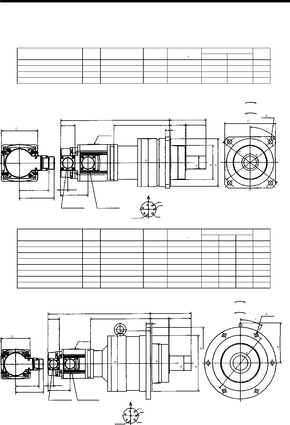
7 - 240
7. OUTLINE DIMENSION DRAWINGS
(3) With reduction gear for precision application
The outer frame of the reduction gear is a material surface such as casting. Its actual dimensions may
be 0.039 to 0.118 in larger than the drawing dimensions. Design the machine side with allowances.
(a) Without electromagnetic brake
Variable Dimensions [in]
Model Output
[kW]
Reduction Gear
Model
Reduction
Ratio
Inertia Moment
WK2[oz in2]LKL
Mass
[lb]
HC-RF103G2 HC-RFS103G2 1.0 BL2-05B-10MEKD 1/5 27.06 11.85 6.06 26.2
HC-RF103G2 HC-RFS103G2 1.0 BL2-09B-10MEKD 1/9 25.15 12.32 6.54 26.2
HC-RF153G2 HC-RFS153G2 1.5 BL2-05B-15MEKD 1/5 29.25 12.84 6.06 28.7
HC-RF203G2 HC-RFS203G2 2.0 BL2-05B-20MEKD 1/5 31.44 13.82 6.06 31.3
L
1.56
3.94
0.77
2.99
3.21
3.78
H
0.47 0.12
1.69 2.17
5.20
W
V
U
A
FG
H
B
E
C
D
Z695327A
Encoder connector
MS3102A20-29P
Power supply connector
CE05-2A22-23P
Power supply connector layout
CE05-2A22-23P
Earth
Motor flange direction
[Unit: in]
Bottom Top
(Side view of motor only)
"Rotation direction"
For reverse
rotation command
For forward
rotation command
Motor plate
(Opposite side)
5.51
4- 0.47
6.30
7.28
5.12
3.70
1.38
3.94
45
Variable Dimensions [in]
Model Output
[kW]
Reduction Gear
Model
Reduction
Ratio
Inertia Moment
WK2[oz in2]LHLI
Mass
[lb]
HC-RF103G2 HC-RFS103G2 1.0 BL3-20B-10MEKD 1/20 45.65 13.94 8.15 4.13 63.7
HC-RF103G2 HC-RFS103G2 1.0 BL3-29B-10MEKD 1/29 35.27 13.94 8.15 4.13 63.7
HC-RF103G2 HC-RFS103G2 1.0 BL3-45B-10MEKD 1/45 29.93 14.33 8.54 4.53 63.7
HC-RF153G2 HC-RFS153G2 1.5 BL3-09B-15MEKD 1/9 36.50 14.76 7.99 3.98 66.1
HC-RF153G2 HC-RFS153G2 1.5 BL3-20B-15MEKD 1/20 47.84 14.92 8.15 4.13 66.1
HC-RF153G2 HC-RFS153G2 1.5 BL3-29B-15MEKD 1/29 37.45 14.92 8.15 4.13 66.1
HC-RF203G2 HC-RFS203G2 2.0 BL3-09B-20MEKD 1/9 38.71 15.75 7.99 3.98 68.8
HC-RF203G2 HC-RFS203G2 2.0 BL3-20B-20MEKD 1/20 50.03 15.91 8.15 4.13 68.8
W
V
U
A
FG
HB
E
C
D
L
1.56
5.51
2.48 2.95
3.78
3.21
0.59 0.20
H
0.77
2.99
LI
Encoder connector
MS3102A20-29P
Power supply connector
CE05-2A22-23P
Power supply connector layout
CE05-2A22-23P
Earth
Motor flange direction
[Unit: in]
Bottom Top
(Side view of motor only)
"Rotation direction"
For reverse
rotation command
For forward
rotation command
Motor plate
Z695328*
6- 0.47
8.66
9.65
7.48
1.97
5.32
7.48
3.94
5.37
30
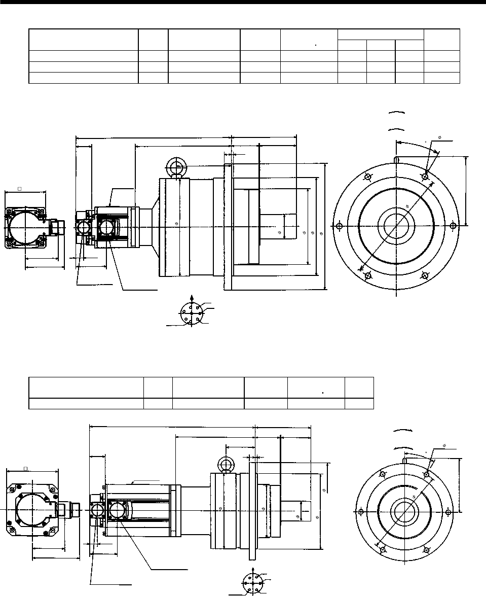
7 - 241
7. OUTLINE DIMENSION DRAWINGS
Variable Dimensions [in]
Model Output
[kW]
Reduction Gear
Model
Reduction
Ratio
Inertia Moment
WK2[oz in2]LHLI
Mass
[lb]
HC-RF153G2 HC-RFS153G2 1.5 BL4-45B-15MEKD 1/45 46.75 16.14 9.37 5.35 110.2
HC-RF203G2 HC-RFS203G2 2.0 BL4-29B-20MEKD 1/29 69.44 16.73 8.98 4.96 112.9
HC-RF203G2 HC-RFS203G2 2.0 BL4-45B-20MEKD 1/45 48.93 17.13 9.37 5.35 112.9
W
V
U
A
FG
H
B
E
C
D
L
1.56
6.30
2.68 3.54
3.78
3.21
0.71 0.20
H
0.77
2.99
LI
6.73
Encoder connector
MS3102A20-29P Power supply connector
CE05-2A22-23P
Power supply connector layout
CE05-2A22-23P
Earth
Motor flange direction
[Unit: in]
Bottom Top
(Side view of motor only)
"Rotation direction"
For reverse
rotation command
For forward
rotation command
Motor plate
Z695329*
6- 0.55
11.02
12.21
9.45
7.32
2.36
9.45
3.94
(
BC11865*
)
30
Model Output
[kW]
Reduction Gear
Model
Reduction
Ratio
Inertia Moment
WK2[oz in2]
Mass
[lb]
HC-RF353G2 HC-RFS353G2 3.5 BL3-05B-35MEKD 1/5 102.788 66.1
W
V
U
Power supply connector layout
CE05-2A24-10P
A
FG
BE C
D
Bottom Top
16.457
1.56
2.48
5.51
2.95
6- 0.47
3.21
4.724
0.59 0.20
7.913
Motor plate
0.77
2.736
5.37
2.913
[Unit: in]
Encoder connector
MS3102A20-29P
Power supply connector
CE05-2A24-10P
Earth
Motor flange direction
"Rotation direction"
For reverse
rotation command
For forward
rotation command
(Side view of motor only)
Z695990A
9.65
7.48
1.97
5.32
7.48
5.118
8.66
(********)
30
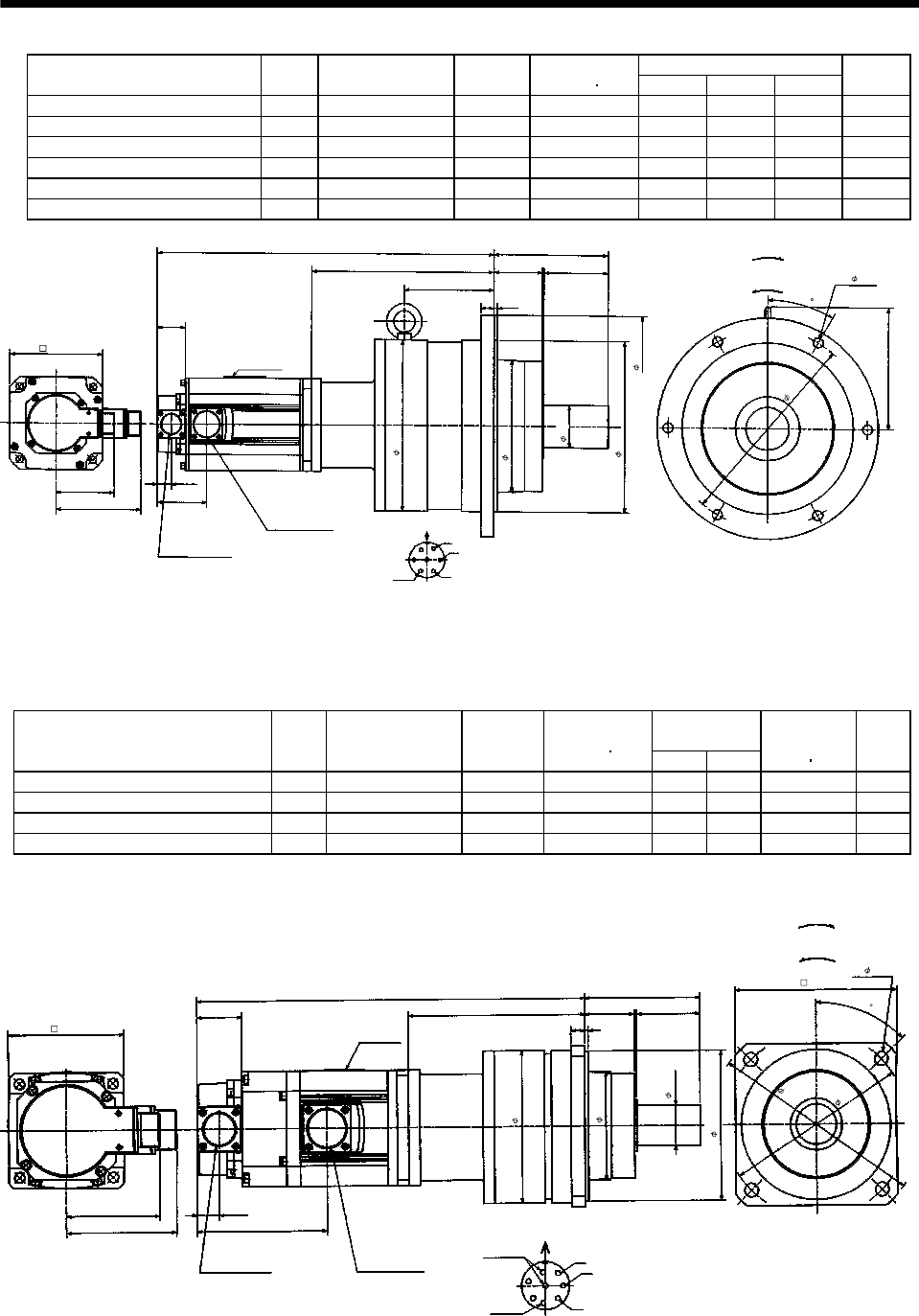
7 - 242
7. OUTLINE DIMENSION DRAWINGS
Variable Dimensions [in]
Model Output
[kW]
Reduction Gear
Model
Reduction
Ratio
Inertia Moment
WK2[oz in2]LHLI
Mass
[lb]
HC-RF353G2 HC-RFS353G2 3.5 BL4-09B-35MEKD 1/9 115.363 18.504 9.961 4.961 125.7
HC-RF353G2 HC-RFS353G2 3.5 BL4-20B-35MEKD 1/20 157.462 18.504 9.961 4.961 125.7
HC-RF353G2 HC-RFS353G2 3.5 BL4-29B-35MEKD 1/29 120.284 18.504 9.961 4.961 125.7
HC-RF503G2 HC-RFS503G2 5.0 BL4-05B-50MEKD 1/5 177.145 19.488 8.701 3.701 114.6
HC-RF503G2 HC-RFS503G2 5.0 BL4-09B-50MEKD 1/9 133.952 20.748 9.961 4.961 136.7
HC-RF503G2 HC-RFS503G2 5.0 BL4-20B-50MEKD 1/20 176.052 20.748 9.961 4.961 136.7
W
V
U
Power supply connector layout
CE05-2A24-10P
A
FG
BE C
D
Power supply connector
CE05-2A24-10P
Bottom Top
L
1.56
2.68
6.30
3.54
6- 0.55
3.21
4.724
0.71 0.20
H
Motor plate
0.77
2.736
6.73
LI
[Unit: in]
Encoder connector
MS3102A20-29P
Earth
Motor flange direction
"Rotation direction"
For reverse
rotation command
For forward
rotation command
(Side view of motor only)
Z695992A
11.02
9.45
12.21
7.323
9.45
5.118
(********)
30
2.36
(b) With electromagnetic brake
Variable
Dimensions [in]
Model Output
[kW]
Reduction Gear
Model
Reduction
Ratio
Inertia Moment
WK2[oz in2]LH
Brake static
friction torque
[oz in]
Mass
(lb)
HC-RF103BG2 HC-RFS103BG2 1.0 BL2-05B-10MEKD 1/5 28.98 13.35 6.06 991 30.9
HC-RF103BG2 HC-RFS103BG2 1.0 BL2-09B-10MEKD 1/9 27.06 13.82 6.54 991 30.9
HC-RF153BG2 HC-RFS153BG2 1.5 BL2-05B-15MEKD 1/5 31.16 14.33 6.06 991 33.3
HC-RF203BG2 HC-RFS203BG2 2.0 BL2-05B-20MEKD 1/5 33.35 15.32 6.06 991 35.9
L
1.56
3.94
0.77
4.47
3.21
3.78
H
0.47 0.12
1.69 2.17
W
V
U
A
FG
HB
E
C
D
Encoder connector
MS3102A20-29P
Power supply connector
CE05-2A22-23P
Power supply connector layout
CE05-2A22-23P
Earth
Motor flange direction
[Unit: in]
Bottom Top
(Side view of motor only)
"Rotation direction"
For reverse
rotation command
For forward
rotation command
(Opposite side)
Motor plate
Brake
Z695330*
(BC11868*)
4- 0.47
6.30
7.28
5.12
1.38
3.70
3.94
5.51
5.20
45
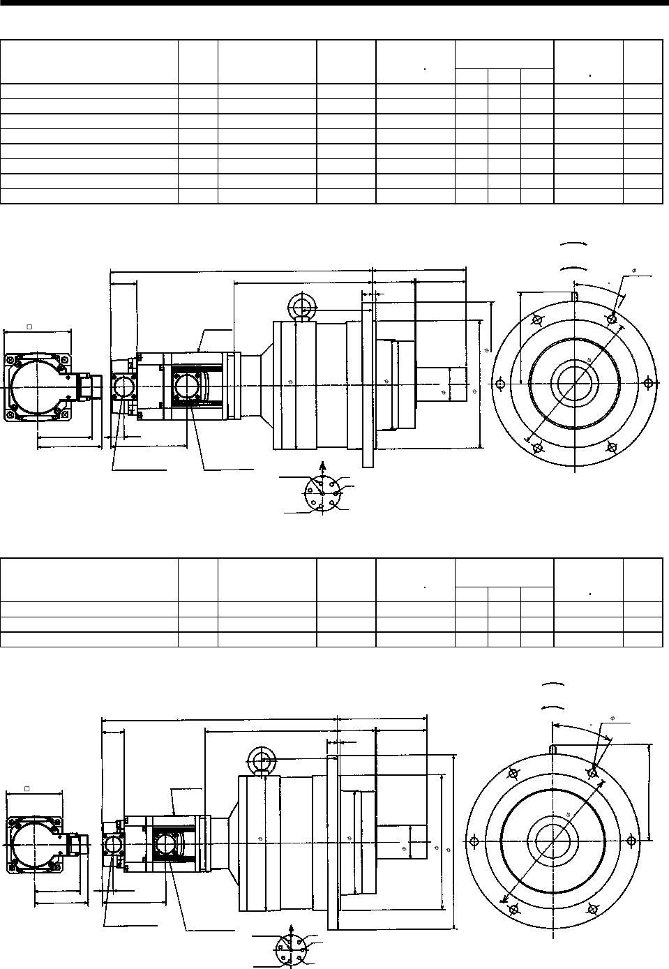
7 - 243
7. OUTLINE DIMENSION DRAWINGS
Variable Dimensions
[in]
Model Output
[kW]
Reduction Gear
Model
Reduction
Ratio
Inertia Moment
WK2[oz in2]LHLI
Brake static
friction torque
[oz in]
Mass
[lb]
HC-RF103BG2 HC-RFS103BG2 1.0 BL3-20B-10MEKD 1/20 47.57 15.43 8.15 4.13 991 68.3
HC-RF103BG2 HC-RFS103BG2 1.0 BL3-29B-10MEKD 1/29 37.18 15.43 8.15 4.13 991 68.3
HC-RF103BG2 HC-RFS103BG2 1.0 BL3-45B-10MEKD 1/45 31.85 15.83 8.54 4.53 991 68.3
HC-RF153BG2 HC-RFS153BG2 1.5 BL3-09B-15MEKD 1/9 38.41 16.26 7.99 3.98 991 70.8
HC-RF153BG2 HC-RFS153BG2 1.5 BL3-20B-15MEKD 1/20 49.75 16.42 8.15 4.13 991 70.8
HC-RF153BG2 HC-RFS153BG2 1.5 BL3-29B-15MEKD 1/29 39.37 16.42 8.15 4.13 991 70.8
HC-RF203BG2 HC-RFS203BG2 2.0 BL3-09B-20MEKD 1/9 40.60 17.24 7.99 3.98 991 73.4
HC-RF203BG2 HC-RFS203BG2 2.0 BL3-20B-20MEKD 1/20 51.94 17.40 8.15 4.13 991 73.4
W
V
U
A
FG
HB
E
C
D
L
1.56 2.48
5.51
2.95
3.21
3.78
0.59 0.20
H
0.77
4.47
5.37
LI
Encoder connector
MS3102A20-29P
Power supply connector
CE05-2A22-23P
Power supply connector layout
CE05-2A22-23P
Earth
Motor flange direction
[Unit: in]
Bottom Top
(Side view of motor only)
"Rotation direction"
For reverse
rotation command
For forward
rotation command
Motor plate
Brake
Z695331*
(BC11869*)
6- 0.47
8.66
9.65
7.48
1.97
5.32
7.48
3.94
30
Variable Dimensions
[in]
Model Output
[kW]
Reduction Gear
Model
Reduction
Ratio
Inertia Moment
WK2[oz in2]LHLI
Brake static
friction torque
[oz in]
Mass
[lb]
HC-RF153BG2 HC-RFS153BG2 1.5 BL4-45B-15MEKD 1/45 48.66 17.64 9.37 5.35 991 114.9
HC-RF203BG2 HC-RFS203BG2 2.0 BL4-29B-20MEKD 1/29 71.35 18.23 8.98 4.96 991 117.5
HC-RF203BG2 HC-RFS203BG2 2.0 BL4-45B-20MEKD 1/45 50.85 18.62 9.37 5.35 991 117.5
W
V
U
A
FG
HB
E
C
D
L
1.56 2.68
6.30
3.54
3.21
3.78
0.71 0.20
H
0.77
4.47
6.73
LI
Encoder connector
MS3102A20-29P Power supply connector
CE05-2A22-23P
Power supply connector layout
CE05-2A22-23P
Earth
Motor flange direction
[Unit: in]
Bottom Top
(Side view of motor only)
"Rotation direction"
For reverse
rotation command
For forward
rotation command
Motor plate
Brake
Z695332*
(
BC11870*
)
6- 0.55
11.02
12.21
9.45
2.36
7.32
9.45
3.94
30
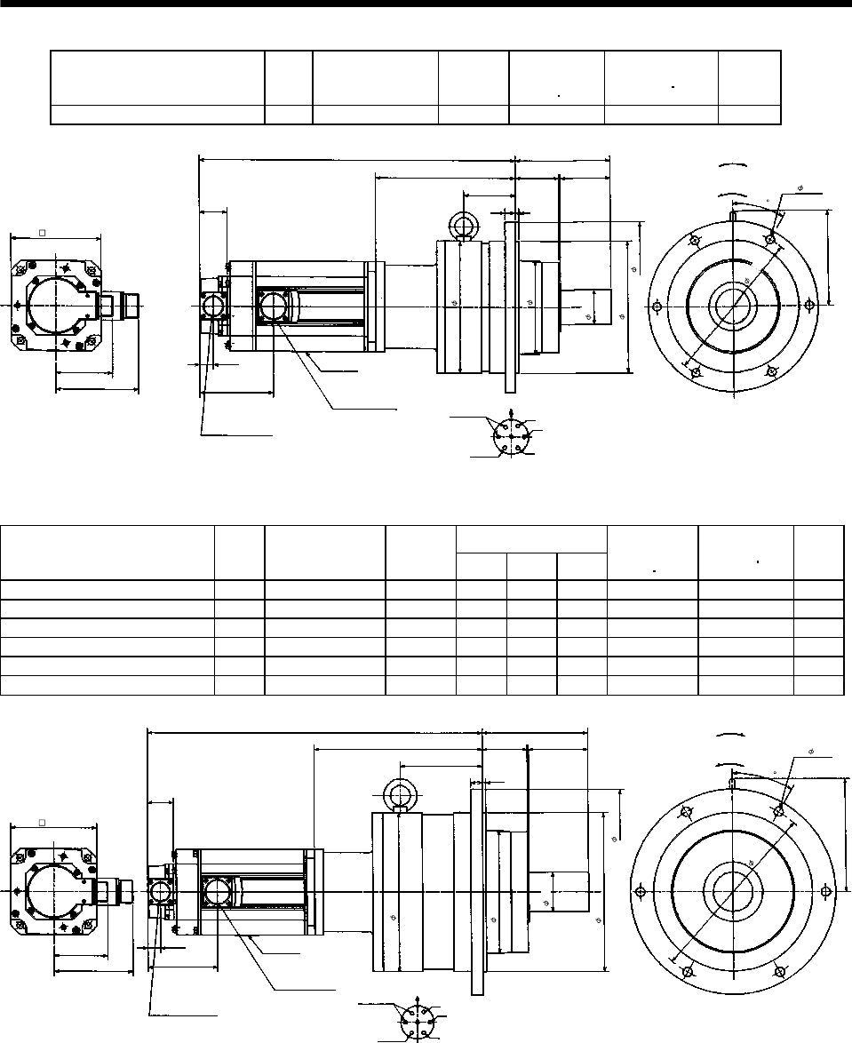
7 - 244
7. OUTLINE DIMENSION DRAWINGS
Model Output
[kW]
Reduction Gear
Model
Reduction
Ratio
Brake static
friction torque
[oz in]
Inertia Moment
WK2[oz in2]
Mass
[lb]
HC-RF353BG2 HC-RFS353BG2 3.5 BL3-05B-35MEKD 1/5 2365 113.723 72.8
W
V
U
A
FG
B
EC
D
Bottom Top
17.913
1.56
2.48
5.51
2.95
3.21
4.724
0.59 0.20
7.913
Motor plate
0.77
4.173
5.37
2.913
[Unit: in]
Encoder connector
MS3102A20-29P
Power supply connector
CE05-2A24-10P
Earth
Motor flange direction
Brake
Power supply connector layout
CE05-2A24-10P
"Rotation direction"
For reverse
rotation command
For forward
rotation command
(Side view of motor only)
Z695991A
6- 0.47
8.66
9.65
7.48
1.97
5.32
7.48
5.118
30
(********)
Variable Dimensions [in]
Model Output
[kW]
Reduction Gear
Model
Reduction
Ratio LHLI
Brake static
friction torque
[oz in]
Inertia Moment
WK2[oz in2]
Mass
[lb]
HC-RF353BG2 HC-RFS353BG2 3.5 BL4-09B-35MEKD 1/9 19.961 9.961 4.961 2365 126.298 132.3
HC-RF353BG2 HC-RFS353BG2 3.5 BL4-20B-35MEKD 1/20 19.961 9.961 4.961 2365 168.397 132.3
HC-RF353BG2 HC-RFS353BG2 3.5 BL4-29B-35MEKD 1/29 19.961 9.961 4.961 2365 120.284 132.3
HC-RF503BG2 HC-RFS503BG2 5.0 BL4-05B-50MEKD 1/5 20.945 8.701 3.701 2365 188.08 123.5
HC-RF503BG2 HC-RFS503BG2 5.0 BL4-09B-50MEKD 1/9 22.205 9.961 4.961 2365 144.887 145.5
HC-RF503BG2 HC-RFS503BG2 5.0 BL4-20B-50MEKD 1/20 22.205 9.961 4.961 2365 186.987 145.5
W
V
U
A
FG
B
ECD
Bottom Top
L
1.56
2.68
6.30
3.54
3.21
4.724
0.71 0.20
H
Motor plate
0.77
4.173
6.73
LI
[Unit: in]
Encoder connector
MS3102A20-29P
Power supply connector
CE05-2A24-10P
Earth
Motor flange direction
Brake
Power supply connector layout
CE05-2A24-10P
"Rotation direction"
For reverse
rotation command
For forward
rotation command
(Side view of motor only)
Z695993A
6- 0.55
11.02
12.21
9.45
2.36
9.45
7.323
5.118
30
(********)
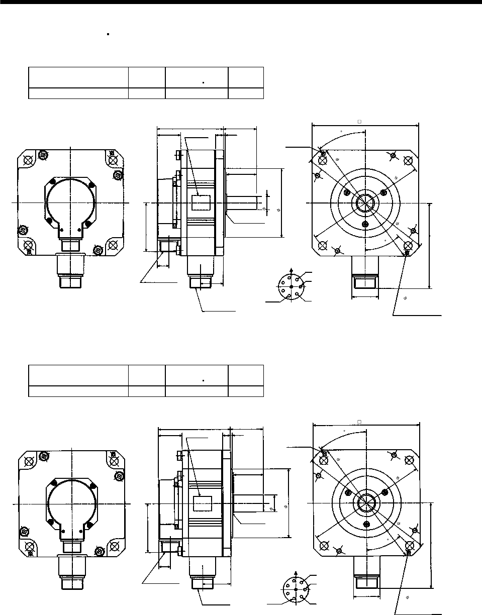
7 - 245
7. OUTLINE DIMENSION DRAWINGS
7.2.5 HC-UF 2000r/min HC-UFS 2000r/min series
(1) Standard (without electromagnetic brake)
Model Output
[kW]
Inertia Moment
WK2[oz in2]
Mass
[lb]
HC-UF72 HC-UFS72 0.75 56.861 17.6
Top
A
B
C
D
E
FG
U
V
W
Oil seal
S30457B
Motor plate
2-M6 screw
1.56
2.165
0.12
Bottom
Top
0.77
3.21
5.669
[Unit: in]
1.732
H
1.496
4.35
1.97
Bottom
Encoder connector
MS3102A20-29P
Power supply connector
CE05-2A22-23P
Earth
Motor flange direction
Power supply connector layout
CE05-2A22-23P
(Opposite
side)
Use hexagon socket
head cap screw.
4- 0.53 mounting hole
Z695911*
(BC11711*)
9.055
7.87
8.465
4.5
6.93
0.866
40
45
0.512
Model Output
[kW]
Inertia Moment
WK2[oz in2]
Mass
[lb]
HC-UF152 HC-UFS152 1.5 120.831 24.3
Top
Bottom
A
B
C
D
E
F
G
U
V
W
Motor plate
(Opposite side) 2-M6 screw
1.56
2.165
0.512 0.12
Bottom
Top
0.77
3.21
5.669
[Unit: in]
1.732
H
1.87
4.724
1.97
Oil seal
S30457B
Encoder connector
MS3102A20-29P
Power supply connector
CE05-2A22-23P
Motor flange direction
Power supply connector layout
CE05-2A22-23P
Earth Use hexagon socket
head cap screw.
4- 0.53 mounting hole
7.87
9.055
8.465
(BC11712*)
Z695912A
1.102
4.5
6.93
40
45
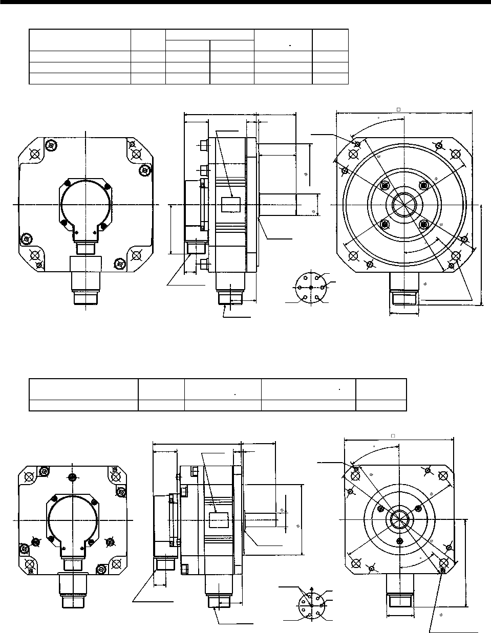
7 - 246
7. OUTLINE DIMENSION DRAWINGS
Variable Dimensions [in]
Model Output
[kW] LKL
Inertia Moment
WK2[oz in2]
Mass
[lb]
HC-UF202 HC-UFS202 2.0 4.646 1.673 208.856 35.3
HC-UF352 HC-UFS352 3.5 5.591 2.618 418.26 44.1
HC-UF502 HC-UFS502 5.0 6.535 3.563 628.756 52.9
A
B
C
D
E
FG
U
V
W
Motor plate
(Opposite side) 2-M8 screw
1.56
2.559
0.63 0.157
Bottom
Top
0.77
3.21
6.457
[Unit: in]
1.85
KL
L
2.362
(Use hexagon socket
head cap screw.)
Top
Bottom
Encoder connector
MS3102A20-29P
Power supply connector
CE05-2A24-10P
Motor flange direction
Power supply connector layout
CE05-2A24-10P
Oil seal
S40608B
Z695914*
8.661
10.63
9.252
9.843
1.378
7.874
(BC12764*)
4- 0.53 mounting hole
37.5
45
Earth
(2) With electromagnetic brake
Model Output [kW] Brake static friction
torque [oz in] Inertia Moment WK2[oz in2]Mass [lb]
HC-UF72B HC-UFS72B 0.75 1204 67.796 22.0
Top
Bottom
A
B
C
D
E
FG
U
V
W
Oil seal
S30457B
Motor plate
(Opposite
side) 2-M6 screw
1.56
2.165
0.512 0.12
Bottom
Top
0.77
5.669
[Unit: in]
1.732
H
1.496
5.669
Brake
Encoder connector
MS3102A20-29P
Power supply connector
CE05-2A22-23P
Motor flange direction
Power supply connector layout
CE05-2A22-23P
Earth
Use hexagon socket
head cap screw.
Z695981A
(BC11714*)
4- 0.53 mounting hole
7.87
9.055
8.465
6.93
4.5
0.866
40
45
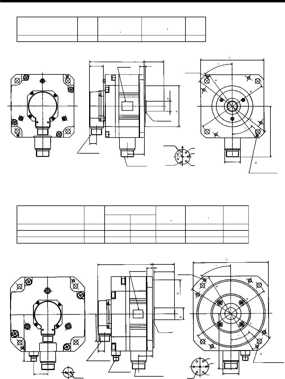
7 - 247
7. OUTLINE DIMENSION DRAWINGS
Model Output
[kW]
Brake static
friction torque
[oz in]
Inertia Moment
WK2[oz in2]
Mass
[lb]
HC-UF152B HC-UFS152B 1.5 1204 131.765 28.7
A
B
C
D
E
FG
U
V
W
2-M6 screw
1.56
2.165
0.512 0.12
5.669
[Unit: in]
1.732
H
1.87
6.043
Top
Bottom
Oil seal
S30457B
Motor plate
(Opposite
side)
Bottom
Top
0.77
Brake
Encoder connector
MS3102A20-29P
Power supply connector
CE05-2A22-23P
Motor flange direction
Power supply connector layout
CE05-2A22-23P
Earth
Use hexagon socket
head cap screw.
(BC11715*)
Z695982B
4- 0.53 mounting hole
7.87
9.055
8.465
1.102
4.5
6.93
40
45
Variable Dimensions [in]
Model Output
[kW] LKL
Brake static
friction torque
[oz in]
Inertia Moment
WK2[oz in2]
Mass
[lb]
HC-UF202B HC-UFS202B 2.0 6.339 1.673 6103 255.876 48.5
HC-UF352B HC-UFS352B 3.5 7.283 2.618 6103 465.28 57.3
HC-UF502B HC-UFS502B 5.0 8.228 3.563 6103 675.776 66.1
Top
Bottom
1.654
Motor flange direction
Brake connector layout
MS3102A10SL-4P
Brake
AB
Encoder connector
MS3102A20-29P
Brake connector
H/MS3102A10SL-4P Power supply connector
CE05-2A24-10P
KL Motor flange direction
Power supply connector layout
CE05-2A24-10P
A
B
C
D
E
FG
U
V
W
Earth
Oil seal
S40608B
Motor plate
(Opposite side)
2-M8 screw
37.5
45
2.559
2.362
0.157
L
Bottom
Top
0.77
3.21
6.457
5.472
[Unit: in]
BC10647A
1.85
0.63
(BC12766*)
4- 0.53 mounting hole
Use hexagon socket
head cap screw.
10.63
9.252
9.843
8.661
1.378
7.874
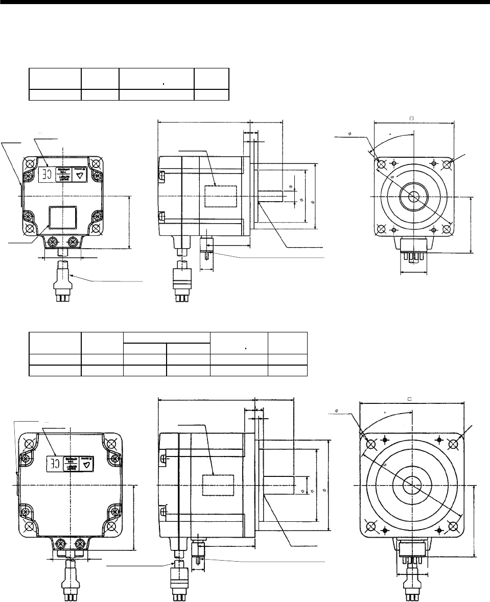
7 - 248
7. OUTLINE DIMENSION DRAWINGS
7.2.6 HC-UF 3000r/min series
(1) Standard (without electromagnetic brake)
Model Output
[W]
Inertia Moment
WK2[oz in2]
Mass
[lb]
HC-UF13 100 0.361 1.8
[Unit: in]
Bottom
Top
Motor plate
(Opposite side)
1.059
2.756
Power supply lead 4-AWG19 11.8in
(With end-insulated round crimping terminal 1.25-4)
Red: Phase U
White: Phase V
Black: Phase W
Green/yellow: Earth
Encoder cable 11.8in
With connector 1-172169-9
(AMP)
0.984
0.20 0.23
0.12
1.969
1.575
0.315
Oil seal
S10207
1.299
0.390
Bottom
Top
Bottom
Top
Bottom
Top
2.362
4- 0.228
0.787
1.575
1.685
BC11740A
Motor plate TUV plate
Caution plate
2.756
R5
45
Variable Dimensions [in]
Model Output
[W] LKL
Inertia Moment
WK2[oz in2]
Mass
[lb]
HC-UF23 200 2.953 1.724 1.318 3.3
HC-UF43 400 3.543 2.315 1.996 3.7
1.969
1.059
L1.181
0.315 0.256
[Unit: in]
Top
Bottom
Top
Bottom
Top
Bottom
BC11513A
Motor plate
(Opposite side)
Encoder cable 11.8in Power supply lead 4-AWG19 11.8in
With connector 1-172169-9
(AMP)
(With end-insulated round crimping terminal 1.25-4)
Red: Phase U
White: Phase V
Black: Phase W
Green/yellow: Earth
Oil seal
SC15307
0.551
0.12
3.543
3.15
4- 0.26
Motor plate
TUV plate
0.390
KL
2.205
2.165
2.756
0.945
R7
45
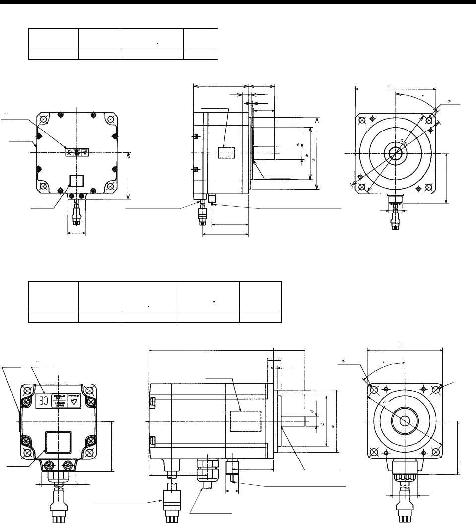
7 - 249
7. OUTLINE DIMENSION DRAWINGS
Model Output
[W]
Inertia Moment
WK2[oz in2]
Mass
[lb]
HC-UF73 750 32.258 11.0
BC11357A
1.059
2.84
3.35 1.58
0.10
0.39
45
0.138
1.28
2.99
0.219
2.76
[Unit: in]
Oil seal
S20357
Encoder cable 11.8in
With connector 1-172169-9
(AMP)
Power supply lead 4-AWG19 11.8in
Motor plate
(Opposite side)
Bottom
Top
(With end-insulated round crimping terminal 1.25-4)
Red: Phase U
White: Phase V
Black: Phase W
Green/
y
ellow: Earth
Motor plate
3.15
4.33
0.75
4.84
5.71
6.50
4- 0.35
TUV plate
Caution
plate
Bottom
Top
Bottom
Top
0.787
Bottom
Top
(2) With electromagnetic brake
Model Output
[W]
Brake static
friction torque
[oz in]
Inertia Moment
WK2[oz in2]
Mass
[lb]
HC-UF13B 100 45 0.405 2.6
1.685
[Unit: in]
BC11767A
Motor plate
(Opposite side)
Encoder cable 11.8in
Power supply lead 4-AWG19 11.8in
1.059
1.575
With connector 1-172169-9
(AMP)
(With end-insulated round crimping terminal 1.25-4)
Red: Phase U
White: Phase V
Black: Phase W
Green/yellow: Earth
Oil seal
SC10207
3.937 0.984
0.12
0.20
Bottom
Top
45
R5
0.23
Brake cable
2
1.575
1.969
0.315
4- 0.228
2.362
0.787
TUV plate
Motor plate
Caution
plate
Bottom
Top
Bottom
Top
Bottom
Top
1.839
1.299
0.390
2.756
Cabtyre cable 2-0.75 11.8in
(With end-insulated round crimping terminal 0.05-4)
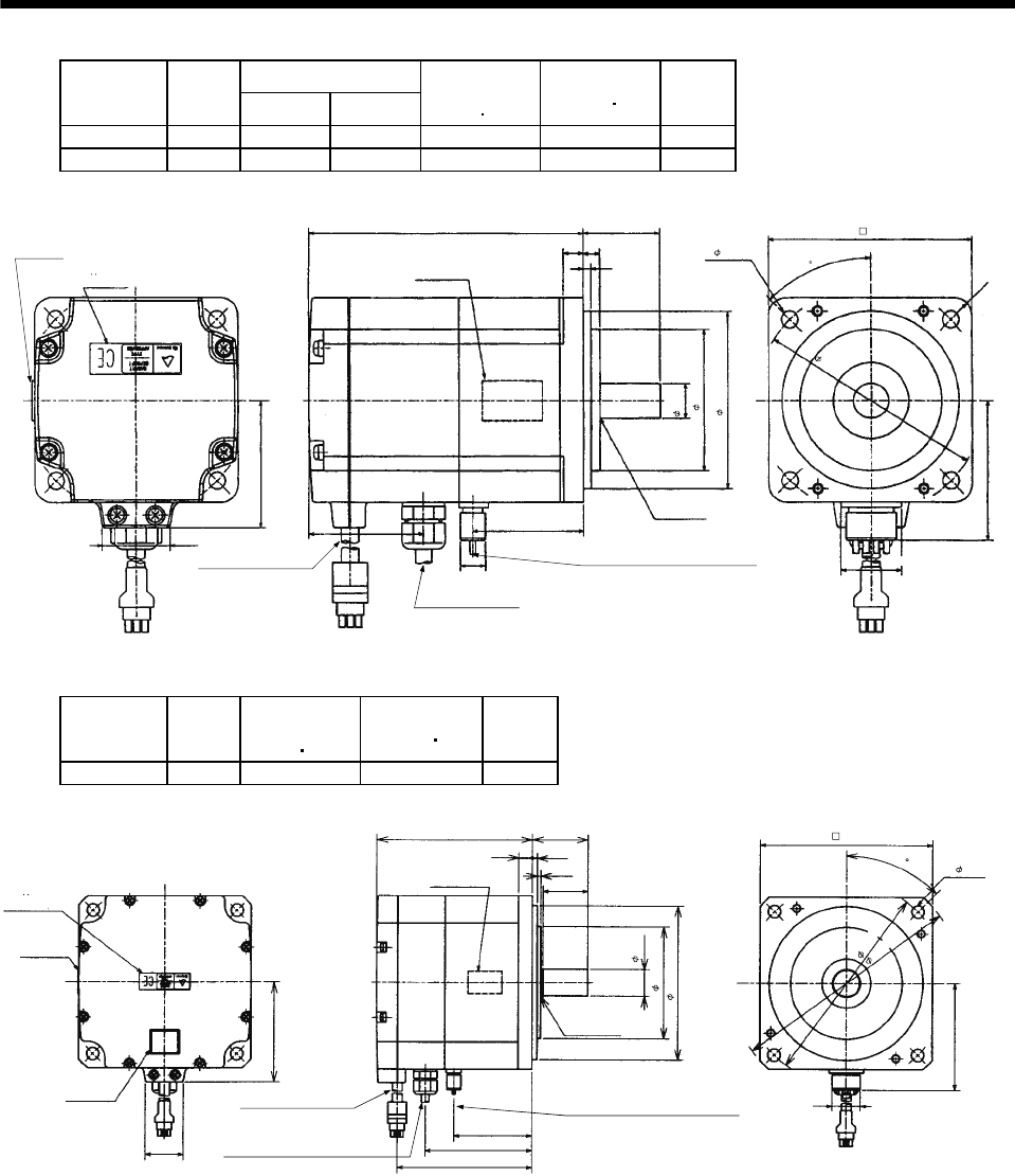
7 - 250
7. OUTLINE DIMENSION DRAWINGS
Variable Dimensions [in]
Model Output
[W] LKL
Brake static
friction torque
[oz in]
Inertia Moment
WK2[oz in2]
Mass
[lb]
HC-UF23B 200 4.291 1.724 184 1.766 4.9
HC-UF43B 400 4.882 2.315 184 2.444 5.3
[Unit: in]
BC11515A
Motor plate
(Opposite side)
Encoder cable 11.8in Power supply lead 4-AWG19 11.8in
1.059
1.969
With connector 1-172169-9
(AMP)
(With end-insulated round crimping terminal 1.25-4)
Red: Phase U
White: Phase V
Black: Phase W
Green/yellow: Earth
Oil seal
SC15307
L1.181
0.12
0.315
Bottom
Top
45
R7
0.256
Brake cable
TUV plate
Motor plate
Bottom
Top
1.858 KL
0.551
2.205
2.756
4- 0.26
3.150
3.543
2.165
Bottom
Top
0.390 0.945
2
Cabtyre cable 2-0.75 1.18in
(With end-insulated round
crim
p
in
g
terminal 0.05-4
)
Model Output
[W]
Brake static
friction torque
[oz in]
Inertia Moment
WK2[oz in2]
Mass
[lb]
HC-UF73B 750 339.87 33.35 13.7
4.370
1.059
5.709
45
0.394
BC11358A
2.835
1.575
1.28
0.138
0.10
6.496
2.99
0.787
2.19
2.99
3.78
Oil seal
SC20357
Encoder cable 11.8in
With connector 1-172169-9
(AMP)
Brake cable
Power supply lead 4-AWG19 11.8in
[Unit: in]
Motor plate
(Opposite side)
Cabtyre cable 2-0.75 11.8in
(With end-insulated round crimping terminal 1.25-4)
(With end-insulated round crimping terminal 1.25-4)
Red: Phase U
White: Phase V
Black: Phase W
Green/yellow: Earth
Bottom
Top
Motor plate
Caution
plate
TUV plate
0.748
4.331
3.150
4.843
4 -0.354
2
Bottom
Top
Bottom
Top
Bottom
Top
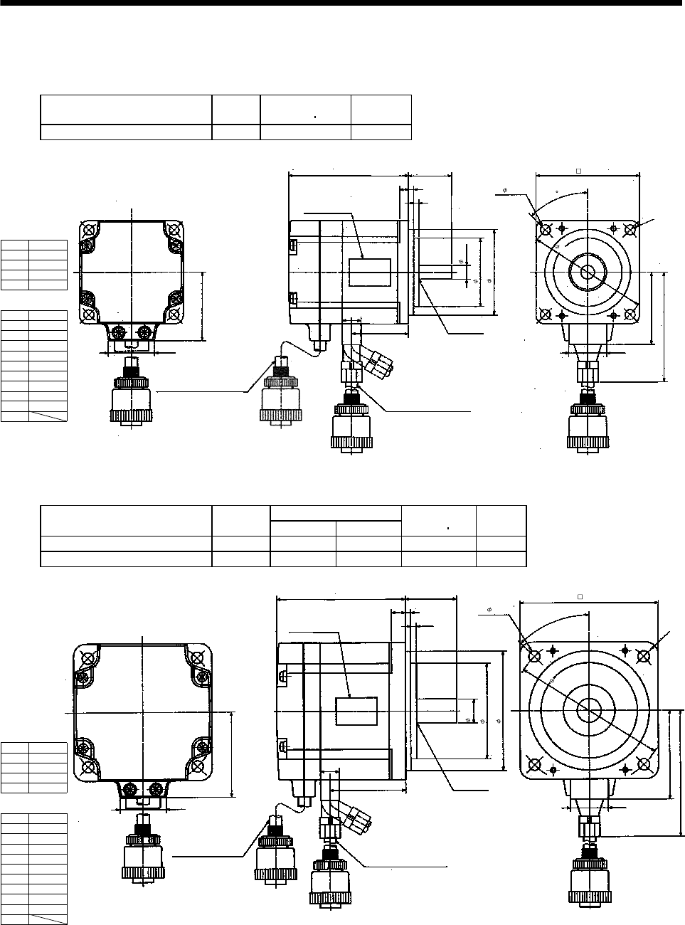
7 - 251
7. OUTLINE DIMENSION DRAWINGS
7.2.7 HC-UF3000r/min, HC-UFS3000r/min series with IP65-compliant connectors
(1) Without electromagnetic brake
Model Output
[W]
Inertia Moment
WK2[oz in2]
Mass
[lb]
HC-UF13-S1 HC-UFS13-S1 100 0.361 1.8
1.575
1.059
2.756 2.362
45
0.20
BC11292A
0.984
0.12
1.575
0.12
0.551
1.299
1.969
3.425
0.945
1
2
3
4
R5
[Unit: in]
Power supply
connector pin
connection list
Pin No. Application
Phase U
Phase V
Phase W
Earth
Encoder connector
pin connection list
Bottom
Top
Oil seal
S10207
Encoder cable 11.8in
Power supply cable 11.8in
Motor plate
(Opposite side)
With connector RM15WTP-10P,
cord clamp RM15WTP-CP7
(Hirose Electric) With connector RM15WTP-4P,
cord clamp RM15WTP-CP8
(Hirose Electric)
1
2
3
4
5
6
7
8
9
10
MR
MRR
BAT
MD
MDR
Pin No. Application
CNT
P5
LG
SD
4- 0.228
0.315
1.969
2.756
Variable Dimensions [in]
Model Output
[W] LKL
Inertia Moment
WK2[oz in2]
Mass
[lb]
HC-UF23-S1 HC-UFS23-S1 200 0.2953 1.732 1.318 3.3
HC-UF43-S1 HC-UFS43-S1 400 3.543 2.323 1.996 3.7
1.969
1.059
L
0.315
BC11293A
1.181
0.12
0.138
0.551
KL
R7
2.362
3.819
0.945
1
2
3
4
Power supply
connector pin
connection list
Pin No. Application
Phase U
Phase V
Phase W
Earth
Encoder connector
pin connection list
[Unit: in]
Bottom
Top
Oil seal
S15307
Encoder cable 11.8in
Power supply cable 11.8in
Motor plate
(Opposite side)
With connector
RM15WTP-10P,
cord clamp
RM15WTP-CP7
(Hirose Electric)
With connector RM15WTP-4P,
cord clamp RM15WTP-CP8
(Hirose Electric)
1
2
3
4
5
6
7
8
9
10
MR
MRR
BAT
MD
MDR
Pin No. Application
CNT
P5
LG
SD
3.543
0.551
2.205
2.756
3.15
4- 0.26
45°
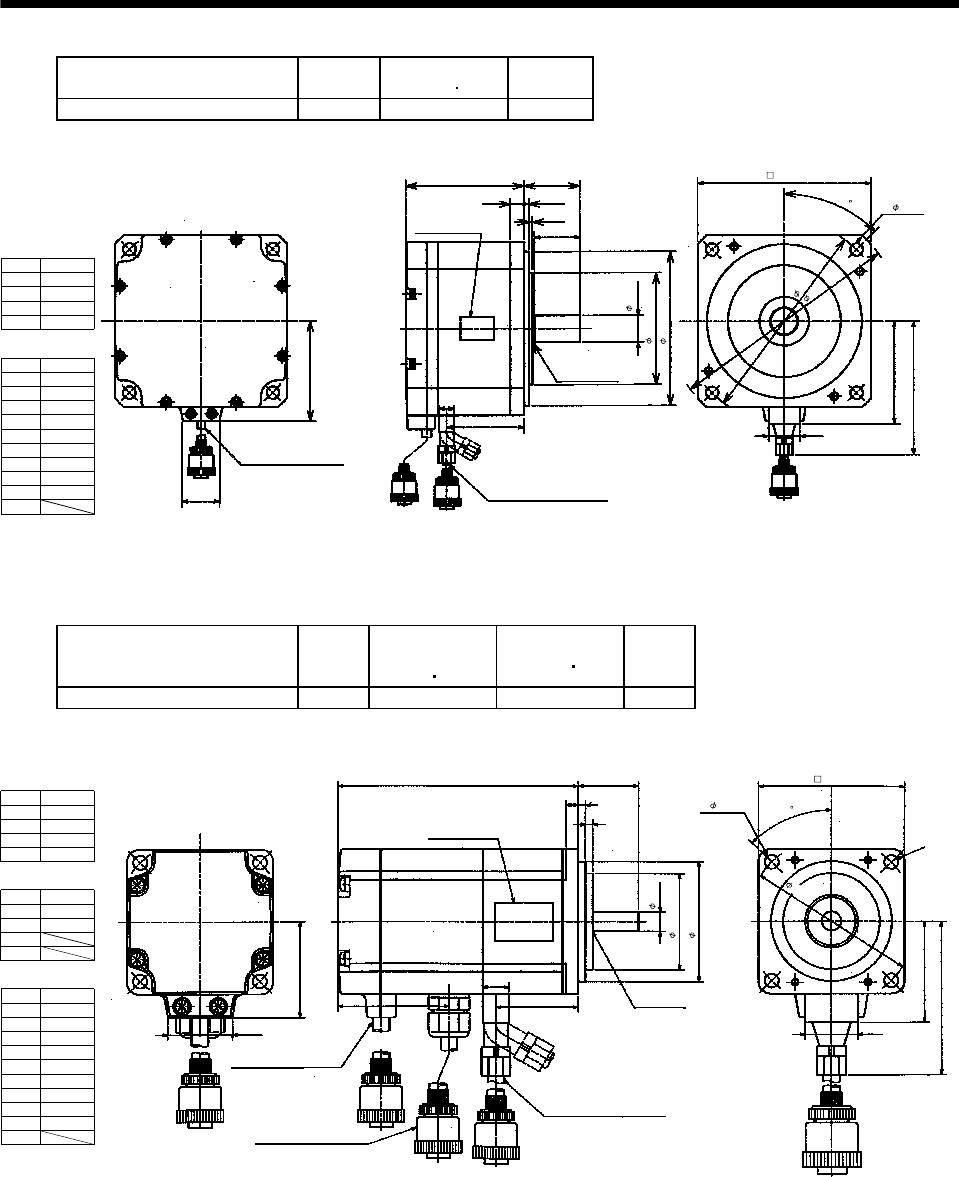
7 - 252
7. OUTLINE DIMENSION DRAWINGS
Model Output
[W]
Inertia Moment
WK2[oz in2]
Mass
[lb]
HC-UF73-S1 HC-UFS73-S1 750 32.258 11.0
BC11359A
3.209
4.665
0.945
[Unit: in]
2.84
1.059
Encoder cable 11.8in
With connector RM15WTP-10P,
cord clamp RM15WTP-CP7
(Hirose Electric)
3.35
0.39
1.58
0.138
1.28
0.551
2.185
0.10
Bottom
Top
Oil seal
S20357
Power supply cable 11.8in
Motor plate
(Opposite side)
With connector RM15WTP-4P,
cord clamp RM15WTP-CP8
(
Hirose Electric
)
0.75
3.15
4.33
1
2
3
4
Power supply
connector pin
connection list
Pin No. Application
Phase U
Phase V
Phase W
Earth
Encoder connector
pin connection list
1
2
3
4
5
6
7
8
9
10
MR
MRR
BAT
MD
MDR
Pin No. Application
CNT
P5
LG
SD
4.84
6.50
5.71
4- 0.35
45
(2) With electromagnetic brake
Model Output
[W]
Brake static
friction torque
[oz in]
Inertia Moment
WK2[oz in2]
Mass
[lb]
HC-UF13B-S1 HC-UFS13B-S1 100 45 0.405 2.6
1.575
1.059
3.937
0.2
BC11295
A
0.984
0.12
0.12
R5
1.969
3.425
0.945
0.551
1.299
1.831
[Unit: in]
Bottom
Top
Oil seal
S10207
Encoder cable 11.8in
Brake cable 11.8in
Power supply cable 11.8in
Power supply
connector pin
connection list
1
2
3
4
Pin No. Application
B1
B2
Encoder connector
pin connection list
Brake connector pin
connection list
1
2
3
4
Pin No. Application
Phase U
Phase V
Phase W
Earth
Motor plate
(Opposite side)
With connector
RM15WTP-10P,
cord clamp RM15WTP-CP7
(Hirose Electric)
With connector RM15WTP-4P,
cord clamp RM15WTP-CP6
(Hirose Electric)
With connector RM15WTP-4P,
cord clamp RM15WTP-CP8
(Hirose Electric)
1
2
3
4
5
6
7
8
9
10
MR
MRR
BAT
MD
MDR
Pin No. Application
CNT
P5
LG
SD
4- 0.228
2.756
2.362
0.315
1.575
1.969
45
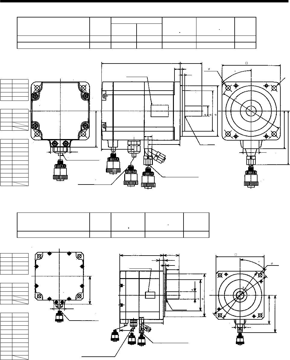
7 - 253
7. OUTLINE DIMENSION DRAWINGS
Variable Dimensions [in]
Model Output
[W] LKL
Brake static
friction torque
[oz in]
Inertia Moment
WK2[oz in2]
Mass
[lb]
HC-UF23B-S1 HC-UFS23B-S1 200 4.291 1.732 184 1.766 4.9
HC-UF43B-S1 HC-UFS43B-S1 400 4.882 2.323 184 2.444 5.3
1.696
1.059
L
0.315
BC11296
A
1.18
0.12
0.138
R7
2.362
3.819
0.945
0.551
KL
1.787
Power supply
connector pin
connection list
1
2
3
4
Pin No. Application
B1
B2
Encoder connector
pin connection list
Brake connector pin
connection list
1
2
3
4
Pin No. Application
Phase U
Phase V
Phase W
Earth
[Unit: in]
Bottom
Top
Oil seal
S15307
Encoder cable 11.8in
Brake cable 11.8in
Power supply cable 11.8in
Motor plate
(Opposite side)
With connector
RM15WTP-10P,
cord clamp
RM15WTP-CP7
(Hirose Electric)
With connector RM15WTP-4P,
cord clamp RM15WTP-CP6
(Hirose Electric)
With connector RM15WTP-4P,
cord clamp RM15WTP-CP8
(Hirose Electric)
1
2
3
4
5
6
7
8
9
10
MR
MRR
BAT
MD
MDR
Pin No. Application
CNT
P5
LG
SD
3.453
1.181
4- 0.26
0.551
2.205
2.756
45
Model Output
[W]
Brake static
friction torque
[oz in]
Inertia Moment
WK2[oz in2]
Mass
[lb]
HC-UF73B-S1 HC-UFS73B-S1 750 339.869 33.351 13.7
4.73
0.39
1.58
0.138
1.28
0.551
2.185
1.378
0.10
BC11360
A
3.209
4.665
0.945
[Unit: in]
4- 0.35
4.84
6.50
5.71
Bottom
Top
Oil seal
S20357
Brake cable 11.8in
Power supply cable 11.8in
Motor plate
(Opposite side)
Motor plate
(Opposite side)
40
1.059
2.835
Encoder cable 11.8in
With connector RM15WTP-10P,
cord clamp RM15WTP-CP7
(Hirose Electric)
With connector RM15WTP-4P,
cord clamp RM15WTP-CP6
(Hirose Electric)
With connector RM15WTP-4P,
cord clamp RM15WTP-CP8
(Hirose Electric)
Power supply
connector pin
connection list
1
2
3
4
Pin No. Application
B1
B2
Encoder connector
pin connection list
Brake connector pin
connection list
1
2
3
4
Pin No. Application
Phase U
Phase V
Phase W
Earth
1
2
3
4
5
6
7
8
9
10
MR
MRR
BAT
MD
MDR
Pin No. Application
CNT
P5
LG
SD
4.33
3.15
0.75
45
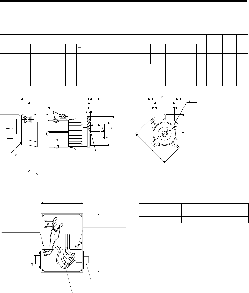
7 - 254
7. OUTLINE DIMENSION DRAWINGS
7.2.8 HA-LH series
(1) Standard (without electromagnetic brake)
Variable Dimensions [in]
Model
F L LA LB LC LD LG LT KL KH IE IF Hanger E LR Q S
Inertia
Moment
WK2
[oz in2]
Oil
Seal
Mass
[lb]
HA-
LH11K2(-Y) 8.189 20.827 8.465 7.087 9.843 8.031 0.787 12.441 18.819 4.016 5.984 12.48 M10 0.118 3.346 3.15 1.654 645.16 S45629B 46.30
HA-
LH15K2(-Y) 22.756 14.252 20.948 1585.56 37.48
HA-
LH22K2(-Y)
10
25.315
10.433 9.055 11.811 9.843 0.984
16.929 23.307
4.606 7.087 14.803 M12 0.197 4.331 3.937 2.165
2159.64
S608295
66.14
Connector
MS3102A20-29P
Oil seal
[Unit: in]
ELG
LR
KH
L
KL
LT 0.197
0.2760.276
Q
Cooling fan
IF
IE
Hangers in 3 places
Exhaust air
Suction air
6.457
0.197
LD
LC
4- 0.571
LA
F
LBh7
S
1 200V 50/60Hz
Note: When using the motor without the hangers, plug the screw holes with the following bolts:
HA-LH11K2: M10 0.591in max.
HA-LH15K2, 22K2: M12 0.709in max.
(Note)
Terminal Box of HA-LH11K2 to 22K2
Power Connection Screw Size
Servo Motor Power Connection Screw Size
HA-LH11K2 8-6
HA-LH15K2 22K2 14-6
5.748
8.228
Ground terminal
M6 screw
3 power leads (U, V, W)
with round crimping terminals
Encoder cable
MS3102A20-29P
Cooling fan leads
(BU,BV)
Round crimping
terminal 0.05-4
[Unit: in]
1.732
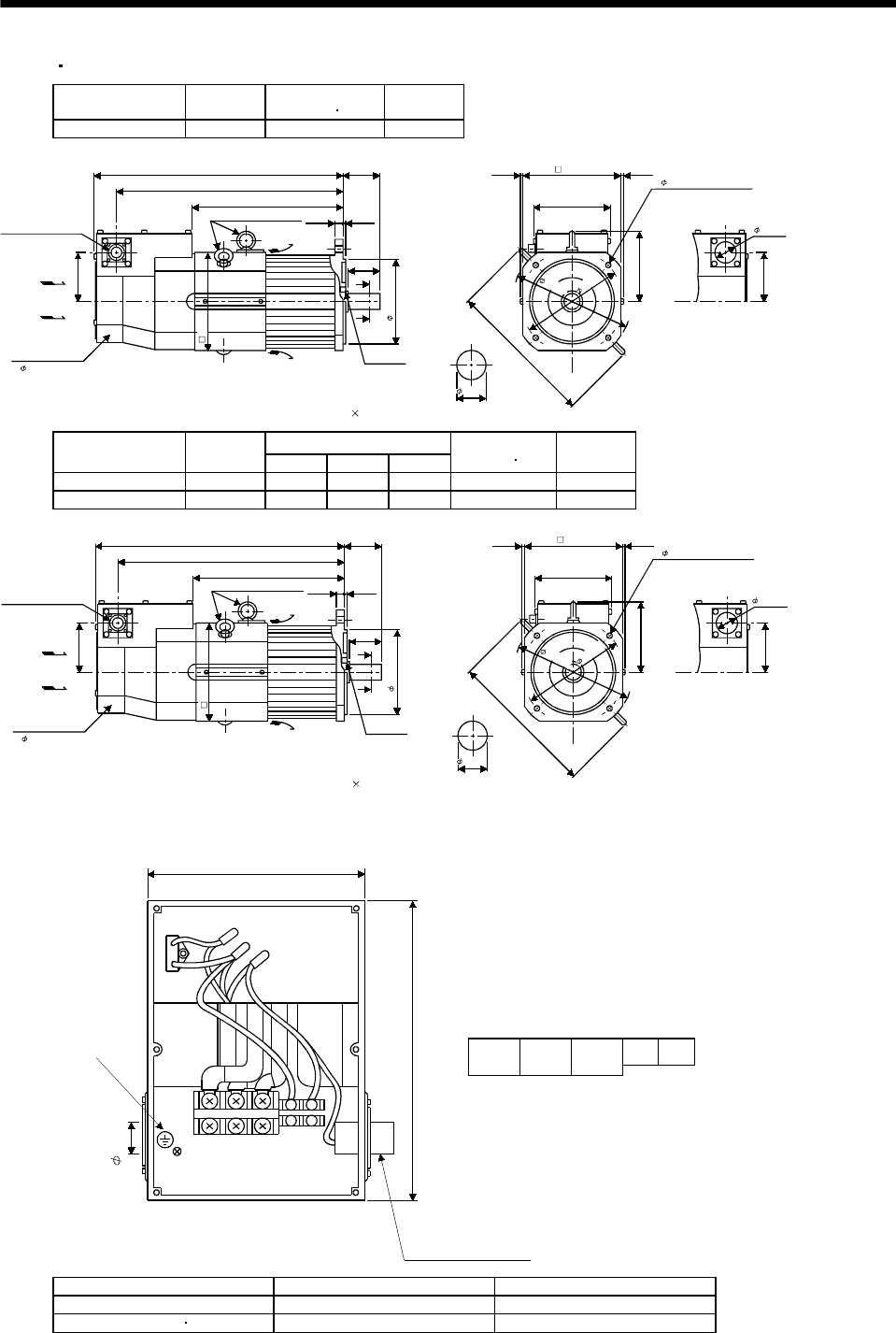
7 - 255
7. OUTLINE DIMENSION DRAWINGS
(2) EN UL/C-UL Standard-Compliant model
Model Output
[W]
Inertia Moment
WK2[oz in2]
Mass
[lb]
HA-LH11K2-EC 11 642.425 154.3
Encoder connector
MS3102A20-29P
Oil seal
S45629B
0.1180.787
3.346
4.016
Use hexagon socket
head cap screw.
20.827
18.819
12.441 6.457
0.2760.276
A
A
3.15
Cooling fan
4.016
12.48
5.984
Section AA
Hangers in 3 places
Exhaust air
Suction air
[Unit: in]
(M10)
4- 0.571 mounting hole
8.031
7.087
1.732
1 200V 50/60Hz
8.189
1.654
8.465
9.843
(Note)
Note: When usin
g
the motor with han
g
ers removed,
p
lu
g
screw holes with bolts M10 15 or less.
Variable Dimensions [in]
Model Output
[W] LKLLT
Inertia Moment
WK2[oz in2]
Mass
[lb]
HA-LH15K2-EC 15 22.756 20.748 14.252 1585.559 238.1
HA-LH22K2-EC 22 25.315 23.307 16.929 2159.641 297.6
S60829B
0.1970.984
4.331
4.606
L
KL
LT 6.457
0.2760.276
A
A
3.937
4.606
14.803
7.087
Encoder connector
MS3102A20-29P
Oil seal
Use hexagon socket
head cap screw.
Cooling fan
Section AA
Hangers in 3 places
Exhaust air
Suction air
[Unit: in]
(M12)
9.055
9.843
4- 0.571 mounting hole
1.732
1 200V 50/60Hz
10
2.165
10.433
11.811
Note: When usin
g
the motor with han
g
ers removed,
p
lu
g
screw holes with bolts M12 18 or less.
(Note)
Terminal Box of HA-LH11K2-EC to 22K2-EC
5.748
Terminal box
BU BV
UVW
Terminal block signal arrangemen
t
UVW
BU BV
[Unit: in]
Protective Earth (PE)
M6 screw
Encoder connector
MS3102A20-29P
8.228
1.732
Model Power Connection Screw Size Cooling fan Connection Screw Size
HA-LH11K2-EC M6 M4
HA-LH15K2-EC 22K2-EC M8 M4
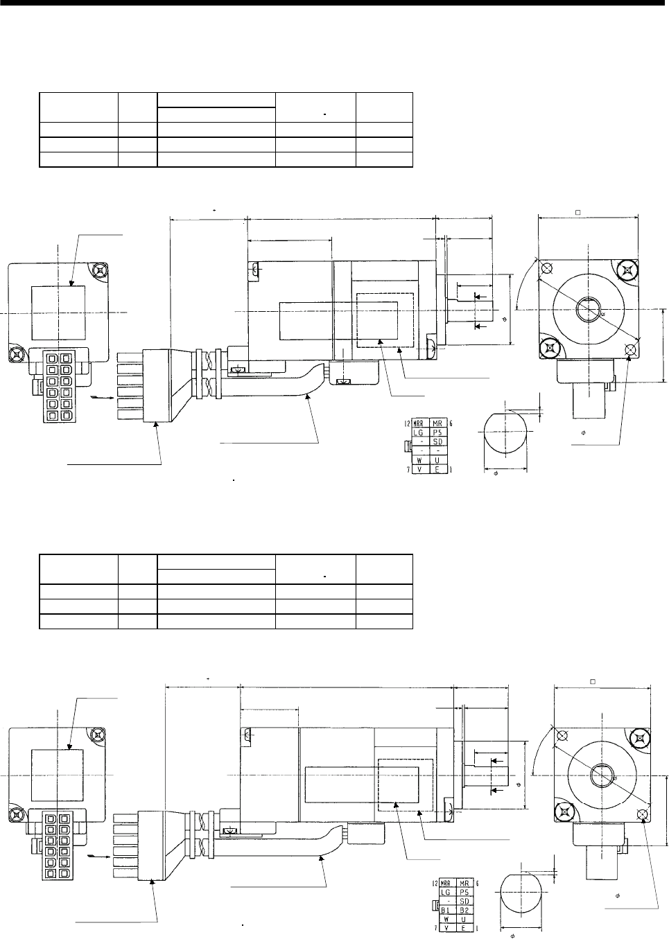
7 - 256
7. OUTLINE DIMENSION DRAWINGS
7.2.9 HC-AQ series
(1) Standard (without electromagnetic brake)
Variable Dimensions [in]
Model Output
[W] L
Inertia Moment
WK2[oz in2]
Mass
[lb]
HC-AQ0135D 10 2.126 0.027 0.419
HC-AQ0235D 20 2.402 0.039 0.485
HC-AQ0335D 30 2.677 0.051 0.551
BC11340D
7.874 0.79
01.102
0.827
45°
0.63
L
0.394
0.02
Arrow C Section A-A
1.299
0.787
0.236
2- 0.114
mounting hole
Caution plate
Bottom
Top
Arrow C
Connector 5557-12R-210
(molex) UL94V-0
Power supply lead/brake lead
U: Red
V: White
W: Black
Earth: Green
B1 B2
0.945 0.5120.098
A
A
Motor plate (opposite side)
CE plate
Bottom
Top
Bottom
Top
[Unit: in]
(2) With electromagnetic brake
Variable Dimensions [in]
Model Output
[W] L
Inertia Moment
WK2[oz in2]
Mass
[lb]
HC-AQ0135BD 10 3.189 0.05 0.639
HC-AQ0235BD 20 3.465 0.062 0.705
HC-AQ0335BD 30 3.74 0.074 0.772
BC11343C
7.874 1.102
0.827
45°
0.63
L
0.394
0.02
Arrow C Section A-A
1.299
0.787
2- 0.114
mounting hole
Caution plate
Bottom
Top
Connector 5557-12R-210
(molex) UL94V-0
Power supply lead/brake lead
U: Red
V: White
W: Black
Earth: Green
B1 B2
0.945 0.512
0.098
A
A
Motor plate (opposite side)
CE plate
[Unit: in]
Arrow C
0.236
Bottom
Top
Top
Bottom
0.79
0
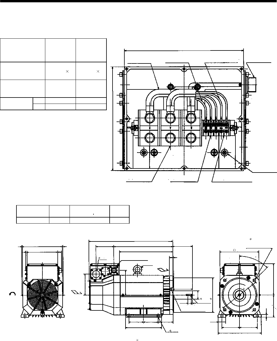
7 - 257
7. OUTLINE DIMENSION DRAWINGS
7.2.10 HA-LF series
Terminal box detail diagram
Motor Model
HA-LF30K2
HA-LF37K2
HA-LF30K24
HA-LF37K24
HA-LF45K24
HA-LF55K24
Motor power supply
lead size
0.0124in2
(AWG8) 2
parallel
0.0341in2
(AWG4) 2
parallel
Motor power supply
terminal block screw
size
M8 M10
LA 8.661 10.472
Terminal box
dimensions (in) LB 8.268 9.055
LA
LB
BG71994C
Motor power supply
lead
Encoder connector
MS3102A20-29P
[Unit: in]
Motor power supply
terminal block
(U V W)
Cooling fan terminal block
(BU BV BW) M4 screw
Thermal protector terminal block
(OHS1 OHS2) M4 screw
Earth terminal
M6 screw
Cooling fan lead
0.9SQ or equivalent AWG#
Thermal protector lead
0.5SQ or equivalent AWG#
Model Output
[kW]
Inertia Moment
WK2[oz in2]
Mass
[lb]
HA-LF30K24 30 3007.095 352.739
0.236 0.23611.26
8.661
0.433 1.063
5.984
23.819
5.039 16.772 5.512
5.512
7.047
4.134 4.134
10.236
4.252
2.008
4- 0.591
0.984 0.197
15.197
0.984 0.315
2.362
9.843
11.024
9.055
0.787
2.165
5
12.205
5
6.299 0
0.02
BC10833
[Unit: in]
Cooling fan
rotation direction Suction air
Encoder connector
MS3102A20-29P
Hanger
(Note) Exhaust air
Oil seal S659013B
M12 screw
4- 0.748
Use hexagon socket
head cap screw.
Note: When the motor is used without the hanger, plug the threaded hole with a bolt of M16 20mm or less.
11.811
45
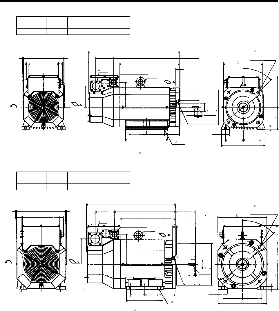
7 - 258
7. OUTLINE DIMENSION DRAWINGS
Model Output
[kW]
Inertia Moment
WK2[oz in2]
Mass
[lb]
HA-LF37K24 37 3553.84 396.832
0.236 0.23611.26
8.661
0.433 1.063
5.987
25.591
5.039 18.543 5.512
5.512
7.047
55
11.969
4.252
2.008
4- 0.591
0.984 0.197
16.969
0.984 0.315
2.362
0.843
11.024
9.055
0.787
2.165
5
12.205
5
6.299 0
0.035
BC10788C
[Unit: in]
Cooling fan
rotation direction Suction air
Encoder connector
MS3102A20-29P
Hanger
(Note) Exhaust air
Oil seal S659013B
M12 screw
4- 0.748
Use hexagon socket
head cap screw.
Note: When the motor is used without the hanger, plug the threaded hole with a bolt of M16 20mm or less.
11.811
45
Model Output
[kW]
Inertia Moment
WK2[oz in2]
Mass
[lb]
HA-LF45K24 45 5904.841 507.063
0.236 0.23613.858
10.472
0.433 1.063
7.244
25.197
5.433 17.283 5.512
5.512
8.504
3.996 3.996
10.315
4.764
2.48
4- 0.748
0.984 0.197
15.709
1.181 0.354
11.811
11.024
0.866
5.492
13.74
5.492
7.087 0
0.02
BC11107
A
[Unit: in]
Cooling fan
rotation
direction Suction air
Encoder connector
MS3102A20-29P
Hanger
(Note)
Exhaust air
Oil seal S709513B
M16 screw
4- 0.748
Use hexagon socket
head cap screw.
Note: When the motor is used without the hanger, plug the threaded hole with a bolt of M16 20mm or less.
2.559
2.756
13.78
13.78
45
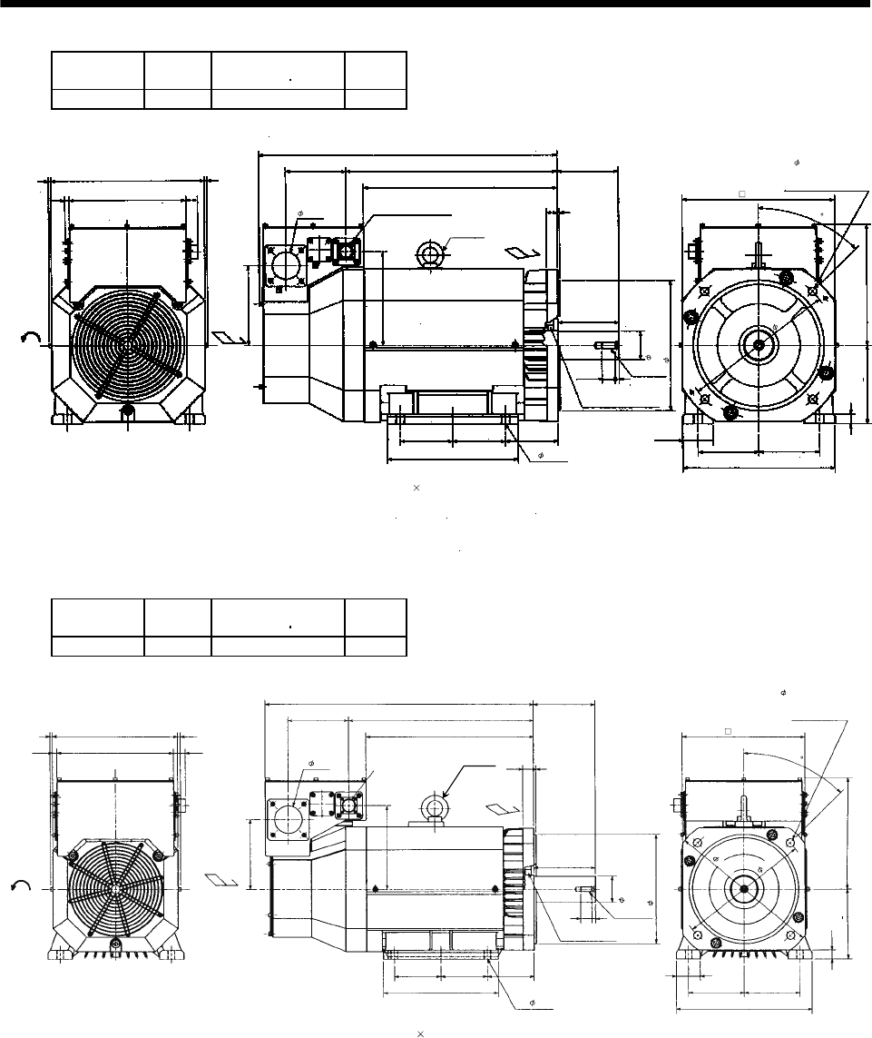
7 - 259
7. OUTLINE DIMENSION DRAWINGS
Model Output
[kW]
Inertia Moment
WK2[oz in2]
Mass
[lb]
HA-LF55K24 55 7162.354 551.155
0.236 0.23613.858
10.472
0.433 1.063
7.244
26.969
5.433 19.055 5.512
5.512
8.504
4.744 4.744
11.811
4.764
2.48
4- 0.748
0.984 0.197
17.48
1.181 0.354
2.559
11.811
13.78
11.024
0.866
2.756
5.492
13.74
5.492
7.087 0
0.02
BC10522F
13.78
Cooling fan
rotation
direction
Suction air
Encoder connector
MS3102A20-29P
Hanger
(Note) Exhaust air
Oil seal S709513B
M16 screw
4- 0.748
Use hexagon socket
head cap screw.
Note: When the motor is used without the hanger, plug the threaded hole with a bolt of M16 20mm or less.
[Unit: in]
45
Model Output
[kW]
Inertia Moment
WK2[oz in2]
Mass
[lb]
HA-LF30K2 30 3007.095 352.739
BC12180*
Note: When the motor is used without the hanger, plug the threaded hole with a bolt of M16 20mm or less.
0.236 0.236
11.26
10.472 1.063
Cooling fan
rotation
direction Suction air
6.299
24.213
5.433 16.575
5.512
5.512
7.559
4.134 4.134
8.11
4.252
0.984 0.197
15
0.985 0.315
Encoder connector
MS3102A20-29P Hanger
(Note)
Exhaust air
Oil seal S659013B
M12 screw
2.48
2.362
9.853
4- 0.591
45
10.236
0.787
2.165
5
12.205
5
6.299 0
0.02
4- 0.748
Use hexagon socket
head cap screw.
11.811
11.024
13.78
0.433
[Unit: in]
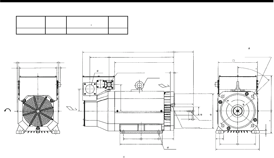
7 - 260
7. OUTLINE DIMENSION DRAWINGS
Model Output
[kW]
Inertia Moment
WK2[oz in2]
Mass
[lb]
HA-LF37K2 37 3553.8 396.8
BC12181*
Cooling fan
rotation
direction Suction air
0.433
0.236 11.26
10.472
0.236
1.063
6.299
5.433
25.984
16.772
18.346
2.48
Encoder connector
MS3102A20-29P Hanger
(Note)
5.512
0.984 0.197
Exhaust air
11.969
54.252
4- 0.591
5
Oil seal
S659013B
0.984
0.315
5.512
2.362
250h7
M12 screw
2.165
5
12.205
5
0.787
6.299 0
0.02 10.236
11.811
13.78
45
4- 0.748
Use hexagon socket
head cap screw.
11.024
[Unit: in]
Note: When the motor is used without the hanger, plug the threaded hole with a bolt of M16 20mm or less.
7.559
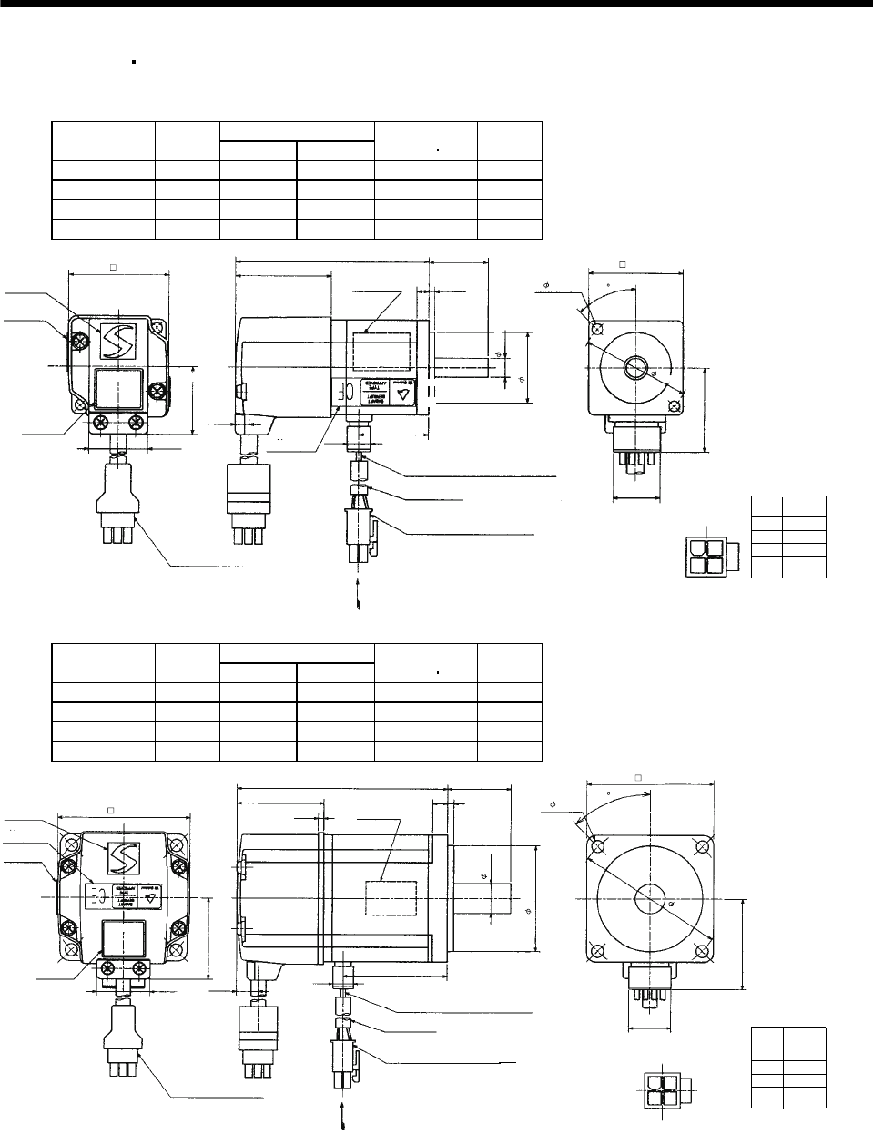
7 - 261
7. OUTLINE DIMENSION DRAWINGS
7.2.11 HC-MFS HC-KFS series
(1) Standard (without electromagnetic brake, without reduction gear)
Variable Dimensions [in]
Model Output
[W] LKL
Inertia Moment
WK2[oz in2]
Mass
[lb]
HC-MFS053 50 3.21 1.16 0.10 0.9
HC-MFS13 100 3.80 0.18 0.16 1.2
HC-KFS053 50 3.21 0.12 0.29 0.9
HC-KFS13 100 3.80 1.75 0.46 1.2
Power supply
connector pin
connection list
1
2
3
4
Pin No. Application
Phase U
Phase V
Phase W
Earth
[Unit: in]
BC11873*
(BC11879*)
0.787
5557-04R-210 (Receptacle)
5556PBTL (Female terminal)
With connector 1-172169-9
(AMP)
Arrow A
1.406
Bottom
Top
Protective tube
Motor plate
(Opposite side)
1.181
1.811
1.575
Logo plate
Power supply connector (Molex)
Encoder cable 11.8in
Motor plate
Caution plate
Bottom
Top
Top
KL
0.984
0.0980.197
L
1.594
0.268
0.390
0.992
1.654
1.130
2- 0.177
Power supply lead 4-AWG19 11.8in
TUV plate
Arrow A
Bottom
Top
Top
1
2
3
4
0.315
45
Bottom Bottom
Variable Dimensions [in]
Model Output
[W] LKL
Inertia Moment
WK2[oz in2]
Mass
[lb]
HC-MFS23 200 3.92 1.93 0.48 2.2
HC-MFS43 400 4.90 0.06 0.78 3.2
HC-KFS23 200 3.92 1.93 2.30 2.2
HC-KFS43 400 4.90 0.06 3.66 3.2
Power supply
connector pin
connection list
1
2
3
4
Pin No. Application
Phase U
Phase V
Phase W
Earth
[Unit: in]
BC11874*
(BC11880*)
0.787
5557-04R-210 (Receptacle)
5556PBTL (Female terminal)
With connector 1-172169-9
(AMP)
Arrow A
1.685
Bottom
Top
Protective tube
Motor plate
(Opposite side)
1.969
2.756
2.362
0.551
Logo plate
Power supply connector (Molex)
Encoder cable 11.8in
Motor plate
Caution plate
Bottom
Top
KL
1.181
0.118
0.276
L
1.614
0.417 0.390
0.992
2.441
1.512
4- 0.228
Power supply lead 4-AWG19 11.8in
TUV plate
Arrow A
Top
Bottom
Top
Bottom
0.106
1
2
3
4
45
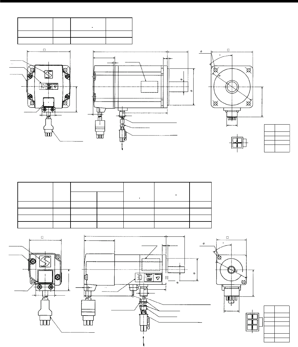
7 - 262
7. OUTLINE DIMENSION DRAWINGS
Model Output
[W]
Inertia Moment
WK2[oz in2]
Mass
[lb]
HC-MFS73 750 3.28 6.6
HC-KFS73 750 8.256 6.6
Power supply
connector pin
connection list
1
2
3
4
Pin No. Application
Phase U
Phase V
Phase W
Earth
[Unit: in]
BC11875*
0.787
5557-04R-210 (Receptacle)
5556PBTL (Female terminal)
With connector 1-172169-9
(AMP)
Arrow A
2.287
Bottom
Top
Protective tube
Motor plate
(Opposite side)
2.756
3.543
3.150
0.748
Logo plate
Power supply connector (Molex)
Encoder cable 11.8in
Motor plate
Caution plate
Bottom
Top
3.413
1.575
0.1180.315
5.591
1.535
0.433 0.390
0.992
3.228
1.917
4- 0.260
Power supply lead 4-AWG19 11.8in
TUV plate
Arrow A
Top
Bottom
Top
Bottom
0.106
1
2
3
4
45
(BC12580*)
(2) With electromagnetic brake
Variable Dimensions [in]
Model Output
[W] LKL
Brake static
friction torque
[oz in]
Inertia Moment
WK2[oz in2]
Mass
[lb]
HC-MFS053B 50 4.31 1.16 45.32 0.12 1.7
HC-MFS13B 100 4.90 1.75 45.32 0.18 2.0
HC-KFS053B 50 4.31 1.16 45.32 0.31 1.7
HC-KFS13B 100 4.90 1.75 45.32 0.48 2.0
Power supply
connector pin
connection list
1
2
3
4
Pin No. Application
Phase U
Phase V
Phase W
Earth
5
6
B1
B2
[Unit: in]
BC11881*
(BC11887*)
0.787
5557-06R-210 (Receptacle)
5556PBTL (Female terminal)
Arrow A
1.406
Bottom
Top
Protective tube
Motor plate
(Opposite side)
1.181
1.811
1.575
0.315
Logo plate
Power supply connector (Molex)
Encoder cable 11.8in
Motor plate
Caution plate
Bottom
Top
Top KL
0.984
0.0980.197
L
1.594
0.268
0.390
0.992
1.654
1.130
2- 0.177
Power supply lead 4-AWG19 11.8in
TUV plate
Arrow A
Bottom
Top
Top
Brake lead
2-0.3 11.8in
2
1
2
4
5
36
2.579
Bottom
With connector 1-172169-9
(AMP)
45
Bottom
Banding band
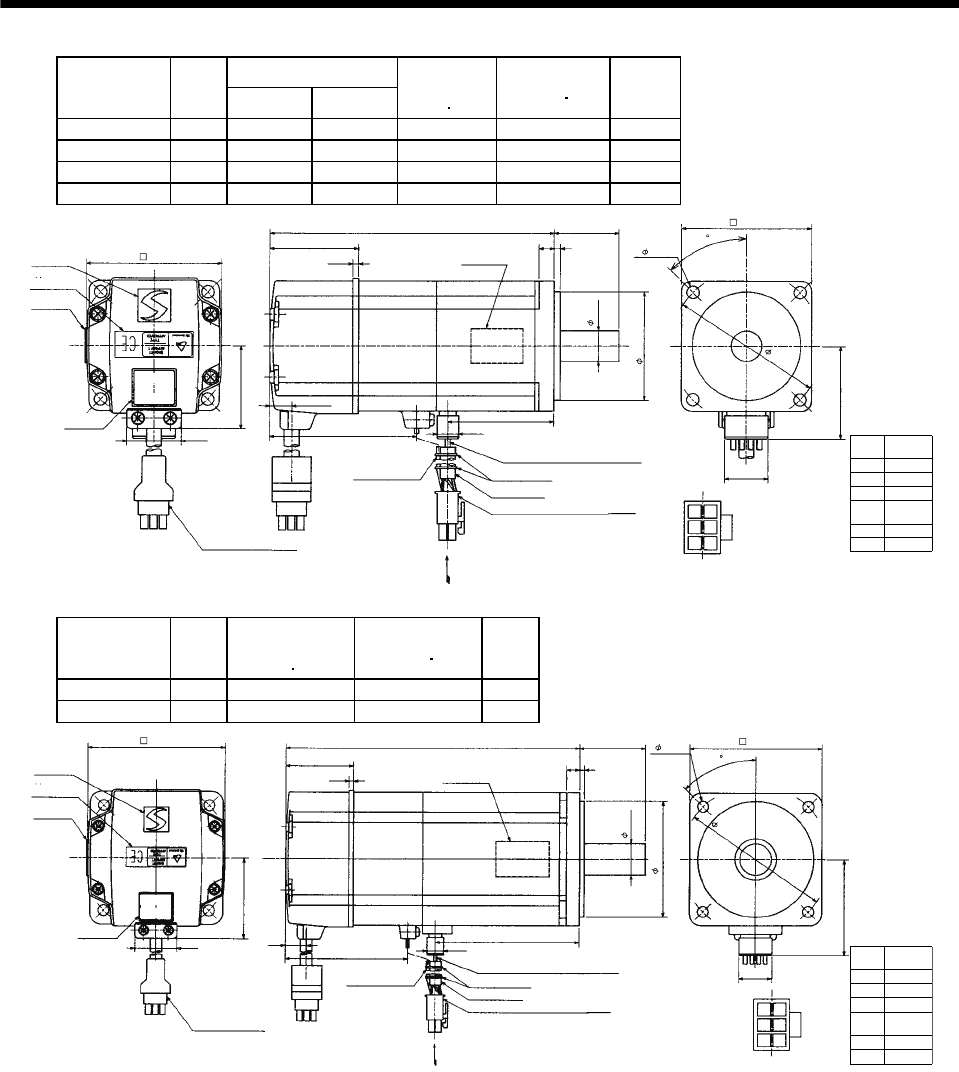
7 - 263
7. OUTLINE DIMENSION DRAWINGS
Variable Dimensions [in]
Model Output
[W] LKL
Brake static
friction torque
[oz in]
Inertia Moment
WK2[oz in2]
Mass
[lb]
HC-MFS23B 200 5.18 1.93 184 0.74 3.5
HC-MFS43B 400 6.16 2.84 184 1.04 4.6
HC-KFS23B 200 5.18 1.93 184 1.694 3.5
HC-KFS43B 400 6.16 2.84 184 2.788 4.6
Power supply
connector pin
connection list
1
2
3
4
Pin No. Application
Phase U
Phase V
Phase W
Earth
5
6
B1
B2
[Unit: in]
BC11882*
(BC11888*)
0.787
5557-06R-210 (Receptacle)
5556PBTL (Female terminal)
With connector 1-172169-9
(AMP) Arrow A
1.685
Bottom
Top
Protective tube
Motor plate
(Opposite side)
1.969
2.756
2.362
0.551
Logo plate
Power supply connector (Molex)
Encoder cable 11.8in
Motor plate
Caution plate
Bottom
Top
KL
1.181
0.118
0.276
L
1.614
0.417
0.390
0.992
2.441
1.512
4- 0.228
Power supply lead 4-AWG19 11.8in
TUV plate
Arrow A
Top
Bottom
Top
Bottom
0.106
2.677
Brake lead
2-0.3 11.8in
2
1
2
4
5
36
45
Banding band
Model Output
[W]
Brake static
friction torque
[oz in]
Inertia Moment
WK2[oz in2]
Mass
[lb]
HC-MFS73B 750 340 3.96 8.8
HC-KFS73B 750 340 8.94 8.8
5557-06R-210 (Receptacle)
5556PBTL (Female terminal)
Power supply
connector pin
connection list
1
2
3
4
Pin No. Application
Phase U
Phase V
Phase W
Earth
5
6
B1
B2
[Unit: in]
BC11883*
0.787
With connector 1-172169-9
(AMP)
Arrow A
2.287
Bottom
Top
Protective tube
Motor plate
(Opposite side)
2.756
3.543
3.150
0.748
Logo plate
Power supply connector (Molex)
Encoder cable 11.8in
Motor plate
Caution plate
Bottom
Top
3.413
1.575
0.1180.315
6.988
1.535
0.433 0.390
0.992
3.228
1.917
4- 0.260
Power supply lead 4-AWG19 11.8in
TUV plate
Arrow A
Top
Bottom
Top
Bottom
0.106
2.835
Brake lead
2-0.3 11.8in
2
1
2
4
5
36
(BC12581*)
45
Banding band
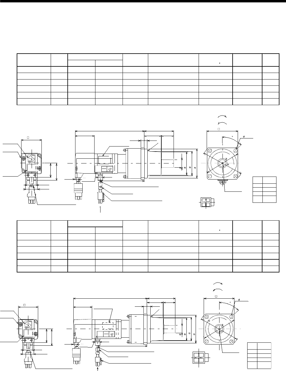
7 - 264
7. OUTLINE DIMENSION DRAWINGS
(3) With reduction gear for general industrial machine
The outer frame of the reduction gear is a material surface such as casting. Its actual dimensions may
be 0.039 to 0.118 in larger than the drawing dimensions. Design the machine side with allowances.
(a) Without electromagnetic brake
Variable Dimensions [in]
Model Output
[W] LKL
Reduction
Gear Model
Reduction Ratio
(Actual Reduction Ratio)
Inertia Moment
WK2[oz in2]Backlash Mass
[lb]
HC-MFS053G1 50 4.96 2.91 K6505 1/5(9/44) 0.30 60min. max. 3.1
HC-MFS053G1 50 5.669 3.62 K6512 1/12(49/576) 0.42 60min. max. 4.0
HC-MFS053G1 50 5.669 3.62 K6520 1/20(25/484) 0.32 60min. max. 4.0
HC-KFS053G1 50 4.96 2.91 K6505 1/5(9/44) 0.49 60min. max. 3.1
HC-KFS053G1 50 5.669 3.62 K6512 1/12(49/576) 0.61 60min. max. 4.0
HC-KFS053G1 50 5.669 3.62 K6520 1/20(25/484) 0.51 60min. max. 4.0
TUV
Rheinland CE
4
3
1
2
Bottom
[Unit: in]
With connector 1-172169-9
(AMP)
Protective tube
Motor plate
(Opposite side)
2.953
2.559
0.630
Logo plate
5557-04R-210 (Receptacle)
5556PBT (Female terminal)
Power supply connector (Molex)
Encoder cable 11.8in
Motor plate
Caution plate
Bottom
Top
KL
2.382
0.256
0.315
L
1.594
0.268
0.992
1.654
1.130
4- 0.276
Power supply lead 4-AWG19 11.8in
TUV plate
Arrow A
Top
Top
1.358 0.984
1.890
3.465
For reverse rotation command
For forward rotation command
"Rotation direction"
M4 threads,
depth 0.315
Arrow A
45
Bottom Power supply
connector pin
connection list
1
2
3
4
Pin No. Application
Phase U
Phase V
Phase W
Earth
BC11896A
(BC11924A)
1.406
2.362
0.787
APPROVED
TYPE
GEPRUFT
BAUART
Bottom
Top
0.390
(R4)
Top
Bottom
( 1.969)
Variable Dimensions [in]
Model Output
[W] LKL
Reduction
Gear Model
Reduction Ratio
(Actual Reduction Ratio)
Inertia Moment
WK2[oz in2]Backlash Mass
[lb]
HC-MFS13G1 100 5.551 3.5 K6505 1/5(9/44) 0.36 60min. max. 3.31
HC-MFS13G1 100 6.26 4.21 K6512 1/12(49/576) 0.48 60min. max. 4.19
HC-MFS13G1 100 6.26 4.21 K6520 1/20(25/484) 0.38 60min. max. 4.19
HC-KFS13G1 100 5.551 3.5 K6505 1/5(9/44) 0.66 60min. max. 3.31
HC-KFS13G1 100 6.26 4.21 K6512 1/12(49/576) 0.78 60min. max. 4.19
HC-KFS13G1 100 6.26 4.21 K6520 1/20(25/484) 0.68 60min. max. 4.19
TUV Rheinland CE
42
13
Bottom
[Unit: in]
With connector 1-172169-9
(AMP)
Protective tube
Motor plate
(Opposite side)
2.953
2.559
0.630
Logo plate
5557-04R-210 (Receptacle)
5556PBT (Female terminal)
Power supply connector (Molex)
Encoder cable 11.8in
Motor plate
Caution plate
Bottom
Top
KL
2.382
(R4)
0.315
L
1.594
0.787
0.992
1.654
1.130
4- 0.276
Power supply lead 4-AWG19 11.8in
TUV plate
Arrow A
Top
Top
1.358 0.984
1.890
3.465
For reverse rotation command
For forward rotation command
"Rotation direction"
M4 threads,
depth 0.315
Arrow A
45
Bottom
Power supply
connector pin
connection list
1
2
3
4
Pin No. Application
Phase U
Phase V
Phase W
Earth
BC11925A
(BC11897A)
1.406
2.362
0.256
APPROVED
TYPE
GEPRUFT
BAUART
Bottom
Top
Top
Bottom
0.268 0.390
( 1.969)
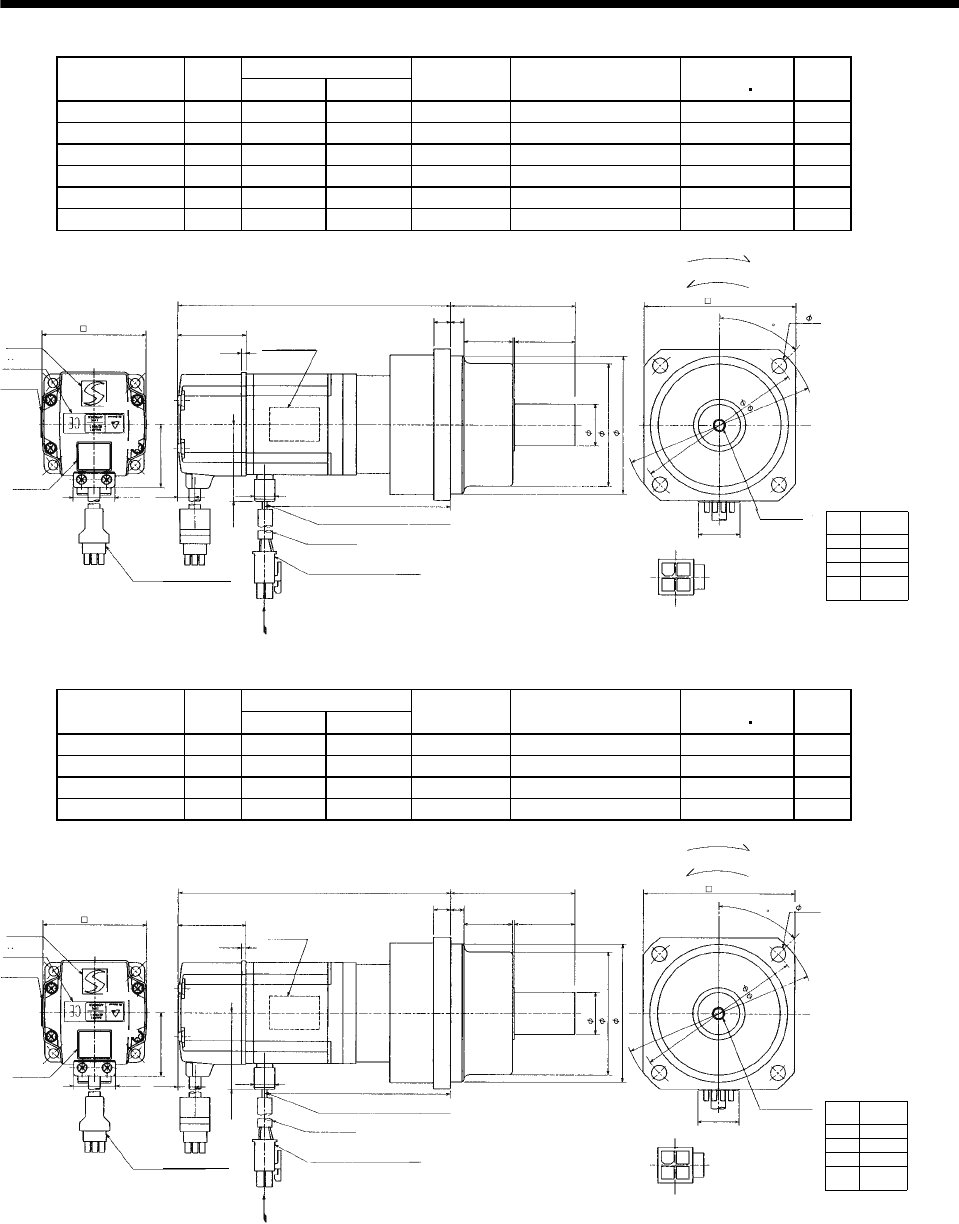
7 - 265
7. OUTLINE DIMENSION DRAWINGS
Variable Dimensions [in]
Model Output
[W] LKL
Reduction
Gear Model
Reduction Ratio
(Actual Reduction Ratio)
Inertia Moment
WK2[oz in2]
Mass
[lb]
HC-MFS23G1 200 6.02 4.04 K9005 1/5(19/96) 1.36 7.3
HC-MFS23G1 200 6.81 4.83 K9012 1/12(25/288) 1.60 8.6
HC-MFS23G1 200 6.81 4.83 K9020 1/20(253/5000) 1.45 8.6
HC-KFS23G1 200 6.02 4.04 K9005 1/5(19/96) 2.296 7.3
HC-KFS23G1 200 6.81 4.83 K9012 1/12(25/288) 2.569 8.6
HC-KFS23G1 200 6.81 4.83 K9020 1/20(253/5000) 2.406 8.6
Power supply
connector pin
connection list
1
2
3
4
Pin No. Application
Phase U
Phase V
Phase W
Earth
[Unit: in]
BC11898*
(BC11926*)
0.787
5557-04R-210 (Receptacle)
5556PBTL (Female terminal)
With connector 1-172169-9
(AMP)
Arrow A
Protective tube
Motor plate
(Opposite side)
3.543
0.984
Logo plate
Power supply connector (Molex)
Encoder cable 11.8in
Motor plate
Caution
plate
Bottom
Top
Bottom
Top
KL
2.913
0.315
0.394
L
0.4170.992
2.441
1.512
Power supply lead 4-AWG19 11.8in
Arrow A
Bottom
TUV plate
Bottom
Top
Top
1.685
0.390
0.106
1.614 1.181 1.378
2.874
3.228
1
2
3
4
For reverse rotation command
For forward rotation command
"Rotation direction"
4.488
3.937
4- 0.354
M6 threads,
depth 0.472
45
Variable Dimensions [in]
Model Output
[W] LKL
Reduction
Gear Model
Reduction Ratio
(Actual Reduction Ratio)
Inertia Moment
WK2[oz in2]
Mass
[lb]
HC-MFS43G1 400 7.01 4.95 K9005 1/5(19/96) 1.62 8.4
HC-MFS43G1 400 7.80 5.73 K9012 1/12(25/288) 1.85 9.7
HC-KFS43G1 400 7.01 4.95 K9005 1/5(19/96) 3.335 8.4
HC-KFS43G1 400 7.80 5.73 K9012 1/12(25/288) 3.609 9.7
Power supply
connector pin
connection list
1
2
3
4
Pin No. Application
Phase U
Phase V
Phase W
Earth
[Unit: in]
BC11899*
(BC11927*)
0.787
5557-04R-210 (Receptacle)
5556PBTL (Female terminal)
With connector 1-172169-9
(AMP)
Arrow A
45
Protective tube
Motor plate
(Opposite side)
3.543
0.984
Logo plate
Power supply connector (Molex)
Encoder cable 11.8in
Motor plate
Caution
plate
Bottom
Top
Bottom
Top
KL
2.913
0.315
0.394
L
0.417
0.992
2.441
1.512
Power supply lead 4-AWG19 11.8in
Arrow A
Bottom
TUV plate
Bottom
Top
Top
1.685
0.390
0.106
1.614 1.181 1.378
2.874
3.228
1
2
3
4
For reverse rotation command
For forward rotation command
"Rotation direction"
4.488
3.937
4- 0.354
M6 threads,
depth 0.472
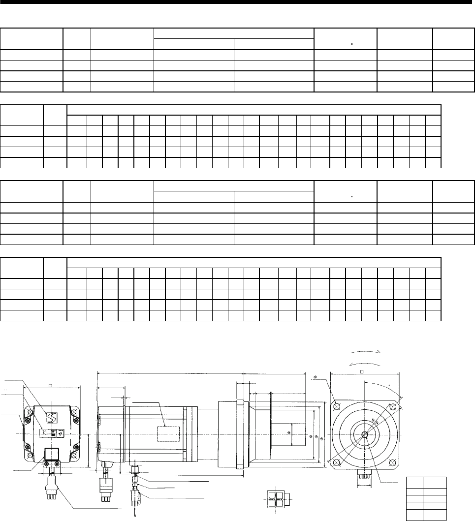
7 - 266
7. OUTLINE DIMENSION DRAWINGS
Reduction Ratio
Model Output
[W]
Reduction Gear
Model Normal Reduction ratio Actual Reduction Ratio
Inertia Moment
WK2[oz in2]Backlash Mass
[lb]
HC-MFS43G1 400 K10020 1/20 253/5000 3.57 60min. max. 12.13
HC-MFS73G1 750 K10005 1/5 1/5 5.58 60min. max. 13.67
HC-MFS73G1 750 K10012 1/12 525/6048 9.22 60min. max. 16.09
HC-MFS73G1 750 K12020 1/20 625/12544 9.57 60min. max. 22.27
Variable Dimensions [in]
Model Output
[W] D LH LK LT H LA LB LC LD LE LF LG LM LN LP L LR KL LZ Q S P R
HC-MFS43G1 400 2.362 1.50 1.61 0.42 1.69 4.53 3.74 5.20 3.94 0.39 2.87 0.39 0.512 0.63 3.39 7.933 3.54 5.87 0.35 1.97 1.26 M8 0.63
HC-MFS73G1 750 3.15 1.89 1.54 0.43 2.29 4.53 3.74 5.20 3.94 0.39 2.87 0.39 0.512 0.63 3.39 8.15 3.54 5.97 0.35 1.97 1.26 M8 0.63
HC-MFS73G1 750 3.15 1.89 1.54 0.43 2.29 4.53 3.74 5.20 3.94 0.39 2.87 0.39 0.512 0.63 3.39 9.016 3.54 6.84 0.35 1.97 1.26 M8 0.63
HC-MFS73G1 750 3.15 1.89 1.54 0.43 2.29 5.51 4.53 6.38 4.72 0.47 3.54 0.59 0.512 0.787 4.09 9.528 4.17 7.35 0.55 2.36 1.57 M10 0.79
Reduction Ratio
Model Output
[W]
Reduction Gear
Model Normal Reduction ratio Actual Reduction Ratio
Inertia Moment
WK2[oz in2]Backlash Mass
[lb]
HC-KFS43G1 400 K10020 1/20 253/5000 5.303 60min. max. 12.13
HC-KFS73G1 750 K10005 1/5 1/5 10.55 60min. max. 13.67
HC-KFS73G1 750 K10012 1/12 525/6048 14.19 60min. max. 16.09
HC-KFS73G1 750 K12020 1/20 625/12544 14.54 60min. max. 22.27
Variable Dimensions [in]
Model Output
[W] D LH LK LT H LA LB LC LD LE LF LG LM LN LP L LR KL LZ Q S P R
HC-KFS43G1 400 2.362 1.50 1.61 0.42 1.69 4.53 3.74 5.20 3.94 0.39 2.87 0.39 0.512 0.63 3.39 7.933 3.54 5.87 0.35 1.97 1.26 M8 0.63
HC-KFS73G1 750 3.15 1.89 1.54 0.43 2.29 4.53 3.74 5.20 3.94 0.39 2.87 0.39 0.512 0.63 3.39 8.15 3.54 5.97 0.35 1.97 1.26 M8 0.63
HC-KFS73G1 750 3.15 1.89 1.54 0.43 2.29 4.53 3.74 5.20 3.94 0.39 2.87 0.39 0.512 0.63 3.39 9.016 3.54 6.84 0.35 1.97 1.26 M8 0.63
HC-KFS73G1 750 3.15 1.89 1.54 0.43 2.29 5.51 4.53 6.38 4.72 0.47 3.54 0.59 0.512 0.787 4.09 9.528 4.17 7.35 0.55 2.36 1.57 M10 0.79
Power supply
connector pin
connection list
1
2
3
4
Pin No. Application
Phase U
Phase V
Phase W
Earth
[Unit: in]
BC11900*
0.787
5557-04R-210 (Receptacle)
5556PBTL (Female terminal)
With connector 1-172169-9
(AMP) Arrow A
45
Protective tube
Motor plate
(Opposite side)
LD
Sh6
Logo plate
Power supply connector (Molex)
Encoder cable 11.8in
Motor plate
Caution
plate
Bottom
Top
Bottom
Top
KL
LR
L
LT
0.992
D
Power supply lead 4-AWG19 11.8in
Arrow
A
TUV plate
Bottom
Top
0.390
0.106
LK
LG
LF
1
2
3
4
For reverse rotation command
For forward rotation command
"Rotation direction"
LC
LA
4- LZ
P threads,
depth R
Bottom
Top
LH
H
LE
LM LN Q
LP
LBh7
(********)
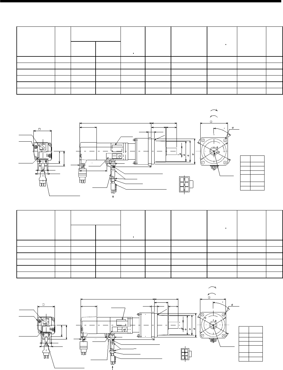
7 - 267
7. OUTLINE DIMENSION DRAWINGS
(b) With electromagnetic brake
Variable Dimensions [in]
Model Output
[W]
LKL
Brake
static
friction
torque
[oz in]
Reduction
Gear Model
Reduction Ratio
(Actual Reduction
Ratio)
Inertia Moment
WK2[oz in2]Backlash Mass
[lb]
HC-MFS053BG1 50 6.06 2.91 45 K6505 1/5(9/44) 0.32 60min. max. 4.0
HC-MFS053BG1 50 6.77 3.62 45 K6512 1/12(49/576) 0.44 60min. max. 4.9
HC-MFS053BG1 50 6.77 3.62 45 K6520 1/20(25/484) 0.34 60min. max. 4.9
HC-KFS053BG1 50 6.02 2.91 45 K6505 1/5(9/44) 0.51 60min. max. 4.0
HC-KFS053BG1 50 6.77 3.62 45 K6512 1/12(49/576) 0.63 60min. max. 4.9
HC-KFS053BG1 50 6.77 3.62 45 K6520 1/20(25/484) 0.53 60min. max. 4.9
TUV Rheinland
BAUART
GEPRUFT
TYPE
APPROVED CE
5
41
2
6
3
Power supply
connector pin
connection list
1
2
3
4
Pin No. Application
Phase U
Phase V
Phase W
Earth
5
6
B1
B2
BC11901A
(BC11929A)
[Unit: in]
5557-06R-210 (Receptacle)
5556PBT (Female terminal) Arrow A
Protective tube
Motor plate
(Opposite side)
2.559
Logo plate
Power supply connector (Molex)
With connector 1-172169-9
(AMP)
Encoder cable 11.8in
Caution
plate
Bottom
2.382
L
0.787
0.992
1.654
Arrow
A
TUV plate 0.390
1.594
0.315
For reverse rotation command
For forward rotation command
"Rotation direction"
3.465
2.953
4- 0.276
M4 threads,
depth 0.315
Bottom
Top
1.130
1.358
0.256
0.984
1.890
2.362
0.630
Bottom
Top
2.579
Power supply lead 4-AWG19 11.8in
Brake lead
2-0.3 11.8in
2
KL
Top
45
Motor plate
1.406
0.268
(R4)
Bottom
Top
Bottom
Top
( 1.969)
Banding band
Variable Dimensions (in)
Model Output
[W]
LKL
Brake
static
friction
torque
[oz in]
Reduction
Gear Model
Reduction Ratio
(Actual Reduction
Ratio)
Inertia Moment
WK2[oz in2]Backlash Mass
[lb]
HC-MFS13BG1 100 6.65 3.43 45 K6505 1/5(9/44) 0.38 60min. max. 4.2
HC-MFS13BG1 100 7.36 4.21 45 K6512 1/12(49/576) 0.50 60min. max. 5.1
HC-MFS13BG1 100 7.36 4.21 45 K6520 1/20(25/484) 0.40 60min. max. 5.1
HC-KFS13BG1 100 6.65 3.43 45 K6505 1/5(9/44) 0.68 60min. max. 4.2
HC-KFS13BG1 100 7.36 4.21 45 K6512 1/12(49/576) 0.80 60min. max. 5.1
HC-KFS13BG1 100 7.36 4.21 45 K6520 1/20(25/484) 0.7 60min. max. 5.1
TUV Rheinland
BAUART
GEPRUFT
TYPE
APPROVED CE
5
41
263
Power supply
connector pin
connection list
1
2
3
4
Pin No. Application
Phase U
Phase V
Phase W
Earth
5
6
B1
B2
BC11902A
(BC11930A)
[Unit: in]
Logo plate
With connector 1-172169-9
(
AMP
)
Encoder cable 11.8in
Caution
plate
0.787
0.992
1.654
1.130
Bottom
Top
Motor plate
1.406
5557-06R-210 (Receptacle)
5556PBT (Female terminal) Arrow A
Protective tube
Motor plate
(Opposite side)
2.559
Power supply connector (Molex)
Bottom
L
Arrow
A
TUV plate
0.390
1.594 0.315
For reverse rotation command
For forward rotation command
"Rotation direction"
3.465
2.953
4- 0.276
M4 threads,
depth 0.315
0.256
2.382
0.984
1.890
2.362
0.630
2.579
Power supply lead 4-AWG19 11.8in
Brake lead
2-0.3 11.8in
2
KL
Top
45
0.268
(R4)
Top
Bottom
1.358
Top
Bottom Bottom
Top
( 1.969)
Banding band
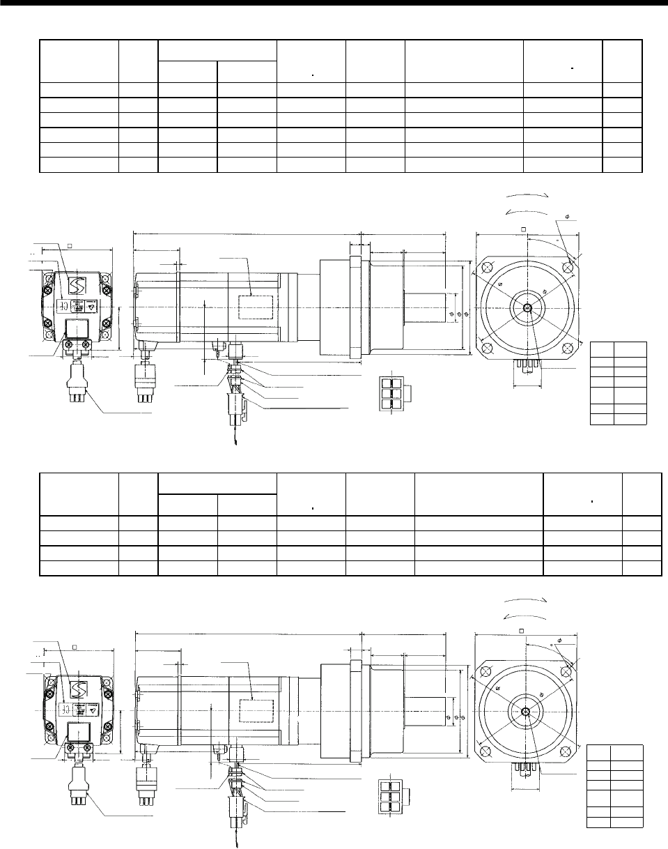
7 - 268
7. OUTLINE DIMENSION DRAWINGS
Variable Dimensions [in]
Model Output
[W] LKL
Brake static
friction torque
[oz in]
Reduction
Gear Model
Reduction Ratio
(Actual Reduction Ratio)
Inertia Moment
WK2[oz in2]
Mass
[lb]
HC-MFS23BG1 200 6.65 4.04 184 K9005 1/5(19/96) 1.58 8.6
HC-MFS23BG1 200 7.36 4.23 184 K9012 1/12(25/288) 1.82 9.9
HC-MFS23BG1 200 7.36 4.23 184 K9020 1/20(253/5000) 1.67 9.9
HC-KFS23BG1 200 6.65 4.04 184 K9005 1/5(19/96) 2.569 8.6
HC-KFS23BG1 200 7.36 4.23 184 K9012 1/12(25/288) 2.843 9.9
HC-KFS23BG1 200 7.36 4.23 184 K9020 1/20(253/5000) 2.679 9.9
Power supply
connector pin
connection list
1
2
3
4
Pin No. Application
Phase U
Phase V
Phase W
Earth
5
6
B1
B2
BC11903*
(BC11931*)
[Unit: in]
0.787
5557-06R-210 (Receptacle)
5556PBTL (Female terminal)
With connector 1-172169-9
(AMP) Arrow A
45
Protective tube
Motor plate
(Opposite side)
3.543
Logo plate
Power supply connector (Molex)
Encoder cable 11.8in
Caution
plate
Top
Bottom
Top
2.992
L
0.417
0.992
2.441
Arrow
A
0.390
1.614
0.394
1
2
4
5
For reverse rotation command
For forward rotation command
"Rotation direction"
4.488
3.937
4- 0.354
M6 threads,
depth 0.472
1.512
0.315
1.181 1.378
2.874
3.228
0.984
Bottom
Top
2.677
Power supply lead 4-AWG19 11.8in
Brake lead
2-0.3 11.8in
2
36
KL
0.106
1.685
Top
Bottom
TUV plate
Motor plate
Bottom
Banding band
Variable Dimensions [in]
Model Output
[W] LKL
Brake static
friction torque
[oz in]
Reduction
Gear Model
Reduction Ratio
(Actual Reduction Ratio)
Inertia Moment
WK2[oz in2]
Mass
[lb]
HC-MFS43BG1 400 8.27 4.95 184 K9005 1/5(19/96) 1.88 9.7
HC-MFS43BG1 400 9.06 5.73 184 K9012 1/12(25/288) 2.12 11.0
HC-KFS43BG1 400 8.27 4.95 184 K9005 1/5(19/96) 3.609 9.7
HC-KFS43BG1 400 9.06 5.73 184 K9012 1/12(25/288) 3.882 11.0
Power supply
connector pin
connection list
1
2
3
4
Pin No. Application
Phase U
Phase V
Phase W
Earth
5
6
B1
B2
BC11904*
(BC11932*)
[Unit: in]
0.787
5557-06R-210 (Receptacle)
5556PBTL (Female terminal)
With connector 1-172169-9
(AMP) Arrow A
45
Protective tube
Motor plate
(Opposite side)
3.543
Logo plate
Power supply connector (Molex)
Encoder cable 11.8in
Caution
plate
Top
Bottom
Top
2.913
L
0.417
0.992
2.441
Arrow
A
0.390
1.614 0.394
1
2
4
5
For reverse rotation command
For forward rotation command
"Rotation direction"
4.488
3.937
4- 0.354
M6 threads,
depth 0.472
1.512
0.315
1.181 1.378
2.874
3.228
0.984
Bottom
Top
2.677
Power supply lead 4-AWG19 11.8in
Brake lead
2-0.3 11.8in
2
36
KL
0.106
1.685
Bottom
Top
TUV plate
Motor plate
Bottom
Banding band
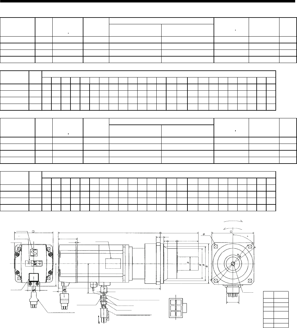
7 - 269
7. OUTLINE DIMENSION DRAWINGS
Reduction Ratio
Model Output
[W]
Brake static
friction torque
[oz in]
Reduction
Gear Model Normal Reduction ratio Actual Reduction Ratio
Inertia Moment
WK2[oz in2]Backlash Mass
[lb]
HC-MFS43BG1 400 184 K10020 1/20 253/5000 3.83 60min. max. 13.4
HC-MFS73BG1 750 340 K10005 1/5 1/5 6.26 60min. max. 15.9
HC-MFS73BG1 750 340 K10012 1/12 525/6048 9.90 60min. max. 18.3
HC-MFS73BG1 750 340 K12020 1/20 625/12544 10.25 60min. max. 25.8
Variable Dimensions [in]
Model Output
[W] D LH LK LT LX H LA LB LC LD LE LF LG LM LN LP L LR KL LZ Q S P R
HC-MFS43BG1 400 2.44 1.51 1.64 0.14 2.68 1.69 4.53 3.74 5.20 3.94 0.39 2.87 0.39 0.512 0.63 3.39 9.19 3.54 5.87 0.35 1.97 1.26 M8 0.63
HC-MFS73BG1 750 3.23 1.92 1.54 0.43 2.84 1.69 4.53 3.74 5.20 3.94 0.39 2.87 0.39 0.512 0.63 3.39 9.55 3.54 5.92 0.35 1.97 1.26 M8 0.63
HC-MFS73BG1 750 3.23 1.92 1.54 0.43 2.84 1.69 4.53 3.74 5.20 3.94 0.39 2.87 0.39 0.512 0.63 3.39 10.41 3.54 6.84 0.35 1.97 1.26 M8 0.63
HC-MFS73BG1 750 3.23 1.92 1.54 0.43 2.84 1.69 5.51 4.53 6.38 4.72 0.47 3.54 0.59 0.512 0.787 4.09 10.93 4.17 7.35 0.55 2.36 1.57 M10 0.79
Reduction Ratio
Model Output
[W]
Brake static
friction torque
[oz in]
Reduction
Gear Model Normal Reduction ratio Actual Reduction Ratio
Inertia Moment
WK2[oz in2]Backlash Mass
[lb]
HC-KFS43BG1 400 184 K10020 1/20 253/5000 5.577 60min. max. 13.4
HC-KFS73BG1 750 340 K10005 1/5 1/5 11.24 60min. max. 15.9
HC-KFS73BG1 750 340 K10012 1/12 525/6048 14.88 60min. max. 18.3
HC-KFS73BG1 750 340 K12020 1/20 625/12544 15.23 60min. max. 25.8
Variable Dimensions [in]
Model Output
[W] D LH LK LT LX H LA LB LC LD LE LF LG LM LN LP L LR KL LZ Q S P R
HC-KFS43BG1 400 2.44 1.51 1.64 0.14 2.68 1.69 4.53 3.74 5.20 3.94 0.39 2.87 0.39 0.512 0.63 3.39 9.19 3.54 5.87 0.35 1.97 1.26 M8 0.63
HC-KFS73BG1 750 3.23 1.92 1.54 0.43 2.84 1.69 4.53 3.74 5.20 3.94 0.39 2.87 0.39 0.512 0.63 3.39 9.55 3.54 5.92 0.35 1.97 1.26 M8 0.63
HC-KFS73BG1 750 3.23 1.92 1.54 0.43 2.84 1.69 4.53 3.74 5.20 3.94 0.39 2.87 0.39 0.512 0.63 3.39 10.41 3.54 6.84 0.35 1.97 1.26 M8 0.63
HC-KFS73BG1 750 3.23 1.92 1.54 0.43 2.84 1.69 5.51 4.53 6.38 4.72 0.47 3.54 0.59 0.512 0.787 4.09 10.93 4.17 7.35 0.55 2.36 1.57 M10 0.79
Power supply
connector pin
connection list
1
2
3
4
Pin No. Application
Phase U
Phase V
Phase W
Earth
5
6
B1
B2
BC11905*
[Unit: in]
0.787
5557-06R-210 (Receptacle)
5556PBTL (Female terminal)
With connector 1-172169-9
(AMP)
Arrow A
45
Protective tube
Motor plate
(Opposite side)
Logo plate
Power supply connector (Molex)
Encoder cable 11.8in
Caution
plate
Top
Bottom
Top
LR
L
LT
0.992
D
Arrow
A
TUV plate
0.390
LK LG
1
2
4
5
For reverse rotation command
For forward rotation command
"Rotation direction"
LA
LC
4- LZ
P threads,
depth R
LH
LE
LN Q
LF
LBh7
Sh6
Bottom
Top
LX
Power supply lead 4-AWG19 11.8in
Brake lead
2-0.3 11.8in
2
36
KL
0.106
H
Bottom
Top
LM
LP
(********)
Motor plate
LD
Bottom
Banding band
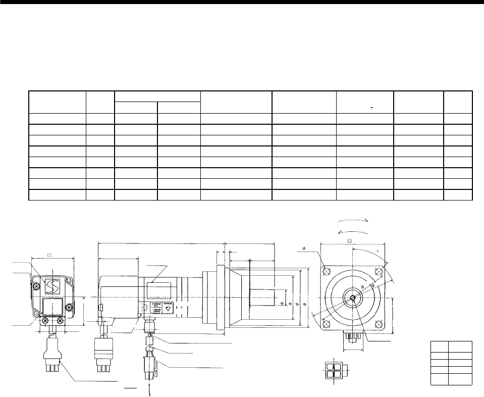
7 - 270
7. OUTLINE DIMENSION DRAWINGS
(4) With reduction gear for precision application
The outer frame of the reduction gear is a material surface such as casting. Its actual dimensions may
be 0.039 to 0.118 in larger than the drawing dimensions. Design the machine side with allowances.
(a) Without electromagnetic brake
Variable Dimensions [in]
Model Output
[W] LKL
Reduction Gear
Model Reduction Ratio Inertia Moment
WK2[oz in2]Backlash Mass
[lb]
HC-MFS053G2 50 5.12 3.07 BK1-05B-A5MEKA 1/5 0.36 3 min. max. 3.1
HC-MFS053G2 50 5.75 3.70 BK1-09B-A5MEKA 1/9 0.33 3 min. max. 3.7
HC-MFS053G2 50 5.75 3.70 BK1-20B-A5MEKA 1/20 0.38 3 min. max. 4.0
HC-MFS053G2 50 5.75 3.70 BK1-29B-A5MEKA 1/29 0.31 3 min. max. 4.0
HC-KFS053G2 50 5.12 3.07 BK1-05B-A5MEKA 1/5 0.55 3 min. max. 3.1
HC-KFS053G2 50 5.75 3.70 BK1-09B-A5MEKA 1/9 0.52 3 min. max. 3.7
HC-KFS053G2 50 5.75 3.70 BK1-20B-A5MEKA 1/20 0.57 3 min. max. 4.0
HC-KFS053G2 50 5.75 3.70 BK1-29B-A5MEKA 1/29 0.50 3 min. max. 4.0
Power supply
connector pin
connection list
1
2
3
4
Pin No. Application
Phase U
Phase V
Phase W
Earth
[Unit: in]
BC11906*
(BC11916*)
Logo plate
Motor plate
With connector 1-172169-9
(AMP)
Encoder cable11.8in
Motor plate
(Opposite side)
0.315
2.382
L
1.594
0.256
0.906
0.268
KL
0.992
Top
1.130
Bottom
Top
TUV plate
Caution plate
Top
1.654
For reverse rotation command
For forward rotation command
Rotation direction
2.756
M4 threads,
depth 0.315
0.787
13
24
Arrow A
4 - 0.260
Top
Bottom
1.406
45
5557-04R-210 (Receptacle)
5556PBTL (Female terminal)
Power supply connector (Molex)
Protective tube
Power supply lead 4-AWG1911.8in
Arrow A
0.390
0.984
1.890
2.559
2.362
0.630
3.150
3.740
Bottom
Top
Bottom Bottom
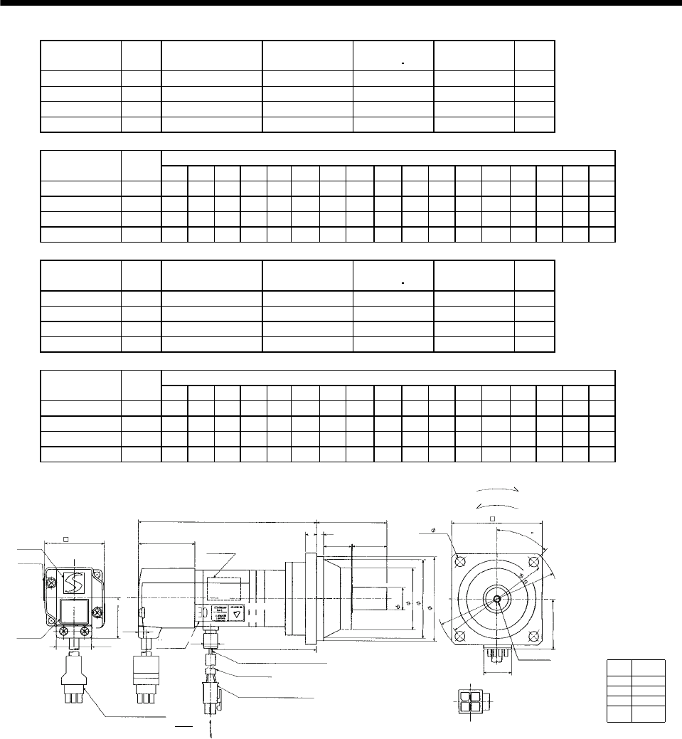
7 - 271
7. OUTLINE DIMENSION DRAWINGS
Model Output
[W]
Reduction Gear
Model Reduction Ratio Inertia Moment
WK2[oz in2]Backlash Mass
[lb]
HC-MFS13G2 100 BK1-05B-01MEKA 1/5 0.43 3 min. max. 3.3
HC-MFS13G2 100 BK1-09B-01MEKA 1/9 0.39 3 min. max. 4.0
HC-MFS13G2 100 BK2-20B-01MEKA 1/20 0.66 3 min. max. 6.6
HC-MFS13G2 100 BK2-29B-01MEKA 1/29 0.52 3 min. max. 6.6
Variable Dimensions [in]
Model Output
[W] LA LB LC LD LE LF LG LH LK L LR KL LZ Q S P R
HC-MFS13G2 100 3.15 2.56 3.74 2.76 0.24 1.89 0.31 2.362 0.906 5.71 2.17 3.66 0.26 0.98 0.63 M4 0.31
HC-MFS13G2 100 3.15 2.56 3.74 2.76 0.24 1.89 0.31 2.362 0.906 6.34 2.17 4.29 0.26 0.98 0.63 M4 0.31
HC-MFS13G2 100 3.94 3.15 4.53 3.35 0.24 2.559 0.39 2.913 1.299 6.57 2.95 4.53 0.26 1.38 0.79 M5 0.39
HC-MFS13G2 100 3.94 3.15 4.53 3.35 0.24 2.559 0.39 2.913 1.299 6.57 2.95 4.53 0.26 1.38 0.79 M5 0.39
Model Output
[W]
Reduction Gear
Model Reduction Ratio Inertia Moment
WK2[oz in2]Backlash Mass
[lb]
HC-KFS13G2 100 BK1-05B-01MEKA 1/5 0.72 3 min. max. 3.3
HC-KFS13G2 100 BK1-09B-01MEKA 1/9 0.69 3 min. max. 4.0
HC-KFS13G2 100 BK2-20B-01MEKA 1/20 0.96 3 min. max. 6.6
HC-KFS13G2 100 BK2-29B-01MEKA 1/29 0.82 3 min. max. 6.6
Variable Dimensions [in]
Model Output
[W] LA LB LC LD LE LF LG LH LK L LR KL LZ Q S P R
HC-KFS13G2 100 3.15 2.56 3.74 2.76 0.24 1.89 0.31 2.362 0.906 5.71 2.17 3.66 0.26 0.98 0.63 M4 0.31
HC-KFS13G2 100 3.15 2.56 3.74 2.76 0.24 1.89 0.31 2.362 0.906 6.34 2.17 4.29 0.26 0.98 0.63 M4 0.31
HC-KFS13G2 100 3.94 3.15 4.53 3.35 0.24 2.559 0.39 2.913 1.299 6.57 2.95 4.53 0.26 1.38 0.79 M5 0.39
HC-KFS13G2 100 3.94 3.15 4.53 3.35 0.24 2.559 0.39 2.913 1.299 6.57 2.95 4.53 0.26 1.38 0.79 M5 0.39
Power supply
connector pin
connection list
1
2
3
4
Pin No. Application
Phase U
Phase V
Phase W
Earth
[Unit: in]
BC11907*
(BC11917*)
Logo plate
Motor plate
With connector 1-172169-9
(AMP)
Encoder cable 11.8in
Motor plate
(Opposite side)
LG
LR
L
LE
LK Q
KL
Top
Bottom
Top
TUV plate
Caution plate
Top
For reverse rotation command
For forward rotation command
Rotation direction
LD
P threads, depth R
Sh6
LF
LBh7
0.787
13
24
Arrow A
4 - LZ
Bottom
1.406
45
5557-04R-210 (Receptacle)
5556PBTL (Female terminal)
Power supply connector (Molex)
Protective tube
Power supply lead 4-AWG19 11.8in
Arrow A
LH
0.268
0.992
1.130
0.390
1.594
1.654
Bottom Bottom Top
Bottom
Top
LA
LC
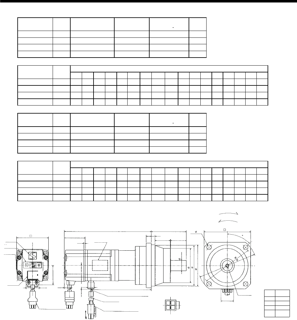
7 - 272
7. OUTLINE DIMENSION DRAWINGS
Model Output
[W]
Reduction Gear
Model Reduction Ratio Inertia Moment
WK2[oz in2]
Mass
[lb]
HC-MFS23G2 200 BK1-05B-02MEKA 1/5 1.04 4.6
HC-MFS23G2 200 BK2-09B-02MEKA 1/9 1.14 7.7
HC-MFS23G2 200 BK3-20B-02MEKA 1/20 1.95 11.0
HC-MFS23G2 200 BK3-29B-02MEKA 1/29 1.51 11.0
Variable Dimensions [in]
Model Output
[W] LA LB LC LD LE LF LG LH LK L LR KL LZ Q S P R
HC-MFS23G2 200 3.15 2.56 3.74 2.76 0.24 1.89 0.31 2.362 0.906 6.18 2.17 4.20 0.26 0.98 0.63 M4 0.31
HC-MFS23G2 200 3.94 3.15 4.53 3.35 0.24 2.559 0.39 2.913 1.299 6.89 2.95 4.91 0.26 1.38 0.79 M5 0.39
HC-MFS23G2 200 4.53 3.74 5.31 3.94 0.31 2.953 0.39 3.346 1.378 7.09 3.35 5.10 0.35 1.57 0.98 M6 0.47
HC-MFS23G2 200 4.53 3.74 5.31 3.94 0.31 2.953 0.39 3.346 1.378 7.09 3.35 5.10 0.35 1.57 0.98 M6 0.47
Model Output
[W]
Reduction Gear
Model Reduction Ratio Inertia Moment
WK2[oz in2]
Mass
[lb]
HC-KFS23G2 200 BK1-05B-02MEKA 1/5 1.968 4.6
HC-KFS23G2 200 BK2-09B-02MEKA 1/9 2.078 7.7
HC-KFS23G2 200 BK3-20B-02MEKA 1/20 2.898 11.0
HC-KFS23G2 200 BK3-29B-02MEKA 1/29 2.460 11.0
Variable Dimensions [in]
Model Output
[W] LA LB LC LD LE LF LG LH LK L LR KL LZ Q S P R
HC-KFS23G2 200 3.15 2.56 3.74 2.76 0.24 1.89 0.31 2.362 0.906 6.18 2.17 4.20 0.26 0.98 0.63 M4 0.31
HC-KFS23G2 200 3.94 3.15 4.53 3.35 0.24 2.559 0.39 2.913 1.299 6.89 2.95 4.91 0.26 1.38 0.79 M5 0.39
HC-KFS23G2 200 4.53 3.74 5.31 3.94 0.31 2.953 0.39 3.346 1.378 7.09 3.35 5.10 0.35 1.57 0.98 M6 0.47
HC-KFS23G2 200 4.53 3.74 5.31 3.94 0.31 2.953 0.39 3.346 1.378 7.09 3.35 5.10 0.35 1.57 0.98 M6 0.47
Power supply
connector pin
connection list
1
2
3
4
Pin No. Application
Phase U
Phase V
Phase W
Earth
[Unit: in]
BC11908*
(BC11918*)
Logo plate
Motor plate
With connector 1-172169-9
(AMP)
Encoder cable 11.8in
Motor plate
(Opposite side)
LG
LR
L
1.641 LE
LK Q
0.417 KL
0.992
1.512
Bottom
Top
TUV plate
Caution plate
Top
2.441
For reverse rotation command
For forward rotation command
Rotation direction
LD
LA
P threads, depth R
Sh6
LF
LBh7
0.787
13
24
Arrow A
4 - LZ
Top
Bottom
LC
1.685
45
5557-04R-210 (Receptacle)
5556PBTL (Female terminal)
Power supply connector (Molex)
Protective tube
Power supply lead 4-AWG19 11.8in
LH
0.106
Arrow A
Bottom
Top
0.390
Bottom
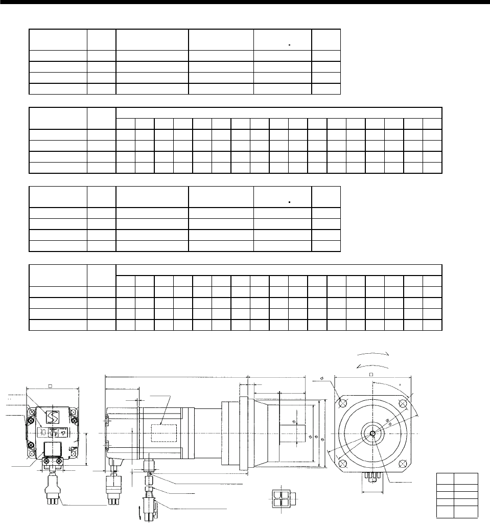
7 - 273
7. OUTLINE DIMENSION DRAWINGS
Model Output
[W]
Reduction Gear
Model Reduction Ratio Inertia Moment
WK2[oz in2]
Mass
[lb]
HC-MFS43G2 400 BK2-05B-04MEKA 1/5 1.61 8.2
HC-MFS43G2 400 BK3-09B-04MEKA 1/9 1.77 11.7
HC-MFS43G2 400 BK4-20B-04MEKA 1/20 2.33 16.5
HC-MFS43G2 400 BK4-29B-04MEKA 1/29 1.85 16.5
Variable Dimensions [in]
Model Output
[W] LA LB LC LD LE LF LG LH LK L LR KL LZ Q S P R
HC-MFS43G2 400 3.94 3.15 4.53 3.35 0.24 2.56 0.39 2.91 1.3 7.24 2.95 5.18 0.26 1.38 0.79 M5 0.39
HC-MFS43G2 400 4.53 3.74 5.31 3.94 0.31 2.95 0.39 3.35 1.38 8.07 3.35 6.01 0.35 1.58 0.98 M6 0.47
HC-MFS43G2 400 5.32 3.94 6.10 4.53 0.31 3.54 0.47 3.94 1.58 8.31 3.94 6.24 0.43 1.97 1.26 M8 0.63
HC-MFS43G2 400 5.32 4.33 6.10 4.53 0.31 3.54 0.47 3.94 1.58 8.31 3.94 6.24 0.43 1.26 1.26 M8 0.63
Model Output
[W]
Reduction Gear
Model Reduction Ratio Inertia Moment
WK2[oz in2]
Mass
[lb]
HC-KFS43G2 400 BK2-05B-04MEKA 1/5 3.335 8.2
HC-KFS43G2 400 BK3-09B-04MEKA 1/9 3.499 11.7
HC-KFS43G2 400 BK4-20B-04MEKA 1/20 4.046 16.5
HC-KFS43G2 400 BK4-29B-04MEKA 1/29 3.609 16.5
Variable Dimensions [in]
Model Output
[W] LA LB LC LD LE LF LG LH LK L LR KL LZ Q S P R
HC-KFS43G2 400 3.94 3.15 4.53 3.35 0.24 2.56 0.39 2.91 1.3 7.24 2.95 5.18 0.26 1.38 0.79 M5 0.39
HC-KFS43G2 400 4.53 3.74 5.31 3.94 0.31 2.95 0.39 3.35 1.38 8.07 3.35 6.01 0.35 1.58 0.98 M6 0.47
HC-KFS43G2 400 5.32 4.33 6.10 4.53 0.31 3.54 0.47 3.94 1.58 8.31 3.94 0.43 0.43 1.97 1.26 M8 0.63
HC-KFS43G2 400 5.32 4.33 6.10 4.53 0.31 3.54 0.47 3.94 1.58 8.31 3.94 0.43 0.43 1.26 1.26 M8 0.63
Power supply
connector pin
connection list
1
2
3
4
Pin No. Application
Phase U
Phase V
Phase W
Earth
[Unit: in]
BC11909*
(BC11919*)
Logo plate
Motor plate
With connector 1-172169-9
(AMP)
Motor plate
(Opposite side)
LG
LR
L
LE
LK Q
KL
Bottom
Top
TUV plate
Caution plate
For reverse rotation command
For forward rotation command
Rotation direction
LD
LA
P threads, depth R
Sh6
LF
LBh7
0.787
13
24
Arrow A
4 - LZ
Top
Bottom
LC
45
5557-04R-210 (Receptacle)
5556PBTL (Female terminal)
Power supply connector (Molex)
Protective tube
Power supply lead 4-AWG19 11.8in
LH
1.6142.441
0.106
Arrow A
Encoder cable 11.8in
0.417
0.992
1.512
Bottom
Top
1.685
0.390
Bottom
Top
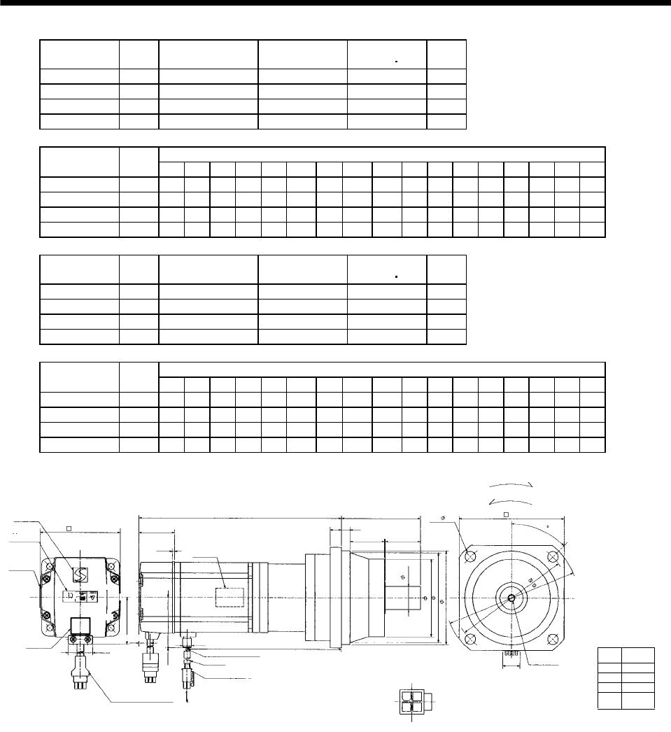
7 - 274
7. OUTLINE DIMENSION DRAWINGS
Model Output
[W]
Reduction Gear
Model Reduction Ratio Inertia Moment
WK2[oz in2]
Mass
[lb]
HC-MFS73G2 750 BK3-05B-08MEKA 1/5 5.32 13.89
HC-MFS73G2 750 BK4-09B-08MEKA 1/9 5.36 18.96
HC-MFS73G2 750 BK5-20B-08MEKA 1/20 5.55 26.46
HC-MFS73G2 750 BK5-29B-08MEKA 1/29 4.97 26.46
Variable Dimensions [in]
Model Output
[W] LA LB LC LD LE LF LG LH LK L LR KL LZ Q S P R
HC-MFS73G2 750 4.53 3.74 5.31 3.94 0.31 2.953 0.39 3.346 1.378 8.35 3.35 6.17 0.35 1.57 0.98 M6 0.47
HC-MFS73G2 750 5.31 4.33 6.10 4.53 0.31 3.543 0.47 3.937 1.575 9.45 3.94 7.27 0.43 1.97 1.26 M8 0.63
HC-MFS73G2 750 5.91 4.92 6.89 5.12 0.39 4.134 0.59 4.528 1.693 9.76 4.53 7.59 0.55 2.36 1.57 M10 0.79
HC-MFS73G2 750 5.91 4.92 6.89 5.12 0.39 4.134 0.59 4.528 1.693 9.76 4.53 7.59 0.55 2.36 1.57 M10 0.79
Model Output
[W]
Reduction Gear
Model Reduction Ratio Inertia Moment
WK2[oz in2]
Mass
[lb]
HC-KFS73G2 750 BK3-05B-08MEKA 1/5 10.30 13.89
HC-KFS73G2 750 BK4-09B-08MEKA 1/9 10.33 18.96
HC-KFS73G2 750 BK5-20B-08MEKA 1/20 10.53 26.46
HC-KFS73G2 750 BK5-29B-08MEKA 1/29 9.95 26.46
Variable Dimensions [in]
Model Output
[W] LA LB LC LD LE LF LG LH LK L LR KL LZ Q S P R
HC-KFS73G2 750 4.53 3.74 5.31 3.94 0.31 2.953 0.39 3.346 1.378 8.35 3.35 6.17 0.35 1.57 0.98 M6 0.47
HC-KFS73G2 750 5.31 4.33 6.10 4.53 0.31 3.543 0.47 3.937 1.575 9.45 3.94 7.27 0.43 1.97 1.26 M8 0.63
HC-KFS73G2 750 5.91 4.92 6.89 5.12 0.39 4.134 0.59 4.528 1.693 9.76 4.53 7.59 0.55 2.36 1.57 M10 0.79
HC-KFS73G2 750 5.91 4.92 6.89 5.12 0.39 4.134 0.59 4.528 1.693 9.76 4.53 7.59 0.55 2.36 1.57 M10 0.79
Power supply
connector pin
connection list
1
2
3
4
Pin No. Application
Phase U
Phase V
Phase W
Earth
[Unit: in]
BC11910*
Logo plate
Motor plate
With connector 1-172169-9
(AMP)
Encoder cable11.8in
Motor plate
(Opposite side)
LG
LR
L
1.535 LE
LK Q
0.390 KL
0.992
1.917
Bottom
Top
TUV plate
Caution plate
3.228
For reverse rotation command
For forward rotation command
Rotation direction
LD
LA
P threads, depth R
Sh6
LF
LBh7
0.787
13
24
Arrow A
4 - LZ
Top
Bottom
LC
2.287
45
5557-04R-210 (Receptacle)
5556PBTL (Female terminal)
Power supply connector (Molex)
Protective tube
Power supply lead 4-AWG1911.8in
LH
0.106
Arrow A
Bottom
Top
Bottom
Top
0.433
(********)
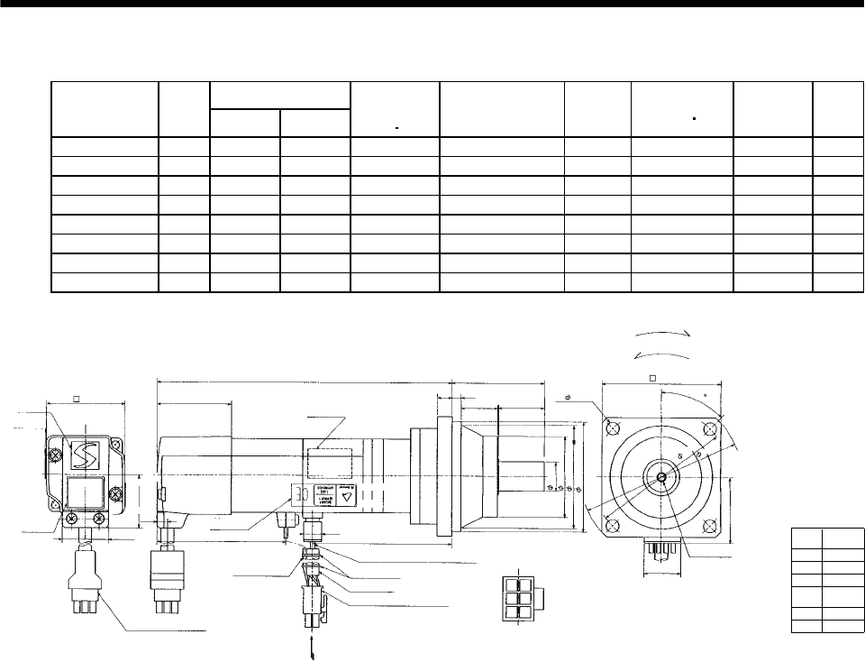
7 - 275
7. OUTLINE DIMENSION DRAWINGS
(b) With electromagnetic brake
Variable Dimensions [in]
Model Output
[W] LKL
Brake static
friction torque
[oz in]
Reduction Gear
Model
Reduction
Ratio
Inertia Moment
WK2[oz in2]Backlash Mass
[lb]
HC-MFS053BG2 50 6.22 3.07 45 BK1-05B-A5MEKA 1/5 0.38 3 min. max. 4.0
HC-MFS053BG2 50 6.85 3.70 45 BK1-09B-A5MEKA 1/9 0.34 3 min. max. 4.6
HC-MFS053BG2 50 6.85 3.70 45 BK1-20B-A5MEKA 1/20 0.39 3 min. max. 4.9
HC-MFS053BG2 50 6.85 3.70 45 BK1-29B-A5MEKA 1/29 0.33 3 min. max. 4.9
HC-KFS053BG2 50 6.22 3.07 45 BK1-05B-A5MEKA 1/5 0.57 3 min. max. 4.0
HC-KFS053BG2 50 6.85 3.70 45 BK1-09B-A5MEKA 1/9 0.54 3 min. max. 4.6
HC-KFS053BG2 50 6.85 3.70 45 BK1-20B-A5MEKA 1/20 0.59 3 min. max. 4.9
HC-KFS053BG2 50 6.85 3.70 45 BK1-29B-A5MEKA 1/29 0.52 3 min. max. 4.9
[Unit: in]
Logo plate
Motor plate
With connector 1-172169-9
(AMP)
Encoder cable 11.8in
Motor plate
(Opposite side)
L
2.579 0.390
KL
Top
Bottom
Top
TUV plate
Caution plate
For reverse rotation command
For forward rotation command
Rotation direction
2.756
14
25
Bottom
45
5557-06R-210 (Receptacle)
5556PBTL (Female terminal)
Power supply connector (Molex)
Protective tube
Power supply lead 4-AWG19 11.8in
Arrow A
36
Arrow A
Break lead
2-0.3 11.8in
2
1.5941.654
0.268
0.992
1.130
4- 0.260
0.315
2.382
0.256
0.906 0.984
1.890
2.559
2.362
0.630
M4 threads, depth
0.315
0.787
1.406
3.150
3.740
BC11911*
(BC11920*)
Power supply
connector pin
connection list
1
2
3
4
Pin No. Application
Phase U
Phase V
Phase W
Earth
5
6
B1
B2
Bottom Bottom
Top
Top
Bottom
Top
Banding band
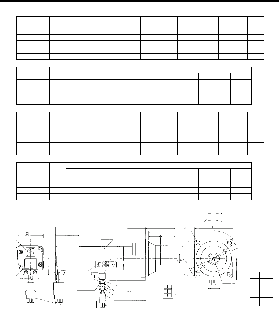
7 - 276
7. OUTLINE DIMENSION DRAWINGS
Model Output
[W]
Brake static
friction torque
[oz in]
Reduction Gear
Model Reduction Ratio Inertia Moment
WK2[oz in2]Backlash Mass
[lb]
HC-MFS13BG2 100 45 BK1-05B-01MEKA 1/5 0.44 3 min. max. 4.2
HC-MFS13BG2 100 45 BK1-09B-01MEKA 1/9 0.40 3 min. max. 4.9
HC-MFS13BG2 100 45 BK2-20B-01MEKA 1/20 0.68 3 min. max. 7.5
HC-MFS13BG2 100 45 BK2-29B-01MEKA 1/29 0.53 3 min. max. 7.5
Variable Dimensions [in]
Model Output
[W] LA LB LC LD LE LF LG LH LK L LR KL LZ Q S P R
HC-MFS13BG2 100 3.15 2.56 3.74 2.76 0.24 1.89 0.31 2.362 0.906 6.81 2.17 3.66 0.26 0.98 0.63 M4 0.31
HC-MFS13BG2 100 3.15 2.56 3.74 2.76 0.24 1.89 0.31 2.362 0.906 7.44 2.17 4.29 0.26 0.98 0.63 M4 0.31
HC-MFS13BG2 100 3.94 3.15 4.53 3.35 0.24 2.559 0.39 2.913 1.299 7.68 2.95 4.53 0.26 1.38 0.79 M5 0.39
HC-MFS13BG2 100 3.94 3.15 4.53 3.35 0.24 2.559 0.39 2.913 1.299 7.68 2.95 4.53 0.26 1.38 0.79 M5 0.39
Model Output
[W]
Brake static
friction torque
[oz in]
Reduction Gear
Model Reduction Ratio Inertia Moment
WK2[oz in2]Backlash Mass
[lb]
HC-KFS13BG2 100 45 BK1-05B-01MEKA 1/5 0.74 3 min. max. 4.2
HC-KFS13BG2 100 45 BK1-09B-01MEKA 1/9 0.71 3 min. max. 4.9
HC-KFS13BG2 100 45 BK2-20B-01MEKA 1/20 0.98 3 min. max. 7.5
HC-KFS13BG2 100 45 BK2-29B-01MEKA 1/29 0.84 3 min. max. 7.5
Variable Dimensions [in]
Model Output
[W] LA LB LC LD LE LF LG LH LK L LR KL LZ Q S P R
HC-KFS13BG2 100 3.15 2.56 3.74 2.76 0.24 1.89 0.31 2.362 0.906 6.81 2.17 3.66 0.26 0.98 0.63 M4 0.31
HC-KFS13BG2 100 3.15 2.56 3.74 2.76 0.24 1.89 0.31 2.362 0.906 7.44 2.17 4.29 0.26 0.98 0.63 M4 0.31
HC-KFS13BG2 100 3.94 3.15 4.53 3.35 0.24 2.559 0.39 2.913 1.299 7.68 2.95 4.53 0.26 1.38 0.79 M5 0.39
HC-KFS13BG2 100 3.94 3.15 4.53 3.35 0.24 2.559 0.39 2.913 1.299 7.68 2.95 4.53 0.26 1.38 0.79 M5 0.39
[Unit: in]
BC11912*
Logo plate
Motor plate
Encoder cable 11.8in
Motor plate
(Opposite side)
LG
LR
L
LE
LK Q
2.579 0.390
KL
Top
Bottom
Top
TUV plate
Caution plate
Top
For reverse rotation command
For forward rotation command
Rotation direction
LD
P threads, depth R
Sh6
LF
LBh7
0.787
14
25
4 - LZ
Top
Bottom
LC
45
5557-06R-210 (Receptacle)
5556PBTL (Female terminal)
Power supply connector (Molex)
Protective tube
Power supply lead 4-AWG19 11.8in
LH
Arrow A
1.406
36
Arrow A
(BC11921*)
Break lead
2-0.3 11.8in
2
With connector
1-172169-9 (AMP)
LA
1.594
1.654
0.268
0.992
1.130
Power supply
connector pin
connection list
1
2
3
4
Pin No. Application
Phase U
Phase V
Phase W
Earth
5
6
B1
B2
Bottom Bottom
Top
Bottom
Banding band
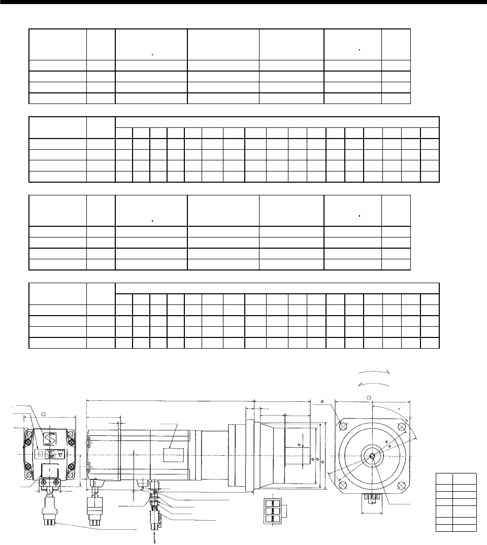
7 - 277
7. OUTLINE DIMENSION DRAWINGS
Model Output
[W]
Brake static
friction torque
[oz in]
Reduction Gear
Model Reduction Ratio Inertia Moment
WK2[oz in2]
Mass
[lb]
HC-MFS23BG2 200 184 BK1-05B-02MEKA 1/5 1.31 6.0
HC-MFS23BG2 200 184 BK2-09B-02MEKA 1/9 1.40 9.0
HC-MFS23BG2 200 184 BK3-20B-02MEKA 1/20 2.21 12.3
HC-MFS23BG2 200 184 BK3-29B-02MEKA 1/29 1.77 12.3
Variable Dimensions [in]
Model Output
[W] LA LB LC LD LE LF LG LH LK L LR KL LZ Q S P R
HC-MFS23BG2 200 3.15 2.56 3.74 2.76 0.24 1.89 0.31 2.362 0.906 7.44 2.17 4.20 0.26 0.98 0.63 M4 0.31
HC-MFS23BG2 200 3.94 3.15 4.53 3.35 0.24 2.559 0.39 2.913 1.299 8.15 2.95 4.91 0.26 1.38 0.79 M5 0.39
HC-MFS23BG2 200 4.53 3.74 5.31 3.94 0.31 2.953 0.39 3.346 1.378 8.35 3.35 5.10 0.35 1.57 0.98 M6 0.47
HC-MFS23BG2 200 4.53 3.74 5.31 3.94 0.31 2.953 0.39 3.346 1.378 8.35 3.35 5.10 0.35 1.57 0.98 M6 0.47
Model Output
[W]
Brake static
friction torque
[oz in]
Reduction Gear
Model Reduction Ratio Inertia Moment
WK2[oz in2]
Mass
[lb]
HC-KFS23BG2 200 184 BK1-05B-02MEKA 1/5 2.242 6.0
HC-KFS23BG2 200 184 BK2-09B-02MEKA 1/9 2.351 9.0
HC-KFS23BG2 200 184 BK3-20B-02MEKA 1/20 3.171 12.3
HC-KFS23BG2 200 184 BK3-29B-02MEKA 1/29 2.734 12.3
Variable Dimensions [in]
Model Output
[W] LA LB LC LD LE LF LG LH LK L LR KL LZ Q S P R
HC-KFS23BG2 200 3.15 2.56 3.74 2.76 0.24 1.89 0.31 2.362 0.906 7.44 2.17 4.20 0.26 0.98 0.63 M4 0.31
HC-KFS23BG2 200 3.94 3.15 4.53 3.35 0.24 2.559 0.39 2.913 1.299 8.15 2.95 4.91 0.26 1.38 0.79 M5 0.39
HC-KFS23BG2 200 4.53 3.74 5.31 3.94 0.31 2.953 0.39 3.346 1.378 8.35 3.35 5.10 0.35 1.57 0.98 M6 0.47
HC-KFS23BG2 200 4.53 3.74 5.31 3.94 0.31 2.953 0.39 3.346 1.378 8.35 3.35 5.10 0.35 1.57 0.98 M6 0.47
[Unit: in]
BC11913*
Logo plate
Encoder cable11.8in
Motor plate
(Opposite side)
LG
LR
L
LE
LK Q
2.667 0.390 KL
Top
Bottom
Top
TUV plate
Caution plate
For reverse rotation command
For forward rotation command
Rotation direction
LD
P threads, depth R
Sh6
LF
LBh7
0.787
14
25
4 - LZ
Top
Bottom
LC
45
5557-06R-210 (Receptacle)
5556PBTL (Female terminal)
Power supply connector (Molex)
Protective tube
Power supply lead 4-AWG19 11.8in
LH
Arrow A
36
Arrow A
(BC11922*)
Break lead
2-0.3 11.8in
2
With connector
1-172169-9
(AMP)
LA
1.685
1.614
2.441
0.106
0.417
0.992
1.512
Power supply
connector pin
connection list
1
2
3
4
Pin No. Application
Phase U
Phase V
Phase W
Earth
5
6
B1
B2
Bottom
Bottom
Top
Motor plate
Banding band
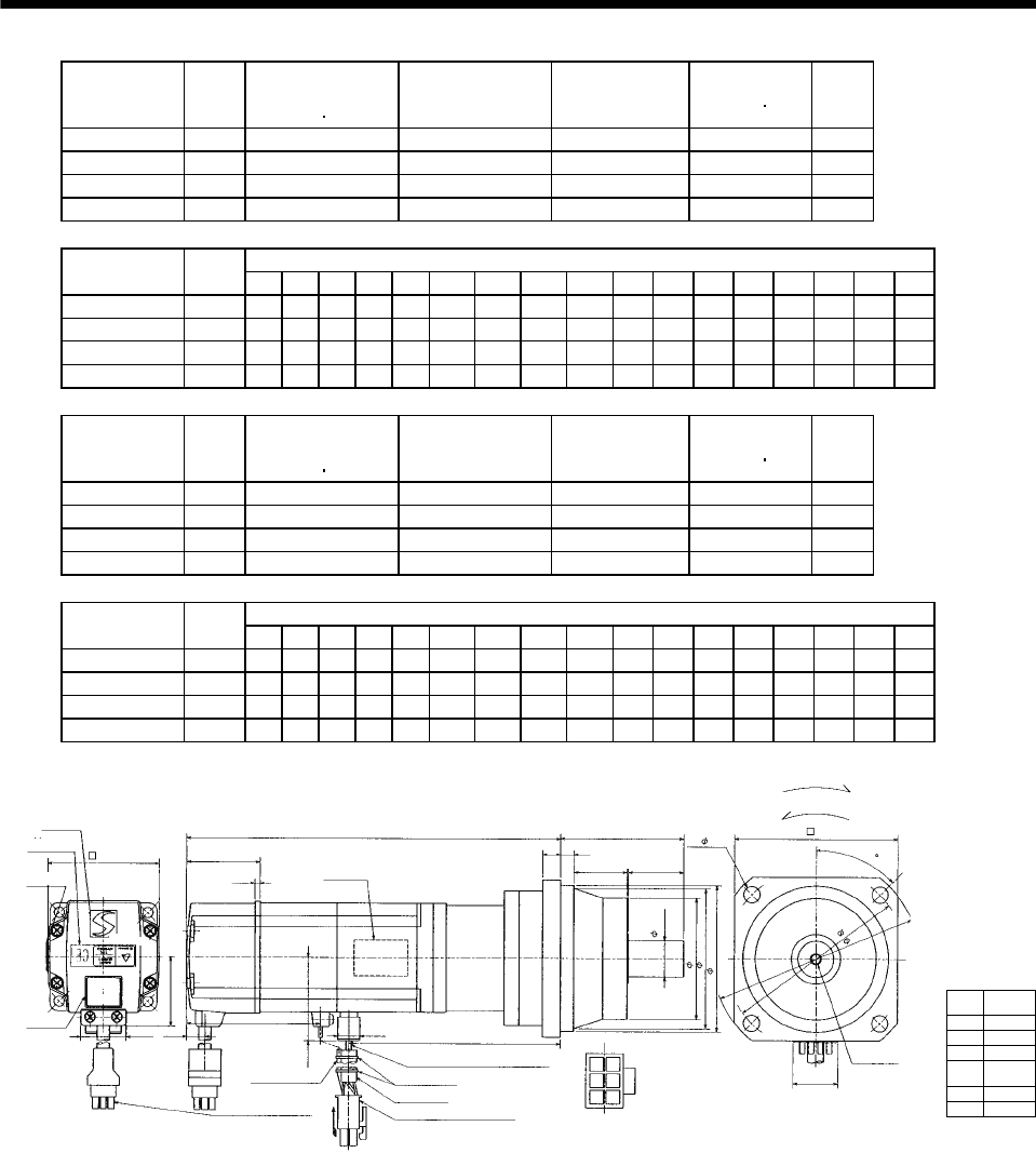
7 - 278
7. OUTLINE DIMENSION DRAWINGS
Model Output
[W]
Brake static
friction torque
[oz in]
Reduction Gear
Model Reduction Ratio Inertia Moment
WK2[oz in2]
Mass
[lb]
HC-MFS43BG2 400 184 BK2-05B-04MEKA 1/5 1.88 9.5
HC-MFS43BG2 400 184 BK3-09B-04MEKA 1/9 2.03 13.0
HC-MFS43BG2 400 184 BK4-20B-04MEKA 1/20 2.59 17.9
HC-MFS43BG2 400 184 BK4-29B-04MEKA 1/29 2.11 17.9
Variable Dimensions [in]
Model Output
[W] LA LB LC LD LE LF LG LH LK L LR KL LZ Q S P R
HC-MFS43BG2 400 3.94 3.15 4.53 3.35 0.24 2.559 0.39 2.913 1.299 8.50 2.95 5.18 0.26 1.38 0.79 M5 0.39
HC-MFS43BG2 400 4.53 3.74 5.31 3.94 0.31 2.953 0.39 3.346 1.378 9.33 3.35 6.01 0.35 1.57 0.98 M6 0.47
HC-MFS43BG2 400 5.31 4.33 6.10 4.53 0.31 3.543 0.47 3.937 1.575 9.57 3.94 6.24 0.43 1.97 1.26 M8 0.63
HC-MFS43BG2 400 5.31 4.33 6.10 4.53 0.31 3.543 0.47 3.937 1.575 9.57 3.94 6.24 0.43 1.97 1.26 M8 0.63
Model Output
[W]
Brake static
friction torque
[oz in]
Reduction Gear
Model Reduction Ratio Inertia Moment
WK2[oz in2]
Mass
[lb]
HC-KFS43BG2 400 184 BK2-05B-04MEKA 1/5 3.609 9.5
HC-KFS43BG2 400 184 BK3-09B-04MEKA 1/9 3.773 13.0
HC-KFS43BG2 400 184 BK4-20B-04MEKA 1/20 4.319 17.9
HC-KFS43BG2 400 184 BK4-29B-04MEKA 1/29 3.882 17.9
Variable Dimensions [in]
Model Output
[W] LA LB LC LD LE LF LG LH LK L LR KL LZ Q S P R
HC-KFS43BG2 400 3.94 3.15 4.53 3.35 0.24 2.559 0.39 2.913 1.299 8.50 2.95 5.18 0.26 1.38 0.79 M5 0.39
HC-KFS43BG2 400 4.53 3.74 5.31 3.94 0.31 2.953 0.39 3.346 1.378 9.33 3.35 6.01 0.35 1.57 0.98 M6 0.47
HC-KFS43BG2 400 5.31 4.33 6.10 4.53 0.31 3.543 0.47 3.937 1.575 9.57 3.94 6.24 0.43 1.97 1.26 M8 0.63
HC-KFS43BG2 400 5.31 4.33 6.10 4.53 0.31 3.543 0.47 3.937 1.575 9.57 3.94 6.24 0.43 1.97 1.26 M8 0.63
Power supply
connector pin
connection list
1
2
3
4
Pin No. Application
Phase U
Phase V
Phase W
Earth
BC11914*
(BC11923)*
5
6
B1
B2
[Unit: in]
Logo plate
Motor plate
With connector 1-172169-9
(AMP)
Encoder cable 11.8in
Motor plate
(Opposite side)
LG
LRL
LE
LK Q
2.677
0.390 KL
Bottom
Top
TUV plate
Caution plate
For reverse rotation command
For forward rotation command
Rotation direction
LD
LA
P threads, depth R
Sh6
LF
LBh7
0.787
14
25
Arrow A
4 - LZ
Top
Bottom
LC
1.685
45
5557-06R-210 (Receptacle)
5556PBTL (Female terminal)
Power supply connector (Molex)
Protective tube
Power supply lead 4-AWG19 11.8in
LH
Arrow A
Break cable
VCTF 2-0.3 11.8in
2
36
1.614
2.441
0.106
0.417
0.992
1.512
Top
Bottom
Top
Bottom
Banding band
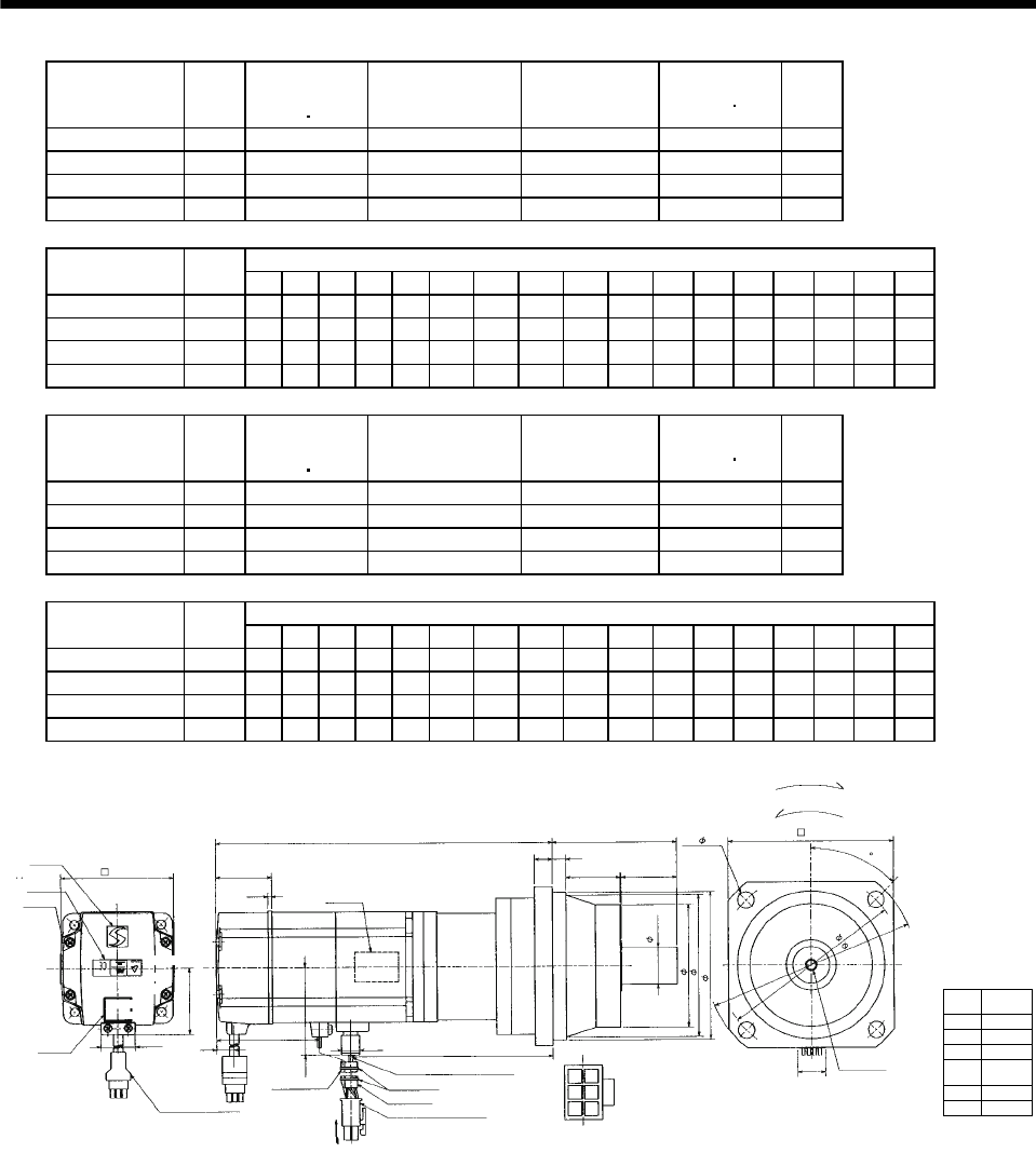
7 - 279
7. OUTLINE DIMENSION DRAWINGS
Model Output
[W]
Brake static
friction torque
[oz in]
Reduction Gear
Model Reduction Ratio Inertia Moment
WK2[oz in2]
Mass
[lb]
HC-MFS73BG2 750 340 BK3-05B-08MEKA 1/5 6.00 16.1
HC-MFS73BG2 750 340 BK4-09B-08MEKA 1/9 6.04 21.2
HC-MFS73BG2 750 340 BK5-20B-08MEKA 1/20 6.24 28.7
HC-MFS73BG2 750 340 BK5-29B-08MEKA 1/29 5.66 28.7
Variable Dimensions [in]
Model Output
[W] LA LB LC LD LE LF LG LH LK L LR KL LZ Q S P R
HC-MFS73BG2 750 4.53 3.74 5.31 3.94 0.31 2.953 0.39 3.346 1.378 9.74 3.35 6.17 0.35 1.57 0.98 M6 0.47
HC-MFS73BG2 750 5.31 4.33 6.10 4.53 0.31 3.543 0.47 3.937 1.575 11.16 3.94 7.59 0.43 1.97 1.26 M8 0.63
HC-MFS73BG2 750 5.91 4.92 6.89 5.12 0.39 4.134 0.59 4.528 1.693 11.16 4.53 7.59 0.55 2.36 1.57 M10 0.79
HC-MFS73BG2 750 5.91 4.92 6.89 5.12 0.39 4.134 0.59 4.528 1.693 11.16 4.53 7.59 0.55 2.36 1.57 M10 0.79
Model Output
[W]
Brake static
friction torque
[oz in]
Reduction Gear
Model Reduction Ratio Inertia Moment
WK2[oz in2]
Mass
[lb]
HC-KFS73BG2 750 340 BK3-05B-08MEKA 1/5 10.98 16.1
HC-KFS73BG2 750 340 BK4-09B-08MEKA 1/9 11.02 21.2
HC-KFS73BG2 750 340 BK5-20B-08MEKA 1/20 11.21 28.7
HC-KFS73BG2 750 340 BK5-29B-08MEKA 1/29 10.63 28.7
Variable Dimensions [in]
Model Output
[W] LA LB LC LD LE LF LG LH LK L LR KL LZ Q S P R
HC-KFS73BG2 750 4.53 3.74 5.31 3.94 0.31 2.953 0.39 3.346 1.378 9.74 3.35 6.17 0.35 1.57 0.98 M6 0.47
HC-KFS73BG2 750 5.31 4.33 6.10 4.53 0.31 3.543 0.47 3.937 1.575 10.85 3.94 7.27 0.43 1.97 1.26 M8 0.63
HC-KFS73BG2 750 5.91 4.92 6.89 5.12 0.39 4.134 0.59 4.528 1.693 11.16 4.53 7.59 0.55 2.36 1.57 M10 0.79
HC-KFS73BG2 750 5.91 4.92 6.89 5.12 0.39 4.134 0.59 4.528 1.693 11.16 4.53 7.59 0.55 2.36 1.57 M10 0.79
Power supply
connector pin
connection list
1
2
3
4
Pin No. Application
Phase U
Phase V
Phase W
Earth
BC11915*
5
6
B1
B2
[Unit: in]
Logo plate
Motor plate
With connector 1-172169-9
(AMP)
Encoder cable 11.8in
Motor plate
(Opposite side)
LG
LRL
LE
LK Q
0.390 KL
Bottom
Top
TUV plate
Caution plate
For reverse rotation command
For forward rotation command
Rotation direction
LD
LA
P threads, depth R
Sh6
LF
LBh7
0.787
14
25
Arrow A
4 - LZ
Top
Bottom
LC
2.287
45
5557-06R-210 (Receptacle)
5556PBTL (Female terminal)
Power supply connector (Molex)
Protective tube
Power supply lead 4-AWG19 11.8in
LH
Arrow A
Break cable
VCTF 2-0.3 11.8in
2
36
1.535
3.228
0.106
0.992
1.917
0.433
2.835
Bottom
Top
Top
Bottom
(********)
Banding band
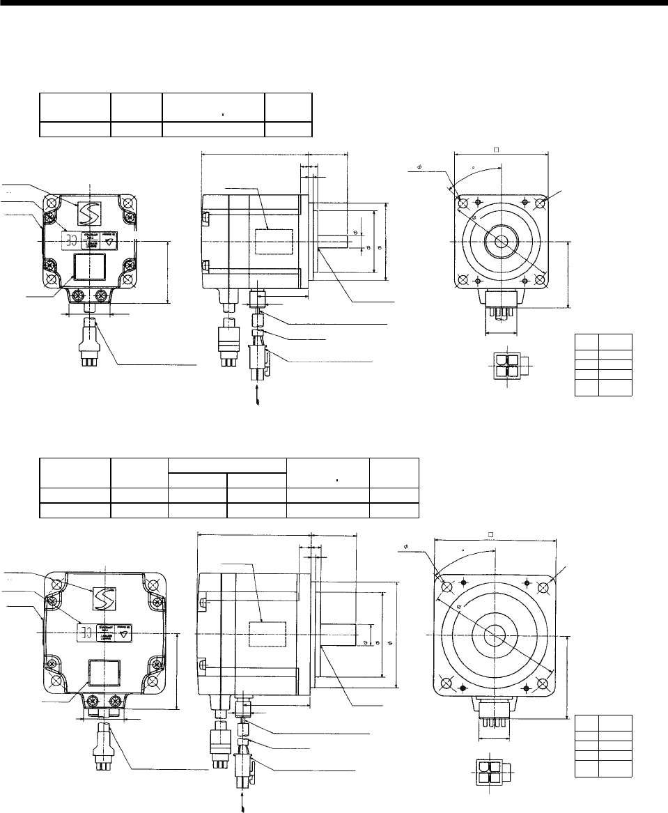
7 - 280
7. OUTLINE DIMENSION DRAWINGS
7.2.12 HC-UFS 3000r/min series
(1) Standard (without electromagnetic brake)
Model Output
[W]
Inertia Moment
WK2[oz in2]
Mass
[lb]
HC-UFS13 100 0.36 1.76
Power supply
connector pin
connection list
1
2
3
4
Pin No. Application
Phase U
Phase V
Phase W
Earth
[Unit: in]
BC11876*
0.787
5557-04R-210 (Receptacle)
5556PBTL (Female terminal)
With connector 1-172169-9
(AMP)
Arrow A
45
1.685
Bottom
Top
Protective tube
Motor plate
(Opposite side)
1.969
2.362
0.315
Logo plate
Power supply connector (Molex)
Encoder cable 11.8in
Motor plate
Caution plate
Bottom
Top Bottom
Top
0.984
0.118
0.197
2.756
0.390
1.299
1.059
1.575
4- 0.228
Power supply lead 4-AWG19 11.8in
TUV plate
Arrow A
Top
1
24
3
0.236
1.575
Oil seal
SC10207
R5
2.756
Bottom
Variable Dimensions [in]
Model Output
[W] LKL
Inertia Moment
WK2[oz in2]
Mass
[lb]
HC-UFS23 200 3.03 1.72 1.32 3.31
HC-UFS43 400 3.62 2.31 2.00 3.75
Power supply
connector pin
connection list
1
2
3
4
Pin No. Application
Phase U
Phase V
Phase W
Earth
[Unit: in]
BC11877*
0.787
5557-04R-210 (Receptacle)
5556PBTL (Female terminal)
With connector 1-172169-9
(AMP)
Arrow A
2.165
Bottom
Top
Protective tube
Motor plate
(Opposite side)
2.756
3.150
0.551
Logo plate
Power supply connector (Molex)
Encoder cable 11.8in
Motor plate
Caution plate
Bottom
Top
Bottom
Top
KL
1.181
0.118
0.315
L
0.390
1.059
1.969
4- 0.260
Power supply lead 4-AWG19 11.8in
TUV plate
Arrow A
Top
Bottom
1
24
3
0.256
2.205
Oil seal
SC15307
R7
3.543
45
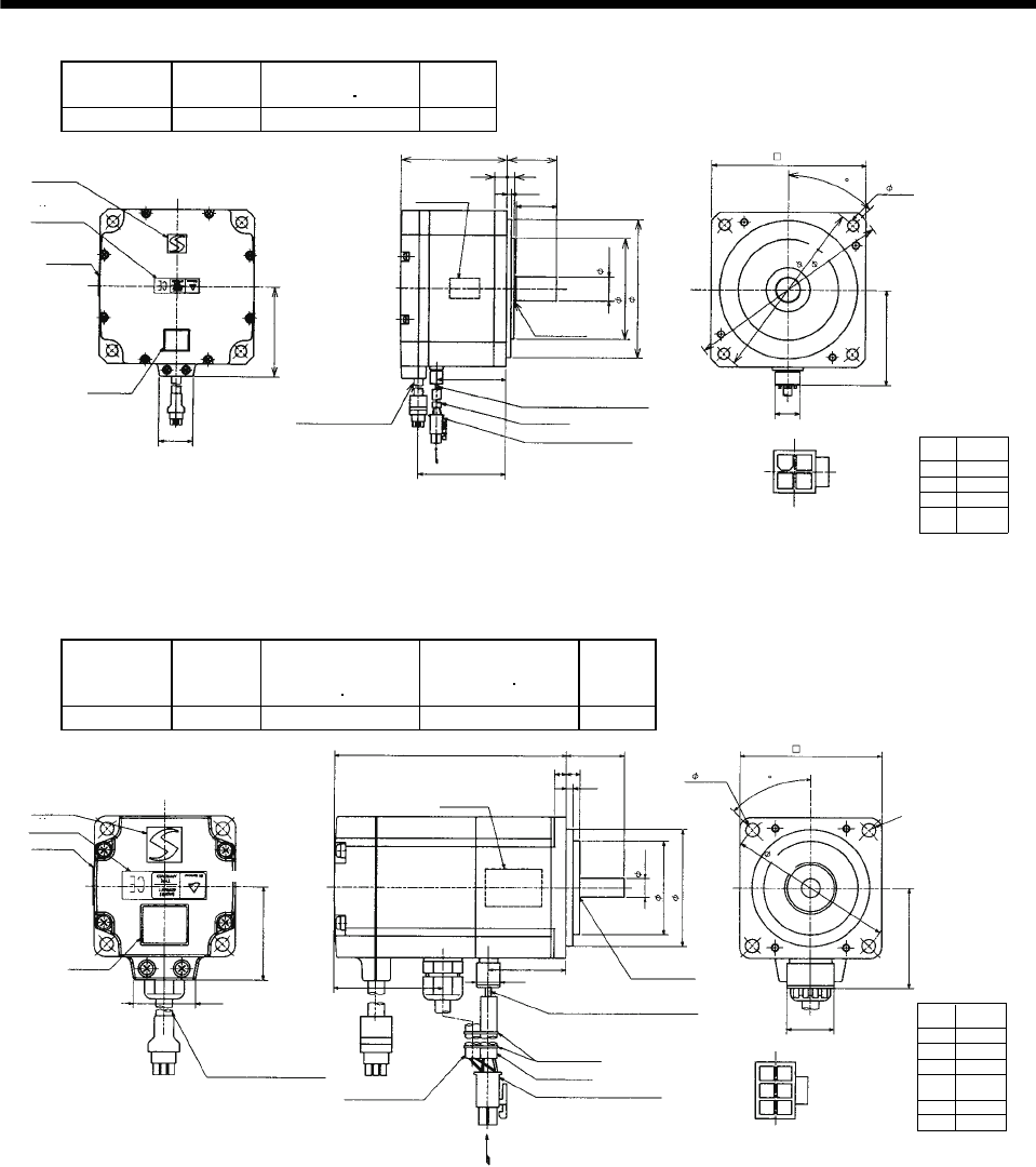
7 - 281
7. OUTLINE DIMENSION DRAWINGS
Model Output
[W]
Inertia Moment
WK2[oz in2]
Mass
[lb]
HC-UFS73 750 32.26 11.02
Power supply
connector pin
connection list
1
2
3
4
Pin No. Application
Phase U
Phase V
Phase W
Earth
[Unit: in]
BC11878*
0.787
5557-04R-210 (Receptacle)
5556PBTL (Female terminal)
With connector
1-172169-9 (AMP)
Arrow A
2.992
Bottom
Top
Protective tube
Motor plate
(Opposite side)
4.331
4.843
0.748
Logo plate
Power supply connector (Molex)
Encoder cable 11.8in
Motor plate
Caution plate
Bottom
Top
Bottom
Top
1.575
0.138
0.394
3.346
2.185
1.059
2.835
4- 0.354
Power supply lead 4-AWG19 11.8in
TUV plate
Arrow A
Top
Bottom
1
24
3
0.236
3.150
Oil seal
SC20357
1.280
2.765
5.709
6.496
45
(2) With electromagnetic brake
Model Output
[W]
Brake static
friction torque
[oz in]
Inertia Moment
WK2[oz in2]
Mass
[lb]
HC-UFS13B 100 45.32 0.41 2.65
Power supply
connector pin
connection list
1
2
3
4
Pin No. Application
Phase U
Phase V
Phase W
Earth
[Unit: in]
BC11884*
5557-06R-210 (Receptacle)
5556PBTL (Female terminal)
With connector
1-172169-9 (AMP)
Arrow A
Bottom
Top
Protective tube
Motor plate
(Opposite side)
Logo plate
Power supply connector (Molex)
Encoder cable 11.8in
Motor plate
Caution plate
Bottom
Top Bottom
Top
3.937
Power supply lead 4-AWG19 11.8in
TUV plate
Arrow A
Top
1
25
4
Oil seal
SC10207
Bottom
Break cable
VCTF 2-0.3 11.8in
236
R5
5
6
B1
B2
1.059
1.575
0.984
0.118
0.197 0.236
1.969
0.315
1.575
0.390
1.299
1.839
2.362
4- 0.228
2.756
0.787
1.685
45
Banding band
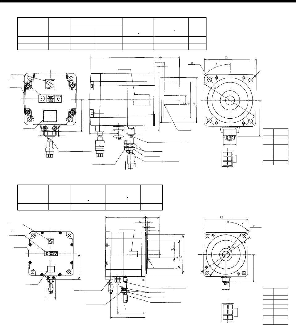
7 - 282
7. OUTLINE DIMENSION DRAWINGS
Variable Dimensions [in]
Model Output
[W] LKL
Brake static
friction torque
[oz in]
Inertia Moment
WK2[oz in2]
Mass
[lb]
HC-UFS23B 200 4.37 1.72 184.1 1.77 4.85
HC-UFS43B 400 4.96 2.31 184.1 2.44 5.29
Power supply
connector pin
connection list
1
2
3
4
Pin No. Application
Phase U
Phase V
Phase W
Earth
[Unit: in]
BC11885*
0.787
5557-06R-210 (Receptacle)
5556PBTL (Female terminal)
With connector
1-172169-9 (AMP)
Arrow A
2.165
Bottom
Top
Protective tube
Motor plate
(Opposite side)
Logo plate
Power supply connector (Molex)
Encoder cable 11.8in
Motor plate
Caution plate
Bottom
Top
Bottom
Top
L
0.390
1.059
1.969
Power supply lead 4-AWG19 11.8in
TUV plate
Arrow
A
Top
1
25
4
Oil seal
SC15307
KL
Bottom
Break cable
VCTF 2-0.3 11.8in
236
R7
5
6
B1
B2
1.181
0.118
0.315 0.256
2.756
0.551
2.205
1.858
3.150
4- 0.260
3.543
45
Banding band
Model Output
[W]
Brake static
friction torque
[oz in]
Inertia Moment
WK2[oz in2]
Mass
[lb]
HC-UFS73B 750 339.87 33.35 13.67
Power supply
connector pin
connection list
1
2
3
4
Pin No. Application
Phase U
Phase V
Phase W
Earth
[Unit: in]
BC11886*
5557-06R-210 (Receptacle)
5556PBTL (Female terminal)
With connector
1-172169-9 (AMP)
Arrow A
45
Bottom
Top
Protective tube
Motor plate
(Opposite side)
Logo plate
Power supply connector (Molex)
Encoder cable 11.8in
Motor plate
Caution plate
Bottom
Top
Bottom
Top
2.992
Power supply lead 4-AWG19 11.8in
TUV plate
Arrow A
Top
1
25
4
Oil seal
SC20357
Bottom
Break cable
VCTF 2-0.3 11.8in
2
36 5
6
B1
B2
3.780
2.185
1.059
2.835
1.575
0.138
0.394 0.236
1.280
4.370
4.331
0.748
3.150
0.787
2.992
4.843
4- 0.354
5.709
6.496
Banding band
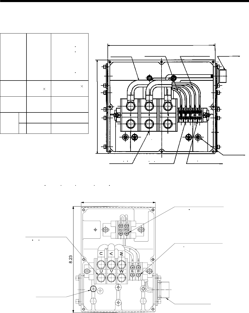
7 - 283
7. OUTLINE DIMENSION DRAWINGS
7.2.13 HA-LFS series
Terminal box detail diagram
Motor Model
HA-LFS15K1
HA-LFS20K1
HA-LFS22K1M
HA-LFS15K14
HA-LFS20K14
HA-LFS22K1M4
HA-LFS30K1M4
HA-LFS30K24
HA-LFS37K24
HA-LFS25K1 to 37K1
HA-LFS30K1M 37K1M
HA-LFS30K2 37K2
HA-LFS25K14 to 37K14
HA-LFS37K1M4
to 50K1M4
HA-LFS45K24 55K24
Motor power
supply lead size
0.0124in2
(AWG8)
2 parallel
0.0341in2(AWG4)
2 parallel
Motor power
supply terminal
block screw size
M8 M10
LA 8.661 10.472
Terminal
box
dimensions
(in) LB 8.268 9.055
LB
Cooling fan terminal block
(BU BV BW) M4 screw
BG71994C
LA
Motor power
supply lead
Cooling fan lead
0.9SQ or equivalent AWG#
Thermal protector lead
0.5SQ or equivalent AWG#
Encoder connector
MS3102A20-29P
Earth terminal
M6 screw
Thermal protector terminal block
(OHS1 OHS2) M4 screw
Motor power supply
terminal block (U V W)
[Unit: in]
HA-LFS 601 701M 6014 701M4 11K2 11K24 terminal box detail diagram
(Note)[Unit: in]
BG72707C
5.75 Thermal sensor terminal
(OHS1 OHS2) M4 screw
Cooling fan terminal block
(BU BV) M4 screw
Encoder connector
MS3102A20-29P
Earth terminal
M6 screw
Motor power supply
terminal block
(U V W) M6 screw
Note. The dimensions without tolerances are reference dimensions.
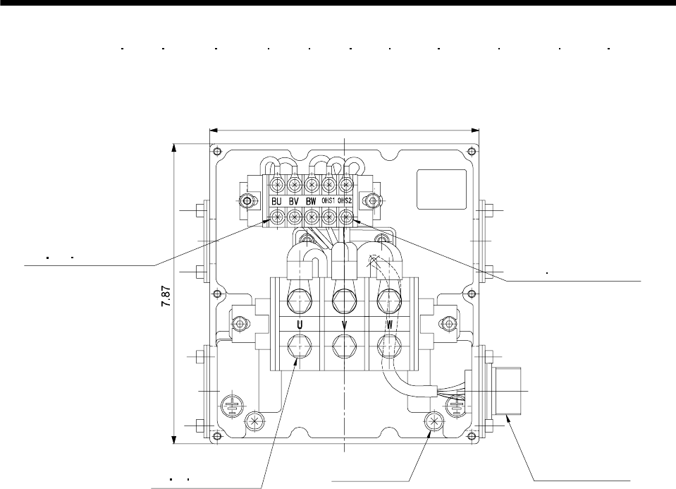
7 - 284
7. OUTLINE DIMENSION DRAWINGS
HA-LFS 801 12K1 11K1M 15K1M 15K2 22K2 8014 12K14 11K1M4 15K1M4 15K24 22K24
terminal box detail diagram
(Note)[Unit: in]
7.09
BG72706
Thermal sensor terminal
(OHS1 OHS2) M4 screw
Cooling fan terminal block
(BU BV BW) M4 screw
Encoder connector
MS3102A20-29P
Earth terminal
M6 screw
Motor power supply
terminal block
(U V W) M8 screw
Note. The dimensions without tolerances are reference dimensions.
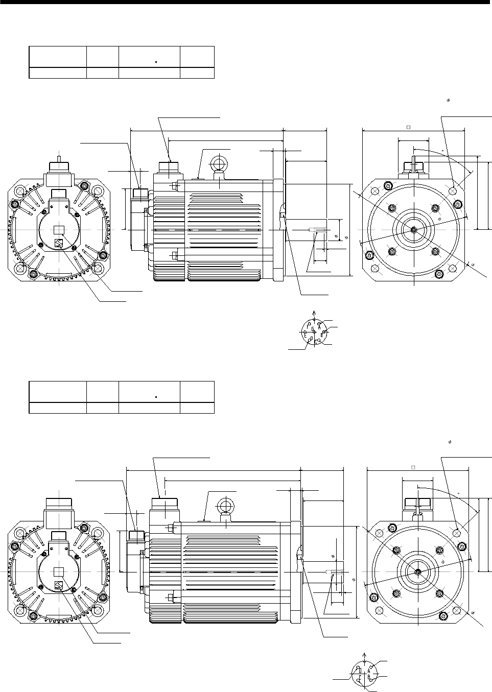
7 - 285
7. OUTLINE DIMENSION DRAWINGS
(1) Standard (without electromagnetic brake, without reduction gear)
Model Output
[kW]
Inertia Moment
WK2[oz in2]
Mass
[lb]
HA-LFS502 5 404.59 61.73
Caution plate
Logo plate
Top
Bottom
3.209
Encoder connector
MS3102A20-29P
11.811
0.768
8.858
3.15
0.118
0.787
3.346
Motor plate
Top Bottom
Power supply connector
CE05-2A24-10P
Oil seal
S50689B
7.089
1.654
0.984
0.205
M8 screw
Motor flange direction
Power supply connector layout
CE05-2A24-10P
Earth
W
V
U
7.874
45
Use hexagon socket
head cap screw.
4- 0.571
9.843
8.465
5.748
2.362
5.276
BC12835A
[Unit: in]
Model Output
[kW]
Inertia Moment
WK2[oz in2]
Mass
[lb]
HA-LFS702 7 515.03 77.16
Caution plate
Logo plate
Top
Bottom
3.209
Encoder connector
MS3102A20-29P
0.768
13.465
10.512
3.15
0.118
0.787
3.346
Motor plate
Top Bottom
Power supply connector
CE05-2A32-17P
Oil seal
S50689B
7.087
1.654
0.984
0.205
M8 screw
Motor flange direction
Power supply connector layout
CE05-2A32-17P
Earth
W
V
U
7.874
45
Use hexagon socket
head cap screw.
4- 0.571
9.843
8.465
5.748
2.362
5.748
BC12836A
[Unit: in]
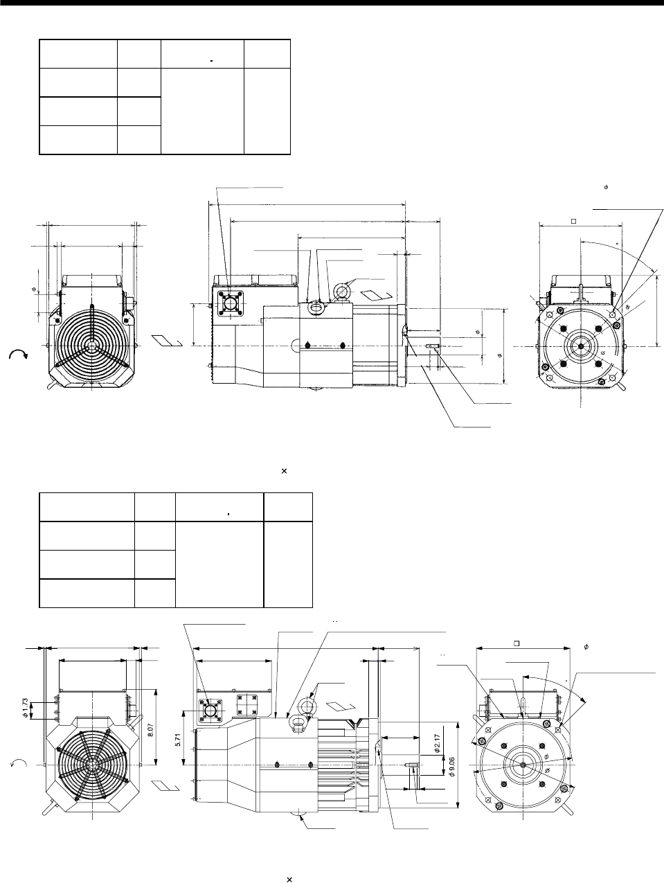
7 - 286
7. OUTLINE DIMENSION DRAWINGS
Model Output
[kW]
Inertia Moment
WK2[oz in2]
Mass
[lb]
HA-LFS601
HA-LFS6014 6
HA-LFS701M
HA-LFS701M4 7
HA-LFS11K2
HA-LFS11K24 11
574.08 121.25
Cooling fan
rotation
direction
Suction air
0.236 0.236
8.11
5.748 1.063
4.016
0.433
1.732
Encoder connector
MS3102A20-29P
Hanger
(Note)
Exhaust air
18.898
10.315
3.346
0.118
0.787
16.772
Motor plate Caution plate
Logo plate
Top
Bottom
Top
Bottom
Top
Oil seal
S50689B
7.087
1.654
3.15
0.78 0.205
M8 screw
7.874
45
Use hexagon socket
head cap screw.
4- 0.571
9.843
8.465
6.732
[Unit: in]
BC12837A, BC12582*, BC12967A
Note. When the motor is used without the hanger, plug the threaded hole with a bolt of M10 20 mm or less.
Model Output
[kW]
Inertia Moment
WK2[oz in2]
Mass
[lb]
HA-LFS801
HA-LFS8014 8
HA-LFS11K1M
HA-LFS11K1M4 11
HA-LFS15K2
HA-LFS15K24 15
1202.84 209.44
BC12804C, BC12964C, BC12969C
BC25028D, BC25670B, BC29888B
1.06
9.84
7.09
0.24 0.24 4.33
3.94
0.200.98
0.26
0.80
19.5
7.87
Encoder connector
MS3102A20-29P Motor plate
Caution plate
Logo plate
Hanger
(Note 2)
Hanger
(Note 2)
9.84
Suction air
Exhaust air
M10 screw
Oil seal
S709513B
Cooling fan
rotation
direction
TUV plate
TUV plate, Logo plate, Caution plate
45
10.4
11.8
4- 0.57 mounting hole
Use hexagon socket head
cap screw.
Top
Bottom
Top
Bottom
(Note 1)[Unit: in]
Note 1. The dimensions without tolerances are reference dimensions.
2. When the motor is used without the hanger, plug the threaded hole with a bolt of M12 20 mm or less.
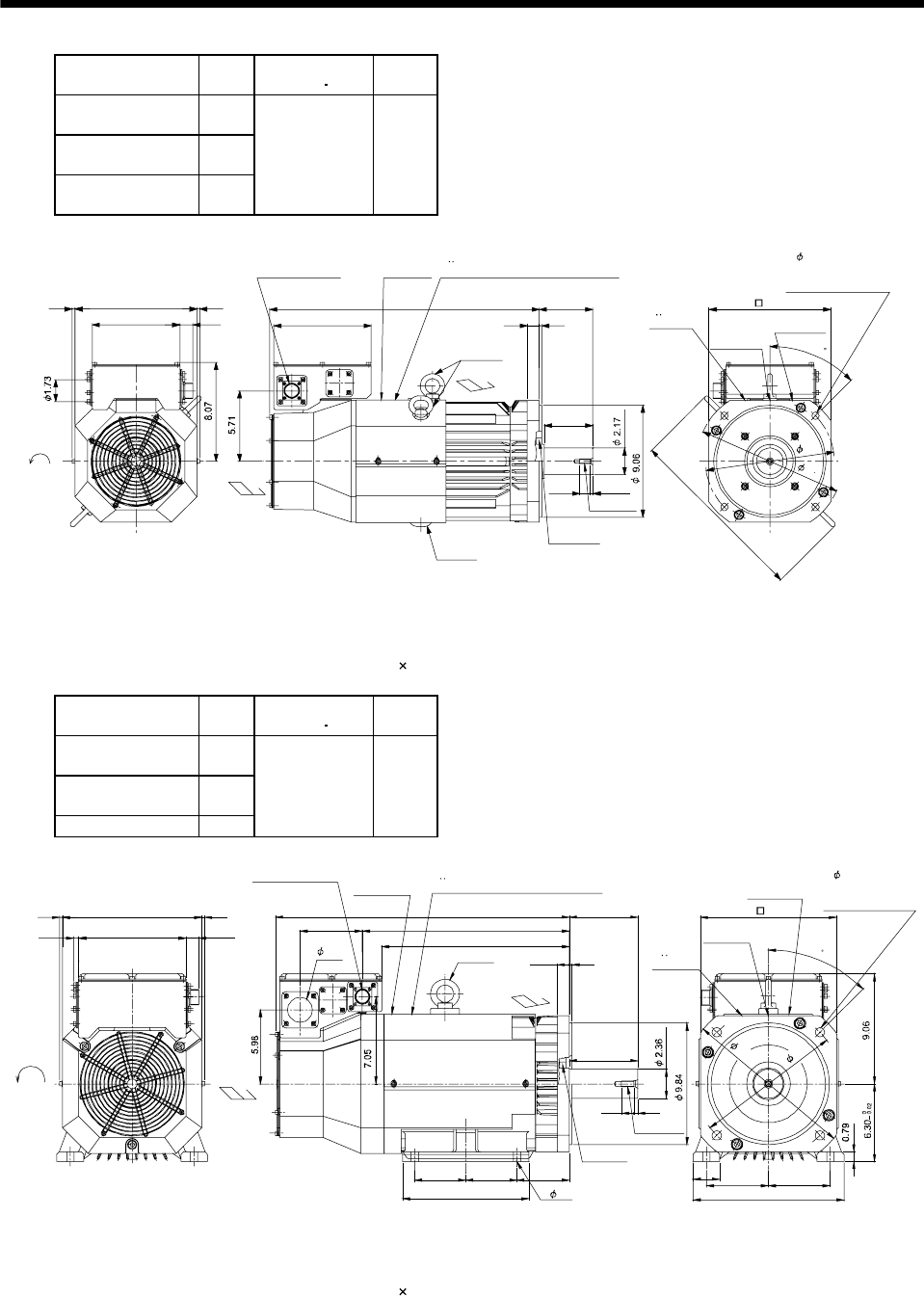
7 - 287
7. OUTLINE DIMENSION DRAWINGS
Model Output
[kW]
Inertia Moment
WK2[oz in2]
Mass
[lb]
HA-LFS12K1
HA-LFS12K14 12
HA-LFS15K1M
HA-LFS15K1M4 15
HA-LFS22K2
HA-LFS22K24 22
1612.9 253.53
21.9
3.94
4.33
0.20
0.98
0.26
0.80
0.240.24 9.84
1.067.09 7.87
BC12970C, BC13039C, BC13158B
BC25300D, BC25349B, BC33032*
Encoder connector
MS3102A20-29P
Motor plate
Caution plate
Logo plate
Hanger
(Note 2)
Hanger
(Note 2)
9.84
Suction air
Exhaust air
M10 screw
Oil seal
S709513B
Cooling fan
rotation
d
irection
TUV plate
TUV plate, Logo plate, Caution plate
45
10.4
11.8
14.8
4- 0.57 mounting hole
Use hexagon socket
head cap screw.
Top
Bottom
Top
Bottom
(Note 1)[Unit: in]
Note 1. The dimensions without tolerances are reference dimensions.
2. When the motor is used without the hanger, plug the threaded hole with a bolt of M12 20 mm or less.
Model Output
[kW]
Inertia Moment
WK2[oz in2]
Mass
[lb]
HA-LFS15K1
HA-LFS15K14 15
HA-LFS22K1M
HA-LFS22K1M4 22
HA-LFS30K24 30
3007.1 352.74
0.24 0.2411.3
1.068.660.43 5.04 16.8
15.2
23.8 5.51
10.2
4.13 4.13 4.25
0.98 0.20
5.51
0.320.98
2.17 5 5
12.2
BC12966A, BC13040A
(BC13233B, BC13235*)
Encoder connector
MS3102A20-29P Motor plate
4- 0.59
Caution plate
Logo plate
2.01 Hanger
(Note 2)
11.0
Suction
air
Exhaust air
M12 screw
Oil seal
S659013B
Cooling fan
rotation
direction
TUV plate
TUV plate, Logo plate, Caution plate
45
11.8
13.8
4- 0.75
Use hexagon socket
head cap screw.
Top
Bottom
Top
Bottom
(Note 1)[Unit: in]
Note 1. The dimensions without tolerances are reference dimensions.
2. When the motor is used without the hanger, plug the threaded hole with a bolt of M12 20 mm or less.
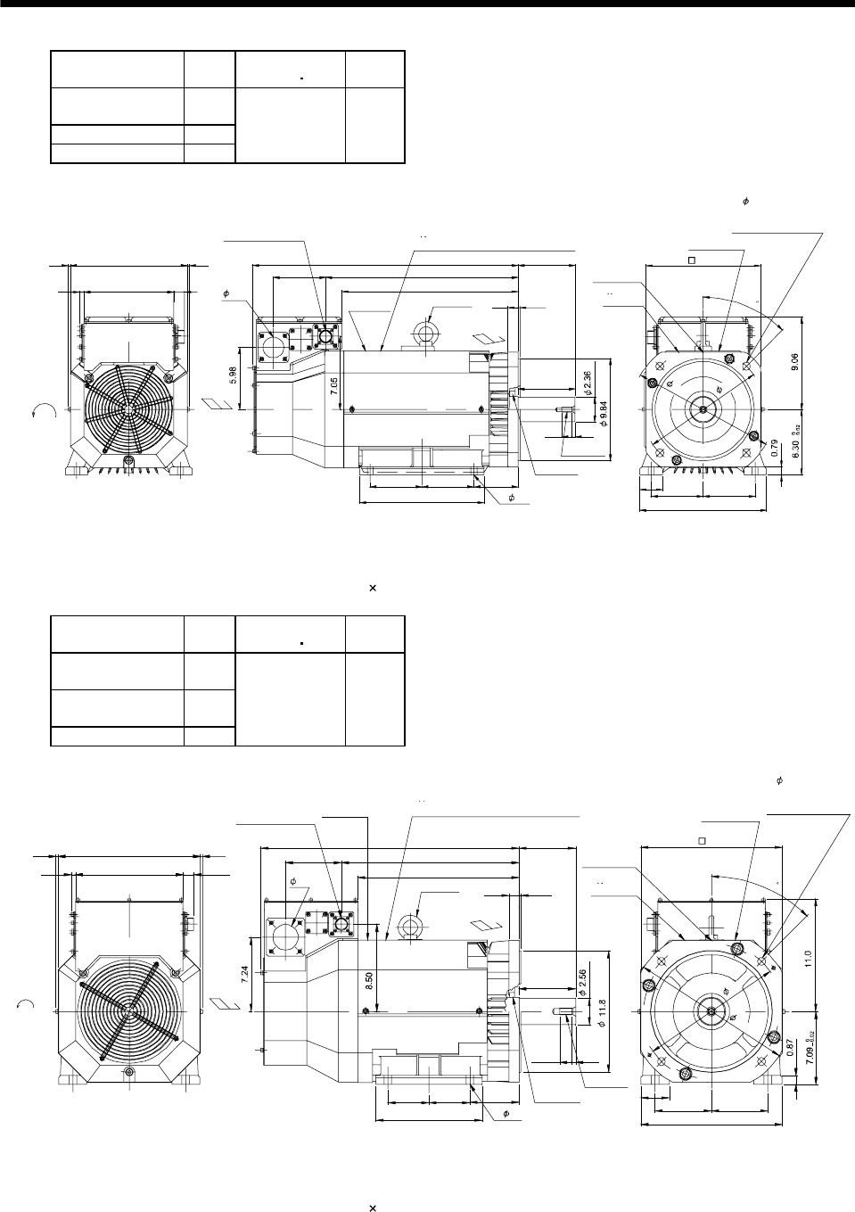
7 - 288
7. OUTLINE DIMENSION DRAWINGS
Model Output
[kW]
Inertia Moment
WK2[oz in2]
Mass
[lb]
HA-LFS20K1
HA-LFS20K14 20
HA-LFS30K1M4 30
HA-LFS37K24 37
3553.84 396.83
1.068.660.43
0.2411.30.24 25.6
16.85.04
15.2
5.51
5 5 4.25
12.0
5.51
0.320.98
2.17 5 5
12.2
0.200.98
BC12972A
(BC13389B, BC13994*)
Encoder connector
MS3102A20-29P
Motor plate
4- 0.59
Caution plate
Logo plate
Hanger
(Note 2)
11.0
Suction air
Exhaust air
M12 screw
Oil seal
S659013B
Cooling fan
rotation
d
irection
TUV plate
TUV plate, Logo plate, Caution plate
45
13.8
11.8
4- 0.75
Use hexagon socket
head cap screw.
Top
Bottom
Top
Bottom
2.01
(Note 1)[Unit: in]
Note 1. The dimensions without tolerances are reference dimensions.
2. When the motor is used without the hanger, plug the threaded hole with a bolt of M16 20 mm or less.
Model Output
[kW]
Inertia Moment
WK2[oz in2]
Mass
[lb]
HA-LFS25K1
HA-LFS25K14 25
HA-LFS37K1M
HA-LFS37K1M4 37
HA-LFS45K24 45
5904.84 507.06
0.24
0.24 13.9
0.43 10.5 1.06
5.43
15.7
17.3
25.2 5.51
0.98 0.20
5.51
10.3
4.0 4.0 4.76
0.351.18
5.495.49
2.76
13.7
BC12508*, BC12973A
(BC13391B, BC13390*)
Encoder connector
MS3102A20-29P
Motor plate
4- 0.75
Caution plate
Logo plate
Hanger
(Note 2)
13.8
Suction
air
Exhaust air
M16 screw
Oil seal
S709513B
Cooling fan
rotation
d
irection
TUV plate
TUV plate, Logo plate, Caution plate
45
13.8
15.8
4- 0.75
Use hexagon socket
head cap screw.
Top
Bottom
Top
Bottom
2.48
(Note 1)[Unit: in]
Note 1. The dimensions without tolerances are reference dimensions.
2. When the motor is used without the hanger, plug the threaded hole with a bolt of M16 20 mm or less.
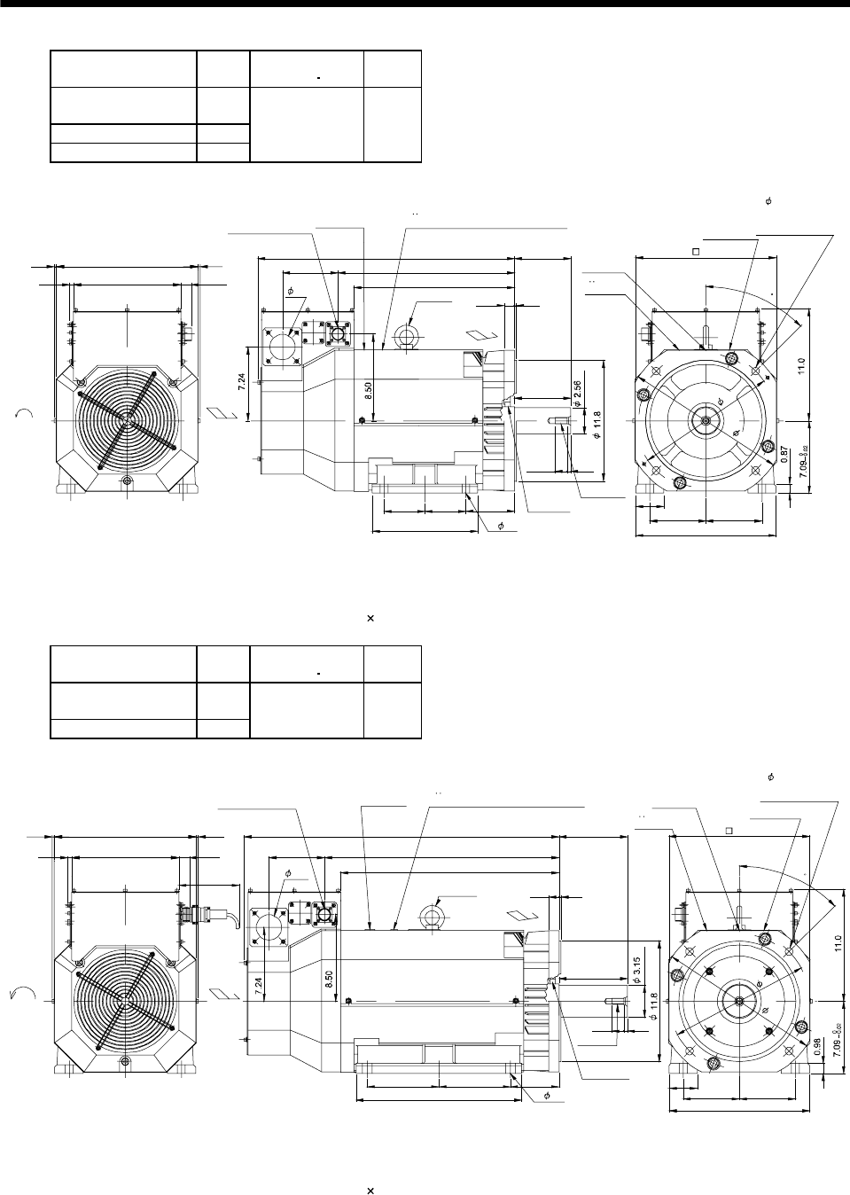
7 - 289
7. OUTLINE DIMENSION DRAWINGS
Model Output
[kW]
Inertia Moment
WK2[oz in2]
Mass
[lb]
HA-LFS30K1
HA-LFS330K14 30
HA-LFS45K1M4 45
HA-LFS55K24 55
7162.35 551.16
0.240.24 13.9
0.43 10.5 1.06
5.43
17.5
19.1
27.0 5.51
0.98 0.20
5.51
11.8
4.74 4.74 4.76
0.35
1.18
5.495.49
2.76
13.7
BC11371B
(BC13393B, BC13392*, BC13232*)
Encoder connector
MS3102A20-29P
Motor plate
4- 0.75
Caution plate
Logo plate
Hanger
(Note 2)
13.8
Suction
air
Exhaust air
M16 screw
Oil seal
S709513B
Cooling fan
rotation
d
irection
TUV plate
TUV plate, Logo plate, Caution plate
45
13.8
15.8
4- 0.75
Use hexagon socket
head cap screw.
Top
Bottom
Top
Bottom
2.48
(Note 1)[Unit: in]
Note 1. The dimensions without tolerances are reference dimensions.
2. When the motor is used without the hanger, plug the threaded hole with a bolt of M16 20 mm or less.
Model Output
[kW]
Inertia Moment
WK2[oz in2]
Mass
[lb]
HA-LFS37K1
HA-LFS37K14 37
HA-LFS50K1M4 50
10224.12 738.55
0.24 13.9 0.24
0.43 10.5 1.06
Approx.
5.91
5.43 23.0
21.4
30.9
7.01 7.01
16.2
4.76
0.98 0.20
6.69
6.69
0.35
1.18
2.76
5.49 5.49
13.7
BC12221*
(BC13395B)
Encoder connector
MS3102A20-29P
Motor plate
4- 0.95
Caution plate
Logo plate
Hanger
(Note 2)
13.8
Suction
air
Exhaust air
M16 screw
Oil seal
S8511013B
Cooling fan
rotation
d
irection
TUV plate
TUV plate, Logo plate, Caution plate
45
13.8
15.8
4- 0.75
Use hexagon socket
head cap screw.
Top
Bottom
Top
Bottom
2.48
(Note 1)[Unit: in]
Note 1. The dimensions without tolerances are reference dimensions.
2. When the motor is used without the hanger, plug the threaded hole with a bolt of M16 20 mm or less.
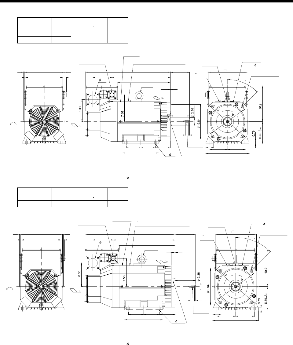
7 - 290
7. OUTLINE DIMENSION DRAWINGS
Model Output
[kW]
Inertia Moment
WK2[oz in2]
Mass
[lb]
HA-LFS30K1M 30
HA-LFS37K2 37 3553.84 396.83
0.240.24 11.3
1.0610.50.43 5.43 18.4
16.8
26.0
0.98 0.20
12.0
5 5 4.25
12.2
5 5
2.17
0.98 0.32
5.51
5.51
BC25299A
Encoder connector
MS3102A20-29P
Motor plate
4- 0.59
Caution plate
Logo plate
Hanger
(Note 2)
11.0
Suction
air
Exhaust air
M12 screw
Oil seal
S659013B
Cooling fan
rotation
direction
TUV plate
TUV plate, Logo plate, Caution plate
45
11.8
13.8
4- 0.75
Use hexagon socket
head cap screw.
Top
Bottom
Top
Bottom
2.48
(Note 1)[Unit: in]
Note 1. The dimensions without tolerances are reference dimensions.
2. When the motor is used without the hanger, plug the threaded hole with a bolt of M16 20 mm or less.
Model Output
[kW]
Inertia Moment
WK2[oz in2]
Mass
[lb]
HA-LFS30K2 30 3007.1 352.74
0.240.24 11.3
1.0610.50.43 5.43 16.6
15
24.2
0.98 0.20
10.2
4.13 4.13 4.25
12.2
5 5
2.17
0.98 0.32
5.51
5.51
BC12971C
Encoder connector
MS3102A20-29P
Motor plate
4- 0.59
Caution plate
Logo plate
Hanger
(Note 2)
11.0
Suction
air
Exhaust air
M12 screw
Oil seal
S659013B
Cooling fan
rotation
d
irection
TUV plate
TUV plate, Logo plate, Caution plate
45
11.8
13.8
4- 0.75
Use hexagon socket
head cap screw.
Top
Bottom
Top
Bottom
2.48
(Note 1)[Unit: in]
Note 1. The dimensions without tolerances are reference dimensions.
2. When the motor is used without the hanger, plug the threaded hole with a bolt of M16 20 mm or less.
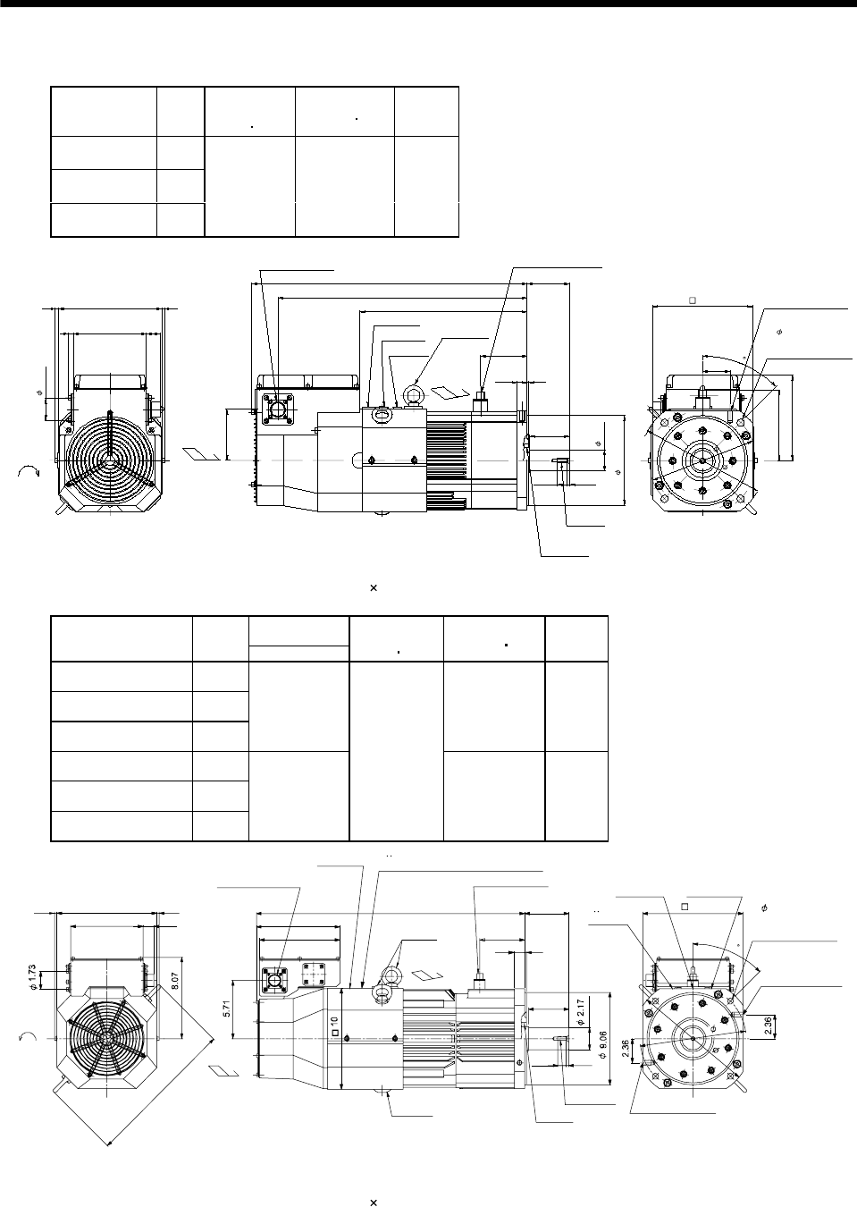
7 - 291
7. OUTLINE DIMENSION DRAWINGS
(2) With electromagnetic brake
Model Output
[kW]
Brake static
friction torque
[oz in]
Inertia Moment
WK2[oz in2]
Mass
[lb]
HA-LFS601B
HA-LFS6014B 6
HA-LFS701MB
HA-LFS701M4B 7
HA-LFS11K2B
HA-LFS11K24B 11
11612 617.82 154.32
4.016
13.15
19.606
6.732
0.433
(0.78) 0.205
3.15
3.346
0.1180.787
21.654
5.748 1.063
8.11 0.236
0.236
3.661
5.591
2.165
Cooling fan
rotation
direction
Suction air
Encoder connector
MS3102A20-29P
Motor plate
Caution plate
Logo plate
Hanger
(Note 2)
M8 screw
Oil seal
S45629B
1.654
45
Use hexagon socket
head cap screw.
4- 0.571
8.465
Top
Bottom
Top
Bottom
1.732
7.087
Brake connector
H/MS3102A10SL-4P
9.843
7.874 M10 screw, depth20
BC13443*
(BC25146*)
Exhaust air
(Note 1)[Unit: in]
Note 1. The dimensions without tolerances are reference dimensions.
2. When the motor is used without the hanger, plug the threaded hole with a bolt of M10 20 mm or less.
Variable
dimensions [in]
Model Output
[kW] L
Brake static
friction torque
[oz in]
Inertia Moment
WK2[oz in2]
Mass
[lb]
HA-LFS801B
HA-LFS8014B 8
HA-LFS11K1MB
HA-LFS11K1M4B 11
HA-LFS15K2B
HA-LFS15K24B 15
24.02 1601.96 277.78
HA-LFS12K1B
HA-LFS12K14B 12
HA-LFS15K1MB
HA-LFS15K1M4B 15
HA-LFS22K2B
HA-LFS22K24B 22
26.38
22729
2017.49 321.88
BC13444B, BC25697A, BC25700B
BC25746A, BC25767A, BC25865B
BC25985B, BC33030*, BC33034*
L
M12 screw, depth 0.87
M12 screw, depth 0.87
4.39
4.33
3.94
0.20
0.98
0.26
0.80
0.24 0.24
7.09 1.06
9.84
14.8
7.87
8.23
Encoder connector
MS3102A20-29P
Brake connector
MS3102A10SL-4P
Motor plate
Caution plateLogo plate
Hanger
(Note 2)
Hanger
(Note 2)
9.84
Suction air
Exhaust air
M10 screw
Oil seal
S60829B
Cooling fan
rotation
d
irection
TUV plate
TUV plate, Logo plate, Caution plate
45
10.4
11.8
4- 0.57mounting hole
Use hexagon socket
head cap screw.
Top
Bottom
Top
Bottom
(Note 1)[Unit: in]
Note 1. The dimensions without tolerances are reference dimensions.
2. When the motor is used without the hanger, plug the threaded hole with a bolt of M16 20 mm or less.
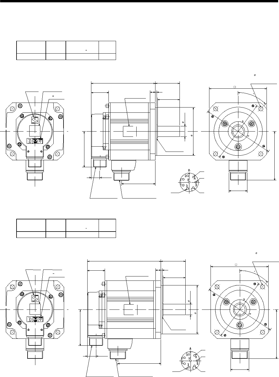
7 - 292
7. OUTLINE DIMENSION DRAWINGS
7.2.14 HC-LFS series
(1) Standard (without electromagnetic brake)
Model Output
[kW]
Inertia Moment
WK2[oz in2]
Mass
[lb]
HC-LFS52 0.5 17.5 14.33
Caution plate
Logo plate
Top
Bottom
TUV plate
Top
Bottom
Top
Bottom
5.728
1.555
1.969
0.118
0.472
2.165
Motor plate
(Opposite side)
Oil seal
S30457B
4.331
0.945
Motor flange direction
Power supply connector layout
CE05-2A22-23P
Earth W
V
U
3.209
Encoder connector
MS3102A20-29P
0.768
3.031
Power supply connector
CE05-2A22-23P
5.118
45
Use hexagon socket
head cap screw.
4- 0.354
6.496
5.709
1.614
4.37
BC12908*
Top
Bottom
[Unit: in]
Model Output
[kW]
Inertia Moment
WK2[oz in2]
Mass
[lb]
HC-LFS102 1.0 25.15 17.64
Caution plateLogo plate
Top
Bottom
Top
Bottom
Top
Bottom
6.516
1.555
1.969
0.118
0.472
2.165
Motor plate
(Opposite side)
Oil seal
S30457B
0.945
Motor flange direction
Power supply connector layout
CE05-2A22-23P
Earth W
V
U
3.209
Encoder connector
MS3102A20-29P
0.768
3.819
Power supply connector
CE05-2A22-23P
45
1.614
4.37
BC12909*
Top
Bottom
TUV plate
6.496
5.709
Use hexagon socket
head cap screw.
4- 0.354
4.331
5.118
[Unit: in]
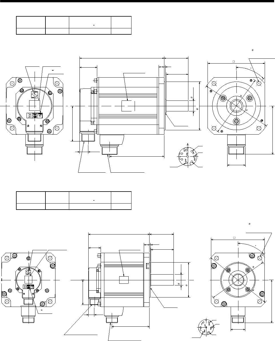
7 - 293
7. OUTLINE DIMENSION DRAWINGS
Model Output
[kW]
Inertia Moment
WK2[oz in2]
Mass
[lb]
HC-LFS152 1.5 34.99 22.05
Caution plateLogo plate
Top
Bottom
Top
Bottom
Top
Bottom
7.598
1.555
1.969
0.118
0.472
2.165
Motor plate
(Opposite side)
Oil seal
S30457B
0.945
Motor flange direction
Power supply connector layout
CE05-2A22-23P
Earth W
V
U
3.209
Encoder connector
MS3102A20-29P
0.768
4.902
Power supply connector
CE05-2A22-23P
45
1.614
4.37
BC12910A
Top
Bottom
TUV plate
6.496
5.709
Use hexagon socket
head cap screw.
4- 0.354
5.118
[Unit: in]
4.331
Model Output
[kW]
Inertia Moment
WK2[oz in2]
Mass
[lb]
HC-LFS202 2.0 120.28 46.3
Caution plateLogo plate
Top
Bottom
Top
Bottom
Top
Bottom
7.874
1.555 2.953
0.118
0.709
3.11
Motor plate
(Opposite side)
Oil seal
S40608B
Motor flange direction
Power supply connector layout
CE05-2A24-10P
Earth
W
V
U
3.209
Encoder connector
MS3102A20-29P
0.768
4.862
Power supply connector
CE05-2A24-10P
45
1.811
5.591
BC13035*
Top
Bottom
TUV plate
9.055
7.874
Use hexagon socket
head cap screw.
4- 0.531
4.5 0
0.001
6.929
[Unit: in]
1.378
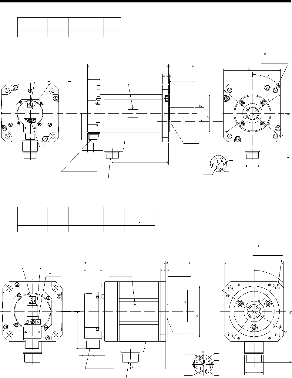
7 - 294
7. OUTLINE DIMENSION DRAWINGS
Model Output
[kW]
Inertia Moment
WK2[oz in2]
Mass
[lb]
HC-LFS302 3.0 196.83 61.73
Caution plateLogo plate
Top
Bottom
Top
Bottom
Top
Bottom
9.843
1.555 2.953
0.118
0.709
3.11
Motor plate
(Opposite side)
Oil seal
S40608B
Motor flange direction
Power supply connector layout
CE05-2A24-10P
Earth
W
V
U
3.209
Encoder connector
MS3102A20-29P
0.768
6.831
Power supply connector
CE05-2A24-10P
45
1.811
5.591
BC13036*
Top
Bottom
TUV plate
9.055
7.874
Use hexagon socket
head cap screw.
4- 0.531
6.929
[Unit: in]
4.5 0
0.001
1.378
Model Output
[kW]
Inertia Moment
WK2[oz in2]
Mass
[lb]
Brake static
friction torque
[N m]
HC-LFS52B 0.5 28.43 19.84 8.3
Caution plate
Logo plate
Top
Bottom
Top
Bottom
Top
Bottom
TUV plate
7.028
1.555
1.969
0.118
0.472
2.165
Motor plate
(Opposite side)
Oil seal
S30457B
3.209
Encoder connector
MS3102A20-29P
0.768
3.031
Power supply connector
CE05-2A22-23P
Top
Bottom
Motor flange direction
Power supply connector layout
CE05-2A22-23P
Earth W
V
U
Brake
45
1.614
4.37
6.496
5.709
Use hexagon socket
head cap screw.
4- 0.354
5.118
BC12984*
0.945
4.331
[Unit: in]
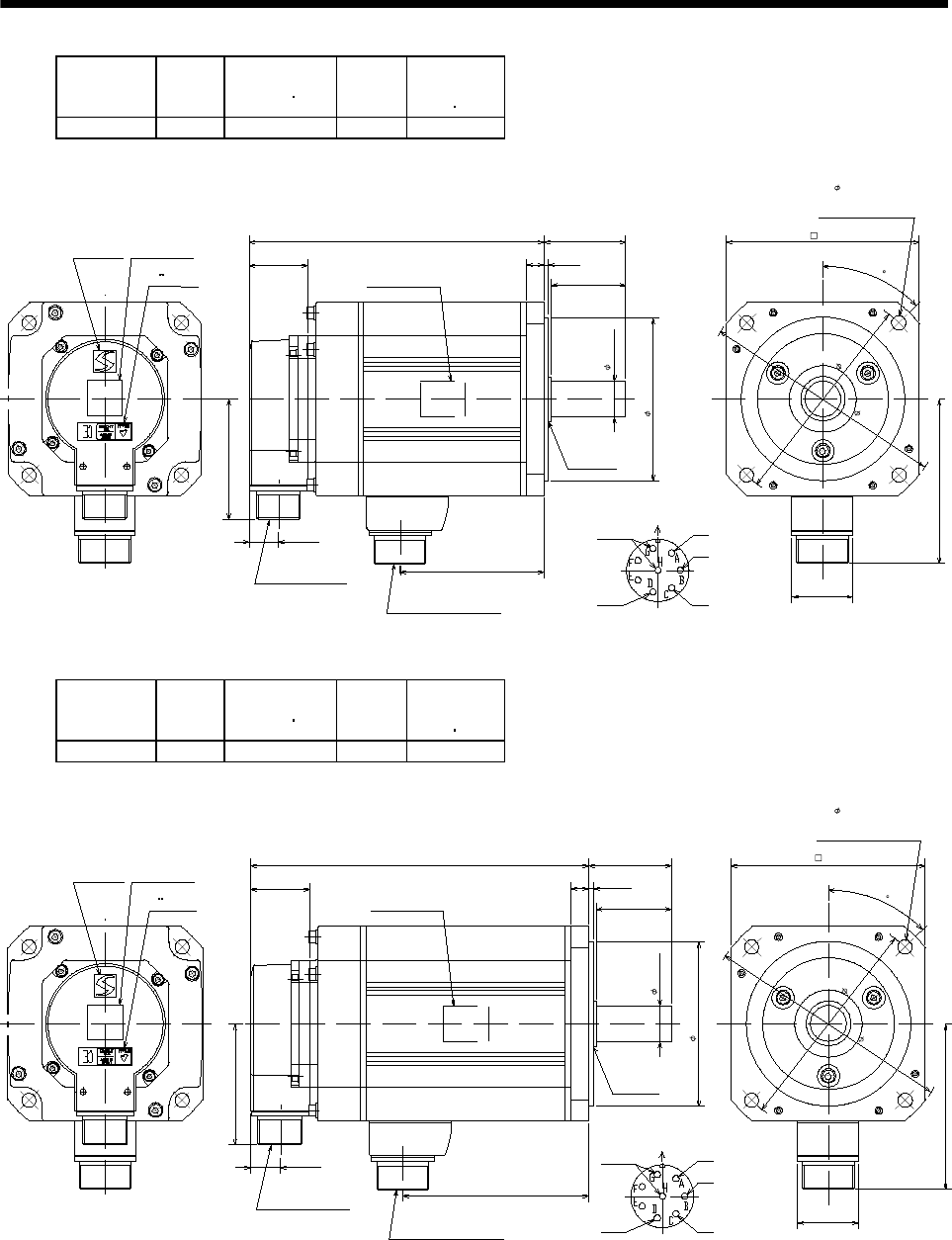
7 - 295
7. OUTLINE DIMENSION DRAWINGS
Model Output
[kW]
Inertia Moment
WK2[oz in2]
Mass
[lb]
Brake static
friction torque
[N m]
HC-LFS102B 1.0 36.09 23.15 8.3
Caution plateLogo plate
Top
Bottom
Top
Bottom
Top
Bottom
TUV plate
7.815
1.555
1.969
0.118
0.472
2.165
Motor plate
(Opposite side)
Oil seal
S30457B
3.209
Encoder connector
MS3102A20-29P
0.768
3.819
Power supply connector
CE05-2A22-23P
0.945
0.433
Top
Bottom
Motor flange direction
Power supply connector layout
CE05-2A22-23P
Earth W
V
U
Brake
45
1.614
4.37
6.496
5.709
Use hexagon socket
head cap screw.
4- 0.354
5.118
BC12985*
[Unit: in]
Model Output
[kW]
Inertia Moment
WK2[oz in2]
Mass
[lb]
Brake static
friction torque
[N m]
HC-LFS152B 1.5 45.93 27.56 8.3
Caution plate
Logo plate
Top
Bottom
Top
Bottom
Top
Bottom
8.898
1.555
1.969
0.118
0.472
2.165
Motor plate
(Opposite side)
Oil seal
S30457B
0.945
Motor flange direction
Power supply connector layout
CE05-2A22-23P
Earth W
V
U
3.209
Encoder connector
MS3102A20-29P
0.768
4.902
Power supply connector
CE05-2A22-23P
45
1.614
4.317
BC12986*
Top
Bottom
TUV plate
6.496
5.709
Use hexagon socket
head cap screw.
4- 0.354
Brake
5.118
0.433
[Unit: in]
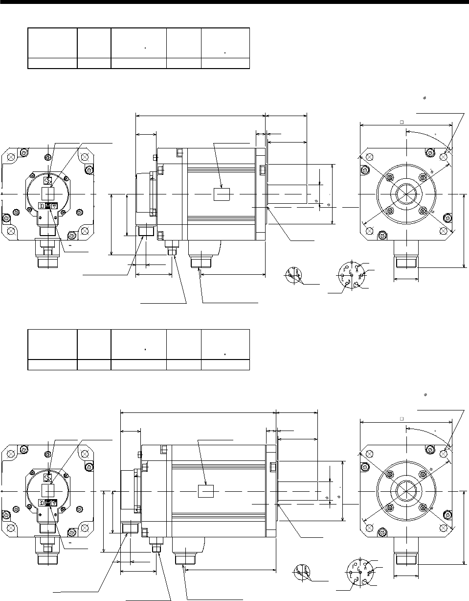
7 - 296
7. OUTLINE DIMENSION DRAWINGS
Model Output
[kW]
Inertia Moment
WK2[oz in2]
Mass
[lb]
Brake static
friction torque
[N m]
HC-LFS202B 2.0 174.96 59.53 43.1
Caution plateLogo plate
Top
Bottom
Top
Bottom
Top
Bottom
11.181
1.555
2.953
0.118
0.709
3.11
Motor plate
(Opposite side)
Oil seal
S40608B
Motor flange direction
Power supply connector layout
CE05-2A24-10P
Earth
W
V
U
3.209
Encoder connector
MS3102A20-29P
0.768
4.862
Power supply connector
CE05-2A24-10P
45
1.811
5.591
BC13037A
Top
Bottom
TUV plate
9.055
7.874
Use hexagon socket
head cap screw.
4- 40.531
Brake
6.929
Brake connector
MS3102A10SL-4P
2.717
4.606
Motor flange direction
Brake connector layout
MS3102A10SL-4P
[Unit: in]
4.5 0
0.001
1.378
Model Output
[kW]
Inertia Moment
WK2[oz in2]
Mass
[lb]
Brake static
friction torque
[N m]
HC-LFS302B 3.0 251.5 74.96 43.1
Caution plateLogo plate
Top
Bottom
Top
Bottom
Top
Bottom
11.732
1.555
2.953
0.118
0.709
3.11
Motor plate
(Opposite side)
Oil seal
S40608B
Motor flange direction
Power supply connector layout
CE05-2A24-10P
Earth
W
V
U
3.209
Encoder connector
MS3102A20-29P
0.768
6.831
Power supply connector
CE05-2A24-10P
45
1.811
5.591
BC13038A
Top
Bottom
TUV plate
9.055
7.874
Use hexagon socket
head cap screw.
4- 0.531
Brake
6.929
Brake connector
MS3102A10SL-4P
2.717
4.606
Motor flange direction
Brake connector layout
MS3102A10SL-4P
[Unit: in]
4.5 0
0.001
1.378
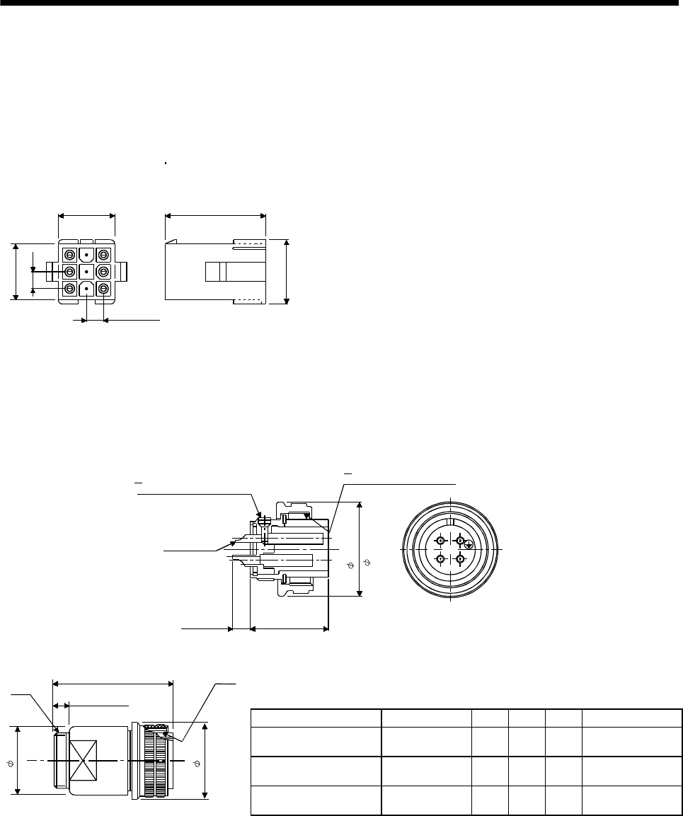
7 - 297
7. OUTLINE DIMENSION DRAWINGS
7.3 Connector
(1) Coupler type
<AMP>
Model
Housing
Connector pin
Crimping tool
: 1-172161-9
: 170359-1
: 755330-1
14 (0.55) 23.7 (0.93)
16 (0.63)
4.2 (0.17)
14 (0.55)
4.2(0.17)
[Unit: mm]
([Unit: in])
170363-1 (loose piece)
(2) Cannon connector type
(a) Connectors
<DDK>
[Unit: mm]
([Unit: in])
CE05-6A14S-2SD-D
3
-20UNEF-2A threads
D terminal
5.6 (0.22) 24 (0.94)
28.57
( 1.12)
CL1
CL2
-20UNEF-2B threads
JAPAN
DDK
A
BC
D
CE05
1
4
S
-
2
4
8
7
[Unit: mm]
([Unit: in])
Model A B C D W
CE05-6A22-23SD-D-BSS 1 3/8-18UNEF-2B 40.48
(1.59)
38.3
(1.51)
61
(2.40) 1 3/16-18UNEF-2A
CE05-6A24-10SD-D-BSS 1 1/2-18UNEF-2B 43.63
(1.72)
42.0
(1.65)
68
(2.68) 1 7/16-18UNEF-2A
W
A
7.85 (0.31) or more
D or less
C
B
CE05-6A32-17SD-D-BSS 2-18UNS-2B 56.33
(2.22)
54.2
(2.13)
79
(3.11) 1 3/4-18UNS-2A
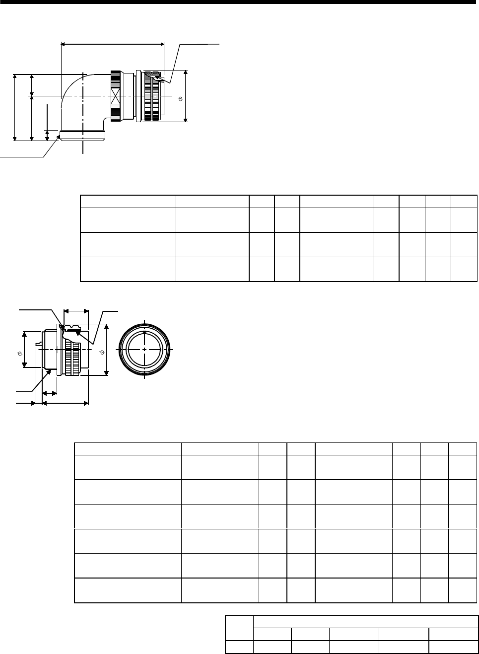
7 - 298
7. OUTLINE DIMENSION DRAWINGS
A
D or less
R
U
Y or more
S
W
B
[Unit: mm]
([Unit: in])
Model A B D W R U S Y
CE05-8A22-23SD-D-BAS 1 3/8-18UNEF-2B 40.48
(1.59)
75.5
(2.97) 1 3/16-18UNEF-2A 16.3
(0.64)
33.3
(1.31)
49.6
(1.95)
7.5
(0.30)
CE05-8A24-10SD-D-BAS 1 1/2-18UNEF-2B 43.63
(1.72)
86.3
(3.40) 1 7/16-18UNEF-2A 18.2
(0.72)
36.5
(1.44)
54.7
(2.15)
7.5
(0.30)
CE05-8A32-17SD-D-BAS 2-18UNS-2B 56.33
(2.22)
93.5
(3.68) 1 3/4-18UNS-2A 24.6
(0.97)
44.5
(1.75)
61.9
(2.44)
8.5
(0.34)
Gasket
H or less
D
C
E
A
J
G
B
[Unit: mm]
([Unit: in])
Model A B C D E G J
D/MS3106A10SL-4S(D190) 5/8-24UNEF-2B 22.22
(0.87)
23.3
(0.92) 9/16-24UNEF-2A 7.5
(0.30)
12.5
(0.49)
13.49
(0.53)
D/MS3106A14S-2S(D190) 7/8-20UNEF-2B 28.57
(1.13)
24.34
(0.96) 3/4-20UNEF-2A 8.46
(0.33)
17.0
(0.67)
13.49
(0.53)
D/MS3106A20-29S(D190) 1 1/4-18UNEF-2B 37.28
(1.47)
34.11
(1.34) 1 1/8-18UNEF-2A 12.16
(0.48)
26.8
(1.06)
18.26
(0.72)
D/MS3106A22-23S(D190) 1 3/8-18UNEF-2B 40.48
(1.59)
34.11
(1.34) 1 1/4-18UNEF-2A 12.15
(0.48)
29.9
(1.18)
18.26
(0.72)
D/MS3106A24-10S(D190) 1 1/2-18UNEF-2B 43.63
(1.72)
36.58
(1.44) 1 3/8-18UNEF-2A 13.42
(0.53)
32.9
(1.30)
18.26
(0.72)
D/MS3106A32-17S(D190) 2-18UNS-2B 56.33
(2.22)
36.95
(1.46) 1 7/8-16UN-2A 13.14
(0.52)
45.3
(1.78)
18.26
(0.72)
Contact Size
#16 #12 #8 #4 #0
H 8 or less 8 or less 10 or less 13 or less 13 or less
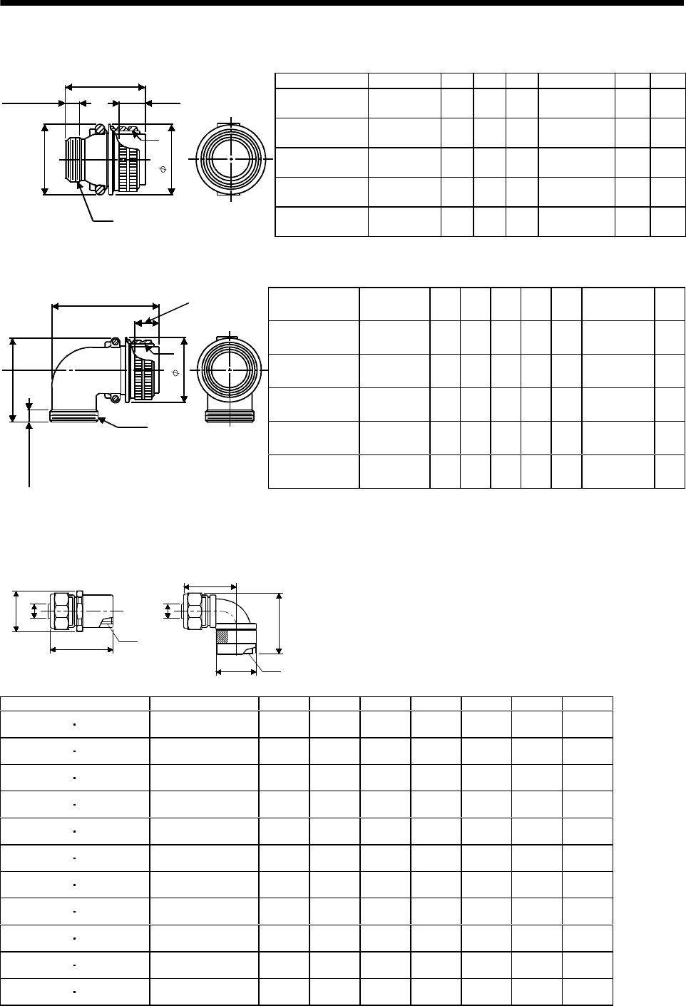
7 - 299
7. OUTLINE DIMENSION DRAWINGS
[Unit: mm]
([Unit: in])
Model A J L Q V W Y
D/MS3106B14S-2S 7/8-20UNEF 13.49
(0.53)
42.88
(1.69)
28.57
(1.13) 3/4-20UNEF 8.0
(0.32)
30
(1.18)
D/MS3106B20-29S 1 1/4-18UNEF 18.26
(0.72)
55.57
(2.19)
37.28
(1.47) 1 3/16-18UNEF 9.53
(0.38)
47
(1.85)
D/MS3106B22-23S 1 3/8-18UNEF 18.26
(0.72)
55.57
(2.19)
40.48
(1.59) 1 3/16-18UNEF 9.53
(0.38)
50
(1.97)
D/MS3106B24-10S 1 1/2-18UNEF 18.26
(0.72)
58.72
(2.31)
43.63
(1.72) 1 7/16-18UNEF 9.53
(0.38)
53
(2.09)
W or more
L or less
J
A
V
Y or less
Q
D/MS3106B32-17S 2-18UNS 18.26
(0.72)
61.92
(2.44)
56.33
(2.22) 1 3/4-18UNS 11.13
(0.44)
66
(2.60)
[Unit: mm]
([Unit: in])
Model A J L Q R U V W
D/MS3108B14S-2S 7/8-20UNEF 13.49
(0.53)
53.97
(2.13)
28.57
(1.13)
14.9
(0.59)
27.0
(1.06) 3/4-20UNEF 9.53
(0.38)
D/MS3108B20-29S 1 1/4-18UNEF 18.26
(0.72)
76.98
(3.03)
37.28
(1.47)
22.5
(0.89)
33.3
(1.31) 1 3/16-18UNEF 9.53
(0.38)
D/MS3108B22-23S 1 3/8-18UNEF 18.26
(0.72)
76.98
(3.03)
40.48
(1.59)
24.1
(0.95)
33.3
(1.31) 1 3/16-18UNEF 9.53
(0.38)
D/MS3108B24-10S 1 1/2-18UNEF 18.26
(0.72)
86.51
(3.41)
43.63
(1.72)
25.6
(1.01)
36.5
(1.44) 1 7/16-18UNEF 9.53
(0.38)
W or more
L or less J
Q
A
V
UR
D/MS3108B32-17S 2-18UNS 18.26
(0.72)
95.25
(3.75)
56.33
(2.22)
32.8
(1.29)
44.4
(1.75) 1 3/4-18UNS 11.13
(0.44)
(b) Flexible conduit connectors
<Daiwa Dengyo>
D(D1)
LA0
C
C
L1
D2
L2
A0
MSA MAA
[Unit: mm]
([Unit: in])
Model A0CLL1L2DD1D2
MSA-10-10 MAA-10-10 9/16-24UNEF-2B 8.2
(0.32)
44
(1.73)
35.5
(1.40)
45
(1.77)
27
(1.06)
29
(1.14)
26
(1.02)
MSA-10-14 MAA-10-14 3/4-20UNEF-2B 8.2
(0.32)
45
(1.77)
39.5
(1.56)
46
(1.18)
27
(1.06)
29
(1.14)
35
(1.38)
MSA-12-14 MAA-12-14 3/4-20UNEF-2B 10.7
(0.42)
45
(1.77)
39.5
(1.56)
46
(1.18)
27
(1.06)
29
(1.14)
35
(1.38)
MSA-16-20 MAA-16-20 1 1/8-18UNEF-2B 14
(0.55)
49.5
(1.95)
47
(1.85)
52
(2.05)
36
(1.42)
38
(1.50)
39
(1.54)
MSA-16-22 MAA-16-22 1 1/4-18UNEF-2B 14
(0.55)
49.5
(1.95)
47
(1.85)
52
(2.05)
38
(1.50)
42
(1.65)
39
(1.54)
MSA-16-24 MAA-16-24 1 3/8-18UNEF-2B 14
(0.55)
49.5
(1.95)
51
(2.01)
54
(2.13)
41
(1.61)
43
(1.69)
47
(1.85)
MSA-22-20 MAA-22-20 1 1/8-18UNEF-2B 18.9
(0.74)
49.5
(1.95)
47
(1.85)
54
(2.13)
36
(1.42)
39
(1.54)
39
(1.54)
MSA-22-22 MAA-22-22 1 1/4-18UNEF-2B 18.9
(0.74)
49.5
(1.95)
47
(1.85)
54
(2.13)
38
(1.50)
42
(1.65)
39
(1.54)
MSA-22-24 MAA-22-24 1 3/8-18UNEF-2B 18.9
(0.74)
49.5
(1.95)
51
(2.01)
56
(2.21)
41
(1.61)
43
(1.69)
47
(1.85)
MSA-28-22 MAA-28-22 1 1/4-18UNEF-2B 24.5
(0.97)
51
(2.01)
53
(2.09)
64
(2.52)
46
(1.18)
50
(1.97)
47
(1.85)
MSA-28-24 MAA-28-24 1 3/8-18UNEF-2B 24.5
(0.97)
51
(2.01)
53
(2.09)
66
(2.60)
46
(1.18)
50
(1.97)
47
(1.85)
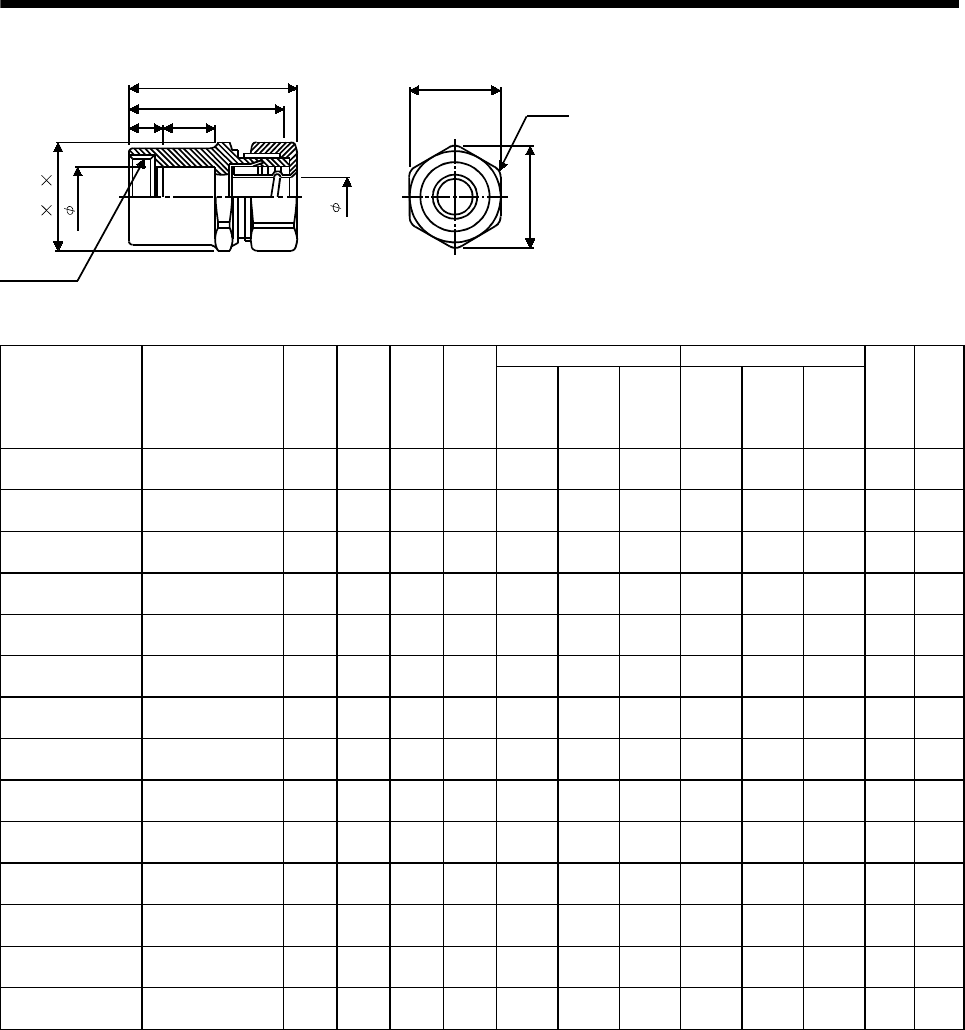
7 - 300
7. OUTLINE DIMENSION DRAWINGS
AA
1
E' F' G'
Threads C
d
d
1
E
G
F
(Note)L(1)
(Note)L1(2)
[Unit: mm]
([Unit: in])
Jam Nut Lock Nut
Model Threads C A A1dd1
E
Width
Across
Flats
F
Width
Across
Corners
G
Number
Of
Corners
E'
Width
Across
Flats
F'
Width
Across
Corners
G'
Number
Of
Corners
LL
1
RCC-102RL-MS10F 9/16-24UNEF-2B 6
(0.24)
15
(0.59)
8.3
(0.33)
11.0
(0.43)
24
(0.95)
26.4
(1.04) 624
(0.95)
26.4
(1.04) 639
(1.54)
36
(1.42)
RCC-102RL-MS14F 3/4-20UNEF-2B 7
(0.28)
15
(0.59)
8.3
(0.33)
15.0
(0.59)
24
(0.95)
26.4
(1.04) 624
(0.95)
26.4
(1.04) 640
(1.58)
37
(1.46)
RCC-103RL-MS14F 3/4-20UNEF-2B 7
(0.28)
15
(0.59)
10.6
(0.42)
15.0
(0.59)
27
(1.06)
29.7
(1.17) 626
(1.02)
28.6
(1.13) 644
(1.73)
41
(1.61)
RCC-104RL-MS14F 3/4-20UNEF-2B 7
(0.28)
15
(0.59)
14.0
(0.55)
15.0
(0.59)
30
(1.18)
33.0
(1.30) 630
(1.18)
33.0
(1.30) 645
(1.77)
42
(1.65)
RCC-104RL-MS20F 1 1/8-18UNEF-2B 9
(0.35)
15
(0.59)
14.0
(0.55)
24.0
(0.95)
30
(1.18)
33.0
(1.30) 632
(1.26)
35.2
(1.39) 647
(1.85)
44
(1.73)
RCC-104RL-MS22F 1 1/4-18UNEF-2B 9
(0.35)
15
(0.59)
14.0
(0.55)
27.0
(1.06)
30
(1.18)
33.0
(1.30) 636
(1.42)
39.6
(1.56) 647
(1.85)
44
(1.73)
RCC-104RL-MS24F 1 3/8-18UNEF-2B 10
(0.39)
20
(0.79)
14.0
(0.55)
30.0
(1.18)
30
(1.18)
33.0
(1.30) 640
(1.58)
42.5
(1.67) 854
(2.13)
50
(1.97)
RCC-106RL-MS20F 1 1/8-18UNEF-2B 9
(0.35)
15
(0.59)
19.0
(0.75)
24.0
(0.95)
37
(1.46)
40.7
(1.60) 636
(1.42)
39.6
(1.56) 650
(1.97)
46
(1.81)
RCC-106RL-MS22F 1 1/4-18UNEF-2B 9
(0.35)
15
(0.59)
19.0
(0.75)
27.0
(1.06)
37
(1.46)
40.7
(1.60) 636
(1.42)
39.6
(1.56) 650
(1.97)
46
(1.81)
RCC-106RL-MS24F 1 3/8-18UNEF-2B 10
(0.39)
20
(0.79)
19.0
(0.75)
30.0
(1.18)
37
(1.46)
40.7
(1.60) 640
(1.58)
42.5
(1.67) 856
(2.21)
52
(2.05)
RCC-106RL-MS32F 1 7/8-16UN-2B 11
(0.43)
20
(0.79)
19.0
(0.75)
42.5
(1.67)
37
(1.46)
40.7
(1.60) 652
(2.05)
54.5
(2.15) 857
(2.24)
53
(2.09)
RCC-108RL-MS22F 1 1/4-18UNEF-2B 9
(0.35)
15
(0.59)
24.4
(0.96)
27.0
(1.06)
45
(1.77)
47.3
(1.86) 844
(1.73)
46.3
(1.82) 855
(2.17)
50
(1.97)
RCC-108RL-MS24F 1 3/8-18UNEF-2B 10
(0.39)
20
(0.79)
24.4
(0.96)
30.0
(1.18)
45
(1.77)
47.3
(1.86) 844
(1.73)
46.3
(1.82) 860
(2.36)
55
(2.17)
RCC-108RL-MS32F 1 7/8-16UN-2B 11
(0.43)
20
(0.79)
24.4
(0.96)
42.5
(1.67)
45
(1.77)
47.3
(1.86) 852
(2.05)
54.5
(2.15) 861
(2.40)
56
(2.21)
Note: (1) indicates the reference dimension before assembling, and (2) the reference dimension after assembling.
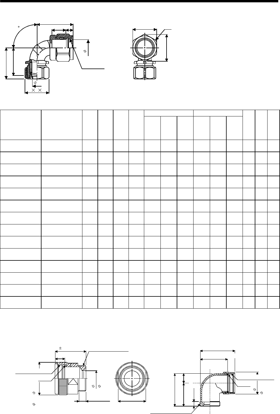
7 - 301
7. OUTLINE DIMENSION DRAWINGS
(Note)L
1(1)
(Note)L
2(2)
AA1
E F G
Threads C
d
d
1
E' G'
F'
L
90
[Unit: mm]
([Unit: in])
Jam Nut Lock Nut
Model Threads C A A1dd1
E
Width
Across
Flats
F
Width
Across
Corners
G
Number
Of
Corners
E'
Width
Across
Flats
F'
Width
Across
Corners
G'
Number
Of
Corners
LL
1L2
RCC-302RL-MS10F 9/16-24UNEF-2B 6
(0.24)
15
(0.59)
8.3
(0.33)
10.0
(0.39)
24
(0.95)
26.4
(1.04) 620
(0.79)
22.0
(0.87) 635
(1.38)
33
(1.30)
30
(1.18)
RCC-302RL-MS14F 3/4-20UNEF-2B 7
(0.28)
15
(0.59)
8.3
(0.33)
13.8
(0.54)
24
(0.95)
26.4
(1.04) 623
(0.91)
25.3
(1.0) 635
(1.38)
33
(1.30)
30
(1.18)
RCC-303RL-MS14F 3/4-20UNEF-2B 7
(0.28)
15
(0.59)
10.6
(0.42)
13.8
(0.54)
27
(1.06)
29.7
(1.17) 623
(0.91)
25.3
(1.0) 637
(1.46)
37
(1.46)
34
(1.34)
RCC-304RL-MS14F 3/4-20UNEF-2B 7
(0.28)
15
(0.59)
14.0
(0.55)
13.8
(0.54)
30
(1.18)
33.0
(1.30) 623
(0.91)
25.3
(1.0) 639
(1.54)
38
(1.50)
35
(1.38)
RCC-304RL-MS20F 1 1/8-18UNEF-2B 9
(0.35)
15
(0.59)
14.0
(0.55)
23.2
(0.91)
30
(1.18)
33.0
(1.30) 632
(1.26)
35.2
(1.39) 641
(1.61)
38
(1.50)
35
(1.38)
RCC-304RL-MS22F 1 1/4-18UNEF-2B 9
(0.35)
15
(0.59)
14.0
(0.55)
26.5
(1.04)
30
(1.18)
33.0
(1.30) 636
(1.42)
39.6
(1.56) 641
(1.61)
38
(1.50)
35
(1.38)
RCC-304RL-MS24F 1 3/8-18UNEF-2B 10
(0.39)
20
(0.79)
14.0
(0.55)
28.7
(1.13)
30
(1.18)
33.0
(1.30) 640
(1.58)
42.5
(1.67) 847
(1.85)
46
(1.81)
43
(1.69)
RCC-306RL-MS20F 1 1/8-18UNEF-2B 9
(0.35)
15
(0.59)
19.0
(0.75)
23.2
(0.91)
37
(1.46)
40.7
(1.60) 632
(1.26)
35.2
(1.39) 645
(1.77)
44
(1.73)
40
(1.58)
RCC-306RL-MS22F 1 1/4-18UNEF-2B 9
(0.35)
15
(0.59)
19.0
(0.75)
26.5
(1.04)
37
(1.46)
40.7
(1.60) 636
(1.42)
39.6
(1.56) 645
(1.77)
44
(1.73)
40
(1.58)
RCC-306RL-MS24F 1 3/8-18UNEF-2B 10
(0.39)
20
(0.79)
19.0
(0.75)
28.7
(1.13)
37
(1.46)
40.7
(1.60) 640
(1.58)
42.5
(1.67) 851
(2.01)
49
(1.93)
45
(1.77)
RCC-306RL-MS32F 1 7/8-16UN-2B 11
(0.43)
20
(0.79)
19.0
(0.75)
40.6
(1.60)
37
(1.46)
40.7
(1.60) 654
(2.13)
56.7
(2.23) 852
(2.05)
49
(1.93)
45
(1.77)
RCC-308RL-MS22F 1 1/4-18UNEF-2B 9
(0.35)
15
(0.59)
24.4
(0.96)
26.5
(1.04)
45
(1.77)
47.3
(1.86) 836
(1.42)
39.6
(1.56) 649
(1.93)
50
(1.97)
45
(1.77)
RCC-308RL-MS24F 1 3/8-18UNEF-2B 10
(0.39)
20
(0.79)
24.4
(0.96)
28.7
(1.13)
45
(1.77)
47.3
(1.86) 840
(1.58)
42.5
(1.67) 856
(2.21)
50
(1.97)
45
(1.77)
RCC-308RL-MS32F 1 7/8-16UN-2B 11
(0.43)
20
(0.79)
24.4
(0.96)
40.6
(1.60)
45
(1.77)
47.3
(1.86) 854
(2.13)
56.7
(2.23) 862
(2.44)
50
(1.97)
45
(1.77)
Note: (1) indicates the reference dimension before assembling, and (2) the reference dimension after assembling.
(c) Back shell
<DDK>
35 (1.38)
O ring
35 ( 1.38)
33.3 (1.31)
48.3 (1.90)
15
(0.59)
17.8
( 0.70)
10.9
11/8-18UNEF-2B
11/8-18UNEF-2B
13/16-18UNEF-2A
13/16-18UNEF-2A
7.85 (0.31)
or more
Effective thread length
CL
CL
31.6 (1.24)
(Spanner fitting)
CE-20BA-S-D
50.5 (1.99) or less
O ring
36
( 1.42)
39.6 (1.56) or less
7.5 (0.30) or more
CE02-20BS-S-D
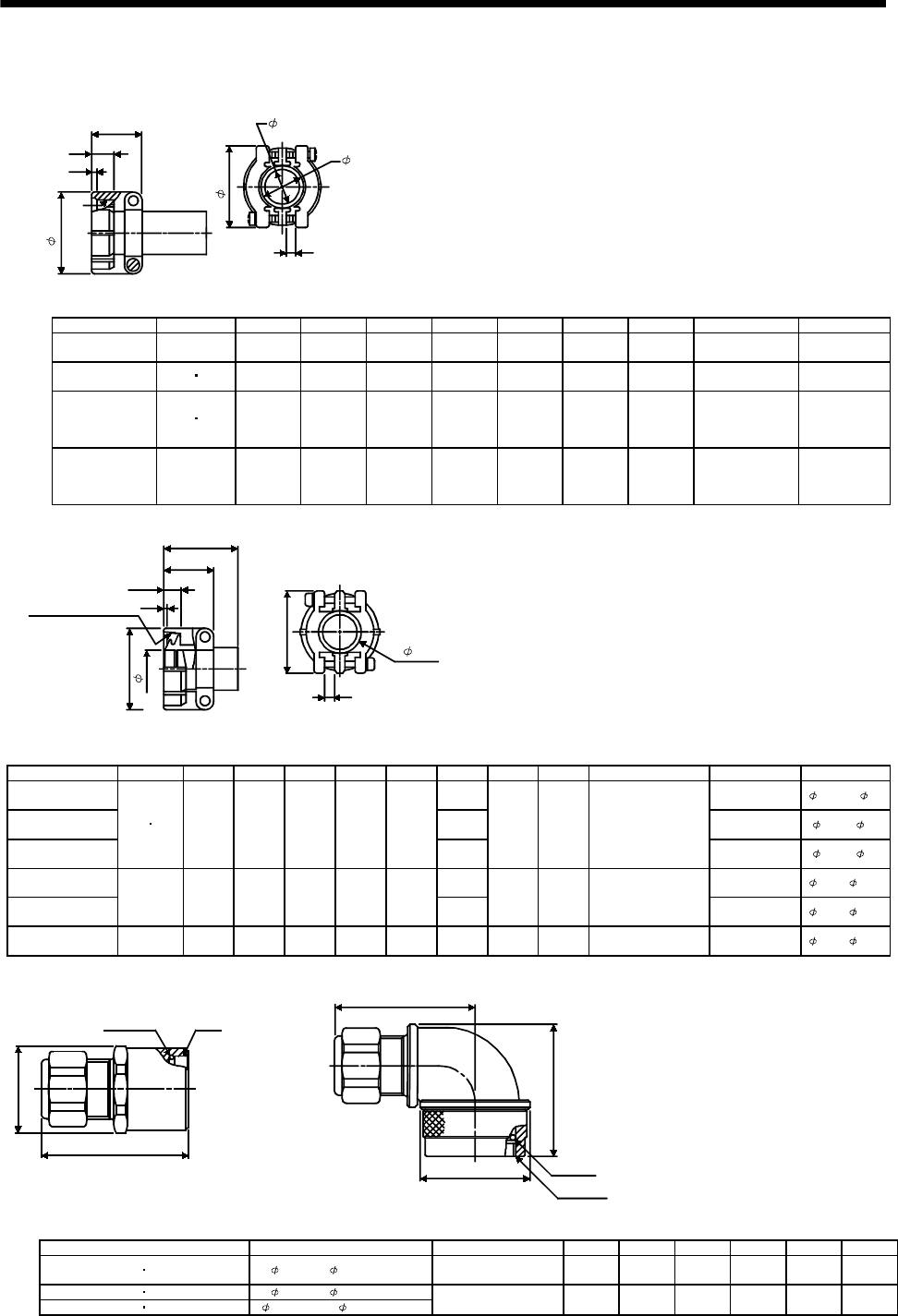
7 - 302
7. OUTLINE DIMENSION DRAWINGS
(d) Cable clamps
<DDK>
A
1.6 (0.06)
V
B
G
E (Bushing ID)
D (Cable clamp ID)
F (Movable range)
Effective thread
length
C
[Unit: mm]
([Unit: in])
Model Shell Size A B C D E F G V Bushing
D/MS3057-6A 14S 22.2
(0.87)
24.6
(0.97)
10.3
(0.41)
11.2
(0.44)
7.9
(0.31)
2.0
(0.08)
27.0
(1.06) 3/4-20UNEF AN3420-6
D/MS3057-12A 20 22 23.8
(0.94)
35.0
(1.38)
10.3
(0.41)
19.0
(0.75)
15.9
(0.63)
4.0
(0.16)
37.3
(1.47) 1 3/16-18UNEF AN3420-12
D/MS3057-16A 24 28 26.2
(1.03)
42.1
(1.66)
10.3
(0.41)
23.8
(0.94)
15.9
(0.63)
19.1
(0.75)
4.8
(0.19)
42.9
(1.69) 1 7/16-18UNEF AN3420-12
AN3420-16
D/MS3057-20A 32 27.8
(1.09)
51.6
(2.03)
11.9
(0.47)
31.7
(1.25)
19.1
(0.75)
23.8
(0.94)
6.3
(0.25)
51.6
(2.03) 1 3/4-18UNS AN3420-16
AN3420-20
(Bushing ID)
Effective thread length
C
A
1.6 (0.06)
V threads
B
G
F
E
(Cable clamp ID)
H
(One-side movable range)
D
[Unit: mm]
([Unit: in])
Model Shell Size A B C D E F G H V Bushing Cable Ran
g
e
CE3057-12A-1-D 16
(0.63) CE3420-12-1 12.5 to 16
CE3057-12A-2-D 13
(0.51) CE3420-12-2 9.5 to 13
CE3057-12A-3-D
20 22 23.8
(0.94)
35.0
(1.38)
10.3
(0.41)
41.3
(1.63)
19.0
(0.75)
10
(0.39)
37.3
(1.47)
4
(0.16) 1 3/16-18UNEF-2B
CE3420-12-3 6.8 to 10
CE3057-16A-1-D 19.1
(0.75) CE3420-16-1 15 to 19.1
CE3057-16A-2-D
24 26.2
(1.03)
42.1
(1.66)
10.3
(0.41)
41.3
(1.63)
23.8
(0.94) 15.5
(0.61)
42.9
(1.69)
4.8
(0.19) 1 7/16-18UNEF-2B
CE3420-16-2 13 to 15.5
CE3057-20A-1-D 32 27.8
(1.09)
51.6
(2.03)
11.9
(0.47)
43
(1.69)
31.7
(1.25)
23.8
(0.94)
51.6
(2.03)
6.3
(0.25) 1 3/4-18UNS-2B CE3420-20-1 22 to 23.8
<Daiwa Dengyo>
O ring
O ring
A0
A0
L
D2
L1
L
2
D(D
1
)
[Unit: mm]
([Unit: in])
Model Acceptable OD A0LL1L2DD1D2
YSO10-5 to 8 YLO10-5 to 8 5 to 8.3 ( 0.20 to 0.33) 9/16-24UNEF-2B 43
(1.69)
39
(1.54)
42.5
(1.67)
24
(0.94)
26
(1.02)
26
(1.02)
YSO14-5 to 8 YLO14-5 to 8 5 to 8.3 ( 0.20 to 0.33)
YSO14-9 to 11 YLO14-9 to 11 8.3 to 11.3 ( 0.33 to 0.45) 3/4-20UNEF-2B 44
(1.73)
43.5
(1.71)
44.5
(1.75)
26
(1.02)
28
(1.10)
35
(1.38)
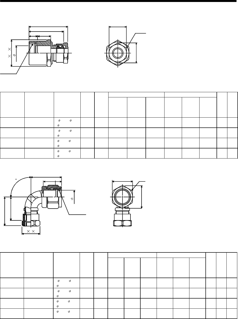
7 - 303
7. OUTLINE DIMENSION DRAWINGS
<Nippon Flex>
(Note)L(1)
(Note)L1(2)
A15
(0.59)
Threads C
d
E' F' G'
E
G
F
[Unit: mm]
([Unit: in])
Tightening Nut Nipple Body
Model Threads C
Applicable
Cable
Diameter
Ad
E
Width
Across
Flats
F
Width
Across
Corners
G
Number
Of
Corners
E'
Width
Across
Flats
F'
Width
Across
Corners
G'
Number
Of
Corners
LL
1
ACS-08RL-
MS10F 9/16-24UNEF-2B 4.0 to 8.0
(0.16 to 0.32)
6
(0.24)
11.0
(0.43)
20
(0.79)
22.0
(0.87) 620
(0.79)
22.0
(0.87) 645
(1.77)
40
(1.57)
ACS-08RL-
MS14F 3/4-20UNEF-2B 4.0 to 8.0
(0.16 to 0.32)
7
(0.28)
15.0
(0.59)
20
(0.79)
22.0
(0.87) 622
(0.87)
24.2
(0.95) 646
(1.81)
41
(1.61)
ACS-12RL-
MS10F 9/16-20UNEF-2B 8.0 to 12.0
(0.32 to 0.47)
6
(0.24)
11.0
(0.43)
24
(0.94)
26.4
(1.04) 624
(0.94)
26.4
(1.04) 646
(1.81)
41
(1.61)
ACS-12RL-
MS14F 3/4-20UNEF-2B 8.0 to 12.0
(0.32 to 0.47)
7
(0.28)
15.0
(0.59)
24
(0.94)
26.4
(1.04) 636
(1.42)
28.6
(1.13) 646
(1.81)
41
(1.61)
Note: (1) indicates the reference dimension before assembling, and (2) the reference dimension after assembling.
Threads C
d
E F G
L
90
(Note)L
1(1)
(Note)L
2(2)
A
15
(0.59)
E' G'
F'
[Unit: mm]
([Unit: in])
Tightening Nut Nipple Body
Model Threads C
Applicable
Cable
Diameter
Ad
E
Width
Across
Flats
F
Width
Across
Corners
G
Number
Of
Corners
E'
Width
Across
Flats
F'
Width
Across
Corners
G'
Number
Of
Corners
LL1L2
ACA-08RL-
MS10F 9/16-24UNEF-2B 4.0 to 8.0
(0.16 to 0.32)
6
(0.24)
10.0
(0.39)
20
(0.79)
22.0
(0.87) 620
(0.79)
22.0
(0.87) 635
(1.38)
37
(1.46)
32
(1.26)
ACA-08RL-
MS14F 3/4-20UNEF-2B 4.0 to 8.0
(0.16 to 0.32)
7
(0.28)
13.8
(0.54)
20
(0.79)
22.0
(0.87) 623
(0.91)
25.3
(1.00) 636
(1.42)
37
(1.46)
32
(1.26)
ACA-12RL-
MS10F 9/16-24UNEF-2B 8.0 to 12.0
(0.32 to 0.47)
6
(0.24)
10.0
(0.39)
24
(0.94)
26.4
(1.04) 620
(0.79)
22.0
(0.87) 640
(1.57)
43
(1.69)
38
(1.50)
ACA-12RL-
MS14F 3/4-20UNEF-2B 8.0 to 12.0
(0.32 to 0.47)
7
(0.28)
13.8
(0.54)
24
(0.94)
26.4
(1.04) 623
(0.91)
25.3
(1.00) 641
(1.61)
43
(1.69)
38
(1.50)
Note: (1) indicates the reference dimension before assembling, and (2) the reference dimension after assembling.
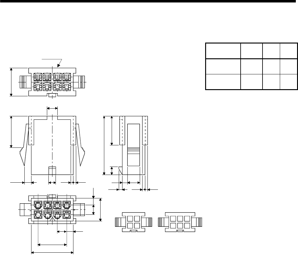
7 - 304
7. OUTLINE DIMENSION DRAWINGS
(3) Plug
[Unit: mm]
([Unit: in])
Model Number
of Poles AB
5509-04P-210 4
(0.16)
4.2
(0.17)
9.6
(0.38)
5559-06P-210 6
(0.24)
8.4
(0.33)
13.8
(0.54)
(2) 11
3
4321
85
4.2
A
B
4.2 2.7
Circuit number
5559
11.6
(0.46)
(0.18)
4.6
13
(0.51)
3.4
(0.13) (0.04) (0.04)
23.9
(0.94) 11.9
(0.47)
(0.12)
2.3 (0.1)
1.4 (0.06)
5(0.2)
1
(0.04)
1
(0.04)
2.5
(0.1)
9.6 (0.38)
(0.17)
(Pitch) (0.17) (0.11)
Pole count-based layout diagram
4 poles 6 poles
Terminal : 5558PBT3L
Hand tool : 57022-5300
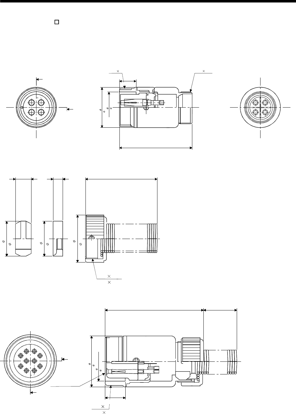
7 - 305
7. OUTLINE DIMENSION DRAWINGS
(4) Plug (For HC-UF -S1)
<Hirose Electric>
[Unit: mm]
([Unit: in])
RM15WTJA-4S
H 5
14
23
14
23 H 5
A
A
A-A
20
( 0.787)
15.3
( 0.602)
35
(1.378)
M19 1
(0.039)
M16 0.75
(0.03)
8
(0.315)
RM15WTP-CP(8)
M16 0.75
(M16 0.03)
64 28.6
(1.126)
19
( 0.748)
14
( 0.551)
13.9
( 0.547)
(0.236) (0.157)
RM15WTJA-10S-(7)
1
9
10
2
3
4
8
5
6
7
H 5
D
D
Section D-D
M19 1
(M19 0.039)
39
(1.535)
20
(0.787)
20
( 0.787)
15.3
( 0.602)
8
(0.315)
Note: The numeral within the parentheses of the connector type indicates the applicable cable diameter, and the above diagrams show
examples. The numeral depends on the used cable diameter.

7 - 306
7. OUTLINE DIMENSION DRAWINGS
MEMO
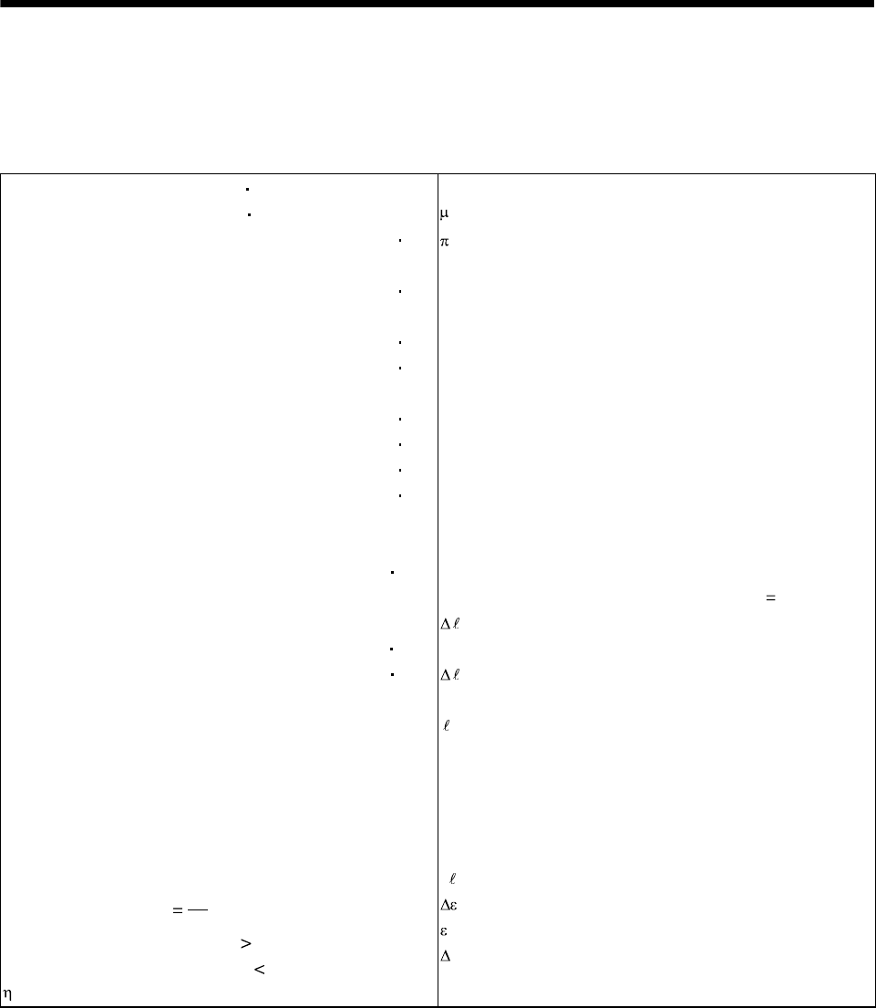
8 - 1
8. CALCULATION METHODS FOR DESIGNING
8. CALCULATION METHODS FOR DESIGNING
8.1 Specification symbol list
The following symbols are required for selecting the proper servo:
Ta: Acceleration torque [N m]
Td: Deceleration torque [N m]
TMa : Servo motor torque necessary for [N m]
acceleration
TMd : Servo motor torque necessary for [N m]
deceleration
TLH : Torque applied during servo motor stop [N m]
TL: Load torque converted into equivalent [N m]
value on servo motor shaft
TU: Unbalance torque [N m]
TF: Load friction torque [N m]
TL0 : Load torque on load shaft [N m]
Trms : Continuous effective load torque [N m]
converted into equivalent value
on servo motor shaft
JL: Load inertia moment converted [kg cm2]
into equivalent value on servo
motor shaft
JL0 : Load inertia moment on load shaft [kg cm2]
JM: Servo motor's rotor inertia moment [kg cm2]
N : Servo motor speed [r/min]
N0: Servo motor speed during fast feed [r/min]
NL0 : Load shaft speed during fast feed [r/min]
V : Moving part speed [mm/min]
V0: Moving part speed during fast feed [mm/min]
Pb: Ball screw lead [mm]
Z1: Number of gear teeth on servo motor shaft
Z2: Number of gear teeth on load gear
n: Gear ratio
nZ1
Z2
Speed reduced when n 1,
Speed increased when n 1
: Drive system efficiency
g : Gravitational acceleration (9.8[m/s2])
: Friction coefficient
: Circle ratio (3.14)
Pt: Number of feedback pulses in [pulse/rev]
position control mode
f : Input pulse frequency in [pps]
position control mode
f0: Input pulse frequency during fast [pps]
feed in position control mode
tpsa : Acceleration time constant of [s]
pulse frequency command in
position control mode
tpsd : Deceleration time constant of [s]
pulse frequency command in
position control mode
Kp: Position control gain 1 [rad/s]
Tp: Position control time constant (Tp 1/Kp) [s]
: Feed per feedback pulse
in position control mode [mm/pulse]
0: Feed per command pulse
in position control mode [mm/pulse]
: Feed [mm]
P : Number of internal command pulses [pulse]
ts: Internal settling time [s]
t0: Positioning time [s]
tc: Time at constant speed of servo [s]
motor in 1 cycle
t: Stopping time in 1 cycle [s]
: Positioning accuracy [mm]
: Number of droop pulses [pulse]
S : Feed per servo motor revolution [mm/rev]
W: Mass [kg]
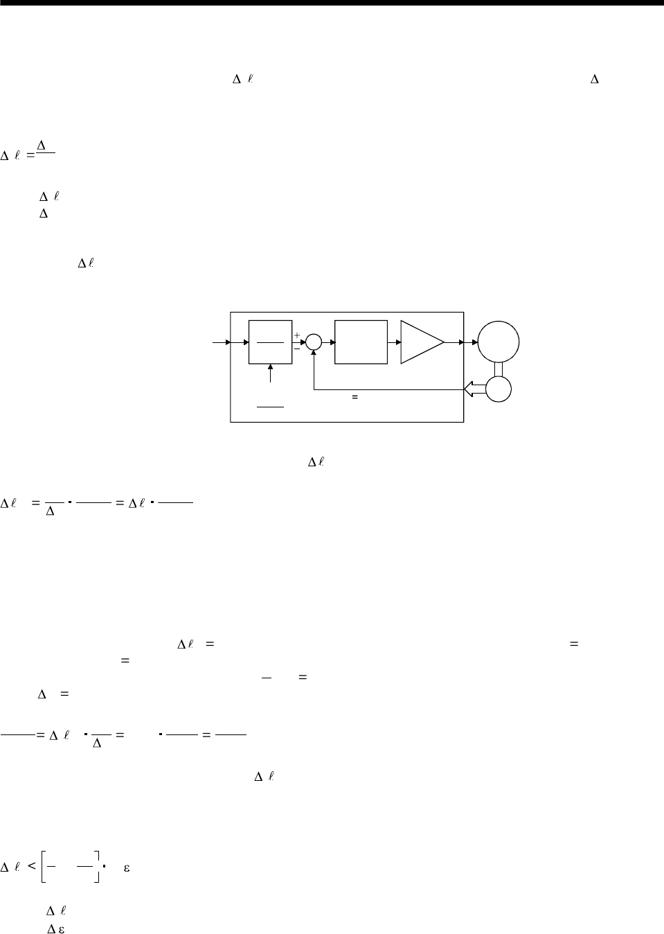
8 - 2
8. CALCULATION METHODS FOR DESIGNING
8.2 Position resolution and electronic gear setting
Position resolution (travel per pulse ) is determined by travel per servo motor revolution S and the
number of encoder feedback pulses Pt, and is represented by Equation 8.1. As the number of feedback
pulses depends on the servo motor series, refer to Section 5.1.
Pt
S.............................................................................................................................................................(8.1)
: Travel per pulse [mm]
S : Travel per servo motor revolution [mm/rev]
Pt: Number of feedback pulses [pulse/rev]
Since has the relationship represented by Equation 8.1, its value is fixed in the control system
after the drive system and encoder have been determined. However, travel per command pulse can
be set as desired using the parameters.
CMX
CDV SM
Pt 8192pulse/rev
Command
pulse train f0
Electronic gear
CMX
CDV
Deviation
counter
Encoder
As shown above, command pulses are multiplied by CMX/CDV set in the parameters to be position
control pulses. Travel per command pulse is expressed by Equation 8.2:
0 Pt
S
CMX
CDV CMX
CDV .......................................................................................................................(8.2)
CMX: Electronic gear (Command pulse multiplication numerator)
CDV: Electronic gear (Command pulse multiplication denominator)
Using the above relationship, travel per command pulse can be set to a value without fraction.
[Setting example]
Find a parameter value for 0 0.01 [mm] in a drive system where ball screw lead PB 10 [mm] and
reduction ratio 1/n 1.
The encoder feedback pulses Pt of the HC MF 8192 [pulses/rev].
Since s 10 [mm/rev], the following is obtained according to Equation 8.2:
CMX
CDV 0Pt
S 0.01 8192
10 1024
125
<Relationship between position resolution and overall accuracy>
Positioning accuracy of machine is the sum of electrical errors and mechanical errors. Normally,
provisions should be made so that positioning accuracy are not affected by electrical system errors. As a
guideline, Equation 8.3 should be satisfied:
1
51
10
to D .........................................................................................................................................(8.3)
where, : Travel per feedback pulse [mm/pulse]
: Positioning accuracy [mm]
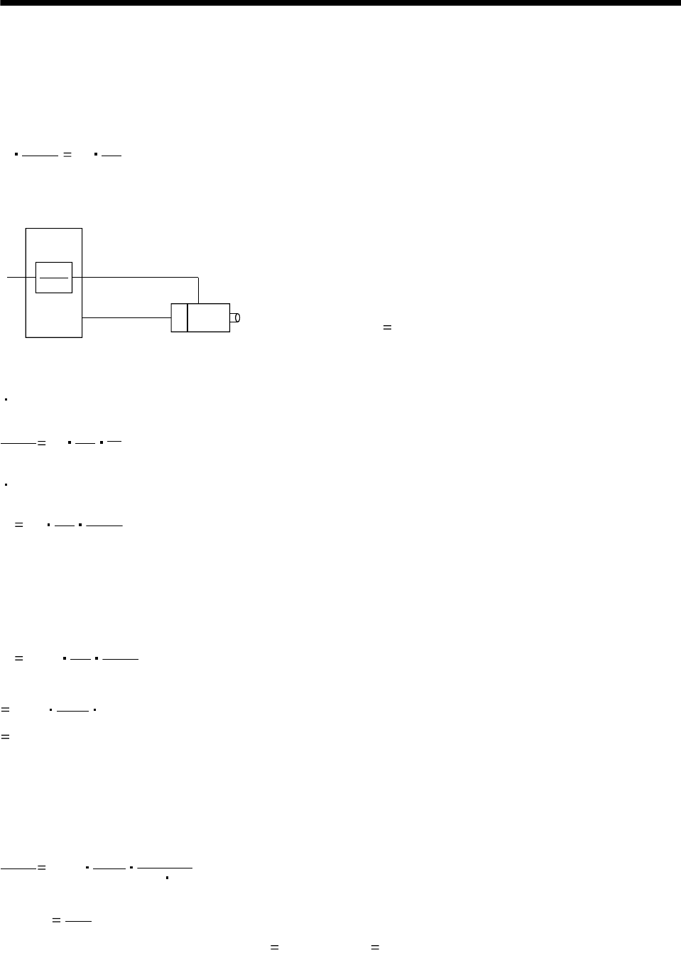
8 - 3
8. CALCULATION METHODS FOR DESIGNING
8.3 Speed and command pulse frequency
The servo motor is run at a speed where the command pulses and feedback pulses are equivalent.
Therefore, the command pulse frequency and feedback pulse frequency are equivalent. The relation
including the parameter settings (CMX, CDV) is as indicated below (refer to the following diagram):
f0CMX
CDV PtN0
60 ..................................................................................................................................... (8.4)
CMX
CDV
f0
Electronic
gear
Feedback pulse
frequency Servo motor
f0:Command pulse frequency [pps]
CMX :Electronic gear
(Commanded pulse multiplication numerator)
CDV :Electronic gear
(Commanded pulse multiplication denominator)
N0:Servo motor speed [r/min]
Pt:Number of feedback pulses [pulses/rev]
(Pt 8192 for HC-MF)
According to Equation 8.4, the following equations may
be used to obtain the electronic gear and command
pulse frequency to rotate the servo motor at No.
Electronic gear
CMX
CDV PtNo
60
1
f0............................................................................................................................................(8.5)
Command pulse frequency
f0 Pt N0
60 CDV
CMX ...........................................................................................................................................(8.6)
[Setting example]
Obtain the command pulse frequency required to run the HC-MF at 3000r/min.
When the electronic gear ratio 1 (initial parameter value) is used, the following result is found according
to Equation 8.6:
f0 8192 N0
60 CDV
CMX
(Command pulse frequency)
8192 3000
60 1
409600[pps]
However, as the maximum input command pulse frequency in the open collector system is 200kpps, for
general-purpose servo 409600pps cannot be entered.
To run the servo motor at the speed of 3000r/min at not more than 200kpps, the electronic gear setting
must be changed. This electronic gear is found by Equation 8.5:
CMX
CDV 8192 3000
60
1
200 103
(Electronic gear)
256
125
Therefore, the parameters are set to CMX 256 and CDV 125.
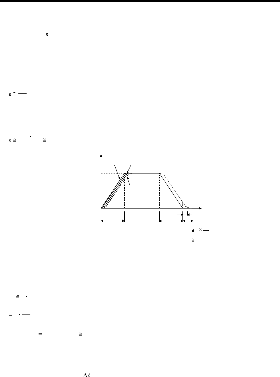
8 - 4
8. CALCULATION METHODS FOR DESIGNING
8.4 Stopping characteristics
(1) Droop pulses ( )
When a pulse train command is used to run the servo motor, there is a relationship between the
command pulse frequency and servo motor speed as shown in the figure. The difference between the
command pulses and feedback pulses during acceleration are called droop pulses, which are
accumulated in the servo amplifier's deviation counter. Equation 8.7 defines a relationship between
the command pulse frequency (f) and position control gain 1(Kp).
f0
Kp[pulse] ...............................................................................................................................................(8.7)
Supposing that the value of position control gain 1 is 70 [rad/s], the droop pulses during operation will
be as follows at the command pulse frequency of 200 [kpps] according to Equation 15.1:
1
200 103 2858[pulse]
Command pulse frequency f
Servo motor speed
[pps][r/min]
0Time
Command Droop pulses
Servo motor
speed
tpsa ts
ts 3 1
70
0.04
Tp
tpsd
(2) Settling time (ts) during linear acceleration/deceleration
Since droop pulses still exist when there are no command pulses, settling time (ts) is required until the
servo motor stops. Set the operation pattern in consideration for the settling time.
The settling time (ts) value is obtained according to Equation 8.8:
ts 3 Tp
3 1
Kp[s] ....................................................................................................................................................(8.8)
*When Kp 70 [rad/s], ts 0.04 [s]. (Refer to the above diagram.)
The settling time (ts) indicates the time required for the servo motor to stop in the necessary
positioning accuracy range. This does not always mean that the servo motor has stopped completely.
Thus, especially when the servo motor is used in high-duty operation and positioning accuracy has no
margin for travel per pulse ( ), the value obtained by Equation 8.8 must be increased.
The settling time (ts) will vary with the moving part conditions. Especially when the load friction
torque is large, movement may be unstable near the stopping position.
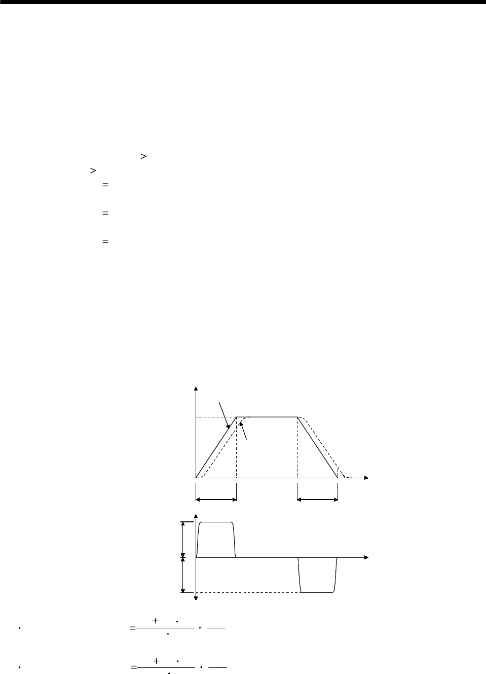
8 - 5
8. CALCULATION METHODS FOR DESIGNING
8.5 Capacity selection
As a first step, confirm the load conditions and temporarily select the servo motor capacity. Then,
determine the operation pattern, calculate required torques according to the following equations, and
check that the servo motor of the initially selected capacity may be used for operation .
(1) Initial selection of servo motor capacity
After calculating the load torque (TL) and load inertia moment (JL), select a servo motor which will
satisfy the following two relationships:
Servo motor's rated torque TL
Servo motor JM JL/m
m 3 : High duty (more than 100 times/min.)
Settling time 40ms or less
m 5 : Middle duty (60 to 100 times/min.)
Settling time 100ms or less
m permissible load inertia moment : Low duty (less than 60 times/min.)
Settling time more than 100ms
Find the acceleration and deceleration torques and continuous effective load torque as described in (2)
to make a final selection. For high-duty positioning, the load inertia moment (JL) value should be as
small as possible. If positioning is infrequent as in line control, the load inertia moment (JL) value may
be slightly larger than in the above conditions.
(2) Acceleration and deceleration torques
The following equations are used to calculate the acceleration and deceleration torques in the
following operation pattern:
Command pulse
Servo motor speed [r/min]
0
0
Nofo
Time
Time
Command
Servo motor
speed
tpsa
Ta
Td
Deceleration
torque
A
cceleration
torque
frequency f [pps]
tpsd
Acceleration torque Ta 9.55 104
(JL JM)No
tpsa
1........................................................................................(8.9)
Deceleration torque Td 9.55 104
(JL JM)No
tpsd
1.....................................................................................(8.10)
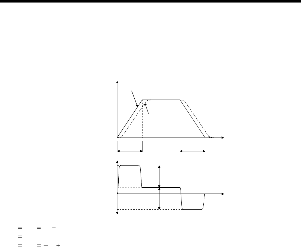
8 - 6
8. CALCULATION METHODS FOR DESIGNING
(3) Torques required for operation
Torques required for the servo motor are the highest during acceleration. If any of the torques
obtained with Equations 8.11 to 8.13 exceeds the maximum servo motor torque, the servo motor speed
cannot be increased as commanded. Confirm that the calculated value is lower than the servo motor's
maximum torque. Since a friction load is normally applied during deceleration, only the acceleration
torque needs to be considered. In the regenerative mode, the value found by Equation 8.13 is negative.
Servo motor torque
0Time
TMa
TMd
T1
T2
TL
Ta
Td
frequency f [pps]
Servo motor speed [r/min]
0
Nofo
Time
Command
Servo motor
speed
tpsa
Command pulse
tpsd
T1 TMa Ta TL.................................................................................................................................... (8.11)
T2 TL........................................................................................................................................................ (8.12)
T3 TMd Td TL.................................................................................................................................. (8.13)
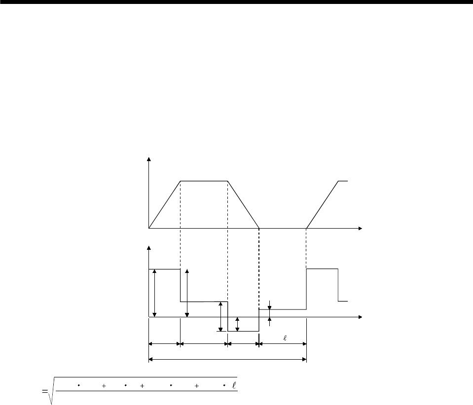
8 - 7
8. CALCULATION METHODS FOR DESIGNING
(4) Continuous effective load torque
If the torque required for the servo motor changes with time, the continuous effective load torque
should be lower than the rated torque of the servo motor. There may be a servo motor torque delay at
the start of acceleration or deceleration due to a delay in the control system. To simplify the
calculation, however, it is assumed that constant acceleration and deceleration torques are applied
during tpsa and tpsd. The following equation is used to calculate the continuous effective load torque in
the following operation pattern. TLH indicates the torque applied during a servo motor stop. A large
torque may be applied especially during a stop in vertical motion applications, and this must be fully
taken into consideration. During vertical drive, the unbalanced torque TU will become TLH.
Servo motor
speedTime
Servo motor torque
N
[r/min]
0Time
0Time
tpsa tc
tf (1 cycle)
TMa
TMd
Td
Ta
TL
TLH
ttpsd
Trms tf
T Ma tpsa T Ltc T Md T LH t
222 2
tpsd .................................................................................(8.14)
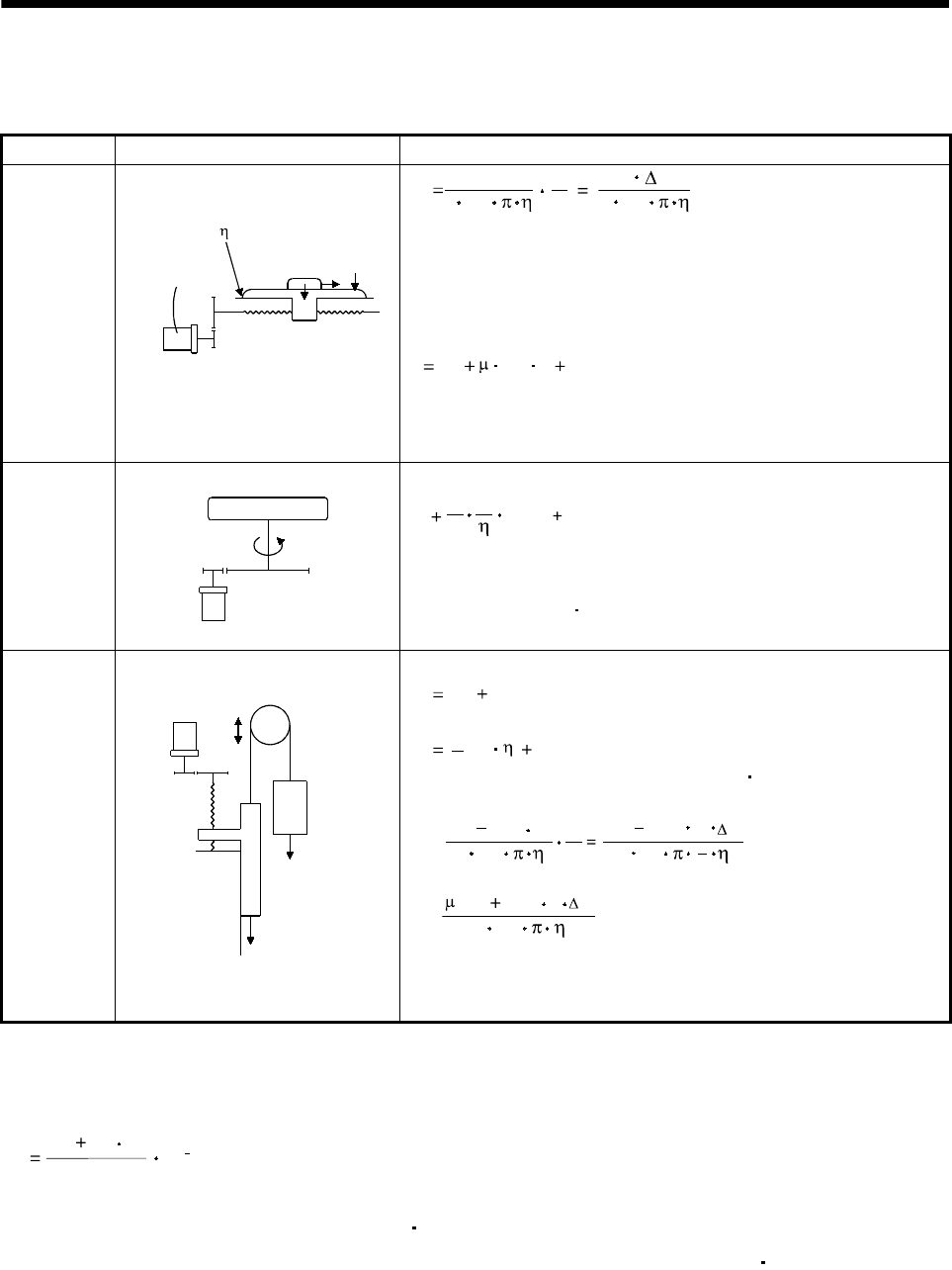
8 - 8
8. CALCULATION METHODS FOR DESIGNING
8.6 Load torque equations
Typical load torque equations are indicated below:
Type Mechanism Equation
Linear
movement
Servo motor
W
Z1
FCFG
Z2
TL 210
3
F
N
V
210
3
F S ......................................(8.15)
F : Force in the axial direction of the machine in linear motion [N]
F in Equation 15.9 is obtained with Equation 8.16 when the table
is moved, for example, as shown in the left diagram.
F Fc (W g FG) ........................................................(8.16)
Fc : Force applied in the axial direction of the moving part [N]
FG: Tightening force of the table guide surface [N]
W : Full mass of the moving part [kg]
Rotary
movement
Servo motor
Z1Z2
TL0
TL n
11TL0 T
F
...........................................................(8.17)
TF: Load friction torque converted into equivalent value on servo
motor shaft [N m]
Vertical
movement
Counter
weight
Servo motor
W2
W1
1/n
Load
Guide
During rise
TL TU TF.........................................................................(8.18)
During fall
TL TU2 TF................................................................(8.19)
TF: Friction torque of the moving part [N m]
TU = 10
(W1 W2 )
N
V
gS
(W1 W2 )g
23210
3...........................(8.20)
TF = 103
2
g
(W1 W2 )S.........................................................(8.21)
W1: Mass of load [kg]
W2: Mass of counterweight [kg]
8.7 Expression for calculating the electromagnetic brake workload
Calculate the brake workload Eb [J] at an emergency stop with the following expression.
182
(JM JL )N2
Eb 10 4
N: Servo motor speed [r/min]
JM: Servo motor's rotor inertia moment [kg cm2]
JL: Load inertia moment converted into equivalent value on servo motor shaft [kg cm2]
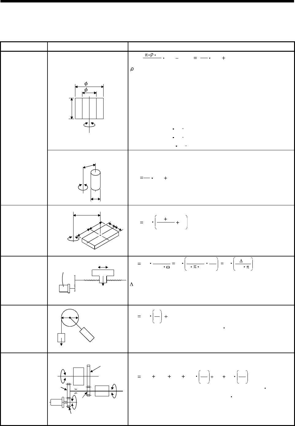
8 - 9
8. CALCULATION METHODS FOR DESIGNING
8.8 Load inertia moment equations
Typical load inertia moment equations are indicated below:
Type Mechanism Equation
Axis of rotation is on the cylinder
center
Axis of rotation
L
D1
D2
JL0 = 32
L(D D )
4
1
4
28
W(D D )
2
1
2
2..........................(8.22)
: Cylinder material density [kg/cm3]
L : Cylinder length [cm]
D1: Cylinder outside diameter [cm]
D2: Cylinder inside diameter [cm]
W : Cylinder mass [kg]
Reference data: material density
Iron : 7.8 10 3 [kg/cm3]
Aluminum : 2.7 10 3 [kg/cm3]
Copper : 8.96 10 3 [kg/cm3]
Cylinder
A
xis of rotation is off the cylinder
Axis of rotation D
R
cente
r
JL0 8
W(D 8R )
22
...............................................................(8.23)
Square block
A
xis of rotation
R
a
abbJL0 W 3
a2b2
R2..........................................................(8.24)
W : Square block mass [kg]
a, b, R : Left diagram [cm]
Object which
moves linearly
Servo motor V
W
N
JL W 600
V
2
1
WN10
V2
W20
2
S..............(8.25)
V : Speed of object moving linearly [mm/min]
S : Moving distance of object moving linearly per servo
motor revolution [mm/rev]
W : Object mass [kg]
Object that is
hung with pulley Servo motor
W
DJL W 2
D2
Jp ..................................................................(8.26)
JP: Pulley inertia moment [kg cm2]
D : Pulley diameter [cm]
W : Object mass [kg]
Converted load
Load A
JA
J31
N3
J21
J11
J22 N2
N1
Load B
JB
JL J11 (J21 J22 JA)N1
N2
2
(J31 JB)N1
N3
2
..................(8.27)
JA, JB: Inertia moments of loads A, B [kg cm2]
J11 to J31 : Inertia moments [kg cm2]
N1 to N3: Speed of each shaft [r/min]
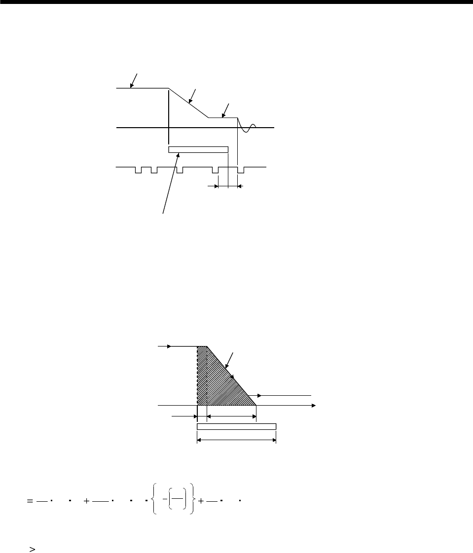
8 - 10
8. CALCULATION METHODS FOR DESIGNING
8.9 Precautions for zeroing
When a general positioning unit is used, the sequence of events is as shown in the following figure.
ON
Actuator signal
When determining the ON duration of the
actuator, consider the deceleration time so
that the speed reaches the creep speed.
Considering the variations of the
actuator signal, adjust the actuator
so that it switches off near the center
of the High of the zero pulse signal.
Z
ero pulse signal
Zeroing speed V1
Deceleration started by actuator signal
Creep speed V2
OFF
(1) When determining the ON duration of the actuator, consider the delay time of the control section and
the deceleration time so that the creep speed is attained. If the actuator signal switches off during
deceleration, precise home position return cannot be performed.
ON duration of the actuator LD
Deceleration time td
Zeroing speed V1
Travel distance gained after
detecting the zeroing dog until
the creep speed is reached L1
Control delay
t
ime t1
Creep speed V2
Travel distance L1 in the chart can be obtained by Equation 8.28
L1 1
60 V1t1 1
120 V1td1V1
V2
2
1
60 V1Tp........................................................................ (8.28)
ON duration of the actuator LD [mm] must be longer than L1 obtained by Equation 8.28, as indicated
in Equation 8.29
LD L1...................................................................................................................................................... (8.29)
where,
V1, V2: As shown in the chart [mm/min]
t1, td: As shown in the chart [s]
L1: As shown in the chart [mm]
LD: As shown in the chart [mm]
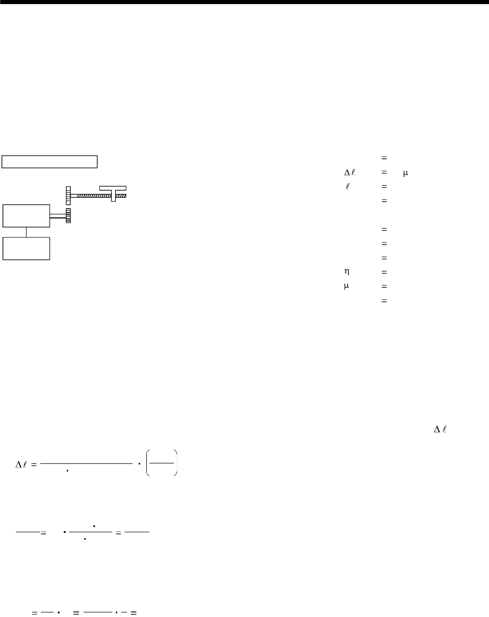
8 - 11
8. CALCULATION METHODS FOR DESIGNING
(2) Set the end (OFF position) of the actuator signal at the middle of two ON positions (Lows) of the zero
pulse signal. If it is set near either ON position of the zero pulse signal, the positioning unit is liable to
misdetect the zero pulse signal. In this case, a fault will occur, e.g. the home position will shift by one
revolution of the servo motor.
The zero pulse output position can be confirmed by OP (encoder Z-phase pulse) on the external I/O
signal display.
8.10 Selection example
Speed of moving part during fast feed V0 30000[mm/min]
Command resolution 10[ m]
Travel 400[mm]
Positioning time t0 within 1[s]
Number of feeds 40[times/min]
Operation cycle tf 1.5[s]
Gear ratio n 8/5
Moving part mass W 60[kg]
Drive system efficiency 0.8
Friction coefficient 0.2
Ball screw lead Pb 16[mm]
Ball screw diameter 20[mm]
Ball screw length 500[mm]
Gear diameter (servo motor) 25[mm]
Gear diameter (load shaft) 40[mm]
Machine specifications
Servo
motor
Servo
amplifier
Gear ratio 5:8
Gear face width 10[mm]
(1) Selection of control parameters
Setting of electronic gear (command pulse multiplication numerator, denominator)
There is the following relationship between the multiplication setting and travel per pulse .
8192 (gear ration)
(ball screw lead) CDV
CMX
When the above machining specifications are substituted in the above equation:
CDV
CMX 10 16 1000
8192 8/5 1000
8192
Acceptable as CMX/CDV is within 1/20 to 20.
(2) Servo motor speed
No Pb
V0n16
30000
5
83000[r/min]
8 - 12
8. CALCULATION METHODS FOR DESIGNING
(3) Acceleration/deceleration time constant
tpsa tpsd t0 V0/60 ts 0.05[s]
ts: settling time.(Here, this is assumed to be 0.15s.)
(4) Operation pattern
Servo motor speed
[r/min]
3000
Time
0.05
to 1.0
tf 1.5
0.05 ts
tpsa 0.15
[s]
tpsd
(5) Load torque (converted into equivalent value on servo motor shaft)
Travel per servo motor revolution
S Pb1
n 16 5
8 10[mm]
TL Wg S
210
3
0.2 60 9.8 10
210
33.14 0.8 0.23[N m]
8 - 13
8. CALCULATION METHODS FOR DESIGNING
(6) Load inertia moment (converted into equivalent value on servo motor shaft)
Moving part
JL1 W 20
2
S 1.52[kg cm2]
Ball screw
JL2 32
LD4n
2
1 0.24[kg cm2]
* 7.8 10 3[kg cm3]
Gear (servo motor shaft)
JL3 32
LD4 0.03[kg cm2]
Gear (load shaft)
JL4 32
LD4n
2
1 0.8[kg cm2]
Full load inertia moment (converted into equivalent value on servo motor shaft)
JL JL1 JL2 JL3 JL4 2.59[kg cm2]
(7) Temporary selection of servo motor
Selection conditions
(a) Load torque servo motor's rated torque
(b) Full load inertia moment 30 servo motor inertia moment
From the above, the HC-MF23 (200W) is temporarily selected.
(8) Acceleration and deceleration torques
Torque required for servo motor during acceleration
TMa (JL JM)No
9.55 104Tpsa TL 1.7[N m]
Torque required for servo motor during deceleration
TMd (JL JM)No
9.55 104Tpsd + TL 1.2[N m]
The torque required for the servo motor during deceleration must be lower than the servo motor's
maximum torque.
8 - 14
8. CALCULATION METHODS FOR DESIGNING
(9) Continuous effective load torque
Trms tf
T tpsa Ttc T
222
Ma L Md tpsd 0.42[N m]
The continuous effective load torque must be lower than the servo motor's rated torque.
(10) Torque pattern
Torque
1.7
[N m]
0.23
1.2
Time [s]
0.05 0.75 0.05
1.5
0.15
(11) Selection results
The HC-MF23 servo motor and MR-J2-20A servo amplifier are selected.
(a) Electronic gear setting
CMX 8192
CDV 1000
(b) During rapid feed
Servo motor speed N0 3000 [r/min]
(c) Acceleration/deceleration time constant
tpsa tpsd 0.05[s]
App. - 1
A
PPENDIX
App. 1 Servo motor ID codes
Motor series ID Motor type ID Encoder ID Servo motor
F053 HC-MF053
FF13 HC-MF13
FF23 HC-MF23
FF43 HC-MF43
02
FF73 HC-MF73
F053 HA-FF053
FF13 HA-FF13
FF23 HA-FF23
FF33 HA-FF33
FF43 HA-FF43
11
FF63 HA-FF63
F053 HC-KF053
FF13 HC-KF13
FF23 HC-KF23
FF43 HC-KF43
12
FF73
003D
HC-KF73
FF81 HC-SF81
F121 HC-SF121
F201 HC-SF201
F301 HC-SF301
FF52 HC-SF52
F102 HC-SF102
F152 HC-SF152
F202 HC-SF202
F352 HC-SF352
F502 HC-SF502
F702 HC-SF702
FF53 HC-SF53
F103 HC-SF103
21
F153 HC-SF153
F203 HC-SF20322
F353 HC-SF353
FF13 HC-UF13
FF23 HC-UF23
FF43 HC-UF43
FF73 HC-UF73
FF32 HC-UF32
FF72 HC-UF72
F152 HC-UF152
31
F202
003C
HC-UF202
F103 HC-RF103
F153 HC-RF153
41
F203
003C
HC-RF203
F053 HC-MFS053
FF13 HC-MFS13
FF23 HC-MFS23
FF43 HC-MFS43
02
FF73 HC-MFS73
F053 HC-KFS053
FF13 HC-KFS13
FF23 HC-KFS23
FF43 HC-KFS43
12
FF73
0041
HC-KFS73
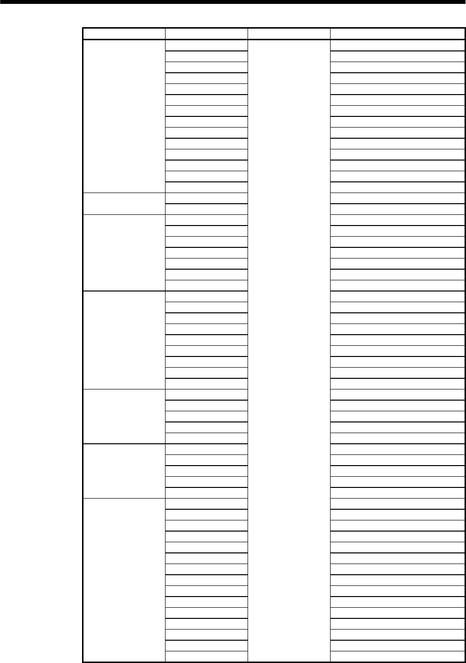
App. - 2
A
PPENDI
X
Motor series ID Motor type ID Encoder ID Servo motor
FF81 HC-SFS81
F121 HC-SFS121
F201 HC-SFS201
F301 HC-SFS301
FF52 HC-SFS52
F102 HC-SFS102
F152 HC-SFS152
F202 HC-SFS202
F352 HC-SFS352
F502 HC-SFS502
F702 HC-SFS702
FF53 HC-SFS53
F103 HC-SFS103
21
F153 HC-SFS153
F203 HC-SFS20322
F353 HC-SFS353
FF52 HC-SFS524
F102 HC-SFS1024
F152 HC-SFS1524
F202 HC-SFS2024
F352 HC-SFS3524
F502 HC-SFS5024
24
F702 HC-SFS7024
FF13 HC-UFS13
FF23 HC-UFS23
FF43 HC-UFS43
FF72 HC-UFS72
FF73 HC-UFS73
F152 HC-UFS152
F202 HC-UFS202
F352 HC-UFS352
31
F502 HC-UFS502
F103 HC-RFS103
F153 HC-RFS153
F203 HC-RFS203
F353 HC-RFS353
41
F503 HC-RFS503
FF52 HC-LFS52
F102 HC-LFS102
F152 HC-LFS152
F202 HC-LFS202
51
F302 HC-LFS302
F601 HA-LFS601
F801 HA-LFS801
1201 HA-LFS12K1
1501 HA-LFS15K1
2001 HA-LFS20K1
2501 HA-LFS25K1
3001 HA-LFS30K1
3701 HA-LFS37K1
F502 HA-LFS502
F702 HA-LFS702
1102 HA-LFS11K2
1502 HA-LFS15K2
2202 HA-LFS22K2
3002 HA-LFS30K2
53
3702
0041
HA-LFS37K2
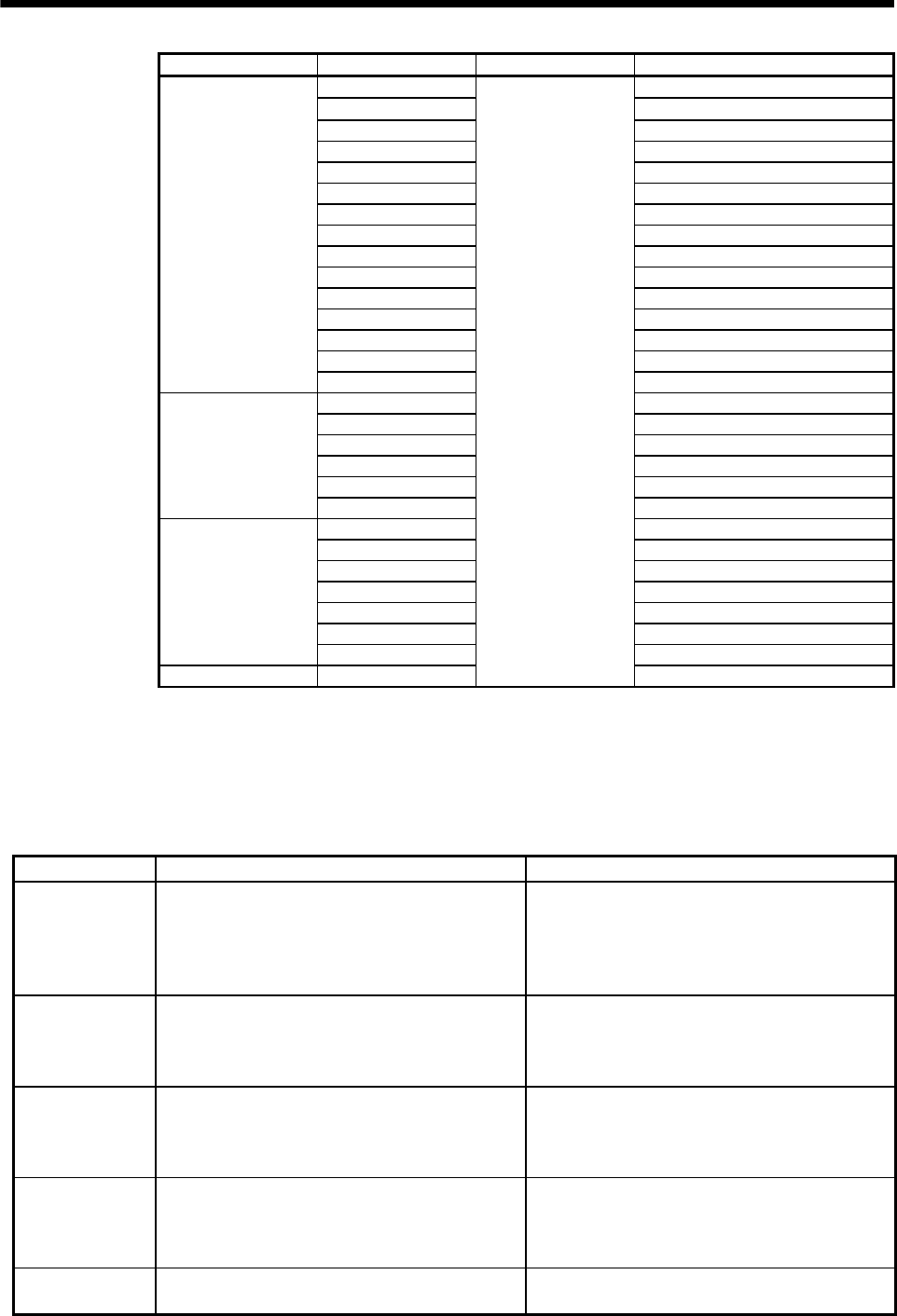
App. - 3
A
PPENDI
X
Motor series ID Motor type ID Encoder ID Servo motor
F601 HA-LFS6014
F801 HA-LFS8014
1201 HA-LFS12K14
1501 HA-LFS15K14
2001 HA-LFS20K14
1102 HA-LFS11K24
1502 HA-LFS15K24
2202 HA-LFS22K24
2501 HA-LFS25K14
3001 HA-LFS30K14
3701 HA-LFS37K14
3002 HA-LFS30K24
3702 HA-LFS37K24
4502 HA-LFS45K24
54
5502 HA-LFS55K24
F701 HA-LFS701M
1101 HA-LFS11K1M
1501 HA-LFS15K1M
2201 HA-LFS22K1M
3001 HA-LFS30K1M
55
3701 HA-LFS37K1M
F701 HA-LFS701M4
1101 HA-LFS11K1M4
1501 HA-LFS15K1M4
2201 HA-LFS22K1M4
3001 HA-LFS30K1M4
3701 HA-LFS37K1M4
56
4501 HA-LFS45K1M4
57 5001
0041
HA-LFS50K1M4
App. 2 Change of connector sets to the RoHS compatible products
The following connector sets have been changed to RoHS compliant since September 2006.
RoHS compliant and non-RoHS compliant connector sets may be mixed based on availability.
Only the components of the connector set that have changed are listed below.
Model Current Product RoHS Compatible Product
MR-ENCNS Amplifier connector (3M or equivalent)
10120-3000VE (connector)
MS3106A20-29S (D190) (Plug, DDK)
CE3057-12A-3 (D265) (Cable clump, DDK)
CE02-20BS-S (Back shell, DDK)
Amplifier connector (3M or equivalent)
10120-3000PE (connector)
D/MS3106A20-29S (D190) (Plug, DDK)
CE3057-12A-3-D (Cable clump, DDK)
CE02-20BS-S-D (Back shell, DDK)
MR-PWCNS1 Power supply connector (DDK)
CE05-6A22-23SD-B-BSS (Connector and back
shell)
CE3057-12A-2 (D265) (Cable clump)
Power supply connector (DDK)
CE05-6A22-23SD-D-BSS (Connector and back
shell)
CE3057-12A-2-D (Cable clump)
MR-PWCNS2 Power supply connector (DDK)
CE05-6A24-24SD-B-BSS (Connector and back
shell)
CE3057-16A-2 (D265) (Cable clump)
Power supply connector (DDK)
CE05-6A24-10SD-B-BSS (Connector and back
shell)
CE3057-16A-2-D (Cable clump)
MR-PWCNS3 Power supply connector (DDK)
CE05-6A32-17SD-B-BSS (Connector and back
shell)
CE3057-20A-1 (D265) (Cable clump)
Power supply connector (DDK)
CE05-6A32-17SD-D-BSS (Connector and back
shell)
CE3057-20A-1-D (Cable clump)
MR-BKCN Electromagnetic brake connector
MS3106A10SL-4S (D190) (Plug, DDK)
Electromagnetic brake connector
D/MS3106A10SL-4S (D190) (Plug, DDK)

REVISIONS
*The manual number is given on the bottom left of the back cover.
Print Data *Manual Number Revision
May.,1998 SH(NA)3181-A First edition
Sep.,1998 SH(NA)3181-B HA-LH11K2 to 22K2 added
HC-SF502(B), 702(B) added
HC-RF353(B), 503(B) added
HC-UF352(B), 502(B)/HC-UF73(B) added
UL/C-UL Standard: Flange size list modified
Section 1.3: Terminal box type added
Chapter 3: Overall changes
Section 5.1: Applicable servo amplifier and regenerative brake duty added for
MR-H -N
Power supply capacity deleted
Section 5.3: HC-MF's permissible speed changed
Section 7.1.1 (2), (c), 2): HA-FF053BG1 1/5 inertia moment changed
Section 7.3: Reviewed due to overall changes to Chapter 3
Feb.,1999 SH(NA)3181-C HC-KF23(B), 43(B) added
HC-AQ0135(B) to 0335(B) added
HA-LF30K24 to 55K24 added
HC-UF-S1 added
UL/C-UL Standard: Flange size list modified
Section 1.1: Servo motor feature list modified
Section 1.2, (2), (h): HC-KF, HC-AQ, HA-LF added to the models
Section 2.1: HC-KF, HC-AQ, HA-LF added to the list
Section 2.3: Sentence modified
Section 2.5: HC-KF, HC-AQ, HA-LF added to the list
Section 2.6: HC-KF, HC-AQ, HA-LF added
Section 2.7: Addition
Section 3.1.4: HC-AQ added
Section 3.2: List modified
Section 3.3: HC-AQ added
Section 5.1: HC-KF, HC-AQ, HA-LF added
Insulation class added
Regenerative brake duty changed: HC-SF121, HC-SF301,
HC-RF503,HC-UF72, HC-UF152, HC-UF23, HC-UF43, HC-UF73
Rated current, maximum current changed: HC-SF702
Section 5.2: HC-KF, HC-AQ, HA-LF added
HC-UF73 modified
Section 5.3: HC-KF added
Section 6.1: HC-KF, HC-AQ added
Section 7.1.1: HC-UF73 modified
HC-UF73B, HC-UF-S1, HC-KF, HC-AQ, HA-LF added
Section 7.1.2: HC-KF-UE added
Section 7.2.1: HC-UF73 modified
HC-UF73B, HC-UF-S1, HC-KF, HC-AQ, HA-LF added
Section 7.2.2: HC-KF-UE added
Mar., 2000 SH(NA)3181-D HC-KFS, HC-MFS, HC-SFS, HC-RFS, HC-UFS, HC-LF30K2 addition
Section 1.1: Motor addition
Section 1.2: Motor addition
Section 2.1: Table modification
Section 2.2: Motor addition
Section 2.5: Motor addition
Section 2.6: Sentence change, motor addition to table
Sections 3.1.1 to 3.1.3: Reconsideration

Print Data *Manual Number Revision
Mar., 2000 SH(NA)3181-D Section 3.1.5: Reconsideration
Sections 3.2, 3.3: Motor addition
Section 5.1: Note 12 change, motor addition
Sections 5.2 to 5.4: Motor addition
Section 7.1: Item reconsideration, motor addition
HC-MF, HC-KF, HC-UF3000r/min outline drawing change
Section 7.2 (3): Plug addition
Feb., 2001 SH(NA)3181-E Addition of HC-KFS73, HC-SFS502 702, HC-RFS352 502 and
HC-UFS502
COMPLIANCE WITH EC DIRECTIVES 2. (B): Addition of servo motors
Section 1.1: Correction to error in writing of HA-LF
Standard models of HC-KF and HC-MF are made compliant with
overseas standards.
Section 1.2: Addition of servo motors
Section 2.1: Change of vibration conditions
Section 2.4 (9): Addition of sentence
Section 2.5 (3): Deletion of Note 2
Section 2.6 (2): Deletion of Note 2
Section 3.1.3: Addition of servo motors
Section 3.2: Addition of servo motors
Section 5.1: Addition of servo motor specifications
Deletion of HC-SF52 and MR-RB32 combinations
Deletion of HC-SF53 and MR-RB32 combinations
Change of the number of regenerative frequencies of HC-UF72
(previously 102, 305, 508 from top to bottom)
Change of HC-KF series and HA-LF series servo amplifier
combinations
HA-LF30K2's previous rated current 83A, maximum current
208A, cooling fan rated current 0.32 (50Hz)/63 (50Hz)
Deletion of HC-SFS52 and MR-RB32 combinations
Deletion of HC-SFS53 and MR-RB32 combinations
Deletion of HC-UFS72 and MR-RB32 combinations
Addition of Note 13
Section 5.2: Addition of torque characteristics
Section 5.3 (1): Addition of servo motors
Section 5.3 (2): Previous permissible load inertia moment
HC-KF, HC-KFS: 25 times
HC-MF, HC-MFS: 5 times
Section 5.3 (4)(C) 1): Previously 2000 hours
Section 5.3 (4)(C) 2): Previously 25000 hours at second time and later
Section 5.4: Addition of servo motors
Section 6.1 (1): HC-KF series 23B, 43B
Previous permissible braking work done per braking
4500[N Em]
Previous permissible braking work done per braking
45000[N Em]
Section 7.1: Addition of servo motors
Oct., 2002 SH(NA)3181-F Safety Instructions: Environmental condition table modification
Addition of About processing of waste
Addition of FOR MAXIMUM SAFETY
Reexamination of table in COMPLIANCE WITH EC
DIRECTIVES
Addition of text to the UL/C-U Standards, addition of HA-
LF, HA-LFS series
Section 1.1: Addition of HA-FF, HA-LFS, HC-LFS, addition of Note sentences

Print Data *Manual Number Revision
Oct., 2002 SH(NA)3181-F Section 1.2: Change/deletion of rating plate, addition of (o) HA-LFS series,
addition of (p) HC-LFS series
Section 1.2 (2) (i): Change of HA-LF series contents
Section 1.3: Change of terminal box type motor diagram
Chapter 2: Addition of CAUTION sentences, deletion of transportation item
Section 2.1: Addition of HA-LFS, HC-LFS series
Section 2.2: Addition of HA-LFS
Section 2.3: Change of (6) into POINT
Section 2.4: Addition of POINT, change of (3) text
Addition of HC-KF, HC-KFS73, HA-LFS, HC-LFS
Section 2.4.1: Addition
Section 2.4.2: Addition
Section 2.5: Addition of (6), (7), (8)
Section 2.5 (1): Addition of HA-LFS, HC-LFS series
Section 2.5 (2): Partial change of text, addition of HA-LFS, HC-LFS
Section 2.5 (5): Partial change of text
Section 2.6: Addition of HA-LFS
Section 2.7: Change
Section 3.1: Reexamination of table
Section 3.1.3: Addition of HA-LFS, HC-LFS
Section 3.1.6: Item addition
Section 3.2: Addition of HA-LFS, HC-LFS series
Section 3.3: Addition of HA-LFS, HC-LFS series
Chapter 4: Addition of (d)
Chapter 4 (2): Partial change of table
Section 5.1: Reexamination of table
Addition of HA-LF series 37K2
Addition of HC-MFS series, HC-KFS series compatible servo
amplifiers
Addition of HC-UFS series compatible servo amplifiers
Addition of HA-LFS, HC-LFS series
Reexamination of Note sentences
Section 5.2: Partial deletion of POINT sentences, addition of items (10) to (13)
Section 5.2 (1): Addition of POINT, reexamination of graph
Section 5.2 (2): Addition of POINT, reexamination of graph
Section 5.2 (5): Addition of POINT, reexamination of graph
Section 5.2 (7): Change of HC-KF053 graph, reexamination of graph
Section 5.3 (1): Addition of Note sentences
Section 5.3 (2): Partial deletion of table
Section 5.3 (4) (c): Change of title
Section 5.4: Addition of HC-LFS series
Section 5.4.1 (2): Addition of HC-LFS series
Section 6.1: Addition of CAUTION sentences
Section 6.1 (1): Addition of text, reexamination of table, addition of HC-LFS
series
Section 6.1 (2): Deletion of diagrams in (a), (b)
Section 6.3: Addition
Section 7.1: Addition of Note sentences, addition of text in With reduction gear
Section 7.1.1 (3) (a): Change of BC12066, BC12067 outline drawings
Section 7.1.1 (3) (b): Change of BC12071, BC12072 outline drawings
Section 7.1.2 (4) (b): Partial change of HA-FF13BG2 inertia moment values
Section 7.1.3 (3) (a): Partial reexamination of outline drawing sub numbers
Section 7.1.3 (3) (b): Partial reexamination of outline drawing sub numbers
Section 7.1.3 (4) (a): Partial reexamination of outline drawing sub numbers
Section 7.1.3 (4) (b): Partial reexamination of outline drawing sub numbers

Print Data *Manual Number Revision
Oct., 2002 SH(NA)3181-F Section 7.1.4 (2): Change of HC-RF(S)353B, HC-RF(S)503B variable
dimensions
Section 7.1.7: Addition of title
Section 7.1.9: Reexamination of variable dimensions and inertia moment
values, change of HC-AQ series outline drawings
Section 7.1.10: Reexamination of terminal box detail drawings and tables,
addition of HA-LF37K2 outline drawing
Section 7.1.11 (1): Partial change of HC-KFS73 inertia moment values, partial
reexamination of sub numbers
Section 7.1.11 (3) (a): Change of BC11896, BC11897 outline drawings
Section 7.1.11 (3) (b): Change of BC11901, BC11902 outline drawings
Section 7.1.13: Addition of HA-LFS series outline drawings
Section 7.1.14: Addition of item (addition of HC-LFS outline drawing)
Section 7.2: Addition of POINT, addition of text in With reduction gear
Section 7.2.1 (3) (a): Change of BC12066, BC12067 outline drawings
Section 7.2.1 (3) (b): Change of BC12071, BC12072 outline drawings
Section 7.2.2 (4) (b): Partial change of HA-FF13BG2 inertia moment values
Section 7.2.3 (3) (a): Partial reexamination of outline drawing sub numbers
Section 7.2.3 (3) (b): Partial reexamination of outline drawing sub numbers
Section 7.2.3 (4) (a): Partial reexamination of outline drawing sub numbers
Section 7.2.3 (4) (b): Partial reexamination of outline drawing sub numbers
Section 7.2.4 (2): Change of HC-RF(S)353B, HC-RF(S)503B variable
dimensions
Section 7.2.7: Change of title
Section 7.2.9: Reexamination of variable dimensions and inertia moment
values, change of HC-AQ series outline drawings
Section 7.2.10: Reexamination of terminal box detail drawings and tables,
addition of HA-LF37K2 outline drawing
Section 7.2.11 (1): Partial change of HC-KFS73 inertia moment values, partial
reexamination of sub numbers
Section 7.2.11 (3) (a): Change of BC11896, BC11897 outline drawings
Section 7.2.11 (3) (b): Change of BC11901, BC11902 outline drawings
Section 7.2.13: Addition of HA-LFS series outline drawings
Section 7.2.14: Addition of item (addition of HC-LFS outline drawing)
Section 7.3 (1): Addition of loose piece
Section 7.3 (2) (b): Addition of Note sentences
Section 7.3 (2) (d): Addition of Note sentences
Section 7.3 (4): Addition
Section 8.1: Reexamination of table
Section 8.7: Addition
Section 8.8: Reexamination of table
Appendices: Addition of HA-LFS, HC-LFS series
Jun., 2003 SH(NA)3181-G Safety Instructions: Addition of 400VAC compatible HA-LFS and 400VAC
compatible HC-SFS to Environmental Condition table
Addition of 400VAC compatible HC-SFS to 2. in
COMPLIANCE WITH EC DIRECTIVES
Addition of 400VAC compatible HA-LFS and 400VAC
compatible HC-SFS to COMFORMANCE WITH UL/C-UL
STANDARD
Section 1.1: Addition of 400VAC compatible HA-LFS and 400VAC compatible
HC-SFS, and reexamination of whole table
Addition of (6), (7), (8)
Section 1.2: Rating plate change
Section 1.2 (I): Addition of 400VAC compatible HC-SFS
Section 1.2 (O): Addition of electromagnetic brake/shaft type to 200VAC
compatible HA-LFS, addition of 400VAC compatible HA-LFS

Print Data *Manual Number Revision
Jun., 2003 SH(NA)3181-G Chapter 2: Partial change of CAUTION sentence
Section 2.1: Addition of 400VAC compatible HA-LFS and 400VAC compatible
HC-SFS to Environmental Condition table
Section 2.4: Addition of Item (4)
Section 2.4.1: Addition of 400VAC compatible HA-LFS and 400VAC
compatible HC-SFS, addition of Note 3
Section 2.4.2 (3): Addition of 400VAC compatible HC-SFS
Section 2.4.2 (4): Permissible thrust load1/20 value change
Section 2.5 (2): Addition of 400VAC compatible HA-LFS and 400VAC
compatible HC-SFS
Section 2.6: Addition of 400VAC compatible HA-LFS
Section 3.1.3: Addition of 400VAC compatible HA-LFS and 400VAC
compatible HC-SFS
Section 3.2: Addition of 400VAC compatible HC-SFS
Section 5.1: Reexamination of whole table, addition of 400VAC compatible HA-
LFS and 400VAC compatible HC-SFS, partial change of Note 10,
addition of Note 14, 15, 16
Section 5.2: Addition of POINT sentence
Section 5.2 (3): Addition of 400VAC compatible HC-SFS,
HC-SF(S)81/102/202/103 graph change
Section 5.2 (5): HC-UF(S)72/152 graph change
Section 5.2 (9): Addition of HA-LF37K2
Section 5.2 (10): Addition of 400VAC compatible HA-LFS, HA-LFS15K1 graph
change
Section 5.3: Addition of 400VAC compatible HC-SFS
Section 5.4: Addition of HA-LF series, HA-LFS series and 400VAC compatible
HC-SFS
Section 5.4.1: Reexamination, key-less table change
Section 6.1 (1): Addition of 400VAC compatible HC-SFS, addition of HA-LFS
series, addition of Note 7
Section 6.3: Partial reexamination
Section 7.1.3: Addition of 400VAC compatible HC-SFS
Section 7.1.10: Terminal box detail diagram change
Section 7.1.13: Terminal box detail diagram change, addition of 400VAC
compatible HA-LFS, overall reexamination, addition of model
with electromagnetic brake
Section 7.2.3: Addition of 400VAC compatible HC-SFS
Section 7.2.10: Terminal box detail diagram change
Section 7.2.13: Terminal box detail diagram change, addition of 400VAC
compatible HA-LFS, overall reexamination, addition of model
with electromagnetic brake
Appendices: Addition of 400VAC compatible HA-LFS and 400VAC compatible
HC-SFS to servo motor ID codes
Sep., 2003 SH(NA)3181-H Safety Instructions: Partial change of text in 3
Addition of HC-SFS524, 1024, 1524, 2024 and 7024, and
HA-LFS6014 and 701M4 to the environment condition
table
Addition of HC-SFS524, 1024, 1524, 2024 and 7024 to the
table in (b) of COMPLIANCE WITH EC DIRECTIVES
Addition of HC-SFS524, 1024, 1524, 2024 and 7024, and
HA-LFS6014 and 701M4 and addition of Note to the
UL/C-UL STANDARD
Section 1.1: Change of the capacities supported by HC-SFS400V and partial
change of the capacities supported by HA-LFS400V
Section 1.2 (2) (l) 2): Rated output addition
Section 1.2 (2) (o) 2): Rated output addition

Print Data *Manual Number Revision
Sep., 2003 SH(NA)3181-H Section 2.1: Addition of HC-SFS524, 1024, 1524, 2024 and 7024, and HA-
LFS6014 and 701M4 to the environment condition table
Section 2.4.1: Addition of HC-SFS524, 1024, 1524, 2024 and 7024, and HA-
LFS6014 and 701M4, change of Note 3 sentence
Partial addition of Note
Section 2.4.2 (3) (a): Addition of HC-SFS524(B)G1, 1024(B)G1, 1524(B)G1,
2024(B)G1 and 7024(B)G1
Section 2.4.2 (3) (b): Addition of HC-SFS524(B)G2, 1024(B)G2, 1524(B)G2,
2024(B)G2 and 7024(B)G2
Section 2.5 (2): Addition of HC-SFS524, 1024, 1524, 2024 and 7024, and HA-
LFS6014 and 701M4
Section 2.6: Addition of HA-LFS6014 and 701M4
Section 3.1.3: Addition of HC-SFS524, 1024, 1524, 2024 and 7024, and HA-
LFS6014 and 701M4
Section 3.2: Addition of HC-SFS524, 1024, 1524, 2024 and 7024
Section 5.1: Addition of HC-SFS524, 1024, 1524, 2024 and 7024, and HA-
LFS6014 and 701M4, addition of Note 14 to HA-LFS200V/400V
table, reexamination of HA-LFS25K14 regenerative brake duty
Section 5.2 (3) (b): Addition of HC-SFS524, 1024, 1524, 2024 and 7024
Section 5.2 (10) (b): Change of Note 1
Section 5.3: Addition of HC-SFS524, 1024, 1524, 2024 and 7024
Section 5.3 (2): Partial change of table contents
Section 5.4: Addition of HC-SFS524, 1024, 1524, 2024 and 7024
Section 5.4.1 (2): Addition of HC-SFS524K, 1024K, 1524K, 2024K and 7024K,
and HA-LFS6014K and 701M4K
Section 6.1: Addition of HC-SFS524B, 1024B, 1524B, 2024B and 7024B, and
HA-LFS6014B and 701M4B, change of Note 7, addition of (4)
Section 6.1 (1): Partial change
Section 7.1.3: Addition of HC-SFS524, 1024, 1524, 2024 and 7024
Section 7.1.13: Addition of HA-LFS6014 and 701M4, partial addition of Note
Section 7.2.3: Addition of HC-SFS524, 1024, 1524, 2024 and 7024
Section 7.2.13: Addition of HA-LFS6014 and 701M4, partial addition of Note
Appendix: Addition of HC-SFS524, 1024, 1524, 2024 and 7024, and HA-
LFS6014 and 701M4
Oct., 2004 SH(NA)3181-J Safety Instructions 4 (1): Note change
4 (5): Circuit diagram change
Section 1.1: HC-UF, HC-UFS, HC-AQ feature representation change
Section 1.2 (2): Remarks addition and change to the axis type field of (a) to (e),
(g), (h), (i) to (o), item addition to (j) axis type field, and axis
type addition to (p)
Section 3.1.3 (2): (a)-3, (b)-3 Servo motor model addition
Section 5.1: Speed/position detection, equipment item contents change, HC-UF
3000 revolutions MR-J2 series regenerative brake duty, HC-SFS
2000 revolutions instantaneous revolution permissible speed, and
rated current value were changed, HC-SFS series, HC-UFS 3000
revolutions regenerative brake duty change, HA-LFS 1000
revolutions, 1500 revolutions, 2000 revolutions 37K rated output
contents addition, HA-LFS 1000 revolutions rated current change,
HA-LFS6014 regenerative brake duty change, addition of MR-
RB54-4 to the regenerative brake duty item, MR-RB34-4, MR-RB-
54-4 addition and rated current value change to the regenerative
brake duty item of HA-LFS 1500 revolutions, HA-LFS 2000
revolutions rated current value change, HC-LFS series compatible
servo amplifier change
Section 5.2: Operation in graph changed to running.

Print Data *Manual Number Revision
Oct., 2004 SH(NA)3181-J Section 5.2 (3): Remarks addition
Graph change to HC-SF(S)52, HC-SF(S)102, HC-SF(S)152, HC-
SF(S)202, HC-SF(S)702 in (a) and HC-SFS524, HC-SFS1024,
HC-SFS1524, HC-SFS2024, HC-SFS3524, HC-SFS7024 in (b)
Section 5.2 (4): HC-RF(S)203, HC-RF(S)503 graph change
Section 5.2 (5): HC-UF(S)202 graph change
Section 5.2 (10): HA-LFS15K1M, HA-LFS22K2 graph change in (a), HA-
LFS15K14 addition and HA-LFS30K14, HA-LFS37K14, HA-
LFS11K1M4, HA-LFS15K1M4, HA-LFS22K1M4, HA-
LFS30K1M4, HA-LFS37K1M4, HA-LFS45K1M4, HA-
LFS50K1M4, HA-LFS15K24, HA-LFS22K24, HA-LFS45K24
graph change in (b)
Section 5.3 (2): Remarks addition
Section 5.3 (3): Remarks addition
Section 5.3 (4): Remarks addition, text change
Section 5.3 (5): Remarks addition
Section 6.1: Correction to mistakes in writing
Section 6.1 (2): Circuit diagram change
Section 6.1 (4): Text addition
Section 7.1.4: Text addition
Section 7.1.11: Text addition
Section 7.1.13 (1): Deletion of Note 3 from HA-LFS15K1, etc., addition of Note
3 to HA-LFS25K1
Section 7.1.13 (4)(b): Correction to mistakes in writing
Section 7.2.11 (4)(b): Correction to mistakes in writing
Section 8.1: Item deletion
Appendices: Memo page deletion
Dec., 2005 SH(NA)3181-K Safety Instructions (2): A precaution for wiring is added
(4): A precaution for usage is added
Service life of this product: added
Service life of EEP-ROM: added
Guarantee: added
Conformance with UL/C-UL standard: Partially changed
Section 5.1: HA-LF37K2 clerical error on rated current is modified to 204A,
and maximum current is modified to 510A
HC-KF23 43 clerical error on power rate at continuous rated
torque is modified
HC-KF23 43 clerical error on inertia moment ratio is modified
HC-KF23 43 recommended load inertia moment ratio to a servo
motor axis is modified
HC-KFS23 43 clerical error on power rate at continuous rated
torque is modified
HC-KFS23 43 clerical error on inertia moment ratio is modified
HC-KFS23 43 recommended load inertia moment ratio to a servo
motor axis is modified
Section 5.3 (2): Note about reduction ratio of the reduction gear is added
Section 5.3 (3): Note about reduction ratio of the reduction gear is added
Section 5.3 (4): Note about reduction ratio of the reduction gear is added
Section 5.3 (5): Note about reduction ratio of the reduction gear is added
Section 5.3 (4)(b): Point is added
Chapter 7: Braking force is changed to static friction torque
Section 7.1.1: HC-KF23 43 clerical error on inertia moment ratio is modified
Section 7.1.2 (4)(b): Clerical error is modified
Section 7.1.2 (5)(a): Clerical error is modified
Section 7.1.2 (5)(b): Clerical error is modified
Section 7.1.3 (3): Clerical error is modified

Print Data *Manual Number Revision
Dec., 2005 SH(NA)3181-K Section 7.1.4 (3)(a): Clerical error is modified
Section 7.1.11 (1): HC-KFS23 43 clerical error on inertia moment ratio is
modified
Section 7.1.11 (2): HC-KFS23 43 clerical error on inertia moment ratio is
modified
Section 7.1.11 (3): HC-KFS23 43 clerical error on inertia moment ratio is
modified
Section 7.1.11 (4): HC-KFS23 43 clerical error on inertia moment ratio is
modified
Section 7.1.13: Detailed drawing of terminal box is reviewed
Section 7.2.1 (1): HC-KF23 43 clerical error on inertia moment ratio is
modified
Section 7.2.1 (2): HC-KF23 43 clerical error on inertia moment ratio is
modified
Section 7.2.1 (3): HC-KF23 43 clerical error on inertia moment ratio is
modified
Section 7.2.1 (4): HC-KF23 43 clerical error on inertia moment ratio is
modified
Section 7.2.1 (5): HC-KF23 43 clerical error on inertia moment ratio is
modified
Section 7.2.2 (5): Clerical error is modified
Section 7.2.3 (3): Clerical error is modified
Section 7.2.3 (5): Clerical error is modified
Section 7.2.4 (3): Clerical error is modified
Section 7.2.5 (1): Clerical error is modified
Section 7.2.11 (2): HC-KF23 43 Clerical error on inertia moment ratio is
modified
Section 7.2.11 (3): HC-KF23 43 Clerical error on inertia moment ratio is
modified
Section 7.2.11 (4): HC-KF23 43 Clerical error on inertia moment ratio is
modified
Section 7.2.13: Detailed drawing of terminal box is reviewed
May, 2008 SH(NA)3181-L Safety Instructions
1. To prevent electric shock: WARNING: Partial change of sentence
2. To prevent fire: CAUTION: Partial change of sentence
4. Additional Instructions
(2) Wiring: CAUTION: Addition of diagram and sentence
(5) Corrective actions: Circuit diagram change
COMPLIANCE WITH EC DIRECTIVE: (3) Addition of performing EMC tests
Section 1.2 (2)(a): Rated output unit changed to [kW]
Chapter 2: CAUTION: Partial change of sentence
Section 2.6: Partial change of servo motor list
Section 3.1: DDK connectors changed to RoHS compatible
Section 3.2: DDK connectors changed to RoHS compatible
Section 4.1: Addition of a sentence in WARNING reminding about
confirmation of powering off charge lamp
Section 5.1: Change of specifications of HA-LFS series and cooling fan power
supply and current
Section 5.2: Addition of 400VAC compatible HA-LFS series graph
Section 5.3: Change of HC series permissible load inertia moment ratio
Section 5.4: Partial change of shaft dimensions
Section 5.4.1 (2): Key shaft (QK) dimensions of HC-UF/UFS (152K, 202K to
502K) modified
Section 6.1: Addition of diagram and sentence

Print Data *Manual Number Revision
May, 2008 SH(NA)3181-L Section 7.1.3 (3): Change of outline drawings
Note added
''HC-SFS52G1H 102G1H 152G1H 524G1H 1024G1H
1524G1H''
''HC-SFS52G1H 524G1H''
''HC-SFS202G1H 2024G1H''
''HC-SFS52BG1H 102BG1H 152BG1H 524BG1H 1024BG1H
1524BG1H''
''HC-SFS52BG1H 524BG1H''
''HC-SFS202BG1H 2024BG1H''
''HC-SFS52G1 102G1 152G1 524G1 1024G1 1524G1''
''HC-SFS52G1 524G1''
''HC-SFS202G1 2024G1''
''HC-SFS52BG1 102BG1 152BG1 524BG1 1024BG1
1524BG1''
''HC-SFS52BG1 524BG1''
''HC-SFS202BG1 2024BG1''
Section 7.1.13: Partial change of terminal box detail diagram
Section 7.1.13 (1): Change of outline drawings
''HA-LFS8014 11K1M 11K1M4 15K2 15K24''
''HA-LFS12K1 12K14 15K1M 15K1M4 22K2 22K24''
''HA-LFS15K1 15K14 22K1M 22K1M4 30K24''
''HA-LFS20K1 20K14 30K1M4 37K24''
''HA-LFS25K1 25K14 37K1M 37K1M4 45K24''
''HA-LFS30K1 30K14 45K1M4 55K24''
''HA-LFS37K1 37K14 50K1M4''
''HA-LFS30K1M 37K2''
''HA-LFS30K2''
''HA-LFS801B 8014B 11K1MB 11K1M4B 15K2B 15K24B
12K1B 12K14B 15K1MB 15K1M4B 22K2B 22K24B''
Section 7.2.3 (3): Change of same outline drawings as Section 7.1.3 (3)
Section 7.2.13: Partial change of terminal box detail diagram
Section 7.2.13 (1): Change of same outline drawings as Section 7.1.13 (1)
Section 7.3: DDK connectors changed to RoHS compatible
App. 2: Addition of RoHS compatible connector sets list
SH(NA)3181-L

L
Servo Motor Instruction Manual
SH (NA) 3181-L (0805) MEE Printed in Japan Specifications subject to change without notice.
This Instruction Manual uses recycled paper.
MODEL
MODEL
CODE 1CW940
MOTOR INSTRUCTION
General-Purpose AC Servo
MODEL
Servo Motor
INSTRUCTION MANUAL
L
HEAD OFFICE : TOKYO BLDG MARUNOUCHI TOKYO 100-8310
