Mitsumi Electric Co DWMW314K WIRELESS LAN + BLUETOOTH MODULE User Manual
Mitsumi Electric Co Ltd WIRELESS LAN + BLUETOOTH MODULE Users Manual
UserManual.wiki
>
Mitsumi Electric Co
>
DWMW314K User Manual
>
Users Manual
Contents
1.
Users Manual
2.
04 User Manual
Users Manual
Navigation menu
Upload a User Manual
Namespaces
Wiki Guide
HTML
PDF
Info
Views
User Manual
Discussion / Help
Navigation
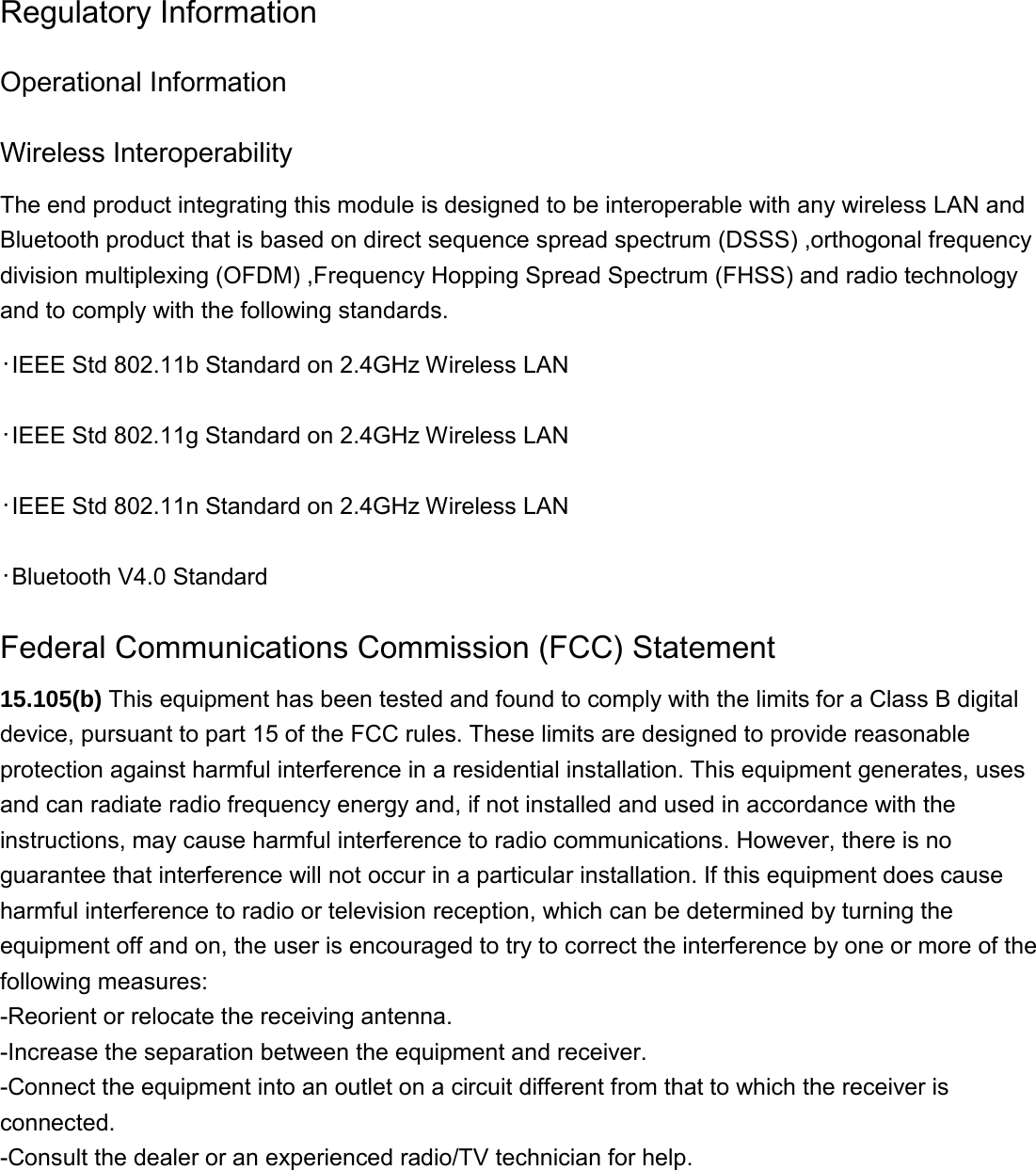
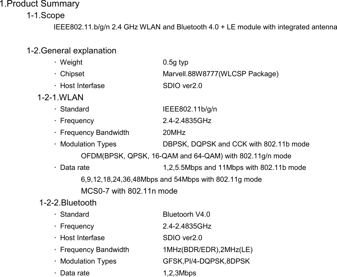
![2.Hardware Specification 2-1. Block diagram 2-2.Environmental condition 1) Operating environment Operating temperature range -20 ~ 70 ℃ ※Temperature on the bottom of the module Operating humidity range 20%~80% (None dew) 2) Storage environment Storage temperature range -30 ~ 85 ℃ Storage humidity range 20%~85% (None dew) 2-3.Power supply Item Min.[V] TYP. Max.[V] VDD33 2.97 3.30V 3.63](https://usermanual.wiki/Mitsumi-Electric-Co/DWMW314K.Users-Manual/User-Guide-3221385-Page-7.png)
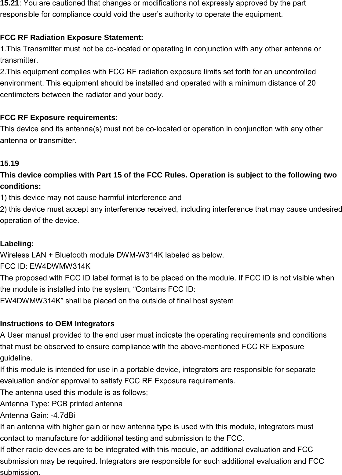
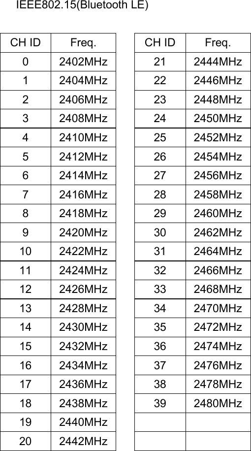
![3.Electrical Characteristics 3-1.Channel Plan IEEE802.11b/g/n CH ID Freq.[MHz] CH ID Freq.[MHz] CH ID Freq.[MHz] 1 2412 6 2437 11 2462 2 2417 7 2442 3 2422 8 2447 4 2427 9 2452 5 2432 10 2457 IEEE802.15(Bluetooth BDR/EDR) CH ID Freq. 0 2402MHz 1 2403MHz 2 2404MHz 3 2405MHz 4 2406MHz 5 2407MHz 6 2408MHz 7 2409MHz 8 2410MHz 9 2411MHz 10 2412MHz 11 2413MHz 12 2414MHz 13 2415MHz 14 2416MHz 15 2417MHz 16 2418MHz 17 2419MHz 18 2420MHz 19 2421MHz 20 2422MHz CH ID Freq. 21 2423MHz22 2424MHz23 2425MHz24 2426MHz25 2427MHz26 2428MHz27 2429MHz28 2430MHz29 2431MHz30 2432MHz31 2433MHz32 2434MHz33 2435MHz34 2436MHz35 2437MHz36 2438MHz37 2439MHz38 2440MHz39 2441MHz40 2442MHz41 2443MHzCH ID Freq. 42 2444MHz43 2445MHz44 2446MHz45 2447MHz46 2448MHz47 2449MHz48 2450MHz49 2451MHz50 2452MHz51 2453MHz52 2454MHz53 2455MHz54 2456MHz55 2457MHz56 2458MHz57 2459MHz58 2460MHz59 2461MHz60 2462MHz61 2463MHz62 2464MHzCH ID Freq. 63 2465MHz64 2466MHz65 2467MHz66 2468MHz67 2469MHz68 2470MHz69 2471MHz70 2472MHz71 2473MHz72 2474MHz73 2475MHz74 2476MHz75 2477MHz76 2478MHz77 2479MHz78 2480MHz](https://usermanual.wiki/Mitsumi-Electric-Co/DWMW314K.Users-Manual/User-Guide-3221385-Page-8.png)
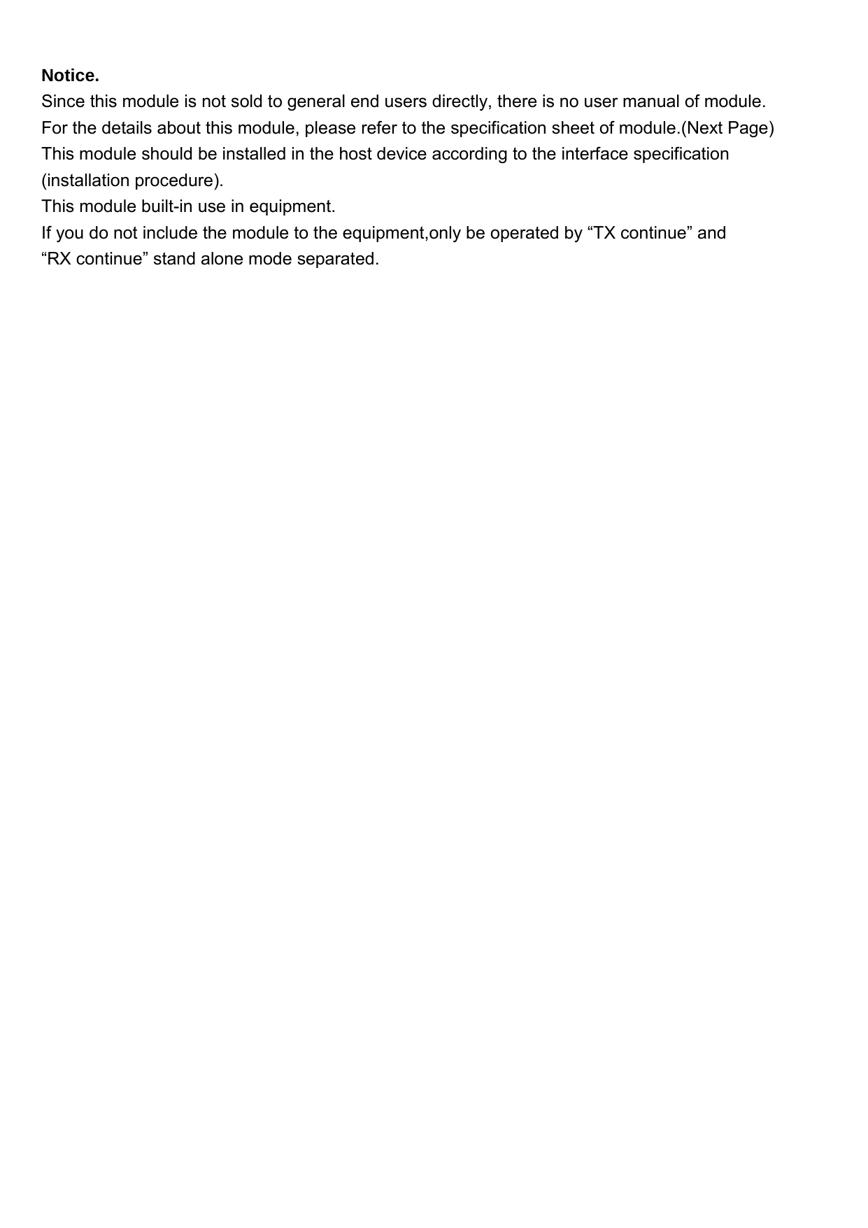
![3-3. Interface specification (SDIO) 3-3-1.Internal VIO Output Voltage Item Min.[V] TYP.[V] Max.[V] VIO 1.78 1.80 1.82 3-3-2. I/O Ratings Min.[V] Typ.[V] Max.[V] Input high voltage 0.8*VIO - VIO+0.3Input low voltage -0.3 - 0.3*VIOInput hysteresis 0.15 - - Output high voltage VIO-0.4 - - Output low voltage - - 0.4 3-3-3.SDIO Protpcol Timing Diagram - Normal Mode 3-3-4.SDIO Protpcol Timing Diagram - High Speed Mode](https://usermanual.wiki/Mitsumi-Electric-Co/DWMW314K.Users-Manual/User-Guide-3221385-Page-11.png)
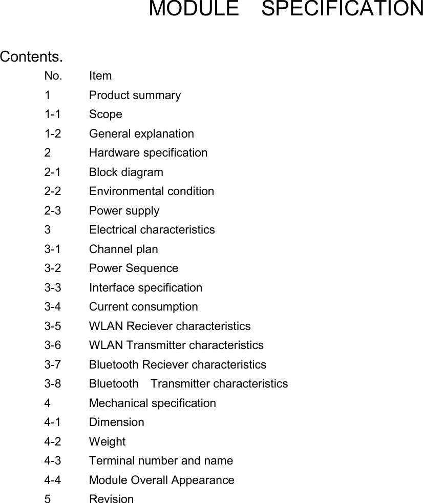
![3-3-5. SDIO Timing Data Symbol Parameter Mode Min Typ. Max fpp Clock Frequency Normal 0 - 25 [MHz] High Speed 0 - 50 [MHz] Twl Clock Low Time Normal 10 [ns] - High Speed 7 [ns] - Twh Clock High Time Normal 10 [ns] - High Speed 7 [ns] - Tisu Input Setup Time Normal 5 [ns] - High Speed 6 [ns] - Tih Input Hold Time Normal 5 [ns] - High Speed 2 [ns] - Todly Output Delay Time - 14 [ns] Toh Output Hold Time High Speed 2.5 [ns] - 3-4. Current consumption 3-4-1.WLAN Upload @ STA Mode Condition Data rate Typ.[mA] Max[mA] 11b 12dBm 11Mbps 310 380 11g 12dBm 54Mbps 260 330 11n 2dBm HT20 MCS7 270 340 Disabled Bluetooth 3-4-2.WLAN Download @ STA Mode Condition Data rate Typ.[mA] Max[mA] 11b 12dBm 11Mbps 170 210 11g 12dBm 54Mbps 170 210 11n 12dBm HT20 MCS7 190 230 Disabled Bluetooth @STA Mode Upload](https://usermanual.wiki/Mitsumi-Electric-Co/DWMW314K.Users-Manual/User-Guide-3221385-Page-12.png)
![3-4-3.Bluetooth Tx Mode Condition Typ.[mA] Max[mA] BDR/EDR 41 45 LE 31 35 Disabled WLAN 3-4-4.Bluetooth Rx Mode Condition Typ.[mA] Max[mA] BDR/EDR 33 36 LE 28 31 Disabled WLAN @Connection Event Tx Measure Point Rx Measure Point 3-4-5. Power Save Mode Typ.[mA] Max[mA] Remarks WLAN DTIM=1 6.0 9.0 Disabled Bluetooth DTIM=3 2.0 4.0 Deep Sleep 0.5 0.8 Pdn 0.1 0.2 Bluetooth Deep Sleep 0.8 1.2 Disabled WLAN Download Measure Point](https://usermanual.wiki/Mitsumi-Electric-Co/DWMW314K.Users-Manual/User-Guide-3221385-Page-13.png)
![3-5. WLAN Receiver characteristics 3-5-1.Minimum Receiver Sensitivity Standard Data rate Min.[dBm] Typ.[dBm] Max.[dBm] PER[%] 802.11b 1 Mbps - -93 -80 8 2 Mbps - -90 -80 8 5.5 bps - -88 -76 8 11 Mbps - -86 -76 8 802.11b 6 Mbps - -86 -82 10 9 Mbps - -85 -81 10 12 Mbps - -84 -79 10 18 Mbps - -82 -77 10 24 Mbps - -79 -74 10 36 Mbps - -76 -70 10 48 Mbps - -71 -66 10 54 Mbps - -70 -65 10 802.11n MCS0 - -86 -82 10 MCS1 - -83 -79 10 MCS2 - -81 -77 10 MCS3 - -78 -74 10 MCS4 - -74 -70 10 MCS5 - -70 -66 10 MCS6 - -68 -65 10 MCS7 - -67 -64 10 3-5-2.Maximum Receiver Sensitivity Standard Data rate Min.[dBm] Typ.[dBm] Max.[dBm] PER[%] 802.11b 1,2Mbps -4 - - 8 5.5,11Mbps -10 - - 10 802.11g 6 to 54Mbps -20 - - 10 802.11n MCS0 to 7 -20 - - 10](https://usermanual.wiki/Mitsumi-Electric-Co/DWMW314K.Users-Manual/User-Guide-3221385-Page-14.png)
![3-6. WLAN Transmitter Characteristics 3-6-1. Output Power Item 2412MHz 2442MHz 2462MHz11b 12.0 dBm 12.0 dBm 12.0 dBm11g 12.0 dBm 12.0 dBm 12.0 dBm11n 12.0 dBm 12.0 dBm 12.0 dBm 3-6-2.Output Power Torelance Item Min. Typ. Max. Torelance -2.5dB 2.5dB 3-6-3.EVM ITEM rate EVM [%] 11b 1 Mbps 35 11b 2 Mbps 35 11b 5.5 Mbps 35 11b 11 Mbps 35 11b 6 Mbps 56.2 11g 9 Mbps 39.8 11g 12 Mbps 31.6 11g 18 Mbps 22.4 11g 24 Mbps 15.8 11g 36 Mbps 11.2 11g 48 Mbps 7.9 11g 54 mBps 5.6 11n MCS0 56.2 11n MCS1 31.6 11n MCS2 22.4 11n MCS3 15.8 11n MCS4 11.2 11n MCS5 7.9 11n MCS6 5.6 11n MCS7 4.0 3-6-4.Frequency Accuracy Item Min.[ppm] Typ. Max.[ppm]Ta = 25 deg. -10 - +10 Ta = 0 to 70 deg. -20 - +20](https://usermanual.wiki/Mitsumi-Electric-Co/DWMW314K.Users-Manual/User-Guide-3221385-Page-15.png)
![3-6-5.Spectrum Mask Mask [dBr] DS 0MHz to +/-11MHz 0 DS f+/-11MHz to 22MHz -28 DS f+/-22MHz -50 OFDM 0MHz to +/-9MHz 0 OFDM f+/-11MHz -20 OFDM f+/-20MHz -28 OFDM f+/-30MHz -40 HT20 0MHz to +/-9MHz 0 HT20 f+/-11MHz -20 HT20 f+/-20MHz -28 HT20 f+/-30MHz -45 3-7.Bluetooth Reciever Characteristics 3-7-1. Basic Data Rate (BDR) Item MIN. TYP. MAX. Frequency 2402MHz 2480MHz Sensitivity BER=0.1% -90dBm -70dBm Maximum Input level -20dBm - - 3-7-2. Enhanced Data Rate (EDR) Item MIN. TYP. MAX. EDR Sensitivity BER=0.1% PI/4DQPSK -90dBm -70dBm 8DPSK -90dBm -70dBm EDR BER Floor Sensitivity -60dBm EDR Maximum Input level BER=0.1% -20dBm - - 3-7-3. Low Energy (LE) Item MIN. TYP. MAX. Sensitivity PER=30.8% -87dBm -70dBm Maximum Input level PER=30.8% -10dBm - -](https://usermanual.wiki/Mitsumi-Electric-Co/DWMW314K.Users-Manual/User-Guide-3221385-Page-16.png)