Miwa Lock DWMS-VDCR01 ALVH Desktop Card Reader User Manual MIWA
Miwa Lock Co., Ltd ALVH Desktop Card Reader MIWA
MIWA user manual

Confidential
User Manual
Miwa Lock Co.,Ltd.
1/8
Version 3.0
March 5,2008
Miwa Lock Co., Ltd.
User Manual
Product Name ALVH Desktop Card Reader
Model DWMS-VDCR01
Confidential
User Manual
Miwa Lock Co.,Ltd.
2/8
1. Introduction
This document describe the supply specifications for the ALVH Desktop Card Reader (VDCR).
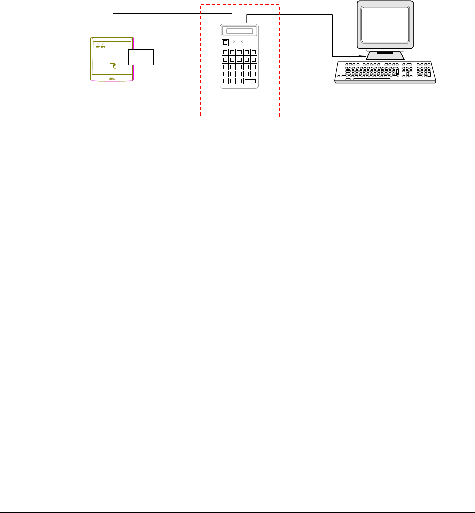
The VDCR is a desktop Mifare card reader/writer installed in the hotel and connects to a PC server via RS-232C port.
PC server can write necessary data to the Mifare card which is placed on the VDCR.
The KB/SSDW-05 is a keyboard which also can write the data in the card when installed between the VDCR and the
computer.
Fig.1.1: Host connection
RUN STOP
MIWA
VDCR
KB/SSDW-05 PC server
RS-232C RS-232C
Mifare card
Confidential
User Manual
Miwa Lock Co.,Ltd.
3/8
2. Hardware specifications
Table 2.1: Hardware specifications
Items Description
General
specifications
Weight
Power consumption
Temperature/ Humidity
Environment
225g (Only main unit ) AC power adapter 230g
13W
Running temperature :+0∼+40°C / 25∼85%
(without condensation)
Storage temperature : −15∼+50°C / 25∼85%
(without condensation)
Room (without excessive dust)
Power source
AC power adapter
Model: 3A-161DA05(MAP ELECTRONICS)
Input: 100Vac~240Vac
Output: 5Vdc,2.6A
Safety standard: UL
Electrical standard: CE
Control board
(including antenna
board)
Performs Mifare card reading/writing
MPU: R8C/Tiny series
R5F21258SNFP (Renesas Technology)
Running frequency :20 MHz
Built in FROM :64kbyte+2kbyte
Built in RAM :3kbyte
Built in I/F :2 channels
Communication with card: By exclusive chip(RC531)
Supply voltage : 3Vdc
Communication board
Perform convertion of signal between Control board and
external serial interface.
Signal level conversion : RS232C ⇔ TTL
Voltage conversion : 5Vdc⇒3Vdc
LED board
LED for power source (RUN indication)
Color : Green
Supply voltage : 5Vdc
Mounting
board
Panel LED board
LED for plane surface illumination (3 colors) and LED for
card detection status indication.
Lighting Panel : 6 (3 for upper side of the panel, 3 for
lower side of the panel)
Illuminated colors :Red / Green / Orange (software control)
Status display : 1 (STS display)
Illuminated colors :Red / Green / Orange (software control)
Supply used :5Vdc
Confidential
User Manual
Miwa Lock Co.,Ltd.
4/8
3. Composition outline
3.1. Outline of system composition
The VDCR composed of the following units.
1. VDCR main unit
2. AC adapter
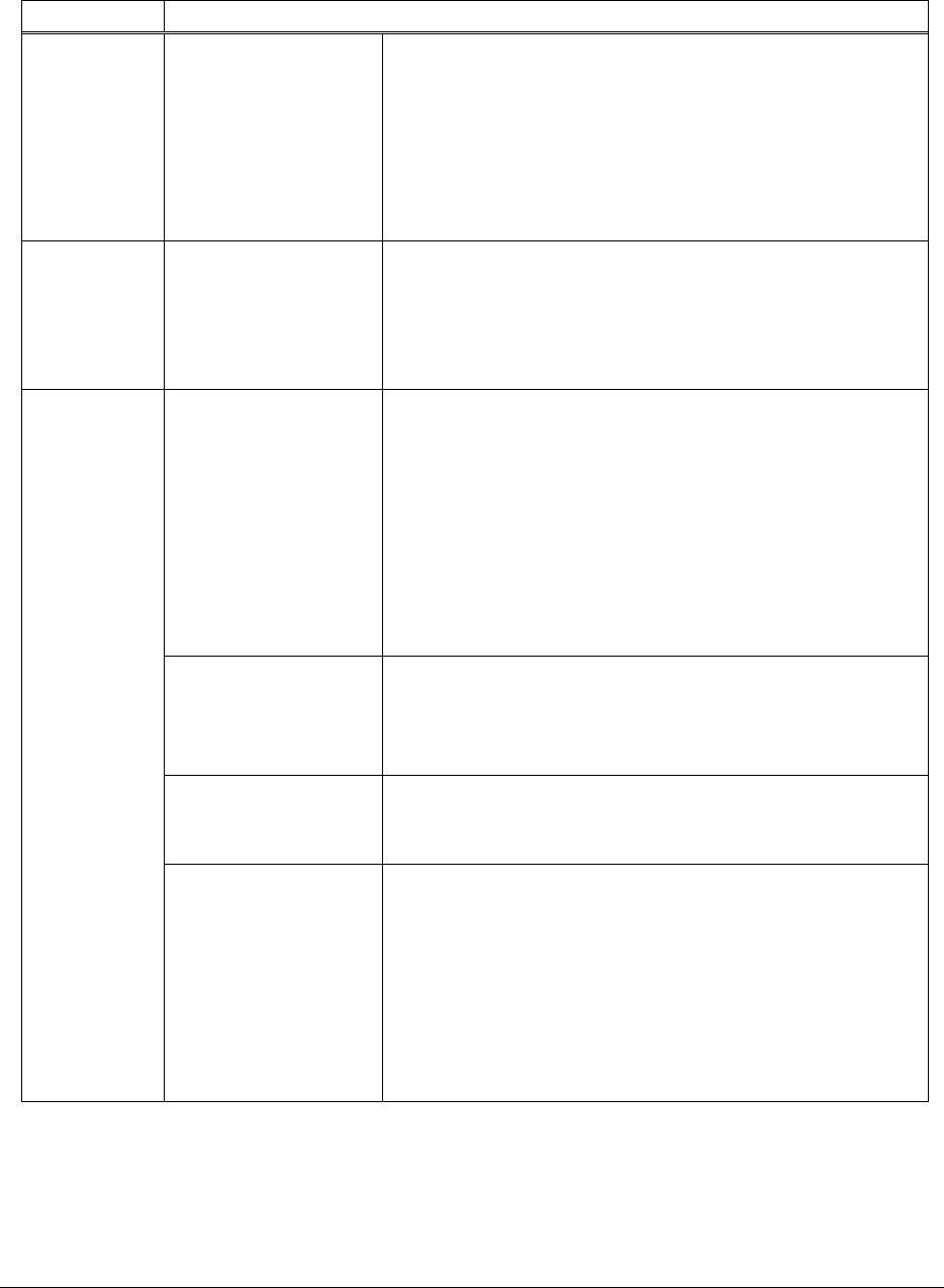
Fig. 3.1 shows the top view of the VDCR main unit, and Fig. 3.2 shows arrangement of external interface of the
VDCR main unit.
Fig. 3.1 Top view of VDCR main unit
D
DD
DC
CC
C 5
55
5.
..
.0
00
0V
VV
V
Fig. 3.2 Arrangement of interface panel of VDCR main unit
Status LED
Power source LED
Serial interface(RS-232C)
DC jack
Lighting panel for card communication
Confidential
User Manual
Miwa Lock Co.,Ltd.
5/8
4. Connection to external devices
4.1. VDCR main unit
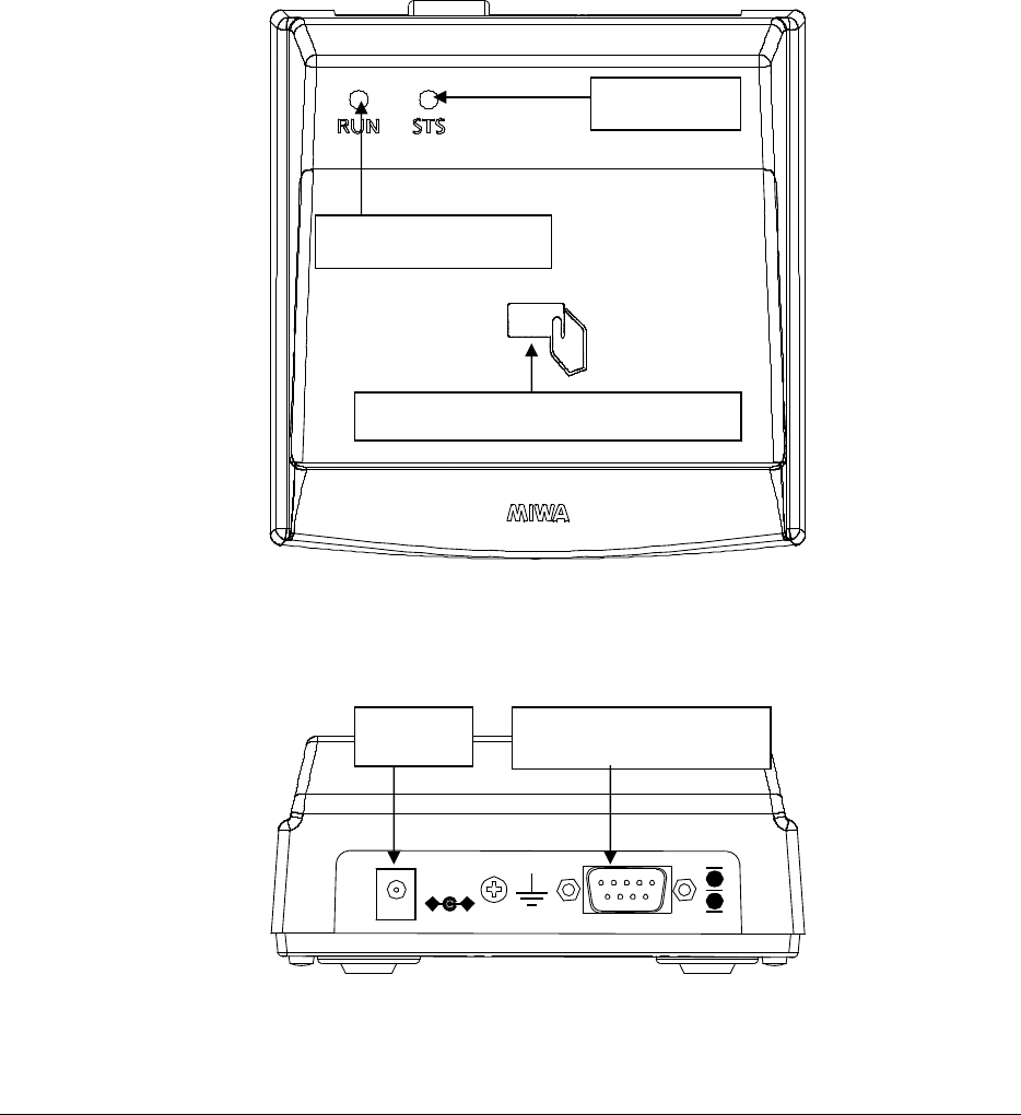
External unit are connected by proper cables to each connector arranged to the posterior interface panel.
1. RS-232C : Upper unit (PC server)
2. 5Vdc : AC adapter
Fig.4.1: External unit connection of VDCR main unit
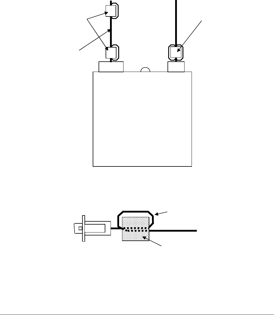
Fig.4.2: Ferrite core
Ferrite core
RS232C cross cable
The cable is turned once and gose through the Ferrite core twice
5Vdc
RS-232C
Upper unit AC adapter
RS232C cross cable
Ferrite core (two turns)
Ferrite core (three turns)
Confidential
User Manual
Miwa Lock Co.,Ltd.
6/8
5. VDCR external interface
5.1. VDCR main unit external interface
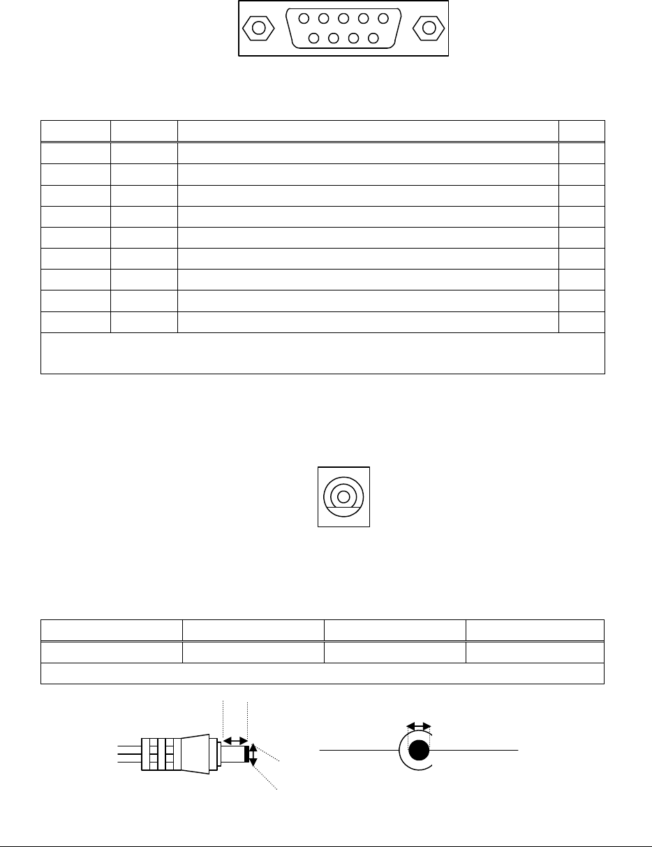
5.1.1. Serial interface (IOIO)
1
6 9
5
Fig. 5.1: Serial interface
Table 5.1:IOIO connector specifications
Pin No. Name Description I/O
1 N.C. - -
2 RX Received data I
3 TX Sent data O
4 DTR Data terminal ready Note 1
O
5 GND Ground -
6 DSR Data set ready Note 1
I
7 RTS Send request(Non-connection) O
8 CTS Send enable(Non-connection) I
9 N.C. - -
Connector used
Model name: EJEY-9P-1F3F-113 Manufacturer: J.S.T Mfg Co., Ltd.
Note 1: #4 pin (DTR) and #6 pin (DSR) are shorted on the control board.
5.1.2. Power supply interface
Fig. 5.2: Power supply interface (DC jack)
Table 5.2: Specification of AC power adapter plug
Inner diameter Outer diameter Length Unit
#1 1.7 #2 4.0 #3 9.5 mm
5Vdc 2.6A
5VdcGND
Fig. 6.3 :Specification of AC power adapter
#1
#2
#3
Confidential
User Manual
Miwa Lock Co.,Ltd.
7/8
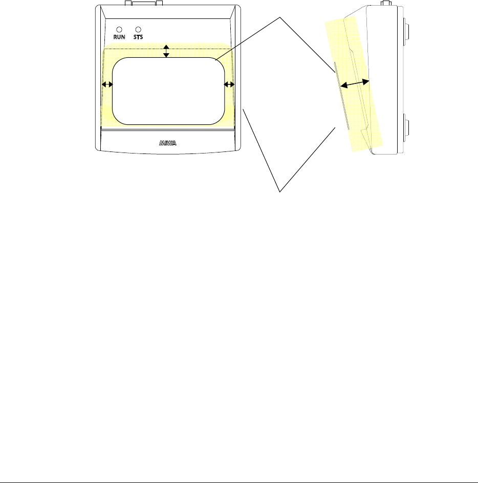
5.2. Condition of Mifare card communication
The Mifare card can communicate up to 12mm from lighting panel surface, under the following conditions:
Condition1 When the applied card is a MARS compatible card, and a single card is held up.
Condition2 Center of the applied card surface is less than 5mm in horizontal direction from the center of the
lighting panel surface.
Condition3 The lighting panel surface and applied card surface are parallel to each other.
Condition4 There are no obstruction to electromagnetic waves (13.56MHz) between the lighting panel surface
and the applied card.
Condition5 There are no obstruction to electromagnetic waves (13.56MHz) within 12mm of the VDCR main
unit.
Fig. 5.4 Shows the communication range of the Mifare card.
Fig. 5.4: Card communication range
Electromagnetic obstacle prohibited area
IC Card
MIFARE
5mm
5mm
5mm
12mm
Confidential
User Manual
Miwa Lock Co.,Ltd.
8/8
6. Regulatory Compliance
6-1. USA-Federal Communications Commission (FCC)
This unit has been tested and found to comply with the limits for a Class B digital device, pursuant to Part 15 of the FCC
rules. These limits are designed to provide reasonable protection against harmful interference in a residential installation.
This unit generates, uses, and can radiate radio frequency energy and, if not installed and used in accordance with the
instructions, may cause harmful interference to radio communications. However, there is no guarantee that interference
will not occur in a particular installation. If this unit does cause harmful interference to radio or television reception, which
can be determined by turning the unit off and on, the user is encouraged to try to correct the interference by one or more
of the following measures:
- Reorient or relocate the receiving antenna.
- Increase the separation between the unit and receiver.
- Connect the unit into an outlet on a circuit different from that to which the receiver is connected.
- Consult the dealer or an experienced radio/TV technician for help.
This unit complies with Part 15 of the FCC Rules. Operation is subject to the following two conditions:
(1) This unit may not cause harmful interference, and (2) This unit must accept any interference received, including
interference that may cause undesired operation.
Caution:
Any changes or modifications not expressly approved by the party responsible for product compliance could void the
user's authority to operate the unit.
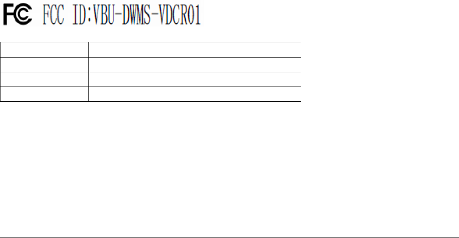
Labelling
MIWA LOCK ALVH Desktop Card Reader is labelled as below.
FCC ID: VBU –DWMS-VDCR01
FCC Portion
Federal Communication Commission Declaraton of Conformity (Doc)Statement
Model No: DWMS-VDCR01
Trade Name ALVH Desktop Card Reader
Responsible Party
MIWA LOCK CO.,LTD.
Address 3-1-12,Shiba, Minato-ku,Tokyo 105-8510,Japan
Telephon No +81-3-3452-1465