Mobi Technologies 70055R Digital Video Baby Monitor User Manual Users manual
Mobi Technologies, Inc. Digital Video Baby Monitor Users manual
Users manual

Compable with...
Wireless
Audio/Video
Monitoring
System
Compatiblewith…
Compatiblewith…

TABLE OF CONTENTS
Introducon 1
Package Contents 2
Features 3
Consumer Guide to Product
Safety
4-5
Knowing your Receiver 6
Knowing Your Camera 7
Installaon & Setup 8
Monitor Operaon 9-10
Camera Operaon 11
Audio/Video & USB Operaon 12
Troubleshoong 13
Radio Interference Advice 14
Warranty 15
Notes 16

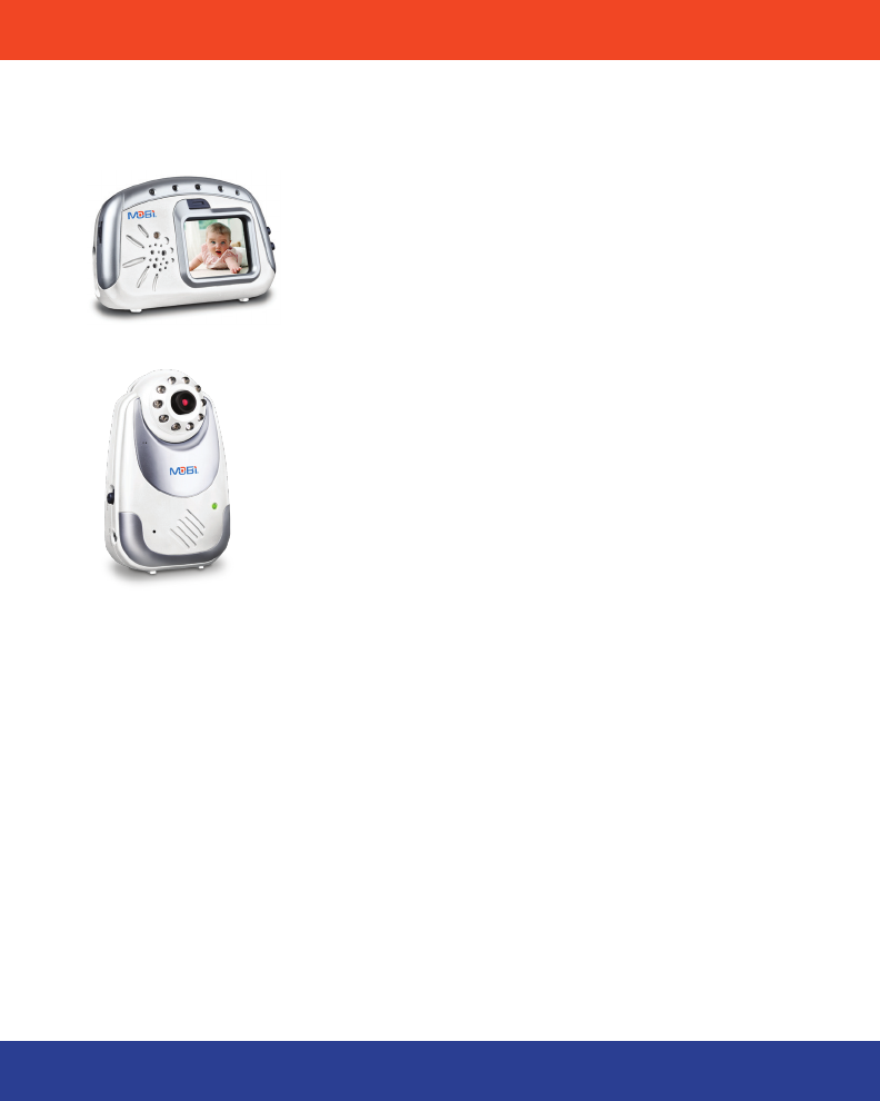
INTRODUCTION
Congratulaons on the purchase of the MobiCam Digital DL Monitoring Sys-
tem, which brings you the latest in wireless technology. We are sure that you
will be pleased with the quality and features of this product but recommend
that you read these instrucons carefully before use in order to fully benet
from its many features.
The MobiCam Digital DL enables you to transmit picture and sound wirelessly,
which is ideal for many situaons such as monitoring a baby, young children,
pets, or elderly. Addionally it can also be used for household security or as an
oce or warehouse surveillance system.
Your MobiCam DL uses digital transmission to ensure a clear and consistent
picture. The signal also passes easily through interior walls. However, buildings
with metal frames or placing the camera near large metal objects may cause
signal degradaon. If recepon is poor, moving the camera or receiver may x
this problem.
1
PACKAGE CONTENTS FEATURES
1 x Receiver Unit
1 x Camera Unit (#70056, addional cameras sold separately)
1 X Receiver Power Cord
1 X Camera Power Cord
1 x AV cable
1 set of mounng screws and anchors
NOTE: If you nd any of the contents are missing or should you need to order replace-
ment parts, please contact the manufacturer or visit www.getmobi.com.
2

FEATURES
• 2.4” Color High Resoluon TFT LCD Display
• Voice Acvated Picture & Sound with Auto Mute
• Audio Only Mode
• No installaon needed—ready to use
• Compact design for easy portability
• Transmission range up to 300 .
• Powerful Night Vision with 20 . range
• Extra Wide Camera Viewing Angle
• Expandable up to 4 Cameras with automac camera scanning opon
• Camera operates on AC or 4 AA Alkaline Baeries (not included).
• Monitor operates on AC or 5 Alkaline AA Baeries (not included)
• Oponal rechargeable baery pack is available (item # 70077).
• USB Output for PC connecon
• Use as a wireless webcam
3

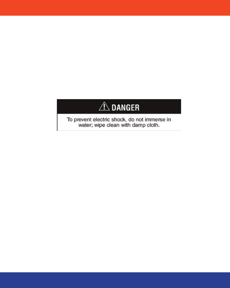
CONSUMER GUIDE TO PRODUCT SAFETY
Please read this instrucon manual before using your MobiCam Digital DL sys-
tem. When using electrical appliances, basic safety precauons should always
be followed.
Please keep safe for future reference.
• This product is not intended to be used as a medical monitor and its
use should not replace adult supervision.
• Periodically examine this product for damage to the cord, housing or
other parts that may result in the risk of re, electric shock or injury.
Do not operate any product with a damaged cord or plug. If the Color
Wireless Monitor malfuncons or is damaged in any manner please
contact the manufacturer for examinaon and repair to avoid a hazard.
• Never use transmier and receiver near water (i.e. bathtub, sink, etc.).
• The AC adaptors are not Toys.
4
• Always use transmier and receiver where there is adequate
venlaon. To prevent overheang, keep away from heat sources
such as radiators, heat registers, stoves, or other appliances that
produce heat.
• Use only a dry coon cloth to keep the Camera and Monitor units
free of dust. Do no use a dampened cloth, water, or liquid cleaner
of any kind.
• Remove the baery from the Monitor during long periods of non-
use as alkaline baeries can leak.
• Unplug the AC adaptors from the Monitor and Camera during peri
ods of non-use. To disconnect from the power supply, grip the
transformer and pull from the power socket. Never pull by the
cord.
• Replace baery with the same equivalent type. Please dispose of
old, defecve baeries in an environmentally friendly manner in
accordance with the relevant legislaon.
• Only use the Monitoring System with the supplied power adaptors.
5
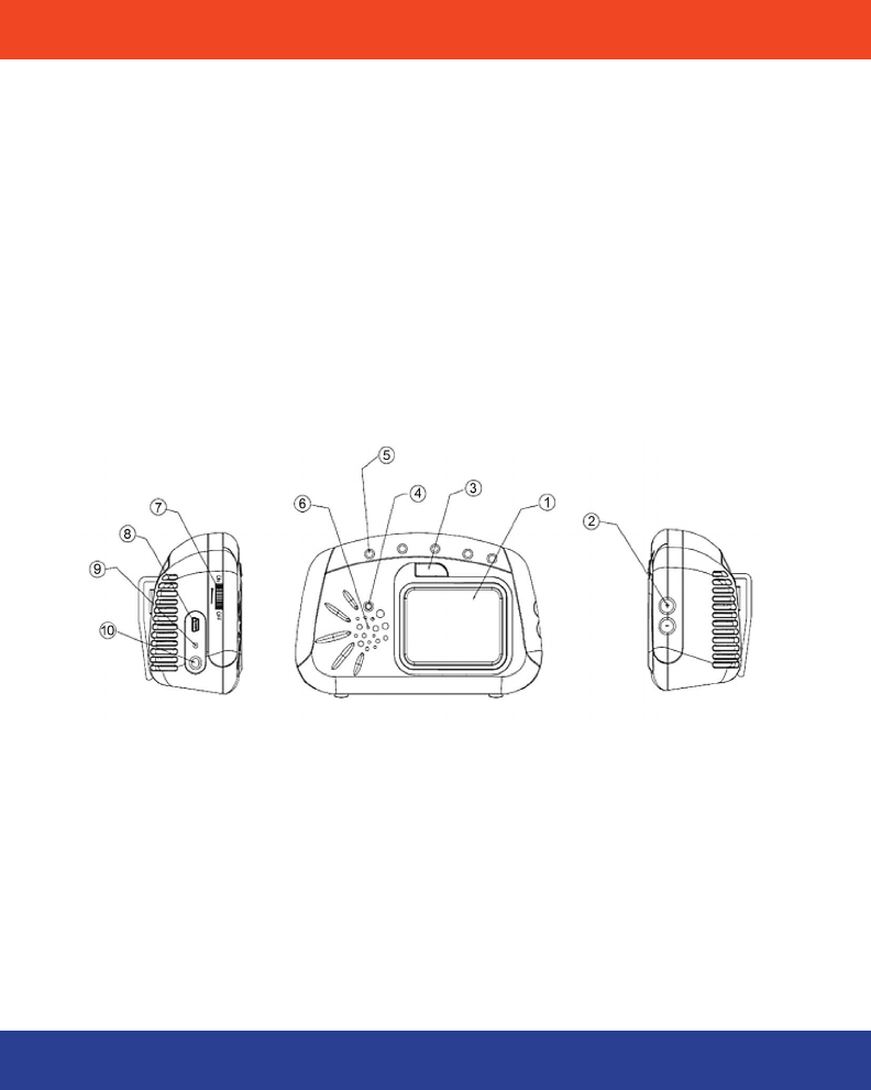
KNOWING YOUR RECEIVER
1. TFT LCD Display
2. Control (+) (-)
3. Mode Buon
4. Power indicator
5. Sound Bar LEDs
6. Speaker
7. Volume and power On/O switch
8. Mini USB Output
9. DC Jack
10. A/V Jack
6
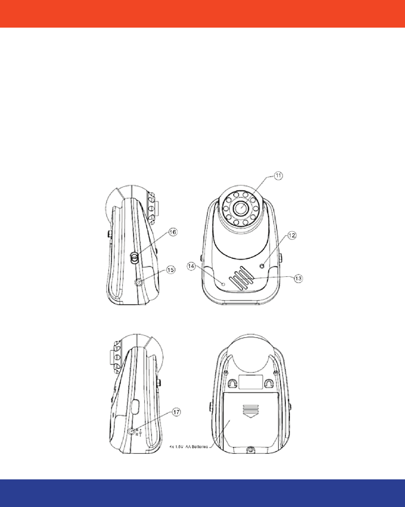
KNOWING YOUR CAMERA
11. Camera Lens
12. Power indicator
13. Mic
14. Night Vision Sensor
15. Link Buon
16. Power On / O
17. DC Jack
7

INSTALLATION & SETUP
The MobiCam Digital DL Monitor is designed to be powered by either baeries
or the AC/DC adaptors. You can also purchase a rechargeable baery pack (item
# 70077) available at getmobi.com or retailer to use with your monitor.
Using AC/DC adaptor:
• Plug the connector of the AC adaptor into the DC Jack on the unit (g.
9 & 17).
• Plug the power cord into an outlet.
• Switch the power plug to the ON posion (g. 7 & 16)
• The power indicator lights will illuminate once the units are turned on
(g. 4 & 12)
Using Baeries:
• Remove the baery door at the boom/back of each unit by loosening
the child-safe screw and sliding the cover downward to release.
• Both units can use 1.5 volt AA size baeries. (Always use baeries of
the same brand and age, alkaline baeries are recommended)
Insert 4 AA baeries into camera and 5 AA baeries into the monitor.
• Replace the covers by aligning the tabs with the tab holes and ghten
ing the child-safe screws.
Please note that the life of baeries is limited. Therefore, when monitoring over
long periods and, in parcular, overnight, it is recommended to use AC adaptors
for both the camera and the monitor unit.
Warning:
1. Do not mix old and new baeries.
2. Do not mix alkaline, standard or rechargeable baeries
3. Remove the baeries during long periods of non-use.
4. Use only the AC adaptors supplied with the package.
Oponal Baery Pack:
The Monitor on your system has a built-in baery recharging circuit. Make sure
you only use the oponal baery pack (Item # 70077), as standard rechargeable
baeries will not recharge.
Note: Camera unit does not recharge baeries.
8

MONITOR OPERATION
Power ON/OFF
Use the volume and ON/OFF switch (g. 7) on the side of the unit to turn On
and O. To adjust the volume use the ON/OFF switch to scroll to the desired
level.
Channel Selecon
Press the Mode Buon on the front of the monitor 1 me to enter the channel
selector mode, use the side “+” and “-” control buons (see g. 2) to change
the Channel or to set your monitor to Scan mode. The display will indicate the
selected channel during the channel selecon process on the boom of the
screen.
Automac Channel Scan
This opon allows the Monitor to scan through all 4 channels automacally and
stops at each channel for approximately 5 seconds in order to monitor mulple
locaons.
“Scan Select Mode”- Selecng which camera to Scan
To set your monitor to scan certain channels while in scan mode, press the
Mode Buon 4 mes unl the Scan Select menu appears. Use the Mode buon
to scroll through the available channels and the “+” and “-” control buons (see
g. 2) to select and deselect the desired channel(s).
“Camera Selecon”- Add or Remove Cameras
To remove paired cameras, press the Mode buon 8 mes unl the Paired
Select menu appears. Use the Mode buon to scroll through the available chan-
nels and the “+” and “-” controls (see g. 2) to select or remove the camera.
Note: You must re-link your camera once it has been removed in order to be able to view
the camera again (see page 12 for linking instrucons).
9
CAMERA OPERATIONMONITOR OPERATION
LCD On/O
Press the Mode Buon and hold for 3 seconds unl the LCD screen is o. This
feature enables you to use the monitor as an audio only system allowing you to
conserve power.
To deacvate, press the Mode Buon for 3 seconds.
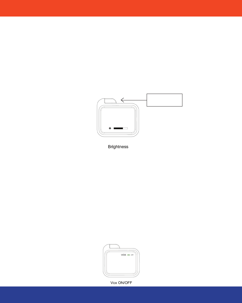
Brightness Control
The brightness on the LCD screen can be adjusted by pressing the Mode buon
2 mes and using the “+ “& “–“ control buons (g. 2) unl the desired level is
reached.
Voice Acvaon (VOX)
Voice Acvaon (VOX) mode allows your monitor to go to sleep mode when
there is no sound in the room. The monitor will automacally turn on when the
camera detects noise– subject to the factory preset sound level. This feature
allows you to conserve baery power.
NOTE: The Monitor will automacally switch to standby mode if no signal is received
from the Camera
To Acvate / Deacvate: Press the Mode buon3 mes and the VOX icon will
appear. Your monitor will display “VOX” when this feature is turned on. Use the
“ + “ & “ - “ control buons (g. 2) to turn the funcon on or o.
10
Mode buon
Power ON/OFF
Use the ON/OFF switch (g. 16) to turn the unit On and O.
Infrared Night Vision Mode (Automac)
The infra-red night vision mode will switch on automacally during darkness or
periods of low levels of light. In this mode only black and white images will be
displayed on the monitor. For best image clarity objects should be placed within
20 of the camera.
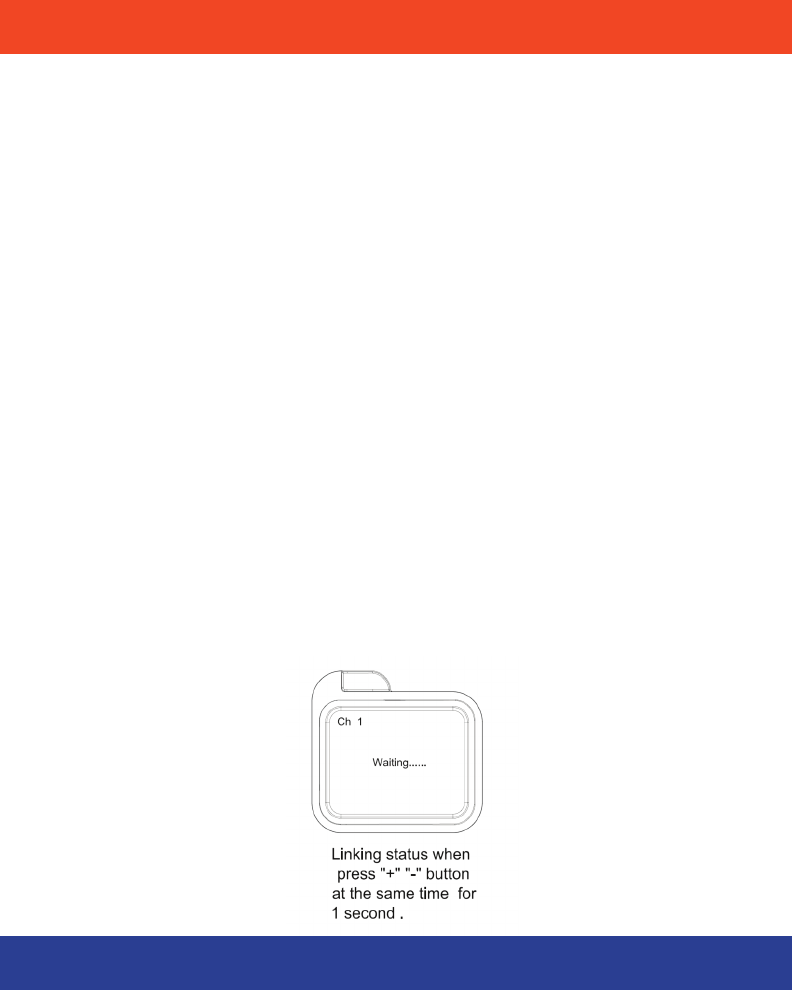
Addional Cameras
(#70056, addional cameras sold separately)
This product is designed to allow monitoring dierent areas with up to 4 cam-
eras (Channel 1, 2, 3 and 4). The Monitor and Camera will be inially paired and
set on channel 1.In order to add addional cameras to your system, you will
need to link the camera to your monitor before use.
1. Select the desired channel (see page 10) on your monitor.
2. Press the link buon on the side of your camera (g. 15), the power
indicator will begin to ash indicang your camera is ready to be
linked.
3. Press the “+ “& “-“ control buons (g. 2) simultaneously unl the im
age appears on the screen.
CAMERA OPERATION
11

AUDIO/VIDEO & USB OPERATION
Audio/Video& USB Output
Your monitor is equipped with both an A/V output and USB output so that you
can connect your monitor to a TV, DVR, VCR or computer so that you can cap-
ture video and sound from the camera transmission.
Note: The monitor screen turns o automacally when A/V cable or USB cable is used.
The screen will turn back on when the cable is removed.
A/V Cable Connecon
The A/V Output Jack is located on the le side of the monitor (g. 10). Simply
connect the supplied AV Connector Cord to the jack and connect the other ends
(three RCA connectors) to the Audio and Video input jacks on your TV, VCR or
Camcorder and select the appropriate input on your device. The monitor screen
will automacally turn o signaling the unit is connected. (Please refer to your
device manual for input selecon & operaon)
USB Connecon
Note: You will need to install the USB driver before using the USB connecon to your PC.
Use a standard Mini USB cable available at retail stores (not included) to con-
nect your monitor to your PC.
The USB output is located on the le side of the monitor (g. 8). Please be sure
to visit our website at www.getmobi.com to download the device driver.
Once you have installed the device driver your MobiCam DL can be ulized as
a wireless webcam. The unit can be used in conjuncon with Skype®, Win-
dows Messenger®, Google Talk® and Yahoo Messenger®. Addionally you can
purchase the MobiCam Anywhere Soware and set your monitor for scheduled
recordings, connuous recording and remote viewing via any PC or windows
enabled cell phone. For more informaon visit www.getmobi.com
12

TROUBLESHOOTING
Problem Soluon
No Image
• Monitor or Camera has not been turned on.
• Check AC/DC connecon
• Conrm power outlet is working properly.
• Baery is low (check Led indicator: Full Power
Green; Low Power - Red)
• Wrong Channel (Please note the monitor will
return to Channel 1 automacally aer power
o)
• VOX mode is on, See Page 11
Only Sound is
Funconing
• LCD screen is O, See Page 10
• Low Power (Check LED indicator: Full Power
Green; Low Power – Red)
Only Black & White
picture displayed
• Camera may have switched to “Infrared Night
Vision Mode,” See Page 12
Baery does not
recharge
• AC/DC adaptor has not been connected.
• Non-rechargeable baery has been used,
See Page 9
Camera will not link • Unit has not been switched on.
• AC/DC adaptor has not been connected.
• Check to make sure you are making contact
with the link buon.
• Check to make sure you are selecng the
correct channel
Screen turns on and o • “VOX” mode is selected, when there is no noise
detected by the camera the screen and audio
turn o, See page 11
• Baeries are low, LED indicator will be red
Channels Keep Switching • Conrm status of scan mode, See page 10
13

RADIO INTERFERENCE ADVICE WARRANTY
FCC Statement
This device complies with part 15 of the FCC Rules. Operaon is subject to the
following two condions:
(1) This device may not cause harmful interference.
(2) This device must accept any interference received, including interference
that may cause undesired operaon.
Any changes or modicaons not expressly approved by the party responsible
for compliance could void the user’s authority to operate the equipment.
FCC Radiaon Exposure Statement:
This equipment complies with FCC radiaon exposure limits set forth for un
-
controlled environment. This equipment should be installed and operated with
minimum distance 20cm between the radiator and your body. This transmier
must not be co-located or operang in conjuncon with any other antenna or
transmier. This equipment complies with FCC RF radiaon exposure limits set
IC STATEMENT:
Operaon of this device is subject to the following two condions:
1. this device may not cause interference, and
2. this device must accept any interference, including interference that
may cause undesired operaon of the device.
14
controlled environment.The model70055T should be installed and operated with
—Reorient or relocate the receiving antenna.
—Increase the separation between the equipment and receiver.
—Connect the equipment into an outlet on a circuit different from that to which the receiver is connected.
—Consult the dealer or an experienced radio/TV technician for help.
—Connect the equipment into an outlet on a circuit different from that to which
the receiver is connected.
transmier.
Note: This equipment has been tested and found to comply with the limits for
a Class B digital device, pursuant to part 15 of the FCC Rules. These limits
are designed to provide reasonable protection against harmful interference
in a residential installation. This equipment generates uses and can radiate
radio frequency energy and, if not installed and used in accordance with the
instructions, may cause harmful interference to radio communications.
instructions, may cause harmful interference to radio communications.
radio frequency energy and, if not installed and used in accordance with the
However, there is no guarantee that interference will not occur in a particular
installation. If this equipment does cause harmful interference to radio or
television reception, which can be determined by turning the equipment off
and on, the user is encouraged to try to correct the interference by one or
more of the following measures:
the receiver is connected.

WARRANTY
Mobi Technologies, Inc. warrants this product to be free from defects in materi-
al and workmanship for a period of ninety (90) days from the date of purchase.
Should this product prove to be defecve at any me during the warranty peri-
od, Mobi Technologies, Inc. will, at its opon, either replace or repair it without
charge. Aer the warranty period, a service charge will be applied for replace-
ment of parts or labor for repair. To obtain warranty service, please return the
product to Mobi along with a dated sales receipt from the place of purchase.
Purchaser is responsible for shipping the product to Mobi Technologies, Inc. at
the address indicated below and for all associated freight and insurance costs.
This warranty does not cover damage caused by accident, misuse, abuse, im-
proper maintenance, unauthorized modicaon, or connecon to an improper
power supply. A charge will be made for repair of such damage. This warranty
excludes all incidental or consequenal damages and any liability other than
what is stated above. © 2011 Mobi Technologies, Inc. All Rights Reserved.
Mobi Technologies, Inc.
5913 Blackwelder St
Culver City CA 90232
Toll Free Number (877) 662-4462
www.getmobi.com
Mobi and MobiCam are registered trademarks of Mobi Technologies, Inc.
© 2011 Mobi Technologies, Inc. All Rights Reserved
Please register your product at: www.getmobi.com/registerproduct.php
15
may cause undesired operation of the device.
this device must accept any interference, including interference that
this device may not cause interference, and
Operation of this device is subject to the following two conditions:
IC STATEMENT:
1.
2.
IC STATEMENT
this device must accept any interference, including interference thatthis device must accept any interference, including interference that
this device may not cause interference, and
may cause undesired operation of the device.

NOTES