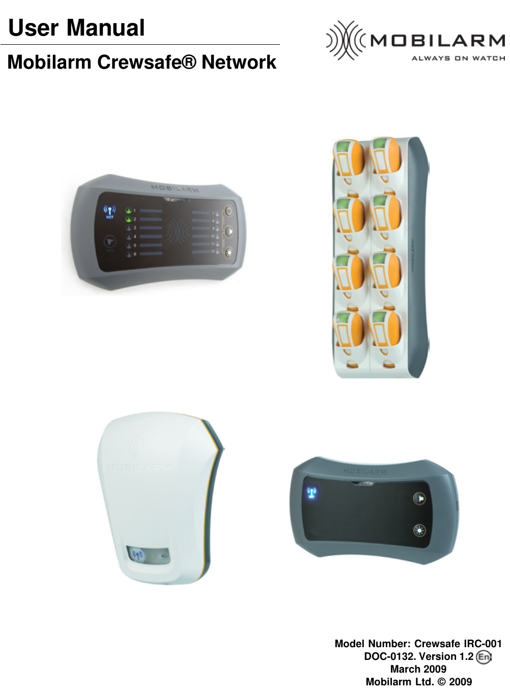
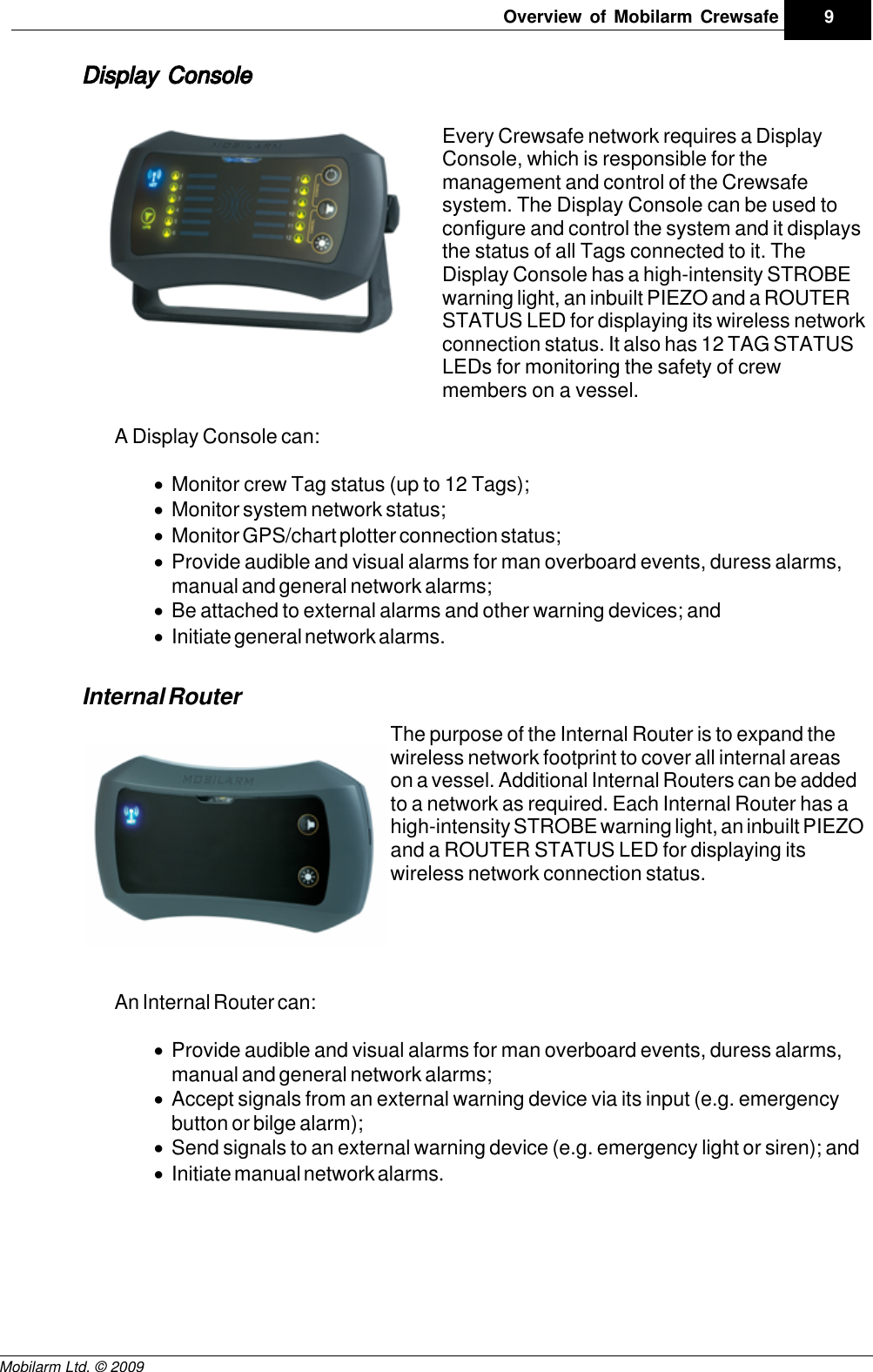
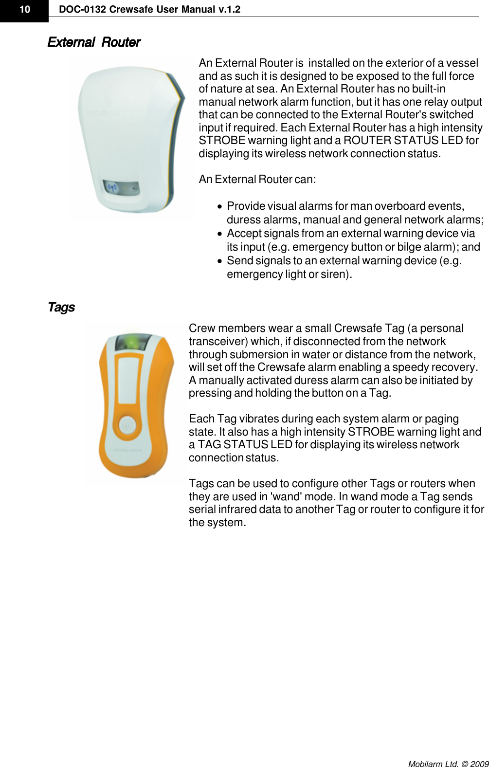
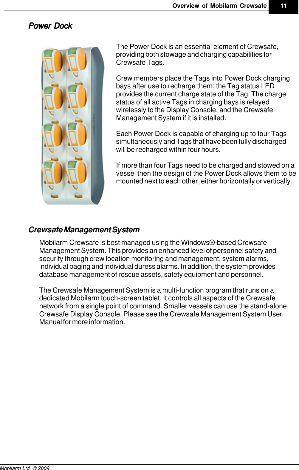
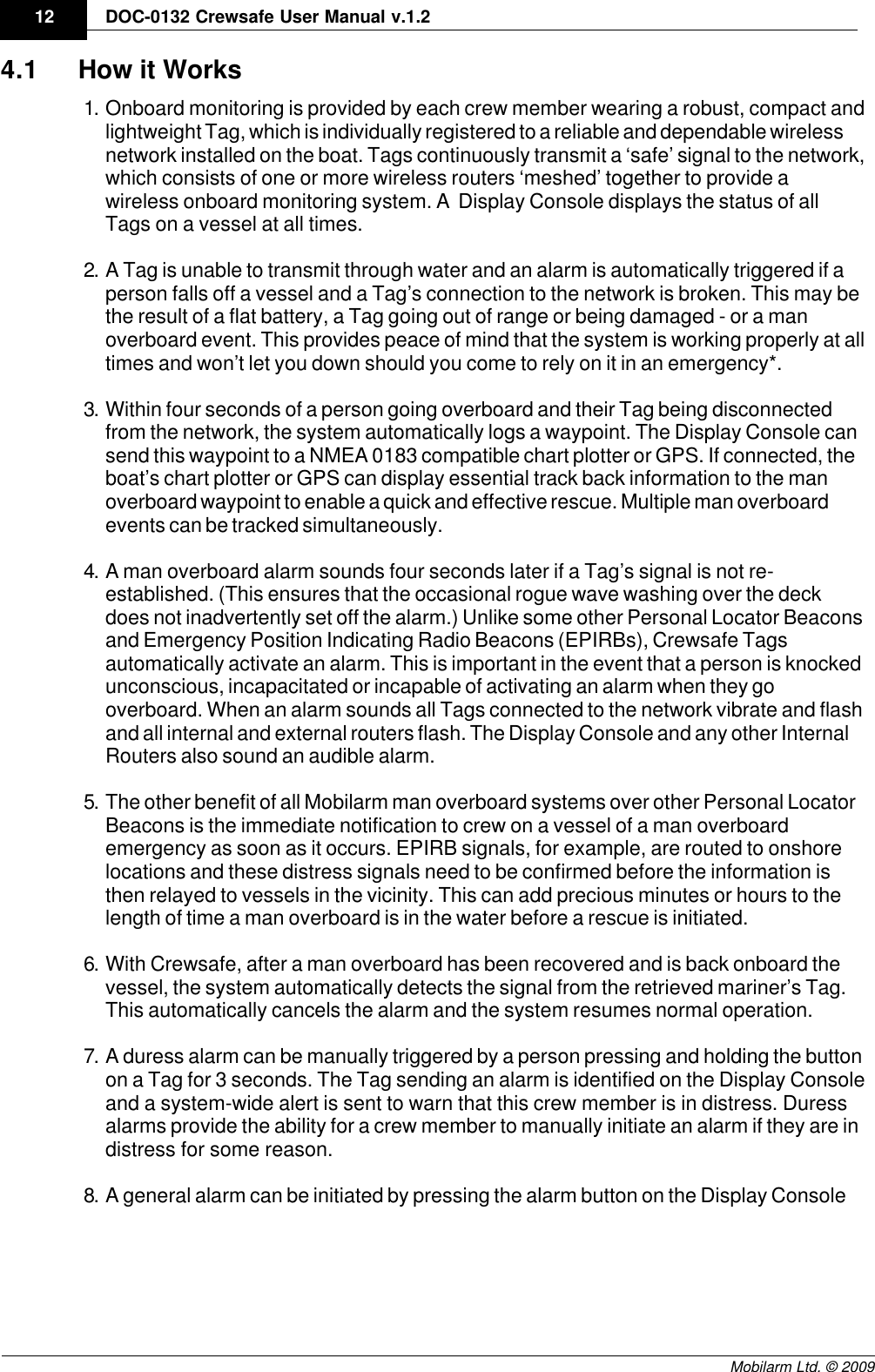
Mobilarm 00140 CREWSAFE NETWORK-TAG User Manual Crewsafe Operation Manual

Mobilarm Limited CREWSAFE NETWORK-TAG Crewsafe Operation Manual

Users Manual

DraftMobilarm Crewsafe® NetworkModel Number: Crewsafe IRC-001DOC-0132. Version 1.2March 2009Mobilarm Ltd. © 2009User Manual
DraftDOC-0132 Crewsafe User Manual v.1.22Mobilarm Ltd. © 2009Table of ContentsPart I Warnings & Safety Information 4Part II Manual Conventions 6Part III Quick Start Guide 7Part IV Overview of Mobilarm Crewsafe 8................................................................................................................................... 121How it Works Part V Getting Started 14................................................................................................................................... 141Turn the System On ................................................................................................................................... 152Turning Tags On/Off ................................................................................................................................... 173Turn the System Off Part VI Routine System Tasks 17................................................................................................................................... 181Monitoring Tag Status ................................................................................................................................... 202Attaching a Tag ................................................................................................................................... 223Charging a Tag ................................................................................................................................... 234Dimming LED Display Intensity ................................................................................................................................... 245Confirm GPS Chart Plotter Data Status Part VII Managing Alarms 25................................................................................................................................... 251Man Overboard Alarms ................................................................................................................................... 282Duress Alarm: Raise, Cancel, Mute ................................................................................................................................... 313General Network Alarm: Raise, Cancel, Mute ................................................................................................................................... 334Manual Network Alarm: Raise, Cancel, Mute ................................................................................................................................... 355False Alarms ................................................................................................................................... 366Managing Multiple Alarms Part VIII System Maintenance 38................................................................................................................................... 381Removing a Tag from the System ................................................................................................................................... 392Adding a Tag to the System ................................................................................................................................... 413Replacing Tag Batteries ................................................................................................................................... 414Adding a Router to the System ................................................................................................................................... 435Updating Crewsafe Firmware ................................................................................................................................... 446Factory Reset: Reassign Tags & Routers Part IX Maintaining System Components 45Part X Integrating MobilarmTechnologies 46
Draft3ContentsMobilarm Ltd. © 2009Part XI Reference 47................................................................................................................................... 481Troubleshooting Guide ................................................................................................................................... 522FAQs ................................................................................................................................... 543Glossary of Terms & Acronyms Part XII Technical Specifications 55................................................................................................................................... 621Trademarks Part XIII Warranty 63................................................................................................................................... 651Exclusions ................................................................................................................................... 672Declaration of Conformity ................................................................................................................................... 693Compliances & Certifications Index 70
Draft4DOC-0132 Crewsafe User Manual v.1.2Mobilarm Ltd. © 20091Warnings & Safety InformationNote: This installation and operation guide contains important information that must beadhered to for reliable use of the product. It is the owner’s sole responsibility to make theeffort to read this documentation, ensure that the installation is carried out to specificationand understand the equipment’s operation and limitations.Location and recovery of a man overboard is beyond the product’s capability and ifnecessary must be accomplished by alternative means.  Mobilarm recommends that allcrew members carry a Mobilarm V100 VPIRB (or Personal Locator Beacon) that can beactivated as an aid for post-MOB location.WARNING: No system can be 100% fail-safe. Installation faults andoperator error will always introduce the possibility of undetected manoverboard (MOB) events, as can circumstances and events beyond theequipment’s design criteria. Crewsafe should never be relied upon as theonly source of man overboard notification. The skipper and crew mustexercise common prudence and good seamanship. Installation andoperation of a Crewsafe system in no way reduces the responsibility of theskipper and crew who have the primary responsibility for safety on board avessel.WARNING: Global Positioning System. (GPS) Crewsafe systems can beintegrated with an external GPS receiver to define the location of a manoverboard and provide track-back information to the user. Thisconfiguration can only be as accurate as the positional data it receives.The Global Positioning System is managed and maintained by the USGovernment who can from time to time alter its effective accuracy. Inaddition, equipment errors or faults and operator errors can also result inmisleading information being displayed by Crewsafe systems. Marinersmust always use alternative means to confirm the location of a manoverboard if the accuracy of the system is ever in doubt.WARNING: Crewsafe systems can only facilitate the recording of the initialposition of where a man overboard event occurred into third party devices.In some areas, drift will take a man overboard away from the location of theoriginal position indicated by the Crewsafe system.WARNING: The Crewsafe system uses a small amount of low voltage DCpower. However, accidental short-circuiting of any of the product’s cablingsystem’s may cause sparks which in turn could ignite combustible gasesor petrol vapors. Make sure that electrical circuits are isolated beforemaking any changes to the system’s cables.RADIO INTERFERENCE WARNINGS: The Crewsafe system emits radio waves that can affect the operation ofnearby electronics, including cardiac pacemakers. Do not wear CrewsafeTags within 9 inches of a pacemaker. If you have a pacemaker or other
Draft5Warnings & Safety InformationMobilarm Ltd. © 2009implanted medical device, please do not wear a Crewsafe Tag without firstconsulting your physician, or the manufacturer of your medical device.Observe and follow all regulations and rules regarding the use of wirelessdevices in locations such as hospitals and on aircraft. Operation in thoselocations may interfere with, or cause malfunctions of equipment, withresulting injuries to persons or damage to property.WARNING: 1. Never attempt to charge a Tag using any device other than a MobilarmPower Dock.2. A new rechargeable battery's full performance is achieved after 2-3complete charge and discharge cycles.3. A Tag will not recharge if the battery temperature is greater than 45degrees. If a Tag is hot because of environmental factors, let it cooldown and reinsert it into the charger.4. Never short-circuit a Power Dock bay by placing metallic objects in thebays (e.g. paper clips, coins or pens).5. Never use a Power Dock or battery that is damaged.6. Do not place Crewsafe Tags near a radar set or expose them toradiation or damage may occur.  Please do not clean them withdetergents or solvents that may damage the integrity of the device.Seals may be damaged by many cleaning devices. If the componentsrequire cleaning, use warm soapy water and wipe with a damp, not wet,cloth. Be sure to clean a Tag when it is switched off, or it may beactivated by the moisture.CAUTION: The high intensity strobe light on a Crewsafe Tag or router maycause discomfort if viewed - avoid staring directly at the strobe when it isoperational.Regular TestingYour Crewsafe system should be checked regularly. We recommend testing thesystem on a regular basis to ensure that alarms are audible and that the system is ingood working order generally.
Draft6DOC-0132 Crewsafe User Manual v.1.2Mobilarm Ltd. © 20092Manual ConventionsVery important warnings are accompanied by the "Stop" sign symbol.Please read these sections very carefully.Caution notes are accompanied by the "Exclamation Mark" symbol. Theyemphasize a particular point that is worth noting.Technical tips are displayed next to the "Tools" symbol. Typographic ConventionsCrewsafe hardware operational features are in uppercase letters.
Draft7Manual ConventionsMobilarm Ltd. © 20093 Quick Start GuideSystem Startup1. Press the Display Console POWERbutton to turn the system on.  2. Remove fully charged Tags from thePower Dock.3. Press the button on each Tag to turn it on.4. Check that each Tag's LED on the DisplayConsole is displayed as solid green.5. Check that the network LED on theDisplay Console and any Internal orExternal Routers are solid blue.System Shutdown1. Press and hold the power button on the Display Console for 5 seconds.2. Return Tags to the Power Dock for charging. Charging continues after systemshutdown as long as power is supplied to the Power Dock.
Draft8DOC-0132 Crewsafe User Manual v.1.2Mobilarm Ltd. © 20094 Overview of Mobilarm CrewsafeMobilarm Crewsafe is a wireless safety network designed to improve the workplacesafety of commercial mariners by keeping track of the crew at work at all times. A'meshed' series of wireless routers automatically detects emergencies involvingpersonnel and can initiate a full-scale alert within seconds of an incident such as a manoverboard event occurring.Each employee carries a small transceiver Tag,which remains connected to the network viaCrewsafe wireless routers. The network immediatelydetects any break in the signal and automaticallyraises an alarm if the connection is not re-established within a few seconds. Therefore, if acrew member goes overboard, the signal is lost andan alarm is raised. Each Tag also features a duressbutton that can be manually activated if an employeeis in distress onboard a vessel.Any break in a Tag's signal, for any reason, raises an alarm. If a Tag is damaged, itsbattery dies or if a person moves out of range of the network, an alarm is raised. Thisensures that co-workers are immediately aware of a possible emergency and employeesare not be left unprotected.  When installed on vessels, Crewsafe can interface with existing chart plotter navigationsystems and GPS devices. In a man overboard (MOB) emergency, your Crewsafesystem can automatically send a waypoint position of where an incident occurs to yourvessel’s chart plotter. This provides essential track back navigation data. The system canreport and track multiple events, but will always prioritise the more serious risk of manoverboard over other emergencies.Following is an introduction to the various elements of the Crewsafe system.
Draft9Overview of Mobilarm CrewsafeMobilarm Ltd. © 2009Display ConsoleEvery Crewsafe network requires a DisplayConsole, which is responsible for themanagement and control of the Crewsafesystem. The Display Console can be used toconfigure and control the system and it displaysthe status of all Tags connected to it. TheDisplay Console has a high-intensity STROBEwarning light, an inbuilt PIEZO and a ROUTERSTATUS LED for displaying its wireless networkconnection status. It also has 12 TAG STATUSLEDs for monitoring the safety of crewmembers on a vessel.A Display Console can:·Monitor crew Tag status (up to 12 Tags);·Monitor system network status;·Monitor GPS/chart plotter connection status;·Provide audible and visual alarms for man overboard events, duress alarms,manual and general network alarms; ·Be attached to external alarms and other warning devices; and·Initiate general network alarms.Internal RouterThe purpose of the Internal Router is to expand thewireless network footprint to cover all internal areason a vessel. Additional Internal Routers can be addedto a network as required. Each Internal Router has ahigh-intensity STROBE warning light, an inbuilt PIEZOand a ROUTER STATUS LED for displaying itswireless network connection status. An Internal Router can:·Provide audible and visual alarms for man overboard events, duress alarms,manual and general network alarms; ·Accept signals from an external warning device via its input (e.g. emergencybutton or bilge alarm); ·Send signals to an external warning device (e.g. emergency light or siren); and·Initiate manual network alarms.
Draft10 DOC-0132 Crewsafe User Manual v.1.2Mobilarm Ltd. © 2009External RouterAn External Router is  installed on the exterior of a vesseland as such it is designed to be exposed to the full forceof nature at sea. An External Router has no built-inmanual network alarm function, but it has one relay outputthat can be connected to the External Router's switchedinput if required. Each External Router has a high intensitySTROBE warning light and a ROUTER STATUS LED fordisplaying its wireless network connection status.An External Router can:·Provide visual alarms for man overboard events,duress alarms, manual and general network alarms;·Accept signals from an external warning device viaits input (e.g. emergency button or bilge alarm); and·Send signals to an external warning device (e.g.emergency light or siren).TagsCrew members wear a small Crewsafe Tag (a personaltransceiver) which, if disconnected from the networkthrough submersion in water or distance from the network,will set off the Crewsafe alarm enabling a speedy recovery.A manually activated duress alarm can also be initiated bypressing and holding the button on a Tag. Each Tag vibrates during each system alarm or pagingstate. It also has a high intensity STROBE warning light anda TAG STATUS LED for displaying its wireless networkconnection status.Tags can be used to configure other Tags or routers whenthey are used in 'wand' mode. In wand mode a Tag sendsserial infrared data to another Tag or router to configure it forthe system.
Draft11Overview of Mobilarm CrewsafeMobilarm Ltd. © 2009Power DockThe Power Dock is an essential element of Crewsafe,providing both stowage and charging capabilities forCrewsafe Tags. Crew members place the Tags into Power Dock chargingbays after use to recharge them; the Tag status LEDprovides the current charge state of the Tag. The chargestatus of all active Tags in charging bays is relayedwirelessly to the Display Console, and the CrewsafeManagement System if it is installed.Each Power Dock is capable of charging up to four Tagssimultaneously and Tags that have been fully dischargedwill be recharged within four hours. If more than four Tags need to be charged and stowed on avessel then the design of the Power Dock allows them to bemounted next to each other, either horizontally or vertically.Crewsafe Management SystemMobilarm Crewsafe is best managed using the Windows®-based CrewsafeManagement System. This provides an enhanced level of personnel safety andsecurity through crew location monitoring and management, system alarms,individual paging and individual duress alarms. In addition, the system providesdatabase management of rescue assets, safety equipment and personnel.The Crewsafe Management System is a multi-function program that runs on adedicated Mobilarm touch-screen tablet. It controls all aspects of the Crewsafenetwork from a single point of command. Smaller vessels can use the stand-aloneCrewsafe Display Console. Please see the Crewsafe Management System UserManual for more information.
Draft12 DOC-0132 Crewsafe User Manual v.1.2Mobilarm Ltd. © 20094.1 How it Works1. Onboard monitoring is provided by each crew member wearing a robust, compact andlightweight Tag, which is individually registered to a reliable and dependable wirelessnetwork installed on the boat. Tags continuously transmit a ‘safe’ signal to the network,which consists of one or more wireless routers ‘meshed’ together to provide awireless onboard monitoring system. A  Display Console displays the status of allTags on a vessel at all times.2. A Tag is unable to transmit through water and an alarm is automatically triggered if aperson falls off a vessel and a Tag’s connection to the network is broken. This may bethe result of a flat battery, a Tag going out of range or being damaged - or a manoverboard event. This provides peace of mind that the system is working properly at alltimes and won’t let you down should you come to rely on it in an emergency*.3. Within four seconds of a person going overboard and their Tag being disconnectedfrom the network, the system automatically logs a waypoint. The Display Console cansend this waypoint to a NMEA 0183 compatible chart plotter or GPS. If connected, theboat’s chart plotter or GPS can display essential track back information to the manoverboard waypoint to enable a quick and effective rescue. Multiple man overboardevents can be tracked simultaneously.4. A man overboard alarm sounds four seconds later if a Tag’s signal is not re-established. (This ensures that the occasional rogue wave washing over the deckdoes not inadvertently set off the alarm.) Unlike some other Personal Locator Beaconsand Emergency Position Indicating Radio Beacons (EPIRBs), Crewsafe Tagsautomatically activate an alarm. This is important in the event that a person is knockedunconscious, incapacitated or incapable of activating an alarm when they gooverboard. When an alarm sounds all Tags connected to the network vibrate and flashand all internal and external routers flash. The Display Console and any other InternalRouters also sound an audible alarm.5. The other benefit of all Mobilarm man overboard systems over other Personal LocatorBeacons is the immediate notification to crew on a vessel of a man overboardemergency as soon as it occurs. EPIRB signals, for example, are routed to onshorelocations and these distress signals need to be confirmed before the information isthen relayed to vessels in the vicinity. This can add precious minutes or hours to thelength of time a man overboard is in the water before a rescue is initiated.6. With Crewsafe, after a man overboard has been recovered and is back onboard thevessel, the system automatically detects the signal from the retrieved mariner’s Tag.This automatically cancels the alarm and the system resumes normal operation.7. A duress alarm can be manually triggered by a person pressing and holding the buttonon a Tag for 3 seconds. The Tag sending an alarm is identified on the Display Consoleand a system-wide alert is sent to warn that this crew member is in distress. Duressalarms provide the ability for a crew member to manually initiate an alarm if they are indistress for some reason.8. A general alarm can be initiated by pressing the alarm button on the Display Console
Draft13Overview of Mobilarm CrewsafeMobilarm Ltd. © 2009for 3 seconds. When an alarm sounds all Tags connected to the network vibrate andflash and all internal and external routers flash. The Display Console and any otherInternal Routers also sound an audible alarm.CAUTION: No system can be 100% fail-safe. Installation faults andoperator error will always introduce the possibility of undetected manoverboard (MOB) events as can circumstances and events beyond theequipment's design criteria. Mobilarm man overboard systems shouldnever be relied on as the only source of man overboard notification. Theskipper and crew must exercise common prudence and good seamanship.Installation and operation of a Mobilarm man overboard system in no wayreduces the responsibility of the skipper and crew, who have the primaryresponsibility for safety onboard a vessel.
Draft14 DOC-0132 Crewsafe User Manual v.1.2Mobilarm Ltd. © 20095 Getting StartedThe following sections describe how to:1. Turn the system on,2. Turn system off, and3. Turn tags on and off.5.1 Turn the System OnWhen the ship's power is turned on all LEDs on each installed router illuminate briefly.This places each router into standby mode.Turning the System On1. Ensure the ship's power is turned on.2. Press the POWER button on the Display Console. This will turn it on and turn onall other routers connected to it.Display Console IndicationsWhen the POWER button is pressed:·All LEDs on the router illuminate briefly and it emits ascending tones.·The blue NETWORK STATUS LED flashes on all routers while thenetwork is being established.·Once the network is established, the NETWORK STATUS LED stopsflashing and turns solid blue.
Draft15Getting StartedMobilarm Ltd. © 2009Display ConsoleNote: A network comprises a Display Console and at least one other activedevice (Tag or router). If only a Display Console is installed on a vessel, theNETWORK STATUS LED will display long blue flashes until a Tag is switchedon.Display Console and Router Network StatusWhen the Display Console POWER button is pressed, the NETWORK STATUSINDICATOR LED on it and any Internal and External  Routers will:1. Flash blue while the network is being established, and2. Display as solid blue once the network is established.If a router's NETWORK STATUS LED does not remain solid blue 20 secondsafter being switched on and starts to flash, please see the troubleshooting guideto diagnose the problem.5.2 Turning Tags On/OffTurning Tags OnPress the Tag BUTTON once.As the Tag turns on:·The STROBE light flashes twice.
Draft16 DOC-0132 Crewsafe User Manual v.1.2Mobilarm Ltd. © 2009·The Tag STATUS INDICATOR LED displays fast red flashes briefly.Once the Tag has joined the network successfully, the Tag's STATUS INDICATORLED flashes green every two seconds. If the Tag's status LED does not turn greenafter several seconds it may not be correctly configured for the network. Please seethe troubleshooting guide for help.Turning Tags OffTags are automatically turned OFF during a system shutdown, but they can also beturned off in the following ways:1. Place Tags into a Power Dock and then press and hold the BUTTON on theTag for 3 seconds.2. If a Tag has triggered a false man overboard alarm, press and hold the TagBUTTON for 10 seconds to turn it OFF.As the Tag turns off, it vibrates and the strobe light flashes for several seconds.See False Alarms for ways to cancel a variety of false alarms.
Draft17Getting StartedMobilarm Ltd. © 20095.3 Turn the System OffPress and hold the POWER button on the Display Console for 5 seconds. This will turnthe Display Console off and turn off all routers and Tags connected to it.Display Console IndicationsWhen the POWER button is pressed:·The Display Console will produce down-ramping audio tones. ·TAG STATUS LEDs flash sequentially and the strobe light will flash.·All LED and strobe indications cease when the Display Console has beenswitched off.CAUTION: Please ensure the system is turned off before power to thesystem is disconnected - otherwise Tags may go into an alarm state. If thesystem loses power briefly and unintentionally for some reason, oncepower is returned to the system it should operate again normally. Tag IndicationsA Tag is turned off during a normal system shutdown. During this process it vibratesand the strobe light flashes for several seconds.6Routine System TasksThe following sections explain basic Crewsafe system functionality in relation to:·Monitoring the status of tags.·Wearing tags.·Recharging tags and replacing batteries.·Dimming LEDs on the Display Console, and·Confirming GPS Chart Plotter Data Status.
Draft18 DOC-0132 Crewsafe User Manual v.1.2Mobilarm Ltd. © 20096.1 Monitoring Tag StatusA Tag's status is monitored by the Display Console and displayed by the TAG STATUSLEDs. Following is a list of the TAG STATUS LED states that can appear on the DisplayConsole:TAG STATUS LEDdisplayNo IlluminationTag is OFF; no Tag is assigned to the TAG STATUS LED on thedisplay console; or a Tag has been removed by canceling a manoverboard alarm.Solid GreenTag is ON and is safeShort OrangeFlashesA factory reset is in ProgressLong OrangeFlashesTag is ON and the battery is lowSolid OrangeTag is being charged in a Power DockShort Fast RedFlashesTag has entered the man overboard warning state prior to analarm and a man overboard waypoint is loggedLong Red FlashesA man overboard or duress alarm has been mutedSolid RedTag has entered an active man overboard alarm state, or a duressalarm has been activatedIlluminated Red for 5SecondsSignifies canceling of any active alarmsExample of Tags in Safe and Alarm States
Draft19Routine System TasksMobilarm Ltd. © 2009Tag LED StatesA Tag's status is also displayed on the Tag itself. The following table describes thepossible states of the LED on a Tag when it is in use or being charged.Tag LED display whenin useNo IlluminationTag is switched off or battery is flatGreen FlashesTag is ON and safe.Orange FlashesTag is connected to the network and the battery is lowShort Red FlashesTag is not configured with a network IDLong Red FlashesTag is switched on and configured with an incorrect networkIDShort Fast Red FlashesTag has been switched on and is attempting to join thenetworkTag LED display whencharging in PowerDock and turned onSolid GreenTag is fully chargedSolid OrangeTag is chargingSolid RedTag charging fault
Draft20 DOC-0132 Crewsafe User Manual v.1.2Mobilarm Ltd. © 20096.2 Attaching a TagCrewsafe Tags are small enough to be worn at alltimes in all marine environments. Tags are designedto be attached to clothing, lifejackets or harnessesthat include:·Belts.·Harnesses or webbing.·Life jacket straps.·Pockets/lanyards*/safety chains to avoid theloss of a Tag over the side of a vessel.*Lanyards are not recommended as the bestmethod of attachment.Mobilarm recommends that Tagsare worn at waist level, both forcomfort and to ensure a manoverboard alarm is activated in anemergency.Attaching a TagThere are two different clips that can be used to attach a Tag. To attach a Tag with amini-clip to a crew member it is necessary to thread a harness or webbing throughthe gap between the Tag and clip. The large Tag clip is able to slide directly onto abelt or strap and is much simpler to attach. Attaching a ClipTo attach either of the two different Tag clips to a Tag, slide it onto the Tag until itlocks firmly into place. To remove it from the Tag, push the TAG LOCKING CLIPaway from body of the Tag and then slide it upwards to remove it. Note: If you areusing the large Tag clip then it needs to be removed before placing the Tag into aPower Dock for charging.
Draft21Routine System TasksMobilarm Ltd. © 2009
Draft22 DOC-0132 Crewsafe User Manual v.1.2Mobilarm Ltd. © 20096.3 Charging a TagCrewsafe Tags are factory fitted with rechargeable batteries that have been fully chargedprior to shipping. However, Tags should be placed in the Power Dock and charged for atleast 4 hours prior to first use. A fully charged Tag should last for up to 48 hours of normal operation in a non-alarmstate. The STATUS LED on a Tag flashes orange when the battery charge is getting low.If the battery is in good condition it should last in a non-alarm state for approximately 10hours after the low battery warning is first indicated.Charged Tag in Power DockCharging a TagA Tag can be fully recharged in four hours. 1. Place the Tag into an empty Power Dock bay so that the button is facingoutwards. Note: If a large Tag clip is attached to a Tag then it needs to beremoved before placing it into the Power Dock.2. Check that the TAG STATUS LED indicates that it is charging. If a Tag'sbattery charge level has dropped below 90 percent, the TAG STATUS LEDwhile charging is solid orange.3. When a Tag's battery is 90 percent charged or higher its TAG STATUS LEDturns solid green.  A Tag will continue to trickle charge after turning green untilit is 100 percent charged.During normal daily use it is not necessary to turn Tags off when they are charging inthe Power Dock.  However, you may wish to turn off a  Tag in the Power Dock if it is aspare Tag.  If a Tag is switched off and placed into the Power Dock the Tag's LED willilluminate green briefly to confirm charging has commenced. The Tag must be turnedon before next use.Tags continue to be charged when the system is turned off via the Display Console,as long the Power Dock is still connected to ship's power.
Draft23Routine System TasksMobilarm Ltd. © 2009Technical Tip: Tags should always be recharged after use, so ensure thatpower docks remain  connected to a power supply even if the vessel isdocked. Regular charging will ensure there is adequate charge in the Tagbattery if there is a man overboard event.  It also extends the life of thebattery. Long-term Tag StorageIf a Tag is likely to be stored for a long period, charge it fully and then turn it off.1. Place the Tag into a Power Dock bay with the button facing outwards.2. Press and hold the BUTTON on the Tag for 3 seconds.An unused Tag battery will discharge itself slowly over time so each stored Tagshould be recharged once a month to ensure the battery does not go completely flat.This will also maximize long-term battery life.6.4 Dimming LED Display IntensityIf routers are installed in sleeping areas or if the brightness of the LEDs is interfering withother equipment in the vicinity, the brightness of the LED displays can be dimmed.Press the DIM button on a Display Console or Internal Router to cycle through the fourbrightness settings - ranging from low to high intensity. Dim Button on Display Console
Draft24 DOC-0132 Crewsafe User Manual v.1.2Mobilarm Ltd. © 20096.5 Confirm GPS Chart Plotter Data StatusIf your Crewsafe system is connected to a GPS chart-plotter, you can check the dataconnection between the two systems by viewing the GPS STATUS LED on the DisplayConsole.GPS Data Status StatesThe possible states of the GPS STATUS LED on the Display Console are listed in thefollowing table to assist in troubleshooting GPS connections.GPS/Chart Plotter LED DisplayNo IlluminationNo GPS or chart plotter is connected at powerupSolid GreenGPS or chart plotter data is goodLong Red FlashesReceiving chart plotter data but it is not valid (chart plotter is likelyto be acquiring GPS data)Solid RedNo data is being received from the GPS chart plotter (likely to be acable/wiring issue, or GPS chart plotter is turned off)
Draft25Routine System TasksMobilarm Ltd. © 20097 Managing AlarmsMobilarm Crewsafe raises a vessel-wide alarm to notify crew of an emergency situation.The following sections explain the management of:·Man Overboard (MOB) alarms, which are automatically activated during manoverboard events.·Duress alarms, which are manually activated by crew members in distress.·General alarms, which are manually activated from a system's Display Console.·Manual alarms, which can be manually activated from internal and external routers.·False alarms, and ·Multiple Alarms.7.1 Man Overboard AlarmsA system-wide man overboard alarm is raised automatically if a Tag either goes out ofrange of the wireless network, or if the Tag is submerged in water during an emergency.When a man overboard is recovered and the Tag's signal reconnects to the network, thealarm will automatically stand down and both the system and Tag default back to normaloperation.Man Overboard AlarmsWhen a Tag is immersed in water it blocks the signal to the network and the followingevents occur:1. After 4 seconds it goes into a man overboard warning state and: ·The man overboard Tag starts to vibrate.·The STROBE on the Tag starts to flash.·The Display Console LED displays fast red flashes.·If the Crewsafe system is connected to a GPS chart plotter, the DisplayConsole stores a way point for the position of the man overboard Tag atthis point.2. After 8 seconds the system goes into a man overboard alarm state and:·The man overboard Tag's STROBE flashes continuously until either thealarm is canceled, or the Tag comes back within range of the network.·The man overboard Tag vibrates initially for 60 seconds and then stops toconserve battery power.·The STROBE on all other active Tags starts to flash and the Tags start tovibrate.·The Display Console and any Internal Routers emit loud repetitive tonesand the strobe on them starts to flash.·The Display Console LED turns red.·The STROBE on all External Routers starts to flash.·Any external safety or alarm warning systems that are attached to a routerwill also be activated when a network-wide alarm is activated (when usingfactory default relay settings).
Draft26 DOC-0132 Crewsafe User Manual v.1.2Mobilarm Ltd. © 2009·Way point data is sent from the Display Console to a compatible chartplotter.·If you have the Crewsafe Management System connected to your systemthen this system will show an alert state. CAUTION: If a crew member moves out of range while carrying a tag thenconnection to the network will be broken and Crewsafe will raise a manoverboard alarm. This will cause the same sequence of events to occurwithin the Crewsafe system as for a man overboard event (See FalseAlarms for information on canceling alarms). Network Mute/Acknowledgement of a Man Overboard Alarm Press the ALARM button on the Display Console. This mute the man overboardalarm across the Crewsafe network .Once muted:·The audio alarm is reduced to a single beep every 5 seconds on the DisplayConsole and Internal Routers.·Active Tags continue to vibrate.·The STROBE light on all routers and Tags will stop flashing, so that nightvision is not affected.Note: If a new man overboard, duress, general or manual network alarm is activatedafter an earlier alarm has been muted, the system will restart loud repetitive tonesand the STROBE will start flashing again.Local Internal Router Mute/Acknowledgement of an AlarmPress the ALARM button on an Internal Router. This only mutes the man overboardalarm locally.
Draft27Managing AlarmsMobilarm Ltd. © 2009Once muted, the audio alarm is reduced to a single beep every 5 seconds on thelocal Internal Router router only. The STROBE on this device will also stop flashing,so that night vision is not affected.Canceling an Man Overboard AlarmWARNING: Never cancel an alarm unless you are sure that everyone isaccounted for.You may wish to cancel a man overboard alarm if:·A person leaves the vessel carrying an active Tag and disconnects from thenetwork, or·An active Tag is lost overboard and cannot be retrieved, or·A Tag's battery runs flat.To cancel the alarm using the Display Console:Press and hold the DIM and ALARM buttons simultaneously for 5 seconds. This will cancel the alarm across the network, except for the man overboard Tag thathas disconnected (moved out of range of the wireless network). This temporarilyremoves the Tag from the Display Console and effectively places it into standbymode. The next time the Tag is turned on within range of the Display Console it willrejoin the network automatically. To cancel the alarm on the disconnected Tag:1. Press and hold the button on a Tag for 10 seconds, or2. Bring the Tag back within range of the network.
Draft28 DOC-0132 Crewsafe User Manual v.1.2Mobilarm Ltd. © 20097.2 Duress Alarm: Raise, Cancel, MuteIf a crew member finds themself in distress but still connected to the network, they caninitiate a manual duress alarm from their Tag. Raising a Duress AlarmPress and hold the BUTTON on a Tag for 3 seconds. During this process the Tagvibrates continuously and its STROBE flashes. After a duress alarm is raised:·The Tag initiating the alarm vibrates intermittently and the STROBE on itflashes.·The STROBE on all other active Tags starts to flash and the Tags start tovibrate.·The Display Console and any Internal Routers emit loud repetitive tones andthe strobe on them starts to flash.·The Display Console LED turns red.·The STROBE on all External Routers starts to flash.·Any external safety or alarm warning systems that are attached to a router willalso be activated when a duress alarm is activated (when using factory defaultrelay settings). ·Way point data is sent from the Display Console to a compatible chart plotteronce the alarm is activated.·If the Crewsafe Management System is connected to your Display Consolethen this will display an alert state.Note: If you are not using the Crewsafe Management System, which can distinguishbetween a man overboard and duress alarm, it is best to initially assume that analarm from a Tag on the Display Console is a man overboard alarm. Network Mute/Acknowledgement of a Duress AlarmPress the ALARM button on the Display Console. This mutes the duress alarm
Draft29Managing AlarmsMobilarm Ltd. © 2009across the Crewsafe network.Once muted:·The audio alarm is reduced to a single beep every 5 seconds on the DisplayConsole and Internal Routers.·Active Tags continue to vibrate.·The STROBE light on all routers and Tags will stop flashing, so that nightvision is not affected.Note: If a new man overboard, duress, general or manual network alarm is activatedafter an earlier alarm has been muted, the system will restart loud repetitive tonesand the STROBE will start flashing again.Local Internal Router Mute/Acknowledgement of a Duress AlarmPress the ALARM button on an Internal Router. This only mutes the duress alarmlocally.Once muted:·The audio alarm is reduced to a single beep every 5 seconds on the local InternalRouter only.·Active tags continue to vibrate.·The STROBE will stop flashing, so that night vision is not affected.
Draft30 DOC-0132 Crewsafe User Manual v.1.2Mobilarm Ltd. © 2009Canceling a Duress AlarmWARNING: Never cancel an alarm unless you are sure that everyone isaccounted for.There are two ways to cancel a duress alarm:1. Press and hold the BUTTON on the Tag that the alarm originated from for 3seconds. This sends a message to the network to cancel the duress alarm.2. Press and hold the DIM and ALARM buttons simultaneously on the DisplayConsole for 5 seconds.
Draft31Managing AlarmsMobilarm Ltd. © 20097.3 General Network Alarm: Raise, Cancel, MuteA general network alarm can be initiated from a Display Console and may be used toalert the crew that there is a problem onboard a vessel. Raising a General Alarm1. Press and hold the ALARM button on the Display Console for 3 seconds.While the button is being pressed the router emits up ramping tones and theSTROBE flashes quickly; or2. Activate an external alarm system that has been wired to the DisplayConsole's switch input (i.e. press an emergency button). When a general network alarm is activated the following events occur:·The STROBE on all active Tags starts to flash and the Tags start to vibrate.·The STROBE on the Display Console and any Internal Routers starts to flashtwice per second and the routers emit loud repetitive tones.·The STROBE on all External Routers starts to flash.·Any external safety or alarm warning systems that are attached to a router willalso be activated (when using factory default relay settings). Network Mute/Acknowledgement of a General AlarmPress the ALARM button on the Display Console. This mutes the general alarmacross the Crewsafe network.Once muted:·The audio alarm is reduced to a single beep every 5 seconds on the DisplayConsole and Internal Routers. ·Active Tags continue to vibrate.·The STROBE light on all routers and Tags will stop flashing, so that nightvision is not affected.
Draft32 DOC-0132 Crewsafe User Manual v.1.2Mobilarm Ltd. © 2009Note: If a new man overboard, duress, general or manual network alarm is activatedafter an earlier alarm has been muted, the system will restart loud repetitive tonesand the STROBE will start flashing again.Local Internal Router Mute/Acknowledgement of a General AlarmPress the ALARM button on an Internal Router. This only mutes the general alarmlocally.Once muted:·The audio alarm on the Internal Router is reduced to a single beep every 5seconds.·Active tags continue to vibrate.·The STROBE light on the Internal Router will stop flashing, so that night visionis not affected.Canceling a General AlarmWARNING: Never cancel an alarm unless you are sure that everyone isaccounted for.1. Press and hold the ALARM button on the Display Console for 3 seconds, or2. To cancel an alarm activated by a warning system wired to the DisplayConsole's switch input, reverse the switch or repress the button used toinitiate the alarm.After cancellation, all network routers and Tags return to their normal operationalstate.
Draft33Managing AlarmsMobilarm Ltd. © 20097.4 Manual Network Alarm: Raise, Cancel, MuteA manual network alarm can be initiated across the Crewsafe network from either anInternal Router or External Router, to alert the crew to an emergency.Raising a Manual Alarm1. Press and hold the ALARM button on an Internal Router for three seconds. Whilethe button is being pressed the router emits up ramping tones and the STROBEflashes quickly; or2. Activate an external alarm system that has been wired to an Internal or ExternalRouter's switch input (i.e. press an emergency button). When a manual network alarm is activated the following events occur:·The STROBE on all active Tags starts to flash and the Tags start to vibrate.·The STROBE on the Display Console and any Internal Routers starts to flashtwice per second and the routers emit loud repetitive tones.·The STROBE on all External Routers starts to flash.·Any external safety or alarm warning systems that are attached to a router willalso be activated (when using factory default relay settings). Network Mute/Acknowledgement of a Manual AlarmPress the ALARM button on the Display Console. This mutes the manual alarm across the Crewsafe network, except for the InternalRouter that the alarm originated from. This device continues to emit loud repetitivetones and/or strobe to enable the crew to identify the source of the alarm.Once muted:·The audio alarm is reduced to a single beep every 5 seconds on the DisplayConsole and Internal Routers (except for the router from which the alarmoriginated). ·Active Tags continue to vibrate.
Draft34 DOC-0132 Crewsafe User Manual v.1.2Mobilarm Ltd. © 2009·The STROBE light on all routers and Tags will stop flashing, so that nightvision is not affected (except for the router from which the alarm originated).Note: If a new man overboard, duress, general or manual network alarm is activatedafter an earlier alarm has been muted, the system will restart loud repetitive tonesand the STROBE will start flashing again.Local Internal Router Mute/Acknowledgement of a Manual AlarmPress the ALARM button on the Internal Router. This only mutes the manual alarmlocally.Once muted:·The audio alarm on the Internal Router is reduced to a single beep every 5seconds.·Active Tags continue to vibrate.·The STROBE light stops flashing, so that night vision is not affected.Note: It is not possible to mute the alarm on the Internal Router that has raised amanual alarm.Canceling a Manual AlarmWARNING: Never cancel an alarm unless you are sure that everyone isaccounted for.There are three ways to cancel a manual alarm:1. To cancel a manual alarm using the Internal Router that raised the alarm,press the ALARM button on that device for 3 seconds.2. To cancel a manual alarm using the Display Console, press and hold the DIMand ALARM buttons simultaneously on that device for 5 seconds. Note: This
Draft35Managing AlarmsMobilarm Ltd. © 2009cancels the manual alarm and all other active general and manual alarmswithin the system.3. To cancel an alarm activated by an external warning system wired to anInternal or External router's switch input, reverse the switch or re-press thebutton used to raise the alarm.After cancellation, all network routers and Tags return to their normal operationalstate unless another alarm is active.7.5 False AlarmsWARNING: Never cancel an alarm unless you are sure that everyone isaccounted for.A false man overboard alarm may occur on the Crewsafe system if:a. A person leaves the vessel carrying an active Tag and disconnects from thenetwork.b. An active Tag is lost overboard and cannot be retrieved.c. A Tag's battery runs flat.A false duress alarm may occur if:a. Someone unintentionally presses the Tag BUTTON for 3 seconds.A false manual or general alarm may occur if:a. Someone unintentionally presses the ALARM BUTTON on a Display Console orInternal Router, or b. Someone unintentionally activates  an external alarm system that has been wired toan Internal or External Router's switch input (i.e. presses an emergency button).To cancel alarms raised in error, please see the relevant section:·Cancelling a Man Overboard Alarm·Cancelling a Duress Alarm·Cancelling a General Alarm·Cancelling a Manual Alarm
Draft36 DOC-0132 Crewsafe User Manual v.1.2Mobilarm Ltd. © 20097.6 Managing Multiple AlarmsWARNING: Although it is possible that multiple alarms will occur as a resultof several people activating an alarm for the same reason or incident, it isimportant to ensure that each alarm is investigated before it is canceled, orbefore multiple alarms are canceled from the system simultaneously.Muting Multiple AlarmsIf more than one alarm has been initiated across the network (i.e. more than oneperson has initiated an alarm from a router, or multiple Tag alarms are active), pressthe ALARM button on the Display Console to mute all current alarms across thesystem. It is also possible to locally mute multiple alarms at an Internal Router bypressing the ALARM button on this router. Any new alarm activated after muting willrestart an audio alarm across the network and reactivate the strobe on Tags.Canceling Multiple Man Overboard AlarmsIf you want to cancel multiple man overboard alarms you need to perform the cancelfunction once for each Tag. The earliest man overboard alarm is canceled first andany other man overboard or duress alarms are canceled in the order in which theyoccurred. Canceling Multiple Duress AlarmsIf you want to cancel multiple duress alarms you need to perform the cancel functiononce for each Tag. The original duress alarm is canceled first and any subsequentduress or man overboard alarms are canceled in the order in which they occurred.Canceling Multiple Manual/General AlarmsPress and hold the DIM and ALARM buttons simultaneously on the Display Consolefor 5 seconds to cancel all current general and manual alarms in the system.Canceling Simultaneous Man Overboard, Duress & General/ManualAlarmsIf both a man overboard or duress alarm and either general and/or manual alarms areactivated simultaneously then they need to be canceled separately. 1. Press and hold the DIM and ALARM buttons simultaneously on the DisplayConsole for 5 seconds to cancel all current general and manual alarms in thesystem. 2. Repeat this process to cancel the active man overboard or Duress alarm. Note: If you have to cancel multiple man overboard or duress alarms then you needrepeat this process for each Tag in an alarm state. The earliest Tag alarm iscanceled first and any subsequent Tag alarms are canceled in the order in which
Draft37Managing AlarmsMobilarm Ltd. © 2009they occurred.Simultaneous Man Overboard & Duress Alarms from the Same TagIt is possible that a duress alarm could be initiated by a person wearing a Tag andthen they could subsequently fall overboard and the same Tag would then initiate aman overboard alarm. There are two possible Crewsafe scenarios in this situation:1. If you are using the Crewsafe Management System it is possible to discernbetween the two alarm states and see that both have occurred.2. If you are:a. Not using the Crewsafe Management System; and b. Have not acknowledged the first alarm from the Tag at the DisplayConsole.Then the same STROBE, PIEZO and LED alarm states will be displayed on theDisplay Console because there is no discernable difference between the twoalarm states.Important note: If you are not using the Crewsafe Management System,which can distinguish between a man overboard and duress alarm, it isbest to initially assume that an alarm from a Tag is a man overboardalarm. Canceling a Man Overboard and Duress Alarm from the Same TagIf both a duress and man overboard alarm are activated at the same time fromthe same Tag, it is only necessary to perform a single cancel function on theDisplay Console to clear the two system alarm states. Press and hold the DIMand ALARM buttons simultaneously on the Display Console for 5 seconds tocancel the alarms and remove the Tag from being in an active monitoring stateon the Display Console.Cancel all System AlarmsAs a last resort, it is possible to clear all alarms from the system by turning thesystem off at the Display Console. WARNING: If you turn the system off at the Display Console then it will beunable to monitor crew on the vessel. The Display Console shuts down allnetwork components in range. A man overboard, duress, general ormanual alarm cannot be raised while the system is shut down and anyman overboard or duress situation that may occur will not be recorded. AllTags need to be individually switched on again if the system is temporarilyshut down using the POWER BUTTON on the Display Console.
Draft38 DOC-0132 Crewsafe User Manual v.1.2Mobilarm Ltd. © 2009Important note: It is important to turn the system off using the POWERbutton on the Display Console, rather than disconnecting the supply ofpower to the unit. Otherwise, the Display Console will retain all previousalarm states. In addition, all Tags will go into a man overboard alarm stateand all other routers will lose network connectivity.8System MaintenanceThe following system maintenance tasks may affect the performance of your Crewsafesystem if not carried out correctly. If in any doubt, Mobilarm recommends that you contactyour authorised Mobilarm service agent.·Adding a new router to the system,·Adding a new tag to the system,·Removing a tag from the system,·Replacing Tag batteries,·Update system firmware, or·Factory reset to assign tags to a Display Console.8.1 Removing a Tag from the SystemYou may need to remove a Tag from the Crewsafe system if:·A person leaves the vessel carrying an active Tag, or·An active Tag is lost overboard and cannot be retrieved, or·An active Tag has been damaged.All of the preceding scenarios will result in the Tag disconnecting from the network andraising a Crewsafe alarm.If a person leaves the vessel carrying an active Tag: Press and hold the DIM and ALARM buttons simultaneously on the Display Consolefor 5 seconds. This will cancel the alarm across the network, except for the Tag that has disconnected(moved out of range of the wireless network). This temporarily removes the Tag from theDisplay Console and effectively places it into standby mode. The next time the Tag isturned on within range of the Display Console it will rejoin the network automatically. If an active Tag is lost overboard and cannot be retrieved, or has been damaged: Reset the Display Console back to its factory default settings. This removes allactive tags from the system and should only be done if you want to permanentlyremove a lost or damaged Tag.
Draft39System MaintenanceMobilarm Ltd. © 2009To reset a Display Console to its factory defaults please see the section titled FactoryReset: Reassign Tags & Routers.Note: When a Display Console is set back to its factory default settings, it does nottotally reset Tags. Tags retain their previous registration information and simply need tobe reconnected to the network to be reassigned to the Display Console.8.2 Adding a Tag to the SystemNew Tags may be added to the Crewsafe network as replacements for lost tags or toaccommodate an increase in crew members. New Tags may be supplied:a. Pre-configured with the correct Network ID, orb. Pre-configured with an incorrect Network ID.If a Tag is pre-configured with the correct Network ID then it should automatically connectto the network once it is turned on. When a Tag that is pre-configured with an incorrect Network ID is turned on and tries toconnect to the existing network, its TAG STATUS LED will flash red.If a Tag is pre-configured with an incorrect Network ID it needs to be reconfigured withthe correct Network ID for the existing networkAdding a Tag with the Correct Network ID1. Press the Display Console POWER button to turn the Crewsafe system on.2. Press the Tag BUTTON.When a configured Tag is turned on:·The STROBE light flashes twice and the Tag STATUS LED flashes red briefly.·The TAG STATUS LED flashes green once it has been registered to thenetwork successfully. ·The next available TAG STATUS LED on the Display Console is allocated tothe new Tag and illuminates solid green.Reconfigure a Tag to the Correct Network IDReconfiguration of a Tag to the correct Network ID can be performed using theDisplay Console, or a configured Tag, i.e. one that has connected to the networkpreviously. Reconfiguration using a Display ConsoleThis is the simplest way to reconfigure a Tag to the existing network.
Draft40 DOC-0132 Crewsafe User Manual v.1.2Mobilarm Ltd. © 20091. Press the Display Console POWER button to turn the Crewsafe systemon.2. Press the POWER and ALARM buttons simultaneously for 5 seconds.This places the Display Console into configuration mode  and the unusedTag LEDs on the router cycle green. The Display Console remains inconfiguration mode for 60 seconds.3. Align the Tag lens to within 150 mm (6 in) of the strobe lens on the DisplayConsole. This enables infrared data transfer of the Network ID.4. While the Display Console is in configuration mode, press the button onthe Tag. The Tag STROBE flashes twice followed by short red LEDflashes until it has acquired the Network ID. 5. Once the Tag has acquired the Network ID it enters 'acquisition mode'.The TAG STATUS LED turns solid green and the STROBE flashes.6. Within 20 seconds of the Tag entering this 'acquisition mode', press theTag button to confirm reconfiguration of the Tag.The Tag should now connect to the network and the Tag's LED should flashgreen. The next available TAG STATUS LED on the Display Console is allocatedto the new Tag and illuminates solid green.Note: If a Tag is not successfully programmed with the Network ID it willcontinue to flash red until the Network ID acquisition process times out.If a Tag does not connect to the network after several attempts, please see theTag section of the troubleshooting guide to diagnose the problem.Reconfiguration using a TagReconfiguration of a Tag can be performed using a configured tag in wandmode. A Tag remains in wand mode for 2 minutes from wand mode activation.1. Turn on the Display Console.2. Ensure that the configured Tag you are using as the 'wand' Tag is turnedoff. 3. Press and hold the button on the configured Tag for 10 seconds. Thisplaces the Tag into wand mode and its LED will flash alternately red and
Draft41System MaintenanceMobilarm Ltd. © 2009green.4. While the configured Tag is in wand mode, press the BUTTON of the Tagto be reconfigured to turn it on. The STROBE on this Tag flashes twiceand then its LED displays short red flashes.5. Align the lenses of both tags so that they face each other. This enablesinfrared data transfer of the Network ID. The Tag being reconfiguredshould:·Flash its STROBE twice alternately with a green LED indication.·Display a sequence of fast red flashes as it is reprogrammed.5. When the Network ID data is sent successfully the Tag will display greenLED flashes.6. Check the Display Console for a new green Tag LED. This confirms thatthe Tag has been successfully added to the network.7. The wand Tag will automatically time-out after two minutes and turn itselfoff. Placing the Tag into a Power Dock will also turn wand mode off.8.3 Replacing Tag BatteriesWARNING: Crewsafe Tags are factory fitted with high-performance 3.6volt CR2 Lithium-ion rechargeable batteries and these must only bereplaced by an approved Mobilarm service agent or the warranty isvoided. Non-rechargeable batteries cannot be used in Tags and if installedthey may rupture, leak or explode causing personal injury. Rechargeable batteries can be charged and discharged hundreds of times but they willeventually wear out. If a Tag's operation time appears to be significantly lower than itshould be after charging, the battery most likely needs replacing. Mobilarm recommendsusing only high-performance 3.6 volt CR2 Lithium-ion rechargeable batteries in CrewsafeTags. To replace a battery in a Tag please return it to an authorized Mobilarm dealer forservicing.8.4 Adding a Router to the SystemInternal or External Routers can be added to a Crewsafe network to increase thefootprint, reliability and redundancy of the system, or to replace an existing device. New routers may be supplied:a. Pre-configured with the correct Network ID, orb. Pre-configured with an incorrect Network ID.If an Internal or External Router is pre-configured with the correct Network ID then itshould automatically connect to the network once it is turned on. When an Internal or External Router that is pre-configured with an incorrect Network ID isturned on and tries to connect to the existing network, it will display as follows:a. The NETWORK STATUS LED will flash purple when turned on and then go intostandby mode where no LEDs are illuminated, or
Draft42 DOC-0132 Crewsafe User Manual v.1.2Mobilarm Ltd. © 2009b. The NETWORK STATUS LED will flash purple when turned on and then flash bluein the 'unsuccessful network connection' error state.If an Internal or External Router is pre-configured with an incorrect Network ID it needs tobe reconfigured with the correct Network ID for the existing network. Adding a Router with a Correct Network ID1. Install the new router and attach ship's power to it.2. Turn the Crewsafe system on by pressing the Display Console POWER button.The router will:·Automatically search for a network that matches its internally programmedNetwork ID. ·Display a flashing blue NETWORK STATUS INDICATOR LED while it is beingadded to the network.·Display a solid blue NETWORK STATUS INDICATOR LED once it hasconnected to the network.Reconfigure a Router to the Correct Network IDReconfiguration of a router to the correct Network ID requires a configured Tag, i.e. one that has connected to the network previously. 1. Turn the Crewsafe system on by pressing the Display Console POWERbutton.2. Ensure the configured Tag is turned off.
Draft43System MaintenanceMobilarm Ltd. © 20093. Press and hold the button on the configured Tag for 10 seconds. This placesthe Tag into wand mode and its LED will flash alternately red and green.4. While the configured Tag is in wand mode, align the Tag lens to within 150mm (6 in) of the strobe lens on the router to be reconfigured. This enablesinfrared data transfer of the Network ID.5. When the Network ID data is sent successfully then the router's STROBE willflash twice and the NETWORK STATUS LED will turn solid blue when itconnects successfully to the network.6. The Tag will automatically time-out after two minutes and turn itself off. Placingthe Tag into a Power Dock will also turn wand mode off.If a router does not connect to the network after several attempts, please see therouter section of the troubleshooting guide to diagnose the problem.8.5 Updating Crewsafe FirmwareIt may be necessary to upgrade firmware in order to update or expand the capability ofyour Crewsafe system. Upgrades to firmware can only be performed by Mobilarm or yourMobilarm dealer. Please contact your dealer if you need to upgrade your system.
Draft44 DOC-0132 Crewsafe User Manual v.1.2Mobilarm Ltd. © 20098.6 Factory Reset: Reassign Tags & RoutersTags are initially assigned to a Display Console panel in the order in which they areregistered to the network. It is possible to change the order of Tags on a Display Console,or remove Tags from the system, by performing a factory reset on the Display Console.The system is limited to 12 Tags if a Display Console is used without the CrewsafeManagement System because there is a maximum of 12 TAG STATUS LEDs on theConsole. Technical Tip: A factory reset can only be performed if the system isturned off and the Display Console has ship's power connected to it. Onceyou have performed a factory reset you must turn off power to all Internaland External Routers, or the routers will not rejoin the network. The onlyway to do this is to briefly turn off ship's power to all Internal and ExternalRouters. Initiating a Factory ResetTo initiate a factory reset of a Crewsafe system, simultaneously press and hold theALARM, DIM and POWER buttons for 5 seconds.During initialization:1. The Display Console NETWORK STATUS LED flashes red and all lights onthe front panel flash orange 8 times. 2. All lights go out for a couple of seconds.3. All lights on the front panel illuminate orange and the NETWORK STATUSLED illuminates purple for a couple of seconds.4. The NETWORK STATUS LED flashes blue as it attempts to reconnect thenetwork of installed routers.After performing the factory reset:·All routers in range are automatically rejoined to the network.·All Tags are reassigned to the Display Console when they are switched on (inthe order that information is received from them).
Draft45System MaintenanceMobilarm Ltd. © 2009Note: When a Display Console is set back to its factory default settings, it does nottotally reset Tags. Tags retain their previous registration information and simply need tobe reconnected to the network to be reassigned to the Display Console.Managing the Registration Order of Tags on the Display ConsoleTo manage the order in which Tags are reassigned to the Display Console, simplyswitch on each Tag in the order that you want them to be listed on the DisplayConsole front panel. Wait for each Tag to be registered and then turn the next Tag onand so forth. Naming TagsThe name of the person wearing a Tag can be written on the pre-printed stickerssupplied with each system and placed next to the LED for their Tag to identify them. Ifyou are using the Crewsafe Management System you can assign alpha-numericnames to your crew and view their Tag status on a PC (see the CrewsafeManagement System User Manual).9Maintaining System ComponentsMobilarm Crewsafe systems are extremely robust and designed for operating in theharshest conditions encountered when at sea. Despite this, we recommend that the unitis looked after as carefully as possible when in use. Please try to avoid:·Dropping any component;·Leaving components like Tags exposed to the elements unnecessarily when not inuse; and·Leaving Tags or other components unnecessarily in full sun on an instrument panelor dashboard, which may expose the components to excessively hightemperatures.Carefully inspect your Crewsafe system over time for any visible cracks as a result ofmisuse, or system components being dropped and taking heavy knocks. Any crackingcould lead to moisture being admitted to the components - rendering the systemunreliable or unusable. If cracking is observed, or if you suspect that a component hasbeen damaged in some way, please return it to your place of purchase for it to beassessed and replaced if required.BatteryThe shelf life for Tag batteries is 2 years. The battery charge state is indicated on theDisplay Console, or by the Crewsafe Management System. A low battery warningindication indicates that a Tag should be recharged.  If a Tag's operation time appearsto be lower than it should be after charging, the battery most likely needs replacing byan authorized Mobilarm dealer.
Draft46 DOC-0132 Crewsafe User Manual v.1.2Mobilarm Ltd. © 2009Cleaning Tags & Power Dock Charger BaysImportant Note: Do not paint your Crewsafe system components, or cleanthem with detergents or solvents that may damage the integrity of thedevice. Seals may be damaged by many cleaning devices. If thecomponents require cleaning, use warm soapy water and wipe with a damp,not wet, cloth.System ChecksIf your system has failed a system test, or you doubt the integrity of the device forsome reason, please return it to your place of purchase or an approved Mobilarmdealer. Contact Mobilarm at support@mobilert.com, or call +61 08 9315 3511, for thenearest approved dealer in your area.10 Integrating Mobilarm TechnologiesMobilarm highly recommends the use of an integrated man overboard solution thatincludes the use of both Crewsafe and VPIRB technologies. For more information on theMobilarm V100 VPIRB please visit www.vpirb.com or http://www.mobilarm.com/page/about_mobilarm_v100_vpirb.html.
Draft47Integrating Mobilarm TechnologiesMobilarm Ltd. © 200911 ReferenceProduct support for Mobilarm Crewsafe systems is provided in various forms. This usermanual should provide all the information required to get you up and running with anyinstalled system. If you are having problems please consult the troubleshooting and FAQsections that follow or your place of purchase for advice.If you require further technical information about Crewsafe or other Mobilarm products,please visit Mobilarm online at  www.mobilarm.com and visit the support section. Hereyou will find the latest software, troubleshooting and FAQ updates. Other downloadablemanuals and materials are also available. Please note: If you cannot find the information you require in thismanual, or on our web-site, please e-mail support@mobilarm.com Replacing Faulty or Damaged ComponentsIf you suspect the system has a technical fault, please contact your place ofpurchase to arrange to have system components assessed and repaired, orreplaced if required.
Draft48 DOC-0132 Crewsafe User Manual v.1.2Mobilarm Ltd. © 200911.1 Troubleshooting GuideALARMSPROBLEMSOLUTIONSomeone has setof a duress alarmby mistake, howdo I turn it off?There are two ways to turn off a false duress alarm:1. Press and hold the BUTTON on the Tag that the alarmoriginated from for three seconds. This sends a message to thenetwork to cancel the duress alarm state. Once canceled, theTag and all system components return to the active monitoringstate.2. Press and hold the DIM and ALARM buttons simultaneously onthe Display Console for 5 seconds. This removes the Tag frombeing in an active monitoring state on the Display Console.Someone hasdropped a Tagoverboard andlost it, how do Iturn off thealarm?To cancel a false man overboard alarm across the Crewsafenetwork, press and hold the DIM and ALARM buttonssimultaneously on the Display Console for 5 seconds. Thisremoves the Tag from being in an active monitoring state on theDisplay Console - effectively placing it into standby mode. Toremove a permanently lost Tag, perform a factory reset and switchall remaining Tags on so that they rejoin the network.Someone haswalked off thevessel whilewearing an activeTag, the manoverboard alarmis sounding sohow can I turn itoff?The crew member has caused a false man overboard alarm. Tocancel a false man overboard alarm across the Crewsafe network,press and hold the DIM and ALARM buttons simultaneously on theDisplay Console for 5 seconds. This removes the Tag from beingin an active monitoring state on the Display Console - effectivelyplacing it into standby mode.Someone has setoff a false  alarmusing an InternalRouter, how do Icancel it?A false manual alarm can be cleared across the network bypressing and holding the DIM and ALARM buttons simultaneouslyon the Display Console for 5 seconds.If someone setsoff a manualalarm, how can Iidentify where thealarm hasoriginated from?If you are not sure who has set the alarm off, you can mute theentire system, except for the Internal Router that the alarmoriginated from, by pressing the ALARM button on the DisplayConsole. The router that initiated the alarm continues to emit loudrepetitive tones and strobe to enable the crew on a vessel toidentify the source of the alarm.Every timesomeone goes toone section of thevessel an manoverboard alarmis activated, eventhough nobodyIf the network is not providing sufficient coverage over all areas ofthe boat a man overboard alarm may be activated. This occursbecause the Tag loses contact with the network and the systemthinks the person has fallen overboard. This can be solved byadding another router to the section or sections of the boat that arecausing problems.
Draft49ReferenceMobilarm Ltd. © 2009has fallenoverboard?Every time we sailpast a particularspot a manoverboard alarmis activated, whatcould be causingthis?If the system is operational and becomes swamped by radiofrequency signals, it may lose contact with active Tags and go intoa man overboard state. This could be caused by very high-energyRF transmissions, or a device in the vicinity transmitting on thesame channel as the Crewsafe system.To get around this, youcould turn the system off and then on again in the vicinity of theinterfering transmissions. The Display Console will automaticallyattempt to connect the system to an interference-free channel onsystem power up. There is an excellent chance it will connect to achannel that is unaffected by the RF signals that previously causedproblems.ROUTERSPROBLEMSOLUTIONMy router'sNETWORKSTATUS LEDFlashes Red whenit is Switched OnIf your router flashes red when it is switched on then it has notbeen configured with a compatible Network ID for the system.Network IDs are usually factory or dealer configured for eachnetwork. Check the Network ID (PAN ID) displayed on any internalor external router against the one displayed on the Display Consoleto ensure they match. If it doesn't match you will need toreprogram your router. My router'sNETWORKSTATUS LEDcontinues withlong blue flashesafter power up Configured routers display long blue flashes initially on power upwhile all network routers join the network. The NETWORKSTATUS LED is solid blue once a router joins the network. If yourrouter continues to display long blue flashes then it is probablyprogrammed with an incorrect Network ID and won't join thenetwork until it is reconfigured. My router'sNETWORKSTATUS LEDflashes purple onpower up andthen isn'tilluminatedIf a router has been used previously and was correctly powereddown before being removed from its previous network, theNETWORK STATUS LED will flash purple on power up and thengo into standby mode where no LEDs are illuminated. The routerneeds to be reconfigured with a correct Network ID.After the networkis  powered up,the NETWORKSTATUS LED onone of the routersis orangeIf any of the routers on the network fail a self test when power isapplied to them an orange fault LED is displayed. The faulty routershould be returned to your Mobilarm dealer for evaluation.When I power upthe DisplayConsole theNETWORKSTATUS LEDflashes blue andThere could be RF interference in the vicinity. If the networkexperiences radio frequency interference on power up, the DisplayConsole automatically searches for a new channel that is free ofinterference. Normally, the Display Console connects to a "quiet"channel unless it is completely "swamped" by RF in the vicinity. If itis unable to find an interference-free channel, the Display Console
Draft50 DOC-0132 Crewsafe User Manual v.1.2Mobilarm Ltd. © 2009then turns offand the network goes into a standby state and the routerNETWORK STATUS INDICATOR LEDs will be off.My router'sNETWORKSTATUS LED isflashing blue veryquicklyIf a router flashes blue very quickly then it has a problem and haslost connection with the network, or has not been configured for theship's network. Other routers on the network display long blueflashes to signify that one or more of the routers on the networkhave lost network connectivity. A faulty router should be returned toyour Mobilarm dealer for evaluation and a non-configured routercan be reprogrammed on the vessel.My DisplayConsole is faultyand I need toreplace it, can Iuse the sameNetwork ID toavoidreprogrammingthe network?Absolutely. In the unlikely event that an Display Console fails,simple contact your nearest Mobilarm dealer and supply the serialnumber and PAN ID (Network ID) displayed on your faulty router. Anew Display Console with the same settings can be supplied toavoid having to reprogram your entire network.TAGSPROBLEMSOLUTIONMy Tag STATUSLED Flashes Redwhen it isSwitched OnIf a Tag's STATUS INDICATOR LED displays short red flashes onpower up then it is not configured for the network. If a Tag's statusLED displays long red flashes on power up then it is not configuredwith a correct Network ID. Network IDs are factory or dealerconfigured. Check the Network ID (PAN ID) displayed on any non-configured Tag against the one displayed on your Display Consoleto ensure they match.My Tag STATUSLED is flashingorange and theTag is vibratingintermittently,what does thismean?The battery is getting low so it should be put on charge if possible.If the battery in the Tag is in good condition then it should last foraround 10 hours from when the low battery indication commences.A man overboard alarm will occur if the battery runs flat.My Tag has beencharged but thebattery is notlasting very longAll rechargeable batteries have a limited life. This will vary a littledepending on the operating environment of the Tag. If a Tag'soperation time is significantly lower than it should be after charging,the battery most likely needs replacing.My Tag wascharging in thePower Dock andthe Tag's LED issolid red - is therea problem?If a fault occurs during charging then the LED on a Tag turns solidred. This may occur if the Tag and battery get too hot (let it cooldown and try to charge it again). It may also occur if a battery or aTag is faulty. If this is the case, the Tag should be returned to yourCrewsafe system dealer.We lost a Tagoverboard, howIf a Tag is lost, clear any alarm from the system using the cancelalarm function on your Display Console.
Draft51ReferenceMobilarm Ltd. © 2009do I remove itfrom the system?There is no need to reprogram the system if a Tag is lost, as longas you have enough spare Tag STATUS LEDs available on yourDisplay Console.I can't seem toreconfigure a newTag for myexisting Crewsafenetwork, what canI check?If a Tag does not successfully become registered to the system,please ensure that your Tag lens is within 150mm (6 in) of theDisplay Console's strobe lens. POWER DOCKSPROBLEMSOLUTIONIf a fault occurs during charging, the LED on a Tag displays assolid red. If a Power Dock bay is short-circuited by either a Tag orsomething placed into the bay, the Power Dock will shut down andthe green LED on the dock will go out.ROUTERSPROBLEMSOLUTIONI have powered upthe system andthe buttons on myDisplay Console(or InternalRouter) don'tseem to beworkingPlease return the router to your Mobilarm dealer.Link from section"Adding aRouter", atbottom of pageWas the wand tag lens lined up correctly with the router lens?Faulty router? Unconfigured tag used?
Draft52 DOC-0132 Crewsafe User Manual v.1.2Mobilarm Ltd. © 200911.2 FAQsSystem Configuration & OperationQ: I seem to be having trouble connecting my new Tag to the network?A: You probably need to configure your new Tag for the network. Tags need to beregistered to the network before they can connect to it. Tags also need to beprogrammed with the Network ID for the current network in order to connect. The correctNetwork ID can be sent to a Tag by placing the Display Console into configuration mode(press and hold the POWER and ALARM buttons) and placing the non-programmed Tagin close proximity to the Display Console. Turn the Tag on, wait for it to recognize thenetwork (LED is solid green) and then press the Tag button to confirm programming ofthe Tag. The Tag should appear as the next available TAG STATUS LED on the DisplayConsole when successfully programmed. (The section of the Crewsafe manual titled Adding a Tag to the System explains this procedure in detail.)Q: My internal and external routers don't seem to be connecting to the network?A: If a router is not configured for a network, or it is pre-configured with the Network ID fora different network, it needs to be configured with the current Network ID in order to beregistered. If your routers' NETWORK STATUS LEDs are flashing red then they haven'tbeen configured with a Network ID. If the NETWORK STATUS LED on a router flashespurple on power up and subsequently doesn't illuminate or flashes blue, then it isprobably programmed with an incorrect Network ID.To configure a router please perform the following:1. Turn the system on, including the router to be programmed, by pressing the DisplayConsole POWER button. 2. Press and hold the button on a configured Tag (one that has connected to thenetwork previously) while it is switched off for 10 seconds. When the Tag enterswand mode the LED on it alternately flashes red and green.3. While the configured Tag is in wand mode, place the Tag in close proximity to therouter being programmed and press the wand Tag's POWER button. This initiatesprogramming of the router with a new Network ID for the new network. 4. If the Network ID data is sent successfully then the router's STROBE will flash twiceand the NETWORK STATUS LED will turn blue when it connects successfully tothe network.5. To exit wand mode, press and hold the button on the wand Tag for a few secondsuntil the LED stops flashing and it enters standby mode.Q: When I power up the Display Console the NETWORK STATUS LED flashesblue and then turns off, what's going on?It's possible that the network is experiencing radio frequency interference on power up.Normally the  Display Console automatically searches for a new channel that is free ofinterference when it is switched on and it connects to a "quiet" channel - unless it is
Draft53ReferenceMobilarm Ltd. © 2009completely "swamped" by RF in the vicinity. If it is unable to find an interference-freechannel, the Display Console and the network goes into a standby state and the routerNETWORK STATUS INDICATOR LEDs will be off. If you are in an area with lots of RFaround, try to power the system up again when you have shifted position slightly.False Alarms & Operational IssuesQ: If someone accidentally loses a Tag overboard or walks off the boat with a Tag,how do I cancel the alarm?A: The simplest way to cancel any false alarm is to press and hold the DIM and ALARMbuttons simultaneously on the Display Console for 5 seconds. This removes the affectedTag from the Display Console front panel and effectively places it into standby mode.Q: If someone accidentally loses a Tag or damages it, how do I remove it from thesystem?A: If a Tag is lost, clear any alarm from the system using the cancel alarm function onyour Display Console.There is no need to reprogram the system if a Tag is lost, as long as you have enoughspare TAG STATUS LEDs available on your Display Console.For more information on resetting an Display Console to its factory defaults please seethe section titled Factory Reset: Reassign Routers & Tags.
Draft54 DOC-0132 Crewsafe User Manual v.1.2Mobilarm Ltd. © 200911.3 Glossary of Terms & AcronymsACMAAustralian Communications and Media AuthorityAMSAAustralian Maritime Safety AuthorityDSC Digital Selective Calling – technology used to automate calling onterrestrial marine radio systems.EPIRBEmergency Position Indicating Radio Beacon.FCCUS Federal Communications CommissionGMDSSGlobal Maritime Distress and Safety System.GRTGross Registered Tons – statutory measurement of a vessel’s size.IECInternational Electrotechnical CommissionIMOInternational Maritime Organization.ITUInternational Telecommunications UnionkHz Kilo Hertz – measurement unit of radio frequency (1 thousand Hertz).MHz Mega Hertz – measurement unit of radio frequency (1 million Hertz).MAYDAYRadio pro-word indicating a voice distress priority messageMIDMaritime Identification Digits MMSIMaritime Mobile Service Identity (DSC identity number)MRCCMaritime Rescue Coordination Centre.MSLSMarine Survivor Locating SystemPANPersonal Area NetworkPLBPersonal Locator Beacon (a small personal radio locating beacon,normally operating through the COSPAS-SARSAT system on 121.5and/or 406 MHz)RCCRescue Coordination CentreRTCMRadio Technical Commission for Maritime ServicesSARSearch and RescueSOLASInternational  Convention  for  the  Safety  of  Life  At  Sea.    Applies  tovessels of 300 GRT and over, engaged on an international voyage.USCGUS Coast GuardVHFVery High Frequency radio band – 30 to 300 MHz. VPIRBVHF Position Indicating Radio Beacon
Draft55ReferenceMobilarm Ltd. © 200912 Technical SpecificationsGeneralPersonal AreaNetwork2.4GHz ISM bandWireless NetworkProtocolIEEE 802.15.4System NodesSupportedRelease v.1.0: supports 32 nodes including routers, with up to 24Tags.ProgrammingInterfaceInfrared serial communications for firmware upgrades & deviceconfigurationProgramming Range500mmCompass SafeDistanceAll system components Safe when inactive at close range(500mm - tested as per IEC 60945 safe distance test); low EMFprior to unit activationStorageTemperature-20° to +70°C (-4° to +158°F).System AlarmsMan OverboardAlarm10 seconds (nominal) after a Tag's signal is disconnected fromthe systemDuress AlarmWithin 4 (nominal)seconds of activationGeneral/ManualAlarmImmediately (nominal) after activation via the Alarm buttonPaging AlertWithin 4 (nominal)seconds of activation using the CrewsafeManagement SystemRouter NetworkStatus LED States(visible on a Display Console, Internal Router and External Router)No IlluminationThe router is switched off; disconnected from the networkLong Blue FlashesOn start up: The router is trying to join the network  During operation:  There is a fault somewhere on the networkShort Blue FlashesA network is being createdSolid BlueThe router has joined the network and is operating normallyFlashing Blue FastThe router has lost connectivity with the networkSolid RedThe router has failed a self test and is not connected to thenetworkLong Red FlashesThe router is not configured for the network (no Network ID)Short Red FlashesA factory Reset is in Progress
Draft56 DOC-0132 Crewsafe User Manual v.1.2Mobilarm Ltd. © 2009Display Console Power Supply11-30V DCTypical PowerConsumption5W maximumOperating Temperature-15° to +70°C (5° to +158°F).Dimensions184 x 103.6 x 40mm (7.24 x 4.08 x 1.57in)Weight301 g (10.62 oz)CaseIngress sealed, UV stabilized, impact resistant housingMounting OptionsSurface/flush or bracket mounting optionsEnvironmentalResistanceIP56Strobe Light120 degree dispersion at 5 candelaAudible AlarmBracket mounted: 70dB at 30cm (1ft) with 24V supplyRelay Outputs2 optically-isolated relay outputs for activation of additionalalerting devices; supports a switching current of 1.5 A at thesupplied voltage, switched to ground.Switched Input100mA switched to ground with a 5K input impedance.Serial Communications2 x 4 wire interfaces supporting NMEA 0183 specifications.System is compatible with the following NMEA sentences:RMC; RMA; GGA; GLL; DSC/DSE; WPL; BWC; BWR.Tag LEDs12 x bi-colour Tag status LEDsRouter/Network StatusLEDOne red and one blue router/network status LED displayGPS/Chart Plotter LED1 bi-colour GPS/chart plotter status LEDControls & OperationPower ButtonTurns the entire system on and off; clears all alarms whenswitched offDim ButtonDims the LEDs on the router; 4 stage dimming.Alarm Button: MutefunctionPress momentarily to mute a man overboard, general, duressor manual alarmAlarm Button: GeneralAlarm OnPress for 3 seconds to initiate a general alarmAlarm Button: GeneralAlarm OffPress for 3 seconds to cancel a general alarmTAG STATUS LEDOperation StatesNo IlluminationTag is OFF; no Tag is assigned to the TAG STATUS LED onthe display console; or a Tag has been deactivated bycanceling a man overboard alarm.Solid GreenTag is ON and is safeLong Orange FlashesTag is ON and the battery is lowSolid OrangeTag is being charged in a Power DockShort Fast Red FlashesTag has entered the man overboard warning state prior to analarm and a man overboard waypoint is logged
Draft57Technical SpecificationsMobilarm Ltd. © 2009Long Red FlashesA man overboard or duress alarm has been mutedSolid RedTag has entered an active man overboard alarm state, or aduress alarm has been activatedGPS/Chart Plotter LEDStatesNo IlluminationNo GPS or chart plotter is connected at powerupSolid GreenGPS or chart plotter data is goodLong Red FlashesReceiving invalid chart plotter data (chart plotter is likely to beacquiring GPS data)Solid RedNo data is being received from the GPS chart plotter (likely tobe a cable/wiring issue, or GPS chart plotter is turned off)Illuminated Red for 5SecondsSignifies canceling of any active alarmsStrobe/Piezo OperationStatesGeneral Alarm InitiatedVery fast flashes on the Display Console with up-rampingtones when initiatedGeneral Alarm ActiveFast flashes accompanied by high level, repetitive tonesGeneral Alarm CanceledVery fast flashes with down-ramping tones when the alarm iscanceledDuress Alarm ActiveAfter manual activation from a Tag, fast flashes on the DisplayConsole accompanied by high level, repetitive tonesMan Overboard AlarmActiveAfter man overboard activation from a Tag, fast flashes on theDisplay Console accompanied by high level, repetitive tonesManual Alarm ActiveAfter activation by an Internal Router, fast flashes on theDisplay Console accompanied by high level, repetitive tonesMute AlarmLong, infrequent flashes when any alarm is mutedRelay 1 Output States(used for devices attached to the router and network mute)OpenOpen during normal operation or if Display Console mute hasbeen activatedClosedCloses when any alarm is activatedRelay 2 Output StatesOpenOpen during normal operationClosedCloses when any alarm is activated until the system isrestored to normal operation
Draft58 DOC-0132 Crewsafe User Manual v.1.2Mobilarm Ltd. © 2009Internal Router Power Supply11-30V DCTypical PowerConsumption3W maximumOperating Temperature-15° to +70°C (5° to +158°F).Dimensions184 x 103.6 x 40mm (7.24 x 4.08 x 1.57in)Weight247 g (8.7oz)CaseIngress sealed, UV stabilized, impact resistant housingMounting OptionsSurface/flush or bracket mounting optionsEnvironmentalResistanceIP56Strobe Light120 degree dispersion at 5 candela.Audible AlarmBracket mounted: 70dB at 30cm (1ft) with 24V supplyRelay Outputs2 optically-isolated relay outputs for activation of additionalalerting devices; supports a switching current of 1.5 A at thesupplied voltage, switched to ground.Switched Input100mA switched to ground with a 5K input impedance.Router/Network StatusLEDOne red and one blue router/network status LEDControls & OperationDim ButtonDims the LEDs on the router; 4 stage dimmingAlarm Button: MutefunctionPress momentarily to mute a man overboard, general, duressor manual alarmAlarm Button: ManualAlarm OnPress for 3 seconds to initiate a manual alarmAlarm Button: ManualAlarm OffPress for 3 seconds to cancel a manual alarmStrobe/Piezo OperationStatesGeneral Alarm ActiveFast flashes accompanied by high level, repetitive tonesDuress Alarm ActiveAfter manual activation from a Tag, fast flashes on the InternalRouter accompanied by high level, repetitive tonesMan Overboard AlarmActiveAfter man overboard activation from a Tag, fast flashes on theInternal Router accompanied by high level, repetitive tonesManual Alarm InitiatedVery fast flashes on the Internal Router with up-ramping toneswhen initiatedManual Alarm ActiveFast flashes on the Internal Router accompanied by high level,repetitive tonesManual Alarm CanceledVery fast flashes with down-ramping tones when the alarm iscanceledMute AlarmLong, infrequent flashes when any alarm is mutedRelay 1 Output States(used for devices attached to the router)OpenOpen during normal operation or if Internal Router or DisplayConsole mute has been activatedClosedCloses when any alarm is activated
Draft59Technical SpecificationsMobilarm Ltd. © 2009Relay 2 Output StatesOpenOpen during normal operationClosedCloses when any alarm is activated until the system isrestored to normal operationExternal RouterPower Supply11-30V DCTypical PowerConsumption3WOperating Temperature-20° to +70°C (-4° to +158°F)Dimensions168 x 140 x 45.7mm (6.61 x 5.51 x 1.80in)Weight736 g (26 oz) including supplied cableCaseIngress sealed, UV stabilized, impact resistant housingMounting OptionsSurface/flush, bracket, pole/railing mounting optionsEnvironmentalResistanceIP67Strobe Light120 degree dispersion at 5 candelaRelay Output1 optically-isolated relay output for activation of additionalalerting devices; supports a switching current of 1.5 A at thesupplied voltage, switched to ground.Switched Input100mA switched to ground with a 5K input impedance.Router/Network StatusLEDOne red and one blue router/network status LEDStrobe OperationStatesGeneral Alarm ActiveStrobe flashes fast after activationDuress Alarm ActiveStrobe flashes fast after activationMan Overboard AlarmActiveStrobe flashes fast after activationManual Alarm ActiveStrobe flashes fast after activationRelay 1 Output States(used for devices attached to the router)OpenOpen during normal operation or if Display Console mute hasbeen activated across the networkClosedCloses when any alarm is activatedTagBattery1 x rechargeable 3.6 volt CR2 batteryBattery Shelf Life1 yearBattery Life - full chargeup to 48 hours of normal operationMan overboard alarmBattery Lifeup to 4 hours in an alarm state when fully chargedMan overboard alarmBattery Life - low batteryindicated10 hours from low battery indicationOperating Temperature-20° to +70°C (-4° to +158°F).
Draft60 DOC-0132 Crewsafe User Manual v.1.2Mobilarm Ltd. © 2009Dimensions95.4 x 50.2 x 37.3mm (3.76 x 1.98 x 1.47in)Weight78 g (2.75 oz)EnvironmentalResistanceIP68; 2 metres for 1 minuteCaseImpact resistant, UV stabilised polycarbonate shell with TPEovermould BuoyancyPositive buoyancyStrobe LightRTCM standard-compatible for in-water trackingLEDOne red/green Bi-LEDControls & OperationSystem On/OffPress button momentarily to turn a Tag onDuress Alarm OnPress and hold Tag button for 3 secondsDuress Alarm OffPress and hold Tag button for 3 secondsMan overboard AlarmMan overboard  warning after 4 (nominal) seconds, MOBalarm after 10 seconds (nominal)Man overboard  WarningAlarmMan overboard  warning after 4 (nominal) seconds, manoverboard alarm after 10 seconds (nominal)Turn off Tag in manoverboard StatePress and hold Tag button for 10 seconds (nominal)Tag LED OperationStatesNo IlluminationTag is switched off or battery is flatGreen FlashesTag is ON and safe.Orange FlashesTag is connected to the network and the battery is lowShort Red FlashesTag is not configured with a network IDLong Red FlashesTag is switched on and configured with an incorrect networkIDShort Fast Red FlashesTag has been switched on and is attempting to join thenetworkTag LED Charge Stateswhen in Power Dockand Turned OnSolid GreenTag is fully chargedSolid OrangeTag is chargingSolid RedTag charging faultStrobe OperationStatesPower On/StartupStrobe flashes twiceMan overboard  WarningStrobe flashes fast once a man overboard warning isactivatedMan overboard  DeviceAlarmStrobe double-flash occurs every 2 seconds when manoverboard alarm is activatedDuress Alarm InitiatedStrobe flashes fast after a duress alarm is initiatedDuress Alarm ActivatedStrobe flashes fast after a duress alarm is activated
Draft61Technical SpecificationsMobilarm Ltd. © 2009Duress Alarm CanceledStrobe flashes fast while the alarm is being canceledGeneral Network AlarmActiveStrobe flashes once each half-second when activatedDuress Network AlarmActiveStrobe flashes once each half-second when activatedMan overboard  NetworkAlarm ActiveStrobe flashes once each half-second when activatedManual Network AlarmActiveStrobe flashes once each half-second when activatedPagingNo flash in paging modeNetwork ShutdownStrobe flashes for five seconds prior to shutdownTag Shutdown (incharger)Strobe flashes for three seconds prior to shutdownTag Vibration DuringOperationMan overboard  Alarm:Tag Initiating AlarmTag vibrates for 60 seconds after a man overboard alarm isactivated, or until it comes back within range of the networkMan overboard  Alarm:Tags not initiating alarmOther Tags not in man overboard alarm state vibrate initiallywhen an alarm is activated  over the networkDuress Alarm: TagInitiating AlarmTag vibrates after a duress alarm is activated until the alarmis either muted on the Display Console or deactivatedDuress Alarm: Tags notinitiating alarmOther Tags not in a duress alarm state vibrate when a duressalarm is activated over the networkGeneral AlarmAll active Tags vibrate after the alarm is activated by theDisplay ConsoleManual AlarmAll active Tags vibrate after the alarm is activated by theDisplay ConsolePagingTags vibrate when paged by the Crewsafe ManagementSystemLow Battery WarningA Tag vibrates for one second every 20 seconds (nominal) toindicate the battery is lowNetwork ShutdownA Tag vibrates for five seconds before during networkshutdownPowerdockPower Supply11-30VMaximum PowerConsumption22WOperatingTemperature-10° to +55°C (-14° to +131°F).Charge Time4 fully discharged Tags in 4 hours maximumDimensions380 x 115 x 54mm (14.96 x 4.53 x 2.13in)Weight0.5 kg (17.64 oz)CaseImpact and water resistant.Mounting OptionsMount vertically or horizontally up to 4 power docks togetherEnvironmentalResistanceIP56
Draft62 DOC-0132 Crewsafe User Manual v.1.2Mobilarm Ltd. © 2009LED IndicationGreen power indication LED12.1 TrademarksThe following names, and/or the logos and symbols associated with them, aretrademarks of Mobilarm Limited in Australia and/or other countries: Always on Watch;Crewsafe; Mobilarm; Mobilert; Onix; SitesafeThe absence of a product or service name or logo from those listed does not constitute awaiver of Mobilarm’s trademark or other intellectual property rights concerning that nameor logo. Please contact Mobilarm Limited at info@mobilarm.com for a copy of ourtrademark policy before referencing or using any trademark or product name.Other Product Trademarks in this Document1. Windows is a registered trademark of Microsoft Corporation in the UnitedStates and other countries.2. Other product names mentioned within this document may be trademarks orregistered trademarks, or a trade name of their respective owner.
Draft63Technical SpecificationsMobilarm Ltd. © 200913 WarrantyLIMITED WARRANTY1. MOBILARM warrants, to the original purchaser only, each Marine Employee SafetyMonitoring Product (“Product”) manufactured and/or supplied by MOBILARMagainst defects in materials and workmanship under normal use and service, andagainst non-conformity to its technical specifications for a period of 24 monthsfrom the date of purchase. Software products are warranted as per the End UserLicense Agreement applicable to that software.2. MOBILARM warrants Software products against failure of programminginstructions due to defects in materials and workmanship when properly installedand used on the hardware designated by MOBILARM. MOBILARM cannot beresponsible in any way for ancillary equipment, hardware or software not furnishedby MOBILARM which is attached to or used in connection with MOBILARM’sProducts, or for the operation of the Product with any ancillary equipment,hardware or software and all such equipment, hardware or software is expresslyexcluded from this warranty. Mobilarm further warrants that Mobilarm ownedstandard Software will substantially conform to Specifications. In the event of a defect, malfunction or failure of the Product during the warrantyperiod, MOBILARM’s liability for any breach of contract or any breach of express orimplied warranties in connection with the sale of Products shall be limited solely torepair or replacement, at its option, of the Product or part(s) therein which, uponexamination by MOBILARM, appear to be defective or not up to factory specifications.MOBILARM may, at its option, repair or replace parts or subassemblies with new orreconditioned parts and subassemblies. Parts thus repaired or replaced arewarranted for the balance of the original applicable warranty. 3. MOBILARM will pay all labour to repair the product and replacement parts chargesincurred in providing the warranty service except where purchaser abuse or otherqualifying exceptions exist. The purchaser must pay any transportation expensesincurred in returning the Product to MOBILARM for service.4. MOBILARM disclaims liability for range, coverage, or operation of the Product andancillary equipment as a whole under this warranty. MOBILARM reserves the rightto make changes or improvements in Products, during subsequent production,without incurring the obligation to install such changes or improvements onpreviously manufactured Products.5. MOBILARM will not warrant installation, maintenance or service of the Products. Inall instances, MOBILARM’s liability for damages shall not exceed the purchaseprice of the defective Product.6. This limited warranty does not extend to any Product which has been subjected tomisuse, neglect, accident, incorrect service repair or maintenance by anyone otherthan MOBILARM or its Authorized Service Agent(s), improper installation,unauthorised modification, loss or damage in transit, or subjected to use inviolation of instructions furnished by MOBILARM, nor does this warranty extend toProducts on which the serial number has been removed, defaced, or changed.
Draft64 DOC-0132 Crewsafe User Manual v.1.2Mobilarm Ltd. © 20097. The implied warranties which the law imposes on the sale of this Product areexpressly LIMITED, in duration, to the time period specified above. MOBILARMshall not be liable under any circumstances for consequential damages resultingfrom the use and operation of this Product, or from the breach of this LIMITEDWARRANTY, any implied warranties, or any contract with MOBILARM.IN CONNECTION WITH THE SALE OF ITS PRODUCTS, MOBILARM MAKES NOWARRANTIES, EXPRESS OR IMPLIED, AS TO THE MERCHANTABILITY ORFITNESS FOR A PARTICULAR PURPOSE OR OTHERWISE, EXCEPT ASEXPRESSLY SET FORTH HEREIN.Some states and territories do not allow the exclusion or limitation of incidental orconsequential damages, or limitation on how long an implied warranty lasts, so theabove limitations or exclusions may not apply. This warranty gives specific legalrights, and there may be other rights which may vary from state to state, or betweenterritories. Warranty PeriodThe standard warranty on Mobilarm Crewsafe systems is 24 (twenty four) months.
Draft65WarrantyMobilarm Ltd. © 200913.1 ExclusionsThe law implies terms, conditions and warranties (‘prescribed terms’) into contracts forthe supply of goods and services and prohibits the exclusion, restriction or modification ofcertain terms, conditions and warranties. Some prescribed terms permit a supplier tolimit its liability for a breach of the prescribed terms. Except as provided by prescribedterms:(1) the liability of the seller in respect of a breach of a prescribed term relating to theproducts or any part of the products is limited at the option of the seller to thereplacement or repair of the products part thereof or payment of the cost of repairingor replacing the products or any part of the products; (2) in these conditions the buyer does not have under any circumstances any causeof action against or right to claim or recover from the seller for, or in respect of, anyloss or damage of any kind whatsoever, caused directly or indirectly by:(a) any defect in material or workmanship of, or any other defect whatsoever in,or unsuitability for, any purpose of the products or any part of the products; or (b) by default or negligence on the part of the seller or of any employee,contractor or agent of the seller or of any person for whom the seller has legalresponsibility relating to the supply of, or otherwise concerning products or anypart of the products. Mobilarm Limited is not liable to the buyer in contract or intort arising out of, or in connection with, or relating to:(a) the performance of the products or any breach of these conditions; or(b) any fact, matter or thing relating to the products; or(c) any error (whether negligent or in breach of contract or not) in informationsupplied to the buyer or a user before or after the date of the purchaser’s oruser’s use of the products.Mobilarm Limited is not liable to the buyer in contract or in tort arising out of, or inconnection with, or relating to:(a) the performance of the products or any breach of these conditions; or(b) any fact, matter or thing relating to the products; or(c) any error (whether negligent or in breach of contract or not) in information suppliedto the buyer or a user before or after the date of thepurchaser’s or user’s use of the products.The total liability of Mobilarm Limited for loss or damage of every kind:(a) whether arising pursuant to this agreement; or(b) out of or in relation to the goods, their sale, delivery or the way they behave, in tortor contract or in any other cause of action; or in any other way whatsoever,is limitedto:(c) the amount paid by the buyer to the seller under this agreement at the date whensuch liability arises; orThe buyer indemnifies on a continuing basis on a fully indemnity basis MobilarmLimited from and against any liability, loss, expense or demand for or arising from anyfalse, misleading, deceptive or misdescriptive representation or statement made bythe buyer in respect of the products, or their intended use to any person. Thisindemnity survives termination of this agreement by either party for any reason.The failure of any party to enforce the provisions of this agreement or to exercise any
Draft66 DOC-0132 Crewsafe User Manual v.1.2Mobilarm Ltd. © 2009rights expressed in this agreement is not be a waiver of such provisions or rights anddoes not affect the enforcement of this agreement.
Draft67WarrantyMobilarm Ltd. © 200913.2 Declaration of ConformityEC Declaration of ConformityIn accordance with EN 17050-1:2004We, Mobilarm LimitedOf, 768 Canning Highway, APPLECROSS WA 6153Declare that: Equipment, Crewsafe 8000 Man Overboard Monitoring SystemsModel name / number: ·Display Console MOA-0130 ·Internal Router MOA-0120 ·External Router MOA-0110 ·Tag MOA-0140 ·Power Dock MOA-0150 In accordance with the following Directives:·73 / 23 EEC The Low Voltage Directive ·89 / 336 / EEC The Electromagnetic Compatibility Directive and its amendingdirectives ·98 / 37 EC The Machinery Directive and its amending directives ·99 / 5 / EC The Radio and Telecommunications Terminal equipment directive has been designed and manufactured to the following specifications:·ETSI EN 300 220 -1 Electromagnetic compatibility and radio spectrum matters(ERM); Short range services (SRD); 25MHz to 1000 MHz with power levelsranging up to 500mw Part 1. ·ETSI EN 300 220- 3 Electromagnetic compatibility and radio spectrum matters(ERM); Short range services (SRD); 25MHz to 1000 MHz with power levelsranging up to 500mw Part 3. ·ETSI EN 301 489 – 1 Electromagnetic compatibility and radio spectrummatters (ERM); Electromagnetic compatibility (EMC) standard for radioequipment and services Part 1. ·ETSI EN 301 489 – 3: Electromagnetic compatibility and radio spectrummatters (ERM); Electromagnetic compatibility (EMC) standard for radioequipment and services Part 3. ·ETSI EN 301 843 – 1: Electromagnetic compatibility and radio spectrummatters (ERM); Electromagnetic compatibility (EMC) standard for Marine radioequipment and services; Part 1. ··ETSI EN 300 328: Electromagnetic compatibility and Radio spectrum Matters(ERM); Wideband transmission systems; Data transmission equipmentoperating in the 2,4 GHz ISM band and using wide band modulationtechniques; Harmonized EN covering essential requirements under article 3.2of the R&TTE Directive·EN61000-6-4:2001: Electromagnetic compatibility (EMC). Generic standards.
Draft68 DOC-0132 Crewsafe User Manual v.1.2Mobilarm Ltd. © 2009Emission standard for industrial environments ·EN61000-6-1:2001: Electromagnetic compatibility (EMC). Generic standards.Immunity for residential, commercial and light-industrial environments ·EN 60945:2002 : Maritime navigation and radiocommunication equipment andsystems. General requirements. Methods of testing and required test results·EN 60950-1:2002: Safety of Information Technology Equipment IncludingElectrical Business Equipment. ·EN 50364: 2001- Limitations of human exposure to electromagnetic fields fromdevices operating in the frequency range 10Hz to 10GHz, and in radiofrequency identification (RFID) and similar applications. I hereby declare that the equipment named above has been designed to comply withthe relevant sections of the above referenced specifications. The unit complies withall essential requirements of the Directives.Signed by:Name: Address: 768 Canning HighwayAPPLECROSS WA 6153Position:at  MOBILARM768 Canning HighwayAPPLECROSS, PERTH, WESTERN AUSTRALIA 6153On         day of                          2009             Technical documentation required by the conformity assessment procedure is kept atthe aforementioned address.
Draft69WarrantyMobilarm Ltd. © 200913.3 Compliances & CertificationsFCC Compliance Information StatementMobilarm Crewsafe 8000 systems comply with Part 15 of the FCC Rules. Operationis subject to the following two conditions: (1) these devices may not cause harmfulinterference, and (2) these devices must accept any interference received, includinginterference that may cause undesired operation. NOTE:This equipment has been tested and found to comply with the limits for a Class Bdigital device, pursuant to Part 15 of the FCC Rules. These limits are designed toprovide reasonable protection against harmful interference in a residential installation.This equipment generates, uses and can radiate radio frequency energy and, if notinstalled and used in accordance with the instructions, may cause harmfulinterference to radio communications. However, there is no guarantee thatinterference will not occur in a particular installation.  If this equipment does causeharmful interference to radio or television reception, which can be determined byturning the equipment off and on, the user is encouraged to try to correct theinterference by one or more of the following measures:·Reorient or relocate the receiving antenna. ·Increase the separation between the equipment and receiver. ·Connect the equipment into an outlet on a circuit different from that to whichthe receiver is connected. ·Consult the dealer or an experienced radio/TV technician for help. Properly shielded and grounded cables and connectors must be used to meet FCCemission limits. Mobilarm is not responsible for any radio or television interferencecaused by using other than recommended cables or connectors. WARNING: Any changes or modifications not expressly approved by Mobilarm Ltd.,could void the user’s authority to operate this  equipment.Other Compliances & CertificationsCertifications USAUSCG; RTCM standard 11901.0AustraliaCü; ACMA; IEC; AMSA;EuropeCE; IEC;Compliances All Crewsafe 8000ProductsFCC; Cü; CE; WEEESpecial Purpose LifeJacketComplies with ISO standard 12402-6:2006 relating to thesafety requirements and additional test methods for specialpurpose lifejackets and buoyancy aids
DraftDOC-0132 Crewsafe User Manual v.1.270Mobilarm Ltd. © 2009Index- A -Add    A New Router     41A New Tag     39Add a Router     41Add a Tag     39Alarms    Duress Alarms     28Factory Reset     44General Alarms     31Managing     25Manual Alarms     33MOB Alarms     25, 36- B -Buttons    Dim     23- C -Cancel    MOB Alarm     25Multiple Alarm     36Cancel Alarm    Duress Alarm     28False Alarms     35General Alarm     31Manual Alarm     33Certifications     69Cleaning    Crewsafe Components     45Compliances     69Components    Maintenance     45Configure a Router     41Configure a Tag     39Conformity    Declaration of Conformity     67Crewsafe Management Software, Overview     8- D -Declaration of Conformity     67Dim Button     23Disclaimer     65Display Console    Add a New Tag     39Cancel a Duress Alarm     28Dim Router LEDs     23GPS Status LED States     24Indications     14Managing Alarms     25MOB Alarms     25Multiple Alarms     36Mute a Duress Alarm     28Mute, Cancel Manual Alarms     33Raise, Mute, Cancel a General Alarm     31Tag Charge LED States     22Tag Status LED States     18Turn Off     17Turn On     14Duress Alarm    Cancel     28Mute Alarm Locally     28Mute Network Alarm     28Raise Alarm     28- E -Exclusions     65External Router    Network Status LED     14Raise, Cancel Manual Alarms     33Turn Off     17Turn On     14- F -Factory Reset    Reassign Routers     44Reassign Tags     44False Alarms    Cancel MOB, Duress, Manual, General Alarms    35FAQs     52Firmware
DraftIndex 71Mobilarm Ltd. © 2009Firmware    Updates     43- G -General Alarms    Mute Alarm Locally     31Mute Network Alarm     31Raise, Cancel Alarm     31Getting Started, Operation     14Glossary of Terms & Acronyms     54GPS    Confirm Data Status     24GPS Status LED    States     24- H -How it works, System     12- I -Internal Router    Dim Router LEDs     23Mute a Duress Alarm Locally     28Mute a General Alarm     31Network Status LED     14Raise, Mute, Cancel Manual Alarms     33Turn Off     17Turn On     14- L -LED    Alarm States     25Dim Router LEDs     23Duress Alarm     28GPS Status LED States     24MOB Alarms     25Multiple Alarms     36Tag Charge LED States     22Tag Status LED States     18Lost Tags    Remove & Replace     38- M -Maintenance    Crewsafe Components     38Man Overboard     6Manual Alarm Mute    Across the Network     33Internal Router Locally     33Manual Alarms    Mute Alarm Locally     33Mute Network Alarm     33Raise, Cancel Alarm     33Manual Conventions     6MOB    Other Technologies     46MOB Alarm    Mute Alarm Locally     25Mute Network Alarm     25Raise, Cancel     25MOB Definition     6Mobilarm    Trademarks     62Warranty     63Multiple Alarms    Cancel     36Mute Alarm Locally     36Mute Network Alarm     36Mute Duress Alarm    Across the Network     28Internal Router Locally     28Mute General Alarm    Across the Network     31Internal Router Locally     31Mute MOB Alarm    Across the network     25Internal Router Locally     25Mute Multiple Alarms    Across the network     36Internal Router Locally     36Muting    Duress Alarms     28General Alarms     31Manual Alarms     33MOB Alarms     25Multiple Alarms     36
DraftDOC-0132 Crewsafe User Manual v.1.272Mobilarm Ltd. © 2009- N -Network ID    Add a Configured Router     41Add a New Configured Tag     39Configure a New Tag     39Configure a Router     41- O -Operation    Add a Network Router     41Add a Tag     39Battery Replacement     22Charging Tags     22Confirm GPS Data Status     24Dim Router LEDs     23Duress Alarms     28Factory Reset     44General Alarms     31Getting Started     14Maintenance     38Managing Alarms     25Manual Alarms     33MOB Alarms     25Multiple Alarms     36Routine System Tasks     17Tag Storage     22Turn Off System     17Turn Off Tags     15, 18Turn On System     14Wand Mode     39Overview, System Components     8- Q -Quick Start Setup     7- R -Reference Section     47Remove & Replace    Tags     38Replace Components     47Router    Add a Network Router     41Turn Off     17Turn On     14Routine System Tasks, Operation     17- S -Safety Information     4Service    Crewsafe Components     38Software    Firmware Updates     43Status LEDs    Dim Router LEDs     23GPS Status LED States     24Tag Charge LED States     22Tag LED States     18Support    Contact Us     47Purchase New Components     47Replace Components     47System    Add a Network Router     41Add a Tag     39Battery Replacement     22Charging Tags     22Confirm GPS Data Status     24Dim Router LEDs     23Duress Alarms     28Factory Reset     44Firmware Updates     43General Alarms     31Getting Started     14Maintenance     38Managing Alarms     25Manual Alarms     33MOB Alarms     25Multiple Alarms     36Routine System Tasks     17Tag Storage     22Turn Off System     17Turn Off Tags     15, 18Turn On System     14Wand Mode     39System Components, Overview     8System Maintenance     45System Off, Quick Start     7System On, Quick Start     7
DraftIndex 73Mobilarm Ltd. © 2009System Test Advice     4System, How it works     12- T -Tags    Add a Tag     39Battery Replacement     22Charging     22Duress Alarms     28General Alarms     31How to wear, attach     20Manual Alarms     33MOB Alarms     25Multiple Alarms     36Raise & Cancel Duress Alarm     28Raise & Cancel MOB Alarm     25Remove & Replace     38Status LED States     18Tag Storage     22Turn Off     15, 18Wand Mode     39Technical Specifications     55Terms and Acronyms     54Trademarks     62Troubleshooting     48- U -Use of    Dim Button     23Duress Alarm     28General Alarms     31GPS Chart Plotter Data     24Manual Alarms     33MOB Alarms     25System     14System, Getting Started     14Tags     15- V -V100 VPIRB     46VPIRB     46- W -Wand Mode    Configure New Tags     39Warnings     4Warranty     63Wearing tags     20

Navigation menu