Mobilarm 00140 CREWSAFE NETWORK-TAG User Manual Crewsafe Operation Manual
Mobilarm Limited CREWSAFE NETWORK-TAG Crewsafe Operation Manual
Mobilarm >
Users Manual
Draft
Mobilarm Crewsafe® Network
Model Number: Crewsafe IRC-001
DOC-0132. Version 1.2
March 2009
Mobilarm Ltd. © 2009
User Manual

Draft
DOC-0132 Crewsafe User Manual v.1.22
Mobilarm Ltd. © 2009
Table of Contents
Part I Warnings & Safety Information 4
Part II Manual Conventions 6
Part III Quick Start Guide 7
Part IV Overview of Mobilarm Crewsafe 8
................................................................................................................................... 121How it Works
Part V Getting Started 14
................................................................................................................................... 141Turn the System On
................................................................................................................................... 152Turning Tags On/Off
................................................................................................................................... 173Turn the System Off
Part VI Routine System Tasks 17
................................................................................................................................... 181Monitoring Tag Status
................................................................................................................................... 202Attaching a Tag
................................................................................................................................... 223Charging a Tag
................................................................................................................................... 234Dimming LED Display Intensity
................................................................................................................................... 245Confirm GPS Chart Plotter Data Status
Part VII Managing Alarms 25
................................................................................................................................... 251Man Overboard Alarms
................................................................................................................................... 282Duress Alarm: Raise, Cancel, Mute
................................................................................................................................... 313General Network Alarm: Raise, Cancel, Mute
................................................................................................................................... 334Manual Network Alarm: Raise, Cancel, Mute
................................................................................................................................... 355False Alarms
................................................................................................................................... 366Managing Multiple Alarms
Part VIII System Maintenance 38
................................................................................................................................... 381Removing a Tag from the System
................................................................................................................................... 392Adding a Tag to the System
................................................................................................................................... 413Replacing Tag Batteries
................................................................................................................................... 414Adding a Router to the System
................................................................................................................................... 435Updating Crewsafe Firmware
................................................................................................................................... 446Factory Reset: Reassign Tags & Routers
Part IX Maintaining System Components 45
Part X Integrating Mobilarm
Technologies 46

Draft
3Contents
Mobilarm Ltd. © 2009
Part XI Reference 47
................................................................................................................................... 481Troubleshooting Guide
................................................................................................................................... 522FAQs
................................................................................................................................... 543Glossary of Terms & Acronyms
Part XII Technical Specifications 55
................................................................................................................................... 621Trademarks
Part XIII Warranty 63
................................................................................................................................... 651Exclusions
................................................................................................................................... 672Declaration of Conformity
................................................................................................................................... 693Compliances & Certifications
Index 70
Draft
4DOC-0132 Crewsafe User Manual v.1.2
Mobilarm Ltd. © 2009
1Warnings & Safety Information
Note: This installation and operation guide contains important information that must be
adhered to for reliable use of the product. It is the owner’s sole responsibility to make the
effort to read this documentation, ensure that the installation is carried out to specification
and understand the equipment’s operation and limitations.
Location and recovery of a man overboard is beyond the product’s capability and if
necessary must be accomplished by alternative means. Mobilarm recommends that all
crew members carry a Mobilarm V100 VPIRB (or Personal Locator Beacon) that can be
activated as an aid for post-MOB location.
WARNING: No system can be 100% fail-safe. Installation faults and
operator error will always introduce the possibility of undetected man
overboard (MOB) events, as can circumstances and events beyond the
equipment’s design criteria. Crewsafe should never be relied upon as the
only source of man overboard notification. The skipper and crew must
exercise common prudence and good seamanship. Installation and
operation of a Crewsafe system in no way reduces the responsibility of the
skipper and crew who have the primary responsibility for safety on board a
vessel.
WARNING: Global Positioning System. (GPS) Crewsafe systems can be
integrated with an external GPS receiver to define the location of a man
overboard and provide track-back information to the user. This
configuration can only be as accurate as the positional data it receives.
The Global Positioning System is managed and maintained by the US
Government who can from time to time alter its effective accuracy. In
addition, equipment errors or faults and operator errors can also result in
misleading information being displayed by Crewsafe systems. Mariners
must always use alternative means to confirm the location of a man
overboard if the accuracy of the system is ever in doubt.
WARNING: Crewsafe systems can only facilitate the recording of the initial
position of where a man overboard event occurred into third party devices.
In some areas, drift will take a man overboard away from the location of the
original position indicated by the Crewsafe system.
WARNING: The Crewsafe system uses a small amount of low voltage DC
power. However, accidental short-circuiting of any of the product’s cabling
system’s may cause sparks which in turn could ignite combustible gases
or petrol vapors. Make sure that electrical circuits are isolated before
making any changes to the system’s cables.
RADIO INTERFERENCE WARNINGS:
The Crewsafe system emits radio waves that can affect the operation of
nearby electronics, including cardiac pacemakers. Do not wear Crewsafe
Tags within 9 inches of a pacemaker. If you have a pacemaker or other
Draft
5Warnings & Safety Information
Mobilarm Ltd. © 2009
implanted medical device, please do not wear a Crewsafe Tag without first
consulting your physician, or the manufacturer of your medical device.
Observe and follow all regulations and rules regarding the use of wireless
devices in locations such as hospitals and on aircraft. Operation in those
locations may interfere with, or cause malfunctions of equipment, with
resulting injuries to persons or damage to property.
WARNING:
1. Never attempt to charge a Tag using any device other than a Mobilarm
Power Dock.
2. A new rechargeable battery's full performance is achieved after 2-3
complete charge and discharge cycles.
3. A Tag will not recharge if the battery temperature is greater than 45
degrees. If a Tag is hot because of environmental factors, let it cool
down and reinsert it into the charger.
4. Never short-circuit a Power Dock bay by placing metallic objects in the
bays (e.g. paper clips, coins or pens).
5. Never use a Power Dock or battery that is damaged.
6. Do not place Crewsafe Tags near a radar set or expose them to
radiation or damage may occur. Please do not clean them with
detergents or solvents that may damage the integrity of the device.
Seals may be damaged by many cleaning devices. If the components
require cleaning, use warm soapy water and wipe with a damp, not wet,
cloth. Be sure to clean a Tag when it is switched off, or it may be
activated by the moisture.
CAUTION: The high intensity strobe light on a Crewsafe Tag or router may
cause discomfort if viewed - avoid staring directly at the strobe when it is
operational.
Regular Testing
Your Crewsafe system should be checked regularly. We recommend testing the
system on a regular basis to ensure that alarms are audible and that the system is in
good working order generally.

Draft
6DOC-0132 Crewsafe User Manual v.1.2
Mobilarm Ltd. © 2009
2Manual Conventions
Very important warnings are accompanied by the "Stop" sign symbol.
Please read these sections very carefully.
Caution notes are accompanied by the "Exclamation Mark" symbol. They
emphasize a particular point that is worth noting.
Technical tips are displayed next to the "Tools" symbol.
Typographic Conventions
Crewsafe hardware operational features are in uppercase letters.
Draft
7Manual Conventions
Mobilarm Ltd. © 2009
3 Quick Start Guide
System Startup
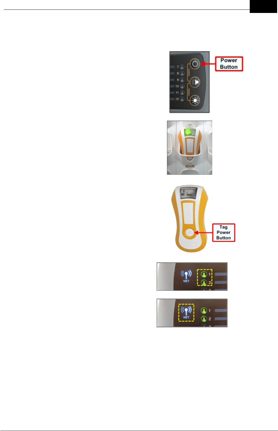
1. Press the Display Console POWER
button to turn the system on.
2. Remove fully charged Tags from the
Power Dock.
3. Press the button on each Tag to turn it on.
4. Check that each Tag's LED on the Display
Console is displayed as solid green.
5. Check that the network LED on the
Display Console and any Internal or
External Routers are solid blue.
System Shutdown
1. Press and hold the power button on the Display Console for 5 seconds.
2. Return Tags to the Power Dock for charging. Charging continues after system
shutdown as long as power is supplied to the Power Dock.
Draft
8DOC-0132 Crewsafe User Manual v.1.2
Mobilarm Ltd. © 2009
4 Overview of Mobilarm Crewsafe
Mobilarm Crewsafe is a wireless safety network designed to improve the workplace
safety of commercial mariners by keeping track of the crew at work at all times. A
'meshed' series of wireless routers automatically detects emergencies involving
personnel and can initiate a full-scale alert within seconds of an incident such as a man
overboard event occurring.
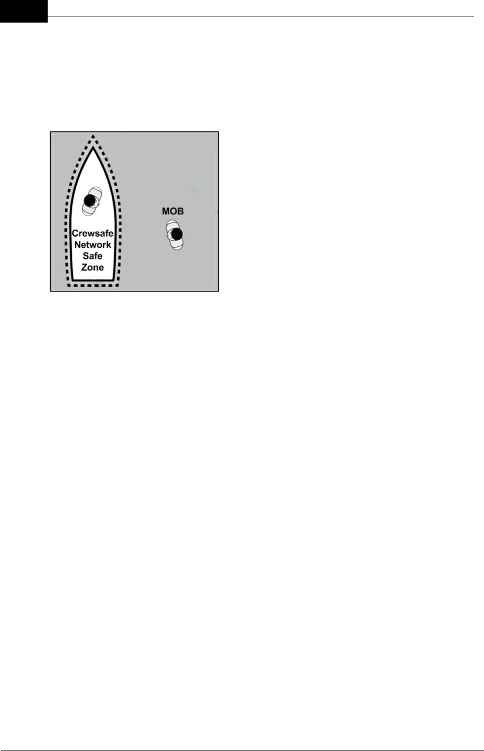
Each employee carries a small transceiver Tag,
which remains connected to the network via
Crewsafe wireless routers. The network immediately
detects any break in the signal and automatically
raises an alarm if the connection is not re-
established within a few seconds. Therefore, if a
crew member goes overboard, the signal is lost and
an alarm is raised. Each Tag also features a duress
button that can be manually activated if an employee
is in distress onboard a vessel.
Any break in a Tag's signal, for any reason, raises an alarm. If a Tag is damaged, its
battery dies or if a person moves out of range of the network, an alarm is raised. This
ensures that co-workers are immediately aware of a possible emergency and employees
are not be left unprotected.
When installed on vessels, Crewsafe can interface with existing chart plotter navigation
systems and GPS devices. In a man overboard (MOB) emergency, your Crewsafe
system can automatically send a waypoint position of where an incident occurs to your
vessel’s chart plotter. This provides essential track back navigation data. The system can
report and track multiple events, but will always prioritise the more serious risk of man
overboard over other emergencies.
Following is an introduction to the various elements of the Crewsafe system.
Draft
9Overview of Mobilarm Crewsafe
Mobilarm Ltd. © 2009
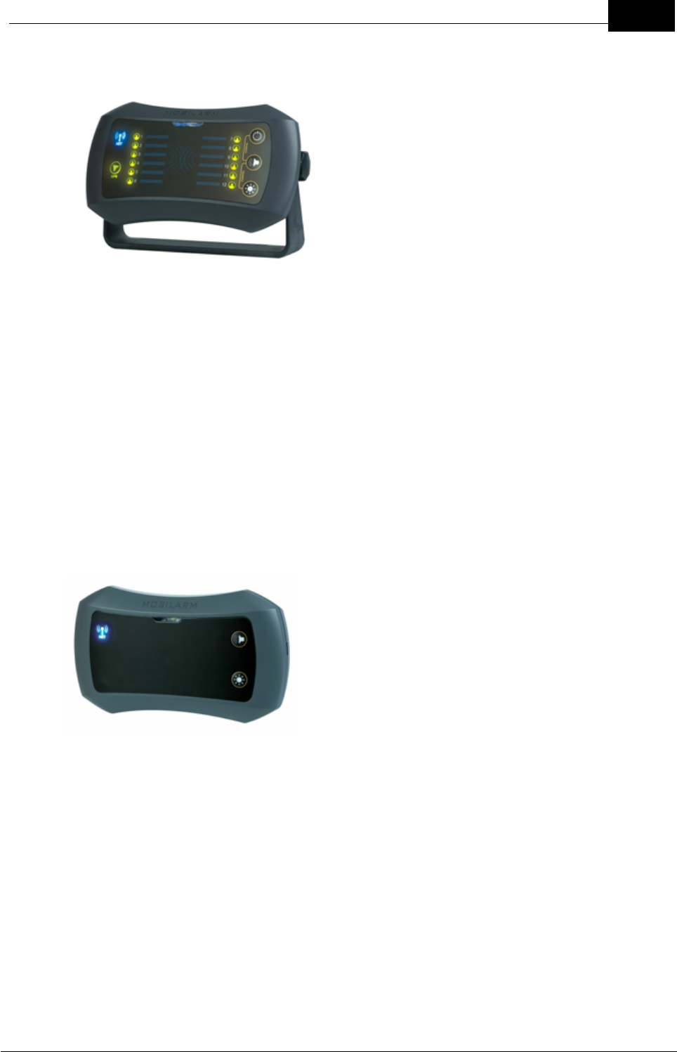
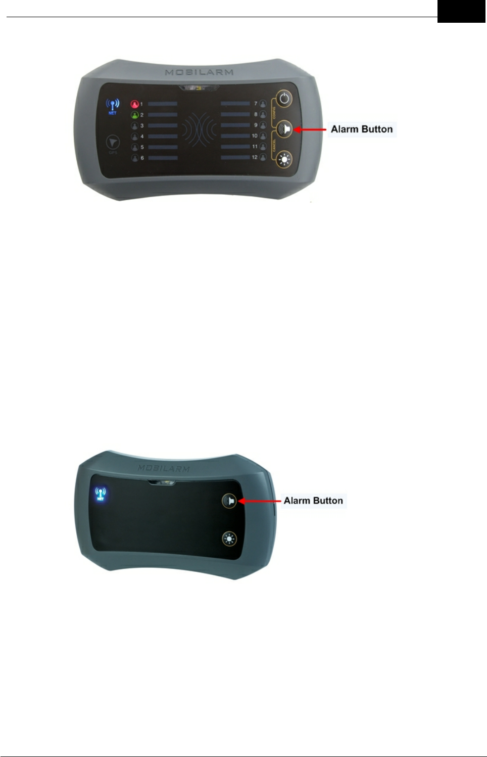
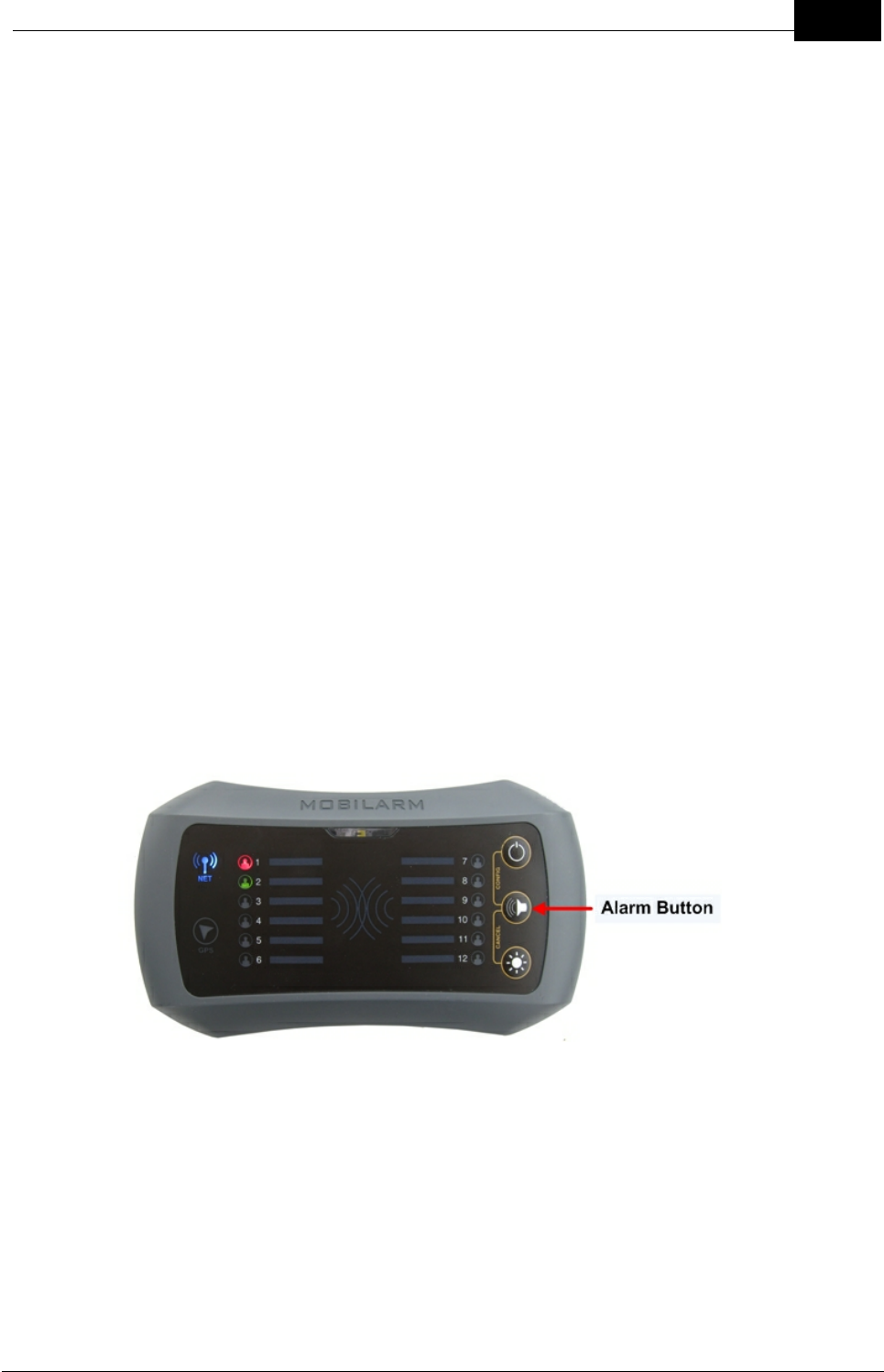
Display Console
Every Crewsafe network requires a Display
Console, which is responsible for the
management and control of the Crewsafe
system. The Display Console can be used to
configure and control the system and it displays
the status of all Tags connected to it. The
Display Console has a high-intensity STROBE
warning light, an inbuilt PIEZO and a ROUTER
STATUS LED for displaying its wireless network
connection status. It also has 12 TAG STATUS
LEDs for monitoring the safety of crew
members on a vessel.
A Display Console can:
·Monitor crew Tag status (up to 12 Tags);
·Monitor system network status;
·Monitor GPS/chart plotter connection status;
·Provide audible and visual alarms for man overboard events, duress alarms,
manual and general network alarms;
·Be attached to external alarms and other warning devices; and
·Initiate general network alarms.
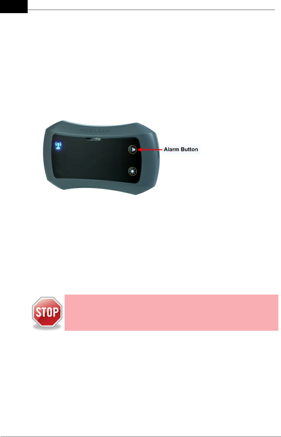
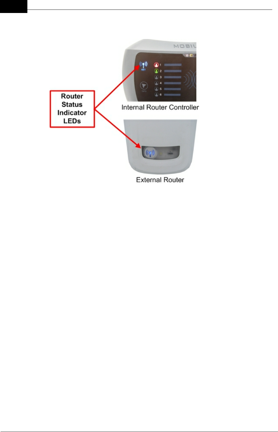
Internal Router
The purpose of the Internal Router is to expand the
wireless network footprint to cover all internal areas
on a vessel. Additional Internal Routers can be added
to a network as required. Each Internal Router has a
high-intensity STROBE warning light, an inbuilt PIEZO
and a ROUTER STATUS LED for displaying its
wireless network connection status.
An Internal Router can:
·Provide audible and visual alarms for man overboard events, duress alarms,
manual and general network alarms;
·Accept signals from an external warning device via its input (e.g. emergency
button or bilge alarm);
·Send signals to an external warning device (e.g. emergency light or siren); and
·Initiate manual network alarms.
Draft
10 DOC-0132 Crewsafe User Manual v.1.2
Mobilarm Ltd. © 2009
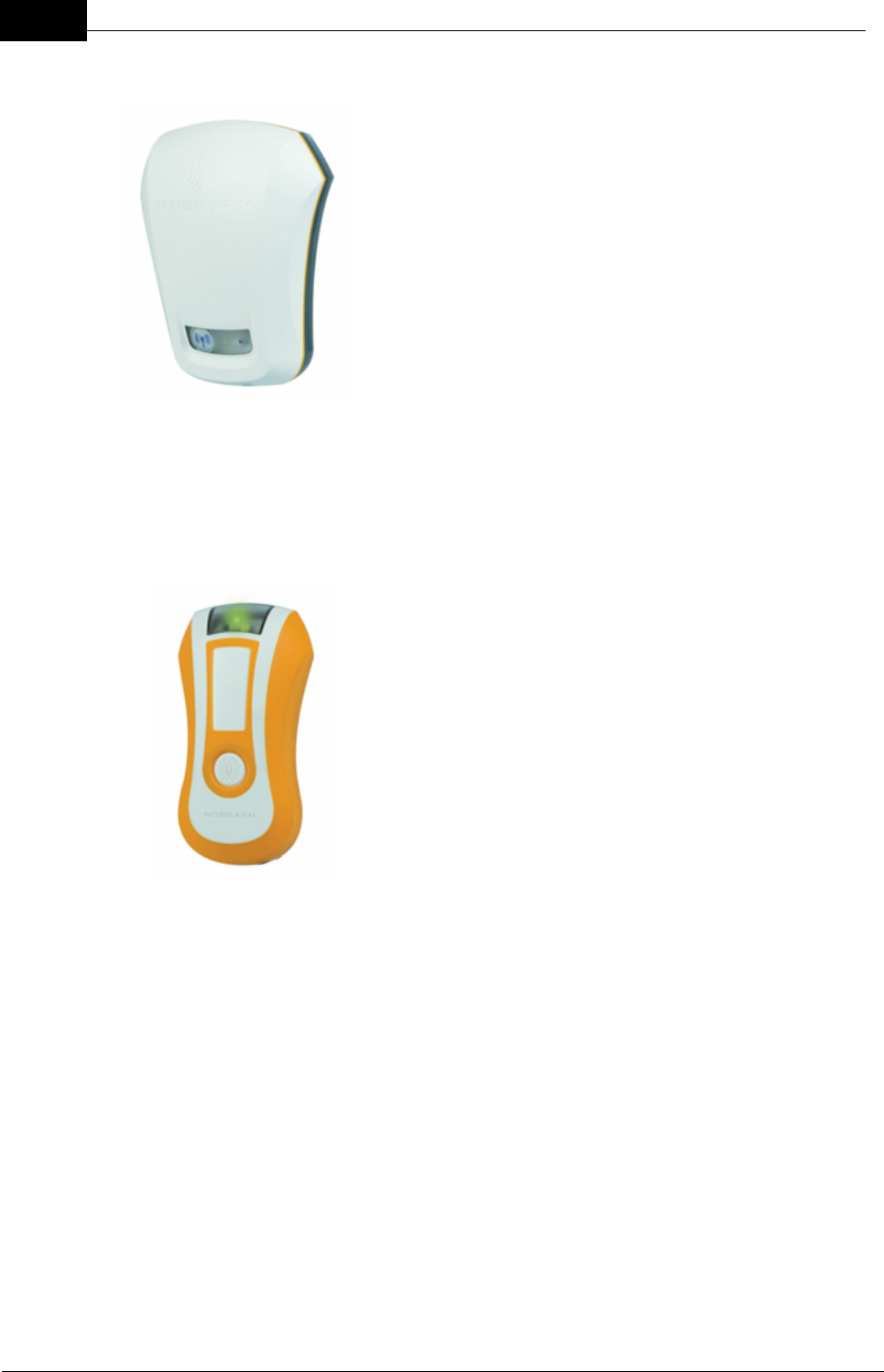
External Router
An External Router is installed on the exterior of a vessel
and as such it is designed to be exposed to the full force
of nature at sea. An External Router has no built-in
manual network alarm function, but it has one relay output
that can be connected to the External Router's switched
input if required. Each External Router has a high intensity
STROBE warning light and a ROUTER STATUS LED for
displaying its wireless network connection status.
An External Router can:
·Provide visual alarms for man overboard events,
duress alarms, manual and general network alarms;
·Accept signals from an external warning device via
its input (e.g. emergency button or bilge alarm); and
·Send signals to an external warning device (e.g.
emergency light or siren).
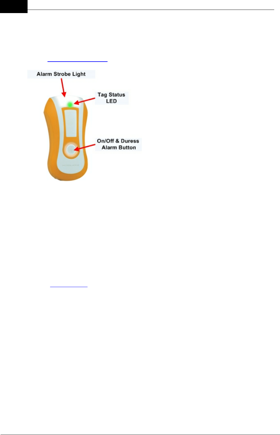
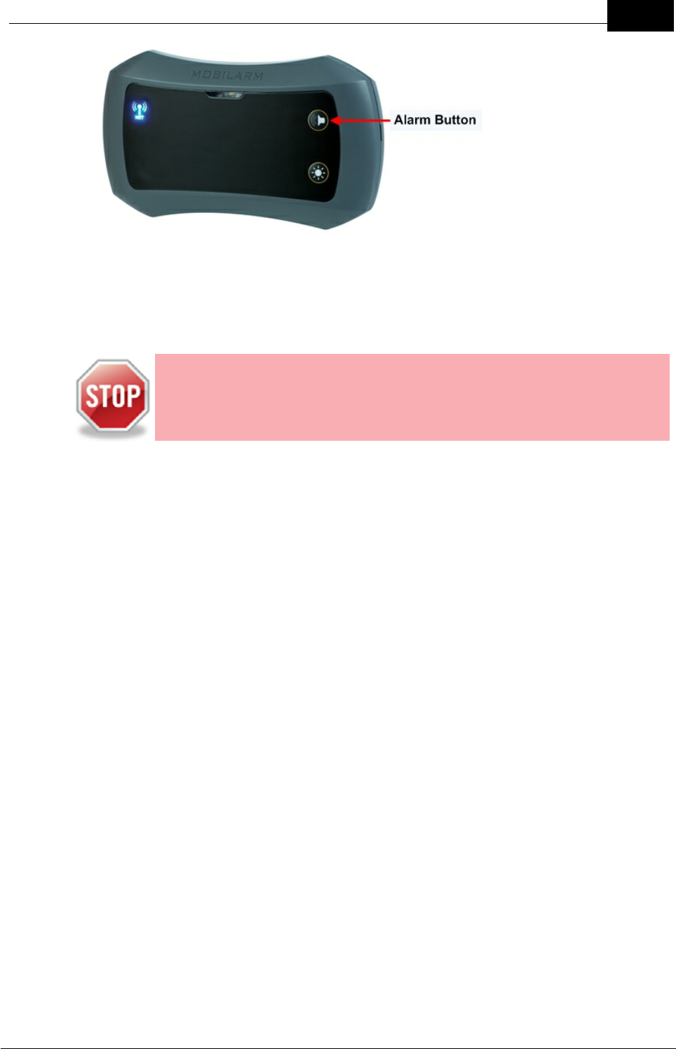
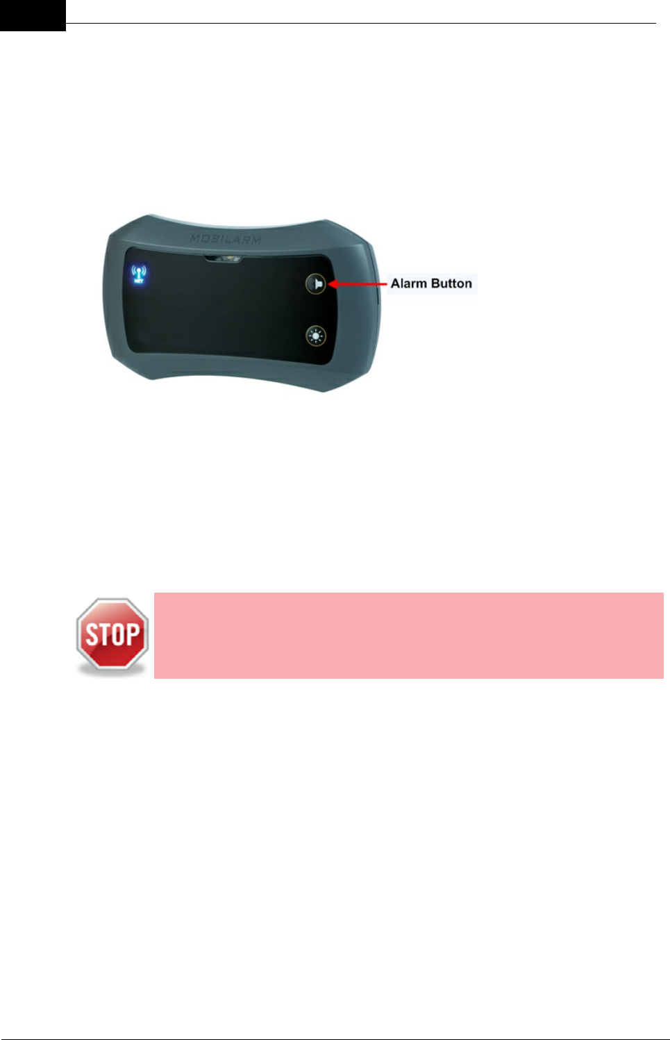
Tags
Crew members wear a small Crewsafe Tag (a personal
transceiver) which, if disconnected from the network
through submersion in water or distance from the network,
will set off the Crewsafe alarm enabling a speedy recovery.
A manually activated duress alarm can also be initiated by
pressing and holding the button on a Tag.
Each Tag vibrates during each system alarm or paging
state. It also has a high intensity STROBE warning light and
a TAG STATUS LED for displaying its wireless network
connection status.
Tags can be used to configure other Tags or routers when
they are used in 'wand' mode. In wand mode a Tag sends
serial infrared data to another Tag or router to configure it for
the system.

Draft
11Overview of Mobilarm Crewsafe
Mobilarm Ltd. © 2009
Power Dock
The Power Dock is an essential element of Crewsafe,
providing both stowage and charging capabilities for
Crewsafe Tags.
Crew members place the Tags into Power Dock charging
bays after use to recharge them; the Tag status LED
provides the current charge state of the Tag. The charge
status of all active Tags in charging bays is relayed
wirelessly to the Display Console, and the Crewsafe
Management System if it is installed.
Each Power Dock is capable of charging up to four Tags
simultaneously and Tags that have been fully discharged
will be recharged within four hours.
If more than four Tags need to be charged and stowed on a
vessel then the design of the Power Dock allows them to be
mounted next to each other, either horizontally or vertically.
Crewsafe Management System
Mobilarm Crewsafe is best managed using the Windows®-based Crewsafe
Management System. This provides an enhanced level of personnel safety and
security through crew location monitoring and management, system alarms,
individual paging and individual duress alarms. In addition, the system provides
database management of rescue assets, safety equipment and personnel.
The Crewsafe Management System is a multi-function program that runs on a
dedicated Mobilarm touch-screen tablet. It controls all aspects of the Crewsafe
network from a single point of command. Smaller vessels can use the stand-alone
Crewsafe Display Console. Please see the Crewsafe Management System User
Manual for more information.

Draft
12 DOC-0132 Crewsafe User Manual v.1.2
Mobilarm Ltd. © 2009
4.1 How it Works
1. Onboard monitoring is provided by each crew member wearing a robust, compact and
lightweight Tag, which is individually registered to a reliable and dependable wireless
network installed on the boat. Tags continuously transmit a ‘safe’ signal to the network,
which consists of one or more wireless routers ‘meshed’ together to provide a
wireless onboard monitoring system. A Display Console displays the status of all
Tags on a vessel at all times.
2. A Tag is unable to transmit through water and an alarm is automatically triggered if a
person falls off a vessel and a Tag’s connection to the network is broken. This may be
the result of a flat battery, a Tag going out of range or being damaged - or a man
overboard event. This provides peace of mind that the system is working properly at all
times and won’t let you down should you come to rely on it in an emergency*.
3. Within four seconds of a person going overboard and their Tag being disconnected
from the network, the system automatically logs a waypoint. The Display Console can
send this waypoint to a NMEA 0183 compatible chart plotter or GPS. If connected, the
boat’s chart plotter or GPS can display essential track back information to the man
overboard waypoint to enable a quick and effective rescue. Multiple man overboard
events can be tracked simultaneously.
4. A man overboard alarm sounds four seconds later if a Tag’s signal is not re-
established. (This ensures that the occasional rogue wave washing over the deck
does not inadvertently set off the alarm.) Unlike some other Personal Locator Beacons
and Emergency Position Indicating Radio Beacons (EPIRBs), Crewsafe Tags
automatically activate an alarm. This is important in the event that a person is knocked
unconscious, incapacitated or incapable of activating an alarm when they go
overboard. When an alarm sounds all Tags connected to the network vibrate and flash
and all internal and external routers flash. The Display Console and any other Internal
Routers also sound an audible alarm.
5. The other benefit of all Mobilarm man overboard systems over other Personal Locator
Beacons is the immediate notification to crew on a vessel of a man overboard
emergency as soon as it occurs. EPIRB signals, for example, are routed to onshore
locations and these distress signals need to be confirmed before the information is
then relayed to vessels in the vicinity. This can add precious minutes or hours to the
length of time a man overboard is in the water before a rescue is initiated.
6. With Crewsafe, after a man overboard has been recovered and is back onboard the
vessel, the system automatically detects the signal from the retrieved mariner’s Tag.
This automatically cancels the alarm and the system resumes normal operation.
7. A duress alarm can be manually triggered by a person pressing and holding the button
on a Tag for 3 seconds. The Tag sending an alarm is identified on the Display Console
and a system-wide alert is sent to warn that this crew member is in distress. Duress
alarms provide the ability for a crew member to manually initiate an alarm if they are in
distress for some reason.
8. A general alarm can be initiated by pressing the alarm button on the Display Console

Draft
13Overview of Mobilarm Crewsafe
Mobilarm Ltd. © 2009
for 3 seconds. When an alarm sounds all Tags connected to the network vibrate and
flash and all internal and external routers flash. The Display Console and any other
Internal Routers also sound an audible alarm.
CAUTION: No system can be 100% fail-safe. Installation faults and
operator error will always introduce the possibility of undetected man
overboard (MOB) events as can circumstances and events beyond the
equipment's design criteria. Mobilarm man overboard systems should
never be relied on as the only source of man overboard notification. The
skipper and crew must exercise common prudence and good seamanship.
Installation and operation of a Mobilarm man overboard system in no way
reduces the responsibility of the skipper and crew, who have the primary
responsibility for safety onboard a vessel.

Draft
14 DOC-0132 Crewsafe User Manual v.1.2
Mobilarm Ltd. © 2009
5 Getting Started
The following sections describe how to:
1. Turn the system on,
2. Turn system off, and
3. Turn tags on and off.
5.1 Turn the System On
When the ship's power is turned on all LEDs on each installed router illuminate briefly.
This places each router into standby mode.
Turning the System On
1. Ensure the ship's power is turned on.
2. Press the POWER button on the Display Console. This will turn it on and turn on
all other routers connected to it.
Display Console Indications
When the POWER button is pressed:
·All LEDs on the router illuminate briefly and it emits ascending tones.
·The blue NETWORK STATUS LED flashes on all routers while the
network is being established.
·Once the network is established, the NETWORK STATUS LED stops
flashing and turns solid blue.
Draft
15Getting Started
Mobilarm Ltd. © 2009
Display Console
Note: A network comprises a Display Console and at least one other active
device (Tag or router). If only a Display Console is installed on a vessel, the
NETWORK STATUS LED will display long blue flashes until a Tag is switched
on.
Display Console and Router Network Status
When the Display Console POWER button is pressed, the NETWORK STATUS
INDICATOR LED on it and any Internal and External Routers will:
1. Flash blue while the network is being established, and
2. Display as solid blue once the network is established.
If a router's NETWORK STATUS LED does not remain solid blue 20 seconds
after being switched on and starts to flash, please see the troubleshooting guide
to diagnose the problem.
5.2 Turning Tags On/Off
Turning Tags On
Press the Tag BUTTON once.
As the Tag turns on:
·The STROBE light flashes twice.
Draft
16 DOC-0132 Crewsafe User Manual v.1.2
Mobilarm Ltd. © 2009
·The Tag STATUS INDICATOR LED displays fast red flashes briefly.
Once the Tag has joined the network successfully, the Tag's STATUS INDICATOR
LED flashes green every two seconds. If the Tag's status LED does not turn green
after several seconds it may not be correctly configured for the network. Please see
the troubleshooting guide for help.
Turning Tags Off
Tags are automatically turned OFF during a system shutdown, but they can also be
turned off in the following ways:
1. Place Tags into a Power Dock and then press and hold the BUTTON on the
Tag for 3 seconds.
2. If a Tag has triggered a false man overboard alarm, press and hold the Tag
BUTTON for 10 seconds to turn it OFF.
As the Tag turns off, it vibrates and the strobe light flashes for several seconds.
See False Alarms for ways to cancel a variety of false alarms.
Draft
17Getting Started
Mobilarm Ltd. © 2009
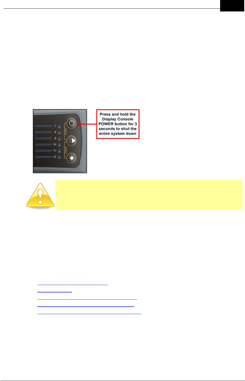
5.3 Turn the System Off
Press and hold the POWER button on the Display Console for 5 seconds. This will turn
the Display Console off and turn off all routers and Tags connected to it.
Display Console Indications
When the POWER button is pressed:
·The Display Console will produce down-ramping audio tones.
·TAG STATUS LEDs flash sequentially and the strobe light will flash.
·All LED and strobe indications cease when the Display Console has been
switched off.
CAUTION: Please ensure the system is turned off before power to the
system is disconnected - otherwise Tags may go into an alarm state. If the
system loses power briefly and unintentionally for some reason, once
power is returned to the system it should operate again normally.
Tag Indications
A Tag is turned off during a normal system shutdown. During this process it vibrates
and the strobe light flashes for several seconds.
6Routine System Tasks
The following sections explain basic Crewsafe system functionality in relation to:
·Monitoring the status of tags.
·Wearing tags.
·Recharging tags and replacing batteries.
·Dimming LEDs on the Display Console, and
·Confirming GPS Chart Plotter Data Status.
Draft
18 DOC-0132 Crewsafe User Manual v.1.2
Mobilarm Ltd. © 2009
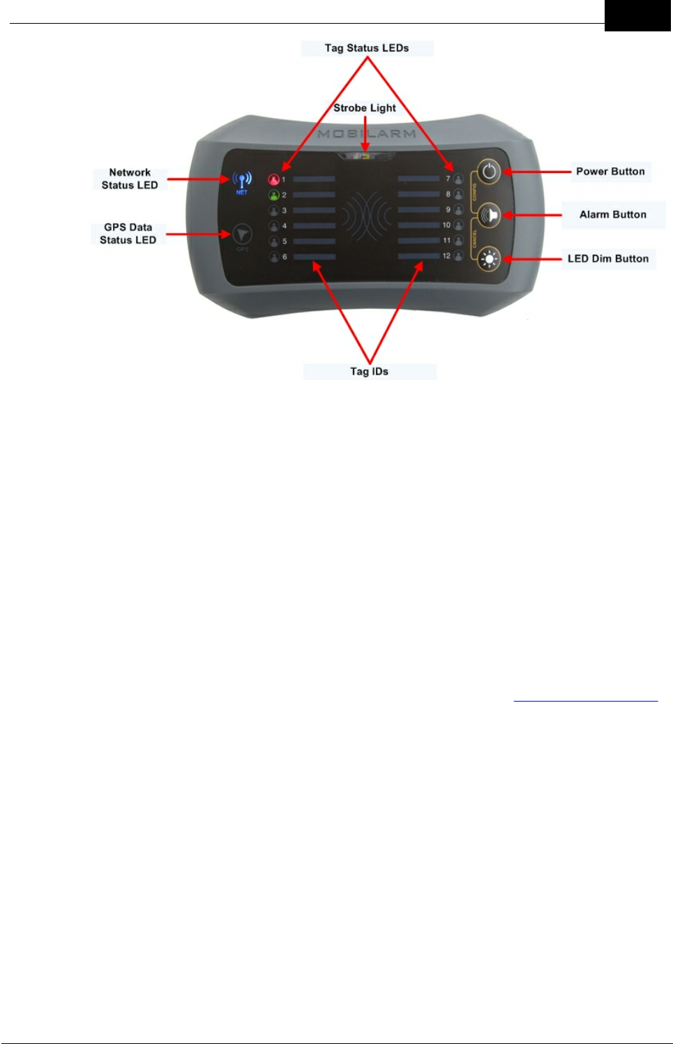
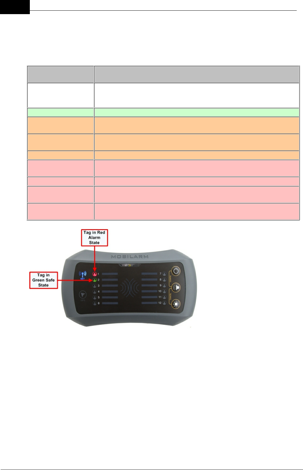
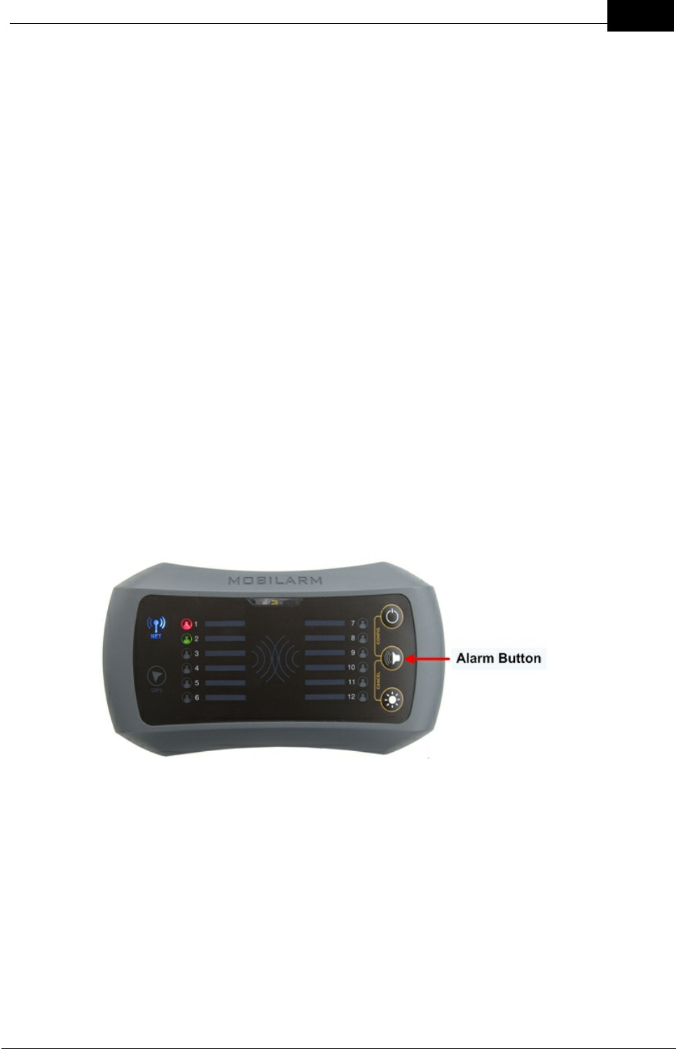
6.1 Monitoring Tag Status
A Tag's status is monitored by the Display Console and displayed by the TAG STATUS
LEDs. Following is a list of the TAG STATUS LED states that can appear on the Display
Console:
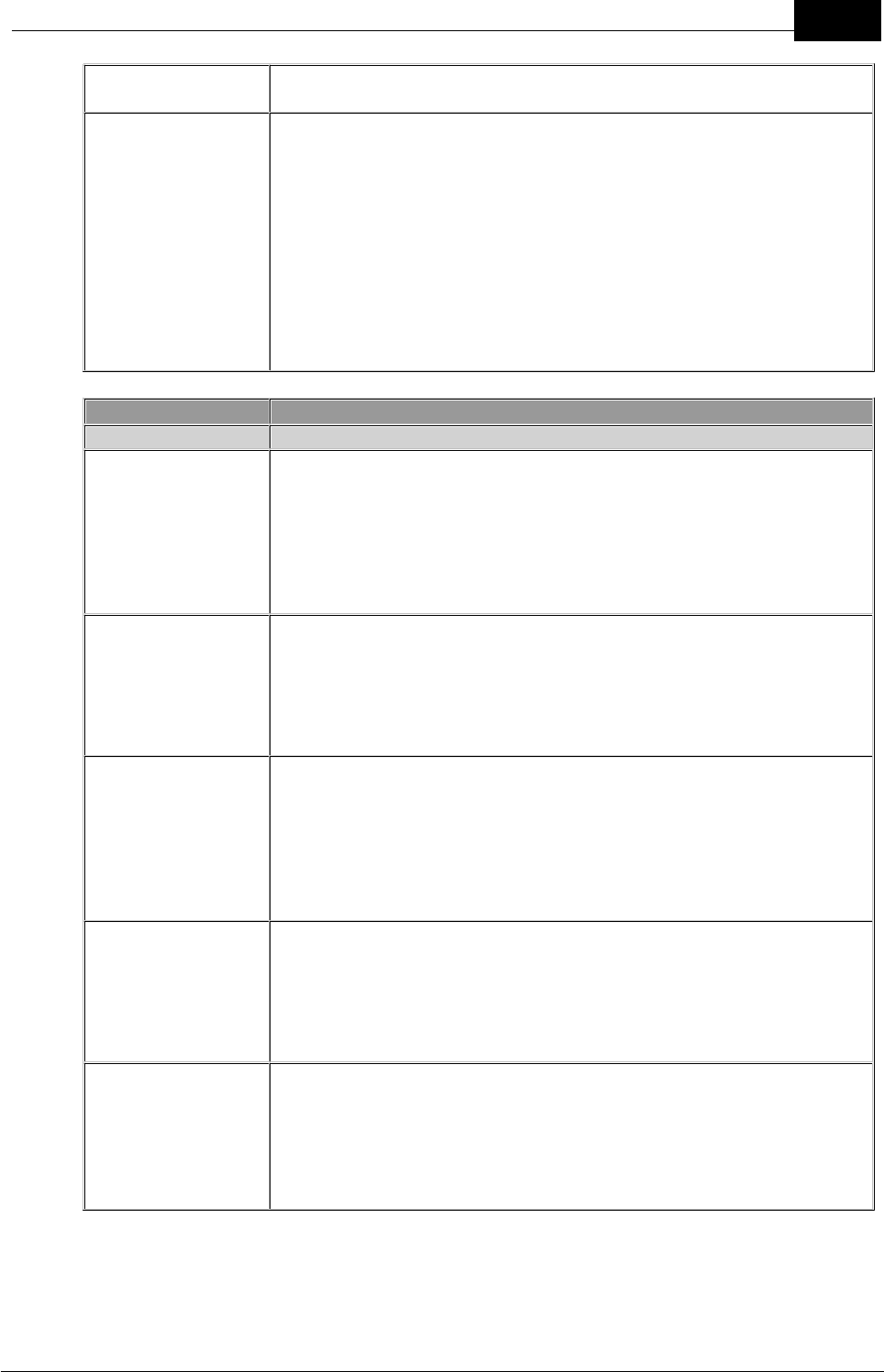
TAG STATUS LED
display
No Illumination
Tag is OFF; no Tag is assigned to the TAG STATUS LED on the
display console; or a Tag has been removed by canceling a man
overboard alarm.
Solid Green
Tag is ON and is safe
Short Orange
Flashes
A factory reset is in Progress
Long Orange
Flashes
Tag is ON and the battery is low
Solid Orange
Tag is being charged in a Power Dock
Short Fast Red
Flashes
Tag has entered the man overboard warning state prior to an
alarm and a man overboard waypoint is logged
Long Red Flashes
A man overboard or duress alarm has been muted
Solid Red
Tag has entered an active man overboard alarm state, or a duress
alarm has been activated
Illuminated Red for 5
Seconds
Signifies canceling of any active alarms
Example of Tags in Safe and Alarm States

Draft
19Routine System Tasks
Mobilarm Ltd. © 2009
Tag LED States
A Tag's status is also displayed on the Tag itself. The following table describes the
possible states of the LED on a Tag when it is in use or being charged.
Tag LED display when
in use
No Illumination
Tag is switched off or battery is flat
Green Flashes
Tag is ON and safe.
Orange Flashes
Tag is connected to the network and the battery is low
Short Red Flashes
Tag is not configured with a network ID
Long Red Flashes
Tag is switched on and configured with an incorrect network
ID
Short Fast Red Flashes
Tag has been switched on and is attempting to join the
network
Tag LED display when
charging in Power
Dock and turned on
Solid Green
Tag is fully charged
Solid Orange
Tag is charging
Solid Red
Tag charging fault
Draft
20 DOC-0132 Crewsafe User Manual v.1.2
Mobilarm Ltd. © 2009
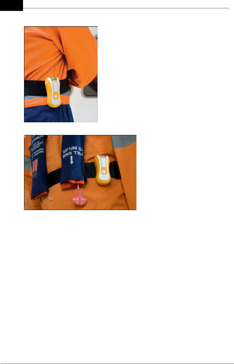
6.2 Attaching a Tag
Crewsafe Tags are small enough to be worn at all
times in all marine environments. Tags are designed
to be attached to clothing, lifejackets or harnesses
that include:
·Belts.
·Harnesses or webbing.
·Life jacket straps.
·Pockets/lanyards*/safety chains to avoid the
loss of a Tag over the side of a vessel.
*Lanyards are not recommended as the best
method of attachment.
Mobilarm recommends that Tags
are worn at waist level, both for
comfort and to ensure a man
overboard alarm is activated in an
emergency.
Attaching a Tag
There are two different clips that can be used to attach a Tag. To attach a Tag with a
mini-clip to a crew member it is necessary to thread a harness or webbing through
the gap between the Tag and clip. The large Tag clip is able to slide directly onto a
belt or strap and is much simpler to attach.
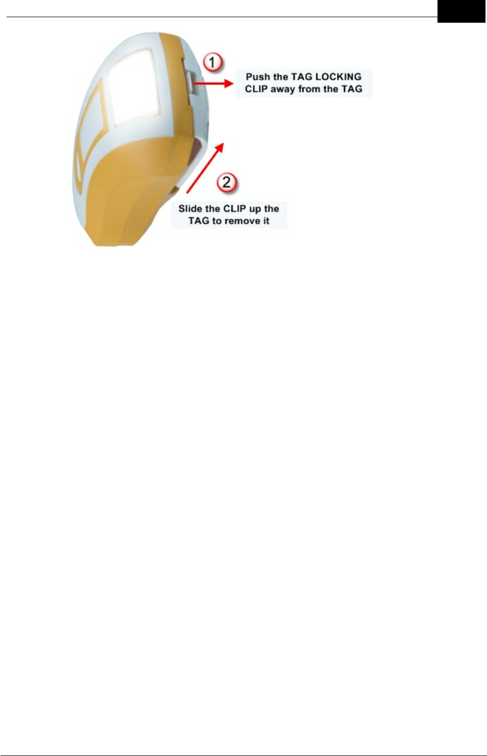
Attaching a Clip
To attach either of the two different Tag clips to a Tag, slide it onto the Tag until it
locks firmly into place. To remove it from the Tag, push the TAG LOCKING CLIP
away from body of the Tag and then slide it upwards to remove it. Note: If you are
using the large Tag clip then it needs to be removed before placing the Tag into a
Power Dock for charging.
Draft
21Routine System Tasks
Mobilarm Ltd. © 2009

Draft
22 DOC-0132 Crewsafe User Manual v.1.2
Mobilarm Ltd. © 2009
6.3 Charging a Tag
Crewsafe Tags are factory fitted with rechargeable batteries that have been fully charged
prior to shipping. However, Tags should be placed in the Power Dock and charged for at
least 4 hours prior to first use.
A fully charged Tag should last for up to 48 hours of normal operation in a non-alarm
state. The STATUS LED on a Tag flashes orange when the battery charge is getting low.
If the battery is in good condition it should last in a non-alarm state for approximately 10
hours after the low battery warning is first indicated.
Charged Tag in
Power Dock
Charging a Tag
A Tag can be fully recharged in four hours.
1. Place the Tag into an empty Power Dock bay so that the button is facing
outwards. Note: If a large Tag clip is attached to a Tag then it needs to be
removed before placing it into the Power Dock.
2. Check that the TAG STATUS LED indicates that it is charging. If a Tag's
battery charge level has dropped below 90 percent, the TAG STATUS LED
while charging is solid orange.
3. When a Tag's battery is 90 percent charged or higher its TAG STATUS LED
turns solid green. A Tag will continue to trickle charge after turning green until
it is 100 percent charged.
During normal daily use it is not necessary to turn Tags off when they are charging in
the Power Dock. However, you may wish to turn off a Tag in the Power Dock if it is a
spare Tag. If a Tag is switched off and placed into the Power Dock the Tag's LED will
illuminate green briefly to confirm charging has commenced. The Tag must be turned
on before next use.
Tags continue to be charged when the system is turned off via the Display Console,
as long the Power Dock is still connected to ship's power.
Draft
23Routine System Tasks
Mobilarm Ltd. © 2009
Technical Tip: Tags should always be recharged after use, so ensure that
power docks remain connected to a power supply even if the vessel is
docked. Regular charging will ensure there is adequate charge in the Tag
battery if there is a man overboard event. It also extends the life of the
battery.
Long-term Tag Storage
If a Tag is likely to be stored for a long period, charge it fully and then turn it off.
1. Place the Tag into a Power Dock bay with the button facing outwards.
2. Press and hold the BUTTON on the Tag for 3 seconds.
An unused Tag battery will discharge itself slowly over time so each stored Tag
should be recharged once a month to ensure the battery does not go completely flat.
This will also maximize long-term battery life.
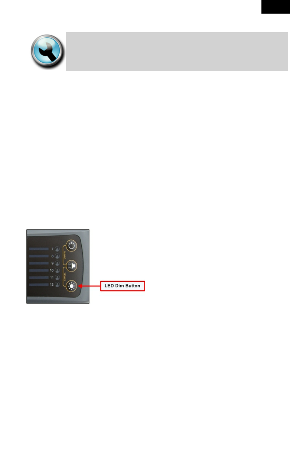
6.4 Dimming LED Display Intensity
If routers are installed in sleeping areas or if the brightness of the LEDs is interfering with
other equipment in the vicinity, the brightness of the LED displays can be dimmed.
Press the DIM button on a Display Console or Internal Router to cycle through the four
brightness settings - ranging from low to high intensity.
Dim Button on Display Console
Draft
24 DOC-0132 Crewsafe User Manual v.1.2
Mobilarm Ltd. © 2009
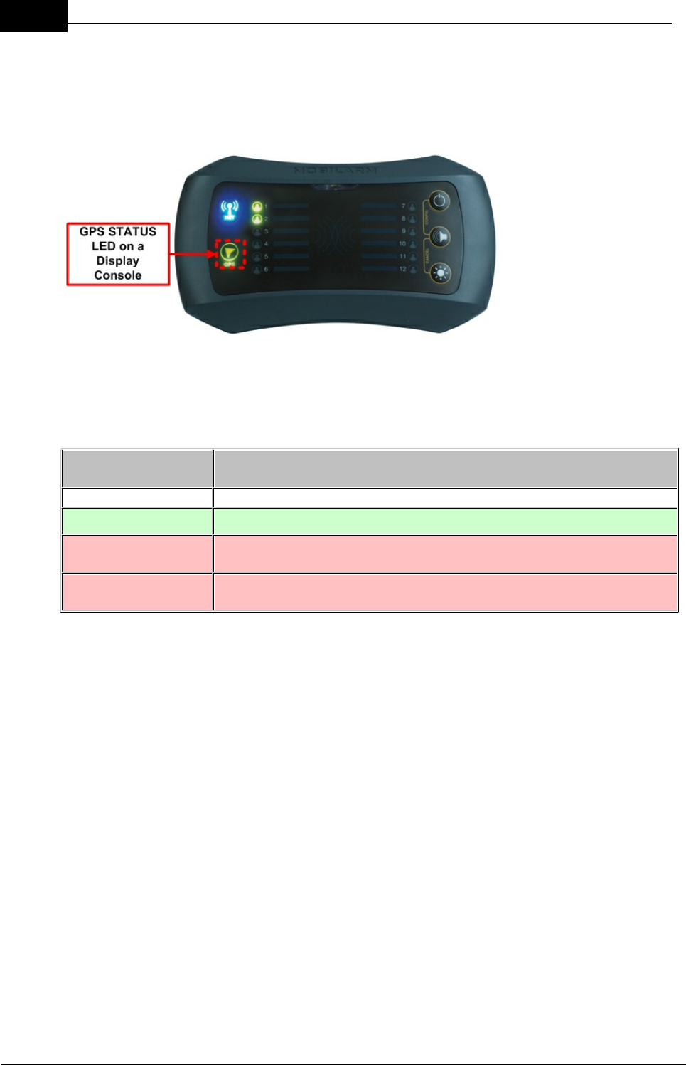
6.5 Confirm GPS Chart Plotter Data Status
If your Crewsafe system is connected to a GPS chart-plotter, you can check the data
connection between the two systems by viewing the GPS STATUS LED on the Display
Console.
GPS Data Status States
The possible states of the GPS STATUS LED on the Display Console are listed in the
following table to assist in troubleshooting GPS connections.
GPS/Chart Plotter
LED Display
No Illumination
No GPS or chart plotter is connected at powerup
Solid Green
GPS or chart plotter data is good
Long Red Flashes
Receiving chart plotter data but it is not valid (chart plotter is likely
to be acquiring GPS data)
Solid Red
No data is being received from the GPS chart plotter (likely to be a
cable/wiring issue, or GPS chart plotter is turned off)

Draft
25Routine System Tasks
Mobilarm Ltd. © 2009
7 Managing Alarms
Mobilarm Crewsafe raises a vessel-wide alarm to notify crew of an emergency situation.
The following sections explain the management of:
·Man Overboard (MOB) alarms, which are automatically activated during man
overboard events.
·Duress alarms, which are manually activated by crew members in distress.
·General alarms, which are manually activated from a system's Display Console.
·Manual alarms, which can be manually activated from internal and external routers.
·False alarms, and
·Multiple Alarms.
7.1 Man Overboard Alarms
A system-wide man overboard alarm is raised automatically if a Tag either goes out of
range of the wireless network, or if the Tag is submerged in water during an emergency.
When a man overboard is recovered and the Tag's signal reconnects to the network, the
alarm will automatically stand down and both the system and Tag default back to normal
operation.
Man Overboard Alarms
When a Tag is immersed in water it blocks the signal to the network and the following
events occur:
1. After 4 seconds it goes into a man overboard warning state and:
·The man overboard Tag starts to vibrate.
·The STROBE on the Tag starts to flash.
·The Display Console LED displays fast red flashes.
·If the Crewsafe system is connected to a GPS chart plotter, the Display
Console stores a way point for the position of the man overboard Tag at
this point.
2. After 8 seconds the system goes into a man overboard alarm state and:
·The man overboard Tag's STROBE flashes continuously until either the
alarm is canceled, or the Tag comes back within range of the network.
·The man overboard Tag vibrates initially for 60 seconds and then stops to
conserve battery power.
·The STROBE on all other active Tags starts to flash and the Tags start to
vibrate.
·The Display Console and any Internal Routers emit loud repetitive tones
and the strobe on them starts to flash.
·The Display Console LED turns red.
·The STROBE on all External Routers starts to flash.
·Any external safety or alarm warning systems that are attached to a router
will also be activated when a network-wide alarm is activated (when using
factory default relay settings).
Draft
26 DOC-0132 Crewsafe User Manual v.1.2
Mobilarm Ltd. © 2009
·Way point data is sent from the Display Console to a compatible chart
plotter.
·If you have the Crewsafe Management System connected to your system
then this system will show an alert state.
CAUTION: If a crew member moves out of range while carrying a tag then
connection to the network will be broken and Crewsafe will raise a man
overboard alarm. This will cause the same sequence of events to occur
within the Crewsafe system as for a man overboard event (See False
Alarms for information on canceling alarms).
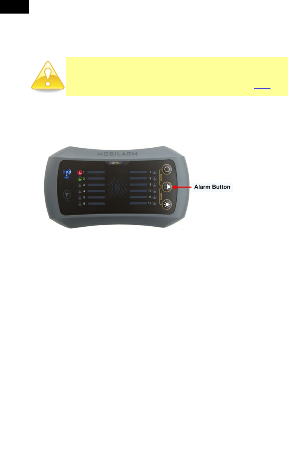
Network Mute/Acknowledgement of a Man Overboard Alarm
Press the ALARM button on the Display Console. This mute the man overboard
alarm across the Crewsafe network .
Once muted:
·The audio alarm is reduced to a single beep every 5 seconds on the Display
Console and Internal Routers.
·Active Tags continue to vibrate.
·The STROBE light on all routers and Tags will stop flashing, so that night
vision is not affected.
Note: If a new man overboard, duress, general or manual network alarm is activated
after an earlier alarm has been muted, the system will restart loud repetitive tones
and the STROBE will start flashing again.
Local Internal Router Mute/Acknowledgement of an Alarm
Press the ALARM button on an Internal Router. This only mutes the man overboard
alarm locally.
Draft
27Managing Alarms
Mobilarm Ltd. © 2009
Once muted, the audio alarm is reduced to a single beep every 5 seconds on the
local Internal Router router only. The STROBE on this device will also stop flashing,
so that night vision is not affected.
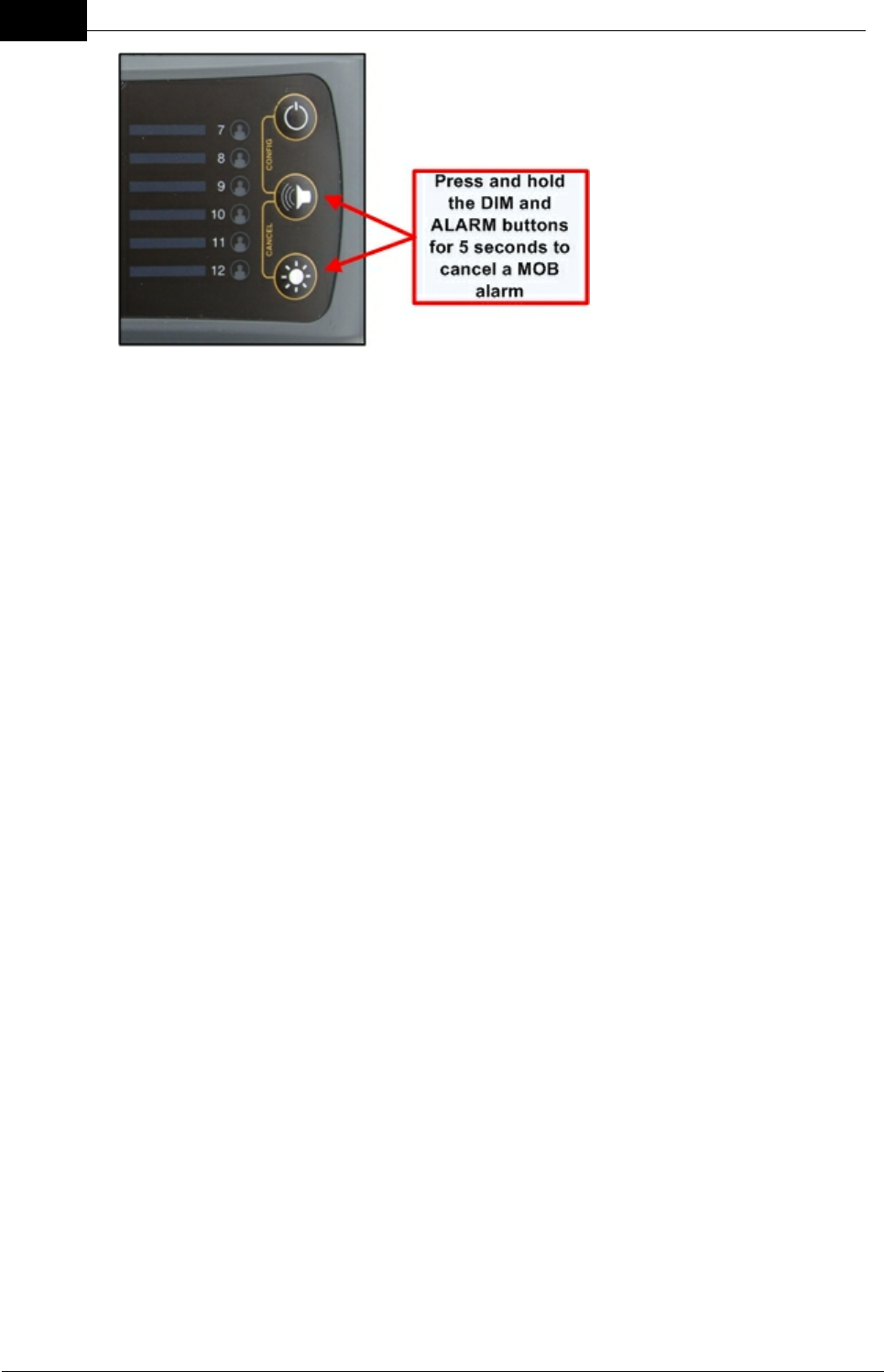
Canceling an Man Overboard Alarm
WARNING: Never cancel an alarm unless you are sure that everyone is
accounted for.
You may wish to cancel a man overboard alarm if:
·A person leaves the vessel carrying an active Tag and disconnects from the
network, or
·An active Tag is lost overboard and cannot be retrieved, or
·A Tag's battery runs flat.
To cancel the alarm using the Display Console:
Press and hold the DIM and ALARM buttons simultaneously for 5 seconds.
This will cancel the alarm across the network, except for the man overboard Tag that
has disconnected (moved out of range of the wireless network). This temporarily
removes the Tag from the Display Console and effectively places it into standby
mode. The next time the Tag is turned on within range of the Display Console it will
rejoin the network automatically.
To cancel the alarm on the disconnected Tag:
1. Press and hold the button on a Tag for 10 seconds, or
2. Bring the Tag back within range of the network.
Draft
28 DOC-0132 Crewsafe User Manual v.1.2
Mobilarm Ltd. © 2009
7.2 Duress Alarm: Raise, Cancel, Mute
If a crew member finds themself in distress but still connected to the network, they can
initiate a manual duress alarm from their Tag.
Raising a Duress Alarm
Press and hold the BUTTON on a Tag for 3 seconds. During this process the Tag
vibrates continuously and its STROBE flashes.
After a duress alarm is raised:
·The Tag initiating the alarm vibrates intermittently and the STROBE on it
flashes.
·The STROBE on all other active Tags starts to flash and the Tags start to
vibrate.
·The Display Console and any Internal Routers emit loud repetitive tones and
the strobe on them starts to flash.
·The Display Console LED turns red.
·The STROBE on all External Routers starts to flash.
·Any external safety or alarm warning systems that are attached to a router will
also be activated when a duress alarm is activated (when using factory default
relay settings).
·Way point data is sent from the Display Console to a compatible chart plotter
once the alarm is activated.
·If the Crewsafe Management System is connected to your Display Console
then this will display an alert state.
Note: If you are not using the Crewsafe Management System, which can distinguish
between a man overboard and duress alarm, it is best to initially assume that an
alarm from a Tag on the Display Console is a man overboard alarm.
Network Mute/Acknowledgement of a Duress Alarm
Press the ALARM button on the Display Console. This mutes the duress alarm
Draft
29Managing Alarms
Mobilarm Ltd. © 2009
across the Crewsafe network.
Once muted:
·The audio alarm is reduced to a single beep every 5 seconds on the Display
Console and Internal Routers.
·Active Tags continue to vibrate.
·The STROBE light on all routers and Tags will stop flashing, so that night
vision is not affected.
Note: If a new man overboard, duress, general or manual network alarm is activated
after an earlier alarm has been muted, the system will restart loud repetitive tones
and the STROBE will start flashing again.
Local Internal Router Mute/Acknowledgement of a Duress Alarm
Press the ALARM button on an Internal Router. This only mutes the duress alarm
locally.
Once muted:
·The audio alarm is reduced to a single beep every 5 seconds on the local Internal
Router only.
·Active tags continue to vibrate.
·The STROBE will stop flashing, so that night vision is not affected.

Draft
30 DOC-0132 Crewsafe User Manual v.1.2
Mobilarm Ltd. © 2009
Canceling a Duress Alarm
WARNING: Never cancel an alarm unless you are sure that everyone is
accounted for.
There are two ways to cancel a duress alarm:
1. Press and hold the BUTTON on the Tag that the alarm originated from for 3
seconds. This sends a message to the network to cancel the duress alarm.
2. Press and hold the DIM and ALARM buttons simultaneously on the Display
Console for 5 seconds.
Draft
31Managing Alarms
Mobilarm Ltd. © 2009
7.3 General Network Alarm: Raise, Cancel, Mute
A general network alarm can be initiated from a Display Console and may be used to
alert the crew that there is a problem onboard a vessel.
Raising a General Alarm
1. Press and hold the ALARM button on the Display Console for 3 seconds.
While the button is being pressed the router emits up ramping tones and the
STROBE flashes quickly; or
2. Activate an external alarm system that has been wired to the Display
Console's switch input (i.e. press an emergency button).
When a general network alarm is activated the following events occur:
·The STROBE on all active Tags starts to flash and the Tags start to vibrate.
·The STROBE on the Display Console and any Internal Routers starts to flash
twice per second and the routers emit loud repetitive tones.
·The STROBE on all External Routers starts to flash.
·Any external safety or alarm warning systems that are attached to a router will
also be activated (when using factory default relay settings).
Network Mute/Acknowledgement of a General Alarm
Press the ALARM button on the Display Console. This mutes the general alarm
across the Crewsafe network.
Once muted:
·The audio alarm is reduced to a single beep every 5 seconds on the Display
Console and Internal Routers.
·Active Tags continue to vibrate.
·The STROBE light on all routers and Tags will stop flashing, so that night
vision is not affected.
Draft
32 DOC-0132 Crewsafe User Manual v.1.2
Mobilarm Ltd. © 2009
Note: If a new man overboard, duress, general or manual network alarm is activated
after an earlier alarm has been muted, the system will restart loud repetitive tones
and the STROBE will start flashing again.
Local Internal Router Mute/Acknowledgement of a General Alarm
Press the ALARM button on an Internal Router. This only mutes the general alarm
locally.
Once muted:
·The audio alarm on the Internal Router is reduced to a single beep every 5
seconds.
·Active tags continue to vibrate.
·The STROBE light on the Internal Router will stop flashing, so that night vision
is not affected.
Canceling a General Alarm
WARNING: Never cancel an alarm unless you are sure that everyone is
accounted for.
1. Press and hold the ALARM button on the Display Console for 3 seconds, or
2. To cancel an alarm activated by a warning system wired to the Display
Console's switch input, reverse the switch or repress the button used to
initiate the alarm.
After cancellation, all network routers and Tags return to their normal operational
state.
Draft
33Managing Alarms
Mobilarm Ltd. © 2009
7.4 Manual Network Alarm: Raise, Cancel, Mute
A manual network alarm can be initiated across the Crewsafe network from either an
Internal Router or External Router, to alert the crew to an emergency.
Raising a Manual Alarm
1. Press and hold the ALARM button on an Internal Router for three seconds. While
the button is being pressed the router emits up ramping tones and the STROBE
flashes quickly; or
2. Activate an external alarm system that has been wired to an Internal or External
Router's switch input (i.e. press an emergency button).
When a manual network alarm is activated the following events occur:
·The STROBE on all active Tags starts to flash and the Tags start to vibrate.
·The STROBE on the Display Console and any Internal Routers starts to flash
twice per second and the routers emit loud repetitive tones.
·The STROBE on all External Routers starts to flash.
·Any external safety or alarm warning systems that are attached to a router will
also be activated (when using factory default relay settings).
Network Mute/Acknowledgement of a Manual Alarm
Press the ALARM button on the Display Console.
This mutes the manual alarm across the Crewsafe network, except for the Internal
Router that the alarm originated from. This device continues to emit loud repetitive
tones and/or strobe to enable the crew to identify the source of the alarm.
Once muted:
·The audio alarm is reduced to a single beep every 5 seconds on the Display
Console and Internal Routers (except for the router from which the alarm
originated).
·Active Tags continue to vibrate.
Draft
34 DOC-0132 Crewsafe User Manual v.1.2
Mobilarm Ltd. © 2009
·The STROBE light on all routers and Tags will stop flashing, so that night
vision is not affected (except for the router from which the alarm originated).
Note: If a new man overboard, duress, general or manual network alarm is activated
after an earlier alarm has been muted, the system will restart loud repetitive tones
and the STROBE will start flashing again.
Local Internal Router Mute/Acknowledgement of a Manual Alarm
Press the ALARM button on the Internal Router. This only mutes the manual alarm
locally.
Once muted:
·The audio alarm on the Internal Router is reduced to a single beep every 5
seconds.
·Active Tags continue to vibrate.
·The STROBE light stops flashing, so that night vision is not affected.
Note: It is not possible to mute the alarm on the Internal Router that has raised a
manual alarm.
Canceling a Manual Alarm
WARNING: Never cancel an alarm unless you are sure that everyone is
accounted for.
There are three ways to cancel a manual alarm:
1. To cancel a manual alarm using the Internal Router that raised the alarm,
press the ALARM button on that device for 3 seconds.
2. To cancel a manual alarm using the Display Console, press and hold the DIM
and ALARM buttons simultaneously on that device for 5 seconds. Note: This

Draft
35Managing Alarms
Mobilarm Ltd. © 2009
cancels the manual alarm and all other active general and manual alarms
within the system.
3. To cancel an alarm activated by an external warning system wired to an
Internal or External router's switch input, reverse the switch or re-press the
button used to raise the alarm.
After cancellation, all network routers and Tags return to their normal operational
state unless another alarm is active.
7.5 False Alarms
WARNING: Never cancel an alarm unless you are sure that everyone is
accounted for.
A false man overboard alarm may occur on the Crewsafe system if:
a. A person leaves the vessel carrying an active Tag and disconnects from the
network.
b. An active Tag is lost overboard and cannot be retrieved.
c. A Tag's battery runs flat.
A false duress alarm may occur if:
a. Someone unintentionally presses the Tag BUTTON for 3 seconds.
A false manual or general alarm may occur if:
a. Someone unintentionally presses the ALARM BUTTON on a Display Console or
Internal Router, or
b. Someone unintentionally activates an external alarm system that has been wired to
an Internal or External Router's switch input (i.e. presses an emergency button).
To cancel alarms raised in error, please see the relevant section:
·Cancelling a Man Overboard Alarm
·Cancelling a Duress Alarm
·Cancelling a General Alarm
·Cancelling a Manual Alarm

Draft
36 DOC-0132 Crewsafe User Manual v.1.2
Mobilarm Ltd. © 2009
7.6 Managing Multiple Alarms
WARNING: Although it is possible that multiple alarms will occur as a result
of several people activating an alarm for the same reason or incident, it is
important to ensure that each alarm is investigated before it is canceled, or
before multiple alarms are canceled from the system simultaneously.
Muting Multiple Alarms
If more than one alarm has been initiated across the network (i.e. more than one
person has initiated an alarm from a router, or multiple Tag alarms are active), press
the ALARM button on the Display Console to mute all current alarms across the
system. It is also possible to locally mute multiple alarms at an Internal Router by
pressing the ALARM button on this router. Any new alarm activated after muting will
restart an audio alarm across the network and reactivate the strobe on Tags.
Canceling Multiple Man Overboard Alarms
If you want to cancel multiple man overboard alarms you need to perform the cancel
function once for each Tag. The earliest man overboard alarm is canceled first and
any other man overboard or duress alarms are canceled in the order in which they
occurred.
Canceling Multiple Duress Alarms
If you want to cancel multiple duress alarms you need to perform the cancel function
once for each Tag. The original duress alarm is canceled first and any subsequent
duress or man overboard alarms are canceled in the order in which they occurred.
Canceling Multiple Manual/General Alarms
Press and hold the DIM and ALARM buttons simultaneously on the Display Console
for 5 seconds to cancel all current general and manual alarms in the system.
Canceling Simultaneous Man Overboard, Duress & General/Manual
Alarms
If both a man overboard or duress alarm and either general and/or manual alarms are
activated simultaneously then they need to be canceled separately.
1. Press and hold the DIM and ALARM buttons simultaneously on the Display
Console for 5 seconds to cancel all current general and manual alarms in the
system.
2. Repeat this process to cancel the active man overboard or Duress alarm.
Note: If you have to cancel multiple man overboard or duress alarms then you need
repeat this process for each Tag in an alarm state. The earliest Tag alarm is
canceled first and any subsequent Tag alarms are canceled in the order in which
Draft
37Managing Alarms
Mobilarm Ltd. © 2009
they occurred.
Simultaneous Man Overboard & Duress Alarms from the Same Tag
It is possible that a duress alarm could be initiated by a person wearing a Tag and
then they could subsequently fall overboard and the same Tag would then initiate a
man overboard alarm. There are two possible Crewsafe scenarios in this situation:
1. If you are using the Crewsafe Management System it is possible to discern
between the two alarm states and see that both have occurred.
2. If you are:
a. Not using the Crewsafe Management System; and
b. Have not acknowledged the first alarm from the Tag at the Display
Console.
Then the same STROBE, PIEZO and LED alarm states will be displayed on the
Display Console because there is no discernable difference between the two
alarm states.
Important note: If you are not using the Crewsafe Management System,
which can distinguish between a man overboard and duress alarm, it is
best to initially assume that an alarm from a Tag is a man overboard
alarm.
Canceling a Man Overboard and Duress Alarm from the Same Tag
If both a duress and man overboard alarm are activated at the same time from
the same Tag, it is only necessary to perform a single cancel function on the
Display Console to clear the two system alarm states. Press and hold the DIM
and ALARM buttons simultaneously on the Display Console for 5 seconds to
cancel the alarms and remove the Tag from being in an active monitoring state
on the Display Console.
Cancel all System Alarms
As a last resort, it is possible to clear all alarms from the system by turning the
system off at the Display Console.
WARNING: If you turn the system off at the Display Console then it will be
unable to monitor crew on the vessel. The Display Console shuts down all
network components in range. A man overboard, duress, general or
manual alarm cannot be raised while the system is shut down and any
man overboard or duress situation that may occur will not be recorded. All
Tags need to be individually switched on again if the system is temporarily
shut down using the POWER BUTTON on the Display Console.

Draft
38 DOC-0132 Crewsafe User Manual v.1.2
Mobilarm Ltd. © 2009
Important note: It is important to turn the system off using the POWER
button on the Display Console, rather than disconnecting the supply of
power to the unit. Otherwise, the Display Console will retain all previous
alarm states. In addition, all Tags will go into a man overboard alarm state
and all other routers will lose network connectivity.
8System Maintenance
The following system maintenance tasks may affect the performance of your Crewsafe
system if not carried out correctly. If in any doubt, Mobilarm recommends that you contact
your authorised Mobilarm service agent.
·Adding a new router to the system,
·Adding a new tag to the system,
·Removing a tag from the system,
·Replacing Tag batteries,
·Update system firmware, or
·Factory reset to assign tags to a Display Console.
8.1 Removing a Tag from the System
You may need to remove a Tag from the Crewsafe system if:
·A person leaves the vessel carrying an active Tag, or
·An active Tag is lost overboard and cannot be retrieved, or
·An active Tag has been damaged.
All of the preceding scenarios will result in the Tag disconnecting from the network and
raising a Crewsafe alarm.
If a person leaves the vessel carrying an active Tag:
Press and hold the DIM and ALARM buttons simultaneously on the Display Console
for 5 seconds.
This will cancel the alarm across the network, except for the Tag that has disconnected
(moved out of range of the wireless network). This temporarily removes the Tag from the
Display Console and effectively places it into standby mode. The next time the Tag is
turned on within range of the Display Console it will rejoin the network automatically.
If an active Tag is lost overboard and cannot be retrieved, or has been damaged:
Reset the Display Console back to its factory default settings. This removes all
active tags from the system and should only be done if you want to permanently
remove a lost or damaged Tag.

Draft
39System Maintenance
Mobilarm Ltd. © 2009
To reset a Display Console to its factory defaults please see the section titled Factory
Reset: Reassign Tags & Routers.
Note: When a Display Console is set back to its factory default settings, it does not
totally reset Tags. Tags retain their previous registration information and simply need to
be reconnected to the network to be reassigned to the Display Console.
8.2 Adding a Tag to the System
New Tags may be added to the Crewsafe network as replacements for lost tags or to
accommodate an increase in crew members.
New Tags may be supplied:
a. Pre-configured with the correct Network ID, or
b. Pre-configured with an incorrect Network ID.
If a Tag is pre-configured with the correct Network ID then it should automatically connect
to the network once it is turned on.
When a Tag that is pre-configured with an incorrect Network ID is turned on and tries to
connect to the existing network, its TAG STATUS LED will flash red.
If a Tag is pre-configured with an incorrect Network ID it needs to be reconfigured with
the correct Network ID for the existing network
Adding a Tag with the Correct Network ID
1. Press the Display Console POWER button to turn the Crewsafe system on.
2. Press the Tag BUTTON.
When a configured Tag is turned on:
·The STROBE light flashes twice and the Tag STATUS LED flashes red briefly.
·The TAG STATUS LED flashes green once it has been registered to the
network successfully.
·The next available TAG STATUS LED on the Display Console is allocated to
the new Tag and illuminates solid green.
Reconfigure a Tag to the Correct Network ID
Reconfiguration of a Tag to the correct Network ID can be performed using the
Display Console, or a configured Tag, i.e. one that has connected to the network
previously.
Reconfiguration using a Display Console
This is the simplest way to reconfigure a Tag to the existing network.
Draft
40 DOC-0132 Crewsafe User Manual v.1.2
Mobilarm Ltd. © 2009
1. Press the Display Console POWER button to turn the Crewsafe system
on.
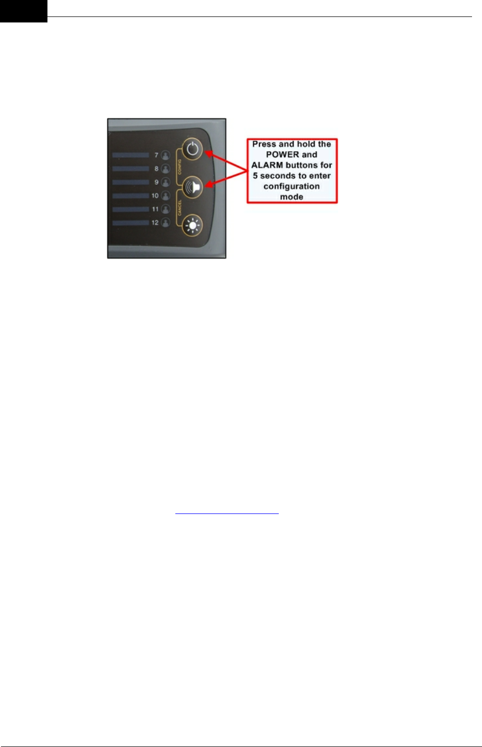
2. Press the POWER and ALARM buttons simultaneously for 5 seconds.
This places the Display Console into configuration mode and the unused
Tag LEDs on the router cycle green. The Display Console remains in
configuration mode for 60 seconds.
3. Align the Tag lens to within 150 mm (6 in) of the strobe lens on the Display
Console. This enables infrared data transfer of the Network ID.
4. While the Display Console is in configuration mode, press the button on
the Tag. The Tag STROBE flashes twice followed by short red LED
flashes until it has acquired the Network ID.
5. Once the Tag has acquired the Network ID it enters 'acquisition mode'.
The TAG STATUS LED turns solid green and the STROBE flashes.
6. Within 20 seconds of the Tag entering this 'acquisition mode', press the
Tag button to confirm reconfiguration of the Tag.
The Tag should now connect to the network and the Tag's LED should flash
green. The next available TAG STATUS LED on the Display Console is allocated
to the new Tag and illuminates solid green.
Note: If a Tag is not successfully programmed with the Network ID it will
continue to flash red until the Network ID acquisition process times out.
If a Tag does not connect to the network after several attempts, please see the
Tag section of the troubleshooting guide to diagnose the problem.
Reconfiguration using a Tag
Reconfiguration of a Tag can be performed using a configured tag in wand
mode. A Tag remains in wand mode for 2 minutes from wand mode activation.
1. Turn on the Display Console.
2. Ensure that the configured Tag you are using as the 'wand' Tag is turned
off.
3. Press and hold the button on the configured Tag for 10 seconds. This
places the Tag into wand mode and its LED will flash alternately red and

Draft
41System Maintenance
Mobilarm Ltd. © 2009
green.
4. While the configured Tag is in wand mode, press the BUTTON of the Tag
to be reconfigured to turn it on. The STROBE on this Tag flashes twice
and then its LED displays short red flashes.
5. Align the lenses of both tags so that they face each other. This enables
infrared data transfer of the Network ID. The Tag being reconfigured
should:
·Flash its STROBE twice alternately with a green LED indication.
·Display a sequence of fast red flashes as it is reprogrammed.
5. When the Network ID data is sent successfully the Tag will display green
LED flashes.
6. Check the Display Console for a new green Tag LED. This confirms that
the Tag has been successfully added to the network.
7. The wand Tag will automatically time-out after two minutes and turn itself
off. Placing the Tag into a Power Dock will also turn wand mode off.
8.3 Replacing Tag Batteries
WARNING: Crewsafe Tags are factory fitted with high-performance 3.6
volt CR2 Lithium-ion rechargeable batteries and these must only be
replaced by an approved Mobilarm service agent or the warranty is
voided. Non-rechargeable batteries cannot be used in Tags and if installed
they may rupture, leak or explode causing personal injury.
Rechargeable batteries can be charged and discharged hundreds of times but they will
eventually wear out. If a Tag's operation time appears to be significantly lower than it
should be after charging, the battery most likely needs replacing. Mobilarm recommends
using only high-performance 3.6 volt CR2 Lithium-ion rechargeable batteries in Crewsafe
Tags. To replace a battery in a Tag please return it to an authorized Mobilarm dealer for
servicing.
8.4 Adding a Router to the System
Internal or External Routers can be added to a Crewsafe network to increase the
footprint, reliability and redundancy of the system, or to replace an existing device.
New routers may be supplied:
a. Pre-configured with the correct Network ID, or
b. Pre-configured with an incorrect Network ID.
If an Internal or External Router is pre-configured with the correct Network ID then it
should automatically connect to the network once it is turned on.
When an Internal or External Router that is pre-configured with an incorrect Network ID is
turned on and tries to connect to the existing network, it will display as follows:
a. The NETWORK STATUS LED will flash purple when turned on and then go into
standby mode where no LEDs are illuminated, or
Draft
42 DOC-0132 Crewsafe User Manual v.1.2
Mobilarm Ltd. © 2009
b. The NETWORK STATUS LED will flash purple when turned on and then flash blue
in the 'unsuccessful network connection' error state.
If an Internal or External Router is pre-configured with an incorrect Network ID it needs to
be reconfigured with the correct Network ID for the existing network.
Adding a Router with a Correct Network ID
1. Install the new router and attach ship's power to it.
2. Turn the Crewsafe system on by pressing the Display Console POWER button.
The router will:
·Automatically search for a network that matches its internally programmed
Network ID.
·Display a flashing blue NETWORK STATUS INDICATOR LED while it is being
added to the network.
·Display a solid blue NETWORK STATUS INDICATOR LED once it has
connected to the network.
Reconfigure a Router to the Correct Network ID
Reconfiguration of a router to the correct Network ID requires a configured Tag, i.e.
one that has connected to the network previously.
1. Turn the Crewsafe system on by pressing the Display Console POWER
button.
2. Ensure the configured Tag is turned off.

Draft
43System Maintenance
Mobilarm Ltd. © 2009
3. Press and hold the button on the configured Tag for 10 seconds. This places
the Tag into wand mode and its LED will flash alternately red and green.
4. While the configured Tag is in wand mode, align the Tag lens to within 150
mm (6 in) of the strobe lens on the router to be reconfigured. This enables
infrared data transfer of the Network ID.
5. When the Network ID data is sent successfully then the router's STROBE will
flash twice and the NETWORK STATUS LED will turn solid blue when it
connects successfully to the network.
6. The Tag will automatically time-out after two minutes and turn itself off. Placing
the Tag into a Power Dock will also turn wand mode off.
If a router does not connect to the network after several attempts, please see the
router section of the troubleshooting guide to diagnose the problem.
8.5 Updating Crewsafe Firmware
It may be necessary to upgrade firmware in order to update or expand the capability of
your Crewsafe system. Upgrades to firmware can only be performed by Mobilarm or your
Mobilarm dealer. Please contact your dealer if you need to upgrade your system.
Draft
44 DOC-0132 Crewsafe User Manual v.1.2
Mobilarm Ltd. © 2009
8.6 Factory Reset: Reassign Tags & Routers
Tags are initially assigned to a Display Console panel in the order in which they are
registered to the network. It is possible to change the order of Tags on a Display Console,
or remove Tags from the system, by performing a factory reset on the Display Console.
The system is limited to 12 Tags if a Display Console is used without the Crewsafe
Management System because there is a maximum of 12 TAG STATUS LEDs on the
Console.
Technical Tip: A factory reset can only be performed if the system is
turned off and the Display Console has ship's power connected to it. Once
you have performed a factory reset you must turn off power to all Internal
and External Routers, or the routers will not rejoin the network. The only
way to do this is to briefly turn off ship's power to all Internal and External
Routers.
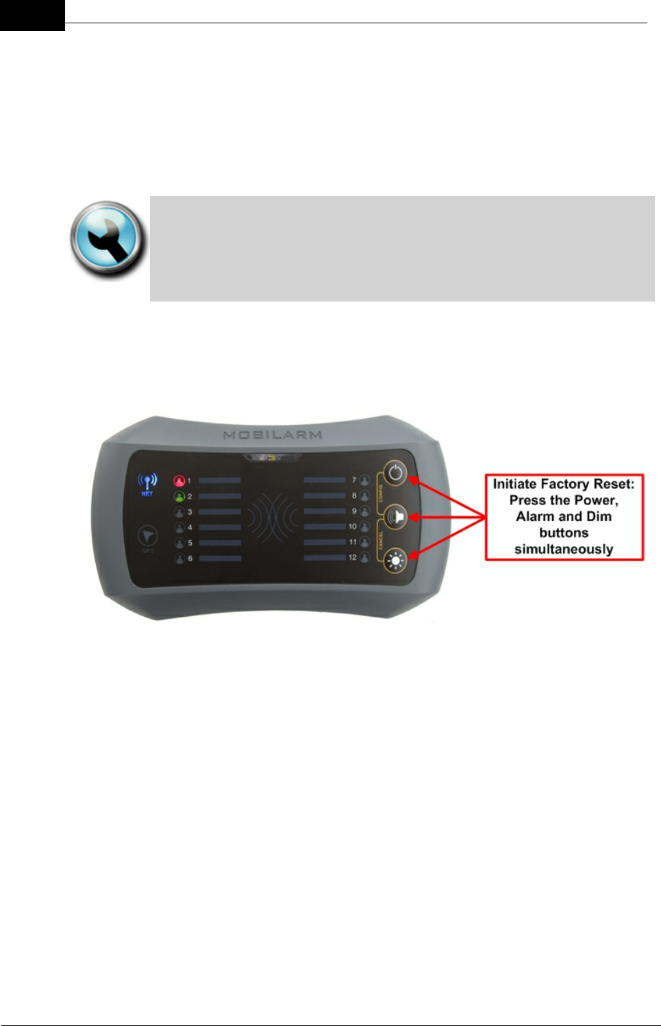
Initiating a Factory Reset
To initiate a factory reset of a Crewsafe system, simultaneously press and hold the
ALARM, DIM and POWER buttons for 5 seconds.
During initialization:
1. The Display Console NETWORK STATUS LED flashes red and all lights on
the front panel flash orange 8 times.
2. All lights go out for a couple of seconds.
3. All lights on the front panel illuminate orange and the NETWORK STATUS
LED illuminates purple for a couple of seconds.
4. The NETWORK STATUS LED flashes blue as it attempts to reconnect the
network of installed routers.
After performing the factory reset:
·All routers in range are automatically rejoined to the network.
·All Tags are reassigned to the Display Console when they are switched on (in
the order that information is received from them).

Draft
45System Maintenance
Mobilarm Ltd. © 2009
Note: When a Display Console is set back to its factory default settings, it does not
totally reset Tags. Tags retain their previous registration information and simply need to
be reconnected to the network to be reassigned to the Display Console.
Managing the Registration Order of Tags on the Display Console
To manage the order in which Tags are reassigned to the Display Console, simply
switch on each Tag in the order that you want them to be listed on the Display
Console front panel. Wait for each Tag to be registered and then turn the next Tag on
and so forth.
Naming Tags
The name of the person wearing a Tag can be written on the pre-printed stickers
supplied with each system and placed next to the LED for their Tag to identify them. If
you are using the Crewsafe Management System you can assign alpha-numeric
names to your crew and view their Tag status on a PC (see the Crewsafe
Management System User Manual).
9Maintaining System Components
Mobilarm Crewsafe systems are extremely robust and designed for operating in the
harshest conditions encountered when at sea. Despite this, we recommend that the unit
is looked after as carefully as possible when in use. Please try to avoid:
·Dropping any component;
·Leaving components like Tags exposed to the elements unnecessarily when not in
use; and
·Leaving Tags or other components unnecessarily in full sun on an instrument panel
or dashboard, which may expose the components to excessively high
temperatures.
Carefully inspect your Crewsafe system over time for any visible cracks as a result of
misuse, or system components being dropped and taking heavy knocks. Any cracking
could lead to moisture being admitted to the components - rendering the system
unreliable or unusable. If cracking is observed, or if you suspect that a component has
been damaged in some way, please return it to your place of purchase for it to be
assessed and replaced if required.
Battery
The shelf life for Tag batteries is 2 years. The battery charge state is indicated on the
Display Console, or by the Crewsafe Management System. A low battery warning
indication indicates that a Tag should be recharged. If a Tag's operation time appears
to be lower than it should be after charging, the battery most likely needs replacing by
an authorized Mobilarm dealer.

Draft
46 DOC-0132 Crewsafe User Manual v.1.2
Mobilarm Ltd. © 2009
Cleaning Tags & Power Dock Charger Bays
Important Note: Do not paint your Crewsafe system components, or clean
them with detergents or solvents that may damage the integrity of the
device. Seals may be damaged by many cleaning devices. If the
components require cleaning, use warm soapy water and wipe with a damp,
not wet, cloth.
System Checks
If your system has failed a system test, or you doubt the integrity of the device for
some reason, please return it to your place of purchase or an approved Mobilarm
dealer. Contact Mobilarm at support@mobilert.com, or call +61 08 9315 3511, for the
nearest approved dealer in your area.
10 Integrating Mobilarm Technologies
Mobilarm highly recommends the use of an integrated man overboard solution that
includes the use of both Crewsafe and VPIRB technologies. For more information on the
Mobilarm V100 VPIRB please visit www.vpirb.com or http://www.mobilarm.com/page/
about_mobilarm_v100_vpirb.html.

Draft
47Integrating Mobilarm Technologies
Mobilarm Ltd. © 2009
11 Reference
Product support for Mobilarm Crewsafe systems is provided in various forms. This user
manual should provide all the information required to get you up and running with any
installed system. If you are having problems please consult the troubleshooting and FAQ
sections that follow or your place of purchase for advice.
If you require further technical information about Crewsafe or other Mobilarm products,
please visit Mobilarm online at www.mobilarm.com and visit the support section. Here
you will find the latest software, troubleshooting and FAQ updates. Other downloadable
manuals and materials are also available.
Please note: If you cannot find the information you require in this
manual, or on our web-site, please e-mail support@mobilarm.com
Replacing Faulty or Damaged Components
If you suspect the system has a technical fault, please contact your place of
purchase to arrange to have system components assessed and repaired, or
replaced if required.

Draft
48 DOC-0132 Crewsafe User Manual v.1.2
Mobilarm Ltd. © 2009
11.1 Troubleshooting Guide
ALARMS
PROBLEM
SOLUTION
Someone has set
of a duress alarm
by mistake, how
do I turn it off?
There are two ways to turn off a false duress alarm:
1. Press and hold the BUTTON on the Tag that the alarm
originated from for three seconds. This sends a message to the
network to cancel the duress alarm state. Once canceled, the
Tag and all system components return to the active monitoring
state.
2. Press and hold the DIM and ALARM buttons simultaneously on
the Display Console for 5 seconds. This removes the Tag from
being in an active monitoring state on the Display Console.
Someone has
dropped a Tag
overboard and
lost it, how do I
turn off the
alarm?
To cancel a false man overboard alarm across the Crewsafe
network, press and hold the DIM and ALARM buttons
simultaneously on the Display Console for 5 seconds. This
removes the Tag from being in an active monitoring state on the
Display Console - effectively placing it into standby mode. To
remove a permanently lost Tag, perform a factory reset and switch
all remaining Tags on so that they rejoin the network.
Someone has
walked off the
vessel while
wearing an active
Tag, the man
overboard alarm
is sounding so
how can I turn it
off?
The crew member has caused a false man overboard alarm. To
cancel a false man overboard alarm across the Crewsafe network,
press and hold the DIM and ALARM buttons simultaneously on the
Display Console for 5 seconds. This removes the Tag from being
in an active monitoring state on the Display Console - effectively
placing it into standby mode.
Someone has set
off a false alarm
using an Internal
Router, how do I
cancel it?
A false manual alarm can be cleared across the network by
pressing and holding the DIM and ALARM buttons simultaneously
on the Display Console for 5 seconds.
If someone sets
off a manual
alarm, how can I
identify where the
alarm has
originated from?
If you are not sure who has set the alarm off, you can mute the
entire system, except for the Internal Router that the alarm
originated from, by pressing the ALARM button on the Display
Console. The router that initiated the alarm continues to emit loud
repetitive tones and strobe to enable the crew on a vessel to
identify the source of the alarm.
Every time
someone goes to
one section of the
vessel an man
overboard alarm
is activated, even
though nobody
If the network is not providing sufficient coverage over all areas of
the boat a man overboard alarm may be activated. This occurs
because the Tag loses contact with the network and the system
thinks the person has fallen overboard. This can be solved by
adding another router to the section or sections of the boat that are
causing problems.
Draft
49Reference
Mobilarm Ltd. © 2009
has fallen
overboard?
Every time we sail
past a particular
spot a man
overboard alarm
is activated, what
could be causing
this?
If the system is operational and becomes swamped by radio
frequency signals, it may lose contact with active Tags and go into
a man overboard state. This could be caused by very high-energy
RF transmissions, or a device in the vicinity transmitting on the
same channel as the Crewsafe system.To get around this, you
could turn the system off and then on again in the vicinity of the
interfering transmissions. The Display Console will automatically
attempt to connect the system to an interference-free channel on
system power up. There is an excellent chance it will connect to a
channel that is unaffected by the RF signals that previously caused
problems.
ROUTERS
PROBLEM
SOLUTION
My router's
NETWORK
STATUS LED
Flashes Red when
it is Switched On
If your router flashes red when it is switched on then it has not
been configured with a compatible Network ID for the system.
Network IDs are usually factory or dealer configured for each
network. Check the Network ID (PAN ID) displayed on any internal
or external router against the one displayed on the Display Console
to ensure they match. If it doesn't match you will need to
reprogram your router.
My router's
NETWORK
STATUS LED
continues with
long blue flashes
after power up
Configured routers display long blue flashes initially on power up
while all network routers join the network. The NETWORK
STATUS LED is solid blue once a router joins the network. If your
router continues to display long blue flashes then it is probably
programmed with an incorrect Network ID and won't join the
network until it is reconfigured.
My router's
NETWORK
STATUS LED
flashes purple on
power up and
then isn't
illuminated
If a router has been used previously and was correctly powered
down before being removed from its previous network, the
NETWORK STATUS LED will flash purple on power up and then
go into standby mode where no LEDs are illuminated. The router
needs to be reconfigured with a correct Network ID.
After the network
is powered up,
the NETWORK
STATUS LED on
one of the routers
is orange
If any of the routers on the network fail a self test when power is
applied to them an orange fault LED is displayed. The faulty router
should be returned to your Mobilarm dealer for evaluation.
When I power up
the Display
Console the
NETWORK
STATUS LED
flashes blue and
There could be RF interference in the vicinity. If the network
experiences radio frequency interference on power up, the Display
Console automatically searches for a new channel that is free of
interference. Normally, the Display Console connects to a "quiet"
channel unless it is completely "swamped" by RF in the vicinity. If it
is unable to find an interference-free channel, the Display Console

Draft
50 DOC-0132 Crewsafe User Manual v.1.2
Mobilarm Ltd. © 2009
then turns off
and the network goes into a standby state and the router
NETWORK STATUS INDICATOR LEDs will be off.
My router's
NETWORK
STATUS LED is
flashing blue very
quickly
If a router flashes blue very quickly then it has a problem and has
lost connection with the network, or has not been configured for the
ship's network. Other routers on the network display long blue
flashes to signify that one or more of the routers on the network
have lost network connectivity. A faulty router should be returned to
your Mobilarm dealer for evaluation and a non-configured router
can be reprogrammed on the vessel.
My Display
Console is faulty
and I need to
replace it, can I
use the same
Network ID to
avoid
reprogramming
the network?
Absolutely. In the unlikely event that an Display Console fails,
simple contact your nearest Mobilarm dealer and supply the serial
number and PAN ID (Network ID) displayed on your faulty router. A
new Display Console with the same settings can be supplied to
avoid having to reprogram your entire network.
TAGS
PROBLEM
SOLUTION
My Tag STATUS
LED Flashes Red
when it is
Switched On
If a Tag's STATUS INDICATOR LED displays short red flashes on
power up then it is not configured for the network. If a Tag's status
LED displays long red flashes on power up then it is not configured
with a correct Network ID. Network IDs are factory or dealer
configured. Check the Network ID (PAN ID) displayed on any non-
configured Tag against the one displayed on your Display Console
to ensure they match.
My Tag STATUS
LED is flashing
orange and the
Tag is vibrating
intermittently,
what does this
mean?
The battery is getting low so it should be put on charge if possible.
If the battery in the Tag is in good condition then it should last for
around 10 hours from when the low battery indication commences.
A man overboard alarm will occur if the battery runs flat.
My Tag has been
charged but the
battery is not
lasting very long
All rechargeable batteries have a limited life. This will vary a little
depending on the operating environment of the Tag. If a Tag's
operation time is significantly lower than it should be after charging,
the battery most likely needs replacing.
My Tag was
charging in the
Power Dock and
the Tag's LED is
solid red - is there
a problem?
If a fault occurs during charging then the LED on a Tag turns solid
red. This may occur if the Tag and battery get too hot (let it cool
down and try to charge it again). It may also occur if a battery or a
Tag is faulty. If this is the case, the Tag should be returned to your
Crewsafe system dealer.
We lost a Tag
overboard, how
If a Tag is lost, clear any alarm from the system using the cancel
alarm function on your Display Console.
Draft
51Reference
Mobilarm Ltd. © 2009
do I remove it
from the system?
There is no need to reprogram the system if a Tag is lost, as long
as you have enough spare Tag STATUS LEDs available on your
Display Console.
I can't seem to
reconfigure a new
Tag for my
existing Crewsafe
network, what can
I check?
If a Tag does not successfully become registered to the system,
please ensure that your Tag lens is within 150mm (6 in) of the
Display Console's strobe lens.
POWER DOCKS
PROBLEM
SOLUTION
If a fault occurs during charging, the LED on a Tag displays as
solid red. If a Power Dock bay is short-circuited by either a Tag or
something placed into the bay, the Power Dock will shut down and
the green LED on the dock will go out.
ROUTERS
PROBLEM
SOLUTION
I have powered up
the system and
the buttons on my
Display Console
(or Internal
Router) don't
seem to be
working
Please return the router to your Mobilarm dealer.
Link from section
"Adding a
Router", at
bottom of page
Was the wand tag lens lined up correctly with the router lens?
Faulty router? Unconfigured tag used?

Draft
52 DOC-0132 Crewsafe User Manual v.1.2
Mobilarm Ltd. © 2009
11.2 FAQs
System Configuration & Operation
Q: I seem to be having trouble connecting my new Tag to the network?
A: You probably need to configure your new Tag for the network. Tags need to be
registered to the network before they can connect to it. Tags also need to be
programmed with the Network ID for the current network in order to connect. The correct
Network ID can be sent to a Tag by placing the Display Console into configuration mode
(press and hold the POWER and ALARM buttons) and placing the non-programmed Tag
in close proximity to the Display Console. Turn the Tag on, wait for it to recognize the
network (LED is solid green) and then press the Tag button to confirm programming of
the Tag. The Tag should appear as the next available TAG STATUS LED on the Display
Console when successfully programmed. (The section of the Crewsafe manual titled
Adding a Tag to the System explains this procedure in detail.)
Q: My internal and external routers don't seem to be connecting to the network?
A: If a router is not configured for a network, or it is pre-configured with the Network ID for
a different network, it needs to be configured with the current Network ID in order to be
registered. If your routers' NETWORK STATUS LEDs are flashing red then they haven't
been configured with a Network ID. If the NETWORK STATUS LED on a router flashes
purple on power up and subsequently doesn't illuminate or flashes blue, then it is
probably programmed with an incorrect Network ID.
To configure a router please perform the following:
1. Turn the system on, including the router to be programmed, by pressing the Display
Console POWER button.
2. Press and hold the button on a configured Tag (one that has connected to the
network previously) while it is switched off for 10 seconds. When the Tag enters
wand mode the LED on it alternately flashes red and green.
3. While the configured Tag is in wand mode, place the Tag in close proximity to the
router being programmed and press the wand Tag's POWER button. This initiates
programming of the router with a new Network ID for the new network.
4. If the Network ID data is sent successfully then the router's STROBE will flash twice
and the NETWORK STATUS LED will turn blue when it connects successfully to
the network.
5. To exit wand mode, press and hold the button on the wand Tag for a few seconds
until the LED stops flashing and it enters standby mode.
Q: When I power up the Display Console the NETWORK STATUS LED flashes
blue and then turns off, what's going on?
It's possible that the network is experiencing radio frequency interference on power up.
Normally the Display Console automatically searches for a new channel that is free of
interference when it is switched on and it connects to a "quiet" channel - unless it is

Draft
53Reference
Mobilarm Ltd. © 2009
completely "swamped" by RF in the vicinity. If it is unable to find an interference-free
channel, the Display Console and the network goes into a standby state and the router
NETWORK STATUS INDICATOR LEDs will be off. If you are in an area with lots of RF
around, try to power the system up again when you have shifted position slightly.
False Alarms & Operational Issues
Q: If someone accidentally loses a Tag overboard or walks off the boat with a Tag,
how do I cancel the alarm?
A: The simplest way to cancel any false alarm is to press and hold the DIM and ALARM
buttons simultaneously on the Display Console for 5 seconds. This removes the affected
Tag from the Display Console front panel and effectively places it into standby mode.
Q: If someone accidentally loses a Tag or damages it, how do I remove it from the
system?
A: If a Tag is lost, clear any alarm from the system using the cancel alarm function on
your Display Console.
There is no need to reprogram the system if a Tag is lost, as long as you have enough
spare TAG STATUS LEDs available on your Display Console.
For more information on resetting an Display Console to its factory defaults please see
the section titled Factory Reset: Reassign Routers & Tags.

Draft
54 DOC-0132 Crewsafe User Manual v.1.2
Mobilarm Ltd. © 2009
11.3 Glossary of Terms & Acronyms
ACMA
Australian Communications and Media Authority
AMSA
Australian Maritime Safety Authority
DSC
Digital Selective Calling – technology used to automate calling on
terrestrial marine radio systems.
EPIRB
Emergency Position Indicating Radio Beacon.
FCC
US Federal Communications Commission
GMDSS
Global Maritime Distress and Safety System.
GRT
Gross Registered Tons – statutory measurement of a vessel’s size.
IEC
International Electrotechnical Commission
IMO
International Maritime Organization.
ITU
International Telecommunications Union
kHz
Kilo Hertz – measurement unit of radio frequency (1 thousand Hertz).
MHz
Mega Hertz – measurement unit of radio frequency (1 million Hertz).
MAYDAY
Radio pro-word indicating a voice distress priority message
MID
Maritime Identification Digits
MMSI
Maritime Mobile Service Identity (DSC identity number)
MRCC
Maritime Rescue Coordination Centre.
MSLS
Marine Survivor Locating System
PAN
Personal Area Network
PLB
Personal Locator Beacon (a small personal radio locating beacon,
normally operating through the COSPAS-SARSAT system on 121.5
and/or 406 MHz)
RCC
Rescue Coordination Centre
RTCM
Radio Technical Commission for Maritime Services
SAR
Search and Rescue
SOLAS
International Convention for the Safety of Life At Sea. Applies to
vessels of 300 GRT and over, engaged on an international voyage.
USCG
US Coast Guard
VHF
Very High Frequency radio band – 30 to 300 MHz.
VPIRB
VHF Position Indicating Radio Beacon
Draft
55Reference
Mobilarm Ltd. © 2009
12 Technical Specifications
General
Personal Area
Network
2.4GHz ISM band
Wireless Network
Protocol
IEEE 802.15.4
System Nodes
Supported
Release v.1.0: supports 32 nodes including routers, with up to 24
Tags.
Programming
Interface
Infrared serial communications for firmware upgrades & device
configuration
Programming Range
500mm
Compass Safe
Distance
All system components Safe when inactive at close range
(500mm - tested as per IEC 60945 safe distance test); low EMF
prior to unit activation
Storage
Temperature
-20° to +70°C (-4° to +158°F).
System Alarms
Man Overboard
Alarm
10 seconds (nominal) after a Tag's signal is disconnected from
the system
Duress Alarm
Within 4 (nominal)seconds of activation
General/Manual
Alarm
Immediately (nominal) after activation via the Alarm button
Paging Alert
Within 4 (nominal)seconds of activation using the Crewsafe
Management System
Router Network
Status LED States
(visible on a Display Console, Internal Router and External Router)
No Illumination
The router is switched off; disconnected from the network
Long Blue Flashes
On start up: The router is trying to join the network
During operation: There is a fault somewhere on the network
Short Blue Flashes
A network is being created
Solid Blue
The router has joined the network and is operating normally
Flashing Blue Fast
The router has lost connectivity with the network
Solid Red
The router has failed a self test and is not connected to the
network
Long Red Flashes
The router is not configured for the network (no Network ID)
Short Red Flashes
A factory Reset is in Progress
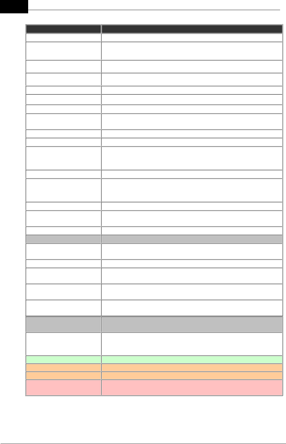
Draft
56 DOC-0132 Crewsafe User Manual v.1.2
Mobilarm Ltd. © 2009
Display Console
Power Supply
11-30V DC
Typical Power
Consumption
5W maximum
Operating Temperature
-15° to +70°C (5° to +158°F).
Dimensions
184 x 103.6 x 40mm (7.24 x 4.08 x 1.57in)
Weight
301 g (10.62 oz)
Case
Ingress sealed, UV stabilized, impact resistant housing
Mounting Options
Surface/flush or bracket mounting options
Environmental
Resistance
IP56
Strobe Light
120 degree dispersion at 5 candela
Audible Alarm
Bracket mounted: 70dB at 30cm (1ft) with 24V supply
Relay Outputs
2 optically-isolated relay outputs for activation of additional
alerting devices; supports a switching current of 1.5 A at the
supplied voltage, switched to ground.
Switched Input
100mA switched to ground with a 5K input impedance.
Serial Communications
2 x 4 wire interfaces supporting NMEA 0183 specifications.
System is compatible with the following NMEA sentences:
RMC; RMA; GGA; GLL; DSC/DSE; WPL; BWC; BWR.
Tag LEDs
12 x bi-colour Tag status LEDs
Router/Network Status
LED
One red and one blue router/network status LED display
GPS/Chart Plotter LED
1 bi-colour GPS/chart plotter status LED
Controls & Operation
Power Button
Turns the entire system on and off; clears all alarms when
switched off
Dim Button
Dims the LEDs on the router; 4 stage dimming.
Alarm Button: Mute
function
Press momentarily to mute a man overboard, general, duress
or manual alarm
Alarm Button: General
Alarm On
Press for 3 seconds to initiate a general alarm
Alarm Button: General
Alarm Off
Press for 3 seconds to cancel a general alarm
TAG STATUS LED
Operation States
No Illumination
Tag is OFF; no Tag is assigned to the TAG STATUS LED on
the display console; or a Tag has been deactivated by
canceling a man overboard alarm.
Solid Green
Tag is ON and is safe
Long Orange Flashes
Tag is ON and the battery is low
Solid Orange
Tag is being charged in a Power Dock
Short Fast Red Flashes
Tag has entered the man overboard warning state prior to an
alarm and a man overboard waypoint is logged
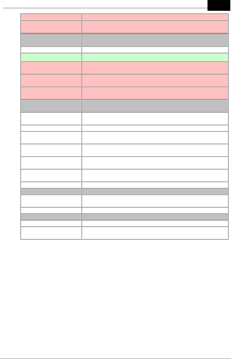
Draft
57Technical Specifications
Mobilarm Ltd. © 2009
Long Red Flashes
A man overboard or duress alarm has been muted
Solid Red
Tag has entered an active man overboard alarm state, or a
duress alarm has been activated
GPS/Chart Plotter LED
States
No Illumination
No GPS or chart plotter is connected at powerup
Solid Green
GPS or chart plotter data is good
Long Red Flashes
Receiving invalid chart plotter data (chart plotter is likely to be
acquiring GPS data)
Solid Red
No data is being received from the GPS chart plotter (likely to
be a cable/wiring issue, or GPS chart plotter is turned off)
Illuminated Red for 5
Seconds
Signifies canceling of any active alarms
Strobe/Piezo Operation
States
General Alarm Initiated
Very fast flashes on the Display Console with up-ramping
tones when initiated
General Alarm Active
Fast flashes accompanied by high level, repetitive tones
General Alarm Canceled
Very fast flashes with down-ramping tones when the alarm is
canceled
Duress Alarm Active
After manual activation from a Tag, fast flashes on the Display
Console accompanied by high level, repetitive tones
Man Overboard Alarm
Active
After man overboard activation from a Tag, fast flashes on the
Display Console accompanied by high level, repetitive tones
Manual Alarm Active
After activation by an Internal Router, fast flashes on the
Display Console accompanied by high level, repetitive tones
Mute Alarm
Long, infrequent flashes when any alarm is muted
Relay 1 Output States
(used for devices attached to the router and network mute)
Open
Open during normal operation or if Display Console mute has
been activated
Closed
Closes when any alarm is activated
Relay 2 Output States
Open
Open during normal operation
Closed
Closes when any alarm is activated until the system is
restored to normal operation
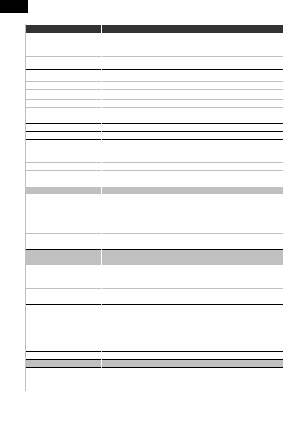
Draft
58 DOC-0132 Crewsafe User Manual v.1.2
Mobilarm Ltd. © 2009
Internal Router
Power Supply
11-30V DC
Typical Power
Consumption
3W maximum
Operating Temperature
-15° to +70°C (5° to +158°F).
Dimensions
184 x 103.6 x 40mm (7.24 x 4.08 x 1.57in)
Weight
247 g (8.7oz)
Case
Ingress sealed, UV stabilized, impact resistant housing
Mounting Options
Surface/flush or bracket mounting options
Environmental
Resistance
IP56
Strobe Light
120 degree dispersion at 5 candela.
Audible Alarm
Bracket mounted: 70dB at 30cm (1ft) with 24V supply
Relay Outputs
2 optically-isolated relay outputs for activation of additional
alerting devices; supports a switching current of 1.5 A at the
supplied voltage, switched to ground.
Switched Input
100mA switched to ground with a 5K input impedance.
Router/Network Status
LED
One red and one blue router/network status LED
Controls & Operation
Dim Button
Dims the LEDs on the router; 4 stage dimming
Alarm Button: Mute
function
Press momentarily to mute a man overboard, general, duress
or manual alarm
Alarm Button: Manual
Alarm On
Press for 3 seconds to initiate a manual alarm
Alarm Button: Manual
Alarm Off
Press for 3 seconds to cancel a manual alarm
Strobe/Piezo Operation
States
General Alarm Active
Fast flashes accompanied by high level, repetitive tones
Duress Alarm Active
After manual activation from a Tag, fast flashes on the Internal
Router accompanied by high level, repetitive tones
Man Overboard Alarm
Active
After man overboard activation from a Tag, fast flashes on the
Internal Router accompanied by high level, repetitive tones
Manual Alarm Initiated
Very fast flashes on the Internal Router with up-ramping tones
when initiated
Manual Alarm Active
Fast flashes on the Internal Router accompanied by high level,
repetitive tones
Manual Alarm Canceled
Very fast flashes with down-ramping tones when the alarm is
canceled
Mute Alarm
Long, infrequent flashes when any alarm is muted
Relay 1 Output States
(used for devices attached to the router)
Open
Open during normal operation or if Internal Router or Display
Console mute has been activated
Closed
Closes when any alarm is activated
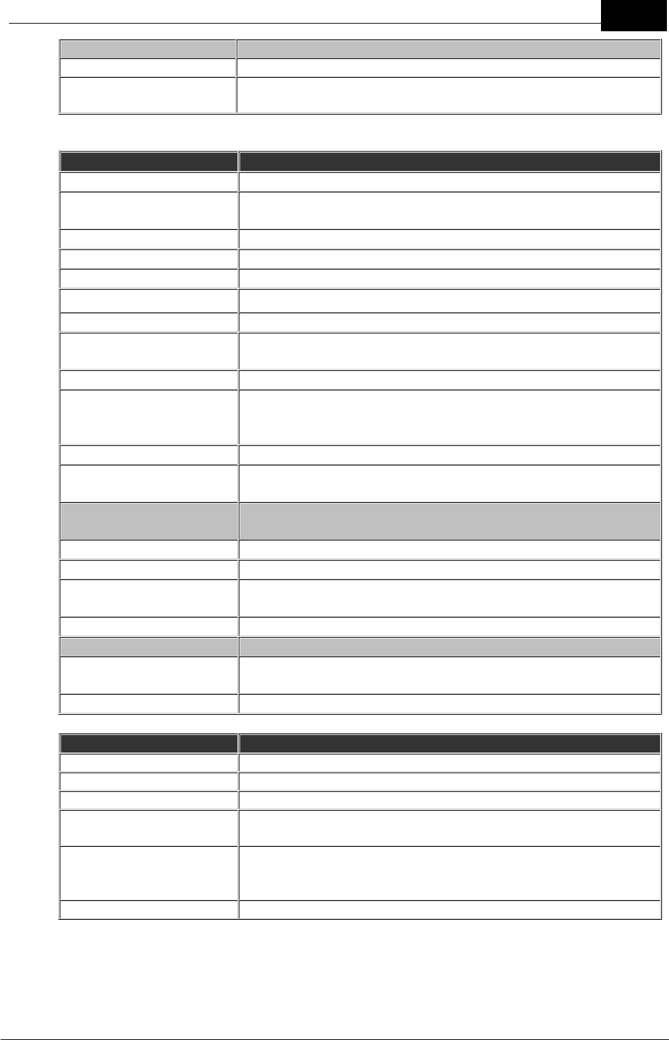
Draft
59Technical Specifications
Mobilarm Ltd. © 2009
Relay 2 Output States
Open
Open during normal operation
Closed
Closes when any alarm is activated until the system is
restored to normal operation
External Router
Power Supply
11-30V DC
Typical Power
Consumption
3W
Operating Temperature
-20° to +70°C (-4° to +158°F)
Dimensions
168 x 140 x 45.7mm (6.61 x 5.51 x 1.80in)
Weight
736 g (26 oz) including supplied cable
Case
Ingress sealed, UV stabilized, impact resistant housing
Mounting Options
Surface/flush, bracket, pole/railing mounting options
Environmental
Resistance
IP67
Strobe Light
120 degree dispersion at 5 candela
Relay Output
1 optically-isolated relay output for activation of additional
alerting devices; supports a switching current of 1.5 A at the
supplied voltage, switched to ground.
Switched Input
100mA switched to ground with a 5K input impedance.
Router/Network Status
LED
One red and one blue router/network status LED
Strobe Operation
States
General Alarm Active
Strobe flashes fast after activation
Duress Alarm Active
Strobe flashes fast after activation
Man Overboard Alarm
Active
Strobe flashes fast after activation
Manual Alarm Active
Strobe flashes fast after activation
Relay 1 Output States
(used for devices attached to the router)
Open
Open during normal operation or if Display Console mute has
been activated across the network
Closed
Closes when any alarm is activated
Tag
Battery
1 x rechargeable 3.6 volt CR2 battery
Battery Shelf Life
1 year
Battery Life - full charge
up to 48 hours of normal operation
Man overboard alarm
Battery Life
up to 4 hours in an alarm state when fully charged
Man overboard alarm
Battery Life - low battery
indicated
10 hours from low battery indication
Operating Temperature
-20° to +70°C (-4° to +158°F).
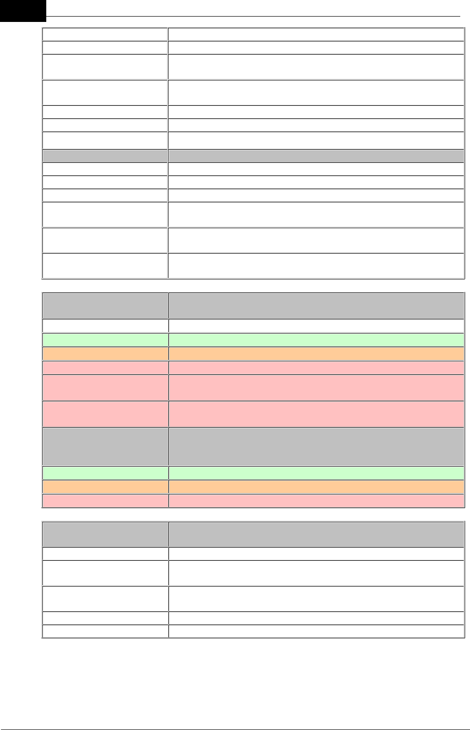
Draft
60 DOC-0132 Crewsafe User Manual v.1.2
Mobilarm Ltd. © 2009
Dimensions
95.4 x 50.2 x 37.3mm (3.76 x 1.98 x 1.47in)
Weight
78 g (2.75 oz)
Environmental
Resistance
IP68; 2 metres for 1 minute
Case
Impact resistant, UV stabilised polycarbonate shell with TPE
overmould
Buoyancy
Positive buoyancy
Strobe Light
RTCM standard-compatible for in-water tracking
LED
One red/green Bi-LED
Controls & Operation
System On/Off
Press button momentarily to turn a Tag on
Duress Alarm On
Press and hold Tag button for 3 seconds
Duress Alarm Off
Press and hold Tag button for 3 seconds
Man overboard Alarm
Man overboard warning after 4 (nominal) seconds, MOB
alarm after 10 seconds (nominal)
Man overboard Warning
Alarm
Man overboard warning after 4 (nominal) seconds, man
overboard alarm after 10 seconds (nominal)
Turn off Tag in man
overboard State
Press and hold Tag button for 10 seconds (nominal)
Tag LED Operation
States
No Illumination
Tag is switched off or battery is flat
Green Flashes
Tag is ON and safe.
Orange Flashes
Tag is connected to the network and the battery is low
Short Red Flashes
Tag is not configured with a network ID
Long Red Flashes
Tag is switched on and configured with an incorrect network
ID
Short Fast Red Flashes
Tag has been switched on and is attempting to join the
network
Tag LED Charge States
when in Power Dock
and Turned On
Solid Green
Tag is fully charged
Solid Orange
Tag is charging
Solid Red
Tag charging fault
Strobe Operation
States
Power On/Startup
Strobe flashes twice
Man overboard Warning
Strobe flashes fast once a man overboard warning is
activated
Man overboard Device
Alarm
Strobe double-flash occurs every 2 seconds when man
overboard alarm is activated
Duress Alarm Initiated
Strobe flashes fast after a duress alarm is initiated
Duress Alarm Activated
Strobe flashes fast after a duress alarm is activated
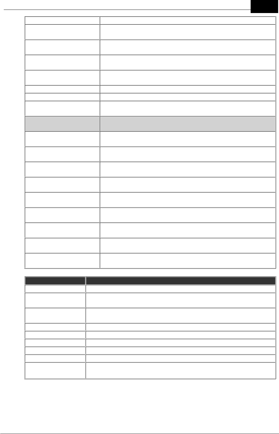
Draft
61Technical Specifications
Mobilarm Ltd. © 2009
Duress Alarm Canceled
Strobe flashes fast while the alarm is being canceled
General Network Alarm
Active
Strobe flashes once each half-second when activated
Duress Network Alarm
Active
Strobe flashes once each half-second when activated
Man overboard Network
Alarm Active
Strobe flashes once each half-second when activated
Manual Network Alarm
Active
Strobe flashes once each half-second when activated
Paging
No flash in paging mode
Network Shutdown
Strobe flashes for five seconds prior to shutdown
Tag Shutdown (in
charger)
Strobe flashes for three seconds prior to shutdown
Tag Vibration During
Operation
Man overboard Alarm:
Tag Initiating Alarm
Tag vibrates for 60 seconds after a man overboard alarm is
activated, or until it comes back within range of the network
Man overboard Alarm:
Tags not initiating alarm
Other Tags not in man overboard alarm state vibrate initially
when an alarm is activated over the network
Duress Alarm: Tag
Initiating Alarm
Tag vibrates after a duress alarm is activated until the alarm
is either muted on the Display Console or deactivated
Duress Alarm: Tags not
initiating alarm
Other Tags not in a duress alarm state vibrate when a duress
alarm is activated over the network
General Alarm
All active Tags vibrate after the alarm is activated by the
Display Console
Manual Alarm
All active Tags vibrate after the alarm is activated by the
Display Console
Paging
Tags vibrate when paged by the Crewsafe Management
System
Low Battery Warning
A Tag vibrates for one second every 20 seconds (nominal) to
indicate the battery is low
Network Shutdown
A Tag vibrates for five seconds before during network
shutdown
Powerdock
Power Supply
11-30V
Maximum Power
Consumption
22W
Operating
Temperature
-10° to +55°C (-14° to +131°F).
Charge Time
4 fully discharged Tags in 4 hours maximum
Dimensions
380 x 115 x 54mm (14.96 x 4.53 x 2.13in)
Weight
0.5 kg (17.64 oz)
Case
Impact and water resistant.
Mounting Options
Mount vertically or horizontally up to 4 power docks together
Environmental
Resistance
IP56

Draft
62 DOC-0132 Crewsafe User Manual v.1.2
Mobilarm Ltd. © 2009
LED Indication
Green power indication LED
12.1 Trademarks
The following names, and/or the logos and symbols associated with them, are
trademarks of Mobilarm Limited in Australia and/or other countries: Always on Watch;
Crewsafe; Mobilarm; Mobilert; Onix; Sitesafe
The absence of a product or service name or logo from those listed does not constitute a
waiver of Mobilarm’s trademark or other intellectual property rights concerning that name
or logo. Please contact Mobilarm Limited at info@mobilarm.com for a copy of our
trademark policy before referencing or using any trademark or product name.
Other Product Trademarks in this Document
1. Windows is a registered trademark of Microsoft Corporation in the United
States and other countries.
2. Other product names mentioned within this document may be trademarks or
registered trademarks, or a trade name of their respective owner.

Draft
63Technical Specifications
Mobilarm Ltd. © 2009
13 Warranty
LIMITED WARRANTY
1. MOBILARM warrants, to the original purchaser only, each Marine Employee Safety
Monitoring Product (“Product”) manufactured and/or supplied by MOBILARM
against defects in materials and workmanship under normal use and service, and
against non-conformity to its technical specifications for a period of 24 months
from the date of purchase. Software products are warranted as per the End User
License Agreement applicable to that software.
2. MOBILARM warrants Software products against failure of programming
instructions due to defects in materials and workmanship when properly installed
and used on the hardware designated by MOBILARM. MOBILARM cannot be
responsible in any way for ancillary equipment, hardware or software not furnished
by MOBILARM which is attached to or used in connection with MOBILARM’s
Products, or for the operation of the Product with any ancillary equipment,
hardware or software and all such equipment, hardware or software is expressly
excluded from this warranty. Mobilarm further warrants that Mobilarm owned
standard Software will substantially conform to Specifications.
In the event of a defect, malfunction or failure of the Product during the warranty
period, MOBILARM’s liability for any breach of contract or any breach of express or
implied warranties in connection with the sale of Products shall be limited solely to
repair or replacement, at its option, of the Product or part(s) therein which, upon
examination by MOBILARM, appear to be defective or not up to factory specifications.
MOBILARM may, at its option, repair or replace parts or subassemblies with new or
reconditioned parts and subassemblies. Parts thus repaired or replaced are
warranted for the balance of the original applicable warranty.
3. MOBILARM will pay all labour to repair the product and replacement parts charges
incurred in providing the warranty service except where purchaser abuse or other
qualifying exceptions exist. The purchaser must pay any transportation expenses
incurred in returning the Product to MOBILARM for service.
4. MOBILARM disclaims liability for range, coverage, or operation of the Product and
ancillary equipment as a whole under this warranty. MOBILARM reserves the right
to make changes or improvements in Products, during subsequent production,
without incurring the obligation to install such changes or improvements on
previously manufactured Products.
5. MOBILARM will not warrant installation, maintenance or service of the Products. In
all instances, MOBILARM’s liability for damages shall not exceed the purchase
price of the defective Product.
6. This limited warranty does not extend to any Product which has been subjected to
misuse, neglect, accident, incorrect service repair or maintenance by anyone other
than MOBILARM or its Authorized Service Agent(s), improper installation,
unauthorised modification, loss or damage in transit, or subjected to use in
violation of instructions furnished by MOBILARM, nor does this warranty extend to
Products on which the serial number has been removed, defaced, or changed.

Draft
64 DOC-0132 Crewsafe User Manual v.1.2
Mobilarm Ltd. © 2009
7. The implied warranties which the law imposes on the sale of this Product are
expressly LIMITED, in duration, to the time period specified above. MOBILARM
shall not be liable under any circumstances for consequential damages resulting
from the use and operation of this Product, or from the breach of this LIMITED
WARRANTY, any implied warranties, or any contract with MOBILARM.
IN CONNECTION WITH THE SALE OF ITS PRODUCTS, MOBILARM MAKES NO
WARRANTIES, EXPRESS OR IMPLIED, AS TO THE MERCHANTABILITY OR
FITNESS FOR A PARTICULAR PURPOSE OR OTHERWISE, EXCEPT AS
EXPRESSLY SET FORTH HEREIN.
Some states and territories do not allow the exclusion or limitation of incidental or
consequential damages, or limitation on how long an implied warranty lasts, so the
above limitations or exclusions may not apply. This warranty gives specific legal
rights, and there may be other rights which may vary from state to state, or between
territories.
Warranty Period
The standard warranty on Mobilarm Crewsafe systems is 24 (twenty four) months.

Draft
65Warranty
Mobilarm Ltd. © 2009
13.1 Exclusions
The law implies terms, conditions and warranties (‘prescribed terms’) into contracts for
the supply of goods and services and prohibits the exclusion, restriction or modification of
certain terms, conditions and warranties. Some prescribed terms permit a supplier to
limit its liability for a breach of the prescribed terms. Except as provided by prescribed
terms:
(1) the liability of the seller in respect of a breach of a prescribed term relating to the
products or any part of the products is limited at the option of the seller to the
replacement or repair of the products part thereof or payment of the cost of repairing
or replacing the products or any part of the products;
(2) in these conditions the buyer does not have under any circumstances any cause
of action against or right to claim or recover from the seller for, or in respect of, any
loss or damage of any kind whatsoever, caused directly or indirectly by:
(a) any defect in material or workmanship of, or any other defect whatsoever in,
or unsuitability for, any purpose of the products or any part of the products; or
(b) by default or negligence on the part of the seller or of any employee,
contractor or agent of the seller or of any person for whom the seller has legal
responsibility relating to the supply of, or otherwise concerning products or any
part of the products. Mobilarm Limited is not liable to the buyer in contract or in
tort arising out of, or in connection with, or relating to:
(a) the performance of the products or any breach of these conditions; or
(b) any fact, matter or thing relating to the products; or
(c) any error (whether negligent or in breach of contract or not) in information
supplied to the buyer or a user before or after the date of the purchaser’s or
user’s use of the products.
Mobilarm Limited is not liable to the buyer in contract or in tort arising out of, or in
connection with, or relating to:
(a) the performance of the products or any breach of these conditions; or
(b) any fact, matter or thing relating to the products; or
(c) any error (whether negligent or in breach of contract or not) in information supplied
to the buyer or a user before or after the date of the
purchaser’s or user’s use of the products.
The total liability of Mobilarm Limited for loss or damage of every kind:
(a) whether arising pursuant to this agreement; or
(b) out of or in relation to the goods, their sale, delivery or the way they behave, in tort
or contract or in any other cause of action; or in any other way whatsoever,is limited
to:
(c) the amount paid by the buyer to the seller under this agreement at the date when
such liability arises; or
The buyer indemnifies on a continuing basis on a fully indemnity basis Mobilarm
Limited from and against any liability, loss, expense or demand for or arising from any
false, misleading, deceptive or misdescriptive representation or statement made by
the buyer in respect of the products, or their intended use to any person. This
indemnity survives termination of this agreement by either party for any reason.
The failure of any party to enforce the provisions of this agreement or to exercise any

Draft
66 DOC-0132 Crewsafe User Manual v.1.2
Mobilarm Ltd. © 2009
rights expressed in this agreement is not be a waiver of such provisions or rights and
does not affect the enforcement of this agreement.

Draft
67Warranty
Mobilarm Ltd. © 2009
13.2 Declaration of Conformity
EC Declaration of Conformity
In accordance with EN 17050-1:2004
We, Mobilarm Limited
Of, 768 Canning Highway, APPLECROSS WA 6153
Declare that:
Equipment, Crewsafe 8000 Man Overboard Monitoring Systems
Model name / number:
·Display Console MOA-0130
·Internal Router MOA-0120
·External Router MOA-0110
·Tag MOA-0140
·Power Dock MOA-0150
In accordance with the following Directives:
·73 / 23 EEC The Low Voltage Directive
·89 / 336 / EEC The Electromagnetic Compatibility Directive and its amending
directives
·98 / 37 EC The Machinery Directive and its amending directives
·99 / 5 / EC The Radio and Telecommunications Terminal equipment directive
has been designed and manufactured to the following specifications:
·ETSI EN 300 220 -1 Electromagnetic compatibility and radio spectrum matters
(ERM); Short range services (SRD); 25MHz to 1000 MHz with power levels
ranging up to 500mw Part 1.
·ETSI EN 300 220- 3 Electromagnetic compatibility and radio spectrum matters
(ERM); Short range services (SRD); 25MHz to 1000 MHz with power levels
ranging up to 500mw Part 3.
·ETSI EN 301 489 – 1 Electromagnetic compatibility and radio spectrum
matters (ERM); Electromagnetic compatibility (EMC) standard for radio
equipment and services Part 1.
·ETSI EN 301 489 – 3: Electromagnetic compatibility and radio spectrum
matters (ERM); Electromagnetic compatibility (EMC) standard for radio
equipment and services Part 3.
·ETSI EN 301 843 – 1: Electromagnetic compatibility and radio spectrum
matters (ERM); Electromagnetic compatibility (EMC) standard for Marine radio
equipment and services; Part 1.
··ETSI EN 300 328: Electromagnetic compatibility and Radio spectrum Matters
(ERM); Wideband transmission systems; Data transmission equipment
operating in the 2,4 GHz ISM band and using wide band modulation
techniques; Harmonized EN covering essential requirements under article 3.2
of the R&TTE Directive
·EN61000-6-4:2001: Electromagnetic compatibility (EMC). Generic standards.

Draft
68 DOC-0132 Crewsafe User Manual v.1.2
Mobilarm Ltd. © 2009
Emission standard for industrial environments
·EN61000-6-1:2001: Electromagnetic compatibility (EMC). Generic standards.
Immunity for residential, commercial and light-industrial environments
·EN 60945:2002 : Maritime navigation and radiocommunication equipment and
systems. General requirements. Methods of testing and required test results
·EN 60950-1:2002: Safety of Information Technology Equipment Including
Electrical Business Equipment.
·EN 50364: 2001- Limitations of human exposure to electromagnetic fields from
devices operating in the frequency range 10Hz to 10GHz, and in radio
frequency identification (RFID) and similar applications.
I hereby declare that the equipment named above has been designed to comply with
the relevant sections of the above referenced specifications. The unit complies with
all essential requirements of the Directives.
Signed by:
Name:
Address: 768 Canning Highway
APPLECROSS WA 6153
Position:
at MOBILARM
768 Canning Highway
APPLECROSS, PERTH, WESTERN AUSTRALIA 6153
On day of 2009
Technical documentation required by the conformity assessment procedure is kept at
the aforementioned address.

Draft
69Warranty
Mobilarm Ltd. © 2009
13.3 Compliances & Certifications
FCC Compliance Information Statement
Mobilarm Crewsafe 8000 systems comply with Part 15 of the FCC Rules. Operation
is subject to the following two conditions: (1) these devices may not cause harmful
interference, and (2) these devices must accept any interference received, including
interference that may cause undesired operation.
NOTE:
This equipment has been tested and found to comply with the limits for a Class B
digital device, pursuant to Part 15 of the FCC Rules. These limits are designed to
provide reasonable protection against harmful interference in a residential installation.
This equipment generates, uses and can radiate radio frequency energy and, if not
installed and used in accordance with the instructions, may cause harmful
interference to radio communications. However, there is no guarantee that
interference will not occur in a particular installation. If this equipment does cause
harmful interference to radio or television reception, which can be determined by
turning the equipment off and on, the user is encouraged to try to correct the
interference by one or more of the following measures:
·Reorient or relocate the receiving antenna.
·Increase the separation between the equipment and receiver.
·Connect the equipment into an outlet on a circuit different from that to which
the receiver is connected.
·Consult the dealer or an experienced radio/TV technician for help.
Properly shielded and grounded cables and connectors must be used to meet FCC
emission limits. Mobilarm is not responsible for any radio or television interference
caused by using other than recommended cables or connectors.
WARNING: Any changes or modifications not expressly approved by Mobilarm Ltd.,
could void the user’s authority to operate this equipment.
Other Compliances & Certifications
Certifications
USA
USCG; RTCM standard 11901.0
Australia
Cü; ACMA; IEC; AMSA;
Europe
CE; IEC;
Compliances
All Crewsafe 8000
Products
FCC; Cü; CE; WEEE
Special Purpose Life
Jacket
Complies with ISO standard 12402-6:2006 relating to the
safety requirements and additional test methods for special
purpose lifejackets and buoyancy aids

Draft
DOC-0132 Crewsafe User Manual v.1.270
Mobilarm Ltd. © 2009
Index
- A -
Add
A New Router 41
A New Tag 39
Add a Router 41
Add a Tag 39
Alarms
Duress Alarms 28
Factory Reset 44
General Alarms 31
Managing 25
Manual Alarms 33
MOB Alarms 25, 36
- B -
Buttons
Dim 23
- C -
Cancel
MOB Alarm 25
Multiple Alarm 36
Cancel Alarm
Duress Alarm 28
False Alarms 35
General Alarm 31
Manual Alarm 33
Certifications 69
Cleaning
Crewsafe Components 45
Compliances 69
Components
Maintenance 45
Configure a Router 41
Configure a Tag 39
Conformity
Declaration of Conformity 67
Crewsafe Management Software, Overview 8
- D -
Declaration of Conformity 67
Dim Button 23
Disclaimer 65
Display Console
Add a New Tag 39
Cancel a Duress Alarm 28
Dim Router LEDs 23
GPS Status LED States 24
Indications 14
Managing Alarms 25
MOB Alarms 25
Multiple Alarms 36
Mute a Duress Alarm 28
Mute, Cancel Manual Alarms 33
Raise, Mute, Cancel a General Alarm 31
Tag Charge LED States 22
Tag Status LED States 18
Turn Off 17
Turn On 14
Duress Alarm
Cancel 28
Mute Alarm Locally 28
Mute Network Alarm 28
Raise Alarm 28
- E -
Exclusions 65
External Router
Network Status LED 14
Raise, Cancel Manual Alarms 33
Turn Off 17
Turn On 14
- F -
Factory Reset
Reassign Routers 44
Reassign Tags 44
False Alarms
Cancel MOB, Duress, Manual, General Alarms
35
FAQs 52
Firmware

Draft
Index 71
Mobilarm Ltd. © 2009
Firmware
Updates 43
- G -
General Alarms
Mute Alarm Locally 31
Mute Network Alarm 31
Raise, Cancel Alarm 31
Getting Started, Operation 14
Glossary of Terms & Acronyms 54
GPS
Confirm Data Status 24
GPS Status LED
States 24
- H -
How it works, System 12
- I -
Internal Router
Dim Router LEDs 23
Mute a Duress Alarm Locally 28
Mute a General Alarm 31
Network Status LED 14
Raise, Mute, Cancel Manual Alarms 33
Turn Off 17
Turn On 14
- L -
LED
Alarm States 25
Dim Router LEDs 23
Duress Alarm 28
GPS Status LED States 24
MOB Alarms 25
Multiple Alarms 36
Tag Charge LED States 22
Tag Status LED States 18
Lost Tags
Remove & Replace 38
- M -
Maintenance
Crewsafe Components 38
Man Overboard 6
Manual Alarm Mute
Across the Network 33
Internal Router Locally 33
Manual Alarms
Mute Alarm Locally 33
Mute Network Alarm 33
Raise, Cancel Alarm 33
Manual Conventions 6
MOB
Other Technologies 46
MOB Alarm
Mute Alarm Locally 25
Mute Network Alarm 25
Raise, Cancel 25
MOB Definition 6
Mobilarm
Trademarks 62
Warranty 63
Multiple Alarms
Cancel 36
Mute Alarm Locally 36
Mute Network Alarm 36
Mute Duress Alarm
Across the Network 28
Internal Router Locally 28
Mute General Alarm
Across the Network 31
Internal Router Locally 31
Mute MOB Alarm
Across the network 25
Internal Router Locally 25
Mute Multiple Alarms
Across the network 36
Internal Router Locally 36
Muting
Duress Alarms 28
General Alarms 31
Manual Alarms 33
MOB Alarms 25
Multiple Alarms 36

Draft
DOC-0132 Crewsafe User Manual v.1.272
Mobilarm Ltd. © 2009
- N -
Network ID
Add a Configured Router 41
Add a New Configured Tag 39
Configure a New Tag 39
Configure a Router 41
- O -
Operation
Add a Network Router 41
Add a Tag 39
Battery Replacement 22
Charging Tags 22
Confirm GPS Data Status 24
Dim Router LEDs 23
Duress Alarms 28
Factory Reset 44
General Alarms 31
Getting Started 14
Maintenance 38
Managing Alarms 25
Manual Alarms 33
MOB Alarms 25
Multiple Alarms 36
Routine System Tasks 17
Tag Storage 22
Turn Off System 17
Turn Off Tags 15, 18
Turn On System 14
Wand Mode 39
Overview, System Components 8
- Q -
Quick Start Setup 7
- R -
Reference Section 47
Remove & Replace
Tags 38
Replace Components 47
Router
Add a Network Router 41
Turn Off 17
Turn On 14
Routine System Tasks, Operation 17
- S -
Safety Information 4
Service
Crewsafe Components 38
Software
Firmware Updates 43
Status LEDs
Dim Router LEDs 23
GPS Status LED States 24
Tag Charge LED States 22
Tag LED States 18
Support
Contact Us 47
Purchase New Components 47
Replace Components 47
System
Add a Network Router 41
Add a Tag 39
Battery Replacement 22
Charging Tags 22
Confirm GPS Data Status 24
Dim Router LEDs 23
Duress Alarms 28
Factory Reset 44
Firmware Updates 43
General Alarms 31
Getting Started 14
Maintenance 38
Managing Alarms 25
Manual Alarms 33
MOB Alarms 25
Multiple Alarms 36
Routine System Tasks 17
Tag Storage 22
Turn Off System 17
Turn Off Tags 15, 18
Turn On System 14
Wand Mode 39
System Components, Overview 8
System Maintenance 45
System Off, Quick Start 7
System On, Quick Start 7

Draft
Index 73
Mobilarm Ltd. © 2009
System Test Advice 4
System, How it works 12
- T -
Tags
Add a Tag 39
Battery Replacement 22
Charging 22
Duress Alarms 28
General Alarms 31
How to wear, attach 20
Manual Alarms 33
MOB Alarms 25
Multiple Alarms 36
Raise & Cancel Duress Alarm 28
Raise & Cancel MOB Alarm 25
Remove & Replace 38
Status LED States 18
Tag Storage 22
Turn Off 15, 18
Wand Mode 39
Technical Specifications 55
Terms and Acronyms 54
Trademarks 62
Troubleshooting 48
- U -
Use of
Dim Button 23
Duress Alarm 28
General Alarms 31
GPS Chart Plotter Data 24
Manual Alarms 33
MOB Alarms 25
System 14
System, Getting Started 14
Tags 15
- V -
V100 VPIRB 46
VPIRB 46
- W -
Wand Mode
Configure New Tags 39
Warnings 4
Warranty 63
Wearing tags 20