Mobilicom MSH-10 Point-to-Point and Point-to-Multipoint communication unit enabling broadband connectivity of data. User Manual Mobilicom s
Mobilicom ltd. Point-to-Point and Point-to-Multipoint communication unit enabling broadband connectivity of data. Mobilicom s
User manual

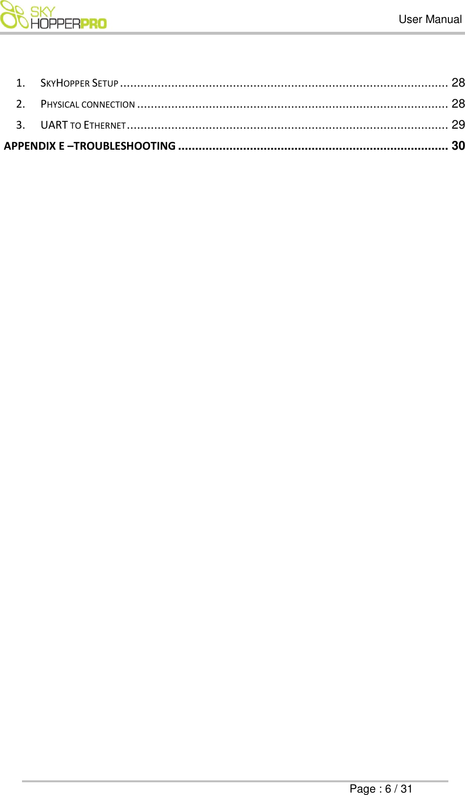

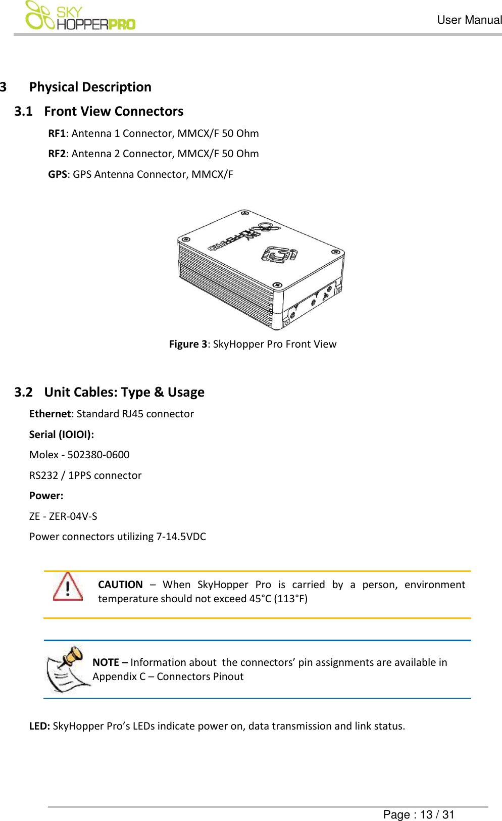
![User Manual Page : 14 / 31 Figure 4: SkyHopper Pro Connector Side view 4 Mechanical Specifications The SkyHopper Pro unit is lightweight and has small form-factor. Dimensions [HxWxD] (mm) [HxWxD] (inch) Weight (gr) Weight (oz.) 26 x 54 x 74 1.0 x 2.1 x 2.9 105 3.7 Table 2: SkyHopper Pro Mechanical Specifications 5 Technical Specifications 5.1 Radio and Modem Specifications 5.1.1 Frequency bands available: 2.4GHz unlicensed band Note: This product is configured to operate within the FCC or CE limitations based on the country of ordering. It is configured within the 2.4 ISM frequency band. Mobilicom takes no responsibility should you choose to take and/or operate this product outside of FCC or CE limits and/or in a country that does not comply with FCC or CE regulations. Please note that SkyHopper specifications vary based on FCC or CE regulations. 5.1.2 Antennas Various standard antennas can be supported using an MMCX/M connector. Some antennas with a different connector (such as SMA) can be used with an adaptor or adaptor cable. The Ground Unit has a mounting kit supplied with an MMCX to SMA connecting cable and SMA/M antennas.](https://usermanual.wiki/Mobilicom/MSH-10/User-Guide-3467700-Page-14.png)

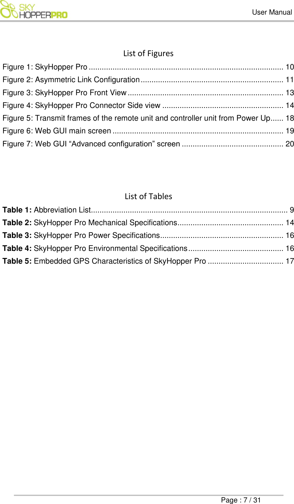
![User Manual Page : 24 / 31 Environmental Temperature Range Operating Storage -10°C to 40°C -50°C to 85°C Humidity 5 to 95% Interfaces Data Ethernet, RS232 Full Ethernet Protocol Transparency IP,TCP,UDP, RTP, HTTP Broadcast, Multicast, Unicast Ethernet, VLAN, VPN Serial Data RS232 USB Optional Dimensions [HxWxD] mm [HxWxD] inch Embedded Package 26 x 54 x 74 1.0 x 2.1 x 2.9 Weight Grams Ounce Embedded Package 105 gr. 3.7 oz. Power DC Voltage (Battery Operated) 7-14.5V DC Power Consumption Up to 12 Watt 8W Average Configuration and Management Unit Monitoring Application Web-Based Application Program Interface API, Code Lib. (Optional) Integrated Options Video Encoder/Decoder H.264 very low latency HD/SD Video Formats up to: 1920x1080p Video Inputs / Outputs Micro HDMI (Input/Output) Analog (Input) Audio Inputs / Outputs Embedded Audio over HDMI, Analog](https://usermanual.wiki/Mobilicom/MSH-10/User-Guide-3467700-Page-24.png)