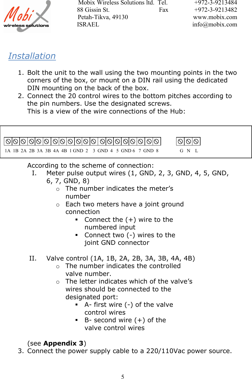
Mobix Wireless Solutions 200 DATA COLLECTION SYSTEM User Manual

Mobix Wireless Solutions LTD DATA COLLECTION SYSTEM Users Manual

Users Manual

Mobix Wireless Solutions ltd.  Tel. +972-3-921348488 Gissin St.                               Fax +972-3-9213482 Petah-Tikva, 49130 www.mobix.com ISRAEL info@mobix.com1nDNet HubUser ManualVersion 15/5/2011
Mobix Wireless Solutions ltd.  Tel. +972-3-921348488 Gissin St.                               Fax +972-3-9213482 Petah-Tikva, 49130 www.mobix.com ISRAEL info@mobix.com2General Description:The n-DNet™ Hub  is  a  standalone  network  interface  unit  connecting  endpoints  to  theMobix patented n-Dimensional Network (see box for n-DNet™ description) It is a featurerich Hub designed to collect, store and forward data from up to eight meters. Meters couldbe in any combination of electric, gas and/or water with Pulse, RS-232 or M-Bus outputs. Abackup battery lasting up to seven years ensures data and operational integrity including lastgasp message so critically important for outage management.As a node on the patented n-Dimensional mesh network, the n-DNet™ Hub communicatessimultaneously in parallel over RF and PLC there by guaranteeing continuous reliable two-way communications at the highest cost efficiency. System tempering detection, parameterdriven abnormal consumption and remote service connect/disconnect are among the smartn-DNet™ Hub unique features.
Mobix Wireless Solutions ltd.  Tel. +972-3-921348488 Gissin St.                               Fax +972-3-9213482 Petah-Tikva, 49130 www.mobix.com ISRAEL info@mobix.com3The FlexIT in the AMR systemComplex:
Mobix Wireless Solutions ltd.  Tel. +972-3-921348488 Gissin St.                               Fax +972-3-9213482 Petah-Tikva, 49130 www.mobix.com ISRAEL info@mobix.com4CapabilitiesProvides an interface forconnection of existing meters tothe n-DNet™ network.Collects and stores readings fromgas/water/ electricity meters in anon volatile memoryCore operation capabilitieswithout external power for atleast 48 hoursOptional control on up to 18valvesDetects tampers on data cable3 LEDs for signaling on powerstatus, TX and RX indicationIsolationThe system has the following isolation featuresbetween the high input voltage and the LT-Bus cables:A switching transformerESD filters on output wiresVaricaps for spike preventionThe cables will have a groundinglineRF standardsComplies with FCC,Frequency 915 MHzSensitivity = –118dBmMax Output Power 20dBmInterfaces4 pulse input ports4 cable status inputs4 output ports (for valve control)3 LED – TX, RX, PowerPulse-out, RS-232, RS-485, M-Bus,ZigBeePLC standardsComplies with FCC regulations100-400KHzEnvironmental-45°C to +80°CFully RoHS CompliantPower consumptionInput Voltage: 100-130VacOperation voltage: 5VdcIdle: 5V, 100mAIn transmission: 500mANetwork SecurityMessage authenticationUnit ID authenticationPassword protection (e.g.,disconnect command)Dimensionssize : 17x12x6.5 cmFor external box drawings seeprevious page
Mobix Wireless Solutions ltd.  Tel. +972-3-921348488 Gissin St.                               Fax +972-3-9213482 Petah-Tikva, 49130 www.mobix.com ISRAEL info@mobix.com5Installation1. Bolt the unit to the wall using the two mounting points in the twocorners of the box, or mount on a DIN rail using the dedicatedDIN mounting on the back of the box.2. Connect the 20 control wires to the bottom pitches according tothe pin numbers. Use the designated screws.This is a view of the wire connections of the Hub:According to the scheme of connection:I. Meter pulse output wires (1, GND, 2, 3, GND, 4, 5, GND,6, 7, GND, 8)oThe number indicates the meter’snumberoEach two meters have a joint groundconnectionConnect the (+) wire to thenumbered inputConnect two (-) wires to thejoint GND connectorII. Valve control (1A, 1B, 2A, 2B, 3A, 3B, 4A, 4B)oThe number indicates the controlledvalve number.oThe letter indicates which of the valve’swires should be connected to thedesignated port:A- first wire (-) of the valvecontrol wiresB- second wire (+) of thevalve control wires(see Appendix 3)3. Connect the power supply cable to a 220/110Vac power source.1A 1B 2A 2B 3A 3B 4A 4B 1 GND 2  3  GND  4  5 GND 6 7 GND 8                  G   N    L
Mobix Wireless Solutions ltd.  Tel. +972-3-921348488 Gissin St.                               Fax +972-3-9213482 Petah-Tikva, 49130 www.mobix.com ISRAEL info@mobix.com6Saftey1. Connect the input and output wires only when mains are notconnected2. Connect mains only to 100-130Vac power source3. All AC connections should be done by an authorized electricianThe FCC Wants You to KnowThis equipment has been tested and found to comply with the limits for aClass B digital device, pursuant to Part 15 of the FCC rules. These limits aredesigned to provide reasonable protection against harmful interference in aresidential installation. This equipment generates, uses and can radiate radiofrequency energy and, if not installed and used in accordance with theinstructions, may cause harmful interference to radio communications.However, there is no guarantee that interference will not occur in a particularinstallation. If this equipment does cause harmful interference to radio ortelevision reception, which can be determined by turning the equipment offand on, the user is encouraged to try to correct the interference by one ormore of the following measures:a) Reorient or relocate the receiving antenna.b) Increase the separation between the equipment and receiver.c) Connect the equipment to an outlet on a circuit different from thatto which the receiver is connected.d) Consult the dealer or an experienced radio/TV technician.FCC WarningA distance of at least 20cm. between the equipment and all personsshould be maintained during the operation of the equipment.Modifications not expressly approved by the manufacturer couldvoid the user authority to operate the equipment under FCC Rules.NOTE: THE MANUFACTURER IS NOT RESPONSIBLE FOR ANY RADIO OR TVINTERFERENCE CAUSED BY UNAUTHORIZED MODIFICATIONS TO THISEQUIPMENT. SUCH MODIFICATIONS COULD VOID THE USER’S AUTHORITYTO OPERATE THE EQUIPMENT.
Mobix Wireless Solutions ltd.  Tel. +972-3-921348488 Gissin St.                               Fax +972-3-9213482 Petah-Tikva, 49130 www.mobix.com ISRAEL info@mobix.com74. Appendix 1Hub external box
Mobix Wireless Solutions ltd.  Tel. +972-3-921348488 Gissin St.                               Fax +972-3-9213482 Petah-Tikva, 49130 www.mobix.com ISRAEL info@mobix.com8Appendix 2Hub installation points
Mobix Wireless Solutions ltd.  Tel. +972-3-921348488 Gissin St.                               Fax +972-3-9213482 Petah-Tikva, 49130 www.mobix.com ISRAEL info@mobix.com9Appendix 3Hub -Meter & Valve connection1A 1B 2A 2B 3A 3B 4A 4B 1 GND 2  3  GND  4  5 GND 6 7 GND 8                  G   N    L+ -+ -+ -+ -+ -- ++ -- +

Navigation menu