Mobix Wireless Solutions 200 DATA COLLECTION SYSTEM User Manual
Mobix Wireless Solutions LTD DATA COLLECTION SYSTEM Users Manual
Users Manual

Mobix Wireless Solutions ltd. Tel. +972-3-9213484
88 Gissin St. Fax +972-3-9213482
Petah-Tikva, 49130 www.mobix.com
ISRAEL info@mobix.com
1
nDNet Hub
User Manual
Version 1
5/5/2011

Mobix Wireless Solutions ltd. Tel. +972-3-9213484
88 Gissin St. Fax +972-3-9213482
Petah-Tikva, 49130 www.mobix.com
ISRAEL info@mobix.com
2
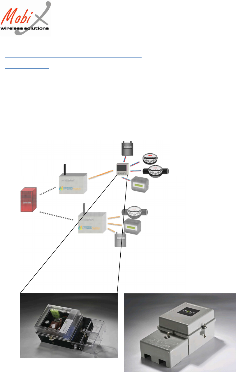
General Description:
The n-DNet™ Hub is a standalone network interface unit connecting endpoints to the
Mobix patented n-Dimensional Network (see box for n-DNet™ description) It is a feature
rich Hub designed to collect, store and forward data from up to eight meters. Meters could
be in any combination of electric, gas and/or water with Pulse, RS-232 or M-Bus outputs. A
backup battery lasting up to seven years ensures data and operational integrity including last
gasp message so critically important for outage management.
As a node on the patented n-Dimensional mesh network, the n-DNet™ Hub communicates
simultaneously in parallel over RF and PLC there by guaranteeing continuous reliable two-
way communications at the highest cost efficiency. System tempering detection, parameter
driven abnormal consumption and remote service connect/disconnect are among the smart
n-DNet™ Hub unique features.
Mobix Wireless Solutions ltd. Tel. +972-3-9213484
88 Gissin St. Fax +972-3-9213482
Petah-Tikva, 49130 www.mobix.com
ISRAEL info@mobix.com
3
The FlexIT in the AMR system
Complex:
Mobix Wireless Solutions ltd. Tel. +972-3-9213484
88 Gissin St. Fax +972-3-9213482
Petah-Tikva, 49130 www.mobix.com
ISRAEL info@mobix.com
4
Capabilities
Provides an interface for
connection of existing meters to
the n-DNet™ network.
Collects and stores readings from
gas/water/ electricity meters in a
non volatile memory
Core operation capabilities
without external power for at
least 48 hours
Optional control on up to 18
valves
Detects tampers on data cable
3 LEDs for signaling on power
status, TX and RX indication
Isolation
The system has the following isolation features
between the high input voltage and the LT-
Bus cables:
A switching transformer
ESD filters on output wires
Varicaps for spike prevention
The cables will have a grounding
line
RF standards
Complies with FCC,
Frequency 915 MHz
Sensitivity = –118dBm
Max Output Power 20dBm
Interfaces
4 pulse input ports
4 cable status inputs
4 output ports (for valve control)
3 LED – TX, RX, Power
Pulse-out, RS-232, RS-485, M-Bus,
ZigBee
PLC standards
Complies with FCC regulations
100-400KHz
Environmental
-45°C to +80°C
Fully RoHS Compliant
Power consumption
Input Voltage: 100-130Vac
Operation voltage: 5Vdc
Idle: 5V, 100mA
In transmission: 500mA
Network Security
Message authentication
Unit ID authentication
Password protection (e.g.,
disconnect command)
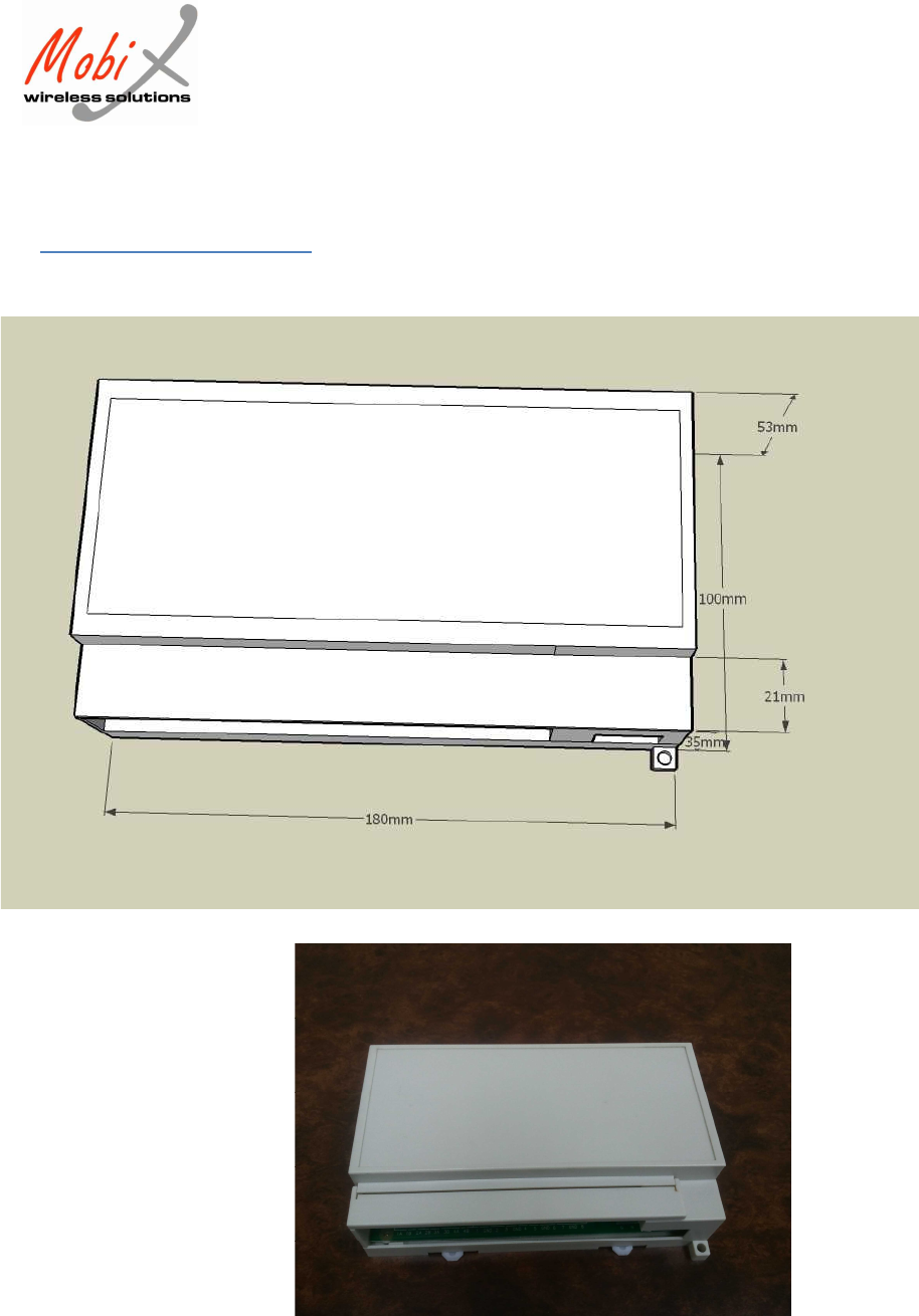
Dimensions
size : 17x12x6.5 cm
For external box drawings see
previous page
Mobix Wireless Solutions ltd. Tel. +972-3-9213484
88 Gissin St. Fax +972-3-9213482
Petah-Tikva, 49130 www.mobix.com
ISRAEL info@mobix.com
5
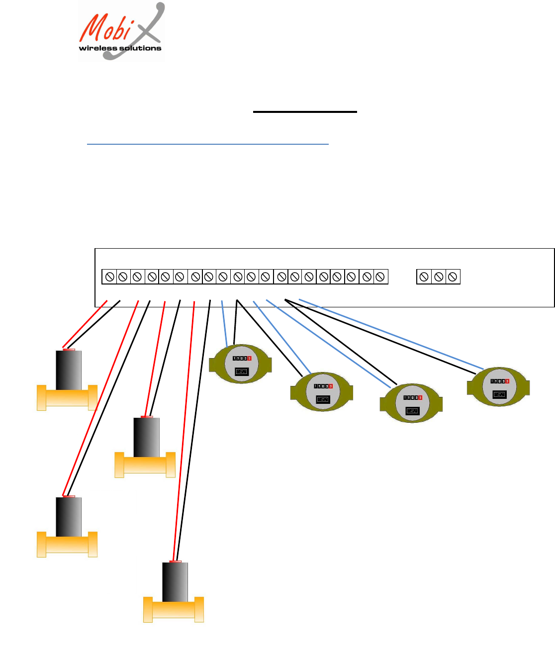
Installation
1. Bolt the unit to the wall using the two mounting points in the two
corners of the box, or mount on a DIN rail using the dedicated
DIN mounting on the back of the box.
2. Connect the 20 control wires to the bottom pitches according to
the pin numbers. Use the designated screws.
This is a view of the wire connections of the Hub:
According to the scheme of connection:
I. Meter pulse output wires (1, GND, 2, 3, GND, 4, 5, GND,
6, 7, GND, 8)
oThe number indicates the meter’s
number
oEach two meters have a joint ground
connection
Connect the (+) wire to the
numbered input
Connect two (-) wires to the
joint GND connector
II. Valve control (1A, 1B, 2A, 2B, 3A, 3B, 4A, 4B)
oThe number indicates the controlled
valve number.
oThe letter indicates which of the valve’s
wires should be connected to the
designated port:
A- first wire (-) of the valve
control wires
B- second wire (+) of the
valve control wires
(see Appendix 3)
3. Connect the power supply cable to a 220/110Vac power source.
1A 1B 2A 2B 3A 3B 4A 4B 1 GND 2 3 GND 4 5 GND 6 7 GND 8 G N L

Mobix Wireless Solutions ltd. Tel. +972-3-9213484
88 Gissin St. Fax +972-3-9213482
Petah-Tikva, 49130 www.mobix.com
ISRAEL info@mobix.com
6
Saftey
1. Connect the input and output wires only when mains are not
connected
2. Connect mains only to 100-130Vac power source
3. All AC connections should be done by an authorized electrician
The FCC Wants You to Know
This equipment has been tested and found to comply with the limits for a
Class B digital device, pursuant to Part 15 of the FCC rules. These limits are
designed to provide reasonable protection against harmful interference in a
residential installation. This equipment generates, uses and can radiate radio
frequency energy and, if not installed and used in accordance with the
instructions, may cause harmful interference to radio communications.
However, there is no guarantee that interference will not occur in a particular
installation. If this equipment does cause harmful interference to radio or
television reception, which can be determined by turning the equipment off
and on, the user is encouraged to try to correct the interference by one or
more of the following measures:
a) Reorient or relocate the receiving antenna.
b) Increase the separation between the equipment and receiver.
c) Connect the equipment to an outlet on a circuit different from that
to which the receiver is connected.
d) Consult the dealer or an experienced radio/TV technician.
FCC Warning
A distance of at least 20cm. between the equipment and all persons
should be maintained during the operation of the equipment.
Modifications not expressly approved by the manufacturer could
void the user authority to operate the equipment under FCC Rules.
NOTE: THE MANUFACTURER IS NOT RESPONSIBLE FOR ANY RADIO OR TV
INTERFERENCE CAUSED BY UNAUTHORIZED MODIFICATIONS TO THIS
EQUIPMENT. SUCH MODIFICATIONS COULD VOID THE USER’S AUTHORITY
TO OPERATE THE EQUIPMENT.
Mobix Wireless Solutions ltd. Tel. +972-3-9213484
88 Gissin St. Fax +972-3-9213482
Petah-Tikva, 49130 www.mobix.com
ISRAEL info@mobix.com
7
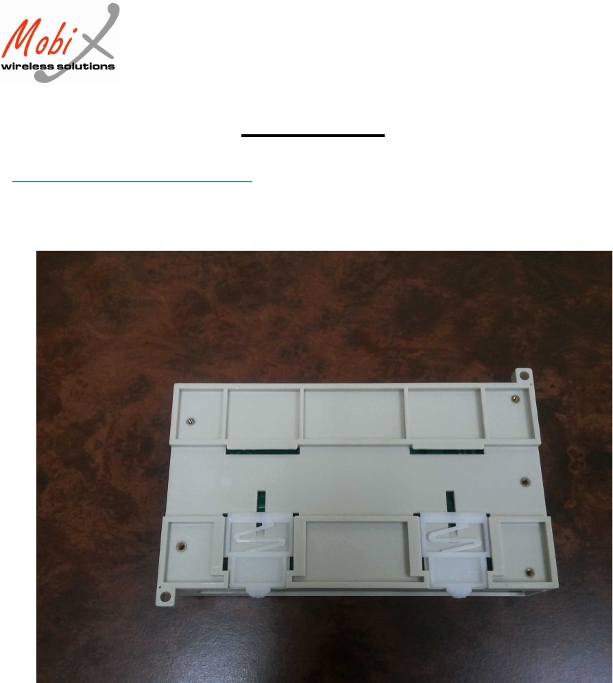
4. Appendix 1
Hub external box
Mobix Wireless Solutions ltd. Tel. +972-3-9213484
88 Gissin St. Fax +972-3-9213482
Petah-Tikva, 49130 www.mobix.com
ISRAEL info@mobix.com
8
Appendix 2
Hub installation points
Mobix Wireless Solutions ltd. Tel. +972-3-9213484
88 Gissin St. Fax +972-3-9213482
Petah-Tikva, 49130 www.mobix.com
ISRAEL info@mobix.com
9
Appendix 3
Hub -Meter & Valve connection
1A 1B 2A 2B 3A 3B 4A 4B 1 GND 2 3 GND 4 5 GND 6 7 GND 8 G N L
+ -
+ -
+ -
+ -
+ -
- +
+ -
- +