Mobix Wireless Solutions 400 Data Collection System User Manual MiniHub V1 3x
Mobix Wireless Solutions LTD Data Collection System MiniHub V1 3x
User Manual

n-DNet MiniHub
User Manual
Version 1.3
06-FEB-14

Page 2
MiniHub User Guide
10/15/2013
Table of Contents
1.
GENERAL DESCRIPTION.................................................................................................................... 3
2.
MINIHUB SPECIFICATIONS ............................................................................................................... 4
3.
CONNECTORS ................................................................................................................................... 5
4.
INSTALLATION ................................................................................................................................. 6
3.
INSTALLATION ................................................................................................................................. 8
4.
SAFETY ............................................................................................................................................. 9
5.
SUPPLY DISCONNECT SWITCH........................................................................................................ 10
5.
ENVIRONMENTAL CHARACTERISTICS ............................................................................................ 10
7.
MAINTENANCE .............................................................................................................................. 11
8.
DECLARATION OF CONFORMITY .................................................................................................... 12
APPENDIX 1 ........................................................................................................................................... 13
APPENDIX 2 ........................................................................................................................................... 14

Page 3
MiniHub User Guide
10/15/2013
1. General Description
The n-DNet™ MiniHub is a standalone network interface unit connecting endpoints to the Mobix
patented n-Dimensional Network (see box for n-DNet™ description) It is a feature rich MiniHub
designed to collect, store and forward data from up to 2 meters. Meters could be in any combination
of electric, gas and/or water with Pulse, RS-232 or RS-485. As a node on the patented n-Dimensional
mesh network, the n-DNet™ MiniHub communicates simultaneously in parallel over RF and PLC
there by guaranteeing continuous reliable two-way communications at the highest cost efficiency.
System tempering detection, parameter driven abnormal consumption and remote service
connect/disconnect are among the smart n-DNet™ MiniHub unique features.

Page 4
MiniHub User Guide
10/15/2013
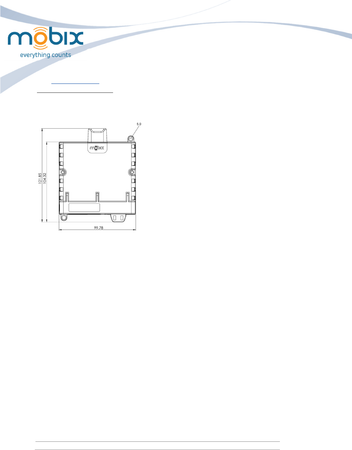
2. MiniHub Specifications
The following tables list the Hub specifications:
Physical Specification:
Specification
Value
Length 121.85 mm
Width
99.8
mm
Height 35 mm
Electrical Specifications:
Specification Value
Input voltage
1
10
-
230 VAC
Input Frequency
50
-
60
HZ
Max Current 20 mA
Environmental :
Specification Value
Operating temperature Range
-
40
°C to +
7
0°C
RoHS standard Fully compliant
PLC Standards :
Specification Value
PLC standard
Complies with FCC,ARIB and EN50065
-
1
-
CENELEC (EU) regulations
RF standard:
Specification
Value
RF standard Complies with FCC, ETSI and ARIB Frequency
240–930 MHz
Sensitivity
-
118dBm
Max Output Power
1
0dBm
(complies with FCC)
Page 5
MiniHub User Guide
10/15/2013
Interfaces
Specification
Value
Pulse/Alarm input port 2
Output port
(for valve control)
1
Serial interface
RS
-
232,RS
-
485
AC switch control 0-100ma/110-250VAC
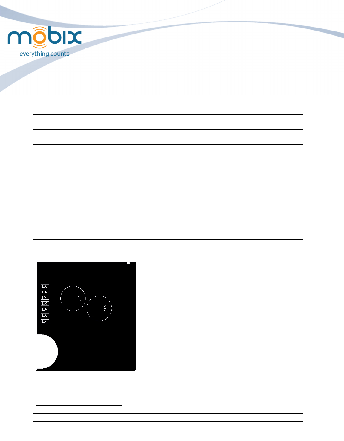
LEDs
LED
Specification
Color
LD1 SW LED Orange
LD2 RF TX Red
LD3
PLC Function
Green
LD4 PLC TX Red
LD5
RF RX
Green
LD6
PLC RX
Green
LD7 Valve capacitor ready Green
Location on the board (top left side):
3. Connectors
AC Interface connector pin out
Pin
Function
GND
GND
Line SW
AC switch output connection

Page 6
MiniHub User Guide
10/15/2013
N Neutral input
L
AC Line input
DC Interface connector pin out
Pin
Function
GND
GND
IN_2
Alarm input
IN_1 Pulse input
OUT_2
Valve control (+)
OUT_1 Valve control (-)
GND
GND
TX
TX RS
-
232 / A
RS
-
485
RX RX RS-232 / B RS-485
4. Installation
1. There are 2 options to mount the MiniHub:
• Mount on a DIN rail using the dedicated DIN mounting on the back of
the box.
• Using the mounting holes on the back of the box
See appendix 2
2. To prevent fire spreading in case of circuit faults, the Hub must be installed in a suitable fire
enclosure to the latest version of UL 61010-1, without any openings at the bottom.
Enclosure minimum size will be 300x250 mm.
3. Connect the 8 control wires to the bottom pitches according to the pin numbers. Use the
designated screws.
This is a view of the wire connections of the MiniHub:
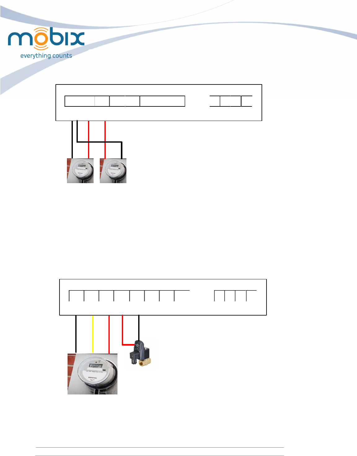
4. According to the scheme of connection:
• Meter pulse wires (IN_1,IN_2,GND)
The number indicates the meter’s number
Each two meters have a joint ground connection
Connect the (+) wire to the numbered input
Connect the (-) wires to the joint GND connector
Page 7
MiniHub User Guide
10/15/2013
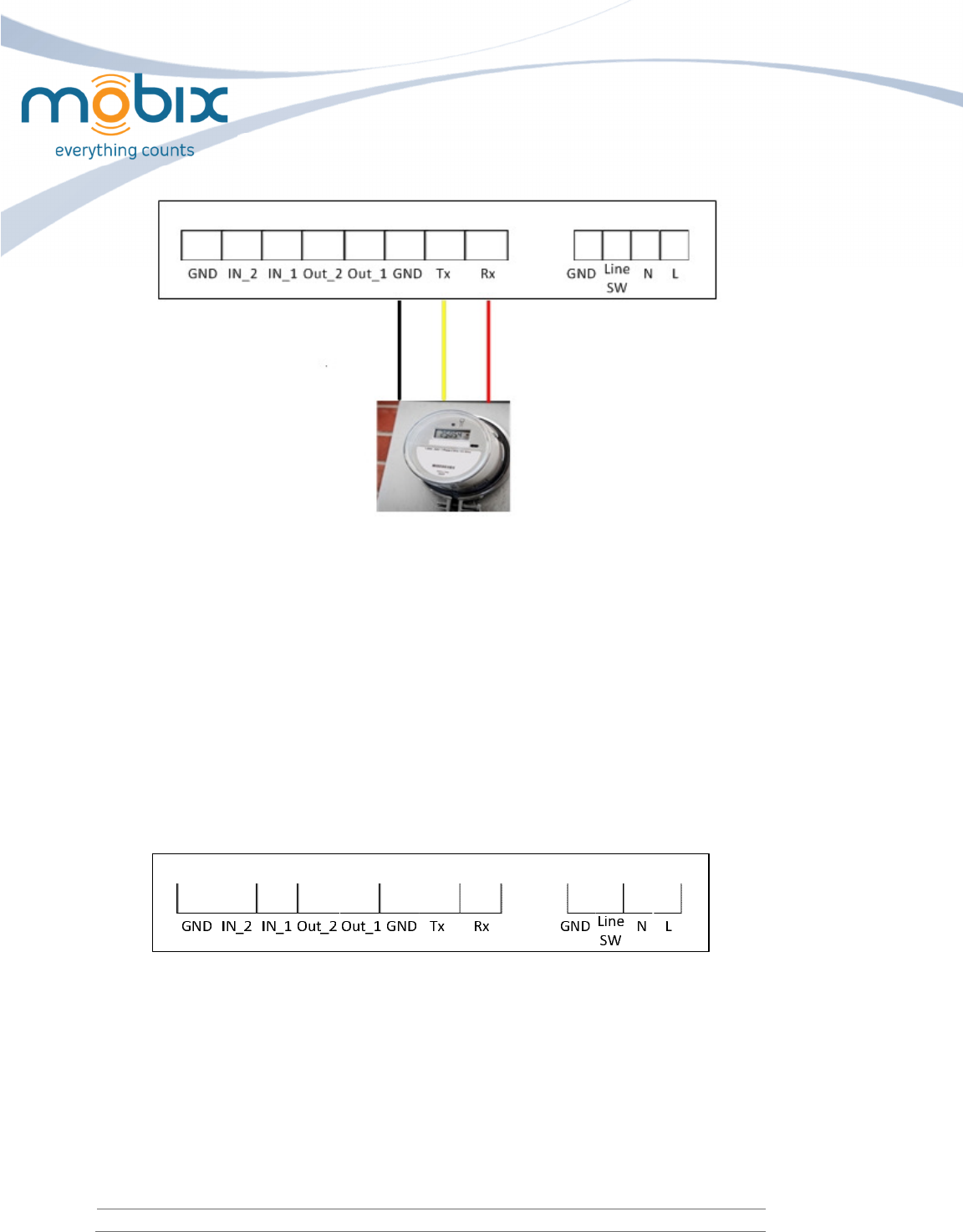
GND IN_2 IN_1 Out_2 Out_1 GND Tx Rx GND N L
Line
SW
5. Meter Pulse + Valve control (GND,IN_2,IN_1,Out_2,Out_1)
The output number indicates the controlled valve.
Out_2 – Connect the (+) wire of the valve control to the numbered output.
Out_1 – Connect the (-) wire of the valve control to the numbered output.
IN_2 – Connect the alarm wire of the Meter to the numbered input
IN_1 – Connect the (+) wire of the Meter to the numbered input
GND – Connect the ground wire of the Meter.
GND IN_2 IN_1 Out_2 Out_1 GND Tx Rx GND N L
Line
SW
6.
Serial
meter connection RS232/RS485
Connect the meter wires to Tx, Rx and GND
Page 8
MiniHub User Guide
10/15/2013
7. Connect the power supply cable to a 230/110Vac power source.
3. Installation
1. Il ya 2 options pour monter le MiniHub:
• Montage sur un rail DIN à l'aide de la norme DIN dédié montage à l'arrière de la boîte.
• Utiliser les trous de montage à l'arrière de la boîte
2. Monter sur un rail DIN à l'aide de la DIN dédié sur le dos de la boîte.
3. Pour éviter la propagation du feu en cas de défauts du circuit, le moyeu doit être installé dans un
boîtier d'incendie adapté à la dernière version de la norme UL 61010-1, sans ouvertures au bas.
4. Connecter les fils de commande 8 pour les emplacements de fond selon l'une des numéros de
broche. Utilisez les vis désignées.
Il s'agit d'un point de vue des connexions du MiniHub:
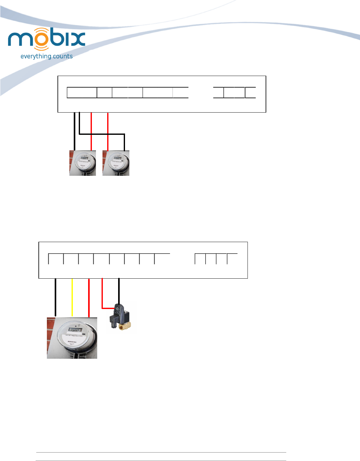
5. Selon le schéma de connexion:
•
Mètre d'impulsion fils (IN_1, IN_2, GND)
fils de compteurs de sortie d'impulsions (IN_1,IN_2,GND)
Le nombre indique le numéro du compteur
Tous les deux mètres ont une connexion de masse commune
Connecter le fil (+) à l'entrée numérotés
Connecter le fil (-) à la commune connecteur GND
Page 9
MiniHub User Guide
10/15/2013
GND IN_2 IN_1 Out_2 Out_1 GND Tx Rx GND N L
Line
SW
6. Mètre d'impulsions + Soupape de commande (GND,IN_2,IN_1,Out_2,Out_1)
Le nombre de sortie indique la soupape commandée.
Out_2 – Connecter le fil (+) de la soupape de commande à la sortie numérotée.
Out_1 – Connecter le fil (-) de la commande de la vanne à la sortie numérotées.
IN_2 – Connecter le fil d'alarme du Mètre à l'entrée numérotés.
IN_1 – Connecter le fil (+) du mètre à l'entrée numérotés
GND – Connecter le fil de terre du mètre
GND IN_2 IN_1 Out_2 Out_1 GND Tx Rx GND N L
Line
SW
4. Safety
• Connect the input and output wires only when mains are not connected
• To prevent fire spreading in case of shortcut, the hub must be installed in a suitable
enclosure without any openings at the bottom.
• Connect mains only to 110-230Vac power source
• All AC connections should be done by an authorized electrician
• The unit intends to be powered from building wiring in Overvoltage Category II. If
the unit is installed in Overvoltage Category higher than II, external overvoltage

Page 10
MiniHub User Guide
10/15/2013
protective device compliant with IEC 61643 standard and NEC/CEC shall beprovided
in building installation to reduce mains transients to Overvoltage Category II.
Sûreté
• Connectez les fils de l'entrée et sortie seulement quand les principale source
d'électricité ne sont pas connectés
• Pour éviter la propagation du feu en cas de raccourci, le moyeu doit être installé
dans une enceinte appropriée sans ouvertures au bas.
• Raccorder seulement aux source d'alimentation 110-230V
• Toutes les connexions AC doit être effectuée par un électricien agréé
• l'unité est destiné à être alimenté à partir de l'installation électrique dans les
catégorie de surtension 2. Si l'unité est installée dans la catégorie de surtension
supérieure à 2, externe conforme surtension dispositif de protection avec la IEC
61643 standard et NEC / CEC doivent être fournis dans la construction de
l'installation pour réduire les transitoires conduites à la catégorie de surtension 2.
5. Supply disconnect switch
A supply disconnect switch, or a circuit breaker must be installed at the connection point of the
power cable to the mains. Circuit breaker should be a standard device with the following
characteristics - 2A 110/230VAC 50/60Hz. An example - S201M-C4NA by ABB. The switch should
be in close proximity to the hub within easy reach for the operator. A marking should be added on
the switch identifying it as a disconnection device for the hub.
Fourniture Sectionneur
Un sectionneur d'alimentation, ou un disjoncteur doit être installé au point de connexion du câble
d'alimentation sur le secteur. Disjoncteur doit être un dispositif standard avec les caractéristiques
suivantes - 2A 110/230VAC 50/60Hz. Un exemple - S201M-C4NA par ABB. Le commutateur doit se
trouver à proximité du concentrateur à la portée de l'opérateur. Un marquage doit être ajouté sur
l'interrupteur de l'identifier comme un dispositif de déconnexion pour le concentrateur.
5. Environmental characteristics
• The Hub is intended for indoor use only. For outdoor application a weatherproof external
enclosure should be added.
• Installation site altitude will be up to 2000m.
• Temperature range should be -40- +70 deg C. For harsher temperatures an external
temperature controlled enclosure should be added.
• Maximum relative humidity 80% for temperatures up to 31 deg C decreasing linearly to
50% relative humidity at 40 deg C.
• Mains supply voltage fluctuations up to +-10% of the nominal voltage.

Page 11
MiniHub User Guide
10/15/2013
• Overvoltage category II
• Pollution Degree 2
Caractéristiques de l'environnement
• Le concentrateur est destiné à une utilisation en intérieur. Pour l'application extérieure
d'une enceinte étanche externe doit être ajouté.
• altitude du site d'installation sera à 2000m.
Plage de température devrait être de -40 à +70 ° C. Pour des températures plus sévères une
température extérieure contrôlée enceinte doit être ajoutée.
• Humidité relative maximale 80% pour des températures jusqu'à 31 ° C diminuant
linéairement jusqu'à une humidité relative de 50% à 40 degrés C.
• Alimentation des fluctuations de tension à + -10% de la tension nominale.
• Catégorie de surtension II
Degré de pollution • 2
7. Maintenance
WARNING: RISK OF ELECTRIC SHOCK
Do not touch live electrical parts.
• Verify that the system is properly installed and grounded according to its installation
manual and national, state, and local codes.
• Incorrect connections may cause electric shock.
• Disconnect input power before installing or servicing the equipment.
WARNING: No user-serviceable parts inside
• If any component part is found to be damaged and/or in need of service, have all such
service performed by a certified electrical contractor or qualified Mobix personnel.
AVERTISSEMENT: RISQUE DE CHOC ÉLECTRIQUE
Ne toucher pas les pièces électriques.
• Vérifiez que le système est correctement installé et mis à la terre conformément à son
manuel d'installation et les codes fédéral, l'Etat, et local.
• Les connexions incorrectes peuvent causer un choc électrique.
• Débranchez la puissance d'entrée avant d'installer ou de réparer l'équipement.
AVERTISSEMENT: Pas de pièces réparables par l'utilisateur à l'intérieur
• Si une pièce composante se trouve à être endommagé et / ou dans le besoin de service, ont
tous effectué un service téléphonique par un électricien agréé ou du personnel qualifié de
Mobix.Alpha
Keep the Hub clean

Page 12
MiniHub User Guide
10/15/2013
• Regularly check for and remove foreign objects or debris on or around your Hub.
Check cords
• If operating, disconnect the Hub from the power source.
• Inspect the Hub supply cord – look for nicks in the insulation or excessive rubs on the cord.
8. Declaration of Conformity
Manufacturer’s Name:
Mobix
Declares under our sole responsibility that the products:
Product Names:
MiniHub H400
Conform(s) to the following standard(s) or other normative document(s):
EMC: FCC Part 15B class B
Radio:
FCC 15C.249
This device complies with Part 15 of the FCC Rules. Operation is subject to the following two conditions:
• The device may not cause harmful interference
• This device must accept any interference received, including interference that may cause undesired
operation.
Modifications: Changes or modifications to this equipment not expressly approved by Mobix may
void the user’s authority to operate this equipment.

Page 13
MiniHub User Guide
10/15/2013
Appendix 1
MiniHub external box
Page 14
MiniHub User Guide
10/15/2013
Appendix 2
MiniHub installation points