Modine Manufacturing 6 558 Users Manual Psh Service
2015-02-09
: Modine-Manufacturing Modine-Manufacturing-6-558-6-Users-Manual-557364 modine-manufacturing-6-558-6-users-manual-557364 modine-manufacturing pdf
Open the PDF directly: View PDF ![]() .
.
Page Count: 28
WARNING
Improper installation, adjustment, alteration, service or
maintenance can cause property damage, injury or death,
and could cause exposure to substances which have been
determined by various state agencies to cause cancer, birth
defects or other reproductive harm. Read the installation,
operating and maintenance instructions thoroughly before
installing or servicing this equipment.
6-558.6
P/N 5H72256A Rev. F
INSTALLATION AND SERVICE MANUAL
separated combustion
high efficiency
gas-fired unit heaters
models PSH & BSH
Contents Page
Inspection on arrival . . . . . . . . . . . . . . . . . . . . . . . . . . . . . . 1
Installation . . . . . . . . . . . . . . . . . . . . . . . . . . . . . . . . . . . . . 2
Performance data . . . . . . . . . . . . . . . . . . . . . . . . . . . . . . . 10
Dimensional data . . . . . . . . . . . . . . . . . . . . . . . . . . . . . . . 11
Operation . . . . . . . . . . . . . . . . . . . . . . . . . . . . . . . . . . . . . 16
Checking input rate . . . . . . . . . . . . . . . . . . . . . . . . . . . . . . 16
Propeller heaters. . . . . . . . . . . . . . . . . . . . . . . . . . . . . . . . 19
Service instructions . . . . . . . . . . . . . . . . . . . . . . . . . . . . . . 21
Troubleshooting guide . . . . . . . . . . . . . . . . . . . . . . . . . . . . 22
Motor data . . . . . . . . . . . . . . . . . . . . . . . . . . . . . . . . . . . . 25
Control options . . . . . . . . . . . . . . . . . . . . . . . . . . . . . . . . . 26
Rating plate identification . . . . . . . . . . . . . . . . . . . . . . . . . 27
Warranty . . . . . . . . . . . . . . . . . . . . . . . . . . . . . . . Back cover
FOR YOUR SAFETY
If you smell gas:
1. Open windows
2. Don't touch electrical switches.
3. Extinguish any open flame.
4. Immediately call your gas supplier.
FOR YOUR SAFETY
The use and storage of gasoline or other flammable vapors
and liquids in open containers in the vicinity of this appliance
is hazardous.
THIS MANUAL IS THE PROPERTY OF THE OWNER.
PLEASE BE SURE TO LEAVE IT WITH THE OWNER WHEN
YOU LEAVE THE JOB.
All models approved for use in California by the CEC (when
equipped with IPI), in New York by the MEA division, and in
Massachusetts. Unit heater is certified for non-residential
applications.
CAUTION
To prevent premature heat exchanger failure do not locate
ANY gas-fired units in areas where chlorinated, halogenated
or acid vapors are present in the atmosphere.
Inspection on Arrival
1. Inspect unit upon arrival. In case of damage, report
immediately to transportation company and your local
Modine sales representative.
2.
Check rating plate on unit to verify that power supply meets
available electric power at the point of installation.
3. Inspect unit received for conformance with description of
product ordered (including specifications where applicable).
October, 2002
Heater Parts from ACF Greenhouses
INSTALLATION
SPECIAL PRECAUTIONS
2
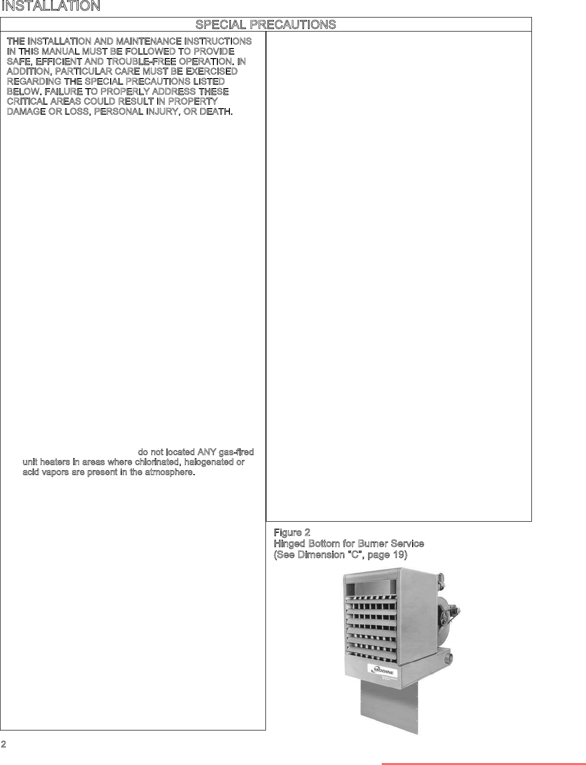
Figure 2
Hinged Bottom for Burner Service
(See Dimension “C”, page 19)
THE INSTALLATION AND MAINTENANCE INSTRUCTIONS
IN THIS MANUAL MUST BE FOLLOWED TO PROVIDE
SAFE, EFFICIENT AND TROUBLE-FREE OPERATION. IN
ADDITION, PARTICULAR CARE MUST BE EXERCISED
REGARDING THE SPECIAL PRECAUTIONS LISTED
BELOW. FAILURE TO PROPERLY ADDRESS THESE
CRITICAL AREAS COULD RESULT IN PROPERTY
DAMAGE OR LOSS, PERSONAL INJURY, OR DEATH.
1. Disconnect power supply before making wiring
connections to prevent electrical shock and equipment
damage. All units must be wired strictly in accordance
with wiring diagram furnished with the unit.
2. Turn off all gas before installing unit heaters.
3. Gas pressure to unit heater controls must never exceed
14" W.C. (1/2 psi).
When leak testing the gas supply piping system, the unit
and its combination gas control must be isolated during
any pressure testing in excess of 14" W.C. (1/2 psi).
The unit should be isolated from the gas supply piping
system by closing its field installed manual shut-off valve.
4. Check gas inlet pressure at unit upstream from
combination gas control. The inlet pressure should be 6" -
7" W.C. on natural gas or 11" - 14" W.C. on propane gas.
Purging of gas piping should be performed as described
in ANSI Z223.1 - Latest Edition or in Canada in
CAN/CGA-B149 codes.
5. All units must be supplied with both combustion air and
exhaust piping to the outdoors.
6. Do not install in potentially explosive or flammable
atmospheres laden with grain dust, sawdust, or similar air-
borne materials. In such applications, a blower type heater
installed in a separate room with ducting, including
appropriate back flow prevention dampers to the dust-
laden room, is recommended.
7. Installation of units in high humidity or salt water
atmospheres will cause accelerated corrosion resulting in
a reduction of the normal life span of the units.
8. To prevent premature failure do not located ANY gas-fired
unit heaters in areas where chlorinated, halogenated or
acid vapors are present in the atmosphere.
9. Maintain separation between units so discharge from one
unit will not be directed into the inlet of another.
10. Do not install unit outdoors.
11. Minimum clearance to combustibles is 12 inches from the
bottom; 18 inches from the sides; 6 inches from the top
and vent connector.
12. Allow at least 6" clearance at the sides and 12" clearance
at rear (or 6" beyond end of fan motor at rear of unit,
whichever is greater) to provide ample air for combustion
and proper operation of fan.
13. The minimum distance from combustible material is based
on the combustible material surface not exceeding 160°F.
Clearance from the top of the unit may be required to be
greater than 6" if heat damage, or other than fire, may
occur to materials above the unit heater at the
temperature described.
14. Do not install units below 7 feet, measured from the
bottom of the unit to the floor, unless properly guarded to
provide protection from moving parts.
15. Modine units are designed for use in heating applications
with ambient temperatures between 32°F and 90°F. If an
application exists where ambient temperatures can be
expected to fall outside of the is range, contact factory
for recommendations.
16. Provide clearance for opening hinged bottom pan for
servicing. See Figure 2. Do not set unit on its bottom.
17. To assure that flames do not impinge on heat exchanger
surfaces, the unit must be suspended in a vertical and
level position. Failure to suspend unit properly may
shorten the life of the unit heater.
18. Do not life unit by power exhauster.
19. Be sure no obstructions block air intake and discharge of
unit.
20. Do not attach duct work, air filters, or polytubes to any
propeller (PSH) model unit.
21. In aircraft hangars, keep the bottom of the unit at least
10' from the highest surface of the wings or engine
enclosure of the highest aircraft housed in the hanger
and in accordance with the requirements of the enforcing
authority and/or NFPA No. 409 — Latest Edition.
22. In garages or other sections of aircraft hangars such as
offices and shops that communicate with areas used for
servicing or storage, keep the bottom of the unit at least
7' above the floor unless the unit is properly guarded to
provide user protection from moving parts. In parking
garages, the unit must be installed in accordance with
the standard for parking structures ANSI/NFPA 88A, and
in repair garages the standard for repair garages NFPA
#88B. In Canada, installation of unit heaters in airplane
hangars must be in accordance with the requirements of
the enforcing authority, and in public garages in
accordance with the current CAN/CGA-B149 codes.
23. Consult piping, electrical, and venting instructions in this
manual before final installation.
24. All literature shipped with your unit should be kept for
future use for servicing or service diagnosis. Do not
discard any literature shipped with your unit.
25. When servicing or repairing this equipment, use only
Modine-approved service replacement parts. A complete
replacement parts list may be obtained by contacting
Modine Manufacturing Company. Refer to the rating
plate on the unit for complete unit model number,
serial number and company address. Any substitution
of parts or controls not approved by Modine will be at
owners risk.
Heater Parts from ACF Greenhouses

INSTALLATION
3
Product Description
Modine PSH and BSH model unit heaters are listed as separated
combustion unit heaters and are defined as follows: A unit heater
for installation in non-residential structures which, when connected
to a sealed combustion air pipe and sealed exhaust vent, supplied
by the installer, constructed so that when installed according to the
manufacturer’s instructions, air for combustion is derived from the
outside atmosphere and the flue gases from the appliance are
discharged to the outside atmosphere and the flue gases from the
appliance are discharged to the outside atmosphere.
In the U.S., the installation of these units must comply with the
“National Fuel Gas Code,” ANSIZ223.1, latest edition (also known
as NFPA 54) and other applicable local building codes.
In Canada, the installation of these units must comply with local
plumbing or waste water codes and other applicable codes and
with the current code CAN/CGA-B149.1, “Installation Code for
Natural Gas Burning Appliances and Equipment” or CAN/CGA-
B149.2, “Installation Code for Propane Burning Appliances and
Equipment.”
1. All installation and service of these units must be performed by
a qualified installation and service agency only as defined in
ANSIZ223.1, latest edition or in Canada by a licensed gas fitter.
2. This unit is certified by C.S.A., with the controls furnished. For
replacement parts, submit the complete model, control code
and serial number shown on rating plate on the unit, Modine
reserves the right to substitute other authorized controls as
replacements.
3. Unit is balanced for correct performance. Do not alter fan or
operate motors at reduced speed.
4. Information on controls is supplied separately.
5. Modine unit heaters use the same burner for natural and
propane gases.
Locating Unit Heaters
In locating units, consider general space-heating requirements,
availability of gas, and proximity to vent locations. Unit heaters
should be located so heated air streams wipe exposed walls
without blowing directly against them. In multiple unit installations,
arrange units so that each supports the sir stream from another,
setting up circulatory air movement in the area. In buildings
exposed to prevailing winds, a large portion of the heated air
should be directed along with windward wall. Avoid interference of
air streams as much as possible.
Mounting height (measured from bottom of unit) at which unit
heaters are installed is critical. Maximum mounting heights for
standard units are listed in Tables 7 and 8 on page 18. Alternate
mounting heights for units with deflector hoods or nozzles are
shown on pages 10 and 12. The maximum mounting heights for
any unit is that heights above which the unit will not deliver heated
air to the floor. The maximum mounting heights must not be
exceeded in order to assure maximum comfort.
Motors and controls used on Modine unit heaters are designed for
use in ambient temperatures between 32°F and 90°F. If an
application exists where ambient temperatures can be expected to
fall outside of this range, contact factory for recommendations.
Combustion Air Requirements
Modine models PSH and BSH separated combustion units are
designed to receive air for combustion directly from the outside
atmosphere via field installed combustion air piping between the
unit and the outside atmosphere. The combustion air inlet of the
unit must be connected to the outside atmosphere.
The maximum equivalent length of combustion air piping cannot
exceed 30 feet. Keep this limitation in mind when locating units.
See page 5 for combustion air piping instructions.
Unit Suspension
Be sure the means of suspension is adequate to support the
weight of the unit. (See page 19 for unit weights.) For proper
operation, the unit must be installed in a level horizontal position.
Clearances to combustibles as specified above must be strictly
maintained.
On all propeller units except the PSH280 and PSH340, two tapped
holes (3/8 - 16) are located in the top of the unit to receive ceiling
hangers. Units with two point suspension, models PSH130 through
PSH225, incorporate a level hanging feature. Depending on what
options and accessories are being used, the heater may not hang
level as received from the factory. Do not hang heaters with
deflector hoods until referring to the "installation manual for
deflector hoods" and making the recommended preliminary
adjustments on the heater. These preliminary adjustments need to
be made with the heater resting on the floor.
PSH130 through PSH225 units without deflector hoods that do not
hang level after being installed, can be corrected in place. Simply
remove both outer side panels (screws to remove are on back
flange of side panel) and you will see the (adjustable) mounting
brackets (Figure 3). Loosen the set screws holding the mounting
brackets in place and using a rubber mallet or something similar,
tap the heater into a position where it does hang level. Re-tighten
set screws and replace the outer side panels.
The PSH280 and PSH340 have four mounting holes. On all blower
units, except the BSH280 and BSH340, two tapped holes are
provided in the top of the unit and two holes in the blower support
bracket. The BSH280 and BSH340 have four tapped holes in the
top of the unit and two in the blower support bracket for mounting.
To assure that flames are directed into the center of heat
exchanger tubes, unit must be supported in a vertical position, with
suspension hangers “UP.” Check with a level. This is important to
the operation and life of unit.
NOTE: Pipe hanger adapter kits, as shown in Figure 3, are
available as accessories from Modine. The hardware allows for
pipe caps to be secured into the top of the unit heater with
machine screws (as illustrated - machine screws are 3/8 - 16 x
1.75 UNC-2A THD). The pipe caps can then accommodate 3/4"
NPT pipe for mounting. Three different kits are available with either
2, 4, or 6 adapters per kit. See price sheet to determine proper kit.
CAUTION
Minimum clearance to combustibles is 12 inches from the
bottom; 18 inches from the sides; 6 inches from the top and vent
connector.
Allow at least 12" at the rear of unit or 6" beyond the end of the
motor (Whichever is greater) to provide ample air for proper
operation of fan.
Provide clearance for opening hinged bottom of servicing. See
Figure 2.
CAUTION
Units must not be installed in potentially explosive, flammable or
corrosive atmosphere.
To prevent premature heat exchanger failure do not locate ANY
gas-fired unit in areas where chlorinated, halogenated or acid
vapors are present in the atmosphere.
Heater Parts from ACF Greenhouses

INSTALLATION
Figure 2
Suspension Methods
Venting
General Venting and Combustion Air
Instructions
Table 1
ANSI venting requirements
1. Table 1 summarizes the ANSI venting requirements for the
various appliance categories. All PSH/BSH models are
category III appliances. The venting requirements for a
category III appliance are included in these instructions.
2. Select the size of vent and combustion air pipe that fits the
power exhauster and combustion air intake on the rear of
the appliance (see pages 14 and 15 for dimensions). Do
not use a vent or combustion air pipe smaller than the size
of the outlet or inlet on the appliance. The pipe should be
single wall galvanized steel or other suitable corrosion
resistant material. Follow the National Fuel Gas Code for
minimum thickness of vent material. The minimum
thickness for connectors varies depending on the pipe
diameter.
3. A minimum of 12 inches straight pipe is recommended from
the power exhauster outlet before turns in the vent pipe.
4. Install the vent and combustion air pipes with a downward
slope from the appliance of 1/4 inch per foot and suspend
securely from overhead structures at points no greater than
3 feet apart. Fasten individual lengths of vent together with
at least three corrosion resistant sheet metal screws.
5. Keep the vent pipe at least 6 inches from combustible
material. The minimum distance from combustible material
is based on the combustible material surface not exceeding
160F. Clearance from the vent pipe (or the top of the unit)
may be required to be greater than 6 inches if heat damage
other than fire (such as material distortion or discoloration)
could result.
6. Avoid venting through unheated space when possible.
When venting does pass through an unheated space,
insulate runs greater than 5 feet to minimize condensation.
Inspect for leakage prior to insulating and use insulation
that is noncombustible with a rating of not less than 350F.
Install a tee fitting at the low point of the vent system and
provide a drip let with a clean out cap as shown in figure
01. The drip leg should be cleaned annually.
7. When the vent passes through an INTERIOR wall or floor, a
metal thimble 4 inches greater than the vent diameter is
necessary. If there is 6 feet or more of vent pipe in the
open space between the unit heater and where the vent
pipe passes through the wall or floor, the thimble need only
be 2 inches greater than the diameter of the vent pipe. If a
thimble is not used, all combustible material must be cut
away to provide a 6 inches clearance. Any material used to
close the opening must be noncombustible.
8. Limit the total equivalent vent pipe length to a minimum of 5
feet and a maximum of 30 feet, making the vent system as
straight as possible. (The equivalent length of a 4 inch
elbow is 5 feet and a 6 inch elbow is 10 feet).
9. Seal the joints with a metallic tape suitable for temperatures
up to 350F. (3M tapes 433 or 363 are acceptable.) Wrap
the tape two full turns around the vent pipe.
10. Do NOT vent this appliance into a masonry chimney.
11. Do NOT use dampers or other devices in the vent or
combustion air pipes.
12. The venting system must be exclusive to a single appliance,
and to other appliance is allowed to be vented into it.
13. Long runs of horizontal or vertical combustion air pipes may
require insulation in very cold climates to prevent the
buildup of condensation on the outside of the pipe where
the pipe passes through conditioned spaces.
14. Vertical combustion air pipes should be fitted with a tee with
a drip leg and a clean out cap to prevent against the
possibility of any moister in the combustion air pipe from
entering the unit. The drip leg should be inspected and
cleaned periodically during the heating season.
15. When condensation may be a problem, the vent system
shall not terminate over public walkways or over an area
where condensate or vapor could create a nuisance or
hazard or could be detrimental to the operation of regulator,
relief openings or other equipment.
16. Precautions must be taken to prevent degradation of
building materials by flue products.
17. The vent cap for vertically vented appliances should extend
above any portion of a building within a horizontal distance
of 2 feet. Refer to figures 7 and 8.
Remove Side Panels
to Adjust Mounting Brackets (Suspension w/ Pipe Adapter Kit)
Appliance Venting
Category Description Requirements
INegative vent pressure Follow standard venting
Non-condensing requirements.
IINegative vent pressure Condensate must be
Condensing drained.
III Positive vent pressure Vent must be gastight.
Non-condensing
IVPositive vent pressure Vent must be liquid and
Condensing gastight.
Condensate must be
drained.
4
CAUTION
Gas-fired heating equipment must be vented — do not operated
unvented.
A built-in power exhauster is provided — additional external
draft hoods (diverters) or power exhausters are not required or
permitted.
Installation must conform with local building codes or in the
absence of local codes, with the National Fuel Gas Code, ANSI
Z223.1 (NFPA 54) — Latest Edition. In Canada installation must
be in accordance with CAN/CGA-B149.1 for natural gas
appliances, and CAN/CGA-B149.2 for propane appliances.
Heater Parts from ACF Greenhouses
INSTALLATION
Venting Instructions for Concentric Vent
Options
The concentric vent concept allows for the vent pipe and the
combustion air pipe to pass through one hole in an
EXTERIOR wall or roof. The concentric vent kits offered are
horizontal or vertical. Venting with 2 pipes; a combustion air
pipe and flue product vent pipe remains an option, primarily
for replacement heaters where two holes through the exterior
of a building already exist.
When utilizing the concentric vent option, you have already
pre-determined whether the unit heater will be horizontal vent
or vertical vent and have received the appropriate kit. At this
time, you need to verify that you have all the components
required for the venting option chosen. The components for
each kit are as follows:
Horizontal Concentric Vent Kit:
• concentric adapter assembly
• specially designed vent termination cap
• specially designed inlet air guard
Vertical Concentric Vent Kit:
• concentric adapter assembly
• standard Briedert Type L or Gary Steel 1092 vent
termination cap
• specially designed inlet terminal
Although the first installation you will make will be the
concentric adapter assembly, you should now “read ahead”
the instructions for the type of venting option you’ve already
chosen - i.e. horizontal concentric, vertical concentric, 2 pipe
horizontal or 2 pipe vertical. These instructions can be found
on pages 5, 6,or 7 of these installation instructions. After
reading your specific instructions, come back to “Installing the
Concentric Vent Adapter Box” section and begin.
Installing the Concentric Vent Adapter Box
1. Determine the location of the box. Refer to the instructions
in the following sections for the method of venting to be
used (vertical or horizontal). Maintain all clearances as
listed in these instructions.
2. This box can be mounted flush to the wall or roof, or the
box can be offset from the wall or roof by using field
supplied brackets. When mounting the box, consider
serviceability and access to the vent and combustion air
pipes.
3. If the box is to be mounted using field supplied brackets,
these brackets must be strong enough to rigidly secure
the box to the wall or roof, and should be made from
corrosion resistant material. After determining the length
of the field supplied brackets, attach them to the sides of
the box using several corrosion resistant sheet metal
screws. See figure 3 for typical installation and brackets.
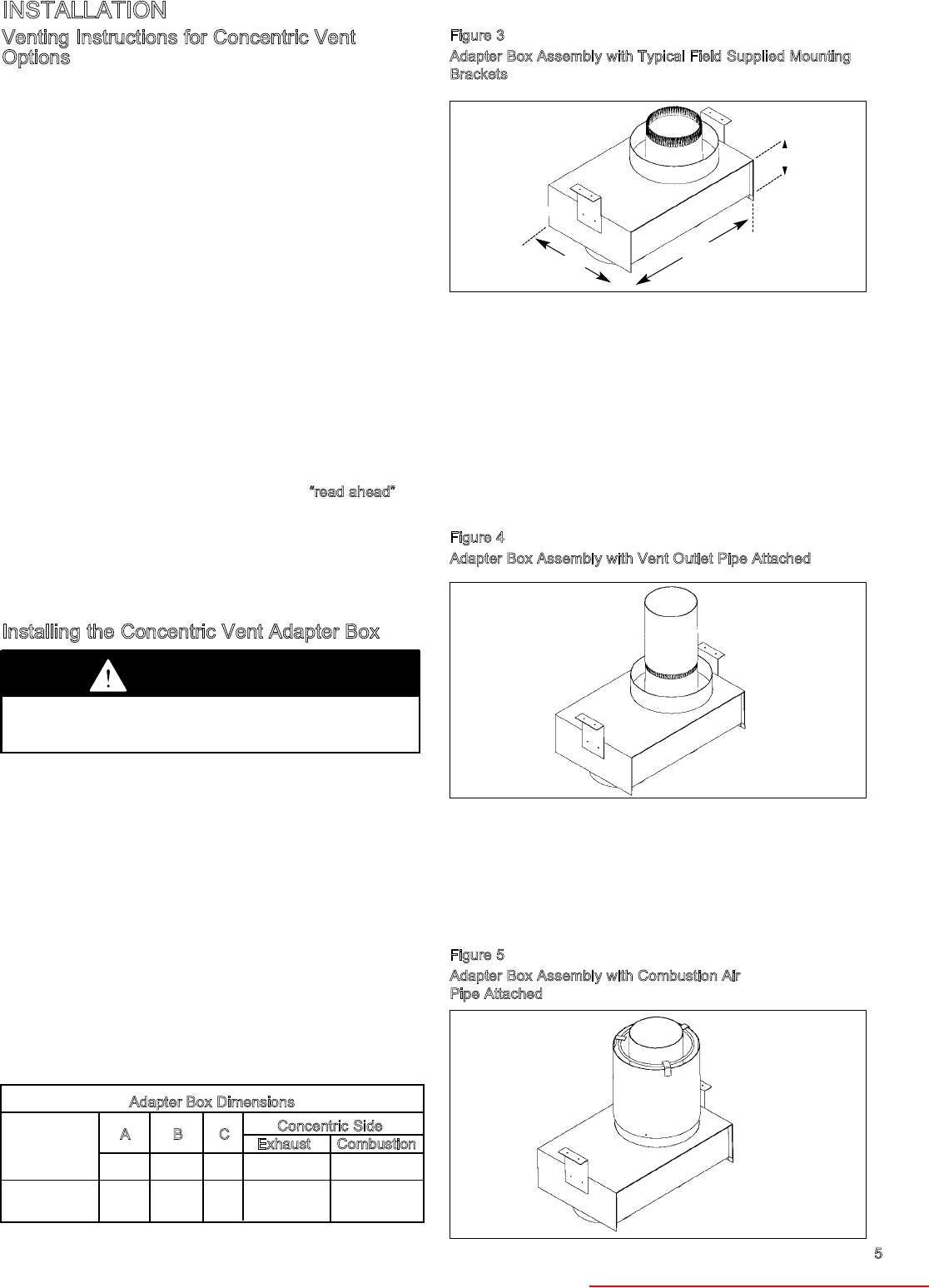
Figure 3
Adapter Box Assembly with Typical Field Supplied Mounting
Brackets
4. Determine the appropriate length of vent pipe that must be
attached to the vent outlet (the concentric side) of the box.
Refer to the following sections for the minimum length of
vent pipe to be used for the method of venting (vertical or
horizontal). Make sure to add the length of the field
supplied brackets if used, and the thickness of the wall or
roof.
5. Cut the vent pipe to the proper length and attach it to the
vent outlet of the concentric vent adapter box using at
least 3 corrosion resistant sheet metal screws. Seal this
joint using metallic tape suitable for temperatures up to
350° F. Wrap the tape two full turns around the vent pipe.
See figure 4.
Figure 4
Adapter Box Assembly with Vent Outlet Pipe Attached
6. Determine the length of the combustion air pipe to extend
through the wall. Refer to the following sections for the
minimum length of combustion air pipe to be used for the
method of venting being used, vertical or horizontal. Cut
the pipe to the proper length.
7. Slide the combustion air pipe over the vent pipe. Attach
the combustion air pipe to the adapter box using at least 3
non corrosive sheet metal screws. See figure 5.
Figure 5
Adapter Box Assembly with Combustion Air
Pipe Attached
Adapter Box Dimensions
A B C Concentric Side
Heater Sizes
130-225 81/4" 113/4" 4" 4" 6"
Heater Sizes
280-340 101/2" 16" 4" 6" 8"
A
B
C
Exhaust Combustion
5
CAUTION
The concentric vent adapter box must be installed inside of
the structure or building. Do not install this box on the
exterior of a building or structure.
Heater Parts from ACF Greenhouses
6
INSTALLATION
8. Place this assembly (the adapter box, vent pipe and
combustion air pipe) through the wall or roof and verify that
the distance requirements as defined in the following
sections are met. Securely attach the assembly (adapter
box and vent and combustion air pipe) to the wall or roof
using appropriate fasteners.
Horizontal Concentric Venting:
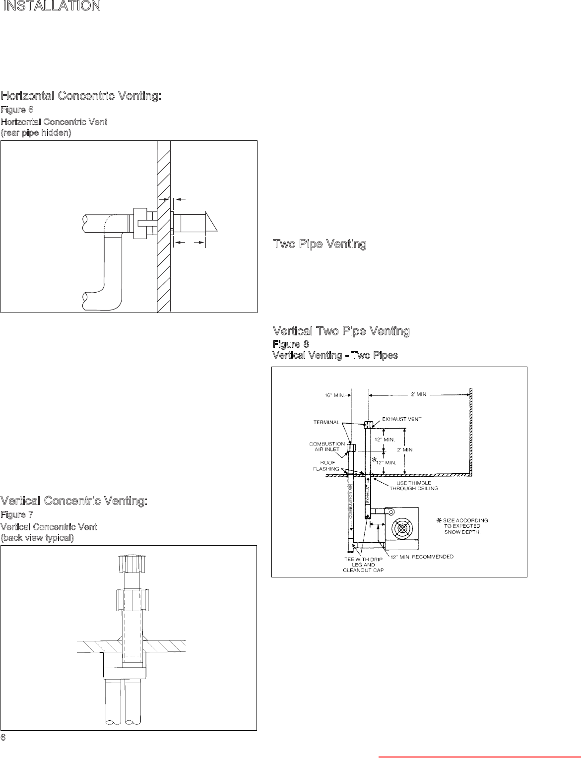
Figure 6
Horizontal Concentric Vent
(rear pipe hidden)
1. The vent pipe must terminate with the terminal supplied by
the manufacture for horizontal venting. Refer to the parts
list on page 5 for the appropriate part.
2. The combustion air pipe must terminate at least 1 inch from
the wall. This will prevent water from running down the wall
and into the pipe and allows for easy installation of the
combustion air intake guard.
3. Caulk between the wall and the air intake pipe.
4. Maintain 12 inches from the combustion air inlet to the back
of the vent terminal.
5. Attach the combustion air intake guard using non corrosive
screws as shown in figure 5. This guard must be placed at
the end of the pipe on the exterior of the building. This
guard helps to prevent animals and debris from entering the
combustion air pipe.
Vertical Concentric Venting:
Figure 7
Vertical Concentric Vent
(back view typical)
1. The vent must terminate with a Gary Steel Model 1092 or
Briedert Type L cap for the appropriate pipe size.
2. The combustion air pipe must terminate with the cap
supplied by the manufacturer. This cap is specially
designed to work with the concentric vent system. Refer to
the parts list on page 5 for the appropriate part.
3. The bottom of the air intake pipe must terminate above the
snow line, or at least 12 inches above the roof, which ever
distance is greater.
4. The bottom of the vent cap must terminate at least 6 inches
above the top of the air intake cap.
5. To attach the caps, slide the combustion air cap over the
vent pipe and fasten it to the combustion air pipe with at
least 3 non corrosive fasteners. Then, attach the vent cap
to the vent pipe, also using at least 3 non corrosive
fasteners.
6. Caulk the gap between the combustion air cap and the vent
pipe with silicone sealant, or other appropriate sealants
suitable for metal to metal contact and for temperatures of
350° F.
Two Pipe Venting
Two pipe venting refers to using two penetrations through an
exterior wall or roof. This method of venting is primarily used
for replacement heaters where two holes through the exterior of
a building exist. To vent using this method, either (2) Briedert
Type L caps or (2) Gary Steel Model 1092 caps provided with
your unit heater must be used. These caps are used for both
vertical and horizontal venting of the heater.
Vertical Two Pipe Venting
1. The bottom of the combustion air cap must be located
above the snow line or 12 inches above the roof, which ever
is greater.
2. The vent must terminate at least 1 foot above and 16
inches horizontally from the combustion air inlet.
3. When the vent passes through a combustible roof, a metal
thimble 4 inches greater than the vent diameter is
necessary. If there is 6 feet or more of vertical vent pipe in
the open space between the unit heater and where the vent
pipe passes through the roof, the thimble need only be 2
inches greater than the diameter of the vent pipe. If a
thimble is not used, all combustible material must be cut
away to provide a 6 inch clearance. Any material used to
close the opening must be noncombustible.
1"
12"
To Exhaust
T
o Combustion
Air Inlet
Figure 8
Vertical Venting - Two Pipes
Heater Parts from ACF Greenhouses

INSTALLATION
Horizontal Two Pipe Venting
1. When horizontal vents pass through a combustible wall (up
to 8 inches thick), the vent passage must be constructed
and insulated as shown in Figure 10.
2. The termination of horizontally vented system must extend
12 inches beyond the exterior surface of an exterior wall.
3. The combustion air pipe must be a minimum of 16 inches
below the vent pipe, and 24 inches from the exterior wall.
4. Support the vent and combustion air pipe as shown in
Figure 10.
Piping
1. Installation of piping must be in accordance with local
codes, and ANSI Z223.1, “National Fuel Gas Code,” or
CAN/CGA-B149 in Canada.
2. Piping to units should conform with local and national
requirements for type and volume and gas handled, and
pressure drop allowed in the line. Refer to Table 5, to
determine the cubic feet per hour (cfh) for the type of gas
and size of unit to be installed. Using this cfh value and the
length of pipe necessary, determine the pipe diameter from
Table 2. Where several units are served by the same main,
the total capacity, cfh, and length of main must be
considered. Avoid pipe sizes smaller than 1/2". Table 2
allows for the usual number of fittings with a 0.3; W.C.
pressure drop. Where the gas supplied has a specific
gravity other than 0.60, apply the multiplying factor as given
in Table 3.
3. After threading and reaming the ends, inspect piping and
remove loose dirt and chips.
4. Support piping so that no strains are imposed on unit or
controls.
5. Use two wrenches when connecting piping to unit controls.
Length Diameter of Pipe — Inches
of Pipe
in Ft. 1/2 3/4 1 1-1/4 1-1/2
15 76 218 440 750 1220
30 73 152 285 590 890
45 44 124 260 435 700
60 50 105 190 400 610
75 97 200 345 545
90 88 160 320 490
105 80 168 285 450
120 158 270 420
150 120 242 380
180 128 225 350
210 205 320
240 190 300
270 178 285
300 170 270
450 140 226
600 119 192
Length Diameter of Pipe — Inches
of Pipe
in Ft. 2 3 4 6 8
15 2480 6500 12880 38700 79000
30 1650 4700 9700 27370 55850
45 1475 3900 7900 23350 45600
60 1150 3250 6800 19330 39500
75 1120 3000 6000 17310 35300
90 930 2600 5400 15800 32250
105 920 2450 5100 14620 29650
120 860 2300 4800 15680 27920
150 710 2000 4100 12240 25000
180 720 1950 4000 11160 22800
210 660 1780 3700 10330 21100
240 620 1680 3490 9600 19740
270 580 1580 3250 9000 18610
300 545 1490 3000 8500 17660
450 450 1230 2500 7000 14420
600 380 1030 2130 6000 12480
Table 2
Gas Pipe Capacities
In Cu. Ft. per Hour with Pressure Drop of 0.3 in W.C. with Specific Gravity 0.60.
Table 3
Specific Gravity Conversion Factors
Multiplying factors to be used with Table 1 when the specific gravity of gas is
other than 0.60.
Natural Gas Propane Gas
Specific Specific
Gravity Factor Gravity Factor
0.55 1.04 1.50 0.633
0.60 1.00 1.53 0.626
0.65 0.962 1.60 0.612
Figure 9
Horizontal Venting - Two Pipes
METAL
SLEEVE
FIBER GLASS
INSULATION
MIN. 2"
2" MIN.
VENT TERMINATION
SUPPORT BRACKET
(where required)
(Make from 1" x 1" steel angle)
9"
9"
45
1"
METAL
SLEEVE
2" MIN.
VENT PIPE
DIAMETER
METAL FACE
PLATE 1"
Figure 10
Exhaust Vent Construction Through Combustible Walls
and Support Bracket
7
CAUTION
Gas pressure to unit heater controls must never exceed 14"
W.C. (1/2 psi).
When leak testing the gas supply piping system, the appliance
and its combination gas control must be isolated during any
pressure testing in excess of 14" W.C. (1/2 psi).
The appliance should be isolated from the gas supply piping
system by closing its field installed manual shut-off valve.
Heater Parts from ACF Greenhouses
INSTALLATION
8
6. Provide a drip pocket before each unit and in the line where
low spots cannot be avoided. (See Figure 7).
7. Take-off to unit should come fro top or side of main to avoid
trapping condensate.
8. Piping, subject to wide temperature variations, should be
insulated.
9. Pitch piping up toward unit at least 1/4" per 15' of horizontal
run.
10. Compounds used on threaded joints of gas piping must be
resistant to action of liquefied petroleum gases.
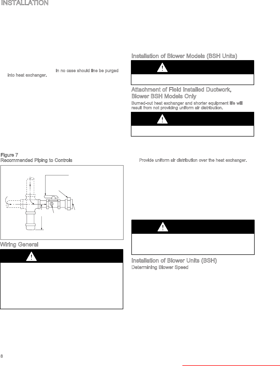
11. Purge air before lighting unit by disconnecting pilot tubing at
combination gas control. In no case should line be purged
into heat exchanger.
12. After installation, check system for gas leaks, using a soap
solution.
13. Install a ground joint union and a manual shut off valve
immediately upstream of the unit including a 1/8" NPT
plugged tapping accessible for test gage connection. (See
Figure 7).
14. Allow at least 5 feet of piping between any high pressure
regulator and unit control string.
15. When Pressure/Leak testing, pressures above 14'' W.C. (1/2
psi), close the field installed shut-off valve, disconnect the
appliance and its combination gas control from the gas
supply line, and plug the supply line before testing. When
testing pressures 14" W.C. (1/2 psi) or below, close the
manual shut-off valve on the appliance before testing.
Wiring General
All field installed wiring must be done in accordance with the
National Electrical Code ANSI/NFPA 70 — Latest Edition or
Canadian Electrical Code CSA C22.1 Part 1 or local codes.
Unit must be electrically grounded according to these codes.
See wiring diagram shipped with unit. For optional wiring
diagrams see Bulletin 6-453.
The power to these units should be protected with a fused
disconnect. Units for use with three-phase electric power must
be provided with a motor starter having properly sized overload
protection.
Location of thermostat should be determined by heating
requirements and be mounted on an inside wall about 5' above
floor level . . . where it will not be affected by heat from the unit
or other sources, or drafts from frequently opened doors. See
instructions packed with thermostat.
Installation of Blower Models (BSH Units)
Attachment of Field Installed Ductwork,
Blower BSH Models Only
Burned-out heat exchanger and shorter equipment life will
result from not providing uniform air distribution.
When installing unit, always follow good duct design practices
for even distribution of the air across the heat exchanger.
Recommended layouts are shown below. When installing blower
units with ductwork, the following must be done.
1. Provide uniform air distribution over the heat exchanger.
Use turning vanes where required. See figures below.
2. Provide removable access panels in the ductwork on the
downstream side of the unit. These openings should be
large enough to view smoke or reflect light inside the casing
to indicate leaks in the heat exchanger and to check for hot
spots on exchanger due to poor air distribution or lack of
sufficient air (cfm).
3. If ductwork is connected to the rear of the unit, use Modine
blower enclosure kit, or if using field designed enclosure,
maintain dimensions of proper blower enclosure as shown.
on page 19.
Installation of Blower Units (BSH)
Determining Blower Speed
The drive assembly and fan motor on all gas-fired blower units
are factory assembled. The adjustable motor sheave has been
pre-set to obtain maximum air flow without any external static
pressure. The motor sheave should be adjusted as required
when the unit is to be operated at other air flows and/or with
external static pressures. Adjustment must always be within the
performance range shown on pages 14 and 15 and the
temperature rise range shown on the unit’s rating plate.
To determine the proper blower speed and motor shave turns
open, the conditions under which the unit is to operate must be
know. If the blower unit is to be used without duct work, nozzles
or filters, the only criteria for determining the motor sheave
turns open and blower speed is the amount of air flow to be
delivered. The performance tables for blower models are shown
on pages 14 and 15. As an example, a model BSH150 unit
GAS
SUPPLY LINE
GAS
SUPPLY LINE
GROUND
JOINT
UNION
3"
MIN.
DRIP
POCKET
PLUGGED
1/8" NPT TEST
GAGE CONNECTION
TO
CONTROLS
A manual shut off valve with
1/8' N.P.T. plugged tapping,
accessible for test gage
connection must be installed
immediately upstream of the
gas supply connection to the
appliance.
Figure 7
Recommended Piping to Controls
CAUTION
Disconnect power supply before making wiring connections to
prevent electrical shock and equipment damage. ALL UNITS
MUST BE WIRED STRICTLY IN ACCORDANCE WITH
WIRING DIAGRAM FURNISHED WITH UNIT.
ANY WIRING DIFFERENT FROM WIRING DIAGRAM MAY BE
HAZARDOUS TO PERSONS AND PROPERTY.
Any damage to or failure of Modine units caused by incorrect
wiring of the units is not covered by MODINE’S STANDARD
WARRANTY (see Back Cover).
CAUTION
Proper air flow and distribution, across the hat exchanger must
be provided to prevent early failure of the blower unit heater.
CAUTION
Do not attempt to attach ductwork of any kind to propeller PSH
models.
CAUTION
Check for red heat exchanger tubes. If bottom of tubes become
red while blower unit is in operation, check for proper air volume
and air distribution. Adjust blower speed or correct discharge
duct design to correct problem.
Heater Parts from ACF Greenhouses

INSTALLATION
9
without filters operating with one external static pressure, that
is, no duct work, nozzles, etc., and is to deliver an air flow of
2071 cfm (cfm = cubic feet of air) requires that the unit be
supplied with a 1/2 hp motor, a C25 drive and, the motor
sheave set at 5 turns open to achieve a blower speed of 255
rpm (see performance table for units without blower enclosure,
page 14). See “Blower Adjustments” for setting of motor sheave
turns open.
If a blower unit is to be used with ductwork or nozzles, etc., the
total external static pressure under which the unit is to operate,
and the required air flow must be known before the unit can be
properly adjusted. Any device added externally to the unit, and
which the air must pass through, causes a resistance to air
flow. This resistance is called pressure loss. The total of the
pressure losses must be determined before adjusting the
blower speed.
If Modine filters are used, the expected pressure loss through
the filters is included in performance data on page 15. If Modine
supplied discharge nozzles are used, the expected pressure
loss of the nozzles can be found footnoted at the bottom of
page 10. If filters, nozzles, or ductwork are to be used with the
unit, and they are not supplied by Modine, the design engineer
or installing contractor must determine the pressure loss for the
externally added devices, or ductwork, to arrive at the total
external static pressure under which the unit is to operate.
Once the total external static pressure and the required air flow
are known, the operating speed of the blower can be
determined and the correct motor sheave adjustments made.
As an example, let’s say a model BSH150 is to be used with a
Modine supplied blower enclosure, Modine supplied filters, are
to be attached to ductwork supplied by others, and the unit is to
move 2071 cfm of air flow against an external static pressure of
0.2" W.C. static pressure, it is seen that the unit will require a
1/2 hp motor using a C22 drive, and the motor sheave should
be set at 1 turn open to achieve a blower speed of 415 rpm.
See “Blower Adjustments” for setting of motor sheave turns
open.
To Install (Figure 8):
1. Remove and discard the tie down strap and the shipping
block beneath the belt tension adjusting screw. (Not used
on all models.)
2. Adjust belt tension adjusting screw for a belt deflection of
approximately 3/4" with five pounds of force applied midway
between the sheaves (refer to Figure 9a). Since the belt
tension will decrease dramatically after an initial run-in
period, It is necessary to periodically re-check the tension.
excessive tension will cause bearing wear and noise.
3. The blower bearings are lubricated for life; however, before
initial unit operation the blower shaft should be lubricated at
the bearings with SAE20 oil. This will reduce initial friction
and start the plastic lubricant flowing.
4. Make electrical connections according to the wiring
diagram.
5. Check rotation of the blower. Motor should be in clockwise
rotation when facing motor pulley. If rotation is incorrect,
correction should be made by interchanging wiring within
the motor. See wiring diagram on the motor.
6. The actual current draw of the motor should be determined.
Under no condition should the current draw exceed that
shown on the motor rating plate.
7. It is the installer’s responsibility to adjust the motor sheave to
provide the specified blower performance as listed on pages
14 and 15, for blower settings different
Recommended Installations Dimension “B” Should Never
Be Less than 1/2 of “A”
A
3" MIN.
12"
MIN.
3" MAX.
TURNING
VANES
12"
B
BAFFLE
12"
MIN.
A
B
BAFFLE
TURNING
VANES
A
BAFFLE
B
12" MIN.
B
3" MAX.
TURNING
VANES
3" MIN.
A
A
B
12"
MIN.
12"
MIN.
TURNING
VANES
SIDE VIEW SIDE VIEW TOP VIEW
SIDE VIEW SIDE VIEW TOP VIEW
D E F
A B C
Figure 8
Blower Model Installation
Threaded Rod
Mounting Brackets on
Blower Assembly
Motor Mounting
Bracket
Motor Sheave
(Movable Face
to Outside)
Motor
Adjustment
Screw
Blower Housing
Combustion Air Inlet
Blower
Sheave
Heater Parts from ACF Greenhouses

from the factory set performance. The drive number on the
unit may be identified by referring to the Power Code
number on the serial plate of the unit (see page 23 for
model number nomenclature) and matching that number
with those shown on page 25. From the listing the drive
number can be determined.
8. Blower sheave and motor sheave should be measured to
assure correct drive is on unit. Refer to page 25 for drive sizes.
Blower Adjustments
Following electrical connections, check blower rotation to
assure blow-through heating. If necessary, change wiring to
reverse blower rotation. Start fan motor and check blower
sheave RPM with a hand-held or strobe-type tachometer. RPM
should check out with the speeds listed in Performance Data
shown on pages 14 and 15 according to the job specifications.
A single-speed motor with an adjustable motor sheave is
supplied with these units. If blower speed changes are required,
adjust motor sheave as follows:
NOTE: Do not fire unit blower adjustment has been made or
unit may cycle on limit (overheat) control.
1. Shut-off power before making blower speed adjustments.
Refer to Determining Blower Speed on page 8 and to Blower
Drive Selection on pages 14 and 15 to determine proper
blower RPM.
2. Loosen and take belt off of motor sheave.
3. Loosen set screw on outer side of adjustable motor sheave.
(see Figure 9).
4. To reduce the speed of the blower, turn outer side of motor
sheave counterclockwise.
5. To increase the speed of the blower, turn outer side of motor
sheave clockwise.
6. Retighten motor sheave set screw, replace belt and retighten
motor base. Adjust belt tension adjusting screw such that there
is 3/4" belt deflection when pressed with 5 pounds of force
midway between the blower and motor sheaves (see Figure
9a). Since the belt tension will decrease dramatically after an
initial run-in period, it is necessary top periodically re-check the
tension to assure continual proper belt adjustment.
7. Check to make certain motor sheave and blower sheave are
aligned. Re-align if necessary.
8. Re-check blower speed after adjustment.
9. Check motor amps. Do not exceed amps shown on motor
nameplate. Slow blower if necessary.
10. Check air temperature rise across unit. Check temperature
rise against values shown in Performance Tables on pages 14
and 15 to assure actual desired air flow is being achieved.
11. If adjustments are required, re-check motor amps after final
blower speed adjustment.
Prior to Operation
Although this unit has been assembled and fire-tested at the
factory, the following pre-operational procedures should be
performed to assure proper on-site operation.
1. Turn off power.
2. Check burner to insure proper alignment.
3. Check fan clearance. Fan should not contact casing when
spun by hand.
4. Check all electrical connections to be sure they are secure.
5. If you are not familiar with the unit’s controls (i.e.
combination gas control), refer to the control manufacturer’s
literature supplied with the unit.
6. Check that all horizontal deflector blades are open a
minimum of 30° as measured from vertical.
Lighting Instructions (Also on Unit)
1. Turn off power. Turn thermostat down. Move gas control
knob (or lever) to OFF and wait 5 minutes.
2. Move gas control knob (or lever) to ON.
3. Set thermostat at desired setting. (Pilot and main burner
will light automatically when thermostat calls for heat).
Shut Down Instructions
Turn off power and close manual gas valve.
After Initial Start Up
1. Check pilot flame adjustment as discussed below.
2. Check gas piping for leaks with a soap bubble solution to
insure safe operation.
3. Check gas input rate, as described below, to assure proper
gas flow and pressure.
Figure 9
Motor Sheave Adjustment
Figure 9a
Belt Tension Adjustment
TOWARD MOTOR
SET SCREW
ADJUSTABLE HALF
OF SHEAVE
3/4" DEFLECTION
WITH 5# FORCE
TOWARD MOTOR
SET SCREW
ADJUSTABLE HALF
OF SHEAVE
10
OPERATION
CAUTION
Start-up and adjustment procedures should be performed by a
qualified serviceman.
Check the gas inlet pressure at the unit upstream of the
combination gas control. The inlet pressure should be 6"-7"
W.C. on natural gas or 11"-14" W.C. on propane. If inlet pressure
is too high, install an additional pressure regulator upstream of
the combination gas control.
The pilot flame must be adjusted as described below. Purging
of air from gas lines, piping, and lighting the pilot should be
performed as described in ANSI Z223.1-latest edition “National
Fuel Gas Code” (CAN/CGA-B149 in Canada).
Be sure no obstructions block air intake and discharge of unit
heater.
Heater Parts from ACF Greenhouses

11
Pilot Flame Adjustment
The pilot is orificed to burn properly with an inlet pressure of 6-
7" W.C. on natural gas and 11-14" W.C. on propane gas, but
final adjustment must be made after installation. Adjust to have
a soft steady flame 3/4" to 1" long and encompassing 3/8"-1/2"
of the tip of the thermocouple or flame sensing rod. Normally
this flame will produce satisfactory results. To adjust the flame
use pilot adjustment screw on combination gas control (for
location, see the combination gas control literature supplied
with unit). If the pilot flame is longer and larger than shown by
Figure 7, it is possible that it may cause soot and/or impinge on
the heat exchanger causing burnout. If the pilot flame is shorter
than shown it may cause poor ignition and result in the controls
not opening the combination gas control. A short flame can be
caused by a dirty pilot orifice. Pilot flame conditions should be
observed periodically to assure trouble-free operation.
Natural Gas Flame Control
Control of burner flames on units utilizing natural gas is
achieved by moving the gas manifold to either increase or
decrease primary combustion air. Prior to flame adjustment,
operate unit with casing closed for about five minutes.
Operation can be viewed through the sight glass on the rear of
the unit (see Figure 11a).
Lack of primary air will cause soft yellow-tipped flames. Excess
primary air produces whort, well-defined flames with a
tendency to lift off the burner ports. Proper operation with
natural gas provides a soft blue flame with a well-defined inner
cone.
To increase primary air, remove the access panel (see Figure
11a and 11b). Next loosen the fastening screws holding the
hinged bottom pan in place and lower the bottom pan (see
Figure 14). With the bottom pan lowered, loosen the manifold
mounting screws (see Figure 14) and tap the manifold away
from the mixer tubes until the yellow flames disappear. To
decrease the primary air, move the manifold closer to the mixer
tubes until flames no longer lift from burner ports, but being
careful not to cause yellow tipping. Retighten manifold mounting
screws after adjustment.
Once adjustment has been made all around the bottom pan.
Replace the access panel, again checking for a good tight seal
around the entire perimeter of the access panel. Observe the
burner flame through the sight glass to make sure proper flame
adjustment has been achieved.
Propane Gas Flame Control
Adjustable primary air shutters are attached to the orifices on
the gas manifold for units equipped for propane gas operation
(see Figure 15). An optimum flame will show a slight yellow tip.
Prior to flame adjustment, operate unit heater with casing
closed for at least five minutes. If flame adjustment is
necessary, remove the access panel (see Figure 11a and 11b)
and adjust primary air shutters. Loosen wing screws and push
shutters forward to reduce primary air until yellow flame tips
appear. Then increase primary air until yellow tips diminish to
just a slight yellow tip and an clean blue flame with a well-
defined inner cone appears.
It may also be necessary to adjust the manifold position in
addition to adjusting air shutters to obtain the proper flame.
Follow the instructions under “Natural Gas Flame Control” for
adjusting the manifold.
Replace the access panel making suer a good tight seal is
achieved around the entire perimeter of the access panel.
Observe the burner flame through the sight glass to make sure
proper flame adjustment has been achieved.
CHECKING INPUT RATE
Input Adjustments
The gas pressure regulator (part of the combination gas
control) is adjusted at the factory for average gas conditions. It
is important that gas be supplied to the heater in accordance
with the input rating stamped on the serial plate. Actual input
rating stamped on the serial plate. Actual input should be
checked and necessary adjustments made after the hater is
installed. Over-firing, a result of too high an input, reduces the
life of the unit, and increases maintenance. Under no
circumstances should the input exceed that shown on the rating
plate.
(A) Meter Timing Method
1. Shut off all other gas-burning equipment, including other
pilot lights served by the gas meter.
2. Start the heater and determine the number of seconds it
takes to consume 1 cu. ft. of gas. Two basic formulas are
useful:
F1 = 3600 C/T
F2 = F1/C
Where
F1 = input to heater, Btuh.
F2 = input to heater, cu. ft. per hr.
C = heating value of gas, Btu per cu. ft.
T = time to consume 1 cu. ft. of gas in sec.
The heating value of gas may be determined from the local
utility or gas dealer.
These are representative values:
GAS Btu per cu. ft.
Natural 1000-1150
Propane 2500
3. If the seconds for 1 cu. ft. are more (input less) than shown
in Table 5 for model being tested, remove the access panel
(see Figure 11a). With access panel removed, locate the
combination gas control and pressure regulator adjustment
screw (see Figure 11b). Remove the cap screw from he
pressure regulator and take one clockwise turn at a time on
the adjustment screw until the correct time is obtained. If
the seconds are less (input greater)than indicated in the
table, follow the same procedure in a counter-clockwise
direction.
If the correct number of seconds cannot be obtained check
orifice size. Correct orifices can be obtained from Modine
Manufacturing Company, Racine, Wisconsin. When requesting
orifices, state type of gas, heating value, and its specific gravity.
Also give model number of unit.
For example, if the input to the heater is 100,000 Btuh and the
heating value of the gas is 1000 Btu per cu. ft., then, by the
second formula, the input is 100 cu. ft. per hr. Table 4 indicates
the time for one revolution of various size meter dials with
various input rates. If a 1 cu. ft. meter dial is used, we proceed
down the cu. ft. column to 100 cu. ft. per hr. and then
horizontally to the left to determine a time of 36 seconds for
one revolution of the dial. Similarly, if the 1/2 cu. ft. dial is used,
we determine a time of 18 seconds for one revolution at the
required input.
After proper firing rate has been achieved, replace regulator
cap crew and replace access panel, making sure a good tight
seal is achieved around the entire perimeter of the access
panel.
Heater Parts from ACF Greenhouses

Table 4
Meter-Timing Gas
(Time required for one revolution is charted for various size
meter dials and various rates of gas input in cu. ft. per hour. To
convert to Btuh, multiply by the heating value of the gas used.)
Figure 10
Dials of Typical Gas Meter
(B) Pressure Method
The pressure method determines input by measuring the
pressure of the gas in the manifold in inches of water.
1. Determine correct manifold pressure from Table 5.
2. Remove access panel (see Figure 11a) and locate
combination gas control.
3. Move gas control knob (or lever) to off.
4. Remove the 1/8" pipe plug in outlet pressure tap in
combination gas control (see Figure 11b) and attach water
manometer or “U” tube which is at least 12" high.
5. Follow lighting instructions and turn thermostat up to get
unit to fire.
6. If pressure as indicated by “U” tube is less than 1/2" higher
or lower than indicated in TAble 5, adjust regulator as
described under “meter-Timing method,” Step 3.
If pressure as indicated by “U” tube is more than 1/2"
higher or lower than indicated in Table 5, check inlet
pressure at unit. The inlet pressure should be 6"-7" W.C.
pressure on natural gas and 11"-14" W.C. on propane gas.
After adjustment move gas control knob (or level) to off and
replace 1/8" pipe plug. With plug in place move knob (or leave)
to on.) Replace the access panel, making use a good tight seal
is achieved around the entire perimeter of the access panel.
VENTING
LABEL
POWER EXHAUSTER
PRESSURE
SWITCH
JUNCTION
BOX
FAN GUARD
FAN MOTOR
SIGHT GLASS
GAS SUPPLY
CONNECTION
(Not Shown)
ACCESS PANEL
COMBUSTION AIR
INLET COLLAR
LIGHTING
INSTRUCTION &
RATING PLATE
12
CHECKING INPUT RATE
Figure 11b
COMBINATION
GAS CONTROL
PRESSURE REGULATOR
ADJUSTMENT SCREW
(UNDER CAP SCREW)
MANIFOLD
PRESSURE TAP
PILOT
TUBING
IGNITION
CONTROL
IGNITION
CABLE
MAIN BURNER
MANIFOLD
Time for 1 Input, Cu. Ft. per Hour, When Meter Dial Size is:
Revolution,
Sec. 1/2 cu. ft. 1 cu. ft. 2 cu. ft. 5 cu. ft.
10 180 360 720 1800
12 150 300 600 1500
14 129 257 514 1286
16 112 225 450 1125
18 100 200 400 1000
20 90 180 360 900
22 82 164 327 818
24 75 150 300 750
26 69 138 277 692
28 64 129 257 643
30 60 120 240 600
35 51 103 206 514
40 45 90 180 450
45 40 80 160 400
50 36 72 144 360
55 33 65 131 327
60 30 60 120 300
70 26 51 103 257
80 22 45 90 225
90 20 40 80 200
100 18 36 72 180
120 15 30 60 150
Figure 11a
CAUTION
Check the gas inlet pressure at the unit upstream of the
combination gas control. The inlet pressure should be 6"-7"
W.C. on natural gas or 11"-14" W.C. on propane. If inlet pressure
is too high, install and additional pressure regulator upstream of
the combination gas control.
Important —Inlet pressure and manifold pressure must be
checked with unit in operation when making final adjustments.
Heater Parts from ACF Greenhouses

13
CHECKING INPUT RATE
Pilot Orifice Identity Numbers
Pilot Burner Identity No. Identity No.
Manufacturer Natural Gas Propane Gas
Honeywell BCR-18 BCR-11 or -12
Robertshaw
Johnson 7715 4710
1 8
N
➁
1 O
P
L
➁As number appears on top of pilot orifice.
Table 6
Orifice Drill sizes with Decimal Equivalents
Main Burner Orifices
Dia. Dia.
Drill Decimal Drill Decimal
Size Equivalent Size Equivalent
19 .1660 37 .1040
21 .1590 39 .0995
22 .1570 40 .0980
24 .1520 41 .0960
27 .1440 43 .0890
29 .1360 44 .0860
Table 5
Manifold Pressure & Gas Consumption➀
Natural Propane
Typical Heating Value (BTU/Cu.Ft.) 1040 2500 No. of
Model Specific Gravity 0.60 1.53 Orifices
Manifold Pressure inches w.c. 3.5 10.0
Cfh . . . . . . . . . . . . . . . . . . . . . . . . . . . . . . . . . . . . . . . 125 52
PSH130 Gal/Hr. Propane . . . . . . . . . . . . . . . . . . . . . . . . . . . . . — 1.42
BSH130 Sec/cu.ft. . . . . . . . . . . . . . . . . . . . . . . . . . . . . . . . . . . . 29 69 2
Orifice Drill Size . . . . . . . . . . . . . . . . . . . . . . . . . . . . . 24 41
Cfh . . . . . . . . . . . . . . . . . . . . . . . . . . . . . . . . . . . . . . . 144 60
PSH150 Gal/Hr. Propane . . . . . . . . . . . . . . . . . . . . . . . . . . . . . — 1.64
BSH150 Sec/cu.ft. . . . . . . . . . . . . . . . . . . . . . . . . . . . . . . . . . . . 25 60 3
Orifice Drill Size . . . . . . . . . . . . . . . . . . . . . . . . . . . . . 29 44
Cfh . . . . . . . . . . . . . . . . . . . . . . . . . . . . . . . . . . . . . . . 163 68
PSH170 Gal/Hr. Propane . . . . . . . . . . . . . . . . . . . . . . . . . . . . . — 1.86
BSH170 Sec/cu. ft. . . . . . . . . . . . . . . . . . . . . . . . . . . . . . . . . . . 25 60 3
Orifice Drill Size . . . . . . . . . . . . . . . . . . . . . . . . . . . . . 27 43
Cfh . . . . . . . . . . . . . . . . . . . . . . . . . . . . . . . . . . . . . . . 216 90
PSH225 Gal/Hr. Propane . . . . . . . . . . . . . . . . . . . . . . . . . . . . . — 2.46
BSH225 Sec/cu.ft. . . . . . . . . . . . . . . . . . . . . . . . . . . . . . . . . . . . 17 40 3
Orifice Drill Size . . . . . . . . . . . . . . . . . . . . . . . . . . . . . 19 37
Cfh . . . . . . . . . . . . . . . . . . . . . . . . . . . . . . . . . . . . . . . 269 112
PSH280 Gal/Hr. Propane . . . . . . . . . . . . . . . . . . . . . . . . . . . . . — 3.06
BSH280 Sec/cu. ft. . . . . . . . . . . . . . . . . . . . . . . . . . . . . . . . . . . 13 32 4
Orifice Drill Size . . . . . . . . . . . . . . . . . . . . . . . . . . . . . 21 39
Cfh . . . . . . . . . . . . . . . . . . . . . . . . . . . . . . . . . . . . . . . 327 136
PSH340 Gal/Hr. Propane . . . . . . . . . . . . . . . . . . . . . . . . . . . . . — 3.72
BSH340 Sec/cu. ft. . . . . . . . . . . . . . . . . . . . . . . . . . . . . . . . . . . 11 26 5
Orifice Drill Size . . . . . . . . . . . . . . . . . . . . . . . . . . . . . 22 40
➀Above gases based on average standards. Units can be furnished for gases of different values and specific gravities. (Gas/Hr. Propane based on 60°F, 30" Hg, 91,500
Btu/Gal.
➁
Heater Parts from ACF Greenhouses

14
➃At 65°F ambient and unit fired at full rated input. Max mounting height as measured from bottom of unit, and without deflector hoods.
➄Note: Ratings shown are for elevations up to 2,000 feet. For elevations above 2,000 feet, ratings should be reduced at the rate of 4% for each 1,000 feet above sea
level. (In Canada see Rating Plate.) Reduction of ratings requires use of high altitude kit.
➅Data listed is for standard 115-volt, 60-Hertz, single-phase motors. All single phase motors are totally enclosed and thermal overload protected.
A
H
D (OPENING)
BB
E
AA
B
KWX
F
C
CC DD
J
L
(MIN. DISTANCE TO WALL)
➁
GAS SUPPLY
CONNECTION
27/8"
FF
G
EE
33/8"
31/8"
4" ROUND FOR
PSH 130 thru 225
MODELS ONLY COMBUSTION AIR
INLET COLLAR
(SIZES 280 & 340)
COMBUSTION AIR
INLET COLLAR
(SIZES 130-225) 31/8"
41/2"
OVAL COLLAR FITS
6" ROUND PIPE FOR
MODELS PSH 280 & 340 ONLY
K
The minimum recommended installation clearance from
top and rear of unit (motor) is six inches. Clearance to
sides is eighteen inches, and clearance at bottom should
equal “C” dimension shown in table for each model.
DO NOT USE PROPELLER UNITS WITH DUCT WORK.
Dimensions (in inches) — PSH
Performance—PSH
Dimension PSH 130 PSH 150 PSH 170 PSH 225 PSH 280 PSH 340
A23-1/2 25-5/8 25-5/8 28-5/8 33-5/8 40
B35-1/2 40-1/2 40-1/2 40-1/2 40-1/2 40-1/2
C22 25 25 25 25 25
D21-1/16 23-3/16 23-3/16 26-3/16 31-3/16 37-1/2
E20 24 24 24 24 24
F12-1/2 14-1/2 14-1/2 14-1/2 — —
G1 2 2 2 1-5/8 1-5/8
H19-7/8 22 22 25 30 36-3/8
AA 8 9 9 9 9 9
BB 7 1/2 7-1/2 7-1/2 7-1/2 7-1/2 7-1/2
CC 1 1/8 1/8 1/8 1-3/8 1-3/8
DD 3-1/4 3-1/4 3-1/4 3-1/4 3-5/8 3-5/8
EE 32-9/16 36 36 36 36-1/16 36-1/16
FF 6-1/2 6-1/2 6-1/2 6-1/2 5-7/8 5-7/8
J (Round) 4 4 4 4 6 6
K➀3/8-16 3/8-16 3/8-16 3/8-16 3/8-16 3/8-16
Natural Gas Connections ➂1/2 1/2 1/2 1/2 3/4 3/4
W— — — — 5 5
X— — — — 16 16
L38-3/8 42 42 42 42 48
Fan Diameters 18 20 20 22 22 24
Approx. Ship. Wt. 198 244 246 272 328 422
➀PSH 130 through PSH 225 — 2 holes.
PSH 280 & PSH 340 — 4 holes.
➁Dimension from rear of unit burner box to center line of gas pipe connection is 6-23/32" for PSH 130 and 6-1/2" for all other models.
➂For natural gas.
Btu/Hr Air Max. Mtg. Heat Standard Motor Data ➅
Input Btu/Hr CFM Outlet Temp. Height Throw
Model ➄Output @ 70°F Velocity Rise (Ft.) ➃(Ft.) ➃HP Amps RPM Type
PSH 130 130,000 106,600 2540 940 39 12 50 1/6 2.8 1075 PSC
PSH 150 150,000 123,000 2900 810 39 16 50 1/6 2.8 1075 PSC
PSH 170 170,000 139,400 2900 820 45 16 50 1/6 2.8 1075 PSC
PSH 225 225,000 184,000 4275 1060 40 20 65 1/3 5.4 1075 PSC
PSH 280 280,000 229,600 4400 960 48 20 65 1/2 6.8 1075 PSC
PSH 340 340,000 275,400 5300 980 48 20 65 1/2 6.8 1075 PSC
SEPARATED COMBUSTION PROPELLER UNIT HEATERS
Heater Parts from ACF Greenhouses
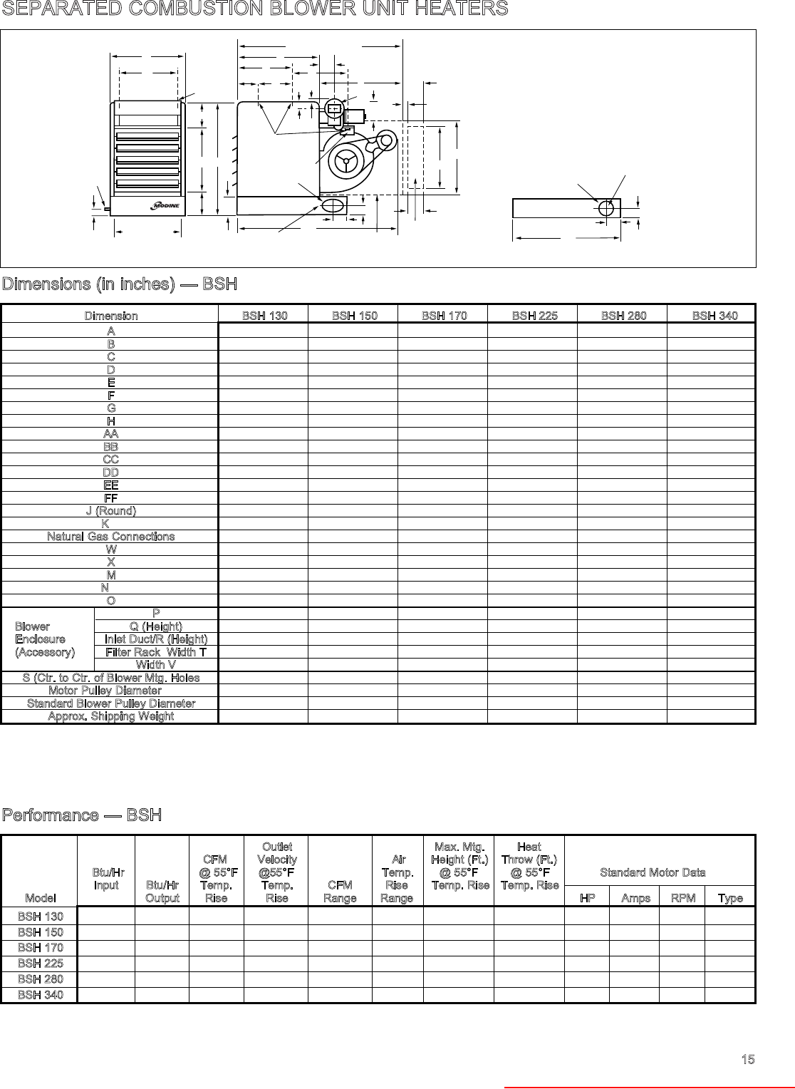
SEPARATED COMBUSTION BLOWER UNIT HEATERS
15
W
X
F
C
G
M
N
S
O
K
/16"
9
5
CC
J
➀ L = C + P (APPROX.)
DD
P
Q x V
R x T
/8"
7
4
/4"
3
FILTER RACK
(OPTIONAL)
BLOWER
ENCLOSURE
(OPTIONAL)
OVAL COLLAR FITS
6" ROUND PIPE FOR
MODELS BSH 280 & 340 ONLY
A
H
D (OPENING)
BB
E
AA
B
K
➁
GAS SUPPLY
CONNECTION
27/8"
FF
/16 "
9
5
/2"
1
4
/8"
1
3
COMBUSTION AIR
INLET COLLAR
(SIZES 130-225)
COMBUSTION AIR
INLET COLLAR
(SIZES 130 - 225) 33/8"
31/8"
EE
4" ROUND FOR
BSH 130 thru 225
MODELS ONLY
The minimum recommended
installation clearance from top and
rear of unit (motor) is six inches.
Clearance to sides is eighteen
inches, and clearance at bottom
should equal “C” dimension shown
in table for each model.
Dimensions (in inches) — BSH
Dimension BSH 130 BSH 150 BSH 170 BSH 225 BSH 280 BSH 340
A23-1/2 25-5/8 25-5/8 25-5/8 33-5/8 40
B35-1/2 40-1/2 40-1/2 40-1/2 40-1/2 40-1/2
C22 25 25 25 25 25
D21-1/16 23-3/16 23-3/16 26-3/16 31-3/16 37-1/2
E20 24 24 24 24 24
F12-1/2 14-1/2 14-1/2 14-1/2 — —
G1 2 2 2 1-5/8 1-5/8
H19-7/8 22 22 25 30 36-3/8
AA 8 9 9 9 9 9
BB 7-1/2 7-1/2 7-1/2 7-1/2 7-1/2 7-1/2
CC 1 1/8 1/8 1/8 1 3/8 1 3/8
DD 3-1/4 3-1/4 3-1/4 3-1/4 3-5/8 3-5/8
EE 32-9/16 36 36 36 36-1/16 36-1/16
FF 6-1/2 6-1/2 6-1/2 6-1/2 5-7/8 5-7/8
J (Round) 4 4 4 4 6 6
K➂3/8-16 3/8-16 3/8-16 3/8-16 3/8-16 3/8-16
Natural Gas Connections 1/2 1/2 1/2 1/2 3/4 3/4
W— — — — 5 5
X— — — — 16 16
M47-3/4 52-3/8 52-3/8 52-3/8 52-3/8 58-1/2
N➃21 24-1/2 24-1/2 24-1/2 17-15/16 22-1/16
O7-1/4 8-1/2 8-1/2 8-1/2 8-1/2 8-1/2
P30 34 34 34 36 36
Blower Q (Height) 21-3/8 25 25 25 25 25
Enclosure Inlet Duct/R (Height) 20 23-3/4 23-5/8 23-5/8 23-5/8 23-5/8
(Accessory) Filter Rack Width T 27-1/2 32-3/4 32-3/4 32-3/4 42-7/8 42-7/8
Width V 29 34 34 34 44-1/4 44-1/4
S (Ctr. to Ctr. of Blower Mtg. Holes 17-3/8 20-3/8 20-3/8 20-3/8 20-3/8 20-3/8
Motor Pulley Diameter ➄3 3 3 3 3 3
Standard Blower Pulley Diameter 13 13 13 13 9 9
Approx. Shipping Weight 240 322 322 344 436 510
➀On blower units L = C + P is distance from front of unit to back of blower enclosure and minimum of distance to wall.
➁Dimension from rear of unit burner box to center line of gas pipe connection is 6-23/32" for BSH 130 and 6-1/2" for all other models.
➂BSH 130 through BSH 225 – 4 holes. BSH 280 and BSH 340 – 6 holes.
➃Distance between mounting hole in unit casing and mounting hole on blower, except on 280 and 340, then distance from rear mounting hole in casing.
➄Motor pulley is adjustable.
➅At 65°F ambient and unit fired at full rated input. Max mounting height as measured from bottom of unit, and without deflector hoods.
➆Note: Ratings shown are for elevations up to 2,000 feet. For elevations above 2,000 feet, ratings should be reduced at the rate of 4% for each 1,000 feet above sea
level. (In Canada see Rating Plate.) Reduction of ratings requires use of high altitude kit.
➇Data listed is for standard 115-volt, 60-Hertz, single-phase motors. All single phase motors are totally enclosed and thermal overload protected.
Performance — BSH
Outlet Max. Mtg. Heat
CFM Velocity Air Height (Ft.) Throw (Ft.)
Btu/Hr @ 55°F @55°F Temp. @ 55°F @ 55°F Standard Motor Data ➇
Input Btu/Hr Temp. Temp. CFM Rise Temp. Rise Temp. Rise
Model ➆Output Rise Rise Range Range ➅ ➅ HP Amps RPM Type
BSH 130 130,000 106,600 1795 682 1161-1795 55-85 11 30 1/4 5.4 1725 SP
BSH 150 150,000 123,000 2071 596 1340-2071 55-85 10 25 1/2 7.8 1725 SP
BSH 170 170,000 139,400 2347 675 1519-2347 55085 11 30 1/2 7.8 1725 SP
BSH 225 225,000 182,250 3068 781 1985-3068 55-85 13 35 3/4 10.2 1725 SP
BSH 280 280,000 229,600 3865 852 2501-3865 55-85 14 40 1 13.2 1725 CP
BSH 340 340,000 275,400 4636 869 3000-4636 55-85 15 40 1 13.2 1725 CP
Note: Mounting heights and throws for BSH models, without ductwork or nozzles, and at a cfm yielding a 55°F
temperature rise are the same as those listed for equivalent size PSH units.
Heater Parts from ACF Greenhouses

0.0 Static Pressure 0.1 Static Pressure 0.2 Static Pressure 0.3 Static Pressure 0.4 Static Pressure
Air Outlet Air Pulley Pulley Pulley
Model Flow
Velocity
Temp. RPM Drive Turns RPM Drive Turns RPM Drive Turns RPM
Number CFM FPM Rise F ➄HP No. Open ➄HP No. Open ➄HP No. Open ➄HP
1795 682 55 385 0 460 1 520 1 570 —
1645 630 60 355 1 435 1/3 -57 2 500 1-1/2 550 1/2 -96 3
1519 587 65 325 2 415 2-1/2 480 2 535
BSH 1410 549 70 305 1/4 -21 3 395 3 465 1/3 -15 2-1/2 520 1/3
130 1316 517 75 285 3-1/2 380 0 450 3 510
1234 489 80 270 4-1/2 365 1/4 -21 1/2 440 3 500
1161 464 85 250 5 350 1-1/2 430 3-1/2 490
2071 596 55 255 1/2 -25 5 330 2 390 0 445
1898 551 60 235 — — — 310 3 375 1/2 430
1752 513 65 220 — — — 295 3-1/2 360 1 415 1/2
BSH 1627 480 70 205 — — — 280 1/2 -25 4 245 1/2 -25 1-1/2 405
150 1519 452 75 190 — — — 270 4-1/2 335 2 395
1424 427 80 180 — — — 260 4-1/2 325 2 390 1/2
1340 405 85 170 — — — 250 5 315 2-1/2 380
2347 675 55 290 3-1/2 360 1 420 1/2 -22 1 470 3/4
2151 624 60 265 1/2 -25 4-1/2 335 2 400 1-1/2 455
1986 581 65 245 5 305 2-1/2 385 0 440
BSH 1844 544 70 230 — — — 290 1/2 -25 3 370 1/2 425
170 1721 512 75 215 — — — 280 3-1/2 355 1/2 -25 1 415
1613 484 80 200 — — — 270 4 345 1-1/2 405 1/2
1519 459 85 190 — — — 250 4-1/2 335 2 395
3068 781 55 385 0 440 3/4 -22 1/2 490 1-1/2 535
2813 722 60 345 1-1/2 415 1 465 2-1/2 510
2596 672 65 315 3/4 -25 2-1/2 390 0 440 3/4 -18 3 485
BSH 2411 630 70 285 3-1/2 365 3/4 -25 1/2 420 3-1/2 470 3/4
225 2250 592 75 260 4-1/2 350 1 405 4 455
2109 560 80 240 — — — 330 2 390 3/4 -25 0 440
1985 531 85 220 — — — 315 2-1/2 375 1/2 425
3865 725 55 530 1/2 575
1-1/2
-23 3-
1/2
615
1-1/2
-23 2-1/2 645
3543 670 60 490 1-1/2 535 1/2 580 3-1/2 615
1-1/2
3271 624 65 450 3 500 1-1/2 545 1/2 585
BSH 3037 584 70 420 1 -18 3-1/2 470 2-1/2 520 1 565
280 2835 550 75 395 4 445 1 -18 3 495 1 -18 1-1/2 540 1
2657 519 80 370 5 425 3-1/2 475 2 525
2501 493 85 350 — — — 405 4 455 2-1/2 510
4636 869 55 610
1-1/2
-16 1/2 655 2 -32 1 690 2 -32 0 725 —
4250 804 60 550 0 605
1-1/2
-16 1/2 645 1-1/2 685 2
3923 748 65 500 1-1/2 560 0 605
1-1/2
-16 1/2 645
BSH 3643 701 70 460 2-1/2 525 1 575 1 615
340 3400 659 75 420 1 -219 3-1/2 490 1 -219 1-1/2 545 1/2 590
1-1/2
3188 623 80 390 4-1/2 465 2-1/2 520 1 -219 1 570
3000 591 85 360 5 440 3 500 1-1/2 550 1
From this Catalog For 575V➇
HP Drive HP Drive
BSH130 1/3 -13 1/3 -14
1/4 -21 1/4 -165
1/3 -15 1/3 -166
1/3 -57 1/4 -167
BSH280 1-1/2 -23 1-1/2 -177
BSH340 1-1/2 -16 1-1/2 -178
16
PERFORMANCE DATA — BLOWER UNIT HEATERS
Blower Models With or Without Blower Enclosures ➀ ➁ ➃ ➄
Important: Note for 575V Only➆
Pulley Pulley
Drive Turns RPM Drive Turns
No. Open ➄HP No. Open
— — 620 2
605 1/2 -96 2
1/2 590 2.5
-15 1 580 2.5
1 570 1/3 -13 1-1/2
1-1/2 560 1-1/2
2 550 2
0 500 3/4 -18 1-1/2
1/2 485 2
-22 1 475 2
1-1/2 470 2
2 460 2-1/2
-25 0 455 1/2 -22 0
0 450 0
-18 2 520 1
0 505 1-1/2
1/2 495 3/4 -18 1-1/2
1 485 2
1 475 2
-22 1-1/2 465 2-1/2
2 460 1/2 -22 0
1/2 575 1 -16 1
1 555 0
2 535 1/2
-18 2-1/2 520 1
2-1/2 510 3/4 -18 1
3 495 1-1/2
3-1/2 485 2
1-1/2 670
1-1/2
-23 1/2
-23 2-1/2 640 1-1/2
3-1/2 620 2
0 595 1 -16 1/2
-18 1/2 580 1
1 560 1 -18 0
1 545 1/2
— — 750 — — —
-32 0 710 — — —
1-1/2 680 2 -32 0
0 650 1
-16 1 625 0
1-1/2 605
1-1/2
-16 1/2
-219 0 585 1
➀Shaded area indicates unit standard motor and drive range.
➁For unit operation in non-shaded area; specify on order optional motor and drive number.
➂Ratings shown are for elevations up to 2,000 feet. For elevations above 2,000 feet, ratings should be reduced at the rate of 4% for each 1,000 feet above sea level.
(Does not apply in Canada — See Rating Plate.)
➃Pulley turns open are approximate. For proper operation, check blower rpm.
➄Rpm and pulley settings shown in bold type, in shaded areas for 0.0 static pressure, indicate factory settings of standard drives.
➆Models not shown use same HP and drive number as cataloged.
➇Performance is the same; motor sheave can accommodate larger shaft.
Model
Number
Heater Parts from ACF Greenhouses

0.0 Static Pressure 0.1 Static Pressure 0.2 Static Pressure 0.3 Static Pressure 0.4 Static Pressure
Air Outlet Air Pulley Pulley Pulley
Model Flow
Velocity
Temp. RPM Drive Turns RPM Drive Turns RPM Drive Turns RPM
Number CFM FPM Rise F ➄HP No. Open ➄HP No. Open ➄HP No. Open ➄HP
1795 682 55 445 1/3 -57 1-1/2 520 1/3 -15 1 575 — — — 615 —
1645 630 60 410 2-1/2 485 1/2 545 1/2 595 —
1519 587 65 375 1/2 460 1 520 1 575 —
BSH 1410 549 70 345 1-1/2 435 1/3 -57 2 500 1/3 -15 1-1/2 560
130 1316 517 75 325 1/4 -21 2 415 2-1/2 480 2 545
1234 489 80 300 3 395 3 460 2-1/2 535 1/3
1161 464 85 285 3-1/2 380 1/4 -21 0 450 3 525
2071 596 55 285 1/2 -25 3-1/2 350 1 415 1/2 -22 1 460
1898 551 60 260 4-1/2 325 2 395 2 445
1752 513 65 235 — — — 305 3 380 0 430 1/2
BSH 1627 480 70 220 — — — 290 1/2 -25 3-1/2 365 1/2 420
150 1519 452 75 205 — — — 280 4 355 1/2 -25 1 405
1424 427 80 190 — — — 265 4 1/2 345 1-1/2 400
1340 405 85 180 — — — 255 5 335 2 390 1/2
2347 675 55 325 2 385 0 445 0 490 3/4
2151 624 60 295 1/2 -25 3-1/2 360 1 425 1/2 -22 1 470
1986 581 65 270 4-1/2 340 1-1/2 405 1-1/2 455
BSH 1844 544 70 250 5 320 1/2 -25 2-1/2 390 0 440
170 1721 512 75 235 — — — 305 3 375 1/2 -25 1/2 425 1/2
1613 484 80 215 — — — 290 3-1/2 365 1/2 415
1519 459 85 205 — — — 275 4 355 1 405
3068 781 55 465 3/4 -18 2 1/2 515 1 550 0 600 1
2813 722 60 420 3 1/2 485 2 515 1 565
2596 672 65 385 0 455 2-1/2 490 1 1/2 540
BSH 2411 630 70 350 1 430 3/4 -18 3-1/2 465 3/4 -18 2 1/2 515
225 2250 592 75 325 3/4 -25 2 410 4 440 3 495 3/4
2109 560 80 300 3 390 4-1/2 425 3-1/2 480
1985 531 85 280 4 375 3/4 -25 1/2 405 4 465
3865 725 55 595
1-1/2
-23 3 645 1-1/2 680
1-1/2
-23 0 705 —
3543 670 60 545 1/2 600
1-1/2
-23 3 640 1-1/2 665
1-1/2
3271 624 65 505 1 1/2 565 4 605 1 -16 1/2 635
BSH 3037 584 70 470 2 1/2 530 1/2 575 1 610
280 2835 550 75 440 1 -18 3 500 1 -18 1-1/2 550 0 585 1
2657 519 80 415 3 1/2 475 2 525 1 -18 1 565
2501 493 85 390 4 1/2 455 2-1/2 505 1-1/2 545 1
4636 869 55 685 2 -32 0 715 — — — 740 — — — 765 —
4250 804 60 615
1-1/2
-16 0 655 2 -32 1 685 2 -32 0 720 —
3923 748 65 560 0 605
1-1/2
-16 1/2 640 1-1/2 680 2
BSH 3643 701 70 515 1 560 0 600
1-1/2
-16 1/2 645
340 3400 659 75 470 1 -219 2 525 1 -219 1 570 1-1/2 615
3188 623 80 435 3 490 1-1/2 540 1 -219 1/2 590
1-1/2
3000 591 85 405 4 465 2-1/2 515 1 565
17
Blower Models With Filter ➀ ➁ ➃ ➄ ➅
➀Shaded area indicates unit standard motor and drive range.
➁For unit operation in non-shaded area; specify on order optional motor and drive number.
➂Ratings shown are for elevations up to 2,000 feet. For elevations above 2,000 feet, ratings should be reduced at the rate of 4% for each 1,000 feet above sea
level. (Does not apply in Canada — See Rating Plate.)
➃Pulley turns open are approximate. For proper operation, check blower rpm.
➄Rpm and pulley settings shown in bold type, in shaded areas for 0.0 static pressure on page 10, indicate factory settings of standard drives.
➅Blower models with filter require the use of a blower enclosure.
Pulley Pulley
Drive Turns RPM Drive Turns
No. Open ➄HP No. Open
— — 660 — — —
— — 640 — — —
— — 625 2
0 610 1/2 -96 2
1/2 600 2
-15 1/2 585 1/3 -13 1
1 575 1
0 530 1/2
0 515 1
-22 1/2 505 1-1/2
1 495 3/4 -18 1-1/2
1-1/2 485 2
1 -1/2 480 2
-25 0 475 2
-18 1-1/2 550 0
2 535 1/2
0 520 3/4 -18 1
1/2 510 1
-22 1 500 1-1/2
1 495 1-1/2
1-1/2 485 2
-16 1/2 635 0
1-1/2 610 1 -16 1/2
1/2 590 1
1 575 1
-18 1-1/2 560 0
2 545 3/4 -18 1/2
2-1/4 535 1/2
— — 725 — — —
-23 1/2 690 0
1-1/2 660
1-1/2
-23 1
1/2 635 1-1/2
-16 1 615 0
1-1/2 595 1 -16 1/2
-18 1/2 580 1
— — 795 — — —
— — 745 — — —
-32 0 705 — — —
1-1/2 670 2 -32 1/2
0 640 1-1/2
-16 1 615
1-1/2
-16 0
1-1/2 595 1/2
From this Catalog For 575V➇
HP Drive HP Drive
BSH130 1/3 -13 1/3 -14
1/4 -21 1/4 -165
1/3 -15 1/3 -166
1/3 -57 1/4 -167
BSH280 1-1/2 -23 1-1/2 -177
BSH340 1-1/2 -16 1-1/2 -178
Important: Note for 575V Only➆
➆Models not shown use same HP and drive number as cataloged.
➇Performance is the same; motor sheave can accommodate larger shaft.
Model
Number
Heater Parts from ACF Greenhouses

18
MOTOR DATA
Power Code Description — PSH Models ➀ ➂ ➃
Model PSH130 PSH150 PSH170 PSH225 PSH280 PSH340
Power Electric
Code Power Horsepower
01 115/60/1 1/6 1/6 1/6 1/3 1/2 1/2
02230/60/1 1/6 1/6 1/6 1/3 1/2 1/2
04200/60/3 1/3 1/3 1/3 1/3 1/2 1/2
05200/460/60/3 1/3 1/3 1/3 1/3 1/2 1/2
Power Code Description — BSH Models ➁ ➂ ➃ ➄
Power Model BSH130 BSH150 BSH170 BSH225 BSH280 BSH340
Code Electric Power HP Drive HP Drive HP Drive HP Drive HP Drive HP Drive
01 115/60/1 1/3 -13 3/4 -18 3/4 -18 3/4 -18 1 -16 1-1/2 -16
02230/60/1 1/3 -13 3/4 -18 3/4 -18 3/4 -18 1 -16 1-1/2 -16
03200-208/60/3 1/3 -13 3/4 -18 3/4 -18 3/4 -18 1 -16 1-1/2 -16
04230/460/60/3 1/3 -13 3/4 -18 3/4 -18 3/4 -18 1 -16 1-1/2 -16
81575/60/3 1/3 -14 3/4 -18 3/4 -18 3/4 -18 1 -16 1-1/2 -178
05115/60/1 1/4 -21 1/2 -25 1/2 -25 3/4 -22 1 -18 1 -29
06230/60/1 1/4 -21 1/2 -25 1/2 -25 3/4 -22 1 -18 1 -29
07200-208/60/3 1/4 -21 1/2 -25 1/2 -25 3/4 -22 1 -18 1 -29
08230/460/60/3 1/4 -21 1/2 -25 1/2 -25 3/4 -22 1 -18 1 -29
82575/60/3 1/4 -165 1/2 -25 1/2 -25 3/4 -22 1 -18 1 -29
09115/60/1 1/3 -15 1/2 -22 1/2 -22 1 -16 1-1/2 -23
10230/60/1 1/3 -15 1/2 -22 1/2 -22 1 -16 1-1/2 -23
11200-208/60/3 1/3 -15 1/2 -22 1/2 -22 1 -16 1-1/2 -23 2 -32
12230/460/60/3 1/3 -15 1/2 -22 1/2 -22 1 -16 1-1/2 -23 2 -32
83575/60/3 1/3 -166 1/2 -22 1/2 -22 1 -16 1-1/2 -177 2 -32
13115/60/1 1/3 -57 3/4 -25
14230/60/1 1/3 -57 3/4 -25
15200-208/60/3 1/3 -57 3/4 -25
16200/460/60/3 1/3 -57 3/4 -25
84575/60/3 1/3 -167 3/4 -25
Motor Data and Total Unit Power Requirements — PSH Models
Voltage 115/60/1 230/60/1 200-208/60/3 230/460/3
Motor Motor Total Total Motor Motor Total Total Motor Motor Total Total Motor Motor Total Total
HP Amps Rpm Amps Watts Amps Rpm Amps Watts Amps Rpm Amps Watts Amps Rpm Amps Watts
1/6 2.8 1075 4.6 400 1.5 1075 2.5 400
1/3 5.4 1075 7.2 610 2.5 1075 3.5 610 1.9 1140 2.8 560 2.2/1.1 1140 3.2/1.6 560
1/2 7.5 1075 9.3 800 3.5 1075 4.5 800 2.6 1140 3.5 850 3.0/1.5 1140 4.0/2.0 850
Unit Power Requirements - Blower BSH Models
115/60/1 230/60/1 200-208/60/3 230/460/60/3 575/60/3 ➄
Total Total Total Total Total Total Total Total Total Total
HP Amps Watts Amps Watts Amps Watts Amps Watts Amps Watts
1/4 7.2 520 3.7 520 2.5 500 2.4/1.2 500 0.9 500
1/3 6.4 515 3.3 515 2.7 530 2.6/1.3 530 1.1 530
1/2 10.3 730 4.8 730 3.4 730 3.6/1.8 730 1.3 730
3/4 12.8 1000 6.5 1000 4.1 970 3.8/1.9 970 1.5 970
1 15.2 1210 7.7 1210 4.9 1230 4.8/2.4 1230 1.9 1230
1-1/2 16.8 1690 8.5 1690 6.5 1630 6.2/3.1 1630 2.3 1630
2 - - - - 8.6 2080 7.6/3.8 2080 2.7 2080
➀Permanent split capacitor motors on models PSH130 through PSH340.
➁Split phase motors for 1/4 through 3/4 hp motors. Capacitor start motors are 1 through 2 hp.
➂Whenever 230V/1
φ
or 230V/3
φ
power is used, it is necessary to specify 230V/25V controls. Whenever 460V/3
φ
power is used, it is necessary to specify 230V/25V
controls and in addition, a 460V/230V 75VA step-down transformer (by others) is required. On 230V/3
φ
or 460V/3
φ
systems, the motor starter coil voltage (motor
starter by others) must be 230V. For 200V/3
φ
systems, the motor starter coil voltage (motor starter by others) must be 200V.
➃All motors used are produced, rated and tested by reputable manufacturers in accordance with NEMA standards and carry the standard warranty of both the motor
manufacturer and Modine. All motors are totally enclosed. Single phase motors have built-in thermal overload protection.
➄575V motor available on blower units only.
Voltage
Heater Parts from ACF Greenhouses

19
CONTROL OPTIONS
Control
Code Service Thermostat Type of
Control System Description No. Voltage Voltage Gas
Single-Stage, Intermittent Pilot Ignition, 100% Shut-off with Continuous Retry — 30 115V 25V natural
Utilizes a single-stage combination gas control and an ignition control (continuous retry). 31 200-208/230V 25V natural
Pilot is automatically lit on call for heat. ➂ 32 460V 25V natural
➂ ➃ 33 575V 25V natural
85 115V 25V propane
86 200-208/230V 25V propane
➂ 93 460v 25V propane
➂ ➃ 94 575v 25V propane
Propeller and Blower Unit Heaters — PSH and BSH Models ➀ ➁ ➂ ➃
Control Operating Sequence
Upon a call for heat from the thermostat, power is supplied to
the time delay relay for the power exhauster motor. The power
exhauster motor will come on in 1 to 25 seconds. In 45 to 90
seconds (from the call for heat) the ignition control will be turned
on. This delay allows for a pre-purge of the unit and the vent.
Sparking will start at the igniter at the same time the first
operator of the combination gas control opens to allow ga to
flow to the pilot burner. The pilot flame should light and be
sensed (proven) in a few seconds. As soon as the pilot flame is
sensed the sparking will stop and the second operator of the
combination gas control will open to allow gas to flow to the
main burner. In 10 to 45 seconds from the time the ignition
control was energized (1 to 2 minutes from the call for heat from
the thermostat) the fan motor will start.
On units with control codes 08 and 09, when the ignition control
is turned on it will attempt to light the pilot flame. If the pilot
flame is not sensed for any reason, the sparking will continue
indefinitely until the pilot flame is sensed or until power is
interrupted to the ignition control. On units with control codes
30, 31, 85 and 86, the sequence is similar, except that when the
ignition control is turned on it will attempt to light the pilot
flame for 70 seconds. If the pilot flame is not sensed for any
reason, the ignition control will wait for a predetermined time
with the combination gas control closed and no sparking.
After the pre-determined time lapses, the cycle will begin
again. The time that lapses between cycles is at
preprogrammed intervals (approximately 6 minutes). This will
continue indefinitely until the pilot flame is sensed or until
power is interrupted to the ignition control.
When the thermostat has been satisfied, power is turned off
to the ignition control (and therefore the combination gas
control), so both the main gas and pilot gas are turned off.
The fan motor will continue to operate for 20 to 60 seconds to
allow the heat exchanger to cool down. Finally, the power
exhauster motor is turned off 1 to 2 minutes after the
thermostat is satisfied. This allows the products of
combustion to be cleared from the unit and the vent. The
system is now ready for another call for heat from the
thermostat.
➀Shaded prices - Standard units in stock; all others 2-3 weeks delivery.
➁Stainless steel burner option - see page 5 for part number and list price.
➂CGA approved 460V and 575V aviailable on blower units only.
➃575V motor available on blower units only.
13 A43 8 0.750 1.9/2.9 0.500 25 A58 13 1.000 1.9/2.9 0.625
14 A44 8 0.750 1.9/2.9 0.625 32 A55 11 1.000 3.4/4.4 0.875
15 A44 9 0.750 1.9/2.9 0.500 57 A46 10 0.750 1.9/2.9 0.500
16 A48 8 1.000 1.9/2.9 0.625 165 A53 13 0.750 1.9/2.9 0.625
18 A49 9 1.000 1.9/2.9 0.625 166 A45 9 0.750 1.9/2.9 0.625
21 A52 13 0.750 1.9/2.9 0.500 167 A47 10 0.750 1.9/2.9 0.625
22 A53 11 1.000 1.9/2.9 0.625 177 A56 11 1.000 3.4/4.4 0.875
23 A56 11 1.000 3.4/4.4 0.625 178 A48 8 1.000 1.9/2.9 0.875
Sheave
Drive
No.
Belt No.
Browning
Blower Sheave Motor
Pitch Dia. Bore Bore
Sheave
Drive
No.
Belt No.
Browning
Blower Sheave Motor
Pitch Dia. Bore
Min/Max
Pitch Dia. Bore
Min/Max
Pitch Dia.
MOTOR DATA
Blower Drive Numbers
Heater Parts from ACF Greenhouses

Mounting 30°
Height to Downward
Bottom Deflector
of Heater Hood Propeller Models➀ (See Figures A and B)
Model PSH 130 PSH 150 PSH 170 PSH 225 PSH 280 PSH 340
X Y Z X Y Z X Y Z X Y Z X Y Z X Y Z
8' 21 44 60 19 39 53 17 37 50 26 53 73 21 43 59 22 46 62
10' 20 43 59 17 38 52 16 35 48 25 53 72 20 42 58 21 56 61
12' 19 42 58 16 37 50 15 34 46 24 52 70 18 41 56 10 43 59
14' 18 41 56 15 35 48 13 32 44 23 50 69 17 39 65 18 42 57
16' 16 38 53 13 32 44 11 28 39 21 49 67 15 37 51 17 40 55
18' 14 36 50 10 28 39 7 20 29 20 47 64 14 34 47 15 37 52
20' 21 31 44 8 23 33 — 18 44 61 11 29 41 13 33 47
22' 8 24 35 — — 16 41 58 8 23 34 8 24 36
Mounting 60°
Height to Downward
Bottom Deflector
of Heater Hood Propeller Models➀ (See Figures A and B)
Model PSH 130 PSH 150 PSH 170 PSH 225 PSH 280 PSH 340
X Y Z X Y Z X Y Z X Y Z X Y Z X Y Z
8' 0 47 65 0 42 57 0 39 54 0 57 78 0 46 63 0 49 66
10' 0 46 63 0 40 55 0 37 50 0 56 76 0 44 61 0 47 64
12' 0 44 60 0 38 52 0 34 47 0 54 74 0 43 58 0 45 62
14' 0 42 57 0 35 48 0 31 43 0 52 72 0 40 55 0 43 59
16' 0 39 53 0 31 43 0 27 37 0 50 69 0 37 51 0 40 55
18' 0 35 48 0 25 35 0 17 23 0 47 65 0 33 45 0 36 50
20' 0 29 40 0 19 27 — 0 44 60 0 26 36 0 31 43
22' 0 16 23 — — 0 39 54 0 19 26 0 21 29
Mounting 90°
Height to Downward
Bottom Deflector
of Heater Hood Propeller Models➀ (See Figures C and D)
Model PSH 130 PSH 150 PSH 170 PSH 225 PSH 280 PSH 340
SSSSSS
8' 56 50 46 77 59 65
10' 50 45 41 69 53 59
12' 46 41 37 63 48 53
14' 43 38 35 58 45 50
16' 40 35 32 54 42 46
18' 38 33 31 51 40 44
20' 36 32 29 49 38 42
22' 34 30 28 46 36 40
24' 45 34 38
30°, 60° and 90° Downward Deflector Hoods - Propeller PSH Models
➀Data based on units fired at full input rate and with an entering air temperature of 80° F.
30° and 60° Deflector Hoods — Propeller and Blower Models
Figure A
30° Hood 60° Hood
Figure B — Throw/Floor Coverage
Note:
O-X = Feet from heater to start of floor coverage.
O-Y = Feet to end of floor coverage.
O-Z = Feet to end of throw.
MOUNTING
HEIGHT
XY
Y
Z
Z
X
60 NOZZLE
30 NOZZLE
60
30
30 DOWNTURN NOZZLE
60 DOWNTURN NOZZLE
20
PERFORMANCE DATA
Heater Parts from ACF Greenhouses

PERFORMANCE DATA
90° Downward Deflector Hood — Propeller and Blower Models
Figure C
90° Hood
Figure D
H
S
S
21
30°, 60° and 90° Downward Deflector Hoods - Propeller BSH Models
Mounting 30°
Height to Downward
Bottom Deflector
of Heater Hood Propeller Models➀ (See Figures A and B)
Model BSH 130 BSH 150 BSH 170 BSH 225 BSH 280 BSH 340
X Y Z X Y Z X Y Z X Y Z X Y Z X Y Z
8' 11 25 34 9 22 30 11 25 35 14 31 43 16 35 48 17 37 50
10' 9 22 31 8 19 26 10 23 32 13 30 41 15 34 44 15 34 48
12' 7 19 26 6 16 23 8 20 28 12 28 38 14 32 44 15 34 46
14' 5 15 21 4 13 19 6 16 23 10 24 34 12 29 41 13 23 44
16' — — — 8 22 31 10 25 36 11 28 40
18' — — — 6 18 26 8 22 31 10 26 36
20' — — — — — 7 20 29
Mounting 60°
Height to Downward
Bottom Deflector
of Heater Hood Propeller Models➀ (See Figures A and B)
Model BSH 130 BSH 150 BSH 170 BSH 225 BSH 280 BSH 340
X Y Z X Y Z X Y Z X Y Z X Y Z X Y Z
8' 0 25 35 0 22 30 0 26 36 0 33 45 0 37 50 0 39 53
10' 0 22 30 0 18 25 0 23 32 0 31 42 0 35 48 0 37 51
12' 0 17 23 0 9 13 0 18 25 0 27 38 0 32 44 0 35 47
14' 0 10 14 — 0 13 19 0 23 32 0 29 40 0 31 43
16' — — — 0 12 17 0 23 32 0 27 37
18' — — — — 0 18 26 0 17 24
20' — — — — 0 13 19 0 14 19
Mounting 90°
Height to Downward
Bottom Deflector
of Heater Hood Propeller Models➀ (See Figures C and D)
Model BSH 130 BSH 150 BSH 170 BSH 225 BSH 280 BSH 340
SSSSSS
8' 26 23 28 32 35 37
10' 25 22 27 31 34 36
12' 24 21 26 30 33 35
14' 23 20 25 29 32 34
16' 22 19 24 28 31 33
18' 21 18 23 27 30 32
20' 20 — 22 26 29 31
22' — — 21 25 28 30
24' — — — 24 27 29
26 — — — — 26 28
28' — — — — 26 27
➀Data based on units fired at full input rate and with an entering air temperature of 80° F.
Heater Parts from ACF Greenhouses

22
PERFORMANCE DATA
H
T
S
Nozzles - Performance
A choice of four air discharge
nozzles accommodate various
heat throw patterns illustrated.
Equipped with adjustable louver
blades, nozzles are fabricated
from galvanized steel and are
offered either unpainted or
painted to match the finish of the
blower unit heaters. Nozzles are
flanged for easy attachment over
the air discharge opening of the
blower unit heater.
H
SS
H
T
S
T
S
S
H
40° Downward Nozzle
40° Splitter Nozzle
90° Vertical Nozzle
5-Way Nozzle
Nozzle Performance Mounting Height, Heat Throw, Heat Spread (in feet)
Nozzle Model Number
Type BSH 130 BSH 150 BSH 170 BSH 225 BSH 280 BSH 340
40° ✝Max. Mounting Ht. (ft.) 20 21 24 24 26 28
Downward Heat Throw (ft.) 58 62 71 71 79 83
Nozzle Heat Spread (ft.) 20 21 24 24 26 28
90° ✝Max. Mounting Ht. (ft.) 20 18 21 24 26 27
Vertical Nozzle Heat Spread (ft.) 20 18 21 24 26 27
40° ✝Max. Mounting Ht. (ft.) 18 18 20 21 25 28
Splitter Heat Throw (ft.) 45 45 51 53 62 69
Nozzle Heat Spread (ft.) 90 90 102 106 123 137
5-Way ✝Max. Mounting Ht. (ft.) 16 16 18 20 19 23
Nozzle Heat Spread (ft.) 22 22 25 27 26 31
The above table is based on an inlet air temperature of 70°F and an air temperature rise of 55°F. Air deflectors on 40° and 90° discharge nozzles set perpendicular to the
face of the air discharge opening. On 5-way nozzles, bottom air deflectors set perpendicular to floor, all other deflectors at 30° to floor. Static pressure measured at 0.1 W.
C. for 90° nozzle 0.2 W. C. for 40° downward and 5-way nozzle and 0.3 W. C. for 40° splitter nozzle. Outlet velocities are approximately 1850 fpm for the 40° nozzle, 900
fpm for the 90° nozzle and 900 fpm for 5-way nozzle. For motor size, drive and blower rpm refer to pages 10 and 11. Mounting Height measured from bottom of unit.
Heater Parts from ACF Greenhouses

23
DIMENSIONAL DATA
40° Downward Nozzle 40° Splitter Nozzle
40° Vertical Nozzle 5-Way Nozzle
Dimensions (in feet)
Nozzle Dimension Model Number
Type Symbol BSH 130 BSH 150 BSH 170 BSH 225 BSH 280 BSH 340
A 21-1/16 23-3/16 23-3/16 26-3/16 31-1/8 37-1/2
B 20 24 24 24 24 24
C 25 30 30 30 36 36
D 4 4 4 6 11 11
A 21-1/16 23-3/16 23-3/16 26-3/16 31-1/8 37-1/2
B 20 24 24 24 24 24
C 23 29 29 30 34 34
D 8 10 10 10 14 14
A 21-1/16 23-3/16 23-3/16 26-3/16 31-1/8 37-1/2
B 20 24 24 24 24 24
C 33-1/2 39 39 40 46 47
D 11 12 12 14 19 20-1/2
A 21 23-3/16 23-3/16 26-3/16 31-1/8 37-1/2
B 20 24 24 24 24 24
C 27 29 29 32 37 43-1/2
D 14 15 15 16 18 18
40°
Downward
Nozzle
90°
Vertical
Nozzle
40°
Splitter
Nozzle
5-Way
Nozzle
B
C
D
A
/4"
3
B
/4"
3
C
D
B
A
/4"
3
C
D
A
C
B
/4"
3
D
Heater Parts from ACF Greenhouses

SERVICE INSTRUCTIONS — SAFETY DEVICES
Figure 13
Rear View Propeller Type Unit
Limit Control (Overheat Switch)
The limit control, mounted on the left inner side panel (when
facing front of unit), will shut off the gas supply to the main
burner in the event of overheating. It is a single pole single
throw switch. The contacts open to shut the combination gas
control off in the event the unit should overheat. This limit
control should operate only when something is seriously wrong
with the unit. Anytime this control operates, correct the difficulty
immediately or serious damage may result. If the limit control
cuts off the gas supply during normal operation:
1. See that front louvers are open and that there are not any
obstructions in the air inlet or outlet.
2. Check actual input to unit against rated input.
3. Check to be sure fan motor is operating.
4. On propeller unit check that fan is not loose on motor shaft.
On blower unit check belt and sheave for tightness or
damage.
5. On propeller units check fan speed against speed on motor
nameplate. On blower units check blower speed against
Performance Tables on pages 14 and 15; check for
restrictions in ducts and for dirty filters.
6. Check to make sur the venting system and combustion air
piping is not damaged or blocked. Also check to be sure
unit is venting normally.
7. Clean heat exchanger tubes inside and out if necessary.
8. If items 1-7 do not solve the problem, check limit control
and replace if necessary. The control is accessible by
removing the left outer side panel, held in place by screws
at the rear of the unit.
24
PRESSURE SWITCH
SENSING TUBES
PRESSURE
SWITCH
JUNCTION BOX TERMINAL
BOARD
SIDE PANEL
MOUNTING
SCREWS
GAS SUPPLY
CONNECTION
ACCESS PANEL
SIGHT GLASS
FAN
MOTOR
Heater Parts from ACF Greenhouses
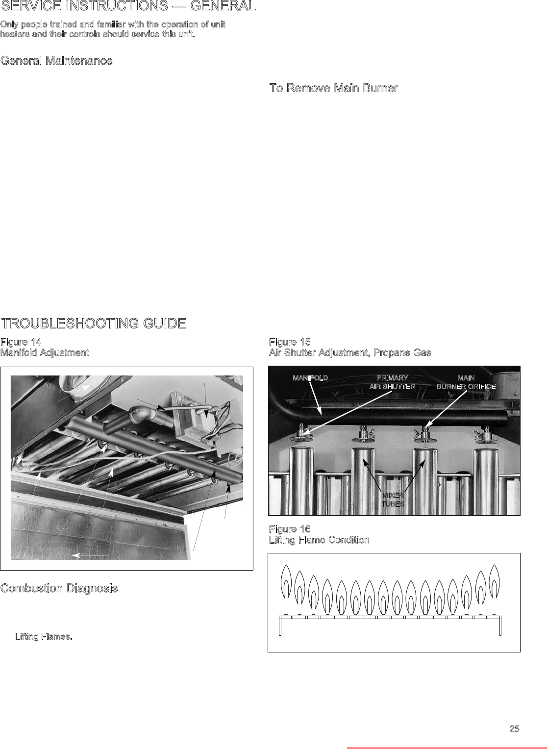
SERVICE INSTRUCTIONS — GENERAL
TROUBLESHOOTING GUIDE
Only people trained and familiar with the operation of unit
heaters and their controls should service this unit.
General Maintenance
1. Service air moving components annually.
a. On propeller units this includes checking motor for
lubrication if motor is not there permanently lubricated
type and check fan for fit on motor shaft and for
damage to blades.
b. On blower units this should include:
(1) checking motor and blower bearings for lubrication
(2) checking belt and sheaves for proper alignment and
adjustment
(3) checking cleanliness of blower wheel and filters
2. Keep unit free from dust, dirt, grease and foreign matter,
paying particular attention to:
a. Combustion air inlet terminal.
b. Main burner ports, pilot burner, an main burner orifices
(avoid use of hard, sharp instruments capable of
damaging surfaces, for cleaning these ports). If air
pressure is available, use air hose to blow dirt and
other foreign matter from within the burner. Also main
burner orifices should be checked for blockage due to
spider webs, etc.
c. Primary air shutters (when used).
d. Clean heat exchanger tubes from bottom with stiff
brush after removing burner. (Do not use wire brush.)
e. Fan blades.
To Remove Main Burner
1. Turn off electricity and gas to unit.
2. Remove access panel (see Figure 13).
3. Remove all fastening screws holding hinged bottom pan in
place and lower bottom pan (see Figure 2).
4. Disconnect pilot tubing and ignition cable from the
combination gas control and ignition control.
5. Remove the two burner retaining pins holding the burner in
place. The burner can then be easily lowered from the unit.
In replacing the burner, be certain that the slots at the front
of the burner are located properly on their shoulder rivets
and that the burner retaining pins are put back into their
proper locations.
Replace bottom pan and access panel, making sure a good
tight seal is achieved along he entire perimeter of both
panels.
Figure 14
Manifold Adjustment
Combustion Diagnosis
To realize full gas heating value requires periodic inspections
with proper combustion control corrections as outlined and
illustrated here.
1. Lifting Flames. Lifting flames rise unevenly above the
burner port and may occur on few or all the ports.
Sometimes the flames drop and lift intermittently. Lifting can
be eliminated by reducing primary air. If flame cannot be
adjusted properly, check input rate to heater and manifold
gas pressure; reduce if necessary. Check the main burner
orifice size with those listed in Table 5 to be sure the unit is
not operating over rated input.
Figure 15
Air Shutter Adjustment, Propane Gas
Figure 16
Lifting Flame Condition
25
MIXER
TUBES
PRIMARY
AIR SHUTTER
MAIN
BURNER ORIFICE
MANIFOLD
COMBUSTION
AIR INLET COLLAR
PILOT
TUBE
MANIFOLD
PILOT AND
IGNITOR
ASSEMBLY
HINGED BOTTOM PAN
MAIN BURNER
ORIFICE
MIXER
TUBES MANIFOLD
MOUNTING
SCREW
IGNITION
CABLE
IGNITION CONTROL
Heater Parts from ACF Greenhouses

26
TROUBLESHOOTING GUIDE
2. Yellow Tipping. Yellow tipping of a normally blue flame is
caused by insufficient primary air, and indicates incomplete
combustion producing carbon monoxide ethylene, aldehyde,
and fee carbon (soot). A dirty orifice or one that is out of
line, can also reduce primary air and cause yellow tipping.
Check main burner orifices, clean, realign, or replace if
necessary. With propane gas, some yellow tipping is always
present, but is not objectionable.
3. Flashback. Flashback occurs when air-gas mixture ignites
inside the mixer tube to burn near the orifice. Flashback on
ignition or during burner operation usually can be eliminated
by reducing primary air. The burner may also be operating
below its rated capacity. Check input rate and adjust to
correct value by increasing orifice size or manifold gas
pressure.
Figure 17
Wavering Flame or Misalignment
4. Wavering Flames. Drafts across burners may cause flames
to appear unstable. Wavering flames can lead to incomplete
combustion if flames impinge on cool surfaces. Wavering
can be caused by air drafts into the burner compartment or
by misalignment of the burner. Draft-blown flames may
indicate a cracked heat exchanger.
Figure 18
Floating Flame Condition
5. Floating Flames. Floating flames are long — do not have
well-defined cones, roll around in the combustion chamber,
sometimes completely off the main burner ports. Usually an
aldehyde odor is present to indicate incomplete combustion.
If combustion air supply is reduced too far, burner flames
will float. Often the pilot flame goes out. Lack of combustion
air causes burner flames to float. The unit may be overfired
so its flue outlet area may be too small for the increased
firing rate. Check input rate and reduce if necessary. Soot or
dust may be blocking the heat exchanger. Check and clear
any blockage. Adjust primary air to get rid of yellow tipping
that may produce soot to block heat exchanger. Make sure
combustion air piping is not blocked.
Intermittent Pilot Ignition Systems
1. Pilot will not light or stay lit.
GOOD BAD
Possible Cause Possible Remedy
1a. No spark at ignitor. 1a. Check connections. Check for proper
spark gap, cracked or broken
electrode ceramic, blown controller
fuse or brittle, cracked or loose high
tension cable. Check power
exhauster pressure switch. Replace if
defective.
1b. Defective flame 1b. Check mili-amps of sensor. Tighten
sensor or loose loose connections. Replace flame
connections to sensor if necessary.
flame sensor.
1c. Pilot valve electrical 1c. Tighten connections.
connections loose.
1d. Defective pilot valve. 1d. Replace.
1e. Poor ground 1e. Check grounding means.
connections.
1f. No power from 1f. Check transformer voltage on
control transformer. secondary side for 25v.
1g. Spark not located in 1g. Correct or replace pilot.
pilot gas stream.
1h. Dirty or plugged 1h. Clean or replace.
pilot orifice.
1i. Pilot line kinked 1i. Correct or replace pilot line.
or obstructed.
1j. Pilot flame too low. 1j. Check pilot flame and adjust per
manufacturer’s recommendations.
1k. Flame sensor out 1k. Reposition.
of position.
1l. Defective ignition 1l. Replace.
controller.
CAUTION
Do not attempt to reuse an ignition control which has been
Replace defective control.
Heater Parts from ACF Greenhouses
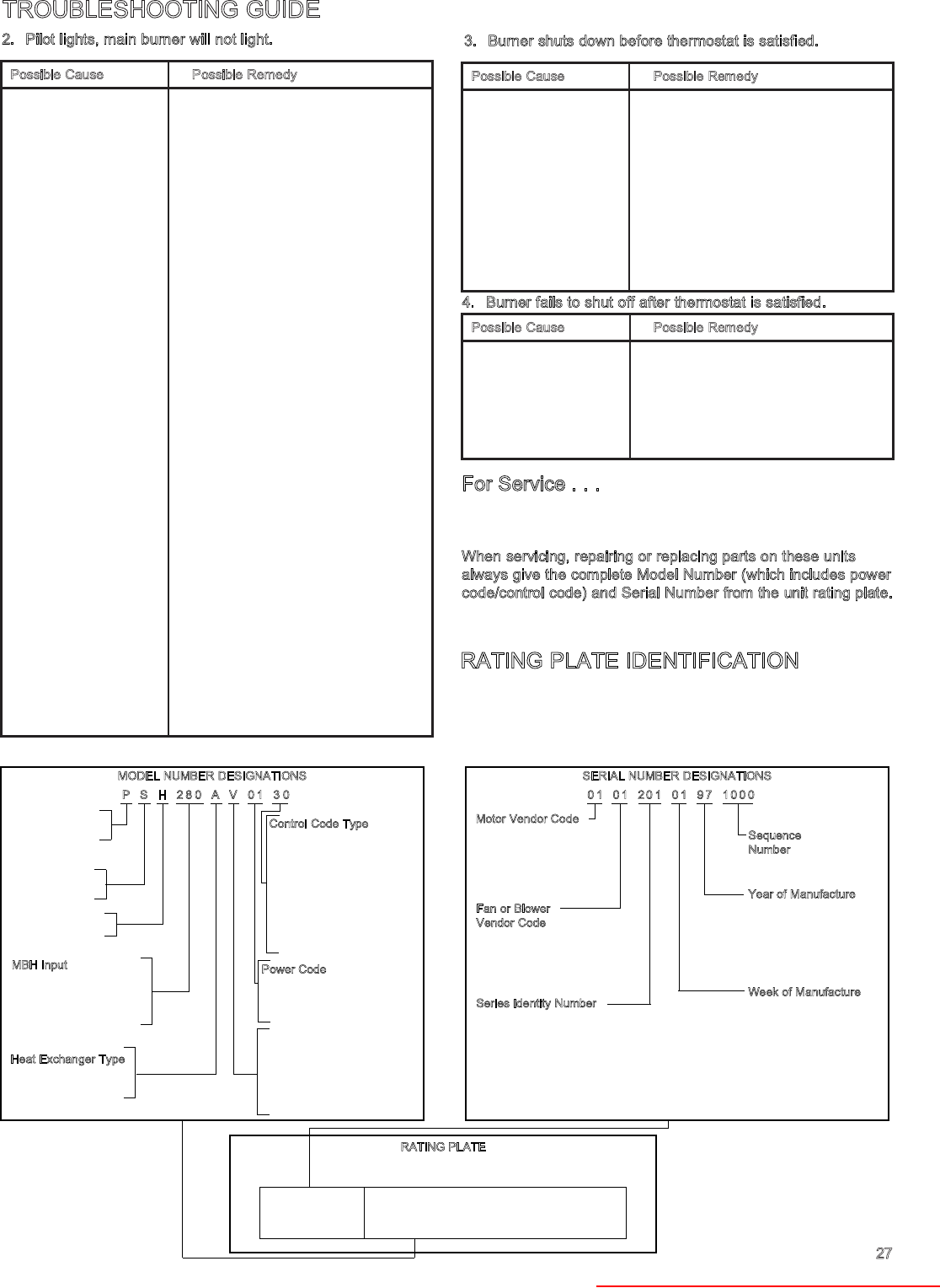
TROUBLESHOOTING GUIDE
Possible Cause Possible Remedy
2a. Gas valve in off 2a. Turn to on position.
off position.
2b. System in lock-out 2b. Reset system.
mode.
2c. Cracked or broken 2c. Replace sensor.
sensor ceramic.
2d. Defective or loose 2d. Correct or replace.
connections to flame
sensor or flame
sensor lead.
2e. Incorrect gas 2e. Check and adjust if necessary to
pressure. manufacturer’s recommendations
and replace if necessary.
2f. Insufficient current 2f. Check current according to
signal from flame manufacturer’s recommendations
sensor. and replace if necessary.
2g. Incorrect or loose 2g. Check wiring.
wiring.
2h. Poor ground to 2h. Check grounding means.
ignition control.
2i. No power to ignition 2i. Check voltage to controller and gas
controller or gas valve.
valve.
2j. Loose limit control 2j. Check connections.
connections or Replace limit control if necessary.
defective unit.
2k. Defective or plugged 2k. Inspect gas valve regulator.
gas valve regulator. Replace if necessary.
2l. Defective thermostat 2l. Calibrate thermostat or replace if
or thermostat out necessary.
of calibration.
2m. Thermostat heat 2m. Check anticipator setting and correct
anticipator if necessary.
incorrectly set.
2n. Defective ignition 2n. Replace.
controller.
Possible Cause Possible Remedy
3a. Flame sensing 3a. Check flame sensing rod, sensor
circuit failure. ceramic, sensor lead and
connections for damage or loss of
continuity. Replace defective
elements.
3b. Soot on sensing rod. 3b. Clean off soot and adjust pilot to
smaller size.
3c. Blockage in heat 3c. Clean heat exchanger.
exchanger. Determine cause and correct.
3d. Blockage in main 3d. Clean or replace orifice.
burner orifice.
Possible Cause Possible Remedy
4a. Faulty thermostat 4a. Check thermostat and anticipator
or improper heat setting. Replace if defective.
anticipator setting.
4b. Defective ignition 4b. Replace.
controller.
4c. Defective gas control. 4c. Replace.
27
2. Pilot lights, main burner will not light. 3. Burner shuts down before thermostat is satisfied.
4. Burner fails to shut off after thermostat is satisfied.
For Service . . .
If a qualified service person cannot solve the problem, consult
your local gas company or local Modine representative.
When servicing, repairing or replacing parts on these units
always give the complete Model Number (which includes power
code/control code) and Serial Number from the unit rating plate.
RATING PLATE IDENTIFICATION
When servicing, repairing or replacing parts on these units
always give the complete Model Number, Power Code Number,
Control Code Number and Serial Number from the unit rating
plate. The sample below shows what these numbers mean.
P - Propeller Unit
B - Blower Unit
S - Separated
Combustion
H - High Efficiency
F - Unit equipped with
intermittent pilot ignition
V - Unit equipped with
intermittent pilot ignition
and concentric vent
compatible.
MBH Input
150 - 150,000 Btu/hr input
170 - 170,000 Btu/hr input
225 - 225,000 Btu/hr input
etc.
Heat Exchanger Type
A - Aluminized
S - Stainless Steel
Control Code Type
30 - 115v/25v intermittent
pilot ignition, 100%
Shut-Off with continuous
retry, natural gas
31 - 230v/25v intermittent
pilot ignition, 100%
Shut-Off with continuous
retry, natural gas
etc.
Power Code
01 - 115v/60Hz/1φ
02 - 230v/60Hz/1φ
etc.
PS H 2 8 0 A V 0 1 3 0
MODEL NUMBER DESIGNATIONS
Motor Vendor Code
01 - Century
05 - Universal
etc.
Fan or Blower
Vendor Code
01 - Revcor
08 - Brookside
etc.
Series Identity Number
Identifies which series of controls
were furnished on the unit.
Sequence
Number
Year of Manufacture
96 - 1996
97 - 1997
etc.
Week of Manufacture
01 - 1st week of year
26 - 26th week of year
etc.
01 0 1 2 0 1 0 1 9 7 1 0 0 0
SERIAL NUMBER DESIGNATIONS
RATING PLATE
Power Code Control Code
SERIAL NUMBER MODEL NUMBER
01122010195 PSH280AF 01 30
Heater Parts from ACF Greenhouses

© Modine Manufacturing Company 2002 11/02 - 1M Litho in USA
Commercial HVAC&R Division
Modine Manufacturing Company
1221 Magnolia Avenue
Buena Vista, VA 24416
Phone: 1.800.828.4328 (HEAT)
FAX: 1.540.261.1903 (Service & Parts)
www.modine.com
Seller warrants its products to be free from defects in material and workmanship,
EXCLUSIVE, HOWEVER, of failures attributable to the use of materials substituted
under emergency conditions for materials normally employed. This warranty covers
replacement of any parts furnished from the factory of Seller, but does not cover
labor of any kind and materials not furnished by Seller, or any charges for any
such labor or materials, whether such labor, materials or charges thereon are due
to replacement of parts, adjustments, repairs, or any other work done. This
warranty does not apply to any equipment which shall have been repaired or
altered outside the factory of Seller in any way so as, in the judgment of Seller, to
affect its stability, nor which has been subjected to misuse, negligence, or
operating conditions in excess of those for which such equipment was designed.
This warranty does not cover the effects of physical or chemical properties of water
or steam or other liquids or gases used in the equipment.
BUYER AGREES THAT SELLER’S WARRANTY OF ITS PRODUCTS TO BE
FREE FROM DEFECT IN MATERIAL AND WORKMANSHIP, AS LIMITED
HEREIN, SHALL BE IN LIEU OF AND EXCLUSIVE OF ALL OTHER
WARRANTIES, EITHER EXPRESS OR IMPLIED, WHETHER ARISING FROM
LAW, COURSE OF DEALING, USAGE OF TRADE, OR OTHERWISE, THERE
ARE NO OTHER WARRANTIES, INCLUDING WARRANTY OF
MERCHANTABILITY OR FITNESS FOR PURPOSE, WHICH EXTEND BEYOND
THE PRODUCT DESCRIPTION CONFIRMED BY BUYER AND SELLER AS OF
THE DATE OF FINAL AGREEMENT.
This warranty is void if the input to the product exceeds the rated input as indicated
on the product serial plate by more than 5% on gas-fired and oil-fired units, or if
the product in the judgment of SELLER has been installed in a corrosive
atmosphere, or subjected to corrosive fluids or gases, been subjected to misuse,
negligence, accident, excessive thermal shock, excessive humidity, physical
damage, impact, abrasion, unauthorized alterations, or operation contrary to
SELLER’S printed instructions, or if the serial number has been altered, defaced or
removed.
Heat Exchangers
For Seller’s non-separated combustion Gas-Fired Unit Heaters
BUYER’S REMEDY FOR BREACH OF WARRANTY, EXCLUSIVE OF ALL
OTHER REMEDIES PROVIDED BY LAW, IS LIMITED TO REPAIR OR
REPLACEMENT AT THE FACTORY OF SELLER, ANY HEAT EXCHANGER
WHICH SHALL, WITHIN TEN YEARS FROM DATE OF FIRST BENEFICIAL
USE BY BUYER OR ANY OTHER USER, WITHIN TEN YEARS FROM DATE
OF RESALE BY BUYER OR ANY OTHER USER, WITHIN TEN YEARS FROM
DATE OF RESALE BY BUYER IN ANY UNCHANGED CONDITION, OR
WITHIN ONE HUNDRED TWENTY-SIX MONTHS FROM DATE OF
SHIPMENT FROM SELLER, WHICHEVER OCCURS FIRST, BE RETURNED
TO SELLER WITH TRANSPORTATION CHARGES PREPAID AND WHICH
THE EXAMINATION OF SELLER SHALL DISCLOSE TO HAVE BEEN
DEFECTIVE; EXCEPT THAT WHEN THE PRODUCT IS TO BE USED BY
BUYER AS A COMPONENT PART OF EQUIPMENT MANUFACTURED BY
BUYER, BUYER’S REMEDY FOR BREACH, AS LIMITED HEREIN, SHALL
BE LIMITED TO ONE YEAR FROM DATE OF SHIPMENT FROM SELLER.
FOR GAS-FIRED PRODUCTS INSTALLED IN HIGH HUMIDITY
APPLICATIONS AND UTILIZING STAINLESS STEEL HEAT EXCHANGERS,
BUYER’S REMEDY FOR BREACH, AS LIMITED HEREIN, SHALL BE
LIMITED TO TEN YEARS FROM DATE OF SHIPMENT FROM SELLER.
For Seller's Low Intensity Gas-Fired Infrared Heaters
BUYER'S REMEDY FOR BREACH OF WARRANTY, EXCLUSIVE OF ALL
OTHER REMEDIES PROVIDED BY LAW, IS LIMITED TO REPAIR OR
REPLACEMENT AT THE FACTORY OF SELLER, ANY HEAT EXCHANGER
WHICH SHALL, WITHIN FIVE YEARS FROM DATE OF FIRST BENEFICIAL
USE BY BUYER OR ANY OTHER USER, WITHIN FIVE YEARS FROM DATE
OF RESALE BY BUYER OR ANY OTHER USER, WITHIN FIVE YEARS
FROM DATE OF RESALE BY BUYER IN ANY UNCHANGED CONDITION,
OR WITHIN 66 MONTHS FROM DATE OF SHIPMENT FROM SELLER,
WHICHEVER OCCURS FIRST, BE RETURNED TO SELLER WITH
TRANSPORTATION CHARGES PREPAID AND WHICH THE EXAMINATION
OF SELLER SHALL DISCLOSE TO HAVE BEEN DEFECTIVE; EXCEPT THAT
WHEN THE PRODUCT IS TO BE USED BY BUYER AS A COMPONENT
PART OF EQUIPMENT MANUFACTURED BY BUYER, BUYER'S REMEDY
FOR BREACH, AS LIMITED HEREIN, SHALL BE LIMITED TO ONE YEAR
FROM DATE OF SHIPMENT FROM SELLER.
Heat Exchanger (Condensers) for all Seller’s products except non-separated
combustion Gas-Fired Unit Heaters and Infrared Heaters, all Burners except
Infrared Heaters, and Sheet Metal for all Seller's products
BUYER’S REMEDY FOR BREACH OF WARRANTY, EXCLUSIVE OF ALL
OTHER REMEDIES PROVIDED BY LAW, IS LIMITED TO REPAIR OR
REPLACEMENT AT THE FACTORY OF SELLER, ANY HEAT EXCHANGER
(CONDENSER) OR BURNER WHICH SHALL, WITHIN ONE YEAR FROM
DATE OF FIRST BENEFICIAL USE BY BUYER OR ANY OTHER USER,
WITHIN ONE YEAR FROM DATE OF RESALE BY BUYER IN ANY
UNCHANGED CONDITION, OR WITHIN EIGHTEEN MONTHS FROM DATE
OF SHIPMENT FROM SELLER, WHICHEVER OCCURS FIRST, BE
RETURNED TO SELLER WITH TRANSPORTATION CHARGES PREPAID
AND WHICH THE EXAMINATION OF SELLER SHALL DISCLOSE TO HAVE
BEEN DEFECTIVE; EXCEPT THAT WHEN THE PRODUCT IS TO BE USED
BY BUYER AS A COMPONENT PART OF EQUIPMENT MANUFACTURED
BY BUYER, BUYER’S REMEDY FOR BREACH, AS LIMITED HEREIN,
SHALL BE LIMITED TO ONE YEAR FROM DATE OF SHIPMENT FROM
SELLER.
Burners
For Seller's Low Intensity Gas-Fired Infrared Heaters
BUYER'S REMEDY FOR BREACH OF WARRANTY, EXCLUSIVE OF ALL
OTHER REMEDIES PROVIDED BY LAW, IS LIMITED TO REPAIR OR
REPLACEMENT AT THE FACTORY OF SELLER, ANY BURNER WHICH
SHALL, WITHIN TWO YEARS FROM DATE OF FIRST BENEFICIAL USE BY
BUYER OR ANY OTHER USER, WITHIN TWO YEARS FROM DATE OF
RESALE BY BUYER IN ANY UNCHANGED CONDITION, OR WITHIN 30
MONTHS FROM DATE OF SHIPMENT FROM SELLER, WHICHEVER
OCCURS FIRST, BE RETURNED TO SELLER WITH TRANSPORTATION
CHARGES PREPAID AND WHICH THE EXAMINATION OF SELLER SHALL
DISCLOSE TO HAVE BEEN DEFECTIVE; EXCEPT THAT WHEN THE
PRODUCT IS TO BE USED BY BUYER AS A COMPONENT PART OF
EQUIPMENT MANUFACTURED BY BUYER, BUYER'S REMEDY FOR
BREACH, AS LIMITED HEREIN, SHALL BE LIMITED TO ONE YEAR FROM
DATE OF SHIPMENT FROM SELLER.
For Seller's High Intensity Gas-Fired Infrared Heaters
BUYER'S REMEDY FOR BREACH OF WARRANTY, EXCLUSIVE OF ALL
OTHER REMEDIES PROVIDED BY LAW, IS LIMITED TO REPAIR OR
REPLACEMENT AT THE FACTORY OF SELLER, ANY BURNER WHICH
SHALL, WITHIN TEN YEARS FROM DATE OF FIRST BENEFICIAL USE BY
BUYER OR ANY OTHER USER, WITHIN TEN YEARS FROM DATE OF
RESALE BY BUYER IN ANY UNCHANGED CONDITION, OR WITHIN 126
MONTHS FROM DATE OF SHIPMENT FROM SELLER, WHICHEVER
OCCURS FIRST, BE RETURNED TO SELLER WITH TRANSPORTATION
CHARGES PREPAID AND WHICH THE EXAMINATION OF SELLER SHALL
DISCLOSE TO HAVE BEEN DEFECTIVE; EXCEPT THAT WHEN THE
PRODUCT IS TO BE USED BY BUYER AS A COMPONENT PART OF
EQUIPMENT MANUFACTURED BY BUYER, BUYER'S REMEDY FOR
BREACH, AS LIMITED HEREIN, SHALL BE LIMITED TO ONE YEAR FROM
DATE OF SHIPMENT FROM SELLER.
All Other Components Excluding Heat Exchanger (Condenser), Burner, and
Sheet Metal
For all Seller's products except Direct-Fired Heaters and High Intensity
Gas-Fired Infrared Heaters
BUYER’S REMEDY FOR BREACH OF WARRANTY, EXCLUSIVE OF ALL
OTHER REMEDIES PROVIDED BY LAW, IS LIMITED TO REPAIR OR
REPLACEMENT AT THE FACTORY OF SELLER, ANY PART OR PARTS
WHICH SHALL, WITHIN TWO YEARS FROM DATE OF FIRST BENEFICIAL
USE BY BUYER OR ANY OTHER USER, WITHIN TWO YEARS FROM DATE
OF RESALE BY BUYER IN ANY UNCHANGED CONDITION, OR WITHIN
THIRTY MONTHS FROM DATE OF SHIPMENT FROM SELLER,
WHICHEVER OCCURS FIRST, BE RETURNED TO SELLER WITH
TRANSPORTATION CHARGES PREPAID AND WHICH THE EXAMINATION
OF SELLER SHALL DISCLOSE TO HAVE BEEN DEFECTIVE; EXCEPT THAT
WHEN THE PRODUCT IS TO BE USED BY BUYER AS A COMPONENT
PART OF EQUIPMENT MANUFACTURED BY BUYER, BUYER’S REMEDY
FOR BREACH, AS LIMITED HEREIN, SHALL BE LIMITED TO ONE YEAR
FROM DATE OF SHIPMENT FROM SELLER.
For Seller's Direct-Fired Heaters and High Intensity Gas-Fired Infrared Heaters
BUYER’S REMEDY FOR BREACH OF WARRANTY EXCLUSIVE OF ALL
OTHER REMEDIES PROVIDED BY LAW IS LIMITED TO REPAIR OR
REPLACEMENT AT THE SELLER’S OPTION ANY PART OR PARTS WHICH
SHALL WITHIN A PERIOD OF ONE YEAR FROM DATE OF FIRST
BENEFICIAL USE BY BUYER OR ANY OTHER USER, WITHIN ONE YEAR
FROM DATE OF RESALE BY BUYER IN ANY UNCHANGED CONDITION,
OR WITHIN 18 MONTHS FROM DATE OF SHIPMENT FROM SELLER,
WHICHEVER OCCURS FIRST, BE RETURNED TO SELLER WITH
TRANSPORTATION CHARGES PREPAID AND WHICH THE EXAMINATION
OF THE SELLER SHALL DISCLOSE TO HAVE BEEN DEFECTIVE.
BUYER AGREES THAT IN NO EVENT WILL SELLER BE LIABLE FOR COSTS
OF PROCESSING, LOST PROFITS, INJURY TO GOODWILL, OR ANY OTHER
CONSEQUENTIAL OR INCIDENTAL DAMAGES OF ANY KIND RESULTING
FROM THE ORDER OR USE OF ITS PRODUCT, WHETHER ARISING FROM
BREACH OF WARRANTY, NONCONFORMITY TO ORDERED SPECIFICATIONS,
DELAY IN DELIVERY, OR ANY LOSS SUSTAINED BY THE BUYER.
Modine Manufacturing Company has a continuous product improvement program;
it reserves the right to change design and specifications without notice.
Heater Parts from ACF Greenhouses
