Monterey 46AK7000 keyboard User Manual MANUAL
Monterey International Corporation keyboard MANUAL
Monterey >
Manual

WARNING
Note: This equipment has been tested and found to comply with the
limits for a Class B digital device, pursuant to Part 15 of FCC Rules.
These limits are designed to provide reasonable protection against
harmful interference in a residential installation. This equipment
generates, uses and can radiate radio frequency energy and, if not
installed and used in accordance with the instruction, may cause
harmful interference to radio communications. However, there is no
guarantee that interference will not occur in a particular installation.
If this equipment does cause harmful interference to radio or
television reception, which can be determined by turning the
equipment off and on, the user is encouraged to try to correct the
interference by one or more of the following measures:
•
Reorient or relocate the receiving antenna.
•
Increase the separation between the equipment and receiver.
•
Connect the equipment into an outlet on a circuit different from that
to which the receiver is connected.
•
Consult the dealer or an experienced radio/TV technician for help.
Notice:
(1) A Unshielded-type power cord is required in order to meet FCC
emission limits and also to prevent interference to the nearby radio
and television reception. It is essential that only the supplied power
cord by used.
(2) Use only shielded cables to connect I/O devices to this equipment.
(3) Changes or modifications not expressly approved by the party
responsible for compliance could void the user’s authority to
operate the equipment.
K7000 Windows Keyboard
1. Scope:
The Monterey K7000 keyboard is 104/105 keys enhanced
layout. Especially with new key support for Microsoft
Windows key. It is also compatible with IBM PC AT or
PS/2 and compatible personal computer.
2. Features:
² Fashion Styling
² 104/105 enhanced layout
² Microsoft Windows compatible
² IBM PC/AT, PS/2 compatible
² Laser engraved printing
² Multi. Lingual selectable
² Nice feeling, light touch membrane tactile switches
² Compact low profile
3. Specification:
3.1 Electrical Specification
3.1.1. Power Requirement
Input Voltage: DC 4.75V to 5.25V
Input Current: 300 mA max.
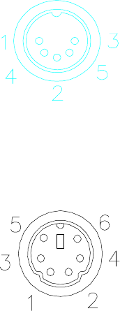
3.1.2. Cable Connector
3.1.2.1 DIN standard 5 pin connector pin
assignment
PIN SIGNAL
1Clock
2Data
3Reserve
4Ground
5VCC
Shield Frame Ground
3.1.2.2 MINI DIN 6 pin connector pin assignment
PIN SIGNAL
1Data
2Reserve
3Ground
4VCC
5Clock
6Reserve
Shield Frame Ground
3.1.3. Contact Resistance : 500 ohm Max.
3.1.4. Insulation Resistance : 100 ohm, 250V DC
3.1.5. Bounce : ¡Ø 10 MilliSecond