Morcom AE2000 Dual Channel Navtex Receiver User Manual AE 2000 REF Manual Ver 1 3
Morcom International, Inc. Dual Channel Navtex Receiver AE 2000 REF Manual Ver 1 3
UserManual.wiki
>
Morcom
>
AE2000 User Manual
User Manual
Navigation menu
Upload a User Manual
Namespaces
Wiki Guide
HTML
PDF
Info
Views
User Manual
Discussion / Help
Navigation

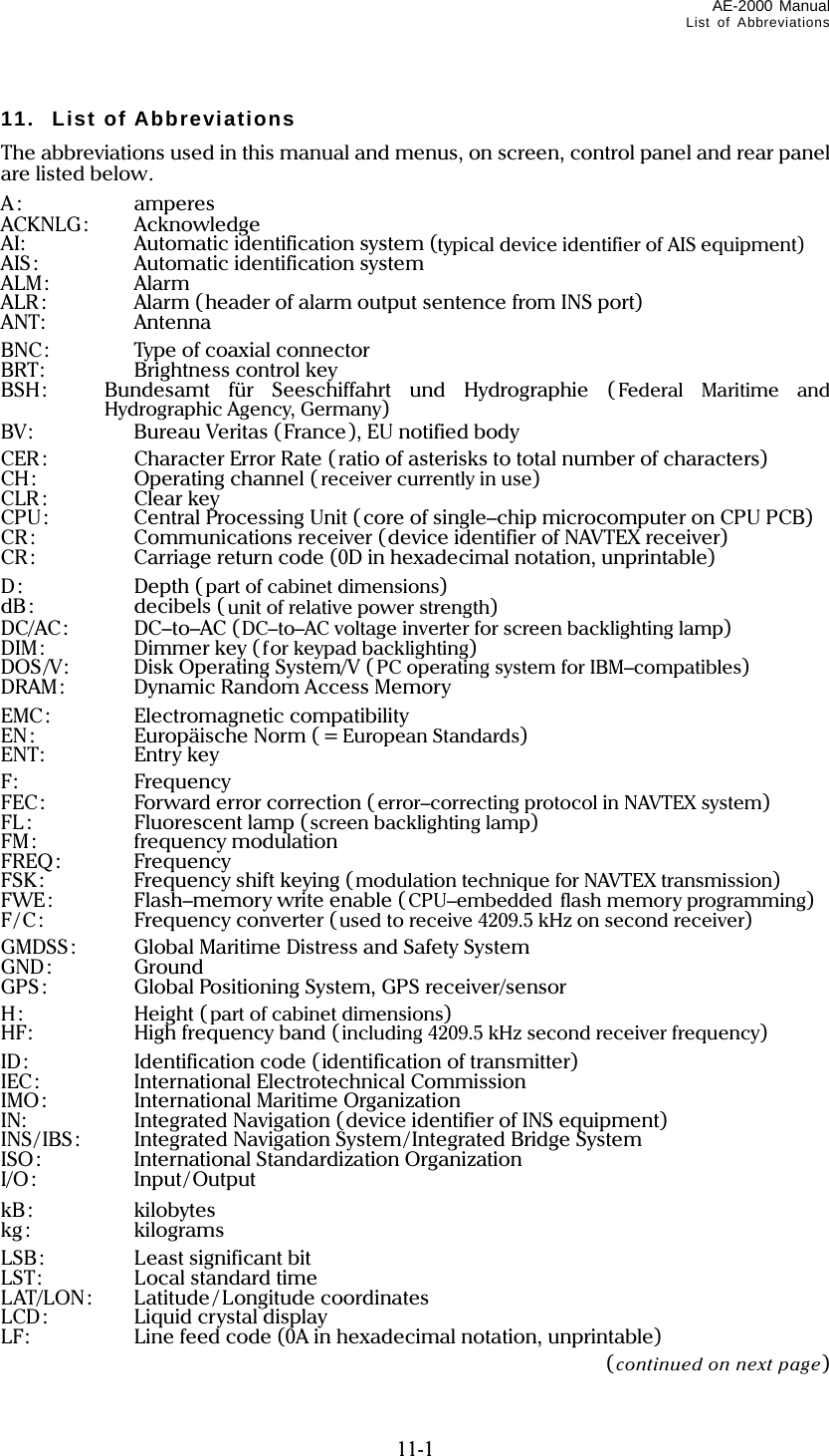
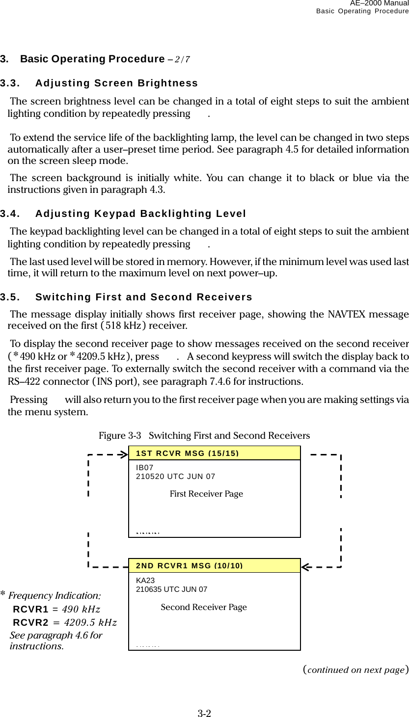
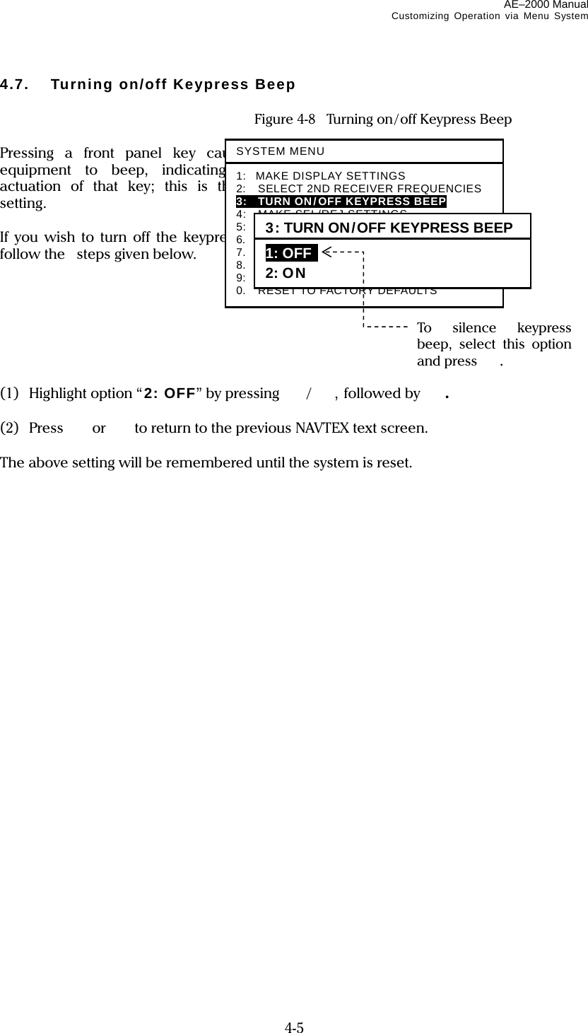
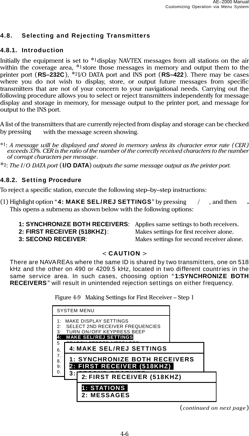
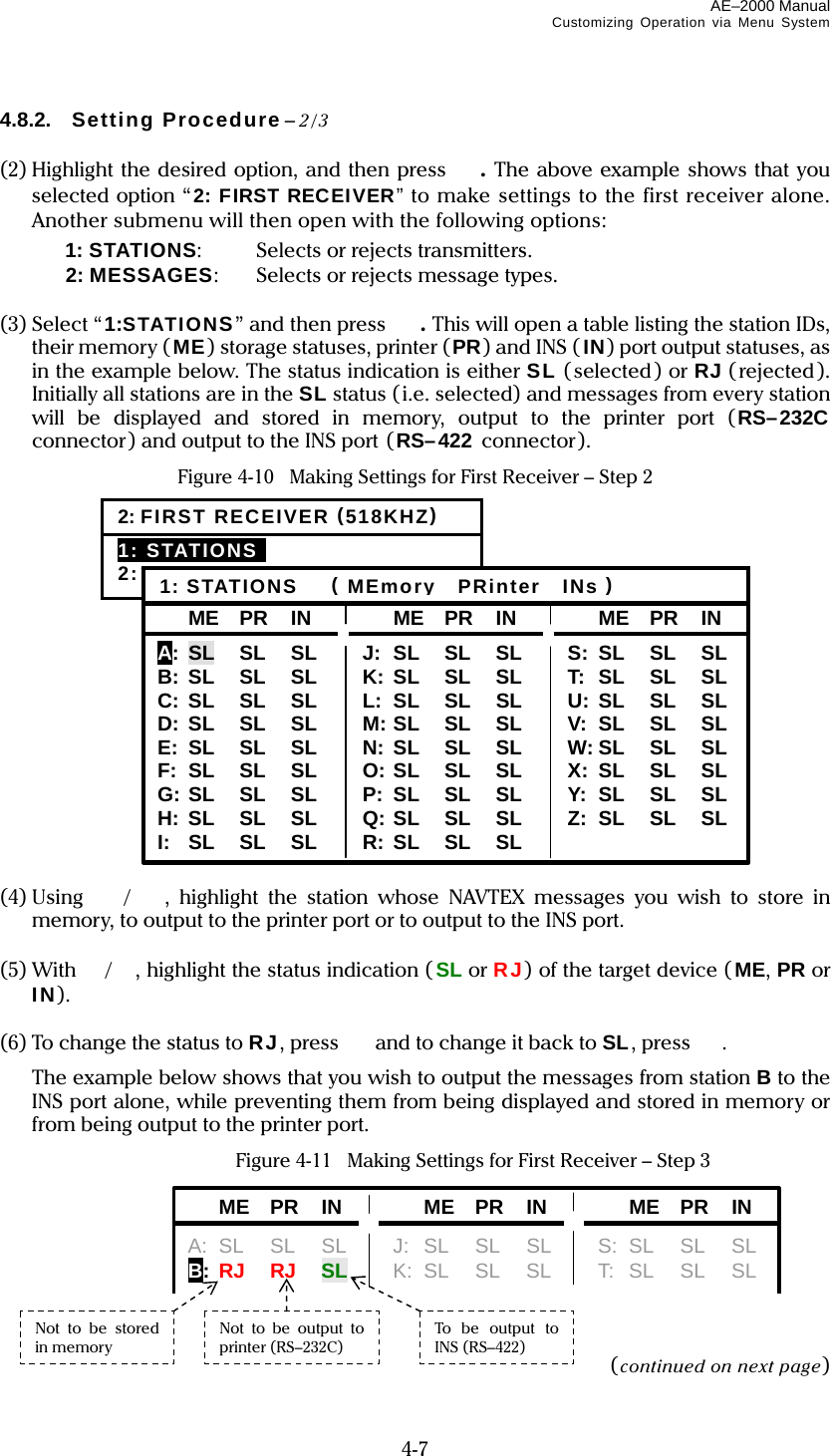
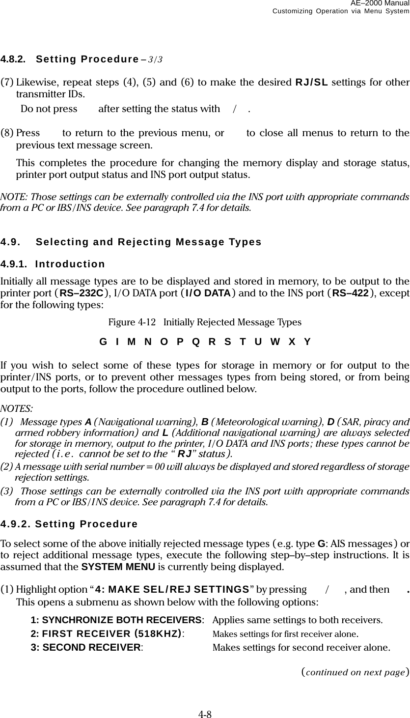
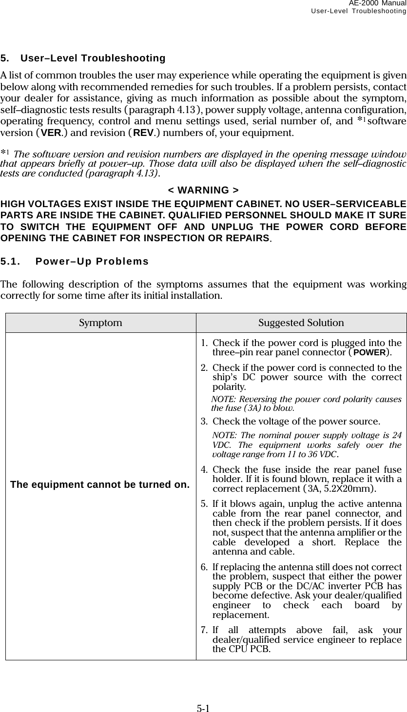
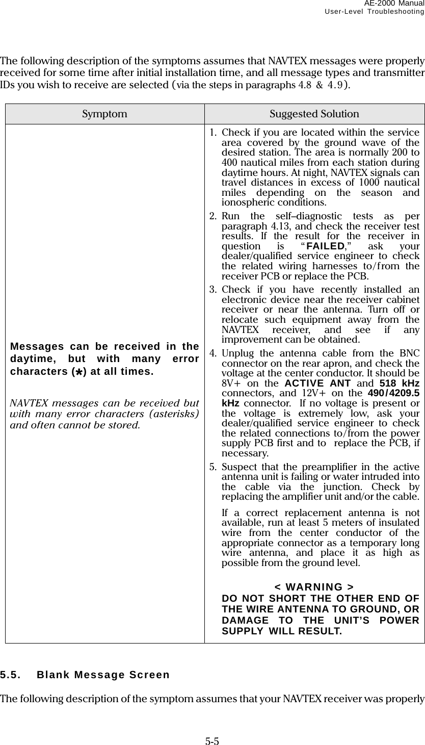
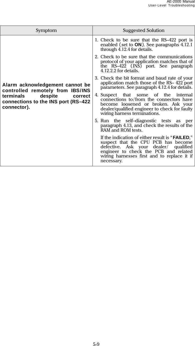
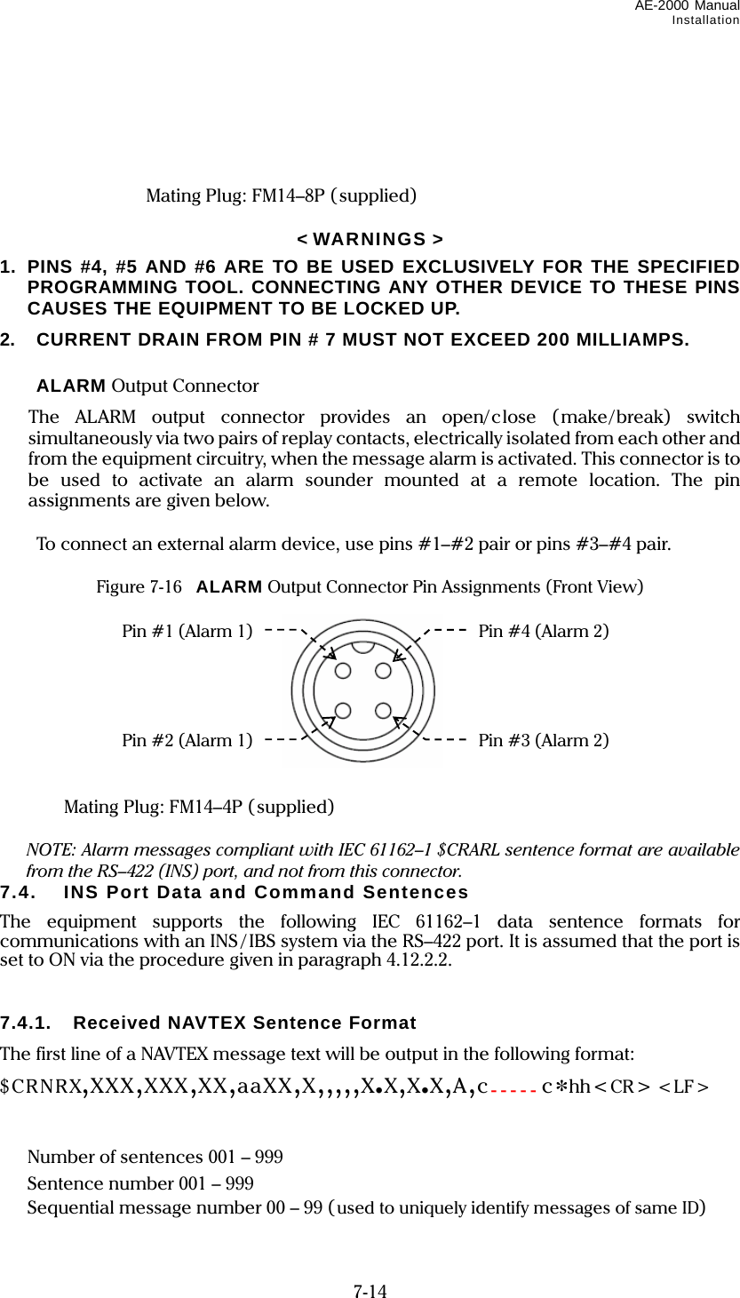
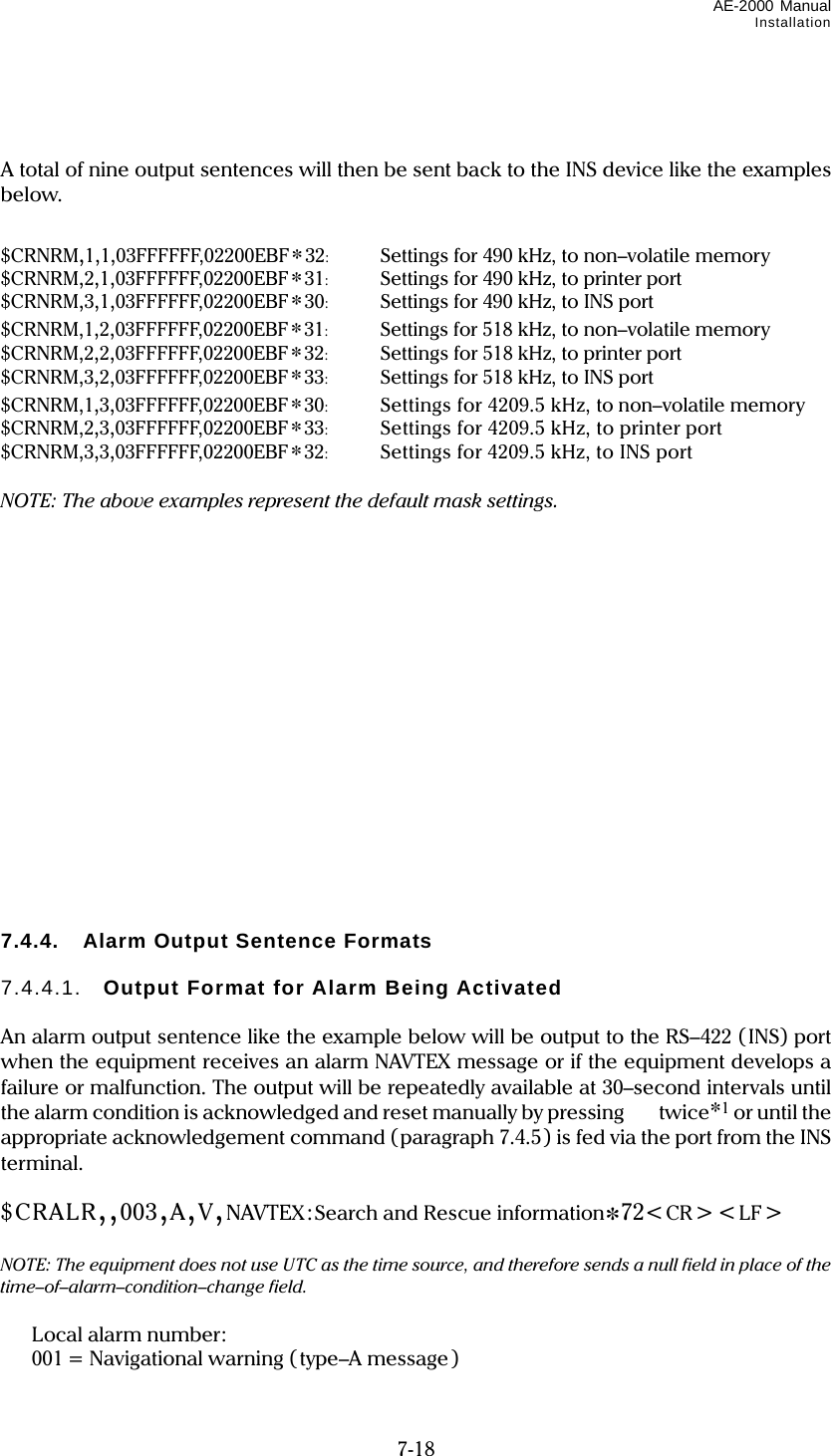
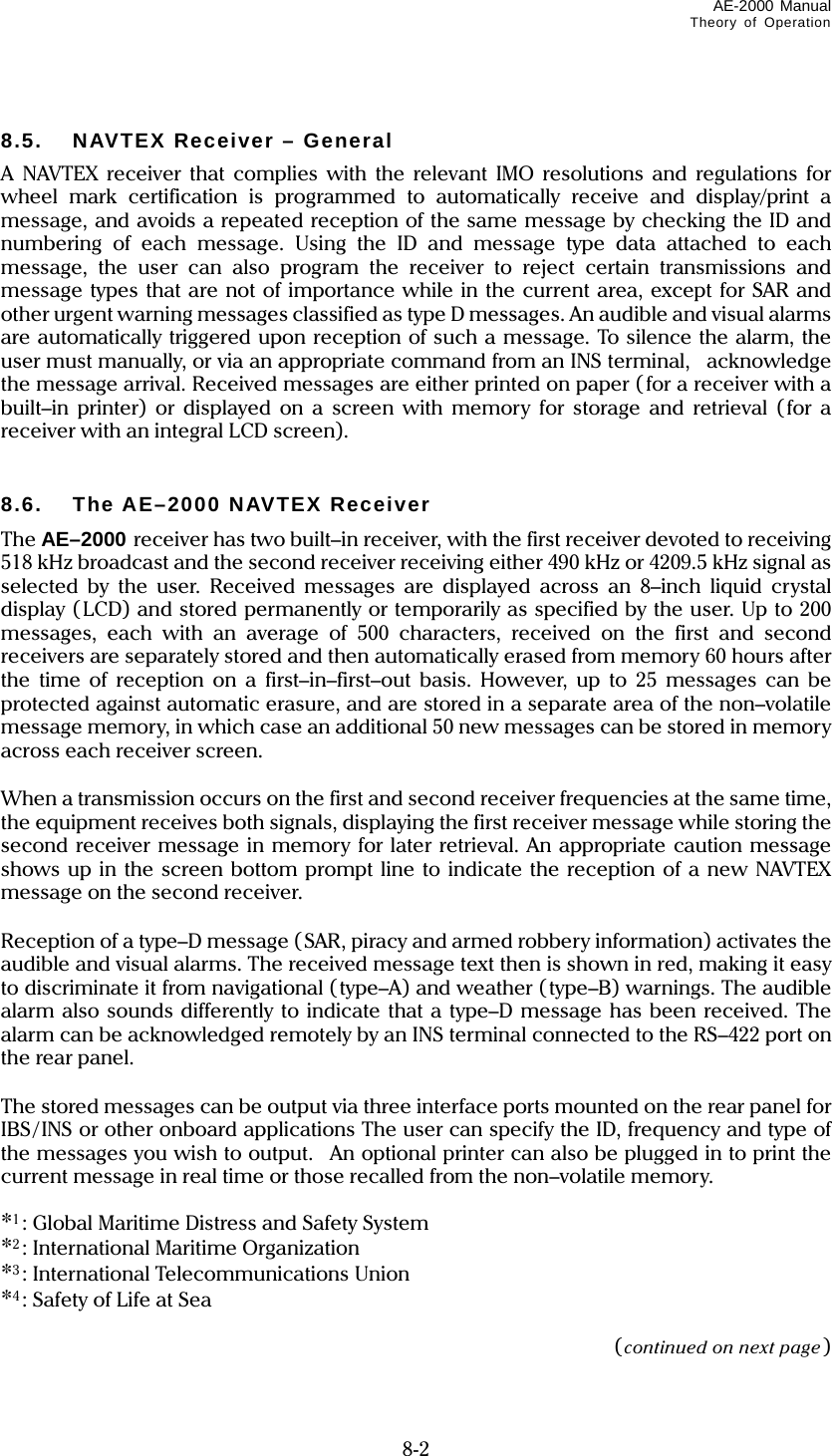
![AE–2000 Manual Important Notes ii < CAUTIONS > 1: Operational – Memory Retention Period Do not leave the equipment switched off for more than 10 days continuously, or all stored messages will be erased, whether they are protected or not. Important messages you wish to preserve should be output to an optional printer or to a PC via an appropriate rear panel interface connector (RS–232C, RS–422 or I/O DATA) if the equipment is to be kept turned off for extended periods of time. 2: Operational – “Memory–Full” Indication As soon as the equipment has stored a total of 199 messages, the following caution will show up in the bottom command/prompts line along with 3 beeps: MEMORY FULL ! [CLR] TO ACKNLG. The oldest message will then be erased from memory automatically after reception of a next new message. As soon as you notice the above warning, be sure to acknowledge each unread message by pressing , and if necessary, press to protect important messages you wish to retain for permanent storage. 3: Environmental Safety – Equipment Disposal The display cabinet and the active antenna unit are considered environmentally safe in their original, assembled forms. However, if either unit is to be discarded for any reason, be sure to follow all relevant local ordinances/regulations, and contact your dealer or the manufacturer (contact information given below) for assistance or instructions before disposing of it. Do not destroy the cabinet or the antenna casing. MORCOM International, Inc. 3656 Centerview Drive, Unit #1 Chantilly, VA 20151 – U. S. A. PHONE: (703)263–9305 FAX: (703)263–9308 www.morcom.com](https://usermanual.wiki/Morcom/AE2000/User-Guide-1042012-Page-5.png)
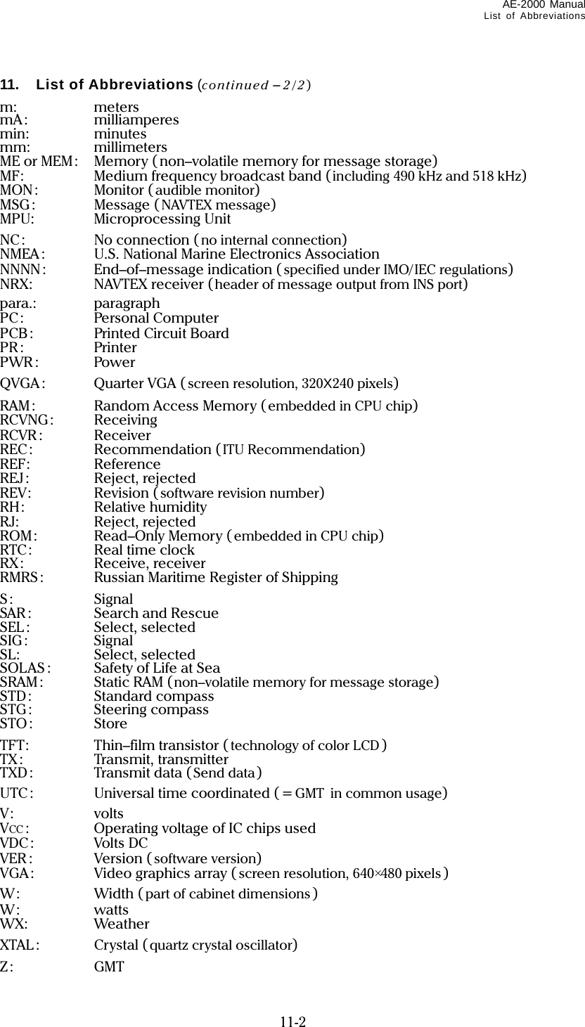
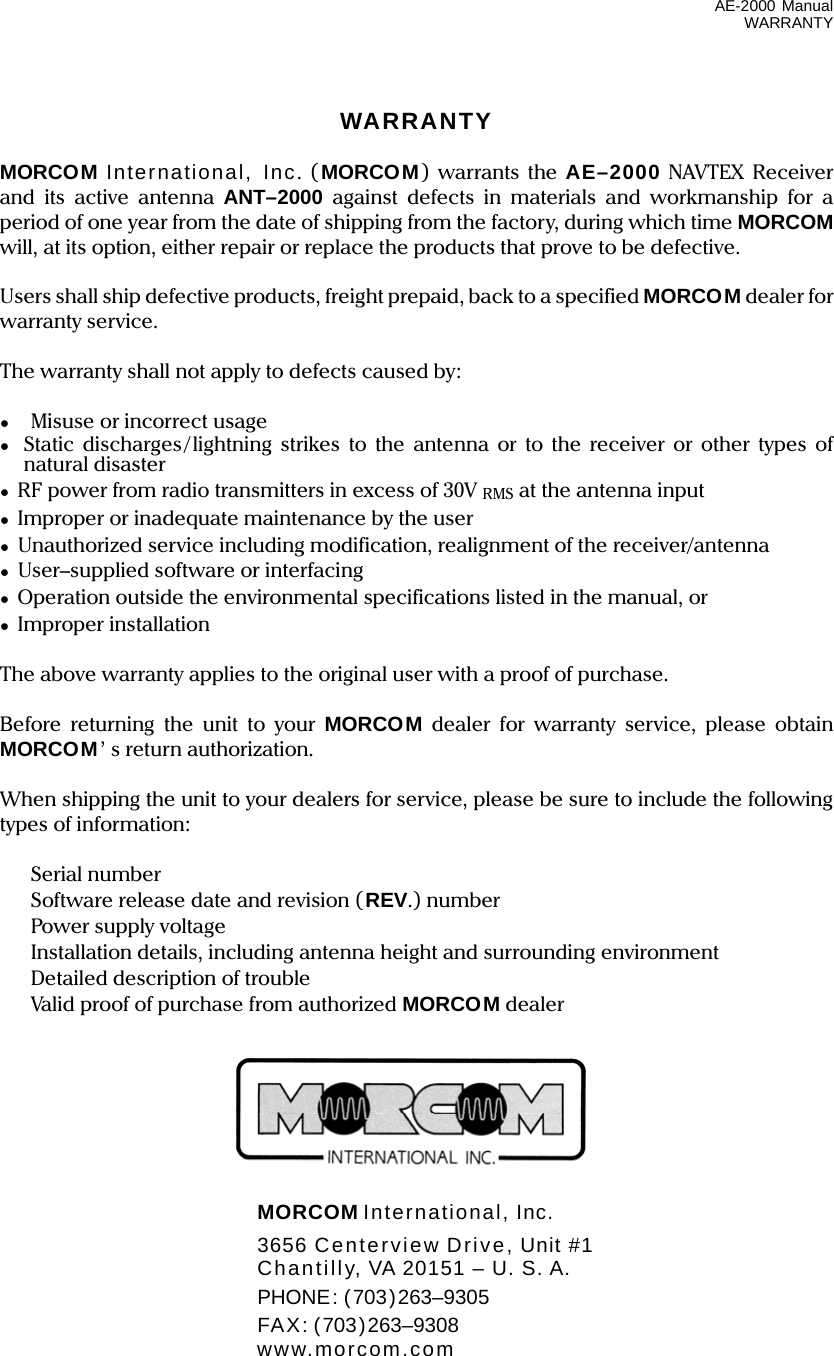
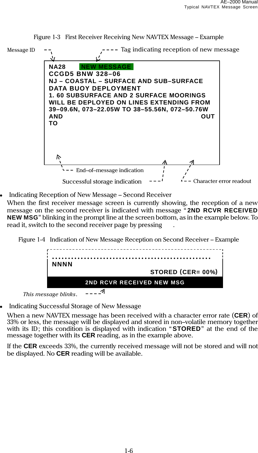
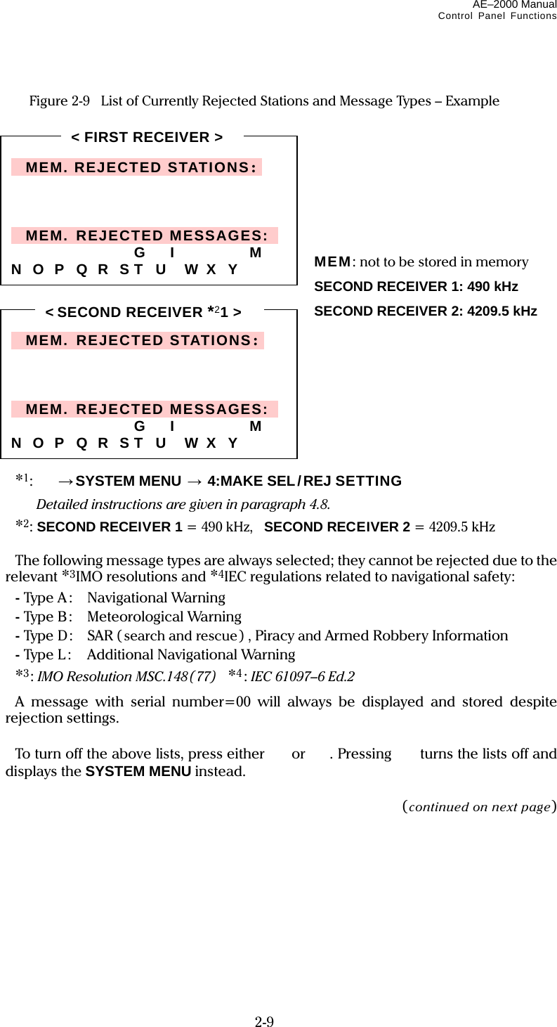
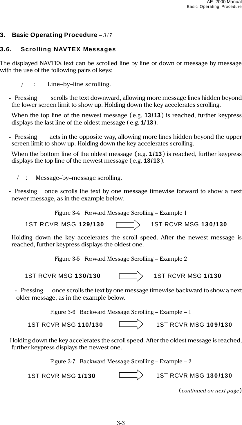
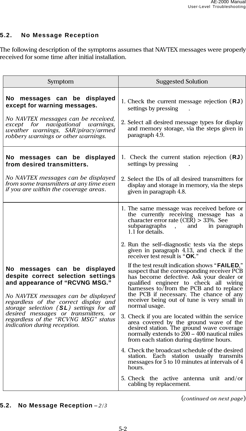
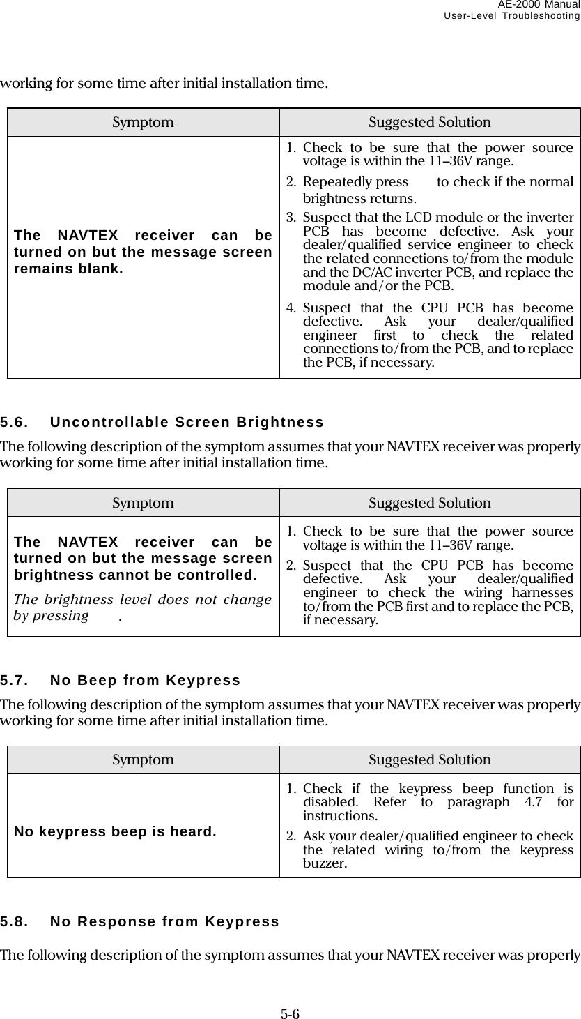
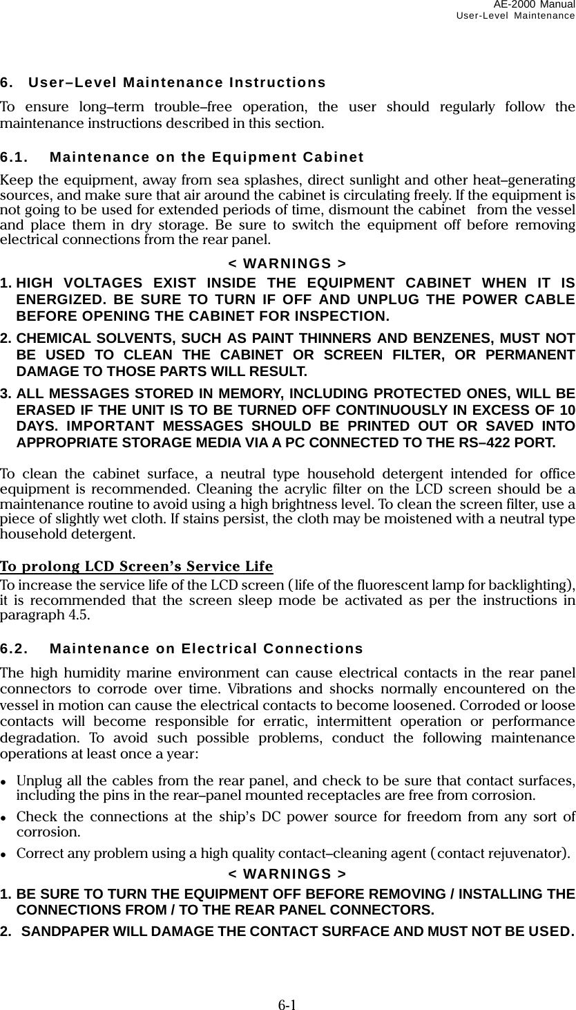
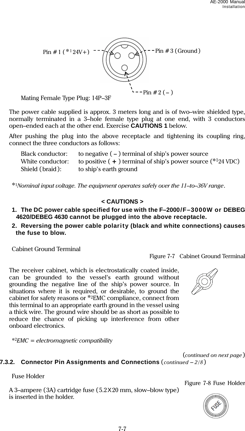
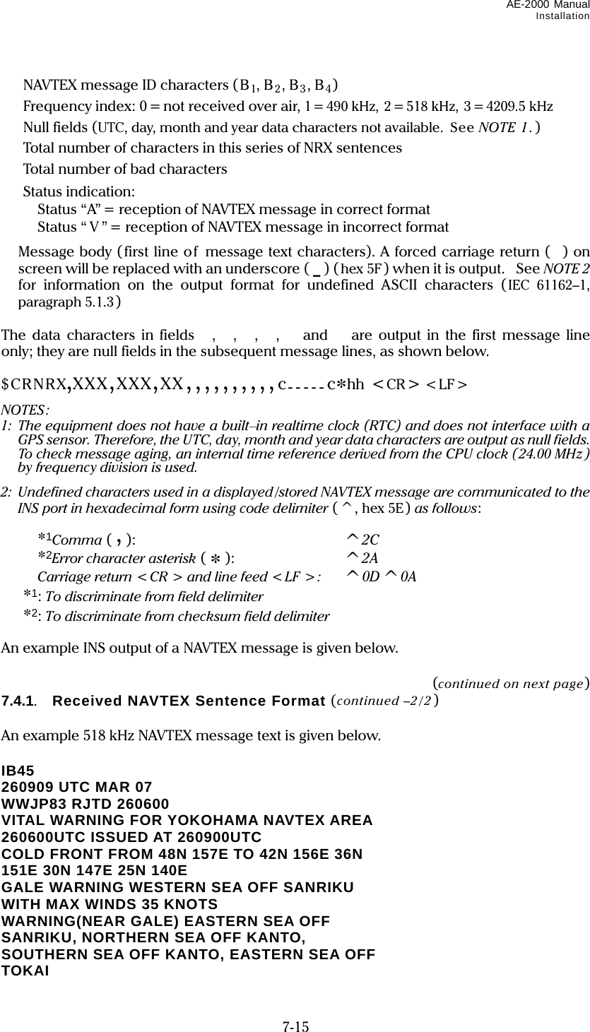
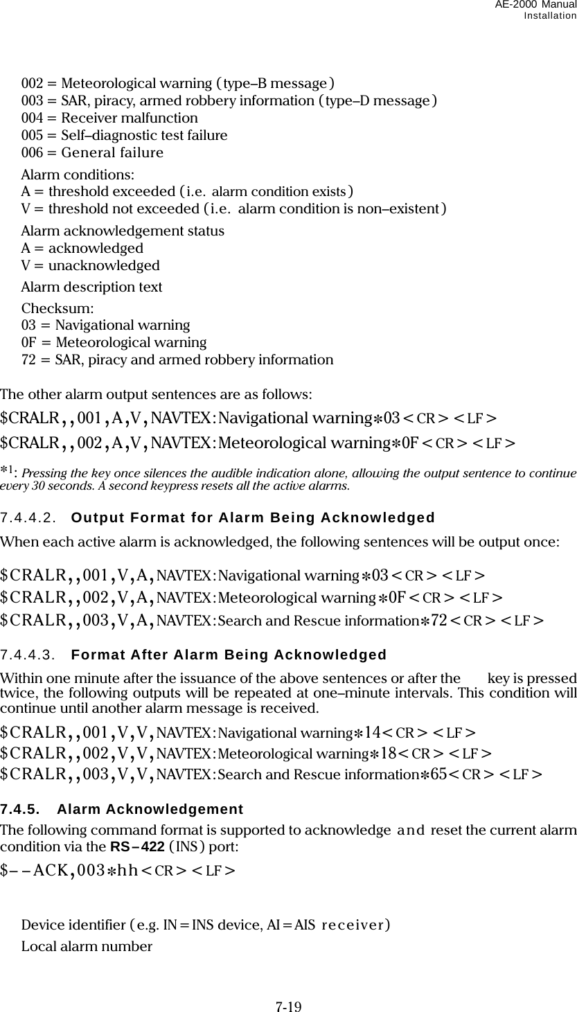
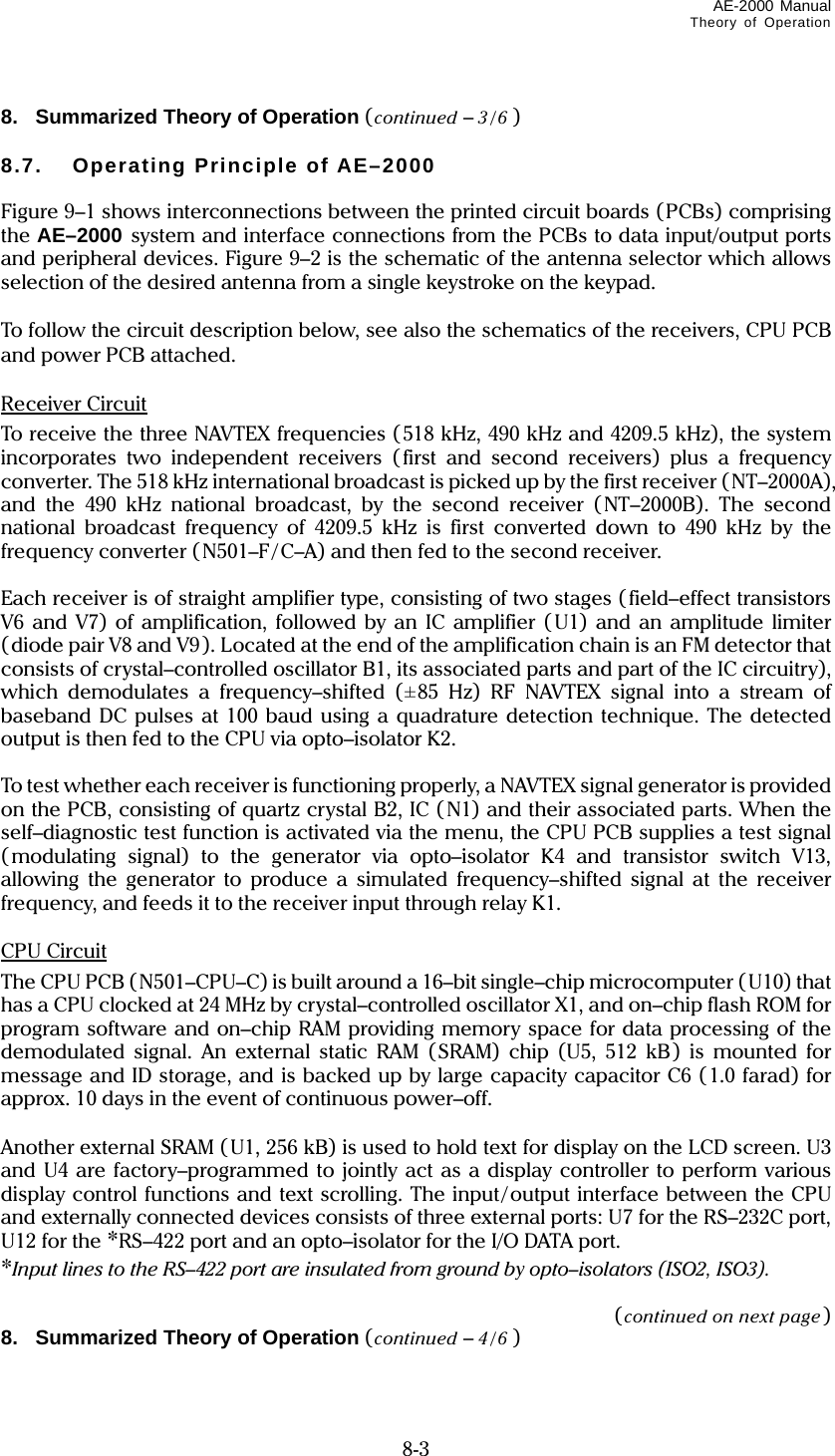
![AE–2000 Manual Typical NAVTEX Message Screen 1-5 the internal non–volatile memory. *1STORED: The message has been stored. When message reception has been completed with a character error rate (CER) of 33% or less, the received NAVTEX message together with its ID will be stored in memory, making it possible to recall it onto the screen at a later time. If the same message is received with a lower CER on the next transmission, the previously stored message will be replaced with the new one. However, if the first message was received with a CER of 4% or less, message replacement will not take place on subsequent reception of the same message with a lower CER. When the CER exceeds 33%, the message and its ID will not be displayed and stored in memory, allowing a retransmission of the same message to be displayed and stored. *1: If the message selection/rejection settings are made so that a particular message type is rejected from storage, this indication will not be displayed regardless of a CER being smaller than 33%. See paragraph 4.9 for the related setting instructions. Character Error Rate (CER) Indication CER is the percentage ratio of the total number of corrupt characters represented by asterisks (*) to the total number of characters received in a message, including control codes (sync. signal, carriage returns, line feeds, letter/numeral shift, etc.), If a message is received with a CER equal to or greater than 33%, it will not be displayed and stored in memory, allowing the same message to be received again on its next transmission. No CER reading will be available on the current transmission. See paragraph for more information on CER. Message Prompt Line This line indicates the receiver’s response for the user’s keypress or displays prompts related to reception of new or alarm NAVTEX messages on the first or second receiver, or related to message storage, like the examples below. ALARM MESSAGE RECEIVED ON 2ND RCVR MORE UNREAD ALARM *2MSG LEFT 2ND *3RCVR RECEIVED NEW MSG MORE NEW MSG LEFT STORAGE LIMIT IS REACHED MEMORY FULL ! *4 [CLR] TO *5 ACKNLG. *2 MSG = MESSAGE, *3 RCVR = RECEIVER *4 [CLR] = *5 ACKNLG = ACKNOWLEDGE 1. Typical NAVTEX Message Screen (continued – 5/5 ) 1.2. Indication of Reception and Storage of New NAVTEX Message ● Indicating Reception of New Message – First Receiver The equipment visually indicates the reception of a new NAVTEX message by attaching a tag (iNEW MESSAGEi) to the message ID, as in the example below. The tag will be turned off 24 hours after reception or when you press .](https://usermanual.wiki/Morcom/AE2000/User-Guide-1042012-Page-14.png)
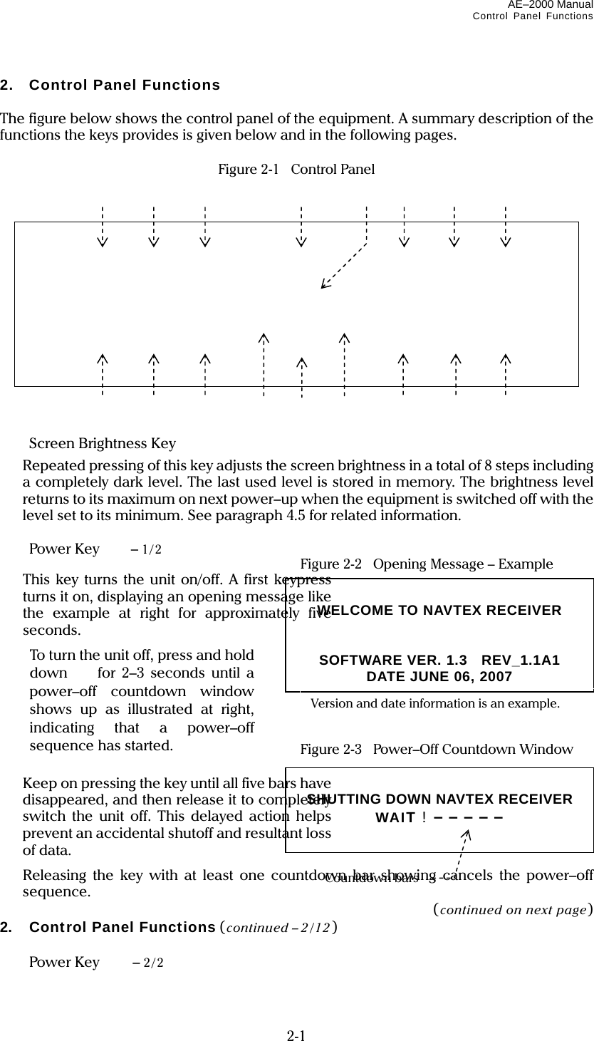
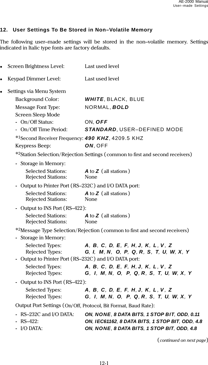
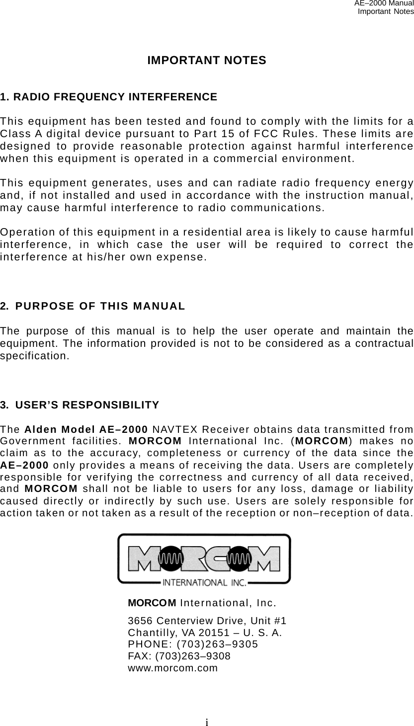
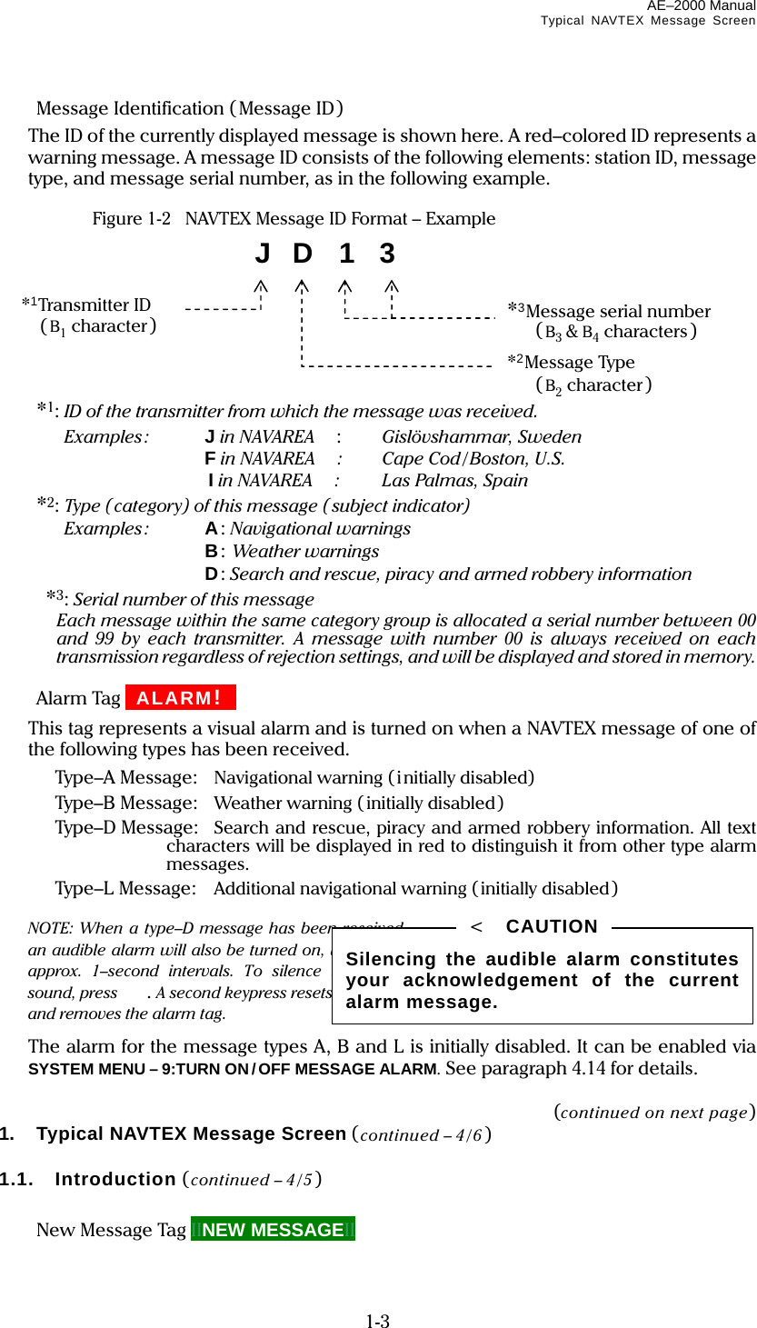
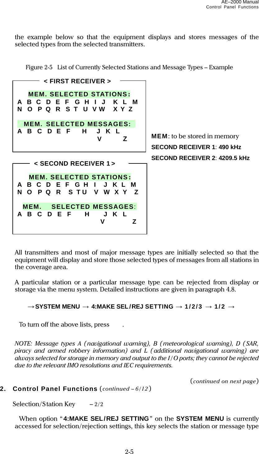
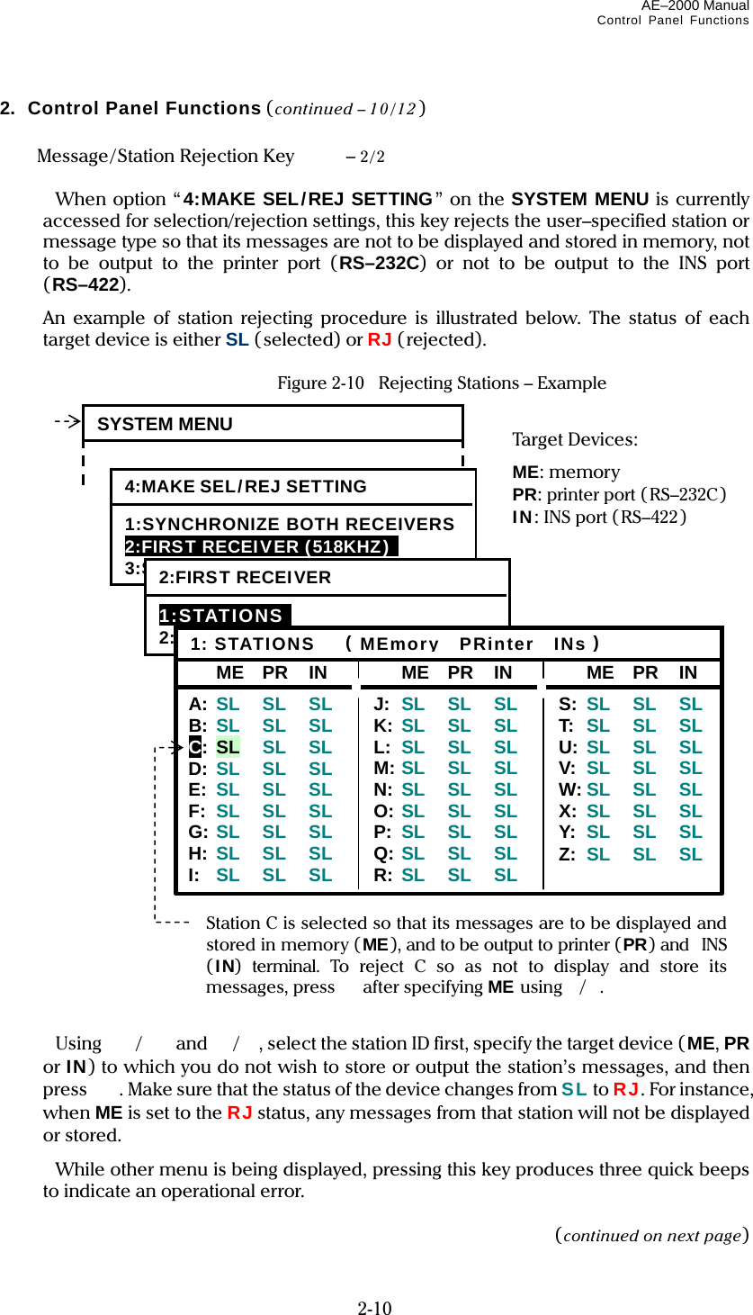
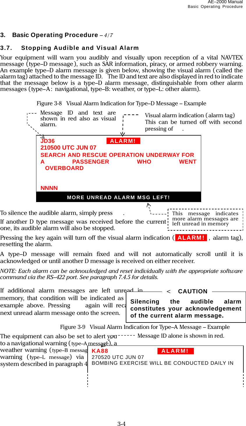
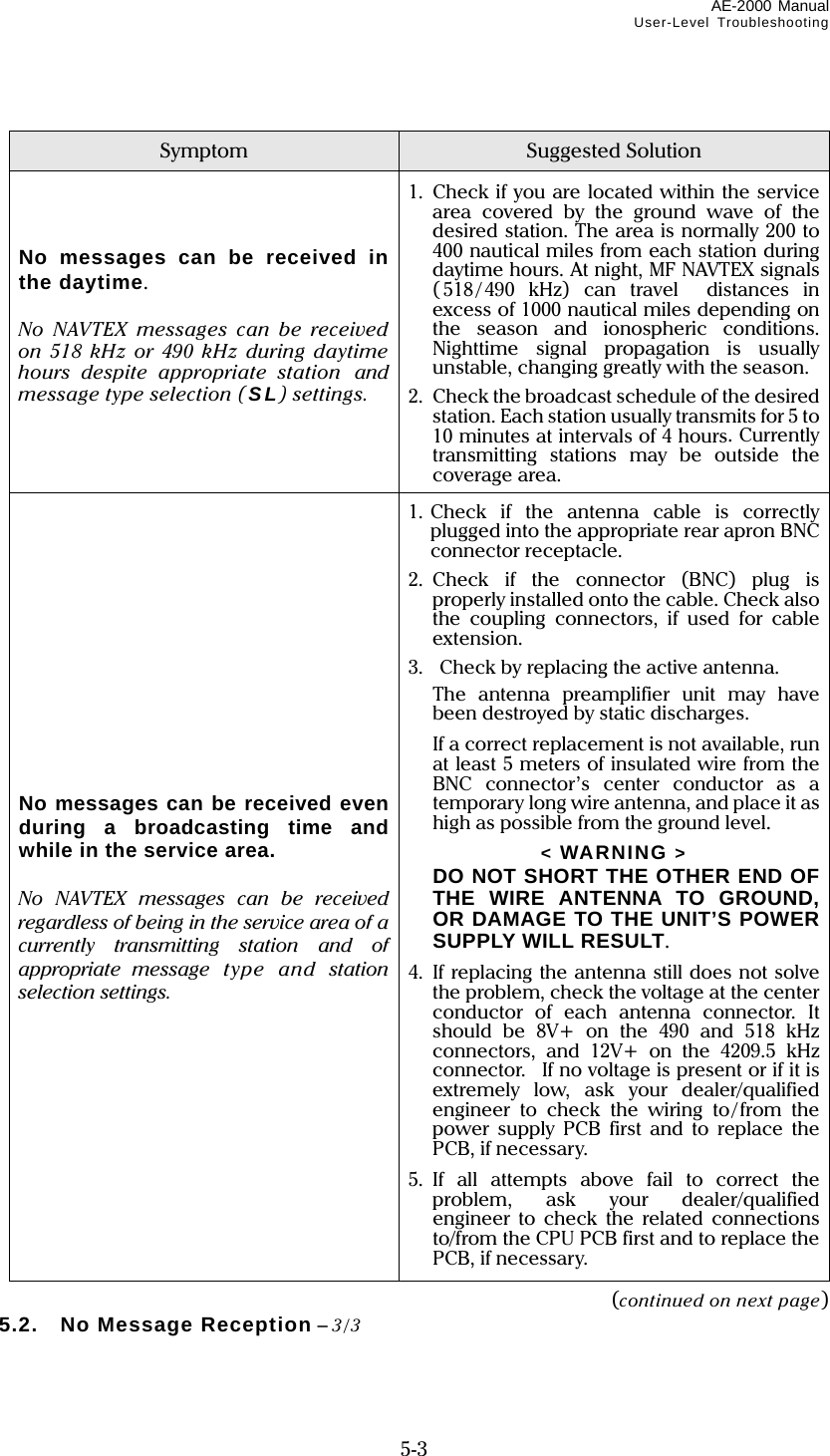
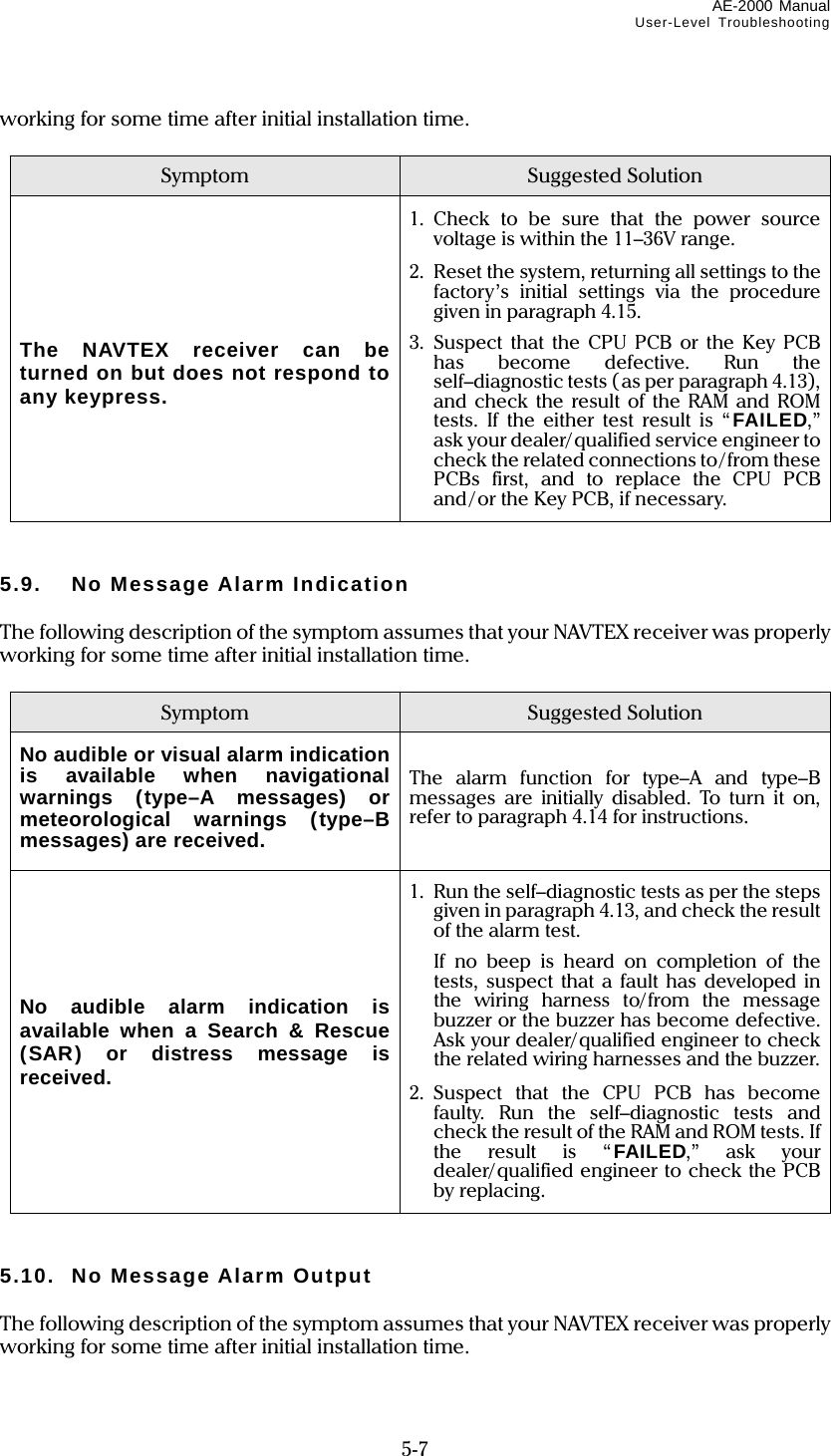
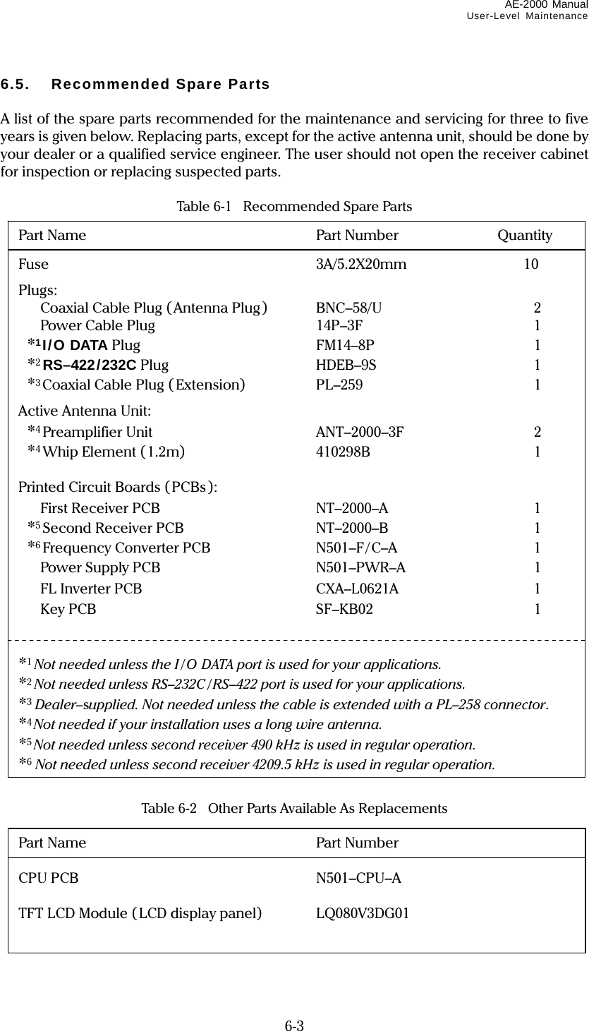
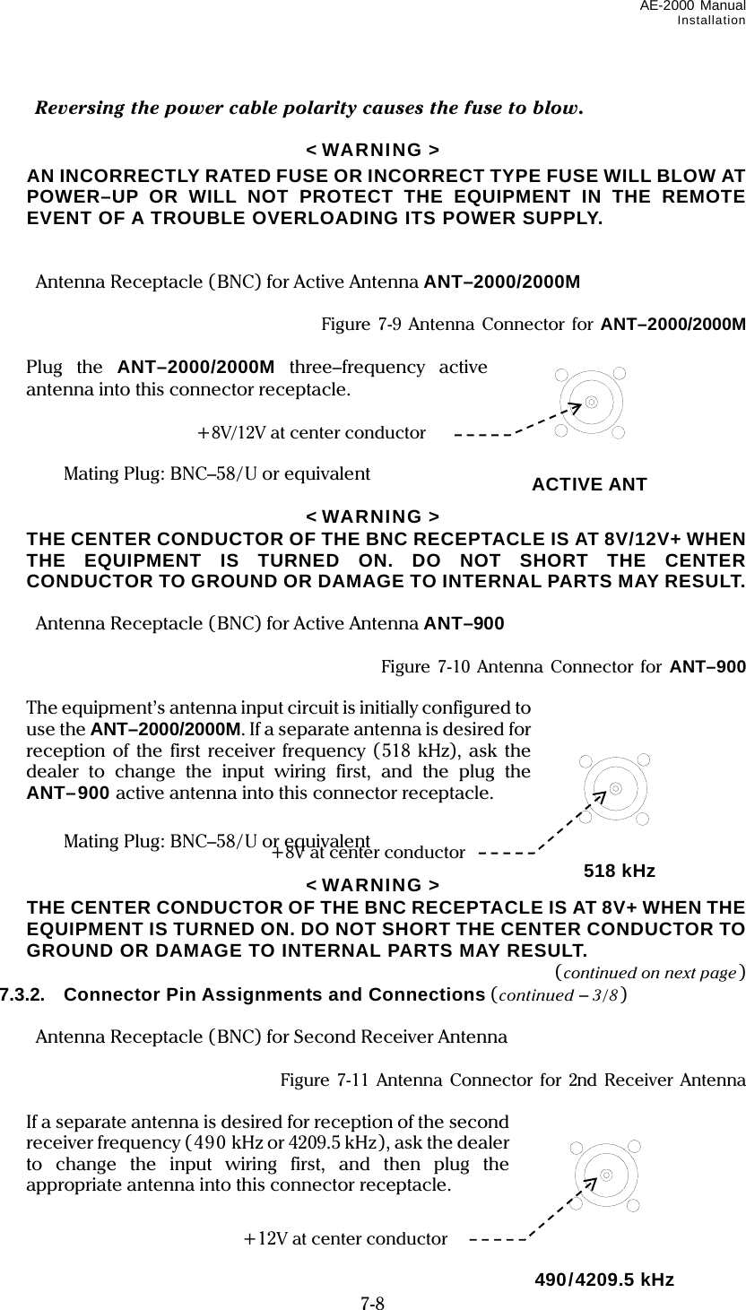
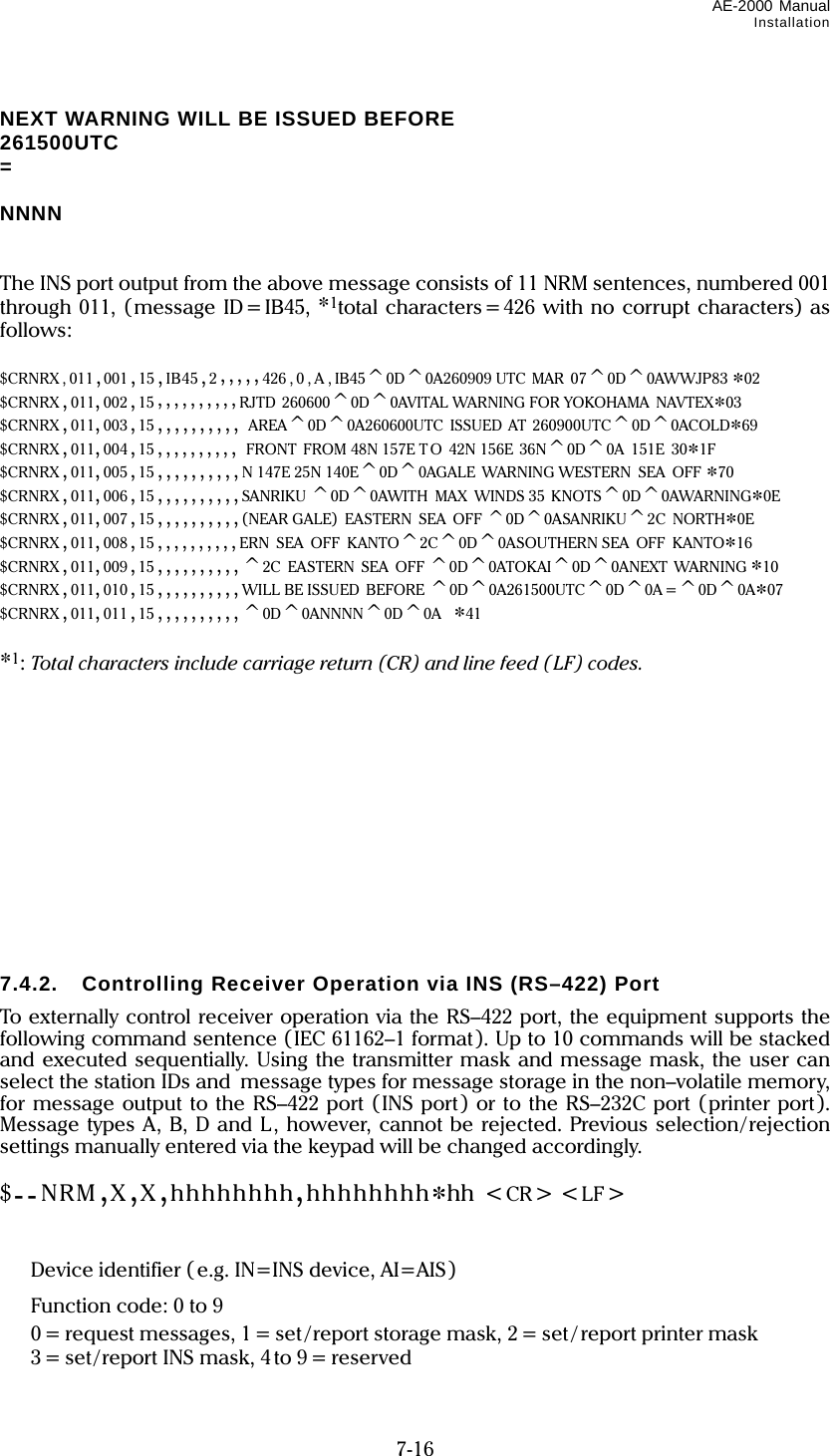
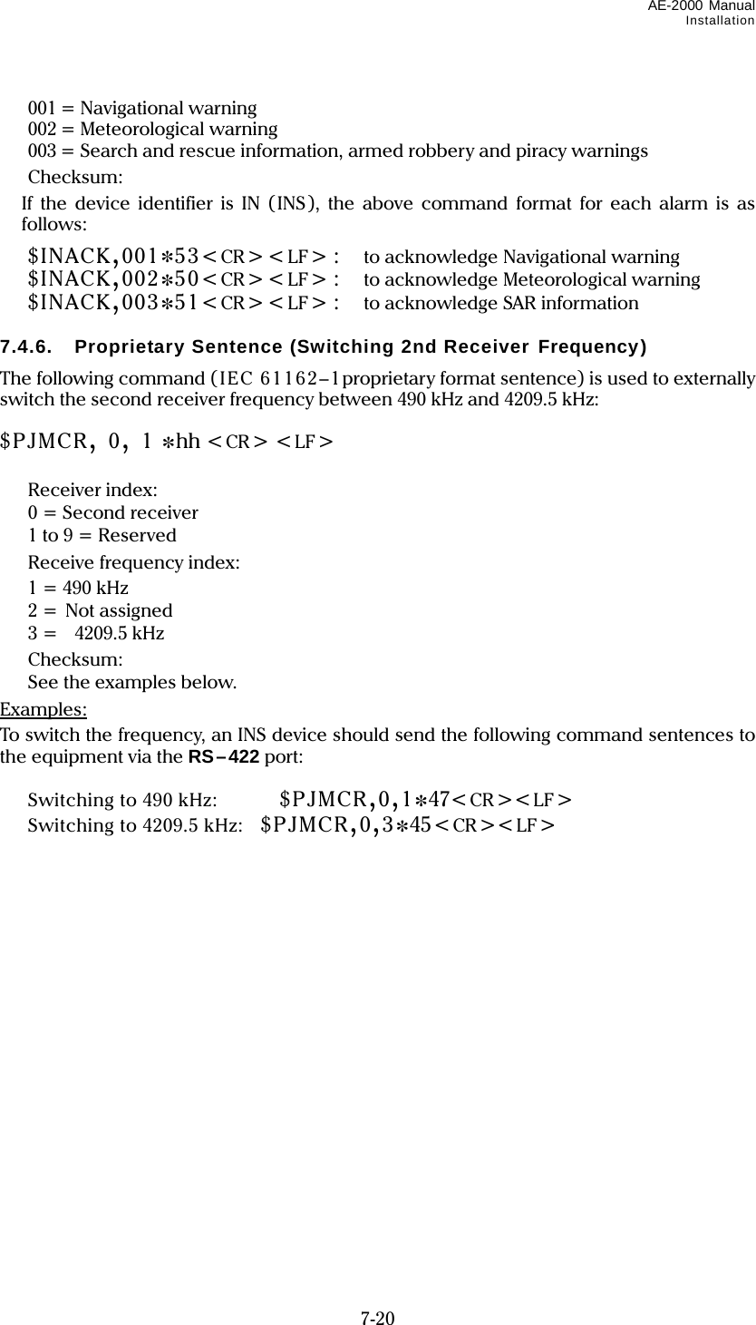
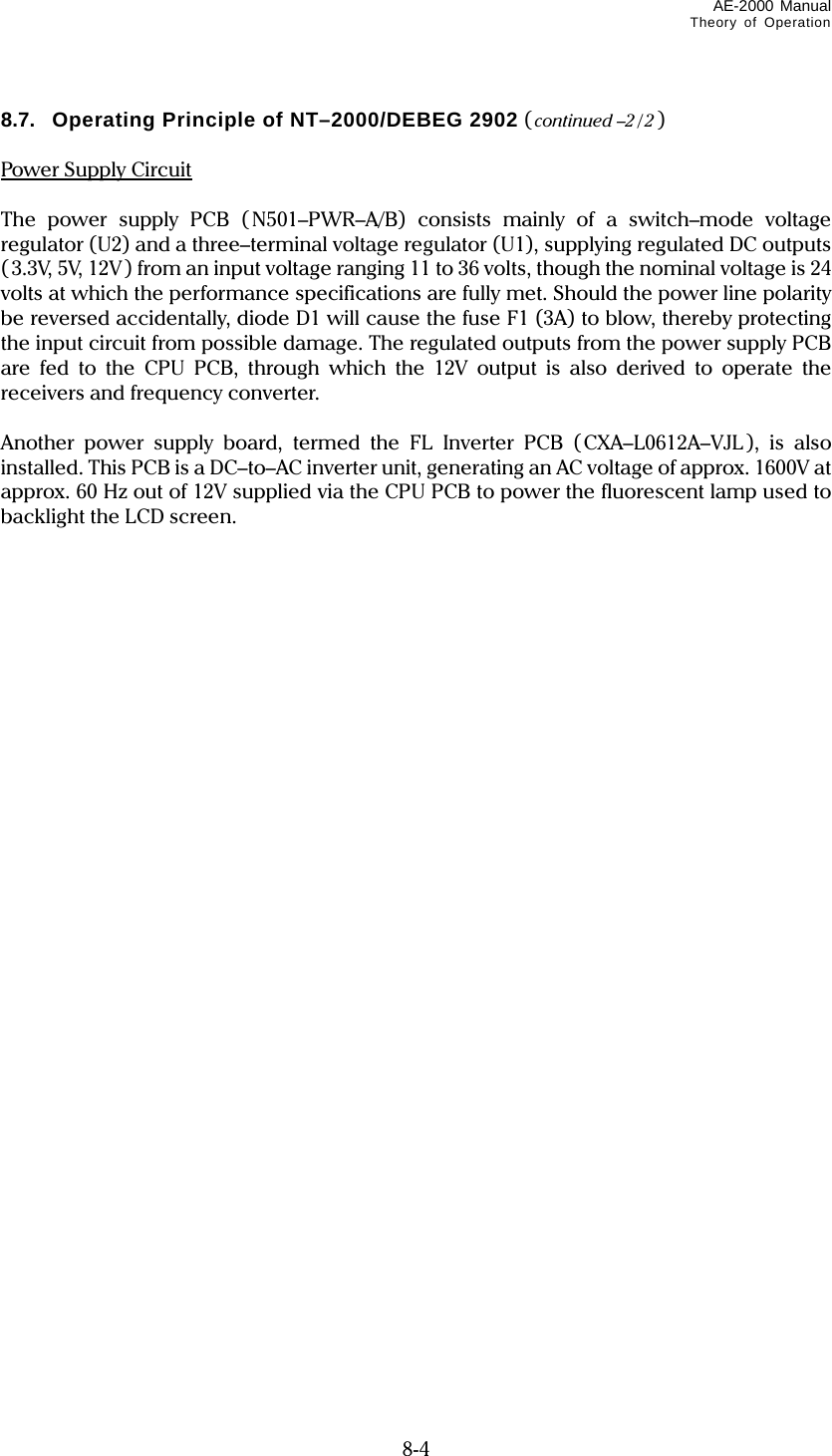
![AE–2000 Manual Control Panel Functions 2-2 After the unit is switched on, the opening message window will be replaced with another window listing the current settings of receiver control parameters, as in the example below. Figure 2-4 Current Settings of Receiver Control Parameters – Example The above list will stay on for approximately 20 seconds before the message screen shows up, replacing it automatically. To turn the list off immediately, press or . Keypad Dimmer Key Pressing this key adjusts the keypad backlighting level in a total of 8 steps including a completely switched–off level. The last used level will be stored in memory. When the equipment is switched off with the level at its minimum, the keypad will be lit at the highest level at next power–up time. Audible Monitor Key Pressing this key allows you to audibly monitor the reception of a NAVTEX transmission. To monitor the sound continuously, hold down the key. As soon as it is released, the audible output is turned off. (continued on next page) 2. Control Panel Functions (continued – 3/12) Screen Page Key CURRENT SETTINGS 1:FIRST RECEIVER: REJECTED STATIONS: REJECTED MESSAGE TYPES: G I M NO P Q R S T U W X Y 2:SECOND RECEIVER: REJECTED STATIONS: REJECTED MESSAGE TYPES: G I M NO P Q R S T U W X Y 3:KEYPRESS BEEP: ON 4:DISABLED MSG ALARMS: A B L 5: RECEIVING MSG OUTPUT: OFF 6: 2ND RECEIVER FREQ.: 490KHZ 7:DISPLAY SLEEP MODE: 5MIN./ 30MIN. IPRESS [CLR] OR [ENT] TO START. Blinks in reverse video.](https://usermanual.wiki/Morcom/AE2000/User-Guide-1042012-Page-17.png)
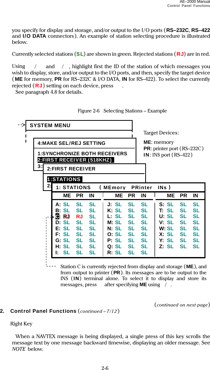
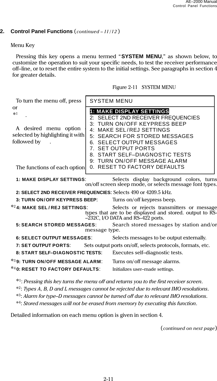
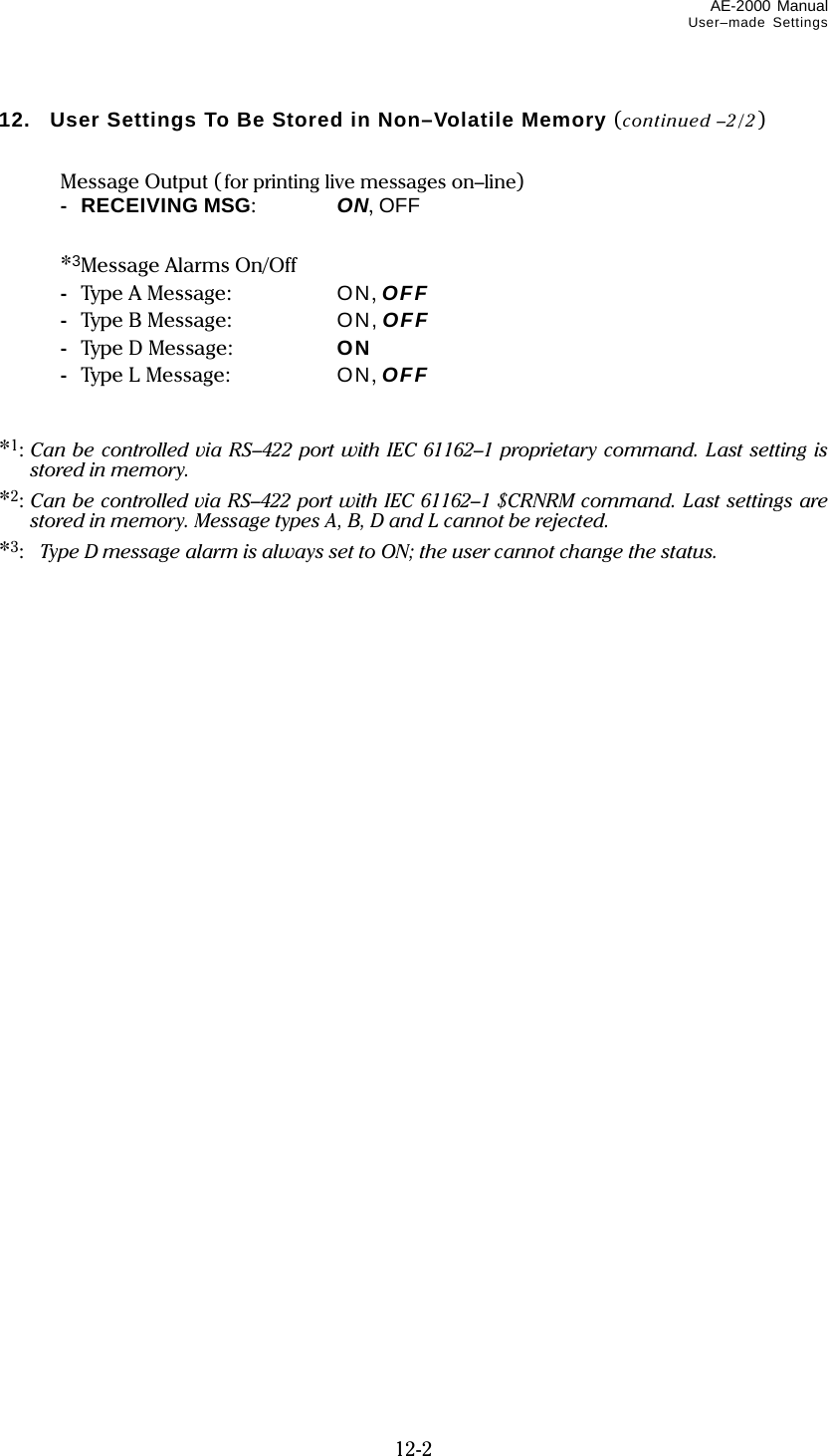
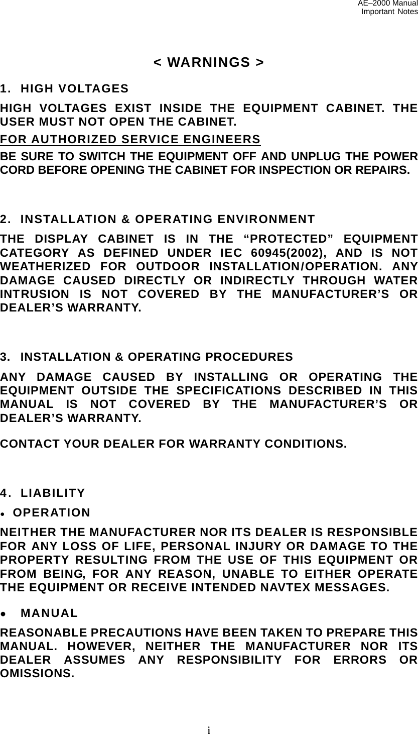
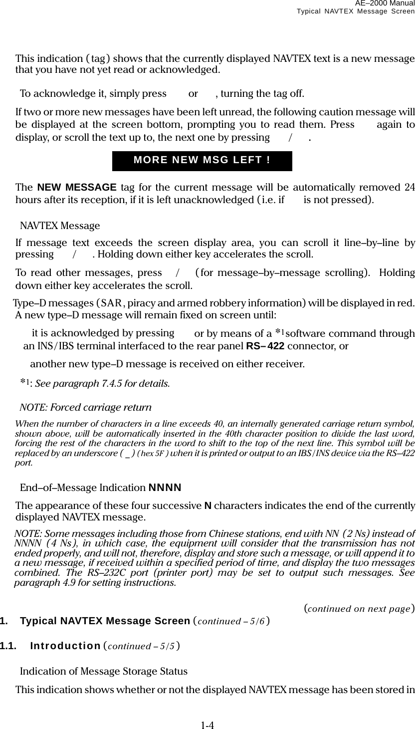
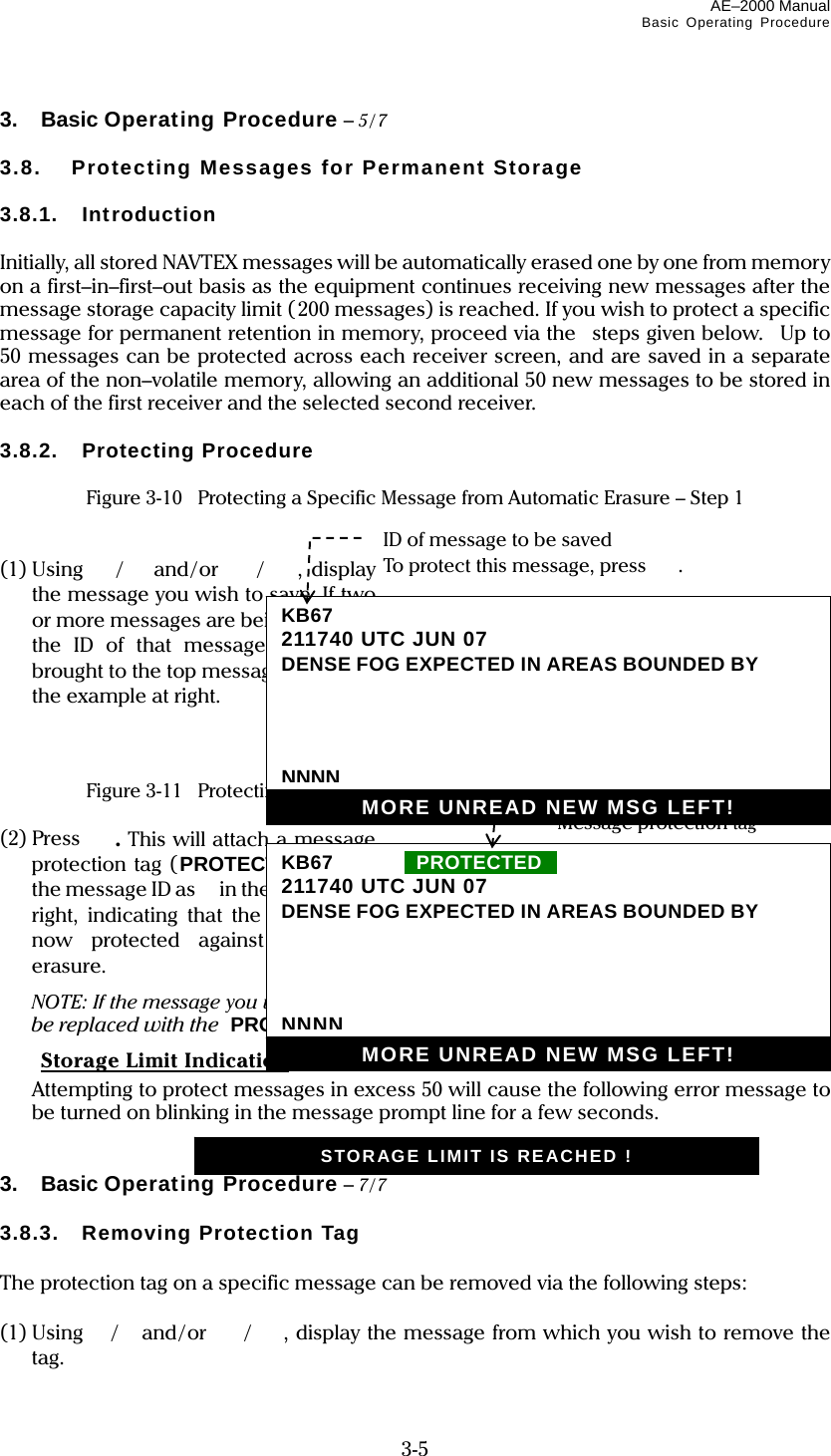
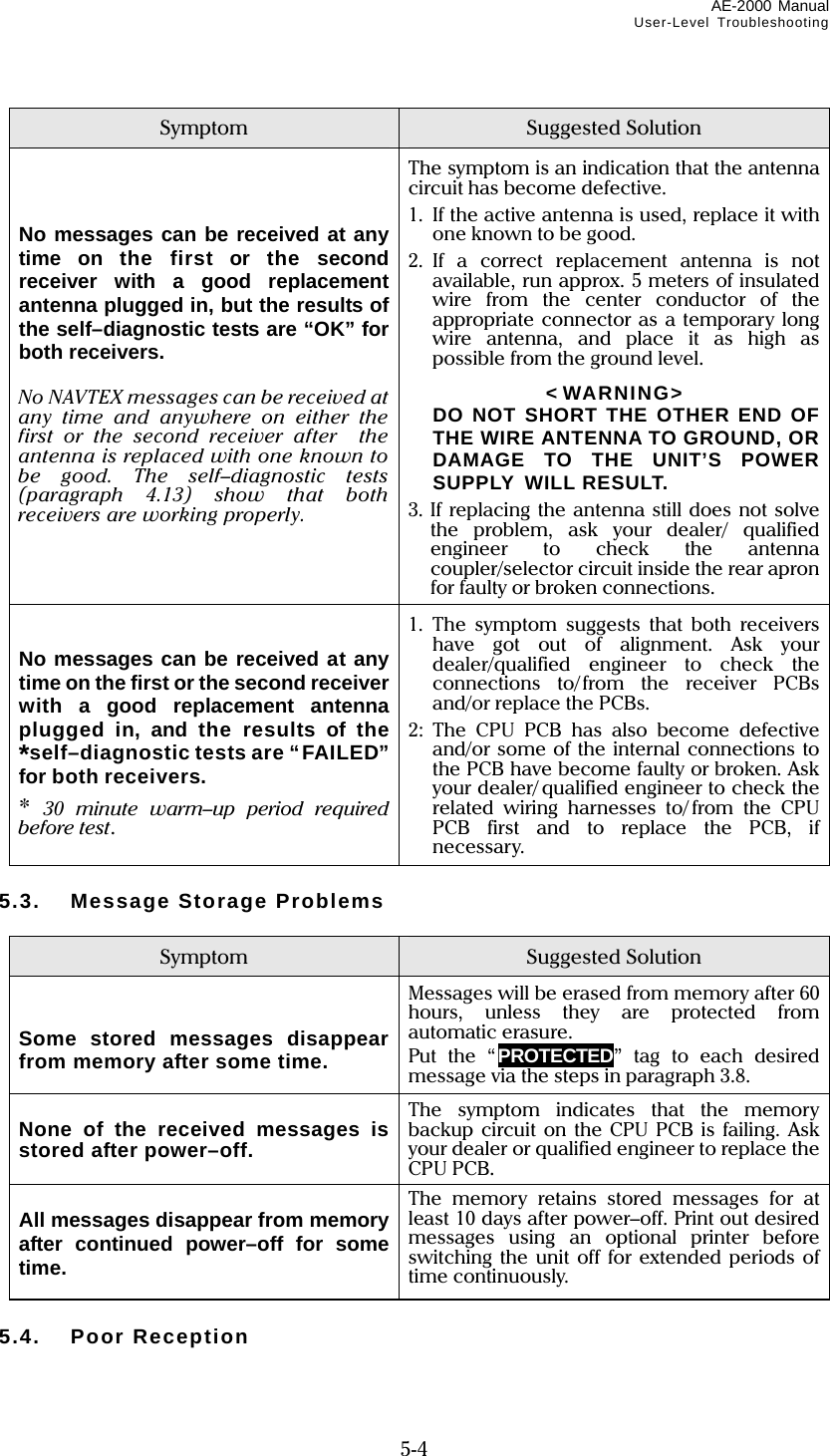
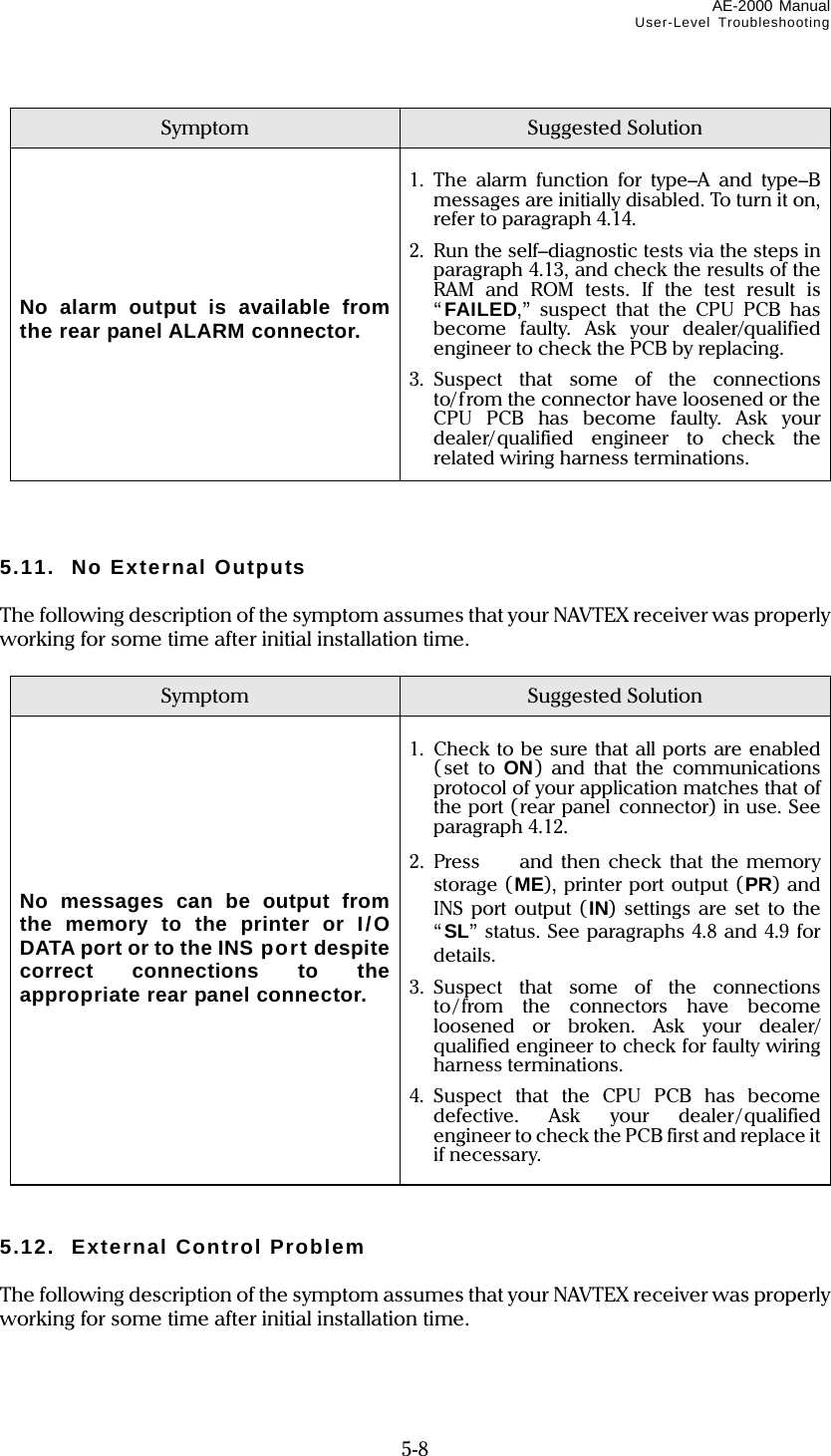
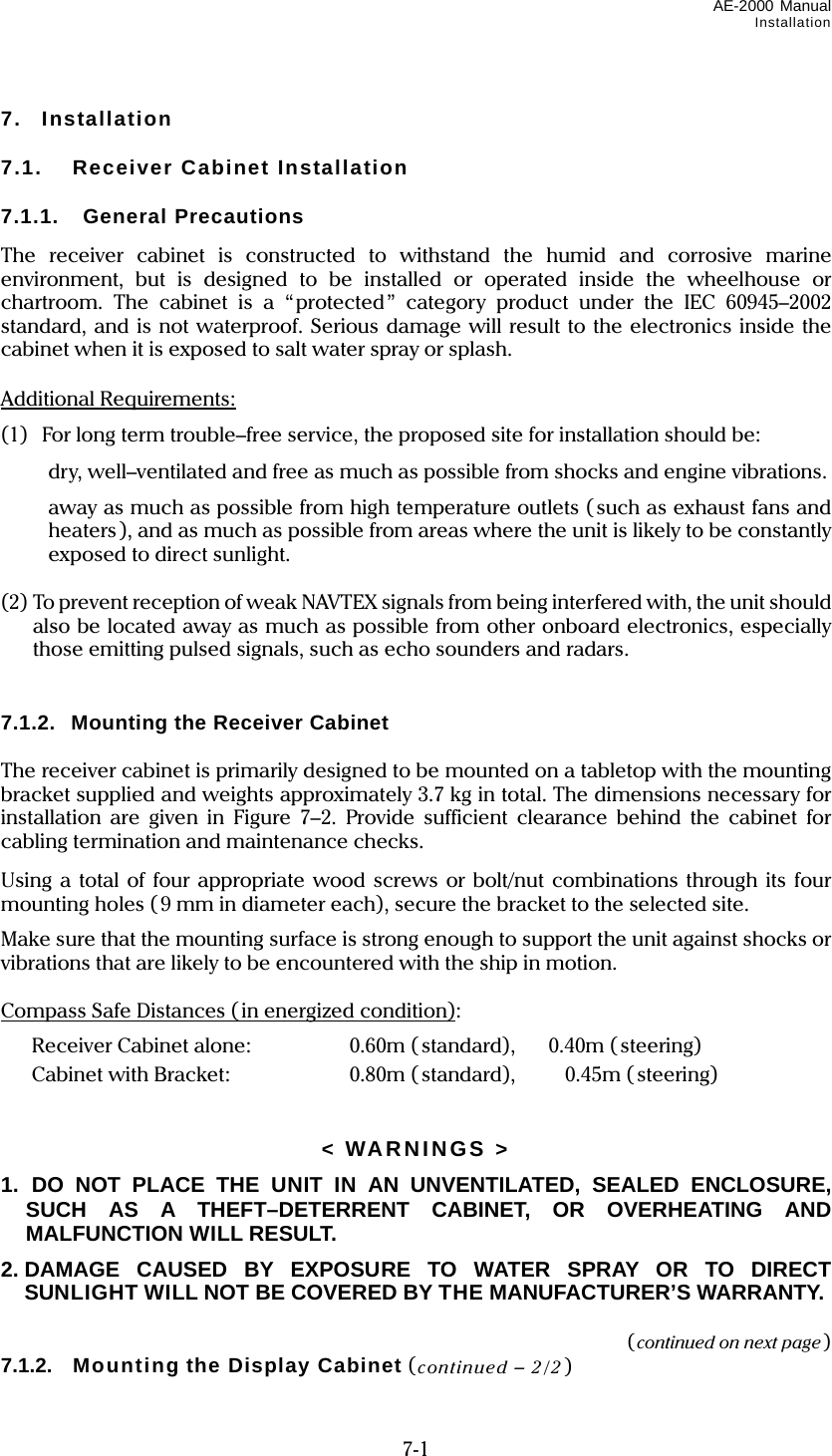
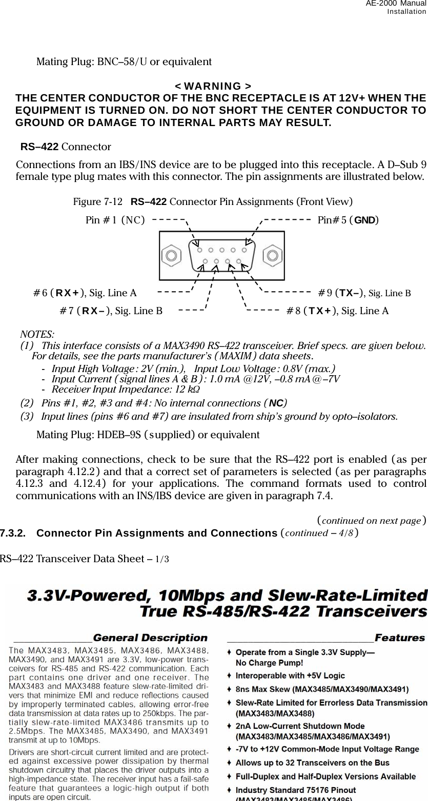
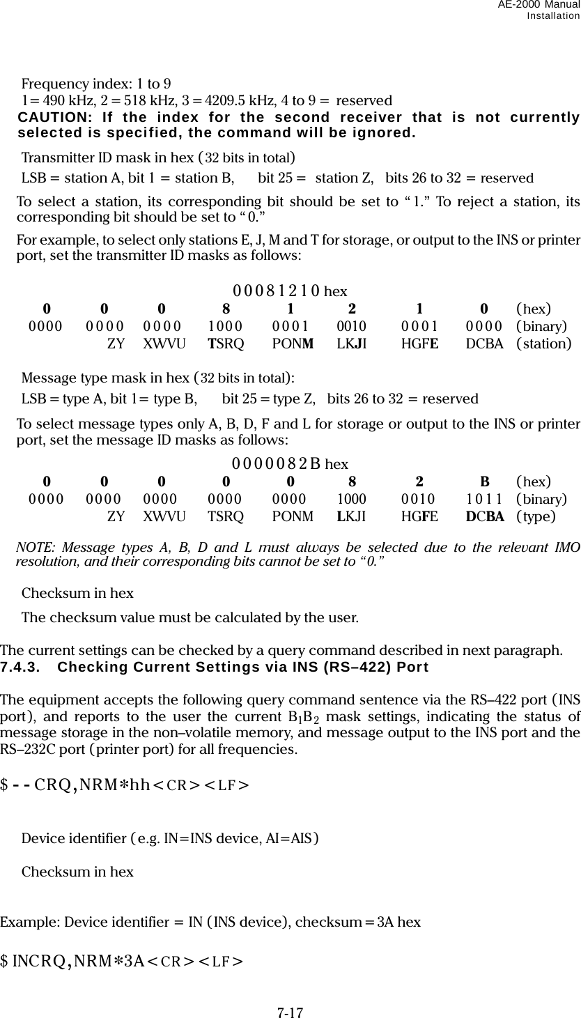
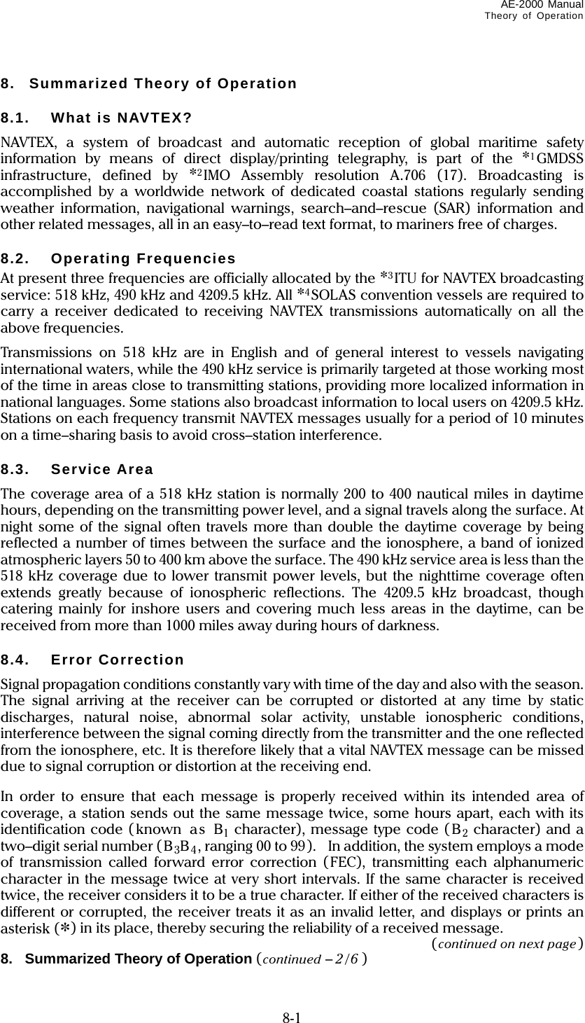
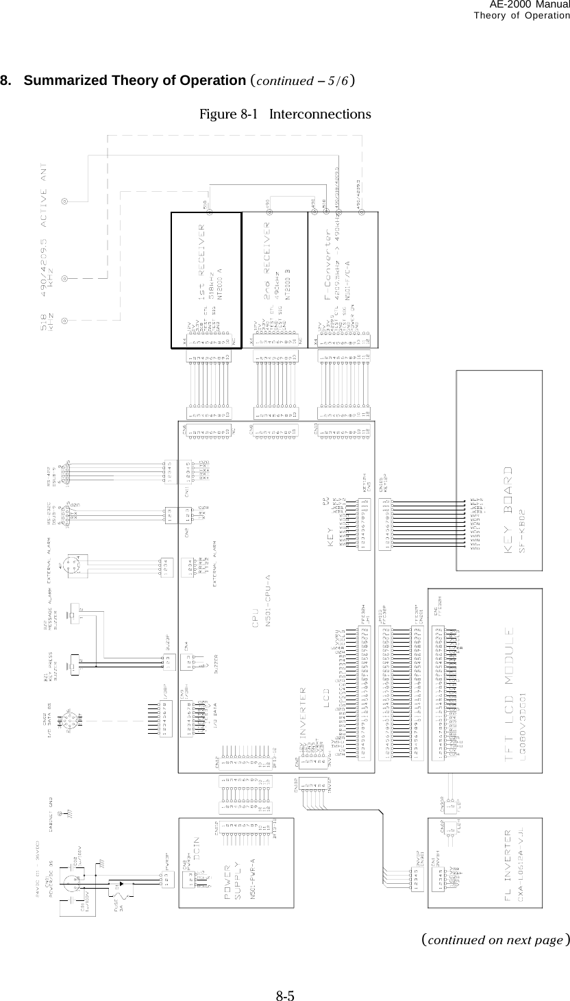
![AE-2000 Manual Control Panel Functions 2-12 2. Control Panel Functions (continued – 12 /12 ) Store Message Key This key is used to place a specific NAVTEX message in permanent storage, thereby protecting it from being automatically erased from memory after the maximum message storage limit (200 messages for each receiver) is reached. Pressing this key attaches a “ PROTECTED” tag to the ID of the message you wish to protect, and pressing *removes the tag from the message, as in the example below. *User confirmation is required. See below. Figure 2-12 Attaching /Removing Message Protection Tag – Example Up to 50 messages can be protected (for each of the first receiver and selected second receiver. An attempt to protect messages beyond this limit causes an operational error, turning on the following caution message in the message prompt line ( screen’s bottom line): The message storage capacity will increase by 50 to 250 messages when 50 received messages on either receiver are protected. Clear Key The major functions this key provides are: *1removing message protection tag ( PROTECTEDI ) from the currently displayed protected NAVTEX message. removing new message tag ( IINEW MESSAGEII ) from a new message, and turning off all menus at a time, returning to the first receiver message page when making settings via the *2menu system. *1:Removing the message protection tag requires your confirmation, as shown at right. Use / to select the desired option and then press . *2: See section 4 for more information. AA46 PROTECTED CCDG7 BNM 886–06 1. KEY W. HBR–MAIN CHAN IS REP BURNING DIM Protection tag is attached. AA46 CCDG7 BNM 886–06 1. KEY W. HBR–MAIN CHAN IS REP BURNING DIM Protection tag is removed. ARE YOU SURE ? 1: NO (CANCEL) 2: YES (EXECUTE) [▲] [▼] [ENT] STORAGE LIMIT IS REACHED !](https://usermanual.wiki/Morcom/AE2000/User-Guide-1042012-Page-27.png)
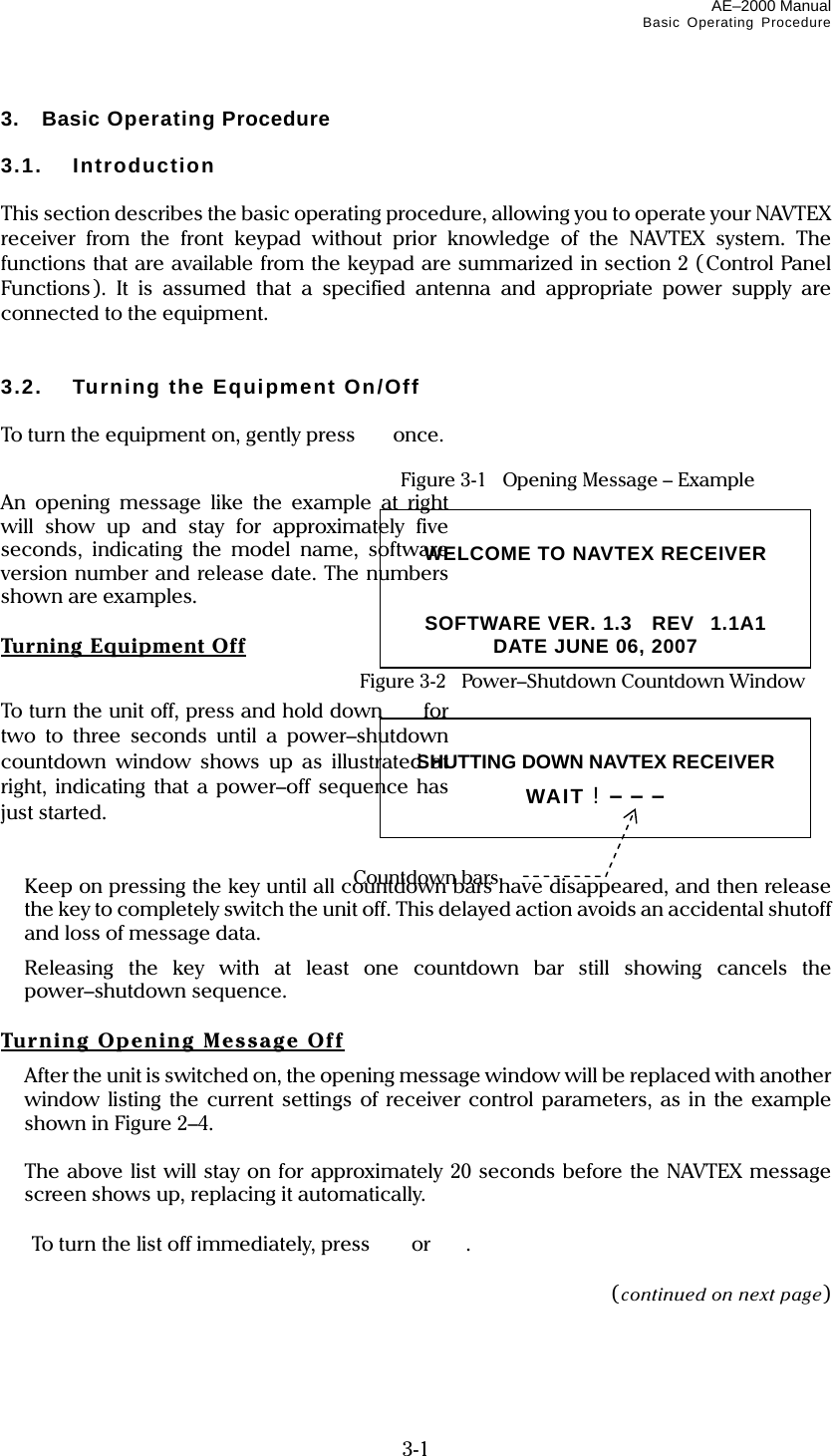
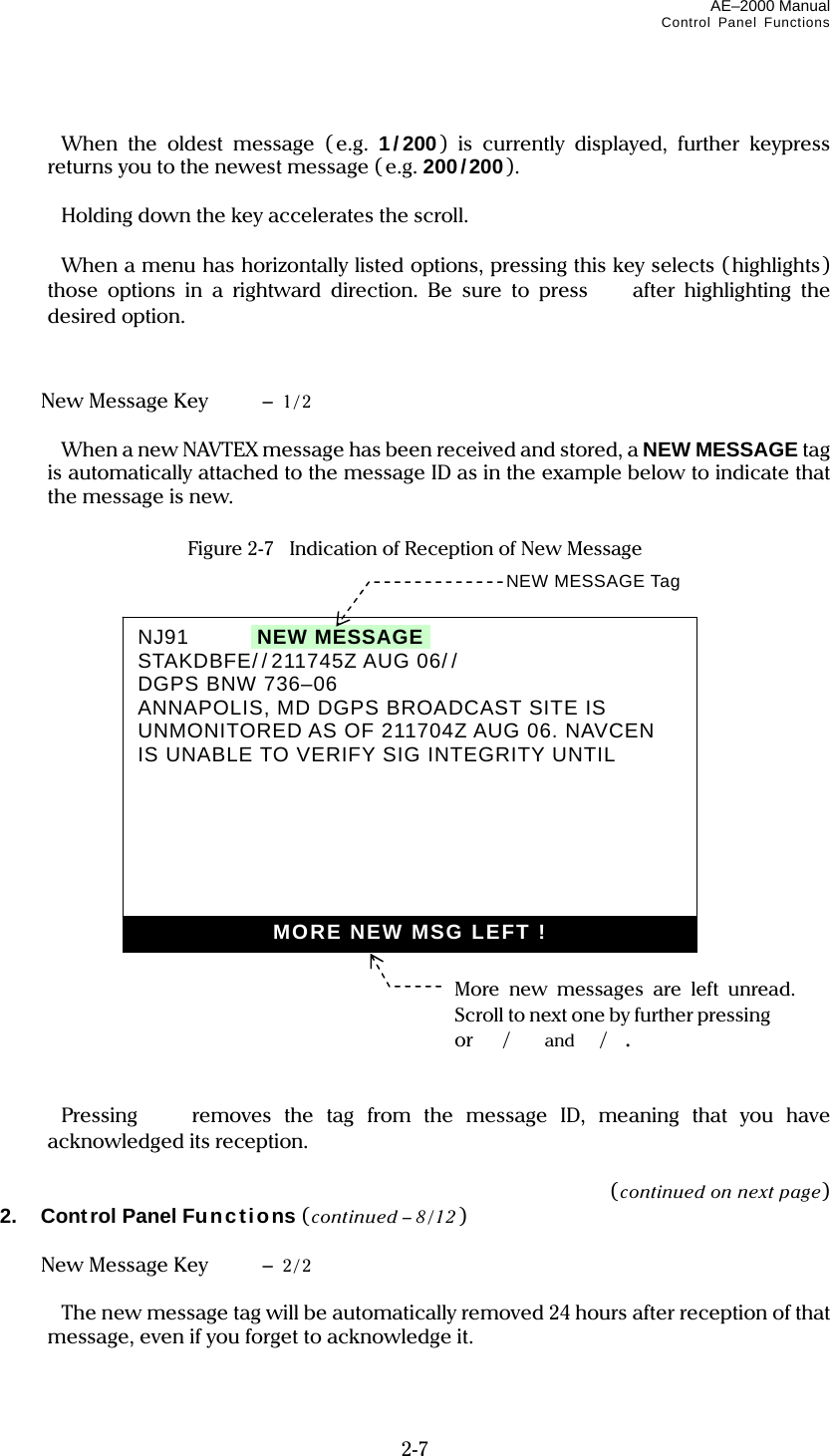
![AE–2000 Manual Basic Operating Procedure 3-6 (2) Press . This will cause the following caution window to pop up, asking you to confirm your action. (3) Press or to highlight option “2:YES (EXECUTE)” and then press . (4) If there are more messages you wish to remove the protection tag from, repeat the above steps. ARE YOU SURE ?1: NO (CANCEL )i 2: YES (EXECUTE ) [▲] [▼] [ENT]](https://usermanual.wiki/Morcom/AE2000/User-Guide-1042012-Page-33.png)
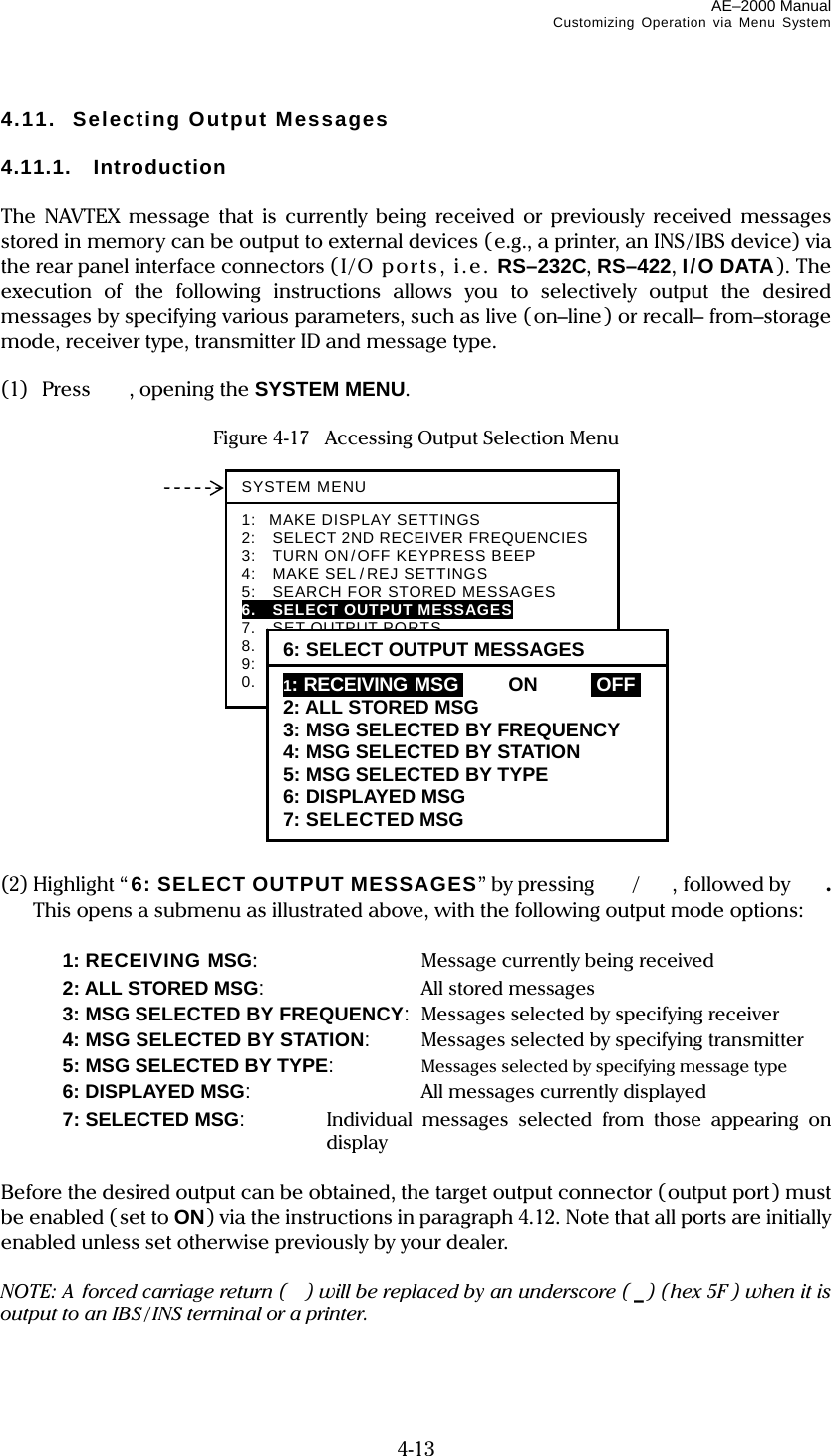
![AE-2000 Manual Customizing Operation via Menu System 4-15 4.11.3. Outputting All Stored Messages To output all the messages stored in memory, follow the steps given below. NOTE: A forced carriage return ( ) will be replaced by an underscore ( _) (hex 5F ) when it is output to an IBS / INS terminal or a printer. (1) Highlight “2:ALL STORED MSG” on the SELECT OUTPUT MESSAGES submenu, and then press . The stored messages will then be output one by one. Figure 4-19 Outputting All Stored Messages The following window will pop up to indicate the outputting action in progress. The window will be turned off automatically upon completion of outputting. To cancel the action, press . (2) Press to return to the previous menu or to return to the first receiver message screen. OUTPUTTING STORED MESSAGES. TO CANCEL, PRESS [CLR]. Select this option with /, and then press . 6: SELECT OUTPUT MESSAGES1: RECEIVING MSG ON IOFFI 2: ALL STORED MSGI 3: MSG SELECTED BY FREQUENCY 4: MSG SELECTED BY STATION 5: MSG SELECTED BY TYPE 6: DISPLAYED MSG 7: SELECTED MSG](https://usermanual.wiki/Morcom/AE2000/User-Guide-1042012-Page-48.png)
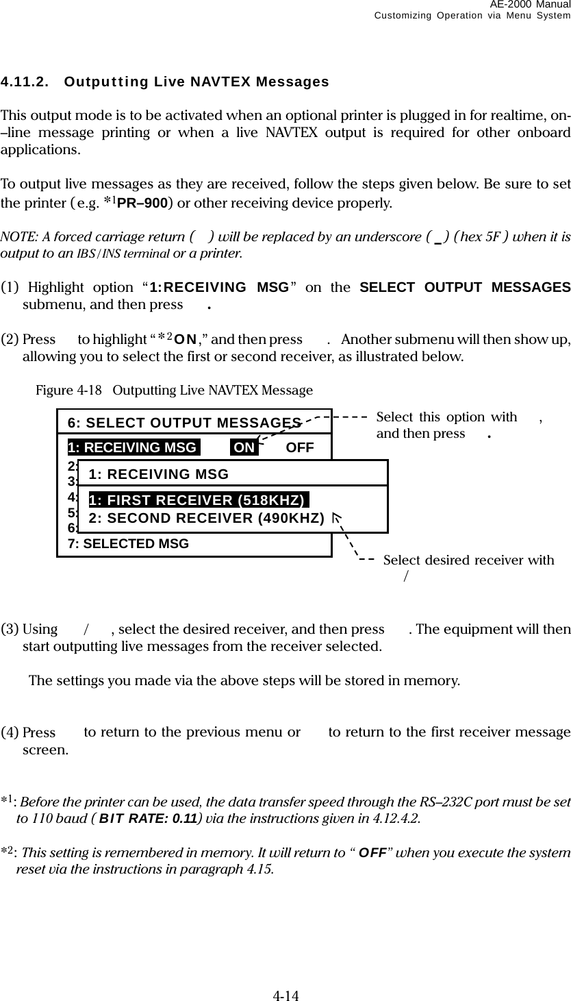
![AE-2000 Manual Customizing Operation via Menu System 4-16 4.11.4. Outputting NAVTEX Messages of Specific Receiver If you wish to output all NAVTEX messages received from either receiver (first or second receiver) alone, carry out the following step–by–step procedure: NOTE: A forced carriage return ( ) will be replaced by an underscore ( _) (hex 5F ) when it is output to an IBS / INS terminal or a printer. (1) Highlight option “ 3:MSG SELECTED BY FREQUENCY” on the SELECT OUTPUT MESSAGES submenu, and then press . This turns on another submenu with the following options, enabling you to select the desired receiver, as in the example illustrated below: 1: FIRST RECEIVER (518 KHZ): Outputs first receiver messages. 2: SECOND RECEIVER: Outputs second receiver messages. Figure 4-20 Outputting Stored Messages of First Receiver – Example (2) Highlight the desired option, and then press . The following window will pop up to indicate the outputting action in progress. The window will be turned off automatically upon completion of outputting. To cancel the action, press . (3) Press to return to the previous menu or to return to the first receiver message screen. OUTPUTTING STORED MESSAGES. TO CANCEL, PRESS [CLR]. To derive first receiver messages from memory, select this option with /, and then press . 6: SELECT OUTPUT MESSAGES1: RECEIVING MSG ON IOFFI 2: ALL STORED MSG 3: MSG SELECTED BY FREQUENCYi 4: MSG SELECTED BY STATION 5: MSG SELECTED BY TYPE 6: DISPLAYED MSG – ALL 7: DISPLAYED MSG – SPECIFIC 3: MSG SELECTED BY FREQUENCY 1: FIRST RECEIVER (518 KHZ) 2: SECOND RECEIVER](https://usermanual.wiki/Morcom/AE2000/User-Guide-1042012-Page-49.png)
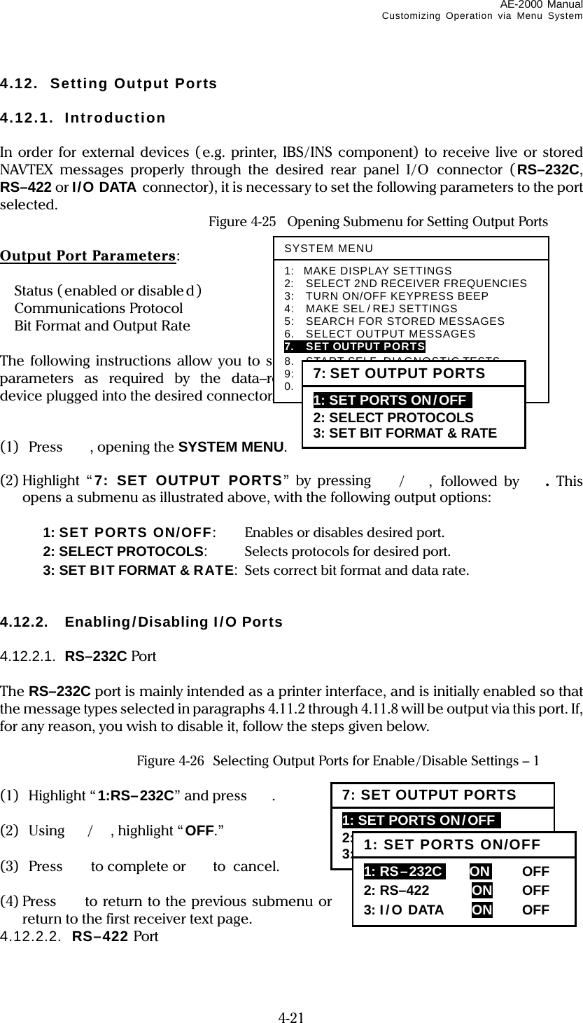
![AE-2000 Manual Customizing Operation via Menu System 4-17 4.11.5. Outputting NAVTEX Messages of Specific Station If you wish to output all messages received from a specific NAVTEX transmitting station, carry out the following step–by–step procedure: NOTE: A forced carriage return ( ) will be replaced by an underscore ( _) (hex 5F ) when it is output to an IBS / INS terminal or a printer. (1) Highlight option “ 4:MSG SELECTED BY STATION” on the SELECT OUTPUT MESSAGES submenu, and then press . This turns on another submenu with a list of station IDs, enabling you to select the desired transmitter, as in the example illustrated below: Figure 4-21 Outputting Stored Messages Received from Station D – Example (2) Using /, highlight the desired ID, and then press . The following window will pop up to indicate the outputting action in progress. The window will be turned off automatically upon completion of outputting. To cancel the action, press . (3) Press to return to the previous menu or to return to the first receiver message screen. Select desired station ID with /, and then press . 6: SELECT OUTPUT MESSAGES1: RECEIVING MSG ON IOFFI 2: ALL STORED MSG 3: MSG SELECTED BY FREQUENCY 4: MSG SELECTED BY STATIONi 5: MSG SELECTED BY TYPE 6: DISPLAYED MSG – ALL 7: DISPLAYED MSG – SPECIFIC 4:MSG SELECTED BY STATIONA B C iDi E F G H I J K L M N O P Q R S T U V W X Y Z OUTPUTTING STORED MESSAGES. TO CANCEL, PRESS [CLR].](https://usermanual.wiki/Morcom/AE2000/User-Guide-1042012-Page-50.png)
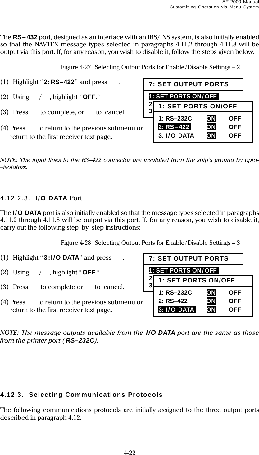
![AE-2000 Manual Customizing Operation via Menu System 4-18 4.11.6. Outputting NAVTEX Messages of Specific Message Type If you wish to output all messages of a specific message type, carry out the following step-–by–step instructions: NOTE: A forced carriage return ( ) will be replaced by an underscore ( _) (hex 5F ) when it is output to an IBS / INS terminal or a printer. (1) Highlight option “5:MSG SELECTED BY TYPE” on the SELECT OUTPUT MESSAGES submenu, and then press . This turns on another submenu with a list of message types, enabling you to select the desired message type, as in the example illustrated below: Figure 4-22 Outputting Stored Messages of Message Type D – Example (2) Using /, highlight the desired message type, and then press . The following window will pop up to indicate the outputting action in progress. The window will be turned off automatically upon completion of outputting. To cancel the action, press . (3) Press to return to the previous menu or to return to the first receiver message screen. 6: SELECT OUTPUT MESSAGES1: RECEIVING MSG ON IOFFI 2: ALL STORED MSG 3: MSG SELECTED BY FREQUENCY 4: MSG SELECTED BY STATION 5: MSG SELECTED BY TYPEi 6: DISPLAYED MSG – ALL 7: DISPLAYED MSG – SPECIFIC Select desired message type with /, and then press . 5:MSG SELECTED BY TYPEA B C iDi E F G H I J K L M N O P Q R S T U V W X Y Z OUTPUTTING STORED MESSAGES. TO CANCEL, PRESS [CLR].](https://usermanual.wiki/Morcom/AE2000/User-Guide-1042012-Page-51.png)
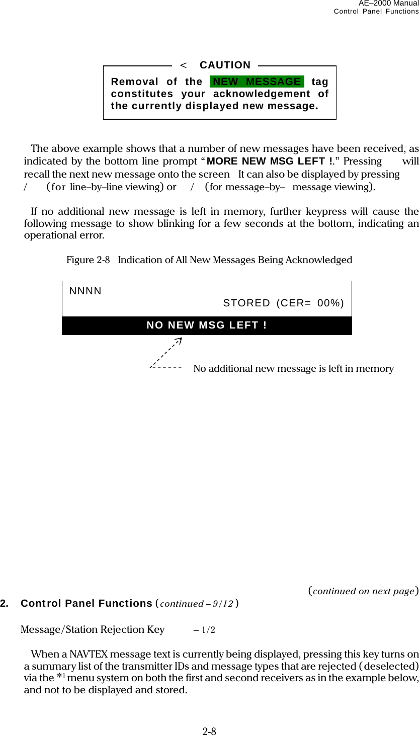
![AE-2000 Manual Customizing Operation via Menu System 4-19 4.11.7. Outputting All Displayed NAVTEX Messages If you wish to output all messages currently displayed, follow the steps given below. NOTE: A forced carriage return ( ) will be replaced by an underscore ( _) (hex 5F ) when it is output to an IBS / INS terminal or a printer. (1) Highlight “ 6:DISPLAYED MSG” on the SELECT OUTPUT MESSAGES submenu, and then press . This turns all menus off, showing the current message screen, as in the example illustrated below. Figure 4-23 Outputting All Currently Displayed Messages – Example (2) Press to output all the displayed messages, or to cancel the function. The previous message screen will return automatically upon completion of the output. NJ91STAKDBFE//211745Z AUG 06// DGPS BNM 736–06 ANNAPOLIS, MD DGPS BROADCAST SITE IS UNMONITORED AS OF 211704Z AUG 06. NAVCEN IS UNABLE TO VERIFY SIG INTEGRITY UNTIL FURTHER NOTICE. NNNN STORED (CER= 00%) AA51 CCGD7 BNW 887–06 1. MIAMI HBW–MIAMI MAIN CHAN LT 19 LLNRD 2. CANCEL AT TIME//190400Z SEP 06X NNNN STORED (CER= 00%) PRESS [ENT] TO OUTPUT OR [CLR] TO EXIT All currently displayed messages will be output by pressing Select this option with /, and then press . 6: SELECT OUTPUT MESSAGES1: RECEIVING MSG ON IOFFI 2: ALL STORED MSG 3: MSG SELECTED BY FREQUENCY 4: MSG SELECTED BY STATION 5: MSG SELECTED BY TYPE 6: DISPLAYED MSG 7: SELECTED MSG](https://usermanual.wiki/Morcom/AE2000/User-Guide-1042012-Page-52.png)
![AE-2000 Manual Customizing Operation via Menu System 4-20 4.11.8. Outputting Specific NAVTEX Message If you wish to output a specific message out of all currently displayed messages, carry out the following procedure: NOTE: A forced carriage return ( ) will be replaced by an underscore ( _) (hex 5F ) when it is output to an IBS / INS terminal or a printer. (1) Highlight “ 7:SELECTED MSG” on the SELECT OUTPUT MESSAGES submenu, and then press . This turns all menus off, showing the current message screen, as in the example illustrated below. Figure 4-24 Outputting Specific Message – Example (2) Using / , highlight the ID of the desired message as in the example above, and then press . To cancel the function, press instead of . Select this option with /, and then press . 6: SELECT OUTPUT MESSAGES1: RECEIVING MSG ON IOFFI 2: ALL STORED MSG 3: MSG SELECTED BY FREQUENCY 4: MSG SELECTED BY STATION 5: MSG SELECTED BY TYPE 6: DISPLAYED MSG 7: SELECTED MSG To output this message, select its ID with / and then press . NJ91 STAKDBFE//211745Z AUG 06// DGPS BNM 736–06 ANNAPOLIS, MD DGPS BROADCAST SITE IS UNMONITORED AS OF 211704Z AUG 06. NAVCEN IS UNABLE TO VERIFY SIG INTEGRITY UNTIL FURTHER NOTICE. NNNN STORED (CER= 00%) AA51 CCGD7 BNW 887–06 1. MIAMI HBW–MIAMI MAIN CHAN LT 19 LLNRD 2. CANCEL AT TIME//190400Z SEP 06X NNNN STORED (CER= 00%) PRESS [ENT] TO OUTPUT OR [CLR] TO EXIT](https://usermanual.wiki/Morcom/AE2000/User-Guide-1042012-Page-53.png)

![AE-2000 Manual List of Alarms 10-1 10. List of Alarms 10.1. Message Alarms ● Alarm for D–Type Message Enabled/ Disabled Status: Enabled at all times. Triggering Condition: To be triggered upon reception of a D–type message. User Interface: - Audible: Beeping at approx. 1–sec. intervals by alarm buzzer. - Visual: Attaching iALARM!i tag to message ID and displaying both message ID and text in red. ● Alarm for A–, B–, and L–Type Messages Enabled/Disabled Status: Initially disabled, and can be individually enabled by the user. See paragraph 4.13 for instructions. Triggering Condition: To be triggered upon reception of an A–, B– or L–type message. User Interface: - Audible: Beeping at approx. 3–sec. intervals by alarm buzzer. - Visual: Attaching iALARM!i tag to message ID and displaying message ID in red. 10.2. Operational Alarms ● Storage Limit Alarm: Enabled/Disabled Status: Enabled at all times. Triggering Condition: To be triggered when protecting NAVTEX messages for permanent storage in excess of 50. User Interface: - Audible: Beeping 3 times in quick succession by small buzzer. - Visual: Displaying warning “STORAGE LIMIT IS REACHED !” in prompt line at screen’s bottom. ● Memory–Full Alarm: Enabled/Disabled Status: Enabled at all times. Triggering Condition: To be triggered when receiving new NAVTEX message with 199 messages stored. User Interface: - Audible: Beeping 3 times in quick succession by small buzzer. - Visual: Displaying warning “MEMORY FULL! [ CLR ] TO ACKNLG.” in prompt line at screen’s bottom. ● Invalid Keypress Alarm: Enabled/Disabled Status: Enabled at all times. Triggering Condition: To be triggered when any key not valid for current operation is pressed. User Interface: - Audible: Beeping 3 times in quick succession by small buzzer. - Visual: Displaying warning “INVALID KEYPRESS,” blinking.](https://usermanual.wiki/Morcom/AE2000/User-Guide-1042012-Page-106.png)