Morcom AE2000 Dual Channel Navtex Receiver User Manual AE 2000 REF Manual Ver 1 3
Morcom International, Inc. Dual Channel Navtex Receiver AE 2000 REF Manual Ver 1 3
Morcom >
User Manual
AE-2000 Instruction Manual
UM-AE2000-2.0
Second Edition
February, 2007
ALDEN
NAVTEX Receiver
MODEL AE–2000
INSTRUCTION MANUAL
Valid for Software Version 1.3

AE-2000 Manual
WARRANTY
WARRANTY
MORCOM International, Inc. ( MORCOM) warrants the AE–2000 NAVTEX Receiver
and its active antenna ANT–2000 against defects in materials and workmanship for a
period of one year from the date of shipping from the factory, during which time MORCOM
will, at its option, either repair or replace the products that prove to be defective.
Users shall ship defective products, freight prepaid, back to a specified MORCOM dealer for
warranty service.
The warranty shall not apply to defects caused by:
● Misuse or incorrect usage
● Static discharges/lightning strikes to the antenna or to the receiver or other types of
natural disaster
● RF power from radio transmitters in excess of 30V RMS at the antenna input
● Improper or inadequate maintenance by the user
● Unauthorized service including modification, realignment of the receiver/antenna
● User–supplied software or interfacing
● Operation outside the environmental specifications listed in the manual, or
● Improper installation
The above warranty applies to the original user with a proof of purchase.
Before returning the unit to your MORCOM dealer for warranty service, please obtain
MORCOM’ s return authorization.
When shipping the unit to your dealers for service, please be sure to include the following
types of information:
Serial number
Software release date and revision (REV.) number
Power supply voltage
Installation details, including antenna height and surrounding environment
Detailed description of trouble
Valid proof of purchase from authorized MORCOM dealer
MORCOM International, Inc.
3656 Centerview Drive, Unit #1
Chantilly, VA 20151 – U. S. A.
PHONE: (703)263–9305
FAX: (703)263–9308
www.morcom.com

AE–2000 Manual
Important Notes
i
IMPORTANT NOTES
1. RADIO FREQUENCY INTERFERENCE
This equipment has been tested and found to comply with the limits for a
Class A digital device pursuant to Part 15 of FCC Rules. These limits are
designed to provide reasonable protection against harmful interference
when this equipment is operated in a commercial environment.
This equipment generates, uses and can radiate radio frequency energy
and, if not installed and used in accordance with the instruction manual,
may cause harmful interference to radio communications.
Operation of this equipment in a residential area is likely to cause harmful
interference, in which case the user will be required to correct the
interference at his/her own expense.
2. PURPOSE OF THIS MANUAL
The purpose of this manual is to help the user operate and maintain the
equipment. The information provided is not to be considered as a contractual
specification.
3. USER’S RESPONSIBILITY
The Alden Model AE–2000 NAVTEX Receiver obtains data transmitted from
Government facilities. MORCOM International Inc. (MORCOM) makes no
claim as to the accuracy, completeness or currency of the data since the
AE–2000 only provides a means of receiving the data. Users are completely
responsible for verifying the correctness and currency of all data received,
and MORCOM shall not be liable to users for any loss, damage or liability
caused directly or indirectly by such use. Users are solely responsible for
action taken or not taken as a result of the reception or non–reception of data.
MORCOM International, Inc.
3656 Centerview Drive, Unit #1
Chantilly, VA 20151 – U. S. A.
PHONE: (703)263–9305
FAX: (703)263–9308
www.morcom.com

AE–2000 Manual
Important Notes
i
< WARNINGS >
1. HIGH VOLTAGES
HIGH VOLTAGES EXIST INSIDE THE EQUIPMENT CABINET. THE
USER MUST NOT OPEN THE CABINET.
FOR AUTHORIZED SERVICE ENGINEERS
BE SURE TO SWITCH THE EQUIPMENT OFF AND UNPLUG THE POWER
CORD BEFORE OPENING THE CABINET FOR INSPECTION OR REPAIRS.
2. INSTALLATION & OPERATING ENVIRONMENT
THE DISPLAY CABINET IS IN THE “PROTECTED” EQUIPMENT
CATEGORY AS DEFINED UNDER IEC 60945(2002), AND IS NOT
WEATHERIZED FOR OUTDOOR INSTALLATION/OPERATION. ANY
DAMAGE CAUSED DIRECTLY OR INDIRECTLY THROUGH WATER
INTRUSION IS NOT COVERED BY THE MANUFACTURER’S OR
DEALER’S WARRANTY.
3. INSTALLATION & OPERATING PROCEDURES
ANY DAMAGE CAUSED BY INSTALLING OR OPERATING THE
EQUIPMENT OUTSIDE THE SPECIFICATIONS DESCRIBED IN THIS
MANUAL IS NOT COVERED BY THE MANUFACTURER’S OR
DEALER’S WARRANTY.
CONTACT YOUR DEALER FOR WARRANTY CONDITIONS.
4. LIABILITY
● OPERATION
NEITHER THE MANUFACTURER NOR ITS DEALER IS RESPONSIBLE
FOR ANY LOSS OF LIFE, PERSONAL INJURY OR DAMAGE TO THE
PROPERTY RESULTING FROM THE USE OF THIS EQUIPMENT OR
FROM BEING, FOR ANY REASON, UNABLE TO EITHER OPERATE
THE EQUIPMENT OR RECEIVE INTENDED NAVTEX MESSAGES.
● MANUAL
REASONABLE PRECAUTIONS HAVE BEEN TAKEN TO PREPARE THIS
MANUAL. HOWEVER, NEITHER THE MANUFACTURER NOR ITS
DEALER ASSUMES ANY RESPONSIBILITY FOR ERRORS OR
OMISSIONS.
AE–2000 Manual
Important Notes
ii
< CAUTIONS >
1: Operational – Memory Retention Period
Do not leave the equipment switched off for more than 10
days continuously, or all stored messages will be erased,
whether they are protected or not. Important messages you
wish to preserve should be output to an optional printer or to
a PC via an appropriate rear panel interface connector
(RS–232C, RS–422 or I/O DATA) if the equipment is to be kept
turned off for extended periods of time.
2: Operational – “Memory–Full” Indication
As soon as the equipment has stored a total of 199
messages, the following caution will show up in the bottom
command/prompts line along with 3 beeps:
MEMORY FULL ! [CLR] TO ACKNLG.
The oldest message will then be erased from memory
automatically after reception of a next new message. As
soon as you notice the above warning, be sure to
acknowledge each unread message by pressing , and if
necessary, press to protect important messages you
wish to retain for permanent storage.
3: Environmental Safety – Equipment Disposal
The display cabinet and the active antenna unit are considered
environmentally safe in their original, assembled forms.
However, if either unit is to be discarded for any reason, be sure
to follow all relevant local ordinances/regulations, and contact
your dealer or the manufacturer (contact information given
below) for assistance or instructions before disposing of it.
Do not destroy the cabinet or the antenna casing.
MORCOM International, Inc.
3656 Centerview Drive, Unit #1
Chantilly, VA 20151 – U. S. A.
PHONE: (703)263–9305
FAX: (703)263–9308
www.morcom.com
AE–2000 Manual
Table of Contents
iii
1. Typical NAVTEX Message Screen.....................................................................1-1
1.1. Introduction .................................................................................................................. 1-1
1.2. Indication of Reception and Storage of New NAVTEX Message............................ 1-5
2. Control Panel Functions .................................................................................2-1
3. Basic Operating Procedure.............................................................................. 3-1
3.1. Introduction .................................................................................................................. 3-1
3.2. Turning the Equipment On /Off .................................................................................. 3-1
3.3. Adjusting Screen Brightness..................................................................................... 3-2
3.4. Adjusting Keypad Backlighting Level ........................................................................ 3-2
3.5. Switching First and Second Receivers ...................................................................... 3-2
3.6. Scrolling NAVTEX Messages ....................................................................................... 3-3
3.7. Stopping Audible and Visual Alarm ........................................................................... 3-4
3.8. Protecting Messages for Permanent Storage ............................................................ 3-5
3.8.1. Int roduction ....................................................................................................... 3-5
3.8.2. Protecting Procedure....................................................................................... 3-5
3.8.3. Removing Protection Tag .............................................................................. 3-5
4. Customizing Operation via Menu System.......................................................... 4-1
4.1. Introduction .................................................................................................................. 4-1
4.2. Accessing the Menu System ....................................................................................... 4-1
4.3. Selecting Screen Background Colors ........................................................................ 4-2
4.4. Selecting Message Font Types .................................................................................... 4-2
4.5. Turning on/off Screen Sleep Mode ............................................................................ 4-2
4.5.1. Introduction ...................................................................................................... 4-2
4.5.2. Turni ng Sleep Mode on ................................................................................ 4-3
4.5.3. Setting Times to Reduced Brightness Levels ............................................. 4-3
4.6. Selecting Frequencies for Second Receiver............................................................. 4-4
4.7. Turning on/off Keypress Beep .................................................................................... 4-5
4.8. Selecting and Rejecting Transmitters........................................................................ 4-6
4.8.1. Introducti on ...................................................................................................... 4-6
4.8.2. Set ting Procedure ............................................................................................ 4-6
4.9. Selecting and Rejecting Message Types.................................................................... 4-8
4.9.1. Introduction ...................................................................................................... 4-8
4.9.2. Setting Procedure .......................................................................................... 4-8
4.10. Searching Memory for Stored Messages................................................................. 4-12
4.11. Selecting Output Messages....................................................................................... 4-13
AE–2000 Manual
Table of Contents
i
v
4.11.1. Introduction...................................................................................................... 4-13
4.11.2. Outpu t t ing Live NAVTEX Messages ......................................................... 4-14
4.11.3. Outputting All Stored Messages ................................................................ 4-15
4.11.4. Outputting NAVTEX Messages of Specific Receiver ........................... 4-16
4.11.5. Output ting NAVTEX Messages of Specific Station .............................. 4-17
4.11.6. Outputting NAVTEX Messages of Specific Message Type ................. 4-18
4.11.7. Outputting All Displayed NAVTEX Messages......................................... 4-19
4.11.8. Outputting Specific NAVTEX Message ................................................... 4-20
4.12. Setting Output Ports ................................................................................................... 4-21
4.12 .1 . Introd uction ................................................................................................... 4-21
4.12.2. Enabling / Disabling I / O Por ts....................................................................... 4-21
4.12.3. Selecting Communications Protocols ................................................. 4-22
4.12.4. Selecting Bit Formats and Data Transfer Rates .............................. 4-23
4.13. Performing Self–Diagnostic Tests ............................................................................ 4-26
4.13.1. Introduction ...................................................................................................... 4-26
4.13.2. Activating Self–Diagnostic Test Function ................................................. 4-27
4.13.3. Checking Test Results....................................................................................... 4-27
4.14. Turning on/off Message Alarms................................................................................ 4-28
4.15. Reset ting the System................................................................................................ 4-29
5. User–Level Troubleshooting ............................................................................ 5-1
5.1. Power–Up Problems.................................................................................................... 5-1
5.2. No Message Reception................................................................................................ 5-2
5.3. Message Storage Problems......................................................................................... 5-4
5.4. Poor Reception.............................................................................................................5-4
5.5. Blank Message Screen ................................................................................................ 5-5
5.6. Uncontrollable Screen Brightness ............................................................................. 5-6
5.7. No Beep from Keypress .............................................................................................. 5-6
5.8. No Response from Keypress ...................................................................................... 5-6
5.9. No Message Alarm Indication .................................................................................... 5-7
5.10. No Message Alarm Output.......................................................................................... 5-7
5.11. No External Outputs .................................................................................................... 5-8
5.12. External Control Problem ........................................................................................... 5-8
6. User–Level Maintenance Instructions ....................................................... 6-1
6.1. Maintenance on the Equipment Cabinet.................................................................. 6-1
6.2. Maintenance on Electrical Connections ................................................................... 6-1
AE–2000 Manual
Table of Contents
v
6.3. Maintenance on The Active Antenna Unit ................................................................ 6-2
6.4. Self–Diagnostic Tests ................................................................................................... 6-2
6.5. Recommended Spare Parts........................................................................................ 6-3
7. Installation .....................................................................................................7-1
7.1. Receiver Cabinet Installation...................................................................................... 7-1
7.1.1. General Precautions ........................................................................................ 7-1
7.1.2. Mounting the Receiver Cabinet.......................................................................... 7-1
7.2. Antenna Installation..................................................................................................... 7-2
7.2.1. Installation Site Requirements ........................................................................... 7-3
7.2.2. Precautions for Cabling ....................................................................................... 7-3
7.3. Electrical Connections ................................................................................................ 7-4
7.3.1. Introduction........................................................................................................ 7-4
7.3.2. Connector Pin Assignments and Connections ......................................... 7-6
7.4. INS Port Data and Command Sentences ................................................................ 7-14
7.4.1. Received NAVTEX Sentence Format......................................................... 7-14
7.4.2. Controlling Receiver Operation via INS (RS–422) Port ....................... 7-16
7.4.3. Checking Current Settings via INS (RS–422) Port................................7-17
7.4.4. Alarm Output Sentence Formats ............................................................... 7-18
7.4.5. Alarm Acknowledgement ............................................................................ 7-19
7.4.6. Proprietar y Sentence (Switching 2nd Receiver Frequency) ............ 7-20
8. Summarized Theory of Operation ..............................................................8-1
8.1. What is NAVTEX? ......................................................................................................... 8-1
8.2. Operating Frequencies................................................................................................ 8-1
8.3. Service Area.................................................................................................................. 8-1
8.4. Error Correction ...........................................................................................................8-1
8.5. NAVTEX Receiver – General ....................................................................................... 8-2
8.6. The AE–2000 NAVTEX Receiver ................................................................................. 8-2
8.7. Operating Principle of AE–2000.................................................................................. 8-3
9. Specifications ................................................................................................ 9-1
10. List of Alarms............................................................................................... 10-1
10.1. Message Alarms ......................................................................................................... 10-1
10.2. Operational Alarms.................................................................................................... 10-1
11. List of Abbreviations................................................................................... 11-1
12. User Settings To Be Stored in Non–Volatile Memory................................... 12-1
AE–2000 Manual
Table of Contents
v
i
13. List of Components To Be Shipped ............................................................... 13-1
AE–2000 Manual
Typical NAVTEX Message Screen
1-1
1. Typical NAVTEX Message Screen
1.1. Introduction
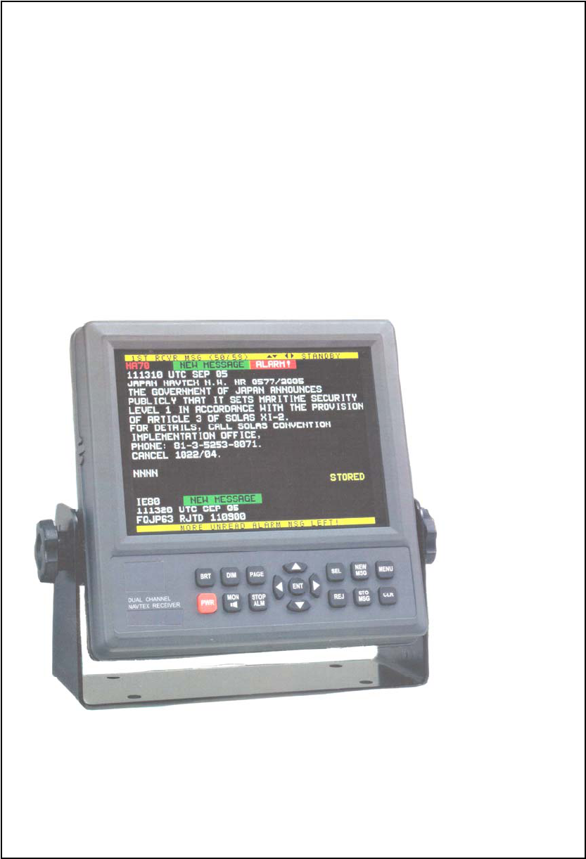
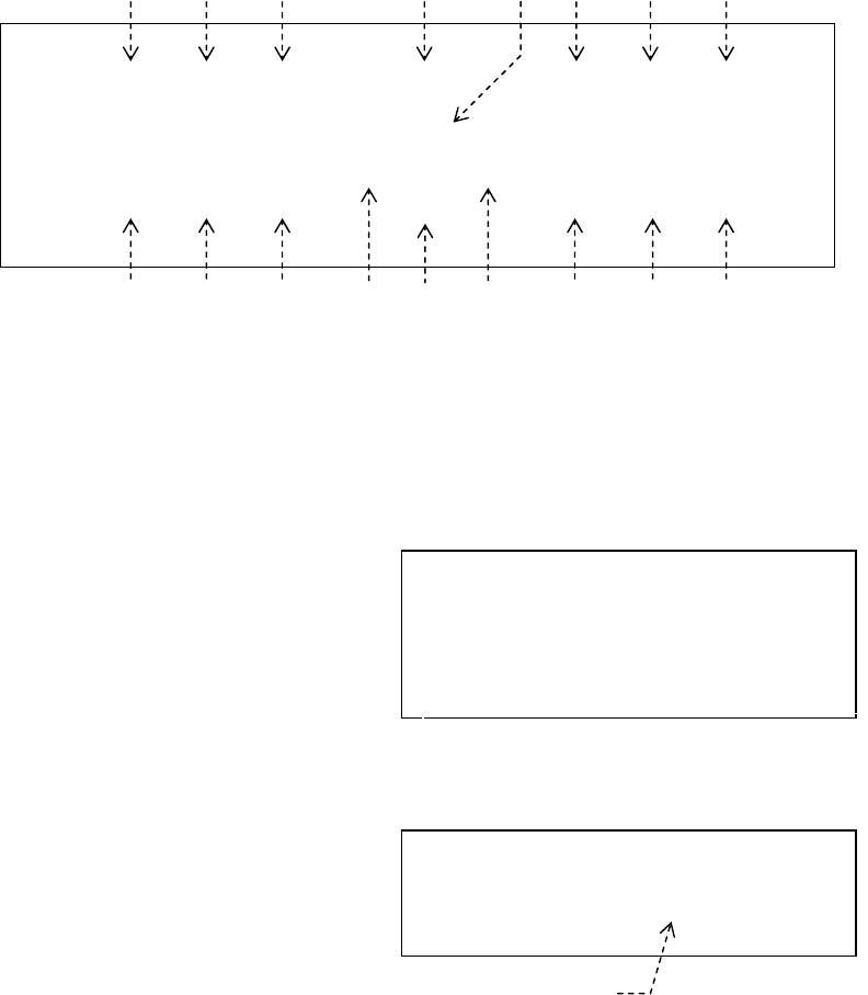
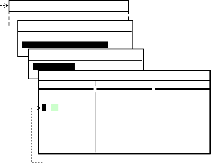
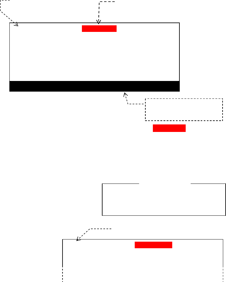
The illustration below represents a typical NAVTEX message screen, showing a new
message received on the first (518 kHz) receiver. A similar screen will show up when the
equipment is switched to receive a second receiver (490 kHz or 4209.5 kHz) message. A
brief description of on–screen indications is given below and in the following pages.
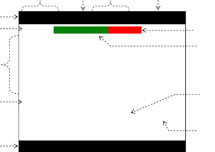
Figure 1-1 Typical NAVTEX Message Screen (First Receiver Page)
Indication of Receiver in Use to Display Current Messages
1ST RCVR: First receiver, 518 kHz
2ND RCVR1: Second receiver, 490 kHz or 2ND RCVR2:4209.5 kHz
The two receivers can be switched by pressing or by means of a software command
from an IBS/INS terminal via the rear panel RS–422 connector (INS port). See
paragraph 7.4 for details.
Message No. and Total No. of Messages Stored
The message number of the currently displayed message along with the total number of
stored messages is indicated in the following format:
Examples:
12/12: Message #12 (newest message) of 12 messages stored
1/12: Message #1 (oldest message) of 12 messages stored
(continued on next page)
1ST RCVR MSG (12/12) STANDBY
JD13 INEW MESSAGEIIALARM!II
011400 UTC JAN
POLISH SAR INFO 003
SOUTHEASTERN BALTIC
FISHING VESSEL OF UNIDENTIFIED REGISTRY
IS ON FIRE AND IS IN DANGER OF SINKING IN
POSITION 55–22.23N 14–40.37E.
ALL SHIPS IN THE VICINITY ARE URGENTLY
REQUESTED TO RUSH TO THE SITE AND OFFER
ASSISTANCE.
NNNN
STORED (CER= 00%)
MORE NEW MSG LEFT !

AE–2000 Manual
Typical NAVTEX Message Screen
1-2
1. Typical NAVTEX Message Screen (continued – 2/6)
1.1. Introduction (continued – 2/5)
Message Scrolling Keys
The keys that can be used to manually scroll messages across the current screen are
indicated.
: Line–by–line scrolling by pressing /
: Message–by–message scrolling by pressing
/
NOTE: When a type–D message (SAR, piracy and armed robbery information) is received,
automatic scrolling will be disabled until the user acknowledges the message with or with
a software command from an IBS /INS terminal via the rear–panel RS–422 connector. See
paragraph 7.4 for details.
Receiver Operating Status Indication
The current status of receiver operation is indicated here.
ABORTED: The receiver has failed to lock onto the current transmission, due, for
example, to weak signal level or noise interference. No message will
be displayed or stored.
NOTE: Signal propagation conditions change greatly with time. You might
not be able to receive a signal in the daytime that can be received at night;
this is normal and should not be considered as a sign of receiver
malfunction.
ACQUIRING: The receiver is currently in the process of locking onto the start
of the current message transmission.
LOCKED: The receiver has locked onto current NAVTEX transmission, allowing a
message to be received. As soon as the equipmet starts receiving the
message, this indication will be replaced by RCVNG MSG.
RCVNG MSG: The receiver is properly receiving a message after locking onto
current transmission. This blinking indication will stay until the
end–of–message code NNNN () is received.
NOTE: Whether to display or output the message to external devices
depends on the character error rate (CER, ) and on the
selection/rejection settings to be made via the procedure in paragraph 4.8.
STANDBY: The receiver is idling, waiting for a NAVTEX message transmission to
begin. Most stations transmit messages every 4 hours.
Operating Status Line
The current status of receiver operation, text scroll keys, etc. are indicated here.
Examples:
1ST RCVR MSG: Message received on the first receiver is currently displayed.
2ND RCVR MSG: Message received on the second receiver (490 or 4209.5 kHz) is
currently displayed.
: Message can be scrolled line by line by pressing /.
STANDBY: Receiver is idling, waiting for a NAVTEX message transmission. See
above for details.
(continued on next page)
1. Typical NAVTEX Message Screen (continued – 3/6 )
1.1. Introduction (continued – 3/5 )
AE–2000 Manual
Typical NAVTEX Message Screen
1-3
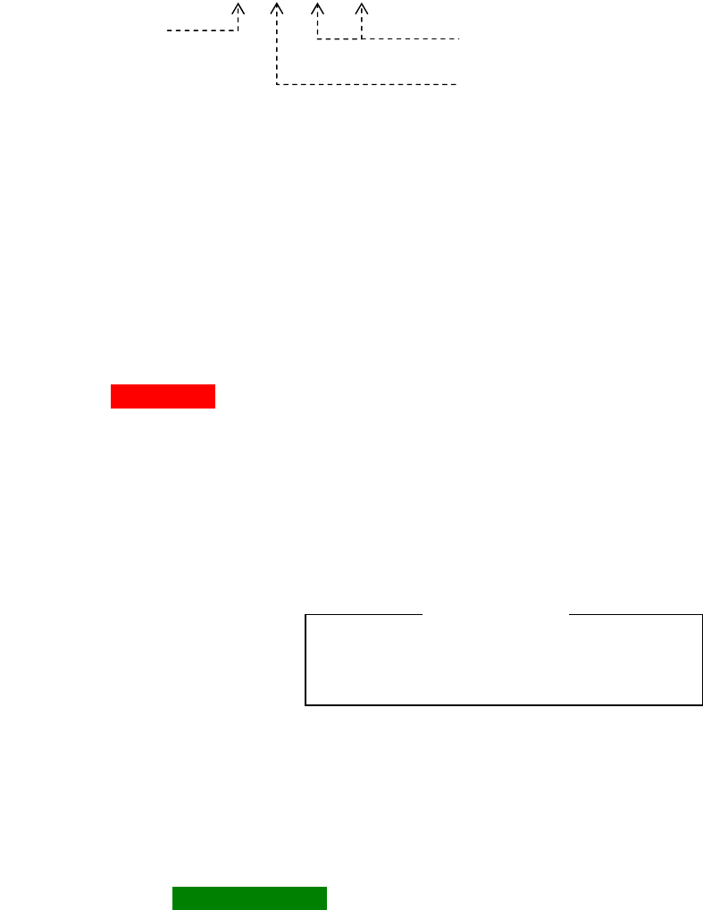
Message Identification (Message ID)
The ID of the currently displayed message is shown here. A red–colored ID represents a
warning message. A message ID consists of the following elements: station ID, message
type, and message serial number, as in the following example.
Figure 1-2 NAVTEX Message ID Format – Example
*1: ID of the transmitter from which the message was received.
Examples: J in NAVAREA : Gislövshammar, Sweden
F in NAVAREA : Cape Cod/Boston, U.S.
I in NAVAREA : Las Palmas, Spain
*2: Type (category) of this message (subject indicator)
Examples: A: Navigational warnings
B: Weather warnings
D: Search and rescue, piracy and armed robbery information
*3: Serial number of this message
Each message within the same category group is allocated a serial number between 00
and 99 by each transmitter. A message with number 00 is always received on each
transmission regardless of rejection settings, and will be displayed and stored in memory.
Alarm Tag IIALARM!III
This tag represents a visual alarm and is turned on when a NAVTEX message of one of
the following types has been received.
Type–A Message: Navigational warning (initially disabled)
Type–B Message: Weather warning (initially disabled)
Type–D Message: Search and rescue, piracy and armed robbery information. All text
characters will be displayed in red to distinguish it from other type alarm
messages.
Type–L Message: Additional navigational warning (initially disabled)
NOTE: When a type–D message has been received,
an audible alarm will also be turned on, beeping at
approx. 1–second intervals. To silence the alarm
sound, press . A second keypress resets the alarm
and removes the alarm tag.
The alarm for the message types A, B and L is initially disabled. It can be enabled via
SYSTEM MENU – 9:TURN ON/OFF MESSAGE ALARM. See paragraph 4.14 for details.
(continued on next page)
1. Typical NAVTEX Message Screen (continued – 4/6 )
1.1. Introduction (continued – 4/5 )
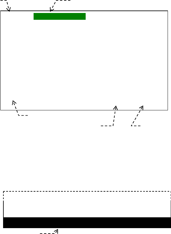
New Message Tag IINEW MESSAGEII
Silencing the audible alarm constitutes
your acknowledgement of the current
alarm message.
< CAUTION
J D 1 3
*3Message serial number
(
B3 & B4 characters)
*2Message Type
(
B2 character)
*1Transmitter ID
(
B1 character)

AE–2000 Manual
Typical NAVTEX Message Screen
1-4
This indication ( tag) shows that the currently displayed NAVTEX text is a new message
that you have not yet read or acknowledged.
To acknowledge it, simply press or , turning the tag off.
If two or more new messages have been left unread, the following caution message will
be displayed at the screen bottom, prompting you to read them. Press again to
display, or scroll the text up to, the next one by pressing /.
The NEW MESSAGE tag for the current message will be automatically removed 24
hours after its reception, if it is left unacknowledged ( i.e. if is not pressed).
NAVTEX Message
If message text exceeds the screen display area, you can scroll it line–by–line by
pressing /. Holding down either key accelerates the scroll.
To read other messages, press /
(for message–by–message scrolling). Holding
down either key accelerates the scroll.
Type–D messages (SAR , piracy and armed robber y information) will be displayed in red.
A new type–D message will remain fixed on screen until:
it is acknowledged by pressing or by means of a *1software command through
an INS/ IBS terminal interfaced to the rear panel RS–422 connector, or
another new type–D message is received on either receiver.
*1: See paragraph 7.4.5 for details.
NOTE: Forced carriage return
When the number of characters in a line exceeds 40, an internally generated carriage return symbol,
shown above, will be automatically inserted in the 40th character position to divide the last word,
forcing the rest of the characters in the word to shift to the top of the next line. This symbol will be
replaced by an underscore ( _ ) (hex 5F ) when it is printed or output to an IBS / INS device via the RS–422
port.
End–of–Message Indication NNNN
The appearance of these four successive N characters indicates the end of the currently
displayed NAVTEX message.
NOTE: Some messages including those from Chinese stations, end with NN ( 2 Ns) instead of
NNNN (4 Ns), in which case, the equipment will consider that the transmission has not
ended properly, and will not, therefore, display and store such a message, or will append it to
a new message, if received within a specified period of time, and display the two messages
combined. The RS–232C port (printer port) may be set to output such messages. See
paragraph 4.9 for setting instructions.
(continued on next page)
1. Typical NAVTEX Message Screen (continued – 5/6 )
1.1. Introduction (continued – 5/5 )
Indication of Message Storage Status
This indication shows whether or not the displayed NAVTEX message has been stored in
MORE NEW MSG LEFT !

AE–2000 Manual
Typical NAVTEX Message Screen
1-5
the internal non–volatile memory.
*1STORED: The message has been stored.
When message reception has been completed with a character error rate (CER) of 33%
or less, the received NAVTEX message together with its ID will be stored in memory,
making it possible to recall it onto the screen at a later time.
If the same message is received with a lower CER on the next transmission, the
previously stored message will be replaced with the new one. However, if the first
message was received with a CER of 4% or less, message replacement will not take
place on subsequent reception of the same message with a lower CER.
When the CER exceeds 33%, the message and its ID will not be displayed and stored in
memory, allowing a retransmission of the same message to be displayed and stored.
*1: If the message selection/rejection settings are made so that a particular message type is
rejected from storage, this indication will not be displayed regardless of a CER being smaller
than 33%. See paragraph 4.9 for the related setting instructions.
Character Error Rate (CER) Indication
CER is the percentage ratio of the total number of corrupt characters represented by
asterisks (*) to the total number of characters received in a message, including control
codes (sync. signal, carriage returns, line feeds, letter/numeral shift, etc.),
If a message is received with a CER equal to or greater than 33%, it will not be displayed
and stored in memory, allowing the same message to be received again on its next
transmission. No CER reading will be available on the current transmission. See
paragraph for more information on CER.
Message Prompt Line
This line indicates the receiver’s response for the user’s keypress or displays prompts
related to reception of new or alarm NAVTEX messages on the first or second receiver,
or related to message storage, like the examples below.
ALARM MESSAGE RECEIVED ON 2ND RCVR
MORE UNREAD ALARM
*2MSG LEFT
2ND
*3RCVR RECEIVED NEW MSG
MORE NEW MSG LEFT
STORAGE LIMIT IS REACHED
MEMORY FULL !
*4 [CLR] TO *5
ACKNLG.
*2 MSG = MESSAGE, *3 RCVR = RECEIVER
*4 [CLR] = *5 ACKNLG = ACKNOWLEDGE
1. Typical NAVTEX Message Screen (continued – 5/5 )
1.2. Indication of Reception and Storage of New NAVTEX Message
● Indicating Reception of New Message – First Receiver
The equipment visually indicates the reception of a new NAVTEX message by attaching a
tag (iNEW MESSAGEi) to the message ID, as in the example below. The tag will be
turned off 24 hours after reception or when you press .
AE–2000 Manual
Typical NAVTEX Message Screen
1-6
Figure 1-3 First Receiver Receiving New NAVTEX Message – Example
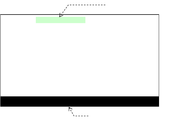
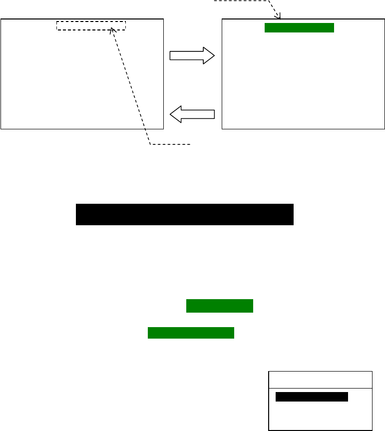
● Indicating Reception of New Message – Second Receiver
When the first receiver message screen is currently showing, the reception of a new
message on the second receiver is indicated with message “ 2ND RCVR RECEIVED
NEW MSG” blinking in the prompt line at the screen bottom, as in the example below. To
read it, switch to the second receiver page by pressing .
Figure 1-4 Indication of New Message Reception on Second Receiver – Example
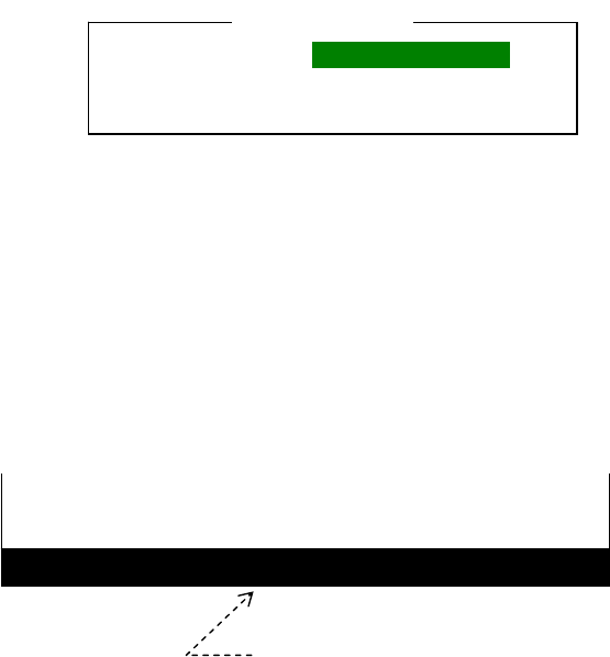
● Indicating Successful Storage of New Message
When a new NAVTEX message has been received with a character error rate (CER) of
33% or less, the message will be displayed and stored in non–volatile memory together
with its ID; this condition is displayed with indication “STORED” at the end of the
message together with its CER reading, as in the example above.
If the CER exceeds 33%, the currently received message will not be stored and will not
be displayed. No CER reading will be available.
NA28 INEW MESSAGEI
CCGD5 BNW 328–06
NJ – COASTAL – SURFACE AND SUB–SURFACE
DATA BUOY DEPLOYMENT
1. 60 SUBSURFACE AND 2 SURFACE MOORINGS
WILL BE DEPLOYED ON LINES EXTENDING FROM
39–09.6N, 073–22.05W TO 38–55.56N, 072–50.76W
AND OUT
TO
Tag indicating reception of new message
Message ID
End–of
–
message indication
Successful storage indication
Character error readout
..................................................
NNNN STORED (CER= 00%)
2ND RCVR RECEI
V
ED NEW MSG
This message blinks.
AE–2000 Manual
Control Panel Functions
2-1
2. Control Panel Functions
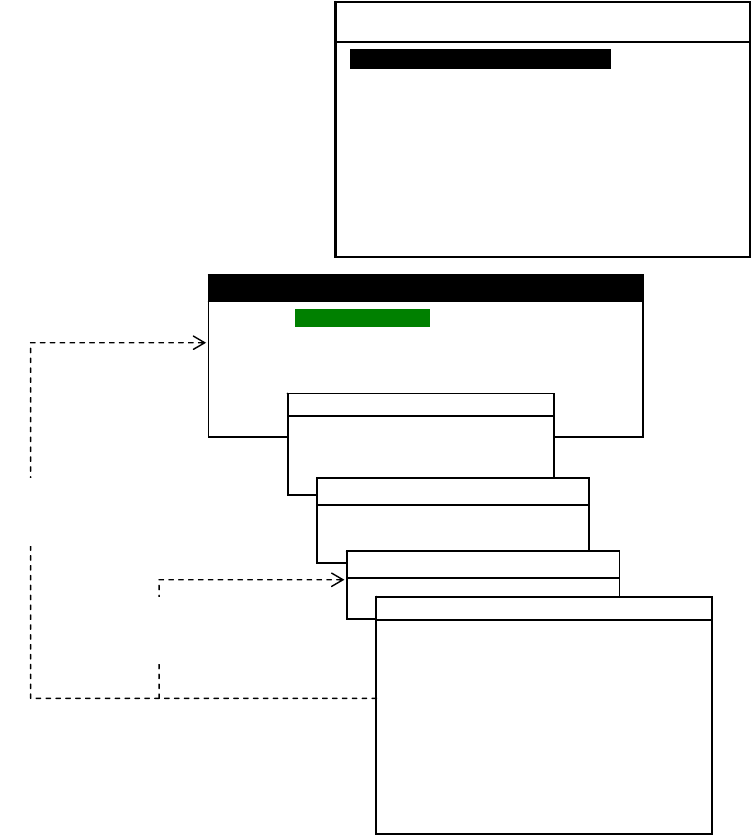
The figure below shows the control panel of the equipment. A summary description of the
functions the keys provides is given below and in the following pages.
Figure 2-1 Control Panel
Screen Brightness Key
Repeated pressing of this key adjusts the screen brightness in a total of 8 steps including
a completely dark level. The last used level is stored in memory. The brightness level
returns to its maximum on next power–up when the equipment is switched off with the
level set to its minimum. See paragraph 4.5 for related information.
Power Key
– 1/2
Figure 2-2 Opening Message – Example
This key turns the unit on/off. A first keypress
turns it on, displaying an opening message like
the example at right for approximately five
seconds.
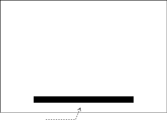
Figure 2-3 Power–Off Countdown Window
Keep on pressing the key until all five bars have
disappeared, and then release it to completely
switch the unit off. This delayed action helps
prevent an accidental shutoff and resultant loss
of data.
Releasing the key with at least one countdown bar showing cancels the power–off
sequence.
(continued on next page)
2. Control Panel Functions (continued – 2/12)
Power Key
– 2/2
To turn the unit off, press and hold
down for 2–3 seconds until a
power–off countdown window
shows up as illustrated at right,
indicating that a power–off
sequence has started.
SHUTTING DOWN NAVTEX RECEIVER
WAIT ! – – – – –
Countdown bars
WELCOME TO NAVTEX RECEIVER
SOFTWARE VER. 1.3 REV_1.1A1
DATE JUNE 06, 2007
Version and date information is an example.
AE–2000 Manual
Control Panel Functions
2-2
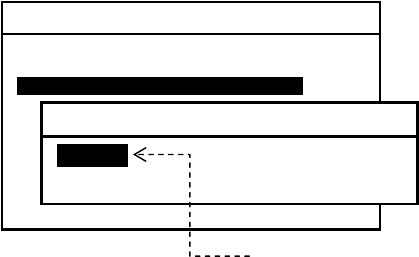
After the unit is switched on, the opening message window will be replaced with
another window listing the current settings of receiver control parameters, as in the
example below.
Figure 2-4 Current Settings of Receiver Control Parameters – Example
The above list will stay on for approximately 20 seconds before the message screen
shows up, replacing it automatically.
To turn the list off immediately, press or .
Keypad Dimmer Key
Pressing this key adjusts the keypad backlighting level in a total of 8 steps including a
completely switched–off level.
The last used level will be stored in memory. When the equipment is switched off with
the level at its minimum, the keypad will be lit at the highest level at next power–up
time.
Audible Monitor Key
Pressing this key allows you to audibly monitor the reception of a NAVTEX transmission.
To monitor the sound continuously, hold down the key. As soon as it is released, the
audible output is turned off.
(continued on next page)
2. Control Panel Functions (continued – 3/12)
Screen Page Key
CURRENT SETTINGS
1:FIRST RECEIVER:
REJECTED STATIONS:
REJECTED MESSAGE TYPES: G I M
NO P Q R S T U W X Y
2:SECOND RECEIVER:
REJECTED STATIONS:
REJECTED MESSAGE TYPES: G I M
NO P Q R S T U W
X Y
3:KEYPRESS BEEP: ON
4:DISABLED MSG ALARMS: A B L
5: RECEIVING MSG OUTPUT: OFF
6: 2ND RECEIVER FREQ.: 490KHZ
7:DISPLAY SLEEP MODE: 5MIN./ 30MIN.
IPRESS [CLR] OR [ENT] TO START.
Blinks in reverse video.

AE–2000 Manual
Control Panel Functions
2-3
Pressing this key switches the message screen between the first receiver screen page
and the second receiver screen page.
For example, if the current screen is currently showing the first receiver page (i.e. 518
kHz NAVTEX message display), a first keypress changes the display to show the second
receiver page (i.e. 490 kHz/4209.5 kHz message display). A second press changes it
back to the first receiver page. See paragraph 3.5 for more details.
Alarm Stop Key
The equipment will alarm you audibly through a built–in buzzer and visually by turning
an alarm tag ( iALARM! I ) in reverse video on the message screen upon reception of
an important NAVTEX warning (type–D message, for example). A type–D message text
will be displayed in red. See paragraph 3.7 for more details.
Pressing this key silences the audible alarm and removes the alarm tag. Observe the
CAUTION below.
A new type–D message received on either the first receiver (518 kHz) or the second
receiver (490 kHz or 4209.5 kHz) will remain fixed on screen and will not automatically
scroll until:
this key is pressed *1twice to acknowledge it,
the user remotely *2acknowledges it from an IBS/INS terminal connected to the
rear–panel RS–422 connector (INS port), or
another new type–D message has been received on either receiver.
If more alarm messages are left unread in memory, a next alarm message will be
displayed after the above keypress.
*1: A first keypress silences the alarm sound only.
*2: See paragraph 7.4 for information on the command format.
Up Key
When a NAVTEX message is being displayed, pressing this key scrolls the message
screen downward one line at a time, allowing you to view message lines hidden
beyond the screen’s upper text display limit. When the newest message (e.g.
200/200) is reached, a further keypress displays the oldest one ( e.g. 1/200).
Holding down the key accelerates text scrolling.
When a menu is displayed, pressing this key selects vertically listed options upward.
Press after highlighting the desired option.
(continued on next page)
2. Control Panel Functions (continued – 4/12 )
Left Key
Silencing the audible alarm constitutes
your acknowledgement of the current
alarm message/condition.
< CAUTION
AE–2000 Manual
Control Panel Functions
2-4
When a NAVTEX message is being displayed, a single press of this key scrolls the
message text by one message forward chronologically, displaying a newer message.
Holding down the key accelerates the scroll.
When the screen is showing the newest message (e.g. 200/200), a further keypress
returns you to the oldest message (e.g. 1/200).
When a currently displayed menu has horizontally listed options, pressing this key
selects (i.e. highlights) those options in a leftward direction. Be sure to press after
highlighting the desired option.
Enter Key
When a NAVTEX message is being displayed, pressing this key displays the newest
message ( e.g. 200/200).
When a menu is being displayed, pressing this key:
- completes the selection of a desired option,
- executes the function selected or,
- finalizes the current setting.
Down Key
When a NAVTEX message is being displayed, pressing this key scrolls the message
screen upward one line at a time, allowing you to view message lines hidden beyond
the lower text display limit of the screen.
When the screen is showing the oldest message (e.g. 1/200), further keypress
returns you to the newest message (e.g. 200/200).
Holding down the key accelerates the scrolling.
When a menu is being displayed, pressing this key selects (highlights) vertically
listed options downward. Be sure to press after highlighting the desired option.
(continued on next page)
2. Control Panel Functions (continued – 5/12)
Message/Station Selection Key
– 1/2
When the screen is showing a NAVTEX message, pressing this key displays a
summary list of the transmitter IDs and message types that are currently selected as in

AE–2000 Manual
Control Panel Functions
2-5
the example below so that the equipment displays and stores messages of the
selected types from the selected transmitters.
Figure 2-5 List of Currently Selected Stations and Message Types – Example
All transmitters and most of major message types are initially selected so that the
equipment will display and store those selected types of messages from all stations in
the coverage area.
A particular station or a particular message type can be rejected from display or
storage via the menu system. Detailed instructions are given in paragraph 4.8.
→SYSTEM MENU → 4:MAKE SEL /REJ SETTING → 1/2/3 → 1/2 →
To turn off the above lists, press .
NOTE: Message types A (navigational warning), B (meteorological warning), D (SAR,
piracy and armed robbery information) and L ( additional navigational warning) are
always selected for storage in memory and output to the I / O ports; they cannot be rejected
due to the relevant IMO resolutions and IEC requirements.
(continued on next page)
2. Control Panel Functions (continued – 6/12)
Selection/Station Key
– 2/2
When option “ 4:MAKE SEL/REJ SETTING” on the SYSTEM MENU is currently
accessed for selection/rejection settings, this key selects the station or message type
MEM. SELECTED STATIONS:
A B C D E F G H I J K L M
N O P Q R S T U V W X Y Z
MEM. SELECTED MESSAGES:
A B C D E F H J K L
V Z
< FIRST RECEIVER >
MEM. SELECTED STATIONS:
A B C D E F G H I J K L M
N O P Q R S T U V W X Y Z
MEM. SELECTED MESSAGES:
A B C D E F H J K L
V Z
< SECOND RECEIVER 1 >
MEM: to be stored in memor
y
SECOND RECEIVER 1: 490 kHz
SECOND RECEIVER 2: 4209.5 kHz

AE–2000 Manual
Control Panel Functions
2-6
you specify for display and storage, and/or output to the I/O ports (RS–232C, RS–422
and I/O DATA connectors). An example of station selecting procedure is illustrated
below.
Currently selected stations (SL) are shown in green. Rejected stations (RJ) are in red.
Using
/ and /
, highlight first the ID of the station of which messages you
wish to display, store, and/or output to the I/O ports, and then, specify the target device
(ME for memory, PR for RS–232C & I/O DATA, IN for RS–422). To select the currently
rejected (RJ) setting on each device, press .
See paragraph 4.8 for details.
Figure 2-6 Selecting Stations – Example
(continued on next page)
2. Control Panel Functions (continued – 7/12)
Right Key
When a NAVTEX message is being displayed, a single press of this key scrolls the
message text by one message backward timewise, displaying an older message. See
NOTE below.
Station C is currently rejected from display and storage (ME), and
from output to printer (PR). Its messages are to be output to the
INS ( IN) terminal alone. To select it to display and store its
messages, press after specifying ME using
/
.
SYSTEM MENU
4:MAKE SEL
/
REJ SETTING
1:SYNCHRONIZE BOTH RECEIVERS
2:FIRST RECEIVER (518KHZ)
3:SECOND RECEIVER
2:FIRST RECEI
V
ER
1:STATIONSI
2:MESSAGES
ME PR IN
A: SL SL SL
B: SL SL SL
C: RJ RJ SL
D: SL SL SL
E: SL SL SL
F: SL SL SL
G: SL SL SL
H: SL SL SL
I: SL SL SL
ME PR IN
J: SL SL SL
K: SL SL SL
L: SL SL SL
M: SL SL SL
N: SL SL SL
O: SL SL SL
P: SL SL SL
Q: SL SL SL
R: SL SL SL
ME PR IN
S: SL SL SL
T: SL SL SL
U: SL SL SL
V: SL SL SL
W: SL SL SL
X: SL SL SL
Y: SL SL SL
Z: SL SL SL
1: STATIONS
(
MEmor
y
PRinter INs
)
Target Devices:
ME: memory
PR: printer port (RS–232C)
IN: INS port (RS–422)
AE–2000 Manual
Control Panel Functions
2-7
When the oldest message ( e.g. 1/200) is currently displayed, further keypress
returns you to the newest message ( e.g. 200/200).
Holding down the key accelerates the scroll.
When a menu has horizontally listed options, pressing this key selects ( highlights)
those options in a rightward direction. Be sure to press after highlighting the
desired option.
New Message Key – 1/2
When a new NAVTEX message has been received and stored, a NEW MESSAGE tag
is automatically attached to the message ID as in the example below to indicate that
the message is new.
Figure 2-7 Indication of Reception of New Message
Pressing removes the tag from the message ID, meaning that you have
acknowledged its reception.
(continued on next page)
2. Control Panel Functions (continued – 8 /12)
New Message Key – 2/2
The new message tag will be automatically removed 24 hours after reception of that
message, even if you forget to acknowledge it.
NEW MESSAGE Tag
NJ91 INEW MESSAGEI
STAKDBFE// 211745Z AUG 06/ /
DGPS BNW 736–06
ANNAPOLIS, MD DGPS BROADCAST SITE IS
UNMONITORED AS OF 211704Z AUG 06. NAVCEN
IS UNABLE TO VERIFY SIG INTEGRITY UNTIL
MORE NEW MSG LEFT !
More new messages are left unread.
Scroll to next one by further pressing
or / and /
.
AE–2000 Manual
Control Panel Functions
2-8
The above example shows that a number of new messages have been received, as
indicated by the bottom line prompt “ MORE NEW MSG LEFT !.” Pressing will
recall the next new message onto the screen It can also be displayed by pressing
/ (for line–by–line viewing) or /
(for message–by– message viewing).
If no additional new message is left in memory, further keypress will cause the
following message to show blinking for a few seconds at the bottom, indicating an
operational error.
Figure 2-8 Indication of All New Messages Being Acknowledged
(continued on next page)
2. Control Panel Functions (continued – 9/12 )
Message/Station Rejection Key – 1/2
When a NAVTEX message text is currently being displayed, pressing this key turns on
a summary list of the transmitter IDs and message types that are rejected (deselected)
via the *1menu system on both the first and second receivers as in the example below,
and not to be displayed and stored.
Removal of the iNEW MESSAGEi tag
constitutes your acknowledgement of
the currently displayed new message.
< CAUTION
NO NEW MSG LEFT !
NNNN STORED (CER= 00%)
No additional new message is left in memory

AE–2000 Manual
Control Panel Functions
2-9
Figure 2-9 List of Currently Rejected Stations and Message Types – Example
*1: →SYSTEM MENU → 4:MAKE SEL/REJ SETTING
Detailed instructions are given in paragraph 4.8.
*2: SECOND RECEIVER 1 = 490 kHz, SECOND RECEIVER 2 = 4209.5 kHz
The following message types are always selected; they cannot be rejected due to the
relevant *3IMO resolutions and *4IEC regulations related to navigational safety:
- Type A : Navigational Warning
- Type B: Meteorological Warning
- Type D : SAR (search and rescue) , Piracy and Armed Robbery Information
- Type L : Additional Navigational Warning
*3: IMO Resolution MSC.148( 77) *4: IEC 61097–6 Ed.2
A message with serial number=00 will always be displayed and stored despite
rejection settings.
To turn off the above lists, press either or . Pressing turns the lists off and
displays the SYSTEM MENU instead.
(continued on next page)
MEM. REJECTED STATIONS:
MEM. REJECTED MESSAGES:
G I M
N O P Q R S T U W X Y
< FIRST RECEIVER >
MEM. REJECTED STATIONS:
MEM. REJECTED MESSAGES:
G I M
N O P Q R S T U W X Y
< SECOND RECEIVER *21 >
MEM: not to be stored in memory
SECOND RECEIVER 1: 490 kHz
SECOND RECEIVER 2: 4209.5 kHz
AE–2000 Manual
Control Panel Functions
2-10
2. Control Panel Functions ( continued – 10 /12 )
Message/Station Rejection Key – 2/2
When option “4:MAKE SEL/REJ SETTING” on the SYSTEM MENU is currently
accessed for selection/rejection settings, this key rejects the user–specified station or
message type so that its messages are not to be displayed and stored in memory, not
to be output to the printer port (RS–232C) or not to be output to the INS port
(RS–422).
An example of station rejecting procedure is illustrated below. The status of each
target device is either SL (selected) or RJ (rejected).
Figure 2-10 Rejecting Stations – Example
Using / and /
, select the station ID first, specify the target device (ME, PR
or IN) to which you do not wish to store or output the station’s messages, and then
press . Make sure that the status of the device changes from SL to RJ. For instance,
when ME is set to the RJ status, any messages from that station will not be displayed
or stored.
While other menu is being displayed, pressing this key produces three quick beeps
to indicate an operational error.
(continued on next page)
SYSTEM MENU
4:MAKE SEL
/
REJ SETTING
1:SYNCHRONIZE BOTH RECEIVERS
2:FIRST RECEIVER (518KHZ)
3:SECOND RECEIVER
2:FIRST RECEI
V
ER
1:STATIONSI
2:MESSAGES
ME PR IN
A: SL SL SL
B: SL SL SL
C: SL SL SL
D: SL SL SL
E: SL SL SL
F: SL SL SL
G: SL SL SL
H: SL SL SL
I: SL SL SL
ME PR IN
J: SL SL SL
K: SL SL SL
L: SL SL SL
M: SL SL SL
N: SL SL SL
O: SL SL SL
P: SL SL SL
Q: SL SL SL
R: SL SL SL
ME PR IN
S: SL SL SL
T: SL SL SL
U: SL SL SL
V: SL SL SL
W: SL SL SL
X: SL SL SL
Y: SL SL SL
Z: SL SL SL
1: STATIONS
(
MEmor
y
PRinter INs
)
Target Devices:
ME: memory
PR: printer port (RS–232C)
IN: INS port (RS–422)
Station C is selected so that its messages are to be displayed and
stored in memory (ME), and to be output to printer ( PR) and INS
(IN) terminal. To reject C so as not to display and store its
messages, press after specifying ME using
/
.

AE–2000 Manual
Control Panel Functions
2-11
2. Control Panel Functions (continued – 11/12)
Menu Key
Pressing this key opens a menu termed “SYSTEM MENU,” as shown below, to
customize the operation to suit your specific needs, to test the receiver performance
off–line, or to reset the entire system to the initial settings. See paragraphs in section 4
for greater details.
Figure 2-11 SYSTEM MENU
To turn the menu off, press again
or
*1.
A desired menu option can be
selected by highlighting it with /,
followed by .
The functions of each option are summarized below.
1: MAKE DISPLAY SETTINGS: Selects display background colors, turns
on/off screen sleep mode, or selects message font types.
2: SELECT 2ND RECEIVER FREQUENCIES: Selects 490 or 4209.5 kHz.
3: TURN ON/OFF KEYPRESS BEEP: Tur ns on/ off keypress beep.
*24: MAKE SEL/ REJ SETTINGS: Selects or rejects transmitters or message
types that are to be displayed and stored. output to RS-
–232C, I/O DATA and RS–422 ports.
5: SEARCH STORED MESSAGES: Search stored messages by station and/or
message type.
6: SELECT OUTPUT MESSAGES: Selects messages to be output externally.
7: SET OUTPUT PORTS: Sets output ports on/off, selects protocols, formats, etc.
8: START SELF–DIAGNOSTIC TESTS: Executes self–diagnostic tests.
*39: TURN ON/OFF MESSAGE ALARM: Turns on/off message alarms.
*40: RESET TO FACTORY DEFAULTS: Initializes user–made settings.
*1: Pressing this key turns the menu off and returns you to the first receiver screen.
*
2: Types A, B, D and L messages cannot be rejected due to relevant IMO resolutions.
*
3: Alarm for type–D messages cannot be turned off due to relevant IMO resolutions.
*
4: Stored messages will not be erased from memory by executing this function.
Detailed information on each menu option is given in section 4.
(continued on next page)
SYSTEM MENU
1: MAKE DISPLAY SETTINGS
2: SELECT 2ND RECEIVER FREQUENCIES
3: TURN ON/OFF KEYPRESS BEEP
4: MAKE SEL/REJ SETTINGS
5: SEARCH FOR STORED MESSAGES
6. SELECT OUTPUT MESSAGES
7. SET OUTPUT PORTS
8. START SELF–DIAGNOSTIC TESTS
9: TURN ON/OFF MESSAGE ALARM
0. RESET TO FACTORY DEFAULTS
AE-2000 Manual
Control Panel Functions
2-12
2. Control Panel Functions (continued – 12 /12 )
Store Message Key
This key is used to place a specific NAVTEX message in permanent storage, thereby
protecting it from being automatically erased from memory after the maximum
message storage limit (200 messages for each receiver) is reached.
Pressing this key attaches a “ PROTECTED” tag to the ID of the message you wish to
protect, and pressing *removes the tag from the message, as in the example
below. *User confirmation is required. See below.
Figure 2-12 Attaching /Removing Message Protection Tag – Example
Up to 50 messages can be protected (for each of the first receiver and selected
second receiver. An attempt to protect messages beyond this limit causes an
operational error, turning on the following caution message in the message prompt
line ( screen’s bottom line):
The message storage capacity will increase by 50 to 250 messages when 50 received
messages on either receiver are protected.
Clear Key
The major functions this key provides are:
*1removing message protection tag ( PROTECTEDI ) from the currently displayed
protected NAVTEX message.
removing new message tag ( IINEW MESSAGEII ) from a new message, and
turning off all menus at a time, returning to the first receiver message page when
making settings via the *2menu system.
*1:Removing the message protection tag requires your
confirmation, as shown at right.
Use / to select the desired option and then press .
*2: See section 4 for more information.
AA46 PROTECTED
CCDG7 BNM 886–06
1. KEY W. HBR–MAIN CHAN
IS REP BURNING
DIM
Protection tag is attached.
AA46
CCDG7 BNM 886–06
1. KEY W. HBR–MAIN CHAN
IS REP BURNING
DIM
Protection tag is removed.
ARE YOU SURE ?
1: NO (CANCEL)
2: YES (EXECUTE)
[
▲
]
[
▼
]
[
ENT
]
STORAGE LIMIT IS REACHED !

AE–2000 Manual
Basic Operating Procedure
3-1
3. Basic Operating Procedure
3.1. Introduction
This section describes the basic operating procedure, allowing you to operate your NAVTEX
receiver from the front keypad without prior knowledge of the NAVTEX system. The
functions that are available from the keypad are summarized in section 2 (Control Panel
Functions). It is assumed that a specified antenna and appropriate power supply are
connected to the equipment.
3.2. Turning the Equipment On/Off
To turn the equipment on, gently press once.
Figure 3-1 Opening Message – Example
An opening message like the example at right
will show up and stay for approximately five
seconds, indicating the model name, software
version number and release date. The numbers
shown are examples.
Turning Equipme nt Off
Figure 3-2 Power–Shutdown Countdown Window
To turn the unit off, press and hold down for
two to three seconds until a power–shutdown
countdown window shows up as illustrated at
right, indicating that a power–off sequence has
just started.
Keep on pressing the key until all countdown bars have disappeared, and then release
the key to completely switch the unit off. This delayed action avoids an accidental shutoff
and loss of message data.
Releasing the key with at least one countdown bar still showing cancels the
power–shutdown sequence.
Turning Opening Message Off
After the unit is switched on, the opening message window will be replaced with another
window listing the current settings of receiver control parameters, as in the example
shown in Figure 2–4.
The above list will stay on for approximately 20 seconds before the NAVTEX message
screen shows up, replacing it automatically.
To turn the list off immediately, press or .
(continued on next page)
WELCOME TO NAVTEX RECEIVER
SOFTWARE VER. 1.3 REV1.1A1
DATE JUNE 06, 2007
SHUTTING DOWN NAVTEX RECEIVER
WAIT ! – – –
Countdown bars
AE–2000 Manual
Basic Operating Procedure
3-2
3. Basic Operating Procedure – 2/7
3.3. Adjusting Screen Brightness
The screen brightness level can be changed in a total of eight steps to suit the ambient
lighting condition by repeatedly pressing .
To extend the service life of the backlighting lamp, the level can be changed in two steps
automatically after a user–preset time period. See paragraph 4.5 for detailed information
on the screen sleep mode.
The screen background is initially white. You can change it to black or blue via the
instructions given in paragraph 4.3.
3.4. Adjusting Keypad Backlighting Level
The keypad backlighting level can be changed in a total of eight steps to suit the ambient
lighting condition by repeatedly pressing .
The last used level will be stored in memory. However, if the minimum level was used last
time, it will return to the maximum level on next power–up.
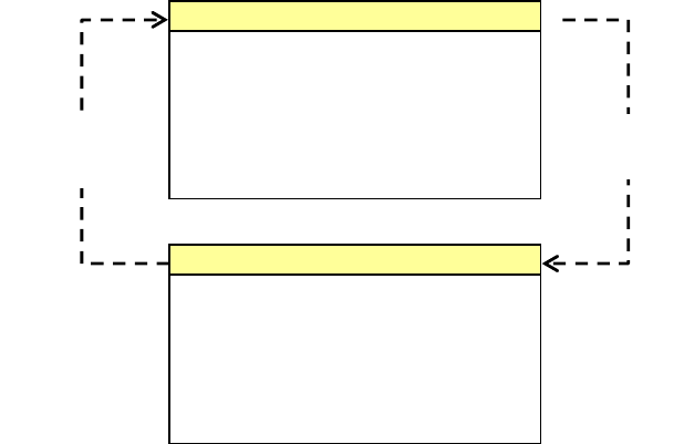
3.5. Switching First and Second Receivers
The message display initially shows first receiver page, showing the NAVTEX message
received on the first ( 518 kHz) receiver.
To display the second receiver page to show messages received on the second receiver
(*490 kHz or *4209.5 kHz ), press . A second keypress will switch the display back to
the first receiver page. To externally switch the second receiver with a command via the
RS–422 connector (INS port), see paragraph 7.4.6 for instructions.
Pressing will also return you to the first receiver page when you are making settings via
the menu system.
Figure 3-3 Switching First and Second Receivers
* Frequency Indication:
RCVR1 = 490 kHz
RCVR2 = 4209.5 kHz
See paragraph 4.6 for
instructions.
(continued on next page)
1ST RCVR MSG (15/15)
IB07
210520 UTC JUN 07
NNNN
First Receiver Page
2ND RCVR1 MSG
(1
0/
10)
KA23
210635 UTC JUN 07
NNNN
Second Receiver Page
AE–2000 Manual
Basic Operating Procedure
3-3
3. Basic Operating Procedure – 3/7
3.6. Scrolling NAVTEX Messages
The displayed NAVTEX text can be scrolled line by line or down or message by message
with the use of the following pairs of keys:
/: Line–by–line scrolling.
- Pressing scrolls the text downward, allowing more message lines hidden beyond
the lower screen limit to show up. Holding down the key accelerates scrolling.
When the top line of the newest message (e.g. 13/13) is reached, further keypress
displays the last line of the oldest message (e.g. 1/13).
- Pressing acts in the opposite way, allowing more lines hidden beyond the upper
screen limit to show up. Holding down the key accelerates scrolling.
When the bottom line of the oldest message (e.g. 1/13) is reached, further keypress
displays the top line of the newest message (e.g. 13/13).
/
: Message–by–message scrolling.
- Pressingonce scrolls the text by one message timewise forward to show a next
newer message, as in the example below.
Figure 3-4 Forward Message Scrolling – Example 1
Holding down the key accelerates the scroll speed. After the newest message is
reached, further keypress displays the oldest one.
Figure 3-5 Forward Message Scrolling – Example 2
- Pressing
once scrolls the text by one message timewise backward to show a next
older message, as in the example below.
Figure 3-6 Backward Message Scrolling – Example – 1
Holding down the key accelerates the scroll speed. After the oldest message is reached,
further keypress displays the newest one.
Figure 3-7 Backward Message Scrolling – Example – 2
(continued on next page)
1ST RCVR MSG 129/130 1ST RCVR MSG 130/130
1ST RCVR MSG 130/130 1ST RCVR MSG 1/130
1ST RCVR MSG 110/130 1ST RCVR MSG 109/130
1ST RCVR MSG 1/130 1ST RCVR MSG 130/130
AE–2000 Manual
Basic Operating Procedure
3-4
3. Basic Operating Procedure – 4/7
3.7. Stopping Audible and Visual Alarm
Your equipment will warn you audibly and visually upon reception of a vital NAVTEX
message (type–D message), such as SAR information, piracy, or armed robbery warning.
An example type–D alarm message is given below, showing the visual alarm ( called the
alarm tag) attached to the message ID. The ID and text are also displayed in red to indicate
that the message below is a type–D alarm message, distinguishable from other alarm
messages (type–A: navigational, type–B: weather, or type–L: other alarm).
Figure 3-8 Visual Alarm Indication for Type–D Message – Example
To silence the audible alarm, simply press .
If another D type message was received before the current
one, its audible alarm will also be stopped.
Pressing the key again will turn off the visual alarm indication (iALARM!ii, alarm tag),
resetting the alarm.
A type–D message will remain fixed and will not automatically scroll until it is
acknowledged or until another D message is received on either receiver.
NOTE: Each alarm can be acknowledged and reset individually with the appropriate software
command via the RS–422 port. See paragraph 7.4.5 for details.
If additional alarm messages are left unread in
memory, that condition will be indicated as in the
example above. Pressing again will recall the
next unread alarm message onto the screen.
Figure 3-9 Visual Alarm Indication for Type–A Message – Example
The equipment can also be set to alert you
to a navigational warning ( type–A message), a
weather warning (type–B message) or other
warning (type–L message) via the menu
system described in paragraph 4.14.
(continued on next page)
Silencing the audible alarm
constitutes your acknowledgement
of the current alarm message.
< CAUTION
Visual alarm indication ( alarm tag)
This can be turned off with second
pressing of .
JD36 II
A
LARM!ii
210500 UTC JUN 07
SEARCH AND RESCUE OPERATION UNDERWAY FOR
A PASSENGER WHO WENT
OVERBOARD
NNNN
MORE UNREAD ALARM MSG LEFT!
This message indicates
more alarm messages are
left unread in memory
Message ID and text are
shown in red also as visual
alarm.
KA88 II
A
LARM!II
270520 UTC JUN 07
BOMBING EXERCISE WILL BE CONDUCTED DAILY IN
Message ID alone is shown in red.

AE–2000 Manual
Basic Operating Procedure
3-5
3. Basic Operating Procedure – 5/7
3.8. Protecting Messages for Permanent Storage
3.8.1. Introduction
Initially, all stored NAVTEX messages will be automatically erased one by one from memory
on a first–in–first–out basis as the equipment continues receiving new messages after the
message storage capacity limit (200 messages) is reached. If you wish to protect a specific
message for permanent retention in memory, proceed via the steps given below. Up to
50 messages can be protected across each receiver screen, and are saved in a separate
area of the non–volatile memory, allowing an additional 50 new messages to be stored in
each of the first receiver and the selected second receiver.
3.8.2. Protecting Procedure
Figure 3-10 Protecting a Specific Message from Automatic Erasure – Step 1
(1) Using /
and/or /, display
the message you wish to save. If two
or more messages are being shown,
the ID of that message should be
brought to the top message line, as in
the example at right.
Figure 3-11 Protecting a Specific Message from Automatic Erasure – Step 2
(2) Press . This will attach a message
protection tag (PROTECTED tag) to
the message ID as in the example at
right, indicating that the message is
now protected against automatic
erasure.
NOTE: If the message you wish to protect is a new message, the NEW MESSAGE tag will
be replaced with the PROTECTED tag.
Storage Limit Indication
Attempting to protect messages in excess 50 will cause the following error message to
be turned on blinking in the message prompt line for a few seconds.
3. Basic Operating Procedure – 7/7
3.8.3. Removing Protection Tag
The protection tag on a specific message can be removed via the following steps:
(1) Using
/
and/or /, display the message from which you wish to remove the
tag.
Message protection tag
KB67 IIPROTECTEDii
211740 UTC JUN 07
DENSE FOG EXPECTED IN AREAS BOUNDED BY
NNNN
MORE UNREAD NEW MSG LEFT!
ID of message to be saved
To protect this message, press .
KB67
211740 UTC JUN 07
DENSE FOG EXPECTED IN AREAS BOUNDED BY
NNNN
MORE UNREAD NEW MSG LEFT!
STORAGE LIMIT IS REACHED !

AE–2000 Manual
Basic Operating Procedure
3-6
(2) Press . This will cause the following caution window to pop up, asking you to
confirm your action.
(3) Press
or to highlight option “2:YES (EXECUTE)” and then press
.
(4) If there are more messages you wish to remove the protection tag from, repeat the
above steps.
A
RE YOU SURE ?
1: NO (CANCEL )i
2: YES (EXECUTE )
[
▲
]
[
▼
]
[
ENT
]
AE–2000 Manual
Customizing Operation via Menu System
4-1
4. Customizing Operation via Menu System
4.1. Introduction
The equipment should work normally with the initial factory settings. Some of the settings,
such as keypress beep on/off, screen background color, rejection of certain transmitters or
message types and alarm on/off, however, may be changed to suit your specific operating
needs via the menu system without degrading the performance.
4.2. Accessing the Menu System
Figure 4-1 System Menu
The menu system can be accessed by simply
pressing . The menu shown at right should
then be turned on, indicating that you have
activated the menu system.
To turn the menu off, press again or *1 .
*1: Pressing returns you to the first receiver page,
if you are operating on the second receiver.
Figure 4-2 Returning to Previous Menu or Directly to Message Screen
Menu options can be selected by pressing /,
followed by .
(continued on next page)
SYSTEM MENU
1: MAKE DISPLAY SETTINGS
2: SELECT 2ND RECEIVER FREQUENCIES
3: TURN ON/OFF KEYPRESS BEEP
4: MAKE SEL /REJ SETTINGS
5: SEARCH FOR STORED MESSAGES
6. SELECT OUTPUT MESSAGES
7. SET OUTPUT PORTS
8. START SELF–DIAGNOSTIC TESTS
9: TURN ON/OFF MESSAGE ALARM
0. RESET TO FACTORY DEFAULTS
1ST RCVR MSG
(
20/20
)
STANDBY
IA05 NEW MESSAGE
220603 UTC
FOG INFORMATION AS OF220600UTC
SYSTEM
MENU
1:SELECT BACKGROUND COLORS
5:MAKE SEL/REJ SETTINGS
1:SYNCHRONIZE BOTH RECEIVERS
2:FIRST RECEIVER (518 KHZ)
3:SECOND RECEIVER
1:SYNCHRONIZE BOTH RECEIVERS
1:STATIONS
2:MESSAGES
2:MESSAGES
A: NAVIGATIONAL WARNING
B: WEATHER WARNING
C: ICE REPORT
D: SEARCH AMD RESCUE INFORMATION,
PIRACY/ARMED ROBBERY
E: WEATHER FORECAST
F: PILOT SERVICE MESSAGE
G: AIS
H: LORAN–C MESSAGE
I: AIS MESSAGE
J: SATNAV MESSAGE
K: OTHER ELECTRONIC NAVAID MSG
L: ADDITIONAL NAV WARNING

AE–2000 Manual
Customizing Operation via Menu System
4-2
4.3. Selecting Screen Background Colors
Figure 4-3 Selecting Screen Background Colors
Three different colors (white, black and blue)
are selectable for the text screen background.
Initially the background is set to white.
The two others can be selected via the
following steps:
(1) Highlight option “ 1:MAKE DISPLAY SETTINGS” by pressing /, followed by
.
(2) Select option “1:SELECT BACKGROUND COLORS” in the same manner.
(3) Highlight the desired option with /again, and then press .
(4) Press
or to return to the text screen.
4.4. Selecting Message Font Types
Figure 4-4 Selecting Message Font Types
NAVTEX messages are initially displayed in a
bold font for ease of reading from a distance
(2–3 meters away).
A thinner type (normal) font can be selected
via the following steps.
(1) Highlight option “1:MAKE DISPLAY
SETTINGS” by pressing / and then
.
(2) Select “2:SELECT MESSAGE FONT TYPES” in the same manner.
(3) Highlight “2:NORMAL” with /again, and then press .
(4) Press
or to return to the text screen.
4.5. Turning on/off Screen Sleep Mode
4.5.1. Introduction
Figure 4-5 Turning Screen Sleep Mode on
The screen brightness initially remains at the
SYSTEM MENU
1: MAKE DISPLAY SETTINGS
2: SELECT 2ND RECEIVER FREQUENCIES
3: SELECT 2ND RECEIVER LANGUAGES
4: TURN ON/OFF KEYPRESS BEEP
5: MAKE SEL / REJ SETTINGS
6. SELECT OUTPUT MESSAGES
7. SET OUTPUT PORTS
8. START SELF–DIAGNOSTIC TESTS
9: TURN ON/OFF MESSAGE ALARM
0. RESET TO FACTORY DEFAULTS
1: MAKE DISPLAY SETTINGS
1: SELECT BACKGROUND COLORSI
2: SELECT MESSAGE FONT TYPES
3: TURN ON/OFF SLEEP MODE
1:SELECT BACKGROUND COLORS
1: WHITEI
2: BLACK
3: BLUE
SYSTEM MENU
1: MAKE DISPLAY SETTINGS
2: SELECT 2ND RECEIVER FREQUENCIES
3: SELECT 2ND RECEIVER LANGUAGES
4: TURN ON/OFF KEYPRESS BEEP
5: MAKE SEL / REJ SETTINGS
6. SELECT OUTPUT MESSAGES
7. SET OUTPUT PORTS
8. START SELF
–
DIAGNOSTIC TESTS
1: MAKE DISPLAY SETTINGS
1: SELECT BACKGROUND COLORS
2: SELECT MESSAGE FONT TYPES
3: TURN ON/OFF SLEEP MODE
i
SYSTEM MENU
1: MAKE DISPLAY SETTINGS
2: SELECT 2ND RECEIVER FREQUENCIES
3: SELECT 2ND RECEIVER LANGUAGES
4: TURN ON/OFF KEYPRESS BEEP
5: MAKE SEL / REJ SETTINGS
6. SELECT OUTPUT MESSAGES
7. SET OUTPUT PORTS
8. START SELF–DIAGNOSTIC TESTS
9: TURN ON/OFF MESSAGE ALARM
0. RESET TO FACTORY DEFAULTS
1: MAKE DISPLAY SETTINGS
1: SELECT BACKGROUND COLORS
2: SELECT MESSAGE FONT TYPESI
3: TURN ON/OFF SLEEP MODE
2:SELECT MESSAGE FONT TYPES
1: BOLDI
2: NORMAL

AE–2000 Manual
Customizing Operation via Menu System
4-3
level set by pressing .
To extend the service life of the backlighting
lamp (fluorescent lamp), a screen sleep mode
can be activated, which automatically reduces
the brightness level in two steps when no key is
pressed for a time period defined by the user.
The sleep mode is initially turned off. To activate its
function and set the time to the sleep mode, follow
the steps given in the following paragraphs.
4.5.2. Turning Sleep Mode on
(1) Highlight option “ 1:MAKE DISPLAY SETTINGS” by pressing /, followed by
.
(2) Select “2:TURN ON/OFF SLEEP MODE” in the same manner.
(3) Select “2: ON” in the same manner.
The following options are now selectable:
1:STANDARD: 1 minute to reduced level 1, 15 minutes to reduced level 2
2:USER–DEFINED MODE: times to reduced levels 1 and 2 are selectable in 1–minute
steps. See NOTE below.
NOTE:
Reduced level 1 = approx. half maximum brightness level
Reduced level 2 = backlighting switched off
(4) Select the desired option, and press .
(5) If you selected “USER–DEFINED MODE” at the above step, proceed to the next
paragraph (4.5.3) for the setting instructions.
(6) Press
or to return to the text screen.
4.5.3. Setting Times to Reduced Brightness Levels
Figure 4-6 Setting Times to Reduced Brightness Levels
If you wish to set the times to the reduced
brightness levels, follow the steps given
below.
(1) Select option “2:ON.”
2:TURN ON/OFF SLEEP MODE
1: OFF
2: ONI
2:TURN ON/OFF SLEEP MODE
1: STANDARD
2: USER–DEFINED MODEi
2:USER–DEFINED MODE
1:TIME TO BRT LEVEL 1I 1 MIN
2:TIME TO BRT LEVEL 2 15 MIN

AE–2000 Manual
Customizing Operation via Menu System
4-4
(2) Select option “USER–DEFINED MODE.”
(3) Highlight option “1:TIME TO BRT LEVEL
1” by pressing /.
(4) Select the desired time period in one–minute steps by pressing/
.
(5) Highlight option “2:TIME TO BRT LEVEL 2” by pressing /.
(6) Select the desired time period in one–minute steps in the same manner.
4.6. Selecting Frequencies for Second Receiver
Figure 4-7 Selecting Second Receiver Frequencies
The following two frequencies are selectable
for the second receiver’s operation:
490 kHz
4209.5 kHz
Initially the second receiver is set to 490 kHz.
Several countries, including Canada, France,
Portugal and U.K., are currently broadcasting
national
language messages on this channel, catering mainly for local users. The NAVTEX service on
4209.5 kHz is primarily intended for users in tropical regions. This shortwave frequency can
be chosen via the following steps:
(1) Highlight option “2:SELECT 2ND RECEIVER FREQUENCIES” by pressing /
, followed by .
(2) Highlight option “2: 4209.5KHZ,“and then press .
(3) Press
or to return to the text screen.
The above setting will be remembered until the system is reset.
SYSTEM MENU
1: MAKE DISPLAY SETTINGS
2: SELECT 2ND RECEIVER FREQUENCIES
3: SELECT 2ND RECEIVER LANGUAGES
4: TURN ON/OFF KEYPRESS BEEP
5: MAKE SEL / REJ SETTINGS
6. SELECT OUTPUT MESSAGES
7. SET OUTPUT PORTS
8. START SELF–DIAGNOSTIC TESTS
9: TURN ON/OFF MESSAGE ALARM
0. RESET TO FACTORY DEFAULTS
2: SELECT 2ND RECEIVER FREQUENCIES
1: 490KHZI
2: 4209.5KHZ
AE–2000 Manual
Customizing Operation via Menu System
4-5
4.7. Turning on/off Keypress Beep
Figure 4-8 Turning on/off Keypress Beep
Pressing a front panel key causes the
equipment to beep, indicating proper
actuation of that key; this is the initial
setting.
If you wish to turn off the keypress beep,
follow the steps given below.
(1) Highlight option “2: OFF” by pressing /, followed by .
(2) Press
or to return to the previous NAVTEX text screen.
The above setting will be remembered until the system is reset.
SYSTEM MENU
1: MAKE DISPLAY SETTINGS
2: SELECT 2ND RECEIVER FREQUENCIES
3: TURN ON/OFF KEYPRESS BEEP
4: MAKE SEL/REJ SETTINGS
5: MAKE SEL /REJ SETTINGS
6. SELECT OUTPUT MESSAGES
7. SET OUTPUT PORTS
8. START SELF–DIAGNOSTIC TESTS
9: TURN ON/OFF MESSAGE ALARM
0. RESET TO FACTORY DEFAULTS
3: TURN ON/OFF KEYPRESS BEEP
1: OFF
2: ON
To silence keypress
beep, select this option
and press .

AE–2000 Manual
Customizing Operation via Menu System
4-6
4.8. Selecting and Rejecting Transmitters
4.8.1. Introduction
Initially the equipment is set to *1display NAVTEX messages from all stations on the air
within the coverage area, *1store those messages in memory and output them to the
printer port (RS–232C), *2I/O DATA port and INS port (RS–422). There may be cases
where you do not wish to display, store, or output future messages from specific
transmitters that are not of your concern to your navigational needs. Carrying out the
following procedure allows you to select or reject transmitters independently for message
display and storage in memory, for message output to the printer port, and message for
output to the INS port.
A list of the transmitters that are currently rejected from display and storage can be checked
by pressing with the message screen showing.
*1: A message will be displayed and stored in memory unless its character error rate (CER)
exceeds 33%. CER is the ratio of the number of the correctly received characters to the number
of corrupt characters per message.
*2: The I / O DATA port (I/O DATA) outputs the same message output as the printer port.
4.8.2. Setting Procedure
To reject a specific station, execute the following step–by–step instructions:
(1) Highlight option “4: MAKE SEL/REJ SETTINGS” by pressing /, and then .
This opens a submenu as shown below with the following options:
1: SYNCHRONIZE BOTH RECEIVERS: Applies same settings to both receivers.
2: FIRST RECEIVER (518KHZ): Makes settings for first receiver alone.
3: SECOND RECEIVER: Makes settings for second receiver alone.
< CAUTION >
There are NAVAREAs where the same ID is shared by two transmitters, one on 518
kHz and the other on 490 or 4209.5 kHz, located in two different countries in the
same service area. In such cases, choosing option “1:SYNCHRONIZE BOTH
RECEIVERS” will result in unintended rejection settings on either frequency.
Figure 4-9 Making Settings for First Receiver – Step 1
(continued on next page)
SYSTEM MENU
1: MAKE DISPLAY SETTINGS
2: SELECT 2ND RECEIVER FREQUENCIES
3: TURN ON/OFF KEYPRESS BEEP
4: MAKE SEL/REJ SETTINGS
5 SEARCH STORED MESSAGES
6. SELECT OUTPUT MESSAGES
7. SET OUTPUT PORTS
8. START SELF–DIAGNOSTIC TESTS
9: TURN ON/OFF MESSAGE ALARM
0. RESET TO FACTORY DEFAULTS
4: MAKE SEL/REJ SETTINGS
1: SYNCHRONIZE BOTH RECEIVERS
2: FIRST RECEIVER (518KHZ)i
3: SECOND RECEIVER
2: FIRST RECEIVER (518KHZ)
1: STATIONSI
2: MESSAGES
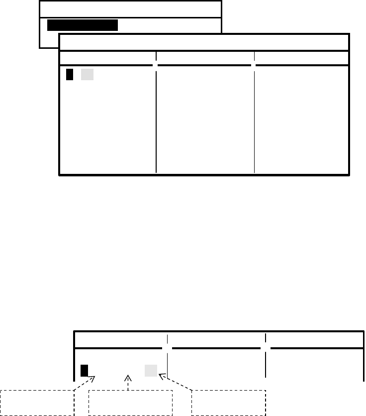
AE–2000 Manual
Customizing Operation via Menu System
4-7
4.8.2. Setting Procedure – 2/3
(2) Highlight the desired option, and then press . The above example shows that you
selected option “2: FIRST RECEIVER” to make settings to the first receiver alone.
Another submenu will then open with the following options:
1: STATIONS: Selects or rejects transmitters.
2: MESSAGES: Selects or rejects message types.
(3) Select “1:STATIONS” and then press . This will open a table listing the station IDs,
their memory (ME) storage statuses, printer (PR) and INS ( IN) port output statuses, as
in the example below. The status indication is either SL (selected) or RJ (rejected).
Initially all stations are in the SL status (i.e. selected) and messages from every station
will be displayed and stored in memory, output to the printer port (RS–232C
connector) and output to the INS port (RS–422 connector).
Figure 4-10 Making Settings for First Receiver – Step 2
(4) Using /, highlight the station whose NAVTEX messages you wish to store in
memory, to output to the printer port or to output to the INS port.
(5) With /, highlight the status indication ( SL or RJ) of the target device (ME, PR or
IN).
(6) To change the status to RJ, press and to change it back to SL, press .
The example below shows that you wish to output the messages from station B to the
INS port alone, while preventing them from being displayed and stored in memory or
from being output to the printer port.
Figure 4-11 Making Settings for First Receiver – Step 3
(continued on next page)
2: FIRST RECEIVER
(
518KHZ
)
1: STATIONSI
2: MESSAGES
ME PR IN
A: SL SL SL
B: SL SL SL
C: SL SL SL
D: SL SL SL
E: SL SL SL
F: SL SL SL
G: SL SL SL
H: SL SL SL
I: SL SL SL
ME PR IN
J: SL SL SL
K: SL SL SL
L: SL SL SL
M: SL SL SL
N: SL SL SL
O: SL SL SL
P: SL SL SL
Q: SL SL SL
R: SL SL SL
ME PR IN
S: SL SL SL
T: SL SL SL
U: SL SL SL
V: SL SL SL
W: SL SL SL
X: SL SL SL
Y: SL SL SL
Z: SL SL SL
1: STATIONS
(
MEmor
y
PRinter INs
)
ME PR IN ME PR IN ME PR IN
A: SL SL SL J: SL SL SL S: SL SL SL
B: RJ RJ SL K: SL SL SL T: SL SL SL
Not to be stored
in memor
y
Not to be output to
p
rinter (RS
–
232C)
To be output to
INS (RS
–
422)
AE–2000 Manual
Customizing Operation via Menu System
4-8
4.8.2. Setting Procedure – 3/3
(7) Likewise, repeat steps (4), (5) and (6) to make the desired RJ/SL settings for other
transmitter IDs.
Do not press
after setting the status with/.
(8) Press to return to the previous menu, or to close all menus to return to the
previous text message screen.
This completes the procedure for changing the memory display and storage status,
printer port output status and INS port output status.
NOTE: Those settings can be externally controlled via the INS port with appropriate commands
from a PC or IBS/INS device. See paragraph 7.4 for details.
4.9. Selecting and Rejecting Message Types
4.9.1. Introduction
Initially all message types are to be displayed and stored in memory, to be output to the
printer port ( RS–232C), I/O DATA port (I/O DATA) and to the INS port (RS–422), except
for the following types:
Figure 4-12 Initially Rejected Message Types
G I M N O P Q R S T U W X Y
If you wish to select some of these types for storage in memory or for output to the
printer/ INS ports, or to prevent other messages types from being stored, or from being
output to the ports, follow the procedure outlined below.
NOTES:
(1) Message types A (Navigational warning), B (Meteorological warning), D (SAR, piracy and
armed robbery information) and L (Additional navigational warning) are always selected
for storage in memory, output to the printer, I/O DATA and INS ports; these types cannot be
rejected (i . e . cannot be set to the “ RJ” status).
(2) A message with serial number= 00 will always be displayed and stored regardless of storage
rejection settings.
(3) Those settings can be externally controlled via the INS port with appropriate commands
from a PC or IBS/I NS device. See paragraph 7.4 for details.
4.9.2. Setting Procedure
To select some of the above initially rejected message types (e.g. type G: AIS messages) or
to reject additional message types, execute the following step–by–step instructions. It is
assumed that the SYSTEM MENU is currently being displayed.
(1) Highlight option “4: MAKE SEL/REJ SETTINGS” by pressing /, and then .
This opens a submenu as shown below with the following options:
1: SYNCHRONIZE BOTH RECEIVERS: Applies same settings to both receivers.
2: FIRST RECEIVER (518KHZ): Makes settings for first receiver alone.
3: SECOND RECEIVER: Makes settings for second receiver alone.
(continued on next page)

AE–2000 Manual
Customizing Operation via Menu System
4-9
4.9.2. Setting Procedure – 2/3
(2) Highlight the desired option, and then press . The example below shows that you
selected option “1: SYNCHRONIZE BOTH RECEIVERS” to make the same settings for
the first and second receivers simultaneously. Another submenu will then open with
the following options:
1: STATIONS: Selects or rejects transmitters.
2: MESSAGES: Selects or rejects message types (message categories).
(3) Select “2:MESSAGES” and then press .
This will open a table listing the message types and titles, their memory (ME) storage
statuses, printer (PR) and INS ( IN) port output statuses, as in the example below. The
status indication is either SL (selected) or RJ ( rejected).
The statuses of the rest of the message types (M through Z) will show up one by one
with repeatedly pressing of , as in the example in Figure 4–14.
Figure 4-13 Making Same Settings for First and Second Receivers – Step 1
Destination Devices: ME: memory PR: printer port (RS–232C)
IN: INS port (RS–422)
Status: SL: selected RJ: rejected
SYSTEM MENU
1: MAKE DISPLAY SETTINGS
2: SELECT 2ND RECEIVER FREQUENCIES
3: TURN ON/OFF KEYPRESS BEEP
4: MAKE SEL/REJ SETTINGS
5 SEARCH STORED MESSAGES
6. SELECT OUTPUT MESSAGES
7. SET OUTPUT PORTS
8. START SELF–DIAGNOSTIC TESTS
9: TURN ON/OFF MESSAGE ALARM
0. RESET TO FACTORY DEFAULTS
4: MAKE SEL/REJ SETTINGS
1: SYNCHRONIZE BOTH RECEIVERS
2: FIRST RECEIVER (518KHZ)
3: SECOND RECEIVER
1: SYNCHRONIZE BOTH RECEIVERS
1: STATIONS
2: MESSAGESi
2: MESSAGES
(
MEmor
y
PRinter INs
)
ME PR IN
A: NAVIGATIONAL WARNING SL SL SL
B: METEOROLOGICAL WARNING SL SL SL
C: ICE REPORT SL SL SL
D: SEARCH AND RESCUE INFORMA– SL SL SL
TION/PIRACY AND ARMED ROBBERY
E: METEOROLOGICAL FORECAST SL SL SL
F: PILOT SERVICE MESSAGE SL SL SL
G: AIS RJ RJ RJ
H: LORAN–C MESSAGE SL SL SL
I: PRESENTLY NOT USED RJ RJ RJ
J: SATNAV MESSAGE SL SL SL
K: OTHER ELECTRONIC NAVAID MSG. SL SL SL
L: ADDITIONAL NAV. WARNING SL SL SL
N
OTE: The settings for
PR apply also
to the I/O DATA port.
AE–2000 Manual
Customizing Operation via Menu System
4-10
(continued on next page)
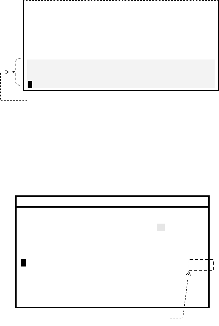
AE–2000 Manual
Customizing Operation via Menu System
4-11
4.9.2. Setting Procedure – 3/3
Figure 4-14 Checking Statuses of Other Message Types – Example
(4) Using /, highlight the message type that you wish, or do not wish, to store in
memory (ME), to output to the printer port (PR) or to output to the INS port (IN). Types
A, B, D and L cannot be selected at any time, and will be skipped.
(5) With /, highlight the status indication ( SL or RJ) of the target device ( ME, PR or
IN). To change the status to RJ, press and to change it back to SL, press . The
example below shows that you wish to output type G messages (AIS) to the INS port
alone, while preventing them from being stored in memory or from being output to the
printer port.
Figure 4-15 Making Same Settings for First and Second Receivers – Step 2
(6) Likewise, repeat steps (4) and (5) to make the desired RJ/SL settings for other
message types. Do not press after setting the status with/.
(7) Press to close all menus to return to the previous text message screen.
2: MESSAGES
(
MEmor
y
PRinter INs
)
ME PR IN
A: NAVIGATIONAL WARNING SL SL SL
B: METEOROLOGICAL WARNING SL SL SL
C: ICE REPORT SL SL SL
D: SEARCH AND RESCUE INFORMA– SL SL SL
TION/PIRACY AND ARMED ROBBERY
E: METEOROLOGICAL FORECAST SL SL SL
F: PILOT SERVICE MESSAGE SL SL SL
G: AIS RJ RJ SL
H: LORAN–C MESSAGE SL SL SL
I: PRESENTLY NOT USED RJ RJ RJ
J: SATNAV MESSAGE SL SL SL
K: OTHER ELECTRONIC NAVAID MSG. SL SL SL
L: ADDITIONAL NAV. WARNING SL SL SL
A
IS messages are to be output to INS port alone
E: METEOROLOGICAL FORECAST SL SL SL
F: PILOT SERVICE MESSAGE SL SL SL
G: AIS RJ RJ RJ
H: LORAN–C MESSAGE SL SL SL
I: PRESENTLY NOT USED RJ RJ RJ
J: SATNAV MESSAGE SL SL SL
K: OTHER ELECTRONIC NAVAID MSG. SL SL SL
L: ADDITIONAL NAV. WARNING SL SL SL
M: MESSAGE TYPE M RJ RJ RJ
N: MESSAGE TYPE N RJ RJ RJ
O: MESSAGE TYPE O RJ RJ RJ
P: MESSAGE TYPE P RJ RJ RJ
Rest of message types partially shown by pressin
g
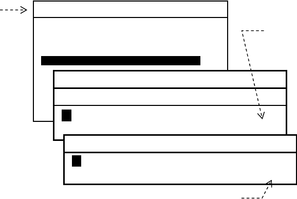
AE–2000 Manual
Customizing Operation via Menu System
4-12
4.10. Searching Memory for Stored Messages
NAVTEX messages stored in non–volatile memory are searchable by station and/or
message type via the following steps.
(1) Highlight option “ 5: SEARCH FOR STORED MESSAGES ” by pressing /,
followed by . This opens a submenu with a list of all station IDs, as shown below. The
wild card character () represents all station IDs.
Figure 4-16 Searching for Stored Messages
(2) Using //
/
, select the station of which messages you wish to search for.
For example, if you wish to search for all stored messages sent from station A, highlight
A . If you wish to search for messages of a specific type from all stations, highlight the
wild card character () which represents all transmitter IDs.
(3) Press . This opens a menu listing all the message types. The wild card () represents
all message types.
(4) Using //
/
, select the desired message type. If you wish to specify all message
types from the station selected at step (2), highlight .
(5) Press . This allows all messages to be displayed that meet the conditions you set at
above steps (2) and (4).
The displayed messages can be scrolled across the screen line–by–line by pressing
/ or message–by–message by pressing
/
.
To return to the menu, press . To return to the previous NAVTEX
text screen, press it once again.
Wild Card representing
all stations
SYSTEM MENU
1: MAKE DISPLAY SETTINGS
2: SELECT 2ND RECEIVER FREQUENCIES
3: TURN ON/OFF KEYPRESS BEEP
4: MAKE SEL/ REJ SETTINGS
5: SEARCH FOR STORED MESSAGESI
6. SELECT OUTPUT MESSAGES
7. SET OUTPUT PORTS
8. START SELF–DIAGNOSTIC TESTS
9: TURN ON/OFF MESSAGE ALARM
0. RESET TO FACTORY DEFAULTS
5: SEARCH STORED MESSAGES
SEARCH BY STATION
Ai B C D E F G H I J K L M
N O P Q R S T U V W X Y Z
SEARCH BY MESSAGE TYPE
Ai B C D E F G H I J K L M
N O P Q R S T U
V
W
X
YZ
W
ild Card representing all message types
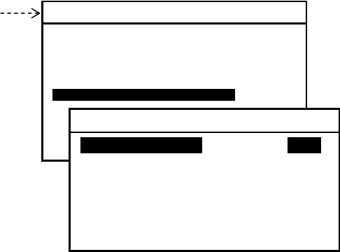
AE–2000 Manual
Customizing Operation via Menu System
4-13
4.11. Selecting Output Messages
4.11.1. Introduction
The NAVTEX message that is currently being received or previously received messages
stored in memory can be output to external devices (e.g., a printer, an INS/IBS device) via
the rear panel interface connectors (I/ O por ts , i. e. RS–232C, RS–422, I/O DATA). The
execution of the following instructions allows you to selectively output the desired
messages by specifying various parameters, such as live (on–line) or recall– from–storage
mode, receiver type, transmitter ID and message type.
(1) Press
, opening the SYSTEM MENU.
Figure 4-17 Accessing Output Selection Menu
(2) Highlight “ 6: SELECT OUTPUT MESSAGES” by pressing /, followed by .
This opens a submenu as illustrated above, with the following output mode options:
1: RECEIVING MSG: Message currently being received
2: ALL STORED MSG: All stored messages
3: MSG SELECTED BY FREQUENCY: Messages selected by specifying receiver
4: MSG SELECTED BY STATION: Messages selected by specifying transmitter
5: MSG SELECTED BY TYPE: Messages selected by specifying message type
6: DISPLAYED MSG: All messages currently displayed
7: SELECTED MSG: Individual messages selected from those appearing on
display
Before the desired output can be obtained, the target output connector (output port) must
be enabled (set to ON) via the instructions in paragraph 4.12. Note that all ports are initially
enabled unless set otherwise previously by your dealer.
NOTE: A forced carriage return ( ) will be replaced by an underscore ( _) (hex 5F ) when it is
output to an IBS / INS terminal or a printer.
SYSTEM MENU
1: MAKE DISPLAY SETTINGS
2: SELECT 2ND RECEIVER FREQUENCIES
3: TURN ON/OFF KEYPRESS BEEP
4: MAKE SEL/REJ SETTINGS
5: SEARCH FOR STORED MESSAGES
6. SELECT OUTPUT MESSAGES
7. SET OUTPUT PORTS
8. START SELF–DIAGNOSTIC TESTS
9: TURN ON/OFF MESSAGE ALARM
0. RESET TO FACTORY DEFAULTS
6: SELECT OUTPUT MESSAGES
1: RECEIVING MSGi ON IOFFI
2: ALL STORED MSG
3: MSG SELECTED BY FREQUENCY
4: MSG SELECTED BY STATION
5: MSG SELECTED BY TYPE
6: DISPLAYED MSG
7: SELECTED MSG

AE-2000 Manual
Customizing Operation via Menu System
4-14
4.11.2. Outputting Live NAVTEX Messages
This output mode is to be activated when an optional printer is plugged in for realtime, on-
–line message printing or when a live NAVTEX output is required for other onboard
applications.
To output live messages as they are received, follow the steps given below. Be sure to set
the printer (e.g. *1PR–900) or other receiving device properly.
NOTE: A forced carriage return () will be replaced by an underscore ( _) (hex 5F ) when it is
output to an IBS / INS terminal or a printer.
(1) Highlight option “1:RECEIVING MSG” on the SELECT OUTPUT MESSAGES
submenu, and then press .
(2) Press to highlight “*2ON,” and then press . Another submenu will then show up,
allowing you to select the first or second receiver, as illustrated below.
Figure 4-18 Outputting Live NAVTEX Message
(3) Using /, select the desired receiver, and then press . The equipment will then
start outputting live messages from the receiver selected.
The settings you made via the above steps will be stored in memory.
(4) Press to return to the previous menu or to return to the first receiver message
screen.
*1: Before the printer can be used, the data transfer speed through the RS–232C port must be set
to 110 baud ( BIT RATE: 0.11) via the instructions given in 4.12.4.2.
*2: This setting is remembered in memory. It will return to “ OFF” when you execute the system
reset via the instructions in paragraph 4.15.
6: SELECT OUTPUT MESSAGES
1: RECEIVING MSGi iONi OFF
2: ALL STORED MSG
3: MSG SELECTED BY FREQUENCY
4: MSG SELECTED BY STATION
5: MSG SELECTED BY TYPE
6: DISPLAYED MSG
7: SELECTED MSG
Select this option with
,
and then press .
1: RECEIVING MSG
1: FIRST RECEIVER (518KHZ)i
2: SECOND RECEIVER (490KHZ)
Select desired receiver with
/
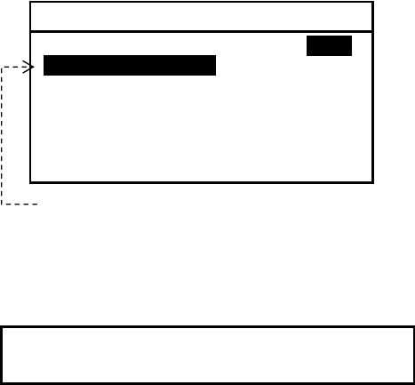
AE-2000 Manual
Customizing Operation via Menu System
4-15
4.11.3. Outputting All Stored Messages
To output all the messages stored in memory, follow the steps given below.
NOTE: A forced carriage return ( ) will be replaced by an underscore ( _) (hex 5F ) when it is
output to an IBS / INS terminal or a printer.
(1) Highlight “2:ALL STORED MSG” on the SELECT OUTPUT MESSAGES submenu, and
then press .
The stored messages will then be output one by one.
Figure 4-19 Outputting All Stored Messages
The following window will pop up to indicate the outputting action in progress.
The window will be turned off automatically upon completion of outputting.
To cancel the action, press .
(2) Press to return to the previous menu or to return to the first receiver message
screen.
OUTPUTTING STORED MESSAGES.
TO CANCEL, PRESS [CLR].
Select this option with /, and then
press .
6: SELECT OUTPUT MESSAGES
1: RECEIVING MSG ON IOFFI
2: ALL STORED MSGI
3: MSG SELECTED BY FREQUENCY
4: MSG SELECTED BY STATION
5: MSG SELECTED BY TYPE
6: DISPLAYED MSG
7: SELECTED MSG
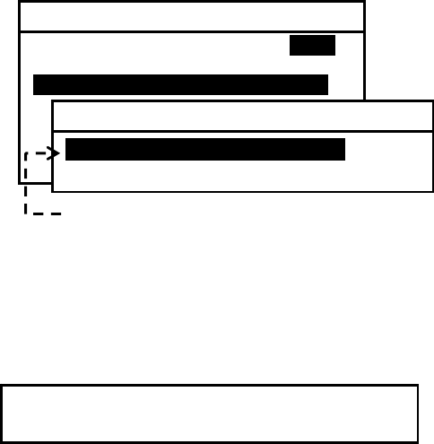
AE-2000 Manual
Customizing Operation via Menu System
4-16
4.11.4. Outputting NAVTEX Messages of Specific Receiver
If you wish to output all NAVTEX messages received from either receiver (first or second
receiver) alone, carry out the following step–by–step procedure:
NOTE: A forced carriage return ( ) will be replaced by an underscore ( _) (hex 5F ) when it is
output to an IBS / INS terminal or a printer.
(1) Highlight option “ 3:MSG SELECTED BY FREQUENCY” on the SELECT OUTPUT
MESSAGES submenu, and then press . This turns on another submenu with the
following options, enabling you to select the desired receiver, as in the example
illustrated below:
1: FIRST RECEIVER (518 KHZ): Outputs first receiver messages.
2: SECOND RECEIVER: Outputs second receiver messages.
Figure 4-20 Outputting Stored Messages of First Receiver – Example
(2) Highlight the desired option, and then press . The following window will pop up to
indicate the outputting action in progress.
The window will be turned off automatically upon completion of outputting.
To cancel the action, press .
(3) Press to return to the previous menu or to return to the first receiver message
screen.
OUTPUTTING STORED MESSAGES.
TO CANCEL, PRESS [CLR].
To derive first receiver messages from
memory, select this option with /,
and then press .
6: SELECT OUTPUT MESSAGES
1: RECEIVING MSG ON IOFFI
2: ALL STORED MSG
3: MSG SELECTED BY FREQUENCYi
4: MSG SELECTED BY STATION
5: MSG SELECTED BY TYPE
6: DISPLAYED MSG – ALL
7: DISPLAYED MSG – SPECIFIC
3: MSG SELECTED BY FREQUENCY
1: FIRST RECEIVER (518 KHZ)
2: SECOND RECEIVER
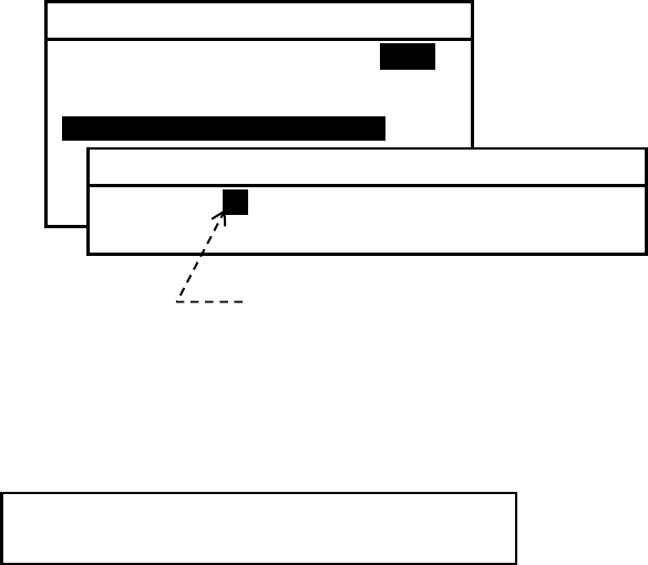
AE-2000 Manual
Customizing Operation via Menu System
4-17
4.11.5. Outputting NAVTEX Messages of Specific Station
If you wish to output all messages received from a specific NAVTEX transmitting station,
carry out the following step–by–step procedure:
NOTE: A forced carriage return ( ) will be replaced by an underscore ( _) (hex 5F ) when it is
output to an IBS / INS terminal or a printer.
(1) Highlight option “ 4:MSG SELECTED BY STATION” on the SELECT OUTPUT
MESSAGES submenu, and then press . This turns on another submenu with a list of
station IDs, enabling you to select the desired transmitter, as in the example illustrated
below:
Figure 4-21 Outputting Stored Messages Received from Station D – Example
(2) Using /, highlight the desired ID, and then press . The following window will
pop up to indicate the outputting action in progress.
The window will be turned off automatically upon completion of outputting.
To cancel the action, press .
(3) Press to return to the previous menu or to return to the first receiver message
screen.
Select desired station ID with /, and
then press .
6: SELECT OUTPUT MESSAGES
1: RECEIVING MSG ON IOFFI
2: ALL STORED MSG
3: MSG SELECTED BY FREQUENCY
4: MSG SELECTED BY STATIONi
5: MSG SELECTED BY TYPE
6: DISPLAYED MSG – ALL
7: DISPLAYED MSG – SPECIFIC
4:MSG SELECTED BY STATION
A B C iDi E F G H I J K L M
N O P Q R S T U V W X Y Z
OUTPUTTING STORED MESSAGES.
TO CANCEL, PRESS [CLR].
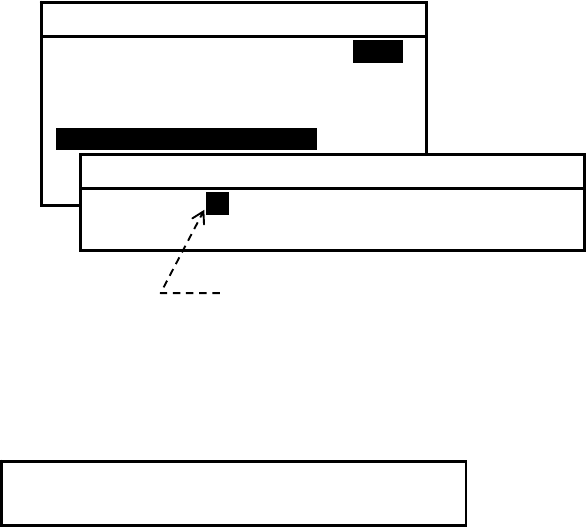
AE-2000 Manual
Customizing Operation via Menu System
4-18
4.11.6. Outputting NAVTEX Messages of Specific Message Type
If you wish to output all messages of a specific message type, carry out the following step-
–by–step instructions:
NOTE: A forced carriage return ( ) will be replaced by an underscore ( _) (hex 5F ) when it is
output to an IBS / INS terminal or a printer.
(1) Highlight option “5:MSG SELECTED BY TYPE” on the SELECT OUTPUT
MESSAGES submenu, and then press . This turns on another submenu with a list of
message types, enabling you to select the desired message type, as in the example
illustrated below:
Figure 4-22 Outputting Stored Messages of Message Type D – Example
(2) Using /, highlight the desired message type, and then press . The following
window will pop up to indicate the outputting action in progress.
The window will be turned off automatically upon completion of outputting.
To cancel the action, press .
(3) Press to return to the previous menu or to return to the first receiver message
screen.
6: SELECT OUTPUT MESSAGES
1: RECEIVING MSG ON IOFFI
2: ALL STORED MSG
3: MSG SELECTED BY FREQUENCY
4: MSG SELECTED BY STATION
5: MSG SELECTED BY TYPEi
6: DISPLAYED MSG – ALL
7: DISPLAYED MSG – SPECIFIC
Select desired message type with /,
and then press .
5:MSG SELECTED BY TYPE
A B C iDi E F G H I J K L M
N O P Q R S T U V W X Y Z
OUTPUTTING STORED MESSAGES.
TO CANCEL, PRESS [CLR].
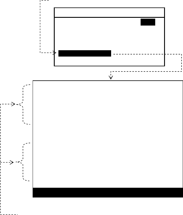
AE-2000 Manual
Customizing Operation via Menu System
4-19
4.11.7. Outputting All Displayed NAVTEX Messages
If you wish to output all messages currently displayed, follow the steps given below.
NOTE: A forced carriage return ( ) will be replaced by an underscore ( _) (hex 5F ) when it is
output to an IBS / INS terminal or a printer.
(1) Highlight “ 6:DISPLAYED MSG” on the SELECT OUTPUT MESSAGES submenu,
and then press . This turns all menus off, showing the current message screen, as in
the example illustrated below.
Figure 4-23 Outputting All Currently Displayed Messages – Example
(2) Press
to output all the displayed messages, or to cancel the function.
The previous message screen will return automatically upon completion of the output.
NJ91
STAKDBFE//211745Z AUG 06//
DGPS BNM 736–06
ANNAPOLIS, MD DGPS BROADCAST SITE IS
UNMONITORED AS OF 211704Z AUG 06. NAVCEN IS
UNABLE TO VERIFY SIG INTEGRITY UNTIL FURTHER
NOTICE.
NNNN STORED (CER= 00%)
AA51
CCGD7 BNW 887–06
1. MIAMI HBW–MIAMI MAIN CHAN LT 19 LLNRD
2. CANCEL AT TIME//190400Z SEP 06X
NNNN STORED (CER= 00%)
PRESS
[
ENT
]
TO OUTPUT OR
[
CLR
]
TO EXIT
All currently displayed messages will be output by pressing
Select this option with /, and then press .
6: SELECT OUTPUT MESSAGES
1: RECEIVING MSG ON IOFFI
2: ALL STORED MSG
3: MSG SELECTED BY FREQUENCY
4: MSG SELECTED BY STATION
5: MSG SELECTED BY TYPE
6: DISPLAYED MSG
7: SELECTED MSG
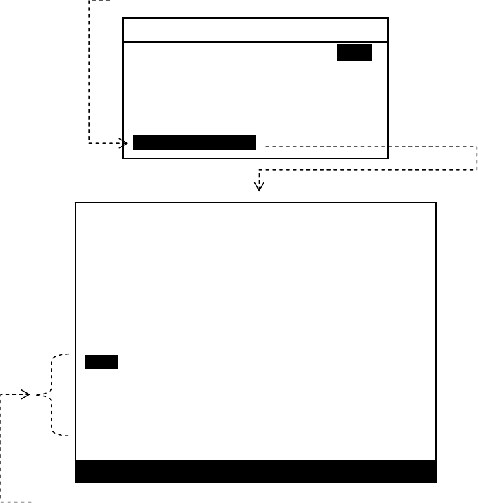
AE-2000 Manual
Customizing Operation via Menu System
4-20
4.11.8. Outputting Specific NAVTEX Message
If you wish to output a specific message out of all currently displayed messages, carry out
the following procedure:
NOTE: A forced carriage return ( ) will be replaced by an underscore ( _) (hex 5F ) when it is
output to an IBS / INS terminal or a printer.
(1) Highlight “ 7:SELECTED MSG” on the SELECT OUTPUT MESSAGES submenu, and
then press . This turns all menus off, showing the current message screen, as in the
example illustrated below.
Figure 4-24 Outputting Specific Message – Example
(2) Using /
, highlight the ID of the desired message as in the example above, and
then press .
To cancel the function, press instead of .
Select this option with /, and then press .
6: SELECT OUTPUT MESSAGES
1: RECEIVING MSG ON IOFFI
2: ALL STORED MSG
3: MSG SELECTED BY FREQUENCY
4: MSG SELECTED BY STATION
5: MSG SELECTED BY TYPE
6: DISPLAYED MSG
7: SELECTED MSG
To output this message, select its ID with / and then press .
NJ91
STAKDBFE//211745Z AUG 06//
DGPS BNM 736–06
ANNAPOLIS, MD DGPS BROADCAST SITE IS
UNMONITORED AS OF 211704Z AUG 06. NAVCEN IS
UNABLE TO VERIFY SIG INTEGRITY UNTIL FURTHER
NOTICE.
NNNN STORED (CER= 00%)
AA51
CCGD7 BNW 887–06
1. MIAMI HBW–MIAMI MAIN CHAN LT 19 LLNRD
2. CANCEL AT TIME//190400Z SEP 06X
NNNN STORED (CER= 00%)
PRESS
[
ENT
]
TO OUTPUT OR
[
CLR
]
TO EXIT
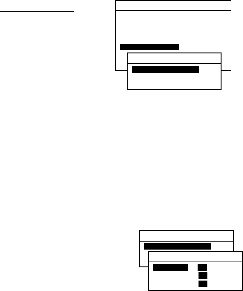
AE-2000 Manual
Customizing Operation via Menu System
4-21
4.12. Setting Output Ports
4.12.1. Introduction
In order for external devices (e.g. printer, IBS/INS component) to receive live or stored
NAVTEX messages properly through the desired rear panel I/O connector (RS–232C,
RS–422 or I/O DATA connector), it is necessary to set the following parameters to the port
selected.
Figure 4-25 Opening Submenu for Setting Output Ports
Output Port Parameters:
Status (enabled or disable d)
Communications Protocol
Bit Format and Output Rate
The following instructions allow you to set these
parameters as required by the data–receiving
device plugged into the desired connector.
(1) Press
, opening the SYSTEM MENU.
(2) Highlight “7: SET OUTPUT PORTS” by pressing /, followed by . This
opens a submenu as illustrated above, with the following output options:
1: SET PORTS ON/OFF: Enables or disables desired port.
2: SELECT PROTOCOLS: Selects protocols for desired port.
3: SET BIT FORMAT & RATE: Sets correct bit format and data rate.
4.12.2. Enabling/Disabling I/O Ports
4.12.2.1. RS–232C Port
The RS–232C port is mainly intended as a printer interface, and is initially enabled so that
the message types selected in paragraphs 4.11.2 through 4.11.8 will be output via this port. If,
for any reason, you wish to disable it, follow the steps given below.
Figure 4-26 Selecting Output Ports for Enable/Disable Settings – 1
(1) Highlight “1:RS–232C” and press .
(2) Using
/
, highlight “ OFF.”
(3) Press
to complete or to cancel.
(4) Press to return to the previous submenu or to
return to the first receiver text page.
4.12.2.2. RS–422 Port
SYSTEM MENU
1: MAKE DISPLAY SETTINGS
2: SELECT 2ND RECEIVER FREQUENCIES
3: TURN ON/OFF KEYPRESS BEEP
4: MAKE SEL / REJ SETTINGS
5: SEARCH FOR STORED MESSAGES
6. SELECT OUTPUT MESSAGES
7. SET OUTPUT PORTS
8. START SELF–DIAGNOSTIC TESTS
9: TURN ON/ OFF MESSAGE ALARM
0. RESET TO FACTORY DEFAULTS
7: SET OUTPUT PORTS
1: SET PORTS ON/OFF
2: SELECT PROTOCOLS
3: SET BIT FORMAT & RATE
7: SET OUTPUT PORTS
1: SET PORTS ON/OFF
2: SELECT PROTOCOLS
3: SET BIT FORMAT & RATE
1: SET PORTS ON/OFF
1: RS–232Ci ON OFF
2: RS–422 ON OFF
3: I/O DATA ON OFF

AE-2000 Manual
Customizing Operation via Menu System
4-22
The RS–432 port, designed as an interface with an IBS/INS system, is also initially enabled
so that the NAVTEX message types selected in paragraphs 4.11.2 through 4.11.8 will be
output via this port. If, for any reason, you wish to disable it, follow the steps given below.
Figure 4-27 Selecting Output Ports for Enable/Disable Settings – 2
(1) Highlight “2:RS–422” and press .
(2) Using
/
, highlight “ OFF.”
(3) Press
to complete, or to cancel.
(4) Press to return to the previous submenu or to
return to the first receiver text page.
NOTE: The input lines to the RS–422 connector are insulated from the ship’s ground by opto-
–isolators.
4.12.2.3. I/O DATA Port
The I/O DATA port is also initially enabled so that the message types selected in paragraphs
4.11.2 through 4.11.8 will be output via this port. If, for any reason, you wish to disable it,
carry out the following step–by–step instructions:
Figure 4-28 Selecting Output Ports for Enable/Disable Settings – 3
(1) Highlight “3:I/O DATA” and press .
(2) Using
/
, highlight “ OFF.”
(3) Press
to complete or to cancel.
(4) Press to return to the previous submenu or to
return to the first receiver text page.
NOTE: The message outputs available from the I/O DATA port are the same as those
from the printer port (RS–232C).
4.12.3. Selecting Communications Protocols
The following communications protocols are initially assigned to the three output ports
described in paragraph 4.12.
7: SET OUTPUT PORTS
1: SET PORTS ON/OFF
2: SELECT PROTOCOLS
3: SET BIT FORMAT & RATE
1: SET PORTS ON/OFF
1: RS–232C ON OFF
2: RS–422i ON OFF
3: I/O DATA ON OFF
7: SET OUTPUT PORTS
1: SET PORTS ON/OFF
2: SELECT PROTOCOLS
3: SET BIT FORMAT & RATE
1: SET PORTS ON/OFF
1: RS–232C ON OFF
2: RS–422 ON OFF
3: I/O DATAi ON OFF
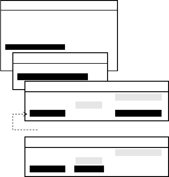
AE-2000 Manual
Customizing Operation via Menu System
4-23
IEC 61162–1 (NMEA–0183 Ver. 2.0 & greater ): RS–422 Port
Asynchronous non–handshaking: RS–232 Port and I/O DATA Port
Of the three ports, only the I/O DATA port can select either the IEC 61162–1 or the
asynchronous non–handshaking transfer mode. If your application using that port requires
the IEC 61162–1 as its protocol, follow the steps given below.
NOTE: If you wish to connect a serial printer other than the PR–900 to the RS–232C or the I/O
DATA port, be sure to turn off its hardware flow control and set it to “X–ON /X–OFF,” if available,
or an erratic printout can result.
(1) Highlight option “2:SELECT PROTOCOLS” on the SET OUTPUT PORTS submenu,
and press . This turns on another submenu for selection of the protocols, as
illustrated below.
Figure 4-29 Accessing Submenu for Selection of Protocols for I/O DATA Port
(2) To change the protocol for the I/O
DATA port to the IEC 61162–1, press
,
highlighting option IEC61162, as
shown below.
Figure 4-30 Selecting Protocol for I/O DATA Port
(3) Press to complete the selection.
(4) Press to return to the previous submenu or to return to the first receiver text page.
4.12.4. Selecting Bit Formats and Data Transfer Rates
4.12.4.1. Introduction
The following instructions allow you to select the correct bit format ( number of data bits,
stop bits, parity bit status) and bit rate (baud rate: 110, 4800, 9600 etc.) that are required by
the application using each I/O port for correct data transfer.
Figure 4-31 Accessing Submenu for Selection
of Bit Formats and Rates
Protocols are selectable for this port only.
SYSTEM MENU
1: MAKE DISPLAY SETTINGS
2: SELECT 2ND RECEIVER FREQUENCIES
3: TURN ON/OFF KEYPRESS BEEP
4: MAKE SEL / REJ SETTINGS
5: SEARCH FOR STORED MESSAGES
6. SELECT OUTPUT MESSAGES
7. SET OUTPUT PORTS
8. START SELF–DIAGNOSTIC TESTS
9: TURN ON/ OFF MESSAGE ALARM
0. RESET TO FACTORY DEFAULTS
7: SET OUTPUT PORTS
1: SET PORTS ON/OFF
2: SELECT PROTOCOLS
3: SET BIT FORMAT & RATE
2: SELECT PROTOCOLS
1: RS–232C IEC61162 NONE (ASCII)
2: RS–422 IEC61162 NONE (ASCII)
3: I/ O DATAI IEC61162 NONE (ASCII)
2: SELECT PROTOCOLS
1: RS–232C IEC61162 NONE (ASCII)
2: RS–422 IEC61162 NONE (ASCII)
3: I/ O DATAI iIEC61162i NONE (ASCII)
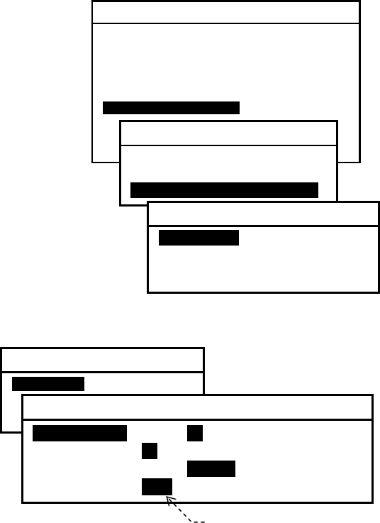
AE-2000 Manual
Customizing Operation via Menu System
4-24
(1) Highlight option “3:SET BIT FORMAT &
RATE” on the SET OUTPUT PORTS
submenu, and then press .
Another submenu (SET BIT FORMAT &
RATE) will then be turned on as shown at right
to specify the port for which you wish to select
those para– meters.
(2) Using /, select the desired port.
The procedure given below assumes that the SET
BIT FORMAT & RATE submenu is currently
displayed.
4.12.4.2. Selecting Parameters for RS–232C Port
The parameters for the RS–232C port are initially set as follows:
Figure 4-32 Checking Current Parameters for RS–232C
Data Bits: 8 bits
Stop Bits: 1 bit
Parity: None
Bit Rate: 110 baud
The current parameter values can be
checked by selecting “1:RS–232C” as
shown at right.
NOTES:
(1) If an optional PR–900 printer is plugged into the RS–232C port, be sure to select the
following parameters before it can be used to print messages correctly:
DATA BITS = 8, STOP BITS = 1, PARITY = NONE, BIT RATE = 0.11 (110 baud)
(2) If you wish to connect a serial printer other than the PR–900 to the RS–232C port, be sure to
turn off its hardware flow control and set it to “X–ON/ X–OFF,” if available, or an erratic
printout can result.
(continued on next page)
4.12.4.2. Selecting Parameters for RS–232C Port ( continued – 2 / 2)
If your RS–232C application requires a different set of parameters, select the appropriate
values by following the steps given below:
(1) Press /to highlight the desired parameter.
For example, to change the parity bit status to non–parity, highlight “ 3:PARITY.”
(2) Press
/
to highlight the desired value, and then press .
For example, highlight “NONE” and press .
SYSTEM MENU
1: MAKE DISPLAY SETTINGS
2: SELECT 2ND RECEIVER FREQUENCIES
3: TURN ON/OFF KEYPRESS BEEP
4: MAKE SEL/ REJ SETTINGS
5: SEARCH FOR STORED MESSAGES
6. SELECT OUTPUT MESSAGES
7. SET OUTPUT PORTS
8. START SELF–DIAGNOSTIC TESTS
9: TURN ON/ OFF MESSAGE ALARM
0. RESET TO FACTORY DEFAULTS
7: SET OUTPUT PORTS
1: SET PORTS ON/OFF
2: SELECT PROTOCOLS
3: SET BIT FORMAT & RATE
3: SET BIT FORMAT & RATE
1: RS–232C
2: RS–422
3: I/ O DATA
3: SET BIT FORMAT & RATE
1: RS–232C
2: RS–422
3: I/O DATA
1: RS
–
232C
1: DATA BITSI 7 I8I
2: STOP BITS I1I 2
3: PARITY ODD INONEI
4: BIT RATE i0.11 4.8 9.6 19.2 38.4
0.11= 11 0 baud
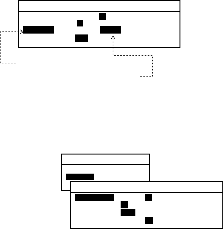
AE-2000 Manual
Customizing Operation via Menu System
4-25
Figure 4-33 Changing Parity Bit Status Parameter – Example
(3) Press to return to the previous submenu or to return to the first receiver text page.
4.12.4.3. Selecting Parameters for RS–422 Port
The parameters for the RS–422 port are initially set as follows:
Figure 4-34 Checking Current Parameters for RS–422
Data Bits: 8 bits
Stop Bits: 1 bit
Parity: Odd parity
Bit Rate: 4800 baud
The current parameter values can be
checked by selecting “2:RS–422” as shown
at right.
Each parameter can be changed in the same manner as in the example given above
(paragraph 4.12.4.2). Be sure to press after selecting the desired value.
(continued on next page)
4.12.4.4. Selecting Parameters for I/O DATA Port
The parameters for the I/O DATA port are initially set as follows:
Data Bits: 8 bits
Stop Bits: 1 bit
Parity: Odd parity
Bit Rate: 4800 baud
NOTES:
(1) The message outputs available from the I/O DATA port are the same as those from the
printer port (RS–232C).
(2) If you wish to connect a serial printer other than the PR–900 to the I/O DATA port, be sure to
turn off its hardware flow control and set it to “X–ON/ X–OFF,” if available, or an erratic
1: RS
–
232C
1: DATA BITS 7 I8I
2: STOP BITS I1I 2
3: PARITYI ODD INONEI
4: BIT RATE i0.11 4.8 9.6 19.2 38.4
(1) Highlight this with /.
(2) Highlight this with
/
, and press .
3: SET BIT FORMAT & RATE
1: RS–232C
2: RS–422
3: I/O DATA
2: RS
–
422
1: DATA BITSI 7 I8I
2: STOP BITS I1I 2
3: PARITY iODD NONE
4: BIT RATE 0.11 4.8 9.6 19.2 38.4
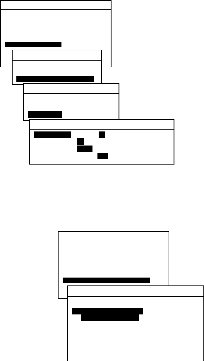
AE-2000 Manual
Customizing Operation via Menu System
4-26
printout can result.
The current parameter values can be checked by selecting “3:I/O DATA” on the SET BIT
FORMAT & RATE submenu, as shown below.
Figure 4-35 Checking Current Parameters for I/O DATA Port
Each parameter value can be changed using / and /
in the same man– ner as in
the example given in paragraph 4.12.4.2.
Be sure to press after selecting the desired value.
4.13. Performing Self–Diagnostic Tests
Figure 4-36 Starting Self–Diagnostic Test
4.13.1. Introduction
Selecting option “ 8: START SELF-
–DIAGNOSTIC TESTS” opens a test report
window as shown at right and at the
same time initiates auto– matically the
built–in function of self–diagnostic tests to
check the integrity of important hardware
com– ponents of the equipment.
Note that the test functions cannot be executed
during live message reception.
SYSTEM MENU
1: MAKE DISPLAY SETTINGS
2: SELECT 2ND RECEIVER FREQUENCIES
3: TURN ON/OFF KEYPRESS BEEP
4: MAKE SEL / REJ SETTINGS
5: SEARCH FOR STORED MESSAGES
6. SELECT OUTPUT MESSAGES
7. SET OUTPUT PORTS
8. START SELF–DIAGNOSTIC TESTS
9: TURN ON/ OFF MESSAGE ALARM
0. RESET TO FACTORY DEFAULTS
7: SET OUTPUT PORTS
1: SET PORTS ON/OFF
2: SELECT PROTOCOLS
3: SET BIT FORMAT & RATE
3: SET BIT FORMAT & RATE
1: RS–232C
2: RS–422
3: I/O DATA
3: I
/
ODATA
1: DATA BITSI 7 I8I
2: STOP BITS i1i 2
3: PARITY iODDi NONE
4: BIT RATE 0.11 I4.8I 9.6 19.2 38.4
SYSTEM MENU
1: MAKE DISPLAY SETTINGS
2: SELECT 2ND RECEIVER FREQUENCIES
3: TURN ON/OFF KEYPRESS BEEP
4: MAKE SEL / REJ SETTINGS
5: SEARCH FOR STORED MESSAGES
6. SELECT OUTPUT MESSAGES
7. SET OUTPUT PORTS
8. START SELF–DIAGNOSTIC TESTS
9: TURN ON/ OFF MESSAGE ALARM
0. RESET TO FACTORY DEFAULTS
8: START SELF
–
DIAGNOSTIC TESTS
SELF–DIAGNOSTIC TEST REPORT
1: TESTING RECEIVERS
1ST RCVRI(518KHZ)I STARTING
2ND RCVR (490KHZ)
2: TESTING ROM
3: TESTING RAM

AE-2000 Manual
Customizing Operation via Menu System
4-27
The self–diagnostic tests should be conducted
once a year as a part of regular maintenance.
The following components will be checked:
First Receiver ( 518 kHz)
Second Receiver
(
490 kHz or 4209.5 kHz, currently selected)
ROM (flash memory embedded in CPU chip, for software storage )
RAM ( DRAM embedded in CPU chip, for software execution) and (SRAM mounted on CPU
PCB, capacitor–backed, for message/ID storage)
Alarm (audible )
Keypad dimmer lamps
4.13.2. Activating Self–Diagnostic Test Function
(1) Allow the equipment to warm up for at least 30 minutes before activating the test
function if the unit was switched off before the test.
(2) Press to open the system menu, highlight “ 8: START SELF–DIAGNOSTIC
TESTS” and press . A test report window will show up as in the example above, and
the tests will start automatically. To cancel the execution, press . If reception of a
NAVTEX message is already in progress, the function cannot be activated, and the
following caution will be turned on, blinking in reverse video.
iWAIT FOR MESSAGE RECEPTION TO END!i
Press
to turn it off, returning to the text screen.
(continued on next page)
4.13.3. Checking Test Results
Figure 4-37 Results of Self–Diagnostic Test – Example
The function will be terminated automatically
just after completion of the keypad dimmer
lamp test (TESTING KEYPAD LAMPS on the
test report). The test report window will
remain to allow the user to check the tests
results. The figure at right shows an example
of the test report showing the results of the
self– diagnostic tests.
The result of each check will be available in one of the following indications:
8: START SELF
–
DIAGNOSTIC TESTS
SELF–DIAGNOSTIC TEST REPORT
1: TESTING RECEIVERS
1ST RCVR((518KHZ)((518K OK
0123456789 ( ).,=?
ABCDEFGHIJKLMNOPQRSTUVWXYZ
2ND RCVR (490KHZ) OK
0123456789 ( ).,=?
ABCDEFGHIJKLMNOPQRSTUVWXYZ
2: TESTING ROM OK
3: TESTING RAM OK
4: TESTING ALARM COMPLETE
5: TESTING KEYPAD LAMPS COMPLETE
SOFTWARE VER. 1.3 REV1.1A1
DATE JUNE 06, 2007
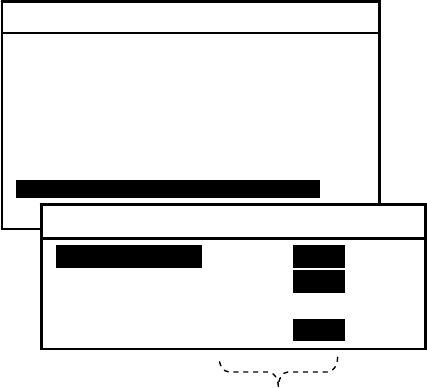
AE-2000 Manual
Customizing Operation via Menu System
4-28
OK: Tested hardware is functioning normally (for test items 1, 2 and 3).
FAILED: Malfunction of tested hardware is detected (for test items 1, 2 and 3).
If this indication shows up, see section 5 (User–Level Trouble– shooting) for
actions to be taken, or contact your dealer for assistance.
NOTE: If the receiver test result is “ FAILED,” check to be sure that the unit has
been turned on for at least 30 minutes before starting the test. This warm–up
period is necessary for the internal test oscillators to become stable. The
“FAILED” indication should not be immediately interpreted as a sign of receiver
malfunction if the unit was tested shortly after power–up.
COMPLETE: Test is completed (for test items 4 and 5). The user should check whether
the tested hardware component functioned correctly.
(1) Result of Audible Alarm Test
Execution of the test “4:TESTING ALARM” checks the buzzer function of the audible
alarm circuit. On successful completion of the test, the buzzer should sound three slow
beeps. If no sound is heard, see section 5 (User–Level Troubleshooting) for actions to be
taken, or contact your dealer for assistance.
(2) Result of Keypad Backlighting Lamp Test
Execution of the test “ 5:TESTING KEYPAD LAMPS” checks the light–emitting diodes
(LEDs) that illuminate the keys and their control circuit. All keys should be lit blinking at
the maximum level during the test. If no key is lit or if some of the keys remain
extinguished, see section 5 (User–Level Troubleshooting) for actions to be taken, or
contact your dealer for assistance.
This test result should be checked in a dark environment for ease of checking.
4.14. Turning on/off Message Alarms
The alarm function for types A (navigational warning), B (meteorological warning) and L
(additional navigational warning) messages is initially disabled unless it was set otherwise
by your dealer. If you wish to enable some or all of the message alarms, follow the steps
given below. The alarm for type–D messages (SAR, piracy and armed robbery information)
cannot be disabled due to the relevant IMO resolutions.
(1) Press
, opening the system menu.
(2) Using /, highlight “9: TURN ON/OFF MESSAGE ALARMS” and then press .
The current alarm on/off status will then be displayed on a submenu as in the example
below.
Figure 4-38 Initial Alarm Status
SYSTEM MENU
1: MAKE DISPLAY SETTINGS
2: SELECT 2ND RECEIVER FREQUENCIES
3: TURN ON/OFF KEYPRESS BEEP
4: MAKE SEL / REJ SETTINGS
5: SEARCH FOR STORED MESSAGES
6. SELECT OUTPUT MESSAGES
7. SET OUTPUT PORTS
8. START SELF–DIAGNOSTIC TESTS
9: TURN ON/OFF MESSAGE ALARMS
0. RESET TO FACTORY DEFAULTS
9: TURN ON/OFF MESSAGE ALARMS
1: MESSAGE A:I ON iOFF
2: MESSAGE B: ON iOFF
3: MESSAGE D: ON
4: MESSAGE L: ON iOFF
Enabled/Disabled Status
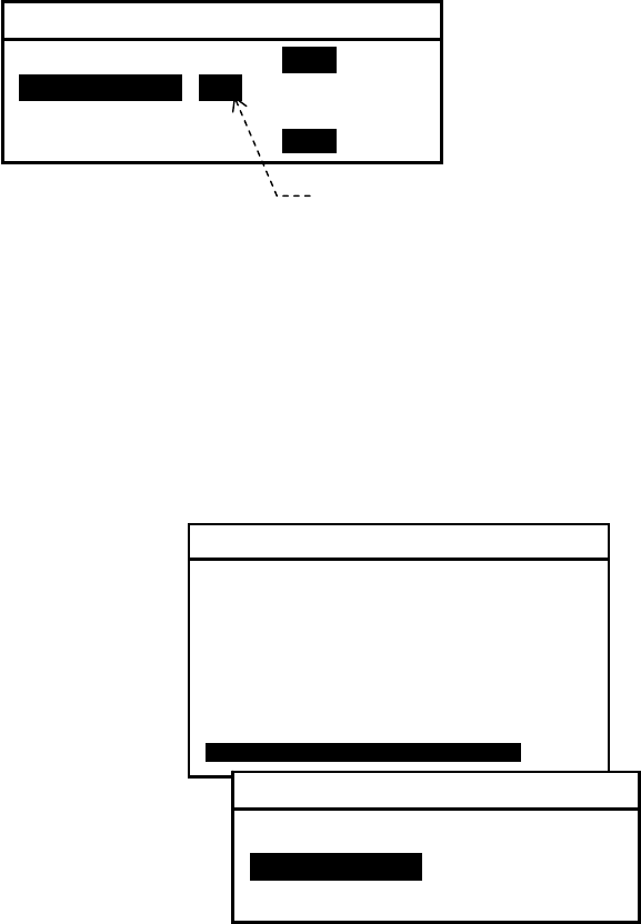
AE-2000 Manual
Customizing Operation via Menu System
4-29
(3) Highlight the desired message type with /, and then highlight status indication
“ON” by pressing
, as in the example below.
Figure 4-39 Enabling Alarm for Type–B Messages
Be sure to press after selecting the desired setting.
(4) Press to return to the previous submenu or to return to the first receiver text page.
4.15. Resetting the System
If, for any reason, you wish to reset the system to return all current operational settings to
the initial factory settings, follow the steps given below. Initialization of the settings does not
affect the message storage; all stored messages will be retained.
Figure 4-40 Resetting the System – Step 1
(1) Press , opening the system menu.
(2) By pressing /, highlight “0:RESET TO
FACTORY DEFAULTS” and then press . This
opens a submenu, asking you to confirm
whether to reset the system, as illustrated at
right.
(3) Press
to highlight “ 2: YES (EXECUTE)” as shown below.
Figure 4-41 Resetting the System – Step 2
9: TURN ON/OFF MESSAGE ALARMS
1: MESSAGE A: ON iOFFi
2: MESSAGE B:i iONi OFF
3: MESSAGE D: ON
4: MESSAGE L: ON iOFFi
Press to highlight ON.
SYSTEM MENU
1: MAKE DISPLAY SETTINGS
2: SELECT 2ND RECEIVER FREQUENCIES
3: TURN ON/OFF KEYPRESS BEEP
4: MAKE SEL/ REJ SETTINGS
5: SEARCH STORED MESSAGES
6. SELECT OUTPUT MESSAGES
7. SET OUTPUT PORTS
8. START SELF–DIAGNOSTIC TESTS
9: TURN ON/ OFF MESSAGE ALARMS
0. RESET TO FACTORY DEFAULTS
0: RESET TO FACTORY DEFAULTS
ARE YOU SURE ?
1: NO(CANCEL)
2: YES(EXECUTE)
AE-2000 Manual
Customizing Operation via Menu System
4-30
(4) Press . This will reset the system and initialize all the settings you have made, and
then return you automatically to the first receiver text page.
Attention to NAVTEX Printer Users
If you are using an optional PR–900 printer or other serial printer plugged into the RS–232C
connector to print NAVTEX messages on–line, be sure to set the menu option RECEIVING
MSG on the SELECT OUTPUT MESSAGES submenu to “ON” again via the instructions in
paragraph 4.11.2 on completion of the resetting. No printout will result if the above menu
option is set to “OFF,” which is the default setting.
0: RESET TO FACTORY DEFAULTS
ARE YOU SURE ?
1: NO(CANCEL)
2: YES(EXECUTE)
Press
after highlighting this
option with .

AE-2000 Manual
User-Level Troubleshooting
5-1
5. User–Level Troubleshooting
A list of common troubles the user may experience while operating the equipment is given
below along with recommended remedies for such troubles. If a problem persists, contact
your dealer for assistance, giving as much information as possible about the symptom,
self–diagnostic tests results (paragraph 4.13), power supply voltage, antenna configuration,
operating frequency, control and menu settings used, serial number of, and *1software
version (VER.) and revision (REV.) numbers of, your equipment.
*1 The software version and revision numbers are displayed in the opening message window
that appears briefly at power–up. Those data will also be displayed when the self–diagnostic
tests are conducted (paragraph 4.13).
< WARNING >
HIGH VOLTAGES EXIST INSIDE THE EQUIPMENT CABINET. NO USER–SERVICEABLE
PARTS ARE INSIDE THE CABINET. QUALIFIED PERSONNEL SHOULD MAKE IT SURE
TO SWITCH THE EQUIPMENT OFF AND UNPLUG THE POWER CORD BEFORE
OPENING THE CABINET FOR INSPECTION OR REPAIRS.
5.1. Power–Up Problems
The following description of the symptoms assumes that the equipment was working
correctly for some time after its initial installation.
Symptom Suggested Solution
The equipment cannot be turned on.
1. Check if the power cord is plugged into the
three–pin rear panel connector ( POWER).
2. Check if the power cord is connected to the
ship’s DC power source with the correct
polarity.
NOTE: Reversing the power cord polarity causes
the fuse (3A) to blow.
3. Check the voltage of the power source.
NOTE: The nominal power supply voltage is 24
VDC. The equipment works safely over the
voltage range from 11 to 36 VDC.
4. Check the fuse inside the rear panel fuse
holder. If it is found blown, replace it with a
correct replacement ( 3A, 5.2X20mm).
5. If it blows again, unplug the active antenna
cable from the rear panel connector, and
then check if the problem persists. If it does
not, suspect that the antenna amplifier or the
cable developed a short. Replace the
antenna and cable.
6. If replacing the antenna still does not correct
the problem, suspect that either the power
supply PCB or the DC/AC inverter PCB has
become defective. Ask your dealer/qualified
engineer to check each board by
replacement.
7. If all attempts above fail, ask your
dealer/qualified service engineer to replace
the CPU PCB.

AE-2000 Manual
User-Level Troubleshooting
5-2
5.2. No Message Reception
The following description of the symptoms assumes that NAVTEX messages were properly
received for some time after initial installation.
Symptom Suggested Solution
No messages can be displayed
except for warning messages.
No NAVTEX messages can be received,
except for navigational warnings,
weather warnings, SAR/piracy/armed
robbery warnings or other warnings.
1. Check the current message rejection (RJ)
settings by pressing .
2. Select all desired message types for display
and memory storage, via the steps given in
paragraph 4.9.
No messages can be displayed
from desired transmitters.
No NAVTEX messages can be displayed
from some transmitters at any time even
if you are within the coverage areas.
1. Check the current station rejection (RJ)
settings by pressing .
2. Select the IDs of all desired transmitters for
display and storage in memory, via the steps
given in paragraph 4.8.
No messages can be displayed
despite correct selection settings
and appearance of “RCVNG MSG.”
No NAVTEX messages can be displayed
regardless of the correct display and
storage selection (SL) settings for all
desired messages or transmitters, or
regardless of the “RCVNG MSG” status
indication during reception.
1. The same message was received before or
the currently receiving message has a
character error rate (CER) > 33%. See
subparagraphs , and in paragraph
1.1 for details.
2. Run the self–diagnostic tests via the steps
given in paragraph 4.13, and check if the
receiver test result is “OK.”
If the test result indication shows “FAILED,”
suspect that the corresponding receiver PCB
has become defective. Ask your dealer or
qualified engineer to check all wiring
harnesses to/ from the PCB and to replace
the PCB if necessary. The chance of any
receiver being out of tune is very small in
normal usage.
3. Check if you are located within the service
area covered by the ground wave of the
desired station. The ground wave coverage
normally extends to 200 – 400 nautical miles
from each station during daytime hours.
4. Check the broadcast schedule of the desired
station. Each station usually transmits
messages for 5 to 10 minutes at intervals of 4
hours.
5. Check the active antenna unit and/or
cabling by replacement.
(continued on next page)
5.2. No Message Reception – 2/3

AE-2000 Manual
User-Level Troubleshooting
5-3
Symptom Suggested Solution
No messages can be received in
the daytime.
No NAVTEX messages can be received
on 518 kHz or 490 kHz during daytime
hours despite appropriate station and
message type selection (SL) settings.
1. Check if you are located within the service
area covered by the ground wave of the
desired station. The area is normally 200 to
400 nautical miles from each station during
daytime hours. At night, MF NAVTEX signals
( 518 / 490 kHz) can travel distances in
excess of 1000 nautical miles depending on
the season and ionospheric conditions.
Nighttime signal propagation is usually
unstable, changing greatly with the season.
2. Check the broadcast schedule of the desired
station. Each station usually transmits for 5 to
10 minutes at intervals of 4 hours. Currently
transmitting stations may be outside the
coverage area.
No messages can be received even
during a broadcasting time and
while in the service area.
No NAVTEX messages can be received
regardless of being in the service area of a
currently transmitting station and of
appropriate message type and station
selection settings.
1. Check if the antenna cable is correctly
plugged into the appropriate rear apron BNC
connector receptacle.
2. Check if the connector (BNC) plug is
properly installed onto the cable. Check also
the coupling connectors, if used for cable
extension.
3. Check by replacing the active antenna.
The antenna preamplifier unit may have
been destroyed by static discharges.
If a correct replacement is not available, run
at least 5 meters of insulated wire from the
BNC connector’s center conductor as a
temporary long wire antenna, and place it as
high as possible from the ground level.
< WARNING >
DO NOT SHORT THE OTHER END OF
THE WIRE ANTENNA TO GROUND,
OR DAMAGE TO THE UNIT’S POWER
SUPPLY WILL RESULT.
4. If replacing the antenna still does not solve
the problem, check the voltage at the center
conductor of each antenna connector. It
should be 8V+ on the 490 and 518 kHz
connectors, and 12V+ on the 4209.5 kHz
connector. If no voltage is present or if it is
extremely low, ask your dealer/qualified
engineer to check the wiring to / from the
power supply PCB first and to replace the
PCB, if necessary.
5. If all attempts above fail to correct the
problem, ask your dealer/qualified
engineer to check the related connections
to/from the CPU PCB first and to replace the
PCB, if necessary.
(continued on next page)
5.2. No Message Reception – 3/3

AE-2000 Manual
User-Level Troubleshooting
5-4
Symptom Suggested Solution
No messages can be received at any
time on the first or the second
receiver with a good replacement
antenna plugged in, but the results of
the self–diagnostic tests are “OK” for
both receivers.
No NAVTEX messages can be received at
any time and anywhere on either the
first or the second receiver after the
antenna is replaced with one known to
be good. The self–diagnostic tests
(paragraph 4.13) show that both
receivers are working properly.
The symptom is an indication that the antenna
circuit has become defective.
1. If the active antenna is used, replace it with
one known to be good.
2. If a correct replacement antenna is not
available, run approx. 5 meters of insulated
wire from the center conductor of the
appropriate connector as a temporary long
wire antenna, and place it as high as
possible from the ground level.
< WARNING>
DO NOT SHORT THE OTHER END OF
THE WIRE ANTENNA TO GROUND, OR
DAMAGE TO THE UNIT’S POWER
SUPPLY WILL RESULT.
3. If replacing the antenna still does not solve
the problem, ask your dealer/ qualified
engineer to check the antenna
coupler/selector circuit inside the rear apron
for faulty or broken connections.
No messages can be received at any
time on the first or the second receiver
with a good replacement antenna
plugged in, and the results of the
*self–diagnostic tests are “FAILED”
for both receivers.
* 30 minute warm–up period required
before test.
1. The symptom suggests that both receivers
have got out of alignment. Ask your
dealer/qualified engineer to check the
connections to/ from the receiver PCBs
and/or replace the PCBs.
2: The CPU PCB has also become defective
and/or some of the internal connections to
the PCB have become faulty or broken. Ask
your dealer/ qualified engineer to check the
related wiring harnesses to/ from the CPU
PCB first and to replace the PCB, if
necessary.
5.3. Message Storage Problems
Symptom Suggested Solution
Some stored messages disappear
from memory after some time.
Messages will be erased from memory after 60
hours, unless they are protected from
automatic erasure.
Put the “PROTECTED” tag to each desired
message via the steps in paragraph 3.8.
None of the received messages is
stored after power–off.
The symptom indicates that the memory
backup circuit on the CPU PCB is failing. Ask
your dealer or qualified engineer to replace the
CPU PCB.
All messages disappear from memory
after continued power–off for some
time.
The memory retains stored messages for at
least 10 days after power–off. Print out desired
messages using an optional printer before
switching the unit off for extended periods of
time continuously.
5.4. Poor Reception

AE-2000 Manual
User-Level Troubleshooting
5-5
The following description of the symptoms assumes that NAVTEX messages were properly
received for some time after initial installation time, and all message types and transmitter
IDs you wish to receive are selected (via the steps in paragraphs 4.8 & 4.9).
Symptom Suggested Solution
Messages can be received in the
daytime, but with many error
characters (*) at all times.
NAVTEX messages can be received but
with many error characters (asterisks)
and often cannot be stored.
1. Check if you are located within the service
area covered by the ground wave of the
desired station. The area is normally 200 to
400 nautical miles from each station during
daytime hours. At night, NAVTEX signals can
travel distances in excess of 1000 nautical
miles depending on the season and
ionospheric conditions.
2. Run the self–diagnostic tests as per
paragraph 4.13, and check the receiver test
results. If the result for the receiver in
question is “ FAILED,” ask your
dealer/qualified service engineer to check
the related wiring harnesses to/from the
receiver PCB or replace the PCB.
3. Check if you have recently installed an
electronic device near the receiver cabinet
receiver or near the antenna. Turn off or
relocate such equipment away from the
NAVTEX receiver, and see if any
improvement can be obtained.
4. Unplug the antenna cable from the BNC
connector on the rear apron, and check the
voltage at the center conductor. It should be
8V+ on the ACTIVE ANT and 518 kHz
connectors, and 12V+ on the 490/4209.5
kHz connector. If no voltage is present or
the voltage is extremely low, ask your
dealer/qualified service engineer to check
the related connections to/from the power
supply PCB first and to replace the PCB, if
necessary.
5. Suspect that the preamplifier in the active
antenna unit is failing or water intruded into
the cable via the junction. Check by
replacing the amplifier unit and/or the cable.
If a correct replacement antenna is not
available, run at least 5 meters of insulated
wire from the center conductor of the
appropriate connector as a temporary long
wire antenna, and place it as high as
possible from the ground level.
< WARNING >
DO NOT SHORT THE OTHER END OF
THE WIRE ANTENNA TO GROUND, OR
DAMAGE TO THE UNIT’S POWER
SUPPLY WILL RESULT.
5.5. Blank Message Screen
The following description of the symptom assumes that your NAVTEX receiver was properly

AE-2000 Manual
User-Level Troubleshooting
5-6
working for some time after initial installation time.
Symptom Suggested Solution
The NAVTEX receiver can be
turned on but the message screen
remains blank.
1. Check to be sure that the power source
voltage is within the 11–36V range.
2. Repeatedly press to check if the normal
brightness returns.
3. Suspect that the LCD module or the inverter
PCB has become defective. Ask your
dealer/ qualified service engineer to check
the related connections to/from the module
and the DC/AC inverter PCB, and replace the
module and / or the PCB.
4. Suspect that the CPU PCB has become
defective. Ask your dealer/qualified
engineer first to check the related
connections to/from the PCB, and to replace
the PCB, if necessary.
5.6. Uncontrollable Screen Brightness
The following description of the symptom assumes that your NAVTEX receiver was properly
working for some time after initial installation time.
Symptom Suggested Solution
The NAVTEX receiver can be
turned on but the message screen
brightness cannot be controlled.
The brightness level does not change
by pressing
.
1. Check to be sure that the power source
voltage is within the 11–36V range.
2. Suspect that the CPU PCB has become
defective. Ask your dealer/qualified
engineer to check the wiring harnesses
to/from the PCB first and to replace the PCB,
if necessary.
5.7. No Beep from Keypress
The following description of the symptom assumes that your NAVTEX receiver was properly
working for some time after initial installation time.
Symptom Suggested Solution
No keypress beep is heard.
1. Check if the keypress beep function is
disabled. Refer to paragraph 4.7 for
instructions.
2. Ask your dealer/qualified engineer to check
the related wiring to /from the keypress
buzzer.
5.8. No Response from Keypress
The following description of the symptom assumes that your NAVTEX receiver was properly

AE-2000 Manual
User-Level Troubleshooting
5-7
working for some time after initial installation time.
Symptom Suggested Solution
The NAVTEX receiver can be
turned on but does not respond to
any keypress.
1. Check to be sure that the power source
voltage is within the 11–36V range.
2. Reset the system, returning all settings to the
factory’s initial settings via the procedure
given in paragraph 4.15.
3. Suspect that the CPU PCB or the Key PCB
has become defective. Run the
self–diagnostic tests (as per paragraph 4.13),
and check the result of the RAM and ROM
tests. If the either test result is “FAILED,”
ask your dealer/qualified service engineer to
check the related connections to/from these
PCBs first, and to replace the CPU PCB
and / or the Key PCB, if necessary.
5.9. No Message Alarm Indication
The following description of the symptom assumes that your NAVTEX receiver was properly
working for some time after initial installation time.
Symptom Suggested Solution
No audible or visual alarm indication
is available when navigational
warnings (type–A messages) or
meteorological warnings (type–B
messages) are received.
The alarm function for type–A and type–B
messages are initially disabled. To turn it on,
refer to paragraph 4.14 for instructions.
No audible alarm indication is
available when a Search & Rescue
(SAR) or distress message is
received.
1. Run the self–diagnostic tests as per the steps
given in paragraph 4.13, and check the result
of the alarm test.
If no beep is heard on completion of the
tests, suspect that a fault has developed in
the wiring harness to/from the message
buzzer or the buzzer has become defective.
Ask your dealer/qualified engineer to check
the related wiring harnesses and the buzzer.
2. Suspect that the CPU PCB has become
faulty. Run the self–diagnostic tests and
check the result of the RAM and ROM tests. If
the result is “ FAILED,” ask your
dealer/qualified engineer to check the PCB
by replacing.
5.10. No Message Alarm Output
The following description of the symptom assumes that your NAVTEX receiver was properly
working for some time after initial installation time.

AE-2000 Manual
User-Level Troubleshooting
5-8
Symptom Suggested Solution
No alarm output is available from
the rear panel ALARM connector.
1. The alarm function for type–A and type–B
messages are initially disabled. To turn it on,
refer to paragraph 4.14.
2. Run the self–diagnostic tests via the steps in
paragraph 4.13, and check the results of the
RAM and ROM tests. If the test result is
“FAILED,” suspect that the CPU PCB has
become faulty. Ask your dealer/qualified
engineer to check the PCB by replacing.
3. Suspect that some of the connections
to/ f rom the connector have loosened or the
CPU PCB has become faulty. Ask your
dealer/qualified engineer to check the
related wiring harness terminations.
5.11. No External Outputs
The following description of the symptom assumes that your NAVTEX receiver was properly
working for some time after initial installation time.
Symptom Suggested Solution
No messages can be output from
the memory to the printer or I/O
DATA port or to the INS port despite
correct connections to the
appropriate rear panel connector.
1. Check to be sure that all ports are enabled
(set to ON) and that the communications
protocol of your application matches that of
the port (rear panel connector) in use. See
paragraph 4.12.
2. Press and then check that the memory
storage (ME), printer port output (PR) and
INS port output (IN) settings are set to the
“SL” status. See paragraphs 4.8 and 4.9 for
details.
3. Suspect that some of the connections
to/ from the connectors have become
loosened or broken. Ask your dealer/
qualified engineer to check for faulty wiring
harness terminations.
4. Suspect that the CPU PCB has become
defective. Ask your dealer/qualified
engineer to check the PCB first and replace it
if necessary.
5.12. External Control Problem
The following description of the symptom assumes that your NAVTEX receiver was properly
working for some time after initial installation time.

AE-2000 Manual
User-Level Troubleshooting
5-9
Symptom Suggested Solution
Alarm acknowledgement cannot be
controlled remotely from IBS/INS
terminals despite correct
connections to the INS port (RS–422
connector).
1. Check to be sure that the RS–422 port is
enabled ( set to ON). See paragraphs 4.12.1
through 4.12.4 for details.
2. Check to be sure that the communications
protocol of your application matches that of
the RS–422 (INS) port. See paragraph
4.12.2.2 for details.
3. Check the bit format and baud rate of your
application match those of the RS– 422 port
parameters. See paragraph 4.12.4 for details.
4. Suspect that some of the internal
connections to/from the connectors have
become loosened or broken. Ask your
dealer/qualified engineer to check for faulty
wiring harness terminations.
5. Run the self–diagnostic tests as per
paragraph 4.13, and check the results of the
RAM and ROM tests.
If the indication of either result is “FAILED,”
suspect that the CPU PCB has become
defective. Ask your dealer/ qualified
engineer to check the PCB and related
wiring harnesses first and to replace it if
necessary.

AE-2000 Manual
User-Level Maintenance
6-1
6. User–Level Maintenance Instructions
To ensure long–term trouble–free operation, the user should regularly follow the
maintenance instructions described in this section.
6.1. Maintenance on the Equipment Cabinet
Keep the equipment, away from sea splashes, direct sunlight and other heat–generating
sources, and make sure that air around the cabinet is circulating freely. If the equipment is
not going to be used for extended periods of time, dismount the cabinet from the vessel
and place them in dry storage. Be sure to switch the equipment off before removing
electrical connections from the rear panel.
< WARNINGS >
1. HIGH VOLTAGES EXIST INSIDE THE EQUIPMENT CABINET WHEN IT IS
ENERGIZED. BE SURE TO TURN IF OFF AND UNPLUG THE POWER CABLE
BEFORE OPENING THE CABINET FOR INSPECTION.
2. CHEMICAL SOLVENTS, SUCH AS PAINT THINNERS AND BENZENES, MUST NOT
BE USED TO CLEAN THE CABINET OR SCREEN FILTER, OR PERMANENT
DAMAGE TO THOSE PARTS WILL RESULT.
3. ALL MESSAGES STORED IN MEMORY, INCLUDING PROTECTED ONES, WILL BE
ERASED IF THE UNIT IS TO BE TURNED OFF CONTINUOUSLY IN EXCESS OF 10
DAYS. IMPORTANT MESSAGES SHOULD BE PRINTED OUT OR SAVED INTO
APPROPRIATE STORAGE MEDIA VIA A PC CONNECTED TO THE RS–422 PORT.
To clean the cabinet surface, a neutral type household detergent intended for office
equipment is recommended. Cleaning the acrylic filter on the LCD screen should be a
maintenance routine to avoid using a high brightness level. To clean the screen filter, use a
piece of slightly wet cloth. If stains persist, the cloth may be moistened with a neutral type
household detergent.
To prolong LCD Screen’s Service Life
To increase the service life of the LCD screen (life of the fluorescent lamp for backlighting),
it is recommended that the screen sleep mode be activated as per the instructions in
paragraph 4.5.
6.2. Maintenance on Electrical Connections
The high humidity marine environment can cause electrical contacts in the rear panel
connectors to corrode over time. Vibrations and shocks normally encountered on the
vessel in motion can cause the electrical contacts to become loosened. Corroded or loose
contacts will become responsible for erratic, intermittent operation or performance
degradation. To avoid such possible problems, conduct the following maintenance
operations at least once a year:
● Unplug all the cables from the rear panel, and check to be sure that contact surfaces,
including the pins in the rear–panel mounted receptacles are free from corrosion.
● Check the connections at the ship’s DC power source for freedom from any sort of
corrosion.
● Correct any problem using a high quality contact–cleaning agent (contact rejuvenator).
< WARNINGS >
1. BE SURE TO TURN THE EQUIPMENT OFF BEFORE REMOVING / INSTALLING THE
CONNECTIONS FROM / TO THE REAR PANEL CONNECTORS.
2. SANDPAPER WILL DAMAGE THE CONTACT SURFACE AND MUST NOT BE USED.
AE-2000 Manual
User-Level Maintenance
6-2
6.3. Maintenance on The Active Antenna Unit
The ANT–2000 active antenna or an optional active antenna unit (e .g. ANT–900, all
consisting of a 1.2m fiberglass whip, a preamplifier housing and coaxial cabling), requires
maintenance at least once every six months:
1. Whip Section
Clean the surface with a piece of soft cloth moistened with neutral household
detergent, while checking for any sign of damage.
Check to be sure that the whip is tightly screwed into the socket on the preamplifier
case, and that the set screw (hex socket head type) is tightened.
Check to be sure that the knurled metallic base is free from damage or corrosion.
Corrosion may be removed with a piece of wood, and then coated with water–
proofing paint. A metallic tool can damage the surface and should not be used
2. Preamplifier Housing
Clean the surface with a piece of soft cloth moistened with neutral household
detergent, while checking for any sign of damage.
Check to be sure that the housing is securely screwed onto the pole (if installed on a
marine mount) or the mounting hardware is properly secured to the mast (if user– or
dockyard–supplied hardware is used). Do not open the housing; no user–serviceable
parts are inside.
3. Cabling
Clean the exposed section with a soft cloth moistened with neutral household
detergent, while checking to be sure that the surface is free from any sign of damage.
If the installation uses a double–ended female coaxial coupler for cable extension,
check to be sure that the jointed section is properly protected with self–bonding taping
and there is no sign of damage.
< WARNING >
THE CENTER CONDUCTOR OF THE COAXIAL CABLE IS AT +8/+12 VDC (518
kHz/4209.5 kHz) WHEN THE EQUIPMENT IS SWITCHED ON. DO NOT SHORT
THE CENTER CONDUCTOR TO GROUND, OR DAMAGE TO THE INTERNAL
POWER SUPPLY CIRCUIT CAN RESULT.
6.4. Self–Diagnostic Tests
Once every 12 months, conduct the self–diagnostic tests as per the procedure described in
paragraph 4.13, and consult your dealer/qualified service engineer for advice if the result
indication of any tested item shows “FAILED.” repeatedly.

AE-2000 Manual
User-Level Maintenance
6-3
6.5. Recommended Spare Parts
A list of the spare parts recommended for the maintenance and servicing for three to five
years is given below. Replacing parts, except for the active antenna unit, should be done by
your dealer or a qualified service engineer. The user should not open the receiver cabinet
for inspection or replacing suspected parts.
Table 6-1 Recommended Spare Parts
Table 6-2 Other Parts Available As Replacements
Part Name Part Number
Quantity
Fuse 3A/5.2X20mm 10
Plugs:
Coaxial Cable Plug (Antenna Plug) BNC–58/U 2
Power Cable Plug 14P–3F 1
*
1I/O DATA Plug FM14–8P 1
*
2RS–422/232C Plug HDEB–9S 1
*3Coaxial Cable Plug (Extension) PL–259 1
Active Antenna Unit:
*
4Preamplifier Unit ANT–2000–3F 2
*4Whip Element (1.2m) 410298B 1
Printed Circuit Boards (PCBs):
First Receiver PCB NT–2000–A 1
*
5Second Receiver PCB NT–2000–B 1
*
6Frequency Converter PCB N501–F/C–A 1
Power Supply PCB N501–PWR–A 1
FL Inverter PCB CXA–L0621A 1
Key PCB SF–KB02 1
*1 Not needed unless the I /O DATA port is used for your applications.
*2 Not needed unless RS–232C /RS–422 port is used for your applications.
*3 Dealer–supplied. Not needed unless the cable is extended with a PL–258 connector.
*4 Not needed if your installation uses a long wire antenna.
*5 Not needed unless second receiver 490 kHz is used in regular operation.
*6
N
ot needed unless second receiver 4209.5 kHz is used in re
g
ular o
p
eration.
Part Name Part Number
CPU PCB N501–CPU–A
TFT LCD Module (LCD display panel) LQ080V3DG01

AE-2000 Manual
Installation
7-1
7. Installation
7.1. Receiver Cabinet Installation
7.1.1. General Precautions
The receiver cabinet is constructed to withstand the humid and corrosive marine
environment, but is designed to be installed or operated inside the wheelhouse or
chartroom. The cabinet is a “protected” category product under the IEC 60945–2002
standard, and is not waterproof. Serious damage will result to the electronics inside the
cabinet when it is exposed to salt water spray or splash.
Additional Requirements:
(1) For long term trouble–free service, the proposed site for installation should be:
dry, well–ventilated and free as much as possible from shocks and engine vibrations.
away as much as possible from high temperature outlets (such as exhaust fans and
heaters), and as much as possible from areas where the unit is likely to be constantly
exposed to direct sunlight.
(2) To prevent reception of weak NAVTEX signals from being interfered with, the unit should
also be located away as much as possible from other onboard electronics, especially
those emitting pulsed signals, such as echo sounders and radars.
7.1.2. Mounting the Receiver Cabinet
The receiver cabinet is primarily designed to be mounted on a tabletop with the mounting
bracket supplied and weights approximately 3.7 kg in total. The dimensions necessary for
installation are given in Figure 7–2. Provide sufficient clearance behind the cabinet for
cabling termination and maintenance checks.
Using a total of four appropriate wood screws or bolt/nut combinations through its four
mounting holes (9 mm in diameter each), secure the bracket to the selected site.
Make sure that the mounting surface is strong enough to support the unit against shocks or
vibrations that are likely to be encountered with the ship in motion.
Compass Safe Distances ( in energized condition):
Receiver Cabinet alone: 0.60m ( standard), 0.40m ( steering)
Cabinet with Bracket: 0.80m ( standard), 0.45m ( steering)
< WARNINGS >
1. DO NOT PLACE THE UNIT IN AN UNVENTILATED, SEALED ENCLOSURE,
SUCH AS A THEFT–DETERRENT CABINET, OR OVERHEATING AND
MALFUNCTION WILL RESULT.
2. DAMAGE CAUSED BY EXPOSURE TO WATER SPRAY OR TO DIRECT
SUNLIGHT WILL NOT BE COVERED BY THE MANUFACTURER’S WARRANTY.
(continued on next page)
7.1.2. Mounting the Display Cabinet (continued – 2/2)
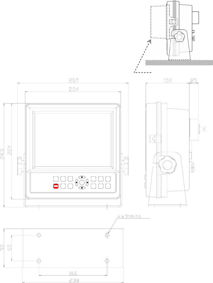
AE-2000 Manual
Installation
7-2
Figure 7-1 Table–Top Mounting – Example
Be sure to attach a serrated plastic washer to the inside
of each arm before placing the cabinet in the bracket.
This pair of washers is supplied separately in the plastic
bag that contains the power cable, fuses, plugs, etc.,
and prevents the cabinet from leaning forward or
backward with the clamping knobs tightened.
After tilting the cabinet to a desired viewing angle,
tighten the clamping knob firmly.
Figure 7-2 Installation Dimensions
7.2. Antenna Installation
The dimensions of the active antenna (ANT–2000/2000M) is given in Figure 7–3. The
same dimensions apply to the optional active antennas (ANT–900 and ANT–2002). If a
Viewing Hood ( option)
MENU
CLR
SEL
REJ
BRT
PWR
PAGE
ENT
DIM
STOP
ALM
MON
NEW
MSG
STO
MSG
NAVTEX RECEIVER
Jmc
NT-2000
Dimensions in millimeters
Weight:
Cabinet only: 2.5 kg
Cabinet + Bracket: 3.7 kg
Compass Safe Distances:
Cabinet only:
0.6m (STD), 0.4m (STG)
Cabinet + Bracket:
0.8m (STD), 0.45m (STG)
AE
–
2000

AE-2000 Manual
Installation
7-3
long wire is to be used permanently, it should be insulated and at least five meters long.
7.2.1. Installation Site Requirements
Active Antenna
For best results and a prolonged service life, the active antenna unit should be installed:
at a site free from continuous, heavy shocks and vibrations,
away as much as possible from the feedpoint or radiating elements of HF/MF
communications antennas, radar scanners and INMARSAT antennas, and
away as much as possible from, and above, any metallic obstructions.
< WARNING >
LOCATING THE ACTIVE ANTENNA CLOSE TO THE FEED POINT OR RADIATING
ELEMENTS OF AN HF/MF TRANSMITTING ANTENNA CAN DESTROY THE
PREAMPLIFIER IN THE CYLINDRICAL HOUSING.
Long Wire Antenna
A long wire antenna should be of insulated type and at least 5 meters long. Bare wire can
short–circuit the antenna to ground and must not be used.
Before connecting the wire to the appropriate rear apron antenna connector, ask your
dealer/qualified service engineer to change the internal wiring (two jumpers) on each
receiver PCB in the cabinet and on the frequency converter board in the rear apron so
that an input impedance match is achieved and that no DC voltage is present on the
connector’s center conductor.
For best results, the wire should be raised as high as possible from the ground, and as
much away as possible from nearby walls or surrounding structures as well as from the
onboard devices listed above, or very poor, noisy reception will result.
7.2.2. Precautions for Cabling
To minimize the effect of interference from other onboard electronics, the coaxial cable
from the antenna unit should not be run close to, and in parallel with, transmit antenna
feed lines, radar waveguides, echo sounder transducer cables, control cables, power
cables, etc. from such equipment. The same requirements apply to the routing of the
long wire antenna.
If the cable is extended with coaxial connectors ( e.g. PL–258/PL–259 pairs), be sure to
make the junctions waterproof using self–bonding tape or other appropriate sealant.
< WARNING >
THE CENTER CONDUCTOR OF THE COAXIAL CABLE IS AT +8 VDC (OR AT +12V
WHEN WORKING ON 4209.5 KHZ) WITH THE EQUIPMENT SWITCHED ON. DO
NOT SHORT THE CENTER CONDUCTOR TO GROUND OR DAMAGE TO THE
POWER SUPPLY PCB CAN RESULT.
< CAUTION >
Water intrusion into the coax cable will seriously degrade the reception performance.
(continued on next page)
7.2.2. Precautions for Cabling (continued –2/2 )
Figure 7-3 ANT–2000/2000M Active Antenna Unit Dimensions
The dimensions are in millimeters except for
the socket section at the base of the
preamplifier housing.
The socket is internally threaded so that it can
accept a 1”–14 straight thread standard marine
pole. To prevent possible loosening, apply a
suitable locking compound over the threads
b f i th k t th l
AE-2000 Manual
Installation
7-4
7.3. Electrical Connections
7.3.1. Introduction
All electrical connections to the equipment are to be made via the connector receptacles
and terminal installed on the rear panel and the rear apron. The figure below shows the rear
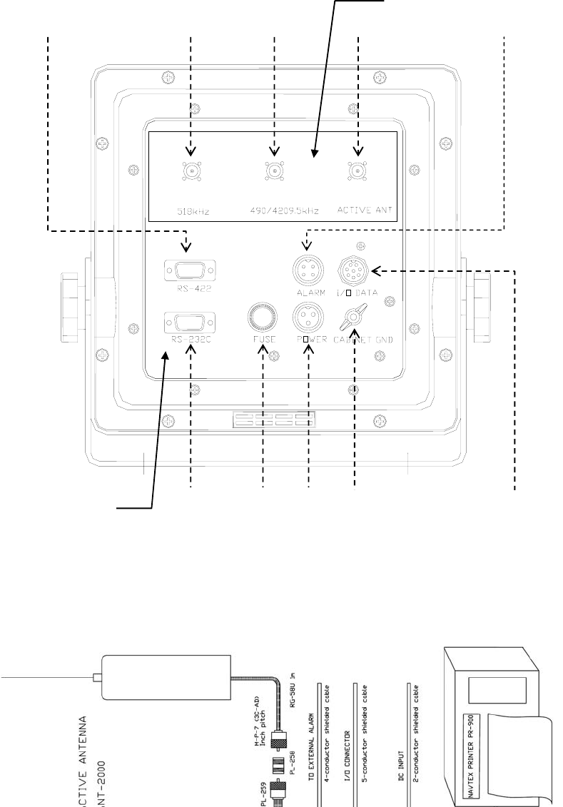
AE-2000 Manual
Installation
7-5
view of the equipment. Overall connections are illustrated in Figure 7–5. A summary
description of the necessary connections to each component is given in the next
paragraphs.
< CAUTIONS >
1. All cables should be plugged in with the equipment switched off.
2. Power cables specified for use with the F–2000/F–3000 or DEBEG 4620/DEBEG
4630 Navigation Sounders cannot be used as alternative cables.
Figure 7-4 Rear View
(continued on next page)
7.3.1. Introduction (continued –2/2 )
Figure 7-5 Overall Connections
Rear Panel
Rear Apron
AE-2000 Manual
Installation
7-6
7.3.2. Connector Pin Assignments and Connections
The pin assignments of the connectors and connections to the pins are illustrated below.
Power Supply Receptacle
Figure 7-6 Power Supply Receptacle (Front View)
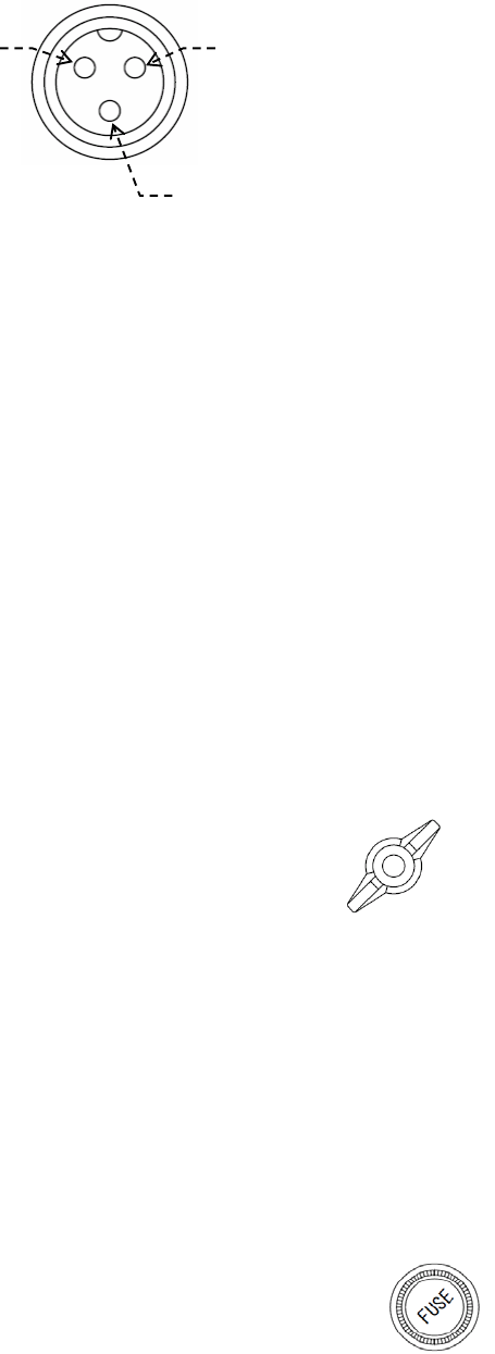
AE-2000 Manual
Installation
7-7
Mating Female Type Plug: 14P–3F
The power cable supplied is approx. 3 meters long and is of two–wire shielded type,
normally terminated in a 3–hole female type plug at one end, with 3 conductors
open–ended each at the other end. Exercise CAUTIONS 1 below.
After pushing the plug into the above receptacle and tightening its coupling ring,
connect the three conductors as follows:
Black conductor: to negative ( – ) terminal of ship’s power source
White conductor: to positive ( + ) terminal of ship’s power source (*124 VDC)
Shield ( braid ): to ship’s earth ground
*
1Nominal input voltage. The equipment operates safely over the 11–to–36V range.
< CAUTIONS >
1. The DC power cable specified for use with the F–2000/F–3000W or DEBEG
4620/DEBEG 4630 cannot be plugged into the above receptacle.
2. Reversing the power cable polarity (black and white connections) causes
the fuse to blow.
Cabinet Ground Terminal
Figure 7-7 Cabinet Ground Terminal
The receiver cabinet, which is electrostatically coated inside,
can be grounded to the vessel’s earth ground without
grounding the negative line of the ship’s power source. In
situations where it is required, or desirable, to ground the
cabinet for safety reasons or *2EMC compliance, connect from
this terminal to an appropriate earth ground in the vessel using
a thick wire. The ground wire should be as short as possible to
reduce the chance of picking up interference from other
onboard electronics.
*
2EMC = electromagnetic compatibility
(continued on next page)
7.3.2. Connector Pin Assignments and Connections (continued – 2/8)
Fuse Holder
Figure 7-8 Fuse Holder
A 3–ampere (3A) cartridge fuse (5.2X20 mm, slow–blow type)
is inserted in the holder.
Pin # 1
(
*124V+
)
Pin # 2 ( –)
Pin # 3 (Ground )
AE-2000 Manual
Installation
7-8
Reversing the power cable polarity causes the fuse to blow.
< WARNING >
AN INCORRECTLY RATED FUSE OR INCORRECT TYPE FUSE WILL BLOW AT
POWER–UP OR WILL NOT PROTECT THE EQUIPMENT IN THE REMOTE
EVENT OF A TROUBLE OVERLOADING ITS POWER SUPPLY.
Antenna Receptacle (BNC) for Active Antenna ANT–2000/2000M
Figure 7-9 Antenna Connector for ANT–2000/2000M
Plug the ANT–2000/2000M three–frequency active
antenna into this connector receptacle.
Mating Plug: BNC–58/U or equivalent
< WARNING >
THE CENTER CONDUCTOR OF THE BNC RECEPTACLE IS AT 8V/12V+ WHEN
THE EQUIPMENT IS TURNED ON. DO NOT SHORT THE CENTER
CONDUCTOR TO GROUND OR DAMAGE TO INTERNAL PARTS MAY RESULT.
Antenna Receptacle (BNC) for Active Antenna ANT–900
Figure 7-10 Antenna Connector for ANT–900
The equipment’s antenna input circuit is initially configured to
use the ANT–2000/2000M. If a separate antenna is desired for
reception of the first receiver frequency (518 kHz), ask the
dealer to change the input wiring first, and the plug the
ANT–900 active antenna into this connector receptacle.
Mating Plug: BNC–58/U or equivalent
< WARNING >
THE CENTER CONDUCTOR OF THE BNC RECEPTACLE IS AT 8V+ WHEN THE
EQUIPMENT IS TURNED ON. DO NOT SHORT THE CENTER CONDUCTOR TO
GROUND OR DAMAGE TO INTERNAL PARTS MAY RESULT.
(continued on next page)
7.3.2. Connector Pin Assignments and Connections (continued – 3/8)
Antenna Receptacle (BNC) for Second Receiver Antenna
Figure 7-11 Antenna Connector for 2nd Receiver Antenna
If a separate antenna is desired for reception of the second
receiver frequency (490 kHz or 4209.5 kHz), ask the dealer
to change the input wiring first, and then plug the
appropriate antenna into this connector receptacle.
ACTIVE ANT
+8V/12V at center conductor
518 kHz
+8V at center conductor
490/4209.5 kHz
+12V at center conductor

AE-2000 Manual
Installation
7-9
Mating Plug: BNC–58/U or equivalent
< WARNING >
THE CENTER CONDUCTOR OF THE BNC RECEPTACLE IS AT 12V+ WHEN THE
EQUIPMENT IS TURNED ON. DO NOT SHORT THE CENTER CONDUCTOR TO
GROUND OR DAMAGE TO INTERNAL PARTS MAY RESULT.
RS–422 Connector
Connections from an IBS/INS device are to be plugged into this receptacle. A D–Sub 9
female type plug mates with this connector. The pin assignments are illustrated below.
Figure 7-12 RS–422 Connector Pin Assignments (Front View)
NOTES:
(1) This interface consists of a MAX3490 RS–422 transceiver. Brief specs. are given below.
For details, see the parts manufacturer’s (MAXIM ) data sheets.
-
Input High Voltage : 2V (min.), Input Low Voltage: 0.8V (max.)
-
Input Current ( signal lines A & B ): 1.0 mA @12V, –0.8 mA @ –7V
-
Receiver Input Impedance: 12 kΩ
(2) Pins #1, #2, #3 and #4 : No internal connections ( NC)
(3) Input lines (pins #6 and #7) are insulated from ship’s ground by opto–isolators.
Mating Plug: HDEB–9S (supplied) or equivalent
After making connections, check to be sure that the RS–422 port is enabled (as per
paragraph 4.12.2) and that a correct set of parameters is selected (as per paragraphs
4.12.3 and 4.12.4) for your applications. The command formats used to control
communications with an INS/IBS device are given in paragraph 7.4.
(continued on next page)
7.3.2. Connector Pin Assignments and Connections (continued – 4/8)
RS–422 Transceiver Data Sheet – 1/3
Pin # 1 (NC ) Pin# 5 ( GND)
#6 (RX+), Sig. Line A #9 (TX–), Sig. Line B
#7 (RX–), Sig. Line B
#8 (TX+), Si
g
. Line A
AE-2000 Manual
Installation
7-10
7.3.2. Connector Pin Assignments and Connections (continued – 5/8)
RS–422 Transceiver Data Sheet – 2/3
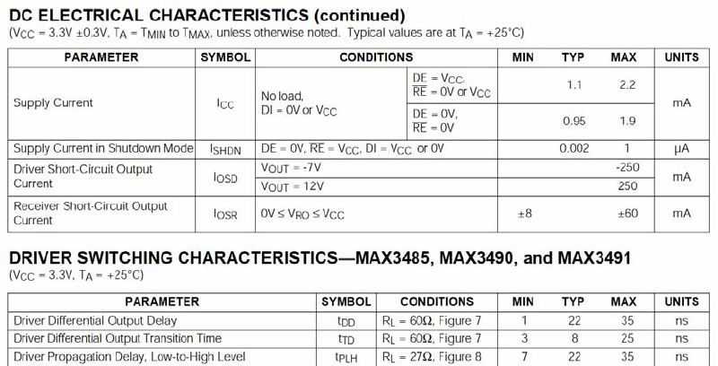
AE-2000 Manual
Installation
7-11
7.3.2. Connector Pin Assignments and Connections (continued – 6/8)
RS–422 Transceiver Data Sheet – 3/3
AE-2000 Manual
Installation
7-12
7.3.2. Connector Pin Assignments and Connections (continued – 7/8)
RS–232C Connector
An optional serial printer (PR–900) is to be plugged into this receptacle. A D–Sub 9
female type plug mates with this connector. The pin assignments are illustrated below.
Figure 7-13 RS–232C Connector Pin Assignments (Front View)
Pin # 1 (NC)
Pin # 2 ( RXD)
Pin # 3 ( TXD)
Pin# 5 ( GND)
Pin # 6 ( NC) Pin # 9 (NC)
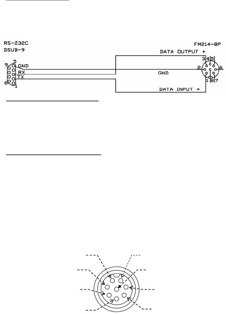
AE-2000 Manual
Installation
7-13
NOTE: Pins #1, #4, #5, #6, #7, #8 and #9: No internal connections (NC)
Mating Plug: HDEB–9S (supplied) or equivalent
After making connections, check to be sure that the RS–232C port is enabled (as per
paragraph 4.12.2 ) and that a correct set of parameters is selected (as per paragraphs
4.12.3 and 4.12.4) for your applications.
Connections to PR–900
The connections from the RS–232C port to the PR–900 serial printer are illustrated
below. A 2–meter cable, terminated in appropriate mating plugs at both ends is normally
supplied with each printer.
Figure 7-14 Connections between RS–232C Port and PR–900
Port Parameter Settings for PR–900
The PR–900 requires the following parameter settings for the RS–232C port:
DATA BITS: 8
STOP BITS: 1
PARITY: NONE
BIT RATE: 0.11 (=110 baud)
See paragraph 4.12 for detailed instructions.
Flow Control for Other Brand Printers
If other brand serial printer (e.g. SEIKOSHA DPU–414) is to be connected, be sure to
disable its hardware flow control, and set the flow control to “ X–ON/X–OFF.” The
AE–2000 does not support a handshaking protocol.
(continued on next page)
7.3.2. Connector Pin Assignments and Connections (continued – 8/8)
I/O DATA Connector
The I/O DATA port is primarily for data communications with other onboard devices
using IEC 61162–1 (NMEA–0183) as the interface. It also provides a port (comprising
pins #4, #5 and #6) for software updating, and a regulated 12V DC 200 mA output for
powering light–duty applications.
Figure 7-15 I/O DATA Connector Pin Assignments (Front View)
#1 (IEC 61162 In + ), Sig. Line A
#2 (IEC 61162 In –), Sig. Line B
#3 (IEC 61162 Out + ), Sig. Line A
#4 (Reserved for software updating)
#5 (Reserved for software
updating)
#6 (Reserved for software
updating)
Pin # 7 ( +12V, 200 mA )
#8 (IEC 61162 Out – ) ,S. Line B
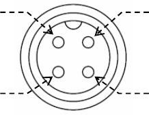
AE-2000 Manual
Installation
7-14
Mating Plug: FM14–8P (supplied)
< WARNINGS >
1. PINS #4, #5 AND #6 ARE TO BE USED EXCLUSIVELY FOR THE SPECIFIED
PROGRAMMING TOOL. CONNECTING ANY OTHER DEVICE TO THESE PINS
CAUSES THE EQUIPMENT TO BE LOCKED UP.
2. CURRENT DRAIN FROM PIN # 7 MUST NOT EXCEED 200 MILLIAMPS.
ALARM Output Connector
The ALARM output connector provides an open/close (make/break) switch
simultaneously via two pairs of replay contacts, electrically isolated from each other and
from the equipment circuitry, when the message alarm is activated. This connector is to
be used to activate an alarm sounder mounted at a remote location. The pin
assignments are given below.
To connect an external alarm device, use pins #1–#2 pair or pins #3–#4 pair.
Figure 7-16 ALARM Output Connector Pin Assignments (Front View)
Mating Plug: FM14–4P (supplied)
NOTE: Alarm messages compliant with IEC 61162–1 $CRARL sentence format are available
from the RS–422 (INS) port, and not from this connector.
7.4. INS Port Data and Command Sentences
The equipment supports the following IEC 61162–1 data sentence formats for
communications with an INS / IBS system via the RS–422 port. It is assumed that the port is
set to ON via the procedure given in paragraph 4.12.2.2.
7.4.1. Received NAVTEX Sentence Format
The first line of a NAVTEX message text will be output in the following format:
$CRNRX,XXX,XXX,XX,aaXX,X,,,,,X.X,X.X,A,c-----c*hh<CR> <LF>
Number of sentences 001 – 999
Sentence number 001 – 999
Sequential message number 00 – 99 (used to uniquely identify messages of same ID)
Pin #1 (Alarm 1)
Pin #2 (Alarm 1) Pin #3 (Alarm 2)
Pin #4 (Alarm 2)
AE-2000 Manual
Installation
7-15
NAVTEX message ID characters (B1, B2, B3, B4)
Frequency index: 0 = not received over air, 1= 490 kHz, 2 = 518 kHz, 3 = 4209.5 kHz
Null fields (UTC, day, month and year data characters not available. See NOTE 1.)
Total number of characters in this series of NRX sentences
Total number of bad characters
Status indication:
Status “A” = reception of NAVTEX message in correct format
Status “ V ” = reception of NAVTEX message in incorrect format
Message body (first line of message text characters). A forced carriage return () on
screen will be replaced with an underscore ( _ ) (hex 5F) when it is output. See NOTE 2
for information on the output format for undefined ASCII characters (IEC 61162–1,
paragraph 5.1.3 )
The data characters in fields , , , , and are output in the first message line
only; they are null fields in the subsequent message lines, as shown below.
$CRNRX,XXX,XXX,XX,,,,,,,,,,c-----c*hh <CR> <LF>
NOTES:
1: The equipment does not have a built–in realtime clock (RTC) and does not interface with a
GPS sensor. Therefore, the UTC, day, month and year data characters are output as null fields.
To check message aging, an internal time reference derived from the CPU clock ( 24.00 MHz)
by frequency division is used.
2: Undefined characters used in a displayed /stored NAVTEX message are communicated to the
INS port in hexadecimal form using code delimiter (^, hex 5E) as follows:
*1Comma ( , ): ^2C
*2Error character asterisk ( * ): ^2A
Carriage return <CR > and line feed <LF >: ^0D^0A
*1: To discriminate from field delimiter
*2: To discriminate from checksum field delimiter
An example INS output of a NAVTEX message is given below.
(continued on next page)
7.4.1. Received NAVTEX Sentence Format (continued –2/2)
An example 518 kHz NAVTEX message text is given below.
IB45
260909 UTC MAR 07
WWJP83 RJTD 260600
VITAL WARNING FOR YOKOHAMA NAVTEX AREA
260600UTC ISSUED AT 260900UTC
COLD FRONT FROM 48N 157E TO 42N 156E 36N
151E 30N 147E 25N 140E
GALE WARNING WESTERN SEA OFF SANRIKU
WITH MAX WINDS 35 KNOTS
WARNING(NEAR GALE) EASTERN SEA OFF
SANRIKU, NORTHERN SEA OFF KANTO,
SOUTHERN SEA OFF KANTO, EASTERN SEA OFF
TOKAI
AE-2000 Manual
Installation
7-16
NEXT WARNING WILL BE ISSUED BEFORE
261500UTC
=
NNNN
The INS port output from the above message consists of 11 NRM sentences, numbered 001
through 011, (message ID=IB45, *1total characters=426 with no corrupt characters) as
follows:
$CRNRX , 011 ,001 ,15 ,IB45 ,2,,,,,426,0,A,IB45^0D^0A260909 UTC MAR 07^0D^0AWWJP83 *02
$CRNRX ,011,002 ,15 ,,,,,,,,,,RJTD 260600^0D^0AVITAL WARNING FOR YOKOHAMA NAVTEX*03
$CRNRX ,011,003 ,15 ,,,,,,,,,, AREA^0D^0A260600UTC ISSUED AT 260900UTC^0D^0ACOLD*69
$CRNRX ,011,004 ,15 ,,,,,,,,,, FRONT FROM 48N 157E T O 42N 156E 36N^0D^0A 151E 30*1F
$CRNRX ,011,005 ,15 ,,,,,,,,,,N 147E 25N 140E^0D^0AGALE WARNING WESTERN SEA OFF *70
$CRNRX ,011,006 ,15 ,,,,,,,,,,SANRIKU ^0D^0AWITH MAX WINDS 35 KNOTS^0D^0AWARNING*0E
$CRNRX ,011,007 ,15 ,,,,,,,,,,(NEAR GALE) EASTERN SEA OFF ^0D^0ASANRIKU^2C NORTH*0E
$CRNRX ,011,008 ,15 ,,,,,,,,,,ERN SEA OFF KANTO^2C^0D^0ASOUTHERN SEA OFF KANTO*16
$CRNRX ,011,009 ,15 ,,,,,,,,,,^2C EASTERN SEA OFF ^0D^0ATOKAI^0D^0ANEXT WARNING *10
$CRNRX ,011,010 ,15 ,,,,,,,,,,WILL BE ISSUED BEFORE ^0D^0A261500UTC^0D^0A =^0D^0A*07
$CRNRX ,011,011 ,15 ,,,,,,,,,,^0D^0ANNNN^0D^0A *41
*1: Total characters include carriage return (CR) and line feed ( LF) codes.
7.4.2. Controlling Receiver Operation via INS (RS–422) Port
To externally control receiver operation via the RS–422 port, the equipment supports the
following command sentence (IEC 61162–1 format). Up to 10 commands will be stacked
and executed sequentially. Using the transmitter mask and message mask, the user can
select the station IDs and message types for message storage in the non–volatile memory,
for message output to the RS–422 port (INS port) or to the RS–232C port (printer port).
Message types A, B, D and L, however, cannot be rejected. Previous selection/rejection
settings manually entered via the keypad will be changed accordingly.
$--NRM,X,X,hhhhhhhh,hhhhhhhh*hh <CR> <LF>
Device identifier ( e.g. IN=INS device, AI=AIS)
Function code: 0 to 9
0 = request messages, 1 = set /report storage mask, 2 = set / report printer mask
3=set/report INS mask, 4to 9=reserved
AE-2000 Manual
Installation
7-17
Frequency index: 1 to 9
1= 490 kHz, 2 = 518 kHz, 3 =4209.5 kHz, 4 to 9 = reserved
CAUTION: If the index for the second receiver that is not currently
selected is specified, the command will be ignored.
Transmitter ID mask in hex (32 bits in total)
LSB = station A, bit 1 = station B, bit 25 = station Z, bits 26 to 32 = reserved
To select a station, its corresponding bit should be set to “1.” To reject a station, its
corresponding bit should be set to “ 0.”
For example, to select only stations E, J, M and T for storage, or output to the INS or printer
port, set the transmitter ID masks as follows:
00081210 hex
0 0 0 8 1 2 1 0 (hex)
0000 0000 0000 1000 0001 0010 0001 0000 (binary)
ZY XWVU TSRQ PONM LKJI HGFE DCBA (station)
Message type mask in hex (32 bits in total):
LSB = type A, bit 1= type B, bit 25 = type Z, bits 26 to 32 = reserved
To select message types only A, B, D, F and L for storage or output to the INS or printer
port, set the message ID masks as follows:
0000082B hex
0 0 0 0 0 8 2 B (hex)
0000 0000 0000 0000 0000 1000 0010 101 1 (binary)
ZY XWVU TSRQ PONM LKJI HGFE DCBA (type)
NOTE: Message types A, B, D and L must always be selected due to the relevant IMO
resolution, and their corresponding bits cannot be set to “0.”
Checksum in hex
The checksum value must be calculated by the user.
The current settings can be checked by a query command described in next paragraph.
7.4.3. Checking Current Settings via INS (RS–422) Port
The equipment accepts the following query command sentence via the RS–422 port (INS
port), and reports to the user the current B1B2 mask settings, indicating the status of
message storage in the non–volatile memory, and message output to the INS port and the
RS–232C port ( printer port) for all frequencies.
$ - - CRQ,NRM*hh<CR><LF>
Device identifier ( e.g. IN=INS device, AI=AIS)
Checksum in hex
Example: Device identifier = IN (INS device), checksum=3A hex
$ INCRQ,NRM*3A<CR><LF>
AE-2000 Manual
Installation
7-18
A total of nine output sentences will then be sent back to the INS device like the examples
below.
$CRNRM,1,1,03FFFFFF,02200EBF*32: Settings for 490 kHz, to non–volatile memory
$CRNRM,2,1,03FFFFFF,02200EBF*31: Settings for 490 kHz, to printer port
$CRNRM,3,1,03FFFFFF,02200EBF*30: Settings for 490 kHz, to INS port
$CRNRM,1,2,03FFFFFF,02200EBF*31: Settings for 518 kHz, to non–volatile memory
$CRNRM,2,2,03FFFFFF,02200EBF*32: Settings for 518 kHz, to printer port
$CRNRM,3,2,03FFFFFF,02200EBF*33: Settings for 518 kHz, to INS port
$CRNRM,1,3,03FFFFFF,02200EBF*30: Settings for 4209.5 kHz, to non–volatile memory
$CRNRM,2,3,03FFFFFF,02200EBF*33: Settings for 4209.5 kHz, to printer port
$CRNRM,3,3,03FFFFFF,02200EBF*32: Settings for 4209.5 kHz, to INS port
NOTE: The above examples represent the default mask settings.
7.4.4. Alarm Output Sentence Formats
7.4.4.1. Output Format for Alarm Being Activated
An alarm output sentence like the example below will be output to the RS–422 (INS) port
when the equipment receives an alarm NAVTEX message or if the equipment develops a
failure or malfunction. The output will be repeatedly available at 30–second intervals until
the alarm condition is acknowledged and reset manually by pressing twice*1 or until the
appropriate acknowledgement command (paragraph 7.4.5) is fed via the port from the INS
terminal.
$CRALR,,003,A,V,NAVTEX:Search and Rescue information*72<CR><LF>
NOTE: The equipment does not use UTC as the time source, and therefore sends a null field in place of the
time–of–alarm–condition–change field.
Local alarm number:
001 = Navigational warning ( type–A message )
AE-2000 Manual
Installation
7-19
002 = Meteorological warning (type–B message )
003 = SAR, piracy, armed robbery information (type–D message)
004 = Receiver malfunction
005 = Self–diagnostic test failure
006 = General failure
Alarm conditions:
A = threshold exceeded ( i.e. alarm condition exists)
V = threshold not exceeded (i.e. alarm condition is non–existent)
Alarm acknowledgement status
A= acknowledged
V = unacknowledged
Alarm description text
Checksum:
03 = Navigational warning
0F = Meteorological warning
72 = SAR, piracy and armed robbery information
The other alarm output sentences are as follows:
$CRALR,,001,A,V,NAVTEX:Navigational warning*03<CR><LF >
$CRALR,,002,A,V,NAVTEX:Meteorological warning*0F<CR><LF>
*1: Pressing the key once silences the audible indication alone, allowing the output sentence to continue
every 30 seconds. A second keypress resets all the active alarms.
7.4.4.2. Output Format for Alarm Being Acknowledged
When each active alarm is acknowledged, the following sentences will be output once:
$CRALR,,001,V,A,NAVTEX:Navigational warning*03<CR><LF >
$CRALR,,002,V,A,NAVTEX:Meteorological warning*0F<CR><LF>
$CRALR,,003,V,A,NAVTEX:Search and Rescue information*72<CR><LF>
7.4.4.3. Format After Alarm Being Acknowledged
Within one minute after the issuance of the above sentences or after the key is pressed
twice, the following outputs will be repeated at one–minute intervals. This condition will
continue until another alarm message is received.
$CRALR,,001,V,V,NAVTEX:Navigational warning*14<CR><LF>
$CRALR,,002,V,V,NAVTEX:Meteorological warning*18<CR><LF>
$CRALR,,003,V,V,NAVTEX:Search and Rescue information*65<CR><LF>
7.4.5. Alarm Acknowledgement
The following command format is supported to acknowledge an d reset the current alarm
condition via the RS–422 (INS) port:
$– – ACK,003*hh<CR><LF>
Device identifier ( e.g. IN=INS device, AI=AIS receiver)
Local alarm number

AE-2000 Manual
Installation
7-20
001 = Navigational warning
002 = Meteorological warning
003 = Search and rescue information, armed robbery and piracy warnings
Checksum:
If the device identifier is IN (INS), the above command format for each alarm is as
follows:
$INACK,001*53<CR><LF> : to acknowledge Navigational warning
$INACK,002*50<CR><LF> : to acknowledge Meteorological warning
$INACK,003*51<CR><LF> : to acknowledge SAR information
7.4.6. Proprietary Sentence (Switching 2nd Receiver Frequency)
The following command (IEC 61162–1proprietary format sentence) is used to externally
switch the second receiver frequency between 490 kHz and 4209.5 kHz:
$PJMCR, 0, 1 *hh <CR> <LF>
Receiver index:
0 = Second receiver
1 to 9 = Reserved
Receive frequency index:
1 = 490 kHz
2 = Not assigned
3 = 4209.5 kHz
Checksum:
See the examples below.
Examples:
To switch the frequency, an INS device should send the following command sentences to
the equipment via the RS–422 port:
Switching to 490 kHz: $PJMCR,0,1*47<CR ><LF>
Switching to 4209.5 kHz: $PJMCR,0,3*45<CR><LF>
AE-2000 Manual
Theory of Operation
8-1
8. Summarized Theory of Operation
8.1. What is NAVTEX?
NAVTEX, a system of broadcast and automatic reception of global maritime safety
information by means of direct display/printing telegraphy, is part of the *1GMDSS
infrastructure, defined by *2IMO Assembly resolution A.706 (17). Broadcasting is
accomplished by a worldwide network of dedicated coastal stations regularly sending
weather information, navigational warnings, search–and–rescue (SAR) information and
other related messages, all in an easy–to–read text format, to mariners free of charges.
8.2. Operating Frequencies
At present three frequencies are officially allocated by the *3ITU for NAVTEX broadcasting
service: 518 kHz, 490 kHz and 4209.5 kHz. All *4SOLAS convention vessels are required to
carry a receiver dedicated to receiving NAVTEX transmissions automatically on all the
above frequencies.
Transmissions on 518 kHz are in English and of general interest to vessels navigating
international waters, while the 490 kHz service is primarily targeted at those working most
of the time in areas close to transmitting stations, providing more localized information in
national languages. Some stations also broadcast information to local users on 4209.5 kHz.
Stations on each frequency transmit NAVTEX messages usually for a period of 10 minutes
on a time–sharing basis to avoid cross–station interference.
8.3. Service Area
The coverage area of a 518 kHz station is normally 200 to 400 nautical miles in daytime
hours, depending on the transmitting power level, and a signal travels along the surface. At
night some of the signal often travels more than double the daytime coverage by being
reflected a number of times between the surface and the ionosphere, a band of ionized
atmospheric layers 50 to 400 km above the surface. The 490 kHz service area is less than the
518 kHz coverage due to lower transmit power levels, but the nighttime coverage often
extends greatly because of ionospheric reflections. The 4209.5 kHz broadcast, though
catering mainly for inshore users and covering much less areas in the daytime, can be
received from more than 1000 miles away during hours of darkness.
8.4. Error Correction
Signal propagation conditions constantly vary with time of the day and also with the season.
The signal arriving at the receiver can be corrupted or distorted at any time by static
discharges, natural noise, abnormal solar activity, unstable ionospheric conditions,
interference between the signal coming directly from the transmitter and the one reflected
from the ionosphere, etc. It is therefore likely that a vital NAVTEX message can be missed
due to signal corruption or distortion at the receiving end.
In order to ensure that each message is properly received within its intended area of
coverage, a station sends out the same message twice, some hours apart, each with its
identification code ( known as B1 character), message type code ( B2 character) and a
two–digit serial number (B3B4, ranging 00 to 99). In addition, the system employs a mode
of transmission called forward error correction (FEC), transmitting each alphanumeric
character in the message twice at very short intervals. If the same character is received
twice, the receiver considers it to be a true character. If either of the received characters is
different or corrupted, the receiver treats it as an invalid letter, and displays or prints an
asterisk (*) in its place, thereby securing the reliability of a received message.
(continued on next page)
8. Summarized Theory of Operation (continued – 2/6 )
AE-2000 Manual
Theory of Operation
8-2
8.5. NAVTEX Receiver – General
A NAVTEX receiver that complies with the relevant IMO resolutions and regulations for
wheel mark certification is programmed to automatically receive and display/print a
message, and avoids a repeated reception of the same message by checking the ID and
numbering of each message. Using the ID and message type data attached to each
message, the user can also program the receiver to reject certain transmissions and
message types that are not of importance while in the current area, except for SAR and
other urgent warning messages classified as type D messages. An audible and visual alarms
are automatically triggered upon reception of such a message. To silence the alarm, the
user must manually, or via an appropriate command from an INS terminal, acknowledge
the message arrival. Received messages are either printed on paper (for a receiver with a
built–in printer) or displayed on a screen with memory for storage and retrieval (for a
receiver with an integral LCD screen).
8.6. The AE–2000 NAVTEX Receiver
The AE–2000 receiver has two built–in receiver, with the first receiver devoted to receiving
518 kHz broadcast and the second receiver receiving either 490 kHz or 4209.5 kHz signal as
selected by the user. Received messages are displayed across an 8–inch liquid crystal
display (LCD) and stored permanently or temporarily as specified by the user. Up to 200
messages, each with an average of 500 characters, received on the first and second
receivers are separately stored and then automatically erased from memory 60 hours after
the time of reception on a first–in–first–out basis. However, up to 25 messages can be
protected against automatic erasure, and are stored in a separate area of the non–volatile
message memory, in which case an additional 50 new messages can be stored in memory
across each receiver screen.
When a transmission occurs on the first and second receiver frequencies at the same time,
the equipment receives both signals, displaying the first receiver message while storing the
second receiver message in memory for later retrieval. An appropriate caution message
shows up in the screen bottom prompt line to indicate the reception of a new NAVTEX
message on the second receiver.
Reception of a type–D message (SAR, piracy and armed robbery information) activates the
audible and visual alarms. The received message text then is shown in red, making it easy
to discriminate it from navigational (type–A) and weather (type–B) warnings. The audible
alarm also sounds differently to indicate that a type–D message has been received. The
alarm can be acknowledged remotely by an INS terminal connected to the RS–422 port on
the rear panel.
The stored messages can be output via three interface ports mounted on the rear panel for
IBS/INS or other onboard applications The user can specify the ID, frequency and type of
the messages you wish to output. An optional printer can also be plugged in to print the
current message in real time or those recalled from the non–volatile memory.
*1: Global Maritime Distress and Safety System
*2: International Maritime Organization
*3: International Telecommunications Union
*4: Safety of Life at Sea
(continued on next page)

AE-2000 Manual
Theory of Operation
8-3
8. Summarized Theory of Operation (continued – 3/6 )
8.7. Operating Principle of AE–2000
Figure 9–1 shows interconnections between the printed circuit boards (PCBs) comprising
the AE–2000 system and interface connections from the PCBs to data input/output ports
and peripheral devices. Figure 9–2 is the schematic of the antenna selector which allows
selection of the desired antenna from a single keystroke on the keypad.
To follow the circuit description below, see also the schematics of the receivers, CPU PCB
and power PCB attached.
Receiver Circuit
To receive the three NAVTEX frequencies (518 kHz, 490 kHz and 4209.5 kHz), the system
incorporates two independent receivers (first and second receivers) plus a frequency
converter. The 518 kHz international broadcast is picked up by the first receiver (NT–2000A),
and the 490 kHz national broadcast, by the second receiver (NT–2000B). The second
national broadcast frequency of 4209.5 kHz is first converted down to 490 kHz by the
frequency converter (N501–F/ C–A) and then fed to the second receiver.
Each receiver is of straight amplifier type, consisting of two stages ( field–effect transistors
V6 and V7) of amplification, followed by an IC amplifier (U1) and an amplitude limiter
( diode pair V8 and V9 ). Located at the end of the amplification chain is an FM detector that
consists of crystal–controlled oscillator B1, its associated parts and part of the IC circuitry),
which demodulates a frequency–shifted (±85 Hz) RF NAVTEX signal into a stream of
baseband DC pulses at 100 baud using a quadrature detection technique. The detected
output is then fed to the CPU via opto–isolator K2.
To test whether each receiver is functioning properly, a NAVTEX signal generator is provided
on the PCB, consisting of quartz crystal B2, IC (N1) and their associated parts. When the
self–diagnostic test function is activated via the menu, the CPU PCB supplies a test signal
(modulating signal) to the generator via opto–isolator K4 and transistor switch V13,
allowing the generator to produce a simulated frequency–shifted signal at the receiver
frequency, and feeds it to the receiver input through relay K1.
CPU Circuit
The CPU PCB (N501–CPU–C) is built around a 16–bit single–chip microcomputer (U10) that
has a CPU clocked at 24 MHz by crystal–controlled oscillator X1, and on–chip flash ROM for
program software and on–chip RAM providing memory space for data processing of the
demodulated signal. An external static RAM (SRAM) chip (U5, 512 kB) is mounted for
message and ID storage, and is backed up by large capacity capacitor C6 (1.0 farad) for
approx. 10 days in the event of continuous power–off.
Another external SRAM (U1, 256 kB) is used to hold text for display on the LCD screen. U3
and U4 are factory–programmed to jointly act as a display controller to perform various
display control functions and text scrolling. The input/output interface between the CPU
and externally connected devices consists of three external ports: U7 for the RS–232C port,
U12 for the *RS–422 port and an opto–isolator for the I/O DATA port.
*Input lines to the RS–422 port are insulated from ground by opto–isolators (ISO2, ISO3).
(continued on next page)
8. Summarized Theory of Operation (continued – 4/6 )

AE-2000 Manual
Theory of Operation
8-4
8.7. Operating Principle of NT–2000/DEBEG 2902 ( continued –2 / 2 )
Power Supply Circuit
The power supply PCB (N501–PWR–A/B) consists mainly of a switch–mode voltage
regulator (U2) and a three–terminal voltage regulator (U1), supplying regulated DC outputs
(3.3V, 5V, 12V) from an input voltage ranging 11 to 36 volts, though the nominal voltage is 24
volts at which the performance specifications are fully met. Should the power line polarity
be reversed accidentally, diode D1 will cause the fuse F1 (3A) to blow, thereby protecting
the input circuit from possible damage. The regulated outputs from the power supply PCB
are fed to the CPU PCB, through which the 12V output is also derived to operate the
receivers and frequency converter.
Another power supply board, termed the FL Inverter PCB (CXA–L0612A–VJL ), is also
installed. This PCB is a DC–to–AC inverter unit, generating an AC voltage of approx. 1600V at
approx. 60 Hz out of 12V supplied via the CPU PCB to power the fluorescent lamp used to
backlight the LCD screen.
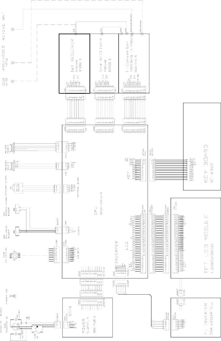
AE-2000 Manual
Theory of Operation
8-5
8. Summarized Theory of Operation (continued – 5/6)
Figure 8-1 Interconnections
(continued on next page)
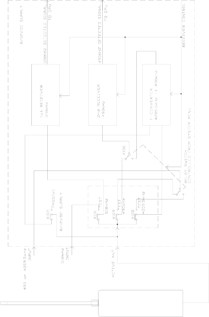
AE-2000 Manual
Theory of Operation
8-6
8. Summarized Theory of Operation (continued – 6/6)
Figure 8-2 Antenna Switching Circuit
AE-2000 Manual
Specifications
9-1
9. Specifications
(1) IEC 60945–2002 Equipment Category:
Receiver Cabinet : Protected
Active Antenna Unit: Exposed
(2) Receive Frequencies:
First Receiver : 518 kHz
Second Receiver : 490 kHz and 4209.5 kHz, front panel–selectable or by *1proprietary
command sentence via RS–422 port
(3) Type of Receiver :
First Receiver: 518 kHz straight amplifier
Second Receiver:
- 490 kHz: 490 kHz straight amplifier
- 4209.5 kHz: Down–conversion to 490 kHz
(4) Antenna Inputs (518, 490 and 4209.5 kHz):
Coaxial: 50Ω(nominal),matched with ANT–2000M active antenna
Unbalanced: 10Ω+ 150 pF for long–wire antenna
(5) Input Protection: 30 VRMS for 15 minutes over 100 kHz–28 MHz range
(6) Active Antennas:
Standard: Preamplified 1.2m glass–fiber whip (ANT–2000M) for reception of
518 kHz, 490 kHz and 4209.5 kHz, with 1–meter RG–58/U coaxial
cable attached, terminated in BNC and PL–259 plugs for cable
extension.
Option: Preamplified 1.2m glass–fiber whip (ANT–900) for reception of
518 kHz, with 30m RG–58/ U cable
Option: Preamplified 1.2m glass–fiber whip (ANT–2002) for reception of
490 kHz and 4209.5 kHz with 30m RG–58/U cable
(7) Receiver Sensitivity : Better than the following values for message reception with
character error rate (CER) of less than 4%:
1 μV e.m.f. to coaxial 50Ω input
5 μV e.m.f. to unbalanced ( 10Ω+150 pF) input
(8) Demodulator : Quadrature detector, crystal–controlled
(9) Mode of Reception: F1B with forward error correction (Annex to ITU–R REC. 476–3,
M.540–2 and 625 B–mode)
Single Frequency: Automatic reception and display of message transmitted on 518
kHz or on user–selected second receiver frequency (490 kHz or
4209.5 kHz)
Dual Frequency: Automatic, simultaneous reception of 518 kHz and user–selected
second receiver frequency (490 kHz or 4209.5 kHz), with
automatic display of first receiver’s live messages while storing
second receiver messages in memory when NAVTEX broadcasts
occur at both frequencies simultaneously.
(10) Second Receiver Selection: 490 kHz or 4209.5 kHz selectable via menu system or
*1proprietary command sentence via RS–422 port
*1:See paragraph 7.4.6 for detail.
(continued on next page)
9. Specifications (continued – 2/4)

AE-2000 Manual
Specifications
9-2
(11) Source of Time: Derived from CPU clock 24.00 MHz for calculation of time passage
to handle message aging. No real time clock (RTC) is used.
(12) Display Screen: 8–inch color VGA TFT LCD, daylight–viewing, backlit
Text display resolution: QVGA
(13) User Interface Language: English (menus, status, prompts, cautions)
(14) Text Display:
NAVTEX Messages : 40 characters per line, 18 lines per screen. A forced carriage return
symbol *2() divides the last word at 40th character position if the
number of character in a line exceeds 40.
Maximum capacity of characters/line: 4096
*2 Hex 5F ( _ ) is output to RS–232C or RS–422 port.
Statuses & Prompts: 1 line (40 characters maximum) at screen’s upper and lower edges
(15) Indication of Message Reception and Storage
Message Reception: Tag iNEW MESSAGEi is attached to message ID.
Storage: Indication “STORED” is turned on at the end of each satisfactorily
received message together with a character error rate (CER=
XX%) readout
(16) Message Scrolling:
Live Messages : Automatic, except for new type–D messages
Stored Messages: Manual, line–by–line or page–by–page scrolling
(17) Message Storage:
Capacity : 200 messages (average 500 characters per message) for each of 518
kHz, 490 kHz and 4209.5 kHz receivers. Up to an additional 50
messages can be stored (for each of 518 kHz and 490 kHz/4209.5
kHz) if stored messages are protected.
Maximum storage of characters: 106,496/ frequency
Maximum characters/message: More than 8000
If the equipment receives a message with a character error rate
(CER) of > 4% and 33%, it will store the message but will receive
the same message to be transmitted subsequently. If the
subsequent message has a lower CER, it will automatically replace
the previously stored one. If a message is received with a CER >
33%, it will not be stored.
Duration: 60 hours 20 minutes from successful reception of each message,
or until the storage limit is reached, after which old messages will
be automatically erased from memory on a first–in–first–out basis
except for user–protected messages that cannot be erased from
memory until their protection tags are removed manually. Time
source is derived from the CPU clock (
24.00 MHz) to compute
message aging.
Storage without Power: Protected messages are stored for at least 10 days after
power is removed continuously.
(continued on next page)
9. Specifications (continued – 3/4)
(18) Message Protection: Up to 50 messages can be protected on each receiver screen
against automatic erasure, and are saved in a separate area of the
non–volatile message memory. Protection of a user–selected
message can be cancelled to allow automatic erasure after a
60–hour time passage.

AE-2000 Manual
Specifications
9-3
Protected messages are indicated with *3tag
iPROTECTEDi attached to the message ID.
*3Removing the tag requires user confirmation.
(19) Message ID Storage:
Capacity: 200 IDs of successfully received messages (with CER 33%) on
each of 518 kHz, 490 kHz and 4209.5 kHz
Duration : 60 hours 20 minutes after receipt or until the storage limit (200 for
each frequency) is reached.
(20) Stored Message Outputs: The following messages can be selectively output via the
RS–422, RS–232C and I/O DATA ports manually through the
menu system or externally with station and message ID mask
settings from an INS terminal:
All currently displayed messages or currently displayed
messages of user’s choice
All stored messages
Stored messages of user’s choice by specifying frequency,
transmitter or message type
(21) External I/O Interfaces:
Printer Interface : RS–232C port ( MAX3232 transceiver)
IBS/INS: RS–422 port (MAX3490 transceiver) with input lines optically
isolated
NMEA–0183/IEC 61162–1: 8–pin connector (I/O DATA port)
Alarm Activation Output: 2 isolated pairs of relay contacts (ALARM port)
(22) Message Alarm Specifications:
Audible Indication: Beeping from front–facing piezoelectric buzzer
- 1–second intervals: Type D messages
- 3–second intervals: Types, A, B and L messages
Visual Indication: Red tag iALARM!i attached to ID
ID and message text displayed in red color for type–D messages
Acknowledgement/Muting: Manually with front panel button or by means of IEC
61162–1 format command ($--ACK command) via RS–422 input
port
Alarm Conditions Output: IEC 61162–1–compliant $CRALR sentences containing
local alarm number and alarm text via RS–422 output port. See
paragraph 7.4.4 for details.
NOTE: See section 10 (List of Alarms) for additional information on alarms.
(continued on next page)
9. Specifications ( continued – 4/4)
(23) Power Requirements: 24 VDC ( nominal), approx. 15W. Floating ground. The unit
operates safely over a 11–to–36V range.
(24) Cabinet Size & Weight: 225 / 245 (W) X 225 / 271 (H) X 135 (D) mm
Approx. 3.7/2.5 kg with / without mounting bracket
(25) Compass Safe Distances (in Energized Condition):
AE-2000 Manual
Specifications
9-4
Cabinet with Bracket: 80 cm (standard), 45 cm ( steering)
Cabinet only: 60 cm (standard), 40 cm ( steering)
(26) Ambient Temperatures: –15 to 55
C ( cabinet, operating)
–25 to 70
C (cabinet, storage)
–
25 to 55
C (active antenna, operating)
–
25 to 70
C (active antenna, storage)
(27) Compliances: IMO Resolutions MSC.148(77) and A.694(17)
IEC 61097–6 Ed.2
IEC 60945–2002, IEC 61162–1, IEC 61162–2
ITU–R 540–2
ITU–R 625–3
EN 300 065V 1.1.3
EN 301 011V 1.1.1
NOTE: Specifications, other than those specified under the above standards, are subject to
change without notice or obligation.

AE-2000 Manual
List of Alarms
10-1
10. List of Alarms
10.1. Message Alarms
● Alarm for D–Type Message
Enabled/ Disabled Status: Enabled at all times.
Triggering Condition: To be triggered upon reception of a D–type message.
User Interface:
- Audible: Beeping at approx. 1–sec. intervals by alarm buzzer.
- Visual: Attaching iALARM!i tag to message ID and displaying both
message ID and text in red.
● Alarm for A–, B–, and L–Type Messages
Enabled/Disabled Status: Initially disabled, and can be individually enabled by the
user. See paragraph 4.13 for instructions.
Triggering Condition: To be triggered upon reception of an A–, B– or L–type message.
User Interface:
- Audible: Beeping at approx. 3–sec. intervals by alarm buzzer.
- Visual: Attaching iALARM!i tag to message ID and displaying
message ID in red.
10.2. Operational Alarms
● Storage Limit Alarm:
Enabled/Disabled Status: Enabled at all times.
Triggering Condition: To be triggered when protecting NAVTEX messages for
permanent storage in excess of 50.
User Interface:
- Audible: Beeping 3 times in quick succession by small buzzer.
- Visual: Displaying warning “STORAGE LIMIT IS REACHED !” in prompt
line at screen’s bottom.
● Memory–Full Alarm:
Enabled/Disabled Status: Enabled at all times.
Triggering Condition: To be triggered when receiving new NAVTEX message with 199
messages stored.
User Interface:
- Audible: Beeping 3 times in quick succession by small buzzer.
- Visual: Displaying warning “MEMORY FULL! [ CLR ] TO
ACKNLG.” in prompt line at screen’s bottom.
● Invalid Keypress Alarm:
Enabled/Disabled Status: Enabled at all times.
Triggering Condition: To be triggered when any key not valid for current operation is
pressed.
User Interface:
- Audible: Beeping 3 times in quick succession by small buzzer.
- Visual: Displaying warning “INVALID KEYPRESS,” blinking.
AE-2000 Manual
List of Abbreviations
11-1
11. List of Abbreviations
The abbreviations used in this manual and menus, on screen, control panel and rear panel
are listed below.
A: amperes
ACKNLG: Acknowledge
AI: Automatic identification system (typical device identifier of AIS equipment)
AIS: Automatic identification system
ALM: Alarm
ALR: Alarm (header of alarm output sentence from INS port)
ANT: Antenna
BNC: Type of coaxial connector
BRT: Brightness control key
BSH: Bundesamt für Seeschiffahrt und Hydrographie ( Federal Maritime and
Hydrographic Agency, Germany)
BV: Bureau Veritas (France), EU notified body
CER: Character Error Rate ( ratio of asterisks to total number of characters)
CH: Operating channel ( receiver currently in use)
CLR : Clear key
CPU: Central Processing Unit (core of single–chip microcomputer on CPU PCB)
CR: Communications receiver (device identifier of NAVTEX receiver)
CR: Carriage return code (0D in hexadecimal notation, unprintable)
D: Depth (part of cabinet dimensions)
dB: decibels ( unit of relative power strength)
DC/AC: DC–to–AC (DC–to–AC voltage inverter for screen backlighting lamp)
DIM: Dimmer key (for keypad backlighting)
DOS/V: Disk Operating System/V ( PC operating system for IBM–compatibles)
DRAM: Dynamic Random Access Memory
EMC: Electromagnetic compatibility
EN: Europäische Norm ( = European Standards)
ENT: Entry key
F: Frequency
FEC: Forward error correction (error–correcting protocol in NAVTEX system)
FL : Fluorescent lamp (screen backlighting lamp)
FM: frequency modulation
FREQ: Frequency
FSK: Frequency shift keying (modulation technique for NAVTEX transmission)
FWE: Flash–memory write enable (CPU–embedded flash memory programming)
F/C: Frequency converter (used to receive 4209.5 kHz on second receiver)
GMDSS: Global Maritime Distress and Safety System
GND: Ground
GPS: Global Positioning System, GPS receiver/sensor
H: Height (part of cabinet dimensions)
HF: High frequency band (including 4209.5 kHz second receiver frequency)
ID: Identification code (identification of transmitter)
IEC: International Electrotechnical Commission
IMO: International Maritime Organization
IN: Integrated Navigation (device identifier of INS equipment)
INS/IBS: Integrated Navigation System/Integrated Bridge System
ISO: International Standardization Organization
I/O: Input/ Output
kB: kilobytes
kg: kilograms
LSB: Least significant bit
LST: Local standard time
LAT/LON: Latitude / Longitude coordinates
LCD: Liquid crystal display
LF: Line feed code (0A in hexadecimal notation, unprintable)
(continued on next page)
AE-2000 Manual
List of Abbreviations
11-2
11. List of Abbreviations (continued – 2/2)
m: meters
mA: milliamperes
min: minutes
mm: millimeters
ME or MEM: Memory ( non–volatile memory for message storage)
MF: Medium frequency broadcast band (including 490 kHz and 518 kHz)
MON: Monitor ( audible monitor)
MSG: Message ( NAVTEX message)
MPU: Microprocessing Unit
NC: No connection (no internal connection)
NMEA : U.S. National Marine Electronics Association
NNNN: End–of–message indication ( specified under IMO/IEC regulations)
NRX: NAVTEX receiver (header of message output from INS port)
para.: paragraph
PC: Personal Computer
PCB: Printed Circuit Board
PR: Printer
PWR : Power
QVGA : Quarter VGA (screen resolution, 320X240 pixels)
RAM : Random Access Memory ( embedded in CPU chip)
RCVNG: Receiving
RCVR : Receiver
REC: Recommendation (ITU Recommendation)
REF: Reference
REJ: Reject, rejected
REV: Revision ( software revision number)
RH: Relative humidity
RJ: Reject, rejected
ROM: Read–Only Memory ( embedded in CPU chip)
RTC: Real time clock
RX: Receive, receiver
RMRS: Russian Maritime Register of Shipping
S: Signal
SAR : Search and Rescue
SEL: Select, selected
SIG: Signal
SL: Select, selected
SOLAS : Safety of Life at Sea
SRAM: Static RAM (non–volatile memory for message storage)
STD: Standard compass
STG: Steering compass
STO: Store
TFT: Thin–film transistor ( technology of color LCD )
TX : Transmit, transmitter
TXD: Transmit data (Send data)
UTC: Universal time coordinated ( = GMT in common usage)
V: volts
VCC : Operating voltage of IC chips used
VDC: Volts DC
VER : Version (software version)
VGA : Video graphics array ( screen resolution, 640×480 pixels )
W: Width (part of cabinet dimensions )
W: watts
WX: Weather
XTAL : Crystal (quartz crystal oscillator)
Z: GMT
AE-2000 Manual
User–made Settings
12-1
12. User Settings To Be Stored in Non–Volatile Memory
The following user–made settings will be stored in the non–volatile memory. Settings
indicated in Italic type fonts are factory defaults.
● Screen Brightness Level: Last used level
● Keypad Dimmer Level: Last used level
● Settings via Menu System
Background Color: WHITE, BLACK, BLUE
Message Font Type: NORMAL, BOLD
Screen Sleep Mode
- On/Off Status: ON, OFF
- On/Off Time Period: STANDARD, USER–DEFINED MODE
*1Second Receiver Frequency: 490 KHZ, 4209.5 KHZ
Keypress Beep: ON, OFF
*2Station Selection/Rejection Settings (common to first and second receivers)
- Storage in Memory:
Selected Stations: A to Z (all stations)
Rejected Stations: None
- Output to Printer Port (RS–232C) and I/O DATA port:
Selected Stations: A to Z (all stations)
Rejected Stations: None
- Output to INS Port (RS–422):
Selected Stations: A to Z (all stations)
Rejected Stations: None
*2Message Type Selection/Rejection (common to first and second receivers)
- Storage in Memory:
Selected Types: A, B, C, D, E, F, H,J, K, L , V , Z
Rejected Types: G, I, M,N, O, P, Q, R, S, T, U, W, X, Y
- Output to Printer Port (RS–232C) and I/O DATA port:
Selected Types: A, B, C, D, E, F, H,J, K, L , V , Z
Rejected Types: G, I, M,N, O, P, Q, R, S, T, U, W, X, Y
- Output to INS Port (RS–422):
Selected Types: A, B, C, D, E, F, H,J, K, L , V , Z
Rejected Types: G, I, M,N, O, P, Q, R, S, T, U, W, X, Y
Output Port Settings (On/Off, Protocol, Bit Format, Baud Rate):
- RS–232C and I/O DATA: ON, NONE, 8 DATA BITS, 1 STOP BIT, ODD, 0.11
- RS–422: ON, IEC61162, 8 DATA BITS, 1 STOP BIT, ODD, 4.8
- I/O DATA: ON, NONE, 8 DATA BITS, 1 STOP BIT, ODD, 4.8
(continued on next page)
AE-2000 Manual
User–made Settings
12-2
12. User Settings To Be Stored in Non–Volatile Memory (continued –2/2)
Message Output (for printing live messages on–line)
- RECEIVING MSG: ON, OFF
*3Message Alarms On/Off
- Type A Message: ON, OFF
- Type B Message: ON, OFF
- Type D Message: ON
- Type L Message: ON, OFF
*1: Can be controlled via RS–422 port with IEC 61162–1 proprietary command. Last setting is
stored in memory.
*2: Can be controlled via RS–422 port with IEC 61162–1 $CRNRM command. Last settings are
stored in memory. Message types A, B, D and L cannot be rejected.
*3: Type D message alarm is always set to ON; the user cannot change the status.
AE-2000 Manual
List of Components To Be Shipped
13-1
13. List of Components To Be Shipped
The following set of components is usually shipped by the manufacturer, either as standard
or optionally. The same information is usually given in the shipping documents ( INVOICE,
PACKING LIST, etc. as requested by the user ) to be attached to the shipment.
● Receiver Console (Cabinet), AE–2000: Standard 1 set
● Active Antenna Assembly, ANT–2000/2000M: Standard 1 set
Preamplifier with *110m coax cable terminated in BNC plug
Whip, 1.2m
● Receiver Mounting Bracket: Standard 1 pc
● Panel Mounting Frame, 3050901: Optional 1 pc
● Cabinet Clamping Knob, M8X15: Standard 2 pcs
● Power Supply Cable: Standard 1 set
3m, 2–conductor shielded, terminated in type FM14–3P plug
● Plugs :
FM14–4P ( external alarm port): Standard 1 pc
FM14–8P ( I/O DATA port): Standard 1 pc
HDEB–9S (RS–232C, RS–422 ports): Standard 2 pcs
● Fuse (3A, 125V, 5.2X20 mm): Standard 2 pcs
● Reference Manual, UM–NT2000–6: Standard 1 copy
*1 OEM models are supplied with 1m RG58/U coax cable terminated in a PL–259.

MORCOM INTERNATIONAL, INC.
3656 Centerview Drive, Unit #1
Chantilly, VA 20151 – U. S. A.
2nd Edition, Feb. 2007
UM–AE2000–2.0
Printed in Japan