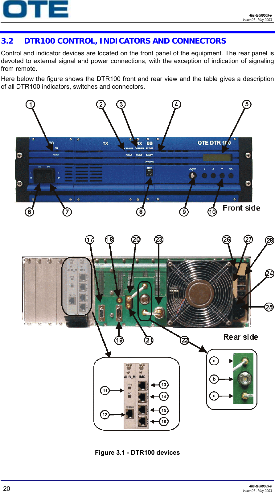
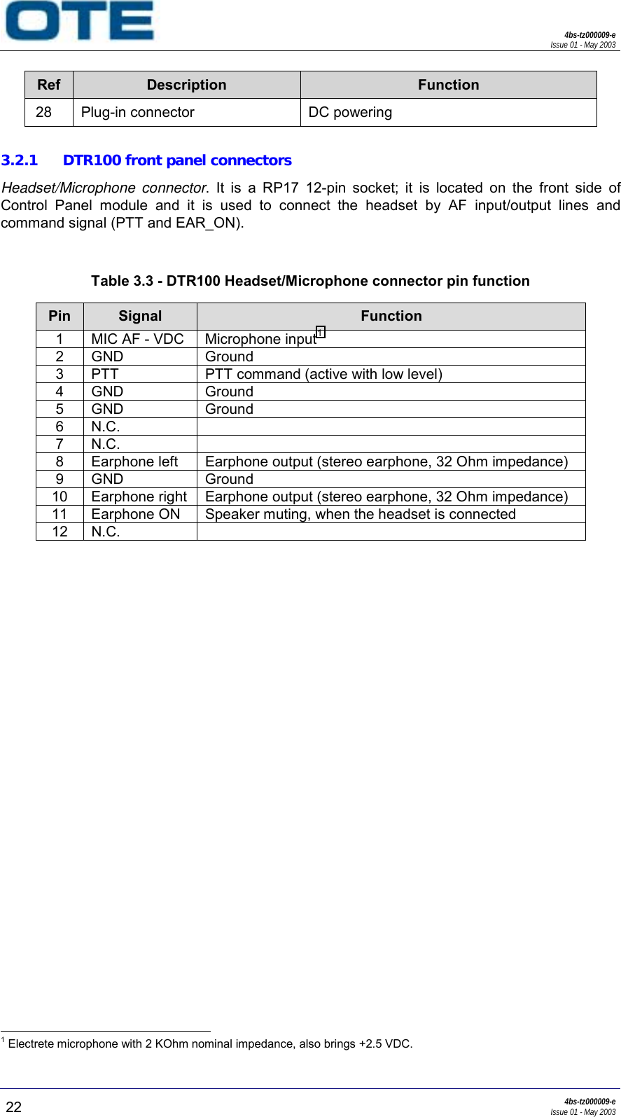
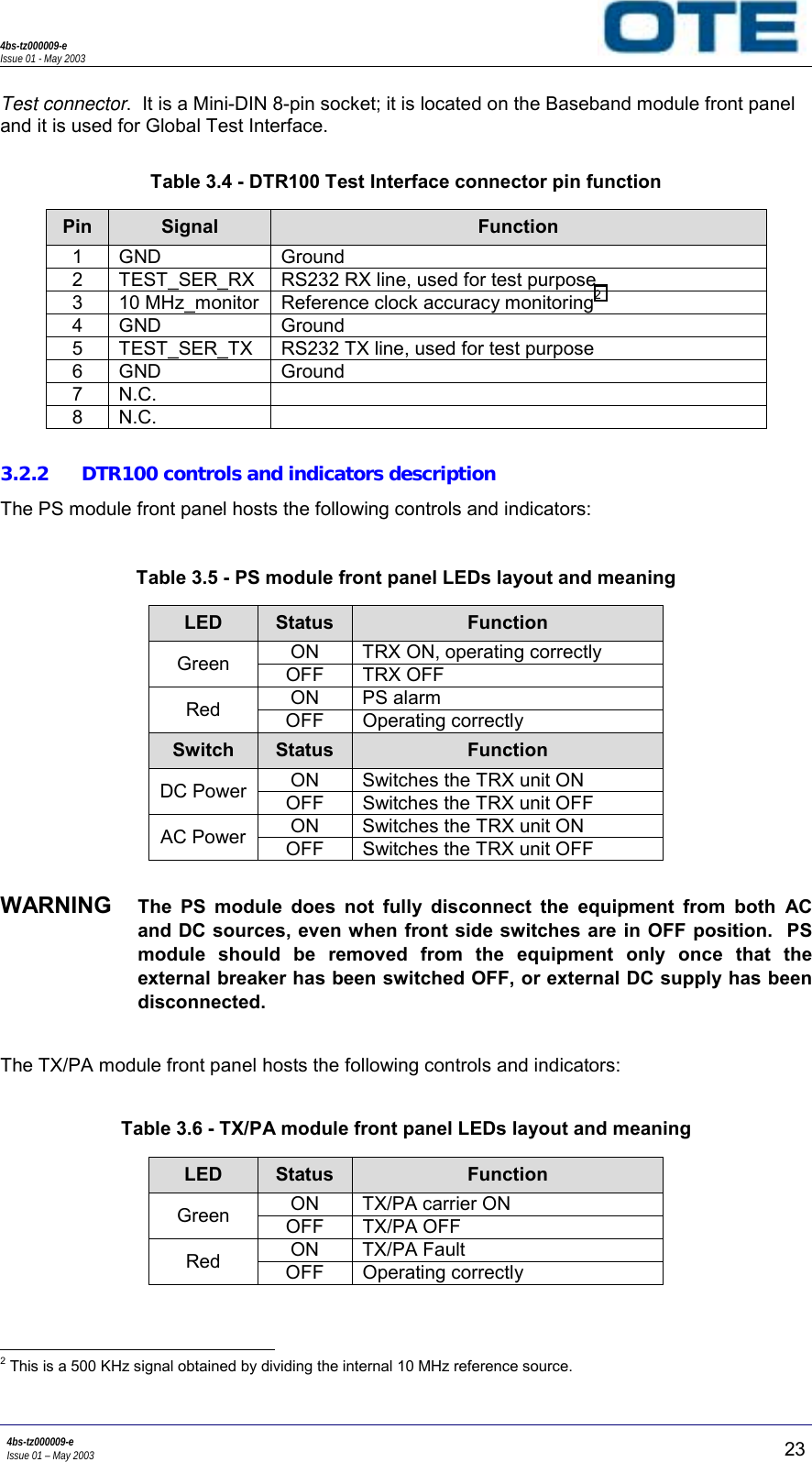
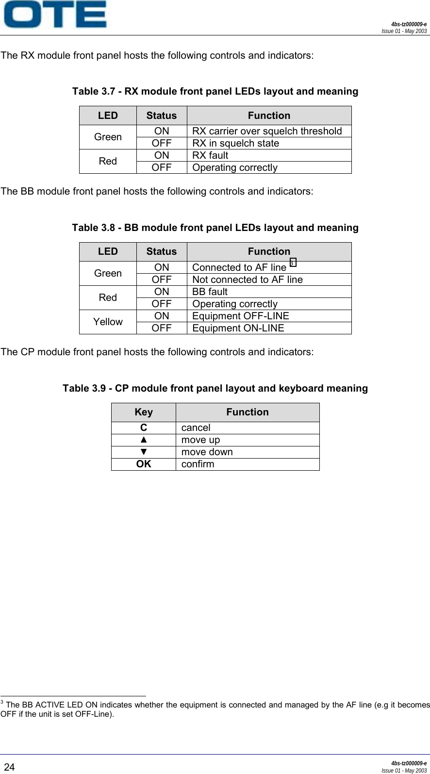
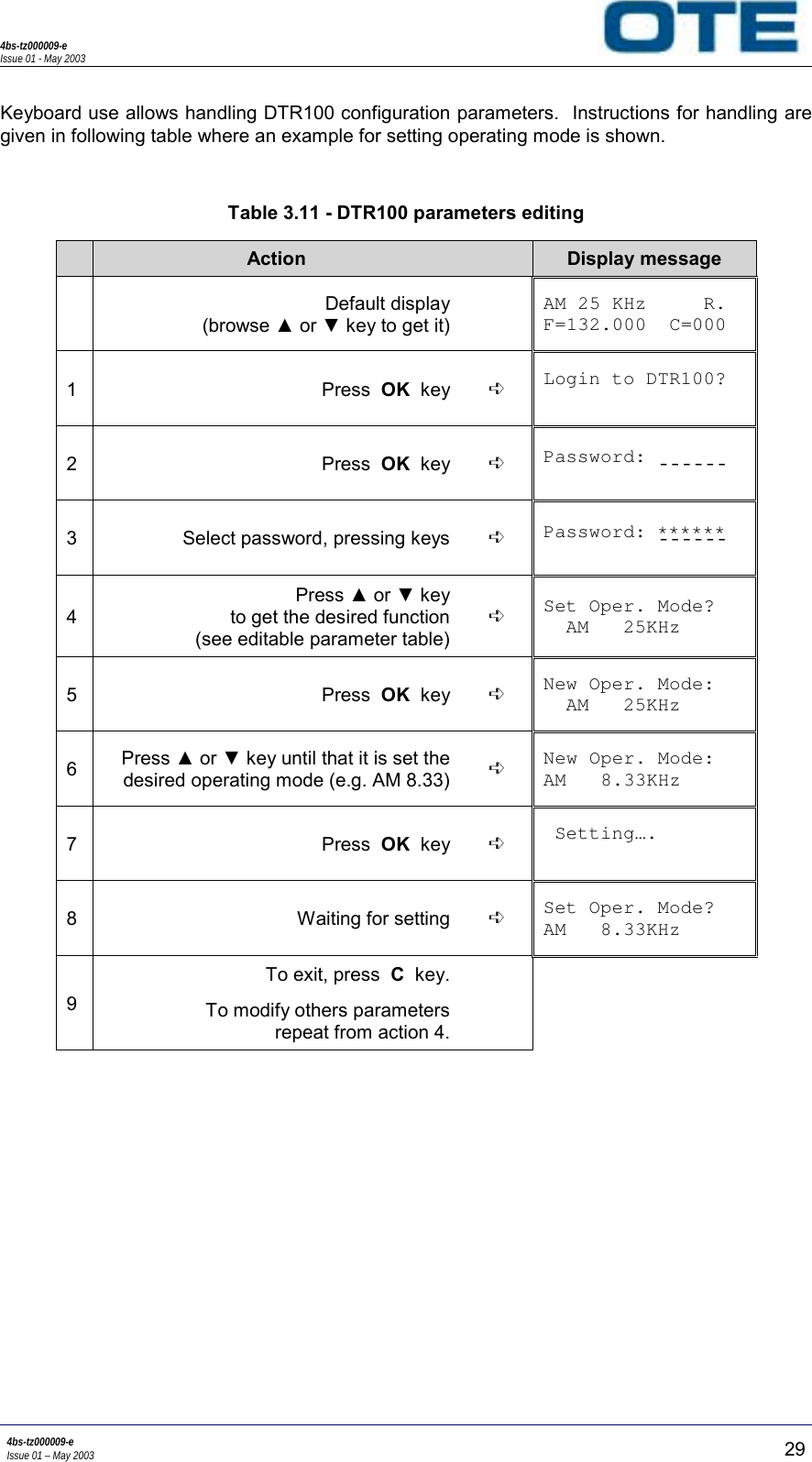
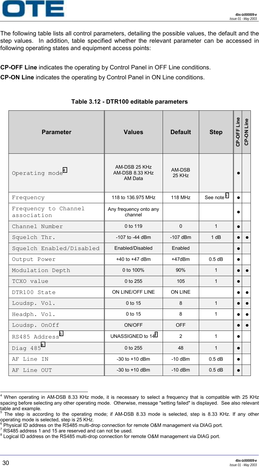
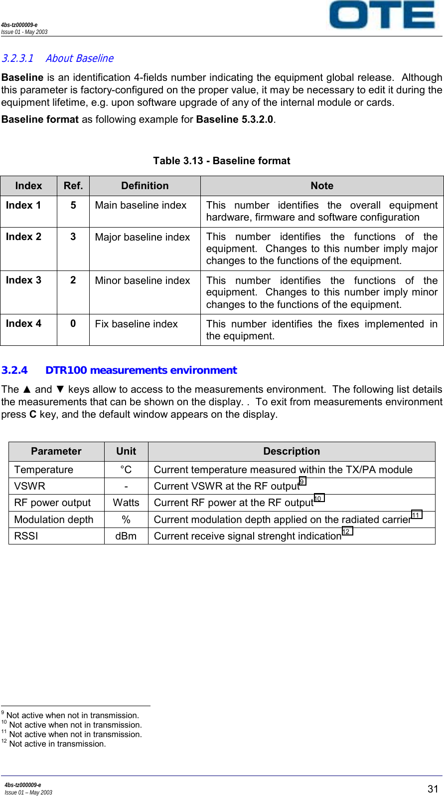
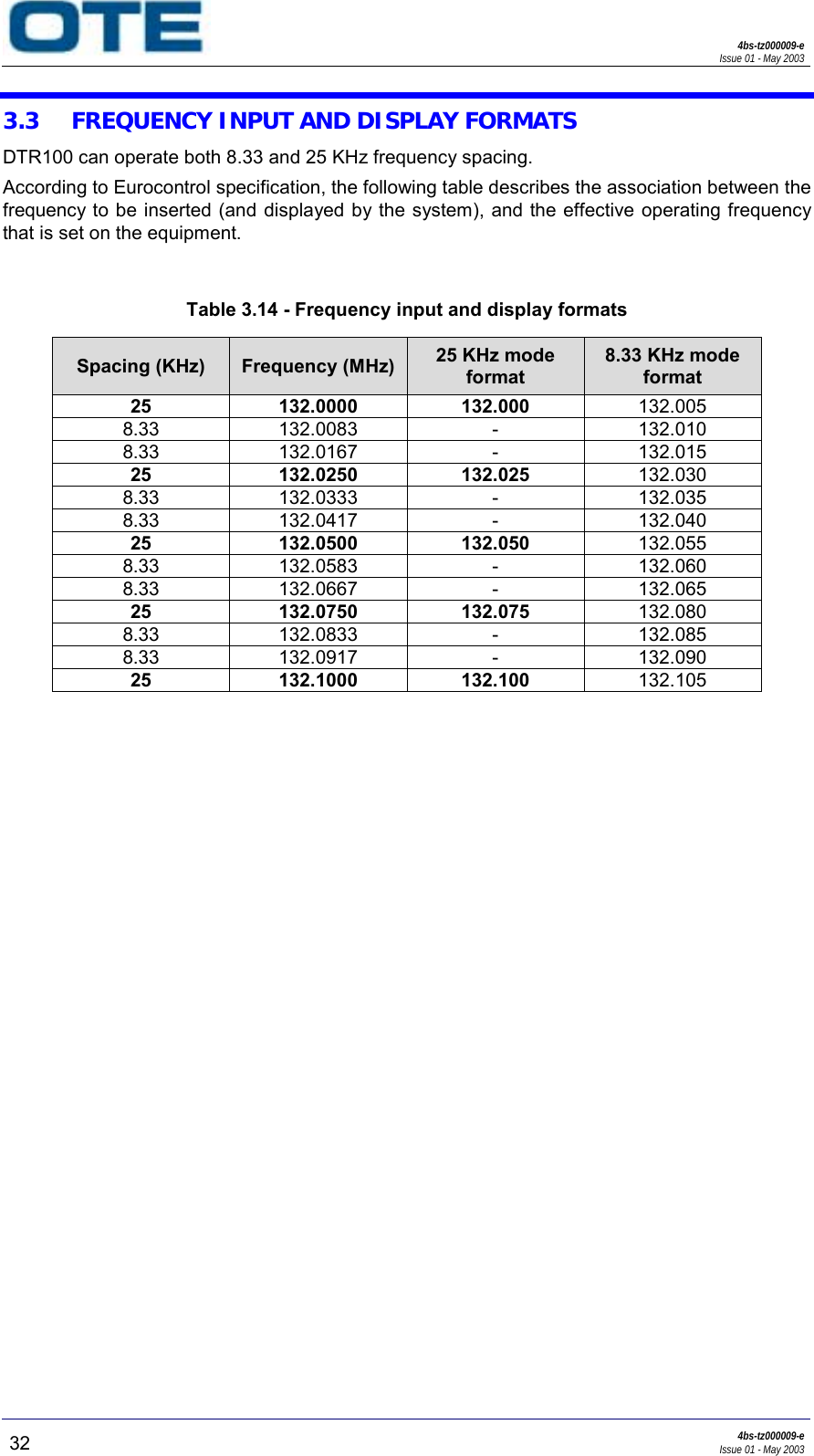
Morcom DTR100REV2-1 DTR100 VHF Transmitter/Receiver User Manual DTR100 Setting up guide

Morcom International, Inc. DTR100 VHF Transmitter/Receiver DTR100 Setting up guide

Users Manual

OTE DTR100Setting-up Guide4bs-tz000009-eRev. 01DTR100 VHF Transceiverfor ATC applicationsOTE S.p.A.- Via E. Barsanti 8, 50127 – Firenze, Italy
4bs-tz000009-eIssue 01 - May 2003b4bs-tz000009-eIssue 01 - May 2003© OTE S.p.A. 2003All copyright and industrial rights in this document and in the technical knowledge it contains areowned by OTE and/or the third parties rightfully concerned.  No part of this document nor anydata herein shall be disclosed, reproduced or used for any purpose whatsoever without the priorwritten consent of OTE as foreseen by the law.  Drawings and specifications are subject tochange.All trademarks and registered trademarks are the property of their respective holders.This document has been prepared to provide technical information on the product concerned. Whilst care has been taken in compiling the material, no responsibility can be accepted for errors oromissions in the text or in associated diagrams or tables.  OTE reserves the right to change specifications, performance or features relevant to the product described without notice. Where thisdocument is furnished in association with a quotation, tender or contract, the specifications, features, performance and availability dates which are relevant to such quotation, tender or contractshall be those specified in the schedule(s), specification(s), statement(s) of compliance or other documents specifically prepared for such purpose and shall not be assumed to be those stated orimplied within this document.
4bs-tz000009-eIssue 01 - May 20034bs-tz000009-eIssue 01 – May 2003 cInformation for the guide user:  Before using the equipment, read all of the instructions contained in themanual and read those relative to safety with special care.  Lue käyttöohjeet ja erityisesti turvallisuuteen liittyvat ohjeet ennen laitteenkäyttöä.  Alvorens over te gaan tot het gebruik van het apparaat lees  met aandachtal de instructies van het handboek en let vooral op die die de veiligheidbetreffen.  Alvorens het apparaat in gebruik te nemen lees alle instructies van hethandboek en  vooral de voorschriften betreffende  de veiligheid.  Avant toute utilisation de l’appareil, lire toutes les indications contenuesdans le Manuel et avec une attention particulière celles relatives à lasécurité.  Läs alla instruktioner i denna manual innan ni använder apparaten och dåsärskilt noggrannt de anvisningar som gäller säkerheten.  Læs alle de vejledninger, der er indeholdt i manualen med særligopmærksomhed på de vejledninger, der vedrører sikkerheden, førapparatet tages i brug.  Vor Gebrauch des Geräts alle in dieser Bedienungsanleitung enthaltenenAnweisungen und Vorschriften lesen. Den Sicherheitsbestimmungen ist dabei besondere Aufmerksamkeit zuwidmen.  Πριν χρησιµοποιήσετε τη συσκευή διαβάστε όλες τις οδηγίες πουπεριέχονται στο εγχειρίδιο και δώστε ιδιαίτερη προσοχή στης οδηγίεςασφαλείας.  Prima di utilizzare l’apparecchiatura leggere tutte le indicazioni contenutenel manuale e con particolare attenzione quelle relative alla sicurezza.
4bs-tz000009-eIssue 01 - May 2003d4bs-tz000009-eIssue 01 - May 2003  Antes de utilizar el equipo leer todas las instrucciones contenidas en elmanual, poniendo particular atención a las de seguridad.  Antes de utilizar o aparelho, leia todas as instruções que constam nomanual e com muita atenção as instruções relativas à segurança.
4bs-tz000009-eIssue 01 - May 20034bs-tz000009-eIssue 01 – May 2003 eTable of contents1. GENERAL .......................................................................................... 31.1 PURPOSE OF THIS GUIDE............................................................................. 41.2 INTRODUCTION............................................................................................ 41.3 DECLARATION OF CE MARK CONFORMANCE...............................................51.4 ECO-COMPATIBILITY ................................................................................... 51.5 GUIDE ORGANISATION................................................................................51.6 GLOSSARY OF ACRONYMS ........................................................................... 62. SAFETY ........................................................................................... 112.1 SAFETY RECOMMENDATIONS ....................................................................112.2 ESD .............................................................................................................152.2.1 ESD precautions.........................................................................................................153. OPERATION .................................................................................... 193.1 OPERATING STATES AND EQUIPMENT ACCESS POINTS............................193.2 DTR100 CONTROL, INDICATORS AND CONNECTORS................................ 203.2.1 DTR100 front panel connectors..................................................................................223.2.2 DTR100 controls and indicators description...............................................................233.2.3 DTR100 Control Panel operating ...............................................................................253.2.3.1 About Baseline........................................................................................................313.2.4 DTR100 measurements environment.........................................................................313.3 FREQUENCY INPUT AND DISPLAY FORMATS............................................. 323.4 START-UP PROCEDURE ..............................................................................334. SETTING-UP ................................................................................... 374.1 INTERFACE CONNECTORS..........................................................................374.1.1 Signal and data...........................................................................................................374.1.2 Power and grounding..................................................................................................414.1.3 Radio frequency..........................................................................................................424.2 SETTINGS AND ADJUSTMENTS...................................................................434.2.1 E&M line interface settings .........................................................................................434.2.2 Equipment adjustments ..............................................................................................464.2.2.1 Reference oscillator monitoring ..............................................................................47
4bs-tz000009-eIssue 01 - May 2003f4bs-tz000009-eIssue 01 - May 2003List of figuresFigure 1.1 - DTR100 equipment .................................................................................................... 3Figure 3.1 - DTR100 devices....................................................................................................... 20Figure 3.2 - DTR100 keyboard menu functional block diagram .................................................. 26Figure 3.3 - DTR100 setting environment functional block diagram ........................................... 27Figure 4.1 - Signal and data connections .................................................................................... 37Figure 4.2 - Power and grounding connections........................................................................... 41Figure 4.3 - DTR100 radio frequency connections...................................................................... 42Figure 4.4 - ALB-M dip-switch bank position ............................................................................... 43Figure 4.5 - E line circuit layout ................................................................................................... 44Figure 4.6 - M line circuit layout................................................................................................... 45List of tablesTable 3.1 - DTR100 front side devices description...................................................................... 21Table 3.2 - DTR100 rear side devices description ...................................................................... 21Table 3.3 - DTR100 Headset/Microphone connector pin function .............................................. 22Table 3.4 - DTR100 Test Interface connector pin function.......................................................... 23Table 3.5 - PS module front panel LEDs layout and meaning .................................................... 23Table 3.6 - TX/PA module front panel LEDs layout and meaning............................................... 23Table 3.7 - RX module front panel LEDs layout and meaning .................................................... 24Table 3.8 - BB module front panel LEDs layout and meaning .................................................... 24Table 3.9 - CP module front panel layout and keyboard meaning .............................................. 24Table 3.10 - DTR100 display messages ..................................................................................... 28Table 3.11 - DTR100 parameters editing .................................................................................... 29Table 3.12 - DTR100 editable parameters .................................................................................. 30Table 3.13 - Baseline format ....................................................................................................... 31Table 3.14 - Frequency input and display formats ...................................................................... 32Table 4.1 - TELCO connector pin function for DTR100 .............................................................. 38Table 4.2 - DIAG connector pin function ..................................................................................... 38Table 4.3 - DATA connector pin function..................................................................................... 38Table 4.4 - CTRL connector pin function..................................................................................... 39Table 4.5 - ANT connector pin function ....................................................................................... 39Table 4.6 - GPS I/F connector pin function ................................................................................. 39Table 4.7 - EXT CLOCK connector pin function.......................................................................... 40Table 4.8 - Service port pin function............................................................................................ 40Table 4.9 - E line settings #1 ....................................................................................................... 44Table 4.10 - E line settings #2 ..................................................................................................... 44Table 4.11 - Setting-up procedure for DTR100 ........................................................................... 46Table 4.12 - Reference oscillator monitoring procedure ............................................................. 47
4bs-tz000009-eIssue 01 - May 20034bs-tz000009-eIssue 01 – May 2003 gDocument historyTitle: OTE DTR100 – Setting-up GuideDocument code: 4bs-tz000009-eDate Variations Rev.May 2003 First Issue. 01
4bs-tz000009-eIssue 01 - May 2003h4bs-tz000009-eIssue 01 - May 2003THIS PAGE HAS BEEN INTENTIONALLY LEFT BLANK
4bs-tz000009-eIssue 01 - May 20034bs-tz000009-eIssue 01 – May 2003 11 - GENERAL
4bs-tz000009-eIssue 01 - May 200324bs-tz000009-eIssue 01 - May 2003THIS PAGE HAS BEEN INTENTIONALLY LEFT BLANK
4bs-tz000009-eIssue 01 - May 20034bs-tz000009-eIssue 01 – May 2003 31. GENERALThis section introduces the DTR100 equipment and the guide itself, by describing their tasks,operating modes and scenarios.The following figure shows the DTR100 layout.Figure 1.1 - DTR100 equipment
4bs-tz000009-eIssue 01 - May 200344bs-tz000009-eIssue 01 - May 20031.1 PURPOSE OF THIS GUIDEThe purpose of this guide is to provide to operators and technical staff the necessary knowledgeof the equipment operating, in order to make possible setting-up activity.Guide user is supposed to have a good skill in telecommunications and RF basics, tounderstand the given terms and parameters.Only trained and qualified personnel may operate the equipment.  Non-observance of theseconditions and the safety instructions can result in personnel injury or in property damage.1.2 INTRODUCTIONThe DTR100 multimode VHF transceiver is a state-of the-art communication unit, specificallydesigned to operate as radio core part of Air Traffic Control ground stations.  It may be regardedas an integrated transmitter and receiver device, since the internal transmit and receive sectionsoperate independently.Thanks to its DSP-based architecture, software-radio approach, and modular design, it allowsfor easy update and re-configuration.The equipment has been designed to fulfil operating requirements in any possible systemlayout.In the transmitter section, the equipment has outstanding performances in terms of noiseradiation and unwanted emissions.  These features, together with the high grade of immunity toexternal interference of the receiver section, allow for meeting considerable co-sitingrequirements under EMC-critical equipment arrangement.DTR100 belongs to the latest OTE's ATC third-generation communication systems family,together with the DR100 (VHF receiver), and DT100 (VHF transmitter).
4bs-tz000009-eIssue 01 - May 20034bs-tz000009-eIssue 01 – May 2003 51.3 DECLARATION OF CE MARK CONFORMANCEThe equipment described in this guide has been designed according the following internationalstandards:Safety:•  CEI EN 60950 (4th edition - 2000) - Safety of information technology equipment.•  CEI EN 60215 (1997-10) - Safety requirements for radio transmitting equipment.EMC:•  ETSI 301 489-1 (version 1.4.1 - 2002) - Electromagnetic compatibility and Radio spectrumMatters (ERM); ElectroMagnetic compatibility (EMC) standard for radio equipment andservices; Part 1: Common technical requirements.•  ETSI 301 489-22 (version 1.2.1 - 2002) - Electromagnetic compatibility and Radio spectrumMatters (ERM); ElectroMagnetic Compatibility (EMC) standard for radio equipment andservices; Part 22: Specific conditions for ground based VHF aeronautical mobile and fixedradio equipment.Any connected device has to comply with the applicable safety standards.In addition, all installation activities must be performed in such a way to not compromise orlower the equipment degree safety; this must also be taken in account whenever designingsystem architecture and choosing installation arrangement.1.4 ECO-COMPATIBILITYThe equipment described in this guide has been designed and realized by following criteria ofeco-compatibility, which are also applied to the manufacturing process.1.5 GUIDE ORGANISATIONThis guide is organized into following sections:• Section 1 – General.  Introduces the equipment.• Section 2 – Safety.  This section gives to operator all necessary information for a correct andsafe use of the equipment.• Section 3 – Operation.  This section describes all the aspects related to the normal use ofequipment, e.g. showing function of each of the front panels controls and indicators.• Section 4 – Setting-up.  This section gives an overview of the DTR100 interfaces anddescribes step-by-step the procedures for the configuration and adjustments of theequipment.
4bs-tz000009-eIssue 01 - May 200364bs-tz000009-eIssue 01 - May 20031.6 GLOSSARY OF ACRONYMSACRONYM MEANINGAC Alternate CurrentAF Audio FrequencyALB-M Analogue Line Barrier MinimalAM-DSB Amplitude Modulation _ Double Side BandATC Air Traffic ControlAWG American Wire GaugeBB BasebandBNC Bayonet Navy Connector (type of RF connector)CE Conformité Européene / Certified EuropeCEI Comitato Elettrotecnico InternazionaleCEI-EN CEI-European NormCP Control PanelCW Continuous WaveDC Direct CurrentDIN Deutsches Institut für NormungDR100 Digital Receiver, OTE 100 seriesDSP Digital Signal Processing/ProcessorDT100 Digital Transmitter, OTE 100 seriesDTR100 Digital Transceiver, OTE 100 seriesEMC ElectroMagnetic ComplianceEMI ElectroMagnetic InterferenceEN European NormERM Electromagnetic compatibility and Radio spectrum MattersESD ElectroStatic DischargeETS European Telecommunications StandardETSI European Telecommunications Standards InstituteGND GroundGNSS Global Navigation Satellite SystemGPS Global Positioning System/SatelliteHMI Human-Machine InterfaceIEC International Electrotechnical Committee/CommissionIMC Interface and Management CardLCD Liquid Crystal Display
4bs-tz000009-eIssue 01 - May 20034bs-tz000009-eIssue 01 – May 2003 7ACRONYM MEANINGLED Light Emitting DiodeN Navy (type of RF connector)NC Normally CloseNO Normally OpenO&M Operation and MaintenanceOTE Officine Toscane ElettromeccanichePA Power Amplifierppm Part Per MillionPS Power Supply (module)PTT Push to TalkRCB Radio Control BusRF Radio FrequencyRSSI Received Signal Strength IndicatorRX Receiver or ReceptionSMA Sub-Miniature A (type of RF connector)SQL Squelch (signaling)TCXO Temperature-Compensated Crystal OscillatorTRX TransceiverTTL Transistor - Transistor LogicTX Transmitter or TransmissionUTC Universal Time CoordinatedVCSS Voice Communication Switching SystemVHF Very High FrequencyVOLMET Aviation Weather BroadcastsVSWR Voltage Standing Wave Ratiowrt with respect to
4bs-tz000009-eIssue 01 - May 200384bs-tz000009-eIssue 01 - May 2003THIS PAGE HAS BEEN INTENTIONALLY LEFT BLANK
4bs-tz000009-eIssue 01 - May 20034bs-tz000009-eIssue 01 – May 2003 92 - SAFETY
4bs-tz000009-eIssue 01 - May 200310 4bs-tz000009-eIssue 01 - May 2003THIS PAGE HAS BEEN INTENTIONALLY LEFT BLANK
4bs-tz000009-eIssue 01 - May 20034bs-tz000009-eIssue 01 – May 2003 112. SAFETYThis section of the guide gives all the instructions and warning for a correct and safe use of theequipment.  Operators are strongly recommended to respect given indications; non-observanceof these instructions can result in personnel injury or in property damage.2.1 SAFETY RECOMMENDATIONSCarefully read all the following cautions and warnings before using the equipment.WARNINGDo not use the equipment for uses different than those indicated in theguide.WARNINGFor correct use of equipment, refer to the relevant section within thisguide.WARNINGProtect the equipment from rainfalls, sprinkling of water and/or otherliquids, and from dust.WARNINGDo not set any object on equipment.WARNINGConnect the equipment to the equipment room ground bar throughdedicated connection, and not through physical contact with otherframes.WARNINGDo not use the equipment if it is not appropriately grounded or if ground isabsent.
4bs-tz000009-eIssue 01 - May 200312 4bs-tz000009-eIssue 01 - May 2003WARNINGThe electric shock can cause the interruption of the natural breathing.  Animmediate action is necessary in order to restore breathing.  It istherefore necessary that the staff be familiarized with the variousmethods of artificial breathing and cardiac massage.  In case of incidents,caused from high tension, an urgent medical aid is necessary to deal thepossible effects of the body poisoning caused from burns.  In all thecases, proper medical assistance must be requested.  It is necessary tomake sure that any person who uses or takes care itself of themaintenance of the equipment having parts under dangerous voltages isable of performing artificial breathing, and it is necessary to instruct thestaff on first aid measures in case the need arises.WARNINGDo not use the equipment if the power cable and/or the power supplyoutlet are damaged.WARNINGDo not use the equipment if antenna, and/or antenna cable is damaged.WARNINGInstall the equipment following the instructions given in this guide.  Theequipment must be installed in such a way complies with the nationalregulations in effect.WARNINGWear protection gloves when handling the equipment.WARNINGWhen handling the equipment be sure that all internal modules and cardsare safely screwed in their position into the chassis.WARNINGThe equipment weight can cause problems during its handling.  Take thenecessary precautions, e.g. be assisted by another person if necessary.WARNINGPosition the equipment in such a way as to guarantee its correct aerationas well as safe accessibility to the front side controls, and rear side powersupply outlets, RF, signal and data connections.
4bs-tz000009-eIssue 01 - May 20034bs-tz000009-eIssue 01 – May 2003 13WARNINGDo not position the equipment standing on its rear side, since this candamage rear panel parts.WARNINGCarry out the maintenance interventions on the equipment following theinstructions given in this guide.WARNINGFollow all accident prevention standards when carrying out maintenanceinterventions on the equipment.WARNINGThe equipment includes components containing beryllium oxide (beryllia),substance that can be highly toxic if no precautionary measures areundertaken.  Pay attention to the beryllium oxide warning label placed onthe relevant module(s), and to beryllium oxide warning within this guide.Relevant module(s) cover must not be removed.WARNINGDisconnect the power supply before carrying out maintenanceinterventions on the equipment.WARNINGThe PS module does not fully disconnect the equipment from both ACand DC sources, even when front side switches are in OFF position.  Partreplacement must take place only once that the external AC breaker hasbeen switched OFF, and/or external DC supply has been disconnected.WARNINGUse only accessories or replacement parts approved by the manufacturerfor the equipment.
4bs-tz000009-eIssue 01 - May 200314 4bs-tz000009-eIssue 01 - May 2003WARNINGOnly authorized technical personnel may carry out maintenanceinterventions on the equipment.OTE S.p.A. VIA BARSANTI, 850127 FIRENZE ITALYTELEPHONEHELP DESK (Italy only)HELP DESK (International)FAXTELEXE-MAIL+39 05532811 800 509590+39 055328142+39 0554381232+39 570276helpdesk.mobile@marconiselenia.comThe equipment complies with all product specification and the greatest care is taken by themanufacturer so that user safety, as far as the effects of electromagnetic waves on health areconcerned, is guaranteed within the limits established by the international specifications.
4bs-tz000009-eIssue 01 - May 20034bs-tz000009-eIssue 01 – May 2003 152.2 ESDNo ESD precautions have to be taken by the operator in the daily use of the equipment.  Theequipment is designed and manufactured in such a way to not be sensible to electrostaticdischarges.2.2.1 ESD precautionsThe equipment includes many electrostatic-sensitive parts that must be handled at a static-safeguarded working area.  Furthermore, they must be arranged in static-safeguardedpackages, either in the case of storing, or in the case of shipment.These recommendations should be followed with the maximum care, especially in the case ofmodules or board extraction and handling.A static safeguard area may be intended as:•  Grounded static dissipating wrist-strap that drains static charge from the operator wearing it.•  A work surface covered with or composed of a grounded, static-dissipating material thatdrains electrical charges from devices placed on the surface.Work surface should provide a standard-size ESD-safeguard snap suitable for snap-stackingwrist-strap connection.  It should be used as a convenient ESD caution, whenever handlingmodules and boards.  These recommendations are to be extended also to activity not strictlyperformed in close equipment surrounding.  If removed, replaced, or located inside workshop,any board should be handled by means of convenient ESD cautions.WARNING  Please note that OTE disclaims any responsibility for problems due topoor ESD protection during activity.
4bs-tz000009-eIssue 01 - May 200316 4bs-tz000009-eIssue 01 - May 2003THIS PAGE HAS BEEN INTENTIONALLY LEFT BLANK
4bs-tz000009-eIssue 01 - May 20034bs-tz000009-eIssue 01 – May 2003 173 - OPERATION
4bs-tz000009-eIssue 01 - May 200318 4bs-tz000009-eIssue 01 - May 2003THIS PAGE HAS BEEN INTENTIONALLY LEFT BLANK
4bs-tz000009-eIssue 01 - May 20034bs-tz000009-eIssue 01 – May 2003 193. OPERATIONThe purpose of this section is to describe the operational management of the DTR100,specifically control and indicator devices and operating through the control panel facilities3.1 OPERATING STATES AND EQUIPMENT ACCESS POINTSThe equipment can be set in two different operating states:• ON Line state if the AF line port, located onto the ALB-M rear panel, is used to manage theAF+signaling connection, e.g. carrying PTT input and the TX and RX balanced audio lines.• OFF Line state if the Headset/Microphone connector, located onto the Control Panel frontside, is used to manage the AF+signaling connection, e.g. carrying PTT input and the TXand RX audio.  In this operating state, the AF line port located onto the ALB-M rear panel isnot enabled, this meaning that the equipment can not provide service to an operator locatedat a remote position.  Although full management of equipment audio facility is possible inOFF Line state (e.g. by Headset), this is the typical operating state to be used for activitiesperformed locally.Concerning O&M functions, the equipment can be managed from the Control Panel (CP) byusing the keyboard.  It is intended as an easy and immediate access point.When performing O&M tasks, it is important to note that all equipment functional parameterscan be accessed only in OFF Line state.  See next chapters for further details about editableparameters.
4bs-tz000009-eIssue 01 - May 200320 4bs-tz000009-eIssue 01 - May 20033.2 DTR100 CONTROL, INDICATORS AND CONNECTORSControl and indicator devices are located on the front panel of the equipment. The rear panel isdevoted to external signal and power connections, with the exception of indication of signalingfrom remote.Here below the figure shows the DTR100 front and rear view and the table gives a descriptionof all DTR100 indicators, switches and connectors.Figure 3.1 - DTR100 devices
4bs-tz000009-eIssue 01 - May 20034bs-tz000009-eIssue 01 – May 2003 21Table 3.1 - DTR100 front side devices descriptionRef Description Function1  LEDs (green, red) PS module status2  LEDs (green, red) TX/PA module status3  LEDs (green, red) RX module status4  LEDs (green, red, yellow) BB module status5  LCD Display 2x10 digits Display on Control Panel6  Switch ON/OFF AC switch7  Switch ON/OFF DC switch8  Mini-DIN 8-pin connector Test connector.9 RP17 Headset/Microphone connector.10  Four control keys Keyboard on Control PanelTable 3.2 - DTR100 rear side devices descriptionRef Description Function11  LEDs (green) PTT and Squelch status indication12  RJ45 connector (keyed) AF line and signaling13  RJ45 connector (DATA) Data interface (RS232) connector14  RJ45 connector (CTRL) Auxiliary control signals I/O connector15  RJ45 connector (DIAG) Remote diagnostic interface connector16  RJ45 connector (ANT) Ext. antenna switch interface connector17  9-pin D-type female Service port18  SMA-type female connector External frequency reference input19  9-pin D-type male GPS/GNSS input20  SMA-type female connector RX module RF input Low sensitivity21  SMA-type female connector RX module RF input High sensitivity22 a: SMA-type female connectorb: N-type female connectorc: SMA-type female connectorConnections of internal RF switch23  N-type female connector RF output24  6.3 A fuse (slow blow). VAC protection25  Standard IEC 320 connector AC powering26  20 A fuse (fast acting). VDC protection27  GND connection point Equipment grounding
4bs-tz000009-eIssue 01 - May 200322 4bs-tz000009-eIssue 01 - May 2003Ref Description Function28  Plug-in connector DC powering3.2.1 DTR100 front panel connectorsHeadset/Microphone connector. It is a RP17 12-pin socket; it is located on the front side ofControl Panel module and it is used to connect the headset by AF input/output lines andcommand signal (PTT and EAR_ON).Table 3.3 - DTR100 Headset/Microphone connector pin functionPin Signal Function1 MIC AF - VDC Microphone input12 GND Ground3 PTT PTT command (active with low level)4 GND Ground5 GND Ground6N.C.7N.C.8 Earphone left Earphone output (stereo earphone, 32 Ohm impedance)9 GND Ground10 Earphone right Earphone output (stereo earphone, 32 Ohm impedance)11 Earphone ON Speaker muting, when the headset is connected12 N.C.                                                     1 Electrete microphone with 2 KOhm nominal impedance, also brings +2.5 VDC.
4bs-tz000009-eIssue 01 - May 20034bs-tz000009-eIssue 01 – May 2003 23Test connector.  It is a Mini-DIN 8-pin socket; it is located on the Baseband module front paneland it is used for Global Test Interface.Table 3.4 - DTR100 Test Interface connector pin functionPin Signal Function1 GND Ground2 TEST_SER_RX RS232 RX line, used for test purpose3 10 MHz_monitor Reference clock accuracy monitoring24 GND Ground5 TEST_SER_TX RS232 TX line, used for test purpose6 GND Ground7N.C.8N.C.3.2.2 DTR100 controls and indicators descriptionThe PS module front panel hosts the following controls and indicators:Table 3.5 - PS module front panel LEDs layout and meaningLED Status FunctionON TRX ON, operating correctlyGreen OFF TRX OFFON PS alarmRed OFF Operating correctlySwitch Status FunctionON Switches the TRX unit ONDC Power OFF Switches the TRX unit OFFON Switches the TRX unit ONAC Power OFF Switches the TRX unit OFFWARNING  The PS module does not fully disconnect the equipment from both ACand DC sources, even when front side switches are in OFF position.  PSmodule should be removed from the equipment only once that theexternal breaker has been switched OFF, or external DC supply has beendisconnected.The TX/PA module front panel hosts the following controls and indicators:Table 3.6 - TX/PA module front panel LEDs layout and meaningLED Status FunctionON TX/PA carrier ONGreen OFF TX/PA OFFON TX/PA FaultRed OFF Operating correctly                                                     2 This is a 500 KHz signal obtained by dividing the internal 10 MHz reference source.
4bs-tz000009-eIssue 01 - May 200324 4bs-tz000009-eIssue 01 - May 2003The RX module front panel hosts the following controls and indicators:Table 3.7 - RX module front panel LEDs layout and meaningLED Status FunctionON RX carrier over squelch thresholdGreen OFF RX in squelch stateON RX faultRed OFF Operating correctlyThe BB module front panel hosts the following controls and indicators:Table 3.8 - BB module front panel LEDs layout and meaningLED Status FunctionON Connected to AF line 3Green OFF Not connected to AF lineON BB faultRed OFF Operating correctlyON Equipment OFF-LINEYellow OFF Equipment ON-LINEThe CP module front panel hosts the following controls and indicators:Table 3.9 - CP module front panel layout and keyboard meaningKey FunctionCcancel▲▲▲▲move up▼▼▼▼move downOK confirm                                                     3 The BB ACTIVE LED ON indicates whether the equipment is connected and managed by the AF line (e.g it becomesOFF if the unit is set OFF-Line).
4bs-tz000009-eIssue 01 - May 20034bs-tz000009-eIssue 01 – May 2003 253.2.3 DTR100 Control Panel operatingThe display allows monitoring and management of DTR100 configuration parameters (e.g.frequency, power output level etc.) through keyboard use.  Moreover, it shows the alarms(intended as messages indicating a detected failure) coming from DTR100 modules.  Followingfigure shows an example of messages that can be visualized on the display, and the keys useto browse windows.
4bs-tz000009-eIssue 01 - May 200326 4bs-tz000009-eIssue 01 - May 2003Figure 3.2 - DTR100 keyboard menu functional block diagram
4bs-tz000009-eIssue 01 - May 20034bs-tz000009-eIssue 01 – May 2003 27Figure 3.3 - DTR100 setting environment functional block diagram
4bs-tz000009-eIssue 01 - May 200328 4bs-tz000009-eIssue 01 - May 2003The following table shows information that can be monitored on display.  Press ▲ or ▼ key tobrowse the windows.Table 3.10 - DTR100 display messagesDisplay message DescriptionDTR100Alarms PresentThis is the default window when alarms are present.AM 25 KHz     R.F=118.000  C=000Default window when no alarms are present.  It givesinformation on current frequency, channel and theindication of OFF Line (L) or ON Line (R) state.Squelch Thr.-107 dBmIndication of squelch threshold level, set by operator.RF Output Pwr. 47.0 dBmPower output level expressed in dBmMod. Depth 90%Modulation index expressed in percentage.AF Line IN-10.0 dBmAF input level to get rated modulation indexAF Line OUT-10.0 dBmAF output levelTCXO Value 105Indication of the fine-tuning of 10 MHz local frequencyreference expressed in steps.DTR100 FAULT: T R B A I PThis window appears only when alarms are present.Letters are referred to modules (or cards) that producean alarm.DTR100 State:    ON  LINEThis window appears only when no alarms arepresent.RS485 Addr2This is the address ID on the RS485 connectionrouted towards an external controller for remote O&MmanagementSquelchENABLEDIndication of squelch state (enabled/disabled)Offset Type:   0Offset Index:  0Indication of carrier offset schemeActivate Measure This windows allows activating the measurementenvironmentBaseline005.003.002.000Indication of the Baseline (global software release) ofthe equipment   RACK TYPE...Stand AloneIndication of the equipment assigned type; this may beMain or Standby (2 equipment in redundancy scheme)or Stand Alone (single equipment)
4bs-tz000009-eIssue 01 - May 20034bs-tz000009-eIssue 01 – May 2003 29Keyboard use allows handling DTR100 configuration parameters.  Instructions for handling aregiven in following table where an example for setting operating mode is shown.Table 3.11 - DTR100 parameters editingAction Display messageDefault display(browse ▲ or ▼ key to get it)AM 25 KHz     R.F=132.000  C=0001Press  OK  key ➪Login to DTR100?2Press  OK  key ➪Password: ˍˍˍˍˍˍ3 Select password, pressing keys ➪Password: ˍˍˍˍˍˍ4Press ▲ or ▼ keyto get the desired function(see editable parameter table)➪Set Oper. Mode?  AM   25KHz5Press  OK  key ➪New Oper. Mode:  AM   25KHz6Press ▲ or ▼ key until that it is set thedesired operating mode (e.g. AM 8.33) ➪New Oper. Mode:AM   8.33KHz7Press  OK  key ➪ Setting….8 Waiting for setting ➪Set Oper. Mode?AM   8.33KHz9To exit, press  C  key.To modify others parametersrepeat from action 4.******
4bs-tz000009-eIssue 01 - May 200330 4bs-tz000009-eIssue 01 - May 2003The following table lists all control parameters, detailing the possible values, the default and thestep values.  In addition, table specified whether the relevant parameter can be accessed infollowing operating states and equipment access points:CP-OFF Line indicates the operating by Control Panel in OFF Line conditions.CP-ON Line indicates the operating by Control Panel in ON Line conditions.Table 3.12 - DTR100 editable parametersParameter Values Default StepCP-OFF LineCP-ON LineOperating mode4AM-DSB 25 KHzAM-DSB 8.33 KHzAM DataAM-DSB25 KHz ●Frequency 118 to 136.975 MHz 118 MHz See note 5●Frequency to ChannelassociationAny frequency onto anychannel ●Channel Number 0 to 119 0 1 ●Squelch Thr. -107 to -44 dBm -107 dBm 1 dB ● ●Squelch Enabled/Disabled Enabled/Disabled Enabled ●Output Power +40 to +47 dBm +47dBm 0.5 dB ●Modulation Depth 0 to 100% 90% 1● ●TCXO value 0 to 255 105 1●DTR100 State ON LINE/OFF LINE ON LINE ●●Loudsp. Vol. 0 to 15 8 1 ● ●Headph. Vol. 0 to 15 8 1 ●●Loudsp. OnOff ON/OFF OFF ● ●RS485 Address6UNASSIGNED to 14721●Diag 48580 to 255 48 1●AF Line IN -30 to +10 dBm -10 dBm 0.5 dB ●AF Line OUT -30 to +10 dBm -10 dBm 0.5 dB ●                                                     4 When operating in AM-DSB 8.33 KHz mode, it is necessary to select a frequency that is compatible with 25 KHzspacing before selecting any other operating mode.  Otherwise, message "setting failed" is displayed.  See also relevanttable and example.5 The step is according to the operating mode; if AM-DSB 8.33 mode is selected, step is 8.33 KHz. If any otheroperating mode is selected, step is 25 KHz.6 Physical ID address on the RS485 multi-drop connection for remote O&M management via DIAG port.7 RS485 address 1 and 15 are reserved and can not be used.8 Logical ID address on the RS485 multi-drop connection for remote O&M management via DIAG port.
4bs-tz000009-eIssue 01 - May 20034bs-tz000009-eIssue 01 – May 2003 313.2.3.1 About BaselineBaseline is an identification 4-fields number indicating the equipment global release.  Althoughthis parameter is factory-configured on the proper value, it may be necessary to edit it during theequipment lifetime, e.g. upon software upgrade of any of the internal module or cards.Baseline format as following example for Baseline 5.3.2.0.Table 3.13 - Baseline formatIndex Ref. Definition NoteIndex 15Main baseline index This number identifies the overall equipmenthardware, firmware and software configurationIndex 2 3 Major baseline index This number identifies the functions of theequipment.  Changes to this number imply majorchanges to the functions of the equipment.Index 3 2 Minor baseline index This number identifies the functions of theequipment.  Changes to this number imply minorchanges to the functions of the equipment.Index 4 0 Fix baseline index This number identifies the fixes implemented inthe equipment.3.2.4 DTR100 measurements environmentThe ▲ and ▼ keys allow to access to the measurements environment.  The following list detailsthe measurements that can be shown on the display. .  To exit from measurements environmentpress C key, and the default window appears on the display.Parameter Unit DescriptionTemperature °C Current temperature measured within the TX/PA moduleVSWR - Current VSWR at the RF output9RF power output Watts Current RF power at the RF output10Modulation depth % Current modulation depth applied on the radiated carrier11RSSI dBm Current receive signal strenght indication12                                                     9 Not active when not in transmission.10 Not active when not in transmission.11 Not active when not in transmission.12 Not active in transmission.
4bs-tz000009-eIssue 01 - May 200332 4bs-tz000009-eIssue 01 - May 20033.3 FREQUENCY INPUT AND DISPLAY FORMATSDTR100 can operate both 8.33 and 25 KHz frequency spacing.According to Eurocontrol specification, the following table describes the association between thefrequency to be inserted (and displayed by the system), and the effective operating frequencythat is set on the equipment.Table 3.14 - Frequency input and display formatsSpacing (KHz) Frequency (MHz) 25 KHz modeformat8.33 KHz modeformat25 132.0000 132.000 132.0058.33 132.0083 - 132.0108.33 132.0167 - 132.01525 132.0250 132.025 132.0308.33 132.0333 - 132.0358.33 132.0417 - 132.04025 132.0500 132.050 132.0558.33 132.0583 - 132.0608.33 132.0667 - 132.06525 132.0750 132.075 132.0808.33 132.0833 - 132.0858.33 132.0917 - 132.09025 132.1000 132.100 132.105
4bs-tz000009-eIssue 01 - May 20034bs-tz000009-eIssue 01 – May 2003 333.4 START-UP PROCEDUREIf the equipment is powered only by AC, please refer to the following steps.•  Set ON the external AC breaker or AC power source.•  Set ON the AC switch on PS module.•  Wait until the equipment booting is completed, and the display shows the default window,with operating mode, frequency, etc. If no alarm is present, operate the equipment.If the equipment is powered by both AC and backup DC, please refer to the following steps.•  Set ON the external AC breaker or AC power source.•  Set ON the external DC breaker or DC power source.•  Set ON the AC switch on PS module.•  Set ON the DC switch on PS module.•  Wait until the equipment booting is completed, and the display shows the default window,with operating mode, frequency, etc. If no alarm is present, operate the equipment.Please note that the equipment is not serviceable until the start-up phase is completed.WARNING  Do not turn OFF the AC switch when the equipment is operating with bothAC and backup DC.The equipment is designed to be powered with DC only for backup purposes. In case of ACsource lack, the PS module is automatically supplied by the backup DC power source, andequipment reduces the RF power output to + 46 dBm (approx. 40 W CW) max.To power-down the equipment (if powered by both AC and backup DC), operator must beforeset OFF the DC and AC switch, and then set OFF the DC and AC breakers or power sources.It is important to note that any maintenance action on the equipment must be done only afterswitching OFF the external AC and DC breakers.WARNING  The PS module does not fully disconnect the equipment from both ACand DC sources, even when front side switches are in OFF position.Internal modules and/or parts should be removed from the equipmentonly once that the external AC and DC breakers have been switched OFF,and/or external supply sources have been disconnected.
4bs-tz000009-eIssue 01 - May 200334 4bs-tz000009-eIssue 01 - May 2003 THIS PAGE HAS BEEN INTENTIONALLY LEFT BLANK
4bs-tz000009-eIssue 01 - May 20034bs-tz000009-eIssue 01 – May 2003 354 - SETTING-UP
4bs-tz000009-eIssue 01 - May 200336 4bs-tz000009-eIssue 01 - May 2003THIS PAGE HAS BEEN INTENTIONALLY LEFT BLANK
4bs-tz000009-eIssue 01 - May 20034bs-tz000009-eIssue 01 – May 2003 374. SETTING-UPThe purpose of this section is to provide to technical staff information and references requiredfor the setting-up of the equipment.The procedure to set-up and align the equipment is given.WARNING  Setting-up are intended to be carried out by qualified technical personnelonly.4.1 INTERFACE CONNECTORSThe interface connectors are located on the equipment rear side.  Following chapters details pinfunction of each connector.4.1.1 Signal and dataSignal and data connections are located on the rear left side of the equipment as shown in thefollowing figure.Figure 4.1 - Signal and data connections
4bs-tz000009-eIssue 01 - May 200338 4bs-tz000009-eIssue 01 - May 2003TELCO connector.  This is a 8-pin RJ45 keyed socket, used to connect the AF input/output linestogether with PTT and squelch signaling. AF input and output circuits are designed to interfacebalanced lines, with 600 ohm nominal impedance.  The LED indicators may be used asmonitoring of E&M signaling activity.Table 4.1 - TELCO connector pin function for DTR100Pin Signal Function (AM-DSB) Function (AM-DATA)1 M- Squelch signaling to external Squelch signaling to ACARS modem2 M+ Squelch signaling to external Squelch signaling to ACARS modem3 AF RX + RX AF balanced audio output FSK output to ACARS modem4 AF RX - RX AF balanced audio output FSK output to ACARS modem5 AF TX + TX AF balanced audio input FSK input from ACARS modem6 AF TX - TX AF balanced audio input FSK input from ACARS modem7 E+ PTT signaling from external PTT command from ACARS modem8 E- PTT signaling from external PTT command from ACARS modemDIAG connector.  This is a 8-pin RJ45 socket, used to connect the RS485 serial data linetowards local controller devices.Table 4.2 - DIAG connector pin functionPin Signal Function1N.C.2N.C.3 GND Ground4 RS485 + RS485 O&M data to/from external controller5 RS485 - RS485 O&M data to/from external controller6 GND Ground7N.C.8N.C.DATA connector.  This 8-pin RJ45 socket allows data link between main and standby unit tosupport changeover features.Table 4.3 - DATA connector pin functionPin Signal Function (AM-DSB) Function (AM-DATA)1 GND Ground Ground2 RS232 TX RS232 TX data to other DTR RS232 TX data to controller3 GND Ground Ground4 RS232 RX RS232 RX data from other DTR RS232 RX data from controller5 GND Ground Ground6 RTS RTS signal to other DTR RTS signal to controller7 GND Ground Ground8 CTS CTS signal from other DTR CTS signal from controller
4bs-tz000009-eIssue 01 - May 20034bs-tz000009-eIssue 01 – May 2003 39CTRL connector.  This is a 8-pin RJ45 socket, used for additional input and output controls andfor the summary alarm output.  All the input/output signals are handled by optocouplers.Table 4.4 - CTRL connector pin functionPin Signal Function1N.C.2 PTT_resp PTT activation response output (command wire)3 PTT_resp_ref PTT activation response output (return wire)4 Mute_IN Receiver muting command input (command wire)5 Mute_IN_ref Receiver muting command input (return wire)6 Alarm Summary alarm status output (command wire)7 Alarm_ref Summary alarm status output (return wire)8N.C.ANT connector.  This is a 8-pin RJ45 socket, used to drive an external device for RF coaxialswitch handling.  Output signal is handled by optocoupler.Table 4.5 - ANT connector pin functionPin Signal Function1N.C.2N.C.3N.C.4 SW_ANT External RF switch drive (command wire)5 SW_ANT_ref External RF switch drive (return wire)6N.C.7N.C.8N.C.GPS I/F connector.  This is a D-type 9-pin male, used for interfacing an external GPS/GNSSdevice to get UTC absolute time reference in VDL modes13.Table 4.6 - GPS I/F connector pin functionPin Signal Function1 1 pps 1 pps reference pulse from external GPS/GNSS (TTL)2 GND Ground3N.C.4 RS232 TX RS232 TX data to external GPS/GNSS5 RS232 RX RS232 RX data from external GPS/GNSS6 GND Ground7N.C.8N.C.9 GND Ground                                                     13 Not available in current release.
4bs-tz000009-eIssue 01 - May 200340 4bs-tz000009-eIssue 01 - May 2003EXT CLOCK input.  This is a SMA-type coaxial female, used to get TTL square-wave 10 MHzhigh-precision clock signal from an external reference, such as high-stability TCXO, or GPS-slaved reference, etc.  It allows for increasing the rated frequency accuracy of the equipment upto the reference one.Table 4.7 - EXT CLOCK connector pin functionPin Signal FunctionCenter Clock 10 MHz reference (TTL)Shield GND ShieldService port.  This is a D-type 9-pin female, used for service tasks and audio recording14.Table 4.8 - Service port pin functionPin Signal Function1 +13.5 VDC +13.5 VDC from PS module152 RS485 - Extension of RCB bus (service purposes only)3 RS485 + Extension of RCB bus (service purposes only)4 REC OUT - Recording balanced audio output5 REC OUT + Recording balanced audio output6N.C.7N.C.8 LDSPK + For connection of external loudspeaker169 LDSPK - For connection of external loudspeaker17                                                     14 600 ohm balanced line carrying both TX and RX audio, having an output of -10 dBm ± 3 dB.15 Max. current output 500 mA.  This output must be used only to power external accessories recommended by OTE,not suitable to power third-part external devices.16 Option not available in current release.17 Option not available in current release.
4bs-tz000009-eIssue 01 - May 20034bs-tz000009-eIssue 01 – May 2003 414.1.2 Power and groundingPower and grounding connections are located on the rear right side of the equipment as shownin the following figure.Figure 4.2 - Power and grounding connectionsVDC plug-in.  This is the DC supply input connection point, to be used with crimped-plug wires.AC main.  This is an IEC 320 standard socket for AC powering, provided with fuse receptacle.Use only CE-approved power cord.GND (screw).  This is a M3 screw terminal point for connection of grounding cable, located onthe rear side of the equipment motherboard.WARNING  The use of a CE-approved power cord is mandatory.
4bs-tz000009-eIssue 01 - May 200342 4bs-tz000009-eIssue 01 - May 20034.1.3 Radio frequencyRadio frequency connections are located on the middle rear side of the equipment as shown inthe following figure.Figure 4.3 - DTR100 radio frequency connectionsRX Low sensitivity input (SMA-female).  By this port, the receiver is fed by the normal input,having equipment rated sensitivity features.RX High sensitivity input (SMA-female).  By this port, the receiver is fed by the high-sensitivityinput, but it is important to note that this connection bypasses the first RX front-end cell, thushaving less protection wrt interfering signals, e.g. radiated carrier from co-located transmitters.This input must be used only when the receiver is connected to an external band-pass filter (e.g.cavity filter).TX/PA output (N-female).  This port is the TX/PA direct radio frequency output.RF switch connectors.  The internal RF switch has a normally-closed SMA port (to be used forthe receiver section, by fitting the external coaxial SMA-SMA jumper), and a normally-openSMA port (to be used for the transmitter section, by fitting the external coaxial SMA-N jumper).The switch common port is then available on an N-female port, to be connected to the radiatingsystem (or the filtering device, etc).By using this layout the equipment fully operates as "transceiver", device, in which thetransmitter and receive sections share the same radiating system.  As factory-default (see theabove figure), the equipment is provided with common TX/RX coaxial port (jumpers present),the normally-closed port is routed to the receiver low-sensitivity input.
4bs-tz000009-eIssue 01 - May 20034bs-tz000009-eIssue 01 – May 2003 434.2 SETTINGS AND ADJUSTMENTSFollowing chapters detail necessary information for proper setting-up of the equipment, bydefining a step-by-step procedure.Setting-up is intended as the sequence of alignment and configuration actions that must beperformed by operator in order to put the equipment in service.4.2.1 E&M line interface settingsALB-M card feature dip-switch banks to match AF line interfacing requirements. Line interfacingadjustments concern E line and M line settings.To perform the setting, the card must be previously removed from the equipment rear side.Following figure shoes dip-switch bank position onto the card (screening cover removed).Figure 4.4 - ALB-M dip-switch bank positionWARNING  Please follow given indications about ESD prevention cares whenhandling the card.
4bs-tz000009-eIssue 01 - May 200344 4bs-tz000009-eIssue 01 - May 2003E line is used to acquire PTT signaling from TELCO line.  The circuit design is based on acurrent detector; the line polarization can be either due to external or internal voltage, as shownin the figure.Figure 4.5 - E line circuit layoutIn the first case, the presence of an external voltage makes the current flow in the loop; in thesecond configuration ALB-M powers the line and external equipment closes the loop.  Theproper configuration can be selected setting contacts 1 to 3 of SW01 according to the table.Table 4.9 - E line settings #1Dip-SwitchLine feed 12345678Internal voltageONONOFFXXXXXExternal voltageOFFOFFONXXXXXWhen external voltage configuration is used, a voltage from 12 to 48 VDC can be applied to Eleads. The applied polarity can be positive or negative. Contacts 5 to 8 of SW01 must be setaccording to external applied voltage value as from configuration given in table below.Table 4.10 - E line settings #2Dip-SwitchLine feed 1234567812V (9V to 18V) X X X X ON X OFF OFF12V (220 Ohm) X X X X ON X ON OFF12V (0 Ohm) X X X X ON X ON ON24V (18V to 36V) X X X X OFF ON OFF OFF48V (36V to 60V) X X X X OFF OFF OFF OFF
4bs-tz000009-eIssue 01 - May 20034bs-tz000009-eIssue 01 – May 2003 45When internal voltage configuration is used, the voltage applied is +12V.  Dip-switches 5 and 6of SW01 are not relevant; only 7 and 8 can be set.  Setting on contact 7 reduces the seriesresistance of about 70% (from 800 Ohm to 220 Ohm).  Setting on contact 8 reduces to zero theseries resistance. This setting can be useful when using long cables that have a seriesresistance not negligible18.M line is used to send squelch signaling towards remote device through the TELCO line.  Thecircuit design is based on an electronic switch. The line can be interfaced in either "floating" or"common ground" layoutFigure 4.6 - M line circuit layoutIn the first case both leads of M line are related to voltage potentials of the external equipment,and are not referred to ALB-M potentials.  In the second case, a dedicated wire for return path isnot present, but the current loop is anyway closed through isolated ALB-M ground.  In thisconfiguration, isolated ALB-M ground and external equipment ground reference must be at thesame potential.When activated, M line interface makes a short circuit on the loop, making current flow19.                                                     18 This setting can be useful when using long cabling having a series resistance not negligible (e.g. a connection of 5Km with AWG24 wire, 0.205 mm2 section, has (84Ohm/Km x 5Km) x 2 = 840 Ohm series resistance).19 The current flow takes place independently from the line polarity.  The residual voltage is 2.5 V @ 20 mA.
4bs-tz000009-eIssue 01 - May 200346 4bs-tz000009-eIssue 01 - May 20034.2.2 Equipment adjustmentsThe following procedure lists the operating parameters (e.g. frequency, modulation depth, etc)that must be adjusted according to system layout requirements.  In any case, further non-mandatory adjustments (e.g. loudspeaker volume, earphone volume, etc) may be doneaccording to user criteria, referring to section § 3 - Operation.Any setting-up activity must be done only after than installation has been completed, thus alsoincluding the connection to any external device and the alignment of ancillary devices (filters,radiating system, etc).  Setting-up is listed in following procedure.Table 4.11 - Setting-up procedure for DTR100Step Action Expected result1Switch ON and wait for the end of boot. After correct booting, control paneldisplays shows the default windows.2Login20. Setting environment menu is active.3Set the equipment OFF Line21.Once setting is done, control paneldisplay shows OFF Line indication.4Set the operating frequency22. Once setting is done, control paneldisplay shows new operating frequency.5Set the operating mode (e.g. AM-25kHz or AM-8.33 kHz).Once setting is done, control paneldisplay shows new operating mode.6Set the equipment RS485 address23. Once setting is done, control paneldisplay shows new RS485 address.7Set the equipment DIAG485 address24. Once setting is done, control paneldisplay shows new DIAG485 address.8Set the RF power output. Once  setting  is  done,  control  paneldisplay new RF power level.9Set the transmission timeout25.Once setting is done, control paneldisplay new transmission timeout figure.10Set the maximum modulation depth26.Once setting is done, control paneldisplay new modulation depth figure.11 Set the TX audio input level27. Once setting is done, control paneldisplay new TX audio input level.                                                     20 The control panel display browsing is detailed into § 3 - Operation.  Please refer to the relevant chapter about howgetting the desired editable parameters.21 OFF Line condition is necessary, since many parameters can not be edited when in ON Line.22 The adjustment of the operating frequency and operating mode must be done in conjunction, refer also to § 3 -Operation for details.23 This parameter is used to assign a specific physical ID address on the DIAG port, within the RS485 multi-dropconnection to an external controller.  If no controller for remote O&M activity is present, this setting is not necessary.24 This parameter is used to assign a specific logical ID address on the DIAG port, within the RS485 multi-dropconnection to an external controller.  If no controller for remote O&M activity is present, this setting is not necessary.25 Transmission timeout sets the maximum elapse of time allowed for transmission.  At timeout counter expiring,transmission is shut-down.  Short timeout values can affect the equipment service by truncate radiated speech.  It isalso possible to set the PTT Timeout OFF by setting the relevant parameter to 0, thus allowing for continuoustransmission operating.  Although this setting is not recommended, it can be required for special application (e.g.VOLMET, etc).26 Setting of maximum modulation depth is anyway referred to a nominal AF input of -10 dBm.  Baseband moduleinternal process operates as compressor/limiter device, avoiding modulation rate to override 95% and causing over-modulation phenomena.27 It operates a gain or attenuation on the TX AF line coming from the VCSS.  It must be set according to the expectednominal AF level of the line.
4bs-tz000009-eIssue 01 - May 20034bs-tz000009-eIssue 01 – May 2003 47Step Action Expected result12Set the RX audio output level28. Once setting is done, control paneldisplay new RX audio output level.13Set the squelch threshold29. Once setting is done, control paneldisplay shows new squelch threshold.14Set the equipment ON Line30. Once setting is done, control paneldisplay shows ON Line indication.15Logout31. Quit the setting environment menu.It is important to note that many of the above parameters do not need to be changed from thedefault settings for a correct operating, and therefore some of the above steps may be ignored.In example, default value of squelch threshold is -107 dBm.  This value allows for correctoperating in standard operating condition, and it is not necessary to change it.4.2.2.1 Reference oscillator monitoringThis adjustment must be done with the equipment ON.  The front side test port has a monitoringfacility for the internal 10 MHz reference oscillator that has a rated 1 ppm accuracy.  Whenoperating in in 25 kHz channel spacing mode 5 ppm accuracy is required; when operating in8.33 kHz channel spacing mode 1 ppm accuracy is required.On the TEST port, a TTL-level 500 KHz square-wave signal is available, obtained by dividingthe internal reference32.  As specified, the counter used for the test must have an internal timebase stability better than 0.1 ppm (1 x 10⁻⁷); it is recommended to use a counter provided withinternal high-stability oven, or slaved to external reference (e.g GPS).It is necessary to wire a cabling having on the equipment side a Mini-DIN 8-pin male, andhaving on the frequency counter side the relevant termination (e.g. BNC coaxial).  Cablingshould be realized preferably with RF-coaxial cable.  The pin 3 of the TEST port must beconnected to the central conductor of coaxial, while pins 1, 4 or 6 (corresponding to GND) mustbe connected to the shield.  Once realized the cable, the procedure for monitoring andadjustment is given in the following table.Table 4.12 - Reference oscillator monitoring procedureStep Action Expected result1Connect the cabling to the TEST port andto the counter input port.Frequency counter displays the 500KHz signal current frequency.2Set the equipment OFF Line. The equipment is OFF Line.3Enter in the display menu the settingenvironment, and scroll the menu until thewindow <Set Osc. value> is shown.Current <Set Osc. value> setting figureis displayed.                                                     28 It operates a gain or attenuation on the RX AF line routed to the VCSS.  It must be set according to the nominal AFlevel expected by the line, or connected device.29 Wrong setting of the squelch threshold may result in no receiving of weak signals.30 ON Line is the normal operating condition.31 Logout is mandatory for permanently storing of the edited parameters.32 The frequency accuracy can be monitored and adjusted even by checking the effective frequency precision of theradiated carrier, e.g. by connecting a radio test set on the transmitter RF output.
4bs-tz000009-eIssue 01 - May 200348 4bs-tz000009-eIssue 01 - May 20034If the equipment is operating in 25 kHzchannel spacing mode, and the frequencyreference is less accurate than 5 ppm wrtthe 500 KHz signal, proceed adjusting the<Set Osc. value> until the desiredaccuracy is achieved.Frequency counter displays the 500KHz signal adjusted frequency.5Alternatively to previous step, if theequipment is operating in 8.33 kHzchannel spacing mode, and the frequencyreference is less accurate than 1 ppm wrtthe 500 KHz signal, proceed adjusting the<Set Osc. value> until the desiredaccuracy is achieved.Frequency counter displays the 500KHz signal adjusted frequency.6Set the equipment ON Line and disconnectthe counter.The equipment is ON Line.

Navigation menu