Moseley Associates 08MUD1F Digital Video Transmitter User Manual
Moseley Associates Inc Digital Video Transmitter
Contents
- 1. Manual
- 2. Revised Manual
Revised Manual
602-13729-01 Rev B Expedio Digital Electronic News Gathering Radio
User Manual
Expedio
D-ENG LINK
Doc. 602-13729-01
October 21, 2002

602-13729-01 Rev B Expedio Digital Electronic News Gathering Radio
Expedio Manual Dwg # 602-13729-01; Revision Levels:
Section Drawing No: REV Revised /
Released Reason
Expedio-20 602-13729-01 A SN /10/21/02 NEW
Expedio-20 602-13729-01 B SN /12/03/02 Add FCC Requirements see
3.2.4
C Modified Front Panel description
Antenna/
Feed
System
D LL /2/5/03 Revised typo from 61.1 Bmi to
61.1 dBmi

i Table of Contents
602-13729-01 Rev B Expedio Digital Electronic News Gathering Radio
Table of Contents
1 SYSTEM DESCRIPTION................................................................................................................ 1-1
1.1 INTRODUCTION.........................................................................................................................1-1
1.2 SYSTEM FEATURES...................................................................................................................1-2
1.2.1 Transmit Chain ............................................................................................................1-2
1.2.2 Receive Chain ..............................................................................................................1-2
1.2.3 Video Encoder..............................................................................................................1-3
1.3 TYPICAL CONFIGURATIONS......................................................................................................1-4
1.3.1 Transport Rate .............................................................................................................1-4
1.3.2 Standalone Operation ..................................................................................................1-5
1.4 REGULATORY NOTICES ............................................................................................................1-5
1.5 SYSTEM DESCRIPTION ..............................................................................................................1-5
1.5.1 Introduction..................................................................................................................1-5
1.5.2 COFDM Modulator / IF Upconverter .........................................................................1-7
1.5.3 RF Double Upconverter...............................................................................................1-9
1.5.4 Power Amplifier (PA)...................................................................................................1-9
1.5.5 RF First Downconverter ............................................................................................1-10
1.5.6 COFDM Demodulator & UHF Downconverter ........................................................1-11
2 STATUS MONITOR PROGRAM .................................................................................................. 2-1
2.1 DESCRIPTION ............................................................................................................................2-1
2.2 SOFTWARE INSTALLATION .......................................................................................................2-1
2.3 USING THE STATUS MONITOR PROGRAM .................................................................................2-2
2.3.1 Start/Stop Status Check................................................................................................2-2
2.3.2 Expedio Unit Data........................................................................................................2-3
2.3.3 Error Statistics.............................................................................................................2-4
2.4 COMMUNICATIONS SETTINGS...................................................................................................2-5
2.5 MPEG/COFDM CONFIGURATIONS .........................................................................................2-5
2.5.1 Switching Configurations.............................................................................................2-5
2.5.2 Default MPEG/COFDM Configuration Settings .........................................................2-6
3 INSTALLATION.............................................................................................................................. 3-1
3.1 UNPACKING..............................................................................................................................3-1
3.2 NOTICES ...................................................................................................................................3-1
3.2.1 CAUTION.....................................................................................................................3-1
3.2.2 WARNING....................................................................................................................3-1
3.2.3 PRE-INSTALLATION NOTES .....................................................................................3-2
3.2.4 Information to Users....................................................................................................3-2
3.3 RACK MOUNT...........................................................................................................................3-2
3.4 REAR PANEL CONNECTIONS & INDICATORS ............................................................................3-2
3.5 POWER REQUIREMENTS............................................................................................................3-5
3.5.1 Power Supply Card Slot Details...................................................................................3-5
3.5.2 AC Line Voltage...........................................................................................................3-5
3.5.3 DC Input Option...........................................................................................................3-6
3.5.4 Fusing...........................................................................................................................3-6
3.6 DATA INTERFACE .....................................................................................................................3-6
3.7 SITE INSTALLATION..................................................................................................................3-6
3.8 ANTENNA/FEED SYSTEM..........................................................................................................3-7
3.8.1 Antenna Installation.....................................................................................................3-7
4 FRONT PANEL OPERATION....................................................................................................... 4-1
4.1 INTRODUCTION.........................................................................................................................4-1

Table of Contents ii
602-13729-01 Rev B Expedio Digital Electronic News Gathering Radio
4.2 FRONT PANEL OPERATION .......................................................................................................4-1
4.2.1 LCD Display ................................................................................................................4-1
4.2.2 Cursor and Screen Control Buttons.............................................................................4-2
4.2.3 LED Status Indicators..................................................................................................4-3
4.2.4 Screen Menu Tree Structure.........................................................................................4-3
4.3 MAIN MENU .............................................................................................................................4-4
4.3.1 Radio Launch...............................................................................................................4-4
1-1 System Description
602-13729-01 Rev B Expedio Digital Electronic News Gathering Radio
1 System Description
1.1 Introduction
The digital system comprises of a Transmitter and a Receiver, whose output RF
frequency is in the Band 1.9GHz to 2.9GHz. The RF band is approximately 300MHz.
Transmitter is comprised of a MPEG2 Video Encoder which will take composite
Video and digitize this and compressed, the output transport stream [DVB-TS] is then
converted to DVB-ASI, which is then Modulated with COFDM (or any other digital
modulators). The COFDM modulator is compliant to DVB-T non-hierarchical modes.
This modulated signal is then converted to the appropriate with an IF of 480MHz thus
providing the means to tune over a band at the RF signal.
Receiver will down convert from the RF signal to an IF of 480MHz. This IF is then
demodulated providing a DVB-TS. This data stream is then MPEG2 Video Decoded
and provided as analogue Video output, together with the Audio channels.
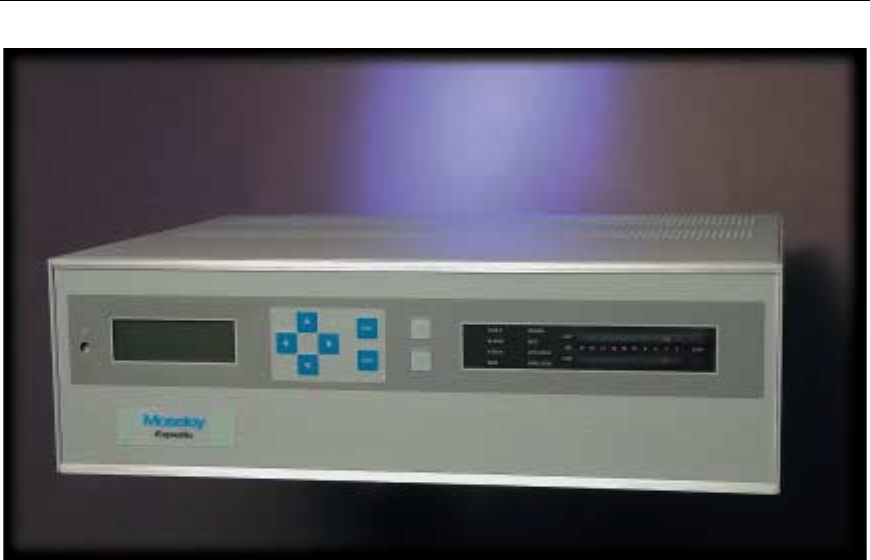
Figure 1: Expedio Modular Open Architecture
System Description 1-2
602-13729-01 Rev B Expedio Digital Electronic News Gathering Radio
1.2 System Features
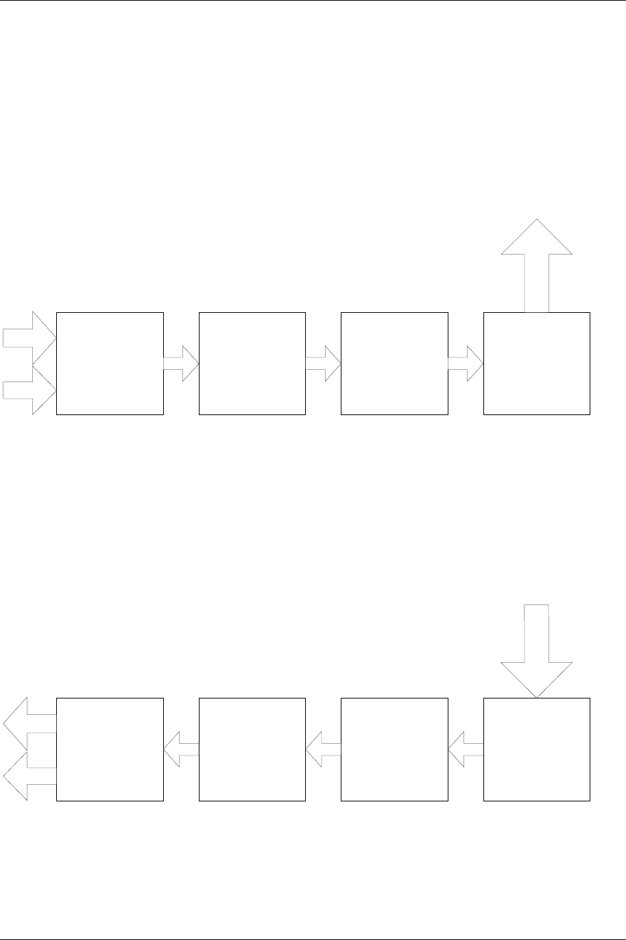
1.2.1 Transmit Chain
The Block diagram below shows the various functional units that make up the
transmitter.
MPEG 2
ENCODER
COFDM
MODULATOR
DVB-T
Double up
Convertor
Power
Amplifier
Video
2 Audio
Channels
RF ouput
to Antenna
Figure 2: Transmit Chain
1.2.2 Receive Chain
The Block diagram below shows the various functional units that make up the
Receiver.
MPEG 2
DECODER
COFDM
DEMODULATOR
DVB-T
UHF Downcnvertor LNA ad
First Downconverto
Video
2 Audio
Channels
Recever
Figure 3: Receive Chain

1-3 System Description
602-13729-01 Rev B Expedio Digital Electronic News Gathering Radio
1.2.3 Video Encoder
Video input is Composite video at 75ohms BNC, with a monitor port available.
There are 2 Audio channels whose input are through the XLR connections.
The data is encoded using advanced MPEG-2 encoding technology. The
compressed data is formatted and transmitted using the DVB-ASI standard. The unit
compresses the incoming video using an adaptive field/frame MPEG-2 Main Profile
@ Main Level algorithm, achieving variable bit rate of 512 Kbps-12 Mbps.
c] The Data Output that is DVB-SPI shall be converted to DVB-ASI with the data to
be 188 byte only, the COFDM modulator will insert the Reed Solomon Encoding
frames.
Standard Compliance
Video Encoding ISO/IEC 13818-2 (MPEG-2), 4:2:0 MP@ML,
and MP@LL
System Multiplexing ISO/IEC 13818-1 (MPEG-2).
Generated Stream Types
Video ES Video Elementary Stream.
Audio ES Packetized Audio Elementary Stream.
Video PES Packetized Video Elementary Stream.
Program Program Stream.
Transport Transport Stream.
Video Encoder
Video Input Format Analog: Composite NTSC (30 fps),
Composite PAL(25 fps)
Video Input Bit Resolution 9 bits.
Preprocessor Programmable 2D (7x6) filter. Temporal and Spatial noise
reduction.
Bit Rates CBR and VBR, 512 Kbps to 12 Mbps.
Bit Rate Resolution 1000 Hz
Variable Frame Rate Programmable frame rate decimation (1 fps through 30/25
fps) support for low bit rate applications.
Programmable Picture Resolution Horizontal: 720, 640, 544, 480, 360, 320, 160
Vertical: 112, 240, 480 (NTSC)
144, 288, 576 (PAL)
Motion Estimation Horizontal: +/-100 H, Vertical: +/-34V.
Same search area in P and B pictures, in both forward and
backward searches.
Half PEL accuracy.
Aspect Ratio Square, 4:3, 16:9
Picture type I, P, B frame processing.
GOP Structure I(M=0), IP(M=1), IPB(M=2), IPBB(M=3)
System Description 1-4
602-13729-01 Rev B Expedio Digital Electronic News Gathering Radio
Audio Input
Audio Input Format Two mono or single analog stereo inputs - Balanced
Output Interfaces
Digital Interface DVB-ASI
1.3 Typical Configurations
1.3.1 Transport Rate
Table 1-1 provides basic data channel capabilities for the Expedio. See (Installation Section) for
more detailed information.
Table 1-1. Expedio Data Channel Configurations
A 8 MHz DVB-T COFDM Payload Data Rate
Modulation Code Bit Rate (Mbit/s @ each Guard Interval
Type Rate 1/32 1/16 1/8 1/4
A 1/2 6.032086 5.854671 5.529412 4.976471
QPSK 2/3 8.042781 7.806228 7.372549 6.635294
2 3/4 9.048128 8.782007 8.294118 7.464706
Bits/Sym 5/6 10.053476 9.757785 9.215686 8.294118
A 7/8 10.556150 10.245675 9.676471 8.708824
A 1/2 12.064171 11.709343 11.058824 9.952941
16-QAM 2/3 16.085561 15.612457 14.745098 13.270588
4 3/4 18.096257 17.564014 16.588235 14.929412
Bits/Sym 5/6 20.106952 19.515571 18.431373 16.588235
A 7/8 21.112299 20.491349 19.352941 17.417647

1-5 System Description
602-13729-01 Rev B Expedio Digital Electronic News Gathering Radio
1.3.2 Standalone Operation
The Expedio may be used as a standalone simplex radio with a internal in the MPEG2 Encoder /
Decoder system or utilize external MPEG2 units and feed DVB-ASI with 188byte format on the
Input and have DVB-ASI out coming out on the Receiver.
1.4 Regulatory Notices
FCC Part 15 Notice
This equipment has been tested and found to comply with the limits for a Class A digital device,
pursuant to part 15 of the FCC Rules. These limits are designed to provide reasonable protection
against harmful interference when the equipment is operated in a commercial environment. This
equipment generates, uses, and can radiate radio frequency energy and, if not installed and used
in accordance with the instruction manual, may cause harmful interference to radio
communications. Operation of this equipment in a residential area is likely to cause harmful
interference, in which case the user will be required to correct the interference at his expense.
Any external data or audio connection to this equipment must use shielded cables.
EC Declaration of Conformity
1.5 System Description
1.5.1 Introduction
The product is a simplex digital radio. The following sections describe the TX system, RX
system, followed by sub-system components. Please reference the accompanying block
diagrams for clarification.
We will follow the typical end-to-end progression of a radio system starting with the TX baseband
inputs, to the COFDM modulator, followed by the upconversion process and the power amplifier.
We then proceed to the RX preamplifier input, the down conversion process, followed by the
COFDM demodulator and baseband outputs.
System Description 1-6
602-13729-01 Rev B Expedio Digital Electronic News Gathering Radio
J2P2
70 MHz
IF O UT
70 MHz
IF IN
TX OUT
1W
1990-2110
MHz
2450-2500
MHz
FRONT
PANEL
CONTROLS
Expedio Transmitter
Starlink/NXE1
Chassis
J2P2
EXCITE
OUT EXCITE
IN
BACK PLANE
PLUG-IN RF AMP
9MHZ
IF
OUT
110-220 VAC
12-48VDC
70 MHZ
CONVERTER
CONTROLLER
79.14286 MHZ
XTAL OSC
LINEAR
POWER AMP
DC
CNVTR
+5V +10V
dc
pwr
cntl telem
NMS
CNTRL
NMS
CARD
POWER
SUPPLY
+5V
+12V
PS
CARD
MPEG2
ENCODER
DVB
ASI
OUT
AUDIO
IN
ANA/
DIG
VIDEO
IN
ANA/
DIG
COFDM
ENCODER
MPEG
VIDEO
DVB
ASI
IN
SPI-
TO-
ASI
EXPEDIO
ENCODER
SIGNAL
INTRFC 480MHZ
CONVERTER
2 GHZ
CONVERTER
SYNTH
550 MHZ
SYNTH
1.51-1.63 GHZ
1.97-2.02 GHZ
CONTROLLER
RF DOUBLE
UP-CONVERTER
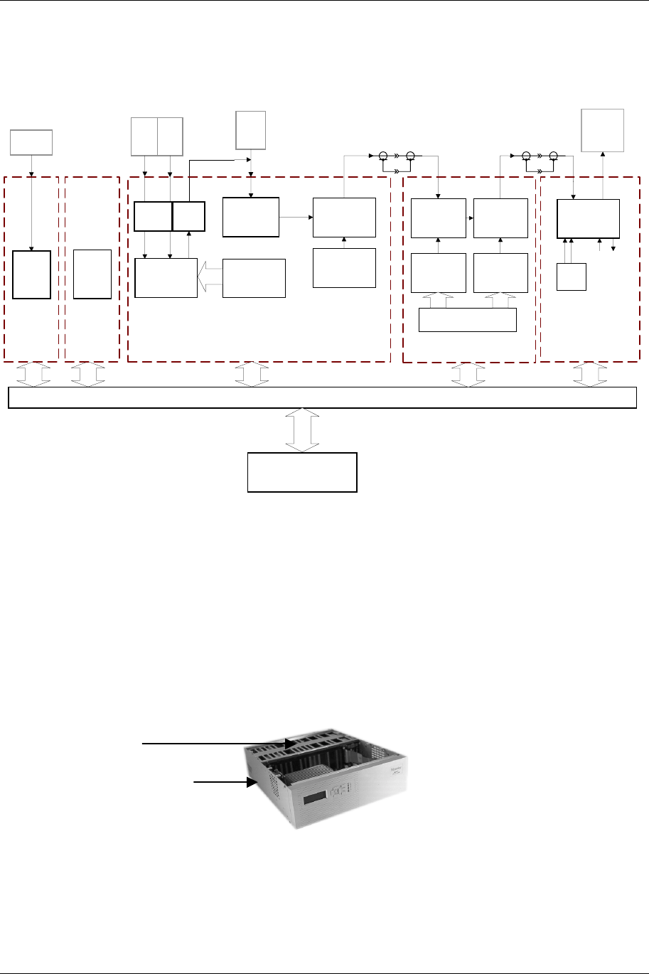
Figure 4: Expedio Transmit System Block Diagram
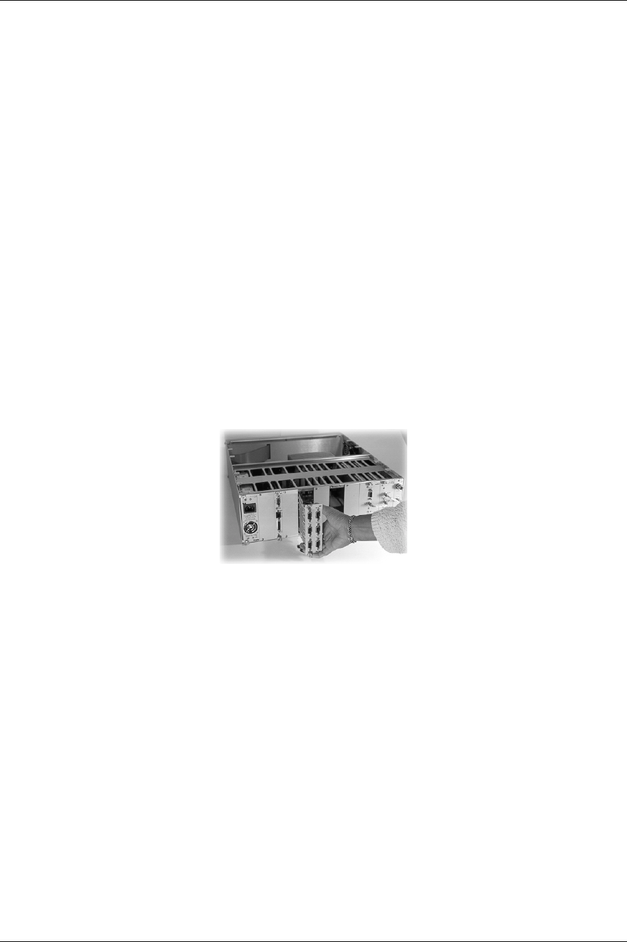
All modules (excluding the Front Panel and Power Amplifier) are interconnected via the
backplane that traverses the entire width of the unit. The backplane contains the various
communication buses as well as the PA (Power Amplifier) control and redundant transfer
circuitry. See Figure 5 below for locations of the Backplane and the Power Amplifier. The power
supply levels and status are monitored on the backplane and the NMS/CPU card processes the
data.
Figure 5: Location of the EXPEDIO Backplane and Power Amplifier
The NMS/CPU card incorporates microprocessor and FPGA logic to configure and monitor the
overall operation of the system via front panel controls, LCD screen menus, status LEDs and the
bar graph display. Module settings are loaded into the installed cards and power-up default
settings are stored in non-volatile memory. LCD screen menu software is uploaded into memory,
Backplane
Digital Radio
1-7 System Description
602-13729-01 Rev B Expedio Digital Electronic News Gathering Radio
providing field upgrade capability. A Windows-based PC interface is available for connection at
the rear panel DATA port.
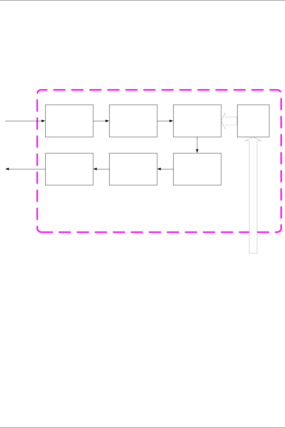
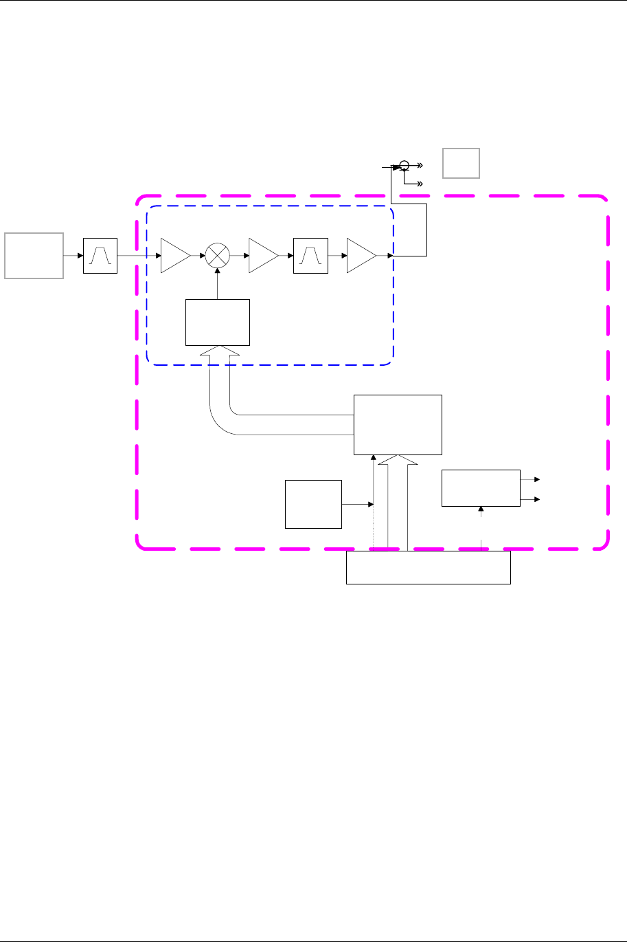
1.5.2 COFDM Modulator / IF Upconverter
ASI to SPI
Convertor
DVB-ASI
I/P
FEC
Reed Solomon
Interleaver
Viterbi
Mapping
Modulation
Inverse
FFT
2K
DAC
BP Filter [9MHz]
&
Gain control
9MHz
IF
Control
Lines
Control from Hitachi
COFDM MODULATOR
Figure 6: COFDM Block Diagram
The COFDM (Coded Orthogonal Frequency Division Multiplex) Modulator is the transmit portion
of the card. The unit also houses the IF Upconverter.
The COFDM Modulator accepts the aggregate data stream via the DVB-ASI Port on the rear
panel (see Figure 6 above).
The modulated signal is provided via low IF of 9MHz which is converted ---------------
System Description 1-8
602-13729-01 Rev B Expedio Digital Electronic News Gathering Radio
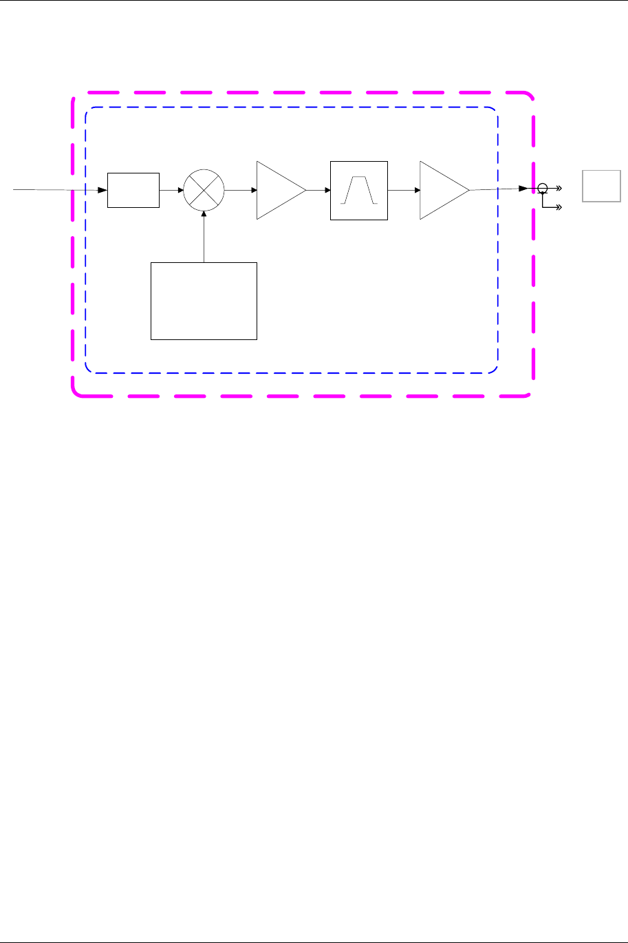
IF UPCONVERTOR
79MHZ
XTAL
OSCILLATOR IF Upconvertor
70MHz SAW
Pad
8dB
9MHz
I/P
70MHz
IF OUT
Figure 7: IF Upconverter Block Diagram
The resultant carrier is translated up to 70 MHz by the IF Upconverter. This is accomplished by a
standard mixing of the carrier with a phase-locked LO. A 70 MHz SAW filter provides an
exceptional, spectrally clean output signal.
1-9 System Description
602-13729-01 Rev B Expedio Digital Electronic News Gathering Radio
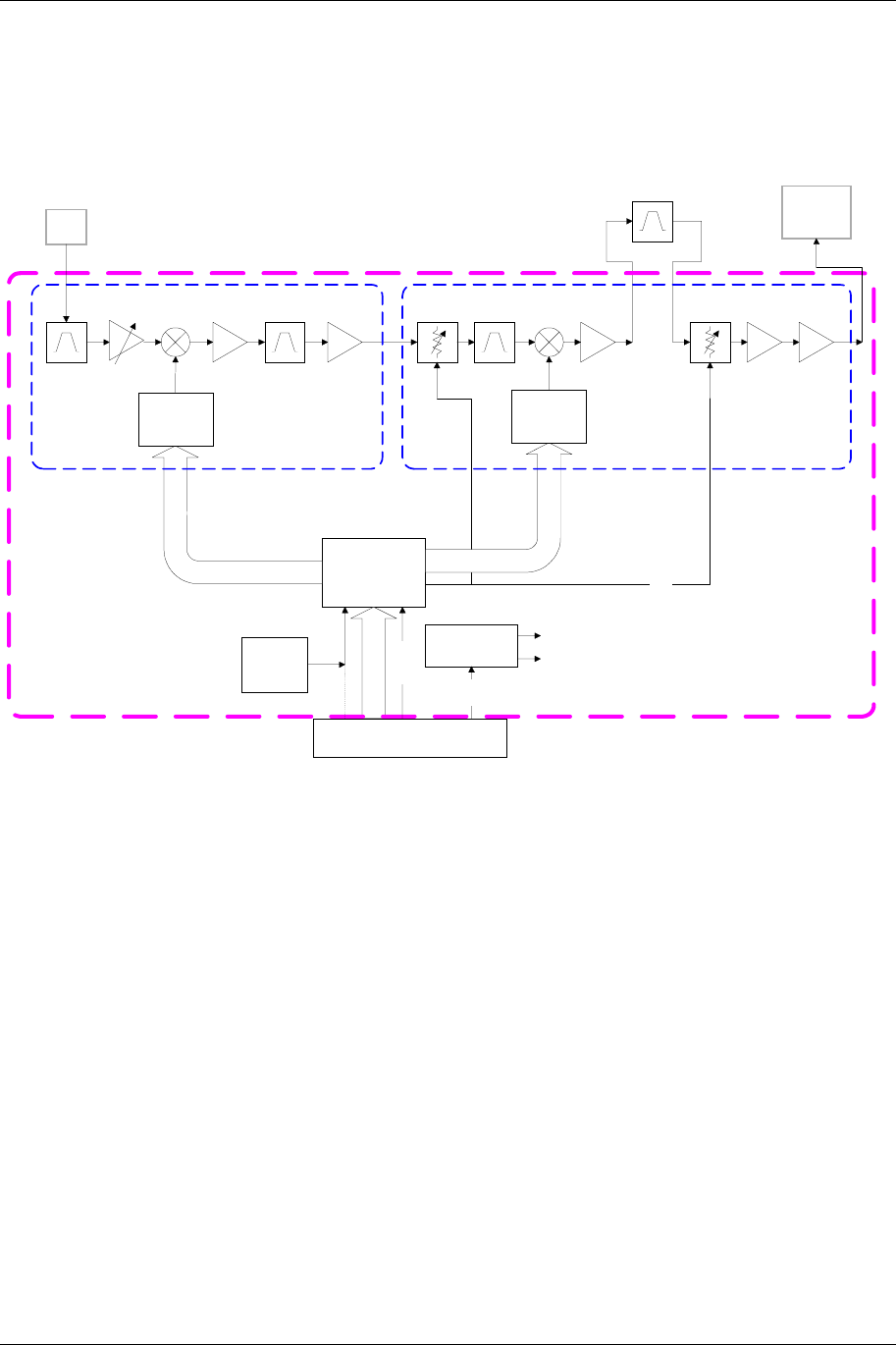
1.5.3 RF Double Upconverter
Expedio Double Up-Converter
MICROCONTLR
EXCITER OUT
+5 dBm
1990-2110 MHz
2450-2500 MHz
REF OSC
I6 M HZ
INTERNAL
DC
CONVERTERS
BACKPLANE INTERFACE
70 MHz
RF IN
-10dBm
I2C
+12V
+5 Vdc/
200 mA
+10 Vdc/
250 mA
ALC
PA telem
SYNTH
550 MHZ 480 MHZ
CONVERTER
70MHZ/
9MHZ
480MHZ/
25MHZ
AGC 45dB 13dB 14dB
SYNTH
1.51-1.63 GHZ
1.97-2.02 GHZ
2-2.5 GHZ
CONVERTER
480MHZ/
25MHZ
0-15dB 0-5dB19dB 17dB 12dB
Figure 8: RF Upconverter Block Diagram
The IF output carrier of the IF Upconverter daughter card is fed to the transmit portion of the RF
Module via an external (rear panel) semi-rigid SMA cable. This module performs the necessary
upconversion to the RF carrier. There is an on-board CPU for independent control of the critical
RF parameters of the system.
Since this is a linear RF processing chain, an automatic leveling control loop (ALC) is
implemented here to maintain maximum available power output (and therefore maximum system
gain). The ALC monitors the PA forward power (FWD) output sample, and controls the up
converter gain per an algorithm programmed in the CPU. The ALC also controls the power-up
RF conditions of the transmitter output.
1.5.4 Power Amplifier (PA)
The Power Amplifier (PA) is a separate module that is mounted to a heat sink and is fan-cooled
for reliable operation. The PA is a design for maximum linearity in an amplitude modulation-based
system.
System Description 1-10
602-13729-01 Rev B Expedio Digital Electronic News Gathering Radio
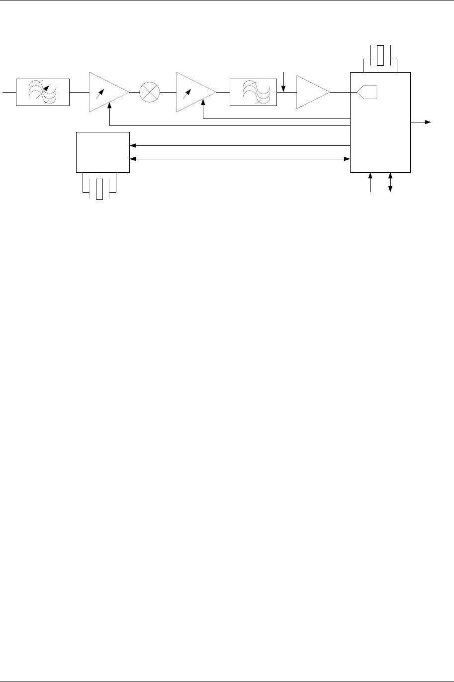
1.5.5 RF First Downconverter
Single Down-Converter
MICROCONTLR
REF OSC
I6 MHZ
INTERNAL
DC
CONVERTERS
BACKPLANE INTERFACE
I2C
+12V
+5 Vdc/
200 mA
+10 Vdc/
250 mA
P2
RF input
-40 to -90 dBm
1990-2110 MHz
2450-2500 MHz
1: 2050 MHz/
120 MHz
2: 2475 MHz/
50MHz
480 MHz
UHF
OUT
SYNTH
1.51-1.63 GHZ
1.97-2.02 GHZ
2-2.5 GHZ
CONVERTER
480MHZ/
25MHZ
13dB 14dB
17dB
Figure 9: RF Downconverter Block Diagram
The receiver handles the traditional RF to UHF conversion from the carrier to 480 MHz.
Considerations are given to image rejection, intermodulation performance, dynamic range, agility,
and survivability. A separate AGC loop was assigned to the RF front end to prevent
intermodulation and saturation problems associated with reception of high level undesirable
interfering RF signals resulting from RF bandwidth that is much wider than the IF bandwidth.
1-11 System Description
602-13729-01 Rev B Expedio Digital Electronic News Gathering Radio
1.5.6 COFDM Demodulator & UHF Downconverter
PLL
CX22702
ADC
SAW(s)
36.16 MHz
SDI SCI
MPEG
TS
Delayed AGC
SCO
SDO
20.48 MHz
Figure 10: UHF Downconverter Block Diagram
This Module receives a UHF COFDM signal and demodulates them using the DVB-T
specifications, and outputs an MPEG2 Transport stream (TTL compatible) for use to decode the
Video stream out of that.

System Description 1-12
602-13729-01 Rev B Expedio Digital Electronic News Gathering Radio
This page is intentionally blank.
2-1 Status Monitor Program
602-13729-01 Rev B Expedio Digital Electronic News Gathering Radio
2 Status Monitor Program
2.1 Description
The Expedio Status Monitor Program is a application that allows you to monitor the status of the
Expedio unit from any Windows-based PC.
2.2 Software Installation
1. Power OFF the Expedio unit and the PC.
2. Connect the serial cable (RS-232) from the PC to the Expedio unit.
3. Turn the Expedio power ON, and then turn the PC power ON.
4. Run the Expedio Self-Extracting Executable from the Expedio CD.
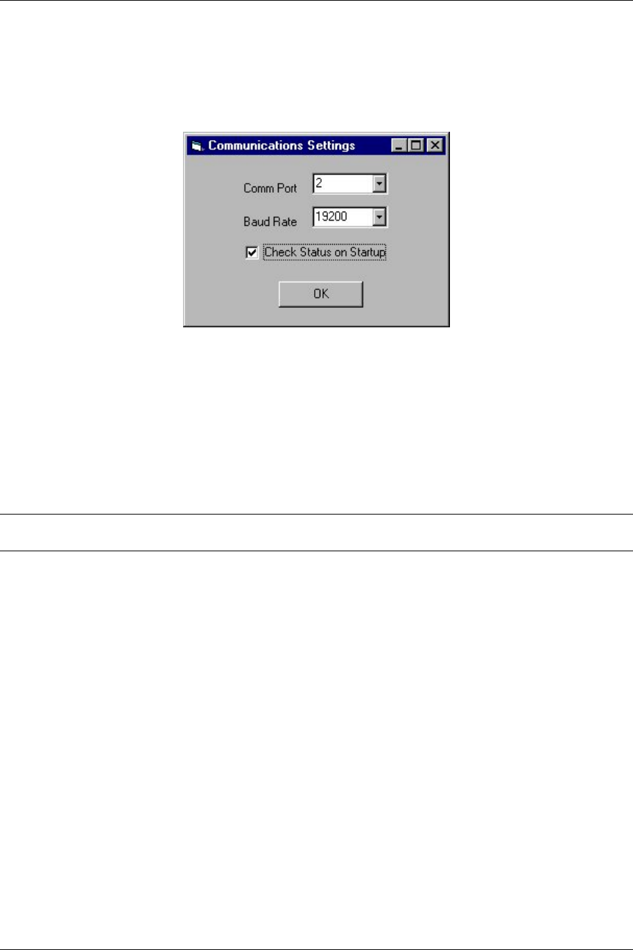
To launch Expedio, double click the Expedio icon on your PC desktop. The first time you run the
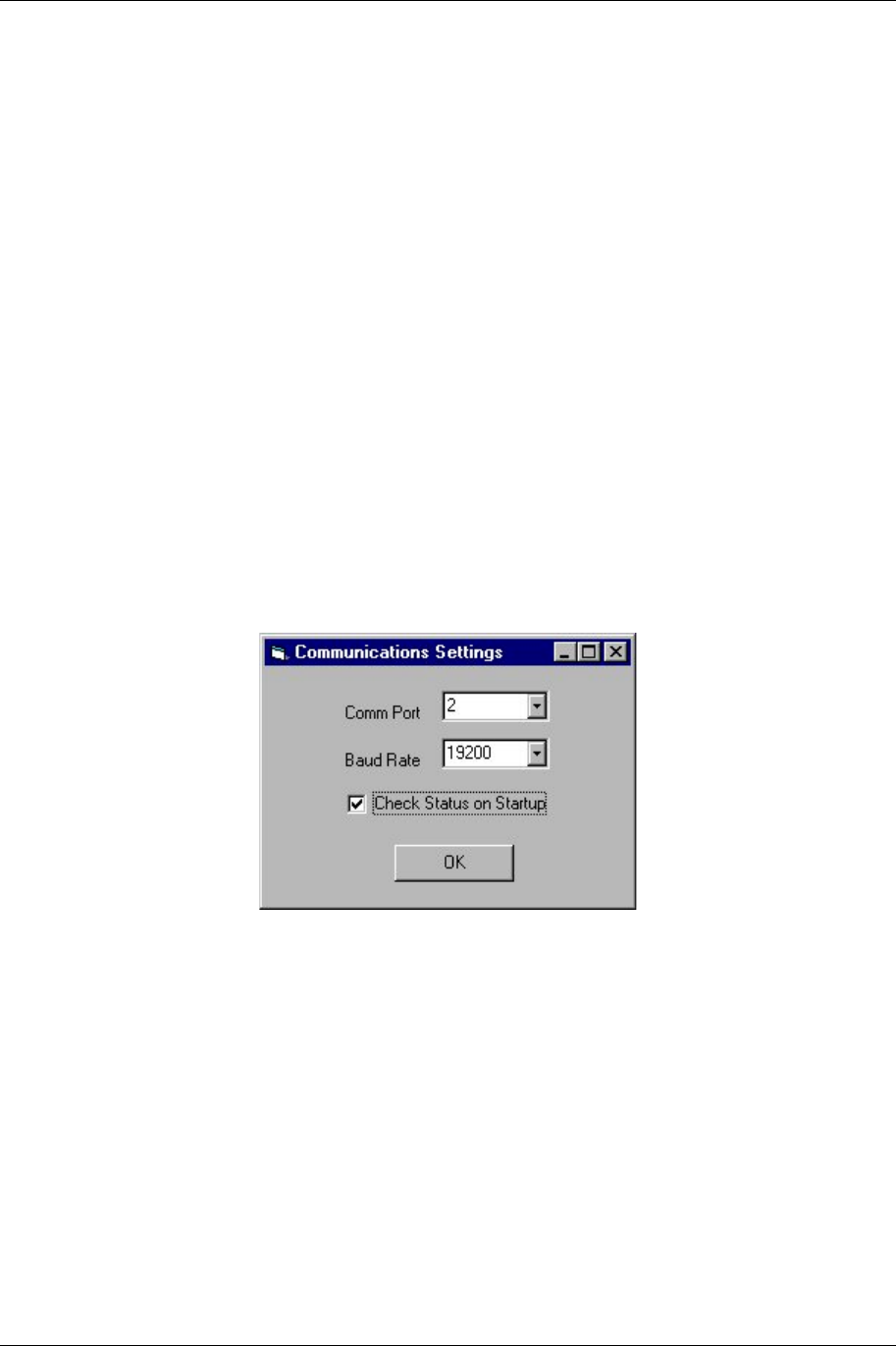
Expedio Status Monitor Program, the Communications Settings window appears.
To begin communicating with the Expedio unit, the Communications Settings must be properly
configured.
• In the Comm Port field, select the Comm Port to which the Serial Cable to the Expedio
unit is connected.
• In the Baud Rate field, select the Baud Rate as configured on the Expedio unit. For more
information about configuring the baud rate, see the section of this manual regarding
hardware setup.
• Optional: Check Status on Startup automatically causes the Status Monitor Program to
begin monitoring the Expedio unit each time the program is launched.
Click OK to accept these communication settings.
Status Monitor Program 2-2
602-13729-01 Rev B Expedio Digital Electronic News Gathering Radio
2.3 Using the Status Monitor Program
2.3.1 Start/Stop Status Check
Status Checking can be started in either of two methods:
• Automatically: Select Check Status on Startup in the Communication Settings. With
this selection, every time program is launched, it first reads the current settings from the
Expedio unit, then starts status checking.
• Manually, by
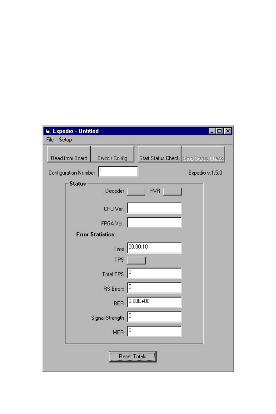
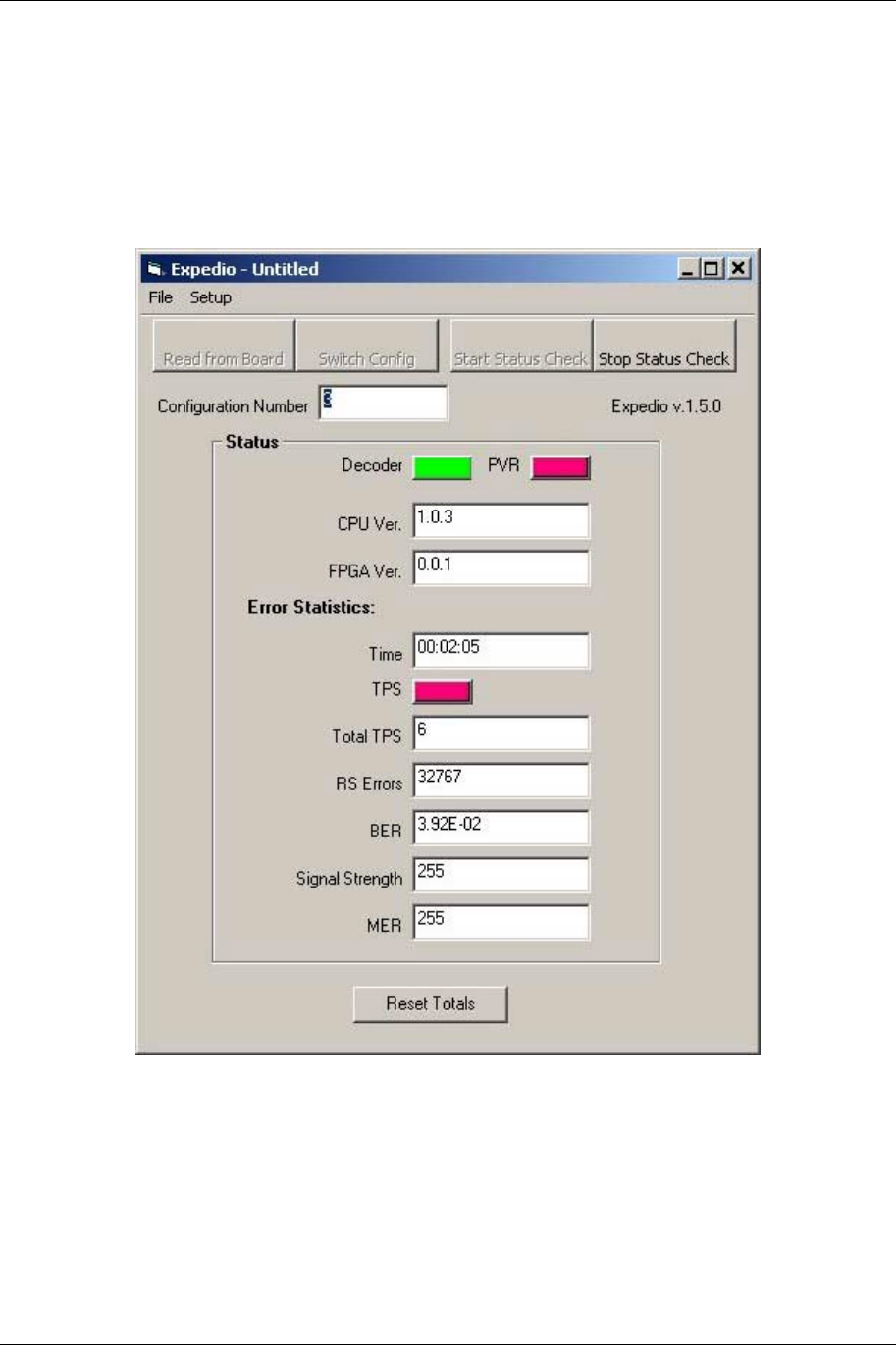
Upon launching the Status Monitor Program, the main screen appears, as pictured below. (Note
that in the example below, the Status Monitor is not currently communicating with the Expedio
unit, thus there are no or zero values in some of the fields.)
To begin monitoring the status of the Expedio unit, click Start Status Check. A progress
bar appears, indicating that the PC is attempting to connect to the Expedio unit. The amount of
2-3 Status Monitor Program
602-13729-01 Rev B Expedio Digital Electronic News Gathering Radio
time required to make a connection and retrieve data depends upon factors such as the speed of
the connection and the quantity of data.
Once the connection is made, Expedio continues to send data until you click Stop Status
Check.
The Status area of the screen displays information that received from the Expedio unit. During
monitoring, the Error Statistics continue to update anytime a change occurs on the Expedio unit
itself.
The communication link between the PC and the Expedio unit processes only one command at a
time; therefore, other features that involve communicating with the Expedio unit cannot be
performed while Status Checking is started.
2.3.2 Expedio Unit Data
The upper portion of the Status area displays information about the unit. Except for PVR, this
information is static, that is, it will not change while you are monitoring the unit.

Status Monitor Program 2-4
602-13729-01 Rev B Expedio Digital Electronic News Gathering Radio
Decoder Indicates the operating mode of the unit:
GREEN = decoder
RED = encoder
NO COLOR (background) = Unknown
PVR Indicates the PVR status:
GREEN = Valid
RED = Invalid
NO COLOR (background) = Unknown, only occurs before status is
obtained or during reset.
CPU Version The version of firmware.
FPGA Version The version number of the unit’s operating system.
Updates to the CPU Version or the FPGA Version can only be performed under the guidance of
Moseley Technical Support.
Read from Board returns status information (excluding PVR) without starting Status Check.
2.3.3 Error Statistics
The lower portion of the Status area displays Error Statistics. This is live data that the system
updates as changes occur on the unit. The represented values include:
• Time Gives the elapsed time since Status Checking started.
• TPS GREEN = Valid
RED = Invalid
NO COLOR (background) = Unknown
• Total TPS Number of invalid TPS checks since Status Checking started.
• RS Errors
• BER
• Signal Strength
• MER
The Reset Totals button returns a field values to zero. The system then updates the fields with
the current values.
2-5 Status Monitor Program
602-13729-01 Rev B Expedio Digital Electronic News Gathering Radio
2.4 Communications Settings
To begin communicating with the Expedio unit, the Communications Settings must be properly
configured.
• In the Comm Port field, select the Comm Port to which the Serial Cable to the Expedio
unit is connected.
• In the Baud Rate field, select the Baud Rate as configured on the Expedio unit. For more
information about configuring the baud rate, see the section of this manual regarding
hardware setup.
• Optional: Check Status on Startup automatically causes the Status Monitor Program to
begin monitoring the Expedio unit each time the program is launched.
Click OK to accept these communication settings.
Note: The Communications Settings cannot be changed while Status Checking is started. To
change Communications Setting, ensure that Status Checking is stopped.
2.5 MPEG/COFDM Configurations
The behavior of the Expedio unit depends on its MPEG Configuration. The appropriate
configuration depends upon the system itself, so Expedio comes equipped with three preinstalled
configurations to choose from. Any of these can serve as the default configuration, which is the
configuration that the Expedio will run whenever it is started or reset.
With administrative privileges, it is possible to modify the three preinstalled configurations. This
can only be done with the assistance of Moseley Technical Support personnel.
2.5.1 Switching Configurations
1. In the Configuration Number field, enter the number of the desired configuration. For a
complete description of the factory installed configurations, see Default MPEG
Configuration Settings.
2. Click
Switch Config.
3. A confirmation screen appears. If you are sure you want to change configurations, click
OK.

Status Monitor Program 2-6
602-13729-01 Rev B Expedio Digital Electronic News Gathering Radio
The progress bar appears, indicating that the change is in process.
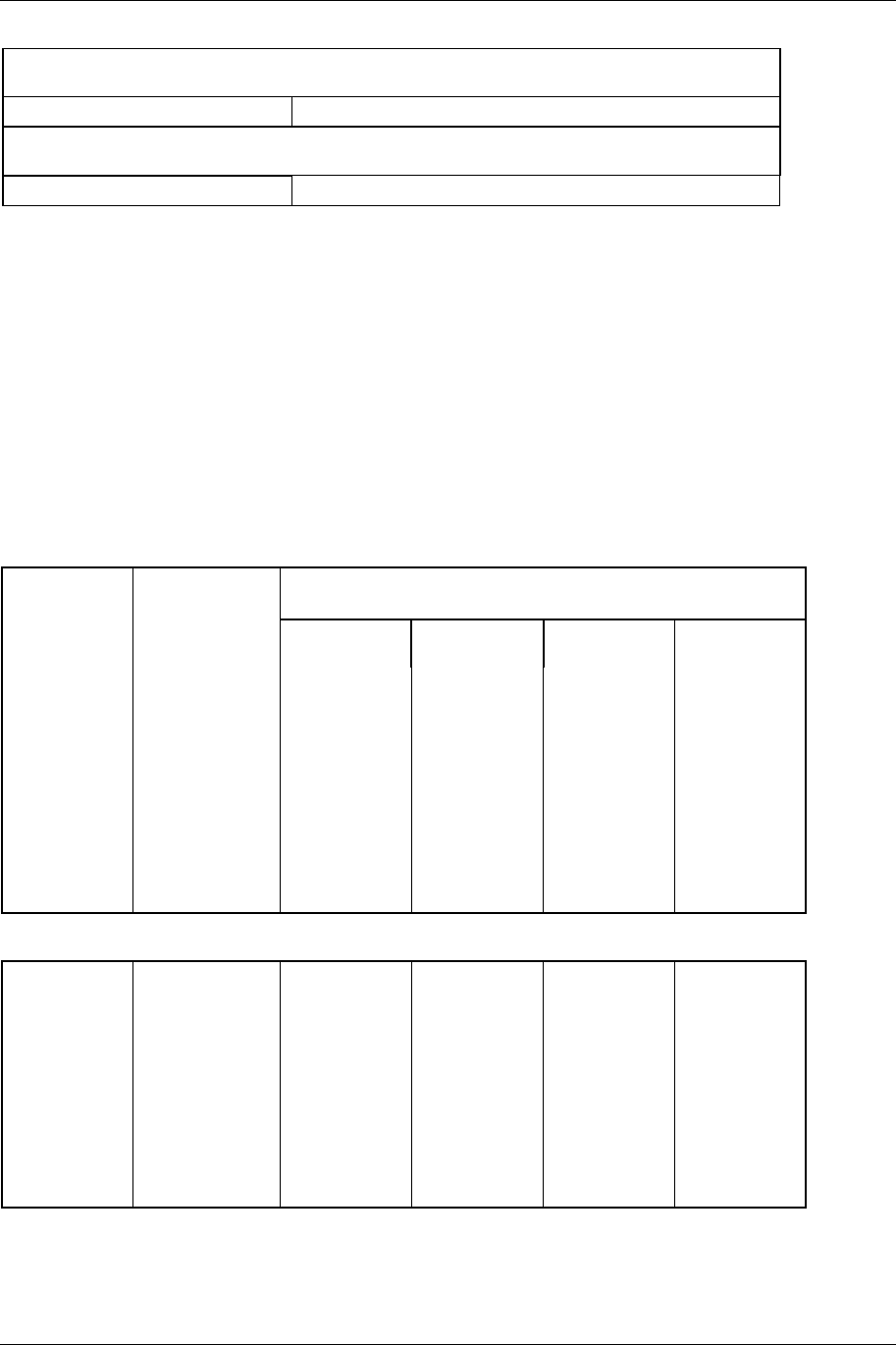
2.5.2 Default MPEG/COFDM Configuration Settings
The following table describes the factory-installed configurations.
Configuration Number
MPEG Settings 1 2 3
Video Rate (Mbits)
Video Resolution
Audio Rate
Compression
Aspect Ratio
Audio Format
GOP
GOP N
Copy
Video PID
Audio PID
COFDM Settings 1 2 3
Modulation
Code Rate
Guard Interval

3-1 Installation
602-13729-01 Rev B Expedio Digital Electronic News Gathering Radio
3 Installation
3.1 Unpacking
The following is a list of all included items.
Description Quantity
Digital Radio (3RU chassis) 1
Rack Ears (with hardware) 2
Power Cord (IEC 3 conductor for AC, 2-wire for DC) 2
Manual (or Soft copy on a CD) 1
Test Data Sheet (customer documentation) 1
Be sure to retain the original boxes and packing material in case of return shipping. Inspect all
items for damage and/or loose parts. Contact the shipping company immediately if anything
appears damaged. If any of the listed parts are missing, call the distributor or the factory
immediately to resolve the problem.
3.2 Notices
3.2.1 CAUTION
DO NOT OPERATE UNITS WITHOUT AN ANTENNA, ATTENUATOR, OR LOAD CONNECTED
TO THE ANTENNA PORT. DAMAGE MAY OCCUR TO THE TRANSMITTER DUE TO
EXCESSIVE REFLECTED RF ENERGY.
ALWAYS ATTENUATE THE SIGNAL INTO THE RECEIVER ANTENNA PORT TO LESS THAN
3000 MICROVOLTS. THIS WILL PREVENT OVERLOAD AND POSSIBLE DAMAGE TO THE
RECEIVER MODULE
3.2.2 WARNING
HIGH VOLTAGE IS PRESENT INSIDE THE POWER SUPPLY MODULE WHEN THE UNIT IS
PLUGGED IN. REMOVAL OF THE POWER SUPPLY CAGE WILL EXPOSE THIS POTENTIAL
TO SERVICE PERSONNEL. TO PREVENT ELECTRICAL SHOCK, UNPLUG THE POWER
CABLE BEFORE SERVICING. QUALIFIED PERSONNEL SHOULD SERVICE UNIT ONLY.
Installation 3-2
602-13729-01 Rev B Expedio Digital Electronic News Gathering Radio
3.2.3 PRE-INSTALLATION NOTES
Always pre-test the system on the bench in its intended configuration prior to installation at a
remote site. Avoid cable interconnection length in excess of 1 meter in strong RF environments.
We highly recommend installation of lightning protectors to prevent line surges from damaging
expensive components.
3.2.4 Information to Users
Changes or Modifications expressly not approved by Moseley Associates as this would render
the compliance of the equipment to be invalid. This would also render the user to operate the
equipment.
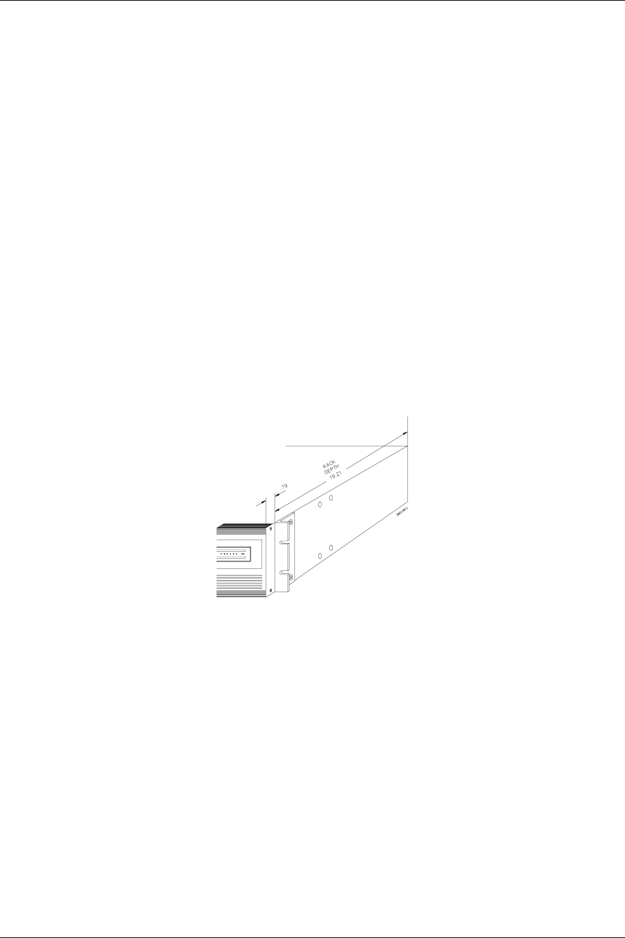
3.3 Rack Mount
The product is normally rack-mounted in a standard 19” cabinet. Leave space clear above (or
below) the unit for proper air ventilation of the card cage. The rack ears are typically mounted as
shown in Figure 11. Other mounting methods are possible by changing the orientation of the rack
ears.
Figure 11: Expedio Typical Rack Mount Bracket Installation
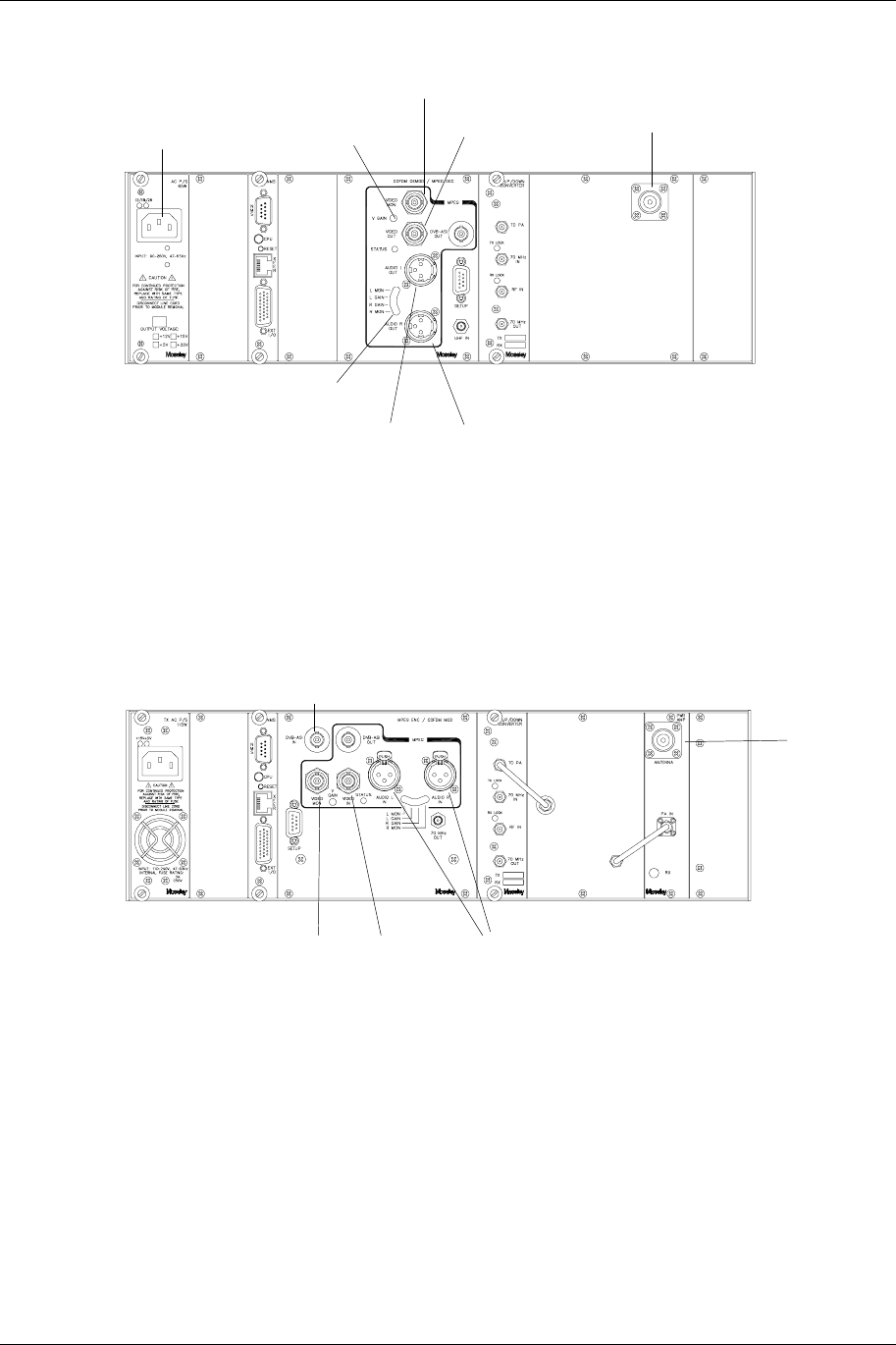
3.4 Rear Panel Connections & Indicators
Please refer to the Figure 12 and 13 for a pictorial of a typical product rear panel (internal
duplexer). Following is a descriptive text of the connections and LED indicators.
3-3 Installation
602-13729-01 Rev B Expedio Digital Electronic News Gathering Radio
AC Supply
or DC as
requested Video Level Control
Video Monitor
Video O/P
From Rx Antenna
RF Connector
Audio Level Control
Audio Left Audio Right - identify Pin
Connect?
Figure 12: Expedio-20 Rear Panel Receiver Connections
Connect to this port if using
external MPEG2 Encoder
Video Monitor Complete
Video I/P Audio
Tx Antenna
RF Connector
Figure 13: Expedio-20 Rear Panel Transmitter Connections

Installation 3-4
602-13729-01 Rev B Expedio Digital Electronic News Gathering Radio
Power Supply:
Inputs: AC: Universal Input, 100-240V, 50/60 Hz; IEC 3
conductor
DC: 24v/48v (Isolated Input); 2 pin socket (custom)
Status LED: +12V: Green LED indicates +12 volt supply OK
+5V: Green LED indicates +5 volt supply OK
NMS Card
I/O Port: RS232 PC access; 9 pin D-sub (female)
Reset Switch: Activates hard system reset
Status LED: Green LED Indicates CPU OK
Converter Module
RF
Connectors: TO PA: SMA (female), Upconverter output to be applied
to linear Power Amplifier module (internal to
radio).
70 MHz
IN: SMA (female), Modulated IF input from QAM
Modulator.
RF IN: SMA (female), Receiver input.
70 MHz
OUT: SMA (female); Downconverter output to
Modulator input
Status LED: RX
LOCK: GREEN indicates RX AFC LOCK
Flashing RED indicates LOSS OF RX LOCK
RX
LOCK: GREEN indicates RX AFC LOCK and strong RX
signal
YELLOW indicates RX AFC LOCK and nominal
RX signal
RED (continuous) indicates RX AFC LOCK and
weak RX signal
RED (flashing) indicates LOSS OF RX LOCK

3-5 Installation
602-13729-01 Rev B Expedio Digital Electronic News Gathering Radio
RF I/O Panel
RF
Connectors: ANTENNA: Type N (female), RF cabling from internal PA
module.
PA IN: SMA (female), RF cabling to internal PA
module.
RX OUT: SMA (female), RF cabling from internal
duplexer.
SEMI-RIGID CABLE
Ensure that the cables are secure and tightly attached.
Check for any damage (kinks or breaks in the copper sheath).
3.5 Power Requirements
3.5.1 Power Supply Card Slot Details
The leftmost slot in the Expedio card cage (as viewed from the rear of the unit) is designated as
the “PRIMARY A” power supply. The main bus voltages (+5 and +/-12) are summed in the
backplane and provide the supply the plug-in modules.
NOTE: The front panel LCD screen displays the system supply voltages and the
nomenclature follows the physical location of the power supply modules.
3.5.2 AC Line Voltage
The Expedio uses a high reliability, universal input switching power supply capable of operation
within an input range of:
100 - 240 VAC; 50/60 Hz
The power supply module is removable from the unit and a perforated cage protects service
personnel from high voltage. The power supply is fan cooled due to high power consumption by
the PA.
CAUTION
High voltage is present when the unit is plugged in. To prevent electrical shock, unplug the power
cable before servicing. Qualified personnel should service power supply module only.

Installation 3-6
602-13729-01 Rev B Expedio Digital Electronic News Gathering Radio
3.5.3 DC Input Option
An optional DC input power supply is available for the EXPEDIO; using high reliability, DC-DC
converter(s) capable of operation within the following input ranges (dependent upon nominal input
rating):
Nominal DC Input Operating Input Range
24 Volt: 20 – 28 VDC
48 Volt: 32 – 64 VDC
The DC input is isolated from chassis ground and can be operated in a positive or negative
ground configuration. The power supply module is removable from the unit and no high voltages
are accessible.
3.5.4 Fusing
For AC modules, the main input fuse is located on the switching power supply mounted to the
carrier PC board and the protective cage may be removed for access to the fuse.
For DC modules, all fusing is located on the carrier PC board.
Always replace any fuse with same type and rating. Other fuses are present on the board, and
are designed for output fail-safe protection of the system. All output fuse values are printed on
the backside of the PC board to aid in replacement.
NOTE: If a fuse does blow in operation, investigate the possible cause of the failure prior to
replacing the fuse, as there is adequate built-in protection margin.
3.6 Data Interface
DVB ASI is the data interfaces into the transmitter modulator.
3.7 Site Installation
The installation of the EXPEDIO involves several considerations. A proper installation is usually
preceded by a pre-installation site survey of the facilities. The purpose of this survey is to
familiarize the customer with the basic requirements needed for the installation to go smoothly.
The following are some considerations to be addressed.
Before taking the product to the installation site verify that the interface connections are
compatible with the equipment to be connected. Also, locate the information provided by the path
analysis that should have been performed before ordering the equipment. At the installation site,
particular care should be taken in locating the product in an area where it is protected from the
weather and as close to the antenna as possible. Locate the power source and verify that it is
suitable for proper installation.
Only qualified technical personnel should perform the installations.

3-7 Installation
602-13729-01 Rev B Expedio Digital Electronic News Gathering Radio
3.8 Antenna/Feed System
3.8.1 Antenna Installation
For compliance with FCC RF Exposure requirements the following has to be adhered to:
1. All antenna installation and servicing is to be performed by qualified technical personnel
only. When servicing the antenna, or working at distances closer than those noted below,
ensure the transmitter has be disabled.
2. Typically, the antenna connected to the transmitter is a directional (high gain) antenna,
fixed-mounted on the side or top of a building, or on a tower. Depending upon the
application and the gain of the antenna, the total composite power could exceed 20 to 61
watts EIRP. The antenna location should be such that only qualified technical personnel
can access it, and that under normal operating conditions the antenna separation from
the user is required to be located at the distance of 3.5meters or more.
3. 15.21 Information to user. – The users manual or instruction manual for an intentional or
unintentional radiator shall caution the user that changes or modifications not expressly
approved by the party responsible for compliance could void the user’s authority to
operate the equipment.
EIRP at the antenna is calculated as follows: -
Transmit power – Cable loss + Antenna Gain = EIRP
E.g.
+31.1dBm – 6dB(for 100m LDF5-50A) +36dBi = 61.1dBmi

Installation 3-8
602-13729-01 Rev B Expedio Digital Electronic News Gathering Radio
This page is intentionally blank.
4-1 Front Panel Operation
602-13729-01 Rev B Expedio Digital Electronic News Gathering Radio
4 Front Panel Operation
4.1 Introduction
This section describes the front panel operation of the EXPEDIO digital radio/modem. This
includes:
• LCD display (including all screen menus)
• Cursor and screen control buttons
• LED status indicators
4.2 Front Panel Operation
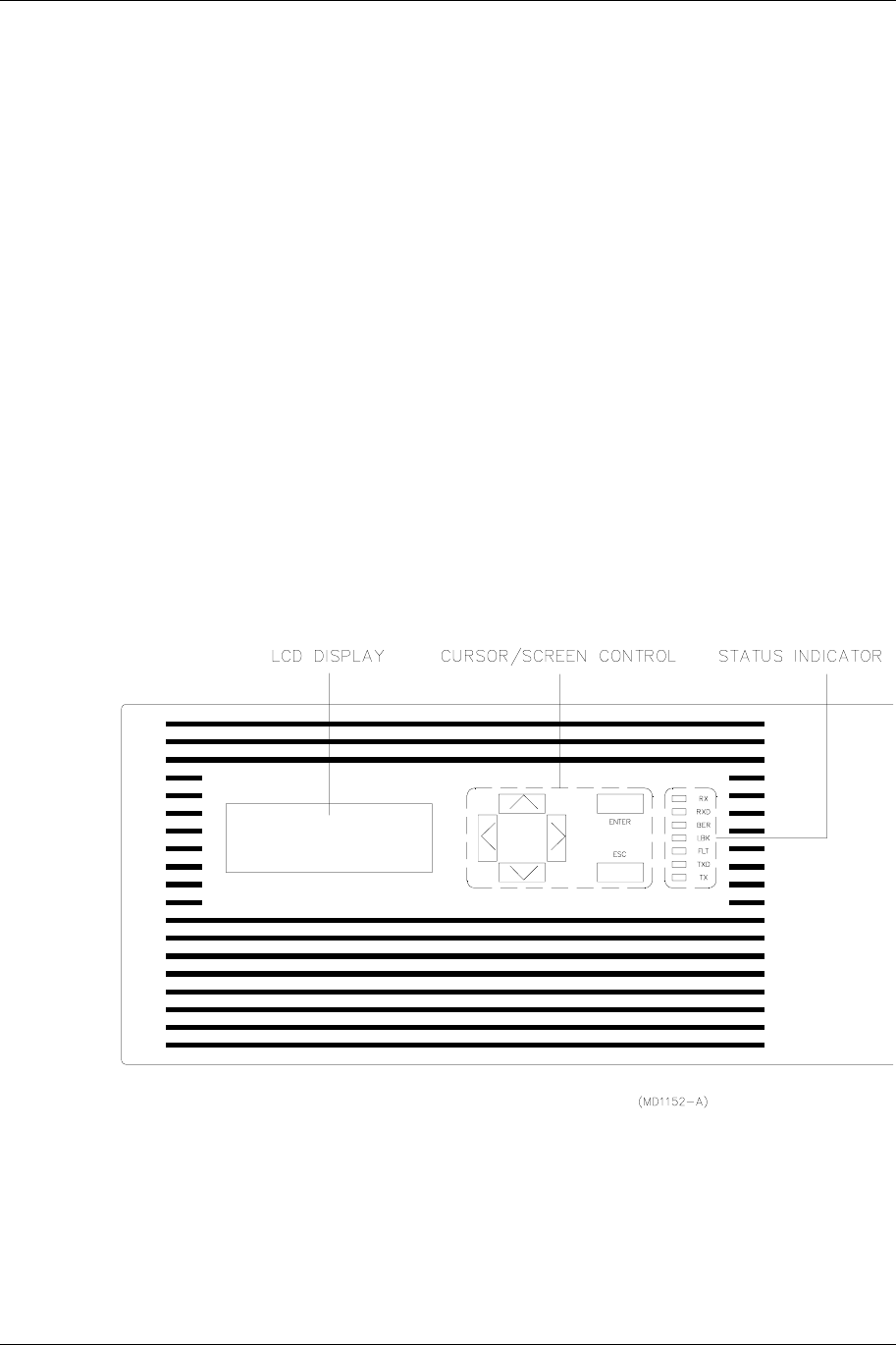
A picture of the EXPEDIO front panel is depicted in Figure 14 below.
Figure 14: EXPEDIO Front Panel
4.2.1 LCD Display
The Liquid Crystal Display (LCD) on the EXPEDIO front panel is the primary user interface and
provides status, control, configuration, and calibration functionality. The menu navigation and
various screens are explained in detail later in this section.
Front Panel Operation 4-2
602-13729-01 Rev B Expedio Digital Electronic News Gathering Radio
Backlight:
An automatic backlight is built-in to the LCD for better clarity under low-light conditions. This
backlight is enabled on power-up and will automatically turn off if there is no button activity by the
user. The backlight will automatically turn on as soon as any button is pressed.
Contrast Adjustment:
Internal adjustment on board (in back of front panel button PCB).
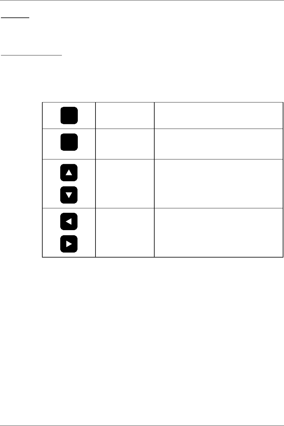
4.2.2 Cursor and Screen Control Buttons
The buttons on the EXPEDIO front panel are used for LCD screen interface and control functions:
ENT
<ENTER> Used to accept an entry (such as a value,
a condition, or a menu choice).
ESC
<ESC> Used to “back up” a level in the menu
structure without saving any current
changes.
<UP>,<DOWN> Used in most cases to move between the
menu items. If there is another menu in
the sequence when the bottom of a menu
is reached, the display will automatically
scroll to that menu.
<LEFT>,<RIGHT> Used to select between conditions (such
as ON/OFF, ENABLED/DISABLED,
LOW/HIGH, etc.) as well as to increase or
decrease numerical values.

4-3 Front Panel Operation
602-13729-01 Rev B Expedio Digital Electronic News Gathering Radio
4.2.3 LED Status Indicators
Table 3-1. LED Status Indicator Functions
LED Name Function
RX Receiver Green indicates that the receiver is enabled, the
synthesizer is phase-locked, and a signal is
being received.
RXD Receive Data Green indicates that valid data is being received.
BER Bit Error Rate Flashes red for each data error detected.
FLT Fault General fault light (red). Consult the STATUS
menus for out of tolerance conditions.
LBK Loopback Red indicates analog or digital loopback is
enabled.
TXD Transmit Data Green indicates the modem clock is phase-
locked and data is being sent.
TX Transmitter Green indicates the transmitter is radiating, and
the RF output (forward power) is above the
factory-set threshold.
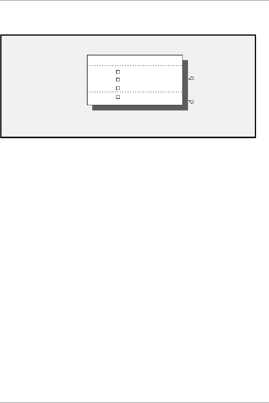
4.2.4 Screen Menu Structure
Figures 3-2a, b and c, located on pages 3-7, 3-8, 3-9 and 3-10, show the tree structure of the
screen menu system. The figures group the screens into functional sets. There may be minor
differences in the purchased unit, due to software enhancements and revisions. The current
software revision may be noted in the SYSTEM sub-menu (under INFO).
In general, <ENTER> will take you to the next screen from a menu choice, <UP> or <DOWN> will
scroll through screens within a menu choice, and <ESC> will take you back up one menu level.
Certain configuration screens have exceptions to this rule, and are noted later in this section.
CAUTION
DO NOT change any settings in the CONFIGURE or CALIBRATE screens. The
security lock-out features of the software may not be fully implemented, and
changing a setting will most likely render the system non-operational!
Front Panel Operation 4-4
602-13729-01 Rev B Expedio Digital Electronic News Gathering Radio
4.3 Main Menu
METER
RADIO
EXP TX MAIN MENU
SYSTEM
ALARMS/FAULTS
Scroll
The main menu appears on system boot-up and is the starting point for all screen navigation.
Unlike most other screens in the software, the main menu scrolls up or down, one line item at a
time.
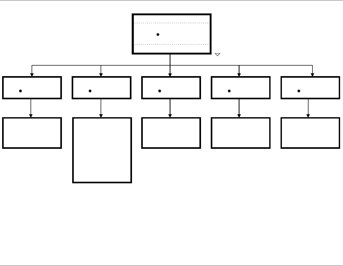
4.3.1 Radio Launch
To access the Radio Launch controls, from the Main Menu click RADIO. The Radio Launch
screen allows the user to quickly get to a particular screen within a functional grouping in the unit.
The logic is slightly different than other screens.
Figure 15 below provides a “Radio Launch Screen Navigation Guide” to assist the user in locating
the desired Radio screen.
4-5 Front Panel Operation
602-13729-01 Rev B Expedio Digital Electronic News Gathering Radio
STATUS
Radio Launch
MOD STATUS
Radio Launch
TX CONFIGURE
Radio Launch
MOD CONFIGURE
Radio Launch
TX CONTROL
Radio Launch
TX
Freq
Xmtr
Fwd
Rev
PA Cur
Temp
Synth
AFC
LO
Xctr
Radio Tx Status
Config.
Board
CPU Users
FPGA Ver
Radio Mod Status
METER
RADIO
EXP TX MAIN MENU
SYSTEM
ALARMS/FAULTS
Scroll
TX Radiate AUTO
OFF
ON
Radio TX Control
Freq. ##.#### MHz
Radio TX ConfigEXP Configure
Config. Default
User1
User2
User3
Figure 15: Radio Launch Screen Navigation Guide

Front Panel Operation 4-6
602-13729-01 Rev B Expedio Digital Electronic News Gathering Radio
This page is intentionally blank

4-7 Front Panel Operation
602-13729-01 Rev B Expedio Digital Electronic News Gathering Radio