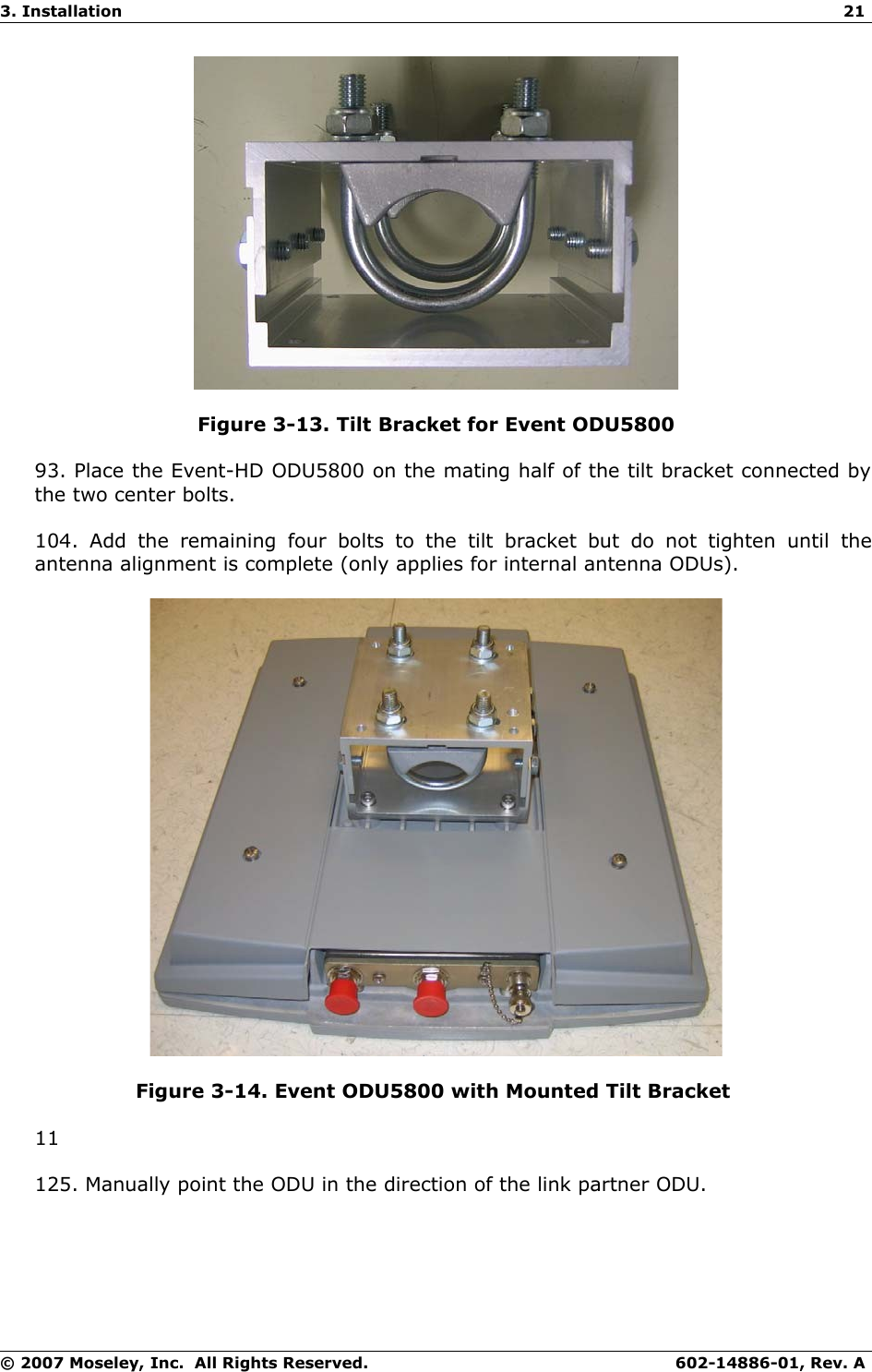
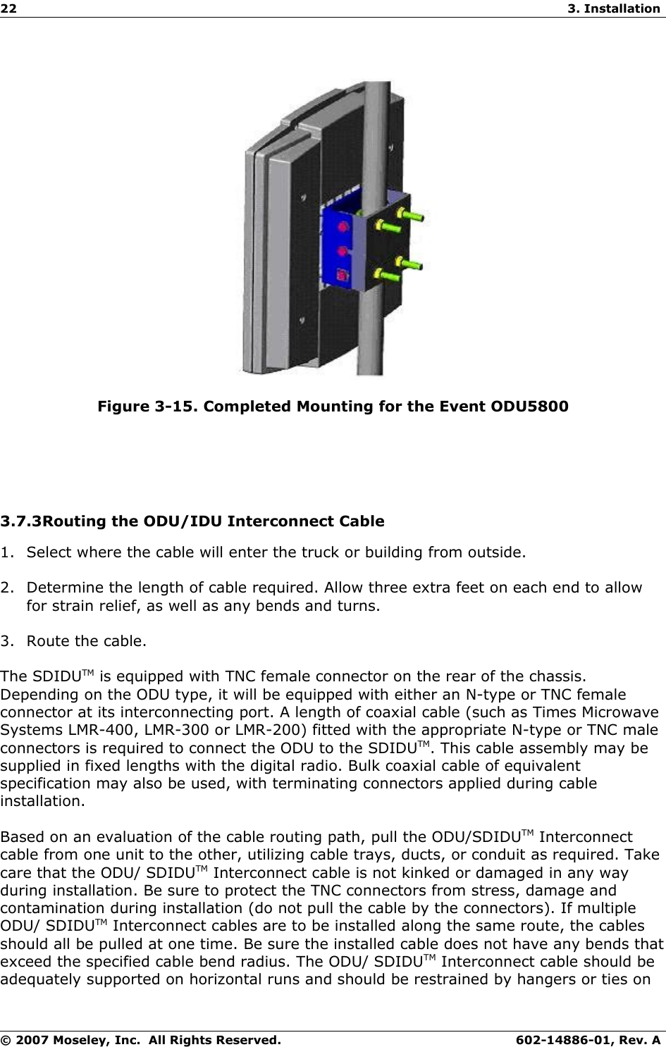
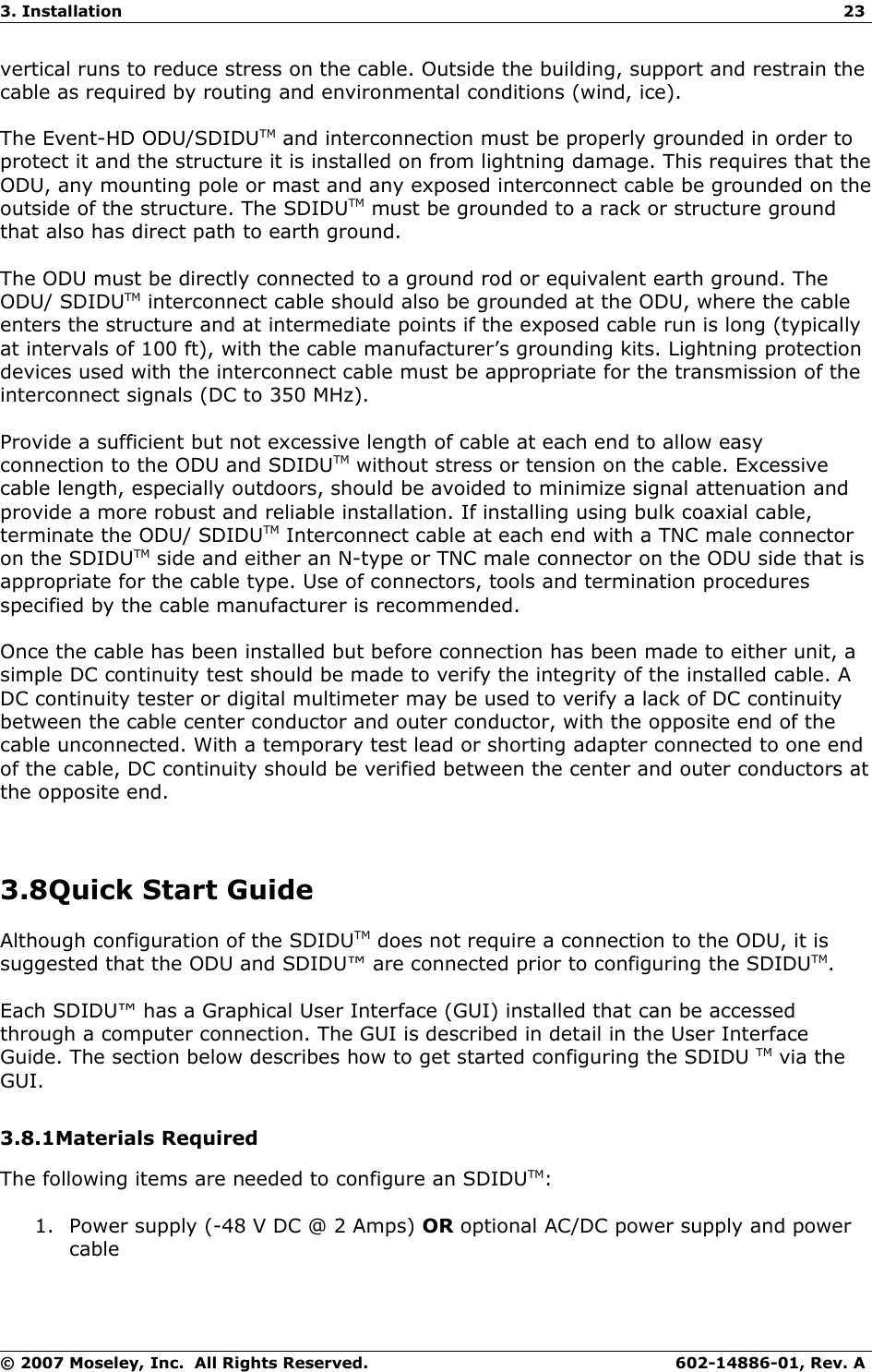
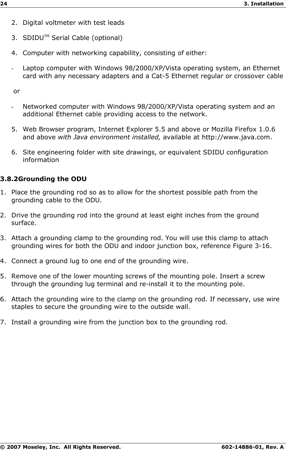
Moseley Associates EVENTHD ODU Event HD Outdoor Unit Digital Transceiver User Manual Event HD User Reference and Installation Manual
Moseley Associates Inc ODU Event HD Outdoor Unit Digital Transceiver Event HD User Reference and Installation Manual
Contents
- 1. Users Manual
- 2. Users Guide
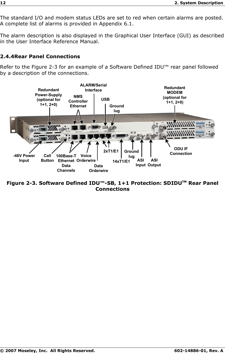
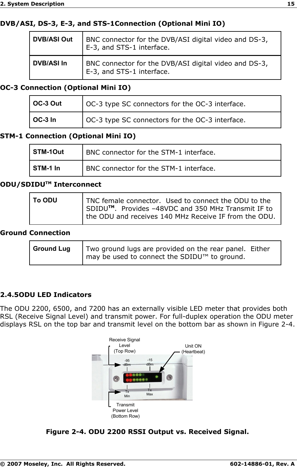
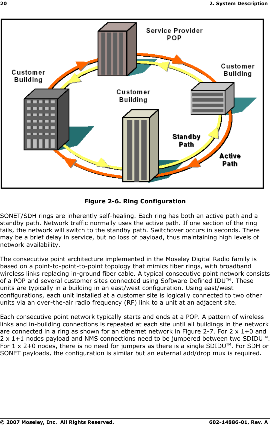
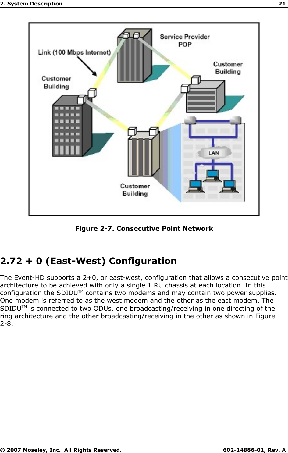
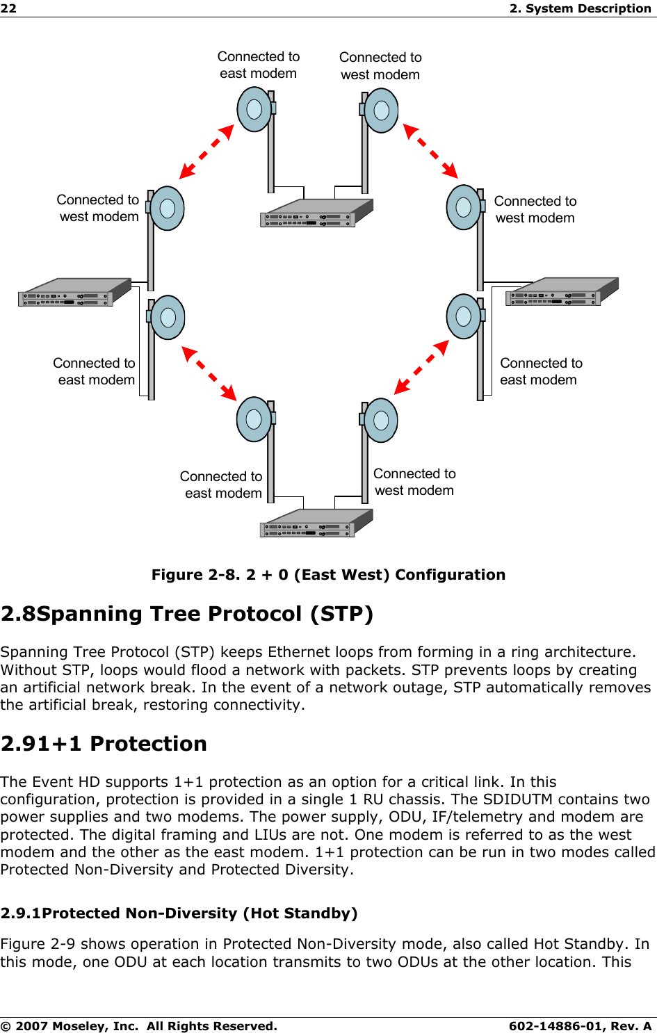
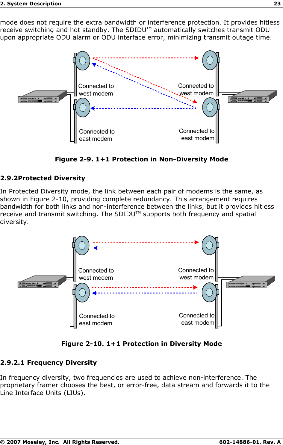
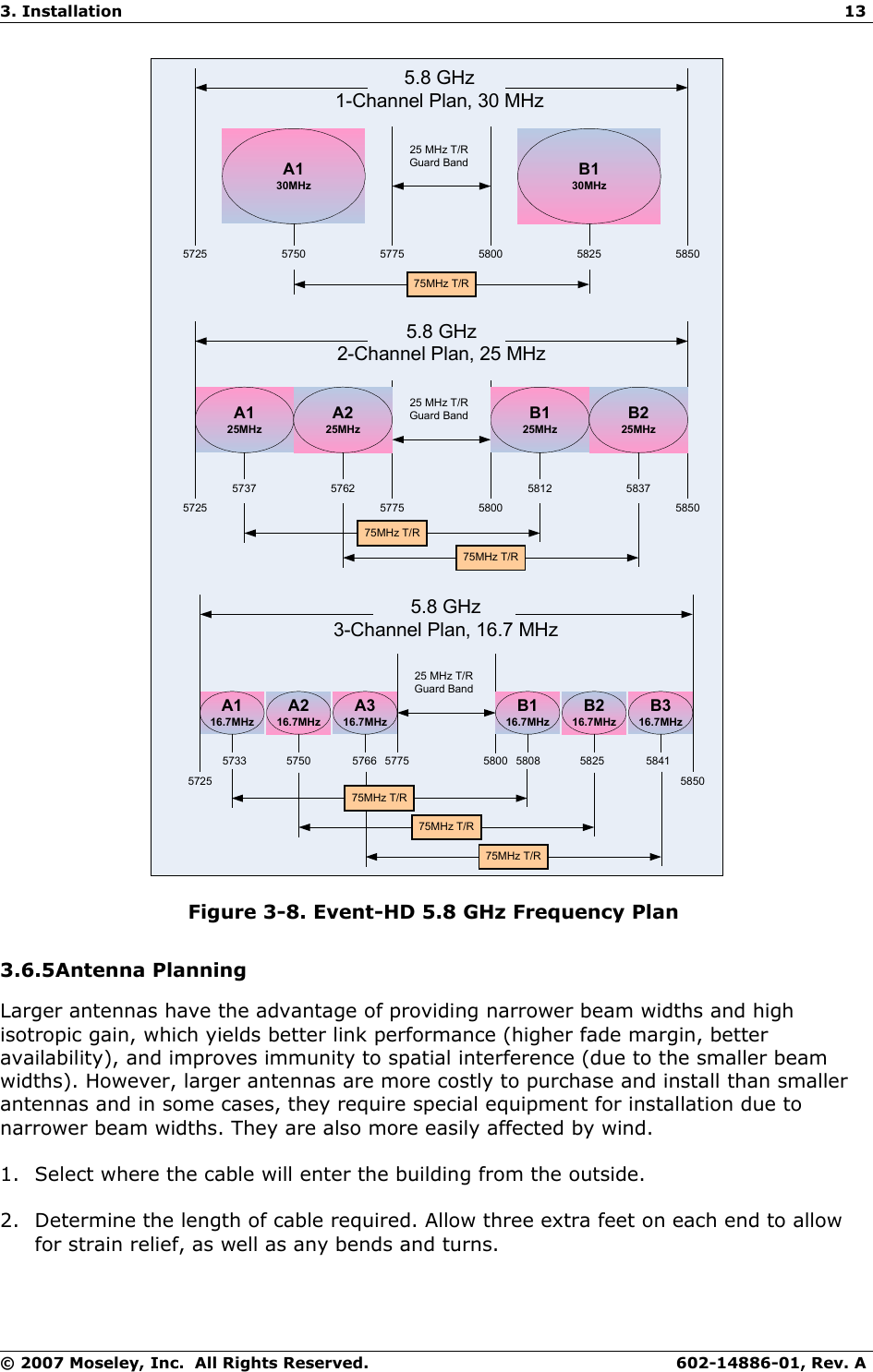
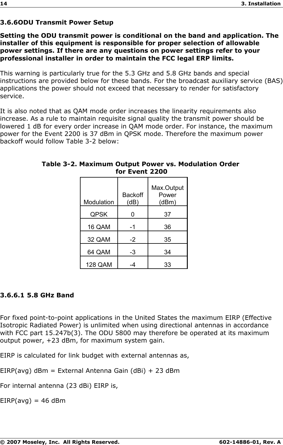
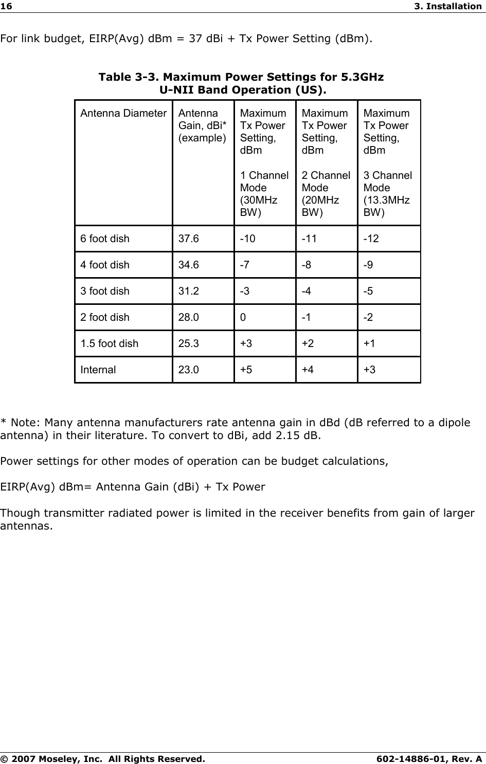
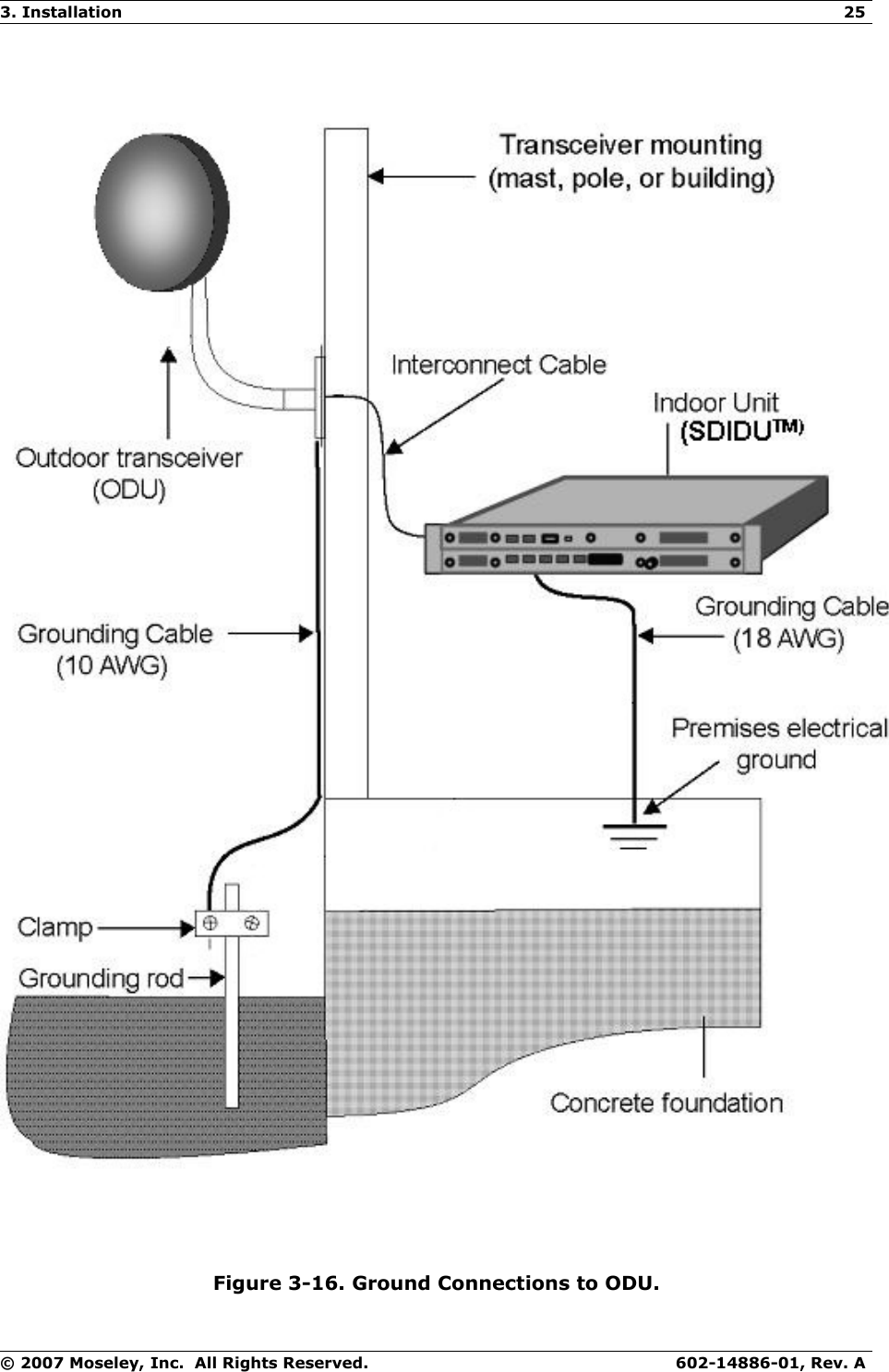
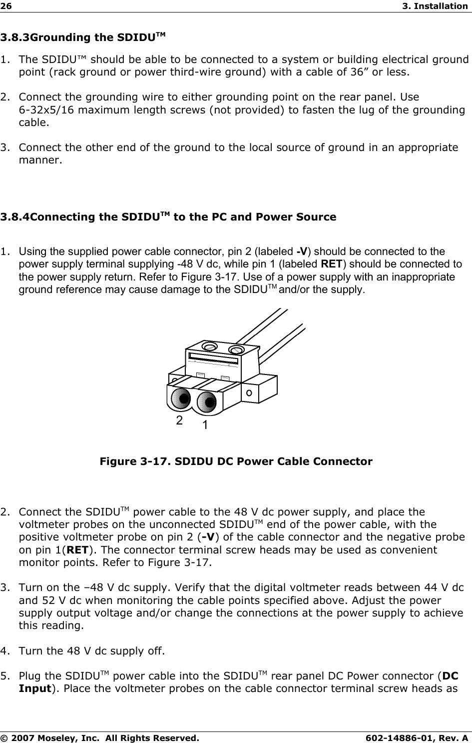
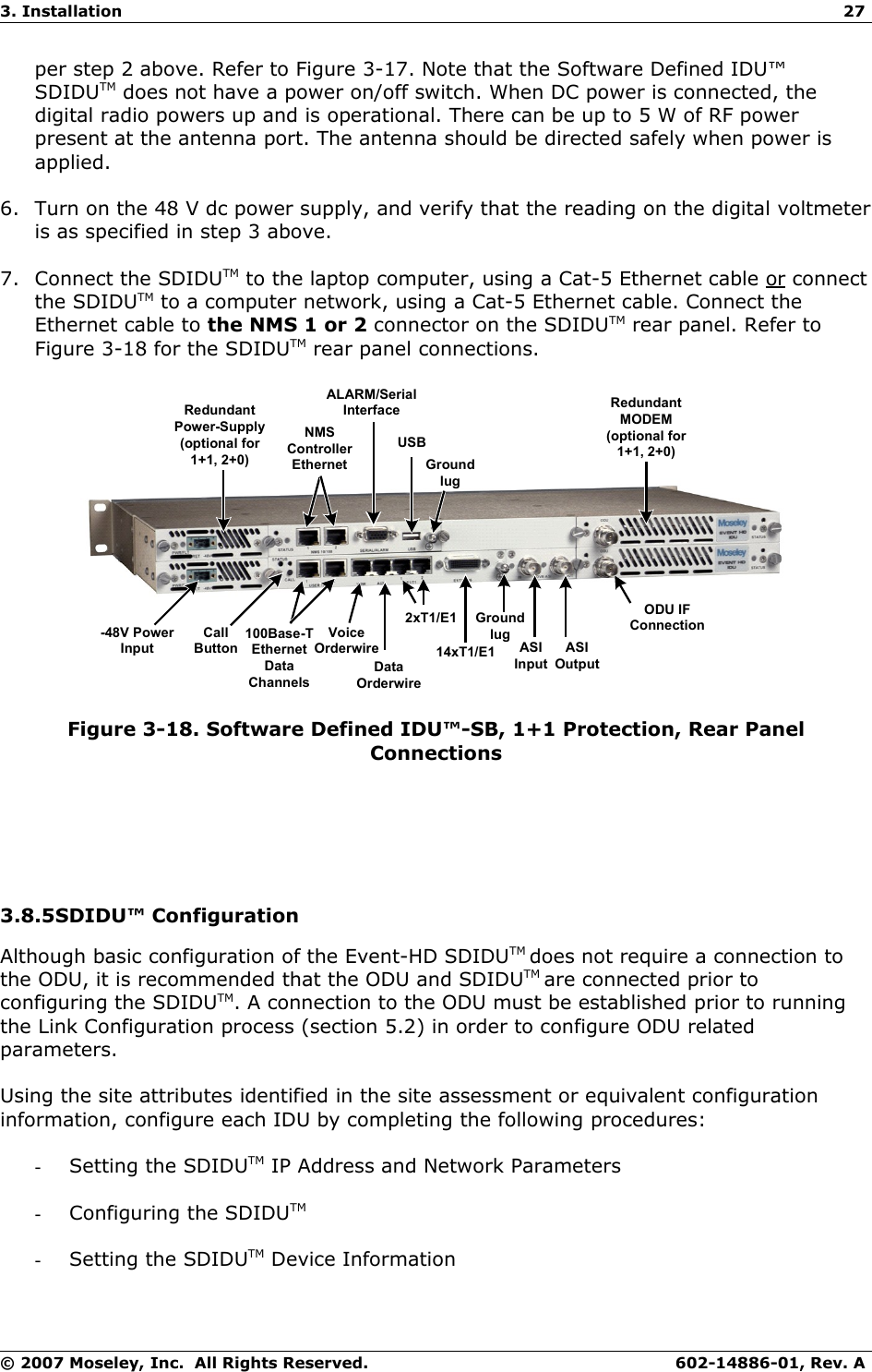
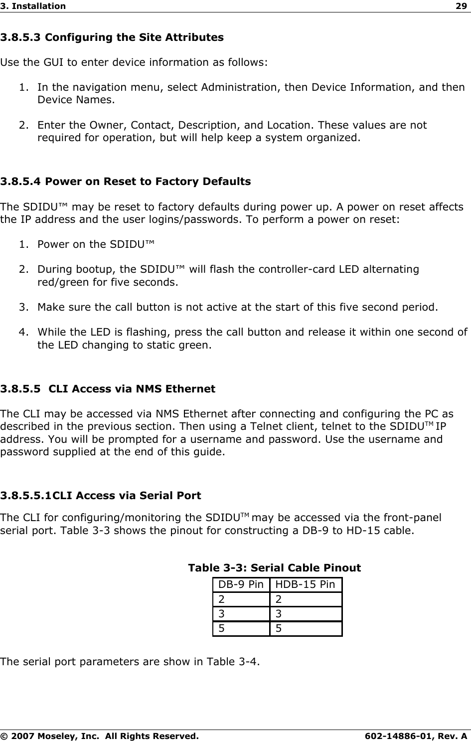
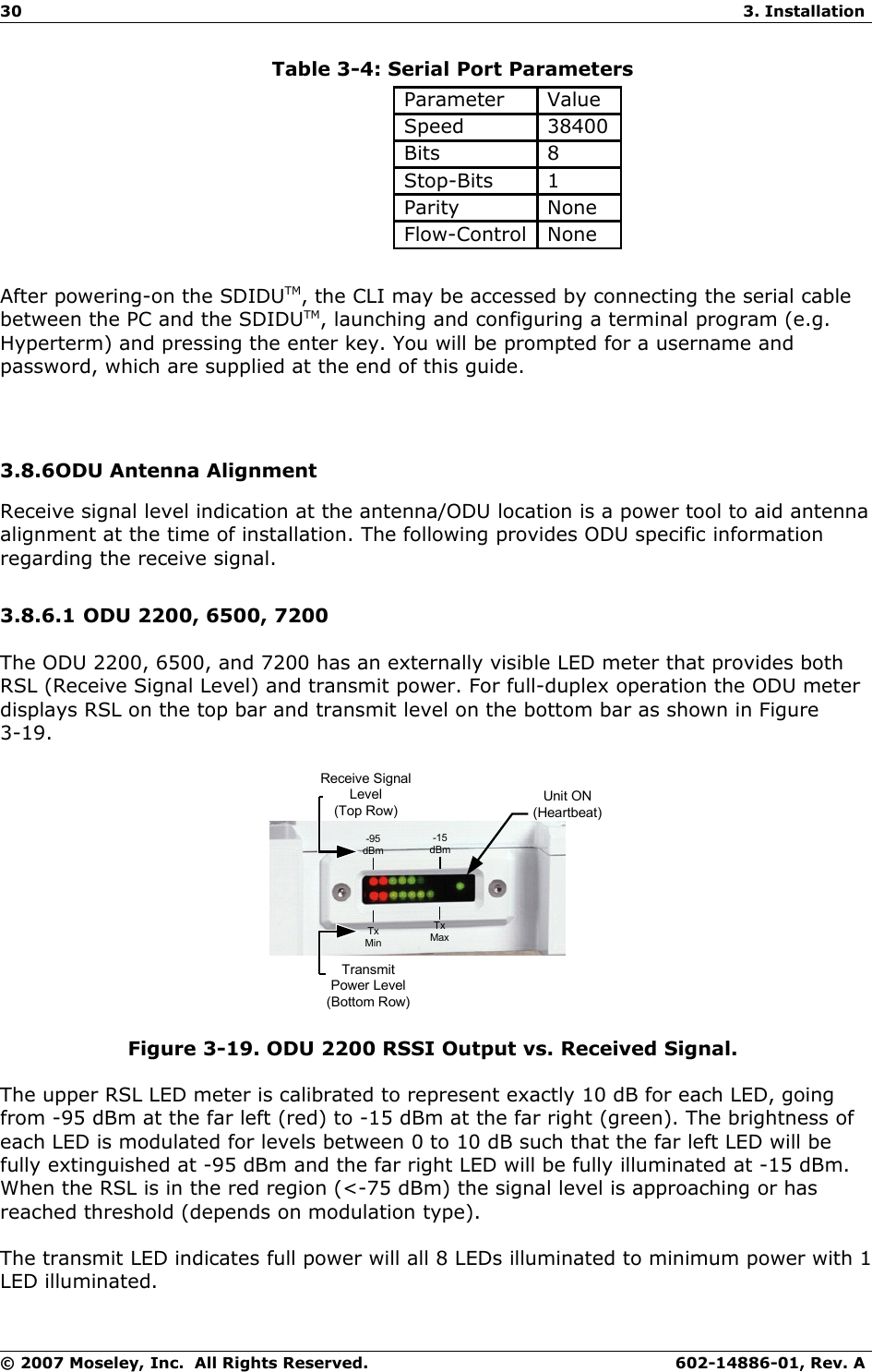
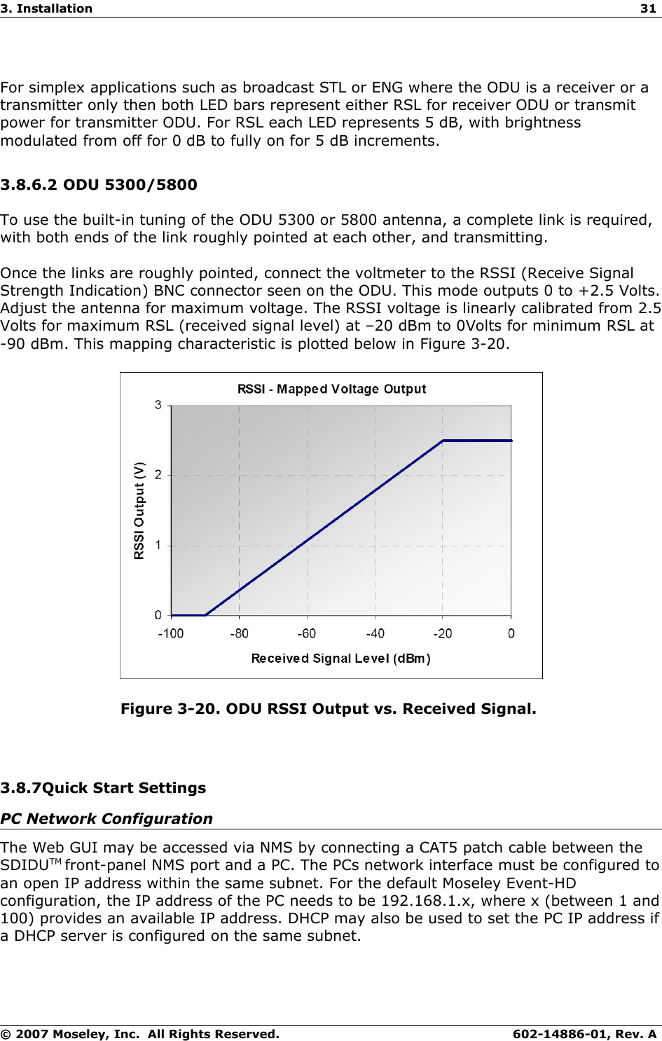
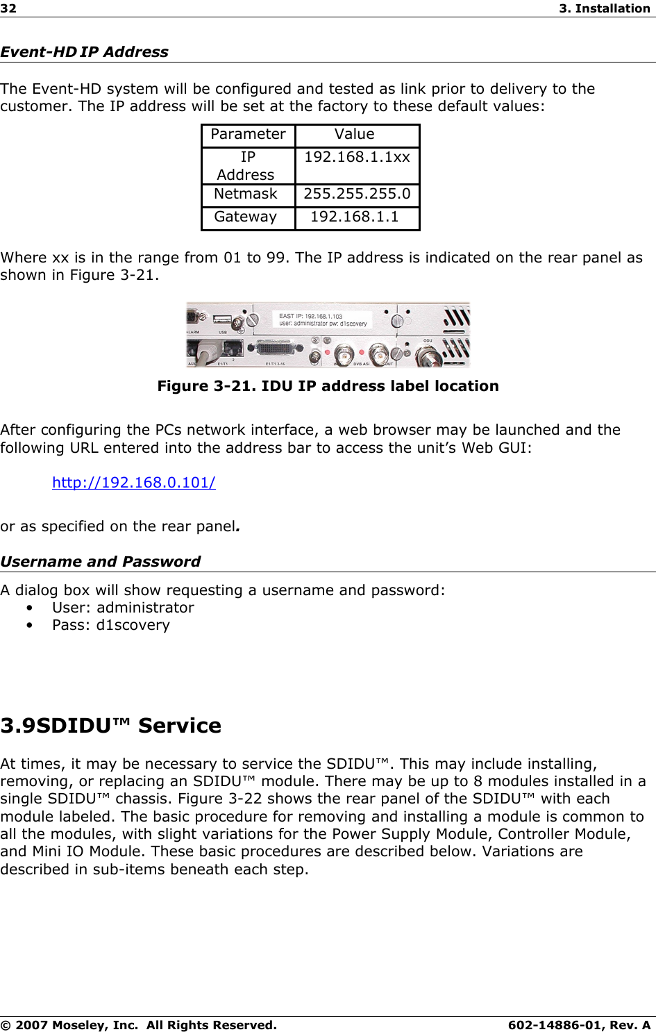
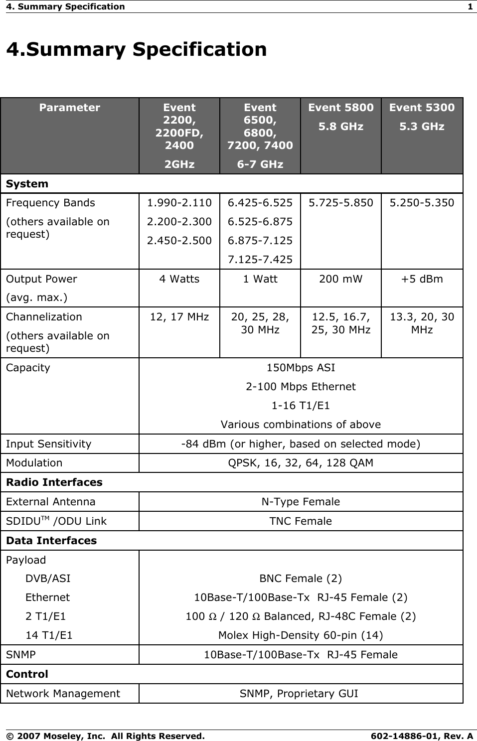
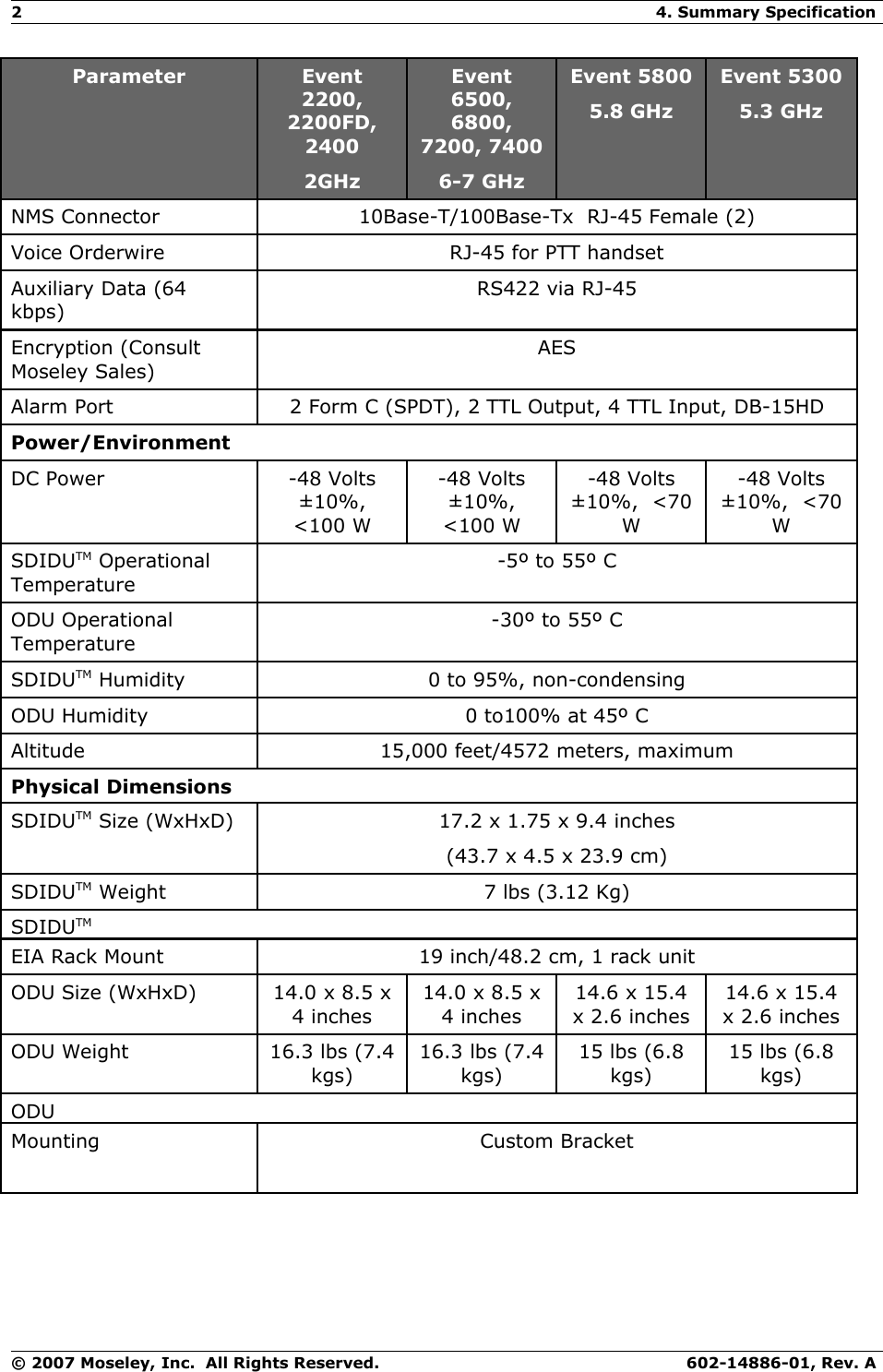
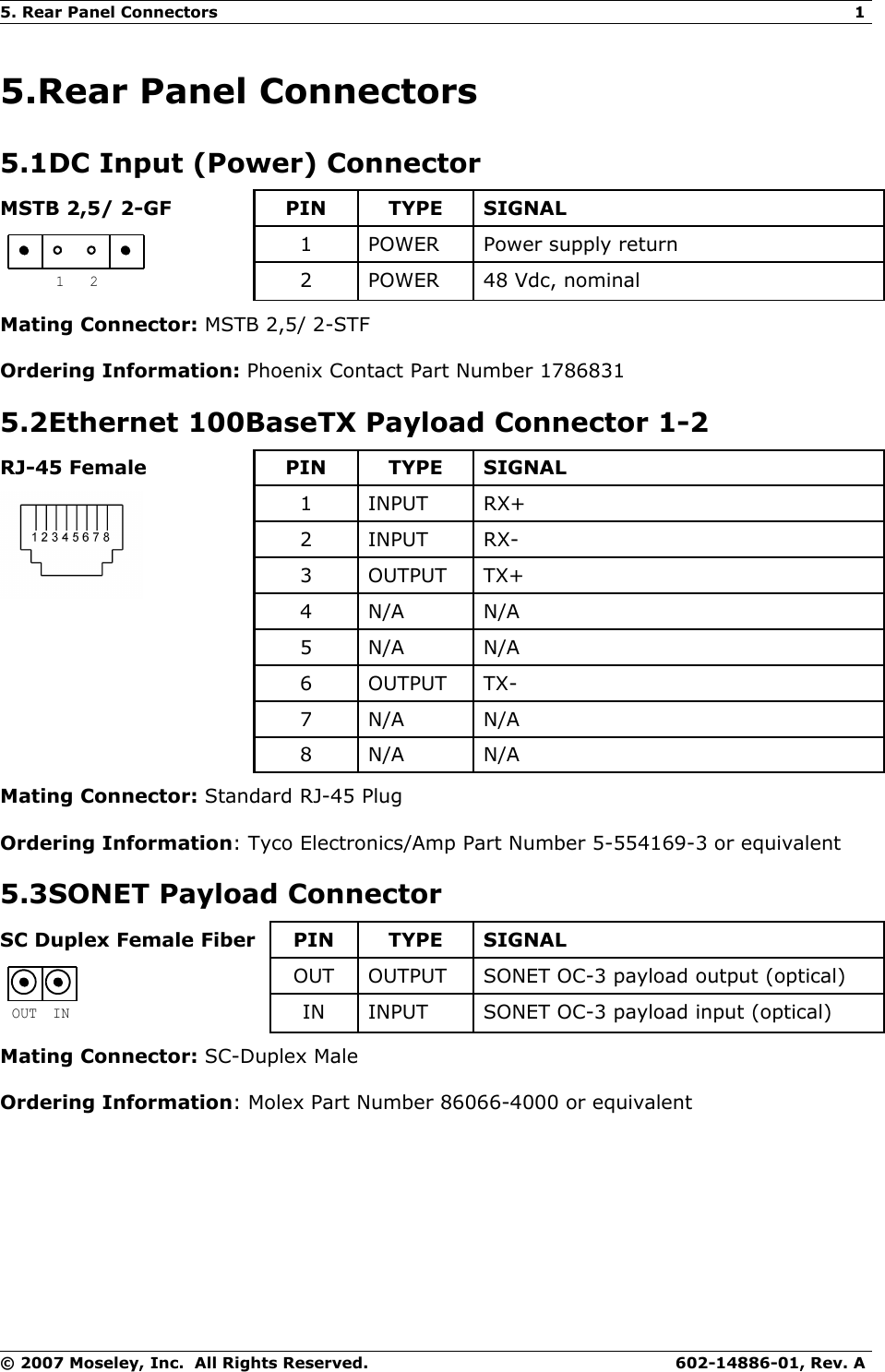
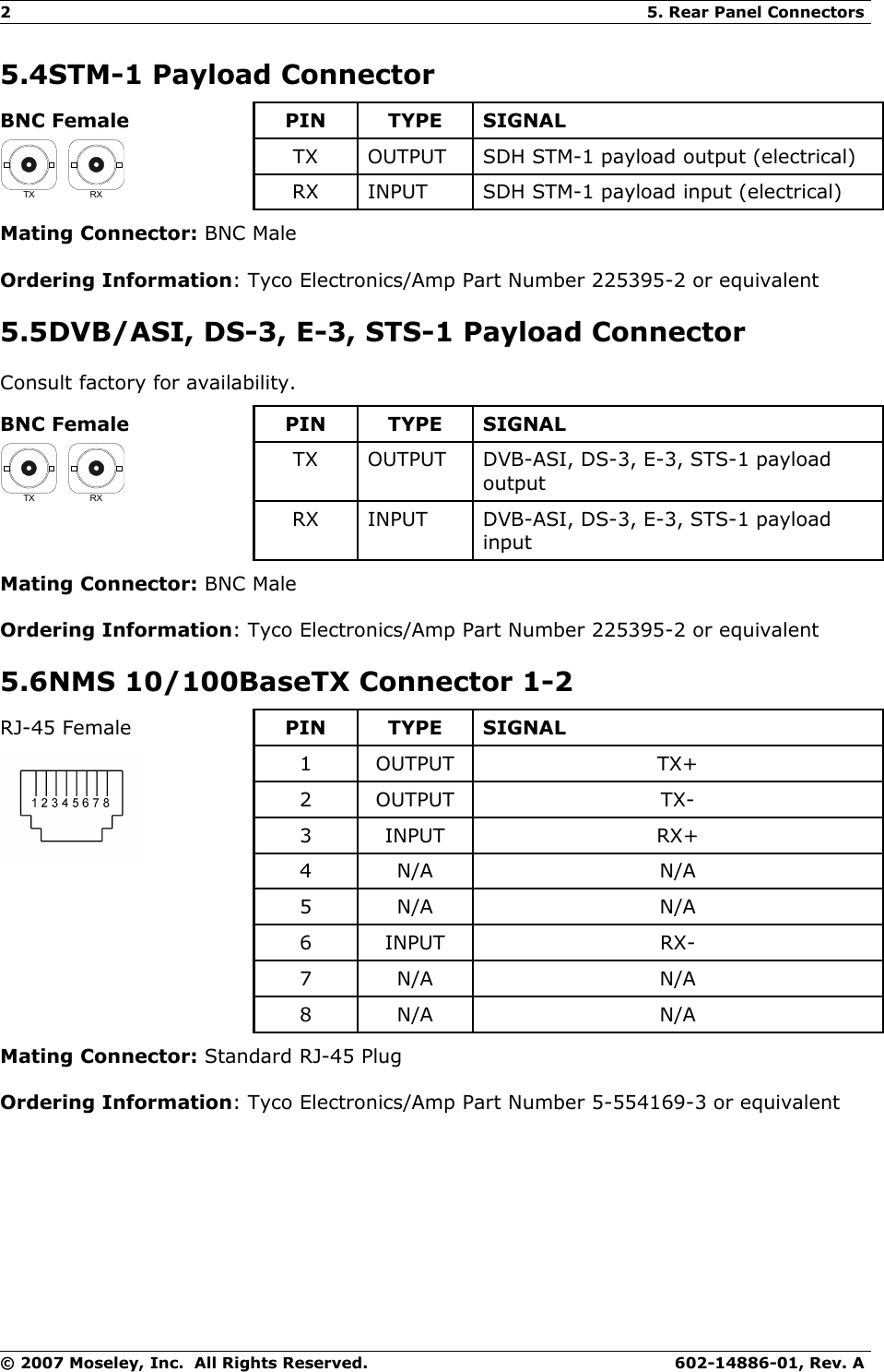
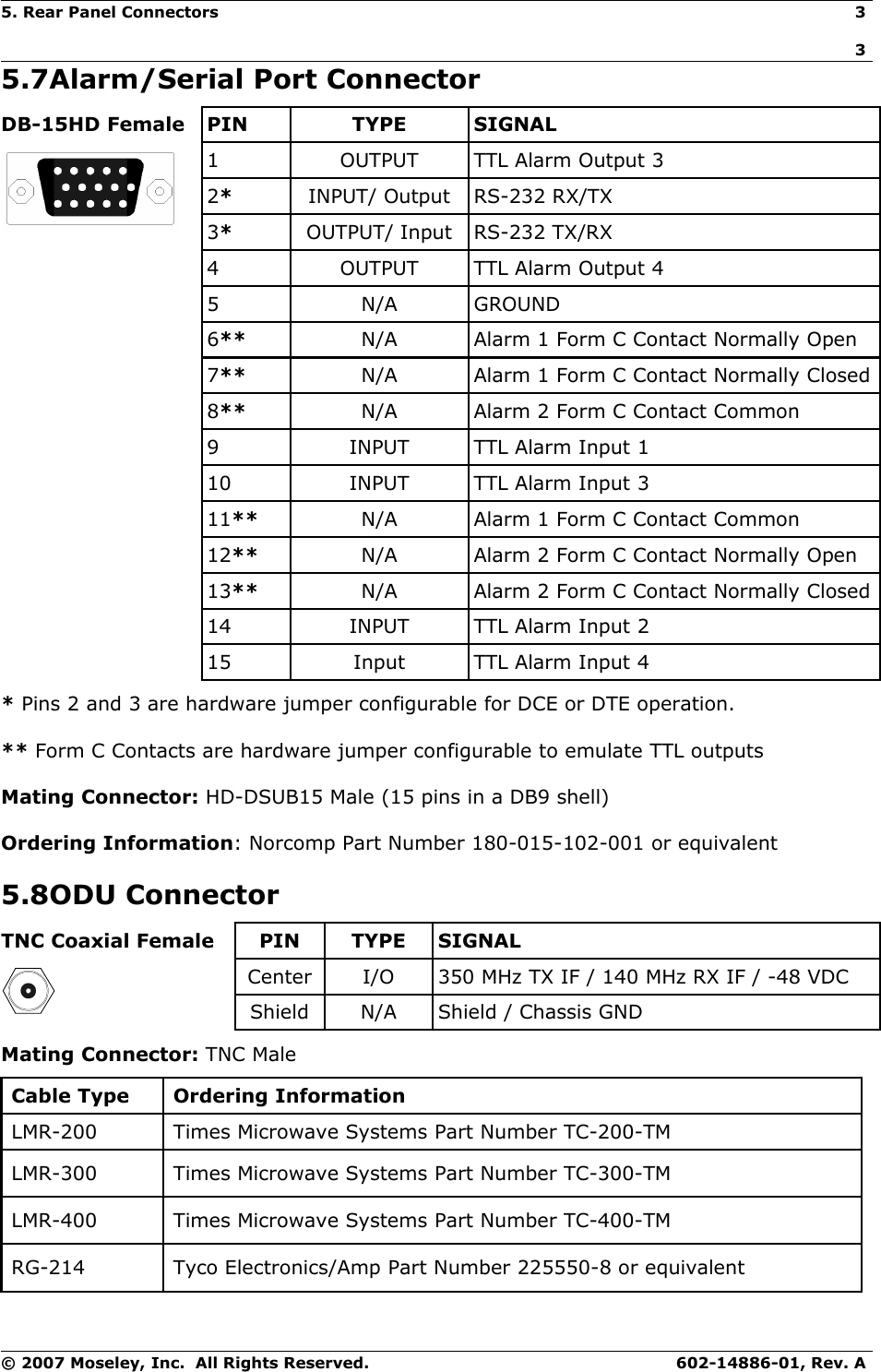
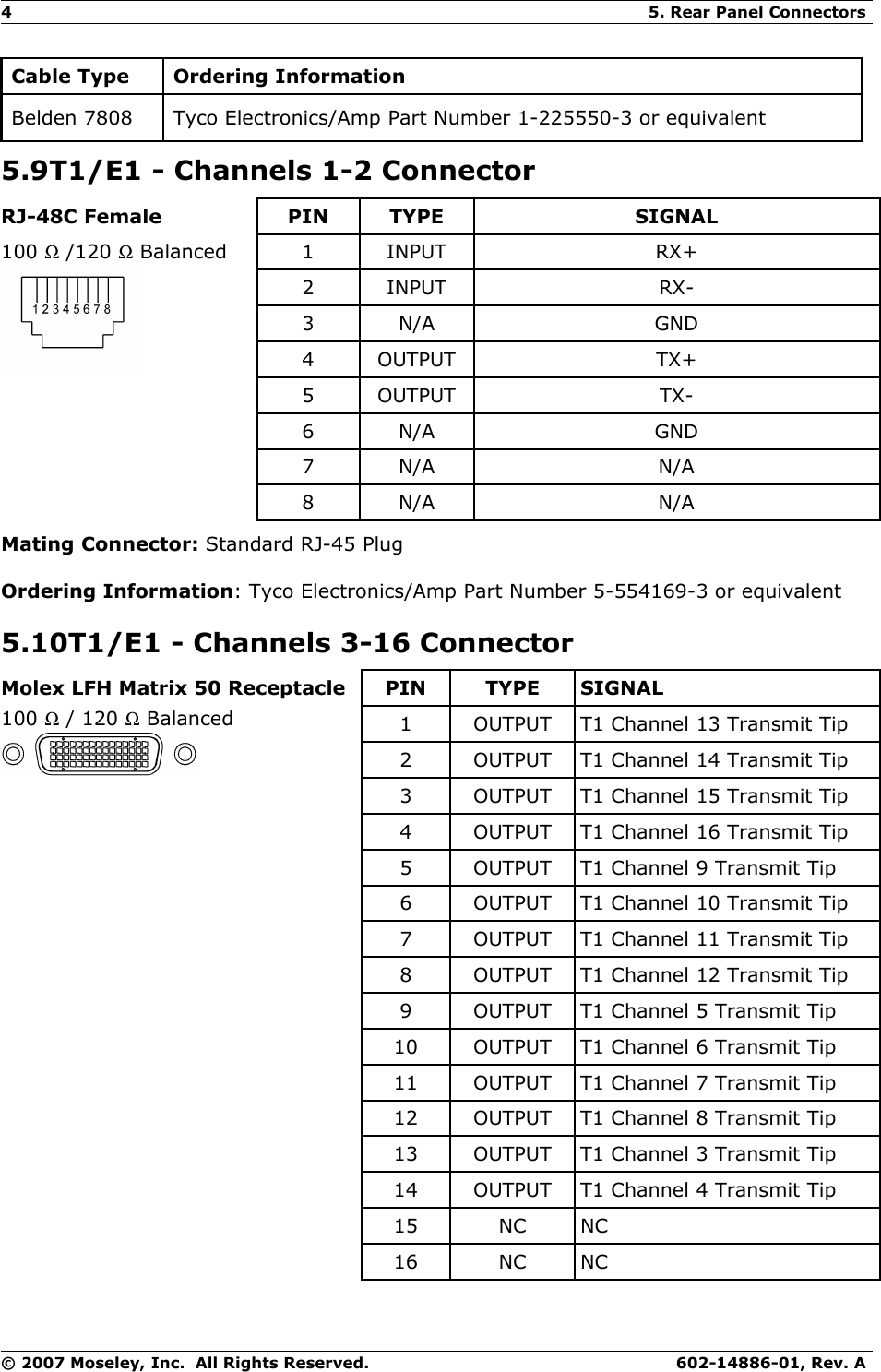
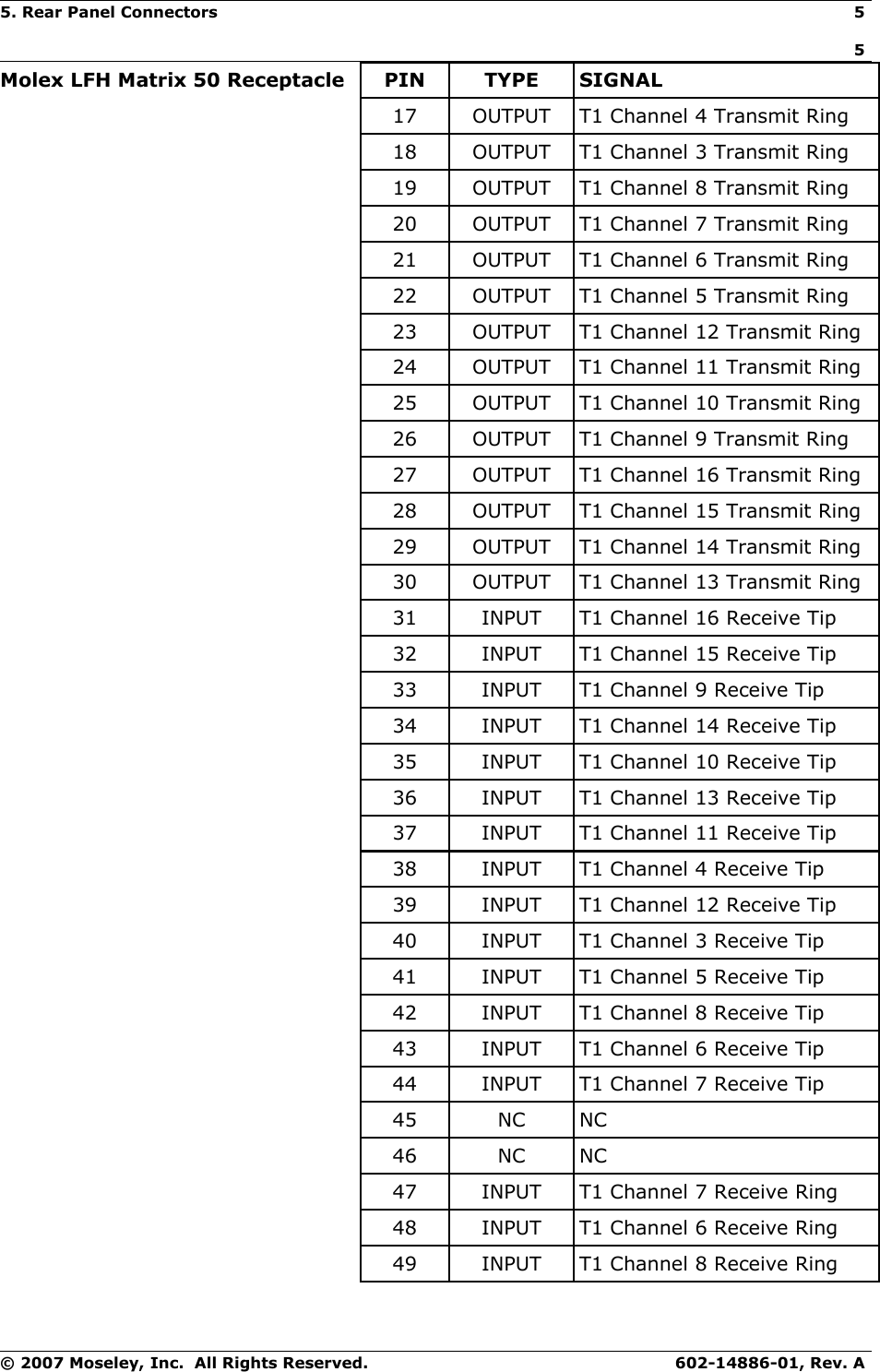
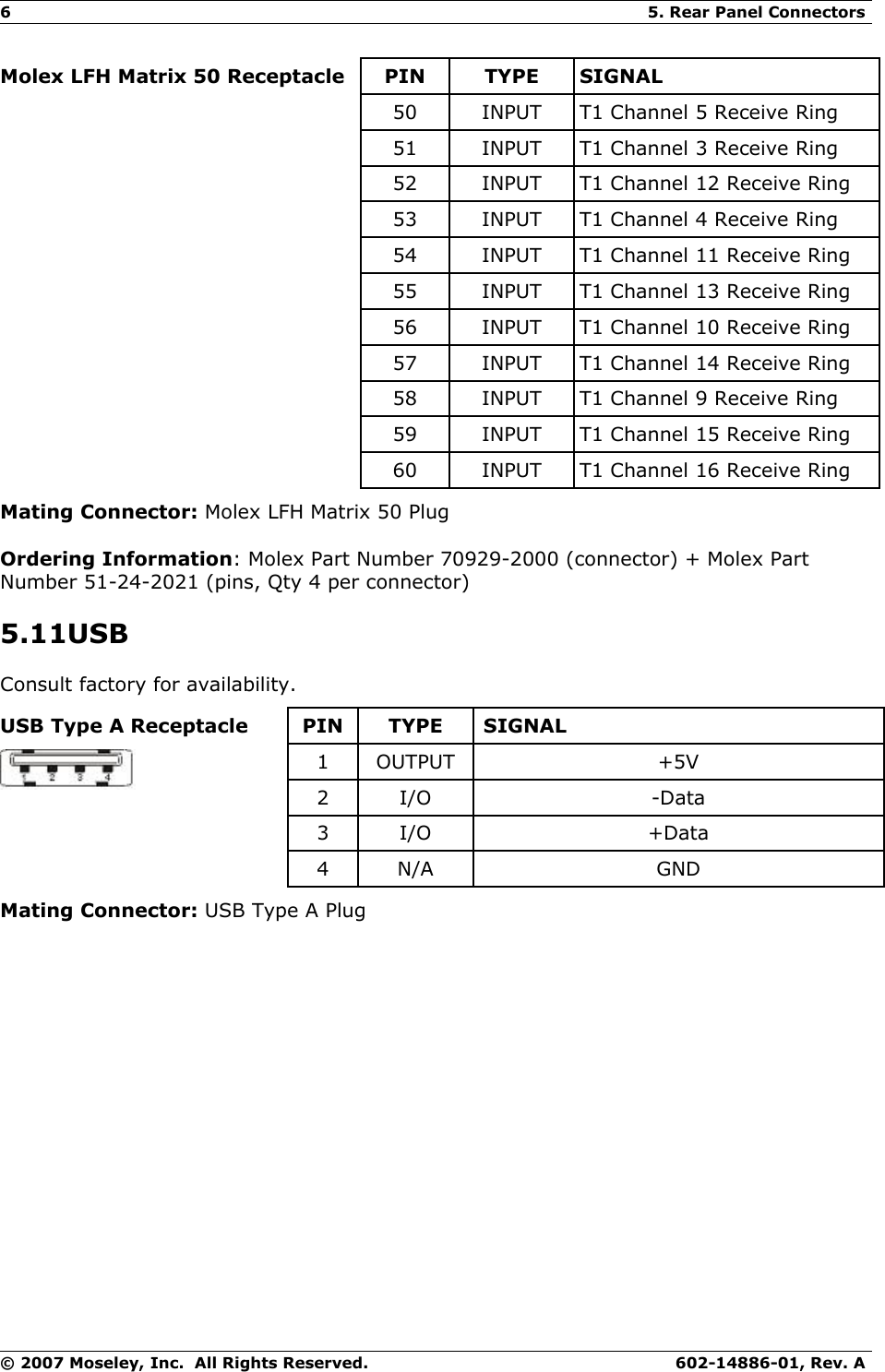
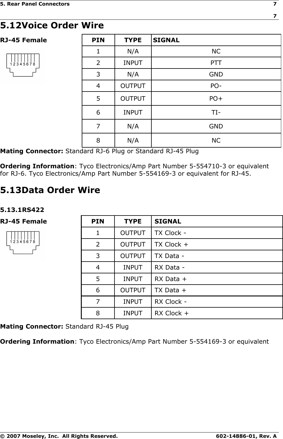
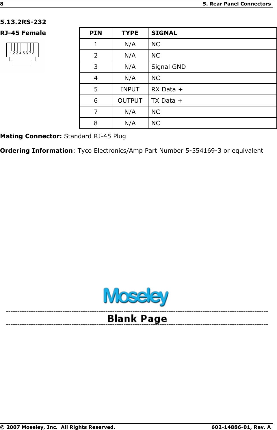
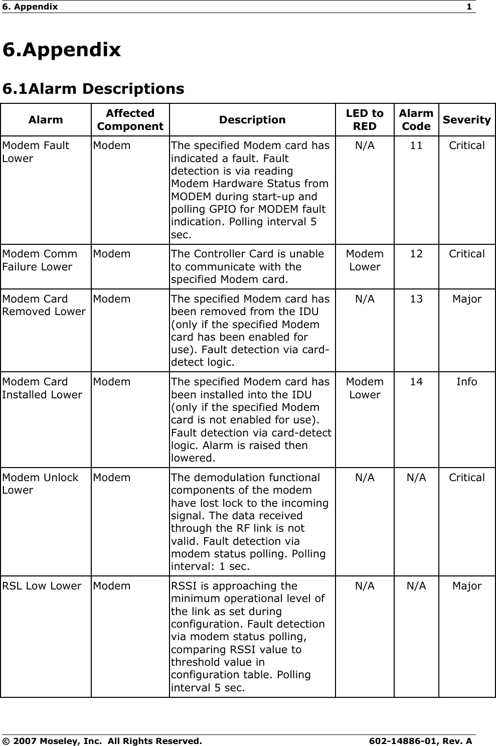
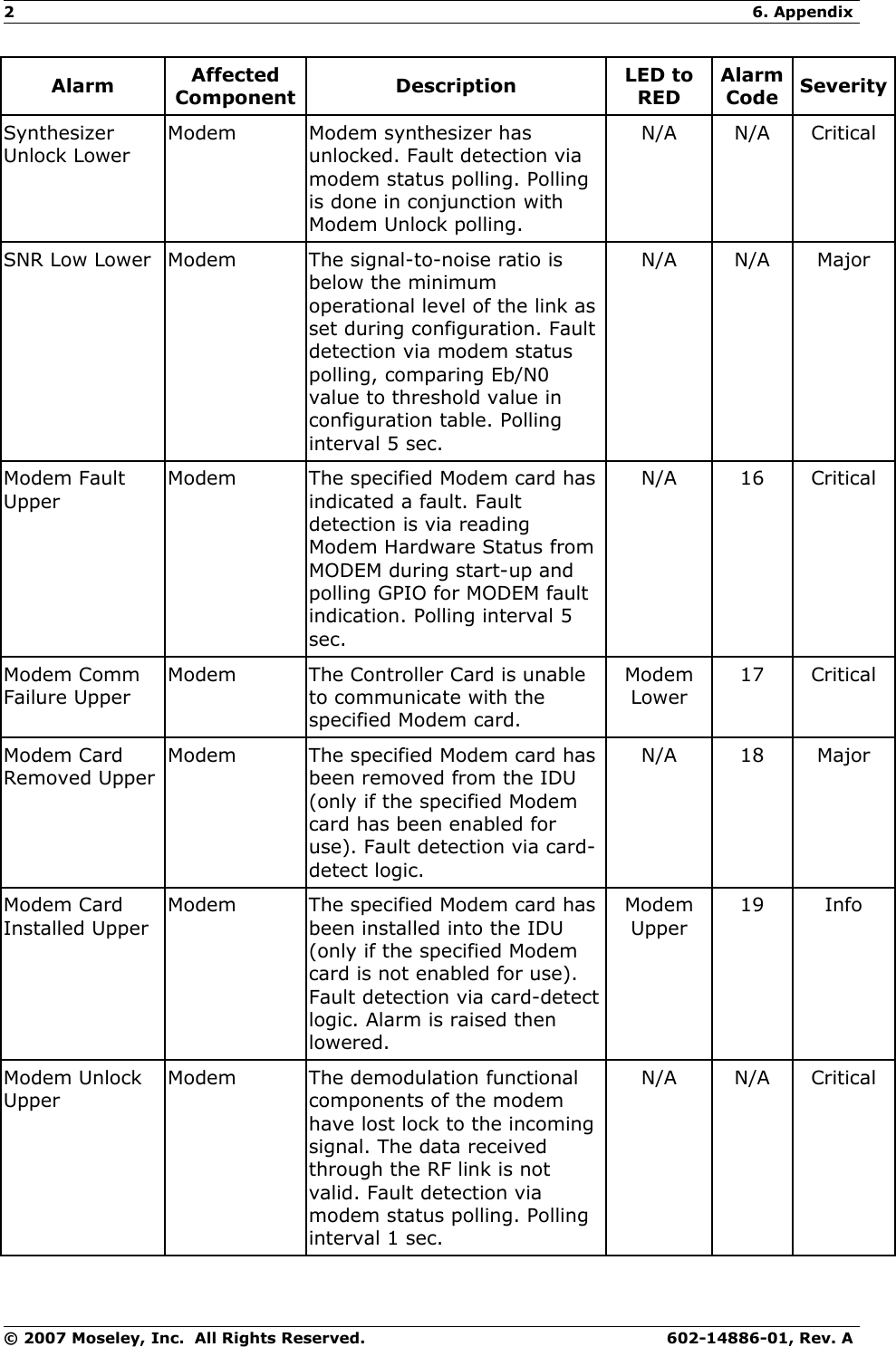
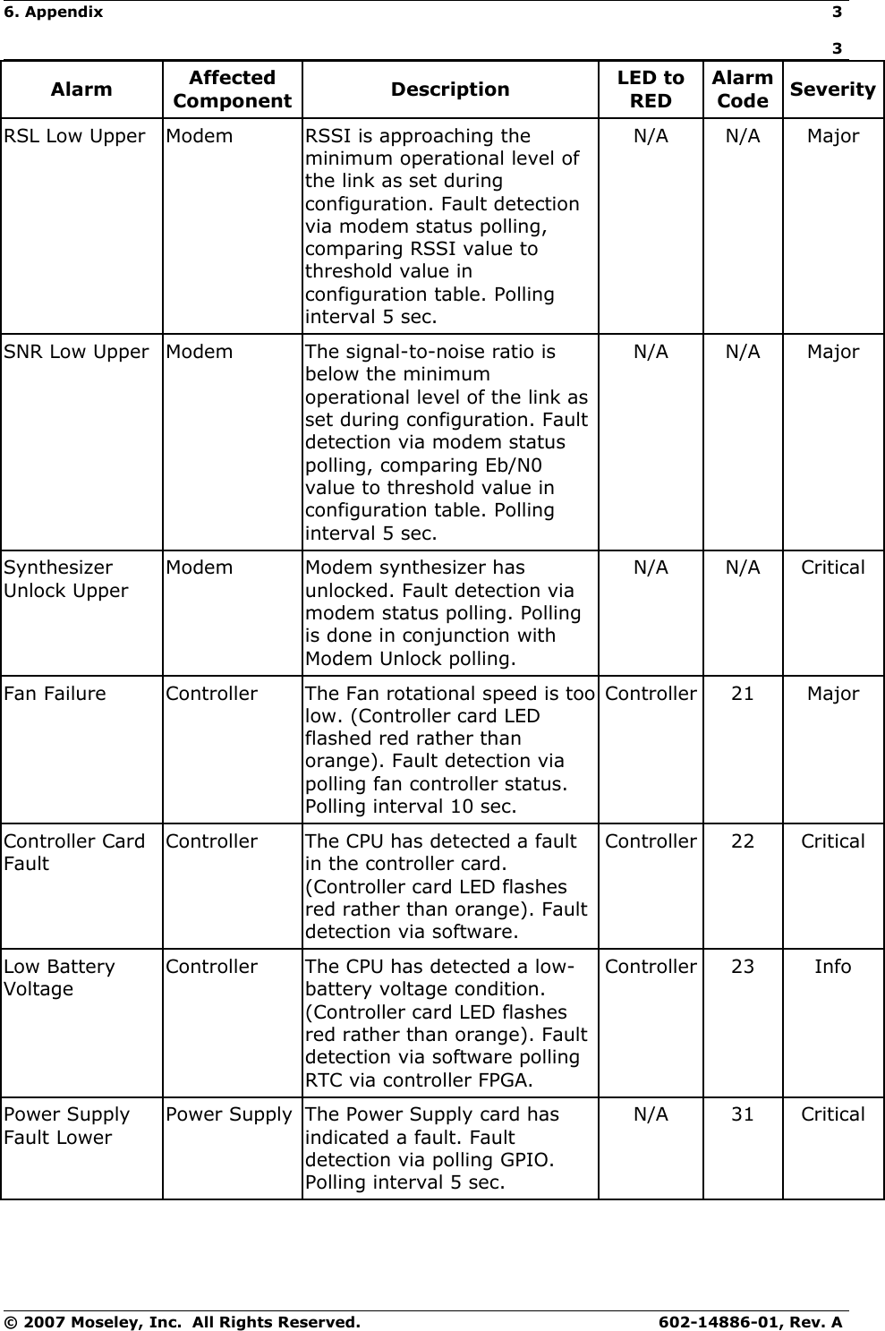
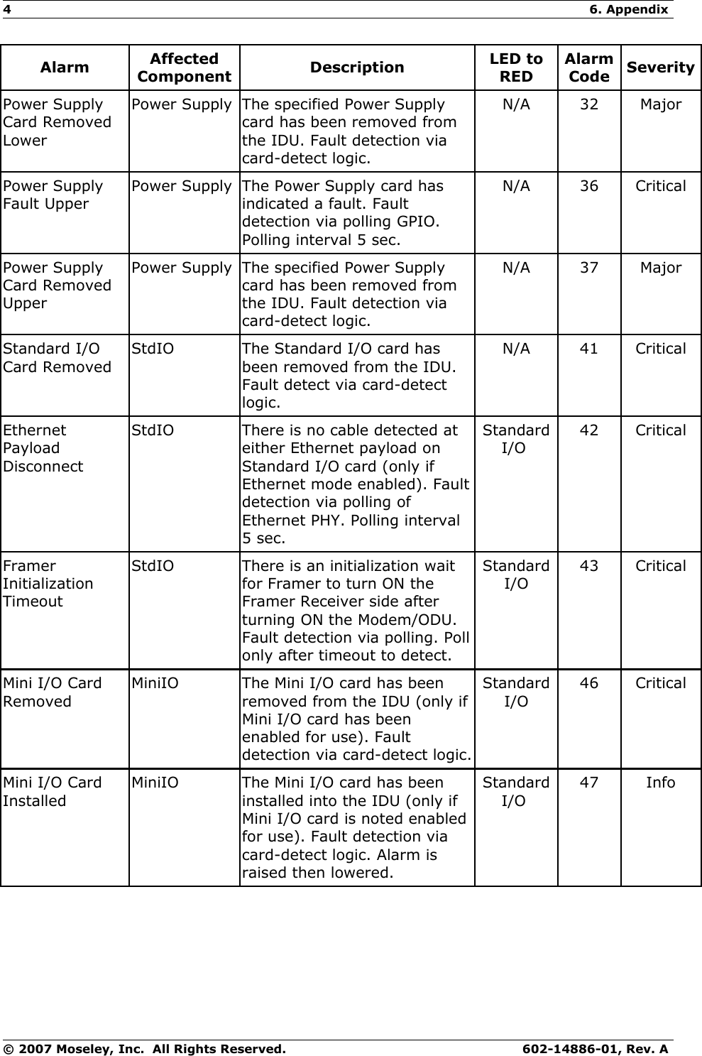
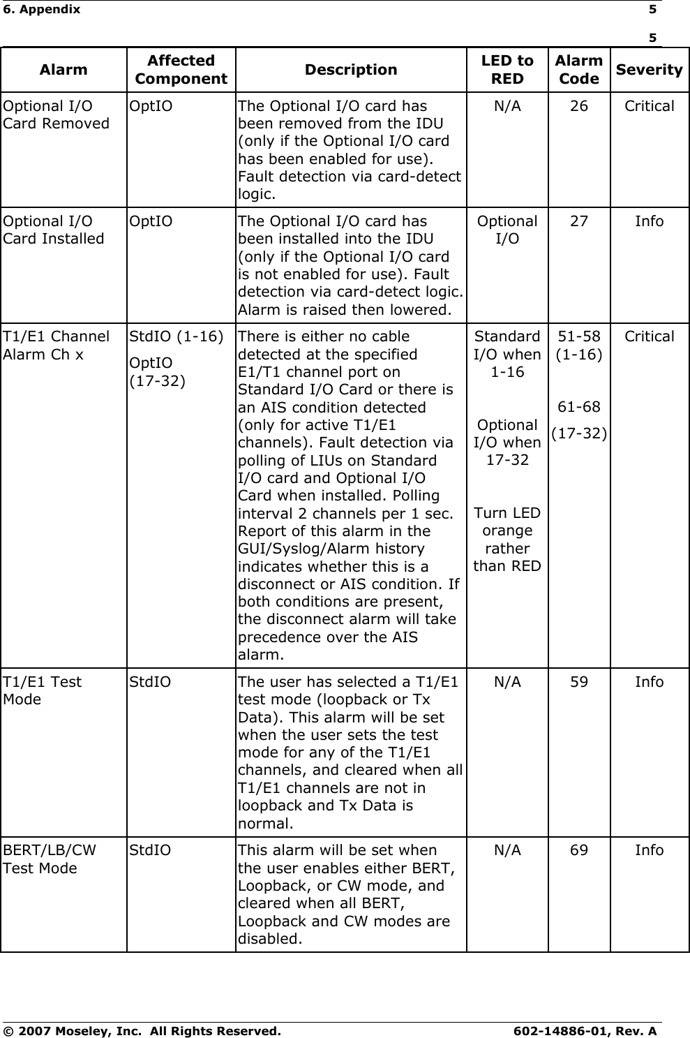
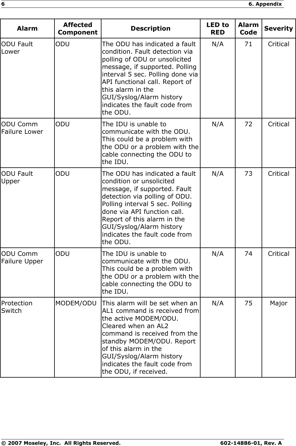
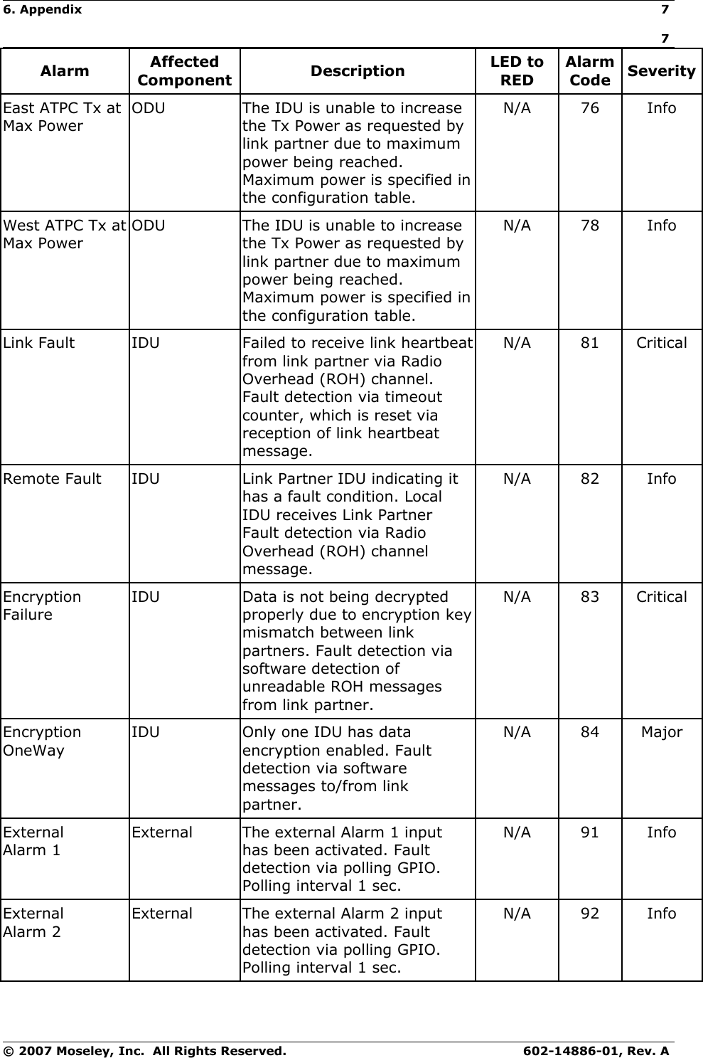
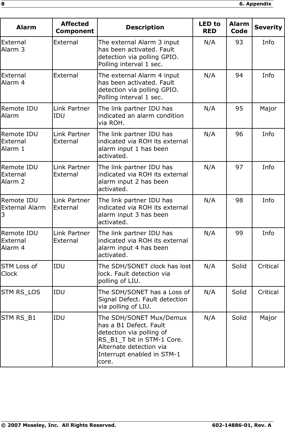
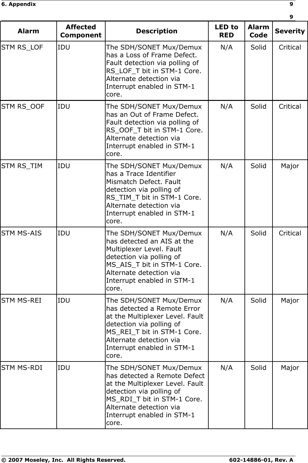
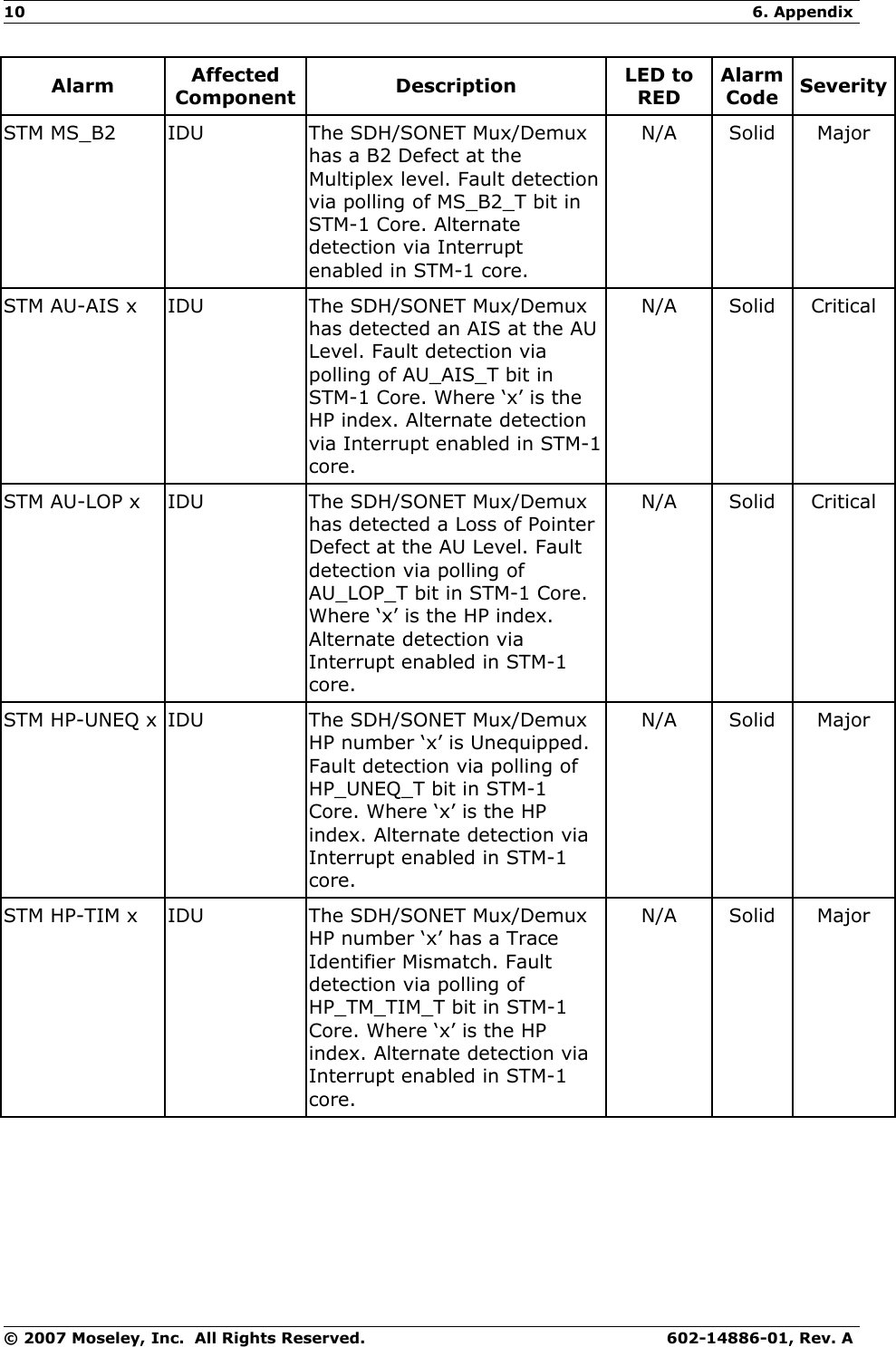
Users Manual