Moseley Associates EVENTHD ODU Event HD Outdoor Unit Digital Transceiver User Manual Event HD User Reference and Installation Manual
Moseley Associates Inc ODU Event HD Outdoor Unit Digital Transceiver Event HD User Reference and Installation Manual
Contents
- 1. Users Manual
- 2. Users Guide
Users Manual

Event HD
User Reference and Installation Manual
Document Number: 602-14886-01, Rev. A
Date: OCTOBER, 2007
© 2006 Moseley, Inc. All Rights Reserved.
This book and the information contained herein is the proprietary and confidential
information of Moseley, Inc. that is provided by Moseley exclusively for evaluating the
purchase of Moseley, Inc. technology and is protected by copyright and trade secret
laws.

ii
No part of this document may be disclosed, reproduced, or transmitted in any form or by
any means, electronic or mechanical, for any purpose without the express written
permission of Moseley, Inc.
For permissions, contact Moseley Marketing Group at 1-805-968-9621 or
1-805-685-9638 (FAX).
Notice of Disclaimer: The information and specifications provided in this document are
subject to change without notice. Moseley, Inc. reserves the right to make changes in
design or components as progress in engineering and manufacturing may warrant.
The Warranty(s) that accompany Moseley products are set forth in the sales
agreement/contract between Moseley and its customer. Please consult the sales
agreement for the terms and conditions of the Warranty(s) provided by Moseley. To
obtain a copy of the Warranty(s), contact you Moseley Sales Representative at
1-805-968-9621 or 1-805-685-9638 (FAX).
The information provided in this document is provided “as is” without warranty of any
kind, either expressed or implied, including, but not limited to, the implied warranties of
merchantability, fitness for a particular purpose, or non-infringement. Some jurisdictions
do not allow the exclusion of implied warranties, so the above exclusion may not apply
to you.
In no event shall Moseley, Inc. be liable for any damages whatsoever – including special,
indirect, consequential or incidental damages or damages for loss of profits, revenue,
use, or data whether brought in contract or tort, arising out of or connected with any
Moseley, Inc., document or the use, reliance upon or performance of any material
contained in or accessed from this document. Moseley’s license agreement may be
provided upon request. Additional Terms and Conditions will be finalized upon
negotiation or a purchase.
The above information shall not be constructed to imply any additional warranties for
Moseley, Inc. equipment including, but not limited to, warranties of merchantability or
fitness for an intended use.
Trademark Information
Software Defined Indoor UnitTM (SDIDUTM) is a product and trademark of Moseley Inc.
JavaTM is a trademark of Sun Microsystems Inc.
Windows® is a registered trademark of Microsoft Corporation
All other brand or product names are trademarks or registered trademarks of their
respective companies or organizations.
Part Number: MK-MAN-4001
© 2007 Moseley, Inc. All Rights Reserved. 602-14886-01, Rev. A

iii
Table of Contents
1. SAFETY PRECAUTIONS ................................................................................... 1
2. SYSTEM DESCRIPTION ................................................................................... 1
2.1 About This Manual ........................................................................................... 1
2.2 Introduction .................................................................................................... 1
2.3 System Features .............................................................................................. 5
2.4 Physical Description ......................................................................................... 6
2.4.1 Model Types
7
2.4.2 Front Panel ............................................................................................... 8
2.4.3 Rear Panel Indicators .................................................................................. 9
2.4.4 Rear Panel Connections ............................................................................. 12
2.4.5 ODU LED Indicators .................................................................................. 15
2.5 System Description ........................................................................................ 16
2.6 Consecutive Point Architecture ......................................................................... 19
2.7 2 + 0 (East-West) Configuration ..................................................................... 21
2.8 Spanning Tree Protocol (STP) .......................................................................... 22
2.9 1+1 Protection ............................................................................................... 22
2.9.1 Protected Non-Diversity (Hot Standby) ........................................................ 22
2.9.2 Protected Diversity ................................................................................... 23
2.10 1 + 1 Multi-hop Repeater Configuration ........................................................... 24
2.11 Data Interfaces ............................................................................................ 25
2.12 Crosspoint Switch ......................................................................................... 26
2.13 Power Management ...................................................................................... 27
2.14 Event-HD Software and Network Management ................................................. 28
2.14.1 IP Address ............................................................................................. 28
2.14.2 Network ................................................................................................. 28
2.14.3 NMS Network Operational Principles .......................................................... 29
2.14.4 Third Party Network Management Software Support .................................... 30
2.15 System Loopbacks ........................................................................................ 30
3. INSTALLATION ............................................................................................... 1
3.1 Unpacking ....................................................................................................... 1
3.2 Notices ........................................................................................................... 2
3.3 PRE-INSTALLATION NOTES ............................................................................... 2
3.4 Back-to-Back Bench Testing .............................................................................. 2
3.5 Overview of Installation and Testing Process ....................................................... 3
3.6 Site Evaluation ................................................................................................ 4
3.6.1 Preparing for a Site Evaluation ..................................................................... 5
3.6.2 Site Evaluation Process ............................................................................... 6
3.6.3 Critical System Calculations ......................................................................... 8
3.6.4 Frequency Plan Determination ................................................................... 10
3.6.5 Antenna Planning ..................................................................................... 13
3.6.6 ODU Transmit Power Setup ........................................................................ 14
3.7 Installation of the Event-HD ............................................................................ 17
3.7.1 Installing the Event-HD SDIDUTM .............................................................. 17
3.7.2 Installing the Event-HD ODU ...................................................................... 18
3.7.3 Routing the ODU/IDU Interconnect Cable .................................................... 22
3.8 Quick Start Guide ........................................................................................... 23
3.8.1 Materials Required .................................................................................... 23
3.8.2 Grounding the ODU ................................................................................... 24
© 2007 Moseley, Inc. All Rights Reserved. 602-14886-01, Rev. A

iv
3.8.3 Grounding the SDIDUTM ........................................................................... 26
3.8.4 Connecting the SDIDUTM to the PC and Power Source .................................. 26
3.8.5 SDIDU™ Configuration .............................................................................. 27
3.8.6 ODU Antenna Alignment ............................................................................ 30
3.8.7 Quick Start Settings ................................................................................. 31
3.9 SDIDU™ Service ............................................................................................ 32
3.9.1 Removing a Module .................................................................................. 33
3.9.2 Installing a Module ................................................................................... 34
4. SUMMARY SPECIFICATION ............................................................................. 1
5. REAR PANEL CONNECTORS ............................................................................. 1
5.1 DC Input (Power) Connector ............................................................................. 1
5.2 Ethernet 100BaseTX Payload Connector 1-2 ........................................................ 1
5.3 SONET Payload Connector ................................................................................. 1
5.4 STM-1 Payload Connector ................................................................................. 2
5.5 DVB/ASI, DS-3, E-3, STS-1 Payload Connector .................................................... 2
5.6 NMS 10/100BaseTX Connector 1-2 ..................................................................... 2
5.7 Alarm/Serial Port Connector .............................................................................. 3
5.8 ODU Connector ................................................................................................ 3
5.9 T1/E1 - Channels 1-2 Connector ........................................................................ 4
5.10 T1/E1 - Channels 3-16 Connector ..................................................................... 4
5.11 USB .............................................................................................................. 6
5.12 Voice Order Wire ............................................................................................ 7
5.13 Data Order Wire ............................................................................................. 7
5.13.1 RS422 ..................................................................................................... 7
5.13.2 RS-232 .................................................................................................... 8
6. APPENDIX ...................................................................................................... 1
6.1 Alarm Descriptions ........................................................................................... 1
Abbreviations & Acronyms ................................................................................... 15
Conversion Chart ................................................................................................ 17
List of Figures
FIGURE 2-1. TYPICAL BROADCAST ENG APPLICATION.......................................2
FIGURE 2-2. MICROWAVE SPLIT MOUNT ARCHITECTURE...................................3
FIGURE 2-2. EVENT-HD FRONT PANEL (OPTIONAL)...........................................8
FIGURE 2-2. SOFTWARE DEFINED IDU™ LEDS: SDIDUTM REAR PANEL
CONFIGURATION FOR SOFTWARE DEFINED IDU™, 1+0 CONFIGURATION.......10
FIGURE 2-3. SOFTWARE DEFINED IDU™-SB, 1+1 PROTECTION: SDIDUTM REAR
PANEL CONNECTIONS......................................................................................12
FIGURE 2-4. ODU 2200 RSSI OUTPUT VS. RECEIVED SIGNAL. .........................15
FIGURE 2-5. EVENT-HD BLOCK DIAGRAM.........................................................17
FIGURE 2-6. RING CONFIGURATION................................................................20
FIGURE 2-7. CONSECUTIVE POINT NETWORK..................................................21
FIGURE 2-8. 2 + 0 (EAST WEST) CONFIGURATION...........................................22
© 2007 Moseley, Inc. All Rights Reserved. 602-14886-01, Rev. A

v
FIGURE 2-9. 1+1 PROTECTION IN NON-DIVERSITY MODE...............................23
FIGURE 2-10. 1+1 PROTECTION IN DIVERSITY MODE.....................................23
FIGURE 2-11. 1 + 1 MULTI-HOP REPEATER CONFIGURATION..........................25
FIGURE 2-12. CROSSPOINT SWITCH................................................................26
FIGURE 2-13. (A) CROSSPOINT SWITCH USED A PASSTHROUGH IN REPEATER
CONFIGURATION. (B) CROSSPOINT SWITCH ALLOWS ACCESS FOR ADD/DROP.
27
FIGURE 2-14. PC AND EVENT-HD SDIDUS™ ON SAME SUBNET.........................29
FIGURE 2-15. EVENT-HD SDIDUS™ ON DIFFERENT SUBNETS...........................30
FIGURE 3-1. EVENT HD (1+0) COMPONENTS......................................................1
FIGURE 3-2. EVENT-HD BACK-TO-BACK TESTING CONFIGURATION...................3
FIGURE 3-3. NETWORK DEPLOYMENT LIFECYCLE...............................................4
FIGURE 3-3. 2 GHZ, 12 MHZ BAS FREQUENCY PLAN.........................................10
FIGURE 3-4. 2 GHZ, 17 MHZ LEGACY BAS FREQUENCY PLAN............................11
FIGURE 3-6. 7 GHZ, 25 MHZ BAS FREQUENCY PLAN.........................................11
FIGURE 3-7. EVENT-HD 5.3 GHZ FREQUENCY PLAN .........................................12
FIGURE 3-8. EVENT-HD 5.8 GHZ FREQUENCY PLAN .........................................13
FIGURE 3-8. SOFTWARE DEFINED IDU™ DIMENSIONS.....................................18
FIGURE 3-9. ¼-20 THREADED MOUNTING HOLE LOCATIONS ON ODU2200.
USE ANY 4.
19
FIGURE 3-10. POLE MOUNTING BRACKETS ON ODU2200
19
FIGURE 3-11. COMPLETED POLE MOUNTING OF ODU2200
20
FIGURE 3-12. EVENT ODU5800 REAR VIEW .....................................................20
FIGURE 3-13. TILT BRACKET FOR EVENT ODU5800..........................................21
FIGURE 3-14. EVENT ODU5800 WITH MOUNTED TILT BRACKET ......................21
FIGURE 3-15. COMPLETED MOUNTING FOR THE EVENT ODU5800....................22
FIGURE 3-16. GROUND CONNECTIONS TO ODU................................................25
FIGURE 3-17. SDIDU DC POWER CABLE CONNECTOR.......................................26
FIGURE 3-18. SOFTWARE DEFINED IDU™-SB, 1+1 PROTECTION, REAR PANEL
CONNECTIONS.................................................................................................27
FIGURE 3-19. ODU 2200 RSSI OUTPUT VS. RECEIVED SIGNAL. .......................30
FIGURE 3-20. ODU RSSI OUTPUT VS. RECEIVED SIGNAL. ................................31
FIGURE 3-21. IDU IP ADDRESS LABEL LOCATION............................................32
FIGURE 3-22. SDIDU™ MODULES.....................................................................33
FIGURE 3-23. THUMBSCREW AND CORNER SCREW LOCATIONS.......................33
© 2007 Moseley, Inc. All Rights Reserved. 602-14886-01, Rev. A

vi
FIGURE 3-24. THREADED HOLE LOCATIONS.....................................................34
FIGURE 3-25. GUIDES......................................................................................35
List of Tables
TABLE 2-1. KEY BENEFITS AND ADVANTAGES OF THE EVENT-HD RADIOS.........3
TABLE 2-4. DVB-ASI OUTPUT STATUS LED......................................................11
© 2007 Moseley, Inc. All Rights Reserved. 602-14886-01, Rev. A

vii
© 2007 Moseley, Inc. All Rights Reserved. 602-14886-01, Rev. A
1. Safety Precautions 1
1.Safety Precautions
PLEASE READ THESE SAFETY PRECAUTIONS!
RF Energy Health Hazard
This symbol indicates a risk of personal injury due to radio frequency exposure.
The radio equipment described in this guide uses radio frequency transmitters. Do not
allow people to come in close proximity to the front of the antenna while the transmitter
is operating. The antenna will be professional installed on fixed-mounted outdoor
permanent structures to provide separation from any other antenna and all persons.
WARNING: RF Energy Exposure Limits and Applicable Rules for 6-38 GHz. It is
recommended that the radio equipment operator refer to the RF exposure rules and
precaution for each frequency band and other applicable rules and precautions with
respect to transmitters, facilities, and operations that may affect the environment due to
RF emissions for each radio equipment deployment site.
Appropriate warning signs must be properly placed and posted at the equipment site and
access entries.
Protection from Lightning
Article 810 of the US National Electric Department of Energy Handbook 1996 specifies
that radio and television lead-in cables must have adequate surge protection at or near
the point of entry to the building. The code specifies that any shielded cable from an
external antenna must have the shield directly connected to a 10 AWG wire that connects
to the building ground electrode.
Do not turn on power before reading Moseley’s product documentation. This device has a
48 VDC direct current input.
Protection from RF Burns
It is hazardous to look into or stand in front of an active antenna aperture. Do not stand
in front of or look into an antenna without first ensuring the associated transmitter or
transmitters are switched off. Do not look into the waveguide port of an ODU (if
applicable) when the radio is active.
© 2007 Moseley, Inc. All Rights Reserved. 602-14886-01, Rev. A
2 1. Safety Precautions
Risk of Personal Injury from Fiber Optics
DANGER: Invisible laser radiation. Avoid direct eye exposure to the end of a fiber, fiber
cord, or fiber pigtail. The infrared light used in fiber optics systems is invisible, but can
cause serious injury to the eye.
WARNING: Never touch exposed fiber with any part of your body. Fiber fragments can
enter the skin and are difficult to detect and remove.
Warning – This is a Class A product
WARNING: This is a Class A product. In a domestic environment this product may cause
radio interference in which case the user may be required to take adequate measures.
Warning – Turn off all power before
servicing
WARNING: Turn off all power before servicing.
Safety Requirements
Safety requirements require a switch be employed between the SDIDU™ external power
supply and the SDIDU™ power supplies.
Proper Disposal
The manufacture of the equipment described herein has required the extraction and use
of natural resources. Improper disposal may contaminate the environment and present a
health risk due to the release of hazardous substances contained within. To avoid
dissemination of these substances into our environment, and to lessen the demand on
natural resources, we encourage you to use the appropriate recycling systems for
disposal. These systems will reuse or recycle most of the materials found in this
equipment in a sound way. Please contact Moseley or your supplier for more information
on the proper disposal of this equipment.
© 2007 Moseley, Inc. All Rights Reserved. 602-14886-01, Rev. A

2. System Description 1
2.System Description
2.1About This Manual
This manual is written for those who are involved in the “hands-on” installation of the
EVENT HD in a microwave point-to-point link, such as installation technicians, site
evaluators, project managers, and network engineers. It assumes the reader has a basic
understanding of how to install hardware, use Windows based software, and operate
test equipment.
2.2Introduction
The Moseley family of digital radios provides high capacity transmission, flexibility,
features, and convenience for wireless digital communications networks. The Moseley
digital point-to-point radios represent a new microwave architecture that is designed to
address universal applications for video, audio, data, PDH and SDH platforms. This
advanced technology platform is designed to provide the flexibility to customers for their
current and future network needs.
The Moseley EVENT HD is a digital microwave radio terminal composed of a Software
Defined Indoor Unit™ (SDIDU™) and Outdoor Unit (ODU). The SDIDU is common to all
product lines whereas the ODU, the radio transceiver unit which establishes the
frequency of operation, is selected by application and model. The ODU is fully
interchangeable covering the licensed 2, 7, 13, 18, and 23 GHz bands as well as the
unlicensed 5.3 and 5.8 GHz ISM bands. Some applications are:
Broadcast STL (Studio-to-Transmitter Link) and BAS (Broadcast Auxiliary Service) for for
licensed half-duplex applications, FCC part 74.602, for data rates to 150 Mbps,
2 GHz band between 1990 to 2110 MHz in 12 MHz and 17 MHz channels.
6.5 GHz band between 6425 to 6525 MHz in 25 MHz channels.
7 GHz band between 6825 to 7125 MHz in 25 MHz channels.
13 GHz band between 12.7 to 13.25 GHz in 25 MHz channels.
© 2007 Moseley, Inc. All Rights Reserved. 602-14886-01, Rev. A

2 2. System Description
ENG VAN Studio
MPEG / HDTV
Encoder
MPEG / HDTV
Decoder
Figure 2-1. Typical Broadcast ENG Application
Unlicensed high-capacity full-duplex data and broadcast applications for data rates to 100
Mbps,
5.3 GHz band between 5.25 to 5.35 GHz for U-NII in 13, 20, and 30 MHz
channels.
5.8 GHz band between 5.725 to 5.850 GHz for ISM in 12.5, 16.7, 25, and 30 MHz
channels.
Licensed high-capacity full-duplex data and broadcast applications for data rates to 100
Mbps,
2/2.2 GHz band, Canada and Australia.
6.8 GHz band, FCC part 101.147, in 10 MHz channels.
6 GHz lower and upper, and 7 GHz ETSI.
18 and 23 GHz, US part 101.
The Event HD digital radios support diversity, 1+0, and 1+1 protection and ring
architectures in a single 1 RU chassis. The modem and power supply functions are
supported using easily replaceable plug-in modules. An additional feature of the SDIDUTM
is provision for a second plug-in modem/IF module to provide diversity, repeater or
east/west network configurations.
The Event HD includes integrated Operations, Administration, Maintenance, and
Provisioning (OAM&P) functionality and design features enabling simple commissioning
when the radio network is initially set up in the field at the customer’s premises.
Furthermore, a highlight of the Event HD is scalability and the capability to support a
© 2007 Moseley, Inc. All Rights Reserved. 602-14886-01, Rev. A
2. System Description 3
ring-type architecture. This ring or consecutive point radio architecture is self-healing in
the event of an outage in the link and automatically re-routes data traffic, thereby
ensuring that service to the end user is not interrupted.
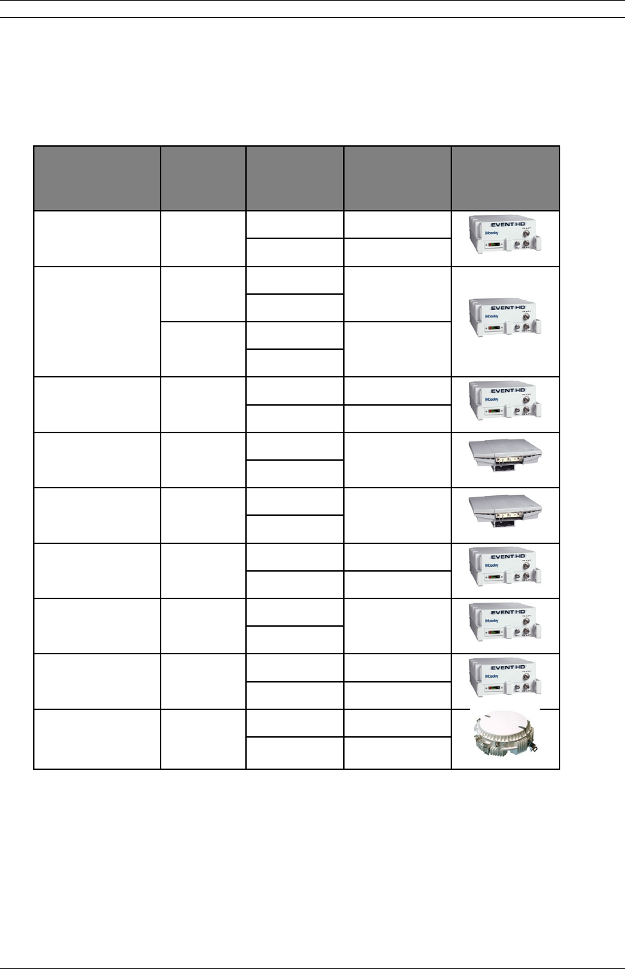
The Event HD digital radios enable network operators (mobile and private), government
and access service provides to offer a portfolio of secure, scalable wireless applications
for data, video, and Voice over IP (VoIP). The overall split mount architecture consists of
a single 1RU rack mount Software Defined Indoor Unit (SDIDUTM) with a cable
connecting to an Outdoor Unit (ODU) with an external antenna.
Core Access
Network
Indoor Unit
Indoor Unit
Indoor Unit
Outdoor
Unit
Outdoor
Unit
Outdoor
Unit
Outdoor
Unit
Outdoor
Unit
Outdoor
Unit
Figure 2-2. Microwave Split Mount Architecture
Table 2-2 shows key features that Moseley technology offers to those involved in the
design, deployment and support of broadband fixed wireless networks.
Table 2-1. Key Benefits and Advantages of the Event-HD Radios
Benefits Advantages to Providers/Customers Reference
Software Defined Indoor Unit (SDIDUTM)
Universal signal processing platform
Advanced Single Chip Modem ASIC
Integrated Forward Error Correction (FEC)
Powerful adaptive equalizer
Enables easy network interface options and
network capacity growth in the future.
Cost effective solution; simplifying product
logistics and overall product life cycle costs.
The flexibility reduces capital and operating
expenditures commonly associated with field
installation, maintenance, training and spares.
Frequency independent and Scalable.
Software defined flexibility enables selective
modulation for spectral efficiency and
adherence to worldwide regulatory emissions
guidelines.
2.2 – 2.5
© 2007 Moseley, Inc. All Rights Reserved. 602-14886-01, Rev. A

4 2. System Description
Benefits Advantages to Providers/Customers Reference
Easy to install units
Straightforward modular system enables fast
deployment and activation.
Carrier-class reliability.
Fast return on investment.
No monthly leased line fees.
3.1, 3.4, 3.6
Complete support of payload capacity with additional voice orderwire
Aggregate capacity beyond basic network
payload.
Scalable and spectrally efficient system.
Separate networks for radio
overhead/management and user payload.
Increases available bandwidth of network.
Allows customer full use of revenue-generating
payload channel.
Lowers total cost of ownership.
2.2 – 2.5
Ring Architecture
Supports a ring (consecutive point)
configuration, thus creating a self-healing
redundancy that is more reliable than
traditional point-to-point networks.
In the event of an outage, traffic is
automatically rerouted via another part of the
ring without service interruption.
Ring/consecutive point networks can overcome
line-of-sight issues and reach more buildings
than other traditional wireless networks.
Networks can be expanded by adding more
Software Defined IDU™ or more rings, without
interruption of service.
A separate management channel allows for a
dedicated maintenance ring with connections
to each Software Defined IDU™ on the ring.
Enables network scalability.
Increases deployment scenarios for initial
deployment as well as network expansion with
reduced line-of-sight issues.
Increases network reliability due to self-
healing redundancy of the network.
Minimizes total cost of ownership and
maintenance of the network.
Allows for mass deployment.
2.6
Adaptive Power Control
Automatically adjusts transmit power in
discrete increments in response to RF
interference.
Enables dense deployment.
Simplifies deployment and network
management.
2.7
Comprehensive Link/Network Management Software
© 2007 Moseley, Inc. All Rights Reserved. 602-14886-01, Rev. A

2. System Description 5
Benefits Advantages to Providers/Customers Reference
A graphical user interface offers security,
configuration, fault, and performance
management via standard craft interfaces.
Suite of SNMP-compatible network
management tools that provide robust local
and remote management capabilities.
Simplifies management of radio network and
minimizes resources as entire network can be
centrally managed out of any location.
Simplifies troubleshooting of single radios,
links, or entire networks.
Simplifies network upgrades with remote
software upgrades.
Allows for mass deployment.
2.5, 2.8
2.3System Features
Selectable Rates and Interfaces
oDVB-ASI interface application scalable from 10 to 100 Mbps.
oPDH Options
Up to 16 x E1/T1
100BaseTX/Ethernet: Scalable 1-100 Mbps
DS-3/E-3/STS-1
oSuper PDH Options
Up to 32 x E1/T1
100 BaseTX/Ethernet: Scalable 1-100 Mbps
oSDH Options
1-2 x SDH STM-1/OC-3 SONET
Support for multiple configurations for both PDH and SDH
o1+0, 1+1 protection/diversity
oHot Standby
oEast/West Repeater (2 + 0)
Selectable Spectral Efficiency of 0.8 to 6.25 bits/Hz (including FEC and spectral
shaping effects)
QPSK, 16 –256 QAM Modulation
© 2007 Moseley, Inc. All Rights Reserved. 602-14886-01, Rev. A

6 2. System Description
Powerful Trellis Coded Modulation concatenated with Reed-Solomon Error
Correction
Built-in Adaptive Equalizer
Support of Voice Orderwire Channels
Adaptive Power Control
Standard high-power feature at antenna port
o5W (37 dBm) in 2 GHz bands
o1W (30 dBm) in 5.8, 7, and 13 GHz bands
Built-in Network Management System (NMS)
Consecutive Point ring architecture
Built-in Bit Error Rate (BER) performance monitoring
Integrated Crosspoint switch: allows a total of 160 E1s (200 T1s) to be mapped
any-to-any between front-panel ports and RF link(s).
2.4Physical Description
The following section details the physical features of the Event HD™ digital radios.
•Model Types
•Front and rear panel configurations
•LED and I/O descriptions
© 2007 Moseley, Inc. All Rights Reserved. 602-14886-01, Rev. A
2. System Description 7
2.4.1Model Types
The following model types are available with associated ODU configuration:
Product Name Band
Primary
Data
Interfaces
Primary
Throughput ODU
1. Event 2200 1990-2110 ASI 10-100 Mbps
Ethernet 2 Mbps ODU2200
2. Event 2200 FD
2025-2150 16xE1/T1
2xEthernet
up to 100
Mbps
2200-2300 16xE1/T1
2xEthernet
up to 100
Mbps
ODU2200FD
3. Event 2500 2450-2500 ASI 10-100 Mbps
Ethernet 2 Mbps ODU2500
4. Event 5300 5250-5350 16xE1/T1
2xEthernet
up to 100
Mbps ODU5300
5. Event 5800 5725-5850 16xE1/T1
2xEthernet
up to 100
Mbps ODU5800
6. Event 6500 6425-6525 ASI 10-150 Mbps
Ethernet 2 Mbps ODU6500
7. Event 6800 6525-6875 16xE1/T1
2xEthernet
up to 100
Mbps
ODU6800
8. Event 7200 6875-7125 ASI 10-150 Mbps
Ethernet 2 Mbps ODU7200
9. Event 13G 12700-132
50
ASI 10-150 Mbps
Ethernet 2 Mbps ODU13G/18G/23G
© 2007 Moseley, Inc. All Rights Reserved. 602-14886-01, Rev. A

8 2. System Description
2.4.2Front Panel
All models of the Event HD are available with an optional front panel to perform primary
configuration functions such as change frequency and monitor receiver status and radio
health parameters. The panel is shown in Figure 2-2.
Figure 2-2. Event-HD front panel (optional)
The menu structure is navigated with the arrow keys, using the “check” key to enter, and
the X key to escape (go back one level). The menu structure gives access to three
primary functions: Status, Configuration, and Alarms. The menus are navigated as
follows:
Event
Status
Configuration
Alarms
Status
Transmit
Receive
Versions
Transmit
Output Pwr: xx.xxxxx
Freq : x.xxxxxx
Receive
Freq: x.xxxxxx
Modem
Errors
Versions
FP:xxxxxxxxxx
IDU/ODU
Modem
RSL :-xx.xxxx
SNR :x.xxxxxx
Lock:xxxxxxxx
IDU/ODU
Software/FPGA
Configuration
Firmware
Errors
Last Err sec:xxxxxx
Err sec 24h:xxxxxx
Software/FPGA
Kernel:xxxxxxxxxxxx
Appl :xxxxxxxxxxxx
FPGA :xxxxxxxxxxxx
Configuration
ODU :xxxxxxxxxxxxx
Modes:xxxxxxxxxxxxx
Chan :xxxxxxxxxxxxx
Firmware
ODU :xxxxxxxxx
Boot :xxxxxxxxx
Modm :xxxxxxxxx
© 2007 Moseley, Inc. All Rights Reserved. 602-14886-01, Rev. A

2. System Description 9
Configuration
ODU Control
ODU Channel
Administration
ODU Control
Str Tx Pwr:x.xxxxx
Mute :xxxxxx
State :xxxxxx
ODU Channel
Link
Loopback
Administration
xxxx days xxh:xxm
FP Network
IDU Network
Link
Freq:x.xxxxxx
Link:QPSK-10.5Mbaud
dataR=BaudR*mod
FP Network
IP :xxx.xxx.xxx.xxx
Mask:xxx.xxx.xxx.xxx
GW :xxx.xxx.xxx.xxx
Loopback
Type:combo of 3
LIU: combo
Duration: combo
IDU Network
IP :xxx.xxx.xxx.xxx
Mask:xxx.xxx.xxx.xxx
GW :xxx.xxx.xxx.xxx
Alarms
Active
Clear
1) mm-dd-yy hh:mm:ss
xxxxxxxxxxxxxxxxxx
xxxxxxxxxxxxxxxxxx
xxxxxxxxxxxxxxxxxx
Are you sure?
2) mm-dd-yy hh:mm:ss
xxxxxxxxxxxxxxxxxx
xxxxxxxxxxxxxxxxxx
xxxxxxxxxxxxxxxxxx
Alarms Cleared
The front panel provides immediate and convenient access to these functions however
much more extensive configuration and status information (status, alarm, graphical
history, constellations, etc.) are provided via the NMS Ethernet interface and web GUI.
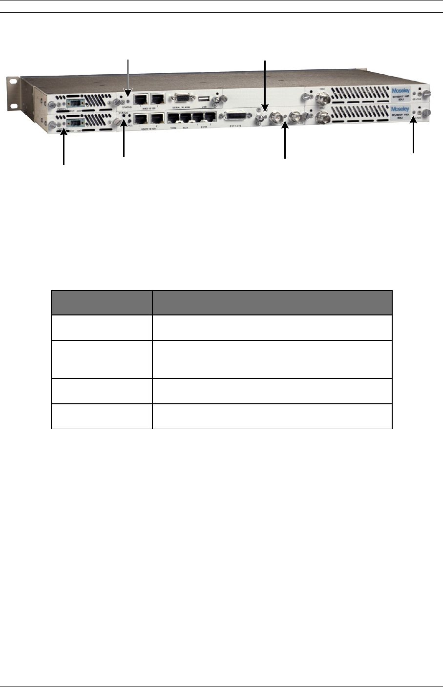
2.4.3Rear Panel Indicators
All models of the Event HD support a variety of rear panel configurations that are
dependent on the network interface and capacity configurations.
Figure 2-2 provides an example of the Event HD 1+0 configuration and the associated
LEDs displayed on the SDIDUTM rear panel. The controller, standard I/O, and each
modem card have a status LED.
© 2007 Moseley, Inc. All Rights Reserved. 602-14886-01, Rev. A
10 2. System Description
Controller
Status LED
Power/
Fault LED
Ethernet/
E1/T1
Status LED
DVB-ASI
Out Status
LED
DVB-ASI In
Status LED
Modem
Status LED
Figure 2-2. Software Defined IDU™ LEDs: SDIDUTM Rear Panel Configuration for
Software Defined IDU™, 1+0 Configuration
The modem status LED indicates the modem status as described in Table 2-2.
Table 2-2. Modem status LED.
LED STATUS
GREEN Active Locked Link
ORANGE Standby Locked Link (1+1 Non-Diversity
Only)
Flashing GREEN Low SNR
Flashing ORANGE Unlocked
© 2007 Moseley, Inc. All Rights Reserved. 602-14886-01, Rev. A

2. System Description 11
Table 2-3. DVB-ASI Input status LED.
LED STATUS
GREEN Good ASI input
RED No ASI input
Alternating
YELLOW/GRN
ASI exceeds radio bit rate
(FIFO overflow)
Flashing RED Loss-of-Frame
Flashing GRN No ASI data
Table 2-4. DVB-ASI Output status LED.
LED STATUS
GREEN Active Locked ASI Link
Alternating
RED/GREEN
No ASI, loss-of-frame
GREEN,
occasionally
flashing YELLOW
Locked ASI link with errors
(yellow flashes)
The controller status LED is the primary rear panel indicator of alarms. An alarm is
generated when a specific condition is identified and is cleared when the specified
condition is no longer detected. When an alarm is posted,
1. The controller status LED turns orange for 5 seconds
2. The controller status LED turns off for 5 seconds
3. The controller status LED flashes orange the number of times specified by the first
digit of the alarm code
4. The controller status LED turns off for 3 seconds
5. The controller status LED flashes orange the number of times specified by the
second digit of the alarm code
Steps 2-5 are repeated for each alarm posted. The entire process is repeated as long as
the alarms are still posted.
© 2007 Moseley, Inc. All Rights Reserved. 602-14886-01, Rev. A
12 2. System Description
The standard I/O and modem status LEDs are set to red when certain alarms are posted.
A complete list of alarms is provided in Appendix H6.1.
The alarm description is also displayed in the Graphical User Interface (GUI) as described
in the User Interface Reference Manual.
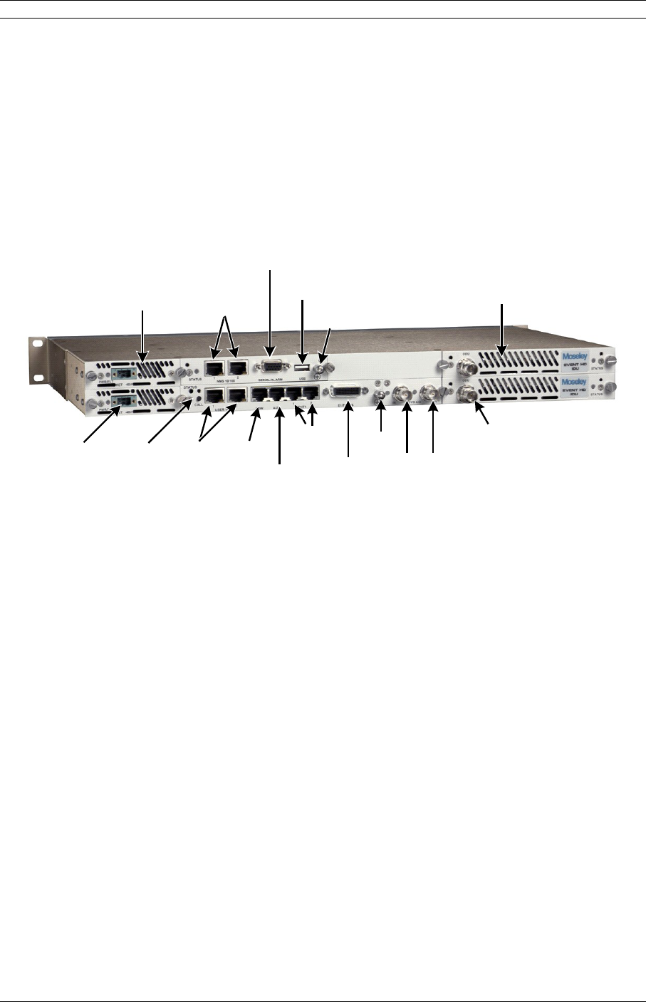
2.4.4Rear Panel Connections
Refer to the Figure 2-3 for an example of a Software Defined IDU™ rear panel followed
by a description of the connections.
NMS
Controller
Ethernet
-48V Power
Input
100Base-T
Ethernet
Data
Channels
ASI
Output
ASI
Input
ODU IF
Connection
Redundant
Power-Supply
(optional for
1+1, 2+0)
ALARM/Serial
Interface Redundant
MODEM
(optional for
1+1, 2+0)
USB
Ground
lug
Call
Button
Voice
Orderwire
Data
Orderwire
2xT1/E1
14xT1/E1
Ground
lug
Figure 2-3. Software Defined IDU™-SB, 1+1 Protection: SDIDUTM Rear Panel
Connections
© 2007 Moseley, Inc. All Rights Reserved. 602-14886-01, Rev. A

2. System Description 13
Power Supply Input
DC Input
-48 VDC
48v (Isolated Input); 2-pin captive power connector. The
Software Defined IDU™ requires an input of 48 volts dc
±10% at the rear panel DC Input connector. The total
required power is dependent on the option cards and
protection configuration (1+0, 1+1). The SDIDUTM rear
panel power connector pin numbering is 1 through 2,
from left to right, when facing the unit rear panel. Pin 1
is the power supply return and is connected to unit
chassis ground internally. Pin 2 should be supplied with
a nominal 48 V dc, with respect to the unit chassis
(ground). A ground-isolated supply may be used,
provided it will tolerate grounding of its most positive
output.
The recommended power input is 44 to 52 V dc at 2
Amps minimum. It is recommended that any power
supply used be able to supply a minimum of 100 W to
the SDIDUTM.
A mating power cable connector is supplied with the
Software Defined IDU™. It is a 2-pin plug, 5 mm pitch,
manufactured by Phoenix Contact, P/N 17 86 83 1
(connector type MSTB 2,5/2-STF). This connector has
screw clamp terminals that accommodate 24 AWG to 12
AWG wire. The power cable wire should be selected to
provide the appropriate current with minimal voltage
drop, based on the power supply voltage and length of
cable required. The recommended wire size for power
cables under 10 feet in length supplying 48 Vdc is 18
AWG.
The SDIDUTM supplies the ODU with all required power
via the ODU/SDIDUTM Interconnect cable. The Software
Defined IDU™ does not have a power on/off switch.
When DC power is connected to the SDIDUTM, the digital
radio powers up and is operational. There can be up to
320 mW of RF power present at the antenna port
(external antenna version). The antenna should be
directed safely when power is applied.
© 2007 Moseley, Inc. All Rights Reserved. 602-14886-01, Rev. A

14 2. System Description
Alarm/Serial Interface
Alarms/Serial DB-15HD female connector for two Form-C relay alarm
outputs (rated load: 1A @ 24 VDC), two TTL alarm
outputs, four TTL alarm inputs, and Serial Console. The
two Form-C relay alarm outputs can be configured to
emulate TTL alarm outputs.
USB Interface
USB USB connector, reserved.
Voice Orderwire Connector
Call Button The voice orderwire provides a PTP connection via a PTT
handset and buzzer. The call button initiates a ring.
Only the SDIDU’s™ link partner will receive the ring.
VOW does not ring all nodes or support “party line” calls.
Voice
Orderwire
RJ-45 modular port connector for voice orderwire
interface.
Data Orderwire Connector
Data
Orderwire
RJ-45 modular port connector for RS422/RS-232 data at
64 kbps.
NMS 10/100 Network Management System Connections
NMS 10/100 1 10/100Base-TX RJ-45 modular local port connector for
access to the Network Management System (SNMP) and
GUI.
NMS 10/100 2 10/100BaseTX RJ-45 modular remote port connector for
access to the Network Management System (SNMP). This
port to be used for consecutive point networks.
100/Ethernet Models: Ethernet 100BaseT Connections
USER 10/100 1 100Base-TX RJ-45 modular port connector for the local
Fast Ethernet interface.
USER 10/100 2 100Base-TX RJ-45 modular port connector. This port to
be used for consecutive point networks.
T1 Channels
T1 1-2 Two T1/E1 (RJ-48C) interface connections.
T1 3-8/16 Single Molex 60-pin connector containing 14 T1/E1
connections.
© 2007 Moseley, Inc. All Rights Reserved. 602-14886-01, Rev. A
2. System Description 15
DVB/ASI, DS-3, E-3, and STS-1Connection (Optional Mini IO)
DVB/ASI Out BNC connector for the DVB/ASI digital video and DS-3,
E-3, and STS-1 interface.
DVB/ASI In BNC connector for the DVB/ASI digital video and DS-3,
E-3, and STS-1 interface.
OC-3 Connection (Optional Mini IO)
OC-3 Out OC-3 type SC connectors for the OC-3 interface.
OC-3 In OC-3 type SC connectors for the OC-3 interface.
STM-1 Connection (Optional Mini IO)
STM-1Out BNC connector for the STM-1 interface.
STM-1 In BNC connector for the STM-1 interface.
ODU/SDIDUTM Interconnect
To ODU TNC female connector. Used to connect the ODU to the
SDIDUTM. Provides –48VDC and 350 MHz Transmit IF to
the ODU and receives 140 MHz Receive IF from the ODU.
Ground Connection
Ground Lug Two ground lugs are provided on the rear panel. Either
may be used to connect the SDIDU™ to ground.
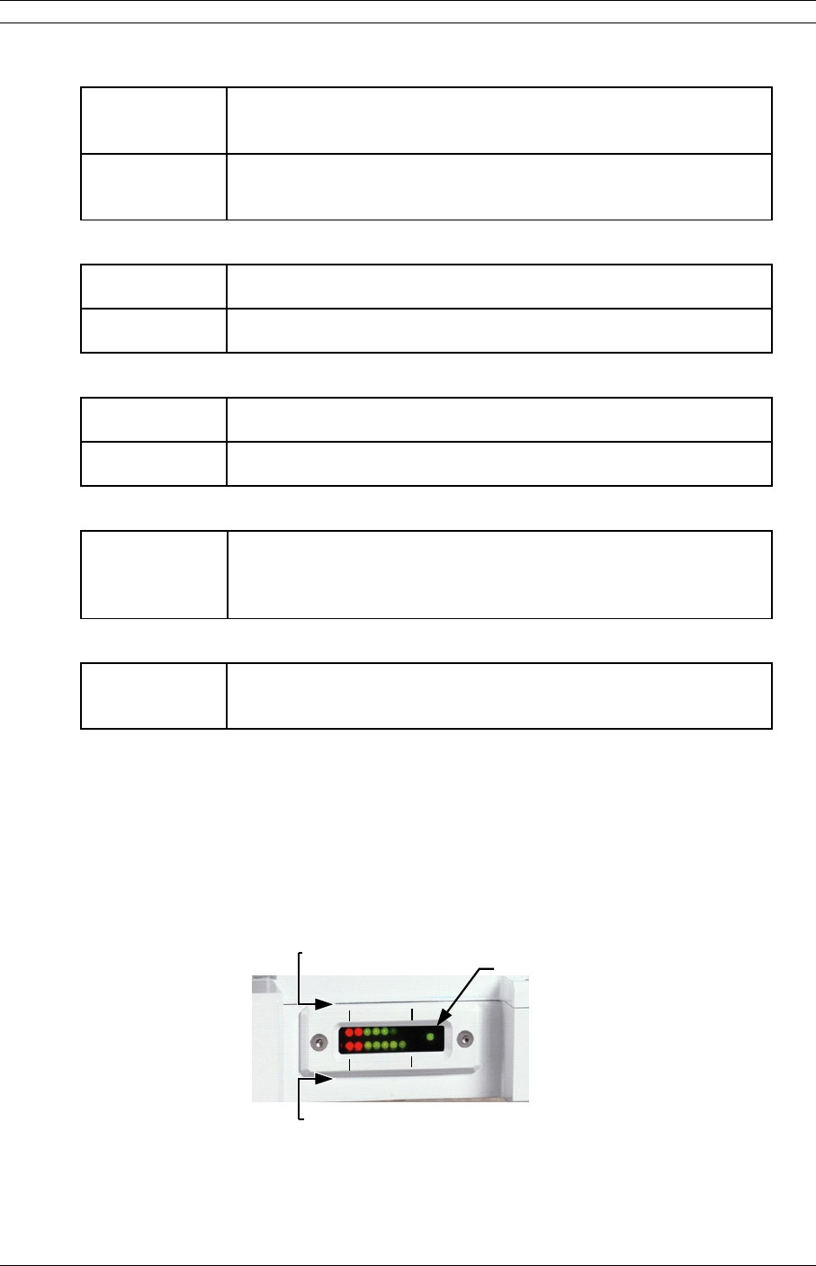
2.4.5ODU LED Indicators
The ODU 2200, 6500, and 7200 has an externally visible LED meter that provides both
RSL (Receive Signal Level) and transmit power. For full-duplex operation the ODU meter
displays RSL on the top bar and transmit level on the bottom bar as shown in Figure 2-4.
Unit ON
(Heartbeat)
-95
dBm
-15
dBm
Tx
Min
Tx
Max
Transmit
Power Level
(Bottom Row)
Receive Signal
Level
(Top Row)
Figure 2-4. ODU 2200 RSSI Output vs. Received Signal.
© 2007 Moseley, Inc. All Rights Reserved. 602-14886-01, Rev. A

16 2. System Description
The upper RSL LED meter is calibrated to represent exactly 10 dB for each LED, going
from -95 dBm at the far left (red) to -15 dBm at the far right (green). The brightness of
each LED is modulated for levels between 0 to 10 dB such that the far left LED will be
fully extinguished at -95 dBm and the far right LED will be fully illuminated at -15 dBm.
When the RSL is in the red region (<-75 dBm) the signal level is approaching or has
reached threshold (depends on modulation type).
The transmit LED indicates full power will all 8 LEDs illuminated to minimum power with 1
LED illuminated. For simplex applications the both rows indicate either RSL or transmit
power.
2.5System Description
The overall Event-HD digital radio architecture consists of a single 1RU rack mount
Software Defined Indoor UnitTM (SDIDUTM) with a cable connecting to an Outdoor Unit
(ODU). The IF signal between the SDIDU and ODU operates at a relatively low frequency
compared with the RF signal allowing for extensive cable runs in excess of 250 m with
inexpensive coaxial cable with no degradation in radio performance.
The Event-HD ODU is mounted to a fixed or telescoping antenna mast near the desired
antenna location providing a short cable run between ODU and antenna at the RF
frequency. This SDIDU /ODU architecture is advantageous when compared to a single
IDU (no ODU) with external mount antenna as operating at these RF frequencies from
the IDU rack to the antenna will result in significant signal degradation and require
expensive low-loss coaxial cable or waveguide.
© 2007 Moseley, Inc. All Rights Reserved. 602-14886-01, Rev. A
2. System Description 17
FRAMER
DVB-ASI
DS-3/ES/
STS-1
2xSTM-1/
OC3
4xDS3/ES/
STS1
STM-1/OC3
64 kbps
Voice
16 T1/E1
User 2x
100Base-Tx Switch MODEM/
FEC ASIC
MODEM/
FEC ASIC
4x44.736/34.368/
51.84 Mbps
2x 155.52 Mbps
4x44.736/34.368/
51.84 Mbps
Up to 150 Mbps
2x 100 Mbps
16x 1.544/2.048
Mbps
Digital
IF
Quad
Mux
SNMP 2x
100Base-Tx Switch
CPU
East/Primary Modem
West/Secondary Modem
Digital
IF
Quad
Mux
2x 100 Mbps
IDU
CONTROLLER
Optional I/O Cards
(Small Slot)
Standard I/O Cards
Optional I/O Cards
(Large Slot)
Primary Power
Supply
Secondary Power
Supply
Serial
RCH Serial
Modem Control
Telemetry
IDU
-48Vdc
-48Vdc
-48Vdc
-48Vdc
Multiplexed
IF
Multiplexed
IF
155.52 Mbps
External
Antenna
N-type
Internal/
Horizontal
Antenna
Transfer
Switch Duplexer
Diversity
Switch
Vertical
Antenna
Unlicensed 5.3/5.8 GHz
Internal Duplexer Configuration
Tx
Rx
Duplexer
Short-Haul 6-38 GHz
Internal Duplexer Config
External
Antenna
(Waveguide
Flange)
Tx
Rx
Transmitter
Up-Converter
Receiver
Down-Converter
350
MHz
140
MHz
DC/DC
Converters
-48Vdc +10Vdc
+5Vdc
+3Vdc
-5Vdc
Commlink
& Processor
5/10
MHz
ODU
RSL
(Received Signal Level)
Voltage
TNC
BNC
Quad
Mux
Tx Out Tx Ext
Antenna
N-Type
Rx In
Rx Ext
Antenna
N-Type
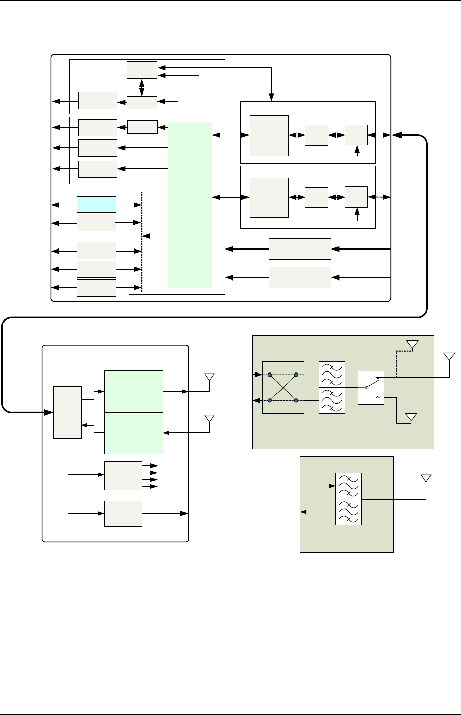
Figure 2-5. Event-HD Block Diagram
Figure 2-5 shows the Event-HD digital radio and interfaces from a functional point of
view. The functional partitions for the I/O, Modem/IF, power supply modules, up/down
converters, and internal RF duplexing partition are shown. The SDIDUTM comes with the
standard I/O capability which can be upgraded. The Modem/IF function is modular
allowing the addition of a second Modem to support protection or ring architectures. The
power supply is similarly modular. In addition, the ODUs are interchangeable allowing
use of a single IDU in licensed, unlicensed, and short-haul applications by swapping the
RF component.
© 2007 Moseley, Inc. All Rights Reserved. 602-14886-01, Rev. A

18 2. System Description
The Event-HD ODU RF Up/Down Converter provides the interface to the antenna. The
transmit section up converts and amplifies the modulated Intermediate Frequency (IF) of
350 MHz from the IF Processor and provides additional filtering. The receive section down
converts the received signal, provides additional filtering, and outputs an IF of 140 MHz
to the IF Processor.
The Event-HD digital radio modem performs QPSK, 16-QAM, 32-QAM, 64-QAM, and 128-
QAM modulation and demodulation of the payload and forward error correction using
advanced modulation and coding techniques. Using all-digital processing, the IF Modem
uses robust modulation and forward error correction coding to minimize the number of
bit errors and optimize the radio and network performance. The IF Modem also
scrambles, descrambles and interleaves/deinterleaves the data stream in accordance
with Intelsat standards to ensure modulation efficiency and resilience to sustained burst
errors. The modulation will vary by application, data rate, and frequency spectrum. The
highest order modulation mode supported is 128 Quadrature Amplitude Modulation
(QAM). Table 2-5 summarizes the TCM/convolutional code rates for each modulation type
supported by the Event-HD.
Table 2-5. Event-HD TCM/Convolutional Code Rates
Modulation Type Available Code Rates
QPSK 1/2, 3/4, 7/8
16-QAM 3/4, 7/8,
32-QAM 4/5, 9/10
64-QAM 5/6, 11/12
128-QAM 11/12
The major functions of the SDIDUTM can be summarized as follows:
•I/O Processing – Event-HD digital radio comes with a standard I/O capability that
includes support for up to 16xT1/E1 and 2x100Base-TX user payloads, 2x100Base-TX
for SNMP, and voice orderwire. In addition, option cards for DVB-ASI,
DS-3/E3/STS-1, 1-2 x STM-1/OC-3, and 4xDS-3/E3/STS-1 may be added. The Event-
HD architecture is flexible and allows for the addition of other I/O types in the future.
•Switch/Framing – The Event-HD digital radio includes an Ethernet Switch and a
proprietary Framer that are designed to support 1+1 protection switching, ring
architecture routing, and overall network control functions.
•Network Processor – The Event-HD digital radio includes a Network Processor which
performs SNMP and Network Management functions.
•Modem/IF – The Event-HD digital radio modem performs forward-error-correction
(FEC) encoding, PSK/QAM modulation and demodulation, equalization, and FEC
decoding functions. The IF chain provides a 350 MHz carrier and receives a 140 MHz
© 2007 Moseley, Inc. All Rights Reserved. 602-14886-01, Rev. A

2. System Description 19
carrier. The multiplexer function is built into an appliqué that resides in the Modem/IF
Module. Two modems can be used for 1+1 protection or ring architectures.
•Power Supply – The Event-HD power supply accepts 48 Vdc and supplies the SDIDUTM
and ODU with power. A second redundant power supply may be added as an optional
module.
The Modem Processor and its associated RAM, ROM, and peripherals control the digital
and analog operation. It also provides configuration and control for both the IF and I/O
cards. The SDIDU interfaces with the ODU to receive and provide modulated transmit
and receive waveforms.
The Event-HD digital radio also provides the physical interface for the user payload and
network management. In transmit mode, the Framer merges user payload (OC-3 or Fast
Ethernet) with radio overhead-encapsulated network management data. This combined
data stream is transmitted without any loss of user bandwidth. In the receive mode, the
Framer separates the combined data stream received from the 256-QAM Modem. The
SDIDUTM supports Scalable Ethernet data rates, such as 25 or 50 Mbps via the 100BaseT
data interface port. The SDIDUTM provides network management data on 10 Mbps ports
accessible via the 10/100BaseTX port. The Central Processor Unit (CPU) provides the
embedded control and network element functionality of the OAM&P. The CPU also
communicates with other functions within the SDIDUTM for configuration, control, and
status monitoring. The CPU passes appropriate status information to the SDIDUTM rear
panel display.
The power supply converts -48 Vdc to the DC voltage levels required by each component
in the system.
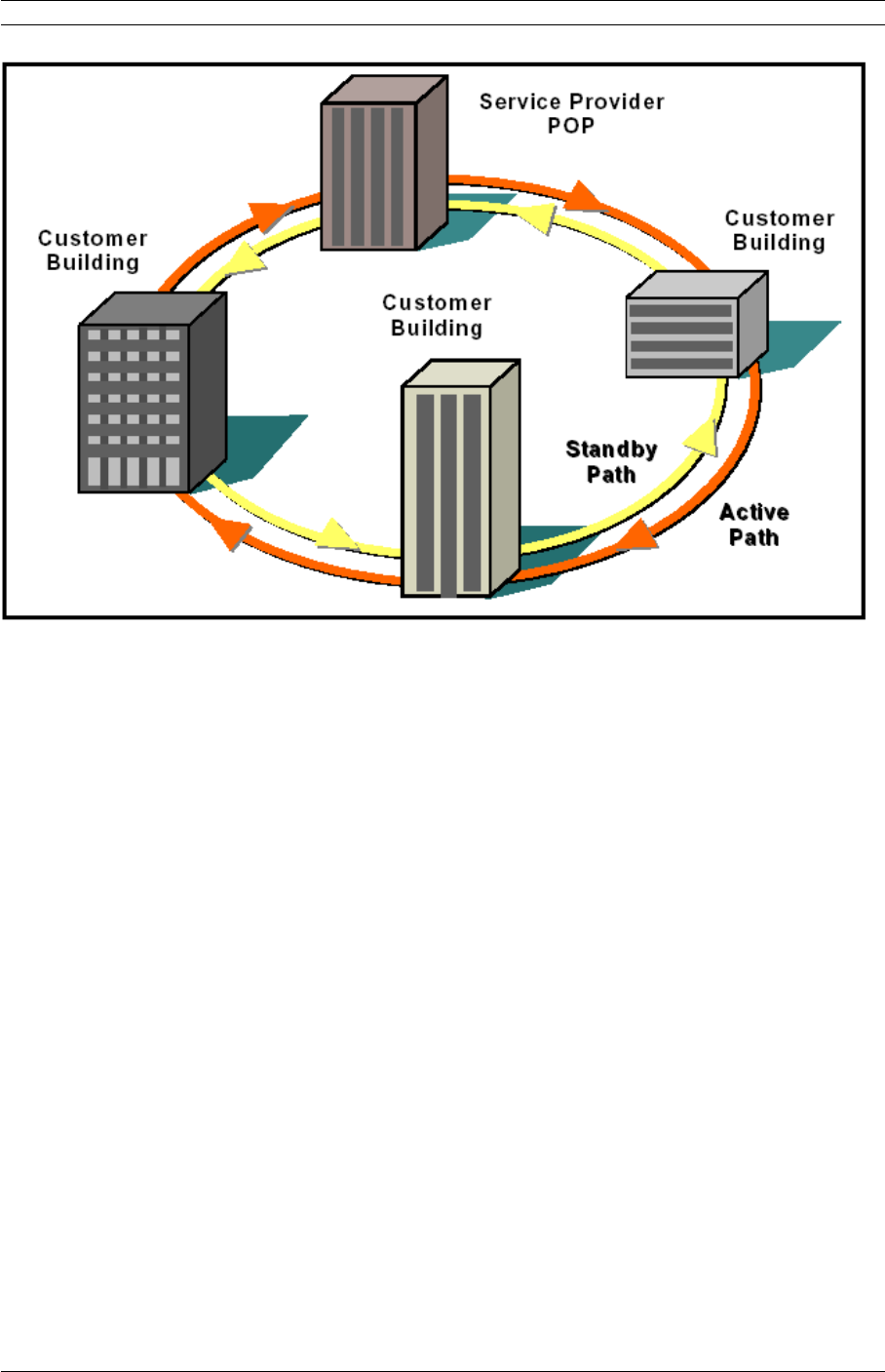
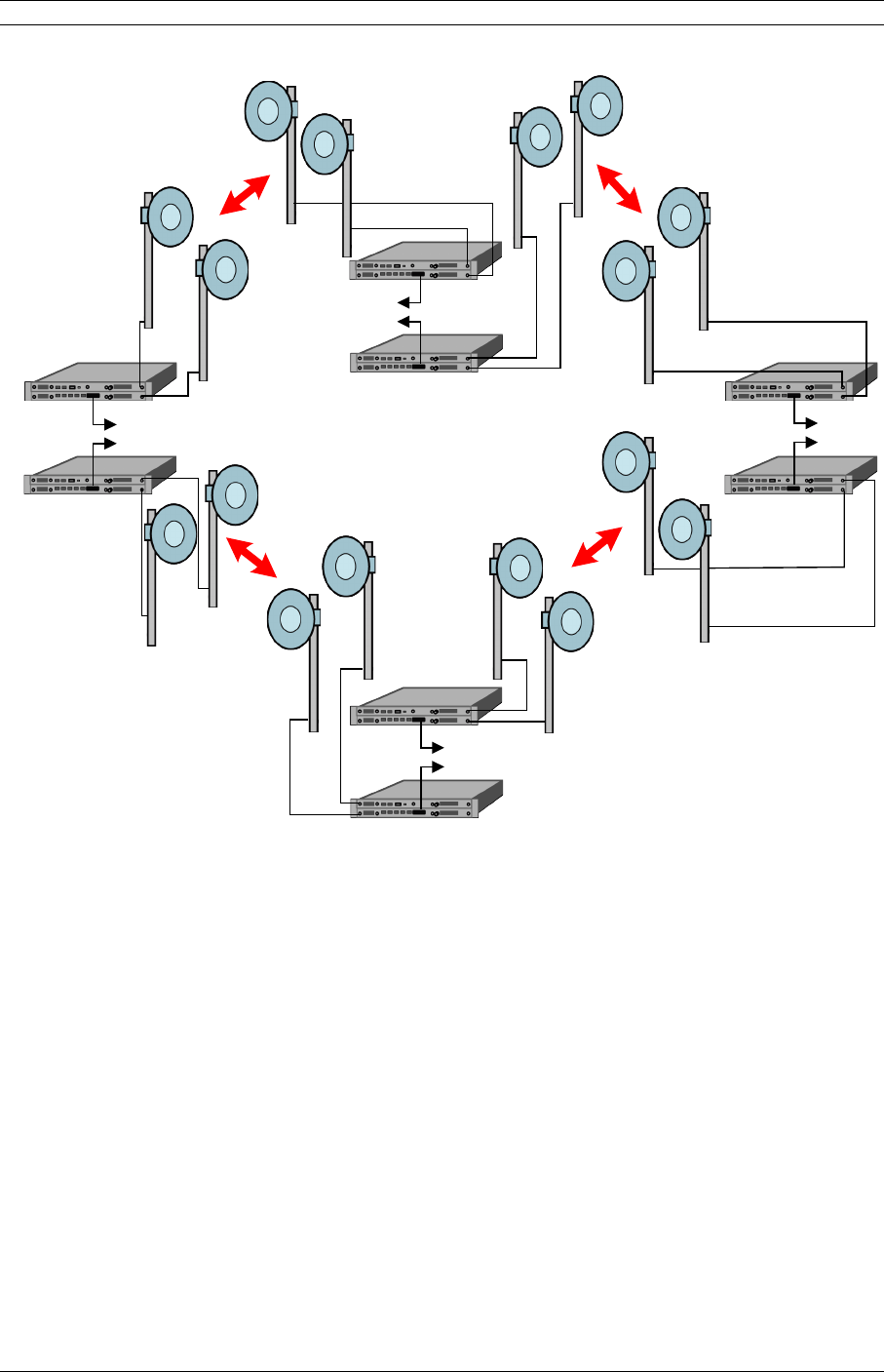
2.6Consecutive Point Architecture
The consecutive point network architecture is based upon the proven SONET/SDH ring.
Telecommunications service providers traditionally use the SONET/SDH ring architecture
to implement their access networks. A typical SONET/SDH network consists of the
service provider’s Point of Presence (POP) site and several customer sites with fiber optic
cables connecting these sites in a ring configuration (see Figure 2-6). This architecture
lets providers deliver high bandwidth with high availability to their customers.
© 2007 Moseley, Inc. All Rights Reserved. 602-14886-01, Rev. A
20 2. System Description
Figure 2-6. Ring Configuration
SONET/SDH rings are inherently self-healing. Each ring has both an active path and a
standby path. Network traffic normally uses the active path. If one section of the ring
fails, the network will switch to the standby path. Switchover occurs in seconds. There
may be a brief delay in service, but no loss of payload, thus maintaining high levels of
network availability.
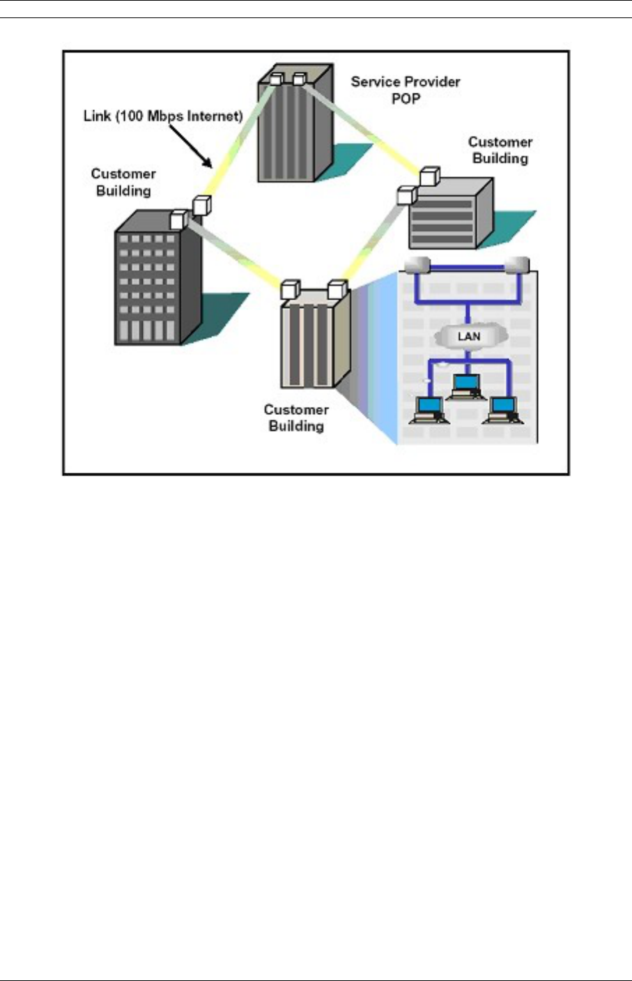
The consecutive point architecture implemented in the Moseley Digital Radio family is
based on a point-to-point-to-point topology that mimics fiber rings, with broadband
wireless links replacing in-ground fiber cable. A typical consecutive point network consists
of a POP and several customer sites connected using Software Defined IDU™. These
units are typically in a building in an east/west configuration. Using east/west
configurations, each unit installed at a customer site is logically connected to two other
units via an over-the-air radio frequency (RF) link to a unit at an adjacent site.
Each consecutive point network typically starts and ends at a POP. A pattern of wireless
links and in-building connections is repeated at each site until all buildings in the network
are connected in a ring as shown for an ethernet network in Figure 2-7. For 2 x 1+0 and
2 x 1+1 nodes payload and NMS connections need to be jumpered between two SDIDUTM.
For 1 x 2+0 nodes, there is no need for jumpers as there is a single SDIDUTM. For SDH or
SONET payloads, the configuration is similar but an external add/drop mux is required.
© 2007 Moseley, Inc. All Rights Reserved. 602-14886-01, Rev. A
2. System Description 21
Figure 2-7. Consecutive Point Network
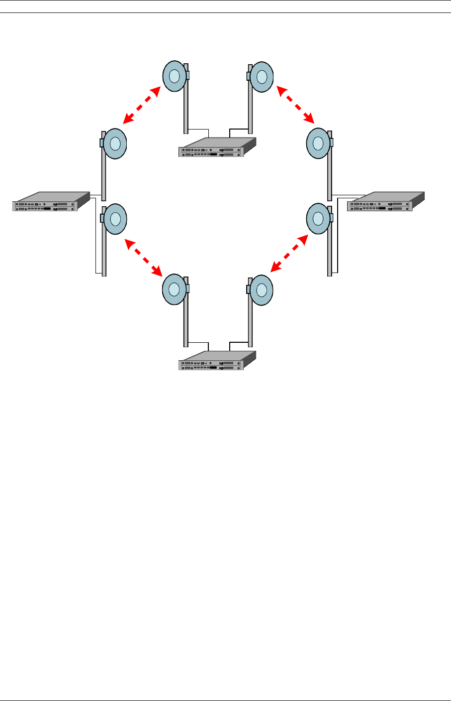
2.72 + 0 (East-West) Configuration
The Event-HD supports a 2+0, or east-west, configuration that allows a consecutive point
architecture to be achieved with only a single 1 RU chassis at each location. In this
configuration the SDIDUTM contains two modems and may contain two power supplies.
One modem is referred to as the west modem and the other as the east modem. The
SDIDUTM is connected to two ODUs, one broadcasting/receiving in one directing of the
ring architecture and the other broadcasting/receiving in the other as shown in Figure
2-8.
© 2007 Moseley, Inc. All Rights Reserved. 602-14886-01, Rev. A
22 2. System Description
Connected to
east modem
Connected to
west modem
Connected to
east modem
Connected to
west modem
Connected to
west modem
Connected to
east modem
Connected to
west modem
Connected to
east modem
Figure 2-8. 2 + 0 (East West) Configuration
2.8Spanning Tree Protocol (STP)
Spanning Tree Protocol (STP) keeps Ethernet loops from forming in a ring architecture.
Without STP, loops would flood a network with packets. STP prevents loops by creating
an artificial network break. In the event of a network outage, STP automatically removes
the artificial break, restoring connectivity.
2.91+1 Protection
The Event HD supports 1+1 protection as an option for a critical link. In this
configuration, protection is provided in a single 1 RU chassis. The SDIDUTM contains two
power supplies and two modems. The power supply, ODU, IF/telemetry and modem are
protected. The digital framing and LIUs are not. One modem is referred to as the west
modem and the other as the east modem. 1+1 protection can be run in two modes called
Protected Non-Diversity and Protected Diversity.
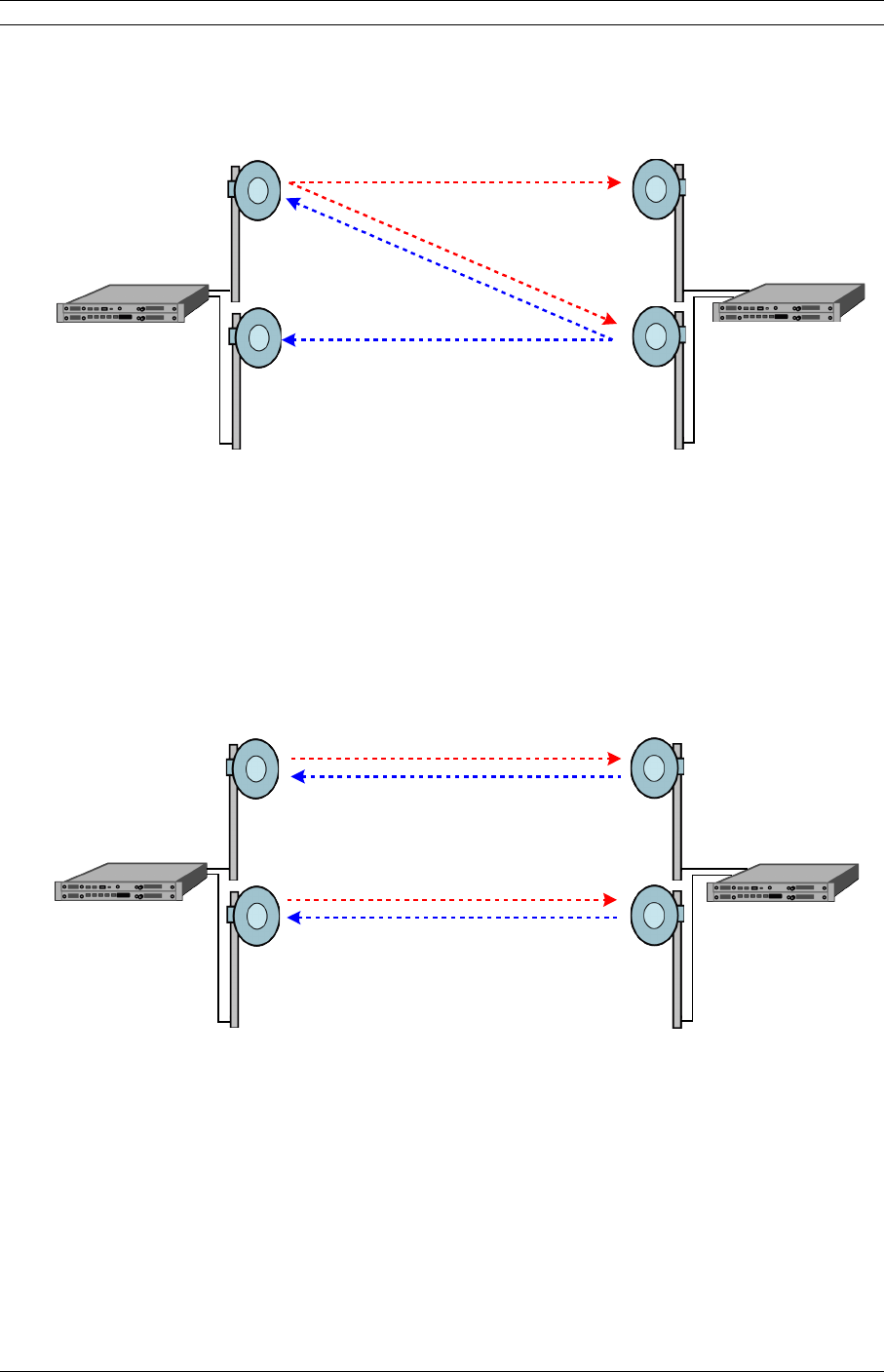
2.9.1Protected Non-Diversity (Hot Standby)
Figure 2-9 shows operation in Protected Non-Diversity mode, also called Hot Standby. In
this mode, one ODU at each location transmits to two ODUs at the other location. This
© 2007 Moseley, Inc. All Rights Reserved. 602-14886-01, Rev. A
2. System Description 23
mode does not require the extra bandwidth or interference protection. It provides hitless
receive switching and hot standby. The SDIDUTM automatically switches transmit ODU
upon appropriate ODU alarm or ODU interface error, minimizing transmit outage time.
Connected to
west modem
Connected to
east modem
Connected to
west modem
Connected to
east modem
Figure 2-9. 1+1 Protection in Non-Diversity Mode
2.9.2Protected Diversity
In Protected Diversity mode, the link between each pair of modems is the same, as
shown in Figure 2-10, providing complete redundancy. This arrangement requires
bandwidth for both links and non-interference between the links, but it provides hitless
receive and transmit switching. The SDIDUTM supports both frequency and spatial
diversity.
Connected to
east modem
Connected to
west modem
Connected to
west modem
Connected to
east modem
Figure 2-10. 1+1 Protection in Diversity Mode
2.9.2.1 Frequency Diversity
In frequency diversity, two frequencies are used to achieve non-interference. The
proprietary framer chooses the best, or error-free, data stream and forwards it to the
Line Interface Units (LIUs).
© 2007 Moseley, Inc. All Rights Reserved. 602-14886-01, Rev. A

24 2. System Description
2.9.2.2 Spatial Diversity
In spatial diversity, two non-interfering paths are used. The proprietary framer chooses
the best, or error-free, data stream and forwards it to the Line Interface Units (LIUs).
2.9.2.2.1Single Transmitter
Protected Non-Diversity, or Hot Standby, is also referred to as Single Transmitter Spatial
Diversity. For more information on this mode, see Section 2.9.1.
2.9.2.2.2Dual Transmitter
When using Dual Transmitter Spatial Diversity, two active transmitters are physically
isolated to avoid crosstalk.
2.101 + 1 Multi-hop Repeater Configuration
The Event HD supports a 1 + 1 multi-hop repeater configuration with drop/insert
capability as shown in Figure 2-11. This configuration provides individual 1 + 1 link
protection as described in section 2.7, as well as the full-scale protection inherent in the
consecutive point architecture as described in section 2.6. At each location within the
network, data may be dropped or inserted. In this configuration each SDIDUTM contains
two power supplies and two modems.
© 2007 Moseley, Inc. All Rights Reserved. 602-14886-01, Rev. A
2. System Description 25
Data
drop/insert
Data
drop/insert
Data
drop/insert
Data
drop/insert
Protected
Link
Protected
Link
Protected
Link
Protected
Link
Figure 2-11. 1 + 1 Multi-Hop Repeater Configuration
2.11Data Interfaces
The primary interface for video and broadcast applications is the DVB-ASI interface
located in the mini-I/O card slot. Alternatively this interface can be replaced with STM-1
Optical/OC-3 or STM-1 Electrical interfaces. The optical interface is single mode at 1300
nm. Consult factory for availability of Mini-IO STM-1/OC-3 Module.
The I/O card has 2x100BaseTX interfaces that can be configured as either primary
payload, or secondary wayside channels. The Over-the-air channel has a data-bandwidth
capacity that is set by the frequency-bandwidth, modulation, and coding. The data-
bandwidth may be allocated to various I/O card interfaces, including 155.52 Mbps for
DVB-ASI or STM-1, 2 Mbps per E1, up to 100 Mbps Ethernet, and up to 1 Mbps NMS.
Only up to 100 Mbps of data-bandwidth may be allocated for either net data, and the two
I/O card 100BaseTX interfaces will share that 100 Mbps data-bandwidth.
© 2007 Moseley, Inc. All Rights Reserved. 602-14886-01, Rev. A
26 2. System Description
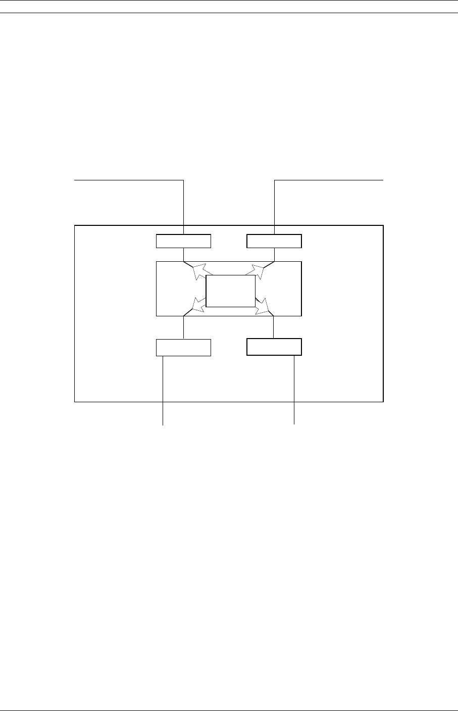
2.12Crosspoint Switch
The SDIDU™ crosspoint switch provides any-to-any E1/T1 routing between rear panel
ports and RF links, as shown in Figure 2-12. Flexible channel mapping allows selection
from predefined routings or custom routing. Custom routings are uploaded to the
SDIDU™ via FTP. Two examples of the crosspoint capability are to use the crosspoint
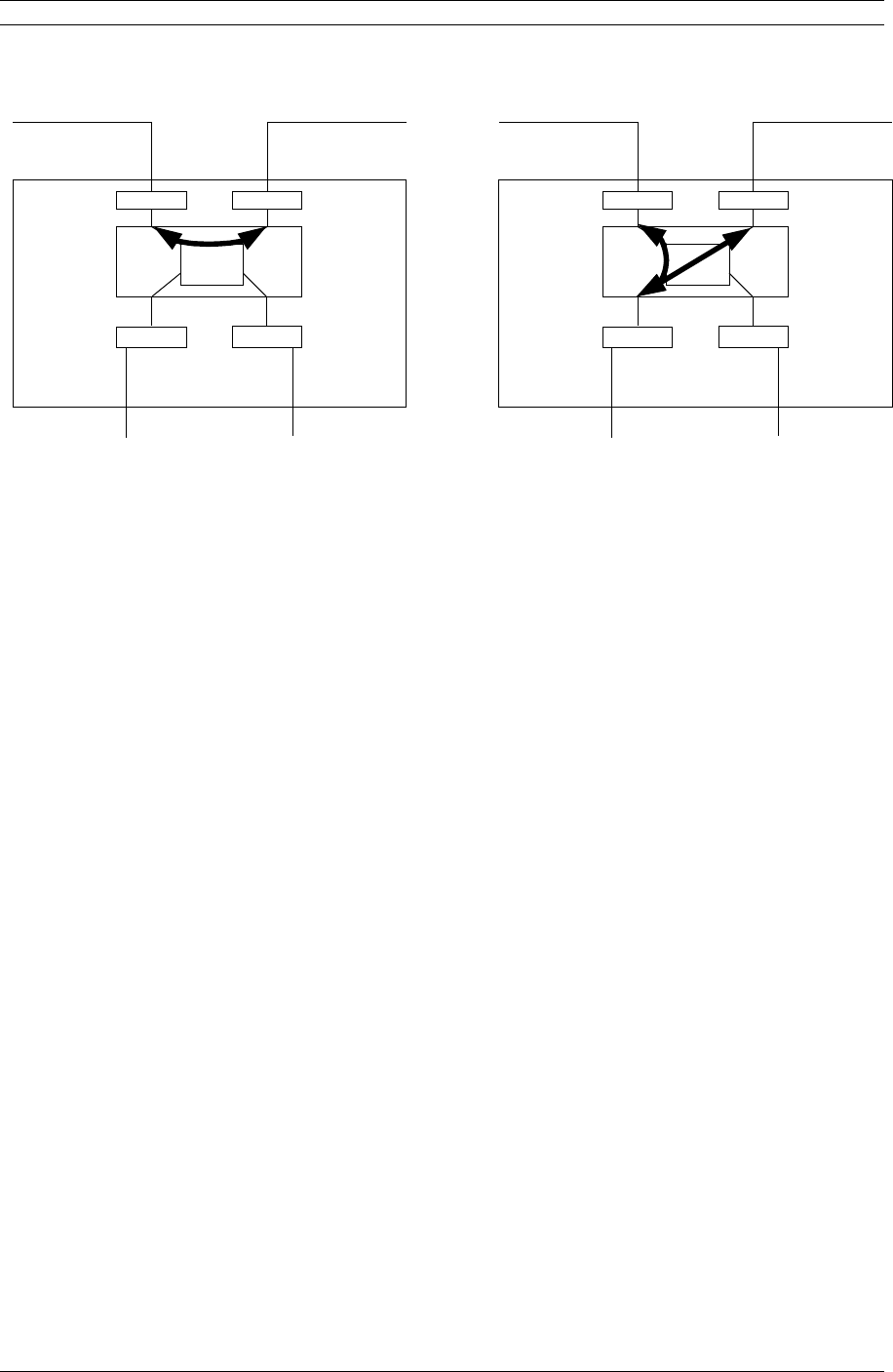
switch to configure a repeater or an add/drop. These examples are shown in Figure 2-13.
In the repeater example, the Crosspoint Switch is used as a passthrough to send E1/T1s
from the east modem to the west modem. In the add/drop example, the crosspoint
switch connects E1/T1s from the modems to the rear-panel ports.
Framer
Modem East Modem West
IO
Up to 32 E1 Up to 32 E1
Up to 16E1 Up to 16E1
Optional IO
Crosspoint
Switch
Figure 2-12. Crosspoint Switch
© 2007 Moseley, Inc. All Rights Reserved. 602-14886-01, Rev. A
2. System Description 27
Crosspoint
Switch
Framer
Modem East Modem West
IO
Up to 32 E1 Up to 32 E1
Up to 16E1 Up to 16E1
Optional IO
Crosspoint
Switch
Framer
Modem East Modem West
IO
Up to 32 E1 Up to 32 E1
Up to 16E1 Up to 16E1
Optional IO
Repeater Example Add/Drop Example
Figure 2-13. (a) Crosspoint Switch used a passthrough in repeater
configuration. (b) Crosspoint Switch allows access for add/drop.
2.13Power Management
RF power management is a radio design feature that controls the power level (typically
expressed in dBm) of the RF signal received from a transmitter by a receiver. The
traditional goal of power management is to ensure that the RF signal at a receiver is
strong enough to maintain the radio link under changing weather and link conditions.
The Quadrature Amplitude Modulation (QAM) is not a constant envelope waveform.
Therefore, the average power and peak power are different. The difference in peak and
average power depends on the constellation type and shaping factor, where spectral
efficiency such as more constellation points or lower shaping factor leading to peak
powers higher than average powers. The peak power is typically 5-7 dB greater than the
average power and never exceeds 7 dB. Regulatory requirements are sometimes based
on peak EIRP which is based on peak power and antenna gain.
Traditional power management techniques such as Constant Transmit Power Control
(CTPC) and Automatic Transmit Power Control (ATPC) transmit at a high power level to
overcome the effects of fading and interference. However, these techniques continue to
operate at a higher power level than needed to maintain the link in clear weather.
Because transmit power remains high when the weather clears, the level of system
interference increases.
Radios operating at high transmit power will interfere with other radios, even if the
interfering source is miles away from the victim. High interference levels can degrade
signal quality to the point that wireless radio links become unreliable and network
availability suffers. The traditional solution to system interference is to increase the
distance between radios. However, the resulting sparse deployment model is
inappropriate for metropolitan areas.
© 2007 Moseley, Inc. All Rights Reserved. 602-14886-01, Rev. A

28 2. System Description
In response to the need for a high-density deployment model the Event-HD uses a
unique power control technique called AdTPC. AdTPC enables Event-HD to transmit at the
minimum power level necessary to maintain a link regardless of the prevailing weather
and interference conditions. The Event-HD is designed and manufactured to not exceed
the maximum power allowed. The purpose of power management is to minimize transmit
power level when lower power levels are sufficient. AdTPC also extends the concept of
power management by controlling not only the power (dBm) of the RF signal, but its
quality (signal-to-noise ratio) as well.
In contrast to ATPC, the AdTPC technique dynamically adjusts the output power based on
both the actual strength and quality of the signal. Networked Event-HD radios constantly
monitor receive power and maintain 10-12 BER performance under varying interference
and climate conditions. Each Event-HD unit can detect when there is a degradation in the
received signal level of quality and adjust the transmit power level of the far-end Event-
HD unit to correct for it.
AdTPC provides maximum power in periods of heavy interference and fading and
minimum power when conditions are clear. Minimal transmit power reduces potential for
co-channel and adjacent channel interference with other RF devices in the service area,
thereby ensuring maximum frequency re-use. The resulting benefit is that operators are
able to deploy more Event-HD units in a smaller area.
2.14Event-HD Software and Network Management
All of the Event-HD parameters are accessible in three ways:
1. Using a standard web-browser via HTTP to access the built in web server.
2. Via SNMP using the fully featured MIB, allowing for automation of data collection
and network management.
3. Via a command line client accessible from a terminal client connected to the serial
port, or telnet over the NMS Ethernet.
The GUI (HTTP), SNMP, and CLI interfaces are discussed in detail in the Software Defined
IDU™ User Interface Manual.
2.14.1IP Address
Each Event-HD radio is configured independently for network parameters such as IP
address, subnet, and gateway. However, the Event-HD also supports acting as a DHCP
client, in which case the IP address can be assigned to the Event-HD radio using a DHCP
server. A specific IP address may be associated with a particular Event-HD radio by
configuring the DHCP server to serve IP addresses based upon the SDIDU™ Ethernet
MAC address.
2.14.2Network
The Event-HD uses an “Out-of-Band” NMS network which is separated from the payload
Ethernet network. Each Event-HD contains a managed Layer 2 Ethernet switch that
supports Spanning-Tree Protocol (STP) for managing NMS traffic. This allows the Event-
© 2007 Moseley, Inc. All Rights Reserved. 602-14886-01, Rev. A
2. System Description 29
HD to be configured in a protected ring configuration where the STP will prevent an
Ethernet loop in the ring. This will also allow the ring to re-configure in the event of an
outage. The Event-HD acts as a network bridge via the Ethernet switch and STP. The
Event-HD does not currently support NMS routing capability.
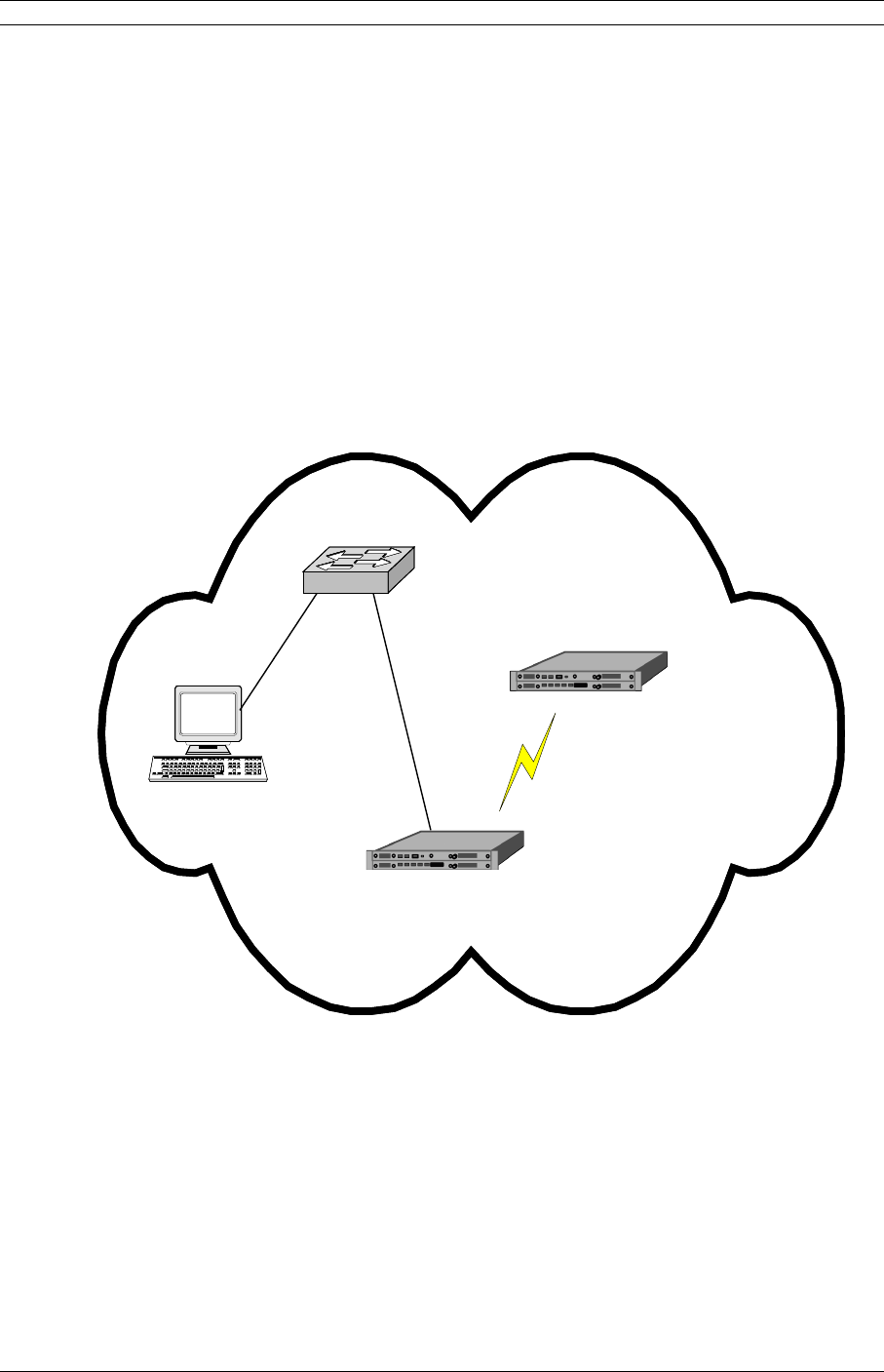
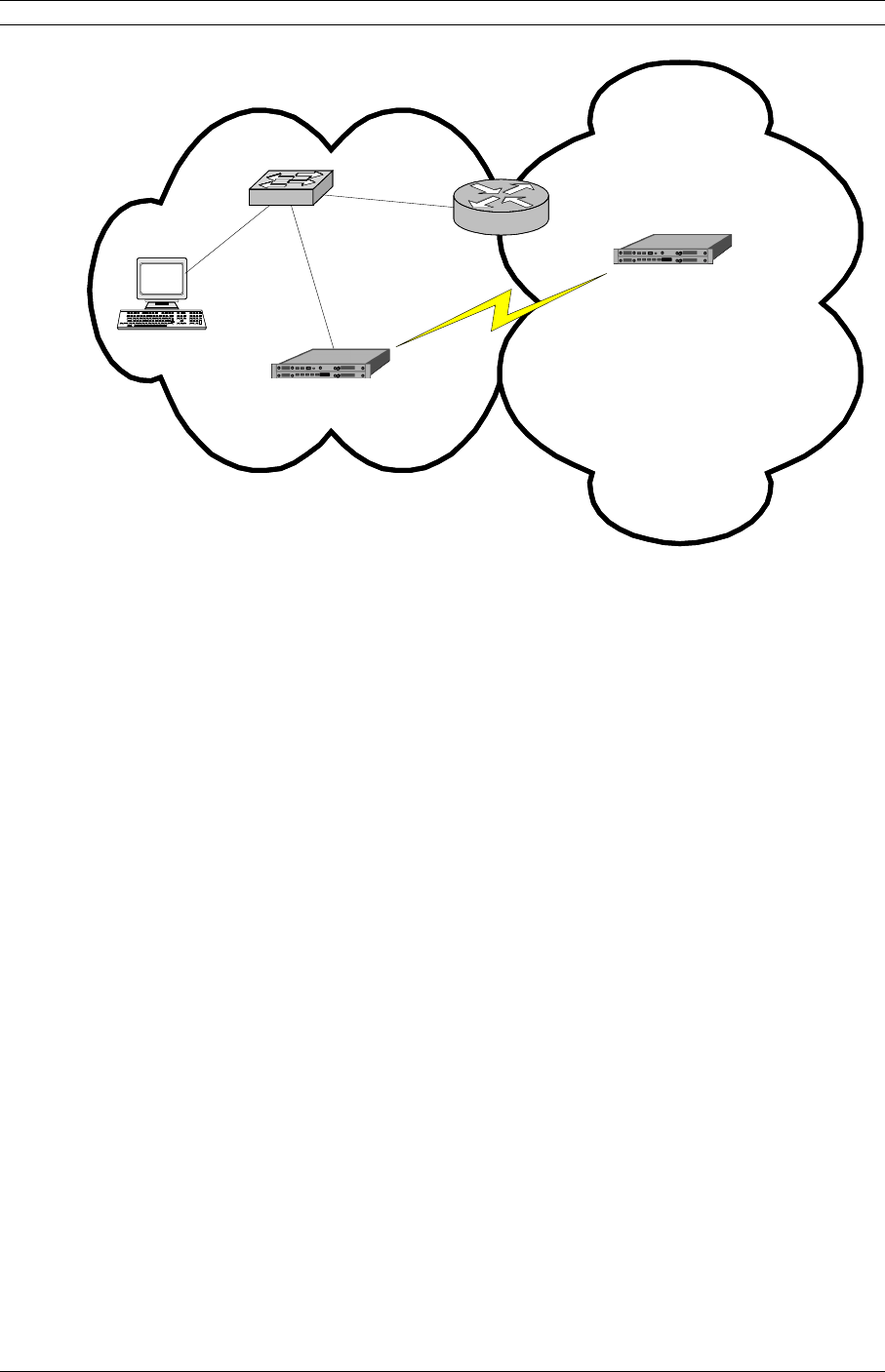
2.14.3NMS Network Operational Principles
The Event-HD does not provide routing capability. Therefore, all Event-HD radios must
be on the same subnet as the PC being used to access the Event-HD radios. If the Event-
HD radios and/or the PC are on different subnets, a router must be used, with the
gateway addresses set appropriately. Figure 2-14 shows the PC and both Event-HD
SDIDUs™ in the same subnet. In this case, no router is required. Figure 2-15 shows the
PC and one of the Event-HD SDIDUs™ in one subnet and the other Event-HD SDIDU™ in
another. In this case, a router is required. Note how the GW addresses are set to allow
communication from the PC to the Event-HD SDIDU™ in the other subnet.
SUBNET PC
192.168.1.10
SWITCH
SDIDU
TM
192.168.1.21
SDIDU
TM
192.168.1.22
Figure 2-14. PC and Event-HD SDIDUs™ on Same Subnet
© 2007 Moseley, Inc. All Rights Reserved. 602-14886-01, Rev. A
30 2. System Description
SUBNET 1 PC
IP: 192.168.1.10
GW: 192.168.1.1
SWITCH
SUBNET 2
ROUTER
IP1: 192.168.1.1
IP2: 192.168.2.1
SDIDU
TM
IP: 192.168.1.21
GW: 192.168.1.1
SDIDU
TM
IP: 192.168.2.33
GW: 192.168.2.1
Figure 2-15. Event-HD SDIDUs™ on Different Subnets
2.14.4Third Party Network Management Software Support
The Event-HD SDIDU™ supports SNMPv1, SNMPv2, and SNMPv3 protocols for use with
third party network management software. The SNMP agent will send SNMP traps to
specified IP addresses when an alarm is set or cleared. Information contained in the trap
includes:
IP address
System uptime
System time
Alarm name
Alarm set/clear detail
The Event-HD SDIDU™ may also be managed via HTTP, TELNET, and SSH
protocols.
2.15System Loopbacks
The Event-HD SDIDU™ provides system loopbacks as a means for test and verification of
a unit, link, and/or network. A variety of loopback points, including LIU selection, are
© 2007 Moseley, Inc. All Rights Reserved. 602-14886-01, Rev. A

2. System Description 31
available. Loopback points and duration are easily selected through the Graphical User
Interface, for more information see the User Interface Guide.
© 2007 Moseley, Inc. All Rights Reserved. 602-14886-01, Rev. A
3. Installation 1
3.Installation
3.1Unpacking
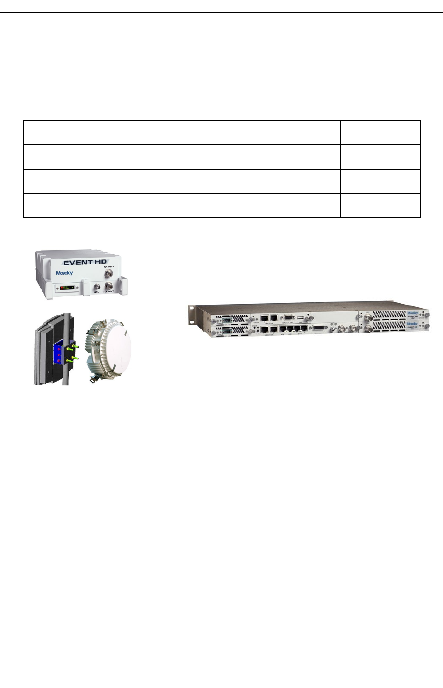
The following is a list of possible included items.
Description Quantity
Event-HD SDIDUTM (1RU chassis) 1
ODU (with hardware) 1
Manual (or Soft copy on a CD) 1
ODUs
SDIDUTM
Figure 3-1. Event HD (1+0) Components
Be sure to retain the original boxes and packing material in case of return shipping.
Inspect all items for damage and/or loose parts. Contact the shipping company
immediately if anything appears damaged. If any of the listed parts are missing, call the
distributor or the factory immediately to resolve the problem.
© 2007 Moseley, Inc. All Rights Reserved. 602-14886-01, Rev. A

2 3. Installation
3.2Notices
CAUTION:
DO NOT OPERATE UNITS WITHOUT AN ANTENNA, ATTENUATOR, OR LOAD CONNECTED
TO THE ANTENNA PORT. DAMAGE MAY OCCUR TO THE TRANSMITTER DUE TO
EXCESSIVE REFLECTED RF ENERGY.
ALWAYS ATTENUATE THE SIGNAL INTO THE RECEIVER ANTENNA PORT TO LESS THAN
-20 dBm. THIS WILL PREVENT OVERLOAD AND POSSIBLE DAMAGE TO THE RECEIVER
MODULE.
WARNING
HIGH VOLTAGE IS PRESENT INSIDE THE ODU and SDIDUTM WHEN THE UNIT IS
PLUGGED IN. TO PREVENT ELECTRICAL SHOCK, UNPLUG THE POWER CABLE
BEFORE SERVICING. UNIT SHOULD BE SERVICED BY QUALIFIED PERSONNEL
ONLY.
3.3PRE-INSTALLATION NOTES
It may be useful to gain familiarity with the Software Defined IDU™ via back-to-back
bench testing prior to final installation. We highly recommend installation of lightning
protectors on the ODU/ SDIDUTM Interconnect Cable to prevent line surges from
damaging expensive components.
3.4Back-to-Back Bench Testing
Back-to-back bench testing prior to final installation is highly recommended in order to
gain familiarity with the product. The following additional equipment is required for back-
to-back testing:
•Low-loss cables, TNC-male connectors on ODU interfaces.
•Three Inline RF attenuators, 2 x 30 dB (10 Watts min.) and 1 x 20 dB (2 Watts min.),
rated for ODU frequency.
The Event-HD SDIDUTM and ODUs must be configured in an operational configuration and
set-up as shown in Figure 3-2 for ODUs with transmit powers of 1W and 5W. For 5.3 GHz
and 5.8 GHz applications the 20 dB attenuator may be removed. When equipment is
connected in operational configuration, no errors should be reported on the rear panel.
© 2007 Moseley, Inc. All Rights Reserved. 602-14886-01, Rev. A

3. Installation 3
ODU 1 ODU 2
SDIDU 1 SDIDU 2
30dB 30dB20dB
10W 2W 10W
Ant.
Port
Ant.
Port
TNC IF
Cable
(supplied)
TNC IF
Cable
(supplied)
Figure 3-2. Event-HD Back-to-Back Testing Configuration
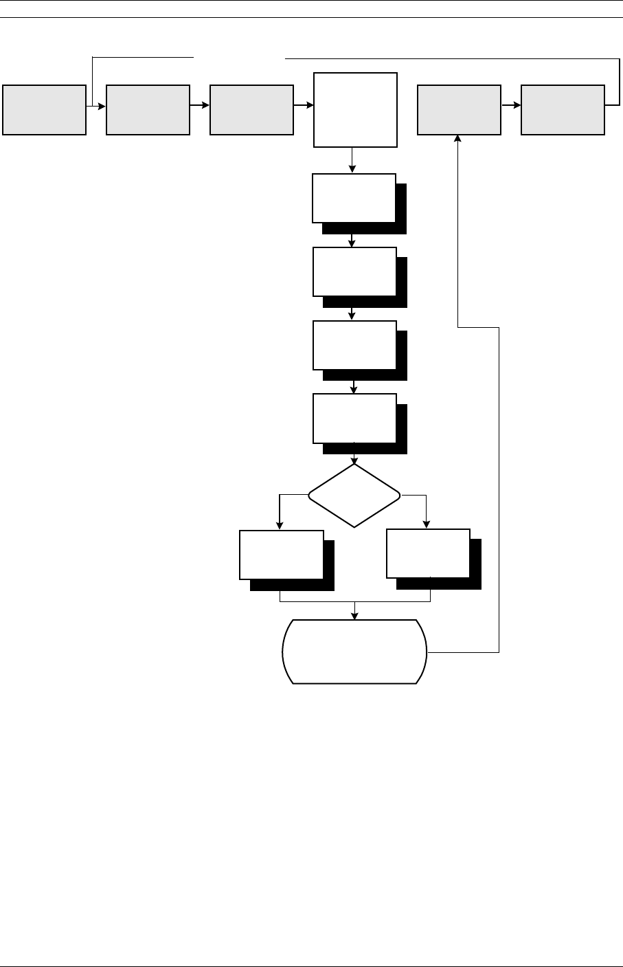
3.5Overview of Installation and Testing Process
The installation and testing process is accomplished by performing a series of separate,
yet interrelated, procedures, each of which is required for the successful implementation
of a production Event-HD network. These procedures are as follows:
•Site Evaluation: gathering specific information about potential Event-HD radio™
installation sites.
•Cable and Installation: Testing and installing ODU cables and optional interface
devices at installation sites.
•Event-HD ODU Mounting and Alignment: Mounting ODUs to a pole or wall, performing
link alignment and radio frequency (RF) verification.
•Event-HD Digital Radio Configuration: Using Event-HD Link Manager software to
install network- and site-specific parameters in the radios.
•Event-HD Digital Radio Testing: Performing cable continuity checks and RF tests for
links, the payload/radio overhead channel, and the management channel.
The following diagram shows where installation and commissioning resides within the
Event-HD network deployment life cycle and defines the sequence in which the processes
that comprise installation and commissioning should be performed.
© 2007 Moseley, Inc. All Rights Reserved. 602-14886-01, Rev. A
4 3. Installation
03-01-013b
Customer
Requirements
RF Planning
& Network
Design
Site Selection
& Acquisition
Installation &
Commissioning
Network
Operation &
Maintenance
Network
Upgrade &
Expansion
Install Cables
Mount and Align
ODUs
Perform Site
Evaluation
Configure Digital
Software Defined
IDU
TM
Perform Fast
PDH Network Test
Perform
SDH Network Test
Type of
Network?
Installation &
Commissioning
Complete
PDH SDH
Network Life Cycle
Figure 3-3. Network Deployment Lifecycle
3.6Site Evaluation
A site evaluation consists of a series of procedures for gathering specific information
about potential Event-HD locations. This information is critical to the successful design
and deployment of a network.
Site evaluations are required to confirm whether or not a building meets network design
requirements. The main objectives are as follows:
© 2007 Moseley, Inc. All Rights Reserved. 602-14886-01, Rev. A

3. Installation 5
•Confirm
•Line of sight for each link
•Event-HD ODU mounting locations
•Site equipment locations
•Cable routes
•Any other potential RF sources
•Prepare site drawings and record site information
3.6.1Preparing for a Site Evaluation
The following tools are required to perform a site evaluation:
•RF and network design diagrams (as required)
•Binoculars
•Global positioning system (GPS) or range finder
•Compass
•Measuring tape and/or wheel
•Digital camera
•Area map
•Aerial photograph (if available)
•List of potential installation sites (“targeted buildings”)
The following tasks must be completed prior to performing a site evaluation:
•Prepare the initial network design by performing the following:
•Identify potential buildings by identifying targeted customers (applicable if you’re
a service provider)
•Identify potential links by selecting buildings based on the high probability of line
of sight
•Arrange for access with the facility personnel into the buildings, equipment rooms,
and architectural plans to become familiar with the location of all ducts, risers, etc.
© 2007 Moseley, Inc. All Rights Reserved. 602-14886-01, Rev. A

6 3. Installation
3.6.2Site Evaluation Process
The following steps must be completed to perform a successful site evaluation. Each step
in the process is detailed in the following subparagraphs:
•Ensure RF Safety compliance: Ensure that appropriate warning signs are properly
placed and posted at the equipment site or access entry. For a complete list of
warnings, refer the Safety Precautions listed at the beginning of this manual.
•Ensure Compliance with Laws, Regulations, Codes, and Agreements: Ensure that
any installation performed as a result of the site evaluation is in full compliance
with applicable federal and local laws, regulations, electrical codes, building codes,
and fire codes.
•Establish Line of Sight between antennas: The most critical step in conducting
a site evaluation is confirming clear radio Line of Sight (LOS) between a
near antenna and a far antenna. If LOS does not exist, another location
must be used.
Event-HD radios must have a clear view of each other, or “line of sight”. Binoculars may
be used evaluate the path from the desired location of the near antenna to the desired
location of the far antenna.
To confirm Line of Sight:
•Ensure that no obstructions are close to the transmitting/receiving path. Take into
consideration trees, bridges, construction of new buildings, unexpected aerial
traffic, window washing units, etc.
•Ensure that each Event-HD ODU can be mounted in the position required to
correctly align the Event-HD ODU with its link partner.
The antennas must also have a clear radio line of sight. If a hard object, such as a
mountain ridge or building, is too close to the signal path, it can damage the radio signal
or reduce its strength. This happens even though the obstacle does not obscure the
direct, visual line of sight. The Fresnel zone for a radio beam is an elliptical area
immediately surrounding the visual path. It varies in thickness depending on the length
of the signal path and the frequency of the signal. The necessary clearance for the
Fresnel zone can be calculated, and it must be taken into account when designing a
wireless links.
© 2007 Moseley, Inc. All Rights Reserved. 602-14886-01, Rev. A

3. Installation 7
As shown in the picture above, when a hard object protrudes into the signal path within
the Fresnel zone, knife-edge diffraction can deflect part of the signal and cause it to
reach the receiving antenna slightly later than the direct signal. Since these deflected
signals are out of phase with the direct signal, they can reduce its power or cancel it out
altogether. If trees or other 'soft' objects protrude into the Fresnel zone, they can
attenuate (reduced the strength of) a passing signal. In short, the fact that you can see a
location does not mean that you can establish a quality radio link to that location.
Consult factory for a link planner spreadsheet that calculates the Fresnel ratio and helps
determine link feasibility.
•Determine Event-HD ODU Mounting Requirements: Event-HD ODUs can be
mounted on an antenna mast, brick, masonry or wall. Refer to detailed installation
sections specific for each ODU and antenna type.
•Determine Event-HD Software Defined IDU™ Installation Location: Software
Defined IDU™ can be installed tabletop or cabinet, wall mount, or rack mount.
The site must provide DC power. Refer to detailed installation sections.
•Document Potential Sources of Co-location Interference: When Event-HD ODUs
are located on a roof or pole with other transmitters and receivers, an interference
analysis may be required to determine and resolve potential interference issues.
The interference analysis needs to be performed by an RF engineer. The specific
information required for each transmitter and receiver includes the following:
-Transmitting and/or receiving frequency
-Type of antenna
-Distance from Event-HD ODU (horizontal and vertical)
-Polarity (horizontal or vertical), if applicable
-Transmit power level
-Antenna direction
•Measure the Link Distance: The two ways to measure link distance are as follows:
-GPS: record the latitude and longitude for the near and far ODU sites and
calculate the link distance. Record the mapping datum used by the GPS unit
and ensure the same mapping datum is used for all site evaluations in a given
network.
-Range finder: measure the link distance (imperial or metric units may be
used).
Once the link distance has been measured, verify that the link distance meets the
availability requirements of the link.
•Select the Grounding Location for both the Event-HD ODU and SDIDUTM: The
Software Defined IDU™ must be properly grounded in order to protect it and the
structure it is installed on from lightning damage. This requires
© 2007 Moseley, Inc. All Rights Reserved. 602-14886-01, Rev. A

8 3. Installation
-Grounding all Event-HD ODUs to antenna tower.
-Grounding all SDIDUTM to the rack.
•Determine the Length of Interconnect Cable from Event-HD ODU to SDIDUTM: The
primary consideration for the outdoor interconnect cable from the Event-HD ODU
to SDIDUTM is the distance and route between the Event-HD ODU and SDIDUTM.
This cable should not exceed 330 feet using Times Microwave LMR-200 cable.
Guidelines are provided in Table 3-1. Exact distances should take ODU
requirements into account.
Table 3-1. Maximum Cable Lengths
Loss at (dB/100 m)
Cable Type 140 MHz 350 MHz
Maximum
Length*
LMR-200 12.6 20.1 100 m
LMR-300 7.6 12.1 165 m
LMR-400 4.9 7.8 256 m
RG-214 8 13.1 153 m
Belden 7808 8.6 14 143 m
* Does not account for connector loss.
•Confirm the Presence of DC Power for the Event-HD Software Defined IDU™.
•Ensure Building Aesthetics: Ensure that the ODU can be mounted so that it is
aesthetically pleasing to the environment and to the property owner. Aesthetics
must be approved by the property owner and the network engineer.
•Take Site Photographs
•Sketch the Site
3.6.3Critical System Calculations
3.6.3.1 Received Signal Level (RSL) and Link Budget
The received signal level (RSL) can be estimated using the following formula:
RSL (dBm) = PTX + GTX ANT – LPath + GRX ANT
Where: PTX is the transmitter output power (in dBm)
GTX ANT is the gain of the transmit antenna (in dB)
GRX ANT is the gain of the receive antenna (in dB)
LPath is the Path loss, defined by:
© 2007 Moseley, Inc. All Rights Reserved. 602-14886-01, Rev. A

3. Installation 9
LP (dB) = 36.6 + 20log10 (F*D)
Where: F is the Frequency in MHz, D is the Distance of path in miles
This link budget is very important in determining any potential problems during
installation. The expected RSL and measured RSL should be close (+/- 5 to 10 dB)
3.6.3.2 Fade Margin Calculation
The fade margin is the difference between the actual received signal and the Event-HD
digital radio’s threshold for the modulation mode selected. The fade margin can be used
to determine availability and should be at least 10 dB for most cases but is ultimately
determined by required application reliability.
3.6.3.3 Availability Calculation
Availability of the microwave path is a prediction of the percent of time that the link will
operate without producing an excessive BER due to multipath fading. Availability is
affected by the following:
•Path length
•Fade margin
•Frequency
•Terrain (smooth, average, mountainous, valleys)
•Climate (dry, temperate, hot, humid)
Depending on the type of traffic carried over the link and the overall network design
redundancy, fade margin should be included to support the desired availability rate.
Critical data and voice may require a very high availability rate (99.999% or 5.3 minutes
of predicted outage per year). To improve availability, the fade margin can be increased
by shortening the path length, transmitting at a higher power level, or by using higher
gain antennas.
Availability can be computed using the following formula, which is known as the Vigants
Barnett Method.
Availability = 100 × (1 – P)
P = 2.5 × 10⁻⁹ × C × F × D3× 10(-FM/10)
Where F is the frequency in MHz
D is the distance in miles
FM is the fade margin in dB
C is the climate/terrain factor as defined below:
© 2007 Moseley, Inc. All Rights Reserved. 602-14886-01, Rev. A
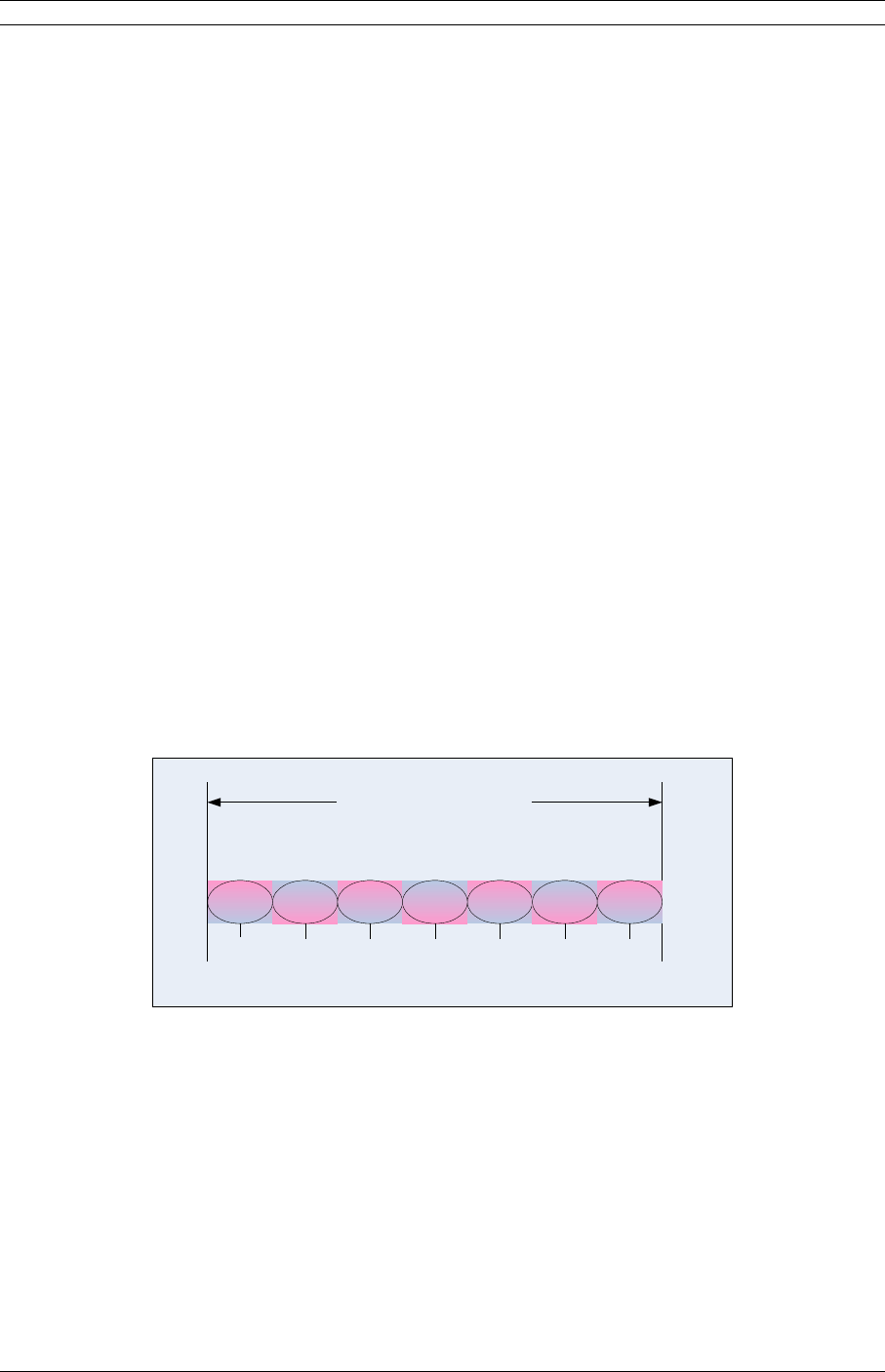
10 3. Installation
Humid/Over Water: C = 4 (worst case channel)
Average Conditions: C = 1
Dry/Mountains: C = 0.25 (best case channel)
Example: Assume 21 dB fade margin, over 5 miles with average climate/terrain. The
availability comes out to be 99.9986. This corresponds to the link being unavailable for
7.6 minutes per year.
3.6.4Frequency Plan Determination
When configuring Event-HD units in a point-to-point or consecutive point configuration,
careful engineering of the Event-HD frequency plans and antenna locations should be
performed in order to minimize potential interference between nearby radios. Nearby
radios should operate on different frequencies, transmitting in the same band (high side
or low side). Local frequency coordination efforts are often a requirement for broadcast
auxiliary service applications. When designing multi-radio configurations, antenna size,
antenna polarization, and antenna location are critical.
The frequency plan is selected based band of use. Desired data rate and capacity is
selected based on expected link conditions or fixed based on application. In a high
interference environment or with lower gain antennas, higher bandwidth, more robust
modulation formats must be employed. The available frequency plans are illustrated in
Figures 3-3 through Figure 3-8 based on application frequency.
The channel assignments shown in the figures correspond to the channel numbers
entered via the graphical user interface (GUI) or SNMP.
A1r
12 MHz
A2r
12 MHz
2 GHz 12 MHz
(BAS Band A)
2031.5
2109.52025.5
2043.5
A3r
12 MHz
2055.5
A5r
12 MHz
A6r
12 MHz
A7r
12 MHz
2091.5 2103.5
A4r
12 MHz
2067.5 2079.5
Frequency (MHz)
Figure 3-3. 2 GHz, 12 MHz BAS Frequency Plan
© 2007 Moseley, Inc. All Rights Reserved. 602-14886-01, Rev. A
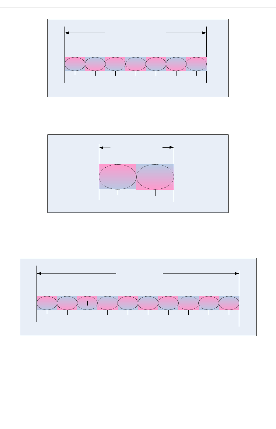
3. Installation 11
A1
18 MHz
A2
17 MHz
2 GHz 17 MHz
(BAS Band A)
1999.0
21101990
2016.5
A3
17 MHz
2033.5
A5
17 MHz
A6
17 MHz
A7
17 MHz
2084.5 2101.5
A4
17 MHz
2050,5 2067.5
Frequency (MHz)
Figure 3-4. 2 GHz, 17 MHz Legacy BAS Frequency Plan
A8
17 MHz
A9
17 MHz
2.4 GHz 17 MHz
(BAS Band A)
2450
2458.5
Frequency (MHz) 2483.5
2475
Figure 3-5. 2.4 GHz, 17 MHz BAS Frequency Plan
A05
25 MHz
A06
25 MHz
7 GHz 25 MHz
(BAS Band)
6887.5
7125
6875
6912.5
A07
25 MHz
6937.5
A09
25 MHz
A10
25 MHz
A11
25 MHz
7012.5 7037.5
A08
25 MHz
6962.5 6987.5
Frequency (MHz)
A12
25 MHz
A13
25 MHz
A14
25 MHz
7087.5 7112.57062.5
Figure 3-6. 7 GHz, 25 MHz BAS Frequency Plan
© 2007 Moseley, Inc. All Rights Reserved. 602-14886-01, Rev. A
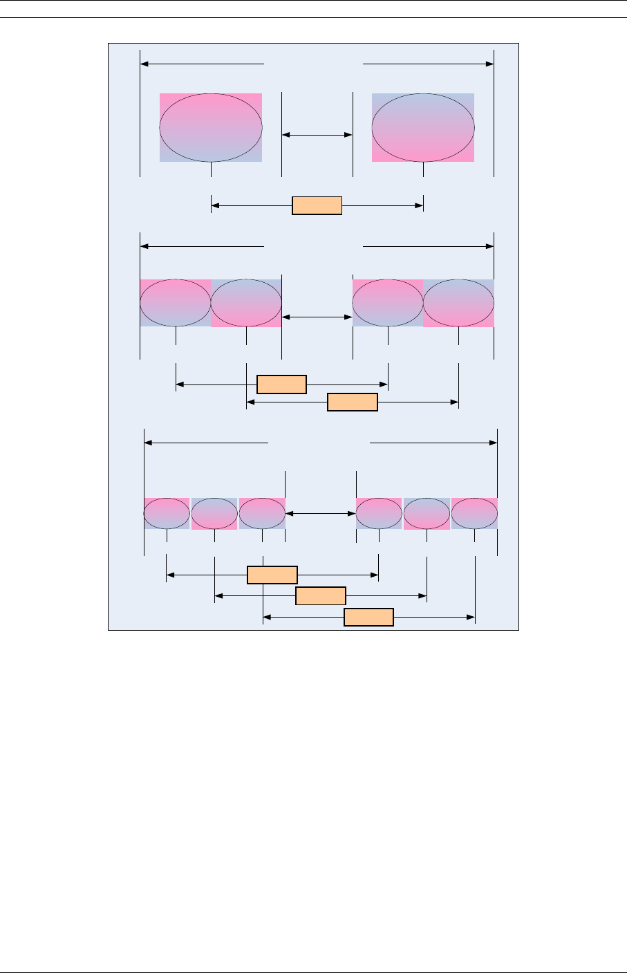
12 3. Installation
A1
30MHz
B1
30MHz
5.3 GHz
1-Channel Plan, 30 MHz
20 MHz T/R
Guard Band
5270 5330 5350531052905250
A1
20MHz
A2
20MHz
5.3 GHz
2-Channel Plan, 20 MHz
20 MHz T/R
Guard Band
5260 5320
5350531052905250
60MHz T/R
B1
20MHz
B2
20MHz
5280 5340
60MHz T/R
60MHz T/R
A1
13MHz
A2
13MHz
5.3 GHz
3-Channel Plan, 13 MHz
20 MHz T/R
Guard Band
5257
5350
53105290
5250
5270
60MHz T/R
A3
13MHz
5283
B1
13MHz
B2
13MHz
B3
13MHz
5317 5330 5343
60MHz T/R
60MHz T/R
Figure 3-7. Event-HD 5.3 GHz Frequency Plan
© 2007 Moseley, Inc. All Rights Reserved. 602-14886-01, Rev. A

3. Installation 13
A1
30MHz
B1
30MHz
5.8 GHz
1-Channel Plan, 30 MHz
25 MHz T/R
Guard Band
5750 5825 5850580057755725
A1
25MHz
A2
25MHz
5.8 GHz
2-Channel Plan, 25 MHz
25 MHz T/R
Guard Band
5737 5812
5850580057755725
75MHz T/R
B1
25MHz
B2
25MHz
5762 5837
75MHz T/R
75MHz T/R
A1
16.7MHz
A2
16.7MHz
5.8 GHz
3-Channel Plan, 16.7 MHz
25 MHz T/R
Guard Band
5733
5850
58005775
5725
5750
75MHz T/R
A3
16.7MHz
5766
B1
16.7MHz
B2
16.7MHz
B3
16.7MHz
5808 5825 5841
75MHz T/R
75MHz T/R
Figure 3-8. Event-HD 5.8 GHz Frequency Plan
3.6.5Antenna Planning
Larger antennas have the advantage of providing narrower beam widths and high
isotropic gain, which yields better link performance (higher fade margin, better
availability), and improves immunity to spatial interference (due to the smaller beam
widths). However, larger antennas are more costly to purchase and install than smaller
antennas and in some cases, they require special equipment for installation due to
narrower beam widths. They are also more easily affected by wind.
1. Select where the cable will enter the building from the outside.
2. Determine the length of cable required. Allow three extra feet on each end to allow
for strain relief, as well as any bends and turns.
© 2007 Moseley, Inc. All Rights Reserved. 602-14886-01, Rev. A

14 3. Installation
3.6.6ODU Transmit Power Setup
Setting the ODU transmit power is conditional on the band and application. The
installer of this equipment is responsible for proper selection of allowable
power settings. If there are any questions on power settings refer to your
professional installer in order to maintain the FCC legal ERP limits.
This warning is particularly true for the 5.3 GHz and 5.8 GHz bands and special
instructions are provided below for these bands. For the broadcast auxiliary service (BAS)
applications the power should not exceed that necessary to render for satisfactory
service.
It is also noted that as QAM mode order increases the linearity requirements also
increase. As a rule to maintain requisite signal quality the transmit power should be
lowered 1 dB for every order increase in QAM mode order. For instance, the maximum
power for the Event 2200 is 37 dBm in QPSK mode. Therefore the maximum power
backoff would follow Table 3-2 below:
Table 3-2. Maximum Output Power vs. Modulation Order
for Event 2200
Modulation
Backoff
(dB)
Max.Output
Power
(dBm)
QPSK 0 37
16 QAM -1 36
32 QAM -2 35
64 QAM -3 34
128 QAM -4 33
3.6.6.1 5.8 GHz Band
For fixed point-to-point applications in the United States the maximum EIRP (Effective
Isotropic Radiated Power) is unlimited when using directional antennas in accordance
with FCC part 15.247b(3). The ODU 5800 may therefore be operated at its maximum
output power, +23 dBm, for maximum system gain.
EIRP is calculated for link budget with external antennas as,
EIRP(avg) dBm = External Antenna Gain (dBi) + 23 dBm
For internal antenna (23 dBi) EIRP is,
EIRP(avg) = 46 dBm
© 2007 Moseley, Inc. All Rights Reserved. 602-14886-01, Rev. A

3. Installation 15
3.6.6.2 5.3 GHz Band
In the 5.3 GHz U-NII band the peak EIRP (Effective Isotropic Radiated Power) is limited
to +30 dBm at the antenna for bandwidths above 20 MHz and is reduced for narrower
bandwidths in accordance with FCC part 15.407a(3).
The installer is responsible during set up of transmit power to not exceed FCC limits on
transmission power. These maximum power levels are provided in Table 3-1 for both
internal antenna and external antenna ODU configurations, along with the operational
bandwidths.
Note that though regulatory limits are stated in terms of peak power, the system
transmit power levels are calibrated as averaged power readings. Average power is used
for link calculations. Therefore the levels provided in the following table is average power
levels that have been certified to correspond with the maximum peak EIRP allowed.
3.6.6.2.1ODU with Internal Antenna
Table 3-3 indicates the maximum average transmit power setting that may be selected
ODU 5300 with internal (23 dBi) antenna.
The number of supported channels per band (low band or high band) is shown in the link
configuration wizard. The greater number of channels supported the lower the emission
bandwidth for each channel.
For link budget, EIRP(Avg) = 23 dBi + Tx Power Setting (dBm).
3.6.6.2.2ODU with External Antenna
When using external antennas with gains greater than 23 dBi, the transmit power must
be reduced in dB from that given in Table 3-3 by the antenna gain difference above 23
dBi for the mode that is being used.
For example, using a 6 foot dish antenna with 37 dBi gain, the output power would be
dropped by
Antenna Gain (External) – 23 dBi = Antenna Gain Difference
37.6 dBi – 23 dBi = 14.6 dB
For mode 100FE1 (single channel configuration with 30MHz emission bandwidth) the
power would be lowered from
Tx Power (Internal Antenna) – Antenna Gain Difference = Tx Power (External Ant)
+5 dBm – 14.6 dB = -9.6 dBm (-10 dBm).
Table 3-3 also presents transmit power settings for various antenna dish sizes.
© 2007 Moseley, Inc. All Rights Reserved. 602-14886-01, Rev. A

16 3. Installation
For link budget, EIRP(Avg) dBm = 37 dBi + Tx Power Setting (dBm).
Table 3-3. Maximum Power Settings for 5.3GHz
U-NII Band Operation (US).
Antenna Diameter Antenna
Gain, dBi*
(example)
Maximum
Tx Power
Setting,
dBm
1 Channel
Mode
(30MHz
BW)
Maximum
Tx Power
Setting,
dBm
2 Channel
Mode
(20MHz
BW)
Maximum
Tx Power
Setting,
dBm
3 Channel
Mode
(13.3MHz
BW)
6 foot dish 37.6 -10 -11 -12
4 foot dish 34.6 -7 -8 -9
3 foot dish 31.2 -3 -4 -5
2 foot dish 28.0 0 -1 -2
1.5 foot dish 25.3 +3 +2 +1
Internal 23.0 +5 +4 +3
* Note: Many antenna manufacturers rate antenna gain in dBd (dB referred to a dipole
antenna) in their literature. To convert to dBi, add 2.15 dB.
Power settings for other modes of operation can be budget calculations,
EIRP(Avg) dBm= Antenna Gain (dBi) + Tx Power
Though transmitter radiated power is limited in the receiver benefits from gain of larger
antennas.
© 2007 Moseley, Inc. All Rights Reserved. 602-14886-01, Rev. A

3. Installation 17
3.7Installation of the Event-HD
The following sections provide installation guides for:
•SDIDUTM Installation
•ODU Installation
3.7.1Installing the Event-HD SDIDUTM
The Event-HD SDIDUTM can be installed in the following three options:
1. Table top or cabinet
2. Wall mount
3. Rack mount
The Event-HD SDIDUTM should be:
•Located where you can easily connect to a power supply and any other equipment
used in your network, such as a router or PC.
•In a relatively clean, dust-free environment that allows easy access to the rear
grounding post as well as the rear panel controls and indicators. Air must be able to
pass freely over the chassis, especially the rear.
•Accessible for service and troubleshooting.
•Protected from rain and extremes of temperature (it is designed for indoor use).
3.7.1.1 Installing on a Table Top or Cabinet
The Event-HD Software Defined IDU™ can be placed on a tabletop or cabinet shelf. In
order to prevent possible disruption, it is recommended to use a strap to secure the
SDIDUTM.
3.7.1.2 Installing on a Wall
An installation option for the Event-HD SDIDUTM is mounting the unit to a wall. Consult
factory for details.
If the wall mount option is being considered, plan to position the Event-HD Software
Defined IDU™ at a height that allows LEDs, the connectors on the rear panel, and the
rear grounding post to be visible at all times and easily accessible. Also, including plastic
clamps to support and arrange the ODU/ SDIDUTM Interconnect Cable should also be
considered.
© 2007 Moseley, Inc. All Rights Reserved. 602-14886-01, Rev. A

18 3. Installation
3.7.1.3 Installing in a Rack
To maintain good airflow and cooling, it is preferred that the Event-HD Software Defined
IDU™ is installed in a slot that has blank spaces above and below the unit.
To rack-mount the SDIDUTM, use the supplied mounting brackets (Moseley part number
2734001-0001) to secure the chassis to the rack cabinet. As shown in Figure 3-8, the
brackets can be attached at any of four points on the sides of the enclosure – back, back,
middle facing front, and middle facing back. This flexibility ensures compatibility with
most rack mounting arrangements.
Width:
17 inches
43.13 cm
Depth:
9.5 inches
24.1 cm
Height:
1.75 inches
4.45 cm
Figure 3-8. Software Defined IDU™ Dimensions
3.7.2Installing the Event-HD ODU
The Event-HD ODU is intended for mounting on either a pole or antenna mast within
close proximity to the antenna.
Each site must be assessed for the mounting method, location, and height. After defining
the mounting location and height for the Event-HD, re-confirm the line of sight.
Note: When operating a 1+1 configured Event-HD, i.e. an SDIDU™ with two power
supplies and two modem modules installed, an ODU must be connected to the modem in
the bottom slot. If the ODU is connected to the modem in the top slot, the SDIDU™ will
not communicate with the ODU, and a link cannot be established.
For proper support the antenna mast or mounting pole must be mounted in a vertical
position (i.e., no tilt), preferably with a plum.
If the ODU utilizes an internal antenna, such as the ODU5300 and ODU5800 with
internal antenna option, vertical tilt of the ODU is accomplished from the tilt
mounting bracket. Also, it is important to note the direction in which the ODU will
point when installing the mounting pole.
The antenna mast or mounting pole must be grounded. Different ODUs may require
different mounting hardware and techniques. The next sections describe mounting
techniques for various ODU families.
© 2007 Moseley, Inc. All Rights Reserved. 602-14886-01, Rev. A
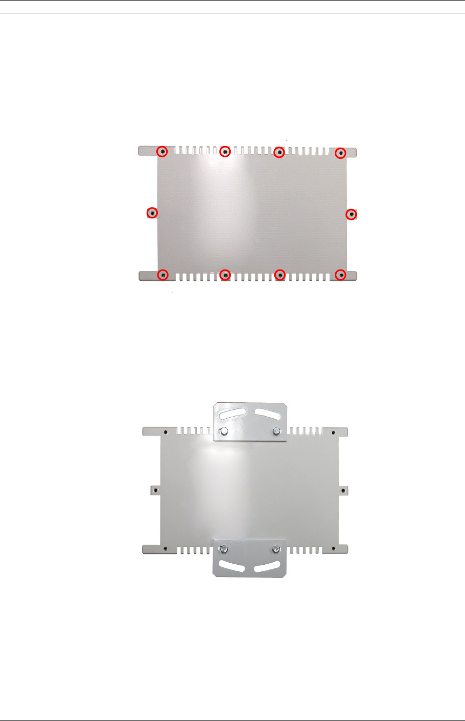
3. Installation 19
3.7.2.1 Installing ODU2200, ODU6500, ODU7200
11. The ODUxx00 chassis family has mounting holes located on the underside of the
unit. There are total of 10 threaded ¼-20 holes available for mounting directly to a
plate or to a pole with optional pole mounting hardware. The threaded screw locations
are shown below in red in Figure 3-9. It is recommended to use at least 4 ¾” screws
with lock washers.
2
Figure 3-9. ¼-20 threaded mounting hole locations on ODU2200.
Use any 4.
32. For pole mounting, optional brackets are installed in the location as shown below
in Figure 3-10.
4
Figure 3-10. Pole Mounting Brackets on ODU2200
53. Install U-bolts to ODU brackets and tighten. Assembled pole-mounted ODU2200
is shown in Figure 3-11.
© 2007 Moseley, Inc. All Rights Reserved. 602-14886-01, Rev. A
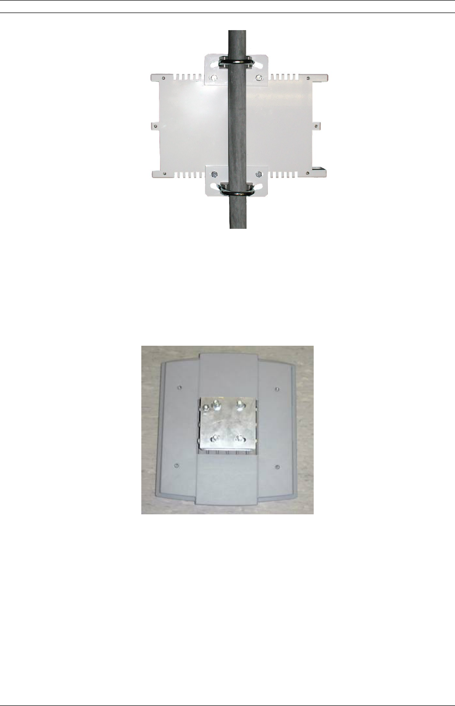
20 3. Installation
6
Figure 3-11. Completed Pole Mounting of ODU2200
3.7.2.2 Installing ODU5300, ODU5800
71. Remove the pole mount portion of the tilt bracket from the ODU5800 by
loosening the middle bolts and removing the top and bottom bolts on each side.
Figure 3-12. Event ODU5800 Rear View
82. Mount the tilt bracket to the mounting pole using the U-Bolts and nuts. Insert the
U-bolts around the pole and through the holes in the tilt bracket. Install a washer and
nut to each side of the threaded U-bolt and hand tighten. Repeat this step for the
second U-bolt.
© 2007 Moseley, Inc. All Rights Reserved. 602-14886-01, Rev. A
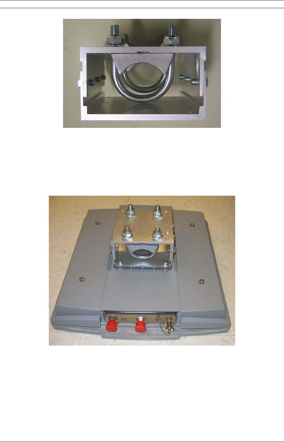
3. Installation 21
Figure 3-13. Tilt Bracket for Event ODU5800
93. Place the Event-HD ODU5800 on the mating half of the tilt bracket connected by
the two center bolts.
104. Add the remaining four bolts to the tilt bracket but do not tighten until the
antenna alignment is complete (only applies for internal antenna ODUs).
Figure 3-14. Event ODU5800 with Mounted Tilt Bracket
11
125. Manually point the ODU in the direction of the link partner ODU.
© 2007 Moseley, Inc. All Rights Reserved. 602-14886-01, Rev. A
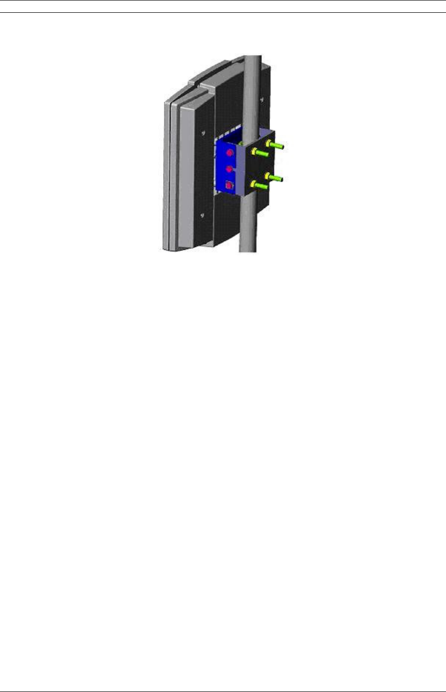
22 3. Installation
Figure 3-15. Completed Mounting for the Event ODU5800
3.7.3Routing the ODU/IDU Interconnect Cable
1. Select where the cable will enter the truck or building from outside.
2. Determine the length of cable required. Allow three extra feet on each end to allow
for strain relief, as well as any bends and turns.
3. Route the cable.
The SDIDUTM is equipped with TNC female connector on the rear of the chassis.
Depending on the ODU type, it will be equipped with either an N-type or TNC female
connector at its interconnecting port. A length of coaxial cable (such as Times Microwave
Systems LMR-400, LMR-300 or LMR-200) fitted with the appropriate N-type or TNC male
connectors is required to connect the ODU to the SDIDUTM. This cable assembly may be
supplied in fixed lengths with the digital radio. Bulk coaxial cable of equivalent
specification may also be used, with terminating connectors applied during cable
installation.
Based on an evaluation of the cable routing path, pull the ODU/SDIDUTM Interconnect
cable from one unit to the other, utilizing cable trays, ducts, or conduit as required. Take
care that the ODU/ SDIDUTM Interconnect cable is not kinked or damaged in any way
during installation. Be sure to protect the TNC connectors from stress, damage and
contamination during installation (do not pull the cable by the connectors). If multiple
ODU/ SDIDUTM Interconnect cables are to be installed along the same route, the cables
should all be pulled at one time. Be sure the installed cable does not have any bends that
exceed the specified cable bend radius. The ODU/ SDIDUTM Interconnect cable should be
adequately supported on horizontal runs and should be restrained by hangers or ties on
© 2007 Moseley, Inc. All Rights Reserved. 602-14886-01, Rev. A

3. Installation 23
vertical runs to reduce stress on the cable. Outside the building, support and restrain the
cable as required by routing and environmental conditions (wind, ice).
The Event-HD ODU/SDIDUTM and interconnection must be properly grounded in order to
protect it and the structure it is installed on from lightning damage. This requires that the
ODU, any mounting pole or mast and any exposed interconnect cable be grounded on the
outside of the structure. The SDIDUTM must be grounded to a rack or structure ground
that also has direct path to earth ground.
The ODU must be directly connected to a ground rod or equivalent earth ground. The
ODU/ SDIDUTM interconnect cable should also be grounded at the ODU, where the cable
enters the structure and at intermediate points if the exposed cable run is long (typically
at intervals of 100 ft), with the cable manufacturer’s grounding kits. Lightning protection
devices used with the interconnect cable must be appropriate for the transmission of the
interconnect signals (DC to 350 MHz).
Provide a sufficient but not excessive length of cable at each end to allow easy
connection to the ODU and SDIDUTM without stress or tension on the cable. Excessive
cable length, especially outdoors, should be avoided to minimize signal attenuation and
provide a more robust and reliable installation. If installing using bulk coaxial cable,
terminate the ODU/ SDIDUTM Interconnect cable at each end with a TNC male connector
on the SDIDUTM side and either an N-type or TNC male connector on the ODU side that is
appropriate for the cable type. Use of connectors, tools and termination procedures
specified by the cable manufacturer is recommended.
Once the cable has been installed but before connection has been made to either unit, a
simple DC continuity test should be made to verify the integrity of the installed cable. A
DC continuity tester or digital multimeter may be used to verify a lack of DC continuity
between the cable center conductor and outer conductor, with the opposite end of the
cable unconnected. With a temporary test lead or shorting adapter connected to one end
of the cable, DC continuity should be verified between the center and outer conductors at
the opposite end.
3.8Quick Start Guide
Although configuration of the SDIDUTM does not require a connection to the ODU, it is
suggested that the ODU and SDIDU™ are connected prior to configuring the SDIDUTM.
Each SDIDU™ has a Graphical User Interface (GUI) installed that can be accessed
through a computer connection. The GUI is described in detail in the User Interface
Guide. The section below describes how to get started configuring the SDIDU TM via the
GUI.
3.8.1Materials Required
The following items are needed to configure an SDIDUTM:
1. Power supply (-48 V DC @ 2 Amps) OR optional AC/DC power supply and power
cable
© 2007 Moseley, Inc. All Rights Reserved. 602-14886-01, Rev. A

24 3. Installation
2. Digital voltmeter with test leads
3. SDIDUTM Serial Cable (optional)
4. Computer with networking capability, consisting of either:
-Laptop computer with Windows 98/2000/XP/Vista operating system, an Ethernet
card with any necessary adapters and a Cat-5 Ethernet regular or crossover cable
or
-Networked computer with Windows 98/2000/XP/Vista operating system and an
additional Ethernet cable providing access to the network.
5. Web Browser program, Internet Explorer 5.5 and above or Mozilla Firefox 1.0.6
and above with Java environment installed, available at http://www.java.com.
6. Site engineering folder with site drawings, or equivalent SDIDU configuration
information
3.8.2Grounding the ODU
1. Place the grounding rod so as to allow for the shortest possible path from the
grounding cable to the ODU.
2. Drive the grounding rod into the ground at least eight inches from the ground
surface.
3. Attach a grounding clamp to the grounding rod. You will use this clamp to attach
grounding wires for both the ODU and indoor junction box, reference Figure 3-16.
4. Connect a ground lug to one end of the grounding wire.
5. Remove one of the lower mounting screws of the mounting pole. Insert a screw
through the grounding lug terminal and re-install it to the mounting pole.
6. Attach the grounding wire to the clamp on the grounding rod. If necessary, use wire
staples to secure the grounding wire to the outside wall.
7. Install a grounding wire from the junction box to the grounding rod.
© 2007 Moseley, Inc. All Rights Reserved. 602-14886-01, Rev. A
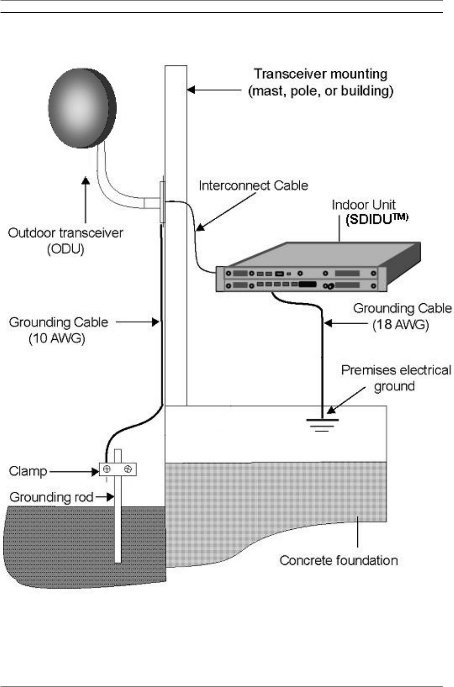
3. Installation 25
Figure 3-16. Ground Connections to ODU.
© 2007 Moseley, Inc. All Rights Reserved. 602-14886-01, Rev. A
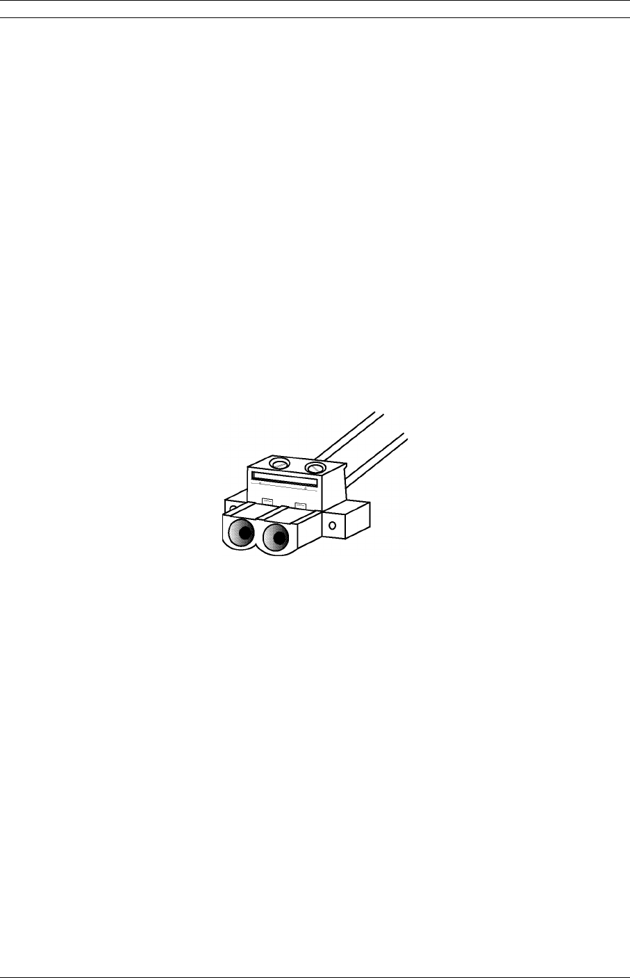
26 3. Installation
3.8.3Grounding the SDIDUTM
1. The SDIDU™ should be able to be connected to a system or building electrical ground
point (rack ground or power third-wire ground) with a cable of 36” or less.
2. Connect the grounding wire to either grounding point on the rear panel. Use
6-32x5/16 maximum length screws (not provided) to fasten the lug of the grounding
cable.
3. Connect the other end of the ground to the local source of ground in an appropriate
manner.
3.8.4Connecting the SDIDUTM to the PC and Power Source
1. Using the supplied power cable connector, pin 2 (labeled -V) should be connected to the
power supply terminal supplying -48 V dc, while pin 1 (labeled RET) should be connected to
the power supply return. Refer to Figure 3-17. Use of a power supply with an inappropriate
ground reference may cause damage to the SDIDUTM and/or the supply.
2
1
Figure 3-17. SDIDU DC Power Cable Connector
2. Connect the SDIDUTM power cable to the 48 V dc power supply, and place the
voltmeter probes on the unconnected SDIDUTM end of the power cable, with the
positive voltmeter probe on pin 2 (-V) of the cable connector and the negative probe
on pin 1(RET). The connector terminal screw heads may be used as convenient
monitor points. Refer to Figure 3-17.
3. Turn on the –48 V dc supply. Verify that the digital voltmeter reads between 44 V dc
and 52 V dc when monitoring the cable points specified above. Adjust the power
supply output voltage and/or change the connections at the power supply to achieve
this reading.
4. Turn the 48 V dc supply off.
5. Plug the SDIDUTM power cable into the SDIDUTM rear panel DC Power connector (DC
Input). Place the voltmeter probes on the cable connector terminal screw heads as
© 2007 Moseley, Inc. All Rights Reserved. 602-14886-01, Rev. A
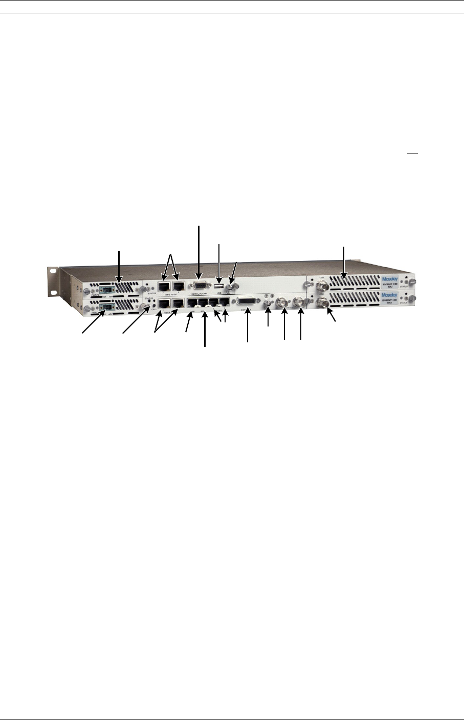
3. Installation 27
per step 2 above. Refer to Figure 3-17. Note that the Software Defined IDU™
SDIDUTM does not have a power on/off switch. When DC power is connected, the
digital radio powers up and is operational. There can be up to 5 W of RF power
present at the antenna port. The antenna should be directed safely when power is
applied.
6. Turn on the 48 V dc power supply, and verify that the reading on the digital voltmeter
is as specified in step 3 above.
7. Connect the SDIDUTM to the laptop computer, using a Cat-5 Ethernet cable or connect
the SDIDUTM to a computer network, using a Cat-5 Ethernet cable. Connect the
Ethernet cable to the NMS 1 or 2 connector on the SDIDUTM rear panel. Refer to
Figure 3-18 for the SDIDUTM rear panel connections.
NMS
Controller
Ethernet
-48V Power
Input
100Base-T
Ethernet
Data
Channels
ASI
Output
ASI
Input
ODU IF
Connection
Redundant
Power-Supply
(optional for
1+1, 2+0)
ALARM/Serial
Interface Redundant
MODEM
(optional for
1+1, 2+0)
USB
Ground
lug
Call
Button
Voice
Orderwire
Data
Orderwire
2xT1/E1
14xT1/E1
Ground
lug
Figure 3-18. Software Defined IDU™-SB, 1+1 Protection, Rear Panel
Connections
3.8.5SDIDU™ Configuration
Although basic configuration of the Event-HD SDIDUTM does not require a connection to
the ODU, it is recommended that the ODU and SDIDUTM are connected prior to
configuring the SDIDUTM. A connection to the ODU must be established prior to running
the Link Configuration process (section 5.2) in order to configure ODU related
parameters.
Using the site attributes identified in the site assessment or equivalent configuration
information, configure each IDU by completing the following procedures:
-Setting the SDIDUTM IP Address and Network Parameters
-Configuring the SDIDUTM
-Setting the SDIDUTM Device Information
© 2007 Moseley, Inc. All Rights Reserved. 602-14886-01, Rev. A

28 3. Installation
3.8.5.1 Setting the IDU IP Address
1. The PC’s network configuration must be set with the parameters provided at
the end of this guide.
2. The IDU should be accessible from your PC at the default IP address provided
at the end of this guide. A network ‘ping’ can be done to verify connectivity to
the IDU.
3. Start web browser and use the SDIDUTM default IP address as the url.
4. Log in at the login prompt. The username and password are provided at the
end of this guide.
5. The GUI includes a navigation menu in the left frame. If this navigation menu
is not visible, make sure the Java environment is properly installed and active.
In the navigation menu, select Administration, then Network Configuration,
and then General. The IP address, IP Netmask, and IP Gateway are shown.
6. Enter the new IP address, IP Netmask, and IP Gateway. The gateway must be
in the same subnet as the IP address for proper operation. Click “Update” to
change the values.
7. To verify the new IP address, change the PC's network configuration to be on
the same subnet as the new IP address set in the unit and a network 'ping'
may be performed to the new address.
8. To continue using the GUI, point the web browser to the new IP address.
3.8.5.2 Link Configuration
Use the GUI to configure the SDIDUTM as follows:
1. To start the GUI, open a web browser and use the SDIDUTM IP address
(192.168.1.1xx) as the URL and log in when prompted.
2. Use the frame on the left side of the window to navigate to “Radio Link.”
3. Select the subcategory “Link Configuration.”
4. Select the operating mode. If the SDIDUTM has one modem installed and is
connected to one ODU, select standard. If the SDIDUTM has two modems installed
and is connected to two ODUs, select 1+1 diversity or 1+1 non-diversity for a
protected link or east-west for a 2+0 ring configuration.
5. Follow the wizard located here to enter the rest of the required settings.
© 2007 Moseley, Inc. All Rights Reserved. 602-14886-01, Rev. A

3. Installation 29
3.8.5.3 Configuring the Site Attributes
Use the GUI to enter device information as follows:
1. In the navigation menu, select Administration, then Device Information, and then
Device Names.
2. Enter the Owner, Contact, Description, and Location. These values are not
required for operation, but will help keep a system organized.
3.8.5.4 Power on Reset to Factory Defaults
The SDIDU™ may be reset to factory defaults during power up. A power on reset affects
the IP address and the user logins/passwords. To perform a power on reset:
1. Power on the SDIDU™
2. During bootup, the SDIDU™ will flash the controller-card LED alternating
red/green for five seconds.
3. Make sure the call button is not active at the start of this five second period.
4. While the LED is flashing, press the call button and release it within one second of
the LED changing to static green.
3.8.5.5 CLI Access via NMS Ethernet
The CLI may be accessed via NMS Ethernet after connecting and configuring the PC as
described in the previous section. Then using a Telnet client, telnet to the SDIDUTM IP
address. You will be prompted for a username and password. Use the username and
password supplied at the end of this guide.
3.8.5.5.1CLI Access via Serial Port
The CLI for configuring/monitoring the SDIDUTM may be accessed via the front-panel
serial port. Table 3-3 shows the pinout for constructing a DB-9 to HD-15 cable.
Table 3-3: Serial Cable Pinout
DB-9 Pin HDB-15 Pin
2 2
3 3
5 5
The serial port parameters are show in Table 3-4.
© 2007 Moseley, Inc. All Rights Reserved. 602-14886-01, Rev. A
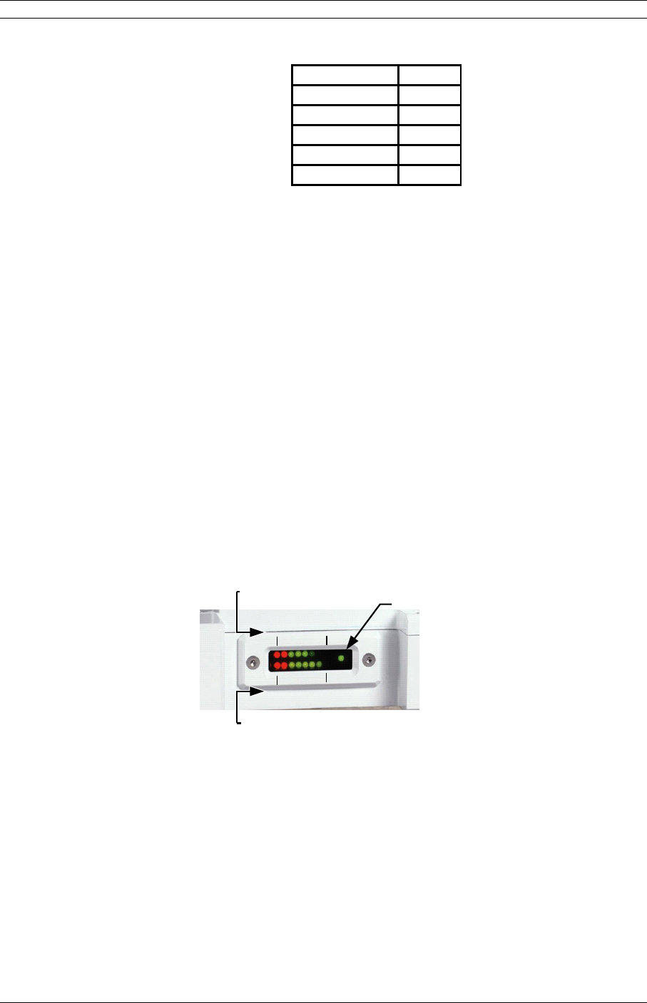
30 3. Installation
Table 3-4: Serial Port Parameters
Parameter Value
Speed 38400
Bits 8
Stop-Bits 1
Parity None
Flow-Control None
After powering-on the SDIDUTM, the CLI may be accessed by connecting the serial cable
between the PC and the SDIDUTM, launching and configuring a terminal program (e.g.
Hyperterm) and pressing the enter key. You will be prompted for a username and
password, which are supplied at the end of this guide.
3.8.6ODU Antenna Alignment
Receive signal level indication at the antenna/ODU location is a power tool to aid antenna
alignment at the time of installation. The following provides ODU specific information
regarding the receive signal.
3.8.6.1 ODU 2200, 6500, 7200
The ODU 2200, 6500, and 7200 has an externally visible LED meter that provides both
RSL (Receive Signal Level) and transmit power. For full-duplex operation the ODU meter
displays RSL on the top bar and transmit level on the bottom bar as shown in Figure
3-19.
Unit ON
(Heartbeat)
-95
dBm
-15
dBm
Tx
Min
Tx
Max
Transmit
Power Level
(Bottom Row)
Receive Signal
Level
(Top Row)
Figure 3-19. ODU 2200 RSSI Output vs. Received Signal.
The upper RSL LED meter is calibrated to represent exactly 10 dB for each LED, going
from -95 dBm at the far left (red) to -15 dBm at the far right (green). The brightness of
each LED is modulated for levels between 0 to 10 dB such that the far left LED will be
fully extinguished at -95 dBm and the far right LED will be fully illuminated at -15 dBm.
When the RSL is in the red region (<-75 dBm) the signal level is approaching or has
reached threshold (depends on modulation type).
The transmit LED indicates full power will all 8 LEDs illuminated to minimum power with 1
LED illuminated.
© 2007 Moseley, Inc. All Rights Reserved. 602-14886-01, Rev. A
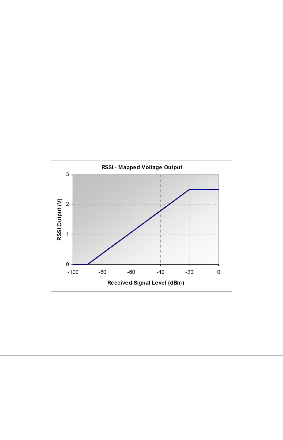
3. Installation 31
For simplex applications such as broadcast STL or ENG where the ODU is a receiver or a
transmitter only then both LED bars represent either RSL for receiver ODU or transmit
power for transmitter ODU. For RSL each LED represents 5 dB, with brightness
modulated from off for 0 dB to fully on for 5 dB increments.
3.8.6.2 ODU 5300/5800
To use the built-in tuning of the ODU 5300 or 5800 antenna, a complete link is required,
with both ends of the link roughly pointed at each other, and transmitting.
Once the links are roughly pointed, connect the voltmeter to the RSSI (Receive Signal
Strength Indication) BNC connector seen on the ODU. This mode outputs 0 to +2.5 Volts.
Adjust the antenna for maximum voltage. The RSSI voltage is linearly calibrated from 2.5
Volts for maximum RSL (received signal level) at –20 dBm to 0Volts for minimum RSL at
-90 dBm. This mapping characteristic is plotted below in Figure 3-20.
Figure 3-20. ODU RSSI Output vs. Received Signal.
3.8.7Quick Start Settings
PC Network Configuration
The Web GUI may be accessed via NMS by connecting a CAT5 patch cable between the
SDIDUTM front-panel NMS port and a PC. The PCs network interface must be configured to
an open IP address within the same subnet. For the default Moseley Event-HD
configuration, the IP address of the PC needs to be 192.168.1.x, where x (between 1 and
100) provides an available IP address. DHCP may also be used to set the PC IP address if
a DHCP server is configured on the same subnet.
© 2007 Moseley, Inc. All Rights Reserved. 602-14886-01, Rev. A
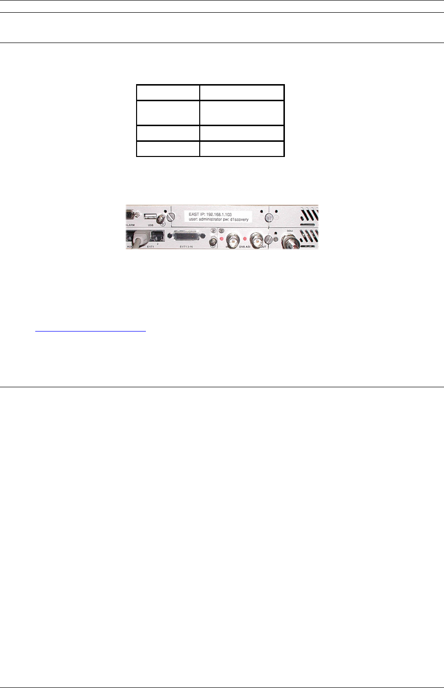
32 3. Installation
Event-HD IP Address
The Event-HD system will be configured and tested as link prior to delivery to the
customer. The IP address will be set at the factory to these default values:
Parameter Value
IP
Address
192.168.1.1xx
Netmask 255.255.255.0
Gateway 192.168.1.1
Where xx is in the range from 01 to 99. The IP address is indicated on the rear panel as
shown in Figure 3-21.
Figure 3-21. IDU IP address label location
After configuring the PCs network interface, a web browser may be launched and the
following URL entered into the address bar to access the unit’s Web GUI:
http://192.168.0.101/
or as specified on the rear panel.
Username and Password
A dialog box will show requesting a username and password:
•User: administrator
•Pass: d1scovery
3.9SDIDU™ Service
At times, it may be necessary to service the SDIDU™. This may include installing,
removing, or replacing an SDIDU™ module. There may be up to 8 modules installed in a
single SDIDU™ chassis. Figure 3-22 shows the rear panel of the SDIDU™ with each
module labeled. The basic procedure for removing and installing a module is common to
all the modules, with slight variations for the Power Supply Module, Controller Module,
and Mini IO Module. These basic procedures are described below. Variations are
described in sub-items beneath each step.
© 2007 Moseley, Inc. All Rights Reserved. 602-14886-01, Rev. A
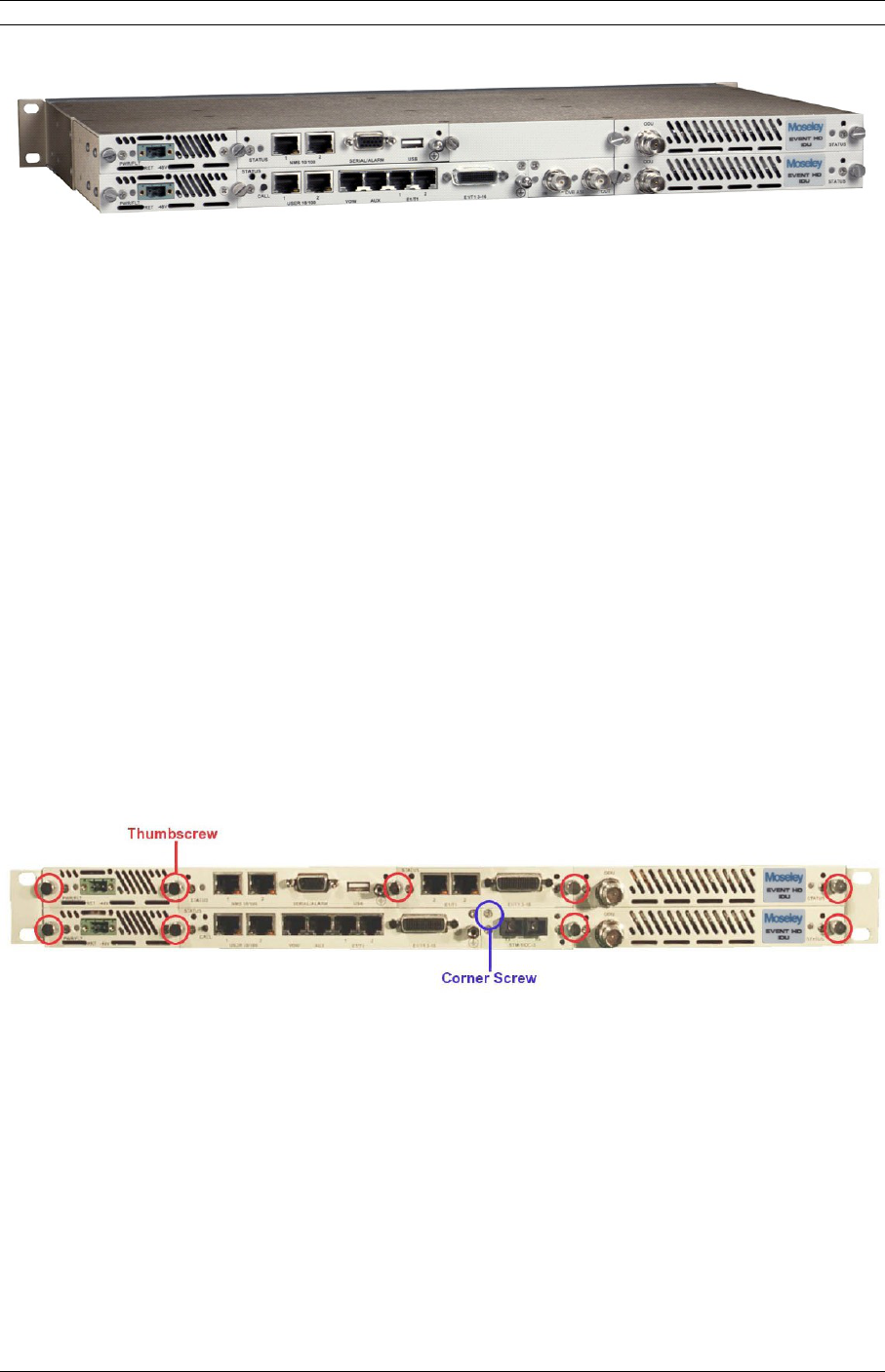
3. Installation 33
Power Supply
Module
Power Supply
Module
Controller
Module
Standard IO
Module
Mini IO
Module
Expansion
Module
Modem
Module
Modem
Module
Figure 3-22. SDIDU™ Modules
3.9.1Removing a Module
9. Modules are static sensitive and should only be handled in an ESD-safe
environment. When packaging modules for shipment or storage, place in an
ESD bag.
10. Remove rear panel connections to the module.
11. Remove the two thumbscrews on either side of the module. Figure 3-23 shows
the locations of these thumb screws.
a. The thumbscrew for the Standard IO Module is located on the right side of
the Mini IO Module slot.
b. If a Mini IO module is installed and the Standard IO Module is to be
removed, both modules will be removed as one unit.
c. When removing only the Mini IO card, remove the corner screw indicated in
Figure 3-23 and one thumb screw.
Figure 3-23. Thumbscrew and Corner Screw Locations
12. Thread thumbscrew(s) into hole(s) shown in Figure 3-24. Remove the module
by grasping the thumbscrew(s) and pulling module straight out of the
SDIDU™. Both thumbscrews should be used for all modules except the Power
Supply and the Mini IO Modules.
a. The Power Supply and Mini IO Modules have only one threaded hole each.
b. When removing the Standard IO Module, the ground lug indicated in Figure
3-24 is used as the second threaded hole. If the SDIDU™ is to remain
© 2007 Moseley, Inc. All Rights Reserved. 602-14886-01, Rev. A
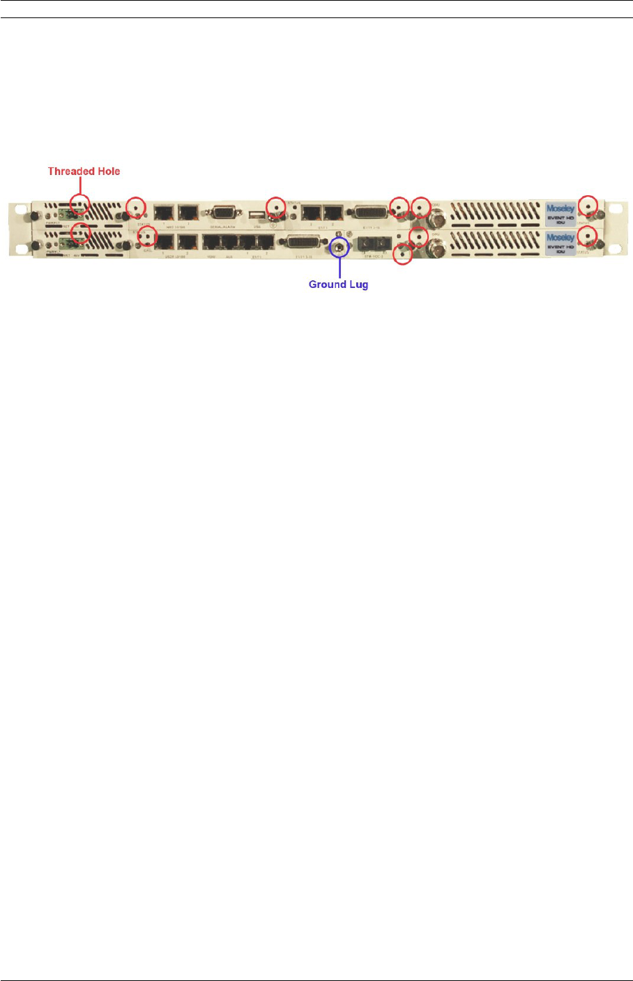
34 3. Installation
powered on and the ground lug is being used to ground the unit, first move
the ground connection to the ground lug located on the Controller Module.
The SDIDU™ retains its current configuration when a module is removed, unless that
module is the Controller Module. In which case, the IP addresses will need to be
reprogrammed.
Figure 3-24. Threaded Hole Locations
3.9.2Installing a Module
1. Modules are static sensitive and should only be handled in an ESD-safe
environment. When packaging modules for shipment or storage, place in an ESD
bag.
2. Line up the module board with the guides in the chassis and slide the module into
the SDIDU™. Figure 3-25 shows a photo of the guides. As the module face plate
comes flush with the face of the SDIDU™, connectors on the rear of the module
will engage with the SDIDU™ backplane. It is possible to encounter interference
from adjacent module rear panels. If this occurs, loosen the thumbscrews holding
the neighboring panels and shift them as necessary to ensure fit.
a. The Mini IO Module only has one guide on the right side. Take care to insert
the Mini IO module carefully and correctly engage the rear connector with its
mate on the Standard IO Module.
© 2007 Moseley, Inc. All Rights Reserved. 602-14886-01, Rev. A
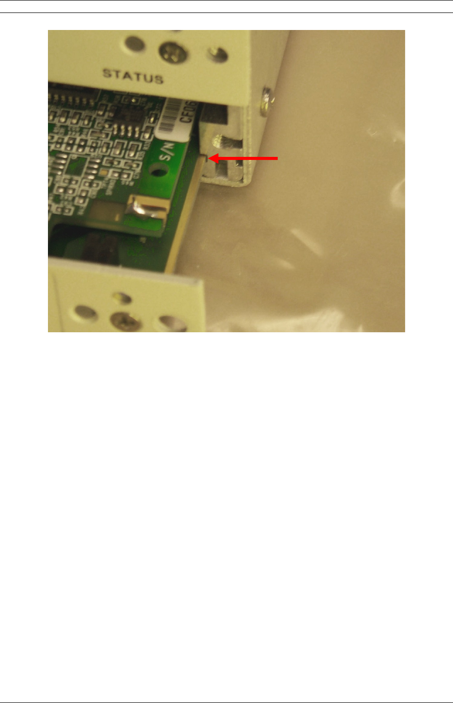
3. Installation 35
Figure 3-25. Guides
3. Install thumbscrews on either side of the module as shown in Figure 3-24.
a. The Mini IO card has a corner screw, which should be installed. This corner
screw is shown in Figure 3-23.
4. Make rear panel connections to the module and power on the SDIDU™ if
necessary.
5. Verify proper operation of the unit.
a. If the Controller Module has been changed, reprogram the IP addresses.
© 2007 Moseley, Inc. All Rights Reserved. 602-14886-01, Rev. A
Guide

36 3. Installation
© 2007 Moseley, Inc. All Rights Reserved. 602-14886-01, Rev. A

4. Summary Specification 1
4.Summary Specification
Parameter Event
2200,
2200FD,
2400
2GHz
Event
6500,
6800,
7200, 7400
6-7 GHz
Event 5800
5.8 GHz
Event 5300
5.3 GHz
System
Frequency Bands
(others available on
request)
1.990-2.110
2.200-2.300
2.450-2.500
6.425-6.525
6.525-6.875
6.875-7.125
7.125-7.425
5.725-5.850 5.250-5.350
Output Power
(avg. max.)
4 Watts 1 Watt 200 mW +5 dBm
Channelization
(others available on
request)
12, 17 MHz 20, 25, 28,
30 MHz
12.5, 16.7,
25, 30 MHz
13.3, 20, 30
MHz
Capacity 150Mbps ASI
2-100 Mbps Ethernet
1-16 T1/E1
Various combinations of above
Input Sensitivity -84 dBm (or higher, based on selected mode)
Modulation QPSK, 16, 32, 64, 128 QAM
Radio Interfaces
External Antenna N-Type Female
SDIDUTM /ODU Link TNC Female
Data Interfaces
Payload
DVB/ASI
Ethernet
2 T1/E1
14 T1/E1
BNC Female (2)
10Base-T/100Base-Tx RJ-45 Female (2)
100 Ω / 120 Ω Balanced, RJ-48C Female (2)
Molex High-Density 60-pin (14)
SNMP 10Base-T/100Base-Tx RJ-45 Female
Control
Network Management SNMP, Proprietary GUI
© 2007 Moseley, Inc. All Rights Reserved. 602-14886-01, Rev. A

2 4. Summary Specification
Parameter Event
2200,
2200FD,
2400
2GHz
Event
6500,
6800,
7200, 7400
6-7 GHz
Event 5800
5.8 GHz
Event 5300
5.3 GHz
NMS Connector 10Base-T/100Base-Tx RJ-45 Female (2)
Voice Orderwire RJ-45 for PTT handset
Auxiliary Data (64
kbps)
RS422 via RJ-45
Encryption (Consult
Moseley Sales)
AES
Alarm Port 2 Form C (SPDT), 2 TTL Output, 4 TTL Input, DB-15HD
Power/Environment
DC Power -48 Volts
±10%,
<100 W
-48 Volts
±10%,
<100 W
-48 Volts
±10%, <70
W
-48 Volts
±10%, <70
W
SDIDUTM Operational
Temperature
-5º to 55º C
ODU Operational
Temperature
-30º to 55º C
SDIDUTM Humidity 0 to 95%, non-condensing
ODU Humidity 0 to100% at 45º C
Altitude 15,000 feet/4572 meters, maximum
Physical Dimensions
SDIDUTM Size (WxHxD) 17.2 x 1.75 x 9.4 inches
(43.7 x 4.5 x 23.9 cm)
SDIDUTM Weight 7 lbs (3.12 Kg)
SDIDUTM
EIA Rack Mount 19 inch/48.2 cm, 1 rack unit
ODU Size (WxHxD) 14.0 x 8.5 x
4 inches
14.0 x 8.5 x
4 inches
14.6 x 15.4
x 2.6 inches
14.6 x 15.4
x 2.6 inches
ODU Weight 16.3 lbs (7.4
kgs)
16.3 lbs (7.4
kgs)
15 lbs (6.8
kgs)
15 lbs (6.8
kgs)
ODU
Mounting Custom Bracket
© 2007 Moseley, Inc. All Rights Reserved. 602-14886-01, Rev. A
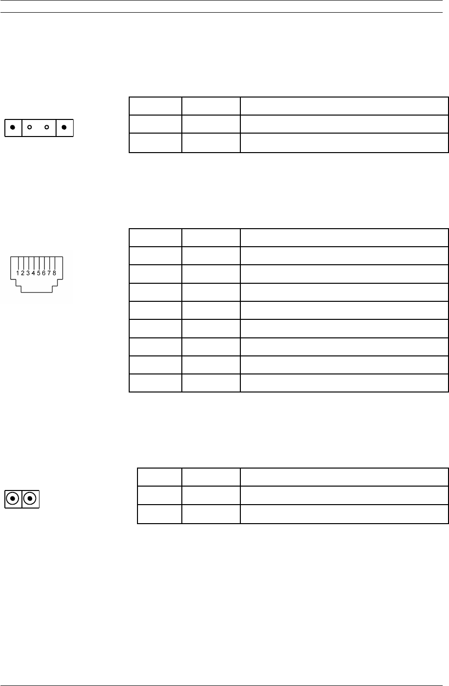
5. Rear Panel Connectors 1
5.Rear Panel Connectors
5.1DC Input (Power) Connector
MSTB 2,5/ 2-GF PIN TYPE SIGNAL
1 2
1 POWER Power supply return
2 POWER 48 Vdc, nominal
Mating Connector: MSTB 2,5/ 2-STF
Ordering Information: Phoenix Contact Part Number 1786831
5.2Ethernet 100BaseTX Payload Connector 1-2
RJ-45 Female PIN TYPE SIGNAL
1 INPUT RX+
2 INPUT RX-
3 OUTPUT TX+
4 N/A N/A
5 N/A N/A
6 OUTPUT TX-
7 N/A N/A
8 N/A N/A
Mating Connector: Standard RJ-45 Plug
Ordering Information: Tyco Electronics/Amp Part Number 5-554169-3 or equivalent
5.3SONET Payload Connector
SC Duplex Female Fiber PIN TYPE SIGNAL
INOUT
OUT OUTPUT SONET OC-3 payload output (optical)
IN INPUT SONET OC-3 payload input (optical)
Mating Connector: SC-Duplex Male
Ordering Information: Molex Part Number 86066-4000 or equivalent
© 2007 Moseley, Inc. All Rights Reserved. 602-14886-01, Rev. A
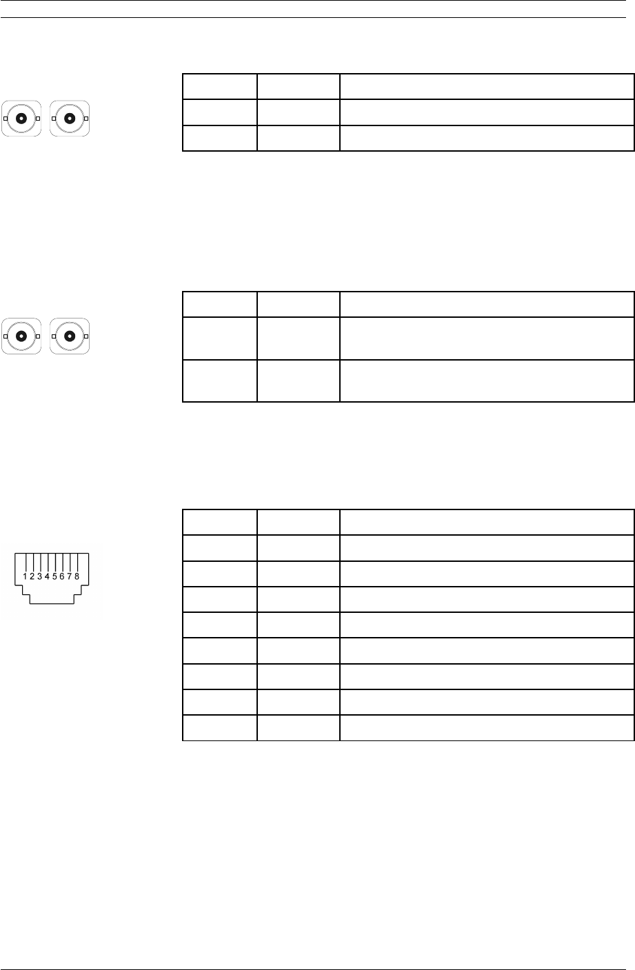
2 5. Rear Panel Connectors
5.4STM-1 Payload Connector
BNC Female PIN TYPE SIGNAL
RXTX
TX OUTPUT SDH STM-1 payload output (electrical)
RX INPUT SDH STM-1 payload input (electrical)
Mating Connector: BNC Male
Ordering Information: Tyco Electronics/Amp Part Number 225395-2 or equivalent
5.5DVB/ASI, DS-3, E-3, STS-1 Payload Connector
Consult factory for availability.
BNC Female PIN TYPE SIGNAL
RXTX
TX OUTPUT DVB-ASI, DS-3, E-3, STS-1 payload
output
RX INPUT DVB-ASI, DS-3, E-3, STS-1 payload
input
Mating Connector: BNC Male
Ordering Information: Tyco Electronics/Amp Part Number 225395-2 or equivalent
5.6NMS 10/100BaseTX Connector 1-2
RJ-45 Female PIN TYPE SIGNAL
1 OUTPUT TX+
2 OUTPUT TX-
3 INPUT RX+
4 N/A N/A
5 N/A N/A
6 INPUT RX-
7 N/A N/A
8 N/A N/A
Mating Connector: Standard RJ-45 Plug
Ordering Information: Tyco Electronics/Amp Part Number 5-554169-3 or equivalent
© 2007 Moseley, Inc. All Rights Reserved. 602-14886-01, Rev. A
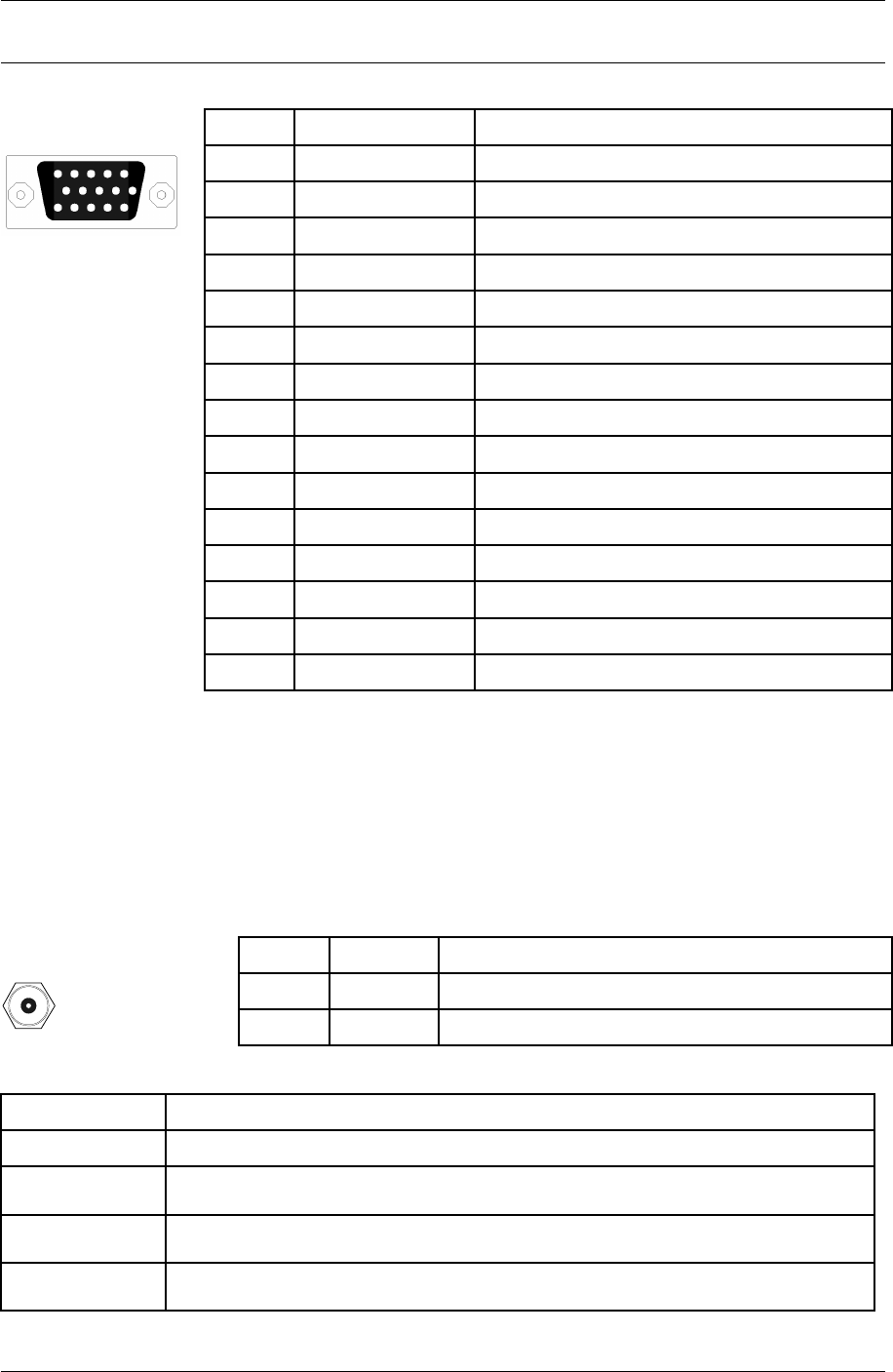
5. Rear Panel Connectors 3
3
5.7Alarm/Serial Port Connector
DB-15HD Female PIN TYPE SIGNAL
1 OUTPUT TTL Alarm Output 3
2*INPUT/ Output RS-232 RX/TX
3*OUTPUT/ Input RS-232 TX/RX
4 OUTPUT TTL Alarm Output 4
5 N/A GROUND
61** N/A Alarm 1 Form C Contact Normally Open
7** N/A Alarm 1 Form C Contact Normally Closed
8** N/A Alarm 2 Form C Contact Common
9 INPUT TTL Alarm Input 1
10 INPUT TTL Alarm Input 3
11** N/A Alarm 1 Form C Contact Common
12** N/A Alarm 2 Form C Contact Normally Open
13** N/A Alarm 2 Form C Contact Normally Closed
14 INPUT TTL Alarm Input 2
15 Input TTL Alarm Input 4
* Pins 2 and 3 are hardware jumper configurable for DCE or DTE operation.
** Form C Contacts are hardware jumper configurable to emulate TTL outputs
Mating Connector: HD-DSUB15 Male (15 pins in a DB9 shell)
Ordering Information: Norcomp Part Number 180-015-102-001 or equivalent
5.8ODU Connector
TNC Coaxial Female PIN TYPE SIGNAL
Center I/O 350 MHz TX IF / 140 MHz RX IF / -48 VDC
Shield N/A Shield / Chassis GND
Mating Connector: TNC Male
Cable Type Ordering Information
LMR-200 Times Microwave Systems Part Number TC-200-TM
LMR-300 Times Microwave Systems Part Number TC-300-TM
LMR-400 Times Microwave Systems Part Number TC-400-TM
RG-214 Tyco Electronics/Amp Part Number 225550-8 or equivalent
© 2007 Moseley, Inc. All Rights Reserved. 602-14886-01, Rev. A
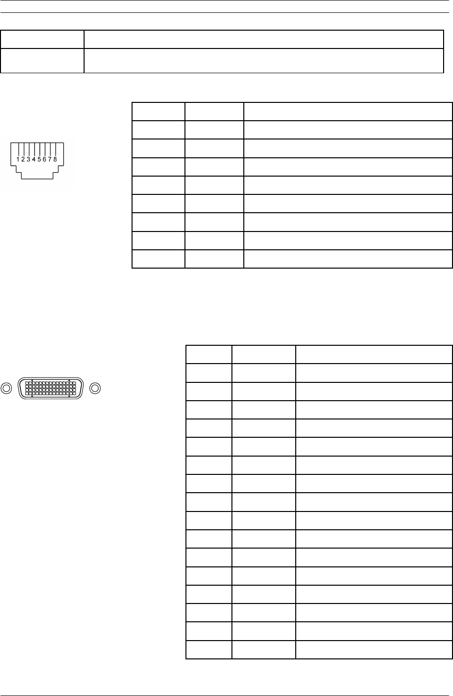
4 5. Rear Panel Connectors
Cable Type Ordering Information
Belden 7808 Tyco Electronics/Amp Part Number 1-225550-3 or equivalent
5.9T1/E1 - Channels 1-2 Connector
RJ-48C Female PIN TYPE SIGNAL
100 Ω /120 Ω Balanced 1 INPUT RX+
2 INPUT RX-
3 N/A GND
4 OUTPUT TX+
5 OUTPUT TX-
6 N/A GND
7 N/A N/A
8 N/A N/A
Mating Connector: Standard RJ-45 Plug
Ordering Information: Tyco Electronics/Amp Part Number 5-554169-3 or equivalent
5.10T1/E1 - Channels 3-16 Connector
Molex LFH Matrix 50 Receptacle PIN TYPE SIGNAL
100 Ω / 120 Ω Balanced 1 OUTPUT T1 Channel 13 Transmit Tip
2 OUTPUT T1 Channel 14 Transmit Tip
3 OUTPUT T1 Channel 15 Transmit Tip
4 OUTPUT T1 Channel 16 Transmit Tip
5 OUTPUT T1 Channel 9 Transmit Tip
6 OUTPUT T1 Channel 10 Transmit Tip
7 OUTPUT T1 Channel 11 Transmit Tip
8 OUTPUT T1 Channel 12 Transmit Tip
9 OUTPUT T1 Channel 5 Transmit Tip
10 OUTPUT T1 Channel 6 Transmit Tip
11 OUTPUT T1 Channel 7 Transmit Tip
12 OUTPUT T1 Channel 8 Transmit Tip
13 OUTPUT T1 Channel 3 Transmit Tip
14 OUTPUT T1 Channel 4 Transmit Tip
15 NC NC
16 NC NC
© 2007 Moseley, Inc. All Rights Reserved. 602-14886-01, Rev. A

5. Rear Panel Connectors 5
5
Molex LFH Matrix 50 Receptacle PIN TYPE SIGNAL
17 OUTPUT T1 Channel 4 Transmit Ring
18 OUTPUT T1 Channel 3 Transmit Ring
19 OUTPUT T1 Channel 8 Transmit Ring
20 OUTPUT T1 Channel 7 Transmit Ring
21 OUTPUT T1 Channel 6 Transmit Ring
22 OUTPUT T1 Channel 5 Transmit Ring
23 OUTPUT T1 Channel 12 Transmit Ring
24 OUTPUT T1 Channel 11 Transmit Ring
25 OUTPUT T1 Channel 10 Transmit Ring
26 OUTPUT T1 Channel 9 Transmit Ring
27 OUTPUT T1 Channel 16 Transmit Ring
28 OUTPUT T1 Channel 15 Transmit Ring
29 OUTPUT T1 Channel 14 Transmit Ring
30 OUTPUT T1 Channel 13 Transmit Ring
31 INPUT T1 Channel 16 Receive Tip
32 INPUT T1 Channel 15 Receive Tip
33 INPUT T1 Channel 9 Receive Tip
34 INPUT T1 Channel 14 Receive Tip
35 INPUT T1 Channel 10 Receive Tip
36 INPUT T1 Channel 13 Receive Tip
37 INPUT T1 Channel 11 Receive Tip
38 INPUT T1 Channel 4 Receive Tip
39 INPUT T1 Channel 12 Receive Tip
40 INPUT T1 Channel 3 Receive Tip
41 INPUT T1 Channel 5 Receive Tip
42 INPUT T1 Channel 8 Receive Tip
43 INPUT T1 Channel 6 Receive Tip
44 INPUT T1 Channel 7 Receive Tip
45 NC NC
46 NC NC
47 INPUT T1 Channel 7 Receive Ring
48 INPUT T1 Channel 6 Receive Ring
49 INPUT T1 Channel 8 Receive Ring
© 2007 Moseley, Inc. All Rights Reserved. 602-14886-01, Rev. A
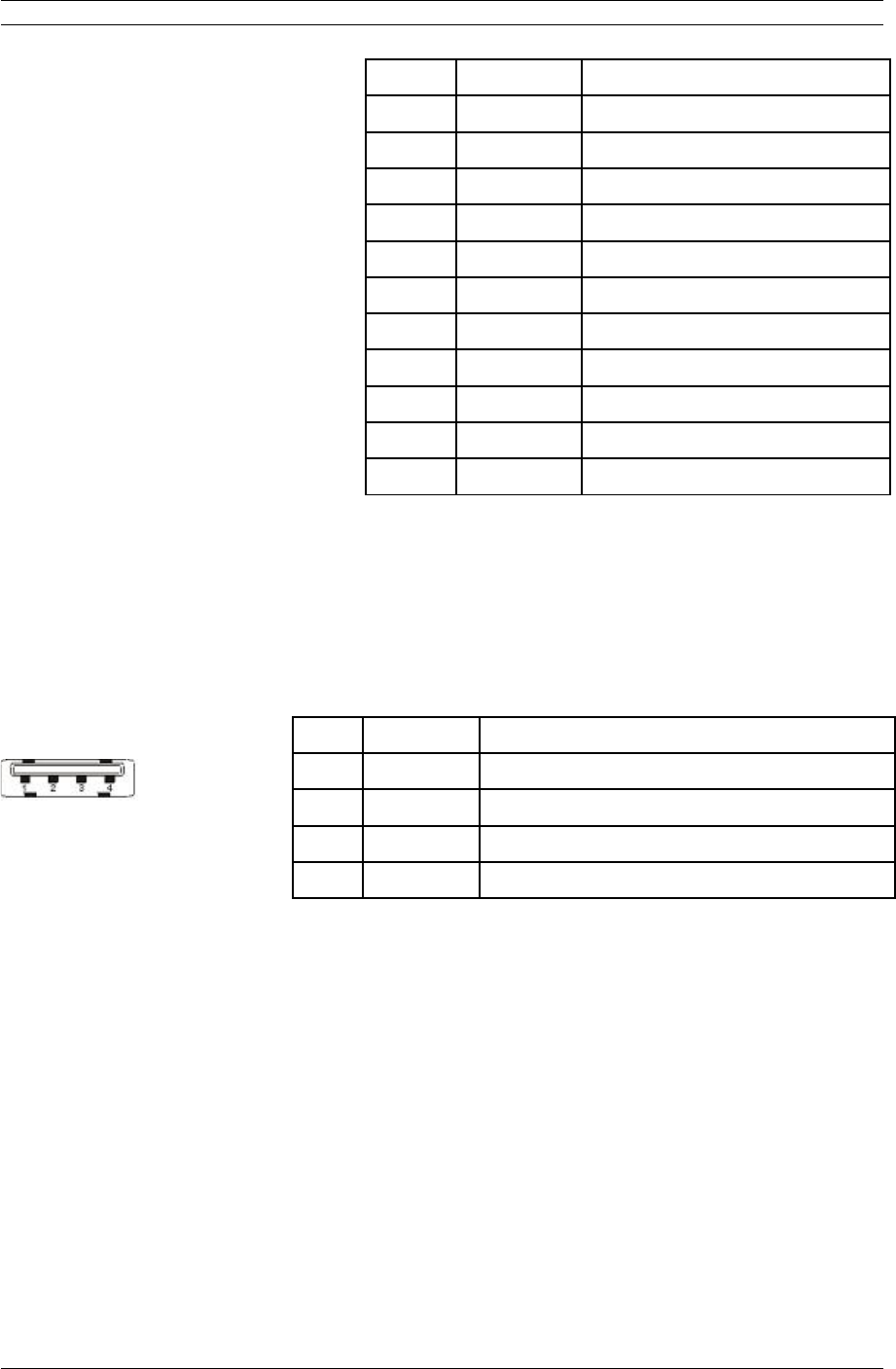
6 5. Rear Panel Connectors
Molex LFH Matrix 50 Receptacle PIN TYPE SIGNAL
50 INPUT T1 Channel 5 Receive Ring
51 INPUT T1 Channel 3 Receive Ring
52 INPUT T1 Channel 12 Receive Ring
53 INPUT T1 Channel 4 Receive Ring
54 INPUT T1 Channel 11 Receive Ring
55 INPUT T1 Channel 13 Receive Ring
56 INPUT T1 Channel 10 Receive Ring
57 INPUT T1 Channel 14 Receive Ring
58 INPUT T1 Channel 9 Receive Ring
59 INPUT T1 Channel 15 Receive Ring
60 INPUT T1 Channel 16 Receive Ring
Mating Connector: Molex LFH Matrix 50 Plug
Ordering Information: Molex Part Number 70929-2000 (connector) + Molex Part
Number 51-24-2021 (pins, Qty 4 per connector)
5.11USB
Consult factory for availability.
USB Type A Receptacle PIN TYPE SIGNAL
1 OUTPUT +5V
2 I/O -Data
3 I/O +Data
4 N/A GND
Mating Connector: USB Type A Plug
© 2007 Moseley, Inc. All Rights Reserved. 602-14886-01, Rev. A
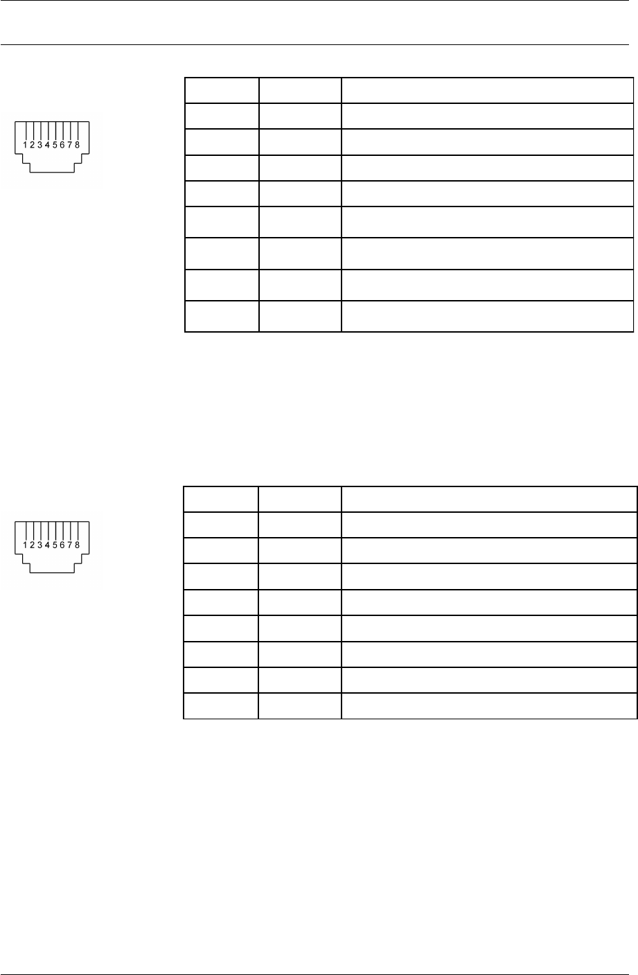
5. Rear Panel Connectors 7
7
5.12Voice Order Wire
Mating Connector: Standard RJ-6 Plug or Standard RJ-45 Plug
Ordering Information: Tyco Electronics/Amp Part Number 5-554710-3 or equivalent
for RJ-6. Tyco Electronics/Amp Part Number 5-554169-3 or equivalent for RJ-45.
5.13Data Order Wire
5.13.1RS422
RJ-45 Female PIN TYPE SIGNAL
1 OUTPUT TX Clock -
2 OUTPUT TX Clock +
3 OUTPUT TX Data -
4 INPUT RX Data -
5 INPUT RX Data +
6 OUTPUT TX Data +
7 INPUT RX Clock -
8 INPUT RX Clock +
Mating Connector: Standard RJ-45 Plug
Ordering Information: Tyco Electronics/Amp Part Number 5-554169-3 or equivalent
© 2007 Moseley, Inc. All Rights Reserved. 602-14886-01, Rev. A
RJ-45 Female PIN TYPE SIGNAL
1 N/A NC
2 INPUT PTT
3 N/A GND
4 OUTPUT PO-
5 OUTPUT PO+
6 INPUT TI-
7 N/A GND
8 N/A NC

8 5. Rear Panel Connectors
5.13.2RS-232
RJ-45 Female PIN TYPE SIGNAL
1 N/A NC
2 N/A NC
3 N/A Signal GND
4 N/A NC
5 INPUT RX Data +
6 OUTPUT TX Data +
7 N/A NC
8 N/A NC
Mating Connector: Standard RJ-45 Plug
Ordering Information: Tyco Electronics/Amp Part Number 5-554169-3 or equivalent
© 2007 Moseley, Inc. All Rights Reserved. 602-14886-01, Rev. A

6. Appendix 1
6.Appendix
6.1Alarm Descriptions
Alarm Affected
Component Description LED to
RED
Alarm
Code Severity
Modem Fault
Lower
Modem The specified Modem card has
indicated a fault. Fault
detection is via reading
Modem Hardware Status from
MODEM during start-up and
polling GPIO for MODEM fault
indication. Polling interval 5
sec.
N/A 11 Critical
Modem Comm
Failure Lower
Modem The Controller Card is unable
to communicate with the
specified Modem card.
Modem
Lower
12 Critical
Modem Card
Removed Lower
Modem The specified Modem card has
been removed from the IDU
(only if the specified Modem
card has been enabled for
use). Fault detection via card-
detect logic.
N/A 13 Major
Modem Card
Installed Lower
Modem The specified Modem card has
been installed into the IDU
(only if the specified Modem
card is not enabled for use).
Fault detection via card-detect
logic. Alarm is raised then
lowered.
Modem
Lower
14 Info
Modem Unlock
Lower
Modem The demodulation functional
components of the modem
have lost lock to the incoming
signal. The data received
through the RF link is not
valid. Fault detection via
modem status polling. Polling
interval: 1 sec.
N/A N/A Critical
RSL Low Lower Modem RSSI is approaching the
minimum operational level of
the link as set during
configuration. Fault detection
via modem status polling,
comparing RSSI value to
threshold value in
configuration table. Polling
interval 5 sec.
N/A N/A Major
© 2007 Moseley, Inc. All Rights Reserved. 602-14886-01, Rev. A

2 6. Appendix
Alarm Affected
Component Description LED to
RED
Alarm
Code Severity
Synthesizer
Unlock Lower
Modem Modem synthesizer has
unlocked. Fault detection via
modem status polling. Polling
is done in conjunction with
Modem Unlock polling.
N/A N/A Critical
SNR Low Lower Modem The signal-to-noise ratio is
below the minimum
operational level of the link as
set during configuration. Fault
detection via modem status
polling, comparing Eb/N0
value to threshold value in
configuration table. Polling
interval 5 sec.
N/A N/A Major
Modem Fault
Upper
Modem The specified Modem card has
indicated a fault. Fault
detection is via reading
Modem Hardware Status from
MODEM during start-up and
polling GPIO for MODEM fault
indication. Polling interval 5
sec.
N/A 16 Critical
Modem Comm
Failure Upper
Modem The Controller Card is unable
to communicate with the
specified Modem card.
Modem
Lower
17 Critical
Modem Card
Removed Upper
Modem The specified Modem card has
been removed from the IDU
(only if the specified Modem
card has been enabled for
use). Fault detection via card-
detect logic.
N/A 18 Major
Modem Card
Installed Upper
Modem The specified Modem card has
been installed into the IDU
(only if the specified Modem
card is not enabled for use).
Fault detection via card-detect
logic. Alarm is raised then
lowered.
Modem
Upper
19 Info
Modem Unlock
Upper
Modem The demodulation functional
components of the modem
have lost lock to the incoming
signal. The data received
through the RF link is not
valid. Fault detection via
modem status polling. Polling
interval 1 sec.
N/A N/A Critical
© 2007 Moseley, Inc. All Rights Reserved. 602-14886-01, Rev. A

6. Appendix 3
3
Alarm Affected
Component Description LED to
RED
Alarm
Code Severity
RSL Low Upper Modem RSSI is approaching the
minimum operational level of
the link as set during
configuration. Fault detection
via modem status polling,
comparing RSSI value to
threshold value in
configuration table. Polling
interval 5 sec.
N/A N/A Major
SNR Low Upper Modem The signal-to-noise ratio is
below the minimum
operational level of the link as
set during configuration. Fault
detection via modem status
polling, comparing Eb/N0
value to threshold value in
configuration table. Polling
interval 5 sec.
N/A N/A Major
Synthesizer
Unlock Upper
Modem Modem synthesizer has
unlocked. Fault detection via
modem status polling. Polling
is done in conjunction with
Modem Unlock polling.
N/A N/A Critical
Fan Failure Controller The Fan rotational speed is too
low. (Controller card LED
flashed red rather than
orange). Fault detection via
polling fan controller status.
Polling interval 10 sec.
Controller 21 Major
Controller Card
Fault
Controller The CPU has detected a fault
in the controller card.
(Controller card LED flashes
red rather than orange). Fault
detection via software.
Controller 22 Critical
Low Battery
Voltage
Controller The CPU has detected a low-
battery voltage condition.
(Controller card LED flashes
red rather than orange). Fault
detection via software polling
RTC via controller FPGA.
Controller 23 Info
Power Supply
Fault Lower
Power Supply The Power Supply card has
indicated a fault. Fault
detection via polling GPIO.
Polling interval 5 sec.
N/A 31 Critical
© 2007 Moseley, Inc. All Rights Reserved. 602-14886-01, Rev. A

4 6. Appendix
Alarm Affected
Component Description LED to
RED
Alarm
Code Severity
Power Supply
Card Removed
Lower
Power Supply The specified Power Supply
card has been removed from
the IDU. Fault detection via
card-detect logic.
N/A 32 Major
Power Supply
Fault Upper
Power Supply The Power Supply card has
indicated a fault. Fault
detection via polling GPIO.
Polling interval 5 sec.
N/A 36 Critical
Power Supply
Card Removed
Upper
Power Supply The specified Power Supply
card has been removed from
the IDU. Fault detection via
card-detect logic.
N/A 37 Major
Standard I/O
Card Removed
StdIO The Standard I/O card has
been removed from the IDU.
Fault detect via card-detect
logic.
N/A 41 Critical
Ethernet
Payload
Disconnect
StdIO There is no cable detected at
either Ethernet payload on
Standard I/O card (only if
Ethernet mode enabled). Fault
detection via polling of
Ethernet PHY. Polling interval
5 sec.
Standard
I/O
42 Critical
Framer
Initialization
Timeout
StdIO There is an initialization wait
for Framer to turn ON the
Framer Receiver side after
turning ON the Modem/ODU.
Fault detection via polling. Poll
only after timeout to detect.
Standard
I/O
43 Critical
Mini I/O Card
Removed
MiniIO The Mini I/O card has been
removed from the IDU (only if
Mini I/O card has been
enabled for use). Fault
detection via card-detect logic.
Standard
I/O
46 Critical
Mini I/O Card
Installed
MiniIO The Mini I/O card has been
installed into the IDU (only if
Mini I/O card is noted enabled
for use). Fault detection via
card-detect logic. Alarm is
raised then lowered.
Standard
I/O
47 Info
© 2007 Moseley, Inc. All Rights Reserved. 602-14886-01, Rev. A

6. Appendix 5
5
Alarm Affected
Component Description LED to
RED
Alarm
Code Severity
Optional I/O
Card Removed
OptIO The Optional I/O card has
been removed from the IDU
(only if the Optional I/O card
has been enabled for use).
Fault detection via card-detect
logic.
N/A 26 Critical
Optional I/O
Card Installed
OptIO The Optional I/O card has
been installed into the IDU
(only if the Optional I/O card
is not enabled for use). Fault
detection via card-detect logic.
Alarm is raised then lowered.
Optional
I/O
27 Info
T1/E1 Channel
Alarm Ch x
StdIO (1-16)
OptIO
(17-32)
There is either no cable
detected at the specified
E1/T1 channel port on
Standard I/O Card or there is
an AIS condition detected
(only for active T1/E1
channels). Fault detection via
polling of LIUs on Standard
I/O card and Optional I/O
Card when installed. Polling
interval 2 channels per 1 sec.
Report of this alarm in the
GUI/Syslog/Alarm history
indicates whether this is a
disconnect or AIS condition. If
both conditions are present,
the disconnect alarm will take
precedence over the AIS
alarm.
Standard
I/O when
1-16
Optional
I/O when
17-32
Turn LED
orange
rather
than RED
51-58
(1-16)
61-68
(17-32)
Critical
T1/E1 Test
Mode
StdIO The user has selected a T1/E1
test mode (loopback or Tx
Data). This alarm will be set
when the user sets the test
mode for any of the T1/E1
channels, and cleared when all
T1/E1 channels are not in
loopback and Tx Data is
normal.
N/A 59 Info
BERT/LB/CW
Test Mode
StdIO This alarm will be set when
the user enables either BERT,
Loopback, or CW mode, and
cleared when all BERT,
Loopback and CW modes are
disabled.
N/A 69 Info
© 2007 Moseley, Inc. All Rights Reserved. 602-14886-01, Rev. A

6 6. Appendix
Alarm Affected
Component Description LED to
RED
Alarm
Code Severity
ODU Fault
Lower
ODU The ODU has indicated a fault
condition. Fault detection via
polling of ODU or unsolicited
message, if supported. Polling
interval 5 sec. Polling done via
API functional call. Report of
this alarm in the
GUI/Syslog/Alarm history
indicates the fault code from
the ODU.
N/A 71 Critical
ODU Comm
Failure Lower
ODU The IDU is unable to
communicate with the ODU.
This could be a problem with
the ODU or a problem with the
cable connecting the ODU to
the IDU.
N/A 72 Critical
ODU Fault
Upper
ODU The ODU has indicated a fault
condition or unsolicited
message, if supported. Fault
detection via polling of ODU.
Polling interval 5 sec. Polling
done via API function call.
Report of this alarm in the
GUI/Syslog/Alarm history
indicates the fault code from
the ODU.
N/A 73 Critical
ODU Comm
Failure Upper
ODU The IDU is unable to
communicate with the ODU.
This could be a problem with
the ODU or a problem with the
cable connecting the ODU to
the IDU.
N/A 74 Critical
Protection
Switch
MODEM/ODU This alarm will be set when an
AL1 command is received from
the active MODEM/ODU.
Cleared when an AL2
command is received from the
standby MODEM/ODU. Report
of this alarm in the
GUI/Syslog/Alarm history
indicates the fault code from
the ODU, if received.
N/A 75 Major
© 2007 Moseley, Inc. All Rights Reserved. 602-14886-01, Rev. A

6. Appendix 7
7
Alarm Affected
Component Description LED to
RED
Alarm
Code Severity
East ATPC Tx at
Max Power
ODU The IDU is unable to increase
the Tx Power as requested by
link partner due to maximum
power being reached.
Maximum power is specified in
the configuration table.
N/A 76 Info
West ATPC Tx at
Max Power
ODU The IDU is unable to increase
the Tx Power as requested by
link partner due to maximum
power being reached.
Maximum power is specified in
the configuration table.
N/A 78 Info
Link Fault IDU Failed to receive link heartbeat
from link partner via Radio
Overhead (ROH) channel.
Fault detection via timeout
counter, which is reset via
reception of link heartbeat
message.
N/A 81 Critical
Remote Fault IDU Link Partner IDU indicating it
has a fault condition. Local
IDU receives Link Partner
Fault detection via Radio
Overhead (ROH) channel
message.
N/A 82 Info
Encryption
Failure
IDU Data is not being decrypted
properly due to encryption key
mismatch between link
partners. Fault detection via
software detection of
unreadable ROH messages
from link partner.
N/A 83 Critical
Encryption
OneWay
IDU Only one IDU has data
encryption enabled. Fault
detection via software
messages to/from link
partner.
N/A 84 Major
External
Alarm 1
External The external Alarm 1 input
has been activated. Fault
detection via polling GPIO.
Polling interval 1 sec.
N/A 91 Info
External
Alarm 2
External The external Alarm 2 input
has been activated. Fault
detection via polling GPIO.
Polling interval 1 sec.
N/A 92 Info
© 2007 Moseley, Inc. All Rights Reserved. 602-14886-01, Rev. A

8 6. Appendix
Alarm Affected
Component Description LED to
RED
Alarm
Code Severity
External
Alarm 3
External The external Alarm 3 input
has been activated. Fault
detection via polling GPIO.
Polling interval 1 sec.
N/A 93 Info
External
Alarm 4
External The external Alarm 4 input
has been activated. Fault
detection via polling GPIO.
Polling interval 1 sec.
N/A 94 Info
Remote IDU
Alarm
Link Partner
IDU
The link partner IDU has
indicated an alarm condition
via ROH.
N/A 95 Major
Remote IDU
External
Alarm 1
Link Partner
External
The link partner IDU has
indicated via ROH its external
alarm input 1 has been
activated.
N/A 96 Info
Remote IDU
External
Alarm 2
Link Partner
External
The link partner IDU has
indicated via ROH its external
alarm input 2 has been
activated.
N/A 97 Info
Remote IDU
External Alarm
3
Link Partner
External
The link partner IDU has
indicated via ROH its external
alarm input 3 has been
activated.
N/A 98 Info
Remote IDU
External
Alarm 4
Link Partner
External
The link partner IDU has
indicated via ROH its external
alarm input 4 has been
activated.
N/A 99 Info
STM Loss of
Clock
IDU The SDH/SONET clock has lost
lock. Fault detection via
polling of LIU.
N/A Solid Critical
STM RS_LOS IDU The SDH/SONET has a Loss of
Signal Defect. Fault detection
via polling of LIU.
N/A Solid Critical
STM RS_B1 IDU The SDH/SONET Mux/Demux
has a B1 Defect. Fault
detection via polling of
RS_B1_T bit in STM-1 Core.
Alternate detection via
Interrupt enabled in STM-1
core.
N/A Solid Major
© 2007 Moseley, Inc. All Rights Reserved. 602-14886-01, Rev. A

6. Appendix 9
9
Alarm Affected
Component Description LED to
RED
Alarm
Code Severity
STM RS_LOF IDU The SDH/SONET Mux/Demux
has a Loss of Frame Defect.
Fault detection via polling of
RS_LOF_T bit in STM-1 Core.
Alternate detection via
Interrupt enabled in STM-1
core.
N/A Solid Critical
STM RS_OOF IDU The SDH/SONET Mux/Demux
has an Out of Frame Defect.
Fault detection via polling of
RS_OOF_T bit in STM-1 Core.
Alternate detection via
Interrupt enabled in STM-1
core.
N/A Solid Critical
STM RS_TIM IDU The SDH/SONET Mux/Demux
has a Trace Identifier
Mismatch Defect. Fault
detection via polling of
RS_TIM_T bit in STM-1 Core.
Alternate detection via
Interrupt enabled in STM-1
core.
N/A Solid Major
STM MS-AIS IDU The SDH/SONET Mux/Demux
has detected an AIS at the
Multiplexer Level. Fault
detection via polling of
MS_AIS_T bit in STM-1 Core.
Alternate detection via
Interrupt enabled in STM-1
core.
N/A Solid Critical
STM MS-REI IDU The SDH/SONET Mux/Demux
has detected a Remote Error
at the Multiplexer Level. Fault
detection via polling of
MS_REI_T bit in STM-1 Core.
Alternate detection via
Interrupt enabled in STM-1
core.
N/A Solid Major
STM MS-RDI IDU The SDH/SONET Mux/Demux
has detected a Remote Defect
at the Multiplexer Level. Fault
detection via polling of
MS_RDI_T bit in STM-1 Core.
Alternate detection via
Interrupt enabled in STM-1
core.
N/A Solid Major
© 2007 Moseley, Inc. All Rights Reserved. 602-14886-01, Rev. A

10 6. Appendix
Alarm Affected
Component Description LED to
RED
Alarm
Code Severity
STM MS_B2 IDU The SDH/SONET Mux/Demux
has a B2 Defect at the
Multiplex level. Fault detection
via polling of MS_B2_T bit in
STM-1 Core. Alternate
detection via Interrupt
enabled in STM-1 core.
N/A Solid Major
STM AU-AIS x IDU The SDH/SONET Mux/Demux
has detected an AIS at the AU
Level. Fault detection via
polling of AU_AIS_T bit in
STM-1 Core. Where ‘x’ is the
HP index. Alternate detection
via Interrupt enabled in STM-1
core.
N/A Solid Critical
STM AU-LOP x IDU The SDH/SONET Mux/Demux
has detected a Loss of Pointer
Defect at the AU Level. Fault
detection via polling of
AU_LOP_T bit in STM-1 Core.
Where ‘x’ is the HP index.
Alternate detection via
Interrupt enabled in STM-1
core.
N/A Solid Critical
STM HP-UNEQ x IDU The SDH/SONET Mux/Demux
HP number ‘x’ is Unequipped.
Fault detection via polling of
HP_UNEQ_T bit in STM-1
Core. Where ‘x’ is the HP
index. Alternate detection via
Interrupt enabled in STM-1
core.
N/A Solid Major
STM HP-TIM x IDU The SDH/SONET Mux/Demux
HP number ‘x’ has a Trace
Identifier Mismatch. Fault
detection via polling of
HP_TM_TIM_T bit in STM-1
Core. Where ‘x’ is the HP
index. Alternate detection via
Interrupt enabled in STM-1
core.
N/A Solid Major
© 2007 Moseley, Inc. All Rights Reserved. 602-14886-01, Rev. A

6. Appendix 11
11
Alarm Affected
Component Description LED to
RED
Alarm
Code Severity
STM HP-REI x IDU The SDH/SONET Mux/Demux
HP number ‘x’ has a Remote
Error Indication. Fault
detection via polling of
HP_REI_T bit in STM-1 Core.
Where ‘x’ is the HP index.
Alternate detection via
Interrupt enabled in STM-1
core.
N/A Solid Major
STM HP-RDI x IDU The SDH/SONET Mux/Demux
HP number ‘x’ has a Remote
Defect Indication. Fault
detection via polling of
HP_RDI_T bit in STM-1 Core.
Where ‘x’ is the HP index.
Alternate detection via
Interrupt enabled in STM-1
core.
N/A Solid Major
STM HP-PLM x IDU The SDH/SONET Mux/Demux
HP number ‘x’ has a Path
Identifier Mismatch. Fault
detection via polling of
HP_PLM_T bit in STM-1 Core.
Where ‘x’ is the HP index.
Alternate detection via
Interrupt enabled in STM-1
core.
N/A Solid Critical
STM HP_B3 x IDU The SDH/SONET Mux/Demux
HP number ‘x’ has a CRC
Error. Fault detection via
polling of HP_B3_T bit in
STM-1 Core. Where ‘x’ is the
HP index. Alternate detection
via Interrupt enabled in STM-1
core.
N/A Solid Major
STM TU-LOM
lkm
IDU The SDH/SONET Mux/Demux
TU number ‘x’ has a Loss of
Multiframe. Fault detection via
polling of TU_LOMF_T bit in
STM-1 Core. Where ‘lkm’ is
the TU index as LKM
numbering. Alternate
detection via Interrupt
enabled in STM-1 core.
N/A Solid Critical
© 2007 Moseley, Inc. All Rights Reserved. 602-14886-01, Rev. A

12 6. Appendix
Alarm Affected
Component Description LED to
RED
Alarm
Code Severity
STM TU-AIS lkm IDU The SDH/SONET Mux/Demux
TU number ‘x’ has an AIS.
Fault detection via polling of
TU_AIS_T bit in STM-1 Core.
Where ‘lkm’ is the TU index as
LKM numbering. Alternate
detection via Interrupt
enabled in STM-1 core.
N/A Solid Critical
STM TU-LOP
lkm
IDU The SDH/SONET Mux/Demux
TU number ‘x’ has a Loss of
Pointer Defect. Fault detection
via polling of TU_LOP_T bit in
STM-1 Core. Where ‘lkm’ is
the TU index as LKM
numbering. Alternate
detection via Interrupt
enabled in STM-1 core.
N/A Solid Critical
STM LP-UNEQ
lkm
IDU The SDH/SONET Mux/Demux
LP number ‘x’ is Unequipped.
Fault detection via polling of
LP_UNEQ_T bit in STM-1 Core.
Where ‘lkm’ is the LP index as
LKM numbering. Alternate
detection via Interrupt
enabled in STM-1 core.
N/A Solid Major
STM LP-TIM lkm IDU The SDH/SONET Mux/Demux
LP number ‘x’ has a Trace
Identifier Mismatch. Fault
detection via polling of
LP_TM_TIM_T bit in STM-1
Core. Where ‘lkm’ is the LP
index as LKM numbering.
Alternate detection via
Interrupt enabled in STM-1
core.
N/A Solid Major
STM LP-REI lkm IDU The SDH/SONET Mux/Demux
LP number ‘x’ has a Remote
Error Indication. Fault
detection via polling of
LP_REI_T bit in STM-1 Core.
Where ‘lkm’ is the LP index as
LKM numbering. Alternate
detection via Interrupt
enabled in STM-1 core.
N/A Solid Major
© 2007 Moseley, Inc. All Rights Reserved. 602-14886-01, Rev. A

6. Appendix 13
13
Alarm Affected
Component Description LED to
RED
Alarm
Code Severity
STM LP-RDI lkm IDU The SDH/SONET Mux/Demux
LP number ‘x’ has a Remote
Defect Indication. Fault
detection via polling of
LP_RDI_T bit in STM-1 Core.
Where ‘lkm’ is the LP index as
LKM numbering. Alternate
detection via Interrupt
enabled in STM-1 core.
N/A Solid Major
STM LP-PLM lkm IDU The SDH/SONET Mux/Demux
LP number ‘x’ has a Path
Identifier Mismatch. Fault
detection via polling of
LP_PLM_T bit in STM-1 Core.
Where ‘lkm’ is the LP index as
LKM numbering. Alternate
detection via Interrupt
enabled in STM-1 core.
N/A Solid Critical
STM LP-RFI lkm IDU The SDH/SONET Mux/Demux
LP number ‘x’ has a Remote
Fault Indication. Fault
detection via polling of
LP_RFI_T bit in STM-1 Core.
Where ‘lkm’ is the LP index as
LKM numbering. Alternate
detection via Interrupt
enabled in STM-1 core.
N/A Solid Critical
STM LP-BIP2
lkm
IDU The SDH/SONET Mux/Demux
LP number ‘x’ has a CRC
Error. Fault detection via
polling of LP_BIP2_T bit in
STM-1 Core. Where ‘lkm’ is
the LP index as LKM
numbering. Alternate
detection via Interrupt
enabled in STM-1 core.
N/A Solid Major
SDIDU Power-
Up
IDU During power-up raise then
lower this alarm.
N/A Solid Info
SDIDU Re-boot IDU When a user reboots the
SDIDU, raise then lower this
alarm prior to re-booting.
N/A Solid Info
© 2007 Moseley, Inc. All Rights Reserved. 602-14886-01, Rev. A

14 6. Appendix
Alarm Affected
Component Description LED to
RED
Alarm
Code Severity
NTP Update IDU When the system time is
updated via NTP raise then
lower this alarm. The previous
system time and new system
time should be noted in the
alarm log, SNMP trap, and
syslog messages.
N/A Solid Info
Remote
Reconfiguration
Failure
IDU When a remote
reconfiguration fails and the
original configuration is
restored after timeout, raise
then lower this alarm.
N/A Solid Info
FPGA
Programming
Failure
IDU When the FPGA programming
fails, this alarm will be set.
N/A Solid Critical
© 2007 Moseley, Inc. All Rights Reserved. 602-14886-01, Rev. A

6. Appendix 15
15
Abbreviations & Acronyms
AdTPC Adaptive Power Control
AIS Alarm Indication Signal
BER Bit Error Rate
Codec Coder-Decoder
CPU Central Processing Unit
DB Decibel
DBm Decibel relative to 1 mW
DCE Data Circuit-Terminating Equipment
DTE Data Terminal Equipment
EIRP Effective Isotropic Radiated Power
FEC Forward Error Correction
FPGA Field Programmable Gate Array
GPIO General Purpose Input/Output
IF Intermediate frequency
IP Internet Protocol
LED Light-Emitting diode
LOS Line of Sight
MIB Management Information Base
Modem Modulator-demodulator
Ms Millisecond
NC Normally closed
NMS Network Management System
OAM&P Operations, Administration, Maintenance, and Provisioning
OC-3 Optical Carrier level 3
ODU Outdoor Unit
PCB Printed circuit board
POP Point of Presence
QAM Quadrature Amplitude Modulation
QPSK Quadrature Phase Shift Keying
RF Radio Frequency
RSL Received Signal Level (in dBm)
RSSI Received Signal Strength Indicator/Indication
© 2007 Moseley, Inc. All Rights Reserved. 602-14886-01, Rev. A

16 6. Appendix
RX Receiver
SDH Synchronous Digital Hierarchy
SNMP Simple Network Management Protocol
SNR Signal-to-Noise Ratio
SDIDUTM Software Defined Indoor Unit (Moseley trademark)
SONET Synchronous Optical Network
STM-1 Synchronous Transport Module 1
TCP/IP Transmission Control Protocol/Internet Protocol
TTL Transistor-transistor logic
TX Transmitter
© 2007 Moseley, Inc. All Rights Reserved. 602-14886-01, Rev. A

6. Appendix 17
17
Conversion Chart
microvolts to dBm (impedance = 50 ohms)
microvolts dBm microvolts dBm
0.10 -127.0 180 -61.9
0.25 -119.0 200 -61.0
0.50 -113.0 250 -59.0
0.70 -110.1 300 -57.4
1.0 -107.0 350 -56.1
1.4 -104.1 400 -54.9
2.0 -101.0 450 -53.9
2.5 -99.0 500 -53.0
3.0 -97.4 600 -51.4
3.5 -96.1 700 -50.1
4.0 -94.9 800 -48.9
4.5 -93.9 900 -47.9
5.0 -93.0 1,000 -47.0
6.0 -91.4 1,200 -45.4
7.0 -90.1 1,400 -44.1
8.0 -88.9 1,600 -42.9
9.0 -87.9 1,800 -41.9
10 -87.0 2,000 -41.0
11 -86.2 2,500 -39.0
12 -85.4 3,000 -37.4
14 -84.1 3,500 -36.1
16 -82.9 4,000 -34.9
18 -81.9 4,500 -33.9
20 -81.0 5,000 -33.0
25 -79.0 6,000 -31.4
30 -77.4 7,000 -30.1
35 -76.1 8,000 -28.9
40 -74.9 9,000 -27.9
45 -73.9 10,000 -27.0
50 -73.0 22.36 mV -20 (10 mW)
60 -71.4 70.7 mV -10(100 mW)
© 2007 Moseley, Inc. All Rights Reserved. 602-14886-01, Rev. A

18 6. Appendix
microvolts dBm microvolts dBm
70 -70.1 223.6 mV 0 (1 mW)
80 -68.9 707.1 mV +10 (10mW)
90 -67.9 2.23 V +20 (100 mW)
100 -67.0 7.07 V +30 (1 W)
120 -65.4 15.83 V +37 (5 W)
140 -64.1 22.36 V +40 (10 W)
160 -62.9
© 2007 Moseley, Inc. All Rights Reserved. 602-14886-01, Rev. A

IN CASE OF DIFFICULTY...
Moseley products are designed for long life and trouble-free operation. However, this
equipment, as with all electronic equipment, may have an occasional component failure.
The following information will assist you in the event that servicing becomes necessary.
TECHNICAL ASSISTANCE
Technical assistance for Moseley products is available from our Technical Support
Department by phone or email. When calling, please give the complete model number of
the radio, along with a description of the trouble/symptom(s) that you are experiencing.
In many cases, problems can be resolved over the telephone, without the need for
returning the unit to the factory. Please use one of the following means for product
assistance:
Phone: 805 968-9621 E-Mail: mailto:Support@moseleysb.com
FAX: 805 685-7772 Web: http://www.moseleysb.com/mb
For all sales related questions please call your sales representative or for general inquires
please email sales@moseleysb.com.
FACTORY SERVICE
Component level repair of radio equipment is not recommended in the field. Many
components are installed using surface mount technology, which requires specialized
training and equipment for proper servicing. For this reason, the equipment should be
returned to the factory for any PC board repairs. The factory is best equipped to
diagnose, repair and align your radio to its proper operating specifications.
If return of the equipment is necessary, you will be issued a Service Request Order
(SRO) number and return shipping address. The SRO number will help expedite the
repair so that the equipment can be repaired and returned to you as quickly as possible.
Please be sure to include the SRO number on the outside of the shipping box, and on any
correspondence relating to the repair. No equipment will be accepted for repair without
an SRO number.
A statement should accompany the radio describing, in detail, the trouble symptom(s),
and a description of any associated equipment normally connected to the radio. It is also
important to include the name and telephone number of a person in your organization
who can be contacted if additional information is required.
The radio must be properly packed for return to the factory. The original shipping
container and packaging materials should be used whenever possible.