MotorGuide 10148 Wireless handheld remote key fob device for PINPOINT User Manual Pinpoint GPS
MotorGuide Wireless handheld remote key fob device for PINPOINT Pinpoint GPS
UserManual.wiki
>
MotorGuide
>
10148 User Manual
User Manual
Navigation menu
Upload a User Manual
Namespaces
Wiki Guide
HTML
PDF
Info
Views
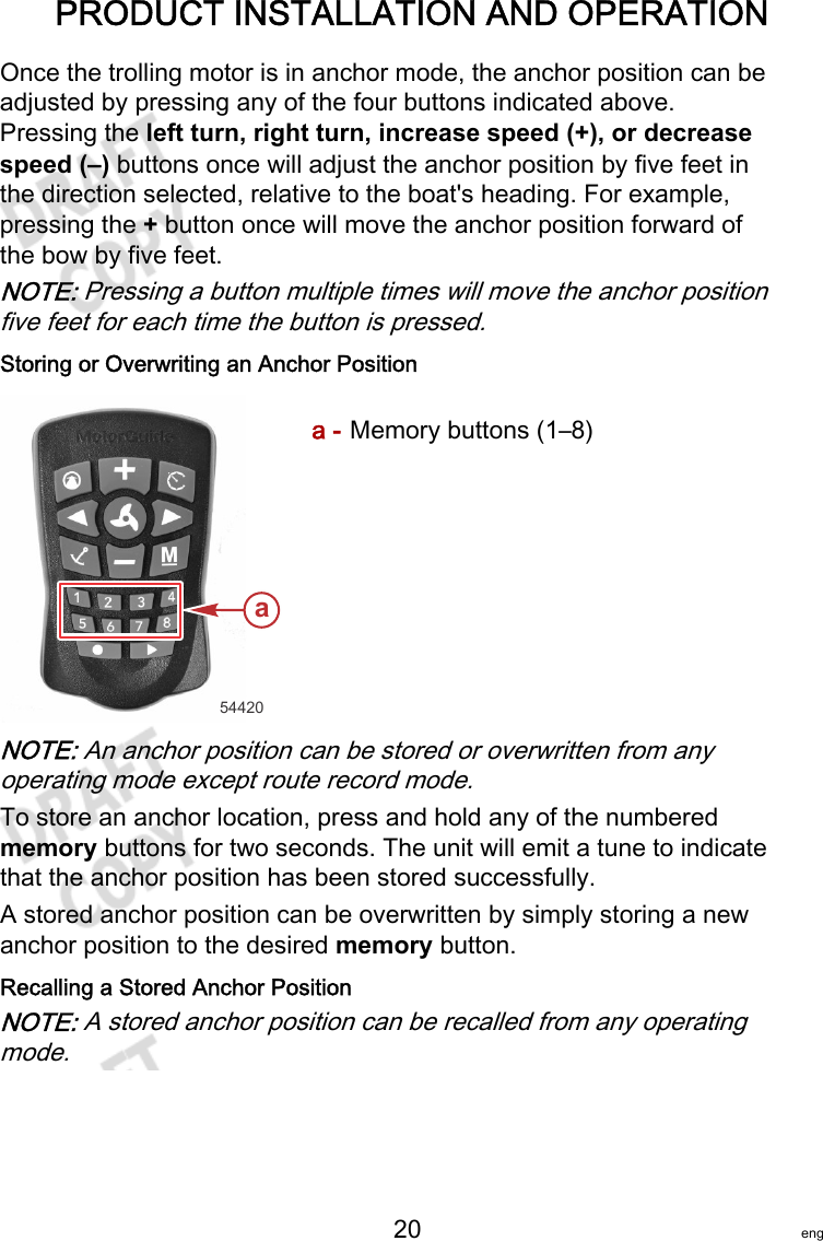
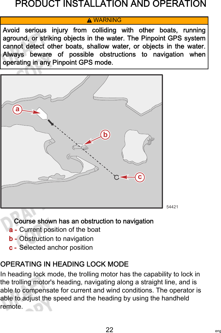
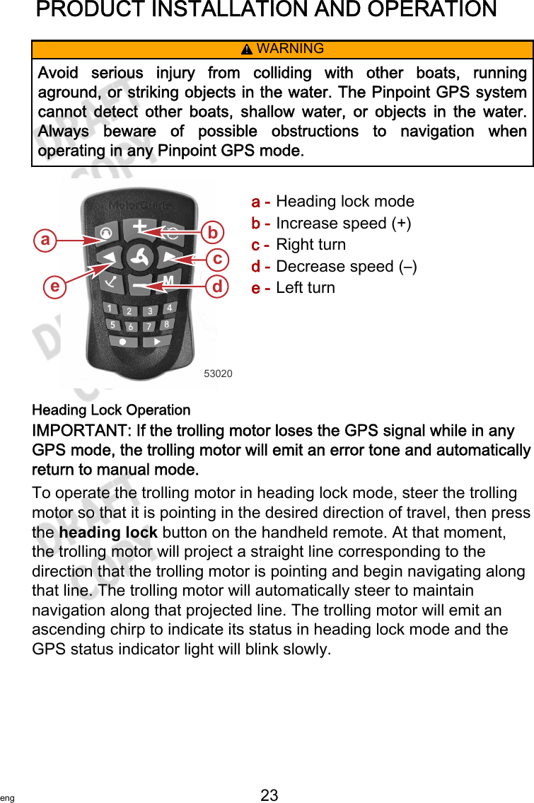
User Manual
Discussion / Help
Navigation