MotorGuide 10148 Wireless handheld remote key fob device for PINPOINT User Manual Pinpoint GPS
MotorGuide Wireless handheld remote key fob device for PINPOINT Pinpoint GPS
User Manual

eng i
FCC and IC Compliance Statement
PINPOINT KEY FOB, FCC ID ‑ MVU10148
ACMA: N2523
IC: 6094A‑09291, 6094A‑09305
This device complies with part 15 of the FCC Rules. Operation is
subject to the following two conditions:
1. This device may not cause harmful interference.
2. This device must accept any interference received including
interference that may cause undesired operation.
This device complies with FCC Rules. Changes or modifications
not expressly approved by MotorGuide could void the user's
authority to operate the equipment.
The MotorGuide Pinpoint GPS System complies with Industry
Canada RSS‑210 standard. See RSS‑GEN 7.1.5. The term "IC:"
before the certification/registration number only signifies that
registration was performed based on a Declaration of Conformity
indicating that Industry Canada technical specifications were met.
The term "IC:" before the certification/registration number does
not imply that Industry Canada approved the equipment.
EU Compliance Statement
Attwood Corporation hereby declares that the Motorguide
Pinpoint GPS System is in compliance with the essential
requirements and other relevant provisions of the 99/5/EC
R&TTE directive.
A copy of the original CE Declaration of Conformity is on our
website at http://www.motorguide.com/support/certifications.
© 2013 Mercury Marine Pinpoint GPS 90-8M0086988 1113
ii eng
Environmental Compliance Statement
All MotorGuide products that are subject to the 2002/96/EC WEEE
directive are compliant with the WEEE marking requirement. Such
products are marked with the "crossed‑out wheelie bin" WEEE
symbol (shown, below) in accordance with European Standard
EN50419.
54539
The symbol on the product or its packaging indicates that this product
must not be disposed of with your other household waste. Instead, it
is your responsibility to dispose of your waste equipment by handing
it over to a designated collection point for the recycling of waste
electrical and electronic equipment. The separate collection and
recycling of your waste equipment at the time of disposal will help
conserve natural resources and ensure that it is recycled in a manner
that protects human health and the environment. For more
information about where you can drop off your waste for recycling,
please contact your local authority, or where you purchased your
product.
Thank You
Thank you for purchasing the MotorGuide Pinpoint GPS Navigation
system.
The Pinpoint GPS Navigation System is designed to enhance the
precision control and functionality of your MotorGuide trolling motor.
We're confident that the Pinpoint GPS will enhance your fishing
experience and we appreciate that you chose MotorGuide.
eng iii
Warranty Message
The product you have purchased comes with a Limited Warranty
from MotorGuide. The terms of the policy are set forth in the
Warranty Information section of this manual. The policy statement
contains a description of the duration of coverage, important
disclaimers and limitations of damages, and other related
information. Please review this important information.
The description and specifications contained herein were in effect at
the time this manual was approved for printing. MotorGuide, whose
policy is one of continued improvement, reserves the right to
discontinue models at any time, to change specifications, designs,
methods, or procedures without notice and without incurring
obligation.
MotorGuide, Lowell, Michigan U.S.A.
© 2013, Mercury Marine
Mercury, Mercury Marine, and MotorGuide are registered trademarks
of Brunswick Corporation. Mercury Product Protection logo is a
registered service mark of Brunswick Corporation.
Eagle and Lowrance are registered trademarks of Navico Inc. Garmin
is a registered trademark of Garmin Ltd. Humminbird is a registered
trademark of Johnson Outdoors Marine Electronics, Inc. Vexilar is a
registered trademark of Vexilar, Inc.
iv eng

eng v
Warranty Information
MotorGuide Two Year Limited Warranty............................................. 1
Product Installation and Operation
Installing the Pinpoint GPS Modules................................................... 4
Operating the Pinpoint GPS System................................................. 15
Owner Service Assistance
Frequently Asked Questions and Troubleshooting........................... 32
Service Assistance............................................................................ 33
Mercury Marine/MotorGuide Service Offices.....................................33
vi eng

WARRANTY INFORMATION
eng 1
MotorGuide Two Year Limited Warranty
KEEP YOUR ORIGINAL PURCHASE RECEIPT OR BILL OF SALE.
1. For recreational use customers, Pinpoint GPS components are
warranted to the original retail purchaser to be free from defects
in material or workmanship for a period of two years from the
date of purchase.
2. To obtain warranty service, the purchaser should deliver or return
the unit (postage prepaid and insured) to any MotorGuide
authorized service dealer. DO NOT RETURN TO PLACE OF
PURCHASE unless they are an authorized service center.
Products returned by mail should be carefully packaged and
include a note describing the nature of the problem and/or
service requested, customer address, and phone number. A copy
of the receipt, bill of sale, registration verification or other proof of
purchase is required with the return of the product for warranty
consideration. Warranty claims will not be accepted without
presentation of purchase receipt for the trolling motor, other
verification of registration, or bill of sale for a boat package.
3. MotorGuide, at its discretion, will repair or replace items covered
under the terms of this warranty. Neither MotorGuide nor
MotorGuide service dealers are responsible for damages to
MotorGuide products due to repairs performed by anyone other
than an authorized MotorGuide service dealer. Neither
MotorGuide nor Attwood is responsible for failure or damage
caused by improper installation, set‑up, preparation, or previous
service or repair errors.

WARRANTY INFORMATION
2 eng
4. For commercial use and government use customers, Pinpoint
GPS components are warranted to the original retail purchaser to
be free from defects in material or workmanship for one (1) year.
Commercial use is defined as any work or employment‑related
use of the product, or any use of the product which generates
income, for any part of the warranty period, even if the product is
only occasionally used for such purpose such as rental fleets,
guides, fish camps or similar operations. Warranty is not
transferable to any subsequent purchaser. The Mercury Product
Protection plan is not available to commercial use or government
use customers.
5. Warranty coverage is available to customers that purchase from
an authorized dealer or retailer that is authorized by MotorGuide
to distribute the product in the country in which the sale occurred.
Warranty coverage and duration varies by the country in which
the owner resides. This Limited Warranty begins on the date the
product is first sold to a purchaser or the date on which the
product is first put into service, whichever occurs first. The repair
or replacement of parts, or the performance of service under this
warranty, does not extend the life of this warranty beyond its
original expiration date. Promotional warranties are not included
in this statement and coverage may vary by promotion. Product
either sold or put into service more than six years from date of
manufacture is excluded from warranty coverage.
6. We reserve the right to improve the design of any trolling motor
or accessory without assuming any obligation to modify any
trolling motor or accessory previously manufactured.
7. This warranty will not apply to: 1) haul‑out, launch, towing and
storage, transportation charges and/or travel time, telephone or
rental charges of any type, inconvenience, or loss of time or
income, or other consequential damages; or 2) removal or
replacement of boat partitions or material because of boat design
for necessary access to the Product; or 3) disconnection and
reconnection of hard‑wired trolling motors.

WARRANTY INFORMATION
eng 3
8. TERMINATION OF COVERAGE: Warranty coverage may be
terminated for repossessed product, or product purchased at
auction, from a salvage yard, from a liquidator, from an insurance
company, from unauthorized marine dealers or boatbuilders, or
other third party entities.
9. ALL INCIDENTAL OR CONSEQUENTIAL DAMAGES ARE
EXCLUDED FROM THIS WARRANTY, WARRANTIES OF
MERCHANTABILITY AND FITNESS ARE EXCLUDED FROM
THIS WARRANTY, IMPLIED WARRANTIES ARE LIMITED TO
THE LIFE OF THIS WARRANTY. SOME STATES DO NOT
ALLOW LIMITATIONS ON HOW LONG AN IMPLIED
WARRANTY LASTS OR THE EXCLUSION OR LIMITATION OF
INCIDENTAL OR CONSEQUENTIAL DAMAGES, SO THE
ABOVE LIMITATIONS OR EXCLUSIONS MAY NOT APPLY TO
YOU. THIS WARRANTY GIVES YOU SPECIFIC LEGAL
RIGHTS, AND YOU MAY ALSO HAVE OTHER LEGAL RIGHTS
WHICH MAY VARY FROM STATE TO STATE.
For Your Records:
Model Number _______________________________
Serial Number _______________________________
PRODUCT INSTALLATION AND OPERATION
4 eng
Installing the Pinpoint GPS Modules
! WARNING
Before working around electrical system components, disconnect
the battery cables from the battery to prevent injury or damage to
the electrical system due to an accidental short circuit.
1. Starting with the negative (–) lead, disconnect the trolling motor
battery cables from the battery, or unplug the trolling motor from
the boat's power receptacle.
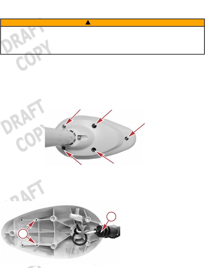
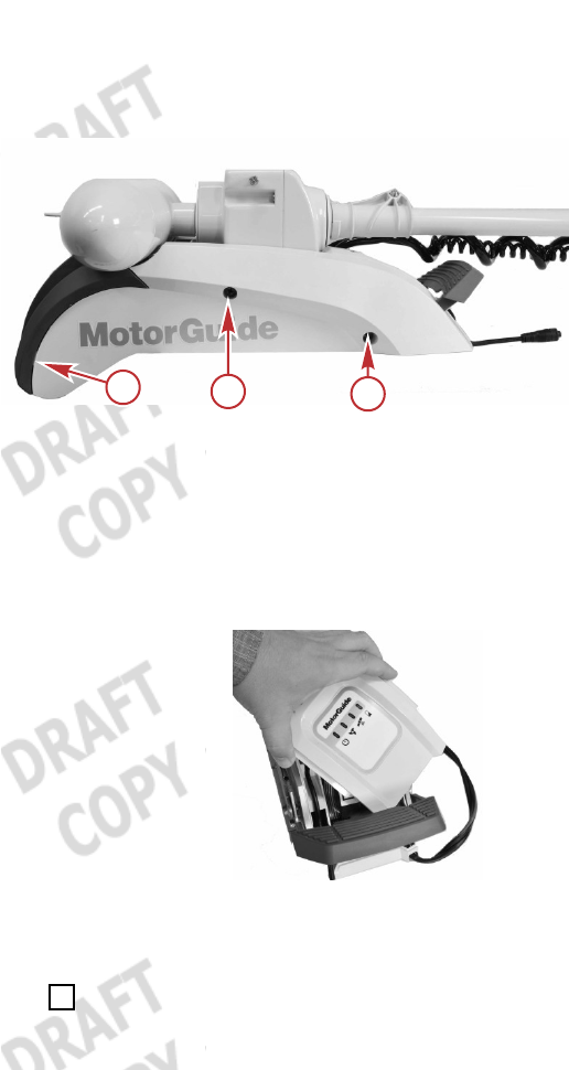
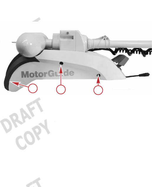
2. Remove the five screws from under the trolling motor head.
Remove the cover from the trolling motor head.
52749
Screw locations—under trolling motor head
3. Remove the cable grommet from the trolling motor head.
a - GPS module
mounting holes
b - Cable grommet
aa
b
54435
PRODUCT INSTALLATION AND OPERATION
eng 5
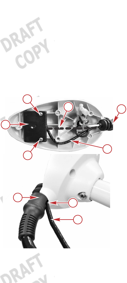
4. Place the upper GPS module into the trolling motor head as
shown, with the GPS cable exiting the module from below.
Secure the upper GPS module to the trolling motor head with two
mounting screws. Push the power wires to one side to ease
installation of the GPS cable. Route the GPS cable out of the
trolling motor head, through the slot in the cable grommet as
shown.
NOTE: The cable grommet is molded to allow the GPS cable to be
routed under it.
IMPORTANT: Do not overtighten the mounting screws or use power
tools to tighten the screws.
a - Upper GPS
module
b - Mounting
screws (2)
c - Incorrect GPS
cable routing—
do not install the
cable here
d - Cable grommet
e - Unused slot for
sonar cable
f - GPS cable
5. Place the cover onto the trolling motor head. Ensure that the
cable grommet is seated in the trolling motor head and that no
wires are pinched. Install the five screws that secure the cover to
the trolling motor head.
53468
a
b
b
d
d
f
e
f
c
PRODUCT INSTALLATION AND OPERATION
6 eng
IMPORTANT: Do not overtighten the screws or use power tools to
tighten the screws.
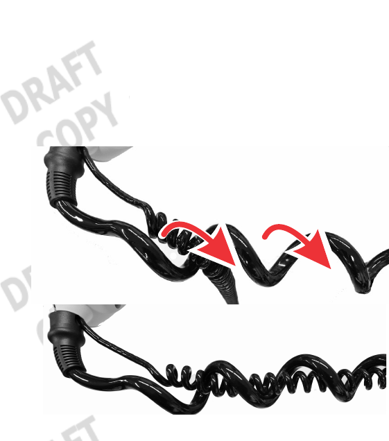
6. Extend the trolling motor column so that the coiled power cable is
as long as possible. Starting from the trolling motor head, wrap
the coiled GPS cable around each coil of the power cable until
you reach the lower mount. This will place the coiled GPS cable
inside the coils for the power cable.
54436
PRODUCT INSTALLATION AND OPERATION
eng 7
7. Remove the side panel screws from each side of the trolling
motor. Gently pull the side panels away from the mount, taking
care not to damage the locating tabs, and remove the side
panels from both sides of the trolling motor.
a - Side panel screws
b - Locating tab
8. Remove the status indicator light panel from the trolling motor by
lifting it up, then rotating it to clear the foot release lever. Do not
unplug the status indicator light panel from the trolling motor.
54527
9. Install the lower GPS module into the empty slot into the trolling
motor base in the following order:
Place the lower GPS module gently into the empty slot.
Route the NMEA cable through the slots as shown, with the
connector exiting the trolling motor base.
aa
b54454
PRODUCT INSTALLATION AND OPERATION
8 eng
NOTE: If the NMEA cable will not be used, it can be coiled and left
inside the trolling motor base.
Remove the cap from the female GPS connector.
Route the male GPS connector through the slot, and
connect it to the female GPS connector by aligning the pins
and locating tabs in the connectors. Press the connectors
together, then turn the nut 1/4 turn to the right until it locks.
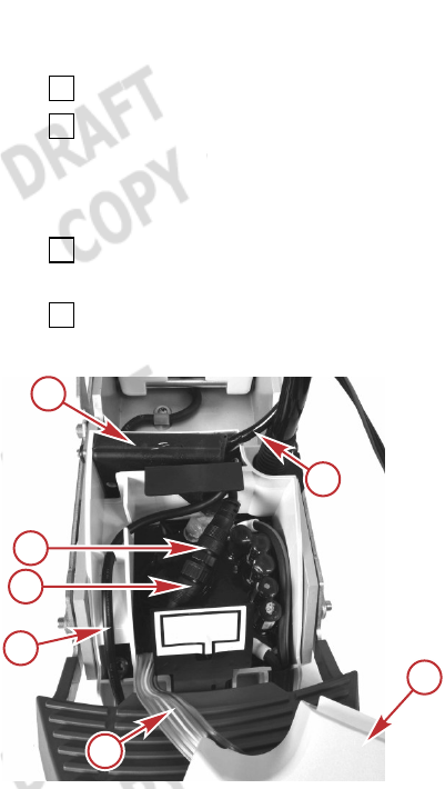
Gently press the lower GPS module into the opening until it
is fully seated.
Remove the plastic plug, and route the GPS cable through
the opening in the trolling motor base.
a - Status light
indicator panel
b - Status light
harness
c - NMEA cable
d - Female GPS
connector
e - Male GPS
connector
f - Lower GPS
module
g - GPS cable
a
b
f
g
53470
d
c
e
PRODUCT INSTALLATION AND OPERATION
eng 9
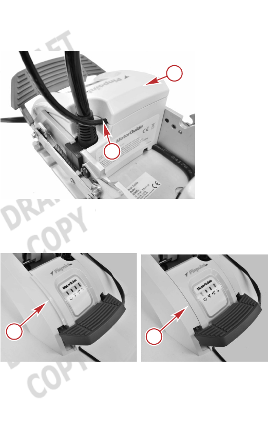
10.Install the status indicator light panel. Ensure that no wires are
pinched between the status indicator light panel and the trolling
motor, and that the GPS cable is positioned as shown.
a - Status indicator
light panel
b - GPS cable
11.Install the side panels onto the trolling motor. Ensure that the
status indicator light panel is seated between the side panels as
shown, and that no wires are pinched.
a - Status indicator light panel not seated—incorrect
b - Status indicator light panel seated between side panels—
correct
a
b
54438
ab
54529
PRODUCT INSTALLATION AND OPERATION
10 eng
12.Ensure that no wires are pinched between the side panels and
the trolling motor. Tighten the side panel mounting screws.
a - Side panel screws
b - Locating tab
LINKING THE HANDHELD REMOTE TO THE TROLLING
MOTOR
The first time the trolling motor is powered up, the handheld remote
will need to be linked to the trolling motor. The linking procedure is
listed as follows:
1. Starting with the positive (+) lead, connect the trolling motor
power cables to the battery.
aa
b54454
PRODUCT INSTALLATION AND OPERATION
eng 11
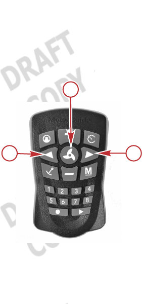
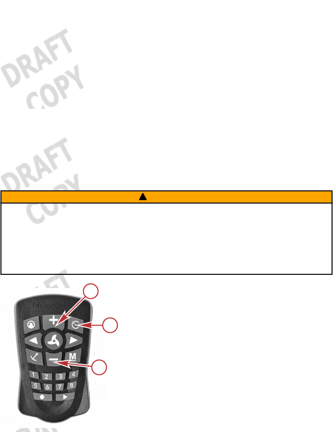
2. Within ten seconds after connecting the power cables, Press the
Left arrow button and Right arrow button on the handheld
remote at the same time. The trolling motor will emit a low tune to
confirm that the handheld remote has been linked to the trolling
motor.
a - Left arrow button
b - Propeller button
c - Right arrow button
If you wish to clear the linked handheld from the trolling motor's
memory, press the Left arrow, Right arrow, and Propeller buttons
at the same time. You will need to complete the link procedure again
to use the handheld remote with the trolling motor.
a
54153
c
b
PRODUCT INSTALLATION AND OPERATION
12 eng
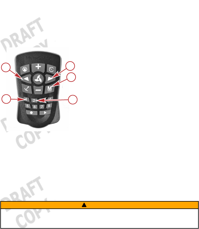
MOUNTING ANGLE CALIBRATION
IMPORTANT: This calibration is required and is normally completed
once when the GPS modules are installed. It should be repeated
when the trolling motor is moved from one boat to another. This
calibration can be done with the boat in or out of the water.
a - Left turn
b - Right turn
c - Manual mode
d - #2 button
e - #1 button
IMPORTANT: A fixed GPS position is required to complete the
mounting angle calibration. The Xi5 will emit an audible tune once it
has acquired a fixed GPS position (in the default audio mode), and
the GPS status indicator light will illuminate.
1. Power up and deploy the trolling motor. Adjust the motor height
so that the motor is clear of any obstructions while turning.
IMPORTANT: Stay a safe distance away from the propeller—the
trolling motor is in an operational mode.
! WARNING
Rotating propellers can cause serious injury or death. Never start
or operate the motor out of water.
a
54148
b
c
d
e

PRODUCT INSTALLATION AND OPERATION
eng 13
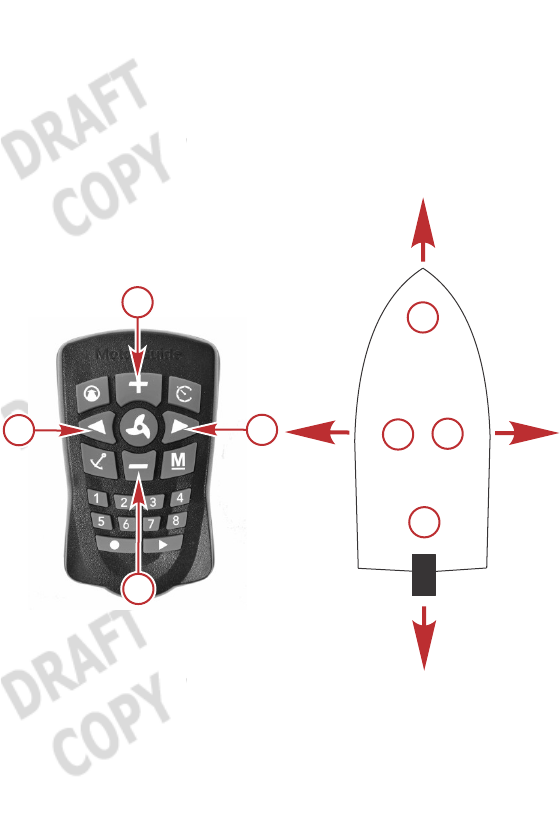
2. Use the left turn and right turn buttons to steer the unit so that it
is facing straight ahead, parallel with the keel of the boat, with the
nose cone of the lower unit facing forward and the propeller
facing aft.
View of boat from above
a - Nose cone facing the bow
b - Propeller facing the stern
c - Parallel lines
3. Once the lower unit is positioned as close to parallel with the keel
as possible, press and hold the Manual mode button, then press
and release the 1, 1, then 2 buttons in sequence. The trolling
motor will emit an audible tune, flash the status indicator light,
and then return to manual mode, completing the mounting angle
calibration.
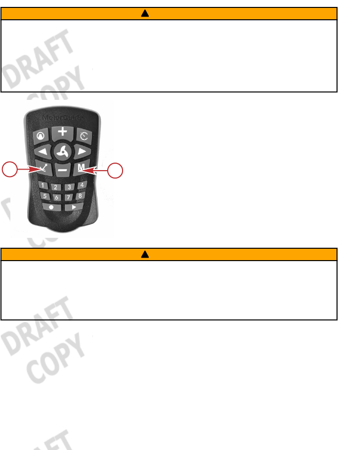
COMPASS CALIBRATION
IMPORTANT: This calibration is completed at the factory. It should
only be repeated if the Pinpoint GPS system is not responding
properly. This calibration must be done with the boat in the water,
using the primary propulsion engine.
54441
b
a
cc

PRODUCT INSTALLATION AND OPERATION
14 eng
IMPORTANT: A fixed GPS position is required to complete the
compass calibration. The Xi5 will emit an audible tune once it has
acquired a fixed GPS position (in the default audio mode), and the
GPS status indicator light will illuminate.
a - Manual mode
b - #1 button
1. Locate a suitable area clear of obstructions to navigation (both
above and below the water line) to perform the compass
calibration.
2. Deploy the trolling motor. Make sure that you are in a location
where your trolling motor and primary propulsion engine will not
hit bottom or other obstructions.
3. Press and hold the Manual mode button, then press 1, 1, 1. The
trolling motor will emit three ascending‑tone beeps.
4. Use the primary propulsion engine to slowly drive the boat in two
complete circles. The trolling motor will emit a tune when the
compass calibration is complete.
RESET TO FACTORY CALIBRATION
To reset the trolling motor to the factory calibration, press and hold
the Manual mode button, then press 1, 1, 4.
53737
b
a

PRODUCT INSTALLATION AND OPERATION
eng 15
Operating the Pinpoint GPS System
PINPOINT GPS STARTUP
The global positioning system (GPS) is a satellite‑based navigation
system capable of providing positional information anywhere on
Earth, provided that the GPS receiver has a clear line of sight to at
least four GPS satellites.
When the trolling motor is powered up and deployed, it is immediately
capable of operating as a conventional trolling motor. The trolling
motor will require approximately 30 seconds to acquire a fixed GPS
position. Having a clear view of the sky overhead, with no large trees,
power lines, bridges, or buildings to interfere with the GPS signal, will
improve the GPS accuracy and reduce the amount of time required to
obtain a fixed GPS position. Once the unit has acquired a fixed GPS
position, the GPS accuracy will continually improve for several
minutes. It is recommended to power up the trolling motor as soon as
possible before operation to allow the fixed GPS position to become
as accurate as possible.
Power up the trolling motor by connecting the battery cables to the
trolling motor batteries, or plugging the trolling motor into the trolling
motor power plug (if equipped). The trolling motor will emit audio
signals to make the operator aware of its status.
• The trolling motor will emit one beep when it is powered up.
• The trolling motor will emit a three‑beep tune once it has
acquired a fixed GPS position, and the GPS status indicator light
will illuminate.
OPERATING IN MANUAL MODE
In manual mode, the trolling motor operates like a conventional
trolling motor. It allows the operator to manually control the direction
of travel and thrust level of the trolling motor, using the directional
controls on the handheld remote or wireless foot pedal. Refer to the
following illustration and instructions to operate the trolling motor in
manual mode with the handheld remote.

PRODUCT INSTALLATION AND OPERATION
16 eng
Once the trolling motor is powered up, it is ready to operate in manual
mode. Manual mode is the default mode after power‑up, and also if
the GPS signal is lost while in a GPS operating mode. The trolling
motor will emit one beep to indicate its status in manual mode. To
enter manual mode from another mode, press the manual mode
button.
a - Left turn
b - Propeller on/off
c - Increase speed
d - Right turn
e - Manual mode
f - Decrease speed
Turning the Handheld Remote On or Off
The handheld remote is always on, and is ready for use anytime that
the trolling motor is powered up and in the deployed position.
Steering
•To turn left, press the left turn button on the handheld remote.
•To turn right, press the right turn button.
• The available steering range allows the trolling motor to turn
beyond 180° for operation in reverse.
Speed Control
•Press the propeller on/off button once to start the propeller, and
press the propeller on/off button again to stop the propeller.
• The trolling motor will emit a two‑beep tone when the propeller is
started, and the propeller status indicator light on the trolling
motor will illuminate.
• The trolling motor will emit a two‑beep tone when the propeller is
stopped, and the propeller status indicator light will turn off.
a
53017
b
c
d
e
f

PRODUCT INSTALLATION AND OPERATION
eng 17
•The system is equipped with 20 speed levels. Press the increase
speed (+) button to increase motor speed by one level, and
press the decrease speed (–) button to reduce the motor speed
by one level.
•Holding the increase speed (+) or decrease speed (–) buttons
will cause the speed level to increase or decrease until the speed
level is reached. Holding the increase speed (+) or decrease
speed (–) button for 2.5 seconds will increase the speed level
from 0% to 100%, or decrease from 100% to 0%, respectively.
The trolling motor will emit two beeps when it reaches the 100%
or 0% speed level.
• The trolling motor will emit two beeps if the user tries to increase
or decrease the motor speed beyond its limits.
OPERATING IN ANCHOR MODE
Anchor mode allows the boat's bow to remain in a fixed location, and
will automatically account for wind and current changes to keep the
boat in the selected location, using the trolling motor steering and
speed controls. In order for anchor mode to operate, the Pinpoint
GPS system must have achieved a fixed GPS location, indicated by
the trolling motor emitting a three‑beep tune, and the GPS status
indicator light will illuminate.
PRODUCT INSTALLATION AND OPERATION
18 eng
! WARNING
Avoid serious injury from colliding with other boats, running
aground, or striking objects in the water. The Pinpoint GPS system
cannot detect other boats, shallow water, or objects in the water.
Always beware of possible obstructions to navigation when
operating in any Pinpoint GPS mode.
a - Anchor mode
b - Manual mode
! WARNING
A spinning propeller, a moving boat, or any solid device attached to
the boat can cause serious injury or death to swimmers. Stop the
trolling motor immediately whenever anyone in the water is near
your boat.
Setting the Anchor
Press the anchor mode button to place the system in anchor mode.
When the anchor mode button is pressed, the system will lock onto
the fixed GPS position at the moment that the button was pressed.
The trolling motor will emit one ascending chirp to indicate its status
in anchor mode, and the GPS status indicator light will blink slowly.
While anchor mode holds the boat in the selected position, the boat
may rotate or pivot around the trolling motor's steering axis. The
orientation of the boat will follow the wind and/or current.
53018
ab
PRODUCT INSTALLATION AND OPERATION
eng 19
Exiting Anchor Mode
Press the anchor mode button again or press the manual mode
button. The trolling motor will emit a descending chirp and the GPS
status indicator light on the trolling motor will stop blinking and remain
on.
Adjusting the Anchor Position—"Jog"
a - Left turn—"jog" left
b - Increase speed—"jog" ahead
c - Right turn—"jog" right
d - Decrease speed—"jog" behind
a
54151
b
c
d
+
_
<
<a
b
c
d

PRODUCT INSTALLATION AND OPERATION
20 eng
Once the trolling motor is in anchor mode, the anchor position can be
adjusted by pressing any of the four buttons indicated above.
Pressing the left turn, right turn, increase speed (+), or decrease
speed (–) buttons once will adjust the anchor position by five feet in
the direction selected, relative to the boat's heading. For example,
pressing the + button once will move the anchor position forward of
the bow by five feet.
NOTE: Pressing a button multiple times will move the anchor position
five feet for each time the button is pressed.
Storing or Overwriting an Anchor Position
a - Memory buttons (1–8)
NOTE: An anchor position can be stored or overwritten from any
operating mode except route record mode.
To store an anchor location, press and hold any of the numbered
memory buttons for two seconds. The unit will emit a tune to indicate
that the anchor position has been stored successfully.
A stored anchor position can be overwritten by simply storing a new
anchor position to the desired memory button.
Recalling a Stored Anchor Position
NOTE: A stored anchor position can be recalled from any operating
mode.
54420
a

PRODUCT INSTALLATION AND OPERATION
eng 21
To recall a stored anchor position, press and release the desired
memory button. The trolling motor will emit an ascending chirp to
indicate that a stored anchor position has been retrieved. If the
selected anchor position button does not have a stored anchor
position, or if the anchor location is over one mile away from your
current location, the trolling motor will emit an error tone.
IMPORTANT: If the trolling motor loses the GPS signal while in any
GPS mode, the trolling motor will emit an error tone and automatically
return to manual mode.
IMPORTANT: When recalling a stored anchor position, the system
will calculate a straight‑line course from your current position to the
selected anchor position. Ensure that there are no obstructions to
navigation between your location and the selected anchor position—
the system will recall an anchor point even if obstructions are present.
If obstructions are encountered, navigate around them by operating in
manual mode.
PRODUCT INSTALLATION AND OPERATION
22 eng
! WARNING
Avoid serious injury from colliding with other boats, running
aground, or striking objects in the water. The Pinpoint GPS system
cannot detect other boats, shallow water, or objects in the water.
Always beware of possible obstructions to navigation when
operating in any Pinpoint GPS mode.
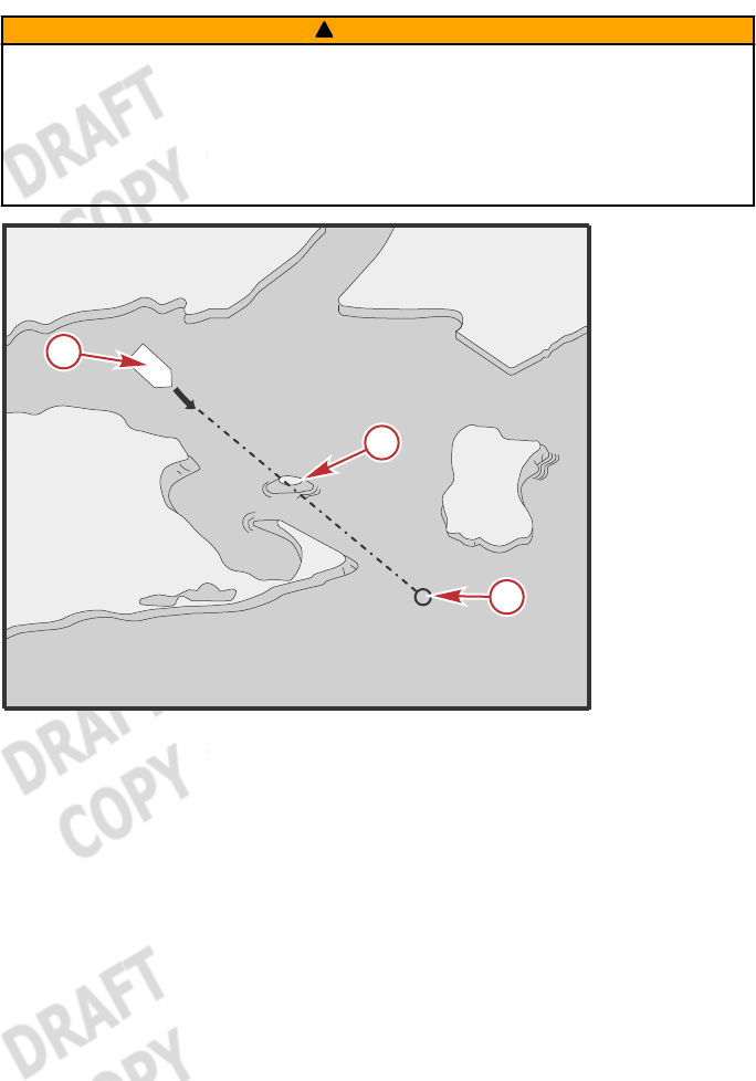
Course shown has an obstruction to navigation
a - Current position of the boat
b - Obstruction to navigation
c - Selected anchor position
OPERATING IN HEADING LOCK MODE
In heading lock mode, the trolling motor has the capability to lock in
the trolling motor's heading, navigating along a straight line, and is
able to compensate for current and wind conditions. The operator is
able to adjust the speed and the heading by using the handheld
remote.
54421
a
b
c
PRODUCT INSTALLATION AND OPERATION
eng 23
! WARNING
Avoid serious injury from colliding with other boats, running
aground, or striking objects in the water. The Pinpoint GPS system
cannot detect other boats, shallow water, or objects in the water.
Always beware of possible obstructions to navigation when
operating in any Pinpoint GPS mode.
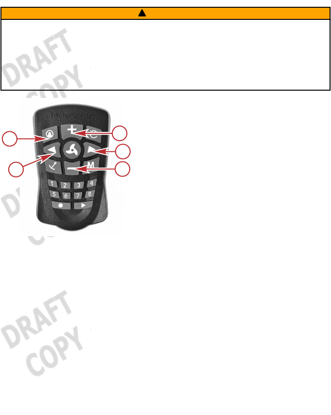
a - Heading lock mode
b - Increase speed (+)
c - Right turn
d - Decrease speed (–)
e - Left turn
Heading Lock Operation
IMPORTANT: If the trolling motor loses the GPS signal while in any
GPS mode, the trolling motor will emit an error tone and automatically
return to manual mode.
To operate the trolling motor in heading lock mode, steer the trolling
motor so that it is pointing in the desired direction of travel, then press
the heading lock button on the handheld remote. At that moment,
the trolling motor will project a straight line corresponding to the
direction that the trolling motor is pointing and begin navigating along
that line. The trolling motor will automatically steer to maintain
navigation along that projected line. The trolling motor will emit an
ascending chirp to indicate its status in heading lock mode and the
GPS status indicator light will blink slowly.
53020
a
c
d
b
e

PRODUCT INSTALLATION AND OPERATION
24 eng
The heading lock automatically adjusts for current and wind
conditions. The trolling motor will drive the bow of the boat along this
course, while the boat itself may be askew to the direction of travel
due to current or wind conditions. In heading lock mode, steering
control is automatic and motor speed is user‑selectable. In extreme
current or wind conditions, it may be necessary to increase the motor
speed to maintain the desired heading.
To exit heading lock mode, press the heading lock button or the
manual mode button. The trolling motor will emit a descending chirp
and the GPS status indicator light will stop blinking.
Adjusting Motor Speed
If heading lock mode is selected from manual mode, the trolling motor
will run at the last selected speed. The motor speed can be manually
adjusted in heading lock mode by pressing the increase speed (+)
button or decrease speed (–) button. The trolling motor will emit two
beeps when the user tries to exceed the available motor speed limits.
Adjusting the Heading
While in heading lock mode, the heading can be adjusted by pressing
the left turn or right turn buttons on the handheld remote. The
trolling motor will resume heading lock navigation based on the new
trolling motor heading.
OPERATING IN ROUTE MODE
Route mode has the ability to store and recall user‑defined routes.
These routes can be recorded and recalled by the user from any
operating mode.
PRODUCT INSTALLATION AND OPERATION
eng 25
! WARNING
Avoid serious injury from colliding with other boats, running
aground, or striking objects in the water. The Pinpoint GPS system
cannot detect other boats, shallow water, or objects in the water.
Always beware of possible obstructions to navigation when
operating in any Pinpoint GPS mode.
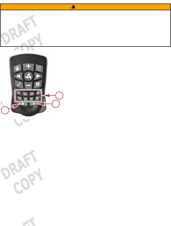
a - Memory
b - Route playback
c - Route record
Storing and Overwriting a Route
A route can be stored from any mode by pressing the route record
button. The trolling motor will emit a tune when the route record
button is pressed. Once the route record button is pressed, begin
navigating along your desired course. You can switch between
manual mode and heading lock mode at any time while recording a
route. The trolling motor will emit one beep (and the GPS status
indicator light will blink) for every 6.5 ft (2 m) traveled while recording.
Press and hold any of the numbered memory buttons to stop
recording and store the route to the selected memory button. The
trolling motor will emit a tune to confirm that it has stored the route.
The trolling motor can store up to eight routes, each up to 4 miles (6.4
km) in length.
Overwriting a stored route is accomplished using the same procedure
as storing a new route.
53021
c
b
a

PRODUCT INSTALLATION AND OPERATION
26 eng
Recalling a Stored Route
A stored route can be recalled while operating in any mode by
pressing the route playback button, then pressing the desired
memory button. The trolling motor will emit an ascending chirp to
indicate that the route has been successfully recalled.
IMPORTANT: When recalling a stored route, the system will calculate
a straight‑line course from your current position to the nearest point
on the recalled route. Ensure that there are no obstructions to
navigation between your current position and recalled route. The
system will recall a stored route even if obstructions are present. If
obstructions are encountered, navigate around them by operating in
manual mode.
PRODUCT INSTALLATION AND OPERATION
eng 27
! WARNING
Avoid serious injury from colliding with other boats, running
aground, or striking objects in the water. The Pinpoint GPS system
cannot detect other boats, shallow water, or objects in the water.
Always beware of possible obstructions to navigation when
operating in any Pinpoint GPS mode.
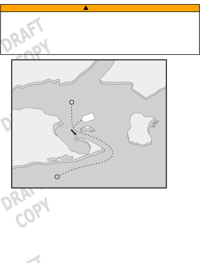
53022
Recalling a stored route—Beware of possible obstructions to
navigation
If the selected memory position is empty, or if the boat is over 1 mile
(1.6 km) from a point on the selected route, the trolling motor will emit
an error tone and exit route mode.
IMPORTANT: If the trolling motor loses the GPS signal while in any
GPS mode, the trolling motor will emit an error tone and automatically
return to manual mode.
PRODUCT INSTALLATION AND OPERATION
28 eng
When recalling a stored route, the trolling motor will navigate to the
nearest point on the route, then travel to the most distant end from
the boat's current position. At any time while traveling along a stored
route, the direction of travel can be reversed by recalling the stored
route again. Once you have reached the end of a stored route, the
trolling motor will set anchor in anchor mode and will emit an
ascending chirp to indicate that the boat has arrived at the end of the
stored route.
USING CRUISE CONTROL
Cruise control can be activated while in heading lock mode or route
playback mode to maintain a constant trolling speed. It will
automatically adjust the motor speed to correct for current and wind
conditions to maintain a constant speed.
! WARNING
Avoid serious injury from colliding with other boats, running
aground, or striking objects in the water. The Pinpoint GPS system
cannot detect other boats, shallow water, or objects in the water.
Always beware of possible obstructions to navigation when
operating in any Pinpoint GPS mode.
a - Increase speed (+)
b - Cruise control
c - Decrease speed (–)
53023
a
b
c

PRODUCT INSTALLATION AND OPERATION
eng 29
Setting Cruise Control
While in heading lock mode or route recall mode, you can set the
cruise control by pressing the cruise control button. The trolling
motor will emit one ascending chirp to indicate that the cruise control
has been activated. The system will automatically set a trolling speed
of 1.0 mph (1.6 kph) and will compensate for current and wind
conditions to maintain this speed. Pressing the cruise control button
again will turn the cruise control off, indicated by a descending chirp
from the trolling motor.
While cruise control is turned on, the GPS speed over ground can be
adjusted by pressing the increase speed (+) or decrease speed (–)
buttons. Pressing either button once will adjust the speed by 0.1 mph
(0.16 kph) accordingly. For example, to set the cruise control at 1.3
mph (2.1 kph), press the cruise control button, then press the
increase speed (+) button three times.
IMPORTANT: If the trolling motor loses the GPS signal while in any
GPS mode, the trolling motor will emit an error tone and automatically
return to manual mode.
SELECTING THE AUDIO MODE
The Pinpoint GPS system has three user‑selectable audio modes to
choose from. These audio modes provide audible confirmation of
selected modes, speeds, and button selections.
a - Manual mode
b - #1 button
c - #2 button
d - #3 button
a
54152
bd
c

PRODUCT INSTALLATION AND OPERATION
30 eng
Audio mode 1 can be selected by pressing and holding the manual
mode button, then pressing 1,3,1.
Audio mode 2 can be selected by pressing and holding the manual
mode button, then pressing 1,3,2.
Audio mode 3 can be selected by pressing and holding the manual
mode button, then pressing 1,3,3.
Condition Audio
Pattern
Audio Mode 1
(Default)
Audio
Mode 2
Audio
Mode 3
Startup 1 beep Yes Yes Yes
Remote learn
confirmation Low tune Yes Yes Yes
User invalid command
(No GPS fix) Error beep Yes Yes Yes
GPS Fix acquired High tune Yes Yes –
Loss of GPS fix Error Yes Yes –
Speed + (when less than
max speed) Short beep – Yes –
Speed + (at max speed) 2 beeps Yes Yes –
Speed ‑ (when greater
than speed level 0) Short beep – Yes –
Speed – (at speed 0) 2 beeps Yes Yes –
Pressing the propeller
on/off button to turn the
propeller on
2 beeps up Yes Yes –
Pressing the propeller
on/off button to turn the
propeller off
2 beeps
down Yes Yes –
Momentary propeller None – – –
Record Route Enable Tune Yes Yes –
Record Route Save Tune Yes Yes –
Recall Route Enable Chirp up Yes Yes –
Recall Route Disable Chirp down Yes Yes –
Reach End of Route Chirp up Yes Yes –
Heading Lock Enable Chirp up Yes Yes –

PRODUCT INSTALLATION AND OPERATION
eng 31
Condition Audio
Pattern
Audio Mode 1
(Default)
Audio
Mode 2
Audio
Mode 3
Heading Lock Disable Chirp down Yes Yes –
Cruise Control Enable Chirp up Yes Yes –
Cruise Control Disable Chirp down Yes Yes –
Anchor Enable Chirp up Yes Yes –
Anchor Disable Chirp down Yes Yes –
Record Anchor Position Tune Yes Yes –
Anchor Recall Chirp up Yes Yes –
Recalling an anchor
point or route more than
one mile away
Error Yes Yes Yes

OWNER SERVICE ASSISTANCE
32 eng
Frequently Asked Questions and Troubleshooting
This section is focused on questions and troubleshooting advice for
the Pinpoint GPS. Refer to Section 6—Owner Service Assistance
in the Xi5 Wireless Owners and Installation Manual for trolling
motor troubleshooting assistance.
Why does the trolling motor emit a tune a few moments after I
power it up?
The GPS has acquired a fixed position. Refer to Section 2—Pinpoint
GPS Startup.
When I recall a stored anchor position, the trolling motor emits
an error tone and will not navigate to my anchor position. Why is
that?
The anchor position you chose to recall is over one mile away from
your current location, or the system has not acquired a fixed GPS
position. Refer to Section 2—Operating in Anchor Mode.
When I try to recall a stored route, the trolling motor emits an
error tone and will not navigate along my route. Why is that?
You are more than one mile away from the nearest point on the
selected route, or the system has not acquired a fixed GPS position.
Refer to Section 2—Operating in Route Mode.
Why did the handheld remote stop working?
Several conditions can cause the handheld remote to stop working.
Verify that the trolling motor is locked in the deployed position. Cycle
the trolling motor power off, then back on. Finally, check the battery in
the handheld remote and replace it if necessary.
The Pinpoint GPS will not store an anchor point, recall a route,
or hold a heading lock. Why is that?
The GPS has not acquired a fixed GPS position. Allow at least 60
seconds for the GPS system to acquire a fixed GPS position. Listen
for a three‑beep tune, and also look for the GPS status indicator light
to illuminate, indicating that the system has acquired a fixed GPS
position. Also, make sure that no obstructions are overhead (such as
bridges, buildings, large trees, etc.) blocking the GPS antenna's view
of the sky overhead.

OWNER SERVICE ASSISTANCE
eng 33
After selecting a mode, the trolling motor emits an error tone,
then does nothing. What is wrong?
The GPS has not acquired a fixed GPS position, the trolling motor
battery voltage is low, or there is a loose battery connection. Listen
for a three‑beep tune, and also look for the GPS status indicator light
to illuminate, indicating that the system has acquired a fixed GPS
position. Check all connections. Charge the batteries and test for a
bad battery if the trouble persists.
Service Assistance
Your satisfaction with your product is very important to us. If you have
a problem or question about your motor, contact your dealer or any
certified MotorGuide Service Center. For more service assistance
information, refer to Section 1 ‑ Warranty Information.
The following information will be needed by the service office:
• Your name and address
• Daytime telephone number
• Model and serial number of your trolling motor
• Proof of purchase or registration verification
• Nature of problem
Mercury Marine/MotorGuide Service Offices
For assistance, call, fax, or write. Please include your daytime
telephone number with mail and fax correspondence.
United States
Telephone English ‑ (920) 929‑5040
Francais ‑ (905) 636‑4751 Mercury Marine
W6250 W. Pioneer Road
P.O. Box 1939
Fond du Lac, WI 54936-1939
Fax English ‑ (920) 929‑5893
Francais ‑ (905) 636‑1704
Website www.motorguide.com

OWNER SERVICE ASSISTANCE
34 eng
Australia, Pacific
Telephone (61) (3) 9791‑5822 Brunswick Asia Pacific Group
41-71 Bessemer Drive
Dandenong South, Victoria 3175
Australia
Fax (61) (3) 9706‑7228
Europe, Middle East, Africa
Telephone (32) (87) 32 • 32 • 11 Brunswick Marine Europe
Parc Industriel de Petit-Rechain
B-4800 Verviers,
Belgium
Fax (32) (87) 31 • 19 • 65
Mexico, Central America, South America, Caribbean
Telephone (954) 744‑3500 Mercury Marine
11650 Interchange Circle North
Miramar, FL 33025
U.S.A.
Fax (954) 744‑3535
Asia, Singapore
Telephone (65) 65466160 Brunswick Asia Pacific Group
T/A Mercury Marine Singapore Pte Ltd
29 Loyang Way
Singapore, 508944
Fax (65) 65467789