Motorola Solutions 89FC5797 Booster Amplifier User Manual
Motorola Solutions, Inc. Booster Amplifier
Exhibit D Users Manual per 2 1033 c3

APPLICANT: MOTOROLA INC. EQUIPMENT TYPE: ABZ89FC5797
EXHIBIT 8
INSTRUCTION MANUALS
An outline of the preliminary 800 MHz high power booster radio system manual is included in this package (in draft
form). Final manuals will be sent to the commission and/or telecommunication certification body (TCB) as soon as
they become available. All of the descriptions and schematics in this filing are up to date and will be included in
the instruction and/or service manuals.

EMotorola, Inc. 2001
All Rights Reserved
Printed in U.S.A.
68P80801D55-A
12/1/01-UP
Commercial Government and
Industrial Solutions Sector
1301 E. Algonquin Road, Schaumburg, IL 60196
t
Commercial Government and
Industrial Solutions Sector DigitalĆCapable Station
with High Power Booster
For Conventional and ASTRO Systems
VHF Range 2
350 W Continuous Duty
800 MHz
150 W Continuous Duty
Table of Contents
Model/Option Information xii....................................................................
Foreword xvi................................................................................
General Safety Information xviii.................................................................
Performance Specifications xx..................................................................
DESCRIPTION
DESCRIPTION 68P81097E11.........................................................
Introduction page 1...................................................................
Flexible Mechanical Design page 1.............................................................
StateĆofĆtheĆArt Electrical Design page 2.........................................................
Summary of Operating Features page 3.........................................................
Station Components page 4...........................................................
Functional Theory of Operation page 6.................................................
Transmitter Circuitry Operation page 6..........................................................
Receiver Circuitry Operation page 7.............................................................
Station Control Circuitry Operation page 7.......................................................
Wireline Interface Board Operation page 8.......................................................
Power Supply Module Operation page 8.........................................................
INSTALLATION
INSTALLATION 68P81096E88........................................................
Pre-Installation Considerations page 2................................................
Installation Overview page 2...................................................................
Environmental Conditions at Intended Site page 3................................................
Equipment Ventilation page 3..................................................................
AC Input Power Requirements page 4...........................................................
Equipment Mounting Methods page 4...........................................................
Site Grounding and Lightning Protection page 5..................................................
Recommended Tools and Equipment page 6.....................................................
Equipment Unpacking and Inspection page 6....................................................
Physical Dimensions and Clearances page 7.....................................................
Ċcontinued on next page Ċ

ii 12/1/0168P80801D55-A
Mechanical Installation page 12........................................................
Unpacking the Equipment page 12............................................................
Mounting Procedures page 14................................................................
Stacking Cabinets page 16...................................................................
Stacking Modular Racks page 17..............................................................
AntiĆVibration/EMI Screws page 18.............................................................
Electrical Connections page 19........................................................
Power Supply Connections page 19...........................................................
RF Cabling Connections page 22..............................................................
Connecting Telephone Lines page 25..........................................................
Connecting V.24 Board page 28...............................................................
Connecting External Reference page 29........................................................
Post-Installation Checkout page 30....................................................
Applying Power page 30......................................................................
Verifying Proper Operation page 30............................................................
Proceeding to Optimization page 32...........................................................
OPTIMIZATION
OPTIMIZATION 68P81086E72........................................................
Description page 1....................................................................
OPERATION
OPERATION 68P81097E12...........................................................
Description page 1....................................................................
Summary of Switches, Pushbuttons, and Connectors page 1.......................................
Summary of LED Indicators page 1.............................................................
MAINTENANCE & TROUBLESHOOTING
ROUTINE MAINTENANCE 68P81086E39..............................................
Introduction page 1...................................................................
Routine Maintenance Overview page 1..........................................................
Recommended Test Equipment page 1.................................................
TROUBLESHOOTING 68P81097E13..................................................
Introduction page 1...................................................................
Troubleshooting Overview page 1..............................................................
Recommended Test Equipment page 2.................................................
List of Test Equipment page 2..................................................................
Troubleshooting Procedures page 3....................................................
Troubleshooting Overview page 3..............................................................
Interpreting LED Indicators page 7..............................................................
Interpreting Alarm Alert Tones page 14.........................................................
Verifying Transmitter Circuitry (Station Exciter and Internal PA) page 16.............................
Verifying Transmitter Circuitry (High Power Booster PA Deck) page 20..............................
Verifying Receiver Circuitry (Analog Capable Stations) page 24...................................
Verifying Receiver Circuitry (Digital Only Stations) page 27.......................................
Using Radio Metering Panel for High Power Booster PA Deck page 29..............................
Ċcontinued on next page Ċ

iii
12/1/01 68P80801D55-A
Module Replacement Procedures page 32..............................................
General Replacement Information page 32......................................................
Replacing Station Internal Power Amplifier Module page 34.......................................
Replacing High Power Booster PA Deck page 35................................................
Replacing High Power Booster PA Deck Front Panel page 36......................................
Replacing Exciter Module page 37.............................................................
Replacing Station Internal Power Supply Module page 38.........................................
Replacing High Power Booster Power Supply Module(s) page 39..................................
Replacing Station Control Module page 40......................................................
Replacing Wireline Interface Board page 44.....................................................
Replacing Receiver Module and/or Preselector Assembly page 46.................................
Replacing ASTRO Modem Card page 48........................................................
Replacing Station Backplane Board page 49....................................................
Replacing High Power Booster Power Supply Backplane Board page 50............................
Replacing Charger Control Board page 51......................................................
Preselector Field Tuning Procedure page 52............................................
Required Test Equipment page 52.............................................................
VHF Tuning Procedure page 53...............................................................
STATION MODULES
RECEIVER CIRCUITRY
RECEIVER MODULE (VHF Ranges 1 and 2; Includes Preselector) 68P81086E28.........
Description page 1....................................................................
General Description page 1....................................................................
Overview of Circuitry page 1...................................................................
Controls, Indicators, and Inputs/Outputs page 2........................................
Functional Theory of Operation page 3.................................................
Synthesizer and VCO Circuitry page 3...........................................................
Preselector Filter Assembly page 4.............................................................
Receiver Front End Circuitry page 4.............................................................
Custom Receiver IC Circuitry page 4............................................................
Address Decode and A/D Converter Circuitry page 5..............................................
Voltage Regulator Circuitry page 5..............................................................
RECEIVER MODULE (800 MHz) 68P81086E76.........................................
Description page 1....................................................................
General Description page 1....................................................................
Overview of Circuitry page 1...................................................................
Controls, Indicators, and Inputs/Outputs page 2........................................
Functional Theory of Operation page 3.................................................
Synthesizer and VCO Circuitry page 3...........................................................
Receiver Front End Circuitry page 4.............................................................
Custom Receiver IC Circuitry page 4............................................................
Address Decode and A/D Converter Circuitry page 5..............................................
Voltage Regulator Circuitry page 5..............................................................
TRANSMITTER CIRCUITRY
EXCITER BOARD (VHF, UHF, 800/900 MHz) 68P81086E24..............................
Description page 1....................................................................
General Description page 1....................................................................
Overview of Circuitry page 1...................................................................
Controls, Indicators, and Inputs/Outputs page 2........................................

iv 12/1/0168P80801D55-A
Functional Theory of Operation page 3.................................................
Synthesizer and VCO Circuitry page 3...........................................................
RF Switch Circuitry page 4.....................................................................
Microprocessor Circuitry page 4................................................................
TX Power Control Circuitry page 5..............................................................
VHF POWER AMPLIFIER MODULE (25W R2) 68P81097E14...............................
Description page 1....................................................................
General Description page 1....................................................................
Overview of Circuitry page 1...................................................................
Controls, Indicators, and Inputs/Outputs page 2........................................
Functional Theory of Operation page 3.................................................
RF Signal Path page 3........................................................................
Output Power Control page 3..................................................................
Sense and Detect Circuitry page 4..............................................................
Cooling Fans Control Circuitry page 6...........................................................
800 MHz POWER AMPLIFIER MODULE (20W; 800 MHz) 68P810xxxxxnew..................
Description page 1....................................................................
General Description page 1....................................................................
Overview of Circuitry page 1...................................................................
Controls, Indicators, and Inputs/Outputs page 2........................................
Functional Theory of Operation page 3.................................................
RF Signal Path page 3........................................................................
Output Power Control page 3..................................................................
Sense and Detect Circuitry page 4..............................................................
Cooling Fans Control Circuitry page 6...........................................................
HIGH POWER BOOSTER POWER AMPLIFIER DECK 68P81097E38.....................
Description page 1....................................................................
Performance Specifications page 4....................................................
Controls, Indicators, and Inputs/Outputs page 5........................................
Interconnect Diagram page 8..........................................................
Functional Theory of Operation (RF Board) page 11.....................................
RF Signal Path page 11......................................................................
Input Power Detect Circuitry page 11...........................................................
On/Off Switch Circuitry page 11...............................................................
Functional Theory of Operation (Control Board) page 12.................................
Main Power Control Path Circuitry page 12......................................................
DC Operating Voltages Circuitry page 13.......................................................
RF Transistrors Biasing Circuitry page 13.......................................................
PIN Diodes Driver Circuitry page 14............................................................
Squaring Circuitry page 14....................................................................
Fan Driver Circuitry page 14...................................................................
Shutdown/Cutback Circuitry page 15...........................................................
Thermometer Circuitry page 15................................................................
Overcurrent Circuitry page 15.................................................................
LED Logic/Driver Circuitry page 16.............................................................
Ċcontinued on next page Ċ
CLONE QUANTAR 800/900
SECTION, MODIFY FOR 800
INTERNAL PA APPLICATION
EITHER ROLL IN 800 COVĆ
ERAGE, OR CLONE AND
MODIFY TO CREATE NEW
800 SECTION

v
12/1/01 68P80801D55-A
Functional Theory of Operation (Low Pass Filter Board) page 17.........................
RF Signal Path page 17......................................................................
Forward/Reverse Power Detect Circuitry page 17................................................
STATION CONTROL CIRCUITRY
STATION CONTROL MODULE (CLN1614) 68P81096E87...............................
Description page 1....................................................................
General Description page 1....................................................................
Overview of Circuitry page 2...................................................................
Controls, Indicators, and Inputs/Outputs page 4........................................
Functional Theory of Operation (CLN7060A Control Board) page 6.......................
Host Microprocessor/Host ASIC Circuitry page 6.................................................
Non-Volatile Memory page 7..................................................................
DRAM Memory page 7........................................................................
External Line Interface Circuitry page 8..........................................................
Digital Signal Processor (DSP) and DSP ASIC Circuitry page 9.....................................
Station Reference Circuitry page 10............................................................
HDLC Bus Control Circuitry page 10...........................................................
Audio Interface Circuitry page 11..............................................................
Input/Output Ports page 12...................................................................
6809/MRTI Interface Circuitry page 12..........................................................
Supply Voltages Circuitry page 13.............................................................
Functional Theory of Operation (CLN7098A LED Board) page 14.........................
Front Panel LEDs and Switches page 14........................................................
Front Panel Connectors page 14...............................................................
WIRELINE CIRCUITRY
WIRELINE INTERFACE BOARD (4-WIRE) 68P81094E77...............................
Description page 1....................................................................
General Description page 1....................................................................
Overview of Circuitry page 1...................................................................
Controls, Indicators, and Inputs/Outputs page 2........................................
Functional Theory of Operation page 3.................................................
Functional Overview page 3....................................................................
Description of Audio/Data Signal Paths page 7...................................................
WIRELINE INTERFACE MODULE (8-WIRE) 68P81094E78.............................
Description page 1....................................................................
General Description page 1....................................................................
Overview of Circuitry page 1...................................................................
Controls, Indicators, and Inputs/Outputs page 2........................................
Functional Theory of Operation page 3.................................................
Functional Overview page 3....................................................................
Description of Audio/Data Signal Paths page 7...................................................

vi 12/1/0168P80801D55-A
BACKPLANES
STATION BACKPLANE BOARD 68P81097E16.........................................
Description page 1....................................................................
General Description page 1....................................................................
Location of Backplane Connectors page 2..............................................
Backplane Connectors Information page 3..............................................
POWER SUPPLY BACKPLANE BOARD 68P81097E39..................................
Description page 1....................................................................
General Description page 1....................................................................
Location of Backplane Connectors page 2..............................................
Backplane Connectors Information page 3..............................................
STATION POWER SUPPLY MODULES
265W POWER SUPPLY MODULE (ac input) 68P81096E09..............................
Description page 1....................................................................
General Description page 1....................................................................
Power Supply Module Simplified Block Diagram page 2...........................................
Overview of Circuitry page 3...................................................................
Performance Specifications page 6....................................................
Controls, Indicators, and Inputs/Outputs page 7........................................
Functional Theory of Operation (ACĆtoĆDC Converter Board) page 8......................
Input Conditioning Circuitry page 8.............................................................
Startup Delay Circuitry page 8..................................................................
Boost/Power Factor Correction Circuitry page 9..................................................
Battery Revert Trigger Circuitry page 9..........................................................
VCC Supply Circuitry page 9...................................................................
LED Status Indicators page 10................................................................
Functional Theory of Operation (DCĆtoĆDC Converter Board) page 11.....................
+14V Main Supply Circuitry page 11...........................................................
+5V Supply Circuitry page 12.................................................................
Battery Charger Control Circuitry page 12.......................................................
Reference Voltage Circuitry page 12...........................................................
Diagnostics Circuitry page 13.................................................................
Address Decode Circuitry page 13.............................................................
Startup/Shutdown Control Circuitry page 14.....................................................
Functional Theory of Operation (Battery Charger/Revert Board) page 15..................
Charger Supply Circuitry page 15..............................................................
Pulse Width Modulator Circuitry page 16.......................................................
Battery Revert Circuitry page 16...............................................................
Current Mode Controller Circuitry page 16......................................................
SPI Bus Interface Circuitry page 17............................................................
Shutdown Circuitry page 17...................................................................
Local Supplies Circuitry page 17...............................................................
625W POWER SUPPLY MODULE (ac input) 68P81097E33..............................
Description page 1....................................................................

vii
12/1/01 68P80801D55-A
Performance Specifications page 6....................................................
Controls, Indicators, and Inputs/Outputs page 7........................................
Functional Theory of Operation (ACĆtoĆDC Converter Board) page 8......................
Input Conditioning Circuitry page 8.............................................................
Startup Delay Circuitry page 8..................................................................
Boost/Power Factor Correction Circuitry page 9..................................................
Battery Revert Trigger Circuitry page 9..........................................................
VCC Supply Circuitry page 9...................................................................
LED Status Indicators page 10................................................................
Functional Theory of Operation (DCĆtoĆDC Converter Board) page 11.....................
+28V Main Supply Circuitry page 11...........................................................
+14V Supply Circuitry page 12................................................................
+5V Supply Circuitry page 12.................................................................
Battery Charger Control Circuitry page 12.......................................................
Reference Voltage Circuitry page 13...........................................................
Diagnostics Circuitry page 13.................................................................
Address Decode Circuitry page 13.............................................................
Startup/Shutdown Control Circuitry page 14.....................................................
Functional Theory of Operation (Battery Charger/Revert Board) page 15..................
Charger Supply Circuitry page 15..............................................................
Pulse Width Modulator Circuitry page 16.......................................................
Battery Revert Circuitry page 16...............................................................
Current Mode Controller Circuitry page 16......................................................
SPI Bus Interface Circuitry page 17............................................................
Shutdown Circuitry page 17...................................................................
Local Supplies Circuitry page 17...............................................................
Battery Control Board page 17................................................................

viii 12/1/0168P80801D55-A
ANCILLARY EQUIPMENT
ANTENNA RELAY OPTION
ANTENNA RELAY (Option X371AA) 68P81097E34.....................................
Description page 1....................................................................
General Description page 1....................................................................
Input and Output Connections page 2..................................................
Option Complement page 3............................................................
Performance Specifications page 3....................................................
Mounting Locations page 4............................................................
Functional Theory of Operation page 5.................................................
TRIPLE CIRCULATOR OPTIONS
VHF TRIPLE CIRCULATOR OPTION (Options X676AA-AC) 68P81097E36...............
Description page 1....................................................................
General Description page 1....................................................................
Options Complement page 2..........................................................
Performance Specifications page 3....................................................
Inputs/Outputs page 4................................................................
Functional Theory of Operation page 5.................................................
MODEM OPTION
ASTRO MODEM CARD (OPTION X437AA) 68P81086E38...............................
Description page 1....................................................................
General Description page 1....................................................................
PERIPHERAL TRAY OPTION
PERIPHERAL TRAY (OPTION X696AA) 68P81097E37..................................
Description page 1....................................................................
General Description page 1....................................................................
Options Complement page 2..........................................................
Peripheral Tray Contents and Inputs/Outputs page 3....................................
UHSO OPTION
ULTRA HIGH STABILITY OSCILLATOR (UHSO; Option X873AA) 68P81088E08...........
Description page 1....................................................................
General Description page 1....................................................................
Inputs/Outputs page 2................................................................
Functional Theory of Operation page 3.................................................

ix
12/1/01 68P80801D55-A
SYSTEM APPLICATIONS
RA/RT CONFIGURATION (TRC CONTROL) 68P81090E98..............................
Overview page 1......................................................................
Electrical Connections (RF Link) page 2................................................
Console to Station 1 Wiring Connections page 2..................................................
Station 2 to Station 3 Wiring Connections page 3.................................................
Electrical Connections (Microwave Link) page 4........................................
Console to Microwave Station 1 Wiring Connections page 4.......................................
Microwave Station 2 to Station 3 Wiring Connections page 5.......................................
RSS Programming page 6.............................................................
TX Wireline Alignment page 7..........................................................
Station 1 TX Wireline Alignment page 7..........................................................
Station 2 TX Wireline Alignment page 7..........................................................
Station 3 TX Wireline Alignment page 8..........................................................
RA/RT CONFIGURATION (E&MKeying) 68P81090E99................................
Overview page 1......................................................................
Electrical Connections (RF Link) page 2................................................
Console to Station 1 Wiring Connections page 2..................................................
Station 2 to Station 3 Wiring Connections page 3.................................................
Electrical Connections (Microwave Link) page 5........................................
Console to Microwave Station 1 Wiring Connections page 5.......................................
Microwave Station 2 to Station 3 Wiring Connections page 6.......................................
RSS Programming page 8.............................................................
TX Wireline Alignment page 9..........................................................
Station 1 TX Wireline Alignment page 9..........................................................
Station 2 TX Wireline Alignment page 9..........................................................
Station 3 TX Wireline Alignment page 10........................................................
FALL BACK INĆCABINET REPEAT FEATURE 68P81095E96.............................
Overview page 1......................................................................
Configuring the FBICR Feature page 4.................................................
MAIN / STANDBY CONFIGURATION 68P81095E89.....................................
Overview page 1......................................................................
Electrical Connections page 2.........................................................
Setting Wireline Impedance Jumpers page 4............................................
RSS Programming page 5.............................................................
Main/Standby Operation page 6........................................................
Customizing Main/Standby Operation page 8...........................................
DUAL CONTROL OF GATED ACCESS VIA TRC AND SAM 68P81096E11.................
Overview page 1......................................................................
Station RSS Programming page 4......................................................
SAM RSS Programming page 8........................................................

x12/1/0168P80801D55-A
INPUT/OUTPUT SPECIFICATIONS FOR EXTERNAL CONTROLLERS 68P81096E86.......
Overview page 1......................................................................
Electrical Connections page 2.........................................................
Electrical Characteristics page 3.......................................................
Editing Wildcard Tables page 8........................................................
, MOTOROLA, QUANTAR, and ASTRO are trademarks of Motorola, Inc.

xi
12/1/01 68P80801D55-A
THIS PAGE INTENTIONALLY LEFT BLANK

xii 12/1/0168P80801D55-A
The following equipment ordering scenario is used by the sales representative to equip a Quantar Station
with High Power Booster with the proper hardware and firmware for specific system types and customerĆ
defined options and features. The scenario is described here to explain the process and to show the strucĆ
ture and contents of the various options and models.
MODEL AND OPTION SELECTION PROCEDURE
(INCLUDES MODEL/OPTION COMPLEMENTS)
(Continued)
The sales model is T5365A (as translated from C99ED/001C).
1NOTE: The Sales Model includes only a TRN7795A Base Station Nameplate. EquipĆ
ping the station with the proper modules is accomplished by ordering additional opĆ
tions, as described in the following steps.
2A System Family Option must be selected as follows:
Conventional Analog
Conventional ASTRO VSELP
Conventional ASTRO CAI
System Type
X597
X599
X806
Family
Option
n
n
n
VHF
3The External Power Booster Option must be ordered as follows:
Add 350W VHF External Power Booster ąCA00052
External Power Booster Option
Add350W800MHzExternalPowerBoosterąCA00116

xiii
12/1/01 68P80801D55-A
(Continued)
5A cabinet or open rack option must be ordered as follows:
Cabinets
X308AG 46" Cabinet
X180AG 60" Cabinet
X36AF 70" Outdoor Cabinet
Standard Open Racks
X832AF 7' Standard Open Rack
X882AF 7½' Standard Open Rack
X810AH 8' Standard Open Rack
Modular Racks
X741AH 30" Modular Rack
X742AG 45" Modular Rack
X743AG 52" Modular Rack
Option Description
The Station Frequency/Power Option must be ordered as follows:
Output
Power
Frequency
Range
VHF High Band
Range 2
(150-174 MHz)
25W
Option
X330AA
VHF
4
If no other options are selected, Motorola's Order Processing appends the appropriate stanĆ
dard options (based on power and frequency band) to complete the station equipment list.
The table on the next page shows the completed equipment lists for the available options.
If additional options are desired, they must be added to the initial order form. Step 7 lists the
available options and the impact each has on the standard equipment configuration.
6
Output
Power
Frequency
Range
800 MHz
20W
Option
X250AA
800 MHz

xiv 12/1/0168P80801D55-A
(Continued)
Quantar Station with High Power Booster
(VHF Range 2; 350W Transmitter)
(X308 46" Cabinet Selected in Step 5)
VHF
Option/
Kit
X597AA Conventional System Family Option
CA00052AB Add External Power Amplifier Booster
CLD1291A High Power Booster PA Deck (VHF R2)
CPN6087A High Power Booster Dual Power Supply Chassis
X330AA VHF High Band Ranges1&2;25WTransmitter
TLD3110B 25 W Power Amplifier Module (VHF R1 & R2)
TKN8699A PA-to-Exciter RF Cable
TRN7480A Station Interconnect Board (Backplane)
TRN7708A PA Module Front Panel
CHN6100A AntiĆVibration/EFI Screws (2)
X308AG 46" Cabinet
THN6691A 46" Cabinet
CLN7516A Hardware
TTN5040B Grommet Kit
X131AB Exciter Module (VHF HighĆBand Range 2)
CLD1280A Exciter Module (Board and Hardware)
CHN6100A AntiĆVibration/EFI Screws (2)
X333AB Receiver Module (VHF HighĆBand Range 2)
CLD1260A Receiver Module (Board, Preselector, Hardware)
CLN7334A Receiver Module Front Panel
TRN7799A VHF/UHF Tuning Kit
CHN6100A AntiĆVibration/EFI Screws (2)
X43AV Booster Dual Power Supply Option (w/o Batt Chrgr)
CPN1049F 265W Power Supply (AC input; w/o battery charger)
CPN1070B 625W Power Supply (AC input; w/o batt chrg); Qty 2
CLN7618A Dual Power Supply Chassis Hardware
CPN6086A Front Panel, Dummy Charger Connector
CLN7261A AC Line Cord Ferrite RFI Suppressor (Qty 3)
CHN6100A AntiĆVibration/EFI Screws (2)
X621AY Station Control Module (SCM); Standard EPIC III
CLN1614A Station Control Module
TRN7476A SCM Internal Speaker
TKN8751A Internal Speaker Cable
X222AB Front Panel (Station Control Module)
TGN6157A Station Control Module Front Panel
CHN6100A AntiĆVibration/EFI Screws (2)
X216AA Wireline Interface Module (WIM) (4-wire)
CLN6955A Wireline Interface Board (4ĆWire)
TKN8731A WIM Cable
CLN6816A RFI Suppressor
C831AA Card Cage
TRN7479A Card Cage Assembly (12")
X142AA Duplex Interface Assembly
TRN7494A Duplex Interface (includes ant. connector bracket)
X249DD RF Cabling (High Power Booster)
TKN8753A Receiver mini-UHF to N-type coax cable
TKN9151A Internal PAĆtoĆHPB Deck coax cable
CKN6456A HPB PA DeckĆtoĆJunction Bracket (TX Out) coax cable
X187AA Domestic Power Cable (Qty 3)
TRN7663A AC Line Cord
X163AD Blank Panels
TRN7696A Dual Slot Wide Blank Panel
CHN6100A AntiĆVibration/EFI Screws (2)
X842AB Ethernet Termination Kit
CLN6885A Ethernet Termination Hardware
X362AD Packing
TBN6626A Packing for 46" Cabinet
X436BA Instruction Manual
68P80801D55 Quantar Station with HiĆPwr Booster Functional Manual
Option
from Initial
Sales Order
Options/Kits
Internally Added
by Motorola
Order
Processing
Description
Source

xv
12/1/01 68P80801D55-A
(Continued)
Quantar Station with High Power Booster
(800 MHz; 150W Transmitter)
(X308 46" Cabinet Selected in Step 5)
Option/
Kit
X597AA Conventional System Family Option
CA00052AB Add External Power Amplifier Booster
CLD1291A High Power Booster PA Deck (VHF R2)
CPN6087A High Power Booster Dual Power Supply Chassis
X330AA VHF High Band Ranges1&2;25WTransmitter
TLD3110B 25 W Power Amplifier Module (VHF R1 & R2)
TKN8699A PA-to-Exciter RF Cable
TRN7480A Station Interconnect Board (Backplane)
TRN7708A PA Module Front Panel
CHN6100A AntiĆVibration/EFI Screws (2)
X308AG 46" Cabinet
THN6691A 46" Cabinet
CLN7516A Hardware
TTN5040B Grommet Kit
X131AB Exciter Module (VHF HighĆBand Range 2)
CLD1280A Exciter Module (Board and Hardware)
CHN6100A AntiĆVibration/EFI Screws (2)
X333AB Receiver Module (VHF HighĆBand Range 2)
CLD1260A Receiver Module (Board, Preselector, Hardware)
CLN7334A Receiver Module Front Panel
TRN7799A VHF/UHF Tuning Kit
CHN6100A AntiĆVibration/EFI Screws (2)
X43AV Booster Dual Power Supply Option (w/o Batt Chrgr)
CPN1049F 265W Power Supply (AC input; w/o battery charger)
CPN1070B 625W Power Supply (AC input; w/o batt chrg); Qty 2
CLN7618A Dual Power Supply Chassis Hardware
CPN6086A Front Panel, Dummy Charger Connector
CLN7261A AC Line Cord Ferrite RFI Suppressor (Qty 3)
CHN6100A AntiĆVibration/EFI Screws (2)
X621AY Station Control Module (SCM); Standard EPIC III
CLN1614A Station Control Module
TRN7476A SCM Internal Speaker
TKN8751A Internal Speaker Cable
X222AB Front Panel (Station Control Module)
TGN6157A Station Control Module Front Panel
CHN6100A AntiĆVibration/EFI Screws (2)
X216AA Wireline Interface Module (WIM) (4-wire)
CLN6955A Wireline Interface Board (4ĆWire)
TKN8731A WIM Cable
CLN6816A RFI Suppressor
C831AA Card Cage
TRN7479A Card Cage Assembly (12")
X142AA Duplex Interface Assembly
TRN7494A Duplex Interface (includes ant. connector bracket)
X249DD RF Cabling (High Power Booster)
TKN8753A Receiver mini-UHF to N-type coax cable
TKN9151A Internal PAĆtoĆHPB Deck coax cable
CKN6456A HPB PA DeckĆtoĆJunction Bracket (TX Out) coax cable
X187AA Domestic Power Cable (Qty 3)
TRN7663A AC Line Cord
X163AD Blank Panels
TRN7696A Dual Slot Wide Blank Panel
CHN6100A AntiĆVibration/EFI Screws (2)
X842AB Ethernet Termination Kit
CLN6885A Ethernet Termination Hardware
X362AD Packing
TBN6626A Packing for 46" Cabinet
X436BA Instruction Manual
68P80801D55 Quantar Station with HiĆPwr Booster Functional Manual
Option
from Initial
Sales Order
Options/Kits
Internally Added
by Motorola
Order
Processing
Description
Source
800 MHz
STILL NEEDS WORK...
KITS BEING SETUP

xvi 12/1/0168P80801D55-A
The following lists available options that may be selected in addition to the standard model
and options (described in Steps 1 thru 6).
7
AVAILABLE HARDWARE OPTIONS FOR QUANTAR STATION with HIGH POWER BOOSTER
Option
Category Option and Complement
Power
Supply
AC Input Supplies
X30BM Booster Dual Power Supply Option (with Batt Chrgr)
ąCPN1050G 265W Power Supply (AC input; w/ battery charger)
ąCPN1071B 625W Power Supply (AC input; w/ batt chrg); Qty 2
ąCLN7261A AC Line Cord Ferrite RFI Suppressor (Qty 3)
ąCLN7619A Dual Power Supply Chassis Hardware
ąCLN7499A Battery Control Board
ąTKN8786A Battery Temperature Sensor Cable (Qty 2)
ąTKN8732A Battery Charger Cable Kit (Station Power Supply)
ąCKN6719ABattery Charger Cable Kit (HPB Power Supplies; Qty 2)
ąTRN5155A 10' Extension Cable w/connectors and fuse block (Qty 3)
ąCLN7419A Station Internal Power Supply Front Panel w/Screws
ąCHN6100A AntiĆVibration/EFI Screws (2)
Wireline
Interface
Module
X84AA Omit Standard Wireline Interface Module (WIM)
X144AA Add 8-Wire Wireline Interface Module (WIM)
CLN6956A 8-Wire Wireline Interface Board (WIB)
TKN8731A WIM Cable Kit
CLN6816A RFI Suppressor
Antenna
Relay
X371AA Add Antenna Relay
TRN7664A Antenna Relay, Cables, and Mounting Hardware
Modem X437AA Add ASTRO Modem
TRN7668A ASTRO Modem Card
Circulator
X676AA Add Triple Circulator (VHF, 132-146 MHz)
TYD4001A Dual Circulator
TLN3391A 50 Ohm Load with Heat Sink
TYD4010A Low Pass Filter
TRN7796A Fan, Peripheral Tray
X676AB Add Triple Circulator (VHF, 144-160 MHz)
TYD4002A Dual Circulator
TLN3391A 50 Ohm Load with Heat Sink
TYD4010A Low Pass Filter
TRN7796A Fan, Peripheral Tray
X676AC Add Triple Circulator (VHF, 158-174 MHz)
TYD4003A Dual Circulator
TLN3391A 50 Ohm Load with Heat Sink
TYD4010A Low Pass Filter
TRN7796A Fan, Peripheral Tray
X676AQ Add Triple Circulator (800 MHz)
TLF7320A Dual Circulator
TLN3391A 50 Ohm Load with Heat Sink
TLF7340A Low Pass Filter
TRN7796A Fan, Peripheral Tray
UHSO
X873AA Add Internal Ultra High Stability Oscillator
CLN7012A BNC Terminator
CHN6100A AntiĆVibration/EFI Screws (2)
CLN1477A UHSO Module
ąTTN5070CąUHSO Board
ąTTN5071AąUHSO Housing and Front Panel
ąTTN5072AąUHSO 5 PPB Ovenized Element
Peripheral
Tray
X696AA Add Peripheral Tray
TRN7751A Quantar Peripheral Shelf
Miscellaneous
HSN1000 External Speaker
TRN7738A External Speaker Hardware (bracket and cable)
HMN1001A Microphone
Note that the external speaker and microphone are not options and must be
ordered as line items on the STIC-1 order form.

xvii
12/1/01 68P80801D55-A
FOREWORD
Product Maintenance
Philosophy
Due to the high percentage of surfaceĆmount components and
multi-layer circuit boards, the maintenance philosophy for this prodĆ
uct is one of Field Replaceable Unit (FRU) substitution. The station is
comprised of selfĆcontained modules (FRUs) which, when determined
to be faulty, may be quickly and easily replaced with a known good
module to bring the equipment back to normal operation. The faulty
module must then be shipped to the Motorola System Support Center
for further troubleshooting and repair to the component level.
Scope of Manual
This manual is intended for use by experienced technicians familiar
with similar types of equipment. In keeping with the maintenance phiĆ
losophy of Field Replaceable Units (FRU), this manual contains funcĆ
tional information sufficient to give service personnel an operational
understanding of all FRU modules, allowing faulty FRU modules to be
identified and replaced with known good FRU replacements.
The information in this manual is current as of the printing date.
Changes which occur after the printing date are incorporated by InĆ
struction Manual Revisions (SMR). These SMRs are added to the manĆ
uals as the engineering changes are incorporated into the equipment.

xviii 12/1/0168P80801D55-A
Service and
Replacement Modules
Motorola System Support Center
1311 E. Algonquin Road
Schaumburg, IL 60196
1-800-221-7144
Int'l 1-847-576-7300
FAX 1-847-576-2172
For complete information on ordering FRU replacement modules, or
instructions on how to return faulty modules for repair, contact the SysĆ
tem Support Center (see sidebar).
The following FRU replacement modules are available:
Receiver Modules
Receiver Module (VHF Range 2) TLN3251A..................
Receiver Module (800 MHz) TLN3315A......................
Exciter Modules
Exciter Module (VHF Range 2) TLN3253A....................
Exciter Module (800 MHz) TLN3307A.......................
Power Amplifier Modules
Power Amplifier Module (VHF 25W, R1 & R2) TLN3255A.......
Power Amplifier Module (800 MHz; 20W) TLN3441A..........
High Power Booster PA Deck (VHF 350W, R2) DLN1108A......
High Power Booster PA Deck (800 MHz, 150W) DLNxxxxx....
Station Control Modules
Station Control Module (Conventional/6809 EPIC III) CLN1621A
Wireline Interface Modules
4-Wire Wireline Interface Module CLN1295A................
8-Wire Wireline Interface Module CLN1296A................
Power Supply Modules
Power Supply Module (265W AC w/o Charger) TLN3261A.....
Power Supply Module (265W AC w/Charger) TLN3262A.......
Power Supply Module (600W AC w/o Charger; HPB) DLN1109A
Power Supply Module (600W AC w/Charger; HPB) DLN1110A.
Miscellaneous
High Power Booster PA Deck Front Panel/Fans DLN1156A.....
Battery Control Board DLN1111A...........................
ASTRO Modem Card TLN3265A............................

xix
12/1/01 68P80801D55-A
GENERAL SAFETY INFORMATION
The following general safety precautions must be observed during all phases of operation, service, and repair of
the equipment described in this manual. The safety precautions listed below represent warnings of certain dangers
of which we are aware. You should follow these warnings and all other safety precautions necessary for the safe
operation of the equipment in your operating environment.
General Safety Precautions
"Read and follow all warning notices and instructions marked on the product or included in this manual beĆ
fore installing, servicing or operating the equipment. Retain these safety instructions for future reference.
Also, all applicable safety procedures, such as Occupational, Safety, and Health Administration (OSHA)
requirements, National Electrical Code (NEC) requirements, local code requirements, safe working practicĆ
es, and good judgement must be used by personnel.
"Refer to appropriate section of the product service manual for additional pertinent safety information.
"Because of danger of introducing additional hazards, do not install substitute parts or perform any unauthoĆ
rized modifications of equipment.
"Identify maintenance actions that require two people to perform the repair. Two people are required when:
- A repair has the risk of injury that would require one person to perform first aid or call for emergency
support. An example would be work around high voltage sources. A second person may be required
to remove power and call for emergency aid if an accident occurs to the first person.
NoteąUse the National Institute of Occupational Safety and Health (NIOSH) lifting equation to deterĆ
mine whether a one or two person lift is required when a system component must be removed and reĆ
placed in its rack.
"If troubleshooting the equipment while power is applied, be aware of the live circuits.
"DO NOT operate the transmitter of any radio unless all RF connectors are secure and all connectors are
properly terminated.
"All equipment must be properly grounded in accordance with Motorola Standards and Guideline for ComĆ
munications Sites R56" 68P81089E50 and specified installation instructions for safe operation.
"Slots and openings in the cabinet are provided for ventilation. To ensure reliable operation of the product
and to protect if from overheating, these slots and openings must not be blocked or covered.
"Only a qualified technician familiar with similar electronic equipment should service equipment.
"Some equipment components can become extremely hot during operation. Turn off all power to the equipĆ
ment and wait until sufficiently cool before touching.
Human Exposure Compliance
This equipment is designed to generate and radiate radio frequency (RF) energy by means of an external antenna.
When terminated into a non-radiating RF load, the base station equipment is certified to comply with Federal ComĆ
munications Commission (FCC) regulations pertaining to human exposure to RF radiation in accordance with the
FCC Rules Part 1 section 1.1310 as published in title 47 code of federal regulations and procedures established
in TIA/EIA TSB92, Report On EME Evaluation for RF Cabinet Emissions Under FCC MPE Guidelines. Compliance
to FCC regulations of the final installation should be assessed and take into account site specific characteristics

xx 12/1/0168P80801D55-A
such as type and location of antennas, as well as site accessibility of occupational personnel (controlled environĆ
ment) and the general public (uncontrolled environment). This equipment should only be installed and maintained
by trained technicians. Licensees of the FCC using this equipment are responsible for insuring that its installation
and operation comply with FCC regulations Part 1 section 1.1310 as published in title 47 code of federal regulations.
Whether a given installation meets FCC limits for human exposure to radio frequency radiation may depend not only
on this equipment but also on whether the environments" being assessed are being affected by radio frequency
fields from other equipment, the effects of which may add to the level of exposure. Accordingly, the overall exposure
may be affected by radio frequency generating facilities that exist at the time the licensee's equipment is being
installed or even by equipment installed later. Therefore, the effects of any such facilities must be considered in site
selection and in determining whether a particular installation meets the FCC requirements.
FCC OET Bulletin 65 provides materials to assist in making determinations if a given facility is compliant with the
human exposure to RF radiation limits. Determining the compliance of transmitter sites of various complexities may
be accomplished by means of computational methods. For more complex sites direct measurement of the power
density may be more expedient. Additional information on the topic of electromagnetic exposure is contained in
the Motorola Standards and Guideline for Communications Sites publication. Persons responsible for installation
of this equipment are urged to consult the listed reference material to assist in determining whether a given installaĆ
tion complies with the applicable limits.
In general the following guidelines should be observed when working in or around radio transmitter sites:
"All personnel should have electromagnetic energy awareness training
"All personnel entering the site must be authorized
"Obey all posted signs
"Assume all antennas are active
"Before working on antennas, notify owners and disable appropriate transmitters
"Maintain minimum 3 feet clearance from all antennas
"Do not stop in front of antennas
"Use personal RF monitors while working near antennas
"Never operate transmitters without shields during normal operation
"Do not operate base station antennas in equipment rooms
For installations outside of the U.S., consult with the applicable governing body and standards for RF energy human
exposure requirements and take the necessary steps for compliance with local regulations.
References
TIA/EIA TSB92 Report On EME Evaluation for RF Cabinet Emissions Under FCC MPE Guidelines," Global EngiĆ
neering Documents: http://global.ihs.com/
FCC OET Bulletin 65 Evaluating Compliance with FCC Guidelines for Human Exposure to Radiofrequency ElectroĆ
magnetic Fields": http://www.fcc.gov/oet/rfsafety/.
Motorola Standards and Guideline for Communications Sites, Motorola manual 68P81089E50.
IEEE Recommended Practice for the Measure of Potentially Hazardous Electromagnetic Fields - RF and MicroĆ
wave, IEEE Std C95.3-1991, Publication Sales, 445 Hoes Lane, P.O. Box 1331, Piscattaway, NJ 08855-1331
IEEE Standard for Safety Levels with Respect to Human Exposure to Radio Frequency Electromagnetic Fields, 3
kHz to 300 GHz, IEEE C95.1-1991, Publication Sales, 445 Hoes Lane, P.O. Box 1331, Piscattaway, NJ 08855-1331.

xxi
12/1/01 68P80801D55-A
PERFORMANCE SPECIFICATIONS
General
TX Sub-Band Range VHF 800 MHz
150-174 MHz (R2) 851-870 MHz
RX Sub-Band Range VHF 800 MHz
150-174 MHz (R2) 806-825 MHz
Number of Channels 16
Channel Spacing VHF: 30, 25, 12.5 kHz 800 MHz: 12.5 kHz, 25 kHz
Frequency Generation Synthesized
Power Supply Type Switching
Power Supply Input Voltage 90-264 V ac
Power Supply Input Frequency 47-63 Hz
Battery Revert 12 V
T/R Separation (with duplexer option) VHF: >1.5 MHz 800 MHz: >45 MHz
Temperature Range (ambient) Ċ30_Cto+60_C

xxii 12/1/0168P80801D55-A
PERFORMANCE SPECIFICATIONS (Cont'd)
Receiver
I-F Frequencies
VHF 800
21.45 MHz (1st) 73.35 MHz (1st)
450 kHz (2nd) 450 kHz (2nd)
Preselector Bandwidth VHF: 4 MHz 800: 19 MHz
Sensitivity (12 dB SINAD) VHF: 0.25 mV800: 0.30 mV
Sensitivity (20 dB Quieting) VHF: 0.35 mV800: 0.42 mV
Adjacent Channel Rejection
VHF 800
90 dB (25/30 kHz) 70 dB (12.5 kHz)
80 dB (23.5 kHz) 80 db (25 kHz)
Intermodulation Rejection
VHF 800
85 dB (25/30 kHz) 85 dB
80 dB (30 kHz)
Spurious and Image Rejection 100 dB
Wireline Output -20 dBm to 0 dBm @ 60% Rated System Deviation, 1 kHz
Audio Response (Analog Mode) +1,-3dBfrom 6dB peroctave de-emphasis;300-3000 Hzreferenced to1000
Hz at line input
Audio Distortion Less than 3% @ 1000 Hz
FM Hum and Noise (300 to 3000 kHz bandĆ
width)
VHF 800
50 dB (25/30 kHz) 45 dB (12.5 kHz)
45 dB (12.5 kHz) 50 dB (25 kHz)
Frequency Stability 1 ppm
RF Input Impedance 50 W
FCC Designation (FCC Rule Part 15) VHF: ABZ89FR3776 800: ABZ89FR5757

xxiii
12/1/01 68P80801D55-A
PERFORMANCE SPECIFICATIONS (Cont'd)
Transmitter
(Station Level, includes both Power Amplifiers)
Power Output VHF 800
100-350 W 5-150 W
Electronic Bandwidth Full sub-band
Intermodulation Attenuation
VHF: 20 dB (single circulator; standard on all PAs)
65 dB (triple circulator - requires triple circulator option)
800: 50 dB (single circulator; standard on all PAs)
SpuriousandHarmonicEmissionsAttenuation 90dB
Deviation ±5 kHz (25 kHz)
±2.5 kHz (12.5 kHz)
Audio Sensitivity -35 dBm to 0 dBm (variable)
Audio Response (Analog Mode) +1, -3 dB from 6 dB per octave pre-emphasis; 300-3000 Hz referenced to
1000 Hz at line input
Audio Distortion Less than 2% @ 1000 Hz @ 60% rated system deviation
FMHum and Noise(300to 3000Hzbandwidth) 45 dB nominal (12.5 kHz)
50 dB nominal (25/30 kHz)
Frequency Stability 1 ppm
RF Output Impedance 50 W
FCC Designation (FCC Rule Parts 22, 74, 80,
90)
VHF
25WInternalPA:ABZ89FC3774
350W High Power PA Deck: ABZ89FC3788
800
20WInternalPA:ABZ89FC5775
150W High Power PA Deck: ABZ89FC5797
MeasurementMethodsperTIA/EIA-603
Specificationssubjecttochangewithoutnotice
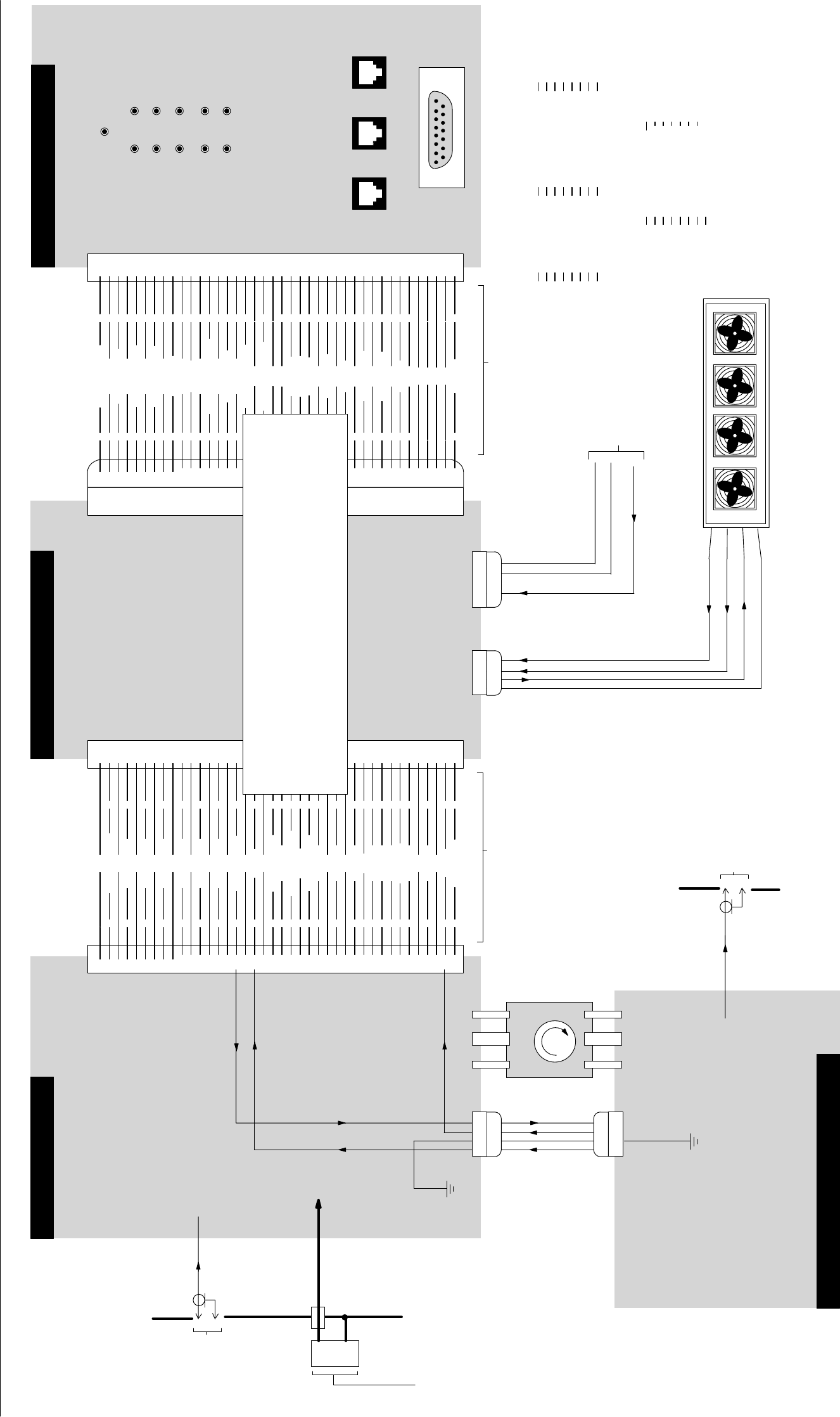
Figure 1. xxxxxxxxx 800 MHz High Power Booster Deck Interconnect Diagram
PTTD4019A RF BOARD
TRANSMIT
RF INPUT
FROM
QUANTAR
POWER
AMPLIFIER
MODULE
P/O
HIGH POWER
BOOSTER DECK
CHASSIS
N-TYPE
CONNECTOR
PTFD4007A LOW PASS FILTER BOARD
PL1 JP10
1 GND 1
2AGATECNTRLDRV A2
3 GND 3
4AGATECNTRL1 A4
5 GND 5
6AGATECNTRL2 A6
7 GND 7
8AGATECNTRL3 A8
9 GND 9
10 AGATECNTRL4 A10
11 GND 11
12 AGATECNTRL5 A12
13 GND 13
14 AGATECNTRL6 A14
15 GND 15
16 AOUT_DET_BIAS A16
17 GND 17
18 "DET_VR "18
19 GND 19
20 APINDIODE_NEG A20
21 AINPUT_VF A21
22 AIN_DET_COMMON A22
23 "TSENSE "23
24 APINDIODE_POS A24
25 "I_SENSE1 "25
26 GND 26
27 "I_SENSE2 "27
28 GND 28
29 "I_SENSE3 "29
30 "+28V "30
31 "I_SENSE4 "31
32 "I_SENSE8 "32
33 "I_SENSE5 "33
34 A+14V_RAW A34
35 "I_SENSE6 "35
36 GND 36
37 "I_SENSE7 "37
38 GND 38
39 "DET_VF "39
40 "TSENSE_RET "40
PTTD4018A CONTROL BOARD
TRANSMIT
RF OUTPUT
P/O
HIGH POWER
BOOSTER DECK
CHASSIS
N-TYPE
CONNECTOR
1234
P2
P2
1234
DET_VR
DET_VF
OUT_DET_COMMON
P9
USER INTERFACE PANEL (UIP)
P5 1234
COOLING FANS
FAN_V_SENSE
FAN_SPIN
GND
FAN_PWR
P6 12345
+14V
P1
RIBBON CABLE
GND
GND FROM
CONNECTOR J6
ON
HPB POWER SUPPLY
BACKPLANE
FAIL
28VDC INPUT HIGH
MAX OUTPUT
FAN FAIL
OVER CURRENT
POWER CUTBACK
INPUT LOW
HIGH TEMPERATURE
VSWR
SHUT DOWN
1"SHUTDOWN_LED "1
2"I_SENSE1 "2
3"CUTBACK_LED "3
4"I_SENSE2 "4
5"HIGH_TEMP_LED "5
6"I_SENSE3 "6
7"INPUT_LOW_LED "7
8"I_SENSE4 "8
9"WSVR_LED "9
10 "I_SENSE5 "10
11 "28V_LED "11
12 "I_SENSE6 "12
13 "OVERCURRENT_LED "13
14 "I_SENSE7 "14
15 "FAN_FAIL_LED "15
16 "I_SENSE8 "16
17 "INPUT_HIGH_LED "17
18 +14V 18
19 "MAX_OUTPUT_LED "19
20 +14V 20
21 "UIP_8 "21
22 "POWER_IN "22
23 "RF_SW_ON "23
24 "FORWARD "24
25 "UIP_6 "25
26 "REFLECTED "26
27 "UIP_5 "27
28 "CELSIUS "28
29 "UIP_4 "29
30 "UIP_FAN_ALM "30
31 "UIP_3 "31
32 "UIP_BATTERY "32
33 "UIP_2 "33
34 "UIP_FAIL "34
35 "UIP_1 "35
36 GND 36
37 GND 37
38 GND 38
39 GND 39
40 "FAIL_LED "40
PL1 MATES DIRECTLY
WITH JP10
J3 J2 J1
J4
18 18 18
18
15 9
1PIN
2 FORWARD P
3 REFLECTED P
4 REFLECTED P
5 TEMPERATURE
6 N/C
7 GND
8 N/C
J3
1 DRAIN DRIVER
2 DRAIN CURRENT 1
3 DRAIN CURRENT 2
4 DRAIN CURRENT 3
5 DRAIN CURRENT 4
6 N/C
7 DRAIN COMM
8 N/C
J2
1 DRAIN DRIVER
2 DRAIN CURRENT 5
3 DRAIN CURRENT 6
4 N/C
5 N/C
6 N/C
7 DRAIN COMM
8 N/C
J1
1 N/C
2 N/C
3 N/C
4 N/C
5 GND
6 OUT_FWD_PWR
7 FANS_SENSE
8 MAJ_ALARM
J4
UIP PINĆOUT DETAILS
9 N/C
10 N/C
11 N/C
12 N/C
13 INPUT_PWR
14 OUT_REFL_PWR
15 BATT_BACKUP
CIRCULATOR
+28V DC
EMI
FEEDĆTHRU
DC INPUT
CONNECTOR
(MOUNTED
ON CHASSIS)
ACCEPTS
DC INPUT PLUG
FROM HPB
POWER SUPPLY
BACKPLANE
IN PROGRESS