Motorola Solutions 89FC5800 Non-Broadcast Transmitter User Manual Exhibit D Users Manual Part 1 per 2 1033 c3
Motorola Solutions, Inc. Non-Broadcast Transmitter Exhibit D Users Manual Part 1 per 2 1033 c3
Contents
- 1. Exhibit D Users Manual per 2 1033 c3
- 2. Exhibit D Users Manual Part 1 per 2 1033 c3
- 3. Exhibit D Users Manual Part 2 per 2 1033 c3
Exhibit D Users Manual Part 1 per 2 1033 c3

APPLICANT: MOTOROLA INC. EQUIPMENT TYPE: ABZ89FC5800
EXHIBIT 8
INSTRUCTION MANUALS
The Preliminary Installation manual for this base radio is provided. Upon request, final manuals will be sent to the
commission and/or telecommunication certification body (TCB) as soon as they become available. All of the
descriptions and schematics in this filing are up to date and will be included in the instruction and/or service
manuals.

APPLICANT: MOTOROLA INC. EQUIPMENT TYPE: ABZ89FC5800
EXHIBIT 8
INSTRUCTION MANUALS
Draft copy of the of the front matter of the following instruction manual is enclosed with this submission:
68P81003Y71-O ........................................................ 6.2 First Draft for Simulcast Hardware Installation
Other system and radio / configuration service software manuals are available to support the product and system
in operation. They can be provided to the Commission upon request.

6.2 First Draft for Simulcast Hardw a r e I n s t a l l a t i o n
© November 2002 Motorola, Inc. 68P81003Y71-O
All Rights Reserved November 2002
Printed in U.S.A.
Computer Software Copyrights
The Motorola products described in this document include a copyrighted Motorola computer program. Laws in the United States and other countries, as well as
International Treaties, preserve for Motorola the exclusive rights for Motorola’s copyrighted computer programs, including the exclusive right to copy, repro-
duce, distribute, or otherwise transfer said computer program(s). Accordingly, the copyrighted Motorola computer programs contained in this document may
not be copied, decompiled, reverse engineered, or reproduced in any manner and on or within any media without the express written permission of Motorola.
Furthermore, the purchase of Motorola products shall not be deemed to grant either directly or by implication, estoppel, or otherwise, any license under the
copyrights, patents, or patent applications of Motorola, except for the normal non-exclusive, royalty-free license to use that arises by operation of law in the
sale of a product.
Document Copyrights
© Motorola, Inc. All rights reserved.
No duplication or distribution of this document or any portion thereof shall take place without the express written permission of Motorola. No part of this
document may be reproduced, distributed, or transmitted in any form or by any means, electronic or mechanical, for any purpose without the express written
permission of Motorola.
To order additional copies of this document contact your Motorola sales representative.
Disclaimer
The information in this document is carefully examined, and is believed to be entirely reliable. However, no responsibility is assumed for inaccuracies. Further-
more, Motorola reserves the right to make changes to any products herein to improve readability, function, or design. Motorola does not assume any liability
arising out of the applications or use of any product or circuit described herein; neither does it cover any license under its patent rights nor the rights of others.
Trademark Information
The following are registered trademarks of Motorola, Inc.: ASTRO, ASTRO-TAC, ASTRO 25, EMBASSY, FLASHport, FullVision, INTELLIREPEATER,
MAXTRAC, Motorola, the Motorola logo, MSF 5000, QUANTAR, QUANTRO, SECURENET, SMARTNET, SMARTZONE, SPECTRA, and STARTSITE.
The following are Motorola trademarks: CENTRACOM Series, CENTRACOM Gold Series, CENTRACOM Series II, CENTRACOM Series II Plus, Cisco,
CoveragePLUS, DIGITAC, DVP, Max-Fax, MDC-600, Micor, MOSCAD, MSF 10000, MTS 2000, OmniLink, Private Conversation, SABER, SMARTNET
II, SmartWorks, and Wireless Network Gateway.
HP, HP-UX, and Hewlett Packard are registered trademarks of Hewlett-Packard Corporation.
UNIX is a registered trademark of The Open Group in the United States and other countries.
Any other brand or product names are trademarks or registered trademarks of their respective holders.
WARRANTY
Limited Software Warranty
For the first ninety (90) days following its initial shipment, Motorola warrants that when properly used, its software will be free from reproducible defects that
cause a material variance from its published specification. However, Motorola does not warrant that program operation will be uninterrupted or error- free, that
each defect will be corrected, or that any program will meet Licensee’s particular requirements.
This warranty does not cover an item of Software (i) used in other than its normal and customary manner; (ii) subjected to misuse; or (iii) subjected to modi-
fications by Licensee or by any party other than Motorola without the prior written consent of Motorola.
Limited Media Warranty
For the first ninety (90) days following its initial shipment, Motorola warrants that the media carrying the software will be free from defects that damage the
performance of the software. Motorola will replace any damaged media free of charge during the warranty period. Warranted media is limited to that which
is used to transport the software (such as floppy disks and authorization key). PROMs that may store the software in equipment are not covered under this
warranty.
Limitation of Liability
Motorola’s total liability and Licensee’s sole remedy for any warranted software shall be limited to, at Motorola’s option, software replacement or the payment
of Licensee’s actual damages, not to exceed the total licensed charge paid by Licensee to Motorola for the item of software that caused the damage.
The warranties set forth above extend only to the first licensee. Subsequent transferees accept these programs "as is" and without warranties of any kind. This
warranty is given in lieu of all other warranties, express or implied, including, without limitation, the warranties of merchantability and fitness for a
particular purpose.
In no event shall Motorola be liable for special, incidental, or consequential damages (including, without limitation, loss of use, time or data, inconvenience,
commercial loss, and lost profits or savings) to the full extent that such may be disclaimed by law even if Motorola has been advised of the possibility of such
damage against licensee by any other party.
Repair of Defects
The classification of defects in Motorola-supplied software shall be the responsibility of Motorola. Remedy of defects is at the sole discretion of Motorola. If
Motorola agrees to remedy a software defect, the new software will be warranted until the end of the original limited warranty period. Replacement of any
software defect shall constitute Motorola supplying the Licensee with the appropriate software media and authorization key. Field installation and configuration
are not included. Field software updates/upgrades and new enhancement option software will be warranted for ninety (90) days from the date of initial shipment.
All warranty service will be performed at service locations designated by Motorola. Travel and associated expenses of the Licensee or such expenses incurred
by Motorola for visits to Licensee’s location by Motorola personnel are not covered by this warranty.

Table
of
Contents
Contents
Simulcast Hardware Installation
WhatIsCoveredInThisManual? .................................... xxi
Helpful Background Information ......................................... xxii
RelatedInformation.............................................. xxii
Understanding the Installation Process
MechanicalInstallationProcess ..................................... 1-1
MechanicalInstallationGuidelines.................................... 1-3
DescriptionofanEquipmentRack.................................. 1-3
VerifyingProperInstallationoftheEquipmentCabinetorRack.................. 1-5
InstallingEquipmentintheEquipmentCabinetorRack........................ 1-6
Installing the Simulcast Subsystem Hardware
General Safety Precautions. . . . . . . . . . . . . . . . . . . . . . . . . . . . . . . . . . . . . . . . 2-2
MaintenanceRequiringTwoPeople ................................. 2-3
LiftingSTR3000SimulcastBaseRadioRacks.............................. 2-3
LiftingEquipmentRacks ...................................... 2-4
LiftingEquipmentRacksHorizontally.............................. 2-4
LiftingEquipmentRacksVertically ............................... 2-4
InstallationProcessOverview...................................... 2-6
SitePreparation............................................. 2-7
GeneralInstallationGuidelines...................................... 2-8
EquipmentInspectionandInventory................................. 2-9
Placement Recommendations . . . . . . . . . . . . . . . . . . . . . . . . . . . . . . . . . . . . 2-9
SpacingRequirements........................................ 2-9
WeightDistributionWithinaRack.................................. 2-9
RackRequirements........................................ 2-10
BondingandGrounding...................................... 2-10
PowerRequirements ....................................... 2-10
AntennaRequirements ...................................... 2-11
RFAntennaattheCo-LocatedSite............................... 2-11
TransmitAntennaontheSTR3000SimulcastBaseRadioRack................. 2-12
GPSRequirements........................................ 2-12
DefiningtheCorrectViewfortheLocation........................... 2-12
EnvironmentalRequirements ................................... 2-13
ExpansionConsiderations..................................... 2-13
ElectrostaticDischarge ...................................... 2-13
68P81003Y71-O November 2002 i
Contents
FCCRequirements .......................................... 2-14
ElectromagneticSafetyRequirements.................................. 2-14
OSHARelatedSafetyRequirements................................ 2-15
HumanExposureComplianceforRFEnergy............................ 2-15
List of References......................................... 2-16
ListofRequiredTools......................................... 2-16
GeneralTools........................................... 2-16
Networking Tools......................................... 2-17
STR3000BaseRadioRackTools................................. 2-17
ToolsforASTRO-TAC9600ComparatorsandMTC9600SiteController .............. 2-18
Technical Support........................................... 2-18
Site-SpecificInformation..................................... 2-19
MotorolaSupportCenters..................................... 2-19
Gathering InformationBeforeCallingMotorola......................... 2-19
WheretoCallforService................................... 2-20
UseofSubcontractors....................................... 2-21
Installing the Prime Site (10Base-2)
Overview of a DigitalSimulcastPrimeSite................................ 3-1
PrimeSiteConfiguration ...................................... 3-2
PrimeSite........................................... 3-2
Prime Site with a Co-LocatedRemoteSite............................ 3-3
PrimeSitewithaMutualAidStation............................... 3-3
InstallingtheMTC9600SiteController ................................. 3-5
Overview of the MTC9600SiteController.............................. 3-5
FunctionalDescriptionoftheSiteController........................... 3-5
RedundantConfigurationforSiteControllers........................... 3-5
Components of the SiteController................................ 3-6
InstallingtheMTC9600SiteController ............................... 3-8
PreparingforInstallation.................................... 3-8
Installing the ChassisintheRack ................................ 3-9
InstallingModulesintheChassis ............................... 3-10
GroundingtheSiteControllerChassis............................. 3-11
Cabling the MTC 9600SiteController............................... 3-11
ConnectingPowertotheSiteController............................ 3-12
PoweringUptheMTC9600SiteController............................. 3-13
Verifying InstallationwiththeLEDs.............................. 3-13
Operating and Environmental SpecificationsforMTC9600SiteController.............. 3-15
InstallingtheASTRO-TAC9600Comparator.............................. 3-15
Overview of the ASTRO-TAC9600Comparator.......................... 3-16
ASTRO-TAC9600HardwareModules............................. 3-17
InstallingtheASTRO-TAC9600ComparatorintheRack...................... 3-18
Number of Cabinets orRacks................................. 3-18
GroundingtheChassis .................................... 3-19
WiringforPower....................................... 3-19
Cabling the ASTRO-TAC9600Comparator ............................ 3-19
PoweringUptheASTRO-TAC9600................................ 3-21
ASTRO-TAC9600OperatingSpecifications............................ 3-21
Environmental Specifications................................... 3-22
ii 68P81003Y71-O November 2002
Contents
RackSpaceRequirements................................... 3-22
Ventilation.......................................... 3-22
InstallingtheTRAK9100SimulcastSiteReference........................... 3-22
OverviewoftheTRAK9100SimulcastSiteReference ....................... 3-23
Functional Description .................................... 3-23
TRAK9100HardwareModules................................ 3-24
InstallingtheTRAK9100SimulcastSiteReferenceintheRack................... 3-25
Grounding theChassis .................................... 3-25
WiringforPower....................................... 3-25
InstallingtheGlobalPositioningSatelliteAntenna ....................... 3-26
Cabling the TRAK9100SimulcastSiteReference.......................... 3-27
PoweringUptheTRAK9100SimulcastSiteReference....................... 3-28
TRAK9100OperatingSpecifications ............................... 3-29
Installing theEthernetSwitch ..................................... 3-30
OverviewoftheEthernetSwitch.................................. 3-30
InstallingtheEthernetSwitchintheRack.............................. 3-30
Grounding the Chassis .................................... 3-30
WiringforPower....................................... 3-30
CablingtheEthernetSwitch.................................... 3-31
Powering Up the EthernetSwitch ................................. 3-32
OperatingandEnvironmentalSpecificationsfortheEthernetSwitch................. 3-32
InstallingtheChannelBank...................................... 3-33
Overview of the ChannelBank................................... 3-33
PrimeSiteInterfaceCardConnections............................. 3-33
ChannelBankSlots...................................... 3-33
Channel Bank HardwareModules............................... 3-35
InstallingtheChannelBankintheRack .............................. 3-35
GroundingtheChassis .................................... 3-35
Cabling the ChannelBank..................................... 3-36
PoweringUptheChannelBank.................................. 3-36
ChannelBankOperatingSpecifications............................... 3-37
Installing the PrimeSiteRouter .................................... 3-37
OverviewofthePrimeSiteRouter................................. 3-37
InstallingthePrimeSiteRouterintheRack............................. 3-38
Grounding the Chassis .................................... 3-38
WiringforPower....................................... 3-38
CablingthePrimeSiteRouter................................... 3-38
Powering Up the PrimeSiteRouter................................. 3-39
PrimeSiteRouterOperatingSpecifications............................. 3-41
68P81003Y71-O November 2002 iii
Contents
Installing the Prime Site (10Base-T)
Overview of a DigitalSimulcastPrimeSite................................ 4-1
PrimeSiteConfiguration ...................................... 4-2
PrimeSite........................................... 4-2
Prime Site withaCo-LocatedRemoteSite............................ 4-2
PrimeSitewithaMutualAidStation............................... 4-3
InstallingtheMTC9600SiteController ................................. 4-4
Overview of the MTC9600SiteController.............................. 4-5
FunctionalDescriptionoftheSiteController........................... 4-5
RedundantConfigurationforSiteControllers........................... 4-5
Components of theSiteController................................ 4-6
InstallingtheMTC9600SiteController ............................... 4-8
PreparingforInstallation.................................... 4-8
Installing the ChassisintheRack ................................ 4-9
InstallingModulesintheChassis ............................... 4-10
GroundingtheSiteControllerChassis............................. 4-11
Cabling the MTC 9600SiteController............................... 4-11
ConnectingPowertotheSiteController............................ 4-12
PoweringUptheMTC9600SiteController............................. 4-13
Ver i f yi n g I n st a l lationwiththeLEDs.............................. 4-13
Operating and Environmental SpecificationsforMTC9600SiteController.............. 4-15
InstallingtheASTRO-TAC9600Comparator.............................. 4-16
Overview of the ASTRO-TAC9600Comparator.......................... 4-16
ASTRO-TAC9600HardwareModules............................. 4-18
InstallingtheASTRO-TAC9600ComparatorintheRack...................... 4-18
Number of CabinetsorRacks................................. 4-18
GroundingtheChassis .................................... 4-19
WiringforPower....................................... 4-19
Cabling the ASTRO-TAC9600Comparator ............................ 4-19
PoweringUptheASTRO-TAC9600................................ 4-22
ASTRO-TAC9600OperatingSpecifications............................ 4-22
Environmental Specifications................................... 4-23
RackSpaceRequirements................................... 4-23
Ventilation.......................................... 4-23
Installing the TRAK 9100SimulcastSiteReference........................... 4-23
OverviewoftheTRAK9100SimulcastSiteReference ....................... 4-24
FunctionalDescription .................................... 4-24
TRAK 9100 Hardware Modules................................ 4-25
InstallingtheTRAK9100SimulcastSiteReferenceintheRack................... 4-25
GroundingtheChassis .................................... 4-25
WiringforPower....................................... 4-2
6
InstallingtheGlobalPositioningSatelliteAntenna ....................... 4-26
CablingtheTRAK9100SimulcastSiteReference.......................... 4-27
Powering Up the TRAK 9100SimulcastSiteReference....................... 4-28
TRAK9100OperatingSpecifications ............................... 4-29
InstallingtheProcurveSwitch..................................... 4-30
Overview of the ProcurveSwitch.................................. 4-30
InstallingtheProcurveSwitchintheRack............................. 4-30
GroundingtheChassis .................................... 4-30
iv 68P81003Y71-O November 2002
Contents
WiringforPower....................................... 4-30
Cabling the ProcurveSwitch.................................... 4-31
OperatingandEnvironmentalSpecificationsfortheProcurveSwitch................. 4-32
PoweringUptheProcurveSwitch................................. 4-33
Testing the SwitchbyResettingIt............................... 4-35
InstallingtheChannelBank...................................... 4-36
OverviewoftheChannelBank................................... 4-36
Prime Site InterfaceCardConnections............................. 4-36
ChannelBankSlots...................................... 4-37
ChannelBankHardwareModules............................... 4-38
Installing theChannelBankintheRack .............................. 4-39
GroundingtheChassis .................................... 4-39
CablingtheChannelBank..................................... 4-39
Powering Up theChannelBank.................................. 4-40
ChannelBankOperatingSpecifications............................... 4-40
InstallingthePrimeSiteRouter .................................... 4-41
Overview of the PrimeSiteRouter................................. 4-41
InstallingthePrimeSiteRouterintheRack............................. 4-42
GroundingtheChassis .................................... 4-42
Wiring for Power....................................... 4-42
CablingthePrimeSiteRouter................................... 4-42
PoweringUpthePrimeSiteRouter................................. 4-43
Prime Site RouterOperatingSpecifications............................. 4-44
Installing the Digital Simulcast Remote Site (10Base-2)
OverviewofaDigitalSimulcastRemoteSite............................... 5-1
Transmitting and Receiving in a Digital Simulcast Subsystem . . . . . . . . . . . . . . . . . . . . . 5-2
V.24 and EthernetLinksinaDigitalSimulcastSubsystem....................... 5-2
TypesofRemoteSiteConfigurations................................. 5-2
RemoteSiteConfiguration ................................... 5-3
Remote Site ConfigurationwithMutualAid ........................... 5-3
InstallingtheSTR3000BaseRadioRack................................. 5-4
OverviewoftheSTR3000BaseRadioRack............................. 5-4
STR 3000 Rack Modules ...................................... 5-5
BaseRadioModules ...................................... 5-6
InstallingtheSTR3000BaseRadioRack............................... 5-7
Placement of the Rack...................................... 5-7
InstallingtheRack....................................... 5-8
68P81003Y71-O November 2002 v
Contents
ConnectingtheSTR3000RacktoGround............................ 5-8
Connecting PowertotheSTR3000Rack............................. 5-9
InstallingtheExpansionCabinets............................... 5-10
CablingtheSTR3000BaseRadioRack.............................. 5-12
Connecting theEthernetCables................................ 5-12
ConnectingtheTransmitCables................................ 5-13
Connecting the Receive Cables . . . . . . . . . . . . . . . . . . . . . . . . . . . . . . . . 5-14
Connecting the V.24Cabling.................................. 5-16
ConnectingCablesforaCo-LocatedRemoteSite........................ 5-17
PoweringUptheSTR3000BaseRadio............................... 5-18
Status PrioritiesforMultifunctionLEDs............................ 5-19
GeneralOperatingSpecifications.................................. 5-19
OperatingSpecificationsfortheBaseRadio .......................... 5-20
Operating SpecificationsfortheTransmitter .......................... 5-21
OperatingSpecificationsfortheRFDS............................. 5-23
AverageHeatDissipationforanSTR3000Rack........................ 5-24
Specifications fortheTowerTopAmplifier............................. 5-24
InstallingtheTRAK9100SimulcastSiteReference........................... 5-25
OverviewoftheTRAK9100SimulcastSiteReference ....................... 5-25
Hardware Modules intheTRAK9100SimulcastSiteReference................. 5-26
InstallingtheTRAK9100SimulcastSiteReferenceintheRack................... 5-26
GroundingtheChassis .................................... 5-27
WiringforPower....................................... 5
-27
InstallinganExpansionRack................................. 5-27
InstallingtheGPSAntenna.................................. 5-27
Cabling the TRAK 9100SimulcastSiteReference.......................... 5-29
PoweringUptheTRAK9100SimulcastSiteReference....................... 5-30
OperatingandEnvironmentalSpecifications............................ 5-31
Installing TRAK 9200SimulcastSiteReferenceforExpansion.................... 5-31
OverviewoftheTRAK9200SimulcastSiteReference ....................... 5-32
CablingtheTRAK9200SimulcastSiteReference ....................... 5-32
Installing the ChannelBank...................................... 5-33
OverviewoftheChannelBank................................... 5-33
ChannelBankHardwareModules............................... 5-34
Installing the ChannelBank.................................... 5-35
GroundingtheChassis .................................... 5-35
ConnectingthePower .................................... 5-35
WiringforPower....................................... 5-3
6
CablingtheChannelBank..................................... 5-38
PoweringUptheChannelBank.................................. 5-39
Troubleshooting TipsfortheChannelBank........................... 5-39
OperatingandEnvironmentalSpecifications............................ 5-39
InstallingtheRemoteSiteHub..................................... 5-40
Overview of the RemoteSiteHub................................. 5-40
InstallingtheRemoteSiteHub................................... 5-41
GroundingtheChassis .................................... 5-41
WiringforPower....................................... 5-41
CablingtheRemoteSiteHub ................................... 5-41
PoweringUptheRemoteSiteHub................................. 5-42
Operating Specifications...................................... 5-43
vi 68P81003Y71-O November 2002
Contents
InstallingtheSimulcastRemoteSiteRouter............................... 5-43
Overview of theSimulcastRemoteSiteRouter........................... 5-43
InstallingtheSimulcastRemoteSiteRouter............................. 5-44
GroundingtheChassis .................................... 5-44
Wiring for Power....................................... 5-44
CablingtheSimulcastRemoteSiteRouter............................. 5-44
PoweringUptheSimulcastRemoteSiteRouter......................... 5-45
Operating Specifications...................................... 5-46
Installing the Digital Simulcast Remote Site (10Base-T)
OverviewofaDigitalSimulcastRemoteSite............................... 6-1
Transmitting and Receiving in a Digital Simulcast Subsystem . . . . . . . . . . . . . . . . . . . . . 6-2
V.24 and EthernetLinksinaDigitalSimulcastSubsystem....................... 6-2
TypesofRemoteSiteConfigurations................................. 6-2
RemoteSiteConfiguration ................................... 6-3
Remote Site ConfigurationwithMutualAid ........................... 6-3
InstallingtheSTR3000BaseRadioRack................................. 6-4
OverviewoftheSTR3000BaseRadioRack............................. 6-5
STR 3000 Rack Modules ...................................... 6-6
BaseRadioModules ...................................... 6-6
InstallingtheSTR3000BaseRadioRack............................... 6-7
Placement of theRack...................................... 6-8
InstallingtheRack....................................... 6-8
ConnectingtheSTR3000RacktoGround............................ 6-9
Connecting PowertotheSTR3000Rack............................. 6-9
InstallingtheExpansionCabinets............................... 6-11
CablingtheSTR3000BaseRadioRack.............................. 6-12
Connecting the EthernetCables................................ 6-12
ConnectingtheTransmitCables................................ 6-13
Connecting the Receive Cables . . . . . . . . . . . . . . . . . . . . . . . . . . . . . . . . 6-14
Connecting the V
.24Cabling.................................. 6-16
ConnectingCablesforaCo-LocatedRemoteSite........................ 6-17
PoweringUptheSTR3000BaseRadio............................... 6-19
Status PrioritiesforMultifunctionLEDs............................ 6-19
GeneralOperatingSpecifications.................................. 6-20
OperatingSpecificationsfortheBaseRadio .......................... 6-20
Operating SpecificationsfortheTransmitter .......................... 6-21
OperatingSpecificationsfortheRFDS............................. 6-23
68P81003Y71-O November 2002 vii
Contents
AverageHeatDissipationforanSTR3000Rack........................ 6-24
SpecificationsfortheTowerTopAmplifier............................. 6-24
InstallingtheTRAK9100SimulcastSiteReference........................... 6-25
OverviewoftheTRAK9100SimulcastSiteReference ....................... 6-25
Hardware ModulesintheTRAK9100SimulcastSiteReference................. 6-26
InstallingtheTRAK9100SimulcastSiteReferenceintheRack................... 6-26
GroundingtheChassis .................................... 6-27
Wiring for Power....................................... 6-27
InstallinganExpansionRack................................. 6-27
InstallingtheGPSAntenna.................................. 6-27
Cabling the TRAK9100SimulcastSiteReference.......................... 6-29
PoweringUptheTRAK9100SimulcastSiteReference....................... 6-30
OperatingandEnvironmentalSpecifications............................ 6-31
Installing TRAK 9200SimulcastSiteReferenceforExpansion.................... 6-31
OverviewoftheTRAK9200SimulcastSiteReference ....................... 6-32
CablingtheTRAK9200SimulcastSiteReference ....................... 6-32
Installing the ChannelBank...................................... 6-33
OverviewoftheChannelBank................................... 6-33
ChannelBankHardwareModules............................... 6-34
Installing the ChannelBank.................................... 6-35
GroundingtheChassis .................................... 6-35
ConnectingthePower .................................... 6-35
WiringforPower....................................... 6
-36
CablingtheChannelBank..................................... 6-38
PoweringUptheChannelBank.................................. 6-39
Troubleshooting TipsfortheChannelBank........................... 6-39
OperatingandEnvironmentalSpecifications............................ 6-39
InstallingtheRemoteSiteSwitch.................................... 6-40
Overview of the RemoteSiteSwitch................................ 6-40
CablingtheProcurveSwitch.................................. 6-40
InstallingtheSimulcastRemoteSiteRouter............................... 6-41
Overview of the SimulcastRemoteSiteRouter........................... 6-41
InstallingtheSimulcastRemoteSiteRouter............................. 6-42
GroundingtheChassis .................................... 6-42
WiringforPower....................................... 6-4
2
CablingtheSimulcastRemoteSiteRouter............................. 6-42
PoweringUptheSimulcastRemoteSiteRouter......................... 6-43
Operating Specifications...................................... 6-44
Installing the MOSCAD Devices
OverviewoftheMOSCADRemoteTerminalUnit............................. 7-1
MOSCADSystemDiagram..................................... 7-1
MOSCAD Network FaultManagementRemoteTerminalUnit..................... 7-3
NFMRTU............................................. 7-3
NFMMultiPortRTU........................................ 7-3
Installing the NFM RTU....................................... 7-4
ConnectingPowertotheNFMRTU............................... 7-4
GroundingtheChassis ..................................... 7-5
CablingtheNFMRTU ....................................... 7-
5
viii 68P81003Y71-O November 2002
Contents
CablingtheNFMRTUatthePrimeSite............................. 7-5
Cabling the NFMRTUattheRemoteSite ............................ 7-6
PoweringUptheNFMRTU..................................... 7-8
InstallingtheNFMMultiPortRTU.................................. 7-8
Connecting PowertotheNFMMultiPortRTU.......................... 7-8
GroundingtheChassis ..................................... 7-9
CablingtheNFMMultiPortRTU................................... 7-9
Cabling the NFMMultiPortRTUatthePrimeSite........................ 7-9
CablingtheNFMMultiPortRTUattheRemoteSite ...................... 7-10
PoweringUptheNFMMultiPortRTU............................... 7-12
Operating and EnvironmentalSpecifications............................ 7-12
OverviewoftheMOSCADIPInterface................................. 7-13
InstallingtheMOSCADIPInterface................................ 7-14
Connecting PowertotheMOSCADIPInterface ........................ 7-14
GroundingtheChassis .................................... 7-14
CablingtheMOSCADIPInterface................................. 7-14
Cabling the MOSCADIPInterfaceatthePrimeSite ...................... 7-14
CablingtheMOSCADIPInterfaceattheRemoteSite...................... 7-15
ConnectingtheIPInterfacetoPort3.............................. 7-15
Powering Up the MOSCADIPInterface.............................. 7-16
OperatingandEnvironmentalSpecifications............................ 7-16
OverviewoftheMOSCADRS232Multiplexer............................. 7-16
Installing the MOSCADRS232Multiplexer ............................ 7-17
ConnectingPowertotheMOSCADRS232Multiplexer..................... 7-17
GroundingtheChassis .................................... 7-18
Cabling the MOSCADRS232Multiplexer............................. 7-18
CablingtheMOSCADRS232MultiplexeratthePrimeSite................... 7-18
CablingtheMOSCADRS232MultiplexerattheRemoteSite.................. 7-19
Powering Up the MOSCADRS232Multiplexer........................... 7-20
OperatingandEnvironmentalSpecifications............................ 7-20
68P81003Y71-O November 2002 ix
Contents
This page intentionally left blank.
x68P81003Y71-O November 2002

List
of
Figures
List of Figures
Figure1-1:FrontViewoftheEquipmentCabinet............................. 1-4
Figure1-2:RackGroundBusBarintheEquipmentCabinet........................ 1-5
Figure2-1:LengthsandAnglesforLiftingUsingtheEyenuts....................... 2-5
Figure2-2:ProperAlignmentoftheEyenuts............................... 2-6
Figure3-1:DigitalSimulcastSubsystemPrimeSite............................ 3-2
Figure3-2:PrimeSitewithCo-LocatedRemoteSite ........................... 3-3
Figure3-3:PrimeSitewithaMutualAidBaseStation........................... 3-4
Figure3-4:FrontViewoftheMTC9600SiteController.......................... 3-6
Figure3-5:RearViewoftheMTC9600SiteController.......................... 3-7
Figure3-6:LEDsontheCPUModule................................. 3-13
Figure3-7:FrontViewoftheASTRO-TAC9600Comparator...................... 3-17
Figure3-8:FrontViewoftheTRAK9100SimulcastSiteReference................... 3-24
Figure3-9:LEDsonthePowerSupplyModuleoftheTRAK9100.................... 3-29
Figure3-10:FrontViewoftheEthernetSwitch............................. 3-30
Figure3-11:FrontViewoftheChannelBank.............................. 3-34
Figure3-12:RearViewoftheChannelBank.............................. 3-34
Figure3-13:FrontViewofthePrimeSiteRouter............................ 3-38
Figure3-14:RearViewofthePrimeSiteRouter ............................ 3-38
Figure4-1:DigitalSimulcastSubsystemPrimeSite............................ 4-2
Figure4-2:PrimeSitewithCo-LocatedRemoteSite ........................... 4-3
Figure4-3:PrimeSitewithaMutualAidBaseStation........................... 4-4
Figure4-4:FrontViewoftheMTC9600SiteController.......................... 4-6
Figure4-5:RearViewoftheMTC9600SiteController.......................... 4-7
Figure4-6:LEDsontheCPUModule................................. 4-14
Figure4-7:FrontViewoftheASTRO-TAC9600Comparator...................... 4-17
Figure4-8:FrontViewoftheTRAK9100SimulcastSiteReference................... 4-24
Figure4-9:LEDsonthePowerSupplyModuleoftheTRAK9100.................... 4-29
Figure4-10:FrontViewofProcurveSwitch .............................. 4-30
Figure4-11:FrontViewoftheChannelBank.............................. 4-37
Figure4-12:RearViewoftheChannelBank.............................. 4-38
Figure4-13:FrontViewofthePrimeSiteRouter............................ 4-41
Figure4-14:RearViewofthePrimeSiteRouter ............................ 4-42
Figure5-1:RemoteSitewithMutualAid................................. 5-3
Figure5-2:STR3000BaseRadioRackwithFourBaseRadios ...................... 5-5
Figure5-3:LayoutoftheBaseRadioModules.............................. 5-7
Figure5-4:TypicalPowerConnectionsfortheSTR3000Rack....................... 5-9
Figure 5-5: Placement of Expansion Cabinets . . . . . . . . . . . . . . . . . . . . . . . . . . . . . . 5-11
Figure5-6:TransmitCablingintheSTR3000Rack........................... 5-14
Figure 5-7: Receive Cabling in the STR 3000 Rack . . . . . . . . . . . . . . . . . . . . . . . . . . . 5-15
Figure5-8:V.24CablingintheSTR3000Rack............................. 5-17
Figure5-9:FrontViewoftheTRAK9100SimulcastSiteReference................... 5-26
68P81003Y71-O November 2002 xi
List of Figures
Figure5-10:PowerSupplyModulewithLEDIndicators......................... 5-31
Figure 5-11: RearViewofTRAK9200................................. 5-32
Figure5-12:FrontViewoftheChannelBank.............................. 5-34
Figure5-13:RearViewoftheChannelBank.............................. 5-34
Figure 5-14: PowerConnectionsontheChannelBank.......................... 5-36
Figure5-15:ACInputtothePowerSupplyontheChannelBank..................... 5-37
Figure5-16:DCInputtothePowerSupplyontheChannelBank..................... 5-37
Figure 5-17: RJ45Pinout ....................................... 5-38
Figure5-18:FrontViewoftheRemoteSiteHub ............................ 5-41
Figure5-19:RearViewoftheRemoteSiteHub............................. 5-41
Figure 5-20: FrontViewoftheSimulcastRemoteSiteRouter...................... 5-43
Figure5-21:RearViewoftheSimulcastRemoteSiteRouter....................... 5-44
Figure6-1:ExampleofaRemoteSiteConfiguration ........................... 6-3
Figure 6-2: RemoteSitewithMutualAid................................. 6-4
Figure6-3:STR3000BaseRadioRackwithFourBaseRadios ...................... 6-5
Figure6-4:LayoutoftheBaseRadioModules.............................. 6-7
Figure 6-5: TypicalPowerConnectionsfortheSTR3000Rack...................... 6-10
Figure 6-6: Placement of Expansion Cabinets . . . . . . . . . . . . . . . . . . . . . . . . . . . . . . 6-11
Figure6-7:TransmitCablingintheSTR3000Rack........................... 6-14
Figure 6-8: ReceiveCablingintheSTR3000Rack........................... 6-15
Figure6-9:V.24CablingintheSTR3000Rack............................. 6-17
Figure6-10:FrontViewoftheTRAK9100SimulcastSiteReference................... 6-26
Figure 6-11: PowerSupplyModulewithLEDIndicators......................... 6-31
Figure6-12:RearViewofTRAK9200................................. 6-32
Figure6-13:FrontViewoftheChannelBank.............................. 6-34
Figure 6-14: Rear ViewoftheChannelBank.............................. 6-34
Figure6-15:PowerConnectionsontheChannelBank.......................... 6-36
Figure6-16:ACInputtothePowerSupplyontheChannelBank..................... 6-37
Figure 6-17: DC InputtothePowerSupplyontheChannelBank..................... 6-37
Figure6-18:RJ45Pinout ....................................... 6-38
Figure6-19:FrontViewoftheSimulcastRemoteSiteRouter...................... 6-42
Figure 6-20: Rear ViewoftheSimulcastRemoteSiteRouter....................... 6-42
Figure7-1:MOSCADComponentDiagram................................ 7-2
Figure7-2:FrontViewoftheNFMXCRTUModel............................ 7-3
Figure 7-3: Rear ViewoftheNFMXCRTUModel............................ 7-3
Figure7-4:FrontViewoftheMultiPortNFMRTU............................ 7-4
Figure7-5:RearViewoftheMultiPortNFMRTU ............................ 7-4
Figure 7-6: MOSCAD IPInterface................................... 7-13
Figure7-7:MOSCADRS232Multiplexer ............................... 7-17
xii 68P81003Y71-O November 2002
Preliminary
Model and Options selection Procedure
GENERAL INFORMATION
! 700 MHz STR 3000 (Tx 764.00625 – 775.99375, Rx 794.00625 – 805.99375)
! 6 Channels per Rack
! 6 Base Radios per Rack, 30 Base Radios per Site
! 100 Watt RF Power Amplifier
! Cabinet Height: 43 RU, 83.5 inches (212 cm)
! Temperature Range: -30° to +60° C (-22°F to 140°F)
! Manual Tuned Cavity Combiners (2, 4 or 6 ports, 150 kHz minimum spacing)
! Antenna Connectors: Receive: N-Female, Transmit: 7/16 Female

Preliminary
700 MHZ STR 3000 ORDERING MATRIX
Super Model and Option Description Nomenclature
STR 3000 Radio Subsystem SQM02SUM0011A
Orderable Options: Choose only one required BR option from the following list.
Add: (1) 100 Watt DC Base Radio X301AD
Add: (2) 100 Watt DC Base Radios X302AD
Add: (3) 100 Watt DC Base Radios X303AD
Add: (4) 100 Watt DC Base Radios X304AD
Add: (5) 100 Watt DC Base Radios X305AB
Add: (6) 100 Watt DC Base Radios X306AB
REQUIRED: Choose a Software Option in the same quantity as BRs ordered above
Add: ASTRO 25 700 MHz Simulcast Trunking Software CA00025AB
Add: ASTRO 25 700 MHz ISR Software CA00158AA
Add: ASTRO 25 700 MHz P25 Limited Digital Conventional
Software CA00242AA
REQUIRED: Choose one Receiver Multicoupler option from the following list:
Add: Primary Receiver Multicoupler X679AF
Add: Primary Receiver Multicoupler with Tower Top Amp Capability X679AG
Add: Expansion Receiver Multicoupler
REQUIRED: Choose one Hardware/Cabling option from the following list:
Add: 700 MHz Primary Cabinet Hardware/Cabling X550BE
Add: 700 MHz Expansion Cabinet Hardware/Cabling X687AG
Add: 700 MHz TX only Expansion CA00159AA Need price update
Add: 700 MHz Primary/800 MHz in the field CA00160AA
REQUIRED: Choose one Transmitter Combiner option from the following list:
Add: 700 MHz 2 Port Cavity Combiner CA00161AA
Add: 700 MHz 4 Port Cavity Combiner CA00162AA
Add: 700 MHz 6 Port Cavity Combiner CA00163AA
The following options can be used to enhance the basic system:
Add: Doors, cabinet, four CA00027AA
Enh: Open cabinet space with tuned combiner port CA00028AA

Preliminary
Field Replacement Units (FRUs):
700 MHz STR 3000 Base Radio
Add: ASTRO 25 700 MHz Simulcast Trunking Software
Add: ASTRO 25 700 MHz ISR Software
Add: ASTRO 25 700 MHz P25 Limited Digital Conventional Software
T6724A
CA00025AB
CA00158AA
CA00242AA
FRU: STR3000 EXCITER MODULE 700 MHZ
FRU: STR3000 RECEIVER MODULE 700 MHZ
FRU: 100W 700 MHZ LINEAR PA
FRU: POWER SUPPLY BOARD
FRU: SIMULCAST 4 and 6 WAY TRAY
FRU: SIMULCAST 4 and 6 WAY TRAY w/TTA
FRU: SIMULCAST 6 WAY TRAY EXPANSION
FRU: STR 3000 CONTROL MODULE
FRU: Configuration Service Software
DLN6520A
DLN6521A
DLN6522A
DLN1102B
CLF1775A
CLF1776A
CLF1777A
DLN1269A
DLN6455A

Preliminary
PRELIMINARY 700 MHZ STR 3000 SPECIFICATIONS
GENERAL PERFORMANCE
Supermodel Number
Number of Channels
Number of Cabinets
Cabinet Height
Footprint * (WxD)
System Weight
Power Requirements
Temperature Range
EBTS thermal loading:
(Preliminary)
Power Consumption*
(Preliminary)
Antenna Connectors
Transmit
Receive
SQM02SUM0011A
1-6 channels
1
43 RU, 83 in. (210 cm)
24x24 in. (60 x 60 cm)
795 lbs (361 kg)
-48 VDC (43-60 VDC)
-30° to +60° C (-22°F to 140°F)
BRs Typ. (BTU) Max.(BTU)
1 1780 2160
2 3459 3190
3 5120 6210
4 6830 8200
5 8500 10220
6 10170 12240
Typical Maximum
3180W 3840 W est.
7/16 Female
N-Female
* NOTE: The number of cabinets, footprint and system weights are stated for a 6 channel system
including the RFDS without options. Some STR 3000 features require the use of additional
equipment.

Preliminary
BASE RADIO
Dimensions
Weight
Power Reqts
# of Frequencies
Freq Generation
Digital Channel Spacing
Mode of Operation
Digital Modulation
Transmit
Receive
Antenna Connectors
Transmit
Receive
8.75x19x16.5 in.
(222x483x419mm)
73 lbs
-48 VDC (42-60 VDC)
1
Synthesized
12.5 kHz
Duplex
Linear Simulcast Modulation, C4FM
C4FM
SMA Female
SMA Female

Preliminary
TRANSMITTER
Frequency Range
Average Power Output
(6 Ch Cavity Combiner)
150 kHz
250 kHz
(Preliminary)
Occupied Bandwidth
RF Output Impedance
Frequency Stability
Modulation Fidelity
Spurious and Harmonic
Emissions Attenuation
Symbol Rate Accuracy
764-776 MHZ
6W-19W per carrier
8W-27W per carrier
8.7 KHZ
50 Ohm
External Reference
10% maximum error
85 dB
10 PPM
NOTE: These specifications were taken at the sub-system (cabinet) level

Preliminary
RECEIVER
Frequency Range
Sensitivity Static Bit Error Rate (BER)
5%
Intermodulation Rejection
(Per TIA methods of measurement)
Adjacent Channel Rejection
Digital Reference
Spurious and Image Response Rejection
Preselector Bandwidth
Bit Error Rate Floor
Signal Displacement Bandwidth
Frequency Stability
Intermediate Stability
1st
2nd
RF Input Impedance
794-806 MHz
-121dBm**
80 dB
60 dB
100 dB***
30 MHz
0.01%
1 kHz
External Reference Required
73.35 MHz
450 kHz
50 Ohm
** With Multicoupler Installed
*** 90 dB at +/- 2.1 MHz
NOTE: These specifications were taken at the sub-system (cabinet) level

Preliminary
TRANSMIT COMBINER SYSTEM
Transmitter Combiner
Frequency Range
Insertion Loss (includes isolator)
2 port Cav Combiner @ 150KHz
2 port Cav Combiner @ 250KHz
4 port Cav Combiner @ 150KHz
4 port Cav Combiner @ 250KHz
6 port Cav Combiner @ 150KHz
6 port Cav Combiner @ 250KHz
8 port Cav Combiner @ 150KHz
8 port Cav Combiner @ 250KHz
10 port Cav Combiner @ 150KHz
10 port Cav Combiner @ 250KHz
12 port Cav Combiner @ 150KHz
12 port Cav Combiner @ 250KHz
(Preliminary)
RF Connector Type
Input
Output
Tx-Tx Isolation
(Preliminary)
700 MHz
764-776 MHz
Typical Maximum
4.0 dB 5.1 dB
3.0dB 3.6dB
4.1 dB 5.2 dB
3.1 dB 3.7 dB
4.2 dB 5.3 dB
3.2 dB 3.8 dB
Will provide when available
N-Female
7/16 Female
32dB
Note: on 700 MHz STR 3000 TX filter or diplexer is required

Preliminary
RECEIVER MULTICOUPLER
Frequency Range
Noise Figure
Gain
3rd Order Input Intercept
Output RF Connector Type
794-824 MHz
Typical Maximum
3.5 dB 4.9 dB
Typical Minimum
11dB 8 dB
Typical Minimum
14 dBm 13 dBm
BNC Female

Chapter
1
Understanding the Installation Process
This chapter provides a general mechanical installation process and some general guidelines
when installing an equipment cabinet or rack.
The following topics are included in this chapter:
•"Mechanical Installation Process" on page 1-1
•"Mechanical Installation Guidelines" on page 1-3
Mechanical Installation Process
Process 1-1 provides guidelines for installing hardware components into a rack in a simulcast subsystem.
68P81003Y71-O November 2002 1-1

Mechanical Installation Process Chapter 1: Understanding the Installation Process
Process 1-1 Installing Hardware Components
1Place each piece of equipment carefully in the area designated on the site plan.
2
Verify that the equipment rack is bolted to the floor and ready for equipment
installation.
See "Verifying Proper Installation of the Equipment Cabinet or Rack" on page
1-5.
If your system was racked and tested by Motorola CCSI, continue
with step 7.
3
Identify the rack space or Rack Unit (RU) location where the hardware
component is to be mounted.
An RU is the standard smallest rack panel height. Its standard
definition is 4.45 cm (1.75 in.).
4
Locate the hardware component near the rack.
Observe all safety precautions when lifting heavy equipment. See
"Lifting STR 3000 Simulcast Base Radio Racks" on page 2-3 for
more information on these precautions.
5Lift and slide the component into the rack.
See "Installing Equipment in the Equipment Cabinet or Rack" on page 1-6.
6Attach the chassis to the rack with the recommended type and size screws or bolts.
7Verify that all boards are properly seated into the chassis, if applicable.
8
Cable the component to the system components.
For the installation of each component, see:
•Chapter 3,"Installing the Prime Site (10Base-2)."
•Chapter 4,"Installing the Prime Site (10Base-T)."
•Chapter 5,"Installing the Digital Simulcast Remote Site (10Base-2)."
•Chapter 6,"Installing the Digital Simulcast Remote Site (10Base-T)."
1-2 68P81003Y71-O November 2002
Simulcast Hardware Installation Mechanical Installation Guidelines
Mechanical Installation Guidelines
Hardware components are typically installed into a equipment cabinet or a standard
48.26 cm (19-in) rack. This section provides the following descriptions and guidelines
for performing an install with the equipment cabinet:
•"Description of an Equipment Rack" on page 1-3
•"Installing Equipment in the Equipment Cabinet or Rack" on page 1-6
Description of an Equipment Rack
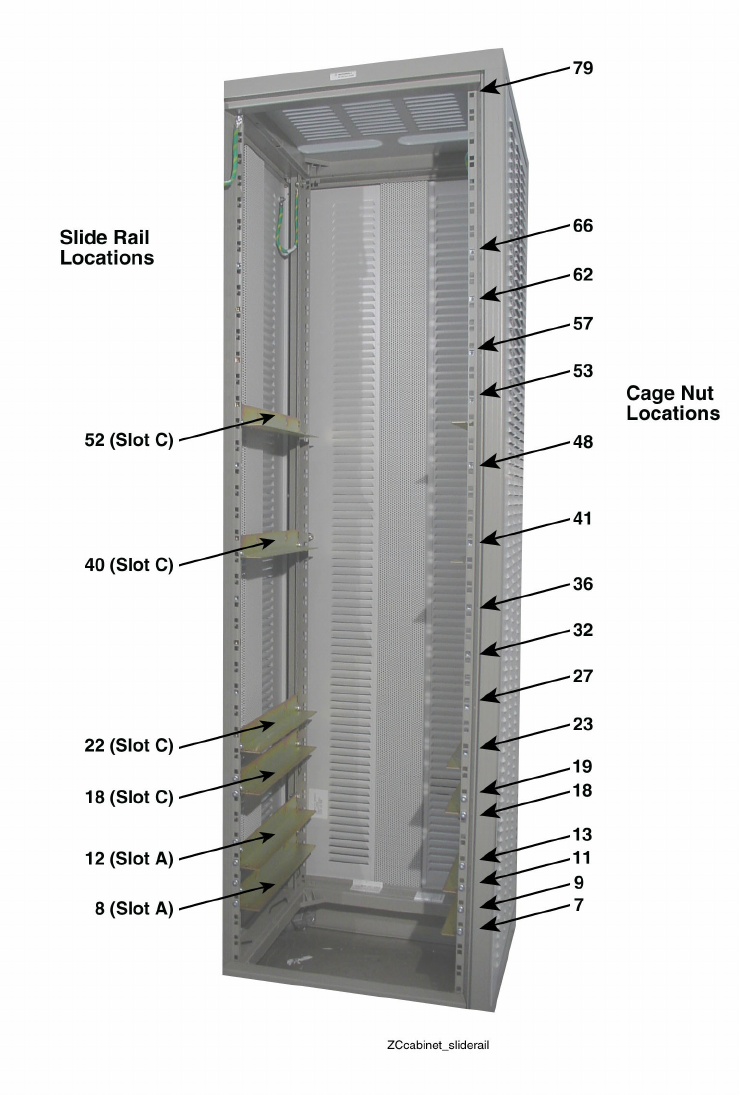
Figure 1-1 shows the front view of the equipment rack and identifies mounting locations for installing
components. The cage nut and slide rail location numbers are determined by counting the blank hole
locations (starting from the rack bottom). The callouts represent the hole numbers.
68P81003Y71-O November 2002 1-3
Description of an Equipment Rack Chapter 1: Understanding the Installation Process
Figure 1-1 Front View of the Equipment Cabinet
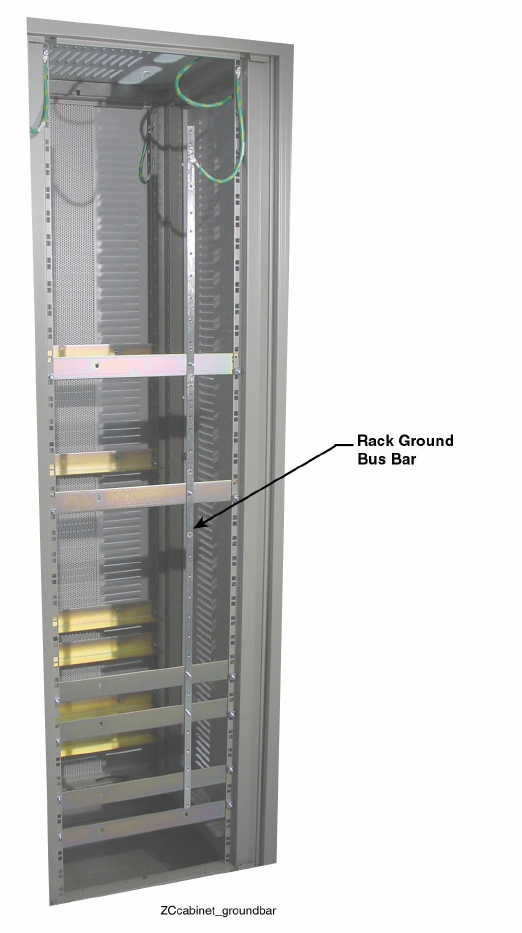
Figure 1-2 shows the Rack Ground Bus (RGB) bar in the equipment cabinet,
which is used to ground the components.
1-4 68P81003Y71-O November 2002
Simulcast Hardware Installation Verifying Proper Installation of the Equipment Cabinet or Rack
Figure 1-2 Rack Ground Bus Bar in the Equipment Cabinet
Verifying Proper Installation of the Equipment Cabinet or Rack
Procedure 1-1 explains how to verify that the equipment cabinet or rack is ready
for hardware component installation.
68P81003Y71-O November 2002 1-5

Installing Equipment in the Equipment Cabinet or Rack Chapter 1: Understanding the Installation Process
Procedure 1-1 How to Verify Proper Equipment Cabinet or Rack Installation
1Verify that the equipment cabinet is properly bolted to the floor.
2Verify that slide rails and cage nut screws on the left and right sides of the
cabinet or rack are installed at the proper bracket hole locations, as shown for
the equipment cabinet in Figure 1-1.
3Verify that the grounding straps of all panels are security fastened to the cabinet
at bracket hole 78 or 79, as shown in Figure 1-1.
Installing Equipment in the Equipment Cabinet or Rack
Procedure 1-2 explains how to install the components into the equipment cabinet or rack.
Procedure 1-2 How to Install a Component into the Equipment Cabinet or Rack
1Remove the component from its shipping box and closely inspect it for any
physical defects or damage.
2Affix any front and rear card location decals to their proper place on the chassis.
3Mark the bracket holes where the component will be attached.
4Insert the component into the cabinet or rack between the marked bracket holes.
Result: The chassis should rest on the installed slide rails near the marked
bracket holes.
5Fasten the component to the cabinet or rack using mounting screws through the
marked bracket holes.
Result: This fastens the component securely to the cabinet or rack.
6Fasten a grounding strap between the component grounding terminal and the
rack ground bus bar (RGB).
7Attach one end of the power cable to the component and the other end to the
appropriate AC outlet, or the UPS power supply (if used).
1-6 68P81003Y71-O November 2002

Chapter
2
Installing the Simulcast Subsystem
Hardware
This chapter provides general information for installing an ASTRO®25 digital simulcast subsystem.
The following topics are included in this chapter:
•"General Safety Precautions" on page 2-2
•"Lifting STR 3000 Simulcast Base Radio Racks" on page 2-3
•"Installation Process Overview" on page 2-6
•"Site Preparation" on page 2-7
•"General Installation Guidelines" on page 2-8
•"FCC Requirements" on page 2-14
•"Electromagnetic Safety Requirements" on page 2-14
•"List of Required Tools" on page 2-16
•"Technical Support" on page 2-18
The Motorola
®
Customer Center for Solution Integration (CCSI) facility stages
most ASTRO
®
25 simulcast systems. This staging process ensures that the
system is assembled correctly and tested to meet customer specifications. Use
this manual in conjunction with Motorola documentation specific to your site.
68P81003Y71-O November 2002 2-1

General Safety Precautions Chapter 2: Installing the Simulcast Subsystem Hardware
General Safety Precautions
Observe the following general safety precautions during all phases of operation, service and
repair of the equipment described in this manual. The safety precautions listed below represent
precautions regarding certain known hazards. Follow these warnings and all other safety
precautions necessary for the safe operation of the equipment.
The installation process requires preparation and knowledge of the site before
installation begins. Review installation procedures and precautions in the
Standards and Guidelines for Communications Sites (68P81089E50) manual before
performing any site or component installation.
Also, all applicable safety procedures, such as Occupational, Safety, and Health Administration
(OSHA) requirements, National Electrical Code (NEC) requirements, local code requirements,
safe working practices, and good judgment must be used by personnel.
These general safety precautions include the following:
•Read and follow all warning notices and instructions marked on the product or
included in this manual before installing, servicing, or operating the equipment.
Retain these safety instructions for future reference.
•Because of the danger of introducing additional hazards, do not install substitute
parts or perform any unauthorized modifications of equipment.
•If troubleshooting the equipment while power is on, be aware of the live circuits.
•Do not operate the radio transmitters unless all RF connectors are secure
and all connectors are properly terminated.
•All equipment must be properly grounded in accordance with the Standards
and Guidelines for Communications Sites (68P81089E50) manual and specified
installation instructions for safe operation.
•Slots and openings in the cabinet are provided for ventilation. These slots and
openings must not be blocked or covered.
•Only a qualified technician familiar with similar electronic equipment
should service equipment.
•Some equipment components can become extremely hot during operation. Turn off all
power to the equipment and wait until sufficiently cool before touching.
•Maintain emergency first aid kits at the site.
•Have personnel call in with their travel routes to help ensure their safety
while traveling between remote sites.
•Establish a communications routine during certain higher risk procedures where
the on-site technician continually updates management or safety personnel of the
progress so that help can be dispatched if needed.
2-2 68P81003Y71-O November 2002

Simulcast Hardware Installation Maintenance Requiring Two People
•Never store combustible materials in or near equipment racks. The combination of
combustible material, heat and electrical energy increases the risk of a fire safety hazard.
Maintenance Requiring Two People
Identify maintenance actions that require two people to perform the repair. Two people are required when:
•A repair has the risk of injury that would require one person to perform first
aid or call for emergency support. An example would be work around high
voltage sources. A second person may be required to remove power and call for
emergency aid if an accident occurs to the first person.
•Use the National Institute of Occupational Safety and Health (NIOSH) lifting
equation to determine whether one or twopersonliftisrequiredwhenasystem
component must be removed and replaced in its rack.
Lifting STR 3000 Simulcast Base Radio Racks
Equipment racks should only be lifted without the use of lifting equipment when there are sufficient
personnel available to ensure that regulations covering health and safety are not breached.
Motorola recommends the use of an appropriate powered mechanical lifting apparatus
for moving and lifting the equipment racks.
In addition to these points, refer to and comply with any local regulations that
govern the use of lifting equipment.
Crush hazard could result in death, personal injury, or equipment
damage. Equipment racks can weigh up to 545kg (1200 lb). Follow the
instructions below for proper lifting procedures.
68P81003Y71-O November 2002 2-3

Lifting Equipment Racks Chapter 2: Installing the Simulcast Subsystem Hardware
Lifting Equipment Racks
Lifting Equipment Racks Horizontally
In some cases, the equipment racks are laid down horizontal to facilitate the shipping process. Use
the appropriate lifting apparatus to lift the racks upright to comply with all applicable health and
safety regulations, and any other regulations applicable to lifting heavy equipment.
Do not use the eyenuts mounted on the top of the rack to lift the rack upright from horizontal position.
The eyenuts are designed only to support and lift equipment in its normal vertical position.
Crush hazard could result in death, personal injury, or equipment damage. Do
not use the eyenuts mounted on the top of the rack to lift the rack upright from
horizontal position. Eyelets could fail, resulting in the equipment dropping.
Lifting Equipment Racks Vertically
Each equipment rack comes with four M10 eyenuts mounted in the top of the rack. Use these
eyenuts to lift the equipment rack vertically. Before using these eyenuts, visually check them
and the rack hardware for any damage that may have occurred during shipping. If any damage
is apparent, do not use. Contact Motorola for replacement parts or material.
Do not use the eyenuts if damage is apparent. Eyenuts could fail, resulting
in the equipment dropping. Contact Motorola for replacements.
Use all four eyenuts when lifting the equipment rack. When lifting from a center point, the distance
from each eyenut to the lifting point must be a minimum of 1 m (40 in.) to ensure that the proper
lifting angle is maintained. Using a shorter length than that specified could cause the eyenuts to fail.
Figure 2-1 shows the minimum lengths and proper 45 degree lifting angles using the eyenuts.
If eyenuts are removed or become loose, install them properly before lifting the equipment rack.
Tighten the eyenuts and bolt assembly by hand. Turn the bolt clockwise an additional 45 degrees.
Eyenuts must be aligned to point towards the center lifting point of the cabinet and tightened to
10.2 to 13.6 Nm (90 to 120 lb-in.) of torque. Proper eyenut tightness and alignment are crucial
to ensure the eyenut assembly performs to its intended lifting capacity.
Figure 2-2 shows the proper alignment of the eyenuts.
2-4 68P81003Y71-O November 2002

Simulcast Hardware Installation Site Preparation
Process 2-1 Installing Equipment within a Digital Simulcast Subsystem
1
Prepare each site to comply with the Motorola requirements and specifications
for the equipment, as listed in the Standards and Guidelines for Communication
Sites (68P81089E50) manual. Other codes and guidelines that may apply to
the location must also be met.
2Inspect and inventory all racks, cabinets, cables, and other equipment with a
Motorola representative to ensure that the order is complete.
3
Install all equipment using the site drawings and other documents provided by
the Field Engineer. Use the installation standards and guidelines for placing and
installing equipment.
4Install all groundings for the racks and cabinets to protect against ground faults,
electrical surges, and lightning in accordance with R56 standards..
5Connect all cables within each rack and between multiple racks (where required).
Connect the subsystem to the overall facility system.
6Run a preliminary check of all sites before applying power and starting the initial
software installations.
Site Preparation
PerformtheactivitieslistedinTable2-1toensure proper site preparation. The table
also references specific chapters in the Standards and Guidelines for Communication
Sites (68P81089E50) manual for more information.
68P81003Y71-O November 2002 2-7

General Installation Guidelines Chapter 2: Installing the Simulcast Subsystem Hardware
Table 2-1 Activities for Site Preparation
Activity Description of Activity Chapter Reference in the Standards
and Guidelines Manual
Review the siteplan. •Prevents potential on-site and off-site
interference by local trunked systems.
•Minimizes cable lengths between the RF
equipment.
•Determines the location of telecom
equipment.
Chapter 4, “Site Design and Development”
Determine site access and
security.
Develop outlines of site access and security
measures.
Review safety
considerations.
Develop outlines of general, installation,
and environmental safety guidelines and
requirements as well as OSHA related
considerations.
•Chapter 2, “Safety Summary”
•Chapter 5, “Communications Site
Building Design and Installation”
Schedule installation of
telephone service.
Ensures options and functions of on-site,
two-way communications for personnel
safety and maintenance.
Chapter 4, “Site Design and Development”
Review grounding
specifications.
Ensures the site meets or exceeds the
Compliance Audit Checklist in Appendix F
as well as the Power and Grounding Checklist
(sub-appendix D in Appendix C).
•Chapter 6, “External Grounding”
•Chapter 7, “Internal Ground”
•Chapter 8, “Power Sources”
•Chapter 9, “Transient Voltage Surge
Suppression”
Schedule installation of site
power.
Provides grounding, power sources, and
surge protection.
•Chapter 6, “External Grounding”
•Chapter 7, “Internal Ground”
•Chapter 8, “Power Sources”
•Chapter 9, “Transient Voltage Surge
Suppression”
General Installation Guidelines
This section provides several guidelines to ensure a quality install. Review these guidelines before
unpacking and installing the system. Review the installation information in the Standards and
Guidelines for Communication Sites (68P81089E50) for more details.
2-8 68P81003Y71-O November 2002