Motorola Solutions 89FC5800 Non-Broadcast Transmitter User Manual Exhibit D Users Manual Part 2 per 2 1033 c3
Motorola Solutions, Inc. Non-Broadcast Transmitter Exhibit D Users Manual Part 2 per 2 1033 c3
Contents
- 1. Exhibit D Users Manual per 2 1033 c3
- 2. Exhibit D Users Manual Part 1 per 2 1033 c3
- 3. Exhibit D Users Manual Part 2 per 2 1033 c3
Exhibit D Users Manual Part 2 per 2 1033 c3
Simulcast Hardware Installation Equipment Inspection and Inventory
Equipment Inspection and Inventory
Motorola recommends that an inventory of all equipment is taken with a Motorola representative to ensure
that the order is complete. Carefully inspect all equipment and accessories to verify they arrived in good
condition. Promptly report any damaged or missing items to a Motorola representative.
Placement Recommendations
The following are recommendations for placing equipment at a site:
•Secure each rack on a firm, and level floor.
•Use the correct mounting hardware to prevent rack movement.
•Use strain relief when installing and positioning cables and cords to help
ensure that no interruption of service occurs.
•Allow at least 1 m (3 ft.) of space at the front and rear of the system to allow for
proper air flow, cooling, and safe access to equipment. The system components
require an ambient air temperature of 0º C to 50º C (32º to 122º F).
•Locate the site racks and other equipment with enough spacing to allow access for service.
Service personnel require access to both the front and rear of the racks.
•Locate the system in an area that is free of dust, smoke, and electrostatic discharge (ESD).
•Ground the racks according to the Standards and Guidelines for
Communication Sites (68P81089E50).
Spacing Requirements
Proper spacing of equipment is essential for ready access to equipment, ease of maintenance, and safety of
personnel. Spacing requirements have been established to meet the National Fire Protection Associations
(NFPA) Code, and the American Society of Heating, Refrigerating, and Air Conditioning Engineers
(ASHRAE) standards. Also, adhere to any local regulations that apply to spacing requirements.
See the Standards and Guidelines for Communication Sites (68P81089E50) for
details on these space requirements.
Weight Distribution Within a Rack
To avoid hazards or damage from uneven loading of a rack, distribute the weight of equipment
evenly in the rack, and consider the limitations of equipment and cables. When possible,
mount the heaviest components in the bottom of the rack.
68P81003Y71-O November 2002 2-9
Rack Requirements Chapter 2: Installing the Simulcast Subsystem Hardware
Rack Requirements
Most communications equipment is installed in a standard 48.26 cm (19-in.) EIA rack
or enclosed cabinet. Refer to the manufacturer’s instructions when installing racks or
cabinets, and installing equipment into the rack or cabinet.
Use all supplied bracing hardware when installing a rack or cabinet and secure
all equipment within a rack or cabinet.
If additional equipment needs to be installed, refer to the system design document provided by
the Field Engineer or consult the Motorola Field Representative.
Bonding and Grounding
Cabinets and equpment racks include a rack grounding bar (RGB) with the capacity to terminate
numerous solid or stranded 6 AWG copper ground wires, which are associated with internal metallic
or fiber optic cables and external grounding to power company equipment.
You must ground all doors of a metal cabinet by bonding the door to the main cabinet
using a 6 AWG (minimum) copper wire.
The RGB is shipped with dual-hole lugs to terminate 2 AWG ground wires. The minimum
number of dual-hole attachments is system dependent and is specified by the customer. This
bar provides electrical continuity between all bonds and ground wire with a current carrying
capacity equal to or exceeding that of a 6 AWG copper wire.
See the Standards and Guidelines for Communication Sites (68P81089E50) for more
information on proper bonding and ground at a site.
Power Requirements
The Standards and Guidelines for Communication Sites (68P81089E50) defines the guidelines
and requirements for cabinets, which house equipment that requires AC power input. Some
of the guidelines and requirements are as follows:
•The cabinet is designed to accept 120/240 V, single-phase power with an amperage
service as required by the electronic equipment.
•Cabinets serviced by commercial power must be equipped with a nationally
recognized test laboratory (NRTL) certified power distribution panel that contains
a main circuit breaker or individual circuit breakers of the correct size as required
for the electronic equipment or specified by the customer.
•A decal showing an electrical schematic of the power wiring must be affixed
to the inside surface of the cabinet.
•All AC power equipment and electrical components must conform to National
Electrical Manufacturers Association (NEMA) and National Electrical Code
(NEC).ThesemustalsobelistedbyanNRTL.
2-10 68P81003Y71-O November 2002

Simulcast Hardware Installation Antenna Requirements
•A surge protector, designed to protect equipment systems from surges at a 120/240 V
service and load center, must be placed on the power feed ahead of all individual load
center circuit breakers. This protector must be listed by an NRTL for the purpose intended.
•Selection of a surge protector is based on the susceptibility of the equipment
powered by the electrical service, with margin provided for locally generated
disturbances. See ANSI/IEEE C62.41 for more details.
•At least one 120 VAC, 15 A duplex convenience outlet equipped with ground fault
interrupter (GFI) protection must be provided in the electronic equipment compartment.
Table 2-2 lists the required wire gauges for various installations. The “loop length” refers to
the combined length of the -48 VDC (hot) lead and the DC return lead. For example, a cabinet
installation that needs 16 feet of wire to reach the power supply rack has a total loop length
of 32 feet. For a standard installation, the equipment cabinet is located adjacent to the power
supply rack with a cable loop length less than 10.6 m (35 ft.).
Wire used for the cabinet power connection to the breaker panel shall not be less than 6 AWG. Total
cable loop (from the power supply rack breakers to the STR 3000 cabinet) voltage drop shall not
exceed 500 mV for the cabling of the -48 VDC (hot) lead and the DC return leads.
Some sites may require larger sizes than those noted in Table 2-2 to meet local codes. When larger cable
is used to run from a power source, the cable shall be “tapped down” to a smaller size for connection
to the STR 3000 breaker panel. In accordance with local code requirements, a properly sized electrical
box mounted on top of the STR 3000 rack cabinet or commercial tap cover is the point where the cable
size transition should take place. The site planner will specify the details of the transition.
When a “tapped down” connection is used, the total voltage drop between the “tapped
down” section and the main loop should not exceed 500 mV.
The screws that connect the power cables to the power supply rack are not provided and must be
locally procured. Power supply rack breaker panel screw size is 3/8-16 x 3/4.
Table 2-2 Power Connection Wire Gauge
Loop Length Wire Gauge Maximum Outer Diameter
of Cable
15.3 m (50 ft.) or less 6AWG 10.2 mm (0.40 in.)
15.3to24.4m(50to80ft.) 4AWG 10.2 mm (0.40 in.)
24.4 to 36.6 m (80 to 120 ft.) 2AWG 10.2 mm (0.40 in.)
Antenna Requirements
All antenna feed line installations are to be made through a metal antenna entry plate that
is external to the site building. See the Standards and Guidelines for Communication Sites
(68P81089E50) for details on the requirements for antenna feed lines.
RF Antenna at the Co-Located Site
The RF antenna provides a link between the prime and remote sites without introducing overload,
desensitivity, and intermodulation at a co-located site. You may need to install a fixed attenuator to the
antenna feed line at the site. The values for these attenuators can vary from site to site.
68P81003Y71-O November 2002 2-11
Transmit Antenna on the STR 3000 Simulcast Base Radio Rack Chapter 2: Installing the Simulcast Subsystem Hardware
Transmit Antenna on the STR 3000 Simulcast Base Radio Rack
One transmit cavity combiner can support up to 12 base radios per transmit antenna. It is possible to
combine the base radios into as few as two cabinets, if they are adjacent. To increase system reliability
and eliminate a single point of failure, use a minimum of two transmit antennas per site.
GPS Requirements
A simulcast subsystem uses two Global Positioning System (GPS) antennas to provide a certain degree
of redundancy in case one antenna is damaged or inadvertently shadowing. Mount the two antennas at
least 3.05 m (10 ft.) apart with an unrestricted aerial view down to within 10˚of the horizon in all
directions. The antennas must also be mounted high enough to clear the peak of the site roof.
Defining the Correct View for the Location
The hemispheric location of the site also affects installation of the GPS antennas. For systems in the
northern hemisphere, mount the antennas to maintain a clear view of the southern sky. For systems in
the southern hemisphere, mount the antennas to maintain a clear view of the northern sky.
Avoiding Obstructions
Be careful to avoid adjacent structures (such as trees and buildings), which can obstruct the GPS
antennas with their wide and solid profiles. Mount the antennas to clear these types of obstructions.
However, an adjacent antenna tower that protrudes into the required view at a prime or remote site does
not obstruct the view and only has a minimal effect on reception from the GPS satellite.
Isolate the GPS antennas from any RF interference by mounting the antennas at least
12˚horizontally from other transmitting antennas.
GPS Antenna Line Loss
The maximum allowable line attenuation between the antenna and the TRAK 9100 GPS receiver is 10 dB.
This 10 dB figure includes a 4 dB margin for attenuation from foliage. So, in an installation in which there
is interference from foliage, allow for 6 dB line loss and 4 dB foliage attenuation. Installations in which
the antenna has an unobstructed view of the sky may have a maximum line attenuation of 10 dB.
In a typical installation using 0.5-in. low density foam coaxial cable, the length of the cable run
should never exceed 45.72 m (150 ft.). This is sufficient for most installations.
When considering the use of larger cables, calculate the cable lengths allowing 4.5 dB of loss at 1.5 GHz.
The remaining 1.5 dB of attenuation is provided by interior site cabling and connectors.
For more information on installation of the GPS antenna, see "Installing the Global
Positioning Satellite Antenna" on page 3-26.
2-12 68P81003Y71-O November 2002
Simulcast Hardware Installation Environmental Requirements
Environmental Requirements
One of the major considerations in designing a site is how to maintain an environment in which the
equipment can operate efficiently. A properly designed heating, ventilation, and air conditioning (HVAC)
system provides the proper environmental conditions for the communications equipment.
Each manufacturer specifies an operating or ambient temperature for their equipment.
These two terms for temperature are defined:
•Operating temperature refers to the temperature within the equipment case with
the equipment operating at a given capacity or load.
•Ambient temperature refers to the environmental temperature as typically measured
152 cm (5 ft.) above the floor in the center of an adjacent aisle.
For the specific environmental requirements for the equipment in a simulcast subsystem, see:
•Chapter 3,"Installing the Prime Site (10Base-2)."
•Chapter 4,"Installing the Prime Site (10Base-T)."
•Chapter 5,"Installing the Digital Simulcast Remote Site (10Base-2)."
•Chapter 6,"Installing the Digital Simulcast Remote Site (10Base-T)."
Expansion Considerations
Expansion cabinets or racks allow equipment to be added to a site. Each type of equipment has its
own specific cabinet or rack for installing additional devices. For example, install an expansion rack
to add STR 3000 Simulcast Base Radios to a site in the digital simulcast subsystem.
Each expansion cabinet or rack has its own requirements for installation. Detailed
information for expansions appear in "Installing the Expansion Cabinets" on page 5-10
and "Installing the Expansion Cabinets" on page 6-11.
Electrostatic Discharge
Electronic components, such as circuit boards and memory modules, can be extremely sensitive
to electrostatic discharge (ESD). Motorola recommends that an antistatic wrist strap and a
conductive foam pad be used when installing or upgrading the system.
If an ESD station is not available, wear an antistatic wrist strap. Wrap the strap around the wrist and
attach the ground end (usually a piece of copper foil or an alligator clip) to an electrical ground. An
electrical ground can be a piece of metal that literally runs into the ground (such as an unpainted
metal pipe) or the metal part of a grounded electrical appliance. An appliance is grounded if it
has a three-prong plug and is plugged into a three-prong grounded outlet.
68P81003Y71-O November 2002 2-13

FCC Requirements Chapter 2: Installing the Simulcast Subsystem Hardware
Do not use a computer as a ground, because it is not plugged in during installation.
FCC Requirements
Radio frequency (RF) transmitters installed at sites within the United States must be in
compliance with the following FCC regulations:
•Only persons holding a general class commercial radio telephone operator’s license
or non-licensed persons working under the immediate supervision of licensed
operators can make adjustments to radio transmitters.
•The power input to the final RF stage shall not exceed the maximum power
specified on the current station authorization.
•The frequency of the transmitter must be checked during initial installation of
the transmitter, when replacing modules, or when making adjustments that affect
the carrier frequency or modulation characteristics.
This equipment has been tested and found to comply with the limits for a Class A digital device,
pursuant to part 15 of the FCC Rules. These limits are designed to provide reasonable protection against
harmful interference when the equipment is operated in a commercial environment.
This equipment generates, uses, and can radiate radio frequency energy. If not installed properly and
used in accordance with the instruction manuals, the equipment may cause harmful interference to
radio communications. Operation of this equipment in a residential area is likely to cause harmful
interference, in which case the user is required to correct the interference.
Electromagnetic Safety Requirements
This section describes information you need to know about working near electromagnetic energy.
2-14 68P81003Y71-O November 2002
Simulcast Hardware Installation OSHA Related Safety Requirements
OSHA Related Safety Requirements
The United States Department of Labor, through the provisions of the Occupational Safety and Health
Act (OSHA) of 1970, has established an electromagnetic energy safety standard that applies to the use
of this equipment. Proper use of this equipment will result in exposure below the OSHA limit.
Human Exposure Compliance for RF Energy
STR 3000 Simulcast Base Radios are designed to generate and radiate RF energy by means of
an external antenna. When terminated into a non-radiating RF load, the base radio equipment
is certified to comply with Federal Communications Commission (FCC) regulations pertaining
to human exposure of RF radiation in accordance with the FCC Rules Part 1 section 1.1310 as
published in title 47 code of federal regulations and procedures established in TIA/EIA TSB92, Report
on EME Evaluation for RF Cabinet Emissions Under FCC MPE Guidelines.
Compliance to FCC regulations of the final installation should be assessed and take into account
site specific characteristics, such as type and location of antennas, as well as site accessibility of
occupational personnel (controlled environment) and general public (uncontrolled environment). This
equipment should only be installed and maintained by trained technicians. Licensees of the FCC
using this equipment are responsible for ensuring that its installation and operation comply with FCC
regulations Part 1 section 1.1310 as published in title 47 code of federal regulations.
Whether a given installation meets FCC limits for human exposure to radio frequency radiation
may depend not only on this equipment, but also on whether the “environments” being assessed are
being affected by radio frequency fields from other equipment, the effects of which may add to the
level of exposure. Accordingly, the overall exposure may be affected by radio frequency generating
facilities that exist at the time the licensee’s equipment is being installed or even by equipment
installed later. Therefore, the effect of any such facilities must be considered in site selection and
in determining whether a particular installation meets the FCC requirements.
FCC OET Bulletin 65 provides materials to assist in making determinations if a given facility is
compliant with the human exposure to RF radiation limits. Determining the compliance of transmitter
sites of various complexities may be accomplished by means of computational methods.
In general, observe the following guidelines when working in or around radio transmitter sites:
•Ensure that all personnel have electromagnetic energy awareness training.
•Ensure that all personnel entering the site are authorized.
•Obey all posted signs.
•Assume all antennas are active.
•Beforeworkingonantennas,notifyowners and disable appropriate transmitters.
•Maintain minimum of 1 m (3 ft.) clearance from all antennas.
•Do not stop in front of antennas.
•Use personal RF monitors while working near antennas.
•Never operate transmitters without shields during normal operation.
•Do not operate base station antennas in equipment rooms.
68P81003Y71-O November 2002 2-15

Installing the STR 3000 Base Radio Rack Chapter 5: Installing the Digital Simulcast Remote Site (10Base-2)
Installing the STR 3000 Base Radio Rack
The STR 3000 Base Radio rack contains the RF channels and related components for a simulcast remote site.
The cables shipped with your system were sized for a specific racking
configuration. Swapping equipment within racks or from one rack to another can
put excessive strain on cables and cause cable failures. Do not install additional
equipment or devices into the rack as this may have a negative effect on the
thermal performance of the equipment and result in reduced safety or reliability.
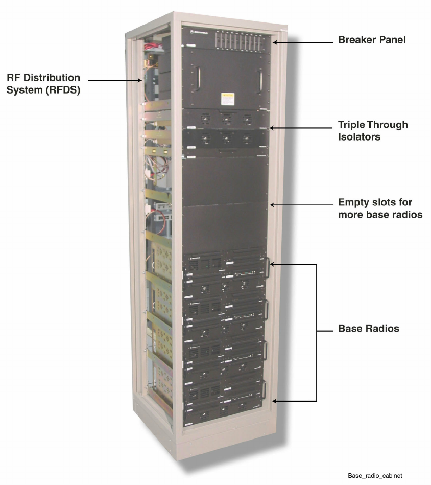
Overview of the STR 3000 Base Radio Rack
The STR 3000 Base Radio is the RF portion of the 800 MHz, digital-only, simulcast remote
site infrastructure. The STR 3000 rack includes from one to six base radios, multicouplers,
combiner, isolator, junction panel, circuit breaker panel, and cabling in a single rack. This rack
provides the transmit and receive capabilities for the remote site.
The STR 3000 rack forwards digital voice and control packets from the comparator to the transmitter
and forwards digital voice and control packets from the receiver to the comparator.
Figure 5-2 shows the STR 3000 Base Radio rack with four base radios.
5-4 68P81003Y71-O November 2002
Simulcast Hardware Installation STR 3000 Rack Modules
Figure 5-2 STR 3000 Base Radio Rack with Four Base Radios
STR 3000 Rack Modules
Table 5-1 lists the hardware modules that comprise the STR 3000 rack.
68P81003Y71-O November 2002 5-5

Base Radio Modules Chapter 5: Installing the Digital Simulcast Remote Site (10Base-2)
Table 5-1 STR 3000 Rack Modules
Module Description
Breaker panel Provides on/off control and electrical overload protection to each module within the cabinet.
Cavity combiner Acts as a band-pass filter, combines two to six transmit signals and places them on a single antenna
port. The minimum channel spacing of the cavity combiner is 150 kHz.
Triple isolator Allows RF to pass from the power amplifier to the combiner and antenna while redirecting any
reflected energy from the antenna system away from the power amp and into a 50 ohm load.
Receive multicoupler (RMC) Supplies a port that takes the signal from the RX antenna and distributes the appropriate
information to each base radio in its rack.
Base radio Handles the transmit and receive functions for the rack through separate modules.
The cavity combiner, triple-through isolator, and receive multicoupler comprise
the Radio Frequency Distribution System (RFDS).
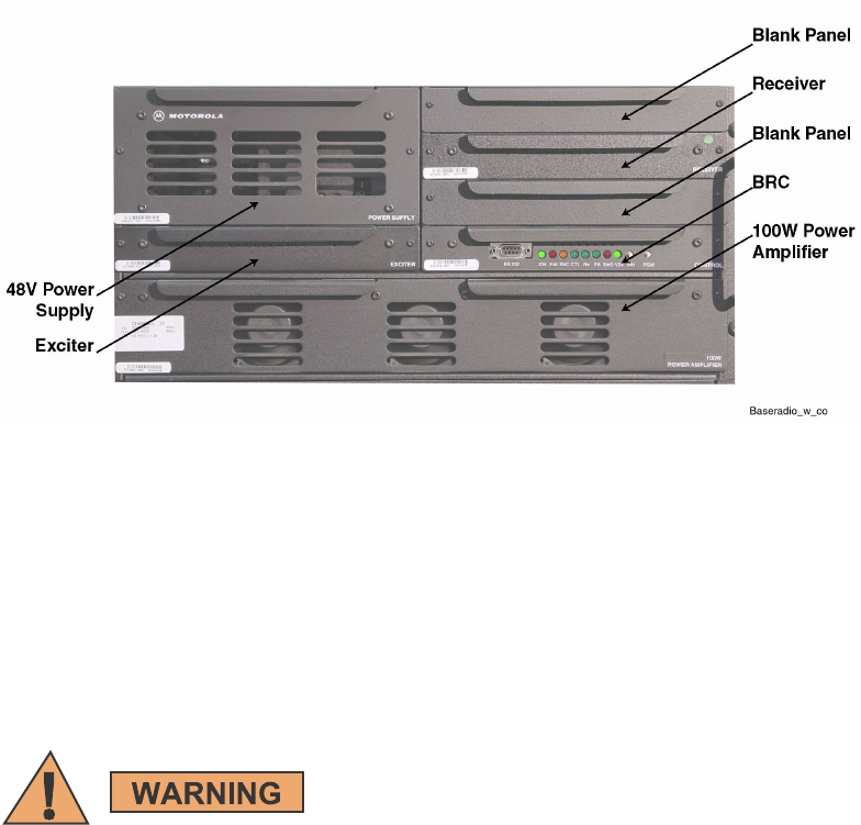
Base Radio Modules
The base radio consists of different modules that handle the transmit and receive functions
for the rack. Table 5-2 lists these modules.
Table 5-2 Base Radio Modules
Module Description
-48 VDC power supply Converts the -48 VDC input to the voltages required by the other base radio modules.
Exciter Provides the transmitter and modulation functions for the base radio in conjunction with
the power amplifier.
Power amplifier (PA) Provides the transmitter functions for the base radio in conjunction with the exciter.
The PA accepts the low-level modulated RF signal from the exciter and amplifies the
signal for transmission via the RF output connector.
Base radio controller Provides signal processing and operational control for other base radio modules.
Receiver Provides the back end receive function.
Figure 5-3 shows the layout for the base radio modules.
5-6 68P81003Y71-O November 2002
Simulcast Hardware Installation Installing the STR 3000 Base Radio Rack
Figure 5-3 Layout of the Base Radio Modules
Installing the STR 3000 Base Radio Rack
The STR 3000 Base Radio Rack is shipped in a cabinet. To install this STR 3000 cabinet, prepare
the site and bolt the rack to the floor in the location indicated on the site design drawings.
Placement of the Rack
Always use two or more persons and appropriate lifting equipment
whenever moving an STR 3000 rack. A fully configured rack weighs
approximately 360 kg (800 lbs). Death, serious personal injury, or
equipment damage can result if the rack tips over.
General suggestions for placing the rack are as follows:
•Secure the rack on a firm and level floor. Use the correct mounting hardware
to eliminate component movement.
•Use strain relief when installing and positioning cables and cords to ensure
that no interruption of service occurs.
•Locate the STR 3000 cabinet where it can be serviced easily. Service people
require access to the front and the rear of the system.
•Locate the STR 3000 cabinet in an area that is free of dust, smoke, and debris.
•Maintain proper grounding and electrostatic discharge (ESD) precautions.
68P81003Y71-O November 2002 5-7
Installing the Rack Chapter 5: Installing the Digital Simulcast Remote Site (10Base-2)
•Maintain proper climate and heating, ventilation, and air conditioning (HVAC) controls.
The base radio and combiner unit weight exceeds 32 kg (70 lbs) and requires
two people to lift when removing the unit from the rack. To avoid injury,
fully support a unit when it is free from the mounting rails.
Installing the Rack
Perform Procedure 5-1 to install the STR 3000 rack.
Procedure 5-1 How to Install the STR 3000 Rack
1Place the rack carefully in the designated area where it will be installed at the
remote site. See the site plan for the correct location.
2Bolt the rack to the floor using the correct hardware for the type of installation.
See the Standards and Guidelines for Communication Sites (68P81089E50) for
details on a rack installation.
3Verify proper grounding of the rack.
4Check to ensure all of the boards are properly seated in the site controller chassis.
Boards may have loosened during shipping.
5Connect power connections to the STR 3000 rack.
See "Connecting Power to the STR 3000 Rack" on page 5-9 for more information.
Connecting the STR 3000 Rack to Ground
Connect each cabinet frame to the site master ground bar using a single dedicated 2 AWG ground wire.
The site ground wire should drop into the top of each cabinet and be connected to the designated
grounding stud located at the junction panel at the top rear of the cabinet. Single hole lugs
(1.27 cm (0.5-in.) diameter) are used for these grounding connections.
Never use a bare or damaged wire for the connection of chassis ground or other
electrical wiring to prevent damage to equipment or potential injury to personnel.
5-8 68P81003Y71-O November 2002
Simulcast Hardware Installation Connecting Power to the STR 3000 Rack
Do NOT daisy-chain multiple equipment cabinet grounds using a single ground
wire. Doing so increases the overall inductance of the ground wire which can
distribute surge energy among the cabinets instead of to the master ground bar.
See Standards and Guidelines for Communications Sites (68P81089E50) for detailed
information on grounding the rack.
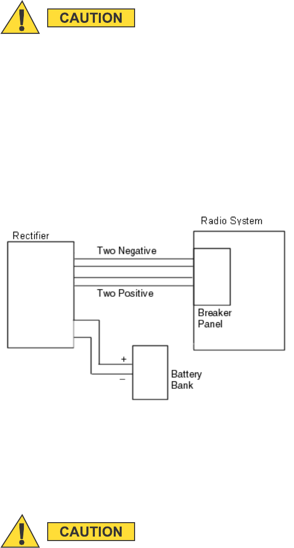
Connecting Power to the STR 3000 Rack
The STR 3000 rack requires a -48 VDC, which is provided by the DC power distribution.
Figure 5-4 shows the typical connections for power to the STR 3000 rack.
Figure 5-4 Typical Power Connections for the STR 3000 Rack
Determining Power Connection Wire Size
Wire size recommendations contained herein reflect Motorola engineering requirements for
proper system operation. Local regulations should be adhered to and will supersede any
other specifications in this manual, where applicable.
Donotusewiresmallerthan16mm2CSA(5AWG).Cableloopvoltagedrop
must not exceed 500 mV for cabling of the -48 VDC and DC return leads.
68P81003Y71-O November 2002 5-9

Installing the Expansion Cabinets Chapter 5: Installing the Digital Simulcast Remote Site (10Base-2)
For a standard installation, the equipment cabinet is located adjacent to the power supply
equipment with a cable loop length less than 10.67 m (35 ft.).
The “loop length” refers to the combined length of the -48 VDC lead and the DC return lead.
For example, a cabinet which needs 4.87 m (16 ft.) of wire between the power supply equipment
and equipment cabinets has a total loop length of 9.75 m (32 ft.).
Table 5-3 lists the required wire sizes for various installations.
Table 5-3 Power Connections Wire Size
Loop Length Wire Size
15.2m(50ft.) orless 16mm
2CSA (5 AWG)
15.2 - 24.8 m (50 - 80 ft.) 25 mm2CSA (4 AWG)
24.8 - 36.6 m (80 - 120 ft.) 35 mm2CSA (2 AWG)
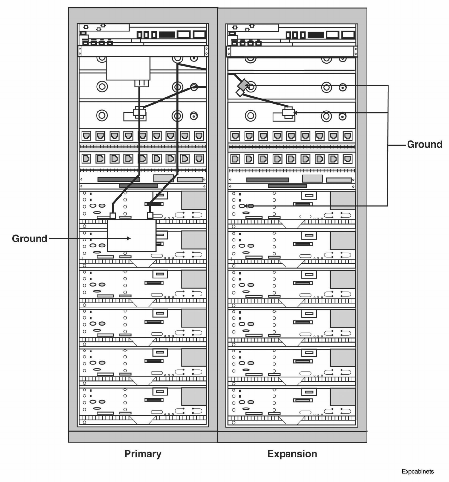
Installing the Expansion Cabinets
If an expansion cabinet is required, the expansion cabinet must be located to the right of the prime cabinet
(See Figure 5-5). The two cavity combiners are connected to their respective side of the phasing harness.
The phasing harness bracket for the transmit combiner is mounted to the expansion rack. The power
monitor unit (PMU) is connected to the post filter, which is connected to the top of the phasing harness.
5-10 68P81003Y71-O November 2002
Simulcast Hardware Installation Installing the Expansion Cabinets
Figure 5-5 Placement of Expansion Cabinets
68P81003Y71-O November 2002 5-11

Cabling the STR 3000 Base Radio Rack Chapter 5: Installing the Digital Simulcast Remote Site (10Base-2)
Cabling the STR 3000 Base Radio Rack
The components of the STR 3000 Base Radio rack are shipped as one unit and do not require separate
cabling during the initial installation. For more information on how to cable each component within
the rack, see Volume 8, Field Replaceable Units and Entities (68P81004Y55).
From the rack, make the following connections to the system:
•"Connecting the Ethernet Cables" on page 5-12
•"Connecting the Transmit Cables" on page 5-13
•"Connecting the Receive Cables" on page 5-14
•"Connecting the V.24 Cabling" on page 5-16
•"Connecting Cables for a Co-Located Remote Site" on page 5-17
Connecting the Ethernet Cables
Table 5-4 lists the Ethernet connections from the STR 3000 rack to the system.
Table 5-4 Ethernet Connections from the STR 3000 Rack
From STR 3000 Rack Destination Device
Port Connector
Type Port Connector
Type
Description
Ethernet Out port
on the junction
panel in the first
cabinet
BNC Port1onHub RJ45 Ethernet LAN connection
Ethernet Out
port on the
junction panel
in succeeding
cabinets
BNC Ethernet out on
preceding panel
RJ45 Ethernet LAN connection
Ethernet Out port
on the junction
panel in the last
cabinet
BNC with 50 ohm
termination
Terminator on
Ethernet Out
BNC LAN termination
Both ends of the Ethernet cabling for a rack must be terminated.
5-12 68P81003Y71-O November 2002

Simulcast Hardware Installation Connecting the Transmit Cables
The DLN1269A base radio controller module can be configured for both 10Base-2
and 10Base-T operation. The site must be all 10Base-2 or all 10Base-T. You
cannot mix configurations within a site.
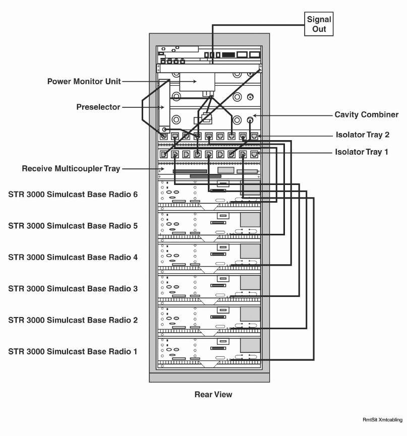
Connecting the Transmit Cables
Table 5-5 lists the transmit connections from the STR 3000 rack to the system.
For more detail on internal cabling, see Volume 8, Field Replaceable Units
and Entities (68P81004Y55).
Table 5-5 Connections for the Transmit Cables
From STR 3000 Rack Destination Device
Port Connector
Type Port Connector
Type
Description
Transmit antenna 7/16 DIN N Type Antenna 7/16 DIN N Type Transmit output from the STR 3000 to
the transmit antenna.
Figure 5-6 shows the transmit cabling layout for a six-channel STR 3000 Base Radio rack.
68P81003Y71-O November 2002 5-13
Connecting the Receive Cables Chapter 5: Installing the Digital Simulcast Remote Site (10Base-2)
Figure 5-6 Transmit Cabling in the STR 3000 Rack
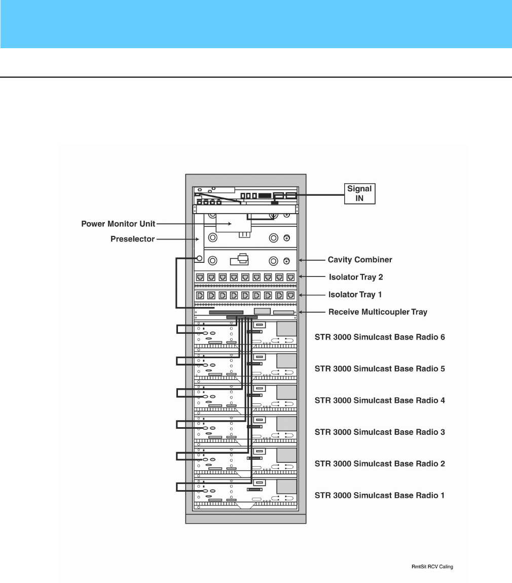
Connecting the Receive Cables
Table 5-6 lists the receive connections from the system into the STR 3000 rack.
5-14 68P81003Y71-O November 2002
Simulcast Hardware Installation Connecting the Receive Cables
Table 5-6 Connections for the Receive Cables
From STR 3000 Rack Destination Device
Port Connector
Type Port Connector
Type
Description
Rx In (Signal IN
on figure)
7/16 DIN N Type Receive antenna 7/16 DIN N Type Receives antenna input into the
STR 3000 rack
Figure 5-7 shows the receive cable connections for the STR 3000 rack.
Figure 5-7 Receive Cabling in the STR 3000 Rack
68P81003Y71-O November 2002 5-15

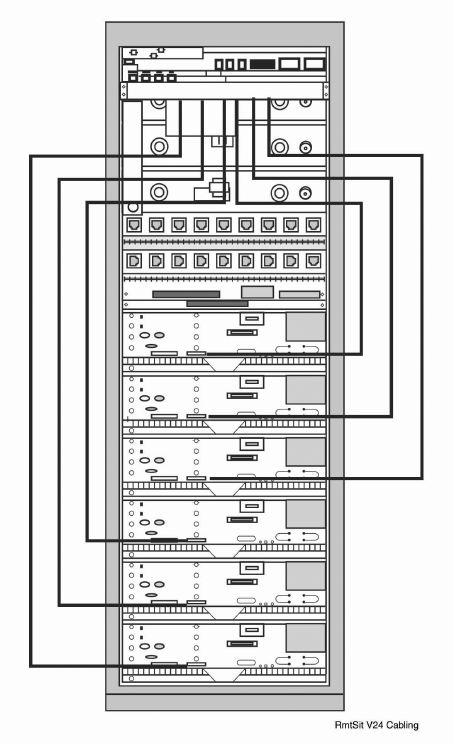
Connecting the V.24 Cabling Chapter 5: Installing the Digital Simulcast Remote Site (10Base-2)
Connecting the V.24 Cabling
Table 5-7 lists the V.24 audio connections for the STR 3000 rack.
Table 5-7 V.24 Cable Connections
From STR 3000 Rack Destination Device
Port Connector
Type Port Connector
Type
Description
Port PNL 1 RJ45 (V.24) Channel Bank 1,
SRU Port 1
RJ45 (V.24) Connection to the prime site.
Port PNL 2 RJ45 (V.24) Channel Bank 1,
SRU Port 2
RJ45 (V.24) Connection to the prime site.
Port PNL 3 RJ45 (V.24) Channel Bank 1,
SRU Port 3
RJ45 (V.24) Connection to the prime site.
Port PNL 4 RJ45 (V.24) Channel Bank 1,
SRU Port 4
RJ45 (V.24) Connection to the prime site.
Port PNL 5 RJ45 (V.24) Channel Bank 1,
SRU Port 5
RJ45 (V.24) Connection to the prime site.
Port PNL 6 RJ45 (V.24) Channel Bank 1,
SRU Port 6
RJ45 (V.24) Connection to the prime site.
Figure 5-8 shows the V.24 cabling layout for a six-channel STR 3000 rack.
5-16 68P81003Y71-O November 2002
Simulcast Hardware Installation Connecting Cables for a Co-Located Remote Site
Figure 5-8 V.24 Cabling in the STR 3000 Rack
Connecting Cables for a Co-Located Remote Site
A co-located remote site is installed along with the prime site or very near to it. This allows the co-located
remote site to connect directly into the prime site and use the same network structures.
Connect the cables listed in Table 5-8 from the STR 3000 rack at a co-located remote site:
•Ethernet cables
•Transmit cables
•Receive cables
68P81003Y71-O November 2002 5-17

Powering Up the STR 3000 Base Radio Chapter 5: Installing the Digital Simulcast Remote Site (10Base-2)
Table 5-8 Cabling Connections from the STR 3000 Rack at a Co-Located Remote Site
From STR 3000 Rack Destination Device
Port Connection
Type Port Connectoin
Type
Description
Ethernet In port
on junction panel
in the first cabinet
BNC Port1onHub BNC Ethernet LAN connection
Ethernet In port on
the junction panel
of succeeding
cabinets
BNC Ethernet out on
panel
BNC Ethernet LAN connection
Last cabinet BNC with 50 ohm
termination
Terminator on
Ethernet Out
BNC with 50 ohm
termination
Ethernet LAN connection
Top of cabinet 7/16 DIN N Type Transmit antenna 7/16 DIN N Type Transmit output from the base radio to
the transmit antenna
Top of cabinet 7/16 DIN N Type Receive antenna 7/16 DIN N Type Receive antenna input into the
STR 3000 rack
Both ends of the Ethernet cabling run must be terminated.
Powering Up the STR 3000 Base Radio
Press the ON/OFF switch on the front of the power supply to apply power to the base radio. As
the radio powers up, the LEDs on the front panel display the following activity:
•All LEDs initially blink.
•The SlnD LED blinks, indicating the software is initializing.
•After about 10 seconds, the V.24 and ON LEDs stay green, indicating that the
power is on and the V.24 link is established.
Table 5-9 lists the LEDs, their corresponding functions, and the indications pro-
vided by various blinking states.
5-18 68P81003Y71-O November 2002

Simulcast Hardware Installation Status Priorities for Multifunction LEDs
Table 5-9 LED Status Indicators on the Base Radio
LED Name Color Solid Blinks Once per
Second
Blinks Twice
per Second
Solid Then
Blinks off 1/4
Second
Station
Operational
(ON)
Green All N/A N/A N/A
Station Failure
(Fail)
Red FRU failure •Ext Ref Failure
•Rx Tx Unlock
Config N/A
Service/Tx Inhibit
(SVC)
Yellow N/A Service SVC Tx Inh N/A
Control
(CTL)
Green Control Ch Failsoft N/A ISP Rx
Rx Active
(Rx)
Green Rx Active Illegal Rx N/A N/A
PA Full/PA Low
(PA)
Green PA Active N/A N/A N/A
Station Disable
(StnD)
Red FLASH N/A N/A N/A
V. 2 4 L i n k
(V24)
Green V24 Link V24 Fail N/A N/A
Status Priorities for Multifunction LEDs
Some LEDs perform multiple functions for the base radio. Table 5-10 lists these LEDs
and the order in which status indications are handled.
Table 5-10 Status Priority for Multifunction LEDs
Multifunction LED Priority of Status
(Highest to Lowest)
Fail •FRU failure
•External reference failure and unlock
•Base radio operational mode
SVC •Transmitter inhibited
•Base radio operational mode
StnD •Software download
•PA inhibited
•Receiver inhibited
General Operating Specifications
This section provides specifications for the STR 3000 rack, base radio, RFDS,
transmitter, receiver, and receiver multicoupler.
68P81003Y71-O November 2002 5-19

Operating Specifications for the Base Radio Chapter 5: Installing the Digital Simulcast Remote Site (10Base-2)
Table 5-11 lists the operating specifications for an STR 3000 rack.
Table 5-11 General Operating Specifications for the STR 3000 Rack
Specification Value or Range
Number of Channels 1-6
Number of Cabinets 1
Cabinet Height 211 cm (83 in.) (48 RU)
Footprint (W x D) 60 x 60 cm (24 x 24 in.)
SystemWeight 361kg(795lb)
Power Requirements -48 VDC (43-60 VDC)
Temperature Range 0to50˚C(32to+122˚F)
Power Consumption Typical: 2,700 W
Maximum: 3,200 W
Antenna Connectors Transmitter: DIN 7/16 Female
Receiver: N-Female
Operating Specifications for the Base Radio
Table 5-12 lists the operating specifications for the base radio.
5-20 68P81003Y71-O November 2002

Simulcast Hardware Installation Operating Specifications for the Transmitter
Table 5-12 Operating Specifications for the Base Radio
Specification Value or Range
Dimensions Height: 22.2 cm (8.75 in.) (5 RU)
Width: 48.3 cm (19 in.)
Depth: 41.9 cm (16.5 in.)
Weight 33 kg (73 lb)
Operating Temperature Range 0 to 50˚C(32to+122˚F)
Power Requirements -48 VDC (41-60 VDC)
Power Dissipation 530 W (typical)
640 W (maximum)
Heat Dissipation 2,160 Btu maximum for 1 base radio 12,240 Btu
maximum for 6 base radios
See Table 5-17 for average heat dissipation for each base
radio.
Rack Spacing •Designed for mounting in an EIA/TIA standard 19-in.
(48.26 cm) rack
•Minimum of 15.24 cm (6 in.) between the cabinet
and the wall
•With doors, minimum of 53.34 cm (21 in.) is required
to open the back door.
Because of weight considerations, the
installation should allow access to the rear
of the unit.
Operating Specifications for the Transmitter
Table 5-13 lists the operating specifications for a transmitter.
68P81003Y71-O November 2002 5-21
Simulcast Hardware Installation Installing the TRAK 9100 Simulcast Site Reference
Table 5-18 Operating Specifications for the Tower Top Amplifier
Installing the TRAK 9100 Simulcast Site Reference
The TRAK 9100 provides a composite 5 Mpps and 1 pps signal used for timing at a remote site. This
section describes how the TRAK 9100 simulcast site reference is installed at a remote site.
Overview of the TRAK 9100 Simulcast Site Reference
As
imulcast system uses signals from the Navstar Global Positioning Satellite (GPS) system to
synchronize the audio from multiple transmitters. A GPS receiver needs to receive the 1 pps signal
from at least four satellites before it can establish its exact geographical location.
The TRAK 9100 uses the satellite signal to derive a high-precision 1 pps signal used in the simulcast
system for time launching. By launching signals at exactly the same time from multiple sites, destructive
interference of the transmitted signals in overlap areas is minimized. In addition to controlling the
launch, the use of GPS allows for variance in delay of the distribution network (T1/E1).
The TRAK 9100 simulcast site reference provides 1 pps and 5 Mpps reference signals
for the following components at a remote site:
•Base radios
•Remote site channel bank
•Remote site hub
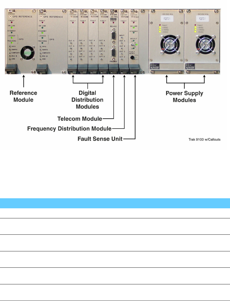
Figure 5-9 shows the modules and connections on the front view of the simulcast site reference.
68P81003Y71-O November 2002 5-25
Hardware Modules in the TRAK 9100 Simulcast Site Reference Chapter 5: Installing the Digital Simulcast Remote Site (10Base-2)
Figure 5-9 Front View of the TRAK 9100 Simulcast Site Reference
Hardware Modules in the TRAK 9100 Simulcast Site Reference
Table 5-19 lists the modules that comprise the TRAK 9100 simulcast site reference.
Table 5-19 TRAK 9100 Simulcast Site Reference Modules
Module Description
Antenna See "Installing the GPS Antenna" on page 5-27.
GPS Receiver (A1) This module contains a crystal oscillator and generates the 1 pps
and 5 Mpps reference signals based on received GPS timing signals.
GPS Receiver (A2) A second oscillator is included for redundancy. (Module A2 does
not include a front-panel cooling fan like Module A1.)
Power Supply Converts AC input to DC voltages used by all other TRAK 9100
modules.
Frequency Distribution
Module
Outputs the 1 pps and 5 Mpps reference signals along with
composite signal.
Fault Sense Unit Detects system failures and provides control, alarm, and status
information.
Installing the TRAK 9100 Simulcast Site Reference in the Rack
The TRAK 9100 simulcast site reference is installed in an EIA/TIA 19-in. (48.26 cm) rack.
5-26 68P81003Y71-O November 2002

Simulcast Hardware Installation Grounding the Chassis
Grounding the Chassis
Connect the grounding cable to the ground lug. The ground lug is a screw on the back of
the power supply located to the left of the AC power receptacles.
Use 6 AWG wire and the appropriate lug connected to chassis ground through to the RGB.
Wiring for Power
The two AC outlets on the rear of the panel provide power to all of the modules in the TRAK 9100.
Installing an Expansion Rack
See "Installing TRAK 9200 Simulcast Site Reference for Expansion" on page 5-31.
Installing the GPS Antenna
The GPS antenna feeds the TRAK 9100 simulcast site reference, which provides a 5 Mpps/1 pps signal (5
Mpps signal at 1 pps repetition rate) to the base radios and other components at the remote site. This
signal establishes timing functions for the transmit and receive frequencies for the base radios.
Perform Procedure 5-2 to install the GPS antenna.
Procedure 5-2 How to Install the GPS Antennas
1Mount the GPS antenna with an unrestricted aerial down view to within 10˚of
the horizon in all directions.
2Mount the antennas high enough to clear the peak of the site roof using the
following guidelines:
•For systems in the northern hemisphere, mount the GPS antennas so that a
clear view of the southern sky is maintained.
•For systems in the southern hemisphere, mount the GPS antennas so that a
clear view of the northern sky is maintained.
3Isolate the GPS antennas from RF interference by mounting the antennas at a
distance of at least 3.66 m (12 ft.) horizontally from the other antennas.
4Mount the GPS antennas to clear obstructions and provide a clear path.
Adjacent structures (such as trees or buildings) are considered
obstructions due to their wide and solid profiles.
Adjacent antenna towers at the RF site which protrude into the
required view (but have a minimal effect on GPS satellite reception
due to their narrow, largely open profiles) are not considered
obstructions.
68P81003Y71-O November 2002 5-27
GPS Antenna Line Loss Chapter 5: Installing the Digital Simulcast Remote Site (10Base-2)
The simulcast system will not operate properly if the GPS receiver is not locked onto at
least four GPS satellites. The four satellites are used to establish a three-dimensional
fix (latitude, longitude, and altitude) for the site.
The TRAK 9100 will free-run for a time period defined by configuration settings. However,
after the specified period while still operating without the GPS satellite signals, the simulcast
system will not operate. The GPS antennas must be properly positioned, and the cables and
connectors must be properly maintained to ensure operation of the simulcast system.
If the TRAK 9100 is powered down, the simulcast system will not operate properly until
the GPS receiver has locked onto the signals from at least four GPS satellites. This
process takes approximately 13 to 25 minutes to complete.
GPS Antenna Line Loss
Cutting the cable below a recommended minimum length can
cause problems with signal strength overload. Refer to Appendix
E in the TRAK 9100 Reference book.
The maximum allowable line attenuation between the antenna and the TRAK 9100 is 6 dB. This
includes a 4 dB margin for attenuation from foliage. Installations in which the antenna has an
unobstructed view of the sky may have a maximum line attenuation of 10 dB.
In a typical installation using 0.5-in., low density foam coaxial cable, the length of the cable run
should never exceed 45.72 m (150 ft). This is sufficient for most installations.
When considering the use of larger cables, calculate the cable lengths allowing 4.5 dB of loss at 1.5 GHz.
The remaining 1.5 dB of attenuation is provided by interior site cabling and connectors.
GPS Antenna Operating Specifications
Table 5-20 lists the operating specifications for the GPS antenna.
Table 5-20 Operating Specifications for the GPS Antenna
Specification Value or Range
Physical Dimensions Diameter: 8.89 cm (3.5 in.)
Height: 10.16 cm (4.0 cm)
Weight 0.32 kg (0.7 lb) (excluding mast)
Operating Temperature -40º to +85º C (-40º to 185º F)
5-28 68P81003Y71-O November 2002

Simulcast Hardware Installation ALARM INDICATION (NO LOCK ON GPS SIGNAL)
ALARM INDICATION (NO LOCK ON GPS SIGNAL)
A system alarm indicates when the GPS signal cannot be located and that the
antenna may need to be repositioned.
Cabling the TRAK 9100 Simulcast Site Reference
All output signal connections interfacing to the network are made via the rear panel. The connections are:
•Two power supply (AC or DC) connectors
•Two GPS antenna N-type connectors
•An RJ45 connector for 10Base-T to distribute Coordinated Universal Time
(UTC) through Network Time Protocol (NTP)
•An RJ45 connector for Alarm (relay contacts) reporting
•A DB9 connector for Time of Day (TOD) output
•An RS232 DB9 connector for diagnostics (VT100)
•An IEEE-488 connector for digital distribution unit (DDU) TRAK 9200
•24 BNC connectors for:
•1 pps
•5Mpps
•1 pps + 5 Mpps composite signals, framed 1.544/2.048 Mbps TTL, and IRIG-B (or 10
MHz if desired) outputs depending on the type of modules plugged at the front panel.
All cables are connected between the BNC T-adapters, which are mounted
to the appropriate module connector.
The cabinet is equipped with cables (index no. 2) and T-adapters for connection to six base
radios regardless of BR complement. Unused T-adapters are left unconnected.
Unless the cabinet is to be used with other RF cabinets, 5 MHz/1 pps OUT
connector must be terminated with a 50 ohm terminator.
Table 5-21 lists all of the cables from the front connections on the TRAK 9100 simulcast site reference.
Table 5-22 lists the cables from the connections on the back of the TRAK 9100.
68P81003Y71-O November 2002 5-29

Powering Up the TRAK 9100 Simulcast Site Reference Chapter 5: Installing the Digital Simulcast Remote Site (10Base-2)
Table 5-21 Cabling from the Front Connections on the TRAK 9100 Simulcast Site Reference
From TRAK 9100 Destination Device
Port Connector
Type Port Connector
Type
Description
AC Input A IEC 320 Power Outlet Power AC Power
AC Input B IEC 320 Power Outlet Power AC Power
Ethernet IN RJ45 Port 6 on the
Remote Site LAN
switch
RJ45 Path for the NTP data
Ethernet IN RS-232 Port 2 on the
MOSCAD NFM
RS-232 Path for diagnostic information to
MOSCAD
Table 5-22 Cabling from the Rear Connections on the TRAK 9100 Simulcast Site Reference
From TRAK 9100 Destination Device
Port Connector
Type Port Connector
Type
Description
10Base-T 10Base-T
(RJ45)
Remote Site
LANSwi Port 5
10Base-T
(RJ45)
NTP information
RS232 I/O RS232 MOSCAD NFM2
Port 2
RS232 Diagnostic information routed to
MOSCAD
Reference Output 24-pin D Digital
Distribution Unit
(DDU) (where
used)
Output to DDU
Powering Up the TRAK 9100 Simulcast Site Reference
The TRAK 9100 has the following three power outputs:
•+5 VDC
•+15 VDC
•-15 VDC
All three outputs have an LED indicator that turns green after the TRAK 9100 powers
up. Figure 5-10 shows the power supply LEDs.
5-30 68P81003Y71-O November 2002
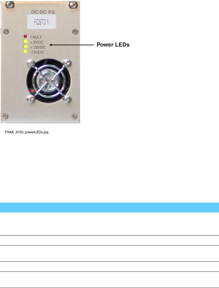
Simulcast Hardware Installation Operating and Environmental Specifications
Figure 5-10 Power Supply Module with LED Indicators
Operating and Environmental Specifications
Table 5-23 lists the operating and environmental specifications for the TRAK 9100 simulcast site reference.
Table 5-23 TRAK 9100 Operating and Environmental Specifications
Specification Value or Range
Physical Dimensions Height: 13.34 cm (5.25 in.) (3U)
Width: 48.26 cm (19 in.)
Depth: 38.1 cm (15 in.)
Weight Approximately 11.34 kg (25 lb) with all modules installed
Operating Temperature –30˚to +60˚C(-22˚to 140˚F) with a rate of change <2˚
C/minute (<3.5˚F/minute)
Power Requirements 100 to 240 VAC ± 10%, 48-63 Hz single-phase
Heat Dissipation 120 W at power-up, tapers to approximately 80 W within
15 minutes of power-up at 25˚C(77˚F)
Installing TRAK 9200 Simulcast Site Reference for Expansion
The TRAK 9200 is the optional expansion chassis which adds simulcast site reference ports.
It provides 56 ports, arranged in four rows of 14 ports each.
68P81003Y71-O November 2002 5-31
Overview of the TRAK 9200 Simulcast Site Reference Chapter 5: Installing the Digital Simulcast Remote Site (10Base-2)
Overview of the TRAK 9200 Simulcast Site Reference
The TRAK 9200 simulcast site reference differs from the TRAK 9100 simulcast site reference with
respect to two modules: the power supply and the termination/fault logic unit.
The power supply has only one output (5 VDC). So the indicators differ from those referenced in "Powering
Up the TRAK 9100 Simulcast Site Reference" on page 5-30. There are only two indicators, as follows:
•Green, indicating the 5 VDC power supply is operating properly.
•Red, indicating a fault with the power supply.
The fault logic unit serves the same function as the fault sense unit in the TRAK 9100.
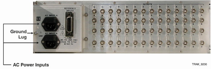
Figure 5-11 shows the rear view of the TRAK 9200.
Figure 5-11 Rear View of TRAK 9200
Cabling the TRAK 9200 Simulcast Site Reference
Table 5-24 lists the cabling for the TRAK 9200 simulcast site reference expansion.
5-32 68P81003Y71-O November 2002
Simulcast Hardware Installation Operating Specifications
Operating Specifications
Table 5-30 lists the operating and environmental specifications for the remote site hub.
Table 5-30 Remote Site Hub Operating and Environmental Specifications
Specification Value or Range
Physical Dimensions Height: 4.32 cm (1.7 in.) (1 RU)
Width: 44.1 cm (17.4 in.)
Depth: 17.0 cm (6.7 in.)
Weight 2.1kg(4.6lb)
Operating Temperature 0˚to 50˚C(32˚to 122˚F)
Power Requirements 85-244 VAC 50/60 Hz 120 W
Heat Dissipation 103 Btu/Hour
Installing the Simulcast Remote Site Router
The remote site router routes network management traffic from a simulcast remote site to the prime site.
Overview of the Simulcast Remote Site Router
The simulcast remote site router routes network management information from the remote
site to the prime site through the High Speed Unit (HSU) card.
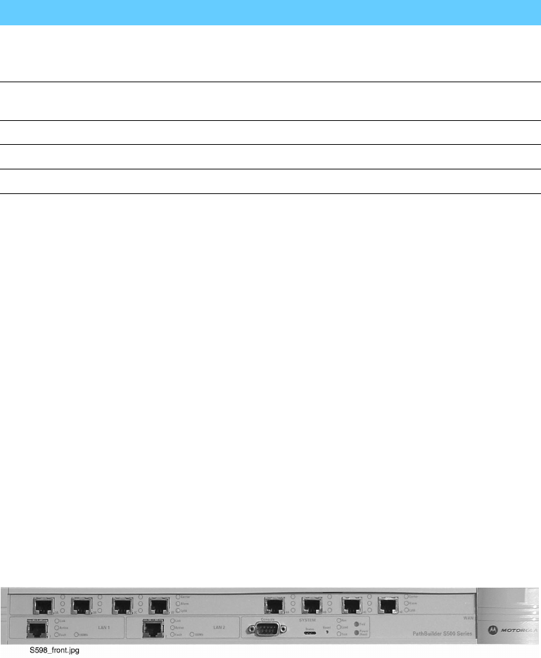
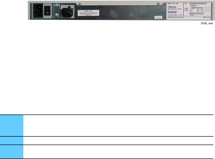
Figure 5-20 and Figure 5-21 respectively show the front and rear views of the simulcast remote site router.
Figure 5-20 Front View of the Simulcast Remote Site Router
68P81003Y71-O November 2002 5-43
Installing the Simulcast Remote Site Router Chapter 5: Installing the Digital Simulcast Remote Site (10Base-2)
Figure 5-21 Rear View of the Simulcast Remote Site Router
Installing the Simulcast Remote Site Router
This section describes how to install the simulcast remote site router.
Grounding the Chassis
Some network topologies require a grounding stud, which is separate from the AC ground
on the chassis of the networking equipment. If this type of grounding is required for the
topology, perform Procedure 5-6 to connect the chassis ground.
Procedure 5-6 How to Connect a Chassis Ground
1Terminate one end of a length of minimum 6 AWG wire with a compression lug.
2Using a grounding screw, attach the lug to the rear of the chassis.
3Terminate the other end of the wire on a permanently connected protective grounding conductor
or RGB.
Wiring for Power
Power is provided to the simulcast remote site router by connecting a power cable to
the power receptacle on the rear of the unit.
Cabling the Simulcast Remote Site Router
Table 5-31 lists the cable connections from the simulcast remote site router.
5-44 68P81003Y71-O November 2002

Simulcast Hardware Installation Powering Up the Simulcast Remote Site Router
Table 5-31 Cable Connections from the Simulcast Remote Site Router
From Remote Site Router Destination Device
Port Connector
Type Port Connector
Type
Description
LAN 1 RJ45 Remote Site Hub RJ45 Ethernet connection only for co-located
LAN 2 RJ45 Remote Site
Switch
RJ45 Ethernet connection between the hub
and the prime site switch
Serial 3 60-pin FlexWAN Channel Bank 60-pin FlexWAN Ethernet connection between the hub
and the channel bank
Serial 4 60-pin FlexWAN Channel Bank 60-pin FlexWAN Ethernet connection between the hub
and the channel bank
WAN 5 RJ45 not used RJ45 not used
WAN 6 RJ45 not used RJ45 not used
Console RS232/DB9 Console/Termi-
nal, Serial Port
RS232/DB9 Communications connection between
the router and a console or terminal
Powering Up the Simulcast Remote Site Router
Perform Procedure 5-7 to power up the simulcast remote site router and verify that it is working.
Procedure 5-7 How to Power Up the Simulcast Remote Site Router
1Attach the power cable to the power receptacle.
2Plug the power cable into the AC outlet.
3Turn the power switch to the ON position.
4Verify that the power LED is on.
The power-up process takes a few seconds. When the process has successfully completed, the
LEDs on the front panel should be on or off, as described in Table 5-32.
68P81003Y71-O November 2002 5-45

Operating Specifications Chapter 5: Installing the Digital Simulcast Remote Site (10Base-2)
Table 5-32 LED Status at Successful Startup
LED Status
LAN
Link On
Active On or blinking
Fault Off
FlexWAN SERIAL
Link On
Active On
Fault Off
SYSTEM
Status All off
Fwd Off or blinking
Power/Fault Green
Run On
Load Off
Test Off
Operating Specifications
Table 5-33 lists the operating specifications for the simulcast remote site router.
Table 5-33 Simulcast Remote Router Operating Specifications
Specification Value or Range
Physical Dimensions Height: 4.32 cm (1.7 in.) (1 RU)
Width: 43.94 cm (17.3 in.)
Depth: 30.48 cm (12.0 in.)
Weight 4.54 kg (10 lb)
Power Requirements 120 W
Heat Dissipation 137 Btu
Temperature Operating: 5˚to 40˚C(41˚to 104˚F)
Non-Operating: -40˚to 75˚C(-40˚to 167˚F)
Relative Humidity Operating: 10% - 90% noncondensing
Non-Operating: 10% - 90% noncondensing
5-46 68P81003Y71-O November 2002