Motorola Solutions 89FT3799 Hand Held Transmitter User Manual 89C80 A Book
Motorola Solutions, Inc. Hand Held Transmitter 89C80 A Book
UserManual.wiki
>
Motorola Solutions
>
89FT3799 User Manual
>
Instruction Manual
Contents
1.
Instruction Manual Cover Page
2.
Instruction Manual
Instruction Manual
Navigation menu
Upload a User Manual
Namespaces
Wiki Guide
HTML
PDF
Info
Views
User Manual
Discussion / Help
Navigation

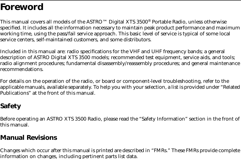
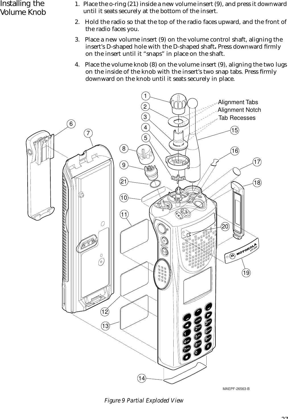
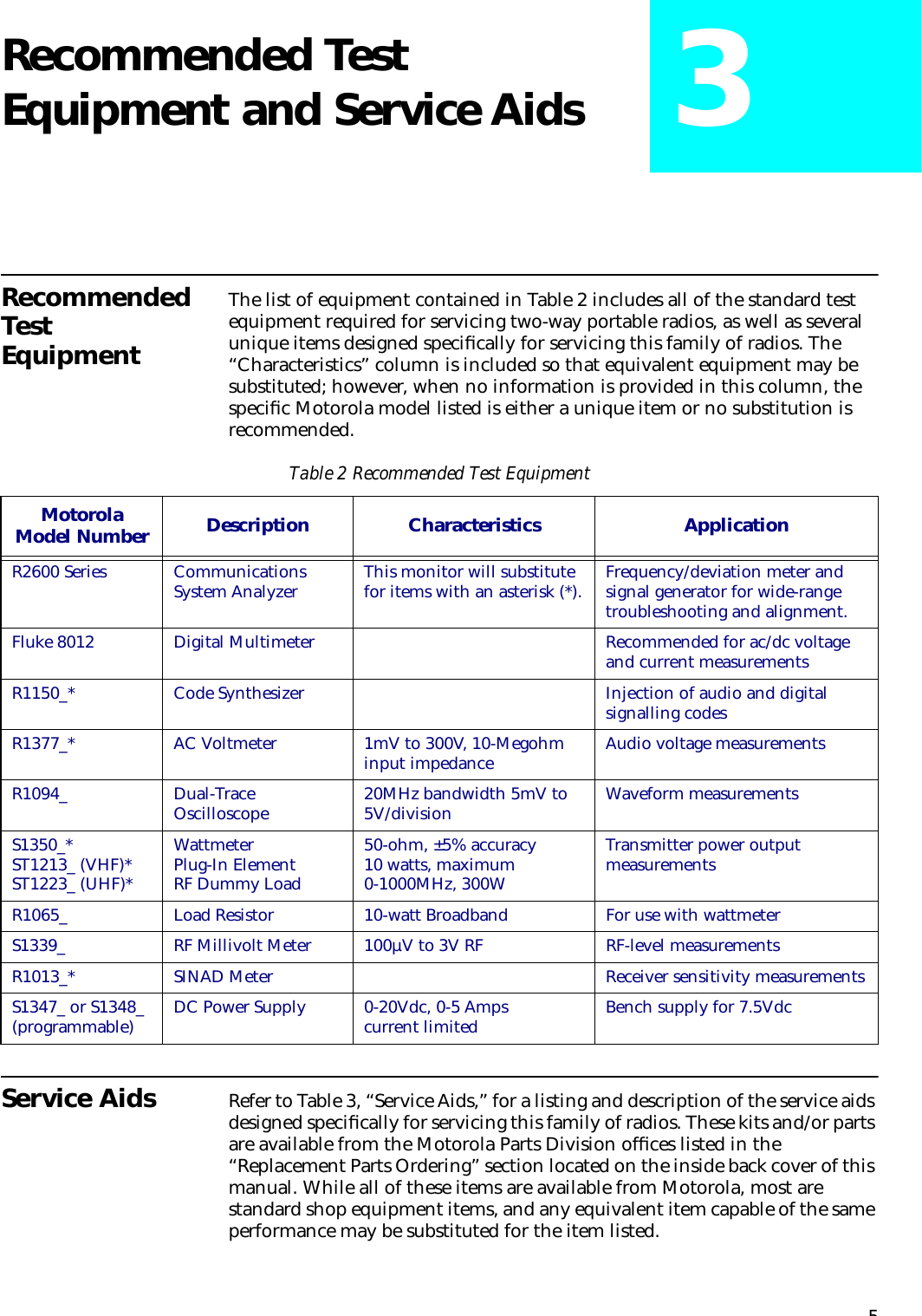
![xiOperational WarningsVehicles With an Air BagDo not place a portable radio in the area over an air bag or in the air bag deployment area. Air bags inflate with great force. If a portable radio is placed in the air bag deployment area and the air bag inflates, the radio may be propelled with great force and cause serious injury to occupants of the vehicle.Potentially Explosive AtmospheresTurn off your two-way radio when you are in any area with a potentially explosive atmosphere, unless it is a radio type especially qualified for use in such areas (for example, Factory Mutual or CENELEC approved). Sparks in a potentially explosive atmosphere can cause an explosion or fire resulting in bodily injury or even death.BatteriesDo not replace or recharge batteries in a potentially explosive atmosphere. Battery contact sparking may occur while installing or removing batteries and may cause an explosion.Blasting Caps and Blasting AreasTo avoid possible interference with blasting operations, turn off your radio when you are near electrical blasting caps, in a blasting area, or in areas posted: “Turn off two-way radio.” Obey all signs and instructions.The areas with potentially explosive atmospheres referred to above include fueling areas such as: below decks on boats; fuel or chemical transfer or storage facilities; areas where the air contains chemicals or particles, such as grain, dust, or metal powders; and any other area where you would normally be advised to turn off a vehicle engine. Areas with potentially explosive atmospheres are often but not always posted.Operational CautionsAntennas• Do not use any portable two-way radio that has a damaged antenna. If a damaged antenna comes into contact with your skin, a minor burn can result.• Make sure you have the correct antenna installed for your radio’s frequency band. Ask your dealer for details.BatteriesAll batteries can cause property damage and/or bodily injury such as burns if a conductive material such as jewelry, keys, or beaded chains touch exposed terminals. The conductive material may complete an electrical circuit (short circuit) and become quite hot. Exercise care in handling any charged battery, particularly when placing it inside a pocket, purse, or other container with metal objects.Battery InformationCharging BatteriesThis product is powered by a nickel-cadmium (Ni-Cd), nickel-metal-hydride (NiMH), or lithium-ion rechargeable battery. Charge the battery before use to ensure optimum capacity and performance. The battery was designed specifically to be used with a Motorola charger. Charging in non-Motorola equipment may lead to battery damage and void the battery warranty.When charging a battery attached to a radio, turn the radio off to ensure a full charge.The battery should be at about 77°F (25°C) (room temperature), whenever possible. Charging a cold battery (below 50° F [10°C]) may result in leakage of electrolyte and ultimately in failure of the battery. Charging a hot battery (above 104°F [40°C]) results in reduced discharge capacity, affecting the performance of the radio. Motorola rapid-rate battery chargers contain a temperature-sensing circuit to ensure that batteries are charged within the temperature limits stated above.!W A R N I N G!Note!C a u t i o nNote](https://usermanual.wiki/Motorola-Solutions/89FT3799.Instruction-Manual/User-Guide-88802-Page-13.png)
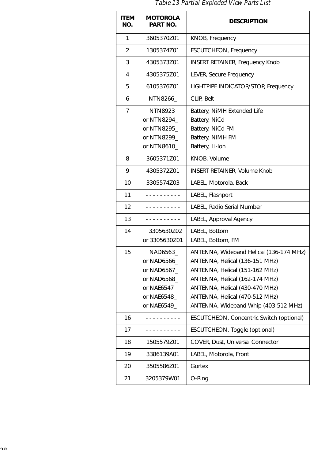
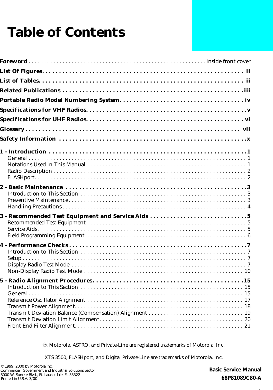
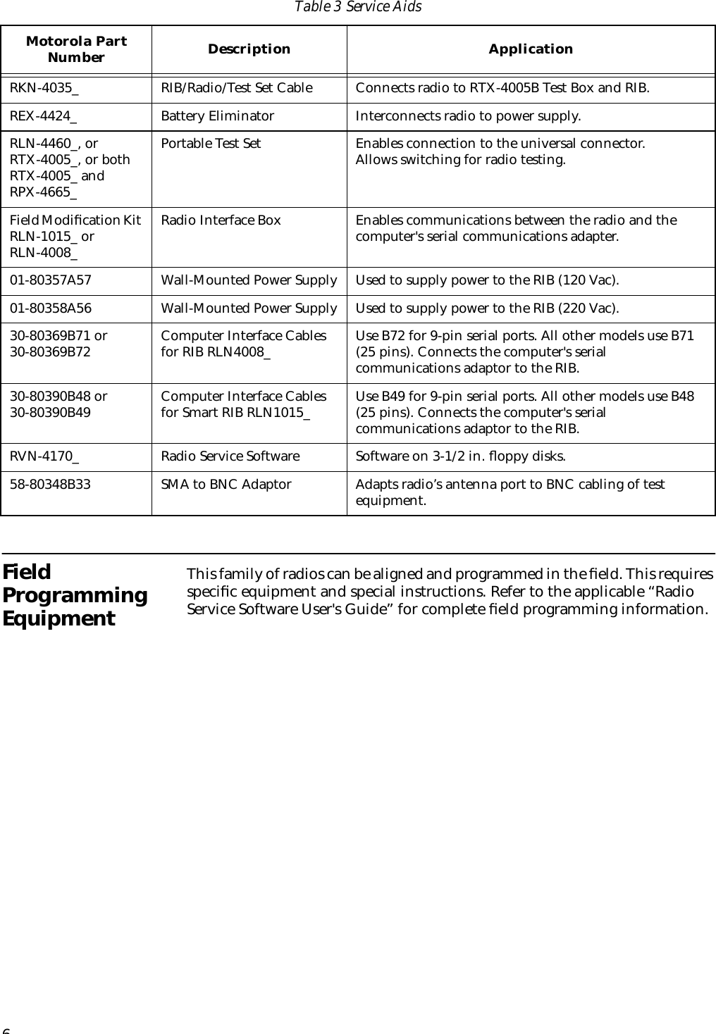
![xiiRecycling of Nickel-Cadmium BatteriesNickel-cadmium (Ni-Cd) rechargeable batteries can be recycled. However, recycling facilities may not be available in all areas. Under various U.S. state laws and the laws of several other countries, Ni-Cd batteries must be recycled or disposed of properly and cannot be disposed of in landfills or incinerators. Contact your local waste management agency for specific requirements and information in your area. Motorola fully endorses and encourages the recycling of Ni-Cd batteries. In the U.S. and Canada, Motorola participates in the nationwide Rechargeable Battery Recycling Corporation (RBRC) program for Ni-Cd battery collection and recycling. Many retailers and dealers participate in this program. For the location of the drop-off facility closest to you, access RBRC's Internet website at www.rbrc.com or call 1-800-8-BATTERY. This internet site and telephone number also provide other useful information concerning recycling options for consumers, businesses, and governmental agencies.Intrinsically Safe Radio InformationFMRC Approved EquipmentAnyone intending to use a radio in a location where hazardous concentrations of flammable materials exist (hazardous atmosphere) is advised to become familiar with the subject of intrinsic safety and with the National Electric Code NFPA 70 (National Fire Protection Association) Article 500 (hazardous [classified] locations).An Approval Guide, issued by Factory Mutual Research Corporation (FMRC), lists manufacturers and the products approved by FMRC for use in such locations. FMRC has also issued a voluntary approval standard for repair service (“Class Number 3605”).FMRC Approval labels are attached to the radio to identify the unit as being FM Approved for specified hazardous atmospheres. This label specifies the hazardous Class/Division/Group along with the part number of the battery that must be used. Depending on the design of the portable unit, this FM label can be found on the back or the bottom of the radio housing. The FM Approval mark is shown below:WARNINGS• Do not operate radio communications equipment in a hazardous atmosphere unless it is a type especially qualified (for example, FMRC Approved) for such use. An explosion or fire may result.• Do not operate an FMRC Approved Product in a hazardous atmosphere if it has been physically damaged (for example, cracked housing). An explosion or fire may result.• Do not replace or charge batteries in a hazardous atmosphere. Contact sparking may occur while installing or removing batteries and cause an explosion or fire.• Do not replace or change accessories in a hazardous atmosphere. Contact sparking may occur while installing or removing accessories and cause an explosion or fire.• Do not operate an FMRC Approved Product unit in a hazardous location with the accessory contacts exposed. Keep the connector cover in place when accessories are not used.• Turn a radio off before removing or installing a battery or accessory.• Do not disassemble an FMRC Approved Product unit in any way that exposes the internal electrical circuits of the unit.Radios must ship from the Motorola manufacturing facility with the hazardous atmosphere capability and FM Approval labeling. Radios will not be “upgraded” to this capability and labeled in the field.A modification changes the unit’s hardware from its original design configuration. Modifications can only be made by the original product manufacturer at one of its FMRC-audited manufacturing facilities.FMAPPROVED!W A R N I N G!](https://usermanual.wiki/Motorola-Solutions/89FT3799.Instruction-Manual/User-Guide-88802-Page-14.png)

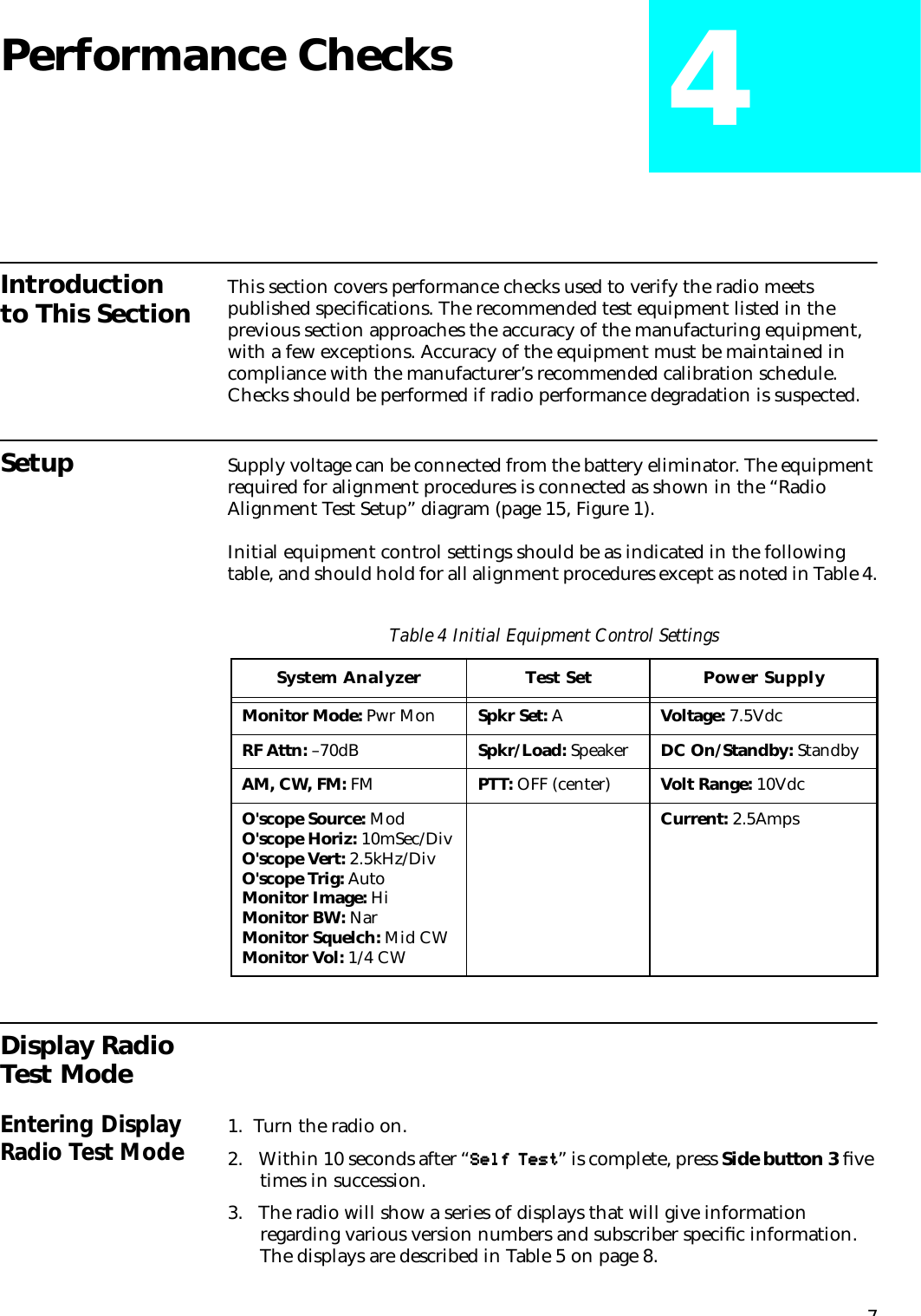
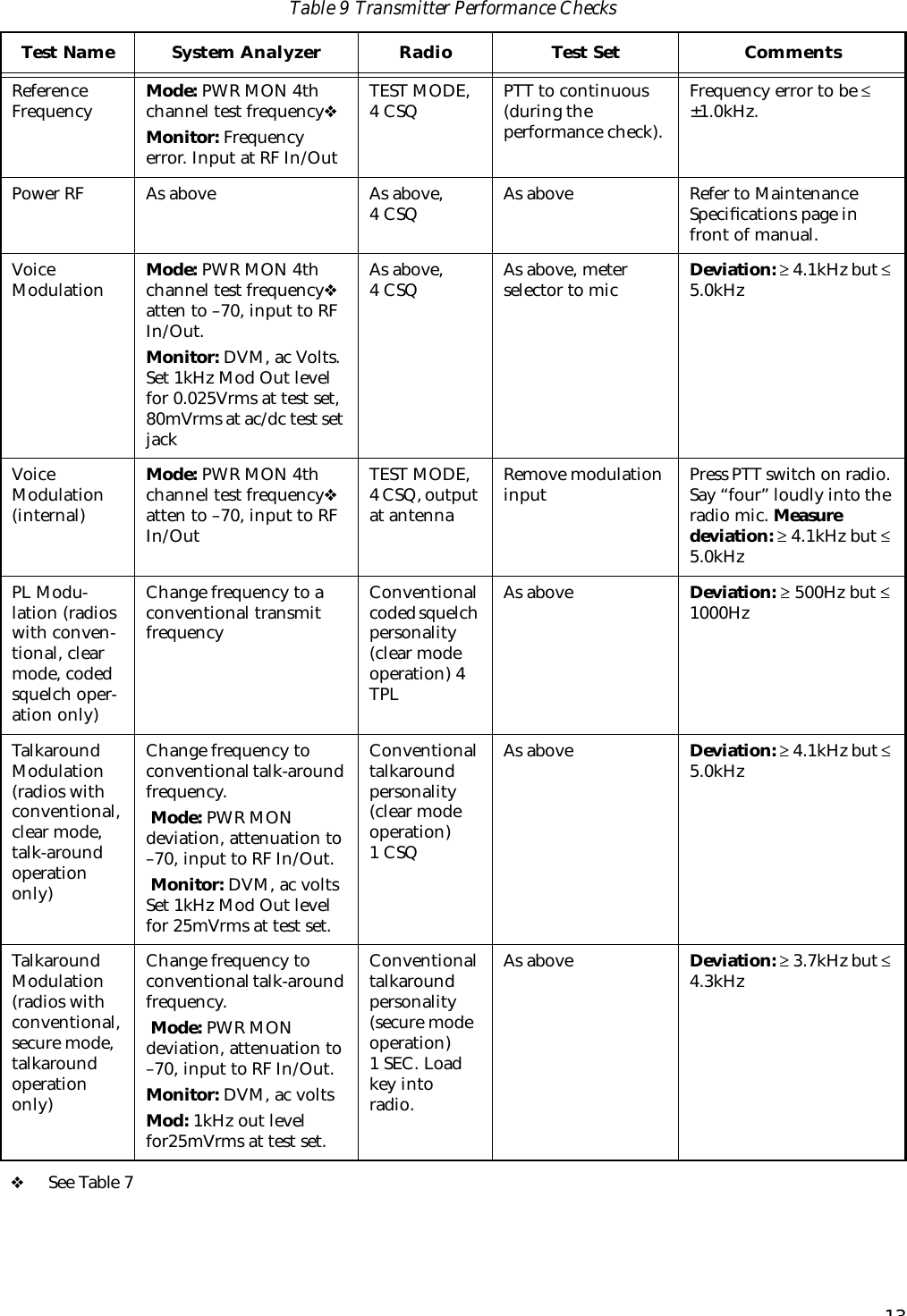


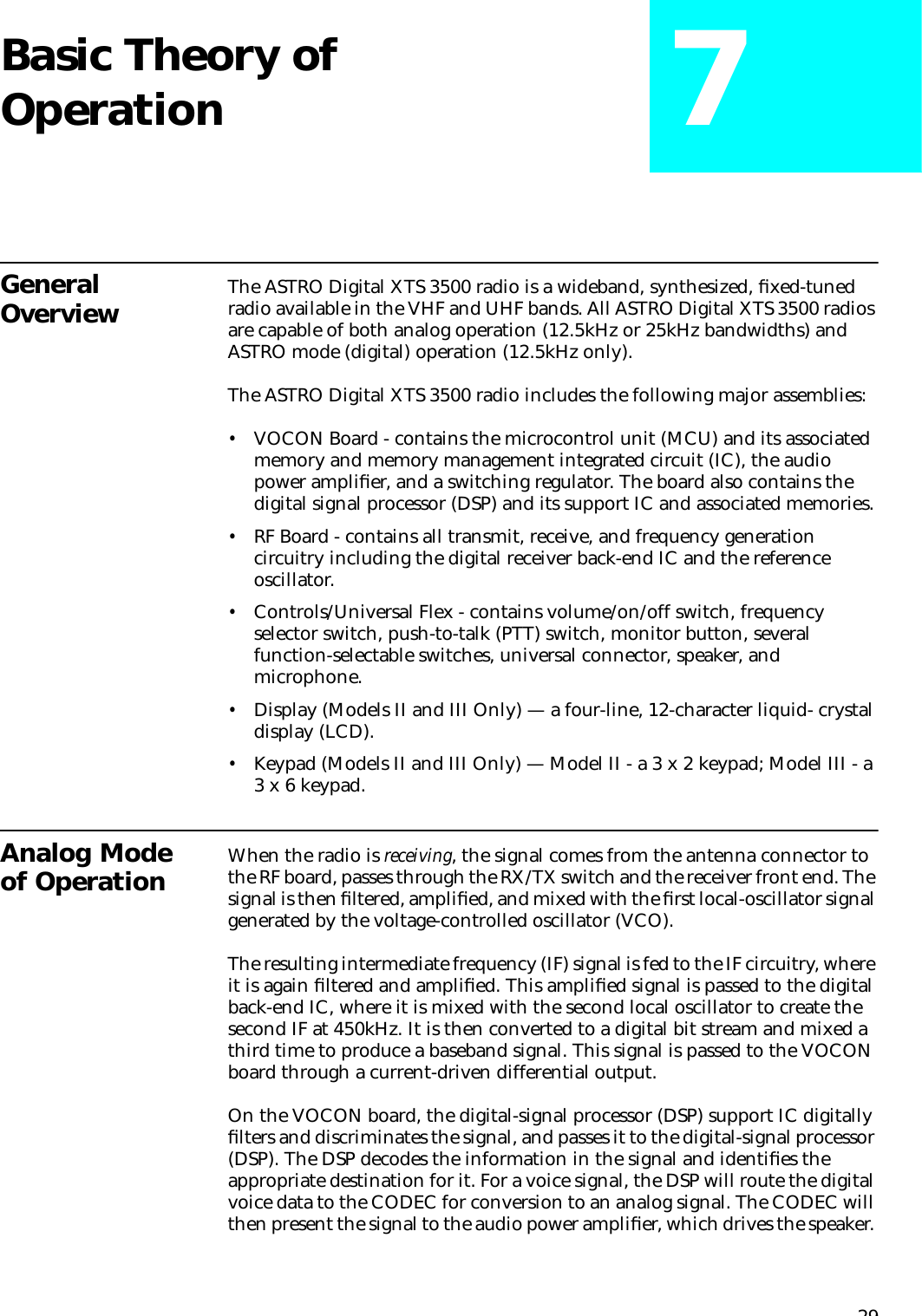
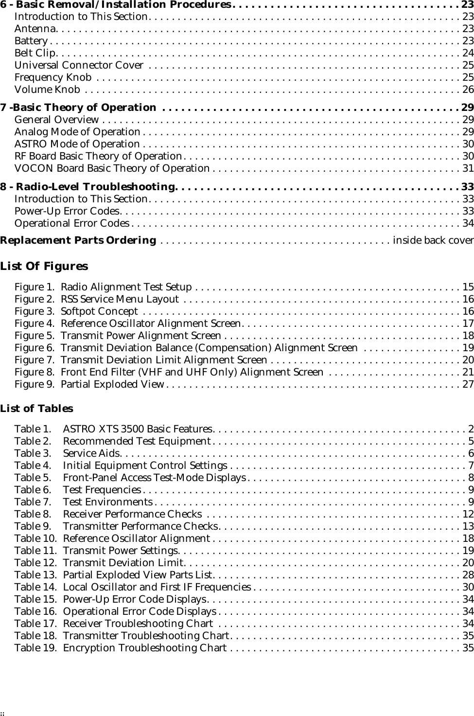
![186. Press F again to dekey the radio.7. Press H to program the new softpot value.8. Press J once to return to the TRANSMITTER ALIGNMENT MENU, or press J twice to return to the SERVICE MENU.Transmit Power AlignmentNOTES:•All power measurements are to be made at the antenna port.•The transmitter power setting keeps the radiated power at or below the level specified in the exclusionary clause for low power devices of IEEE Standard C95.1-1991.1. From the SERVICE MENU, press B to select the TRANSMITTER ALIGNMENT MENU.2. Press C to select the TRANSMIT POWER alignment screen. The screen will indicate the transmit frequencies to be used. See Figure 5.Figure 5 Transmit Power Alignment Screen3. Press P (or Z or [RETURN]) to select a frequency field (starting with the highest frequency shown). Then, press F to key the radio. The screen will indicate that the radio is transmitting.4. Use the É/Ç arrow keys to adjust the transmit power per the values shown in Table 11.Table 10 Reference Oscillator AlignmentBand TargetVHF or UHF ±100 HzMOTOROLA Radio Service Software Use UP/DOWN Arrows To Adjust Softpot. XTS Model: H24SDH9PW7AN MAIN:SERVICE:TX ALIGN:TX POWER TRANSMIT POWER -------------- Current Value New Softpot Value Frequency High Pwr Mid Pwr Low Pwr High Pwr Mid Pwr Low Pwr --------- -------- -------- ------- -------- -------- ------- 450.0250 65 25 25 65 25 25 465.2250 67 26 26 67 26 26 475.1250 68 27 27 68 27 27 484.9750 69 28 28 69 28 28 500.2750 72 29 29 72 29 29 511.9750 75 30 30 75 30 30 519.9750 59 31 31 59 31 31 Transmitter..Off 0 127 MIN |----+----+----+----+----+----X----+----+----+----+----+----| MAX F1 F2 F3 F4 F5 F6 F7 F8 F9 F10 HELP TOGGLE PROGRAM EXIT PTT VALUE](https://usermanual.wiki/Motorola-Solutions/89FT3799.Instruction-Manual/User-Guide-88802-Page-34.png)
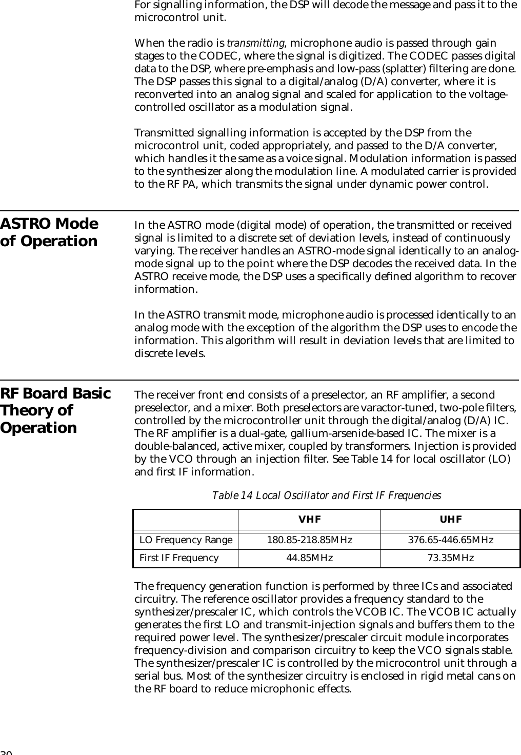
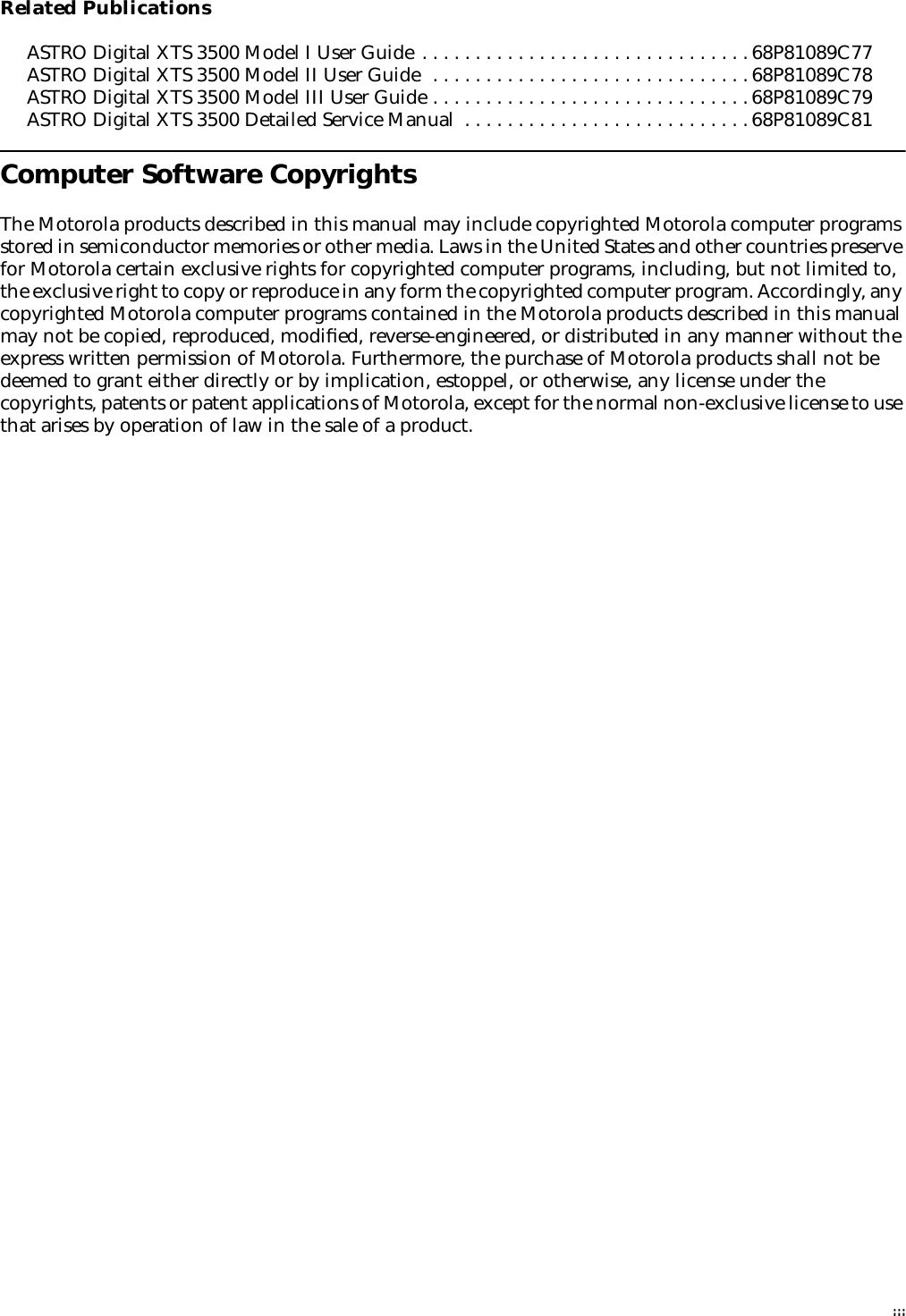
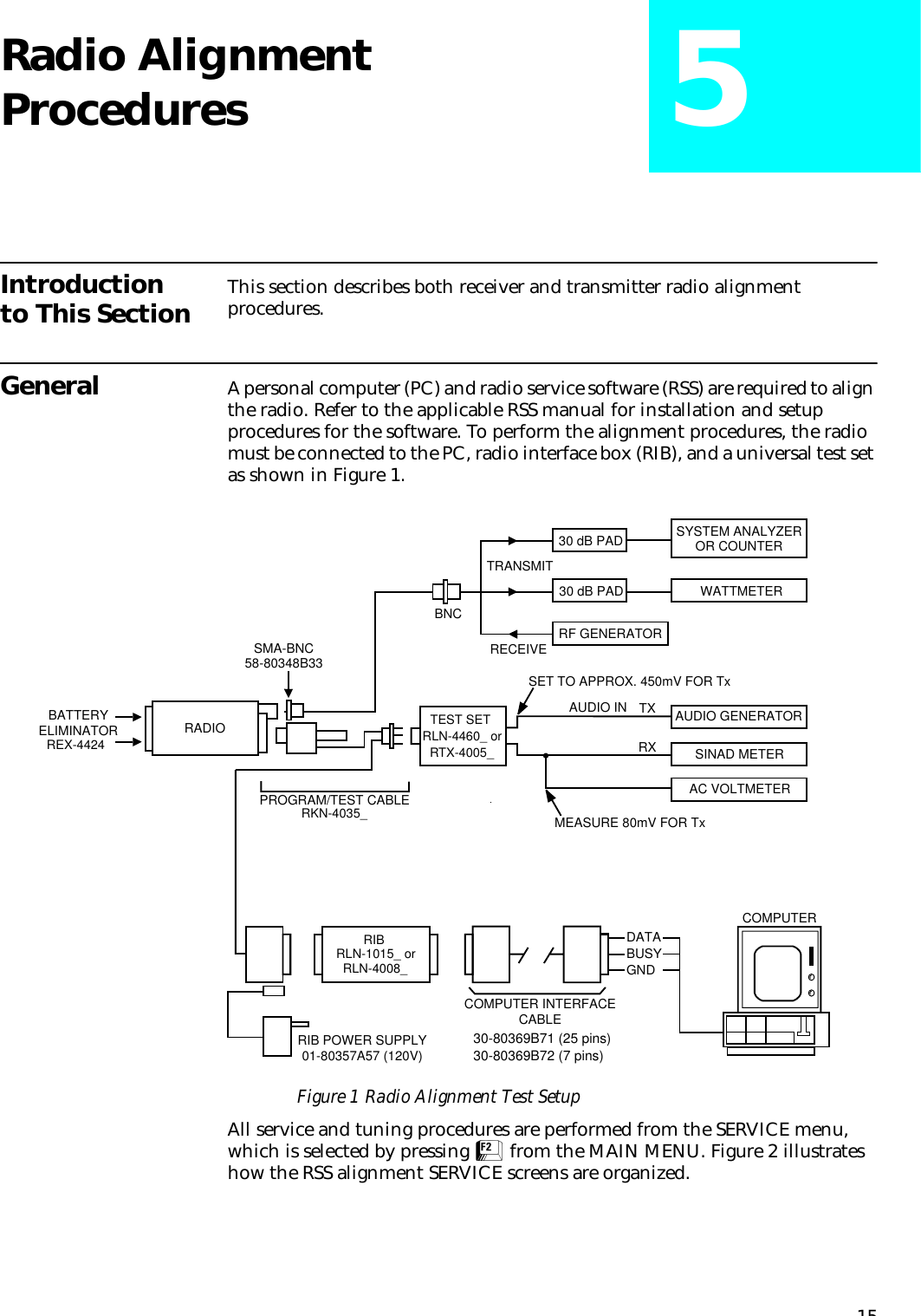
![195. Press F to dekey the radio.6. Press H to program the value.7. Repeat steps 3-6 for the remaining frequencies.8. Press J once to return to the TRANSMITTER ALIGNMENT MENU, or press J twice to return to the SERVICE MENU.Transmit Deviation Balance (Compensation) AlignmentCompensation alignment balances the modulation sensitivity of the VCO and reference modulation (synthesizer low-frequency port) lines. The compensation algorithm is critical to the operation of signalling schemes that have very-low-frequency components (for example, DPL) and could result in distorted waveforms if improperly adjusted. 1. From the SERVICE MENU, press B to select the TRANSMITTER ALIGNMENT MENU.2. Press D to select the TRANSMIT DEVIATION BALANCE (COMPENSATION) alignment screen. The screen will indicate the transmit frequencies to be used. See Figure 6.Figure 6 Transmit Deviation Balance (Compensation) Alignment Screen3. Press P (or Z or [RETURN]) to select a frequency field (starting with the lowest frequency shown).4. Press D. This will cause the radio to key and the radio’s DSP IC to inject an 80Hz tone into the RF board.5. Measure the deviation and record this value.Table 11 Transmit Power SettingsPower Level Test Frequencies136-174MHz 450-512MHz 512-520MHz1 Watt 1.2W - 1.4W 1.2W - 1.4W 1.2W - 1.4W5 Watts ———— 5.2W - 5.4W 3.2W - 3.4W6 Watts 6.2W - 6.5W ———— ————MOTOROLA Radio Service Software Use UP/DOWN Arrows To Adjust Softpot. XTS Model: H24SDC9PW5AN MAIN:SERVICE:TX ALIGN:BAL ATTN TRANSMIT DEVIATION BALANCE (COMPENSATION) ----------------------------------------- Current Frequency Value New Softpot Value --------- ------- ----------------- 450.025 30 30 465.225 30 30 475.125 30 30 484.975 45 45 500.275 45 45 511.975 45 45 519.975 45 Transmitter..Off 45 0 63 MIN |---+---+---+---+---+---+---+---+---+---+---+---+---+---+---+---| MAX F1 F2 F3 F4 F5 F6 F7 F8 F9 F10 HELP TOGGLE LOW TOGGLE HIGH PROGRAM EXIT TONE PTT TONE PTT VALUE](https://usermanual.wiki/Motorola-Solutions/89FT3799.Instruction-Manual/User-Guide-88802-Page-35.png)
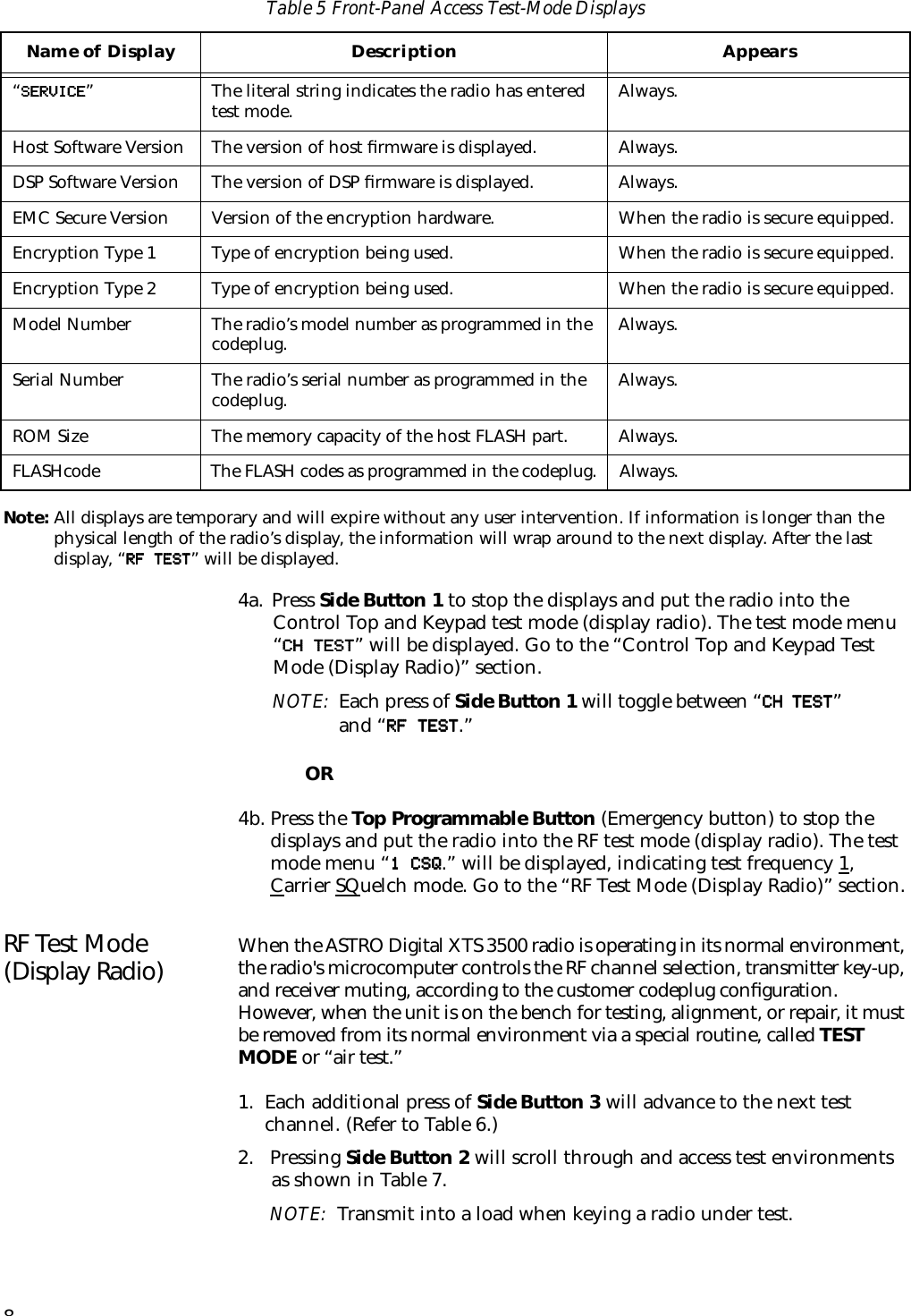
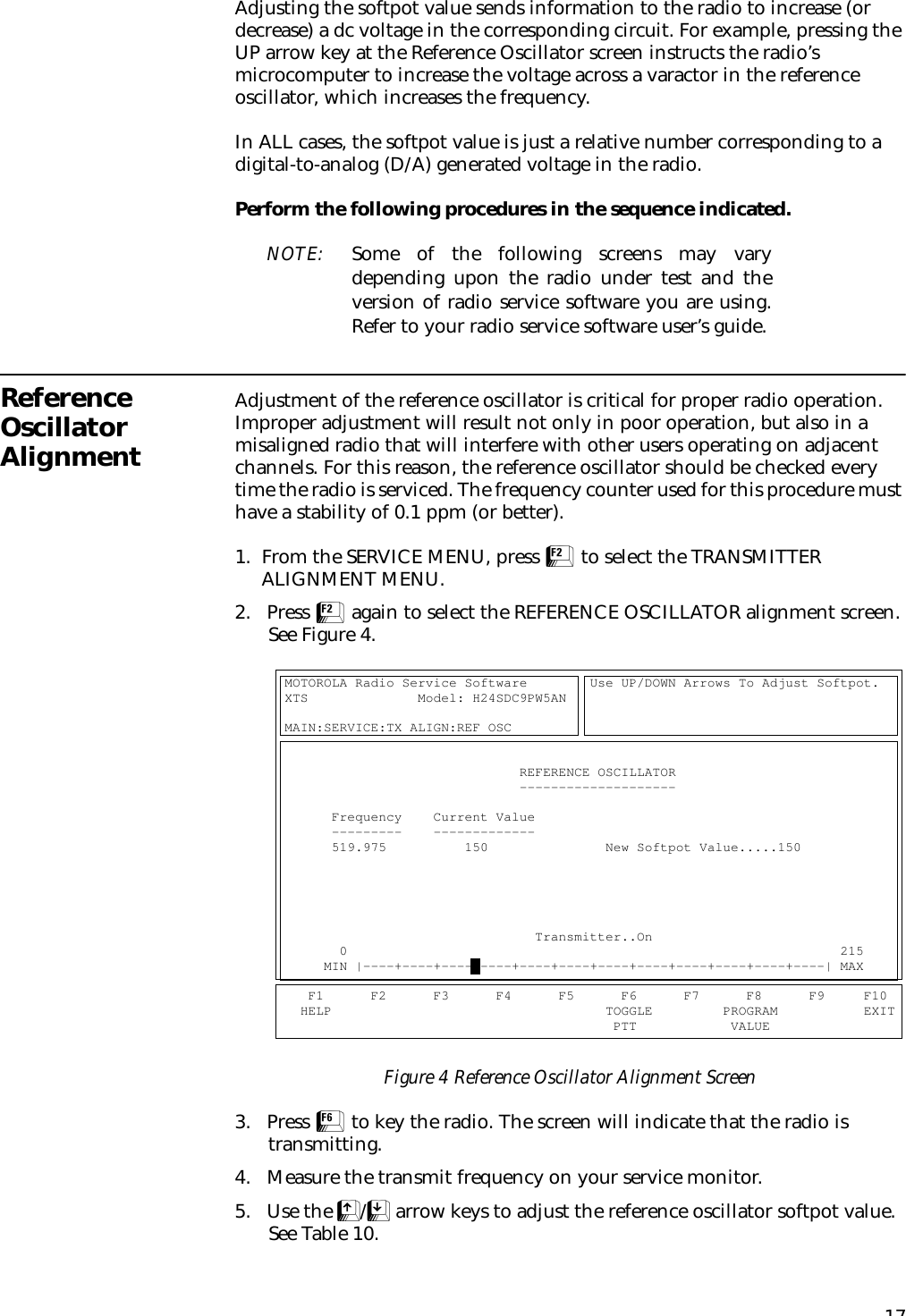
![206. Press D to dekey the radio.7. Press F. This will cause the radio’s DSP IC to change the injection tone to 3kHz, 100mVrms. Use the É/Ç arrow keys to adjust the deviation to within ±2% of the value recorded in step 5.8. Repeat steps 4-7 until the 3kHz tone deviation is within ±2% of the 80Hz tone deviation.9. Press F again to dekey the radio.10. Press H to program the new softpot value.11. Repeat steps 3-10 for the remaining frequencies.12. Press J once to return to the TRANSMITTER ALIGNMENT MENU, or press J twice to return to the SERVICE MENU.Transmit Deviation Limit Alignment1. From the SERVICE MENU, press B to select the TRANSMITTER ALIGNMENT MENU.2. Press E to select the TRANSMIT DEVIATION LIMIT alignment screen. The screen will indicate the transmit frequencies to be used. See Figure 7.Figure 7 Transmit Deviation Limit Alignment Screen3. Press P (or Z or [RETURN]) to select a frequency field (starting with the lowest frequency shown).4. Press F to key the radio. Then use the É/Ç arrow keys to adjust for a deviation per the values shown in Table 12.5. Press F again to dekey the radio.6. Press H to program the softpot value.7. Repeat steps 3-6 for the remaining frequencies.Table 12 Transmit Deviation LimitBand Deviation (Hz)VHF or UHF 2785 - 2885MOTOROLA Radio Service Software Use UP/DOWN Arrows To Adjust Softpot. XTS Model: H24SDC9PW5AN MAIN:SERVICE:TX ALIGN:DEV.LIMIT TRANSMIT DEVIATION LIMIT ------------------------ Current Frequency Value New Softpot Value --------- ------- ----------------- 450.025 24500 24500 465.225 24500 24500 475.125 24500 24500 484.975 24500 24500 500.275 24500 24500 511.975 24500 24500 519.975 24500 Transmitter..Off 24500 0 32767 MIN |----+----+----+----+----+----+----+----+X---+----+----+----| MAX F1 F2 F3 F4 F5 F6 F7 F8 F9 F10 HELP TOGGLE PROGRAM EXIT PTT VALUE](https://usermanual.wiki/Motorola-Solutions/89FT3799.Instruction-Manual/User-Guide-88802-Page-36.png)
![218. Press J once to return to the TRANSMITTER ALIGNMENT MENU, or press J twice to return to the SERVICE MENU.Front End Filter Alignment1. From the SERVICE MENU, press C to select the RECEIVER ALIGNMENT MENU.2. Press B to select the FRONT END FILTER (VHF AND UHF ONLY) screen. The screen will indicate the receive frequencies at which the filter is to be aligned. See Figure 8.Figure 8 Front End Filter (VHF and UHF Only) Alignment Screen3. Press P (or Z or [RETURN]) to select a frequency field.4. Set the RF test generator to the first receive frequency +150Hz. Set the RF level at the radio standard antenna port to 4.0µV with no modulation.5. Adjust the É/Ç arrow keys to obtain a peak value in the RSSI (receive signal strength indicator) field. NOTE: D must be pressed to obtain each RSSI reading after adjustment.6. Press H to program the new softpot value. 7. Repeat steps 3-6 for the remaining frequencies.8. Press J once to return to the RECEIVER ALIGNMENT MENU, or press J twice to return to the SERVICE MENU.MOTOROLA Radio Service Software Use UP/DOWN Arrows To Adjust Softpot. ASTRO Model: H09KDH9PW7AN MAIN:SERVICE:RX ALIGN:FE FL FRONT END FILTER (VHF AND UHF ONLY) ----------------------------------- Current Frequency Value New Softpot Value RSSI....0 --------- ------- ----------------- 450.075 0 0 465.275 0 0 475.275 0 0 485.025 0 0 500.225 0 0 511.925 0 0 519.925 0 0 0 255 MIN |---+---+---+---+---+---+---+---+---+---+---+---+---+---+---+---| MAX F1 F2 F3 F4 F5 F6 F7 F8 F9 F10 HELP READ PROGRAM EXIT RSSI VALUE](https://usermanual.wiki/Motorola-Solutions/89FT3799.Instruction-Manual/User-Guide-88802-Page-37.png)