Motorola Solutions 89FT3799 Hand Held Transmitter User Manual 89C80 A Book
Motorola Solutions, Inc. Hand Held Transmitter 89C80 A Book
Contents
- 1. Instruction Manual Cover Page
- 2. Instruction Manual
Instruction Manual

1
™
Digital XTS 3500
™
Portable Radios
Basic Service Manual

2
Foreword
This manual covers all models of the ASTRO™ Digital XTS 3500
®
Portable Radio, unless otherwise
specified. It includes all the information necessary to maintain peak product performance and maximum
working time, using the pass/fail service approach. This basic level of service is typical of some local
service centers, self-maintained customers, and some distributors.
Included in this manual are: radio specifications for the VHF and UHF frequency bands; a general
description of ASTRO Digital XTS 3500 models; recommended test equipment, service aids, and tools;
radio alignment procedures; fundamental disassembly/reassembly procedures; and general maintenance
recommendations.
For details on the operation of the radio, or board or component-level troubleshooting, refer to the
applicable manuals, available separately. To help you with your selection, a list is provided under “Related
Publications” at the front of this manual.
Safety
Before operating an ASTRO XTS 3500 Radio, please read the “Safety Information” section in the front of
this manual.
Manual Revisions
Changes which occur after this manual is printed are described in “FMRs.” These FMRs provide complete
information on changes, including pertinent parts list data.

i
Table of Contents
Foreword
. . . . . . . . . . . . . . . . . . . . . . . . . . . . . . . . . . . . . . . . . . . . . . . . . . . . . . . . . .inside front cover
List Of Figures. . . . . . . . . . . . . . . . . . . . . . . . . . . . . . . . . . . . . . . . . . . . . . . . . . . . . . . . . . . . ii
List of Tables. . . . . . . . . . . . . . . . . . . . . . . . . . . . . . . . . . . . . . . . . . . . . . . . . . . . . . . . . . . . . ii
Related Publications . . . . . . . . . . . . . . . . . . . . . . . . . . . . . . . . . . . . . . . . . . . . . . . . . . . . . . iii
Portable Radio Model Numbering System. . . . . . . . . . . . . . . . . . . . . . . . . . . . . . . . . . . . . iv
Specifications for VHF Radios. . . . . . . . . . . . . . . . . . . . . . . . . . . . . . . . . . . . . . . . . . . . . . . .v
Specifications for UHF Radios. . . . . . . . . . . . . . . . . . . . . . . . . . . . . . . . . . . . . . . . . . . . . . . vi
Glossary. . . . . . . . . . . . . . . . . . . . . . . . . . . . . . . . . . . . . . . . . . . . . . . . . . . . . . . . . . . . . . . . vii
Safety Information . . . . . . . . . . . . . . . . . . . . . . . . . . . . . . . . . . . . . . . . . . . . . . . . . . . . . . . .x
1 - Introduction . . . . . . . . . . . . . . . . . . . . . . . . . . . . . . . . . . . . . . . . . . . . . . . . . . . . . . . . . . .1
General . . . . . . . . . . . . . . . . . . . . . . . . . . . . . . . . . . . . . . . . . . . . . . . . . . . . . . . . . . . . . . . . . . . . . . . 1
Notations Used in This Manual . . . . . . . . . . . . . . . . . . . . . . . . . . . . . . . . . . . . . . . . . . . . . . . . . . . . 1
Radio Description . . . . . . . . . . . . . . . . . . . . . . . . . . . . . . . . . . . . . . . . . . . . . . . . . . . . . . . . . . . . . . . 2
FLASHport. . . . . . . . . . . . . . . . . . . . . . . . . . . . . . . . . . . . . . . . . . . . . . . . . . . . . . . . . . . . . . . . . . . . . 2
2 - Basic Maintenance . . . . . . . . . . . . . . . . . . . . . . . . . . . . . . . . . . . . . . . . . . . . . . . . . . . . . .3
Introduction to This Section . . . . . . . . . . . . . . . . . . . . . . . . . . . . . . . . . . . . . . . . . . . . . . . . . . . . . . 3
Preventive Maintenance. . . . . . . . . . . . . . . . . . . . . . . . . . . . . . . . . . . . . . . . . . . . . . . . . . . . . . . . . . 3
Handling Precautions . . . . . . . . . . . . . . . . . . . . . . . . . . . . . . . . . . . . . . . . . . . . . . . . . . . . . . . . . . . . 4
3 - Recommended Test Equipment and Service Aids . . . . . . . . . . . . . . . . . . . . . . . . . . . . .5
Recommended Test Equipment . . . . . . . . . . . . . . . . . . . . . . . . . . . . . . . . . . . . . . . . . . . . . . . . . . . . 5
Service Aids. . . . . . . . . . . . . . . . . . . . . . . . . . . . . . . . . . . . . . . . . . . . . . . . . . . . . . . . . . . . . . . . . . . . 5
Field Programming Equipment . . . . . . . . . . . . . . . . . . . . . . . . . . . . . . . . . . . . . . . . . . . . . . . . . . . . 6
4 - Performance Checks . . . . . . . . . . . . . . . . . . . . . . . . . . . . . . . . . . . . . . . . . . . . . . . . . . . . .7
Introduction to This Section . . . . . . . . . . . . . . . . . . . . . . . . . . . . . . . . . . . . . . . . . . . . . . . . . . . . . . 7
Setup . . . . . . . . . . . . . . . . . . . . . . . . . . . . . . . . . . . . . . . . . . . . . . . . . . . . . . . . . . . . . . . . . . . . . . . . . 7
Display Radio Test Mode . . . . . . . . . . . . . . . . . . . . . . . . . . . . . . . . . . . . . . . . . . . . . . . . . . . . . . . . . 7
Non-Display Radio Test Mode . . . . . . . . . . . . . . . . . . . . . . . . . . . . . . . . . . . . . . . . . . . . . . . . . . . . 10
5 - Radio Alignment Procedures. . . . . . . . . . . . . . . . . . . . . . . . . . . . . . . . . . . . . . . . . . . . .15
Introduction to This Section . . . . . . . . . . . . . . . . . . . . . . . . . . . . . . . . . . . . . . . . . . . . . . . . . . . . . 15
General . . . . . . . . . . . . . . . . . . . . . . . . . . . . . . . . . . . . . . . . . . . . . . . . . . . . . . . . . . . . . . . . . . . . . . 15
Reference Oscillator Alignment . . . . . . . . . . . . . . . . . . . . . . . . . . . . . . . . . . . . . . . . . . . . . . . . . . . 17
Transmit Power Alignment. . . . . . . . . . . . . . . . . . . . . . . . . . . . . . . . . . . . . . . . . . . . . . . . . . . . . . . 18
Transmit Deviation Balance (Compensation) Alignment . . . . . . . . . . . . . . . . . . . . . . . . . . . . . . . 19
Transmit Deviation Limit Alignment. . . . . . . . . . . . . . . . . . . . . . . . . . . . . . . . . . . . . . . . . . . . . . . 20
Front End Filter Alignment. . . . . . . . . . . . . . . . . . . . . . . . . . . . . . . . . . . . . . . . . . . . . . . . . . . . . . . 21
A
, Motorola, ASTRO, and Private-Line are registered trademarks of Motorola, Inc.
XTS 3500, FLASHport, and Digital Private-Line are trademarks of Motorola, Inc.
© 1999, 2000 by Motorola Inc.
8000 W. Sunrise Blvd., Ft. Lauderdale, FL 33322
Printed in U.S.A. 3/00
Basic Service Manual
68P81089C80-A
Commercial, Government and Industrial Solutions Sector
ii
6 - Basic Removal/Installation Procedures. . . . . . . . . . . . . . . . . . . . . . . . . . . . . . . . . . . . 23
Introduction to This Section. . . . . . . . . . . . . . . . . . . . . . . . . . . . . . . . . . . . . . . . . . . . . . . . . . . . . . 23
Antenna. . . . . . . . . . . . . . . . . . . . . . . . . . . . . . . . . . . . . . . . . . . . . . . . . . . . . . . . . . . . . . . . . . . . . . 23
Battery. . . . . . . . . . . . . . . . . . . . . . . . . . . . . . . . . . . . . . . . . . . . . . . . . . . . . . . . . . . . . . . . . . . . . . . 23
Belt Clip. . . . . . . . . . . . . . . . . . . . . . . . . . . . . . . . . . . . . . . . . . . . . . . . . . . . . . . . . . . . . . . . . . . . . . 24
Universal Connector Cover . . . . . . . . . . . . . . . . . . . . . . . . . . . . . . . . . . . . . . . . . . . . . . . . . . . . . . 25
Frequency Knob . . . . . . . . . . . . . . . . . . . . . . . . . . . . . . . . . . . . . . . . . . . . . . . . . . . . . . . . . . . . . . . 25
Volume Knob . . . . . . . . . . . . . . . . . . . . . . . . . . . . . . . . . . . . . . . . . . . . . . . . . . . . . . . . . . . . . . . . . 26
7 -Basic Theory of Operation . . . . . . . . . . . . . . . . . . . . . . . . . . . . . . . . . . . . . . . . . . . . . . . 29
General Overview . . . . . . . . . . . . . . . . . . . . . . . . . . . . . . . . . . . . . . . . . . . . . . . . . . . . . . . . . . . . . . 29
Analog Mode of Operation. . . . . . . . . . . . . . . . . . . . . . . . . . . . . . . . . . . . . . . . . . . . . . . . . . . . . . . 29
ASTRO Mode of Operation . . . . . . . . . . . . . . . . . . . . . . . . . . . . . . . . . . . . . . . . . . . . . . . . . . . . . . . 30
RF Board Basic Theory of Operation. . . . . . . . . . . . . . . . . . . . . . . . . . . . . . . . . . . . . . . . . . . . . . . .30
VOCON Board Basic Theory of Operation . . . . . . . . . . . . . . . . . . . . . . . . . . . . . . . . . . . . . . . . . . . 31
8 - Radio-Level Troubleshooting. . . . . . . . . . . . . . . . . . . . . . . . . . . . . . . . . . . . . . . . . . . . . 33
Introduction to This Section. . . . . . . . . . . . . . . . . . . . . . . . . . . . . . . . . . . . . . . . . . . . . . . . . . . . . . 33
Power-Up Error Codes. . . . . . . . . . . . . . . . . . . . . . . . . . . . . . . . . . . . . . . . . . . . . . . . . . . . . . . . . . . 33
Operational Error Codes . . . . . . . . . . . . . . . . . . . . . . . . . . . . . . . . . . . . . . . . . . . . . . . . . . . . . . . . . 34
Replacement Parts Ordering
. . . . . . . . . . . . . . . . . . . . . . . . . . . . . . . . . . . . . . . . inside back cover
List Of Figures
Figure 1. Radio Alignment Test Setup . . . . . . . . . . . . . . . . . . . . . . . . . . . . . . . . . . . . . . . . . . . . . .15
Figure 2. RSS Service Menu Layout . . . . . . . . . . . . . . . . . . . . . . . . . . . . . . . . . . . . . . . . . . . . . . . . 16
Figure 3. Softpot Concept . . . . . . . . . . . . . . . . . . . . . . . . . . . . . . . . . . . . . . . . . . . . . . . . . . . . . . . 16
Figure 4. Reference Oscillator Alignment Screen. . . . . . . . . . . . . . . . . . . . . . . . . . . . . . . . . . . . . . 17
Figure 5. Transmit Power Alignment Screen . . . . . . . . . . . . . . . . . . . . . . . . . . . . . . . . . . . . . . . . . 18
Figure 6. Transmit Deviation Balance (Compensation) Alignment Screen . . . . . . . . . . . . . . . . . 19
Figure 7. Transmit Deviation Limit Alignment Screen . . . . . . . . . . . . . . . . . . . . . . . . . . . . . . . . . 20
Figure 8. Front End Filter (VHF and UHF Only) Alignment Screen . . . . . . . . . . . . . . . . . . . . . . . 21
Figure 9. Partial Exploded View. . . . . . . . . . . . . . . . . . . . . . . . . . . . . . . . . . . . . . . . . . . . . . . . . . . 27
List of Tables
Table 1. ASTRO XTS 3500 Basic Features. . . . . . . . . . . . . . . . . . . . . . . . . . . . . . . . . . . . . . . . . . . .2
Table 2. Recommended Test Equipment. . . . . . . . . . . . . . . . . . . . . . . . . . . . . . . . . . . . . . . . . . . . 5
Table 3. Service Aids. . . . . . . . . . . . . . . . . . . . . . . . . . . . . . . . . . . . . . . . . . . . . . . . . . . . . . . . . . . . 6
Table 4. Initial Equipment Control Settings . . . . . . . . . . . . . . . . . . . . . . . . . . . . . . . . . . . . . . . . .7
Table 5. Front-Panel Access Test-Mode Displays. . . . . . . . . . . . . . . . . . . . . . . . . . . . . . . . . . . . . . 8
Table 6. Test Frequencies . . . . . . . . . . . . . . . . . . . . . . . . . . . . . . . . . . . . . . . . . . . . . . . . . . . . . . . . 9
Table 7. Test Environments . . . . . . . . . . . . . . . . . . . . . . . . . . . . . . . . . . . . . . . . . . . . . . . . . . . . . . 9
Table 8. Receiver Performance Checks . . . . . . . . . . . . . . . . . . . . . . . . . . . . . . . . . . . . . . . . . . . . 12
Table 9. Transmitter Performance Checks. . . . . . . . . . . . . . . . . . . . . . . . . . . . . . . . . . . . . . . . . . 13
Table 10. Reference Oscillator Alignment . . . . . . . . . . . . . . . . . . . . . . . . . . . . . . . . . . . . . . . . . . . 18
Table 11. Transmit Power Settings. . . . . . . . . . . . . . . . . . . . . . . . . . . . . . . . . . . . . . . . . . . . . . . . . 19
Table 12. Transmit Deviation Limit. . . . . . . . . . . . . . . . . . . . . . . . . . . . . . . . . . . . . . . . . . . . . . . . 20
Table 13. Partial Exploded View Parts List. . . . . . . . . . . . . . . . . . . . . . . . . . . . . . . . . . . . . . . . . . .28
Table 14. Local Oscillator and First IF Frequencies . . . . . . . . . . . . . . . . . . . . . . . . . . . . . . . . . . . . 30
Table 15. Power-Up Error Code Displays. . . . . . . . . . . . . . . . . . . . . . . . . . . . . . . . . . . . . . . . . . . . 34
Table 16. Operational Error Code Displays . . . . . . . . . . . . . . . . . . . . . . . . . . . . . . . . . . . . . . . . . . 34
Table 17. Receiver Troubleshooting Chart . . . . . . . . . . . . . . . . . . . . . . . . . . . . . . . . . . . . . . . . . . 34
Table 18. Transmitter Troubleshooting Chart. . . . . . . . . . . . . . . . . . . . . . . . . . . . . . . . . . . . . . . . 35
Table 19. Encryption Troubleshooting Chart . . . . . . . . . . . . . . . . . . . . . . . . . . . . . . . . . . . . . . . . 35

iii
Related Publications
ASTRO Digital XTS 3500 Model I User Guide . . . . . . . . . . . . . . . . . . . . . . . . . . . . . . .68P81089C77
ASTRO Digital XTS 3500 Model II User Guide . . . . . . . . . . . . . . . . . . . . . . . . . . . . . .68P81089C78
ASTRO Digital XTS 3500 Model III User Guide . . . . . . . . . . . . . . . . . . . . . . . . . . . . . .68P81089C79
ASTRO Digital XTS 3500 Detailed Service Manual . . . . . . . . . . . . . . . . . . . . . . . . . . .68P81089C81
Computer Software Copyrights
The Motorola products described in this manual may include copyrighted Motorola computer programs
stored in semiconductor memories or other media. Laws in the United States and other countries preserve
for Motorola certain exclusive rights for copyrighted computer programs, including, but not limited to,
the exclusive right to copy or reproduce in any form the copyrighted computer program. Accordingly, any
copyrighted Motorola computer programs contained in the Motorola products described in this manual
may not be copied, reproduced, modified, reverse-engineered, or distributed in any manner without the
express written permission of Motorola. Furthermore, the purchase of Motorola products shall not be
deemed to grant either directly or by implication, estoppel, or otherwise, any license under the
copyrights, patents or patent applications of Motorola, except for the normal non-exclusive license to use
that arises by operation of law in the sale of a product.

iv
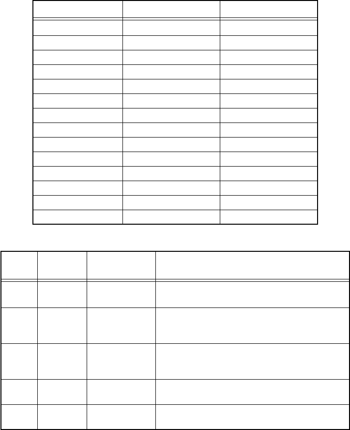
Portable Radio Model Numbering System
Position 1 - Type of Unit
D = Dash-Mounted Mobile Radio
M = Motorcycle Mobile Radio
T =Trunk-Mounted Mobile Radio
Positions 2 & 3 - Model Series
Position 4 - Frequency Band
Less than 29.7MHz
29.7 to 35.99MHz
36 to 41.99MHz
42 to 50MHz
66 to 80MHz
74 to 90MHz
Product Specific
136 to 162MHz
146 to 178MHz
174 to 210MHz
190 to 235MHz
336 to 410MHz
403 to 437MHz
438 to 482MHz
470 to 520MHz
Product Specific
806 to 870MHz
825 to 870MHz
896 to 941MHz
1.0 to 1.6GHz
1.5 to 2.0GHz
Values given represent range only; they are
not absolute.
Position 5 - Power Level
0 to 0.7 Watts
0.7 to 0.9 Watts
1.0 to 3.9 Watts
4.0 to 5.0 Watts
5.1 to 6.0 Watts
6.1 to 10 Watts
Position 6 - Physical Packages
RF Modem Operation
Receiver Only
Standard Control; No Display
Standard Control; With Display
Limited Keypad; No Display
Limited Keypad; With Display
Full Keypad; No Display
Full Keypad; With Display
Limited Controls; No Display
Limited Controls; Basic Display
Limited Controls; Limited Display
Rotary Controls; Standard Display
Enhanced Controls; Enhanced Display
Low Profile; No Display
Low Profile; Basic Display
Low Profile; Basic Display, Full Keypad
Position 7 - Channel Spacing
1 = 5kHz
2 = 6.25kHz
3 = 10kHz
4 = 12.5kHz
5 = 15kHz
6 = 20/25kHz
7 = 30kHz
9 = Variable/Programmable
Typical Model Number:
Position:
Position 8 - Primary Operation
Conventinal/Simplex
Conventional/Duplex
Trunked Twin Type
Dual Mode Trunked
Dual Mode Trunked/Duplex
Trunked Type I
Trunked Type II
FDMA* Digital Dual Mode
TDMA** Digital Dual Mode
Single Sideband
Global Positioning Satellite Capable
Amplitude Companded Sideband (ACSB)
Programmable
* FDMA = Frequency Division Multiple Access
** TDMA = Time Division Multiple Access
Position 9 - Primary System Type
Conventional
Privacy Plus®
Clear SMARTNET™
Advanced Conventional Stat-Alert™
Enhanced Privacy Plus®
Nauganet 888 Series
Japan Specialized Mobile Radio (JSMR)
Multi-Channel Access (MCA)
CoveragePLUS™
MPT1327* - Public
MPT1327* - Private
Radiocom
Tone Signalling
Binary Signalling
Phonenet®
Programmable
Secure Conventional
Secure SMARTNET™
* MPT = Ministry of Posts and Telecommunications
Position 10 - Feature Level
1 = Basic
2 = Limited Package
3 = Limited Plus
4 = Intermediate
5 = Standard Package
6 = Standard Plus
7 = Expanded Package
8 = Expanded Plus
9 = Full Feature/
Programmable
Position 11 - Version
Version Letter (Alpha) - Major Change
Position 12 -
Unique Model Variations
C = Cenelec
N = Standard Package
Positions 13 - 16
“SP” Model Suffix
1 23 4 5 6 7 8 9 10 11 1213141516
T04S LF 9 P W 7 A N S P 0 1
04 = ASTRO
A
B
C
D
F
G
H
J
K
L
M
=
=
=
=
=
=
=
=
=
=
=
P
Q
R
S
T
U
V
W
Y
Z
=
=
=
=
=
=
=
=
=
=
A
B
C
D
E
F
=
=
=
=
=
=
10.1 to 15 Watts
16 to 25 Watts
26 to 35 Watts
36 to 60 Watts
G
H
J
K
L
=
=
=
=
A
B
C
D
E
F
G
H
J
K
L
M
N
P
Q
R
=
=
=
=
=
=
=
=
=
=
=
=
=
=
=
=
A
B
C
D
E
F
G
H
J
K
L
M
P
=
=
=
=
=
=
=
=
=
=
=
=
=
A
B
C
D
E
F
G
H
J
K
L
M
N
P
Q
W
X
Y
=
=
=
=
=
=
=
=
=
=
=
=
=
=
=
=
=
=
= 61 to 110 Watts
H = Hand-Held Portable
H24 S C F 9 P W 7 A N S P 0 1
24 = XTS 3500

v
SPECIFICATIONS FOR VHF RADIOS
All specifications are per Telecommunications Industries Association TIA-603 unless otherwise noted
GENERAL RECEIVER TRANSMITTER
FCC Designation:
AZ489FT3799
Temperature Range:
Operating:
–30°C to +60°C
Storage:
–40°C to +85°C
Power Supply:
Nickel-Cadmium Battery (NiCd)
or
Nickel-Metal-Hydride Battery (NiMH)
or
Lithium-Ion Battery (Li-Ion)
Battery Voltage:
Nominal:
7.5 Volts
Range:
6 to 9 Volts
Transmit Current Drain (Typical):
2100mA
Receive Current Drain (Rated Audio):
240mA
Standby Current Drain:
80mA
Recommended Battery:
Ultra-HIgh-Capacity NiCd:
NTN8294_
or
Extended-Capacity
NiMH:
NTN8293_
or
Li-Ion:
NTN8610_
or
Ultra–High-Capacity NiCd FM:
NTN8295_*
or
Ultra–High-Capacity NiMH FM:
NTN8299_*
Optional FM (Factory Mutual) Battery:
* FM Intrinsically Safe: Class I, II, III, Division 1,
Groups C, D,E, F, and G. FM Non-incendive:
Class 1, Division 2, Groups A, B, C, and D.
Dimensions (H x W x D)
Note: 2.44" = width at PTT; 2.34" = width at
bottom; 1.83" = depth at speaker; 0.97" =
depth at keypad
Less Battery:
6.58" x 2.44" x 1.83"/6.58" x 2.34" x 0.97"
(167.13mm x 61.90mm x 46.42mm/
167.13mm x 59.49mm x 24.56mm)
With Battery:
6.58" x 2.44" x 1.83"/6.58" x 2.34" x 1.65"
(167.13mm x 61.90mm x 46.42mm/
167.13mm x 59.49mm x 41.97mm)
Weight: (w/Helical Antenna)
Less Battery:
14.10oz. (383gm)
With Ultra-High Cap. NiCd:
25.19oz. (693gm)
With Li-Ion:
20.41oz. (583gm)
With Ultra-High Cap. NiMH:
23.45oz. (644gm)
With Extended- Cap. NiMH:
24.04oz. (682gm)
Frequency Range:
136-174MHz
Bandwidth:
38MHz
Quieting Sensitivity (20dBQ):
0.35µV (typical)
Usable Sensitivity
(12dB SINAD):
0.20µV (typical)
Intermodulation:
–78dB (typical)
Selectivity (typical)
(25/30kHz Channel):
–80dB
(12.5kHz Channel):
–67dB
Spurious Rejection:
–78dB
Frequency Stability
(–30+60°C; 25°C reference):
±.0002%
Rated Audio:
500mW
FM Hum and Noise (typical):
25kHz –50dB
12.5kHz –44dB
Distortion (At Rated Audio):
1.5% Typical
Channel Spacing:
12.5/25 kHz
RF Power:
136-174MHz:
1 to 6 Watts
Frequency Range:
136-174MHz
Frequency Stability (typical)
(–30 to +60°C; 25°C ref.):
±.0002%
Emission (Conducted and Radiated):
–75dBc
FM Hum and Noise (typical)
(Companion Receiver):
25kHz –50dB
12.5kHz –44dB
Distortion:
2% Typical
Modulation Limiting:
25kHz chnls ±5.0kHz
12.5kHz chnls ±2.5kHz
Adjacent Channel Power Ratio:
25kHz –73dBc
12.5kHz –63dBc
Emissions Designators:
20K0F1E, 16K0F3E, 11K0F3E,
8K10F1D, and 8K10F1E
Specifications subject to change without notice

vi
SPECIFICATIONS FOR UHF RADIOS
All specifications are per Telecommunications Industries Association TIA-603 unless otherwise noted
GENERAL RECEIVER TRANSMITTER
FCC Designation:
AZ489FT4828
Temperature Range:
Operating:
–30°C to +60°C
Storage:
–40°C to +85°C
Power Supply:
Nickel-Cadmium Battery (NiCd)
or
Nickel-Metal-Hydride Battery (NiMH)
or
Lithium-Ion Battery (Li-Ion)
Battery Voltage:
Nominal:
7.5 Volts
Range:
6 to 9 Volts
Transmit Current Drain (Typical):
2000mA
Receive Current Drain (Rated Audio):
240mA
Standby Current Drain:
80mA
Recommended Battery:
Ultra-HIgh-Capacity NiCd:
NTN8294_
or
Extended-Capacity
NiMH:
NTN8293_
or
Li-Ion:
NTN8610_
or
Ultra–High-Capacity NiCd FM:
NTN8295_*
or
Ultra–High-Capacity NiMH FM:
NTN8299_*
Optional FM (Factory Mutual) Battery:
* FM Intrinsically Safe: Class I, II, III, Division 1,
Groups C, D,E, F, and G. FM Non-incendive:
Class 1, Division 2, Groups A, B, C, and D.
Dimensions (H x W x D)
Note: 2.44" = width at PTT; 2.34" = width at
bottom; 1.83" = depth at speaker; 0.97" =
depth at keypad
Less Battery:
6.58" x 2.44" x 1.83"/6.58" x 2.34" x 0.97"
(167.13mm x 61.90mm x 46.42mm/
167.13mm x 59.49mm x 24.56mm)
With Battery:
6.58" x 2.44" x 1.83"/6.58" x 2.34" x 1.65"
(167.13mm x 61.90mm x 46.42mm/
167.13mm x 59.49mm x 41.97mm)
Weight: (w/Helical Antenna)
Less Battery:
14.10oz. (383gm)
With Ultra-High Cap. NiCd:
25.19oz. (693gm)
With Li-Ion:
20.41oz. (583gm)
With Ultra-High Cap. NiMH:
23.45oz. (644gm)
With Extended- Cap. NiMH:
24.04oz. (682gm)
Frequency Range:
450-520MHz
Bandwidth:
70MHz
Quieting Sensitivity (20dBQ):
0.35µV (typical)
Usable Sensitivity
(12dB SINAD):
0.20µV (typical)
Intermodulation:
–78dB (typical)
Selectivity (typical)
(25/30kHz Channel):
–78dB
(12.5kHz Channel):
–70dB
Spurious Rejection:
–80dB
Frequency Stability
(–30+60°C; 25°C reference):
±.0002%
Rated Audio:
500mW
FM Hum and Noise (typical):
25kHz –48dB
12.5kHz –43dB
Distortion (At Rated Audio):
1.5% Typical
Channel Spacing: 12.5/25 kHz
RF Power:
450-520MHz: 1 Watt/5 Watts
Frequency Range: 450-520MHz
Frequency Stability (typical)
(–30 to +60°C; 25°C ref.): ±.0002%
Emission (Conducted and Radiated): –75dBc
FM Hum and Noise (typical)
(Companion Receiver): 25kHz –48dB
12.5kHz –42dB
Distortion: 2% Typical
Modulation Limiting: 25kHz chnls ±5.0kHz
12.5kHz chnls ±2.5kHz
Emissions Designators:
20K0F1E, 16K0F3E, 11K0F3E,
8K10F1D, and 8K10F1E
Specifications subject to change without notice

vii
GLOSSARY
A/D Analog-to-Digital converter; converts an instantaneous dc voltage
level to a corresponding digital value.
ABACUS IC Custom integrated circuit providing a digital receiver IF backend.
ADDAG Analog-to-Digital/Digital-to-Analog Glue IC
APCO Association of Public Safety Communication Officers
CODEC Coder/Decoder IC for analog-to-digital and digital-to-analog
conversion.
D/A Digital-to-Analog converter; converts a digital value to a
corresponding dc voltage value.
DTMF Dual-Tone Multi-Frequency
DPL Digital Private-Line™
DSP Digital Signal Processor; microcontroller specifically tailored for
signal processing computations. In this case refers specifically to
Motorola DSP56603.
DSPS IC Digital Signal Processor Support IC. Generates processor clocks
and provides peripheral functions for the DSP.
Firmware Software or a software/hardware combination of computer
programs and data, with a fixed logic configuration stored in a
read-only memory; information can not be altered or
reprogrammed.
FGU Frequency Generation Unit
FLASHport™ A Motorola term that describes the ability of a radio to change
memory. Every FLASHport radio contains a FLASHport EEPROM
memory chip that can be software written and rewritten to, again
and again.
Host Motorola HC12A4 microcontrol unit U204 (see MCU).
Host Port Parallel memory mapped interface consisting of eight registers in
the DSP56603.
IC Integrated Circuit
IMBE Improved Multi-Band Excitation: a sub-band, voice encoding
algorithm used in ASTRO digital voice.
MCU MicroControl Unit
MDC Motorola Digital Communications
viii
MISO Master In Slave Out; used by the slave device to send data to the
master device.
MOSI Master Out Slave In; used by the master device to send data to the
slave device.
OMPAC Over-Molded Pad-Array Carrier; a Motorola custom IC package,
distinguished by the presence of solder balls on the bottom pads.
Open Architecture A controller configuration that utilizes a microprocessor with
extended ROM and RAM.
PC Board Printed Circuit board
PCIC Power Control IC
PL Private-Line® tone squelch; a continuous sub-audible tone that is
transmitted along with the carrier.
PLL Phase-Locked Loop; a circuit in which an oscillator is kept in phase
with a reference, usually after passing through a frequency divider.
PTT Push-To-Talk; the switch located on the left side of the radio
which, when pressed, causes the radio to transmit.
Registers Short-term data-storage circuits within the microcontrol unit or
programmable logic IC.
Repeater Remote transmit/receive facility that re-transmits received signals
in order to improve communications coverage.
RESET Reset line; an input to the microcontroller that restarts execution.
RF PA Radio Frequency Power Amplifier
RSS Radio Service Software
RPT/TA RePeaTer/Talk-Around
RX DATA Recovered digital data line.
Signal Qualifier Mode An operating mode whereby the radio is muted but still continues
to analyze receive data to determine RX signal type.
SCI IN Serial Communication Interface INput line
Softpot Software potentiometer; a computer-adjustable electronic
attenuator.
Software Computer programs, procedures, rules, documentation, and data
pertaining to the operation of a system.
SPI Serial Peripheral Interface; how the microcontroller communicates
to modules and ICs through the CLOCK and DATA lines.
ix
Squelch Muting of audio circuits when received signal levels fall below a
pre-determined value.
SRAM Static-RAM chip used for volatile, program/data memory.
SSI Synchronous Serial Interface on the DSP56603 to the CODEC,
DSPS IC, and ADDAG.
Standby Mode An operating mode whereby the radio is muted but still continues
to monitor data.
System Select The act of selecting the desired operating system with the system-
select switch (also, the name given to this switch).
TOT Time-Out Timer; a timer that limits the length of a transmission.
TSOP Thin Small-Outline Package
UART Universal Asynchronous Receiver Transmitter.
µC Microcontrol unit (see MCU).
VCO Voltage-Controlled Oscillator; an oscillator whereby the frequency
of oscillation can be varied by changing a control voltage.
VCOB IC Voltage-Controlled Oscillator Buffer IC
Vocoder VOice enCODER; the DSP-based system for digitally processing
the analog signals, includes the capabilities of performing voice
compression algorithms or voice encoding.
VOCON VOcoder/CONtroller board
VSWR Voltage Standing Wave Ratio

x
Safety Information
Safe And Efficient Operation Of Motorola Two-Way Radios
For information regarding radio use in hazardous areas, please refer to the Factory Mutual (FM) approval manual
supplement that is included with radio models that offer this capability.
Exposure To Radio Frequency Energy
National and International Standards and Guidelines
Your Motorola Two-Way Radio, which generates and radiates radio frequency (RF) electromagnetic energy (EME), is
designed to comply with the following National and International Standards and Guidelines regarding exposure of
human beings to radio frequency electromagnetic energy:
• Federal Communications Commission Report and Order No. FCC 96-326 (August 1996)
• American National Standards Institute (C95.1 - 1992)
• National Council on Radiation Protection and Measurements (NCRP - 1986)
• International Commission on Non-Ionizing Radiation Protection (ICNRP - 1986)
• European Committee for Electrotechnical Standardisation (CENELEC):
To assure optimal radio performance and that human exposure to radio frequency electromagnetic energy is within
the guidelines set forth in the above standards, always adhere to the following procedures:
Portable Radio Operation and EME Exposure
• When transmitting with a portable radio, hold the radio in a vertical position with its microphone
1 to 2 inches (2.5 to 5 centimeters) away from your mouth. Keep the antenna at least 1 inch (2.5
centimeters) from your head and body.
• If you wear a portable two-way radio on your body, ensure that the antenna is at least 1 inch (2.5
centimeters) from your body when transmitting.
Electromagnetic Interference/Compatibility
Nearly every electronic device is susceptible to electromagnetic interference (EMI) if inadequately
shielded, designed, or otherwise configured for electromagnetic compatibility.
• To avoid electromagnetic interference and/or compatibility conflicts, turn off your radio in any facility where
posted notices instruct you to do so. Hospitals or health care facilities may be using equipment that is sensitive
to external RF energy.
• When instructed to do so, turn off your radio when on board an aircraft. Any use of a radio must be in accordance
with airline regulations or crew instructions.
• ENV. 50166-1
1995 E Human Exposure to Electromagnetic Fields Low Frequency (0Hz to 10kHz)
• ENV. 50166-2
1995 E Human Exposure to Electromagnetic Fields High Frequency (10kHz to 300GHz)
• Proceedings of
SC211/8 1996 Safety Considerations for Human Exposure to E.M.F.s from Mobile Telecommunications
Equipment (M.T.E.) in the Frequency Range 30MHz - 6 GHz (E.M.F. - Electromagnetic
Fields)
MAN WITH
R
Note

xi
Operational Warnings
Vehicles With an Air Bag
Do not place a portable radio in the area over an air bag or in the air bag deployment area. Air bags inflate with great
force. If a portable radio is placed in the air bag deployment area and the air bag inflates, the radio may be propelled
with great force and cause serious injury to occupants of the vehicle.
Potentially Explosive Atmospheres
Turn off your two-way radio when you are in any area with a potentially explosive atmosphere, unless it is a radio
type especially qualified for use in such areas (for example, Factory Mutual or CENELEC approved). Sparks in a
potentially explosive atmosphere can cause an explosion or fire resulting in bodily injury or even death.
Batteries
Do not replace or recharge batteries in a potentially explosive atmosphere. Battery contact sparking may occur while
installing or removing batteries and may cause an explosion.
Blasting Caps and Blasting Areas
To avoid possible interference with blasting operations, turn off your radio when you are near electrical blasting caps,
in a blasting area, or in areas posted: “Turn off two-way radio.” Obey all signs and instructions.
The areas with potentially explosive atmospheres referred to above include fueling areas such as: below
decks on boats; fuel or chemical transfer or storage facilities; areas where the air contains chemicals or
particles, such as grain, dust, or metal powders; and any other area where you would normally be advised
to turn off a vehicle engine. Areas with potentially explosive atmospheres are often but not always
posted.
Operational Cautions
Antennas
• Do not use any portable two-way radio that has a damaged antenna. If a damaged antenna comes into contact
with your skin, a minor burn can result.
• Make sure you have the correct antenna installed for your radio’s frequency band. Ask your dealer for details.
Batteries
All batteries can cause property damage and/or bodily injury such as burns if a conductive material such as jewelry,
keys, or beaded chains touch exposed terminals. The conductive material may complete an electrical circuit (short
circuit) and become quite hot. Exercise care in handling any charged battery, particularly when placing it inside a
pocket, purse, or other container with metal objects.
Battery Information
Charging Batteries
This product is powered by a nickel-cadmium (Ni-Cd), nickel-metal-hydride (NiMH), or lithium-ion rechargeable
battery. Charge the battery before use to ensure optimum capacity and performance. The battery was designed
specifically to be used with a Motorola charger. Charging in non-Motorola equipment may lead to battery damage
and void the battery warranty.
When charging a battery attached to a radio, turn the radio off to ensure a full charge.
The battery should be at about 77°F (25°C) (room temperature), whenever possible. Charging a cold battery (below
50° F [10°C]) may result in leakage of electrolyte and ultimately in failure of the battery. Charging a hot battery (above
104°F [40°C]) results in reduced discharge capacity, affecting the performance of the radio. Motorola rapid-rate battery
chargers contain a temperature-sensing circuit to ensure that batteries are charged within the temperature limits
stated above.
!
W A R N I N G
!
Note
!
C a u t i o n
Note

xii
Recycling of Nickel-Cadmium Batteries
Nickel-cadmium (Ni-Cd) rechargeable batteries can be recycled. However, recycling facilities may not be available in
all areas. Under various U.S. state laws and the laws of several other countries, Ni-Cd batteries must be recycled or
disposed of properly and cannot be disposed of in landfills or incinerators.
Contact your local waste management agency for specific requirements and information in your area.
Motorola fully endorses and encourages the recycling of Ni-Cd batteries. In the U.S. and Canada, Motorola
participates in the nationwide Rechargeable Battery Recycling Corporation (RBRC) program for Ni-Cd battery
collection and recycling. Many retailers and dealers participate in this program.
For the location of the drop-off facility closest to you, access RBRC's Internet website at www.rbrc.com or call 1-800-
8-BATTERY. This internet site and telephone number also provide other useful information concerning recycling
options for consumers, businesses, and governmental agencies.
Intrinsically Safe Radio Information
FMRC Approved Equipment
Anyone intending to use a radio in a location where hazardous concentrations of flammable materials exist
(hazardous atmosphere) is advised to become familiar with the subject of intrinsic safety and with the National
Electric Code NFPA 70 (National Fire Protection Association) Article 500 (hazardous [classified] locations).
An Approval Guide, issued by Factory Mutual Research Corporation (FMRC), lists manufacturers and the products
approved by FMRC for use in such locations. FMRC has also issued a voluntary approval standard for repair service
(“Class Number 3605”).
FMRC Approval labels are attached to the radio to identify the unit as being FM Approved for specified hazardous
atmospheres. This label specifies the hazardous Class/Division/Group along with the part number of the battery that
must be used. Depending on the design of the portable unit, this FM label can be found on the back or the bottom
of the radio housing. The FM Approval mark is shown below:
WARNINGS
• Do not operate radio communications equipment in a hazardous atmosphere unless it is a type
especially qualified (for example, FMRC Approved) for such use. An explosion or fire may result.
• Do not operate an FMRC Approved Product in a hazardous atmosphere if it has been physically
damaged (for example, cracked housing). An explosion or fire may result.
• Do not replace or charge batteries in a hazardous atmosphere. Contact sparking may occur while
installing or removing batteries and cause an explosion or fire.
• Do not replace or change accessories in a hazardous atmosphere. Contact sparking may occur while
installing or removing accessories and cause an explosion or fire.
• Do not operate an FMRC Approved Product unit in a hazardous location with the accessory contacts
exposed. Keep the connector cover in place when accessories are not used.
• Turn a radio off before removing or installing a battery or accessory.
• Do not disassemble an FMRC Approved Product unit in any way that exposes the internal electrical
circuits of the unit.
Radios must ship from the Motorola manufacturing facility with the hazardous atmosphere capability and FM
Approval labeling. Radios will not be “upgraded” to this capability and labeled in the field.
A modification changes the unit’s hardware from its original design configuration. Modifications can only be made
by the original product manufacturer at one of its FMRC-audited manufacturing facilities.
FM
APPROVED
!
W A R N I N G
!

xiii
WARNINGS
• Failure to use an FMRC Approved Product unit with an FMRC Approved battery or FMRC Approved
accessories specifically approved for that product may result in the dangerously unsafe condition of
an unapproved radio combination being used in a hazardous location.
• Unauthorized or incorrect modification of an FMRC Approved Product unit will negate the Approval
rating of the product.
Repair of FMRC Approved Products
REPAIRS FOR MOTOROLA PRODUCTS WITH FMRC APPROVAL ARE THE RESPONSIBILITY OF THE USER.
You should not repair or relabel any Motorola- manufactured communication equipment bearing the FMRC Approval
label (“FMRC Approved Product”) unless you are familiar with the current FMRC Approval standard for repairs and
service (“Class Number 3605”).
You may want to consider using a repair facility that operates under 3605 repair service approval.
WARNINGS
• Incorrect repair or relabeling of any FMRC Approved Product unit could adversely affect the
Approval rating of the unit.
• Use of a radio that is not intrinsically safe in a hazardous atmosphere could result in serious injury
or death.
FMRC’s Approval Standard Class Number 3605 is subject to change at any time without notice to you, so you may
want to obtain a current copy of 3605 from FMRC. Per the December 1994 publication of 3605, some key definitions
and service requirements are as follows:
Repair
A repair constitutes something done internally to the unit that would bring it back to its original condition—
Approved by FMRC. A repair should be done in an FMRC Approved facility.
Items not considered as repairs are those in which an action is performed on a unit which does not require the outer
casing of the unit to be opened in a manner which exposes the internal electrical circuits of the unit. You do not have
to be an FMRC Approved Repair Facility to perform these actions.
Relabeling
The repair facility shall have a method by which the replacement of FMRC Approval labels are controlled to ensure
that any relabeling is limited to units that were originally shipped from the Manufacturer with an FM Approval label
in place. FMRC Approval labels shall not be stocked by the repair facility. An FMRC Approval label shall be ordered
from the original manufacturer, as needed, to repair a specific unit. Replacement labels may be obtained and applied
by the repair facility, provided there is satisfactory evidence that the unit being relabeled was originally an FMRC
Approved unit. Verification may include, but is not limited to: a unit with a damaged Approval label, a unit with a
defective housing displaying an Approval label, or a customer invoice indicating the serial number of the unit and
purchase of an FMRC Approved model.
Do Not Substitute Options or Accessories
The Motorola communications equipment certified by Factory Mutual is tested as a system and consists of the FM
Approved portable, FM Approved battery, and FM Approved accessories or options, or both. This FM Approved
portable and battery combination must be strictly observed. There must be no substitution of items, even if the
substitute has been previously Approved with a different Motorola communications equipment unit. Approved
configurations are listed in the FM Approval Guide published by FMRC, or in the product FM Supplement. This FM
Supplement is shipped from the manufacturer with the FM Approved radio and battery combination. The Approval
Guide, or the Approval Standard Class Number 3605 document for repairs and service, can be ordered directly from
Factory Mutual Research Corporation located in Norwood, Massachusetts.
!
W A R N I N G
!
!
W A R N I N G
!

xiv
Notes

1
Introduction 1
General This manual covers information needed for level one troubleshooting. Level
one troubleshooting consists of radio programming, radio alignment, knobs
replacement, and installation and removal of antenna, belt clip, battery, and
universal connector cover.
Included in this manual are radio specifications for the VHF and UHF
frequency bands, a general description of XTS 3500 models, recommended
test equipment, service aids, radio alignment procedures, general
maintenance recommendations, and procedures for basic assembly and
disassembly.
Notations Used
in This Manual Throughout the text in this publication, you will notice the use of warnings,
cautions, and notes. These notations are used to emphasize that safety hazards
exist, and care must be taken and observed.
NOTE: An operational procedure, practice, or condition, etc.,
which is essential to emphasize.
CAUTION indicates a potentially hazardous situation which,
if not avoided, may result in equipment damage.
!
C a u t i o n
WARNING indicates a potentially hazardous situation
which, if not avoided, could result in death or injury.
!
W A R N I N G
!
DANGER indicates an imminently hazardous
situation which, if not avoided, will result in
death or injury.
D A N G E R
!
2
Radio
Description The ASTRO Digital XTS 3500 radios are among the most sophisticated two-
way radios available. The radios are available in the VHF and UHF R2 bands.
One of the newest in a long line of quality Motorola products, the ASTRO
Digital XTS 3500 radio provides improved voice quality across more coverage
area. The digital process, called “embedded signalling,” intermixes system
signalling information with digital voice, resulting in improved system
reliability, and the capability of supporting a multitude of advanced features.
Such features add up to better, more cost-effective two-way radio
communications.
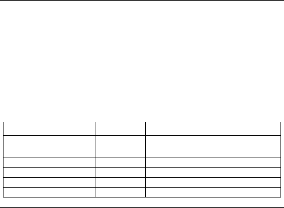
ASTRO Digital XTS 3500 radios are available in three basic models. Table 1
describes their basic features.
FLASHport The ASTRO Digital XTS 3500 radio utilizes Motorola’s revolutionary
FLASHport technology. FLASHport makes it possible to add software that
drives the radio’s capabilities both at the time of purchase and later on.
Previously, changing a radio’s features and capabilities meant significant
modifications, or buying a new radio. But now, similar to how a computer can
be loaded with different software, the radio’s features and capabilities can be
upgraded with FLASHport software.
Table 1 ASTRO XTS 3500 Basic Features
Feature Model I Model II Model III
Display None LCD
4 lines/
12 characters per line
LCD
4 lines/
12 characters per line
Keypad None 3 x 2 button 3 x 6 button
Channel Capability 48 255 255
Dialing from Prestored List No Yes Yes
Programmable Softkeys No Yes Yes

3
Basic Maintenance 2
Introduction
to This Section This section of the manual describes preventive maintenance and handling
precautions. Each of these topics provides information vital to the successful
operation and maintenance of your radio.
Preventive
Maintenance The ASTRO Digital XTS 3500 radios do not require a scheduled preventive
maintenance program; however, periodic visual inspection and cleaning is
recommended.
Inspection Check that the external surfaces of the radio are clean, and that all external
controls and switches are functional. A detailed inspection of the interior
electronic circuitry is not needed.
Cleaning The following procedures describe the recommended cleaning agents and the
methods to be used when cleaning the external surfaces of the radio. External
surfaces include the housing assembly and battery case. These surfaces should
be cleaned whenever a periodic visual inspection reveals the presence of
smudges, grease, and/or grime.
The only recommended agent for cleaning the external radio surfaces is a 0.5%
solution of a mild dishwashing detergent, such as JOY®, in water.
Cleaning External
Plastic Surfaces The detergent-water solution should be applied sparingly with a stiff, non-
metallic, short-bristled brush to work all loose dirt away from the radio. A soft,
absorbent, lintless cloth or tissue should be used to remove the solution and
dry the radio. Make sure that no water remains entrapped near the connectors,
cracks, or crevices.
The effects of certain chemicals and their vapors can
have harmful results on certain plastics. Aerosol
sprays, tuner cleaners, and other chemicals should
be avoided.
!
C a u t i o n

4
Handling
Precautions Complementary metal-oxide semiconductor (CMOS) devices, and other high-
technology devices, are used in this family of radios. While the attributes of
these devices are many, their characteristics make them susceptible to damage
by electrostatic discharge (ESD) or high-voltage charges. Damage can be latent,
resulting in failures occurring weeks or months later. Therefore, special
precautions must be taken to prevent device damage during disassembly,
troubleshooting, and repair. Handling precautions are mandatory for this
radio, and are especially important in low-humidity conditions.

5
Recommended Test
Equipment and Service Aids 3
Recommended
Test
Equipment
The list of equipment contained in Table 2 includes all of the standard test
equipment required for servicing two-way portable radios, as well as several
unique items designed specifically for servicing this family of radios. The
“Characteristics” column is included so that equivalent equipment may be
substituted; however, when no information is provided in this column, the
specific Motorola model listed is either a unique item or no substitution is
recommended.
Service Aids Refer to Table 3, “Service Aids,” for a listing and description of the service aids
designed specifically for servicing this family of radios. These kits and/or parts
are available from the Motorola Parts Division offices listed in the
“Replacement Parts Ordering” section located on the inside back cover of this
manual. While all of these items are available from Motorola, most are
standard shop equipment items, and any equivalent item capable of the same
performance may be substituted for the item listed.
Table 2 Recommended Test Equipment
Motorola
Model Number Description Characteristics Application
R2600 Series Communications
System Analyzer This monitor will substitute
for items with an asterisk (*). Frequency/deviation meter and
signal generator for wide-range
troubleshooting and alignment.
Fluke 8012 Digital Multimeter Recommended for ac/dc voltage
and current measurements
R1150_* Code Synthesizer Injection of audio and digital
signalling codes
R1377_* AC Voltmeter 1mV to 300V, 10-Megohm
input impedance Audio voltage measurements
R1094_ Dual-Trace
Oscilloscope 20MHz bandwidth 5mV to
5V/division Waveform measurements
S1350_*
ST1213_ (VHF)*
ST1223_ (UHF)*
Wattmeter
Plug-In Element
RF Dummy Load
50-ohm, ±5% accuracy
10 watts, maximum
0-1000MHz, 300W
Transmitter power output
measurements
R1065_ Load Resistor 10-watt Broadband For use with wattmeter
S1339_ RF Millivolt Meter 100µV to 3V RF RF-level measurements
R1013_* SINAD Meter Receiver sensitivity measurements
S1347_ or S1348_
(programmable) DC Power Supply 0-20Vdc, 0-5 Amps
current limited Bench supply for 7.5Vdc

6
Field
Programming
Equipment
This family of radios can be aligned and programmed in the field. This requires
specific equipment and special instructions. Refer to the applicable “Radio
Service Software User's Guide” for complete field programming information.
Table 3 Service Aids
Motorola Part
Number Description Application
RKN-4035_ RIB/Radio/Test Set Cable Connects radio to RTX-4005B Test Box and RIB.
REX-4424_ Battery Eliminator Interconnects radio to power supply.
RLN-4460_, or
RTX-4005_, or both
RTX-4005_ and
RPX-4665_
Portable Test Set Enables connection to the universal connector.
Allows switching for radio testing.
Field Modification Kit
RLN-1015_ or
RLN-4008_
Radio Interface Box Enables communications between the radio and the
computer's serial communications adapter.
01-80357A57 Wall-Mounted Power Supply Used to supply power to the RIB (120 Vac).
01-80358A56 Wall-Mounted Power Supply Used to supply power to the RIB (220 Vac).
30-80369B71 or
30-80369B72 Computer Interface Cables
for RIB RLN4008_ Use B72 for 9-pin serial ports. All other models use B71
(25 pins). Connects the computer's serial
communications adaptor to the RIB.
30-80390B48 or
30-80390B49 Computer Interface Cables
for Smart RIB RLN1015_ Use B49 for 9-pin serial ports. All other models use B48
(25 pins). Connects the computer's serial
communications adaptor to the RIB.
RVN-4170_ Radio Service Software Software on 3-1/2 in. floppy disks.
58-80348B33 SMA to BNC Adaptor Adapts radio’s antenna port to BNC cabling of test
equipment.

7
Performance Checks 4
Introduction
to This Section This section covers performance checks used to verify the radio meets
published specifications. The recommended test equipment listed in the
previous section approaches the accuracy of the manufacturing equipment,
with a few exceptions. Accuracy of the equipment must be maintained in
compliance with the manufacturer’s recommended calibration schedule.
Checks should be performed if radio performance degradation is suspected.
Setup Supply voltage can be connected from the battery eliminator. The equipment
required for alignment procedures is connected as shown in the “Radio
Alignment Test Setup” diagram (page 15, Figure 1).
Initial equipment control settings should be as indicated in the following
table, and should hold for all alignment procedures except as noted in Table 4.
Display Radio
Test Mode
Entering Display
Radio Test Mode 1. Turn the radio on.
2. Within 10 seconds after “SS
SSee
eell
llff
ff
TT
TTee
eess
sstt
tt” is complete, press Side button 3 five
times in succession.
3. The radio will show a series of displays that will give information
regarding various version numbers and subscriber specific information.
The displays are described in Table 5 on page 8.
Table 4 Initial Equipment Control Settings
System Analyzer Test Set Power Supply
Monitor Mode: Pwr Mon Spkr Set: A Voltage: 7.5Vdc
RF Attn: –70dB Spkr/Load: Speaker DC On/Standby: Standby
AM, CW, FM: FM PTT: OFF (center) Volt Range: 10Vdc
O'scope Source: Mod
O'scope Horiz: 10mSec/Div
O'scope Vert: 2.5kHz/Div
O'scope Trig: Auto
Monitor Image: Hi
Monitor BW: Nar
Monitor Squelch: Mid CW
Monitor Vol: 1/4 CW
Current: 2.5Amps

8
Note: All displays are temporary and will expire without any user intervention. If information is longer than the
physical length of the radio’s display, the information will wrap around to the next display. After the last
display, “RR
RRFF
FF
TT
TTEE
EESS
SSTT
TT” will be displayed.
4a. Press Side Button 1 to stop the displays and put the radio into the
Control Top and Keypad test mode (display radio). The test mode menu
“CC
CCHH
HH
TT
TTEE
EESS
SSTT
TT” will be displayed. Go to the “Control Top and Keypad Test
Mode (Display Radio)” section.
NOTE: Each press of Side Button 1 will toggle between “CC
CCHH
HH
TT
TTEE
EESS
SSTT
TT”
and “RR
RRFF
FF
TT
TTEE
EESS
SSTT
TT.”
OR
4b. Press the Top Programmable Button (Emergency button) to stop the
displays and put the radio into the RF test mode (display radio). The test
mode menu “11
11
CC
CCSS
SSQQ
QQ.” will be displayed, indicating test frequency 1,
Carrier SQuelch mode. Go to the “RF Test Mode (Display Radio)” section.
RF Test Mode
(Display Radio) When the ASTRO Digital XTS 3500 radio is operating in its normal environment,
the radio's microcomputer controls the RF channel selection, transmitter key-up,
and receiver muting, according to the customer codeplug configuration.
However, when the unit is on the bench for testing, alignment, or repair, it must
be removed from its normal environment via a special routine, called TEST
MODE or “air test.”
1. Each additional press of Side Button 3 will advance to the next test
channel. (Refer to Table 6.)
2. Pressing Side Button 2 will scroll through and access test environments
as shown in Table 7.
NOTE: Transmit into a load when keying a radio under test.
Table 5 Front-Panel Access Test-Mode Displays
Name of Display Description Appears
“SS
SSEE
EERR
RRVV
VVII
IICC
CCEE
EE” The literal string indicates the radio has entered
test mode. Always.
Host Software Version The version of host firmware is displayed. Always.
DSP Software Version The version of DSP firmware is displayed. Always.
EMC Secure Version Version of the encryption hardware. When the radio is secure equipped.
Encryption Type 1 Type of encryption being used. When the radio is secure equipped.
Encryption Type 2 Type of encryption being used. When the radio is secure equipped.
Model Number The radio’s model number as programmed in the
codeplug. Always.
Serial Number The radio’s serial number as programmed in the
codeplug. Always.
ROM Size The memory capacity of the host FLASH part. Always.
FLASHcode The FLASH codes as programmed in the codeplug. Always.
9
** All deviation values are based on deviation tuning of this mode
*** On radios equipped with secure option
Control Top
and Keypad
Test Mode
(Display Radio)
This test mode is used to verify proper operation of all radio buttons and
switches if a failure is suspected.
1. Press and hold the Top Programmable Button; all segments on the
display will light, and the LED on the control top will illuminate a red
color.
2. Release the Top Programmable Button; “33
33//
//00
00” appears, which indicates
that the Top Programmable Button is in the open condition.
3. Press the Top Programmable Button again; “33
33//
//11
11” appears, which
indicates that the Top Programmable Button is in the closed condition.
4. Rotate the Mode/Zone Selector Switch; “44
44//
//00
00” through “44
44//
//11
1155
55” appears,
which indicates that the selector switch is in mode/zone position 1
through 16.
Table 6 Test Frequencies
Test Channel VHF UHF Band 2
TX #1 136.025 450.025
RX #1 136.075 450.075
TX #2 142.125 465.225
RX #2 142.075 465.275
TX #3 154.225 475.125
RX #3 154.275 475.275
TX #4 160.125 484.975
RX #4 160.175 485.025
TX #5 168.075 500.275
RX #5 168.125 500.225
TX #6 173.975 511.975
RX #6 173.925 511.925
TX #7 177.975 519.975
RX #7 177.925 519.925
Table 7 Test Environments
No. of
Beeps Display Description Function
1 CSQ Carrier
Squelch RX: unsquelch if carrier detected
TX: mic audio
3 TPL Tone
Private-Line RX: unsquelch if carrier and
tone (192.8 Hz) detected
TX: mic audio + tone (192.8 Hz)
9 SEC Secure*** RX: auto-coded clear
TX: with key present—encrypted audio
with key absent—constant unsquelch
11 AST ASTRO RX: none
TX: 1200Hz tone **
12 USQ Carrier
Unsquelch RX: unsquelch always
TX: mic audio

10
5. Rotate the Two-Position Concentric Switch; “66
6655
55//
//00
00” and “66
6655
55//
//11
11” appear.
6. Cycle through the Three-Position Programmable Switch; “66
6677
77//
//00
00,”
“66
6677
77//
//11
11,” and “66
6677
77//
//22
22” appear.
7. Rotate the Volume Control; “22
22//
//00
00” through “22
22//
//22
2255
5555
55” appear.
8. Press Side Button 1; “99
9966
66//
//11
11” appears; release, “99
9966
66//
//00
00” appears.
9. Press Side Button 2; “99
9977
77//
//11
11”appears; release, “99
9977
77//
//00
00” appears.
10. Press Side Button 3; “99
9988
88//
//11
11”appears; release, “99
9988
88//
//00
00” appears.
11. Press the PTT Switch; “11
11//
//11
11” appears; release, “11
11//
//00
00” appears.
12. Keypad Checks:
Model III Only—
-Press 0, “44
4488
88//
//11
11” appears; release, “44
4488
88//
//00
00” appears.
-Press 1, “44
4499
99//
//11
11” appears; release, “44
4499
99//
//00
00” appears.
-Press 2, “55
5500
00//
//11
11” appears; release, “55
5500
00//
//00
00” appears.
-Press 3, “55
5511
11//
//11
11” appears; release, “55
5511
11//
//00
00” appears.
-Press 4, “55
5522
22//
//11
11” appears; release, “55
5522
22//
//00
00” appears.
-Press 5, “55
5533
33//
//11
11” appears; release, “55
5533
33//
//00
00” appears.
-Press 6, “55
5544
44//
//11
11” appears; release, “55
5544
44//
//00
00” appears.
-Press 7, “55
5555
55//
//11
11” appears; release, “55
5555
55//
//00
00” appears.
-Press 8, “55
5566
66//
//11
11” appears; release, “55
5566
66//
//00
00” appears.
-Press 9, “55
5577
77//
//11
11” appears; release, “55
5577
77//
//00
00” appears.
-Press *, “55
5588
88//
//11
11” appears; release, “55
5588
88//
//00
00” appears.
-Press #, “55
5599
99//
//11
11” appears; release, “55
5599
99//
//00
00” appears.
All Display Models—
-Press <, “11
1122
2288
88//
//11
11” appears; release, “11
1122
2288
88//
//00
00” appears.
-Press O, “11
1122
2299
99//
//11
11” appears; release, “11
1122
2299
99//
//00
00” appears.
-Press >, “11
1133
3300
00//
//11
11” appears; release, “11
1133
3300
00//
//00
00” appears.
-Press the left-hand M key on the top row of keys, “11
1133
3311
11//
//11
11” appears;
release, “11
1133
3311
11//
//00
00” appears.
-Press the center N key, “11
1133
3322
22//
//11
11” appears; release, “11
1133
3322
22//
//00
00” appears.
-Press the right-hand M key, “11
1133
3333
33//
//11
11” appears; release, “11
1133
3333
33//
//00
00”
appears.
Non-Display
Radio Test
Mode
Entering Non-
Display Radio
Test Mode
1. Turn the radio on.
2. Within 10 seconds after the top green LED turns off, press Side button 3
five times in succession.
11
ppyp
mode (non-display radio). Go to the “Control Top and Keypad Test Mode
(Non-Display Radio)” section.
NOTE: Each press of Side Button 1 will toggle between Control
Top and Keypad test mode (non-display radio) and RF test
mode (non-display radio).
OR
3b. Press the Top Programmable Button (Emergency button) to stop the
displays and put the radio into the RF test mode (non-display radio). Go
to the “RF Test Mode (Non-Display Radio)” section.
RF Test Mode
(Non-Display
Radio)
When the ASTRO Digital XTS 3500 radio is operating in its normal environment,
the radio's microcomputer controls the RF channel selection, transmitter key-up,
and receiver muting, according to the customer codeplug configuration.
However, when the unit is on the bench for testing, alignment, or repair, it must
be removed from its normal environment via a special routine, called TEST
MODE or “air test.”
1. Each additional press of Side Button 3 will advance to the next test
channel. (Refer to Table 6.) The channel number is represented by the
number of beeps emitted by the radio after the button press (for example,
five beeps indicates channel 5).
2. Pressing Side Button 2 will scroll through and access test environments
as shown in Table 7. The test environment is represented by the number
of beeps emitted by the radio after the button press (for example, 11
beeps indicate AST).
NOTE: Transmit into a load when keying a radio under test.
Control Top
and Keypad
Test Mode
(Non-Display
Radio)
This test mode is used to verify proper operation of all radio buttons and
switches if a failure is suspected.
1. Press and hold the Top Programmable Button; the LED on the control
top lights red, and the radio beeps.
2. Release the Top Programmable Button; the radio beeps again.
3. Press the Top Programmable Button again; the radio beeps, indicating
that the Top Programmable Button is in the closed condition.
4. Rotate the Two-Position Concentric Switch; the radio beeps in each
switch position.
5. Rotate the Mode/Zone Selector Switch; the radio beeps in each switch
position.
6. Cycle through the Three-Position Programmable Switch; the radio
beeps in each switch position.
7. Rotate the Volume Control; the radio beeps at each new volume setting.
8. Press Side Button 1; the radio beeps.
9. Press Side Button 2; the radio beeps.
10. Press Side Button 3; the radio beeps.

12
Table 8 Receiver Performance Checks
Test Name System Analyzer Radio Test Set Comments
Reference
Frequency Mode: PWR MON 4th
channel test frequency❖
Monitor: Frequency error.
Input at RF In/Out
TEST MODE, 4
CSQ output at
antenna
PTT to continuous
(during the
performance check)
Frequency error to
be ≤ ±1.0kHz
Rated Audio Mode: GEN
Output level: 1.0mV RF
4th channel test
frequency❖
Mod: 1kHz tone at 3kHz
deviation
Monitor: DVM: ac Volts
TEST MODE, 4
CSQ PTT to OFF (center);
meter selector to Audio
PA
Set volume control
to 3.74Vrms
Distortion As above, except to
distortion As above As above Distortion < 3.0%
Sensitivity
(SINAD) As above, except SINAD;
lower the RF level for 12dB
SINAD
As above PTT to OFF (center) RF input to be <
0.35µV
Noise Squelch
Threshold (only
radios with
conventional
system need to
be tested)
RF level set to 1mV RF As above PTT to OFF (center);
meter selection to
Audio PA; spkr/load to
speaker
Set volume control
to 3.74Vrms
As above, except change
frequency to a
conventional system. Raise
RF level from zero until
radio unsquelches.
Out of TEST
MODE; select
a conventional
system
As above Unsquelch to
occur at < 0.25µV.
Preferred SINAD =
5-8dB
❖ See Table 7

13
Table 9 Transmitter Performance Checks
Test Name System Analyzer Radio Test Set Comments
Reference
Frequency Mode: PWR MON 4th
channel test frequency❖
Monitor: Frequency
error. Input at RF In/Out
TEST MODE,
4 CSQ PTT to continuous
(during the
performance check).
Frequency error to be ≤
±1.0kHz.
Power RF As above As above,
4 CSQ As above Refer to Maintenance
Specifications page in
front of manual.
Voice
Modulation Mode: PWR MON 4th
channel test frequency❖
atten to –70, input to RF
In/Out.
Monitor: DVM, ac Volts.
Set 1kHz Mod Out level
for 0.025Vrms at test set,
80mVrms at ac/dc test set
jack
As above,
4 CSQ As above, meter
selector to mic Deviation: ≥ 4.1kHz but ≤
5.0kHz
Voice
Modulation
(internal)
Mode: PWR MON 4th
channel test frequency❖
atten to –70, input to RF
In/Out
TEST MODE,
4 CSQ, output
at antenna
Remove modulation
input Press PTT switch on radio.
Say “four” loudly into the
radio mic. Measure
deviation: ≥ 4.1kHz but ≤
5.0kHz
PL Modu-
lation (radios
with conven-
tional, clear
mode, coded
squelch oper-
ation only)
Change frequency to a
conventional transmit
frequency
Conventional
coded squelch
personality
(clear mode
operation) 4
TPL
As above Deviation: ≥ 500Hz but ≤
1000Hz
Talkaround
Modulation
(radios with
conventional,
clear mode,
talk-around
operation
only)
Change frequency to
conventional talk-around
frequency.
Mode: PWR MON
deviation, attenuation to
–70, input to RF In/Out.
Monitor: DVM, ac volts
Set 1kHz Mod Out level
for 25mVrms at test set.
Conventional
talkaround
personality
(clear mode
operation)
1 CSQ
As above Deviation: ≥ 4.1kHz but ≤
5.0kHz
Talkaround
Modulation
(radios with
conventional,
secure mode,
talkaround
operation
only)
Change frequency to
conventional talk-around
frequency.
Mode: PWR MON
deviation, attenuation to
–70, input to RF In/Out.
Monitor: DVM, ac volts
Mod: 1kHz out level
for25mVrms at test set.
Conventional
talkaround
personality
(secure mode
operation)
1 SEC. Load
key into
radio.
As above Deviation: ≥ 3.7kHz but ≤
4.3kHz
❖See Table 7

14
Notes
15
Radio Alignment
Procedures 5
Introduction
to This Section This section describes both receiver and transmitter radio alignment
procedures.
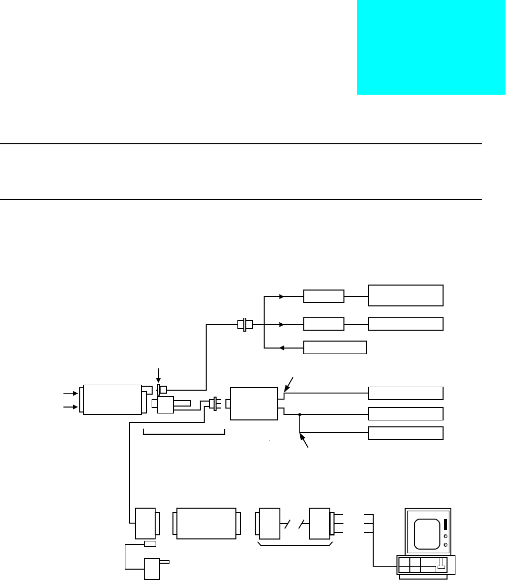
General A personal computer (PC) and radio service software (RSS) are required to align
the radio. Refer to the applicable RSS manual for installation and setup
procedures for the software. To perform the alignment procedures, the radio
must be connected to the PC, radio interface box (RIB), and a universal test set
as shown in Figure 1.
Figure 1 Radio Alignment Test Setup
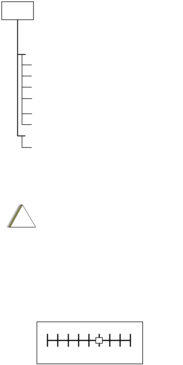
All service and tuning procedures are performed from the SERVICE menu,
which is selected by pressing B from the MAIN MENU. Figure 2 illustrates
how the RSS alignment SERVICE screens are organized.
BNC
RIB
RLN-4008B
RIB POWER SUPPLY
01-80357A57 (120V)
COMPUTER INTERFACE
CABLE
30-80369B71
30-80369B72 (IBM "AT" ONLY)
DATA
BUSY
GND
COMPUTER
AUDIO GENERATOR
SINAD METER
AC VOLTMETER
TX
RX
30 dB PAD
30 dB PAD
RF GENERATOR
SYSTEM ANALYZER
OR COUNTER
WATTMETER
BATTERY
ELIMINATOR
RTL-4224A
TRANSMIT
RECEIVE
TEST SET
RTX-4005B
RADIO
PROGRAM/TEST CABLE
RKN-4046A
AUDIO IN
SET TO APPROX. 450mV FOR Tx
MEASURE 80mV FOR Tx
SMA-BNC
58-80348B33
REX-4424
RKN-4035_
RIB
RLN-4008_
RLN-1015_ or
TEST SET
RLN-4460_ or
RTX-4005_
30-80369B71 (25 pins)
30-80369B72 (7 pins)
16
Figure 2 RSS Service Menu Layout
All SERVICE screens read and program the radio codeplug directly; you do
NOT have to use the RSS GET/SAVE functions to use the SERVICE menus.
The SERVICE screens introduce the concept of the “softpot,” an analog
SOFTware-controlled POTentiometer used for adjusting all transceiver
alignment controls.
Each SERVICE screen provides the capability to increase or decrease the
‘softpot’ value with the keyboard UP/DOWN arrow keys respectively. A
graphical scale is displayed indicating the minimum, maximum, and
proposed value of the softpot, as shown in Figure 3.
Figure 3 Softpot Concept
REFERENCE OSCILLATOR ALIGNMENT
TRANSMIT POWER ALIGNMENT
TRANSMITTER ALIGNMENT MENU
TRANSMIT DEVIATION BALANCE
(COMPENSATION) ALIGNMENT
TRANSMIT DEVIATION LIMIT ALIGNMENT
F2 -
F2 -
F3 -
F4 -
F5 -
RECEIVER ALIGNMENT MENU
F3 -
FRONT END BANDPASS FILTER ALIGNMENTF2 -
SERVICE
HELPF1 -
EXIT, RETURN TO SERVICE MENUF10 -
B
A
B
C
D
E
C
B
J
Do NOT switch radios in the middle of any SERVICE
procedure. Always use the EXIT key to return to the
MAIN menu screen before disconnecting the radio.
Improper exits from the SERVICE screens may leave
the radio in an improperly configured state and
result in seriously degraded radio or system
performance.
!
C a u t i o n
Min.
Value Max.
Value
015
17
Adjusting the softpot value sends information to the radio to increase (or
decrease) a dc voltage in the corresponding circuit. For example, pressing the
UP arrow key at the Reference Oscillator screen instructs the radio’s
microcomputer to increase the voltage across a varactor in the reference
oscillator, which increases the frequency.
In ALL cases, the softpot value is just a relative number corresponding to a
digital-to-analog (D/A) generated voltage in the radio.
Perform the following procedures in the sequence indicated.
NOTE: Some of the following screens may vary
depending upon the radio under test and the
version of radio service software you are using.
Refer to your radio service software user’s guide.
Reference
Oscillator
Alignment
Adjustment of the reference oscillator is critical for proper radio operation.
Improper adjustment will result not only in poor operation, but also in a
misaligned radio that will interfere with other users operating on adjacent
channels. For this reason, the reference oscillator should be checked every
time the radio is serviced. The frequency counter used for this procedure must
have a stability of 0.1 ppm (or better).
1. From the SERVICE MENU, press B to select the TRANSMITTER
ALIGNMENT MENU.
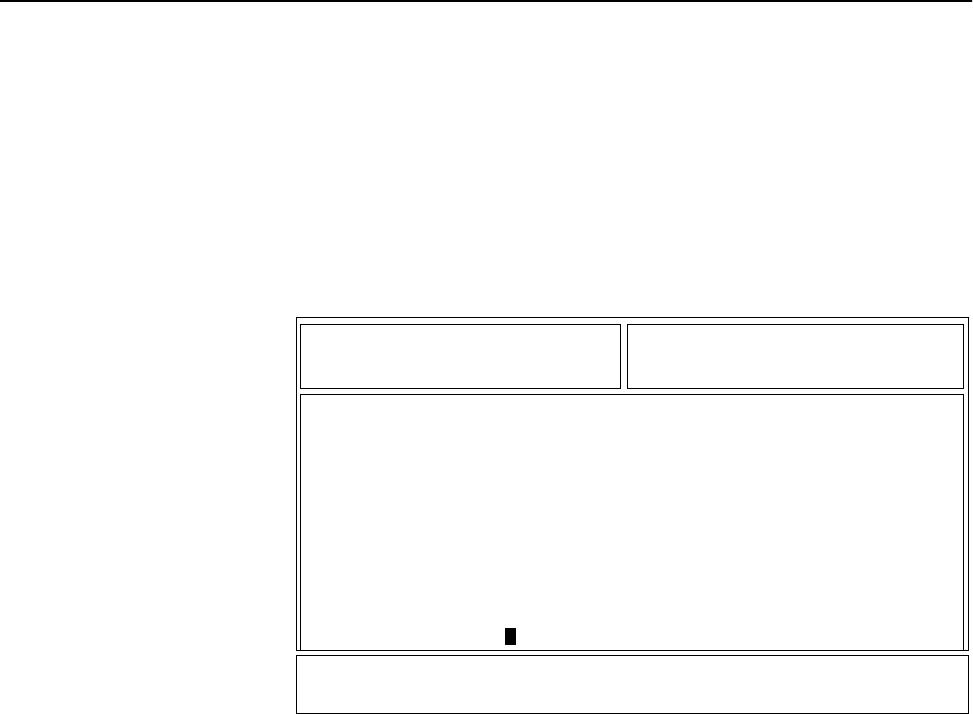
2. Press B again to select the REFERENCE OSCILLATOR alignment screen.
See Figure 4.
Figure 4 Reference Oscillator Alignment Screen
3. Press F to key the radio. The screen will indicate that the radio is
transmitting.
4. Measure the transmit frequency on your service monitor.
5. Use the É/Ç arrow keys to adjust the reference oscillator softpot value.
See Table 10.
MOTOROLA Radio Service Software Use UP/DOWN Arrows To Adjust Softpot.
XTS Model: H24SDC9PW5AN
MAIN:SERVICE:TX ALIGN:REF OSC
REFERENCE OSCILLATOR
--------------------
Frequency Current Value
--------- -------------
519.975 150 New Softpot Value.....150
Transmitter..On
0 215
MIN |----+----+----+----+----+----+----+----+----+----+----+----| MAX
F1 F2 F3 F4 F5 F6 F7 F8 F9 F10
HELP TOGGLE PROGRAM EXIT
PTT VALUE

18
6. Press F again to dekey the radio.
7. Press H to program the new softpot value.
8. Press J once to return to the TRANSMITTER ALIGNMENT MENU, or
press J twice to return to the SERVICE MENU.
Transmit
Power
Alignment
NOTES:
•All power measurements are to be made at the antenna port.
•The transmitter power setting keeps the radiated power at or below
the level specified in the exclusionary clause for low power devices
of IEEE Standard C95.1-1991.
1. From the SERVICE MENU, press B to select the TRANSMITTER
ALIGNMENT MENU.
2. Press C to select the TRANSMIT POWER alignment screen. The screen
will indicate the transmit frequencies to be used. See Figure 5.
Figure 5 Transmit Power Alignment Screen
3. Press P (or Z or [RETURN]) to select a frequency field (starting with
the highest frequency shown). Then, press F to key the radio. The
screen will indicate that the radio is transmitting.
4. Use the É/Ç arrow keys to adjust the transmit power per the values
shown in Table 11.
Table 10 Reference Oscillator Alignment
Band Target
VHF or UHF ±100 Hz
MOTOROLA Radio Service Software Use UP/DOWN Arrows To Adjust Softpot.
XTS Model: H24SDH9PW7AN
MAIN:SERVICE:TX ALIGN:TX POWER
TRANSMIT POWER
--------------
Current Value New Softpot Value
Frequency High Pwr Mid Pwr Low Pwr High Pwr Mid Pwr Low Pwr
--------- -------- -------- ------- -------- -------- -------
450.0250 65 25 25 65 25 25
465.2250 67 26 26 67 26 26
475.1250 68 27 27 68 27 27
484.9750 69 28 28 69 28 28
500.2750 72 29 29 72 29 29
511.9750 75 30 30 75 30 30
519.9750 59 31 31 59 31 31
Transmitter..Off
0 127
MIN |----+----+----+----+----+----X----+----+----+----+----+----| MAX
F1 F2 F3 F4 F5 F6 F7 F8 F9 F10
HELP TOGGLE PROGRAM EXIT
PTT VALUE
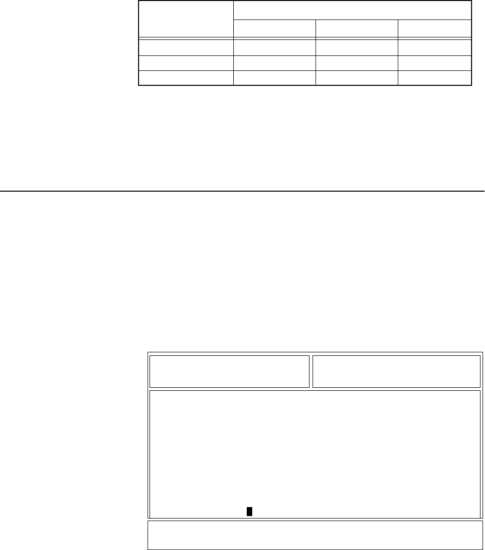
19
5. Press F to dekey the radio.
6. Press H to program the value.
7. Repeat steps 3-6 for the remaining frequencies.
8. Press J once to return to the TRANSMITTER ALIGNMENT MENU, or
press J twice to return to the SERVICE MENU.
Transmit
Deviation
Balance
(Compensation)
Alignment
Compensation alignment balances the modulation sensitivity of the VCO and
reference modulation (synthesizer low-frequency port) lines. The
compensation algorithm is critical to the operation of signalling schemes that
have very-low-frequency components (for example, DPL) and could result in
distorted waveforms if improperly adjusted.
1. From the SERVICE MENU, press B to select the TRANSMITTER
ALIGNMENT MENU.
2. Press D to select the TRANSMIT DEVIATION BALANCE
(COMPENSATION) alignment screen. The screen will indicate the
transmit frequencies to be used. See Figure 6.
Figure 6 Transmit Deviation Balance (Compensation) Alignment Screen
3. Press P (or Z or [RETURN]) to select a frequency field (starting with
the lowest frequency shown).
4. Press D. This will cause the radio to key and the radio’s DSP IC to inject
an 80Hz tone into the RF board.
5. Measure the deviation and record this value.
Table 11 Transmit Power Settings
Power Level Test Frequencies
136-174MHz 450-512MHz 512-520MHz
1 Watt 1.2W - 1.4W 1.2W - 1.4W 1.2W - 1.4W
5 Watts ———— 5.2W - 5.4W 3.2W - 3.4W
6 Watts 6.2W - 6.5W ———— ————
MOTOROLA Radio Service Software Use UP/DOWN Arrows To Adjust Softpot.
XTS Model: H24SDC9PW5AN
MAIN:SERVICE:TX ALIGN:BAL ATTN
TRANSMIT DEVIATION BALANCE (COMPENSATION)
-----------------------------------------
Current
Frequency Value New Softpot Value
--------- ------- -----------------
450.025 30 30
465.225 30 30
475.125 30 30
484.975 45 45
500.275 45 45
511.975 45 45
519.975 45 Transmitter..Off 45
0 63
MIN |---+---+---+---+---+---+---+---+---+---+---+---+---+---+---+---| MAX
F1 F2 F3 F4 F5 F6 F7 F8 F9 F10
HELP TOGGLE LOW TOGGLE HIGH PROGRAM EXIT
TONE PTT TONE PTT VALUE
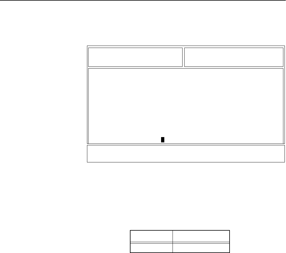
20
6. Press D to dekey the radio.
7. Press F. This will cause the radio’s DSP IC to change the injection tone
to 3kHz, 100mVrms. Use the É/Ç arrow keys to adjust the deviation to
within ±2% of the value recorded in step 5.
8. Repeat steps 4-7 until the 3kHz tone deviation is within ±2% of the 80Hz
tone deviation.
9. Press F again to dekey the radio.
10. Press H to program the new softpot value.
11. Repeat steps 3-10 for the remaining frequencies.
12. Press J once to return to the TRANSMITTER ALIGNMENT MENU, or
press J twice to return to the SERVICE MENU.
Transmit
Deviation
Limit
Alignment
1. From the SERVICE MENU, press B to select the TRANSMITTER
ALIGNMENT MENU.
2. Press E to select the TRANSMIT DEVIATION LIMIT alignment screen.
The screen will indicate the transmit frequencies to be used. See Figure 7.
Figure 7 Transmit Deviation Limit Alignment Screen
3. Press P (or Z or [RETURN]) to select a frequency field (starting with
the lowest frequency shown).
4. Press F to key the radio. Then use the É/Ç arrow keys to adjust for a
deviation per the values shown in Table 12.
5. Press F again to dekey the radio.
6. Press H to program the softpot value.
7. Repeat steps 3-6 for the remaining frequencies.
Table 12 Transmit Deviation Limit
Band Deviation (Hz)
VHF or UHF 2785 - 2885
MOTOROLA Radio Service Software Use UP/DOWN Arrows To Adjust Softpot.
XTS Model: H24SDC9PW5AN
MAIN:SERVICE:TX ALIGN:DEV.LIMIT
TRANSMIT DEVIATION LIMIT
------------------------
Current
Frequency Value New Softpot Value
--------- ------- -----------------
450.025 24500 24500
465.225 24500 24500
475.125 24500 24500
484.975 24500 24500
500.275 24500 24500
511.975 24500 24500
519.975 24500 Transmitter..Off 24500
0 32767
MIN |----+----+----+----+----+----+----+----+X---+----+----+----| MAX
F1 F2 F3 F4 F5 F6 F7 F8 F9 F10
HELP TOGGLE PROGRAM EXIT
PTT VALUE
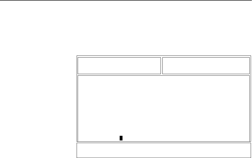
21
8. Press J once to return to the TRANSMITTER ALIGNMENT MENU, or
press J twice to return to the SERVICE MENU.
Front End
Filter
Alignment
1. From the SERVICE MENU, press C to select the RECEIVER ALIGNMENT
MENU.
2. Press B to select the FRONT END FILTER (VHF AND UHF ONLY) screen.
The screen will indicate the receive frequencies at which the filter is to be
aligned. See Figure 8.
Figure 8 Front End Filter (VHF and UHF Only) Alignment Screen
3. Press P (or Z or [RETURN]) to select a frequency field.
4. Set the RF test generator to the first receive frequency +150Hz. Set the RF
level at the radio standard antenna port to 4.0µV with no modulation.
5. Adjust the É/Ç arrow keys to obtain a peak value in the RSSI (receive
signal strength indicator) field.
NOTE: D must be pressed to obtain each RSSI reading after
adjustment.
6. Press H to program the new softpot value.
7. Repeat steps 3-6 for the remaining frequencies.
8. Press J once to return to the RECEIVER ALIGNMENT MENU, or press
J twice to return to the SERVICE MENU.
MOTOROLA Radio Service Software Use UP/DOWN Arrows To Adjust Softpot.
ASTRO Model: H09KDH9PW7AN
MAIN:SERVICE:RX ALIGN:FE FL
FRONT END FILTER (VHF AND UHF ONLY)
-----------------------------------
Current
Frequency Value New Softpot Value RSSI....0
--------- ------- -----------------
450.075 0 0
465.275 0 0
475.275 0 0
485.025 0 0
500.225 0 0
511.925 0 0
519.925 0 0
0 255
MIN |---+---+---+---+---+---+---+---+---+---+---+---+---+---+---+---| MAX
F1 F2 F3 F4 F5 F6 F7 F8 F9 F10
HELP READ PROGRAM EXIT
RSSI VALUE

22
Notes

23
Basic Removal/Installation
Procedures 6
Introduction
to This Section This section gives basic procedures for removing and installing the XTS 3500
radio’s:
•Antenna,
•Battery,
•Belt Clip,
•Universal Connector Cover,
•Volume Knob, and
•Frequency Knob.
Antenna
Installing the
Antenna Screw the threaded end of the antenna into the antenna receptacle on the top
of the radio. Rotate the antenna clockwise until it seats firmly against the
bushing.
Removing the
Antenna Rotate the antenna counterclockwise until its threaded end unscrews from the
radio’s antenna receptacle.
Battery NOTE: The battery is shipped uncharged, and must be
charged for at least 16 hours before use.
To avoid a possible explosion:
• DO NOT replace the battery in an area labeled
“hazardous atmosphere.”
• DO NOT discard batteries in a fire.
!
W A R N I N G
!
If your radio is programmed with volatile-key retention
(consult your service technician), encryption keys will be
retained for approximately 30 seconds after battery removal.
!
C a u t i o n
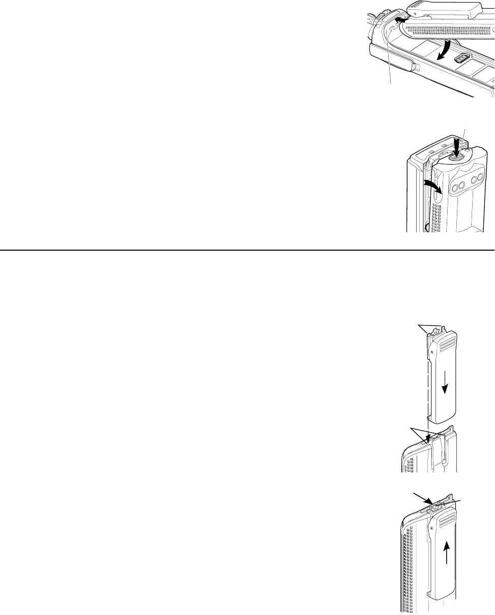
24
Installing the Battery 1. Turn off the radio and hold it with the
back of the radio facing upward
2. Insert the top edge of the battery into
the area at the top of the radio
between the radio’s case and chassis.
Make sure the three tabs on the radio
chassis align with the three slots
under the top edge of the battery.
3. Rotate the battery toward the radio,
and squeeze the battery and radio
together until the battery “clicks” in place.
Removing the Battery 1. Turn off the radio and hold it so that the
release button on the bottom of the battery
is facing upward.
2. Press downward on the release button so
the battery disengages from the radio.
3. Remove the battery completely away from
the radio
Belt Clip NOTE: The battery must be removed from the
radio before the belt clip can be installed
or removed.
Installing the
Belt Clip 1. Hold the battery in one hand so that the
top of the battery faces upward, and the
back of the battery faces you.
2. Holding the belt clip in the other hand
with its top facing upward, align the
slide assembly on the front of the belt
clip with the slots on the back of the
battery.
3. Slide the belt clip downward toward the
bottom of the battery until the belt clip
“clicks” in place.
Removing the Belt Clip 1. Hold the battery (with belt clip installed)
in one hand so that the top of the battery
faces upward, and the front (radio side)
of the battery faces you.
2. At the top of the battery, press down on
the belt clip’s metal tab and slide the
belt clip upward until it disengages from
the battery.
3. Continue to slide the belt clip upward
until it is free from the battery.
Slide
Assembly
Slots
Belt Clip
Battery
Metal
Tab
Press
Down
Radio Chassis
Release
Button
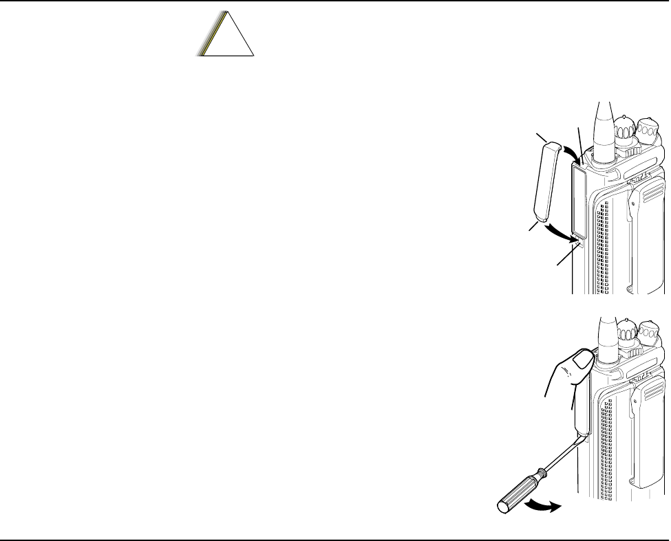
25
Universal
Connector
Cover
Installing the
Universal
Connector Cover
1. Looking at the antenna side of the radio,
insert the top (flat) hooked end of the cover
into the slot on the top of the radio, above
the universal connector. Press downward on
the cover’s top to seat it in the slot.
2. While holding the cover seated in the top
slot, insert the cover’s bottom (rounded)
hooked end into the slot below the universal
connector. Press firmly inward on the cover’s
bottom until it snaps in place.
Removing the
Universal
Connector Cover
1. Looking at the antenna side of the radio,
insert a flat-bladed screwdriver into the area
between the lower end of the universal
connector cover and the slot below the
universal connector.
2. While holding the cover’s top (flat) end in place
with your thumb, pry upward on the cover’s
lower end until it disengages from the radio.
Frequency
Knob NOTES:
•Refer to Figure 9, the Partial Exploded View, and Table 13, the Partial
Exploded View Parts List. Numbers in parentheses ( ) refer to item
numbers in Figure 9 and Table 13.
•The battery (7) should be removed from the radio before installing or
removing the frequency knob (1).
•In cases where the frequency insert (3) and escutcheon (2) must be
removed, a new frequency insert and new escutcheon must be used
for reassembly.
Removing the
Frequency Knob 1. Hold the radio in one hand so that the top of the radio faces upward, and
the front of the radio faces you.
2. With the other hand, grasp the frequency knob (1) and pull it upward,
while rocking the knob back and forth, until it is free from the frequency
insert (3) or the insert is free from the shaft.
3. If necessary, while pressing the insert’s (3) two snap tabs away from the
frequency control shaft so that the insert disengages from the shaft, use
needle-nosed pliers to lift the insert up and off of the frequency control
shaft. Discard the removed frequency insert.
4. Remove the secure lever (4) and the lightpipe (5).
When the universal connector is not in use, keep it covered
with the universal connector cover.
!
C a u t i o n
Top
Slot
Bottom
Slot
Top
Hooked End
Bottom
Hooked End

26
Installing the
Frequency Knob 1. Hold the radio so that the top of the radio faces upward, and the front of
the radio faces you.
2. Align the lightpipe (5) so that its straight tab is over the slot for the
illuminated pointer. Push the tab down into the slot so that it is securely
seated.
3. Place the secure lever (4) on the frequency control shaft, aligning it so
that its pointer is at the front of the radio and its two inner slots line up
with the two keys on the shaft. Slide the secure lever down to the bottom
of the shaft.
4. If you are replacing the escutcheon (2):
a. Remove the backing paper from the escutcheon.
b. Align the number “1” on the escutcheon with the alignment notch
on the insert (3).
c. Slide the escutcheon down over the insert until the alignment tabs on
the escutcheon fit inside the tab recesses on the insert.
d. Adhere the escutcheon to the insert.
5. Place a new frequency insert (3) and new escutcheon (2) on the frequency
control shaft, aligning the insert’s D-shaped hole with the D-shaped
shaft. Press downward firmly on the insert until it “snaps” in place on the
shaft.
6. Place the frequency knob (1) on the frequency insert (3), aligning it’s
pointer with the number “1” on the escutcheon (2). Press firmly
downward on the knob until it seats securely in place.
Volume Knob NOTES:
•Refer to Figure 9, the Partial Exploded View, and Table 13, the Partial
Exploded View Parts List. Numbers in parentheses ( ) refer to item
numbers in Figure 9 and Table 13.
•The battery (7) should be removed from the radio before installing or
removing the volume knob (8).
•In cases where the volume insert (9) must be removed, a new volume
insert must be used for reassembly.
Removing the
Volume Knob 1. Hold the radio in one hand so that the top of the radio faces upward, and
the front of the radio faces you.
2. With the other hand, grasp the volume knob (8) and pull it upward,
while pushing it toward the back of the radio, until it is free from the
volume insert (9).
3. While pressing the volume insert’s (9) two snap tabs away from the
volume control shaft so that the insert disengages from the shaft, use
needle-nosed pliers to pull the insert up and off of the volume control
shaft. Discard the removed volume insert.
4. Using needle-nosed pliers or some other pointed instrument, remove the
o-ring (21).
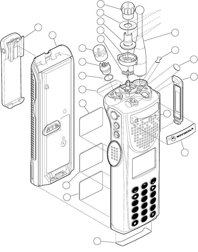
27
Installing the
Volume Knob 1. Place the o-ring (21) inside a new volume insert (9), and press it downward
until it seats securely at the bottom of the insert.
2. Hold the radio so that the top of the radio faces upward, and the front of
the radio faces you.
3. Place a new volume insert (9) on the volume control shaft, aligning the
insert’s D-shaped hole with the D-shaped shaft. Press downward firmly
on the insert until it “snaps” in place on the shaft.
4. Place the volume knob (8) on the volume insert (9), aligning the two lugs
on the inside of the knob with the insert’s two snap tabs. Press firmly
downward on the knob until it seats securely in place.
Figure 9 Partial Exploded View
123
456
78
0
9
ABC
DEF
GHI
JKL
MNO
PRS
TUV
WXY
HOME
XTS 3500
1
2
3
4
5
17
18
20
16
15
8
9
10
11
21
14
13
12
7
6
19
A
B
C
Tab Recesses
Alignment Tabs
Alignment Notch
MAEPF-26563-B

28
Table 13 Partial Exploded View Parts List
ITEM
NO. MOTOROLA
PART NO. DESCRIPTION
1 3605370Z01 KNOB, Frequency
2 1305374Z01 ESCUTCHEON, Frequency
3 4305373Z01 INSERT RETAINER, Frequency Knob
4 4305375Z01 LEVER, Secure Frequency
5 6105376Z01 LIGHTPIPE INDICATOR/STOP, Frequency
6 NTN8266_ CLIP, Belt
7 NTN8923_
or NTN8294_
or NTN8295_
or NTN8299_
or NTN8610_
Battery, NiMH Extended Life
Battery, NiCd
Battery, NiCd FM
Battery, NiMH FM
Battery, Li-Ion
8 3605371Z01 KNOB, Volume
9 4305372Z01 INSERT RETAINER, Volume Knob
10 3305574Z03 LABEL, Motorola, Back
11 - - - - - - - - - - LABEL, Flashport
12 - - - - - - - - - - LABEL, Radio Serial Number
13 - - - - - - - - - - LABEL, Approval Agency
14 3305630Z02
or 3305630Z01 LABEL, Bottom
LABEL, Bottom, FM
15 NAD6563_
or NAD6566_
or NAD6567_
or NAD6568_
or NAE6547_
or NAE6548_
or NAE6549_
ANTENNA, Wideband Helical (136-174 MHz)
ANTENNA, Helical (136-151 MHz)
ANTENNA, Helical (151-162 MHz)
ANTENNA, Helical (162-174 MHz)
ANTENNA, Helical (430-470 MHz)
ANTENNA, Helical (470-512 MHz)
ANTENNA, Wideband Whip (403-512 MHz)
16 - - - - - - - - - - ESCUTCHEON, Concentric Switch (optional)
17 - - - - - - - - - - ESCUTCHEON, Toggle (optional)
18 1505579Z01 COVER, Dust, Universal Connector
19 3386139A01 LABEL, Motorola, Front
20 3505586Z01 Gortex
21 3205379W01 O-Ring

29
Basic Theory of
Operation 7
General
Overview The ASTRO Digital XTS 3500 radio is a wideband, synthesized, fixed-tuned
radio available in the VHF and UHF bands. All ASTRO Digital XTS 3500 radios
are capable of both analog operation (12.5kHz or 25kHz bandwidths) and
ASTRO mode (digital) operation (12.5kHz only).
The ASTRO Digital XTS 3500 radio includes the following major assemblies:
•VOCON Board - contains the microcontrol unit (MCU) and its associated
memory and memory management integrated circuit (IC), the audio
power amplifier, and a switching regulator. The board also contains the
digital signal processor (DSP) and its support IC and associated memories.
•RF Board - contains all transmit, receive, and frequency generation
circuitry including the digital receiver back-end IC and the reference
oscillator.
•Controls/Universal Flex - contains volume/on/off switch, frequency
selector switch, push-to-talk (PTT) switch, monitor button, several
function-selectable switches, universal connector, speaker, and
microphone.
•Display (Models II and III Only) — a four-line, 12-character liquid- crystal
display (LCD).
•Keypad (Models II and III Only) — Model II - a 3 x 2 keypad; Model III - a
3 x 6 keypad.
Analog Mode
of Operation When the radio is receiving, the signal comes from the antenna connector to
the RF board, passes through the RX/TX switch and the receiver front end. The
signal is then filtered, amplified, and mixed with the first local-oscillator signal
generated by the voltage-controlled oscillator (VCO).
The resulting intermediate frequency (IF) signal is fed to the IF circuitry, where
it is again filtered and amplified. This amplified signal is passed to the digital
back-end IC, where it is mixed with the second local oscillator to create the
second IF at 450kHz. It is then converted to a digital bit stream and mixed a
third time to produce a baseband signal. This signal is passed to the VOCON
board through a current-driven differential output.
On the VOCON board, the digital-signal processor (DSP) support IC digitally
filters and discriminates the signal, and passes it to the digital-signal processor
(DSP). The DSP decodes the information in the signal and identifies the
appropriate destination for it. For a voice signal, the DSP will route the digital
voice data to the CODEC for conversion to an analog signal. The CODEC will
then present the signal to the audio power amplifier, which drives the speaker.
30
For signalling information, the DSP will decode the message and pass it to the
microcontrol unit.
When the radio is transmitting, microphone audio is passed through gain
stages to the CODEC, where the signal is digitized. The CODEC passes digital
data to the DSP, where pre-emphasis and low-pass (splatter) filtering are done.
The DSP passes this signal to a digital/analog (D/A) converter, where it is
reconverted into an analog signal and scaled for application to the voltage-
controlled oscillator as a modulation signal.
Transmitted signalling information is accepted by the DSP from the
microcontrol unit, coded appropriately, and passed to the D/A converter,
which handles it the same as a voice signal. Modulation information is passed
to the synthesizer along the modulation line. A modulated carrier is provided
to the RF PA, which transmits the signal under dynamic power control.
ASTRO Mode
of Operation In the ASTRO mode (digital mode) of operation, the transmitted or received
signal is limited to a discrete set of deviation levels, instead of continuously
varying. The receiver handles an ASTRO-mode signal identically to an analog-
mode signal up to the point where the DSP decodes the received data. In the
ASTRO receive mode, the DSP uses a specifically defined algorithm to recover
information.
In the ASTRO transmit mode, microphone audio is processed identically to an
analog mode with the exception of the algorithm the DSP uses to encode the
information. This algorithm will result in deviation levels that are limited to
discrete levels.
RF Board Basic
Theory of
Operation
The receiver front end consists of a preselector, an RF amplifier, a second
preselector, and a mixer. Both preselectors are varactor-tuned, two-pole filters,
controlled by the microcontroller unit through the digital/analog (D/A) IC.
The RF amplifier is a dual-gate, gallium-arsenide-based IC. The mixer is a
double-balanced, active mixer, coupled by transformers. Injection is provided
by the VCO through an injection filter. See Table 14 for local oscillator (LO)
and first IF information.
The frequency generation function is performed by three ICs and associated
circuitry. The reference oscillator provides a frequency standard to the
synthesizer/prescaler IC, which controls the VCOB IC. The VCOB IC actually
generates the first LO and transmit-injection signals and buffers them to the
required power level. The synthesizer/prescaler circuit module incorporates
frequency-division and comparison circuitry to keep the VCO signals stable.
The synthesizer/prescaler IC is controlled by the microcontrol unit through a
serial bus. Most of the synthesizer circuitry is enclosed in rigid metal cans on
the RF board to reduce microphonic effects.
Table 14 Local Oscillator and First IF Frequencies
VHF UHF
LO Frequency Range 180.85-218.85MHz 376.65-446.65MHz
First IF Frequency 44.85MHz 73.35MHz

31
The receiver back end consists of a two-pole crystal filter, an IF amplifier, a
second two-pole crystal filter, and the digital back-end IC. The two-pole filters
are wide enough to accommodate 4kHz modulation. Final IF filtering is done
digitally in the DSP.
The digital back-end IC consists of an amplifier, the second mixer, an IF
analog-to-digital converter, a baseband down-converter, and a 2.4MHz
synthesis circuit to provide a clock to the DSP-support IC on the VOCON
board. The second LO is generated by discrete components external to the IC.
The output of the digital back-end IC is a digital bit stream that is current
driven on a differential pair for a reduction in noise generation.
The transmitter consists of an RF driver IC that gets an injection signal from
the VCO and a final-stage power amplifier. Transmit power is controlled by a
power-control IC that monitors the output of a directional coupler and adjusts
PA control voltages correspondingly. The signal passes through a RX/TX
switch that uses PIN diodes to automatically provide an appropriate interface
to transmit or receive signals. Antenna selection is done mechanically in the
control top.
VOCON Board
Basic Theory of
Operation
The vocoder and controller (VOCON) board contains the radio’s microcontrol
unit with its memory and support circuits, the digital-signal processor (DSP),
its memory devices, and the DSP-support IC, voltage regulators, audio, and
power control circuits. Connected to the VOCON board are the display board,
RF board, keypad board, controls/universal flex, and (optional) encryption
module.
The microcontrol unit controls receive/transmit frequencies, power levels,
display, and other radio functions, using either direct logic control or serial
communications paths to the devices.The microcontrol unit executes a stored
program located in the FLASH ROM. Data is transferred to and from memory
by the microcontrol unit data bus. The memory location from which data is
read, or to which data is written, is selected by the address lines.
The DSP-support IC is supplied with a 16.8MHz clock from the RF board. Both
the DSP and the microprocessor have their clocks generated by the DSP-
support IC. They can both be adjusted so that the harmonics do not cause
interference with the radio’s receive channel.
The regulator and power-control circuits include 3.3-volt analog, 3.3-volt
digital, and 5-volt regulators. The audio PA is sourced from 7.5V. The
regulator’s power-down mode is controlled by the microcontrol unit, which
senses the position of the on/off switch. The 5-volt regulator has an error pin
for low-voltage resets.
The DSP performs signalling and voice encoding and decoding as well as audio
filtering and volume control. This IC performs Private-Line®/Digital Private
Line™ (PL/DPL) encode and alert-tone generation. The IC transmits pre-
emphasis on analog signals and applies a low-pass (splatter) filter to all
transmitted signals. It requires a clock on the EXTAL pin. An 8kHz interrupt
signal generated by the DSP-support IC is also required for functionality. It is
programmed using parallel programming from the microcontrol unit.
32
The audio CODEC performs analog-to-digital and digital-to-analog
conversions on audio signals. The DSP controls squelch, deviation,
and executes receiver and transmitter filtering. The DSP-support IC
receives a 2.4MHz clock, and receives data and formats it for the DSP.

33
Radio-Level
Troubleshooting 8
Introduction
to This Section This section of the manual contains troubleshooting charts and error codes
that will help you to isolate a problem. Level one troubleshooting will support
only radio alignment, programming, battery replacement, and knob
replacement. If the radio needs further troubleshooting, it must be sent to the
depot.
Board- and component-level and service information can be found in the
“ASTRO Digital XTS 3500 Portable Radios Detailed Service Manual,” Motorola
publication number 68P81089C81.
Power-Up
Error Codes When the radio is turned on (power-up), the radio performs cursory tests to
determine if its basic electronics and software are in working order. Problems
detected during these tests are presented as error codes on the radio’s display.
For non-display radios, the problem will be presented at power-up by a single,
low-frequency tone. The radio should be sent to the depot if cycling power
and reprogramming the code plug do not solve the problem. The presence of
an error should prompt the user that a problem exists and that a service
technician should be contacted.
Self-test errors are classified as either fatal or non-fatal. Fatal errors will inhibit
user operation; non-fatal errors will not. Use Table 15 to aid in understanding
particular power-up error code displays.
Table 15 Power-Up Error Code Displays
Error
Code Description Corrective Action
01/02 FLASH ROM Codeplug Checksum Non-Fatal Error Reprogram the codeplug.
01/12 Internal EEPROM Codeplug Checksum Non-Fatal Error Reprogram the codeplug.
01/22 RF Deck Codeplug Checksum Non-Fatal Error Reprogram the codeplug.
01/82 FLASH ROM Codeplug Checksum Fatal Error Reprogram the codeplug.
01/88 RAM Fatal Error — Note: not a checksum failure Send radio to depot.
01/92 Internal EEPROM Codeplug Checksum Fatal Error Reprogram the codeplug.
01/A2 RF Deck Codeplug Checksum Fatal Error Reprogram the codeplug.
02/10 DSP Support IC Checksum Non-Fatal Error Turn the radio off, then on.
02/81 DSP ROM Checksum Fatal Error Send radio to depot.
02/88 DSP RAM Fatal Error — Note: not a checksum failure Turn the radio off, then on.
02/90 General DSP Hardware Failure (DSP startup message not received correctly) Turn the radio off, then on.
09/10 Secure Hardware Error Turn the radio off, then on.
09/90 Secure Hardware Fatal Error Send radio to depot.
Note: If the corrective action does not fix the failure, send the radio to the depot.
34
Operational Error
Codes During radio operation, the radio performs dynamic tests to determine
if the radio is working properly. Problems detected during these tests
are presented as error codes on the radio’s display. The presence of an
error code should prompt a user that a problem exists and that a
service technician should be contacted. Use Table 16 to aid in
understanding particular operational error codes.
Table 16 Operational Error Code Displays
Error Code Description Corrective Action
FAIL 001 Synthesizer Out-of-Lock a. Reprogram codeplug
b. Send radio to depot
FAIL 002 Selected Mode/Zone Codeplug Checksum Error Reprogram codeplug
Table 17 Receiver Troubleshooting Chart
Symptom Possible Cause Correction or Test (Measurements
Taken at Room Temperature)
Radio Dead; Display Does
Not Light Up 1. Dead Battery Replace with charged battery.
2. Blown Fuse Send radio to depot.
3. On/Off Switch
4. Regulators
Radio Dead; Display
Lights Up 1. VOCON Board Send radio to depot.
2. RF Board
No Receiver Audio or
Receiver Does Not Unmute Programming a. Does the transmitted signal match the receiver
configuration (PL, DPL, etc.)?
b. With the monitor function enabled, can the radio
be unmuted?
Audio Distorted or Not Loud
Enough Synthesizer Not On
Frequency Check synthesizer frequency by measuring the
transmitter frequency; if off by more than ±1000Hz,
realign.
RF Sensitivity Poor 1. Synthesizer Not
On Frequency Check synthesizer frequency by measuring the
transmitter frequency; if off by more than ≤ ±1000Hz,
realign.
2. Antenna Switch Send radio to depot.
3. Receiver Front-
End Tuning Check RF front-end tuning for optimum sensitivity using
the RSS.
Radio Will Not Turn Off VOCON Board Send radio to depot.

35
Table 18 Transmitter Troubleshooting Chart
Symptom Possible Cause Correction or Test (Measurements
Taken at Room Temperature)
No RF Power Out 1. TX Power Level or Frequency Check TX power level and frequency
programming (from RSS).
2. No PTT From Control Top Send radio to depot.
3. No Injection To Power Amplifier
No Modulation;
Distorted Modulation 1. Programming Check deviation and compensation
settings using the RSS.
2. VOCON Board Send radio to depot.
Bad Microphone Sensitivity 1. Check Deviation and Compensation Realign if necessary.
2. Microphone Send radio to depot.
No/Low Signalling
(PL, DPL, MDC) 1. Programming Check Programming
2. VOCON Board Send radio to depot.
Can’t Set Deviation Balance RF Board Send radio to depot.
Table 19 Encryption Troubleshooting Chart
Symptom Possible Cause Corrective Action
No “KK
KKEE
EEYY
YYLL
LLOO
OOAA
AADD
DD” on Radio Display When Keyloading
Cable is Attached to the Radio Side Connector 1. Defective Keyload Cable Send radio to depot.
2. Defective Radio
Keyloader Displays “FF
FFAA
AAII
IILL
LL.” 1. Wrong Keyloader Make Sure the Keyloader
is a “T----CX” or
“T----DX” Keyloader.
2. Bad Keyloader Try Another Keyloader
3. Defective Radio Send radio to depot.
Note: Keyloaders “T----AX” and “T----BX” must be upgraded to “T----CX” and “T----DX” in order to
keyload an XTS 3500 radio.
36

3
REPLACEMENT PARTS ORDERING
ORDERING INFORMATION
MAIL ORDERS
Send written orders to the following addresses:
TELEPHONE ORDERS
United States and Canada Aftermarket Products Division: Servicers Training (VHS Video Tapes):
Call: 1-800-422-4210 Call: 847-576-2828
1-800-826-1913 (For Federal Government Orders)
1-847-538-8023 (International Orders)
FAX ORDERS
United States and Canada Aftermarket Products Division: Federal Government Orders:
FAX: 847-538-8198 (Domestic) FAX: 410-712-4991
847-576-3023 (International) International: 410-712-6200
Parts ID: 847-538-8194
PARTS CUSTOMER SERVICE PRODUCT CUSTOMER SERVICE
When ordering replacement parts or equipment
information, the complete identification number
should be included. This applies to all components,
kits, and chassis. If the component part number is
not known, the order should include the number of
the chassis or kit of which it is a part, and sufficient
description of the desired component to identify it.
Crystal and channel element orders should specify
the crystal or channel element type number, crystal
and carrier frequency, and the model number in
which the part is used.
Replacement Parts/
Test Equipment/Manuals/
Crystal Service Items:
Motorola Inc.
United States and Canada
Aftermarket Products Division
Attention: Order Processing
1313 E. Algonquin Road
Schaumburg, IL 60196
Federal Government Orders:
Motorola Inc.
United States and Canada
Aftermarket Products Division
Attention: Order Processing
7230 Parkway Drive
Landover, MD 21076
International Orders:
Motorola Inc.
United States and Canada
Aftermarket Products Division
Attention: International Order
Processing
1313 E. Algonquin Road
Schaumburg, IL 60196
United States and Canada Aftermarket Products
Division:
Call: 1-800-422-4210
Parts Identification:
Call: 847-538-0021
Customer Response Center
(Sales and Service Assistance):
Call: 1-800-247-2346
FAX: 1-800-232-9272
TEPF-9679-U

4
Motorola
8000 West Sunrise Boulevard
Fort Lauderdale, Florida 33322
68P81089C80-A