Motorola Solutions 89FT3844 Paging transmitter for MURS User Manual
Motorola Solutions, Inc. Paging transmitter for MURS Users Manual
Users Manual
1
CB200-M
User Guide

2
4
5
6
7
8
9
10
11
12
13
14
15
16
17
18
19
TABLE OF CONTENTS
RF Safety & FCC...............................................................................................................................
Safety & Information........................................................................................................................
Electromagnetic Interference Compliance.......................................................................................
Computer Software Copyrights........................................................................................................
Documentation Copyrights...............................................................................................................
Battery Installation............................................................................................................................
Controls Interface ............................................................................................................................
LCD Display......................................................................................................................................
LCD Wakeup.....................................................................................................................................
Scrolling Menu.................................................................................................................................
MURS Channel Selection.................................................................................................................
Code Selection.................................................................................................................................
Message Recording..........................................................................................................................
Message Playback............................................................................................................................
Volume Adjusting.............................................................................................................................
LCD Contrast.....................................................................................................................................

3
TABLE OF CONTENTS
Software Version..............................................................................................................................
Call Cycles.........................................................................................................................................
Cycle Delay........................................................................................................................................
Inverted Codes..................................................................................................................................
RF Busy Delay....................................................................................................................................
Mounting the Device........................................................................................................................
Frequency Tables - MURS................................................................................................................
CTCSS Code Tables...........................................................................................................................
Notes.................................................................................................................................................
20
21
22
23
24
25
26
27 - 29
30 - 31

4RF SAFETY & FCC COMPLIANCE
This equipment has been tested and found to comply with the limits for a Class B digital device,
pursuant to Part 15 of the FCC Rules. These limits are designed to provide reasonable protection
against harmful interference in a residential installation. This equipment generates uses and can
radiate radio frequency energy and, if not installed and used in accordance with the instructions,
may cause harmful interference to radio communications. Howev er, there is no guarantee that
interference will not occur in a particular installation. If this equipment does cause harmful
interference to radio or television reception, which can be determined by turning the equipment off
and on, the user is encouraged to try to correct the interference by one of the following measures:
• Reorient or relocate the receiving antenna.
• Increase the separation between the equipment and receiver.
• Connect the equipment into an outlet on a circuit different from that to which the receiver is connected.
• Consult the dealer or an experienced radio/TV technician for help.
• Observe a minimum safe distance of 20 cm from the device to the operator.
FCC License is not required. This device operates on frequencies authorized for use in the Multi-Use
Radio Service (MURS). MURS frequencies are available for unlicensed business or personal use.
Federal Communications Commision
445 12th Street, SW
Washington, DC 20554
1-888-225-5322 (1-888-CALL FCC) Voice: toll free 1-888-835-5322 (1-888-TELL FCC) TTY: toll free

5
RF SAFETY & FCC COMPLIANCE
This equipment has been tested and found to comply with the limits for a Class B digital device,
pursuant to Part 15 of the FCC Rules. These limits are designed to provide reasonable protection
against harmful interference in a residential installation. This equipment generates uses and can
radiate radio frequency energy and, if not installed and used in accordance with the instructions,
may cause harmful interference to radio communications. Howev er, there is no guarantee that
interference will not occur in a particular installation. If this equipment does cause harmful
interference to radio or television reception, which can be determined by turning the equipment off
and on, the user is encouraged to try to correct the interference by one of the following measures:
• Reorient or relocate the receiving antenna.
• Increase the separation between the equipment and receiver.
• Connect the equipment into an outlet on a circuit different from that to which the receiver is connected.
• Consult the dealer or an experienced radio/TV technician for help.
• Observe a minimum safe distance of 20 cm from the device to the operator.
FCC License is not required. This device operates on frequencies authorized for use in the Multi-Use
Radio Service (MURS). MURS frequencies are available for unlicensed business or personal use.
Federal Communications Commision
445 12th Street, SW
Washington, DC 20554
1-888-225-5322 (1-888-CALL FCC) Voice: toll free 1-888-835-5322 (1-888-TELL FCC) TTY: toll free
SAFETY & INFORMATION
The CB200-M requires care in mounting and servicing. Observing the following precautions will
ensure the proper function and safety of the unit.
CAUTION!
• Do not screw through the device to mount to a surface.
• Keep the Callbox away from water, high moisture, and high temperatures.
• This equipment contains potentially hazardous voltages.
• Do not attempt to disassemble the unit.
• Except for the batteries, this unit contains absolutely no user serviceable components and all
service should be completed only by qualified service personnel.
• Do not dispose of batteries in fire. The batteries may explode.
• Do not open or mutilate the batteries, they contain dangerous electrolytes.
• Operating this unit in any capacity other than its intended purpose may result in system failure
and possible injury and voids any and all warranty.

6EMI COMPATIBILITY
ELECTROMAGNETIC INTERFERENCE (EMI) COMPLIANCE
NOTE: Nearly every electronic device is susceptible to electromagnetic interference (EMI) if
inadequately shielded, designed, or otherwise configured for electromagnetic compatibility.
This device complies with part 15 of the FCC Rules. Operation is subject to the following conditions:
(1) This device may not cause harmful interference, and
(2) This device must accept any interference received, including interference that may cause
undesired operation of the device.
(3) Changes or modifications made to this device, not expressly approved by Motorola, could void
the authority of the user to operate this equipment.

7
The Motorola Solutions products described in this manual may include copyrighted Motorola
Solutions computer programs stored in semiconductor memories or other media. Laws in the
United States and other countries preserve for Motorola Solutions certain exclusive rights
for copyrighted computer programs including, but not limited to, the exclusive right to copy
or reproduce in any form the copyrighted computer program. Accordingly, any copyrighted
Motorola computer programs contained in the Motorola Solutions products described in
this manual may not be copied, reproduced, modified, reverse-engineered, or distributed in
any manner without the express written permission of Motorola Solutions. Furthermore,
the purchase of Motorola Solutions products shall not be deemed to grant either directly or
by implication, estoppel, or otherwise, any license under the copyrights, patents or patent
applications of Motorola Solutions, except for the normal nonexclusive license to use that
arises by operation of law in the sale of a product.
COMPUTER SOFTWARE COPYRIGHTS

8
No duplication or distribution of this document or any portion thereof shall take place without
the express written permission of Motorola Solutions. No part of this manual may be reproduced,
distributed, or transmitted in any form or by any means, electronic or mechanical, for any purpose
without the express written permission of Motorola Solutions.
DISCLAIMER
The information in this document is carefully examined, and is believed to be entirely reliable.
However, no responsibility is assumed for inaccuracies. Furthermore, Motorola Solutions reserves
the right to make changes to any products herein to improve readability, function, or design.
Motorola Solutions does not assume any liability arising out of the applications or use of any
product or circuit described herein; nor does it cover any license under its patent rights, nor the
rights of others.
DOCUMENTATION COPYRIGHTS
9
No duplication or distribution of this document or any portion thereof shall take place without
the express written permission of Motorola Solutions. No part of this manual may be reproduced,
distributed, or transmitted in any form or by any means, electronic or mechanical, for any purpose
without the express written permission of Motorola Solutions.
DISCLAIMER
The information in this document is carefully examined, and is believed to be entirely reliable.
However, no responsibility is assumed for inaccuracies. Furthermore, Motorola Solutions reserves
the right to make changes to any products herein to improve readability, function, or design.
Motorola Solutions does not assume any liability arising out of the applications or use of any
product or circuit described herein; nor does it cover any license under its patent rights, nor the
rights of others.
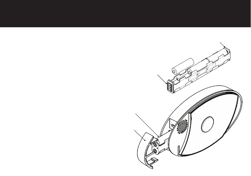
INSTALLING THE BATTERIES
The CB200-M uses six (6) AA batteries.
1. Remove the battery holder from
cardboard packaging.
2. Orient the battery holder with the four
copper contacts pointed
towards you.
3. Insert the batteries following battery
sled sticker.
4. Insert battery holder into
bottom of device with the four contacts
first.
5. Replace the battery holder cover.
BATTERY
HOLDER
BATTERY
HOLDER
COPPER
CONTACT
BATTERY HOLDER
COVER
+
-
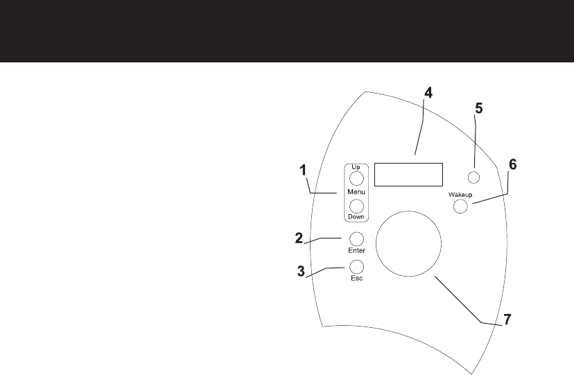
10 CONTROL INTERFACE
1. Menu Button
2. Enter Button
3. Esc Button
4. Display
5. Microphone
6. Wake Up Button
7. Call Button
Available Controls and Components
11
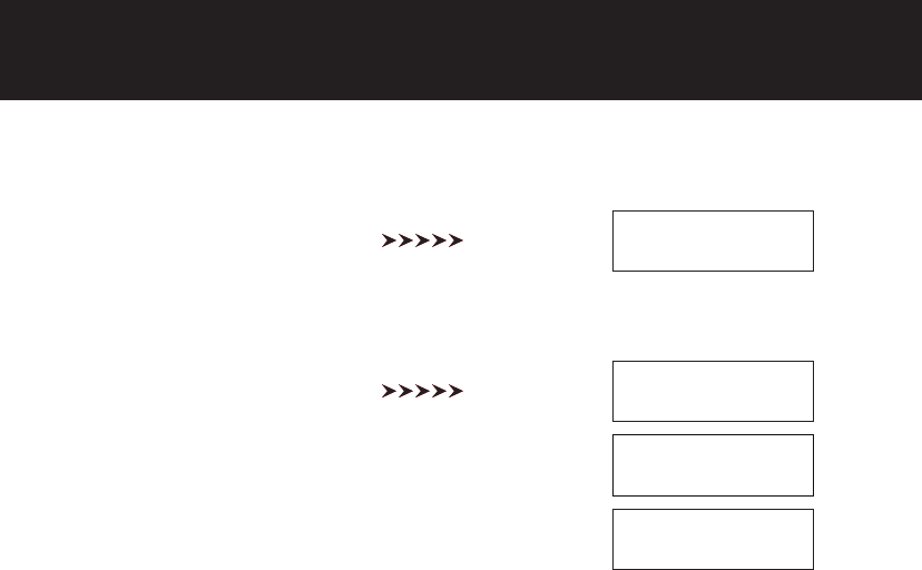
CONTROL INTERFACE LCD DISPLAY
Initial Power-Up
Once the batteries are installed in
the unit, the Call Button blinks and
LCD display shows
Interface ENA.
If the USB Serial Interface is not
to be used, press the ESC button
to exit this mode. The default
status screen will be shown on the
display. If nothing is pressed, the
unit will enter sleep mode after 60
seconds and the screen will clear.
Status Screen
The Status Screen toggles the
current Frequency and CTCSS
setting continuously.
INTERFACE ENA
-ESC to EXIT-
CB200-M
Insert Battery
Press Esc
Freq No: 6
MHZ:154.5700
CTCSS CODE: 1
67.0 HZ ANA
Channel Spacing
12.5 KHZ
12 LCD WAKEUP
The screen is in a blank “sleep” state during most operation, even when the system is operating.
This is a feature to increase battery life and prevent tampering.
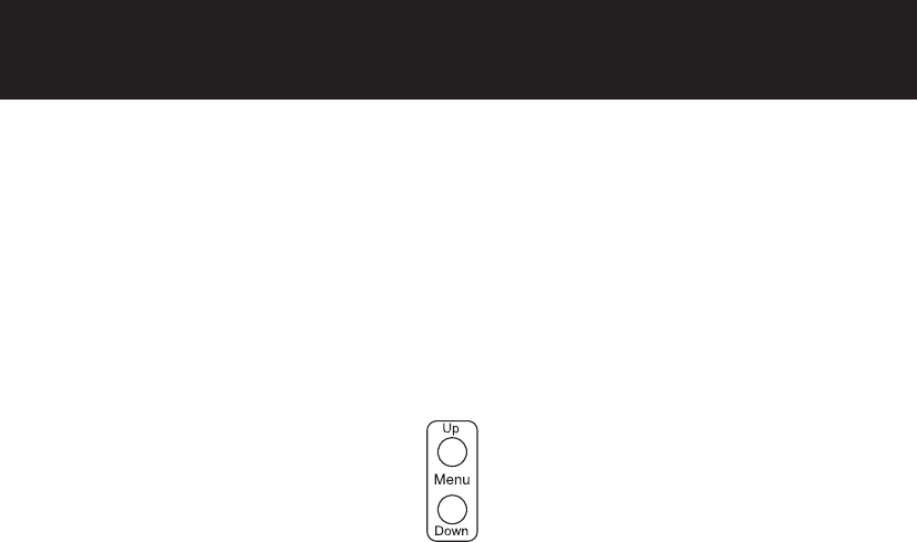
To enter the Menu options, press the Wakeup button on the unit. The large round button blinks to
indicate it is awake.
The display remains disabled until any LCD menu control button is pressed. The LCD menu control
buttons are Up or Down as shown in the following.
13
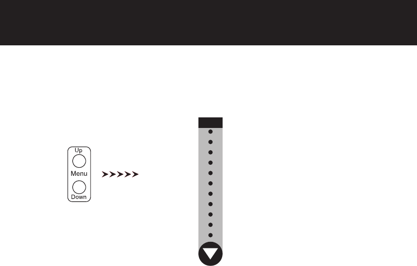
SCROLLING MENU
You can setup preferred features on CB200-M by scrolling through the menu options. Press the
Menu Buttons to scroll through menus.
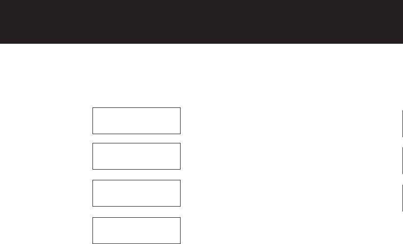
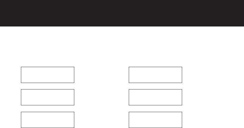
Menu options are presented in the order below, and the list repeats continuously.
v
Set MURS Channel Number
Set Radio Code
Message Record
Message Playback
Volume Adjust
LCD Contrast
Software Version
Call Cycles
Cycle Delay
Inverted Codes
RF Busy Delay
MURS
14 MURS CHANNEL SELECTION
Set MURS Channel Number
When the unit is awake and displaying the Status Screen, press the
UP or Down Menu buttons until “MURS Chan No?” appears.
Press Enter
Press Up or Down to
select new channel
Press Enter to select new
channel
Press Enter to select new
channel
The CB200-M is now programmed with the new channel selected.
Old:6 154.5700
New:6 154.5700
Old:6 154.5700
New:2 154.6000
Old:6 154.5700
**Chan Updated
MURS Chan No?
15
RADIO CODE SELECTION
Old:12 100.Hz
The CB200-M is now programmed with the new CTCSS squelch code.
Set Squelch Code Frequency
When the unit is awake and displaying the Status Screen, press the
UP or Down Menu buttons until “Radio Code?” appears.
Radio Code? Press Enter Old:12 100.0 Hz
New:12 100.0 Hz
Press Up or Down to
select new squelch code
Old:12 100.0 Hz
New:13 103.5 Hz
Press Enter to select
new squelch code
**Code Updated
Press Enter to select
new squelch code
Press Up or Down to
select new channel
Channel No 1-7?
Ch:1 154.5700
Press Enter to select
new channel
Channel No 1-7?
Ch:3 151.8200

16 MESSAGE RECORDING
Press Up or Down button until “Msg Record?” appears.
The new message automatically playback to verify it was recorded correctly. Message cannot be
longer than 10 seconds.
Msg Record?
Select Message?
Aux Message
Select Message?
Local Message
Hold ENTER Btn
To Record Msg
Press Enter
Press Up or Down to find
message to record.
Press Enter to select mes-
sage to record.
Hold Enter button to record
a new message.
17
MESSAGE PLAYBACK
Press Up or Down button until “Msg Playback?” appears.
Press Enter
Press Up or Down to find
message to playback.
Press Enter to select
message to playback.
Select new message to
playback or press Esc to exit.
Msg Playback?
Select Message?
Local Message
Select Message?
Radio Message
-Playback Act-
Radio Message

18 VOLUME ADJUSTMENT
Volume Adjust?
Speaker Volume?
-Speaker Vol-
Vol(1-63): 45
Press Up or Down button until “Volume Adjust?” appears.
Press Enter
Press Up or Down to select which volume
to adjust, then press Enter.
Press Up or Down until desired volume
selection is shown. The volume settings
take place immediately. Press Esc to exit.

19
LCD CONTRAST
Press Up or Down button until “LCD Contrast?” appears.
If the need arises to adjust the LCD contrast, check the batteries first. The batteries may be too
weak to operate the unit correctly.
Press Enter
Press Up or Down until desired contrast
selection is shown. The contrast settings
take place immediately. Press Esc to exit.
LCD Contrast?
-LCD Contrast-
(0-15): 0

20 SOFTWARE VERSION
You may be asked by a field support or technical support personnel to determine the CB200-M
device’s software version.
Press Up or Down button until “Software Ver?” appears.
Press Enter
The software version is shown

21
SOFTWARE VERSION CALL CYCLES
Call Cycles refers to the repeating radio broadcasts that will occur when the call button is active.
Press Up or Down button until “Call Cycles?” appears.
Press Enter
Press Up or Down to increase or decrease
the Call Cycle selection. The range is 1-30
cycles. Press Enter to select the new Call
Cycle.
Call Cycles?
Old: 2 cycles
New: 2 cycles

22 CYCLE DELAY
Call Delay refers to the delay (in seconds) between repeating radio broadcasts that occur when
the call button (or aux button) is active.
Press Up or Down button until “Cycle Delay?” appears.
Press Enter
Cycle Delay?
Old: 45 sec
New: 45 sec
Press Up or Down to increase or decrease
the Cycle Delay selection. The range is
10-180 seconds. Press Enter to select the
new Call Cycle.
23
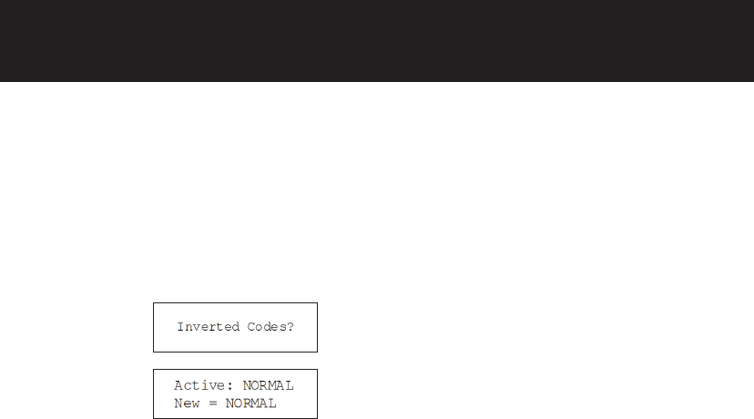
CYCLE DELAY INVERTED CODES
Press Up or Down button until “Inverted Codes?” appears.
WARNING: If the incorrect digital code is selected, the radio broadcast will not open the squelch
of the receiving unit.
When selecting digital CTCSS (squelch) codes, some receiving units may require inverted Octal
numeric codes. Typically, receivers use the non-inverted codes. CB200-M is set to non-inverted by
default.
Note: This feature only applicable for CB200-M
Press Up or Down to select between
NORMAL and INVERTED. Press Enter
to select the new setting.
Press Enter
24
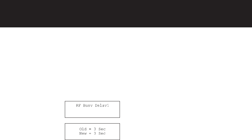
RF Busy Delay defines the amount of time after the CB200-M recognizes an open channel before it
makes it’s radio transmission. This is helpful if you would like to set a longer time between button
press and radio message or to prevent transmitting while conversations are ongoing in some
environments.
Press Enter
Use the Up or Down to cycle through the
RF Busy Delay selections (3-15 seconds).
Press Enter to select the new value, or
Esc to exit without any changes. Default
setting is 3-seconds.
RF BUSY DELAY
Press Up or Down button until “RF Busy Delay?” appears.
MOUNTING THE DEVICE

25
RF BUSY DELAY
The CB200-M can be mouted to the wall using the included 3M DualLock strips or by using the
optional wall mounting bracket.
Using 3M DualLock
Ensure both the back of the callbox and the area of the surface that is being attached to is clean,
flat, and dry.
1. Peel off one side of the DualLock’s release backing and firmly adhere to the left side of the unit.
Repeat this with the other DualLock to the right side of the callbox.
2. Once both strips of DualLock are attached to the callbox, peel off the white release backing and
carefully align the unit to be level on the surface you intend to place it.
3. Once the callbox appears aligned, firmly press it to the wall in one motion.
Note: The callbox can be removed by applying firm pressure around the exterior edge of the unit.
For optional mounting accessories, please use the mounting bracket available from your Motorola
CB200-M distributor.
MOUNTING THE DEVICE
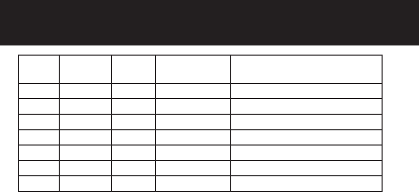
26 FREQUENCY SELECTION TABLE - MURS
Freq.
No.
Freq. Value CTCSS
Code
Bandwidth
(KHz)
Description
1 154.5700 0 20 KHz Default Freq / Code
2 154.6000 0 20 KHz Default Freq / Code
3 151.8200 57 (131) 11.25 KHz Default Freq / Code
4 151.8800 57 (131) 11.25 KHz Default Freq / Code
5 151.9400 57 (131) 11.25 KHz Default Freq / Code
6 154.5700 57 (131) 20 KHz Default Freq / Code
7 154.6000 57 (131) 20 KHz Default Freq / Code
Note: the CTCSS Code shown is the default setting. The CTCSS squelch code can be changed by
the user. (Refer to the Radio Code Selection section on page 15.)
27
FREQUENCY SELECTION TABLE - MURS
Freq.
No.
Freq. Value CTCSS
Code
Bandwidth
(KHz)
Description
1 154.5700 0 20 KHz Default Freq / Code
2 154.6000 0 20 KHz Default Freq / Code
3 151.8200 57 (131) 11.25 KHz Default Freq / Code
4 151.8800 57 (131) 11.25 KHz Default Freq / Code
5 151.9400 57 (131) 11.25 KHz Default Freq / Code
6 154.5700 57 (131) 20 KHz Default Freq / Code
7 154.6000 57 (131) 20 KHz Default Freq / Code
CTCSS CHART (ANALOG)
No. Code Hz No. Code Hz No. Code Hz No. Code Hz
1 67.0 13 103.5 25 156.7 37 241.8
2 71.9 14 107.2 26 162.2 38 250.3
3 74.4 15 110.9 27 167.9
4 77.0 16 114.8 28 173.8
5 79.7 17 118.8 29 179.9
6 82.5 18 123.0 30 186.2
7 85.4 19 127.3 31 192.8
8 88.5 20 131.8 32 203.5
9 91.5 21 136.5 33 210.7
10 94.8 22 141.3 34 218.1
11 97.4 23 146.2 35 225.7
12 100.0 24 151.4 36 233.6
Note: the CTCSS Code shown is the default setting. The CTCSS squelch code can be changed by
the user. (Refer to the Radio Code Selection section on page 15.)
28 CTCSS CHART (DIGITAL)
No. Code No. Code No. Code No. Code
39 023 51 073 63 156 75 261
40 025 52 074 64 162 76 263
41 026 53 117 65 165 77 265
42 031 54 115 66 172 78 271
43 032 55 116 67 174 79 306
44 043 56 125 68 205 80 311
45 047 57 131 69 223 81 315
46 051 58 132 70 226 82 331
47 054 59 134 71 243 83 343
48 065 60 143 72 244 84 346
49 071 61 152 73 245 85 351
50 072 62 155 74 251 86 364
CTCSS CHART (DIGITAL)
29
CTCSS CHART (DIGITAL)
No. Code No. Code No. Code
87 365 99 503 111 654
88 371 100 506 112 662
89 411 101 516 113 664
90 412 102 532 114 703
91 413 103 546 115 712
92 423 104 565 116 723
93 431 105 606 117 731
94 432 106 612 118 732
95 445 107 624 119 734
96 464 108 627 120 743
97 465 109 631 121 754
98 466 110 632

30 NOTES

31
NOTES

Printed in USA 02012018M