Motorola Solutions 89FT4828 Hand-held Portable Device. User Manual 89C80 O p i iv TOC
Motorola Solutions, Inc. Hand-held Portable Device. 89C80 O p i iv TOC
UserManual.wiki
>
Motorola Solutions
>
89FT4828 User Manual
Instruction Manual
Navigation menu
Upload a User Manual
Namespaces
Wiki Guide
HTML
PDF
Info
Views
User Manual
Discussion / Help
Navigation
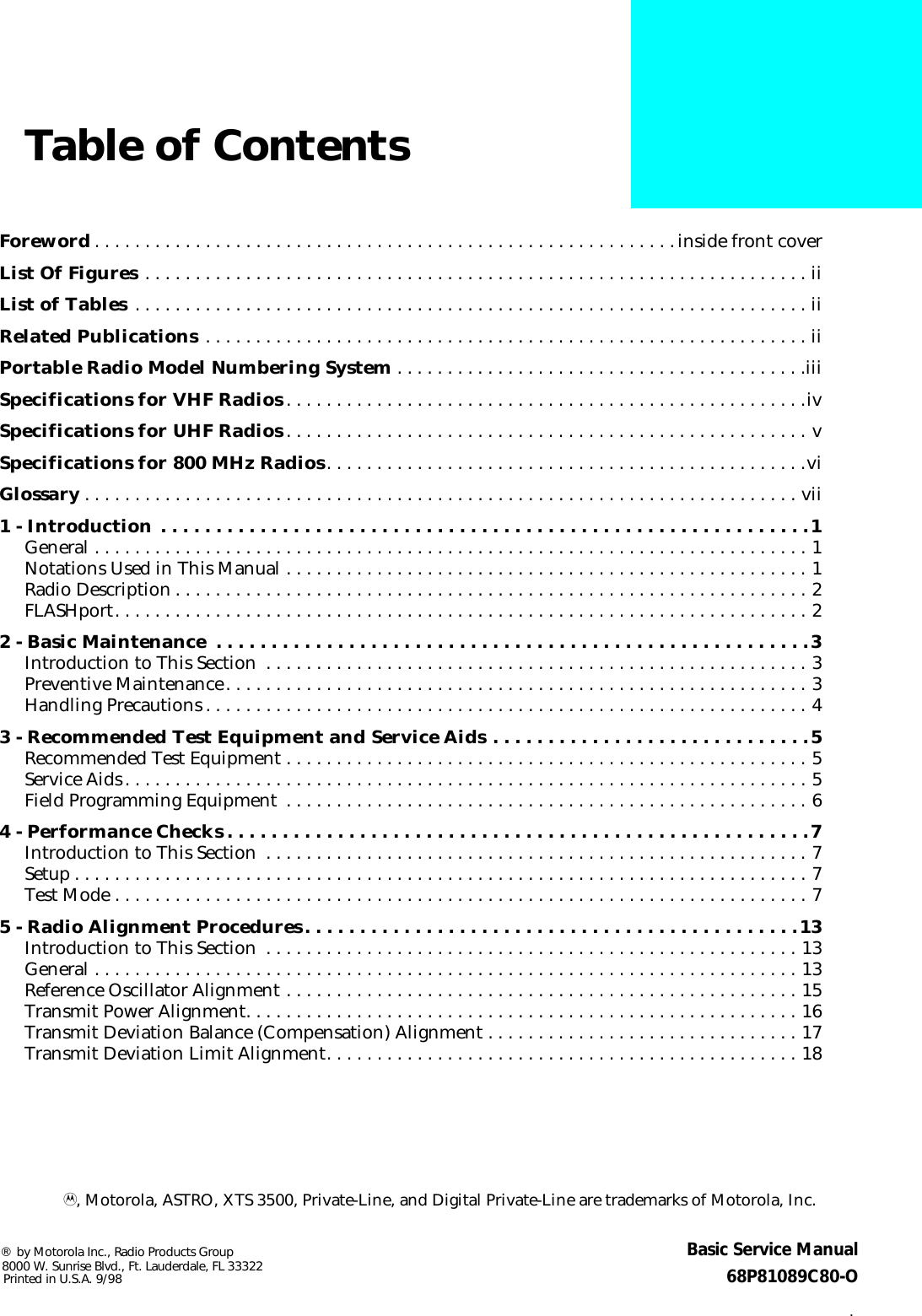


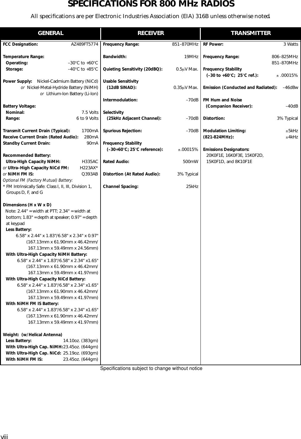


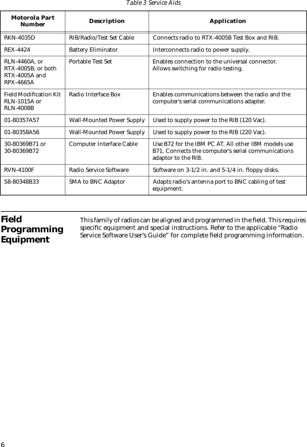
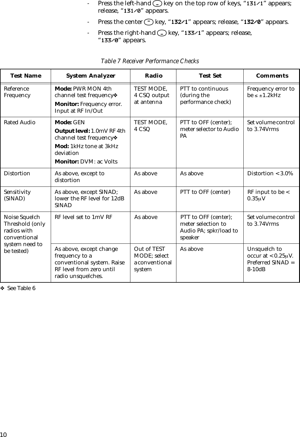
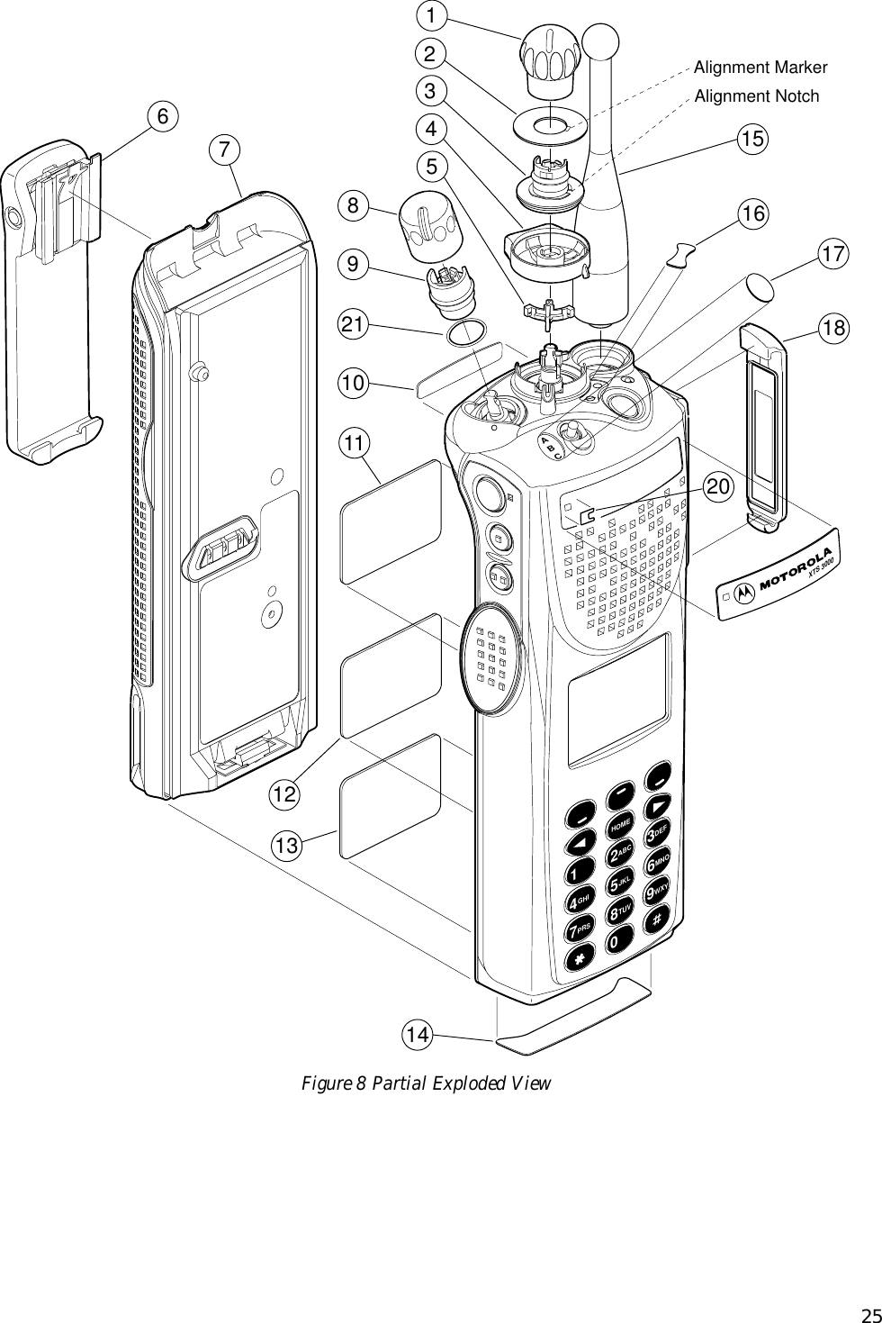
![15Adjusting the softpot value sends information to the radio to increase (or decrease) a dc voltage in the corresponding circuit. For example, pressing the UP arrow key at the Reference Oscillator screen instructs the radio’s microcomputer to increase the voltage across a varactor in the reference oscillator, which increases the frequency.In ALL cases, the softpot value is just a relative number corresponding to a digital-to-analog (D/A) generated voltage in the radio.Perform the following procedures in the sequence indicated.NOTE: Some of the following screens mayvary depending upon the radio undertest and the version of radio servicesoftware you are using. Refer to yourradio service software user’s guide.Reference Oscillator AlignmentAdjustment of the reference oscillator is critical for proper radio operation. Improper adjustment will result not only in poor operation, but also in a misaligned radio that will interfere with other users operating on adjacent channels. For this reason, the reference oscillator should be checked every time the radio is serviced. The frequency counter used for this procedure must have a stability of 0.1 ppm (or better).1. From the SERVICE MENU, press B to select the TRANSMITTER ALIGNMENT MENU.2. Press B again to select the REFERENCE OSCILLATOR alignment screen. See Figure 4.Figure 4 Reference Oscillator Alignment Screen3. Press P (or Z or [RETURN]) to select a frequency field (starting with the highest frequency shown). Then, press F to key the radio. The screen will indicate that the radio is transmitting.MOTOROLA Radio Service Software Use UP/DOWN Arrows To Adjust Softpot. XTS Model: H24SDC9PW5AN MAIN:SERVICE:TX ALIGN:REF OSC REFERENCE OSCILLATOR -------------------- Frequency Current Value --------- ------------- 519.975 150 New Softpot Value.....150 Transmitter..On 0 255 MIN |----+----+----+----+----+----+----+----+----+----+----+----| MAX F1 F2 F3 F4 F5 F6 F7 F8 F9 F10 HELP TOGGLE PROGRAM EXIT PTT VALUE](https://usermanual.wiki/Motorola-Solutions/89FT4828/User-Guide-7089-Page-21.png)
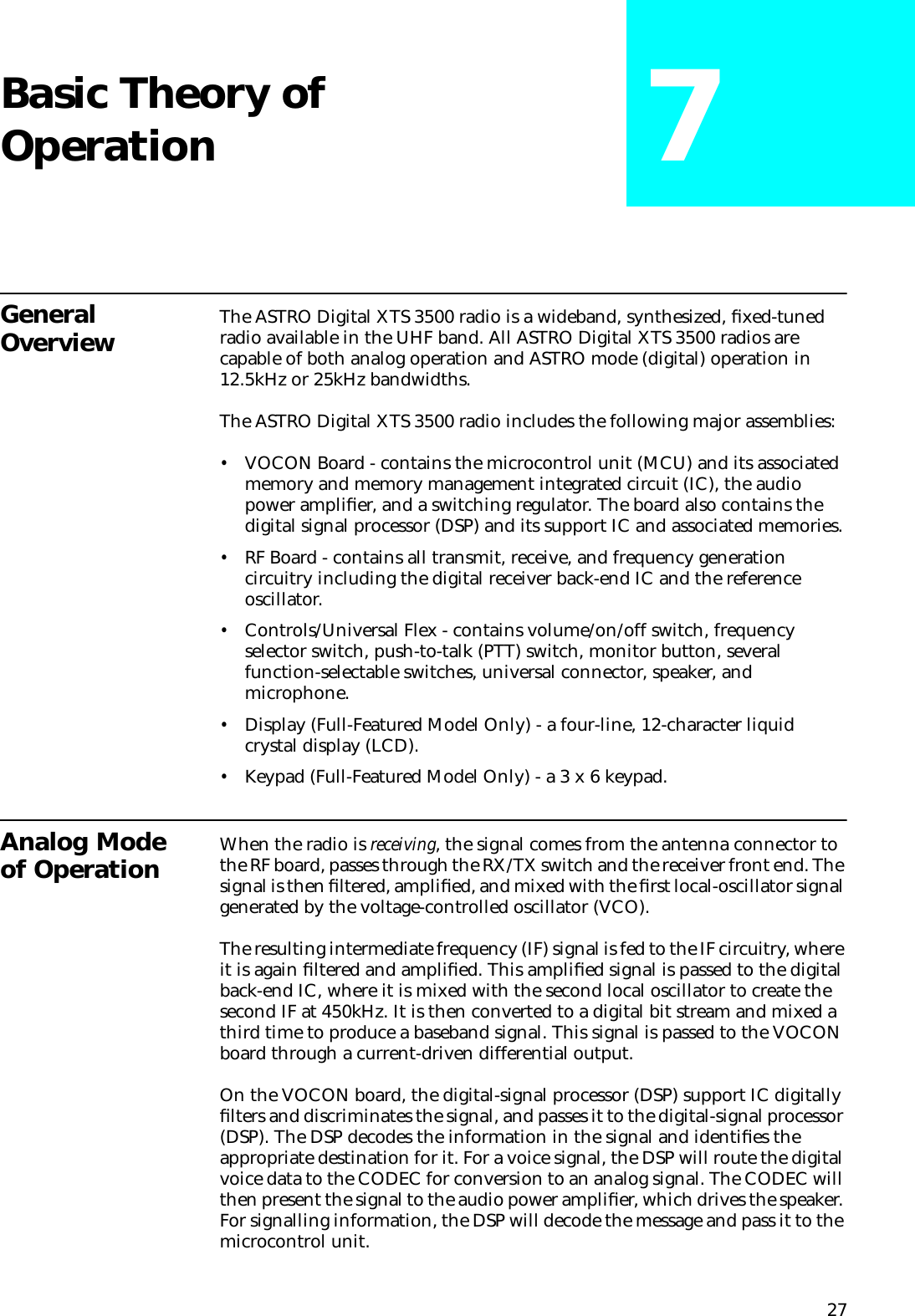
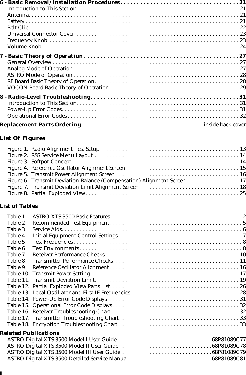
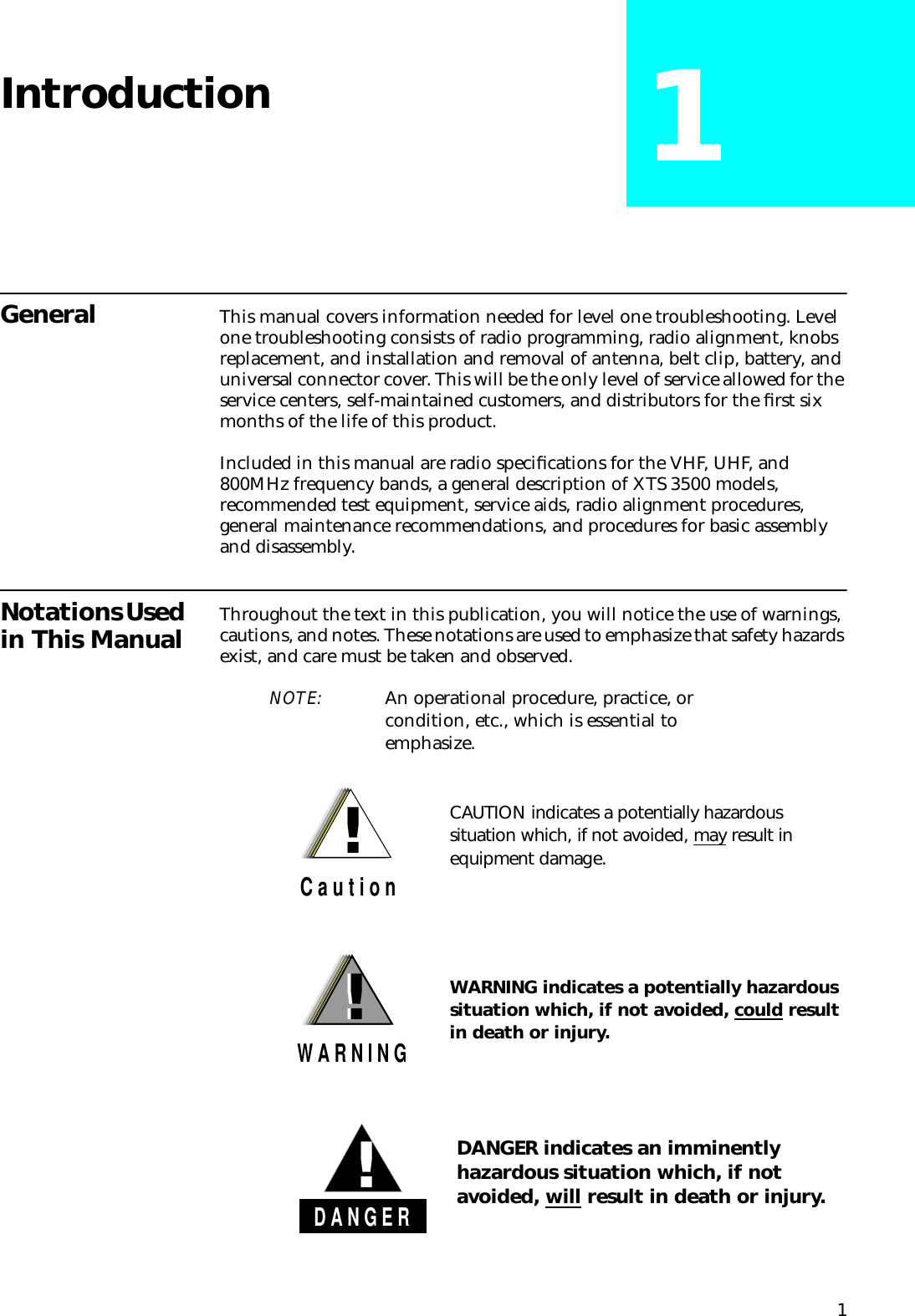
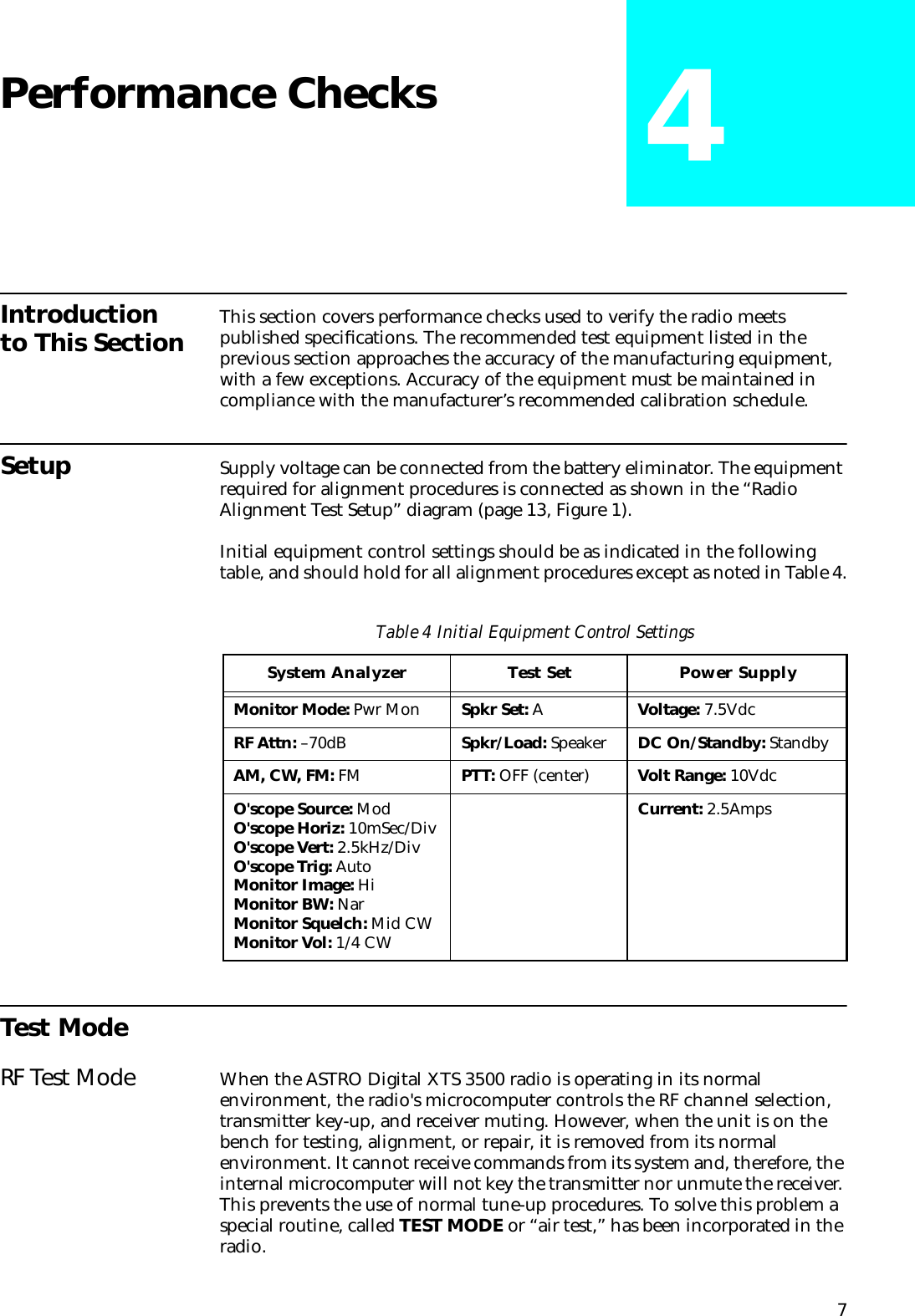
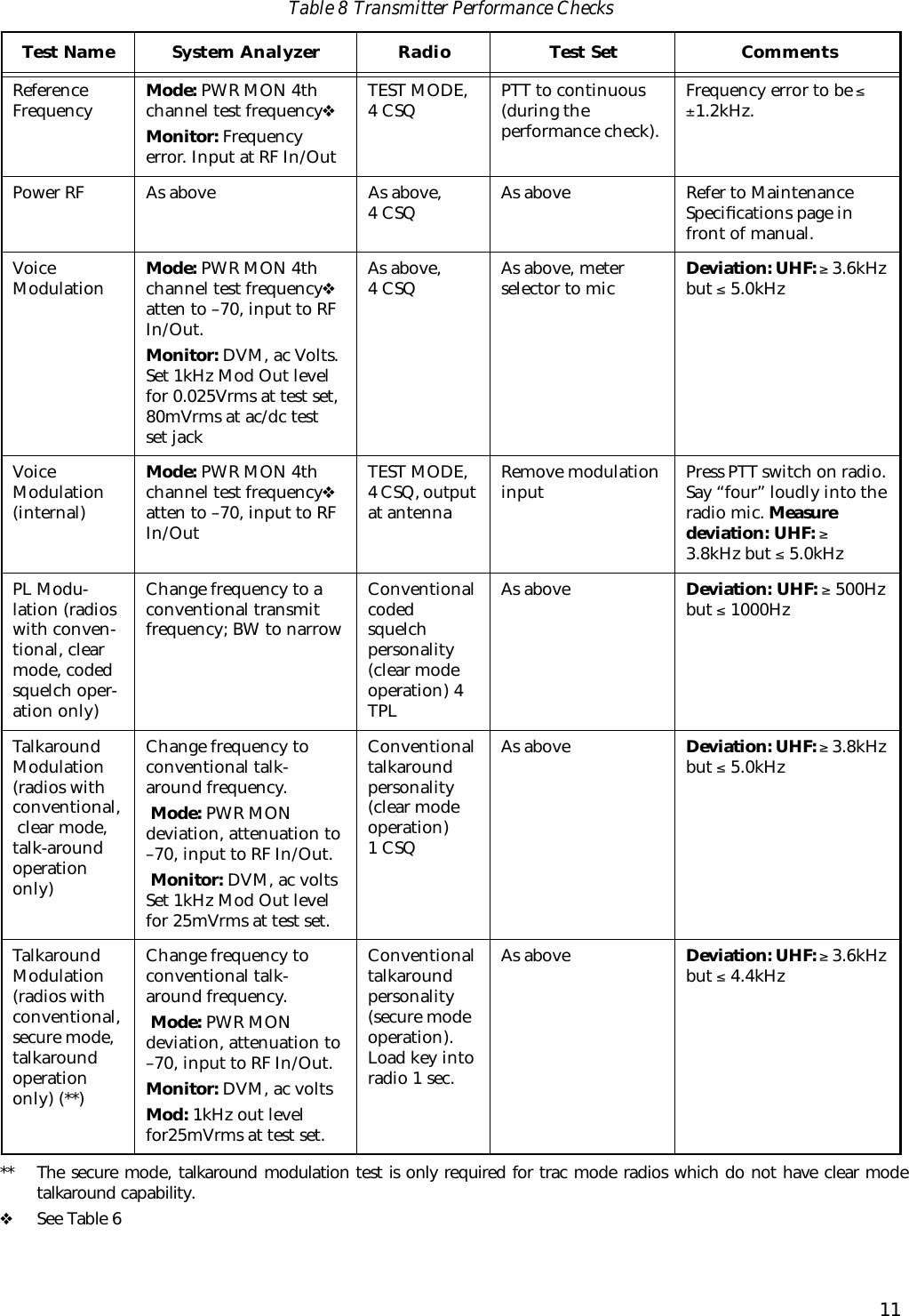
![164. Measure the transmit frequency on your service monitor.5. Use the É/Ç arrow keys to adjust the reference oscillator softpot value. See Table 9.6. Press F again to dekey the radio.7. Press H to program the new softpot value.8. Press J once to return to the TRANSMITTER ALIGNMENT MENU, or press J twice to return to the SERVICE MENU.Transmit Power AlignmentNOTES:•All power measurements are to be made at the antenna port.•The transmitter power setting keeps the radiated power at or below the level specified in the exclusionary clause for low power devices of IEEE Standard C95.1-1991.1. From the SERVICE MENU, press B to select the TRANSMITTER ALIGNMENT MENU.2. Press C to select the TRANSMIT POWER alignment screen. The screen will indicate the transmit frequencies to be used. See Figure 5.Figure 5 Transmit Power Alignment Screen3. Press P (or Z or [RETURN]) to select a frequency field (starting with the highest frequency shown). Then, press F to key the radio. The screen will indicate that the radio is transmitting.4. Use the É/Ç arrow keys to adjust the transmit power per the values shown in Table 10.Table 9 Reference Oscillator AlignmentBand TargetUHF ±100 HzMOTOROLA Radio Service Software Use UP/DOWN Arrows To Adjust Softpot. XTS Model: H24SDC9PW5AN MAIN:SERVICE:TX ALIGN:TX POWER TRANSMIT POWER -------------- Current Value New Softpot Value Frequency High Pwr Low Pwr High Pwr Low Pwr --------- -------- ------- -------- ------- 450.025 10 23 10 23 465.225 11 28 11 28 475.125 20 33 20 33 484.975 33 40 33 40 500.275 43 45 43 45 511.975 58 58 58 58 519.975 58 58 Transmitter..On 58 58 0 127 MIN |---+---+---+---+---+---+---+---+---+---+---+---+---+---+---+---| MAX F1 F2 F3 F4 F5 F6 F7 F8 F9 F10 HELP TOGGLE PROGRAM EXIT PTT VALUE](https://usermanual.wiki/Motorola-Solutions/89FT4828/User-Guide-7089-Page-22.png)
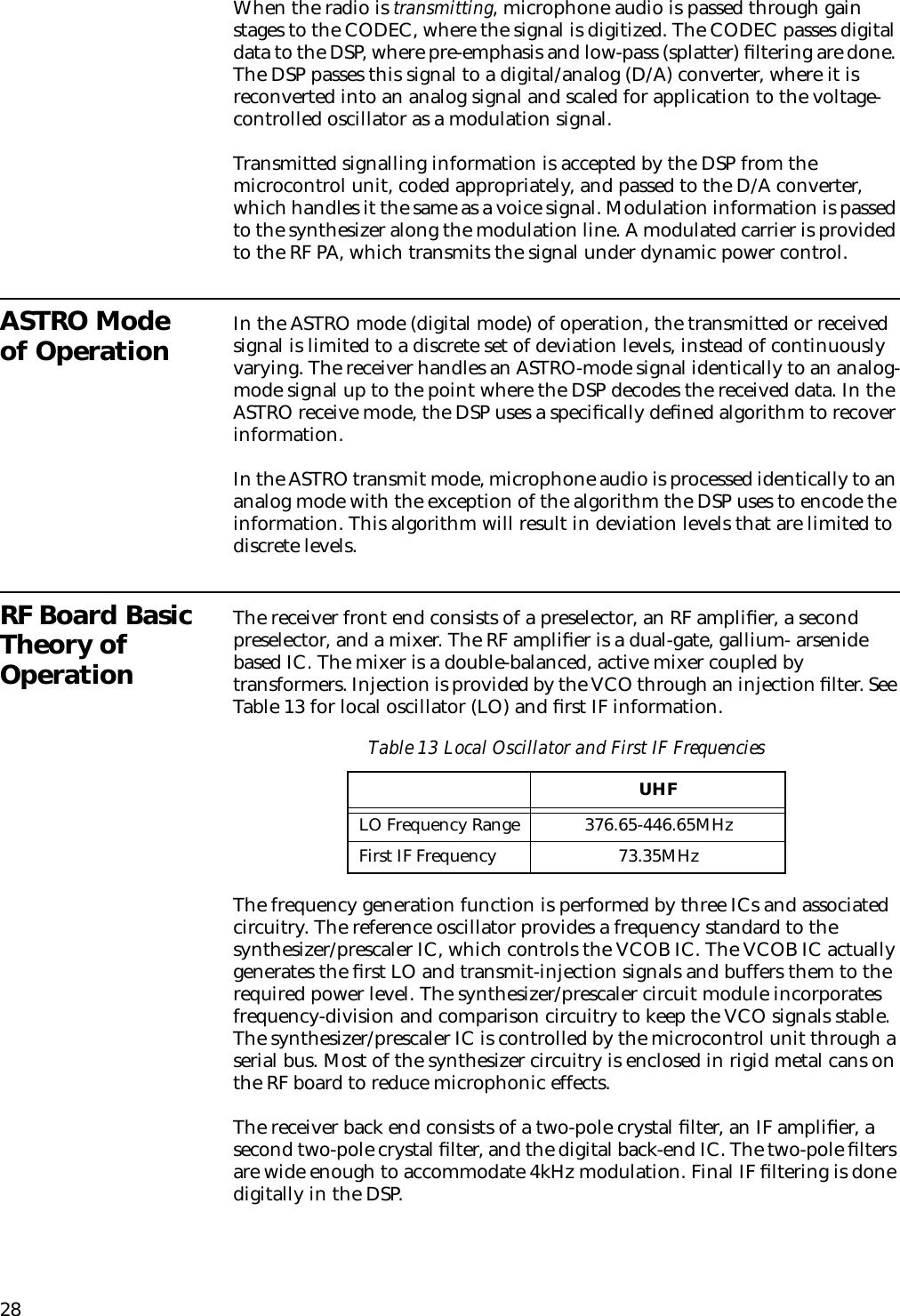
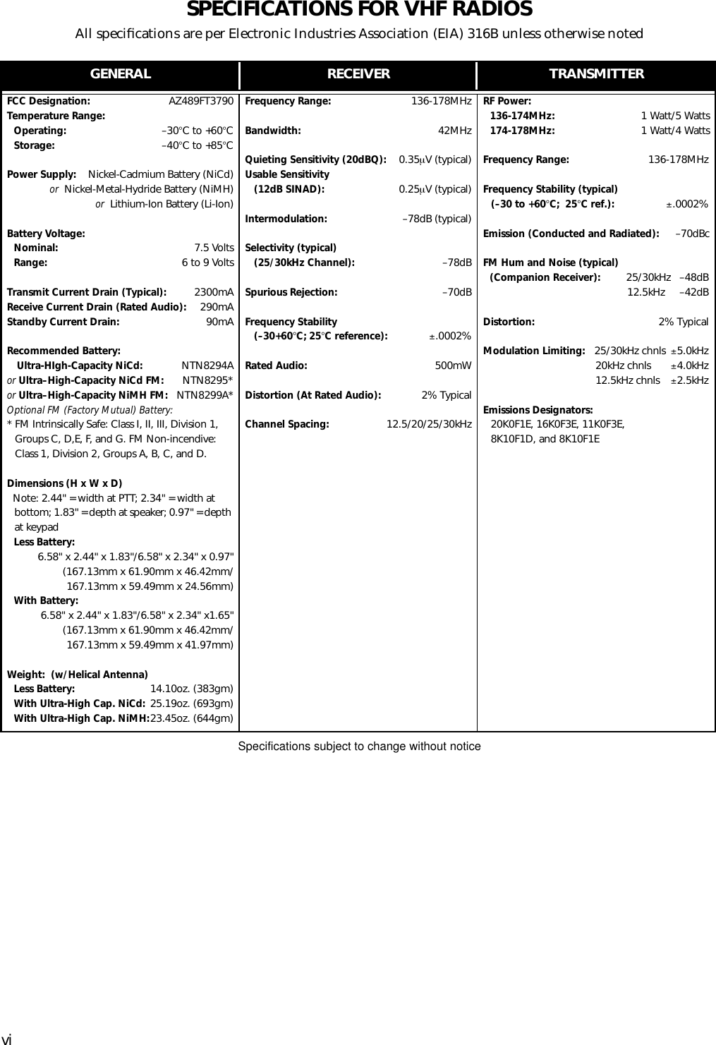
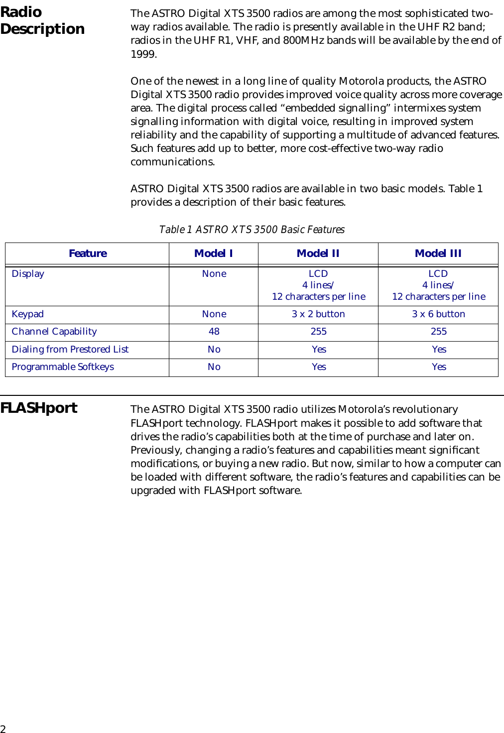
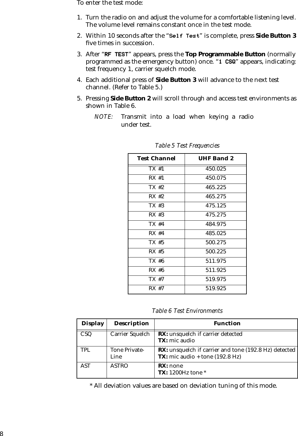
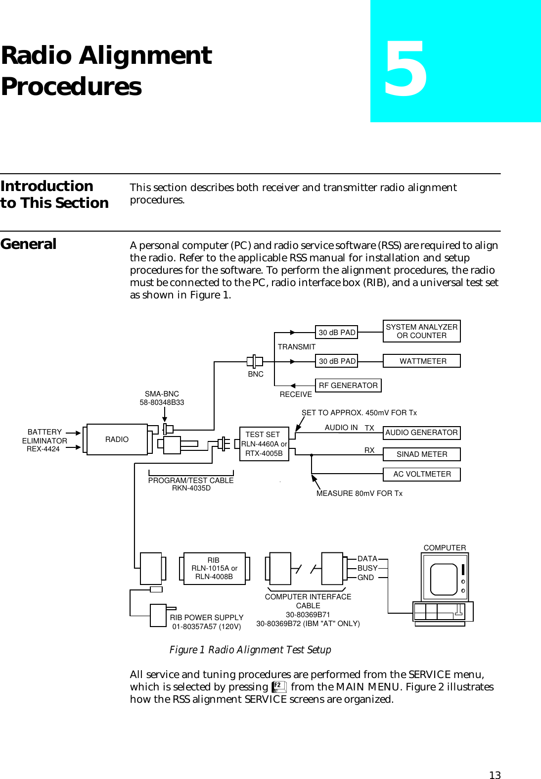
![175. Press F to dekey the radio.6. Press H to program the value.7. Repeat steps 3-6 for the remaining frequencies.8. Press J once to return to the TRANSMITTER ALIGNMENT MENU, or press J twice to return to the SERVICE MENU.Transmit Deviation Balance (Compensation) AlignmentCompensation alignment balances the modulation sensitivity of the VCO and reference modulation (synthesizer low-frequency port) lines. The compensation algorithm is critical to the operation of signalling schemes that have very-low-frequency components (for example, DPL) and could result in distorted waveforms if improperly adjusted. 1. From the SERVICE MENU, press B to select the TRANSMITTER ALIGNMENT MENU.2. Press D to select the TRANSMIT DEVIATION BALANCE (COMPENSATION) alignment screen. The screen will indicate the transmit frequencies to be used. See Figure 6.Figure 6 Transmit Deviation Balance (Compensation) Alignment Screen3. Press P (or Z or [RETURN]) to select a frequency field (starting with the lowest frequency shown).4. Press D. This will cause the radio to key and the radio’s DSP IC to inject an 80Hz tone into the RF board.5. Measure the deviation and record this value.6. Press D to dekey the radio.Table 10 Transmit Power SettingsUHF Power Level Test Frequencies450-512MHz 512-520MHz1 Watt 1.2W - 1.4W 1.2W - 1.4W5 Watts 5.2W - 5.4W 3.2W - 3.4WMOTOROLA Radio Service Software Use UP/DOWN Arrows To Adjust Softpot. XTS Model: H24SDC9PW5AN MAIN:SERVICE:TX ALIGN:BAL ATTN TRANSMIT DEVIATION BALANCE (COMPENSATION) ----------------------------------------- Current Frequency Value New Softpot Value --------- ------- ----------------- 450.025 30 30 465.225 30 30 475.125 30 30 484.975 45 45 500.275 45 45 511.975 45 45 519.975 45 Transmitter..Off 45 0 63 MIN |---+---+---+---+---+---+---+---+---+---+---+---+---+---+---+---| MAX F1 F2 F3 F4 F5 F6 F7 F8 F9 F10 HELP TOGGLE LOW TOGGLE HIGH PROGRAM EXIT TONE PTT TONE PTT VALUE](https://usermanual.wiki/Motorola-Solutions/89FT4828/User-Guide-7089-Page-23.png)
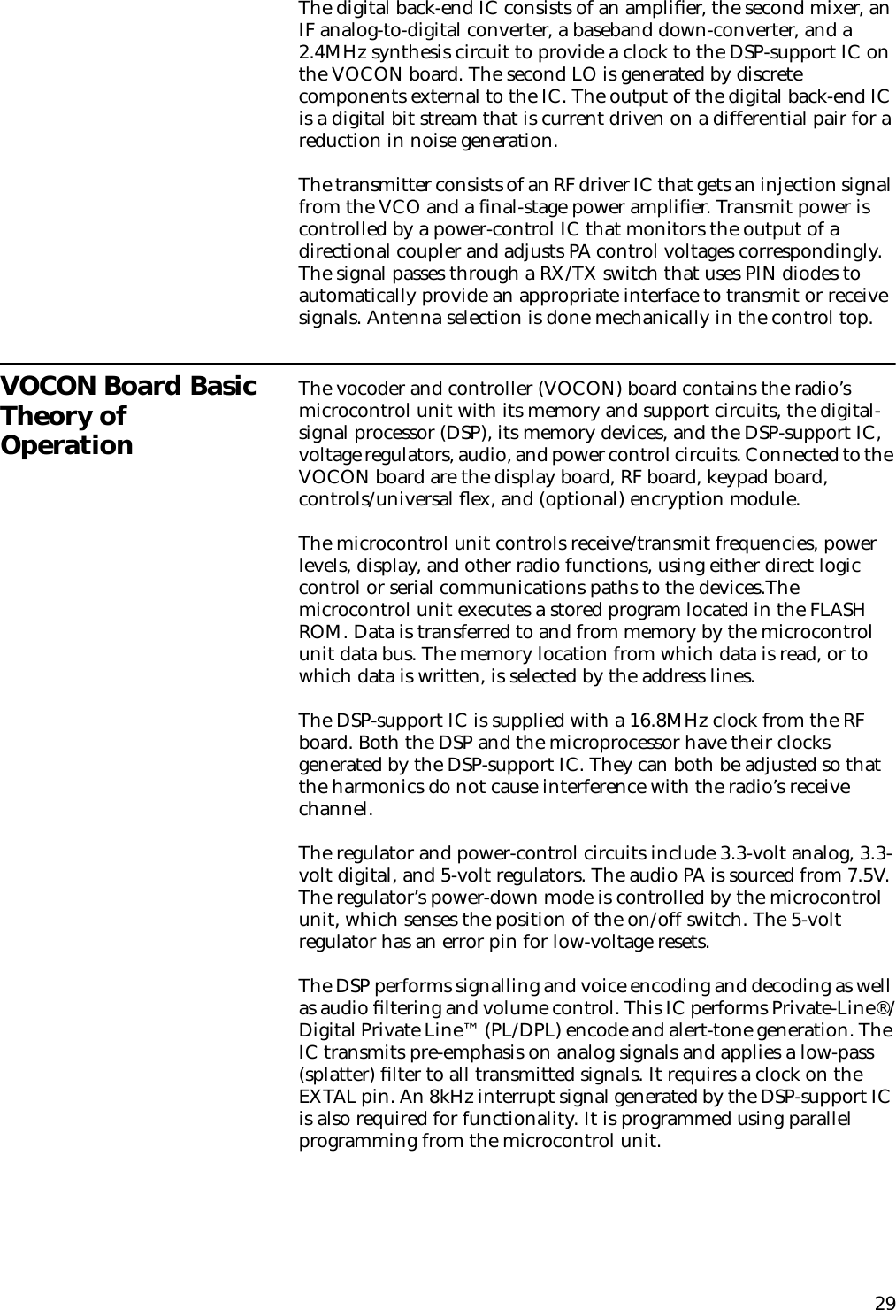
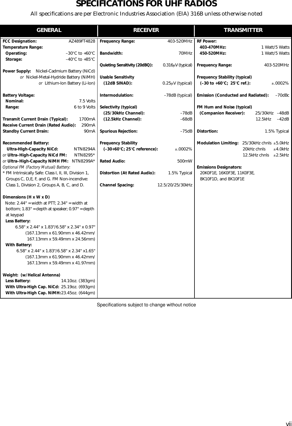
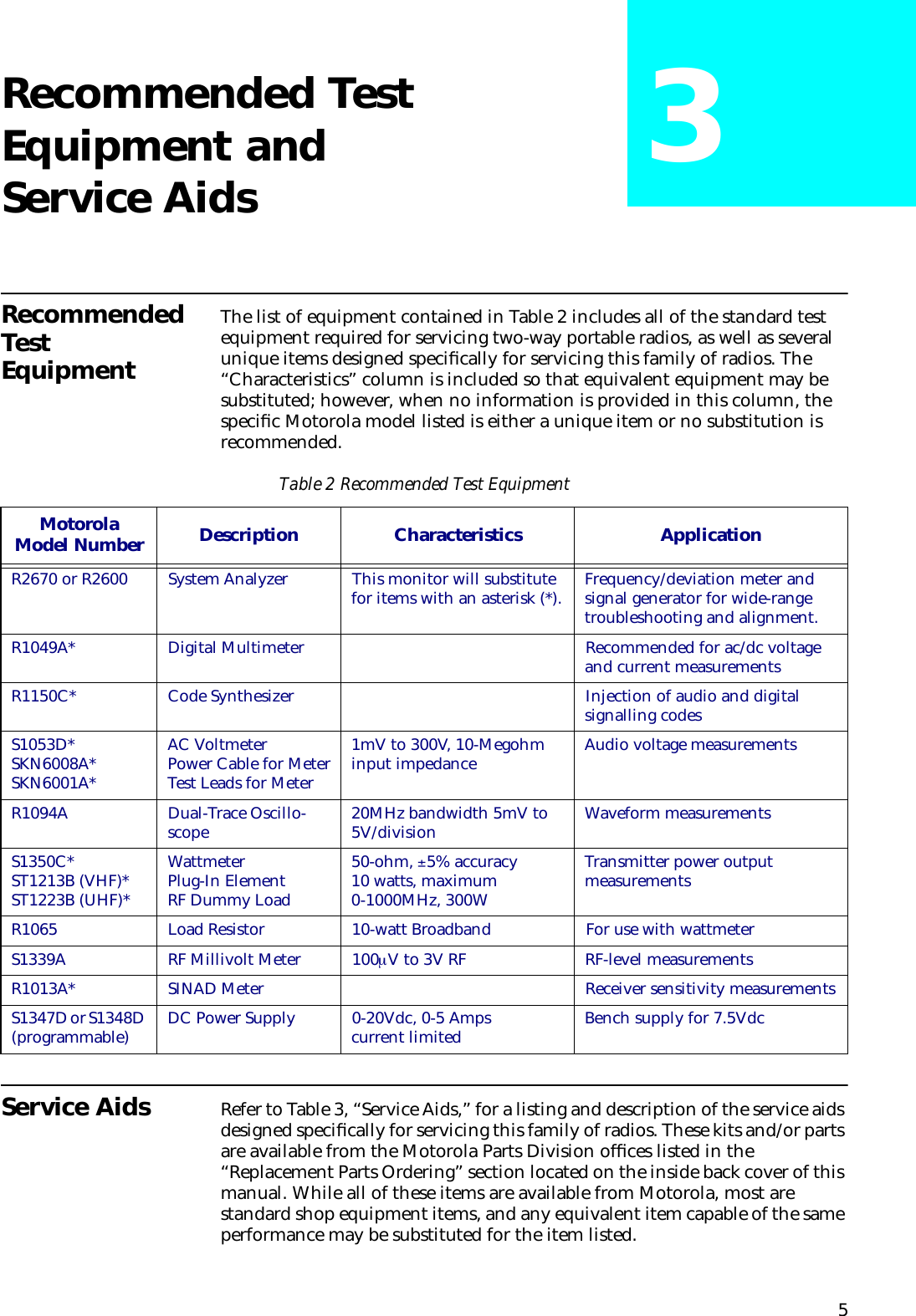
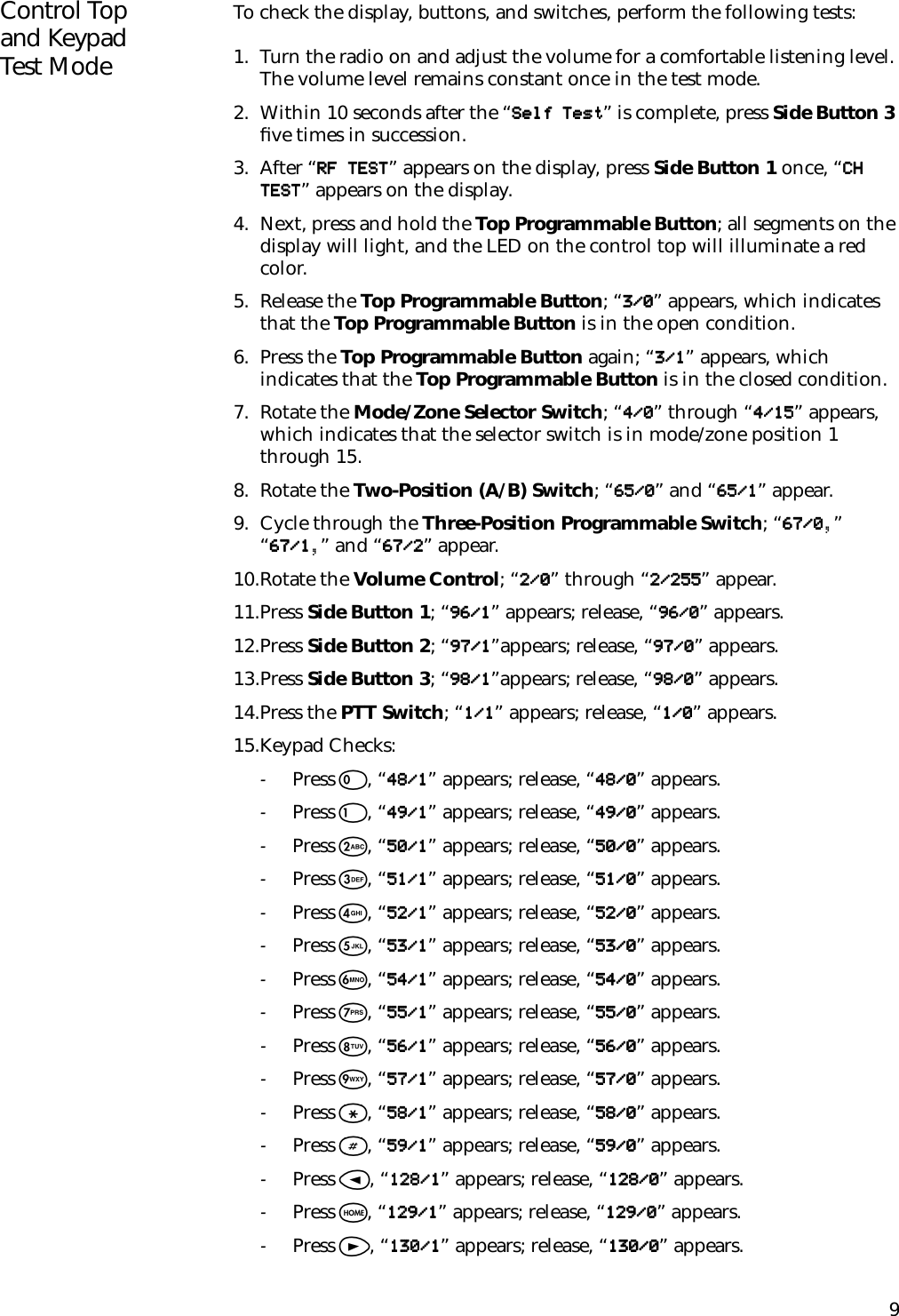
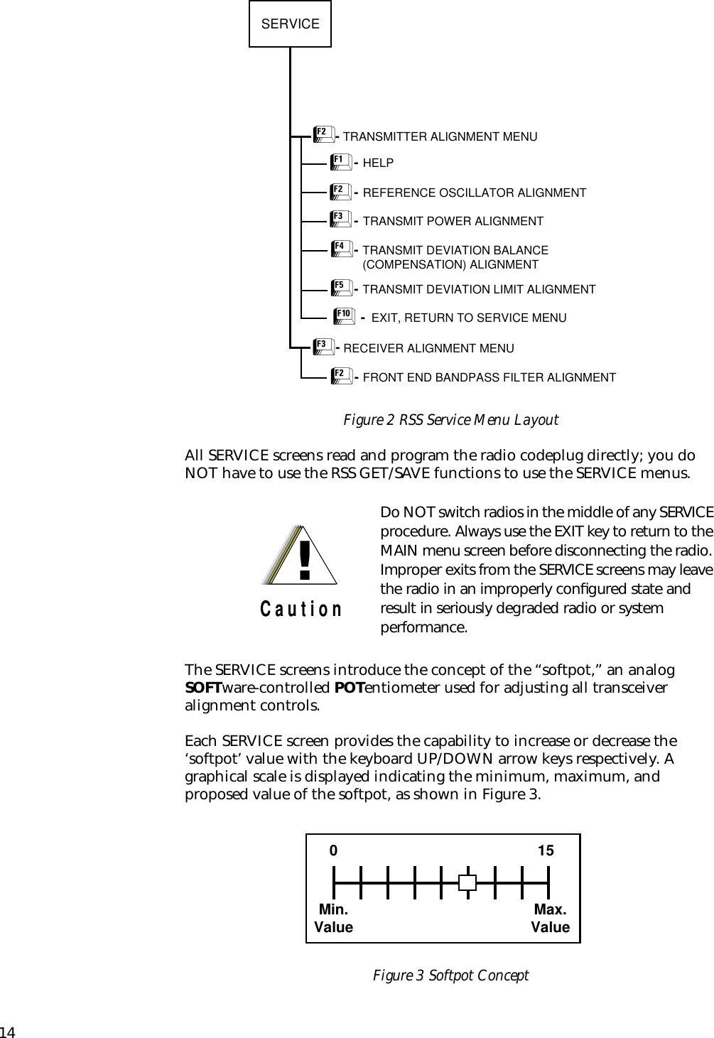
![187. Press F. This will cause the radio’s DSP IC to change the injection tone to 3kHz, 100mVrms. Use the É/Ç arrow keys to adjust the deviation to within ±2% of the value recorded in step 5.8. Repeat steps 4-7 until the 3kHz tone deviation is within ±2% of the 80Hz tone deviation.9. Press F again to dekey the radio.10.Press H to program the new softpot value.11.Repeat steps 3-10 for the remaining frequencies.12.Press J once to return to the TRANSMITTER ALIGNMENT MENU, or press J twice to return to the SERVICE MENU.Transmit Deviation Limit AlignmentIMPORTANT NOTE:Put the radio in the RF test mode and scroll tothe ASTRO test environment, indicated by“AST” on the display (refer to the“Performance Checks” section for details). Allother deviation values are derived from theASTRO test environment mode transmitdeviation limit.1. From the SERVICE MENU, press B to select the TRANSMITTER ALIGNMENT MENU.2. Press E to select the TRANSMIT DEVIATION LIMIT alignment screen. The screen will indicate the transmit frequencies to be used. See Figure 7.Figure 7 Transmit Deviation Limit Alignment Screen3. Press P (or Z or [RETURN]) to select a frequency field (starting with the lowest frequency shown).4. Press F to key the radio. Then use the É/Ç arrow keys to adjust for a deviation per the values shown in Table 11.MOTOROLA Radio Service Software Use UP/DOWN Arrows To Adjust Softpot. XTS Model: H24SDC9PW5AN MAIN:SERVICE:TX ALIGN:DEV.LIMIT TRANSMIT DEVIATION LIMIT ------------------------ Current Frequency Value New Softpot Value --------- ------- ----------------- 450.025 175 175 465.225 175 175 475.125 180 180 484.975 180 180 500.275 180 180 511.975 180 180 519.975 180 Transmitter..Off 180 0 32767 MIN |----+----+----+----+----+----+----+----+X---+----+----+----| MAX F1 F2 F3 F4 F5 F6 F7 F8 F9 F10 HELP TOGGLE PROGRAM EXIT PTT VALUE](https://usermanual.wiki/Motorola-Solutions/89FT4828/User-Guide-7089-Page-24.png)