Motorola Solutions 89FT4828 Hand-held Portable Device. User Manual 89C80 O p i iv TOC
Motorola Solutions, Inc. Hand-held Portable Device. 89C80 O p i iv TOC
Instruction Manual

i
Table of Contents
Foreword
. . . . . . . . . . . . . . . . . . . . . . . . . . . . . . . . . . . . . . . . . . . . . . . . . . . . . . . . . .inside front cover
List Of Figures
. . . . . . . . . . . . . . . . . . . . . . . . . . . . . . . . . . . . . . . . . . . . . . . . . . . . . . . . . . . . . . . . . . ii
List of Tables
. . . . . . . . . . . . . . . . . . . . . . . . . . . . . . . . . . . . . . . . . . . . . . . . . . . . . . . . . . . . . . . . . . . ii
Related Publications
. . . . . . . . . . . . . . . . . . . . . . . . . . . . . . . . . . . . . . . . . . . . . . . . . . . . . . . . . . . . ii
Portable Radio Model Numbering System
. . . . . . . . . . . . . . . . . . . . . . . . . . . . . . . . . . . . . . . . .iii
Specifications for VHF Radios
. . . . . . . . . . . . . . . . . . . . . . . . . . . . . . . . . . . . . . . . . . . . . . . . . . . .iv
Specifications for UHF Radios
. . . . . . . . . . . . . . . . . . . . . . . . . . . . . . . . . . . . . . . . . . . . . . . . . . . . v
Specifications for 800 MHz Radios
. . . . . . . . . . . . . . . . . . . . . . . . . . . . . . . . . . . . . . . . . . . . . . . .vi
Glossary
. . . . . . . . . . . . . . . . . . . . . . . . . . . . . . . . . . . . . . . . . . . . . . . . . . . . . . . . . . . . . . . . . . . . . . . vii
1 - Introduction . . . . . . . . . . . . . . . . . . . . . . . . . . . . . . . . . . . . . . . . . . . . . . . . . . . . . . . . . . .1
General . . . . . . . . . . . . . . . . . . . . . . . . . . . . . . . . . . . . . . . . . . . . . . . . . . . . . . . . . . . . . . . . . . . . . . . 1
Notations Used in This Manual . . . . . . . . . . . . . . . . . . . . . . . . . . . . . . . . . . . . . . . . . . . . . . . . . . . . 1
Radio Description . . . . . . . . . . . . . . . . . . . . . . . . . . . . . . . . . . . . . . . . . . . . . . . . . . . . . . . . . . . . . . . 2
FLASHport. . . . . . . . . . . . . . . . . . . . . . . . . . . . . . . . . . . . . . . . . . . . . . . . . . . . . . . . . . . . . . . . . . . . . 2
2 - Basic Maintenance . . . . . . . . . . . . . . . . . . . . . . . . . . . . . . . . . . . . . . . . . . . . . . . . . . . . . .3
Introduction to This Section . . . . . . . . . . . . . . . . . . . . . . . . . . . . . . . . . . . . . . . . . . . . . . . . . . . . . . 3
Preventive Maintenance. . . . . . . . . . . . . . . . . . . . . . . . . . . . . . . . . . . . . . . . . . . . . . . . . . . . . . . . . . 3
Handling Precautions . . . . . . . . . . . . . . . . . . . . . . . . . . . . . . . . . . . . . . . . . . . . . . . . . . . . . . . . . . . . 4
3 - Recommended Test Equipment and Service Aids . . . . . . . . . . . . . . . . . . . . . . . . . . . . .5
Recommended Test Equipment . . . . . . . . . . . . . . . . . . . . . . . . . . . . . . . . . . . . . . . . . . . . . . . . . . . . 5
Service Aids. . . . . . . . . . . . . . . . . . . . . . . . . . . . . . . . . . . . . . . . . . . . . . . . . . . . . . . . . . . . . . . . . . . . 5
Field Programming Equipment . . . . . . . . . . . . . . . . . . . . . . . . . . . . . . . . . . . . . . . . . . . . . . . . . . . . 6
4 - Performance Checks . . . . . . . . . . . . . . . . . . . . . . . . . . . . . . . . . . . . . . . . . . . . . . . . . . . . .7
Introduction to This Section . . . . . . . . . . . . . . . . . . . . . . . . . . . . . . . . . . . . . . . . . . . . . . . . . . . . . . 7
Setup . . . . . . . . . . . . . . . . . . . . . . . . . . . . . . . . . . . . . . . . . . . . . . . . . . . . . . . . . . . . . . . . . . . . . . . . . 7
Test Mode . . . . . . . . . . . . . . . . . . . . . . . . . . . . . . . . . . . . . . . . . . . . . . . . . . . . . . . . . . . . . . . . . . . . . 7
5 - Radio Alignment Procedures. . . . . . . . . . . . . . . . . . . . . . . . . . . . . . . . . . . . . . . . . . . . .13
Introduction to This Section . . . . . . . . . . . . . . . . . . . . . . . . . . . . . . . . . . . . . . . . . . . . . . . . . . . . . 13
General . . . . . . . . . . . . . . . . . . . . . . . . . . . . . . . . . . . . . . . . . . . . . . . . . . . . . . . . . . . . . . . . . . . . . . 13
Reference Oscillator Alignment . . . . . . . . . . . . . . . . . . . . . . . . . . . . . . . . . . . . . . . . . . . . . . . . . . . 15
Transmit Power Alignment. . . . . . . . . . . . . . . . . . . . . . . . . . . . . . . . . . . . . . . . . . . . . . . . . . . . . . . 16
Transmit Deviation Balance (Compensation) Alignment . . . . . . . . . . . . . . . . . . . . . . . . . . . . . . . 17
Transmit Deviation Limit Alignment. . . . . . . . . . . . . . . . . . . . . . . . . . . . . . . . . . . . . . . . . . . . . . . 18
A
, Motorola, ASTRO, XTS 3500, Private-Line, and Digital Private-Line are trademarks of Motorola, Inc.
® by Motorola Inc., Radio Products Group
8000 W. Sunrise Blvd., Ft. Lauderdale, FL 33322
Printed in U.S.A. 9/98
Basic Service Manual
68P81089C80-O
ii
6 - Basic Removal/Installation Procedures. . . . . . . . . . . . . . . . . . . . . . . . . . . . . . . . . . . . 21
Introduction to This Section. . . . . . . . . . . . . . . . . . . . . . . . . . . . . . . . . . . . . . . . . . . . . . . . . . . . . . 21
Antenna. . . . . . . . . . . . . . . . . . . . . . . . . . . . . . . . . . . . . . . . . . . . . . . . . . . . . . . . . . . . . . . . . . . . . . 21
Battery. . . . . . . . . . . . . . . . . . . . . . . . . . . . . . . . . . . . . . . . . . . . . . . . . . . . . . . . . . . . . . . . . . . . . . . 21
Belt Clip. . . . . . . . . . . . . . . . . . . . . . . . . . . . . . . . . . . . . . . . . . . . . . . . . . . . . . . . . . . . . . . . . . . . . . 22
Universal Connector Cover . . . . . . . . . . . . . . . . . . . . . . . . . . . . . . . . . . . . . . . . . . . . . . . . . . . . . . 23
Frequency Knob . . . . . . . . . . . . . . . . . . . . . . . . . . . . . . . . . . . . . . . . . . . . . . . . . . . . . . . . . . . . . . . 23
Volume Knob . . . . . . . . . . . . . . . . . . . . . . . . . . . . . . . . . . . . . . . . . . . . . . . . . . . . . . . . . . . . . . . . . 24
7 - Basic Theory of Operation. . . . . . . . . . . . . . . . . . . . . . . . . . . . . . . . . . . . . . . . . . . . . . . 27
General Overview . . . . . . . . . . . . . . . . . . . . . . . . . . . . . . . . . . . . . . . . . . . . . . . . . . . . . . . . . . . . . . 27
Analog Mode of Operation. . . . . . . . . . . . . . . . . . . . . . . . . . . . . . . . . . . . . . . . . . . . . . . . . . . . . . . 27
ASTRO Mode of Operation . . . . . . . . . . . . . . . . . . . . . . . . . . . . . . . . . . . . . . . . . . . . . . . . . . . . . . . 28
RF Board Basic Theory of Operation. . . . . . . . . . . . . . . . . . . . . . . . . . . . . . . . . . . . . . . . . . . . . . . .28
VOCON Board Basic Theory of Operation . . . . . . . . . . . . . . . . . . . . . . . . . . . . . . . . . . . . . . . . . . . 29
8 - Radio-Level Troubleshooting. . . . . . . . . . . . . . . . . . . . . . . . . . . . . . . . . . . . . . . . . . . . . 31
Introduction to This Section. . . . . . . . . . . . . . . . . . . . . . . . . . . . . . . . . . . . . . . . . . . . . . . . . . . . . . 31
Power-Up Error Codes. . . . . . . . . . . . . . . . . . . . . . . . . . . . . . . . . . . . . . . . . . . . . . . . . . . . . . . . . . . 31
Operational Error Codes . . . . . . . . . . . . . . . . . . . . . . . . . . . . . . . . . . . . . . . . . . . . . . . . . . . . . . . . . 32
Replacement Parts Ordering
. . . . . . . . . . . . . . . . . . . . . . . . . . . . . . . . . . . . . . . . inside back cover
List Of Figures
Figure 1. Radio Alignment Test Setup . . . . . . . . . . . . . . . . . . . . . . . . . . . . . . . . . . . . . . . . . . . . . .13
Figure 2. RSS Service Menu Layout . . . . . . . . . . . . . . . . . . . . . . . . . . . . . . . . . . . . . . . . . . . . . . . . 14
Figure 3. Softpot Concept . . . . . . . . . . . . . . . . . . . . . . . . . . . . . . . . . . . . . . . . . . . . . . . . . . . . . . . 14
Figure 4. Reference Oscillator Alignment Screen. . . . . . . . . . . . . . . . . . . . . . . . . . . . . . . . . . . . . . 15
Figure 5. Transmit Power Alignment Screen . . . . . . . . . . . . . . . . . . . . . . . . . . . . . . . . . . . . . . . . . 16
Figure 6. Transmit Deviation Balance (Compensation) Alignment Screen . . . . . . . . . . . . . . . . . 17
Figure 7. Transmit Deviation Limit Alignment Screen . . . . . . . . . . . . . . . . . . . . . . . . . . . . . . . . . 18
Figure 8. Partial Exploded View. . . . . . . . . . . . . . . . . . . . . . . . . . . . . . . . . . . . . . . . . . . . . . . . . . . 25
List of Tables
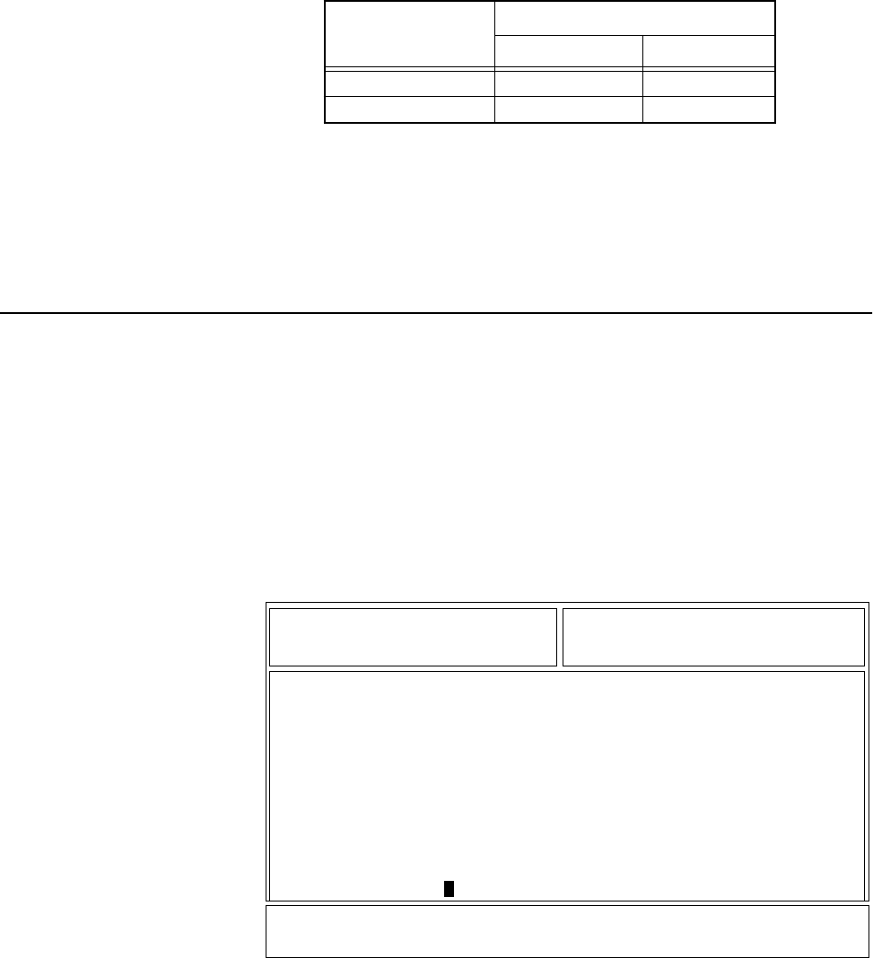
Table 1. ASTRO XTS 3500 Basic Features. . . . . . . . . . . . . . . . . . . . . . . . . . . . . . . . . . . . . . . . . . . .2
Table 2. Recommended Test Equipment. . . . . . . . . . . . . . . . . . . . . . . . . . . . . . . . . . . . . . . . . . . . 5
Table 3. Service Aids. . . . . . . . . . . . . . . . . . . . . . . . . . . . . . . . . . . . . . . . . . . . . . . . . . . . . . . . . . . . 6
Table 4. Initial Equipment Control Settings . . . . . . . . . . . . . . . . . . . . . . . . . . . . . . . . . . . . . . . . .7
Table 5. Test Frequencies . . . . . . . . . . . . . . . . . . . . . . . . . . . . . . . . . . . . . . . . . . . . . . . . . . . . . . . . 8
Table 6. Test Environments . . . . . . . . . . . . . . . . . . . . . . . . . . . . . . . . . . . . . . . . . . . . . . . . . . . . . . 8
Table 7. Receiver Performance Checks . . . . . . . . . . . . . . . . . . . . . . . . . . . . . . . . . . . . . . . . . . . . 10
Table 8. Transmitter Performance Checks. . . . . . . . . . . . . . . . . . . . . . . . . . . . . . . . . . . . . . . . . . 11
Table 9. Reference Oscillator Alignment . . . . . . . . . . . . . . . . . . . . . . . . . . . . . . . . . . . . . . . . . . . 16
Table 10. Transmit Power Setting . . . . . . . . . . . . . . . . . . . . . . . . . . . . . . . . . . . . . . . . . . . . . . . . . 17
Table 11. Transmit Deviation Limit. . . . . . . . . . . . . . . . . . . . . . . . . . . . . . . . . . . . . . . . . . . . . . . . 19
Table 12. Partial Exploded View Parts List. . . . . . . . . . . . . . . . . . . . . . . . . . . . . . . . . . . . . . . . . . .26
Table 13. Local Oscillator and First IF Frequencies . . . . . . . . . . . . . . . . . . . . . . . . . . . . . . . . . . . . 28
Table 14. Power-Up Error Code Displays. . . . . . . . . . . . . . . . . . . . . . . . . . . . . . . . . . . . . . . . . . . . 31
Table 15. Operational Error Code Displays . . . . . . . . . . . . . . . . . . . . . . . . . . . . . . . . . . . . . . . . . . 32
Table 16. Receiver Troubleshooting Chart . . . . . . . . . . . . . . . . . . . . . . . . . . . . . . . . . . . . . . . . . . 32
Table 17. Transmitter Troubleshooting Chart. . . . . . . . . . . . . . . . . . . . . . . . . . . . . . . . . . . . . . . . 33
Table 18. Encryption Troubleshooting Chart . . . . . . . . . . . . . . . . . . . . . . . . . . . . . . . . . . . . . . . . 33
Related Publications
ASTRO Digital XTS 3500 Model I User Guide . . . . . . . . . . . . . . . . . . . . . . . . . . . . . . .68P81089C77
ASTRO Digital XTS 3500 Model II User Guide . . . . . . . . . . . . . . . . . . . . . . . . . . . . . .68P81089C78
ASTRO Digital XTS 3500 Model III User Guide . . . . . . . . . . . . . . . . . . . . . . . . . . . . . .68P81089C79
ASTRO Digital XTS 3500 Detailed Service Manual. . . . . . . . . . . . . . . . . . . . . . . . . . . .68P81089C81

iii
Computer Software Copyrights
The Motorola products described in this manual may include copyrighted Motorola computer programs
stored in semiconductor memories or other media. Laws in the United States and other countries preserve
for Motorola certain exclusive rights for copyrighted computer programs, including, but not limited to,
the exclusive right to copy or reproduce in any form the copyrighted computer program. Accordingly, any
copyrighted Motorola computer programs contained in the Motorola products described in this manual
may not be copied, reproduced, modified, reverse-engineered, or distributed in any manner without the
express written permission of Motorola. Furthermore, the purchase of Motorola products shall not be
deemed to grant either directly or by implication, estoppel, or otherwise, any license under the
copyrights, patents or patent applications of Motorola, except for the normal non-exclusive license to use
that arises by operation of law in the sale of a product.
iv

vi
SPECIFICATIONS FOR VHF RADIOS
All specifications are per Electronic Industries Association (EIA) 316B unless otherwise noted
GENERAL RECEIVER TRANSMITTER
FCC Designation:
AZ489FT3790
Temperature Range:
Operating:
–30
°
C to +60
°
C
Storage:
–40
°
C to +85
°
C
Power Supply:
Nickel-Cadmium Battery (NiCd)
or
Nickel-Metal-Hydride Battery (NiMH)
or
Lithium-Ion Battery (Li-Ion)
Battery Voltage:
Nominal:
7.5 Volts
Range:
6 to 9 Volts
Transmit Current Drain (Typical):
2300mA
Receive Current Drain (Rated Audio):
290mA
Standby Current Drain:
90mA
Recommended Battery:
Ultra-HIgh-Capacity NiCd:
NTN8294A
or
Ultra–High-Capacity NiCd FM:
NTN8295*
or
Ultra–High-Capacity
NiMH FM:
NTN8299A*
Optional FM (Factory Mutual) Battery:
* FM Intrinsically Safe: Class I, II, III, Division 1,
Groups C, D,E, F, and G. FM Non-incendive:
Class 1, Division 2, Groups A, B, C, and D.
Dimensions (H x W x D)
Note: 2.44" = width at PTT; 2.34" = width at
bottom; 1.83" = depth at speaker; 0.97" = depth
at keypad
Less Battery:
6.58" x 2.44" x 1.83"/6.58" x 2.34" x 0.97"
(167.13mm x 61.90mm x 46.42mm/
167.13mm x 59.49mm x 24.56mm)
With Battery:
6.58" x 2.44" x 1.83"/6.58" x 2.34" x1.65"
(167.13mm x 61.90mm x 46.42mm/
167.13mm x 59.49mm x 41.97mm)
Weight: (w/Helical Antenna)
Less Battery:
14.10oz. (383gm)
With Ultra-High Cap. NiCd:
25.19oz. (693gm)
With Ultra-High Cap. NiMH:
23.45oz. (644gm)
Frequency Range:
136-178MHz
Bandwidth:
42MHz
Quieting Sensitivity (20dBQ):
0.35
m
V (typical)
Usable Sensitivity
(12dB SINAD):
0.25
m
V (typical)
Intermodulation:
–78dB (typical)
Selectivity (typical)
(25/30kHz Channel):
–78dB
Spurious Rejection:
–70dB
Frequency Stability
(–30+60
°
C; 25
°
C reference):
±
.0002%
Rated Audio:
500mW
Distortion (At Rated Audio):
2% Typical
Channel Spacing:
12.5/20/25/30kHz
RF Power:
136-174MHz:
1 Watt/5 Watts
174-178MHz:
1 Watt/4 Watts
Frequency Range:
136-178MHz
Frequency Stability (typical)
(–30 to +60
°
C; 25
°
C ref.):
±
.0002%
Emission (Conducted and Radiated):
–70dBc
FM Hum and Noise (typical)
(Companion Receiver):
25/30kHz –48dB
12.5kHz –42dB
Distortion:
2% Typical
Modulation Limiting:
25/30kHz chnls
±
5.0kHz
20kHz chnls
±
4.0kHz
12.5kHz chnls
±
2.5kHz
Emissions Designators:
20K0F1E, 16K0F3E, 11K0F3E,
8K10F1D, and 8K10F1E
Specifications subject to change without notice

vii
SPECIFICATIONS FOR UHF RADIOS
All specifications are per Electronic Industries Association (EIA) 316B unless otherwise noted
GENERAL RECEIVER TRANSMITTER
FCC Designation:
AZ489FT4828
Temperature Range:
Operating:
–30
°
C to +60
°
C
Storage:
–40
°
C to +85
°
C
Power Supply:
Nickel-Cadmium Battery (NiCd)
or
Nickel-Metal-Hydride Battery (NiMH)
or
Lithium-Ion Battery (Li-Ion)
Battery Voltage:
Nominal:
7.5 Volts
Range:
6 to 9 Volts
Transmit Current Drain (Typical):
1700mA
Receive Current Drain (Rated Audio):
290mA
Standby Current Drain:
90mA
Recommended Battery:
Ultra-HIgh-Capacity NiCd:
NTN8294A
or
Ultra–High-Capacity NiCd FM:
NTN8295*
or
Ultra–High-Capacity
NiMH FM:
NTN8299A*
Optional FM (Factory Mutual) Battery:
* FM Intrinsically Safe: Class I, II, III, Division 1,
Groups C, D,E, F, and G. FM Non-incendive:
Class 1, Division 2, Groups A, B, C, and D.
Dimensions (H x W x D)
Note: 2.44" = width at PTT; 2.34" = width at
bottom; 1.83" = depth at speaker; 0.97" = depth
at keypad
Less Battery:
6.58" x 2.44" x 1.83"/6.58" x 2.34" x 0.97"
(167.13mm x 61.90mm x 46.42mm/
167.13mm x 59.49mm x 24.56mm)
With Battery:
6.58" x 2.44" x 1.83"/6.58" x 2.34" x1.65"
(167.13mm x 61.90mm x 46.42mm/
167.13mm x 59.49mm x 41.97mm)
Weight: (w/Helical Antenna)
Less Battery:
14.10oz. (383gm)
With Ultra-High Cap. NiCd:
25.19oz. (693gm)
With Ultra-High Cap. NiMH:
23.45oz. (644gm)
Frequency Range:
403-520MHz
Bandwidth:
70MHz
Quieting Sensitivity (20dBQ):
0.316
m
V (typical)
Usable Sensitivity
(12dB SINAD):
0.25
m
V (typical)
Intermodulation:
–78dB (typical)
Selectivity (typical)
(25/30kHz Channel):
–78dB
(12.5kHz Channel):
–68dB
Spurious Rejection:
–75dB
Frequency Stability
(–30+60
°
C; 25
°
C reference):
±
.0002%
Rated Audio:
500mW
Distortion (At Rated Audio):
1.5% Typical
Channel Spacing:
12.5/20/25/30kHz
RF Power:
403-470MHz:
1 Watt/5 Watts
450-520MHz:
1 Watt/5 Watts
Frequency Range:
403-520MHz
Frequency Stability (typical)
(–30 to +60
°
C; 25
°
C ref.):
±
.0002%
Emission (Conducted and Radiated):
–70dBc
FM Hum and Noise (typical)
(Companion Receiver):
25/30kHz –48dB
12.5kHz –42dB
Distortion:
1.5% Typical
Modulation Limiting:
25/30kHz chnls
±
5.0kHz
20kHz chnls
±
4.0kHz
12.5kHz chnls
±
2.5kHz
Emissions Designators:
20K0F1E, 16K0F3E, 11K0F3E,
8K10F1D, and 8K10F1E
Specifications subject to change without notice

viii
SPECIFICATIONS FOR 800 MHz RADIOS
All specifications are per Electronic Industries Association (EIA) 316B unless otherwise noted.
GENERAL RECEIVER TRANSMITTER
FCC Designation: AZ489FT5774
Temperature Range:
Operating: –30°C to +60°C
Storage: –40°C to +85°C
Power Supply: Nickel-Cadmium Battery (NiCd)
or Nickel-Metal-Hydride Battery (NiMH)
or Lithium-Ion Battery (Li-Ion)
Battery Voltage:
Nominal: 7.5 Volts
Range: 6 to 9 Volts
Transmit Current Drain (Typical): 1700mA
Receive Current Drain (Rated Audio): 280mA
Standby Current Drain: 90mA
Recommended Battery:
Ultra-HIgh Capacity NiMH: H335AC
or Ultra–High Capacity NiCd FM: H223AX*
or NiMH FM IS: Q393AB
Optional FM (Factory Mutual) Battery:
* FM Intrinsically Safe: Class I, II, III, Division 1,
Groups D, F, and G
Dimensions (H x W x D)
Note: 2.44" = width at PTT; 2.34" = width at
bottom; 1.83" = depth at speaker; 0.97" = depth
at keypad
Less Battery:
6.58" x 2.44" x 1.83"/6.58" x 2.34" x 0.97"
(167.13mm x 61.90mm x 46.42mm/
167.13mm x 59.49mm x 24.56mm)
With Ultra-High Capacity NiMH Battery:
6.58" x 2.44" x 1.83"/6.58" x 2.34" x1.65"
(167.13mm x 61.90mm x 46.42mm/
167.13mm x 59.49mm x 41.97mm)
With Ultra-High Capacity NiCd Battery:
6.58" x 2.44" x 1.83"/6.58" x 2.34" x1.65"
(167.13mm x 61.90mm x 46.42mm/
167.13mm x 59.49mm x 41.97mm)
With NiMH FM IS Battery:
6.58" x 2.44" x 1.83"/6.58" x 2.34" x1.65"
(167.13mm x 61.90mm x 46.42mm/
167.13mm x 59.49mm x 41.97mm)
Weight: (w/Helical Antenna)
Less Battery: 14.10oz. (383gm)
With Ultra-High Cap. NiMH:23.45oz. (644gm)
With Ultra-High Cap. NiCd: 25.19oz. (693gm)
With NiMH FM IS: 23.45oz. (644gm)
Frequency Range: 851–870MHz
Bandwidth: 19MHz
Quieting Sensitivity (20dBQ): 0.5mV Max.
Usable Sensitivity
(12dB SINAD): 0.35mV Max.
Intermodulation: –70dB
Selectivity
(25kHz Adjacent Channel): –70dB
Spurious Rejection: –70dB
Frequency Stability
(–30+60°C; 25°C reference): ±.00015%
Rated Audio: 500mW
Distortion (At Rated Audio): 3% Typical
Channel Spacing: 25kHz
RF Power: 3 Watts
Frequency Range: 806–825MHz
851–870MHz
Frequency Stability
(–30 to +60°C; 25°C ref.): ± .00015%
Emission (Conducted and Radiated): –46dBw
FM Hum and Noise
(Companion Receiver): –40dB
Distortion: 3% Typical
Modulation Limiting: ±5kHz
(821-824MHz): ±4kHz
Emissions Designators:
20K0F1E, 16K0F3E, 15K0F2D,
15K0F1D, and 8K10F1E
Specifications subject to change without notice

1
Introduction
1
General
This manual covers information needed for level one troubleshooting. Level
one troubleshooting consists of radio programming, radio alignment, knobs
replacement, and installation and removal of antenna, belt clip, battery, and
universal connector cover. This will be the only level of service allowed for the
service centers, self-maintained customers, and distributors for the first six
months of the life of this product.
Included in this manual are radio specifications for the VHF, UHF, and
800MHz frequency bands, a general description of XTS 3500 models,
recommended test equipment, service aids, radio alignment procedures,
general maintenance recommendations, and procedures for basic assembly
and disassembly.
Notations Used
in This Manual
Throughout the text in this publication, you will notice the use of warnings,
cautions, and notes. These notations are used to emphasize that safety hazards
exist, and care must be taken and observed.
NOTE:
An operational procedure, practice, or
condition, etc., which is essential to
emphasize.
CAUTION indicates a potentially hazardous
situation which, if not avoided, may result in
equipment damage.
!
C a u t i o n
WARNING indicates a potentially hazardous
situation which, if not avoided, could result
in death or injury.
!
W A R N I N G
!
DANGER indicates an imminently
hazardous situation which, if not
avoided, will result in death or injury.
D A N G E R
!
2
Radio
Description
The ASTRO Digital XTS 3500 radios are among the most sophisticated two-
way radios available. The radio is presently available in the UHF R2 band;
radios in the UHF R1, VHF, and 800MHz bands will be available by the end of
1999.
One of the newest in a long line of quality Motorola products, the ASTRO
Digital XTS 3500 radio provides improved voice quality across more coverage
area. The digital process called “embedded signalling” intermixes system
signalling information with digital voice, resulting in improved system
reliability and the capability of supporting a multitude of advanced features.
Such features add up to better, more cost-effective two-way radio
communications.
ASTRO Digital XTS 3500 radios are available in two basic models. Table 1
provides a description of their basic features.
FLASHport
The ASTRO Digital XTS 3500 radio utilizes Motorola’s revolutionary
FLASHport technology. FLASHport makes it possible to add software that
drives the radio’s capabilities both at the time of purchase and later on.
Previously, changing a radio’s features and capabilities meant significant
modifications, or buying a new radio. But now, similar to how a computer can
be loaded with different software, the radio’s features and capabilities can be
upgraded with FLASHport software.
Table 1 ASTRO XTS 3500 Basic Features
Feature Model I Model II Model III
Display None LCD
4 lines/
12 characters per line
LCD
4 lines/
12 characters per line
Keypad None 3 x 2 button 3 x 6 button
Channel Capability 48 255 255
Dialing from Prestored List No Yes Yes
Programmable Softkeys No Yes Yes

3
Basic Maintenance
2
Introduction
to This Section
This section of the manual describes preventive maintenance and handling
precautions. Each of these topics provides information vital to the successful
operation and maintenance of your radio.
Preventive
Maintenance
The ASTRO Digital XTS 3500 radios do not require a scheduled preventive
maintenance program; however, periodic visual inspection and cleaning is
recommended.
Inspection
Check that the external surfaces of the radio are clean, and that all external
controls and switches are functional. A detailed inspection of the interior
electronic circuitry is not needed.
Cleaning
The following procedures describe the recommended cleaning agents and the
methods to be used when cleaning the external surfaces of the radio. External
surfaces include the housing assembly and battery case. These surfaces should
be cleaned whenever a periodic visual inspection reveals the presence of
smudges, grease, and/or grime.
The only recommended agent for cleaning the external radio surfaces is a 0.5%
solution of a mild dishwashing detergent, such as JOY
®
, in water.
Cleaning External
Plastic Surfaces
The detergent-water solution should be applied sparingly with a stiff, non-
metallic, short-bristled brush to work all loose dirt away from the radio. A soft,
absorbent, lintless cloth or tissue should be used to remove the solution and
dry the radio. Make sure that no water remains entrapped near the connectors,
cracks, or crevices.
The effects of certain chemicals and their vapors can
have harmful results on certain plastics. Aerosol
sprays, tuner cleaners, and other chemicals should
be avoided.
!
C a u t i o n

4
Handling
Precautions
Complementary metal-oxide semiconductor (CMOS) devices, and other high-
technology devices, are used in this family of radios. While the attributes of
these devices are many, their characteristics make them susceptible to damage
by electrostatic discharge (ESD) or high-voltage charges. Damage can be latent,
resulting in failures occurring weeks or months later. Therefore, special
precautions must be taken to prevent device damage during disassembly,
troubleshooting, and repair. Handling precautions are mandatory for this
radio, and are especially important in low-humidity conditions.
At this time, troubleshooting and repair of the radio will not be supported by
the field or self-maintained customer.
DO NOT attempt to disassemble the
radio.

5
Recommended Test
Equipment and
3
Service Aids
Recommended
Test
Equipment
The list of equipment contained in Table 2 includes all of the standard test
equipment required for servicing two-way portable radios, as well as several
unique items designed specifically for servicing this family of radios. The
“Characteristics” column is included so that equivalent equipment may be
substituted; however, when no information is provided in this column, the
specific Motorola model listed is either a unique item or no substitution is
recommended.
Service Aids
Refer to Table 3, “Service Aids,” for a listing and description of the service aids
designed specifically for servicing this family of radios. These kits and/or parts
are available from the Motorola Parts Division offices listed in the
“Replacement Parts Ordering” section located on the inside back cover of this
manual. While all of these items are available from Motorola, most are
standard shop equipment items, and any equivalent item capable of the same
performance may be substituted for the item listed.
Table 2 Recommended Test Equipment
Motorola
Model Number Description Characteristics Application
R2670 or R2600 System Analyzer This monitor will substitute
for items with an asterisk (*). Frequency/deviation meter and
signal generator for wide-range
troubleshooting and alignment.
R1049A* Digital Multimeter Recommended for ac/dc voltage
and current measurements
R1150C* Code Synthesizer Injection of audio and digital
signalling codes
S1053D*
SKN6008A*
SKN6001A*
AC Voltmeter
Power Cable for Meter
Test Leads for Meter
1mV to 300V, 10-Megohm
input impedance Audio voltage measurements
R1094A Dual-Trace Oscillo-
scope 20MHz bandwidth 5mV to
5V/division Waveform measurements
S1350C*
ST1213B (VHF)*
ST1223B (UHF)*
Wattmeter
Plug-In Element
RF Dummy Load
50-ohm,
±
5% accuracy
10 watts, maximum
0-1000MHz, 300W
Transmitter power output
measurements
R1065 Load Resistor 10-watt Broadband For use with wattmeter
S1339A RF Millivolt Meter 100
m
V to 3V RF RF-level measurements
R1013A* SINAD Meter Receiver sensitivity measurements
S1347D or S1348D
(programmable) DC Power Supply 0-20Vdc, 0-5 Amps
current limited Bench supply for 7.5Vdc

6
Field
Programming
Equipment
This family of radios can be aligned and programmed in the field. This requires
specific equipment and special instructions. Refer to the applicable “Radio
Service Software User's Guide” for complete field programming information.
Table 3 Service Aids
Motorola Part
Number Description Application
RKN-4035D RIB/Radio/Test Set Cable Connects radio to RTX-4005B Test Box and RIB.
REX-4424 Battery Eliminator Interconnects radio to power supply.
RLN-4460A, or
RTX-4005B, or both
RTX-4005A and
RPX-4665A
Portable Test Set Enables connection to the universal connector.
Allows switching for radio testing.
Field Modification Kit
RLN-1015A or
RLN-4008B
Radio Interface Box Enables communications between the radio and the
computer's serial communications adapter.
01-80357A57 Wall-Mounted Power Supply Used to supply power to the RIB (120 Vac).
01-80358A56 Wall-Mounted Power Supply Used to supply power to the RIB (220 Vac).
30-80369B71 or
30-80369B72 Computer Interface Cable Use B72 for the IBM PC AT. All other IBM models use
B71. Connects the computer's serial communications
adaptor to the RIB.
RVN-4100F Radio Service Software Software on 3-1/2 in. and 5-1/4 in. floppy disks.
58-80348B33 SMA to BNC Adaptor Adapts radio’s antenna port to BNC cabling of test
equipment.

7
Performance Checks
4
Introduction
to This Section
This section covers performance checks used to verify the radio meets
published specifications. The recommended test equipment listed in the
previous section approaches the accuracy of the manufacturing equipment,
with a few exceptions. Accuracy of the equipment must be maintained in
compliance with the manufacturer’s recommended calibration schedule.
Setup
Supply voltage can be connected from the battery eliminator. The equipment
required for alignment procedures is connected as shown in the “Radio
Alignment Test Setup” diagram (page 13, Figure 1).
Initial equipment control settings should be as indicated in the following
table, and should hold for all alignment procedures except as noted in Table 4.
Test Mode
RF Test Mode
When the ASTRO Digital XTS 3500 radio is operating in its normal
environment, the radio's microcomputer controls the RF channel selection,
transmitter key-up, and receiver muting. However, when the unit is on the
bench for testing, alignment, or repair, it is removed from its normal
environment. It cannot receive commands from its system and, therefore, the
internal microcomputer will not key the transmitter nor unmute the receiver.
This prevents the use of normal tune-up procedures. To solve this problem a
special routine, called
TEST MODE
or “air test,” has been incorporated in the
radio.
Table 4 Initial Equipment Control Settings
System Analyzer Test Set Power Supply
Monitor Mode:
Pwr Mon
Spkr Set:
A
Voltage:
7.5Vdc
RF Attn:
–70dB
Spkr/Load:
Speaker
DC On/Standby:
Standby
AM, CW, FM:
FM
PTT:
OFF (center)
Volt Range:
10Vdc
O'scope Source:
Mod
O'scope Horiz:
10mSec/Div
O'scope Vert:
2.5kHz/Div
O'scope Trig:
Auto
Monitor Image:
Hi
Monitor BW:
Nar
Monitor Squelch:
Mid CW
Monitor Vol:
1/4 CW
Current:
2.5Amps

8
To enter the test mode:
1. Turn the radio on and adjust the volume for a comfortable listening level.
The volume level remains constant once in the test mode.
2. Within 10 seconds after the “
SS
SSee
eell
llff
ff
TT
TTee
eess
sstt
tt
” is complete, press
Side Button 3
five times in succession.
3. After “
RR
RRFF
FF
TT
TTEE
EESS
SSTT
TT
” appears, press the
Top Programmable Button
(normally
programmed as the emergency button) once. “
11
11
CC
CCSS
SSQQ
QQ
” appears, indicating:
test frequency 1, carrier squelch mode.
4. Each additional press of
Side Button 3
will advance to the next test
channel. (Refer to Table 5.)
5. Pressing
Side Button 2
will scroll through and access test environments as
shown in Table 6.
NOTE:
Transmit into a load when keying a radio
under test.
* All deviation values are based on deviation tuning of this mode.
Table 5 Test Frequencies
Test Channel UHF Band 2
TX #1 450.025
RX #1 450.075
TX #2 465.225
RX #2 465.275
TX #3 475.125
RX #3 475.275
TX #4 484.975
RX #4 485.025
TX #5 500.275
RX #5 500.225
TX #6 511.975
RX #6 511.925
TX #7 519.975
RX #7 519.925
Table 6 Test Environments
Display Description Function
CSQ Carrier Squelch
RX:
unsquelch if carrier detected
TX:
mic audio
TPL Tone Private-
Line
RX:
unsquelch if carrier and tone (192.8 Hz) detected
TX:
mic audio + tone (192.8 Hz)
AST ASTRO
RX:
none
TX:
1200Hz tone *
9
Control Top
and Keypad
Test Mode
To check the display, buttons, and switches, perform the following tests:
1. Turn the radio on and adjust the volume for a comfortable listening level.
The volume level remains constant once in the test mode.
2. Within 10 seconds after the “
SS
SSee
eell
llff
ff
TT
TTee
eess
sstt
tt
” is complete, press
Side Button 3
five times in succession.
3. After “
RR
RRFF
FF
TT
TTEE
EESS
SSTT
TT
” appears on the display, press Side Button 1 once, “CC
CCHH
HH
TT
TTEE
EESS
SSTT
TT” appears on the display.
4. Next, press and hold the Top Programmable Button; all segments on the
display will light, and the LED on the control top will illuminate a red
color.
5. Release the Top Programmable Button; “33
33//
//00
00” appears, which indicates
that the Top Programmable Button is in the open condition.
6. Press the Top Programmable Button again; “33
33//
//11
11” appears, which
indicates that the Top Programmable Button is in the closed condition.
7. Rotate the Mode/Zone Selector Switch; “44
44//
//00
00” through “44
44//
//11
1155
55” appears,
which indicates that the selector switch is in mode/zone position 1
through 15.
8. Rotate the Two-Position (A/B) Switch; “66
6655
55//
//00
00” and “66
6655
55//
//11
11” appear.
9. Cycle through the Three-Position Programmable Switch; “66
6677
77//
//00
00,”
“66
6677
77//
//11
11,” and “66
6677
77//
//22
22” appear.
10.Rotate the Volume Control; “22
22//
//00
00” through “22
22//
//22
2255
5555
55” appear.
11.Press Side Button 1; “99
9966
66//
//11
11” appears; release, “99
9966
66//
//00
00” appears.
12.Press Side Button 2; “99
9977
77//
//11
11”appears; release, “99
9977
77//
//00
00” appears.
13.Press Side Button 3; “99
9988
88//
//11
11”appears; release, “99
9988
88//
//00
00” appears.
14.Press the PTT Switch; “11
11//
//11
11” appears; release, “11
11//
//00
00” appears.
15.Keypad Checks:
-Press 0, “44
4488
88//
//11
11” appears; release, “44
4488
88//
//00
00” appears.
-Press 1, “44
4499
99//
//11
11” appears; release, “44
4499
99//
//00
00” appears.
-Press 2, “55
5500
00//
//11
11” appears; release, “55
5500
00//
//00
00” appears.
-Press 3, “55
5511
11//
//11
11” appears; release, “55
5511
11//
//00
00” appears.
-Press 4, “55
5522
22//
//11
11” appears; release, “55
5522
22//
//00
00” appears.
-Press 5, “55
5533
33//
//11
11” appears; release, “55
5533
33//
//00
00” appears.
-Press 6, “55
5544
44//
//11
11” appears; release, “55
5544
44//
//00
00” appears.
-Press 7, “55
5555
55//
//11
11” appears; release, “55
5555
55//
//00
00” appears.
-Press 8, “55
5566
66//
//11
11” appears; release, “55
5566
66//
//00
00” appears.
-Press 9, “55
5577
77//
//11
11” appears; release, “55
5577
77//
//00
00” appears.
-Press *, “55
5588
88//
//11
11” appears; release, “55
5588
88//
//00
00” appears.
-Press #, “55
5599
99//
//11
11” appears; release, “55
5599
99//
//00
00” appears.
-Press <, “11
1122
2288
88//
//11
11” appears; release, “11
1122
2288
88//
//00
00” appears.
-Press O, “11
1122
2299
99//
//11
11” appears; release, “11
1122
2299
99//
//00
00” appears.
-Press >, “11
1133
3300
00//
//11
11” appears; release, “11
1133
3300
00//
//00
00” appears.

10
-Press the left-hand M key on the top row of keys, “11
1133
3311
11//
//11
11” appears;
release, “11
1133
3311
11//
//00
00” appears.
-Press the center N key, “11
1133
3322
22//
//11
11” appears; release, “11
1133
3322
22//
//00
00” appears.
-Press the right-hand M key, “11
1133
3333
33//
//11
11” appears; release,
“11
1133
3333
33//
//00
00” appears.
Table 7 Receiver Performance Checks
Test Name System Analyzer Radio Test Set Comments
Reference
Frequency Mode: PWR MON 4th
channel test frequency❖
Monitor: Frequency error.
Input at RF In/Out
TEST MODE,
4 CSQ output
at antenna
PTT to continuous
(during the
performance check)
Frequency error to
be £ ±1.2kHz
Rated Audio Mode: GEN
Output level: 1.0mV RF 4th
channel test frequency❖
Mod: 1kHz tone at 3kHz
deviation
Monitor: DVM: ac Volts
TEST MODE,
4 CSQ PTT to OFF (center);
meter selector to Audio
PA
Set volume control
to 3.74Vrms
Distortion As above, except to
distortion As above As above Distortion < 3.0%
Sensitivity
(SINAD) As above, except SINAD;
lower the RF level for 12dB
SINAD
As above PTT to OFF (center) RF input to be <
0.35mV
Noise Squelch
Threshold (only
radios with
conventional
system need to
be tested)
RF level set to 1mV RF As above PTT to OFF (center);
meter selection to
Audio PA; spkr/load to
speaker
Set volume control
to 3.74Vrms
As above, except change
frequency to a
conventional system. Raise
RF level from zero until
radio unsquelches.
Out of TEST
MODE; select
a conventional
system
As above Unsquelch to
occur at < 0.25mV.
Preferred SINAD =
8-10dB
❖ See Table 6

11
Table 8 Transmitter Performance Checks
Test Name System Analyzer Radio Test Set Comments
Reference
Frequency Mode: PWR MON 4th
channel test frequency❖
Monitor: Frequency
error. Input at RF In/Out
TEST MODE,
4 CSQ PTT to continuous
(during the
performance check).
Frequency error to be £
±1.2kHz.
Power RF As above As above,
4 CSQ As above Refer to Maintenance
Specifications page in
front of manual.
Voice
Modulation Mode: PWR MON 4th
channel test frequency❖
atten to –70, input to RF
In/Out.
Monitor: DVM, ac Volts.
Set 1kHz Mod Out level
for 0.025Vrms at test set,
80mVrms at ac/dc test
set jack
As above,
4 CSQ As above, meter
selector to mic Deviation: UHF: ³ 3.6kHz
but £ 5.0kHz
Voice
Modulation
(internal)
Mode: PWR MON 4th
channel test frequency❖
atten to –70, input to RF
In/Out
TEST MODE,
4 CSQ, output
at antenna
Remove modulation
input Press PTT switch on radio.
Say “four” loudly into the
radio mic. Measure
deviation: UHF: ³
3.8kHz but £ 5.0kHz
PL Modu-
lation (radios
with conven-
tional, clear
mode, coded
squelch oper-
ation only)
Change frequency to a
conventional transmit
frequency; BW to narrow
Conventional
coded
squelch
personality
(clear mode
operation) 4
TPL
As above Deviation: UHF: ³ 500Hz
but £ 1000Hz
Talkaround
Modulation
(radios with
conventional,
clear mode,
talk-around
operation
only)
Change frequency to
conventional talk-
around frequency.
Mode: PWR MON
deviation, attenuation to
–70, input to RF In/Out.
Monitor: DVM, ac volts
Set 1kHz Mod Out level
for 25mVrms at test set.
Conventional
talkaround
personality
(clear mode
operation)
1 CSQ
As above Deviation: UHF: ³ 3.8kHz
but £ 5.0kHz
Talkaround
Modulation
(radios with
conventional,
secure mode,
talkaround
operation
only) (**)
Change frequency to
conventional talk-
around frequency.
Mode: PWR MON
deviation, attenuation to
–70, input to RF In/Out.
Monitor: DVM, ac volts
Mod: 1kHz out level
for25mVrms at test set.
Conventional
talkaround
personality
(secure mode
operation).
Load key into
radio 1 sec.
As above Deviation: UHF: ³ 3.6kHz
but £ 4.4kHz
** The secure mode, talkaround modulation test is only required for trac mode radios which do not have clear mode
talkaround capability.
❖See Table 6

13
Radio Alignment
Procedures 5
Introduction
to This Section This section describes both receiver and transmitter radio alignment
procedures.
General A personal computer (PC) and radio service software (RSS) are required to align
the radio. Refer to the applicable RSS manual for installation and setup
procedures for the software. To perform the alignment procedures, the radio
must be connected to the PC, radio interface box (RIB), and a universal test set
as shown in Figure 1.
Figure 1 Radio Alignment Test Setup
All service and tuning procedures are performed from the SERVICE menu,
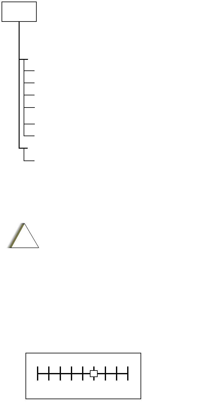
which is selected by pressing B from the MAIN MENU. Figure 2 illustrates
how the RSS alignment SERVICE screens are organized.
BNC
RIB
RLN-4008B
RIB POWER SUPPLY
01-80357A57 (120V)
COMPUTER INTERFACE
CABLE
30-80369B71
30-80369B72 (IBM "AT" ONLY)
DATA
BUSY
GND
COMPUTER
AUDIO GENERATOR
SINAD METER
AC VOLTMETER
TX
RX
30 dB PAD
30 dB PAD
RF GENERATOR
SYSTEM ANALYZER
OR COUNTER
WATTMETER
BATTERY
ELIMINATOR
RTL-4224A
TRANSMIT
RECEIVE
TEST SET
RTX-4005B
RADIO
PROGRAM/TEST CABLE
RKN-4046A
AUDIO IN
SET TO APPROX. 450mV FOR Tx
MEASURE 80mV FOR Tx
SMA-BNC
58-80348B33
REX-4424
RKN-4035D
RIB
RLN-4008B
RLN-1015A or
TEST SET
RLN-4460A or
RTX-4005B
14
Figure 2 RSS Service Menu Layout
All SERVICE screens read and program the radio codeplug directly; you do
NOT have to use the RSS GET/SAVE functions to use the SERVICE menus.
The SERVICE screens introduce the concept of the “softpot,” an analog
SOFTware-controlled POTentiometer used for adjusting all transceiver
alignment controls.
Each SERVICE screen provides the capability to increase or decrease the
‘softpot’ value with the keyboard UP/DOWN arrow keys respectively. A
graphical scale is displayed indicating the minimum, maximum, and
proposed value of the softpot, as shown in Figure 3.
Figure 3 Softpot Concept
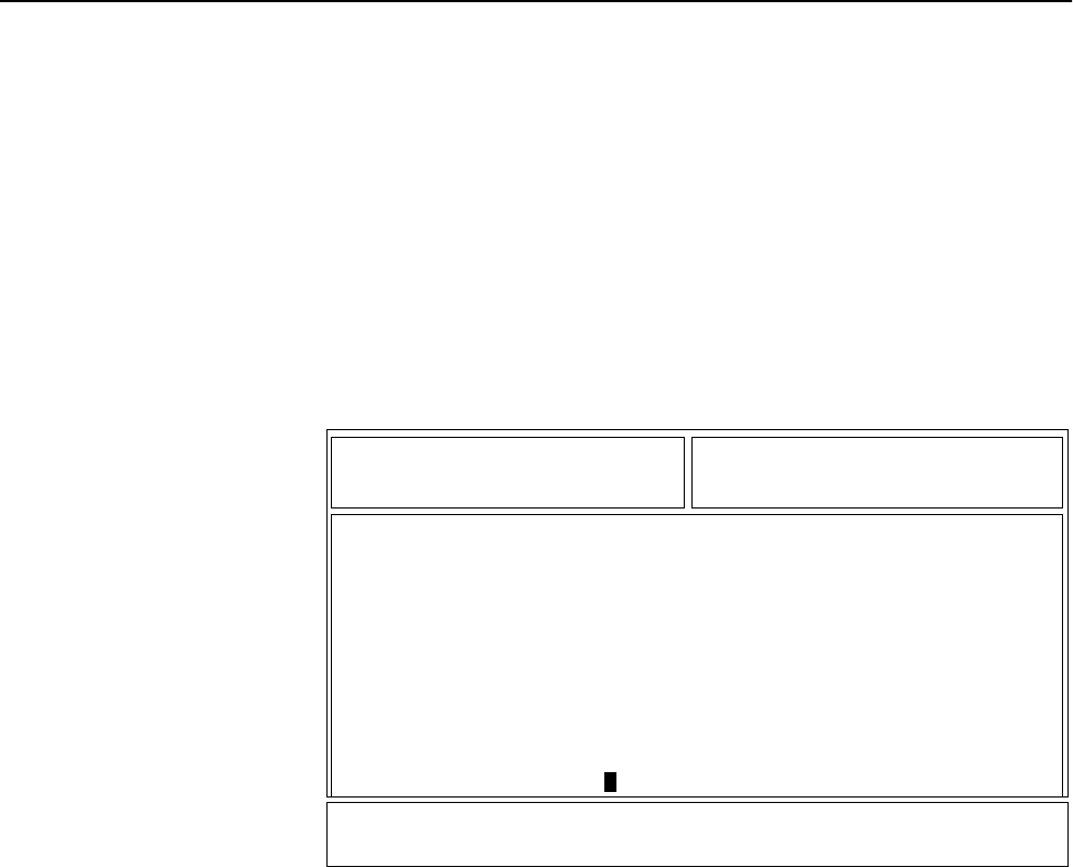
REFERENCE OSCILLATOR ALIGNMENT
TRANSMIT POWER ALIGNMENT
TRANSMITTER ALIGNMENT MENU
TRANSMIT DEVIATION BALANCE
(COMPENSATION) ALIGNMENT
TRANSMIT DEVIATION LIMIT ALIGNMENT
F2 -
F2 -
F3 -
F4 -
F5 -
RECEIVER ALIGNMENT MENU
F3 -
FRONT END BANDPASS FILTER ALIGNMENTF2 -
SERVICE
HELPF1 -
EXIT, RETURN TO SERVICE MENUF10 -
B
A
B
C
D
E
C
B
J
Do NOT switch radios in the middle of any SERVICE
procedure. Always use the EXIT key to return to the
MAIN menu screen before disconnecting the radio.
Improper exits from the SERVICE screens may leave
the radio in an improperly configured state and
result in seriously degraded radio or system
performance.
!
C a u t i o n
Min.
Value Max.
Value
015
15
Adjusting the softpot value sends information to the radio to increase
(or decrease) a dc voltage in the corresponding circuit. For example,
pressing the UP arrow key at the Reference Oscillator screen instructs
the radio’s microcomputer to increase the voltage across a varactor in
the reference oscillator, which increases the frequency.
In ALL cases, the softpot value is just a relative number corresponding
to a digital-to-analog (D/A) generated voltage in the radio.
Perform the following procedures in the sequence indicated.
NOTE: Some of the following screens may
vary depending upon the radio under
test and the version of radio service
software you are using. Refer to your
radio service software user’s guide.
Reference
Oscillator
Alignment
Adjustment of the reference oscillator is critical for proper radio
operation. Improper adjustment will result not only in poor operation,
but also in a misaligned radio that will interfere with other users
operating on adjacent channels. For this reason, the reference
oscillator should be checked every time the radio is serviced. The
frequency counter used for this procedure must have a stability of 0.1
ppm (or better).
1. From the SERVICE MENU, press B to select the TRANSMITTER
ALIGNMENT MENU.
2. Press B again to select the REFERENCE OSCILLATOR alignment
screen. See Figure 4.
Figure 4 Reference Oscillator Alignment Screen
3. Press P (or Z or [RETURN]) to select a frequency field
(starting with the highest frequency shown). Then, press F to
key the radio. The screen will indicate that the radio is
transmitting.
MOTOROLA Radio Service Software Use UP/DOWN Arrows To Adjust Softpot.
XTS Model: H24SDC9PW5AN
MAIN:SERVICE:TX ALIGN:REF OSC
REFERENCE OSCILLATOR
--------------------
Frequency Current Value
--------- -------------
519.975 150 New Softpot Value.....150
Transmitter..On
0 255
MIN |----+----+----+----+----+----+----+----+----+----+----+----| MAX
F1 F2 F3 F4 F5 F6 F7 F8 F9 F10
HELP TOGGLE PROGRAM EXIT
PTT VALUE
16
4. Measure the transmit frequency on your service monitor.
5. Use the É/Ç arrow keys to adjust the reference oscillator softpot value.
See Table 9.
6. Press F again to dekey the radio.
7. Press H to program the new softpot value.
8. Press J once to return to the TRANSMITTER ALIGNMENT MENU, or
press J twice to return to the SERVICE MENU.
Transmit
Power
Alignment
NOTES:
•All power measurements are to be made at the antenna port.
•The transmitter power setting keeps the radiated power at or below
the level specified in the exclusionary clause for low power devices
of IEEE Standard C95.1-1991.
1. From the SERVICE MENU, press B to select the TRANSMITTER
ALIGNMENT MENU.
2. Press C to select the TRANSMIT POWER alignment screen. The screen
will indicate the transmit frequencies to be used. See Figure 5.
Figure 5 Transmit Power Alignment Screen
3. Press P (or Z or [RETURN]) to select a frequency field (starting with
the highest frequency shown). Then, press F to key the radio. The
screen will indicate that the radio is transmitting.
4. Use the É/Ç arrow keys to adjust the transmit power per the values
shown in Table 10.
Table 9 Reference Oscillator Alignment
Band Target
UHF ±100 Hz
MOTOROLA Radio Service Software Use UP/DOWN Arrows To Adjust Softpot.
XTS Model: H24SDC9PW5AN
MAIN:SERVICE:TX ALIGN:TX POWER
TRANSMIT POWER
--------------
Current Value New Softpot Value
Frequency High Pwr Low Pwr High Pwr Low Pwr
--------- -------- ------- -------- -------
450.025 10 23 10 23
465.225 11 28 11 28
475.125 20 33 20 33
484.975 33 40 33 40
500.275 43 45 43 45
511.975 58 58 58 58
519.975 58 58 Transmitter..On 58 58
0 127
MIN |---+---+---+---+---+---+---+---+---+---+---+---+---+---+---+---| MAX
F1 F2 F3 F4 F5 F6 F7 F8 F9 F10
HELP TOGGLE PROGRAM EXIT
PTT VALUE
17
5. Press F to dekey the radio.
6. Press H to program the value.
7. Repeat steps 3-6 for the remaining frequencies.
8. Press J once to return to the TRANSMITTER ALIGNMENT MENU, or
press J twice to return to the SERVICE MENU.
Transmit
Deviation
Balance
(Compensation)
Alignment
Compensation alignment balances the modulation sensitivity of the VCO and
reference modulation (synthesizer low-frequency port) lines. The
compensation algorithm is critical to the operation of signalling schemes that
have very-low-frequency components (for example, DPL) and could result in
distorted waveforms if improperly adjusted.
1. From the SERVICE MENU, press B to select the TRANSMITTER
ALIGNMENT MENU.
2. Press D to select the TRANSMIT DEVIATION BALANCE
(COMPENSATION) alignment screen. The screen will indicate the
transmit frequencies to be used. See Figure 6.
Figure 6 Transmit Deviation Balance (Compensation) Alignment Screen
3. Press P (or Z or [RETURN]) to select a frequency field (starting with
the lowest frequency shown).
4. Press D. This will cause the radio to key and the radio’s DSP IC to inject
an 80Hz tone into the RF board.
5. Measure the deviation and record this value.
6. Press D to dekey the radio.
Table 10 Transmit Power Settings
UHF Power Level Test Frequencies
450-512MHz 512-520MHz
1 Watt 1.2W - 1.4W 1.2W - 1.4W
5 Watts 5.2W - 5.4W 3.2W - 3.4W
MOTOROLA Radio Service Software Use UP/DOWN Arrows To Adjust Softpot.
XTS Model: H24SDC9PW5AN
MAIN:SERVICE:TX ALIGN:BAL ATTN
TRANSMIT DEVIATION BALANCE (COMPENSATION)
-----------------------------------------
Current
Frequency Value New Softpot Value
--------- ------- -----------------
450.025 30 30
465.225 30 30
475.125 30 30
484.975 45 45
500.275 45 45
511.975 45 45
519.975 45 Transmitter..Off 45
0 63
MIN |---+---+---+---+---+---+---+---+---+---+---+---+---+---+---+---| MAX
F1 F2 F3 F4 F5 F6 F7 F8 F9 F10
HELP TOGGLE LOW TOGGLE HIGH PROGRAM EXIT
TONE PTT TONE PTT VALUE
18
7. Press F. This will cause the radio’s DSP IC to change the injection tone
to 3kHz, 100mVrms. Use the É/Ç arrow keys to adjust the deviation to
within ±2% of the value recorded in step 5.
8. Repeat steps 4-7 until the 3kHz tone deviation is within ±2% of the 80Hz
tone deviation.
9. Press F again to dekey the radio.
10.Press H to program the new softpot value.
11.Repeat steps 3-10 for the remaining frequencies.
12.Press J once to return to the TRANSMITTER ALIGNMENT MENU, or
press J twice to return to the SERVICE MENU.
Transmit
Deviation
Limit
Alignment
IMPORTANT NOTE:
Put the radio in the RF test mode and scroll to
the ASTRO test environment, indicated by
“AST” on the display (refer to the
“Performance Checks” section for details). All
other deviation values are derived from the
ASTRO test environment mode transmit
deviation limit.
1. From the SERVICE MENU, press B to select the TRANSMITTER
ALIGNMENT MENU.
2. Press E to select the TRANSMIT DEVIATION LIMIT alignment screen.
The screen will indicate the transmit frequencies to be used. See Figure 7.
Figure 7 Transmit Deviation Limit Alignment Screen
3. Press P (or Z or [RETURN]) to select a frequency field (starting with
the lowest frequency shown).
4. Press F to key the radio. Then use the É/Ç arrow keys to adjust for a
deviation per the values shown in Table 11.
MOTOROLA Radio Service Software Use UP/DOWN Arrows To Adjust Softpot.
XTS Model: H24SDC9PW5AN
MAIN:SERVICE:TX ALIGN:DEV.LIMIT
TRANSMIT DEVIATION LIMIT
------------------------
Current
Frequency Value New Softpot Value
--------- ------- -----------------
450.025 175 175
465.225 175 175
475.125 180 180
484.975 180 180
500.275 180 180
511.975 180 180
519.975 180 Transmitter..Off 180
0 32767
MIN |----+----+----+----+----+----+----+----+X---+----+----+----| MAX
F1 F2 F3 F4 F5 F6 F7 F8 F9 F10
HELP TOGGLE PROGRAM EXIT
PTT VALUE

19
5. Press F again to dekey the radio.
6. Press H to program the softpot value.
7. Repeat steps 3-6 for the remaining frequencies.
8. Press J once to return to the TRANSMITTER ALIGNMENT MENU, or
press J twice to return to the SERVICE MENU.
Table 11 Transmit Deviation Limit
Band Deviation (Hz)
UHF 2785 - 2885

21
Basic Removal/Installation
Procedures 6
Introduction
to This Section This section gives basic procedures for removing and installing the XTS 3500
radio’s:
•Antenna,
•Battery,
•Belt Clip,
•Universal Connector Cover,
•Volume Knob, and
•Frequency Knob.
Antenna
Installing the
Antenna Screw the threaded end of the antenna into the antenna receptacle on the top
of the radio. Rotate the antenna clockwise until it seats firmly against the
bushing.
Removing the
Antenna Rotate the antenna counterclockwise until its threaded end unscrews from the
radio’s antenna receptacle.
Battery NOTE: The battery is shipped uncharged, and must be
charged for at least 16 hours before use.
To avoid a possible explosion:
• DO NOT replace the battery in an area labeled
“hazardous atmosphere.”
• DO NOT discard batteries in a fire.
!
W A R N I N G
!
If your radio is programmed with volatile-key retention
(consult your service technician), encryption keys will be
retained for approximately 30 seconds after battery removal.
!
C a u t i o n

22
Installing the
Battery 1. Turn off the radio and hold it with the back of
the radio facing upward
2. Insert the top edge of the battery into the area
at the top of the radio between the radio’s
case and chassis. Make sure the three tabs on
the radio chassis align with the three slots
under the top edge of the battery.
3. Rotate the battery toward the radio, and
squeeze the battery and radio together until
the battery “clicks” in place.
Removing the
Battery 1. Turn off the radio and hold it so that the release
button on the bottom of the battery is facing
upward.
2. Press downward on the release button so the
battery disengages from the radio.
3. Remove the battery completely away from the
radio
Belt Clip NOTE: The battery must be removed from the radio
before the belt clip can be installed or removed.
Installing the
Belt Clip 1. Hold the battery in one hand so that the top of
the battery faces upward, and the back of the
battery faces you.
2. Holding the belt clip in the other hand with its
top facing upward, align the slide assembly on
the front of the belt clip with the slots on the
back of the battery.
3. Slide the belt clip downward toward the bottom
of the battery until the belt clip “clicks” in place.
Removing the
Belt Clip 1. Hold the battery (with belt clip installed) in one
hand so that the top of the battery faces upward,
and the front (radio side) of the battery faces
you.
2. At the top of the battery, press down on the belt
clip’s metal tab and slide the belt clip upward
until it disengages from the battery.
3. Continue to slide the belt clip upward until it is
free from the battery.
Slide
Assembly
Slots
Belt Clip
Battery
Metal
Tab
Press
Down
23
Universal
Connector
Cover
Installing the
Universal
Connector Cover
1. Looking at the antenna side of the radio,
insert the top (flat) hooked end of the cover
into the slot on the top of the radio, above
the universal connector. Press downward on
the cover’s top to seat it in the slot.
2. While holding the cover seated in the top
slot, insert the cover’s bottom (rounded)
hooked end into the slot below the universal
connector. Press firmly inward on the cover’s
bottom until it snaps in place.
Removing the
Universal
Connector Cover
1. Looking at the antenna side of the radio,
insert a flat-bladed screwdriver into the area
between the lower end of the universal
connector cover and the slot below the
universal connector.
2. Pry upward on the cover’s lower end until it
disengages from the radio.
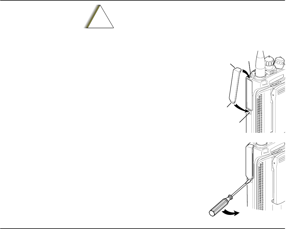
Frequency
Knob NOTES:
•Refer to Figure 8, the Partial Exploded View, and Table 12, the
Partial Exploded View Parts List. Numbers in parentheses ( ) refer to
item numbers in Figure 8 and Table 12.
•The battery (7) should be removed from the radio before installing
or removing the frequency knob (1).
Removing the
Frequency Knob 1. Hold the radio in one hand so that the top of the radio faces upward, and
the front of the radio faces you.
2. With the other hand, grasp the frequency knob (1) and pull it upward,
while pushing it toward the back of the radio, until it is free from the
frequency insert (3).
3. While pressing the insert’s (3) two snap tabs away from the frequency
control shaft so that the insert disengages from the shaft, use needle-nosed
pliers to lift the insert up and off of the frequency control shaft.
4. Remove the secure lever (4) and the lightpipe (5).
Installing the
Frequency Knob 1. Hold the radio so that the top of the radio faces upward, and the front of
the radio faces you.
When the universal connector is not in use, keep it covered
with the universal connector cover.
!
C a u t i o n
Top
Slot
Bottom
Slot
Top
Hooked End
Bottom
Hooked End

24
2. Align the lightpipe (5) so that its straight tab is over the slot for the
illuminated pointer. Push the tab down into the slot so that it is securely
seated.
3. Place the secure lever (4) on the frequency control shaft, aligning it so that
its pointer is at the front of the radio and its two inner slots line up with
the two keys on the shaft. Slide the secure lever down to the bottom of the
shaft.
4. If you are replacing the escutcheon (2), remove the backing paper from
the escutcheon, align its alignment marker with the alignment notch
(between numbers 4 and 5) on the insert, and adhere it to the insert.
5. Place a new frequency insert (3) and escutcheon (2) on the frequency
control shaft, aligning the insert’s D-shaped hole with the D-shaped shaft.
Press downward firmly on the insert until it “snaps” in place on the shaft.
6. Place the frequency knob (1) on the frequency insert (3), aligning it’s
pointer with the number “1” on the escutcheon (2). Press firmly
downward on the knob until it seats securely in place.
Volume Knob NOTES:
•Refer to Figure 8, the Partial Exploded View, and Table 12, the
Partial Exploded View Parts List. Numbers in parentheses ( ) refer to
item numbers in Figure 8 and Table 12.
•The battery (7) should be removed from the radio before installing
or removing the volume knob (8).
Removing the
Volume Knob 1. Hold the radio in one hand so that the top of the radio faces upward, and
the front of the radio faces you.
2. With the other hand, grasp the volume knob (8) and pull it upward, while
pushing it toward the back of the radio, until it is free from the volume
insert (9).
3. While pressing the volume insert’s (9) two snap tabs away from the
volume control shaft so that the insert disengages from the shaft, use
needle-nosed pliers to pull the insert up and off of the volume control
shaft. Discard the removed volume insert.
4. Using needle-nosed pliers or some other pointed instrument, remove the
o-ring (21).
Installing the
Volume Knob 1. Place the o-ring (21) inside a new volume insert (9), and press it downward
until it seats securely at the bottom of the insert.
2. Hold the radio so that the top of the radio faces upward, and the front of
the radio faces you.
3. Place the volume insert (9) on the volume control shaft, aligning its D-
shaped hole with the D-shaped shaft. Press downward firmly on the insert
until it “snaps” in place on the shaft.
4. Place the volume knob (8) on the volume insert (9), aligning the two lugs
on the inside of the knob with the insert’s two snap tabs. Press firmly
downward on the knob until it seats securely in place.
25
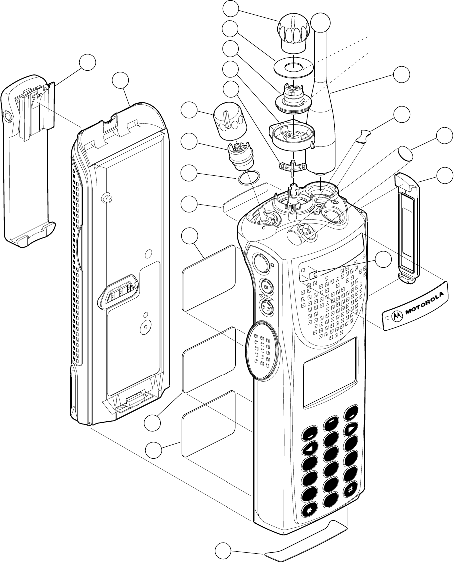
Figure 8 Partial Exploded View
123
456
78
0
9
ABC
DEF
GHI
JKL
MNO
PRS
TUV
WXY
HOME
XTS 3000
1
2
3
4
5
17
18
20
16
15
8
9
10
11
21
14
13
12
7
6
A
B
C
Alignment Notch
Alignment Marker

26
Table 12 Partial Exploded View Parts List
ITEM
NO. MOTOROLA
PART NO. DESCRIPTION
1 3605370Z01 KNOB, Frequency
2 1305374Z01 ESCUTCHEON, Frequency
3 4305373Z01 INSERT RETAINER, Frequency Knob
4 4305375Z01 LEVER, Secure Frequency
5 6105376Z01 LIGHTPIPE INDICATOR/STOP, Frequency
6 NTN8266A CLIP, Belt
7 NTN8298A Battery, NiCd
8 3605371Z01 KNOB, Volume
9 4305372Z01 INSERT RETAINER, Volume Knob
10 3305574Z01 LABEL, Motorola, Back
11 - - - - - - - - - - LABEL, Flashport
12 - - - - - - - - - - LABEL, Radio Serial Number
13 - - - - - - - - - - LABEL, Approval Agency
14 3305630Z02 LABEL, Bottom
15 NAF5037A
or NAF5039A
or NAF5042A
ANTENNA, 800MHz Whip (806-870 MHz)
ANTENNA, 800MHz Dipole (806-870 MHz)
ANTENNA, 800MHz Stubby Quarterwave
(806-870 MHz)
16 - - - - - - - - - - ESCUTCHEON, Concentric Switch (optional)
17 - - - - - - - - - - ESCUTCHEON, Toggle (optional)
18 1505579Z01 COVER, Dust, Universal Connector
19 3305573Z01 LABEL, Motorola, Front
20 3505586Z01 Gortex
21 3205379W01 O-Ring

27
Basic Theory of
Operation 7
General
Overview The ASTRO Digital XTS 3500 radio is a wideband, synthesized, fixed-tuned
radio available in the UHF band. All ASTRO Digital XTS 3500 radios are
capable of both analog operation and ASTRO mode (digital) operation in
12.5kHz or 25kHz bandwidths.
The ASTRO Digital XTS 3500 radio includes the following major assemblies:
•VOCON Board - contains the microcontrol unit (MCU) and its associated
memory and memory management integrated circuit (IC), the audio
power amplifier, and a switching regulator. The board also contains the
digital signal processor (DSP) and its support IC and associated memories.
•RF Board - contains all transmit, receive, and frequency generation
circuitry including the digital receiver back-end IC and the reference
oscillator.
•Controls/Universal Flex - contains volume/on/off switch, frequency
selector switch, push-to-talk (PTT) switch, monitor button, several
function-selectable switches, universal connector, speaker, and
microphone.
•Display (Full-Featured Model Only) - a four-line, 12-character liquid
crystal display (LCD).
•Keypad (Full-Featured Model Only) - a 3 x 6 keypad.
Analog Mode
of Operation When the radio is receiving, the signal comes from the antenna connector to
the RF board, passes through the RX/TX switch and the receiver front end. The
signal is then filtered, amplified, and mixed with the first local-oscillator signal
generated by the voltage-controlled oscillator (VCO).
The resulting intermediate frequency (IF) signal is fed to the IF circuitry, where
it is again filtered and amplified. This amplified signal is passed to the digital
back-end IC, where it is mixed with the second local oscillator to create the
second IF at 450kHz. It is then converted to a digital bit stream and mixed a
third time to produce a baseband signal. This signal is passed to the VOCON
board through a current-driven differential output.
On the VOCON board, the digital-signal processor (DSP) support IC digitally
filters and discriminates the signal, and passes it to the digital-signal processor
(DSP). The DSP decodes the information in the signal and identifies the
appropriate destination for it. For a voice signal, the DSP will route the digital
voice data to the CODEC for conversion to an analog signal. The CODEC will
then present the signal to the audio power amplifier, which drives the speaker.
For signalling information, the DSP will decode the message and pass it to the
microcontrol unit.
28
When the radio is transmitting, microphone audio is passed through gain
stages to the CODEC, where the signal is digitized. The CODEC passes digital
data to the DSP, where pre-emphasis and low-pass (splatter) filtering are done.
The DSP passes this signal to a digital/analog (D/A) converter, where it is
reconverted into an analog signal and scaled for application to the voltage-
controlled oscillator as a modulation signal.
Transmitted signalling information is accepted by the DSP from the
microcontrol unit, coded appropriately, and passed to the D/A converter,
which handles it the same as a voice signal. Modulation information is passed
to the synthesizer along the modulation line. A modulated carrier is provided
to the RF PA, which transmits the signal under dynamic power control.
ASTRO Mode
of Operation In the ASTRO mode (digital mode) of operation, the transmitted or received
signal is limited to a discrete set of deviation levels, instead of continuously
varying. The receiver handles an ASTRO-mode signal identically to an analog-
mode signal up to the point where the DSP decodes the received data. In the
ASTRO receive mode, the DSP uses a specifically defined algorithm to recover
information.
In the ASTRO transmit mode, microphone audio is processed identically to an
analog mode with the exception of the algorithm the DSP uses to encode the
information. This algorithm will result in deviation levels that are limited to
discrete levels.
RF Board Basic
Theory of
Operation
The receiver front end consists of a preselector, an RF amplifier, a second
preselector, and a mixer. The RF amplifier is a dual-gate, gallium- arsenide
based IC. The mixer is a double-balanced, active mixer coupled by
transformers. Injection is provided by the VCO through an injection filter. See
Table 13 for local oscillator (LO) and first IF information.
The frequency generation function is performed by three ICs and associated
circuitry. The reference oscillator provides a frequency standard to the
synthesizer/prescaler IC, which controls the VCOB IC. The VCOB IC actually
generates the first LO and transmit-injection signals and buffers them to the
required power level. The synthesizer/prescaler circuit module incorporates
frequency-division and comparison circuitry to keep the VCO signals stable.
The synthesizer/prescaler IC is controlled by the microcontrol unit through a
serial bus. Most of the synthesizer circuitry is enclosed in rigid metal cans on
the RF board to reduce microphonic effects.
The receiver back end consists of a two-pole crystal filter, an IF amplifier, a
second two-pole crystal filter, and the digital back-end IC. The two-pole filters
are wide enough to accommodate 4kHz modulation. Final IF filtering is done
digitally in the DSP.
Table 13 Local Oscillator and First IF Frequencies
UHF
LO Frequency Range 376.65-446.65MHz
First IF Frequency 73.35MHz

29
The digital back-end IC consists of an amplifier, the second mixer, an
IF analog-to-digital converter, a baseband down-converter, and a
2.4MHz synthesis circuit to provide a clock to the DSP-support IC on
the VOCON board. The second LO is generated by discrete
components external to the IC. The output of the digital back-end IC
is a digital bit stream that is current driven on a differential pair for a
reduction in noise generation.
The transmitter consists of an RF driver IC that gets an injection signal
from the VCO and a final-stage power amplifier. Transmit power is
controlled by a power-control IC that monitors the output of a
directional coupler and adjusts PA control voltages correspondingly.
The signal passes through a RX/TX switch that uses PIN diodes to
automatically provide an appropriate interface to transmit or receive
signals. Antenna selection is done mechanically in the control top.
VOCON Board Basic
Theory of
Operation
The vocoder and controller (VOCON) board contains the radio’s
microcontrol unit with its memory and support circuits, the digital-
signal processor (DSP), its memory devices, and the DSP-support IC,
voltage regulators, audio, and power control circuits. Connected to the
VOCON board are the display board, RF board, keypad board,
controls/universal flex, and (optional) encryption module.
The microcontrol unit controls receive/transmit frequencies, power
levels, display, and other radio functions, using either direct logic
control or serial communications paths to the devices.The
microcontrol unit executes a stored program located in the FLASH
ROM. Data is transferred to and from memory by the microcontrol
unit data bus. The memory location from which data is read, or to
which data is written, is selected by the address lines.
The DSP-support IC is supplied with a 16.8MHz clock from the RF
board. Both the DSP and the microprocessor have their clocks
generated by the DSP-support IC. They can both be adjusted so that
the harmonics do not cause interference with the radio’s receive
channel.
The regulator and power-control circuits include 3.3-volt analog, 3.3-
volt digital, and 5-volt regulators. The audio PA is sourced from 7.5V.
The regulator’s power-down mode is controlled by the microcontrol
unit, which senses the position of the on/off switch. The 5-volt
regulator has an error pin for low-voltage resets.
The DSP performs signalling and voice encoding and decoding as well
as audio filtering and volume control. This IC performs Private-Line®/
Digital Private Line™ (PL/DPL) encode and alert-tone generation. The
IC transmits pre-emphasis on analog signals and applies a low-pass
(splatter) filter to all transmitted signals. It requires a clock on the
EXTAL pin. An 8kHz interrupt signal generated by the DSP-support IC
is also required for functionality. It is programmed using parallel
programming from the microcontrol unit.
30
The audio CODEC performs analog-to-digital and digital-to-analog
conversions on audio signals. The DSP controls squelch deviation, and
executes receiver and transmitter filtering. The DSP-support IC
receives a 2.4MHz clock, and receives data and formats it for the DSP.