Motorola Solutions 89FT4839 Moscad-L P44-UHF FLN5923A, SCADA Terminal User Manual MOBAT RADIO P44
Motorola Solutions, Inc. Moscad-L P44-UHF FLN5923A, SCADA Terminal MOBAT RADIO P44
Contents
technical manual

MOTOROLA INC. FCC ID: AZ4FLN2583A
Created by Ishay Kokavka 10/2/00
Page 1 of 6 Motorola confidential property EXHIBIT 8A
1
MOBAT RADIO (P44)
1 Radios spec (data sheet)……………………………………………………….....2-3
2 Pin configuration ……………………………………………………………….……4
3 Operating method ( siganls ….)……………………………………………….….5-6
MOTOROLA INC. FCC ID: AZ4FLN2583A
Created by Ishay Kokavka 10/2/00
Page 2 of 6 Motorola confidential property EXHIBIT 8A
2
1 Radios spec (data sheet)
1.1 Introduction
The P44 MOBAT radio is a mounted, stand alone, 7 channels UHF/VHF RF board
which will be mounted on the MOSCAD_L (Or Moscad by a Sabonia) by means of
an interface piggyback, for communication via port 3.
1.2 P44 Radio types.
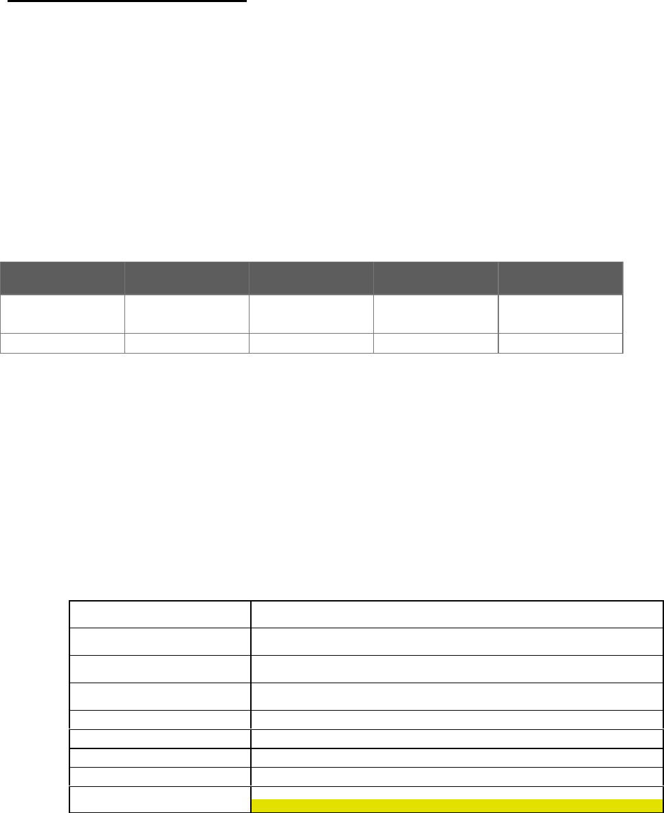
The P44 Types of Radios is shown in table 1.1 below.
P44- UHF1
FLN2582A P44- UHF21
FLN2583A P44- VHF1
FLN2584A P44- VHF2
FLN2585A
Channel BW 6.25,12.5,25
Khz 6.25,12.5,25
Khz 6.25,12.5,25
Khz 6.25,12.5,25
Khz
Frequency 438-470 MHz 403 – 433 MHz 136 - 155 MHz 146 - 174 MHz
Table 1.1 P44 Types of Radios.
The marked radios are the radios that will be tested (UHF).
1.3 P44 Spec
The P44 Spec is shown in table 1.2 below.
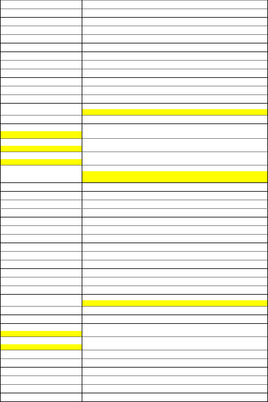
GENERAL
P44
UHF/VHF
12.5kHz Channel BW
Synthesizer Reference 2.1,2.225,2.4 Mhz
Channel Spacing 12.5Khz / 25Khz (6.25 capable)
Operating Temperature - 30C to +60C
Operating Mode Simplex / Half Duplex
Supply Voltage -1 (Main) 7.5V +/-1.5V
DO-13.8V+/-20%
MOTOROLA INC. FCC ID: AZ4FLN2583A
Created by Ishay Kokavka 10/2/00
Page 3 of 6 Motorola confidential property EXHIBIT 8A
3
Supply Voltage -2 5V +/-5%
RF Connector RF Micro Jack
Interface Connector 14-pin In-Line socket on 0.100 inch
Synthesizer Data Load Time 98 bits in 48 microseconds minimum
Dimensions 3.3"L x 2.25" W x 0.49" H
Transmitter
RF Power Out 1-5 Watt (Adjustable)
Conducted Spurs - 38dbm
Frequency Stability 2.5ppm (1.5ppm Optional)
FM Hum and Noise 40dB
Modulation Sensitivity 175 mV RMS/Khz
100 mV RMS/Khz Nominal
Switching Bandwidth 32Mhz
Audio Input DC Level 2.5 VDC
Audio Distortion
In what frequency response?
<3%
Attack Time
What it means ?
12mSec (7mSec Typical)
Typical Current Drain 2A @ 5Watt
Max 1.4A @ 14V , 5Watt
Max 2A @ 7.5V , 5Watt
Receiver
Sensitivity 0.38uV / 12dB SINAD
Frequency Stability 2.5ppm (1.5ppm Optional)
Selectivity 60 dB
Intermodulation 60 dB
Spurious Rejection 70 dB
Image Rejection 70 dB
FM Hum and Noise 48dB
Frequency Response Flat +/- 2 dB from DC to 5kHz
Audio Output :AC Level 70 mV RMS/Khz
100 mV RMS/Khz Nominal
Audio Output :DC Level 2.5VDC
Audio Response Flat
Audio Distortion
In what frequency response ?
<5%
Carrier Detect Attack Time
Is it RSSI or CSQ ?
25 mSec
Current Drain ~47 mA
Turn Around Time 7 mSec Typical
Switching Bandwidth 32 Mhz
RSSI 0.5 to 1.9 V monotonically (20mV/dB)
Conducted Spurs - 57dbm
Group Delay Distortion <30uSec
MOTOROLA INC. FCC ID: AZ4FLN2583A
Created by Ishay Kokavka 10/2/00
Page 4 of 6 Motorola confidential property EXHIBIT 8A
4
< 20uSsc
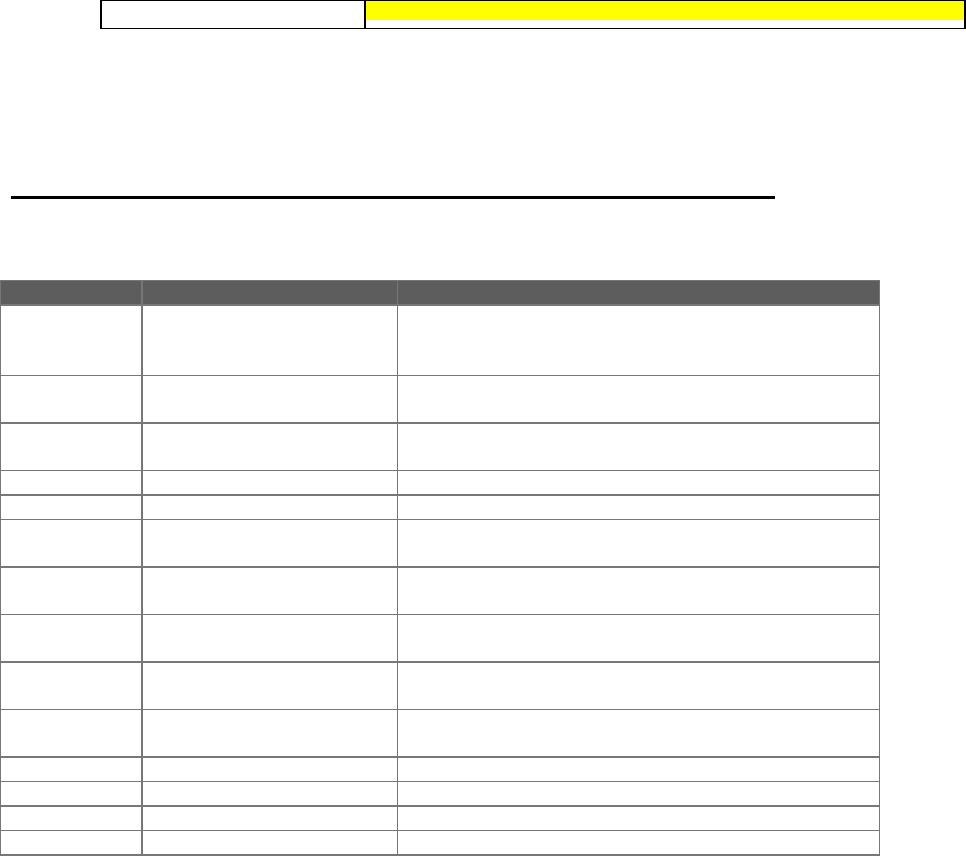
2 Pin configuration of P44 radio is shown in table 2.1 below
PIN No. Signal Name
1 GND Reference node for all receive transmit and power
signals. Proper grounding requires metal screws in the
four corners mounted to a common chassis.
2SW_B+ Transmit - Max 2A @ 7.5VDC @ 5 Watt
Receive - 47mA @ 7.5VDC
3 XMIT_B+ This signal is Asserted only during transmit time . 250
mA @ 7.5VDC
4 RX_5V Not Connected
5 TX_5V Asserted during Transmit - 40Ma @ 5VDC
6 MODE_IN Analog data in to the radio to be transmitted.
DC coupled with a nominal bias of 2.5VDC.
7 SQ_DET Output signal from the radio indicating that there is a
valid RF signal on the channel
8 Reset This pin in pulled up in the radio. In normal mode must
kept up. Used when programming the radio.
9 RSSI Output signal from the radio. The Volt level of this pin is
according to the RF level of the received signal.
10 Audio_Out Received analog data is transferred to the CPU via this
pin.
11 CH_SEL_B Channel select pin (1 out of 7)
12 CH_SEL_A Channel select pin (1 out of 7)
13 CH_SEL_C Channel select pin (1 out of 7)
14 CH_SEL_D Channel select pin (1 out of 7)
Table 2.1 pin configuration of P44 radio.
MOTOROLA INC. FCC ID: AZ4FLN2583A
Created by Ishay Kokavka 10/2/00
Page 5 of 6 Motorola confidential property EXHIBIT 8A
5
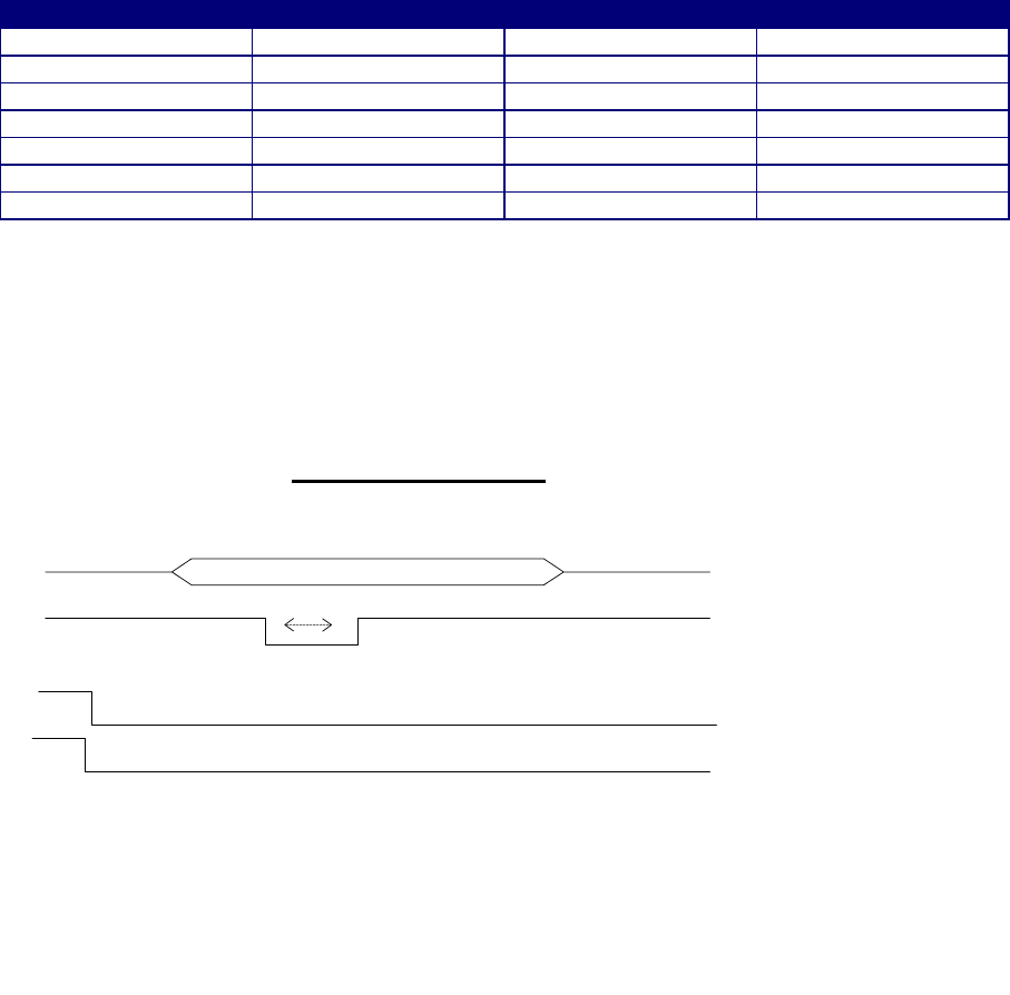
3 Operating method ( siganls ….)
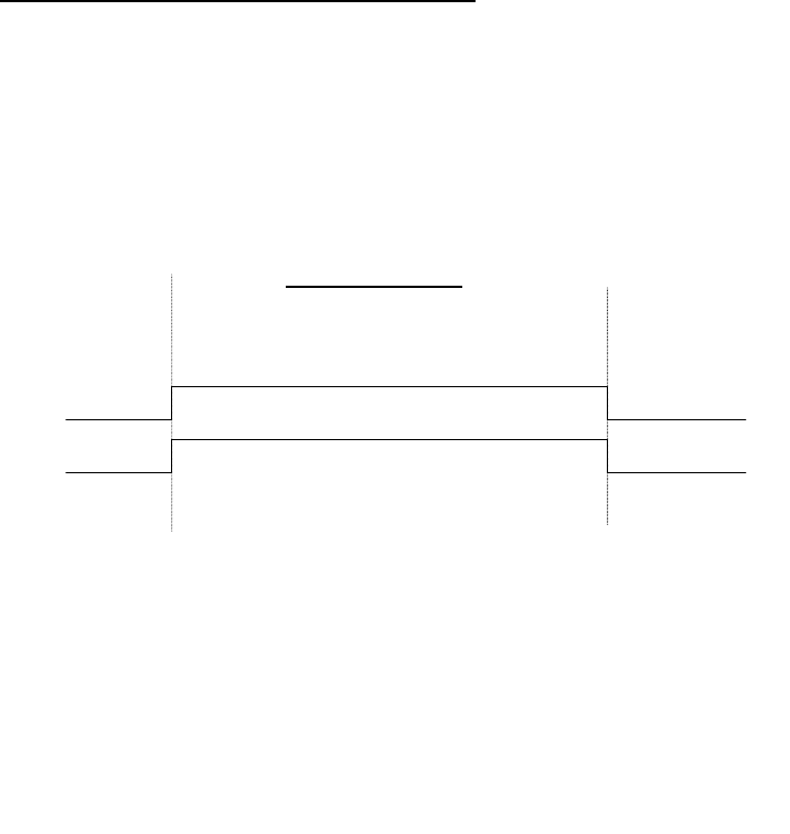
3.1 TIMING DIAGRAMS
Figure 3 shows the timing diagrams of the MOBAT radio in transients between transmit and receive modes
as it will be used with the MOSCAD_L.
Timing Diagram
Receive Transmit Receive
Xmit_B+
Tx_5V
FIGURE 3.1 TIMMING DIAGRAM
3.2 Channel Change
The radio can operate in multi channel mode and single channel mode and is
programmable via the RSS software of Mobat.
3.2.1 Single Channel
In this mode only channels 1, and 2 are operational.
CH_SEL_A is 0VDC Channel 1 is selected
CH_SEL_A is 5VDC Channel 2 is selected
When this signal is changed an interrupt is generated on the radio and the channel is changed.
MOTOROLA INC. FCC ID: AZ4FLN2583A
Created by Ishay Kokavka 10/2/00
Page 6 of 6 Motorola confidential property EXHIBIT 8A
6
3.2.2 Multi channel
The channel of the radio is determined by the three channel select bits
CH_SEL_B CH_SEL_C CH_SEL_D Channel selected
0001
1002
0103
1104
0015
1016
0117
Changing a channel could be done only in receive mode.
After setting CH_SEL_B – CH-SEL_D reset CH_SEL_A for 5mS and assert it again.
Channel select Timing
Valid CH_SEL_B - CH_SEL_D
Xmit_B+
Tx_5V
5 Ms
CH_SEL A