Motorola Solutions 89FT4839 MOSCAD Series SCADA Terminals User Manual MOSCAD M Owner s Manual
Motorola Solutions, Inc. MOSCAD Series SCADA Terminals MOSCAD M Owner s Manual
Contents
users and install manual

MOSCAD-M™
Remote Terminal Unit
Owner’s Manual
68P02961C50-O

68P02961C50-O
©Motorola Inc., 2001 August 2001
CONTENTS
INTRODUCTION......................................................................................................................... 1
SCOPE OF THIS MANUAL ............................................................................................................... 1
GENERAL DESCRIPTION ................................................................................................................ 1
HARDWARE OPTIONS .................................................................................................................... 2
Line, RS232 and RS485 Communication Interfaces..............................................................................2
Radio Communication Interfaces ..........................................................................................................2
I/O Configurations.................................................................................................................................2
Power Supply and Battery .....................................................................................................................2
INSTALLATION .......................................................................................................................... 3
GENERAL ...................................................................................................................................... 3
Power Connections:...............................................................................................................................3
WALL MOUNTING ......................................................................................................................... 3
Wall Mounting with Screws ...................................................................................................................4
Wall Mounting on DIN Rail...................................................................................................................5
CONNECTIONS............................................................................................................................... 7
Ground Connection................................................................................................................................7
Power Connections ................................................................................................................................7
Backup Battery Connection ...................................................................................................................7
Internal Radio Connection - antenna ....................................................................................................7
External Radio Connection....................................................................................................................7
Line Communication Connection ..........................................................................................................8
INSTALLATION OF BACKUP BATTERIES ......................................................................................... 9
MISCELLANEOUS......................................................................................................................... 10
Open the Case Door.............................................................................................................................10
Close the Case Door ............................................................................................................................10
Antenna Placement ..............................................................................................................................10
Fixed Site Antennas .............................................................................................................................10
THE MOSCAD-M UNIT............................................................................................................ 11
OVERVIEW .................................................................................................................................. 11
COMMUNICATION PORTS ............................................................................................................ 12
CONNECTORS.............................................................................................................................. 12
CONTROLS AND INDICATORS....................................................................................................... 12
Contents
ii
LED Control.........................................................................................................................................13
System Software Downloading ............................................................................................................13
CPU Reset............................................................................................................................................13
LED DISPLAY INDICATIONS........................................................................................................ 14
CPU Page LED Functions...................................................................................................................14
IO1 Page LED Functions.....................................................................................................................15
IO2 Page LED Functions.....................................................................................................................17
IO3 Page LED Functions.....................................................................................................................18
AO Page LED Functions .....................................................................................................................19
User Page LED Functions...................................................................................................................20
I/OS (ALL MODELS).................................................................................................................... 22
Wetting switch connection (x2)............................................................................................................22
DO Magnetic Relay connection (x4) ...................................................................................................23
DO Open Collector (x4).......................................................................................................................23
DI (x12)................................................................................................................................................24
ADDITIONAL I/OS (EXPANDED I/O MODELS ONLY) .................................................................... 25
AI (x4) ..................................................................................................................................................25
AO (x1).................................................................................................................................................26
DI (x3)..................................................................................................................................................27
Pin Assignment - Main Board TBs ......................................................................................................28
Pin Assignment - Expansion Board TBs ..............................................................................................29
BACKUP BATTERY ...................................................................................................................... 29
POWER SUPPLY ........................................................................................................................... 30
POWER MANAGEMENT......................................................................................................... 31
OVERVIEW .................................................................................................................................. 31
RUN MODE ................................................................................................................................. 31
SLEEP MODE ............................................................................................................................... 32
WAKEUP EVENTS........................................................................................................................ 33
ETHERNET INTERFACE OPTION ....................................................................................... 34
OVERVIEW .................................................................................................................................. 34
EXTERNAL ETHERNET INTERFACE UNIT...................................................................................... 34
INSTALLATION............................................................................................................................. 35
Connections .........................................................................................................................................35
APPENDIX A: CABLES AND ADAPTERS ............................................................................ 36
GENERAL .................................................................................................................................... 36
RTU-TO-COMPUTER/TERMINAL CONNECTIONS.......................................................................... 36
RTU-TO-MODEM CONNECTIONS ................................................................................................ 37
RTU-to-Modem Asynchronous Connection .........................................................................................37
RTU-TO-RTU CONNECTION....................................................................................................... 38
RTU-to-RTU Asynchronous Communications Connection .................................................................38
Contents
iii
APPENDIX B: MODELS AND ACCESSORIES .................................................................... 39
GENERAL .................................................................................................................................... 39
INSTALLATION OF MOSCAD-M WITH GP140/328/HT750/ PRO5150 RADIO ........................... 41
MOSCAD-M INSTALLATION KIT FOR GP140/GP328/HT750/ PRO5150 RADIOS .................... 42
MOSCAD-M DEBUG HARDWARE KIT....................................................................................... 42
MOSCAD-M Board..............................................................................................................................42
Debug Setup.........................................................................................................................................43
Logic Analyzer .....................................................................................................................................45
Pin Assignment – Logic Analyzer TBs.................................................................................................45
APPENDIX C: CHANGING THE ANALOG INPUT MEASUREMENT TYPE................ 46
GENERAL .................................................................................................................................... 46
DISASSEMBLING THE RTU .......................................................................................................... 46
Remove Connectors .............................................................................................................................46
Open RTU ............................................................................................................................................46
Remove Main Board ............................................................................................................................47
Remove Expansion Board....................................................................................................................47
Place Jumpers......................................................................................................................................48
REASSEMBLING THE RTU ........................................................................................................... 49
Install Expansion Board ......................................................................................................................49
Install Main Board...............................................................................................................................50
Close Case ...........................................................................................................................................50
1
INTRODUCTION
Scope of this Manual
This manual provides instructions for the installation and operation of the MOSCAD-M ™
Remote Terminal Unit (RTU). It also provides on-site tuning instructions for RTU elements
that do not necessarily require shop level assistance.
This manual covers the basic RTU and most communications and I/O options. The online help
of the MOSCAD-M RTU Configurator contains additional information on the RTU.
General Description
The RTU is a remotely located unit used for monitoring and control of local equipment. The
unit can operate in stand-alone mode, or as an intelligent RTU or node on a distributed control
system.
The RTU consists of the following components installed in a plastic case: printed circuit
board, internal/external radio, and battery housing. This manual describes both basic and
expanded I/O models.
The MOSCAD-M is a low-power unit that incorporates a variety of power save modes which
enable the unit to operate with minimal power consumption.
The RTU case is suitable for either wall or DIN rail mounting.
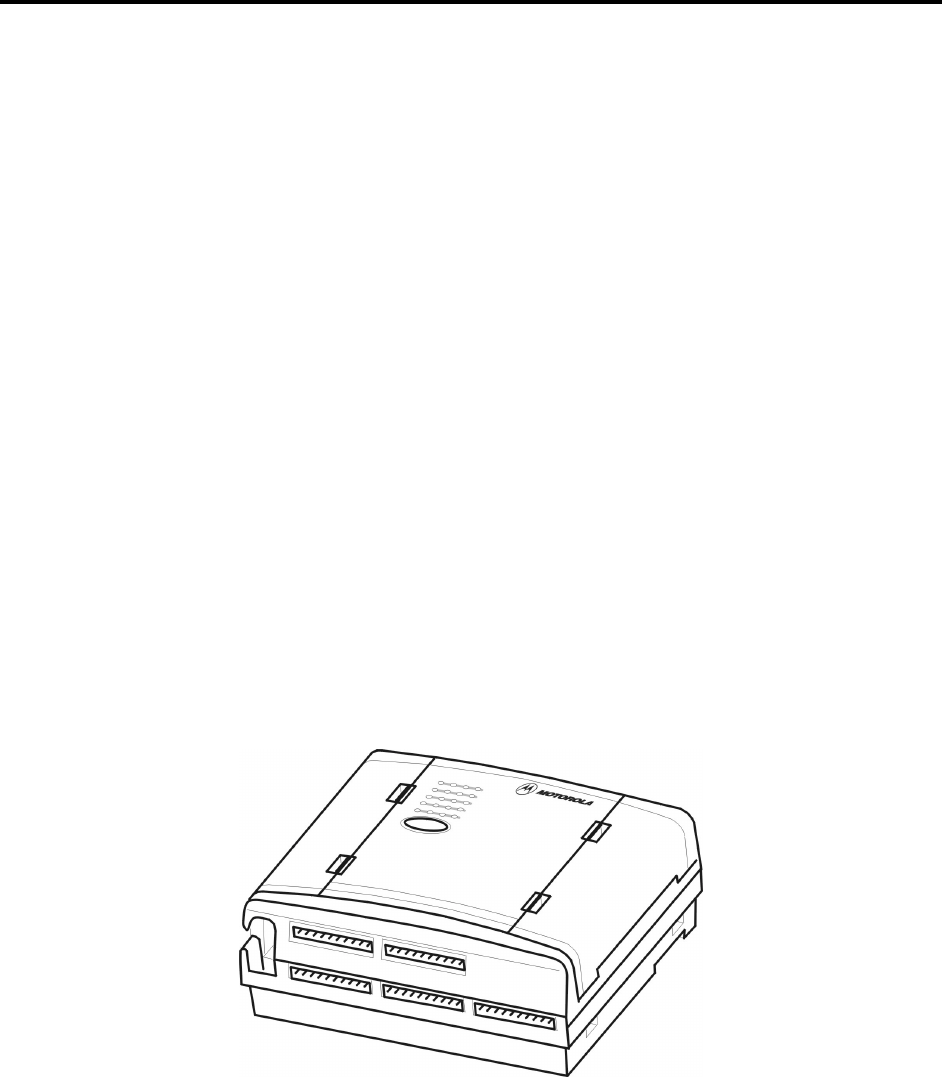
Figure 1 provides a general view of the MOSCAD-M RTU.
The MOSCAD-M RTU is enclosed in an indoor plastic case and is intended for outdoor base
station use. The installer must make sure that the installation meets the requirements of the
standard and protects the unit from weather hazards.
The antenna must be physically secured at a permanent outdoor location.
Figure 1
MOSCAD-M RTU –General View with Case
Introduction
2
Hardware Options
Line, RS232 and RS485 Communication Interfaces
A variety of Line, RS232, and RS485 communication interfaces are available:
• RS485 adapter
• RS232 multiplexer
• Ethernet Interface Unit
Radio Communication Interfaces
A variety of radios can be attached using internal DPSK or duo-binary modem:
• Internal radio UHF High Band
• Internal radio UHF Low Band
• Variety of external radios (GP140/328, HT750, PRO5150)
For details on the available external radio models, and their connection to the RTU, see
Appendix B.
I/O Configurations
Different models of the MOSCAD-M RTU have slightly different I/O configurations.
Models with basic I/O configuration:
• 12 Digital Input
• 8 Digital Output (4 Magnetically Latched, 4 Open Collector)
• 2 Digital Output (Solid State)
Models with expanded I/O configuration:
• 15 Digital Input
• 8 Digital Output (4 Magnetically Latched, 4 Open Collector)
• 4 Analog Input (4-20 mA)
• 1 Analog Output (0-5V or 4-20mA)
• 2 Digital Output (Solid State)
Power Supply and Battery
The power supply and backup battery options are:
• 9-30V DC power input (compatible with 12V DC Solar Panel)
• 3 x “C” backup battery (for Real Time Clock and RAM retention)

3
INSTALLATION
General
MOSCAD-M SAFETY SUMMARY
The MOSCAD-M should be installed by qualified and authorized
technicians. If the installation involves high-voltage connections,
technicians must be specifically qualified to handle high voltage.
This equipment was tested with cables 3 meters in length. If longer
cables and/or cabinets are used, the installer is responsible for making
sure that the installation complies with the requirements of the relevant
standard.
The product is a radio accessory. The installer must make sure that the
radio connected to the system has all required approvals and that the
installation meets the requirements of the standard. This equipment is a
base station unit and complies with the FCC base station requirements.
The antenna must be installed outdoors.
Power Connections:
This device accepts 9-30V DC input, maximum 2.5A @15V DC.
This chapter covers the following installation procedures:
• Wall mounting
• Connections
• Backup Batteries
• Miscellaneous
Wall Mounting
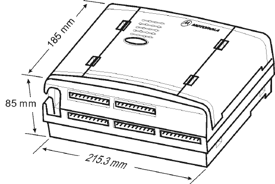
The dimensions of the unit are: width – 21.5 cm (8.46"), height – 18.5 cm (7.28"), depth – .85
cm (.33"), weight – 1.5kg maximum (see Figure 2).
Installation
4
Figure 2
Dimensions of MOSCAD-M RTU Plastic Case
The unit can be installed on screws or on DIN rail mounting. Before installing the
MOSCAD-M RTU, verify that there is sufficient space around the unit. Allow 20 cm (7.87")
from the bottom of the box for the TB connectors. When an RF connector is attached (internal
radio models), allow for an extra 10 cm (4"): 2.02 cm (.8") from the top of the box for the RF
connector and 8 cm (3.15") for the wires. For models with external radios, allow 8 cm (3.15").
Wall Mounting with Screws
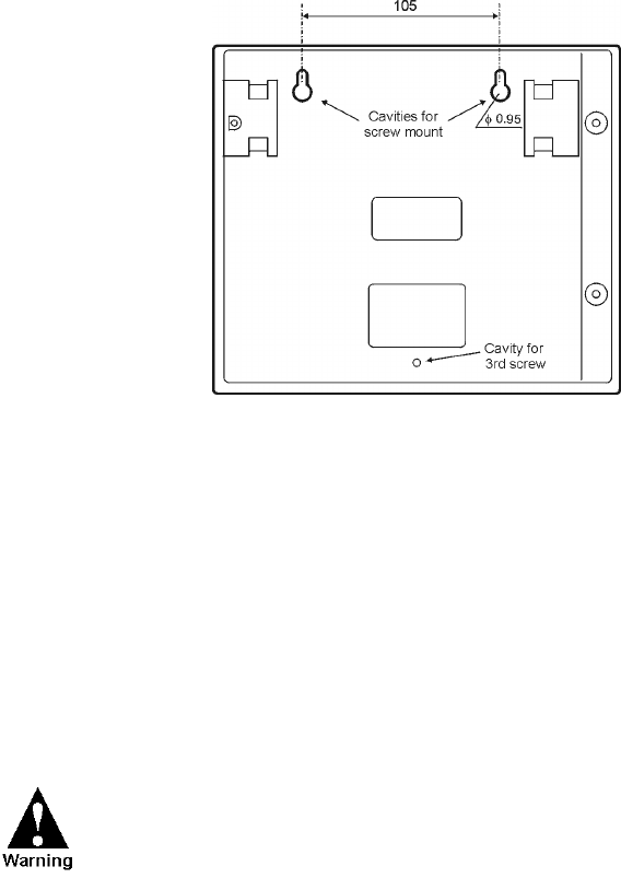
The MOSCAD-M can be mounted on the wall using screws, as shown in Figure 3.
1. Secure two screws (maximum head size 0.9 mm) on the wall, 105 mm apart.
2. Hang the unit on the screws, fitting the two cavities on the back cover of the unit over the
screws (see Figure 3).
The screws used should not protrude from the wall surface by more than 6 mm or by less than
4 mm.
Installation
5
Figure 3
Installation of MOSCAD-M – Screw Mount
It is also possible to attach the MOSCAD-M to the wall using the small screw hole at the
bottom of case, though this requires dismantling the RTU, which is generally discouraged.
Consult Motorola service personnel before opening the MOSCAD-M casing. To mount the
RTU:
1. Open the case and dismantle the parts of the MOSCAD-M.
2. Secure the back of the case against the wall using a screw whose diameter is less than
3.5 mm and head size is at least 5.5 mm.
3. Reassemble the parts of the MOSCAD.
Before beginning any disassembly or reassembly procedures, you
should be adequately grounded to prevent damage to static sensitive
devices in the unit.
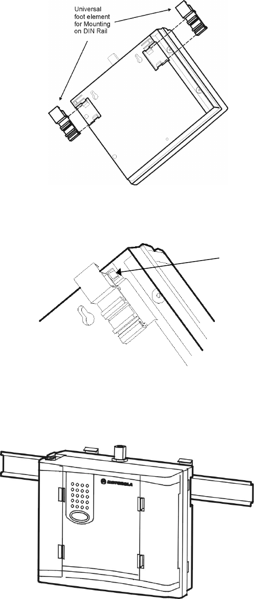
Wall Mounting on DIN Rail
For mounting the RTU on a DIN rail, two universal foot elements (Phoenix Connectors MFC
PIN UMK-FE) are required. To mount the unit, proceed as follows:
1. Slide the two foot elements into the recesses on the back cover of the unit as shown in
Figure 4. Press until they click behind the snaps that secure their placement. (See zoomed
image in Figure 5.)
Installation
6
Figure 4
DIN Rail Attachment
Figure 5
DIN Rail Attachment-Foot Element Snap-in (Enlarged)
2. Press the unit onto the DIN rail, using both universal foot elements. The elements can be
used on DIN rail 35 mm and G rails. (See Figure 6).
Figure 6
MOSCAD-M Mounted on DIN Rail
SNAP

Installation
7
Connections
Verify that all power and ground connections are made in
accordance with local standards.
Ground Connection
Connect the grounding cable directly to the protective
grounding pins 9 and 10 (PGND) in the main power-in connector
(see TB1 in Figure 9).
Power Connections
The unit can be connected directly to a 9-30V DC source through the main Power-In connector
(see Figure 9) where Pin #1 is + (positive) and Pin #2 is – (negative).
It is recommended to connect the main power supply to the unit
with a 3.5 amp fuse on the cable.
Backup Battery Connection
The RTU has a special chamber for 3 “C” alkaline backup batteries (not supplied) that are
used to retain the unit’s RAM and Real Time Clock in power fail situations.
Internal Radio Connection - antenna
The internal radio is connected through the 14-pin connector on the Main board inside the
plastic housing. Its power is driven from that connector. When an internal radio is installed,
Port 3 of the radio cannot be used.
External Radio Connection
Connect the external radio to Port 3 (see Figure 9). Verify that the radio button is set to ON.
The radio signals are driven from the AUX connector in Figure 9.
It is recommended to replace the external radio only when the
unit is powered off.

Installation
8
If the external radio is connected to an outside power supply,
first power on the unit, and then power on the radio.
The auxiliary power supply (maximum 2A) can be changed to 6V,
6.5V, 7.5V, 8V, 9V or 9.6V DC by changing the setting of the P11
jumper located on the Main board. (See markings on the board.) To
set the power to 8V, remove the jumper and save for future use.
This is usually set in the factory according to the external power
supply of the radio. The default setting is 9V DC. To change the
voltage, follow the disassembly instructions in Appendix C, place the
jumper and reassemble.
Line Communication Connection
Line Communications are connected through Ports 1 or 2 (see Figure 9.) Port 1 can be
programmed as RS485 (1A) or RS232 (1B). Port 2 can be programmed as RS232.
Installation
9
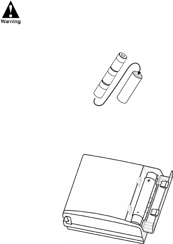
Installation of Backup Batteries
The backup battery should not be installed before the unit is
connected to the main power supply. This may cause the
battery to drain.
1. Place 3 “C” size alkaline batteries into the carton cylinder, each in the same direction, as
shown in Figure 7 below.
Figure 7
Backup Battery Cylinder and 3 Backup C Batteries
2. Place the cylinder with the batteries into the battery case in the direction indicated on the
unit (see Figure 8 below).
Figure 8
Installation of Backup Batteries

Installation
10
Miscellaneous
Open the Case Door
To open the case door properly, press the two clips (latches) and pull the wing to an open
position. The cable cover is opened counter-clockwise to expose the cable connections and
the backup battery cover is opened clockwise to expose the battery housing.
Close the Case Door
To close the case door properly, press until the latch clicks. Note that if the batteries in the
housing are not inserted properly, the backup battery cover door may not close. If the cable
connections are not threaded properly through the cable holes, the cable cover may not close.
Antenna Placement
The antenna is connected to the internal radio through the snap hole on top of the plastic
housing (see Figure 9). For models with external radios, screw the antenna onto the radio
antenna connector.
An antenna placed on top of the plastic housing produces
strong electromagnetic fields that could be harmful to the
electronics of the MOSCAD-M RTU and to people in the vicinity.
Fixed Site Antennas
The antenna installation must comply with the following requirements in order to assure
optimal performance and make sure human exposure to radio frequency electromagnetic
energy is within the guidelines set forth by the local regulations.
• The antenna must be mounted outside the building.
• Mount the antenna on a tower if at all possible.
• If the antenna is to be mounted on a building, then it must be mounted on the roof.
• As with all fixed site antenna installations, it is the responsibility of the licensee to manage
the site in accordance with applicable regulatory requirements. This may require
additional compliance actions such as site survey measurements, signage, and site access
restrictions in order to ensure that exposure limits are not exceeded.
11
THE MOSCAD-M UNIT
Overview
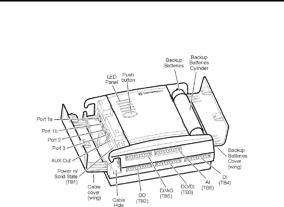
The MOSCAD-M RTU (shown below) contains power connections, line communication ports,
internal/external radio interfaces, radio modems and I/Os.
Figure 9
MOSCAD-M Unit

The MOSCAD-M Unit
12
Communication Ports
The MOSCAD-M RTU has 3 ports available:
PORT 1 - RS232 Configurator Port (for programming and monitoring the unit), RS232
External Dialup Modem, or RS485 Communication, User protocol
(1A is used for RS485)
(1B is used for RS232)
PORT 2 – Secondary Port RS232 (User protocol)
PORT 3 – External Radio interface
Ports 2 and 3 can work simultaneously with each other and with either Port 1A or Port 1B.
Ports 1A and 1B cannot work simultaneously. Port 3 cannot be used when an internal radio is
installed.
Connectors
The MOSCAD-M RTU has the following connectors available (see Figure 9):
RS485 Port 1A (RJ45, 4 pin)
RS232 Port 1B (RJ45, 8 pin)
RS232 Port 2 (RJ45, 8 pin)
External Radio Port 3 (RJ45, 8 pin)
AUX out for external radio power supply (2 pin)
Power In/Solid State DO (10 pin) - TB1
DO (10 pin) – TB2
DO/DI (10 pin) – TB3
DI (10 pin) – TB4
DI/AO (10 pin) – TB5
AI (10 pin) - TB6
The MOSCAD-M RTU has the following internal connectors.
Internal radio connector (14 pin)
Backup Battery connector (2 pin)
I/O Expansion connector (26 pin)
Controls and Indicators
The push-button is used to activate the LED panel, to toggle the LED panel so that it displays
the status of the CPU or of the I/Os, to initiate software downloading to the CPU, and to erase
User Flash memory and RAM.
The MOSCAD-M Unit
13
LED Control
Display On/Advance
When the display is off, pressing the push-button once, momentarily, activates the display.
Every consecutive momentary depression of the push-button advances the display to the next
page, in the following order: CPU > IO1 (I/O Page 1-DI) > IO2 (I/O Page 2-DO) > IO3
(I/O Page 3-AI) > Page 4 (AO) > Page 5 (User Application Controlled) > Page 6 (Hardware
Test Controlled). The next depression of the push-button returns the display to the CPU.
Display Off
The display can be programmed using the Configurator Site Configuration tool to turn off
automatically after a predefined period of time if the push-button has not been pressed.
LED Test
When the push-button is pressed continuously for a few seconds, all LEDs light up
simultaneously. When the push-button is released, the LEDs turn off.
User Flash Erase
After power-up, all LEDs light up. To erase the User Flash, press the push-button while the
LEDs are lit. All the LEDs flash three times. Now, release the push-button.
Alternatively, press the push-button continuously for at least 40 seconds at any time to erase
the User Flash.
User RAM Erase (Cold Restart)
Turn off the power supply, while the push-button is depressed. The next time the unit is
powered up, it will perform “cold restart”, which means all data stored in the RAM is erased.
Note: The data that is stored in the Flash (i.e. applications, site configuration, and network
configuration) will not be erased.
System Software Downloading
During power up, press the push-button continuously. This will cause the unit to enter
bootstrap downloading mode, in which the FLASH is programmed from a PC connected to
Port 1 of the MOSCAD-M. The CPU LED will begin to blink at 1 Hz, indicating that the CPU
has entered bootstrap downloading mode. If after 120 seconds no bootstrap software is loaded
and executed, the normal power-up procedure is performed.
CPU Reset
To reset the CPU when a backup battery is not installed, turn the power supply to the unit off
and on again. When a backup battery is installed, follow the Cold Restart method described
above.

The MOSCAD-M Unit
14
LED Display Indications
A 5 × 4 matrix of LEDs is used for diagnostics and testing of the unit (see Figure 10). The top
row indicates to which page or toggle (CPU, IO1, IO2, IO3, Page 4, Page 5, Page 6) the LED
panel is set. To advance from one page to another, press the push-button once quickly. The
first depression of the push-button activates the display. Subsequent short depressions of the
push-button advance the display to the next page: CPU > IO1 (I/O Page 1-DI) > IO2 (I/O Page
2-DO) > IO3 (I/O Page 3-AI) > Page 4 (AO) > Page 5 (User Application Controlled) > Page 6
(Hardware Test Controlled). In each page, the LEDs have different functions, as described in
the charts below.
CPU IO1 IO2 IO3
15913
2 6 10 14
3 7 11 15
4 8 12 16
Figure 10
LED Panel
CPU Page LED Functions
The following table describes the functions of the diagnostic LEDs when set to the initial CPU
(Page 0) toggle or display (CPU LED on).
Name On/Off Function/Indication
CPU On:
Flashing:
Display is in CPU mode.
CPU is in bootstrap mode OR FPGA is not loaded
correctly.
IO1 Off
IO2 Off
IO3 Off
LED 1
LOAD
On A file (e.g. configuration, application program) is
being downloaded to FLASH memory.
LED 5
CONF
On A Site configuration definition has been loaded
into FLASH memory.
LED 9
APPL
On An application program has been loaded into
FLASH memory.

The MOSCAD-M Unit
15
Name On/Off Function/Indication
LED 13
MON
On Controlled by application for user use.
LED 2
RST
On The CPU is in Reset mode.
LED 3
ERR
On An error has occurred.
LED 4
BATT
On The backup battery does not exist or has reached
a critical level of 3.5V.
LED 6
TX1
On The RTU is transmitting data via Port 1.
LED 7
RX1
On The RTU is receiving data via Port 1.
LED 8
CM1
On The communication channel used by Port 1 is
busy.
LED 10
TX2
On The RTU is transmitting data via Port 2.
LED 11
RX2
On The RTU is receiving data via Port 2.
LED 12
CM2
On The communication channel used by Port 2 is
busy.
LED 14
TX3
On The RTU is transmitting data via Port 3.
LED 15
RX3
On The RTU is receiving data via Port 3.
LED 16
CM3
On The communication channel used by Port 3 is
busy.

The MOSCAD-M Unit
16
IO1 Page LED Functions
The following table describes the functions of the diagnostic LEDs when set to the IO1
(Page 1) toggle or display (IO1 LED on).
Name On/Off Function/Indication
CPU Off
Flashing: FPGA is not loaded correctly.
IO1 On Display is in IO1 page.
IO2 Off
IO3 Off
LED 1 On DI1 is on.
LED 2 On DI2 is on.
LED 3 On DI3 is on.
LED 4 On DI4 is on.
LED 5 On DI5 is on.
LED 6 On DI6 is on.
LED 7 On DI7 is on.
LED 8 On DI8 is on.
LED 9 On DI9 is on.
LED 10 On DI10 is on.
LED 11 On DI11 is on. (Can be fast counter)
LED 12 On DI12 is on. (Can be fast counter)
LED 13 On DI13 is on. (Models with expansion board only)
LED 14 On DI14 is on. (Models with expansion board only)
LED 15 On DI15 is on. (Models with expansion board only)
The LED is not updated after each change in DI status, but rather
after the user performs a scan. Thus, the status of the DI reflects
the status as of the last software scan.

The MOSCAD-M Unit
17
IO2 Page LED Functions
The following table describes the functions of the diagnostic LEDs when set to the IO2
(Page 2) toggle or display (IO2 LED on).
Name On/Off Function/Indication
CPU Off
Flashing: FPGA is not loaded correctly.
IO1 Off
IO2 On Display is in IO2 page.
IO3 Off
LED 1 On DO1 is set.
LED 2 On DO2 is set.
LED 3 On DO3 is set.
LED 4 On DO4 is set.
LED 5 On DO5 is set.
LED 6 On DO6 is set.
LED 7 On DO7 is set.
LED 8 On DO8 is set.
LED 9 On Solid State 1 (AI wetting) is set.
LED 10 On Solid State 2 (DI wetting) is set.

The MOSCAD-M Unit
18
IO3 Page LED Functions
The following table describes the functions of the diagnostic LEDs when set to the IO3
(Page 3) toggle or display (IO3 LED on). Each AI has two LEDS which represent its status
(underflow or overflow). When both LEDS are lit, that means that this specific AI is not
calibrated.
Name On/Off Function/Indication
CPU Off
Flashing: FPGA is not loaded correctly.
IO1 Off
IO2 Off
IO3 On Display is in IO3 page.
LED 1 On AI1 Overflow.
LED 2 On AI1 Underflow.
LED 3 On AI1 is uncalibrated.
LED 4 Off AI1 measures Current. (If AI1 is On,
it measures Voltage.)
LED 5 On AI2 Overflow.
LED 6 On AI2 Underflow.
LED 7 On AI2 is uncalibrated.
LED 8 Off AI2 measures Current. (If AI2 is On,
it measures Voltage.)
LED 9 On AI3 Overflow.
LED 10 On AI3 Underflow.
LED 11 On AI3 is uncalibrated.
LED 12 Off AI3 measures Current. (If AI3 is On,
it measures Voltage.)
LED 13 On AI4 Overflow.
LED 14 On AI4 Underflow.
LED 15 On AI4 is uncalibrated.
LED 16 Off AI4 measures Current. (If AI4 is On,
it measures Voltage.)

The MOSCAD-M Unit
19
AO Page LED Functions
The following table describes the functions of the diagnostic LEDs when set to the AO
(Page 4) toggle or display (CPU and IO1 LEDs on).
Name On/Off Function/Indication
CPU On
IO1 On
IO2 Off
IO3 Off Display is in AO page.
LED 1 On AO1 Voltage.
LED 2 On AO1 Current.
LED 3 On AO1 is uncalibrated.
LED 4 Off
LED 5 Off
LED 6 Off
LED 7 Off
LED 8 Off
LED 9 Off
LED 10 Off
LED 11 Off
LED 12 Off
LED 13 Off
LED 14 Off
LED 15 Off
LED 16 Off

The MOSCAD-M Unit
20
User Page LED Functions
The following table describes the functions of the diagnostic LEDs when set to the User
(Page 5) toggle or display (CPU and IO2 LEDs on). The LEDs are controlled by the user ‘C’
Application.
Name On/Off Function/Indication
CPU On
IO1 Off
IO2 On
IO3 Off
LED 1 On User Controlled
LED 2 On User Controlled
LED 3 On User Controlled
LED 5 On User Controlled
LED 6 On User Controlled
LED 7 On User Controlled
LED 9 On User Controlled
LED 10 On User Controlled
LED 11 On User Controlled
LED 13 On User Controlled
LED 14 On User Controlled
LED 15 On User Controlled
LED 16 On User Controlled
The user may choose to define the functions of the diagnostic LEDs in an application program.
The display returns from a user-defined toggle to the CPU toggle when the push-button is
pressed or as a result of a ‘C’ command. (See ‘C’ Toolkit for MOSCAD Family RTUs
manual.)

The MOSCAD-M Unit
21
Hardware Test Page LED Functions
The following table describes the functions of the diagnostic LEDs when set to the Hardware
Test (Page 6) toggle or display (CPU and IO3 LEDs on). The LEDs are controlled by the
Hardware Test utility of the MOSCAD-M Configurator.
Name On/Off Function/Indication
CPU On
IO1 Off
IO2 Off
IO3 On
LED 1 On Hardware Test Controlled
LED 2 On Hardware Test Controlled
LED 3 On Hardware Test Controlled
LED 5 On Hardware Test Controlled
LED 6 On Hardware Test Controlled
LED 7 On Hardware Test Controlled
LED 9 On Hardware Test Controlled
LED 10 On Hardware Test Controlled
LED 11 On Hardware Test Controlled
LED 13 On Hardware Test Controlled
LED 14 On Hardware Test Controlled
LED 15 On Hardware Test Controlled
The MOSCAD-M Unit
22
I/Os (All Models)
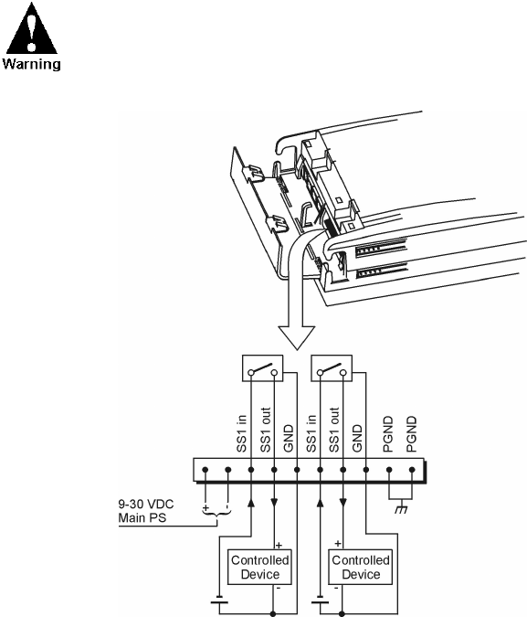
Wetting switch connection (x2)
Two solid state (SS1, SS2) Digital Outputs are provided for wetting/supply voltage control of
the DI, AI, or external devices. They are connected to the Power In TB1 (pins 3-8) and can
drive up to 400mA each. The switches are equipped with over-current protection, limiting the
current driven through each of them to 400 mA maximum. Figure 11 shows how the solid
state DOs are to be connected.
It is recommended that the wetting power be connected to the
solid state output with a fuse of 1 amp.
Figure 11
Main Board Solid State Digital Output I/O Connection
The MOSCAD-M Unit
23
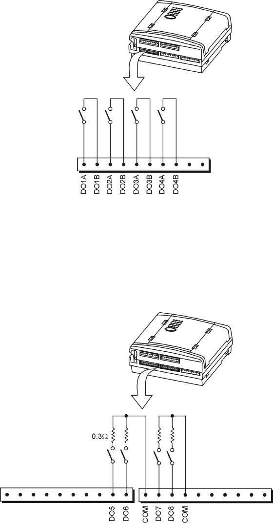
DO Magnetic Relay connection (x4)
Four magnetically latched Digital Outputs are connected to TB2. They can drive up to 2A.
Figure 12 shows how the DOs are to be connected.
Figure 12
Main Board Magnetically Latched Digital Output I/O Connection
DO Open Collector (x4)
Four open collector Digital Outputs are connected to TB2/TB3. The DOs can sink a current of
up to 500mA. They are divided into two groups of two, each with a common ground. Figure
13 shows how the DOs are to be connected
Figure 13
Main Board Open Collector Digital Output I/O Connection
The MOSCAD-M Unit
24
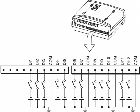
DI (x12)
Twelve wet Digital Inputs are connected to TB3-TB5. Three of these (DI1-DI3) may be used
as Wakeup events for the RTU. DI11-DI12 can be used to count pulses of up to 10KHz. They
count the rising edge of the pulse. They can also show the actual state of the DI (On/Off).
Figure 14 shows how the DIs are to be connected.
Figure 14
Main Board Digital Inputs I/O Connection
The MOSCAD-M Unit
25
Additional I/Os (Expanded I/O Models only)
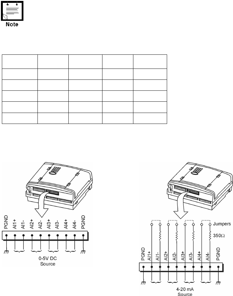
AI (x4)
Four Analog Inputs are connected via TB6. (See Figure 9.) The AIs are 4-20mA or 0-5V.
Each AI has a jumper which determines the measurement. If the jumper is placed (closed), the
AI is set up to measure current (4-20mA). If it is not placed (removed), it measures voltage
(0-5V). The jumpers are placed in the factory based on customer order.
If the status of the jumpers is changed, the AI Type must be
changed accordingly in the Hardware Test tool of the MOSCAD-M
Configurator. See Configurator help.
Four options are available for the AI expansion configuration. The default AI setup of all
MOSCAD-M PLUS radios will be 4-20mA (no option is required.)
Options AI1 AI2 AI3 AI4
Default 4-20mA 4-20mA 4-20mA 4-20mA
V741 4-20mA 4-20mA 4-20mA 0-5V
V742 4-20mA 4-20mA 0-5V 0-5V
V743 4-20mA 0-5V 0-5V 0-5V
V744 0-5V 0-5V 0-5V 0-5V
A label on the plastic housing will specify the AI setup. If, for some reason, the jumpers need
to be changed, the RTU must be disassembled. For instructions, see Appendix C. Figure 15
shows how the AIs are to be connected.
Figure 15
Expansion Board Analog Input (Voltage/Current) I/O Connection
The MOSCAD-M Unit
26
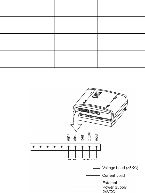
AO (x1)
One Analog Output is connected to TB5. The AO is 0-20mA or 0-5V. The AO type (current
or voltage) is determined by connecting to the proper pin on the TB and by selecting the
proper AO type in the software (either via the Configurator Hardware Test utility or the user
software application.)
The AO can be driven from an internal or external power supply. The minimum output
resistance for voltage is 5KΩ. The maximum output resistance for current is as shown below:
Power Supply Current Output Maximum Output
Resistance
Internal 8VDC 120 Ω
Internal 6VDC 100 Ω
Internal 9VDC 250 Ω
External (24VDC) 23-30VDC 750 Ω
External (24VDC) 22VDC 700 Ω
External (24VDC) 20VDC Max 600 Ω
The figure below shows how the AO is to be connected.
Figure 16
Expansion Board Analog Output I/O Connection
The MOSCAD-M Unit
27
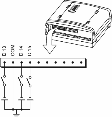
DI (x3)
An additional 3 wet Digital Inputs are connected via TB5. Figure 17 shows how the DIs are to
be connected.
Figure 17
Expansion Board Wet Digital Input I/O Connection

The MOSCAD-M Unit
28
Pin Assignment - Main Board TBs
The following charts indicate the function of each pin in the various terminal blocks (TBs) on
the Main board as shown in Figure 9.
TB1
(Power)
Pin #
Function TB2
(DO)
Pin #
Function
1 Vin + 1 DO1A in
2 Vin - 2 DO1B out
3 SS1in 3 DO2A in
4 SS1out 4 DO2B out
5SS1gnd 5 DO3A in
6 SS2in 6 DO3B out
7 SS2out 7 DO4A in
8 SS2gnd 8 DO4B out
9 PGND 9 DO5 (OC)
10 PGND 10 DO6 (OC)
TB3
(DO/DI)
Pin #
Function TB4
(DI)
Pin #
Function
1 COM DO5, DO6 1 DI6
2 DO7 2 DI7
3 DO8 3 COM DI4-DI7
4 COM DO7, DO8 4 DI8
5DI1 5DI9
6DI2 6DI10
7 DI3 7 COM DI8-DI10
8 COM DI1-DI3 8 DI11
9DI4 9DI12
10 DI5 10 COM DI11-DI12

The MOSCAD-M Unit
29
Pin Assignment - Expansion Board TBs
The following charts indicate the function of each pin in the various terminal blocks (TBs) on
the Expansion board as shown in Figure 9.
TB5
(DI/AO)
Pin #
Function TB6
(AI)
Pin #
Function
1 DI13 1 PGND
2 COM DI13-DI14 2 AI1 +
3 DI14 3 AI1 -
4 DI15 4 AI2 +
5PGND 5AI2 -
6 Vin + 6 AI3 +
7 Vin - 7 AI3 -
8 Iout 8 AI4 +
9 COM AO 9 AI4 -
10 Vout 10 PGND
Backup Battery
Below 8.9V DC, the unit enters Low Power Sleep mode. As long as the input power is above
6V DC, the unit is still powered from the main power supply input. If the input power drops
below 6V DC, the unit will use the backup battery to preserve the contents of the RAM and
Real Time Clock (RTC) data. In this case, the unit is in Low Power Sleep mode and not in
Reset mode. This means that the status of outputs 1 to 8 is preserved.
The battery will retain the data for at least 70 days (cumulative). Power consumption from the
backup battery will be <5mA @ 4.5V DC.
If no backup battery is detected, or if the backup battery falls below 3.1V DC (power fail), the
unit will shut down until power is restored. In this case, the RAM and Real Time Clock
(RTC) data will not be retained. LED 4 (BATT) will indicate when the backup battery voltage
drops below 3.5V. This indication is also available for the user application. Under these
circumstances, the SS1 and SS2 Solid State switches are turned off even if they were set to
independent operation mode.

The MOSCAD-M Unit
30
Power Supply
The MOSCAD-M can be operated from an input of 9-30V DC. The minimum input level is
determined by the output voltage level required for the AUX/Internal radio.
The table below describes the minimum input levels for the different settings:
Output
Power
Minimum
Input Power
69
6.5 9
7.5 9
810
9 10.5
9.6 11.5
The AUX/Internal radio power is set by a jumper on the Main board. The table below
describes the different models with their default settings from the factory:
Model Output
Power
Minimum
Input Power
F4570A 9.6 11.5
F4571A 9 10.5
F4572A 9 10.5
F4573A 7.5 9
F4574A 7.5 9
F4575A 7.5 9
F4580A 9.6 11.5
F4581A 9 10.5
F4582A 9 10.5
F4583A 7.5 9
F4584A 7.5 9
F4585A 7.5 9

31
POWER MANAGEMENT
Overview
The MOSCAD-M includes a Power Management feature which is controlled by the user
application. The unit can operate in four power save modes:
• Power Management Disabled (in which the entire system is operational and no power
saving technique is used)
• Run mode (in which the entire system is operational and power is provided only to active
ports of the unit)
• Idle Sleep mode (in which the unit uses low power)
• Low Power Sleep mode (in which the unit is basically off)
When the MOSCAD-M is powered up, it operates in Run mode. If all application and system
tasks are idle, and the Power Management Feature is enabled, the RTU will enter Idle Sleep
mode in order to conserve power. The unit will return to Run mode if one of several Wakeup
events occurs.
If the input power falls below 8.9V, the unit automatically enters Low Power Sleep mode. The
unit will return to its previous mode (Run or Idle Sleep) when the input power returns to at
least 9.3V.
The Power Management Feature, which is disabled by default, can
be enabled by the user application.
Run Mode
In Run mode, tasks will execute, suspend and exit, as necessary. In order to execute, each
application and system task will request a ‘visa’ from the ‘visa manager’. When the task
suspends or exits, its visa is returned. If all visas in the system have been returned, the unit
can enter Idle Sleep mode. A task can choose to operate without a visa; however, it may be
forced into Idle Sleep mode by the system when all other tasks have returned their visas.
Before a task suspends itself, it will define those Wakeup events which will cause it to wake
up. When the requested Wakeup event occurs, the task will receive a signal and awaken (even
if the Power Management feature is disabled.) If one of these events occurs while the system
is in Run mode, it will prevent the system from entering Idle Sleep mode.
Total power consumption from the main power supply in Run mode is at most 150mA @ 14V
DC. Typically, power consumption will be 50mA. The additional power consumed by the
radio in Run mode depends on the radio type and will be at least 40mA.

Power Management
32
Sleep Mode
The MOSCAD-M will enter Sleep mode in the following situations:
• Idle Sleep - All system and application tasks are idle.
• Low Power Sleep - The main power supply falls below 8.9V.
Power consumption is minimized by switching off the power of all non-active circuits and
devices (communications inputs and outputs, etc). In Sleep mode, the unit’s power
consumption will be <5mA @ 14V DC.
In Sleep mode, the current consumption is <5mA. However, the
power consumption will be significantly higher if the AO is enabled or
the radio port is defined as a Wakeup event. If Port 3 is enabled in
Sleep mode, the power consumption will be 30mA and the radio
power consumption will be at least 40mA, for a total of at least
70mA.
When entering Idle Sleep mode, the following power supplies are disabled:
• Radio/auxiliary power supply
• AI power supply
• AO power supply
• SS1 and SS2 switches power supply
• 3.3V Peripheral power supply
• Port 1 UART, Port 2 UART power supply
One or more of these power supplies might be left active, depending on the type of Wakeup
events that are selected. (See Wakeup events below.)
The AO power supply will not be disabled in Idle Sleep mode if a
value is set in the AO.
By default, The solid state SS1 and SS2 switches are controlled by
the Power Management feature. However, it is possible to configure
them to an independent operation mode where they are controlled
(enabled/disabled) by the user application only. If the unit enters Low
Power Sleep mode, SS1 and SS2 will be turned off even if set to
independent operation mode.
If one of several preprogrammed Wakeup events occurs, the unit will return from Idle Sleep
mode to Run mode. Those tasks which requested the Wakeup event will wake up and any
other tasks will remain suspended.
If, however, the unit is in Low Power Sleep mode, it will not respond to Wakeup events.
When a power level of 9.3V is restored at the power input, the unit will revert to its previous
mode.

Power Management
33
Wakeup Events
When enabling the Power Management feature, the MOSCAD-M user should configure those
Wakeup events that will wake up the unit from Idle Sleep mode.
The possible Wakeup events are:
• DI Wakeup
When a Change of State occurs in DI1 and/or DI2 and/or DI3, a Wakeup event is
generated.
• Push-Button Wakeup
Pressing the push-button when the unit is in Idle Sleep Mode will cause a Wakeup event.
(The push-button is enabled at all times.) The unit will enter Run mode for at least 30
seconds.
• Communication Port Wakeup
A signal received at one of the unit’s three ports, if designated by the user as a Wakeup
event, will cause the unit to wake up.
Port 1 Wakeup: when data stream is received.
Port 2 Wakeup: when data stream is received.
Port 3 Wakeup: when an indication for an active channel (channel monitor) is received.
• Periodic (Internal) Wakeup
The Real Time Clock (RTC) will cause the unit to wake up every 5 minutes to reset the
watchdog timer.
The user application can request a wakeup after a certain period of time or upon receipt of a
specific Wakeup event. This will then cause the system tasks (and the unit) to wake up and the
unit to return to Run mode.
See the ‘C’ Toolkit for MOSCAD Family RTUs manual (68P02956C75) for details on the
system functions which provide these services to the application.
For more information on the Power Management Feature, see the MOSCAD-M RTU
Configurator User’s Guide (68P02961C55).
34
ETHERNET INTERFACE OPTION
Overview
The Ethernet interface option is used as a communication link for the MOSCAD-M units with
Local Area Networks (LAN). The Ethernet interface option supports TCP/IP protocol on a
Twisted Pair (TP) connector, with automatic polarity correction.
External Ethernet Interface Unit
Enclosed in a plastic box, the external Ethernet Interface unit provides an RS232 port for
connection of MOSCAD units to LAN. The external Ethernet unit is powered by 9-15V DC
and has indication LEDs on its front panel. The system software of the external Ethernet unit
can be upgraded using the Ethernet Interface Downloader program.
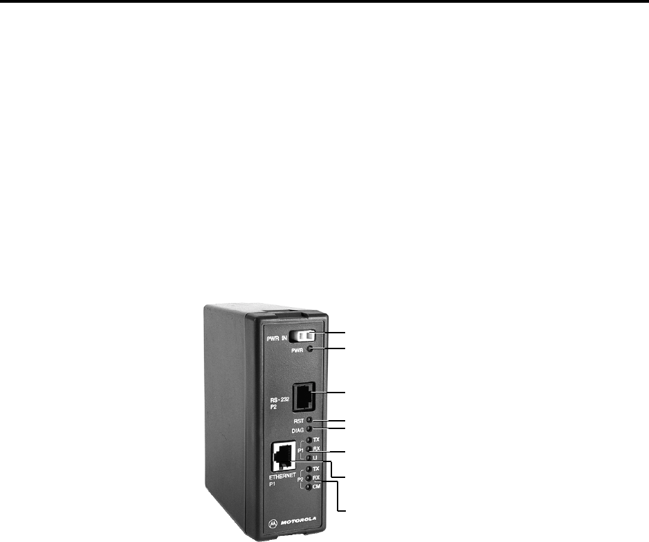
The following figure depicts the front panel of the Ethernet unit.
Figure 18
External Ethernet Unit – Front Panel
The Ethernet indication LEDs are:
• TX - Ethernet Transmit
• RX - Ethernet Receive
• LI - Ethernet Link Integrity
The RS232 indication LEDs are:
• TX - RS232 Transmit
• RX - RS232 Receive
• CM - RS232 Channel Monitor
Power LED
12V DC (9-15V) Power inlet
Ethernet twisted pair
connecto
r
Ethernet indication LEDs
RS232 indication LEDs
RST - Reset
DIAG - Dia
g
nostics Data Presen
t
RS232 Connector to RTU
Ethernet Interface Option
35
Installation
The unit can be connected to Port 1 or Port 2 of the MOSCAD-M RTU. (See Figure 9.)
Connections
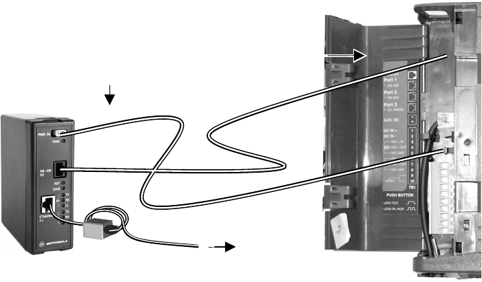
To connect the external Ethernet Interface unit, proceed as follows:
1. Connect the communication cable (FKN5953A) between the external Ethernet Interface
unit RS232 Port (P2) and the MOSCAD-M RS232 port (Port 1B or Port 2). If the
communication cable is not long enough (80 cm) for external connections, use a longer
cable.
2. If no radio is attached to the MOSCAD-M, connect the power cable (FKN4465A) between
the Ethernet unit power inlet and the AUX DC connector on the MOSCAD-M. Make sure
that the AUX DC is configured to 9V DC and above, as described in the External Radio
Connection section of the Installation chapter.
If a radio (internal or external) is attached to the MOSCAD-M, connect the Ethernet unit
power inlet to an external 9-15V DC power supply using the external power cable
FKN4090A (not supplied).
3. Connect the Ethernet Interface unit Ethernet Port (P1) to the LAN, using an Ethernet
twisted pair shielded cable. Install a Suppression Core (Fair-Rite) P.N. 0443164151 on the
cable as shown below.
Figure 19
Connection of External Ethernet Unit to MOSCAD-M RTU (without radio)
FKN5953A
To LAN
9V DC from the
AUX DC outlet in
MOSCAD-M
FKN4465A
Ethernet Unit
Use Port 1 or
Port 2 RS232
connectors
MOSCAD-M RTU
36
APPENDIX A: CABLES AND ADAPTERS
General
This appendix provides supplementary data on cables and adapters used in various
MOSCAD-M systems. The following applications are covered:
• RTU-to-Computer/Terminal Connections
• RTU-to-Modem Connections
• RTU-to-RTU Connections
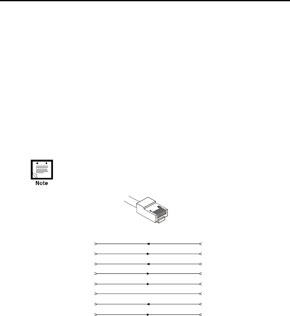
RTU-to-Computer/Terminal Connections
For a 25-pin or 9-pin D-type connector, use the FLN6457 cable kit, in order to connect one of
the RTU RS232 ports to a computer or terminal. The kit includes a cable with RJ45 modular
jacks on both ends, an RJ45 to 25-pin female D-Type adapter, and an RJ45 to 9-pin D-Type
adapter.
When the connector is facing upwards, the left-hand pin is Pin No. 1,
and the right-hand pin is Pin No. 8.
Tx DATA
Rx DATA
RTS
CTS
GND
DTR
Tx DATA
Rx DATA
RTS
CTS
DSR
GND
DTR
Rec Line (DCD)
DSR
22
Rec Line (DCD)
13
54
85
J1
(RJ45)
J2
(25-Pin
D-Type)
76
47
320
67
(9-Pin
D-Type)
(3)
(2)
(7)
(8)
(6)
(5)
(4)
(1)
Figure 22
RJ45-to-D-Type Female Connector Adapter
RJ45
Connector
Appendix A: Cables and Adapters
37
RTU-to-Modem Connections
Only R&TTE approved modems should be used to connect the RTU
to the PSTN.
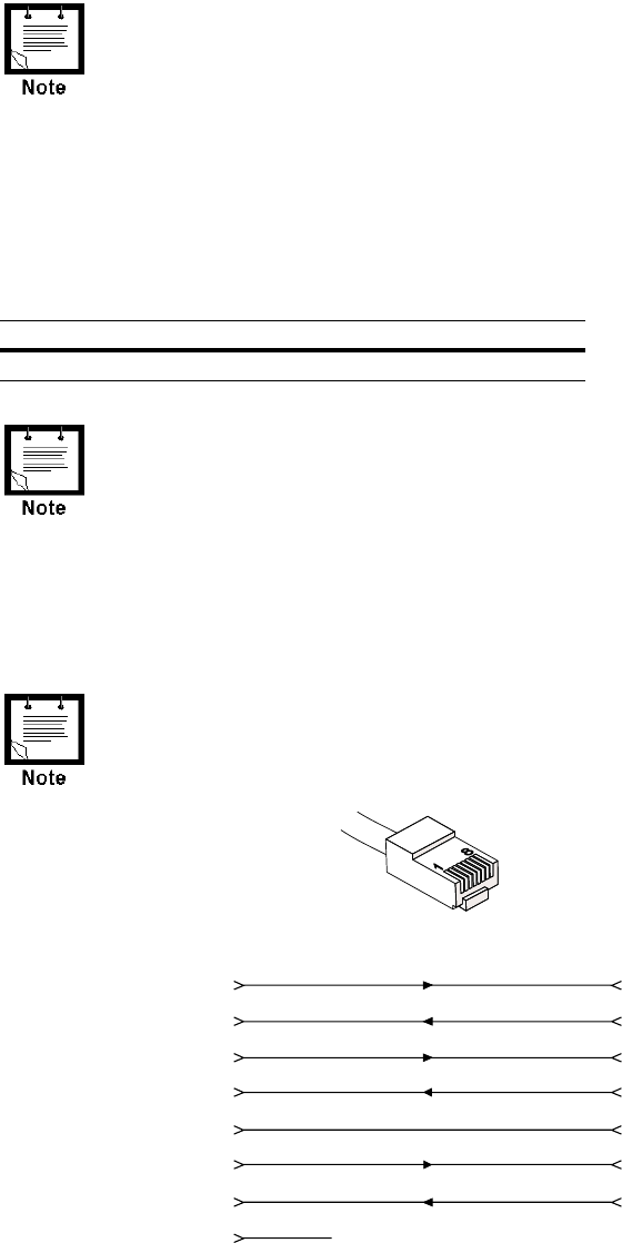
RTU-to-Modem Asynchronous Connection
For a 9-pin or 25-pin connection, use the FLN6458 cable kit to connect one of the
MOSCAD-M RTU RS232 ports asynchronously to a modem. (The RTU serves as DTE.) The
kit includes a cable with RJ45 modular jacks on both ends and an RJ45 to 9-pin and 25-pin
male D-Type adapter (see Figure 21). The possible RTU configurations are detailed below:
Port No. Configurator Definition
1 RS-232 UART External Dialup Modem (MDLC)
1. Before transmitting, the RTU sends an RTS=on signal to the
modem, and will not transmit unless it receives a feedback
CTS=on signal from the modem.
2. The RTU will not receive unless it receives a DCD=on signal from
the modem.
3. When using a modem in auto-answer mode (connected to a
computer port) for remote service, the RTU does not support the
RTS/CTS protocol, as the port is designed to operate with a local
computer as well as with a modem.
When the connector is facing upwards, the left-hand pin is Pin No. 1,
and the right-hand pin is Pin No. 8.
Tx DATA
Rx DATA
RTS
CTS
GND
DTR
Tx DATA
Rx DATA
RTS
CTS
GND
DTR
Rec Line (DCD)
12
Rec Line (DCD)
23
64
35
J1
(RJ45)
J2
(25-Pin
D-Type)
47
820
58
7
(9-Pin
D-Type)
(3)
(2)
(7)
(8)
(5)
(4)
(1)
+12V NOT USED
Figure 21
RJ45-to-D-Type Male Connector Adapter
RJ45
Connector
Appendix A: Cables and Adapters
38
RTU-to-RTU Connection
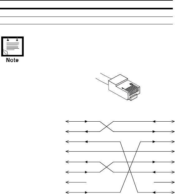
RTU-to-RTU Asynchronous Communications Connection
This section provides data on the cable (not supplied) recommended for the RTU-to-RTU
RS232 asynchronous interconnection (refer to Figure 22). The following table defines the
RTU port for this connection type.
Port No. Configurator Definition
1B RS-232 UART RTU-to-RTU (MDLC)
2 RS-232 UART RTU-to-RTU (MDLC)
When the connector is facing upwards, the left-hand pin is Pin No. 1,
and the right-hand pin is Pin No. 8.
Tx DATA
Rx DATA
CTS
GND
Tx DATA
Rx DATA
GND
RTS
+12V
11
+12V
22
33
44
J1
(RJ45)
J2
(RJ45)
55
66
77
88
RTS
DTRDTR
DCD DCD
NOT CONNECTED NOT
CONNECTED
CTS
Figure 22
RTU-to-RTU RS232 Asynchronous Communications Cable
RJ45
Connector

39
APPENDIX B: MODELS AND ACCESSORIES
General
The chart below describes the models, options and accessories available.
MOSCAD-M RTU Models Model
MOSCAD-M with Interface to External Radio F4570
MOSCAD-M with 4W 403-433 MHz Internal Radio F4571
MOSCAD-M with 4W 438-470 MHz Internal Radio F4572
MOSCAD-M with 5W 136-174 MHz External Radio F4573
MOSCAD-M with 4W 403-470 MHz External Radio F4574
MOSCAD-M with 4W 470-512 MHz External Radio F4575
MOSCAD-M Plus with Interface to External Radio F4580
MOSCAD-M Plus with 4W 403-433 MHz Internal Radio F4581
MOSCAD-M Plus with 4W 438-470 MHz Internal Radio F4582
MOSCAD-M Plus with 5W 136-174 MHz External Radio F4583
MOSCAD-M Plus with 4W 403-470 MHz External Radio F4584
MOSCAD-M Plus with 4W 470-512 MHz External Radio F4585
MOSCAD-M Options Option
ENH: Set radio to: HT750 V951
ENH: Set radio to: GP140 V952
ENH: Set radio to: GP328 V953
ENH: Set radio to: PRO5150 V954
ALT: Set 4AI to: 3 x 4-20mA & 1 x 0-5V V741
ALT: Set 4AI to: 2 x 4-20mA & 2 x 0-5V V742
ALT: Set 4AI to: 1 x 4-20mA & 3 x 0-5V V743
ALT: Set 4AI to: 4 x 0-5V V744

Appendix B: Models and Accessories
40
Miscellaneous Accessory
ADD: MOSCAD-M Installation Kit for GP/HT/PRO Radios V154
FLN3010
ADD: MOSCAD-M Installation Kit for HT1000 Radio V153
ADD: DIN Rail V020
ADD: Bracket for Ethernet Unit V056
Programming Tools Model
MOSCAD-M Configurator F4560
MOSCAD Family ‘C’ Toolkit Software F4561
MOSCAD-M Debug Kit (C Toolkit) FLN3012
Appendix B: Models and Accessories
41
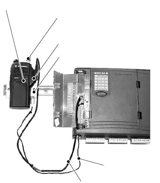
Installation of MOSCAD-M with GP140/328/HT750/PRO5150 Radio
MOSCAD-M models which are equipped with GP140, GP328, HT750 or PRO5150 radios
should be connected as shown below.
If your MOSCAD-M model does not include one of these radios, the MOSCAD-M Installation
Kit for GP140/GP328/HT750/PRO5150 Radios can be purchased. The radio is then
connected as shown below.
Figure 23
Connection of MOSCAD-M to GP140/328/HT750/PRO5150 Radio
• Secure the Mounting Bracket to the DIN Rail.
• Attach the radio to the Mounting Bracket using snaps.
• Route the Audio Communication Cable from the “PORT 3” connector of the MOSCAD-M
to the Audio Accessory Adapter. Plug in and tighten the connector.
• Route the DC Power Cable from the “AUX. DC” connector of MOSCAD-M to the
Mounting Bracket and plug in the connector. Make sure the AUX power is set to 7.5V
DC. Set the middle knob (channel select knob) to Channel 1.
• Use the BNC Adapter to connect an external antenna to the radio.
Mounting Bracket (Kit FCN5516A)
Audio Communication Cable
FKN8023A
DC Power Cable
FKN4465A
Audio Accessory Adapter HLN9716B
GP140/GP328/HT750/PRO5150 Radio
BNC Adapter HLN9756A
Appendix B: Models and Accessories
42
MOSCAD-M Installation Kit for GP140/GP328/HT750/PRO5150 Radios
The MOSCAD-M Installation Kit for GP140/GP328/HT750/PRO5150 Radios enables users to
install a GP140, GP328, HT750 or PRO5150 radio (externally) to the MOSCAD-M. The
Installation Kit includes:
• Mounting Bracket (FCN5516A)
• Audio Communication Cable (FKN5953A)
• Audio Accessory Adapter (HLN9716B)
• DC Power Cable (FKN4465A)
• BNC Adapter (HLN9756A)
• DIN Rail Radio Connectors (Part #0786144U05)
See Figure 23 for connection details.
MOSCAD-M Debug Kit
The MOSCAD-M Debug kit enables the user to debug a ‘C’ application using the XRAY
debugger. Set up the MOSCAD-M Configurator PC as described below, then follow the
debugging instructions in the ‘C’ Toolkit for MOSCAD Family RTUs manual.
MOSCAD-M Board
The kit consists of a special MOSCAD-M board, specifically built for debugging. The system
software (system.krl) is burned into the flash memory at the factory. Another system file
(MmxyyD2.krl) is available with the Debug System Installation (FVN9779) MOSCAD-M
Configurator and must be downloaded before using the Microtec XRAY debugger.
The debug board has no plastic housing and all components are visible. Next to the push-
button there are two additional buttons which do not exist in the standard MOSCAD-M. The
leftmost button is Reset. The rightmost button is NMI (Non Masked Interrupt). The NMI (or
CTRL+C from the PC keyboard) will stop the program.
Two megabytes of RAM are installed in the debug board to enable downloading the system
software from the PC to the unit.

Appendix B: Models and Accessories
43
Debug Setup
By default, downloading from the PC to the unit is done via Port 2. When the unit is first
powered up, LED 12 (CM2) should be lit, indicating that the debugger should be downloaded
via Port 2.
In order to connect to Port 1, a modified system file must be downloaded to the flash. This file
is available from the factory.
To set up the system for debugging, do as follows:
a) Compile and link your application using Microtec tools.
b) Connect the MOSCAD-M Configurator to the debug board as you would the standard
MOSCAD-M board.
c) In the Site Configuration utility, set Port 2 to Not Used.
d) Download the site configuration.
e) Connect Port 1 of the RTU to the COM port of the PC.
f) Switch off the RTU, then switch it on again, while the push-button is pressed. The system
will then be in bootstrap mode where a new system can be downloaded.
g) If a communication session is open with the RTU, make sure to use the Stop
Communication utility in the Configurator.
h) In the Downloader utility, make sure the proper PC COM port is specified in the download
session and download the system file using the MMxyyD2.KRL file. The .krl file, which
is found in the C:\MConf150\system directory when the debug system is installed,
downloads the corresponding system and kernel files to the RTU.
i) Make sure that the CM2 LED is lit, indicating that the port is ready to communicate with
the Microtec debugger.
j) Connect Port 2 of the RTU to the PC COM port on which the XRAY debugger runs.
k) Copy the include file (e.g. MM_V100.inc) which suits your MOSCAD-M version into the
directory. Compile and link your source files.
l) Use the MCDEBUG.BAT file to load the ‘C’ application into the RAM.
m) Follow the debug instructions in the ‘C’ Toolkit for MOSCAD Family RTUs manual.
If the unit is powered off or if the main power input falls below 3.1V
DC, the RAM data will not be retained and the debugger will have to
be downloaded again.

Appendix B: Models and Accessories
44
Logic Analyzer
The MOSCAD-M debug board can be connected to a Logic Analyzer in order to perform
sophisticated debugging. The Logic Analyzer is used when it is necessary to see what is
running on the data and address bus. This is generally in extreme cases where the memory is
corrupted and the problem cannot be found using the debugger capabilities.
The Logic Analyzer is connected to the board through connectors P12, P13, and P14 on the
upper right-hand side of the board. These connectors (Motorola part # 2808044H09) are not
provided with the MOSCAD-M board and must be ordered separately and assembled.
The pins of the connection cable should be configured according to the Pin Assignment below.
Once the pins are configured, the cables should be connected from the Logic Analyzer to the
connectors on the board.
Pin Assignment – Logic Analyzer TBs
The following charts indicate the function of each pin in the various connectors.
P12
Pin #
Function P12
Pin #
Function
1 NC 11 Address bus Add bit 8
2 NC 12 Address bus Add bit 7
3 PG0_DTACK 13 Address bus Add bit 6
4 Address bus Add bit 15 14 Address bus Add bit 5
5 Address bus Add bit 14 15 Address bus Add bit 4
6 Address bus Add bit 13 16 Address bus Add bit 3
7 Address bus Add bit 12 17 Address bus Add bit 2
8 Address bus Add bit 11 18 Address bus Add bit 1
9 Address bus Add bit 10 19 PG1_A0
10 Address bus Add bit 9 20 GND

Appendix B: Models and Accessories
45
P13
Pin #
Function P13
Pin #
Function
1 EMUCS 11 EN_OF signal
2 EMUIRQ 12 RESET signal
3 HIZ 13 CSB1 - upper RAM
chip select
4 Data bit 21 14 CSB0 - lower RAM
chip select
5 Flash chip select
(CSA0)
15 Data bus D20
6 UDS signal 16 Data bus D19
7 LDS signal 17 Data bus D18
8 LWE_LB signal 18 Data bus D17
9 UWE_UB signal 19 Data bus D16
10 RW signal 20 GND
P14
Pin #
Function P14
Pin #
Function
1 NC 11 Data bus D8
2 NC 12 Data bus D7
3 CLK0 (clock out signal) 13 Data bus D6
4 Data bus D15 14 Data bus D5
5 Data bus D14 15 Data bus D4
6 Data bus D13 16 Data bus D3
7 Data bus D12 17 Data bus D2
8 Data bus D11 18 Data bus D1
9 Data bus D10 19 Data bus D0
10 Data bus D9 20 GND
46
APPENDIX C: CHANGING THE ANALOG INPUT
MEASUREMENT TYPE
General
This chapter describes changing the units of measurements of the AIs, from current to voltage
and vice versa. To do so, the RTU is disassembled, jumpers are placed on the Expansion
board, and the unit is reassembled, as described below. The AI setup of the MOSCAD-M
PLUS radios is described under AI (x4) in the Installation chapter.
If the status of the jumpers is changed, the AI Type must be
changed accordingly in the Hardware Test tool of the MOSCAD-M
Configurator. See Configurator help.
Before beginning any disassembly or reassembly procedures,
you should be adequately grounded to prevent damage to
static sensitive devices in the unit.
Disassembling the RTU
Remove Connectors
Before opening the RTU, the five 10-pin connectors on the bottom of the RTU must be
disconnected. Note the configuration of the connections so that they can be easily reconnected
after placing the jumpers and reassembling the RTU.
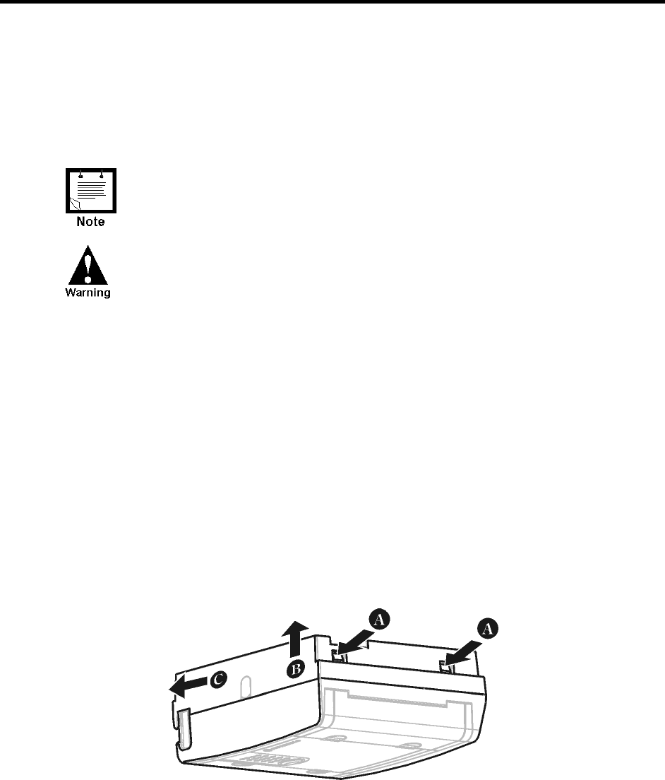
Open RTU
Turn the unit upside down, so that the rightmost wing is closer to you. Using both thumbs,
press the two tabs (A) at the bottom of the unit, as shown in Figure 24, to release the back of
the case. Lift the cover (B) and push forward slightly (C), to release the cover from the top
tabs.
Figure 24
Opening MOSCAD-M RTU Plastic Case
Appendix C: Changing the Analog Input Measurement Type
47
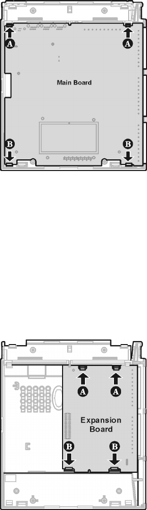
Remove Main Board
Press the two small tabs (A) at the top of the Main board (shown in Figure 25) to release the
top of the Main board. Then press the two small tabs at the bottom of the Main board (B) to
release the bottom of the Main board. Lift the Main board out of the housing.
Figure 25
Removing Main Board from MOSCAD-M RTU
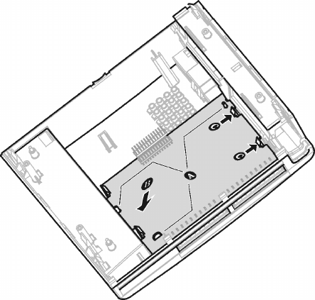
Remove Expansion Board
Press the two small tabs at the top of the Expansion board (A) to release the top of the
Expansion board. (See Figure 26.) Then press the two small tabs at the bottom of the
Expansion board (B) to release the bottom of the Expansion board. Lift the Expansion board
out of the housing.
Figure 26
Removing Expansion Board from MOSCAD-M RTU
Appendix C: Changing the Analog Input Measurement Type
48
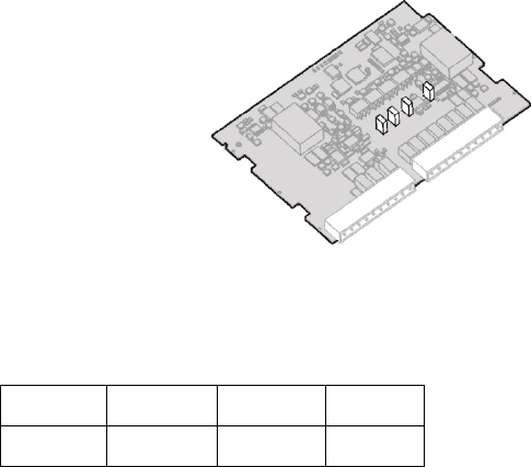
Place Jumpers
Flip over the Expansion board. Locate the four jumpers marked P7, P8, P9, and P10, near the
center of the board, as shown in Figure 27. All jumpers which are placed measure 4-20mA.
To change an AI to 0-5V, remove the jumpers. Make sure to save the cap. To change an AI to
4-20mA, place the jumpers. Press the cap down until you hear it click.
Figure 27
Expansion Board with Jumpers
The chart below shows the correlation of jumpers to AIs.
AI1 AI2 AI3 AI4
P7 P8 P9 P10
Appendix C: Changing the Analog Input Measurement Type
49
Reassembling the RTU
Install Expansion Board
With the jumpers facing down and the 10-pin connectors on your right, lower the bottom of
the Expansion board into the case. Align the peg on the upper left-hand side of the board (A)
and the two tongues toward the bottom of the board (A) with the matching grooves (A) (see
Figure 28). Press the Expansion board under the two large snaps at the bottom of the board
until you hear them click (B). Press the top of the Expansion board under the two small snaps
until you hear them click (C).
Figure 28
Installing Expansion Board
Appendix C: Changing the Analog Input Measurement Type
50
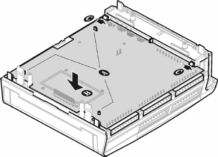
Install Main Board
Hold the Main board with the push-button facing down and the 10-pin connectors on the right.
Lower the board, aligning the two small gray round pegs (A) (see Figure 29) on the bottom of
board and the small oblong peg on the upper left-hand side of the board with the matching
grooves. Using both thumbs, press the bottom of the Main board under the two bottom snaps
(B). Use both thumbs to press the top of the board under the two top snaps (C).
Figure 29
Installing Main Board
Close Case
Hold the back of the case face down, with the holes for screw mount to your left. Align the
two top snaps with the two grooves on the top of the case back. Press with both thumbs until
you hear it click. Use both thumbs to press the bottom of case back under the snaps until you
hear it click.
Turn the unit right side up.
Reconnect the 10-pin connectors in their original configuration.