Motorola Solutions 89FT4839 MOSCAD Series SCADA Terminals User Manual MOSCAD M Owner s Manual

Motorola Solutions, Inc. MOSCAD Series SCADA Terminals MOSCAD M Owner s Manual

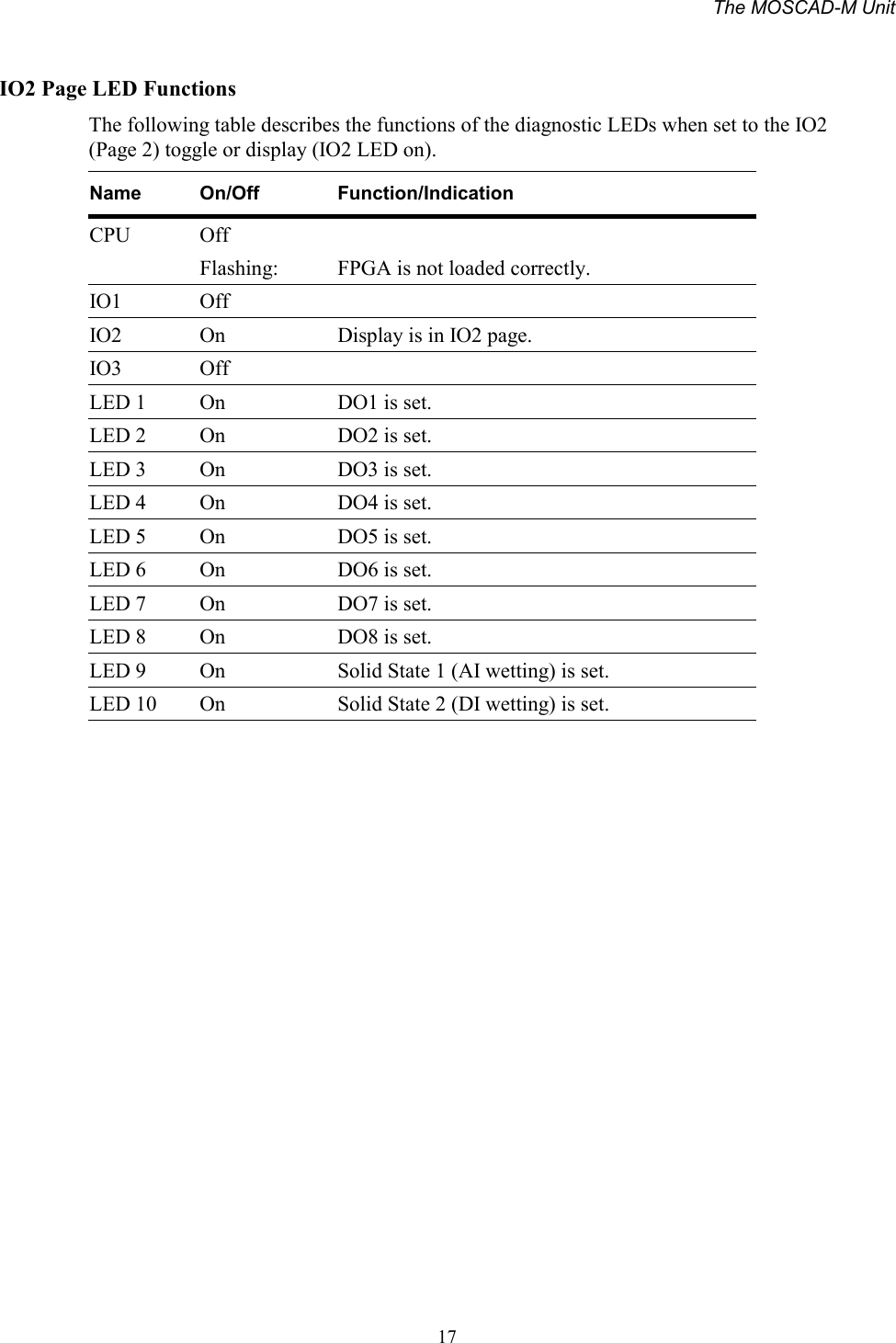
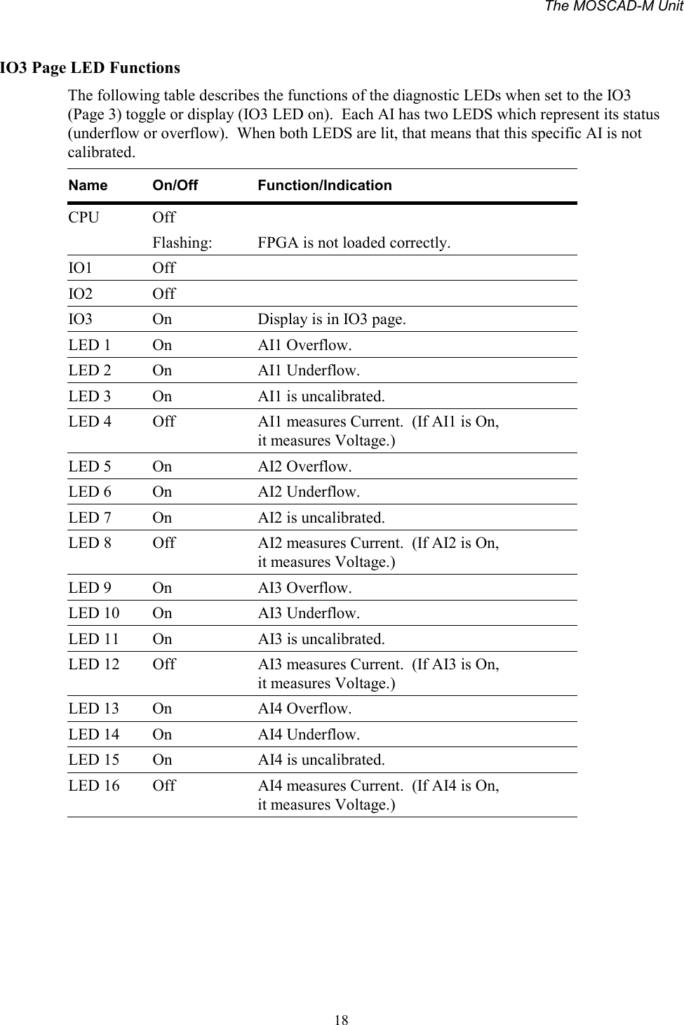
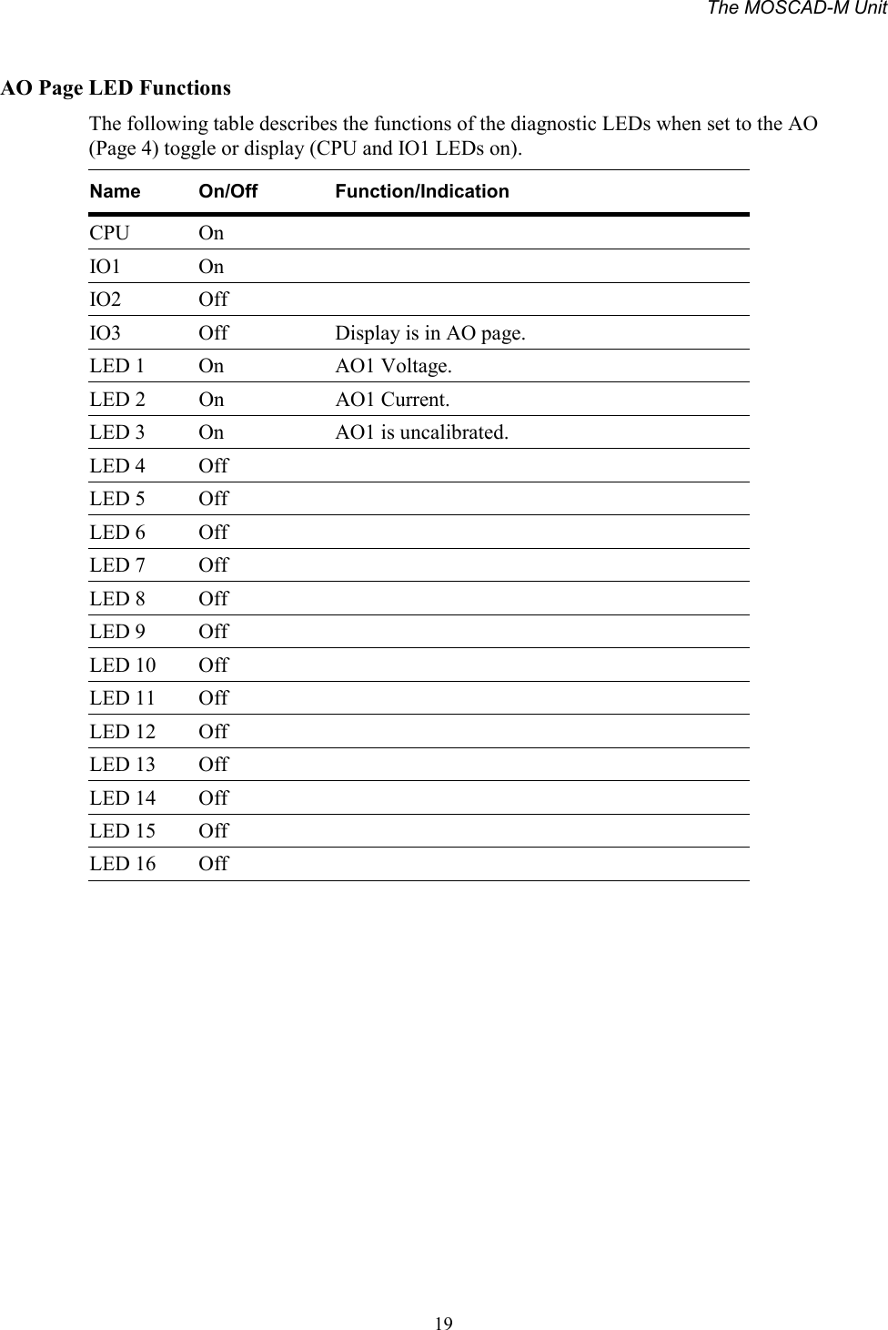
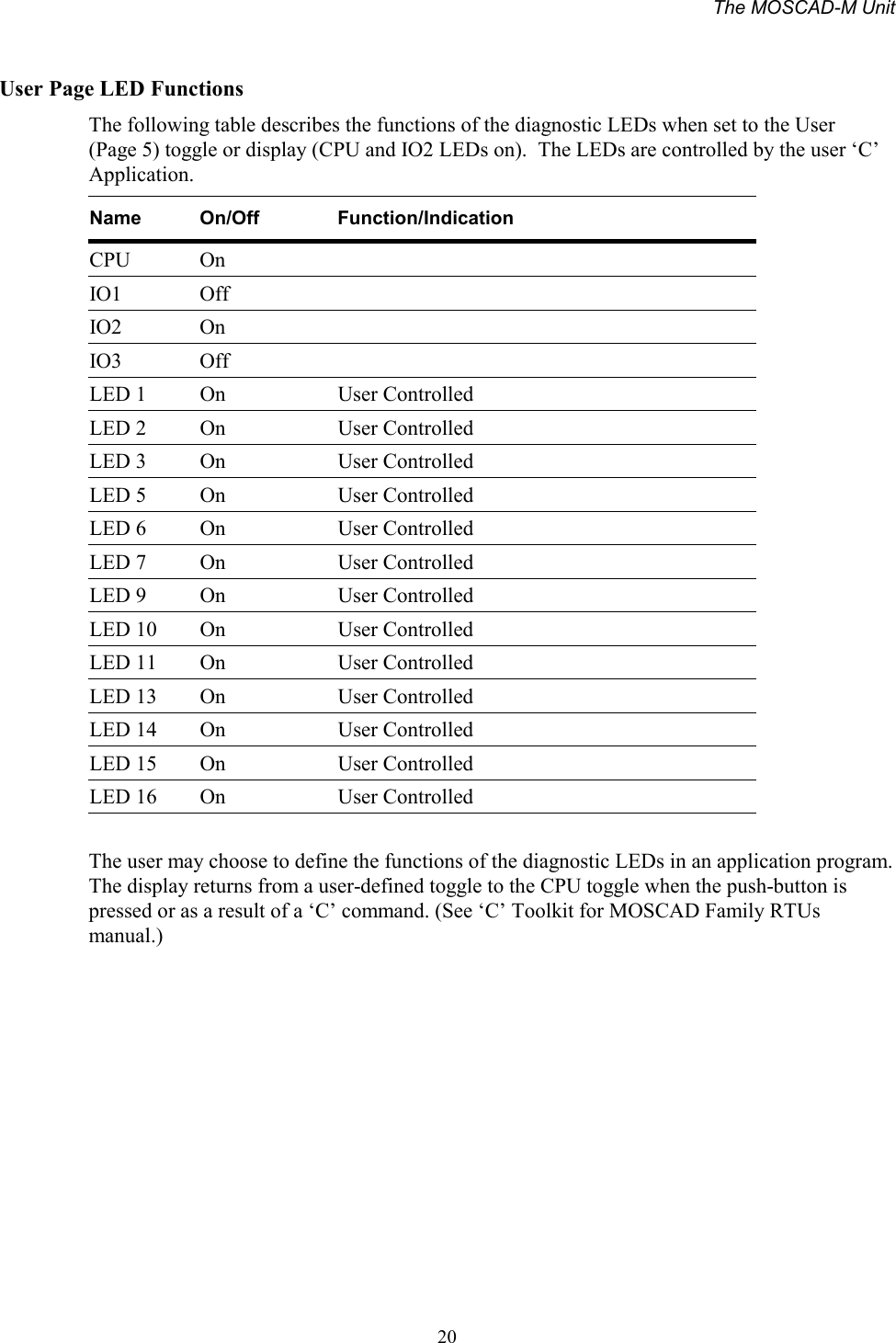
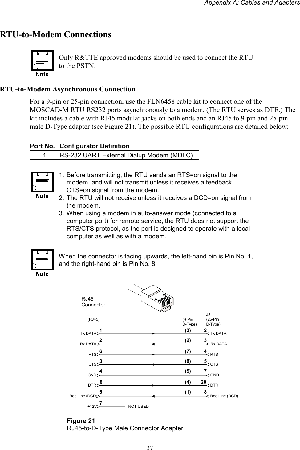
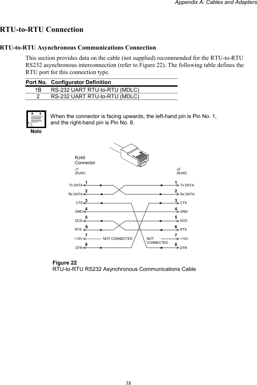
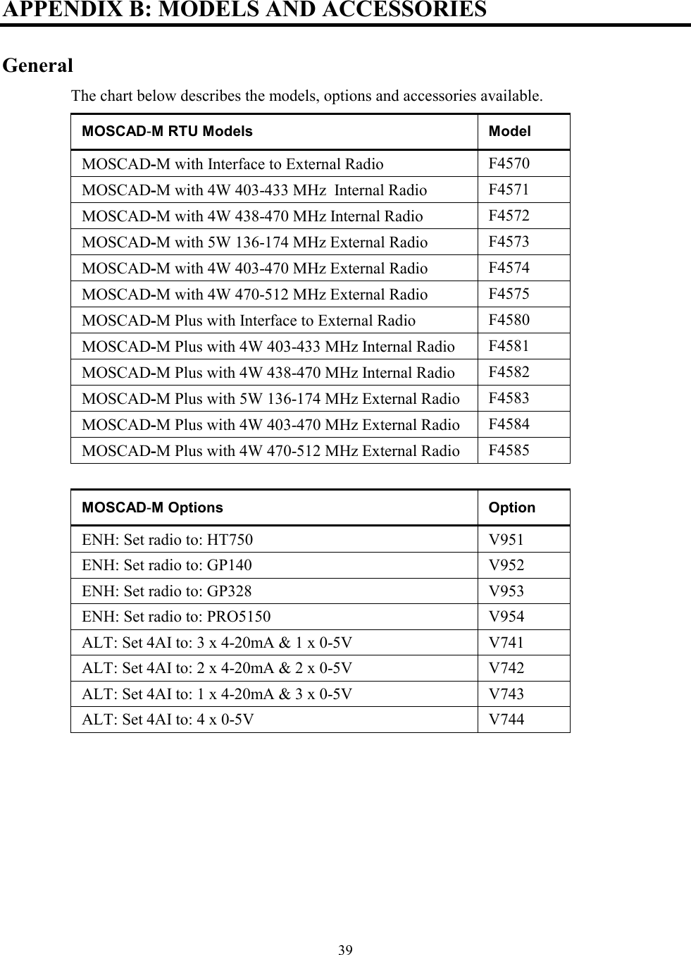
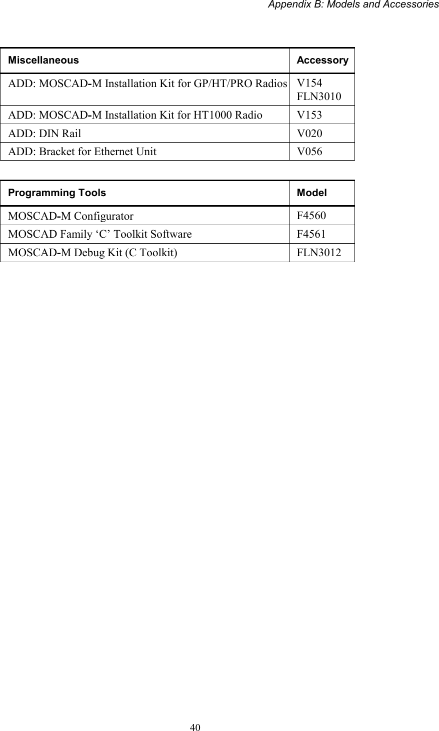
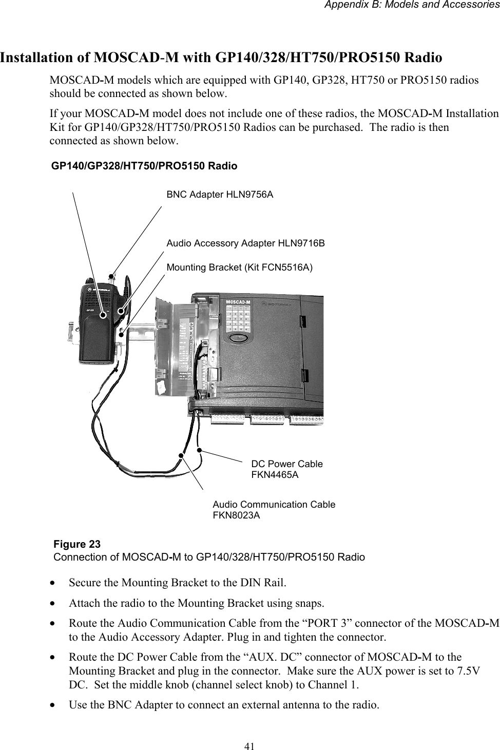
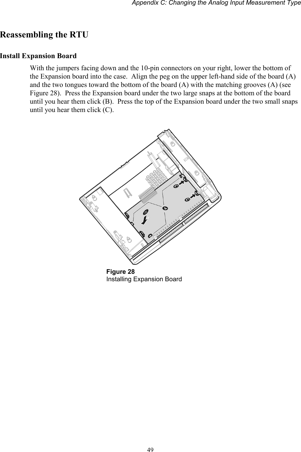
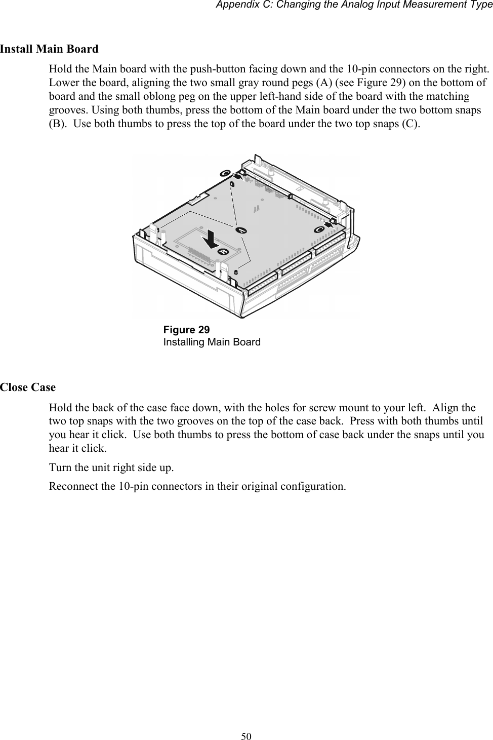
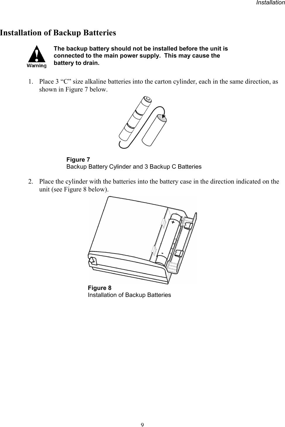
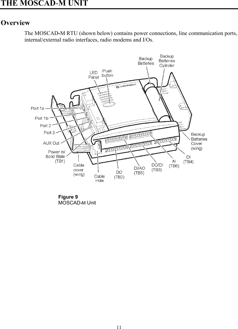
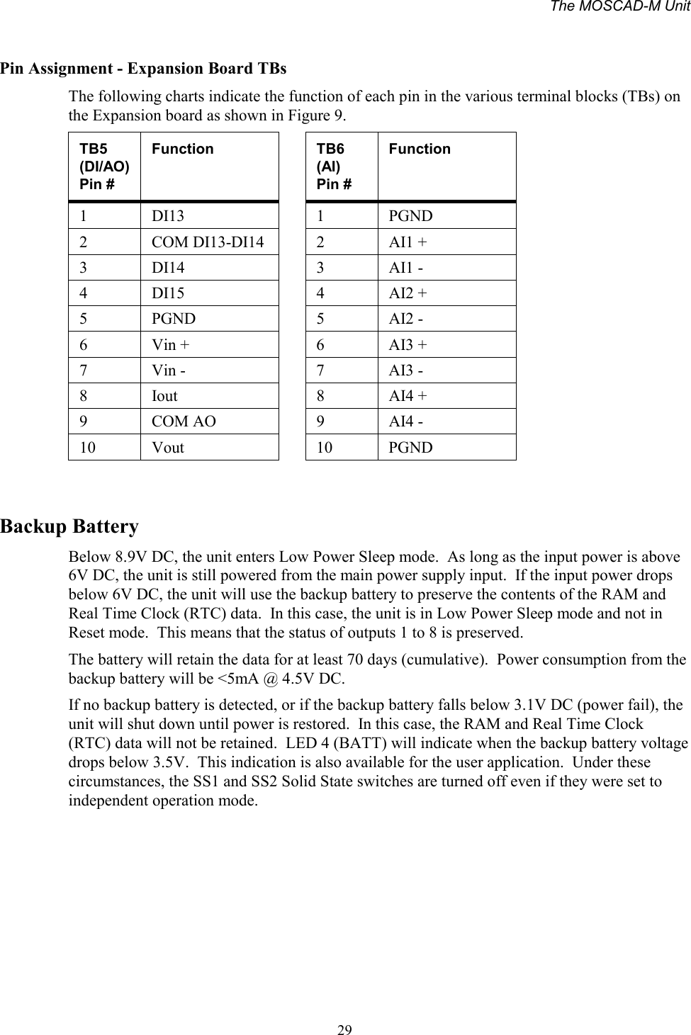
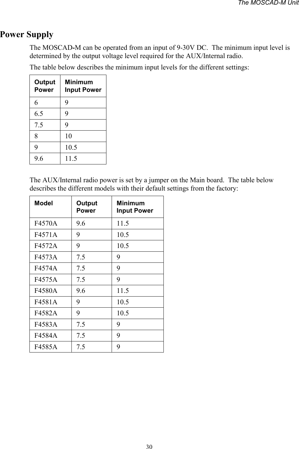
users and install manual

MOSCAD-M™Remote Terminal UnitOwner’s Manual68P02961C50-O
                                                                68P02961C50-O©Motorola Inc., 2001                                                                                                                                  August 2001CONTENTSINTRODUCTION......................................................................................................................... 1SCOPE OF THIS MANUAL ............................................................................................................... 1GENERAL DESCRIPTION ................................................................................................................ 1HARDWARE OPTIONS .................................................................................................................... 2Line, RS232 and RS485 Communication Interfaces..............................................................................2Radio Communication Interfaces ..........................................................................................................2I/O Configurations.................................................................................................................................2Power Supply and Battery .....................................................................................................................2INSTALLATION .......................................................................................................................... 3GENERAL ...................................................................................................................................... 3Power Connections:...............................................................................................................................3WALL MOUNTING ......................................................................................................................... 3Wall Mounting with Screws ...................................................................................................................4Wall Mounting on DIN Rail...................................................................................................................5CONNECTIONS............................................................................................................................... 7Ground Connection................................................................................................................................7Power Connections ................................................................................................................................7Backup Battery Connection ...................................................................................................................7Internal Radio Connection - antenna ....................................................................................................7External Radio Connection....................................................................................................................7Line Communication Connection ..........................................................................................................8INSTALLATION OF BACKUP BATTERIES ......................................................................................... 9MISCELLANEOUS......................................................................................................................... 10Open the Case Door.............................................................................................................................10Close the Case Door ............................................................................................................................10Antenna Placement ..............................................................................................................................10Fixed Site Antennas .............................................................................................................................10THE MOSCAD-M UNIT............................................................................................................ 11OVERVIEW .................................................................................................................................. 11COMMUNICATION PORTS ............................................................................................................ 12CONNECTORS.............................................................................................................................. 12CONTROLS AND INDICATORS....................................................................................................... 12
ContentsiiLED Control.........................................................................................................................................13System Software Downloading ............................................................................................................13CPU Reset............................................................................................................................................13LED DISPLAY INDICATIONS........................................................................................................ 14CPU Page LED Functions...................................................................................................................14IO1 Page LED Functions.....................................................................................................................15IO2 Page LED Functions.....................................................................................................................17IO3 Page LED Functions.....................................................................................................................18AO Page LED Functions .....................................................................................................................19User Page LED Functions...................................................................................................................20I/OS (ALL MODELS).................................................................................................................... 22Wetting switch connection (x2)............................................................................................................22DO Magnetic Relay connection (x4) ...................................................................................................23DO Open Collector (x4).......................................................................................................................23DI (x12)................................................................................................................................................24ADDITIONAL I/OS (EXPANDED I/O MODELS ONLY) .................................................................... 25AI (x4) ..................................................................................................................................................25AO (x1).................................................................................................................................................26DI (x3)..................................................................................................................................................27Pin Assignment - Main Board TBs ......................................................................................................28Pin Assignment - Expansion Board TBs ..............................................................................................29BACKUP BATTERY ...................................................................................................................... 29POWER SUPPLY ........................................................................................................................... 30POWER MANAGEMENT......................................................................................................... 31OVERVIEW .................................................................................................................................. 31RUN MODE ................................................................................................................................. 31SLEEP MODE ............................................................................................................................... 32WAKEUP EVENTS........................................................................................................................ 33ETHERNET INTERFACE OPTION ....................................................................................... 34OVERVIEW .................................................................................................................................. 34EXTERNAL ETHERNET INTERFACE UNIT...................................................................................... 34INSTALLATION............................................................................................................................. 35Connections .........................................................................................................................................35APPENDIX A: CABLES AND ADAPTERS ............................................................................ 36GENERAL .................................................................................................................................... 36RTU-TO-COMPUTER/TERMINAL CONNECTIONS.......................................................................... 36RTU-TO-MODEM CONNECTIONS ................................................................................................ 37RTU-to-Modem Asynchronous Connection .........................................................................................37RTU-TO-RTU CONNECTION....................................................................................................... 38RTU-to-RTU Asynchronous Communications Connection .................................................................38
ContentsiiiAPPENDIX B: MODELS AND ACCESSORIES .................................................................... 39GENERAL .................................................................................................................................... 39INSTALLATION OF MOSCAD-M WITH GP140/328/HT750/ PRO5150 RADIO ........................... 41MOSCAD-M INSTALLATION KIT FOR GP140/GP328/HT750/ PRO5150 RADIOS .................... 42MOSCAD-M DEBUG HARDWARE KIT....................................................................................... 42MOSCAD-M Board..............................................................................................................................42Debug Setup.........................................................................................................................................43Logic Analyzer .....................................................................................................................................45Pin Assignment – Logic Analyzer TBs.................................................................................................45APPENDIX C: CHANGING THE ANALOG INPUT MEASUREMENT TYPE................ 46GENERAL .................................................................................................................................... 46DISASSEMBLING THE RTU .......................................................................................................... 46Remove Connectors .............................................................................................................................46Open RTU ............................................................................................................................................46Remove Main Board ............................................................................................................................47Remove Expansion Board....................................................................................................................47Place Jumpers......................................................................................................................................48REASSEMBLING THE RTU ........................................................................................................... 49Install Expansion Board ......................................................................................................................49Install Main Board...............................................................................................................................50Close Case ...........................................................................................................................................50
1INTRODUCTIONScope of this ManualThis manual provides instructions for the installation and operation of the MOSCAD-M ™Remote Terminal Unit (RTU). It also provides on-site tuning instructions for RTU elementsthat do not necessarily require shop level assistance.This manual covers the basic RTU and most communications and I/O options.  The online helpof the MOSCAD-M RTU Configurator contains additional information on the RTU.General DescriptionThe RTU is a remotely located unit used for monitoring and control of local equipment.  Theunit can operate in stand-alone mode, or as an intelligent RTU or node on a distributed controlsystem.The RTU consists of the following components installed in a plastic case: printed circuitboard, internal/external radio, and battery housing.  This manual describes both basic andexpanded I/O models.The MOSCAD-M is a low-power unit that incorporates a variety of power save modes whichenable the unit to operate with minimal power consumption.The RTU case is suitable for either wall or DIN rail mounting.Figure 1 provides a general view of the MOSCAD-M RTU.The MOSCAD-M RTU is enclosed in an indoor plastic case and is intended for outdoor basestation use. The installer must make sure that the installation meets the requirements of thestandard and protects the unit from weather hazards.The antenna must be physically secured at a permanent outdoor location.Figure 1MOSCAD-M RTU –General View with Case
Introduction2Hardware OptionsLine, RS232 and RS485 Communication InterfacesA variety of Line, RS232, and RS485 communication interfaces are available:• RS485 adapter• RS232 multiplexer• Ethernet Interface UnitRadio Communication InterfacesA variety of radios can be attached using internal DPSK or duo-binary modem:• Internal radio UHF High Band• Internal radio UHF Low Band• Variety of external radios (GP140/328, HT750, PRO5150)For details on the available external radio models, and their connection to the RTU, seeAppendix B.I/O ConfigurationsDifferent models of the MOSCAD-M RTU have slightly different I/O configurations.Models with basic I/O configuration:• 12 Digital Input• 8 Digital Output (4 Magnetically Latched, 4 Open Collector)• 2 Digital Output (Solid State)Models with expanded I/O configuration:• 15 Digital Input• 8 Digital Output (4 Magnetically Latched, 4 Open Collector)• 4 Analog Input (4-20 mA)• 1 Analog Output (0-5V or 4-20mA)• 2 Digital Output (Solid State)Power Supply and BatteryThe power supply and backup battery options are:• 9-30V DC power input (compatible with 12V DC Solar Panel)• 3 x “C” backup battery (for Real Time Clock and RAM retention)
3INSTALLATIONGeneralMOSCAD-M SAFETY SUMMARYThe MOSCAD-M should be installed by qualified and authorizedtechnicians. If the installation involves high-voltage connections,technicians must be specifically qualified to handle high voltage.This equipment was tested with cables 3 meters in length.  If longercables and/or cabinets are used, the installer is responsible for makingsure that the installation complies with the requirements of the relevantstandard.The product is a radio accessory.  The installer must make sure that theradio connected to the system has all required approvals and that theinstallation meets the requirements of the standard. This equipment is abase station unit and complies with the FCC base station requirements.The antenna must be installed outdoors.Power Connections:This device accepts 9-30V DC input, maximum 2.5A @15V DC.This chapter covers the following installation procedures:• Wall mounting• Connections• Backup Batteries• MiscellaneousWall MountingThe dimensions of the unit are: width – 21.5 cm (8.46"), height – 18.5 cm (7.28"), depth – .85cm (.33"), weight – 1.5kg maximum (see Figure 2).
Installation4Figure 2Dimensions of MOSCAD-M RTU Plastic CaseThe unit can be installed on screws or on DIN rail mounting.  Before installing theMOSCAD-M RTU, verify that there is sufficient space around the unit.  Allow 20 cm (7.87")from the bottom of the box for the TB connectors. When an RF connector is attached (internalradio models), allow for an extra 10 cm (4"): 2.02 cm (.8") from the top of the box for the RFconnector and 8 cm (3.15") for the wires. For models with external radios, allow 8 cm (3.15").Wall Mounting with ScrewsThe MOSCAD-M can be mounted on the wall using screws, as shown in Figure 3.1. Secure two screws (maximum head size 0.9 mm) on the wall, 105 mm apart.2. Hang the unit on the screws, fitting the two cavities on the back cover of the unit over thescrews (see Figure 3).The screws used should not protrude from the wall surface by more than 6 mm or by less than4 mm.
Installation5Figure 3Installation of MOSCAD-M – Screw MountIt is also possible to attach the MOSCAD-M to the wall using the small screw hole at thebottom of case, though this requires dismantling the RTU, which is generally discouraged.Consult Motorola service personnel before opening the MOSCAD-M casing.  To mount theRTU:1. Open the case and dismantle the parts of the MOSCAD-M.2. Secure the back of the case against the wall using a screw whose diameter is less than3.5 mm and head size is at least 5.5 mm.3. Reassemble the parts of the MOSCAD.Before beginning any disassembly or reassembly procedures, youshould be adequately grounded to prevent damage to static sensitivedevices in the unit.Wall Mounting on DIN RailFor mounting the RTU on a DIN rail, two universal foot elements (Phoenix Connectors MFCPIN UMK-FE) are required.  To mount the unit, proceed as follows:1. Slide the two foot elements into the recesses on the back cover of the unit as shown inFigure 4.  Press until they click behind the snaps that secure their placement.  (See zoomedimage in Figure 5.)
Installation6Figure 4DIN Rail AttachmentFigure 5DIN Rail Attachment-Foot Element Snap-in (Enlarged)2. Press the unit onto the DIN rail, using both universal foot elements.  The elements can beused on DIN rail 35 mm and G rails. (See Figure 6).Figure 6MOSCAD-M Mounted on DIN RailSNAP
Installation7ConnectionsVerify that all power and ground connections are made inaccordance with local standards.Ground ConnectionConnect the grounding cable directly to the protectivegrounding pins 9 and 10 (PGND) in the main power-in connector(see TB1 in Figure 9).Power ConnectionsThe unit can be connected directly to a 9-30V DC source through the main Power-In connector(see Figure 9) where Pin #1 is + (positive) and Pin #2 is – (negative).It is recommended to connect the main power supply to the unitwith a 3.5 amp fuse on the cable.Backup Battery ConnectionThe RTU has a special chamber for 3 “C” alkaline backup batteries (not supplied) that areused to retain the unit’s RAM and Real Time Clock in power fail situations.Internal Radio Connection - antennaThe internal radio is connected through the 14-pin connector on the Main board inside theplastic housing.  Its power is driven from that connector.  When an internal radio is installed,Port 3 of the radio cannot be used.External Radio ConnectionConnect the external radio to Port 3 (see Figure 9). Verify that the radio button is set to ON.The radio signals are driven from the AUX connector in Figure 9.It is recommended to replace the external radio only when theunit is powered off.
Installation8If the external radio is connected to an outside power supply,first power on the unit, and then power on the radio.The auxiliary power supply (maximum 2A) can be changed to 6V,6.5V, 7.5V, 8V, 9V or 9.6V DC by changing the setting of the P11jumper located on the Main board.  (See markings on the board.)  Toset the power to 8V, remove the jumper and save for future use.This is usually set in the factory according to the external powersupply of the radio.  The default setting is 9V DC.  To change thevoltage, follow the disassembly instructions in Appendix C, place thejumper and reassemble.Line Communication ConnectionLine Communications are connected through Ports 1 or 2 (see Figure 9.)  Port 1 can beprogrammed as RS485 (1A) or RS232 (1B).  Port 2 can be programmed as RS232.
Installation9Installation of Backup BatteriesThe backup battery should not be installed before the unit isconnected to the main power supply.  This may cause thebattery to drain.1. Place 3 “C” size alkaline batteries into the carton cylinder, each in the same direction, asshown in Figure 7 below.Figure 7Backup Battery Cylinder and 3 Backup C Batteries2. Place the cylinder with the batteries into the battery case in the direction indicated on theunit (see Figure 8 below).Figure 8Installation of Backup Batteries
Installation10MiscellaneousOpen the Case DoorTo open the case door properly, press the two clips (latches) and pull the wing to an openposition.  The cable cover is opened counter-clockwise to expose the cable connections andthe backup battery cover is opened clockwise to expose the battery housing.Close the Case DoorTo close the case door properly, press until the latch clicks.  Note that if the batteries in thehousing are not inserted properly, the backup battery cover door may not close.  If the cableconnections are not threaded properly through the cable holes, the cable cover may not close.Antenna PlacementThe antenna is connected to the internal radio through the snap hole on top of the plastichousing (see Figure 9).  For models with external radios, screw the antenna onto the radioantenna connector.An antenna placed on top of the plastic housing producesstrong electromagnetic fields that could be harmful to theelectronics of the MOSCAD-M RTU and to people in the vicinity.Fixed Site AntennasThe antenna installation must comply with the following requirements in order to assureoptimal performance and make sure human exposure to radio frequency electromagneticenergy is within the guidelines set forth by the local regulations.• The antenna must be mounted outside the building.• Mount the antenna on a tower if at all possible.• If the antenna is to be mounted on a building, then it must be mounted on the roof.• As with all fixed site antenna installations, it is the responsibility of the licensee to managethe site in accordance with applicable regulatory requirements.  This may requireadditional compliance actions such as site survey measurements, signage, and site accessrestrictions in order to ensure that exposure limits are not exceeded.
11THE MOSCAD-M UNITOverviewThe MOSCAD-M RTU (shown below) contains power connections, line communication ports,internal/external radio interfaces, radio modems and I/Os.Figure 9MOSCAD-M Unit
The MOSCAD-M Unit12Communication PortsThe MOSCAD-M RTU has 3 ports available:PORT 1 - RS232 Configurator Port (for programming and monitoring the unit), RS232External Dialup Modem, or RS485 Communication, User protocol            (1A is used for RS485)            (1B is used for RS232)PORT 2 – Secondary Port RS232 (User protocol)PORT 3 – External Radio interfacePorts 2 and 3 can work simultaneously with each other and with either Port 1A or Port 1B.Ports 1A and 1B cannot work simultaneously.  Port 3 cannot be used when an internal radio isinstalled.ConnectorsThe MOSCAD-M RTU has the following connectors available (see Figure 9):RS485 Port 1A (RJ45, 4 pin)RS232 Port 1B (RJ45, 8 pin)RS232 Port 2 (RJ45, 8 pin)External Radio Port 3 (RJ45, 8 pin)AUX out for external radio power supply (2 pin)Power In/Solid State DO (10 pin) - TB1DO (10 pin) – TB2DO/DI (10 pin) – TB3DI (10 pin) – TB4DI/AO (10 pin) – TB5AI (10 pin) - TB6The MOSCAD-M RTU has the following internal connectors.Internal radio connector (14 pin)Backup Battery connector (2 pin)I/O Expansion connector (26 pin)Controls and IndicatorsThe push-button is used to activate the LED panel, to toggle the LED panel so that it displaysthe status of the CPU or of the I/Os, to initiate software downloading to the CPU, and to eraseUser Flash memory and RAM.
The MOSCAD-M Unit13LED ControlDisplay On/AdvanceWhen the display is off, pressing the push-button once, momentarily, activates the display.Every consecutive momentary depression of the push-button advances the display to the nextpage, in the following order: CPU > IO1 (I/O Page 1-DI) > IO2 (I/O Page 2-DO) > IO3(I/O Page 3-AI) > Page 4 (AO) > Page 5 (User Application Controlled) > Page 6 (HardwareTest Controlled).  The next depression of the push-button returns the display to the CPU.Display OffThe display can be programmed using the Configurator Site Configuration tool to turn offautomatically after a predefined period of time if the push-button has not been pressed.LED TestWhen the push-button is pressed continuously for a few seconds, all LEDs light upsimultaneously. When the push-button is released, the LEDs turn off.User Flash EraseAfter power-up, all LEDs light up. To erase the User Flash, press the push-button while theLEDs are lit. All the LEDs flash three times.  Now, release the push-button.Alternatively, press the push-button continuously for at least 40 seconds at any time to erasethe User Flash.User RAM Erase (Cold Restart)Turn off the power supply, while the push-button is depressed.  The next time the unit ispowered up, it will perform “cold restart”, which means all data stored in the RAM is erased.Note: The data that is stored in the Flash (i.e. applications, site configuration, and networkconfiguration) will not be erased.System Software DownloadingDuring power up, press the push-button continuously. This will cause the unit to enterbootstrap downloading mode, in which the FLASH is programmed from a PC connected toPort 1 of the MOSCAD-M. The CPU LED will begin to blink at 1 Hz, indicating that the CPUhas entered bootstrap downloading mode. If after 120 seconds no bootstrap software is loadedand executed, the normal power-up procedure is performed.CPU ResetTo reset the CPU when a backup battery is not installed, turn the power supply to the unit offand on again.  When a backup battery is installed, follow the Cold Restart method describedabove.
The MOSCAD-M Unit14LED Display IndicationsA 5 × 4 matrix of LEDs is used for diagnostics and testing of the unit  (see Figure 10). The toprow indicates to which page or toggle (CPU, IO1, IO2, IO3, Page 4, Page 5, Page 6) the LEDpanel is set.  To advance from one page to another, press the push-button once quickly.  Thefirst depression of the push-button activates the display.  Subsequent short depressions of thepush-button advance the display to the next page: CPU > IO1 (I/O Page 1-DI) > IO2 (I/O Page2-DO) > IO3 (I/O Page 3-AI) > Page 4 (AO) > Page 5 (User Application Controlled) > Page 6(Hardware Test Controlled).  In each page, the LEDs have different functions, as described inthe charts below.CPU IO1 IO2 IO3159132 6 10 143 7 11 154 8 12 16Figure 10LED PanelCPU Page LED FunctionsThe following table describes the functions of the diagnostic LEDs when set to the initial CPU(Page 0) toggle or display (CPU LED on).Name On/Off Function/IndicationCPU On:Flashing:Display is in CPU mode.CPU is in bootstrap mode OR FPGA is not loadedcorrectly.IO1 OffIO2 OffIO3 OffLED 1LOADOn A file (e.g. configuration, application program) isbeing downloaded to FLASH memory.LED 5CONFOn A Site configuration definition has been loadedinto FLASH memory.LED 9APPLOn An application program has been loaded intoFLASH memory.
The MOSCAD-M Unit15Name On/Off Function/IndicationLED 13MONOn Controlled by application for user use.LED 2RSTOn The CPU is in Reset mode.LED 3ERROn An error has occurred.LED 4BATTOn The backup battery does not exist or has reacheda critical level of 3.5V.LED 6TX1On The RTU is transmitting data via Port 1.LED 7RX1On The RTU is receiving data via Port 1.LED 8CM1On The communication channel used by Port 1 isbusy.LED 10TX2On The RTU is transmitting data via Port 2.LED 11RX2On The RTU is receiving data via Port 2.LED 12CM2On The communication channel used by Port 2 isbusy.LED 14TX3On The RTU is transmitting data via Port 3.LED 15RX3On The RTU is receiving data via Port 3.LED 16CM3On The communication channel used by Port 3 isbusy.
The MOSCAD-M Unit16IO1 Page LED FunctionsThe following table describes the functions of the diagnostic LEDs when set to the IO1(Page 1) toggle or display (IO1 LED on).Name On/Off Function/IndicationCPU OffFlashing: FPGA is not loaded correctly.IO1 On Display is in IO1 page.IO2 OffIO3 OffLED 1 On DI1 is on.LED 2 On DI2 is on.LED 3 On DI3 is on.LED 4 On DI4 is on.LED 5 On DI5 is on.LED 6 On DI6 is on.LED 7 On DI7 is on.LED 8 On DI8 is on.LED 9 On DI9 is on.LED 10 On DI10 is on.LED 11 On DI11 is on. (Can be fast counter)LED 12 On DI12 is on. (Can be fast counter)LED 13 On DI13 is on. (Models with expansion board only)LED 14 On DI14 is on. (Models with expansion board only)LED 15 On DI15 is on. (Models with expansion board only)The LED is not updated after each change in DI status, but ratherafter the user performs a scan.  Thus, the status of the DI reflectsthe status as of the last software scan.
The MOSCAD-M Unit17IO2 Page LED FunctionsThe following table describes the functions of the diagnostic LEDs when set to the IO2(Page 2) toggle or display (IO2 LED on).Name On/Off Function/IndicationCPU OffFlashing: FPGA is not loaded correctly.IO1 OffIO2 On Display is in IO2 page.IO3 OffLED 1 On DO1 is set.LED 2 On DO2 is set.LED 3 On DO3 is set.LED 4 On DO4 is set.LED 5 On DO5 is set.LED 6 On DO6 is set.LED 7 On DO7 is set.LED 8 On DO8 is set.LED 9 On Solid State 1 (AI wetting) is set.LED 10 On Solid State 2 (DI wetting) is set.
The MOSCAD-M Unit18IO3 Page LED FunctionsThe following table describes the functions of the diagnostic LEDs when set to the IO3(Page 3) toggle or display (IO3 LED on).  Each AI has two LEDS which represent its status(underflow or overflow).  When both LEDS are lit, that means that this specific AI is notcalibrated.Name On/Off Function/IndicationCPU OffFlashing: FPGA is not loaded correctly.IO1 OffIO2 OffIO3 On Display is in IO3 page.LED 1 On AI1 Overflow.LED 2 On AI1 Underflow.LED 3 On AI1 is uncalibrated.LED 4 Off AI1 measures Current.  (If AI1 is On,it measures Voltage.)LED 5 On AI2 Overflow.LED 6 On AI2 Underflow.LED 7 On AI2 is uncalibrated.LED 8 Off AI2 measures Current.  (If AI2 is On,it measures Voltage.)LED 9 On AI3 Overflow.LED 10 On AI3 Underflow.LED 11 On AI3 is uncalibrated.LED 12 Off AI3 measures Current.  (If AI3 is On,it measures Voltage.)LED 13 On AI4 Overflow.LED 14 On AI4 Underflow.LED 15 On AI4 is uncalibrated.LED 16 Off AI4 measures Current.  (If AI4 is On,it measures Voltage.)
The MOSCAD-M Unit19AO Page LED FunctionsThe following table describes the functions of the diagnostic LEDs when set to the AO(Page 4) toggle or display (CPU and IO1 LEDs on).Name On/Off Function/IndicationCPU OnIO1 OnIO2 OffIO3 Off Display is in AO page.LED 1 On AO1 Voltage.LED 2 On AO1 Current.LED 3 On AO1 is uncalibrated.LED 4 OffLED 5 OffLED 6 OffLED 7 OffLED 8 OffLED 9 OffLED 10 OffLED 11 OffLED 12 OffLED 13 OffLED 14 OffLED 15 OffLED 16 Off
The MOSCAD-M Unit20User Page LED FunctionsThe following table describes the functions of the diagnostic LEDs when set to the User(Page 5) toggle or display (CPU and IO2 LEDs on).  The LEDs are controlled by the user ‘C’Application.Name On/Off Function/IndicationCPU OnIO1 OffIO2 OnIO3 OffLED 1 On User ControlledLED 2 On User ControlledLED 3 On User ControlledLED 5 On User ControlledLED 6 On User ControlledLED 7 On User ControlledLED 9 On User ControlledLED 10 On User ControlledLED 11 On User ControlledLED 13 On User ControlledLED 14 On User ControlledLED 15 On User ControlledLED 16 On User ControlledThe user may choose to define the functions of the diagnostic LEDs in an application program.The display returns from a user-defined toggle to the CPU toggle when the push-button ispressed or as a result of a ‘C’ command. (See ‘C’ Toolkit for MOSCAD Family RTUsmanual.)
The MOSCAD-M Unit21Hardware Test Page LED FunctionsThe following table describes the functions of the diagnostic LEDs when set to the HardwareTest (Page 6) toggle or display (CPU and IO3 LEDs on).  The LEDs are controlled by theHardware Test utility of the MOSCAD-M Configurator.Name On/Off Function/IndicationCPU OnIO1 OffIO2 OffIO3 OnLED 1 On Hardware Test ControlledLED 2 On Hardware Test ControlledLED 3 On Hardware Test ControlledLED 5 On Hardware Test ControlledLED 6 On Hardware Test ControlledLED 7 On Hardware Test ControlledLED 9 On Hardware Test ControlledLED 10 On Hardware Test ControlledLED 11 On Hardware Test ControlledLED 13 On Hardware Test ControlledLED 14 On Hardware Test ControlledLED 15 On Hardware Test Controlled
The MOSCAD-M Unit22I/Os (All Models)Wetting switch connection (x2)Two solid state (SS1, SS2) Digital Outputs are provided for wetting/supply voltage control ofthe DI, AI, or external devices.  They are connected to the Power In TB1 (pins 3-8) and candrive up to 400mA each.  The switches are equipped with over-current protection, limiting thecurrent driven through each of them to 400 mA maximum.  Figure 11 shows how the solidstate DOs are to be connected.It is recommended that the wetting power be connected to thesolid state output with a fuse of 1 amp.Figure 11Main Board Solid State Digital Output I/O Connection
The MOSCAD-M Unit23DO Magnetic Relay connection (x4)Four magnetically latched Digital Outputs are connected to TB2.  They can drive up to 2A.Figure 12 shows how the DOs are to be connected.Figure 12Main Board Magnetically Latched Digital Output I/O ConnectionDO Open Collector (x4)Four open collector Digital Outputs are connected to TB2/TB3.  The DOs can sink a current ofup to 500mA.  They are divided into two groups of two, each with a common ground.  Figure13 shows how the DOs are to be connectedFigure 13Main Board Open Collector Digital Output I/O Connection
The MOSCAD-M Unit24DI (x12)Twelve wet Digital Inputs are connected to TB3-TB5.  Three of these (DI1-DI3) may be usedas Wakeup events for the RTU.  DI11-DI12 can be used to count pulses of up to 10KHz.  Theycount the rising edge of the pulse.  They can also show the actual state of the DI (On/Off).Figure 14 shows how the DIs are to be connected.Figure 14Main Board Digital Inputs I/O Connection
The MOSCAD-M Unit25Additional I/Os (Expanded I/O Models only)AI (x4)Four Analog Inputs are connected via TB6.  (See Figure 9.)  The AIs are 4-20mA or 0-5V.Each AI has a jumper which determines the measurement.  If the jumper is placed (closed), theAI is set up to measure current (4-20mA).  If it is not placed (removed), it measures voltage(0-5V). The jumpers are placed in the factory based on customer order.If the status of the jumpers is changed, the AI Type must bechanged accordingly in the Hardware Test tool of the MOSCAD-MConfigurator.  See Configurator help.Four options are available for the AI expansion configuration.  The default AI setup of allMOSCAD-M PLUS radios will be 4-20mA (no option is required.)Options AI1 AI2 AI3 AI4Default 4-20mA 4-20mA 4-20mA 4-20mAV741 4-20mA 4-20mA 4-20mA 0-5VV742 4-20mA 4-20mA 0-5V 0-5VV743 4-20mA 0-5V 0-5V 0-5VV744 0-5V 0-5V 0-5V 0-5VA label on the plastic housing will specify the AI setup.  If, for some reason, the jumpers needto be changed, the RTU must be disassembled.  For instructions, see Appendix C.  Figure 15shows how the AIs are to be connected.                           Figure 15Expansion Board Analog Input (Voltage/Current) I/O Connection
The MOSCAD-M Unit26AO (x1)One Analog Output is connected to TB5.  The AO is 0-20mA or 0-5V.  The AO type (currentor voltage) is determined by connecting to the proper pin on the TB and by selecting theproper AO type in the software (either via the Configurator Hardware Test utility or the usersoftware application.)The AO can be driven from an internal or external power supply.  The minimum outputresistance for voltage is 5KΩ.  The maximum output resistance for current is as shown below:Power Supply Current Output Maximum OutputResistanceInternal 8VDC 120 ΩInternal 6VDC 100 ΩInternal 9VDC 250 ΩExternal (24VDC) 23-30VDC 750 ΩExternal (24VDC) 22VDC 700 ΩExternal (24VDC) 20VDC Max 600 ΩThe figure below shows how the AO is to be connected.Figure 16Expansion Board Analog Output I/O Connection
The MOSCAD-M Unit27DI (x3)An additional 3 wet Digital Inputs are connected via TB5.  Figure 17 shows how the DIs are tobe connected.Figure 17Expansion Board Wet Digital Input I/O Connection
The MOSCAD-M Unit28Pin Assignment - Main Board TBsThe following charts indicate the function of each pin in the various terminal blocks (TBs) onthe Main board as shown in Figure 9.TB1(Power)Pin #Function TB2(DO)Pin #Function1 Vin + 1 DO1A in2 Vin - 2 DO1B out3 SS1in 3 DO2A in4 SS1out 4 DO2B out5SS1gnd 5 DO3A in6 SS2in 6 DO3B out7 SS2out 7 DO4A in8 SS2gnd 8 DO4B out9 PGND 9 DO5 (OC)10 PGND 10 DO6 (OC)TB3(DO/DI)Pin #Function TB4(DI)Pin #Function1 COM DO5, DO6 1 DI62 DO7 2 DI73 DO8 3 COM DI4-DI74 COM DO7, DO8 4 DI85DI1 5DI96DI2 6DI107 DI3 7 COM DI8-DI108 COM DI1-DI3 8 DI119DI4 9DI1210 DI5 10 COM DI11-DI12
The MOSCAD-M Unit29Pin Assignment - Expansion Board TBsThe following charts indicate the function of each pin in the various terminal blocks (TBs) onthe Expansion board as shown in Figure 9.TB5(DI/AO)Pin #Function TB6(AI)Pin #Function1 DI13 1 PGND2 COM DI13-DI14 2 AI1 +3 DI14 3 AI1 -4 DI15 4 AI2 +5PGND 5AI2 -6 Vin + 6 AI3 +7 Vin - 7 AI3 -8 Iout 8 AI4 +9 COM AO 9 AI4 -10 Vout 10 PGNDBackup BatteryBelow 8.9V DC, the unit enters Low Power Sleep mode.  As long as the input power is above6V DC, the unit is still powered from the main power supply input.  If the input power dropsbelow 6V DC, the unit will use the backup battery to preserve the contents of the RAM andReal Time Clock (RTC) data.  In this case, the unit is in Low Power Sleep mode and not inReset mode.  This means that the status of outputs 1 to 8 is preserved.The battery will retain the data for at least 70 days (cumulative).  Power consumption from thebackup battery will be <5mA @ 4.5V DC.If no backup battery is detected, or if the backup battery falls below 3.1V DC (power fail), theunit will shut down until power is restored.  In this case, the RAM and Real Time Clock(RTC) data will not be retained.  LED 4 (BATT) will indicate when the backup battery voltagedrops below 3.5V.  This indication is also available for the user application.  Under thesecircumstances, the SS1 and SS2 Solid State switches are turned off even if they were set toindependent operation mode.
The MOSCAD-M Unit30Power SupplyThe MOSCAD-M can be operated from an input of 9-30V DC.  The minimum input level isdetermined by the output voltage level required for the AUX/Internal radio.The table below describes the minimum input levels for the different settings:OutputPowerMinimumInput Power696.5 97.5 98109 10.59.6 11.5The AUX/Internal radio power is set by a jumper on the Main board.  The table belowdescribes the different models with their default settings from the factory:Model OutputPowerMinimumInput PowerF4570A 9.6 11.5F4571A 9 10.5F4572A 9 10.5F4573A 7.5 9F4574A 7.5 9F4575A 7.5 9F4580A 9.6 11.5F4581A 9 10.5F4582A 9 10.5F4583A 7.5 9F4584A 7.5 9F4585A 7.5 9
31POWER MANAGEMENTOverviewThe MOSCAD-M includes a Power Management feature which is controlled by the userapplication.  The unit can operate in four power save modes:• Power Management Disabled (in which the entire system is operational and no powersaving technique is used)• Run mode (in which the entire system is operational and power is provided only to activeports of the unit)• Idle Sleep mode (in which the unit uses low power)• Low Power Sleep mode (in which the unit is basically off)When the MOSCAD-M is powered up, it operates in Run mode.  If all application and systemtasks are idle, and the Power Management Feature is enabled, the RTU will enter Idle Sleepmode in order to conserve power.  The unit will return to Run mode if one of several Wakeupevents occurs.If the input power falls below 8.9V, the unit automatically enters Low Power Sleep mode.  Theunit will return to its previous mode (Run or Idle Sleep) when the input power returns to atleast 9.3V.The Power Management Feature, which is disabled by default, canbe enabled by the user application.Run ModeIn Run mode, tasks will execute, suspend and exit, as necessary.  In order to execute, eachapplication and system task will request a ‘visa’ from the ‘visa manager’.  When the tasksuspends or exits, its visa is returned.  If all visas in the system have been returned, the unitcan enter Idle Sleep mode. A task can choose to operate without a visa; however, it may beforced into Idle Sleep mode by the system when all other tasks have returned their visas.Before a task suspends itself, it will define those Wakeup events which will cause it to wakeup.  When the requested Wakeup event occurs, the task will receive a signal and awaken (evenif the Power Management feature is disabled.)  If one of these events occurs while the systemis in Run mode, it will prevent the system from entering Idle Sleep mode.Total power consumption from the main power supply in Run mode is at most 150mA @ 14VDC.  Typically, power consumption will be 50mA.  The additional power consumed by theradio in Run mode depends on the radio type and will be at least 40mA.
Power Management32Sleep ModeThe MOSCAD-M will enter Sleep mode in the following situations:• Idle Sleep - All system and application tasks are idle.• Low Power Sleep - The main power supply falls below 8.9V.Power consumption is minimized by switching off the power of all non-active circuits anddevices (communications inputs and outputs, etc).  In Sleep mode, the unit’s powerconsumption will be <5mA @ 14V DC.In Sleep mode, the current consumption is <5mA.  However, thepower consumption will be significantly higher if the AO is enabled orthe radio port is defined as a Wakeup event.  If Port 3 is enabled inSleep mode, the power consumption will be 30mA and the radiopower consumption will be at least 40mA, for a total of at least70mA.When entering Idle Sleep mode, the following power supplies are disabled:• Radio/auxiliary power supply• AI power supply• AO power supply• SS1 and SS2 switches power supply• 3.3V Peripheral power supply• Port 1 UART, Port 2 UART power supplyOne or more of these power supplies might be left active, depending on the type of Wakeupevents that are selected.  (See Wakeup events below.)The AO power supply will not be disabled in Idle Sleep mode if avalue is set in the AO.By default, The solid state SS1 and SS2 switches are controlled bythe Power Management feature.  However, it is possible to configurethem to an independent operation mode where they are controlled(enabled/disabled) by the user application only. If the unit enters LowPower Sleep mode, SS1 and SS2 will be turned off even if set toindependent operation mode.If one of several preprogrammed Wakeup events occurs, the unit will return from Idle Sleepmode to Run mode.  Those tasks which requested the Wakeup event will wake up and anyother tasks will remain suspended.If, however, the unit is in Low Power Sleep mode, it will not respond to Wakeup events.When a power level of 9.3V is restored at the power input, the unit will revert to its previousmode.
Power Management33Wakeup EventsWhen enabling the Power Management feature, the MOSCAD-M user should configure thoseWakeup events that will wake up the unit from Idle Sleep mode.The possible Wakeup events are:• DI WakeupWhen a Change of State occurs in DI1 and/or DI2 and/or DI3, a Wakeup event isgenerated.• Push-Button WakeupPressing the push-button when the unit is in Idle Sleep Mode will cause a Wakeup event.(The push-button is enabled at all times.)  The unit will enter Run mode for at least 30seconds.• Communication Port WakeupA signal received at one of the unit’s three ports, if designated by the user as a Wakeupevent, will cause the unit to wake up.Port 1 Wakeup: when data stream is received.Port 2 Wakeup: when data stream is received.Port 3 Wakeup: when an indication for an active channel (channel monitor) is received.• Periodic (Internal) WakeupThe Real Time Clock (RTC) will cause the unit to wake up every 5 minutes to reset thewatchdog timer.The user application can request a wakeup after a certain period of time or upon receipt of aspecific Wakeup event.  This will then cause the system tasks (and the unit) to wake up and theunit to return to Run mode.See the ‘C’ Toolkit for MOSCAD Family RTUs manual (68P02956C75) for details on thesystem functions which provide these services to the application.For more information on the Power Management Feature, see the MOSCAD-M RTUConfigurator User’s Guide (68P02961C55).
34ETHERNET INTERFACE OPTIONOverviewThe Ethernet interface option is used as a communication link for the MOSCAD-M units withLocal Area Networks (LAN).  The Ethernet interface option supports TCP/IP protocol on aTwisted Pair (TP) connector, with automatic polarity correction.External Ethernet Interface UnitEnclosed in a plastic box, the external Ethernet Interface unit provides an RS232 port forconnection of MOSCAD units to LAN. The external Ethernet unit is powered by 9-15V DCand has indication LEDs on its front panel.  The system software of the external Ethernet unitcan be upgraded using the Ethernet Interface Downloader program.The following figure depicts the front panel of the Ethernet unit.Figure 18External Ethernet Unit – Front PanelThe Ethernet indication LEDs are:• TX - Ethernet Transmit• RX - Ethernet Receive• LI   - Ethernet Link IntegrityThe RS232 indication LEDs are:• TX - RS232 Transmit• RX - RS232 Receive• CM - RS232 Channel MonitorPower LED12V DC (9-15V) Power inletEthernet twisted pairconnectorEthernet indication LEDsRS232 indication LEDsRST -     ResetDIAG - Diagnostics Data PresentRS232 Connector to RTU
Ethernet Interface Option35InstallationThe unit can be connected to Port 1 or Port 2 of the MOSCAD-M RTU. (See Figure 9.)ConnectionsTo connect the external Ethernet Interface unit, proceed as follows:1. Connect the communication cable (FKN5953A) between the external Ethernet Interfaceunit RS232 Port (P2) and the MOSCAD-M RS232 port (Port 1B or Port 2). If thecommunication cable is not long enough (80 cm) for external connections, use a longercable.2. If no radio is attached to the MOSCAD-M, connect the power cable (FKN4465A) betweenthe Ethernet unit power inlet and the AUX DC connector on the MOSCAD-M.  Make surethat the AUX DC is configured to 9V DC and above, as described in the External RadioConnection section of the Installation chapter.If a radio (internal or external) is attached to the MOSCAD-M, connect the Ethernet unitpower inlet to an external 9-15V DC power supply using the external power cableFKN4090A (not supplied).3. Connect the Ethernet Interface unit Ethernet Port (P1) to the LAN, using an Ethernettwisted pair shielded cable.  Install a Suppression Core (Fair-Rite) P.N. 0443164151 on thecable as shown below.Figure 19Connection of External Ethernet Unit to MOSCAD-M RTU (without radio)FKN5953ATo LAN9V DC from theAUX DC outlet inMOSCAD-MFKN4465AEthernet UnitUse Port 1 orPort 2 RS232connectorsMOSCAD-M RTU
36APPENDIX A: CABLES AND ADAPTERSGeneralThis appendix provides supplementary data on cables and adapters used in variousMOSCAD-M systems. The following applications are covered:• RTU-to-Computer/Terminal Connections• RTU-to-Modem Connections• RTU-to-RTU ConnectionsRTU-to-Computer/Terminal ConnectionsFor a 25-pin or 9-pin D-type connector, use the FLN6457 cable kit, in order to connect one ofthe RTU RS232 ports to a computer or terminal. The kit includes a cable with RJ45 modularjacks on both ends, an RJ45 to 25-pin female D-Type adapter, and an RJ45 to 9-pin D-Typeadapter.When the connector is facing upwards, the left-hand pin is Pin No. 1,and the right-hand pin is Pin No. 8.Tx DATARx DATARTSCTSGNDDTRTx DATARx DATARTSCTSDSRGNDDTRRec Line (DCD)DSR22Rec Line (DCD)135485J1(RJ45)J2(25-PinD-Type)764732067(9-PinD-Type)(3)(2)(7)(8)(6)(5)(4)(1)Figure 22RJ45-to-D-Type Female Connector AdapterRJ45Connector
Appendix A: Cables and Adapters37RTU-to-Modem ConnectionsOnly R&TTE approved modems should be used to connect the RTUto the PSTN.RTU-to-Modem Asynchronous ConnectionFor a 9-pin or 25-pin connection, use the FLN6458 cable kit to connect one of theMOSCAD-M RTU RS232 ports asynchronously to a modem. (The RTU serves as DTE.) Thekit includes a cable with RJ45 modular jacks on both ends and an RJ45 to 9-pin and 25-pinmale D-Type adapter (see Figure 21). The possible RTU configurations are detailed below:Port No. Configurator Definition1 RS-232 UART External Dialup Modem (MDLC)1. Before transmitting, the RTU sends an RTS=on signal to themodem, and will not transmit unless it receives a feedbackCTS=on signal from the modem.2. The RTU will not receive unless it receives a DCD=on signal fromthe modem.3. When using a modem in auto-answer mode (connected to acomputer port) for remote service, the RTU does not support theRTS/CTS protocol, as the port is designed to operate with a localcomputer as well as with a modem.When the connector is facing upwards, the left-hand pin is Pin No. 1,and the right-hand pin is Pin No. 8.Tx DATARx DATARTSCTSGNDDTRTx DATARx DATARTSCTSGNDDTRRec Line (DCD)12Rec Line (DCD)236435J1(RJ45)J2(25-PinD-Type)47820587(9-PinD-Type)(3)(2)(7)(8)(5)(4)(1)+12V NOT USEDFigure 21RJ45-to-D-Type Male Connector AdapterRJ45Connector
Appendix A: Cables and Adapters38RTU-to-RTU ConnectionRTU-to-RTU Asynchronous Communications ConnectionThis section provides data on the cable (not supplied) recommended for the RTU-to-RTURS232 asynchronous interconnection (refer to Figure 22). The following table defines theRTU port for this connection type.Port No. Configurator Definition1B RS-232 UART RTU-to-RTU (MDLC)2 RS-232 UART RTU-to-RTU (MDLC)When the connector is facing upwards, the left-hand pin is Pin No. 1,and the right-hand pin is Pin No. 8.Tx DATARx DATACTSGNDTx DATARx DATAGNDRTS+12V11+12V223344J1(RJ45)J2(RJ45)55667788RTSDTRDTRDCD DCDNOT CONNECTED NOTCONNECTEDCTSFigure 22RTU-to-RTU RS232 Asynchronous Communications CableRJ45Connector
39APPENDIX B: MODELS AND ACCESSORIESGeneralThe chart below describes the models, options and accessories available.MOSCAD-M RTU Models ModelMOSCAD-M with Interface to External Radio F4570MOSCAD-M with 4W 403-433 MHz  Internal Radio F4571MOSCAD-M with 4W 438-470 MHz Internal Radio F4572MOSCAD-M with 5W 136-174 MHz External Radio F4573MOSCAD-M with 4W 403-470 MHz External Radio F4574MOSCAD-M with 4W 470-512 MHz External Radio F4575MOSCAD-M Plus with Interface to External Radio F4580MOSCAD-M Plus with 4W 403-433 MHz Internal Radio F4581MOSCAD-M Plus with 4W 438-470 MHz Internal Radio F4582MOSCAD-M Plus with 5W 136-174 MHz External Radio F4583MOSCAD-M Plus with 4W 403-470 MHz External Radio F4584MOSCAD-M Plus with 4W 470-512 MHz External Radio F4585MOSCAD-M Options OptionENH: Set radio to: HT750 V951ENH: Set radio to: GP140 V952ENH: Set radio to: GP328 V953ENH: Set radio to: PRO5150 V954ALT: Set 4AI to: 3 x 4-20mA & 1 x 0-5V V741ALT: Set 4AI to: 2 x 4-20mA & 2 x 0-5V V742ALT: Set 4AI to: 1 x 4-20mA & 3 x 0-5V V743ALT: Set 4AI to: 4 x 0-5V V744
Appendix B: Models and Accessories40Miscellaneous AccessoryADD: MOSCAD-M Installation Kit for GP/HT/PRO Radios V154FLN3010ADD: MOSCAD-M Installation Kit for HT1000 Radio V153ADD: DIN Rail V020ADD: Bracket for Ethernet Unit V056Programming Tools ModelMOSCAD-M Configurator F4560MOSCAD Family ‘C’ Toolkit Software F4561MOSCAD-M Debug Kit (C Toolkit) FLN3012
Appendix B: Models and Accessories41Installation of MOSCAD-M with GP140/328/HT750/PRO5150 RadioMOSCAD-M models which are equipped with GP140, GP328, HT750 or PRO5150 radiosshould be connected as shown below.If your MOSCAD-M model does not include one of these radios, the MOSCAD-M InstallationKit for GP140/GP328/HT750/PRO5150 Radios can be purchased.  The radio is thenconnected as shown below.Figure 23Connection of MOSCAD-M to GP140/328/HT750/PRO5150 Radio• Secure the Mounting Bracket to the DIN Rail.• Attach the radio to the Mounting Bracket using snaps.• Route the Audio Communication Cable from the “PORT 3” connector of the MOSCAD-Mto the Audio Accessory Adapter. Plug in and tighten the connector.• Route the DC Power Cable from the “AUX. DC” connector of MOSCAD-M to theMounting Bracket and plug in the connector.  Make sure the AUX power is set to 7.5VDC.  Set the middle knob (channel select knob) to Channel 1.• Use the BNC Adapter to connect an external antenna to the radio.Mounting Bracket (Kit FCN5516A)Audio Communication CableFKN8023ADC Power CableFKN4465AAudio Accessory Adapter HLN9716BGP140/GP328/HT750/PRO5150 RadioBNC Adapter HLN9756A
Appendix B: Models and Accessories42MOSCAD-M Installation Kit for GP140/GP328/HT750/PRO5150 RadiosThe MOSCAD-M Installation Kit for GP140/GP328/HT750/PRO5150 Radios enables users toinstall a GP140, GP328, HT750 or PRO5150 radio (externally) to the MOSCAD-M.  TheInstallation Kit includes:• Mounting Bracket (FCN5516A)• Audio Communication Cable (FKN5953A)• Audio Accessory Adapter (HLN9716B)• DC Power Cable (FKN4465A)• BNC Adapter (HLN9756A)• DIN Rail Radio Connectors (Part #0786144U05)See Figure 23 for connection details.MOSCAD-M Debug KitThe MOSCAD-M Debug kit enables the user to debug a ‘C’ application using the XRAYdebugger.  Set up the MOSCAD-M Configurator PC as described below, then follow thedebugging instructions in the ‘C’ Toolkit for MOSCAD Family RTUs manual.MOSCAD-M BoardThe kit consists of a special MOSCAD-M board, specifically built for debugging.  The systemsoftware (system.krl) is burned into the flash memory at the factory.  Another system file(MmxyyD2.krl) is available with the Debug System Installation (FVN9779) MOSCAD-MConfigurator and must be downloaded before using the Microtec XRAY debugger.The debug board has no plastic housing and all components are visible.  Next to the push-button there are two additional buttons which do not exist in the standard MOSCAD-M.  Theleftmost button is Reset.  The rightmost button is NMI (Non Masked Interrupt).  The NMI (orCTRL+C from the PC keyboard) will stop the program.Two megabytes of RAM are installed in the debug board to enable downloading the systemsoftware from the PC to the unit.
Appendix B: Models and Accessories43Debug SetupBy default, downloading from the PC to the unit is done via Port 2. When the unit is firstpowered up, LED 12 (CM2) should be lit, indicating that the debugger should be downloadedvia Port 2.In order to connect to Port 1, a modified system file must be downloaded to the flash.  This fileis available from the factory.To set up the system for debugging, do as follows:a) Compile and link your application using Microtec tools.b) Connect the MOSCAD-M Configurator to the debug board as you would the standardMOSCAD-M board.c) In the Site Configuration utility, set Port 2 to Not Used.d) Download the site configuration.e) Connect Port 1 of the RTU to the COM port of the PC.f) Switch off the RTU, then switch it on again, while the push-button is pressed.  The systemwill then be in bootstrap mode where a new system can be downloaded.g) If a communication session is open with the RTU, make sure to use the StopCommunication utility in the Configurator.h) In the Downloader utility, make sure the proper PC COM port is specified in the downloadsession and download the system file using the MMxyyD2.KRL file.  The .krl file, whichis found in the C:\MConf150\system directory when the debug system is installed,downloads the corresponding system and kernel files to the RTU.i) Make sure that the CM2 LED is lit, indicating that the port is ready to communicate withthe Microtec debugger.j) Connect Port 2 of the RTU to the PC COM port on which the XRAY debugger runs.k) Copy the include file (e.g. MM_V100.inc) which suits your MOSCAD-M version into thedirectory. Compile and link your source files.l) Use the MCDEBUG.BAT file to load the ‘C’ application into the RAM.m) Follow the debug instructions in the ‘C’ Toolkit for MOSCAD Family RTUs manual.If the unit is powered off or if the main power input falls below 3.1VDC, the RAM data will not be retained and the debugger will have tobe downloaded again.
Appendix B: Models and Accessories44Logic AnalyzerThe MOSCAD-M debug board can be connected to a Logic Analyzer in order to performsophisticated debugging.  The Logic Analyzer is used when it is necessary to see what isrunning on the data and address bus.  This is generally in extreme cases where the memory iscorrupted and the problem cannot be found using the debugger capabilities.The Logic Analyzer is connected to the board through connectors P12, P13, and P14 on theupper right-hand side of the board.   These connectors (Motorola part # 2808044H09) are notprovided with the MOSCAD-M board and must be ordered separately and assembled.The pins of the connection cable should be configured according to the Pin Assignment below.Once the pins are configured, the cables should be connected from the Logic Analyzer to theconnectors on the board.Pin Assignment – Logic Analyzer TBsThe following charts indicate the function of each pin in the various connectors.P12Pin #Function P12Pin #Function1 NC 11 Address bus Add bit 82 NC 12 Address bus Add bit 73 PG0_DTACK 13 Address bus Add bit 64 Address bus Add bit 15 14 Address bus Add bit 55 Address bus Add bit 14 15 Address bus Add bit 46 Address bus Add bit 13 16 Address bus Add bit 37 Address bus Add bit 12 17 Address bus Add bit 28 Address bus Add bit 11 18 Address bus Add bit 19 Address bus Add bit 10 19 PG1_A010 Address bus Add bit 9 20 GND
Appendix B: Models and Accessories45P13Pin #Function P13Pin #Function1 EMUCS 11 EN_OF signal2 EMUIRQ 12 RESET signal3 HIZ 13 CSB1 - upper RAMchip select4 Data bit 21 14 CSB0 - lower RAMchip select5 Flash chip select(CSA0)15 Data bus D206 UDS signal 16 Data bus D197 LDS signal 17 Data bus D188 LWE_LB signal 18 Data bus D179 UWE_UB signal 19 Data bus D1610 RW signal 20 GNDP14Pin #Function P14Pin #Function1 NC 11 Data bus D82 NC 12 Data bus D73 CLK0 (clock out signal) 13 Data bus D64 Data bus D15 14 Data bus D55 Data bus D14 15 Data bus D46 Data bus D13 16 Data bus D37 Data bus D12 17 Data bus D28 Data bus D11 18 Data bus D19 Data bus D10 19 Data bus D010 Data bus D9 20 GND
46APPENDIX C: CHANGING THE ANALOG INPUTMEASUREMENT TYPEGeneralThis chapter describes changing the units of measurements of the AIs, from current to voltageand vice versa.  To do so, the RTU is disassembled, jumpers are placed on the Expansionboard, and the unit is reassembled, as described below.  The AI setup of the MOSCAD-MPLUS radios is described under AI (x4) in the Installation chapter.If the status of the jumpers is changed, the AI Type must bechanged accordingly in the Hardware Test tool of the MOSCAD-MConfigurator.  See Configurator help.Before beginning any disassembly or reassembly procedures,you should be adequately grounded to prevent damage tostatic sensitive devices in the unit.Disassembling the RTURemove ConnectorsBefore opening the RTU, the five 10-pin connectors on the bottom of the RTU must bedisconnected.  Note the configuration of the connections so that they can be easily reconnectedafter placing the jumpers and reassembling the RTU.Open RTUTurn the unit upside down, so that the rightmost wing is closer to you.  Using both thumbs,press the two tabs (A) at the bottom of the unit, as shown in Figure 24, to release the back ofthe case.  Lift the cover (B) and push forward slightly (C), to release the cover from the toptabs.Figure 24Opening MOSCAD-M RTU Plastic Case
Appendix C: Changing the Analog Input Measurement Type47Remove Main BoardPress the two small tabs (A) at the top of the Main board (shown in Figure 25) to release thetop of the Main board.  Then press the two small tabs at the bottom of the Main board (B) torelease the bottom of the Main board.  Lift the Main board out of the housing.Figure 25Removing Main Board from MOSCAD-M RTURemove Expansion BoardPress the two small tabs at the top of the Expansion board (A) to release the top of theExpansion board.   (See Figure 26.)  Then press the two small tabs at the bottom of theExpansion board (B) to release the bottom of the Expansion board.    Lift the Expansion boardout of the housing.Figure 26Removing Expansion Board from MOSCAD-M RTU
Appendix C: Changing the Analog Input Measurement Type48Place JumpersFlip over the Expansion board.  Locate the four jumpers marked P7, P8, P9, and P10, near thecenter of the board, as shown in Figure 27.  All jumpers which are placed measure 4-20mA.To change an AI to 0-5V, remove the jumpers.  Make sure to save the cap.  To change an AI to4-20mA, place the jumpers.  Press the cap down until you hear it click.Figure 27Expansion Board with JumpersThe chart below shows the correlation of jumpers to AIs.AI1 AI2 AI3 AI4P7 P8 P9 P10
Appendix C: Changing the Analog Input Measurement Type49Reassembling the RTUInstall Expansion BoardWith the jumpers facing down and the 10-pin connectors on your right, lower the bottom ofthe Expansion board into the case.  Align the peg on the upper left-hand side of the board (A)and the two tongues toward the bottom of the board (A) with the matching grooves (A) (seeFigure 28).  Press the Expansion board under the two large snaps at the bottom of the boarduntil you hear them click (B).  Press the top of the Expansion board under the two small snapsuntil you hear them click (C).Figure 28Installing Expansion Board
Appendix C: Changing the Analog Input Measurement Type50Install Main BoardHold the Main board with the push-button facing down and the 10-pin connectors on the right.Lower the board, aligning the two small gray round pegs (A) (see Figure 29) on the bottom ofboard and the small oblong peg on the upper left-hand side of the board with the matchinggrooves. Using both thumbs, press the bottom of the Main board under the two bottom snaps(B).  Use both thumbs to press the top of the board under the two top snaps (C).Figure 29Installing Main BoardClose CaseHold the back of the case face down, with the holes for screw mount to your left.  Align thetwo top snaps with the two grooves on the top of the case back.  Press with both thumbs untilyou hear it click.  Use both thumbs to press the bottom of case back under the snaps until youhear it click.Turn the unit right side up.Reconnect the 10-pin connectors in their original configuration.

Navigation menu