Motorola Solutions 89FT4839 Moscad-L P44-UHF FLN5923A, SCADA Terminal User Manual Chapter Error
Motorola Solutions, Inc. Moscad-L P44-UHF FLN5923A, SCADA Terminal Chapter Error
Contents
programmers manual

ToolBox for MOSCAD
RTUs
For Programming ToolBox Version 7.51
Motorola Inc.1999
All rights reserved
System Overview
68P02956C45-A
COMMERCIAL WARRANTY (STANDARD)
Motorola radio communications products are warranted to be free from defects in material and workmanship for a
period of ONE (1) YEAR, (except for crystals and channel elements which are warranted for a period of ten (10) years),
from the date of shipment. Parts, including crystals and channel elements, will be replaced free of charge for the full
warranty period but the labor to replace defective parts will only be provided for one Hundred-Twenty (120) days from
the date of shipment. Thereafter purchaser must pay for the labor involved in repairing the product or replacing the
parts at the prevailing rates together with any transportation charges to or from the place where warranty service is
provided. This express warranty is extended by Motorola Communications and Electronics Inc., 1301 E. Algonquin
Road, Schaumburg, Illinois 60196, to the original purchaser only, and only to those purchasing for purpose of leasing or
solely for commercial, industrial, or governmental use.
THIS WARRANTY IS GIVEN IN LIEU OF ALL OTHER WARRANTIES EXPRESS OR IMPLIED WHICH ARE
SPECIFICALLY EXCLUDED, INCLUDING WARRANTIES OF MERCHANTABILITY OR FITNESS FOR A
PARTICULAR PURPOSE. IN NO EVENT SHALL MOTOROLA BE LIABLE FOR INCIDENTAL OR CONSEQUENTIAL
DAMAGES TO THE FULL EXTENT SUCH MAY BE DISCLAIMED BY LAW.
In the event of a defect, malfunction or failure to conform to specifications established by seller, or if appropriate, to
specifications accepted by Seller in writing, during the period shown, Motorola, at its option, will either repair or replace
the product or refund the purchase price thereof, and such action on the part of Motorola shall be the full extent of
Motorola’s liability hereunder.
This warranty is void if:
a. the product is used in other than its normal and customary manner;
b. the product has been subject to misuse, accident neglect or damage;
c. unauthorized alterations or repairs have been made, or unapproved parts used in the equipment.
This warranty extends only to individual products, batteries are excluded, but carry their own separate limited warranty.
Because each radio system is unique, Motorola disclaims liability for range, coverage, or operation of the system as a
whole under this warranty except by a separate written agreement signed by an officer of Motorola.
Non-Motorola manufactured products are excluded from this warranty, but subject to the warranty provided by their
manufacturers, a copy of which will be supplied to you on specific written request.
In order to obtain performance of this warranty, purchaser must contact its Motorola salesperson or Motorola at the
address first above shown, attention Quality Assurance Department.
This warranty applies only within the United States.
COMPUTER SOFTWARE COPYRIGHTS
The Motorola products described in this instruction manual may include copyrighted Motorola computer programs
stored in semi conductor memories or other media. Laws in the United States and other countries preserve for Motorola
certain exclusive rights for copyrighted computer programs including the exclusive right to copy or reproduce in any
form the copyrighted computer program. Accordingly, any copyrighted Motorola computer programs contained in the
Motorola products described in this instruction manual may not be copied or reproduced in any manner without the
express written permission of Motorola. Furthermore, the purchase of Motorola products shall not be deemed to grant
either directly or by implication, estoppel, or otherwise, any license under the copyrights, patents or patent applications
of Motorola, except for the normal non-exclusive, royalty free license to use that arises by operation of law in the sale of
a product.
i
Table of Contents
GENERAL ..............................................................................................................................................................III
Glossary ...........................................................................................................................................................iii
Terms and Conventions....................................................................................................................................vi
MOSCAD RTU And ToolBox Software Version Policy ...................................................................................vii
Applicable Documentation...............................................................................................................................viii
Model Complements.........................................................................................................................................ix
Options.............................................................................................................................................................x
Accessories.......................................................................................................................................................xi
THE MOSCAD SYSTEM -OVERVIEW...................................................................................................................1
The MOSCAD System ......................................................................................................................................1
Control Center .............................................................................................................................................................. 1
Remote Terminal Unit (RTU)....................................................................................................................................... 2
Communication Processor/MODBUS (MCP-M) ......................................................................................................... 2
Communication Processor/TCP/IP (MCP-T)................................................................................................................ 2
ToolBox for MOSCAD RTUs ...........................................................................................................................3
Features and Functions ................................................................................................................................................. 3
The RTU Programming Concept.................................................................................................................................. 3
Programming Sequence ................................................................................................................................................ 4
RTU Definition............................................................................................................................................................. 4
Communication Network..................................................................................................................................6
The RTUs and the Network.......................................................................................................................................... 7
Communication Links................................................................................................................................................... 7
Communication Types.................................................................................................................................................. 7
Network Configurations ............................................................................................................................................... 8
Starting a ToolBox Application........................................................................................................................15
Entering the Password .................................................................................................................................................. 15
Changing the Session Password.................................................................................................................................... 15
THE TOOLBOX FOR MOSCAD RTUS...................................................................................................................16
Hardware and Software Requirements ............................................................................................................16
Installing ToolBox............................................................................................................................................16
Connecting ToolBox to RTU ............................................................................................................................16
A Brief Tour .....................................................................................................................................................16
The RTU....................................................................................................................................................................... 16
Database Principles....................................................................................................................................................... 18
Programming Philosophy.............................................................................................................................................. 20
The Tools..........................................................................................................................................................22
Site Configuration (MOSCAD-L)................................................................................................................................. 23
Network Configuration................................................................................................................................................. 25
Application Programmer .................................................................................................................................26
Database Builder........................................................................................................................................................... 28
Process Programming ................................................................................................................................................... 28
I/O Link ........................................................................................................................................................................ 29
Compiler....................................................................................................................................................................... 30
Downloading and Monitoring....................................................................................................................................... 31
REMOTE TERMINAL UNIT......................................................................................................................................32
The RTU Hardware..........................................................................................................................................32
ii
CPU Module................................................................................................................................................................. 32
I/O Modules.................................................................................................................................................................. 38
RTU Software...................................................................................................................................................38
MDLC COMMUNICATION PROTOCOL ...................................................................................................................40
Physical Layer..................................................................................................................................................41
Link Layer ........................................................................................................................................................41
Network Layer..................................................................................................................................................42
Transportation Layer .......................................................................................................................................42
Session Layer ...................................................................................................................................................42
Presentation Layer...........................................................................................................................................43
Application Layer.............................................................................................................................................43
iii
General
Glossary
This list of terms consists of abbreviations, acronyms and specialized words used in this
manual.
Acronyms and Abbreviations
ACK Acknowledge
AGA American Gas Association
ASL Arithmetical Shift to Left
ASR Arithmetical Shift to Right
BCD Convert to BCD Format
BIN Convert to Binary Format
CD Carrier Detect
COS Change of State
CPU Central Processing Unit
CPY Copy
CRC Cyclic Redundancy Check
CTD Count Down
CTS Clear to Send
CTU Count Up
DBB Data Base Builder
DCE Data Communication Equipment
DFM Direct Frequency Modulation
DOF Delay Off
DON Delay On
DPL Digital Private Line
DPSK Differential Phase Shift Keying
DSP Digital Signal Processing
DSR Data Set Ready
DTE Data Terminal Equipment
DTR Data Ready
EGU Engineering Units
FEP Front End Processor (MCP-M, MCP-T, or FIU)
FIU Field Interface Unit
FSK Frequency Shift Keying
GND Ground
GPS Global Positioning System
HDLC High -level Data Link Communication
HW Hardware
I/O Input/Output
IGC/M IBM Graphic Center for MOSCAD (old)
IMP Integrated Multiprotocol Processor
INTRAC Two-layer (32 bits) protocol
General
iv
JMP Jump
JSP Jump To Subprocess
LED Light Emitting Diode
LSL Shift to Left
LSR Shift to Right
MCP-M Motorola Communication Processor – MODBUS
MCP-T Motorola Communication Processor – TCP/IP
MDLC MDLC Motorola Data Link Communication (Seven-layer OSI protocol)
MEIC Previous generation RTU type
MMI Man Machine Interface
MODBUS MODICON BUS Protocol
MOSCAD Motorola SCADA
MOSCAD-L Motorola SCADA-Light
MOVE Move Value
MOVH Move High
MTE Multi Task Environment
NACK Negative Acknowledge
N.C. Normally Closed
N.O. Normally Open
NEMA National Electrical Manufacturers Association (issues enclosure
standards)
OSI Open System Interconnection
OVF Overflow
PC Personal Computer
PID Proportional Integral Derivative
PL Private Line
PLC Programmable Logic Controller
PPH Pulse per Hour
PPS Pulse per Second
PSTN Public Switching Telephone Network
PTT PushtoTalk(buttononradio)
RAM Random Access Memory
RET Return
RF Radio Frequency
ROM Read Only Memory
ROR Rotate to Right
RNR Receive, Not Ready
RR Receive, Ready
RST Reset
RTS Request to Send
RTU Remote Terminal Unit (can be MOSCAD or MOSCAD-L)
RUNP Run Process
RX Receive
SCADA Supervisory Control and Data Acquisition
SW Software
TDPSK Trunked Differential Phase Shift Keying
General
v
TRT Retentive Timer
TX Transmit
UART Universal Asynchronous Receiver Transmitter
UCL User Call Function
UDF Underflow
XTAL Crystal
Definitions
Upload Load a block of data or code, from the RTU to the ToolBox
Download Load a block of data or code, from the ToolBox to the RTU.
General
vi
Terms and Conventions
The MOSCAD RTU is shipped in two versions, MOSCAD RTU and MOSCAD-L RTU.
Most of the features described in the MOSCAD documentation are common to MOSCAD
and MOSCAD-L. Throughout the documentation the terms “RTU” and “MOSCAD” refer
to the “generic” system. Differences are indicated by specific references to MOSCAD and
MOSCAD-L.
RTUs and MCP/Ms are “sites”. In the MOSCAD documentation, references to “site”
generally mean “RTU” and vice-versa. The MCP/M is a central adapter between SCADA
and the field.
The MOSCAD ToolBox package consists of several Windows 95/NT applications, such as
Site Configuration and Application Programmer. Throughout the MOSCAD
documentation the application names are printed in initial capitals.
Some features are valid from a certain version of Programming ToolBox. as specified
using the ≥Va.b notation. See MOSCAD RTU And ToolBox Software Version Policy.

General
vii
MOSCAD RTU And ToolBox Software Version Policy
The version numbers of the Programming ToolBox and MOSCAD RTU system software
are updated according to additional features and improvements.
Compatibility (at source level) between the Programming ToolBox and the MOSCAD
RTU is assured only if the version number of the Programming ToolBox Software is later
than the version number of the MOSCAD RTU system software.
A version number is composed of two numbers, as in the following example: V1.61. The
one-digit number to the left of the decimal point describes a major modification of the
software, while the two-digit number to the right of the decimal point describes a minor
modification.
In this manual, some headings of major subjects are marked by the following annotation:
≥Va.b.
For example, ≥V1.61 indicates that the marked subject is supported by an RTU whose
MOSCAD software version number is at least 1.61.
This numbering convention applies to MOSCAD-L as well, except for the versions below:
If no version number is specified, then that feature is supported by all versions of
MOSCAD and MOSCAD-L.
MOSCAD-L Version Supported by
ToolBox Version
1.0x 5.01
2.0x 6.00
2.40 6.50
General
viii
Applicable Documentation
The MOSCAD system includes the following manuals:
•ToolBox for MOSCAD RTUs, MOSCAD Programming ToolBox - Overview,
Motorola publication no. 68P02956C45
•ToolBox for MOSCAD RTUs, MOSCAD Programming ToolBox - System Setup &
Diagnostic Tools, Motorola publication no. 68P02956C50
•ToolBox for MOSCAD RTUs, MOSCAD Programming ToolBox - Application
Programmer, Motorola publication no. 68P02956C55
•ToolBox for MOSCAD RTUs, MOSCAD Programming ToolBox - Third Party
Protocols Support, Modbus and Allen Bradley,
Motorola publication no. 68P02956C70
•ToolBox for MOSCAD RTUs, MOSCAD Programming ToolBox C Toolkit,
Motorola publication no. 68P02956C75
•ToolBox for MOSCAD RTUs, MOSCAD Programming ToolBox - AGA8 Gas Flow
Calculations, Motorola publication no. 68P02957C10
•MOSCAD RTU Service manual,
Motorola publication no. 68P02991G90
•MOSCAD RTU Owner's manual,
Motorola publication no. 68P02994G10
•MCP/M User’s Manual, Motorola publication no. 68P02945C05-0.
General
ix
Model Complements
F2316 MOSCAD Programming ToolBox
FVN4126 Program Software Package on CD-ROM + Manuals
FLN6457 RS232 Terminal Adapter Cable + Adapters
General
x
Options
V377 Third Party Protocols
FVN4119 Third Party Protocols
V378 AC Analyzer Toolkit
FVN 4335 AC Analyzer Toolkit
V284 AGA8 Gas Flow Calculations
FVN 4334 AGA8 Gas Flow Calculations
V212 Master Key Diskette
FVN 4396 Master Key Diskette
V385 X.25 option for ToolBox
FVN 4730 X.25 option for ToolBox
V204 MDLC over IP option for ToolBox
FVN 4782 MDLC over IP option for ToolBox
General
xi
Accessories
FVN1710 Upgrade ToolBox
FVN4126 Program Software Package on CD-ROM + Manuals
FVN4334 AGA8 Gas Flow Calculations + Manual
FVN4119 Third Party Protocols
FVN4335 AC Analyzer Toolkit
FVN4396 Master Key Diskette
FLN2391 “C” Toolkit Package + Manual
1
The MOSCAD System - Overview
MOSCAD Programming ToolBox is a package of computer programs that builds
sophisticated distributed SCADA (Supervisory Control and Data Acquisition) systems
for a wide range of applications.
The MOSCAD (Motorola SCADA) system consists of remote terminal units (RTU)
and one or more computerized control centers, connected to a communication network
via the Communication Processor/TCP/IP (MCP-T) or the Communication
Processor/MODBUS (MCP-M). The Programming ToolBox software package runs
on a Pentium 100 (or more powerful) computer.
The main function of the Programming ToolBox is to define and maintain the
MOSCAD system according to user needs and requirements.
The Programming ToolBox also enables the engineer to program/download the
application program to be executed in the RTU and to perform debugging in each
RTU, using a symbolic (graphic) debugging tool. The Programming ToolBox may be
operated either locally by direct connection to the selected unit’s computer port, or
remotely, by connection to a computer port of any other RTU in the system (MCP-M,
MCP-T, or RTU) via the system communication network.
By connecting the Programming ToolBox to a computer port of one of the RTUs,
MCP-Ms, or MCP-Ts in the system, you can program or service that specific RTU or
any other RTU in the system.
The MOSCAD System
The entire control system is comprised of the SCADA central computer as a master
station, communicating with RTUs over various communication links, such as
conventional radio, trunked radio, microwave, wireline, or dial system (telephone).
The communication system is used for transmitting alarms, status information,
telemetric readings, calculated data, diagnostics, and error logging information from
the RTUs to the central facility computer and vice versa. It is also used for
downloading, monitoring, and debugging the application program at the site.
The system can be relatively simple, comprising several RTUs and a control center, or
a more complicated hierarchical system, where several sub-centrals communicate with
lower, parallel and higher hierarchies. The RTUs may also communicate with each
other and/or with any other hierarchy in the system.
Control Center
The control center computer, with the user interface, provides the user with full
graphic control of the RTUs’ operation, including database and parameter changes,
and on-line application monitoring for the system engineer. The central computer and
MCP-M communicate using the MODBUS protocol; MCP-T uses the TCP/IP
protocol.
The MOSCAD System - Overview
2
One of the functions of the control center is to exchange data with the RTUs. It may
interrogate the RTUs for any portion of their database. Multiple interrogation
(polling) cycles operate with different priorities and by different trigger mechanisms
(time or events).
Remote Terminal Unit (RTU)
The RTU is a smart modular unit designed to operate as a stand-alone controller or as
part of a system having any number of RTUs, control centers, and sub-centrals
connected through a communication network with any number of links and nodes.
The RTU is configured and loaded with the appropriate application using the
Programming ToolBox.
The RTU is a microprocessor-based unit, which consists of a CPU module and various
I/O and communication modules. The very wide range of I/O and communication
modules makes the MOSCAD system flexible to satisfy any application requirements.
MOSCAD-L, on the other hand, is a lighter version with a limited number of I/O
modules and fewer features.
The MCP-M and the RTUs communicate using the MDLC protocol, based on the
seven layers of the OSI (Open Systems Interconnection) model published by ISO, and
adapted for SCADA communications. The protocol provides network support and
multiple logical channels per physical port, enabling simultaneous central-to-RTU and
RTU-to-RTU sessions. It also enables each RTU to simultaneously run several
communication sessions, such as data exchange, on-line monitoring, diagnostics, etc.
The RTU is discussed in more detail later in this manual. For technical information,
consult the Owner’s manual and the Service manual.
Note that throughout the ToolBox documentation, the terms RTU and unit are used
interchangeably.
Communication Processor/MODBUS (MCP-M)
The MCP-M is an intelligent, intermediary unit that ensures communications between
the control center and the RTUs. Its pre-loaded application and database allow it to
perform tasks independently, at times when the control center is not active. The MCP-
M application and database are dedicated to collecting data from the field and
performing scheduling tasks.
The MCP-M is installed in the control center and does not require any further
programming: the user only customizes the unit by setting parameters. It can be
configured using a ToolBox of its own, which differs from the ToolBox for RTUs
covered in this manual.
The communication processor does not have independent I/O capabilities. Any data
collection and assessment needs that may arise in the control center premises are met
by an additional RTU that is connected to the network like any remote terminal on the
field.
The MOSCAD System - Overview
3
Communication Processor/TCP/IP (MCP-T)
The MCP-T replaces the MCP-M where only a router that converts TCP/IP (over
Ethernet) to MDLC and vice versa, is needed. Unlike MCP-M, it does not have a
database or any control capabilities.
ToolBox for MOSCAD RTUs
This section is a brief review of Programming ToolBox, the software package used to
configure an RTU system and to build an application.
Features and Functions
The following are the main features of the Programming ToolBox:
•Configuring the RTU sites, configuring the network, building and maintaining the
application database and flow
•Preparing project documentation for the user
•Automatically creating a “central file” to be used later during RTU database
creation in the MCP-M.
•Performing the following functions on any RTU either via local connection or via
the communication network:
Downloading and uploading the site configuration and related data
Downloading the application and the network configuration
Downloading and uploading the compressed source
Downloading C blocks which are run by the application
Downloading the phone book
Downloading the third-party protocol
Real-time symbolic (graphic) monitoring and debugging of the application (both
database and process)
Updating the time and the date in RTU sites
Testing all hardware modules, including software calibration of analog inputs and
outputs
Testing radio channels
Retrieving time-tagged events (of very high resolution) logged in the RTUs
Synchronizing the system clock according to MCP-M’s or FIU’s time
Retrieving errors logged in the RTUs (hardware or software malfunctions)
Capturing the data packets on the communication links and analyzing the seven
layers of the MDLC protocol
System software diagnostics by object entity names
The RTU Programming Concept
The various circles illustrated below describe the RTU in layers. The first layer is the
RTU hardware that is the base for the system software and application (including
configuration) software. When the application software runs, the RTU database is
updated.
The MOSCAD System - Overview
4
The following figure shows different ways of accessing and modifying each of the
RTU layers, using the Programming ToolBox:
•Locally by direct connection to the RTU
•Remotely via the communication network
Diagnostics/Debugging
Local Programming
Download/U
p
load/Monitor
Download/Monitor
or
RTU
MCP/M
Remote
Programming
Remote
Programming
APPLICATION
DATA BASE
APPLICATION
SOFTWARE
SYSTEM
SOFTWARE
HARDWARE
(CPU, COMM,
I/O MODULES)
RTU
CONTROL
CENTER
PROGRAMMING
TOOL BOX
PROGRAMMING
TOOL BOX
Diagnostics
Programming Sequence
The definition of the RTU application allows the system engineer to build a database
as a set of tables. The tables used for the RTU database definition are the basis for
process programming, I/O link definition, automatic central database definition, real-
time monitoring of the RTU’s operation, etc.
Once the database is built, the RTU application is created using the symbolic Motorola
Advanced Ladder Diagram Language. These symbolic definitions are later used for
monitoring and debugging.
The necessary RTU application documentation is automatically produced, including
automatic insertion of notes into the produced documents.
After downloading the application to the RTU, the control program of the terminal
controls the RTU run-time operations. The Programming ToolBox terminal then
allows the system engineer to perform any required operation.
RTU Definition
The RTU definition is carried out in three stages, stored as corresponding sections in
the RTU:
•Site configuration - defining the I/O modules mounted on the RTU, the unit’s ports,
and the site address.
•Network configuration - for defining the communications network structure.
•Application program - building the application database and flow.
The MOSCAD System - Overview
5
Site Configuration
The MOSCAD system operates with a very wide range of I/O modules and interface
communication boards which satisfy any application requirements. The site
configuration includes the definition of:
•The I/O modules mounted on the RTU and their location in the various racks
•The ports of the RTU and their parameters
•Site ID (logical address) and system address.
Since several RTUs in the system usually have the same configuration (except for the
logical address), you save the configuration to a file. Then, you can download the
same configuration to different RTUs, adding only their logical address and system
address.
Once the configuration is downloaded to the site, it is ready to receive the user
application program. The site configuration must be defined and downloaded to the
RTU before downloading the application.
The file created by Site Configuration is later used by Application Programmer during
I/O Link definition function (I/O assignment). Full details can be found in the
Application Programmer manual.
Network Configuration
The Network Configuration application is designed to define the communication
nodes in the network. The program determines the network structure - there is no need
to define all RTUs, only the nodes in the network. The MDLC protocol uses these
definitions for the automatic routing of the packets through the network.
Network configuration is needed only in MOSCAD systems that use more than one
communication link. A simple network, such as one MCP-M connected to one
communication link, does not require network configuration.
Like site configuration, the network configuration parameters can be saved to a file.
These parameters can be downloaded using Network Configuration or can be
automatically loaded into the RTUs with the application. During application loading,
the user is asked to provide the network configuration name, the site ID, and one link
ID of the destination RTU.
The same network configuration file is used for all the sites in the system and may also
be used in other systems (with the same structure).
Note: The network configuration must be loaded to all sites in the system (including
site nodes) to enable each site to route the packets through the network.
The MOSCAD System - Overview
6
RTU Application
The RTU application is the control process to be executed by the remote terminal.
The application definition consists of the following:
•RTU database
•The process to be performed by the RTU (in the form of rungs, using the Motorola
Ladder Diagram Language and C functions)
•The connections between the database and the various inputs and outputs of the I/O
modules (I/O link). The I/O link portion of the RTU application is based on the
definition of the RTU I/O modules as determined in the site configuration.
The RTU database is divided into reserved variables or constants, retrieved from a
wide bank of system information (such as functional variables, reserved flags or
temporary buffers), and user variables or constants, arranged according to various data
types (such as discrete inputs/outputs, value inputs/outputs, timers, parameters,
integer/real values, etc.). User variables, in most cases, represent the actual
inputs/outputs from/to the outside world. They are designed to monitor and control
the user devices connected to the appropriate RTUs. They may also be used to
represent internal inputs/outputs for intermediate results and time elements, or to
perform various calculations.
The application database is built as a set of tables, where tables define a group of
devices. Each row defines a separate device, and each column contains device-
specific data. The table entries are assigned user-significant names, such as PUMP1.
During program execution, the process continuously updates the database according to
the following:
•RTU physical inputs/outputs incoming information
•Internal data stored in the RTU memory
•Data received via the communication channel and the communication ports.
Downloading
The downloading to the RTU is performed in the following order:
•Site configuration
•RTU application (and/or network configuration) according to the configuration
definition.
•Additional optional blocks, such as: Phone book, “C” blocks, special drivers
(MODBUS, AGA8, DNP3, etc.)
Communication Network
The MOSCAD system network consists of RTUs communicating with one or more
computerized control centers and/or with other RTUs. Each control center is
connected to the communication network via the MCP-M or MCP-T.
The system can be relatively simple, comprising several RTUs and one control center.
It can be modularly expanded to a more hierarchical system, where several sub-
The MOSCAD System - Overview
7
systems (comprising intelligent RTUs and/or sub-centrals controlling their peripheral
RTUs) communicate with a central computer.
The communication network is flexible, enabling each RTU to communicate with
hierarchies above it (RTU-to-central), parallel to it (RTU-to-RTU), under it (another
RTU), and also relaying messages through it (when the RTU serves as a
communication node).
While the communication protocol allows for a complex hierarchical system structure,
it does not make it complicated. This is because most of the communication
interactions are transparent to the user, except in those cases where the communication
is to be defined by the ladder application. In such cases, you should perform simple
programming operations to configure the required application.
The RTUs and the Network
Each RTU may be configured to serve as a far-end terminal or as a regional center.
The RTU may function as a regional center either by definition or only after loss of
communication with the central. It also can act as a communication node (an
interconnection point between two or more different links) while performing its other
tasks.
The RTU network uses the MDLC protocol, which incorporates all seven layers of the
OSI model adapted for SCADA. It supports multiple logical channels per physical
port, enabling simultaneous central-to-RTU and RTU-to-RTU sessions. It also enables
each RTU to simultaneously run several kinds of communication applications, such as
reporting alarms by contention, on-line monitoring, performing diagnostics checks,
etc. The MDLC protocol is discussed later in this manual.
The Programming ToolBox may perform monitoring, modification, diagnostics, error
logging, etc., on any RTU in the system from any RS232 port in the system,
configured as either RS232 Local Computer port or RTU-to-RTU RS232 (RS-link1 –
RS-link19).
Communication Links
The system may support a network comprised of a nearly unlimited number of links.
The RTU supports a variety of communication media and baud rates, as detailed
below:
•Through the radio/wireline communication port:
Direct FM (DFM) modem on conventional radio, up to 4800 bps
FSK modem on conventional radio, up to 2400 bps
FSK modem on trunked radio, up to 2400 bps
Wireline, up to 19200 bps, using external modems
Wireline, up to 2400 bps, using built-in modems
Dial-up, up to 2400 bps, using built-in modems
External Dial-up modem
•Through the RS-232-C and RS-485 communication ports, up to 19200 bps.
The communication via the various ports may be simultaneous.
The MOSCAD System - Overview
8
The RTU operates on all radio frequencies: VHF 136-174 MHz, UHF 403-430 and
450-470 MHz, 900 MHz band, 800/900 MHz trunking and microwave.
The RTU contains a circuit for monitoring activity on the radio or line
communications channel. Channel access software prevents the RTU from
transmitting over a busy channel. Transmission is inhibited until the channel is free.
There are also several priority levels for getting to the channel when it becomes
available.
Communication Types
TheRTUsinthesystemarelinkedtoaradioorwirelinenetworkasdefinedbythe
system engineer, according to user requirements. Each RTU executes its application
and, simultaneously, supports the communications link (or links) defined for it, and
serves as a network node, if so defined.
The MOSCAD system supports up to 29 wireline links (LINE 1 to LINE 29), up to
nine radio links (RADIO 1 to RADIO 9), and up to 19 local RTU-to-RTU links (RS-
link 1 to RS-link 19) that use RS232. Any of the radios may be either conventional or
trunked. Computers may be connected to the ports configured as RS232 Local
Computer or as local RTU-to-RTU link.
For conventional radios, up to nine zones can be defined on every frequency (of the
nine supported frequencies). A radio link for conventional radios is divided into zones
when not all sites can communicate with each other and F1/F2 repeaters (using two
frequencies) are not to be used. In this case, some RTUs will serve as Store &
Forward repeaters and the link is divided into zones.
A zone is defined as a group of one or more sites that can directly communicate with
each other without a Store & Forward repeater. The name of a zone is composed of
the link name and the zone number. For example, for RADIO 3 zone number 1 is
named RADIO 3/1, zone number 2 - RADIO 3/2 and so on.
After defining the communications network, the user must define the various links
used in the system as well as the RTUs that serve as nodes between the links. A
network node is an RTU that functions as an interconnection point between two or
more different links. A Store & Forward node, on the other hand, is a network node,
which relays messages using the same physical port.
Network Configurations
The MOSCAD system supports both simple and complex communication networks.
The following sections describe various configurations from different aspects.
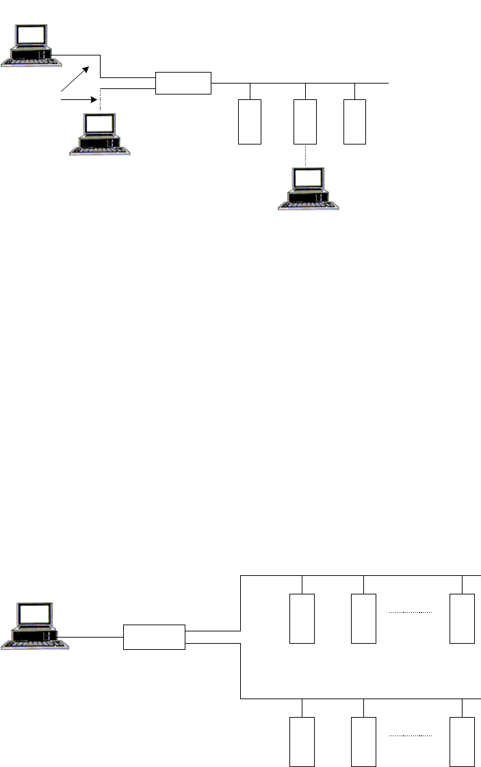
Simple System
A simple system, comprised of a central computer, MCP-M, and RTUs connected over
one communication link, is shown in the following figure:
The MOSCAD System - Overview
9
Programming
Toolbox
MCP/M
Central
Computer
Programming
Toolbox
RTU 1
RTU 2
RTU 3
RS-232C
Radio link (
RADIO 1
)
The Programming ToolBox may be connected to any port of the RTU or MCP-M
configured as a computer port.
The radio link, named RADIO 1 in the above figure, can be a conventional radio using
DFM (Direct Frequency Modulation) or FSK (Frequency Shift Keying) radio modems,
or a trunked radio using FSK radio modem.
The ports of the RTUs and MCP-M should be defined via Site Configuration. The
logical name (in this case, RADIO 1) of the communication link is also defined. As
networks involve at least two types of links, simple systems do not need to be
configured as networks.
Two-Link and Multiple Link Systems
A two-link system utilizing a communications network, comprised of two
communication links, is described in the following figure:
MCP/M
Central
Computer
RTU 4
RTU 5
RTU 6
RS-232C
RADIO 1
RTU 1
RTU 2
RTU 3
LINE 1
The MCP-M in the system illustrated above serves as a network node between link
RADIO 1 and link LINE 1. Configuring the MCP-M to have access to two different
links enables the MCP-M to serve as a node between these links.
The MDLC protocol permits RTU-to-RTU communications without the intervention
of the central computer. RTUs that are not on the same link communicate with each
other via the network node (in this case, the MCP-M).
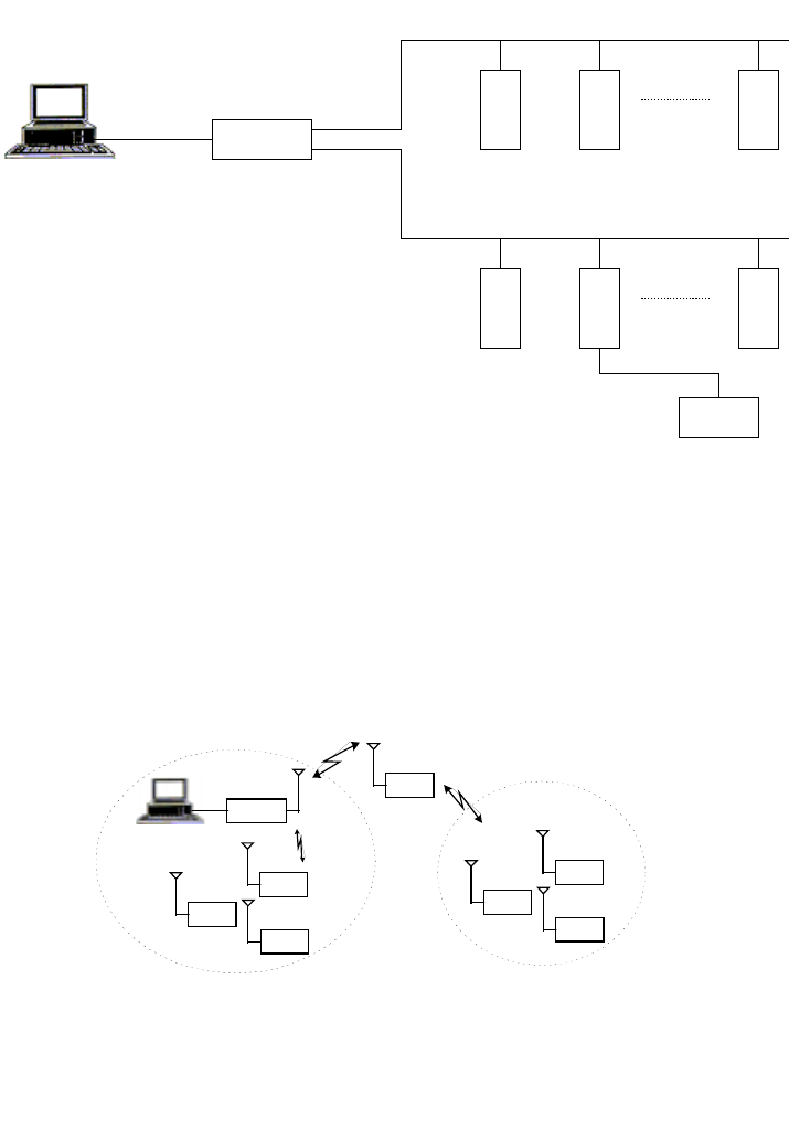
The MOSCAD System - Overview
10
A multi-link system is a network that uses several link types. The following figure
illustrates a system where a third link type, RADIO 3, connects an RTU to another
terminal that communicates over RADIO 2. RTUs connected to the RADIO 1 link can
reach RTU 7 via MCP-M and then RADIO 2.
MCP/M
Central
Computer
RTU 4
RTU 5
RTU 6
RS-232C
RADIO 1
RTU 1
RTU 2
RTU 3
RADIO 2
RTU 7
RADIO 3
Two-Zone System
A two-zone system that uses conventional radio over a single frequency is described in
the following figure:
ZONE 2
MCP/M
RTU 9
RTU 2
RTU 1
RTU 3
ZONE 1
RTU 4
RTU 5
RTU 6
Store & Forward
RTU 9 (Site ID = 9) is configured as a Store & Forward repeater. It performs data
exchange between units that operate on the same frequency but are unable to
communicate directly for reasons of path and propagation. Any RTU in zone 1 may
communicate with any RTU in zone 2 via this repeater.
The figure below illustrates this system schematically. In this case, RTU 9 is a
network node between the RADIO 1/1 and RADIO 1/2 links. The network software
The MOSCAD System - Overview
11
treats the Store & Forward node as it treats the node between line and radio: logically
the links appear as two different links, but physically they share the same port.
MCP/M
RTU 1
RTU 2
RTU 4
RADIO 1/1
RTU 3
RTU 9
RADIO 1/2
Using Site Configuration, the MCP-M and the RTUs in zone 1 are configured to have
access to the RADIO 1/1 link. The RTUs in zone 2 are configured to have access to
the RADIO 1/2 link, and RTU 9, the network node, is configured to have access to
both RADIO 1/1 and RADIO 1/2 links.
Using Network Configuration, RTU 9 is configured as the only node in the network.
This terminal is configured to have two links, RADIO 1/1 and RADIO 1/2.
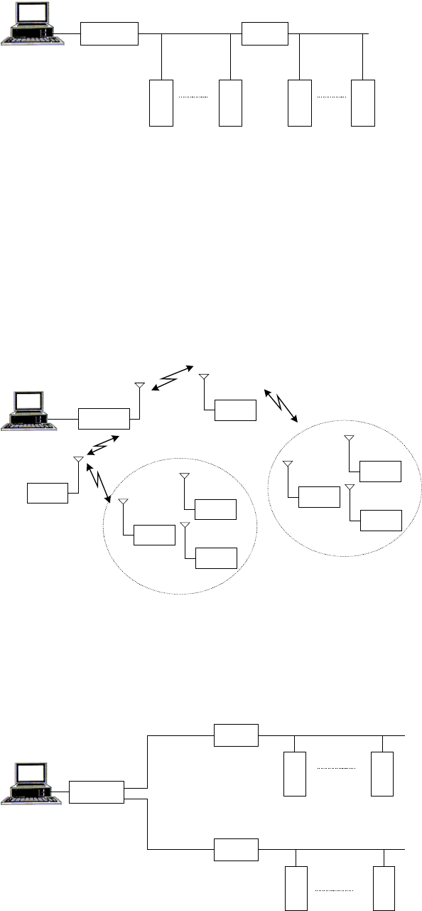
Multiple Zone System
The following figure illustrates a MOSCAD system spanning multiple zones.
ZONE 2
MCP/M
RTU 40
RTU 15
RTU 2
RTU 1
RTU 3
ZONE 1
RTU 4
RTU 5
RTU 6
The schematic representation of this system is shown below. The system assumes that
the two nodes, RTU 15 and RTU 40, cannot “hear” each other. They communicate via
the MCP-M, which is also a Store & Forward node. This system, therefore, consists
of four zones and three nodes (RTU 15, RTU 40, and MCP-M). Any communication
between RTUs in different zones passes through these three nodes.
MCP/M
RTU 1
RTU 2
RADIO 1/3
RTU 15
RTU 1
RTU 2
RADIO 1/2
RADIO 1/1
RADIO 1/4
RTU 40
The MOSCAD System - Overview
12
In the above situation, three nodes with their accessible (logical) links should be
defined, using Network Configuration.
Using Site Configuration, the RTUs in zone 1 should be configured to have access to
the RADIO 1/1 link, and the RTUs in zone 2 to the RADIO 1/2 link.
RTU 15 should be configured to have access to both RADIO 1/1 and RADIO 1/3
links, while RTU 40 should be configured to have access to both RADIO 1/2 and
RADIO 1/4 links.
The MCP-M is configured to have access to both RADIO 1/3 and RADIO 1/4 links.
Assuming that the two nodes (RTU 15 and RTU 40) can “hear” each other, the result
is a system consisting of three zones and two nodes, as shown in the following figure:
MCP/M
RTU 1
RTU 2
RADIO 1/3
RTU 15
RTU 4
RTU 5
RADIO 1/2
RADIO 1/1
RTU 40
In this case, the two nodes do not communicate through the MCP-M. Therefore, the
MCP-M does not serve as a node in the system. Note that the communication between
RTUs in different zones passes only through two nodes.
Dual Dial Port
(MOSCAD version ≥V3.70, MOSCAD-L version ≥V1.00)
The CPU supports two dial links at Port2 and Port3. Port2 may be connected to an
external AT modem and Port3 may be connected to either an external AT modem, or
to an internal modem configured at dial option.
Prior to using an external modem, emulate an external terminal using a PC and any
standard communication program, and set its parameters as follows:
•9600 bps (for example)
•8 bits
•no parity
•1stopbit
Enter the modem telephone numbers into the MOSCAD Phone Book utility. If your
telephone works either in a pulse or in a tone mode, it is recommended to add the
letter P(pulse) or T (tone) in front of the telephone number.
If you are using an external modem, set its configuration according to the following
list.
The MOSCAD System - Overview
13
Action Command
Disable off-line echoing ATE0
Enable audio messages ATV1
Disable quiet mode (The status codes are sent to
the terminal.) ATQ0
Enable all codes ATX4
Enable carrier detect when a connection is
established. AT&C1
You may enter the commands in one string, ATE0V1Q0X4&CI&W, where &W
implies saving the above parameters for the next power-up.
When several RTUs are connected to the PSTN (Public Switching Telephone
Network), as illustrated below, several configurations are viable as described in the
examples that follow.
EXTERNAL
MODEM AT
PORT 2
RTU 4 RTU 5
RTU 3
RTU 2
RTU 1
EXTERNAL MODEM
AT PORT 2 EXTERNAL MODEM
AT PORT 3
INTERNAL MODEM
AT PORT 3
EXTERNAL
MODEM AT
PORT 3
INTERNAL
MODEM AT
PORT 3
EXTERNAL
MODEM AT
PORT 2
PSTN
Note that in the illustrated configurations, as in all the connections over the PSTN,
there is only one link ID. It is the responsibility of the software to decide which line to
dial. When two lines are available, the Port 2 line has priority.
1. To communicate between RTU 1 and RTU 2:
•Configure RTU 1 Port 2 as external modem.
•Update the RTU 2 telephone number.
•Any transmission from RTU 1 to RTU 2 will cause automatic dialing.
As the connection is established, information will be transferred from
one modem to the other. When no information is transferred for a
period longer than the “Hanging up an unused line by INITIATOR
after...” Advanced Physical Layer parameter, the line will be
disconnected.

The MOSCAD System - Overview
14
2. To communicate between RTU 1 and RTU 4:
•Configure RTU 1 Port 2 as external modem.
•Update the two RTU 4 telephone numbers.
•Any transmission from RTU 1 to RTU 4 will cause automatic dialing
to the first number in the phone book. If the first number is busy, or
there is no answer, the second number is automatically dialed. As the
connection is established, information will be transferred from one
modem to the other. When no information is transferred for a period
longer than the “Hanging up an unused line by INITIATOR after...”
Advanced Physical Layer parameter, the line will be disconnected.
3. To communicate between RTU 4, RTU 5, and RTU 3 simultaneously:
•Configure RTU 4 Port 2 as external modem and RTU 4 Port 3 as
internal modem dial-up, Auto Answer & Dial.
•Update the two RTU 5 telephone numbers and the RTU 3 telephone
number.
•Any transmission from RTU 4 to RTU 5 will cause automatic dialing
from the first available port (when both ports are available, Port 2 is
chosen) to the first number on the list. If the first number is busy, or
there is no answer, the second number is automatically dialed. As the
connection is established, information will be transferred from one
modem to the other. When no information is transferred for a period
longer than the “Hanging up an unused line by INITIATOR after...”
Advanced Physical Layer parameter, the line will be disconnected.
•AnytransmissionfromRTU4toRTU3whileRTU4andRTU5are
connected, will cause automatic dialing from Port 3. If RTU 4 and
RTU 5 are disconnected, then Port 2 will be selected for dialing.

The MOSCAD System - Overview
15
Starting a ToolBox Application
ToolBox consists of different Windows applications. Each application is activated via
an icon included in the ToolBox program folder.
Entering the Password
When a ToolBox application is activated at the beginning of a work session, ToolBox
displays the Password window, where the password is entered and OK is clicked.
(See The Tools in the The ToolBox for MOSCAD RTUs section of this manual.)
This operation activates the communication driver and the password remains in force
throughout the session. If you want to access an RTU that requires a different
password, you must stop the communication driver first. See Changing the Session
Password below.
Changing the Session Password
To access an RTU that requires a different password, close all ToolBox tools and then
double-click the Stop Communication Driver application icon in the ToolBox program
folder. Then, activate the ToolBox application you want and enter the password.
!WARNING
If you try to stop the communication driver while a communication session is
in progress, a message warns you that a logical channel is currently open. If
you chose to continue (stop the driver), the results of the current
communication cannot be predicted. It is advisable to finish the current task
andthentostopthedriver.
16
The ToolBox for MOSCAD RTUs
MOSCAD ToolBox is a set of software tools designed to implement MOSCAD
projects. The core of a MOSCAD project is one or more applications that reside in the
RTUs that make up a MOSCAD system. ToolBox allows users of different levels and
interests to deal with different aspects of the applications. For example, the
application developer would usually work with the ToolBox programming tools, while
other types of users would fine-tune the applications at the field, using the ToolBox
customization and setup tools.
Hardware and Software Requirements
MOSCAD ToolBox runs on a Pentium 100 (or more powerful) computer under
Windows 95 or Windows NT. It requires a minimum of 32Mb of RAM.
Installing ToolBox
The MOSCAD Programming ToolBox is installed like any other Windows
application. Insert the installation disk in your CD driver, activate setup.exe, and
follow installation messages and instructions. Written instructions can be found on
the leaflet attached to the CD.
Connecting ToolBox to RTU
The unit (RTU) may be connected to a local computer via cable FLN6457, which ends
with an adapter suitable for computer connection (25-pin female D-type connector).
Any RS232 port of the RTU defined as RS232 Local Computer may be used for
connection to the Programming ToolBox. This connection provides access to that
specific RTU, or to any other RTU in the network, to perform all the functions
described in this manual.
The RS232 ports default configuration of RTUs received from factory is RS232 Local
Computer (9600 baud).
A Brief Tour
This chapter provides a brief description of the MOSCAD/MOSCAD-L
communication system, and clarifies basic concepts.
The RTU
MOSCAD™ is the name of Motorola’s family of SCADA products. It is available in
a variety of enclosures, with a multiplicity of two-way radios, and with many different
types of input/output (I/O) modules. A MOSCAD RTU is a remote terminal unit in a
MOSCAD system.
The ToolBox for MOSCAD RTUs
17
Think of an RTU as a computer. It has a CPU, real-time clock, RAM and ROM
memory, serial communication ports, etc. A remote terminal unit (RTU) which is
installed at some field location is a computer. An RTU which may act as a district
controller is a computer. An RTU that functions as the communications bridge
between the radio (or other) communications system and the Master Control Center is
a computer. Certainly, that Master Control Center is a computer.
Just as a computer may be programmed to perform required tasks on a continuous
basis, MOSCAD is programmed in an advanced, powerful version of the ladder-logic
programming language (and/or ‘C’). The programmed rungs are compiled into the
very same format that would be used to program an EPROM; the compiled code is
downloaded into electrically-programmed ROM within the RTU. The application, as
programmed, may then be monitored and debugged.
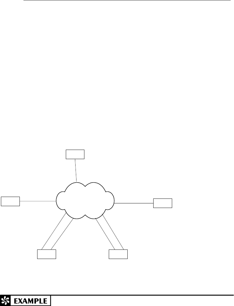
The following picture shows the main parts of the MOSCAD.
Radio or
Modem
Backup
Battery
AC Power
Supply
CPU
Module
Expansion
I/O Modules
NEMA
Enclosure
The ToolBox for MOSCAD RTUs
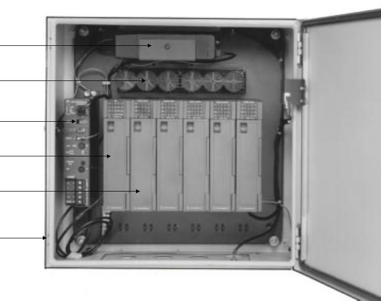
18
The following picture illustrates MOSCAD-L.
The MOSCAD application developer need not have a degree or background in
computer science. Any programming experience in ladder-logic, Basic, Pascal or C is
helpful, but not required.
Database Principles
All worthwhile computer programming languages require the programmer to define
the variables before they are used. The definition includes the variable name and
variable logic type. The programming language reserves the appropriate memory for
the variable type, and can check for type mismatches as the logic statements are
written (create an immediate error if the logic statement uses an illegal named variable
type). RTU applications must have all variables defined by name and type before they
may be used.
How those named variables are organized is unconventional from a computer
programming perspective. However, it makes perfect sense when RTU-to-RTU or
RTU-to-central communications is considered.
The language organizes the programming variables into collections called tables.
Tables look very much like computer spreadsheets: they include many rows and may
include many columns. Each row and column intersection (cell) is a variable. Some
tables have many rows but only one column. All the variables in a single-column table
are of the same type, i.e. all bits, all values, all digital inputs, etc. Each variable in the
table is uniquely named: PUMP1, PUMP2, etc. Such a table may contain up to 250
uniquely named variables. A single-column table is illustrated below:
The ToolBox for MOSCAD RTUs
19
Other tables have many rows and many columns. All variable types within any column
are the same, but the several different columns may be of different variable types. For
example, a three column table may contain one column labeled PUMP and be a
digital-input type; the next column may be labeled START and be an internal value
type; the third column may be labeled RUNTIM and be a timer type. The variable
names are a combination of the column name and the row number, i.e. PUMP,2 and
START,4. This multiple-column table structure is particularly attractive when dealing
with dissimilar but related data, particularly as it may apply to some physical device
such as the pumps at a pump site. A multiple-column table may contain up to 250 rows
and up to 8 columns. Such a table is illustrated below:
The programmer may create up to 127 tables of his/her own design. The design and
organization of the tables should be carefully planned. The operation of the
application can be monitored by observing the variables; a good table design collects
related variables so that many different, but related, things can be observed
simultaneously.
A good table design anticipates which variables must be reported to a central site, and
organizes those variables (whenever possible) into just a few tables. Understand this
part of the project, and the technical details of the applications—they are both very
important. Note that the protocol driver in the central has the same table structures as
do the RTUs communicating with the central. Data transfer becomes the simple task
of moving row/column data between identical tables.
You, the programmer, define the variable names. You are not required to use a bit-
and-register notation that reflects the electrical design of the RTU. You may define
and name your variables as you wish, with no restrictions other than name length.
Even if you program in another language, the RTU system will accept your variable
names.

The ToolBox for MOSCAD RTUs
20
The database supports many variable (data) types. For full details, refer to the
Database Concept chapter in the Application Programmer manual.
Programming Philosophy
In order to create an application program which meets your needs, first identify the
tasks required of the program, including the information needed to complete each task
(e.g. digital inputs, variables from another site, permission flags from the central, etc.).
Next, sketch, in flowchart form, the logical steps required to convert the stated inputs
into the required output(s). Make sure that all combinations of inputs are properly
addressed and lead to the correct output(s). This step is key, as it is much easier to
correct mistakes in a flowchart on paper than to debug and correct lines of
programming code.
All of the logic operators that are used in Basic or Pascal or C programming languages
are available to the RTU ladder-logic programmer. Only the syntax is different.
Remember, the logic statements will eventually be compiled; you can’t tell how it was
programmed by looking at the compiled code.
The operators are discussed at length in the Ladder Diagram Language chapter of the
Application Programmer manual.
Ladder logic originated from the language of relays. The contacts of the relays, singly
or in combinations, appear to the left of the logic statements and constitute the tests.
The coil of the relays appears to the right of the logic statement and constitutes the
actions. Tests on the left, actions on the right. Line after line. The structure looks
like the rungs of a ladder, hence the name of the programming language and the name
(rung) of each logic statement.
The RTU implementation of ladder logic programming allows up to six lines per rung,
and up to eight symbols on a single line. Therefore each RTU rung may indeed be a
complete logic statement (IF this THEN that ORIF other-this THEN other-that ELSE
...).
Some of the basic tests and actions are listed below.
Tests (inputs)
—| |— The fundamental relay contact is Normally Open; it closes when the coil is
active. There is also a Normally Closed relay contact that opens when the
coil is active. The variable name being tested must be a bit-type(not a
—| / |— value-type) and appears above the symbol. These are illustrated on the left.
It’s quite amazing how many decisions can be made with only these two
operators. Put them in series and you have a logical AND – see below. Put
them in parallel and you have a logical OR. You can apply Boolean logic to
reduce the number of required open/close contacts, as is mandatory with
hardware logic solutions. But every RTU “coil” has an unlimited number
of like-named contacts, so there is no cost incentive to minimize the number
of relay contacts. You can therefore avoid such reductions and keep the
logic readable.
—| |— —| |— —| / |—……. x •
• •
• y•
••
•z

The ToolBox for MOSCAD RTUs
21
—| < |— Ladder logic originally treated only binary data – relay contact open or
closed. Ladder logic was later modified to handle value (non-binary) data.
—| = |— The variable names being tested must be value-types (not bit-types) and
appear above and below the symbol. These symbols are shown at left.
—| ≠
≠ ≠
≠ |— Testing value data has many applications. Consider some process that must
operate if a value exceeds some setpoint.
—| > |—
—| ↑
↑ ↑
↑ |— A third type of test operator is the Differentiator. It checks for a difference
between the current and previous state of the named variable(s) that precede
—| ↓
↓ ↓
↓ |— it in the rung; the operator is true only when this difference occurs. The
operator can be used to check for the rising or falling “edge” of the named
variable(s), so that the associated action only occurs once. The index
variable, if used in any of the preceding named variables, also appears
above the differentiator symbol.
Actions (Outputs)
—( ) Relay On & Relay Off: The original ladder logic action was to energize the
coil of a relay – this remains the fundamental action. As long as the
—( / ) associated test is true, then the coil (action) will be energized (true). A
extension of this concept is the NOT – as long as the test is true, the action
will not be true. The named variable associated with the coil appears above
these symbols as illustrated on the left.
—( L) Latch & Unlatch: Situations exist wherein the test may be momentarily true,
but the associated action should remain true until specifically made not true.
—( U) Combinational logic can be used to create this action, or – more simply –
the Latch and Unlatch actions may be used. If the test(s) in the rung used to
latch the coil is true then the named variable will be latched; a similar action
will happen in the rung used to unlatch the coil. Rungs are tested and
executed sequentially, as they appear in the task, so if both rungs are
simultaneously true then the action in the last rung to be executed will
determine the state of the named variable. The symbols are shown on the
left.
—( SCAN ) Scan: This action reads input data from physical I/O modules into the CPU
module, and updates the appropriate variables in the several data tables. The
action also writes data from the CPU data tables to the I/O modules. And
the action updates mapped bit and value variables within the data tables.
—( MOVE ) Move Low & Move High: When the associated test is true, these actions
move (copy) value data from one variable to another without changing the
—( MOVH) source variable. Move Low (MOVE) is more commonly used; it moves all
16 bits of one value variable to another value variable. Move Low may also
be used to move 8 consecutive bits in a single-column table into the low
byte of a value variable (bit packing); Move High (MOVH) would be used
to move 8 other consecutive bits in a single-column table into the high byte
of the value variable. MOVE or MOVH can also be used to move the low or
high byte respectively of a value variable to 8 consecutive bits of a single-
column table (bit unpacking).
The ToolBox for MOSCAD RTUs
22
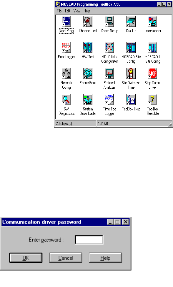
The Tools
ToolBox is a collection of software programs that eases the task of coding the
flowchart steps and making the RTU run the application correctly. A printer is
required if the user wants hard copies of the application; the application is also stored
on the hard disk.
After installing ToolBox, the icons of the various tools included in your package
appear in the MOSCAD Programming ToolBox folder, as shown below.
Many of the basic tools are described in detail in the System Setup and Diagnostics
(SSD) manual. These include, Site Configuration, Network Configuration, various
Utilities, and Diagnostic tools.
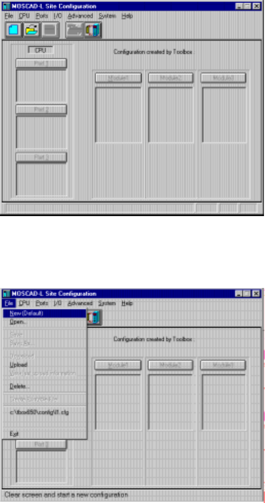
To start a tool:
1. Connect to the RTU (though you can set configuration values and develop
applications without an RTU connection).
2. Double-click the icon of the tool you want. If a password is required, the
following dialog box appears.
3. Type the password and click OK.
4. The main window of the selected tool appears. If a password was required, but
was incorrectly entered, no communication is established between the RTU and
the ToolBox. If the Cancel button is pressed, the tool starts up, but some of the
communications-related functions will be hidden (gray)
The ToolBox for MOSCAD RTUs
23
Site Configuration (MOSCAD-L)
Let’s start with Site Configuration (this brief tour illustrates the site configuration for
MOSCAD-L; the processes described here are very similar to those that apply to the
full MOSCAD system). This program is used to define which I/O modules are present
in the unit and where they will be placed in the module rack. It is also used to
determine the functionality of the RS-232 and radio (modem) ports on the CPU
module to be defined. The address of the specific RTU is then defined, and the
combination downloaded into the RTU’s CPU module. This process gives some
personality to the RTU; this process must be accomplished via a local cable between
the ToolBox computer and the RTU.
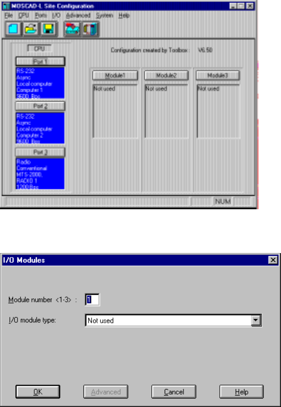
After activating the MOSCAD-L Site Configuration application, the following
window appears:
The File menu includes commands for starting a new configuration, retrieving an
existing set (file) of configuration values, saving a configuration, printing the contents
of a configuration file, and the like. Click the File menu (or press ALT+F) to open it.
It looks as shown below.
The ToolBox for MOSCAD RTUs
24
To start configuring a site, select the New command from the File menu or click on the
New icon. This automatically opens a new file, with default configuration settings, as
shown below. The sections marked Module1 Module2, Module3 each represent an
expansion I/O module in the unit. (See the picture of the unit in The RTU section
above.) The CPU module does not appear on the Site Configuration screen, as it is
always placed in Rack 0, Module 0. The other I/O modules may be specified by
clicking the desired Module (e.g. Module1) button.
After clicking Module1, the I/O Modules dialog box appears, which enables you to
select a type for the module:
After selecting the module type from the list, click OK.
Repeat the process (click the Module2 button, then open the type list, etc.) for all the
required I/O modules. Made a mistake? Just click Type again, and select another
value from the type list. The current definitions of the three ports of the CPU module
appear on the main window. One port, usually Port 1, is by default defined as Link
Name = Computer 1, and Port Type = RS232- Local Computer. Use this port for the
local connection of the ToolBox. To see the default port definition, click the Port 1
button. The following is displayed:
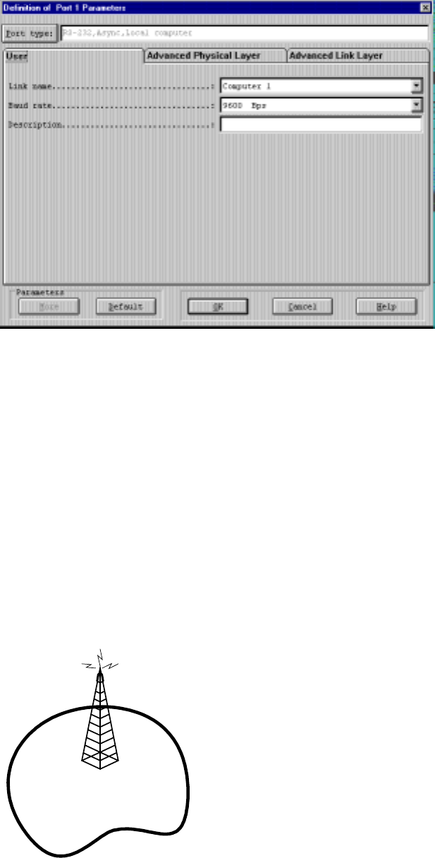
The ToolBox for MOSCAD RTUs
25
The other two ports are configured in a similar way, though the values vary. Port 2
defaults to the same configuration as Port 1, but can be changed as necessary. Port 3
usually defines the communications medium required (e.g. radio, modem ). Once the
ports are configured, the values are saved in a site configuration file and downloaded
to the unit. The Site Configuration section of the System Setup and Diagnostics
manual describes the types and parameters for each port, as well as the procedure for
defining, saving and downloading the site configuration to the RTU.
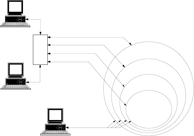
Network Configuration
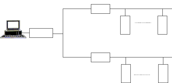
The second major step is configuring the network. Most data radio communication
systems have a single base transmitter located somewhere near the center of the
physical coverage area, as illustrated below. The transmitter emits radio energy; the
distance the emission travels define the coverage limits of the system. Normally, all
data equipment will lie within this coverage area, in which case, no network
configuration need be defined.
RTU
RTU
RTU
RTU
RTU
However, if one or more sites with data equipment lie outside this coverage area;
reliable communications with these sites cannot be assured. The RTU provides a
solution to this problem which requires no additional hardware. A map of the network
is created and existing units are used to relay information around the network to its
destination.
The ToolBox for MOSCAD RTUs
26
Any RTU can receive data, validate that data, and store it in a buffer for
retransmission a few seconds later. An RTU with more than one communications
medium (link), known as a “network node”, stores the data and relays it to another
RTU. Note that network node RTUs are also capable of operating as regular RTUs;
thus no special, dedicated hardware is required. The data Store & Forward capability
is a communications protocol task; and requires nothing to be programmed in the
application.
A logical name is assigned to each communications medium in the network (e.g.
Radio1, Radio2, Line1, Line2). Most sites will have a single communications medium
– these are not network nodes. A few sites may have both a radio and a wireline
modem, or two radios – these are definitely network nodes. Some sites may have a
single radio that communicates both with the main portion of the system and also with
one or more out-of-range RTU sites. These are also network nodes; the link names
would be Radio1/Zone1 and Radio1/Zone2 (abbreviated Radio1/1 and Radio1/2
respectively) or their equivalent.
Use the Network Configuration program to define these network nodes and their
respective links, as described in the Network Configuration section of the System
Setup and Diagnostics manual.
Application Programmer
Once the site and network have been defined, building the application can be built,
using the Application Programmer. The application (also called a project) consists of
a database and a ladder program.
1 Activate Application Programmer from the MOSCAD Programming ToolBox
folder, as you opened the Site Configuration and Network Configuration. (If you
chose not to connect to the unit at this time, hit CANCEL when prompted for the
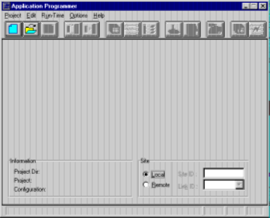
Communication driver password. The main window appears as shown below. Note
that most of the icons will be dimmed and unselectable.
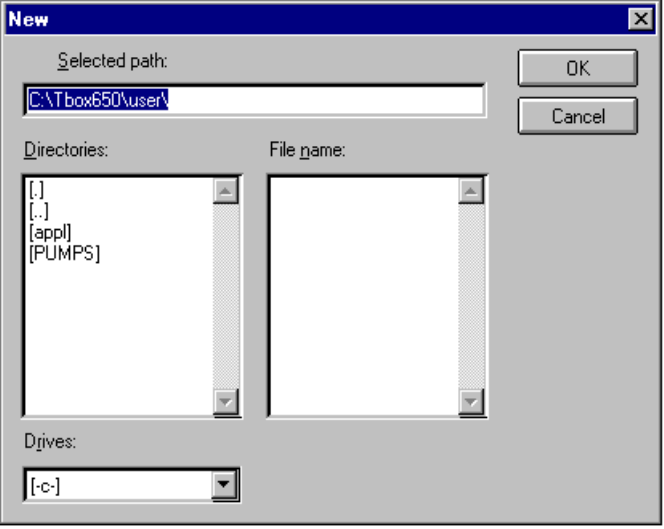
2. From the Project menu, select the New command, or click on the New icon. The
New dialog box is displayed. The ToolBox lists all existing applications (projects)
under Directories; hence the list may vary from computer to computer.
The ToolBox for MOSCAD RTUs
27
3. For each project, Application Programmer opens a new subdirectory under
tbox750\user. The path appears in the Selected Path box, and the insertion point is
positioned where you are expected to type the name of the project. Type a project
name of up to 8 characters and click the Create button. This creates the sub-
directories and the application files. Anything you save related to the application will
be stored in that directory. Another user (e.g. user1) area can be created by changing
the value in Selected Path.
4. Open the Edit menu. The commands Database Builder, Process Programming and
I/O Link represent the main application building steps.
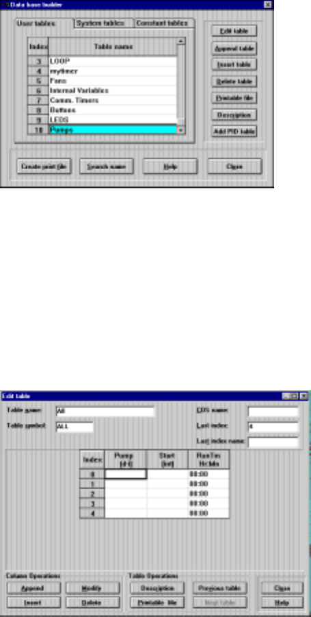
Database Builder
Database Builder is used to create the application variables. Variables are “declared”
in table-like windows.
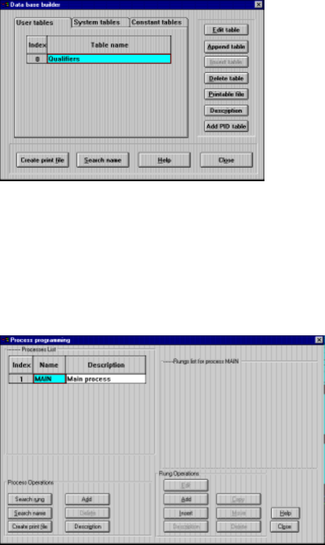
Select Database Builder from the Edit menu. The following dialog box is displayed.
The Database Builder window tabs show three types of tables, User Tables (created by
the user specifically for the project), System Tables (available to the project), and
Constants Table (available to the project). User Tables is selected by default. Here
you may create (Append) and Edit tables of variables which represent the inputs and
outputs of your system, as mentioned in Database Principles above. For full details,
see the Application Programmer manual.
The ToolBox for MOSCAD RTUs
28
Process Programming
The defined variables may now be used in the coding of the various rungs of the
application, which determine what actions are performed, under what conditions. You
may wish to refer at this time to the lists of available tests and actions in Programming
Philosophy above. Tests, actions, and variables – you're ready to go. Both the Data
Base Builder and the Process Programming use an Append/Add capability to define a
new table or process, and an Edit capability to insert variables or logic statements into
that table/process. Open the Edit menu and select Process Programming. The
following dialog box is displayed.
The MAIN process exists by default because it automatically runs at powerup or upon
an application restart. The MAIN process provides the framework in which the
application runs. Process and Rung Operations enable you to add and edit new rungs
and processes. The logic of the rungs is programmed according to the logic of the
flowchart created, which was based on the tasks required of the RTU. For full details
on Process Programming, see the Application Programmer manual.
I/O Link
The Site Configuration program is used to define the physical aspects of the RTU
hardware. The Application Programmer program is used to define a virtual process
The ToolBox for MOSCAD RTUs
29
that has no link to any physical reality. Yet such a link is required. This is done using
I/O Link.
1. In the Application Programmer main window, open the File menu and select Import
Site Configuration.
2. Select the site configuration file related to your application (field.cfg).
3. Open the Edit menu and select I/O Link. The following dialog box is displayed.
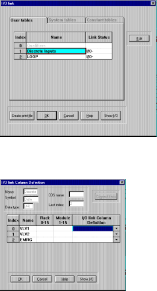
4. The I/O Link dialog displays the application tables. The Status column shows those
tables that include an I/O module which requires linking. The minus sign indicates
incomplete link data. Highlight the first table that needs link information and click the
Edit button. The table is displayed.
For each variable in the table, enter the appropriate Rack and Module numbers on the
RTU and the desired physical input or output on the specified module. These
definitions are saved together with the rest of the project information. For a full
description of the I/O Link procedure, see the Application Programmer manual.
The link process is the only association between the physical reality of the site
configuration and the virtual reality of the application. If the site configuration is
The ToolBox for MOSCAD RTUs
30
subsequently revised, the new version should be imported into the project. The
application itself is not necessarily affected.
Compiler
Once the application is saved, it must be converted into a form which can be
understood by the CPU. The compiler turns the visual ladder logic table and rung
definitions into code to be executed directly by the microprocessor in the CPU
module. Open the Run-Time menu in the main window and select the Compiler
command. A two-pass compilation takes place. Errors are reported along with the
associated rung name. You must correct these errors to produce error-free compiled
code. A successful compilation produces an “End of Compilation” message that
provides a few items of information.
Downloading and Monitoring
The compiled code is ready to be downloaded into the CPU module. This can be done
locally, using a cable, or remotely over the communications network (from any site in
the system to any other site in the system).
The runtime operation of the downloaded code may be monitored via an upload from
the CPU. You can upload locally using a cable, or via the communications network.
You may monitor the runtime values in any table or in any rung – you choose the
presentation format.
32
Remote Terminal Unit
The MOSCAD Remote Terminal Unit (RTU) is a modular unit, comprised of a CPU
module, communication boards, and I/O modules interconnected by a common modular
bus. The modular construction allows you to configure each RTU according to the precise
requirements of the application. It also permits future expansion as the application
develops.
The lighter model, MOSCAD-L RTU, includes only a CPU and three I/O modules.
The RTU Hardware
The core of the RTU is the CPU module. The other modules provide digital (discrete) and
analog input/output capabilities.
Each module is enclosed in a plastic box, which allows for fast assembly/disassembly
(snap-in technique) without the need for tools.
In the MOSCAD RTU, each module has LED indicators that monitor operations.
CPU Module
The MOSCAD CPU module, based on the high-performance Motorola Integrated
Multiprotocol Processor (IMP) MC68302, provides three communication channels, one of
which is an interchangeable interface plug-in board. The module is located in slot 0 of rack
number 0 - the leftmost module on the first bus of the first rack.
MOSCAD-L is based on the LC68302 processor and provides three communication
channels.
Memories
The CPU board contains two types of on-board memories:
•Static CMOS RAM (SRAM), used for storing data and system parameters. The RAM is
backed-up by a lithium battery.
•Segmented FLASH memory, used for storing the system program, the site configuration
information, the user application, and the system configuration data, and programmed
via Programming Toolbox.
Front Panel - MOSCAD
The CPU module’s front panel includes the following:
•Communication port connectors
•Twenty diagnostic LEDs
•Two push-buttons
•Battery
Communication Ports

Remote Terminal Unit
33
The CPU module has three communication ports with the following characteristics:
•Communication port 1 with two interface options:
RS-485 for UART start/stop operation and baud rate of up to 57,600 b/sec (port 1A).
RS-232C with full DCE/DTE operation and baud rate of up to 57,600 b/sec (port 1B).
•Communication port 2 with RS-232C interface as port 1b.
•Communication port 3 – a plug-in port designed for various radio or line
communications. The available plug-in boards are listed in Site Configuration.
The two RS-232C ports (1b and 2) may be configured by the site configuration software
(see Site Configuration in the System Setup and Diagnostics Tools manual). The default
configuration of both ports is RS232 Local Computer.
Diagnostic LEDs
InMOSCAD,the20diagnosticLEDsarearrangedin4x5matrix.Thefunctionofeach
LED is described below:
PWR LOAD CONF APPL
AC TX1 TX2
CPU ERR
MON
RX2
RST BAT CM1 CM2
FAIL PORTS
RX1
CPU
TX3
RX3
CM3
PWR (Power): Lights as long as the 12 V DC input power is applied to the RTU,
indicating that the unit is operating.
AC (AC Fail): Lights when the AC power supply to the unit fails (operates on the unit’s 12
V battery).
CPU (CPU Fail): Lights to indicate a malfunction in the CPU. The nature of the
malfunction is indicated by the 16 LEDs situated in the four columns on the right, which
light simultaneously with the CPU Fail LED, as detailed below (CPU LED is on):
•(1) CM3 LED is on: RAM test has failed.
•(2) RX3 LED is on: ROM test has failed.
•(3) CM3 and RX3 LEDs are on: FLASH memory test has failed.
Remote Terminal Unit
34
•(4) TX3 LED is on: Create software module has failed. (There is probably not enough
memory. It is advisable to add a memory extension board or to reduce memory
consumption.)
•(5) CM3 and TX3 LEDs are on: Real time clock has failed.
•(6) RX3 and TX3 LEDs are on: Internal clock has failed.
•(7) CM3, RX3, and TX3 LEDs are on: Hardware breakpoint has failed.
•(8) MON LED is on: XTAL rate change has failed.
•(9) CM3 and MON LEDs are on: User request has failed.
•(10) RX3 and MON LEDs are on: Application version was compiled and downloaded
by a previous version of the Programming Toolbox.
•(11) RX3, CM3, and MON LEDs are on: The current site configuration was
downloaded by a previous version of the Programming Toolbox.
RST (CPU Reset): Flashes upon reset of the CPU, usually caused by the watchdog timer,
indicating that the software is not running properly.
ERR (Error): Lights to indicate that an illegal state has been detected in the software, or a
module/board is missing, and other malfunctions. These events are logged in a special
error logger in the CPU. The contents of the error logger may be read via Programming
Toolbox (see Diagnostics in the System Setup and Diagnostics Tools manual).
BAT (low battery voltage): Lights to indicate that the voltage of the lithium battery (which
backs up the CMOS RAM when the 12 V voltage is not supplied to the modules), is low.
The battery must be replaced. Note that the battery may be replaced without interrupting
RTU operation, by pulling out the used battery and inserting a new one.
LOAD: Lights to indicate that a configuration definition or an application is being
downloaded to the FLASH memory.
CONF (configuration): Is lit to indicate that a site configuration definition has been loaded
into the FLASH memory.
APPL (application): Is lit to indicate that an application has been loaded into the FLASH
memory. The LED flashes in the following cases:
•When the application program is in the “STOP SCAN” state for performing diagnostics
via the monitoring program of the Application Programmer.
•When the application run-time is too long (more than 1.2 seconds). This is caused by a
mistake in the Ladder Diagram program, such as an infinite loop.
•When the application program is in the STOP state during hardware test performed by
the Programming Toolbox.
MON (monitor): Lights when the monitoring program of Application Programmer
performs symbolic debugging of the Ladder Diagram function. This is achieved by
inserting breakpoints to obtain “snapshots” of the data during the process.
TX1: Lights when the RTU is transmitting data via port 1.
RX1: Lights when the RTU is receiving data via port 1.

Remote Terminal Unit
35
CM1: Lights when the communications channel used by port 1 is busy.
TX2, RX2, CM2: As above, for port 2.
TX3, RX3, CM3: As above, for port 3.
By default, LEDs are always displayed. Even the command "Disable leds display" in "Leds
Test" in the "HW Test" in the ToolBox will not turn any LEDs off. However, it is possible
to set a time out for the LEDs. In the Site Configuration, use the "Advanced" menu, choose
"General System Parameters" and then "Leds". The "Leds operating mode" has a default
value of "Light always". This may be changed to "Light up to time out". The default time
out is 600 seconds, which is ten minutes.
When the time out is reached, the LEDs turn off. This provides a small savings in
electricity. Pressing the push-button will re-light the LEDs in CPU mode. When working in
"Light up to time out" mode, the command "Disable leds display" in "Leds Test" in the
"HW Test" in the ToolBox will turn all the LEDs off. Then the command "Enable leds
display" will relight the LEDs in CPU mode.
Push-button PB1
The main function of PB1 is to turn the LEDs on and off, as follows:
•When the push-button is pressed once momentarily, the display is activated
•When the push-button is quickly pressed twice, the display turns off. To conserve
energy, the display turns off after 10 minutes if it is not switched off manually.
•When the push-button is pressed continuously, all the LEDs light simultaneously (for
LED test). The LEDs extinguish when the switch is no longer pressed.
In all modules there are several LEDs that do not turn off when all other LEDs do. These
LEDs, such as the four leftmost LEDs of the CPU module, indicate malfunctions and
important events.
Push-button PB2
For the use of the ladder application.
A CPU restart is performed when the RTU is switched on, and PB1 and PB2 are pressed
simultaneously for about 10 seconds continuously. A CPU restart is also performed when
PB1 and PB2 are pressed simultaneously for about 30 seconds continuously while the RTU
is operating. This erases the user flash memory (i.e. site configuration, applications, etc.)
and restores the RTU to the default configuration. The buzzer sounds when the RTU is
restarted.
Battery
The lithium battery backs up the CMOS RAM and the real time clock when the 12V
voltage is not supplied to the modules. Note that the battery may be replaced without
interrupting the RTU’s operation by pulling out the used battery and inserting a new one.
The RTU is shipped from the factory with the battery disconnected by an insulating strip
(to prolong battery life). Carefully pull out the strip before working with the RTU. If the
RTU is to be stored for a long time, do not forget to place the insulating strip.
Buzzer

Remote Terminal Unit
36
The buzzer sounds during the cold start-up of the CPU module and while erasing the
configuration/application from the FLASH memory.
Front Panel – MOSCAD-L
The CPU module’s front panel includes the following:
•Twenty diagnostic LEDs
•One push-button
Diagnostic LEDs
In MOSCAD-L, the LEDs are arranged as shown below:
CPU M1 M2 M3
LOAD
1CONF
5Appl
9MON
13
RST
2TX1
6TX2
10 TX3
14
ERR
3RX1
7RX2
11 RX3
15
BAT
4CM1
8CM2
12 CM3
16
The upper row of four LEDs (CPU, M1, M2, M3) is used to indicate what information is
displayed in the remaining sixteen LEDs (CPU, or I/O Module 1, 2 or 3). Each press of the
push-buttonswitchesfromCPULEDdisplaytoM1toM2toM3,andthenbacktoCPU.
In any display mode, when blinking, M1, M2, and M3 also indicate I/O Module Fail.
There are two possible reasons for I/O Module Fail:
(1) Missing I/O module
(2) Incorrect I/O module (doesn't match configuration in Flash)
CPU RESET (RST LED)
In the CPU LED display, one LED is NOT always under software control. This is the RST
LED (second row, first column). When ONLY the CPU LED and the RST LED are on,
then the CPU is in RESET state and these LEDs are hardware controlled.
When ONLY the RST LED is on during startup (CPU LED OFF), the CPU is performing
power up tests.
CPU LEDs on startup: SERIOUS FAILURE (CPU FAIL)
When a SERIOUS FAILURE is found during startup power up tests, the ERR LED will
blink (CPU LED OFF). For example, on ROM fail, or RAM fail, or CREATE fail, the
ERR LED will blink, and the LEDs in columns 3 and 4 will contain the error code
indicating the CPU error. (See list of errors under CPU Fail in MOSCAD Diagnostic
LEDs above.)
Remote Terminal Unit
37
AI LEDs
If both the UDF and the OVF LED for a channel are on, this indicates that the specified AI
channel is not calibrated. If this occurs in the field, it indicates a hardware problem with
the IO module.
DC On-Off Switch
In MOSCAD-L versions up to and including V2.0x, switching DC OFF with the DC On-
Off switch normally causes COLD RESTART. This is different than MOSCAD, which
has a Lithium Battery backup to provide WARM RESTART.
As of version V2.40, WARM RESTART may be triggered on MOSCAD-L (e.g. to replace
a faulty I/O module,) if you have AC FAIL (see below) when you switch DC OFF. First
disconnect the PWR IN connector, and wait until the PWR LED goes off. This is AC
FAIL. Then switch DC OFF. Replace the I/O module. When DC is switched ON again,
you should get WARM RESTART, if the battery is connected and functioning. Don't
forget to reconnect the PWR IN connector; otherwise the battery will be drained. This
procedure enables WARM RESTART on systems with Solar Panel which never have AC
FAIL.
COLD RESTART is performed by switching DC OFF with the DC On-Off switch, while
pushing the push-button. ( ≥V2.40)
LEDs Timeout
By default, LEDs are always displayed. Even the command "Disable leds display" in "Leds
Test" in the "HW Test" in the ToolBox will not turn any LEDs off. However, it is possible
to set a time out for the LEDs. In the Site Configuration, use the "Advanced" menu, choose
"General System Parameters" and then "Leds". The "Leds operating mode" has a default
value of "Light always". This may be changed to "Light up to time out". The default time
out is 600 seconds, which is ten minutes.
When the time out is reached, the LEDs turn off. This provides a small savings in
electricity. Pressing the push-button will re-light the LEDs in CPU mode. When working in
"Light up to time out" mode, the command "Disable leds display" in "Leds Test" in the
"HW Test" in the ToolBox will turn all the LEDs off. Then the command "Enable leds
display" will relight the LEDs in CPU mode.
Push-button PB1
Push-button during normal operation
When the push-button is pressed once momentarily, the display is activated. Every
consecutive short pressing of the push-button advances the display mode in those modules
where more than one display mode is available.
One long press (several seconds): Test LEDS. This will light all LEDS regardless of the
display mode. When the push-button is released, the display will return to the CPU display
state. However, after pressing for ten seconds the display will return to the CPU display
state, even if the push-button is still pressed.
One very long press (thirty/forty seconds): Erase Flash. During normal operation, press the
push-button and hold it down continuously (thirty/forty seconds) until the LEDs blink
Remote Terminal Unit
38
three times. Then the MOSCAD-L will erase the User Configuration, Application and
everything else in the Flash memory. After that, CPU RESET will occur.
Push-button during startup
Push-button pressed while power turned on: Download System. CPU LED begins to blink
(all other LEDs off). CPU is in "Download System to Flash" mode.
Push-button pressed after power is turned on and all LEDs are on: Erase User Flash.
During startup, while all LEDs are on, press the push-button and hold it down continuously
until the LEDs blink three times. Then the MOSCAD-L will erase the User Configuration,
Application and everything else in the Flash memory. After that, CPU RESTART will
occur.
The push-button is also used when downloading system software (see System Downloader
section in System Setup and Diagnostics Tools manual.)
I/O Modules
The RTU uses modular design with a variety of modules, such as:
•Input modules, for discrete inputs and input counters or analog inputs
•Output modules, for discrete outputs or analog outputs
•Mixed input/output modules
RTU Software
The RTU software design is based on an object-oriented Multi-Tasking Executive System
(MTE). It has been designed so that during “cold start-up” it creates all software entities
needed to support the different hardware modules and communication ports as configured
via Site Configuration program by the system engineer. This permits the use of only one
standard software package for all RTUs and provides flexibility in supporting the
application requirements without sacrificing efficiency.
The software supports a communication protocol based on the OSI model (published by
ISO). The protocol comprises all of the seven recommended layers, adapted for SCADA.
The RTU software also provides the following:
•Ladder application processes divided to run under up to five different priorities, to
improve time efficiency. Another ten tasks can be run by ‘C’ Toolkit.
•Real time symbolic monitor debugger for the Ladder Diagram application.
•Clean power-down/power-up recovery of the RTU (supported by software and
hardware). After power-up, the RTU continues from the same task that was suspended.
The RTU’s real time clock continues to advance with battery power during the outage
time. The application decides whether anything is to be done about “lost” time.
•Clock synchronization – between various RTUs; can be activated via the ToolBox or a
Ladder application.
•Background “housekeeping” of the software entities – to detect software and hardware
malfunctions.
Remote Terminal Unit
39
•An error logger to store all abnormal conditions (software and hardware) for retrieval at
any time by the Programming Toolbox Error Logger from any port in the system (not
necessarily on the same RTU).
•Diagnostics of every software entity (using symbolic entity names) in the RTU,
provided from any port in the system.
The RTU does not have option jumpers or potentiometers. All options and adjustments
are software controlled. This increases reliability while reducing the risk of forgetting
adjustments.

40
MDLC Communication Protocol
The MDLC communication protocol is based on the OSI (Open Systems Interconnection)
model published by ISO. The protocol comprises the seven recommended layers adapted
for SCADA, in which every RTU is simultaneously a distributed control unit and a
communication node serving itself as well as other units.
Information is transmitted in the form of variable-length digital words. Advanced security
techniques are employed to provide protection against false messages.
The protocol is efficient for transferring small quantities of information, such as
measurements and discrete statuses, as well as for transferring large quantities of
information, such as downloading software applications, including data base, process, etc.
SITE A
APPLICATION
PRESENTATION
SESSION
TRANSPORT
NETWORK
MULTI-LINK
PHYSICAL
SITE C
APPLICATION
PRESENTATION
SESSION
TRANSPORT
NETWORK
MULTI-LINK
PHYSICAL
MULTI-LINK
PHYSICAL
MULTI-LINK
PHYSICAL
NETWORK
SITE B
CRC CRC CRC CRC
The following subparagraphs describe the seven layers of the protocol, shown in the figure
above:
•Physical layer.
•Link layer.
•Network layer.
•Transportation layer.
•Session layer.
•Presentation layer.
•Application layer.
MDLC Communication Protocol
41
Physical Layer
The physical layer comprises the various communication ports and their associated
software.
The software contains all the specific handling required by the communication ports and
provides an identical interface to the link layer. In this way, it is possible to define a
standard entity for the link layer.
The software is flexible and adapts itself to the number of ports and their various types as
defined by the user, but the possibility of defining a large number of ports of various types
does not impair software efficiency.
The physical ports may also be configured to provide hard-copy printout to a printer.
Link Layer
The function of the link layer is to ensure proper communication over a single
communication channel. The information is stored in variable-length frames where the link
layer protocol contains the following fields (for a DATA frame):
•The address of the unit to which the DATA is transmitted.
•The address of the transmitting unit.
•The number of the frame.
•CRC for error detection.
Dual addressing is used to allow RTU-to-RTU transmission without central intervention,
transmission to several centrals, or a hierarchical system where some of the RTUs serve as
sub-centrals for the lower hierarchies.
During reception, the address is identified by hardware (and not by software) at the
physical level, in order not to spend software time on checking words that are not intended
for that specific RTU. This preliminary screening enables reception of at least four
different addresses per RTU: single address to access a specific RTU, broadcast address to
access a group of RTUs, and two additional addresses enabling various communication
operations.
A link entity associated with a channel may receive several types of information:
information that is intended for that specific RTU and information passing through it and
is designated to other RTUs. The link entity transmits an acknowledgment (ACK) to each
RTU according to the DATA received from it. The ACK word is separated from the
DATA word, since the RTU receiving the DATA is not necessarily the same RTU to
which the ACK is addressed.
The ACK word enables the receiving site to identify the missing frames and retransmit
only those frames, thus saving air time by not repeating all the information transmitted.
The CRC is 32 bits or 16 bits per CCITT definition.
The frame synchronization (FLAG), at the beginning and at the end of each word, is
transmitted in different ways for different physical ports.
MDLC Communication Protocol
42
Network Layer
A system is defined as a network whenever it uses more than one communication medium,
such as wireline and/or various radios, as well as Store & Forward repeaters, all on a single
frequency. The communications in the network occur among nodes, which physically may
be RTUs, centrals, or repeaters.
The network layer and its protocol are responsible for routing packets in the network via
the various nodes to enable communication between any two sites in the network.
It is possible to access any application anywhere in the system from any port in the system,
such as the RS-232 ports of the various RTUs, for purposes of definition, monitoring,
modification, diagnostics, error logging, etc.
Transportation Layer
The transportation layer ensures END-to-END completeness of the information
transmission (between the RTU that has transmitted the message and the one that should
receive it). This layer transfers the DATA in an orderly fashion to the session layer above
it. The protocol of this layer assigns sequential numbers to the packets (independent of the
numbers assigned by the link layer) and transmits an ACK word to indicate that the DATA
is complete and all packets are transferred in the appropriate order to the layer above.
The transport layer performs multiplexing, thus enabling several session entities (logical
channels) to operate via one physical port or several physical ports. It is possible to define
any number of logical channels, regardless of the number of physical channels defined.
Session Layer
The session layer enables the definition of any number of entities (instances), which are
capable of conducting a session with a parallel entity in another RTU, a central, or a sub-
central. These entities and their protocol simultaneously conduct several sessions between
any two sites, i.e., to simultaneously run several applications such as data transfer,
diagnostics, monitoring, etc., without interference between the applications. The session
handling includes the following:
•Start session.
•Synchronization of message direction.
•End session.
•Abort session.
•Re-synchronize session.
The session layer also provides for transfer of short one-frame messages from one site to
the parallel application at another site without the need to start a session.
MDLC Communication Protocol
43
Presentation Layer
This layer handles the presentation of the DATA received from the various applications
within the various packets. It performs the following:
•Checks that the information transferred to the application is complete.
•Compresses the information.
•Encrypts the information.
•Checks authentication.
Application Layer
This layer contains all the communication applications required for maintaining a SCADA
system, as detailed below:
a. Application enabling bi-directional data transfer upon request from the data bases of
the sites.
b. Software for downloading configuration to the sites:
•I/O modules definition.
•Communication ports definition.
c. Software for downloading and monitoring application software (defined by the user
in the ladder diagram language) to the sites, including:
•Definition of the data structure.
•Object code of processes.
•Real-time symbolic monitoring of data base and processes.
d. Application for transmitting events and short messages.
e. Application for broadcasts.
f. Application for remote diagnostics of the hardware and the software.
g. Application for the retrieval of error messages stored in the error logs of the sites.
h. Application for the calibration of A/D and D/A modules.
i. Application for communication analysis and accumulation of statistics.
j. General Downloader to download various blocks (e.g. site configuration, ladder
applications, network configuration, phone book, “C” blocks, third party drivers,
x.25 conversion table, IP conversion table, etc.)