Motorola Solutions 89FT4844 UHF Two-Way Radio User Manual 00 RP4470 NA
Motorola Solutions, Inc. UHF Two-Way Radio 00 RP4470 NA
Users Manual

1
English
CONTENTS
Computer Software Copyrights. . . . . . . . . . 3
Safety . . . . . . . . . . . . . . . . . . . . . . . . . . . . . 5
Safety and General Information . . . . . . . . . 5
RF Operational Characteristics . . . . . . . 5
Exposure To Radio Frequency Energy . 5
Portable Radio Operation
and EME Exposure . . . . . . . . . . . . . . . . . . . 6
Antenna Care. . . . . . . . . . . . . . . . . . . . . 6
Two-Way Radio Operation. . . . . . . . . . . 6
Body-Worn Operation . . . . . . . . . . . . . . 6
Data Operation. . . . . . . . . . . . . . . . . . . . 6
Approved Accessories . . . . . . . . . . . . . . 7
Electromagnetic Interference/
Compatibility . . . . . . . . . . . . . . . . . . . . . . . . 7
Safety and General . . . . . . . . . . . . . . . . . . . 8
Operational Warnings . . . . . . . . . . . . . . . . . 8
Operational Cautions . . . . . . . . . . . . . . . . . 9
Intrinsically Safe Radio Information. . . . . . 10
FMRC Approved Equipment . . . . . . . . 10
Repair of FMRC Approved Products . . 11
Radio Overview . . . . . . . . . . . . . . . . . . . . 15
Parts of the Radio . . . . . . . . . . . . . . . . . . . 15
On/Off/Volume Knob . . . . . . . . . . . . . . 16
Channel Selector Knob . . . . . . . . . . . . 16
Push-to-Talk (PTT) Button . . . . . . . . . 16
Microphone . . . . . . . . . . . . . . . . . . . . . 16
LED Indicator. . . . . . . . . . . . . . . . . . . . 16
Programmable Buttons . . . . . . . . . . . . 16
Indicator Tones. . . . . . . . . . . . . . . . . . . . . 18
Audio Indicators for Programmable
Buttons . . . . . . . . . . . . . . . . . . . . . . . . . . . 18
Improved Audio Features . . . . . . . . . . . . . 19
Low Level Expansion (LLE). . . . . . . . . 19
Companding . . . . . . . . . . . . . . . . . . . . 19
Getting Started . . . . . . . . . . . . . . . . . . . . 21
Battery Information . . . . . . . . . . . . . . . . . . 21
Battery Care and Tips . . . . . . . . . . . . . 21
Charging your Battery . . . . . . . . . . . . . 22
Battery Status . . . . . . . . . . . . . . . . . . . 22
Accessory Information . . . . . . . . . . . . . . . 24
Attaching the Battery . . . . . . . . . . . . . . 24
Removing the Battery . . . . . . . . . . . . . 24
Attaching the Antenna . . . . . . . . . . . . . 25
Removing the Antenna . . . . . . . . . . . . 25
Attaching the Side Connector Cover . . 26
Turning The Radio On or Off . . . . . . . . . . 26
Adjusting the RadioÕs Volume. . . . . . . . . . 27
Selecting a Radio Channel . . . . . . . . . . . . 27
CONTENTS
User Guide
Guide de l´usager
68P81093C98-O
Motorola, the stylized M logo are trademarks of Motorola, Inc.
® Reg. U.S. Patent & Trademark Office. All other product or
service names are the property of their respective owners.
© 2001 Motorola, Inc. All rights reserved. Printed in U.S.A.
Motorola, le logo stylisé M sont des marques de commerce de
Motorola, Inc. MD Marque déposée. U.S. Patent & Trademark
Office. Tous les autres noms de produits ou services
appartiennent à leurs propriétaires respectifs.
© 2001 Motorola, Inc. Tous droits réservés. Imprimé aux États-Unis. EX500

2
English
CONTENTS
Sending a Call . . . . . . . . . . . . . . . . . . . . . 27
Receiving a Call . . . . . . . . . . . . . . . . . . . . 27
Radio Call Information . . . . . . . . . . . . . . 29
Receiving a Selective Call . . . . . . . . . . . . 29
Receiving a Call Alertª Page . . . . . . . . . 29
Emergency Alarms . . . . . . . . . . . . . . . . . . 29
Talkaround . . . . . . . . . . . . . . . . . . . . . . . . 30
Squelch. . . . . . . . . . . . . . . . . . . . . . . . . . . 30
Power Level . . . . . . . . . . . . . . . . . . . . . . . 31
Scan . . . . . . . . . . . . . . . . . . . . . . . . . . . . . 33
Starting or Stopping a Scan Operation. . . 33
Talkback . . . . . . . . . . . . . . . . . . . . . . . . . . 33
Deleting a Nuisance Channel . . . . . . . . . . 33
Adding a Deleted Nuisance Channel back to
the Scan List. . . . . . . . . . . . . . . . . . . . . . . 34
Scan Channel Discovery Alert . . . . . . . . . 34
Scan List Member Priority . . . . . . . . . . . . 34
Warranty . . . . . . . . . . . . . . . . . . . . . . . . . 37
Limited Warranty . . . . . . . . . . . . . . . . . . . 37
Accessories . . . . . . . . . . . . . . . . . . . . . . 41
Carry Cases . . . . . . . . . . . . . . . . . . . . . . . 41
Remote Speaker Microphones . . . . . . . . . 41
Earpieces . . . . . . . . . . . . . . . . . . . . . . . . . 41
Batteries. . . . . . . . . . . . . . . . . . . . . . . . . . 41
Chargers . . . . . . . . . . . . . . . . . . . . . . . . . 41
Antennas . . . . . . . . . . . . . . . . . . . . . . . . . 42

3
English
CONTENTS
COMPUTER SOFTWARE
COPYRIGHTS
The Motorola products described in this
manual may include copyrighted Motorola
computer programs stored in
semiconductor memories or other media.
Laws in the United States and other
countries preserve for Motorola certain
exclusive rights for copyrighted computer
programs, including, but not limited to, the
exclusive right to copy or reproduce in any
form the copyrighted computer program.
Accordingly, any copyrighted Motorola
computer programs contained in the
Motorola products described in this manual
may not be copied, reproduced, modiÞed,
reverse-engineered, or distributed in any
manner without the express written
permission of Motorola. Furthermore, the
purchase of Motorola products shall not be
deemed to grant either directly or by
implication, estoppel, or otherwise, any
license under the copyrights, patents or
patent applications of Motorola, except for
the normal non-exclusive license to use that
arises by operation of law in the sale of a
product.


5
English
SAFETY
SAFETY AND GENERAL
INFORMATION
IMPORTANT INFORMATION ON SAFE AND
EFFICIENT OPERATION
READ THIS INFORMATION BEFORE USING
YOUR MOTOROLA TWO-WAY RADIO
The information provided in this document
supersedes the general safety information
contained in user guides published prior to
October 2000. For information regarding radio
use in a hazardous atmosphere refer to the
Factory Mutual (FM) manual supplement
included with radio models that offer this
capability and/or the intrinsic safety radio
information section of this user manual.
RADIO FREQUENCY (RF)
OPERATIONAL CHARACTERISTICS
To transmit (talk) you must push the Push-
To-Talk button; to receive (listen) you must
release the Push-To-Talk button.
When the
radio is transmitting, it generates radio
frequency (RF) energy; when it is receiving, or
when it is off, it does not generate RF energy.
PORTABLE RADIO OPERATION
AND EME EXPOSURE
Your Motorola radio is designed to comply with
the following national and international
standards and guidelines regarding exposure
of human beings to radio frequency
electromagnetic energy (EME):
¥ United States Federal Communications
Commission, Code of Federal
Regulations; 47 CFR part 2 sub-part J
¥ American National Standards Institute
(ANSI) / Institute of Electrical and
Electronic Engineers (IEEE) C95. 1-1992
¥ Institute of Electrical and Electronic Engi-
neers (IEEE) C95.1-1999 Edition
¥ National Council on Radiation
Protection and Measurements (NCRP) of
the United States, Report 86, 1986
¥ International Commission on Non-Ionizing
Radiation Protection (ICNIRP) 1998
S
SAFETY

6
English
SAFETY
¥ Ministry of Health (Canada) Safety Code 6.
Limits of Human Exposure to Radio Fre-
quency Electromagnetic Fields in the Fre-
quency Range from 3 kHz to 300 GHz,
1999
¥ Australian Communications Authority Radi-
ocommunications (Electromagnetic Radia-
tion - Human Exposure) Standard 1999
(applicable to wireless phones only)
To assure optimal radio performance and
make sure human exposure to radio
frequency electromagnetic energy is within
the guidelines set forth in the above
standards, always adhere to the following
procedures:
Two-way Radio Operation
When using your radio,
hold
the radio in a vertical
position with the
microphone one to two
inches (2.5 to 5 centimeters)
away from the lips.
Body-worn Operation
To maintain compliance with FCC RF exposure
guidelines, if you wear a radio on your body
when transmitting, always place the radio in
a
Motorola approved clip, holder, holster,
case, or body harness for this product
. Use
of non-Motorola-approved accessories may
exceed FCC RF exposure guidelines.
If you
do not use a Motorola approved body-worn
accessory and are not using the radio in
the intended use positions along side of the
head in the phone mode or in front of the
face in the two-way radio mode, then
ensure the antenna and radio is kept the
following minimum distances from the
body when transmitting:
¥ Phone or Two-way radio mode: one inch
(2.5 centimeters)
¥ Data operation using any data feature with
or without an accessory cable: one inch
(2.5 centimeters)
Antenna Care
Use only the supplied or an approved
replacement antenna.
Unauthorized
antennas, modiÞcations, or attachments could
MAN WITH RADIO

7
English
SAFETY
damage the radio and may violate FCC
regulations.
DO NOT hold the antenna when the radio is
“IN USE”.
Holding the antenna affects call
quality and may cause the radio to operate at a
higher power level than needed.
Approved Accessories
For a list of approved Motorola accessories
look in the appendix or accessory section of
your radioÕs User Guide.
ELECTROMAGNETIC
INTERFERENCE/COMPATIBILITY
Note:
Nearly every electronic device is
susceptible to electromagnetic
interference (EMI) if inadequately
shielded, designed or otherwise conÞg-
ured for electromagnetic compatibility.
FACILITIES
To avoid electromagnetic interference and/or
compatibility conßicts, turn off your radio in any
facility where posted notices instruct you to do
so. Hospitals or health care facilities may be
using equipment that is sensitive to external
RF energy.
AIRCRAFT
When instructed to do so, turn off your radio
when on board an aircraft. Any use of a radio
must be in accordance with applicable
regulations per airline crew instructions.
Medical Devices
• Pacemakers
The Health Industry Manufacturers Associ-
ation recommends that a minimum separa-
tion of 6 inches (15 centimeters) be
maintained between a handheld wireless
radio and a pacemaker.These recommen-
dations are consistent with those of the
U.S. Food and Drug Administration.
Persons with pacemakers should:
¥ ALWAYS keep the radio more than 6
inches (15 centimeters) from their
pacemaker when the radio is turned
ON.
¥ not carry the radio in the breast
pocket.

8
English
SAFETY
¥ use the ear opposite the pacemaker to
minimize the potential for interference.
¥ turn the radio OFF immediately if you
have any reason to suspect that inter-
ference is taking place.
• Hearing Aids
Some digital wireless radios may interfere
with some hearing aids. In the event of such
interference, you may want to consult your
hearing aid manufacturer to discuss
alternatives.
• Other Medical Devices
If you use any other personal medical
device, consult the manufacturer of your
device to determine if it is adequately
shielded from RF energy. Your physician
may be able to assist you in obtaining this
information.
SAFETY AND GENERAL
Use While Driving
Check the laws and regulations on the use of
radios in the area where you drive. Always
obey them.
When using your radio while driving, please:
¥ Give full attention to driving and to the road.
¥ Use hands-free operation, if available.
¥ Pull off the road and park before making or
answering a call if driving conditions so
require.
OPERATIONAL WARNINGS
FOR VEHICLES WITH AN AIR
BAG
Do not place a portable radio in
the area over an air bag or in the
air bag deployment area. Air
bags inßate with great force. If a portable radio
is placed in the air bag deployment area and
the air bag inßates, the radio may be propelled
with great force and cause serious injury to
occupants of the vehicle.
POTENTIALLY EXPLOSIVE
ATMOSPHERES
Turn off your radio prior to entering any area
with a potentially explosive atmosphere, unless
it is a radio type especially qualiÞed for use in
such areas as "Intrinsically Safe" (for example,
Factory Mutual, CSA, UL, or CENELEC). Do
!
W A R N I N G
!

9
English
SAFETY
not remove, install, or charge batteries in such
areas. Sparks in a potentially explosive
atmosphere can cause an explosion or Þre
resulting in bodily injury or even death.
Note:
The areas with potentially explosive
atmospheres referred to above include
fueling areas such as below decks on
boats, fuel or chemical transfer or stor-
age facilities, areas where the air con-
tains chemicals or particles, such as
grain, dust or metal powders, and any
other area where you would normally
be advised to turn off your vehicle
engine. Areas with potentially explosive
atmospheres are often but not always
posted.
BLASTING CAPS AND AREAS
To avoid possible interference with blasting
operations, turn off your radio when you are
near electrical blasting caps, in a blasting area,
or in areas posted: "Turn off two-way radio.Ó
Obey all signs and instructions.
OPERATIONAL CAUTIONS
ANTENNAS
Do not use any portable radio
that has a damaged antenna.
If
a damaged antenna comes into
contact with your skin, a minor
burn can result.
BATTERIES
All batteries can cause property damage and/
or bodily injury such as burns if a conductive
material such as jewelry, keys, or beaded
chains touch exposed terminals. The
conductive material may complete an
electrical circuit (short circuit) and become
quite hot. Exercise care in handling any
charged battery, particularly when placing it
inside a pocket, purse, or other container with
metal objects.
!
C a u t i o n

10
English
SAFETY
INTRINSICALLY SAFE RADIO
INFORMATION
FMRC Approved Equipment
Anyone intending to use a radio in a location
where hazardous concentrations of ßammable
material exist (hazardous atmosphere) is
advised to become familiar with the subject of
intrinsic safety and with the National Electric
Code NFPA 70 (National Fire Protection
Association) Article 500 (hazardous [classiÞed]
locations).
An Approval Guide, issued by Factory Mutual
Research Corporation (FMRC), lists
manufacturers and the products approved by
FMRC for use in such locations. FMRC has
also issued a voluntary approval standard for
repair service (ÒClass Number 3605Ó).
FMRC Approval labels are attached to the
radio to identify the unit as being FM Approved
for speciÞed hazardous atmospheres. This
label speciÞes the hazardous Class/Division/
Group along with the part number of the
battery that must be used. Depending on the
design of the portable unit, this FM label can
be found on the back or the bottom of the radio
housing. The FM Approval mark is shown
below:
WARNINGS
¥Do not operate radio communica-
tions equipment in a hazardous
atmosphere unless it is a type
especially qualiÞed for such use (e.g.,
FMRC Approved). An explosion or Þre may
result.
¥ Do not operate an FMRC Approved Product
in a hazardous atmosphere if it has been
physically damaged (e.g., cracked hous-
ing). An explosion or Þre may result.
¥ Do not replace or charge batteries in a haz-
ardous atmosphere. Contact sparking may
occur while installing or removing batteries
and cause an explosion or Þre.
WARNINGS
¥Do not replace or change acces-
sories in a hazardous atmosphere.
FM
APPROVED
!
W A R N I N G
!
!
W A R N I N G
!

11
English
SAFETY
Contact sparking may occur while installing
or removing accessories and cause an
explosion or Þre.
¥ Do not operate an FMRC Approved Product
unit in a hazardous location with the acces-
sory contacts exposed. Keep the connector
cover in place when accessories are not
used.
¥ Turn a radio off before removing or installing
a battery or accessory.
¥ Do not disassemble an FMRC Approved
Product unit in any way that exposes the
internal electrical circuits of the unit.
¥ Radios must ship from the Motorola manu-
facturing facility with the hazardous atmo-
sphere capability and FM Approval labeling.
Radios will not be ÒupgradedÓ to this capa-
bility and labeled in the Þeld.
¥ A modiÞcation changes the unitÕs hardware
from its original design conÞguration. Modi-
Þcations can only be made by the original
product manufacturer at one of its
FMRC-audited manufacturing facilities.
WARNINGS
¥Failure to use an FMRC Approved
Product unit with an FMRC
Approved battery or FMRC
Approved accessories speciÞcally approved
for that product may result in the danger-
ously unsafe condition of an unapproved
radio combination being used in a hazard-
ous location.
¥ Unauthorized or incorrect modiÞcation of an
FMRC Approved Product unit will negate
the Approval rating of the product.
Repair of FMRC Approved Products
REPAIRS FOR MOTOROLA PRODUCTS
WITH FMRC APPROVAL ARE THE
RESPONSIBILITY OF THE USER.
You should not repair or relabel any Motorola-
manufactured communication equipment
bearing the FMRC Approval label (ÒFMRC
Approved ProductÓ) unless you are familiar
with the current FMRC Approval standard for
repairs and service (ÒClass Number 3605Ó).
You may want to consider using a repair facility
that operates under 3605 repair service approval.
!
W A R N I N G
!

12
English
SAFETY
WARNINGS
¥Incorrect repair or relabeling of
any FMRC Approved Product unit
could adversely affect the Approval
rating of the unit.
¥ Use of a radio that is not intrinsically safe in
a hazardous atmosphere could result in
serious injury or death.
FMRCÕs Approval Standard Class Number
3605 is subject to change at any time without
notice to you, so you may want to obtain a
current copy of 3605 from FMRC. Per the
December 1994 publication of 3605, some key
deÞnitions and service requirements are as
follows:
Repair
A repair constitutes something done internally
to the unit that would bring it back to its original
conditionÑApproved by FMRC. A repair
should be done in an FMRC Approved facility.
Items not considered as repairs are those in
which an action is performed on a unit which
does not require the outer casing of the unit to
be opened in a manner which exposes the
internal electrical circuits of the unit. You do not
have to be an FMRC Approved Repair Facility
to perform these actions.
Relabeling
The repair facility shall have a method by which
the replacement of FMRC Approval labels are
controlled to ensure that any relabeling is
limited to units that were originally shipped
from the Manufacturer with an FM Approval
label in place. FMRC Approval labels shall not
be stocked by the repair facility. An FMRC
Approval label shall be ordered from the
original manufacturer, as needed, to repair a
speciÞc unit. Replacement labels may be
obtained and applied by the repair facility,
provided there is satisfactory evidence that the
unit being relabeled was originally an FMRC
Approved unit. VeriÞcation may include, but is
not limited to: a unit with a damaged Approval
label, a unit with a defective housing displaying
an Approval label, or a customer invoice
indicating the serial number of the unit and
purchase of an FMRC Approved model.
!
W A R N I N G
!

13
English
SAFETY
Do Not Substitute Options or Accessories
The Motorola communications equipment
certiÞed by Factory Mutual is tested as a
system and consists of the FM Approved
portable, FM Approved battery, and FM
Approved accessories or options, or both. This
FM Approved portable and battery
combination must be strictly observed. There
must be no substitution of items, even if the
substitute has been previously Approved with a
different Motorola communications equipment
unit. Approved conÞgurations are listed in the
FM Approval Guide published by FMRC, or in
the product FM Supplement. This FM
Supplement is shipped from the manufacturer
with the FM Approved radio and battery
combination. The Approval Guide, or the
Approval Standard Class Number 3605
document for repairs and service, can be
ordered directly from Factory Mutual Research
Corporation located in Norwood,
Massachusetts.

14
English
SAFETY
NOTES
15
English
RADIO OVERVIEW
RADIO OVERVIEW
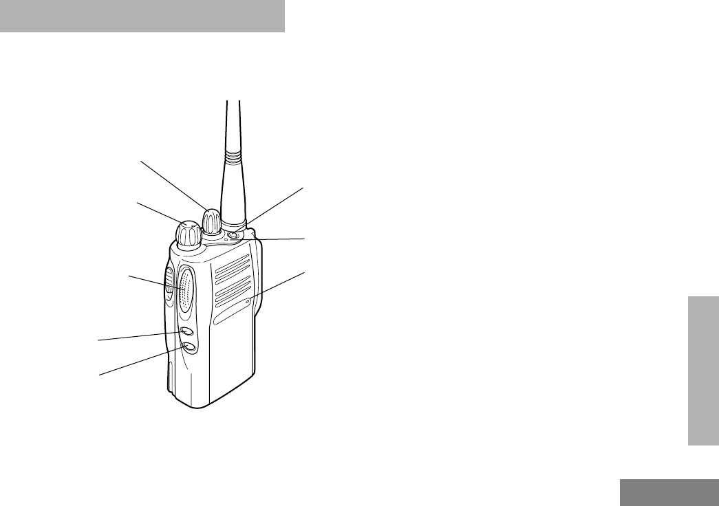
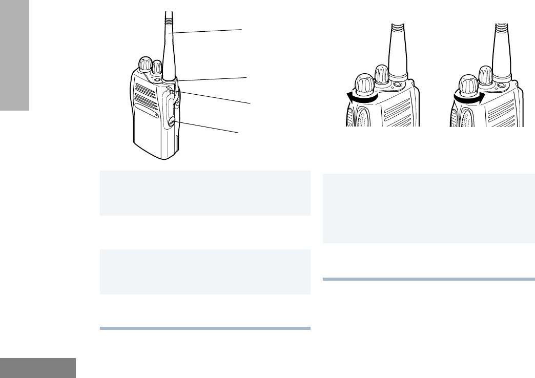
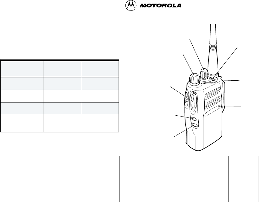
PARTS OF THE RADIO
EX500 Model
On/Off/Volume Knob
Microphone
(programmable)
Side Button 1
Push-to-Talk (PTT)
(programmable)
Side Button 2
(programmable)
Top Button
Button
LED Indicator
Channel Selector
Knob

16
English
RADIO OVERVIEW
On/Off/Volume Knob
Turns the radio on or off, and adjusts the
radioÕs volume.
Channel Selector Knob
Switches the radio to different channels.
Push-to-Talk (PTT) Button
Press and hold down this button to talk,
release it to listen.
Microphone
Speak clearly into the microphone when
sending a message.
LED Indicator
Gives battery status, power-up status, radio
call information and scan status.
Programmable Buttons
Several of the radioÕs buttons can be
programmed as short-cut buttons for many of
the radioÕs features. Programmable buttons
include:
¥ Top button,
¥ two side buttons
Each button can access up to two features,
depending on the type of button press:
¥
short press
- quickly pressing and
releasing the programmable buttons,
or
¥
long press
- pressing and holding the
programmable buttons for at least
1 1/2 seconds, or
¥
hold down
- pressing and holding
down the programmable buttons while
checking status or making adjust-
ments.
The table on page 17 summarizes the
programmable features available.

17
English
RADIO OVERVIEW
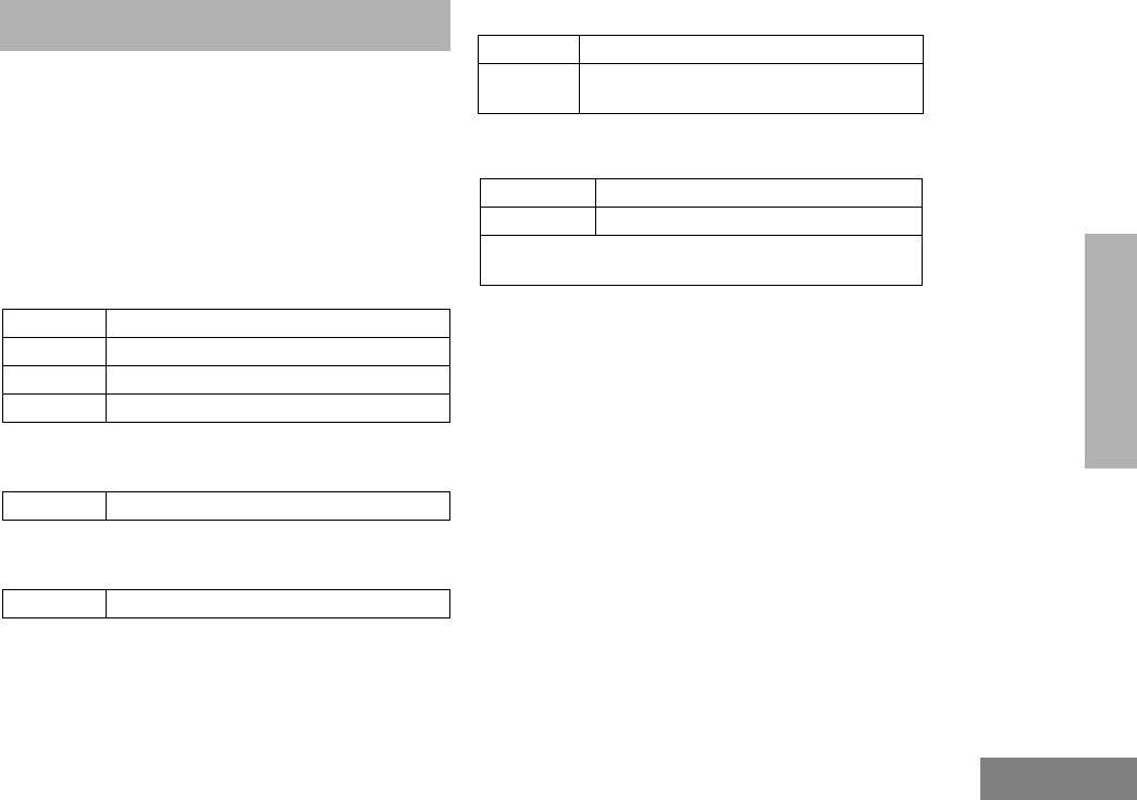
Button Short Press Long Press Press and Hold Page Button
Emergency* Initiates an Emer-
gency Alert.
Cancels your radioÕs
Emergency status.
Ñ 29
Monitor/Perma-
nent Monitor
Ñ Continually monitors the
selected channel.
Monitors the selected
channel for any activity.
33
Volume Set Ñ Ñ Sounds a tone for
adjusting the radioÕs vol-
ume level.
27
Battery Gauge Ñ Ñ Checks the batteryÕs
charge status.
22
Scan/Nuisance
Channel Delete
Toggles Scan on and
off.
Deletes a nuisance
channel while scanning.
Ñ 33
Tx Power Toggles your radioÕs transmit power level
between High and Low power.
Ñ31
Repeater/
Talkaround
Toggle between using a repeater or transmitting
directly to another radio.
Ñ 30
Squelch Toggles your radioÕs squelch level between tight/
normal squelch.
Ñ30
*
If Emergency function is required, it can ONLY be programmed to the Top Button.
Depending on how your radio has been programmed by your dealer, these functions are activated EITHER through
short press OR long press, but not both.
18
English
RADIO OVERVIEW
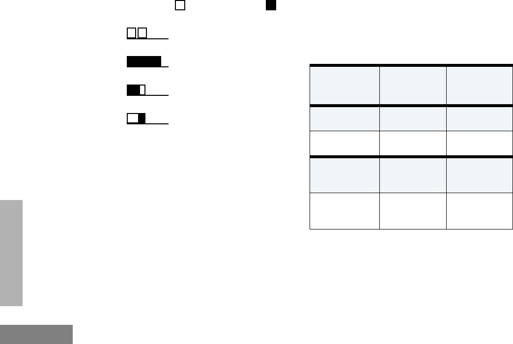
INDICATOR TONES
High pitched tone Low pitched tone
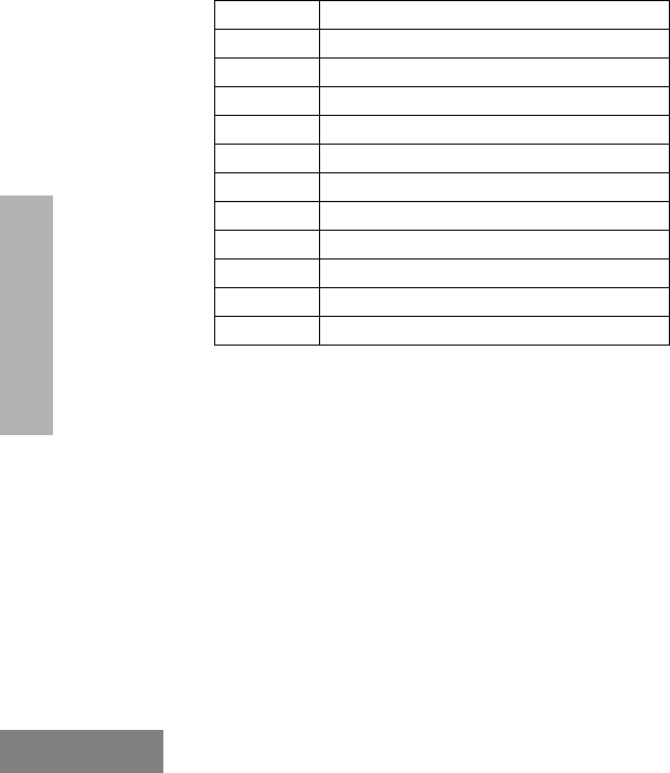
AUDIO INDICATORS FOR
PROGRAMMABLE BUTTONS
Some programmable keys function as toggles
(alternating between two different choices).
These keys use audio indicators to indicate the
change.
Self Test Pass Tone
Self Test Fail Tone
Positive Indicator Tone
Negative Indicator Tone
Programmable
Buttons
Positive
Indicator
Tone
Negative
Indicator
Tone
Scan
Starts
Scan
operation
Stops
Scan
operation
Tx Power Transmits at
low
power
Transmits at
high
power
Squelch Operates in
tight
squelch
Operates in
normal
squelch
Repeater/
Talkaround
DOES NOT
use the
repeater
Uses the
repeater

19
English
RADIO OVERVIEW
IMPROVED AUDIO FEATURES
Low Level Expansion (LLE)
The LLE feature of your radio improves voice
quality by reducing unwanted background
noise when receiving a message. It is
compatible with most major types of audio
processing systems available today.
Companding
Companding is a feature that allows further
improvement of voice quality. It compresses
your voice at transmission, and expands it
when receiving while simultaneously reducing
extraneous noise. However, to enjoy this
beneÞt,
ALL
transmitting and receiving radios
must have this feature activated.
NOTE:
Contact your dealer for your radioÕs
current companding settings or to
change the settings.

20
English
RADIO OVERVIEW
NOTES

21
English
GETTING STARTED
]
BATTERY INFORMATION
Battery Care and Tips
This product is powered by a rechargeable
battery.
The following battery tips will help you obtain
the highest performance and longest cycle life
from your Motorola rechargeable battery.
¥ Batteries are shipped uncharged from
the factory. Always charge a new
battery 14 - 16 hours before initial use,
regardless of the status indicated by
the charger.
¥ Charging in non-Motorola equipment
may lead to battery damage and void
the battery warranty.
¥ When charging a battery that is
attached to the radio, turn the radio off
to ensure a full charge.
¥ The battery should be at about 77¡F
(25¡C) (room temperature) whenever
possible. Charging a cold battery,
(below 50¡F [10¡C]) may result in
leakage of electrolyte and ultimately, in
failure of the battery.
¥ Charging a hot battery (above 95¡F
[35¡C]) results in reduced discharge
capacity, affecting the performance of
the radio. Motorola rapid-rate battery
chargers contain a temperature-
sensing circuit to ensure that the
battery is charged within these
temperature limits.
¥ New batteries can be stored up to two
years without signiÞcant cycle loss.
Store new/unused batteries in a cool
dry area.
¥ Batteries which have been in storage
should be charged overnight.
¥ Do not return fully charged batteries to
the charger for an Òextra boostÓ. This
action will
significantly
reduce cycle
life.
¥ Do not leave your radio and battery in
the charger when not charging.
Continuous charging will shorten
battery life. (Do not use your charger
GETTING STARTED
22
English
GETTING STARTED
as a radio stand.)
¥ For optimum battery life and operation
use only Motorola brand chargers.
They were designed to operate as an
integrated energy system.
Charging your Battery
When the battery level is very low, you need to
recharge the battery before you can continue
to use your radio.
1. Place the radio with the battery
attached or the battery alone in the
charger.
2. The chargerÕs LED would indicate the
charging progress.
NOTE:
Because new batteries or batteries
that have not been used for several
months could prematurely indicate full
charge (solid green LED), charge the
batteries for 14 to 16 hours prior to ini-
tial use to achieve optimal perfor-
mance.
Battery Status
You can check battery charge status by holding
down the preprogrammed
Battery Gauge
button (see page 17). The charge status is
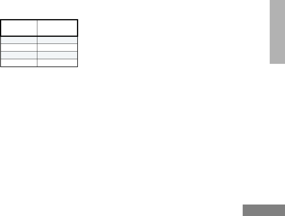
LED color Status
Single ßash of
Green
Successful charger power-
up.
Flashing Red
*
Battery is unchargeable.
Flashing Yellow Charger is getting ready to
charge.
Red Battery is charging.
Flashing Green
Battery is 90% charged.
Green Battery is fully charged.
*
Remove the battery from charger and use a pen-
cil eraser to clean the four metal contacts on the
bottom of the battery. Place the battery back into
the charger. If the LED indicator continues to ßash
red, replace the battery.
A standard battery may require one hour to
charge to 90% capacity.
24
English
GETTING STARTED
ACCESSORY INFORMATION
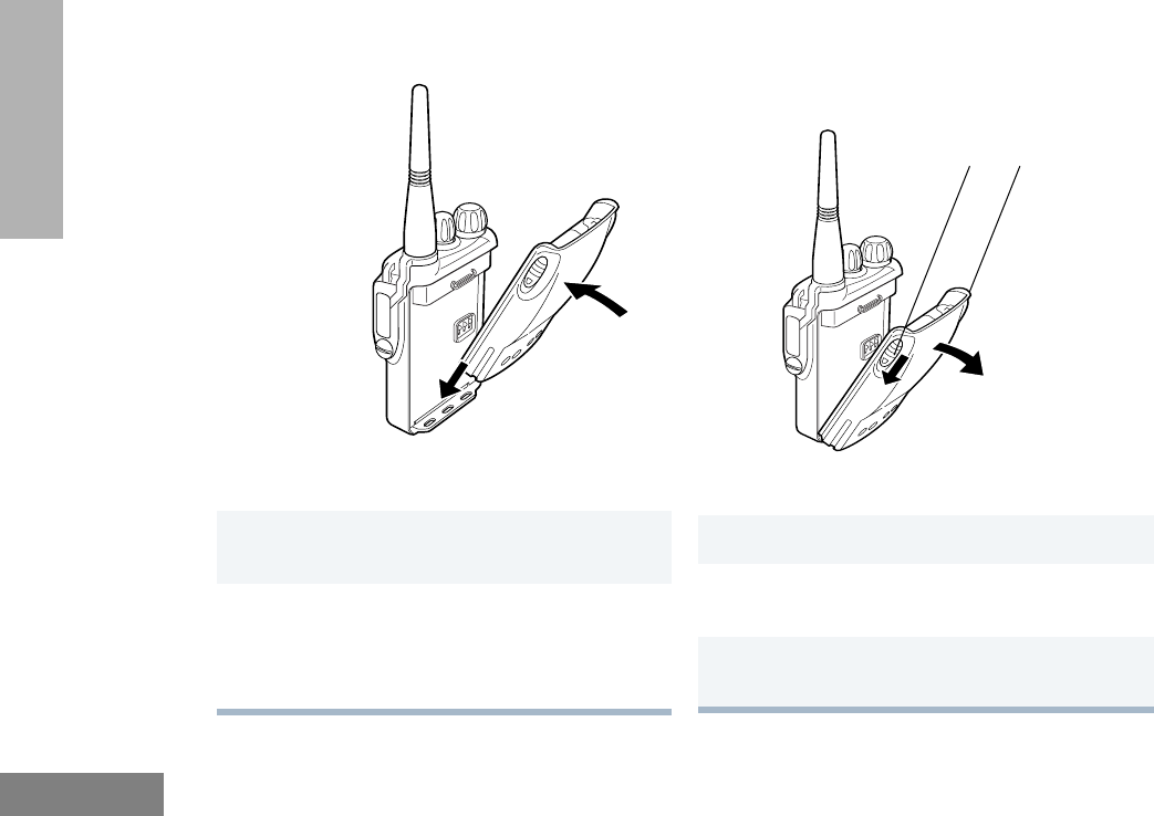
Attaching the Battery Removing the Battery
1
Fit the extensions at the bottom of the battery
into the slots at the bottom of the radio.
2
Press the top part of the battery towards the
radio until a click is heard.
Note:
It is important to make sure that both
battery latches are secured.
1
Turn off the radio, if it is turned on.
2Slide the battery latches, on both sides of the
battery, downwards.
3Pull the top part of the battery away from the
radio.
Battery
Latches
25
English
GETTING STARTED
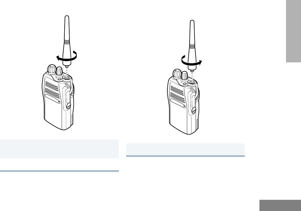
Attaching the Antenna Removing the Antenna
1Align the threaded end of the antenna with the
radioÕs antenna connector.
2Turn the antenna clockwise to attach it.
Turn the antenna counterclockwise to remove it.
26
English
GETTING STARTED
Attaching the Side Connector Cover TURNING THE RADIO ON OR OFF
1Place the loop (attached to the side connector
cover) over the antenna; then slide it down-
ward until it touches the top of the radio.
2Insert the tab on the top of the cover into the
slot above the connector.
3Position the cover over the connector and
align the thumbscrew with the threaded hole
in the radio.
4Tighten the thumbscrew to hold the cover in
place. Do not overtighten the thumbscrew.
Thumbscrew
Loop
Antenna
Slot
1Turn the On/Off/Volume (see page 15) knob
clockwise to turn on the radio. You will hear
the Self Test Pass Tone and see a green LED
if the radio powers up successfully. If the
radio fails to power up, you will hear the Self
Test Fail Tone.
2Turn the On/Off/Volume knob (see page 15)
counter-clockwise, until a click is heard, to
turn off the radio.
ON OFF

27
English
GETTING STARTED
ADJUSTING THE RADIO’S VOLUME
SELECTING A RADIO CHANNEL
Your radio offers sixteen (16) channels for easy
access to required conventional channels.
Some channels on your radio may not be
programmed. Check with your dealer for more
information.
To select a channel:
SENDING A CALL
RECEIVING A CALL
1Press and hold the
Volume Set button (see
page 17); you will hear a continuous tone.
2Turn the On/Off/Volume knob (see page 16)
and adjust the volume level.
3Release the Volume Set button (see
page 17).
Turn the Channel Selector knob (see page 15)
clockwise or counter-clockwise until you reach the
desired channel.
1Turn your radio on.
2Use the Channel Selector knob (see
page 15) to select to the desired channel.
3Press the PTT button (see page 15), and
speak clearly with your mouth about 2.5 to 5
cm (one to two inches) away from the micro-
phone.
4Release the PTT button (see page 15) when
you Þnish speaking.
1Turn your radio on.
2Adjust the radioÕs volume.
3Switch to the desired channel.
4If at any time a call comes through, you will
hear the call at the volume level you have
set.

28
English
GETTING STARTED
NOTES

29
English
RADIO CALL
INFORMATION
RADIO CALL INFORMATION
RECEIVING A SELECTIVE CALL
Selective Call allows a radio user to
communicate with a single unit without
involving other units in conversation.
When you receive a selective call:
¥ You will hear two alert tones.
¥ The LED Indicator will light yellow.
To answer the call, press the PTT button.
RECEIVING A CALL ALERT™ PAGE
When your radio receives a Call Alert page, it
sounds four alert tones continuously until you
respond.
Press the PTT button to answer the Call Alert
page, or press any other key to cancel it.
Note: Your radio will not receive any Selective
Calls until you clear the page.
EMERGENCY ALARMS
If programmed by your dealer, the orange Top
button can send one of the following
emergency alarms described below:
¥ MDC Emergency Alarm (only if the
signaling system you are on is MDC),
and
¥ Emergency Siren
Note: The MDC Emergency Alarm feature
gives you a one-button quick access to
call a particular radio or center (pre-
deÞned by your dealer) in emergency
situations. When activated, the radio
goes into an Emergency state, which
can be programmed to
¥ continually give visual and audio
feedback,
¥ give no audio feedback, but with
visual feedback, or
¥ give no audio/visual feedback, but
the radio can receive and transmit.

30
English
RADIO CALL
INFORMATION
The Emergency Siren will cause the radio
to sound a repetitive tone at the maximum
volume.
TALKAROUND
In your communications network, you may be
using a repeater to cover a larger area than
what is possible with your radio. However, you
can communicate with another radio within
your radioÕs range without going through the
repeater by using the
Talkaround
feature. This
is especially useful when the repeater is down
SQUELCH
If a particular channel receives many
unwanted calls coming from radios that do not
belong to your communications group and are
some distance away, or the Òbackground noiseÓ
is excessive, you can try to Þlter these
transmissions out by tightening the channelÕs
squelch. However, tightening squelch could
cause calls from members of your
communications group that are farther away to
be Þltered out as well.
1Press and release the Emergency button
(see page 17) to initiate an Emergency
Alarm.
2Press and hold the Emergency button (see
page 17) to cancel the Emergency Alarm.
3Press and release the Emergency button
(see page 17) to restart the Emergency
sequence.
Press the programmed Repeater/Talkaround
button to toggle between the options of making or
not making a call through the repeater. A positive
indicator tone indicates that the radio is in
talkaround mode, while a negative indicator tone
indicates that the radio is in repeater mode.

31
English
RADIO CALL
INFORMATION
To set the squelch level:
POWER LEVEL
You can transmit your calls at different transmit
power levels. A higher level means you can
reach a radio that is farther away. Lower power
level conserves battery power. You are advised
to transmit as frequently as possible on low
power, and use high power only when needed.
Press the programmed Squelch button to toggle
between the options of having normal squelch or
tightening the squelch of your radio. A positive
indicator tone indicates that the radio is operating
in tight squelch, while a negative indicator tone
indicates that the radio is operating in normal
squelch.
Press the programmed Tx Power button to toggle
between the options for High or Low power trans-
mit level. A positive indicator tone indicates that
the radio is operating in low power mode, while a
negative indicator tone indicates that the radio is
operating in high power mode.

32
English
RADIO CALL
INFORMATION
NOTES

33
English
SCAN
SCAN
You can monitor several channels in order to
receive any call that is transmitted on any of
these channels. Sixteen different channels can
be programmed into a scan list. Each channel
can share the same scan list or have different
scan lists assigned to them.
Once the radioÕs scan operation is activated
and the radio detects a call coming through a
channel in its scan list, it switches to that
channel for you to receive the call.
STARTING OR STOPPING A SCAN
OPERATION
The LED Indicator will blink (green) during a
scan operation. It will stop blinking when the
radio switches to a channel.
TALKBACK
If the programmable Talkback option is set, you
can respond to any calls received during the
scan operation by pressing the PTT button
before the programmed hang-time ends.
Check with your dealer for details.
DELETING A NUISANCE CHANNEL
If a channel continually generates unwanted
calls/noise, you can temporarily remove it from
the scan list by performing a
Nuisance
Channel Delete
operation.
Note: You cannot perform a
Nuisance Chan-
nel Delete
on a priority channel or if
there is only one remaining channel in
the scan list.
1Press the Scan button (see page 17) to start
a scan operation.
2Press the Scan button again to stop the scan
operation.
1While the radio is on the Nuisance Channel,
press and hold the Scan button (see page
17) until you hear a tone.
2Release the Scan button.

34
English
SCAN
ADDING A DELETED NUISANCE
CHANNEL BACK TO THE SCAN
LIST
SCAN CHANNEL DISCOVERY
ALERT
Sometimes you need to know which channel
the radio has switched to during a scan
operation. The Scan Channel Discovery Alert
gives you this information.
After you have stopped a scan operation, this
feature gives you audio feedback when you
select the last channel that was switched to by
the scan operation.
To do this:
SCAN LIST MEMBER PRIORITY
A channel in your scan list may be prioritized
(check with your dealer for details). In such a
case, the radio will check that prioritized
channel more frequently than the other non-
prioritized channels.
Assuming a scan list with 6 channels, if all your
channels are non-prioritized, the normal scan
operation would check for activity in the
following sequence:
1Press the Scan button (see page 17) to stop
the scan operation.
2Press the Scan button again to re-start the
scan operation.
1Stop the scan operation.
2Turn the Channel Selector knob (see page
15) to change the channels.
3When you reach the last channel the scan
operation switched to, the radio sounds an
alert tone.
C
h
.
1
C
h
.
3
C
h
.
4
C
h
.
5
C
h
.
2
C
h
.
6

35
English
SCAN
If Channel 2 is prioritized, the scan operation
would change to
Note: Even though your radio has switched
to a non-priority channel, your radio
will still check for activity on the priority
channel. If some activity is detected
there, the radio will switch to that prior-
ity channel.
C
h
.
2
C
h
.
4
C
h
.
2
C
h
.
2
C
h
.
2
C
h
.
5
C
h
.
1
C
h
.
6
C
h
.
3
C
h
.
2

36
English
SCAN
NOTES

37
English
WARRANTY
WARRANTY
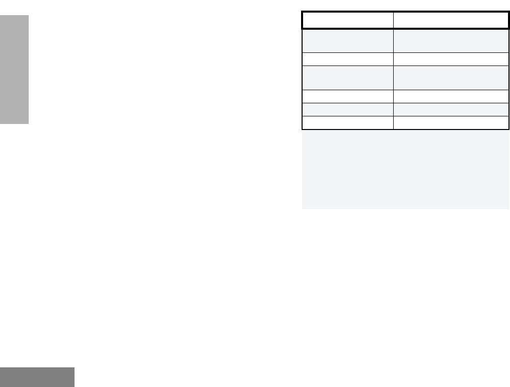
LIMITED WARRANTY
MOTOROLA COMMUNICATION
PRODUCTS
I. WHAT THIS WARRANTY COVERS AND
FOR HOW LONG:
MOTOROLA INC. (ÒMOTOROLAÓ) warrants the
MOTOROLA manufactured Communication
Products listed below (ÒProductÓ) against defects
in material and workmanship under normal use
and service for a period of time from the date of
purchase as scheduled below:
EX500 Units Two (2) Years
Product Accessories One (1) Year
Motorola, at its option, will at no charge either
repair the Product (with new or reconditioned
parts), replace it (with a new or reconditioned
Product), or refund the purchase price of the
Product during the warranty period provided it is
returned in accordance with the terms of this
warranty. Replaced parts or boards are warranted
for the balance of the original applicable warranty
period. All replaced parts of Product shall become
the property of MOTOROLA.
This express limited warranty is extended by
MOTOROLA to the original end user purchaser
only and is not assignable or transferable to any
other party. This is the complete warranty for the
Product manufactured by MOTOROLA.
MOTOROLA assumes no obligations or liability
for additions or modiÞcations to this warranty
unless made in writing and signed by an ofÞcer
of MOTOROLA. Unless made in a separate
agreement between MOTOROLA and the
original end user purchaser, MOTOROLA does
not warrant the installation, maintenance or
service of the Product.
MOTOROLA cannot be responsible in any way
for any ancillary equipment not furnished by
MOTOROLA which is attached to or used in
connection with the Product, or for operation of
the Product with any ancillary equipment, and all
such equipment is expressly excluded from this
warranty. Because each system which may use
the Product is unique, MOTOROLA disclaims
liability for range, coverage, or operation of the
system as a whole under this warranty.

38
English
WARRANTY
II. GENERAL PROVISIONS:
This warranty sets forth the full extent of
MOTOROLA'S responsibilities regarding the
Product. Repair, replacement or refund of the
purchase price, at MOTOROLAÕs option, is the
exclusive remedy. THIS WARRANTY IS GIVEN
IN LIEU OF ALL OTHER EXPRESS
WARRANTIES. IMPLIED WARRANTIES,
INCLUDING WITHOUT LIMITATION, IMPLIED
WARRANTIES OF MERCHANTABILITY AND
FITNESS FOR A PARTICULAR PURPOSE, ARE
LIMITED TO THE DURATION OF THIS LIMITED
WARRANTY. IN NO EVENT SHALL MOTOROLA
BE LIABLE FOR DAMAGES IN EXCESS OF
THE PURCHASE PRICE OF THE PRODUCT,
FOR ANY LOSS OF USE, LOSS OF TIME,
INCONVENIENCE, COMMERCIAL LOSS, LOST
PROFITS OR SAVINGS OR OTHER
INCIDENTAL, SPECIAL OR CONSEQUENTIAL
DAMAGES ARISING OUT OF THE USE OR
INABILITY TO USE SUCH PRODUCT, TO THE
FULL EXTENT SUCH MAY BE DISCLAIMED BY
LAW.
III. STATE LAW RIGHTS:
SOME STATES DO NOT ALLOW THE
EXCLUSION OR LIMITATION OF INCIDENTAL
OR CONSEQUENTIAL DAMAGES OR
LIMITATION ON HOW LONG AN IMPLIED
WARRANTY LASTS, SO THE ABOVE
LIMITATION OR EXCLUSIONS MAY NOT
APPLY.
This warranty gives speciÞc legal rights, and there
may be other rights which may vary from state to
state.
IV. HOW TO GET WARRANTY SERVICE:
You must provide proof of purchase (bearing the
date of purchase and Product item serial
number) in order to receive warranty service and,
also, deliver or send the Product item,
transportation and insurance prepaid, to an
authorized warranty service location. Warranty
service will be provided by Motorola through one
of its authorized warranty service locations. If you
Þrst contact the company which sold you the
Product (e.g., dealer or communication service
provider), it can facilitate your obtaining warranty
service. You can also call Motorola at 1-800-927-
2744 US/Canada.

39
English
WARRANTY
V. WHAT THIS WARRANTY DOES NOT
COVER:
A) Defects or damage resulting from use of the
Product in other than its normal and
customary manner.
B) Defects or damage from misuse, accident,
water, or neglect.
C) Defects or damage from improper testing,
operation, maintenance, installation,
alteration, modiÞcation, or adjustment.
D) Breakage or damage to antennas unless
caused directly by defects in material
workmanship.
E) A Product subjected to unauthorized
Product modiÞcations, disassemblies or
repairs (including, without limitation, the
addition to the Product of non-Motorola
supplied equipment) which adversely affect
performance of the Product or interfere with
Motorola's normal warranty inspection and
testing of the Product to verify any warranty
claim.
F) Product which has had the serial number
removed or made illegible.
G) Rechargeable batteries if:
1) any of the seals on the battery
enclosure of cells are broken or show
evidence of tampering.
2) the damage or defect is caused by
charging or using the battery in
equipment or service other than the
Product for which it is speciÞed.
H) Freight costs to the repair depot.
I) A Product which, due to illegal or
unauthorized alteration of the software/
Þrmware in the Product, does not function in
accordance with MOTOROLAÕs published
speciÞcations or the FCC type acceptance
labeling in effect for the Product at the time
the Product was initially distributed from
MOTOROLA.
J) Scratches or other cosmetic damage to
Product surfaces that does not affect the
operation of the Product.
K) Normal and customary wear and tear.
VI. PATENT AND SOFTWARE PROVISIONS:
MOTOROLA will defend, at its own expense, any
suit brought against the end user purchaser to
the extent that it is based on a claim that the
Product or parts infringe a United States patent,
and MOTOROLA will pay those costs and
damages Þnally awarded against the end user
purchaser in any such suit which are attributable
to any such claim, but such defense and
payments are conditioned on the following:

40
English
WARRANTY
A) that MOTOROLA will be notiÞed promptly in
writing by such purchaser of any notice of
such claim;
B) that MOTOROLA will have sole control of the
defense of such suit and all negotiations for
its settlement or compromise; and
C) should the Product or parts become, or in
MOTOROLAÕs opinion be likely to become,
the subject of a claim of infringement of a
United States patent, that such purchaser
will permit MOTOROLA, at its option and
expense, either to procure for such
purchaser the right to continue using the
Product or parts or to replace or modify the
same so that it becomes non-infringing or to
grant such purchaser a credit for the Product
or parts as depreciated and accept its
return. The depreciation will be an equal
amount per year over the lifetime of the
Product or parts as established by
MOTOROLA.
MOTOROLA will have no liability with respect to
any claim of patent infringement which is based
upon the combination of the Product or parts
furnished hereunder with software, apparatus or
devices not furnished by MOTOROLA, nor will
MOTOROLA have any liability for the use of
ancillary equipment or software not furnished by
MOTOROLA which is attached to or used in
connection with the Product. The foregoing
states the entire liability of MOTOROLA with
respect to infringement of patents by the Product
or any parts thereof.
Laws in the United States and other countries
preserve for MOTOROLA certain exclusive rights
for copyrighted MOTOROLA software such as
the exclusive rights to reproduce in copies and
distribute copies of such Motorola software.
MOTOROLA software may be used in only the
Product in which the software was originally
embodied and such software in such Product
may not be replaced, copied, distributed,
modiÞed in any way, or used to produce any
derivative thereof. No other use including, without
limitation, alteration, modiÞcation, reproduction,
distribution, or reverse engineering of such
MOTOROLA software or exercise of rights in
such MOTOROLA software is permitted. No
license is granted by implication, estoppel or
otherwise under MOTOROLA patent rights or
copyrights.
VII. GOVERNING LAW:
This Warranty is governed by the laws of the
State of Illinois, USA.
41
English
ACCESSORIES
ACCESSORIES
Motorola offers a number of accessories to
enhance the productivity of your two-way radio.
Many of the available accessories are listed
below. Your authorized Motorola dealer will
also have a complete list of accessories.
Additional Accessories will be available for this
product in the near future.
CARRY CASES
REMOTE SPEAKER MICROPHONES
EARPIECES
BATTERIES
CHARGERS
HLN9985 Waterproof Bag
JMZN4020 Radio Handstrap
JMZN4023 Plastic Carry Holder with Swivel Belt Clip
PMLN4421 Soft Leather Case with Fixed Swivel Clip
JMMN4073 Remote Speaker Microphone
JMMN4062 2 Wire Surveillance Earpiece
JMNN4023 1000 mAH Li-Ion High Capacity Battery
JMNN4024 1320 mAH Li-Ion Ultra High Capacity
Battery
AAHTN3000 120V Single-Unit Rapid Charger, US Plug
AAHTN3003 120V Multi-Unit Rapid Charger, US Plug
Note: You must use the ÒCÓ version multi-charger or
newer to be compatible with the EX500.
42
English
ACCESSORIES
ANTENNAS
PMAD4012 VHF 136-155 MHz 9cm, Stubby
PMAD4013 VHF 155-174 MHz 9cm, Stubby
PMAD4014 VHF 136-155 MHz 14cm, Standard
PMAD4015 VHF 155-174 MHz 14cm, Standard
PMAD4023 VHF 150-161 MHz, 14cm
PMAD4025 VHF 150-161 MHz, 9cm
PMAE4002 403-433 MHz Stubby Antenna
PMAE4003 433-470 MHz Stubby Antenna
NAE6483 403-512 MHz Whip Antenna
PMAE4006 UHF 470-510 MHz, 9cm, Helical
PMAE4007 UHF 490-512 MHz, 9cm
PMAE4008 UHF 470-512 MHz, Whip
EX500 Quick Reference Card
Adding a Deleted Nuisance Channel back to
the Scan List
1. Press the preprogrammed Scan button to stop the scan
operation.
2. Press the preprogrammed Scan button again to re-start the
scan operation.
Programmable Buttons’ Audio Indicators
Programmable
Buttons Positive
Indicator Tone Negative
Indicator Tone
Scan Starts Scan
operation
Stops Scan
operation
Tx Power Transmits at low
power
Transmits at high
power
Squelch Operates in tight
squelch
Operates in
normal squelch
Repeater/
Talkaround
Radio DOES
NOT use the
repeater
Radio uses the
repeater
LED Indicator
Channel Selector Knob
On/Off/Volume Knob
Top Button
(programmable)
Microphone
Push-to-Talk
(PTT) Button
Side Button 1
(programmable)
Side Button 2
(programmable)
Button Function Short Press Long Press Hold Down Page
Receiving a Call
1. Turn radio on.
2. Adjust volume level.
3. Switch to desired channel.
4. If at any time a call comes through, it will be heard at the
volume level set.
Emergency Alarm
1. Press programmed Emergency button to initiate
Emer-
gency Alarm/Siren
.
2. Press and hold Emergency button to cancel
Emergency
Alarm/Siren
.
3. Press and release Emergency button to restart Emergency
sequence.
Starting or Stopping a Scan Operation
The LED Indicator will blink (green) during a scan operation. It
will stop blinking when the radio switches to a channel.
1. Press the preprogrammed Scan button to start a scan oper-
ation.
2. Press the preprogrammed Scan button again to stop the
scan operation.
Deleting a Nuisance Channel
1. While radio is on a Nuisance Channel, press and hold the
preprogrammed Scan button until a tone is sounded.
2. Release the preprogrammed Scan button.
Turning On the Radio
¥ Turn On/Off/Volume knob clockwise. Self Test Pass Tone
will sound and green LED will light up if radio powers up
successfully. If radio fails power up, the Self Test Fail Tone
will sound.
Turning Off the Radio
¥ Turn On/Off/Volume knob counter-clockwise, until click is
heard.
Adjusting the Radio’s Volume
1. Press and hold Volume Set button until continuous tone is
sounded.
2. Turn On/Off/Volume knob to adjust volume level.
3. Release Volume Set button when desired level is achieved.
Selecting a Radio Channel
¥ Turn Channel Selector knob clockwise or counter-clock-
wise to reach desired channel.
Sending a Call
1. Turn on radio.
2. Use Channel Selector knob to select the desired channel.
3. Press PTT button, and speak clearly with mouth about 2.5
to 5 cm (one to two inches) away from microphone.
4. Release PTT button when call is completed.