Motorola Solutions 89FT4881 PORTABLE 2-WAY RADIO User Manual XTS4000
Motorola Solutions, Inc. PORTABLE 2-WAY RADIO XTS4000
Contents
- 1. USERS MANUAL
- 2. SAFETY MANUAL
USERS MANUAL
ASTRO® XTS™ 4000
Digital Portable Radio,
Quick Reference Card
Product Safety and RF Exposure Compliance
ATTENTION!
This radio is restricted to occupational use only to satisfy FCC RF
energy exposure requirements. Before using this product, read the
RF energy awareness information and operating instructions in the
Product Safety and RF Exposure booklet enclosed with your radio
(Motorola Publication part number 68P81095C98) to ensure
compliance with RF energy exposure limits.
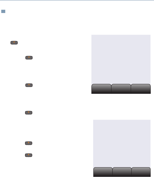
Radio On/Off
Zones/Channels
Receive/Transmit
Send Emergency Alarm
Send Emergency Call
Send Silent Emergency Alarm
Before using this product, read the operating instructions
for safe usage contained in the Product Safety and RF
Exposure booklet enclosed with your radio.
!
C
a u t i o
n
DEL
a/A/1
. , ?
Internal Audio
Speaker
Power Button
Internal
Display
Data Button
Menu Select
Buttons
Keypad
Programmable
Button
Home
Button
Keypad
External
Audio
Speaker
Microphone
1On - Power On/Off button
2Off - Power On/Off button
1 Zone - Menu entry to select desired zone.
2 Channel - Menu entry to select desired
channel.
1 Radio on and select zone/channel.
2 Listen for a transmission.
- or, if preprogrammed -
Press Monitor button and listen for activity.
3 Adjust volume, if necessary.
4Press PTT to transmit; release to receive.
Radio on and press Emergency button.
Display shows current zone/channel, and
Emergency. You hear short, medium-pitched
tone.
Note: To exit emergency at any time, press
and hold Emergency button.
When acknowledgment is received, you hear
four beeps; alarm ends; radio exits
emergency.
1 Radio on and press Emergency button.
Note: To exit emergency at any time, press
and hold Emergency button.
2 Press and hold PTT. Announce your
emergency into the microphone.
3 Release PTT to end call.
4 Press and hold Emergency button to exit
emergency.
1 Radio on and press Emergency button.
Display does not change and you hear no
tone.
Note: To exit emergency at any time, press
and hold Emergency button.
2 Silent emergency continues until you:
• Press and hold Emergency button to exit
emergency state.
- or -
• Press and release PTT to exit silent
emergency and enter regular emergency
(alarm, call, or alarm with call).
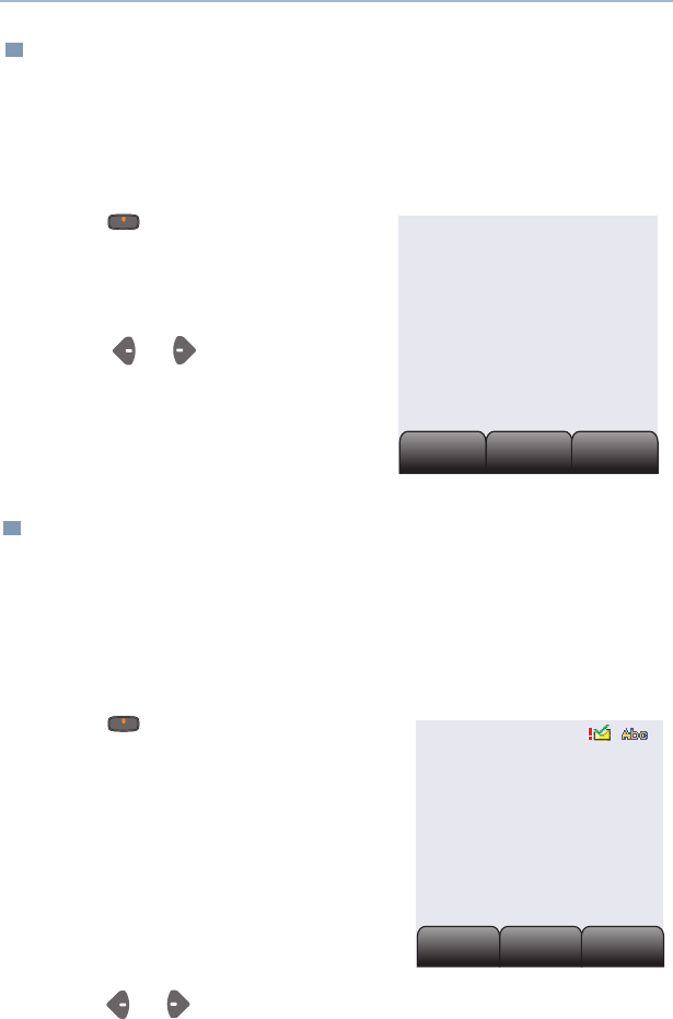
Display Status Symbols
Menu Entries (Use With Menu Navigation)
Receiving an individual call.
Received signal strength for the
current site (trunking only). The more
bars in the symbol, the stronger the
signal.
Displays the level of charge in the
battery at external display. It blinks
when the battery is low.
Displays the level of charge in the
battery at internal display. It blinks
when the battery is low.
You are talking directly to another radio
or through a repeater;
Displayed = direct;
Not Displayed = repeater.
This channel is being monitored (could
make reference to Carrier Squelch).
The radio is muted to normal dispatch
calls (could make reference to PL, DPL
or signaling Squelch).
Your radio is in secure operation;
Displayed = secure operation;
Not Displayed = clear operation;
Blinking = receiving an encrypted
voice call
The radio is scanning a scan list.
Blinking = Priority 1 Channel during
scan; Steady = Priority 2 Channel
during scan.
Audio is routed to the radio’s external
speaker;
Audio is routed to the radio’s internal
speaker.
Indicates the type of ring style selected
for incoming calls and pages.
Steady = Radio is transmiting in AES.
Blinking = Radio is receiving in AES.
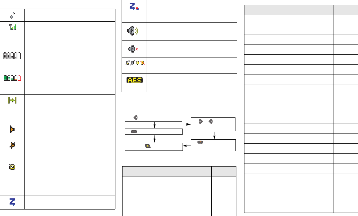
Entry Menu Selection Page
Call Private Call/Selective Call 43/46
Chan Select a Channel 20
Dir Repeater/Direct 53
Eras Key Zeroization/Erase 58
Menu Navigation
to find Menu Entry
directly below Menu
to exit
or to scroll
through sub-list
directly below
Menu Entry to select
Entry Menu Selection Page
Key Key Selection 56
Kset Keyset Selection 57
Logf Radio Lock 24
Name Text Select 34
Num Number Select 33
Page Call Alert Page 48
Phon Phone 40
Prog Editing 33
Pswd Password 23
Pwr TX Power Level 22
Reky Rekey Request 59
Rpgm Reprogram Request 61
Scan Scan On/Off 37
Site Site Lock/Unlock 65
Spkr Loudspeaker 26
Sts Status Call 51
Styl Ring Style 25
Tgrp Talkgroup Call 50
View View a List 32
Zone Select a Zone 20
m
ASTRO® XTS™ 4000
Digital Portable Radio
User Guide
6871618L01-C

This declaration is applicable to your radio only if your radio is labeled
with the FCC logo shown below.
DECLARATION OF CONFORMITY
Per FCC CFR 47 Part 2 Section 2.1077(a)
Responsible Party
Name: Motorola, Inc.
Address: 8000 West Sunrise Boulevard
Plantation, FL 33322 USA
Phone Number: 1-800-927-2744
Hereby declares that the product:
Model Name: XTS 4000
conforms to the following regulations:
FCC Part 15, subpart B, section 15.107(a), 15.107(d) and section 15.109(a)
Class B Digital Device
As a personal computer peripheral, this device complies with Part 15 of the FCC
Rules. Operation is subject to the following two conditions:
1. this device may not cause harmful interference, and
2. this device must accept any interference received, including interference that
may cause undesired operation.
Note: This equipment has been tested and found to comply with the limits for a
Class B digital device, pursuant to part 15 of the FCC Rules. These limits are
designed to provide reasonable protection against harmful interference in a
residential installation. This equipment generates, uses and can radiate radio
frequency energy and, if not installed and used in accordance with the
instructions, may cause harmful interference to radio communications.
However, there is no guarantee that interference will not occur in a particular
installation.
If this equipment does cause harmful interference to radio or television reception,
which can be determined by turning the equipment off and on, the user is
encouraged to try to correct the interference by one or more of the following
measures:
• Reorient or relocate the receiving antenna.
• Increase the separation between the equipment and receiver.
• Connect the equipment into an outlet on a circuit different from that to which
the receiver is connected.
• Consult the dealer or an experienced radio/TV technician for help.

Product Safety and RF Exposure Compliance
ATTENTION!
This radio is restricted to occupational use only to satisfy FCC RF energy
exposure requirements. Before using this product, read the RF energy
awareness information and operating instructions in the Product Safety and RF
Exposure booklet enclosed with your radio (Motorola Publication part number
6881095C98) to ensure compliance with RF energy exposure limits.
Computer Software Copyrights
The Motorola products described in this manual may include copyrighted Motorola
computer programs stored in semiconductor memories or other media. Laws in the
United States and other countries preserve for Motorola certain exclusive rights for
copyrighted computer programs, including, but not limited to, the exclusive right to copy
or reproduce in any form the copyrighted computer program. Accordingly, any
copyrighted Motorola computer programs contained in the Motorola products described
in this manual may not be copied, reproduced, modified, reverse-engineered, or
distributed in any manner without the express written permission of Motorola.
Furthermore, the purchase of Motorola products shall not be deemed to grant either
directly or by implication, estoppel, or otherwise, any license under the copyrights,
patents or patent applications of Motorola, except for the normal non-exclusive license
to use that arises by operation of law in the sale of a product.
Documentation Copyrights
No duplication or distribution of this document or any portion thereof shall take place
without the express written permission of Motorola. No part of this manual may be
reproduced, distributed, or transmitted in any form or by any means, electronic or
mechanical, for any purpose without the express written permission of Motorola.
Disclaimer
The information in this document is carefully examined, and is believed to be entirely
reliable. However, no responsibility is assumed for inaccuracies. Furthermore, Motorola
reserves the right to make changes to any products herein to improve readability,
function, or design. Motorola does not assume any liability arising out of the
applications or use of any product or circuit described herein; nor does it cover any
license under its patent rights, nor the rights of others.
MOTOROLA, the Stylized M Logo and ASTRO are registered in the U.S. Patent &
Trademark Office. All other product or service names are the property of their
respective owners.
P25 radios contain technology patented by Digital Voice Systems, Inc.
© Motorola, Inc. 2008. All Rights Reserved. Printed in the U.S.A. 1/08.
Before using this product, read the operating instructions for safe
usage contained in the Product Safety and RF Exposure booklet
enclosed with your radio.
!
C
a u t i o
n

ASTRO XTS 4000 i
Table of Contents
General Radio Operation . . . . . . . . . . . . . . . . . . . . . . . 1
Notations Used in This Manual ......................................................... 1
Your XTS 4000 Radio ....................................................................... 2
Physical Features of the XTS 4000 Radio ........................................ 3
Programmable Controls .................................................................... 3
Display .............................................................................................. 4
Keypad ............................................................................................ 10
Alert Tones ...................................................................................... 12
Standard Accessories ..................................................................... 15
Radio On and Off ............................................................................ 18
Set the Volume ................................................................................ 19
Zones and Channels ....................................................................... 20
Receive / Transmit .......................................................................... 21
Common Radio Features . . . . . . . . . . . . . . . . . . . . . . 22
Transmit Power Level ..................................................................... 22
Radio Lock ...................................................................................... 23
Ring Style ........................................................................................ 25
Loudspeaker ................................................................................... 26
Conventional Squelch Operation .................................................... 27
Time-out Timer ................................................................................ 28
Emergency ...................................................................................... 29
Lists ................................................................................................. 32
Scan ................................................................................................ 37
Telephone Calls (Trunking Only) ..................................................... 39
Private Calls (Trunking Only) .......................................................... 42
Selective Calls (ASTRO Conventional Only) .................................. 45
Call Alert Paging ............................................................................. 47
Conventional Talkgroup Calls (Conventional Operation Only) ........ 50
Status Calls (ASTRO 25 Trunking Only) ......................................... 51
Repeater or Direct Operation .......................................................... 53
Smart PTT (Conventional Only) ...................................................... 54
Special Radio Features. . . . . . . . . . . . . . . . . . . . . . . . 55
Secure Operations .......................................................................... 55
Digital PTT ID .................................................................................. 60
Dynamic Regrouping (Trunking Only) ............................................. 61
Trunking System Controls ............................................................... 64
ARS User Login and Text Messaging Features . . . . 67

ii
Automatic Registration Service (ARS) .............................................67
ARS User Login Feature .................................................................69
Text Messaging ................................................................................74
Helpful Tips . . . . . . . . . . . . . . . . . . . . . . . . . . . . . . . . . 87
Radio Care ......................................................................................87
Service .............................................................................................89
Battery .............................................................................................89
Accessories. . . . . . . . . . . . . . . . . . . . . . . . . . . . . . . . . 93
Antennas .........................................................................................93
Batteries and Battery Accessories ...................................................94
Carry Accessories ...........................................................................94
Chargers ..........................................................................................94
Headsets and Earpieces .................................................................94
Glossary . . . . . . . . . . . . . . . . . . . . . . . . . . . . . . . . . . . 95
Commercial Warranty. . . . . . . . . . . . . . . . . . . . . . . . 100
Index . . . . . . . . . . . . . . . . . . . . . . . . . . . . . . . . . . . . . 105
ASTRO XTS 4000 1
General Radio Operation
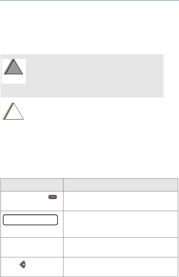
Notations Used in This Manual
Throughout the text in this publication, you will notice the use of
WARNING, Caution, and Note. These notations are used to
emphasize that safety hazards exist, and the care that must be taken
or observed.
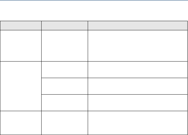
The following special notations identify certain items:
An operational procedure, practice, or
condition, etc., which may result in injury or
death if not carefully observed.
An operational procedure, practice, or condition,
etc., which may result in damage to the equipment
if not carefully observed.
Note: An operational procedure, practice, or condition,
etc., which is essential to emphasize.
Example Description
Secure button or Buttons and keys are shown in bold print or
as a key symbol.
Information appearing on the radio’s
display is shown using the special display
font.
Phone Menu entries are shown similar to the way
they appear on the radio’s display.
Press This means “Press the right side of the
4-way Navigation button.”
!
W A R N I N G
!
!
C
a u t i o
n
PHONE CALL
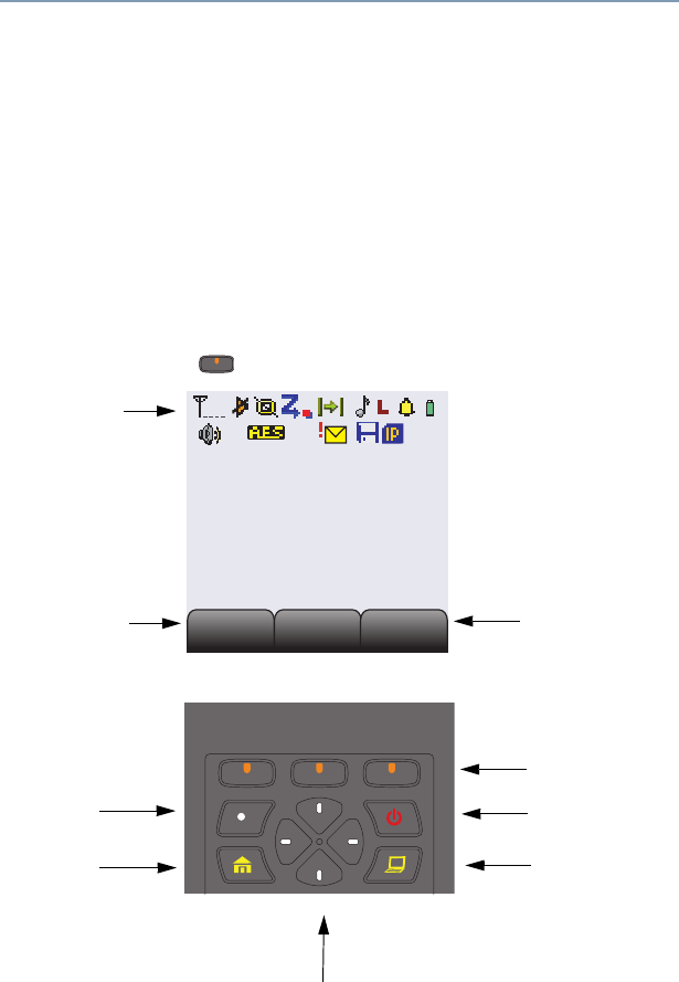
ASTRO XTS 4000 3
General Radio Operation
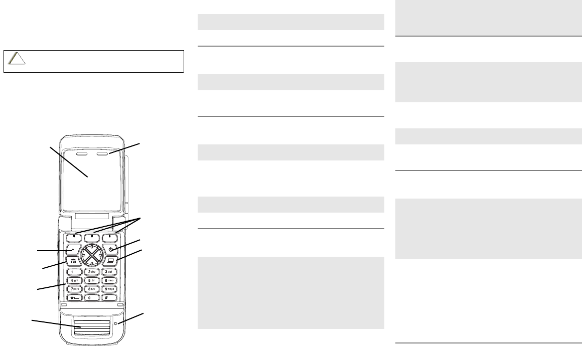
Physical Features of the XTS 4000 Radio
Note: Do not block or cover the microphone when talking through the
radio.
Programmable Controls
The following radio controls can be programmed to operate certain
software-activated features.
The features that can be assigned to these controls by a qualified radio
technician, and the pages where these features can be found are listed in
Table 2 on page 4. Check with your dealer for more information
supporting the programmable buttons.
Any references in this manual to controls that are “preprogrammed”
mean that a qualified radio technician must use the radio’s
programming software to assign a feature to a control.
Table 1: Physical Features
No. Feature No. Feature
1Antenna 10 Menu Select Buttons
2Home Button 11 Power Button
3 Volume Rocker 12 Data Button
4PTT (Push-to-Talk) Button 13 4-Way Navigation Button
5External Display 14 Keypad
6External Audio Speaker 18 Audio Jack
7Battery 19 CE Connector
8Internal Audio Speaker 21 Microphone
9 Internal Display
No. Feature No. Feature
15 Secure Button 17 Keypad Programmable
Button
16 Emergency Button 20 Side Button
4
General Radio Operation
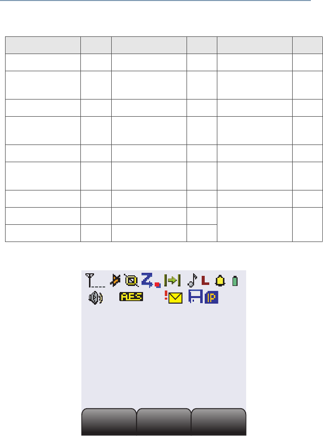
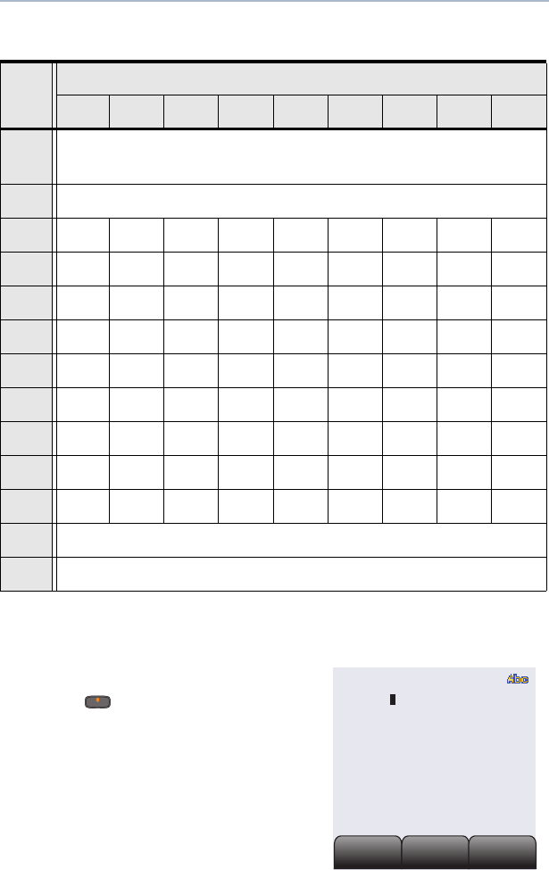
Display
The above screen is typical of what you will see on your radio. The
130 x 130 pixel liquid crystal display (LCD) shows radio status, text, and
menu entries.
Table 2: Programmable Features
Feature Page Feature Page Feature Page
Call Alert 46 PL Defeat 27 Selective Call 45
Call Response 39 Private Call 42 Site Lock/
Unlock
65
Channel 20 Repeater/Direct 53 Site Search 66
Dynamic Priority 38 Reprogram
Request
61 Speaker 26
Emergency 29 Ring Style 25 Status 51
Dim 5 Scan List
Programming
34 TX Power Level 22
Monitor 21 Scan On/Off 37 Volume Set 19
Nuisance Delete 37 Secure/Clear 55 Zone 20
Phone 39 Select 36
Secondary Area
Secondary Area
Primary Area
Primary Area
Tertiary Area
Tertiary Area
Call
Call
Scan
Scan
Zone
Zone
ASTRO XTS 4000 5
General Radio Operation
Adjusting the Display Brightness
Press the preprogrammed Dim button or access this feature through the
menu to change the display brightness to one of three levels.
• Off to high
• High to medium
• Medium to off
The level of brightness will remain on for a preprogrammed time before it
turns off automatically, or you can turn it off immediately by pressing the
Dim button again.
Status Icons
At the internal display, the top two display rows contain icons that indicate
radio operating conditions. Some of these icons are also shown in
external display, but in monochrome. The table below shows a list of
these icons.
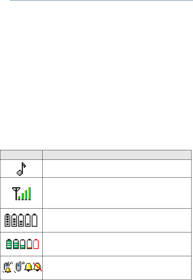
Table 3: Status Symbols
Icon Description
*Call Received
Blinks when receiving an Individual Call.
Received Signal Strength Indication (RSSI)
The received signal strength for the current site, for
trunking only. The more bars in the symbol, the
stronger the signal.
Fuel Gauge at External Display
Displays the level of charge in the battery. Blinks when
battery is low.
*Fuel Gauge at Internal Display
Displays the level of charge in the battery. Blinks when
battery is low.
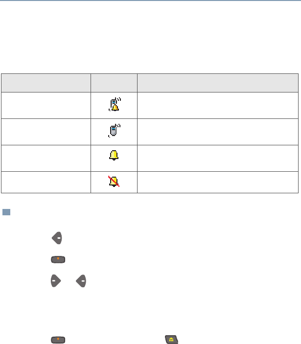
Ring Style
Indicates the type of ring style selected for incoming
calls and pages. See “Ring Style” on page 25.
6
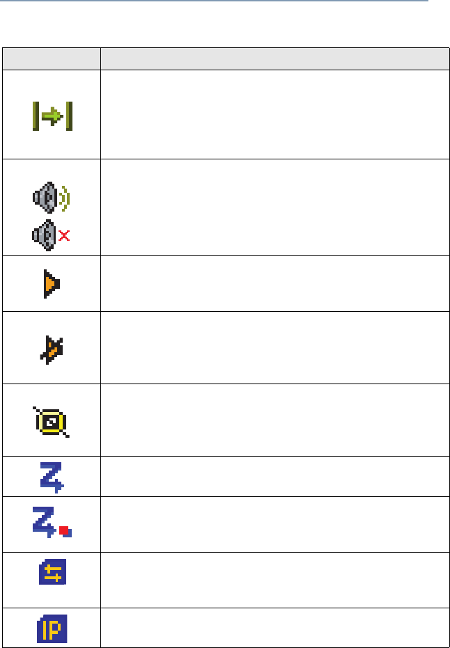
General Radio Operation
Direct
•Displayed = You are talking directly to another
radio, not through a repeater, during conventional
operation only.
•Not Displayed = You are talking through a repeater
Loudspeaker
• Audio is routed to the radio’s external speaker.
• Audio is routed to the radio’s internal speaker.
Monitor (Carrier Squelch)
The selected channel is being monitored during
conventional operation only.
In Call User Alert
The radio is muted to normal dispatch calls. PL, DPL or
signalling squelch will be heard when dispatching the
calls.
Secure Operation
•Displayed = secure operation
•Not Displayed = clear operation
•Blinking = receiving an encrypted voice call
Scan
The radio is scanning a scan list.
Priority-One/Priority-Two Channel Scan
Indicates scanning of a priority mode (blinking for
Priority-One mode; steady for Priority-Two mode).
*Packet Data Activity
Indicates the subscriber is transmitting and receiving
data.
*Packet Data IP
Indicates the subscriber is ready to access the FNE.
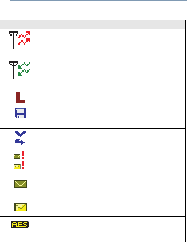
Table 3: Status Symbols (Continued)
Icon Description
ASTRO XTS 4000 7
General Radio Operation
Note: All these icons, except the ones marked with *, are also displayed
in the external display.
Tx
Indicates the radio is transmitting data. Will not be
displayed when the radio is sending a silent
emergency alarm.
Rx
Indicates the radio is receiving data. Will not be
displayed when the radio is sending a silent
emergency alarm.
Tx Power Level
Indicates the transmission power is LOW.
*PPP Link Establishment
Indicates the subscriber is ready to receive data
through a data cable.
Vote Scan
Indicates the mode is in a voting scan system.
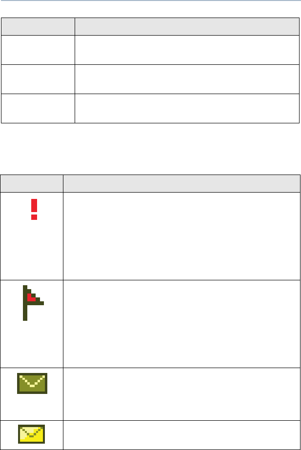
Priority Message
Indicates the radio has received a priority message.
Icon is displayed together with the Inbox Full or New
Message icon.
Inbox Full
Indicates the radio has received a new message while
the inbox is full.
New Message
Indicates the radio has received a new message.
*Advanced Encryption Standard (AES)
•Displayed = Radio is transmitting in AES.
•Blinking = Radio is receiving in AES.
Table 3: Status Symbols (Continued)
Icon Description
8
General Radio Operation
Menu Entry (Softkey)
The bottom row of the display contains one to three menu entries (also
known as softkeys). The menu entries allow you to select one of several
menus to access the radio’s features. The menu entries are accessed
through the Menu Select buttons.
Menu Select Buttons
The Menu Select buttons access the menu entries of features that have
been activated by a qualified radio technician. Your radio may be
programmed differently from the following example, but the display for
turning Scan on or off might look like the example below. For instance, to
turn Scan on, press directly below Scan.
Menu Entry
3 Menu Select
Buttons
(softkey) Menu Entry
(softkey)
Home
Button
Icon Area
Power On/Off
Programmable
Button
Data Button
Secondary Area
Secondary Area
Primary Area
Primary Area
Tertiary Area
Tertiary Area
Call
Call
Scan
Scan
Zone
Zone
4-Way Navigation Buttons
ASTRO XTS 4000 9
General Radio Operation
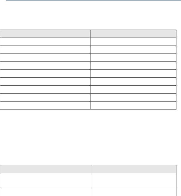
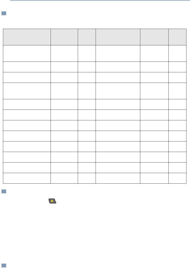
Menu Entry Features
Home Button
The Home button, always returns you to the home (default) display. In
most cases, this is the current mode.
Some radio features that you can edit require saving information in
memory. Pressing the Home button after editing those features causes
information to be saved before going to the home display.
Some features do not require you to press the Home button to go to the
home display. This reduces the required number of key presses.
ON/OFF Button
This button is used to power up or power down the radio.
Table 4: Menu Entries
Feature Menu
Entry Page Feature Menu
Entry Page
Private Call /
Selective Call
Call 43/46 Password Pswd 23
Channel Selection Chan 20 TX Power Level Pwr 22
Repeater/Direct Dir 53 Rekey Request Reky 59
Key Zeroization/
Erase
Eras 58 Reprogram
Request
Rpgm 61
Key Selection Key 56 Scan On/Off Scan 37
Keyset Selection Kset 57 Site Lock/Unlock Site 65
Radio Lock Logf 24 Loudspeaker Spkr 26
Text Select Name 34 Status Call Sts 51
Number Select Num 33 Ring Style Styl 25
Call Alert Page Page 48 Talkgroup Call TGrp 50
Phone Phon 40 View a List View 32
Editing Prog 33 Zone Selection Zone 20
10
General Radio Operation
Data Button
A CPS programmable button that can be programmed to launch specific
data features such as text messaging and location service.
Programmable Buttons
The programmable buttons can be programmed for features as specified
in the CPS. These buttons provide you convenient access to commonly
used radio features.
4-Way Navigation Button
This button is used to scroll through the radio’s lists or items in the display,
or both. It is also used to move the cursor while you are in data entry
screen type.
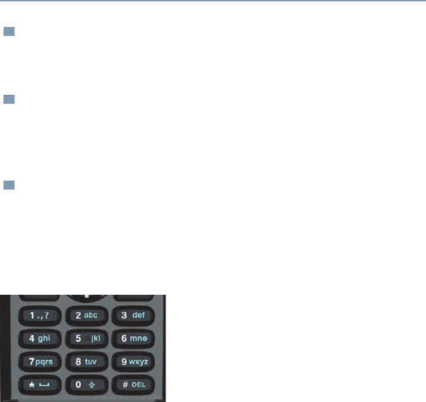
Keypad
The 3 x 4-key alphanumeric keypad provides
an interface to your radio’s features.
The keypad functions in a manner similar to
a standard telephone keypad when entering
numeric digits.
When the keypad is used to edit a list, each
key can generate different characters of the alphabet.
Refer to Table 5, for a complete list of characters.

ASTRO XTS 4000 11
General Radio Operation
Table 5: Keypad Characters
Key Number of times the key is pressed
123456789
00()<>
11&%
2ABC2abc
3DEF3def
4GHI4gh i
5JKL5 j k l
6MNO6mn o
7PQRS7pqr s
8TUV8 t u v
9WXYZ9wxyz
**/+-=
##.!?,;

12
General Radio Operation
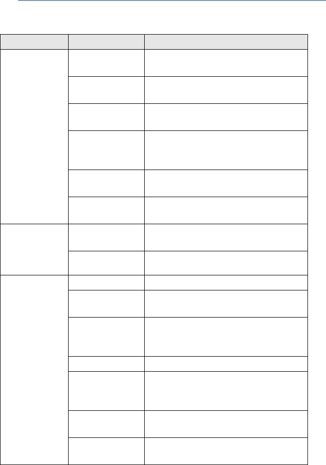
Alert Tones
An alert tone is a sound or group of sounds. Your radio uses alert tones to
inform you of your radio’s conditions. The following table lists these tones
and when they occur.
Table 6: Alert Tones
You Hear Tone Name Heard
Short,
Low-Pitched
Tone
Invalid
Key-Press When wrong key is pressed.
Radio Self-Test
Fail When radio fails its power-up self
test.
Reject When unauthorized request is
made.
Time-Out Timer
Warning Four seconds before time out.
Long, Low-
Pitched Tone
No ACK
Received When radio fails to receive an
acknowledgment.
Time-Out Timer
Timed Out After time out.
Talk Prohibit/
PTT Inhibit (Only when PTT button is pressed)
transmissions are not allowed.
Out-of-Range (Only when PTT button is pressed)
the radio is out of range of the
system.
Individual Call
Warning Tone When radio is in an individual call
for greater than 6 seconds without
any activity.
A Group of
Low-Pitched
Tones
Busy When system is busy.
ASTRO XTS 4000 13
General Radio Operation
Short,
Medium-
Pitched
Tone
Valid Key-
Press When correct key is pressed.
Radio Self-Test
Pass When radio passes its power-up
self test.
Clear Voice At beginning of a non-coded
communication.
Priority
Channel
Received
When activity on a priority channel
is received.
Emergency
Alarm Entry When entering the emergency
state.
Central Echo When central controller has
received a request from a radio.
Long,
Medium-
Pitched
Tone
Volume Set When volume is changed on a
quiet channel.
Emergency Exit When exiting the emergency state.
A Group of
Medium-
Pitched
Tones
Failsoft When the trunking system fails.
Automatic Call
Back When voice channel is available
from previous request.
Talk Permit (Only when PTT button is pressed)
verifying system accepting
transmissions.
Keyfail When encryption key has been lost.
Console
Acknowledge When status, emergency alarm, or
reprogram request ACK is
received.
Received
Individual Call When Call Alert or Private Call is
received.
Call Alert Sent When Call Alert is received by the
target radio.
Table 6: Alert Tones (Continued)
You Hear Tone Name Heard
14
General Radio Operation
Short,
High-Pitched
Tone (Chirp)
Low-Battery
Chirp When battery is below preset
threshold value. Happens only
during transmit mode or standby
mode.
Ringing
Fast Ringing When system is searching for
target of Private Call.
Enhanced Call
Sent When waiting for target of Private
Call to answer the call.
Phone Call
Received When a land-to-mobile phone call
is received.
Gurgle Dynamic
Regrouping (Only when the PTT button is
pressed) a dynamic ID has been
received.
Table 6: Alert Tones (Continued)
You Hear Tone Name Heard
ASTRO XTS 4000 15
General Radio Operation
Standard Accessories
Battery
Charging the Battery
The Motorola-approved battery shipped with your radio is uncharged.
Prior to using a new battery, charge a 630mAh Standard Li-Ion Battery
for a minimum of 5 hours to ensure optimum capacity and performance.
Charge a new 1260mAh Standard Li-Ion Battery for a minimum of 7 hours
to ensure optimum capacity and performance.
For a list of Motorola-authorized batteries available for use with your XTS
4000 radio, see “Batteries and Battery Accessories” on page 94.
Note: When charging a battery attached to a radio, turn the radio off to
ensure a full charge.
Battery Charger
To charge the battery, place the battery, with or without the radio, in a
Motorola-approved charger. The charger’s LED indicates the charging
progress. For a list of chargers, see “Chargers” on page 94.
Note: If the radio is turned on while in the charger, the LED indicator will
remain red due to the power draw of the radio. To determine if the
battery has reached full charge, turn the radio off and wait 10
seconds. The LED will turn green if the battery is fully charged.
Antenna
For information regarding available antennas, see page 93.
To avoid a possible explosion:
• DO NOT replace the battery in any area
labeled “hazardous atmosphere”.
• DO NOT discard batteries in a fire.
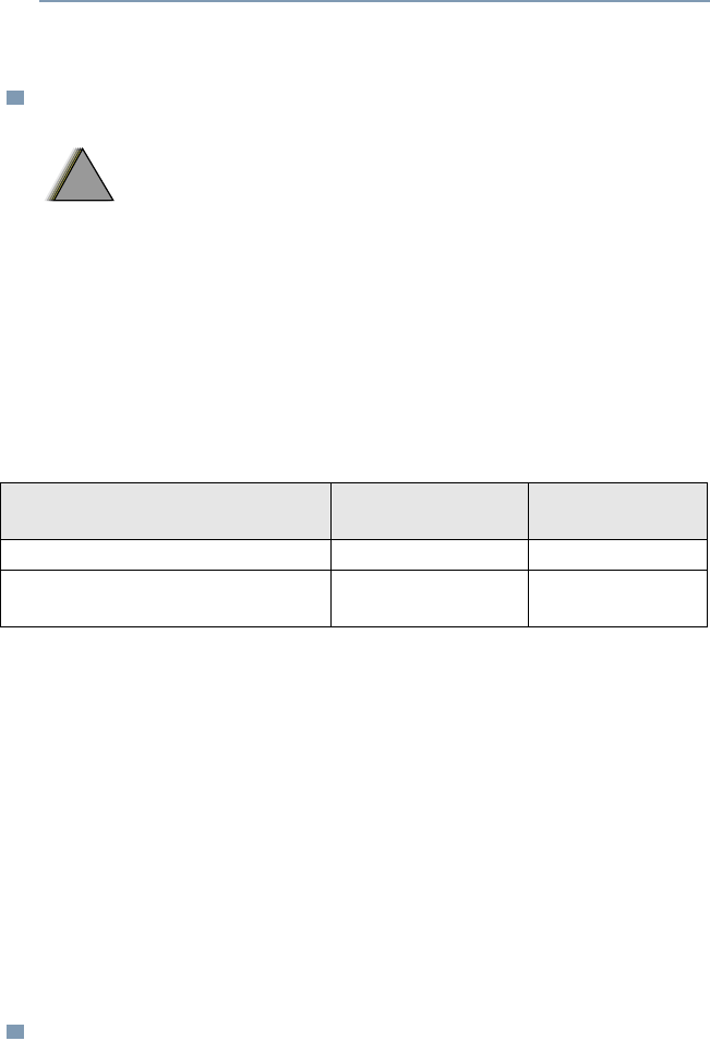
Batteries Charge Complete
Time (Hour) Standby Mode
Time (Hour)
630 mAh Standard Li-Ion Battery 5 4
*1260mAh High Capacity Li-Ion
Battery 5 8
!
W A R N I N G
!
20
General Radio Operation
Zones and Channels
A zone is a grouping of channels. A channel is a group of radio
characteristics, such as transmit/receive frequency pairs.
Before you use your radio to receive or send messages, you should
select the zone and channel.
Select a Zone
Select a Channel
1Press to find Zone.
2Press directly below Zone.
The current zone blinks and the channel name, does not blink.
3Press to find the zone you want.
4Press directly below Sel to confirm the displayed zone and
channel.
OR
Press the PTT button to transmit on the displayed zone/channel.
5Press directly below Sel to return to home display.
1Press to find Chan.
2Press directly below Chan.
The display shows the current channel name blinking and the zone,
not blinking.
3Press to find the channel name you want.
OR
Use the keypad to enter the channel number.
4Press directly below Sel to confirm the displayed zone and
channel.
OR
Press the PTT button to transmit on the displayed zone/channel.
5Press directly below Sel to return to home display.

ASTRO XTS 4000 21
General Radio Operation
Receive / Transmit
Radio users who switch from analog to digital radios often assume that
the lack of static on a digital channel is an indication that the radio is not
working properly. This is not the case. Digital technology quiets the
transmission by removing the “noise” from the signal and allowing only
the clear voice or data information to be heard.
This section emphasizes the importance of knowing how to monitor a
channel for traffic before keying up to send a transmission.
Without Using the Monitor Buttons
Use the Preprogrammed Monitor Button
1Turn the radio on and select the desired zone and channel.
2Listen for a transmission.
3Adjust the Volume Rocker if necessary.
4Press and hold the PTT button to transmit. Tx icon appears on
the display.
5Release the PTT button to receive (listen).
1Turn the radio on and select the desired zone and channel.
2Press the Monitor button and listen for activity. The Carrier
Squelch indicator is displayed.
3Adjust the Volume Rocker if necessary.
4Press and hold the PTT button to transmit. Tx icon appears on
the display.
5Release the PTT button to receive (listen).

22
Common Radio Features
Transmit Power Level
This feature lets you select the power level at which your radio will
transmit. The radio will always turn on to the default setting. This
feature must be preprogrammed by a qualified radio technician.
•Select Low for a shorter transmitting distance and to conserve
power.
•Select High for a longer transmitting distance.
Select Power Level
1Press to find Pwr.
2Press directly below Pwr to toggle between Low and High.
ASTRO XTS 4000 23
Common Radio Features
Radio Lock
This feature changes your radio to a more robust security system that
protects the use of the secure encryption keys. If this feature is
enabled in your radio by a qualified radio technician, when you turn
the radio on, you see Radio locked.
Unlock Your Radio
Change Your Password
1Enter your numeric password.
Note:
• Secure-equipped radios — 6 to 8 characters.
• Clear radios — 0 to 8 characters.
If you make a mistake, press to backspace.
2Press the preprogrammed Select button after you enter your
password. If the password is correct, the radio unlocks.
Note:
• If the password is incorrect, the radio remains locked.
•If you enter three incorrect passwords in a row, you see
Deadlock. Turn the radio off and then on, and begin again at
step 1.
•Secure Radios Only — If you enter a total of 15 consecutive
incorrect passwords (turning the radio off and on does not reset
this number), the radio erases all of its encryption keys. See a
qualified radio technician.
1Press to find Pswd.
2Press directly below Pswd.
3Enter the old password.
4Press directly below Sel.
24
Common Radio Features
Enable or Disable the Radio Lock Feature
(Secure Radios Only)
This feature (programmable by a qualified radio technician) allows
you to enable or disable the radio lock feature.
5Enter the new password.
6Press directly below Sel.
7Re-enter the new password.
8Press directly below Sel. The password is updated.
Note:
• If the two passwords do not match, repeat steps 5 through 8.
• If you enter three incorrect old passwords, the radio exits the
password feature. You cannot access this feature again until
you turn the radio off and on.
1Press to find Logf.
2Press directly below Logf to toggle between “Pswd enabled”
and “Pwsd disabled”.
ASTRO XTS 4000 25
Common Radio Features
Ring Style
This feature allows you to select the type of alert when your radio
receives incoming individual calls or pages.
Select Ring Style
Ring Style Icon Description
Vibrate and Ring Radio vibrates and rings when incoming
individual calls and pages are received.
Vibrate Only Radio vibrates when incoming calls and
pages are received.
Ring Only Radio rings when incoming calls and pages
are received.
Silent Radio is in silent mode.
1Press to find Styl.
2Press directly below Styl.
3Press or to select the ring style.
Note: The default factory setting is Vibrate and Ring.
4Press directly below Sel.
5Press directly below Cncl or to return to home display.
26
Common Radio Features
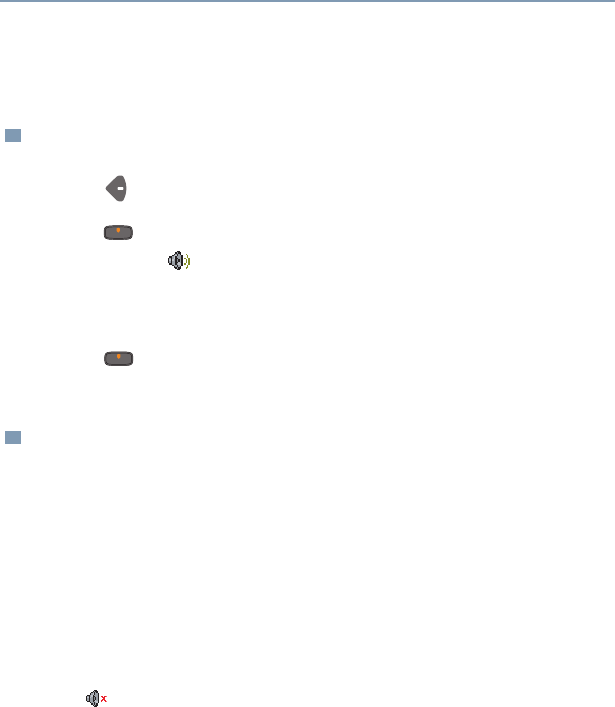
Loudspeaker
The external speaker allows you to share your call with your group.
Change to External Speaker
Turn off External Speaker and Activate Vibration
When the flip is closed, you can manually turn off the external
speaker and activate the vibration alert, using the radio’s
preprogrammed Spkr side button.
1Press to find Spkr.
2Press directly below Spkr to toggle the audio to the external
speaker. The icon is shown on the display.
Note: When the earpiece or headset is plugged into the audio
jack, the external speaker will not work.
3Press directly below Spkr again to route the audio back to
the internal speaker.
1Close the flip of the radio.
2Press the preprogrammed Spkr side button to turn off the
external speaker. The vibration alert is now activated
whenever a dispatch or talkgroup call is received.
The icon is shown on the display.
Note: The vibration will stop once the flip is opened or when an
audio accessory is plugged into the audio jack.
The external speaker will remain turned off even after you
open the flip to answer a call and then close it back.
When the external speaker is turned off, the vibration alert
is always turned on regardless of the ring style setting.
3Press the side button again to turn on the external speaker.
ASTRO XTS 4000 27
Common Radio Features
Conventional Squelch Operation
Digital Options
One or more of the following options may be programmed in your
radio. Consult your service technician for more information.
This option Will allow you to hear
Digital Carrier-Operated
Squelch (COS) any digital traffic.
Normal Squelch any digital traffic having the correct
Network Access Code (NAC).
Selective Switch any digital traffic having the correct
network access code and correct
talkgroup.

28
Common Radio Features
Time-out Timer
The time-out timer turns off your radio’s transmitter. The timer is set
for 60 seconds at the factory, but it can be programmed from 0 to 7.75
minutes (465 seconds) by a qualified radio technician.
1Hold down the PTT button longer than the programmed time.
You will hear a short, low-pitched warning tone, the
transmission will cut-off.
2Release the PTT button.
3Press the PTT to re-transmit. The time-out timer restarts.

ASTRO XTS 4000 29
Common Radio Features
Emergency
If the top (orange) button is programmed to send an emergency
signal, then this signal overrides any other communication over the
selected channel.
Your radio can be programmed for the following:
• Emergency Alarm
• Emergency Call
• Emergency Alarm with Emergency Call
• Silent Emergency Alarm
Consult a qualified radio technician for emergency programming of
your radio.
Send an Emergency Alarm
An emergency alarm will send a data transmission to the dispatcher,
identifying the radio sending the emergency.
1With your radio turned on, press the Emergency button. The
current zone/channel is displayed alternately with Emergency on
the external display and a short, medium-pitched tone sounds.
If the selected channel does not support emergency, the display
shows No Emergency. Select a channel that does show
Emergency.
Note: To exit emergency at any time, press and hold the
Emergency button for about a second.
2When you receive the dispatcher’s acknowledgment, you see ACK
Received, four tones sound, the alarm ends, and the radio exits
the emergency mode.
If no acknowledgement is received, you see No Acknowledge,
the alarm ends, and the radio exits the emergency mode.
Note: For Emergency Alarm with Emergency Call: The radio
enters the Emergency Call state either after it receives the
dispatcher’s acknowledgment, or if you press the PTT button
while in Emergency Alarm. Go to step 2 of “Send an
Emergency Call”, below.

30
Common Radio Features
Send an Emergency Call
Send a Silent Emergency Alarm
This type of dispatch gives your radio priority access on a channel.
The radio operates in the normal dispatch manner while in
Emergency Call, except, if enabled, it will return to one of the
following:
• Tactical/Non-Revert — You talk on the channel you selected
before you entered the emergency state.
• Non-Tactical/Revert — You talk on a preprogrammed emergency
channel. The emergency alarm is sent on this same channel.
1. With your radio turned on, press the Emergency button.The
current channel is displayed alternately with Emergency, on the
external display and a short, medium-pitched tone sounds.
Note: To exit emergency at any time, press and hold the
Emergency button for about a second.
2Press and hold the PTT button and announce your emergency
into the microphone.
3Release the PTT button to end the transmission and wait for a
response from the dispatcher.
4Press and hold the Emergency button for about a second to exit
emergency.
1With your radio turned on, press the Emergency button. The
display does not change, the LED does not light, and you hear
no tones.
Note: To exit emergency at any time, press and hold the
Emergency button for about a second.

66
Special Radio Features
Site View and Change
You can view the number of the current site or force your radio to
change to a new one.
View the Current Site
Change the Current Site
Press the preprogrammed Site Search button.
The display momentarily shows the name of the current site
and its corresponding received signal strength indicator (RSSI).
(See Table 3 on page 5.)
OR
If the radio is scanning for a new site, you momentarily see
Scanning site.
Press and hold down the preprogrammed Site Search button.
You momentarily see Scanning site and hear a tone.
When the radio finds a new site, it returns to the home display.

ASTRO XTS 4000 67
ARS User Login and Text Messaging Features
Automatic Registration Service (ARS)
Automatic Registration Service feature provides an automated data
application registration for the radio. When you turn on the radio, the
device automatically registers with the server. Data applications
within the fixed network can determine the presence of a device on
the system and send data to the device. For example: Text
Messaging Service (TMS).
Automatic Registration Service for the radio consists of 2 modes:
• ARS Server Mode (default mode)
• ARS Non Server Mode
Note: ARS default mode can be changed by a qualified radio
technician using the radio’s programming software.

ASTRO XTS 4000 75
ARS User Login and Text Messaging Features
Table 8: TMS Menu Options
Menu Options Description/ Function
Inbx This is used to store new incoming messages or
messages that you have received. Inbox can hold
up to 30 messages.
Comp This menu option brings you to the compose
screen.
Drft This is used to store all saved messages or
messages that are to be sent at a later time. Draft
folder can hold up to 10 messages.
Sent This is used to store the messages that you have
already sent. Sent folder can hold up to 10
messages.
Back This menu option brings you back to the TMS
main menu or previous menu.
Edit This menu option brings you to the Quick Text
Messages screen.
Save This menu option allows you to save your
messages to the Draft folder.
Rply This menu option allows you to reply a message.
Del This menu option allows you to delete a message.
Addr This menu option allows you to key in the target
address, or select one from the list.
New This menu option allows you to compose a new
message.
List This menu option allows you to select a predefined
message.
Impt This menu option is used to toggle on/off the
“Priority” flag for an outgoing message.
76
ARS User Login and Text Messaging Features
Table 9: TMS Status Symbols
Rqrp This menu option is used to toggle on/off the
“Request reply” flag for an outgoing message.
Curr This menu option is used to delete the current
selected message.
All This menu option is used to delete all the
messages in the current message inbox.
Symbol Indication
Priority Message
This icon is displayed
• when “Priority” is toggled on before sending the
message.
• in the Inbox folder for messages which are
flagged with ‘Priority’.
Request Receipt
This icon is displayed
• when “Request Receipt” is toggled on before
sending the message.
• in the Inbox folder for messages which are
flagged with ‘Request Receipt’.
Inbox Full
This icon is displayed when the Inbox Folder is full. If
a new message is received when the inbox is full, the
icon will be blinking.
New Message Icon
The radio has received a new message.
Menu Options Description/ Function
ASTRO XTS 4000 77
ARS User Login and Text Messaging Features
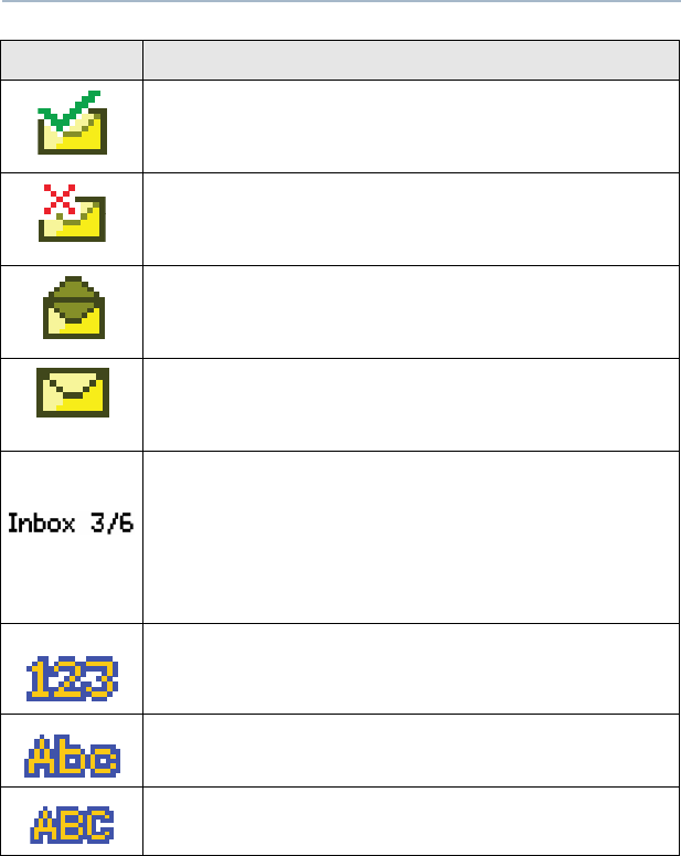
Message Sent
This icon is displayed if the selected message has
been successfully sent.
Message Unsent
This icon is displayed if the selected message was
not successfully sent.
Read Message
This icon is displayed when the selected message in
the Inbox has been read.
Unread Message
The selected message in the Inbox folder has not
been read.
Message Index
This icon indicates the index of the current message
the user is viewing. Example: if the user is looking at
the third message out of a total of 6 messages in the
Inbox folder, the icon is displayed as the icon on the
left column.
Num Lock
The text entry is currently in num lock mode.
Normal Mode
The text entry is currently in the normal mode.
Uppercase
The text entry is currently in uppercase mode.
Symbol Indication
78
ARS User Login and Text Messaging Features
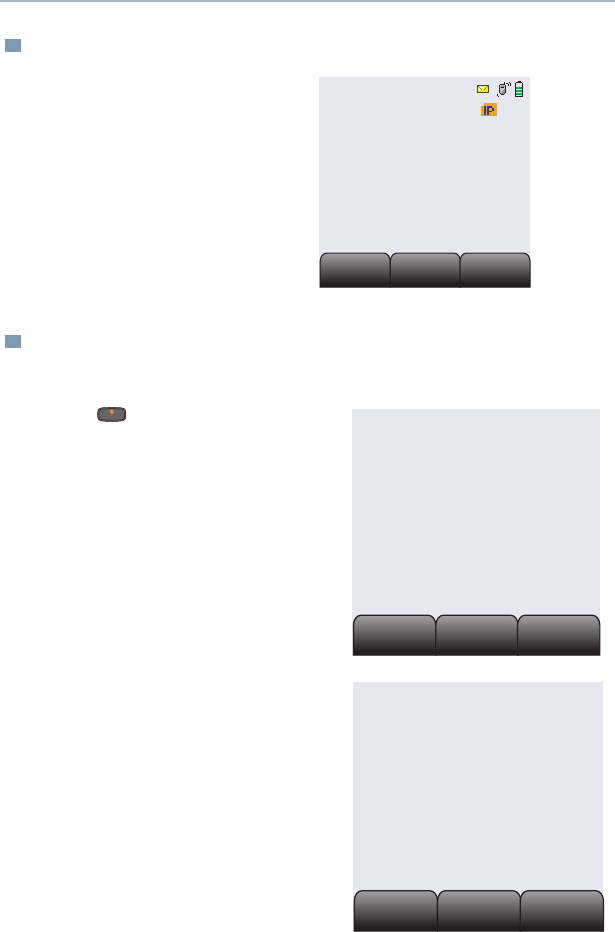
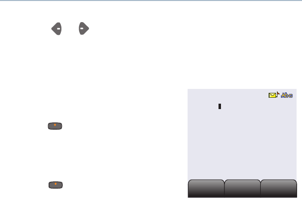
Receive a Message
To View Message from the Inbox
When you receive a
message, a momentary text,
New msg appears on the
display along with a new
message icon.
If inbox is full, the message
icon will be blinking.
1Access TMS (Launch TMS).
2Press directly below
Inbx.
3The Inbox screen appears.
The first message in the list is
displayed. Inbox can hold up
to 30 messages. Message
status icons are displayed at
the top of the screen.
Prog
Prog
TMS
TMS
User
User
New Msg
Inbx
Inbx
Drft
Drft
Comp
Comp
User
00000004
Rply
Rply
Back
Back
Del
Del
From:User
Hello
Inbox 01/01

ASTRO XTS 4000 79
ARS User Login and Text Messaging Features
4Scroll to the message you want to read by pressing the or
button.
Note: If the message fills more than one screen, scroll to read
it by pressing or button.
5To delete the message, press below Del. See “Delete a
Message” on page 85. for further details.
80
ARS User Login and Text Messaging Features
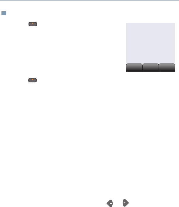
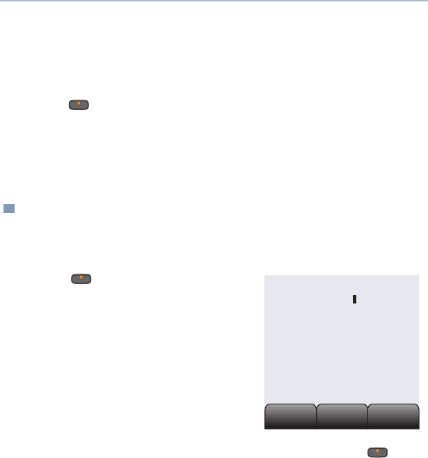
Compose a New Text Message
1Press below Comp to compose a new
message.
The Compose Message Screen appears.
List or New option appears on the
display.
2Press below New to type a new message.
A blinking cursor appears on the display indicating point of input.
3 Writing Text
Type your message using the keypad.
Press the key labeled with the desired character, once for the
first character, twice for the second, and so on. Refer to table 10
below for complete list of characters.
For example:
To enter “s”, press 7 key four times. To enter “7”, press the
key five times. If you do not press a key for a few seconds, the
character is accepted, and the cursor moves to the next position.
Press # key to delete a character.
Press * key to add a space.
You can move the cursor by pressing or .
Press and hold 0 to toggle between normal text entry mode,
uppercase mode and num lock mode.
Note: i) During the uppercase mode, multi-tapping the keys will
only scroll through the uppercase letters.
(Example : A->B->C->2)
ii) During the num lock mode, pressing the keypad will
only enter the numeric digits. Subsequent presses of
the same key will insert the same digit to the text
message (no multi-tap).
List or new
New
New
List
List
Back
Back
ASTRO XTS 4000 81
ARS User Login and Text Messaging Features
Table 10: Keypad Characters
Key Number of times the key is pressed (in normal mode)
123456789
0 0 or press and hold to toggle between normal text
entry mode, uppercase mode and num lock mode.
1 1 . , ? ! ; @ _ - * # & $ / + = \ “ ‘ ( )
1*1.@_-*#/
2abc2ABC
3def3DEF
4gh i 4GHI
5jkl5JKL
6mno6MNO
7pqrs7PQRS
8tuv8TUV
9wxyz9WXYZ
* Space
# Delete a character
Note: * Only applicable when addressing a message.
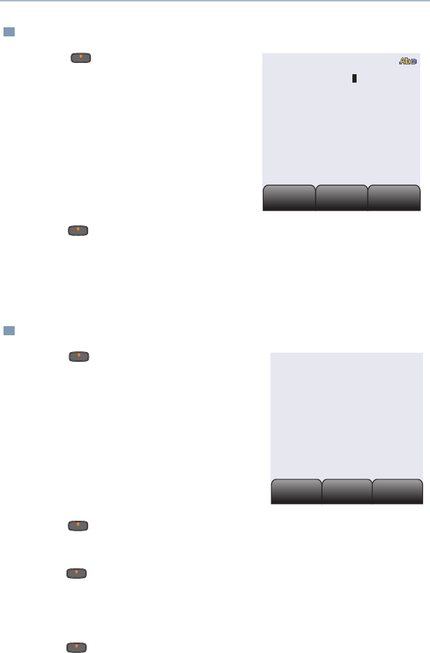
4 Addressing a Message
Press below Addr to
address your outgoing
message.
The Address input screen
appears.
Impt
Impt
Back
Back
RqRp
RqRp
Addr:
82
ARS User Login and Text Messaging Features
Press or to scroll through the address list.
OR
Use direct address entry via multi-tap.
5 Append a Priority Message or Request Receipt
Before sending your message, you
can append a priority message or a
request receipt to your message.
Press below Impt to toggle on/
off a “Priority” flag for an outgoing
message. A ‘Priority’ flag icon is
displayed at the top of the screen
when it is toggled on.
Press below Rqrp to toggle on/
off the “Request Receipt” icon for an
outgoing message. A ‘Request
receipt’ status icon is displayed at the top of the screen when it
is toggled on.
Note:
• The “Priority” flag on a message does not imply that the
message will get higher priority over the other messages when
it is being transmitted. It is just an indication that can be
embedded into a message to indicate to the receiver that the
message is important.
• When you receive a message that is flagged with the
“Request Receipt” icon, you must manually respond to the
sender that you have received the message. The system will
not automatically send back a notification that the radio
received such message.
Impt
Impt
Back
Back
RqRp
RqRp
Addr:
ASTRO XTS 4000 83
ARS User Login and Text Messaging Features
Send a Predefined Message
Quick Text Messages are messages that are predefined and usually
consist of messages that are used most frequently.
6When an address has been appended to the outgoing message,
press the PTT button to send your message.
OR
Press below Save to save your message for sending at a
later time.
The message will be saved in the “Draft folder”. See “To Access
the Draft Folder” on page 86. for further details.
1Press below List to use the
predefined message.
The first predefined message
appears.
2When a message has been selected from the list, press
below Addr to append an address to the outgoing message.
3Press the PTT button to send the predefined message.
Addr
Addr
Back
Back
Edit
Edit
I am late today
QT 01/01
84
ARS User Login and Text Messaging Features
Edit a Quick Text Message
Reply to a Received Message
1Press below Edit to edit
a quick text message.
The Editing Screen appears.
A blinking cursor appears at
the end of the predefined
text.
Edit your message using the
keypad.
2Press below Save to save the edited changes. The message
is saved in the Draft folder.
3When an address has been appended to the outgoing message,
press the PTT button to send the edited message.
1Press below Rply to
reply to a message
The Compose Message
Screen appears.
2Press below New to type a new message.
OR
Press below List to use the predefined message / Quick
text message.
OR
Press below Back to return to TMS main menu.
Addr
Addr
Back
Back
Save
Save
I am late today
QT 01/01
List or new
New
New
List
List
Back
Back
ASTRO XTS 4000 85
ARS User Login and Text Messaging Features
Delete a Message
1From the Inbox, Draft or Sent screen, scroll to select a message
for deletion.
2After selecting a message, press
below Del. The display shows
2 delete options.
Press below Curr to delete
only the current message.
OR
Press below All to delete all
messages.
OR
Press below Back to return to previous menu.
3When you select to delete all
messages,a confirmation screen
appears.
Press below Yes to delete all
messages.
Press below No to return to
previous screen.
Curr
Curr
Back
Back
All
All
From : User1
Inbox 01/01
Hello
Curr
Curr
Back
Back
All
All
Del all?
Inbox 01/01
86
ARS User Login and Text Messaging Features
To Access the Draft Folder
The Draft folder stores the messages that were saved previously.
Newest saved message is appended at the bottom of the list. Draft
folder can hold up to 10 messages. The oldest draft in the folder is
deleted when the 11th message comes in.
To Access the Sent Folder
The Sent folder stores the messages that were sent out previously.
Newly sent message is appended where the newest message is at
the beginning of the list and the oldest message is at the bottom of
the list. The oldest Sent message in the folder is deleted when the
11th message comes in.
1Press below Drft. The Draft
screen appears.
The first draft in list is displayed.
2Press or to scroll through
the list of drafts.
1Press below Sent. The Sent
screen appears.
The first sent message in the list is
displayed. A message delivery icon
will be displayed at the top right
corner of the screen.
2Press or to scroll through the list of other messages that
have been sent.
Edit
Edit
Back
Back
Del
Del
I have a meeting at
9am tomorrow
Draft 01/01
Impt
Impt
Back
Back
RqRp
RqRp
To: User
Have a nice day
87
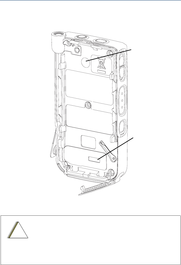
Helpful Tips
Radio Care
• The XTS 4000 radio casting has a RF Dust cover.
Never remove this cover as this would create leak
paths into the radio.
• Never insert any objects into the vent port, such as
needles, tweezers, or screwdrivers. This could
create leak paths into the radio.
Vent Port
RF Dust Cover
!
C
a u t i o
n
88
Helpful Tips
Cleaning
To clean the external surfaces of your radio:
1Combine one teaspoon of mild dishwashing detergent to one
gallon of water (0.5% solution).
2Apply the solution sparingly with a stiff, non-metallic, short-bristled
brush, making sure excess detergent does not get entrapped near
the connectors, controls or crevices. Dry the radio thoroughly with
a soft, lint-free cloth.
3Clean battery contacts with a lint-free cloth to remove dirt or
grease.
• If the radio battery contact area has been
submerged in water, dry and clean the radio battery
contacts before attaching a battery to the radio.
Otherwise, the water could short-circuit the radio.
• If the radio has been submerged in water, shake
the radio well so that any water that may be trapped
inside the speaker grille and microphone port can
be removed. Otherwise, the water will decrease the
audio quality of the radio.
• Do not disassemble the radio. This could damage
radio seals and result in leak paths into the radio.
Any radio maintenance should be performed only
by a qualified radio technician.
Do not use solvents to clean your radio. Spirits
may permanently damage the radio housing.
Do not submerge the radio in the detergent
solution.
!
C
a u t i o
n
!
C
a u t i o
n

ASTRO XTS 4000 89
Helpful Tips
Handling
• Do not pound, drop, or throw the radio unnecessarily. Never carry
the radio by the antenna.
• Avoid subjecting the radio to an excess of liquids. Do not
submerge the radio.
• Avoid subjecting the radio to corrosives, solvents or spirits.
• Do not disassemble the radio.
• Keep the accessory-connector cover in place until ready to use
the connector. Close the cover immediately once the accessory
has been disconnected.
Service
Proper repair and maintenance procedures will assure efficient
operation and long life for this product. A Motorola maintenance
agreement will provide expert service to keep this and all other
communication equipment in perfect operating condition. A
nationwide service organization is provided by Motorola to support
maintenance services. Through its maintenance and installation
program, Motorola makes available the finest service to those
desiring reliable, continuous communications on a contract basis. For
a contract service agreement, please contact your nearest Motorola
service or sales representative, or an authorized Motorola dealer.
Express Service Plus (ESP) is an optional extended service coverage
plan, which provides for the repair of this product for an additional
period of either one or two years beyond the normal expiration date of
the standard warranty. For more information about ESP, contact the
Motorola Radio Support Center at 3761 South Central Avenue,
Rockford, IL 61102 (800) 227-6772 / (847)725-4200.
Battery
Battery Life
Battery life is determined by several factors. Among the more critical
is the average depth of discharge with each cycle. Typically, the
deeper the average discharge, the fewer cycles a battery will last. Top
up your battery frequently, if possible.

90
Helpful Tips
Charging the Battery
Motorola batteries are designed specifically to be used with a
Motorola charger. Charging in non-Motorola equipment may lead to
battery damage and void the battery warranty. Motorola-authorized
battery chargers may not charge batteries other than the ones listed
on page 94.
The battery should be at about 25°C (77°F) (room temperature),
whenever possible, for charging. The acceptable charge temperature
range is 0°C to 45°C. Motorola rapid-rate battery chargers contain a
temperature-sensing circuit to ensure that batteries are charged
within the temperature limits stated above.
Battery Charge Status
Your radio can indicate your battery’s charge status through:
• vibrations and sounds
• fuel gauge symbol on the display
LED and Sounds
When your battery is low, and the radio is in standby mode or transmit
mode:
• if vibration is turned on, your radio will vibrate
• you hear a low-battery “chirp” (short, high-pitched tone)
But these would not happen during receive mode.
ASTRO XTS 4000 91
Helpful Tips
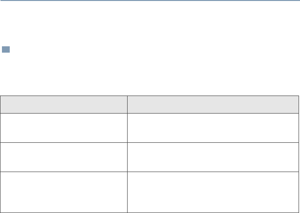
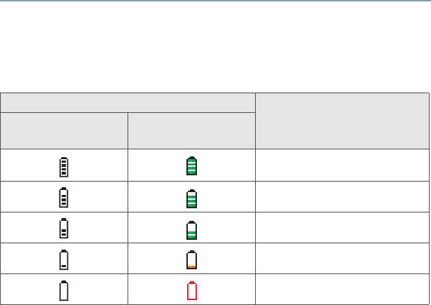
Fuel Gauge Symbol
The radio indicates the current battery charge level through a fuel
gauge symbol. Refer to the table below for more information.
Battery Recycling and Disposal
Lithium Ion (Li-Ion) rechargeable batteries can be recycled. However,
recycling facilities may not be available in all areas. Under various
U.S. state laws and the laws of several other countries, Li-Ion
batteries must be recycled and cannot be disposed of in landfills or
incinerators. Contact your local waste management agency for
specific requirements and information in your area.
Motorola fully endorses and encourages the recycling of Li-Ion
batteries. In the U.S. and Canada, Motorola participates in the
nationwide Rechargeable Battery Recycling Corporation (RBRC)
program for Li-Ion battery collection and recycling. Many retailers and
dealers participate in this program.
For the location of the drop-off facility closest to you, access RBRC's
Internet web site at www.rbrc.com or call 1-800-8-BATTERY. This
internet site and telephone number also provide other useful
Fuel Gauge Charge Level
External
Indicator Internal
Indicator
60% - 100%
40% - 59%
20% - 39%
6% - 19%
0% - 5%
92
Helpful Tips
information concerning recycling options for consumers, businesses,
and governmental agencies.
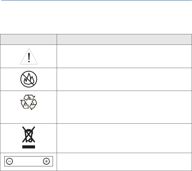
Symbol Definition
Important safety important follows.
Do not dispose of your battery or mobile device
in a fire.
Your battery or mobile device may require
recycling in accordance with local laws. Contact
your local regulatory authorities for more
information.
Do not throw your battery or mobile device in
the trash.
Your mobile device contains an internal lithium
ion battery.
Li Ion BATT
ASTRO XTS 4000 93
Accessories
Motorola provides the following approved accessories to improve the
productivity of your XTS 4000 portable two-way radio. Motorola do
not certify the use of other Nextel type accessories with this radio.
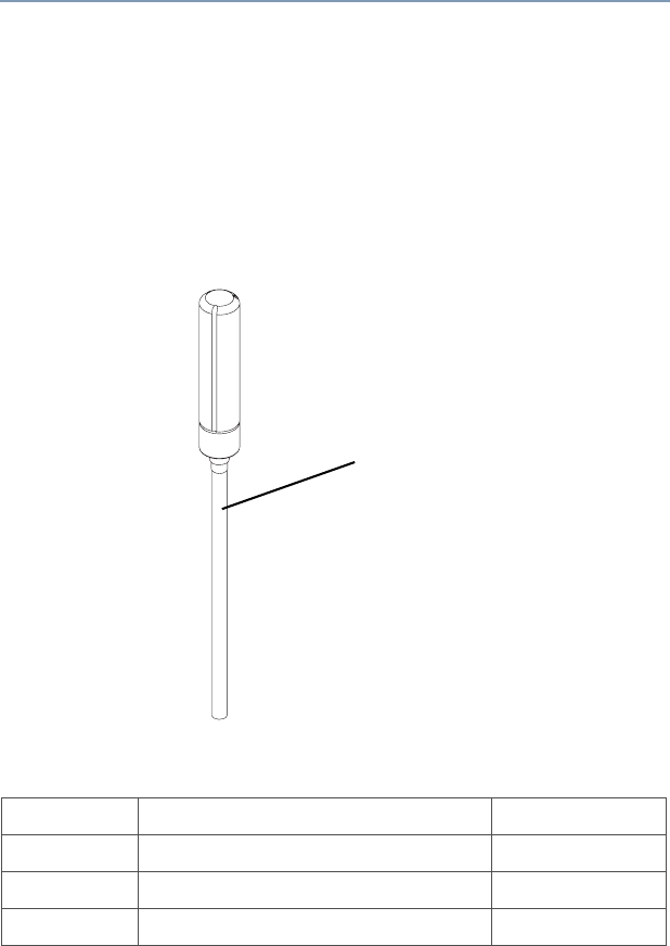
Antennas
Antennas for different frequencies are indicated by the color of the
straw. Please refer to the following picture to identify the straw on the
antenna.
The straw color for each antenna is given in the following table.
NAD6582_ Antenna 136 – 151 MHz Yellow
NAD6581_ Antenna 145 – 166 MHz Black
NAD6583_ Antenna 162 – 174 MHz Blue
NAE6552_ Antenna 380 – 470MHz Red
Straw
94
Accessories
Batteries and Battery Accessories
Carry Accessories
Belt Clips
Chargers
Headsets and Earpieces
NNTN6944_ 630 mAh Standard Li-Ion Battery
PMNN4083_ 1260 mAh Standard Li-Ion Battery
NNTN6945_ Plastic Belt Clip
NNTN6946_ Leather Belt Clip
NNTN6938_ XTS 4000 Charger US 110V AC
NNTN6937_ XTS 4000 Charging Cradle
NNTN6939_ XTS 4000 Charger 12V Vehicular
NNTN5006BP Headset Earbud with PTT
NNTN5211_ 2-Wire Surveillance Kit