Motorola Solutions 89FT4882 PORTABLE 2-WAY RADIO User Manual 63M01 A BRUS en
Motorola Solutions, Inc. PORTABLE 2-WAY RADIO 63M01 A BRUS en
UserManual.wiki
>
Motorola Solutions
>
89FT4882 User Manual
USERS MANUAL
Navigation menu
Upload a User Manual
Namespaces
Wiki Guide
HTML
PDF
Info
Views
User Manual
Discussion / Help
Navigation
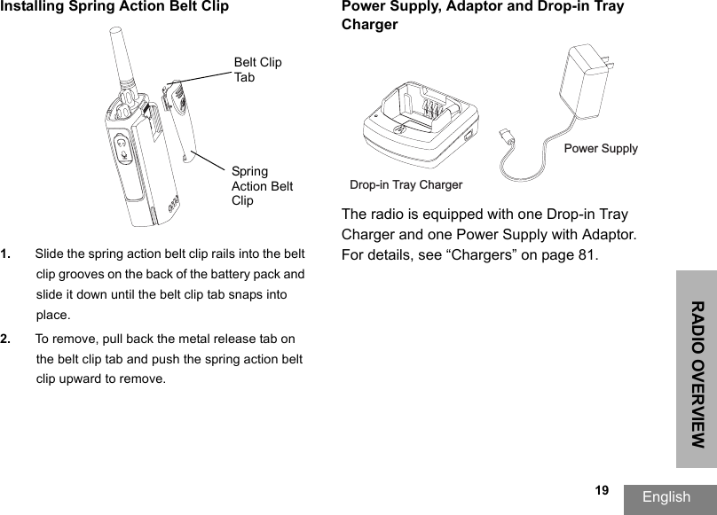
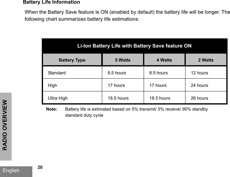
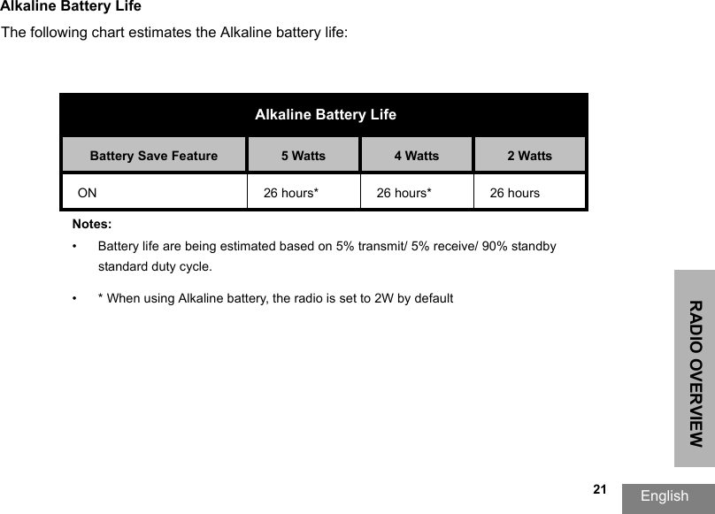
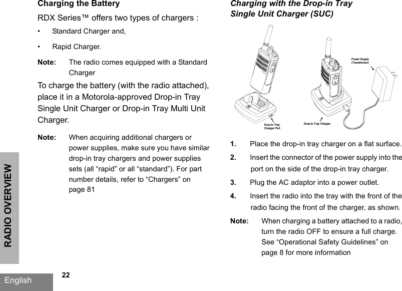
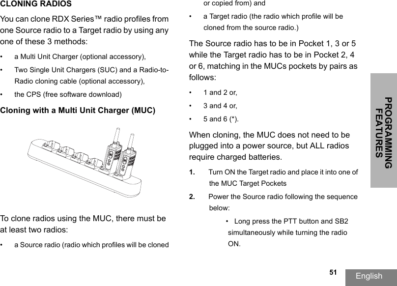
![RADIO OVERVIEWEnglish 14BATTERY FEATURESRDX Series™ radios provide Lithium-Ion batteries that come in different capacities that will define the battery life. It also offers the option to use Alkaline batteries.About the Li-Ion BatteryThe RDX Series™ radio comes equipped with a rechargeable Li-Ion battery. This battery should be charged before initial use to ensure optimum capacity and performance. Battery life is determined by several factors. Among the more critical are the regular overcharge of batteries and the average depth of discharge with each cycle. Typically, the greater the overcharge and the deeper the average discharge, the fewer cycles a battery will last. For example, a battery which is overcharged and discharged 100% several times a day, lasts fewer cycles than a battery that receives less of an overcharge and is discharged to 50% per day. Further, a battery which receives minimal overcharging and averages only 25% discharge, lasts even longer.Motorola batteries are designed specifically to be used with a Motorola charger and vice versa. Charging in non-Motorola equipment may lead to battery damage and void the battery warranty. The battery should be at about 77°F (25°C) (room temperature), whenever possible. Charging a cold battery (below 50° F [10°C]) may result in leakage of electrolyte and ultimately in failure of the battery. Charging a hot battery (above 95°F [35°C]) results in reduced discharge capacity, affecting the performance of the radio. Motorola rapid-rate battery chargers contain a temperature-sensing circuit to ensure that batteries are charged within the temperature limits stated above.](https://usermanual.wiki/Motorola-Solutions/89FT4882/User-Guide-873597-Page-16.png)