Motorola Solutions 89FT4906 PORTABLE 2-WAY RADIO User Manual APX 7000 Portable Top Display User Guide
Motorola Solutions, Inc. PORTABLE 2-WAY RADIO APX 7000 Portable Top Display User Guide
UserManual.wiki
>
Motorola Solutions
>
89FT4906 User Manual
>
Users Guide
Contents
1.
RF Safety Guide
2.
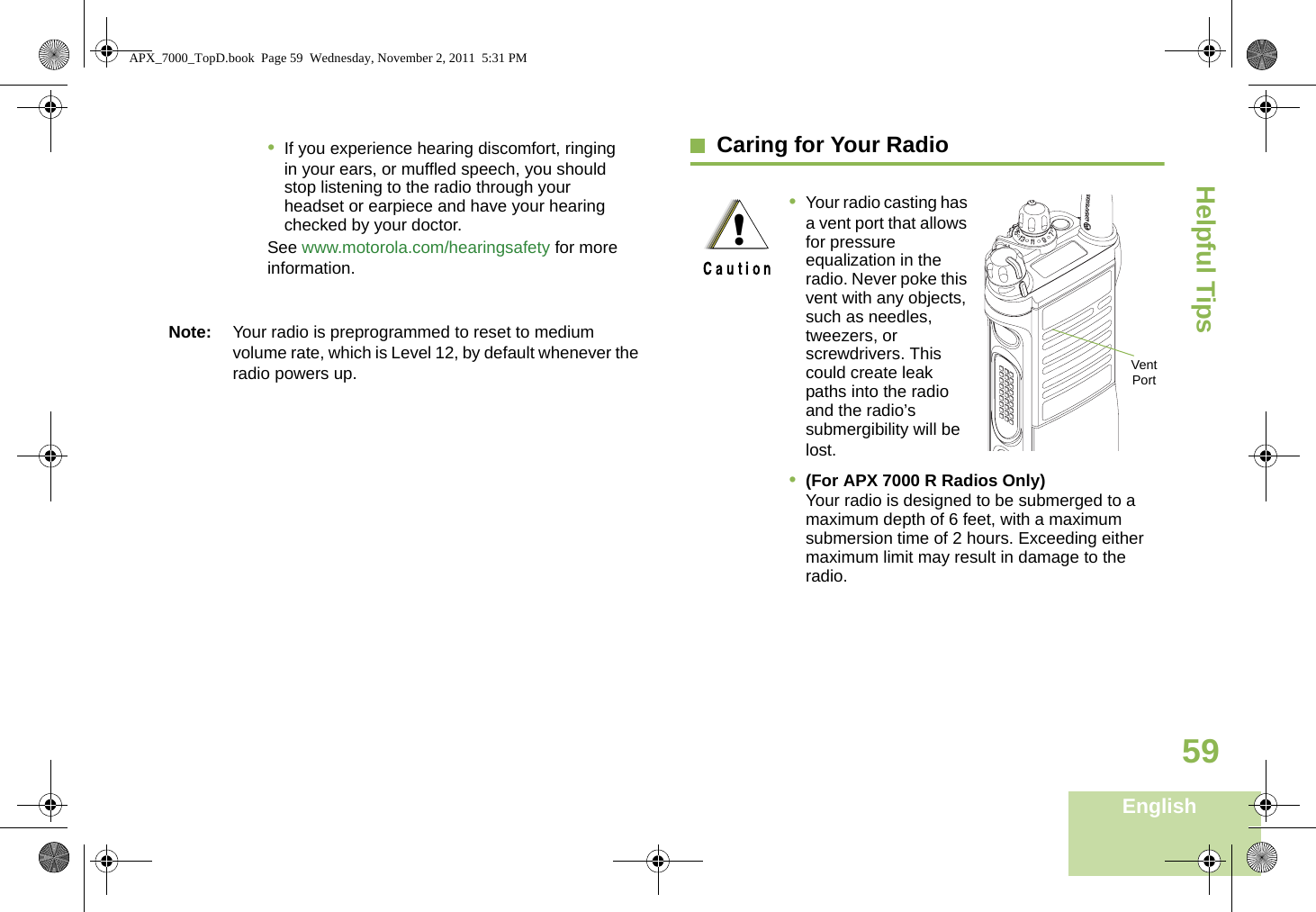
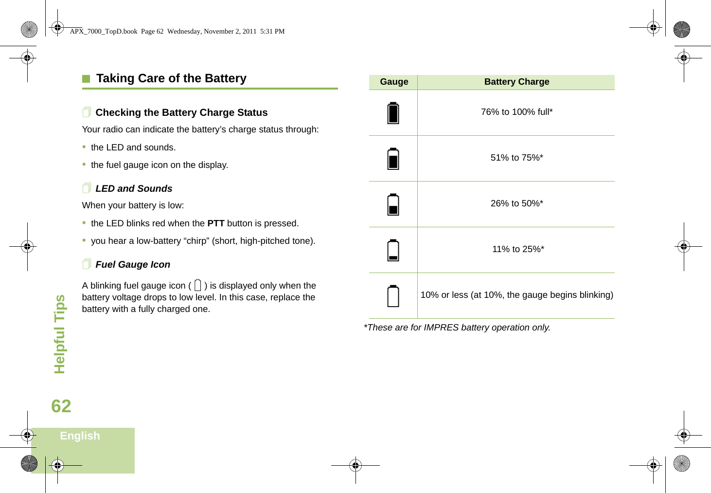
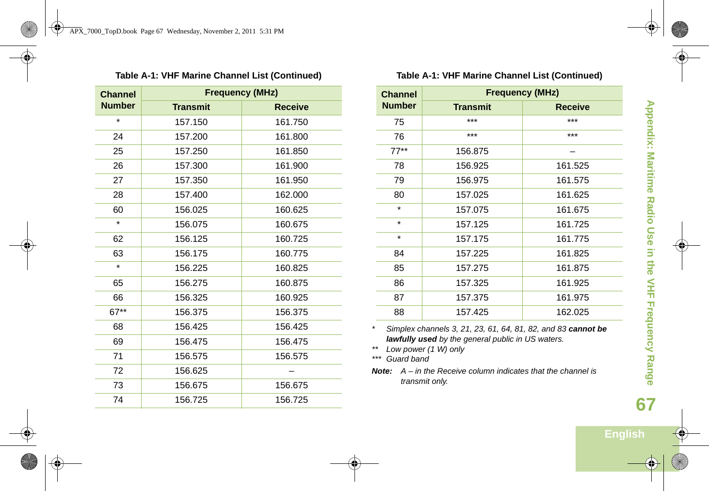
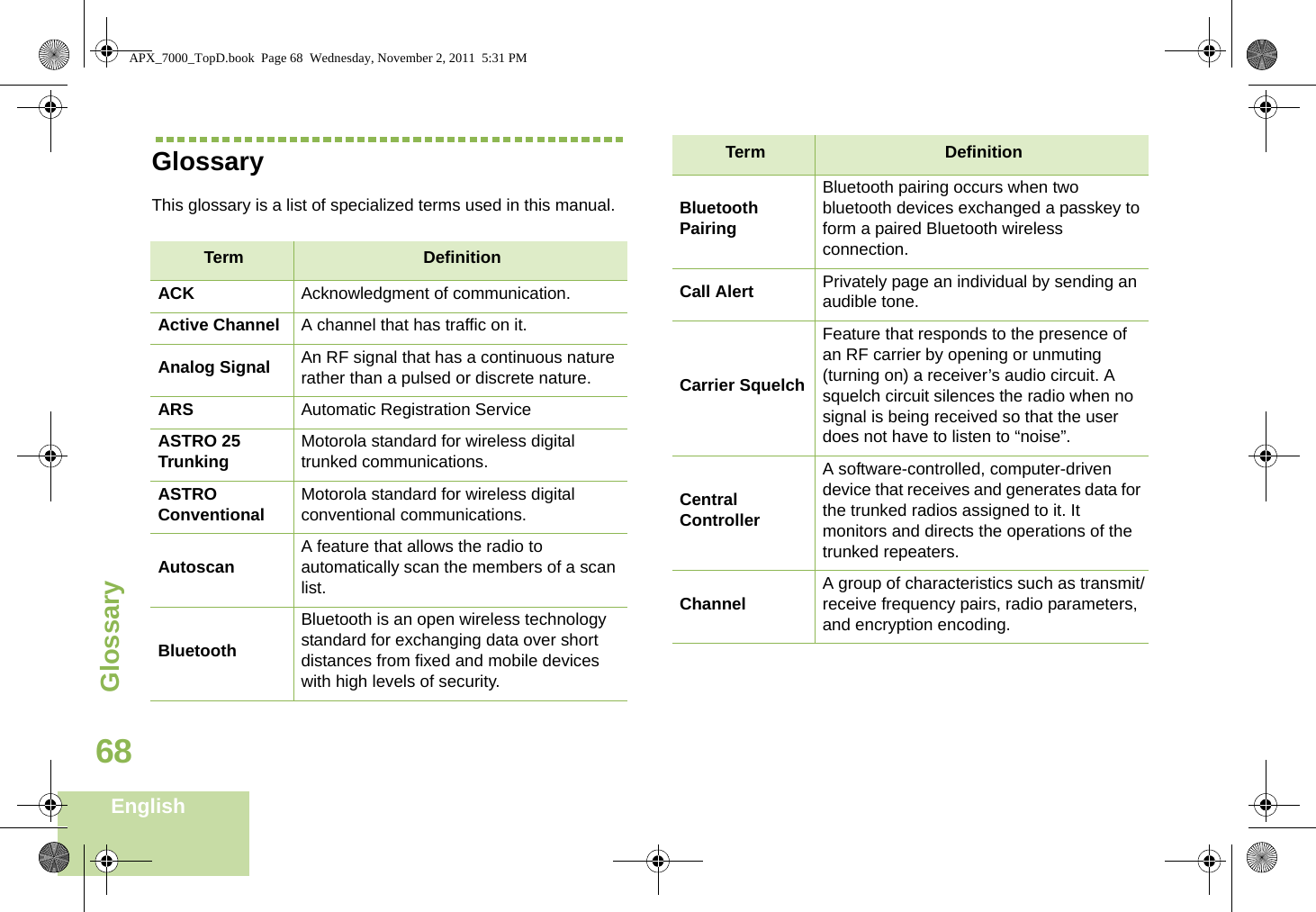
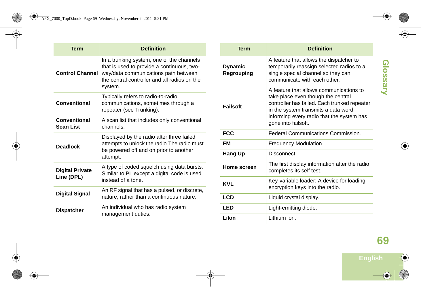
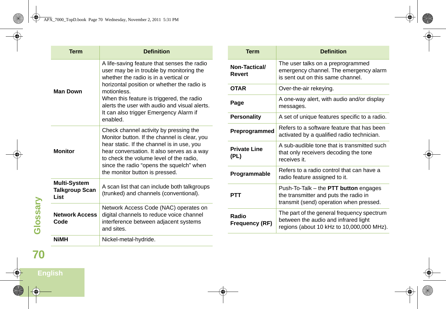
Users Guide
Users Guide
Navigation menu
Upload a User Manual
Namespaces
Wiki Guide
HTML
PDF
Info
Views
User Manual
Discussion / Help
Navigation