Motorola Solutions 89FT5797 iM1000 Wireless Data Modem User Manual
Motorola Solutions, Inc. iM1000 Wireless Data Modem
UserManual.wiki
>
Motorola Solutions
>
89FT5797 User Manual
>
User manual
Contents
1.
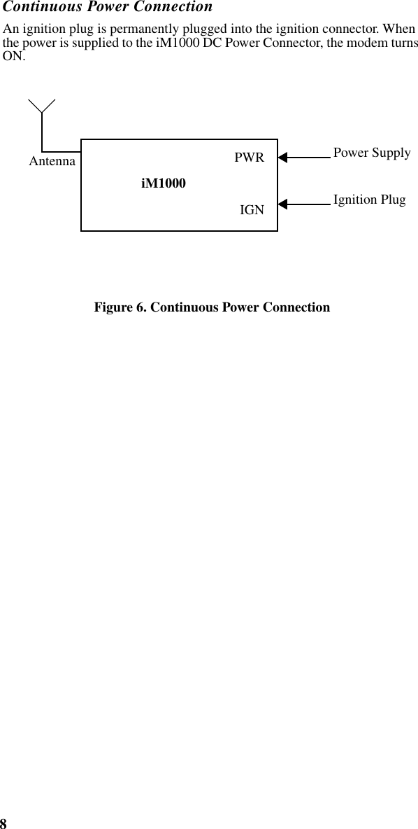
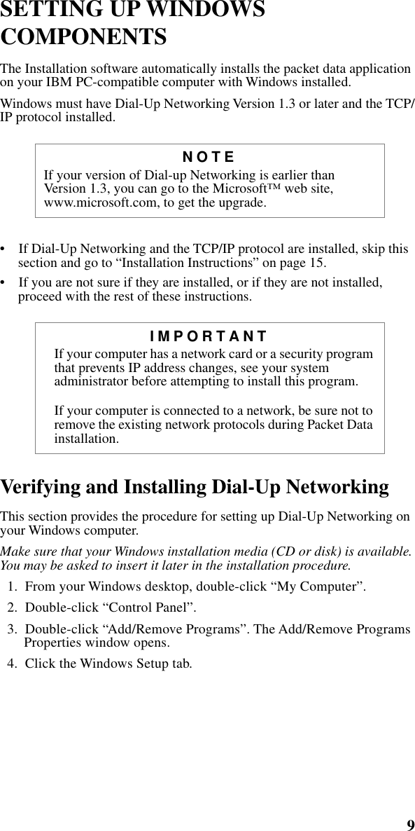
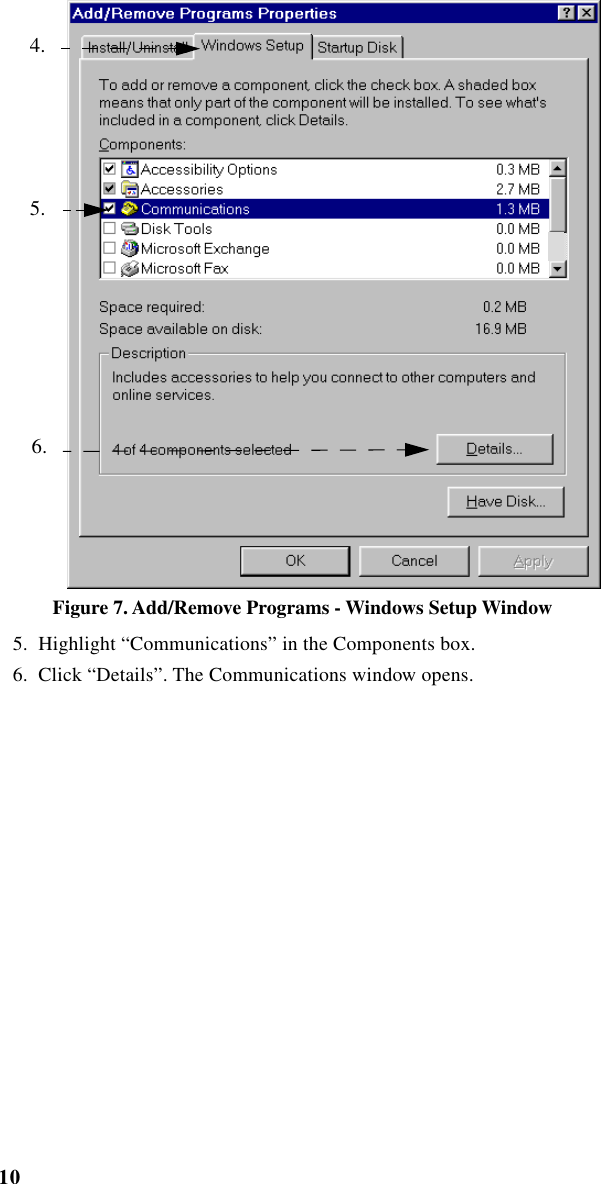
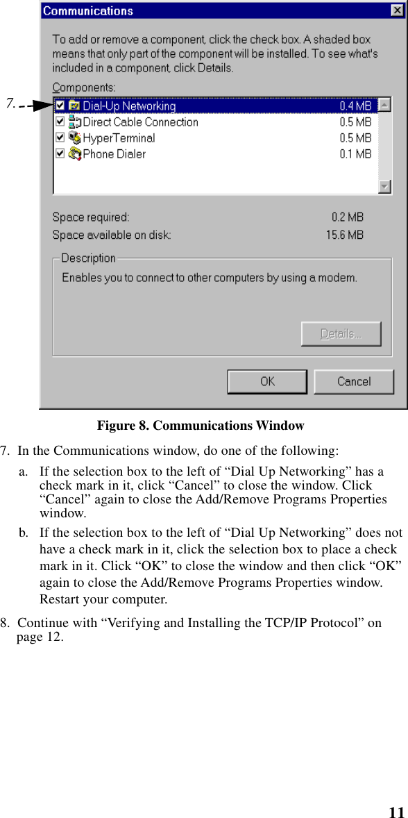
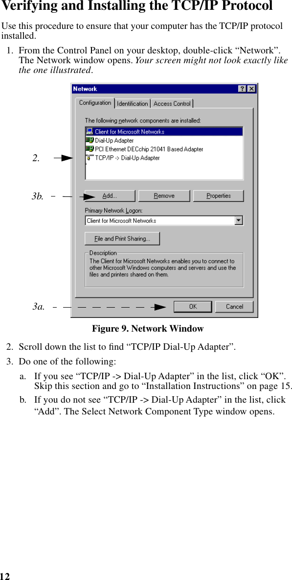
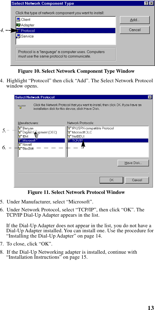
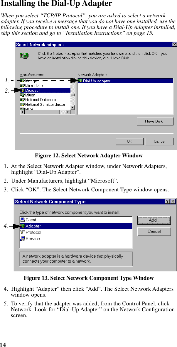
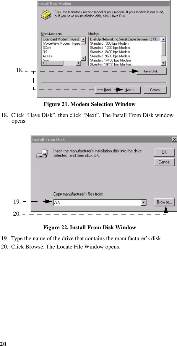
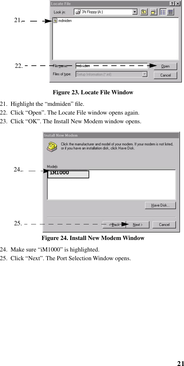
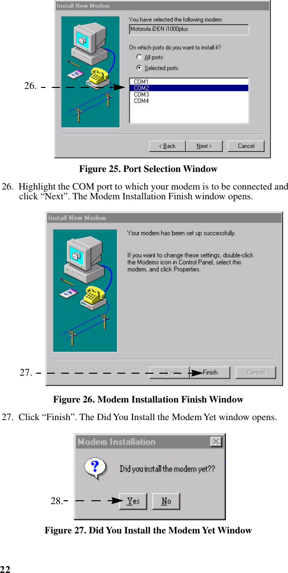
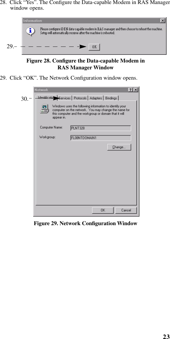
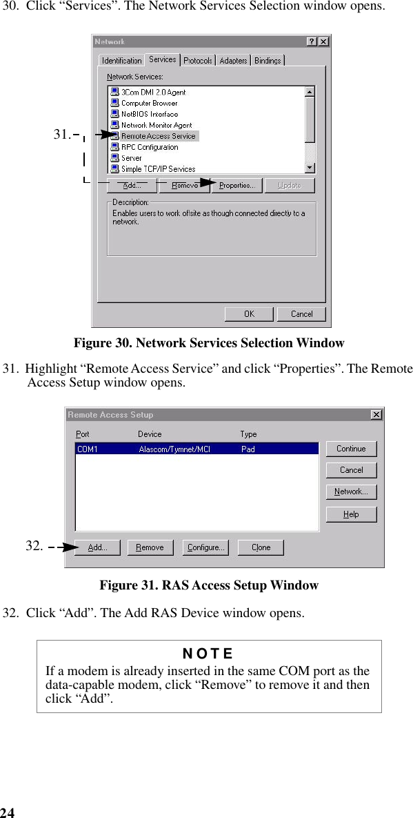
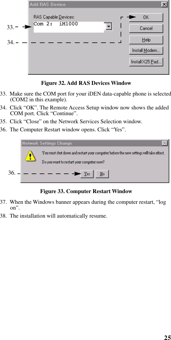
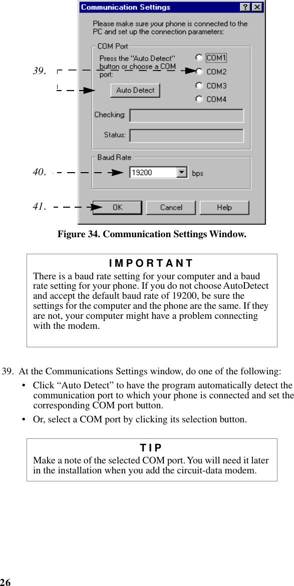
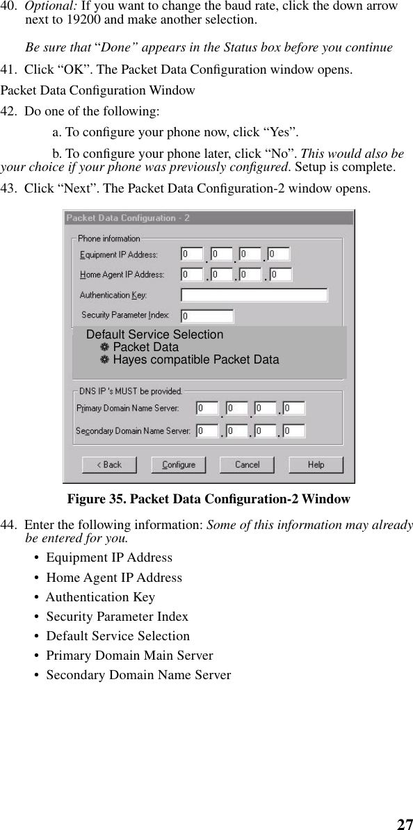
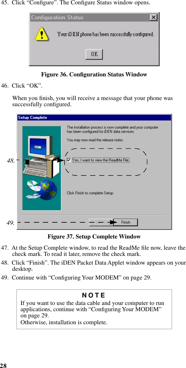
User manual
2.
Amended Users Manual
User manual
Navigation menu
Upload a User Manual
Namespaces
Wiki Guide
HTML
PDF
Info
Views
User Manual
Discussion / Help
Navigation