Motorola Solutions 89FT5797 iM1000 Wireless Data Modem User Manual iModem user
Motorola Solutions, Inc. iM1000 Wireless Data Modem iModem user
UserManual.wiki
>
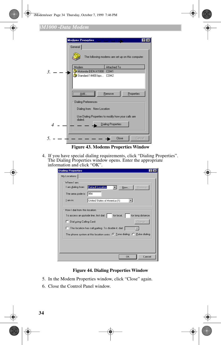
Motorola Solutions
>
89FT5797 User Manual
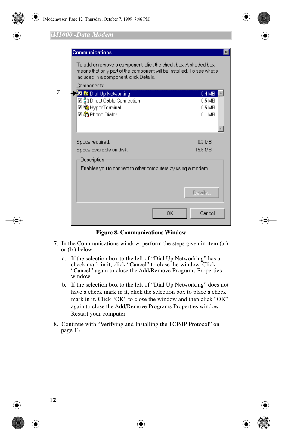
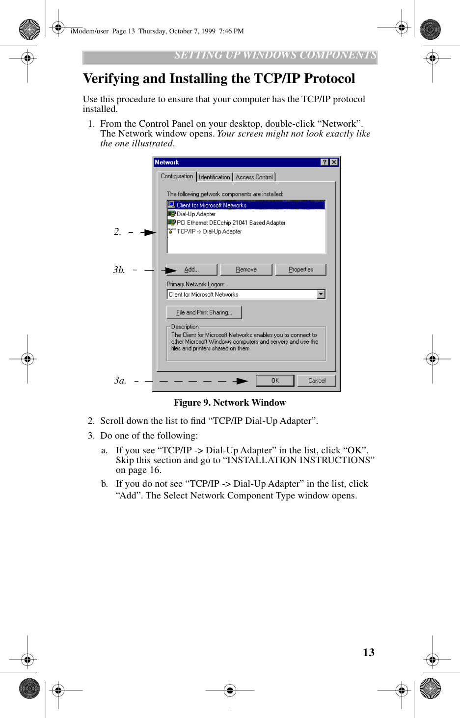
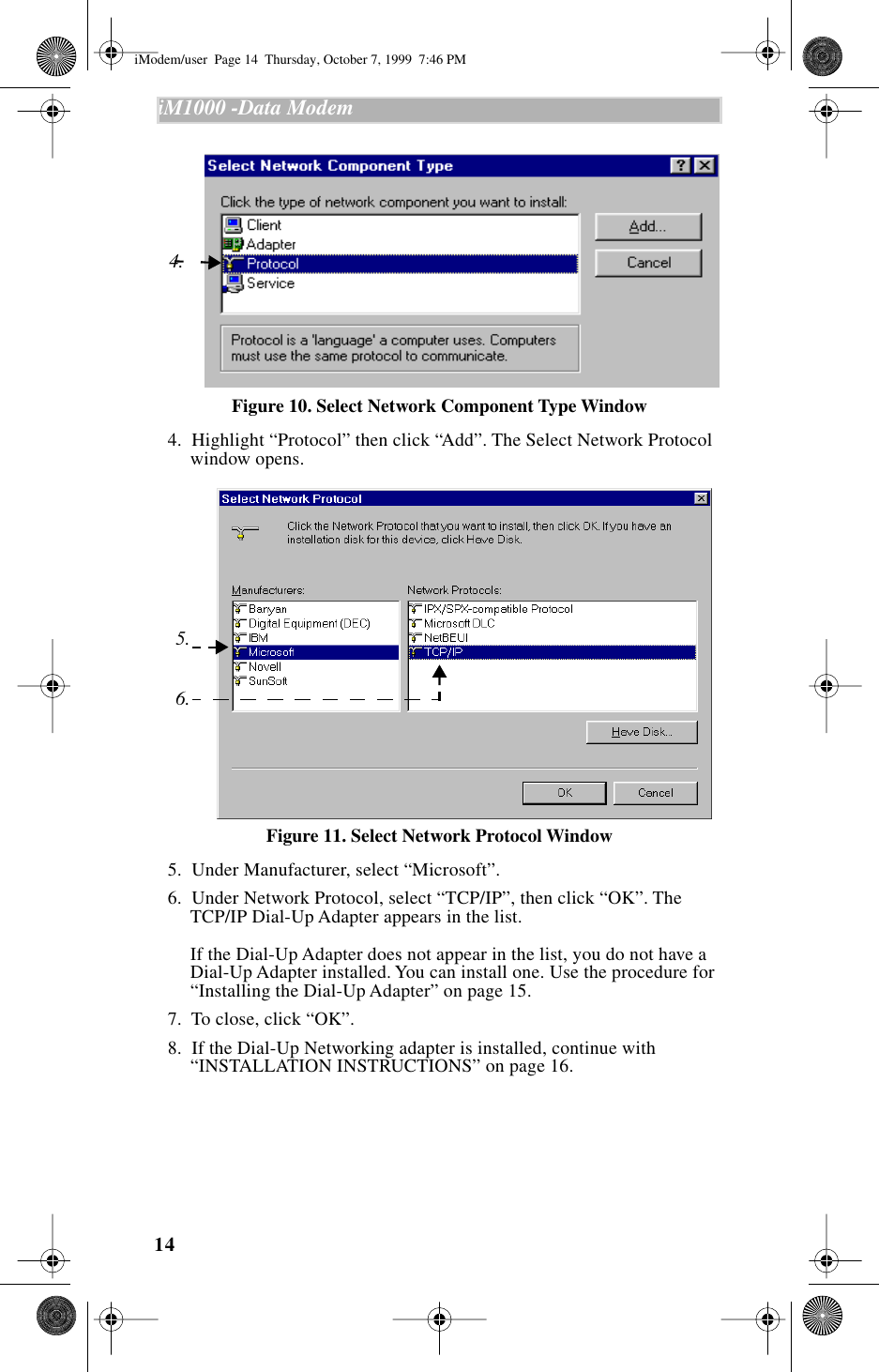
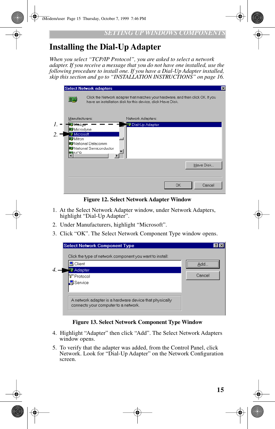
>
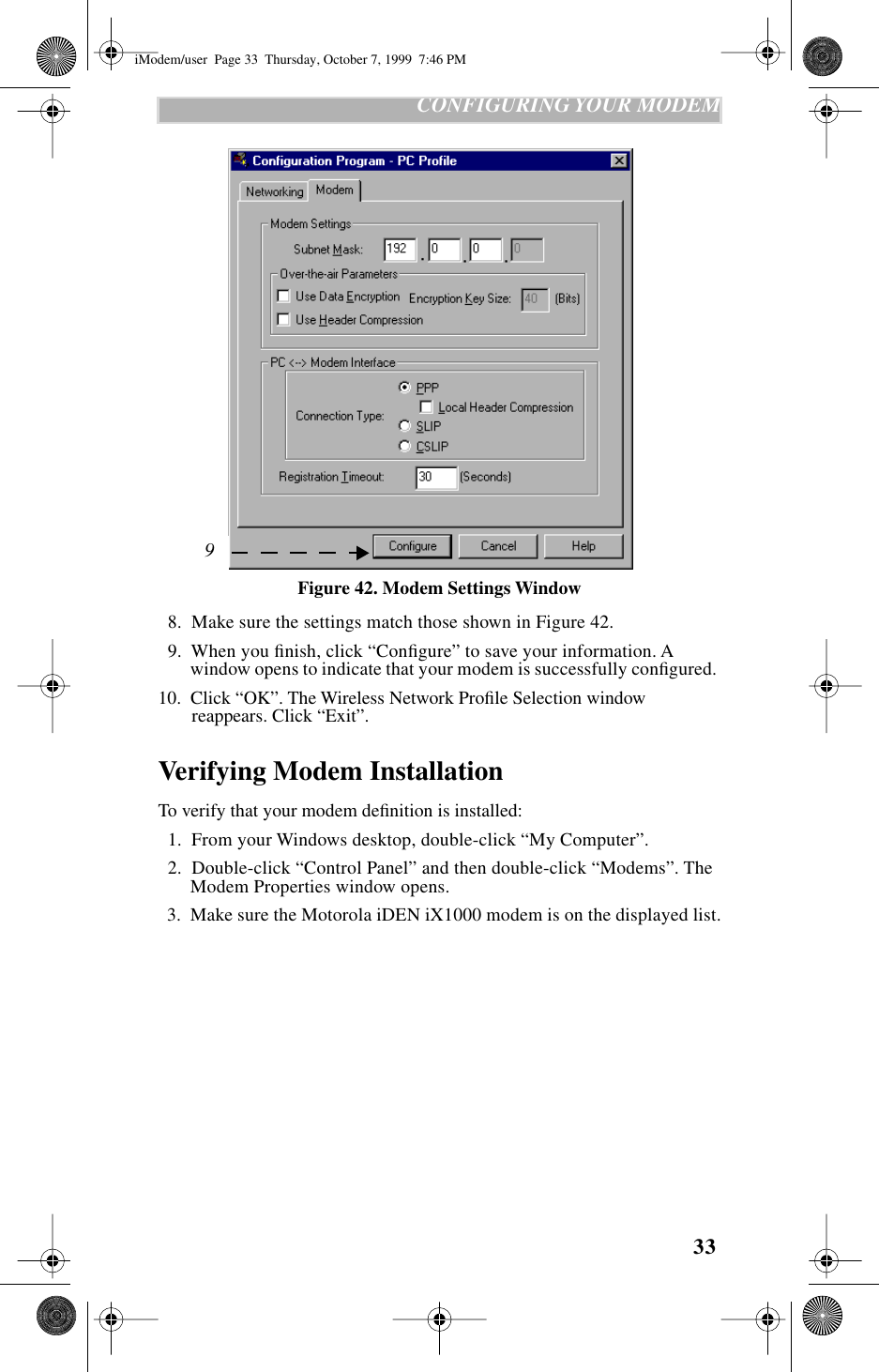
Amended Users Manual
Contents
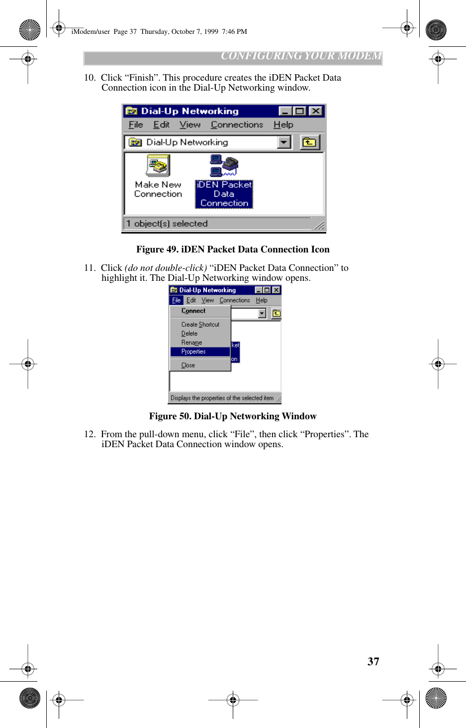
1.
User manual
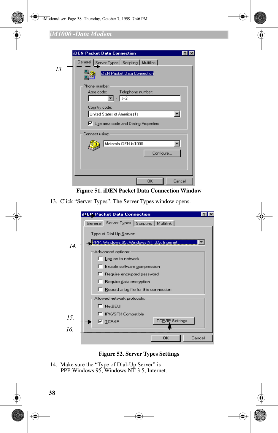
2.
Amended Users Manual
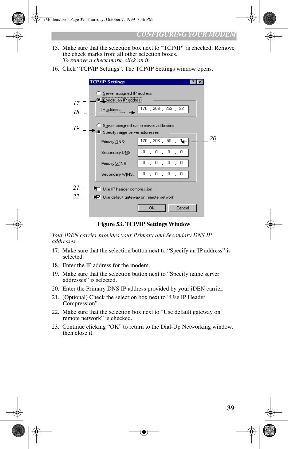
Amended Users Manual
Navigation menu
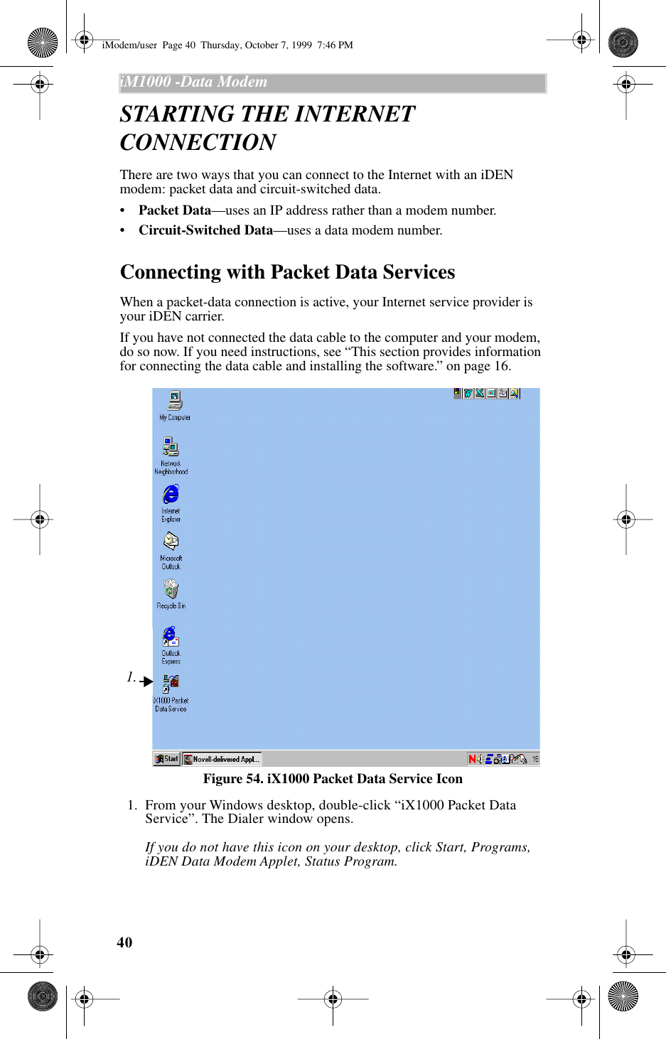
Upload a User Manual
Namespaces
Wiki Guide
HTML
PDF
Info
Views
User Manual
Discussion / Help
Navigation
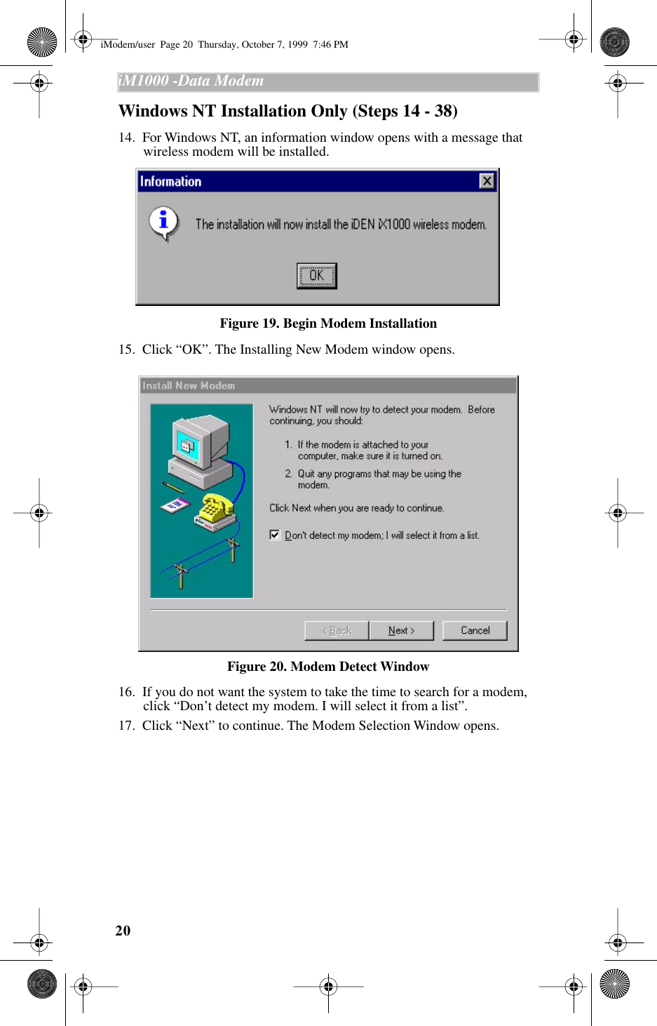
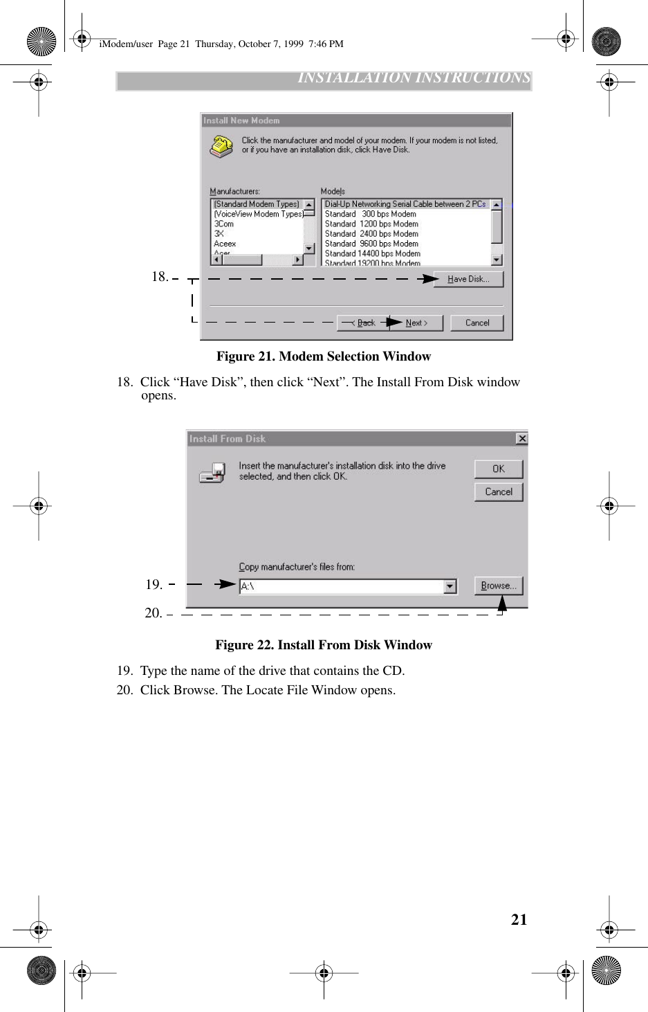
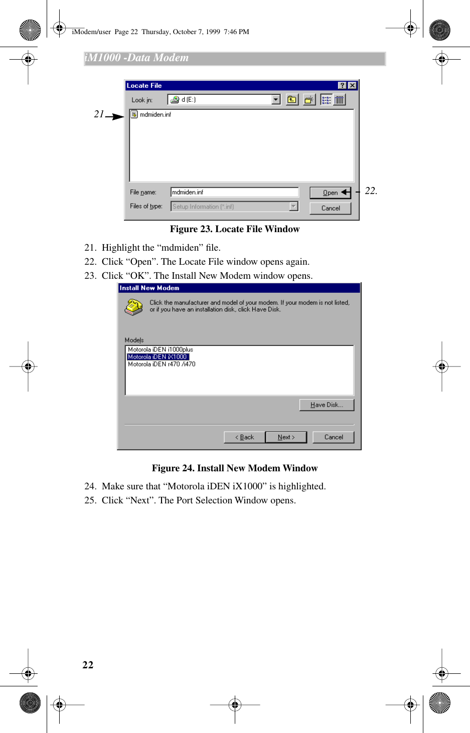
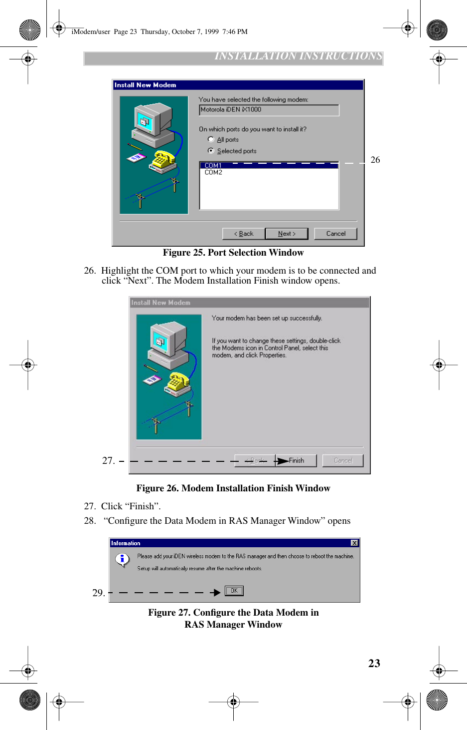
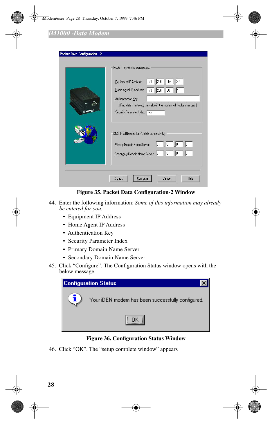
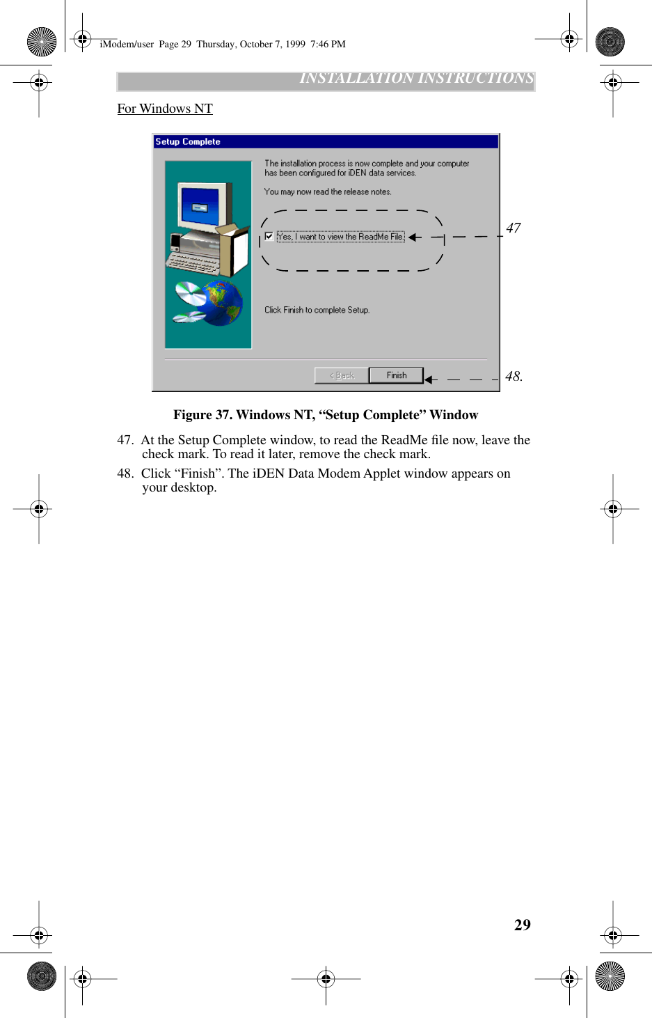
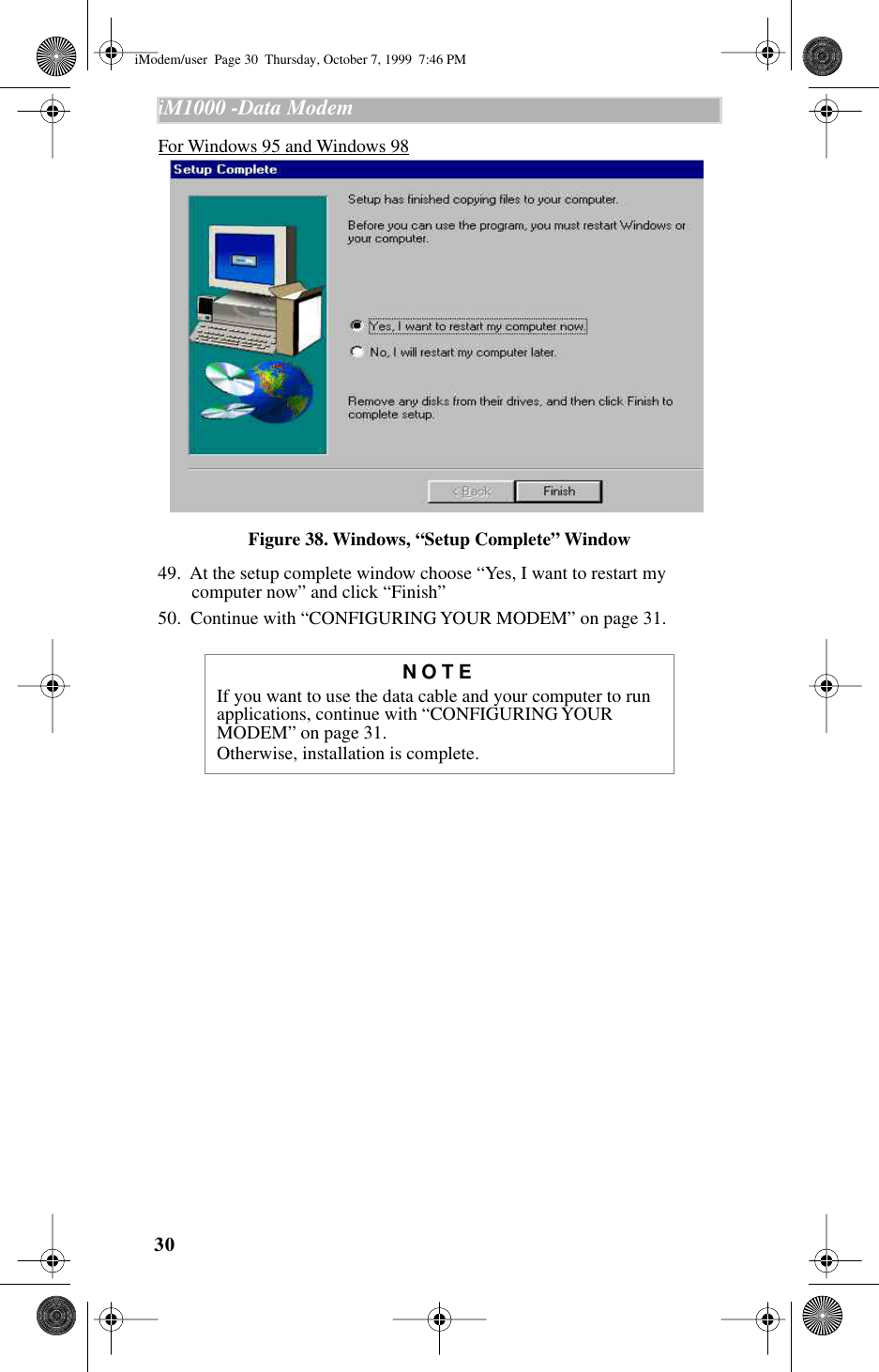
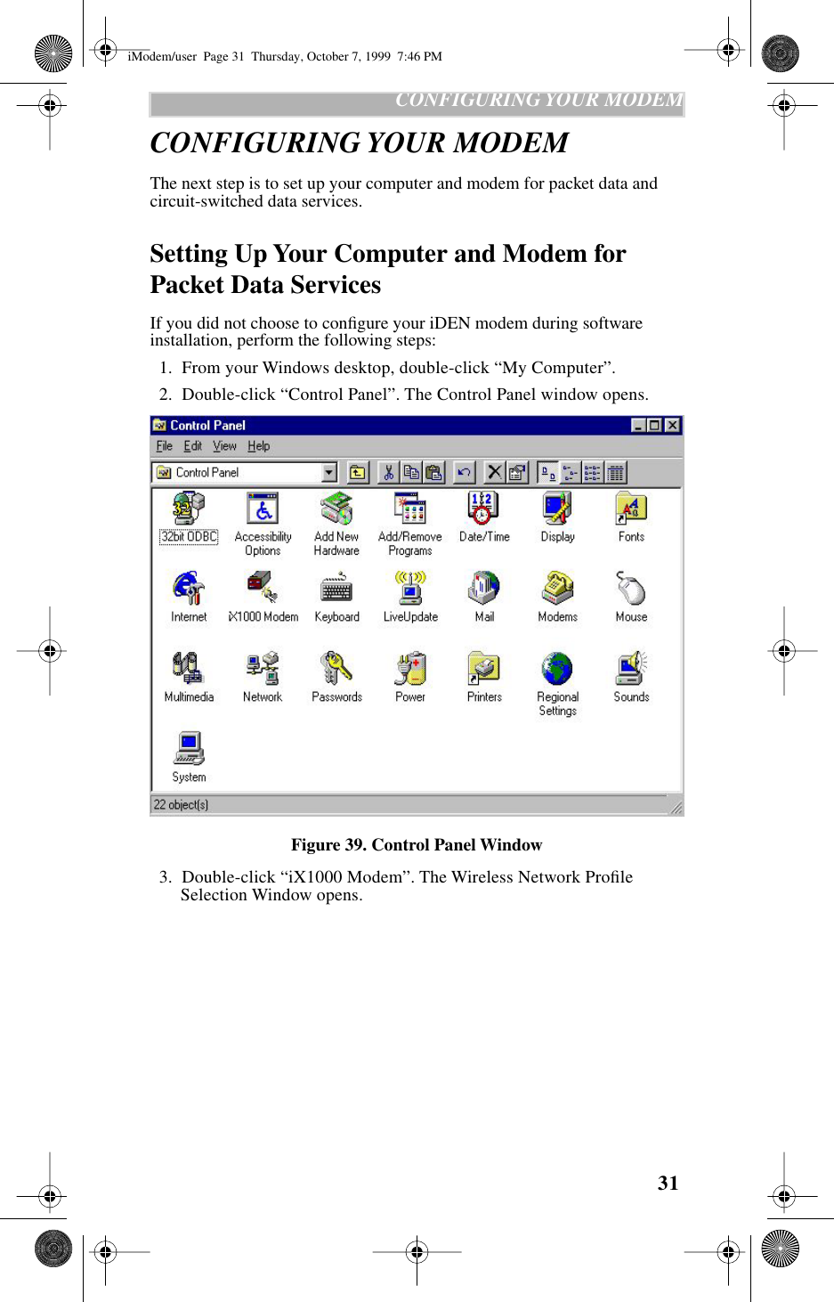

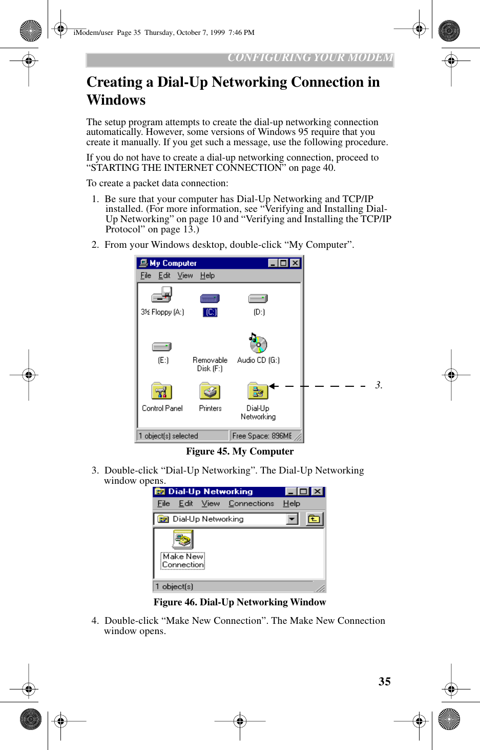
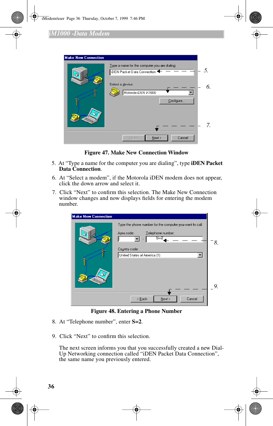
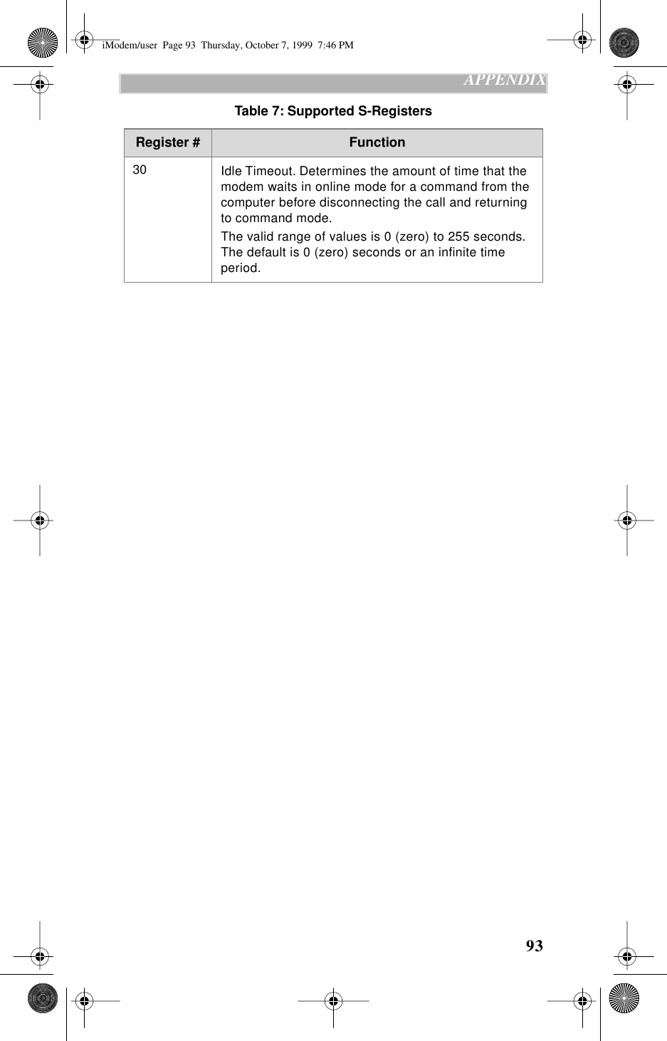
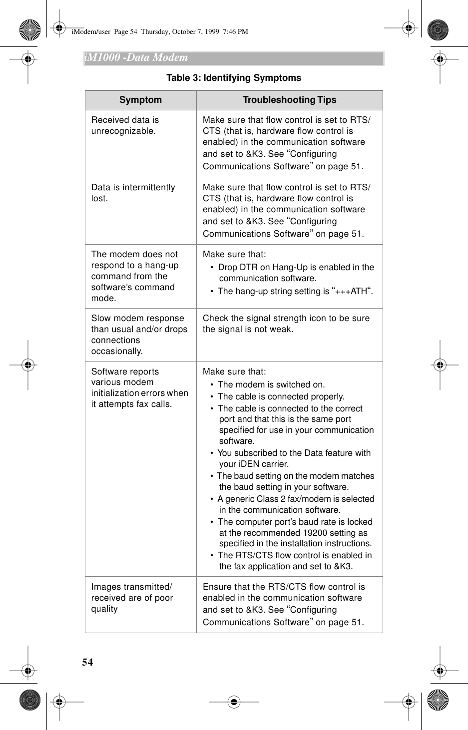
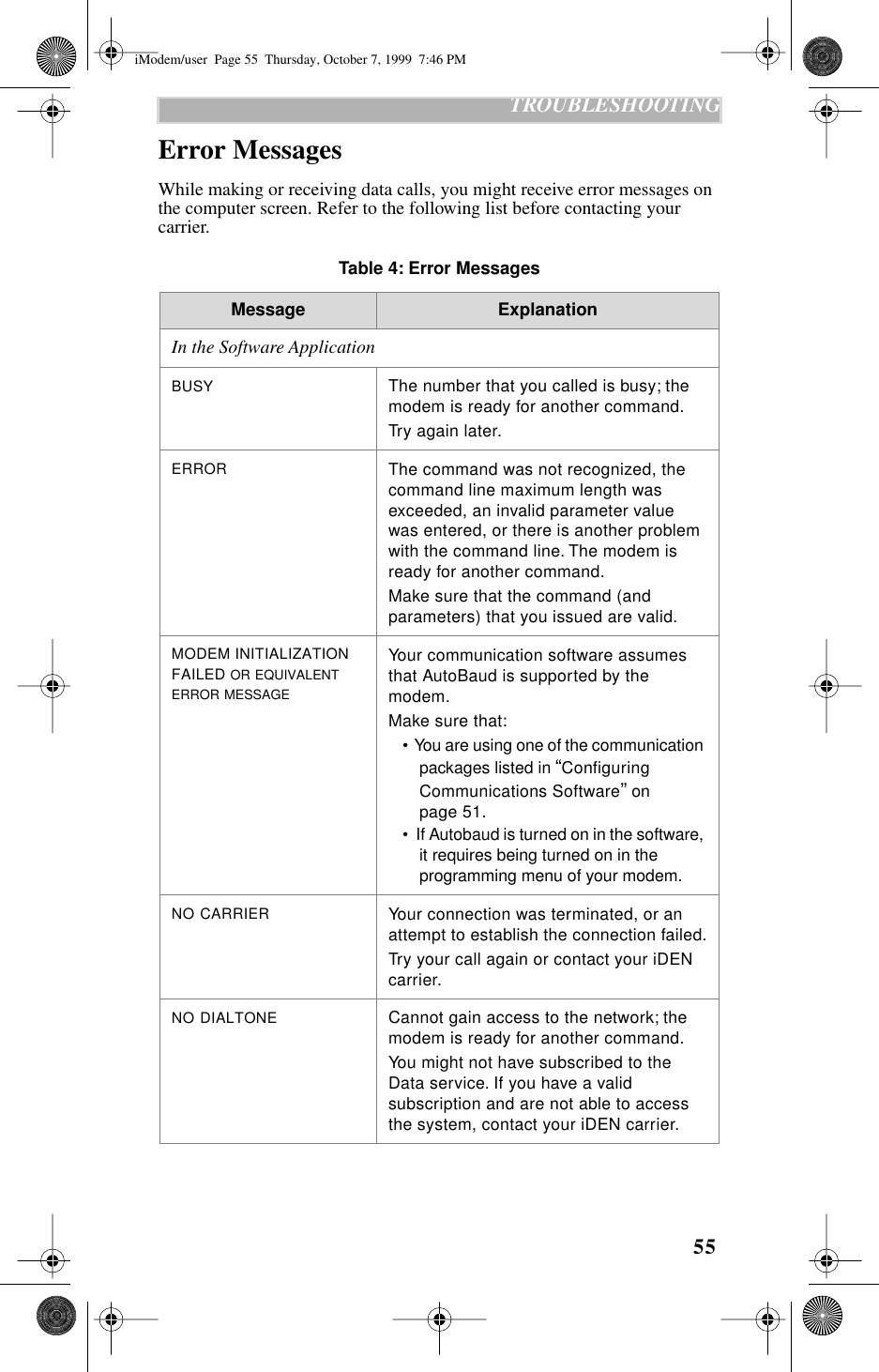
![51 RELATED SOFTWARERELATED SOFTWAREThis section provides information about:• Online service software• Configuring communication softwareOnline Service SoftwareOnline service software is distributed by an Internet Service Provider (ISP), a fee-based online subscription service, such as IBM® Internet Access, AOL®, or Prodigy®. 1. Install the software provided by your online service. 2. Connect your modem to the computer and make sure that both are turned on. 3. Start your online software. For instructions, see the information that came with your online service software. 4. When your computer displays the message, CONNECT, log on to the network and start using the online service.Configuring Communications SoftwareFor achieving peak operating efficiency with your modem during circuit-switched data use, configure your communication software according to the instructions provided below. Note that these instructions are application-specific.PROCOMM PLUS for Windows 4.0Before you install PROCOMM PLUS, modify the “pw2.ini” file in the Windows directory and type the following lines under “[options]”: faxlockedrate=19200fbor=12TTo configure for data modem: 1. In your communication software, select “Setup” on the menu bar, then select “Setup...” The Current Setup window opens. 2. Click the “Data Modem/Connection” icon.a. Select “Connection Setup”. (1) Set the default baud rate to 19200.(2) From the Selected Port listing, choose the port to which the modem is connected.(3) Click the selection box next to “Use Hardware Flow Control”.(4) Select “Install New Modem or Connection” then select “Generic Hayes-Compatible 2400 (no fax)”.b. Select “Data Modem Commands”.iModem/user Page 51 Thursday, October 7, 1999 7:46 PM](https://usermanual.wiki/Motorola-Solutions/89FT5797.Amended-Users-Manual/User-Guide-77357-Page-52.png)
![79 APPENDIXLocal Character Framing+ICF This parameter determines the local serial port asynchronous data framing. The second parameter is needed only if you select less than eight data bits.Action AT+icf=<Framing>[,<Parity>]Query AT+icf?Range AT+icf=?Parameter Values:Framing0 AutoDetect3 8 data bits, 1 stop bit5 7 data bits, 1 parity bit, 1 stop bitParity0 Odd1Even2 Mark3 SpaceiModem/user Page 79 Thursday, October 7, 1999 7:46 PM](https://usermanual.wiki/Motorola-Solutions/89FT5797.Amended-Users-Manual/User-Guide-77357-Page-80.png)